CNC 8058/8060/8065. Installation manual. - Fagor Automation
764
Ref: 2102 8058/8060 8065 CNC Installation manual.
-
Upload
khangminh22 -
Category
Documents
-
view
0 -
download
0
Transcript of CNC 8058/8060/8065. Installation manual. - Fagor Automation

Ref: 2102
8058/80608065CNCInstallation manual.
BLANK PAGE
ꞏ2ꞏ
MACHINE SAFETY
It is up to the machine manufacturer to make sure that the safety of the machineis enabled in order to prevent personal injury and damage to the CNC or to theproducts connected to it. On start-up and while validating CNC parameters, itchecks the status of the following safety elements. If any of them is disabled, theCNC shows the following warning message.
• Feedback alarm for analog axes.
• Software limits for analog and sercos linear axes.
• Following error monitoring for analog and sercos axes (except the spindle)both at the CNC and at the drives.
• Tendency test on analog axes.
FAGOR AUTOMATION shall not be held responsible for any personal injuries orphysical damage caused or suffered by the CNC resulting from any of the safetyelements being disabled.
DUAL-USE PRODUCTS
Products manufactured by FAGOR AUTOMATION since April 1st 2014 willinclude "-MDU" in their identification if they are included on the list of dual-useproducts according to regulation UE 428/2009 and require an export licensedepending on destination.
TRANSLATION OF THE ORIGINAL MANUAL
This manual is a translation of the original manual. This manual, as well as thedocuments derived from it, have been drafted in Spanish. In the event of anycontradictions between the document in Spanish and its translations, the wordingin the Spanish version shall prevail. The original manual will be labeled with thetext "ORIGINAL MANUAL".
HARDWARE EXPANSIONS
FAGOR AUTOMATION shall not be held responsible for any personal injuries orphysical damage caused or suffered by the CNC resulting from any hardwaremanipulation by personnel unauthorized by Fagor Automation.
If the CNC hardware is modified by personnel unauthorized by FagorAutomation, it will no longer be under warranty.
COMPUTER VIRUSES
FAGOR AUTOMATION guarantees that the software installed contains nocomputer viruses. It is up to the user to keep the unit virus free in order toguarantee its proper operation. Computer viruses at the CNC may cause it tomalfunction.
FAGOR AUTOMATION shall not be held responsible for any personal injuries orphysical damage caused or suffered by the CNC due a computer virus in thesystem.
If a computer virus is found in the system, the unit will no longer be under warranty.
All rights reserved. No part of this documentation may be transmitted,transcribed, stored in a backup device or translated into another languagewithout Fagor Automation’s consent. Unauthorized copying or distributing of thissoftware is prohibited.
The information described in this manual may be subject to changes due totechnical modifications. Fagor Automation reserves the right to change thecontents of this manual without prior notice.
All the trade marks appearing in the manual belong to the corresponding owners.The use of these marks by third parties for their own purpose could violate therights of the owners.
It is possible that CNC can execute more functions than those described in itsassociated documentation; however, Fagor Automation does not guarantee thevalidity of those applications. Therefore, except under the express permissionfrom Fagor Automation, any CNC application that is not described in thedocumentation must be considered as "impossible". In any case, FagorAutomation shall not be held responsible for any personal injuries or physicaldamage caused or suffered by the CNC if it is used in any way other than asexplained in the related documentation.
The content of this manual and its validity for the product described here has beenverified. Even so, involuntary errors are possible, hence no absolute match isguaranteed. However, the contents of this document are regularly checked andupdated implementing the necessary corrections in a later edition. We appreciateyour suggestions for improvement.
The examples described in this manual are for learning purposes. Before usingthem in industrial applications, they must be properly adapted making sure thatthe safety regulations are fully met.
Installation manual.
CNC 8058CNC 8060CNC 8065
ꞏ3ꞏ
REF: 2102
I N D E X
About the product - CNC 8058 ....................................................................................................11About the product - CNC 8060 ................................................................................................... 15About the product - CNC 8065 ................................................................................................... 21Declaration of CE conformity and warranty conditions ............................................................... 27Safety conditions ........................................................................................................................ 29Returning conditions ................................................................................................................... 33CNC maintenance ...................................................................................................................... 35New features............................................................................................................................... 37
[1] INSTALLATION MANUAL.
CHAPTER 1 SOFTWARE INSTALLATION.
1.1 Software installation at the CNC. .................................................................................. 451.1.1 Work modes and software protection for the CNC..................................................... 461.2 Software installation at the PC (simulator). .................................................................... 491.3 Changing the language of the help files......................................................................... 501.4 Updating the software version. ...................................................................................... 511.4.1 Software update and incompatibilities (8060). ........................................................... 521.4.2 Software update and incompatibilities (8065). ........................................................... 551.5 Requirements before and after CNC setup.................................................................... 581.6 Installation of third-party software (CNC 8065 only). ..................................................... 591.7 Software configuration. .................................................................................................. 601.7.1 MTB (Machine Tool Builder) folder. ........................................................................... 611.7.2 USERS folder............................................................................................................. 62
CHAPTER 2 MACHINE PARAMETERS.
2.1 Parameter matching between the CNC and the Sercos drive. ...................................... 652.2 Parameters to verify before the startup.......................................................................... 672.3 General machine parameters. ....................................................................................... 692.3.1 Channel configuration. ............................................................................................... 692.3.2 Configuring the axes of the system............................................................................ 702.3.3 Configuration of a tandem system. ............................................................................ 712.3.4 Configuration of a gantry axis. ................................................................................... 752.3.5 Configuration of a multi-axis group. ........................................................................... 782.3.6 Configuring the spindles of the system. ..................................................................... 802.3.7 Time setting (system)................................................................................................. 812.3.8 Sercos bus configuration............................................................................................ 832.3.9 Mechatrolink bus configuration. ................................................................................. 842.3.10 CAN bus configuration. .............................................................................................. 852.3.11 Serial line configuration.............................................................................................. 862.3.12 MODBUS. .................................................................................................................. 872.3.13 Bus EtherCAT bus. .................................................................................................... 882.3.14 Default conditions (sytem).......................................................................................... 882.3.15 Arithmetic parameters. ............................................................................................... 892.3.16 Cross compensation table.......................................................................................... 912.3.17 Volumetric compensation tables. ............................................................................... 942.3.18 Execution times.......................................................................................................... 972.3.19 Numbering of the digital inputs (CANfagor bus)......................................................... 982.3.20 Numbering of the digital outputs (CANfagor bus). ..................................................... 992.3.21 Numbering of the digital inputs (CANopen bus)....................................................... 1002.3.22 Numbering of the digital outputs (CANopen bus)..................................................... 1022.3.23 Numbering of analog inputs for temperature sensors PT100. ................................. 1042.3.24 Number of special analog inputs (non-voltage)........................................................ 1052.3.25 Probe setting. ........................................................................................................... 1062.3.26 Shared PLC memory................................................................................................ 1082.3.27 Management of local I/O. ......................................................................................... 1082.3.28 Synchronized switching............................................................................................ 1092.3.29 PWM (Pulse-Width Modulation). .............................................................................. 1102.3.30 Power control. .......................................................................................................... 1112.3.31 Gap control............................................................................................................... 1122.3.32 Leapfrog. .................................................................................................................. 1182.3.33 Compensating the dispersion by the CO2 laser path............................................... 119
Installation manual.
CNC 8058CNC 8060CNC 8065
ꞏ4ꞏ
REF: 2102
2.3.34 Backup of non-volatile data...................................................................................... 1212.3.35 Tool offset and wear. ............................................................................................... 1212.3.36 Spindle synchronization. .......................................................................................... 1222.3.37 Define the number of jog panels and their relationship with the channels. .............. 1222.3.38 PLC type. ................................................................................................................. 1232.3.39 Rename the axes and the spindles.......................................................................... 1232.3.40 Zero offsets. ............................................................................................................. 1242.3.41 Remote module RCS-S (Sercos Counter). .............................................................. 1242.3.42 Access to the parameter table of the channel.......................................................... 1252.4 General machine parameters. Execution channels. .................................................... 1262.4.1 Channel configuration. ............................................................................................. 1262.4.2 Configuring the axes of the channel. ....................................................................... 1272.4.3 Configuring the spindles of the channel. .................................................................. 1302.4.4 Configuration of the C axis....................................................................................... 1312.4.5 Time setting (channel). ............................................................................................ 1322.4.6 Configuration of the HSC mode (channel). .............................................................. 1332.4.7 Virtual tool axis......................................................................................................... 1372.4.8 Default conditions (channel). ................................................................................... 1382.4.9 Arc center correction. ............................................................................................... 1452.4.10 Behavior of the feedrate and the feedrate override. ................................................ 1462.4.11 Override of the dynamics. ........................................................................................ 1472.4.12 DMC configuration. .................................................................................................. 1482.4.13 Movement of the independent axes......................................................................... 1492.4.14 Definition of the subroutines. ................................................................................... 1502.4.15 Tabletop probe position. .......................................................................................... 1532.4.16 Block search. ........................................................................................................... 1552.4.17 Interruption subroutines. .......................................................................................... 1552.4.18 Machining feedrate. ................................................................................................. 1562.4.19 Rapid traverse for the automatic mode.................................................................... 1572.4.20 Maximum acceleration and jerk on the tool path. .................................................... 1582.4.21 Maximum frequency on the tool path. ...................................................................... 1582.4.22 Resonance frequency of the machine. .................................................................... 1592.4.23 "Retrace" function. ................................................................................................... 1592.4.24 Withdrawal the tool. ................................................................................................. 1602.4.25 Master spindle.......................................................................................................... 1602.5 Machine parameters for the axes and spindles. .......................................................... 1612.5.1 Belonging to the channel. ........................................................................................ 1612.5.2 Type of axis and drive.............................................................................................. 1622.5.3 Configuring a Sercos drive....................................................................................... 1632.5.4 Configuring a Mechatrolink drive. ............................................................................ 1662.5.5 Hirth axis. ................................................................................................................. 1672.5.6 Axis configuration for lathe type machines. ............................................................. 1682.5.7 Synchronization of axes and spindles...................................................................... 1702.5.8 Configuration of the rotary axes............................................................................... 1712.5.9 Module configuration (rotary axes and spindle). ...................................................... 1732.5.10 Activating the spindle for DMC................................................................................. 1732.5.11 Configuration of the C axis....................................................................................... 1742.5.12 Configuration of the spindle. .................................................................................... 1752.5.13 Spindle override change while threading. ................................................................ 1782.5.14 Software axis limits. ................................................................................................. 1792.5.15 Work zones. ............................................................................................................. 1802.5.16 Runaway protection and tendency test. ................................................................... 1802.5.17 PLC Offset. .............................................................................................................. 1812.5.18 Dwell for dead axes. ................................................................................................ 1822.5.19 Radius / diameter. .................................................................................................... 1832.5.20 Home search............................................................................................................ 1842.5.21 Configuration of the probing movement. .................................................................. 1862.5.22 Repositioning of the axes in tool inspection............................................................. 1882.5.23 Configuration of the independent axis. .................................................................... 1882.5.24 Configure the maximum safety limit for the feedrate and for the speed. ................. 1892.5.25 JOG mode................................................................................................................ 1902.5.26 Leadscrew error compensation................................................................................ 1952.5.27 Filters to eliminate resonance frequency. ................................................................ 1982.5.28 Work sets. ................................................................................................................ 2012.6 Machine parameters for the axes. Work sets. ............................................................. 2022.6.1 Feedback resolution................................................................................................. 2022.6.2 Loop setting. ............................................................................................................ 2062.6.3 Backlash compensation. .......................................................................................... 2062.6.4 Backlash compensation with an additional command pulse.................................... 2072.6.5 Adjustment of rapid traverse G00 and maximum speed. ......................................... 2102.6.6 Rapid traverse for the automatic mode. ................................................................... 2122.6.7 Gain setting.............................................................................................................. 2132.6.8 Linear acceleration................................................................................................... 2172.6.9 Trapezoidal and square sine acceleration. .............................................................. 2192.6.10 Enable specific acceleration values for movements in G0....................................... 222

Installation manual.
CNC 8058CNC 8060CNC 8065
ꞏ5ꞏ
REF: 2102
2.6.11 Linear acceleration (G0 movements). ...................................................................... 2232.6.12 Trapezoidal and square sine acceleration (G0 movements).................................... 2242.6.13 Configuration of the HSC mode. .............................................................................. 2262.6.14 Home search............................................................................................................ 2282.6.15 Following error. ........................................................................................................ 2332.6.16 Axis lubrication. ........................................................................................................ 2362.6.17 Module configuration (rotary axes and spindle). ...................................................... 2372.6.18 Spindle speed. ......................................................................................................... 2382.6.19 Analog command setting.......................................................................................... 2392.6.20 Number of the analog output and of the feedback input associated with the axis. .. 2402.6.21 Set the drive associated with the axes of a multi-axis group. .................................. 2432.6.22 Feedback type.......................................................................................................... 2432.6.23 Encoder Information................................................................................................. 2442.6.24 EnDat transmission format....................................................................................... 2452.6.25 SSI Feedback type................................................................................................... 2462.6.26 Delay estimate at the drive....................................................................................... 2512.6.27 Correction of bus and drive delay. ........................................................................... 2512.7 Machine parameters for JOG mode............................................................................. 2522.7.1 Handwheel configuration.......................................................................................... 2522.7.2 Configure the jog keys. ............................................................................................ 2542.7.3 Configure the user keys as jog keys. ....................................................................... 2562.7.4 HBLS portable operator panel.................................................................................. 2572.7.5 Remote terminal HBH3/HBH4. ................................................................................ 2572.7.6 Example of how to set the handwheels and jog keys. ............................................. 2582.8 Machine parameters for the M function table............................................................... 2622.8.1 M function table........................................................................................................ 2622.9 Machine parameters for kinetics. ................................................................................. 2642.9.1 Kinematics configuration. ......................................................................................... 2652.9.2 Definition of the spindle kinetics (types 1 through 8)................................................ 2702.9.3 Definition of the table kinetics (types 9 through 12). ................................................ 2742.9.4 Definition of the kinematics of the spindle - table (types 13 through 16).................. 2792.9.5 Definition of the spindle kinetics (types 17 through 24)............................................ 2842.9.6 Definition of the –C– axis kinematics (types 41 through 42). ................................... 2882.9.7 Definition of the –C– axis kinematics (type 43) . ...................................................... 2902.9.8 Vectorial definition of spindle kinematics (type 50). ................................................. 2912.9.9 Vectorial definition of table kinematics (type 51)...................................................... 2952.9.10 Vectorial definition of spindle-table kinematics (type 52). ........................................ 2992.9.11 Definition of the OEM kinematics (types 100 through 105)...................................... 3062.9.12 Configuration of angular transformations. ................................................................ 3072.9.13 Configuration of angular transformations (parameters). .......................................... 3082.10 Machine parameters for the magazine. ....................................................................... 3102.10.1 Tool magazine configuration. ................................................................................... 3102.10.2 Magazine data.......................................................................................................... 3112.10.3 Tool magazine management.................................................................................... 3122.10.4 Types of tool magazine. ........................................................................................... 3142.11 Machine parameters for HMI (Interface). ..................................................................... 3162.11.1 Main window dimensions and resolution.................................................................. 3162.11.2 Customizing the softkeys. ........................................................................................ 3172.11.3 Interface setting........................................................................................................ 3182.11.4 Keyboard configuration ([CUSTOM] key)................................................................. 3202.11.5 Keyboard configuration ([NEXT] key)....................................................................... 3212.11.6 Keyboard configuration ([ESC] key)......................................................................... 3232.11.7 Simulated jog keyboard............................................................................................ 3242.11.8 CNC shut down. ....................................................................................................... 3242.11.9 Graphics configuration. ............................................................................................ 3252.12 OEM machine parameters. .......................................................................................... 3262.12.1 Reading drive (Sercos or Mechatrolink) variables. .................................................. 3262.12.2 Generic OEM parameters. ....................................................................................... 3282.12.3 Example: Changing the FFGAIN for the drive (PP216) in synchronous mode. ...... 3302.12.4 Cam editor................................................................................................................ 331
CHAPTER 3 INTRODUCTION TO THE PLC.
3.1 PLC program................................................................................................................ 3343.2 Modular structure of the PLC program......................................................................... 3353.3 PLC program execution. .............................................................................................. 3363.4 PLC resources. ............................................................................................................ 3373.4.1 Numbering of the physical inputs and outputs. ........................................................ 3403.5 Operation of a timer. .................................................................................................... 3423.5.1 Monostable mode. TG1 input................................................................................... 3443.5.2 Delayed activation mode. TG2 input. ....................................................................... 3463.5.3 Delayed deactivation mode. TG3 input. ................................................................... 3483.5.4 Signal limiting mode. TG4 Input. .............................................................................. 3503.6 Operation of a counter. ................................................................................................ 352
Installation manual.
CNC 8058CNC 8060CNC 8065
ꞏ6ꞏ
REF: 2102
CHAPTER 4 PLC PROGRAMMING.
4.1 Directing instructions. .................................................................................................. 3574.2 Consulting instructions................................................................................................. 3614.2.1 Simple consulting instructions.................................................................................. 3614.2.2 Flank detection instructions. .................................................................................... 3624.2.3 Comparing instructions. ........................................................................................... 3634.3 Operators and symbols................................................................................................ 3644.4 Action instructions........................................................................................................ 3654.4.1 Assignment binary instructions. ............................................................................... 3664.4.2 Conditional binary instructions. ................................................................................ 3674.4.3 Sequence breaking action instructions. ................................................................... 3684.4.4 Arithmetic action instructions. .................................................................................. 3694.4.5 Logic action instructions........................................................................................... 3714.4.6 Specific action instructions....................................................................................... 3734.4.7 Action instruction of the electronic cam. ................................................................. 3764.4.8 Instructions for independent move: positioning. ...................................................... 3784.4.9 Instructions for independent move: synchronization. .............................................. 3804.4.10 Instructions for coordinate latching using a probe or digital input. ........................... 3824.5 Considerations for some functions. ............................................................................. 3864.5.1 Work zones. ............................................................................................................. 3864.6 Summary programming commands............................................................................. 388
CHAPTER 5 CNC-PLC COMMUNICATION.
5.1 Auxiliary –M– functions. ............................................................................................... 3925.1.1 Special considerations with the multi-spindle option and channels. ........................ 3935.2 Auxiliary –H– functions. ............................................................................................... 3945.2.1 Special considerations with the multi-spindle option and channels. ........................ 3955.3 Auxiliary –S– function. ................................................................................................. 3965.3.1 Special considerations with the multi-spindle option and channels. ........................ 3975.4 Transferring auxiliary functions -M-, -H-, -S-................................................................ 3985.4.1 Synchronized transfer. ............................................................................................. 3995.4.2 Non-synchronized transfer. ...................................................................................... 4005.5 Displaying PLC errors and messages. ........................................................................ 401
CHAPTER 6 LOGIC CNC INPUTS AND OUTPUTS.
6.1 General consulting signals........................................................................................... 4046.2 Consulting signals for axes and spindles..................................................................... 4166.3 Consulting signals for the spindle. ............................................................................... 4226.4 Consultation signals of the independent interpolator. .................................................. 4246.5 Consulting logic signals; laser. .................................................................................... 4266.6 Tool manager consulting signals. ................................................................................ 4286.7 Keystroke consulting signals. ...................................................................................... 4306.8 General modifiable signals. ........................................................................................ 4346.9 Modifiable signals for axes and spindles. .................................................................... 4456.10 Spindle modifiable signals. .......................................................................................... 4496.11 Modifiable logic signals; laser. ..................................................................................... 4536.12 Modifiable signals of the independent interpolator. ..................................................... 4556.13 Tool manager modifiable signals. ................................................................................ 4566.14 Keystroke modifiable signals. ...................................................................................... 459
CHAPTER 7 TOOL AND MAGAZINE MANAGEMENT.
7.1 Types of tool magazine................................................................................................ 4677.2 Tool table, active tool table and tool magazine table................................................... 4697.3 Communication between manager and PLC. .............................................................. 4707.3.1 Manager --> PLC communication. ........................................................................... 4717.3.2 PLC --> Manager communication. ........................................................................... 4727.3.3 Manager Emergency................................................................................................ 4747.3.4 Tool monitoring. ....................................................................................................... 4757.4 Variables related to tool magazine management. ....................................................... 4767.5 Tool loading and unloading from the magazines. ........................................................ 4777.6 Magazine-less system. ................................................................................................ 4787.6.1 Valid operations and marks activated by the PLC with each one of them. .............. 4797.6.2 Detailed description of the operations of the magazine. .......................................... 4807.6.3 Basic PLC programming. ......................................................................................... 4807.7 Turret type magazine................................................................................................... 4817.7.1 Valid operations and marks activated by the PLC with each one of them. .............. 4827.7.2 Detailed description of the operations of the magazine. .......................................... 4847.7.3 Communication between the PLC and the M06 subroutine..................................... 4867.7.4 Program of the M06 subroutine. .............................................................................. 4877.7.5 Basic PLC programming. ......................................................................................... 489
Installation manual.
CNC 8058CNC 8060CNC 8065
ꞏ7ꞏ
REF: 2102
7.8 Synchronous magazine without changer arm.............................................................. 4907.8.1 Valid operations and marks activated by the PLC with each one of them. .............. 4917.8.2 Detailed description of the operations of the magazine. .......................................... 4937.8.3 Communication between the PLC and the M06 subroutine..................................... 4967.8.4 Program of the M06 subroutine................................................................................ 4977.8.5 Basic PLC programming. ......................................................................................... 4997.9 Synchronous magazine with changer arm and 1 claw................................................. 5007.9.1 Valid operations and marks activated by the PLC with each one of them. .............. 5017.9.2 Detailed description of the operations of the magazine. .......................................... 5037.9.3 Communication between the PLC and the M06 subroutine..................................... 5067.9.4 Program of the M06 subroutine................................................................................ 5077.9.5 Basic PLC programming. ......................................................................................... 5107.10 Synchronous magazine with changer arm and 2 claws............................................... 5127.10.1 Valid operations and marks activated by the PLC with each one of them. .............. 5137.10.2 Detailed description of the operations of the magazine. .......................................... 5157.10.3 Communication between the PLC and the M06 subroutine..................................... 5187.10.4 Program of the M06 subroutine................................................................................ 5197.10.5 Basic PLC programming. ......................................................................................... 5227.11 Asynchronous magazine with changer arm. ................................................................ 5247.11.1 Valid operations and marks activated by the PLC with each one of them. .............. 5257.11.2 Detailed description of the operations of the magazine. .......................................... 5287.11.3 Communication between the PLC and the M06 subroutine..................................... 5327.11.4 Program of the M06 subroutine................................................................................ 5337.11.5 Basic PLC programming. ......................................................................................... 536
CHAPTER 8 KEYBOARD SIMULATION VIA THE PLC. KEY CODES.
8.1 Selecting the language and the keyboard distribution. ................................................ 5398.2 Key codes. ................................................................................................................... 5418.2.1 Keyboard shortcuts. CNC's own keys. ..................................................................... 5428.3 Consulting the last key accepted by the CNC.............................................................. 5438.4 Keyboard simulation via the PLC................................................................................. 5438.5 Key codes depending on keyboard layout. .................................................................. 5458.5.1 Scan codes. "Spanish (Spain)” keyboard layout. ..................................................... 5458.5.2 Scan codes. Keyboard distribution "English (United States)". ................................. 5468.6 Example. Keyboard simulation via the PLC................................................................. 547
CHAPTER 9 CNC VARIABLES.
[2] CONCEPTS.
CHAPTER 10 GENERAL SETUP.
10.1 Configure the name and number of axes and spindles. .............................................. 55310.1.1 Configure the number of axes and spindles of the system. ..................................... 55410.1.2 Configure the number of axes and spindles of the channels. .................................. 55510.2 Configuration examples. .............................................................................................. 55610.2.1 Milling machine with 1 channel, 3 axes and 1 spindle. ............................................ 55710.2.2 Milling machine with 1 channel, 5 axes (2 free) and 1 spindle................................. 55810.2.3 Milling machine with 3 channels, 9 axes and 2 spindles.......................................... 55910.2.4 Lathe with 1 channel, 3 axes and 1 spindle. Configuration of "plane" type axes. .... 56110.2.5 Lathe with 1 channel, 3 axes and 1 spindle. Configuration of trihedron type axes. . 56210.2.6 Lathe with 1 channel, 3 axes (1 free) and 1 spindle. Configuration of "plane" type axes.
56310.2.7 Lathe with 2 channels, 4 axes and 2 spindles. Configuration of "plane" type axes. 56410.2.8 Lathe with 3 channels, 6 axes and 2 spindles. Configuration of "plane" type axes. 565
CHAPTER 11 CONFIGURING AN AXIS.
11.1 Configure an axis as rotary axis................................................................................... 56711.2 Configure two axes as a tandem axis. ......................................................................... 57011.2.1 Tandem axis configuration. Machine parameters. ................................................... 57111.2.2 Effect of the preload. ................................................................................................ 57311.2.3 Tandem axis configuration. Block diagram. ............................................................. 57511.2.4 Tandem related variables......................................................................................... 57711.2.5 Tandem adjustment procedure. ............................................................................... 57811.3 Analog axes. ................................................................................................................ 57911.3.1 Configure the number of the analog output and of the feedback input. ................... 57911.3.2 Configure 2 axes with the same feedback input and analog output......................... 58111.4 Multi-axis management................................................................................................ 58211.4.1 Configuration of a multi-axis group. Machine parameters........................................ 584
Installation manual.
CNC 8058CNC 8060CNC 8065
ꞏ8ꞏ
REF: 2102
11.4.2 Configuration of a multi-axis group. The PLC routine generates an error. .............. 58711.4.3 Changing the set and the gear at the CNC and at the drive. ................................... 58811.4.4 Configuration examples. .......................................................................................... 58911.5 Home search. .............................................................................................................. 59111.5.1 Home search (axes and spindles). .......................................................................... 59311.5.2 Home search (gantry axes)...................................................................................... 59611.6 Software limits of the axes........................................................................................... 59811.6.1 How to set the software travel limits. ....................................................................... 60011.6.2 Set the tolerance for an axis located at the software travel limits. ........................... 602
CHAPTER 12 VOLUMETRIC COMPENSATION.
12.1 Basic volumetric compensation. .................................................................................. 60512.1.1 Setup. General; machine parameters. ..................................................................... 60512.1.2 Setup. PLC. General modifiable signals. ................................................................. 60512.1.3 File containing basic volumetric compensation data................................................ 60612.1.4 Sequence to define the values in the file. ................................................................ 60712.1.5 Variables. ................................................................................................................. 60912.2 Medium or large volumetric compensation. ................................................................. 61112.2.1 Setup. General; machine parameters. ..................................................................... 61112.2.2 Setup. PLC. General modifiable signals. ................................................................. 61112.2.3 Variables. ................................................................................................................. 61212.3 Error messages (cause and solution). ......................................................................... 614
CHAPTER 13 CONFIGURING THE HSC MODE.
13.1 Influence of the type of acceleration and of the filters in HSC mode. .......................... 61813.2 Configuration of the HSC mode................................................................................... 61913.2.1 Setup. General; machine parameters. ..................................................................... 61913.2.2 Setup. Machine parameters; axis set....................................................................... 62013.3 Variables...................................................................................................................... 62113.3.1 Analysis of the loop time (cycle time) at the CNC.................................................... 62113.3.2 Analysis of the loop time (cycle time) in the channel. .............................................. 62213.3.3 Variables associated with the feedrate on the tool path. ......................................... 62213.3.4 Variables associated with feedrate limitation. .......................................................... 62313.3.5 Variables associated with the block being executed................................................ 62413.3.6 Variables associated with the coordinates in the loop. ............................................ 62513.3.7 Variables associated with the velocity in the loop. ................................................... 62613.3.8 Variables associated with the velocity command and the feedback. ....................... 62713.4 Procedure for analysis and adjustment of the HSC..................................................... 62813.5 The loops and the variables. ....................................................................................... 631
CHAPTER 14 SUBROUTINES.
14.1 Run subroutines from RAM (extension *.fst). .............................................................. 63514.2 Subroutine associated with the start. ........................................................................... 63614.2.1 Configure the subroutines........................................................................................ 63614.3 Subroutine associated with the reset. .......................................................................... 63714.3.1 Configure the subroutines........................................................................................ 63714.4 Subroutine associated with 8055-MC and 8055-TC programs (subroutines 9998 and
9999)............................................................................................................................ 63914.4.1 Configure the subroutines........................................................................................ 63914.5 Subroutines associated with the kinematics calibration cycle. .................................... 64014.5.1 Configure the subroutines........................................................................................ 64014.6 Subroutines associated with the tool calibration cycle. ............................................... 64114.6.1 Configure the subroutines........................................................................................ 64114.6.2 Example of a subroutine. ......................................................................................... 64214.7 Subroutines associated with the part measuring cycle. .............................................. 64314.7.1 Configure the subroutines........................................................................................ 64314.7.2 Example of a subroutine. ......................................................................................... 64414.8 Subroutine associated with the tool change (function T). ............................................ 64514.8.1 Configure the subroutines........................................................................................ 64514.9 Subroutine associated with the tool change (function M6). ......................................... 64614.9.1 Configure the subroutines........................................................................................ 64614.10 Subroutine associated with function G74. ................................................................... 64714.10.1 Configure the subroutines........................................................................................ 64714.11 Subroutines associated with M functions..................................................................... 64814.11.1 Configure the subroutines. ...................................................................................... 64814.11.2 Variables. ................................................................................................................. 64814.12 OEM subroutines associated with functions G180 to G189 / G380 to G399............... 64914.12.1 Configure the subroutines........................................................................................ 64914.12.2 Variables. ................................................................................................................. 64914.13 Interruption subroutines. .............................................................................................. 65014.13.1 Configure the subroutines........................................................................................ 650
Installation manual.
CNC 8058CNC 8060CNC 8065
ꞏ9ꞏ
REF: 2102
14.13.2 Variables. ................................................................................................................. 65014.14 Subroutine associated with the command #INITIALSUB. ........................................... 65114.14.1 Configure the subroutines. ...................................................................................... 65114.14.2 Variables. ................................................................................................................. 65114.15 Subroutine associated with the command #PIERCING. ............................................. 65214.15.1 Configure the subroutines. ...................................................................................... 65214.15.2 Variables. ................................................................................................................. 65314.16 Subroutine associated with the command #CUTTING ON and #CUTTING OFF. ...... 65414.16.1 Configure the subroutines. ...................................................................................... 65414.16.2 Variables. ................................................................................................................. 65514.17 Subroutine associated with the command #FINALSUB. ............................................. 65614.17.1 Configure the subroutines. ...................................................................................... 65614.17.2 Variables. ................................................................................................................. 65614.18 User subroutines associated with functions G500 to G599. ........................................ 65714.18.1 Configure the subroutines. ...................................................................................... 65714.19 User subroutines associated with functions G8000 to G8999. .................................... 65814.19.1 Configure the subroutines. ...................................................................................... 65814.20 Assistance for subroutines........................................................................................... 65914.20.1 Subroutine help files................................................................................................. 65914.20.2 List of available subroutines..................................................................................... 661
CHAPTER 15 HARDWARE.
15.1 Management of several keyboards. ............................................................................ 66315.1.1 How to configure the feature. ................................................................................... 66315.1.2 Operation of the jog panels. ..................................................................................... 66815.2 Configure a handwheel as "feed handwheel". ............................................................. 66915.3 Assigning a help text to the graphic softkeys and to the CNC status icon................... 67115.4 Remote module RCS-S. .............................................................................................. 67215.4.1 Configure the module like as a node of the Sercos bus........................................... 67315.4.2 Configure the analog outputs. .................................................................................. 67315.4.3 Configuration of the feedback inputs........................................................................ 67415.4.4 Configure the feedback input for a handwheel......................................................... 67415.4.5 Disabling the feedback input alarms. ....................................................................... 67515.4.6 Parameter setting example. ..................................................................................... 67615.5 Number the digital inputs and outputs of the CANopen bus. ....................................... 67815.5.1 Example. I/O numbering via machine parameters. .................................................. 68015.6 Configure the PT100 inputs. ........................................................................................ 68415.6.1 CNC variables. ......................................................................................................... 685
CHAPTER 16 LASER.
16.1 “Lantek Expert Inside” application. Manual and automatic nesting.............................. 68716.1.1 About the application................................................................................................ 68716.1.2 Downloading the application manual. ...................................................................... 68816.1.3 Configuring the application startup........................................................................... 68916.1.4 Accessing the application......................................................................................... 68916.1.5 Configuring the application language....................................................................... 69016.2 Gap control. ................................................................................................................. 69216.2.1 Connecting the gap sensor. ..................................................................................... 69416.2.2 Adjusting the axis that controls the gap. .................................................................. 69516.2.3 Configuring the gap.................................................................................................. 69616.2.4 Configuring the gap sensor. ..................................................................................... 69716.2.5 Adjusting the sensor position loop. .......................................................................... 69816.2.6 PLC signals. ............................................................................................................. 69916.2.7 Gap compensation examples. ................................................................................. 70016.2.8 Operating the PLC to remove the axis associated with the gap control................... 701
CHAPTER 17 CALCULATION OF THE KINEMATICS DIMENSIONS.
17.1 Angular spindle. Calculation of the dimensions using a probe. ................................... 70417.2 Angular spindle. Calculation of the dimensions using a dial indicator. ........................ 71017.3 Rotary table. Calculation of the dimensions using a probe.......................................... 714
CHAPTER 18 DMC (DYNAMIC MACHINING CONTROL).
18.1 Setup............................................................................................................................ 72018.1.1 Configuring the override limits for the DMC. ........................................................... 72018.1.2 Enable a spindle to allow the DMC. ........................................................................ 72018.1.3 Displaying the DMC behavior on the oscilloscope. .................................................. 72018.2 Programming DMC. ..................................................................................................... 72118.2.1 Activating the DMC. ................................................................................................. 72118.2.2 Deactivating the DMC. ............................................................................................. 72318.2.3 Summary of the variables. ....................................................................................... 723
Installation manual.
CNC 8058CNC 8060CNC 8065
ꞏ10ꞏ
REF: 2102
18.3 Define the tool data...................................................................................................... 72518.4 Operating with DMC. ................................................................................................... 72618.4.1 DMC operation......................................................................................................... 72618.4.2 Automatic mode. DMC status and progress. ........................................................... 72818.4.3 Percentage of feedrate (feedrate override). ............................................................. 73018.4.4 Machining analysis................................................................................................... 73118.5 Error messages (cause and solution) .......................................................................... 733
CHAPTER 19 HD GRAPHICS.
19.1 Configure the graphics for the rotary axes cycles (ꞏMꞏ model). ................................... 735
CHAPTER 20 ETHERCAT BUS.
20.1 Configure the bus topology.......................................................................................... 73820.1.1 Install the program. .................................................................................................. 73820.1.2 Run the configurator. .............................................................................................. 73920.1.3 Problems with the license. ....................................................................................... 74020.1.4 Online mode. Scan the bus to detect the modules. ................................................. 74120.1.5 Off-line mode. Build the bus topology manually....................................................... 74320.1.6 Export the configuration file. .................................................................................... 74420.1.7 Save the project. ...................................................................................................... 74420.1.8 Copy the configuration file to the CNC..................................................................... 74520.2 Map the EtherCAT resources to the PLC resources. .................................................. 74620.2.1 Install the program. .................................................................................................. 74620.2.2 Interface description................................................................................................. 74720.2.3 Open a configuration (default mapping)................................................................... 74920.2.4 Change the numbering of the resources.................................................................. 75020.2.5 Overlapped. ............................................................................................................. 75220.2.6 Configure the Fagor analog inputs and outputs. ...................................................... 75420.2.7 Export routing file. .................................................................................................... 75520.2.8 Save the project. ...................................................................................................... 75520.2.9 Copy the routing file to the CNC. ............................................................................. 75520.3 Diagnosis in the CNC. ................................................................................................. 75620.3.1 General information. ................................................................................................ 75620.3.2 Error in the slaves. ................................................................................................... 757
CHAPTER 21 REMOTE OPENPCS (ONLY FOR CNC 8065).
Installation manual.
CNC 8058CNC 8060CNC 8065
ꞏ11ꞏ
REF: 2102
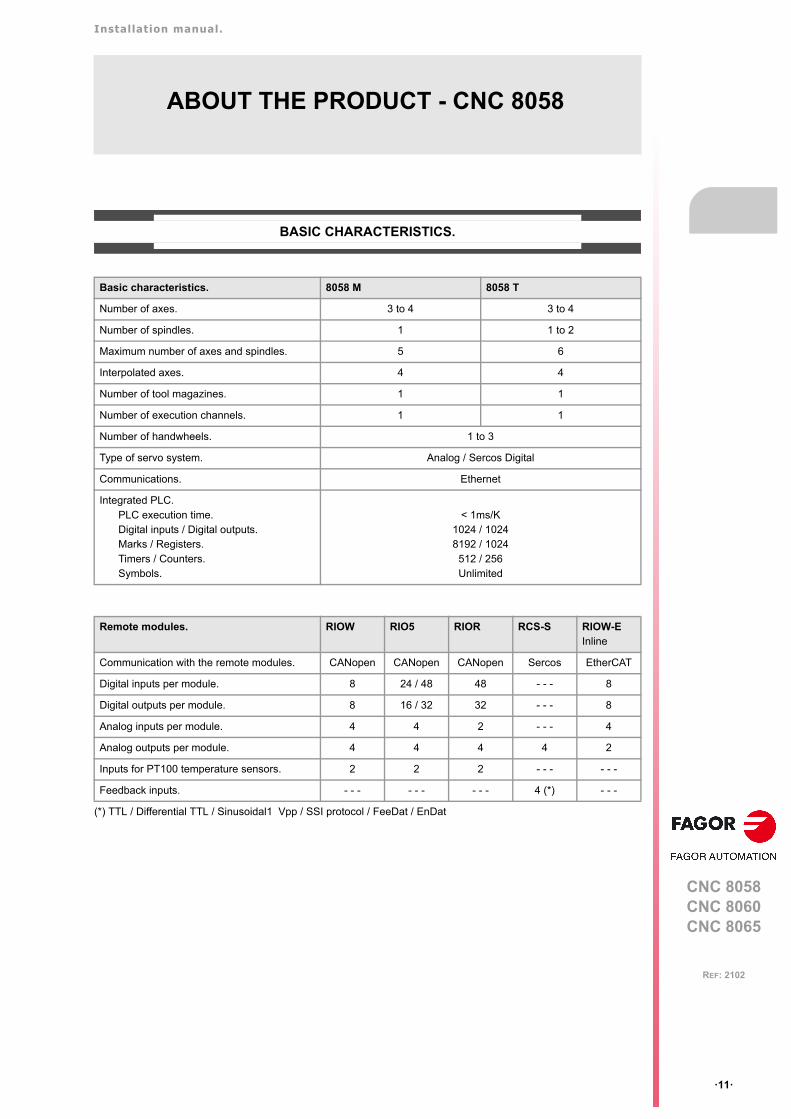
ABOUT THE PRODUCT - CNC 8058
BASIC CHARACTERISTICS.
(*) TTL / Differential TTL / Sinusoidal1 Vpp / SSI protocol / FeeDat / EnDat
Basic characteristics. 8058 M 8058 T
Number of axes. 3 to 4 3 to 4
Number of spindles. 1 1 to 2
Maximum number of axes and spindles. 5 6
Interpolated axes. 4 4
Number of tool magazines. 1 1
Number of execution channels. 1 1
Number of handwheels. 1 to 3
Type of servo system. Analog / Sercos Digital
Communications. Ethernet
Integrated PLC. PLC execution time.Digital inputs / Digital outputs.Marks / Registers.Timers / Counters.Symbols.
< 1ms/K1024 / 10248192 / 1024
512 / 256Unlimited
Remote modules. RIOW RIO5 RIOR RCS-S RIOW-EInline
Communication with the remote modules. CANopen CANopen CANopen Sercos EtherCAT
Digital inputs per module. 8 24 / 48 48 - - - 8
Digital outputs per module. 8 16 / 32 32 - - - 8
Analog inputs per module. 4 4 2 - - - 4
Analog outputs per module. 4 4 4 4 2
Inputs for PT100 temperature sensors. 2 2 2 - - - - - -
Feedback inputs. - - - - - - - - - 4 (*) - - -

Installation manual.
CNC 8058CNC 8060CNC 8065
ꞏ12ꞏ
REF: 2102
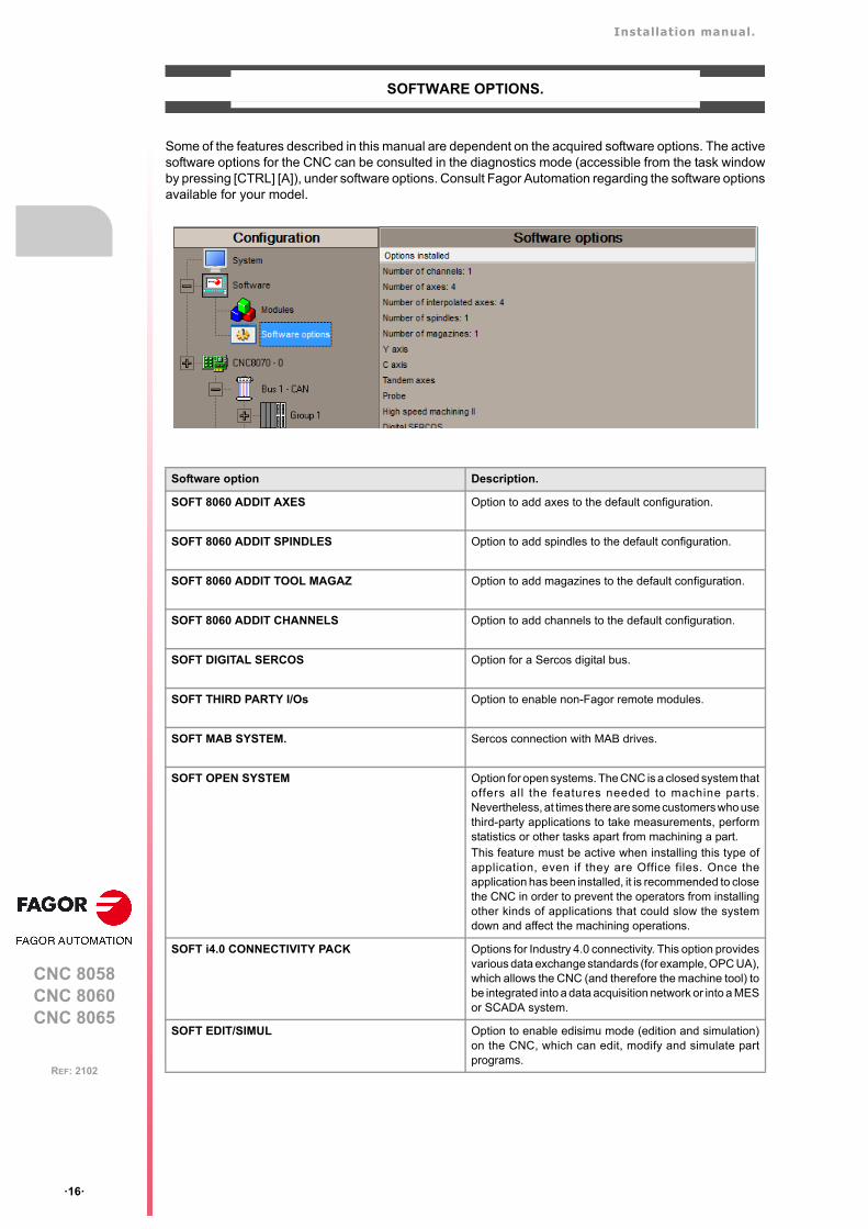
SOFTWARE OPTIONS.
Some of the features described in this manual are dependent on the acquired software options. The activesoftware options for the CNC can be consulted in the diagnostics mode (accessible from the task windowby pressing [CTRL] [A]), under software options. Consult Fagor Automation regarding the software optionsavailable for your model.
Software option Description.
SOFT 8060 ADDIT AXES Option to add axes to the default configuration.
SOFT 8060 ADDIT SPINDLES Option to add spindles to the default configuration.
SOFT DIGITAL SERCOS Option for a Sercos digital bus.
SOFT THIRD PARTY DRIVES Option to use EtherCAT third party drives.
SOFT THIRD PARTY I/Os Option to use third party I/O modules.
SOFT i4.0 CONNECTIVITY PACK Options for Industry 4.0 connectivity. This option providesvarious data exchange standards (for example, OPC UA),which allows the CNC (and therefore the machine tool) tobe integrated into a data acquisition network or into a MESor SCADA system.
SOFT EDIT/SIMUL Option to enable edisimu mode (edition and simulation)on the CNC, which can edit, modify and simulate partprograms.
SOFT TOOL RADIUS COMP Opt ion to enab le rad ius compensa t ion . Th iscompensation programs the contour to be machinedbased on part dimensions without taking into account thedimensions of the tool that will be used later on. Thisavoids having to calculate and define the tool paths basedon the tool radius.
SOFT PROFILE EDITOR Option to enable the profile editor in edisimu mode and inthe cycle editor. This editor can graphically, and in aguided way, define rectangular, circular profiles or anyprofile made up of straight and circular sections an it canalso import dxf files. After defining the profile, the CNCgenerates the required blocks and add them to theprogram.
SOFT 60 HD GRAPHICS High definition solid 3D graphics for the execution andsimulation of part-programs and canned cycles of theeditor. During machining, the HD graphics display, in realtime, the tool removing the material from the part, allowingthe condition of the part to be seen at all times. Thesegraphics are required for the collision control (FCAS).
Installation manual.
CNC 8058CNC 8060CNC 8065
ꞏ13ꞏ
REF: 2102
SOFT 60 IIP CONVERSATIONAL The IIP (Interactive Icon-based Pages) mode, orconversational mode, works with the CNC in a graphicaland guided way based on predefined cycles. There is noneed to work with part programs, have any previousprogramming knowledge or be familiar with Fagor CNCs.Working in conversational mode is easier than in ISOmode, as it ensures proper data entry and minimizes thenumber of operations to be defined.
SOFT 60 C AXIS Option to enable C-axis kinematics and associatedcanned cycles. The machine parameters of each axis orspindle indicate whether it can operate as a C axis or not.For this reason, it is not necessary to add specific axes tothe configuration.
SOFT 60 TANDEM AXES Option to enable tandem axle control. A tandem axisconsists of two motors mechanically coupled to eachother forming a single transmission system (axis orspindle). A tandem axis helps provide the necessarytorque to move an axis when a single motor is not capableof supplying enough torque to do it.When activating this feature, it should be kept in mind thatfor each tandem axis of the machine, another axis mustbe added to the entire configuration. For example, on alarge 3-axis lathe (X Z and tailstock), if the tailstock is atandem axis, the final purchase order for the machinemust indicate 4 axes.
SOFT 60 HSSA I MACHINING SYSTEM Option to enable the HSSA-I (High Speed SurfaceAccuracy) algorithm for high speed machining (HSC).This new HSSA algorithm allows for high speedmachining optimization, where higher cutting speeds,smoother contours, a better surface finishing and greaterprecision are achieved.
SOFT 60 PROBE Option to enable functions G100, G103 and G104 (forprobe movements) and probe canned cycles (which helpto measure part surfaces and to calibrate tools). For thelaser model, it only activates the non-cycle function G100.The CNC may have two probes; usually a tabletop probeto calibrate tools and a measuring probe to measure thepart.
SOFT 60 CONV USER CYCLES Option to enable user conversational cycles. The user andthe OEM can add their own canned cycles (user cycles)using the FGUIM application that comes installed on theCNC. The application offers a guided way to define a newcomponent and its softkey menu without having to befamiliar with script languages. User cycles work in asimilar way as Fagor canned cycles.
SOFT 60 PPTRANS Option to enable the program translator, which canconvert programs written in other languages to Fagor ISOcode.
SOFT FMC Option to enable the FMC (Fagor Machining Calculator).The FMC application consists of a database of materialsto be machined and machining operations, with aninterface to choose suitable cutting conditions for theseoperations.
SOFT FFC Option to enable the FFC (Fagor Feed Control). Duringthe execution of a canned cycle of the editor, the FFCfunction makes it possible to replace the feedrate andspeed programmed in the cycle with the active values ofthe execution, which are acted upon by the feed overrideand speed override.
SOFT 60/65/70 OPERATING TERMS Option to enable a temporary user license for the CNC,which is valid until the date set by the OEM. While thelicense is valid, the CNC will be fully operational(according to the purchased software options).
Software option Description.

BLANK PAGE
ꞏ14ꞏ
Installation manual.
CNC 8058CNC 8060CNC 8065
ꞏ15ꞏ
REF: 2102
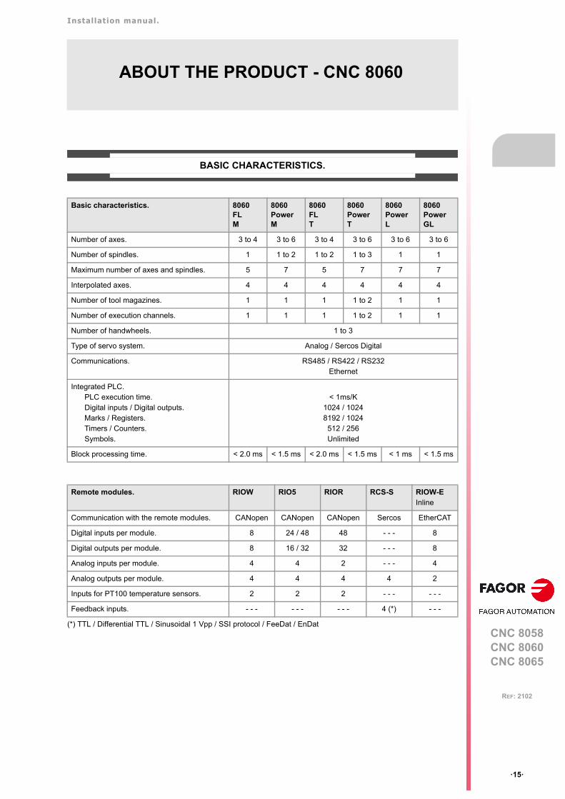
ABOUT THE PRODUCT - CNC 8060
BASIC CHARACTERISTICS.
(*) TTL / Differential TTL / Sinusoidal 1 Vpp / SSI protocol / FeeDat / EnDat
Basic characteristics. 8060FLM
8060PowerM
8060FLT
8060PowerT
8060PowerL
8060PowerGL
Number of axes. 3 to 4 3 to 6 3 to 4 3 to 6 3 to 6 3 to 6
Number of spindles. 1 1 to 2 1 to 2 1 to 3 1 1
Maximum number of axes and spindles. 5 7 5 7 7 7
Interpolated axes. 4 4 4 4 4 4
Number of tool magazines. 1 1 1 1 to 2 1 1
Number of execution channels. 1 1 1 1 to 2 1 1
Number of handwheels. 1 to 3
Type of servo system. Analog / Sercos Digital
Communications. RS485 / RS422 / RS232Ethernet
Integrated PLC. PLC execution time.Digital inputs / Digital outputs.Marks / Registers.Timers / Counters.Symbols.
< 1ms/K1024 / 10248192 / 1024
512 / 256Unlimited
Block processing time. < 2.0 ms < 1.5 ms < 2.0 ms < 1.5 ms < 1 ms < 1.5 ms
Remote modules. RIOW RIO5 RIOR RCS-S RIOW-EInline
Communication with the remote modules. CANopen CANopen CANopen Sercos EtherCAT
Digital inputs per module. 8 24 / 48 48 - - - 8
Digital outputs per module. 8 16 / 32 32 - - - 8
Analog inputs per module. 4 4 2 - - - 4
Analog outputs per module. 4 4 4 4 2
Inputs for PT100 temperature sensors. 2 2 2 - - - - - -
Feedback inputs. - - - - - - - - - 4 (*) - - -
Installation manual.
CNC 8058CNC 8060CNC 8065
ꞏ16ꞏ
REF: 2102
SOFTWARE OPTIONS.
Some of the features described in this manual are dependent on the acquired software options. The activesoftware options for the CNC can be consulted in the diagnostics mode (accessible from the task windowby pressing [CTRL] [A]), under software options. Consult Fagor Automation regarding the software optionsavailable for your model.
Software option Description.
SOFT 8060 ADDIT AXES Option to add axes to the default configuration.
SOFT 8060 ADDIT SPINDLES Option to add spindles to the default configuration.
SOFT 8060 ADDIT TOOL MAGAZ Option to add magazines to the default configuration.
SOFT 8060 ADDIT CHANNELS Option to add channels to the default configuration.
SOFT DIGITAL SERCOS Option for a Sercos digital bus.
SOFT THIRD PARTY I/Os Option to enable non-Fagor remote modules.
SOFT MAB SYSTEM. Sercos connection with MAB drives.
SOFT OPEN SYSTEM Option for open systems. The CNC is a closed system thatoffers all the features needed to machine parts.Nevertheless, at times there are some customers who usethird-party applications to take measurements, performstatistics or other tasks apart from machining a part.This feature must be active when installing this type ofapplication, even if they are Office files. Once theapplication has been installed, it is recommended to closethe CNC in order to prevent the operators from installingother kinds of applications that could slow the systemdown and affect the machining operations.
SOFT i4.0 CONNECTIVITY PACK Options for Industry 4.0 connectivity. This option providesvarious data exchange standards (for example, OPC UA),which allows the CNC (and therefore the machine tool) tobe integrated into a data acquisition network or into a MESor SCADA system.
SOFT EDIT/SIMUL Option to enable edisimu mode (edition and simulation)on the CNC, which can edit, modify and simulate partprograms.
Installation manual.
CNC 8058CNC 8060CNC 8065
ꞏ17ꞏ
REF: 2102
SOFT TOOL RADIUS COMP Opt ion to enab le rad ius compensa t i on . Th iscompensation programs the contour to be machinedbased on part dimensions without taking into account thedimensions of the tool that will be used later on. Thisavoids having to calculate and define the tool paths basedon the tool radius.
SOFT PROFILE EDITOR Option to enable the profile editor in edisimu mode and inthe cycle editor. This editor can graphically, and in aguided way, define rectangular, circular profiles or anyprofile made up of straight and circular sections an it canalso import dxf files. After defining the profile, the CNCgenerates the required blocks and add them to theprogram.
SOFT 60 HD GRAPHICS High definition solid 3D graphics for the execution andsimulation of part-programs and canned cycles of theeditor. During machining, the HD graphics display, in realtime, the tool removing the material from the part, allowingthe condition of the part to be seen at all times. Thesegraphics are required for the collision control (FCAS).
SOFT 60 IIP CONVERSATIONAL The IIP (Interactive Icon-based Pages) mode, orconversational mode, works with the CNC in a graphicaland guided way based on predefined cycles. There is noneed to work with part programs, have any previousprogramming knowledge or be familiar with Fagor CNCs.Working in conversational mode is easier than in ISOmode, as it ensures proper data entry and minimizes thenumber of operations to be defined.
SOFT 60 RTCP Option to enable dynamic RTCP (Rotating Tool CenterPoint) required to machine with 4, 5 and 6 axis kinematics;for example, angular and orthogonal spindles, tiltingtables, etc. The RTCP orientation of the tool may bechanged without modifying the position occupied by thetool tip on the part.
SOFT 60 C AXIS Option to enable C-axis kinematics and associatedcanned cycles. The machine parameters of each axis orspindle indicate whether it can operate as a C axis or not.For this reason, it is not necessary to add specific axes tothe configuration.
SOFT 60 Y AXIS Option to enable lathe Y-axis kinematics and associatedcanned cycles.
SOFT 60 TANDEM AXES Option to enable tandem axle control. A tandem axisconsists of two motors mechanically coupled to eachother forming a single transmission system (axis orspindle). A tandem axis helps provide the necessarytorque to move an axis when a single motor is not capableof supplying enough torque to do it.When activating this feature, it should be kept in mind thatfor each tandem axis of the machine, another axis mustbe added to the entire configuration. For example, on alarge 3-axis lathe (X Z and tailstock), if the tailstock is atandem axis, the final purchase order for the machinemust indicate 4 axes.
SOFT 60 SYNCHRONISM Option to enable the synchronization of paired axes andspindles, in speed or position, and through a given ratio.
SOFT 60 HSSA I MACHINING SYSTEM Option to enable the HSSA-I (High Speed SurfaceAccuracy) algorithm for high speed machining (HSC).This new HSSA algorithm allows for high speedmachining optimization, where higher cutting speeds,smoother contours, a better surface finishing and greaterprecision are achieved.
Software option Description.
Installation manual.
CNC 8058CNC 8060CNC 8065
ꞏ18ꞏ
REF: 2102
SOFT 60 HSSA II MACHINING SYSTEM Option to enable the HSSA-II (High Speed SurfaceAccuracy) algorithm for high-speed machining (HSC),which has the following advantages compared to theHSSA-I algorithm.
• Advanced algorithm for point preprocessing in realtime.
• Extended curvature algorithm with dynamiclimitations. Improved acceleration and jerk control.
• Greater number of pre-processed points.• Filters to smooth out the dynamic machine behavior.
SOFT 60 PROBE Option to enable functions G100, G103 and G104 (forprobe movements) and probe canned cycles (which helpto measure part surfaces and to calibrate tools). For thelaser model, it only activates the non-cycle function G100.The CNC may have two probes; usually a tabletop probeto calibrate tools and a measuring probe to measure thepart.
SOFT 60 CONV USER CYCLES Option to enable user conversational cycles. The user andthe OEM can add their own canned cycles (user cycles)using the FGUIM application that comes installed on theCNC. The application offers a guided way to define a newcomponent and its softkey menu without having to befamiliar with script languages. User cycles work in asimilar way as Fagor canned cycles.
SOFT 60 PROGTL3 Option to enable the ProGTL3 programming language(ISO language extension), allowing profiles to beprogrammed using a geometric language and without theneed to use an external CAD system. This language canprogram lines and circles where the end point is definedas the intersection of 2 other sections, pockets, ruledsurfaces, etc.
SOFT 60 PPTRANS Option to enable the program translator, which canconvert programs written in other languages to Fagor ISOcode.
SOFT PWM CONTROL Option to enable PWM (Pulse - Width Modulation) controlon laser machines. This feature is essential for cuttingvery thick sheets, where the CNC must create a series ofPWM pulses to control laser power when drilling the initialpoint. This function is only available for Sercos bus controlsystems and must also use one of the two fast digitaloutputs available from the central unit.
SOFT GAP CONTROL Option to enable gap control, which makes it possible toset a fixed distance between the laser nozzle and thesheet surface with the use of a sensor. The CNCcompensates the difference between the distancemeasured by the sensor and the programmed distancewith additional movements on the axis programmed forthe gap.
SOFT DMC Option to enable the DMC (Dynamic Machining Control).DMC adapts the feedrate during machining to maintainthe cutting power as close as possible to ideal machiningconditions.
SOFT FMC Option to enable the FMC (Fagor Machining Calculator).The FMC application consists of a database of materialsto be machined and machining operations, with aninterface to choose suitable cutting conditions for theseoperations.
SOFT FFC Option to enable the FFC (Fagor Feed Control). Duringthe execution of a canned cycle of the editor, the FFCfunction makes it possible to replace the feedrate andspeed programmed in the cycle with the active values ofthe execution, which are acted upon by the feed overrideand speed override.
Software option Description.
Installation manual.
CNC 8058CNC 8060CNC 8065
ꞏ19ꞏ
REF: 2102
SOFT 60/65/70 OPERATING TERMS Option to enable a temporary user license for the CNC,which is valid until the date set by the OEM. While thelicense is valid, the CNC will be fully operational(according to the purchased software options).
SOFT MANUAL NESTING Option to enable nesting in the automatic option. Nestingconsists of creating a pattern on the sheet material usingpreviously defined figures (in dxf, dwg or parametric files),so as to use most of the sheet as possible. Once thepattern has been defined, the CNC creates a program.During manual nesting, the operator distributes the partson top of the sheet material.
SOFT AUTO NESTING Option to enable nesting in the automatic option. Nestingconsists of creating a pattern on the sheet material usingpreviously defined figures (in dxf, dwg or parametric files),so as to use most of the sheet as possible. Once thepattern has been defined, the CNC creates a program.During automatic nesting, the application distributes thefigures on the sheet material and optimizes the spaces.
Software option Description.

BLANK PAGE
ꞏ20ꞏ
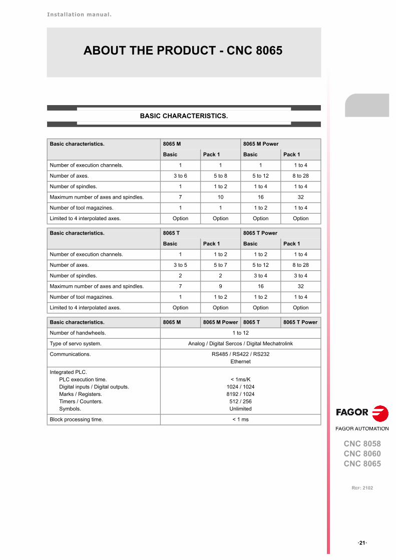
Installation manual.
CNC 8058CNC 8060CNC 8065
ꞏ21ꞏ
REF: 2102
ABOUT THE PRODUCT - CNC 8065
BASIC CHARACTERISTICS.
Basic characteristics. 8065 M 8065 M Power
Basic Pack 1 Basic Pack 1
Number of execution channels. 1 1 1 1 to 4
Number of axes. 3 to 6 5 to 8 5 to 12 8 to 28
Number of spindles. 1 1 to 2 1 to 4 1 to 4
Maximum number of axes and spindles. 7 10 16 32
Number of tool magazines. 1 1 1 to 2 1 to 4
Limited to 4 interpolated axes. Option Option Option Option
Basic characteristics. 8065 T 8065 T Power
Basic Pack 1 Basic Pack 1
Number of execution channels. 1 1 to 2 1 to 2 1 to 4
Number of axes. 3 to 5 5 to 7 5 to 12 8 to 28
Number of spindles. 2 2 3 to 4 3 to 4
Maximum number of axes and spindles. 7 9 16 32
Number of tool magazines. 1 1 to 2 1 to 2 1 to 4
Limited to 4 interpolated axes. Option Option Option Option
Basic characteristics. 8065 M 8065 M Power 8065 T 8065 T Power
Number of handwheels. 1 to 12
Type of servo system. Analog / Digital Sercos / Digital Mechatrolink
Communications. RS485 / RS422 / RS232Ethernet
Integrated PLC. PLC execution time.Digital inputs / Digital outputs.Marks / Registers.Timers / Counters.Symbols.
< 1ms/K1024 / 10248192 / 1024
512 / 256Unlimited
Block processing time. < 1 ms
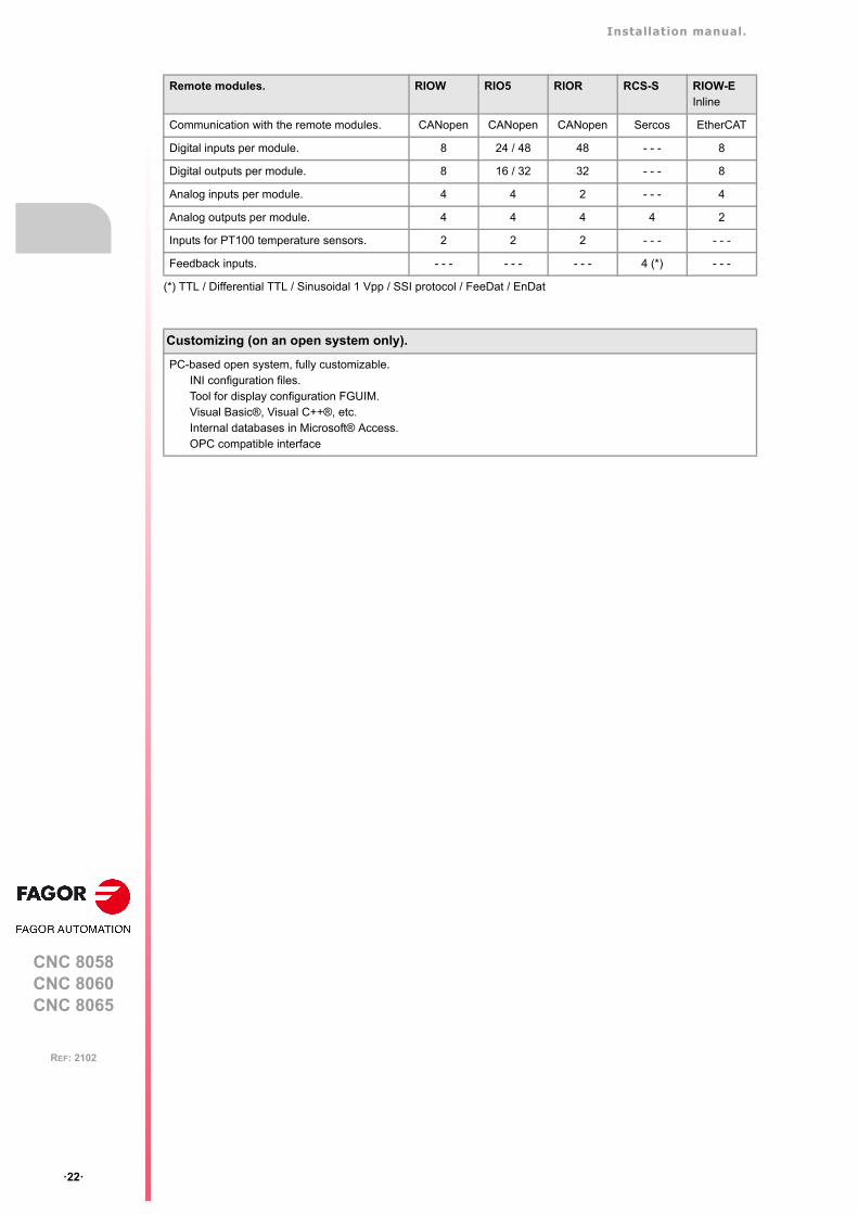
Installation manual.
CNC 8058CNC 8060CNC 8065
ꞏ22ꞏ
REF: 2102
(*) TTL / Differential TTL / Sinusoidal 1 Vpp / SSI protocol / FeeDat / EnDat
Remote modules. RIOW RIO5 RIOR RCS-S RIOW-EInline
Communication with the remote modules. CANopen CANopen CANopen Sercos EtherCAT
Digital inputs per module. 8 24 / 48 48 - - - 8
Digital outputs per module. 8 16 / 32 32 - - - 8
Analog inputs per module. 4 4 2 - - - 4
Analog outputs per module. 4 4 4 4 2
Inputs for PT100 temperature sensors. 2 2 2 - - - - - -
Feedback inputs. - - - - - - - - - 4 (*) - - -
Customizing (on an open system only).
PC-based open system, fully customizable.INI configuration files.Tool for display configuration FGUIM.Visual Basic®, Visual C++®, etc.Internal databases in Microsoft® Access.OPC compatible interface
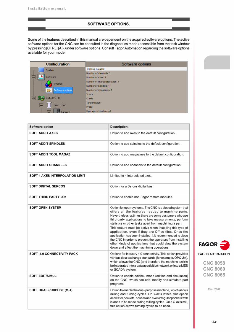
Installation manual.
CNC 8058CNC 8060CNC 8065
ꞏ23ꞏ
REF: 2102
SOFTWARE OPTIONS.
Some of the features described in this manual are dependent on the acquired software options. The activesoftware options for the CNC can be consulted in the diagnostics mode (accessible from the task windowby pressing [CTRL] [A]), under software options. Consult Fagor Automation regarding the software optionsavailable for your model.
Software option Description.
SOFT ADDIT AXES Option to add axes to the default configuration.
SOFT ADDIT SPINDLES Option to add spindles to the default configuration.
SOFT ADDIT TOOL MAGAZ Option to add magazines to the default configuration.
SOFT ADDIT CHANNELS Option to add channels to the default configuration.
SOFT 4 AXES INTERPOLATION LIMIT Limited to 4 interpolated axes.
SOFT DIGITAL SERCOS Option for a Sercos digital bus.
SOFT THIRD PARTY I/Os Option to enable non-Fagor remote modules.
SOFT OPEN SYSTEM Option for open systems. The CNC is a closed system thatoffers all the features needed to machine parts.Nevertheless, at times there are some customers who usethird-party applications to take measurements, performstatistics or other tasks apart from machining a part.This feature must be active when installing this type ofapplication, even if they are Office files. Once theapplication has been installed, it is recommended to closethe CNC in order to prevent the operators from installingother kinds of applications that could slow the systemdown and affect the machining operations.
SOFT i4.0 CONNECTIVITY PACK Options for Industry 4.0 connectivity. This option providesvarious data exchange standards (for example, OPC UA),which allows the CNC (and therefore the machine tool) tobe integrated into a data acquisition network or into a MESor SCADA system.
SOFT EDIT/SIMUL Option to enable edisimu mode (edition and simulation)on the CNC, which can edit, modify and simulate partprograms.
SOFT DUAL-PURPOSE (M-T) Option to enable the dual-purpose machine, which allowsmilling and turning cycles. On Y-axis lathes, this optionallows for pockets, bosses and even irregular pockets withislands to be made during milling cycles. On a C-axis mill,this option allows turning cycles to be used.
Installation manual.
CNC 8058CNC 8060CNC 8065
ꞏ24ꞏ
REF: 2102
SOFT TOOL RADIUS COMP Opt ion to enab le rad ius compensa t ion . Th iscompensation programs the contour to be machinedbased on part dimensions without taking into account thedimensions of the tool that will be used later on. Thisavoids having to calculate and define the tool paths basedon the tool radius.
SOFT PROFILE EDITOR Option to enable the profile editor in edisimu mode and inthe cycle editor. This editor can graphically, and in aguided way, define rectangular, circular profiles or anyprofile made up of straight and circular sections an it canalso import dxf files. After defining the profile, the CNCgenerates the required blocks and add them to theprogram.
SOFT HD GRAPHICSIn a multi-channel system, this feature requires the MP-PLUS (83700201) processor.
High definition solid 3D graphics for the execution andsimulation of part-programs and canned cycles of theeditor. During machining, the HD graphics display, in realtime, the tool removing the material from the part, allowingthe condition of the part to be seen at all times. Thesegraphics are required for the collision control (FCAS).
SOFT IIP CONVERSATIONAL The IIP (Interactive Icon-based Pages) mode, orconversational mode, works with the CNC in a graphicaland guided way based on predefined cycles. There is noneed to work with part programs, have any previousprogramming knowledge or be familiar with Fagor CNCs.Working in conversational mode is easier than in ISOmode, as it ensures proper data entry and minimizes thenumber of operations to be defined.
SOFT RTCPThis feature requires the MP-PLUS (83700201)processor.
Option to enable dynamic RTCP (Rotating Tool CenterPoint) required to machine with 4, 5 and 6 axis kinematics;for example, angular and orthogonal spindles, tiltingtables, etc. The RTCP orientation of the tool may bechanged without modifying the position occupied by thetool tip on the part.
SOFT C AXIS Option to enable C-axis kinematics and associatedcanned cycles. The machine parameters of each axis orspindle indicate whether it can operate as a C axis or not.For this reason, it is not necessary to add specific axes tothe configuration.
SOFT Y AXIS Option to enable lathe Y-axis kinematics and associatedcanned cycles.
SOFT TANDEM AXES Option to enable tandem axle control. A tandem axisconsists of two motors mechanically coupled to eachother forming a single transmission system (axis orspindle). A tandem axis helps provide the necessarytorque to move an axis when a single motor is not capableof supplying enough torque to do it.When activating this feature, it should be kept in mind thatfor each tandem axis of the machine, another axis mustbe added to the entire configuration. For example, on alarge 3-axis lathe (X Z and tailstock), if the tailstock is atandem axis, the final purchase order for the machinemust indicate 4 axes.
SOFT SYNCHRONISM Option to enable the synchronization of paired axes andspindles, in speed or position, and through a given ratio.
SOFT KINEMATIC CALIBRATION Option to enable tool calibration. For the first time, thiskinematics calibration allows for the kinematics offsets tobe calculated using various approximate data and, also,from time to time to correct any possible deviationscaused by day-to-day machining operations.
Software option Description.

Installation manual.
CNC 8058CNC 8060CNC 8065
ꞏ25ꞏ
REF: 2102
SOFT HSSA II MACHINING SYSTEM Option to enable the HSSA-II (High Speed SurfaceAccuracy) algorithm for high speed machining (HSC).This new HSSA algorithm allows for high speedmachining optimization, where higher cutting speeds,smoother contours, a better surface finishing and greaterprecision are achieved. The HSSA-II algorithm has thefollowing advantages compared to the HSSA-I algorithm.
• Advanced algorithm for point preprocessing in realtime.
• Extended curvature algorithm with dynamiclimitations. Improved acceleration and jerk control.
• Greater number of pre-processed points.• Filters to smooth out the dynamic machine behavior.
SOFT FVC STANDARDSOFT FVC UP TO 10m3SOFT FVC MORE TO 10m3
Options to enable volumetric compensation. Theprecision of the parts is l imited by the machinemanufac tur ing to lerances, wear, the e ffec t o ftemperature, etc., especially on 5-axis machines.Volumetric compensation corrects these geometric errorsto a larger extent, thus improving the precision of thepositioning. The volume to be compensated is defined bya point cloud and for each point theerror to be corrected is measured. When mapping the totalwork volume of the machine, the CNC knows the exactposition of the tool at all times.There are 3 options, which depend on the size of themachine.
• FVC STANDARD: Compensation for 15625 points(maximum 1000 points per axis). Quick calibration(time), but less precise than the other two, butsufficient for the desired tolerances.
• FVC UP TO 10m3: Volume compensation up to 10 m³.More accurate than FVC STANDARD, but requires amore accurate calibration using a Tracer or Trackerlaser).
• FVC MORE TO 10m3: Volume compensation greaterthan 10 m³. More accurate than FVC STANDARD, butrequires a more accurate calibration using a Tracer orTracker laser.
SOFT TANGENTIAL CONTROL Option to enable tangential control. "Tangential Control"maintains a rotary axis always in the same orientation withrespect to the programmed tool path. The machining pathis defined on the axes of the active plane and the CNCmaintains the orientation of the rotary axis along the entiretool path.
SOFT PROBE Option to enable functions G100, G103 and G104 (forprobe movements) and probe canned cycles (which helpto measure part surfaces and to calibrate tools). For thelaser model, it only activates the non-cycle function G100.The CNC may have two probes; usually a tabletop probeto calibrate tools and a measuring probe to measure thepart.
SOFT CONV USER CYCLES Option to enable user conversational cycles. The user andthe OEM can add their own canned cycles (user cycles)using the FGUIM application that comes installed on theCNC. The application offers a guided way to define a newcomponent and its softkey menu without having to befamiliar with script languages. User cycles work in asimilar way as Fagor canned cycles.
SOFT PROGTL3 Option to enable the ProGTL3 programming language(ISO language extension), allowing profiles to beprogrammed using a geometric language and without theneed to use an external CAD system. This language canprogram lines and circles where the end point is definedas the intersection of 2 other sections, pockets, ruledsurfaces, etc.
SOFT PPTRANS Option to enable the program translator, which canconvert programs written in other languages to Fagor ISOcode.
Software option Description.
Installation manual.
CNC 8058CNC 8060CNC 8065
ꞏ26ꞏ
REF: 2102
SOFT DMC Option to enable the DMC (Dynamic Machining Control).DMC adapts the feedrate during machining to maintainthe cutting power as close as possible to ideal machiningconditions.
SOFT FMC Option to enable the FMC (Fagor Machining Calculator).The FMC application consists of a database of materialsto be machined and machining operations, with aninterface to choose suitable cutting conditions for theseoperations.
SOFT FFC Option to enable the FFC (Fagor Feed Control). Duringthe execution of a canned cycle of the editor, the FFCfunction makes it possible to replace the feedrate andspeed programmed in the cycle with the active values ofthe execution, which are acted upon by the feed overrideand speed override.
SOFT 60/65/70 OPERATING TERMS Option to enable a temporary user license for the CNC,which is valid until the date set by the OEM. While thelicense is valid, the CNC will be fully operational(according to the purchased software options).
SOFT FCAS Option to enable the FCAS (Fagor Collision AvoidanceSystem). The FCAS option, within the system limitations,monitors the automatic, MDI/MDA, manual and toolinspection movements in real time, so as to avoidcollisions between the tool and the machine. The FCASoption requires that the HD graphics to be active and thatthere is a defined a model configuration of the machineadjusted to reality (.xca file), which includes all its movingparts.
SOFT IEC 61131 LANGUAGEThis feature requires the MP-PLUS (83700201)processor.
IEC 61131 is a PLC programming language that is verypopular in alternative markets, which is slowly enteringinto the machine-tool market. With this feature, the PLCmay be programmed either in the usual Fagor languageor in IEC 61131 format.
Software option Description.
Installation manual.
CNC 8058CNC 8060CNC 8065
ꞏ27ꞏ
REF: 2102
DECLARATION OF CE CONFORMITY AND WARRANTY CONDITIONS
DECLARATION OF CONFORMITY
The declaration of conformity for the CNC is available in the downloads section of FAGOR’S corporatewebsite. http://www.fagorautomation.com. (Type of file: Declaration of conformity).
WARRANTY TERMS
The warranty conditions for the CNC are available in the downloads section of FAGOR’s corporate website.http://www.fagorautomation.com. (Type of file: General sales-warranty conditions.

BLANK PAGE
ꞏ28ꞏ
Installation manual.
CNC 8058CNC 8060CNC 8065
ꞏ29ꞏ
REF: 2102
SAFETY CONDITIONS
Read the following safety measures in order to prevent harming people or damage to this product and thoseproducts connected to it. Fagor Automation shall not be held responsible of any physical or material damageoriginated from not complying with these basic safety rules.
PRECAUTIONS BEFORE CLEANING THE UNIT
PRECAUTIONS DURING REPAIRS
In case of a malfunction or failure, disconnect it and call the technical service.
PRECAUTIONS AGAINST PERSONAL HARM
Before start-up, verify that the machine that integrates this CNC meets the 2006/42/EC Directive.
Do not get into the inside of the unit. Only personnel authorized by Fagor Automation may access theinterior of this unit.
Do not handle the connectors with the unitconnected to AC power.
Before handling these connectors (I/O, feedback, etc.), make surethat the unit is not powered.
Do not get into the inside of the unit. Only personnel authorized by Fagor Automation may access theinterior of this unit.
Do not handle the connectors with the unitconnected to AC power.
Before handling these connectors (I/O, feedback, etc.), make surethat the unit is not powered.
Interconnection of modules. Use the connection cables provided with the unit.
Use proper cables. To prevent risks, only use cables and Sercos fiber recommended forthis unit. To prevent a risk of electrical shock at the central unit, use the properconnector (supplied by Fagor); use a three-prong power cable (oneof them being ground).
Avoid electric shocks. To prevent electrical shock and fire risk, do not apply electrical voltageout of the indicated range.
Ground connection. In order to avoid electrical discharges, connect the ground terminalsof all the modules to the main ground terminal. Also, beforeconnecting the inputs and outputs of this product, make sure that theground connection has been done.In order to avoid electrical shock, before turning the unit on verify thatthe ground connection is properly made.
Do not work in humid environments. In order to avoid electrical discharges, always work with a relativehumidity (non-condensing).
Do not work in explosive environments. In order to avoid risks, harm or damages, do not work in explosiveenvironments.
Installation manual.
CNC 8058CNC 8060CNC 8065
ꞏ30ꞏ
REF: 2102
PRECAUTIONS AGAINST DAMAGE TO THE PRODUCT
SAFETY SYMBOLS
Symbols that may appear in the manual.
Work environment. This unit is ready to be used in industrial environments complying withthe directives and regulations effective in the European Community.Fagor Automation shall not be held responsible for any damagesuffered or caused by the CNC when installed in other environments(residential, homes, etc.).
Install this unit in the proper place. It is recommended, whenever possible, to install the CNC away fromcoolants, chemical product, blows, etc. that could damage it.This unit meets the European directives on electromagneticcompatibility. Nevertheless, it is recommended to keep it away fromsources of electromagnetic disturbance such as:
Powerful loads connected to the same mains as the unit.Nearby portable transmitters (radio-telephones, Ham radiotransmitters).Nearby radio / TC transmitters.Nearby arc welding machines.Nearby high voltage lines.
Enclosures. It is up to the manufacturer to guarantee that the enclosure where theunit has been installed meets all the relevant directives of theEuropean Union.
Avoid disturbances coming from themachine.
The machine must have all the interference generating elements(relay coils, contactors, motors, etc.) uncoupled.
Use the proper power supply. Use an external regulated 24 Vdc power supply for the keyboard,operator panel and the remote modules.
Connecting the power supply to ground. The zero Volt point of the external power supply must be connectedto the main ground point of the machine.
Analog inputs and outputs connection. Use shielded cables connecting all their meshes to the correspondingpin.
Ambient conditions. Maintain the CNC within the recommended temperature range, bothwhen running and not running. See the corresponding chapter in thehardware manual.
Central unit enclosure. To maintain the right ambient conditions in the enclosure of the centralunit, it must meet the requirements indicated by Fagor. See thecorresponding chapter in the hardware manual.
Power switch. This switch must be easy to access and at a distance between 0.7 and1.7 m (2.3 and 5.6 ft) off the floor.
Danger or prohibition symbol.This symbol indicates actions or operations that may hurt people or damage products.
Warning or caution symbol.This symbol indicates situations that certain operations could cause and the suggested actions to preventthem.
Obligation symbol. This symbol indicates actions and operations that must be carried out.
Information symbol.This symbol indicates notes, warnings and advises.
Symbol for additional documentation.This symbol indicates that there is another document with more detailed and specific information.
i
Installation manual.
CNC 8058CNC 8060CNC 8065
ꞏ31ꞏ
REF: 2102
Symbols that the product may carry.
Ground symbol.This symbol indicates that that point must be under voltage.
ESD components.This symbol identifies the cards as ESD components (sensitive to electrostatic discharges).

BLANK PAGE
ꞏ32ꞏ
Installation manual.
CNC 8058CNC 8060CNC 8065
ꞏ33ꞏ
REF: 2102
RETURNING CONDITIONS
Pack it in its original package along with its original packaging material. If you do not have the originalpackaging material, pack it as follows:
1 Get a cardboard box whose 3 inside dimensions are at least 15 cm (6 inches) larger than those of theunit itself. The cardboard being used to make the box must have a resistance of 170 Kg (375 lb.).
2 Attach a label to the device indicating the owner of the device along with contact information (address,telephone number, email, name of the person to contact, type of device, serial number, etc.). In caseof malfunction also indicate symptom and a brief description of the problem.
3 Protect the unit wrapping it up with a roll of polyethylene or with similar material. When sending a centralunit with monitor, protect especially the screen.
4 Pad the unit inside the cardboard box with polyurethane foam on all sides.
5 Seal the cardboard box with packaging tape or with industrial staples.

BLANK PAGE
ꞏ34ꞏ
Installation manual.
CNC 8058CNC 8060CNC 8065
ꞏ35ꞏ
REF: 2102
CNC MAINTENANCE
CLEANING
The accumulated dirt inside the unit may act as a screen preventing the proper dissipation of the heatgenerated by the internal circuitry which could result in a harmful overheating of the unit and, consequently,possible malfunctions. Accumulated dirt can sometimes act as an electrical conductor and short-circuit theinternal circuitry, especially under high humidity conditions.
To clean the operator panel and the monitor, a smooth cloth should be used which has been dipped intode-ionized water and /or non abrasive dish-washer soap (liquid, never powder) or 75º alcohol. Never useair compressed at high pressure to clean the unit because it could cause the accumulation of electrostaticcharges that could result in electrostatic shocks.
The plastics used on the front panel are resistant to grease and mineral oils, bases and bleach, dissolveddetergents and alcohol. Avoid the action of solvents such as chlorine hydrocarbons, venzole, esters andether which can damage the plastics used to make the unit’s front panel.
PRECAUTIONS BEFORE CLEANING THE UNIT
Fagor Automation shall not be held responsible for any material or physical damage derived from theviolation of these basic safety requirements.
• Do not handle the connectors with the unit supplied with power. Before handling these connectors (I/O,feedback, etc.), make sure that the unit is not powered.
• Do not get into the inside of the unit. Only personnel authorized by Fagor Automation may access theinterior of this unit.

BLANK PAGE
ꞏ36ꞏ
Installation manual.
CNC 8058CNC 8060CNC 8065
ꞏ37ꞏ
REF: 2102
Below is a list of the features added in this software version and the manuals that describe them.
NEW FEATURES.
Manual reference: Ref: 2102
Date of publication: February, 2021
Associated software: v6.21.12
List of features. Manual
Unified version for milling machine, lathe and laser.
New integrated CNC 8058 model, with 10K monitor. [HARD]
SO W10. New Windows 10 operating system. The CNC must meet the following requirements.
• 16 GB NandFlash.
• 4 GB FRAM memory.
OPC UA protocol.
“Lantek Expert Inside ” application.
New RIOS-E Inline modules.
• IB IL 24 DI 32/HD-PAC
• IB IL 24 DO 32/HD-PAC
[RIOS-E]
This version must be installed in administrator mode, so that the process properly registers thenew FCombo.ocx control.
[INST]
Incompatibility in gap control. With version v6.20, the CNC always considers the approachcoordinate in absolute coordinates, regardless of the active G90/G91 function. To program theapproach coordinate in incremental coordinates, add the “INC” command to the #GAPCTRLinstruction.
[INST]
Incompatibility in the leapfrog. With version v6.20, the CNC always considers the coordinateprogrammed in the “POS” command in absolute coordinates, regardless of the G90/G91command. To program the coordinate at the end of the leap in incremental coordinates, use the“INCPOS” command.
[INST]
New language for the HMI. Turkish.
• Machine parameters: LANGUAGE
[INST]
The HEADREF parameter values have changed to "Tool base" (previously "Yes"), "Head base"(previously "No") and there is a new "Auto tool base" value. With the new "Auto Tool Base" value,on activating the CNC kinematics, calculate the value of TDATA13/TDATA14/TDATA15 (non-vectorial kinematics) or TDATA1/TDATA2/TDATA3 (vectorial kinematics), in case any TDATAhas changed manually.
[INST]
[CYC-M] ............. Machining canned cycles (ꞏMꞏ model).[CYC-T]..............Machining canned cycles (ꞏTꞏ model).[HARD]...............Hardware configuration.[FGUIM] ............. Customizing guide (FGUIM & API).[INST]................. Installation manual.[LSR].................. Operating and programming manual (ꞏLꞏ model).[OPT] .................Operating manual.[OPT-MC]........... Operating manual (MC option).[OPT-TC]............Operating manual (TC option).[PRG] .................Programming manual.[RIOS-E] ............EtherCAT remote modules (RIOW-E Inline)[VAR].................. CNC variables.
Installation manual.
CNC 8058CNC 8060CNC 8065
ꞏ38ꞏ
REF: 2102
If a movement smaller than the INPOSW parameter is programmed on a dead axis, the CNC doesnot enable or move the axis.
• Machine parameters: INPOSW
[INST]
New TMOPERATION=12 operation for asynchronous magazine. Leave the spindle tool in themagazine and take a tool from the same magazine (as TMOPERATION=5). It is an optimisedoperation, valid when both tools are special and can collide in the arm or when it is not desirablefor them to coincide in the changer arm.
[INST]
For a multi-axis where the same motor controls several axes, the CNC allows dynamicmanagement of the multi-axis. This type of management consists of activating the axes of thegroup as they are programmed. To carry out the dynamic management of a multi-axis group, theaxes of the group should be configured as dead axes and the DWELL>0 parameter defined. Theaxes use the DWELL parameter as a waiting time before giving an error for not having theSWITCH mark active. The PLC monitors that the ENABLE mark is active in order to engage thataxis and activate its mark SWITCH, SERVOON, SPENA and DRENA mark.
[INST]
Gap control at the drive.
• Parameters: GAPANAINTYPEGAPANAINID
[INST]
Connect the gap sensor via the EtherCAT.
• Parameters: GAPANAINTYPEGAPANAINID
[INST]
Increases the limit of PDEF symbols. The PDEF directing instruction can define up to 200 symbolsand can be used in the PLC program, a PLC subroutine in C language, part program (usingvariables) or external application.
[INST]
Subroutines in C language support DEF/PDEF symbols. Every time the PLC compiles theprogram, it generates the file plc_pdef.h with the #define of all the symbols defined in the PLCprogram. The file is saved in the folder ..\MTB\PLC\Project.
[INST]
Changing the FFGAIN for the drive (PP216) in synchronous mode. [INST]
DMC. Power peak detection.
• Machine parameters: DMCPEAKSIZE
• Variable: (V.)[ch].MPG.DMCPEAKSIZE
[INST] [VAR]
DMC. Detection of excessive power consumption.
• Machine parameters: DMCPWRFACTOR
• Variable: (V.)[ch].MPG.DMCPWRFACTOR
[INST] [VAR]
Customisation of the user cycle header. The “Data” control has a new property called “Addparameter in cycle first line”. If this property is checked, the cycle adds the data to the cycle headeras “Variable=Value”. The variable will take on the name of the property “Subroutine parameter”.
+#CYCLE BEGIN (1-Simple screw) (V.C.TOOL=1 V.C.SPEED=100) (CW_V_1_0)
[FGUIM]
Association of a help text to user cycle data. The “Data” control has the new “HelpTxt” propertythat defines the help text appearing on the CNC when selecting the data.
[FGUIM]
New FCombo control to manage profiles in user cycles. [FGUIM]
New API functions for common technology tables. [FGUIM]
Fguim allows changes to be made to the interface while the CNC is running. Any changes madeby Fguim are updated in the CNC during the next startup. For the changes to be assumed at theCNC, they must be previously saved from the Fguim.
[FGUIM]
Translator 8055. Translation of the G72+G16+G15 sequence. [OPT]
"Intel Graphics Control Panel" application. Configuring the brightness and contrast of themonitors.
[OPT]
Utilities mode. Encryption of scripts (scp files) and subroutines associated with user cycles. [OPT]
When calibrating kinematics in Setup mode, if the calculated value is equal to the sum ofTDATA+Offset saved, the CNC will not offer to update TDATA and set the offset to 0.
[OPT]
Kinematics calibration. The cycle only allows part of the travel of the rotary axes module to becalibrated. The part of the non-calibrated path is not compensated.
Lathe HD graphics take into account offsets in the X axis of part zero.
List of features. Manual
[CYC-M] .............Machining canned cycles (ꞏMꞏ model).[CYC-T]..............Machining canned cycles (ꞏTꞏ model).[HARD]...............Hardware configuration.[FGUIM] .............Customizing guide (FGUIM & API).[INST]................. Installation manual.[LSR]..................Operating and programming manual (ꞏLꞏ model).[OPT] .................Operating manual.[OPT-MC] ...........Operating manual (MC option).[OPT-TC]............Operating manual (TC option).[PRG] .................Programming manual.[RIOS-E] ............EtherCAT remote modules (RIOW-E Inline)[VAR]..................CNC variables.
Installation manual.
CNC 8058CNC 8060CNC 8065
ꞏ39ꞏ
REF: 2102
Active offsets table. The user tables offer a new table for showing the active values in differentfunctions; G92, G159, G201, etc.
[OPT]
Mini-numeric keypad. By clicking on the top center of the status bar (name of the selectedprogram), the CNC displays a mini numeric keypad to make it easier to enter data by using thetouch screen.
[OPT]
Logging data and events in a user log.
• Variable: (V.)E.USERLOG
[OPT]
In programs that include #SET AX (change configuration of axes) and #DEFGRAF (load graphicconfiguration), the CNC will allow the program to be simulated after executing a #SET AX in MDIdifferent to that of the program.
If the CNC reaches the end of a program without an M02/M30, then it ends the execution withoutprompting a warning.
[PRG]
If the execution of an interruption subroutine (marks INT1/INT4 of the PLC) ends with M30, thenthe program execution also ends. If the execution of an interruption subroutine ends with #RET,then the program execution continues.
[INST] [PRG]
Table+spindle kinematics (type 52). From this version onwards, the CNC does not take intoaccount the axes of the table that are not programmed.
• Statement: #SELECT ORI.
[PRG]
Table+spindle kinematics (type 52). Take into account the position of the table when orientingthe tool. ALL command.
• Statement: #SELECT ORI.
[PRG]
Table+spindle kinematics (type 52). When activating the RTCP, define the part of the kinematics(table or spindle) to be used and the type of RTCP (static or dynamic). HEAD, TABLE commands
• Statement: #RTCP.
[PRG]
Table+spindle kinematics (type 52). When activating the RTCP, define the part of the kinematics(table or spindle) to be used and the type of RTCP (static or dynamic). HEAD, TABLE commands.
• Statement: #RTCP.
[PRG]
Table+spindle kinematics (type 52). Activation of the RTCP according to the values defined inthe machine parameters (TDATA). CLEAR command.
• Statement: #RTCP.
[PRG]
Table+spindle kinematics (type 52). Rotate the part coordinate system when rotating the table.COROT command.
• Statement: #RTCP.
[PRG]
List of features. Manual
[CYC-M] ............. Machining canned cycles (ꞏMꞏ model).[CYC-T]..............Machining canned cycles (ꞏTꞏ model).[HARD]...............Hardware configuration.[FGUIM] ............. Customizing guide (FGUIM & API).[INST]................. Installation manual.[LSR].................. Operating and programming manual (ꞏLꞏ model).[OPT] .................Operating manual.[OPT-MC]........... Operating manual (MC option).[OPT-TC]............Operating manual (TC option).[PRG] .................Programming manual.[RIOS-E] ............EtherCAT remote modules (RIOW-E Inline)[VAR].................. CNC variables.
Installation manual.
CNC 8058CNC 8060CNC 8065
ꞏ40ꞏ
REF: 2102
Management of discontinuities in the orientation of rotary axes. Orient the tool in the programmeddirection of the main or secondary rotary axis. DIRF, DIRS commands.
• Statement: #DEFROT.
[PRG]
OEM subroutines for kinematics calibration can execute motions in two axes at the same time.
New mode for defining a tilted plane (MODE 7). Mode for defining an inclined plane rotating firstaround the third axis of the part, then on the second axis of the new plane and finally on the firstaxis of the new plane.
• Statement: #CS / #ACS.
[PRG]
Activate a kinematic displaying the tool tip dimensions. TIP command.
• Statement: #KIN ID.
• Variable: (V.)G.KINIDMODE
[PRG] [VAR]
Defining the path and the name of a program in a macro.
• Statement: #DEF.
[PRG]
Does not prompt an error for operations using #OPEN, #WRITE y #CLOSE. New commandMUTED.
• Statement: #OPEN.
[PRG]
New access mode R(READ). Verify if the file exists.
• Statement: #OPEN.
[PRG]
Change the HMI variables from the workpiece programme.
• Statement: #MSGVAR.
[PRG]
DMC. If a minimum and maximum override with value 100 is programmed, the DMC monitorsthe power but without changing the override to keep the power constant. The actions to take whenincreasing the power will be defined by the OEM, for example, from the PLC.
• Statement: #DMC.
[PRG]
Identifying the installation folder.
• Variable: (V.)G.FOLDERID.
[VAR]
Identification of the language selected in the CNC.
• Variable: (V.)G.LANGUAGEID.
[VAR]
Error code for #OPEN, #WRITE or #CLOSE statements.
• Variable: (V.)G.FILEERRNO
[VAR]
From the part-program (#MSGVAR) change the HMI variables.
• Variable: (V.)G.CNCMSG[num]
[VAR]
Working with RTCP in spindle+table kinematics.
• Variable: (V.)G.RTCPMODE
[VAR]
Softkey to hide the Fagor cycles from the editor and conversational mode. [CYC-M] [CYC-T]
[OPT-MC] [OPT-TC]
The canned cycles may be defined by the CZ plane. [CYC-M] [CYC-T]
[OPT-MC] [OPT-TC]
The #CYL instruction admits programming of the CZ plane (#CYL[C,Z]).
The profile editor shows the CZ plane oriented correctly.
The #PLC instruction allows symbols defined by the PLC program (PDEF command).
• Instruction #PLC.
[LSR]
Gap control. The CNC always considers the approach coordinate in absolute coordinates,regardless of the active G90/G91 function. To program the approach coordinate in incrementalcoordinates, add the “INC” command to the #GAPCTRL instruction.
• Statement: #GAPCTRL
[LSR]
Leapfrog. The CNC always considers the coordinate programmed in the “POS” command inabsolute coordinates, regardless of the G90/G91 command. To program the coordinate at theend of the leap in incremental coordinates, use the “INCPOS” command.
• Instruction #LEAP.
[LSR]
Power control through the PWM frequency (FREQ command).
• Instruction #PWRCTRL.
• Variables: (V.)G.PWRFREQON(V.)G.PWRFREQOVRMIN(V.)G.PWRFREQOVRMAX(V.)G.PWRFREQFMIN(V.)G.PWRFREQFMAX
[LSR]
Power control set by the OEM (FMASTER command). When the laser cut has a configurationwhere the feedrate between the nozzle and the sheet is not dependent on the XY axes (forexample, tube cutting where only one axis is rotated), the feedrate can be defined from the PLCby writing in the G.FEEDPWRCTRL variable and activating the power control through theFMASTER command.
• Instruction #PWRCTRL.
• Variable: (V.)G.FEEDPWRCTRL
[LSR]
List of features. Manual
[CYC-M] .............Machining canned cycles (ꞏMꞏ model).[CYC-T]..............Machining canned cycles (ꞏTꞏ model).[HARD]...............Hardware configuration.[FGUIM] .............Customizing guide (FGUIM & API).[INST]................. Installation manual.[LSR]..................Operating and programming manual (ꞏLꞏ model).[OPT] .................Operating manual.[OPT-MC] ...........Operating manual (MC option).[OPT-TC]............Operating manual (TC option).[PRG] .................Programming manual.[RIOS-E] ............EtherCAT remote modules (RIOW-E Inline)[VAR]..................CNC variables.
Installation manual.
CNC 8058CNC 8060CNC 8065
ꞏ41ꞏ
REF: 2102
Generic technology tables in the laser model.
• Instruction #TECHTABLE.
• Variables: (V.)TT.tableName_varName(V.)[ch].G.ACTIVEMATERIAL(V.)[ch].G.TECHTABLE
• Subroutines: nombreTablaON.fstnombreTablaOFF.fst
[LSR]
Technology tables. Adding a parameter after the selected position. [LSR]
Improved refresh speed of the CUT_VIEW. [LSR]
CUT_VIEW mode. Improving the graphic display with many piercing points. [LSR]
CUT_VIEW mode. New method for selecting piercing points; “Restart PP”. [LSR]
CUT_VIEW mode. Select the current point as the piercing point. [LSR]
Change the orientation of the XY axes of the CUT_VIEW. [LSR]
Refresh the CUT_VIEW.
• CVIEWREFRESH mark.
[INST] [LSR]
Executing within a piercing point selection. [LSR]
Keep in mind that the angle of the sheet when resuming the cut using “Break PP” or “Restart PP”. [LSR]
The CNC can limit the preview of the program to a specific area by using the instructions#PREVIEW BEGIN and #PREVIEW END. The #PREVIEW BEGIN instruction defines the startof the cut preview and the #PREVIEW END instruction the end of the cut preview, both for theprogram selector and in the CUT_VIEW page in automatic mode.
• Instruction #PREVIEW BEGIN.
[LSR]
Automatic mode. “Verify nozzle” softkey. [LSR]
Position and dimensions of the minimum rectangle containing the drawing.
• Variables: (V.)G.FRAMEOFF1(V.)G.FRAMEOFF2(V.)G.INCMAX1(V.)G.INCMAX2
[LSR]
G137 as the new default value for the transition between blocks (parameter IRCOMP). For lasermodels, the default value is G137; for other models it is G136.
[LSR]
New algorithm for G137 machining. [LSR]
Defining a profile (#PIERCING and #CUTTING). Before now, the beginning of a laser profilestarted with transition G0 to G1 and ended with transition G1 to G0. And from now on, theinstructions #PIERCING and #CUTTING ON indicate the beginning of a profile (it is only possibleto program one of these) and #CUTTING OFF is to end the profile.
[LSR]
Cutting of several sheets in a single program. To cut several sheets on the same table, each witha different angle, different programs can be executed for each sheet using the #EXEC instruction.If the execution is interrupted and resumed using a “Break PP”, then the CNC will recall therotation of the corresponding program.
[LSR]
Cutting sheets longer than the table feed. [LSR]
List of features. Manual
[CYC-M] ............. Machining canned cycles (ꞏMꞏ model).[CYC-T]..............Machining canned cycles (ꞏTꞏ model).[HARD]...............Hardware configuration.[FGUIM] ............. Customizing guide (FGUIM & API).[INST]................. Installation manual.[LSR].................. Operating and programming manual (ꞏLꞏ model).[OPT] .................Operating manual.[OPT-MC]........... Operating manual (MC option).[OPT-TC]............Operating manual (TC option).[PRG] .................Programming manual.[RIOS-E] ............EtherCAT remote modules (RIOW-E Inline)[VAR].................. CNC variables.

BLANK PAGE
ꞏ42ꞏ
PARTE 1.INSTALLATION MANUAL.

BLANK PAGE
ꞏ44ꞏ
CNC 8058CNC 8060CNC 8065
1
ꞏ45ꞏ
REF: 2102
1. SOFTWARE INSTALLATION.
1.1 Software installation at the CNC.
Fagor supplies the CNC with properly installed software. Both at a CNC and at a PC(simulator), the necessary files for the CNC are located in the following folder. See"1.7 Software configuration." on page 60.
Software protection at the CNC. System with a write-protected (read-only) disk.
Fagor delivers the unit with the disk that is write-protected except for the folders or files thatmust be unprotected for the normal operation of the CNC. The disk has been pre-configuredwith three access modes, each offers a different protection level. See "1.1.1 Work modesand software protection for the CNC." on page 46.
Software setting.
It is up to manufacturer to set up the CNC and adapt it to his machine. The manufacturercan also customize the CNC's look using the screen customizing program FGUIM. Beforeusing this tool, read the relevant documentation carefully.
CNC setting; the MTB folder.
Both for the CNC and the PC (simulator), the OEM provides the folder ..\MTB to save anychanges made to the CNC; such as the PLC program, the machine parameters, etc. TheCNC manages the MTB folders differently.
• No MTB folder appears when installing the software for the first time. On system startupand depending on the validation code, the system will move the corresponding folderfrom ..\CONFIGURATION to the CNC8070 (or FAGORCNC) and will rename it MTB.
• When changing the validation code, the system will return the MTB folder to the..\CONFIGURATION folder and will give it its old name (MTB_M, MTB_T, etc); then, theCNC will move the corresponding folder from ..\CONFIGURATION to CNC8070 (orFAGORCNC) and will rename it MTB.
• If the OEM has created the MTB folder manually, for example by copying it from a backup,the system will not make any changes on power-up nor when modifying the validationcode.
The CNC software must not be re-installed or modified in any way without the express consent fromFagor Automation. Fagor Automation shall not be held responsible for any personal injuries, physicalor material damage suffered or caused by the CNC due to software manipulation.
8060 CNC C:\FAGORCNC and its corresponding subfolders.
8065 CNC C:\CNC70 and its corresponding subfolders.
Model and platform. Installation folder.
CNC 8060 C:\FagorCnc and its corresponding subfolders.
CNC 8065 (Q7-A platform). C:\FagorCnc and its corresponding subfolders.
CNC 8065 (XTX platform). C:\Cnc8070 and its corresponding subfolders.
Installation manual.
CNC 8058CNC 8060CNC 8065
1.
SO
FT
WA
RE
INS
TA
LL
AT
ION
.
Sof
twar
e in
stal
latio
n a
t th
e C
NC
.
ꞏ46ꞏ
REF: 2102
1.1.1 Work modes and software protection for the CNC.
Fagor delivers the unit with the disk that is write-protected except for the folders or files thatmust be unprotected for the normal operation of the CNC. The changes made to protectedfolders or files will be operative until the unit is turned off and back on, the CNC will thenrestore the initial configuration. The changes made to unprotected areas of the disk willremain.
The disk has been pre-configured with three access modes, each offers a different protectionlevel. The unit shows the active work mode with an icon on the task bar of the operatingsystem, next to the clock. When the CNC is turned on, the status bar shows the active workmode with icons.
Work mode change (diskMonitor window).
• Having the CNC application turned off, the work mode change is done using the [ALT][D]or with icon indicating the active work mode, on the task bar of the operative system (nextto the clock). In either case, the unit shows the DiskMonitor window to switch from onework mode to another. This process implies restarting the unit and if the manufacturerhas set it up this way, it will also be necessary to enter the corresponding password.
• Having the CNC started up in any work mode, the [ALT][D] hotkey shows the DiskMonitorwindow to change from one work mode to another. This process implies restarting theunit and if the manufacturer has set it up this way, it will also be necessary to enter thecorresponding password.
• The desired work mode may be selected from the utilities mode, from the softkey menu.This process implies restarting the unit and if the manufacturer has set it up this way, itwill also be necessary to enter the corresponding password.
Icon. Work mode.
Administrator mode.
Setup mode.
User mode.
These work modes will not be available when upgrading the software from a version where the unithas a disk that is not write-protected (not read-only). Since it is not write-protected, the changes madeto it will remain.
i
Installation manual.
CNC 8058CNC 8060CNC 8065
SO
FT
WA
RE
INS
TA
LL
AT
ION
.
1.
Sof
twar
e in
stal
latio
n a
t th
e C
NC
.
ꞏ47ꞏ
REF: 2102
Protecting or unprotecting the folders.
In the previous window, when selecting the -i- at the top right hand side, the unit shows thelist of folders and files that are unprotected at the time. In administrator mode and the listof folders being visible, pressing [CTRL]+[ALT]+[TAB]+[SHIFT] it is possible to protect orunprotect any folder or file of the system that is not key for the proper operation of the CNC.
Administrator mode.
The access to the administrator mode is enabled with the validation code ("Open system"software option). If you don't have this software option, (i.e. you have a "closed system") youwill not be able to access the administrator mode and, therefore, you will not be able to installthird-party software.
Protection level.
There is not protection level in administrator mode, the whole disk is unprotected.
Protection password.
The access to this mode is protected with the password "administrator mode", defined in theutilities mode. When starting the unit up in this work mode, it will request the accesspassword.
Setup mode.
Protection level.
The setup mode has an intermediate protection level where everything that may be changedwhile setting the machine up is unprotected; folders ..\MTB, ..\USERS, ..\DIAGNOSIS andthe Windows register.
Protection password.
The access to this mode is protected with the password "machine parameters", defined inthe utilities mode. When starting the unit up in this work mode, it will request the accesspassword.
This mode must only be used to install non-Fagor software, to install the CNC (also possiblefrom the setup mode), to update the operative system or change the system configuration.The CNC application does not start up in this mode.
.
The unit shows the following image on the desk, with redbackground, indicating the active work mode and warning that itis not a protected mode.
ADMINISTRATOR MODE
The setup mode must only be used to update the CNC software and to set up the machine;it does not allow installing third-party software. This mode may be used to access theoperative system.
.
The unit shows the following image on the desk, with yellowbackground, indicating the active work mode and warning that itis not a protected mode.
SETUP MODE
Installation manual.
CNC 8058CNC 8060CNC 8065
1.
SO
FT
WA
RE
INS
TA
LL
AT
ION
.
Sof
twar
e in
stal
latio
n a
t th
e C
NC
.
ꞏ48ꞏ
REF: 2102
User mode.
Part-programs must be saved in the "..\USERS" folder; the CNC considers the files savedin other folders as temporary files and will be deleted when the CNC is turned off. Files fromflash, pendrives, ethernet, etc. can only be managed from the explorer of the utilities mode.
Protection level.
The user mode has the maximum protection level where only the folders and files that maybe changed during the normal operation of the machine are unprotected.
Protection password.
The access to this mode is not protected with the password.
Restrictions for working in Setup mode and switching to Usermode.
The purpose of the following restrictions is for the OEM to deliver his machines with the CNCin protected work mode (User mode).
SETUP mode
On power-up, the CNC will show a message indicating that it is in an unprotected mode andthat the setup has not been completed yet. In this situation, the CNC is no longer under Fagorwarranty. After a certain period of time, with the next reset, the CNC shows the messageagain.
When closing the application, the CNC asks if the setup is completed..
• If YES is selected and there are passwords, the CNC makes a backup copy and switchesover to USER mode (process OK).
• If YES is selected and there are no passwords, the CNC issues a warning message anddoes not close the application.
USER mode (work mode).
On power-up, the CNC checks for passwords and a backup copy. If any of these two ismissing, the CNC will show a message indicating that setup has not been completed yet.In this situation, the CNC is no longer under Fagor warranty. The CNC checks this at everyreset.
This situation can be reached when accessing the USER mode from SETUP mode through"DiskMonitor".
It is the usual work mode for the user, once the setup is completed. This mode does not allowupdating the CNC or accessing the operative system. Some utilities of the operative system(task manager, clock) will be available from the diagnosis mode.

Installation manual.
CNC 8058CNC 8060CNC 8065
SO
FT
WA
RE
INS
TA
LL
AT
ION
.
1.
Sof
twar
e in
sta
llatio
n at
the
PC
(si
mul
ator
).
ꞏ49ꞏ
REF: 2102
1.2 Software installation at the PC (simulator).
The CNC may be installed on a PC, which can be used as a learning simulator. The CNCinstalled at a PC offers all the features and functions but it can only be used in simulator modeand cannot be connected to any type of machine.
Both at a CNC and at a PC (simulator), the necessary files for the CNC are located in thefollowing folder. See "1.7 Software configuration." on page 60.
Installing the licenses.
Local license or network license.
During the installation, you will have to choose the type of license; local license (LOCAL)or network license (NET). The type of license indicates where the dongle (hardware key)is connected. For the dongle (hardware key) of he parallel port, always choose the locallicense.
• Choose the local license if the dongle (hardware key) will be connected to the PC wherethe CNC software has been installed.
• Choose the net license if the dongle (hardware key) will be connected to a server. Whenthe CNC simulator needs to be authenticated, it will automatically look for the serverthroughout the net. The CNC software needs not be installed at the server; however, thesoftware that enables the dongle (hardware key) must be installed at the server.
About the hardware key.
The hardware key provided by Fagor must be connected to the USB port of the PC (afterchoosing the local license option) or to a server (after choosing the network license option).Once the software has been installed, the dongle (hardware key) must be connected to thePC before the CNC can be used.
CNC setting; the MTB folder.
Both for the CNC and the PC (simulator), the OEM provides the folder ..\MTB to save anychanges made to the CNC; such as the PLC program, the machine parameters, etc. TheCNC manages the MTB folders differently.
• No MTB folder appears when installing the software for the first time. On system startupand depending on the validation code, the system will move the corresponding folderfrom ..\CONFIGURATION to the CNC8070 and will rename it MTB.
• When changing the validation code, the system will return the MTB folder to the..\CONFIGURATION folder and will give it its old name (MTB_M, MTB_T, etc); then, itwill move the corresponding folder from ..\CONFIGURATION to CNC8070 and willrename it MTB.
• If the OEM has created the MTB folder manually, for example by copying it from a backup,the system will not make any changes on power-up nor when modifying the validationcode.
8060 CNC C:\FAGORCNC and its corresponding subfolders.
8065 CNC C:\CNC70 and its corresponding subfolders.
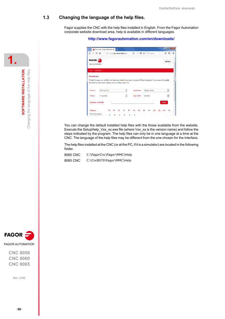
Installation manual.
CNC 8058CNC 8060CNC 8065
1.
SO
FT
WA
RE
INS
TA
LL
AT
ION
.
Ch
angi
ng th
e la
ngu
age
of th
e he
lp fi
les.
ꞏ50ꞏ
REF: 2102
1.3 Changing the language of the help files.
Fagor supplies the CNC with the help files installed in English. From the Fagor Automationcorporate website download area, help is available in different languages.
http://www.fagorautomation.com/en/downloads/
You can change the default installed help files with the those available from the website.Execute the SetupHelp_Vxx_xx.exe file (where Vxx_xx is the version name) and follow thesteps indicated by the program. The help files can only be in one language at a time at theCNC. The language of the help files may be different from the one chosen for the interface.
The help files installed at the CNC (or at the PC, if it is a simulator) are located in the followingfolder.
8060 CNC C:\FagorCnc\Fagor\MMC\Help
8065 CNC C:\Cnc8070\Fagor\MMC\Help
Installation manual.
CNC 8058CNC 8060CNC 8065
SO
FT
WA
RE
INS
TA
LL
AT
ION
.
1.
Upd
atin
g th
e so
ftwa
re v
ers
ion.
ꞏ51ꞏ
REF: 2102
1.4 Updating the software version.
The updates must be carried out using the software supplied by Fagor Automation. Updatingthe software maintains the set up of the machine parameters, PLC program, tool table andtool magazine data. Before updating the software, check the list of possible incompatibilitiesbetween versions.
Before updating the sofware.
It is recommended to always have a backup copy of the full configuration (ASCII files) suchas machine parameter tables, tool tables, active-tools table and tool magazine tables as wellas the PLC program. Should any anomaly occur during the installation, these file will helprestore the CNC configuration.
Software update.
To update the software, close all the programs that may be running, including the CNC. Thesoftware must be installed in setup mode.
Insert the Fagor dongle in the USB port and execute the setup8070_Vxx_xx_xx.exe program(where Vxx_xx is the version name). Then, follow the instructions displayed on the screen.
When starting the process, the CNC offers the possibility of installing from scratch; in thiscase, the installation process will not keep the CNC configuration like the machineparameters, PLC program, etc.
Updating remote nodes of the CAN bus.
Every time the CNC is powered up, it verifies the versions of the remote nodes detected inthe CAN bus and automatically updates all these devices if necessary. When done loading,it goes on with the usual start-up process.
If the loading is not successful, and, consequently, the software coherence between all theelements of the CAN bus cannot be guaranteed, the CNC will display the corresponding errormessage every time [RESET] is pressed.

Installation manual.
CNC 8058CNC 8060CNC 8065
1.
SO
FT
WA
RE
INS
TA
LL
AT
ION
.
Upd
atin
g th
e so
ftwa
re v
ers
ion.
ꞏ52ꞏ
REF: 2102
1.4.1 Software update and incompatibilities (8060).
Version V1.31.01.
Apply or not tool radius compensation in G00.
In this version, movements in G00 do not apply tool radius compensation. This has beencorrected in later versions with parameter G00COMP.
Version V1.40.
New software option "third-party CANopen".
From this version one, if a machine is using some non-Fagor CANopen module, the CNCwill not recognize it and it will issue the corresponding error message when initializing theCAN bus.
Extended scope of the software option "Probing canned cycles".
The software option "Probing canned cycles" is now called "Probe". From this version on,functions G100, G101, G102, G103 and 104 need this software option.
Version V1.70.
HD Graphics and tool holder orientation.
The M model, the canned cycles associated with the rotary axes need the longitudinal axis(parameter LONGAXIS) and the cross axis (parameter FACEAXIS) to be defined. When oneof these parameters is defined, the milling HD graphics take into account the orientation ofthe tool defined in the tool table. If the CNC does not have an axis defined as eitherLONGAXIS or FACEAXIS, it will not take into account the orientation of the tool holder.
Xca files.
The CNC has an updated version of the HD graphics, which incorporates the new FCAS(collision control) which use Version 2 of xca files. So, when updating the CNC version, thexca files defining the configuration of the machine must be installed/updated.
For a complete installation (option 3 of the installer), the setup installs the new xca files. Fora version update (options 1 or 2 of the installer), the new xca files must be copied manually.
• If they are the default xca files, just copy the new files to their location into..\Fagor\Grafdata\Machines.
• If they are xca files that are customized for the machine, then the following modificationsmust be made.
Icon. Meaning.
The CNC orientates the tool according to the first axisdefined as FACEAXIS.
The CNC orientates the tool according to the first axisdefined as LONGAXIS.
Between: <ComponentSet>
y: <GeometryObject name="NO_MACHINE">
Include: <GeometryObject name="VERSION_2"></GeometryObject>
Replace: <ReferenceObject name="SYS-Tool1"/>
With: <ToolVice name="SYS-Tool1" spindle="S1"/>
Installation manual.
CNC 8058CNC 8060CNC 8065
SO
FT
WA
RE
INS
TA
LL
AT
ION
.
1.
Upd
atin
g th
e so
ftwa
re v
ers
ion.
ꞏ53ꞏ
REF: 2102
Version V6.01.03.
Xca files and parameters FACEAXIS and LONGAXIS.
The *.def file accompanying the machine configuration (xca file) defines whether thegraphics work with the tool base or tool tip coordinates. Also, for each tool, the FIXORIparameter defines whether the tool is oriented according to the axes defined by FACEAXISand LONGAXIS. From this version and higher, the graphics operate in the following manner.
• If the HD graphics work with the tool tip coordinates, then they respond to the parametersFACEAXIS and LONGAXIS.
• If the HD graphics work with the tool base coordinates, then they respond to theparameters FACEAXIS and LONGAXIS.
Version V6.21.12.
Software installation.
This version must be installed in administrator mode, so that the process properly registersthe new FCombo.ocx control.
Gap control.
With version v6.20, the CNC always considers the approach coordinate in absolutecoordinates, regardless of the active G90/G91 function. To program the approach coordinatein incremental coordinates, add the “INC” command to the #GAPCTRL instruction.
Replace: <ReferenceObject name="SYS-Tool2"/>
With: <ToolVice name="SYS-Tool2" spindle="S2"/>
Replace: <ReferenceObject name="SYS-Tool3"/>
With: <ToolVice name="SYS-Tool3" spindle="S3"/>
Replace: <ReferenceObject name="SYS-Tool4"/>
With: <ToolVice name="SYS-Tool4" spindle="S4"/>
Replace: <Connection plug="stdPlug@S1" socket="stdSocket@C1"/><Connection plug="stdPlug@SYS-Tool1" socket="stdSocket@S1" rotation="0 1 0 -90"/>
With: <Connection plug="stdPlug@SYS-Tool1" socket="stdSocket@C1" rotation="0 1 0 -90"/>
Replace: <Connection plug="stdPlug@S1" socket="stdSocket@C2"/><Connection plug="stdPlug@SYS-Tool1" socket="stdSocket@S2" rotation="0 1 0 -90"/>
With: <Connection plug="stdPlug@SYS-Tool1" socket="stdSocket@C2" rotation="0 1 0 -90"/>
Replace: <Connection plug="stdPlug@S1" socket="stdSocket@C3"/><Connection plug="stdPlug@SYS-Tool1" socket="stdSocket@S3" rotation="0 1 0 -90"/>
With: <Connection plug="stdPlug@SYS-Tool1" socket="stdSocket@C3" rotation="0 1 0 -90"/>
Replace: <Connection plug="stdPlug@S1" socket="stdSocket@C4"/><Connection plug="stdPlug@SYS-Tool1" socket="stdSocket@S4" rotation="0 1 0 -90"/>
With: <Connection plug="stdPlug@SYS-Tool1" socket="stdSocket@C4" rotation="0 1 0 -90"/>

Installation manual.
CNC 8058CNC 8060CNC 8065
1.
SO
FT
WA
RE
INS
TA
LL
AT
ION
.
Upd
atin
g th
e so
ftwa
re v
ers
ion.
ꞏ54ꞏ
REF: 2102
Leapfrog.
With version v6.20, the CNC always considers the coordinate programmed in the “POS”command in absolute coordinates, regardless of the G90/G91 command. To program thecoordinate at the end of the leap in incremental coordinates, use the “INCPOS” command.
Installation manual.
CNC 8058CNC 8060CNC 8065
SO
FT
WA
RE
INS
TA
LL
AT
ION
.
1.
Upd
atin
g th
e so
ftwa
re v
ers
ion.
ꞏ55ꞏ
REF: 2102
1.4.2 Software update and incompatibilities (8065).
Version V4.25.
Unit change in machine parameter FTIMELIM, related to HSC machining.
In earlier versions, parameter FTIMELIM was programmed in milliseconds. From this versionon, this parameter is set in percentage.
Version V5.31.01.
Apply or not tool radius compensation in G00.
In this version, movements in G00 do not apply tool radius compensation. This has beencorrected in later versions with parameter G00COMP.
Version V5.40.
New software option "third-party CANopen".
From this version one, if a machine is using some non-Fagor CANopen module, the CNCwill not recognize it and it will issue the corresponding error message when initializing theCAN bus.
Extended scope of the software option "Probing canned cycles".
The software option "Probing canned cycles" is now called "Probe". From this version on,functions G100, G101, G102, G103 and 104 need this software option.
Version V5.70.
HD Graphics and tool holder orientation.
The M model, the canned cycles associated with the rotary axes need the longitudinal axis(parameter LONGAXIS) and the cross axis (parameter FACEAXIS) to be defined. When oneof these parameters is defined, the milling HD graphics take into account the orientation ofthe tool defined in the tool table. If the CNC does not have an axis defined as eitherLONGAXIS or FACEAXIS, it will not take into account the orientation of the tool holder.
Xca files.
The CNC has an updated version of the HD graphics, which incorporates the new FCAS(collision control) which use Version 2 of xca files. So, when updating the CNC version, thexca files defining the configuration of the machine must be installed/updated.
For a complete installation (option 3 of the installer), the setup installs the new xca files. Fora version update (options 1 or 2 of the installer), the new xca files must be copied manually.
• If they are the default xca files, just copy the new files to their location into..\Fagor\Grafdata\Machines.
Icon. Meaning.
The CNC orientates the tool according to the first axisdefined as FACEAXIS.
The CNC orientates the tool according to the first axisdefined as LONGAXIS.
Installation manual.
CNC 8058CNC 8060CNC 8065
1.
SO
FT
WA
RE
INS
TA
LL
AT
ION
.
Upd
atin
g th
e so
ftwa
re v
ers
ion.
ꞏ56ꞏ
REF: 2102
• If they are xca files that are customized for the machine, then the following modificationsmust be made.
Version V6.01.03.
Xca files and parameters FACEAXIS and LONGAXIS.
The *.def file accompanying the machine configuration (xca file) defines whether thegraphics work with the tool base or tool tip coordinates. Also, for each tool, the FIXORIparameter defines whether the tool is oriented according to the axes defined by FACEAXISand LONGAXIS. From this version and higher, the graphics operate in the following manner.
• If the HD graphics work with the tool tip coordinates, then they respond to the parametersFACEAXIS and LONGAXIS.
• If the HD graphics work with the tool base coordinates, then they respond to theparameters FACEAXIS and LONGAXIS.
Between: <ComponentSet>
y: <GeometryObject name="NO_MACHINE">
Include: <GeometryObject name="VERSION_2"></GeometryObject>
Replace: <ReferenceObject name="SYS-Tool1"/>
With: <ToolVice name="SYS-Tool1" spindle="S1"/>
Replace: <ReferenceObject name="SYS-Tool2"/>
With: <ToolVice name="SYS-Tool2" spindle="S2"/>
Replace: <ReferenceObject name="SYS-Tool3"/>
With: <ToolVice name="SYS-Tool3" spindle="S3"/>
Replace: <ReferenceObject name="SYS-Tool4"/>
With: <ToolVice name="SYS-Tool4" spindle="S4"/>
Replace: <Connection plug="stdPlug@S1" socket="stdSocket@C1"/><Connection plug="stdPlug@SYS-Tool1" socket="stdSocket@S1" rotation="0 1 0 -90"/>
With: <Connection plug="stdPlug@SYS-Tool1" socket="stdSocket@C1" rotation="0 1 0 -90"/>
Replace: <Connection plug="stdPlug@S1" socket="stdSocket@C2"/><Connection plug="stdPlug@SYS-Tool1" socket="stdSocket@S2" rotation="0 1 0 -90"/>
With: <Connection plug="stdPlug@SYS-Tool1" socket="stdSocket@C2" rotation="0 1 0 -90"/>
Replace: <Connection plug="stdPlug@S1" socket="stdSocket@C3"/><Connection plug="stdPlug@SYS-Tool1" socket="stdSocket@S3" rotation="0 1 0 -90"/>
With: <Connection plug="stdPlug@SYS-Tool1" socket="stdSocket@C3" rotation="0 1 0 -90"/>
Replace: <Connection plug="stdPlug@S1" socket="stdSocket@C4"/><Connection plug="stdPlug@SYS-Tool1" socket="stdSocket@S4" rotation="0 1 0 -90"/>
With: <Connection plug="stdPlug@SYS-Tool1" socket="stdSocket@C4" rotation="0 1 0 -90"/>
Installation manual.
CNC 8058CNC 8060CNC 8065
SO
FT
WA
RE
INS
TA
LL
AT
ION
.
1.
Upd
atin
g th
e so
ftwa
re v
ers
ion.
ꞏ57ꞏ
REF: 2102
Version V6.21.12.
Software installation.
This version must be installed in administrator mode, so that the process properly registersthe new FCombo.ocx control.
Gap control.
With version v6.20, the CNC always considers the approach coordinate in absolutecoordinates, regardless of the active G90/G91 function. To program the approach coordinatein incremental coordinates, add the “INC” command to the #GAPCTRL instruction.
Leapfrog.
With version v6.20, the CNC always considers the coordinate programmed in the “POS”command in absolute coordinates, regardless of the G90/G91 command. To program thecoordinate at the end of the leap in incremental coordinates, use the “INCPOS” command.
Installation manual.
CNC 8058CNC 8060CNC 8065
1.
SO
FT
WA
RE
INS
TA
LL
AT
ION
.
Req
uire
men
ts b
efor
e an
d a
fter
CN
C s
etup
.
ꞏ58ꞏ
REF: 2102
1.5 Requirements before and after CNC setup.
The CNC setup is carried out in setup mode. Fagor delivers the unit ready to start up in thismode. When powering the unit up, the desktop will show an image showing thiscircumstance.
After starting the CNC application, proceed with setup. When starting the application, it willdisplay a warning indicating that it is operating in SETUP (not safe) mode.
When closing the application with the key sequence [ALT]+[F4] and choosing the optionsto "close" or to "close and make a backup copy", the CNC shows a second dialog box askingwhether setup has been completed or not. If the "NO" is chosen, the next time the unit isturned on, it will start in setup mode again. If the "Yes" option is chosen, the CNC makes abackup copy of the MTB folder and, the next time it is turned on, the unit will start in user mode.
The unit will remain in setup mode until the manufacturer changes it to user mode in responseto the dialog displayed when shutting the application down. If while in user mode, it isnecessary to change something that has to do with setup, the setup mode must be accessedmanually. See "1.1.1 Work modes and software protection for the CNC." on page 46.
When starting the application up, either in setup or user mode, the CNC display can showwarnings whose cause must be solved by the manufacturer during setup.
The unit must be delivered to the user ready to start up in user mode.
Installation manual.
CNC 8058CNC 8060CNC 8065
SO
FT
WA
RE
INS
TA
LL
AT
ION
.
1.
Inst
alla
tion
of th
ird-p
arty
sof
twar
e (C
NC
806
5 on
ly).
ꞏ59ꞏ
REF: 2102
1.6 Installation of third-party software (CNC 8065 only).
The CNC you have purchased is an industrial PC equipped with Windows XP Embeddedor Windows 7 operating system that allows for the installation of third-party applications. Theinstallation of this software must meet the following requirements.
Any malfunction of the equipment due to the installation of third-party software frees FagorAutomation from any responsibility.
Installation in the hard disk.
The CNC that you purchased may have either just a compact flash or a compact flash anda hard disk. To install any software, the CNC must have enough free memory in the compactflash. To avoid ending up with little free memory in the compact flash, it may be necessaryto install third-party software in a hard disk.
Also, in order to install third-party software, you must have an open system; i.e. with accessto the administrator. The access to the administrator mode is enabled with the validationcode. If you don't have this software option, you will not be able to access the administratormode and, therefore, you will not be able to install third-party software. Software installationdone in setup mode or user mode will disappear when turning the CNC off.
The access to the administrator mode is protected with the password "administrator mode",defined in the utilities mode. To obtain the relevant password, contact the supplier of yourmachine.
When installing third-party software, remember that the results of the software, generatedprograms, etc. must be saved in an unprotected folder, for example CNC8070\USERS.Never use a protected foder because it will be temporary and it will disappear when turningthe CNC off.
System requirements.
Before installing the software, make sure that the CNC meets all the requirements of thesoftware, both the CPU and the memory. You can consult this information in the CNC'sdiagnosis mode.
Also check that there is enough free memory space in the disk for your application.
Remember that the equipment, the operating system and the CNC (depending on theconfiguration of the machine) may consume between 50% and 60% of the availableresources. Once the software has been installed, the CNC being up and running, check thestatus of the system resources and check that the CNC is running properly, screen refresh,etc.
Installation manual.
CNC 8058CNC 8060CNC 8065
1.
SO
FT
WA
RE
INS
TA
LL
AT
ION
.
Sof
twar
e co
nfig
ura
tion.
ꞏ60ꞏ
REF: 2102
1.7 Software configuration.
The necessary files for the CNC are located in the following folder.
8060 CNC C:\FAGORCNC and its corresponding subfolders.
8065 CNC C:\CNC70 and its corresponding subfolders.
Folder. Contents.
BACKUPSDIR Backup of previous installations.Every time the user installed a full new version, the installer saves a copyof the previous installation in this folder.
CONFIGURATION MTB folders of the system.This folder contains the various MTB folders of the system; MTB_T for latheand MTB_M for mill. When booting system and depending on the validationcode, the system will move the corresponding folder from CONFIGURATIONto MTB.
DIAGNOSIS Information for the diagnosis.This folder contains relevant information for proper error diagnosis, includingthe reportfagor.zip file.
DRIVERS CNC drivers.This folder contains some necessary drives for proper operation of the CNC.
FAGOR Version folder.This folder contains the software corresponding to the CNC version installed.Software updates are carried out in this directory and do not affect thecontents of the MTB and USERS directories.Do not change the contents of this directory. Only authorized personnel fromFagor Automation may modify the contents of this directory. FagorAutomation shall not be held responsible of the performance of this CNC ifthe contents of this directory have been changed.
MTB OEM folder.This folder is especially directed at machine manufacturers. This foldercontains the modifications made by the OEM at the CNC like, for example,the PLC program, machine parameters, new screens, integrating externalapplications, etc.
TMP Temporary files.The CNC uses this folder to save the temporary files it generates whileoperating. The CNC deletes the contents of this folder on power-up.
USERS User folder.This folder is especially directed at users. The purpose of this folder is toprovide the user with a memory space for storing part-programs, profiles, etc.as they are generated.
The CNC deletes the contents of the TMP folder on power-up. Do not use this folder to save files thatyou'd like to keep.i
Installation manual.
CNC 8058CNC 8060CNC 8065
SO
FT
WA
RE
INS
TA
LL
AT
ION
.
1.
Sof
twar
e co
nfig
ura
tion.
ꞏ61ꞏ
REF: 2102
1.7.1 MTB (Machine Tool Builder) folder.
This folder is especially directed at machine manufacturers. This folder contains themodifications made by the OEM at the CNC like, for example, the PLC program, machineparameters, new screens, integrating external applications, etc.
Folder. Contents.
DATA This folder contains the following files or subfolders.• The databases for machine parameters, tables, etc. and the safety
backup (in ASCII) of those tables.• The files related to the data of the editor cycles (dat files). • The data the CNC must maintain after it has been turned off (coordinates,
zero offsets, etc.).• Each language of the ..\LANG\ subfolder contains the file cncError.txt
that contains the OEM messages and errors in different languages. If anerror text is not in the folder of the language active at the CNC, it looksfor it in ..\LANG\ENGLISH\cncError.txt; if it is not there, the CNC will issuethe relevant error message.
DRIVE This folder contains the information regarding the DDSSETUP mode.
GRAFDATA This folder contains the information regarding graphics.
KINEMATIC This folder contains the information regarding the OEM kinematics.
MMC This folder contains the CNC custom setting made by the machine builder.• The "...\CONFIG" subfolder contains the configuration files (ini files) and
the files that may be modified using the screen customizing tool (Fguim).• The ..\IMAGES subfolder contains the images, icons, videos, etc. that
the OEM uses to customize the CNC.• Each language of the ..\LANG subfolder contains the texts used by the
scripts. Each language of the ..\LANG subfolder contains the file with thetexts for the language active at the CNC. When changing the CNClanguage, the CNC replaces this file with the one correspondinglanguage.
PLC This folder contains the information regarding the PLC.• Each language of the ..\LANG\ subfolder contains the messages and
errors of the PLC in different languages.• The ..\PROJECT subfolder contains the files that make up the PLC
project and the object file.• The ..\WATCH contains the data saved from the monitoring and logic
analyzer services.
RELEASE This folder contains the components (ocx files) used by the OEM to createhis own application.
SUB This folder contains the following files or subfolders.• The OEM subroutines (tool change, home search, etc.).• Each language of the ..\HELP folder contains the help files associated
with OEM subroutines and the pcall.txt file that contains the list of OEMsubroutines. If these files are not in the folder of the language active atthe CNC, the editor will not provide them as help.
TUNING This folder contains the information regarding the setup assistance.
Installation manual.
CNC 8058CNC 8060CNC 8065
1.
SO
FT
WA
RE
INS
TA
LL
AT
ION
.
Sof
twar
e co
nfig
ura
tion.
ꞏ62ꞏ
REF: 2102
1.7.2 USERS folder.
This folder is especially directed at users. The purpose of this folder is to provide the userwith a memory space for storing part-programs, profiles, etc. as they are generated. Werecommend to save these programs in the folders created for this purpose in order to makeit easier and faster to find them and make safety backup copies.
Since the disk is write-protected, the programs created by the user must be saved in thisfolder; the only one that is not protected. Any program saved in a protected folder will betemporary and will be deleted when the CNC is turned off.
Folder. Contents.
HELP Each language of the ..\HELP folder contains the help files associated withuser-defined global subroutines and the pcall.txt file that contains the list ofuser subroutines.
POCKET This folder contains the profiles that have been created using the profileeditor and are related to the editor cycles.
PRG This folder contains the part-programs created by the user who may createnew subfolders and store the programs in a more orderly fashion.The subfolder "...\PRG_8055_TO_8070" contains the programs translatedfrom the 8055 format into the 8070 language. The CNC saves the converted(translated) program with the same name but with the extension m55 (millingprogram) or t55 (lathe program).
PROFILE This folder contains the profiles that have been created using the profileeditor.
REPORTS This folder contains the bmp files that the CNC generates when printing agraphic to a file and the pm reports generated from the diagnosis mode.
SUB This folder contains the subroutines created by the user, whose location mustbe fixed for the CNC (for example, the generic user subroutines G500-G599)and the subroutine program_start)

CNC 8058CNC 8060CNC 8065
2
ꞏ63ꞏ
REF: 2102
2. MACHINE PARAMETERS.
This chapter describes the meaning of all the machine parameters of the CNC. Someparameters depend on the CNC model (8060/8065) and others are common to both. TheCNC shows the right parameters depending on the model and the active software options.
In order for the machine tool to be able to properly execute the programmed instructions andinterpret the elements connected to it, the CNC must know the specific machine data. Someof this data may be the number of axes, feedrates, accelerations, feedback, type of toolmagazine, tool changer, etc. This data is set by the machine manufacturer and must becommunicated to the CNC through the machine parameters. The machine parameters ofthe CNC are shown grouped as follows.
Icons associated with machine parameters.
Parameter validating method.
Parameter matching.
Machine parameters. Meaning.
General parameters. These parameters set the name of the axes and spindles,power-up conditions, subroutines associated with specificfunctions, etc.Some of these parameters must be defined first becausethey configure the axis parameter tables. For example, thenumber and name of the axes and spindles, etc.
Axis and spindle parameters. These parameters indicate the properties of the axes andspindles, travel l imits, moving conditions, relatedhandwheels, probing, compensations, etc.Each axis or spindle may have up to 4 work sets. Thefollowing must be set for each one: feedrates and gains,home searches, accelerations, etc.
Jog parameters. These parameters set the handwheels and the JOG keys.
Parameters of the M function table. These parameters set the new M functions, the type ofsynchronization and the subroutine associated with each Mfunction of the system.
Parameters for the Kinematics table. These parameters indicate the type and characteristics ofeach kinematics.
Parameters for the magazines. These parameters indicate the number of tool magazinesand number of tool pockets (positions), etc.
HMI parameters. These parameters are used to define the communicationenvironment (interface) between the operator and the CNC.
OEM parameters. These parameters set the reading/writing of drive variables,editing cams, defining a group of generic parameters so themanufacturer can use them like machine parameters, etc.
This icon may appear next to the parameter name and indicates that the CNC must berestarted for the parameter to assume its new value. The parameters that do not have thisicon next to them can assume the new value by just pressing the "Validate" softkey.
This icon may appear next to the parameter name and indicates that it involved in theparameter matching between the CNC and the drive.
Installation manual.
CNC 8058CNC 8060CNC 8065
2.
MA
CH
INE
PA
RA
ME
TE
RS
.
ꞏ64ꞏ
REF: 2102
Selection of parameter values.
The icons appearing next to the parameter value permit accessing the list of pre-establishedvalues, a data table, a set of parameters or to refer to a file. For those parameters that donot have an icon next to them, a value must be edited within the indicated range.
Default value of the parameters at a simulator.
When the CNC is installed as a simulator at a PC, the default value of certain machineparameters may be different from those mentioned here. The changes basically have to dowith the maximum axis feedrates, accelerations and jerk. The probe data has also beenchanged in order to have, in jog mode, the part centering and tool calibration cycles.
Icon. Meaning.
The parameter has a list of options.
To access a data table.
To access a group of parameters.
The parameter refers to a file.
Installation manual.
CNC 8058CNC 8060CNC 8065
MA
CH
INE
PA
RA
ME
TE
RS
.
2.
Par
am
ete
r m
atch
ing
betw
een
the
CN
C a
nd th
e S
erco
s dr
ive.
ꞏ65ꞏ
REF: 2102
2.1 Parameter matching between the CNC and the Sercos drive.
Some parameters of the CNC and of the drive must be set equivalently to ensure propersystem operation. While initializing the Sercos ring, on CNC power-up and when validatingthe machine parameters of the axes and spindles, the CNC updates at the drives the valueof the parameters necessary to ensure that they are equivalent.
Parameter matching and speed ranges (gears).
The number of parameter sets to define the speed ranges (gears) may be different at theCNC and at the drive. If there is a parameter set at the CNC, the parameter matching updatesparameters NP121, NP122, NP131 and NP133 of each set of the drive with the valuesdefined at the CNC. The parameter matching will save the CNC's default set values in therest of the sets of the drive.
Understanding the parameter matching table.
The table indicates which CNC parameters are involved in parameter matching as well asthe drive parameters that are affected. The different columns of the table have the followingmeaning.
The CNC does not match the parameters when the drive is an ACSD. i
CNC List of CNC machine parameters.
DRIVE List of drive parameters that are equivalent to each CNC parameter.
Sercos It indicates writing the parameter at the drive depends or not on the typeSercos configuration, position or velocity).
Feedback It indicates whether or not writing the parameter at the drive depends onthe type of axis feedback, internal or external.
CNC DRIVE Sercos Feedback Remarks
AXISTYPEAXISMODE
PP76 PP76=65; Linear axis.PP76=66; Rotary axis without module.PP76=194; Rotary axis with module.
PITCH NP123
INPUTREV NP121.x It affects all the gears.
OUTPUTREV NP122.x It affects all the gears.
NPULSES2 PP115 (bit 0)NP117
External.External.
B0=0; If rotary encoder (NPULSES2<>0).B0=1; If linear encoder (NPULSES2==0).NP117; If rotary encoder (NPULSES2<>0).
PITCH2 NP133NP117NP118
External.External.External.
NP133; If rotary encoder (NPULSES2<>0).NP117; If linear encoder (NPULSES2==0).NP118; If linear encoder (NPULSES2==0).
INPUTREV2 NP131.x External. It affects all the gears.Only if rotary encoder (NPULSES2<>0).
OUTPUTREV2 NP132.x External. It affects all the gears.Only if rotary encoder (NPULSES2<>0).
FBACKSRCSINMAGNI
GP10 GP10=0; External feedback is not being used.GP10=1; TTL signal (SINMAGNI==0).GP10=2; Vpp signal (SINMAGNI<>0).
FBACKDIFF PP5 Position. External.
FBMIXTIME PP16 Position. External.
AXISCHLOOPCH
PP115 (bit 3) Position. External. B3=0; Feedback sign AXISCH==LOOPCH.B3=1; Feedback sign AXISCH<>LOOPCH.
AXISCH PP55 (bit 0,2,3) Position. B1=0 B2=0 B3=0; It does not change the signof the feedback reading (AXISCH==NO)B1=1 B2=1 B3=1; It does not change the signof the feedback reading (AXISCH==YES)
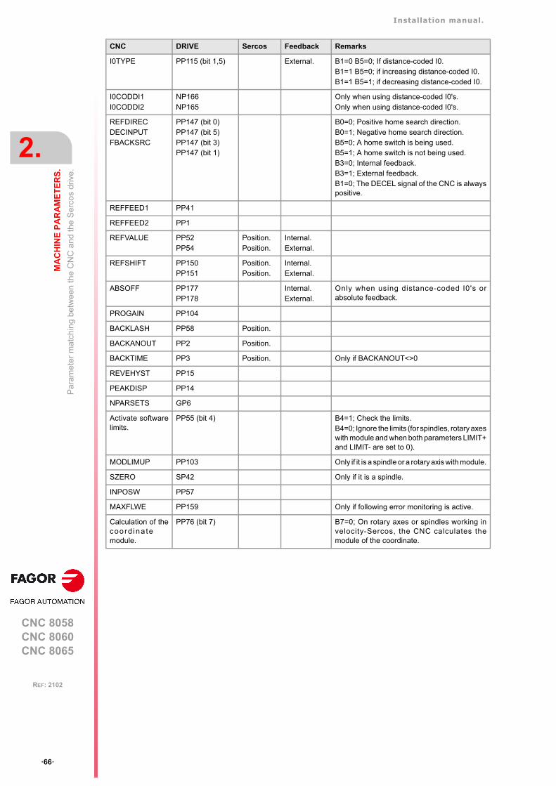
Installation manual.
CNC 8058CNC 8060CNC 8065
2.
MA
CH
INE
PA
RA
ME
TE
RS
.
Par
am
ete
r m
atch
ing
betw
een
the
CN
C a
nd th
e S
erco
s dr
ive.
ꞏ66ꞏ
REF: 2102
I0TYPE PP115 (bit 1,5) External. B1=0 B5=0; If distance-coded I0.B1=1 B5=0; if increasing distance-coded I0.B1=1 B5=1; if decreasing distance-coded I0.
I0CODDI1I0CODDI2
NP166NP165
Only when using distance-coded I0's.Only when using distance-coded I0's.
REFDIRECDECINPUTFBACKSRC
PP147 (bit 0)PP147 (bit 5)PP147 (bit 3)PP147 (bit 1)
B0=0; Positive home search direction.B0=1; Negative home search direction.B5=0; A home switch is being used.B5=1; A home switch is not being used.B3=0; Internal feedback.B3=1; External feedback.B1=0; The DECEL signal of the CNC is alwayspositive.
REFFEED1 PP41
REFFEED2 PP1
REFVALUE PP52PP54
Position.Position.
Internal.External.
REFSHIFT PP150PP151
Position.Position.
Internal.External.
ABSOFF PP177PP178
Internal.External.
Only when using distance-coded I0's orabsolute feedback.
PROGAIN PP104
BACKLASH PP58 Position.
BACKANOUT PP2 Position.
BACKTIME PP3 Position. Only if BACKANOUT<>0
REVEHYST PP15
PEAKDISP PP14
NPARSETS GP6
Activate softwarelimits.
PP55 (bit 4) B4=1; Check the limits.B4=0; Ignore the limits (for spindles, rotary axeswith module and when both parameters LIMIT+and LIMIT- are set to 0).
MODLIMUP PP103 Only if it is a spindle or a rotary axis with module.
SZERO SP42 Only if it is a spindle.
INPOSW PP57
MAXFLWE PP159 Only if following error monitoring is active.
Calculation of thecoord ina temodule.
PP76 (bit 7) B7=0; On rotary axes or spindles working invelocity-Sercos, the CNC calculates themodule of the coordinate.
CNC DRIVE Sercos Feedback Remarks
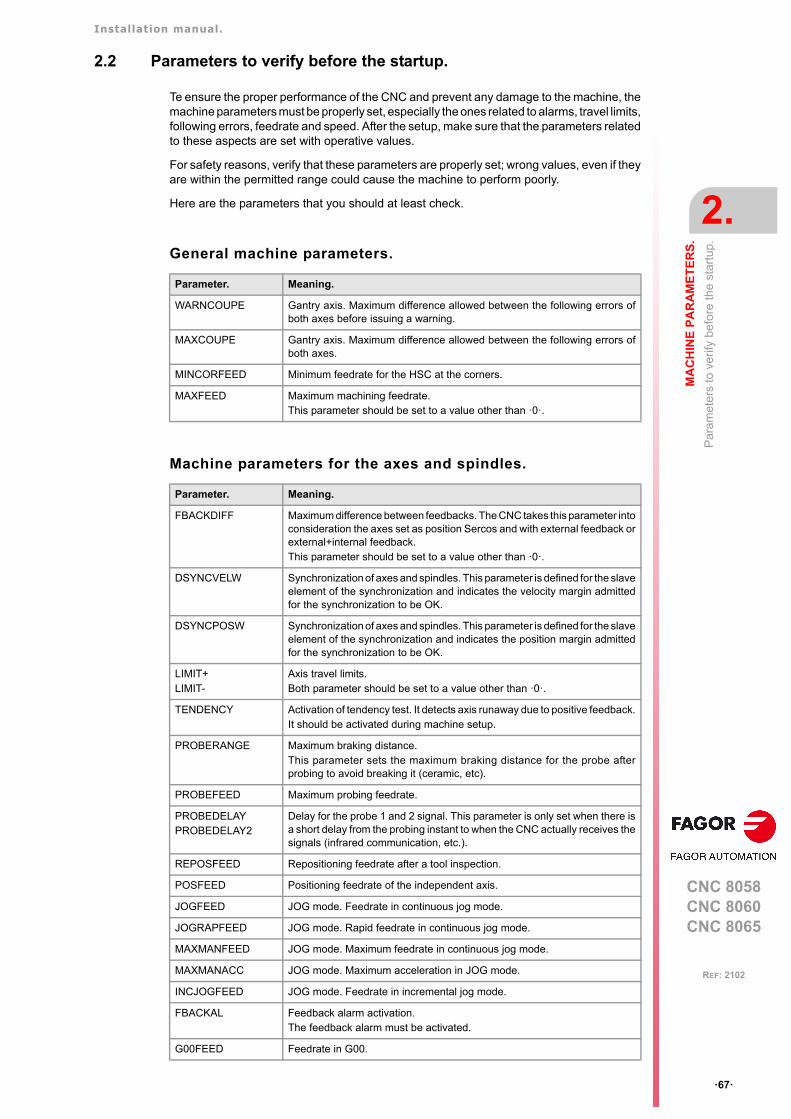
Installation manual.
CNC 8058CNC 8060CNC 8065
MA
CH
INE
PA
RA
ME
TE
RS
.
2.
Par
am
ete
rs t
o ve
rify
befo
re th
e s
tart
up.
ꞏ67ꞏ
REF: 2102
2.2 Parameters to verify before the startup.
Te ensure the proper performance of the CNC and prevent any damage to the machine, themachine parameters must be properly set, especially the ones related to alarms, travel limits,following errors, feedrate and speed. After the setup, make sure that the parameters relatedto these aspects are set with operative values.
For safety reasons, verify that these parameters are properly set; wrong values, even if theyare within the permitted range could cause the machine to perform poorly.
Here are the parameters that you should at least check.
General machine parameters.
Machine parameters for the axes and spindles.
Parameter. Meaning.
WARNCOUPE Gantry axis. Maximum difference allowed between the following errors ofboth axes before issuing a warning.
MAXCOUPE Gantry axis. Maximum difference allowed between the following errors ofboth axes.
MINCORFEED Minimum feedrate for the HSC at the corners.
MAXFEED Maximum machining feedrate.This parameter should be set to a value other than ꞏ0ꞏ.
Parameter. Meaning.
FBACKDIFF Maximum difference between feedbacks. The CNC takes this parameter intoconsideration the axes set as position Sercos and with external feedback orexternal+internal feedback.This parameter should be set to a value other than ꞏ0ꞏ.
DSYNCVELW Synchronization of axes and spindles. This parameter is defined for the slaveelement of the synchronization and indicates the velocity margin admittedfor the synchronization to be OK.
DSYNCPOSW Synchronization of axes and spindles. This parameter is defined for the slaveelement of the synchronization and indicates the position margin admittedfor the synchronization to be OK.
LIMIT+LIMIT-
Axis travel limits. Both parameter should be set to a value other than ꞏ0ꞏ.
TENDENCY Activation of tendency test. It detects axis runaway due to positive feedback.It should be activated during machine setup.
PROBERANGE Maximum braking distance. This parameter sets the maximum braking distance for the probe afterprobing to avoid breaking it (ceramic, etc).
PROBEFEED Maximum probing feedrate.
PROBEDELAYPROBEDELAY2
Delay for the probe 1 and 2 signal. This parameter is only set when there isa short delay from the probing instant to when the CNC actually receives thesignals (infrared communication, etc.).
REPOSFEED Repositioning feedrate after a tool inspection.
POSFEED Positioning feedrate of the independent axis.
JOGFEED JOG mode. Feedrate in continuous jog mode.
JOGRAPFEED JOG mode. Rapid feedrate in continuous jog mode.
MAXMANFEED JOG mode. Maximum feedrate in continuous jog mode.
MAXMANACC JOG mode. Maximum acceleration in JOG mode.
INCJOGFEED JOG mode. Feedrate in incremental jog mode.
FBACKAL Feedback alarm activation.The feedback alarm must be activated.
G00FEED Feedrate in G00.
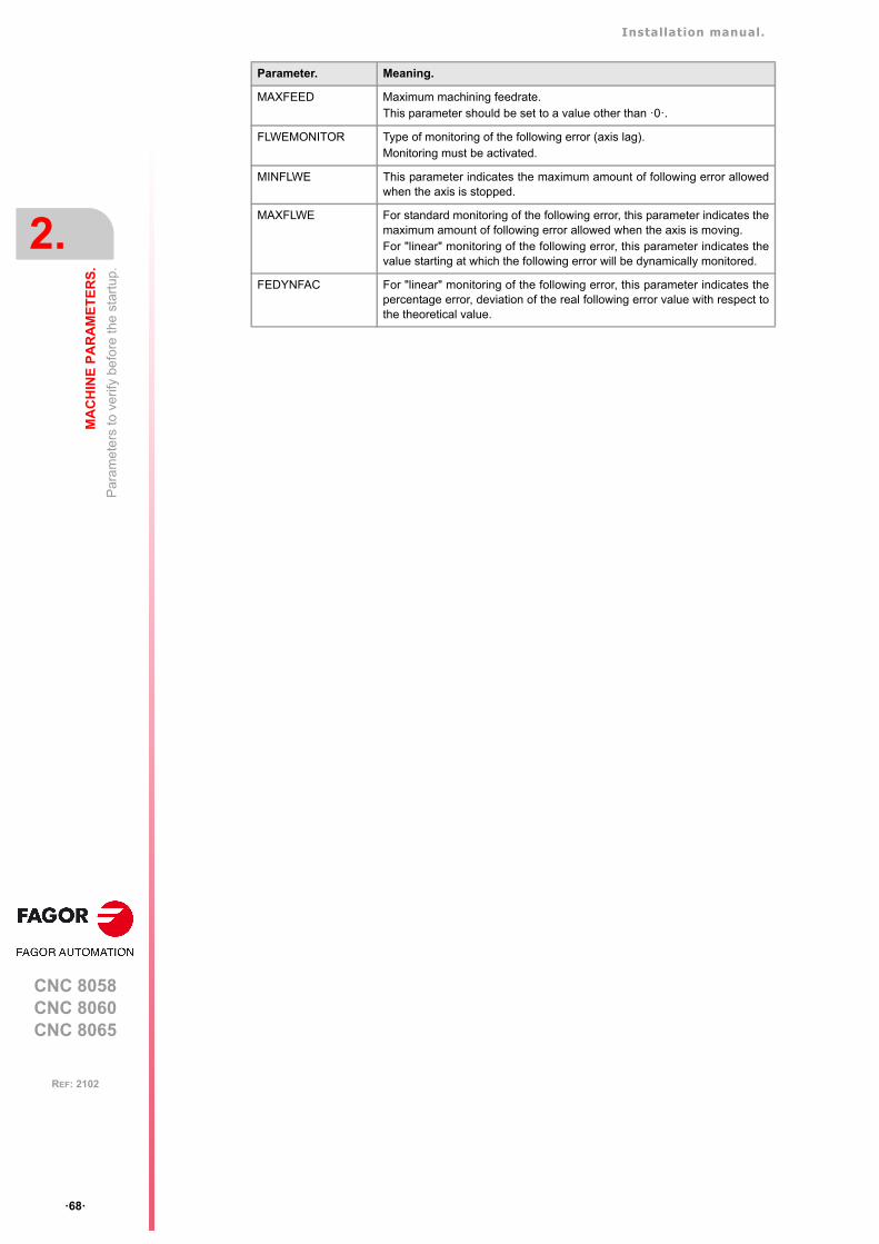
Installation manual.
CNC 8058CNC 8060CNC 8065
2.
MA
CH
INE
PA
RA
ME
TE
RS
.
Par
am
ete
rs t
o ve
rify
befo
re th
e s
tart
up.
ꞏ68ꞏ
REF: 2102
MAXFEED Maximum machining feedrate.This parameter should be set to a value other than ꞏ0ꞏ.
FLWEMONITOR Type of monitoring of the following error (axis lag).Monitoring must be activated.
MINFLWE This parameter indicates the maximum amount of following error allowedwhen the axis is stopped.
MAXFLWE For standard monitoring of the following error, this parameter indicates themaximum amount of following error allowed when the axis is moving. For "linear" monitoring of the following error, this parameter indicates thevalue starting at which the following error will be dynamically monitored.
FEDYNFAC For "linear" monitoring of the following error, this parameter indicates thepercentage error, deviation of the real following error value with respect tothe theoretical value.
Parameter. Meaning.
Installation manual.
CNC 8058CNC 8060CNC 8065
MA
CH
INE
PA
RA
ME
TE
RS
.
2.
Gen
eral
mac
hin
e pa
ram
eter
s.
ꞏ69ꞏ
REF: 2102
2.3 General machine parameters.
2.3.1 Channel configuration.
NCHANNELNumber of CNC channels.Possible values: From 1 to 4.Default value: 1.Associated variable: (V.)MPG.NCHANNEL
The use of channels is oriented to machines like dual-spindle lathes where each channelhas one of the spindles and two axes; machines with feeders, where the machine and thefeeder will be different channels; tool magazine loading and unloading system controlled asan axis.
The CNC can have a single execution channel (single channel system) or several (multi-channel system). Each channel is a different work environment that can act upon a part ofor the whole CNC system. The difference between a multi-channel system and severalindependent CNC's is that the channels can not only act independently, but also together;in other words, they can communicate, synchronize with each other and carry outcoordinated actions.
The axes and spindles of a channel.
A channel can have a group of axes and spindles that act independently or in parallel withthe rest of the channels. It is also possible to configure a channel without assigning axesor spindles to it at first; then, later on, axes and spindles may be added to it or removed fromit via part-program or in the MDI/MDA.mode.
Operation of a channel.
In order to be able to move an axis or spindle, it must be assigned to a channel. Each channelcan only control its axes and spindles, although via part-program or MDI/MDA it cancommand movements to axes or spindles of other channels.
Each channel can execute a different program, be in an different work mode and have itsown data. The channels can share information through variables and arithmetic parametersand, if necessary, they may be synchronized via part-program.
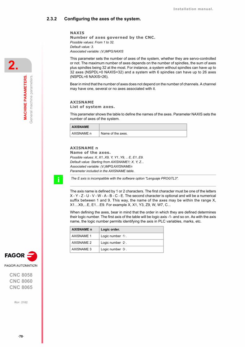
Installation manual.
CNC 8058CNC 8060CNC 8065
2.
MA
CH
INE
PA
RA
ME
TE
RS
.
Gen
eral
mac
hin
e pa
ram
eter
s.
ꞏ70ꞏ
REF: 2102
2.3.2 Configuring the axes of the system.
NAXISNumber of axes governed by the CNC.Possible values: From 1 to 32.Default value: 3.Associated variable: (V.)MPG.NAXIS
This parameter sets the number of axes of the system, whether they are servo-controlledor not. The maximum number of axes depends on the number of spindles, the sum of axesplus spindles being 32 at the most. For instance, a system without spindles can have up to32 axes (NSPDL=0 NAXIS=32) and a system with 6 spindles can have up to 26 axes(NSPDL=6 NAXIS=26).
Bear in mind that the number of axes does not depend on the number of channels. A channelmay have one, several or no axes associated with it.
AXISNAMEList of system axes.
This parameter shows the table to define the names of the axes. Parameter NAXIS sets thenumber of axes of the system.
AXISNAME nName of the axes.Possible values: X, X1..X9, Y, Y1..Y9, .. E, E1..E9.Default value: Starting from AXISNAME1; X, Y, Z...Associated variable: (V.)MPG.AXISNAMEnParameter included in the AXISNAME table.
The axis name is defined by 1 or 2 characters. The first character must be one of the lettersX - Y - Z - U - V - W - A - B - C - E. The second character is optional and will be a numericalsuffix between 1 and 9. This way, the name of the axes may be within the range X,X1…X9,...E, E1…E9. For example X, X1, Y3, Z9, W, W7, C...
When defining the axes, bear in mind that the order in which they are defined determinestheir logic number. The first axis of the table will be logic axis -1- and so on. As with the axisname, the logic number permits identifying the axis in PLC variables, marks, etc.
AXISNAME
AXISNAME n Name of the axes.
The E axis is incompatible with the software option "Lenguaje PROGTL3".i
AXISNAME n Logic order.
AXISNAME 1 Logic number ꞏ1ꞏ.
AXISNAME 2 Logic number ꞏ2ꞏ.
AXISNAME 3 Logic number ꞏ3ꞏ.
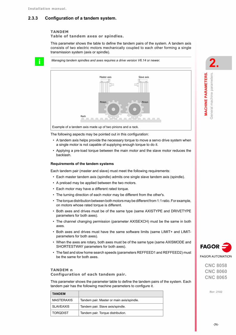
Installation manual.
CNC 8058CNC 8060CNC 8065
MA
CH
INE
PA
RA
ME
TE
RS
.
2.
Gen
eral
mac
hin
e pa
ram
eter
s.
ꞏ71ꞏ
REF: 2102
2.3.3 Configuration of a tandem system.
TANDEMTable of tandem axes or spindles.
This parameter shows the table to define the tandem pairs of the system. A tandem axisconsists of two electric motors mechanically coupled to each other forming a singletransmission system (axis or spindle).
The following aspects may be pointed out in this configuration:
• A tandem axis helps provide the necessary torque to move a servo drive system whena single motor is not capable of supplying enough torque to do it.
• Applying a pre-load torque between the main motor and the slave motor reduces thebacklash.
Requirements of the tandem systems
Each tandem pair (master and slave) must meet the following requirements:
• Each master tandem axis (spindle) admits one single slave tandem axis (spindle).
• A preload may be applied between the two motors.
• Each motor may have a different rated torque.
• The turning direction of each motor may be different from the other's.
• The torque distribution between both motors may be different from 1:1 ratio. For example,on motors whose rated torque is different.
• Both axes and drives must be of the same type (same AXISTYPE and DRIVETYPEparameters for both axes).
• The channel changing permission (parameter AXISEXCH) must be the same in bothaxes.
• Both axes and drives must have the same software limits (same LIMIT+ and LIMIT-parameters for both axes).
• When the axes are rotary, both axes must be of the same type (same AXISMODE andSHORTESTWAY parameters for both axes).
• The fast and slow home search speeds (parameters REFFEED1 and REFFEED2) mustbe the same for both axes.
TANDEM nConfiguration of each tandem pair.
This parameter shows the parameter table to define the tandem pairs of the system. Eachtandem pair has the following machine parameters to configure it.
Managing tandem spindles and axes requires a drive version V6.14 or newer.i
Example of a tandem axis made up of two pinions and a rack.
TANDEM
MASTERAXIS Tandem pair. Master or main axis/spindle.
SLAVEAXIS Tandem pair. Slave axis/spindle.
TORQDIST Tandem pair. Torque distribution.
Master axis Slave axis
Pinion Pinion
Rack
Installation manual.
CNC 8058CNC 8060CNC 8065
2.
MA
CH
INE
PA
RA
ME
TE
RS
.
Gen
eral
mac
hin
e pa
ram
eter
s.
ꞏ72ꞏ
REF: 2102
MASTERAXISTandem pair. Master or main axis/spindle.Possible values: Any axis defined in the parameter AXISNAME or spindle defined in SPDLNAME.Associated variable: (V.)MPG.TMASTERAXIS[nb]Parameter included in the TANDEM table.
This parameter sets which is the master axis or spindle of the tandem pair. The master motorof the tandem, besides generating torque, it is in charge of positioning.
The CNC closes the position loop only with the position of the master axis of the tandem.The velocity command of the master axis/spindle of the tandem is also sent to the slaveaxis/spindle of the tandem closing the velocity loop. The tandem control changes the velocitycommand of the master axis/spindle and that of the slave axis/spindle according to the torquedistribution and the selected preload.
SLAVEAXISTandem pair. Slave axis/spindle.Possible values: Any axis defined in the parameter AXISNAME or spindle defined in SPDLNAME.Associated variable: (V.)MPG.TSLAVEAXIS[nb]Parameter included in the TANDEM table.
This parameter sets which is the slave axis or spindle of the tandem pair. The slave motoronly provides torque. The CNC closes the position loop only with the position of the masteraxis of the tandem.
TORQDISTTandem pair. Torque distribution.Possible values: from 1 to 99%.Default value: 50 %.Associated variable: (V.)MPG.TORQDIST[nb]Parameter included in the TANDEM table.
This parameter sets the torque percentage supplied by each motor to obtain the totalnecessary torque in the tandem. The parameter indicates the percentage to be provided bythe master motor. The difference between the value of this parameter and 100% is thepercentage applied to the slave motor.
If the motors are identical and they're both supposed to output the same torque, thisparameter should be set to 50%.
PRELOADTandem pair. Preload between both motors.Possible values: Within ±100%.Default value: 0 (it disables the preload).Associated variable: (V.)MPG.PRELOAD[nb]Parameter included in the TANDEM table.
The preload is the amount of torque applied before, in both directions, to both motors of thetandem to set a traction between them in order to eliminate the backlash when the tandemis in rest position. The parameter indicates the percentage of the rated torque of the mastermotor that will be applied as preload.
PRELOAD Tandem pair. Preload between both motors.
PRELFITI Tandem pair. Filter time to apply the preload.
TPROGAIN Tandem pair. Proportional gain (Kp) for the tandem.
TINTIME Tandem pair. Integral gain (Ki) for the tandem.
TCOMPLIM Tandem pair. Compensation limit.
TORQMODE Tandem pair. Torque control mode.
TANDEM
Installation manual.
CNC 8058CNC 8060CNC 8065
MA
CH
INE
PA
RA
ME
TE
RS
.
2.
Gen
eral
mac
hin
e pa
ram
eter
s.
ꞏ73ꞏ
REF: 2102
In order for the two motors to supply opposite torques, the preload value must be greaterthan the maximum torque needed at all times, including accelerations.
PRELFITITandem pair. Filter time to apply the preload.Possible values: From 0 to 65535 milliseconds (setting it to 0 disables the filter).Default value: 0 ms.Associated variable: (V.)MPG.PRELFITI[nb]Parameter included in the TANDEM table.
First order filter that sets the time it takes the CNC to apply the preload gradually. This filtereliminates the torque steps at the input of the tandem compensator when setting a preloadparameter, hence avoiding a step in the velocity command of the master motor and slavemotor of the tandem.
TPROGAINTandem pair. Proportional gain (Kp) for the tandem.Possible values: from 0 to 100%.Default value: 0 (no proportional gain is applied).Associated variable: (V.)MPG.TPROGAIN[nb]Parameter included in the TANDEM table.
The proportional controller generates an output proportional to the torque error between thetwo motors.
TINTTIMETandem pair. Integral gain (Ki) for the tandem.Possible values: From 0 to 65535 milliseconds.Default value: 0 (no integral gain is applied).Associated variable: (V.)MPG.TINTTIME[nb]Parameter included in the TANDEM table.
The integral controller generates an output proportional to the integral of the torque errorbetween the two motors.
Applying the preload necessarily implies mechanically joining the master and slave axes that makeup the tandem; otherwise, the motors will move even without control command.
S Speed.
S.max Maximum speed.
Kp Proportional gain.
T.nom Rated torque.
T.err Torque error between motors.
T.mst Torque of the master motor.
T.slv Torque of the slave motor.
Example:
A tandem axis has a maximum speed of 2000 rpm and a rated torque of 20 Nm. TPROGAINhas been set to 10%.
Kp = (2000 rpm / 20 Nm) ꞏ 0.1= 10 rpm/Nm.
S Speed.
S.max Maximum speed.
Kp Proportional gain.
Ki Integral gain.
T.nom Rated torque.
T.err Torque error between motors.
S Kp T.err=
KpS.maxT.nom--------------- TPROGAIN=
T.err T.mst– T.slv PRELOAD+ + =
S Ki T.err=
KiControlTimeIntegralTime------------------------------- Kp=
Installation manual.
CNC 8058CNC 8060CNC 8065
2.
MA
CH
INE
PA
RA
ME
TE
RS
.
Gen
eral
mac
hin
e pa
ram
eter
s.
ꞏ74ꞏ
REF: 2102
TCOMPLIMTandem pair. Compensation limit.Possible values: from 0 to 100%.Default value: 0 (disables the tandem axis).Associated variable: (V.)MPG.TCOMPLIM[nb]Parameter included in the TANDEM table.
This parameter limits the maximum compensation applied by the tandem. This limit is alsoapplied to the integral.
This parameter refers to the master motor. It is defined as percentage of the maximum speedof the master motor. If programmed with a "0" value, the output of the tandem control willbe zero, thus disabling the tandem.
TORQMODETandem pair. Torque control mode.Possible values: With torque control / Without torque control.Default value: With torque control.Associated variable: (V.)MPG.TORQMODE[nb]Parameter included in the TANDEM table.
This parameter indicates whether the CNC takes the torque into account when managingthe tandem. This parameter should be set to its default value.
T.mst Torque of the master motor.
T.slv Torque of the slave motor.
T.err T.mst– T.slv PRELOAD+ + =
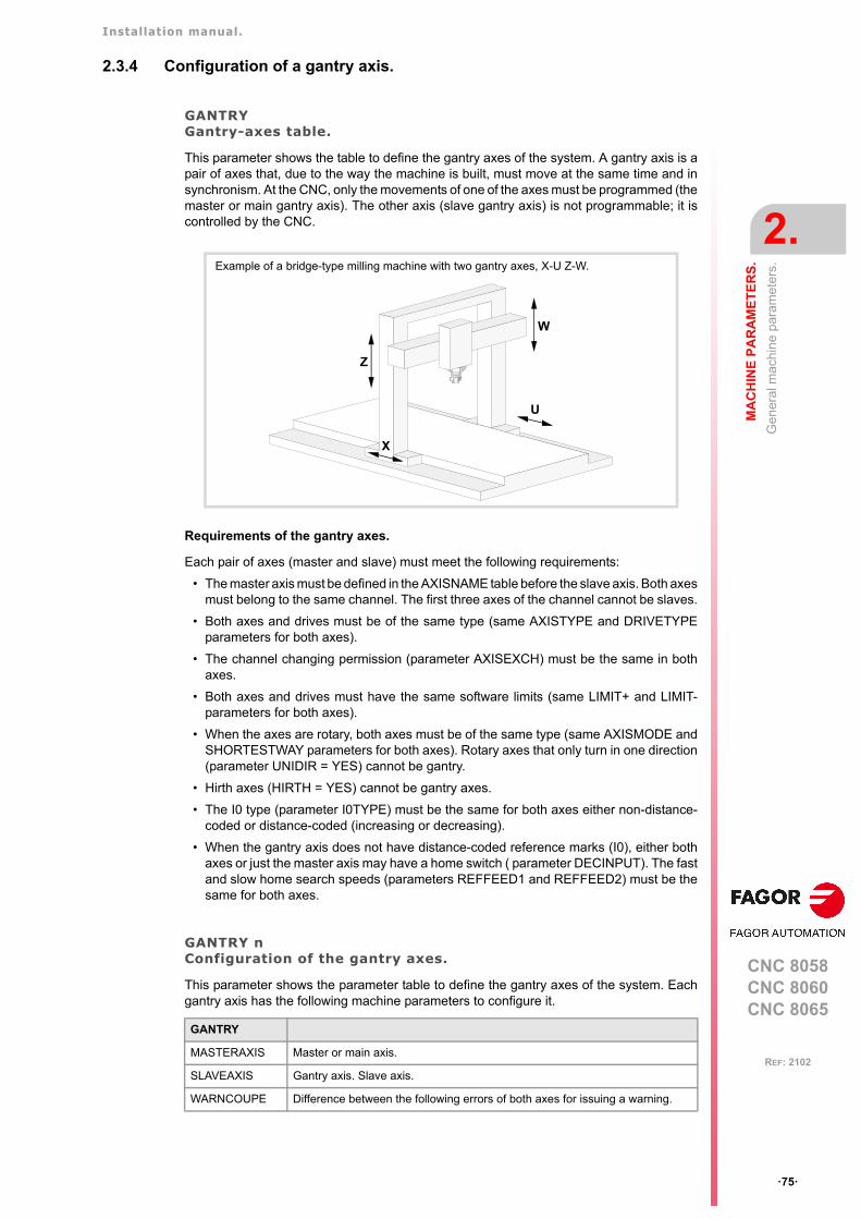
Installation manual.
CNC 8058CNC 8060CNC 8065
MA
CH
INE
PA
RA
ME
TE
RS
.
2.
Gen
eral
mac
hin
e pa
ram
eter
s.
ꞏ75ꞏ
REF: 2102
2.3.4 Configuration of a gantry axis.
GANTRYGantry-axes table.
This parameter shows the table to define the gantry axes of the system. A gantry axis is apair of axes that, due to the way the machine is built, must move at the same time and insynchronism. At the CNC, only the movements of one of the axes must be programmed (themaster or main gantry axis). The other axis (slave gantry axis) is not programmable; it iscontrolled by the CNC.
Requirements of the gantry axes.
Each pair of axes (master and slave) must meet the following requirements:
• The master axis must be defined in the AXISNAME table before the slave axis. Both axesmust belong to the same channel. The first three axes of the channel cannot be slaves.
• Both axes and drives must be of the same type (same AXISTYPE and DRIVETYPEparameters for both axes).
• The channel changing permission (parameter AXISEXCH) must be the same in bothaxes.
• Both axes and drives must have the same software limits (same LIMIT+ and LIMIT-parameters for both axes).
• When the axes are rotary, both axes must be of the same type (same AXISMODE andSHORTESTWAY parameters for both axes). Rotary axes that only turn in one direction(parameter UNIDIR = YES) cannot be gantry.
• Hirth axes (HIRTH = YES) cannot be gantry axes.
• The I0 type (parameter I0TYPE) must be the same for both axes either non-distance-coded or distance-coded (increasing or decreasing).
• When the gantry axis does not have distance-coded reference marks (I0), either bothaxes or just the master axis may have a home switch ( parameter DECINPUT). The fastand slow home search speeds (parameters REFFEED1 and REFFEED2) must be thesame for both axes.
GANTRY nConfiguration of the gantry axes.
This parameter shows the parameter table to define the gantry axes of the system. Eachgantry axis has the following machine parameters to configure it.
Example of a bridge-type milling machine with two gantry axes, X-U Z-W.
GANTRY
MASTERAXIS Master or main axis.
SLAVEAXIS Gantry axis. Slave axis.
WARNCOUPE Difference between the following errors of both axes for issuing a warning.
Z
X
U
W
Installation manual.
CNC 8058CNC 8060CNC 8065
2.
MA
CH
INE
PA
RA
ME
TE
RS
.
Gen
eral
mac
hin
e pa
ram
eter
s.
ꞏ76ꞏ
REF: 2102
MASTERAXISGantry axis. Master or main axis.Possible values: Any axes defined in AXISNAME.Associated variable: (V.)MPG.MASTERAXIS[nb]Parameter included in the GANTRY table.
This parameter sets which is the master axis of the gantry pair.
SLAVEAXISGantry axis. Slave axis.Possible values: Any axes defined in AXISNAME.Associated variable: (V.)MPG.SLAVEAXIS[nb]Parameter included in the GANTRY table.
This parameter sets which is the slave axis of the gantry pair.
WARNCOUPEGantry axis. Difference between the following errors of both axes for issuing a warning.Possible values: From 0.0001 to 99999.9999 mm.Possible values: From 0 to 3937.00787 inch.Possible values: From 0.0001 to 99999.9999 degrees.Default value: 1.0000 mm / 0.03937 inch / 1.0000 degree.Associated variable: (V.)MPG.WARNCOUPE[nb]Parameter included in the GANTRY table.
This parameter sets the maximum difference allowed between the following errors of bothaxes before issuing a warning. This warning lets the user act upon the machine before theCNC issues the error.
The value of parameter WARNCOUPE must be lower than that of parameter MAXCOUPE.
MAXCOUPEGantry axis. Maximum difference allowed between the following errors of both axes.Possible values: From 0.0001 to 99999.9999 mm.Possible values: From 0 to 3937.00787 inch.Possible values: From 0.0001 to 99999.9999 degrees.Default value: 1.0000 mm / 0.03937 inch / 1.0000 degree.Associated variable: (V.)MPG.MAXCOUPE[nb]Parameter included in the GANTRY table.
This parameter indicates the maximum difference allowed between the following errors ofboth axes. If the difference exceeds this value, the CNC will display an error message.
DIFFCOMPGantry axis. Compensate for the coordinate (position) difference between the two axes after G74.Possible values: Yes / No.Default value: Yes.Associated variable: (V.)MPG.DIFFCOMP[nb]Parameter included in the GANTRY table.
This parameter enables the correction of the position difference between the master and theslave axes after homing. The correction of the position difference is applied using the markDIFFCOMP(axis).
MAXCOUPE Difference between the following errors of both axes for issuing a warning.
DIFFCOMP Compensate for the coordinate (position) difference between the two axes afterG74.
MAXDIFF Maximum position value (coordinate) difference between both axes tocompensate for.
GANTRY
Installation manual.
CNC 8058CNC 8060CNC 8065
MA
CH
INE
PA
RA
ME
TE
RS
.
2.
Gen
eral
mac
hin
e pa
ram
eter
s.
ꞏ77ꞏ
REF: 2102
To compensate the position value, the slave axis will move until reaching the position of themaster axis at the feedrate set by parameter REFFEED2. This process can only beinterrupted with RESET.
MAXDIFFGantry axis. Maximum position value (coordinate) difference between both axes to compensate for.Possible values: From 0 to 99999.9999 mm.Possible values: From 0 to 3937.00787 inch.Possible values: From 0 to 99999.9999 degrees.Default value: 0.Associated variable: (V.)MPG.MAXDIFF[nb]Parameter included in the GANTRY table.
To avoid correcting coordinate differences that are too big between the master and the slaveaxes, this parameter sets the maximum coordinate difference allowed to be correctedbetween both axes. The CNC will only correct the coordinate difference when it is smallerthan the value set in this parameter.

Installation manual.
CNC 8058CNC 8060CNC 8065
2.
MA
CH
INE
PA
RA
ME
TE
RS
.
Gen
eral
mac
hin
e pa
ram
eter
s.
ꞏ78ꞏ
REF: 2102
2.3.5 Configuration of a multi-axis group.
MULTIAXISTable of multi-axis groups.
A multi-axis group may be used to control several axes with a single drive, controlling oneor more motors. This parameter shows the multi-axis group definition table for defining thenumber of groups of the system and the composition of each group.
Requirements and limitations of a multi-axis group.
The axes associated with the same drive must meet the following requirements.
• Any Sercos axis of the system may be part of a multi-axis group, except those that belongto gantry or tandem axes.
• Since the axes are controlled by the same drive, all the axes of a group must have thesame Sercos address (parameter DRIVEID).
• All the axes of a group must work in the same Sercos operating mode, position or speed,(parameter OPMODEP). If the external feedback (direct feedback) of the axis isconnected to a drive, the axis may be operated in either position-Sercos mode or velocity-Sercos mode (velocity-Sercos mode is recommended). If the external feedback (directfeedback) of the axis is connected to local or remote feedback input, the axis can onlywork in velocity-Sercos mode.
• If the external feedback is local or remote, the CNC homes the axis as if it were analog;the drive does not know that the axis has been homed and does not update its positionvalue, it only receives the velocity command. If the external feedback is connected toanother drive, it will not be possible to home the axis.
• The axis being governed by the drive is selected via PLC (mark SWITCH(axis)). The PLCmust either park the axes not governed by the drive or set them as DRO axes.
• For a multi-axis where the same motor controls several axes, the CNC allows dynamicmanagement of the multi-axis. This type of management consists of activating the axesof the group as they are programmed. To carry out the dynamic management of a multi-axis group, the axes of the group should be configured as dead axes and the DWELL>0parameter defined. The axes use the DWELL parameter as a waiting time before givingan error for not having the SWITCH mark active. The PLC monitors that the ENABLEmark is active in order to engage that axis and activate its mark SWITCH, SERVOON,SPENA and DRENA mark.
• The CNC keeps monitoring (following error, tendency test, etc.) all the axes sharing thedrive even if the axis is not selected.
MULNGROUPNumber of multi-axis groups in the system.Possible values: From 0 to 16.Default value: 0.Associated variable: (V.)MPG.MULNGROUPParameter included in the MULTIAXIS table.
This parameter sets the number of multi-axis groups of the system.
MULTIAXIS
MULNGROUPS Number of multi-axis groups in the system.
GROUP n Multi-axis groups.
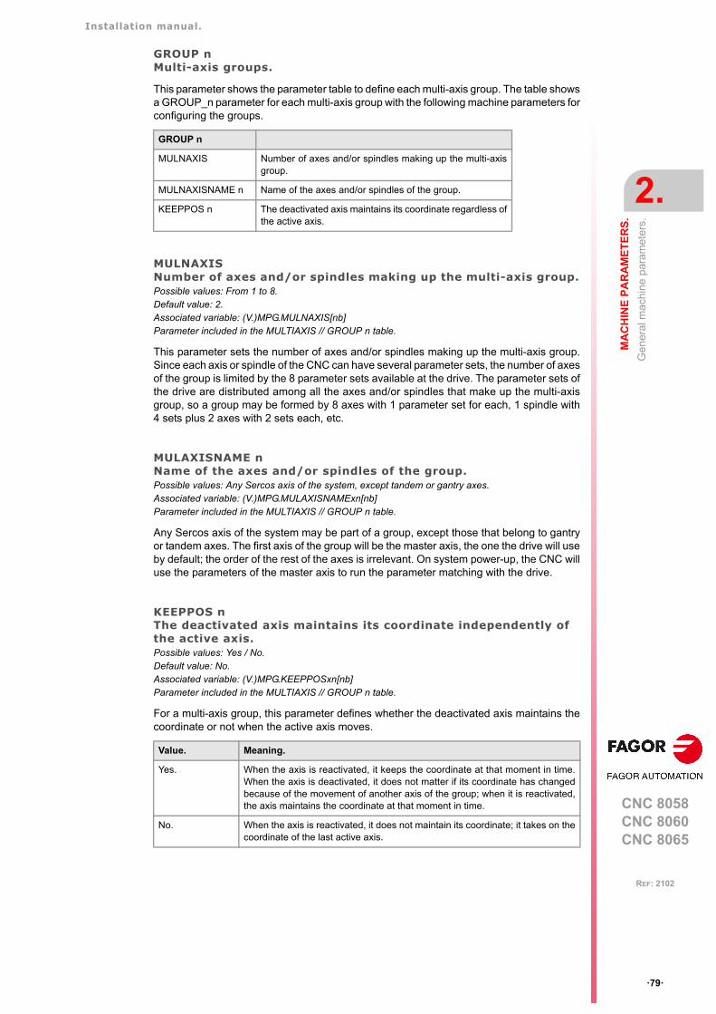
Installation manual.
CNC 8058CNC 8060CNC 8065
MA
CH
INE
PA
RA
ME
TE
RS
.
2.
Gen
eral
mac
hin
e pa
ram
eter
s.
ꞏ79ꞏ
REF: 2102
GROUP nMulti-axis groups.
This parameter shows the parameter table to define each multi-axis group. The table showsa GROUP_n parameter for each multi-axis group with the following machine parameters forconfiguring the groups.
MULNAXISNumber of axes and/or spindles making up the multi-axis group.Possible values: From 1 to 8.Default value: 2.Associated variable: (V.)MPG.MULNAXIS[nb]Parameter included in the MULTIAXIS // GROUP n table.
This parameter sets the number of axes and/or spindles making up the multi-axis group.Since each axis or spindle of the CNC can have several parameter sets, the number of axesof the group is limited by the 8 parameter sets available at the drive. The parameter sets ofthe drive are distributed among all the axes and/or spindles that make up the multi-axisgroup, so a group may be formed by 8 axes with 1 parameter set for each, 1 spindle with4 sets plus 2 axes with 2 sets each, etc.
MULAXISNAME nName of the axes and/or spindles of the group.Possible values: Any Sercos axis of the system, except tandem or gantry axes.Associated variable: (V.)MPG.MULAXISNAMExn[nb]Parameter included in the MULTIAXIS // GROUP n table.
Any Sercos axis of the system may be part of a group, except those that belong to gantryor tandem axes. The first axis of the group will be the master axis, the one the drive will useby default; the order of the rest of the axes is irrelevant. On system power-up, the CNC willuse the parameters of the master axis to run the parameter matching with the drive.
KEEPPOS nThe deactivated axis maintains its coordinate independently of the active axis.Possible values: Yes / No.Default value: No.Associated variable: (V.)MPG.KEEPPOSxn[nb]Parameter included in the MULTIAXIS // GROUP n table.
For a multi-axis group, this parameter defines whether the deactivated axis maintains thecoordinate or not when the active axis moves.
GROUP n
MULNAXIS Number of axes and/or spindles making up the multi-axisgroup.
MULNAXISNAME n Name of the axes and/or spindles of the group.
KEEPPOS n The deactivated axis maintains its coordinate regardless ofthe active axis.
Value. Meaning.
Yes. When the axis is reactivated, it keeps the coordinate at that moment in time.When the axis is deactivated, it does not matter if its coordinate has changedbecause of the movement of another axis of the group; when it is reactivated,the axis maintains the coordinate at that moment in time.
No. When the axis is reactivated, it does not maintain its coordinate; it takes on thecoordinate of the last active axis.
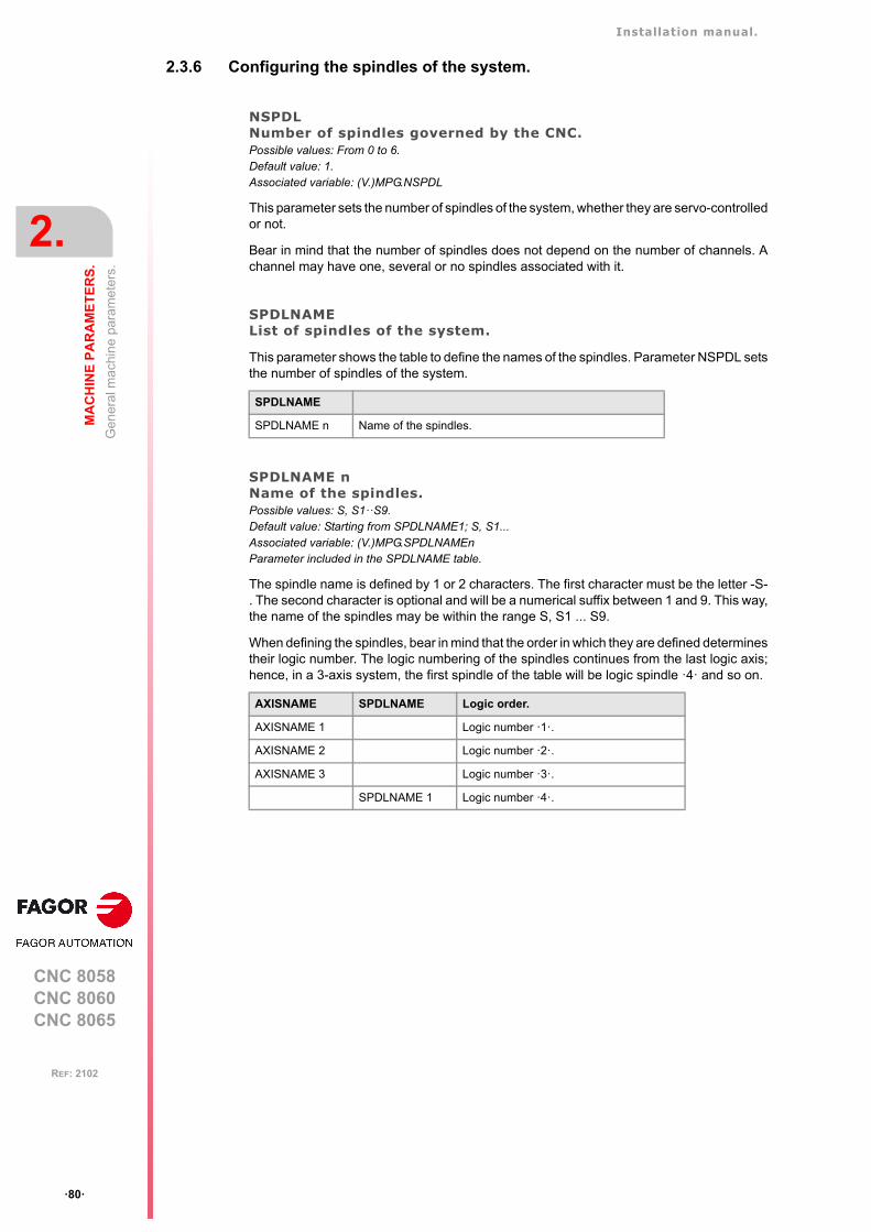
Installation manual.
CNC 8058CNC 8060CNC 8065
2.
MA
CH
INE
PA
RA
ME
TE
RS
.
Gen
eral
mac
hin
e pa
ram
eter
s.
ꞏ80ꞏ
REF: 2102
2.3.6 Configuring the spindles of the system.
NSPDLNumber of spindles governed by the CNC.Possible values: From 0 to 6.Default value: 1.Associated variable: (V.)MPG.NSPDL
This parameter sets the number of spindles of the system, whether they are servo-controlledor not.
Bear in mind that the number of spindles does not depend on the number of channels. Achannel may have one, several or no spindles associated with it.
SPDLNAMEList of spindles of the system.
This parameter shows the table to define the names of the spindles. Parameter NSPDL setsthe number of spindles of the system.
SPDLNAME nName of the spindles.Possible values: S, S1ꞏꞏS9.Default value: Starting from SPDLNAME1; S, S1...Associated variable: (V.)MPG.SPDLNAMEnParameter included in the SPDLNAME table.
The spindle name is defined by 1 or 2 characters. The first character must be the letter -S-. The second character is optional and will be a numerical suffix between 1 and 9. This way,the name of the spindles may be within the range S, S1 ... S9.
When defining the spindles, bear in mind that the order in which they are defined determinestheir logic number. The logic numbering of the spindles continues from the last logic axis;hence, in a 3-axis system, the first spindle of the table will be logic spindle ꞏ4ꞏ and so on.
SPDLNAME
SPDLNAME n Name of the spindles.
AXISNAME SPDLNAME Logic order.
AXISNAME 1 Logic number ꞏ1ꞏ.
AXISNAME 2 Logic number ꞏ2ꞏ.
AXISNAME 3 Logic number ꞏ3ꞏ.
SPDLNAME 1 Logic number ꞏ4ꞏ.
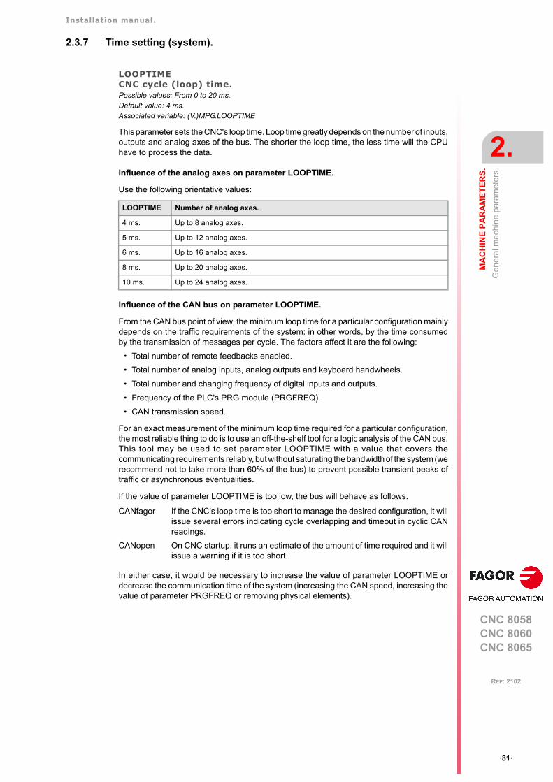
Installation manual.
CNC 8058CNC 8060CNC 8065
MA
CH
INE
PA
RA
ME
TE
RS
.
2.
Gen
eral
mac
hin
e pa
ram
eter
s.
ꞏ81ꞏ
REF: 2102
2.3.7 Time setting (system).
LOOPTIMECNC cycle (loop) time.Possible values: From 0 to 20 ms.Default value: 4 ms.Associated variable: (V.)MPG.LOOPTIME
This parameter sets the CNC's loop time. Loop time greatly depends on the number of inputs,outputs and analog axes of the bus. The shorter the loop time, the less time will the CPUhave to process the data.
Influence of the analog axes on parameter LOOPTIME.
Use the following orientative values:
Influence of the CAN bus on parameter LOOPTIME.
From the CAN bus point of view, the minimum loop time for a particular configuration mainlydepends on the traffic requirements of the system; in other words, by the time consumedby the transmission of messages per cycle. The factors affect it are the following:
• Total number of remote feedbacks enabled.
• Total number of analog inputs, analog outputs and keyboard handwheels.
• Total number and changing frequency of digital inputs and outputs.
• Frequency of the PLC's PRG module (PRGFREQ).
• CAN transmission speed.
For an exact measurement of the minimum loop time required for a particular configuration,the most reliable thing to do is to use an off-the-shelf tool for a logic analysis of the CAN bus.This tool may be used to set parameter LOOPTIME with a value that covers thecommunicating requirements reliably, but without saturating the bandwidth of the system (werecommend not to take more than 60% of the bus) to prevent possible transient peaks oftraffic or asynchronous eventualities.
If the value of parameter LOOPTIME is too low, the bus will behave as follows.
In either case, it would be necessary to increase the value of parameter LOOPTIME ordecrease the communication time of the system (increasing the CAN speed, increasing thevalue of parameter PRGFREQ or removing physical elements).
LOOPTIME Number of analog axes.
4 ms. Up to 8 analog axes.
5 ms. Up to 12 analog axes.
6 ms. Up to 16 analog axes.
8 ms. Up to 20 analog axes.
10 ms. Up to 24 analog axes.
CANfagor If the CNC's loop time is too short to manage the desired configuration, it willissue several errors indicating cycle overlapping and timeout in cyclic CANreadings.
CANopen On CNC startup, it runs an estimate of the amount of time required and it willissue a warning if it is too short.
Installation manual.
CNC 8058CNC 8060CNC 8065
2.
MA
CH
INE
PA
RA
ME
TE
RS
.
Gen
eral
mac
hin
e pa
ram
eter
s.
ꞏ82ꞏ
REF: 2102
PRGFREQFrequency of the PLC's PRG module.Possible values: from 1 to 100 cycles.Default value: 2 cycles.Associated variable: (V.)MPG.PRGFREQ
This parameter indicates how often (every how many CNC cycles) a full cycle of the PLCprogram is executed. This parameter also sets the refreshing frequency of the digital inputsand outputs as well as analog inputs.
Thus, with a sampling period LOOPTIME = 4 ms of and a frequency of PRGFREQ = 2, thePLC program will be executed every 4 x 2 = 8 ms.

Installation manual.
CNC 8058CNC 8060CNC 8065
MA
CH
INE
PA
RA
ME
TE
RS
.
2.
Gen
eral
mac
hin
e pa
ram
eter
s.
ꞏ83ꞏ
REF: 2102
2.3.8 Sercos bus configuration.
SERBRATESercos transmission rate.Possible values: 2/4/8/16 Mbps (megabits per second).Default value: 4 Mbps.Associated variable: (V.)MPG.SERBRATE
This parameter indicates the Sercos transmission speed used when communicating with thedrives and RCS-S modules (Sercos counter). All elements of the Sercos ring must have thesame value.
Speeds of 8 Mbps and 16 Mbps require a Sercos board that can work at these speeds;otherwise the speed will be limited to 2 Mbps and 4 Mbps.
SERPOWSESercos optical power.Possible values: From 1 to 6 ("Sercos I" board) / from 1 to 8 ("Sercos II" board).Default value: 4 ("Sercos I" board) / 2 ("Sercos II" board).Associated variable: (V.)MPG.SERPOWSE
This parameter sets the Sercos power or the intensity of the light going through the optic fiber.The optical power value depends on the total length of the cable being used. Set thisparameter with the same value used by the drives.
Use the following approximate values. Assigning other values, e.g. a value of 6 for a lengthof 3 m, can cause communication errors due to fiber optic signal distortion.
Recommended values ("Sercos I" board).
Recommended values ("Sercos II" board).
Sercos communication at 8 and 16 MHz requires a drive version V6.05 or higher.i
SERPOWSE Cable length.
2 Less than 7 meters.
4 From 7 to 15 meters.
6 More than 15 meters.
SERPOWSE Cable length. Recommended cable type.
1 to 4 Less than 15 meters. SFO / SFO-FLEX
5 to 6 From 15 to 30 meters. SFO-FLEX
7 From 30 to 40 meters. SFO-FLEX
8 More than 40 meters. SFO-V-FLEX

Installation manual.
CNC 8058CNC 8060CNC 8065
2.
MA
CH
INE
PA
RA
ME
TE
RS
.
Gen
eral
mac
hin
e pa
ram
eter
s.
ꞏ84ꞏ
REF: 2102
2.3.9 Mechatrolink bus configuration.
MLINKMechatrolink mode.Possible values: No / Mlink-I / Mlink-II.Default value: No.Associated variable: (V.)MPG.MLINK
This parameter may be used to set the Mechatrolink bus in either Mlink-I mode or Mlink-IImode. All the elements of the bus must be operating in the same mode (Mlink-I or Mlink-II);therefore, the selection will be conditioned by the mode available at the slaves connectedto the bus.
Limitations of a system with a Mechatrolink bus.
• The CNC does not run any parameter matching process with Mechatrolink drives. Theparameters of the drive must be set with the assistance of external tools provided by thedrive manufacturer, through the interface of the device itself or writing the parametersfrom the DDSSetup and Tuning modes of the CNC.
• Second feedback cannot be used; therefore, the feedbacks cannot be combined(parameter FBMIXTIME) or swapped (parameter FBACKSRC). No configuration similarto semi-Sercos is possible either.
• Tandem axes or spindles are not possible.
• Axes or spindles cannot be parked.
• Bode is not available.
• Set changing is not possible.
• The coordinate cannot be initialized.
• The dynamic changing of feed forward, AC forward and Kv will depend on the devicesconnected to the bus.
DATASIZETelegram size in Mlink-II mode.Possible values: 17 / 32 bytes.Default value: 32 bytes.Associated variable: (V.)MPG.DATASIZE
This parameter sets the telegram size for the Mlink-II mode. All the elements of the bus mustbe operating with the same telegram size; therefore, the selection will be conditioned by theproperties of the slaves connected to the bus.
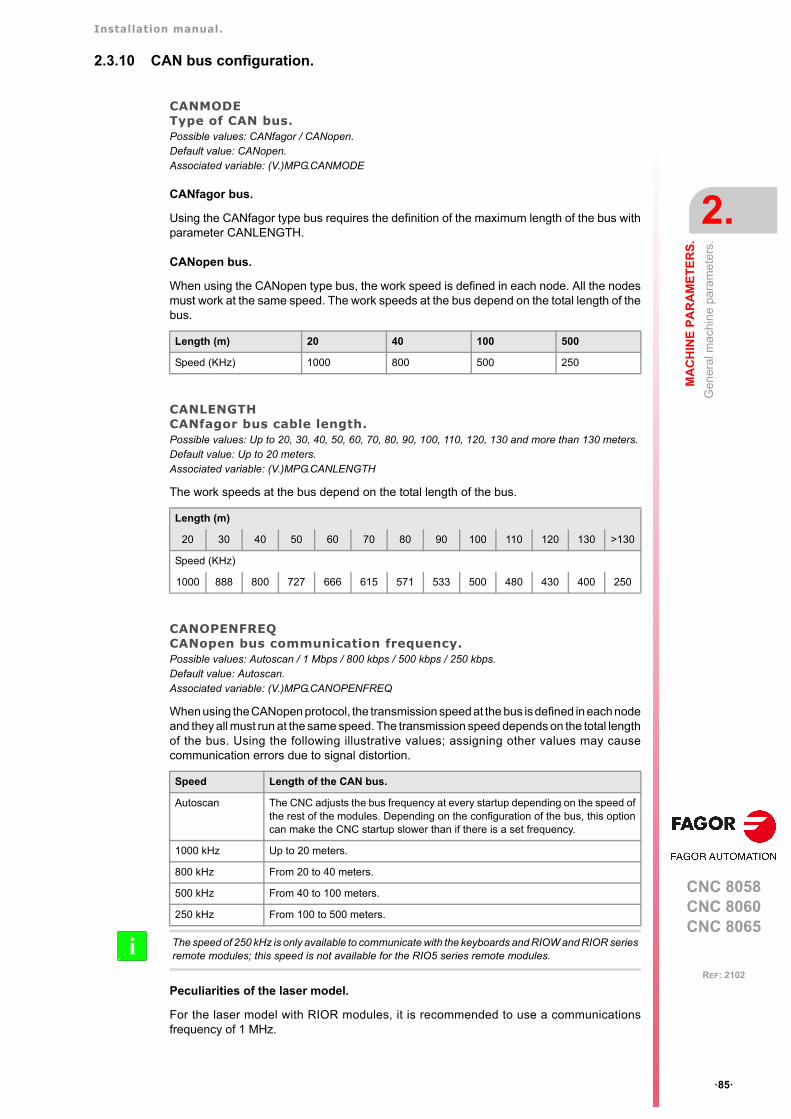
Installation manual.
CNC 8058CNC 8060CNC 8065
MA
CH
INE
PA
RA
ME
TE
RS
.
2.
Gen
eral
mac
hin
e pa
ram
eter
s.
ꞏ85ꞏ
REF: 2102
2.3.10 CAN bus configuration.
CANMODEType of CAN bus.Possible values: CANfagor / CANopen.Default value: CANopen.Associated variable: (V.)MPG.CANMODE
CANfagor bus.
Using the CANfagor type bus requires the definition of the maximum length of the bus withparameter CANLENGTH.
CANopen bus.
When using the CANopen type bus, the work speed is defined in each node. All the nodesmust work at the same speed. The work speeds at the bus depend on the total length of thebus.
CANLENGTHCANfagor bus cable length.Possible values: Up to 20, 30, 40, 50, 60, 70, 80, 90, 100, 110, 120, 130 and more than 130 meters.Default value: Up to 20 meters.Associated variable: (V.)MPG.CANLENGTH
The work speeds at the bus depend on the total length of the bus.
CANOPENFREQCANopen bus communication frequency.Possible values: Autoscan / 1 Mbps / 800 kbps / 500 kbps / 250 kbps.Default value: Autoscan.Associated variable: (V.)MPG.CANOPENFREQ
When using the CANopen protocol, the transmission speed at the bus is defined in each nodeand they all must run at the same speed. The transmission speed depends on the total lengthof the bus. Using the following illustrative values; assigning other values may causecommunication errors due to signal distortion.
Peculiarities of the laser model.
For the laser model with RIOR modules, it is recommended to use a communicationsfrequency of 1 MHz.
Length (m) 20 40 100 500
Speed (KHz) 1000 800 500 250
Length (m)
20 30 40 50 60 70 80 90 100 110 120 130 >130
Speed (KHz)
1000 888 800 727 666 615 571 533 500 480 430 400 250
Speed Length of the CAN bus.
Autoscan The CNC adjusts the bus frequency at every startup depending on the speed ofthe rest of the modules. Depending on the configuration of the bus, this optioncan make the CNC startup slower than if there is a set frequency.
1000 kHz Up to 20 meters.
800 kHz From 20 to 40 meters.
500 kHz From 40 to 100 meters.
250 kHz From 100 to 500 meters.
The speed of 250 kHz is only available to communicate with the keyboards and RIOW and RIOR seriesremote modules; this speed is not available for the RIO5 series remote modules. i
Installation manual.
CNC 8058CNC 8060CNC 8065
2.
MA
CH
INE
PA
RA
ME
TE
RS
.
Gen
eral
mac
hin
e pa
ram
eter
s.
ꞏ86ꞏ
REF: 2102
2.3.11 Serial line configuration.
RSTYPEType of serial line.Possible values: RS232 / RS485 / RS422.Default value: RS232.Associated variable: (V.)MPG.RSTYPE
Type of serial line. Standard configuration for RS232 and full-duplex configuration for RS422.For the HBLS (portable operator panel) select RS422.
In the RS485, the CNC uses the same signal to control "send data" and "receive data", thereforesending is disabled while receiving. In order to ensure proper communication, an 8-ms delay is requiredfrom when the CNC stops sending till it is ready to receive data. At the slaves connected to the CNC,this delay time must be set from when data is received till it is sent. An external RS232/RS485 adaptershould be used if this delay cannot be set at the slave.
i

Installation manual.
CNC 8058CNC 8060CNC 8065
MA
CH
INE
PA
RA
ME
TE
RS
.
2.
Gen
eral
mac
hin
e pa
ram
eter
s.
ꞏ87ꞏ
REF: 2102
2.3.12 MODBUS.
MODBUSConfigure the ModBUS server.
This parameter shows the table to configure the ModBus server.
MODBUSSVRTCPActivate the ModBUS sever on TCP.Possible values: Yes / No.Default value: No.Associated variable: (V.)MPG.MODBUSSVRTCPParameter included in the MODBUS table.
Activate the ModBUS sever on TCP.
MODBUSSVRRSActivate the ModBUS sever on RS485.Possible values: Yes / No.Default value: No.Associated variable: (V.)MPG.MODBUSSVRRSParameter included in the MODBUS table.
Activate the ModBUS sever on RS485.
MODSVRIDIdentifier of the ModBUS sever on RS485.Possible values: From 1 to 255.Default value: 1.Associated variable: (V.)MPG.MODSVRIDParameter included in the MODBUS table.
Identifier of the ModBUS sever on RS485.
MODBRATECommunication speed of the ModBUS sever on RS485.Possible values: 19200 Bd / 38400 Bd / 57600 Bd / 115200 Bd.Default value: 19200 Bd.Associated variable: (V.)MPG.MODBRATEParameter included in the MODBUS table.
Communication speed of the ModBUS sever on RS485.
MODBUS
MODBUSSVRTCP Activate the ModBUS sever on TCP.
MODBUSSVRRS Activate the ModBUS sever on RS485.
MODSVRID Identifier of the ModBUS sever on RS485.
MODBRATE Communication speed of the ModBUS sever on RS485.
Installation manual.
CNC 8058CNC 8060CNC 8065
2.
MA
CH
INE
PA
RA
ME
TE
RS
.
Gen
eral
mac
hin
e pa
ram
eter
s.
ꞏ88ꞏ
REF: 2102
2.3.13 Bus EtherCAT bus.
ETHERCATBUSActivate EtherCAT bus.Possible values: Yes / No.Default value: No.Associated variable: (V.)MPG.ETHERCATBUS
Activate EtherCAT bus.
2.3.14 Default conditions (sytem).
INCHESDefault work units (millimeters, inch).Possible values: Millimeters / inches.Default value: Millimeters.Associated variable: (V.)MPG.INCHES
This parameter indicates the work units assumed by the CNC by default; i.e. on power-up,after executing an M02 or M30 or after a reset. To change the units from the part-program,use function G70 or G71.
PRESSUREDefault pressure units.Possible values: Bar / Psi.Default value: Bar.Associated variable: (V.)MPG.PRESSURE
This parameter indicates the work units assumed by the CNC by default; i.e. on power-up,after executing an M02 or M30 or after a reset.
Installation manual.
CNC 8058CNC 8060CNC 8065
MA
CH
INE
PA
RA
ME
TE
RS
.
2.
Gen
eral
mac
hin
e pa
ram
eter
s.
ꞏ89ꞏ
REF: 2102
2.3.15 Arithmetic parameters.
MAXLOCPMaximum local arithmetic parameter.Possible values: From 0 to 99.Default value: 25.Associated variable: (V.)MPG.MAXLOCP
See general machine parameter MINLOCP.
MINLOCPMinimum local arithmetic parameter.Possible values: From 0 to 99.Default value: 0.Associated variable: (V.)MPG.MINLOCP
Parameters MINLOCP and MAXLOCP define the group of local arithmetic parameters to beused. Local parameters may only be accessed from the program or subroutine where theyhave been programmed. There are seven groups of local parameters in each channel.
MAXGLBPMaximum global arithmetic parameter.Possible values: From 100 to 9999.Default value: 299.Associated variable: (V.)MPG.MAXGLBP
Check general machine parameter MINGLBP.
MINGLBPMinimum global arithmetic parameter.Possible values: From 100 to 9999.Default value: 100.Associated variable: (V.)MPG.MINGLBP
Parameters MAXGLBP and MINGLBP define the group of global arithmetic parameters tobe used. Global parameters may be accessed from any program or subroutine called uponfrom the channel. There is a group of global parameters in each channel. The value of theseparameters is shared by the program and the subroutines.
ROPARMAXMaximum global read-only arithmetic parameter.Possible values: From 100 to 9999.Default value: 0.Associated variable: (V.)MPG.ROPARMAX
See general machine parameter ROPARMIN.
ROPARMINMinimum global read-only arithmetic parameter.Possible values: From 100 to 9999.Default value: 0.Associated variable: (V.)MPG.ROPARMIN
Parameters ROPARMAX and ROPARMIN may be used to protect a group of globalarithmetic parameters so they cannot be modified. If both parameters are set to "0", therewill be no protected parameters.
MAXCOMPMaximum arithmetic parameter common to all the channels.Possible values: From 10000 to 19999.Default value: 10025.Associated variable: (V.)MPG.MAXCOMP
Check general machine parameter MINCOMP.
Installation manual.
CNC 8058CNC 8060CNC 8065
2.
MA
CH
INE
PA
RA
ME
TE
RS
.
Gen
eral
mac
hin
e pa
ram
eter
s.
ꞏ90ꞏ
REF: 2102
MINCOMPMinimum arithmetic parameter common to all the channels.Possible values: From 10000 to 19999.Default value: 10000.Associated variable: (V.)MPG.MINCOMP
Parameters MAXCOMP and MINCOMP the group of local arithmetic parameters commonto all the channels to be used. The common parameters may be accessed from any channel.The value of these parameters is shared by all the channels.
BKUPCUPNumber of common non-volatile arithmetic parameters.Possible values: From 0 to 20.Default value: 0.Associated variable: (V.)MPG.BKUPCUP
This parameter indicates the number of common arithmetic parameters that are saved inRAM memory with a battery. The CNC saves the first parameters, from the first one to theone set in this parameter.
Non-volatile data means that their values must be maintained from one session to anotherand after turning the CNC off. The CNC saves this data when the CNC is turned off, whenpower is removed, when a hardware error occurs, etc.
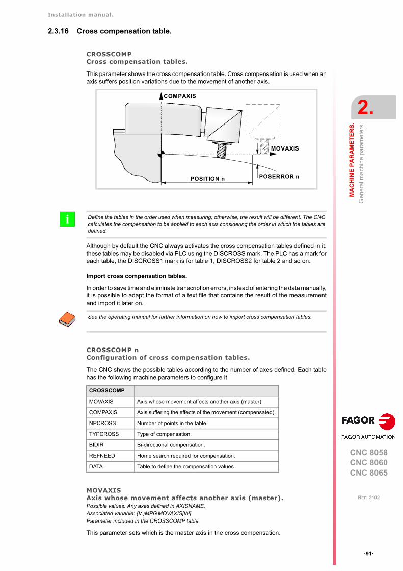
Installation manual.
CNC 8058CNC 8060CNC 8065
MA
CH
INE
PA
RA
ME
TE
RS
.
2.
Gen
eral
mac
hin
e pa
ram
eter
s.
ꞏ91ꞏ
REF: 2102
2.3.16 Cross compensation table.
CROSSCOMPCross compensation tables.
This parameter shows the cross compensation table. Cross compensation is used when anaxis suffers position variations due to the movement of another axis.
Although by default the CNC always activates the cross compensation tables defined in it,these tables may be disabled via PLC using the DISCROSS mark. The PLC has a mark foreach table, the DISCROSS1 mark is for table 1, DISCROSS2 for table 2 and so on.
Import cross compensation tables.
In order to save time and eliminate transcription errors, instead of entering the data manually,it is possible to adapt the format of a text file that contains the result of the measurementand import it later on.
CROSSCOMP nConfiguration of cross compensation tables.
The CNC shows the possible tables according to the number of axes defined. Each tablehas the following machine parameters to configure it.
MOVAXISAxis whose movement affects another axis (master).Possible values: Any axes defined in AXISNAME.Associated variable: (V.)MPG.MOVAXIS[tbl]Parameter included in the CROSSCOMP table.
This parameter sets which is the master axis in the cross compensation.
MOVAXIS
COMPAXIS
POSITION n POSERROR n
Define the tables in the order used when measuring; otherwise, the result will be different. The CNCcalculates the compensation to be applied to each axis considering the order in which the tables aredefined.
i
See the operating manual for further information on how to import cross compensation tables.
CROSSCOMP
MOVAXIS Axis whose movement affects another axis (master).
COMPAXIS Axis suffering the effects of the movement (compensated).
NPCROSS Number of points in the table.
TYPCROSS Type of compensation.
BIDIR Bi-directional compensation.
REFNEED Home search required for compensation.
DATA Table to define the compensation values.
Installation manual.
CNC 8058CNC 8060CNC 8065
2.
MA
CH
INE
PA
RA
ME
TE
RS
.
Gen
eral
mac
hin
e pa
ram
eter
s.
ꞏ92ꞏ
REF: 2102
COMPAXISAxis suffering the effects of the movement (compensated).Possible values: Any axes defined in AXISNAME.Associated variable: (V.)MPG.COMPAXIS[tbl]Parameter included in the CROSSCOMP table.
This parameter sets which is the compensated axis in the cross compensation.
NPCROSSNumber of points in the table.Possible values: From 0 to 1000.Default value: 0 (there is no table).Associated variable: (V.)MPG.NPCROSS[tbl]Parameter included in the CROSSCOMP table.
Each cross compensation table can have up to 1000 points.
TYPCROSSType of compensation (type of coordinates).Possible values: Real / Theoretical.Default value: Real.Associated variable: (V.)MPG.TYPCROSS[tbl]Parameter included in the CROSSCOMP table.
This parameter determines whether the cross compensation will be applied on to theoreticalor real coordinates.
BIDIRBi-directional compensation.Possible values: Yes / No.Default value: No.Associated variable: (V.)MPG.BIDIR[tbl]Parameter included in the CROSSCOMP table.
This parameter indicates whether the compensation is bidirectional or not; i.e. if thecompensation is different in each direction. If the compensation is not bidirectional, it appliesthe same compensation in both directions.
REFNEEDHome search required for compensation.Possible values: Yes / No.Default value: No.Associated variable: (V.)MPG.REFNEED[tbl]Parameter included in the CROSSCOMP table.
This parameter indicates whether both axes must be homed or not before applying thecompensation.
DATATable to define the compensation values.
This parameter shows the list of compensation points and values. The CNC only lets accessthis table when parameters are MOVAXIS, COMPAXIS and NPCROSS set.
The DATA table must indicate the amount of error to be compensated in specific positionsof the moving axis. The number of points is set by parameter NPCROSS. ParametersPOSITION, POSERROR and NEGERROR must be set for each point. ParameterNEGERROR only if the table has been defined with bidirectional compensation (BIDIR =YES).
CROSSCOMPDATA
POSITION Position of the master axis.
POSERROR Amount of error to compensate when moving in the positive direction.
NEGERROR Amount of error to compensate when moving in the negative direction.
Installation manual.
CNC 8058CNC 8060CNC 8065
MA
CH
INE
PA
RA
ME
TE
RS
.
2.
Gen
eral
mac
hin
e pa
ram
eter
s.
ꞏ93ꞏ
REF: 2102
POSITIONPosition of the master axis.Possible values (1): Within ±99999.9999 mm.Possible values (2): Within ±3937.00787 inch.Possible values (3): Within ±99999.9999 degrees.Default value: 0.Associated variable: (V.)MPG.POSITION[tbl][pt]Parameter included in the CROSSCOMP // DATA table.
This parameter sets the position of the master axis in each point of the compensation. Thepoints of the table must be ordered by their position on the axis and the table must beginby the most negative point (or least positive) to be compensated. For axis positioning outsidethis area, the CNC will apply the compensation that was defined for the nearest end.
POSERRORAmount of error to compensate when moving in the positive direction.Possible values (1): Within ±99999.9999 mm.Possible values (2): Within ±3937.00787 inch.Possible values (3): Within ±99999.9999 degrees.Default value: 0.Associated variable: (V.)MPG.POSERROR[tbl][pt]Parameter included in the CROSSCOMP // DATA table.
This parameter indicates the amount of error on the compensated axis when the master axismoves in the positive direction. If the table has not been defined with bi-directionalcompensation, this amount of error will also be applied on movements in the negativedirection.
The machine reference point must have "0" error.
NEGERRORAmount of error to compensate when moving in the negative direction.Possible values (1): Within ±99999.9999 mm.Possible values (2): Within ±3937.00787 inch.Possible values (3): Within ±99999.9999 degrees.Default value: 0.Associated variable: (V.)MPG.NEGERROR[tbl][pt]Parameter included in the CROSSCOMP // DATA table.
This parameter indicates the amount of error on the compensated axis when the master axismoves in the negative direction. This compensation is only available if the table has beendefined with bidirectional compensation.
The machine reference point must have "0" error.
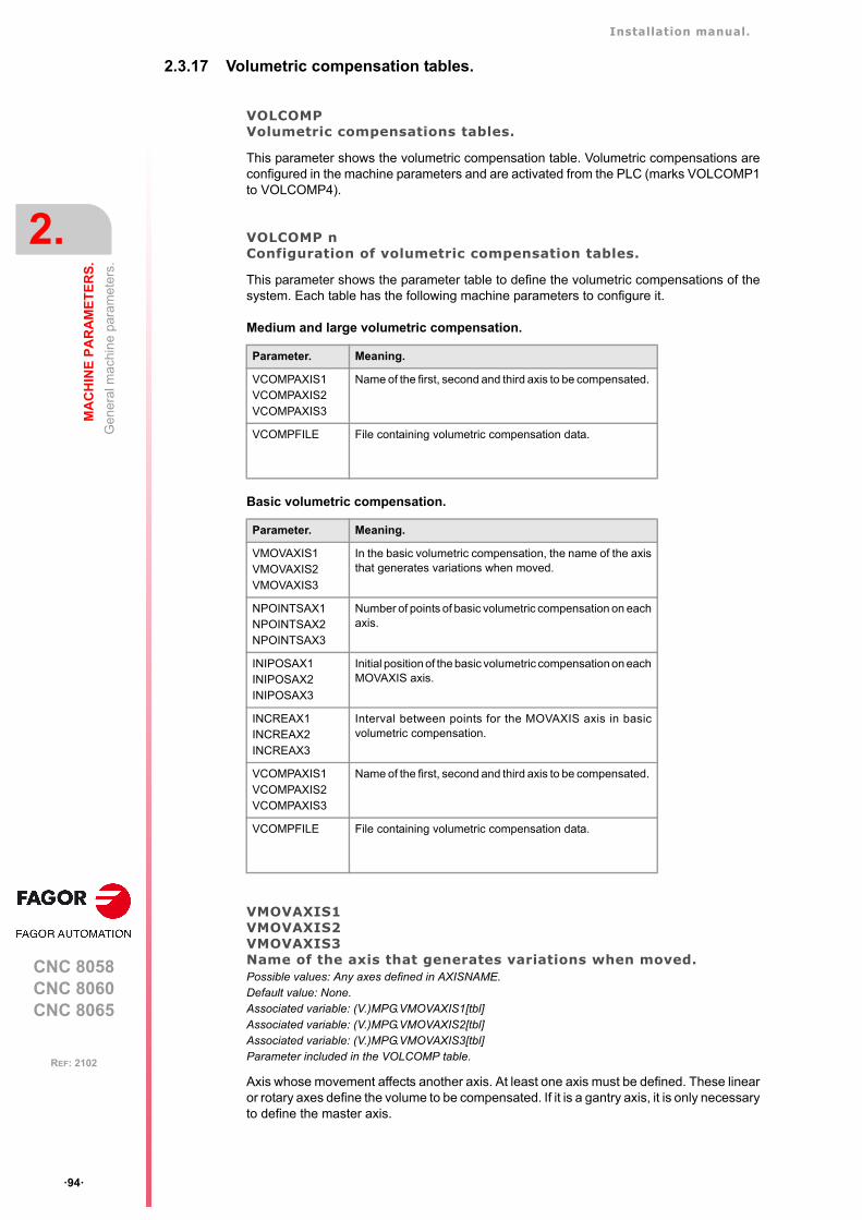
Installation manual.
CNC 8058CNC 8060CNC 8065
2.
MA
CH
INE
PA
RA
ME
TE
RS
.
Gen
eral
mac
hin
e pa
ram
eter
s.
ꞏ94ꞏ
REF: 2102
2.3.17 Volumetric compensation tables.
VOLCOMPVolumetric compensations tables.
This parameter shows the volumetric compensation table. Volumetric compensations areconfigured in the machine parameters and are activated from the PLC (marks VOLCOMP1to VOLCOMP4).
VOLCOMP nConfiguration of volumetric compensation tables.
This parameter shows the parameter table to define the volumetric compensations of thesystem. Each table has the following machine parameters to configure it.
Medium and large volumetric compensation.
Basic volumetric compensation.
VMOVAXIS1VMOVAXIS2VMOVAXIS3Name of the axis that generates variations when moved.Possible values: Any axes defined in AXISNAME.Default value: None.Associated variable: (V.)MPG.VMOVAXIS1[tbl]Associated variable: (V.)MPG.VMOVAXIS2[tbl]Associated variable: (V.)MPG.VMOVAXIS3[tbl]Parameter included in the VOLCOMP table.
Axis whose movement affects another axis. At least one axis must be defined. These linearor rotary axes define the volume to be compensated. If it is a gantry axis, it is only necessaryto define the master axis.
Parameter. Meaning.
VCOMPAXIS1VCOMPAXIS2VCOMPAXIS3
Name of the first, second and third axis to be compensated.
VCOMPFILE File containing volumetric compensation data.
Parameter. Meaning.
VMOVAXIS1VMOVAXIS2VMOVAXIS3
In the basic volumetric compensation, the name of the axisthat generates variations when moved.
NPOINTSAX1NPOINTSAX2NPOINTSAX3
Number of points of basic volumetric compensation on eachaxis.
INIPOSAX1INIPOSAX2INIPOSAX3
Initial position of the basic volumetric compensation on eachMOVAXIS axis.
INCREAX1INCREAX2INCREAX3
Interval between points for the MOVAXIS axis in basicvolumetric compensation.
VCOMPAXIS1VCOMPAXIS2VCOMPAXIS3
Name of the first, second and third axis to be compensated.
VCOMPFILE File containing volumetric compensation data.
Installation manual.
CNC 8058CNC 8060CNC 8065
MA
CH
INE
PA
RA
ME
TE
RS
.
2.
Gen
eral
mac
hin
e pa
ram
eter
s.
ꞏ95ꞏ
REF: 2102
These parameters are only available for basic volumetric compensation; they have nofunction in medium and large volumetric compensations, where the order of the axes isimplicit in the file. The CNC displays these parameters when loading a file with the extensioncsv in the parameter VCOMPFILE.
NPOINTSAX1NPOINTSAX2NPOINTSAX3Number of points of the basic volumetric compensation for the MOVAXIS axis.Possible values: From 2 to 1000 points.Default value: 10 points.Associated variable: (V.)MPG.NPOINTSAX1[tbl]Associated variable: (V.)MPG.NPOINTSAX2[tbl]Associated variable: (V.)MPG.NPOINTSAX3[tbl]Parameter included in the VOLCOMP table.
Number of points that define the volume to be compensated for each axis. The total numberof points for the volume is limited to 15,625, and is calculated in the following manner:NPOINTSAX1 × NPOINTSAX2 × NPOINTSAX3. The total number of points for the volumecan be distributed among all the axes, up to a maximum of 1000 points per axis.
These parameters are only available for basic volumetric compensation; they have nofunction in medium and large volumetric compensations. The CNC displays theseparameters when loading a file with the extension csv in the parameter VCOMPFILE.
INIPOSAX1INIPOSAX2INIPOSAX3Initial position of the basic volumetric compensation for the MOVAXIS axis.Possible values: Within ±99999.9999 mm / Within ±3937.00787 inch.Default value: 0.Associated variable: (V.)MPG.INIPOSAX1[tbl]Associated variable: (V.)MPG.INIPOSAX2[tbl]Associated variable: (V.)MPG.INIPOSAX3[tbl]Parameter included in the VOLCOMP table.
Initial position of the basic volumetric compensation for the MOVAXIS axis.
These parameters are only available for basic volumetric compensation; they have nofunction in medium and large volumetric compensations. The CNC displays theseparameters when loading a file with the extension csv in the parameter VCOMPFILE.
INCREAX1INCREAX2INCREAX3Interval between points for the MOVAXIS axis in basic volumetric compensation.Possible values: Within ±99999.9999 mm / Within ±3937.00787 inch.Default value: 10 mm / 0.3937 inch.Associated variable: (V.)MPG.INCREAX1[tbl]Associated variable: (V.)MPG.INCREAX2[tbl]Associated variable: (V.)MPG.INCREAX3[tbl]Parameter included in the VOLCOMP table.
Interval between points for the MOVAXIS axis in basic volumetric compensation.
These parameters are only available for basic volumetric compensation; they have nofunction in medium and large volumetric compensations. The CNC displays theseparameters when loading a file with the extension csv in the parameter VCOMPFILE.
Installation manual.
CNC 8058CNC 8060CNC 8065
2.
MA
CH
INE
PA
RA
ME
TE
RS
.
Gen
eral
mac
hin
e pa
ram
eter
s.
ꞏ96ꞏ
REF: 2102
VCOMPAXIS1VCOMPAXIS2VCOMPAXIS3Name of the axis to be compensated.Possible values: Any axes defined in AXISNAME.Default value: None.Associated variable: (V.)MPG.VCOMPAXIS1[tbl]Associated variable: (V.)MPG.VCOMPAXIS2[tbl]Associated variable: (V.)MPG.VCOMPAXIS3[tbl]Parameter included in the VOLCOMP table.
These parameters set the axes to be compensated with volumetric compensation. The axesmay be linear or rotary, and at least one axis must be defined. The axes associated with thesame compensation may belong to different channels and they may be interchanged fromone channel to another while the compensation is active. An axis can be included in severaldifferent compensations, but compensations that share axes cannot be active at the sametime. If it is a gantry axis, it is only necessary to define the master axis; the CNC also appliesthe compensation to the slave axis.
VCOMPFILEFile containing volumetric compensation data.Associated variable: (V.)MPG.VCOMPFILE[tbl]Parameter included in the VOLCOMP table.
Medium and large volumetric compensation.
The compensation tables are generated by the calibration application; they are not editablefrom the CNC. The units in the file data (millimeters or inches) must be those defined by theCNC (parameter INCHES).
Basic volumetric compensation.
The data to be compensated must be a text file (in csv format). The OEM or the companyresponsible for the calibration must generate this file and define it in the machine parameterVCOMPFILE. The units in the file data (millimeters or inches) must be those defined by theCNC (parameter INCHES).
Installation manual.
CNC 8058CNC 8060CNC 8065
MA
CH
INE
PA
RA
ME
TE
RS
.
2.
Gen
eral
mac
hin
e pa
ram
eter
s.
ꞏ97ꞏ
REF: 2102
2.3.18 Execution times.
MINAENDWMinimum duration of the AUXEND signal.Possible values: From 0 to 65535 ms.Default value: 10 ms.Associated variable: (V.)MPG.MINAENDW
This parameter has the following meanings.
• This parameter sets the time that the AUXEND signal must stay active for the CNC toconsider it a valid signal. AUXEND is the synchronization signal that the PLC sends tothe CNC to indicate that the –M–, –S–, –T– functions have been executed.
• For –M– functions (which do not need synchronization), this parameter indicates theduration of the MSTROBE signal.
• For –H– functions (which do not need synchronization), this parameter indicates theduration of the HSTROBE signal.
The value assigned to this parameter must be equal to or greater than the PLC's inputfrequency (LOOPTIME x PRGFREQ).
REFTIMEEstimated home searching time.Possible values: From 0 to 1000000 ms.Default value: 0. ms.Associated variable: (V.)MPG.REFTIME
See general machine parameter TTIME.
HTIMEEstimated time for an H function.Possible values: From 0 to 1000000 ms.Default value: 0. ms.Associated variable: (V.)MPG.HTIME
See general machine parameter TTIME.
DTIMEEstimated time for a D function.Possible values: From 0 to 1000000 ms.Default value: 0. ms.Associated variable: (V.)MPG.DTIME
See general machine parameter TTIME.
TTIMEEstimated time for a T function.Possible values: From 0 to 1000000 ms.Default value: 0. ms.Associated variable: (V.)MPG.TTIME
In Editing - Simulation mode, there is an option that allows calculating the time required toexecute a part with the machining conditions established in the program. To fine tune thatcalculation, one may define these parameters that indicate the estimated time for processingparticular functions.
The values are generic, for any H, D, T function or for homing one or several axes at a time.Spindle machine parameter SPDLTIME indicates the estimated time for executing an Sfunction and the machine parameter of the M function table –M– MTIME indicates the timeestimated to execute an M function.
Installation manual.
CNC 8058CNC 8060CNC 8065
2.
MA
CH
INE
PA
RA
ME
TE
RS
.
Gen
eral
mac
hin
e pa
ram
eter
s.
ꞏ98ꞏ
REF: 2102
2.3.19 Numbering of the digital inputs (CANfagor bus).
NDIMODTotal number of digital input modules.Possible values: From 0 to 64.Default value: 0 (no numbering is defined).Associated variable: (V.)MPG.NDIMOD
This parameter shows the number of digital input modules connected to the same bus CAN.After defining this parameter, it is possible to set the numbering of the digital inputs of eachmodule by assigning a base index to the first of them. If this parameter is not set, the CNCnumbers the digital inputs sequentially according to the order of the modules in the bus.
DIMODADDRTable of digital input modules.
This parameter shows the list of digital input modules connected to the same bus CAN. Wheninserting a new module, the CNC will assign the numbering of the table to the first modulesand the next valid base index after the highest one assigned until then to the last module.
DIMOD nBase index of the digital input modules.Possible values: From 0 to 1009. Default value: The first valid value.Associated variable: (V.)MPG.DIMODADDR[nb]Parameter included in the DIMODADDR table.
This parameter sets the base index from which the digital inputs of the module are numbered.The values of the base index must be comply with the formula "16n + 1" (i.e. 1, 17, 33, etc.).If an invalid base index is entered, it assumes the nearest previous valid one. The baseindexes may follow any order, they do not have to be sequential.
Installation manual.
CNC 8058CNC 8060CNC 8065
MA
CH
INE
PA
RA
ME
TE
RS
.
2.
Gen
eral
mac
hin
e pa
ram
eter
s.
ꞏ99ꞏ
REF: 2102
2.3.20 Numbering of the digital outputs (CANfagor bus).
NDOMODTotal number of digital output modules.Possible values: From 0 to 64.Default value: 0 (no numbering is defined).Associated variable: (V.)MPG.NDOMOD
This parameter shows the number of digital outputs modules connected to the same busCAN. After defining this parameter, it is possible to set the numbering of the digital outputsof each module by assigning a base index to the first of them. If this parameter is not set,the CNC numbers the digital outputs sequentially according to the order of the modules inthe bus.
DOMODADDRTable of digital output modules.
This parameter shows the list of digital output modules connected to the same bus CAN.When inserting a new module, the CNC will assign the numbering of the table to the firstmodules and the next valid base index after the highest one assigned until then to the lastmodule.
DOMOD nBase index of the digital output modules.Possible values: From 0 to 1009.Default value: The first valid value.Associated variable: (V.)MPG.DOMODADDR[nb]Parameter included in the DOMODADDR table.
This parameter sets the base index from which the digital outputs of the module arenumbered. The values of the base index must be comply with the formula "16n + 1" (i.e. 1,17, 33, etc.). If an invalid base index is entered, it assumes the nearest previous valid one.The base indexes may follow any order, they do not have to be sequential.
Installation manual.
CNC 8058CNC 8060CNC 8065
2.
MA
CH
INE
PA
RA
ME
TE
RS
.
Gen
eral
mac
hin
e pa
ram
eter
s.
ꞏ100ꞏ
REF: 2102
2.3.21 Numbering of the digital inputs (CANopen bus).
NDIMODTotal number of digital input logic blocks.Possible values: From 0 to 42.Default value: 0 (no numbering is defined).Associated variable: (V.)MPG.NDIMOD
This parameter shows the number of logic blocks that the digital input modules connectedto the CANopen bus are divided into. After defining this parameter, it is possible to set thenumbering of the digital inputs of each logic block by assigning a base index to the first ofthem.
• In RIO5 and RIOR nodes, each module is a logic block, several modules cannot begrouped in a block or divide a module into blocks. The logic blocks must have the samenumber and size as the modules physically detected in the bus.
• In the RIO5 nodes, each double module (module with two boards) it counts as two, inother words, two logic blocks.
• In RIOW nodes and third-party nodes, it is possible to display as many logic blocks asdesired, both in number and in size.
If this parameter is not set, the CNC numbers the digital inputs sequentially according to theorder of the modules in the bus.
DIMODADDRBase addresses of the digital input logic blocks.
This parameter shows the table to set the digital input logic blocks. The following fields mustbe defined for each block.
The configuration must meet the following requirements. If the parameters are not setaccording to these requirements, the CNC will ignore it and it will number the digital inputssequentially according to the order of the modules in the bus.
• The parameters of all I/O nodes of the bus must be set; no node can be left undefined.
• The parameters of all the resources of a node must be set; no I/O can be left without anumber.
• The maximum number of logic blocks in the system will be 64, both for digital inputs anddigital outputs.
• The number of I/Os in a logic block must be other than zero and a multiple of 8 (8, 16,24, 32, ...1024).
• The values of the base index must be comply with the formula "8n + 1" (i.e. 1, 9, 17, 25,etc.).
• The blocks may be distributed at will within the range of resources managed by PLC(1...1024). The PLC admits blanks, but the blocks cannot overlap; in other words, a PLCdigital input or output can only belong to a single node-module of the bus.
NODENode number of the header to which the I/O logic block belongs.Possible values: From 1 to 126.Default value: 0.Associated variable: (V.)MPG.DIMODNODE[nb]
Node number of the header to which the I/O logic block belongs. The parameters of all I/Onodes of the bus must be set; no node can be left undefined.
Column. Meaning.
MNEMONIC Mnemonic of the logic block.
NODE Node number of the header to which the I/O logic block belongs.
BLOCK Number of the logic block.
ADDRESS Base address of the logic block.
NDI Number of digital inputs of the module.

Installation manual.
CNC 8058CNC 8060CNC 8065
MA
CH
INE
PA
RA
ME
TE
RS
.
2.
Gen
eral
mac
hin
e pa
ram
eter
s.
ꞏ101ꞏ
REF: 2102
BLOCKNumber of the logic block.Possible values: From 1 to 64.Default value: 0.Associated variable: (V.)MPG.DIMODBLOCK[nb]
Number of the logic block. The maximum number of logic blocks in the system will be 64,both for digital inputs and digital outputs.
ADDRESSBase address of the logic block.Possible values: From 1 to 1017.Default value: The first valid value.Associated variable: (V.)MPG.DIMODADDR[nb]
This parameter sets the base index from which the digital inputs of the logic block arenumbered. The values of the base index must be comply with the formula "8n + 1" (i.e. 1,9, 17, 25, etc.). If an invalid base index is entered, it assumes the nearest previous valid one.The base indexes may follow any order, they do not have to be sequential.
In the RIO5 nodes, each double module (module with two boards) it counts as two, in otherwords, two logic blocks. These modules must be assigned two base indexes for the inputsand two base indexes for the outputs; one for each board.
NDINumber of digital inputs of the logic block.Possible values: From 8 to 1024.Default value: 0.Associated variable: (V.)MPG.DIMODNDI[nb]
Number of digital inputs of the logic block; it must be other than zero and a multiple of 8 (8,16, 24, 32, ...1024). The parameters of all the resources of a node must be set; no I/O canbe left without a number.

Installation manual.
CNC 8058CNC 8060CNC 8065
2.
MA
CH
INE
PA
RA
ME
TE
RS
.
Gen
eral
mac
hin
e pa
ram
eter
s.
ꞏ102ꞏ
REF: 2102
2.3.22 Numbering of the digital outputs (CANopen bus).
NDOMODTotal number of digital output logic blocks.Possible values: From 0 to 42.Default value: 0 (no numbering is defined).Associated variable: (V.)MPG.NDOMOD
This parameter shows the number of logic blocks that the digital output modules connectedto the CANopen bus are divided into. After defining this parameter, it is possible to set thenumbering of the digital outputs of each logic block by assigning a base index to the first ofthem.
• In RIO5 and RIOR nodes, each module is a logic block, several modules cannot begrouped in a block or divide a module into blocks. The logic blocks must have the samenumber and size as the modules physically detected in the bus.
• In the RIO5 nodes, each double module (module with two boards) it counts as two, inother words, two logic blocks.
• In RIOW nodes and third-party nodes, it is possible to display as many logic blocks asdesired, both in number and in size.
If this parameter is not set, the CNC numbers the digital outputs sequentially according tothe order of the modules in the bus.
DOMODADDRBase addresses of the digital output logic blocks.
This parameter shows the table to set the digital output logic blocks. The following fields mustbe defined for each block.
The configuration must meet the following requirements. If the parameters are not setaccording to these requirements, the CNC will ignore it and it will number the digital outputssequentially according to the order of the modules in the bus.
• The parameters of all I/O nodes of the bus must be set; no node can be left undefined.
• The parameters of all the resources of a node must be set; no I/O can be left without anumber.
• The maximum number of logic blocks in the system will be 64, both for digital inputs anddigital outputs.
• The number of I/Os in a logic block must be other than zero and a multiple of 8 (8, 16,24, 32, ...1024).
• The values of the base index must be comply with the formula "8n + 1" (i.e. 1, 9, 17, 25,etc.).
• The blocks may be distributed at will within the range of resources managed by PLC(1...1024). The PLC admits blanks, but the blocks cannot overlap; in other words, a PLCdigital input or output can only belong to a single node-module of the bus.
NODENode number of the header to which the I/O logic block belongs.Possible values: From 1 to 125.Default value: 0.Associated variable: (V.)MPG.DOMODNODE[nb]
Node number of the header to which the I/O logic block belongs. The parameters of all I/Onodes of the bus must be set; no node can be left undefined.
Column. Meaning.
MNEMONIC Mnemonic of the logic block.
NODE Node number of the header to which the I/O logic block belongs.
BLOCK Number of the logic block.
ADDRESS Base address of the logic block.
NDO Number of digital outputs of the module.
Installation manual.
CNC 8058CNC 8060CNC 8065
MA
CH
INE
PA
RA
ME
TE
RS
.
2.
Gen
eral
mac
hin
e pa
ram
eter
s.
ꞏ103ꞏ
REF: 2102
BLOCKNumber of the logic block.Possible values: From 1 to 64.Default value: 0.Associated variable: (V.)MPG.DOMODBLOCK[nb]
Number of the logic block. The maximum number of logic blocks in the system will be 64,both for digital inputs and digital outputs.
ADDRESSBase address of the logic block.Possible values: From 1 to 1017.Default value: The first valid value.Associated variable: (V.)MPG.DOMODADDR[nb]
This parameter sets the base index from which the digital outputs of the logic block arenumbered. The values of the base index must be comply with the formula "8n + 1" (i.e. 1,9, 17, 25, etc.). If an invalid base index is entered, it assumes the nearest previous valid one.The base indexes may follow any order, they do not have to be sequential.
In the RIO5 nodes, each double module (module with two boards) it counts as two, in otherwords, two logic blocks. These modules must be assigned two base indexes for the inputsand two base indexes for the outputs; one for each board.
NDONumber of digital outputs of the logic block.Possible values: From 8 to 1024.Default value: 0.Associated variable: (V.)MPG.DOMODNDO[nb]
Number of digital outputs of the logic block; it must be other than zero and a multiple of 8(8, 16, 24, 32, ...1024). The parameters of all the resources of a node must be set; no I/Ocan be left without a number.
Installation manual.
CNC 8058CNC 8060CNC 8065
2.
MA
CH
INE
PA
RA
ME
TE
RS
.
Gen
eral
mac
hin
e pa
ram
eter
s.
ꞏ104ꞏ
REF: 2102
2.3.23 Numbering of analog inputs for temperature sensors PT100.
NPT100Total number of active PT100 inputs.Possible values: From 0 to 10.Default value: 0 (there are no active PT100 inputs).Associated variable: (V.)MPG.NPT100
This parameter indicates the number of PT100 inputs active in the CAN bus. A PT100 inputmust be active if it has one of these temperature sensors connected to it. If the input is activein the machine parameter and there is no sensor connected, the CNC returns thecorresponding error.
PT100Table of active PT100 inputs.
This parameter shows the list of PT100 inputs active in the CAN bus.
PT100 nAnalog input associated with the PT100 input.Possible values: From 0 to 32.Default value: 0 (Do not activate the PT100 input).Associated variable: (V.)MPG.PT100[nb]
This parameter indicates the number of the analog input associated with each active PT100input. Each parameter can take any valid value; there is no need to follow a particular order.
When numbering the analog inputs, the CNC considers the PT100 inputs as analog inputs.This way, for numbering, the CNC considers the following:
• The RIO5 modules have 6 analog inputs; the four analog inputs (AI1..AI4) and the twotwo PT100 inputs (AI5..AI6).
• The RIOR modules have 4 analog inputs; the two analog inputs (AI1..AI2) and the twoPT100 inputs (AI3..AI4).
Example.In a system with an RIO5 module (node 1) and an RIOR (node 2), the CNC identifies the analog inputsas follows.
• (address = 0) CNC• (address = 1) RIO5
- Analog inputs. - 1..4 - PT100 inputs. - 5..6
• (address = 2) RIOR- Analog inputs. - 7..8 - PT100 inputs. - 9..10
To have 3 PT100 inputs active (the two of the first module and the first one of the second module),the PT100 parameters may be set as follows.
NPT100 = 3PT100 1 = 5PT100 2 = 6PT100 3 = 9
Installation manual.
CNC 8058CNC 8060CNC 8065
MA
CH
INE
PA
RA
ME
TE
RS
.
2.
Gen
eral
mac
hin
e pa
ram
eter
s.
ꞏ105ꞏ
REF: 2102
2.3.24 Number of special analog inputs (non-voltage).
NSAINumber of special analog inputs (non-voltage).Possible values: From 0 to 30.Default value: 0 (all inputs are analog voltage inputs).Associated variable: (V.)MPG.NSAI
Number of analog inputs that are non-voltage inputs; for example, the analog inputs of theRIOR module can be configured by current.
SAISpecial analog input table.
This parameter shows the table to define the special analog inputs of the system. Thefollowing fields must be defined for each analog input.
ADDRESSAnalog input number.Possible values: From 0 to 60.Default value: 0.Associated variable: (V.)MPG.ADDRESS[n]
Analog input number.
FACTORConversion factor.Possible values: Within ±999999999.999999999.Default value: 0.0061035.Associated variable: (V.)MPG.FACTOR[n]
The factor indicates the resolution of the A/D converter of the analog input; this means itrepresents the increment of the analog value for each converter unit.
• For the current analog inputs of the RIOR or RIOW module, use the default value so thatthe CNC can read the values in deciamperes.
• For third-party analog inputs, calculate the conversion factor based on the measurementrange (magnitude) and resolution (number of bits). Consult the module manufacturer forboth these values.
• For analog inputs that have a non-linear conversion or an asymmetric offset, set the factoras "1" and carry out the transformation with the PLC.
SAI Meaning.
ADDRESS Analog input
FACTOR Conversion factor.
Example. Analog inputs for the RIOR module.• 16 bit analog inputs de (15 bits + sign); meaning values within ±32767.• Measuring range ±20 milliamperes.
Factor = 200 / 32767 = 0.0061035 (to return the value in deciamperes)
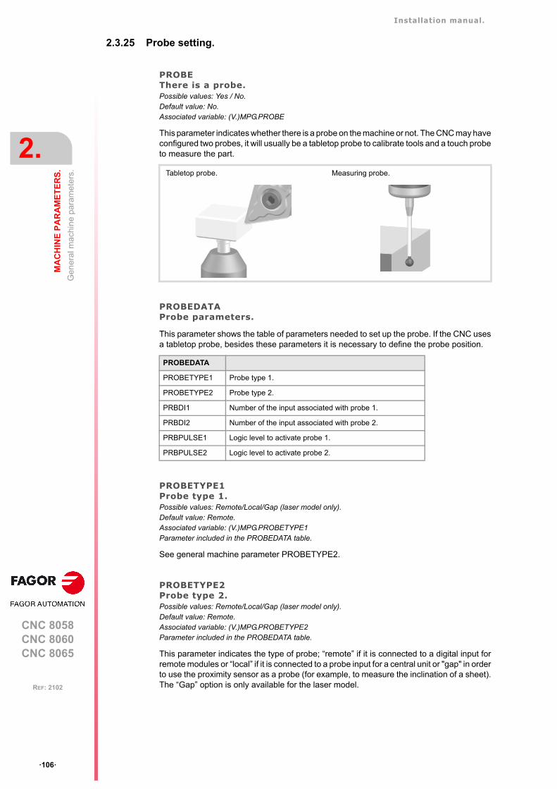
Installation manual.
CNC 8058CNC 8060CNC 8065
2.
MA
CH
INE
PA
RA
ME
TE
RS
.
Gen
eral
mac
hin
e pa
ram
eter
s.
ꞏ106ꞏ
REF: 2102
2.3.25 Probe setting.
PROBEThere is a probe.Possible values: Yes / No.Default value: No.Associated variable: (V.)MPG.PROBE
This parameter indicates whether there is a probe on the machine or not. The CNC may haveconfigured two probes, it will usually be a tabletop probe to calibrate tools and a touch probeto measure the part.
PROBEDATAProbe parameters.
This parameter shows the table of parameters needed to set up the probe. If the CNC usesa tabletop probe, besides these parameters it is necessary to define the probe position.
PROBETYPE1Probe type 1.Possible values: Remote/Local/Gap (laser model only).Default value: Remote.Associated variable: (V.)MPG.PROBETYPE1Parameter included in the PROBEDATA table.
See general machine parameter PROBETYPE2.
PROBETYPE2Probe type 2.Possible values: Remote/Local/Gap (laser model only).Default value: Remote.Associated variable: (V.)MPG.PROBETYPE2Parameter included in the PROBEDATA table.
This parameter indicates the type of probe; “remote” if it is connected to a digital input forremote modules or “local” if it is connected to a probe input for a central unit or "gap" in orderto use the proximity sensor as a probe (for example, to measure the inclination of a sheet).The “Gap” option is only available for the laser model.
Tabletop probe. Measuring probe.
PROBEDATA
PROBETYPE1 Probe type 1.
PROBETYPE2 Probe type 2.
PRBDI1 Number of the input associated with probe 1.
PRBDI2 Number of the input associated with probe 2.
PRBPULSE1 Logic level to activate probe 1.
PRBPULSE2 Logic level to activate probe 2.
Installation manual.
CNC 8058CNC 8060CNC 8065
MA
CH
INE
PA
RA
ME
TE
RS
.
2.
Gen
eral
mac
hin
e pa
ram
eter
s.
ꞏ107ꞏ
REF: 2102
PRBDI1Number of the input associated with probe 1.Possible values: From 1 to 1024 for the remote probe / 1 or 2 for the local probe.Default value: 0 (no probe is connected).Associated variable: (V.)MPG.PRBDI1Parameter included in the PROBEDATA table.
See general machine parameter PRBDI2.
PRBDI2Number of the input associated with probe 2.Possible values: From 1 to 1024 for the remote probe / 1 or 2 for the local probe.Default value: 0 (no probe is connected).Associated variable: (V.)MPG.PRBDI2Parameter included in the PROBEDATA table.
This parameter indicates the number of the input that the probe is connected to. For remoteprobes, this parameter indicates the digital input number; for local probes, it indicates thelocal probe input number; for a proximity sensor it is not necessary to define this parameter.
The digital input will be a physical input of the module or a logic input of the PLC. The PLCconsiders logic inputs the inputs that do not exist physically; for example, if inputs 1 through256 are numbered at the remote modules, the PLC considers logic inputs the ones from 257to 1024.
Two remote probes cannot be connected to the same module if they are going to be involvedin simultaneous probing operations; for example, a probe in each channel and both makinga probing movement.
PRBPULSE1Logic level to activate probe 1.Possible values: Positive / Negative.Default value: Positive.Associated variable: (V.)MPG.PRBPULSE1Parameter included in the PROBEDATA table.
See general machine parameter PRBPULSE2.
PRBPULSE2Logic level to activate probe 2.Possible values: Positive / Negative.Default value: Positive.Associated variable: (V.)MPG.PRBPULSE2Parameter included in the PROBEDATA table.
This parameter indicates whether the probe functions are active high (24V or 5 V) or activelow (0V) of the signal provided by the probe. In any case, the probe signal must be at least20 ms long for the CNC to consider it valid.
To use the proximity sensor as a probe, set PRBPULSE=negative to use G100 orPRBPULSE=positive for G103. The probing will finalize when the INTOL input of the PLCis deactivated.
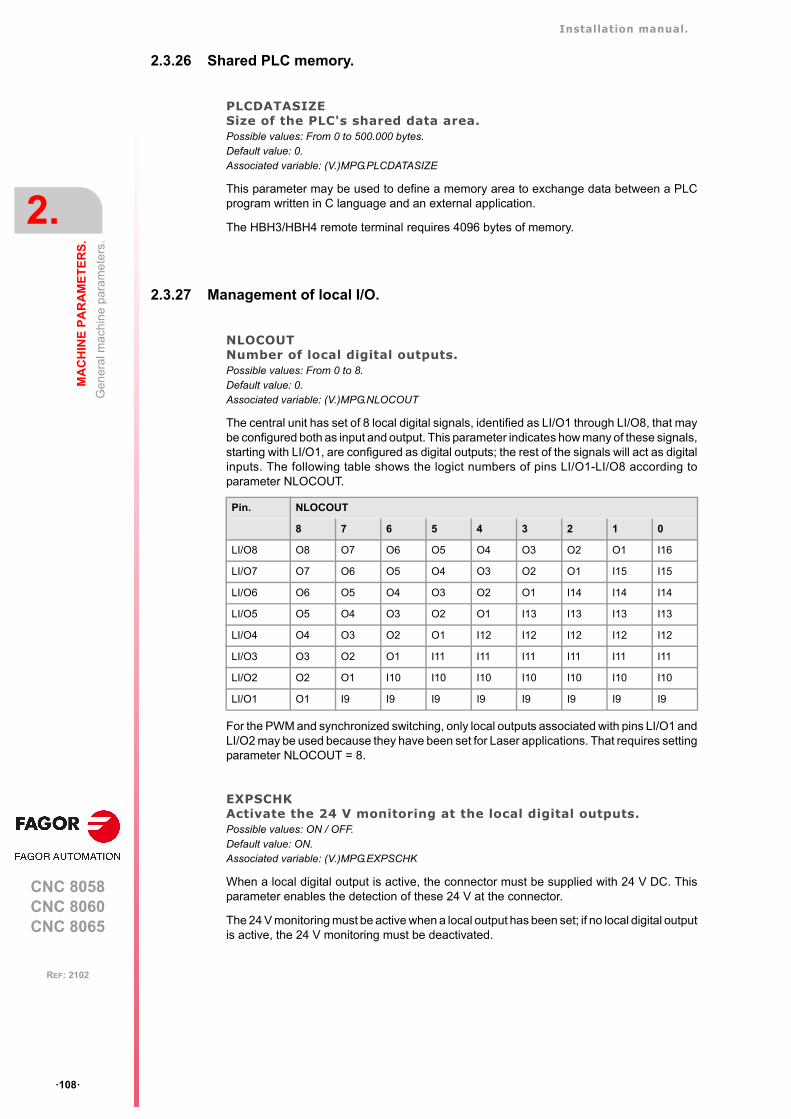
Installation manual.
CNC 8058CNC 8060CNC 8065
2.
MA
CH
INE
PA
RA
ME
TE
RS
.
Gen
eral
mac
hin
e pa
ram
eter
s.
ꞏ108ꞏ
REF: 2102
2.3.26 Shared PLC memory.
PLCDATASIZESize of the PLC's shared data area.Possible values: From 0 to 500.000 bytes.Default value: 0.Associated variable: (V.)MPG.PLCDATASIZE
This parameter may be used to define a memory area to exchange data between a PLCprogram written in C language and an external application.
The HBH3/HBH4 remote terminal requires 4096 bytes of memory.
2.3.27 Management of local I/O.
NLOCOUTNumber of local digital outputs. Possible values: From 0 to 8.Default value: 0.Associated variable: (V.)MPG.NLOCOUT
The central unit has set of 8 local digital signals, identified as LI/O1 through LI/O8, that maybe configured both as input and output. This parameter indicates how many of these signals,starting with LI/O1, are configured as digital outputs; the rest of the signals will act as digitalinputs. The following table shows the logict numbers of pins LI/O1-LI/O8 according toparameter NLOCOUT.
For the PWM and synchronized switching, only local outputs associated with pins LI/O1 andLI/O2 may be used because they have been set for Laser applications. That requires settingparameter NLOCOUT = 8.
EXPSCHKActivate the 24 V monitoring at the local digital outputs.Possible values: ON / OFF.Default value: ON.Associated variable: (V.)MPG.EXPSCHK
When a local digital output is active, the connector must be supplied with 24 V DC. Thisparameter enables the detection of these 24 V at the connector.
The 24 V monitoring must be active when a local output has been set; if no local digital outputis active, the 24 V monitoring must be deactivated.
Pin. NLOCOUT
8 7 6 5 4 3 2 1 0
LI/O8 O8 O7 O6 O5 O4 O3 O2 O1 I16
LI/O7 O7 O6 O5 O4 O3 O2 O1 I15 I15
LI/O6 O6 O5 O4 O3 O2 O1 I14 I14 I14
LI/O5 O5 O4 O3 O2 O1 I13 I13 I13 I13
LI/O4 O4 O3 O2 O1 I12 I12 I12 I12 I12
LI/O3 O3 O2 O1 I11 I11 I11 I11 I11 I11
LI/O2 O2 O1 I10 I10 I10 I10 I10 I10 I10
LI/O1 O1 I9 I9 I9 I9 I9 I9 I9 I9
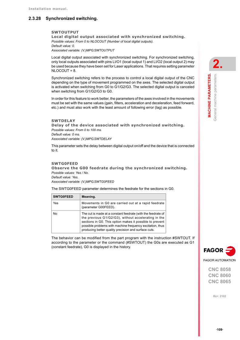
Installation manual.
CNC 8058CNC 8060CNC 8065
MA
CH
INE
PA
RA
ME
TE
RS
.
2.
Gen
eral
mac
hin
e pa
ram
eter
s.
ꞏ109ꞏ
REF: 2102
2.3.28 Synchronized switching.
SWTOUTPUTLocal digital output associated with synchronized switching.Possible values: From 0 to NLOCOUT (Number of local digital outputs).Default value: 0.Associated variable: (V.)MPG.SWTOUTPUT
Local digital output associated with synchronized switching. For synchronized switching,only local outputs associated with pins LI/O1 (local output 1) and LI/O2 (local output 2) maybe used because they have been set for Laser applications. That requires setting parameterNLOCOUT = 8.
Synchronized switching refers to the process to control a local digital output of the CNCdepending on the type of movement programmed on the axes. The selected digital outputis activated when switching from G0 to G1/G2/G3. The selected digital output is canceledwhen switching from G1/G2/G3 to G0.
In order for this feature to work better, the parameters of the axes involved in the movementsmust be set with the same values (gain, filters, acceleration and deceleration, feed forward,etc.) and must also work with the least amount of following error (lag) as possible.
SWTDELAYDelay of the device associated with synchronized switching.Possible values: From 0 to 100 ms.Default value: 0 ms.Associated variable: (V.)MPG.SWTDELAY
This parameter sets the delay between digital output on/off and the device that is connectedto it.
SWTG0FEEDObserve the G00 feedrate during the synchronized switching.Possible values: Yes / No.Default value: Yes.Associated variable: (V.)MPG.SWTG0FEED
The SWTG0FEED parameter determines the feedrate for the sections in G0.
The behavior can be modified from the part program with the instruction #SWTOUT. Ifaccording to the parameter or the command (#SWTOUT) the G0s are executed as G1(constant feedrate), G0 is displayed in the history.
SWTG0FEED Meaning.
Yes Movements in G0 are carried out at a rapid feedrate(parameter G00FEED).
No The cut is made at a constant feedrate (with the feedrate ofthe previous G1/G2/G3), without accelerating in thesections in G0. This option makes it possible to preventpossible problems with machine frequency excitation, thusproducing better quality precision and surface cuts.
Installation manual.
CNC 8058CNC 8060CNC 8065
2.
MA
CH
INE
PA
RA
ME
TE
RS
.
Gen
eral
mac
hin
e pa
ram
eter
s.
ꞏ110ꞏ
REF: 2102
2.3.29 PWM (Pulse-Width Modulation).
PWMOUTPUTLocal digital output associated with the PWM.Possible values: From 0 to 2.Default value: 0.Associated variable: (V.)MPG.PWMOUTPUT
Local digital output associated with the PWM. For the PWM, only local outputs associatedwith pins LI/O1 (local output 1) and LI/O2 (local output 2) may be used because they havebeen set for Laser applications. That requires setting parameter NLOCOUT = 8.
The output for the PWM and for synchronized switching may be the same one and they maybe used at the same time (same value at parameters SWTOUTPUT and PWMOUTPUT).However, this configuration is not recommended for certain types of Laser generators.
PWMCANCELCancel the PWM after an M30 or a reset.Possible values: Yes / No.Default value: No.Associated variable: (V.)MPG.PWMCANCEL
This parameter indicates whether the CNC cancels the PWM after executing M02, M30 orafter a reset.
When there is a CNC error in the channel that has the PWM active (or in any channel if itis managed via PLC), it the parameter is set to "Yes", the CNC deactivates the PWM. If theparameter is set to "No", the CNC keeps the status of the output; i.e. it does not cancel theoutput if it is active. Once the PWM is deactivated for some error, that PWM will not bereactivated when the error disappears; therefore, they have to be reactivated either byprogram or via PLC.
PWMOUTPUT Meaning.
0 PWM missing.
1 Local output 1 (pin LI/O1).
2 Local output 2 (pin LI/O2).
Installation manual.
CNC 8058CNC 8060CNC 8065
MA
CH
INE
PA
RA
ME
TE
RS
.
2.
Gen
eral
mac
hin
e pa
ram
eter
s.
ꞏ111ꞏ
REF: 2102
2.3.30 Power control.
PWRCTRLACTManage power based on the actual feed.Possible values: Yes / No.Default value: No.Associated variable: (V.)MPG.PWRCTRLACT
The CNC allows control of the power, laser or PWM duty, based on the feed. This parameterdefines the feed to be used by the CNC to manage the power.
PWRCTRLCANCELCanceling power control with reset/M2/M30.Possible values: Yes / No.Default value: No.Associated variable: (V.)MPG.PWRCTRLCANCEL
This parameter indicates whether the CNC cancels the power control after executing M02,M30 or after a reset.
Value. Meaning.
Yes. The CNC managers the power based on the actual feed(variable (V.)A.FEED.xn).
No The CNC manages the power based on the theoretical feed(variable (V.)A.TFEED.xn).
Value. Meaning.
Yes. The CNC cancels the power control. A channel error cancels the power control. If an errordisables the power control, it will not be re-enabled when theerror disappears. It should be programmed again via theprogram or PLC.
No The CNC does not cancel the power control. A channel error does not cancel the power control; this willmaintain its previous status. At the beginning of theexecution, after a reset and upon accessing the toolinspection, the CNC synchronizes the preparation of blockswith the execution.
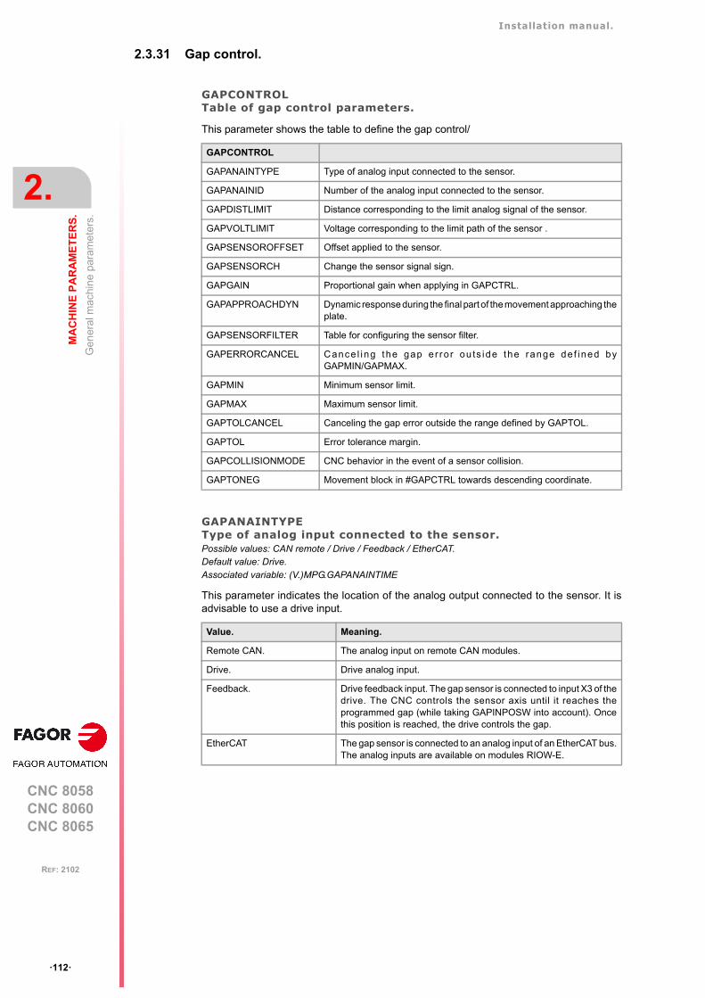
Installation manual.
CNC 8058CNC 8060CNC 8065
2.
MA
CH
INE
PA
RA
ME
TE
RS
.
Gen
eral
mac
hin
e pa
ram
eter
s.
ꞏ112ꞏ
REF: 2102
2.3.31 Gap control.
GAPCONTROLTable of gap control parameters.
This parameter shows the table to define the gap control/
GAPANAINTYPEType of analog input connected to the sensor.Possible values: CAN remote / Drive / Feedback / EtherCAT.Default value: Drive.Associated variable: (V.)MPG.GAPANAINTIME
This parameter indicates the location of the analog output connected to the sensor. It isadvisable to use a drive input.
GAPCONTROL
GAPANAINTYPE Type of analog input connected to the sensor.
GAPANAINID Number of the analog input connected to the sensor.
GAPDISTLIMIT Distance corresponding to the limit analog signal of the sensor.
GAPVOLTLIMIT Voltage corresponding to the limit path of the sensor .
GAPSENSOROFFSET Offset applied to the sensor.
GAPSENSORCH Change the sensor signal sign.
GAPGAIN Proportional gain when applying in GAPCTRL.
GAPAPPROACHDYN Dynamic response during the final part of the movement approaching theplate.
GAPSENSORFILTER Table for configuring the sensor filter.
GAPERRORCANCEL Cance l ing the gap e r ro r ou ts ide the range de f ined byGAPMIN/GAPMAX.
GAPMIN Minimum sensor limit.
GAPMAX Maximum sensor limit.
GAPTOLCANCEL Canceling the gap error outside the range defined by GAPTOL.
GAPTOL Error tolerance margin.
GAPCOLLISIONMODE CNC behavior in the event of a sensor collision.
GAPTONEG Movement block in #GAPCTRL towards descending coordinate.
Value. Meaning.
Remote CAN. The analog input on remote CAN modules.
Drive. Drive analog input.
Feedback. Drive feedback input. The gap sensor is connected to input X3 of thedrive. The CNC controls the sensor axis until it reaches theprogrammed gap (while taking GAPINPOSW into account). Oncethis position is reached, the drive controls the gap.
EtherCAT The gap sensor is connected to an analog input of an EtherCAT bus.The analog inputs are available on modules RIOW-E.
Installation manual.
CNC 8058CNC 8060CNC 8065
MA
CH
INE
PA
RA
ME
TE
RS
.
2.
Gen
eral
mac
hin
e pa
ram
eter
s.
ꞏ113ꞏ
REF: 2102
GAPANAINIDNumber of the analog input connected to the sensor.Possible values (1): If GAPANAINTYPE=Remote CAN, from 1 to 60.Possible values (2): If GAPANAINTYPE=Drive, from 101 to 132 or from 201 to 232.Possible values (3): If GAPANAINTYPE=Feedback, drive node number.Possible values (4): If GAPANAINTYPE=EtherCAT, from 1 to 1024.Default value: None (no gap control).Associated variable: (V.)MPG.GAPANAINID
The sensor can be connected to an analog output of the CAN remote modules or a Sercosdrive. In either case, this parameter indicates the analog output being used. It is advisableto use a drive input.
Analog input of the CAN remote modules.
In this case, this parameter indicates the number of the analog output used for the command.The analog output modules are numbered following the logic order of the remote groups.If there are several analog-output modules in each group, the order is from left to right.
Managing the analog command from Sercos drives.
In this case, this parameter indicates the number of the analog output and the drive to beused. The parameter is set with a three-digit number; the first digit indicates the number ofthe analog output to be used (1 or 2) and the other two digits indicate the logic address ofthe drive (1 through 32). The "address" rotary selector switch sets the logic address.
For example, if the parameter is with a value of ꞏ107ꞏ, it indicates that the CNC uses analoginput ꞏ1ꞏ of the drive whose logic address is ꞏ7ꞏ
Drive feedback input.
In this case, this parameter indicates the node number of the drive.
Analog input of remote EtherCAT modules.
In this case, this parameter indicates the PLC register that maps the analog input connectedto the sensor.
GAPDISTLIMITDistance corresponding to the limit analog signal of the sensor.Possible values: From 0 to 99999.9999 mm / From 0 to 3937.00787 inches.Default value: 10.0000 mm / 0.39370 inch.Associated variable: (V.)MPG.GAPDISTLIMIT
Distance corresponding to the limit analog signal of the sensor (parameter GAPVOLTLIMIT).
GAPVOLTLIMITVoltage corresponding to the travel limit of the sensor.Possible values: From 0 to 10000 mVDefault value: 10000 mV.Associated variable: (V.)MPG.GAPVOLTLIMIT
Voltage (in millivolts) corresponding to the limit path of the sensor (parameterGAPDISTLIMIT).
This feature requires the drive version v9.10 or higher. Refer to the drive manual for the gap sensorconnection.i
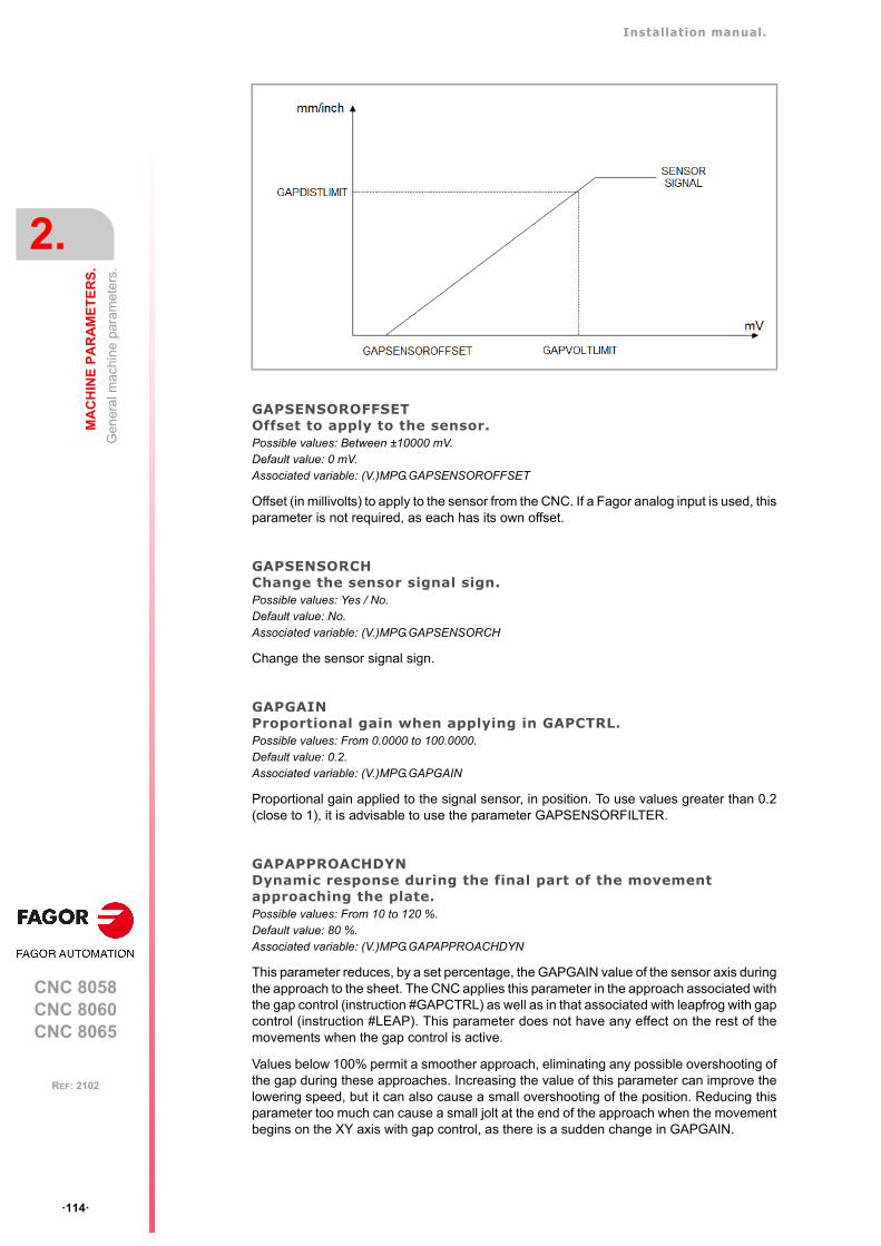
Installation manual.
CNC 8058CNC 8060CNC 8065
2.
MA
CH
INE
PA
RA
ME
TE
RS
.
Gen
eral
mac
hin
e pa
ram
eter
s.
ꞏ114ꞏ
REF: 2102
GAPSENSOROFFSETOffset to apply to the sensor.Possible values: Between ±10000 mV.Default value: 0 mV.Associated variable: (V.)MPG.GAPSENSOROFFSET
Offset (in millivolts) to apply to the sensor from the CNC. If a Fagor analog input is used, thisparameter is not required, as each has its own offset.
GAPSENSORCHChange the sensor signal sign.Possible values: Yes / No.Default value: No.Associated variable: (V.)MPG.GAPSENSORCH
Change the sensor signal sign.
GAPGAINProportional gain when applying in GAPCTRL.Possible values: From 0.0000 to 100.0000.Default value: 0.2.Associated variable: (V.)MPG.GAPGAIN
Proportional gain applied to the signal sensor, in position. To use values greater than 0.2(close to 1), it is advisable to use the parameter GAPSENSORFILTER.
GAPAPPROACHDYNDynamic response during the final part of the movement approaching the plate.Possible values: From 10 to 120 %.Default value: 80 %.Associated variable: (V.)MPG.GAPAPPROACHDYN
This parameter reduces, by a set percentage, the GAPGAIN value of the sensor axis duringthe approach to the sheet. The CNC applies this parameter in the approach associated withthe gap control (instruction #GAPCTRL) as well as in that associated with leapfrog with gapcontrol (instruction #LEAP). This parameter does not have any effect on the rest of themovements when the gap control is active.
Values below 100% permit a smoother approach, eliminating any possible overshooting ofthe gap during these approaches. Increasing the value of this parameter can improve thelowering speed, but it can also cause a small overshooting of the position. Reducing thisparameter too much can cause a small jolt at the end of the approach when the movementbegins on the XY axis with gap control, as there is a sudden change in GAPGAIN.
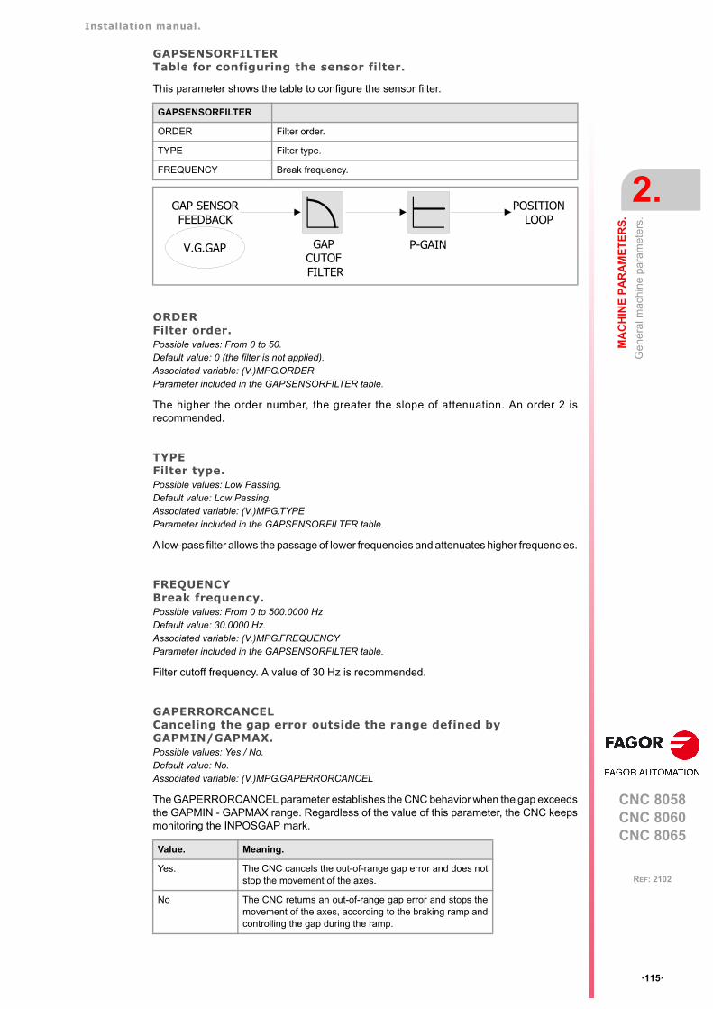
Installation manual.
CNC 8058CNC 8060CNC 8065
MA
CH
INE
PA
RA
ME
TE
RS
.
2.
Gen
eral
mac
hin
e pa
ram
eter
s.
ꞏ115ꞏ
REF: 2102
GAPSENSORFILTERTable for configuring the sensor filter.
This parameter shows the table to configure the sensor filter.
ORDERFilter order.Possible values: From 0 to 50.Default value: 0 (the filter is not applied).Associated variable: (V.)MPG.ORDERParameter included in the GAPSENSORFILTER table.
The higher the order number, the greater the slope of attenuation. An order 2 isrecommended.
TYPEFilter type.Possible values: Low Passing.Default value: Low Passing.Associated variable: (V.)MPG.TYPEParameter included in the GAPSENSORFILTER table.
A low-pass filter allows the passage of lower frequencies and attenuates higher frequencies.
FREQUENCYBreak frequency.Possible values: From 0 to 500.0000 HzDefault value: 30.0000 Hz.Associated variable: (V.)MPG.FREQUENCYParameter included in the GAPSENSORFILTER table.
Filter cutoff frequency. A value of 30 Hz is recommended.
GAPERRORCANCELCanceling the gap error outside the range defined by GAPMIN/GAPMAX.Possible values: Yes / No.Default value: No.Associated variable: (V.)MPG.GAPERRORCANCEL
The GAPERRORCANCEL parameter establishes the CNC behavior when the gap exceedsthe GAPMIN - GAPMAX range. Regardless of the value of this parameter, the CNC keepsmonitoring the INPOSGAP mark.
GAPSENSORFILTER
ORDER Filter order.
TYPE Filter type.
FREQUENCY Break frequency.
Value. Meaning.
Yes. The CNC cancels the out-of-range gap error and does notstop the movement of the axes.
No The CNC returns an out-of-range gap error and stops themovement of the axes, according to the braking ramp andcontrolling the gap during the ramp.
GAP SENSORFEEDBACK
V.G.GAP
POSITIONLOOP
P-GAINGAPCUTOF FILTER
Installation manual.
CNC 8058CNC 8060CNC 8065
2.
MA
CH
INE
PA
RA
ME
TE
RS
.
Gen
eral
mac
hin
e pa
ram
eter
s.
ꞏ116ꞏ
REF: 2102
GAPMINMinimum sensor limit.Possible values: From 0 to 99999.9999 mm / From 0 to 3937.00787 inches.Default value: 0.Associated variable: (V.)MPG.GAPMIN
Minimum value permitted for the gap. If the gap exceeds the range defined in the parametersGAPMIN and GAPMAX, the PLC deactivates the INPOSGAP mark. The behavior of theCNC depends on the GAPTOLCANCEL parameter.
GAPMAXMaximum sensor limit.Possible values: From 0 to 99999.9999 mm / From 0 to 3937.00787 inches.Default value: 5.0000 mm / 0.19685 inch.Associated variable: (V.)MPG.GAPMAX
Maximum value permitted for the gap. This parameter should be lower than GAPDISTLIMIT.If the gap exceeds the range defined in the parameters GAPMIN and GAPMAX, the PLCdeactivates the INPOSGAP mark. The behavior of the CNC depends on theGAPTOLCANCEL parameter.
GAPTOLCANCELCanceling the gap error outside the range defined by GAPTOL.Possible values: Yes / No.Default value: No.Associated variable: (V.)MPG.GAPTOLCANCEL
The GAPTOLCANCEL parameter establishes the behavior of the CNC when the gapexceeds the margin set in the GAPTOL parameter.
GAPTOLError tolerance margin.Possible values: From 0 to 99999.9999 mm / From 0 to 3937.00787 inches.Default value: 0.1000 mm / 0.00394 inch.Associated variable: (V.)MPG.GAPTOL
This parameter defines a positioning window on the programmed gap, to finish the approachblock. If the axis exceeds the tolerance set in the GAPTOL parameter, the PLC deactivatesthe INTOL mark. The behavior of the CNC depends on the GAPTOLCANCEL parameter.
GAPCOLLISIONMODECNC behavior in the event of a sensor collision. Possible values: Do not display error / Display error.Default value: Issue an error.Associated variable: (V.)MPG.GAPCOLLISIONMODE
The gap control sensor may have a collusion signal connected to the CNC, which shouldbe managed by the PLC via the GAPCOLLISION mark. If the PLC activates theGAPCOLLISION mark, the CNC will display an error or not, depending on how thisparameter has been set. The error does not activate the emergency.
Value. Meaning.
Yes. The CNC cancels the out-of-tolerance gap error and doesnot stop the movement of the axes.
No The CNC returns an out-of-tolerance gap error and stops themovement of the axes, according to the braking ramp andcontrolling the gap during the ramp.
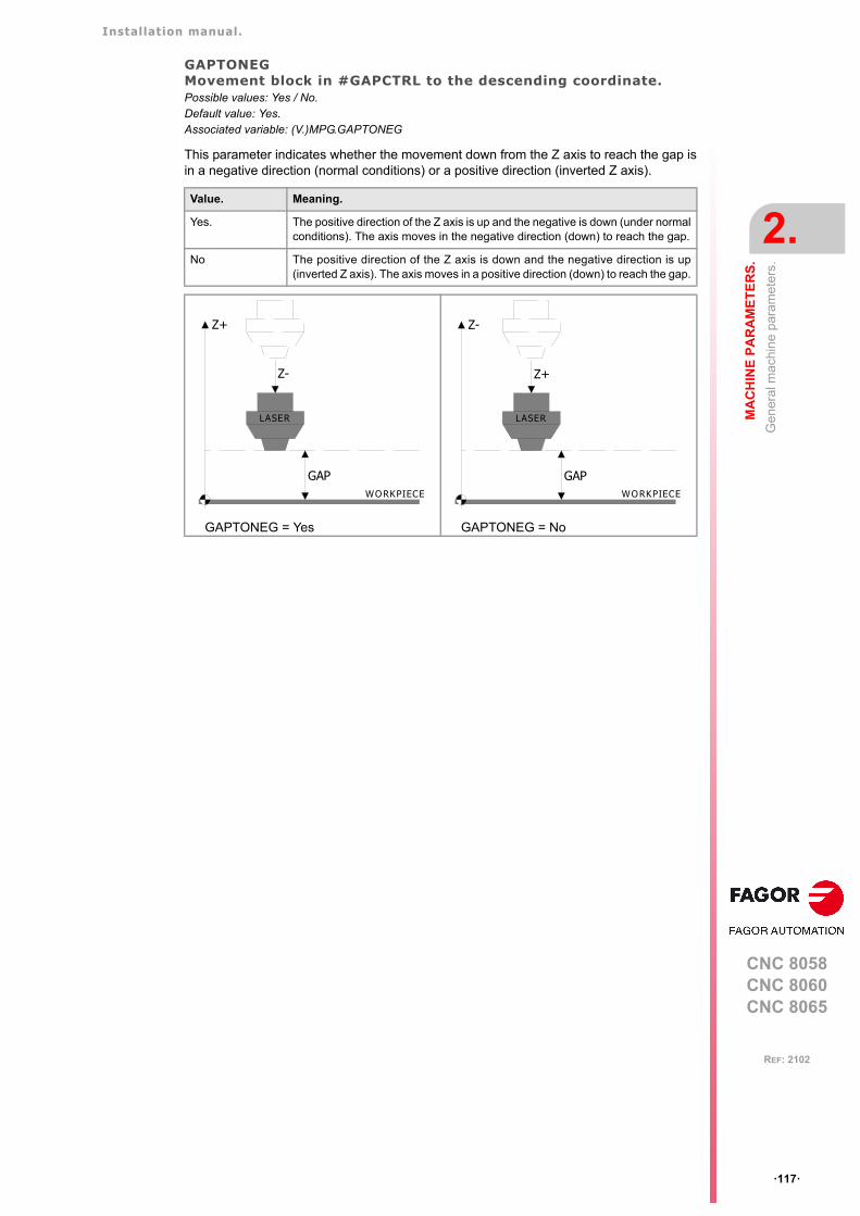
Installation manual.
CNC 8058CNC 8060CNC 8065
MA
CH
INE
PA
RA
ME
TE
RS
.
2.
Gen
eral
mac
hin
e pa
ram
eter
s.
ꞏ117ꞏ
REF: 2102
GAPTONEGMovement block in #GAPCTRL to the descending coordinate.Possible values: Yes / No.Default value: Yes.Associated variable: (V.)MPG.GAPTONEG
This parameter indicates whether the movement down from the Z axis to reach the gap isin a negative direction (normal conditions) or a positive direction (inverted Z axis).
Value. Meaning.
Yes. The positive direction of the Z axis is up and the negative is down (under normalconditions). The axis moves in the negative direction (down) to reach the gap.
No The positive direction of the Z axis is down and the negative direction is up(inverted Z axis). The axis moves in a positive direction (down) to reach the gap.
GAPTONEG = Yes GAPTONEG = No
GAP
Z+
LASER
Z-
WORKPIECEGAP
Z-
LASER
Z+
WORKPIECE
Installation manual.
CNC 8058CNC 8060CNC 8065
2.
MA
CH
INE
PA
RA
ME
TE
RS
.
Gen
eral
mac
hin
e pa
ram
eter
s.
ꞏ118ꞏ
REF: 2102
2.3.32 Leapfrog.
LEAPDYNOVRDynamic response of the leap during the leapfrog.Possible values: From 10 to 100000 %.Default value: 100 %.Associated variable: (V.)MPG.LEAPDYNOVR
This parameter enables the dynamic response of the Z axis (the longitudinal axis) to bereduced during the leapfrog for a smoother leap, in both the up and down flanks. Making themovement smoother will result in a longer machining time when there are leapfrogs.
Height of the leapfrog.
The height level that is reached in a leapfrog (#LEAP) depends on the ACCJERK, DECJERK,ACEL and DECEL values. The leapfrog requires high ACEL and DECEL values (of around15,000 mm/s² or greater), as well as ACCJERK and DECJERK values (of around 20 timesthe ACEL and DECEL).
Plate approach.
The CNC executes the approach to the plate with linear acceleration LACC1 and LACC2,and thus this must not be very high (around a third of the ACEL and DECEL).
Parameter. Meaning.
SLOPETYPE Type of acceleration by default; linear, trapezoidal and square sine.
ACCELDECEL
Acceleration and deceleration.Parameters ACCEL and DECEL set the acceleration values when it istrapezoidal or square-sine (bell shaped) (parameter SLOPETYPE).
ACCJERKDECJERK
Acceleration and deceleration jerk.Parameters ACCJERK and DECJERK set the slope of the acceleration anddeceleration. Both parameters help limit the acceleration changes so themachine runs more smoothly in small speed increments or decrements and withFFGAIN values close to 100%. The lower the value assigned to theseparameters, the smoother the machine response, but the acc/dec time willincrease.
Parameter. Meaning.
LACC1LACC2
Acceleration of the first and second section.Parameters LACC1 and LACC2 set the acceleration values when it is linear(SLOPETYPE parameter).
Example.For an ACEL and DECEL = 18,000 mm/s².• LACC1 and LACC2 = 6000 mm/s².• ACCJERK and DECJERK= 360,000 mm/s³.

Installation manual.
CNC 8058CNC 8060CNC 8065
MA
CH
INE
PA
RA
ME
TE
RS
.
2.
Gen
eral
mac
hin
e pa
ram
eter
s.
ꞏ119ꞏ
REF: 2102
2.3.33 Compensating the dispersion by the CO2 laser path.
LASERFOLLOWCompensate the dispersion by the CO2 laser path.
This parameter shows the table to define the compensation. The goal of the compensationis to keep the total laser path constant in order to prevent dispersion variations in the cutoffpoint on the sheet.
For the compensation, a slave axis, which follows the main axes, is used. The dispersioncompensation is activated from the program using the instruction #FOLLOW or from the PLCusing the instruction FOLLOW.
LASERFOLLOWAXEISIndicates the slave axis to which FOLLOW is applied.Possible values: X, X1ꞏꞏX9, ꞏꞏ , C, C1ꞏꞏC9.Default value: 0 (no compensation).Associated variable: (V.)MPG.LASERFOLLOWParameter included in the LASERFOLLOW table.
Name of the slave axis for compensation (axis on which the instruction #FOLLOW or thePLC command FOLLOW acts). The variable V.A.FLWMASTER.xn of this axis will be themain element of the synchronization.
The axis name is defined by 1 or 2 characters. The first character must be one of the lettersX - Y - Z - U - V - W - A - B - C. The second character is optional and will be a numericalsuffix between 1 and 9. This way, the name of the spindles may be within the range X,X1…X9,...C, C1…C9. For example X, X1, Y3, Z9, W, W7, C...
LASERFOLLOWOFFSETSource offset of the X Y Z axes regarding the slave axis.Possible values: Within ±99999.9999 mm / Within ±3937.00787 inch.Default value: 0.Associated variable: (V.)MPG.LASERFOLLOWOFFSETParameter included in the LASERFOLLOW table.
This offset allows the minimization of the total laser path.
LASERFOLLLOW
LASERFOLLOWAXIS Slave axis applied to which FOLLOW is applied.
LASERFOLLOWOFFSET Offset of the X Y Z axes with respect to the slave axis.
LASERFOLLOW1 Indicates how the first of the X Y Z axes affect the slave axis.
LASERFOLLOW2 Indicates how the second of the X Y Z axes affect the slave axis.
LASERFOLLOW3 Indicates how the third of the X Y Z axes affect the slave axis.
SLAVE LASER
X
Y
Installation manual.
CNC 8058CNC 8060CNC 8065
2.
MA
CH
INE
PA
RA
ME
TE
RS
.
Gen
eral
mac
hin
e pa
ram
eter
s.
ꞏ120ꞏ
REF: 2102
LASERFOLLOW1Effect of the first of the X Y Z axes on the slave axis.Possible values: No effect / Positive / Negative. Default value: Not affected.Associated variable: (V.)MPG.LASERFOLLOW1Parameter included in the LASERFOLLOW table.
This parameter indicates if the first axis (according to the machine parameters) of the channelthat manages the compensation affects the slave axis, as well as its direction.
LASERFOLLOW2Effect of the second of the X Y Z axes on the slave axis.Possible values: No effect / Positive / Negative. Default value: Not affected.Associated variable: (V.)MPG.LASERFOLLOW2Parameter included in the LASERFOLLOW table.
This parameter indicates if the second axis (according to the machine parameters) of thechannel that manages the compensation affects the slave axis, as well as its direction.
LASERFOLLOW3Effect of the second of the X Y Z axes on the slave axis.Possible values: No effect / Positive / Negative. Default value: Not affected.Associated variable: (V.)MPG.LASERFOLLOW3Parameter included in the LASERFOLLOW table.
This parameter indicates if the third axis (according to the machine parameters) of thechannel that manages the compensation affects the slave axis, as well as its direction.
• If any of the parameters LASERFOLLOW1, LASERFOLLOW2 or LASERFOLLOW3 isdifferent from 0, the CNC will automatically update the variable V.A.FLWMASTER.xn ofthe slave axis (LASERFOLLOWAXIS parameter) as follows.
• If parameters LASERFOLLOW1, LASERFOLLOW2 and LASERFOLLOW3 are 0, theOEM should enter the value of the variable V.A.FLWMASTER.xn (e.g. from the PLC).
V.A.FLWMASTER.xn = V.MPG.LASERFOLLOWOFFSET + V.MPG.LASERFOLLOW1 * V.A.TPOS.X + V.MPG.LASERFOLLOW2 * V.A.TPOS.Y + V.MPG.LASERFOLLOW3 * V.A.TPOS.Z
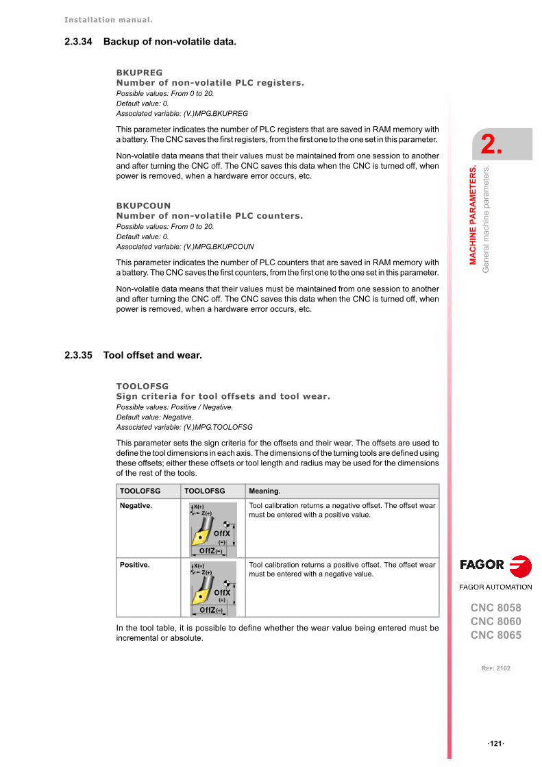
Installation manual.
CNC 8058CNC 8060CNC 8065
MA
CH
INE
PA
RA
ME
TE
RS
.
2.
Gen
eral
mac
hin
e pa
ram
eter
s.
ꞏ121ꞏ
REF: 2102
2.3.34 Backup of non-volatile data.
BKUPREGNumber of non-volatile PLC registers.Possible values: From 0 to 20.Default value: 0.Associated variable: (V.)MPG.BKUPREG
This parameter indicates the number of PLC registers that are saved in RAM memory witha battery. The CNC saves the first registers, from the first one to the one set in this parameter.
Non-volatile data means that their values must be maintained from one session to anotherand after turning the CNC off. The CNC saves this data when the CNC is turned off, whenpower is removed, when a hardware error occurs, etc.
BKUPCOUNNumber of non-volatile PLC counters.Possible values: From 0 to 20.Default value: 0.Associated variable: (V.)MPG.BKUPCOUN
This parameter indicates the number of PLC counters that are saved in RAM memory witha battery. The CNC saves the first counters, from the first one to the one set in this parameter.
Non-volatile data means that their values must be maintained from one session to anotherand after turning the CNC off. The CNC saves this data when the CNC is turned off, whenpower is removed, when a hardware error occurs, etc.
2.3.35 Tool offset and wear.
TOOLOFSGSign criteria for tool offsets and tool wear.Possible values: Positive / Negative.Default value: Negative.Associated variable: (V.)MPG.TOOLOFSG
This parameter sets the sign criteria for the offsets and their wear. The offsets are used todefine the tool dimensions in each axis. The dimensions of the turning tools are defined usingthese offsets; either these offsets or tool length and radius may be used for the dimensionsof the rest of the tools.
In the tool table, it is possible to define whether the wear value being entered must beincremental or absolute.
TOOLOFSG TOOLOFSG Meaning.
Negative. Tool calibration returns a negative offset. The offset wearmust be entered with a positive value.
Positive. Tool calibration returns a positive offset. The offset wearmust be entered with a negative value.
Installation manual.
CNC 8058CNC 8060CNC 8065
2.
MA
CH
INE
PA
RA
ME
TE
RS
.
Gen
eral
mac
hin
e pa
ram
eter
s.
ꞏ122ꞏ
REF: 2102
2.3.36 Spindle synchronization.
SYNCCANCELCancels the spindle synchronization.Possible values: Yes / No.Default value: Yes.Associated variable: (V.)MPG.SYNCCANCEL
This parameter indicates whether the CNC cancels spindle synchronization or not afterexecuting M02, M30 or after an error or reset.
2.3.37 Define the number of jog panels and their relationship with the channels.
NKEYBDNumber of jog panels.Possible values: From 1 to 8.Default value: 1.Associated variable: (V.)MPG.NKEYBD
Number of jog panels.
KEYBDCHList of jog panels of the system.
This parameter shows the table to assign the jog panels to the channels.
The CNC numbers the operator panels following the order (sequence) that they occupy inthe CAN bus (Address switch). The first jog panel will be the one with the lowest numberand so on.
KEYBDnCHChannel to which the jog panel is assigned.Possible values: Active channel / CH1 / CH2 / CH3 / CH4.Default value: Active channel.Associated variable: (V.)MPG.KEYBDCH[jog]Parameter included in the KEYBDCH table.
Each jog panel may be assigned to a particular channel or always to the active channel.When a jog panel is assigned to a channel, it is always operative even if the channel is notthe active one. When there are several jog panels assigned to the same channel, operationsmay be carried out from any of them indistinctively.
KEYBDCH
KEYBDnCH Channel to which the jog panel is assigned.
Installation manual.
CNC 8058CNC 8060CNC 8065
MA
CH
INE
PA
RA
ME
TE
RS
.
2.
Gen
eral
mac
hin
e pa
ram
eter
s.
ꞏ123ꞏ
REF: 2102
2.3.38 PLC type.
PLCTYPEPLC type.Possible values: IEC / IEC+Fagor / Fagor.Default value: IEC.Associated variable: (V.)MPG.PLCTYPE
This parameter selects the type of PLC to be used; the Fagor one, the standard IEC-61131or both. The following table shows who is affected by the startup (RUN) and stop (STOP)of the PLC depending on this parameter as well as the status of the mark PLCREADY.
2.3.39 Rename the axes and the spindles.
RENAMECANCELCancel the name change for the axes and the spindles.Possible values: Yes / No.Default value: Yes.Associated variable: (V.)MPG.RENAMECANCEL
The #RENAME instruction may be used to rename the axes and spindles via part-programor MDI/MDA mode. This parameter indicates whether the CNC keeps or cancel the namesof the axes and spindles (#RENAME) after a reset or at the beginning of a new part-programin the same channel.
After turning the CNC off and on, the axes and spindles always keep their new name, exceptafter a checksum error or after validating the machine parameters that involve restoring theoriginal configuration of channels, axes or spindles. In either case, the axes and the spindleswill recover their original names.
PLCTYPE RUN STOP PLCREADY
IEC Fagor IEC Fagor IEC Fagor
IEC Yes No Yes No ON - - -
IEC+Fagor Yes Yes Yes Yes ON ON
Fagor No Yes No Yes OFF ON
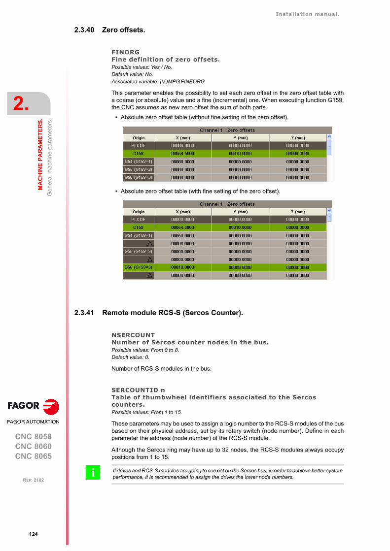
Installation manual.
CNC 8058CNC 8060CNC 8065
2.
MA
CH
INE
PA
RA
ME
TE
RS
.
Gen
eral
mac
hin
e pa
ram
eter
s.
ꞏ124ꞏ
REF: 2102
2.3.40 Zero offsets.
FINORGFine definition of zero offsets.Possible values: Yes / No.Default value: No.Associated variable: (V.)MPG.FINEORG
This parameter enables the possibility to set each zero offset in the zero offset table witha coarse (or absolute) value and a fine (incremental) one. When executing function G159,the CNC assumes as new zero offset the sum of both parts.
• Absolute zero offset table (without fine setting of the zero offset).
• Absolute zero offset table (with fine setting of the zero offset).
2.3.41 Remote module RCS-S (Sercos Counter).
NSERCOUNTNumber of Sercos counter nodes in the bus.Possible values: From 0 to 8.Default value: 0.
Number of RCS-S modules in the bus.
SERCOUNTID nTable of thumbwheel identifiers associated to the Sercos counters.Possible values: From 1 to 15.
These parameters may be used to assign a logic number to the RCS-S modules of the busbased on their physical address, set by its rotary switch (node number). Define in eachparameter the address (node number) of the RCS-S module.
Although the Sercos ring may have up to 32 nodes, the RCS-S modules always occupypositions from 1 to 15.
If drives and RCS-S modules are going to coexist on the Sercos bus, in order to achieve better systemperformance, it is recommended to assign the drives the lower node numbers.i
Installation manual.
CNC 8058CNC 8060CNC 8065
MA
CH
INE
PA
RA
ME
TE
RS
.
2.
Gen
eral
mac
hin
e pa
ram
eter
s.
ꞏ125ꞏ
REF: 2102
2.3.42 Access to the parameter table of the channel.
CHANNEL nParameter table of channel.
This parameter shows the machine parameter table of the channel.
Installation manual.
CNC 8058CNC 8060CNC 8065
2.
MA
CH
INE
PA
RA
ME
TE
RS
.
Gen
era
l mac
hin
e p
aram
eter
s. E
xecu
tion
chan
nel
s.
ꞏ126ꞏ
REF: 2102
2.4 General machine parameters. Execution channels.
2.4.1 Channel configuration.
GROUPIDGroup the channel belongs to.Possible values: From 0 to 2.Default value: 0 (it does not belong to any group).Associated variable: (V.)[ch].MPG.GROUPID
Two or more channels may be configured to form a group. The channels of the same groupbehave as follows.
• Each channel may be in a different work mode, except in jog and automatic modes.Toggling between the jog mode and automatic mode of a channel will affect all thechannels of the group that are in any of these modes; the channels that are in a differentmode will not be affected.
• A reset in any of the channels of the group affects all of them.
• Any error in any of the channels of the group interrupts the execution in all of them.
CHTYPEType of channel.Possible values: CNC / PLC / CNC+PLC.Default value: CNC.Associated variable: (V.)[ch].MPG.CHTYPE
A channel may be governed from the CNC, from the PLC or from both.
Channels governed by the PLC have neither jog mode nor MDI/MDA mode. The automaticand EDISIMU modes are available, but programs cannot be executed or simulated.
If during setup, it is necessary to display these work modes or execute or simulate programs,set the channel as being governed from the CNC+PLC and once setup is completed, setit back as a PLC channel.
HIDDENCHHidden channel.Possible values: Yes / No.Default value: No.Associated variable: (V.)[ch].MPG.HIDDENCH
Hidden channels are not displayed and cannot be selected.
A hidden channel cannot be reset from the operator panel; to reset it, either group it withanother channel or reset it from the PLC mark RESETIN.
Installation manual.
CNC 8058CNC 8060CNC 8065
MA
CH
INE
PA
RA
ME
TE
RS
.
2.
Gen
era
l mac
hin
e p
aram
eter
s. E
xecu
tion
chan
nel
s.
ꞏ127ꞏ
REF: 2102
2.4.2 Configuring the axes of the channel.
CHNAXISNumber of axes of the channel.Possible values: From 0 to 28.Default value: 3.Associated variable: (V.)[ch].MPG.CHNAXIS
This parameter sets the number of axes of the channel, whether they are servo-controlledor not.
A channel may have initially associated with it one, several or no of the axes defined in thesystem. In any case, the number of axes assigned to the channel cannot be higher than thenumber of axes of the system, defined by parameter NAXIS. The sum of the axes assignedto the channels cannot exceed the number of axes of the system either.
It is possible to change the configuration of the axes of a channel via part-program, (defininga new configuration, adding or removing axes) using the instructions #SET AX, #FREE AXand #CALL AX.
CHAXISNAMEList of the axes of the channel.
This parameter shows the table to define the names of the axes. Parameter CHNAXIS setsthe number of axes of the channel.
CHAXISNAME nName of the axes.Possible values: Any axes defined in AXISNAME.Default value: Starting from CHAXISNAME1; X, Y, Z...Associated variable: (V.)[ch].MPG.CHAXISNAMEnParameter included in the CHAXISNAME table.
Any axis defined by parameter AXISNAME may belong to the channel.
When defining the axes, bear in mind that the order in which they are defined determinestheir index in the channel. The index of the first axis of the table will be ꞏ1ꞏ and so on. Aswith the axis name, the index in the channel permits identifying the axis in PLC variables,marks, etc.
The order of the axes and work planes (mill model).
The order of the axes in the channel sets the main work planes, those selected with functionsG17, G18 and G19. Function G20 may be used to form any work plane with the axes of thechannel.
The order of the axes and work planes (lathe model).
The order of the axes of the channel and parameter GEOCONFIG set the main work planes.Refer to the parameter for further detail.
CHAXISNAME
CHAXISNAME n Name of the axes.
CHAXISNAME n Index in the channel.
CHAXISNAME 1 Index ꞏ1ꞏ.
CHAXISNAME 2 Index ꞏ2ꞏ.
CHAXISNAME 3 Index ꞏ3ꞏ.
Plane. Abscissa axis. Ordinate axis. Longitudinal axis.
G17 CHAXISNAME 1 CHAXISNAME 2 CHAXISNAME 3
G18 CHAXISNAME 3 CHAXISNAME 1 CHAXISNAME 2
G19 CHAXISNAME 2 CHAXISNAME 3 CHAXISNAME 1
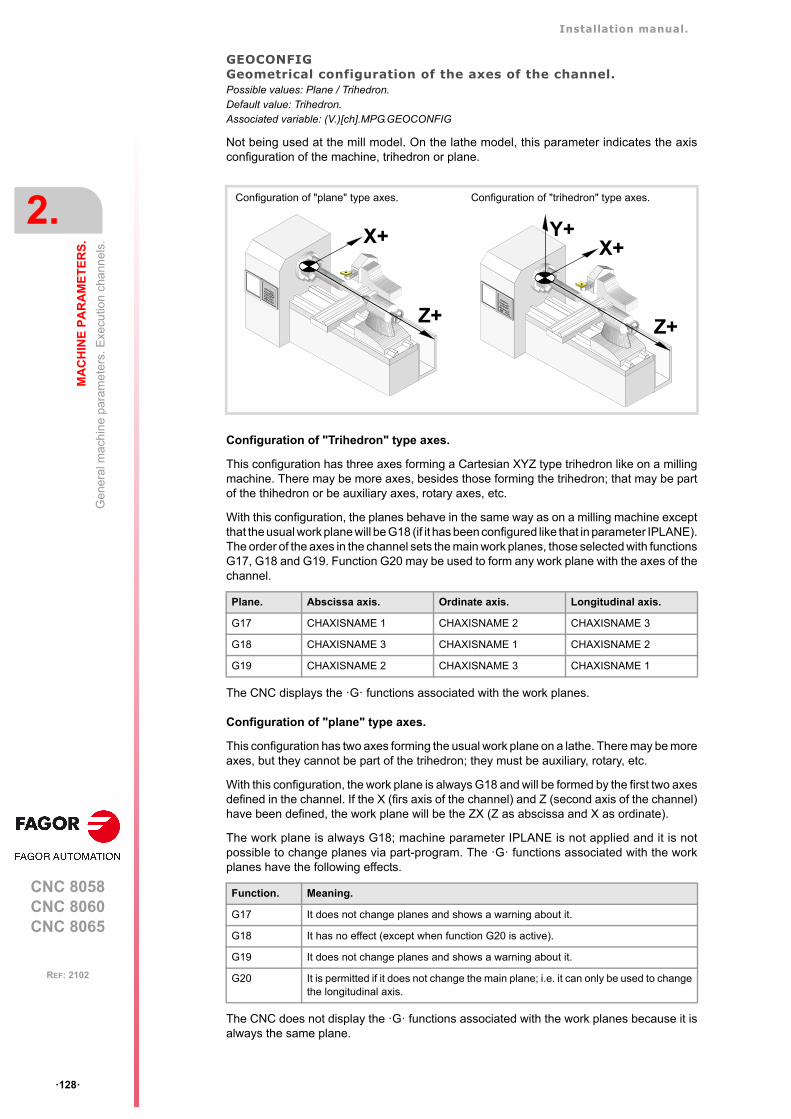
Installation manual.
CNC 8058CNC 8060CNC 8065
2.
MA
CH
INE
PA
RA
ME
TE
RS
.
Gen
era
l mac
hin
e p
aram
eter
s. E
xecu
tion
chan
nel
s.
ꞏ128ꞏ
REF: 2102
GEOCONFIGGeometrical configuration of the axes of the channel.Possible values: Plane / Trihedron.Default value: Trihedron.Associated variable: (V.)[ch].MPG.GEOCONFIG
Not being used at the mill model. On the lathe model, this parameter indicates the axisconfiguration of the machine, trihedron or plane.
Configuration of "Trihedron" type axes.
This configuration has three axes forming a Cartesian XYZ type trihedron like on a millingmachine. There may be more axes, besides those forming the trihedron; that may be partof the thihedron or be auxiliary axes, rotary axes, etc.
With this configuration, the planes behave in the same way as on a milling machine exceptthat the usual work plane will be G18 (if it has been configured like that in parameter IPLANE).The order of the axes in the channel sets the main work planes, those selected with functionsG17, G18 and G19. Function G20 may be used to form any work plane with the axes of thechannel.
The CNC displays the ꞏGꞏ functions associated with the work planes.
Configuration of "plane" type axes.
This configuration has two axes forming the usual work plane on a lathe. There may be moreaxes, but they cannot be part of the trihedron; they must be auxiliary, rotary, etc.
With this configuration, the work plane is always G18 and will be formed by the first two axesdefined in the channel. If the X (firs axis of the channel) and Z (second axis of the channel)have been defined, the work plane will be the ZX (Z as abscissa and X as ordinate).
The work plane is always G18; machine parameter IPLANE is not applied and it is notpossible to change planes via part-program. The ꞏGꞏ functions associated with the workplanes have the following effects.
The CNC does not display the ꞏGꞏ functions associated with the work planes because it isalways the same plane.
Configuration of "plane" type axes. Configuration of "trihedron" type axes.
Plane. Abscissa axis. Ordinate axis. Longitudinal axis.
G17 CHAXISNAME 1 CHAXISNAME 2 CHAXISNAME 3
G18 CHAXISNAME 3 CHAXISNAME 1 CHAXISNAME 2
G19 CHAXISNAME 2 CHAXISNAME 3 CHAXISNAME 1
Function. Meaning.
G17 It does not change planes and shows a warning about it.
G18 It has no effect (except when function G20 is active).
G19 It does not change planes and shows a warning about it.
G20 It is permitted if it does not change the main plane; i.e. it can only be used to changethe longitudinal axis.
X+
Z+
X+
Z+
Y+
Installation manual.
CNC 8058CNC 8060CNC 8065
MA
CH
INE
PA
RA
ME
TE
RS
.
2.
Gen
era
l mac
hin
e p
aram
eter
s. E
xecu
tion
chan
nel
s.
ꞏ129ꞏ
REF: 2102
Configuration of "plane" type axes. Arc programming.
Programming the arc center I K depends on the active work plane.
• With function G18, in circular interpolations, the arc center I is associated with the firstaxis of the channel (usually X) and K with the second axis of the channel (usually Z).
• With function G20, in circular interpolations, the arc center I is associated with theabscissa axis (usually Z) and K with the ordinate axis of the channel (usually X).
Configuration of "plane" type axes. The longitudinal axis.
In this configuration, the second axis of the channel is considered as longitudinal axis. If theX (first axis of the channel) and Z (second axis of the channel) axes have been defined, thework plane will be the ZX and Z will be the longitudinal axis. Tool length compensation isapplied on this longitudinal axis when using milling tools. With lathe tools, tool lengthcompensation is applied on all the axes where a tool offset has been defined.
When using milling tools on a lathe, the longitudinal compensation axis may be changed bymeans of the #TOOLAX instruction or the G20 function.
Configuration of "plane" type axes. Axis swapping.
The axes may be swapped, but it must be borne in mind that the previous behavior staysthe same for the first and second axes of the channel resulting from the swap.
Installation manual.
CNC 8058CNC 8060CNC 8065
2.
MA
CH
INE
PA
RA
ME
TE
RS
.
Gen
era
l mac
hin
e p
aram
eter
s. E
xecu
tion
chan
nel
s.
ꞏ130ꞏ
REF: 2102
2.4.3 Configuring the spindles of the channel.
CHNSPDLNumber of spindles of the channel.Possible values: From 0 to 4.Default value: 1.Associated variable: (V.)[ch].MPG.CHNSPDL
This parameter sets the number of spindles of the channel, whether they are servo-controlledor not.
A channel may have initially one, several or no spindles associated with it. In any case, thenumber of spindles assigned to the channel cannot be higher than the number of spindlesof the system, defined by parameter NSPDL. The sum of the spindles assigned to thechannels cannot exceed the number of spindles of the system either.
It is possible to change the configuration of the spindles of a channel via part-program,(defining a new configuration, adding or remove spindles) using the instructions #SET SP,#FREE SP and #CALL SP.
CHSPDLNAMEList of the spindles of the channel.
This parameter shows the table to define the names of the spindles. Parameter CHNSPDLsets the number of spindles of the channel.
CHSPDLNAME nName of the spindles.Possible values: Any spindle defined in SPDLNAME.Default value: Starting from CHSPDLNAME1; S, S1...Associated variable: (V.)[ch].MPG.SPDLNAMEnParameter included in the CHSPDLNAME table.
Any spindle defined by parameter SPDLNAME may belong to the channel.
On CNC power-up and after a reset, the channel assumes as master spindle the first spindledefined by the machine parameters of the channel (original master). If this spindle is parkedor "handed out" to another channel, the channel assumes as master spindle the next spindledefined by the machine parameters and so on.
When defining the spindles, bear in mind that the order in which they are defined determinestheir index in the channel. The index of the first spindle of the table will be ꞏ1ꞏ and so on. Aswith the spindle name, the index in the channel permits identifying the spindle in PLCvariables, marks, etc.
CHSPDLNAME
CHSPDLNAME n Name of the spindles.
CHSPDLNAME Index in the channel.
CHSPDLNAME 1 Index ꞏ1ꞏ.
CHSPDLNAME 2 Index ꞏ2ꞏ.
CHSPDLNAME 3 Index ꞏ3ꞏ.
Installation manual.
CNC 8058CNC 8060CNC 8065
MA
CH
INE
PA
RA
ME
TE
RS
.
2.
Gen
era
l mac
hin
e p
aram
eter
s. E
xecu
tion
chan
nel
s.
ꞏ131ꞏ
REF: 2102
2.4.4 Configuration of the C axis.
CAXNAMEDefault name of the C axis.Possible values: Any valid axis name; X, X1ꞏꞏX9, ꞏꞏ , C, C1ꞏꞏC9.Default value: C.Associated variable: (V.)[ch].MPG.CAXNAME
This parameter must be defined whenever there is an axis or spindle set as C axis.
When setting more than one C axis, use the program instruction #CAX to indicate the onethat is active. Only one C axis may be active in each channel.
ALIGNC"C" axis alignment for diametrical machining.Possible values: Yes / No.Default value: Yes.Associated variable: (V.)[ch].MPG.ALIGNC
This parameter indicates whether the tool can machine the whole surface diametrically ina single run (ALIGNC = No) or the "C" axis must be aligned (ALIGNC = Yes).
ALIGNC Meaning.
Yes.
(1) Machining up to the center.(2) Rotate the "C" axis 180°.(3) Resume machining by moving the tool back.
No.
Installation manual.
CNC 8058CNC 8060CNC 8065
2.
MA
CH
INE
PA
RA
ME
TE
RS
.
Gen
era
l mac
hin
e p
aram
eter
s. E
xecu
tion
chan
nel
s.
ꞏ132ꞏ
REF: 2102
2.4.5 Time setting (channel).
PREPFREQMaximum number of blocks to prepare per cycle.Possible values: From 1 to 8. Default value: 1.Associated variable: (V.)[ch].MPG.PREPFREQ
While executing a program, the CNC reads in advance the blocks to be executed in orderto calculate the path to follow; this is known as block preparations. The number of blocksto be prepared depends on the type of machining operation; it is not the same to processblocks generated with a CAD-CAM and the blocks coming from a program edited manuallyor with canned cycles.
This parameter sets the maximum number of blocks the CNC must process in each cycle(parameter LOOPTIME). The CNC will try processing the number of blocks set in thisparameter and, if not possible, it will only process the number of blocks that it can.
Besides preparing the blocks, the CNC carries out several tasks in each cycle. Increasingthe value of parameter PREPFREQ unnecessarily can jeopardize the rest of the task. Beforemodifying the value of this parameter, check with the service department.
ANTIMEAnticipation time.Possible values: From 0 to 10000000 ms. Default value: 0.Associated variable: (V.)[ch].MPG.ANTIME
This parameter is used on punch presses that have an eccentric cam as a punching system.This parameter indicates how long before the axes reach position, the anticipation logicsignal ADVINPOS of the channel is activated .
This signal may be used to start the movement of the punch before the axes reach theposition. This reduces idle time, thus increasing the number of punches per minute.
If the total duration of the movement is lower than the value in the parameter, the anticipationsignal ADVINPOS will be activated immediately.
If set to zero, the anticipation signal ADVINPOS is always active.
Installation manual.
CNC 8058CNC 8060CNC 8065
MA
CH
INE
PA
RA
ME
TE
RS
.
2.
Gen
era
l mac
hin
e p
aram
eter
s. E
xecu
tion
chan
nel
s.
ꞏ133ꞏ
REF: 2102
2.4.6 Configuration of the HSC mode (channel).
HSCParameter table of the HSC mode.
This parameter shows the table to define the HSC work mode.
HSCDEFAULTMODEDefault mode when programming #HSC ON.Possible values: SURFACE / CONTERROR / FAST.Default value: SURFACE.Associated variable: (V.)[ch].MPG.HSCDEFAULTMODE
Default mode to activate HSC machining.
FEEDAVRGCalculating feedrate average.Possible values: Yes / No.Default value: Yes.Associated variable: (V.)[ch].MPG.FEEDAVRG
This parameter enables the adjustment of the feedrate according to the block reading speedand their size. This adjustment eliminates the need to slow down due to a poor supply ofsmall blocks; although as a result, the feedrate reached is lower, the overall machining timewill improve. The block reading speed depends on machine parameter PREPFREQ.
This parameter is only valid when the acceleration profile is trapezoidal or square sine(parameter SLOPETYPE), that is the default acceleration profile for the HSC CONTERRORmode.
MINCORFEEDMinimum feedrate at the corners.Possible values: From 0 to 200000.0000 mm/min / from 0 to 7874.01575 inch/min.Default value: 0.Associated variable: (V.)[ch].MPG.MINCORFEED
This value should not be modified because it is possible to exceed the dynamics of the axes.
HSC
HSCDEFAULTMODE Modo por defecto al programar #HSC ON.
FEEDAVRG Calculating feedrate average.
MINCORFEED Minimum feedrate at the corners.
CORNER Maximum angle of the corner to machine it in square corner mode.
SMOOTHFREQ Smoothing frequency in the interpolation.
HSCFILTFREQ Filter frequency (CONTERROR mode).
FASTFACTOR Default feedrate percentage (FAST mode).
FTIMELIM Time difference permitted in feedrate interpolation (FAST mode).
FSMOOTHFREQ Smoothing frequency in the interpolation (FAST mode).
FASTFILTFREQ Filter frequency (FAST mode).
SURFFILTFREQ Axis filter frequency (SURFACE mode).
FREQRES First resonance frequency of the machine.
SOFTFREQ Path filter frequency for profiles of linear acceleration.
HSCROUND Default value of the maximum path error in HSC.
ORISMOOTH Orientation smoothing of the rotary axes working with RTCP.
Installation manual.
CNC 8058CNC 8060CNC 8065
2.
MA
CH
INE
PA
RA
ME
TE
RS
.
Gen
era
l mac
hin
e p
aram
eter
s. E
xecu
tion
chan
nel
s.
ꞏ134ꞏ
REF: 2102
CORNERMaximum angle of the corner to machine it in square corner mode.Possible values: From 0 to 180.0000º.Default value: 0.Associated variable: (V.)[ch].MPG.CORNER
This parameter indicates the maximum angle between two paths, under which the machiningoperation is carried out in square corner mode.
SMOOTHFREQSmoothing frequency in the interpolation.Possible values: From 0 to 500.0000.Default value: 0 (not active).Associated variable: (V.)[ch].MPG.SMOOTHFREQ
This parameter sets the smoothing frequency in path interpolation. This parameter avoidsaccelerating and decelerating throughout a path, beyond a particular frequency whengenerating an averaged speed.
HSCFILTFREQFilter frequency (CONTERROR mode).Possible values: From 0 to 500.0000.Default value: 40.Associated variable: (V.)[ch].MPG.HSCFILTFREQ
This parameter activates an automatic FIR filter for all the axes of the channel during theexecution in CONTERROR mode. This filter may be used to smooth the response of the axesgenerating a smoother tool path and, if necessary, reduce the feedrate so the path error isadjusted to the programmed path.
This parameter inserts a variable (non constant) phase shift depending on the frequencies.This phase shift can cause a change on the path if it is not executed at the same feedrateas, for example, when changing the feedrate override percentage or when moving back andforth on the same path.
FASTFACTORDefault feedrate percentage (FAST mode).Possible values: From 0 to 100.Default value: 100.Associated variable: (V.)[ch].MPG.FASTFACTOR
This parameter indicates the feedrate at the corners and indicates the acelerationpercentage to be reached, of the maximum that the CNC can reach in FAST mode. Thisparameter indicates the default value and it may be changed from the part program.
FTIMELIMTime difference permitted in feedrate interpolation (FAST and SURFACE modes).Possible values: from 0 to 100000.0000 %.Default value: 200 %.Associated variable: (V.)[ch].MPG.FTIMELIM
The feedrate interpolation in HSC FAST and SURFACE modes improves the machiningquality. Parameter FTIMELIM allows limiting the time it takes the CNC to interpolate thefeedrate in each segment. When programmed with a 0 value, the CNC does not interpolatethe feedrate and, therefore, the execution is faster. When increasing the value of thisparameter, it increases the maximum total execution time allowed; e.g. a value of 200% or300% will allow an execution time twice or three times as long in the interpolated segment.
In rather large blocks where the feedrate adaptation represents a longer additional time thanthe one indicated in FTIMELIM, the CNC will adapt the feedrate using the maximumdynamics to avoid unnecessary waste of time.
Installation manual.
CNC 8058CNC 8060CNC 8065
MA
CH
INE
PA
RA
ME
TE
RS
.
2.
Gen
era
l mac
hin
e p
aram
eter
s. E
xecu
tion
chan
nel
s.
ꞏ135ꞏ
REF: 2102
FSMOOTHFREQSmoothing frequency in the interpolation (FAST and SURFACE modes).Possible values: From 0 to 500.0000.Default value: 20.Associated variable: (V.)[ch].MPG.FSMOOTHFREQ
This parameter sets the smoothing frequency in path interpolation for the HSC FAST andSURFACE modes. This parameter avoids accelerating and decelerating throughout a path,beyond a particular frequency when generating an averaged speed. It is only applied whenthe HSC FAST or SURFACE mode is active.
FASTFILTFREQFilter frequency (FAST mode).Possible values: From 0 to 500.0000.Default value: 17.Associated variable: (V.)[ch].MPG.FASTFILTFREQ
This parameter activates an automatic "low pass" filter for all the axes of the channel whileexecuting in HSC FAST mode that permits smoothing the response of the axes by generatinga smoother path. This filter has the drawback of rounding the corners slightly.
This parameter inserts a constant phase shift regardless of the frequencies.
SURFFILTFREQAxis filter frequency (SURFACE mode).Possible values: From 0 to 500.0000 Hz.Default value: 25 Hz.Associated variable: (V.)[ch].MPG.SURFFILTFREQ
This parameter activates an automatic filter for all the axes of the channel while executingin HSC SURFACE mode that permits smoothing the response of the axes by generating asmoother path.
FREQRESFirst resonance frequency of the machine.Possible values: From 0 to 500.0000.Default value: 0.Associated variable: (V.)[ch].MPG.FREQRES
Resonance frequency that the CNC must eliminate when generating the velocity command.
This parameter is only valid when the acceleration profile is trapezoidal or square sine(parameter SLOPETYPE), that is the default acceleration profile for the HSC CONTERRORmode.
SOFTFREQPath filter frequency for profiles of linear acceleration.Possible values: From 0 to 500.0000 Hz.Default value: 25 Hz.Associated variable: (V.)[ch].MPG.SOFTFREQ
This parameter may be used to smooth the velocity profile in HSC SURFACE mode, whichimproves machining time and surface quality. This parameter must be set using the FineTuneapplication.
HSCROUNDDefault value of the maximum path error in HSC.Possible values: From 0.0001 to 99999.9999 mm / from 0 to 3937.00787 inches.Default value: 0.06 mm / 0.00236 inch.Associated variable: (V.)[ch].MPG.HSCROUND
Maximum path error in HSC.
Installation manual.
CNC 8058CNC 8060CNC 8065
2.
MA
CH
INE
PA
RA
ME
TE
RS
.
Gen
era
l mac
hin
e p
aram
eter
s. E
xecu
tion
chan
nel
s.
ꞏ136ꞏ
REF: 2102
ORISMOOTHOrientation smoothing of the rotary axes working with RTCP.Possible values: From 0 to 200 ms.Default value: 60 ms.Associated variable: (V.)[ch].MPG.ORISMOOTH
This parameter smooths the orientation of the rotary axes, without tool tip error, when workingwith RTCP in HSC SURFACE mode.
Installation manual.
CNC 8058CNC 8060CNC 8065
MA
CH
INE
PA
RA
ME
TE
RS
.
2.
Gen
era
l mac
hin
e p
aram
eter
s. E
xecu
tion
chan
nel
s.
ꞏ137ꞏ
REF: 2102
2.4.7 Virtual tool axis.
A virtual axis of the tool is a fictitious axis that always moves in the direction in which thetool is oriented. The purpose of the virtual tool is to facilitate the movement in the directionof the tool when it is not aligned with with the axes of the machine. This way and dependingon the applied kinematics, it will move the corresponding X Y Z axes so the tool moves alongits axis. This function facilitates drilling operations, withdrawing the tool in its direction as wellas increasing or decreasing the depth of the pass while machining a part.
VIRTAXISNAMEVirtual tool axis name.Possible values: Any valid axis name; X, X1ꞏꞏX9, ꞏꞏ , C, C1ꞏꞏC9.Default value: none.Associated variable: (V.)[ch].MPG.VIRTAXISNAME
Name identifying the virtual axis of the tool.
The virtual tool axis must be a linear axis, must belong to the channel and cannot be partof the main trihedron when it is active. Since it is an axis of the channel, it may be movedlike any other axis in the various work modes: automatic, jog, tool inspection, axisrepositioning, etc. The virtual tool axis has travel limits that may be set by machine parameterand by program.
VIRTAXCANCELAutomatic cancellation of the virtual tool axis after an M30 and Reset.Possible values: Yes / No.Default value: No.Associated variable: (V.)[ch].MPG.VIRTAXCANCEL
This parameter indicates whether the CNC cancels or not the virtual tool axis after executingan M02/M30 and after a reset.
Installation manual.
CNC 8058CNC 8060CNC 8065
2.
MA
CH
INE
PA
RA
ME
TE
RS
.
Gen
era
l mac
hin
e p
aram
eter
s. E
xecu
tion
chan
nel
s.
ꞏ138ꞏ
REF: 2102
2.4.8 Default conditions (channel).
The following parameters indicate the conditions assumed by the channel on power-up, afterexecuting an M02 or M30 or after a reset.
KINIDDefault kinematics number.Possible values: From 0 to 6 or nothing.Default value: Nothing (the CNC does not assume any kinematics on power-up). Associated variable: (V.)[ch].MPG.KINID
This parameter indicates the number of kinematics (no type) assumed by the CNC at startup,after executing an M02, M30 or after a reset; machine parameter validation does not changethe active kinematics. If set to ꞏ0ꞏ, on power-up the CNC restores the kinematics that wasactive when it was turned off. If set to "None", the CNC does not activate any kinematics bydefault.
There can be up to 6 different kinematics defined at the CNC. To select another kinematicsfrom the part-program, use the #KIN ID instruction.
CSCANCELCancel the inclined plane on start-up.Possible values: Yes / No.Default value: Yes.Associated variable: (V.)[ch].MPG.CSCANCEL
This parameter indicates whether on start-up the CNC cancels the inclined plane(#CS/#ACS) that was active when the CNC was turned off. When the value is “No”, the CNCsaves the final result of the CS + ACS programmed in a single CS; it does not maintain theprogrammed nesting.
LINKCANCELCancel axis coupling by default.Possible values: Yes / No.Default value: Yes.Associated variable: (V.)[ch].MPG.LINKCANCEL
This parameter indicates whether the active axis couplings (#LINK) are canceled or not atthe end of the part-program, after an emergency or after a reset.
MIRRORCANCELCancel mirror image (G11/G12/G13/G14) after M30 and reset.Possible values: Yes / No.Default value: Yes.Associated variable: (V.)[ch].MPG.MIRRORCANCEL
This parameter indicates whether mirror image is cancelled or not at the end of the partprogram or after a reset.
SLOPETYPEDefault acceleration type.Possible values: Linear / Trapezoidal / Square sine (bell shaped).Default value: Square sine (bell shaped).Associated variable: (V.)[ch].MPG.SLOPETYPE
This parameter indicates the type of acceleration applied by default in automatic movements.There are three types of acceleration, namely: linear, trapezoidal and square sine (bellshaped). It is recommended to use square-sine type acceleration. When working in manual(JOG) mode, the CNC always applies linear acceleration.
The dynamics of trapezoidal and square sine (bell shaped) accelerations are similar.Trapezoidal acceleration may be used to program ramps in order to smooth out the acc/decchanges. The square sine acceleration is an improvement to the trapezoidal acceleration;it smoothes out the jerk so the movements are softer and the axis mechanics suffers less.
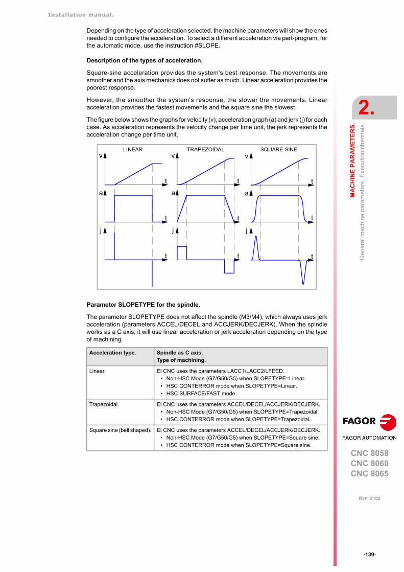
Installation manual.
CNC 8058CNC 8060CNC 8065
MA
CH
INE
PA
RA
ME
TE
RS
.
2.
Gen
era
l mac
hin
e p
aram
eter
s. E
xecu
tion
chan
nel
s.
ꞏ139ꞏ
REF: 2102
Depending on the type of acceleration selected, the machine parameters will show the onesneeded to configure the acceleration. To select a different acceleration via part-program, forthe automatic mode, use the instruction #SLOPE.
Description of the types of acceleration.
Square-sine acceleration provides the system's best response. The movements aresmoother and the axis mechanics does not suffer as much. Linear acceleration provides thepoorest response.
However, the smoother the system's response, the slower the movements. Linearacceleration provides the fastest movements and the square sine the slowest.
The figure below shows the graphs for velocity (v), acceleration graph (a) and jerk (j) for eachcase. As acceleration represents the velocity change per time unit, the jerk represents theacceleration change per time unit.
Parameter SLOPETYPE for the spindle.
The parameter SLOPETYPE does not affect the spindle (M3/M4), which always uses jerkacceleration (parameters ACCEL/DECEL and ACCJERK/DECJERK). When the spindleworks as a C axis, it will use linear acceleration or jerk acceleration depending on the typeof machining.
Acceleration type. Spindle as C axis. Type of machining.
Linear. El CNC uses the parameters LACC1/LACC2/LFEED.• Non-HSC Mode (G7/G50/G5) when SLOPETYPE=Linear.• HSC CONTERROR mode when SLOPETYPE=Linear.• HSC SURFACE/FAST mode.
Trapezoidal. El CNC uses the parameters ACCEL/DECEL/ACCJERK/DECJERK.• Non-HSC Mode (G7/G50/G5) when SLOPETYPE=Trapezoidal.• HSC CONTERROR mode when SLOPETYPE=Trapezoidal.
Square sine (bell shaped). El CNC uses the parameters ACCEL/DECEL/ACCJERK/DECJERK.• Non-HSC Mode (G7/G50/G5) when SLOPETYPE=Square sine.• HSC CONTERROR mode when SLOPETYPE=Square sine.
t
v
t
a
t
j
t
v
t
a
t
j
t
v
t
a
t
j
LINEAR TRAPEZOIDAL SQUARE SINE
Installation manual.
CNC 8058CNC 8060CNC 8065
2.
MA
CH
INE
PA
RA
ME
TE
RS
.
Gen
era
l mac
hin
e p
aram
eter
s. E
xecu
tion
chan
nel
s.
ꞏ140ꞏ
REF: 2102
IPLANEMain plane (G17/G18) by default.Possible values: G17 / G18.Default value: G17.Associated variable: (V.)[ch].MPG.IPLANE
This parameter indicates the main work plane assumed by the CNC by default. The axesthat form the work plane depend on machine parameter CHAXISNAME.
M models (mill) and L models (laser).
It is recommended to define the IPLANE parameter as G17. To change the work plane viapart-program, use function G17, G18, G19 or G20.
T model (lathe). Configuration of "Trihedron" type axes.
It is recommended to define the IPLANE parameter as G18. To change the work plane viapart-program, use function G17, G18, G19 or G20.
T model (lathe). Configuration of "plane" type axes.
The work plane is always G18; machine parameter IPLANE is not applied and it is notpossible to change planes via the part-program, only the longitudinal axis (G20).
ISYSTEMType of coordinates (G90/G91) by default.Possible values: G90 / G91.Default value: G90.Associated variable: (V.)[ch].MPG.ISYSTEM
This parameter indicates the type of coordinates assumed by the CNC by default. Thecoordinates of a point may be defined either in absolute coordinates (G90) referred to partzero or in incremental coordinates (G91) referred to the current position.
To change the type of coordinates via part-program, use function G90 or G91.
IMOVEType of movement (G0/G1) by default.Possible values: G0 / G1.Default value: G01.Associated variable: (V.)[ch].MPG.IMOVE
This parameter indicates the type of movement, G0 or G1, assumed by the CNC by default(after a start-up, following a reset or M30). To change them from the part-program, usefunction G0 or G1.
Plane. Abscissa axis. Ordinate axis. Longitudinal axis.
G17 CHAXISNAME 1 CHAXISNAME 2 CHAXISNAME 3
G18 CHAXISNAME 3 CHAXISNAME 1 CHAXISNAME 2
IMOVE Meaning.
G0. • The CNC assumes the G0 function. Movements in G0 are carried out in rapidas set by parameter G00FEED.
• The CNC will display G0 in the G function history.• When opening the MDI/MDA mode and programming a movement without
G, the CNC will execute it as G0.• When programming a movement via the manual mode, the axis moves as
G0.
G1. • The CNC assumes function G1. Movements in G1 are carried out at thefeedrate active at the CNC.
• The CNC does not display G1 in the G function history.• When opening the MDI/MDA mode and programming a movement without
G, the CNC will execute it as G1.• When programming a movement via the manual mode, the axis moves as
G1.
Installation manual.
CNC 8058CNC 8060CNC 8065
MA
CH
INE
PA
RA
ME
TE
RS
.
2.
Gen
era
l mac
hin
e p
aram
eter
s. E
xecu
tion
chan
nel
s.
ꞏ141ꞏ
REF: 2102
Parameter G0MODAL; maintaining function G0 as modal or non-modal.
The value IMOVE=G0 has priority over G0MODAL=No. The G0 function is defined as non-modal, however, with IMOVE=G0, the CNC assumes the G0 function at start-up after a resetor M30. After programming G1, G2 or G3, the CNC recovers G1 as a modal function untilthe following reset or M30. See "G0MODAL Programming for G0 remains as modal." onpage 141.
G0MODALProgramming for G0 remains as modal.Possible values: Yes / No.Default value: Yes.Associated variable: (V.)[ch].MPG.G0MODAL.
This parameter defines whether the G00 function is modal or not.
IMOVE parameter; type of movement (G0/G1) at startup, after a reset or M30.
The value IMOVE=G0 has priority over G0MODAL=No. The G0 function is defined as non-modal, however, with IMOVE=G0, the CNC assumes the G0 function at start-up after a resetor M30. After programming G1, G2 or G3, the CNC recovers G1 as a modal function untilthe following reset or M30. See "IMOVE Type of movement (G0/G1) by default." on page 140.
G2G3MODALProgramming in G2/G3 remains as modal.Possible values: Yes / No.Default value: Yes.Associated variable: (V.)[ch].MPG.G2G3MODAL.
This parameter defines whether the G2/G3 functions are modal or not.
IFEEDType of feedrate (G94/G95) by default.Possible values: G94 / G95. Default value: G94.Associated variable: (V.)[ch].MPG.IFEED
This parameter indicates the type of feedrate assumed by the CNC by default.
• With G94, the feedrate is assumed in mm/min or degrees/min or inches/min.
• With G95, the feedrate is assumed in mm/rev or degrees/rev or inches/rev.
The typical configuration for the mill model will be G94. The typical configuration for the lathemodel will be G95.
To change the type of feedrate via part-program, use function G93 or G94.
G0MODAL Meaning.
Yes. The G00 function is modal. After it has been programmed, it remains active untilG01, G02, G03, G33 or G63 are programmed.
No. The G00 function is non-modal, it must be programmed for each rapid traverseblock. For the following program block, if there is no programmed movementfunction (G0, G1, G2, G3, G33 or G63), the CNC uses G1, meaning that G1remains as modal.Within the range of influence of a canned cycle, the last programmed G will bemaintain active, while G0 remains being modal.
G2G3MODAL Meaning.
Yes. The G02 and G03 functions are modal. Once they are programmed, they remainactive until G00, G01, G33 or G63 are programmed.
No. The G02 and G03 functions are non-modal. These must be programmed for eachcircular interpolation block. For the following program block, if there is noprogrammed movement function (G0, G1, G2, G3, G33 or G63), the CNC usesG1.
Installation manual.
CNC 8058CNC 8060CNC 8065
2.
MA
CH
INE
PA
RA
ME
TE
RS
.
Gen
era
l mac
hin
e p
aram
eter
s. E
xecu
tion
chan
nel
s.
ꞏ142ꞏ
REF: 2102
FPRMANFunction G95 admitted in jog mode.Possible values: Yes / No.Default value: No.Associated variable: (V.)[ch].MPG.FPRMAN
Parameter valid on models -T-, -BL- and -OL-; not being used on the -M- model.
This parameter indicates whether function G95 (feedrate in mm/turn or inch/turn) is allowedin jog mode, for jog movements; it does not affect handwheel movements or in MDI/MDAmode.
The CNC will apply function G95 to the main axes of the channel (parameter GEOCONFIG);G95 does not affect the rest of the axes (auxiliary axes, steady rest, tailstock, turrets, etc.)even if FPRMAN = YES.
When G95 is active and FPRMAN = YES, the real feedrate (Freal) displayed in jog andconversational modes always is in mm/turn or inch/turn, whether the moving axis is a mainaxis or not.
IRCOMPTool radius compensation mode (G136/G137) by default.Possible values: G136 / G137.Default value: G136 (mill/lathe) / G137 (laser).Associated variable: (V.)[ch].MPG.IRCOMP
This parameter indicates the compensation mode assumed by the CNC by default. Beingthe radius compensation active, the compensated paths may be blended together usingcircular paths (G136) or linear paths (G137).
To change the type of compensation via part-program, use function G136 or G137.
COMPCANCELHow to cancel tool radius compensation.Possible values: With motion / Without motion.Default value: Without motion.Associated variable: (V.)[ch].MPG.COMPCANCEL
This parameter indicates whether tool radius compensation is canceled in the first motionblock, even if the plane axes are not involved, or if it requires a movement of the plane axes.
G00COMPApply tool radius compensation in G00.Possible values: Yes / No.Default value: Yes (milling and lathe) / No (laser).Associated variable: (V.)[ch].MPG.G00COMP
This parameter indicates whether the CNC applies tool radius compensation or not in G0movements.
GEOCONFIG. Meaning.
Plane The CNC will apply function G95 to the first two axes of the channel.
Trihedron The CNC will apply function G95 to the first three axes of the channel.
Installation manual.
CNC 8058CNC 8060CNC 8065
MA
CH
INE
PA
RA
ME
TE
RS
.
2.
Gen
era
l mac
hin
e p
aram
eter
s. E
xecu
tion
chan
nel
s.
ꞏ143ꞏ
REF: 2102
LCOMPTYPKeep the longitudinal axis when changing planes (G17/G18/G19).Possible values: Yes / No.Default value: No.Associated variable: (V.)[ch].MPG.LCOMPTYPE
This parameter indicates which will be the longitudinal axis when changing planes(G17/G18/G19). In either case, the longitudinal axis may be changed via part-program usingG20 functions or #TOOL AX.
PLANECANCELAssume IPLANE as active plane after M30/RESET or keep the active one.Possible values: Yes / No.Default value: Yes.Associated variable: (V.)[ch].MPG.PLANECANCEL
This parameter defines which is the active plane after executing M02, M30 or reset.
ICORNERType of corner (G5/G7/G50) by default.Possible values: G50 / G5 / G7.Default value: G50.Associated variable: (V.)[ch].MPG.ICORNER
This parameter indicates the type of corner assumed by the CNC by default. There are threetypes of corners, namely: square (G7), rounded (G5) and semi-rounded (G50). To changethe type of corner via part-program, use function G5, G7 or G50.
• When working in square corner, the CNC starts executing the next movement when theaxis gets into the in-position zone defined by parameter INPOSW.
• When working in round corner, it is possible to control the corner of the programmedprofile.
• When working in semi-rounded corner, the CNC starts executing the next movementonce the theoretical interpolation of the current move is completed.
If G5is selected, parameter ROUNTYPE must be set.
ROUNDTYPERounding type in G5 (by default).Possible values: Chordal error / % Feedrate.Default value: Chordal error.Associated variable: (V.)[ch].MPG.ROUNDTYPE
This parameter indicates the type of rounding applied by default when working in roundcorner. To change the type of rounding via program, use the #ROUNDPAR instruction.
The rounding may be executed by limiting the chordal error or the feedrate. The chordal error(#ROUNDPAR [1]) defines the maximum deviation allowed between the programmed pointand the resulting profile. The feedrate (#ROUNDPAR [2]) defines the percentage of theactive feedrate to be used for machining. Depending on the option selected, either parameterMAXROUND or ROUNDFEED will have to be set.
LCOMPTYP Meaning.
Yes. When changing work planes (G17/G18/G19), the CNC el CNC keeps thelongitudinal axis that was active before the plane change.
No. When changing the work planes (G17/G18/G19), the CNC assumes the axisperpendicular to the plane as the new longitudinal axis.
PLANECANCEL. Meaning.
Yes On power-up, after executing an M02 or M30, and after a reset, the CNC assumesthe plane defined in parameter IPLANE.
No On power-up, the CNC assumes the plane defined in parameter IPLANE; afterexecuting an M02 or M30, and after a reset, the CNC maintains the main activeplane.
Installation manual.
CNC 8058CNC 8060CNC 8065
2.
MA
CH
INE
PA
RA
ME
TE
RS
.
Gen
era
l mac
hin
e p
aram
eter
s. E
xecu
tion
chan
nel
s.
ꞏ144ꞏ
REF: 2102
MAXROUNDMaximum rounding error in G5.Possible values: From 0.02 to 99999.9999 mm or degrees / from 0.00079 to 3937.00787 inch.Default value: 0.1000 mm or degrees / 0.00394 inch.Associated variable: (V.)[ch].MPG.MAXROUND
This parameter sets the maximum deviation allowed between the programmed point and theprofile resulting from rounding the corner. The CNC takes it into account if ROUNDTYPE= Chordal error.
This parameter also sets the maximum contour allowed for the HSC mode when notprogramming CONTERROR (CONTERROR mode) or E (FAST mode).
ROUNDFEEDPercentage of feedrate in G5.Possible values: From 0 to 100.Default value: 100.Associated variable: (V.)[ch].MPG.ROUNDFEED
This parameter sets the percentage of the active feedrate to be used for machining. The CNCtakes it into account if ROUNDTYPE = % Feedrate.
Installation manual.
CNC 8058CNC 8060CNC 8065
MA
CH
INE
PA
RA
ME
TE
RS
.
2.
Gen
era
l mac
hin
e p
aram
eter
s. E
xecu
tion
chan
nel
s.
ꞏ145ꞏ
REF: 2102
2.4.9 Arc center correction.
CIRINERRMaximum absolute radius error permitted.Possible values: From 0 to 99999.9999 mm or degrees / from 0 to 3937.00787 inch.Default value: 0.0100 mm or degrees / 0.00039 inch.Associated variable: (V.)[ch].MPG.CIRINERR
See general machine parameter CIRINFACT.
CIRINFACTMaximum relative radius error permitted.Possible values: from 0 to 100.0 %.Default value: 0.1 %.Associated variable: (V.)[ch].MPG.CIRINFACT
These parameters set the conditions for correcting the center position in circularinterpolations. On circular interpolations, the CNC calculates the radius of the starting pointand end point of the tool path. Theoretically, they should be the same; but these parametersmay be used to set the maximum difference allowed between both radius.
Parameter CIRINERR indicates the maximum absolute error allowed. ParameterCIRINFACT indicates the maximum relative error allowed (% of the radius). Both parametersare taken into account. The CNC will show the relevant error message when this differencebetween them is greater than CIRINERR and greater than —CIRINFACT x Radius—.
This function is controlled via program using functions G264 and G265.
Installation manual.
CNC 8058CNC 8060CNC 8065
2.
MA
CH
INE
PA
RA
ME
TE
RS
.
Gen
era
l mac
hin
e p
aram
eter
s. E
xecu
tion
chan
nel
s.
ꞏ146ꞏ
REF: 2102
2.4.10 Behavior of the feedrate and the feedrate override.
MAXOVRMaximum override (%) permitted.Possible values: From 0 to 255.Default value: 200.Associated variable: (V.)[ch].MPG.MAXOVR
This parameter indicates the maximum percentage to be applied to the programmed axisfeedrate (feedrate override).
The percentage applied to the programmed feedrate may be set by program, via PLC or bythe switch of the panel. The one set by program has the highest priority and the one set bythe switch has the lowest priority.
Different values may be set for each axis via PLC and by program. The one selected at theswitch is common to all of them.
RAPIDOVROverride acts in G00 (from 0 to 100%).Possible values: Yes / No.Default value: Yes.Associated variable: (V.)[ch].MPG.RAPIDOVR
This parameter indicates whether the feedrate % may be modified (between 0% and 100%)or not when working in G0. If not allowed, the percentage will stay fixed at 100%.
Regardless of the value assigned to this parameter, the override always attends to the 0%position and never acts over 100%. It is always possible to change the % of feedrate whenmoving in jog mode.
FEEDNDApply the programmed feedrate to all the axes of the channel.Possible values: Yes / No.Default value: No.Associated variable: (V.)[ch].MPG.FEEDND
This parameter indicates whether the programmed feedrate is applied to all the axes of thechannel or only to the main axes.
FEEDND Meaning.
Yes. The programmed feedrate will be the result of composing the movements ontoall the axes of the channel.
No. If a movement has been programmed on any of the main axes, the programmedfeedrate will be the result of composing the movement only onto these axes. Therest of the axes move at their corresponding feedrate to end the movement ofthem all at the same time.The programmed feedrate is limited only if an axis could exceed its MAXFEED.If none of the main axes are programmed, the programmed feedrate will bereached on the axis moving the farthest so they can all reach their destinationat the same time.

Installation manual.
CNC 8058CNC 8060CNC 8065
MA
CH
INE
PA
RA
ME
TE
RS
.
2.
Gen
era
l mac
hin
e p
aram
eter
s. E
xecu
tion
chan
nel
s.
ꞏ147ꞏ
REF: 2102
2.4.11 Override of the dynamics.
MINDYNOVRMinimum override for the dynamics in HSC.Possible values: From 10 to 100 %.Default value: 30 %.Associated variable: (V.)[ch].MPG.MINDYNOVR
The screen of the automatic mode offers a slider for changing the dynamics defined byprogram for a machining operation. This parameter sets the minimum percentage to beapplied using the slider. If both parameters MINDYNOVR and MAXDYNOVR are set at100%, the CNC will not show the slider and it will not be possible to change in real time themachining dynamics.
MAXDYNOVRMaximum override for the dynamics in HSC.Possible values: From 100 to 500 %.Default value: 200 %.Associated variable: (V.)[ch].MPG.MAXDYNOVR
The screen of the automatic mode offers a slider for changing the dynamics defined byprogram for a machining operation. This parameter sets the maximum percentage to beapplied using the slider. If both parameters MINDYNOVR and MAXDYNOVR are set at100%, the CNC will not show the slider and it will not be possible to change in real time themachining dynamics.

Installation manual.
CNC 8058CNC 8060CNC 8065
2.
MA
CH
INE
PA
RA
ME
TE
RS
.
Gen
era
l mac
hin
e p
aram
eter
s. E
xecu
tion
chan
nel
s.
ꞏ148ꞏ
REF: 2102
2.4.12 DMC configuration.
MINDMCOVRMinimum DMC override of all channel axes.Possible values: From 10 to 100 %.Default value: 80 %.Associated variable: (V.)[ch].MPG.MINDMCOVR
See machine parameter MAXDMCOVR.
MAXDMCOVRMaximum DMC override of all channel axes.Possible values: From 100 to 255 %.Default value: 120 %.Associated variable: (V.)[ch].MPG.MAXDMCOVR
These parameters indicate the minimum and maximum percentage of feedrate (feedrateoverride) that DMC (dynamic machining control) can apply on the channel. Both percentagescan be changed in the instruction #DMC ON. The feedrate percentage applied by DMC isadded to that selected using the operator panel switch.
The resulting override (overrideDMC + overrideJOG) may exceed the set limits for bothparameters. The CNC always abides by the maximum limit set in the machine parameterMAXOVR.
If the user selects an override with the switch on the operator panel that is lower thanMINDMCOVR, the CNC inhibits DMC (but does not deactivate it); when the override onceagain exceeds MINDMCOVR, DMC will once again operate as normal.
The feedrate percentage set by the program (variable V.G.PRGFRO) or by the PLC (variableV.PLC.FRO) inhibit DMC, but they do not deactivate it; if canceled, DMC resumes controlover the feedrate percentage.
DMCPEAKSIZEExcess power percentage for monitoring the power peaks in the DMC. Possible values: From 0 to 100 %. Default value: 20 %.Associated variable: (V.)[ch].MPG.DMCPEAKSIZE
Excess power percentage, above the rated power, for monitoring the power peaks in theDMC. If it is set to 0, the peaks are not monitored. If the power read exceeds the power toachieve (target power+no-load power) in the defined percentage, the CNC issues a warning.It stops the axes while moving the spindle and activates the DMCPWRPEAK mark.
This parameter enables the detection of a power peak, which may be due to the breakageof the tool, depth of cut too large, etc.
DMCPWRFACTORMultiplication factor of the target power for monitoring the excess power consumed in the DMC. Possible values: From 0.0 to 100.0. Default value: 2.0.Associated variable: (V.)[ch].MPG.DMCPWRFACTOR
Multiplication factor of the target power to be deemed excessive consumed power. If definedwith a value smaller than or equal to "1", power consumption will not be monitored. If all thevalues of the power read over 2 seconds exceeds the power to achieve multiplied by thisfactor, the CNC will issue a warning and activate the DMCPWRHOLD mark.
This parameter enables the detection of excessive power consumption which may be dueto tool wear.
Override % OverrideDMC % OverrideJOG % 100
-----------------------------------------------------------------------------------------------------=
Installation manual.
CNC 8058CNC 8060CNC 8065
MA
CH
INE
PA
RA
ME
TE
RS
.
2.
Gen
era
l mac
hin
e p
aram
eter
s. E
xecu
tion
chan
nel
s.
ꞏ149ꞏ
REF: 2102
2.4.13 Movement of the independent axes.
IMOVEMACHMovement of the independent axis referred to machine coordinates.Possible values: Yes / No.Default value: No.Associated variable: (V.)[ch].MPG.IMOVEMACH
This parameter indicates whether the movements of the independent axes are referred tomachine coordinates (IMOVEMACH = YES) or to part coordinates (IMOVEMACH = NO),before the coordinate transformations.
XFITOINDThe transfer inhibit of the channel affects the independent axes.Possible values: Yes / No.Default value: Yes.Associated variable: (V.)[ch].MPG.XFITOIND
This parameter indicates whether the transfer inhibit of the channel (_XFERINH mark)affects the movements of the independent axis programmed from the PLC or not. Thetransfer inhibit of the channel always affects the movements of the independent axisprogrammed from the CNC.
XFITOIND Meaning.
Yes The _XFERINH mark affects the movement of the independent axis programmedfrom the PLC and from the CNC.
No The _XFERINH mark does not affect the movements of the independent axisprogrammed from the PLC; but it does affect the ones programmed from theCNC.
Installation manual.
CNC 8058CNC 8060CNC 8065
2.
MA
CH
INE
PA
RA
ME
TE
RS
.
Gen
era
l mac
hin
e p
aram
eter
s. E
xecu
tion
chan
nel
s.
ꞏ150ꞏ
REF: 2102
2.4.14 Definition of the subroutines.
SUBTABLEOEM-subroutines table.
The manufacturer’s subroutines are those stored in folder ..\MTB\Sub. These subroutinesare associated with functions of the CNC such as tool change, G74, G180 to G189, G380to G399, etc.
If the same subroutines are executed repeatedly during execution, it is more efficient to loadthem into the RAM memory of the CNC because this way, they may be accessed faster andexecution time may be consequently optimized. To load a subroutine into RAM, it must havethe extension .fst.
Being the CNC in USER mode, the OEM routines having a .fst extension are loaded intoRAM memory when starting up the CNC application. Being the CNC in SETUP mode, theOEM subroutines whose extension is .fst will be loaded into RAM memory the first time theyare executed in the program.
TOOLSUBSubroutine associated with "T".Possible values: any text with up to 64 characters.Associated variable: (V.)[ch].MPG.TOOLSUB
This subroutine is executed automatically every time a T function (tool selection) is executed.
REFPSUB (G74)Subroutine associated with function G74.Possible values: any text with up to 64 characters.Associated variable: (V.)[ch].MPG.REFPSUB
Function G74 (home search) may be programmed in two ways. indicating the axes and theorder they will be homed or by programming G74 alone (without axes).
When executing a block that only contains the G74 function (without axes), it calls thesubroutine indicated in this parameter. This subroutine must contain the axes and the order(sequence) to search home.
This subroutine is also called when homing the axis in JOG mode without selecting the axes.
INT1SUB··INT4SUBInterruption subroutines.Possible values: any text with up to 64 characters.Associated variable: (V.)[ch].MPG.INT1SUB / (V.)[ch].MPG.INT4SUB
These parameters indicate the name of the interruption subroutines associated with marksINT1 to INT4 of the PLC. When the PLC activates one of these marks, the channel interruptsthe execution of the program and executes the corresponding interruption subroutine. If theprogram is interrupted (STOP) or no program is in execution (channel in READY state), theexecution of the subroutine depends on parameter SUBINTSTOP.
INITIALSUBSubroutine associated with the command #INITIALSUB.Possible values: any text with up to 64 characters.Associated variable: (V.)[ch].MPG.INITIALSUB
This parameter indicates the name of the subroutine associated with the instruction#INITIALSUB. Every time the CNC executes this instruction, its associated subroutine iscalled upon.
Installation manual.
CNC 8058CNC 8060CNC 8065
MA
CH
INE
PA
RA
ME
TE
RS
.
2.
Gen
era
l mac
hin
e p
aram
eter
s. E
xecu
tion
chan
nel
s.
ꞏ151ꞏ
REF: 2102
PIERCINGSubroutine associated with the command #PIERCING.Possible values: any text with up to 64 characters.Associated variable: (V.)[ch].MPG.PIERCING
This parameter indicates the name of the subroutine associated with the instruction#PIERCING. Every time the CNC executes this instruction, its associated subroutine isinvoked (by default, Piercing.fst).
At the start of the subroutine (or when the OEM deems it necessary), the OEM must activatethe PIERCING mark (assigning it the value 1) to indicate to the PLC that it must start thepiercing operation. At the end of the subroutine (or when the OEM deems it necessary), theOEM must deactivate this mark (assigning it the value 0) to indicate to the CNC that it hasfinished the piercing operation.
CUTTINGONSubroutine associated with the command #CUTTING ON.Possible values: any text with up to 64 characters.Associated variable: (V.)[ch].MPG.CUTTINGON
This parameter indicates the name of the subroutine associated with the instruction#CUTTING ON. Every time the CNC executes this instruction, its associated subroutine isinvoked (by default, Cuttingon.fst).
At the start of the subroutine Cuttingon.fst (or when the OEM deems it necessary), the OEMmust activate the CUTTING mark (assigning it a value of 1) to indicate to the PLC that itshould start the cutting operation.
CUTTINGOFFSubroutine associated with the command #CUTTING OFF.Possible values: any text with up to 64 characters.Associated variable: (V.)[ch].MPG.CUTTINGOFF
This parameter indicates the name of the subroutine associated with the instruction#CUTTING OFF. Every time the CNC executes this instruction, its associated subroutine isinvoked (by default, Cuttingoff.fst).
At the end of the Cuttingoff.fst subroutine (or when the OEM deems it necessary), the OEMmust deactivate the CUTTING mark (assigning it a value of 0) to indicate to the CNC thatit has finished the cutting operation.
FINALSUBSubroutine associated with the command #FINALSUB.Possible values: any text with up to 64 characters.Associated variable: (V.)[ch].MPG.FINALSUB
This parameter indicates the name of the subroutine associated with the instruction#FINALSUB. Every time the CNC executes this instruction, its associated subroutine iscalled upon.
OEMSUB (G18x)Subroutines associated with functions G180 through G189.Possible values: any text with up to 64 characters.Associated variable: (V.)[ch].MPG.OEMSUB1ꞏꞏ10
These parameters indicate the number of the subroutines associated with functions G180through G189. Every time one of these functions is executed, its associated subroutine iscalled upon.
The OEM is responsible for ensuring that the subroutine has all the safety aspects related to handlingthe laser.
The OEM is responsible for ensuring that the subroutine has all the safety aspects related to handlingthe laser.
The OEM is responsible for ensuring that the subroutine has all the safety aspects related to handlingthe laser.
Installation manual.
CNC 8058CNC 8060CNC 8065
2.
MA
CH
INE
PA
RA
ME
TE
RS
.
Gen
era
l mac
hin
e p
aram
eter
s. E
xecu
tion
chan
nel
s.
ꞏ152ꞏ
REF: 2102
OEMSUB (G38x)Subroutines associated with functions G380 through G399.Possible values: any text with up to 64 characters.Associated variable: (V.)[ch].MPG.OEMSUB11ꞏꞏ30
These parameters indicate the number of the subroutines associated with functions G380through G399. Every time one of these functions is executed, its associated subroutine iscalled upon.
SUBPATHPath of the program subroutines.Associated variable: (V.)[ch].MPG.SUBPATH
This parameter indicates the directory, by default, containing the user subroutines and thenecessary subroutines to execute programs of the 8055 MC and 8055 TC.
User subroutines.
User subroutines are those associated with part-programs. These subroutines must be inan unprotected folder for the user mode. When calling any of these subroutines (instructions#PCALL, #CALL, etc.) without indicating the path, the subroutine looks for them in this orderand in the following directories:
1 Folder selected with the #PATH instruction.
2 Folder of the program in execution.
3 Folder indicated in the machine parameter SUBPATH.
When the call indicates the whole path, it will only look for it in the indicated folder.
Subroutines 9998 to 9999.
In order to be able to execute programs of the 8055 MC/TC, the CNC must have twosubroutines called 9998 and 9999 written in 8070 CNC language.
Each program in the language of the 8055 MC/TC has a call to the corresponding subroutineat the beginning and at the end. Both subroutines must be defined, even if no operation isto be carried out at the beginning or at the end of the part-program, in which case thesubroutines will be empty (except for the end-of-subroutine block). If any of thesesubroutines is missing, the CNC will issue an error message every time when trying toexecute a part-program.
9998 Subroutine that the CNC will execute at the beginning of each program.
9999 Subroutine that the CNC will execute at the end of each program.
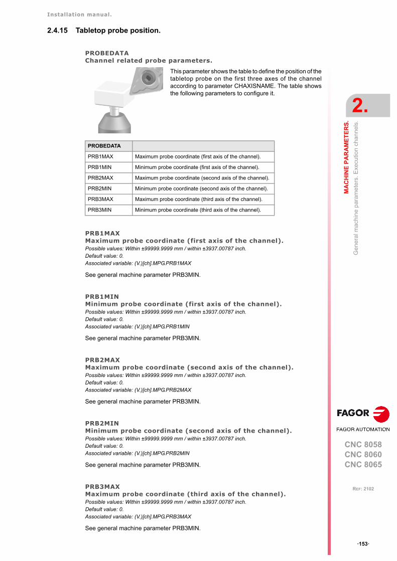
Installation manual.
CNC 8058CNC 8060CNC 8065
MA
CH
INE
PA
RA
ME
TE
RS
.
2.
Gen
era
l mac
hin
e p
aram
eter
s. E
xecu
tion
chan
nel
s.
ꞏ153ꞏ
REF: 2102
2.4.15 Tabletop probe position.
PROBEDATAChannel related probe parameters.
PRB1MAXMaximum probe coordinate (first axis of the channel).Possible values: Within ±99999.9999 mm / within ±3937.00787 inch.Default value: 0.Associated variable: (V.)[ch].MPG.PRB1MAX
See general machine parameter PRB3MIN.
PRB1MINMinimum probe coordinate (first axis of the channel).Possible values: Within ±99999.9999 mm / within ±3937.00787 inch.Default value: 0.Associated variable: (V.)[ch].MPG.PRB1MIN
See general machine parameter PRB3MIN.
PRB2MAXMaximum probe coordinate (second axis of the channel).Possible values: Within ±99999.9999 mm / within ±3937.00787 inch.Default value: 0.Associated variable: (V.)[ch].MPG.PRB2MAX
See general machine parameter PRB3MIN.
PRB2MINMinimum probe coordinate (second axis of the channel).Possible values: Within ±99999.9999 mm / within ±3937.00787 inch.Default value: 0.Associated variable: (V.)[ch].MPG.PRB2MIN
See general machine parameter PRB3MIN.
PRB3MAXMaximum probe coordinate (third axis of the channel).Possible values: Within ±99999.9999 mm / within ±3937.00787 inch.Default value: 0.Associated variable: (V.)[ch].MPG.PRB3MAX
See general machine parameter PRB3MIN.
This parameter shows the table to define the position of thetabletop probe on the first three axes of the channelaccording to parameter CHAXISNAME. The table showsthe following parameters to configure it.
PROBEDATA
PRB1MAX Maximum probe coordinate (first axis of the channel).
PRB1MIN Minimum probe coordinate (first axis of the channel).
PRB2MAX Maximum probe coordinate (second axis of the channel).
PRB2MIN Minimum probe coordinate (second axis of the channel).
PRB3MAX Maximum probe coordinate (third axis of the channel).
PRB3MIN Minimum probe coordinate (third axis of the channel).
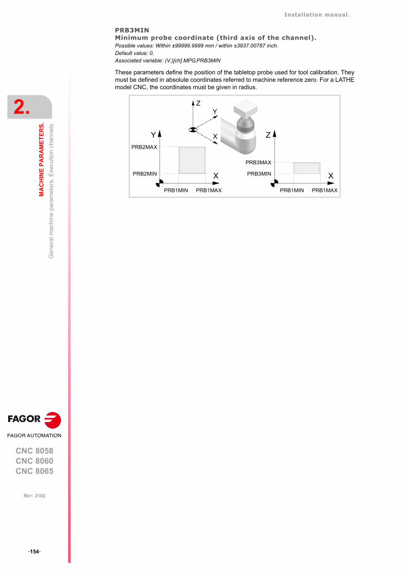
Installation manual.
CNC 8058CNC 8060CNC 8065
2.
MA
CH
INE
PA
RA
ME
TE
RS
.
Gen
era
l mac
hin
e p
aram
eter
s. E
xecu
tion
chan
nel
s.
ꞏ154ꞏ
REF: 2102
PRB3MINMinimum probe coordinate (third axis of the channel).Possible values: Within ±99999.9999 mm / within ±3937.00787 inch.Default value: 0.Associated variable: (V.)[ch].MPG.PRB3MIN
These parameters define the position of the tabletop probe used for tool calibration. Theymust be defined in absolute coordinates referred to machine reference zero. For a LATHEmodel CNC, the coordinates must be given in radius.
X
Y
PRB1MAXPRB1MIN
PRB2MAX
PRB2MIN
Z
X
Y
X
Z
PRB1MAXPRB1MIN
PRB3MAX
PRB3MIN
Installation manual.
CNC 8058CNC 8060CNC 8065
MA
CH
INE
PA
RA
ME
TE
RS
.
2.
Gen
era
l mac
hin
e p
aram
eter
s. E
xecu
tion
chan
nel
s.
ꞏ155ꞏ
REF: 2102
2.4.16 Block search.
FUNPLCSend the M, H, S functions to the PLC during block search.Possible values: Yes / No.Default value: No.Associated variable: (V.)[ch].MPG.FUNPLC
With block search, it is possible to recover the program history up to a particular block, thatmay be in a program or in a subroutine, in such way that if program execution is resumedat that block, it will do so with the same conditions as if it were executed from the beginning.
This parameter determines whether or not the CNC sends the M, H, S functions to the PLCduring block search. The M function table has an MPLC field to define whether the CNCsends the function to the PLC or not. All M functions set in the table will be sent out to thePLC or not depending on this field regardless of the setting of machine parameter FUNPLC.
2.4.17 Interruption subroutines.
SUBINTSTOPExecute interruption subroutines while the program is stopped or while no program is in execution.Possible values: Yes / No.Default value: No.Associated variable: (V.)[ch].MPG.SUBINTSTOP
This parameter determines whether the CNC must execute the interruption subroutine whenthe program is interrupted (STOP) or no program is in execution (channel in READY state).In order to execute the subroutine when no program is in execution, the channel must bein automatic mode; the subroutine cannot be executed from jog mode.
FUNPLC Meaning.
Yes In this case, the functions are sent out to the PLC during block search as theyare being read. Once block search ends and after repositioning the axes, theCNC shows the "MHSF" softkey for executing any function of this type, thusmodifying the machining conditions.
No In this case, the functions are not sent out to the PLC during block search. Afterthe search, the CNC screen shows the history of those functions so the user canenable them in the desired order.
Installation manual.
CNC 8058CNC 8060CNC 8065
2.
MA
CH
INE
PA
RA
ME
TE
RS
.
Gen
era
l mac
hin
e p
aram
eter
s. E
xecu
tion
chan
nel
s.
ꞏ156ꞏ
REF: 2102
2.4.18 Machining feedrate.
MAXFEEDMaximum machining feedrate on the tool path.Possible values: From 0 to 500000.0000 mm/min / from 0 to 19685.03937 inch/min.Default value: 0.Associated variable: (V.)[ch].MPG.MAXFEED
This parameter sets the maximum machining feedrate (movements in G01/G02/G03) alongthe path; when set to ꞏ0ꞏ, the feedrate is not limited This parameter cannot be set with a valuehigher than that of parameter G00FEED.
When trying to exceed the maximum feedrate via part-program, via PLC or from the operatorpanel, the CNC limits the feedrate to the maximum value set in MAXFEED without showingany error message or warning.
If the machining feedrate is not limited, the CNC assumes for all the movements the one setin machine parameter G00FEED as the maximum feedrate.
How to limit temporarily the maximum feedrate via PLC
The PLC has the variable (V.)[ch].PLC.G00FEED that may be used to limit the feedrate inthe channel for any type of movement (G00, G01, etc). This variable limits the feedrate ofthe path and affects all the axes whether they move interpolated or one axis at a time.
The CNC assumes the change immediately and the change stays active until the variabletakes a value of ꞏ0ꞏ restoring the limits set by machine parameters.
DEFAULTFEEDAssume MAXFEED for movements in G1/G2/G3 without active feedrate.Possible values: Yes / No.Default value: No.Associated variable: (V.)[ch].MPG.DEFAULTFEED
This parameter sets whether or not the axes move at the feedrate set in MAXFEED whenprogramming a movement in G01/G02/G03 without programming the feedrate. If thisparameter is set to ꞏNoꞏ, the CNC will issue an error message when programming amovement in G01/G02/G03 without programming the feedrate.
The CNC takes this parameter into account when MAXFEED has been set with a value otherthan ꞏ0ꞏ.
Installation manual.
CNC 8058CNC 8060CNC 8065
MA
CH
INE
PA
RA
ME
TE
RS
.
2.
Gen
era
l mac
hin
e p
aram
eter
s. E
xecu
tion
chan
nel
s.
ꞏ157ꞏ
REF: 2102
2.4.19 Rapid traverse for the automatic mode
RAPIDENIt is used to enable rapid traverse for the automatic mode.Possible values: Disabled / EXRAPID or rapid key / EXRAPID and rapid key.Default value: Disabled.Associated variable: (V.)[ch].MPG.RAPIDEN
This parameter indicates whether rapid traverse may be enabled or not during the executionof a program for the programmed movements. Depending on the selected option, activatingrapid traverse will require activating the PLC mark EXRAPID or pressing the "rapid" key orboth.
When activating rapid traverse while executing a program, each axis will assume thefeedrate set by its parameter FRAPIDEN, as long as G0 or a thread is not active. Movementsin G0 are carried out at the feedrate set in parameter G00FEED. The threads are executedat the programmed feedrate. The rapid traverse will also be limited by channel parameterFRAPIDEN.
FRAPIDENRapid traverse in the channel for movements in automatic mode.Possible values: From 0 to 500000.0000 mm/min / from 0 to 19685.03937 inch/min.Default value: 0.Associated variable: (V.)[ch].MPG.FRAPIDEN
Maximum feedrate in the channel for the program being executed, when rapid traverse forthe automatic mode is active (parameter RAPIDEN). If the parameter is set with a "0" value,the feedrate is not limited.
This parameter does not the movements programmed in G00 or the threads. Movementsin G0 are carried out at the feedrate set in parameter G00FEED. The threads are executedat the programmed feedrate.
Rapid traverse cannot exceed the value set in axis parameters G00FEED and FRAPIDENor the maximum feedrate set by PLC (variable (V.)PLC.G00FEED). Rapid traverse cannotexceed the value set in axis parameter MAXFEED of the channel and the active feedrateset by PLC (variable (V.)PLC.F).
RAPIDEN Meaning.
Disabled. Rapid traverse is not available for the automatic mode.
EXRAPID or rapid key. To activate the rapid feed, just activate the PLC mark EXRAPID orpress the "rapid" key of the jog panel.
EXRAPID and rapid key. To activate the rapid feed, just activate the PLC mark EXRAPID andpress the "rapid" key of the jog panel.
If "EXRAPID or rapid key" is the chosen option for RAPIDEN and the CNC has several channels, theEXRAPID mark will only affect the corresponding channel. The rapid key, on the other hand, affectssimultaneously all the channels that may be affected at the time. If the active channel is in jog modeand another channel is executing a program, when pressing the rapid key in the active channel (jogmode), the rapid traverse will also be applied in the channel that is executing the program.In a system where the rapid key may affect several channels at the same time, we recommend tochoose the "EXRAPID and rapid key" option or manage by PLC the behavior of the rapid key accordingto the active channel and the selected work mode (jog or automatic).

Installation manual.
CNC 8058CNC 8060CNC 8065
2.
MA
CH
INE
PA
RA
ME
TE
RS
.
Gen
era
l mac
hin
e p
aram
eter
s. E
xecu
tion
chan
nel
s.
ꞏ158ꞏ
REF: 2102
2.4.20 Maximum acceleration and jerk on the tool path.
MAXACCELMaximum acceleration on the machining path.Possible values: From 0.0010 to 600000000.0000 mm/min / from 0.00004 to 23622047.24409 inch/min.Default value: There is no maximum feedrate.Associated variable: (V.)[ch].MPG.MAXACCEL
This parameter may be used to smooth the feedrate on the tool path by limiting the maximumacceleration on it. Regardless of the value of this parameter, the CNC always respects thedynamics of the axes involved in the path; i.e. it respects the acceleration set for each axis.
How to change temporarily the maximum acceleration defined.
The variable "(V.)[ch].G.MAXACCEL" may be used to temporarily change at a particular timeand in real time the value set by the machine parameter. The CNC assumes the changeimmediately and stays active until M30 or reset is executed, in which case the CNC restoresthe value set by the machine parameter. If the variable takes the value of ꞏ0ꞏ, the CNC doesnot apply any acceleration limit on the tool path, not even the one set by machine parameter.
MAXJERKMaximum jerk on the machining path.Possible values: From 0.0010 to 6E11 mm/min / from 0.00004 to 2.362E10 inch/min.Default value: There is no maximum feedrate.Associated variable: (V.)[ch].MPG.MAXJERK
This parameter may be used to smooth the feedrate on the tool path by limiting the maximumjerk on it. Regardless of the value of this parameter, the CNC always respects the dynamicsof the axes involved in the path; i.e. it respects the jerk set for each axis.
How to change temporarily the maximum jerk defined.
The variable "(V.)[ch].G.MAXJERK" may be used to temporarily change at a particular timeand in real time the value set by the machine parameter. The CNC assumes the changeimmediately and stays active until M30 or reset is executed, in which case the CNC restoresthe value set by the machine parameter. If the variable takes the value of ꞏ0ꞏ, the CNC doesnot apply any jerk limit on the tool path, not even the one set by machine parameter.
2.4.21 Maximum frequency on the tool path.
MAXFREQMaximum frequency generated on the machining path.Possible values: From 0 to 500 Hz.Default value: 0.Associated variable: (V.)[ch].MPG.MAXFREQ
This parameter may be used to set the parameters the damping (smoothing) filter formachining in G5. This filter improves the machining of CAD parts without having to activatethe HSC feature. This parameter must be set using the FineTune application.
Installation manual.
CNC 8058CNC 8060CNC 8065
MA
CH
INE
PA
RA
ME
TE
RS
.
2.
Gen
era
l mac
hin
e p
aram
eter
s. E
xecu
tion
chan
nel
s.
ꞏ159ꞏ
REF: 2102
2.4.22 Resonance frequency of the machine.
CURVFREQRESFirst resonance frequency of the machine in the arcs.Possible values: From 0 to 500.0000 HzDefault value: 0.Associated variable: (V.)[ch].MPG.CURVFREQRES
Resonance frequency that the CNC must eliminate when generating the command duringcircular tool paths. The CNC applies this filter in HSC, G50, G5 and G7.
2.4.23 "Retrace" function.
RETRACACPermit enabling the "retrace" function.Possible values: Yes / No.Default value: No.Associated variable: (V.)[ch].MPG.RETRACAC
This parameter indicates whether the "retrace" function may be used at the CNC or not. Oncethe "retrace" function is permitted, it may be activated from the PLC using the RETRACEmark.
NRETBLKMaximum number of blocks allowed for the "retrace" function.Possible values: From 0 to 300.Default value: 75.Associated variable: (V.)[ch].MPG.NRETBLK
This parameter sets the maximum number of blocks that may be retraced (executedbackwards) with the "retrace" function. Once the CNC has retraced all the blocks, it goeson executing forward.
It is recommended not to increase the value of this parameter unnecessarily. In order to beable to execute the "retrace" function, the CNC stores the information of the last blocksexecuted. The higher the value assigned to this parameter, the greater the information theCNC must store.
RETMFUNCTreatment of the M functions with the "retrace" function.Possible values: Ignore / Cancel.Default value: Ignore.Associated variable: (V.)[ch].MPG.RETMFUNC
This parameter sets the behavior of the "retrace" function when executing M functions. Whenthe CNC finds an M function, it can either ignore it and keep executing blocks in retrace orcancel the "retrace" function.
This parameter does not affect the following "M" functions.
• Functions M00 and M01 are always executed; they are sent to the PLC and [CYCLESTART] must be pressed to resume execution in retrace.
• Functions M03 and M04 are always ignored; the CNC does not start the spindle nor doesit change its turning direction.
• Function M05 only cancels the retrace function if it implies stopping the spindle; in otherwords, if the spindle is not running, an M05 function does not cancel the retrace function.
Installation manual.
CNC 8058CNC 8060CNC 8065
2.
MA
CH
INE
PA
RA
ME
TE
RS
.
Gen
era
l mac
hin
e p
aram
eter
s. E
xecu
tion
chan
nel
s.
ꞏ160ꞏ
REF: 2102
2.4.24 Withdrawal the tool.
RETRACTENABLEEnable tool withdrawal.
This parameter shows the parameter table to enable tool withdrawal (retraction) in varioussituations.
RETRACTTHREADEnable tool withdrawal (retraction) in threading.Possible values: ON / OFF.Default value: ON.Associated variable: (V.)[ch].MPG.RETRACTTHREAD
This parameter defines the CNC behavior when interrupting a threading ([STOP] key or PLCmark _FEEDHOL).
2.4.25 Master spindle.
MASTERSPDLMaster spindle maintained.Possible values: Temporary / maintained.Default value: Temporary.Associated variable: (V.)[ch].MPG.MASTERSPDL
This parameter indicates whether the channel keeps the current master spindle or recoversits original master spindle after executing M02, M30 or after an emergency or reset orrestarting the CNC.
When a channel does not keep its master spindle, on CNC power-up and after a reset, thechannel assumes as master spindle the first spindle defined by the machine parameters ofthe channel (original master). If this spindle is parked or "handed out" to another channel,the channel assumes as master spindle the next spindle defined by the machine parametersand so on. If the channel does not have spindles of the original configuration (the one definedby the machine parameters) because they are parked or "handed out", it assumes as masterspindle the first one of the current configuration that is not parked.
Exchanging spindles between channels.
When spindles are being exchanged between channels, the behavior of this parameter alsodepends on parameter AXISEXCH that sets whether the channel change of a spindle istemporary or permanent. If the current master spindle of the channel is a spindle "loaned"by another channel and its permission to change channels is temporary (AXISEXCH =Temporary), the spindle returns to its original channel.
RETRACTENABLE
RETRACTTHREAD Enable tool withdrawal (retraction) in threading.
RETRACTTHREAD Meaning.
OFF The CNC stops the axes at the end of the pass.
ON • In electronic threading (G33/G34), function G233 defines the distancethat the axes withdraw from the part. If G233 is not active, the axes stopat the end of the pass.
• In threading canned cycles, (-T- model), both ISO and conversational,the CNC withdraws the axes from the part. The distance that the toolwithdraws depends on how the cycle is programmed.
MASTERSPDL Meaning.
Temporary. The channel recovers its original master spindle if it is free; otherwise, it selectsas master the firs spindle available in the original configuration.
Maintained. The channel keeps the active master spindle.
Installation manual.
CNC 8058CNC 8060CNC 8065
MA
CH
INE
PA
RA
ME
TE
RS
.
2.
Mac
hin
e pa
ram
ete
rs fo
r th
e a
xes
and
spin
dle
s.
ꞏ161ꞏ
REF: 2102
2.5 Machine parameters for the axes and spindles.
The CNC only shows the parameters for the selected type of axis and drive. That's why itdisplays some characters next to each parameter indicating the corresponding type of axisand drive.
In the laser model, the parameters related to spindle speed (defined in rpm) define the power(defined in watts).
2.5.1 Belonging to the channel.
AXISEXCHChannel change permission.Parameter valid for linear and rotary axes and spindles. Parameter valid for analog drive, Sercos and simulated. Possible values: No / Temporary / Maintained.Default value: No.Associated variable: (V.)[ch].MPA.AXISEXCH.xn
Initially, each channel has some axes and spindles assigned to it. The CNC can changechannel axes and spindles or just change the configuration of a channel by modifying theposition of its axes and spindles or eliminating some of them.
In order for the CNC to be able to change the channel axes and spindles, they must havepermission. Parameter AXISEXCH sets whether the axis or the spindle has permission tochange channels and if it does, whether the change is temporary or permanent; in otherwords, whether the change is maintained after an M02, M30, a reset or after restarting theCNC.
The original configuration (the one defined in the machine parameters) of a channel with axesand spindles of the type "AXISEXCH = Maintained" may be restored either by validating themachine parameters or by undoing the changes, for example using a part-program. It mustbe borne in mind that validating the machine parameters restores the configuration of all thechannels.
AXISEXCH. Meaning.
No. • The CNC can modify the position of the axis or spindle in its channel or evenremove it from the channel.
• The CNC cannot change the axis or the spindle of the channel. • The CNC does not maintain the changes when restarting the part-program,
after a reset or after restarting the CNC. The axis or spindle returns to itsoriginal position, set by machine parameters.
Temporary. • The CNC can modify the position of the axis or spindle in its channel or evenremove it from the channel.
• The CNC can change the axis or the spindle of the channel. • The CNC does not maintain the changes when restarting the part-program,
after a reset or after restarting the CNC. The axis or spindle returns to itschannel and original position, set by machine parameters.
Maintained. • The CNC can modify the position of the axis or spindle in its channel or evenremove it from the channel.
• The CNC can change the axis or the spindle of the channel. • The CNC maintains the changes when restarting the part-program, after a
reset or after restarting the CNC. The axis or spindle stays in its new channel,but it can change the position to let the original axes of the channel return.
Installation manual.
CNC 8058CNC 8060CNC 8065
2.
MA
CH
INE
PA
RA
ME
TE
RS
.
Mac
hin
e pa
ram
ete
rs fo
r th
e a
xes
and
spin
dle
s.
ꞏ162ꞏ
REF: 2102
2.5.2 Type of axis and drive.
AXISTYPEType of axis.Parameter valid for linear and rotary axes and spindles. Parameter valid for analog drive, Sercos and simulated. Possible values: Linear / Rotary / Spindle.Default value: Linear.Associated variable: (V.)[ch].MPA.AXISTYPE.xn
The axes defined here may be configured as gantry or tandem axes.
DRIVETYPEType of drive.Parameter valid for linear and rotary axes and spindles. Parameter valid for analog drives, Sercos, Mlink (Mechatrolink) and simulated drives. Possible values: Analog / Sercos / Mlink / Simulated.Default value: Simulated.Associated variable: (V.)[ch].MPA.DRIVETYPE.xn
This parameter sets the type of drive, analog, Sercos, Mlink (Mechatrolink) or simulated. TheCNC does not allow having Sercos and Mechatrolink drives in the same system; but it doesallow combining these drives with analog drives. The simulated axis option must be usedwhen there is no physical axis or during setup. With the Simulated option, the CNC simulatesall the movements, it assumes the theoretical coordinate as real and does not output velocitycommands.
The simulated axes are not activated with the validation code. It is possible to use as manysimulated axes as you wish as long as the sum of the simulated axes and the physical axesdoes not exceed the maximum number of axes possible (as set by parameter NAXIS).
Type of drive when the CNC has been installed as simulator at a PC.
When the CNC is installed as a simulator at a PC, the drive may be a simulated type, Sercosor Mechatrolink; it cannot be analog. In either case, the CNC simulates all the movementsand assumes the theoretical coordinate as the real one.
POSUNITSFeedback system units.Parameter valid for linear and rotary axes and spindles. Parameter valid for Sercos, Mlink (Mechatrolink) and simulated drives. Possible values: Measurement / Pulses.Default value: Measurement.Associated variable: (V.)[ch].MPA.POSUNITS.xn
This parameter sets the units system used by the feedback system.
Refer to the drive manual for further detail.
POSUNITS Meaning.
Measurement. The communication with the drive is in millimeters or degrees.
Pulses. The communication with the drive is in pulses.
Installation manual.
CNC 8058CNC 8060CNC 8065
MA
CH
INE
PA
RA
ME
TE
RS
.
2.
Mac
hin
e pa
ram
ete
rs fo
r th
e a
xes
and
spin
dle
s.
ꞏ163ꞏ
REF: 2102
2.5.3 Configuring a Sercos drive.
SERCOSDATASercos drive data.Parameter valid for linear and rotary axes and spindles. Parameter valid for a Sercos drive.
This parameter shows the table to define the communication with the Sercos drive.
DRIVEIDSercos drive address.Parameter valid for linear and rotary axes and spindles. Parameter valid for a Sercos drive. Possible values: From 1 to 32.Default value: 1.Associated variable: (V.)[ch].MPA.DRIVEID.xnParameter included in the SERCOSDATA table.
This parameter indicates the position (node) occupied by the drive in the Sercos connection.
OPMODEPDrive's main operating mode.Parameter valid for linear and rotary axes and spindles. Parameter valid for a Sercos drive. Possible values: Position / Speed.Default value: Position.Associated variable: (V.)[ch].MPA.OPMODEP.xnParameter included in the SERCOSDATA table.
This parameter indicates the operating mode of the Sercos drive; velocity command orposition command. Refer to the drive manual for further detail.
We recommend to set the axes (except tandem axes) to operate in position-Sercos modeand the spindles in velocity-Sercos mode. However, tandem axes must necessarily work invelocity-Sercos mode. All the axes that will be interpolated with the tandem axis must alsooperate in velocity-Sercos mode.
Operating mode of the drive in velocity-Sercos.
• The velocity command is sent out to the drive in ten-thousandths rpm of the motor Whenneeding to use the SANALOG from the PLC, its value will also be given in ten-thousandths rpm of the motor.
• The CNC receives the drive's feedback as absolute coordinate in ten-thousandths of amillimeter or thousandths of a degree (same as in Sercos position mode).
• The CNC controls the home search. The home search is carried out without stoppingthe spindle if it was turning. If it is turning in M03 or M04 and M19 is programmed, thespindle decelerates down to REFFEED1 and starts searching home.
• The following error and the backlash compensation are calculated at the CNC.
• The CNC applies feed-forward and AC-forward.
• When the spindle is turning in open loop, the coordinate is simulated.
Operating mode of the drive in position-Sercos.
• The command is sent out to the drive in absolute coordinates, in ten-thousandths of amillimeter (linear axes) or thousandths of a degree (rotary axes). When needing to use
SERCOSDATA
DRIVEID Sercos drive address.
OPMODEP Main operating mode of the Sercos drive.
FBACKSRC Type of feedback.
FBACKDIFF Maximum difference between feedbacks.
ULTRAIPO Parameter not being used at this time.
FBACKTIME Time constant for combined feedback.
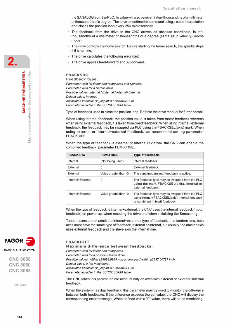
Installation manual.
CNC 8058CNC 8060CNC 8065
2.
MA
CH
INE
PA
RA
ME
TE
RS
.
Mac
hin
e pa
ram
ete
rs fo
r th
e a
xes
and
spin
dle
s.
ꞏ164ꞏ
REF: 2102
the SANALOG from the PLC, its value will also be given in ten-thousandths of a millimeteror thousandths of a degree. The drive smoothes the command using a cubic interpolationand closes the position loop every 256 microseconds.
• The feedback from the drive to the CNC arrives as absolute coordinate, in ten-thousandths of a millimeter or thousandths of a degree (same as in velocity-Sercosmode).
• The drive controls the home search. Before starting the home search, the spindle stopsif it is turning.
• The drive calculates the following error (lag).
• The drive applies feed-forward and AC-forward.
FBACKSRCFeedback type.Parameter valid for linear and rotary axes and spindles. Parameter valid for a Sercos drive. Possible values: Internal / External / Internal+External.Default value: Internal.Associated variable: (V.)[ch].MPA.FBACKSRC.xnParameter included in the SERCOSDATA table.
Type of feedback used to close the position loop. Refer to the drive manual for further detail.
When using internal feedback, the position value is taken from motor feedback whereaswhen using external feedback, it is taken from direct feedback. When using internal+externalfeedback, the feedback may be swapped via PLC using the FBACKSEL(axis) mark. Whenusing external or internal+external feedback, we recommend setting parameterFBACKDIFF.
When the type of feedback is external or internal+external, the CNC can enable thecombined feedback; parameter FBMIXTIME.
When the type of feedback is internal+external, the CNC uses the internal feedback (motorfeedback) on power-up, when resetting the drive and when initializing the Sercos ring.
Tandem axes do not admit the internal+extenrnal type of feedback. In a tandem axis, bothaxes must have the same type of feedback, external or internal, but usually, the master axisuses external feedback and the slave axis the internal one.
FBACKDIFFMaximum difference between feedbacks.Parameter valid for linear and rotary axes. Parameter valid for a position-Sercos drive. Possible values: Within ±99999.9999 mm or degrees / within ±3937.00787 inch.Default value: 0 (no monitoring).Associated variable: (V.)[ch].MPA.FBACKDIFF.xnParameter included in the SERCOSDATA table.
The CNC takes this parameter into account only on axes with external or external+internalfeedback.
When the system has dual feedback, this parameter may be used to monitor the differencebetween both feedbacks. If the difference exceeds the set value, the CNC will display thecorresponding error message. When defined with a "0" value, there will be no monitoring.
FBACKSRC FBMIXTIME Type of feedback.
Internal (Not being used) Internal feedback.
External 0 External feedback.
External Value greater than ꞏ0ꞏ. The combined (mixed) feedback is active.
Internal+External 0 The feedback type may be swapped from the PLCusing the mark FBACKSEL(axis). Internal orexternal feedback.
Internal+External Value greater than ꞏ0ꞏ. The feedback type may be swapped from the PLCusing the mark FBACKSEL(axis). Internal feedbackor combined (mixed) feedback.

Installation manual.
CNC 8058CNC 8060CNC 8065
MA
CH
INE
PA
RA
ME
TE
RS
.
2.
Mac
hin
e pa
ram
ete
rs fo
r th
e a
xes
and
spin
dle
s.
ꞏ165ꞏ
REF: 2102
ULTRAIPO(Not being used at this time)
Parameter not being used at this time.
FBMIXTIMETime constant for combined (mixed) feedback.Parameter valid for linear and rotary axes and spindles. Parameter valid for a Sercos drive. Possible values: From 0 to 3200.0 ms.Default value: 0.Associated variable: (V.)[ch].MPA.FBMIXTIME.xnParameter included in the SERCOSDATA table.
This parameter may be used to set the time constant to be used when combining feedbacks;i.e. it sets the delay between the coordinates entered in the position loop of the rotary encoderand that of the linear encoder. The CNC takes this parameter into account only when usingexternal or external+internal feedback.
If the parameter is set to a value other than ꞏ0ꞏ, the combined feedback is enabled; if set toꞏ0ꞏ, only the external feedback is enabled. When changing this parameter, the parametervalidation will force resetting, initializing, the Sercos ring.
On machines that have a lot of backlash and use external feedback to obtain greateraccuracy may suffer some instability. This kind of machines, with internal feedback, runsmoothly, but they may loose accuracy; using external feedback on the other hand, themachine is more accurate but it may run more abruptly. The combination of the two feedbacksachieves the desired result of accuracy and smoothness.
The CNC uses the combined feedback to calculate the velocity command, but it uses theexternal (direct) feedback to calculate the compensations, circularity test, etc.
This parameter requires a drive version V6.13 or newer. i
Installation manual.
CNC 8058CNC 8060CNC 8065
2.
MA
CH
INE
PA
RA
ME
TE
RS
.
Mac
hin
e pa
ram
ete
rs fo
r th
e a
xes
and
spin
dle
s.
ꞏ166ꞏ
REF: 2102
2.5.4 Configuring a Mechatrolink drive.
MLINKDATAData of the Mechatrolink drive.Parameter valid for linear and rotary axes and spindles. Parameter valid for a Mechatrolink drive.
This parameter shows the table to define the communication with the Mechatrolink drive.
DRIVEIDDrive address.Parameter valid for linear and rotary axes and spindles. Parameter valid for a Mechatrolink drive. Possible values: From 1 to 14 (Mlink-I) / From 1 to 30 (Mlink-II).Default value: 1.Associated variable: (V.)[ch].MPA.DRIVEID.xnParameter included in the MLINKDATA table.
This parameter indicates the position (node) occupied by the drive in the Mechatrolink bus.The drives must occupy consecutive positions starting at ꞏ1ꞏ. Although the relationshipbetween the node number and the logic number of the axis or spindle is irrelevant, for claritysake we recommend to configure the nodes in the same order the axes and spindles aredefined at the CNC.
OPMODEPDrive's main operating mode.Parameter valid for linear and rotary axes and spindles. Parameter valid for a Mechatrolink drive. Possible values: Position / Velocity / Inverter.Default value: Position (axes) / Velocity (spindles).Associated variable: (V.)[ch].MPA.OPMODEP.xnParameter included in the MLINKDATA table.
This parameter indicates the type of drive and the operating mode; servo with a velocitycommand, servo with a position command or inverter control; the latter is only available forspindles. We recommend to set the servos of the axes to operate in position mode and thespindles in velocity mode. The inverter option must be used when the spindle is connectedto this type of device.
OPTIONActivate the drive options.Parameter valid for linear and rotary axes and spindles. Parameter valid for a Mechatrolink drive. Possible values: From $00000000 to $0000FFFF.Default value: $00000000.Associated variable: (V.)[ch].MPA.OPTION.xnParameter included in the MLINKDATA table.
This parameter lets configure different options of the Mechatrolink drive, such as activatingacc/dec filters, activate the first or second feedback, choose either a P or a PI control for thevelocity loop, etc.
The drive options are coded in 16-bit format. Refer to the drive manual for the meaning ofeach bit.
MLINKDATA
DRIVEID Drive select.
OPMODEP Main operating mode of the drive.
OPTION Activate the drive options.
Installation manual.
CNC 8058CNC 8060CNC 8065
MA
CH
INE
PA
RA
ME
TE
RS
.
2.
Mac
hin
e pa
ram
ete
rs fo
r th
e a
xes
and
spin
dle
s.
ꞏ167ꞏ
REF: 2102
2.5.5 Hirth axis.
HIRTHAxis with Hirth toothing.Parameter valid for linear and rotary axes. Parameter valid for analog drive, Sercos and simulated. Possible values: Yes / No.Default value: No.Associated variable: (V.)[ch].MPA.HIRTH.xn
A Hirth axis is the one that can only be positioned at positions multiple of a given value. Evenif the position of a Hirth axis does not coincide with its pitch, the axis may be moved to a validposition in both automatic and jog modes. If the position to move the axis does not matchits pitch, the CNC will issue an error message.
HPITCHHirth axis pitch.Parameter valid for linear and rotary axes. Parameter valid for analog drive, Sercos and simulated. Possible values (1): From 0 to 99999.9999 mm.Possible values (2): From 0 to 3937.00787 inch.Possible values (3): From 0 to 99999.9999 degrees.Default value: 1 mm / 0.03937 inch / 1 degree.Associated variable: (V.)[ch].MPA.HPITCH.xn
When the axis is set as Hirth axis, this parameter indicates its pitch. Parameter REFVALUEwill be taken as initial coordinate for the next increments.
Any stop or movement in continuous jog will stop the axis in coordinates multiple of HPITCH.Movements in incremental jog will only be valid if they are greater than HPITCH and will belimited to multiples of this value. The positions of the switch for jog movements may becustomized at the axis parameter table so they match the desired steps.
The way the decimals of a Hirth axis will be displayed on the screen will be configured using FGUIM.
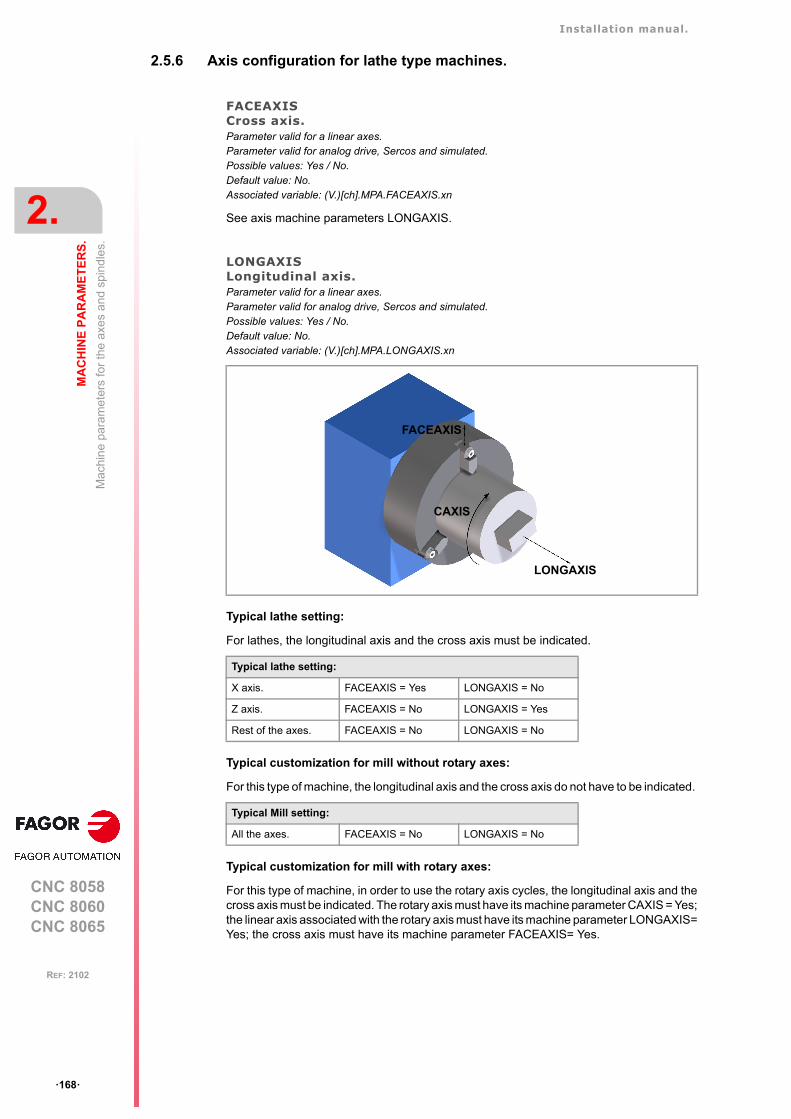
Installation manual.
CNC 8058CNC 8060CNC 8065
2.
MA
CH
INE
PA
RA
ME
TE
RS
.
Mac
hin
e pa
ram
ete
rs fo
r th
e a
xes
and
spin
dle
s.
ꞏ168ꞏ
REF: 2102
2.5.6 Axis configuration for lathe type machines.
FACEAXISCross axis.Parameter valid for a linear axes. Parameter valid for analog drive, Sercos and simulated. Possible values: Yes / No.Default value: No.Associated variable: (V.)[ch].MPA.FACEAXIS.xn
See axis machine parameters LONGAXIS.
LONGAXISLongitudinal axis.Parameter valid for a linear axes. Parameter valid for analog drive, Sercos and simulated. Possible values: Yes / No.Default value: No.Associated variable: (V.)[ch].MPA.LONGAXIS.xn
Typical lathe setting:
For lathes, the longitudinal axis and the cross axis must be indicated.
Typical customization for mill without rotary axes:
For this type of machine, the longitudinal axis and the cross axis do not have to be indicated.
Typical customization for mill with rotary axes:
For this type of machine, in order to use the rotary axis cycles, the longitudinal axis and thecross axis must be indicated. The rotary axis must have its machine parameter CAXIS = Yes;the linear axis associated with the rotary axis must have its machine parameter LONGAXIS=Yes; the cross axis must have its machine parameter FACEAXIS= Yes.
Typical lathe setting:
X axis. FACEAXIS = Yes LONGAXIS = No
Z axis. FACEAXIS = No LONGAXIS = Yes
Rest of the axes. FACEAXIS = No LONGAXIS = No
Typical Mill setting:
All the axes. FACEAXIS = No LONGAXIS = No
LONGAXIS
FACEAXIS
CAXIS
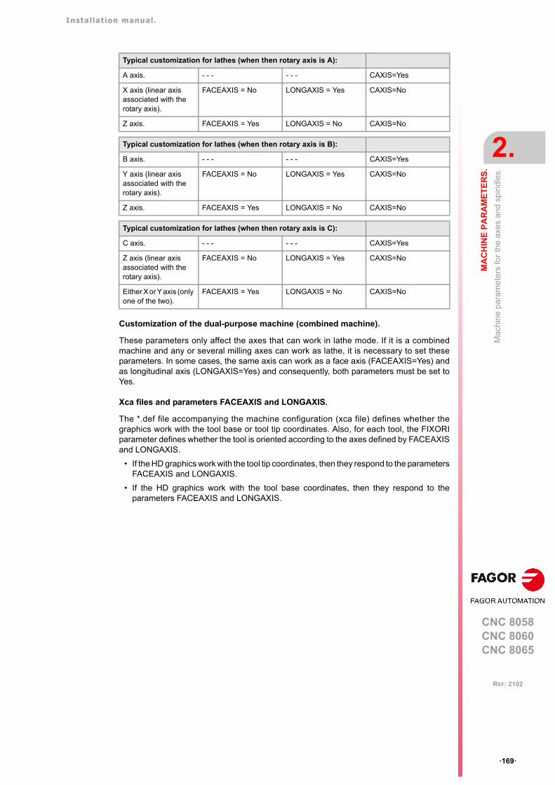
Installation manual.
CNC 8058CNC 8060CNC 8065
MA
CH
INE
PA
RA
ME
TE
RS
.
2.
Mac
hin
e pa
ram
ete
rs fo
r th
e a
xes
and
spin
dle
s.
ꞏ169ꞏ
REF: 2102
Customization of the dual-purpose machine (combined machine).
These parameters only affect the axes that can work in lathe mode. If it is a combinedmachine and any or several milling axes can work as lathe, it is necessary to set theseparameters. In some cases, the same axis can work as a face axis (FACEAXIS=Yes) andas longitudinal axis (LONGAXIS=Yes) and consequently, both parameters must be set toYes.
Xca files and parameters FACEAXIS and LONGAXIS.
The *.def file accompanying the machine configuration (xca file) defines whether thegraphics work with the tool base or tool tip coordinates. Also, for each tool, the FIXORIparameter defines whether the tool is oriented according to the axes defined by FACEAXISand LONGAXIS.
• If the HD graphics work with the tool tip coordinates, then they respond to the parametersFACEAXIS and LONGAXIS.
• If the HD graphics work with the tool base coordinates, then they respond to theparameters FACEAXIS and LONGAXIS.
Typical customization for lathes (when then rotary axis is A):
A axis. - - - - - - CAXIS=Yes
X axis (linear axis associated with the rotary axis).
FACEAXIS = No LONGAXIS = Yes CAXIS=No
Z axis. FACEAXIS = Yes LONGAXIS = No CAXIS=No
Typical customization for lathes (when then rotary axis is B):
B axis. - - - - - - CAXIS=Yes
Y axis (linear axis associated with the rotary axis).
FACEAXIS = No LONGAXIS = Yes CAXIS=No
Z axis. FACEAXIS = Yes LONGAXIS = No CAXIS=No
Typical customization for lathes (when then rotary axis is C):
C axis. - - - - - - CAXIS=Yes
Z axis (linear axis associated with the rotary axis).
FACEAXIS = No LONGAXIS = Yes CAXIS=No
Either X or Y axis (only one of the two).
FACEAXIS = Yes LONGAXIS = No CAXIS=No
Installation manual.
CNC 8058CNC 8060CNC 8065
2.
MA
CH
INE
PA
RA
ME
TE
RS
.
Mac
hin
e pa
ram
ete
rs fo
r th
e a
xes
and
spin
dle
s.
ꞏ170ꞏ
REF: 2102
2.5.7 Synchronization of axes and spindles.
SYNCSETSet of parameters for synchronization.Parameter valid for rotary axes and spindles. Parameter valid for analog drive, Sercos and simulated. Possible values: From 0 to 4.Default value: 1.Associated variable: (V.)[ch].MPA.SYNCSET.xn
Parameter set assumed by the axis or spindle when it is synchronized. If the parameter isset to ꞏ0ꞏ (zero), the CNC will try to synchronize the spindle without forcing the set change.
• A slave axis or spindle always assumes the set defined in its parameter SYNCSET.
• If the master and slave spindles are in the same channel, master spindle assumes theset defined in its parameter SYNCSET. If both spindles are in different channels, theparameter set of the master spindle must be selected before synchronizing.
DSYNCVELWSpeed synchronization window.Parameter valid for linear and rotary axes and spindles. Parameter valid for analog drive, Sercos and simulated. Possible values (1): From 0 to 200000.0000 mm/min.Possible values (2): From 0 to 7874.01575 inch/min.Possible values (3): From 0 to 36000000.0000 degrees/min.Possible values (4): From 0 to 100000 rpm.Default value: 100 mm/min / 3.937 inch/min / 3600 degrees/min / 10 rpm.Associated variable: (V.)[ch].MPA.DSYNCVELW.xn
This parameter is defined for the slave element of the synchronization and indicates thevelocity margin admitted for the synchronization to be OK.
When the spindles are synchronized in speed, the slave spindle turns at the same speedas the master spindle (taking the ratio into account). If the value defined in this parameteris exceeded, the SYNSPEED signal goes low; the movement is not stopped and no errormessage is issued.
When synchronizing axes, the slave axis moves at the same feedrate as the master(considering the ratio). If the difference between the synchronism speed calculated for theslave axis and its real speed exceeds the value set in this parameter, it cancels the INSYNCmark of the PLC.
DSYNCPOSWPosition synchronization window.Parameter valid for linear and rotary axes and spindles. Parameter valid for analog drive, Sercos and simulated. Possible values (1): From 0 to 99999.9999 mm/min.Possible values (2): From 0 to 3937.00787 inch/min.Possible values (3): From 0 to 99999.9999 degrees/min.Default value: 0.0100 mm/min / 0.00039 inch/min / 0.0100 degrees/min.Associated variable: (V.)[ch].MPA.DSYNCPOSW.xn
This parameter is defined for the slave element of the synchronization and indicates theposition margin admitted for the synchronization to be OK.
When the spindles are synchronized in position, the slave spindle follows the master keepingthe programmed offset (bearing the ratio in mind) and it activates the SYNCHRONP markof the PLC. If the value set in this parameter is exceeded, it cancels the SYNPOSI mark ofthe PLC; it does not stop the movement or issue any error message.
When synchronizing axes, the slave axis follows the master keeping the offset (consideringthe ratio). If the difference between the synchronism position calculated for the slave axisand its real position exceeds the value set in this parameter, it cancels the INSYNC markof the PLC.
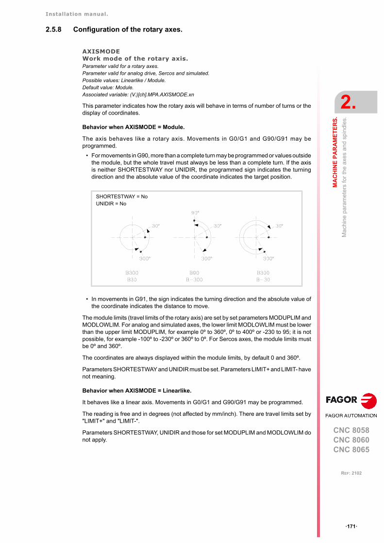
Installation manual.
CNC 8058CNC 8060CNC 8065
MA
CH
INE
PA
RA
ME
TE
RS
.
2.
Mac
hin
e pa
ram
ete
rs fo
r th
e a
xes
and
spin
dle
s.
ꞏ171ꞏ
REF: 2102
2.5.8 Configuration of the rotary axes.
AXISMODEWork mode of the rotary axis.Parameter valid for a rotary axes. Parameter valid for analog drive, Sercos and simulated. Possible values: Linearlike / Module.Default value: Module.Associated variable: (V.)[ch].MPA.AXISMODE.xn
This parameter indicates how the rotary axis will behave in terms of number of turns or thedisplay of coordinates.
Behavior when AXISMODE = Module.
The axis behaves like a rotary axis. Movements in G0/G1 and G90/G91 may beprogrammed.
• For movements in G90, more than a complete turn may be programmed or values outsidethe module, but the whole travel must always be less than a complete turn. If the axisis neither SHORTESTWAY nor UNIDIR, the programmed sign indicates the turningdirection and the absolute value of the coordinate indicates the target position.
• In movements in G91, the sign indicates the turning direction and the absolute value ofthe coordinate indicates the distance to move.
The module limits (travel limits of the rotary axis) are set by set parameters MODUPLIM andMODLOWLIM. For analog and simulated axes, the lower limit MODLOWLIM must be lowerthan the upper limit MODUPLIM, for example 0º to 360º, 0º to 400º or -230 to 95; it is notpossible, for example -100º to -230º or 360º to 0º. For Sercos axes, the module limits mustbe 0º and 360º.
The coordinates are always displayed within the module limits, by default 0 and 360º.
Parameters SHORTESTWAY and UNIDIR must be set. Parameters LIMIT+ and LIMIT- havenot meaning.
Behavior when AXISMODE = Linearlike.
It behaves like a linear axis. Movements in G0/G1 and G90/G91 may be programmed.
The reading is free and in degrees (not affected by mm/inch). There are travel limits set by"LIMIT+" and "LIMIT-".
Parameters SHORTESTWAY, UNIDIR and those for set MODUPLIM and MODLOWLIM donot apply.
SHORTESTWAY = NoUNIDIR = No
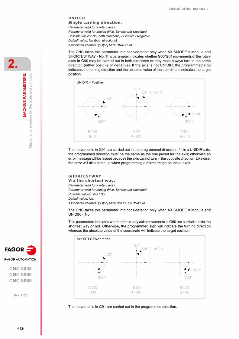
Installation manual.
CNC 8058CNC 8060CNC 8065
2.
MA
CH
INE
PA
RA
ME
TE
RS
.
Mac
hin
e pa
ram
ete
rs fo
r th
e a
xes
and
spin
dle
s.
ꞏ172ꞏ
REF: 2102
UNIDIRSingle turning direction.Parameter valid for a rotary axes. Parameter valid for analog drive, Sercos and simulated. Possible values: No (both directions) / Positive / Negative.Default value: No (both directions).Associated variable: (V.)[ch].MPA.UNIDIR.xn
The CNC takes this parameter into consideration only when AXISMODE = Module andSHORTESTWAY = No. This parameter indicates whether G00/G01 movements of the rotaryaxes in G90 may be carried out in both directions or they must always turn in the samedirection (either positive or negative). If the axis is not UNIDIR, the programmed signindicates the turning direction and the absolute value of the coordinate indicates the targetposition.
The movements in G91 are carried out in the programmed direction. If it is a UNIDIR axis,the programmed direction must be the same as the one preset for the axis; otherwise anerror message will be issued because the axis cannot turn in the opposite direction. Likewise,the error will also come up when programming a mirror image on these axes.
SHORTESTWAYVia the shortest way.Parameter valid for a rotary axes. Parameter valid for analog drive, Sercos and simulated. Possible values: Yes / No.Default value: No.Associated variable: (V.)[ch].MPA.SHORTESTWAY.xn
The CNC takes this parameter into consideration only when AXISMODE = Module andUNIDIR = No.
This parameters indicates whether the rotary axis movements in G90 are carried out via theshortest way or not. Otherwise, the programmed sign will indicate the turning directionwhereas the absolute value of the coordinate will indicate the target position.
The movements in G91 are carried out in the programmed direction.
UNIDIR = Positive.
SHORTESTWAY = Yes
Installation manual.
CNC 8058CNC 8060CNC 8065
MA
CH
INE
PA
RA
ME
TE
RS
.
2.
Mac
hin
e pa
ram
ete
rs fo
r th
e a
xes
and
spin
dle
s.
ꞏ173ꞏ
REF: 2102
2.5.9 Module configuration (rotary axes and spindle).
MODCOMPModule compensation.Parameter valid for rotary axes and spindles. Parameter valid for analog drive, Sercos and simulated. Possible values: Yes / No.Default value: No (without compensation).Associated variable: (V.)[ch].MPA.MODCOMP.xn
The CNC takes this parameter into consideration only when AXISMODE = Module.
The module compensation must be activated when the axis resolution is not exact. Rangeparameters MODNROT and MODERR set the compensation to be applied to obtain theexact reading. The CNC applies module compensation throughout the entire revolution.
2.5.10 Activating the spindle for DMC.
DMCSPDLSpindle with enabled power control.Possible values: Yes / No.Default value: No.Associated variable: (V.)[ch].MPA.DMCSPDL.sn
This parameter indicates whether or not the DMC can act upon the spindle.
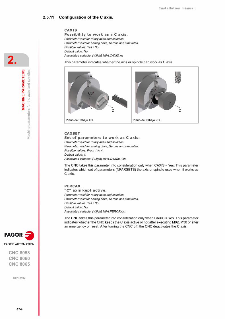
Installation manual.
CNC 8058CNC 8060CNC 8065
2.
MA
CH
INE
PA
RA
ME
TE
RS
.
Mac
hin
e pa
ram
ete
rs fo
r th
e a
xes
and
spin
dle
s.
ꞏ174ꞏ
REF: 2102
2.5.11 Configuration of the C axis.
CAXISPossibility to work as a C axis.Parameter valid for rotary axes and spindles. Parameter valid for analog drive, Sercos and simulated. Possible values: Yes / No.Default value: No.Associated variable: (V.)[ch].MPA.CAXIS.xn
This parameter indicates whether the axis or spindle can work as C axis.
CAXSETSet of parameters to work as C axis.Parameter valid for rotary axes and spindles. Parameter valid for analog drive, Sercos and simulated. Possible values: From 1 to 4.Default value: 1.Associated variable: (V.)[ch].MPA.CAXSET.xn
The CNC takes this parameter into consideration only when CAXIS = Yes. This parameterindicates which set of parameters (NPARSETS) the axis or spindle uses when it works asC axis.
PERCAX"C" axis kept active.Parameter valid for rotary axes and spindles.Parameter valid for analog drive, Sercos and simulated. Possible values: Yes / No.Default value: No.Associated variable: (V.)[ch].MPA.PERCAX.xn
The CNC takes this parameter into consideration only when CAXIS = Yes. This parameterindicates whether the CNC keeps the C axis active or not after executing M02, M30 or afteran emergency or reset. After turning the CNC off, the CNC deactivates the C axis.
Plano de trabajo XC. Plano de trabajo ZC.
Z
X
C
Z
X
C
Installation manual.
CNC 8058CNC 8060CNC 8065
MA
CH
INE
PA
RA
ME
TE
RS
.
2.
Mac
hin
e pa
ram
ete
rs fo
r th
e a
xes
and
spin
dle
s.
ꞏ175ꞏ
REF: 2102
2.5.12 Configuration of the spindle.
AUTOGEARAutomatic gear change.Parameter valid for spindles. Parameter valid for analog drive, Sercos and simulated. Possible values: Yes / No.Default value: No.Associated variable: (V.)[ch].MPA.AUTOGEAR.xn
This parameter indicates whether the gear change is automatically generated by activating(if necessary) the auxiliary functions M41, M42, M43 and M44 when programming the speed.
LOSPDLIMLower "rpm OK" percentage.Parameter valid for spindles. Parameter valid for analog drive, Sercos and simulated. Possible values: From 0 to 255.Default value: 50.Associated variable: (V.)[ch].MPA.LOSPDLIM.xn
See axis machine parameters UPSPDLIM.
UPSPDLIMUpper "rpm OK" percentage.Parameter valid for spindles. Parameter valid for analog drive, Sercos and simulated. Possible values: From 0 to 255.Default value: 150.Associated variable: (V.)[ch].MPA.UPSPDLIM.xn
When working with M3 and M4, the REVOK signal is set high when the actual spindle rpmare between these percentages.
The REVOK signal may be used to manage the Feedhold signal and avoid machining atlower or higher rpm than the ones programmed.
SPDLTIMEEstimated time for an S function.Parameter valid for spindles. Parameter valid for analog drive, Sercos and simulated. Possible values: From 0 to 1000000 ms.Default value: 0 ms.Associated variable: (V.)[ch].MPA.SPDLTIME.xn
In EDISIMU mode, there is an option that allows calculating the time required to execute apart with the machining conditions established in the program.
To fine tune that calculation, one may define this parameter that indicates the estimated timefor processing the S function.
When assigning a value other than "0", the CNC interprets that the "S" value must be passedon to the PLC using signals SSTROBE + SFUN1.
Installation manual.
CNC 8058CNC 8060CNC 8065
2.
MA
CH
INE
PA
RA
ME
TE
RS
.
Mac
hin
e pa
ram
ete
rs fo
r th
e a
xes
and
spin
dle
s.
ꞏ176ꞏ
REF: 2102
SPDLSTOPFunctions M2 and M30, an error or a reset stop the spindle.Parameter valid for spindles. Parameter valid for analog drive, Sercos and simulated. Possible values: Yes / No.Default value: Yes.Associated variable: (V.)[ch].MPA.SPDLSTOP.xn
This parameter indicates whether the spindle is stopped or not when executing M02, M30,when doing a reset or when an error occurs; otherwise, function M5 will have to beprogrammed. The spindle errors and an emergency always stop the spindle.
• If it is set to ꞏNoꞏ, function G96 remains active with an M2, M30 or a reset.
• If it is set to ꞏYesꞏ, function G96 will not remain active with an M2, M30 or a reset.
SREVM05With G84, the spindle must be stopped to change the turning direction.Parameter valid for spindles. Parameter valid for analog drive, Sercos and simulated. Possible values: Yes / No.Default value: No.Associated variable: (V.)[ch].MPA.SREVM05.xn
This parameter indicates whether the spindle must be stopped (with M5) when reversing thespindle in tapping cycle.
M19SPDLEREVThe SPDLEREV mark (reverse turning direction) affects the spindle in M19.Parameter valid for spindles. Parameter valid for analog drives and velocity-Sercos drives. Possible values: Yes / No.Default value: No.Associated variable: (V.)[ch].MPA.M19SPDLEREV.xn
This parameter defines whether the PLC mark SPDLEREV (reverse turning direction) alsoaffects the spindles in M19. The SPDLEREV mark always affects the spindles in open loop(M3/M4), regardless of how this parameter has been set.
STEPOVRSpindle override step.Parameter valid for spindles. Parameter valid for analog drive, Sercos and simulated. Possible values: From 0 to 255.Default value: 5.Associated variable: (V.)[ch].MPA.STEPOVR.xn
This parameter sets the incremental step used to change the programmed spindle speedwith the spindle override keys of the operator panel. Parameter ignored when the operatorpanel has a spindle speed override switch.
MINOVRMinimum override (%) permitted for the spindle.Parameter valid for spindles. Parameter valid for analog drive, Sercos and simulated. Possible values: From 0 to 255.Default value: 50.Associated variable: (V.)[ch].MPA.MINOVR.xn
This parameter sets the minimum percentage allowed to apply to the spindle speed whenit is changed from the operator panel (keys or speed override switch).
Installation manual.
CNC 8058CNC 8060CNC 8065
MA
CH
INE
PA
RA
ME
TE
RS
.
2.
Mac
hin
e pa
ram
ete
rs fo
r th
e a
xes
and
spin
dle
s.
ꞏ177ꞏ
REF: 2102
MAXOVRMaximum override (%) permitted for the spindle.Parameter valid for spindles. Parameter valid for analog drive, Sercos and simulated. Possible values: From 0 to 255.Default value: 150.Associated variable: (V.)[ch].MPA.MAXOVR.xn
This parameter sets the maximum percentage allowed to apply to the spindle speed whenit is changed from the operator panel (keys or speed override switch).
Installation manual.
CNC 8058CNC 8060CNC 8065
2.
MA
CH
INE
PA
RA
ME
TE
RS
.
Mac
hin
e pa
ram
ete
rs fo
r th
e a
xes
and
spin
dle
s.
ꞏ178ꞏ
REF: 2102
2.5.13 Spindle override change while threading.
THREADOVRMaximum variation allowed for the override while threading.Parameter valid for spindles. Parameter valid for analog drive, Sercos and simulated. Possible values: from 0 to 100%.Default value: 0 (The override cannot be changed).Associated variable: (V.)[ch].MPA.THREADOVR.xn
If this parameter is set with a value other than ꞏ0ꞏ, it is possible to change the spindle overrideduring electronic threading (G33) and in the threading canned cycles of the ꞏTꞏ model (G86,G87 and their equivalent of the cycle editor).
The parameter sets the maximum spindle override variation possible, both to increase it andto reduce it. For example, if set to ꞏ30ꞏ, the override may be varied between 80% and 130%.The limits set by machine parameters MINOVR and MAXOVR can never be exceeded.
In order to avoid damaging the thread when varying the spindle override, you should usea feed-forward value close to 100% on the axes involved in threading so the following erroris as small as possible. The CNC allows modifying the spindle override while threading ifit detects that the feed forward (parameter FFWTYPE) is not active in a gear of the axesinvolved or if the active feed forward is lower than 90% Feed forward is defined withparameter FFGAIN and may be modified from the PLC using variables.
Threading canned cycles of the ꞏTꞏ model. Considerations related to changing theoverride value.
• In threading cycles, it is possible to change the spindle speed during the threadingpasses, except in those done all the way to the final depth of the thread (one or two finalpasses) which are done at the override value active at the beginning of the pass.
• Even if the override is changed, the CNC respects the pitch and entry of the thread.
• It is recommended not to change the override on threads with flank infeed.
Electronic threading G33. Considerations related to changing the override value.
• If more than one G33 have been programmed for the same thread, all the threadingoperations must start at the same speed; otherwise, the entry point (start) to the threadwill not be the same in all the threads. The CNC permits changing the spindle overrideduring the thread cutting pass.
• If more than one G33 have been programmed for a multi-start (multi-entry) thread, allthe threading operations must start at the same speed; otherwise, the angle between thestarts (entry points) to the thread will not be the same as the one programmed. The CNCpermits changing the spindle override during the thread cutting pass.
OVRFILTERTime to make the override change effective.Parameter valid for spindles. Parameter valid for analog drive, Sercos and simulated. Possible values: From 0 to 1000000 ms.Default value: 0.Associated variable: (V.)[ch].MPA.OVRFILTER.xn
The CNC takes this parameter into account only if THREADOVR other than 0 (zero).
This parameter acts as a filter to make the override change effective The override changeis applied progressively during the indicated period of time.
Installation manual.
CNC 8058CNC 8060CNC 8065
MA
CH
INE
PA
RA
ME
TE
RS
.
2.
Mac
hin
e pa
ram
ete
rs fo
r th
e a
xes
and
spin
dle
s.
ꞏ179ꞏ
REF: 2102
2.5.14 Software axis limits.
LIMIT+Positive software limit.Parameter valid for linear and rotary axes. Parameter valid for analog drive, Sercos and simulated. Possible values (1): Within ±99999.9999 mm.Possible values (2): Within ±3937.00787 inch.Possible values (3): Within ±99999.9999 degrees.Default value: 99999.9999 mm / 3937.00787 inch / 99999.9999 degrees.Associated variable: (V.)[ch].MPA.POSLIMIT.xn
See axis machine parameters LIMIT-.
LIMIT-Negative software limit.Parameter valid for linear and rotary axes. Parameter valid for analog drive, Sercos and simulated. Possible values (1): Within ±99999.9999 mm.Possible values (2): Within ±3937.00787 inch.Possible values (3): Within ±99999.9999 degrees.Default value: -99999.9999 mm / -3937.00787 inch / -99999.9999 degrees.Associated variable: (V.)[ch].MPA.NEGLIMIT.xn
On rotary axes, the CNC takes this parameter into account when AXISMODE = Linearlike.
On linear and rotary axes, these parameters set the axis travel limits. If both are set to "0",there will be no software limits.
SWLIMITTOLSoftware limit tolerance.Parameter valid for linear and rotary axes. Parameter valid for analog drive, Sercos and simulated. Possible values (1): Within ±99999.9999 mm.Possible values (2): Within ±3937.00787 inch.Possible values (3): Within ±99999.9999 degrees.Default value: 0.1000 mm / 0.00394 inch / 0.1000 degrees.Associated variable: (V.)[ch].MPA.SWLIMITTOL.xn
This parameter indicates the maximum variation or oscillation allowed for an axis locatedat the limit.
This parameter indicates the maximum variation or oscillation allowed to a real coordinateof an axis referred to the software limits, before issuing an error indicating travel limit overrun.The programmed theoretical movement of the axis is only possible up to the exact limit, butthe real axis coordinate is allowed this margin before the error is issued.
When they are DRO axes, the error is also issued when the real coordinate exceeds the limitover the tolerance.
When no theoretical movement has been programmed, the limit overrun error will only beissued when exceeding the tolerance in a sampling period (cycle time); for example, whenhitting the axis causing it to overrun the limits abruptly. In any other case, if no theoreticalmovement has been programmed for the axis, the error will not be issued even if it overrunsthe limits.
The software limits are always set in radius, regardless of the setting of parameter DIAMPROG.i
Installation manual.
CNC 8058CNC 8060CNC 8065
2.
MA
CH
INE
PA
RA
ME
TE
RS
.
Mac
hin
e pa
ram
ete
rs fo
r th
e a
xes
and
spin
dle
s.
ꞏ180ꞏ
REF: 2102
2.5.15 Work zones.
ZONELIMITTOLSafety distance of the limits of the work zones.Parameter valid for linear and rotary axes.Parameter valid for analog drive, Sercos and simulated.Possible values: From 0 to 99999.9999 mm or degrees / from 0 to 3937.00787 inch.Default value: 0.1000 mm or degrees / 0.00394 inch.Associated variable: (V.)[ch].MPA.ZONELIMITTOL.xn
Safety distance applied by the CNC to the axis with respect to the limit of the work zone. Whena work zone is active, the CNC stops the axes when one of them reaches the safety distance.The safety distance is defined per axis and each axis will have the same safety distance forall the zones..
The safety distance may be modified with the following variable which will assume the valueof this parameter on startup.
2.5.16 Runaway protection and tendency test.
TENDENCYActivation of tendency test.Parameter valid for linear and rotary axes and spindles. Parameter valid for analog drives and simulated drives. Possible values: Yes / No.Default value: No.Associated variable: (V.)[ch].MPA.TENDENCY.xn
This parameter enables two tests:
• Axis tendency watch.
This test watches that the real movement coincides with the theoretical movement, fromthe time period set in parameter ESTDELAY. If no theoretical movement has beenprogrammed for the axis, the test detects whether the axis is moving in one directionlonger than the time indicated in parameter ESTDELAY. If no theoretical movement hasbeen programmed for the axis, the test detects whether it is moving in the oppositedirection longer than the time indicated by ESTDELAY.
• Runaway protection.
This test watches the real movement of the axis from startup to detect if runs awayconsidering the time defined in the parameter TENDTIME.
If this alarm is canceled, the CNC shows on power-up a message indicating that this safetyis disabled. This situation can only be allowed during setup; once setup is completed, thisalarm must be enabled.
TENDTIMETime to detect axis runaway.Parameter valid for linear and rotary axes and spindles. Parameter valid for analog drives and simulated drives. Possible values: From 0 to 65535 ms.Default value: 0.Associated variable: (V.)[ch].MPA.TENDTIME.xn
When the runaway test is active, this parameter defines the time the CNC must wait beforeissuing an error message. We recommend to set a short time (about 4 sampling periods)to prevent the axis from moving too far.
(V.)[ch].A.ZONELIMITTOL.xn Safety distance of the limits of the work zones.
Installation manual.
CNC 8058CNC 8060CNC 8065
MA
CH
INE
PA
RA
ME
TE
RS
.
2.
Mac
hin
e pa
ram
ete
rs fo
r th
e a
xes
and
spin
dle
s.
ꞏ181ꞏ
REF: 2102
2.5.17 PLC Offset.
PLCOINCPLC offset increment per cycle.Parameter valid for linear and rotary axes and spindles. Parameter valid for analog drive, Sercos and simulated. Possible values (1): From 0 to 99999.9999 mm/min.Possible values (2): From 0 to 3937.00787 inch/min.Possible values (3): From 0 to 99999.9999 degrees/min.Default value: 0 (they are assumed instantaneously).Associated variable: (V.)[ch].MPA.PLCOINC.xn
The PLC offset is an additional compensation over the real coordinate of the axis. The CNCapplies this compensation in a transparent way for the user who will not see it reflected inthe coordinates. A typical utility is to correct the axis dilatations due to temperature.
This parameter indicates whether the CNC assumes the PLC offsets instantaneously in asampling period (cycle time) or in steps.
The PLC offset to be applied is set in the variable (V.)A.PLCOF.xn. The PLC offset appliedso far may be checked in the variable (V.)A.ACTPLCOF.xn.
Example:
It is set PLCOINC = 0.001 mm (one micron per CNC cycle). If the PLC Offset had an initialvalue of 0.25 mm and the new value is 0.30 mm, the PLC offset applied per cycle will be:
0.250 0.251 0.252 0.253 ꞏ ꞏ ꞏ 0.297 0.298 0.299 0.300

Installation manual.
CNC 8058CNC 8060CNC 8065
2.
MA
CH
INE
PA
RA
ME
TE
RS
.
Mac
hin
e pa
ram
ete
rs fo
r th
e a
xes
and
spin
dle
s.
ꞏ182ꞏ
REF: 2102
2.5.18 Dwell for dead axes.
DWELLDwell for dead axes.Parameter valid for linear and rotary axes and spindles. Parameter valid for analog drive, Sercos and simulated. Possible values: From 0 to 1000000 ms.Default value: 0 (no dwell).Associated variable: (V.)[ch].MPA.DWELL.xn
When an axis has a brake, for example very heavy vertical axes, it is only governed whileit is moving. When it is governed by the CNC (movements), it is referred to as being aliveand, when not moving (brake on), it is referred to as being "dead".
To bring it to "life", release the brake and close the position loop. The time required for thisoperation must be defined by the DWELL parameter.
The CNC waits the amount of time set in parameter DWELL before generating a movementon the "dead" axis if it does not have the SERVOON signal active. Once the dwell has started,the CNC will wait the time set in parameter DWELL before starting the movement, even ifthe SERVOON signal has been activated before.
Special care must be taken with the delayed disconnection of the axis, when it becomes a"dead" axis. If the SERVOON signal has been turned off and a new movement of the axisbegins, the CNC will not start timing but it could issue an error indicating that the axis is lockedup if as a result of disconnecting logically, the SERVOON signal ends up dropping.
On a tandem axis, both the master and slave axes must be enabled so they can be moved.In this case, the CNC only applies the time set in DWELL to the SERVOON of the masteraxis; if the enabling of the slave axis is slower, the PLC maneuver must verify that both axesare enabled before generating the movement.
If an axis is going to work as a "dead" axis in a program with path joints, G5, G50 or HSC,it will be necessary to enable the axis via PLC as "dead" axis (DEAD(axis) signal). This way,the CNC knows at all times that it will have to apply a dwell before every movement of thataxis.
The ENABLE signal indicates to the PLC to let the axis move and the SERVOON signalthat the drive is ready.
SERVOON
ENABLE
VelocityCommand
DWELL
Installation manual.
CNC 8058CNC 8060CNC 8065
MA
CH
INE
PA
RA
ME
TE
RS
.
2.
Mac
hin
e pa
ram
ete
rs fo
r th
e a
xes
and
spin
dle
s.
ꞏ183ꞏ
REF: 2102
2.5.19 Radius / diameter.
DIAMPROGProgramming in diameters. Parameter valid for a linear axes. Parameter valid for analog drive, Sercos and simulated. Possible values: Yes / No.Default value: No.Associated variable: (V.)[ch].MPA.DIAMPROG.xn
The CNC takes this parameter into consideration only when FACEAXIS = Yes.
On turning machines, the coordinates of the cross axis may be programmed in either radiusor diameter. To change the type of coordinates via program, use function G151 or G152.
Installation manual.
CNC 8058CNC 8060CNC 8065
2.
MA
CH
INE
PA
RA
ME
TE
RS
.
Mac
hin
e pa
ram
ete
rs fo
r th
e a
xes
and
spin
dle
s.
ꞏ184ꞏ
REF: 2102
2.5.20 Home search.
REFDIRECHoming direction.Parameter valid for linear and rotary axes and spindles. Parameter valid for analog drive, Sercos and simulated. Possible values: Negative / Positive.Default value: Positive.Associated variable: (V.)[ch].MPA.REFDIREC.xn
For analog and simulated axes, parameter REFDIREC indicates the axis moving directionto begin the home search. For a Sercos axis, parameter REFDIREC indicates the motorturning direction, which does not necessary have to be the same as the positive or negativefeedback reading (pulse counting) direction of the axis.
This parameter has no effect on spindles that are stopped and have no home switch. If thespindle is turning, the CNC respects its turning direction to start searching home. If thespindle has a home switch and is turning, the CNC stops the spindle and starts the homesearch in the direction indicated by REFDIREC.
REFMODEHome search mode.Parameter valid for linear and rotary axes and spindles. Parameter valid for a position-Sercos drive. Possible values: Drive / CNC.Default value: CNC.Associated variable: (V.)[ch].MPA.REFMODE.xn
This parameter indicates who manages the axis home search.
DECINPUTThe axis/spindle has a home switch.Parameter valid for linear and rotary axes and spindles. Parameter valid for analog drives and Sercos drives. Possible values: Yes / No.Default value: Yes.Associated variable: (V.)[ch].MPA.DECINPUT.xn
If the axis has a home search but no distance-coded reference marks, the axis moves upto the home switch, then it reverses the movement and when it releases the home switch,the home switch is enabled. If the axis has a home switch and distance-coded referencemarks, the axis needs not reach the home switch in order to find the reference mark.
On spindles with home switch, the home search algorithm runs two passes over the homeswitch. The first pass is run at the speed set in REFFEED1 and it serves to calculate theposition of the home switch. The second pass is run at the same speed until reaching thehome switch, going over it a the speed set in REFFEED2 and doing the usual home search.
When there is a home switch, the CNC does not search home on the go, depending onwhether it is turning in M3 or M4; the home search is always done in the direction set byREFDIREC.
Value. Meaning.
Drive. The drive homes the axis as if it were a position-Sercos axis.
CNC. The drive homes the axis as if it were a velocity-Sercos axis. The CNC executesthe parameter matching as if it were a velocity-Sercos axis.
Installation manual.
CNC 8058CNC 8060CNC 8065
MA
CH
INE
PA
RA
ME
TE
RS
.
2.
Mac
hin
e pa
ram
ete
rs fo
r th
e a
xes
and
spin
dle
s.
ꞏ185ꞏ
REF: 2102
REFINIHome search in the first movement.Parameter valid for spindles. Parameter valid for analog drive, Sercos and simulated.Possible values: Yes / No.Default value: Yes.Associated variable: (V.)[ch].MPA.REFINI.xn
This parameter determines whether the CNC homes the spindle in its first movement or not.The CNC takes this parameter into account only when parameters NPULSES y NPULSES2have been set with a value other than 0.
Installation manual.
CNC 8058CNC 8060CNC 8065
2.
MA
CH
INE
PA
RA
ME
TE
RS
.
Mac
hin
e pa
ram
ete
rs fo
r th
e a
xes
and
spin
dle
s.
ꞏ186ꞏ
REF: 2102
2.5.21 Configuration of the probing movement.
PROBEAXISThe axis can participate in probing movements.Parameter valid for linear and rotary axes. Parameter valid for analog drive, Sercos and simulated. Possible values: Yes / No.Default value: No.Associated variable: (V.)[ch].MPA.PROBEAXIS.xn
This parameter indicates whether the axis is involved in a probing move (G100).
PROBERANGEMaximum braking distance.Parameter valid for linear and rotary axes. Parameter valid for analog drive, Sercos and simulated. Possible values (1): From 0 to 99999.9999 mm/min.Possible values (2): From 0 to 3937.00787 inch/min.Possible values (3): From 0 to 99999.9999 degrees/min.Default value: 1.0000 mm / 0.03937 inch / 1.0000 degree.Associated variable: (V.)[ch].MPA.PROBERANGE.xn
This parameter sets the maximum braking distance for the probe after probing to avoidbreaking it (ceramic, etc). The CNC issues an error messages when this distance isexceeded.
PROBEFEEDMaximum probing feedrate.Parameter valid for linear and rotary axes. Parameter valid for analog drive, Sercos and simulated. Possible values (1): From 0 to 36000000.0000 mm/min.Possible values (2): From 0 to 1417322.83465 inch/min.Possible values (3): From 0 to 36000000.0000 degrees/min.Default value: 0.Associated variable: (V.)[ch].MPA.PROBEFEED.xn
The value of this parameter must be smaller than the feedrate needed to brake within thedistance set by PROBERANGE with the acceleration and jerk values of the axis. Otherwise,it will show a warning when validating the axis parameters indicating the maximum feedratethat may be reached. If PROBEFEED is set to 0, the CNC calculates and uses the maximumpossible value of this parameter.
PROBEDELAYDelay for the "probe 1" signal.Parameter valid for linear and rotary axes and spindles. Parameter valid for analog drive, Sercos and simulated. Possible values: Within ±100000.0000 ms.Default value: 0 (no delay).Associated variable: (V.)[ch].MPA.PROBEDELAY.xn
See axis machine parameters PROBEDELAY2.
PROBEDELAY2Delay for the "probe 2" signal.Parameter valid for linear and rotary axes and spindles. Parameter valid for analog drive, Sercos and simulated. Possible values: Within ±100000.0000 ms.Default value: 0 (no delay).Associated variable: (V.)[ch].MPA.PROBEDELAY2.xn
Parameter PROBEDELAY corresponds to the probe set by PRBID1 and PROBEDELAY2to the probe set by PRBID2.
In some types of probes, there is a short delay of a few milliseconds from the probing instantto when the CNC actually receives the signals (infrared communication, etc.). In these cases,
Installation manual.
CNC 8058CNC 8060CNC 8065
MA
CH
INE
PA
RA
ME
TE
RS
.
2.
Mac
hin
e pa
ram
ete
rs fo
r th
e a
xes
and
spin
dle
s.
ꞏ187ꞏ
REF: 2102
it must indicate the time elapsed from when the probing takes place till the CNC receivesthe signal. For the laser model, if the proximity probe for the gap control has a delay, it isdefined in these parameters.
Probe calibration cycle "#PROBE 2" may be used to set this parameter. After it is executed,the cycle returns, in arithmetic parameter P298 the best value to be assigned to parameterPROBEDELAY for the axes and the spindle.
Installation manual.
CNC 8058CNC 8060CNC 8065
2.
MA
CH
INE
PA
RA
ME
TE
RS
.
Mac
hin
e pa
ram
ete
rs fo
r th
e a
xes
and
spin
dle
s.
ꞏ188ꞏ
REF: 2102
2.5.22 Repositioning of the axes in tool inspection.
REPOSFEEDMaximum repositioning feedrate.Parameter valid for linear and rotary axes. Parameter valid for analog drive, Sercos and simulated. Possible values (1): From 0 to 200000.0000 mm/min.Possible values (2): From 0 to 7874.01575 inch/min.Possible values (3): From 0 to 36000000.0000 degrees/min.Default value: 0.Associated variable: (V.)[ch].MPA.REPOSFEED.xn
Repositioning feedrate after a tool inspection or an interruption subroutine. If not defined,the CNC assumes as repositioning feedrate the one defined for the continuous jog mode(parameter JOGFEED). The value of parameter REPOSFEED must always be lower thanG00FEED, MAXMANFEED and JOGRAPFEED.
2.5.23 Configuration of the independent axis.
POSFEEDPositioning feedrate.Parameter valid for linear and rotary axes and spindles. Parameter valid for analog drive, Sercos and simulated. Possible values (1): From 0 to 200000.0000 mm/min.Possible values (2): From 0 to 7874.01575 inch/min.Possible values (3): From 0 to 36000000.0000 degrees/min.Possible values (4): From 0 to 100000.0000 rpm.Default value: 1000.0000 mm/min / 39.37008 inch/min / 1000.0000 degrees/min / 1000 rpm.Associated variable: (V.)[ch].MPA.POSFEED.xn
Positioning feedrate of the independent axis.
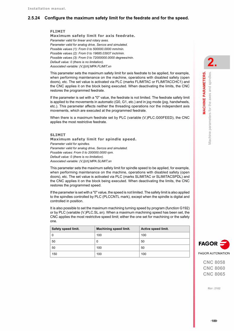
Installation manual.
CNC 8058CNC 8060CNC 8065
MA
CH
INE
PA
RA
ME
TE
RS
.
2.
Mac
hin
e pa
ram
ete
rs fo
r th
e a
xes
and
spin
dle
s.
ꞏ189ꞏ
REF: 2102
2.5.24 Configure the maximum safety limit for the feedrate and for the speed.
FLIMITMaximum safety limit for axis feedrate.Parameter valid for linear and rotary axes. Parameter valid for analog drive, Sercos and simulated. Possible values (1): From 0 to 500000.0000 mm/min.Possible values (2): From 0 to 19685.03937 inch/min.Possible values (3): From 0 to 72000000.0000 degrees/min.Default value: 0 (there is no limitation).Associated variable: (V.)[ch].MPA.FLIMIT.xn
This parameter sets the maximum safety limit for axis feedrate to be applied, for example,when performing maintenance on the machine, operations with disabled safety (opendoors), etc. The set value is activated via PLC (marks FLIMITAC or FLIMITACCHC1) andthe CNC applies it on the block being executed. When deactivating the limits, the CNCrestores the programmed feedrate.
If the parameter is set with a "0" value, the feedrate is not limited. The feedrate safety limitis applied to the movements in automatic (G0, G1, etc.) and in jog mode (jog, handwheels,etc.). This parameter affects neither the threading operations nor the independent axismovements, which are executed at the programmed feedrate.
When there is a maximum feedrate set by PLC (variable (V.)PLC.G00FEED), the CNCapplies the most restrictive feedrate.
SLIMITMaximum safety limit for spindle speed.Parameter valid for spindles. Parameter valid for analog drive, Sercos and simulated. Possible values: From 0 to 200000.0000 rpm.Default value: 0 (there is no limitation).Associated variable: (V.)[ch].MPA.SLIMIT.sn
This parameter sets the maximum safety limit for spindle speed to be applied, for example,when performing maintenance on the machine, operations with disabled safety (opendoors), etc. The set value is activated via PLC (marks SLIMITAC or SLIMITACSPDL) andthe CNC applies it on the block being executed. When deactivating the limits, the CNCrestores the programmed speed.
If the parameter is set with a "0" value, the speed is not limited. The safety limit is also appliedto the spindles controlled by PLC (PLCCNTL mark), except when the spindle is digital andcontrolled in position.
It is also possible to set the maximum machining turning speed by program (function G192)or by PLC (variable (V.)PLC.SL.sn). When a maximum machining speed has been set, theCNC applies the most restrictive speed limit; either the one set for machining or the safetyone.
Safety speed limit. Machining speed limit. Active speed limit.
0 100 100
50 0 50
50 100 50
150 100 100
Installation manual.
CNC 8058CNC 8060CNC 8065
2.
MA
CH
INE
PA
RA
ME
TE
RS
.
Mac
hin
e pa
ram
ete
rs fo
r th
e a
xes
and
spin
dle
s.
ꞏ190ꞏ
REF: 2102
2.5.25 JOG mode.
MANUALManual operating mode parameters.Parameter valid for linear and rotary axes and spindles. Parameter valid for analog drive, Sercos and simulated.
This parameter shows the parameter table to define the movements in jog mode. Onspindles, these parameters will only be applied when the spindle is interpolated with axesduring rigid tapping or when the spindle works as C axis.
JOG MODE. CONTINUOUS JOG.
JOGFEEDFeedrate in continuous jog.Parameter valid for linear and rotary axes and spindles. Parameter valid for analog drive, Sercos and simulated. Possible values (1): From 0 to 200000.0000 mm/min.Possible values (2): From 0 to 7874.01575 inch/min.Possible values (3): From 0 to 36000000.0000 degrees/min.Default value: 1000.0000 mm/min / 39.37008 inch/min / 1000.0000 degrees/min.Associated variable: (V.)[ch].MPA.JOGFEED.xnParameter included in the JOG table.
This parameter sets the feedrate for movements in continuous jog mode.
JOGRAPFEEDRapid feedrate in continuous jog. Parameter valid for linear and rotary axes and spindles. Parameter valid for analog drive, Sercos and simulated. Possible values (1): From 0 to 200000.0000 mm/min.Possible values (2): From 0 to 7874.01575 inch/min.Possible values (3): From 0 to 36000000.0000 degrees/min.Default value: 10000.0000 mm/min / 393.70079 inch/min / 10000.0000 degrees/min.Associated variable: (V.)[ch].MPA.JOGRAPFEED.xnParameter included in the JOG table.
This parameter sets the rapid feedrate for movements in continuous jog mode.
MANUAL
JOGFEED Feedrate in continuous jog mode.
JOGRAPFEED Rapid feedrate in continuous jog mode.
MAXMANFEED Maximum feedrate in continuous jog mode.
MAXMANACC Maximum acceleration in continuous JOG mode.
INCJOGDIST Distance to travel in incremental jog.
INCJOGFEED Feedrate in incremental jog.
MPGRESOL Handwheel resolution.
MPGFILTER Filter time for the handwheel.
MANPOSSW Maximum positive travel with G201.
MANNEGSW Maximum negative travel with G201.
MANFEEDP Maximum % of jog feedrate in G201.
IPOFEEDP Maximum % of execution feedrate in G201.
MANACCP Maximum % of jog acceleration in G201.
IPOACCP Maximum % of execution acceleration in G201.
Installation manual.
CNC 8058CNC 8060CNC 8065
MA
CH
INE
PA
RA
ME
TE
RS
.
2.
Mac
hin
e pa
ram
ete
rs fo
r th
e a
xes
and
spin
dle
s.
ꞏ191ꞏ
REF: 2102
MAXMANFEEDMaximum feedrate in continuous jog.Parameter valid for linear and rotary axes and spindles. Parameter valid for analog drive, Sercos and simulated. Possible values (1): From 0 to 200000.0000 mm/min.Possible values (2): From 0 to 7874.01575 inch/min.Possible values (3): From 0 to 36000000.0000 degrees/min.Default value: 10000.0000 mm/min / 393.70079 inch/min / 10000.0000 degrees/min.Associated variable: (V.)[ch].MPA.MAXMANFEED.xnParameter included in the JOG table.
This parameter sets the maximum feedrate for movements in continuous jog mode.
MAXMANACCMaximum acceleration in continuous JOG.Parameter valid for linear and rotary axes and spindles. Parameter valid for analog drive, Sercos and simulated. Possible values (1): From 0.0010 to 600000000.0000 mm/s².Possible values (2): From 0.00004 to 23622047.2440 inch/s².Possible values (3): From 0.0010 to 600000000.0000 degrees/s² .Default value: 10000.0000 mm/s² / 393.70079 inch/s² / 10000.0000 degrees/s² .Associated variable: (V.)[ch].MPA.MAXMANACC.xnParameter included in the JOG table.
This parameter sets the maximum acceleration for movements in continuous jog mode.
JOG MODE. INCREMENTAL JOG.
INCJOGDISTTable for incremental jog distances.Parameter valid for linear and rotary axes and spindles. Parameter valid for analog drive, Sercos and simulated.
This parameter shows the table to define the axis movements in each position of the jogselector switch. The table shows five parameters, one per each position of the operatorpanel.
INCJOGDISTDistance traveled in incremental jog.Parameter valid for linear and rotary axes and spindles. Parameter valid for analog drive, Sercos and simulated. Possible values (1): From 0.0001 to 99999.9999 mm.Possible values (2): From 0.0000 3937.00787 inch.Possible values (3): From 0.0001 to 99999.9999 degrees.Associated variable: (V.)[ch].MPA.INCJOGDIST[pos].xn
In each parameter, you must set the distance the axis moves every time the jog key ispressed. The most typical values are those set by default.
INCJOGDIST1 Switch position ꞏ1ꞏ.
INCJOGDIST2 Switch position ꞏ10ꞏ.
INCJOGDIST3 Switch position ꞏ100ꞏ.
INCJOGDIST4 Switch position ꞏ1000ꞏ.
INCJOGDIST5 Switch position ꞏ10000ꞏ.
Parameter. Distance.
INCJOGDIST1 0.0010 mm or degrees / 0.00003937 inch.
INCJOGDIST2 0.0100 mm or degrees / 0.00039370 inch.
INCJOGDIST3 0.1000 mm or degrees / 0.00393700 inch.
INCJOGDIST4 1.0000 mm or degrees / 0.03937007 inch.
INCJOGDIST5 10.000 mm or degrees / 0.39370078 inch.
Installation manual.
CNC 8058CNC 8060CNC 8065
2.
MA
CH
INE
PA
RA
ME
TE
RS
.
Mac
hin
e pa
ram
ete
rs fo
r th
e a
xes
and
spin
dle
s.
ꞏ192ꞏ
REF: 2102
INCJOGFEEDTable for incremental jog feedrates.Parameter valid for linear and rotary axes and spindles. Parameter valid for analog drive, Sercos and simulated.
This parameter shows the table to define the axis feedrate in each position of the jog selectorswitch. The table shows five parameters, one per each position of the operator panel.
INCJOGFEED nFeedrate in incremental jog.Parameter valid for linear and rotary axes and spindles. Parameter valid for analog drive, Sercos and simulated. Possible values (1): From 1 to 200000.0000 mm/min.Possible values (2): From 0.03937 to 7874.01575 inch/min.Possible values (3): From 1 to 200000.0000 degrees/min.Default value: 1000.0000 mm/min / 39.37008 inch/min / 1000.0000 degrees/min.Associated variable: (V.)[ch].MPA.INCJOGFEED[pos].xn
In each parameter, you must set the axis feedrate.
JOG MODE. HANDWHEELS.
MPGRESOLTable for handwheel resolution.Parameter valid for linear and rotary axes and spindles. Parameter valid for analog drive, Sercos and simulated.
This parameter shows the table to define the resolution of the handwheel in each positionof the jog selector switch. The table shows three parameters, one per each position of theoperator panel.
MPGRESOL nHandwheel resolution in each switch position.Parameter valid for linear and rotary axes and spindles. Parameter valid for analog drive, Sercos and simulated. Possible values (1): Within ±99999.9999 mm (ꞏ0ꞏ not admitted).Possible values (2): Within ±3937.00787 inch (ꞏ0ꞏ not admitted).Possible values (3): Within ±99999.9999 degrees (ꞏ0ꞏ not admitted).Associated variable: (V.)[ch].MPA.MPGRESOL[pos].xn
In each parameter, you must set the distance the axis moves per feedback pulse providedby the handwheel. If the resolution is negative, the moving direction is reversed (movementin the opposite direction to that indicated by the A and B signals of the handwheel). The mosttypical values are those set by default.
INCJOGFEED1 Switch position ꞏ1ꞏ.
INCJOGFEED2 Switch position ꞏ10ꞏ.
INCJOGFEED3 Switch position ꞏ100ꞏ.
INCJOGFEED4 Switch position ꞏ1000ꞏ.
INCJOGFEED5 Switch position ꞏ10000ꞏ.
MPGRESOL1 Switch position ꞏ1ꞏ.
MPGRESOL2 Switch position ꞏ10ꞏ.
MPGRESOL3 Switch position ꞏ100ꞏ.
Parameter. Resolution.
MPGRESOL1 0.0010 mm or degrees / 0.00003937 inch.
MPGRESOL2 0.0100 mm or degrees / 0.00039370 inch.
MPGRESOL3 0.1000 mm or degrees / 0.00393700 inch.
Installation manual.
CNC 8058CNC 8060CNC 8065
MA
CH
INE
PA
RA
ME
TE
RS
.
2.
Mac
hin
e pa
ram
ete
rs fo
r th
e a
xes
and
spin
dle
s.
ꞏ193ꞏ
REF: 2102
MPGFILTERFilter time for the handwheel.Parameter valid for linear and rotary axes and spindles. Parameter valid for analog drive, Sercos and simulated. Possible values: From 1 to 1000.Default value: 10.Associated variable: (V.)[ch].MPA.MPGFILTER.xn
This filter smoothes the handwheel movements avoiding sudden variations. This parameterindicates the number of CNC cycles used to are the handwheel pulses read.
JOG MODE. MANUAL INTERVENTION.
MANPOSSWMaximum positive travel with G201.Parameter valid for linear and rotary axes and spindles. Parameter valid for analog drive, Sercos and simulated. Possible values (1): Within ±99999.9999 mm.Possible values (2): Within ±3937.00787 inch.Possible values (3): Within ±99999.9999 degrees.Default value: 99999.9999 mm / 3937.00787 inch / 99999.9999 degrees.Associated variable: (V.)[ch].MPA.MANPOSSW.xnParameter included in the JOG table.
See axis machine parameters MANNEGSW.
MANNEGSWMaximum negative travel with G201.Parameter valid for linear and rotary axes and spindles. Parameter valid for analog drive, Sercos and simulated. Possible values (1): Within ±99999.9999 mm.Possible values (2): Within ±3937.00787 inch.Possible values (3): Within ±99999.9999 degrees.Default value: -99999.9999 mm / -3937.00787 inch / -99999.9999 degrees .Associated variable: (V.)[ch].MPA.MANNEGSW.xnParameter included in the JOG table.
When using function G201, Manual mode laid over the Automatic mode, these parametersindicate how far the axis may be moved in both directions.
MANFEEDPMaximum % of jog feedrate in G201.Parameter valid for linear and rotary axes and spindles. Parameter valid for analog drive, Sercos and simulated. Possible values: From 0 to 100.Default value: 20.Associated variable: (V.)[ch].MPA.MANFEEDP.xnParameter included in the JOG table.
See axis machine parameters IPOFEEDP.
Example:The handwheel has a graduated disk with 100 lines and we would like a feed of 0.001 mm per lineat switch position ꞏ1ꞏ.
• A 100-line handwheel provides 1 pulse per line.MPGRESOL1 = 0.0010 mm.
• A 200-line handwheel provides 2 pulses per line.MPGRESOL1 = 0.0005 mm.
• A 25-line handwheel provides 1 pulse every 4 lines.MPGRESOL1 = 0.0040 mm.
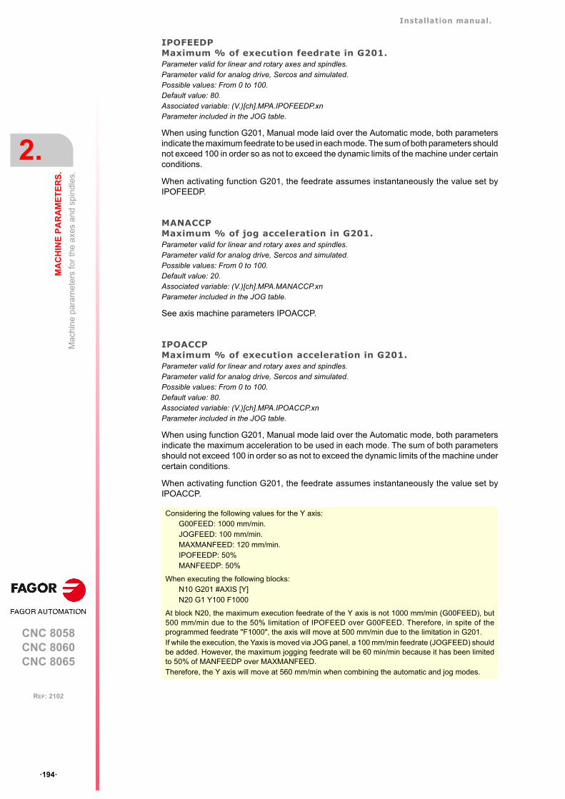
Installation manual.
CNC 8058CNC 8060CNC 8065
2.
MA
CH
INE
PA
RA
ME
TE
RS
.
Mac
hin
e pa
ram
ete
rs fo
r th
e a
xes
and
spin
dle
s.
ꞏ194ꞏ
REF: 2102
IPOFEEDPMaximum % of execution feedrate in G201.Parameter valid for linear and rotary axes and spindles. Parameter valid for analog drive, Sercos and simulated. Possible values: From 0 to 100.Default value: 80.Associated variable: (V.)[ch].MPA.IPOFEEDP.xnParameter included in the JOG table.
When using function G201, Manual mode laid over the Automatic mode, both parametersindicate the maximum feedrate to be used in each mode. The sum of both parameters shouldnot exceed 100 in order so as not to exceed the dynamic limits of the machine under certainconditions.
When activating function G201, the feedrate assumes instantaneously the value set byIPOFEEDP.
MANACCPMaximum % of jog acceleration in G201.Parameter valid for linear and rotary axes and spindles. Parameter valid for analog drive, Sercos and simulated. Possible values: From 0 to 100.Default value: 20.Associated variable: (V.)[ch].MPA.MANACCP.xnParameter included in the JOG table.
See axis machine parameters IPOACCP.
IPOACCPMaximum % of execution acceleration in G201.Parameter valid for linear and rotary axes and spindles. Parameter valid for analog drive, Sercos and simulated. Possible values: From 0 to 100.Default value: 80.Associated variable: (V.)[ch].MPA.IPOACCP.xnParameter included in the JOG table.
When using function G201, Manual mode laid over the Automatic mode, both parametersindicate the maximum acceleration to be used in each mode. The sum of both parametersshould not exceed 100 in order so as not to exceed the dynamic limits of the machine undercertain conditions.
When activating function G201, the feedrate assumes instantaneously the value set byIPOACCP.
Considering the following values for the Y axis:G00FEED: 1000 mm/min.JOGFEED: 100 mm/min.MAXMANFEED: 120 mm/min.IPOFEEDP: 50%MANFEEDP: 50%
When executing the following blocks:N10 G201 #AXIS [Y]N20 G1 Y100 F1000
At block N20, the maximum execution feedrate of the Y axis is not 1000 mm/min (G00FEED), but500 mm/min due to the 50% limitation of IPOFEED over G00FEED. Therefore, in spite of theprogrammed feedrate "F1000", the axis will move at 500 mm/min due to the limitation in G201.If while the execution, the Yaxis is moved via JOG panel, a 100 mm/min feedrate (JOGFEED) shouldbe added. However, the maximum jogging feedrate will be 60 min/min because it has been limitedto 50% of MANFEEDP over MAXMANFEED. Therefore, the Y axis will move at 560 mm/min when combining the automatic and jog modes.
Installation manual.
CNC 8058CNC 8060CNC 8065
MA
CH
INE
PA
RA
ME
TE
RS
.
2.
Mac
hin
e pa
ram
ete
rs fo
r th
e a
xes
and
spin
dle
s.
ꞏ195ꞏ
REF: 2102
2.5.26 Leadscrew error compensation.
LSCRWCOMPLeadscrew error compensation.Parameter valid for linear and rotary axes and spindles. Parameter valid for analog drive, Sercos and simulated. Possible values: Yes / No.Default value: No.Associated variable: (V.)[ch].MPA.LSCRWCOMP.xn
This parameter indicates whether the axis uses leadscrew error compensation or not.
LSCRWDATALeadscrew compensation table.Parameter valid for linear and rotary axes and spindles. Parameter valid for analog drive, Sercos and simulated.
This parameter shows the table to define the leadscrew error compensation. The table showsthe following parameters to configure it.
NPOINTSNumber of points in the table.Parameter valid for linear and rotary axes and spindles. Parameter valid for analog drive, Sercos and simulated. Possible values: From 0 to 1000.Default value: 0 (there is no table).Associated variable: (V.)[ch].MPA.NPOINTS.xnParameter included in the LSCRWCOMP table.
The leadscrew error compensation table can have up to 1000 points.
TYPLSCRWType of compensation (type of coordinates).Parameter valid for linear and rotary axes and spindles. Parameter valid for analog drive, Sercos and simulated. Possible values: Real / Theoretical.Default value: Real.Associated variable: (V.)[ch].MPA.TYPLSCRW.xnParameter included in the LSCRWCOMP table.
This parameter determines whether the leadscrew error compensation will be applied on totheoretical or real coordinates.
BIDIRBi-directional compensation.Parameter valid for linear and rotary axes and spindles. Parameter valid for analog drive, Sercos and simulated. Possible values: Yes / No.Default value: No.Associated variable: (V.)[ch].MPA.BIDIR.xnParameter included in the LSCRWCOMP table.
This parameter indicates whether the compensation is bidirectional or not; i.e. if thecompensation is different in each direction. If the compensation is not bidirectional, it appliesthe same compensation in both directions.
LSCRWDATA
NPOINTS Number of points in the table.
TYPLSCRW Type of compensation.
BIDIR Bi-directional compensation.
REFNEED Home search required for compensation.
DATA Table to define the compensation values.
Installation manual.
CNC 8058CNC 8060CNC 8065
2.
MA
CH
INE
PA
RA
ME
TE
RS
.
Mac
hin
e pa
ram
ete
rs fo
r th
e a
xes
and
spin
dle
s.
ꞏ196ꞏ
REF: 2102
REFNEEDMandatory home search.Parameter valid for linear and rotary axes and spindles. Parameter valid for analog drive, Sercos and simulated. Possible values: Yes / No.Default value: No.Associated variable: (V.)[ch].MPA.REFNEED.xnParameter included in the LSCRWCOMP table.
This parameter indicates whether the axis must be homed or not before applying thecompensation.
DATALeadscrew error compensation at each point.Parameter valid for linear and rotary axes and spindles. Parameter valid for analog drive, Sercos and simulated.
This parameter shows the list of compensation points and values. The CNC only lets accessthis table when parameter NPOINTS has been set.
The DATA table must indicate the amount of error to be compensated in specific positionsof the axis. The number of points is set by parameter NPOINTS. Parameters POSITION,POSERROR and NEGERROR must be set for each point. Parameter NEGERROR only ifthe table has been defined with bidirectional compensation (BIDIR = YES).
POSITIONPosition of each point.Parameter valid for linear and rotary axes and spindles. Parameter valid for analog drive, Sercos and simulated. Possible values (1): Within ±99999.9999 mm.Possible values (2): Within ±3937.00787 inch.Possible values (3): Within ±99999.9999 degrees.Default value: 0.Associated variable: (V.)[ch].MPA.POSITION[pt].xnParameter included in the LSCRWCOMP // DATA table.
Each parameter of the table represents a profile point to be compensated. The position thatoccupies the point in the profile will be referred to machine zero. When defining the variouspoints in the table, the following requirements must be met.
• The points of the table must be ordered by their position on the axis and the table mustbegin by the most negative point (or least positive) to be compensated. For axispositioning outside this area, the CNC will apply the compensation that was defined forthe nearest end.
• The maximum slope of the table is ꞏ1ꞏ; i.e. the compensation steps must not exceed theposition step between two consecutive points.
Import leadscrew compensation tables.
In order to save time and eliminate transcription errors, instead of entering the data manually,it is possible to adapt the format of a text file that contains the result of the measurementand import it later on.
LSCRWCOMPDATA
POSITION Axis position.
POSERROR Amount of error to compensate when moving in the positive direction.
NEGERROR Amount of error to compensate when moving in the negative direction.
See the operating manual for further information on how to import leadscrew error compensationtables.
Installation manual.
CNC 8058CNC 8060CNC 8065
MA
CH
INE
PA
RA
ME
TE
RS
.
2.
Mac
hin
e pa
ram
ete
rs fo
r th
e a
xes
and
spin
dle
s.
ꞏ197ꞏ
REF: 2102
POSERRORError in the positive direction.Parameter valid for linear and rotary axes and spindles. Parameter valid for analog drive, Sercos and simulated. Possible values (1): Within ±99999.9999 mm.Possible values (2): Within ±3937.00787 inch.Possible values (3): Within ±99999.9999 degrees.Default value: 0.Associated variable: (V.)[ch].MPA.POSERROR[pt].xnParameter included in the LSCRWCOMP // DATA table.
This parameter indicates the amount of error when the axis moves in the positive direction.If the table has not been defined with bi-directional compensation, this amount of error willalso be applied on movements in the negative direction.
NEGERRORError in the negative direction.Parameter valid for linear and rotary axes and spindles. Parameter valid for analog drive, Sercos and simulated. Possible values (1): Within ±99999.9999 mm.Possible values (2): Within ±3937.00787 inch.Possible values (3): Within ±99999.9999 degrees.Default value: 0.Associated variable: (V.)[ch].MPA.NEGERROR[pt].xnParameter included in the LSCRWCOMP // DATA table.
This parameter indicates the amount of error when the axis moves in the negative direction.This parameter is only available if the table has been defined with bidirectionalcompensation.
Installation manual.
CNC 8058CNC 8060CNC 8065
2.
MA
CH
INE
PA
RA
ME
TE
RS
.
Mac
hin
e pa
ram
ete
rs fo
r th
e a
xes
and
spin
dle
s.
ꞏ198ꞏ
REF: 2102
2.5.27 Filters to eliminate resonance frequency.
FILTERFilter table.Parameter valid for linear and rotary axes and spindles. Parameter valid for analog drive, Sercos and simulated.
This parameter shows the tables to configure the frequency filters. Up to 3 different filtersmay be defined for each axis or spindle, hence being possible to eliminate several resonancefrequencies.
Frequency filters may be applied to axes and spindles. The filters defined for the spindle willonly be applied when it works as a C axis or it is doing a rigid tapping.
The CNC offers several filters. The "anti-resonance" filter (notch filter) that limits a zone ofthe passing band and the low-pass filters that eliminate the banding passing from a particularfrequency on.
One of them is usually used, although both types of filters can also be applied to the sameaxis or spindle when the resonance frequency is within the bandwidth of a "low passing" filter.
In order to obtain a good part finish, it is recommended to set all the axes that interpolatewith each other with the same filter type and with the same frequency.
FILTER nFilter configuration.Parameter valid for linear and rotary axes and spindles. Parameter valid for analog drive, Sercos and simulated.
Each table has the following machine parameters to configure it.
ORDERFilter order.Parameter valid for linear and rotary axes and spindles. Parameter valid for analog drive, Sercos and simulated. Possible values: From 0 to 10 for low passing filter / from 0 to 5 for anti-resonance filter / from 0 to 50for FAGOR low passing filter.Default value: 0 (No filter is applied).Associated variable: (V.)[ch].MPA.ORDER[nb].xnParameter included in the FILTER table.
The down ramp is dampened down; the higher the order the greater the drop. A higher orderimplies more calculation; therefore, we recommend to consult our Technical supportdepartment before modifying this parameter.
TYPEFilter type.Parameter valid for linear and rotary axes and spindles. Parameter valid for analog drive, Sercos and simulated. Possible values: Low Passing / Anti-resonance (notch filter) / Low passing FAGOR.Default value: Low Passing.Associated variable: (V.)[ch].MPA.TYPE[nb].xnParameter included in the FILTER table.
Usually, rigid and robust machines have a passing band of up to 30 Hz; i.e. they are capableof responding up to this frequency. The rest of the machines may have resonance at lowerfrequencies (10 Hz or less) that are generated on usual paths.
FILTER
ORDER Filter order.
TYPE Filter type.
FREQUENCY Cut-off or center frequency.
NORBWIDTH Normal bandwidth.
SHARE Percentage of signal going through the filter.
Installation manual.
CNC 8058CNC 8060CNC 8065
MA
CH
INE
PA
RA
ME
TE
RS
.
2.
Mac
hin
e pa
ram
ete
rs fo
r th
e a
xes
and
spin
dle
s.
ꞏ199ꞏ
REF: 2102
"Low passing" filter.
If the machine shows the resonance frequency at the end of its passing band, it will be enoughto eliminate it using a "low passing" filter.
These filters are also used to limit a jerk whose parameter has been set too high for themachine but necessary to make it run faster. This way, the CNC smoothes the movementsout although it has the drawback of slightly rounding the corners off.
• The "low passing" filter, for the same frequency requires a lower order and consecuentlyadds a shorter delay.
This type of filter inserts a variable (non constant) phase shift depending on thefrequencies. This phase shift can cause a change on the path if it is not executed at thesame feedrate as, for example, when changing the feedrate override percentage or whenmoving back and forth on the same path.
• The "FAGOR low passing" filter inserts a constant phase shift regardless of the frequency.This type of filter needs a higher order to apply the same amount of filtering.
Anti-resonance filter (band-rejection, notch filter).
If the machine shows the resonance frequency in the middle of its passing band, it will bea good idea to eliminate it using a "notch" filter.
FREQUENCYCut-off or center frequency.Parameter valid for linear and rotary axes and spindles. Parameter valid for analog drive, Sercos and simulated. Possible values: from 0 to 500.0 Hz.Default value: 30.0 Hz.Associated variable: (V.)[ch].MPA.FREQUENCY[nb].xnParameter included in the FILTER table.
On "low passing" filters, this parameter indicates the break point frequency or frequencywhere the amplitude drops 3 dB or it reaches 70% of the nominal amplitude.
-3 dB = 20 log (A/Ao) ==> A = 0,707 Ao
On the band-rejection filter (notch filter), this parameter indicates the center frequency or thefrequency where the resonance reaches its maximum value.
Ao
fFREQUENCY
0,707ꞏAo (-3dB)A
ff f1 2
FREQUENCY
A
Ao
0,707ꞏAo (-3dB)
Installation manual.
CNC 8058CNC 8060CNC 8065
2.
MA
CH
INE
PA
RA
ME
TE
RS
.
Mac
hin
e pa
ram
ete
rs fo
r th
e a
xes
and
spin
dle
s.
ꞏ200ꞏ
REF: 2102
NORBWIDTHNormal bandwidth.Parameter valid for linear and rotary axes and spindles. Parameter valid for analog drive, Sercos and simulated. Possible values: From 0 to 100.0Default value: 1.0Associated variable: (V.)[ch].MPA.NORWIDTH[nb].xnParameter included in the FILTER table.
This parameter is calculated with the following formula. The f1 and f2 values correspond tothe break frequency where the amplitude drops 3 dB or it reaches 70% of the nominalamplitude.
-3 dB = 20 log (A/Ao) ==> A = 0,707 Ao
SHAREPercentage of signal going through the filter. Parameter valid for linear and rotary axes and spindles. Parameter valid for analog drive, Sercos and simulated. Possible values: From 0 to 100.Default value: 100.Associated variable: (V.)[ch].MPA.SHARE[nb].xnParameter included in the FILTER table.
This parameter indicates the percentage of signal going through the filter. This value mustbe equivalent to the percentual overshooting of the resonance because it must compensatefor it.
Example of a calculation for a particular response of the machine.
NORBWIDTH FREQUENCYf2 f1–
------------------------------------=
SHARE=100(Ar-Ao)/Arfr
f
A
Ar
Ao
Installation manual.
CNC 8058CNC 8060CNC 8065
MA
CH
INE
PA
RA
ME
TE
RS
.
2.
Mac
hin
e pa
ram
ete
rs fo
r th
e a
xes
and
spin
dle
s.
ꞏ201ꞏ
REF: 2102
2.5.28 Work sets.
NPARSETSNumber of parameter sets available.Parameter valid for linear and rotary axes and spindles. Parameter valid for analog drive, Sercos and simulated. Possible values: From 1 to 4.Default value: 1.Associated variable: (V.)[ch].MPA.NPARSETS.xn
Up to 4 different parameter sets may be defined to indicate the dynamics of the axis in eachone of them (feedrates, gains, accelerations, etc.).
DEFAULTSETSet of default parameters on power-up.Parameter valid for linear and rotary axes and spindles. Parameter valid for analog drive, Sercos and simulated. Possible values: From 0 to 4.Default value: 1.Associated variable: (V.)[ch].MPA.DEFAULTSET.xn
Axis behavior:
For the axes, the parameter DEFAULTSET indicates the parameter set assumed by the CNCduring power-up, after executing an M02 or M30 or after a reset. When defined with a "0"value, the parameter set is always maintained. To select a parameter set on the axis or viathe part-program, use function G112.
Spindle behavior.
For the spindles, the parameter DEFAULTSET is not used either in the start-up or in the reset;both circumstances are managed from the PLC maneuver. During power-up, the CNC usesthe set indicated by the PLC; if there is no set indicated, then the CNC starts-up without aset. After a reset, the CNC uses the set indicated by the PLC; if there is no set indicated,then the CNC remains as it is.
The parameter DEFAULTSET is only used when moving the spindle for the first time withouta set and without S programmed. In this case, the CNC uses the set indicated in theparameter DEFAULTSET. If DEFAULTSET is set at the value of ꞏ0ꞏ, the CNC uses the setof 1.
• The CNC starts-up without a set, and just after starting-up the CNC runs an M19 or G74.
• The CNC starts-up without a set, and just after starting-up the spindles that do not havethe SYNCSET parameter defined are synchronized.
• If the Sercos ring falls and the drive uses the default set.
If the CNC starts-up without a set, when the spindle starts-up for the first time (M3/M4 withS programmed) the CNC uses the appropriate set, which id dependant on S.
The start-up and reset do not use the parameter DEFAULTSET; both circumstances aremanaged from the PLC maneuver. During power-up, the CNC uses the set indicated by thePLC; if there is no set indicated, then the CNC starts-up without a set. After a reset, the CNCuses the set indicated by the PLC; if there is no set indicated, then the CNC remains as it is.
To select a parameter set on a spindle from the part-program and make a gear change, usefunctions M41 through M44.
SET nWork sets.Parameter valid for linear and rotary axes and spindles. Parameter valid for analog drive, Sercos and simulated.
It shows the machine parameter table of the set.
Installation manual.
CNC 8058CNC 8060CNC 8065
2.
MA
CH
INE
PA
RA
ME
TE
RS
.
Mac
hin
e pa
ram
eter
s fo
r th
e ax
es. W
ork
sets
.
ꞏ202ꞏ
REF: 2102
2.6 Machine parameters for the axes. Work sets.
Up to 4 different parameter sets may be defined to indicate the dynamics of the axis in eachone of them (feedrates, gains, accelerations, etc.). Each set only shows the parameters forthe selected type of axis and drive.
In the laser model, the parameters related to spindle speed (defined in rpm) define the power(defined in watts).
2.6.1 Feedback resolution.
PITCHLeadscrew pitch. Parameter valid for linear and rotary axes and spindles. Parameter valid for analog drive, Sercos and simulated. Possible values (1): From 0 to 99999.9999 mm.Possible values (2): From 0 to 3937.00787 inch.Possible values (3): From 0 to 99999.9999 degrees.Default value: 5 mm / 0.19685 inch / 360º.Associated variable: (V.)[ch].MPA.PITCH[set].xn
The meaning of this parameter depends on the type of feedback.
• On a linear axis with a rotary encoder and leadscrew, the parameter defines theleadscrew pitch.
• On a linear axis with a linear encoder (scale), the parameter defines the pitch of the scale.
• On a rotary axis, the parameter sets the number of degrees per turn of the encoder.
INPUTREVTurns of the motor shaft.Parameter valid for linear and rotary axes and spindles. Parameter valid for analog drive, Sercos and simulated. Possible values: From 1 to 32767.Default value: 1.Associated variable: (V.)[ch].MPA.INPUTREV[set].xn
See machine parameter OUTPUTREV.
OUTPUTREVTurns of machine axis.Parameter valid for linear and rotary axes and spindles. Parameter valid for analog drive, Sercos and simulated. Possible values: From 1 to 32767.Default value: 1.Associated variable: (V.)[ch].MPA.OUTPUTREV[set].xn
The possible gear ratio between the motor and the encoder may also be entered directlythrough parameter PITCH; in that case, parameters INPUTREV and OUTPUTREV must beset to ꞏ1ꞏ If the gear ratio is not an integer multiple, we recomend to set the real values ofthe gear ratio in INPUTREV and OUTPUTREV instead of leaving a inaccurate number inPITCH.
Type of axis. PITCH
Axis with a 5 mm pitch leadscrew. 5 mm.
Axis with a 20 µm pitch Fagor scale. 0.020 mm.
Rotary axis with a 1/10 gear ratio. 36º.
Installation manual.
CNC 8058CNC 8060CNC 8065
MA
CH
INE
PA
RA
ME
TE
RS
.
2.
Mac
hin
e pa
ram
eter
s fo
r th
e ax
es. W
ork
sets
.
ꞏ203ꞏ
REF: 2102
NPULSESNumber of encoder pulses.Parameter valid for linear and rotary axes and spindles. Parameter valid for analog drives, velocity-Sercos drives and simulated drives. Possible values: From 0 to 1000000.Default value: 1250.Associated variable: (V.)[ch].MPA.NPULSES[set].xn
This parameter sets the number of degrees per turn of the encoder. When using a gearreduction on the axis, the whole assembly must be taken into account when defining thenumber of pulses per turn. With linear encoders (scales), set NPULSES = 0
If parameters NPULSES and NPULSES2 are set with a value other than ꞏ0ꞏ, parameterREFINI determines whether the CNC homes the spindle on its first movement or not.
PITCH2Leadscrew pitch (external feedback).Parameter valid for linear and rotary axes and spindles. Parameter valid for a Sercos drive. Possible values (1): From 0 to 99999.9999 mm.Possible values (2): From 0 to 3937.00787 inch.Possible values (3): From 0 to 99999.9999 degrees.Default value: 5 mm / 0.19685 inch / 360º.Associated variable: (V.)[ch].MPA.PITCH2[set].xn
The meaning of this parameter depends on the type of feedback.
• On a linear axis with a rotary encoder and leadscrew, the parameter defines theleadscrew pitch.
• On a linear axis with a linear encoder (scale), the parameter defines the pitch of the scale.
• On a rotary axis, the parameter sets the number of degrees per turn of the encoder.
INPUTREV2Turns of the motor shaft (external feedback)Parameter valid for linear and rotary axes and spindles. Parameter valid for a Sercos drive. Possible values: From 1 to 32767.Default value: 1.Associated variable: (V.)[ch].MPA.INPUTREV2[set].xn
See machine parameter OUTPUTREV2.
OUTPUTREV2Turns of machine axis (external feedback).Parameter valid for linear and rotary axes and spindles. Parameter valid for a Sercos drive. Possible values: From 1 to 32767.Default value: 1.Associated variable: (V.)[ch].MPA.OUTPUTREV2[set].xn
Parameters INPUTREV2 and OUTPUTREV2 set the gear ratio for the second feedback.
Type of axis. PITCH
Axis with a 5 mm pitch leadscrew. 5 mm.
Axis with a 20 µm pitch Fagor scale. 0.020 mm.
Rotary axis with a 1/10 gear ratio. 36º.
Installation manual.
CNC 8058CNC 8060CNC 8065
2.
MA
CH
INE
PA
RA
ME
TE
RS
.
Mac
hin
e pa
ram
eter
s fo
r th
e ax
es. W
ork
sets
.
ꞏ204ꞏ
REF: 2102
NPULSES2Number of pulses of the encoder (external feedback).Parameter valid for linear and rotary axes and spindles. Parameter valid for a Sercos drive. Possible values: From 0 to 1000000.Default value: 1250.Associated variable: (V.)[ch].MPA.NPULSES2[set].xn
This parameter sets the number of degrees per turn of the encoder for the second feedback.When using a gear reduction on the axis, the whole assembly must be taken into accountwhen defining the number of pulses per turn. With linear encoders (scales), set NPULSES2= 0.
If parameters NPULSES and NPULSES2 are set with a value other than ꞏ0ꞏ, parameterREFINI determines whether the CNC homes the spindle on its first movement or not.
SINMAGNIMultiplying factor for sinusoidal feedback signal.Parameter valid for linear and rotary axes and spindles. Parameter valid for analog drives and simulated drives. Possible values: From 0 to 255.Default value: 0.Associated variable: (V.)[ch].MPA.SINMAGNI[set].xn
This parameter indicates the multiplying factor applied to the sinewave feedback of the axis.For square feedback signals, set SINMAGNI = 0; the CNC always applies a x4 factor.
Parameters SINMAGNI, PITCH and NPULSES set the axis feedback resolution as shownin the table below.
ABSFEEDBACKAbsolute feedback system.Parameter valid for linear and rotary axes and spindles. Parameter valid for analog drive, Sercos and simulated. Possible values: Yes / No.Default value: No.Associated variable: (V.)[ch].MPA.ABSFEEDBACK[set].xn
This parameter indicates whether the axis uses absolute feedback or not. With this system,the axis is considered to be homed right on power-up and no movement is generated whenprogramming a home search. The PLC mark REFPOIN is always active.
Type of encoder. PITCH NPULSES SINMAGNI
Rotary axis.Rotary encoder.Square signals.
Rotation of the axis per turn of the encoder
Number of pulses. 0
Rotary axis.Rotary encoder.Sinusoidal signals.
Rotation of the axis per turn of the encoder
Number of pulses. Multiplying factor.
Linear axis.Rotary encoder.Square signals.
Leadscrew pitch. Number of pulses. 0
Linear axis.Rotary encoder.Sinusoidal signals.
Leadscrew pitch. Number of pulses. Multiplying factor.
Linear encoder.Square signals.
Pitch of encoder. 0 0
Linear encoder.Sinusoidal signals.
Pitch of encoder. 0 Multiplying factor.
Installation manual.
CNC 8058CNC 8060CNC 8065
MA
CH
INE
PA
RA
ME
TE
RS
.
2.
Mac
hin
e pa
ram
eter
s fo
r th
e ax
es. W
ork
sets
.
ꞏ205ꞏ
REF: 2102
FBACKALActivate feedback alarm.Parameter valid for linear and rotary axes and spindles. Parameter valid for an analog drive. Possible values: Yes / No.Default value: Yes.Associated variable: (V.)[ch].MPA.FBACKAL[set].xn
This parameter may be used to activate the feedback alarm. This alarm can tell the differencebetween the feedback cables being disconnected or broken for differential TTL signals andsinusoidal signals.
When a feedback alarm occurs, the PLC turns the REFPOIN mark off.
If this alarm is canceled, the CNC shows on power-up a message indicating that this safetyis disabled. This situation can only be allowed during setup; once setup is completed, thisalarm must be enabled.
HWFBACKALEnable the hardware alarm (alarm pin) of the local feedback. Parameter valid for linear and rotary axes and spindles. Parameter valid for analog drives and velocity-Sercos drives. Possible values: Yes / No.Default value: Yes.Associated variable: (V.)[ch].MPA.HWFBACKAL[set].xn
Parameter only valid for the 8060, in the following cases.
• Analog axes and spindles with local feedback.
• Velocity-Sercos axes and spindles with external and local feedbacks.
• Velocity-Sercos axes and spindles with internal+external and local feedbacks.
This parameter enables the feedback hardware alarm through the alarm pin of the connector.This alarm can tell the difference between the feedback cables being disconnected or brokenfor differential TTL signals and sinusoidal signals.
Installation manual.
CNC 8058CNC 8060CNC 8065
2.
MA
CH
INE
PA
RA
ME
TE
RS
.
Mac
hin
e pa
ram
eter
s fo
r th
e ax
es. W
ork
sets
.
ꞏ206ꞏ
REF: 2102
2.6.2 Loop setting.
LOOPCHVelocity command sign change.Parameter valid for linear and rotary axes and spindles. Parameter valid for analog drive, Sercos and simulated. Possible values: Yes / No.Default value: No.Associated variable: (V.)[ch].MPA.LOOPCH[set].xn
See machine parameter AXISCH.
AXISCHFeedback sign change.Parameter valid for linear and rotary axes and spindles. Parameter valid for analog drive, Sercos and simulated. Possible values: Yes / No.Default value: No.Associated variable: (V.)[ch].MPA.AXISCH[set].xn
If the axis runs away, the CNC issues a following error message. Change the value ofparameter LOOPCH. If it does not run away, but the counting direction is not the desired one,change the values of both parameters AXISCH and LOOPCH.
INPOSWIn-position zone.Parameter valid for linear and rotary axes and spindles. Parameter valid for analog drive, Sercos and simulated. Possible values (1): From 0.0001 to 99999.9999 mm.Possible values (2): From 0.0000 to 3937.00787 inch.Possible values (3): From 0.0001 to 99999.9999 degrees.Default value: 0.0100 mm / 0.00039 inch / 0.0100 degrees.Associated variable: (V.)[ch].MPA.INPOSW[set].xn
The in-position zone is defined as the zone before and after the programmed position wherethe axis is considered to be in position. Parameter INPOSW defines the width of both zones.
If a movement smaller than the INPOSW parameter is programmed on a dead axis, the CNCdoes not enable or move the axis.
2.6.3 Backlash compensation.
BACKLASHAmount of backlash to be compensated. Parameter valid for linear and rotary axes and spindles. Parameter valid for analog drive, Sercos and simulated. Possible values (1): Within ±3.2768 mm.Possible values (2): Within ±0.12901 inch.Possible values (3): Within ±3.2768 degrees.Default value: 0.Associated variable: (V.)[ch].MPA.BACKLASH[set].xn
With linear encoders (scales), set BACKLASH = 0.
When an axis has backlash and reverses its moving direction, there is a delay from the instantthe motor starts turning to the moment when the axis actually moves. This usually happenson axes with encoder and on old machines whose leadscrew assembly is defective (wornout).
Use a dial indicator to measure this backlash. Move the axis in a direction and set the dialindicator to "0". Move the axis in the opposite direction in incremental mode until detectingthat the axis is moving. The amount of backlash is the difference between the commandeddistance and what it actually moved.
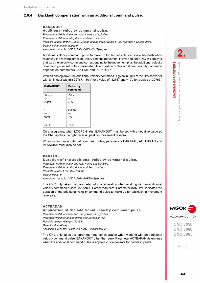
Installation manual.
CNC 8058CNC 8060CNC 8065
MA
CH
INE
PA
RA
ME
TE
RS
.
2.
Mac
hin
e pa
ram
eter
s fo
r th
e ax
es. W
ork
sets
.
ꞏ207ꞏ
REF: 2102
2.6.4 Backlash compensation with an additional command pulse.
BAKANOUTAdditional velocity command pulse.Parameter valid for linear and rotary axes and spindles. Parameter valid for analog drives and Sercos drives. Possible values: Within ±32767 with an analog drive / within ±1000 rpm with a Sercos drive.Default value: 0 (Not applied).Associated variable: (V.)[ch].MPA.BAKANOUT[set].xn
Additional velocity command pulse to make up for the possible leadscrew backlash whenreversing the moving direction. Every time the movement is inverted, the CNC will apply tothat axis the velocity command corresponding to the movement plus the additional velocitycommand pulse set in this parameter. The duration of this additional velocity commanddepends on parameters BAKTIME and PEAKDISP.
With an analog drive, the additional velocity command is given in units of the D/A converterwith an integer within ± 32767. - 10 V for a value of -32767 and +10V for a value of 32767.
On analog axes, when LOOPCH=Yes, BAKANOUT must be set with a negative value sothe CNC applies the right reversal peak for movement reversal.
When setting an additional command pulse, parameters BAKTIME, ACTBAKAN andPEAKDISP must also be set.
BAKTIMEDuration of the additional velocity command pulse.Parameter valid for linear and rotary axes and spindles. Parameter valid for analog drives and Sercos drives. Possible values: From 0 to 100 ms.Default value: 0.Associated variable: (V.)[ch].MPA.BAKTIME[set].xn
The CNC only takes this parameter into consideration when working with an additionalvelocity command pulse; BAKANOUT other than zero. Parameter BAKTIME indicates theduration of the additional velocity command pulse to make up for backlash in movementreversals.
ACTBAKANApplication of the additional velocity command pulse.Parameter valid for linear and rotary axes and spindles. Parameter valid for analog drives and Sercos drives. Possible values: Always / G2-G3.Default value: Always.Associated variable: (V.)[ch].MPA.ACTBAKAN[set].xn
The CNC only takes this parameter into consideration when working with an additionalvelocity command pulse; BAKANOUT other than zero. Parameter ACTBAKAN determineswhen the additional command pulse is applied to compensate for backlash peaks.
BAKANOUT Veloc i tycommand.
-32767ꞏꞏꞏ-3277ꞏꞏꞏ1ꞏꞏꞏ3277ꞏꞏꞏ32767
-10 V.ꞏꞏꞏ-1 V.ꞏꞏꞏ0,3 mV.ꞏꞏꞏ1 V.ꞏꞏꞏ10 V.

Installation manual.
CNC 8058CNC 8060CNC 8065
2.
MA
CH
INE
PA
RA
ME
TE
RS
.
Mac
hin
e pa
ram
eter
s fo
r th
e ax
es. W
ork
sets
.
ꞏ208ꞏ
REF: 2102
PEAKDISPBacklash peak cuttoff distance.Parameter valid for linear and rotary axes and spindles. Parameter valid for analog drives and Sercos drives. Possible values (1): From 0 to 99999.9999 mm.Possible values (2): From 0 to 3937.00787 inch.Possible values (3): From 0 to 99999.9999 degrees.Default value: 0.0050 mm / 0.00508 mm / 0.0050 degrees.Associated variable: (V.)[ch].MPA.PEAKDISP[set].xn
The CNC only takes this parameter into consideration when working with an additionalvelocity command pulse; BAKANOUT other than zero. Parameter PEAKDISP sets the realdistance traveled by the axis after the theoretical movement reversal, where the CNC cutsthe reversal peak off on that axis (additional command pulse).
REVEHYSTHysteresis for applying the additional command pulse in movement reversals.Parameter valid for linear and rotary axes and spindles. Parameter valid for analog drives and Sercos drives. Possible values (1): From 0 to 99999.9999 mm.Possible values (2): From 0 to 3937.00787 inch.Possible values (3): From 0 to 99999.9999 degrees.Default value: 0.Associated variable: (V.)[ch].MPA.REVEHYST[set].xn
This parameter limits the use of backlash compensation when the CNC detects a movementreversal so it is not applied every time the CNC receives a reversal command.
This parameter sets the value that the axis position must vary after the first movementreversal (hysteresis) for the CNC to consider applying backlash compensation. If the axisdoes not exceed this margin, the CNC does not apply backlash compensation.
Considerations.
• If REVEHYST=0, Backlash compensation by reversal peak will always be applied oneach reversal.
• If REVEHYST other than 0, and parameter PEAKDISP is used to cut the backlash peakoff, we recommend to set REVEHYST to a lower value than that of PEAKDISP so theCNC applies the backlash peak.
BAKANOUTCommand to end backlash compensation (cutoff). The feedback indicates that the axis has travelled the distance set in the PEAKDISP parameters.
[ms]
Command to begin backlash compensation.
[rpm]
Theoretical position.
Position feedback.
Movement amplitude set by parameter (PEAKDISP).

Installation manual.
CNC 8058CNC 8060CNC 8065
MA
CH
INE
PA
RA
ME
TE
RS
.
2.
Mac
hin
e pa
ram
eter
s fo
r th
e ax
es. W
ork
sets
.
ꞏ209ꞏ
REF: 2102
• When having axes set as DRO axes, the value of the BACKLASH parameter will be takeninto consideration. In these cases, especially when using sinusoidal feedback, werecommend to set REVEHYST to a value other than 0 in order to apply backlash.
If REVEHYST= 0.0005 mm, the CNC will not activate the compensation in reversalsoccurring after the first one as long as the axis position does not change (vary) at least inthe amount set by this parameter, taking as reference the position it occupied in the firstposition command reversing order.In other words, if the CNC receives a command (order) to reverse when the positioncommand has only changed 0.0002 mm from the position where the first reversal commandtook place, the CNC does not apply the compensation (the value set in REVEHYST hasnot been exceeded) and it simply reverses the moving direction.Only when the position command variation reaches 0.0005 mm, the CNC will apply thecompensation. After applying a compensation, the CNC will take the new order to reverseas a new reference to evaluate the position variation and determine when the value set inparameter REVEHYST has been reached again and start compensating again.
1
1
REVEHYST
REVEHYST
REVEHYST
REVEHYST
1
2
3
2 21
213t
Reversal of the position command.Limit set in REVEHYST. Beginning of backlash compensation.Cancellation of backlash compensation.
Position.
Installation manual.
CNC 8058CNC 8060CNC 8065
2.
MA
CH
INE
PA
RA
ME
TE
RS
.
Mac
hin
e pa
ram
eter
s fo
r th
e ax
es. W
ork
sets
.
ꞏ210ꞏ
REF: 2102
2.6.5 Adjustment of rapid traverse G00 and maximum speed.
G00FEEDFeedrate in G00.Parameter valid for linear and rotary axes and spindles. Parameter valid for analog drive, Sercos and simulated. Possible values (1): From 0 to 500000.0000 mm/min.Possible values (2): From 0 to 19685.03937 inch/min.Possible values (3): From 0 to 72000000.0000 degrees/min.Possible values (4): From 0 to 200000.0000 rpm.Default value: 10000.0000 mm/min / 393.70079 inch/min / 1080000 degrees/min / 3000.0000 rpm.Associated variable: (V.)[ch].MPA.G00FEED[set].xn
Lathe and mill models.
Rapid positioning (traverse, G00) are always carried out at the maximum speed possible.The one indicated by G00FEED.
Laser model.
Maximum generator power. In order for the power control through an analog output to bemanaged correctly (#PWRCTRL ON[OUT], the watts defined in the parameter G00FEEDas the generator power must match the volt level defined in the parameter MAXVOLT.
How to limit temporarily the maximum feedrate via PLC
The PLC has the variable (V.)[ch].PLC.G00FEED that may be used to limit the feedrate inthe channel for any type of movement (G00, G01, etc). This variable limits the feedrate ofthe path and affects all the axes whether they move interpolated or one axis at a time.
The CNC assumes the change immediately and the change stays active until the variabletakes a value of ꞏ0ꞏ restoring the limits set by machine parameters.
MAXFEEDMaximum axis machining feedrate.Parameter valid for linear and rotary axes and spindles. Parameter valid for analog drive, Sercos and simulated. Possible values (1): From 0 to 500000.0000 mm/min.Possible values (2): From 0 to 19685.03937 inch/min.Possible values (3): From 0 to 72000000.0000 degrees/min.Possible values (4): From 0 to 1388.8889 rpm.Default value: 0.Associated variable: (V.)[ch].MPA.MAXFEED[set].xn
This parameter sets the maximum machining feedrate (movements in G01/G02/G03) of theaxis; when set to ꞏ0ꞏ, the feedrate is not limited This parameter cannot be set with a valuehigher than that of parameter G00FEED.
When trying to exceed the maximum feedrate via part-program, via PLC or from the operatorpanel, the CNC limits the feedrate to the maximum value set in MAXFEED without showingany error message or warning.
If the machining feedrate is not limited, the CNC assumes for all the movements the one setin machine parameter G00FEED as the maximum feedrate.
Variable. Machine parameters. Feedrate.
(V.)PLC.G00FEED G00FEED (axis) MAXFEED (axis) G00 G01, G02, ꞏꞏꞏ
0 10000 0 10000 10000
0 10000 6000 10000 6000
4000 10000 6000 4000 4000
7000 10000 6000 7000 6000
12000 10000 6000 10000 6000
Installation manual.
CNC 8058CNC 8060CNC 8065
MA
CH
INE
PA
RA
ME
TE
RS
.
2.
Mac
hin
e pa
ram
eter
s fo
r th
e ax
es. W
ork
sets
.
ꞏ211ꞏ
REF: 2102
MAXVOLTVelocity command to reach G00FEED.Parameter valid for linear and rotary axes and spindles. Parameter valid for analog drives and velocity-Sercos drives. Possible values: from 0 to 10000.0000 mV.Default value: 9500 mV (9.5 V).Associated variable: (V.)[ch].MPA.MAXVOLT[set].xn
Lathe and mill models.
This is the velocity command the CNC must output so the axis can reach its maximum rapidtraverse feedrate G00FEED.
Laser model.
This is the command the CNC must provide for the spindle to reach the maximum generatorpower set in parameter G00FEED.
MAXFREQFrequency required to reach G00FEED.Parameter valid for spindles. Parameter valid for a Mechatrolink inverter. Possible values: From 0.0010 to 10000.0000 Hz.Default value: 50 Hz.Associated variable: (V.)[ch].MPA.MAXFREQ[set].xn
When the drive is an inverter, this parameter indicates the frequency to be provided by theCNC for the spindle to reach the speed set in parameter G00FEED.
MAXRPMMaximum motor rpm.Parameter valid for linear and rotary axes and spindles. Parameter valid for a Mechatrolink speed and inverter.Possible values: From 0 to 100000 rpm.Default value: 3000 rpm.Associated variable: (V.)[ch].MPA.MAXRPM[set].xn
Maximum motor rpm.
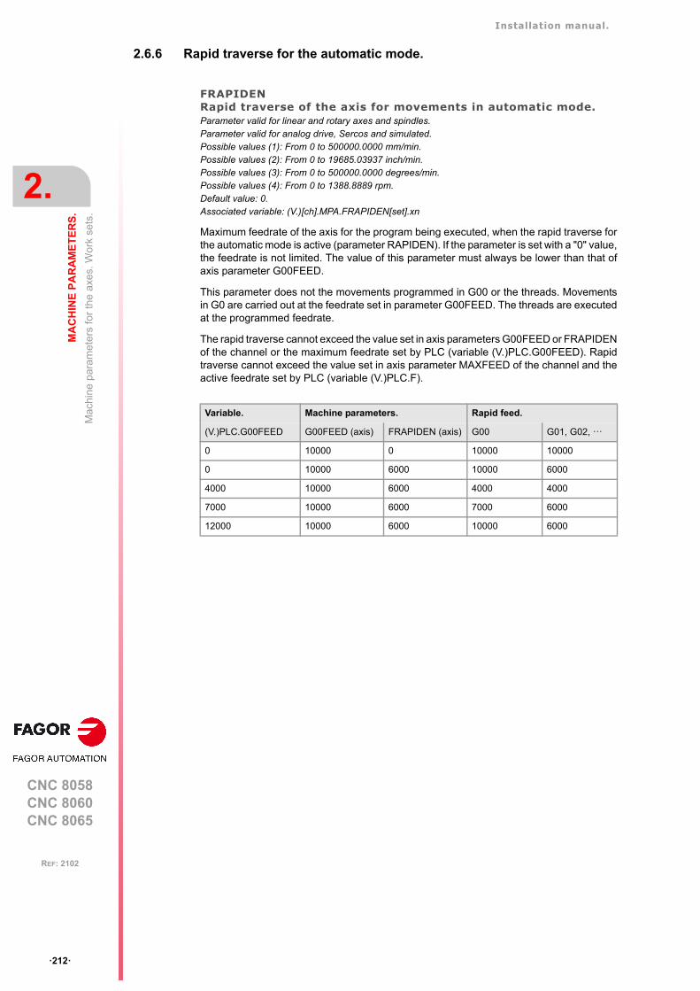
Installation manual.
CNC 8058CNC 8060CNC 8065
2.
MA
CH
INE
PA
RA
ME
TE
RS
.
Mac
hin
e pa
ram
eter
s fo
r th
e ax
es. W
ork
sets
.
ꞏ212ꞏ
REF: 2102
2.6.6 Rapid traverse for the automatic mode.
FRAPIDENRapid traverse of the axis for movements in automatic mode.Parameter valid for linear and rotary axes and spindles. Parameter valid for analog drive, Sercos and simulated. Possible values (1): From 0 to 500000.0000 mm/min.Possible values (2): From 0 to 19685.03937 inch/min.Possible values (3): From 0 to 500000.0000 degrees/min.Possible values (4): From 0 to 1388.8889 rpm.Default value: 0.Associated variable: (V.)[ch].MPA.FRAPIDEN[set].xn
Maximum feedrate of the axis for the program being executed, when the rapid traverse forthe automatic mode is active (parameter RAPIDEN). If the parameter is set with a "0" value,the feedrate is not limited. The value of this parameter must always be lower than that ofaxis parameter G00FEED.
This parameter does not the movements programmed in G00 or the threads. Movementsin G0 are carried out at the feedrate set in parameter G00FEED. The threads are executedat the programmed feedrate.
The rapid traverse cannot exceed the value set in axis parameters G00FEED or FRAPIDENof the channel or the maximum feedrate set by PLC (variable (V.)PLC.G00FEED). Rapidtraverse cannot exceed the value set in axis parameter MAXFEED of the channel and theactive feedrate set by PLC (variable (V.)PLC.F).
Variable. Machine parameters. Rapid feed.
(V.)PLC.G00FEED G00FEED (axis) FRAPIDEN (axis) G00 G01, G02, ꞏꞏꞏ
0 10000 0 10000 10000
0 10000 6000 10000 6000
4000 10000 6000 4000 4000
7000 10000 6000 7000 6000
12000 10000 6000 10000 6000
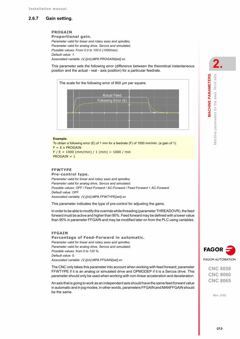
Installation manual.
CNC 8058CNC 8060CNC 8065
MA
CH
INE
PA
RA
ME
TE
RS
.
2.
Mac
hin
e pa
ram
eter
s fo
r th
e ax
es. W
ork
sets
.
ꞏ213ꞏ
REF: 2102
2.6.7 Gain setting.
PROGAINProportional gain.Parameter valid for linear and rotary axes and spindles. Parameter valid for analog drive, Sercos and simulated. Possible values: From 0.0 to 100.0 (1000/min).Default value: 1.Associated variable: (V.)[ch].MPA.PROGAIN[set].xn
This parameter sets the following error (difference between the theoretical instantaneousposition and the actual - real - axis position) for a particular feedrate.
FFWTYPEPre-control type.Parameter valid for linear and rotary axes and spindles. Parameter valid for analog drive, Sercos and simulated. Possible values: OFF / Feed Forward / AC-Forward / Feed Forward + AC-Forward.Default value: OFFAssociated variable: (V.)[ch].MPA.FFWTYPE[set].xn
This parameter indicates the type of pre-control for adjusting the gains.
In order to be able to modify the override while threading (parameter THREADOVR), the feedforward must be active and higher than 90%. Feed forward may be defined with a lower valuethan 90% in parameter FFGAIN and may be modified later on from the PLC using variables.
FFGAINPercentage of Feed-Forward in automatic.Parameter valid for linear and rotary axes and spindles. Parameter valid for analog drive, Sercos and simulated. Possible values: from 0 to 120 %.Default value: 0.Associated variable: (V.)[ch].MPA.FFGAIN[set].xn
The CNC only takes this parameter into account when working with feed forward; parameterFFWTYPE if it is an analog or simulated drive and OPMODEP if it is a Sercos drive. Thisparameter should only be used when working with non-linear acceleration and deceleration.
An axis that is going to work as an independent axis should have the same feed forward valuein automatic and in jog modes; in other words, parameters FFGAIN and MANFFGAIN shouldbe the same.
The scale for the following error of 800 µm per square.
Example:To obtain a following error (E) of 1 mm for a feedrate (F) of 1000 mm/min. (a gain of 1).F = E x PROGAINF / E = 1000 (mm/min) / 1 (mm) = 1000 / minPROGAIN = 1
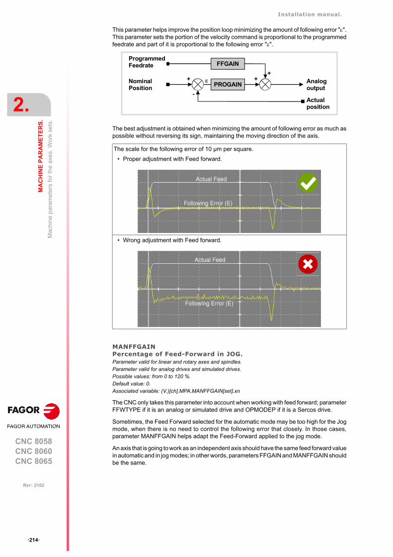
Installation manual.
CNC 8058CNC 8060CNC 8065
2.
MA
CH
INE
PA
RA
ME
TE
RS
.
Mac
hin
e pa
ram
eter
s fo
r th
e ax
es. W
ork
sets
.
ꞏ214ꞏ
REF: 2102
This parameter helps improve the position loop minimizing the amount of following error "".This parameter sets the portion of the velocity command is proportional to the programmedfeedrate and part of it is proportional to the following error "".
The best adjustment is obtained when minimizing the amount of following error as much aspossible without reversing its sign, maintaining the moving direction of the axis.
MANFFGAINPercentage of Feed-Forward in JOG.Parameter valid for linear and rotary axes and spindles. Parameter valid for analog drives and simulated drives. Possible values: from 0 to 120 %.Default value: 0.Associated variable: (V.)[ch].MPA.MANFFGAIN[set].xn
The CNC only takes this parameter into account when working with feed forward; parameterFFWTYPE if it is an analog or simulated drive and OPMODEP if it is a Sercos drive.
Sometimes, the Feed Forward selected for the automatic mode may be too high for the Jogmode, when there is no need to control the following error that closely. In those cases,parameter MANFFGAIN helps adapt the Feed-Forward applied to the jog mode.
An axis that is going to work as an independent axis should have the same feed forward valuein automatic and in jog modes; in other words, parameters FFGAIN and MANFFGAIN shouldbe the same.
The scale for the following error of 10 µm per square.
• Proper adjustment with Feed forward.
• Wrong adjustment with Feed forward.
FFGAIN
PROGAIN
ProgrammedFeedrate
NominalPosition
+ ++
Analogoutput
Actualposition
-
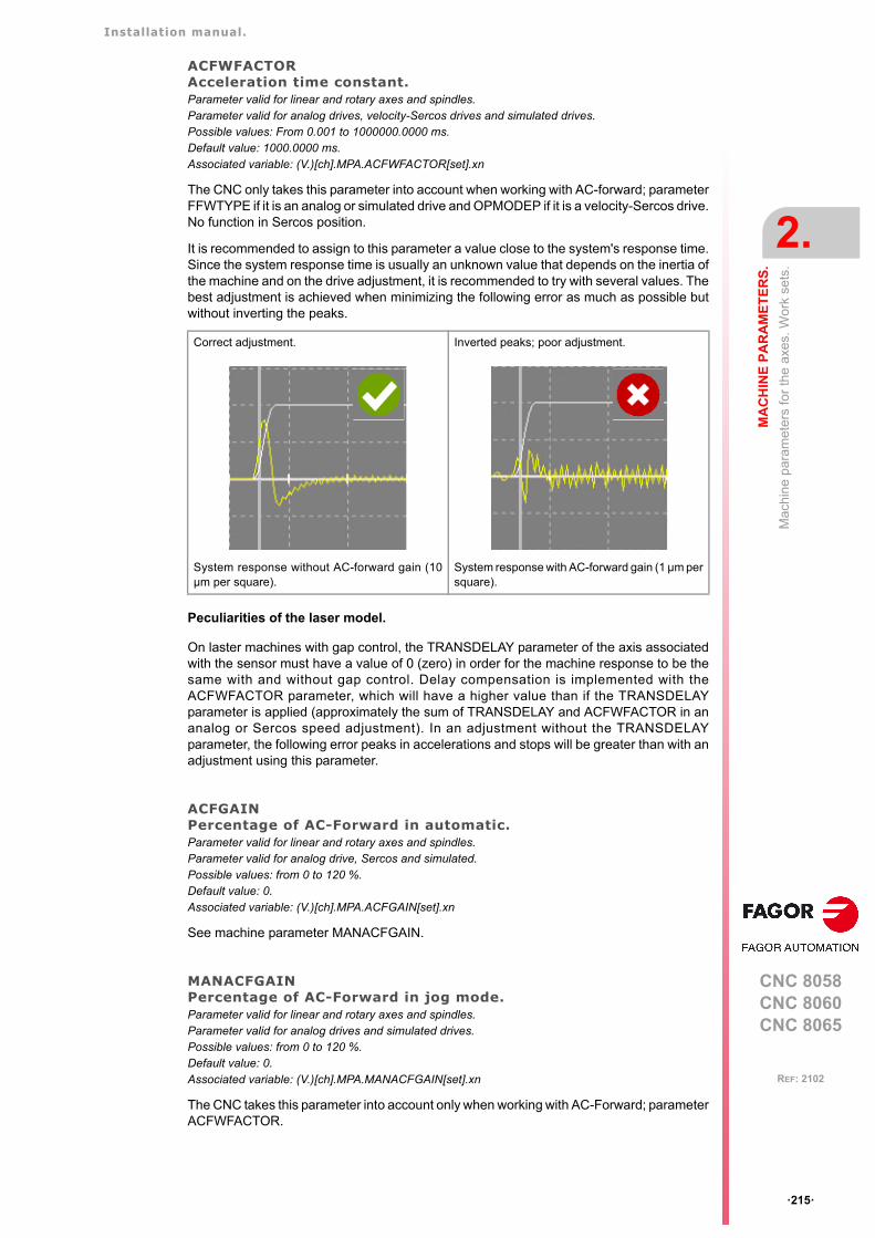
Installation manual.
CNC 8058CNC 8060CNC 8065
MA
CH
INE
PA
RA
ME
TE
RS
.
2.
Mac
hin
e pa
ram
eter
s fo
r th
e ax
es. W
ork
sets
.
ꞏ215ꞏ
REF: 2102
ACFWFACTORAcceleration time constant.Parameter valid for linear and rotary axes and spindles. Parameter valid for analog drives, velocity-Sercos drives and simulated drives. Possible values: From 0.001 to 1000000.0000 ms.Default value: 1000.0000 ms.Associated variable: (V.)[ch].MPA.ACFWFACTOR[set].xn
The CNC only takes this parameter into account when working with AC-forward; parameterFFWTYPE if it is an analog or simulated drive and OPMODEP if it is a velocity-Sercos drive.No function in Sercos position.
It is recommended to assign to this parameter a value close to the system's response time.Since the system response time is usually an unknown value that depends on the inertia ofthe machine and on the drive adjustment, it is recommended to try with several values. Thebest adjustment is achieved when minimizing the following error as much as possible butwithout inverting the peaks.
Peculiarities of the laser model.
On laster machines with gap control, the TRANSDELAY parameter of the axis associatedwith the sensor must have a value of 0 (zero) in order for the machine response to be thesame with and without gap control. Delay compensation is implemented with theACFWFACTOR parameter, which will have a higher value than if the TRANSDELAYparameter is applied (approximately the sum of TRANSDELAY and ACFWFACTOR in ananalog or Sercos speed adjustment). In an adjustment without the TRANSDELAYparameter, the following error peaks in accelerations and stops will be greater than with anadjustment using this parameter.
ACFGAINPercentage of AC-Forward in automatic.Parameter valid for linear and rotary axes and spindles. Parameter valid for analog drive, Sercos and simulated. Possible values: from 0 to 120 %.Default value: 0.Associated variable: (V.)[ch].MPA.ACFGAIN[set].xn
See machine parameter MANACFGAIN.
MANACFGAINPercentage of AC-Forward in jog mode.Parameter valid for linear and rotary axes and spindles. Parameter valid for analog drives and simulated drives. Possible values: from 0 to 120 %.Default value: 0.Associated variable: (V.)[ch].MPA.MANACFGAIN[set].xn
The CNC takes this parameter into account only when working with AC-Forward; parameterACFWFACTOR.
Correct adjustment.
System response without AC-forward gain (10µm per square).
Inverted peaks; poor adjustment.
System response with AC-forward gain (1 µm persquare).
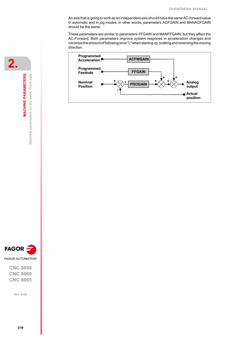
Installation manual.
CNC 8058CNC 8060CNC 8065
2.
MA
CH
INE
PA
RA
ME
TE
RS
.
Mac
hin
e pa
ram
eter
s fo
r th
e ax
es. W
ork
sets
.
ꞏ216ꞏ
REF: 2102
An axis that is going to work as an independent axis should have the same AC-forward valuein automatic and in jog modes; in other words, parameters ACFGAIN and MANACFGAINshould be the same.
These parameters are similar to parameters FFGAIN and MANFFGAIN; but they affect theAC-Forward. Both parameters improve system response in acceleration changes andminimize the amount of following error "" when starting up, braking and reversing the movingdirection.
FFGAIN
PROGAIN
ProgrammedFeedrate
NominalPosition
+ ++
Analogoutput
Actualposition
-
ACFWGAINProgrammedAcceleration
++

Installation manual.
CNC 8058CNC 8060CNC 8065
MA
CH
INE
PA
RA
ME
TE
RS
.
2.
Mac
hin
e pa
ram
eter
s fo
r th
e ax
es. W
ork
sets
.
ꞏ217ꞏ
REF: 2102
2.6.8 Linear acceleration.
LACC1Acceleration of the first section.Parameter valid for linear and rotary axes and spindles. Parameter valid for analog drive, Sercos and simulated. Possible values (1): From 0.0000 to 600000000.0000 mm/s².Possible values (2): From 0.00000 to 23622047.24409 inch/s².Possible values (3): From 0.0000 to 600000000.0000 degrees/s².Default value: 1000.0000 mm/s² / 39.37008 inch/s² / 1000.0000 degrees/s².Associated variable: (V.)[ch].MPA.LACC1[set].xn
See parameter LACC2.
LACC2Acceleration of the second section.Parameter valid for linear and rotary axes and spindles. Parameter valid for analog drive, Sercos and simulated. Possible values (1): From 0.0000 to 600000000.0000 mm/s².Possible values (2): From 0.00000 to 23622047.24409 inch/s².Possible values (3): From 0.0000 to 600000000.0000 degrees/s².Default value: 1000.0000 mm/s² / 39.37008 inch/s² / 1000.0000 degrees/s².Associated variable: (V.)[ch].MPA.LACC2[set].xn
Parameters LACC1 and LACC2 set the acceleration values when it is linear (parameterSLOPETYPE) or when working with HSC in FAST mode. The CNC applies parametersLACC1 and LACC2 to the movements in G1, G2 and G3; movements in G0 depend onparameter G0ACDCJERK.
G0ACDCJERK Meaning.
Yes. Movements in G0 use parameters LACC1G0, LACC2G0 and LFEEDG0.
No. Movements in G0 use parameters LACC1, LACC2 and LFEED.
1 Acceleration according to parameter LACC1 until reaching the feedrate indicated inLFEED.
2 Acceleration according to parameter LACC2 until reaching the programmed feedrate.
3 Movement at programmed feedrate (without acceleration).
4 Deceleration according to parameter LACC2 until reaching the feedrate indicated inLFEED.
5 Deceleration according to parameter LACC1.
LACC1
LACC2
- LACC2
- LACC1
t
a
t
F
LFEED
1
23
5
4
Installation manual.
CNC 8058CNC 8060CNC 8065
2.
MA
CH
INE
PA
RA
ME
TE
RS
.
Mac
hin
e pa
ram
eter
s fo
r th
e ax
es. W
ork
sets
.
ꞏ218ꞏ
REF: 2102
LFEEDAcceleration changing speed.Parameter valid for linear and rotary axes and spindles. Parameter valid for analog drive, Sercos and simulated. Possible values (1): From 0 to 200000.0000 mm/min.Possible values (2): From 0 to 7874.01575 inch/min.Possible values (3): From 0 to 36000000.0000 degrees/min.Possible values (4): From 0 to 100000.0000 rpm.Default value: 3000 mm/min / 118.11023 inch/min / 1080000 degrees/min / 3000 rpm.Associated variable: (V.)[ch].MPA.LFEED[set].xn
While accelerating, when reaching the feedrate defined in this parameter, it changes theacceleration from LACC1 to LACC2. While decelerating, when reaching the feedrate definedin this parameter, it changes the acceleration from LACC2 to LACC1.
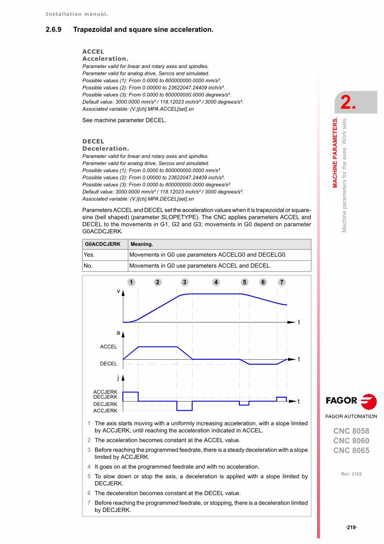
Installation manual.
CNC 8058CNC 8060CNC 8065
MA
CH
INE
PA
RA
ME
TE
RS
.
2.
Mac
hin
e pa
ram
eter
s fo
r th
e ax
es. W
ork
sets
.
ꞏ219ꞏ
REF: 2102
2.6.9 Trapezoidal and square sine acceleration.
ACCELAcceleration.Parameter valid for linear and rotary axes and spindles. Parameter valid for analog drive, Sercos and simulated. Possible values (1): From 0.0000 to 600000000.0000 mm/s².Possible values (2): From 0.00000 to 23622047.24409 inch/s².Possible values (3): From 0.0000 to 600000000.0000 degrees/s².Default value: 3000.0000 mm/s² / 118.12023 inch/s² / 3000 degrees/s².Associated variable: (V.)[ch].MPA.ACCEL[set].xn
See machine parameter DECEL.
DECELDeceleration.Parameter valid for linear and rotary axes and spindles. Parameter valid for analog drive, Sercos and simulated. Possible values (1): From 0.0000 to 600000000.0000 mm/s².Possible values (2): From 0.00000 to 23622047.24409 inch/s².Possible values (3): From 0.0000 to 600000000.0000 degrees/s².Default value: 3000.0000 mm/s² / 118.12023 inch/s² / 3000 degrees/s².Associated variable: (V.)[ch].MPA.DECEL[set].xn
Parameters ACCEL and DECEL set the acceleration values when it is trapezoidal or square-sine (bell shaped) (parameter SLOPETYPE). The CNC applies parameters ACCEL andDECEL to the movements in G1, G2 and G3; movements in G0 depend on parameterG0ACDCJERK.
G0ACDCJERK Meaning.
Yes. Movements in G0 use parameters ACCELG0 and DECELG0.
No. Movements in G0 use parameters ACCEL and DECEL.
1 The axis starts moving with a uniformly increasing acceleration, with a slope limitedby ACCJERK, until reaching the acceleration indicated in ACCEL.
2 The acceleration becomes constant at the ACCEL value.
3 Before reaching the programmed feedrate, there is a steady deceleration with a slopelimited by ACCJERK.
4 It goes on at the programmed feedrate and with no acceleration.
5 To slow down or stop the axis, a deceleration is applied with a slope limited byDECJERK.
6 The deceleration becomes constant at the DECEL value.
7 Before reaching the programmed feedrate, or stopping, there is a deceleration limitedby DECJERK.
t
v
t
a
ACCEL
DECEL
t
j
ACCJERKDECJERK
ACCJERKDECJERK
1 2 3 54 6 7
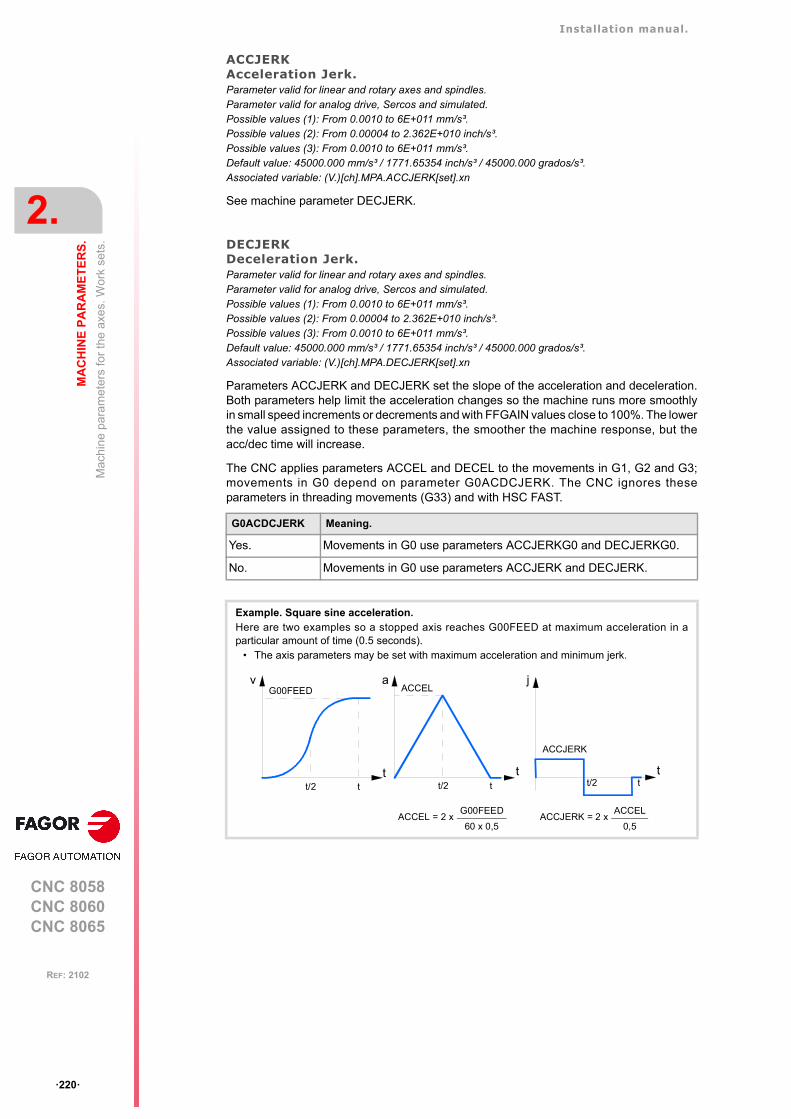
Installation manual.
CNC 8058CNC 8060CNC 8065
2.
MA
CH
INE
PA
RA
ME
TE
RS
.
Mac
hin
e pa
ram
eter
s fo
r th
e ax
es. W
ork
sets
.
ꞏ220ꞏ
REF: 2102
ACCJERKAcceleration Jerk.Parameter valid for linear and rotary axes and spindles. Parameter valid for analog drive, Sercos and simulated. Possible values (1): From 0.0010 to 6E+011 mm/s³.Possible values (2): From 0.00004 to 2.362E+010 inch/s³.Possible values (3): From 0.0010 to 6E+011 mm/s³.Default value: 45000.000 mm/s³ / 1771.65354 inch/s³ / 45000.000 grados/s³.Associated variable: (V.)[ch].MPA.ACCJERK[set].xn
See machine parameter DECJERK.
DECJERKDeceleration Jerk.Parameter valid for linear and rotary axes and spindles. Parameter valid for analog drive, Sercos and simulated. Possible values (1): From 0.0010 to 6E+011 mm/s³.Possible values (2): From 0.00004 to 2.362E+010 inch/s³.Possible values (3): From 0.0010 to 6E+011 mm/s³.Default value: 45000.000 mm/s³ / 1771.65354 inch/s³ / 45000.000 grados/s³.Associated variable: (V.)[ch].MPA.DECJERK[set].xn
Parameters ACCJERK and DECJERK set the slope of the acceleration and deceleration.Both parameters help limit the acceleration changes so the machine runs more smoothlyin small speed increments or decrements and with FFGAIN values close to 100%. The lowerthe value assigned to these parameters, the smoother the machine response, but theacc/dec time will increase.
The CNC applies parameters ACCEL and DECEL to the movements in G1, G2 and G3;movements in G0 depend on parameter G0ACDCJERK. The CNC ignores theseparameters in threading movements (G33) and with HSC FAST.
G0ACDCJERK Meaning.
Yes. Movements in G0 use parameters ACCJERKG0 and DECJERKG0.
No. Movements in G0 use parameters ACCJERK and DECJERK.
Example. Square sine acceleration.Here are two examples so a stopped axis reaches G00FEED at maximum acceleration in aparticular amount of time (0.5 seconds).
• The axis parameters may be set with maximum acceleration and minimum jerk.
v a j
t tttt/2
G00FEED ACCEL
ACCJERK
tt/2 tt/2
ACCEL = 2 x G00FEED
60 x 0,5ACCJERK = 2 x
ACCEL
0,5
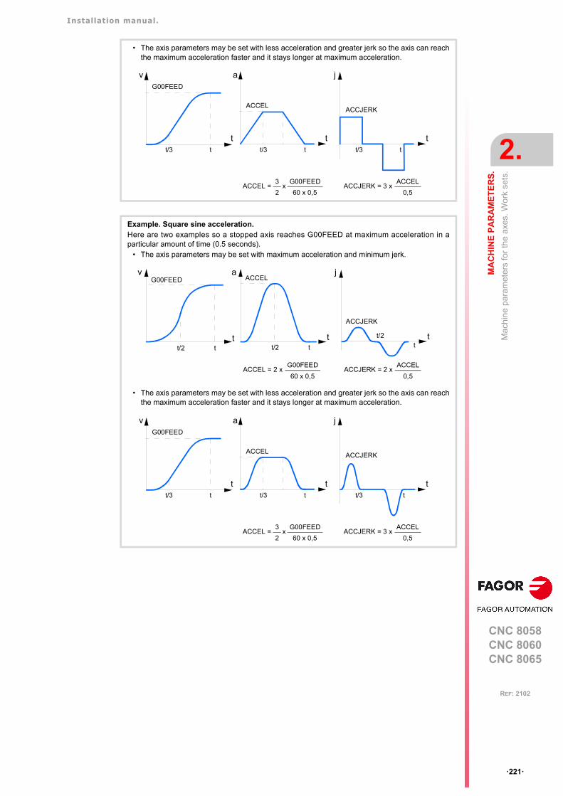
Installation manual.
CNC 8058CNC 8060CNC 8065
MA
CH
INE
PA
RA
ME
TE
RS
.
2.
Mac
hin
e pa
ram
eter
s fo
r th
e ax
es. W
ork
sets
.
ꞏ221ꞏ
REF: 2102
• The axis parameters may be set with less acceleration and greater jerk so the axis can reachthe maximum acceleration faster and it stays longer at maximum acceleration.
Example. Square sine acceleration.Here are two examples so a stopped axis reaches G00FEED at maximum acceleration in aparticular amount of time (0.5 seconds).
• The axis parameters may be set with maximum acceleration and minimum jerk.
• The axis parameters may be set with less acceleration and greater jerk so the axis can reachthe maximum acceleration faster and it stays longer at maximum acceleration.
v
t
G00FEED
a
t
ACCEL
j
t
ACCJERK
tt/3 tt/3 tt/3
ACCJERK = 3 x ACCEL
0,5ACCEL =
G00FEED
60 x 0,5
3
2x
v a j
t tttt/2
G00FEED ACCEL
ACCJERK
tt/2 t
t/2
ACCEL = 2 x G00FEED
60 x 0,5ACCJERK = 2 x
ACCEL
0,5
t/3
v
t
G00FEED
a
t
ACCEL
j
t
ACCJERK
tt/3 tt/3 t
ACCJERK = 3 x ACCEL
0,5ACCEL =
G00FEED
60 x 0,5
3
2x
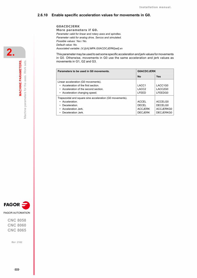
Installation manual.
CNC 8058CNC 8060CNC 8065
2.
MA
CH
INE
PA
RA
ME
TE
RS
.
Mac
hin
e pa
ram
eter
s fo
r th
e ax
es. W
ork
sets
.
ꞏ222ꞏ
REF: 2102
2.6.10 Enable specific acceleration values for movements in G0.
G0ACDCJERKMore parameters if G0.Parameter valid for linear and rotary axes and spindles. Parameter valid for analog drive, Sercos and simulated. Possible values: Yes / No.Default value: No.Associated variable: (V.)[ch].MPA.G0ACDCJERK[set].xn
This parameter may be used to set some specific acceleration and jerk values for movementsin G0. Otherwise, movements in G0 use the same acceleration and jerk values asmovements in G1, G2 and G3.
Parameters to be used in G0 movements. G0ACDCJERK
No Yes
Linear acceleration (G0 movements).• Acceleration of the first section.• Acceleration of the second section.• Acceleration changing speed.
LACC1LACC2LFEED
LACC1G0LACC2G0LFEEDG0
Trapezoidal and square sine acceleration (G0 movements).• Acceleration.• Deceleration.• Acceleration Jerk.• Deceleration Jerk.
ACCELDECELACCJERKDECJERK
ACCELG0DECELG0ACCJERKG0DECJERKG0
Installation manual.
CNC 8058CNC 8060CNC 8065
MA
CH
INE
PA
RA
ME
TE
RS
.
2.
Mac
hin
e pa
ram
eter
s fo
r th
e ax
es. W
ork
sets
.
ꞏ223ꞏ
REF: 2102
2.6.11 Linear acceleration (G0 movements).
LACC1G0Acceleration of the first section (G0 movements).Parameter valid for linear and rotary axes and spindles. Parameter valid for analog drive, Sercos and simulated. Possible values (1): From 0.0000 to 600000000.0000 mm/s².Possible values (2): From 0.00000 to 23622047.24409 inch/s².Possible values (3): From 0.0000 to 600000000.0000 degrees/s².Default value: 1000.0000 mm/s² / 39.37008 inch/s² / 1000.0000 degrees/s².Associated variable: (V.)[ch].MPA.LACC1G0[set].xn
See parameter LACC2G0.
LACC2G0Acceleration of the second section (G0 movements).Parameter valid for linear and rotary axes and spindles. Parameter valid for analog drive, Sercos and simulated. Possible values (1): From 0.0000 to 600000000.0000 mm/s².Possible values (2): From 0.00000 to 23622047.24409 inch/s².Possible values (3): From 0.0000 to 600000000.0000 degrees/s².Default value: 1000.0000 mm/s² / 39.37008 inch/s² / 1000.0000 degrees/s².Associated variable: (V.)[ch].MPA.LACC2G0[set].xn
Parameters LACC1G0 and LACC2G0 set the acceleration values when it is linear(parameter SLOPETYPE) or when working with HSC in FAST mode. The CNC appliesparameters LACC1G0 and LACC2G0 to G0 movements.
LFEEDG0Acceleration changing speed (G0 movements).Parameter valid for linear and rotary axes and spindles. Parameter valid for analog drive, Sercos and simulated. Possible values (1): From 0 to 200000.0000 mm/min.Possible values (2): From 0 to 7874.01575 inch/min.Possible values (3): From 0 to 36000000.0000 degrees/min.Possible values (4): From 0 to 100000.0000 rpm.Default value: 3000 mm/min / 118.11023 inch/min / 1080000 degrees/min / 3000 rpm.Associated variable: (V.)[ch].MPA.LFEEDG0[set].xn
While accelerating, when reaching the feedrate defined in this parameter, it changes theacceleration from LACC1G0 to LACC2G0. While decelerating, when reaching the feedratedefined in this parameter, it changes the acceleration from LACC2G0 to LACC1G0.
Installation manual.
CNC 8058CNC 8060CNC 8065
2.
MA
CH
INE
PA
RA
ME
TE
RS
.
Mac
hin
e pa
ram
eter
s fo
r th
e ax
es. W
ork
sets
.
ꞏ224ꞏ
REF: 2102
2.6.12 Trapezoidal and square sine acceleration (G0 movements).
ACCELG0Acceleration (G0 movements).Parameter valid for linear and rotary axes and spindles. Parameter valid for analog drive, Sercos and simulated. Possible values (1): From 0.0000 to 600000000.0000 mm/s².Possible values (2): From 0.00000 to 23622047.24409 inch/s².Possible values (3): From 0.0000 to 600000000.0000 degrees/s².Default value: 4000.0000 mm/s² / 157.48031 inch/s² / 4000 degrees/s².Associated variable: (V.)[ch].MPA.ACCELG0[set].xn
See machine parameter DECELG0.
DECELG0Deceleration (G0 movements).Parameter valid for linear and rotary axes and spindles. Parameter valid for analog drive, Sercos and simulated. Possible values (1): From 0.0000 to 600000000.0000 mm/s².Possible values (2): From 0.00000 to 23622047.24409 inch/s².Possible values (3): From 0.0000 to 600000000.0000 degrees/s².Default value: 4000.0000 mm/s² / 157.48031 inch/s² / 4000 degrees/s².Associated variable: (V.)[ch].MPA.DECELG0[set].xn
Parameters ACCEL and DECEL set the acceleration values when it is trapezoidal or square-sine (bell shaped) (parameter SLOPETYPE). The CNC applies parameters ACCEL andDECEL to the movements in G1, G2 and G3; movements in G0 depend on parameterG0ACDCJERK.
ACCJERKG0Acceleration jerk (G0 movements).Parameter valid for linear and rotary axes and spindles. Parameter valid for analog drive, Sercos and simulated. Possible values (1): From 0.0010 to 6E+011 mm/s³.Possible values (2): From 0.00004 to 2.362E+010 inch/s³.Possible values (3): From 0.0010 to 6E+011 mm/s³.Default value: 55000.000 mm/s³ / 2165.35433 inch/s³ / 55000.000 grados/s³.Associated variable: (V.)[ch].MPA.ACCJERKG0[set].xn
See machine parameter DECJERKG0.
DECJERKG0Deceleration jerk (G0 movements).Parameter valid for linear and rotary axes and spindles. Parameter valid for analog drive, Sercos and simulated. Possible values (1): From 0.0010 to 6E+011 mm/s³.Possible values (2): From 0.00004 to 2.362E+010 inch/s³.Possible values (3): From 0.0010 to 6E+011 mm/s³.Default value: 55000.000 mm/s³ / 2165.35433 inch/s³ / 55000.000 grados/s³.Associated variable: (V.)[ch].MPA.DECJERKG0[set].xn
Parameters ACCJERKG0 and DECJERKG0 set the slope of the acceleration anddeceleration. Both parameters help limit the acceleration changes so the machine runs moresmoothly in small speed increments or decrements and with FFGAIN values close to 100%.The lower the value assigned to these parameters, the smoother the machine response, butthe acc/dec time will increase.
G0ACDCJERK Meaning.
Yes. Movements in G0 use parameters ACCELG0 and DECELG0.
No. Movements in G0 use parameters ACCEL and DECEL.
Installation manual.
CNC 8058CNC 8060CNC 8065
MA
CH
INE
PA
RA
ME
TE
RS
.
2.
Mac
hin
e pa
ram
eter
s fo
r th
e ax
es. W
ork
sets
.
ꞏ225ꞏ
REF: 2102
The CNC applies parameters ACCEL and DECEL to the movements in G1, G2 and G3;movements in G0 depend on parameter G0ACDCJERK. The CNC ignores theseparameters in threading movements (G33) and with HSC FAST.
G0ACDCJERK Meaning.
Yes. Movements in G0 use parameters ACCJERKG0 and DECJERKG0.
No. Movements in G0 use parameters ACCJERK and DECJERK.

Installation manual.
CNC 8058CNC 8060CNC 8065
2.
MA
CH
INE
PA
RA
ME
TE
RS
.
Mac
hin
e pa
ram
eter
s fo
r th
e ax
es. W
ork
sets
.
ꞏ226ꞏ
REF: 2102
2.6.13 Configuration of the HSC mode.
HSCParameter table of the HSC mode.
This parameter shows the table to define the HSC work mode.
These parameters help increase or decrease the acceleration and jerk limits on curved path,due to the centripetal acceleration and at path joints, without affecting the way the axisaccelerates or decelerates.
CORNERACCMaximum acceleration permitted at the corners.Parameter valid for linear and rotary axes and spindles. Parameter valid for analog drive, Sercos and simulated. Possible values (1): From 0 to 100000.0000 mm/s².Possible values (2): From 0 to 3937.00787 inch/s².Possible values (3): From 0 to 100000.0000 grados/s².Default value: 0.Associated variable: (V.)[ch].MPA.CORNERACC[set].xn
This parameter sets the maximum acceleration allowed for the axis during block transition.If this parameter is set with a ꞏ0ꞏ value, the maximum acceleration of the axis is respected.
CURVACCMaximum contouring acceleration permitted.Parameter valid for linear and rotary axes and spindles. Parameter valid for analog drive, Sercos and simulated. Possible values (1): From 0 to 100000.0000 mm/s².Possible values (2): From 0 to 3937.00787 inch/s².Possible values (3): From 0 to 100000.0000 grados/s².Default value: 0.Associated variable: (V.)[ch].MPA.CURVAACC[set].xn
If this parameter is set with a ꞏ0ꞏ value, the maximum acceleration of the axis is respected.
CORNERJERKMaximum Jerk permitted at the corners.Parameter valid for linear and rotary axes and spindles. Parameter valid for analog drive, Sercos and simulated. Possible values (1): De 0 a 1E+009 mm/s³.Possible values (2): De 0 a 39370078.74016 inch/s³.Possible values (3): De 0 a 1E+009 grados/s³.Default value: 0.Associated variable: (V.)[ch].MPA.CORNERJERK[set].xn
If this parameter is set with a ꞏ0ꞏ value, the maximum jerk of the axis is respected.
HSC
CORNERACC Maximum acceleration permitted at the corners.
CURVACC Maximum contouring acceleration permitted.
CORNERJERK Maximum Jerk permitted at the corners.
CURVJERK Maximum contouring Jerk permitted.
FASTACC Maximum acceleration permitted (FAST mode).
MAXERROR Position error.
CONTERROR Tolerance per axis.
Installation manual.
CNC 8058CNC 8060CNC 8065
MA
CH
INE
PA
RA
ME
TE
RS
.
2.
Mac
hin
e pa
ram
eter
s fo
r th
e ax
es. W
ork
sets
.
ꞏ227ꞏ
REF: 2102
CURVJERKMaximum contouring Jerk permitted.Parameter valid for linear and rotary axes and spindles. Parameter valid for analog drive, Sercos and simulated. Possible values (1): De 0 a 1E+009 mm/s³.Possible values (2): De 0 a 39370078.74016 inch/s³.Possible values (3): De 0 a 1E+009 grados/s³.Default value: 0.Associated variable: (V.)[ch].MPA.CURVJERK[set].xn
If this parameter is set with a ꞏ0ꞏ value, the maximum jerk of the axis is respected.
FASTACCMaximum acceleration permitted (FAST mode).Parameter valid for linear and rotary axes and spindles. Parameter valid for analog drive, Sercos and simulated. Possible values (1): From 0 to 100000.0000 mm/s².Possible values (2): From 0 to 3937.00787 inch/s².Possible values (3): From 0 to 100000.0000 grados/s².Default value: 0.Associated variable: (V.)[ch].MPA.FASTACC[set].xn
If this parameter is set with a ꞏ0ꞏ value, the maximum acceleration of the axis is respected.
MAXERRORPosition error.Parameter valid for linear and rotary axes and spindles. Parameter valid for analog drive, Sercos and simulated. Possible values (1): From 0 to 9999.99999 mm.Possible values (2): From 0 to 3937.00787 inch.Possible values (3): From 0 to 9999.99999 degrees.Default value: 0.1000 mm / 0.00394 inch / 0.1000 grados.Associated variable: (V.)[ch].MPA.MAXERROR[set].xn
Maximum axis position error in HSC when working outside the plane/trihedron.
CONTERRORTolerance per axis for smoothing the generated n-dimensional path.Parameter valid for linear and rotary axes and spindles. Parameter valid for analog drive, Sercos and simulated. Default value: 0.1000 mm/º.Associated variable: (V.)[ch].MPA.CONTERROR[set].xn
For 5-axis machining, this parameter may be used to set the tolerance per axis for smoothingthe generated n-dimensional path. This parameter does not affect the 3D error when workingwith RTCP. We recommend setting this parameter on rotary axes.
Installation manual.
CNC 8058CNC 8060CNC 8065
2.
MA
CH
INE
PA
RA
ME
TE
RS
.
Mac
hin
e pa
ram
eter
s fo
r th
e ax
es. W
ork
sets
.
ꞏ228ꞏ
REF: 2102
2.6.14 Home search.
The home search process depends on the characteristics of the machine.
I0TYPEReference mark (I0) type.Parameter valid for linear and rotary axes and spindles. Parameter valid for analog drive, Sercos and simulated. Possible values: Not distance-coded / increasing distance-coded / decreasing distance-coded. Default value: Not distance-coded.Associated variable: (V.)[ch].MPA.I0TYPE[set].xn
This parameter indicates that it is the I0 type of encoder.
REFVALUEHome position.Parameter valid for linear and rotary axes and spindles. Parameter valid for analog drive, Sercos and simulated. Possible values (1): Within ±99999.9999 mm.Possible values (2): Within ±3937.00787 inch.Possible values (3): Within ±99999.9999 degrees.Default value: 0.Associated variable: (V.)[ch].MPA.REFVALUE[set].xn
The machine reference point must be defined in the following cases:
• The feedback system does not have distance-coded marks.
• The feedback system has distance-coded marks and leadscrew error compensation isbeing applied on that axis.
Set the home position referred to Machine Reference Zero.
REFSHIFTOffset of the reference point (home).Parameter valid for linear and rotary axes. Parameter valid for analog drive, Sercos and simulated. Possible values (1): Within ±99999.9999 mm.Possible values (2): Within ±3937.00787 inch.Possible values (3): Within ±99999.9999 degrees.Default value: 0.Associated variable: (V.)[ch].MPA.REFSHIFT[set].xn
Sometimes, to readjust the machine, it is necessary to take down the feedback device, thuswhen putting back up, the new home point might no coincide with the previous one. Sincethe home point must still be the same, the difference between the new point and the old pointmust be assigned to parameter REFSHIFT . This way, when the axis finds the I0, it movesthe distance indicated in REFSHIFT and at that point updates its coordinate to the value ofREFVALUE.
The value to be set in REFSHIFT must be measured without leadscrew compensation beingactive because it is considered to be a correction to the encoder position value.
Value. Meaning.
Normal. The encoder can have of one or more I0 marks, but there is only one selectedmark (for example, with a micro (home-switch)). The encoder references theposition using this I0 mark. Depending on the initial position, long movementsmay be necessary until the position is homed.
Inc reas ingdistance-coded
The encoder has several I0 marks, separated at different distances, following amathematical formula. The encoder refers to the position after exceeding twocontiguous I0 marks, that is, after a few millimeters.
• The I0 codification will be increased when the distance between the I0 marksincreases according to the direction of movement during the home search.
• The I0 codification will be decreased when the distance between the I0 marksdecreases according to the direction of movement during the home search.
Decreas ingdistance-coded
Installation manual.
CNC 8058CNC 8060CNC 8065
MA
CH
INE
PA
RA
ME
TE
RS
.
2.
Mac
hin
e pa
ram
eter
s fo
r th
e ax
es. W
ork
sets
.
ꞏ229ꞏ
REF: 2102
When the axes are position-Sercos; during parameter matching, the CNC sends the valueof parameter REFSHIFT to the drive so it takes it into account; this way the CNC coordinateand that of the drive will be the same.
REFFEED1Fast home searching feedrate.Parameter valid for linear and rotary axes and spindles. Parameter valid for analog drive, Sercos and simulated. Possible values (1): From 0 to 200000.0000 mm/min.Possible values (2): From 0 to 7873.992 inch/min.Possible values (3): From 0 to 200000.0000 degrees/min.Possible values (4): From 0 to 100000.0000 rpm.Default value: 1000.0000 mm/min / 39.37001 inch/min / 1000.0000 degrees/min / 100.0000 rpm.Associated variable: (V.)[ch].MPA.REFFEED1[set].xn
See machine parameter REFFEED2.
REFFEED2Slow home searching feedrate. Parameter valid for linear and rotary axes and spindles. Parameter valid for analog drive, Sercos and simulated. Possible values (1): From 0 to 200000.0000 mm/min.Possible values (2): From 0 to 7873.992 inch/min.Possible values (3): From 0 to 200000.0000 degrees/min.Possible values (4): From 0 to 100000.0000 rpm.Default value: 100.0000 mm/min / 3.93700 inch/min / 100.0000 degrees/min / 10.0000 rpm.Associated variable: (V.)[ch].MPA.REFFEED2[set].xn
When the feedback system does not have distance-coded reference marks (I0, the homesearch is carried out at the feedrate indicated by "REFFEED1" until the home switch isreached. It then reverses its movement at the feedrate indicated by "REFFEED2" and it goeson until the CNC receives the reference marker pulse from the feedback device.
REFPULSEType of I0 pulse.Parameter valid for linear and rotary axes and spindles. Parameter valid for analog drive, Sercos and simulated. Possible values: Positive / Negative.Default value: Positive.Associated variable: (V.)[ch].MPA.REFPULSE[set].xn
This parameter indicates the type of flank of the I0 signal that is used for home search.
POSINREFHome search moving the axis to the reference point.Parameter valid for linear and rotary axes. Parameter valid for analog drive, Sercos and simulated. Possible values: Yes / No.Default value: No.Associated variable: (V.)[ch].MPA.POSINREF[set].xn
This parameter indicates whether the axis moves or not to the machine reference point(parameter REFVALUE) while homing. This movement is not necessary when the axis hasinternal absolute feedback (motor feedback).
On axes with absolute motor feedback, the CNC knows at all times the relative axis positionper motor revolution. In these cases, while homing the axis, the CNC knows its position assoon as the home switch is pressed; hence not being necessary to move up to the referencepoint.
Installation manual.
CNC 8058CNC 8060CNC 8065
2.
MA
CH
INE
PA
RA
ME
TE
RS
.
Mac
hin
e pa
ram
eter
s fo
r th
e ax
es. W
ork
sets
.
ꞏ230ꞏ
REF: 2102
MAXDIFREFMaximum position difference allowed to consider that there is no need to home again.Parameter valid for linear and rotary axes. Parameter valid for analog drive, Sercos and simulated. Possible values (1): From 0.0001 to 99999.0000 mm.Possible values (2): From 0 to 3936.96850 inch.Possible values (3): From 0.0001 to 99999.0000 degrees.Default value: 0.0200 mm / 0.00079 inch / 0.0200 degrees.Associated variable: (V.)[ch].MPA.MAXDIFREF[set].xn
This parameter indicates whether or not the axis must be homed depending on the maximumposition difference allowed.
ABSOFFOffset with respect to the distance-coded ref. mark.Parameter valid for linear and rotary axes and spindles. Parameter valid for analog drive, Sercos and simulated. Possible values (1): Within ±99999.9999 mm.Possible values (2): Within ±3937.00787 inch.Possible values (3): Within ±99999.9999 degrees.Default value: 0.Associated variable: (V.)[ch].MPA.ABSOFF[set].xn
The CNC takes this parameter into account when I0TYPE = Distance coded, whenABSFEEDBACK = Yes or when the absolute feedback is an RCS-S module.
With linear encoders with distance-coded (I0 reference marks, it is possible to know theposition of the machine by simply moving the axis a distance of 20 or 100 mm. After readingtwo consecutive distance-coded reference marks (20 or 100 mm away from each other), itis possible to know the axis position with respect to the zero point of the graduated glass (C).
In order for the CNC to show the position with respect to Machine Zero (M), this parametermust be assigned the position of the machine zero (M) with respect to the glass zero point (C).
The zero point of the glass (beginning of the distance code) may be in or out the scale'smeasuring length.
EXTMULTExternal factor for distance-coded reference marks.Parameter valid for linear and rotary axes and spindles. Parameter valid for analog drives and simulated drives. Possible values: From 0 to 65535.Default value: 0.Associated variable: (V.)[ch].MPA.EXTMULT[set].xn
The CNC takes this parameter into account if I0TYPE = Distance coded.
This parameter indicates the relationship between the mechanical period (of the graduationon the glass) and the electrical period (of the feedback signal) being applied to the CNC.
(C) Zero position of the glass.
(M) Machine reference zero position.
Example with a Fagor linear encoder.
A "FOX" type Fagor linear encoder has a graduation period of 100 µm (gap between lines)and an electrical signal period of 4 µm.
EXTMULT = 100 / 4 = 25

Installation manual.
CNC 8058CNC 8060CNC 8065
MA
CH
INE
PA
RA
ME
TE
RS
.
2.
Mac
hin
e pa
ram
eter
s fo
r th
e ax
es. W
ork
sets
.
ꞏ231ꞏ
REF: 2102
Values to be assigned for Fagor encoders with distance-coded I0.
I0CODDI1Pitch between 2 fixed distance-coded reference marks.Parameter valid for linear and rotary axes and spindles. Parameter valid for analog drive, Sercos and simulated. Possible values: From 0 to 65535.Default value: 1000.Associated variable: (V.)[ch].MPA.I0CODDI1[set].xn
See machine parameter I0CODDI2.
I0CODDI2Pitch between 2 variable distance-coded reference marks.Parameter valid for linear and rotary axes and spindles. Parameter valid for analog drive, Sercos and simulated. Possible values: From 0 to 65535.Default value: 1001.Associated variable: (V.)[ch].MPA.I0CODDI2[set].xn
The CNC takes this parameter into account if I0TYPE = Distance coded.
The pitch between reference marks is defined in number of waves.
Linear encoder. EXTMULT
SOPSVOP
GOP MOPMOCMOTMOVP
COPCOCCOTCOVP
FOP 1
SOXSVOX
GOX MOXMOVX
COXCOVX
FOT 5
MOYMOVY
COY 10
LOP 1
LOX 10
FOX 25
Rotary encoder. EXTMULT
HO SO 90,000 pulses. 5
HO SO 180.000 pulses. 10
HOP SOP 18.000 pulses. 1
Example with a Fagor linear encoder.
Pitch between 2 fixed reference marks. 20.000 mm
Pitch between 2 variable reference marks. 20.020 mm
Period of the sinusoidal signal 20 µm
Number of waves between fixed reference marks 20000/(20 x EXTMULT) = 1000
Number of waves between variable reference marks 20020/(20 x EXTMULT) = 1001
Installation manual.
CNC 8058CNC 8060CNC 8065
2.
MA
CH
INE
PA
RA
ME
TE
RS
.
Mac
hin
e pa
ram
eter
s fo
r th
e ax
es. W
ork
sets
.
ꞏ232ꞏ
REF: 2102
Values to be assigned for Fagor encoders with distance-coded I0.
Linear encoder. I0CODDI1 I0CODDI2
SOPSVOP
GOP MOPMOCMOTMOVP
COPCOCCOTCOVP
FOP 1000 1001
SOXSVOX
GOX MOXMOVX
COXCOVX
FOT 1000 1001
MOYMOVY
COY 1000 1001
LOP 2000 2001
LOX 2000 2001
FOX 1000 1001
Rotary encoder. I0CODDI1 I0CODDI2
HO SO 90,000 pulses. 1000 1001
HO SO 180.000 pulses. 1000 1001
HOP SOP 18.000 pulses. 1000 1001
Installation manual.
CNC 8058CNC 8060CNC 8065
MA
CH
INE
PA
RA
ME
TE
RS
.
2.
Mac
hin
e pa
ram
eter
s fo
r th
e ax
es. W
ork
sets
.
ꞏ233ꞏ
REF: 2102
2.6.15 Following error.
Following error is the difference between the theoretical position and the actual (real) positionof the axis. The following error decreases when increasing the axis gain.
The more similar (identical) the following errors of interpolating axes are, the better themachining of curved sections will be on circular interpolations.
FLWEMONITORType of monitoring of the following error (axis lag).Parameter valid for linear and rotary axes and spindles. Parameter valid for analog drive, Sercos and simulated. Possible values: OFF / Standard / Linear.Default value: Standard.Associated variable: (V.)[ch].MPA.FLWEMONITOR[set].xn
This parameter determines how the following error will be monitored.
• If set to "OFF", the following error is not monitored, thus no error message will be issued.
• The "standard" monitoring monitors the following error all the time and an error messagewill be issued when it exceeds the value of parameter MAXFLWE if the axis is movingor MINFLWE if the axis is stopped.
• Linear monitoring performs a dynamic supervision that allows a percentage of followingerror. This percentage is set by parameter FEDYNFAC.
If this watch is canceled, the CNC shows on power-up a message indicating that this safetyis disabled. This situation can only be allowed during setup; once setup is completed, thiswatch must be enabled.
MINFLWEMaximum following error when stopped.Parameter valid for linear and rotary axes and spindles. Parameter valid for analog drives and Sercos drives. Possible values (1): From 0.0001 to 99999.9999 mm.Possible values (2): From 0 to 3937.00787 inch.Possible values (3): From 0.0001 to 99999.9999 degrees.Default value: 1.0000 mm / 0.03937 inch / 1.0000 degrees.Associated variable: (V.)[ch].MPA.MINFLWE[set].xn
The CNC takes this parameter into account only if FLWEMONITOR other than OFF.
This parameter indicates the maximum amount of following error allowed when the axis isstopped. The MINFLWE value cannot be greater than 1/4 of the total axis travel (LIMIT+ toLIMIT-).
MAXFLWEMaximum following error when moving.Parameter valid for linear and rotary axes and spindles. Parameter valid for analog drives and Sercos drives. Possible values (1): From 0.0001 to 99999.9999 mm.Possible values (2): From 0 to 3937.00787 inch.Possible values (3): From 0.0001 to 99999.9999 degrees.Default value: 30.0000 mm / 1.18110 inch / 30.0000 degrees.Associated variable: (V.)[ch].MPA.MAXFLWE[set].xn
The CNC takes this parameter into account only if FLWEMONITOR other than OFF.
The meaning of this parameter depends on the value of FLWEMONITOR.
• With FLWEMONITOR = Standard, MAXFLWE indicates the maximum amount offollowing error allowed when the axis is moving.
• With FLWEMONITOR = Linear, MAXFLWE indicates the value starting at which thefollowing error is dynamically monitored.
Installation manual.
CNC 8058CNC 8060CNC 8065
2.
MA
CH
INE
PA
RA
ME
TE
RS
.
Mac
hin
e pa
ram
eter
s fo
r th
e ax
es. W
ork
sets
.
ꞏ234ꞏ
REF: 2102
FEDYNFACPercentage of following error deviation allowed.Parameter valid for linear and rotary axes and spindles. Parameter valid for analog drives and Sercos drives. Possible values: from 0 to 100 %.Default value: 50.Associated variable: (V.)[ch].MPA.FEDYNFAC[set].xn
The CNC takes this parameter into account only if FLWEMONITOR other than OFF.
This parameter indicates the permitted percentage error; in other words the deviation of thereal following error with respect to the theoretical one.
The CNC calculates the maximum and minimum following error (Fe) at all times dependingon feedrate (F). If is not within the permitted zone (shaded area of the figure) , the CNC willissue the relevant error message.
Parameter MAXFLWE indicates the value starting at which the following error will bedynamically monitored.
ESTDELAYFollowing error delay.Parameter valid for linear and rotary axes and spindles. Parameter valid for analog drives and Sercos drives. Possible values: From 0 to 1000000 ms.Default value: 0.Associated variable: (V.)[ch].MPA.ESTDELAY[set].xn
The CNC takes this parameter into account if FLWEMONITOR=Linear.
This parameter is used to define a delay applied when estimating the following error so thetheoretical value (1) comes closer to the real one (2) thus avoiding undesired following errormessages. This parameter is also used as the time required to issue the tendency error (run-away protection).
Setting parameter ESTDELAY requires activating the estimate of linear following error andusing the oscilloscope to check variables (V.)A.FLWE.xn and (V.)A.FLWEST.xn. The valueof parameter ESTDELAY must be slightly higher than the maximum delay between the twosignals. When calculating this parameter, bear in mind that the worst scenario is whenreversing the movement in G00.
Installation manual.
CNC 8058CNC 8060CNC 8065
MA
CH
INE
PA
RA
ME
TE
RS
.
2.
Mac
hin
e pa
ram
eter
s fo
r th
e ax
es. W
ork
sets
.
ꞏ235ꞏ
REF: 2102
INPOMAXTime to get in position.Parameter valid for linear and rotary axes and spindles. Parameter valid for analog drive, Sercos and simulated. Possible values: From 0 to 1000000 ms.Default value: 0.Associated variable: (V.)[ch].MPA.INPOMAX[set].xn
Parameter INPOMAX limits (maximum time) the time the axis needs to get in position. Thisparameter provides the possibility to watch the positioning of the axis ensuring that it getsin position in a specific amount of time and issuing an error if otherwise.
INPOTIMEMinimum time to stay in position.Parameter valid for linear and rotary axes and spindles. Parameter valid for analog drive, Sercos and simulated. Possible values: From 0 to 1000000 ms.Default value: 0.Associated variable: (V.)[ch].MPA.MPA.INPOTIME[set].xn
Parameter INPOTIME sets the time the axis must stay in the in-position zone so the CNCconsiders it to be "in position".
Parameters INPOMAX and INPOTIME ensure that when working with dead axes (axes onlycontrolled while moving), the movement will be completed when they are in position.

Installation manual.
CNC 8058CNC 8060CNC 8065
2.
MA
CH
INE
PA
RA
ME
TE
RS
.
Mac
hin
e pa
ram
eter
s fo
r th
e ax
es. W
ork
sets
.
ꞏ236ꞏ
REF: 2102
2.6.16 Axis lubrication.
DISTLUBRIDistance to move to lubricate the axis.Parameter valid for linear and rotary axes and spindles. Parameter valid for analog drive, Sercos and simulated. Possible values (1): From 0 to 2000000000 mm.Possible values (2): From 0 to 78739920 inch.Possible values (3): From 0 to 2000000000 degrees.Default value: 0 (no lubrication).Associated variable: (V.)[ch].MPA.DISTLUBRI[set].xn
The PLC reads this parameter in mm instead of doing it in tenths of a micron (0.0001 mm).
The lubrication signal is activated after travelling the distance indicated in this parameter.The CNC logic inputs and outputs: LUBR(axis), LUBRENA(axis) and LUBROK(axis) mustbe used in order for the PLC lubricates the axes and gears.
1 The LUBRENA(axis) mark indicates whether this feature is to be used or not.
2 When the axis has traveled the distance set by parameter DISTLUBRI, the CNC turnsthe LUBR(axis) mark on to let the PLC know that it must lubricate the axis.
3 After lubricating the axis, the PLC sets the LUBROK(axis) mark high (=1) to let the CNCknow that the axis has been lubricated.
4 The CNC sets the LUBR(axis) mark low (=0) and resets its count to "0".
Installation manual.
CNC 8058CNC 8060CNC 8065
MA
CH
INE
PA
RA
ME
TE
RS
.
2.
Mac
hin
e pa
ram
eter
s fo
r th
e ax
es. W
ork
sets
.
ꞏ237ꞏ
REF: 2102
2.6.17 Module configuration (rotary axes and spindle).
MODUPLIMUpper limit of the module.Parameter valid for rotary axes and spindles. Parameter valid for analog drive, Sercos and simulated. Possible values: Within ±99999.9999º.Default value: 360.Associated variable: (V.)[ch].MPA.MODUPLIM[set].xn
See machine parameter MODLOWLIM.
MODLOWLIMLower limit of the module.Parameter valid for rotary axes and spindles. Parameter valid for analog drive, Sercos and simulated. Possible values: Within ±99999.9999º.Default value: 0.Associated variable: (V.)[ch].MPA.MODLOWLIM[set].xn
The CNC takes these parameters into consideration only when AXISMODE = Module.
For a reading within ±180°, set MODUPLIM = 180º and MODLOWLIM = -180º.
MODNROTModule error. Number of turns.Parameter valid for rotary axes and spindles. Parameter valid for analog drive, Sercos and simulated. Possible values: From 1 to 32767 turns.Default value: 1.Associated variable: (V.)[ch].MPA.MODNROT[set].xn
See machine parameter MODERR.
MODERRModule error. Number of increments.Parameter valid for rotary axes and spindles. Parameter valid for analog drive, Sercos and simulated. Possible values: Within ±32767.Default value: 0.Associated variable: (V.)[ch].MPA.MODERR[set].xn
The CNC takes these parameters into consideration only when AXISMODE = Module andMODCOMP = Yes. These parameters indicate the compensation to be applied tocompensate for an inexact axis resolution. The CNC applies module compensationthroughout the entire revolution.
Parameter MODERR indicates the amount of error to be compensated when the axis hasrotated the revolutions indicated in parameter MODNROT. This correction is necessary, forexample, when using a 1024 line encoder whose parameter has been set to 1000 pulses.
Installation manual.
CNC 8058CNC 8060CNC 8065
2.
MA
CH
INE
PA
RA
ME
TE
RS
.
Mac
hin
e pa
ram
eter
s fo
r th
e ax
es. W
ork
sets
.
ꞏ238ꞏ
REF: 2102
2.6.18 Spindle speed.
SZEROSpeed considered "0 rpm".Parameter valid for spindles. Parameter valid for analog drives and simulated drives. Possible values: From 0 to 100000 rpm.Default value: 1.Associated variable: (V.)[ch].MPA.SZERO[set].xn
This parameter indicates the rpm value below which the spindle is considered to be stopped.The CNC uses this parameter to switch the spindle to C axis mode and also to accept thevelocity command programmed with SANALOG when the spindle is controlled from the PLC.This parameter can also be used from the PLC to permit opening the machine doors.
POLARM3Sign of the velocity command for M3.Parameter valid for spindles. Parameter valid for analog drives, velocity-Sercos drives and simulated drives. Possible values: Positive / Negative.Default value: Positive.Associated variable: (V.)[ch].MPA.POLARM3[set].xn
See machine parameter POLARM3.
POLARM4Sign of the velocity command for M4.Parameter valid for spindles. Parameter valid for analog drives, velocity-Sercos drives and simulated drives. Possible values: Positive / Negative.Default value: Negative.Associated variable: (V.)[ch].MPA.POLARM4[set].xn
Lathe and mill models.
Parameters POLARM3 and POLARM indicate the direction of the velocity command and,therefore, the spindle turning direction for functions M3 and M4 respectively.
The CNC offers the following variable to reverse, via part-program or PLC, the direction ofthe velocity command set in this parameter.
Laser model.
Parameters POLARM3 and POLARM indicate the direction of the velocity command forfunctions M3 and M4 respectively. Both parameters must be set to "Positive".
Variable. Meaning.
(V.)[ch].A.POLARITY.sn(V.)[ch].SP.POLARITY.sn
This variable may be used to reverse the meaning of parametersPOLARM3 and POLARM4. The variable does not modify the values ofthe machine parameters.
Installation manual.
CNC 8058CNC 8060CNC 8065
MA
CH
INE
PA
RA
ME
TE
RS
.
2.
Mac
hin
e pa
ram
eter
s fo
r th
e ax
es. W
ork
sets
.
ꞏ239ꞏ
REF: 2102
2.6.19 Analog command setting.
SERVOOFFOffset compensation.Parameter valid for linear and rotary axes and spindles. Parameter valid for an analog drive. Possible values: Within ±32767.Default value: 0.Associated variable: (V.)[ch].MPA.SERVOOFF[set].xn
Velocity command applied as offset to the drive. The velocity command is given in D/Aconverter units that could be any integer within ±32767; a value of ±32767 corresponds toan analog velocity command of ±10V.
MINANOUTMinimum velocity command.Parameter valid for linear and rotary axes and spindles. Parameter valid for an analog drive. Possible values: From 0 to 32767.Default value: 0.Associated variable: (V.)[ch].MPA.MINANOUT[set].xn
The velocity command is given in D/A converter units that could be any integer between 0and 32767; a value of ±32767 corresponds to an analog velocity command of 10V.
SERVOOFF Veloc i tycommand.
-32767ꞏꞏꞏ-3277ꞏꞏꞏ1ꞏꞏꞏ3277ꞏꞏꞏ32767
-10 V.ꞏꞏꞏ-1 V.ꞏꞏꞏ0,3 mV.ꞏꞏꞏ1 V.ꞏꞏꞏ10 V.
MINANOUT Veloc i tycommand.
1ꞏꞏꞏ3277ꞏꞏꞏ32767
0,3 mV.ꞏꞏꞏ1 V.ꞏꞏꞏ10 V.
Installation manual.
CNC 8058CNC 8060CNC 8065
2.
MA
CH
INE
PA
RA
ME
TE
RS
.
Mac
hin
e pa
ram
eter
s fo
r th
e ax
es. W
ork
sets
.
ꞏ240ꞏ
REF: 2102
2.6.20 Number of the analog output and of the feedback input associated withthe axis.
ANAOUTTYPEType of analog output associated with the axis. Parameter valid for linear and rotary axes and spindles.Parameter valid for an analog drive.Possible values: Remote CAN / Drive / Sercos Counter / Local.Default value: Remote CAN.Associated variable: (V.)[ch].MPA.ANAOUTTYPE[set].xn
This parameter is only valid for analog axes and indicates where the analog output is located;in the remote CAN modules, in a Sercos drive or in an RCS-S module (Sercos counter) orlocal. Local analog output only on the 8060.
ANAOUTIDNumber of the analog output associated with the axis.Parameter valid for linear and rotary axes and spindles. Parameter valid for an analog drive. Possible values: From 1 to 16 for remote modules / Sercos drives, from 101 to 132 or from 201 to 232/ Sercos counter, rom 1 to 32.Default value: 0.Associated variable: (V.)[ch].MPA.ANAOUTID[set].xn
The velocity command for an analog axis may be taken from an analog output of the remoteCAN modules or of a Sercos drive. or of an RCS-S module (Sercos counter). In either case,this parameter indicates the analog output used for the command.
When two axes will not be in the configuration at the same time, the CNC allows using thesame analog output for both axes.
Managing the analog command from CAN remote modules.
In this case, this parameter indicates the number of the analog output used for the command.The analog output modules are numbered following the logic order of the remote groups(rotary switch of the power supply). If there are several analog-output modules in each group,the order is from top to bottom and from left to right. The analog outputs of the first modulewill be 1 through 4, those of the second module 5 through 8 and so on.
Managing the analog command from Sercos drives.
In this case, this parameter indicates the number of the analog output and the drive to beused. The parameter is set with a three-digit number; the first digit indicates the number ofthe analog output to be used (1 or 2) and the other two digits indicate the logic address ofthe drive (1 through 32). The "address" rotary selector switch sets the logic address.
For example, if the parameter is with a value of ꞏ107ꞏ, it indicates that the CNC uses analoginput ꞏ1ꞏ of the drive whose logic address is ꞏ7ꞏ In this case, to consult the voltage at thisoutput, the variable must be written as V.G.ANAO[107].
Managing the analog command from the RCS-S module.
In this case, this parameter indicates the number of the analog output used for the command.The RCS-S modules are numbered according to their logic order (parameterSERCOUNTID). The analog outputs of the first module will be 1 through 4, those of thesecond module 5 through 8 and so on.
The parameters OP1 and OP2 of the drive must be set to 0.i
Installation manual.
CNC 8058CNC 8060CNC 8065
MA
CH
INE
PA
RA
ME
TE
RS
.
2.
Mac
hin
e pa
ram
eter
s fo
r th
e ax
es. W
ork
sets
.
ꞏ241ꞏ
REF: 2102
COUNTERTYPEType of feedback input for the axis. Parameter valid for linear and rotary axes and spindles. Parameter valid for analog drives and velocity-Sercos drives. Possible values: Remote CAN / Drive / Sercos Counter / Local.Default value: Remote.Associated variable: (V.)[ch].MPA.COUNTERTYPE[set].xn
Meaning for an analog axis.
This parameter indicates the location of the axis feedback input; at the remote modules, atthe free feedback of a Sercos drive, in an RCS-S module (Sercos counter) or at the localfeedback inputs of the central unit. When the feedback input is at a drive, the CNC does notallow homing the axis.
Meaning for a velocity-Sercos axis.
This parameter indicates the location of the axis external feedback (direct) input; at theremote modules, at the free feedback of a Sercos drive or at the local feedback inputs ofthe central unit.
The axis can use the second free feedback input of that drive or of another one. When theaxis uses the second feedback input of another drive, the CNC does not allow homing theaxis.
COUNTERIDNumber of the feedback input for the axis.Parameter valid for linear and rotary axes and spindles. Parameter valid for analog drives and velocity-Sercos drives. Possible values: Remote modules, from 1 to 40 / Sercos drive, from 1 to 32 / RCS-S module, from 1to 32 / Local inputs, from 1 to 2.Default value: 0.Associated variable: (V.)[ch].MPA.COUNTERID[set].xn
The feedback input of an analog axis and the input for the external (direct) feedback of aSercos axis may be located at the remote modules, at the free feedback input of a Sercosdrive, in an RCS-S module (Sercos counter) or at the local feedback inputs of the centralunit. Depending on the location of the feedback input, this parameter will indicate whichfeedback input will be used (either local or remote) or the drive/counter number. When twoaxes will not be in the configuration at the same time, the CNC allows using the samefeedback input for both axes.
Feedback input in CANfagor remote modules.
A counter module is used as feedback input in the remote modules. This parameter indicatesthe number of the feedback input being used.
The counter modules are numbered following the logic order of the remote groups (rotaryswitch of the power supply). If there are several Counter modules in each group, the orderis from top to bottom and from left to right. The counters of the first module will be 1 through4, those of the second module 5 through 8 and so on.
Feedback input in Sercos drives.
In this case, the second feedback input of the drive will always be used. The parameterindicates the logic address of the drive (from 1 to 32). The "address" rotary selector switchsets the logic address.
When the axis feedback is at a Sercos drive, at this drive set parameter PP5=-0,0001.i
When the internal (motor) feedback and the external (direct) feedback of an axis are at different drives,set parameter PP5=-0,0001 at the drive that receives the external feedback.i

Installation manual.
CNC 8058CNC 8060CNC 8065
2.
MA
CH
INE
PA
RA
ME
TE
RS
.
Mac
hin
e pa
ram
eter
s fo
r th
e ax
es. W
ork
sets
.
ꞏ242ꞏ
REF: 2102
Feedback input of an RCS-S module.
This parameter indicates the number of the feedback input being used.
The RCS-S modules are numbered according to their logic order (parameterSERCOUNTID). The feedback inputs of the first module will be 1 through 4, those of thesecond module 5 through 8 and so on.
Local feedback input.
The 8065 has two feedback inputs and this parameter indicates which one of them is used.Handwheels are numbered from 1 to 2.
The 8060 only has one feedback input; therefore, there is no need to set this parameter.
Laser model.
In the laser model, the spindle feedback input will be 0, since there is no real feedback.
Installation manual.
CNC 8058CNC 8060CNC 8065
MA
CH
INE
PA
RA
ME
TE
RS
.
2.
Mac
hin
e pa
ram
eter
s fo
r th
e ax
es. W
ork
sets
.
ꞏ243ꞏ
REF: 2102
2.6.21 Set the drive associated with the axes of a multi-axis group.
DRIVESETSet of the drive to be used.Parameter valid for linear and rotary axes and spindles. Parameter valid for a Sercos drive. Possible values: From 0 to 8.Default value: 0.Associated variable: (V.)[ch].MPA.DRIVESET[set].xn
At the axes that belong to a multi-axis group, parameter DRIVESET indicates the set to beactivated at the drive after a set or gear change at the CNC (G112 and M41 to M44). TheCNC sends the changes of Kv, feed-forward (parameter FFGAIN) and AC-forward(parameter ACFGAIN) to the set indicated in this parameter.
Being parameter matching active, the CNC sends the parameters of set ꞏ1ꞏ of the masteraxis to the set ꞏ0ꞏ and to the gear ꞏ1ꞏ (first) of the drive. For the rest of the sets of the masteraxis, the CNC only sends the gear data to the drive; set ꞏ2ꞏ of the CNC to the gear 2 of thedrive and so on. At the master axis of multi-axis group, in order for parameter matching towork properly, this parameter must coincide with the set number where it is; i.e. DRIVESET=1in set ꞏ1ꞏ, DRIVESET=2 in ꞏ2ꞏ and so on. At the slave axis of a multi-axis group, this parameterindicates the gear to be used at the drive. If the axis belongs to a multi-axis group, theparameter does not admit a ꞏ0ꞏ (zero) value.
2.6.22 Feedback type.
FEEDBACKTYPEFeedback type of the RCS-S module.Parameter valid for linear and rotary axes and spindles. Parameter valid for analog drives and velocity-Sercos drives. Possible values (1): Local inputs; TTL / differential TTL / Vpp / SSI.Possible values (2): Sercos counter; TTL / differential TTL / Vpp / SSI / FeeDat / EnDat.Default value: Differential TTL.Associated variable: (V.)[ch].MPA.FEEDBACKTYPE[set].xn
Cuando la entrada de captación del eje se encuentra en la entrada local o en un móduloRCS-S (contadora Sercos), este parámetro define el tipo de señal. El parámetro muestralas opciones posibles para cada caso; entrada local o módulo RCS.
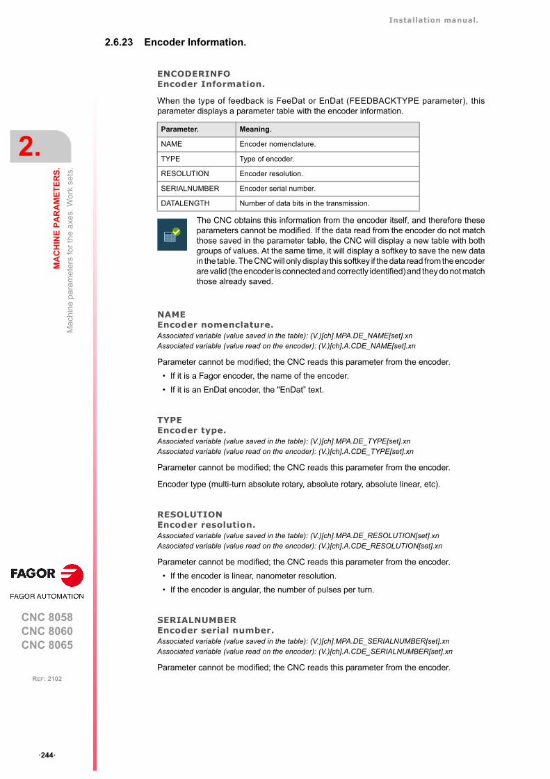
Installation manual.
CNC 8058CNC 8060CNC 8065
2.
MA
CH
INE
PA
RA
ME
TE
RS
.
Mac
hin
e pa
ram
eter
s fo
r th
e ax
es. W
ork
sets
.
ꞏ244ꞏ
REF: 2102
2.6.23 Encoder Information.
ENCODERINFOEncoder Information.
When the type of feedback is FeeDat or EnDat (FEEDBACKTYPE parameter), thisparameter displays a parameter table with the encoder information.
NAMEEncoder nomenclature.Associated variable (value saved in the table): (V.)[ch].MPA.DE_NAME[set].xnAssociated variable (value read on the encoder): (V.)[ch].A.CDE_NAME[set].xn
Parameter cannot be modified; the CNC reads this parameter from the encoder.
• If it is a Fagor encoder, the name of the encoder.
• If it is an EnDat encoder, the "EnDat” text.
TYPEEncoder type.Associated variable (value saved in the table): (V.)[ch].MPA.DE_TYPE[set].xnAssociated variable (value read on the encoder): (V.)[ch].A.CDE_TYPE[set].xn
Parameter cannot be modified; the CNC reads this parameter from the encoder.
Encoder type (multi-turn absolute rotary, absolute rotary, absolute linear, etc).
RESOLUTIONEncoder resolution.Associated variable (value saved in the table): (V.)[ch].MPA.DE_RESOLUTION[set].xnAssociated variable (value read on the encoder): (V.)[ch].A.CDE_RESOLUTION[set].xn
Parameter cannot be modified; the CNC reads this parameter from the encoder.
• If the encoder is linear, nanometer resolution.
• If the encoder is angular, the number of pulses per turn.
SERIALNUMBEREncoder serial number.Associated variable (value saved in the table): (V.)[ch].MPA.DE_SERIALNUMBER[set].xnAssociated variable (value read on the encoder): (V.)[ch].A.CDE_SERIALNUMBER[set].xn
Parameter cannot be modified; the CNC reads this parameter from the encoder.
Parameter. Meaning.
NAME Encoder nomenclature.
TYPE Type of encoder.
RESOLUTION Encoder resolution.
SERIALNUMBER Encoder serial number.
DATALENGTH Number of data bits in the transmission.
The CNC obtains this information from the encoder itself, and therefore theseparameters cannot be modified. If the data read from the encoder do not matchthose saved in the parameter table, the CNC will display a new table with bothgroups of values. At the same time, it will display a softkey to save the new datain the table. The CNC will only display this softkey if the data read from the encoderare valid (the encoder is connected and correctly identified) and they do not matchthose already saved.
Installation manual.
CNC 8058CNC 8060CNC 8065
MA
CH
INE
PA
RA
ME
TE
RS
.
2.
Mac
hin
e pa
ram
eter
s fo
r th
e ax
es. W
ork
sets
.
ꞏ245ꞏ
REF: 2102
DATALENGTHNumber of data bits in the transmission. Associated variable (value saved in the table): (V.)[ch].MPA.DE_DATALENGTH[set].xnAssociated variable (value read on the encoder): (V.)[ch].A.CDE_DATALENGTH[set].xn
Parameter cannot be modified; the CNC reads this parameter from the encoder.
2.6.24 EnDat transmission format.
ENDATEnDat parameter table.
When the feedback type (FEEDBACKTYPE parameter) is EnDat, this parameter displaysthe parameter table to configure the transmission.
ENDATCLKFREQEnDat communication frequency.Parameter valid for linear and rotary axes and spindles.Parameter valid for analog drives and velocity-Sercos drives.Possible values: 250kHz / 500 kHz /1 MHz / 2 MHz / 4 MHz.Default value: 2 MHz.Associated variable: (V.)[ch].MPA.ENDATCLKFREQ[set].xn
When the feedback type is EnDat (FEEDBACKTYPE parameter), this parameter defines thecommunication frequency. The frequency depends on the cable length; the shorter the cable,the greater the frequency can be.
It is recommended to use the default frequency (2 MHz), which is viable for cables of up to100 m in length. To select the speed for 4 MHz, the encoder must be capable of operatingthis speed and the cable must be shorter than 50 m in length.
Parameter. Meaning.
ENDATCLKFREQ EnDat communication frequency.
Installation manual.
CNC 8058CNC 8060CNC 8065
2.
MA
CH
INE
PA
RA
ME
TE
RS
.
Mac
hin
e pa
ram
eter
s fo
r th
e ax
es. W
ork
sets
.
ꞏ246ꞏ
REF: 2102
2.6.25 SSI Feedback type.
SSITYPESSI feedback type connected to the corresponding feedback.Possible values: Fagor SSITYPE / G user / User.Default value: User.Associated variable: (V.)[ch].MPA.SSITYPE[set].xn
When FEEDBACKTYPE=SSI, this parameter is used to set the format of the SSItransmission. The parameter offers a number of preset types for connecting the mostcommon linear and rotary encoders. If the encoder is not listed, the user option may beselected to set the properties of the SSI communication.
SSISSI (Synchronous Serial Interface) parameter table.
This parameter shows the parameter table to set the SSI transmission format. Dependingon the type of linear encoder selected, (parameter SSITYPE), some of these values will bepreset and cannot be changed. All values may be used for the "user" type linear encoder.
Value. Meaning.
Fagor LA Fagor linear encoder.
Fagor GAFagor SAFagor SVA
Fagor linear encoder.
Fagor HA-27-D200 Fagor encoder.
Fagor HA-23-D90Fagor SA-23-D90Fagor SA-23-D170
Fagor encoder.
ABSIND (inductosyn LIN+ABS) Absolute linear feedback.
ABSIND (inductosyn ROT+ABS) Absolute rotary feedback in one encoder revolution.
ABSIND (resolver) Absolute rotary feedback in one revolution.
ABSIND (inductosyn LIN) Absolute linear feedback in the pitch.Homing the linear encoder required.
ABSIND (inductosyn ROT) Absolute rotary feedback in the pitch.Homing the linear encoder required.
G user User configuration.
User User configuration.
Example for a Fagor absolute linear encoder (Fagor LA).Example of parameter setting for connecting the Fagor LA absolute linear encoder, set with defaultparameters (factory set).
SSICLKFREQ = 1 / T = 400. 400 kHz.
SSIDATALENGTH = n Bit length of the position value (coordinate).
SSICRCBITS = 0 There are no CRC bits.
SSISTARTBITS = 0 There are no start bits.
SSIPACKFORMAT = 3 Data + Alarm.
SSIALARMBITS = 1 1 alarm/acknowledge bit.
SSIDATAMODE = 1 MSB First.
SSIALARMLEVEL = 1 The acknowledge is indicated with data at 0;therefore, an alarm signal is produced when the bit isat 1.
Installation manual.
CNC 8058CNC 8060CNC 8065
MA
CH
INE
PA
RA
ME
TE
RS
.
2.
Mac
hin
e pa
ram
eter
s fo
r th
e ax
es. W
ork
sets
.
ꞏ247ꞏ
REF: 2102
SSICLKFREQSSI communication frequency.Possible values: From 59 to 7500 kHz.Default value: 150 kHz.Associated variable: (V.)[ch].MPA.SSICLKFREQ[set].xn
Frequency of the clock for SSI communication. The recommended maximum frequencydepends on the length of the cable.
SSIDATAFORMATParameters to set the format of the SSI transmission reading data.
The position read via SSI transmission may be received in different formats.
• The following parameters set the amount of SSI data that will be read.
• The following parameters set the order and format used for the system to send the data.
• The following parameters set how to interpret the bits that determine that the SSItransmission has been successful.
SSIDATALENGTHNumber of bits of the SSI transmission that make up the position value (coordinate). Possible values: From 0 to 255.Default value: 0.Associated variable: (V.)[ch].MPA.SSIDATALENGTH[set].xn
Number of bits of the SSI transmission that make up the position value (coordinate). Forexample, 32 for Fagor absolute linear encoders with the default parameters.
Length. Maximum frequency.
Up to 20 meters. 600 kHz.
Up to 50 meters. 400 kHz.
Up to 75 meters. 300 kHz.
Up to 100 meters. 250 kHz.
Parameter. Meaning.
SSIDATALENGTH Number of bits of the SSI transmission that make up the position value(coordinate).
SSICRCBITS Number of bits, if any, for some kind of transmission validity check (CRC,checksum, parity).
SSIALARMBITS Number of bits, if any, for transmission OK check.The feedback device can send one or more bits indicating an alarmcondition if something goes wrong or one or more acknowledgment bitsif the transmission is successful.
SSISTARTBITS Number of bits, if any, to wait for before receiving position data.
Parameter. Meaning.
SSIPACKFORMAT Order in which the encoder sends the data. Whether the position data,the CRC or the alarm is received first and in which order. If start bits havebeen programmed, it is assumed that they will be received first.
SSIDATAMODE Order in which the most significant bit is transmitted.• SSIDATAMODE = 0; the LSB (Least Significant Bit) is the first one.• SSIDATAMODE = 1; the MSB (Most Significant Bit) is the first one.
SSIOPERATION Type of operation before any data is read.
Parameter. Meaning.
SSIALARMLEVEL Values that may make the encoder transmit one or more bits indicatingsome kind of error.
SSICRCTYPE Type of calculation to do when the encoder transmits extra data besidesthe position value in order to run a data coherence check.
Installation manual.
CNC 8058CNC 8060CNC 8065
2.
MA
CH
INE
PA
RA
ME
TE
RS
.
Mac
hin
e pa
ram
eter
s fo
r th
e ax
es. W
ork
sets
.
ꞏ248ꞏ
REF: 2102
SSIOPERATIONType of operation before any data is read.Possible values: From 0 to 1.Default value: 0.Associated variable: (V.)[ch].MPA.SSIOPRATION[set].xn
This parameter indicates whether any kind of operation must be carried out on the databefore being interpreted, because they may be coded in a particular format.
SSIPACKFORMATSSI package format.Possible values: Data / Data-CRC / CRC-Data / Data-Alarm / Alarm-Data / Data-CRC-Alarm /Alarm-Data-CRC / Data-Alarm-CRC / Alarm-CRC-Data / CRC-Data-Alarm / CRC-Alarm-Data.Default value: Data.Associated variable: (V.)[ch].MPA.SSIPACKFORMAT[set].xn
This parameter indicates the order in which the different data types of the SSI transmissionwill be received. Depending on parameters SSICRCBITS and SSIALARMBITS, only thepossible options will be displayed. The order indicated by the parameter is the one thatcorresponds to the SSI transmission sequence. If start bits have been programmed, the CNCassumes that they will be received first.
SSICRCTYPECRC type.Possible values: Do not calculate CRC / Fagor Checksum / INDUCTOSYN Checksum.Default value: Do not calculate CRCAssociated variable: (V.)[ch].MPA.SSICRCTYPE[set].xn
When the encoder transmits extra data besides the position data, this parameter sets thetype of calculation to do to check data coherence. This parameter only makes sense whenSSICRCBITS is other than 0.
Value. Meaning.
0 The data is received in binary format.
1 The data is received in Gray Code format.
Example:SSICRCBITS = 5SSIALARMBITS = 1SSIDATABITS = 23SSIPACKFORMAT = Alarm - Data - CRCThe CNC expects the SSI transmission to be a sequence of bits where the first one is the alarm bitfollowed by 23 position bits or data bits and finally the 5 CNC bits.
Value. Meaning.
Do not calculate CRC. Even if the CNC receives the CRC bits, they are not processed atall and, therefore, no errors are reported when the transmission isnot correct. It is not a recommendable option and it must only be usedduring setup.
Fagor checksum. Data checking algorithm used in Fagor Automation feedbacksystems.
INDUCTOSYN checksum. Data check ing a lgor i thm used when connect ing to anINDUCTOSYN module.
Installation manual.
CNC 8058CNC 8060CNC 8065
MA
CH
INE
PA
RA
ME
TE
RS
.
2.
Mac
hin
e pa
ram
eter
s fo
r th
e ax
es. W
ork
sets
.
ꞏ249ꞏ
REF: 2102
SSICRCBITSNumber of CRC bits of the SSI transmission to check that the transmission is valid.Possible values: From 0 to 31.Default value: 0.Associated variable: (V.)[ch].MPA.SSICRCBITS[set].xn
Number of bits, if any, for the transmission validity check (CRC, checksum, parity).
SSISTARTBITSNumber of start bits.Possible values: From 0 to 3.Default value: 0.Associated variable: (V.)[ch].MPA.SSISTARTBITS[set].xn
Number of bits, if any, to wait for before receiving position data.
SSIALARMBITSNumber of alarm bits.Possible values: From 0 to 2.Default value: 0.Associated variable: (V.)[ch].MPA.SSIALARMBITS[set].xn
The feedback device can send one or more bits indicating an alarm condition if somethinggoes wrong or one or more acknowledgment bits if the transmission is successful.
SSIALARMLEVELLevel of the alarm bits to issue an error.Possible values: From 0 to 3.Default value: 0.Associated variable: (V.)[ch].MPA.SSIALARMLEVEL[set].xn
Value that the alarm/acknowledge bits for an error condition to occur. This parameter onlymakes sense when SSIALARMBITS is other than 0.
SSIDATAMODETransmission mode. Possible values: From 0 to 1.Default value: 0.Associated variable: (V.)[ch].MPA.SSIDATAMODE[set].xn
Order in which the most significant bit is transmitted.
For example, Fagor absolute linear encoders may be configured to transmit 5 CNC bits together withthe position value. If a linear encoder is configured in this mode, program SSIDATALENGTH=27 andSSICRCBITS =5.
Example:If an encoder indicates an error condition with 2 bits where the first one is a 1 and the second a 0SSIALARMBITS = 2SSIALARMLEVEL = 2.
Example:If an encoder has a transmission-OK acknowledgment bit and it indicates it with a logic 0. SSIALARMBITS = 1SSIALARMLEVEL = 1. Because a 0 means that everything is OK.
Value. Meaning.
0 The LSB (Least Significant Bit) is the first one.
1 The MSB (Most Significant Bit) is the first one.
Installation manual.
CNC 8058CNC 8060CNC 8065
2.
MA
CH
INE
PA
RA
ME
TE
RS
.
Mac
hin
e pa
ram
eter
s fo
r th
e ax
es. W
ork
sets
.
ꞏ250ꞏ
REF: 2102
STARTDELAYNumber of clocks to wait between the first down flank and the first up flank.Possible values: From 0 to 255.Default value: 0.Associated variable: (V.)[ch].MPA.STARTDELAY[set].xn
This parameter sets the number of SSI clocks to wait for since the first SSI down flank untilthe first up flank is generated. This value is needed to implement the wait time to convertthe signal in some encoders.
SSIRESOLDigital counting (feedback) resolution.Possible values: From 1 to 999999999.Default value: 10000.Associated variable: (V.)[ch].MPA.SSIRESOL[set].xn
Number of digital counting units contained in a pitch.
Example:CLOCKFREQ = 400 kHz STARTDELAY = 3Waiting time = (1/400*1000)*3 = 7,5 clocks.
Example:Fagor absolute linear encoder with a pitch of 20 microns and a digital resolution of 1 dµ.
SSIRESOL = 20 µ / 0.1 µ = 200.
Example:For a 8192 ppt encoder and a 10 mm pitch screw.
PITCH = 10 mm.SSIRESOL = 8192.The resolution of the axis will be; 10 / 8192 = 0.0012 mm.
Example:For SSITYPE = ABSIND (inductosyn ROT+ABS), for a 2 or 4-degree turn and depending on whetherit is a high resolution or low resolution encoder, the counting increment is 10000 units.
PITCH = 2º or 4ºSSIRESOL = 10000 The resolution of the axis will be; 2º or 4º / 10000 = 0.0002 or 0.0004 degrees.
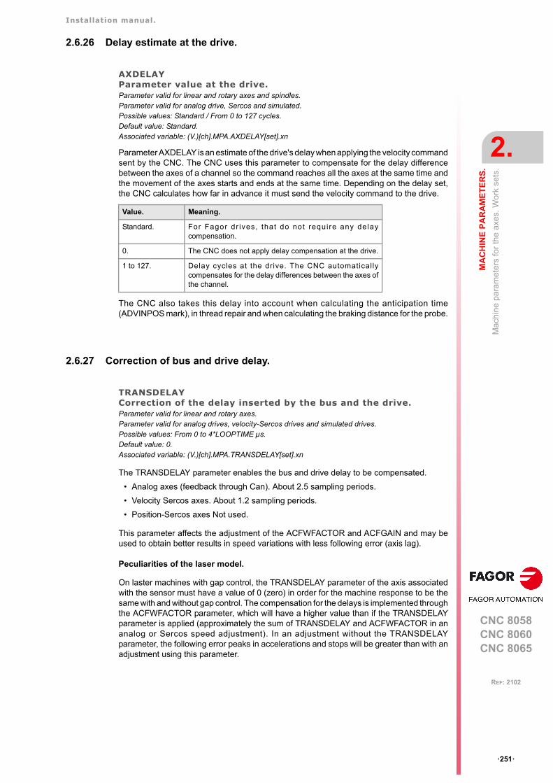
Installation manual.
CNC 8058CNC 8060CNC 8065
MA
CH
INE
PA
RA
ME
TE
RS
.
2.
Mac
hin
e pa
ram
eter
s fo
r th
e ax
es. W
ork
sets
.
ꞏ251ꞏ
REF: 2102
2.6.26 Delay estimate at the drive.
AXDELAYParameter value at the drive.Parameter valid for linear and rotary axes and spindles. Parameter valid for analog drive, Sercos and simulated. Possible values: Standard / From 0 to 127 cycles.Default value: Standard.Associated variable: (V.)[ch].MPA.AXDELAY[set].xn
Parameter AXDELAY is an estimate of the drive's delay when applying the velocity commandsent by the CNC. The CNC uses this parameter to compensate for the delay differencebetween the axes of a channel so the command reaches all the axes at the same time andthe movement of the axes starts and ends at the same time. Depending on the delay set,the CNC calculates how far in advance it must send the velocity command to the drive.
The CNC also takes this delay into account when calculating the anticipation time(ADVINPOS mark), in thread repair and when calculating the braking distance for the probe.
2.6.27 Correction of bus and drive delay.
TRANSDELAYCorrection of the delay inserted by the bus and the drive.Parameter valid for linear and rotary axes.Parameter valid for analog drives, velocity-Sercos drives and simulated drives.Possible values: From 0 to 4*LOOPTIME µs.Default value: 0.Associated variable: (V.)[ch].MPA.TRANSDELAY[set].xn
The TRANSDELAY parameter enables the bus and drive delay to be compensated.
• Analog axes (feedback through Can). About 2.5 sampling periods.
• Velocity Sercos axes. About 1.2 sampling periods.
• Position-Sercos axes Not used.
This parameter affects the adjustment of the ACFWFACTOR and ACFGAIN and may beused to obtain better results in speed variations with less following error (axis lag).
Peculiarities of the laser model.
On laster machines with gap control, the TRANSDELAY parameter of the axis associatedwith the sensor must have a value of 0 (zero) in order for the machine response to be thesame with and without gap control. The compensation for the delays is implemented throughthe ACFWFACTOR parameter, which will have a higher value than if the TRANSDELAYparameter is applied (approximately the sum of TRANSDELAY and ACFWFACTOR in ananalog or Sercos speed adjustment). In an adjustment without the TRANSDELAYparameter, the following error peaks in accelerations and stops will be greater than with anadjustment using this parameter.
Value. Meaning.
Standard. For Fagor dr ives, that do not require any delaycompensation.
0. The CNC does not apply delay compensation at the drive.
1 to 127. Delay cycles at the drive. The CNC automaticallycompensates for the delay differences between the axes ofthe channel.

Installation manual.
CNC 8058CNC 8060CNC 8065
2.
MA
CH
INE
PA
RA
ME
TE
RS
.
Ma
chin
e pa
ram
eter
s fo
r JO
G m
ode.
ꞏ252ꞏ
REF: 2102
2.7 Machine parameters for JOG mode.
2.7.1 Handwheel configuration.
NMPGNumber of handwheels connected to the CNC.Possible values: From 0 to 12.Default value: 0 (there are no handwheels).Associated variable: (V.)MPMAN.NMPG
Electronic handwheels may be used to move the axes. Depending on the type of handwheel,The CNC may have general handwheels to move any axis or individual handwheels that willonly move their associated axes. Several individual and general handwheels may be usedat the same time, up to a total of 12 handwheels. The portable operator panel HBLS doesnot count as handwheel when setting this parameter. The HBH3/HBH4 remote terminal hasa handwheel.
To set the resolution of each handwheel, the distance it moves at each switch position, setthe parameter MPGRESOL.
MANPGTable of handwheels.
This parameter shows the list of available handwheels.
MANPG nHandwheel configuration.
This parameter shows the table to configure the handwheels. Each table shows the followingparameters to configure it.
COUNTERTYPEType of feedback input for the handwheel.Possible values: Remote / Keyboard / Local / Sercos Counter.Default value: Remote.Associated variable: (V.)MPMAN.COUNTERTYPE[hw]Parameter included in the MANPG table.
This parameter indicates the location of the handwheel feedback input; at the countermodules of the remote CAN groups, at the RCS-S modules (Sercos counter) at the keyboardor at the local feedback inputs of the central unit. For the HBH3/HBH4 remote terminal, selectthe "Variable” value.
COUNTERIDFeedback input associated with the handwheel.Possible values: From 1 to 40 if remote CAN feedback / from -1 to -9 if feedback at the keyboard / from1 to 2 if local feedback / from 1 to 32 if feedback at RCS-S module / 1 if variable feedback.Default value: 0.Associated variable: (V.)MPMAN.COUNTERID[hw]Parameter included in the MANPG table.
The handwheels may be connected through the keyboards (3 per keyboard) , and throughthe counters modules of the remote CAN groups (4 per module), through the RCS-S countermodules (4 per module) or through the local feedback inputs.
Parameter. Meaning.
COUNTERTYPE Handwheel feedback type.
COUNTERID Feedback input for the handwheel.
HWFBTYPE Feedback type associated with the handwheel input.
MPGAXIS Name of the axis associated with the handwheel.
Installation manual.
CNC 8058CNC 8060CNC 8065
MA
CH
INE
PA
RA
ME
TE
RS
.
2.
Ma
chin
e pa
ram
eter
s fo
r JO
G m
ode.
ꞏ253ꞏ
REF: 2102
Handwheels connected through the keyboard.
Handwheels are numbered from -9 to -1. Handwheels are numbered following the logic orderof the keyboards (rotary switch of the Power Supply element).
Handwheels connected through the remote CAN groups.
Handwheels are numbered from 1 to 40. The handwheels are numbered following the logicorder of the remote groups (rotary switch of the Power Supply element). If there are severalCounter modules in each group, the order is from top to bottom and from left to right.
Handwheels connected through the local feedback inputs.
The 8065 has two feedback inputs and this parameter indicates which one of them is used.Handwheels are numbered from 1 to 2. The 8060 only has one feedback input; therefore,there is no need to set this parameter.
Handwheels connected through the RCS-S modules (Sercos counter).
Handwheels are numbered from 1 to 32. Handwheels are numbered according to the logicalorder of the RCS-.S modules (parameter SERCOUNTID). The feedback inputs of the firstmodule will be 1 through 4, those of the second module 5 through 8 and so on.
Handwheels connected through a “Variable” input.
The HBH3/HBH4 remote terminal always as a value of ꞏ1ꞏ.
HWFBTYPEFeedback type associated with the handwheel input.Possible values: TTL / TTLDIFF.Default value: TTLDIFF.Associated variable: (V.)MPMAN.HWFBTYPE[hw]Parameter included in the MANPG table.
Type of feedback associated with the handwheel input when it is connected to the local inputsor to an RCS-S module (Sercos counter).
MPGAXISName of the axis associated with the handwheel.Possible values: Any axes defined in AXISNAME.Associated variable: (V.)MPMAN.MPGAXIS[hw]Parameter included in the MANPG table.
This parameter sets whether the handwheel is associated with a particular axis (individualhandwheel) or it can move any axis of the machine (general handwheel). To set an individualhandwheel, define the name of the axis it is associated with. To set a general handwheel,do not assign any value to this parameter, leave it blank. For the HBH3/HBH4 remoteterminal, leave this parameter as undefined.
An axis may be moved indistinctly with its individual handwheel or with a general handwheel.To move an axis with a general handwheel, use the jog keypad to select the axis to be moved.To move an axis with an individual handwheel, no prior axis selection is needed.
• If there are several axes selected in handwheel mode, the general handwheel will moveall of them.
• If an axis has been selected which has an individual handwheel selected with it, this axismay be moved with the general handwheel, with the individual one or with both at thesame time. When using both handwheels simultaneously, the CNC will add or subtractthe pulses provided by both handwheels depending on which direction they are turned.
• If the CNC has several general handwheels, any of them can move the axes selectedin handwheel mode. When using several handwheels simultaneously, each axis involvedwill be applied the sum of the increments of all the handwheels.
Keyboard order. Numbering of the handwheels.
First keyboard in the bus. -1 -2 -3
Second keyboard in the bus. -4 -5 -6
Third keyboard in the bus. -7 -8 -9
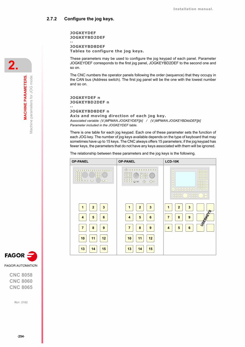
Installation manual.
CNC 8058CNC 8060CNC 8065
2.
MA
CH
INE
PA
RA
ME
TE
RS
.
Ma
chin
e pa
ram
eter
s fo
r JO
G m
ode.
ꞏ254ꞏ
REF: 2102
2.7.2 Configure the jog keys.
JOGKEYDEFJOGKEYBD2DEF··JOGKEYBD8DEFTables to configure the jog keys.
These parameters may be used to configure the jog keypad of each panel. ParameterJOGKEYDEF corresponds to the first jog panel, JOGKEYBD2DEF to the second one andso on.
The CNC numbers the operator panels following the order (sequence) that they occupy inthe CAN bus (Address switch). The first jog panel will be the one with the lowest numberand so on.
JOGKEYDEF nJOGKEYBD2DEF n··JOGKEYBD8DEF nAxis and moving direction of each jog key.Associated variable: (V.)MPMAN.JOGKEYDEF[jk] / (V.)MPMAN.JOGKEYBDkbDEF[jk]Parameter included in the JOGKEYDEF table.
There is one table for each jog keypad. Each one of these parameter sets the function ofeach JOG key. The number of jog keys available depends on the type of keyboard that maysometimes have up to 15 keys. The CNC always offers 15 parameters; if the jog keypad hasfewer keys, the parameters that do not have any keys associated with them will be ignored.
The relationship between these parameters and the jog keys is the following.
OP-PANEL OP-PANEL LCD-10K
CNCOFF
200190
180
170
160
150
140
130
120110
100908070
60
50
40
30
20
10
42
0
FEED
100001000
100101
10010 1
jogX Y Z
+_
4 5 6
+
_
CSS
m/min
ZERO SINGLE RESET
1
4
2
5
3
6
7 8 9
10 11 12
13 14 15
1
4
2
5
3
6
7 8 9
10 11 12
13 14 15
1 2 3
7 8 9
4 5 6
US
ER
KE
YS
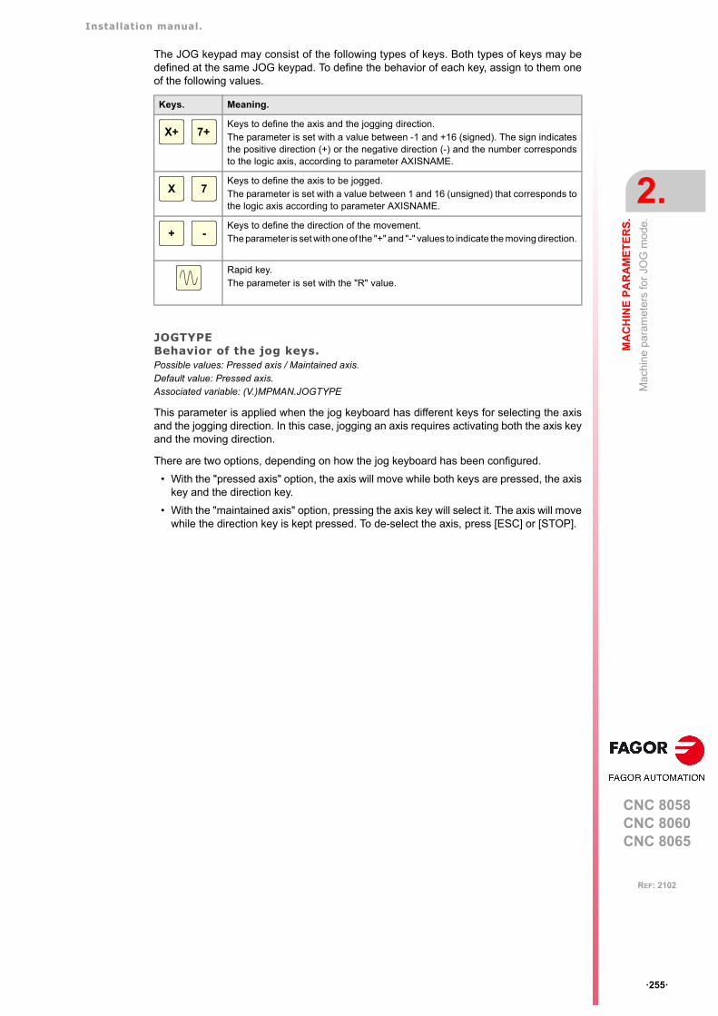
Installation manual.
CNC 8058CNC 8060CNC 8065
MA
CH
INE
PA
RA
ME
TE
RS
.
2.
Ma
chin
e pa
ram
eter
s fo
r JO
G m
ode.
ꞏ255ꞏ
REF: 2102
The JOG keypad may consist of the following types of keys. Both types of keys may bedefined at the same JOG keypad. To define the behavior of each key, assign to them oneof the following values.
JOGTYPEBehavior of the jog keys.Possible values: Pressed axis / Maintained axis.Default value: Pressed axis.Associated variable: (V.)MPMAN.JOGTYPE
This parameter is applied when the jog keyboard has different keys for selecting the axisand the jogging direction. In this case, jogging an axis requires activating both the axis keyand the moving direction.
There are two options, depending on how the jog keyboard has been configured.
• With the "pressed axis" option, the axis will move while both keys are pressed, the axiskey and the direction key.
• With the "maintained axis" option, pressing the axis key will select it. The axis will movewhile the direction key is kept pressed. To de-select the axis, press [ESC] or [STOP].
Keys. Meaning.
Keys to define the axis and the jogging direction.The parameter is set with a value between -1 and +16 (signed). The sign indicatesthe positive direction (+) or the negative direction (-) and the number correspondsto the logic axis, according to parameter AXISNAME.
Keys to define the axis to be jogged.The parameter is set with a value between 1 and 16 (unsigned) that corresponds tothe logic axis according to parameter AXISNAME.
Keys to define the direction of the movement.The parameter is set with one of the "+" and "-" values to indicate the moving direction.
Rapid key.The parameter is set with the "R" value.
X+ 7+
X 7
+ -
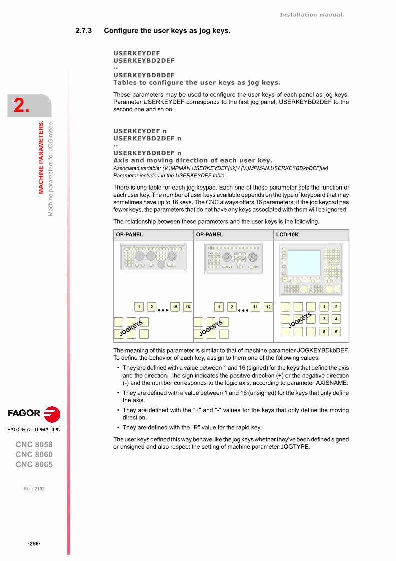
Installation manual.
CNC 8058CNC 8060CNC 8065
2.
MA
CH
INE
PA
RA
ME
TE
RS
.
Ma
chin
e pa
ram
eter
s fo
r JO
G m
ode.
ꞏ256ꞏ
REF: 2102
2.7.3 Configure the user keys as jog keys.
USERKEYDEFUSERKEYBD2DEF··USERKEYBD8DEFTables to configure the user keys as jog keys.
These parameters may be used to configure the user keys of each panel as jog keys.Parameter USERKEYDEF corresponds to the first jog panel, USERKEYBD2DEF to thesecond one and so on.
USERKEYDEF nUSERKEYBD2DEF n··USERKEYBD8DEF nAxis and moving direction of each user key.Associated variable: (V.)MPMAN.USERKEYDEF[uk] / (V.)MPMAN.USERKEYBDkbDEF[uk]Parameter included in the USERKEYDEF table.
There is one table for each jog keypad. Each one of these parameter sets the function ofeach user key. The number of user keys available depends on the type of keyboard that maysometimes have up to 16 keys. The CNC always offers 16 parameters; if the jog keypad hasfewer keys, the parameters that do not have any keys associated with them will be ignored.
The relationship between these parameters and the user keys is the following.
The meaning of this parameter is similar to that of machine parameter JOGKEYBDkbDEF.To define the behavior of each key, assign to them one of the following values:
• They are defined with a value between 1 and 16 (signed) for the keys that define the axisand the direction. The sign indicates the positive direction (+) or the negative direction(-) and the number corresponds to the logic axis, according to parameter AXISNAME.
• They are defined with a value between 1 and 16 (unsigned) for the keys that only definethe axis.
• They are defined with the "+" and "-" values for the keys that only define the movingdirection.
• They are defined with the "R" value for the rapid key.
The user keys defined this way behave like the jog keys whether they've been defined signedor unsigned and also respect the setting of machine parameter JOGTYPE.
OP-PANEL OP-PANEL LCD-10K
CNCOFF
200190
180
170
160
150
140
130
120110
100908070
60
50
40
30
20
10
42
0
FEED
100001000
100101
10010 1
jogX Y Z
+_
4 5 6
+
_
CSS
m/min
ZERO SINGLE RESET
1 2 15 16
JOGKEYS
1 2 11 12
JOGKEYS
1 2
3 4
5 6JOGKEYS
Installation manual.
CNC 8058CNC 8060CNC 8065
MA
CH
INE
PA
RA
ME
TE
RS
.
2.
Ma
chin
e pa
ram
eter
s fo
r JO
G m
ode.
ꞏ257ꞏ
REF: 2102
2.7.4 HBLS portable operator panel.
HBLSActivate the portable operator panel HBLS.Possible values: Yes / No.Default value: No.Associated variable: (V.)MPMAN.HBLS
This parameter indicates whether there is a portable panel HBLS connected to the CNCthrough the serial line or not. In order to be able to use the portable operator panel HBLS,the serial line must be configured as RS422 (parameter RSTYPE). The portable operatorpanel HBLS must not be considered when counting the handwheels of the system(parameter NMPG).
2.7.5 Remote terminal HBH3/HBH4.
HBHIPIP address of the HBH handwheel. Possible values: From 0 to 15 characters.Default value: 0.Associated variable: (V.)MPMAN.HBHIP
IP address of the HBH handwheel.
For further information on the HBH3/HBH4 remote terminal, please refer to the manual.
When there is a connection to a router, the IP address of the CNC must be static in order to avoidconnection problems with the terminal at start-up.
Installation manual.
CNC 8058CNC 8060CNC 8065
2.
MA
CH
INE
PA
RA
ME
TE
RS
.
Ma
chin
e pa
ram
eter
s fo
r JO
G m
ode.
ꞏ258ꞏ
REF: 2102
2.7.6 Example of how to set the handwheels and jog keys.
Handwheel setting.
On a machine with X, Y, Z and A axes, we would like an individual handwheel for the X axis,an individual handwheel for the Y and a general handwheel for the Z and A axes.
• Individual handwheel for the X axis.
Feedback input: keyboard (MPG1).
Disk graduated with 100 lines.
Pulses/ turn: 100
Resolutions (X): 0.001, 0.01, 0.1
• Individual handwheel for the Y axis.
Feedback input: keyboard (MPG2).
Disk graduated with 100 lines.
Pulses/ turn: 200
Resolutions (Y): 0.001, 0.01, 0.1
• General handwheel for the rest of the axes (Z, A).
Feedback input: Counter (X1).
Disk graduated with 100 lines.
Pulses/ turn: 100
Resolutions (Z): 0.001, 0.01, 0.1
Resolutions (A): 0.01, 0.1, 1
Parameter setting:
X axis handwheel (MANPG 1).
Y axis handwheel (MANPG 2).
Machine parameter. Value. Meaning.
NMPG 3 3-handwheel system.
Machine parameter. Value. Meaning.
COUNTERTYPE Keyboard. Handwhee l connec ted to thekeyboard.
COUNTERID -1 MPG1 connector.
MPGAXIS X Associated axis.
MPGRESOL 1 0.001 Resolution 0.001
MPGRESOL 10 0.01 Resolution 0.01
MPGRESOL 100 0.1 Resolution 0.1
Machine parameter. Value. Meaning.
COUNTERTYPE Keyboard. Handwhee l connec ted to thekeyboard.
COUNTERID -2 MPG2 connector.
MPGAXIS Y Associated axis.
MPGRESOL 1 0.0005 Resolution 0.001
MPGRESOL 10 0.005 Resolution 0.01
MPGRESOL 100 0.05 Resolution 0.1
Installation manual.
CNC 8058CNC 8060CNC 8065
MA
CH
INE
PA
RA
ME
TE
RS
.
2.
Ma
chin
e pa
ram
eter
s fo
r JO
G m
ode.
ꞏ259ꞏ
REF: 2102
Handwheel associated with the rest of the axes (Z + A).
Setting the jog keys.
On a machine with the X, Y, U, V axes defined as AXISNAME 1, 2, 3, 4, we would like tojog the X and Y axes with the keys that have the same names, the U axis with the keys forthe 4th axis and the V axis with those of the 5th axis.
Example 1: JOG-PANEL keyboard.
Example 2: JOG-PANEL keyboard.
Machine parameter. Value. Meaning.
COUNTERTYPE Remote. Handwheel connected to the remote modules.
COUNTERID 1 Feedback input X1.
MPGAXIS Handwheel associated with the rest of the axes.
Z- MPGRESOL 1 0.001 Z axis. Resolution 0.001
Z- MPGRESOL 10 0.01 Z axis. Resolution 0.01
Z- MPGRESOL 100 0.1 Z axis. Resolution 0.1
A- MPGRESOL 1 0.01 A axis. Resolution 0.01
A- MPGRESOL 10 0.1 A axis. Resolution 0.1
A- MPGRESOL 100 1 A axis. Resolution 1
Jog keyboard. JOGKEYDEF Key. Value.
1 [X+] 1+
2 [Y+] 2+
3 [4+] 3+
4 [X-] 1-
5 [Y-] 2-
6 [4-] 3-
7 [5+] 4+
8 [R] R
9 [5-] 4-
10 - 15 - - -
Jog keyboard. JOGKEYDEF Key. Value.
1 [X] 1
2 [Y] 2
3 [+] +
4 [4] 3
5 [5] 4
6 [-] -
7 [R] R
8 - 15 - - -
X+
X-
Y+
Y-
4+
4-
5+ 5-
X
4
Y
5
+
-
Installation manual.
CNC 8058CNC 8060CNC 8065
2.
MA
CH
INE
PA
RA
ME
TE
RS
.
Ma
chin
e pa
ram
eter
s fo
r JO
G m
ode.
ꞏ260ꞏ
REF: 2102
Example 3: JOG-PANEL keyboard.
Example 4: LCD-10K keyboard.
Example 5: LCD-10K keyboard.
Jog keyboard. JOGKEYDEF Key. Value.
1 [+] +
2 [R] R
3 [-] -
4 [X] 1
5 [4+] 3+
6 [4-] 3-
7 [Y] 2
8 [5+] 4+
9 [5-] 4-
10 - 15 - - -
Jog keyboard. JOGKEYDEF Key. Value.
1 [X+] 1+
2 [Y+] 2+
3 [4+] 3+
4 [5+] 4+
5 [R] R
6 [5-] 4-
7 [X-] 1-
8 [Y-] 2-
9 [4-] 3-
Jog keyboard. JOGKEYDEF Key. Value.
1 [X] 1
2 [Y] 2
3 [+] +
4 [R] R
5 - - -
6 - - -
7 [4] 3
8 [5] 4
9 [-] -
+
X 4+
-
4-
Y 5-5+
X+
X-
Y+
Y-
4+
4-
5+ 5-
X
4
Y
5
+
-
Installation manual.
CNC 8058CNC 8060CNC 8065
MA
CH
INE
PA
RA
ME
TE
RS
.
2.
Ma
chin
e pa
ram
eter
s fo
r JO
G m
ode.
ꞏ261ꞏ
REF: 2102
Example 6: LCD-10K keyboard.
Jog keyboard. JOGKEYDEF Key. Value.
1 [X+] 1+
2 [Y+] 2+
3 [R] R
4 - 6 - - -
7 [X-] 1-
8 [Y-] 2-
9 - - -
USERKEYDEF Key. Value.
1 [4] 4
2 [5] 5
3 [+] +
4 [-] -
5 - 6 - - -
X+
X-
Y+
Y-
4
+
5
-
USERKEYSJOGKEYS
Installation manual.
CNC 8058CNC 8060CNC 8065
2.
MA
CH
INE
PA
RA
ME
TE
RS
.
Ma
chin
e pa
ram
eter
s fo
r th
e M
func
tion
tab
le.
ꞏ262ꞏ
REF: 2102
2.8 Machine parameters for the M function table.
2.8.1 M function table.
MTABLESIZENumber of table elements.Possible values: from 0 to 200.Default value: 50.Associated variable: (V.)MPM.MTABLESIZE
This parameter indicates the number of M functions to be defined in the table. Each functionmay be assigned a subroutine and defined the type of synchronization.
It must be borne in mind that some auxiliary functions, besides what is indicated in this table,have a specific meaning when used in a CNC program. These functions are M00, M01, M02,M03, M04, M05, M06, M08, M09, M19, M30, M41, M42, M43 and M44.
DATAM function table.
It shows the "M" function setting table. The following fields must be defined for each Mfunction.
MNUMM function number.Possible values: from 0 to 65535.Associated variable: (V.)MPM.MNUM[pos]Parameter included in the DATA table.
This parameter indicates the number of the M function.
SYNCHTYPEType of synchronization.Possible values: Without synchronization / Before-Before / Before-After / After-After.Default value: Before - Before.Associated variable: (V.)MPM.SYNCHTYPE[pos]Parameter included in the DATA table.
Since the M functions may be programmed together with the movement of the axes, in thesame block, it must be indicated when the function is to be sent out to the PLC and whenit will be checked that it has been already executed (synchronization).
DATA
MNUM M function number.
SYNCHTYPE Type of synchronism.
MPROGNAME Name of subroutine associated with M function.
MTIME Estimated time for an M function.
MPLC Send the M function to the PLC during block search.
COMMENT Description of the M function.
Type of synchronism. Meaning.
Without synchronization. M function not synchronized.
Before - Before. The M function is sent to the PLC and synchronized before themovement.
Before - After. The M function is sent to the PLC before the movement andsynchronized after the movement.
After - After. The M function is sent to the PLC and synchronized after themovement.
Installation manual.
CNC 8058CNC 8060CNC 8065
MA
CH
INE
PA
RA
ME
TE
RS
.
2.
Ma
chin
e pa
ram
eter
s fo
r th
e M
func
tion
tab
le.
ꞏ263ꞏ
REF: 2102
The M functions may be sent and/or synchronized before or after the movement.
• If an M function is used to turn on a lamp, it will be set without synchronization becausethere is no need to check that the lamp has indeed turned on.
• Functions M03 and M04 to start up the spindle, they should be executed andsynchronized before the movement.
• Function M5 to stop the spindle, should be executed and synchronized after themovement.
MPROGNAMEName of subroutine associated with M function.Possible values: any text with up to 64 characters.Default value: Without subroutine.Associated variable: (V.)MPM.MPROGNAME[pos]Parameter included in the DATA table.
The subroutines associated with the M functions must be located in the "..\MTB\Sub" folder.
When associating a subroutine with an M function, the execution of the M function executesthe associated subroutine without executing the M function itself. To send the M function tothe PLC, it must be programmed in the subroutine.
The type of synchronization of the M functions that have an associated subroutine must be"without synchronization" or "After-After". The CNC executes the associated subroutine afterexecuting the programmed movement (if any).
MTIMEEstimated time for an M function.Possible values: From 0 to 1000000 ms.Default value: 0 ms.Associated variable: (V.)MPM.MTIME[pos]Parameter included in the DATA table.
In EDISIMU mode, there is an option that allows calculating the time required to execute apart with the machining conditions established in the program. This parameter may be setto fine tune that calculation.
MPLCSend the M function to the PLC during block search.Possible values: Yes / No.Default value: Yes.Associated variable: (V.)MPM.MPLC[pos]Parameter included in the DATA table.
This field indicates whether the M function must be sent to the PLC during block search.
COMMENTDescription of the M function.Associated variable: (V.)MPM.COMMENT[pos]Parameter included in the DATA table.
This field offers the possibility to associate a short description with the M function. This fieldis for information only; it is not used by the CNC.
The comments are saved in the file MComments.txt and it is possible to have one file perlanguage. These files are saved in the folder ..\MTB\Data\Lang.
To have different procedures in the subroutines associated with certain M functions, the code of eachchannel may be differentiated within the subroutine using the variable (V.)G.CNCHANNEL.i
Installation manual.
CNC 8058CNC 8060CNC 8065
2.
MA
CH
INE
PA
RA
ME
TE
RS
.
Mac
hin
e pa
ram
eter
s fo
r ki
netic
s.
ꞏ264ꞏ
REF: 2102
2.9 Machine parameters for kinetics.
Up to 6 different kinetics may be set for a machine. The type of kinetics to be applied mustbe defined for each of them. Channel machine parameter KINID indicates the kinematicsnumber (not type) assumed by the CNC in that channel on power-up. To select a kinematicsfrom the part-program, use the #KIN ID instruction.
Types of kinematics (predefined by Fagor or integrated by the OEM).
The CNC offers a number of pre-defined kinematics that may be easily configured bymachine parameters. Besides these kinematics, the OEM can integrate 6 additionalkinematics.
The OEM kinematics are integrated through a generic API and are then configured usingthese machine parameters. To include the kinematics for your machine, contact FagorAutomation.
Axes of the kinematics.
One kinematics may be active per channel. A kinematics may be configured by between 3and 8 axes. All the axes making up the kinematics must belong to the same channel andmust occupy the first positions in the following order.
The first 3 axes must be linear; spindle compensation will be applied on to them. The restof the axes may be either rotary or linear, depending on the type of kinematics.
Axis order. Meaning.
1st axis First main axis of the plane (abscissa).
2nd axis 2nd main axis of the plane (ordinate).
3rd axis Longitudinal axis.
4th axis Four axes of the kinematics.
5th axis Fifth axis of the kinematics.
6th axis Sixth axis of the kinematics.
7th axis Seventh axis of the kinematics.
8th axis Eighth axis of the kinematics.
9th axis and the next ones. Rest of the axes.
Installation manual.
CNC 8058CNC 8060CNC 8065
MA
CH
INE
PA
RA
ME
TE
RS
.
2.
Mac
hin
e pa
ram
eter
s fo
r ki
netic
s.
ꞏ265ꞏ
REF: 2102
2.9.1 Kinematics configuration.
NKINNumber of kinematics defined.Possible values: From 0 to 6.Default value: 0.Associated variable: (V.)MPK.NKIN
Up to 6 different kinetics may be set for a machine. The type of kinetics to be applied mustbe defined for each of them. Channel machine parameter KINID indicates the kinematicsnumber (not type) assumed by the CNC in that channel on power-up. To select a kinematicsfrom the part-program, use the #KIN ID instruction.
KINEMATIC nKinematics table.
It shows the table to define the kinematics of the system. The kinematics preset by Fagorhave the following machine parameters to configure them.
The OEM kinematics have the following machine parameters to configure them.
TYPEKinematics type.Possible values: From 0 to 99 (kinematics predefined by Fagor) / from 100 to 105 (OEM kinematics).Default value: 0.Associated variable: (V.)MPK.TYPE
The first 100 of the 106 possible kinematics are predefined by Fagor and the other 6 maybe integrated into the CNC by the manufacturer (OEM).
Kinematics predefined by Fagor.
DATA
TYPE Kinematics type.
HEADREF Machine reference position HEAD/TOOL.
TDATA n Numeric parameter in decimal format.
TDATA_I n Numeric parameter in integer format.
DATA
TYPE Kinematics type.
NKINAX Number of axes of the kinematics.
PARAM_D_SIZE Number of numeric parameters in decimal format.
TDATA n Numeric parameter of the kinematics in decimal format.
PARAM_I_SIZE Number of parameters of the kinematics in integer format.
TDATA_I n Numeric parameter of the kinematics in integer format.
AUXCTE_SIZE Size of the area of auxiliary variables.
KINDATA_SIZE Size of the area for general purpose data.
TYPE Kinematics type.
TYPE = 1 Orthogonal or spherical spindle head YX.
TYPE = 2 Orthogonal or spherical spindle head ZX.
TYPE = 3 Orthogonal or spherical spindle head XY.
TYPE = 4 Orthogonal or spherical spindle head ZY.
TYPE = 5 Swivel (angular) spindle XZ.
TYPE = 6 Swivel (angular) spindle YZ.
TYPE = 7 Swivel (angular) spindle ZX.
TYPE = 8 Swivel (angular) spindle ZY.
TYPE = 9 Rotary table AB.
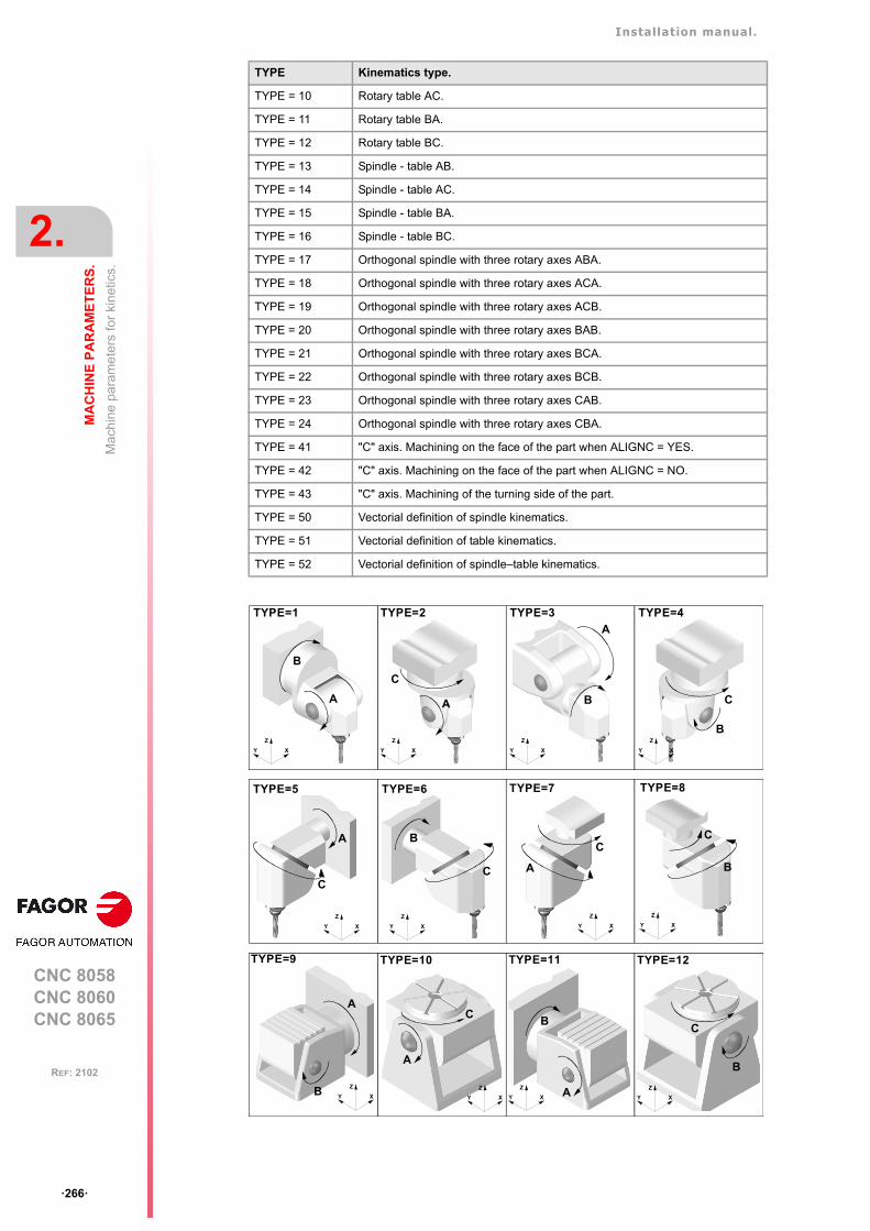
Installation manual.
CNC 8058CNC 8060CNC 8065
2.
MA
CH
INE
PA
RA
ME
TE
RS
.
Mac
hin
e pa
ram
eter
s fo
r ki
netic
s.
ꞏ266ꞏ
REF: 2102
TYPE = 10 Rotary table AC.
TYPE = 11 Rotary table BA.
TYPE = 12 Rotary table BC.
TYPE = 13 Spindle - table AB.
TYPE = 14 Spindle - table AC.
TYPE = 15 Spindle - table BA.
TYPE = 16 Spindle - table BC.
TYPE = 17 Orthogonal spindle with three rotary axes ABA.
TYPE = 18 Orthogonal spindle with three rotary axes ACA.
TYPE = 19 Orthogonal spindle with three rotary axes ACB.
TYPE = 20 Orthogonal spindle with three rotary axes BAB.
TYPE = 21 Orthogonal spindle with three rotary axes BCA.
TYPE = 22 Orthogonal spindle with three rotary axes BCB.
TYPE = 23 Orthogonal spindle with three rotary axes CAB.
TYPE = 24 Orthogonal spindle with three rotary axes CBA.
TYPE = 41 "C" axis. Machining on the face of the part when ALIGNC = YES.
TYPE = 42 "C" axis. Machining on the face of the part when ALIGNC = NO.
TYPE = 43 "C" axis. Machining of the turning side of the part.
TYPE = 50 Vectorial definition of spindle kinematics.
TYPE = 51 Vectorial definition of table kinematics.
TYPE = 52 Vectorial definition of spindle–table kinematics.
TYPE Kinematics type.
TYPE=2
A
C
XY
Z
TYPE=1
B
A
XY
Z
TYPE=3
XY
Z
A
B
TYPE=4
XY
Z
C
B
TYPE=5
A
XY
Z
C
TYPE=6
XY
Z
B
C
C
TYPE=7
XY
Z
A
TYPE=8
XY
Z
B
C
A
B
TYPE=9
XY
Z
A
C
TYPE=10
XY
Z
B
TYPE=12
XY
Z
C
A
TYPE=11
XY
Z
B
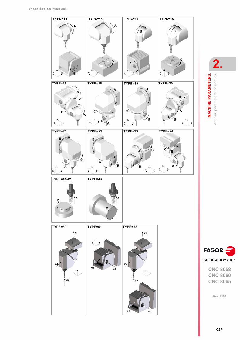
Installation manual.
CNC 8058CNC 8060CNC 8065
MA
CH
INE
PA
RA
ME
TE
RS
.
2.
Mac
hin
e pa
ram
eter
s fo
r ki
netic
s.
ꞏ267ꞏ
REF: 2102
TYPE=13
XY
Z
A
B
TYPE=14
XY
Z
A
C
TYPE=15
XY
Z
B
A
TYPE=16
XY
Z
C
B
XY
Z
B
A
A
TYPE=17
XY
Z
A
C
A
TYPE=18
XY
Z
A
C
B
TYPE=19
XY
Z
B
A
TYPE=20
B
XY
Z
TYPE=21
C
A
B
XY
Z
TYPE=22
C
B
BXY
Z
TYPE=23
C
B
A
XY
Z
TYPE=24
CB
A
C
TYPE=41/42
Y
C
TYPE=43
Z
TYPE=50 TYPE=51 TYPE=52
XY
Z
V1 V2
XY
Z
V3
V2
V1
V4 V5
XY
Z
V3
V2
V1
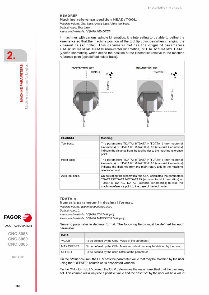
Installation manual.
CNC 8058CNC 8060CNC 8065
2.
MA
CH
INE
PA
RA
ME
TE
RS
.
Mac
hin
e pa
ram
eter
s fo
r ki
netic
s.
ꞏ268ꞏ
REF: 2102
HEADREFMachine reference position HEAD/TOOL.Possible values: Tool base / Head base / Auto tool base.Default value: Tool base.Associated variable: (V.)MPK.HEADREF
In machines with various spindle kinematics, it is interesting to be able to define thekinematics so that the machine position of the tool tip coincides when changing thek inemat ics (sp ind le ) . Th is parameter de f ines the o r ig in o f parametersTDATA13/TDATA14/TDATA15 (non-vector kinematics) or TDATA1/TDATA2/TDATA3(vector kinematics), which define the position of the kinematics relative to the machinereference point (spindle/tool holder base).
TDATA nNumeric parameter in decimal format.Possible values: Within ±999999999.0000Default value: 0.Associated variable: (V.)MPK.TDATAkin[nb]Associated variable: (V.)MPK.MAXOFTDATAkin[nb]
Numeric parameter in decimal format. The following fields must be defined for eachparameter.
On the "Value" column, the OEM sets the parameter value that may be modified by the userusing the "OFFSET" column or its associated variable.
On the "MAX OFFSET" column, the OEM determines the maximum offset that the user mayset. This column will always be a positive value and the offset set by the user will be a value
HEADREF Meaning.
Tool base. The parameters TDATA13/TDATA14/TDATA15 (non-vectorialkinematics) or TDATA1/TDATA2/TDATA3 (vectorial kinematics)indicate the distance from the tool holder to the machine referencepoint.
Head base. The parameters TDATA13/TDATA14/TDATA15 (non-vectorialkinematics) or TDATA1/TDATA2/TDATA3 (vectorial kinematics)indicate the distance from the main rotary axis to the machinereference point.
Auto tool base. On activating the kinematics, the CNC calculates the parametersTDATA13/TDATA14/TDATA15 (non-vectorial kinematics) orTDATA1/TDATA2/TDATA3 (vectorial kinematics) to take themachine reference point to the base of the tool holder.
DATA
VALUE To be defined by the OEM. Value of the parameter.
MAX OFFSET To be defined by the OEM. Maximum offset that may be defined by the user.
OFFSET To be defined by the user. Offset of the parameter.
Installation manual.
CNC 8058CNC 8060CNC 8065
MA
CH
INE
PA
RA
ME
TE
RS
.
2.
Mac
hin
e pa
ram
eter
s fo
r ki
netic
s.
ꞏ269ꞏ
REF: 2102
between "- MAX OFFSET" and "+ MAX OFFSET". If he sets a maximum offset of zero, theuser will not be able to set any offset.
The offset values set by the user will be added to its corresponding TDATA parameter. Thenew value will be effective when activating the kinematics (#KIN ID) or RTCP.
TDATA_I nNumeric parameter in integer format.Possible values: Within ±2147483647Default value: 0.Associated variable: (V.)MPK.TDATA_Ikin[nb]Associated variable: (V.)MPK.MAXOFTDATA_Ikin[nb]
Numeric parameter in integer format. The following fields must be defined for eachparameter.
On the "Value" column, the OEM sets the parameter value that may be modified by the userusing the "OFFSET" column or its associated variable.
On the "MAX OFFSET" column, the OEM determines the maximum offset that the user mayset. This column will always be a positive value and the offset set by the user will be a valuebetween "- MAX OFFSET" and "+ MAX OFFSET". If he sets a maximum offset of zero, theuser will not be able to set any offset.
The offset values set by the user will be added to its corresponding TDATA parameter. Thenew value will be effective when activating the kinematics (#KIN ID) or RTCP.
DATA
VALUE To be defined by the OEM. Value of the parameter.
MAX OFFSET To be defined by the OEM. Maximum offset that may be defined by the user.
OFFSET To be defined by the user. Offset of the parameter.
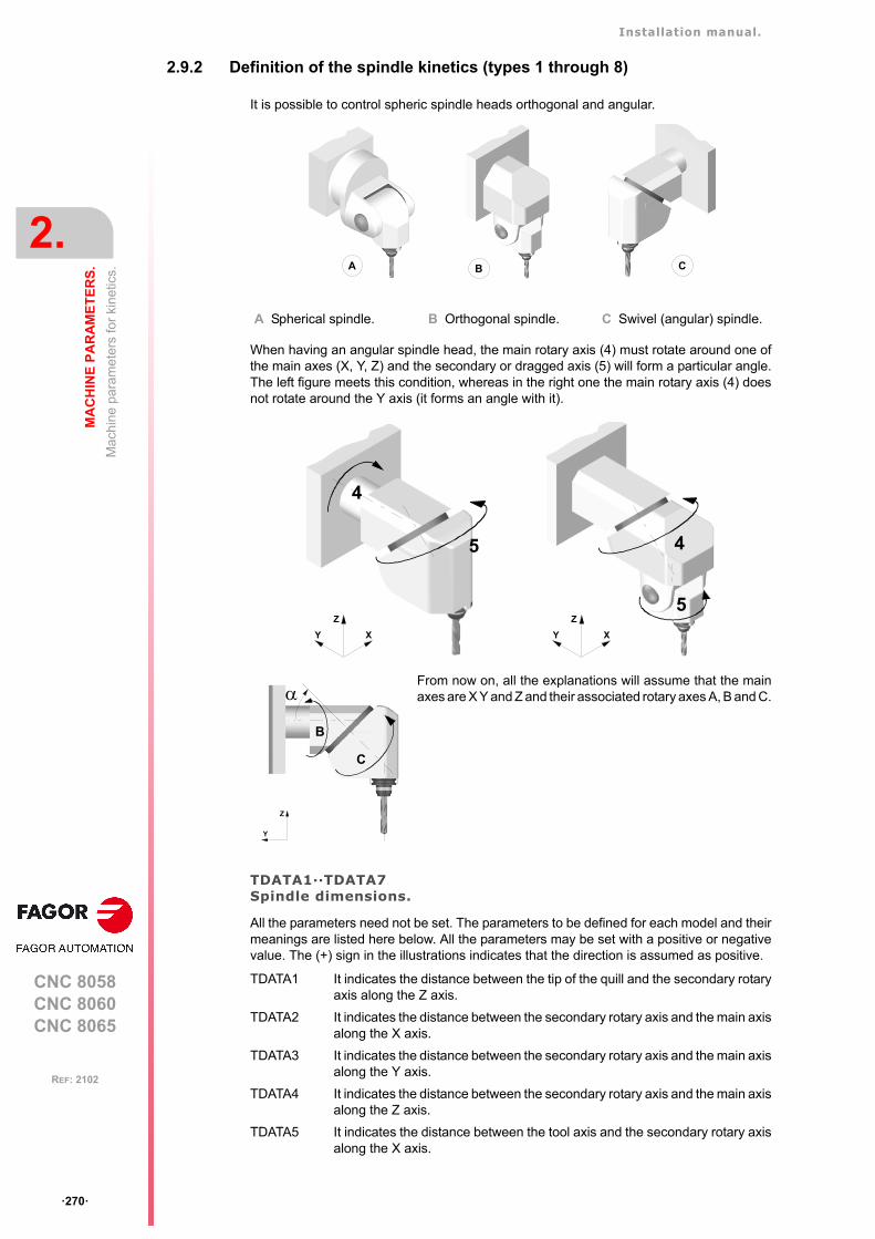
Installation manual.
CNC 8058CNC 8060CNC 8065
2.
MA
CH
INE
PA
RA
ME
TE
RS
.
Mac
hin
e pa
ram
eter
s fo
r ki
netic
s.
ꞏ270ꞏ
REF: 2102
2.9.2 Definition of the spindle kinetics (types 1 through 8)
It is possible to control spheric spindle heads orthogonal and angular.
When having an angular spindle head, the main rotary axis (4) must rotate around one ofthe main axes (X, Y, Z) and the secondary or dragged axis (5) will form a particular angle.The left figure meets this condition, whereas in the right one the main rotary axis (4) doesnot rotate around the Y axis (it forms an angle with it).
TDATA1··TDATA7Spindle dimensions.
All the parameters need not be set. The parameters to be defined for each model and theirmeanings are listed here below. All the parameters may be set with a positive or negativevalue. The (+) sign in the illustrations indicates that the direction is assumed as positive.
A Spherical spindle. B Orthogonal spindle. C Swivel (angular) spindle.
From now on, all the explanations will assume that the mainaxes are X Y and Z and their associated rotary axes A, B and C.
TDATA1 It indicates the distance between the tip of the quill and the secondary rotaryaxis along the Z axis.
TDATA2 It indicates the distance between the secondary rotary axis and the main axisalong the X axis.
TDATA3 It indicates the distance between the secondary rotary axis and the main axisalong the Y axis.
TDATA4 It indicates the distance between the secondary rotary axis and the main axisalong the Z axis.
TDATA5 It indicates the distance between the tool axis and the secondary rotary axisalong the X axis.
B CA
4
5
XY
Z5
XY
Z
4
Y
Z
B
C
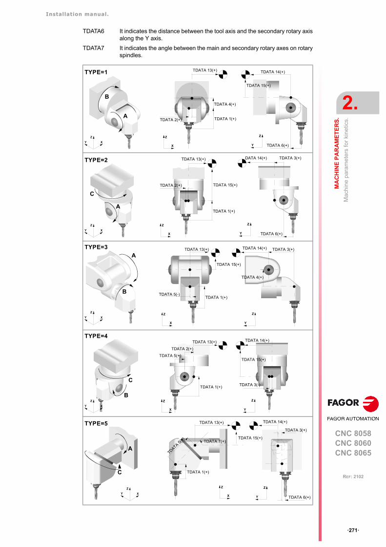
Installation manual.
CNC 8058CNC 8060CNC 8065
MA
CH
INE
PA
RA
ME
TE
RS
.
2.
Mac
hin
e pa
ram
eter
s fo
r ki
netic
s.
ꞏ271ꞏ
REF: 2102
TDATA6 It indicates the distance between the tool axis and the secondary rotary axisalong the Y axis.
TDATA7 It indicates the angle between the main and secondary rotary axes on rotaryspindles.
TYPE=1
B
A
XY
Z
X
Z
TDATA 1(+)TDATA 2(+)
TDATA 4(+)
Y
Z
TDATA 14(+)
TDATA 6(+)
TDATA 13(+)
TDATA 15(+)
TYPE=2
A
C
XY
Z
X
Z
TDATA 1(+)
TDATA 2(+) TDATA 15(+)
Y
Z
TDATA 6(+)
TDATA 3(+)DATA 14(+)TDATA 13(+)
TYPE=3
XY
Z
A
B
Y
Z
TDATA 3(+)
TDATA 4(+)
X
Z
TDATA 1(+)
TDATA 13(+)
TDATA 5(-)
TDATA 15(+)
TDATA 14(+)
TYPE=4
XY
Z
C
B
X
Z
TDATA 1(+)
TDATA 2(+)
TDATA 5(+)
Y
Z
TDATA 15(+)
TDATA 3(-)
TDATA 13(+) TDATA 14(+)
TYPE=5
A
XY
Z
C
Y
Z
TDATA 3(+)
TDATA 6(+)X
Z
TDATA 1(+)
TDATA 13(+)
TDATA 5(+
)TDATA 7(+)
TDATA 15(+)
TDATA 14(+)
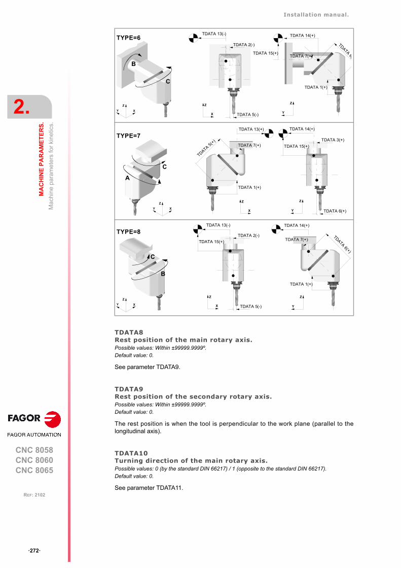
Installation manual.
CNC 8058CNC 8060CNC 8065
2.
MA
CH
INE
PA
RA
ME
TE
RS
.
Mac
hin
e pa
ram
eter
s fo
r ki
netic
s.
ꞏ272ꞏ
REF: 2102
TDATA8Rest position of the main rotary axis.Possible values: Within ±99999.9999º.Default value: 0.
See parameter TDATA9.
TDATA9Rest position of the secondary rotary axis.Possible values: Within ±99999.9999º.Default value: 0.
The rest position is when the tool is perpendicular to the work plane (parallel to thelongitudinal axis).
TDATA10Turning direction of the main rotary axis.Possible values: 0 (by the standard DIN 66217) / 1 (opposite to the standard DIN 66217).Default value: 0.
See parameter TDATA11.
TYPE=6
XY
Z
B
C
TDATA 2(-)
X
Z
TDATA 5(-) Y
Z
TDATA 1(+)
TDATA 14(+)
TDATA 6(TDATA 7(+)
TDATA 13(-)
TDATA 15(+)
C
TYPE=7
XY
Z
A
Y
Z
TDATA 3(+)
TDATA 15(+)
TDATA 6(+)X
Z
TDATA 1(+)
TDATA 5(+
)TDATA 7(+)
TDATA 13(+) TDATA 14(+)
TYPE=8
XY
Z
B
C
TDATA 2(-)
X
Z
TDATA 15(+)
TDATA 5(-) Y
Z
TDATA 1(+)
TDATA 6(+)
TDATA 7(+)
TDATA 13(-) TDATA 14(+)
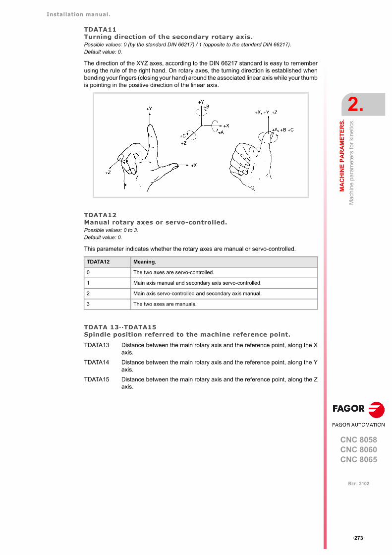
Installation manual.
CNC 8058CNC 8060CNC 8065
MA
CH
INE
PA
RA
ME
TE
RS
.
2.
Mac
hin
e pa
ram
eter
s fo
r ki
netic
s.
ꞏ273ꞏ
REF: 2102
TDATA11Turning direction of the secondary rotary axis.Possible values: 0 (by the standard DIN 66217) / 1 (opposite to the standard DIN 66217).Default value: 0.
The direction of the XYZ axes, according to the DIN 66217 standard is easy to rememberusing the rule of the right hand. On rotary axes, the turning direction is established whenbending your fingers (closing your hand) around the associated linear axis while your thumbis pointing in the positive direction of the linear axis.
TDATA12Manual rotary axes or servo-controlled.Possible values: 0 to 3.Default value: 0.
This parameter indicates whether the rotary axes are manual or servo-controlled.
TDATA 13··TDATA15Spindle position referred to the machine reference point.
TDATA12 Meaning.
0 The two axes are servo-controlled.
1 Main axis manual and secondary axis servo-controlled.
2 Main axis servo-controlled and secondary axis manual.
3 The two axes are manuals.
TDATA13 Distance between the main rotary axis and the reference point, along the Xaxis.
TDATA14 Distance between the main rotary axis and the reference point, along the Yaxis.
TDATA15 Distance between the main rotary axis and the reference point, along the Zaxis.
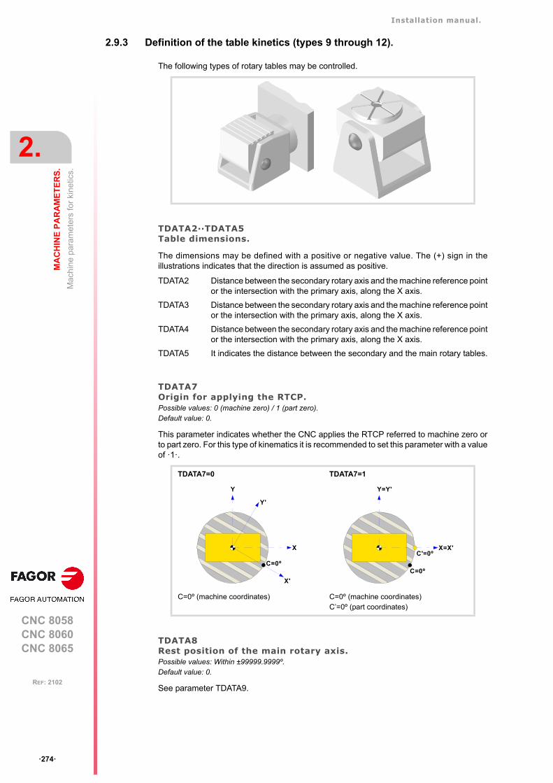
Installation manual.
CNC 8058CNC 8060CNC 8065
2.
MA
CH
INE
PA
RA
ME
TE
RS
.
Mac
hin
e pa
ram
eter
s fo
r ki
netic
s.
ꞏ274ꞏ
REF: 2102
2.9.3 Definition of the table kinetics (types 9 through 12).
The following types of rotary tables may be controlled.
TDATA2··TDATA5Table dimensions.
The dimensions may be defined with a positive or negative value. The (+) sign in theillustrations indicates that the direction is assumed as positive.
TDATA7Origin for applying the RTCP.Possible values: 0 (machine zero) / 1 (part zero).Default value: 0.
This parameter indicates whether the CNC applies the RTCP referred to machine zero orto part zero. For this type of kinematics it is recommended to set this parameter with a valueof ꞏ1ꞏ.
TDATA8Rest position of the main rotary axis.Possible values: Within ±99999.9999º.Default value: 0.
See parameter TDATA9.
TDATA2 Distance between the secondary rotary axis and the machine reference pointor the intersection with the primary axis, along the X axis.
TDATA3 Distance between the secondary rotary axis and the machine reference pointor the intersection with the primary axis, along the X axis.
TDATA4 Distance between the secondary rotary axis and the machine reference pointor the intersection with the primary axis, along the X axis.
TDATA5 It indicates the distance between the secondary and the main rotary tables.
TDATA7=0 TDATA7=1
C=0º (machine coordinates) C=0º (machine coordinates)C’=0º (part coordinates)
X
Y
C=0º
Y'
X'
X=X'
Y=Y'
C=0º
C'=0º
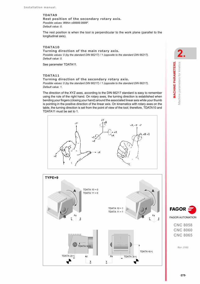
Installation manual.
CNC 8058CNC 8060CNC 8065
MA
CH
INE
PA
RA
ME
TE
RS
.
2.
Mac
hin
e pa
ram
eter
s fo
r ki
netic
s.
ꞏ275ꞏ
REF: 2102
TDATA9Rest position of the secondary rotary axis.Possible values: Within ±99999.9999º.Default value: 0.
The rest position is when the tool is perpendicular to the work plane (parallel to thelongitudinal axis).
TDATA10Turning direction of the main rotary axis.Possible values: 0 (by the standard DIN 66217) / 1 (opposite to the standard DIN 66217).Default value: 0.
See parameter TDATA11.
TDATA11Turning direction of the secondary rotary axis.Possible values: 0 (by the standard DIN 66217) / 1 (opposite to the standard DIN 66217).Default value: 1.
The direction of the XYZ axes, according to the DIN 66217 standard is easy to rememberusing the rule of the right hand. On rotary axes, the turning direction is established whenbending your fingers (closing your hand) around the associated linear axis while your thumbis pointing in the positive direction of the linear axis. On kinematics with rotary axes on thetable, the turning direction is set from the point of view of the tool; therefore, TDATA10 andTDATA11 must be set to 1.
A
B
TYPE=9
XY
Z
TDATA 5(+)
TDATA 2(+)
X
Z
TDATA 4(+)
Y
Z TDATA 3(+)
A
B XY
Z
TDATA 10 = 0
TDATA 11 = 0
TDATA 10 = 1
TDATA 11 = 1
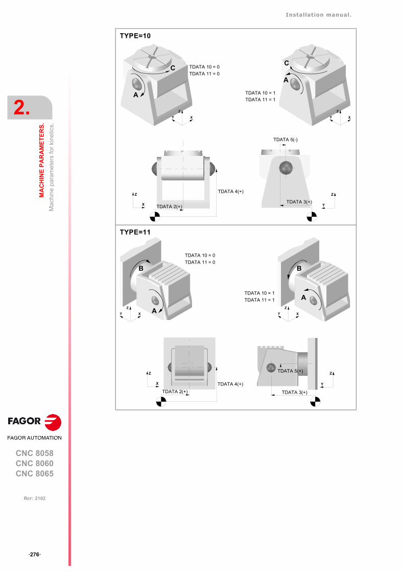
Installation manual.
CNC 8058CNC 8060CNC 8065
2.
MA
CH
INE
PA
RA
ME
TE
RS
.
Mac
hin
e pa
ram
eter
s fo
r ki
netic
s.
ꞏ276ꞏ
REF: 2102
A
C
TYPE=10
XY
Z
X
ZTDATA 4(+)
TDATA 2(+) Y
Z
TDATA 3(+)
TDATA 5(-)
A
C
XY
Z
TDATA 10 = 1
TDATA 11 = 1
TDATA 10 = 0
TDATA 11 = 0
A
TYPE=11
XY
Z
B
X
Z
TDATA 4(+)
TDATA 2(+)
TDATA 5(+)
Y
Z
TDATA 3(+)
A
XY
Z
B
TDATA 10 = 0
TDATA 11 = 0
TDATA 10 = 1
TDATA 11 = 1
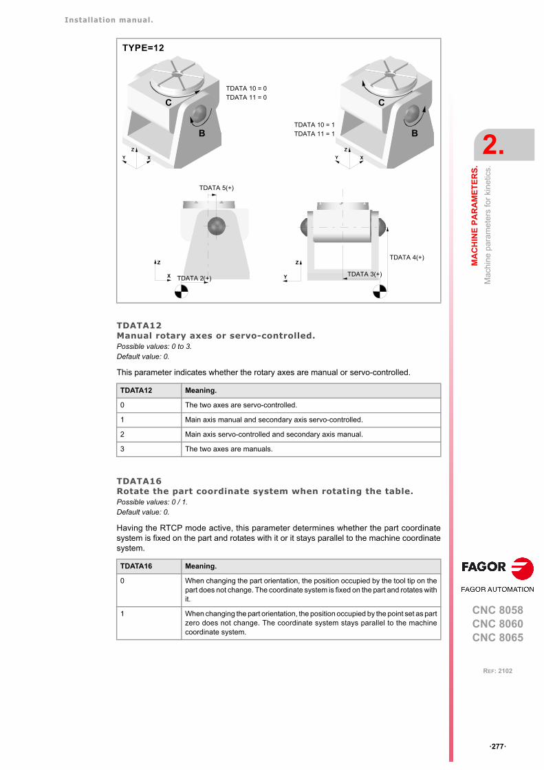
Installation manual.
CNC 8058CNC 8060CNC 8065
MA
CH
INE
PA
RA
ME
TE
RS
.
2.
Mac
hin
e pa
ram
eter
s fo
r ki
netic
s.
ꞏ277ꞏ
REF: 2102
TDATA12Manual rotary axes or servo-controlled.Possible values: 0 to 3.Default value: 0.
This parameter indicates whether the rotary axes are manual or servo-controlled.
TDATA16Rotate the part coordinate system when rotating the table.Possible values: 0 / 1.Default value: 0.
Having the RTCP mode active, this parameter determines whether the part coordinatesystem is fixed on the part and rotates with it or it stays parallel to the machine coordinatesystem.
TDATA12 Meaning.
0 The two axes are servo-controlled.
1 Main axis manual and secondary axis servo-controlled.
2 Main axis servo-controlled and secondary axis manual.
3 The two axes are manuals.
TDATA16 Meaning.
0 When changing the part orientation, the position occupied by the tool tip on thepart does not change. The coordinate system is fixed on the part and rotates withit.
1 When changing the part orientation, the position occupied by the point set as partzero does not change. The coordinate system stays parallel to the machinecoordinate system.
B
TYPE=12
XY
Z
C
B
XY
Z
C
TDATA 10 = 1
TDATA 11 = 1
TDATA 10 = 0
TDATA 11 = 0
TDATA 4(+)
TDATA 3(+)Y
Z
TDATA 5(+)
TDATA 2(+)X
Z
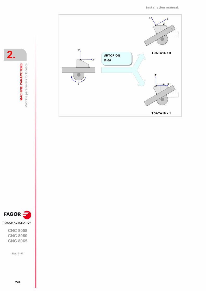
Installation manual.
CNC 8058CNC 8060CNC 8065
2.
MA
CH
INE
PA
RA
ME
TE
RS
.
Mac
hin
e pa
ram
eter
s fo
r ki
netic
s.
ꞏ278ꞏ
REF: 2102
X'
Z'
#RTCP ON
B-30
B
TDATA16 = 0
X'Z'
TDATA16 = 1
X'
Z'
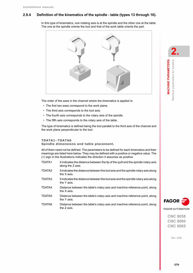
Installation manual.
CNC 8058CNC 8060CNC 8065
MA
CH
INE
PA
RA
ME
TE
RS
.
2.
Mac
hin
e pa
ram
eter
s fo
r ki
netic
s.
ꞏ279ꞏ
REF: 2102
2.9.4 Definition of the kinematics of the spindle - table (types 13 through 16).
In this type of kinematics, one rotating axis is at the spindle and the other one at the table.The one at the spindle orients the tool and that of the work table orients the part.
The order of the axes in the channel where the kinematics is applied is:
• The first two axes correspond to the work plane.
• The third axis corresponds to the tool axis.
• The fourth axis corresponds to the rotary axis of the spindle.
• The fifth axis corresponds to the rotary axis of the table.
The type of kinematics is defined being the tool parallel to the third axis of the channel andthe work plane perpendicular to the tool.
TDATA1··TDATA6Spindle dimensions and table placement.
All of them need not be defined. The parameters to be defined for each kinematics and theirmeanings are listed here below. They may be defined with a positive or negative value. The(+) sign in the illustrations indicates the direction it assumes as positive.
TDATA1 It indicates the distance between the tip of the quill and the spindle rotary axisalong the Z axis.
TDATA2 It indicates the distance between the tool axis and the spindle rotary axis alongthe X axis.
TDATA3 It indicates the distance between the tool axis and the spindle rotary axis alongthe Y axis.
TDATA4 Distance between the table's rotary axis and machine reference point, alongthe X axis.
TDATA5 Distance between the table's rotary axis and machine reference point, alongthe Y axis.
TDATA6 Distance between the table's rotary axis and machine reference point, alongthe Z axis.
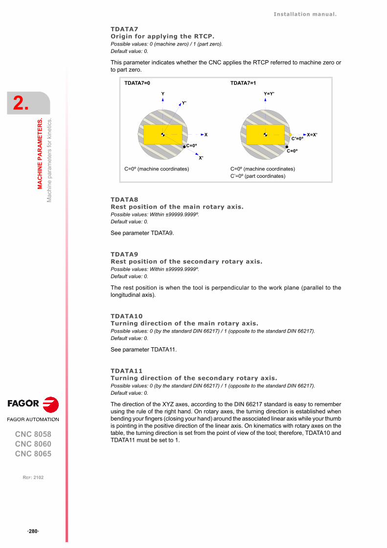
Installation manual.
CNC 8058CNC 8060CNC 8065
2.
MA
CH
INE
PA
RA
ME
TE
RS
.
Mac
hin
e pa
ram
eter
s fo
r ki
netic
s.
ꞏ280ꞏ
REF: 2102
TDATA7Origin for applying the RTCP.Possible values: 0 (machine zero) / 1 (part zero).Default value: 0.
This parameter indicates whether the CNC applies the RTCP referred to machine zero orto part zero.
TDATA8Rest position of the main rotary axis.Possible values: Within ±99999.9999º.Default value: 0.
See parameter TDATA9.
TDATA9Rest position of the secondary rotary axis.Possible values: Within ±99999.9999º.Default value: 0.
The rest position is when the tool is perpendicular to the work plane (parallel to thelongitudinal axis).
TDATA10Turning direction of the main rotary axis.Possible values: 0 (by the standard DIN 66217) / 1 (opposite to the standard DIN 66217).Default value: 0.
See parameter TDATA11.
TDATA11Turning direction of the secondary rotary axis.Possible values: 0 (by the standard DIN 66217) / 1 (opposite to the standard DIN 66217).Default value: 0.
The direction of the XYZ axes, according to the DIN 66217 standard is easy to rememberusing the rule of the right hand. On rotary axes, the turning direction is established whenbending your fingers (closing your hand) around the associated linear axis while your thumbis pointing in the positive direction of the linear axis. On kinematics with rotary axes on thetable, the turning direction is set from the point of view of the tool; therefore, TDATA10 andTDATA11 must be set to 1.
TDATA7=0 TDATA7=1
C=0º (machine coordinates) C=0º (machine coordinates)C’=0º (part coordinates)
X
Y
C=0º
Y'
X'
X=X'
Y=Y'
C=0º
C'=0º
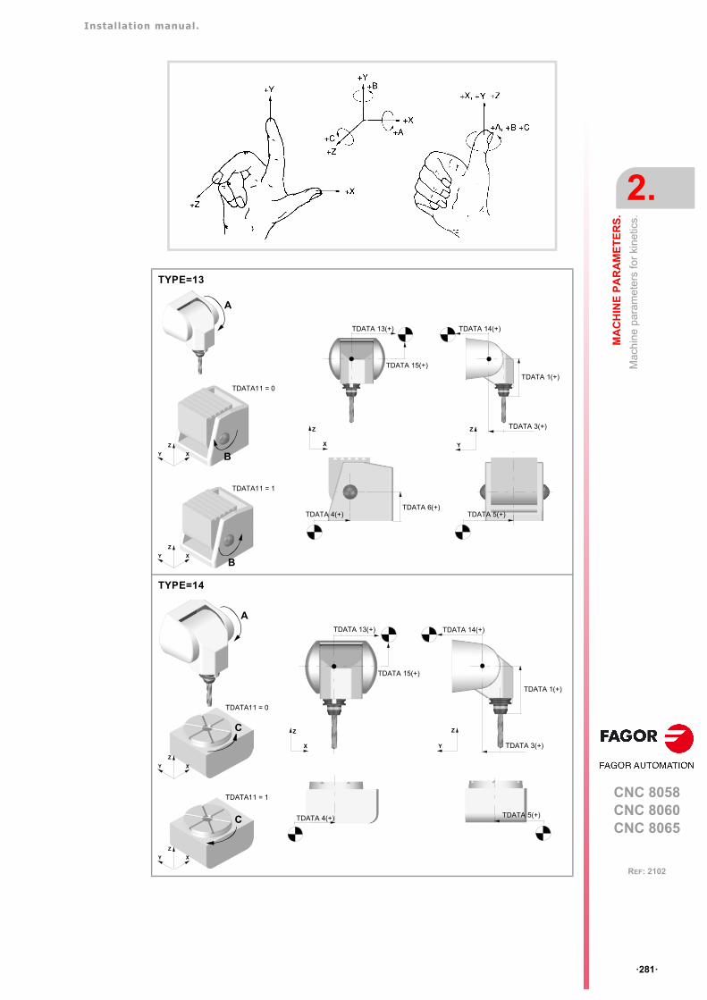
Installation manual.
CNC 8058CNC 8060CNC 8065
MA
CH
INE
PA
RA
ME
TE
RS
.
2.
Mac
hin
e pa
ram
eter
s fo
r ki
netic
s.
ꞏ281ꞏ
REF: 2102
TYPE=13
XY
Z
A
B
TDATA 1(+)
Y
Z TDATA 3(+)
TDATA 14(+)TDATA 13(+)
X
Z
TDATA 5(+)
TDATA 15(+)
TDATA 6(+)
XY
Z
B
TDATA11 = 0
TDATA11 = 1
TDATA 4(+)
TYPE=14
XY
Z
A
C
TDATA 13(+)
X
Z
TDATA 4(+)
TDATA 15(+)
TDATA 1(+)
Y
Z
TDATA 3(+)
TDATA 14(+)
TDATA 5(+)
XY
Z
C
TDATA11 = 0
TDATA11 = 1
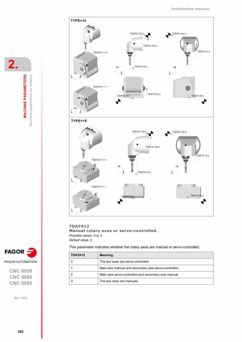
Installation manual.
CNC 8058CNC 8060CNC 8065
2.
MA
CH
INE
PA
RA
ME
TE
RS
.
Mac
hin
e pa
ram
eter
s fo
r ki
netic
s.
ꞏ282ꞏ
REF: 2102
TDATA12Manual rotary axes or servo-controlled.Possible values: 0 to 3.Default value: 0.
This parameter indicates whether the rotary axes are manual or servo-controlled.
TDATA12 Meaning.
0 The two axes are servo-controlled.
1 Main axis manual and secondary axis servo-controlled.
2 Main axis servo-controlled and secondary axis manual.
3 The two axes are manuals.
TYPE=15
XY
Z
B
A
TDATA 1(+)
Y
Z
TDATA 14(+)
TDATA 5(+)TDATA 6(+)
TDATA 13(+)
X
Z
TDATA 15(+)
TDATA 2(+)
XY
Z
A
TDATA11 = 1
TDATA11 = 0
TDATA 4(+)
TYPE=16
XY
Z
C
B
TDATA 4(+)
TDATA 13(+)
X
Z
TDATA 15(+)
TDATA 2(+)
TDATA 1(+)
Y
Z
TDATA 14(+)
TDATA 5(+)
XY
Z
C
TDATA11 = 1
TDATA11 = 0

Installation manual.
CNC 8058CNC 8060CNC 8065
MA
CH
INE
PA
RA
ME
TE
RS
.
2.
Mac
hin
e pa
ram
eter
s fo
r ki
netic
s.
ꞏ283ꞏ
REF: 2102
TDATA13··TDATA15Spindle placement.
TDATA13 Distance defining the spindle placement, from the rotary axis, along the Xaxis.
TDATA14 Distance defining the spindle placement, from the rotary axis, along the Yaxis.
TDATA15 Distance defining the spindle placement, from the rotary axis, along the Zaxis.
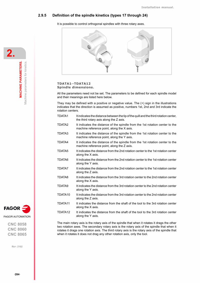
Installation manual.
CNC 8058CNC 8060CNC 8065
2.
MA
CH
INE
PA
RA
ME
TE
RS
.
Mac
hin
e pa
ram
eter
s fo
r ki
netic
s.
ꞏ284ꞏ
REF: 2102
2.9.5 Definition of the spindle kinetics (types 17 through 24)
It is possible to control orthogonal spindles with three rotary axes.
TDATA1··TDATA12Spindle dimensions.
All the parameters need not be set. The parameters to be defined for each spindle modeland their meanings are listed here below.
They may be defined with a positive or negative value. The (+) sign in the illustrationsindicates that the direction is assumed as positive, numbers 1st, 2nd and 3rd indicate therotation centers.
The main rotary axis is the rotary axis of the spindle that when it rotates it drags the othertwo rotation axes. The secondary rotary axis is the rotary axis of the spindle that when itrotates it drags one rotation axis. The third rotary axis is the rotary axis of the spindle thatwhen it rotates it does not drag any other rotation axis, only the tool.
TDATA1 It indicates the distance between the tip of the quill and the third rotation center,the third rotary axis along the Z axis.
TDATA2 It indicates the distance of the spindle from the 1st rotation center to themachine reference point, along the X axis.
TDATA3 It indicates the distance of the spindle from the 1st rotation center to themachine reference point, along the Y axis.
TDATA4 It indicates the distance of the spindle from the 1st rotation center to themachine reference point, along the Z axis.
TDATA5 It indicates the distance from the 2nd rotation center to the 1st rotation centeralong the X axis.
TDATA6 It indicates the distance from the 2nd rotation center to the 1st rotation centeralong the Y axis.
TDATA7 It indicates the distance from the 2nd rotation center to the 1st rotation centeralong the Z axis.
TDATA8 It indicates the distance from the 3rd rotation center to the 2nd rotation centeralong the X axis.
TDATA9 It indicates the distance from the 3rd rotation center to the 2nd rotation centeralong the Y axis.
TDATA10 It indicates the distance from the 3rd rotation center to the 2nd rotation centeralong the Z axis.
TDATA11 It indicates the distance from the shaft of the tool to the 3rd rotation centeralong the X axis.
TDATA12 It indicates the distance from the shaft of the tool to the 3rd rotation centeralong the Y axis.
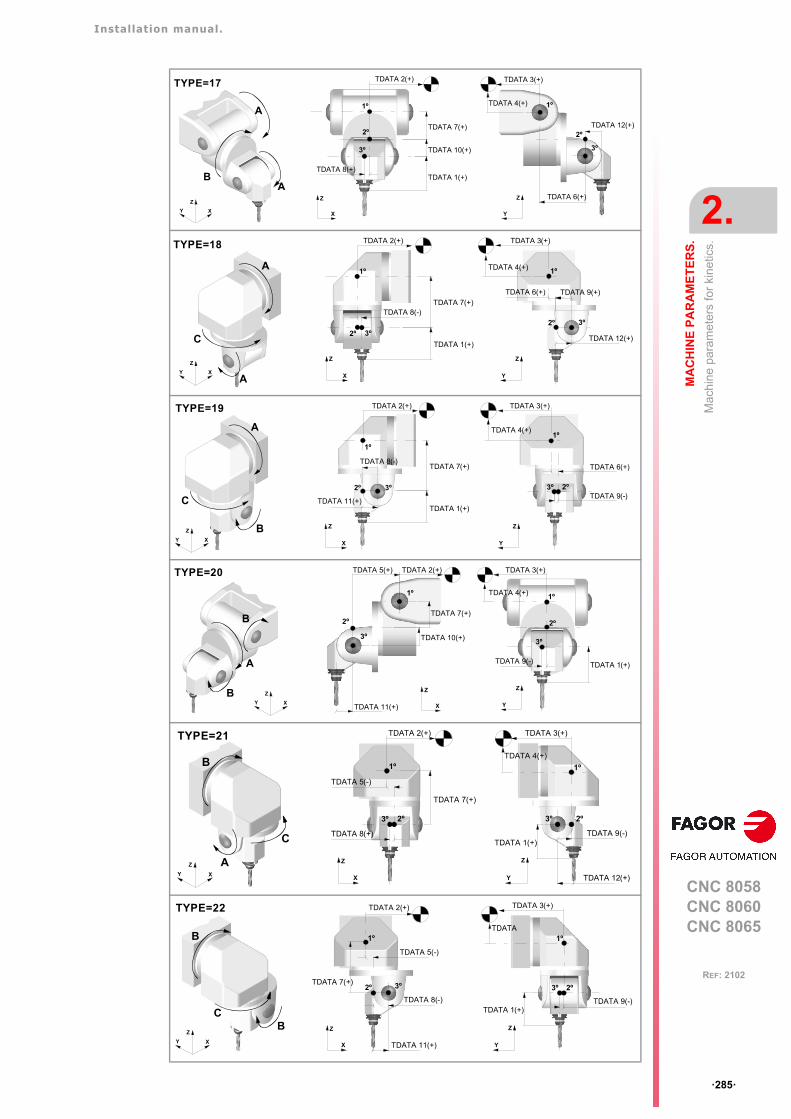
Installation manual.
CNC 8058CNC 8060CNC 8065
MA
CH
INE
PA
RA
ME
TE
RS
.
2.
Mac
hin
e pa
ram
eter
s fo
r ki
netic
s.
ꞏ285ꞏ
REF: 2102
XY
Z
B
A
A
TYPE=17
X
Z
TDATA 1(+)
TDATA 2(+)
TDATA 7(+)
TDATA 10(+)
TDATA 8(+)
1º
2º
3º
Y
Z
TDATA 3(+)
TDATA 4(+)
TDATA 6(+)
TDATA 12(+)
1º
2º
3º
XY
Z
A
C
A
TYPE=18
X
Z
TDATA 8(-)
1º
2º
TDATA 1(+)
TDATA 2(+)
TDATA 7(+)
3º
Y
Z
1º
TDATA 9(+)
TDATA 12(+)
3º 2º
TDATA 3(+)
TDATA 4(+)
TDATA 6(+)
Y
Z
TDATA 3(+)
TDATA 4(+)1º
TDATA 6(+)
2º 3º TDATA 9(-)
XY
Z
A
C
B
TYPE=19
X
Z
1º
TDATA 2(+)
2º
TDATA 1(+)
TDATA 7(+)
3º
TDATA 8(-)
TDATA 11(+)
XY
Z
B
A
TYPE=20
BY
Z
2º
3º
1º
TDATA 3(+)
TDATA 4(+)
TDATA 1(+)TDATA 9(-)
TDATA 7(+)
X
Z
2º
3º
1º
TDATA 2(+)TDATA 5(+)
TDATA 10(+)
TDATA 11(+)
XY
Z
TYPE=21
C
A
B
X
Z
1º
2º 3º
TDATA 2(+)
TDATA 5(-)
TDATA 7(+)
TDATA 8(+)
Y
Z
1º
2º 3º
TDATA 1(+)
TDATA 3(+)
TDATA 4(+)
TDATA 9(-)
TDATA 12(+)
Y
Z
1º
2º 3º
TDATA 1(+)
TDATA 3(+)
TDATA
TDATA 9(-)
XY
Z
TYPE=22
C
B
B
X
Z
1º
3º
TDATA 2(+)
TDATA 5(-)
TDATA 7(+)
TDATA 8(-)
TDATA 11(+)
2º
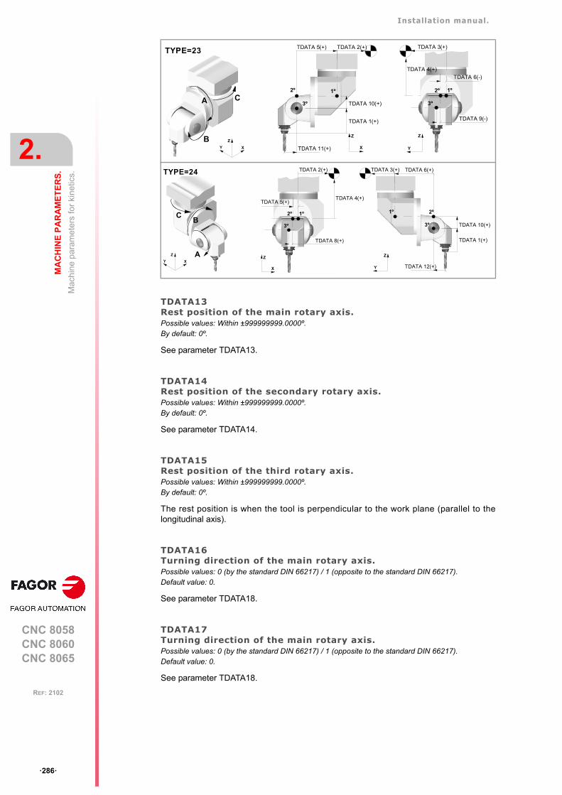
Installation manual.
CNC 8058CNC 8060CNC 8065
2.
MA
CH
INE
PA
RA
ME
TE
RS
.
Mac
hin
e pa
ram
eter
s fo
r ki
netic
s.
ꞏ286ꞏ
REF: 2102
TDATA13Rest position of the main rotary axis.Possible values: Within ±999999999.0000º.By default: 0º.
See parameter TDATA13.
TDATA14Rest position of the secondary rotary axis.Possible values: Within ±999999999.0000º.By default: 0º.
See parameter TDATA14.
TDATA15Rest position of the third rotary axis.Possible values: Within ±999999999.0000º.By default: 0º.
The rest position is when the tool is perpendicular to the work plane (parallel to thelongitudinal axis).
TDATA16Turning direction of the main rotary axis.Possible values: 0 (by the standard DIN 66217) / 1 (opposite to the standard DIN 66217).Default value: 0.
See parameter TDATA18.
TDATA17Turning direction of the main rotary axis.Possible values: 0 (by the standard DIN 66217) / 1 (opposite to the standard DIN 66217).Default value: 0.
See parameter TDATA18.
XY
Z
TYPE=23
C
B
A
Y
Z
1º 2º
3º
TDATA 3(+)
TDATA 4(+)
TDATA 9(-)
TDATA 6(-)
X
Z
1º
3º
TDATA 2(+)TDATA 5(+)
TDATA 11(+)
2º
TDATA 1(+)
TDATA 10(+)
Y
Z
1º
3º
TDATA 3(+) TDATA 6(+)
TDATA 12(+)
2º
TDATA 1(+)
TDATA 10(+)
XY
Z
TYPE=24
CB
A
X
Z
1º 2º
3º
TDATA 2(+)
TDATA 4(+)
TDATA 8(+)
TDATA 5(+)
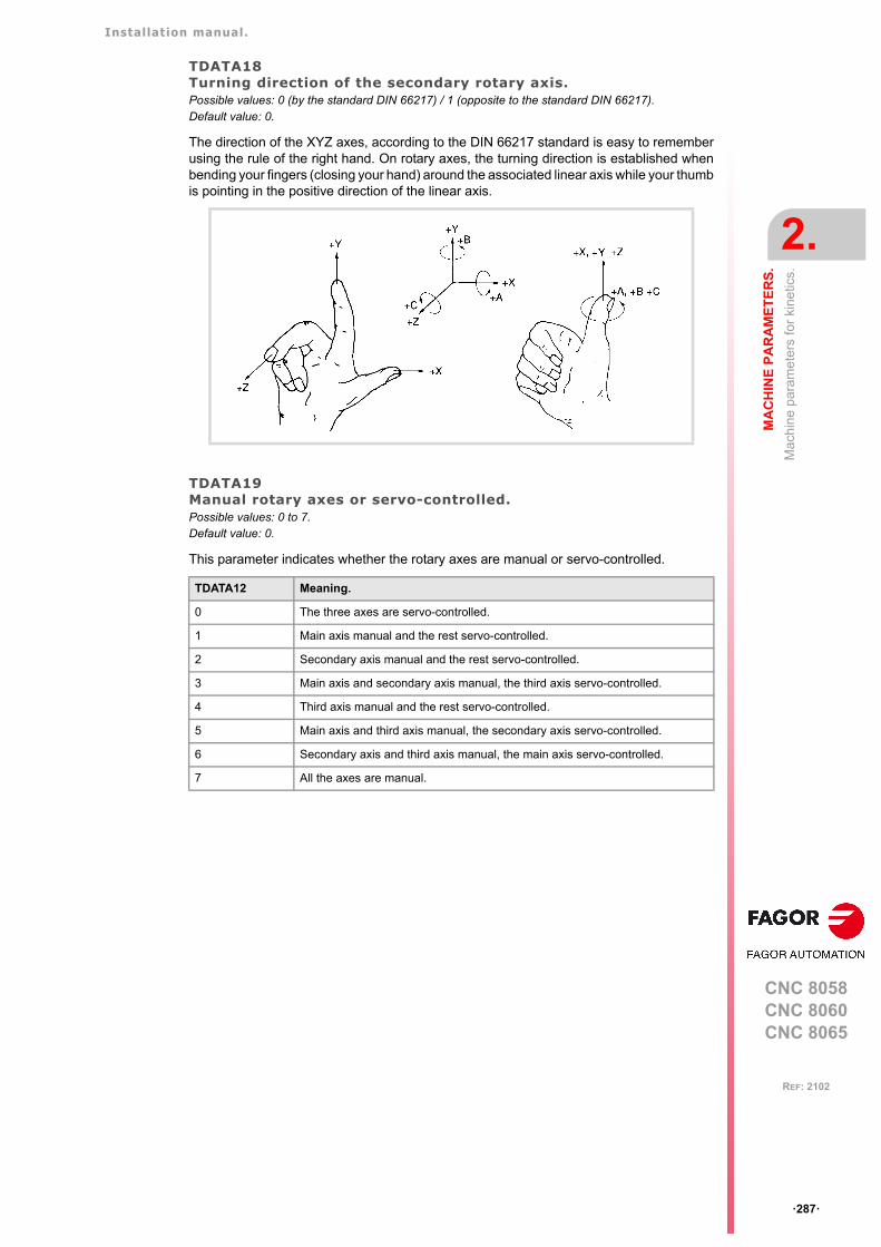
Installation manual.
CNC 8058CNC 8060CNC 8065
MA
CH
INE
PA
RA
ME
TE
RS
.
2.
Mac
hin
e pa
ram
eter
s fo
r ki
netic
s.
ꞏ287ꞏ
REF: 2102
TDATA18Turning direction of the secondary rotary axis.Possible values: 0 (by the standard DIN 66217) / 1 (opposite to the standard DIN 66217).Default value: 0.
The direction of the XYZ axes, according to the DIN 66217 standard is easy to rememberusing the rule of the right hand. On rotary axes, the turning direction is established whenbending your fingers (closing your hand) around the associated linear axis while your thumbis pointing in the positive direction of the linear axis.
TDATA19Manual rotary axes or servo-controlled. Possible values: 0 to 7.Default value: 0.
This parameter indicates whether the rotary axes are manual or servo-controlled.
TDATA12 Meaning.
0 The three axes are servo-controlled.
1 Main axis manual and the rest servo-controlled.
2 Secondary axis manual and the rest servo-controlled.
3 Main axis and secondary axis manual, the third axis servo-controlled.
4 Third axis manual and the rest servo-controlled.
5 Main axis and third axis manual, the secondary axis servo-controlled.
6 Secondary axis and third axis manual, the main axis servo-controlled.
7 All the axes are manual.
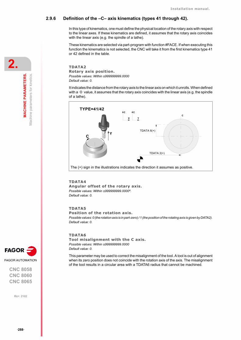
Installation manual.
CNC 8058CNC 8060CNC 8065
2.
MA
CH
INE
PA
RA
ME
TE
RS
.
Mac
hin
e pa
ram
eter
s fo
r ki
netic
s.
ꞏ288ꞏ
REF: 2102
2.9.6 Definition of the –C– axis kinematics (types 41 through 42).
In this type of kinematics, one must define the physical location of the rotary axis with respectto the linear axes. If these kinematics are defined, it assumes that the rotary axis coincideswith the linear axis (e.g. the spindle of a lathe).
These kinematics are selected via part-program with function #FACE. If when executing thisfunction the kinematics is not selected, the CNC will take it from the first kinematics type 41or 42 defined in the table.
TDATA2Rotary axis position.Possible values: Within ±999999999.0000Default value: 0.
It indicates the distance from the rotary axis to the linear axis on which it unrolls. When definedwith a ꞏ0ꞏ value, it assumes that the rotary axis coincides with the linear axis (e.g. the spindleof a lathe).
TDATA4Angular offset of the rotary axis.Possible values: Within ±999999999.0000º. Default value: 0.
TDATA5Position of the rotation axis.Possible values: 0 (the rotation axis is in part-zero) / 1 (the position of the rotating axis is given by DATA2).Default value: 0.
TDATA6Tool misalignment with the C axis.Possible values: Within ±999999999.0000Default value: 0.
This parameter may be used to correct the misalignment of the tool. A tool is out of alignmentwhen its zero position does not coincide with the rotation axis of the axis. The misalignmentof the tool results in a circular area with a TDATA6 radius that cannot be machined.
The (+) sign in the illustrations indicates the direction it assumes as positive.
C
TYPE=41/42
Y
X
C
DATA 15
TDATA 2(+)
TDATA 6(+)
Y
C
C
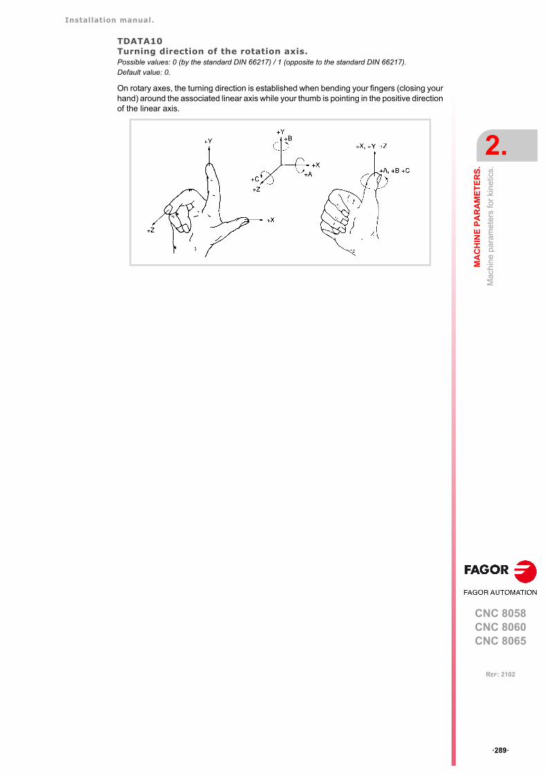
Installation manual.
CNC 8058CNC 8060CNC 8065
MA
CH
INE
PA
RA
ME
TE
RS
.
2.
Mac
hin
e pa
ram
eter
s fo
r ki
netic
s.
ꞏ289ꞏ
REF: 2102
TDATA10Turning direction of the rotation axis.Possible values: 0 (by the standard DIN 66217) / 1 (opposite to the standard DIN 66217).Default value: 0.
On rotary axes, the turning direction is established when bending your fingers (closing yourhand) around the associated linear axis while your thumb is pointing in the positive directionof the linear axis.

Installation manual.
CNC 8058CNC 8060CNC 8065
2.
MA
CH
INE
PA
RA
ME
TE
RS
.
Mac
hin
e pa
ram
eter
s fo
r ki
netic
s.
ꞏ290ꞏ
REF: 2102
2.9.7 Definition of the –C– axis kinematics (type 43) .
In this type of kinematics, one must define the physical location of the rotary axis with respectto the linear axes. If these kinematics are defined, it assumes that the rotary axis coincideswith the linear axis (e.g. the spindle of a lathe).
These kinematics are selected via part-program with function #CYL. If when executing thisfunction the kinematics is not selected, the CNC will take it from the first kinematics type 43defined in the table.
TDATA2Rotary axis position.Possible values: Within ±999999999.0000Default value: 0.
It indicates the position of the rotary axis along the tool axis. When defined with a ꞏ0ꞏ value,it assumes that the rotary axis coincides with the linear axis (e.g. the spindle of a lathe).
TDATA4Angular offset for the rotary axis.Possible values: Within ±999999999.0000º. Default value: 0.
TDATA10Turning direction of the rotation axis.Possible values: 0 (by the standard DIN 66217) / 1 (opposite to the standard DIN 66217).Default value: 0.
On rotary axes, the turning direction is established when bending your fingers (closing yourhand) around the associated linear axis while your thumb is pointing in the positive directionof the linear axis.
The (+) sign in the illustrations indicates the direction it assumes as positive.
C
TYPE=43
Z
X
Z
Y
Z
TDATA 2(+)
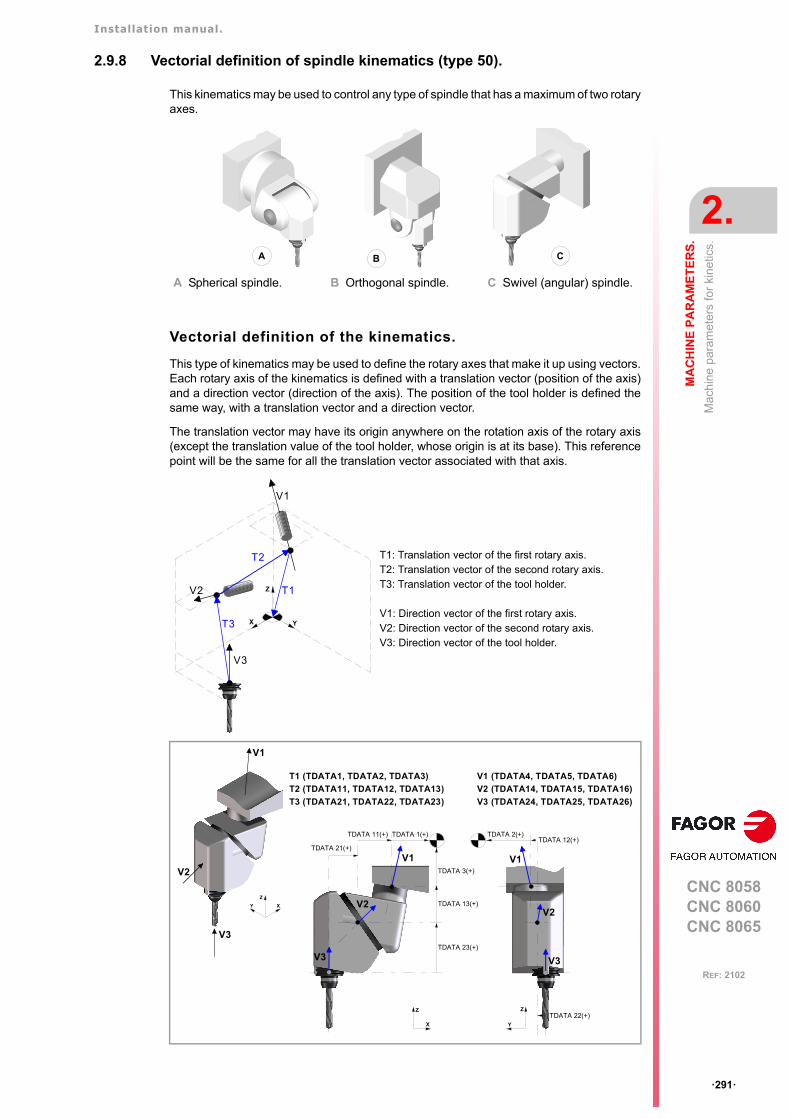
Installation manual.
CNC 8058CNC 8060CNC 8065
MA
CH
INE
PA
RA
ME
TE
RS
.
2.
Mac
hin
e pa
ram
eter
s fo
r ki
netic
s.
ꞏ291ꞏ
REF: 2102
2.9.8 Vectorial definition of spindle kinematics (type 50).
This kinematics may be used to control any type of spindle that has a maximum of two rotaryaxes.
Vectorial definition of the kinematics.
This type of kinematics may be used to define the rotary axes that make it up using vectors.Each rotary axis of the kinematics is defined with a translation vector (position of the axis)and a direction vector (direction of the axis). The position of the tool holder is defined thesame way, with a translation vector and a direction vector.
The translation vector may have its origin anywhere on the rotation axis of the rotary axis(except the translation value of the tool holder, whose origin is at its base). This referencepoint will be the same for all the translation vector associated with that axis.
A Spherical spindle. B Orthogonal spindle. C Swivel (angular) spindle.
T1: Translation vector of the first rotary axis.T2: Translation vector of the second rotary axis.T3: Translation vector of the tool holder.
V1: Direction vector of the first rotary axis.V2: Direction vector of the second rotary axis.V3: Direction vector of the tool holder.
B CA
T3
V2
X Y
Z
T2
V1
V3
T1
XY
Z
Y
Z
TDATA 3(+)
TDATA 1(+)
V3
V2
T3 (TDATA21, TDATA22, TDATA23)
T1 (TDATA1, TDATA2, TDATA3)
T2 (TDATA11, TDATA12, TDATA13)
TDATA 2(+)
TDATA 13(+)
TDATA 23(+)
V1
TDATA 12(+)
TDATA 22(+)
V1V1
V3
V2
X
Z
TDATA 11(+)
TDATA 21(+)
V3
V2
V3 (TDATA24, TDATA25, TDATA26)
V1 (TDATA4, TDATA5, TDATA6)
V2 (TDATA14, TDATA15, TDATA16)
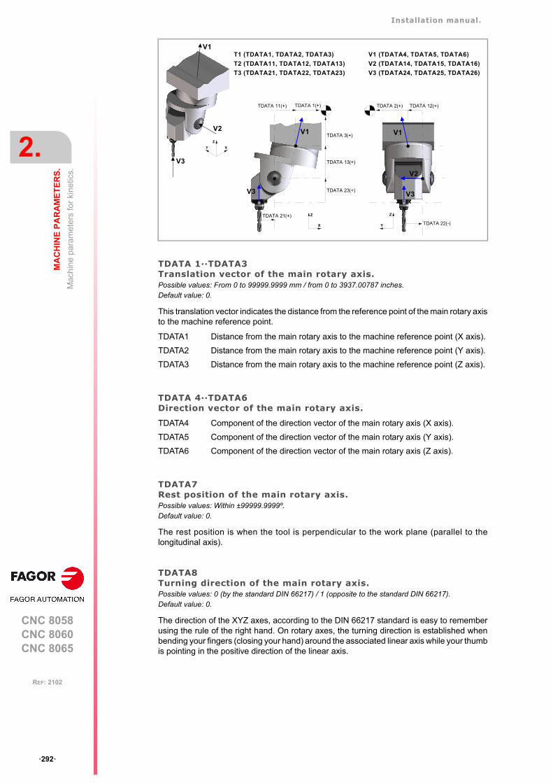
Installation manual.
CNC 8058CNC 8060CNC 8065
2.
MA
CH
INE
PA
RA
ME
TE
RS
.
Mac
hin
e pa
ram
eter
s fo
r ki
netic
s.
ꞏ292ꞏ
REF: 2102
TDATA 1··TDATA3Translation vector of the main rotary axis.Possible values: From 0 to 99999.9999 mm / from 0 to 3937.00787 inches.Default value: 0.
This translation vector indicates the distance from the reference point of the main rotary axisto the machine reference point.
TDATA 4··TDATA6Direction vector of the main rotary axis.
TDATA7Rest position of the main rotary axis.Possible values: Within ±99999.9999º.Default value: 0.
The rest position is when the tool is perpendicular to the work plane (parallel to thelongitudinal axis).
TDATA8Turning direction of the main rotary axis.Possible values: 0 (by the standard DIN 66217) / 1 (opposite to the standard DIN 66217).Default value: 0.
The direction of the XYZ axes, according to the DIN 66217 standard is easy to rememberusing the rule of the right hand. On rotary axes, the turning direction is established whenbending your fingers (closing your hand) around the associated linear axis while your thumbis pointing in the positive direction of the linear axis.
TDATA1 Distance from the main rotary axis to the machine reference point (X axis).
TDATA2 Distance from the main rotary axis to the machine reference point (Y axis).
TDATA3 Distance from the main rotary axis to the machine reference point (Z axis).
TDATA4 Component of the direction vector of the main rotary axis (X axis).
TDATA5 Component of the direction vector of the main rotary axis (Y axis).
TDATA6 Component of the direction vector of the main rotary axis (Z axis).
XY
Z
TDATA 21(+)
Y
Z
TDATA 3(+)
TDATA 1(+)
V1
V3
V2
T3 (TDATA21, TDATA22, TDATA23)
T1 (TDATA1, TDATA2, TDATA3)
T2 (TDATA11, TDATA12, TDATA13)
TDATA 2(+)
TDATA 13(+)
TDATA 23(+)
TDATA 11(+)
V3
V1
X
Z
V2
TDATA 12(+)
TDATA 22(-)
V3
V1
V3 (TDATA24, TDATA25, TDATA26)
V1 (TDATA4, TDATA5, TDATA6)
V2 (TDATA14, TDATA15, TDATA16)
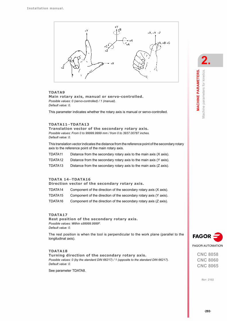
Installation manual.
CNC 8058CNC 8060CNC 8065
MA
CH
INE
PA
RA
ME
TE
RS
.
2.
Mac
hin
e pa
ram
eter
s fo
r ki
netic
s.
ꞏ293ꞏ
REF: 2102
TDATA9Main rotary axis, manual or servo-controlled.Possible values: 0 (servo-controlled) / 1 (manual).Default value: 0.
This parameter indicates whether the rotary axis is manual or servo-controlled.
TDATA11··TDATA13Translation vector of the secondary rotary axis.Possible values: From 0 to 99999.9999 mm / from 0 to 3937.00787 inches.Default value: 0.
This translation vector indicates the distance from the reference point of the secondary rotaryaxis to the reference point of the main rotary axis.
TDATA 14··TDATA16Direction vector of the secondary rotary axis.
TDATA17Rest position of the secondary rotary axis.Possible values: Within ±99999.9999º.Default value: 0.
The rest position is when the tool is perpendicular to the work plane (parallel to thelongitudinal axis).
TDATA18Turning direction of the secondary rotary axis.Possible values: 0 (by the standard DIN 66217) / 1 (opposite to the standard DIN 66217).Default value: 0.
See parameter TDATA8.
TDATA11 Distance from the secondary rotary axis to the main axis (X axis).
TDATA12 Distance from the secondary rotary axis to the main axis (Y axis).
TDATA13 Distance from the secondary rotary axis to the main axis (Z axis).
TDATA14 Component of the direction of the secondary rotary axis (X axis).
TDATA15 Component of the direction of the secondary rotary axis (Y axis).
TDATA16 Component of the direction of the secondary rotary axis (Z axis).
Installation manual.
CNC 8058CNC 8060CNC 8065
2.
MA
CH
INE
PA
RA
ME
TE
RS
.
Mac
hin
e pa
ram
eter
s fo
r ki
netic
s.
ꞏ294ꞏ
REF: 2102
TDATA19Secondary rotary axis, manual or servo-controlled.Possible values: 0 (servo-controlled) / 1 (manual).Default value: 0.
This parameter indicates whether the rotary axis is manual or servo-controlled.
TDATA21··TDATA23Translation vector of the tool holder.Possible values: From 0 to 99999.9999 mm / from 0 to 3937.00787 inches.Default value: 0.
This translation vector indicates the distance from the base of the tool holder to the referencepoint of the secondary rotary axis.
TDATA 24··TDATA26Direction vector of the tool holder.
TDATA21 Distance from the tool base to the secondary rotary axis (X axis).
TDATA22 Distance from the tool base to the secondary rotary axis (Y axis).
TDATA23 Distance from the tool base to the secondary rotary axis (Z axis).
TDATA24 Component of the direction of the tool holder (X axis).
TDATA25 Component of the direction of the tool holder (Y axis).
TDATA26 Component of the direction of the tool holder (Z axis).

Installation manual.
CNC 8058CNC 8060CNC 8065
MA
CH
INE
PA
RA
ME
TE
RS
.
2.
Mac
hin
e pa
ram
eter
s fo
r ki
netic
s.
ꞏ295ꞏ
REF: 2102
2.9.9 Vectorial definition of table kinematics (type 51).
This kinematics may be used to control any type of table that has a maximum of two rotaryaxes.
Vectorial definition of the kinematics.
This type of kinematics may be used to define the rotary axes that make it up using vectors.Each rotary axis of the kinematics is defined with a translation vector (position of the axis)and a direction vector (direction of the axis).
The translation vector may have its origin anywhere on the rotation axis of the rotary axis.This reference point will be the same for all the translation vector associated with that axis.
From now on, all the explanations assume that the mainaxes are X Y Z.
T1: Translation vector of the first rotary axis.T2: Translation vector of the second rotary axis.
V1: Direction vector of the first rotary axis.V2: Direction vector of the second rotary axis.
V2
X Y
Z
T2
V1
T1
XY
Z
V1TDATA 1(+)
X
Z
V2
V1
V2
TDATA 3(+)
TDATA 13(-)
Y
Z
TDATA 11(+) TDATA 2(+) TDATA 12(+)
T1 (TDATA1, TDATA2, TDATA3)
T2 (TDATA11, TDATA12, TDATA13)
V1 (TDATA4, TDATA5, TDATA6)
V2 (TDATA14, TDATA15, TDATA16)
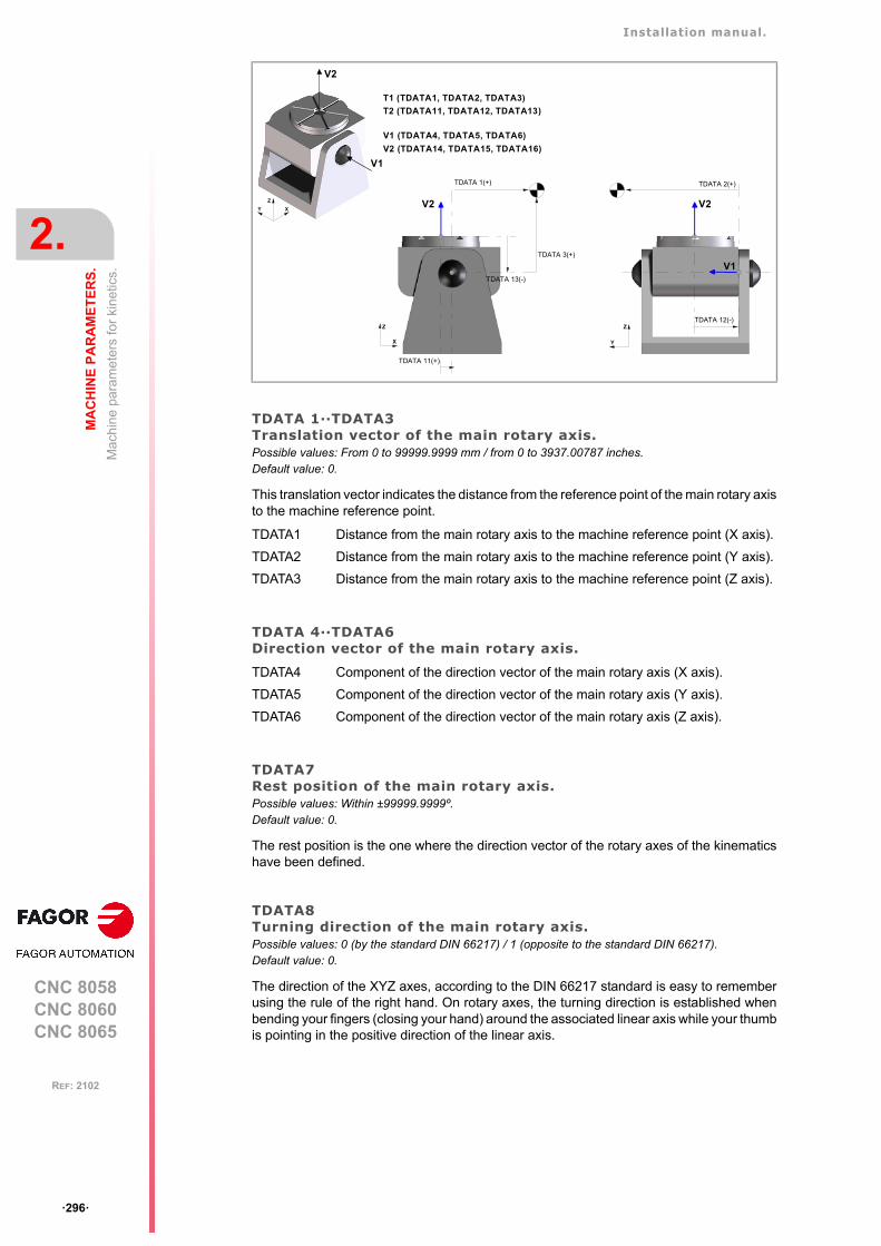
Installation manual.
CNC 8058CNC 8060CNC 8065
2.
MA
CH
INE
PA
RA
ME
TE
RS
.
Mac
hin
e pa
ram
eter
s fo
r ki
netic
s.
ꞏ296ꞏ
REF: 2102
TDATA 1··TDATA3Translation vector of the main rotary axis.Possible values: From 0 to 99999.9999 mm / from 0 to 3937.00787 inches.Default value: 0.
This translation vector indicates the distance from the reference point of the main rotary axisto the machine reference point.
TDATA 4··TDATA6Direction vector of the main rotary axis.
TDATA7Rest position of the main rotary axis.Possible values: Within ±99999.9999º.Default value: 0.
The rest position is the one where the direction vector of the rotary axes of the kinematicshave been defined.
TDATA8Turning direction of the main rotary axis.Possible values: 0 (by the standard DIN 66217) / 1 (opposite to the standard DIN 66217).Default value: 0.
The direction of the XYZ axes, according to the DIN 66217 standard is easy to rememberusing the rule of the right hand. On rotary axes, the turning direction is established whenbending your fingers (closing your hand) around the associated linear axis while your thumbis pointing in the positive direction of the linear axis.
TDATA1 Distance from the main rotary axis to the machine reference point (X axis).
TDATA2 Distance from the main rotary axis to the machine reference point (Y axis).
TDATA3 Distance from the main rotary axis to the machine reference point (Z axis).
TDATA4 Component of the direction vector of the main rotary axis (X axis).
TDATA5 Component of the direction vector of the main rotary axis (Y axis).
TDATA6 Component of the direction vector of the main rotary axis (Z axis).
T1 (TDATA1, TDATA2, TDATA3)
T2 (TDATA11, TDATA12, TDATA13)
XY
Z
V2
V1
Y
Z
X
Z
V2
TDATA 1(+)
TDATA 11(+)
TDATA 13(-)
TDATA 3(+)
V1
V2
TDATA 12(-)
TDATA 2(+)
V1 (TDATA4, TDATA5, TDATA6)
V2 (TDATA14, TDATA15, TDATA16)
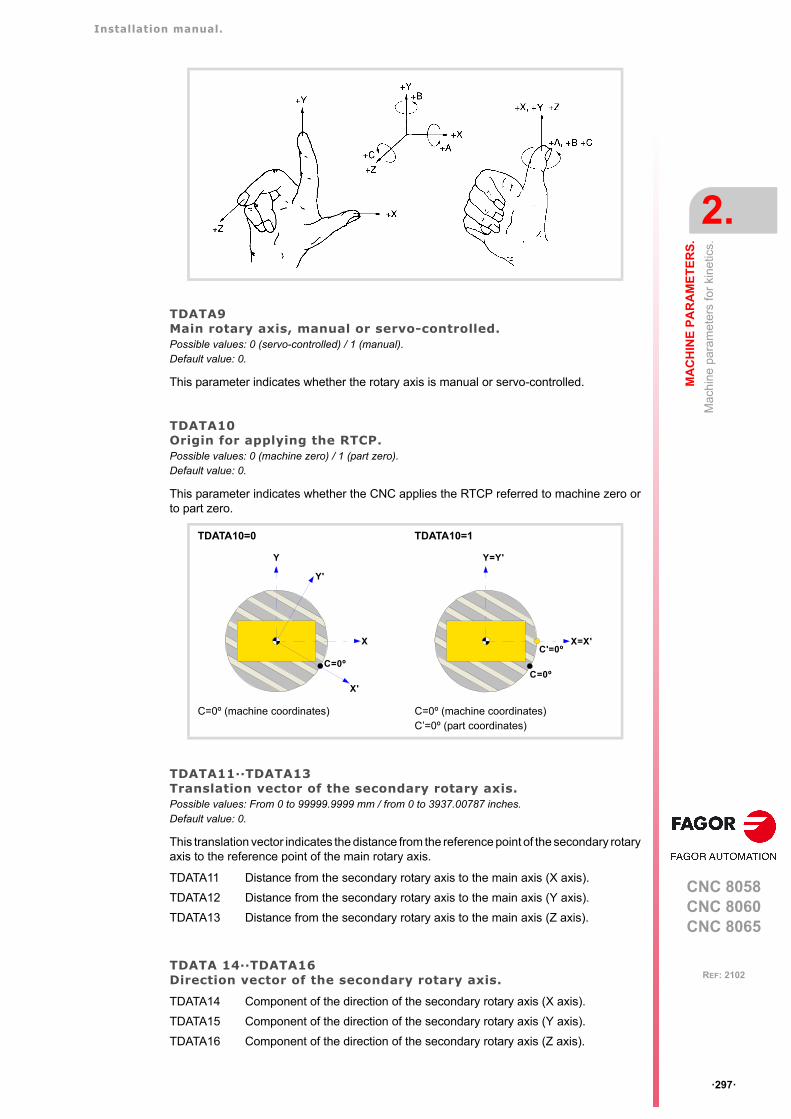
Installation manual.
CNC 8058CNC 8060CNC 8065
MA
CH
INE
PA
RA
ME
TE
RS
.
2.
Mac
hin
e pa
ram
eter
s fo
r ki
netic
s.
ꞏ297ꞏ
REF: 2102
TDATA9Main rotary axis, manual or servo-controlled.Possible values: 0 (servo-controlled) / 1 (manual).Default value: 0.
This parameter indicates whether the rotary axis is manual or servo-controlled.
TDATA10Origin for applying the RTCP.Possible values: 0 (machine zero) / 1 (part zero).Default value: 0.
This parameter indicates whether the CNC applies the RTCP referred to machine zero orto part zero.
TDATA11··TDATA13Translation vector of the secondary rotary axis.Possible values: From 0 to 99999.9999 mm / from 0 to 3937.00787 inches.Default value: 0.
This translation vector indicates the distance from the reference point of the secondary rotaryaxis to the reference point of the main rotary axis.
TDATA 14··TDATA16Direction vector of the secondary rotary axis.
TDATA10=0 TDATA10=1
C=0º (machine coordinates) C=0º (machine coordinates)C’=0º (part coordinates)
TDATA11 Distance from the secondary rotary axis to the main axis (X axis).
TDATA12 Distance from the secondary rotary axis to the main axis (Y axis).
TDATA13 Distance from the secondary rotary axis to the main axis (Z axis).
TDATA14 Component of the direction of the secondary rotary axis (X axis).
TDATA15 Component of the direction of the secondary rotary axis (Y axis).
TDATA16 Component of the direction of the secondary rotary axis (Z axis).
X
Y
C=0º
Y'
X'
X=X'
Y=Y'
C=0º
C'=0º
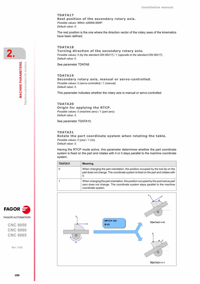
Installation manual.
CNC 8058CNC 8060CNC 8065
2.
MA
CH
INE
PA
RA
ME
TE
RS
.
Mac
hin
e pa
ram
eter
s fo
r ki
netic
s.
ꞏ298ꞏ
REF: 2102
TDATA17Rest position of the secondary rotary axis.Possible values: Within ±99999.9999º.Default value: 0.
The rest position is the one where the direction vector of the rotary axes of the kinematicshave been defined.
TDATA18Turning direction of the secondary rotary axis.Possible values: 0 (by the standard DIN 66217) / 1 (opposite to the standard DIN 66217).Default value: 0.
See parameter TDATA8.
TDATA19Secondary rotary axis, manual or servo-controlled.Possible values: 0 (servo-controlled) / 1 (manual).Default value: 0.
This parameter indicates whether the rotary axis is manual or servo-controlled.
TDATA20Origin for applying the RTCP.Possible values: 0 (machine zero) / 1 (part zero).Default value: 0.
See parameter TDATA10.
TDATA31Rotate the part coordinate system when rotating the table.Possible values: 0 (yes) / 1 (no).Default value: 0.
Having the RTCP mode active, this parameter determines whether the part coordinatesystem is fixed on the part and rotates with it or it stays parallel to the machine coordinatesystem.
TDATA31 Meaning.
0 When changing the part orientation, the position occupied by the tool tip on thepart does not change. The coordinate system is fixed on the part and rotates withit.
1 When changing the part orientation, the position occupied by the point set as partzero does not change. The coordinate system stays parallel to the machinecoordinate system.
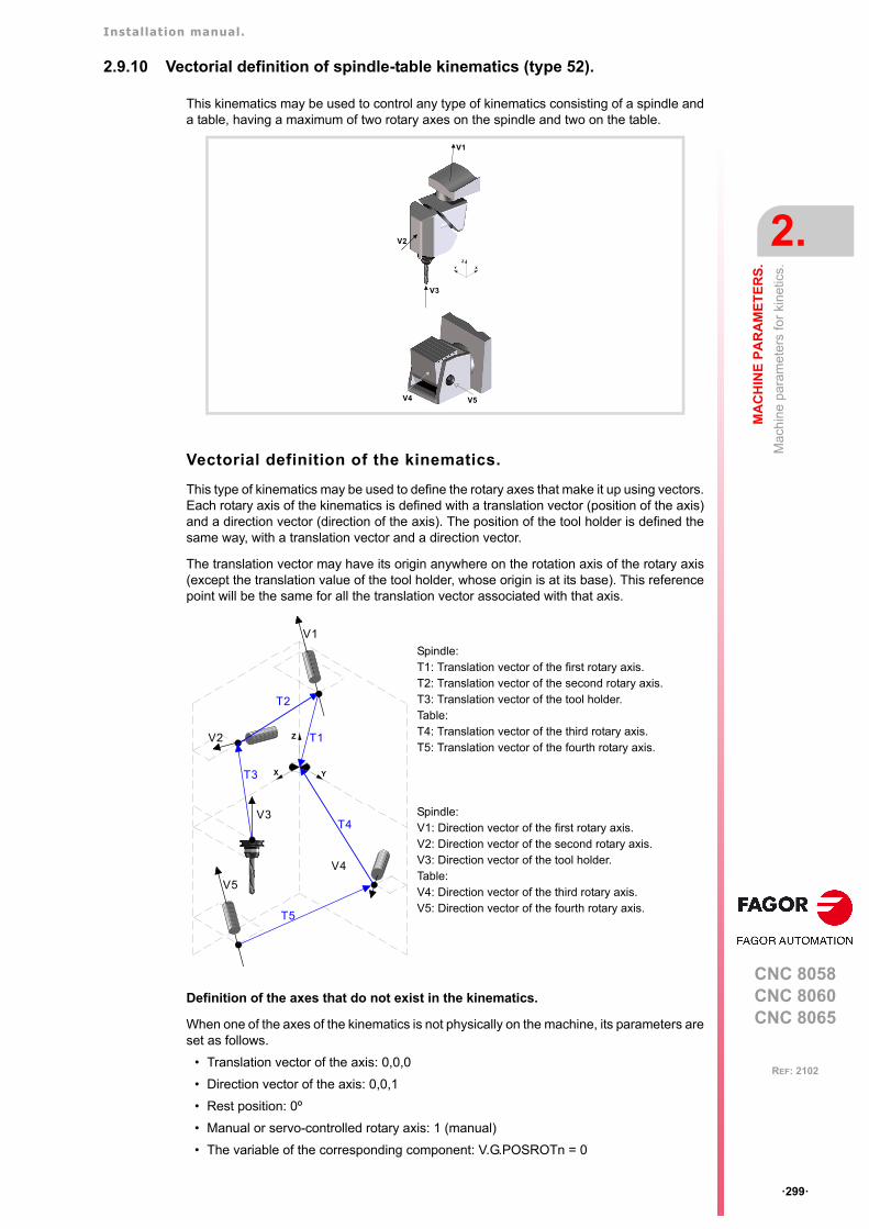
Installation manual.
CNC 8058CNC 8060CNC 8065
MA
CH
INE
PA
RA
ME
TE
RS
.
2.
Mac
hin
e pa
ram
eter
s fo
r ki
netic
s.
ꞏ299ꞏ
REF: 2102
2.9.10 Vectorial definition of spindle-table kinematics (type 52).
This kinematics may be used to control any type of kinematics consisting of a spindle anda table, having a maximum of two rotary axes on the spindle and two on the table.
Vectorial definition of the kinematics.
This type of kinematics may be used to define the rotary axes that make it up using vectors.Each rotary axis of the kinematics is defined with a translation vector (position of the axis)and a direction vector (direction of the axis). The position of the tool holder is defined thesame way, with a translation vector and a direction vector.
The translation vector may have its origin anywhere on the rotation axis of the rotary axis(except the translation value of the tool holder, whose origin is at its base). This referencepoint will be the same for all the translation vector associated with that axis.
Definition of the axes that do not exist in the kinematics.
When one of the axes of the kinematics is not physically on the machine, its parameters areset as follows.
• Translation vector of the axis: 0,0,0
• Direction vector of the axis: 0,0,1
• Rest position: 0º
• Manual or servo-controlled rotary axis: 1 (manual)
• The variable of the corresponding component: V.G.POSROTn = 0
Spindle:T1: Translation vector of the first rotary axis.T2: Translation vector of the second rotary axis.T3: Translation vector of the tool holder.Table:T4: Translation vector of the third rotary axis.T5: Translation vector of the fourth rotary axis.
Spindle:V1: Direction vector of the first rotary axis.V2: Direction vector of the second rotary axis.V3: Direction vector of the tool holder.Table:V4: Direction vector of the third rotary axis.V5: Direction vector of the fourth rotary axis.
XY
Z
V3
V2
V1
V4 V5
T3
V2
X Y
Z
T2
V1
V3
T1
V4
T5
V5
T4
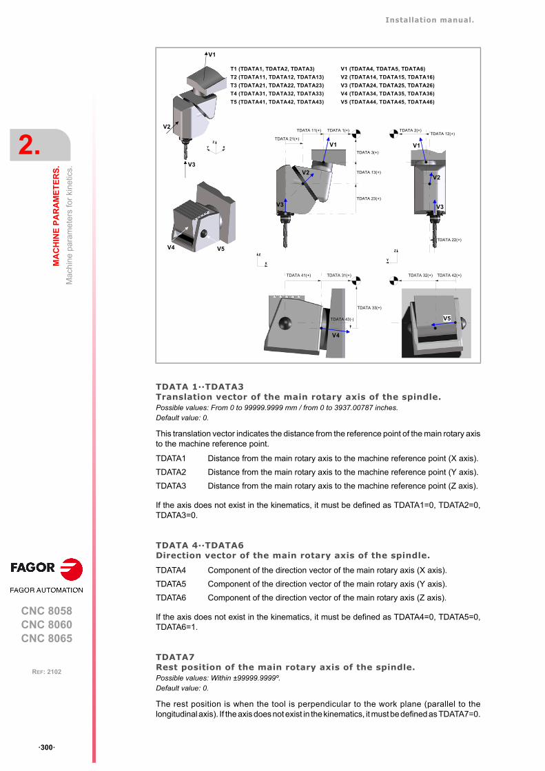
Installation manual.
CNC 8058CNC 8060CNC 8065
2.
MA
CH
INE
PA
RA
ME
TE
RS
.
Mac
hin
e pa
ram
eter
s fo
r ki
netic
s.
ꞏ300ꞏ
REF: 2102
TDATA 1··TDATA3Translation vector of the main rotary axis of the spindle.Possible values: From 0 to 99999.9999 mm / from 0 to 3937.00787 inches.Default value: 0.
This translation vector indicates the distance from the reference point of the main rotary axisto the machine reference point.
If the axis does not exist in the kinematics, it must be defined as TDATA1=0, TDATA2=0,TDATA3=0.
TDATA 4··TDATA6Direction vector of the main rotary axis of the spindle.
If the axis does not exist in the kinematics, it must be defined as TDATA4=0, TDATA5=0,TDATA6=1.
TDATA7Rest position of the main rotary axis of the spindle.Possible values: Within ±99999.9999º.Default value: 0.
The rest position is when the tool is perpendicular to the work plane (parallel to thelongitudinal axis). If the axis does not exist in the kinematics, it must be defined as TDATA7=0.
TDATA1 Distance from the main rotary axis to the machine reference point (X axis).
TDATA2 Distance from the main rotary axis to the machine reference point (Y axis).
TDATA3 Distance from the main rotary axis to the machine reference point (Z axis).
TDATA4 Component of the direction vector of the main rotary axis (X axis).
TDATA5 Component of the direction vector of the main rotary axis (Y axis).
TDATA6 Component of the direction vector of the main rotary axis (Z axis).
TDATA 31(+)
V4
TDATA 33(+)
TDATA 43(-)
TDATA 41(+)
XY
Z
TDATA 3(+)
TDATA 1(+)
V3
V2
T3 (TDATA21, TDATA22, TDATA23)
T1 (TDATA1, TDATA2, TDATA3)
T2 (TDATA11, TDATA12, TDATA13)
TDATA 2(+)
TDATA 13(+)
TDATA 23(+)
V1
TDATA 12(+)
TDATA 22(+)
V1V1
V3
V2
TDATA 11(+)
TDATA 21(+)
V3
V2
V4 V5
V5
TDATA 32(+) TDATA 42(+)
T4 (TDATA31, TDATA32, TDATA33)
T5 (TDATA41, TDATA42, TDATA43)
X
Z
Y
Z
V3 (TDATA24, TDATA25, TDATA26)
V1 (TDATA4, TDATA5, TDATA6)
V2 (TDATA14, TDATA15, TDATA16)
V4 (TDATA34, TDATA35, TDATA36)
V5 (TDATA44, TDATA45, TDATA46)
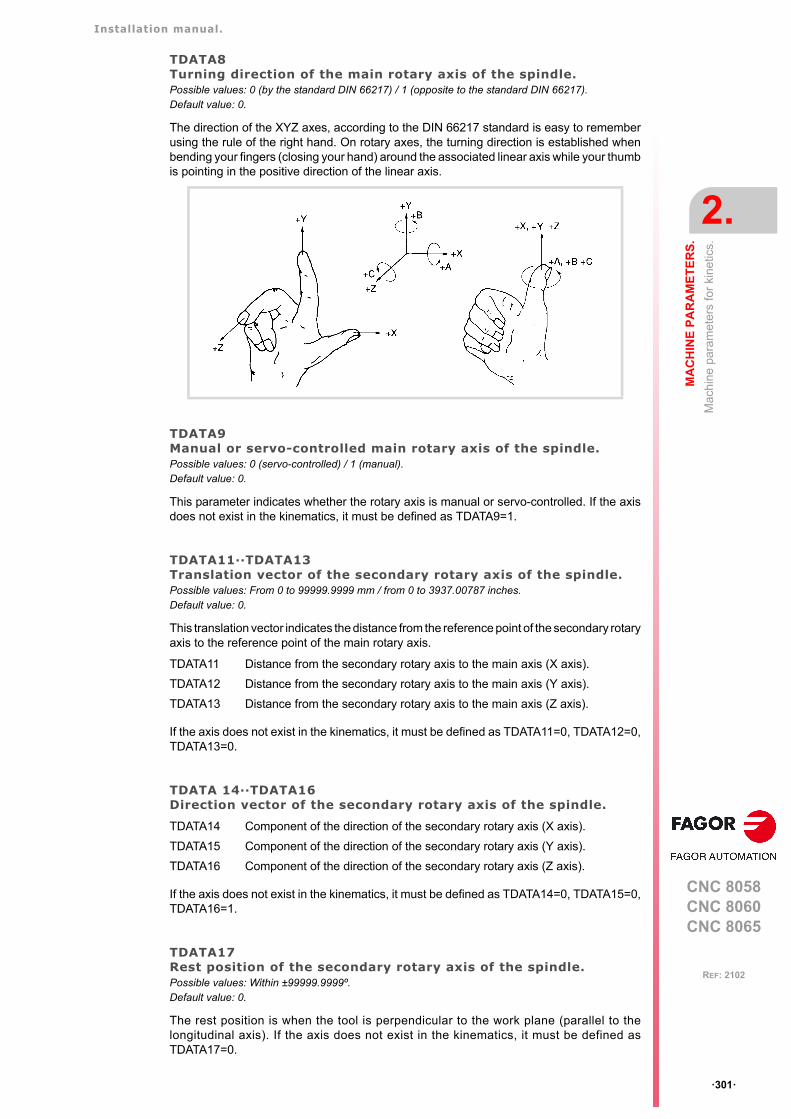
Installation manual.
CNC 8058CNC 8060CNC 8065
MA
CH
INE
PA
RA
ME
TE
RS
.
2.
Mac
hin
e pa
ram
eter
s fo
r ki
netic
s.
ꞏ301ꞏ
REF: 2102
TDATA8Turning direction of the main rotary axis of the spindle.Possible values: 0 (by the standard DIN 66217) / 1 (opposite to the standard DIN 66217).Default value: 0.
The direction of the XYZ axes, according to the DIN 66217 standard is easy to rememberusing the rule of the right hand. On rotary axes, the turning direction is established whenbending your fingers (closing your hand) around the associated linear axis while your thumbis pointing in the positive direction of the linear axis.
TDATA9Manual or servo-controlled main rotary axis of the spindle.Possible values: 0 (servo-controlled) / 1 (manual).Default value: 0.
This parameter indicates whether the rotary axis is manual or servo-controlled. If the axisdoes not exist in the kinematics, it must be defined as TDATA9=1.
TDATA11··TDATA13Translation vector of the secondary rotary axis of the spindle.Possible values: From 0 to 99999.9999 mm / from 0 to 3937.00787 inches.Default value: 0.
This translation vector indicates the distance from the reference point of the secondary rotaryaxis to the reference point of the main rotary axis.
If the axis does not exist in the kinematics, it must be defined as TDATA11=0, TDATA12=0,TDATA13=0.
TDATA 14··TDATA16Direction vector of the secondary rotary axis of the spindle.
If the axis does not exist in the kinematics, it must be defined as TDATA14=0, TDATA15=0,TDATA16=1.
TDATA17Rest position of the secondary rotary axis of the spindle.Possible values: Within ±99999.9999º.Default value: 0.
The rest position is when the tool is perpendicular to the work plane (parallel to thelongitudinal axis). If the axis does not exist in the kinematics, it must be defined asTDATA17=0.
TDATA11 Distance from the secondary rotary axis to the main axis (X axis).
TDATA12 Distance from the secondary rotary axis to the main axis (Y axis).
TDATA13 Distance from the secondary rotary axis to the main axis (Z axis).
TDATA14 Component of the direction of the secondary rotary axis (X axis).
TDATA15 Component of the direction of the secondary rotary axis (Y axis).
TDATA16 Component of the direction of the secondary rotary axis (Z axis).
Installation manual.
CNC 8058CNC 8060CNC 8065
2.
MA
CH
INE
PA
RA
ME
TE
RS
.
Mac
hin
e pa
ram
eter
s fo
r ki
netic
s.
ꞏ302ꞏ
REF: 2102
TDATA18Turning direction of the secondary rotary axis of the spindle.Possible values: 0 (by the standard DIN 66217) / 1 (opposite to the standard DIN 66217).Default value: 0.
See parameter TDATA8.
TDATA19manual or servo-controlled secondary rotary axis of the spindle.Possible values: 0 (servo-controlled) / 1 (manual).Default value: 0.
This parameter indicates whether the rotary axis is manual or servo-controlled. If the axisdoes not exist in the kinematics, it must be defined as TDATA19=1.
TDATA21··TDATA23Translation vector of the tool holder.Possible values: From 0 to 99999.9999 mm / from 0 to 3937.00787 inches.Default value: 0.
This translation vector indicates the distance from the base of the tool holder to the referencepoint of the secondary rotary axis.
TDATA 24··TDATA26Direction vector of the tool holder.
TDATA 31··TDATA33Translation vector of the main rotary axis of the table.Possible values: From 0 to 99999.9999 mm / from 0 to 3937.00787 inches.Default value: 0.
This translation vector indicates the distance from the reference point of the main rotary axisto the machine reference point.
If the axis does not exist in the kinematics, it must be defined as TDATA31=0, TDATA32=0,TDATA33=0.
TDATA 34··TDATA36Direction vector of the main rotary axis of the table.
If the axis does not exist in the kinematics, it must be defined as TDATA34=0, TDATA35=0,TDATA36=1.
TDATA21 Distance from the tool base to the secondary rotary axis (X axis).
TDATA22 Distance from the tool base to the secondary rotary axis (Y axis).
TDATA23 Distance from the tool base to the secondary rotary axis (Z axis).
TDATA24 Component of the direction of the tool holder (X axis).
TDATA25 Component of the direction of the tool holder (Y axis).
TDATA26 Component of the direction of the tool holder (Z axis).
TDATA31 Distance from the main rotary axis to the machine reference point (X axis).
TDATA32 Distance from the main rotary axis to the machine reference point (Y axis).
TDATA33 Distance from the main rotary axis to the machine reference point (Z axis).
TDATA34 Component of the direction vector of the main rotary axis (X axis).
TDATA35 Component of the direction vector of the main rotary axis (Y axis).
TDATA36 Component of the direction vector of the main rotary axis (Z axis).
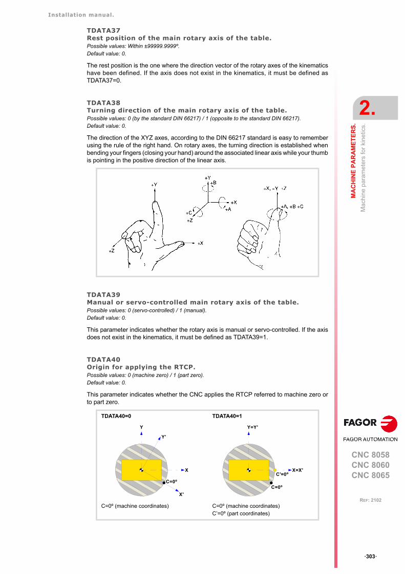
Installation manual.
CNC 8058CNC 8060CNC 8065
MA
CH
INE
PA
RA
ME
TE
RS
.
2.
Mac
hin
e pa
ram
eter
s fo
r ki
netic
s.
ꞏ303ꞏ
REF: 2102
TDATA37Rest position of the main rotary axis of the table.Possible values: Within ±99999.9999º.Default value: 0.
The rest position is the one where the direction vector of the rotary axes of the kinematicshave been defined. If the axis does not exist in the kinematics, it must be defined asTDATA37=0.
TDATA38Turning direction of the main rotary axis of the table.Possible values: 0 (by the standard DIN 66217) / 1 (opposite to the standard DIN 66217).Default value: 0.
The direction of the XYZ axes, according to the DIN 66217 standard is easy to rememberusing the rule of the right hand. On rotary axes, the turning direction is established whenbending your fingers (closing your hand) around the associated linear axis while your thumbis pointing in the positive direction of the linear axis.
TDATA39Manual or servo-controlled main rotary axis of the table.Possible values: 0 (servo-controlled) / 1 (manual).Default value: 0.
This parameter indicates whether the rotary axis is manual or servo-controlled. If the axisdoes not exist in the kinematics, it must be defined as TDATA39=1.
TDATA40Origin for applying the RTCP.Possible values: 0 (machine zero) / 1 (part zero).Default value: 0.
This parameter indicates whether the CNC applies the RTCP referred to machine zero orto part zero.
TDATA40=0 TDATA40=1
C=0º (machine coordinates) C=0º (machine coordinates)C’=0º (part coordinates)
X
Y
C=0º
Y'
X'
X=X'
Y=Y'
C=0º
C'=0º
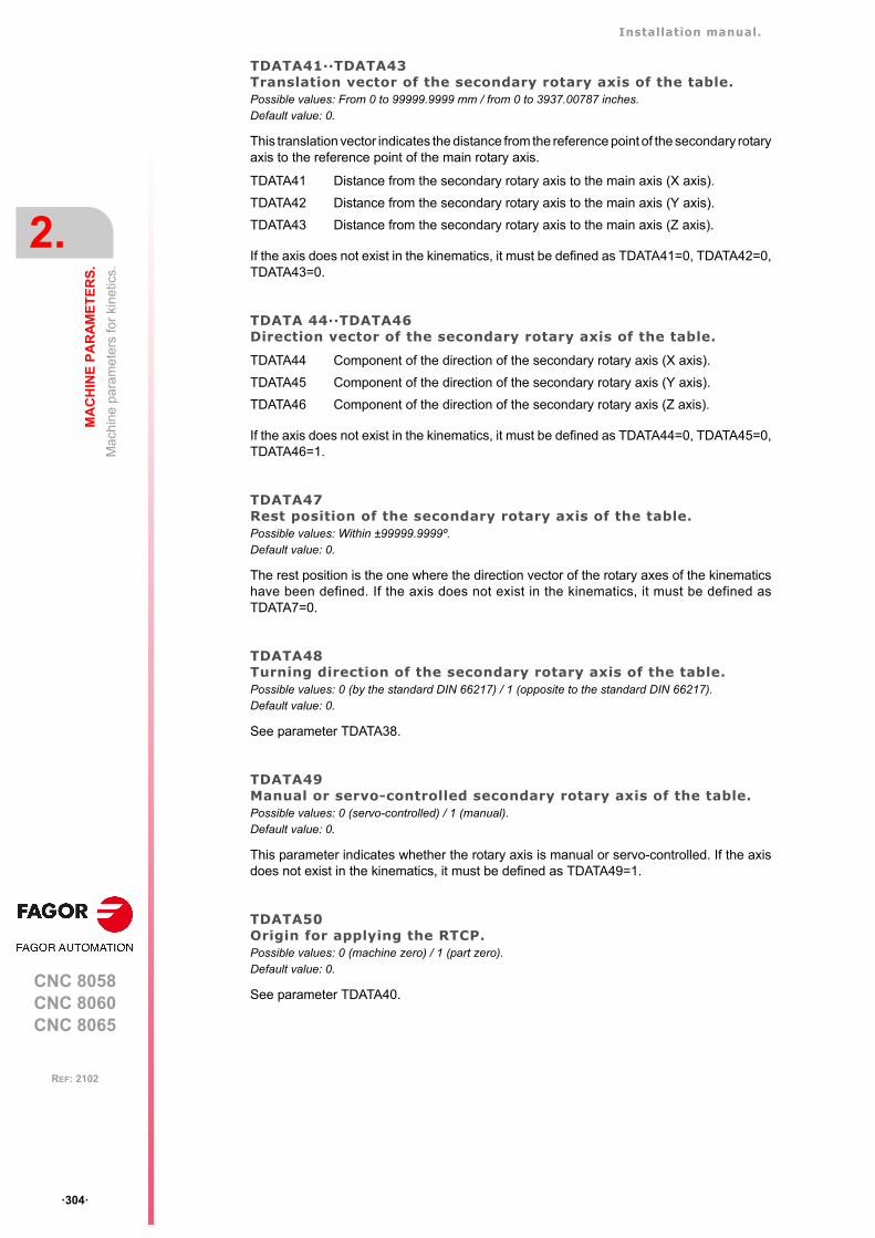
Installation manual.
CNC 8058CNC 8060CNC 8065
2.
MA
CH
INE
PA
RA
ME
TE
RS
.
Mac
hin
e pa
ram
eter
s fo
r ki
netic
s.
ꞏ304ꞏ
REF: 2102
TDATA41··TDATA43Translation vector of the secondary rotary axis of the table.Possible values: From 0 to 99999.9999 mm / from 0 to 3937.00787 inches.Default value: 0.
This translation vector indicates the distance from the reference point of the secondary rotaryaxis to the reference point of the main rotary axis.
If the axis does not exist in the kinematics, it must be defined as TDATA41=0, TDATA42=0,TDATA43=0.
TDATA 44··TDATA46Direction vector of the secondary rotary axis of the table.
If the axis does not exist in the kinematics, it must be defined as TDATA44=0, TDATA45=0,TDATA46=1.
TDATA47Rest position of the secondary rotary axis of the table.Possible values: Within ±99999.9999º.Default value: 0.
The rest position is the one where the direction vector of the rotary axes of the kinematicshave been defined. If the axis does not exist in the kinematics, it must be defined asTDATA7=0.
TDATA48Turning direction of the secondary rotary axis of the table.Possible values: 0 (by the standard DIN 66217) / 1 (opposite to the standard DIN 66217).Default value: 0.
See parameter TDATA38.
TDATA49Manual or servo-controlled secondary rotary axis of the table.Possible values: 0 (servo-controlled) / 1 (manual).Default value: 0.
This parameter indicates whether the rotary axis is manual or servo-controlled. If the axisdoes not exist in the kinematics, it must be defined as TDATA49=1.
TDATA50Origin for applying the RTCP.Possible values: 0 (machine zero) / 1 (part zero).Default value: 0.
See parameter TDATA40.
TDATA41 Distance from the secondary rotary axis to the main axis (X axis).
TDATA42 Distance from the secondary rotary axis to the main axis (Y axis).
TDATA43 Distance from the secondary rotary axis to the main axis (Z axis).
TDATA44 Component of the direction of the secondary rotary axis (X axis).
TDATA45 Component of the direction of the secondary rotary axis (Y axis).
TDATA46 Component of the direction of the secondary rotary axis (Z axis).
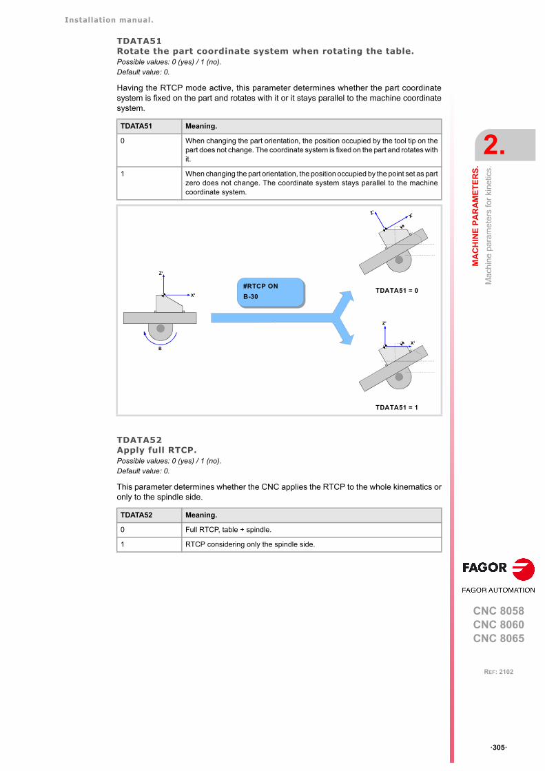
Installation manual.
CNC 8058CNC 8060CNC 8065
MA
CH
INE
PA
RA
ME
TE
RS
.
2.
Mac
hin
e pa
ram
eter
s fo
r ki
netic
s.
ꞏ305ꞏ
REF: 2102
TDATA51Rotate the part coordinate system when rotating the table.Possible values: 0 (yes) / 1 (no).Default value: 0.
Having the RTCP mode active, this parameter determines whether the part coordinatesystem is fixed on the part and rotates with it or it stays parallel to the machine coordinatesystem.
TDATA52Apply full RTCP.Possible values: 0 (yes) / 1 (no).Default value: 0.
This parameter determines whether the CNC applies the RTCP to the whole kinematics oronly to the spindle side.
TDATA51 Meaning.
0 When changing the part orientation, the position occupied by the tool tip on thepart does not change. The coordinate system is fixed on the part and rotates withit.
1 When changing the part orientation, the position occupied by the point set as partzero does not change. The coordinate system stays parallel to the machinecoordinate system.
TDATA52 Meaning.
0 Full RTCP, table + spindle.
1 RTCP considering only the spindle side.
X'
Z'
#RTCP ON
B-30
B
TDATA51 = 0
X'Z'
TDATA51 = 1
X'
Z'
Installation manual.
CNC 8058CNC 8060CNC 8065
2.
MA
CH
INE
PA
RA
ME
TE
RS
.
Mac
hin
e pa
ram
eter
s fo
r ki
netic
s.
ꞏ306ꞏ
REF: 2102
2.9.11 Definition of the OEM kinematics (types 100 through 105).
In OEM kinematics, you must indicate the number of parameters, auxiliary variables andgeneral purpose data being used.
NKINAXNumber of axes of the kinematics.Possible values: From 0 to 8.Default value: 0.Associated variable: (V.)MPK.NKINAX[kin]
PARAM_D_SIZENumber of parameters in decimal format.Possible values: From 0 to 100.Default value: 0.Associated variable: (V.)MPK.PARAM_D_SIZE[kin]
TDATA1··100Parameters for configuring the kinematics (decimal format).
There are 100 kinematics predefined by Fagor. For OEM kinematics, the number ofparameters may be configured.
PARAM_I_SIZENumber of parameters in integers.Possible values: From 0 to 100.Default value: 0.Associated variable: (V.)MPK.PARAM_I_SIZE[kin]
TDATA_I1··100Parameters for configuring the kinematics (integer format).
There are 100 kinematics predefined by Fagor. For OEM kinematics, the number ofparameters may be configured.
AUXCTE_SIZESize of the area of auxiliary variables.Possible values: From 0 to 1000 bytes.Default value: 0.Associated variable: (V.)MPK.AUXCTE_SIZE[kin]
KINDATA_SIZESize of the area for general purpose data.Possible values: From 0 to 100000 bytes.Default value: 0.Associated variable: (V.)MPK.KINDATA_SIZE[kin]
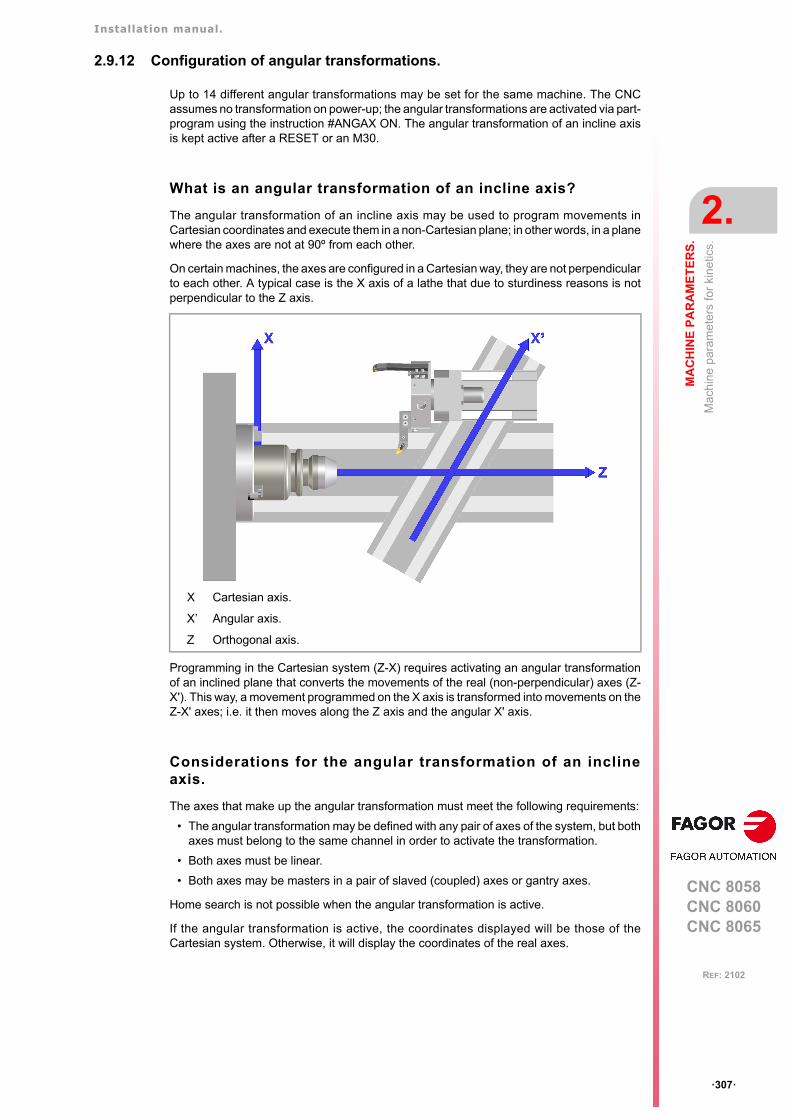
Installation manual.
CNC 8058CNC 8060CNC 8065
MA
CH
INE
PA
RA
ME
TE
RS
.
2.
Mac
hin
e pa
ram
eter
s fo
r ki
netic
s.
ꞏ307ꞏ
REF: 2102
2.9.12 Configuration of angular transformations.
Up to 14 different angular transformations may be set for the same machine. The CNCassumes no transformation on power-up; the angular transformations are activated via part-program using the instruction #ANGAX ON. The angular transformation of an incline axisis kept active after a RESET or an M30.
What is an angular transformation of an incline axis?
The angular transformation of an incline axis may be used to program movements inCartesian coordinates and execute them in a non-Cartesian plane; in other words, in a planewhere the axes are not at 90º from each other.
On certain machines, the axes are configured in a Cartesian way, they are not perpendicularto each other. A typical case is the X axis of a lathe that due to sturdiness reasons is notperpendicular to the Z axis.
Programming in the Cartesian system (Z-X) requires activating an angular transformationof an inclined plane that converts the movements of the real (non-perpendicular) axes (Z-X'). This way, a movement programmed on the X axis is transformed into movements on theZ-X' axes; i.e. it then moves along the Z axis and the angular X' axis.
Considerations for the angular transformation of an inclineaxis.
The axes that make up the angular transformation must meet the following requirements:
• The angular transformation may be defined with any pair of axes of the system, but bothaxes must belong to the same channel in order to activate the transformation.
• Both axes must be linear.
• Both axes may be masters in a pair of slaved (coupled) axes or gantry axes.
Home search is not possible when the angular transformation is active.
If the angular transformation is active, the coordinates displayed will be those of theCartesian system. Otherwise, it will display the coordinates of the real axes.
X Cartesian axis.
X’ Angular axis.
Z Orthogonal axis.
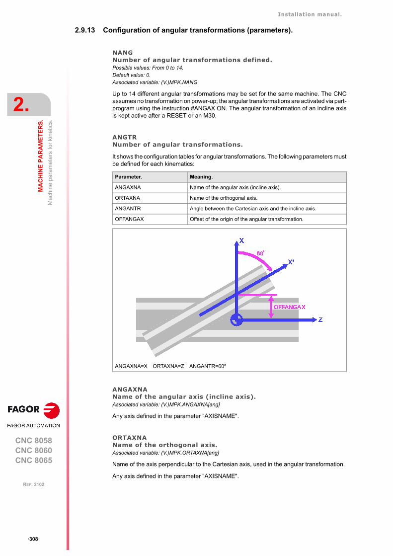
Installation manual.
CNC 8058CNC 8060CNC 8065
2.
MA
CH
INE
PA
RA
ME
TE
RS
.
Mac
hin
e pa
ram
eter
s fo
r ki
netic
s.
ꞏ308ꞏ
REF: 2102
2.9.13 Configuration of angular transformations (parameters).
NANGNumber of angular transformations defined.Possible values: From 0 to 14.Default value: 0.Associated variable: (V.)MPK.NANG
Up to 14 different angular transformations may be set for the same machine. The CNCassumes no transformation on power-up; the angular transformations are activated via part-program using the instruction #ANGAX ON. The angular transformation of an incline axisis kept active after a RESET or an M30.
ANGTRNumber of angular transformations.
It shows the configuration tables for angular transformations. The following parameters mustbe defined for each kinematics:
ANGAXNAName of the angular axis (incline axis).Associated variable: (V.)MPK.ANGAXNA[ang]
Any axis defined in the parameter "AXISNAME".
ORTAXNAName of the orthogonal axis.Associated variable: (V.)MPK.ORTAXNA[ang]
Name of the axis perpendicular to the Cartesian axis, used in the angular transformation.
Any axis defined in the parameter "AXISNAME".
Parameter. Meaning.
ANGAXNA Name of the angular axis (incline axis).
ORTAXNA Name of the orthogonal axis.
ANGANTR Angle between the Cartesian axis and the incline axis.
OFFANGAX Offset of the origin of the angular transformation.
ANGAXNA=X ORTAXNA=Z ANGANTR=60º

Installation manual.
CNC 8058CNC 8060CNC 8065
MA
CH
INE
PA
RA
ME
TE
RS
.
2.
Mac
hin
e pa
ram
eter
s fo
r ki
netic
s.
ꞏ309ꞏ
REF: 2102
ANGANTRAngle between the Cartesian axis and the incline axis.Possible values: Within ±360.0000º.Default value: 30 degrees.Associated variable: (V.)MPK.ANGANTR[ang]
Angle between the Cartesian angle and the angular axis it is associated with. If its value is0º, there is no need to do an angular transformation.
Positive angle when the angular axis has been rotated clockwise and negative ifcounterclockwise.
OFFANGAXOffset of the origin of the angular transformation.Possible values: Within ±99999.9999 mm / within ±3937.00787 inch.Default value: 0.Associated variable: (V.)MPK.OFFANGAX[ang]
Distance between machine zero and the origin of the coordinate system of the incline axis.
Installation manual.
CNC 8058CNC 8060CNC 8065
2.
MA
CH
INE
PA
RA
ME
TE
RS
.
Ma
chin
e p
aram
eter
s fo
r th
e m
agaz
ine.
ꞏ310ꞏ
REF: 2102
2.10 Machine parameters for the magazine.
2.10.1 Tool magazine configuration.
NTOOLMZNumber of tool magazines.Possible values: From 0 to 4.Default value: 1.Associated variable: (V.)TM.NTOOLMZ
Number of system's tool magazines.
Although each channel has its own tool management, the tool magazines are not associatedwith any particular channel. They are not associated with any particular spindle either.
GROUNDGround tools are permitted (manual load).Possible values: Yes / No.Default value: No.Associated variable: (V.)TM.MZGROUND[mz]
They are the ones not located in the magazine. When programming them, the CNC requeststhem to be inserted in the spindle.
MAGAZINE nTool magazine table.
This parameter shows the tables to define the magazine data. Each table shows the followingmachine parameters to configure it.
MAGAZINE n
STORAGE Parameters related to storage.
MANAGEMENT Magazine management related parameters.
Installation manual.
CNC 8058CNC 8060CNC 8065
MA
CH
INE
PA
RA
ME
TE
RS
.
2.
Ma
chin
e p
aram
eter
s fo
r th
e m
agaz
ine.
ꞏ311ꞏ
REF: 2102
2.10.2 Magazine data.
STORAGEParameters related to magazine.
This parameter shows or hides the magazine data. Each table shows the following machineparameters to configure it.
SIZESize of the magazine (number of pockets).Possible values: From 0 to 1000.Default value: 20.Associated variable: (V.)TM.MZSIZE[mz]Parameter included in the MAGAZINE // STORAGE table.
This parameter indicates the capacity of the magazine without including the ground tools.
RANDOMRandom magazine.Possible values: Yes / No.Default value: No.Associated variable: (V.)TM.MZRANDOM[mz]Parameter included in the MAGAZINE // STORAGE table.
This parameter indicates whether the tools must always occupy the same position (non-random) or they may occupy any position (random).
MAGAZINE n
SIZE Size of the tool magazine (number of pockets).
RANDOM Random magazine.

Installation manual.
CNC 8058CNC 8060CNC 8065
2.
MA
CH
INE
PA
RA
ME
TE
RS
.
Ma
chin
e p
aram
eter
s fo
r th
e m
agaz
ine.
ꞏ312ꞏ
REF: 2102
2.10.3 Tool magazine management.
MANAGEMENTMagazine management related parameters.
This parameter shows the data to configure the magazine management. Each table showsthe following machine parameters to configure it.
TYPEMagazine type.Possible values: Asynchronous / Synchronous / Turret / Synchronous + 2 Arms / Synchronous + 1 Arm.Default value: Synchronous.Associated variable: (V.)TM.MZTYPE[mz]Parameter included in the MAGAZINE // MANAGEMENT table.
This parameter indicates the type of magazine. See "7.1 Types of tool magazine." on page467.
CYCLICCyclic tool changer.Possible values: Yes / No.Default value: Yes.Associated variable: (V.)TM.MZCYCLIC[mz]Parameter included in the MAGAZINE // MANAGEMENT table.
A cyclic tool changer requires a tool change command (function M06) after searching a tooland before searching the next one. With a non-cyclic tool changer, it is possible to searchfor several tools in a row without necessarily having to make the actual tool change (M06function).
OPTIMIZETool management.Possible values: Yes / No.Default value: Yes.Associated variable: (V.)TM.MZOPTIMIZED[mz]Parameter included in the MAGAZINE // MANAGEMENT table.
When programming several T's in a row without an M6, this parameter indicates whetherall the programmed tools are selected (OPTIMIZE = No) or just the ones involving a toolchange (OPTIMIZE = Yes). Optimizing only works when executing a program. In MDI mode,this parameter is ignored and all the blocks are executed.
MANAGEMENT
TYPE Type of magazine.
CYCLIC Cyclic tool changer.
OPTIMIZE Tool management.
M6ALONE Action when executing an M06 without selecting a T.
T2 It looks for the tool if OPTMIZE = No.
T3 M6 It always looks for the tool. The M6 implies a tool change.
T5 It always looks for the tool. M6 comes next.
M6
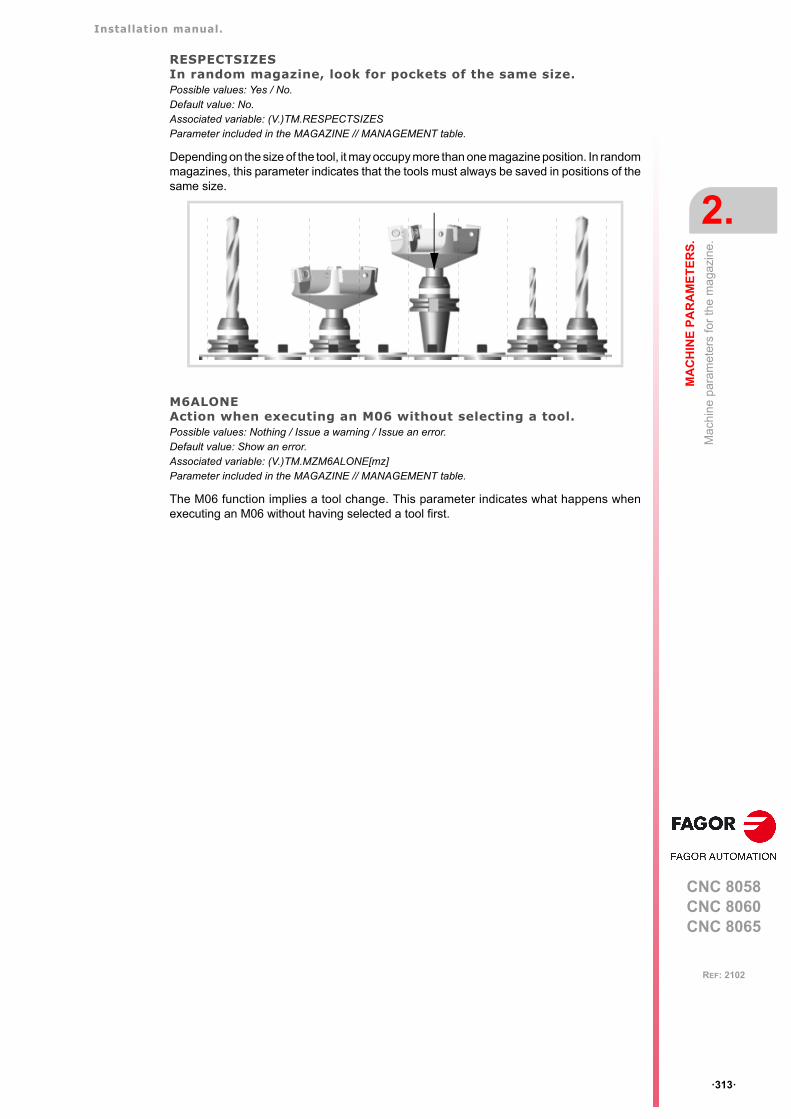
Installation manual.
CNC 8058CNC 8060CNC 8065
MA
CH
INE
PA
RA
ME
TE
RS
.
2.
Ma
chin
e p
aram
eter
s fo
r th
e m
agaz
ine.
ꞏ313ꞏ
REF: 2102
RESPECTSIZESIn random magazine, look for pockets of the same size.Possible values: Yes / No.Default value: No.Associated variable: (V.)TM.RESPECTSIZESParameter included in the MAGAZINE // MANAGEMENT table.
Depending on the size of the tool, it may occupy more than one magazine position. In randommagazines, this parameter indicates that the tools must always be saved in positions of thesame size.
M6ALONEAction when executing an M06 without selecting a tool.Possible values: Nothing / Issue a warning / Issue an error.Default value: Show an error.Associated variable: (V.)TM.MZM6ALONE[mz]Parameter included in the MAGAZINE // MANAGEMENT table.
The M06 function implies a tool change. This parameter indicates what happens whenexecuting an M06 without having selected a tool first.
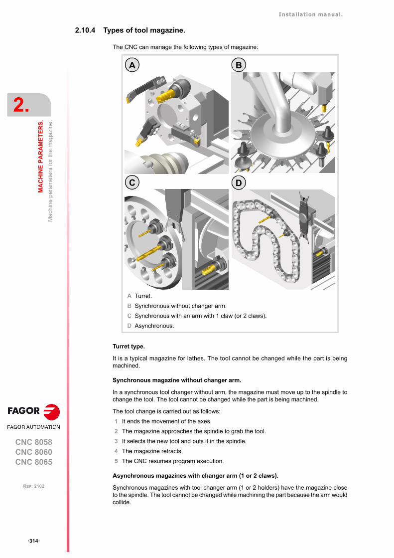
Installation manual.
CNC 8058CNC 8060CNC 8065
2.
MA
CH
INE
PA
RA
ME
TE
RS
.
Ma
chin
e p
aram
eter
s fo
r th
e m
agaz
ine.
ꞏ314ꞏ
REF: 2102
2.10.4 Types of tool magazine.
The CNC can manage the following types of magazine:
Turret type.
It is a typical magazine for lathes. The tool cannot be changed while the part is beingmachined.
Synchronous magazine without changer arm.
In a synchronous tool changer without arm, the magazine must move up to the spindle tochange the tool. The tool cannot be changed while the part is being machined.
The tool change is carried out as follows:
1 It ends the movement of the axes.
2 The magazine approaches the spindle to grab the tool.
3 It selects the new tool and puts it in the spindle.
4 The magazine retracts.
5 The CNC resumes program execution.
Asynchronous magazines with changer arm (1 or 2 claws).
Synchronous magazines with tool changer arm (1 or 2 holders) have the magazine closeto the spindle. The tool cannot be changed while machining the part because the arm wouldcollide.
A Turret.
B Synchronous without changer arm.
C Synchronous with an arm with 1 claw (or 2 claws).
D Asynchronous.
D
B
C
A
Installation manual.
CNC 8058CNC 8060CNC 8065
MA
CH
INE
PA
RA
ME
TE
RS
.
2.
Ma
chin
e p
aram
eter
s fo
r th
e m
agaz
ine.
ꞏ315ꞏ
REF: 2102
The tool change is carried out as follows: Example with 2 holders:
1 The new tool is selected in the magazine.
2 It ends the movement of the axes.
3 The arm takes a tool on each holder (from the magazine and from the spindle) and swapsthem.
4 The arm retracts.
5 The CNC resumes program execution.
Asynchronous magazines.
An asynchronous magazine is located away from the spindle. Most of the movements maybe carried out while machining the part, thus minimizing machining time.
The tool change is carried out as follows:
1 While machining, a new tool is selected at the magazine, the changer arm picks it up andbrings it closer to the spindle.
2 It ends the movement of the axes.
3 The other holder picks up the tool that is in the spindle and makes the change.
4 The program resumes execution and the changer arm returns to the magazine to leavethe tool.

Installation manual.
CNC 8058CNC 8060CNC 8065
2.
MA
CH
INE
PA
RA
ME
TE
RS
.
Mac
hin
e pa
ram
eter
s fo
r H
MI (
Inte
rfac
e).
ꞏ316ꞏ
REF: 2102
2.11 Machine parameters for HMI (Interface).
These parameters are used to define the communication environment (interface) betweenthe operator and the CNC. To validate the changes made to these parameters, the CNC mustbe reset.
2.11.1 Main window dimensions and resolution.
WINDOWMain window dimensions and resolution.
This parameter shows the data to configure the main window. The table has the followingmachine parameters.
POSXX coordinate of the top left corner.Default value: 0.Parameter included in the WINDOW table.
Consult the machine parameter of HMI POSY.
POSYY coordinate of the top left corner.Default value: 0.Parameter included in the WINDOW table.
These parameters define the X and Y coordinate to position the upper left corner of theinterface. The interface can be moved by clicking with the mouse on the icon showing theprogram status of the active channel. Double click on this icon and the interface is positionedin the upper left corner (POSX=0 POSY=0).
RESOLUTIONScreen resolution.Possible values: CUSTOM / 10" / 15" / 19" / 21" LANDSCAPE / 21" PORTRAIT.Default value: 10".Parameter included in the WINDOW table.
Screen resolution. The CUSTOM option enables the width (WIDTH parameter) and theheight (HEIGHT parameter) of the window to be customized. The predefined sizes are setto the following resolutions.
WINDOW
POSX X coordinate of the top left corner.
POSY Y coordinate of the top left corner.
RESOLUTION Window resolution.
WIDTH Width of the window.
HEIGHT Height of the window.
RESOLUTION.(value)
Interface size (pixels).
CUSTOM This option enables the width (WIDTH parameter) and the height(HEIGHT parameter) of the screen to be customized.
10" 800 × 600.
15" 1024 × 768.
Installation manual.
CNC 8058CNC 8060CNC 8065
MA
CH
INE
PA
RA
ME
TE
RS
.
2.
Mac
hin
e pa
ram
eter
s fo
r H
MI (
Inte
rfac
e).
ꞏ317ꞏ
REF: 2102
WIDTHWidth of the window.Possible values: From 800 to 1680 pixels.Default value: 800 pixels.Parameter included in the WINDOW table.
Consult the machine parameter of HMI HEIGHT.
HEIGHTHeight of the window.Possible values: From 480 to 1050 pixels.Default value: 600 pixels.Parameter included in the WINDOW table.
The WIDTH and HEIGHT parameters define the window size. These parameters can onlybe modified when the RESOLUTION parameter has the value "CUSTOM".
2.11.2 Customizing the softkeys.
HMENUNSOFTKEYNumber of softkeys on the horizontal menu.Possible values: From 7 to 12.Default value: 7.
Number of softkeys on the horizontal menu.
VMENUNSOFTKEYNumber of softkeys on the vertical menu.Possible values: From 5 to 12.Default value: 5.
Number of softkeys on the vertical menu.
SOFTKEYMETRICSDimensions of the softkeys.Possible values: Standard / Advanced.Default value: Standard.
This parameter makes it possible to optimize the width of the vertical softkeys and the heightof the horizontal softkeys, so that the space they occupy is more proportionate.
19" 1280 × 1024.
21" LANDSCAPEHorizontal widescreen.
1300 × 1080. The interface does not cover the entire screen,allowing room for a virtual keyboard.
21" PORTRAITVertical widescreen.
1080 × 1400. The interface does not cover the entire screen,allowing room for a virtual keyboard.
RESOLUTION.(value)
Interface size (pixels).
Value. Meaning.
Standard. The interface maintains a proportional value between theheight and width of the softkeys.
Advanced. The interface optimizes the space occupied by the softkeys.Recommended option for panoramic monitors, where theinterface occupies the entire screen.
Installation manual.
CNC 8058CNC 8060CNC 8065
2.
MA
CH
INE
PA
RA
ME
TE
RS
.
Mac
hin
e pa
ram
eter
s fo
r H
MI (
Inte
rfac
e).
ꞏ318ꞏ
REF: 2102
2.11.3 Interface setting.
HMITYPEInterface type of the CNC.Possible values: Standard / Classic / Advanced.Default value: Standard.
This parameter sets how to operate with the CNC, through the interface.
SFTYPE(Reserved)
VMENUPosition of the vertical softkey-menu.Possible values: Left / Right.Default value: Right.
Depending on hardware, the vertical softkeys F8 through F12 appear on the left or on theright of the monitor. This parameter may be used to put the vertical softkey menu on theproper side.
LANGUAGEWork language.Default value: English.
Select a language among those available.
ENGLISH SPANISH ITALIAN GERMAN
FRENCH BASQUE PORTUGUESE CHINESE
RUSSIAN CZECK KOREAN DUTCH
POLISH TURKISH
FFORMATDisplay format for the programmed F.Default value: 5.2.
This parameter sets the numerical format (integers and decimals) for displaying the feedratevalue. If the format is 0.0, the interface assumes the format defined by means of the FGUIMapplication.
SFORMATDisplay format for the programmed S.Default value: 5.1.
This parameter sets the numerical format (integers and decimals) for displaying the spindlepeed value. If the format is 0.0, the interface assumes the format defined by means of theFGUIM application.
Value. Meaning.
Standard. Default way to operate at the CNC that may be classic or advanced dependingon the CNC model.
Classic. Hotkey-based method to operate to select the work mode (automatic, jog, editor,etc.).
Advanced. Default operating way for the 8065. Operating method based on the [Main-Menu]key that shows a main menu to access the various work modes (automatic, jog,editor, etc.) through softkeys. Hotkeys for direct access can also be used.This is the standard way of the 8065.
Installation manual.
CNC 8058CNC 8060CNC 8065
MA
CH
INE
PA
RA
ME
TE
RS
.
2.
Mac
hin
e pa
ram
eter
s fo
r H
MI (
Inte
rfac
e).
ꞏ319ꞏ
REF: 2102
MMINCHSOFTKEYShow the softkey for toggling the display format between mm and inches.Possible values: Yes / No.Default value: No.
This parameter indicates whether or not the CNC shows the softkey for toggling betweenmm and inches. This parameter is linked to the MMInchSoftkey input of the mmc8070.ini file.
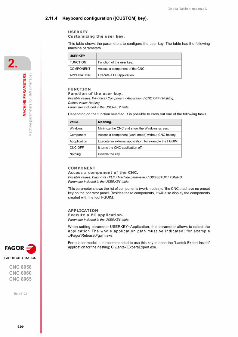
Installation manual.
CNC 8058CNC 8060CNC 8065
2.
MA
CH
INE
PA
RA
ME
TE
RS
.
Mac
hin
e pa
ram
eter
s fo
r H
MI (
Inte
rfac
e).
ꞏ320ꞏ
REF: 2102
2.11.4 Keyboard configuration ([CUSTOM] key).
USERKEYCustomizing the user key.
This table shows the parameters to configure the user key. The table has the followingmachine parameters.
FUNCTIONFunction of the user key.Possible values: Windows / Component / Application / CNC OFF / Nothing.Default value: Nothing.Parameter included in the USERKEY table.
Depending on the function selected, it is possible to carry out one of the following tasks.
COMPONENTAccess a component of the CNC.Possible values: Diagnosis / PLC / Machine parameters / DDSSETUP / TUNINGParameter included in the USERKEY table.
This parameter shows the list of components (work modes) of the CNC that have no presetkey on the operator panel. Besides these components, it will also display the componentscreated with the tool FGUIM.
APPLICATIONExecute a PC application.Parameter included in the USERKEY table.
When setting parameter USERKEY=Application, this parameter allows to select theappl ica t ion The who le app l i ca t ion pa th must be ind icated ; for example..\Fagor\Release\Fguim.exe.
For a laser model, it is recommended to use this key to open the "Lantek Expert Inside"application for the nesting; C:\Lantek\Expert\Expert.exe.
USERKEY
FUNCTION Function of the user key.
COMPONENT Access a component of the CNC.
APPLICATION Execute a PC application.
Value. Meaning.
Windows Minimize the CNC and show the Windows screen.
Component Access a component (work mode) without CNC hotkey.
Appplication Execute an external application, for example the FGUIM.
CNC OFF It turns the CNC application off.
Nothing. Disable the key.
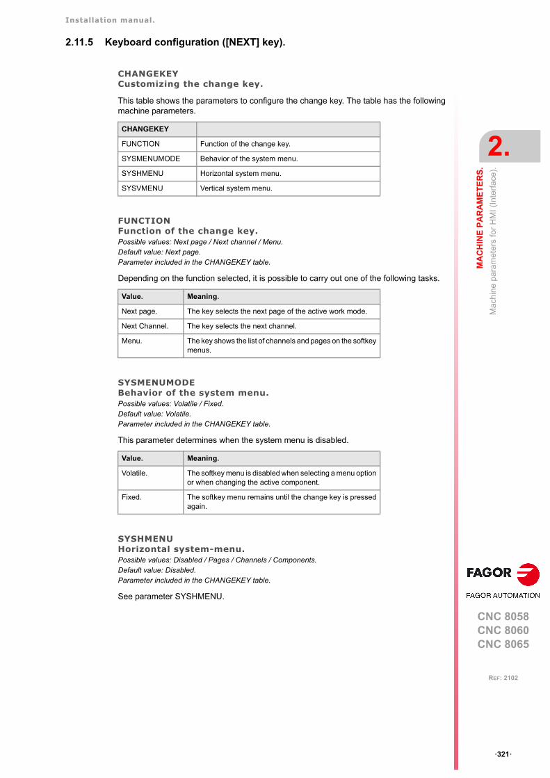
Installation manual.
CNC 8058CNC 8060CNC 8065
MA
CH
INE
PA
RA
ME
TE
RS
.
2.
Mac
hin
e pa
ram
eter
s fo
r H
MI (
Inte
rfac
e).
ꞏ321ꞏ
REF: 2102
2.11.5 Keyboard configuration ([NEXT] key).
CHANGEKEYCustomizing the change key.
This table shows the parameters to configure the change key. The table has the followingmachine parameters.
FUNCTIONFunction of the change key.Possible values: Next page / Next channel / Menu.Default value: Next page.Parameter included in the CHANGEKEY table.
Depending on the function selected, it is possible to carry out one of the following tasks.
SYSMENUMODEBehavior of the system menu.Possible values: Volatile / Fixed.Default value: Volatile.Parameter included in the CHANGEKEY table.
This parameter determines when the system menu is disabled.
SYSHMENUHorizontal system-menu.Possible values: Disabled / Pages / Channels / Components.Default value: Disabled.Parameter included in the CHANGEKEY table.
See parameter SYSHMENU.
CHANGEKEY
FUNCTION Function of the change key.
SYSMENUMODE Behavior of the system menu.
SYSHMENU Horizontal system menu.
SYSVMENU Vertical system menu.
Value. Meaning.
Next page. The key selects the next page of the active work mode.
Next Channel. The key selects the next channel.
Menu. The key shows the list of channels and pages on the softkeymenus.
Value. Meaning.
Volatile. The softkey menu is disabled when selecting a menu optionor when changing the active component.
Fixed. The softkey menu remains until the change key is pressedagain.
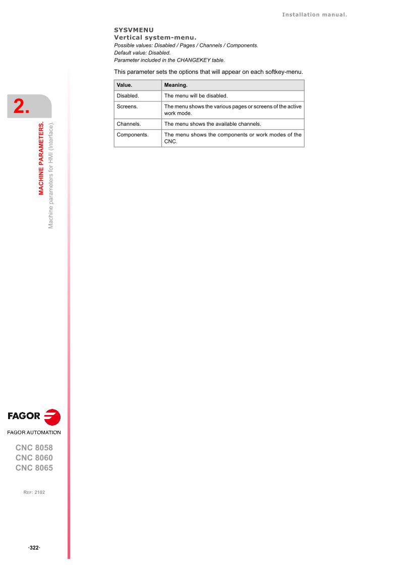
Installation manual.
CNC 8058CNC 8060CNC 8065
2.
MA
CH
INE
PA
RA
ME
TE
RS
.
Mac
hin
e pa
ram
eter
s fo
r H
MI (
Inte
rfac
e).
ꞏ322ꞏ
REF: 2102
SYSVMENUVertical system-menu.Possible values: Disabled / Pages / Channels / Components.Default value: Disabled.Parameter included in the CHANGEKEY table.
This parameter sets the options that will appear on each softkey-menu.
Value. Meaning.
Disabled. The menu will be disabled.
Screens. The menu shows the various pages or screens of the activework mode.
Channels. The menu shows the available channels.
Components. The menu shows the components or work modes of theCNC.
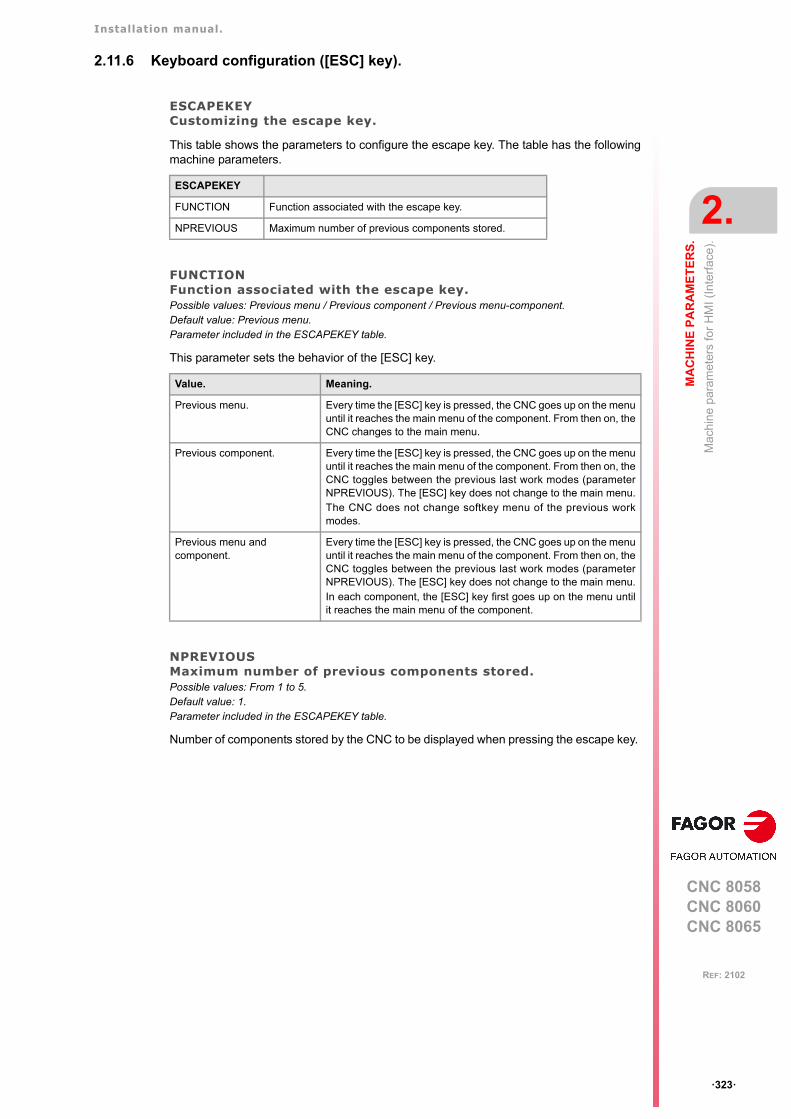
Installation manual.
CNC 8058CNC 8060CNC 8065
MA
CH
INE
PA
RA
ME
TE
RS
.
2.
Mac
hin
e pa
ram
eter
s fo
r H
MI (
Inte
rfac
e).
ꞏ323ꞏ
REF: 2102
2.11.6 Keyboard configuration ([ESC] key).
ESCAPEKEYCustomizing the escape key.
This table shows the parameters to configure the escape key. The table has the followingmachine parameters.
FUNCTIONFunction associated with the escape key.Possible values: Previous menu / Previous component / Previous menu-component.Default value: Previous menu.Parameter included in the ESCAPEKEY table.
This parameter sets the behavior of the [ESC] key.
NPREVIOUSMaximum number of previous components stored.Possible values: From 1 to 5.Default value: 1.Parameter included in the ESCAPEKEY table.
Number of components stored by the CNC to be displayed when pressing the escape key.
ESCAPEKEY
FUNCTION Function associated with the escape key.
NPREVIOUS Maximum number of previous components stored.
Value. Meaning.
Previous menu. Every time the [ESC] key is pressed, the CNC goes up on the menuuntil it reaches the main menu of the component. From then on, theCNC changes to the main menu.
Previous component. Every time the [ESC] key is pressed, the CNC goes up on the menuuntil it reaches the main menu of the component. From then on, theCNC toggles between the previous last work modes (parameterNPREVIOUS). The [ESC] key does not change to the main menu.The CNC does not change softkey menu of the previous workmodes.
Previous menu and component.
Every time the [ESC] key is pressed, the CNC goes up on the menuuntil it reaches the main menu of the component. From then on, theCNC toggles between the previous last work modes (parameterNPREVIOUS). The [ESC] key does not change to the main menu.In each component, the [ESC] key first goes up on the menu untilit reaches the main menu of the component.
Installation manual.
CNC 8058CNC 8060CNC 8065
2.
MA
CH
INE
PA
RA
ME
TE
RS
.
Mac
hin
e pa
ram
eter
s fo
r H
MI (
Inte
rfac
e).
ꞏ324ꞏ
REF: 2102
2.11.7 Simulated jog keyboard.
SIMJOGPANELSimulated JOG panel.Possible values: Yes / No.Default value: No.
This parameter indicates whether the simulated panel is available or not. To select ordeselect it, press [CTRL][J].
A simulated jog keyboard is a window that lays over the CNC screen and may be used tosimulated the jog keys and the keys for accessing the work modes. It may have to be usedwhen working with telediagnosis (remote control of the CNC).
2.11.8 CNC shut down.
WINEXITExit Windows when closing the CNC.Possible values: Yes / No.Default value: No (Windows is not closed).
This parameter indicates whether Windows is closed or not when exiting the CNC using[ALT][F4].
Installation manual.
CNC 8058CNC 8060CNC 8065
MA
CH
INE
PA
RA
ME
TE
RS
.
2.
Mac
hin
e pa
ram
eter
s fo
r H
MI (
Inte
rfac
e).
ꞏ325ꞏ
REF: 2102
2.11.9 Graphics configuration.
GRAPHTYPEList of graphics in each channel.
On the lathe model, this parameter shows the table to define the configuration of the graphicsin each channel.
GRAPHTYPECH nType of graphics in each channel.Possible values: Horizaontal or vertical lathe; X+ Z+ / X- Z+ / X+ Z- / X- Z-.Default value: Horizontal X+ Z+.Parameter included in the GRAPHTYPE table.
In the lathe model, this parameter sets the configuration of the graphics of the channel.
DIAGPSW(Reserved)
GRAPHTYPE
GRAPHTYPECH n Type of graphics in each channel.
Horizontal lathe.
Vertical lathe.
Z+
X-
Z+
X+
Z-
X-
Z-
X+
Z-
X-Z+
X-
Z+
X+ Z-
X+
It is also possible to display the graphics of a dual-turret lathe (TT lathe). To do that, use the FGUIMapplication to change the Channel1 and Channel2 properties of the graphics window to display theexecution of both channels on a single graphics.
Installation manual.
CNC 8058CNC 8060CNC 8065
2.
MA
CH
INE
PA
RA
ME
TE
RS
.
OE
M m
achi
ne
para
met
ers.
ꞏ326ꞏ
REF: 2102
2.12 OEM machine parameters.
2.12.1 Reading drive (Sercos or Mechatrolink) variables.
DRIVEVARDrive variables table.
Parameter DRIVEVAR may be used to define the list of DRV variables that grant access tothe variables and/or parameters of the digital drives via part-program, MDI/MDA mode, PLCor interface.
The table has the following machine parameters.
Characteristics and limitations of Mechatrolink devices.
The access to Mechatrolink devices using DRV variables has the following characteristicsand limitations.
• Access to variables and/or parameters of the devices is only available for the Mlink-IImode with 32 bytes.
• The variables can only be read, whereas the parameters may be read or written.
• Access to the variables of the drive is asynchronous (managed through the servicechannel) whereas access to the parameters is synchronous (managed through the cyclicchannel).
• Either the parameters or the variables may be defined for the same axis, not both.
• If variables have been defined, it is not possible to access the DDSSetup or the setupassistance.
• The maximum number of variables per axis or spindle is 2. There is no limit for parametersper axis.
SIZENumber of variables to be consulted at the drive.Possible values: From 0 to 99.Default value: 0.Associated variable: (V.)DRV.SIZEParameter included in the DRIVEVAR table.
This parameter sets the number of variables to be consulted at the drive.
DATAVariables of the drives.
This parameter shows the table to define the list of DRV variables.
For Sercos drives, the following fields must be defined for each DRV variable.
• Sercos. DRV variables can access the variables of the drive. These variablesmay be read-only or read and written.
• Mechatrolink. DRV variables can access the variables and/or parameters of thedrive. The variables of the drive can only be read, whereas theparameters may be read or written.
DRIVEVAR
SIZE Number of elements of the drive variables table
DATA Variables of the drives.
Field. Meaning.
MNEMONIC Mnemonic assigned to the DRV variable. The access to the variable from theCNC will be as follows:
(V.)DRV.{mnemonic}.{axis}(V.)DRV.{mnemonic}.{spindle}
AXIS Name of the axis or spindle being accessed by the variable; defining it as "*"means all axes and spindles.
Installation manual.
CNC 8058CNC 8060CNC 8065
MA
CH
INE
PA
RA
ME
TE
RS
.
2.
OE
M m
achi
ne
para
met
ers.
ꞏ327ꞏ
REF: 2102
For Mechatrolink devices, the following fields must be defined for each DRV variable.
ID ID Sercos identifier of the variable to be consulted at the drive.
TYPE Access type, synchronous or asynchronous. Variables of synchronous accessare managed through the cyclic channel. Variables of asynchronous access aremanaged through the service channel, even if the default option at the drive isthe opposite. Not all the variables may be defined with synchronous access; onlythe ones that can use the Sercos cyclic channel. Refer to the drive manual.If possible, we recommend to define the variables with synchronous accessbecause the read-write requests of these variables through the bus are faster andreduces traffic through the bus.
MODE Access mode. These variables may be read-only or read and written.
Field. Meaning.
MNEMONIC Mnemonic assigned to the DRV variable. The access to the variable from theCNC will be as follows:
(V.)DRV.{mnemonic}.{axis}(V.)DRV.{mnemonic}.{spindle}
AXIS Name of the axis or spindle being accessed by the variable; defining it as "*"means all axes and spindles.
ID Identifier of the parameter (0000-FFFF) or of the variable (0-F) to be consultedat the device.
TYPE Type of consultation; variable or parameter.
MODE Access mode. The variables of the drive can only be read, whereas theparameters may be read or written.
Field. Meaning.

Installation manual.
CNC 8058CNC 8060CNC 8065
2.
MA
CH
INE
PA
RA
ME
TE
RS
.
OE
M m
achi
ne
para
met
ers.
ꞏ328ꞏ
REF: 2102
2.12.2 Generic OEM parameters.
The values of the table may be modified at any time. The new values are assumedimmediately without having to validate the parameters. This means that the values andpermissions of the table may be modified while executing a program.
The simulation environment has a copy of this table. On CNC power-up, the values of theparameters of the real table are copied into the simulation table and from there on, theybecome different in the writing of the variables of both tables. In the simulation table, onlythe parameter values may be modified, not the rest of the permissions. The values of thesimulation table can only be read or modified through their variable.
MTBPAROEM-parameter table.
This table offers 1000 generic parameters that the OEM can use as machine parameters.The table has the following machine parameters.
SIZENumber of OEM parameters.Possible values: From 0 to 1000.Default value: 0.Associated variable: (V.)MTB.SIZE
This parameter sets the number of OEM parameters that will be used.
DATAList of OEM parameters.
This parameter shows the table of OEM parameters. The following fields must be definedfor each parameter.
VALUEParameter value.Possible values: Within ±99999.9999.Default value: 0.
If the parameter is affected by the change of units (INCHES field), the value is entered inthe table in the units selected by machine parameter INCHES.
Each parameter has its own variables for reading or modifying (if it has a write permission)their value from the part-program, PLC or interface. The access to these parameters usingvariables will be as follows.
It must be borne in mind that reading and writing these variables interrupts block preparationaffecting program execution time. If the value of the parameter is not going to be changed
MTBPAR
SIZE Number of OEM parameters.
DATA List of OEM parameters.
DATA
VALUE Value of the parameter.
MODE Mode for accessing the parameter from its variable.
INCHES The parameter is affected by the change of units.
COMMENT OEM parameter description.
(V.)MTB.P[i] Value of the OEM parameter [i].
(V.)MTB.PF[i] Value of the OEM parameter [i]. Value per 10000.
Mnemoni. Value. V.MTB.P[i] V.MTB.PF[i]
P0 7 V.MTB.P[0] = 7 V.MTB.PF[0] = 70000
P8 12,5 V.MTB.P[8] = 12,5 V.MTB.PF[8] = 125000
Installation manual.
CNC 8058CNC 8060CNC 8065
MA
CH
INE
PA
RA
ME
TE
RS
.
2.
OE
M m
achi
ne
para
met
ers.
ꞏ329ꞏ
REF: 2102
during execution, it is recommended to read the MTB variables at the beginning of theprogram using arithmetic parameters (local or global) and use the global ones throughoutthe program.
MODEMode for accessing the parameter from its variable.Possible values: Read / Write.Default value: Read.
The access to the parameters from the variables may be read-only or read-write. The valuemay always be written directly into the table, regardless of the value assigned to this field.
In Setup mode, the variables can modify the read-only MTBPAR parameters using a partprogram.
INCHESThe parameter is affected by the change of units.Possible values: Yes / No.Default value: Yes.
This field indicates whether the value of the parameter is affected by the change of units,mm or inches. For example, when the parameter represents a coordinate.
COMMENTOEM parameter description.
This field offers the possibility to associate a short description with the parameter. This fieldis for information only; it is not used by the CNC. The comments are saved in the fileMTBComments.txt and it is possible to have one file per language. These files are savedin the folder ..\MTB\Data\Lang.
Setup mode. Variables can write parameters using write and read-only permission.These new values are kept after the CNC has been restarted or shutdown.
User Mode. Variables can only write parameters using write permission. These newvalues are kept after the CNC has been restarted or shutdown.
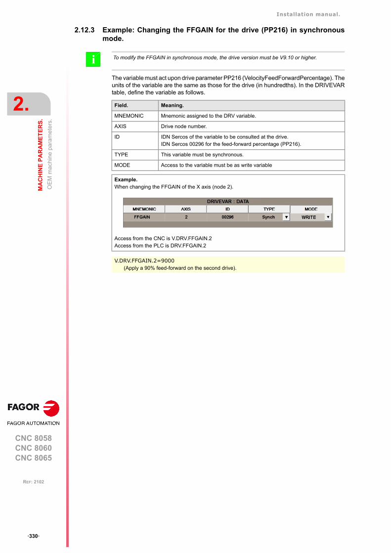
Installation manual.
CNC 8058CNC 8060CNC 8065
2.
MA
CH
INE
PA
RA
ME
TE
RS
.
OE
M m
achi
ne
para
met
ers.
ꞏ330ꞏ
REF: 2102
2.12.3 Example: Changing the FFGAIN for the drive (PP216) in synchronousmode.
The variable must act upon drive parameter PP216 (VelocityFeedForwardPercentage). Theunits of the variable are the same as those for the drive (in hundredths). In the DRIVEVARtable, define the variable as follows.
To modify the FFGAIN in synchronous mode, the drive version must be V9.10 or higher.i
Field. Meaning.
MNEMONIC Mnemonic assigned to the DRV variable.
AXIS Drive node number.
ID IDN Sercos of the variable to be consulted at the drive.IDN Sercos 00296 for the feed-forward percentage (PP216).
TYPE This variable must be synchronous.
MODE Access to the variable must be as write variable
Example.When changing the FFGAIN of the X axis (node 2).
Access from the CNC is V.DRV.FFGAIN.2Access from the PLC is DRV.FFGAIN.2
V.DRV.FFGAIN.2=9000(Apply a 90% feed-forward on the second drive).
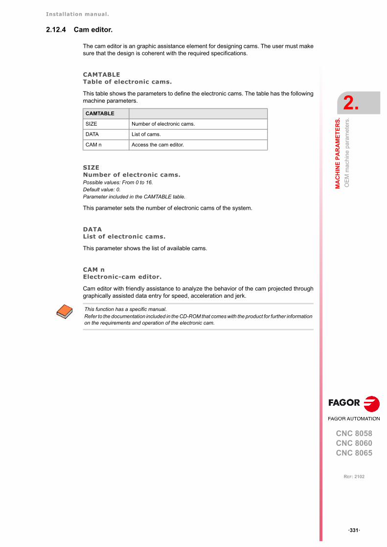
Installation manual.
CNC 8058CNC 8060CNC 8065
MA
CH
INE
PA
RA
ME
TE
RS
.
2.
OE
M m
achi
ne
para
met
ers.
ꞏ331ꞏ
REF: 2102
2.12.4 Cam editor.
The cam editor is an graphic assistance element for designing cams. The user must makesure that the design is coherent with the required specifications.
CAMTABLETable of electronic cams.
This table shows the parameters to define the electronic cams. The table has the followingmachine parameters.
SIZENumber of electronic cams.Possible values: From 0 to 16.Default value: 0.Parameter included in the CAMTABLE table.
This parameter sets the number of electronic cams of the system.
DATAList of electronic cams.
This parameter shows the list of available cams.
CAM nElectronic-cam editor.
Cam editor with friendly assistance to analyze the behavior of the cam projected throughgraphically assisted data entry for speed, acceleration and jerk.
CAMTABLE
SIZE Number of electronic cams.
DATA List of cams.
CAM n Access the cam editor.
This function has a specific manual. Refer to the documentation included in the CD-ROM that comes with the product for further informationon the requirements and operation of the electronic cam.
Installation manual.
CNC 8058CNC 8060CNC 8065
2.
MA
CH
INE
PA
RA
ME
TE
RS
.
OE
M m
achi
ne
para
met
ers.
ꞏ332ꞏ
REF: 2102

CNC 8058CNC 8060CNC 8065
3
ꞏ333ꞏ
REF: 2102
3. INTRODUCTION TO THE PLC.
The PLC program may be either edited at the front panel or copied from a peripheral or PC.The PLC program has a modular structure and may combine files in "C" language, contact(ladder) language or mnemonic language.
For the program to be executed, its object file (executable) must be generated. On power-up, the CNC executes the executable PLC program stored in memory; if there isn't one, theCNC will show the relevant error code.
Data exchange takes place in automatic mode between the CNC and the PLC. The followingis possible from the PLC:
• Control physical inputs and outputs (remote modules).
• Consult and/or modify CNC-PLC exchange variables.
• Consult and/or modify the internal CNC variables.
• Display messages or errors at the CNC.
The following is possible from the CNC:
• Transfer auxiliary functions M, H and S.
• Access PLC resources from any part-program.
Abbreviations used in this chapter.
(=0) Low logic level.
(=1) High logic level.
(g.m.p.) General machine parameter.
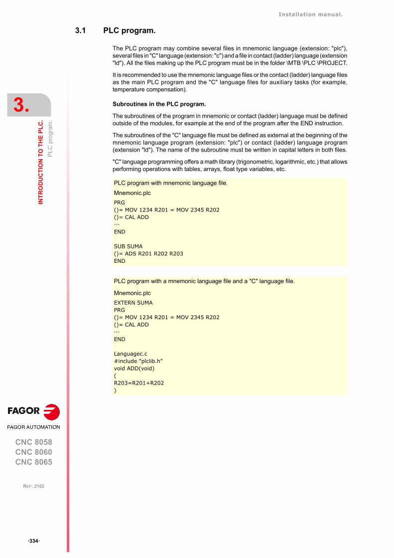
Installation manual.
CNC 8058CNC 8060CNC 8065
3.
INT
RO
DU
CT
ION
TO
TH
E P
LC
.
PL
C p
rogr
am.
ꞏ334ꞏ
REF: 2102
3.1 PLC program.
The PLC program may combine several files in mnemonic language (extension: "plc"),several files in "C" language (extension: "c") and a file in contact (ladder) language (extension"ld"). All the files making up the PLC program must be in the folder \MTB \PLC \PROJECT.
It is recommended to use the mnemonic language files or the contact (ladder) language filesas the main PLC program and the "C" language files for auxiliary tasks (for example,temperature compensation).
Subroutines in the PLC program.
The subroutines of the program in mnemonic or contact (ladder) language must be definedoutside of the modules, for example at the end of the program after the END instruction.
The subroutines of the "C" language file must be defined as external at the beginning of themnemonic language program (extension: "plc") or contact (ladder) language program(extension "ld"). The name of the subroutine must be written in capital letters in both files.
"C" language programming offers a math library (trigonometric, logarithmic, etc.) that allowsperforming operations with tables, arrays, float type variables, etc.
PLC program with mnemonic language file.
Mnemonic.plc
PRG()= MOV 1234 R201 = MOV 2345 R202()= CAL ADD···END
SUB SUMA()= ADS R201 R202 R203END
PLC program with a mnemonic language file and a "C" language file.
Mnemonic.plc
EXTERN SUMAPRG()= MOV 1234 R201 = MOV 2345 R202()= CAL ADD···END
Languagec.c#include "plclib.h"void ADD(void)(R203=R201+R202)
Installation manual.
CNC 8058CNC 8060CNC 8065
INT
RO
DU
CT
ION
TO
TH
E P
LC
.
3.
Mod
ula
r st
ruct
ure
of th
e P
LC
pro
gram
.
ꞏ335ꞏ
REF: 2102
3.2 Modular structure of the PLC program.
The PLC program may comprise the following modules. Every module must begin with thedirective instruction that defines it (CY1, PRG, PE) and end with the directing instruction END.
• First Cycle module (CY1).
• Main module (PRG).
• Periodic module (PE).
First Cycle module.
It is an optional module. The module begins with the directing instruction CY1 and ends withthe directive instruction END.
The PLC executes the first cycle module onlyonce when starting up the PLC program. Thismodules is used to initialized the various resources and variables before executing the mainprogram.
Main module.
The main module begins with the directing instruction PRG and ends with the directiveinstruction END.
The PLC executes the main module cyclically with the frequency set by parameterPRGFREQ. This module is in charge of analyzing and modifying the CNC inputs, outputsand variables. The PRG execution takes about 100 µs.
Parameter PRGFREQ indicates how often (every how many CNC cycles) the PLC executesa full cycle of the main module. Hence, with a sampling period of 4 ms (LOOPTIME=4) anda frequency of 2 cycles (PRGFREQ=2), the PLC executes the main module every 4 x 2 =8ms.
Periodic module.
It is an optional module. The periodic module begins with the directing instruction PE andends with the directive instruction END.
The PLC executes the periodic module cyclically with the frequency set by the directiveinstruction PE, between 1 and 2147483647 ms and never less than the loop time (parameterLOOPTIME). This module could be used to execute tasks that do not need to be executedat every PLC cycle.
For example, a task to be performed every 30 seconds could be defined in a periodic moduleusing the instruction (PE 30000).
Installation manual.
CNC 8058CNC 8060CNC 8065
3.
INT
RO
DU
CT
ION
TO
TH
E P
LC
.
PLC
pro
gra
m e
xecu
tion.
ꞏ336ꞏ
REF: 2102
3.3 PLC program execution.
Main module (PRG)
The main module is processed as follows:
1 The PLC assigns the current value of the physical inputs (remote modules) to the Iresources.
2 The PLC assumes the current values of the internal CNC variables (CNCREADY, START,FHOUT, .....).
3 The PLC executes the main program (PRG).
4 The PLC updates the internal CNC variables (EMERGEN, STOP, FEEDHOL, ...) withthe current values of the associated PLC resources.
5 The PLC assigns the current value of the PLC's "O" resources to the physical outputs(remote modules).
6 The PLC concludes the cycle and is ready for the next scan.
Periodic module (PE)
The periodic module is processed as follows:
1 The PLC takes into account the current values of the physical inputs (remote modules)at the beginning of the module.
2 The PLC executes the periodic module.
3 The PLC assigns the current value of the PLC's "O" resources to the physical outputs(remote modules).
4 The PLC concludes the execution of the periodic Module.

Installation manual.
CNC 8058CNC 8060CNC 8065
INT
RO
DU
CT
ION
TO
TH
E P
LC
.
3.
PL
C r
eso
urce
s.
ꞏ337ꞏ
REF: 2102
3.4 PLC resources.
The PLC has the following resources.
• Inputs (I1-I1024) and outputs (O1-O1024).
• Local inputs (LI1-LI16) and local outputs (LO1-LO8).
• Marks (M1-M8192).
• Messages (MSG1-MSG1024).
• Errors (ERR1-ERR1024)
• Clocks (CLK).
• Registers (R1-R1024).
• Timers (T1-T512).
• Counters (C1-C256).
• Registers and marks for CNC-PLC communication.
The MSG, ERR, CLK and T resources are initialized (=0) when starting up the PLC. M, Cand R resources maintain their value between CNC start-ups.
Inputs (I1-I1024) and outputs (O1-O1024).
The inputs are elements that provide information to the PLC on the signals they receive fromthe outside world. They are represented by the letter "I" followed by an input number between"I1" and "I1024".
The outputs are elements that let the PLC activate or deactivate the various devices of theelectrical cabinet. They are represented by the letter "O" followed by an output numberbetween "O1" and "O1024".
Numbering of the physical inputs and outputs.
There are two different ways to number the inputs and outputs. Depending on the order ofthe remote modules or via machine parameters. See "3.4.1 Numbering of the physicalinputs and outputs." on page 340.
Local inputs (LI1-LI16) and local outputs (LO1-LO8).
The central unit has a set of 8 local digital inputs and 8 local digital signals that may beconfigured both as input and output. They are called local inputs and outputs because theyare located in the central unit, not in the remote modules. The local inputs are representedwith the letter LI followed by the input number, from LI1 to LI16. The local outputs arerepresented with the letter LO followed by the output number, from LO1 to LO8.
Local digital I/O are ignored when setting the number of remote I/O or when saving theconfiguration of the CAN bus. Local I/O will always be referred to in the same way regardlessof the system configuration.
Local I/O will be refreshed with the same frequency as the remote I/O and also from the PEmodule.
Marks (M1-M8192).
They are elements capable of memorizing in a bit (like an internal relay) the value set by theuser. If the mark is (=0), it will be referred to as being set low. If the mark is (=1), it will bereferred to as being set high.
They are represented by the letter "M" followed by a mark number between M1 and M8192.
Installation manual.
CNC 8058CNC 8060CNC 8065
3.
INT
RO
DU
CT
ION
TO
TH
E P
LC
.
PL
C r
eso
urce
s.
ꞏ338ꞏ
REF: 2102
Messages (MSG1-MSG1024).
When activated (=1), they display a message on the CNC screen. The texts associated withthe messages must be previously defined in the message and error table of the PLC.
They are represented by the letters "MSG" followed by a message number between MSG1and MSG1024.
All of them are initialized (=0) when starting up the PLC.
Errors (ERR1-ERR1024)
When activated (=1), they cause an error, they show an error message and interrupt theexecution of the CNC. The texts associated with the errors must be previously defined inthe message and error table of the PLC. PLC errors may be configured so they activate theemergency signal of the PLC (_EMERGEN).
They are represented by the word "ERR" followed by an error number between ERR1 andERR1024.
All of them are initialized (=0) when starting up the PLC.
The errors do not activate the alarm of the CNC, (_ALARM) signal.
Clocks (CLK).
They are internal clocks with different time periods to be used in the PLC program.
They are represented by the word "CLK" followed by a clock number .
All of them are initialized (=0) when starting up the PLC.
These are the clock marks available. Their half-period (or after how long their state 0/1changes) is shown next to them.
Registers (R1-R1024).
They are elements that can store a numeric variable in 32 bits. The value stored in eachregister is considered as a signed integer between ± 2.147.483.647. It can be processedas decimal or hexadecimal number (preceded by the "$" sign). For example:
They are represented by the letter "R" followed by a register number between R1 and R1024.It is also possible to refer to a register bit with the letter "B" and a bit number (0/31). The PLCtakes bit 0 as the least significant bit and as bit 31 as the most significant bit.
Clock. Period. Clock. Period. Clock. Period.
CLK1 1 ms CLK100 100 ms CLK1000 1 s
CLK2 2 ms CLK200 200 ms CLK2000 2 s
CLK4 4 ms CLK400 400 ms CLK4000 4 s
CLK8 8 ms CLK800 800 ms CLK8000 8 s
CLK16 16 ms CLK1600 1.6 s CLK16000 16 s
CLK32 32 ms CLK3200 3.2 s CLK32000 32 s
CLK64 64 ms CLK6400 6.4 s CLK64000 64 s
CLK128 128 ms CLK12800 12.8 s CLK128000 128 s
156 (Decimal)
$9C (Hexadecimal)
B7R155 Refers to bit 7 of register 155.

Installation manual.
CNC 8058CNC 8060CNC 8065
INT
RO
DU
CT
ION
TO
TH
E P
LC
.
3.
PL
C r
eso
urce
s.
ꞏ339ꞏ
REF: 2102
Timers (T1-T512).
They are elements capable of maintaining their output at the same logic level (state) for apreset time period (time constant) after which their output changes states.
They are represented by the letter "T" followed by a time number between T1 and T512.
All timers are initialized (=0) when starting up the PLC.
See "3.5 Operation of a timer." on page 342.
Counters (C1-C256).
They are elements capable of counting up or down a preset amount of events.
They are represented by the letter "C" followed by a counter number between C1 and C256.
See "3.6 Operation of a counter." on page 352.
Registers and marks for CNC-PLC communication.
The PLC has access to a some internal CNC data.
The PLC can consult and/or modify certain CNC signals (marks and registers).
• Consultation signals: CNCREADY, START, FHOUT, ...
• Modifiable signals: _EMERGEN, _STOP, _FEEDHOL, ...
See chapter "6 Logic CNC inputs and outputs.".
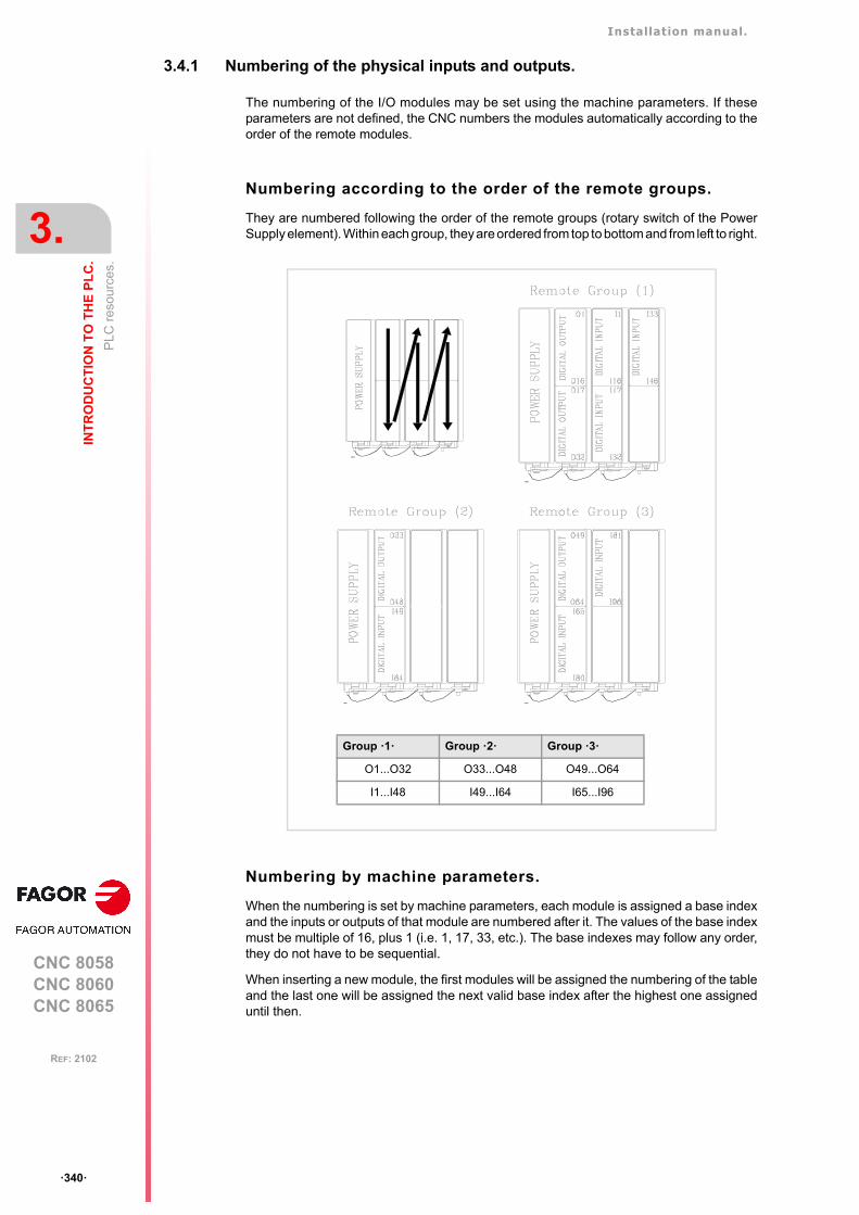
Installation manual.
CNC 8058CNC 8060CNC 8065
3.
INT
RO
DU
CT
ION
TO
TH
E P
LC
.
PL
C r
eso
urce
s.
ꞏ340ꞏ
REF: 2102
3.4.1 Numbering of the physical inputs and outputs.
The numbering of the I/O modules may be set using the machine parameters. If theseparameters are not defined, the CNC numbers the modules automatically according to theorder of the remote modules.
Numbering according to the order of the remote groups.
They are numbered following the order of the remote groups (rotary switch of the PowerSupply element). Within each group, they are ordered from top to bottom and from left to right.
Numbering by machine parameters.
When the numbering is set by machine parameters, each module is assigned a base indexand the inputs or outputs of that module are numbered after it. The values of the base indexmust be multiple of 16, plus 1 (i.e. 1, 17, 33, etc.). The base indexes may follow any order,they do not have to be sequential.
When inserting a new module, the first modules will be assigned the numbering of the tableand the last one will be assigned the next valid base index after the highest one assigneduntil then.
Group ꞏ1ꞏ Group ꞏ2ꞏ Group ꞏ3ꞏ
O1...O32 O33...O48 O49...O64
I1...I48 I49...I64 I65...I96
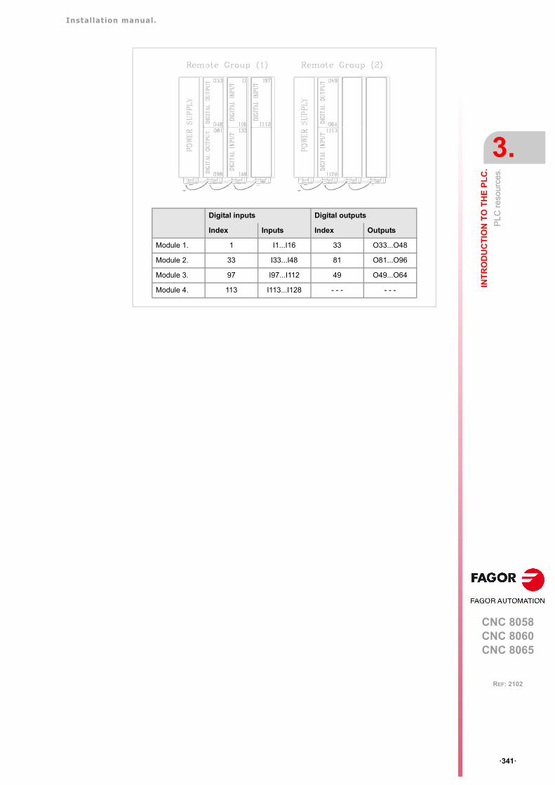
Installation manual.
CNC 8058CNC 8060CNC 8065
INT
RO
DU
CT
ION
TO
TH
E P
LC
.
3.
PL
C r
eso
urce
s.
ꞏ341ꞏ
REF: 2102
Digital inputs Digital outputs
Index Inputs Index Outputs
Module 1. 1 I1...I16 33 O33...O48
Module 2. 33 I33...I48 81 O81...O96
Module 3. 97 I97...I112 49 O49...O64
Module 4. 113 I113...I128 - - - - - -
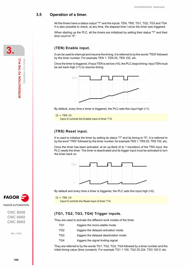
Installation manual.
CNC 8058CNC 8060CNC 8065
3.
INT
RO
DU
CT
ION
TO
TH
E P
LC
.
Ope
ratio
n of
a ti
mer
.
ꞏ342ꞏ
REF: 2102
3.5 Operation of a timer.
All the timers have a status output "T" and the inputs: TEN, TRS, TG1, TG2, TG3 and TG4.It is also possible to check, at any time, the elapsed time t since the timer was triggered.
When starting up the PLC, all the timers are initialized by setting their status "T" and theirtime count to "0".
(TEN) Enable input.
It can be used to interrupt and resume the timing. It is referred to by the words "TEN" followedby the timer number. For example TEN 1, TEN 25, TEN 102, etc.
Once the timer is triggered, if input TEN is set low (=0), the PLC stops timing; input TEN mustbe set back high (=1) to resume timing.
By default, every time a timer is triggered, the PLC sets this input high (=1).
(TRS) Reset input.
It is used to initialize the timer by setting its status "T" and its timing to "0". It is referred toby the word "TRS" followed by the timer number, for example TRS 1, TRS 25, TRS 102, etc.
Once the timer has been activated, at an up-flank (0 to 1 transition) of the TRS input, thePLC resets the timer. The timer is deactivated and its trigger input must be activated to turnthe timer back on.
By default and every time a timer is triggered, the PLC sets this input high (=0).
(TG1, TG2, TG3, TG4) Trigger inputs.
They are used to activate the different work modes of the timer.
TG1 triggers the mono-stable mode.
TG2 triggers the delayed activation mode.
TG3 triggers the delayed deactivation mode.
TG4 triggers the signal limiting signal.
They are referred to by the words TG1, TG2, TG3, TG4 followed by a timer number and theinitial timing value (time constant). For example TG1 1 100, TG2 25 224, TG3 102 0, etc.
I2 = TEN 10Input I2 controls the Enable input of timer T10.
I3 = TRS 10Input I3 controls the Reset input of timer T10.

Installation manual.
CNC 8058CNC 8060CNC 8065
INT
RO
DU
CT
ION
TO
TH
E P
LC
.
3.
Ope
ratio
n of
a ti
mer
.
ꞏ343ꞏ
REF: 2102
Set the time constant.
The time constant is defined with a numeric value or with an internal value of a register R.Its value must be within the 0 to 4294967295 ms range, which is the equivalent of 1193 hours(almost 50 days).
Activating the timer.
The timer is activated according to the selected input number at an up-flank (0 to 1 transition)or at a down-flank (1 to 0 transition).
Later on, this same section shows how to operate in each of these modes.
(T) Status output.
It indicates the logic state of the timer. It is referred to by the letter "T" followed by the timernumber. For example: T1, T25, T102, etc.
As the timer's logic state depends on the selected work mode (TG1, TG2, TG3 and TG4)it will be explained later on.
(T) Elapsed time.
It indicates the time elapsed at the timer since it was triggered. It is referred to by the letter"T" followed by the timer number. It is represented by T123 which is the same as the statusoutput, but is used in different types of instructions.
In binary instructions, it refers to the logic state of the timer.
In arithmetic and comparison instructions, it refers to the elapsed time.
TG1 20 100Triggers timer T20 in Mono-stable mode (TG1) with a time constant of 100 ms.
TG2 22 R200Triggers timer T22 in delayed activation mode (TG2) with the time constant stored in register R200in ms.
T123 = M100Assigns the state (1/0) of T123 to M100.
I2 = MOV T123 R200Transfers the time elapsed at T123 to register R200.
CPS T123 GT 1000 = M100Compares the time elapsed at T123 is greater than 1000. If so, it activates mark M100.
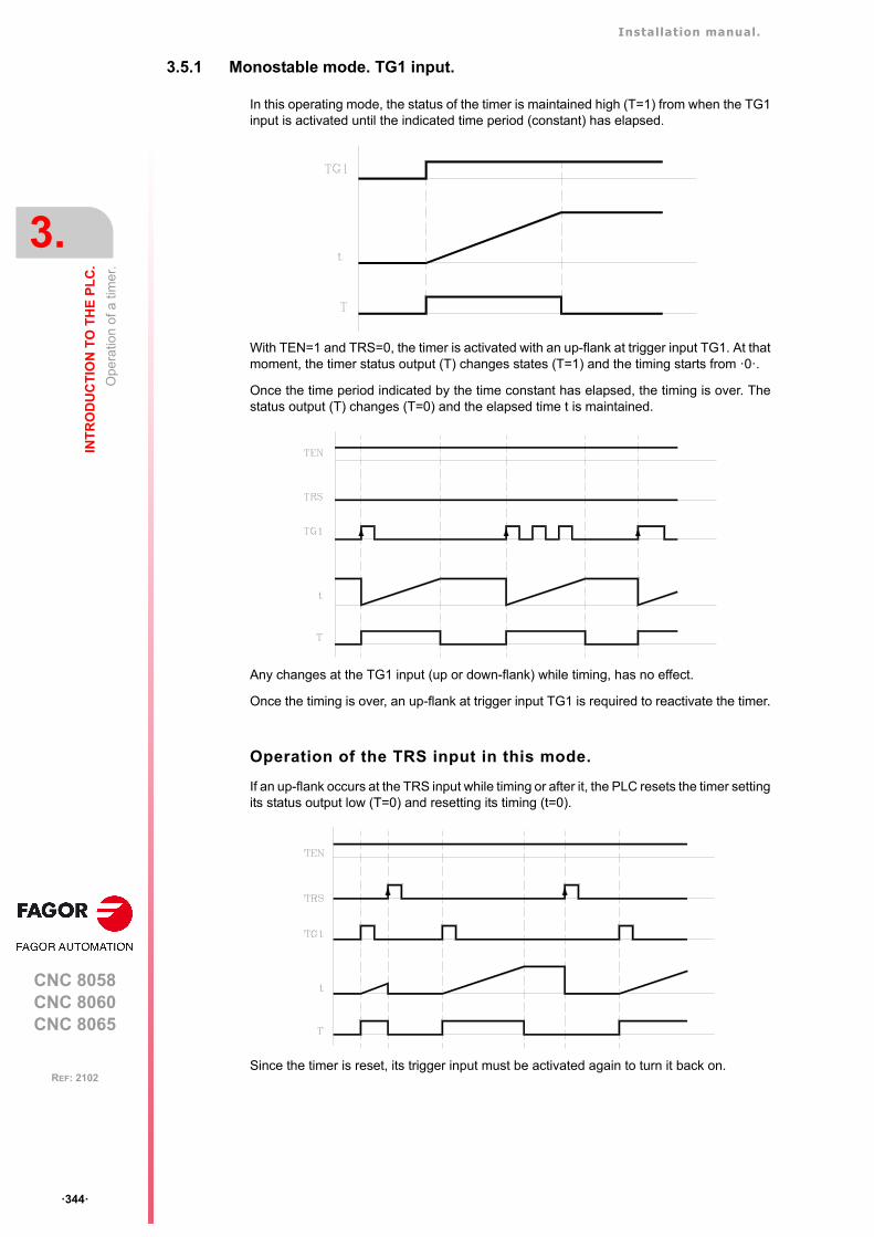
Installation manual.
CNC 8058CNC 8060CNC 8065
3.
INT
RO
DU
CT
ION
TO
TH
E P
LC
.
Ope
ratio
n of
a ti
mer
.
ꞏ344ꞏ
REF: 2102
3.5.1 Monostable mode. TG1 input.
In this operating mode, the status of the timer is maintained high (T=1) from when the TG1input is activated until the indicated time period (constant) has elapsed.
With TEN=1 and TRS=0, the timer is activated with an up-flank at trigger input TG1. At thatmoment, the timer status output (T) changes states (T=1) and the timing starts from ꞏ0ꞏ.
Once the time period indicated by the time constant has elapsed, the timing is over. Thestatus output (T) changes (T=0) and the elapsed time t is maintained.
Any changes at the TG1 input (up or down-flank) while timing, has no effect.
Once the timing is over, an up-flank at trigger input TG1 is required to reactivate the timer.
Operation of the TRS input in this mode.
If an up-flank occurs at the TRS input while timing or after it, the PLC resets the timer settingits status output low (T=0) and resetting its timing (t=0).
Since the timer is reset, its trigger input must be activated again to turn it back on.
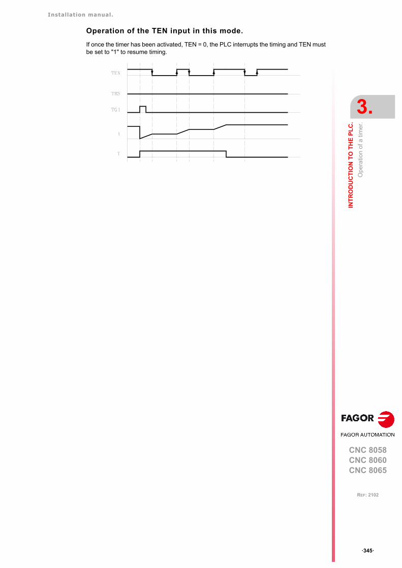
Installation manual.
CNC 8058CNC 8060CNC 8065
INT
RO
DU
CT
ION
TO
TH
E P
LC
.
3.
Ope
ratio
n of
a ti
mer
.
ꞏ345ꞏ
REF: 2102
Operation of the TEN input in this mode.
If once the timer has been activated, TEN = 0, the PLC interrupts the timing and TEN mustbe set to "1" to resume timing.
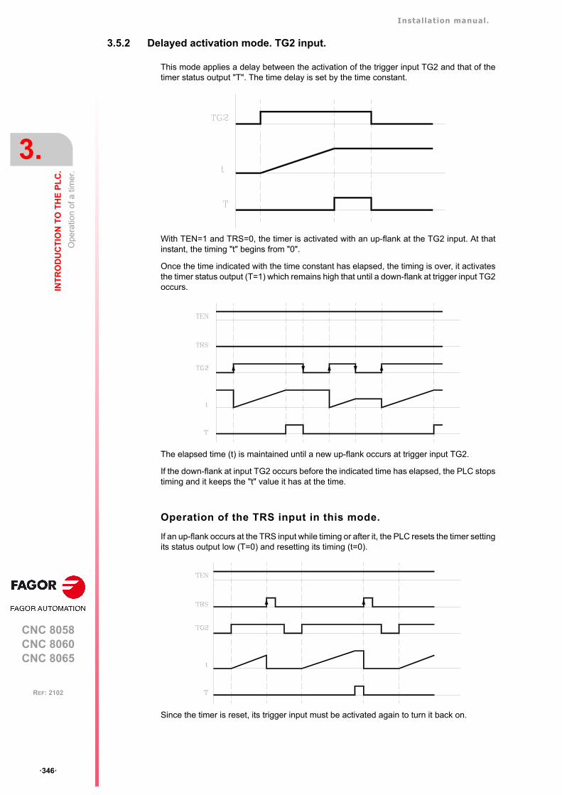
Installation manual.
CNC 8058CNC 8060CNC 8065
3.
INT
RO
DU
CT
ION
TO
TH
E P
LC
.
Ope
ratio
n of
a ti
mer
.
ꞏ346ꞏ
REF: 2102
3.5.2 Delayed activation mode. TG2 input.
This mode applies a delay between the activation of the trigger input TG2 and that of thetimer status output "T". The time delay is set by the time constant.
With TEN=1 and TRS=0, the timer is activated with an up-flank at the TG2 input. At thatinstant, the timing "t" begins from "0".
Once the time indicated with the time constant has elapsed, the timing is over, it activatesthe timer status output (T=1) which remains high that until a down-flank at trigger input TG2occurs.
The elapsed time (t) is maintained until a new up-flank occurs at trigger input TG2.
If the down-flank at input TG2 occurs before the indicated time has elapsed, the PLC stopstiming and it keeps the "t" value it has at the time.
Operation of the TRS input in this mode.
If an up-flank occurs at the TRS input while timing or after it, the PLC resets the timer settingits status output low (T=0) and resetting its timing (t=0).
Since the timer is reset, its trigger input must be activated again to turn it back on.
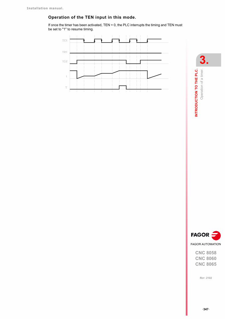
Installation manual.
CNC 8058CNC 8060CNC 8065
INT
RO
DU
CT
ION
TO
TH
E P
LC
.
3.
Ope
ratio
n of
a ti
mer
.
ꞏ347ꞏ
REF: 2102
Operation of the TEN input in this mode.
If once the timer has been activated, TEN = 0, the PLC interrupts the timing and TEN mustbe set to "1" to resume timing.
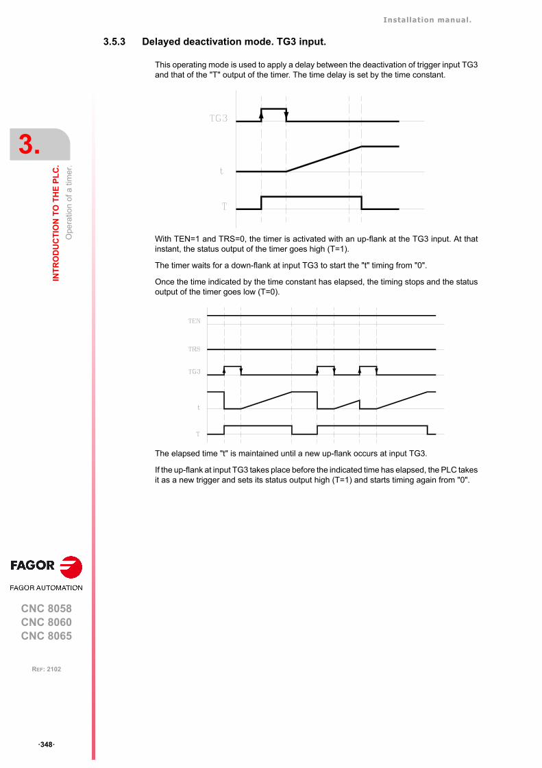
Installation manual.
CNC 8058CNC 8060CNC 8065
3.
INT
RO
DU
CT
ION
TO
TH
E P
LC
.
Ope
ratio
n of
a ti
mer
.
ꞏ348ꞏ
REF: 2102
3.5.3 Delayed deactivation mode. TG3 input.
This operating mode is used to apply a delay between the deactivation of trigger input TG3and that of the "T" output of the timer. The time delay is set by the time constant.
With TEN=1 and TRS=0, the timer is activated with an up-flank at the TG3 input. At thatinstant, the status output of the timer goes high (T=1).
The timer waits for a down-flank at input TG3 to start the "t" timing from "0".
Once the time indicated by the time constant has elapsed, the timing stops and the statusoutput of the timer goes low (T=0).
The elapsed time "t" is maintained until a new up-flank occurs at input TG3.
If the up-flank at input TG3 takes place before the indicated time has elapsed, the PLC takesit as a new trigger and sets its status output high (T=1) and starts timing again from "0".
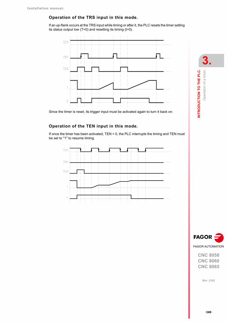
Installation manual.
CNC 8058CNC 8060CNC 8065
INT
RO
DU
CT
ION
TO
TH
E P
LC
.
3.
Ope
ratio
n of
a ti
mer
.
ꞏ349ꞏ
REF: 2102
Operation of the TRS input in this mode.
If an up-flank occurs at the TRS input while timing or after it, the PLC resets the timer settingits status output low (T=0) and resetting its timing (t=0).
Since the timer is reset, its trigger input must be activated again to turn it back on.
Operation of the TEN input in this mode.
If once the timer has been activated, TEN = 0, the PLC interrupts the timing and TEN mustbe set to "1" to resume timing.
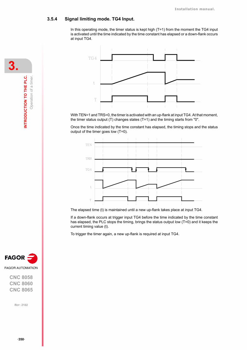
Installation manual.
CNC 8058CNC 8060CNC 8065
3.
INT
RO
DU
CT
ION
TO
TH
E P
LC
.
Ope
ratio
n of
a ti
mer
.
ꞏ350ꞏ
REF: 2102
3.5.4 Signal limiting mode. TG4 Input.
In this operating mode, the timer status is kept high (T=1) from the moment the TG4 inputis activated until the time indicated by the time constant has elapsed or a down-flank occursat input TG4.
With TEN=1 and TRS=0, the timer is activated with an up-flank at input TG4. At that moment,the timer status output (T) changes states (T=1) and the timing starts from "0".
Once the time indicated by the time constant has elapsed, the timing stops and the statusoutput of the timer goes low (T=0).
The elapsed time (t) is maintained until a new up-flank takes place at input TG4.
If a down-flank occurs at trigger input TG4 before the time indicated by the time constanthas elapsed, the PLC stops the timing, brings the status output low (T=0) and it keeps thecurrent timing value (t).
To trigger the timer again, a new up-flank is required at input TG4.
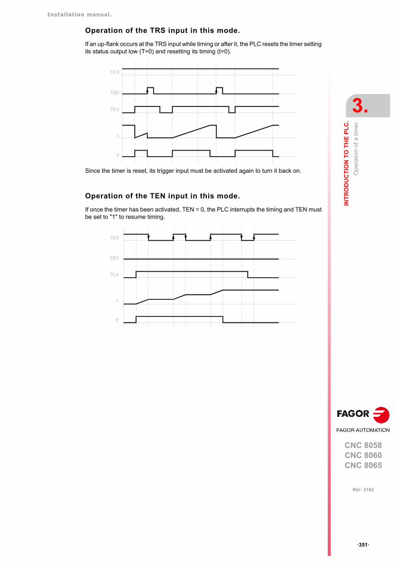
Installation manual.
CNC 8058CNC 8060CNC 8065
INT
RO
DU
CT
ION
TO
TH
E P
LC
.
3.
Ope
ratio
n of
a ti
mer
.
ꞏ351ꞏ
REF: 2102
Operation of the TRS input in this mode.
If an up-flank occurs at the TRS input while timing or after it, the PLC resets the timer settingits status output low (T=0) and resetting its timing (t=0).
Since the timer is reset, its trigger input must be activated again to turn it back on.
Operation of the TEN input in this mode.
If once the timer has been activated, TEN = 0, the PLC interrupts the timing and TEN mustbe set to "1" to resume timing.
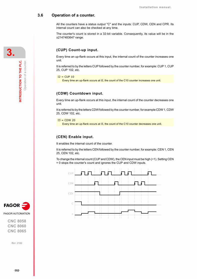
Installation manual.
CNC 8058CNC 8060CNC 8065
3.
INT
RO
DU
CT
ION
TO
TH
E P
LC
.
Op
erat
ion
of a
co
unte
r.
ꞏ352ꞏ
REF: 2102
3.6 Operation of a counter.
All the counters have a status output "C" and the inputs: CUP, CDW, CEN and CPR. Itsinternal count can also be checked at any time.
The counter's count is stored in a 32-bit variable. Consequently, its value will be in the±2147483647 range.
(CUP) Count-up input.
Every time an up-flank occurs at this input, the internal count of the counter increases oneunit.
It is referred to by the letters CUP followed by the counter number, for example: CUP 1, CUP25, CUP 102, etc.
(CDW) Countdown input.
Every time an up-flank occurs at this input, the internal count of the counter decreases oneunit.
It is referred to by the letters CDW followed by the counter number, for example CDW 1, CDW25, CDW 102, etc.
(CEN) Enable input.
It enables the internal count of the counter.
It is referred to by the letters CEN followed by the counter number, for example: CEN 1, CEN25, CEN 102, etc.
To change the internal count (CUP and CDW), the CEN input must be high (=1). Setting CEN= 0 stops the counter's count and ignores the CUP and CDW inputs.
I2 = CUP 10Every time an up-flank occurs at I2, the count of the C10 counter increases one unit.
I3 = CDW 20Every time an up-flank occurs at I3, the count of the C10 counter decreases one unit.
Installation manual.
CNC 8058CNC 8060CNC 8065
INT
RO
DU
CT
ION
TO
TH
E P
LC
.
3.
Op
erat
ion
of a
co
unte
r.
ꞏ353ꞏ
REF: 2102
(CPR) Preset input.
To preset the counter with the desired value.
It is referred to with the letters CPR followed by the counter number and the preset countvalue. The counter is preset with the indicated value with an up-flank at the CPR input.
The count value may be indicated by a numeric value or by the internal value of a register"R". Its value must be between 0 and ± 2,147,483.647.
(C) Status output.
It indicates the logic state of the counter. It is referred to by the letter "C" followed by thecounter number, for example: C1, C25, C102, etc.
The logic status of the counter will be C=1 when its count value is "0" and C=0 if otherwise.
(C) Count value.
It indicates the value of the internal count of the counter.
It is referred to by the letter "C" followed by the counter number, for example: C1, C25, C102,etc. Its representation C123 is the same as that of the status output, but different typeinstructions are used for them.
In binary instruction, it refers to the logic status of the counter.
In arithmetic and comparison instructions, it refers to the internal count of the counter.
The PLC has a 32-bit variable to store the count of each counter.
CPR 20 100Presets counter C20 with a value of 100.
CPR 22 R200Presets counter C22 with the value of register R200
C123 = M100Assigns the status (0/1) of C123 to M100
I2 = MOV C123 R200Transfers the count of C123 to register R200.
CPS C123 GT 1000 = M100Compares whether the count of C123 is greater than 1000. If so, it activates mark M100.
Installation manual.
CNC 8058CNC 8060CNC 8065
3.
INT
RO
DU
CT
ION
TO
TH
E P
LC
.
Op
erat
ion
of a
co
unte
r.
ꞏ354ꞏ
REF: 2102
CNC 8058CNC 8060CNC 8065
4
ꞏ355ꞏ
REF: 2102
4. PLC PROGRAMMING.
The PLC program may comprise the following modules. Every module must begin with thedirective instruction that defines it (CY1, PRG, PE) and end with the directing instruction END.
• First Cycle module (CY1).
• Main module (PRG).
• Periodic module (PE).
All of them consist of a series of instructions that depending on their function may be eitherdirecting or executable instructions.
Directing instructions.
The directing instructions provide the PLC with information on the type of module (PRG,CY1, ...) and on how it must be executed (REA, IMA, ...).
Executable instructions.
With the executable instructions, it is possible to check and/or change the status of the PLCresources. They consist of:
• Logic or Boolean instructions (I28 AND I30).
• Action instructions (=O25).
Logic expressions consist of:
• Consulting instructions (I28, O25).
• Operators (AND).
Logic expressions can be written in two or more different lines without having to include anydividing character. However, to make the program easier to understand, the "\" character maybe inserted at the end of each line, but it is not necessary.
The following programming examples are equivalent.
Option 1. I32 AND I36 AND M111 = O25
Option 2. I32 AND I36 AND M111= O25
Option 3. I32 AND I36 AND M111= O25
Option 4. I32 \AND I36 \AND M111= O25
Installation manual.
CNC 8058CNC 8060CNC 8065
4.
PL
C P
RO
GR
AM
MIN
G.
ꞏ356ꞏ
REF: 2102
Comments.
All comments must begin with ";". Lines beginning with a ";" are considered comments andare not executed.
Empty lines are also possible.
Programming example:
PRG ; Directing instruction
; Example ; Comment
I100 = M102 ; Executable instruction
I28 AND I30 ; Logic expression
= O25 ; Action instruction
I32 \ ; Consulting instruction (1st part of expression)
AND I36 ; Consulting instruction (2nd part of expression)
= M300 ; Action instruction
END ; Directing instruction
Installation manual.
CNC 8058CNC 8060CNC 8065
PL
C P
RO
GR
AM
MIN
G.
4.
Dire
ctin
g in
stru
ctio
ns.
ꞏ357ꞏ
REF: 2102
4.1 Directing instructions.
They provide the PLC with information on the type of program module and on how it mustbe executed. The available directing instructions are:
PRG, PE t, CY1Type of module.
The PLC program is structured by modules. Every module must begin with the directiveinstruction that defines it (CY1, PRG, PE) and end with the directing instruction END. See"3.2 Modular structure of the PLC program." on page 335.
ENDEnd of module or subroutine.
It must be defined for each module or subroutine.
A carriage return (empty line) is required after the last END.
REA, IMAReal or image values.
They indicate whether the following consultations are carried out using the real values (REA)or image values (IMA) or the I, O, M resources. The rest of the resources have no imagevalues, only real.
The real value is the one the resource has at that time and the image value is the one it hadat the end of the previous cycle scan. Image values (IMA) and real values (REA) may becombined in the same instruction.
By default, all the modules (PRG, CY1, PEt) operate with real resource values. Actioninstructions (=O32) always update the real values of the PLC resources.
PRG, PE t, CY1 Type of module.
END End of module.
REA, IMA Real or image values.
L Label.
SUB Subroutine definition.
DEF, PDEF Symbol definition.
NOMONIT No monitoring.
EXTERN External subroutine definition.
CY1 First cycle module.
PRG Main module.
PE t Periodic module. It is executed every "t" milliseconds.
CY1 ; Beginning of the CY1 module
···
END ; End of the CY1 module
PRG ; Beginning of the PRG module
···
END ; End of the PRG module
IMA I3 AND REA M4 = 02
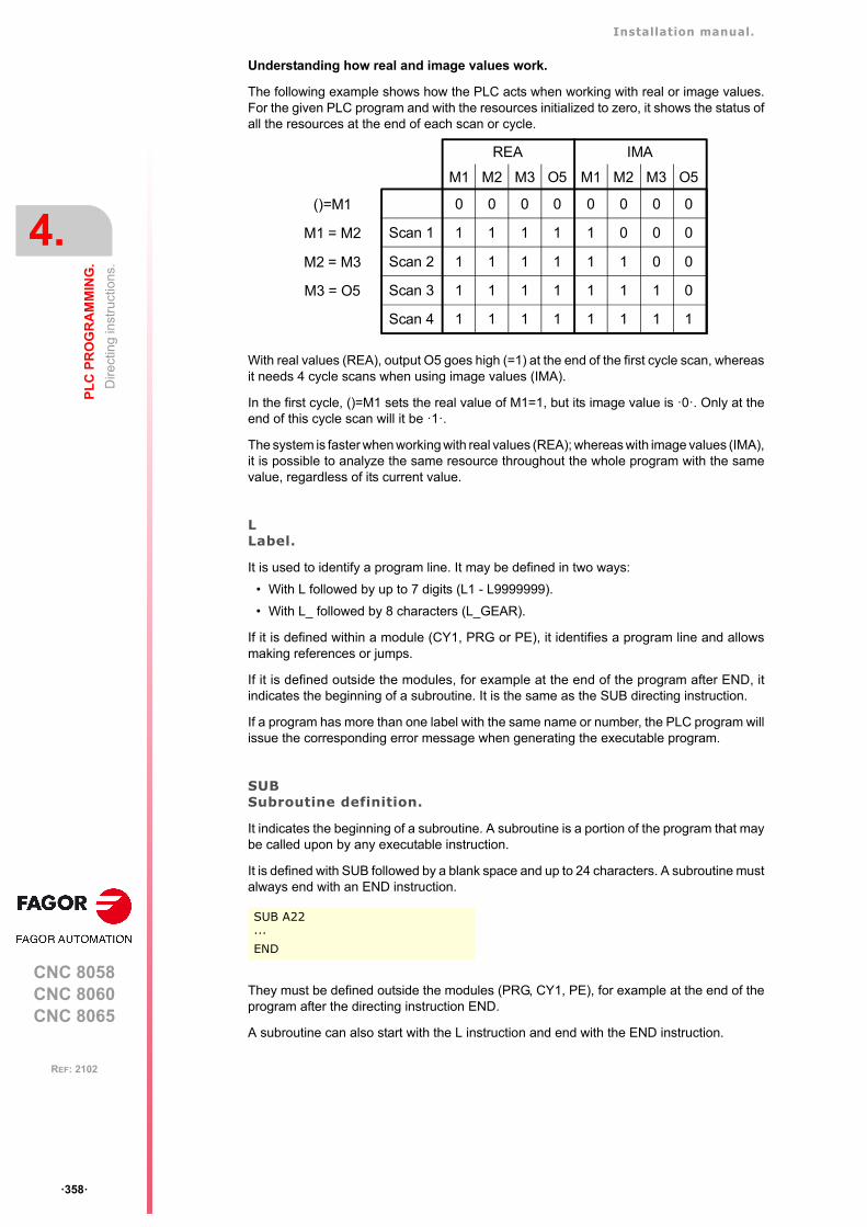
Installation manual.
CNC 8058CNC 8060CNC 8065
4.
PL
C P
RO
GR
AM
MIN
G.
Dire
ctin
g in
stru
ctio
ns.
ꞏ358ꞏ
REF: 2102
Understanding how real and image values work.
The following example shows how the PLC acts when working with real or image values.For the given PLC program and with the resources initialized to zero, it shows the status ofall the resources at the end of each scan or cycle.
With real values (REA), output O5 goes high (=1) at the end of the first cycle scan, whereasit needs 4 cycle scans when using image values (IMA).
In the first cycle, ()=M1 sets the real value of M1=1, but its image value is ꞏ0ꞏ. Only at theend of this cycle scan will it be ꞏ1ꞏ.
The system is faster when working with real values (REA); whereas with image values (IMA),it is possible to analyze the same resource throughout the whole program with the samevalue, regardless of its current value.
LLabel.
It is used to identify a program line. It may be defined in two ways:
• With L followed by up to 7 digits (L1 - L9999999).
• With L_ followed by 8 characters (L_GEAR).
If it is defined within a module (CY1, PRG or PE), it identifies a program line and allowsmaking references or jumps.
If it is defined outside the modules, for example at the end of the program after END, itindicates the beginning of a subroutine. It is the same as the SUB directing instruction.
If a program has more than one label with the same name or number, the PLC program willissue the corresponding error message when generating the executable program.
SUBSubroutine definition.
It indicates the beginning of a subroutine. A subroutine is a portion of the program that maybe called upon by any executable instruction.
It is defined with SUB followed by a blank space and up to 24 characters. A subroutine mustalways end with an END instruction.
They must be defined outside the modules (PRG, CY1, PE), for example at the end of theprogram after the directing instruction END.
A subroutine can also start with the L instruction and end with the END instruction.
SUB A22···END
Scan 1
Scan 4
Scan 3
Scan 2
M1 M2 M3 O5 M1 M2 M3 O5
1 1 1 1 1 1 1 1
1 1 1 1 1 1 1 0
1 1 1 1 1 1 0 0
1 1 1 1 1 0 0 0
0 0 0 0 0 0 0 0
REA IMA
()=M1
M3 = O5
M2 = M3
M1 = M2
Installation manual.
CNC 8058CNC 8060CNC 8065
PL
C P
RO
GR
AM
MIN
G.
4.
Dire
ctin
g in
stru
ctio
ns.
ꞏ359ꞏ
REF: 2102
EXTERNExternal subroutine definition.
The subroutines defined in the "C" language file used by the program must be defined asexternal at the beginning of the program before the DEF instructions and the modules: CY1,PRE and PEt. With the EXTERN instruction, those subroutines may be defined one by one.
It is defined with EXTERN followed by a blank space and the name of the subroutine withup to 24 characters.
DEF, PDEFSymbol definition.
Symbols are always programmed at the beginning of the program, before the modules CY1,PRE and PEt. Since the PLC project may consist of several files and the symbols must bedefined before they are used, we recommend to define them in the first file of the PLC project.However, the symbols may be defined in any file as long as they are used in that file or inlater files.
The PLC allows to define a number of symbols for easier programming and laterunderstanding of the PLC program. These symbols are programmed using the DEF o PDEFinstruction followed by the name of the symbol, a constant or PLC resource. The PLC allowsassociating a symbol may be associated with any decimal or hexadecimal number or PLCresource such as inputs (I), outputs (O), marks (M), registers (R), register bits, counters (C)and timers (T).
Every time the PLC compiles a program with subroutines in C language, it generates thefile plc_pdef.h with the #defines of all the symbols defined in the PLC program. The file issaved in the folder ..\MTB\PLC\Project.
Symbols will consist of a sequence of up to 20 characters with capital letters (A..Z) and digits(0..9). Symbols may also begin with the "/" character; in that case, the next character mustbe a letter. The name may have a "_" character, but it cannot be its first character. Wordsreserved for instructions cannot be used in symbols.
Duplicate symbols cannot be defined; but several symbols may be assigned to the sameresource. Once a symbol has been associated with a resource or numeric value, it is possibleto use the name of the resource, the number or its associated symbol.
Accessing the PDEF symbols from a part-program or from an application.
Accessing the symbols defined with the PDEF instruction from a part-program, MDI orexternal application is done using variables as follows. Consulting this variable from the part-program interrupts block preparation.
V.PLC.symbol Access from a part-program or MDI.
PLC.symbol Access from an external application.
EXTERN SUMAEXTERN TEMPERATURE
DEF The DEF directive allows you to define an unlimited number of symbols for usein the PLC program or in a PLC subroutine in C language.
PDEF The PDEF directing instruction can define up to 200 symbols and can be usedin the PLC program, a PLC subroutine in C language, part program (usingvariables) or external application. Symbols exceeding this limit will be ignored andthe CNC will issue the corresponding warning.
The symbols associated with a constant can only be used inside the PLCprogram; they can be accessed neither from the part-program nor from anexternal application. The symbols associated with a constant cannot bemonitored, used in a trace of the logic analyzer or accessed from externalvariables.
PDEF COOL I12PDEF CONSTANT $FFFF3DEF DATA_D1 372893DEF DATA_D3 -437289DEF /FAN I23
Installation manual.
CNC 8058CNC 8060CNC 8065
4.
PL
C P
RO
GR
AM
MIN
G.
Dire
ctin
g in
stru
ctio
ns.
ꞏ360ꞏ
REF: 2102
The variables may be read or written depending on the resource assigned to the symboldefined with PDEF.
NOMONITNo monitoring.
When programming this directing instruction, it does not generate information necessary tomonitor the PLC program. In other words, the program is not monitored.
It must always be programmed at the beginning of the program, before the DEF instructionand the modules: CY1, PRG and PEt.
This instruction should only be used when the PLC program execution time is very critical.Define it after debugging the PLC program.
Programming example.
;No monitoring
NOMONIT
;External subroutine
EXTERN TEMPERATURE
;Symbol definition
DEF COOL I12DEF /FAN I23
;CY1 module
CY1···END
;PRG module
PRG···IMA I3 AND REA M4 = 02···L_GEAR···END
;PEt module
PE 100···END
;Subroutine
SUB A22···END
Installation manual.
CNC 8058CNC 8060CNC 8065
PL
C P
RO
GR
AM
MIN
G.
4.
Co
nsul
ting
inst
ruct
ions
.
ꞏ361ꞏ
REF: 2102
4.2 Consulting instructions.
They may be used to check the status of PLC resources as well as the marks and registersfor CNC-PLC communication. There are the following consulting instructions.
• Simple consulting instructions.
• Flank detection instructions.
• Comparing instructions.
4.2.1 Simple consulting instructions.
They test the status of the resources and they return their logic state.
• Inputs (I1-I1024)
• Outputs (O1-O1024)
• Local inputs (LI1-LI16)
• Local outputs (LO1-LO8)
• Marks (M1-M8192)
• Messages (MSG1-MSG1024)
• Errors (ERR1-ERR1024)
• Clocks (CLK)
• Registers (R1-R1024)
• Register bits (B0-B31 R1-R1024)
• Timer status (T1-T512)
• Counter status (C1-C256)
• CNC-PLC communication marks.
I12
Returns a "1" if the I12 input is active and a "0" if otherwise.
START
Returns a "1" when the CYCLE START key of the front panel is pressed and a "0" ifotherwise.
Installation manual.
CNC 8058CNC 8060CNC 8065
4.
PL
C P
RO
GR
AM
MIN
G.
Co
nsul
ting
inst
ruct
ions
.
ꞏ362ꞏ
REF: 2102
4.2.2 Flank detection instructions.
They check whether the state of a resource has changed since the last time this consultationwas made. This consultation may be made on real or image values. The instructionsavailable are:
DFUDetect an up flank.
It detects an up-flank (0-to-1 change) at the indicated resource. It returns a "1" if it happened.
DFDDetect a down flank.
It detects an down-flank (0-to-1 change) at the indicated resource. It returns a "1" if ithappened.
The programming format for DFU and DFD is:
DFU Detect an up flank.
DFD Detect a down flank.
DFUDFD
I1ꞏꞏ1024O1ꞏꞏ1024M1ꞏꞏ8192MSG1ꞏꞏ1024ERR1ꞏꞏ1024B0ꞏꞏ31 R1ꞏꞏ1024CLKCNC-PLC communication marks
DFU I23DFU B3R120DFU AUXENDDFD O32DFD M45
Installation manual.
CNC 8058CNC 8060CNC 8065
PL
C P
RO
GR
AM
MIN
G.
4.
Co
nsul
ting
inst
ruct
ions
.
ꞏ363ꞏ
REF: 2102
4.2.3 Comparing instructions.
CPSCompare two operands.
With the CPS instruction, it is possible to make comparisons between two operands,checking whether the first one is greater than (GT), greater than or equal to (GE), equal to(EQ), different from (NE), less than or equal to (LE) or less than (LT) the second one.
It is possible to use as operands, timers (internal count), counters (internal count), registers,registers for CNC-PLC communication and decimal (#) or hexadecimal numbers within±2147483647 or between 0 and $FFFFFFFF.
If the required condition is met, the consulting instruction returns a logic value "1" and a "0"if otherwise.
The programming format is:
CPS T1ꞏꞏ512C1ꞏꞏ256R1ꞏꞏ1024R CNC-PLC#
GTGEEQNELELT
T1ꞏꞏ512C1ꞏꞏ256R1ꞏꞏ1024R CNC-PLC#
CPS C12 GT R14 = M100
If the internal count of counter "C12" is GREATER than the value of register R14, thePLC will assign the value of "1" to mark M100 and a "0" if otherwise.
CPS T2 EQ 100 = TG1 5 2000
When the time elapsed at timer "T2" is equal to 100 milliseconds, it will trigger timer"T5" in monostable mode and with time constant of 2 seconds.
Installation manual.
CNC 8058CNC 8060CNC 8065
4.
PL
C P
RO
GR
AM
MIN
G.
Op
erat
ors
and
sym
bol
s.
ꞏ364ꞏ
REF: 2102
4.3 Operators and symbols.
They are used to group and operate with different consulting instructions.
The available operators are NOT, AND, OR, XOR. The operators are associated from leftto right and the priorities ordered from the highest to the lowest are: NOT AND XOR OR.
The available symbols are: \, (, ).
NOTNegates the result of the consultation.
ANDLogic function "AND".
ORLogic function "OR”.
XORLogic "Exclusive OR" function.
\Line feed.
It is used to write a logic expression in more than one line The following may be programmed:
or also:
( )Open and close parenthesis.
They help clarify and select the order the logic expression is evaluated.
A consulting instruction consisting of only these two operators always has a value of "1".
NOT I2 = O3
Output "O3" will be active when input I2 is not.
I4 AND I5 = O6
Output "O6" will be active when both inputs (I4, I5) are active.
I7 OR I8 = O9
Output "O9" will be active when either one (or both) inputs are active.
I10 XOR I11 = O12
Output "O12" will be active when both inputs I10 and I11 have different logic states.
DFU MSTROBE AND CPS MFUN* EQ 3 = M1003
DFU MSTROBE \AND CPS MFUN* EQ 3= M1003
(I2 OR I3) AND (I4 OR (NOT I5 AND I6)) = O7
( ) = O2
Output O2 will always be high "1".
Installation manual.
CNC 8058CNC 8060CNC 8065
PL
C P
RO
GR
AM
MIN
G.
4.
Act
ion
inst
ruct
ions
.
ꞏ365ꞏ
REF: 2102
4.4 Action instructions.
Action instructions allow changing the status of PLC resources and CNC-PLCcommunication marks depending on the result of the logic expression.
Logic expression = Action instruction
There may be several action instructions associated with a single logic expression. All theaction instructions must be preceded by the "=" sign.
All the action instructions admit a prior NOT that inverts the result of the expression for thataction.
The action instructions are divided into:
• Assignment binary action instructions.
• Conditional binary action instructions.
• Sequence breaking action instructions.
• Arithmetic action instructions.
• Logic action instructions.
• Specific action instructions.
Action instructions may change the status of all the PLC resources except for the physicalinputs being used. When seeing the field "I 1/1024", one must understand that only the statusof the unused inputs may be changed.
For example, if physical inputs I1 through I32 are used, only inputs I33 through I1024 maybe changed.
I2 = O3 = NOT M100 = NOT TG1 2 100 = CPR 1 100
Output O3 will show the status of input I2.
Mark M100 will show the negated state of input I2.
A down-flank at input I2 will activate the trigger input TG1 of timer T2.
An up-flank at I2 will preset counter C1 with a value of 100.
Installation manual.
CNC 8058CNC 8060CNC 8065
4.
PL
C P
RO
GR
AM
MIN
G.
Act
ion
inst
ruct
ions
.
ꞏ366ꞏ
REF: 2102
4.4.1 Assignment binary instructions.
They assign the value (0/1) resulting from a logic expression to the indicated resource.
= I 1/1024 = O 1/1024 = M 1/8192
= MSG 1/1024 = ERR 1/1024 = TEN 1/512
= TRS 1/512 = TGn 1/512 #/R = CUP 1/256
= CDW 1/256 = CEN 1/256 = CPR 1/256 #/R
= B 0/31 R 1/499 = CNC-PLC mark
I3 = TG1 4 100
Assigns the status of input I3 to the trigger input TG1 of timer T4. Thus, an up-flankat I3 will trigger the TG1 input of timer T4.
(I2 OR I3) AND (I4 OR (NOT I5 AND I6)) = M111
Assigns to mark M111 the result of evaluating the logic expression: (I2 OR I3) AND (I4OR (NOT I5 AND I6)).
Installation manual.
CNC 8058CNC 8060CNC 8065
PL
C P
RO
GR
AM
MIN
G.
4.
Act
ion
inst
ruct
ions
.
ꞏ367ꞏ
REF: 2102
4.4.2 Conditional binary instructions.
There are 3 instructions: SET, RES and CPL, that are used to change the status of theindicated resource.
The programming format is:
= SETIf expression = "1", it sets the resource to "1".
If the result of the logic expression is a "1", it sets the indicated resource to "1". If the resultis "0", it does not change the resource.
= RESIf expression = "1", it sets the resource to "0".
If the result of the logic expression is a "1", it sets the indicated resource to "0". If the resultis "0", it does not change the resource.
= CPLIf expression = "1", it complements the resource.
If the result of the logic expression is a "1", it complements the status of the indicatedresource. If the result is "0", it will not change the resource.
= SET= RES= CPL
I 1/1024O 1/1024M 1/8192MSG 1/1024ERR 1/1024B 0/31 R 1/1024CNC-PLC mark
CPS T2 EQ 100 = SET B0R100
When the timing of timer T2 reaches 100 milliseconds, it sets bit 0 of register R100 to"1".
I12 OR NOT I22 = RES M55 = NOT RES M65
When the result of the logic expression is a "1", the PLC sets "M55 = 0"; but does notchange M65. If the result of the logic expression is a "0", the PLC does not change M55;but it sets "M65 = 0".
DFU I8 OR DFD M22 = CPL B12R35
Every time an up-flank is detected at input I8 or down-flank of mark M22, the PLCcomplements the state of bit 12 of register R35.
Installation manual.
CNC 8058CNC 8060CNC 8065
4.
PL
C P
RO
GR
AM
MIN
G.
Act
ion
inst
ruct
ions
.
ꞏ368ꞏ
REF: 2102
4.4.3 Sequence breaking action instructions.
These actions interrupt the sequence of a program, resuming it somewhere else in theprogram.
= JMPUnconditional jump.
If the result of the logic expression is a "1", it jumps to the indicated label. If the result is a"0", it goes on to the next program line.
Its syntax depends on how the label to jump to was defined
= JMP L123 If the label was defined as L123.
= JMP L_ASA2 If the label was defined as L_ASA2.
= CALCall to a subroutine.
If the result of the logic expression is a "1", this action executes the indicated subroutine.If the result of the logic expression is a "0", the PLC will ignore this action and the programwill go on without executing that subroutine.
Once the subroutine execution is over, the PLC will continue at the action instruction orexecutable instruction programmed after CAL.
Its syntax depends on how its associated subroutine was defined.
= CAL OILING If it was defined as SUB OILING.
= CAL L234 If it was defined as L234.
= CAL L_GEAR If it was defined as L_GEAR.
= RETReturn or end of a subroutine.
If the result of the logic expression is a "1", the PLC will treat this action like an ENDinstruction. If the result is a "0", the PLC will ignore it.
If while executing a subroutine, the PLC detects a validated RET, it will conclude thesubroutine.
I8 = JMP L12
If I8=1 the program continues at L12 and it does not execute the intermediate blocks.
NOT M14 AND NOT B7R120 = O8CPS T2 EQ 2000 = O12L12(I12 AND I23) OR M54 = O6
I2 = CAL L5 = O2
With I2=1, subroutine L5 will be executed and once executed, the PLC will set O2 tothe value of input I2 (=1). If I2=0, the subroutine is not executed and the PLC sets outputO2 to the status of input I2 (=0).
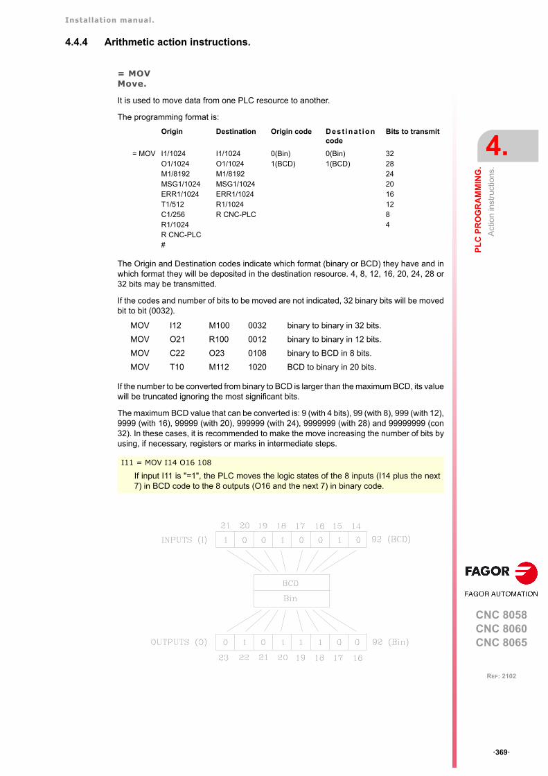
Installation manual.
CNC 8058CNC 8060CNC 8065
PL
C P
RO
GR
AM
MIN
G.
4.
Act
ion
inst
ruct
ions
.
ꞏ369ꞏ
REF: 2102
4.4.4 Arithmetic action instructions.
= MOVMove.
It is used to move data from one PLC resource to another.
The programming format is:
The Origin and Destination codes indicate which format (binary or BCD) they have and inwhich format they will be deposited in the destination resource. 4, 8, 12, 16, 20, 24, 28 or32 bits may be transmitted.
If the codes and number of bits to be moved are not indicated, 32 binary bits will be movedbit to bit (0032).
If the number to be converted from binary to BCD is larger than the maximum BCD, its valuewill be truncated ignoring the most significant bits.
The maximum BCD value that can be converted is: 9 (with 4 bits), 99 (with 8), 999 (with 12),9999 (with 16), 99999 (with 20), 999999 (with 24), 9999999 (with 28) and 99999999 (con32). In these cases, it is recommended to make the move increasing the number of bits byusing, if necessary, registers or marks in intermediate steps.
Origin Destination Origin code Dest inat ioncode
Bits to transmit
= MOV I1/1024O1/1024M1/8192MSG1/1024ERR1/1024T1/512C1/256R1/1024R CNC-PLC#
I1/1024O1/1024M1/8192MSG1/1024ERR1/1024R1/1024R CNC-PLC
0(Bin)1(BCD)
0(Bin)1(BCD)
32282420161284
MOV I12 M100 0032 binary to binary in 32 bits.
MOV O21 R100 0012 binary to binary in 12 bits.
MOV C22 O23 0108 binary to BCD in 8 bits.
MOV T10 M112 1020 BCD to binary in 20 bits.
I11 = MOV I14 O16 108
If input I11 is "=1", the PLC moves the logic states of the 8 inputs (I14 plus the next7) in BCD code to the 8 outputs (O16 and the next 7) in binary code.
Installation manual.
CNC 8058CNC 8060CNC 8065
4.
PL
C P
RO
GR
AM
MIN
G.
Act
ion
inst
ruct
ions
.
ꞏ370ꞏ
REF: 2102
= NGU R 1/1024Complements the bits of a register.
It changes the state of each one of the 32 bits of a register.
= NGS R 1/1024Register sign change.
Changes the sign of the register.
= ADS, = SBS, = MLS, = DVS, = MDSArithmetic operations.
for adding (ADS), subtracting (SBS), multiplying (MLS), dividing (DVS) and calculating themodule or remainder of a division (MDS).
Its programming format is:
"Operation" "1st operand" "2nd operand" "Result".
• The operands may be: Registers, CNC-PLC communication registers and numbers(#) in the ±2147483647 range or between 0 and $FFFFFFFF.
• The result of the operation may be stored in a register or in a CNC-PLCcommunication register.
Examples with R100=1234 and R101=100.
I15 = NGU R152
If input "I15 is =1", the PLC changes the state of the 32 bits of register R152.
R152 before: 0001 0001 0001 0001 0001 0001 0001 0001
R152 after: 1110 1110 1110 1110 1110 1110 1110 1110
I16 = NGS R89
If input "I16 = 1", the PLC changes the sign of the contents of register R89.
R89 before: 0001 0001 0001 0001 0001 0001 0001 0001
R89 after: 1110 1110 1110 1110 1110 1110 1110 1111
= ADS= SBS= MLS= DVS= MDS
R1/1024R CNC-PLC#
R1/1024R CNC-PLC#
R1/1024R CNC-PLC
() = ADS R100 R101 R102 ; R102 = 1234 + 100 = 1334
() = SBS R100 R101 R103 ; R103 = 1234 - 100 = 1134
() = MLS R100 R101 R104 ; R104 = 1234 x 100 = 123400
() = DVS R100 R101 R105 ; R105 = 1234 : 100 = 12
() = MDS R100 R101 R106 ; R106 = 1234 MOD 100 = 34
() = ADS 1563 R101 R112 ; R112 = 1563 + 100 = 1663
() = SBS R100 1010 R113 ; R113 = 1234 - 1010 = 224
() = MLS 1563 100 R114 ; R114 = 1563 x 100 = 156300
() = MLS SANALOG 10000 R115
= DVS R115 32767 R115 ; Spindle speed command in mV.
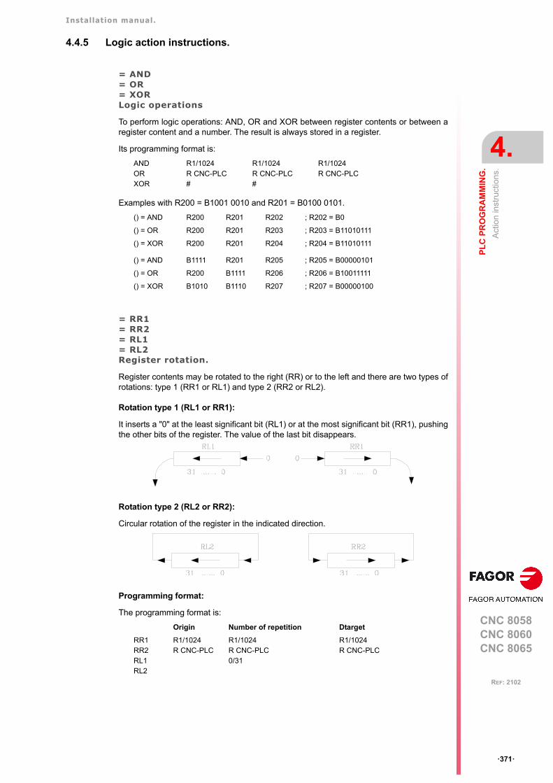
Installation manual.
CNC 8058CNC 8060CNC 8065
PL
C P
RO
GR
AM
MIN
G.
4.
Act
ion
inst
ruct
ions
.
ꞏ371ꞏ
REF: 2102
4.4.5 Logic action instructions.
= AND= OR= XORLogic operations
To perform logic operations: AND, OR and XOR between register contents or between aregister content and a number. The result is always stored in a register.
Its programming format is:
Examples with R200 = B1001 0010 and R201 = B0100 0101.
= RR1= RR2= RL1= RL2Register rotation.
Register contents may be rotated to the right (RR) or to the left and there are two types ofrotations: type 1 (RR1 or RL1) and type 2 (RR2 or RL2).
Rotation type 1 (RL1 or RR1):
It inserts a "0" at the least significant bit (RL1) or at the most significant bit (RR1), pushingthe other bits of the register. The value of the last bit disappears.
Rotation type 2 (RL2 or RR2):
Circular rotation of the register in the indicated direction.
Programming format:
The programming format is:
ANDORXOR
R1/1024R CNC-PLC#
R1/1024R CNC-PLC#
R1/1024R CNC-PLC
() = AND R200 R201 R202 ; R202 = B0
() = OR R200 R201 R203 ; R203 = B11010111
() = XOR R200 R201 R204 ; R204 = B11010111
() = AND B1111 R201 R205 ; R205 = B00000101
() = OR R200 B1111 R206 ; R206 = B10011111
() = XOR B1010 B1110 R207 ; R207 = B00000100
Origin Number of repetition Dtarget
RR1RR2RL1RL2
R1/1024R CNC-PLC
R1/1024R CNC-PLC0/31
R1/1024R CNC-PLC

Installation manual.
CNC 8058CNC 8060CNC 8065
4.
PL
C P
RO
GR
AM
MIN
G.
Act
ion
inst
ruct
ions
.
ꞏ372ꞏ
REF: 2102
The origin and destination registers must always be defined, even when they are both thesame. The number of repetitions indicates the consecutive number of times the register willbe rotated.
RR1 R100 1 R200
It makes one type-1 right-hand rotation of R100 leaving the result in R200.
RL2 R102 4 R101
It makes four type-2 left-hand rotation of R102 leaving the result in R101.
Installation manual.
CNC 8058CNC 8060CNC 8065
PL
C P
RO
GR
AM
MIN
G.
4.
Act
ion
inst
ruct
ions
.
ꞏ373ꞏ
REF: 2102
4.4.6 Specific action instructions.
= ERAClears a group of resources.
It is used to clear or initialize a group of same-type resources. Indicate the first and lastresource to be erased.
The programming format is:
When erasing a group of I, O, M, MSG, ERR or R, the PLC sets them all to "0".
Erasing a group of timers is like resetting them and erasing a group of counters is likepresetting with a "0" value.
This action is especially handy when executed in the first cycle module (CY1) in order to setthe desired resources to their initial work conditions (states).
=PARParity of a register.
It analyzes the type of parity of a register. If the register has EVEN parity, this instruction setsthe selected mark, message or error to "1" and to "0" if it has ODD parity.
The programming format is:
= CNCRD= CNCWRReading (CNCRD) and writing (CNCWR) of CNC variables.
Used to read (CNCRD) and write (CNCWR) the internal CNC variables. Their programmingformat is:
CNCRD (Variable, Register, Mark)
CNCWR (Register, Variable, Mark)
The CNCRD action loads the contents of the variable into the register and the CNCWR actionloads the contents of register into the variable. The mark is set to "1" at the beginning of theoperation and it keeps its value until the end of the operation.
When using CNCRD to read the variables of the arithmetic parameters and those of the OEM,it returns the value multiplied by 10000 (float mode reading).
When requesting information on a nonexistent variable (for example the position of annonexistent axis), it will show the relevant error message. Likewise, when trying to read avalue whose range is greater than that of the PLC register, the CNC will return a zero value
= ERA I1/1024O1/1024M1/8192MSG1/1024ERR1/1024T1/512C1/256R1/1024
1/10241/10241/81921/10241/10241/5121/2561/1024
I10 = ERA O5 12
If input "I10=1", the PLC sets outputs O5 through O12 (both included) to "0".
I23 = ERA C15 18
If input "I23 =1", the PLC presets counters C15 through C18 (both included) to "0".
= PAR R1/1024R CNC-PLC
M1/8192MSG1/1024ERR1/1024M CNC-PLC
I15 = PAR R123 M222
If input "I15=1", the PLC analyzes register R123 and sets mark M222 to "1" if EVENparity or to "0" if ODD parity.
Installation manual.
CNC 8058CNC 8060CNC 8065
4.
PL
C P
RO
GR
AM
MIN
G.
Act
ion
inst
ruct
ions
.
ꞏ374ꞏ
REF: 2102
and will issue the corresponding error message. Whenever an error occurs when readinga variable, the communication mark will remain at "1".
Syntax of the variables in commands CNCRD and CNCWR.
For these two commands, it is possible to define, in the mnemonic of the variable, the channelnumber using an integer, a register or a symbol defined with DEF or PDEF.
If the mnemonic of the variable contains numerical suffixes, e.g. (V.).G.GUP[i], they too canbe defined with an integer, a register or a symbol defined with DEF or PDEF.
Consulting synchronous and asynchronous variables.
Synchronous variables are the ones resolved immediately whereas asynchronous variablesare the ones requiring several cycle scans to be resolved.
• Example of how to access asynchronous variables:
<condition> AND NOT M11 = CNCRD (TM.TOOL, R11, M11)
do not repeat this consultation until it ends.
DFD M11 AND CPS R11 EQ 3 = ...
wait for the consultation to end before comparing the data.
• Examples of how to access synchronous variables:
<condition> = CNCRD (G.FREAL, R12, M12)CPS R12 GT 2000 = ...
No need to wait before consulting the data because synchronous variables areresolved immediately.
<condition> = CNCWR (R13, PLC.TIMER, M13)
It resets the clock enabled by the PLC with the value contained in register R13.
= CNCEXExecution of a CNC block.
It may be used to execute a CNC block in the indicated channel, including calls to subroutinesor to complete programs. It works like when executing a block in MDI. The restrictions forthe execution of commands are the same as for the MDI blocks.
Its programming format is:
CNCEX (block, mark, channel)
The mark is set to "1" at the beginning of the operation and it keeps its value until the endof the operation. If the channel is not indicated, the block is executed in the first or mainchannel.
Once the block has been executed, the CNC channel activates the FREE mark to let thePLC know that it is ready to accept a new block. The execution of the CNCEX commandmay be canceled with the mark PLCABORT.
CNCRD ([1].G.FREAL, R10, M1000)
... = MOV 1 R12CNCRD ([R12].G.FREAL, R10, M1000)
DEF CHANNEL 3CNCRD ([CHANNEL].G.FREAL, R10, M1000)
... = MOV 153 R101CNCWR (G.GUP[R101], R10, M1000)
DEF PARAM 153CNCRD (G.GUP[PARAM], R10, M1000)
... = CNCEX (G00 X0 Y0, M99, 2)
... = CNCEX (#CALL sub3.nc, M34)
Installation manual.
CNC 8058CNC 8060CNC 8065
PL
C P
RO
GR
AM
MIN
G.
4.
Act
ion
inst
ruct
ions
.
ꞏ375ꞏ
REF: 2102
Executing independent movements from the PLC. Commands MOVEABS, MOVEADDand MOVEINF.
The movements of the independent axes may be programmed directly or with the CNCEXcommand; however, it is not recommended to use both methods in the same PLC programor subroutine.
The treatment for the execution of the commands is different and the order they are executedmight not be the desired one. The CNCEX command is executed through a CNC channelwhereas the MOVE* commands are executed directly at the interpolator (usually fasterexecution).
The independent movements may be executed as follows: The two should not be used inthe same program or subroutine.
() = CNCEX(#MOVE ADD [X100,F100,NULL], M120,1)() = MOVEADD(X,100000,100000,NULL)
Installation manual.
CNC 8058CNC 8060CNC 8065
4.
PL
C P
RO
GR
AM
MIN
G.
Act
ion
inst
ruct
ions
.
ꞏ376ꞏ
REF: 2102
4.4.7 Action instruction of the electronic cam.
= CAM ON= TCAM ON= CAM OFFActivate the electronic cam with real coordinates (CAM ON), with theoretical coordinates (TCAM ON) or cancel the electronic cam (CAM OFF).
The programming format for each of them is the following.
CAM ON (cam, master/"TIME", slave, master_off, slave_off, range_master, range_slave, type)TCAM ON (cam, master/"TIME", slave, master_off, slave_off, range_master, range_slave, type)CAM OFF (slave)
Executing the CAM OFF command involves eliminating the synchronization of the cam.Once this command has been programmed, the cam ends when reaching the end of itsprofile.
Cam mode.
Two types of cams may be activated; cams in time or cams according to the position of themaster axis. The activation instruction is the same and it is selected by the call-parameters.
Cam number.
To activate a cam, it must have been previously defined at the cam editor, within the machineparameters.
Master axis activation range.
The cam is activated when the master axis is between the positions "master_off" and"master_off + range_master".
Range for the slave axis.
The cam applies it to the slave axis when the slave axis is between "slave_off" and "slave_off+ range_slave".
This function has a specific manual. This manual that you are reading now only offers some informationabout this function. Refer to the specific documentation to obtain further information regarding therequirements and operation of the electronic cam.
Parameter. Meaning.
cam Cam number.
master Name of the master axis.
TIME Time cam. When programming "TIME" instead of an axis name, the cam isinterpreted as being a time cam.
slave Name of the slave axis.
master_off Offset for the master axis.
slave_off Offset for the slave axis.
range_master Master axis activation scale or range.
range_slave Slave axis activation scale or range.
type It defines the type of cam; periodic or not periodic. It is programmed usingparameters "ONCE" (non-periodic cam) or "CONT" (periodic cam).
Installation manual.
CNC 8058CNC 8060CNC 8065
PL
C P
RO
GR
AM
MIN
G.
4.
Act
ion
inst
ruct
ions
.
ꞏ377ꞏ
REF: 2102
Cam type.
Depending on the execution mode, the time cams and the position cams may be of twodifferent types; i.e. periodic or non-periodic. It is selected with the type parameter.
If the master axis is a rotary module and the cam definition range is that module, the twoexecution modes are equivalent.
Either mode maintains synchronization until the #CAM OFF command is executed. Whenreaching that command, the execution of the cam will end the next time the end of the camprofile is reached.
= CAM SELECT= CAM DESELECTSelect (CAM SELECT) or cancel a file cam (CAM DESELECT).
The data of a cam may be defined in a file that may be loaded from the CNC or from thePLC. When executing a cam from a file, the CNC reads its data dynamically and,consequently, the number of points to define the cam is unlimited.
The following commands only define the location of the cam; to activate it, use the instruction#CAM ON (from the CNC) or the command CAM ON (from the PLC). After selecting a filecam, it stays available until the cam table of the machine parameters is validated or the CNCis turned off.
The programming format for each of them is the following.
CAM SELECT (cam, file)CAM DESELECT (cam)
Executing the CAM OFF command involves eliminating the synchronization of the cam.Once this command has been programmed, the cam ends when reaching the end of itsprofile.
Not periodic It is defined by assigning the "ONCE" value to the type parameter.
This mode maintains the synchronization for the range defined for themaster axis. If the master axis moves backwards or if it is a module,the slave axis will keep on executing the cam profile until thecancellation is programmed.
Periodic It is defined by assigning the "CONT" value to the type parameter.
In this mode, when reaching the end of the range of the master axis,it calculates the offset to execute the cam again shifted in the amountof that range. In other words, identical cams are executed along thepath of the master axis.
Parameter. Meaning.
cam Cam number.
file Name and path of the file containing the cam data.
Installation manual.
CNC 8058CNC 8060CNC 8065
4.
PL
C P
RO
GR
AM
MIN
G.
Act
ion
inst
ruct
ions
.
ꞏ378ꞏ
REF: 2102
4.4.8 Instructions for independent move: positioning.
= MOVE ABS= MOVE ADD= MOVE INFAbsolute positioning movement (MOV ABS), incremental (MOVE ADD) or no-end (MOVE INF).
The programming format for each of them is the following.
MOVE ABS (axis, pos, feed, blend)MOVE ADD (axis, pos, feed, blend)MOVE INF (axis, direction, feed, blend)
The programming units are the standard PLC units. The coordinates the feedrates will begiven in ten-thousandths if they are in mm or degrees or in hundred-thousandths if they arein inches.
Position to reach.
With MOVE ABS it will be defined in absolute coordinates whereas with MOVE ADD it willbe defined in incremental coordinates. For positioning, the zero offset active in the channelis ignored.
The moving direction is determined by the coordinate or the increment programmed. Forrotary axes, the moving direction is determined by the type of axis. If it is unidirectional, itpositions in the preset direction; otherwise, it positions via the shortest path.
Moving direction.
Moving direction. It is used with MOVE INF to execute an endless (infinite) movement untilthe axis limit is reached or until the movement is interrupted.
Dynamic blend with the next block
It sets the feedrate used to reach the position (dynamic blend with the next block). It isprogrammed with one of the following parameters.
This function has a specific manual. This manual that you are reading now only offers some informationabout this function. Refer to the specific documentation to obtain further information regarding therequirements and operation of the independent axes.
Parameter. Meaning.
axis Axis to position.
pos Position to reach.
direction Moving direction. It is programmed with parameters "DIRPOS" (positivedirection) or "DIRNEG" (negative direction).
feed Positioning feedrate
blend Dynamic blend with the next block It is programmed using parameters"PRESENT", "NULL", "NEXT" or "WAITINPOS.
PRESENT The axis reaches the indicated position at the feedrate indicated by theblock itself.
NEXT The axis reaches the indicated position at the feedrate indicated in thenext block.
NULL The axis reaches the indicated position at zero feedrate.
WAITINPOS The axis reaches the indicated position at zero feedrate and it waitsto be in position before executing the next block.
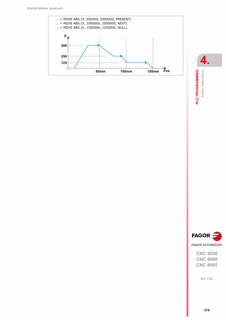
Installation manual.
CNC 8058CNC 8060CNC 8065
PL
C P
RO
GR
AM
MIN
G.
4.
Act
ion
inst
ruct
ions
.
ꞏ379ꞏ
REF: 2102
.. = MOVE ABS (X, 500000, 5000000, PRESENT)
.. = MOVE ABS (X, 1000000, 2500000, NEXT)
.. = MOVE ABS (X, 1500000, 1250000, NULL)
F
Pos
500
250
125
50mm 100mm 150mm
Installation manual.
CNC 8058CNC 8060CNC 8065
4.
PL
C P
RO
GR
AM
MIN
G.
Act
ion
inst
ruct
ions
.
ꞏ380ꞏ
REF: 2102
4.4.9 Instructions for independent move: synchronization.
= FOLLOW ON= TFOLLOW ON= FOLLOW OFFActivate the synchronized movement with real coordinates (FOLLOW ON), with theoretical coordinates (TFOLLOW ON) or cancel the synchronized movement (FOLLOW OFF).
The programming format for each of them is the following. Optional parameters are indicatedbetween the <> characters.
FOLLOW ON (master, slave, <Nnratio>, <Ddratio>, synctype)TFOLLOW ON (master, slave, <Nnratio>, <Ddratio>, synctype)FOLLOW OFF (slave)
The programming units are the standard PLC units. The coordinates the feedrates will begiven in ten-thousandths if they are in mm or degrees or in hundred-thousandths if they arein inches.
Velocity synchronization.
Velocity offset.
It may be used to vary the speed of the slave axis independently from that of the master axis.It is defined with the variable V.A.SYNCVELOFF.xn.
Gear ratio.
Ratio (Nslave/Nmaster) between the number of turns of the slave axis (Nslave) and thenumber of turns of the master axis (Nmaster).
Fine adjustment of the gear ratio.
The gear ratio is determined when programming the instruction and its value remainsconstant during the whole operation. However, and even if the synchronization is in progress,this ratio may be modified by fine-adjusting it. The fine adjustment of the ratio is defined withthe variable GEARADJ.
Position (phase) synchronization.
Position offset.
It may be used to vary the position of the slave axis independently from that of the masteraxis. It is defined with the variable V.A.SYNCPOSOFF.xn.
This function has a specific manual. This manual that you are reading now only offers some informationabout this function. Refer to the specific documentation to obtain further information regarding therequirements and operation of the independent axes.
Parameter. Meaning.
master Name of the master axis.
slave Name of the slave axis.
Nnratio Optional. Numerator of the gear ratio. Turns of the slave axis.
Ddratio Optional. Denominator of the gear ratio. Rotations of the master axis.
synctype Type of synchronism. It is programmed with parameters "POS" (positionsynchronism) or "VEL" (velocity synchronism).
Example from the PLC program.
FOLLOW ON (A1, Z, N3, D1, VEL)TFOLLOW ON (A1, Z, VEL)FOLLOW OFF (Z)
Installation manual.
CNC 8058CNC 8060CNC 8065
PL
C P
RO
GR
AM
MIN
G.
4.
Act
ion
inst
ruct
ions
.
ꞏ381ꞏ
REF: 2102
Gear ratio.
Ratio (Nslave/Nmaster) between the number of turns of the slave axis (Nslave) and thenumber of turns of the master axis (Nmaster).
The gear ratio is determined when programming the instruction and its value remainsconstant during the whole operation. In this synchronization mode, it is not possible tochange this value while the system is running, because this behavior is more for an electroniccam than for an electronic gear. To solve this matter, an electronic cam may be programmedinstead.
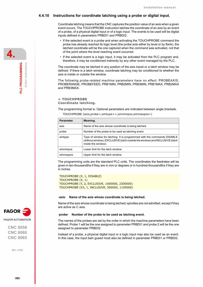
Installation manual.
CNC 8058CNC 8060CNC 8065
4.
PL
C P
RO
GR
AM
MIN
G.
Act
ion
inst
ruct
ions
.
ꞏ382ꞏ
REF: 2102
4.4.10 Instructions for coordinate latching using a probe or digital input.
Coordinate latching means that the CNC captures the position value of an axis when a givenevent occurs. The TOUCHPROBE instruction latches the coordinate of an axis by an eventof a probe, of a physical digital input or of a logic input. The events to be used will be digitalinputs defined in parameters PRBDI1 and PRBDI2.
• If the selected event is a probe and when activating the TOUCHPROBE command theprobe has already reached its logic level (the probe acts either by level or by flank), thelatched coordinate will be the one captured when the command was activated, not thatof the point where the level reaching event occurred.
• If the selected event is a logic input, it may be activated from the PLC program and,therefore, it may be conditioned indirectly by any other event managed by the PLC.
The coordinate may be latched in any position of the axis travel or a latch window may bedefined. If there is a latch window, coordinate latching may be conditioned to whether theaxis is inside or outside the window.
The following probe-related machine parameters have no effect: PROBEAXIS,PROBERANGE, PROBEFEED, PRB1MIN, PRB2MIN, PRB3MIN, PRB1MAX, PRB2MAXand PRB3MAX.
= TOUCHPROBECoordinate latching.
The programming format is: Optional parameters are indicated between angle brackets.
TOUCHPROBE (axis,probe<,wintype><,winminpos,winmaxpos>)
The programming units are the standard PLC units. The coordinates the feedrates will begiven in ten-thousandths if they are in mm or degrees or in hundred-thousandths if they arein inches.
ꞏaxisꞏ Name of the axis whose coordinate is being latched.
Name of the axis whose coordinate is being latched; spindles are not admitted, except if theyare active as C axis.
ꞏprobeꞏ Number of the probe to be used as latching event.
The names of the probes are set by the order in which the machine parameters have beendefined. Probe 1 will be the one assigned to parameter PRBDI1 and probe 2 will be the oneassigned to parameter PRBDI2.
Instead of a probe, a physical digital input or a logic input may also be used as an event.In this case, the input bein gused must also be defined in parameter PRBDI1 or PRBDI2.
Parameter. Meaning.
axis Name of the axis whose coordinate is being latched.
probe Number of the probe to be used as latching event.
wintype Type of window for latching. It is programmed with the commands DISABLE(without window), EXCLUSIVE (latch outside the window) and INCLUSIVE (latchinside the window).
winminpos Lower limit for the latch window.
winmaxpos Upper limit for the latch window.
TOUCHPROBE (X, 1, DISABLE)TOUCHPROBE (X, 1)TOUCHPROBE (Y, 2, EXCLUSIVE, 1000000, 2300000)TOUCHPROBE (X3, 1, INCLUSIVE, 500000, 1105000)
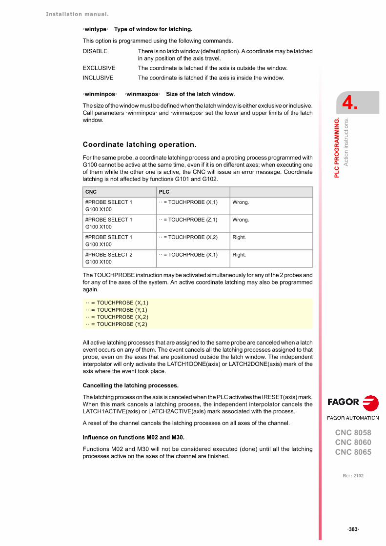
Installation manual.
CNC 8058CNC 8060CNC 8065
PL
C P
RO
GR
AM
MIN
G.
4.
Act
ion
inst
ruct
ions
.
ꞏ383ꞏ
REF: 2102
ꞏwintypeꞏ Type of window for latching.
This option is programmed using the following commands.
ꞏwinminposꞏ ꞏwinmaxposꞏ Size of the latch window.
The size of the window must be defined when the latch window is either exclusive or inclusive.Call parameters ꞏwinminposꞏ and ꞏwinmaxposꞏ set the lower and upper limits of the latchwindow.
Coordinate latching operation.
For the same probe, a coordinate latching process and a probing process programmed withG100 cannot be active at the same time, even if it is on different axes; when executing oneof them while the other one is active, the CNC will issue an error message. Coordinatelatching is not affected by functions G101 and G102.
The TOUCHPROBE instruction may be activated simultaneously for any of the 2 probes andfor any of the axes of the system. An active coordinate latching may also be programmedagain.
All active latching processes that are assigned to the same probe are canceled when a latchevent occurs on any of them. The event cancels all the latching processes assigned to thatprobe, even on the axes that are positioned outside the latch window. The independentinterpolator will only activate the LATCH1DONE(axis) or LATCH2DONE(axis) mark of theaxis where the event took place.
Cancelling the latching processes.
The latching process on the axis is canceled when the PLC activates the IRESET(axis) mark.When this mark cancels a latching process, the independent interpolator cancels theLATCH1ACTIVE(axis) or LATCH2ACTIVE(axis) mark associated with the process.
A reset of the channel cancels the latching processes on all axes of the channel.
Influence on functions M02 and M30.
Functions M02 and M30 will not be considered executed (done) until all the latchingprocesses active on the axes of the channel are finished.
DISABLE There is no latch window (default option). A coordinate may be latchedin any position of the axis travel.
EXCLUSIVE The coordinate is latched if the axis is outside the window.
INCLUSIVE The coordinate is latched if the axis is inside the window.
CNC PLC
#PROBE SELECT 1G100 X100
ꞏꞏ = TOUCHPROBE (X,1) Wrong.
#PROBE SELECT 1G100 X100
ꞏꞏ = TOUCHPROBE (Z,1) Wrong.
#PROBE SELECT 1G100 X100
ꞏꞏ = TOUCHPROBE (X,2) Right.
#PROBE SELECT 2G100 X100
ꞏꞏ = TOUCHPROBE (X,1) Right.
·· = TOUCHPROBE (X,1)·· = TOUCHPROBE (Y,1)·· = TOUCHPROBE (X,2)·· = TOUCHPROBE (Y,2)
Installation manual.
CNC 8058CNC 8060CNC 8065
4.
PL
C P
RO
GR
AM
MIN
G.
Act
ion
inst
ruct
ions
.
ꞏ384ꞏ
REF: 2102
Consultation signals of the PLC associated with coordinatelatching.
The independent interpolator has a mark for each probe. Probe 1 will be the one assignedto parameter PRBDI1 and probe 2 will be the one assigned to parameter PRBDI2.
PROBE1ACTIVEPROBE2ACTIVE
The independent interpolator actives this mark when a latching process is active with theindicated probe and it deactivates when there is no active latching process with the indicatedprobe.
LATCH1ACTIVE(axis)LATCH2ACTIVE(axis)
The independent interpolator actives this mark when activating a latching process on the axiswith the indicated probe and it deactivates when the latching process ends or it is canceled.
The latching process on the axis is canceled when the PLC activates the IRESET(axis) mark.A reset of the channel cancels the latching processes on all axes of the channel.
Functions M02 and M30 will not be considered executed (done) until all the latchingprocesses active on the axes of the channel are finished.
LATCH1DONE(axis)LATCH2DONE(axis)
The independent interpolator actives this mark when the latch event on the axis with theindicated probe occurs; it deactivates it when activating a new latching process on the axiswith the same probe.
Variables related to coordinate latching.
The coordinate latching processes do not affect the variables associated with probing G100.
(V.)[ch].A.LATCH1.xnVariable that can only be read from the program, PLC and interface.Variable valid for rotary and linear axes.The variable returns the execution value; reading it interrupts block preparation.
Machine coordinate obtained from latching probe 1 on the ꞏxnꞏ axis.
Syntax.
ꞏchꞏ Channel number.
ꞏxnꞏ Name, logic number or index of the axis.
(V.)[ch].A.LATCH2.xnVariable that can only be read from the program, PLC and interface.Variable valid for rotary and linear axes.The variable returns the execution value; reading it interrupts block preparation.
Machine coordinate obtained from latching probe 2 on the ꞏxnꞏ axis.
Syntax.
ꞏchꞏ Channel number.
V.A.LATCH1.Z Z axis.
V.A.LATCH1.4 Axis with logic number ꞏ4ꞏ.
V.[2].A.LATCH1.1 Axis with index ꞏ1ꞏ in the channel ꞏ2ꞏ.
Installation manual.
CNC 8058CNC 8060CNC 8065
PL
C P
RO
GR
AM
MIN
G.
4.
Act
ion
inst
ruct
ions
.
ꞏ385ꞏ
REF: 2102
ꞏxnꞏ Name, logic number or index of the axis.
(V.)[ch].A.ACCUDIST.xnVariable that can be read and written via program, PLC and interface.Variable valid for rotary and linear axes as well as for spindles.The variable returns the execution value; reading it interrupts block preparation.
Distance traveled by the axis or spindle since the last coordinate latching. This variable isinitialized to ꞏ0ꞏ when a latching event takes place. To add a position offset to this variableat the latch point, just add it from the PLC in a later cycle.
Syntax.
ꞏchꞏ Channel number.
ꞏxnꞏ Name, logic number or index of the axis.
(V.)[ch].A.PREVACCUDIST.xnVariable that can be read and written via program, PLC and interface.Variable valid for rotary and linear axes as well as for spindles.The variable returns the execution value; reading it interrupts block preparation.
Distance traveled by the axis or spindle between the last two coordinate latchings. Thisvariable updates (refreshes) its value at every latching event; that's why the variable will havea ꞏ0ꞏ value until the first one takes place.
Syntax.
ꞏchꞏ Channel number.
ꞏxnꞏ Name, logic number or index of the axis.
V.A.LATCH2.Z Z axis.
V.A.LATCH2.4 Axis with logic number ꞏ4ꞏ.
V.[2].A.LATCH2.1 Axis with index ꞏ1ꞏ in the channel ꞏ2ꞏ.
V.MPA.ACCUDIST.Z Z axis.
V.MPA.ACCUDIST.4 Axis with logic number ꞏ4ꞏ.
V.[2].MPA.ACCUDIST.1 Axis with index ꞏ1ꞏ in the channel ꞏ2ꞏ.
V.MPA.PREVACCUDIST.Z Z axis.
V.MPA.PREVACCUDIST.4 Axis with logic number ꞏ4ꞏ.
V.[2].MPA.PREVACCUDIST.1 Axis with index ꞏ1ꞏ in the channel ꞏ2ꞏ.
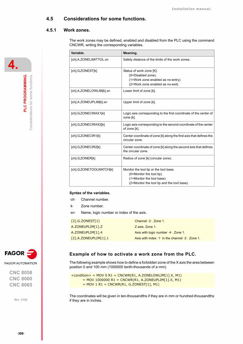
Installation manual.
CNC 8058CNC 8060CNC 8065
4.
PL
C P
RO
GR
AM
MIN
G.
Con
side
ratio
ns
for
som
e fu
nctio
ns.
ꞏ386ꞏ
REF: 2102
4.5 Considerations for some functions.
4.5.1 Work zones.
The work zones may be defined, enabled and disabled from the PLC using the commandCNCWR, writing the corresponding variables.
Syntax of the variables.
ꞏchꞏ Channel number.
ꞏkꞏ Zone number.
ꞏxnꞏ Name, logic number or index of the axis.
Example of how to activate a work zone from the PLC.
The following example shows how to define a forbidden zone of the X axis the area betweenposition 0 and 100 mm (1000000 tenth-thousands of a mm).
The coordinates will be given in ten-thousandths if they are in mm or hundred-thousandthsif they are in inches.
Variable. Meaning.
[ch].A.ZONELIMITTOL.xn Safety distance of the limits of the work zones.
[ch].G.ZONEST[k] Status of work zone [K].(0=Disabled zone).(1=Work zone enabled as no-entry).(2=Work zone enabled as no-exit).
[ch].A.ZONELOWLIM[k].xn Lower limit of zone [k].
[ch].A.ZONEUPLIM[k].xn Upper limit of zone [k].
[ch].G.ZONECIRAX1[k] Logic axis corresponding to the first coordinate of the center ofzone [k].
[ch].G.ZONECIRAX2[k] Logic axis corresponding to the second coordinate of the centerof zone [k].
[ch].G.ZONECIR1[k] Center coordinate of zone [k] along the first axis that defines thecircular zone.
[ch].G.ZONECIR2[k] Center coordinate of zone [k] along the second axis that definesthe circular zone.
[ch].G.ZONER[k] Radius of zone [k] (circular zone).
[ch].G.ZONETOOLWATCH[k] Monitor the tool tip or the tool base.(0=Monitor the tool tip).(1=Monitor the tool base).(2=Monitor the tool tip and the tool base).
[2].G.ZONEST[1] Channel ꞏ2ꞏ. Zone 1.
A.ZONEUPLIM[1].Z Z axis. Zone 1.
A.ZONEUPLIM[1].4 Axis with logic number ꞏ4ꞏ. Zone 1.
[2].A.ZONEUPLIM[1].1 Axis with index ꞏ1ꞏ in the channel ꞏ2ꞏ. Zone 1.
<condition> = MOV 0 R1 = CNCWR(R1, A.ZONELOWLIM[1].X, M1)= MOV 1000000 R1 = CNCWR(R1, A.ZONEUPLIM[1].X, M1)= MOV 1 R1 = CNCWR(R1, G.ZONEST[1], M1)
Installation manual.
CNC 8058CNC 8060CNC 8065
PL
C P
RO
GR
AM
MIN
G.
4.
Con
side
ratio
ns
for
som
e fu
nctio
ns.
ꞏ387ꞏ
REF: 2102
Synchronize changes in the zones from the part-program andfrom the PLC.
When making changes in the work zone from the PLC while executing a part-program, it mustbe borne in mind that the CNC has already prepared the program blocks immediately afterthe one being executed; therefore, checking the new limits and/or the new status may notbe correct for some blocks after the change. In order to ensure proper synchronization ofthe changes between the part-program and the PLC, these changes should be executed viainterruption subroutines.
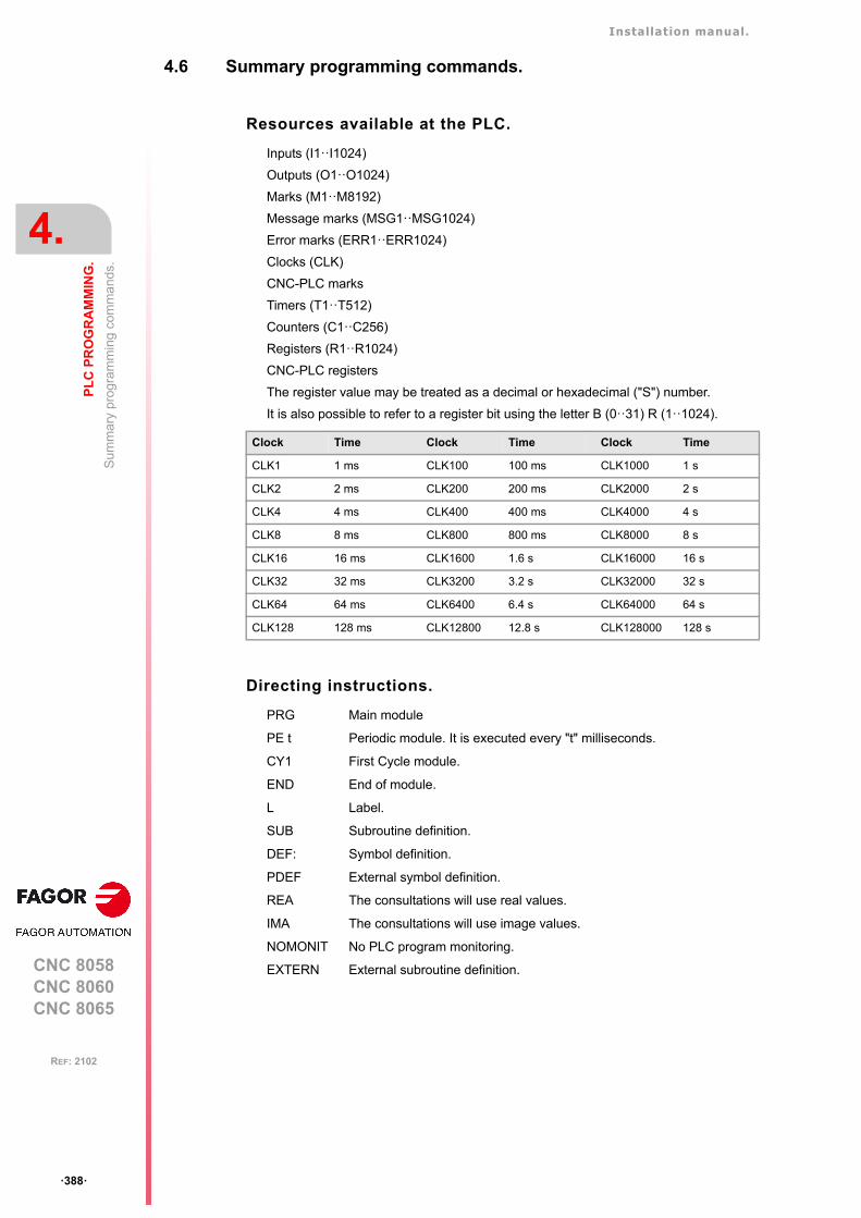
Installation manual.
CNC 8058CNC 8060CNC 8065
4.
PL
C P
RO
GR
AM
MIN
G.
Sum
mar
y pr
ogra
mm
ing
com
ma
nds.
ꞏ388ꞏ
REF: 2102
4.6 Summary programming commands.
Resources available at the PLC.
Inputs (I1ꞏꞏI1024)
Outputs (O1ꞏꞏO1024)
Marks (M1ꞏꞏM8192)
Message marks (MSG1ꞏꞏMSG1024)
Error marks (ERR1ꞏꞏERR1024)
Clocks (CLK)
CNC-PLC marks
Timers (T1ꞏꞏT512)
Counters (C1ꞏꞏC256)
Registers (R1ꞏꞏR1024)
CNC-PLC registers
The register value may be treated as a decimal or hexadecimal ("S") number.
It is also possible to refer to a register bit using the letter B (0ꞏꞏ31) R (1ꞏꞏ1024).
Directing instructions.
PRG Main module
PE t Periodic module. It is executed every "t" milliseconds.
CY1 First Cycle module.
END End of module.
L Label.
SUB Subroutine definition.
DEF: Symbol definition.
PDEF External symbol definition.
REA The consultations will use real values.
IMA The consultations will use image values.
NOMONIT No PLC program monitoring.
EXTERN External subroutine definition.
Clock Time Clock Time Clock Time
CLK1 1 ms CLK100 100 ms CLK1000 1 s
CLK2 2 ms CLK200 200 ms CLK2000 2 s
CLK4 4 ms CLK400 400 ms CLK4000 4 s
CLK8 8 ms CLK800 800 ms CLK8000 8 s
CLK16 16 ms CLK1600 1.6 s CLK16000 16 s
CLK32 32 ms CLK3200 3.2 s CLK32000 32 s
CLK64 64 ms CLK6400 6.4 s CLK64000 64 s
CLK128 128 ms CLK12800 12.8 s CLK128000 128 s
Installation manual.
CNC 8058CNC 8060CNC 8065
PL
C P
RO
GR
AM
MIN
G.
4.
Sum
mar
y pr
ogra
mm
ing
com
ma
nds.
ꞏ389ꞏ
REF: 2102
Consulting instructions.
• Simple consulting instructions.
I1ꞏꞏ1024 Inputs.
O1ꞏꞏ1024 Outputs.
M1ꞏꞏ8192 Marks.
MSG1ꞏꞏ1024 Messages.
ERR1ꞏꞏ1024 Errors.
T1ꞏꞏ512 Timers (status).
C1ꞏꞏ256 Counters (status).
B0ꞏꞏ31 R1ꞏꞏ1024 Register bit.
CLK Clocks.
M <CNC-PLC> Marks for CNC-PLC communication.
• Flank detection instructions.
DFU Up flank detection.
DFD Down flank detection.
• Comparing instructions.
CPS For comparisons.
Operators.
NOT Negates the result of the consultation.
AND Logic function "AND".
OR Logic function "OR”.
XOR Logic "Exclusive OR" function.
\ Line feed.
( ) Consulting instruction whose value is always "1".
Action instructions.
• Assignment binary action instructions.
• Conditional binary action instructions.
= SET If expression = "1", it sets the resource to "1".
= RES If expression = "1", it sets the resource to "0".
= CPL If expression = "1", it complements the resource.
• Sequence breaking action instructions.
= JMP L Unconditional jump.
= CAL Call to a subroutine.
= RET Return or end of a subroutine.
• Arithmetic action instructions.
= MOV Move.
= NGU R1ꞏꞏ1024 Complements the bits of a register.
= NGS R1ꞏꞏ1024 Register sign change.
= ADS Add.
= I 1/1024 = O 1/1024 = M 1/8192
= MSG 1/1024 = ERR 1/1024 = TEN 1/512
= TRS 1/512 = TGn 1/512 #/R = CUP 1/256
= CDW 1/256 = CEN 1/256 = CPR 1/256 #/R
= B 0/31 R 1/499 = CNC-PLC mark
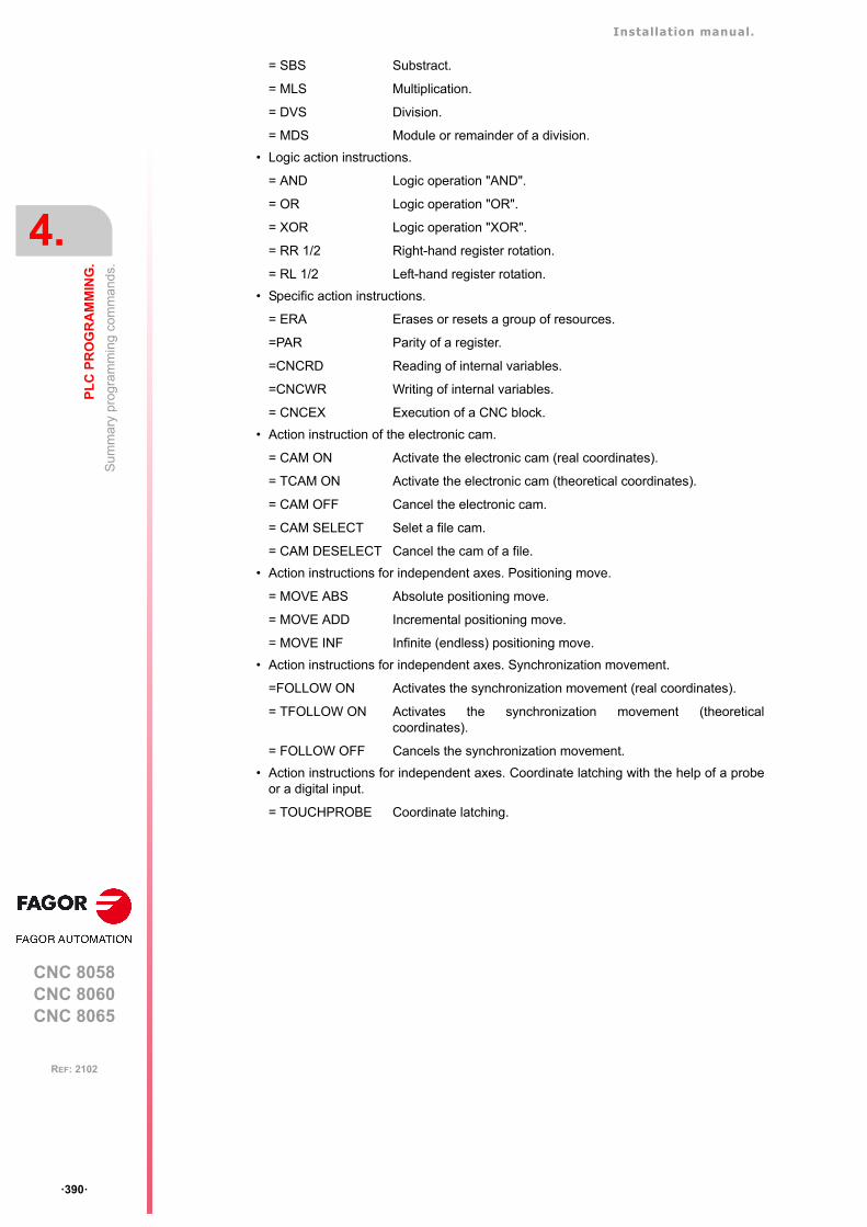
Installation manual.
CNC 8058CNC 8060CNC 8065
4.
PL
C P
RO
GR
AM
MIN
G.
Sum
mar
y pr
ogra
mm
ing
com
ma
nds.
ꞏ390ꞏ
REF: 2102
= SBS Substract.
= MLS Multiplication.
= DVS Division.
= MDS Module or remainder of a division.
• Logic action instructions.
= AND Logic operation "AND".
= OR Logic operation "OR".
= XOR Logic operation "XOR".
= RR 1/2 Right-hand register rotation.
= RL 1/2 Left-hand register rotation.
• Specific action instructions.
= ERA Erases or resets a group of resources.
=PAR Parity of a register.
=CNCRD Reading of internal variables.
=CNCWR Writing of internal variables.
= CNCEX Execution of a CNC block.
• Action instruction of the electronic cam.
= CAM ON Activate the electronic cam (real coordinates).
= TCAM ON Activate the electronic cam (theoretical coordinates).
= CAM OFF Cancel the electronic cam.
= CAM SELECT Selet a file cam.
= CAM DESELECT Cancel the cam of a file.
• Action instructions for independent axes. Positioning move.
= MOVE ABS Absolute positioning move.
= MOVE ADD Incremental positioning move.
= MOVE INF Infinite (endless) positioning move.
• Action instructions for independent axes. Synchronization movement.
=FOLLOW ON Activates the synchronization movement (real coordinates).
= TFOLLOW ON Activates the synchronization movement (theoreticalcoordinates).
= FOLLOW OFF Cancels the synchronization movement.
• Action instructions for independent axes. Coordinate latching with the help of a probeor a digital input.
= TOUCHPROBE Coordinate latching.
CNC 8058CNC 8060CNC 8065
5
ꞏ391ꞏ
REF: 2102
5. CNC-PLC COMMUNICATION.
With the data exchange between the CNC and the PLC, it is possible to:
• Control the logic CNC inputs and outputs in peripheral mode using specific PLC marksand registers.
• Transfer auxiliary M, H and S functions from the CNC to the PLC.
• Generate messages and errors at the CNC using PLC marks.
• Read and modify internal CNC variables from the PLC.
• Access all PLC resources from any part-program.
• Monitor PLC resources on the CNC screen.
Abbreviations used in this chapter.
–M– and –H– functions with channels.
The M and H functions are exchanged by channel. When using several channels, the marksand registers of these functions must indicate the channel number they refer to. If no channelnumber is indicated, the marks and registers refer to the first channel.
–S– functions with multiple spindles.
The exchange of S functions is independent from the channel. When using several spindles,the marks and registers of these functions refer to the spindle number. The spindle numberis determined by its logic number.
(=0) Low logic level.
(=1) High logic level.
Installation manual.
CNC 8058CNC 8060CNC 8065
5.
CN
C-P
LC
CO
MM
UN
ICA
TIO
N.
Aux
iliar
y –M
– fu
nctio
ns.
ꞏ392ꞏ
REF: 2102
5.1 Auxiliary –M– functions.
Up to 7 M functions in the same block. The CNC indicates to the PLC which auxiliary Mfunctions are programmed in the execution block using 32-bit registers MFUN1 throughMFUN7. Each one of them indicates the number of one of the M functions programmed inthe block. If all the registers are not used, the CNC assigns $FFFFFFFF to the unused ones(those with the highest numbers).
This way, if a block contains functions M100, M120 and M135, the CNC will transfer thefollowing information to the PLC.
Command MFUN*. Checking if a function has been programmed in the block.
To know whether a particular M function is programmed in the execution block, use one ofthe following methods:
• Check all the MFUN registers one by one until that particular M function is found or untilone of them has the value of $FFFFFFFF.
• Use the MFUN* command to check all the registers at the same time.
Sending the function and synchronizing the execution.
Within the CNC machine parameters, the auxiliary M function table indicates when thefunction is sent and when the PLC execution is synchronized. In either case, it may be beforeor after the movement.
The sending and synchronizing types may be the following:
M not synchronized.
M sent out and synchronized before the movement.
M sent out before the move and synchronized after the movement.
M sent out and synchronized after the movement.
M functions with different types of synchronization may be programmed in the same block.Each one of them will be sent out to the PLC at the right moment. The transfer of auxiliaryM functions is described later on in this chapter. See "5.4 Transferring auxiliary functions-M-, -H-, -S-." on page 398.
MFUN1 MFUN2 MFUN3 MFUN4 - MFUN7
100 120 135 $FFFFFFFF
Example to detect M30. If it has been programmed, it will return a "1", and a "0" if otherwise.
CPS MFUN* EQ 30 = ...
The functions may be set as follows:
M11 not synchronized.
M12 is sent and synchronized before the movement.
M13 is sent before and synchronized after the movement.
M14 is sent and synchronized after the movement.
When executing a block like this:
X100 F1000 M11 M12 M13 M14
The functions are transferred as follows:
1 It sends the M11 M12 and M13 functions out to the PLC.
2 waits for the PLC to execute the M12.
3 The CNC moves the axis to X100.
4 It sends the M14 function to the PLC.
5 It waits until the PLC executes the M13 and M14.
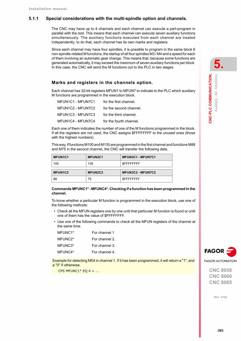
Installation manual.
CNC 8058CNC 8060CNC 8065
CN
C-P
LC
CO
MM
UN
ICA
TIO
N.
5.
Aux
iliar
y –M
– fu
nctio
ns.
ꞏ393ꞏ
REF: 2102
5.1.1 Special considerations with the multi-spindle option and channels.
The CNC may have up to 4 channels and each channel can execute a part-program inparallel with the rest. This means that each channel can execute seven auxiliary functionssimultaneously. The auxiliary functions executed from each channel are treatedindependently; to do that, each channel has its own marks and registers.
Since each channel may have four spindles, it is possible to program in the same block 6non-spindle-related M functions, the startup of all four spindles M3 / M4 and a speed for eachof them involving an automatic gear change. This means that, because some functions aregenerated automatically, it may exceed the maximum of seven auxiliary functions per block.In this case, the CNC will send the M functions out to the PLC in two stages.
Marks and registers in the channels option.
Each channel has 32-bit registers MFUN1 to MFUN7 to indicate to the PLC which auxiliaryM functions are programmed in the execution block.
MFUN1C1 - MFUN7C1 for the first channel.
MFUN1C2 - MFUN7C2 for the second channel.
MFUN1C3 - MFUN7C3 for the third channel.
MFUN1C4 - MFUN7C4 for the fourth channel.
Each one of them indicates the number of one of the M functions programmed in the block.If all the registers are not used, the CNC assigns $FFFFFFFF to the unused ones (thosewith the highest numbers).
This way, if functions M100 and M135 are programmed in the first channel and functions M88and M75 in the second channel, the CNC will transfer the following data.
Commands MFUNC1* - MFUNC4*. Checking if a function has been programmed in thechannel.
To know whether a particular M function is programmed in the execution block, use one ofthe following methods:
• Check all the MFUN registers one by one until that particular M function is found or untilone of them has the value of $FFFFFFFF.
• Use one of the following commands to check all the MFUN registers of the channel atthe same time.
MFUNC1* For channel 1
MFUNC2* For channel 2.
MFUNC3* For channel 3.
MFUNC4* For channel 4.
MFUN1C1 MFUN2C1 MFUN3C1 - MFUN7C1
100 135 $FFFFFFFF
MFUN1C2 MFUN2C2 MFUN3C2 - MFUN7C2
88 75 $FFFFFFFF
Example for detecting M04 in channel 1. If it has been programmed, it will return a "1", anda "0" if otherwise.
CPS MFUNC1* EQ 4 = ...
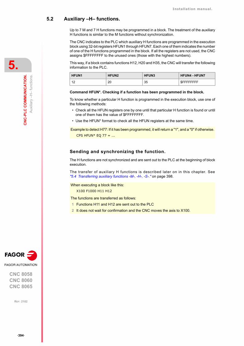
Installation manual.
CNC 8058CNC 8060CNC 8065
5.
CN
C-P
LC
CO
MM
UN
ICA
TIO
N.
Aux
iliar
y –
H–
func
tions
.
ꞏ394ꞏ
REF: 2102
5.2 Auxiliary –H– functions.
Up to 7 M and 7 H functions may be programmed in a block. The treatment of the auxiliaryH functions is similar to the M functions without synchronization.
The CNC indicates to the PLC which auxiliary H functions are programmed in the executionblock using 32-bit registers HFUN1 through HFUN7. Each one of them indicates the numberof one of the H functions programmed in the block. If all the registers are not used, the CNCassigns $FFFFFFFF to the unused ones (those with the highest numbers).
This way, if a block contains functions H12, H20 and H35, the CNC will transfer the followinginformation to the PLC.
Command HFUN*. Checking if a function has been programmed in the block.
To know whether a particular H function is programmed in the execution block, use one ofthe following methods:
• Check all the HFUN registers one by one until that particular H function is found or untilone of them has the value of $FFFFFFFF.
• Use the HFUN* format to check all the HFUN registers at the same time.
Sending and synchronizing the function.
The H functions are not synchronized and are sent out to the PLC at the beginning of blockexecution.
The transfer of auxiliary H functions is described later on in this chapter. See"5.4 Transferring auxiliary functions -M-, -H-, -S-." on page 398.
HFUN1 HFUN2 HFUN3 HFUN4 - HFUN7
12 20 35 $FFFFFFFF
Example to detect H77: If it has been programmed, it will return a "1", and a "0" if otherwise.
CPS HFUN* EQ 77 = ...
When executing a block like this:
X100 F1000 H11 H12
The functions are transferred as follows:
1 Functions H11 and H12 are sent out to the PLC
2 It does not wait for confirmation and the CNC moves the axis to X100.
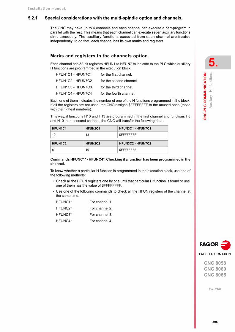
Installation manual.
CNC 8058CNC 8060CNC 8065
CN
C-P
LC
CO
MM
UN
ICA
TIO
N.
5.
Aux
iliar
y –
H–
func
tions
.
ꞏ395ꞏ
REF: 2102
5.2.1 Special considerations with the multi-spindle option and channels.
The CNC may have up to 4 channels and each channel can execute a part-program inparallel with the rest. This means that each channel can execute seven auxiliary functionssimultaneously. The auxiliary functions executed from each channel are treatedindependently; to do that, each channel has its own marks and registers.
Marks and registers in the channels option.
Each channel has 32-bit registers HFUN1 to HFUN7 to indicate to the PLC which auxiliaryH functions are programmed in the execution block.
HFUN1C1 - HFUN7C1 for the first channel.
HFUN1C2 - HFUN7C2 for the second channel.
HFUN1C3 - HFUN7C3 for the third channel.
HFUN1C4 - HFUN7C4 for the fourth channel.
Each one of them indicates the number of one of the H functions programmed in the block.If all the registers are not used, the CNC assigns $FFFFFFFF to the unused ones (thosewith the highest numbers).
This way, if functions H10 and H13 are programmed in the first channel and functions H8and H10 in the second channel, the CNC will transfer the following data.
Commands HFUNC1* - HFUNC4*. Checking if a function has been programmed in thechannel.
To know whether a particular H function is programmed in the execution block, use one ofthe following methods:
• Check all the HFUN registers one by one until that particular H function is found or untilone of them has the value of $FFFFFFFF.
• Use one of the following commands to check all the HFUN registers of the channel atthe same time.
HFUNC1* For channel 1
HFUNC2* For channel 2.
HFUNC3* For channel 3.
HFUNC4* For channel 4.
HFUN1C1 HFUN2C1 HFUN3C1 - HFUN7C1
10 13 $FFFFFFFF
HFUN1C2 HFUN2C2 HFUN3C2 - HFUN7C2
8 10 $FFFFFFFF
Installation manual.
CNC 8058CNC 8060CNC 8065
5.
CN
C-P
LC
CO
MM
UN
ICA
TIO
N.
Aux
iliar
y –
S–
fun
ctio
n.
ꞏ396ꞏ
REF: 2102
5.3 Auxiliary –S– function.
The auxiliary S function indicates the spindle turning speed with M03 and M04 or the angularposition with M19.
The S function with M03 and M04 is always executed at the beginning of the block and theCNC waits for confirmation before going on executing the program. When working with M19,the CNC treats the spindle like a regular linear axis. It only sends the M19 out to the PLC.
The CNC uses 32-bit register SFUN1 to indicate to the PLC the value of the S functionprogrammed in the block. If not programmed, the value of $FFFFFFFF is sent out. The SFUNcommand only assumes the value of the programmed S if spindle parameter SPDLTIME isother than zero.
The transfer of the S function is described later on in this chapter. See "5.4 Transferringauxiliary functions -M-, -H-, -S-." on page 398.
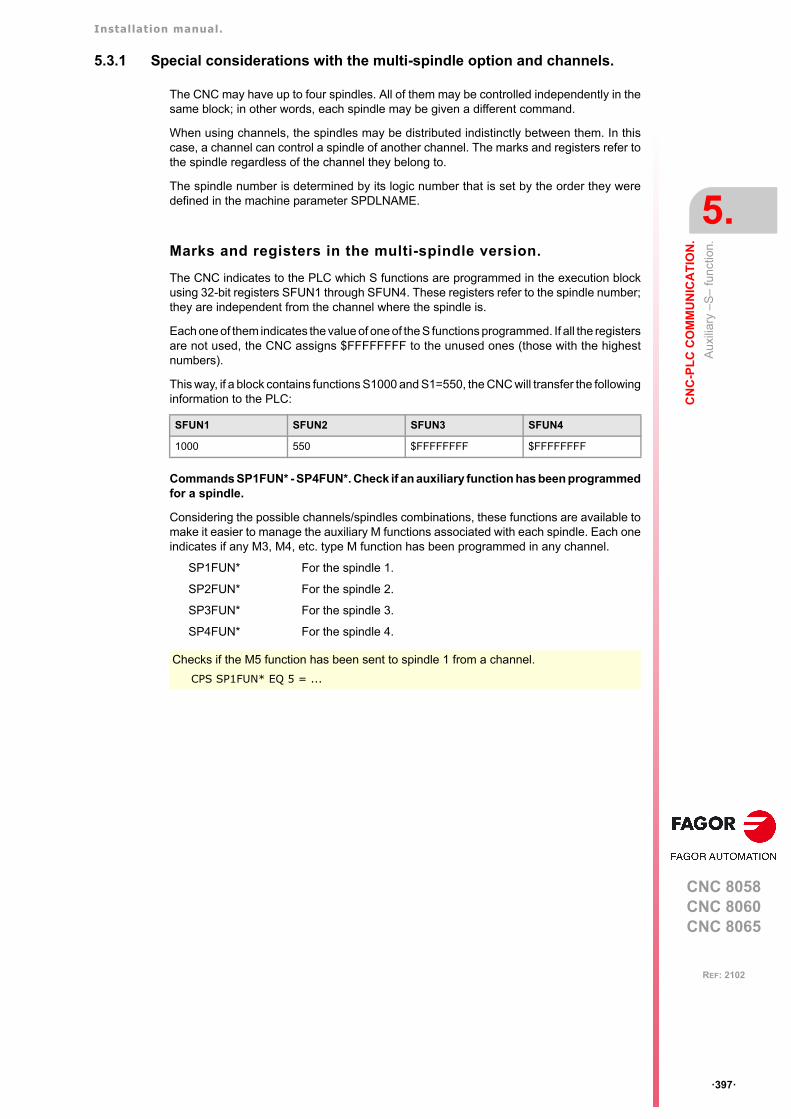
Installation manual.
CNC 8058CNC 8060CNC 8065
CN
C-P
LC
CO
MM
UN
ICA
TIO
N.
5.
Aux
iliar
y –
S–
fun
ctio
n.
ꞏ397ꞏ
REF: 2102
5.3.1 Special considerations with the multi-spindle option and channels.
The CNC may have up to four spindles. All of them may be controlled independently in thesame block; in other words, each spindle may be given a different command.
When using channels, the spindles may be distributed indistinctly between them. In thiscase, a channel can control a spindle of another channel. The marks and registers refer tothe spindle regardless of the channel they belong to.
The spindle number is determined by its logic number that is set by the order they weredefined in the machine parameter SPDLNAME.
Marks and registers in the multi-spindle version.
The CNC indicates to the PLC which S functions are programmed in the execution blockusing 32-bit registers SFUN1 through SFUN4. These registers refer to the spindle number;they are independent from the channel where the spindle is.
Each one of them indicates the value of one of the S functions programmed. If all the registersare not used, the CNC assigns $FFFFFFFF to the unused ones (those with the highestnumbers).
This way, if a block contains functions S1000 and S1=550, the CNC will transfer the followinginformation to the PLC:
Commands SP1FUN* - SP4FUN*. Check if an auxiliary function has been programmedfor a spindle.
Considering the possible channels/spindles combinations, these functions are available tomake it easier to manage the auxiliary M functions associated with each spindle. Each oneindicates if any M3, M4, etc. type M function has been programmed in any channel.
SP1FUN* For the spindle 1.
SP2FUN* For the spindle 2.
SP3FUN* For the spindle 3.
SP4FUN* For the spindle 4.
SFUN1 SFUN2 SFUN3 SFUN4
1000 550 $FFFFFFFF $FFFFFFFF
Checks if the M5 function has been sent to spindle 1 from a channel.
CPS SP1FUN* EQ 5 = ...
Installation manual.
CNC 8058CNC 8060CNC 8065
5.
CN
C-P
LC
CO
MM
UN
ICA
TIO
N.
Tra
nsfe
rrin
g au
xilia
ry fu
nctio
ns -
M-,
-H
-, -
S-.
ꞏ398ꞏ
REF: 2102
5.4 Transferring auxiliary functions -M-, -H-, -S-.
The M and H functions are transferred per channel. Transferring S functions does not dependon the channel.
When executing a block that contains M, H, S functions, the following information istransferred to the PLC.
Transferring -M- functions.
The CNC assigns the numbers of the M functions programmed in the block to registersMFUN1 through MFUN7. Some M functions have an associated function (DMxx) that isactivated when sending the M to the PLC.
The CNC activates the general logic output MSTROBE to "tell" the PLC that it must executethem. This mark is kept high (=1) for a time period indicated by parameter MINAENDW.
Depending on the type of synchronization, the CNC will either wait or not for the general inputAUXEND to be activated indicating the end of the PLC execution. The type ofsynchronization is defined in the machine parameters
The CNC cancels the general logic output MSTROBE to conclude the execution.
Transferring -H- functions.
The CNC assigns the numbers of the H functions programmed in the block to registersHFUN1 through HFUN7.
The CNC activates the general logic output HSTROBE to "tell" the PLC that it must executethem. This mark is kept high (=1) for a time period indicated by parameter MINAENDW.
After this time period, the CNC considers its execution completed because there is nosynchronization.
When sending several blocks in a row just having H functions, the CNC waits twice the timeindicated in parameter MINAENDW.
Transferring -S- functions
The CNC assigns the values of the S programmed in each spindle to registers SFUN1through SFUN4.
The CNC activates the general logic output SSTROBE to "tell" the PLC that it must executeit. The CNC waits for the general input AUXEND to be activated indicating the end of thePLC execution.
The CNC cancels the general logic output SSTROBE to conclude the execution.
M00 M01 M02 M03 M04
M05 M06 M08 M09 M19
M30 M41 M42 M43 M44
N10 H60
N20 H30 H18
N30 H40
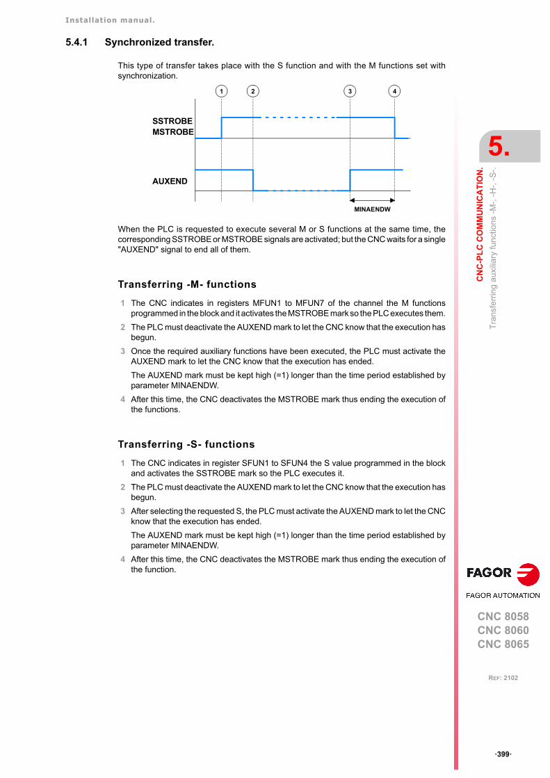
Installation manual.
CNC 8058CNC 8060CNC 8065
CN
C-P
LC
CO
MM
UN
ICA
TIO
N.
5.
Tra
nsfe
rrin
g au
xilia
ry fu
nctio
ns -
M-,
-H
-, -
S-.
ꞏ399ꞏ
REF: 2102
5.4.1 Synchronized transfer.
This type of transfer takes place with the S function and with the M functions set withsynchronization.
When the PLC is requested to execute several M or S functions at the same time, thecorresponding SSTROBE or MSTROBE signals are activated; but the CNC waits for a single"AUXEND" signal to end all of them.
Transferring -M- functions
1 The CNC indicates in registers MFUN1 to MFUN7 of the channel the M functionsprogrammed in the block and it activates the MSTROBE mark so the PLC executes them.
2 The PLC must deactivate the AUXEND mark to let the CNC know that the execution hasbegun.
3 Once the required auxiliary functions have been executed, the PLC must activate theAUXEND mark to let the CNC know that the execution has ended.
The AUXEND mark must be kept high (=1) longer than the time period established byparameter MINAENDW.
4 After this time, the CNC deactivates the MSTROBE mark thus ending the execution ofthe functions.
Transferring -S- functions
1 The CNC indicates in register SFUN1 to SFUN4 the S value programmed in the blockand activates the SSTROBE mark so the PLC executes it.
2 The PLC must deactivate the AUXEND mark to let the CNC know that the execution hasbegun.
3 After selecting the requested S, the PLC must activate the AUXEND mark to let the CNCknow that the execution has ended.
The AUXEND mark must be kept high (=1) longer than the time period established byparameter MINAENDW.
4 After this time, the CNC deactivates the MSTROBE mark thus ending the execution ofthe function.
AUXEND
1 2 43
MINAENDW
SSTROBEMSTROBE

Installation manual.
CNC 8058CNC 8060CNC 8065
5.
CN
C-P
LC
CO
MM
UN
ICA
TIO
N.
Tra
nsfe
rrin
g au
xilia
ry fu
nctio
ns -
M-,
-H
-, -
S-.
ꞏ400ꞏ
REF: 2102
5.4.2 Non-synchronized transfer.
This type of transfer takes place with the H function and with the M functions set withoutsynchronization.
Transferring -M- functions
1 The CNC indicates in registers MFUN1 to MFUN7 of the channel the M functionsprogrammed in the block and it activates the MSTROBE mark so the PLC executes them.
2 The CNC keeps the MSTROBE mark active for a time period indicated by parameterMINAENDW.
3 After this time, the CNC goes on executing the program regardless of the time requiredby the PLC to execute that function.
Transferring -H- functions
1 The CNC indicates in registers HFUN1 to HFUN7 of the channel the H functionsprogrammed in the block and it activates the HSTROBE mark so the PLC executes them.
2 The CNC keeps the HSTROBE mark active for a time period indicated by parameterMINAENDW.
3 After this time, the CNC goes on executing the program regardless of the time requiredby the PLC to execute that function.
Considerations for transferring these functions.
The value of parameter MINAENDW should be the same or longer than the PLC programexecution period parameter PRGFREQ in order to ensure that the PLC detects that signal.
When sending non-synchronized H or M functions corresponding to consecutive blocks ofthe same program, the CNC waits between blocks for a time period indicated by MINANEDWso the PLC can read all the functions.
PLC
1 2 3
MINAENDW
SSTROBEMSTROBE
EXECUTION
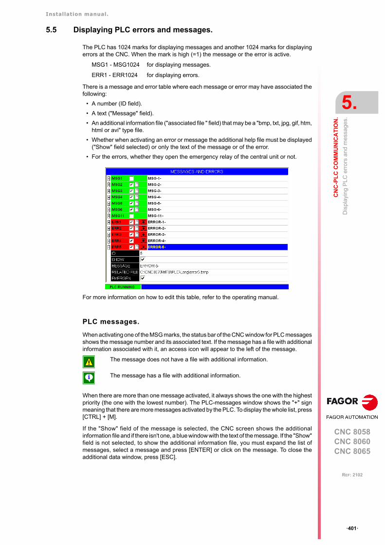
Installation manual.
CNC 8058CNC 8060CNC 8065
CN
C-P
LC
CO
MM
UN
ICA
TIO
N.
5.
Dis
play
ing
PLC
err
ors
an
d m
ess
age
s.
ꞏ401ꞏ
REF: 2102
5.5 Displaying PLC errors and messages.
The PLC has 1024 marks for displaying messages and another 1024 marks for displayingerrors at the CNC. When the mark is high (=1) the message or the error is active.
MSG1 - MSG1024 for displaying messages.
ERR1 - ERR1024 for displaying errors.
There is a message and error table where each message or error may have associated thefollowing:
• A number (ID field).
• A text ("Message" field).
• An additional information file ("associated file " field) that may be a "bmp, txt, jpg, gif, htm,html or avi" type file.
• Whether when activating an error or message the additional help file must be displayed("Show" field selected) or only the text of the message or of the error.
• For the errors, whether they open the emergency relay of the central unit or not.
For more information on how to edit this table, refer to the operating manual.
PLC messages.
When activating one of the MSG marks, the status bar of the CNC window for PLC messagesshows the message number and its associated text. If the message has a file with additionalinformation associated with it, an access icon will appear to the left of the message.
When there are more than one message activated, it always shows the one with the highestpriority (the one with the lowest number). The PLC-messages window shows the "+" signmeaning that there are more messages activated by the PLC. To display the whole list, press[CTRL] + [M].
If the "Show" field of the message is selected, the CNC screen shows the additionalinformation file and if there isn't one, a blue window with the text of the message. If the "Show"field is not selected, to show the additional information file, you must expand the list ofmessages, select a message and press [ENTER] or click on the message. To close theadditional data window, press [ESC].
The message does not have a file with additional information.
The message has a file with additional information.
Installation manual.
CNC 8058CNC 8060CNC 8065
5.
CN
C-P
LC
CO
MM
UN
ICA
TIO
N.
Dis
play
ing
PLC
err
ors
an
d m
ess
age
s.
ꞏ402ꞏ
REF: 2102
PLC errors.
When activating one of the ERR marks, the CNC interrupts the execution of the part-programand it displays a window in the middle of the screen showing the error number and itsassociated text. If the error has the "Emergen" field selected, the error will open theemergency relay of the CNC.
External inputs should be used to activate and deactivate error marks, thus preventing theCNC from receiving those errors at every new PLC cycle scan.
Grouping the additional information text files in a single file.
PLC messages and errors can show an additional information file in text format. The PLCallows grouping several or all these files into a single file as follows.
Defining the additional information file.
It must be a text file (extension txt) and may have any name. The information of eachmessage and error must be structured in the following format:
[<id>]<text>
The <id> field, keeping the brackets, will be the code that identifies the help text inside thefile, which needs not be the same as the number of the error or message it will be associatedwith. The <text> field will be the information text that may have up to 500 characters includingline feeds.
For example, the OEM.txt file will have the following structure.
Calling the texts from the PLC message or from the PLC error.
To associate the help message with a PLC message or PLC error, the "associated file" fieldmust be defined like <file>#<id>. The <file> field will be the path and the name of the file.The <id> field will be the code that identifies the help text inside the file.
For example, the "associated file" will be defined as follows.
C:\FAGORCNC\MTB\PLC\LANG\OEM.txt#27
If the error has a file with additional information associated with it, an access icon will appearto the right of the error number. If the error has the "Show" field selected, the CNC showsthe additional information file directly on the screen. If the "Show" field is not selected, theadditional information file will be displayed when pressing the [HELP] key or when clickingon the icon mentioned earlier. To close the additional data window, press [ESC].
[10]Help text.[27]Help text.[33]Help text.
CNC 8058CNC 8060CNC 8065
6
ꞏ403ꞏ
REF: 2102
6. LOGIC CNC INPUTS AND OUTPUTS.
CNC's physical inputs and outputs are the set of system inputs and outputs that are governedby the PLC and communicate with the outside world through CNC connectors.
The CNC also has a number of logic inputs and outputs to exchange the internal data withthe marks and registers of the PLC. This way, the PLC has access to some internal CNCdata. Each of these logic inputs and outputs may be referred to using its associatedmnemonic. The mnemonics that begin with a "_" sign indicate that the signal is active low(0 V).
CNCREADY _ALARM
AUXEND _EMERGEN
MANUAL _STOP
The CNC's logic outputs or PLC consulting signals are grouped into:
• General consulting signals.
• Axis consulting signals.
• Spindle consulting signals.
• Consultation signals of the independent interpolator.
• Tool manager consulting signals.
• Laser consulting signals.
• Keystroke consulting signals.
The CNC's logic inputs or signals that may be modified via PLC are grouped into:
• General modifiable signals.
• Axis modifiable signals.
• Spindle modifiable signals.
• Modifiable signals of the independent interpolator.
• Tool manager modifiable signals.
• Laser modifiable signals.
• Keystroke modifiable signals.
Abbreviations used in this chapter.
(=0) Low logic level.
(=1) High logic level.
Installation manual.
CNC 8058CNC 8060CNC 8065
6.
LO
GIC
CN
C IN
PU
TS
AN
D O
UT
PU
TS
.
Gen
eral
con
sulti
ng s
ign
als.
ꞏ404ꞏ
REF: 2102
6.1 General consulting signals.
CNCREADY
This mark indicates the CNC status. It is set to "0" when the CNC is in an error state (redstatus window) and to "1" if otherwise.
Include this mark in the PLC maneuver to enable the drives.
READY
There is a mark for each channel. The mnemonics for each channel are the following.
READYC1 READYC2 READYC3 READYC4
This mark indicates the status of the CNC channel. It is set to "0" when the CNC is in an errorstate (red status window) and to "1" if otherwise.
SERCOSRDY
In Sercos configuration, this mark indicates the ring status. The CNC sets this mark high (=1)to indicate that the Sercos ring has been properly initialized.
All the drive status consultations (DRSTAF DRSTAS) and the read/write (CNCRD CNCWR)operations of the drive variables are conditioned by this mark.
START
There is a mark for each channel. The mnemonics for each channel are the following.
STARTC1 (can also be programmed as START)
STARTC2 STARTC3 STARTC4
The CNC channel activates this mark to indicate to the PLC that the [START] key has beenpressed at the operator panel. If the rest of the conditions are met (hydraulic, safety, etc.),the PLC must activate the CYSTART mark in order for the program to start running. See"CYSTART" on page 435.
RESETOUT
There is a mark for each channel. The mnemonics for each channel are the following.
RESETOUTC1 (can also be programmed as RESETOUT)
RESETOUTC2 RESETOUTC3 RESETOUTC4
CNC channel reset. The channel activates the RESETOUT (RESETOUT=1) mark to indicatethat the reset has finalized. This mark stays active for the time period set in general parameterMINAENDW.
; +++++++++++++++++++++++++++++++++++++++++++++++++; AXIS ENABLE; +++++++++++++++++++++++++++++++++++++++++++++++++CNCREADY \ ; CNC without errorsAND NOT B1R2 \ ; FEEDHOLD due to lack of power at the X axis driveAND NOT PARKEDX \ ; X axis parkedAND NOT PARKEDX \ ; Unpark X axisAND NOT PARKEDX \ ; Park X axis= SERVOXON ; X axis servo drive active= SPENAX ; X axis sercos enable= TG3 2 500 ; Delay for DRENAX;T2\; Delay to the drop of speed enable= DRENAX \; Drive enable via Sercos.
START AND (rest of conditions) = CYSTART
Installation manual.
CNC 8058CNC 8060CNC 8065
LO
GIC
CN
C IN
PU
TS
AN
D O
UT
PU
TS
.
6.
Gen
eral
con
sulti
ng s
ign
als.
ꞏ405ꞏ
REF: 2102
The channel uses this mark whenever performing a reset, either from the [RESET] key onthe operator panel or when the PLC activates the RESETIN mark. See "RESETIN" on page436.
FHOUT
There is a mark for each channel. The mnemonics for each channel are the following.
FHOUTC1 (can also be programmed as FHOUT)
FHOUTC2 FHOUTC3 FHOUTC4
The CNC channel sets this mark high (=1) when the execution of the part-program isinterrupted. To interrupt and later resume the execution of a program, proceed as follows:
• If the PLC has set the mark "_STOP" to (=0), to resume the execution, the PLC mustset marks "_STOP" and "CYSTART" to (=1).
• If the PLC has set the mark "_FEEDHOL" to (=0), to resume the execution, the PLC mustset the "_FEEDHOL" mark to (=1).
_ALARM
There is a mark for each channel. The mnemonics for each channel are the following.
_ALARMC1 (can also be programmed as _ALARM)
_ALARMC2 _ALARMC3 _ALARMC4
The CNC channel activates this mark (at "0") when there is an alarm, an emergencygenerated by the CNC channel or when the PLC activates the emergency signal_EMERGEN. The CNC channel cancels this mark (at "1") when the CNC channel messageis removed and the cause of the alarm or emergency has been eliminated.
For moves in automatic mode, if the CNC detects a collision in a positioning or withdrawalmovement inside a probing cycle (or even outside of it), it stops the movement, issues thecorresponding error message, opens the emergency relay and activates the _ALARM signal("0" level).
There is no output associated with this mark. The following example shows how to associateoutput O1.
MANUAL
There is a mark for each channel. The mnemonics for each channel are the following.
MANUALC1 (can also be programmed as MANUAL)
MANUALC2 MANUALC3 MANUALC4
The CNC channel sets this mark high (=1) when the Manual Operation (JOG) mode isselected.
AUTOMAT
There is a mark for each channel. The mnemonics for each channel are the following.
AUTOMATC1 (can also be programmed as AUTOMAT)
AUTOMATC2 AUTOMATC3 AUTOMATC4
The CNC channel sets this mark high (=1) when the automatic operation mode is selected.
_ALARM AND (rest of conditions) = O1If there are no errors, output O1 will be high (=1)
Installation manual.
CNC 8058CNC 8060CNC 8065
6.
LO
GIC
CN
C IN
PU
TS
AN
D O
UT
PU
TS
.
Gen
eral
con
sulti
ng s
ign
als.
ꞏ406ꞏ
REF: 2102
MDI
There is a mark for each channel. The mnemonics for each channel are the following.
MDIC1 (can also be programmed as MDI)
MDIC2 MDIC3 MDIC4
The CNC channel sets this mark high (=1) when the MDI (Manual Data Input) mode isselected.
• If the MDI mode is selected while in automatic mode, the AUTOMAT and MDI marks willbe activated.
• If the MDI mode is selected in JOG mode, the MANUAL and MDI marks are activated.
SBOUT
There is a mark for each channel. The mnemonics for each channel are the following.
SBOUTC1 (can also be programmed as SBOUT)
SBOUTC2 SBOUTC3 SBOUTC4
The CNC channel sets this mark high (=1) when the "Single Block" execution mode isselected.
• If the –single block– mode is selected while in automatic mode, the AUTOMAT andSBOUT marks are activated.
• If the –single block– mode is selected while in JOG mode, the MANUAL and SBOUTmarks marks are activated.
INCYCLE
There is a mark for each channel. The mnemonics for each channel are the following.
INCYCLEC1 (can also be programmed as INCYCLE)
INCYCLEC2 INCYCLEC3 INCYCLEC4
The CNC channel sets this mark high (=1) when executing a block or moving an axis.
• In execution. It is set high (=1) at the beginning of the execution and it stays high untilthe end, until the [STOP] key is pressed or until the "_STOP" mark is set low (=0).
• In MDI or Single Block execution, it is set low (=0) at the end of the block.
• In JOG mode, it stays high (=1) while any of the JOG keys is pressed.
RAPID
There is a mark for each channel. The mnemonics for each channel are the following.
RAPIDC1 (can also be programmed as RAPID)
RAPIDC2 RAPIDC3 RAPIDC4
The CNC channel sets this mark high (=1) when executing a rapid traverse movement (G0).
ZERO
There is a mark for each channel. The mnemonics for each channel are the following.
ZEROC1 (can also be programmed as ZERO)
ZEROC2 ZEROC3 ZEROC4
The CNC channel sets this mark high (=1) when searching home (G74).

Installation manual.
CNC 8058CNC 8060CNC 8065
LO
GIC
CN
C IN
PU
TS
AN
D O
UT
PU
TS
.
6.
Gen
eral
con
sulti
ng s
ign
als.
ꞏ407ꞏ
REF: 2102
PROBE
There is a mark for each channel. The mnemonics for each channel are the following.
PROBEC1 (can also be programmed as PROBE)
PROBEC2 PROBEC3 PROBEC4
The CNC channel sets this mark high (=1) when executing a probing movement (G100).
THREAD
There is a mark for each channel. The mnemonics for each channel are the following.
THREADC1 (can also be programmed as THREAD)
THREADC2 THREADC3 THREADC4
The CNC channel sets this mark high (=1) when executing an electronic threading block(G33).
TAPPING
There is a mark for each channel. The mnemonics for each channel are the following.
TAPPINGC1 (can also be programmed as TAPPING)
TAPPINGC2 TAPPINGC3 TAPPINGC4
The CNC channel sets this mark high (=1) when executing a tapping canned cycle. The markstays active during the possible dwell programmed at the bottom of the thread.
In milling, cycle G84, the mark stays active throughout the whole cycle (including the blockswith movement to the starting point, etc.). In lathe, cycle G83, the mark stays active onlyduring the actual threading.
RIGID
There is a mark for each channel. The mnemonics for each channel are the following.
RIGIDC1 (can also be programmed as RIGID)
RIGIDC2 RIGIDC3 RIGIDC4
The CNC channel sets this mark high (=1) when executing an rigid tapping block (G63).Tapping (G84 in milling and G83 in lathe) set as rigid tapping set this mark to (=1) duringthe whole tapping operation, including the dwell at the bottom of the thread.
CSS
There is a mark for each channel. The mnemonics for each channel are the following.
CSSC1 (can also be programmed as CSS)
CSSC2 CSSC3 CSSC4
The CNC channel sets this mark high (=1) when Constant Surface Speed is selected (G96).
INTEREND
There is a mark for each channel. The mnemonics for each channel are the following.
INTERENDC1 (can also be programmed as INTEREND)
INTERENDC2 INTERENDC3 INTERENDC4
The CNC sets the INTEREND mark high (=1) when the theoretical movement of the axes(when it no longer outputs the velocity command). The INTEREND mark may be used toactivate external devices before the axes reach their position. The mark ADVINPOS can alsobe used. See "ADVINPOS" on page 412.
Installation manual.
CNC 8058CNC 8060CNC 8065
6.
LO
GIC
CN
C IN
PU
TS
AN
D O
UT
PU
TS
.
Gen
eral
con
sulti
ng s
ign
als.
ꞏ408ꞏ
REF: 2102
INPOSI
There is a mark for each channel. The mnemonics for each channel are the following.
INPOSIC1 (can also be programmed as INPOSI or INPOS)
INPOSIC2 INPOSIC3 INPOSIC4
The CNC channel sets the INPOSI mark to (=1) to indicate that all its active axes and spindleshave reached position, except the independent axes programmed from the PLC. TheINPOSI mark stays at (=1) while the independent axes are moving.
An axis is in position when it stays within the in-position zone (window) (parameter INPOSW)for a time period indicated by parameter INPOSTIME.
SPN1···SPN7
There is a register for each channel. The mnemonics for each channel are the following. Hereis an example of the mnemonics for SPN1; it is the same for the rest of the registers.
SPN1C1 SPN1C2 SPN1C3 SPN1C4
The channel uses these registers to indicate to the PLC which spindle of the channel eachauxiliary M function selected for execution is addressed to.
Each channel can have up to 7 M functions in a block. If all the registers are not used, thehexadecimal value $FFFFFFFF is assigned to the unused ones (those with the highestnumbers).
This way, if the next block is programmed in the first channel, the CNC will pass on to thePLC the following information.
M3.S1 S1=1000 M4.S2 S2=500
Clockwise rotation of spindle S1 at 1000 rpm and counterclockwise rotation of spindle S2at 500 rpm.
If a function is programmed in the block without mentioning the spindle, it will assume themaster spindle of the channel.
Commands SP1FUN* - SP4FUN*. Checking if a spindle receives a function from anychannel.
In order to know whether a particular spindle has received a particular function or not, it ispossible to check all the registers one by one or use the following commands to check allof them at the same time.
MFUN1C1 MFUN2C1 MFUN3C1 - MFUN7C1
3 4 $FFFFFFFF
SPN1C1 SPN2C1 SPN3C1 - SPN7C1
1 2 $FFFFFFFF
SP1FUN* For spindle 1.
SP2FUN* For spindle 2.
SP3FUN* For spindle 3.
SP4FUN* For spindle 4.
CPS SP1FUN* EQ 5 = ...Example to check if the first spindle has received an M5 function from any channel. If it has beenprogrammed, it will return a "1", and a "0" if otherwise.
Installation manual.
CNC 8058CNC 8060CNC 8065
LO
GIC
CN
C IN
PU
TS
AN
D O
UT
PU
TS
.
6.
Gen
eral
con
sulti
ng s
ign
als.
ꞏ409ꞏ
REF: 2102
MFUN1···MFUN7
There is a register for each channel. The mnemonics for each channel are the following. Hereis an example of the mnemonics for MFUN1; it is the same for the rest of the registers.
MFUN1C1 (can also be programmed as MFUN1)
MFUN1C2 MFUN1C3 MFUN1C4
The channel uses these registers to indicate to the PLC the M auxiliary functions selectedfor execution. Each channel can have up to 7 M in a block. If all the registers are not used,the hexadecimal value $FFFFFFFF is assigned to the unused ones (those with the highestnumbers). This way, if functions M100 and M135 are programmed in the first channel andfunctions M88 and M75 in the second channel, the CNC will transfer the following data.
If, then, the M88 function is executed in the first channel, then:
Commands MFUNC1* - MFUNC4*. Checking if a function has been programmed in thechannel.
In order to know whether a particular function is programmed in the block currently beingexecuted, all the registers may be checked one by one or the following commands may beused to check them all at the same time.
HFUN1···HFUN7
There is a register for each channel. The mnemonics for each channel are the following. Hereis an example of the mnemonics for HFUN1; it is the same for the rest of the registers.
HFUN1C1 (can also be programmed as HFUN1)
HFUN1C2 HFUN1C3 HFUN1C4
The channel uses these registers to indicate to the PLC the H auxiliary functions selectedfor execution. Each channel can have up to 7 H functions in a block. If all the registers arenot used, the hexadecimal value $FFFFFFFF is assigned to the unused ones (those withthe highest numbers). This way, if functions H10 and H20 are programmed in the first channeland functions H30 and H40 in the second channel, the CNC will transfer the following data.
MFUN1C1 MFUN2C1 MFUN3C1 - MFUN7C1
100 135 $FFFFFFFF
MFUN1C2 MFUN2C2 MFUN3C2 - MFUN7C2
88 75 $FFFFFFFF
MFUN1C1 MFUN2C1 MFUN3C1 - MFUN7C1
88 $FFFFFFFF $FFFFFFFF
MFUNC1* For channel 1. They can also be programmed as MFUN*.
MFUNC2* For channel 2.
MFUNC3* For channel 3.
MFUNC4* For channel 4.
CPS MFUNC1* EQ 4 = ...Example for detecting M04 in channel 1. If it has been programmed, it will return a "1", and a "0"if otherwise.
HFUN1C1 HFUN2C1 HFUN3C1 - HFUN7C1
10 20 $FFFFFFFF
HFUN1C2 HFUN2C2 HFUN3C2 - HFUN7C2
30 40 $FFFFFFFF
Installation manual.
CNC 8058CNC 8060CNC 8065
6.
LO
GIC
CN
C IN
PU
TS
AN
D O
UT
PU
TS
.
Gen
eral
con
sulti
ng s
ign
als.
ꞏ410ꞏ
REF: 2102
If, then, the H50 function is executed in the first channel, then:
Commands HFUNC1* - HFUNC4*. Checking if a function has been programmed in thechannel.
In order to know whether a particular function is programmed in the block currently beingexecuted, all the registers may be checked one by one or the following commands may beused to check them all at the same time.
MSTROBE
There is a mark for each channel. The mnemonics for each channel are the following.
MSTROBEC1 (can also be programmed as MSTROBE)
MSTROBEC2 MSTROBEC3 MSTROBEC4
The CNC channel sets this mark high (=1) to indicate to the PLC that it must execute theauxiliary M functions indicated in registers MFUN1 through MFUN7 of the channel.
HSTROBE
There is a mark for each channel. The mnemonics for each channel are the following.
HSTROBEC1 (can also be programmed as HSTROBE)
HSTROBEC2 HSTROBEC3 HSTROBEC4
The CNC channel sets this mark high (=1) to indicate to the PLC that it must execute theauxiliary H functions indicated in registers HFUN1 through HFUN7.
SFUN1···SFUN4
There is a register for each spindle. The mnemonics for each spindle are the following:
SFUN1 SFUN2 SFUN3 SFUN4
These registers indicate the programmed speed for each spindle. These registers refer tothe spindle number; they are independent from the channel where the spindle is. The CNConly uses the registers of the spindles whose SPDLTIME parameter has a value other thanzero.
Each one of them indicates the value of one of the S functions programmed. If all the registersare not used, the CNC assigns $FFFFFFFF to the unused ones (those with the highestnumbers).
This way, if a block contains functions S1000 and S1=550 and the value of SPDLTIMEparameter of both spindles is other than zero, the CNC will transfer the following informationto the PLC.
HFUN1C1 HFUN2C1 HFUN3C1 - HFUN7C1
50 $FFFFFFFF $FFFFFFFF
HFUNC1* For channel 1. They can also be programmed as HFUN*.
HFUNC2* For channel 2.
HFUNC3* For channel 3.
HFUNC4* For channel 4.
CPS HFUNC1* EQ 10 = ...
Example for detecting H10 in channel 1. If it has been programmed, it will return a "1", and a "0"if otherwise.
SFUN1 SFUN2 SFUN3 SFUN4
1000 550 $FFFFFFFF $FFFFFFFF
Installation manual.
CNC 8058CNC 8060CNC 8065
LO
GIC
CN
C IN
PU
TS
AN
D O
UT
PU
TS
.
6.
Gen
eral
con
sulti
ng s
ign
als.
ꞏ411ꞏ
REF: 2102
SSTROBE
There is a mark for each spindle. The mnemonics for each spindle are the following:
SSTROBE1 (can also be programmed as SSTROBE)
SSTROBE2 SSTROBE3 SSTROBE4
The CNC channel sets this mark high (=1) to indicate to the PLC that a new spindle speedhas been selected. The CNC channel only uses this mark on spindles whose SPDLTIMEparameter has a value other than zero.
DM00DM01DM02DM06DM08DM09DM30
These marks are associated with the functions M00, M01, M02, M06, M08, M09 and M30.Each function has a mark for each channel. Here is an example of the mnemonics for DM00;it is the same for the rest of the marks (DM01, DM02, DM06, DM08, DM09, DM30).
DM00C1 (can also be programmed as DM00)
DM00C2 DM00C3 DM00C4
The CNC indicates in these marks the status of the spindle auxiliary M functions. The markis set to (=1) if the function is active and to (=0) if otherwise.
DM03DM04DM05DM19DM41DM42DM43DM44
These marks are associated with the functions M03, M04, M05, M19, M41, M42, M43 andM44. Each function has a mark for each spindle. Here is an example of the mnemonics forDM03; it is the same for the rest of the marks (DM04, DM05, DM19, DM41, DM42, DM43,DM44).
DM03SP1 (can also be programmed as DM03)
DM03SP2 DM03SP3 DM03SP4
The CNC indicates in these marks the status of the spindle auxiliary M functions. The markis set to (=1) if the function is active and to (=0) if otherwise.
BLKSEARCH
There is a mark for each channel. The mnemonics for each channel are the following.
BLKSEARCHC1 (can also be programmed as BLKSEARCH)
BLKSEARCHC2 BLKSEARCHC3 BLKSEARCHC4
The CNC channel sets this mark high (=1) to indicate that the "Block Search" option is activein the Automatic Operation mode.
Installation manual.
CNC 8058CNC 8060CNC 8065
6.
LO
GIC
CN
C IN
PU
TS
AN
D O
UT
PU
TS
.
Gen
eral
con
sulti
ng s
ign
als.
ꞏ412ꞏ
REF: 2102
ADVINPOS
There is a mark for each channel. The mnemonics for each channel are the following.
ADVINPOSC1 (can also be programmed as ADVINPOS)
ADVINPOSC2 ADVINPOSC3 ADVINPOSC4
The CNC channel sets this signal high for some time before the axes reach position. Thistime is set by machine parameter ANTIME.
If the total duration of the movement is lower than the value set by parameter ANTIME, themark goes high (=1) immediately.
If parameter ANTIME has been set to 0, the mark is always active.
It is used on punch presses that have an eccentric cam as a punching system. This signalmay be used to start the movement of the punch before the axes reach the position. Thisreduces idle time, thus increasing the number of punches per minute.
CAXIS
There is a mark for each channel. The mnemonics for each channel are the following.
CAXISC1 (can also be programmed as CAXIS)
CAXISC2 CAXISC3 CAXISC4
The CNC channel sets this mark to (=1) when the spindle is working as C axis. This markis kept active while any of the functions #CAX, #FACE or #CYL are kept active.
FREE
There is a mark for each channel. The mnemonics for each channel are the following.
FREEC1 FREEC2 FREEC3 FREEC4
The CNC channel sets this signal high (=1) to indicate to the PLC that it is ready to accepta new block, sent using the CNCEX command.
WAITOUT
There is a mark for each channel. The mnemonics for each channel are the following.
WAITOUTC1 WAITOUTC2 WAITOUTC3 WAITOUTC4
It is applied to channel synchronization. The CNC channel sets this signal high (=1) toindicate to the PLC that it is waiting for a synchronization signal. Synchronization signals maybe executed from the part-program using the #WAIT or #MEET instructions.
MMCWDG
This mark indicates the status of the operating system. Its value is (=0) when the CNCoperating system is working properly and (=1) when the operating system is locked up.
Include this mark in the PLC maneuver to enable the emergencies when the operatingsystem locks up.
TANGACTIV
There is a mark for each channel. The mnemonics for each channel are the following.
TANGACTIVC1 TANGACTIVC2 TANGACTIVC3 TANGACTIVC4
The CNC channel sets this mark high (=1) to let the PLC know that a tangential control isactive in the channel. This mark is not initialized when tangential control is frozen(suspended).
Installation manual.
CNC 8058CNC 8060CNC 8065
LO
GIC
CN
C IN
PU
TS
AN
D O
UT
PU
TS
.
6.
Gen
eral
con
sulti
ng s
ign
als.
ꞏ413ꞏ
REF: 2102
RETRAEND
There is a mark for each channel. The mnemonics for each channel are the following.
RETRAENDC1 RETRAENDC2 RETRAENDC3 RETRAENDC4
The CNC channel sets this mark high (=1) to cancel the retrace function. The CNC channelcancels the retrace function in the following cases.
• The CNC channel has executed all the blocks stored for the retrace function.
• The CNC channel has reached the beginning of the program.
• The CNC channel has reached a block that cannot be executed with the retrace function.
In all these cases, the CNC channel sets its mark RETRAEND high (=1) to indicate to thePLC that all possible blocks have been executed and that it must set its RETRACE markto "0". See "RETRACE" on page 440.
If the PLC automatically removes the RETRACE mark with the RETRAEND mark, the CNCgoes on with the normal execution of the program, forward. Otherwise, if the RETRACE markstays active, the CNC will issue a warning indicating that this mark must be deactivated inorder to resume the execution of the program. The same occurs when trying to execute anew program after executing the retrace function.
The retrace function is also canceled after M30, with a reset or when the PLC sets the channelmark RETRACE low (=0)
PSWSET
The CNC activates this mark when there is an OEM password.
DINDISTC1DINDISTC2DINDISTC3DINDISTC4
The CNC has three marks per channel. The mnemonics for each channel are the following.
DINDISTC1C2 DINDISTC1C3 DINDISTC1C4
DINDISTC2C1 DINDISTC2C3 DINDISTC2C4
DINDISTC3C1 DINDISTC3C2 DINDISTC3C4
DINDISTC4C1 DINDISTC4C2 DINDISTC4C3
These marks are related to dynamic distribution of machining operations between channels(instruction #DINDIST). The option of synchronized identical passes uses these marks; italso uses the marks associated with synchronizing independent axes.
During the roughing operation of the cycle, the CNC channel activates these marks toindicate which channel has the cycle been programmed in and which are the channelsinvolved in the distribution of the passes. The channel of the CNC cancels the marks afterfinishing the withdrawal from the last roughing pass in the last channel. During the finishingoperation, the CNC channel cancels all these marks.
The first channel indicated in the mnemonic refers to the channel that executes the cycle;the second one refers to the channel involved in the distribution of passes. For example:
• If the cycle is executed in channel ꞏ1ꞏ and the rest of the passes are distributed withchannel ꞏ2ꞏ, the CNC activates the DINDISTC1C2 mark.
• If the cycle is executed in channel ꞏ2ꞏ and the rest of the passes are distributed withchannels ꞏ1ꞏ and ꞏ3ꞏ, the CNC activates marks DINDISTC2C1 and DINDISTC2C3.
Use these marks so interrupting the program, resuming it and executing it block by blockin one of the channels affects all the channels involved in the distribution of passes.
Installation manual.
CNC 8058CNC 8060CNC 8065
6.
LO
GIC
CN
C IN
PU
TS
AN
D O
UT
PU
TS
.
Gen
eral
con
sulti
ng s
ign
als.
ꞏ414ꞏ
REF: 2102
DINDISTYPE
There is a mark for each channel. The mnemonics for each channel are the following.
DINDISTYPEC1 DINDISTYPEC2 DINDISTYPEC3 DINDISTYPEC4
This mark is associated with the dynamic distribution of machining operations betweenchannels (instruction #DINDIST) and indicates the active type. The CNC activates the markwhen the option of synchronized identical passes is active (#DINDIST[1]). The CNCdeactivates the mark when the option for distribution of passes between channels is active(#DINDIST[0]).
SERPLCAC
This mark is related to the change of the work set or of the parameter set of a Sercos drive(variable (V.)[ch].A.SETGE.xn). The CNC activates the mark to indicate that the requestedchange is being carried out.
Only one change can be taking place at a time. If other gear or set changes are programmedduring this process, even if they are at different drives, the CNC only keeps the oneprogrammed last and ignores the rest of the intermediate changes.
OVERTEMP
This mark indicates the temperature status of the CNC. This mark is deactivated while roomtemperature is correct. The CNC checks every minute the unit temperature; if in threesamples in a row the temperature exceeds 60 ºC (140 ºF), the CNC activates this mark andissues the warning about this situation. The CNC will deactivate this mark when thetemperature of the unit goes below the maximum allowed (60 ºC / 140 ºF).
Every time [START] is pressed, the CNC checks that the room temperature does not exceed65 ºC (149 ºF) and, if it does, inhibits the [START] and issues error E173. The CNC will letcomplete the execution in progress, but it will not allow to resume it after an interruption, atool inspection, etc.
Include this mark in the PLC routine to restrict the CNC operation in case of over-temperature.
MLINKRDY
In Mechatrolink configuration, this mark indicates the bus status. The CNC activates thismark to indicate that the Mechatrolink bus has been properly initialized.
All status consultations of the servos and inverters and the read/write (CNCRD/CNCWR)operations of their variables must be conditioned by this mark. The status of the servos andinverters may be consulted using the following variables.
RETRACT
There is a mark for each channel. The mnemonics for each channel are the following.
RETRACTC1 (can also be programmed as RETRACT)
RETRACTC2 RETRACTC3 RETRACTC4
The CNC uses this mark when it withdraws the axes from the part after interrupting athreading operation ([STOP] key or PLC mark _FEEDHOL). The CNC channel sets thissignal high when it starts withdrawing the axes from the part and keeps it high until itcompletes the movement.
The withdrawal of the axes is enabled in parameter RETRACTTHREAD and it is applied toelectronic threading (G33/G34) and the threading canned cycles of the -T- model, both ISOand conversational.
If the PLC activates this mark, there is an over-temperature risk and the integrity of the unit is at risk.Turn the unit off to avoid possible damage.
V.A.MSTATUS.xn V.A.MSUBSTAT.xn V.A.MALARM.xn V.A.MIOMON.xn
Installation manual.
CNC 8058CNC 8060CNC 8065
LO
GIC
CN
C IN
PU
TS
AN
D O
UT
PU
TS
.
6.
Gen
eral
con
sulti
ng s
ign
als.
ꞏ415ꞏ
REF: 2102
COLLISIONACTIVCOLLISIONACTIVC1
The CNC activates this mark (change from 0 to 1) when the FCAS option is active. The CNCdeactivates this mark (change from 1 to 0) when the FCAS option is not active.
In order to keep the collision control active, apart from acting on the COLLISIONOFF mark,the machine configuration (xca file) must be loaded and the HD graphics must be selected.Collision control is not active if the STD graphics (Fagor standard graphics) are selected.
DMCPWRPEAK
There is a mark for each channel. The mnemonics for each channel are the following.
DMCPWRPEAKC1 DMCPWRPEAKC2 DMCPWRPEAKC3 DMCPWRPEAKC4
With the DMC active, the CNC channel activates (=1) this mark if the power read exceedsthe power to achieve (target power + no-load power) in the defined percentage in theDMCPEAKSIZE parameter.
DMCPWRHOLD
There is a mark for each channel. The mnemonics for each channel are the following.
DMCPWRHOLDC1 DMCPWRHOLDC2 DMCPWRHOLDC3 DMCPWRHOLDC4
With the DMC active, the CNC channel activates (=1) this mark if all the power values readover 2 seconds exceed the power to achieve multiplied by the DMCPOWERFACTORparameter.
ADVCUTOFF
The CNC activates this mark (change from 0 to 1) during the execution of microjoints, whenthe laser reaches the distance G.ADVCUTOFFW or the time G.ADVCUTOFFT before#CUTTING OFF. If both variables are programmed, the CNC activates the mark when thelaser reaches both values. The CNC deactivates this mark (change from 1 to 0) when startinga G0 or at the end of interpolation. The PLC operations associated with the end of the profilemust be associated with this mark (turn off the laser, close the gas outlet, etc.).
Installation manual.
CNC 8058CNC 8060CNC 8065
6.
LO
GIC
CN
C IN
PU
TS
AN
D O
UT
PU
TS
.
Con
sulti
ng s
ign
als
for
axe
s an
d sp
ind
les.
ꞏ416ꞏ
REF: 2102
6.2 Consulting signals for axes and spindles.
When the spindle is working in closed loop (M19 or G63), it behaves like an axis.
The signal names are generic. Replace the word (axis) with the spindle name or with thename or logic number of the axis.
For example, the name of the ENABLE(axis) mark for a machine with the X, Y, Z, Z2, B axesand spindle S.
ENABLEX, ENABLEZ2, ENABLEB, ENABLES
ENABLE3 for the Z axis.
ENABLE5 for the B axis.
ENABLE(axis)
The CNC sets this mark to (=1) to indicate to the PLC that it is going to move thecorresponding axis or spindle in closed loop, so the PLC enables the axis or spindle ifnecessary. This mark stays active until the axis or spindle gets in position, even if thetheoretical movement has not finished; i.e. until the CNC activates the INPOS(axis) mark.
This mark is also enabled in the movements of the independent axis, in spindle movementsin closed loop (for example M19 or G74) or when a spindle goes into closed loop using theinstruction #SERVO ON.
When the movement of an axis implies the movement of a slave axis, the ENABLE(axis)mark of the slave axis will also be enabled. For example, on gantry axes, slaved with #LINK,synchronized with #FOLLOW, electronic cams or spindles synchronized in closed loop with#SYNC even if the slave axis is in another channel.
DIR(axis)
The CNC sets this mark to (=1) to indicate that the axis is moving in the negative directionand to (=0) when moving in the positive direction. When the axis is stopped, it keeps the lastvalue.
If the PLC stops the movement of the axes (mark _FEEDHOL=0) the ENABLE(axis) signalstays at (=1).
REFPOIN(axis)
This mark is set low (=0) on CNC power-up and is set high (=1) after searching home or aftersetting the machine coordinate (G174). The mark stays at (=1) until turning the CNC off.
This mark is set to (=0) when a feedback alarm occurs on the analog axes.
On axes and spindles without absolute feedback, the mark is set to (=0) in the followingcases.
• When a home search fails.
• When parking the axis or spindle.
• On Sercos axes and spindles, if the ring fails.
• On spindles or rotary axes controlled as a spindle, when switching to open loop.
• On analog axes, when a feedback alarm occurs.
Installation manual.
CNC 8058CNC 8060CNC 8065
LO
GIC
CN
C IN
PU
TS
AN
D O
UT
PU
TS
.
6.
Con
sulti
ng s
ign
als
for
axe
s an
d sp
ind
les.
ꞏ417ꞏ
REF: 2102
DRSTAF(axis)DRSTAS(axis)
The CNC uses these marks when communicating with the drive via Sercos® and theyindicate the drive's status.
In case of error, both marks stay at (=1) if the axis is moving.
Normal.
1 After actuating the main switch at the electrical cabinet, the drive is supplied with 24 V DC.
2 The drive runs an internal test. If OK, it activates the SYSTEM OK output. From thatinstant on, apply power to the Power Supply.
Marks DRSTAF(*)=0 DRSTAS(*)=1
3 When there is power at the bus, the drive is ready to provide torque. To do that, activatethe Drive enable and Speed enable inputs.
Marks DRSTAF(*)=1 DRSTAS(*)=0
4 Once the Drive enable and Speed enable inputs are activated, the drive is runningproperly.
Marks DRSTAF(*)=1 DRSTAS(*)=1
Mark consultation.
When consulting the DRSTAF(*) and DRSTAS(*) marks, the following values may result:
DRSTAF(*)=0 DRSTAS(*)=0
The drive is in error or it does not exist.
DRSTAF(*)=0 DRSTAS(*)=1
The DC bus has no power. The drive cannot be enabled; but it is possible to provide powerto the drives' power supply.
DRSTAF(*)=1 DRSTAS(*)=0
The drive's DC bus now has power. The drive may be enabled.
DRSTAF(*)=1 DRSTAS(*)=1
The drive is enabled.
INPOS(axis)
The CNC sets this mark high (=1) when the relevant axis or spindle is in position and thereis no request for motion (ENABLE(axis) mark deactivated). An axis is in position when it stayswithin the in-position zone (window) (parameter INPOSW) for a time period indicated byparameter INPOSTIME.
There is an INPOS(axis) mark for each axis and for the spindle and a general INPOSI markfor the channel that indicates whether all axes and the spindle have reached their positionor not, except the independent axes programmed from the PLC. See "INPOSI" on page 408.
HIRTHON(axis)
This mark is related to Hirth axes. A Hirth axis is a rotary axis that can only be positionedat specific positions, every so many degrees. The HIRTHON(axis) mark indicates whetherit is working as a Hirth axis (=1) or as a regular rotary or linear axis (=0) without having toposition at specific positions.
Both linear and rotary axes can be Hirth axes. Machine parameter HIRTH indicates whetherthe axis can work as Hirth axis or not. Functions G170 and G171 indicate whether it is a Hirthaxis (G171, by default) or a normal linear or rotary axis (G170).
MATCH(axis)
The MATCH(axis) mark indicates whether the Hirth axis is properly positioned (=1) or not(=0). A Hirth axis is a rotary axis that can only be positioned at specific positions, every somany degrees.

Installation manual.
CNC 8058CNC 8060CNC 8065
6.
LO
GIC
CN
C IN
PU
TS
AN
D O
UT
PU
TS
.
Con
sulti
ng s
ign
als
for
axe
s an
d sp
ind
les.
ꞏ418ꞏ
REF: 2102
LUBR(axis)
The CNC sets this mark high (=1) when the relevant axis or spindle needs to be lubricated.See "LUBRENA(axis) LUBROK(axis)" on page 447.
Machine parameter DISTLUBRI indicates the distance to be moved before being lubricated.
PARK(axis)UNPARK(axis)
The CNC sets mark PARK(axis) to (=1) to indicate that an axis or spindle is being parkedand mark UNPARK(axis) to (=1) to indicate that an axis is being unparked. The markPARKED(axis) is also used, it may be modified and is described later on. See"PARKED(axis)" on page 447.
When parking an axis or spindle, the CNC will not control the axis (it ignores the drive signals,feedback systems, etc.) because, it interprets that the axis is not present in the new machineconfiguration. When unparking an axis, the CNC will control the axis again because itinterprets that the axis is present again in the new machine configuration.
The axes may be parked and unparked from the CNC or from the PLC.
Considerations about axis parking.
The CNC will not allow parking an axis in the following cases.
• If the axis belongs to the active kinematics.
• If the axis belongs to an active transformation #AC or #ACS.
• If the axis belongs to an active angular transformation #ANGAX .
• If the axis belongs to a gantry, tandem pair or is a slaved axis.
• If the axis belongs to an active tangential control #TANGCTRL.
Considerations about spindle parking.
The CNC will not allow parking a spindle in the following cases.
• If the spindle is not stopped.
• If the spindle is working as a C axis.
• If G96 or G63 is active and it is the master spindle of the channel.
• If G33 or G95 is active and it is the master spindle of the channel or the spindle is usedto synchronize the feedrate.
• If the spindle belongs to a tandem pair or is a synchronized spindle, be it the master orthe slave.
If after parking the spindles, there is only one spindle left in the channel, it will become thenew master. If a spindle is unparked and it is the only spindle of the channel, it is also assumedas the new master spindle.
Park/Unpark from the CNC.
This type of maneuver is good for applications that need the axes or spindles to be parkedautomatically from a part program (for example from a part-program). The parking/unparkingmaneuver via part-program or MDI is controlled using the programming instructions #PARKand #UNPARK.
Application example.
There are machines that, depending on the type of machining, may have 2 different axisconfigurations. For example, a machine that interchanges a regular spindle with anorthogonal one may have the following configurations:
• With a normal spindle, X Y Z axes configuration.
• With an orthogonal spindle, X Y Z A B axes configuration.
When working with a regular spindle, the A and B axes are not present and the CNC issuesan error because it takes them into account (drives, feedback systems, etc.). The A andB axes must be parked to avoid this.
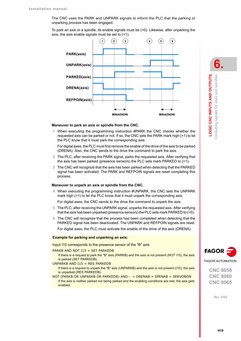
Installation manual.
CNC 8058CNC 8060CNC 8065
LO
GIC
CN
C IN
PU
TS
AN
D O
UT
PU
TS
.
6.
Con
sulti
ng s
ign
als
for
axe
s an
d sp
ind
les.
ꞏ419ꞏ
REF: 2102
The CNC uses the PARK and UNPARK signals to inform the PLC that the parking orunparking process has been engaged.
To park an axis or a spindle, its enable signals must be (=0). Likewise, after unparking theaxis, the axis enable signals must be set to (=1).
Maneuver to park an axis or spindle from the CNC.
1 When executing the programming instruction #PARK the CNC checks whether therequested axis can be parked or not. If so, the CNC sets the PARK mark high (=1) to letthe PLC know that it must park the corresponding axis.
For digital axes, the PLC must first remove the enable of the drive of the axis to be parked(DRENA). Also, the CNC sends to the drive the command to park the axis.
2 The PLC, after receiving the PARK signal, parks the requested axis. After verifying thatthe axis has been parked (presence sensors) the PLC sets mark PARKED to (=1).
3 The CNC will recognize that the axis has been parked when detecting that the PARKEDsignal has been activated. The PARK and REFPOIN signals are reset completing thisprocess.
Maneuver to unpark an axis or spindle from the CNC.
4 When executing the programming instruction #UNPARK, the CNC sets the UNPARKmark high (=1) to let the PLC know that it must unpark the corresponding axis.
For digital axes, the CNC sends to the drive the command to unpark the axis.
5 The PLC, after receiving the UNPARK signal, unparks the requested axis. After verifyingthat the axis has been unparked (presence sensors) the PLC sets mark PARKED to (=0).
6 The CNC will recognize that the process has been completed when detecting that thePARKED signal has been deactivated. The UNPARK and REFPOIN signals are reset.
For digital axes, the PLC must activate the enable of the drive of the axis (DRENA).
Example for parking and unparking an axis:
Input I15 corresponds to the presence sensor of the "B" axis
PARKB AND NOT I15 = SET PARKEDBIf there is a request to park the "B" axis (PARKB) and the axis is not present (NOT I15), the axisis parked (SET PARKEDB).
UNPARKB AND I15 = RES PARKEDBIf there is a request to unpark the "B" axis (UNPARKB) and the axis is not present (I15), the axisis unparked (RES PARKEDB).
NOT (PARKB OR UNPARKB OR PARKEDB) AND··· = DRENAB = SPENAB = SERVOBONIf the axis is neither parked nor being parked and the enabling conditions are met, the axis getsenabled.
PARK(axis)
UNPARK(axis)
PARKED(axis)
DRENA(axis)
REFPOIN(axis)
1 2 5 6
MINAENDW MINAENDW
3 4

Installation manual.
CNC 8058CNC 8060CNC 8065
6.
LO
GIC
CN
C IN
PU
TS
AN
D O
UT
PU
TS
.
Con
sulti
ng s
ign
als
for
axe
s an
d sp
ind
les.
ꞏ420ꞏ
REF: 2102
Park/Unpark from the PLC.
This type of maneuver is good for applications that need manual parking of the axes eitherwhile the machine is off or on (with or without power).
The axis parking/unparking maneuver, handled from the PLC program, is controlled usingthe PARKED signal. This mark is usually affected by the input for the axis presence sensor.The state of this signal is maintained even if the CNC is turned off.
The CNC uses logic signals PARK and UNPARK to inform the PLC that the parking orunparking processes are in execution.
To park an axis, the axis enable signals must be (=0). Likewise, after unparking the axis, theaxis enable signals must be set to (=1).
For safety, after parking and unparking an axis, the REFPOIN signal of the axis is set to (=0).
Maneuver to park an axis or spindle from the PLC.
1 From the PLC program, the PARKED mark is set to (=1) to park the relevant axis. TheCNC sets the PARK mark to (=1) and begins parking the axis.
For digital axes, the PLC must first remove the enable of the drive of the axis to be parked(DRENA). Also, the CNC sends to the drive the command to park the axis.
2 The CNC considers the operation completed. It resets the PARK signal.
Maneuver to unpark an axis or spindle from the PLC.
3 From the PLC program, the PARKED mark is set to (=0) to unpark the relevant axis. TheCNC sets the UNPARK mark to (=1) and begins unparking the axis.
For digital axes, the CNC sends to the drive the command to unpark the axis.
4 The CNC considers the operation completed. It resets the UNPARK signal.
For digital axes, the PLC must activate the enable of the drive of the axis (DRENA).
In versions older than V2.00, at the end of the parking or unparking maneuver, the PLC must generatea reset (RESETIN). i
Example for parking and unparking an axis:
I10 = PARKEDV
Axis present. "V" axis presence sensor
NOT (PARKV OR UNPARKV OR PARKEDV) AND··· = DRENAV = SPENAV = SERVOVON
If the axis is neither parked nor being parked and the enabling conditions are met, theaxis gets enabled.
PARK(axis)
UNPARK(axis)
PARKED(axis)
DRENA(axis)
REFPOIN(axis)
1 2 3 4
Installation manual.
CNC 8058CNC 8060CNC 8065
LO
GIC
CN
C IN
PU
TS
AN
D O
UT
PU
TS
.
6.
Con
sulti
ng s
ign
als
for
axe
s an
d sp
ind
les.
ꞏ421ꞏ
REF: 2102
ACTFBACK(axis)
The CNC uses this mark when the system has external+internal feedback. See machineparameter FBACKSRC.
The CNC sets this mark high (=1) to indicate that the external feedback (direct feedback)is being used . The CNC sets this mark high (=0) to indicate that the internal feedback (motorfeedback) is being used .
The feedback type may be swapped from the PLC using the mark FBACKSEL(axis). See"FBACKSEL(axis)" on page 447.
TANGACT(axis)
The CNC sets this mark high (=1) to indicate that tangential control is active in the axis. TheCNC sets this mark high (=0) when freezing (suspending) or canceling the tangential controlof the axis.
LOPEN(axis)
The CNC activates this mark to inform the PLC that the axis position loop is open.
MAXDIFF(axis)
This mark is used on gantry axes. The CNC activates this mark when it cannot correct theposition difference between the master axis and the slave axis because the difference isgreater than the value set in machine parameter MAXDIFF. Position correction must beenabled in machine parameter DIFFCOMP.
Installation manual.
CNC 8058CNC 8060CNC 8065
6.
LO
GIC
CN
C IN
PU
TS
AN
D O
UT
PU
TS
.
Co
nsul
ting
sign
als
for
the
spin
dle
.
ꞏ422ꞏ
REF: 2102
6.3 Consulting signals for the spindle.
REVOK
There is a mark for each spindle. The mnemonics for each spindle are the following:
REVOK1 (can also be programmed as REVOK)
REVOK2 REVOK3 REVOK4
It indicates whether the actual (real) spindle rpm match the ones programmed (=1) or not(=0). In other words, whether they are within the percentages set by machine parameterUPSPDLIM and LOSPDLIM.
• When the spindle is stopped, M5, REVOK is (=1).
• With M3 and M4, the CNC sets this mark high (=1) when the actual spindle rpm matchthe ones programmed.
• When working in closed loop (M19 or G63), the CNC sets this mark low (=0) while thespindle is moving and high (=1) when the spindle is in position.
The REVOK signal may be used to handle the Feedhold signal and avoid machining at loweror higher rpm than desired.
SYNCMASTER
There is a mark for each spindle. The mnemonics for each spindle are the following:
SYNCMASTER1 SYNCMASTER2 SYNCMASTER3 SYNCMASTER4
This mark is activated at the master spindle and indicates that a synchronization has begunwith the #SYNC instruction. When activating a synchronization, the CNC activates theENABLE signal at both spindles and waits for the SERVOON signal (if DWELLis used).
When a spindle synchronization is active, the PLCCNTL, INHIBIT and SPDLEREV signalsof both master and slave are ignored. Likewise, while threading, only the feedback andreference signal of the main spindle are taken into account.
SYNCHRON
There is a mark for each spindle. The mnemonics for each spindle are the following:
SYNCHRON1 SYNCHRON2 SYNCHRON3 SYNCHRON4
This mark is activated at the slave spindle and indicates that a synchronization has begunwith the #SYNC instruction. When activating a synchronization, the CNC activates theENABLE signal at both spindles and waits for the SERVOON signal (if DWELLis used).
When a spindle synchronization is active, the PLCCNTL, INHIBIT and SPDLEREV signalsof both master and slave are ignored. Likewise, while threading, only the feedback andreference signal of the main spindle are taken into account.
SYNCHRONP
There is a mark for each spindle. The mnemonics for each spindle are the following:
SYNCRONP1 SYNCRONP2 SYNCRONP3 SYNCRONP4
This mark is activated at the slave spindle and indicates that a position synchronization hasbegun. This mark may be used to distinguish between synchronization in position or invelocity and to know which mark, SYNSPEED or SYNCPOSI, to attend to.
SYNSPEED
There is a mark for each spindle. The mnemonics for each spindle are the following:
SYNSPEED1 SYNSPEED2 SYNSPEED3 SYNSPEED4
This mark is activated at the slave spindle when it is synchronized in speed.
This mark is set to (=0) when exceeding the maximum speed error allowed, whose defaultvalue is set by machine parameter DSYNCVELW.
Installation manual.
CNC 8058CNC 8060CNC 8065
LO
GIC
CN
C IN
PU
TS
AN
D O
UT
PU
TS
.
6.
Co
nsul
ting
sign
als
for
the
spin
dle
.
ꞏ423ꞏ
REF: 2102
SYNCPOSI
There is a mark for each spindle. The mnemonics for each spindle are the following:
SYNCPOSI1 SYNCPOSI2 SYNCPOSI3 SYNCPOSI4
This mark is activated at the slave spindle when it is synchronized in position.
This mark is set to (=0) when exceeding the maximum position error allowed, whose defaultvalue is set by machine parameter DSYNCPOSW.
GEAROK
There is a mark for each spindle. The mnemonics for each channel are the following.
GEAROK1 (can also be programmed as GEAROK)
GEAROK2 GEAROK3 GEAROK4
The spindle activates this mark when the parameter set selected at the CNC and at the PLCare the same. In order for both parameter sets to coincide, funciton M41 must be active atthe CNC and the GEAR1 mark at the PLC, M42 with GEAR2 and so on.
If both parameter sets do not coincide, the CNC executes no action. Include this mark in thePLC maneuver to define the actions to carry out when both parameter sets do not coincide,such as stop the spindle or interrupt the execution of the part-program.
Installation manual.
CNC 8058CNC 8060CNC 8065
6.
LO
GIC
CN
C IN
PU
TS
AN
D O
UT
PU
TS
.
Co
nsul
tatio
n si
gna
ls o
f the
ind
epen
den
t int
erp
olat
or.
ꞏ424ꞏ
REF: 2102
6.4 Consultation signals of the independent interpolator.
The signal names are generic. Replace the text (axis) with the name or logic axis number.
IBUSY(axis)
For movements of the independent axis, the independent interpolator of the axis activatesthis mark when it has an instruction pending to execute.
IFREE(axis)
For movements of the independent axis, the independent interpolator of the axis activatesthis mark when it is ready to accept a new motion block. The axis interpolator can activatethis mark even if there is block in execution, so it can join both blocks at the joining feedrateindicated in the first block.
IFHOUT(axis)
For movements of the independent axis, the independent interpolator of the axis activatesthis mark when the execution has been interrupted.
IEND(axis)
For movements of the independent axis, the independent interpolator of the axis activatesthis mark when it finishes generating the theoretical movement.
INSYNC(axis)
For synchronization movements of an independent axis and of an electronic cam, theinterpolator of the axis activates this mark when synchronism has been reached. This markstays active while maintaining synchronism.
PROBE1ACTIVEPROBE2ACTIVE
It is applied when latching the coordinate of an axis. There is a mark for each probe. Probe1 will be the one assigned to parameter PRBDI1 and probe 2 will be the one assigned toparameter PRBDI2.
The independent interpolator actives this mark when a latching process is active with theindicated probe and it deactivates when there is no active latching process with the indicatedprobe.
LATCH1ACTIVE(axis)LATCH2ACTIVE(axis)
It is applied when latching the coordinate of an axis. There is a mark for each probe. Probe1 will be the one assigned to parameter PRBDI1 and probe 2 will be the one assigned toparameter PRBDI2.
The independent interpolator actives this mark when activating a latching process on the axiswith the indicated probe and it deactivates when the latching process ends or it is canceled.
The latching process on the axis is canceled when the PLC activates the IRESET(axis) mark.A reset of the channel cancels the latching processes on all axes of the channel.
Functions M02 and M30 will not be considered executed (done) until all the latchingprocesses active on the axes of the channel are finished.

Installation manual.
CNC 8058CNC 8060CNC 8065
LO
GIC
CN
C IN
PU
TS
AN
D O
UT
PU
TS
.
6.
Co
nsul
tatio
n si
gna
ls o
f the
ind
epen
den
t int
erp
olat
or.
ꞏ425ꞏ
REF: 2102
LATCH1DONE(axis)LATCH2DONE(axis)
It is applied when latching the coordinate of an axis. There is a mark for each probe. Probe1 will be the one assigned to parameter PRBDI1 and probe 2 will be the one assigned toparameter PRBDI2.
The independent interpolator actives this mark when the latch event on the axis with theindicated probe occurs; it deactivates it when activating a new latching process on the axiswith the same probe.
FOLLOW(axis)
For movements of the independent axis, the interpolator of the axis activates this mark whenthe axis synchronization is active (#FOLLOW).
MOVCMD(axis)
For movements of the independent axis, the interpolator of the axis activates this mark whena positioning has been executed (#MOVE).

Installation manual.
CNC 8058CNC 8060CNC 8065
6.
LO
GIC
CN
C IN
PU
TS
AN
D O
UT
PU
TS
.
Co
nsul
ting
logi
c si
gna
ls; l
aser
.
ꞏ426ꞏ
REF: 2102
6.5 Consulting logic signals; laser.
ACTIVEMATERIALON
The CNC activates this mark when there is an active material file (due to the execution of#MATERIAL, #TECHTABLE, activation from HMI or recovery during start up).
PIERCING
Piercing enabled. The OEM must manage this variable in the subroutine associated withpiercing (by default, Piercing.fst), to indicate to the PLC when to start (value 1) and end (valor0) the piercing operation. The instruction #PLC makes it possible to manage a PLC markfrom the part or subroutine program, without interrupting the block preparation.
This mark shows the state of the variable V.PLC.PIERCING. The OEM can also use thisvariable in the subroutine associated with the piercing (by default, Piercing.fst) to modify thestatus of this mark. Entering this variable interrupts the block preparation.
CUTTING
Active cutting. The OEM must manage this mark in the subroutines associated with cutting(by default, Cutting.fst / Cuttingoff.fst), to indicate to the PLC when to begin (value 1) andend (valor 0) the cutting operation. The instruction #PLC makes it possible to manage a PLCmark from the part or subroutine program, without interrupting the block preparation.
This mark shows the state of the variable V.PLC.CUTTING. The OEM can also use thisvariable in the subroutines associated with cutting (by default, Cuttingon.fst / Cuttingoff.fst)to modify the status of this mark. Entering this variable interrupts the block preparation.
COMVARACT
The CNC activates this mark when the user validates the common parameters of the activepiercing or cutting table. The PLC should disable this mark when management with thesevariables is complete.
CUTVARACT
The CNC activates this mark when the user validates the cutting parameters of the activetable. The PLC should disable this mark when management with these variables is complete.
When the subroutine Cuttingon.fst changes only the cutting type (#CUTTING ON), the CNCdoes not activate this mark, as the synchronization with the PLC is implemented through Mfunctions.
The subroutine Cuttingon.fst (or the one associated with the cutting process) performs aseries of operations with the variables associated with the technological tables, operationsthat may also be required when the user modifies the table directly (which means modifyingthe variables). The PLC manages the effects of these variables on the machine devices(analog inputs, digital inputs, etc).
PIRVARACT
The CNC activates this mark when the user validates the piercing parameters of the activetable. The PLC should disable this mark when management with these variables is complete.
When the subroutine Piercing.fst changes only the piercing type (#PIERCING), the CNCdoes not activate this mark, as the synchronization with the PLC is implemented through Mfunctions.
The subroutine Piercing.fst (or the one associated with the piercing process) performs aseries of operations with the variables associated with the technological tables, operationsthat may also be required when the user modifies the table directly (which means modifyingthe variables). The PLC manages the effects of these variables on the machine devices(analog inputs, digital inputs, etc).
Installation manual.
CNC 8058CNC 8060CNC 8065
LO
GIC
CN
C IN
PU
TS
AN
D O
UT
PU
TS
.
6.
Co
nsul
ting
logi
c si
gna
ls; l
aser
.
ꞏ427ꞏ
REF: 2102
INPOSGAP
The CNC activates this mark if the gap is within the range defined by the parametersGAPMIN-GAPMAX. If the gap exceeds the range set by these parameters, the CNCdeactivates the INPOSGAP mark. The GAPERRORCANCEL parameter establishes theCNC behavior when the gap exceeds the GAPMIN - GAPMAX range.
INTOL
The CNC activates this mark if the gap is within the tolerance limit defined by the parameterGAPTOL regarding the gap value programmed. If the axis exceeds the tolerance set in theGAPTOL parameter, the CNC deactivates the INTOL mark. The GAPTOLCANCELparameter establishes the CNC behavior when the gap exceeds the tolerance set inGAPTOL.
INPOSLIMIT
The CNC activates this mark (changes from 0 to 1) when the leap programmed with a #LEAPreaches the highest point (POSLIMIT command). The CNC deactivates this mark (changesfrom 1 to 0) when the leap starts to lower from this point. If the leap does not reach the highestpoint due to lack of space, the CNC will not activate this mark. In the event of any error, theCNC will deactivate this mark.
GAPERRORCANCEL Meaning.
Yes. The CNC cancels the out-of-range gap error and does notstop the movement of the axes.
No The CNC returns an out-of-range gap error and stops themovement of the axes, according to the braking ramp andcontrolling the gap during the ramp.
GAPTOLCANCEL Meaning.
Yes. The CNC cancels the out-of-range gap error and does notstop the movement of the axes.
No The CNC returns an out-of-range gap error and stops themovement of the axes, according to the braking ramp andcontrolling the gap during the ramp.
Installation manual.
CNC 8058CNC 8060CNC 8065
6.
LO
GIC
CN
C IN
PU
TS
AN
D O
UT
PU
TS
.
Too
l man
ager
con
sulti
ng s
ign
als.
ꞏ428ꞏ
REF: 2102
6.6 Tool manager consulting signals.
TMOPERATION
There is a register for each channel. The mnemonics for each channel are the following.
TMOPERATIONC1 (same as TMOPERATION)
TMOPERATIONC2 TMOPERATIONC3 TMOPERATIONC4
This register indicates the type of operation to be carried out by the tool manager.
TMOPSTROBE
There is a mark for each channel. The mnemonics for each channel are the following.
TMOPSTROBEC1 (same as TMOPSTROBE)
TMOPSTROBEC2 TMOPSTROBEC3 TMOPSTROBEC4
The CNC sets this mark high (=1) to let the PLC know that it must execute the operationindicated by TMOPERATION.
LEAVEPOS
There is a register for each magazine. The mnemonics for each magazine are the following.
LEAVEPOSMZ1 (can also be programmed as LEAVEPOS)
LEAVEPOSMZ2 LEAVEPOSMZ3 LEAVEPOSMZ4
This register indicates the magazine position to leave the tool. While selecting a turretposition (#ROTATEMZ instruction), this register takes the value of ꞏ0ꞏ if it is a positive relativepositioning and the value of ꞏ1ꞏ if it is a negative relative positioning.
TAKEPOS
There is a register for each magazine. The mnemonics for each magazine are the following.
TAKEPOSMZ1 (can also be programmed as TAKEPOS)
TAKEPOSMZ2 TAKEPOSMZ3 TAKEPOSMZ4
This register indicates the magazine position of the tool to be taken. While selecting a turretposition (#ROTATEMZ instruction), this register takes the value of ꞏ0ꞏ if it is an absolutepositioning and the value of ꞏ1ꞏ if it is a relative positioning.
NEXTPOS
There is a register for each magazine. The mnemonics for each magazine are the following.
NEXTPOSMZ1 (can also be programmed as NEXTPOS)
NEXTPOSMZ2 NEXTPOSMZ3 NEXTPOSMZ4
This register indicates the magazine position occupied by the next tool. While selecting aturret position (#ROTATEMZ instruction); in an absolute positioning, this register indicatesthe position to reach and, in a relative positioning, the number of positions to rotate.
TWORNOUT
There is a mark for each channel. The mnemonics for each channel are the following.
TWORNOUTC1 (can also be programmed as TWORNOUT)
TWORNOUTC2 TWORNOUTC3 TWORNOUTC4
The CNC channel sets this mark high (=1) to "tell" the PLC that the tool has been rejectedbecause it is worn out (real life > maximum life span).
Installation manual.
CNC 8058CNC 8060CNC 8065
LO
GIC
CN
C IN
PU
TS
AN
D O
UT
PU
TS
.
6.
Too
l man
ager
con
sulti
ng s
ign
als.
ꞏ429ꞏ
REF: 2102
TMINEM
There is a register for each magazine. The mnemonics for each magazine are the following.
TMINEMZ1 (can also be programmed as TMINEM)
TMINEMZ2 TMINEMZ3 TMINEMZ4
The CNC sets this mark high (=1) to inform the PLC that an emergency has occurred at thetool manager.
MZID
There is a register for each channel. The mnemonics for each channel are the following.
MZIDC1 MZIDC2 MZIDC3 MZIDC4
This register indicates which magazine contains the tool requested by the channel.
When two magazines are involved in a tool change, the lower portion of this register indicatesthe destination magazine for the tool and the higher portion the source magazine for the tool.
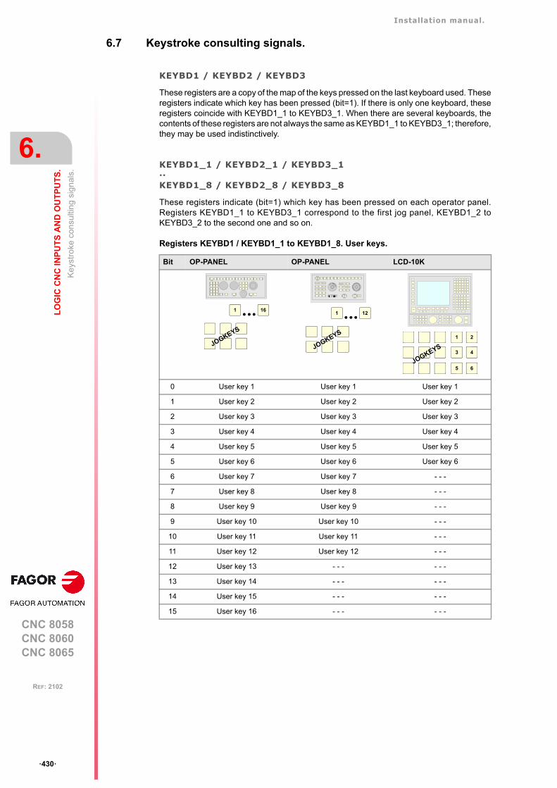
Installation manual.
CNC 8058CNC 8060CNC 8065
6.
LO
GIC
CN
C IN
PU
TS
AN
D O
UT
PU
TS
.
Ke
ystr
oke
cons
ulti
ng s
ign
als.
ꞏ430ꞏ
REF: 2102
6.7 Keystroke consulting signals.
KEYBD1 / KEYBD2 / KEYBD3
These registers are a copy of the map of the keys pressed on the last keyboard used. Theseregisters indicate which key has been pressed (bit=1). If there is only one keyboard, theseregisters coincide with KEYBD1_1 to KEYBD3_1. When there are several keyboards, thecontents of these registers are not always the same as KEYBD1_1 to KEYBD3_1; therefore,they may be used indistinctively.
KEYBD1_1 / KEYBD2_1 / KEYBD3_1··KEYBD1_8 / KEYBD2_8 / KEYBD3_8
These registers indicate (bit=1) which key has been pressed on each operator panel.Registers KEYBD1_1 to KEYBD3_1 correspond to the first jog panel, KEYBD1_2 toKEYBD3_2 to the second one and so on.
Registers KEYBD1 / KEYBD1_1 to KEYBD1_8. User keys.
Bit OP-PANEL OP-PANEL LCD-10K
0 User key 1 User key 1 User key 1
1 User key 2 User key 2 User key 2
2 User key 3 User key 3 User key 3
3 User key 4 User key 4 User key 4
4 User key 5 User key 5 User key 5
5 User key 6 User key 6 User key 6
6 User key 7 User key 7 - - -
7 User key 8 User key 8 - - -
8 User key 9 User key 9 - - -
9 User key 10 User key 10 - - -
10 User key 11 User key 11 - - -
11 User key 12 User key 12 - - -
12 User key 13 - - - - - -
13 User key 14 - - - - - -
14 User key 15 - - - - - -
15 User key 16 - - - - - -
1 16
JOGKEYS
CNCOFF
200190
180
170
160
150
140
130
120110
100908070
60
50
40
30
20
10
42
0
FEED
100001000
100101
10010 1
jogX Y Z
+_
4 5 6
+
_
CSS
m/min
ZERO SINGLE RESET
1 12
JOGKEYS1 2
3 4
5 6JOGKEYS
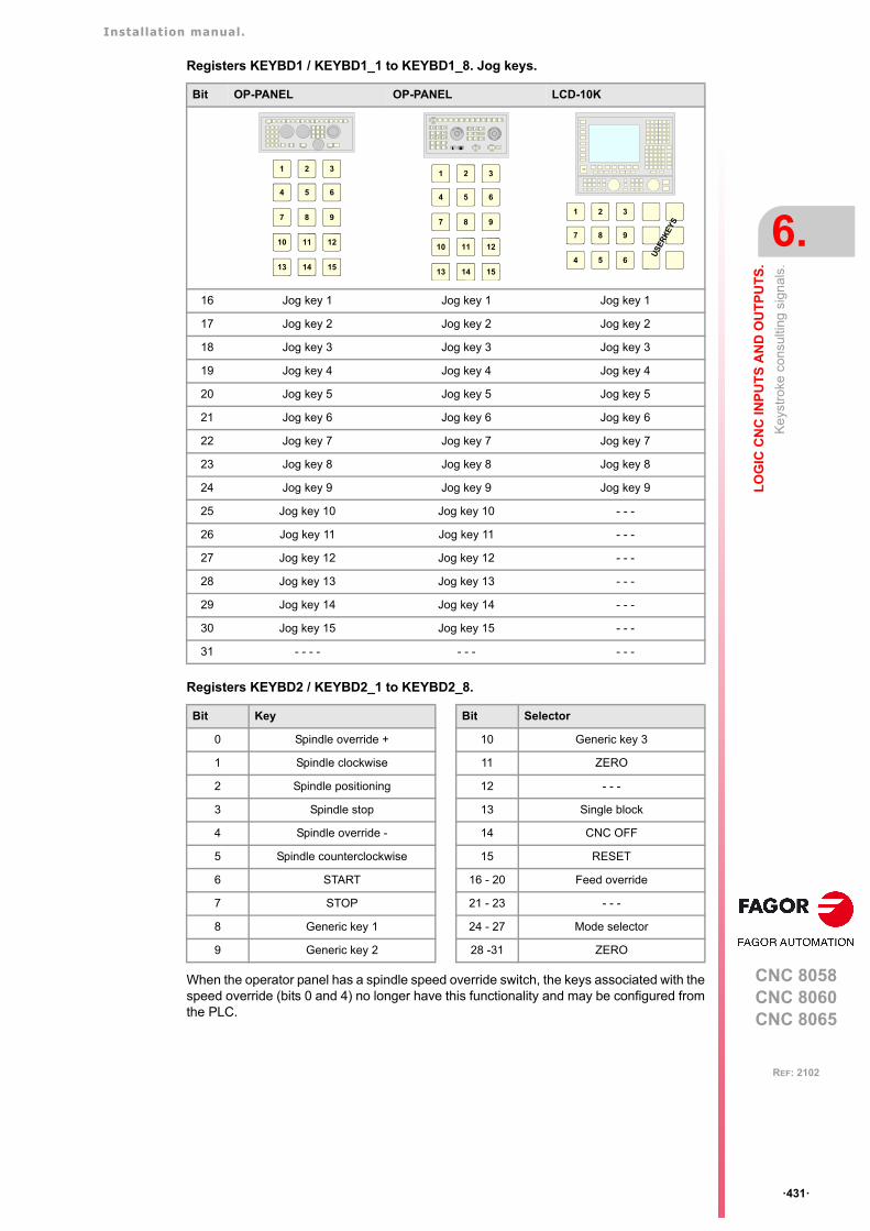
Installation manual.
CNC 8058CNC 8060CNC 8065
LO
GIC
CN
C IN
PU
TS
AN
D O
UT
PU
TS
.
6.
Ke
ystr
oke
cons
ulti
ng s
ign
als.
ꞏ431ꞏ
REF: 2102
Registers KEYBD1 / KEYBD1_1 to KEYBD1_8. Jog keys.
Registers KEYBD2 / KEYBD2_1 to KEYBD2_8.
When the operator panel has a spindle speed override switch, the keys associated with thespeed override (bits 0 and 4) no longer have this functionality and may be configured fromthe PLC.
Bit OP-PANEL OP-PANEL LCD-10K
16 Jog key 1 Jog key 1 Jog key 1
17 Jog key 2 Jog key 2 Jog key 2
18 Jog key 3 Jog key 3 Jog key 3
19 Jog key 4 Jog key 4 Jog key 4
20 Jog key 5 Jog key 5 Jog key 5
21 Jog key 6 Jog key 6 Jog key 6
22 Jog key 7 Jog key 7 Jog key 7
23 Jog key 8 Jog key 8 Jog key 8
24 Jog key 9 Jog key 9 Jog key 9
25 Jog key 10 Jog key 10 - - -
26 Jog key 11 Jog key 11 - - -
27 Jog key 12 Jog key 12 - - -
28 Jog key 13 Jog key 13 - - -
29 Jog key 14 Jog key 14 - - -
30 Jog key 15 Jog key 15 - - -
31 - - - - - - - - - -
Bit Key Bit Selector
0 Spindle override + 10 Generic key 3
1 Spindle clockwise 11 ZERO
2 Spindle positioning 12 - - -
3 Spindle stop 13 Single block
4 Spindle override - 14 CNC OFF
5 Spindle counterclockwise 15 RESET
6 START 16 - 20 Feed override
7 STOP 21 - 23 - - -
8 Generic key 1 24 - 27 Mode selector
9 Generic key 2 28 -31 ZERO
1
4
2
5
3
6
7 8 9
10 11 12
13 14 15
CNCOFF
200190
180
170
160
150
140
130
120110
100908070
60
50
40
30
20
10
42
0
FEED
100001000
100101
10010 1
jogX Y Z
+_
4 5 6
+
_
CSS
m/min
ZERO SINGLE RESET
1
4
2
5
3
6
7 8 9
10 11 12
13 14 15
1 2 3
7 8 9
4 5 6
US
ER
KE
YS

Installation manual.
CNC 8058CNC 8060CNC 8065
6.
LO
GIC
CN
C IN
PU
TS
AN
D O
UT
PU
TS
.
Ke
ystr
oke
cons
ulti
ng s
ign
als.
ꞏ432ꞏ
REF: 2102
Registers KEYBD2 / KEYBD2_1 to KEYBD2_8. Generic keys.
Registers KEYBD2 / KEYBD2_1 to KEYBD2_8. Feedrate override selector
Bit Jog Panel
8 Generic key 1
9 Generic key 2
10 Generic key 3
KEYBD2
20 19 18 17 16
0 0 0 0 0 0 %
0 0 0 0 1 2 %
0 0 0 1 0 4 %
0 0 0 1 1 10 %
0 0 1 0 0 20 %
0 0 1 0 1 30 %
0 0 1 1 0 40 %
0 0 1 1 1 50 %
0 1 0 0 0 60 %
0 1 0 0 1 70 %
0 1 0 1 0 80 %
0 1 0 1 1 90 %
0 1 1 0 0 100 %
0 1 1 0 1 110 %
0 1 1 1 0 120 %
0 1 1 1 1 130 %
1 0 0 0 0 140 %
1 0 0 0 1 150 %
1 0 0 1 0 160 %
1 0 0 1 1 170 %
1 0 1 0 0 180 %
1 0 1 0 1 190 %
1 0 1 1 0 200 %
160
150
140
1
2
3

Installation manual.
CNC 8058CNC 8060CNC 8065
LO
GIC
CN
C IN
PU
TS
AN
D O
UT
PU
TS
.
6.
Ke
ystr
oke
cons
ulti
ng s
ign
als.
ꞏ433ꞏ
REF: 2102
Registers KEYBD2 / KEYBD2_1 to KEYBD2_8. Movement selector (handwheel,incremental jog or continuous jog).
Registers KEYBD3 / KEYBD3_1 to KEYBD3_8. Spindle speed override selector.
KEYBD2
27 26 25 24
0 0 0 0 Handwheel x100
0 0 0 1 Handwheel x10
0 0 1 0 Handwheel x1
0 0 1 1 Jog 1
0 1 0 0 Jog 10
0 1 0 1 Jog 100
0 1 1 0 Jog 1000
0 1 1 1 Jog 10000
1 0 0 0 Continuous jog
KEYBD3
4 3 2 1 0
0 0 0 0 0 0 %
0 0 0 0 1 2 %
0 0 0 1 0 4 %
0 0 0 1 1 10 %
0 0 1 0 0 20 %
0 0 1 0 1 30 %
0 0 1 1 0 40 %
0 0 1 1 1 50 %
0 1 0 0 0 60 %
0 1 0 0 1 70 %
0 1 0 1 0 80 %
0 1 0 1 1 90 %
0 1 1 0 0 100 %
0 1 1 0 1 110 %
0 1 1 1 0 120 %
0 1 1 1 1 130 %
1 0 0 0 0 140 %
1 0 0 0 1 150 %
1 0 0 1 0 160 %
1 0 0 1 1 170 %
1 0 1 0 0 180 %
1 0 1 0 1 190 %
1 0 1 1 0 200 %
Installation manual.
CNC 8058CNC 8060CNC 8065
6.
LO
GIC
CN
C IN
PU
TS
AN
D O
UT
PU
TS
.
Gen
era
l mo
difia
ble
sign
als.
ꞏ434ꞏ
REF: 2102
6.8 General modifiable signals.
_EMERGEN
There is a mark for each channel. The mnemonics for each channel are the following.
_EMERGENC1 (can also be programmed as _EMERGEN)
_EMERGENC2 _EMERGENC3 _EMERGENC4
If the PLC sets this mark low (=0), the CNC stops the axes and the spindle and displays thecorresponding error message. The CNC interrupts the movement of the axes leaving themwithout command; the axes do not stop using a set acceleration ramp.
While the _EMERGEN mark is low (=0), the CNC does not allow executing programs andaborts any axis or spindle movement.
_STOP
There is a mark for each channel. The mnemonics for each channel are the following.
_STOPC1 (can also be programmed as _STOP)
_STOPC2 _STOPC3 _STOPC4
If the PLC sets this mark at a low logic level, the CNC channel interrupts the execution ofthe part program. To resume the execution of the program, besides setting this mark at ahigh logical level, the PLC should activate the CYSTART mark. See "CYSTART" on page435.
• This mark does not stop the spindle.
• This mark does not affect the independent movement of an axis (independentinterpolator), which also does not affect the key [STOP].
• This mark does not turn off the laser.
• This mark does not disable gap control, except in approach movement. In this case, theaxis will remain stationary and without gap control until the movement is resumed.
The treatment received by the signal _STOP is similar to that given to the [STOP] key in theCNC. With this signal at a low logic level, all keys remain enabled.
_XFERINH
There is a mark for each channel. The mnemonics for each channel are the following.
_XFERINHC1 (can also be programmed as _XFERINH)
_XFERINHC2 _XFERINHC3 _XFERINHC4
If the PLC sets this mark low (=0), the CNC channel interrupts the execution of the programat the end of the block being executed and inhibits the execution of the next block. If the axisneeds more braking distance than it has with the block being executed, the CNC can continueexecuting more blocks until the axis comes to a complete stop respecting the dynamics ofthe machine. When this mark is set back high (=1), the CNC resumes the execution of theprogram.
Having this mark (=0), the CNC does not allow jog movements for the axes of the channel;pressing a jog key is ignored.
The _EMERGEN, _STOP, _FEEDHOL, _XFERINH and CYSTART signals must be defined in the PLCprogram.
I-EMERG AND (rest of conditions) = _EMERGENIf the emergency-stop button is pressed (I-EMERG=0) or any other emergency situation occurs (=0), the _EMERGEN mark is set low (=0) causing an emergency at the CNC.
Installation manual.
CNC 8058CNC 8060CNC 8065
LO
GIC
CN
C IN
PU
TS
AN
D O
UT
PU
TS
.
6.
Gen
era
l mo
difia
ble
sign
als.
ꞏ435ꞏ
REF: 2102
This mark always affects the movements of the independent axis programmed from theCNC; the ones programmed from the PLC depend on parameter XFITOIND. If the PLCdeactivates the _XFERINH mark, the CNC channel interrupts the movements of theindependent axis when they reach position and inhibits the execution of the next movement.
To manage the transfer inhibit in an independent movement, the PLC also has a particularmark per axis (_IXFERINH(axis) mark). See " _IXFERINH(axis)" on page 455.
_FEEDHOL
There is a mark for each channel. The mnemonics for each channel are the following.
_FEEDHOLC1 (can also be programmed as _FEEDHOL)
_FEEDHOLC2 _FEEDHOLC3 _FEEDHOLC4
If the PLC sets this mark at a high logic level, the CNC channel momentarily interrupts themovement of the axes. When the mark returns to the high logic level, the movement of theaxes continues. All the stops and starts of the axes are carried out with the correspondingacceleration and deceleration.
• This mark does not stop the spindle.
• This mark does not affect the independent movement of an axis (independentinterpolator).
• On hirth axes, if the axis does not stop in a particular position, the CNC does not activatethe MATCH(axis) mark.
• This mark does not turn off the laser. If the power control is active, the laser removes theminimum defined power.
If the PLC sets the _FEEDHOL at a low logic level in a motionless block, the CNC continuesexecuting the program until it detects a motion block.
The "Freal" text of the screens of the automatic and jog modes shows the status of this mark.The text appears in red when the _FEEDHOL mark is active. The status of the mark is notdisplayed if the screen does not show this text.
CYSTART
There is a mark for each channel. The mnemonics for each channel are the following.
CYSTARTC1 (can also be programmed as CYSTART)
CYSTARTC2 CYSTARTC3 CYSTARTC4
When the operator presses the [START] key, the CNC lets the PLC know by activating theSTART mark. If the rest of the conditions are met (hydraulic, safety, etc.), the PLC mustactivate the CYSTART mark in order for the program to start running.
SBLOCK
There is a mark for each channel. The mnemonics for each channel are the following.
SBLOCKC1 (can also be programmed as SBLOCK)
SBLOCKC2 SBLOCKC3 SBLOCKC4
If the PLC sets this mark high (=1), the CNC switches to SINGLE BLOCK operation mode.
XFITOIND Meaning.
Yes The _XFERINH mark affects the movement of the independent axis programmedfrom the PLC and from the CNC.
No The _XFERINH mark does not affect the movements of the independent axisprogrammed from the PLC; but it does affect the ones programmed from theCNC.
START AND (rest of conditions) = CYSTART
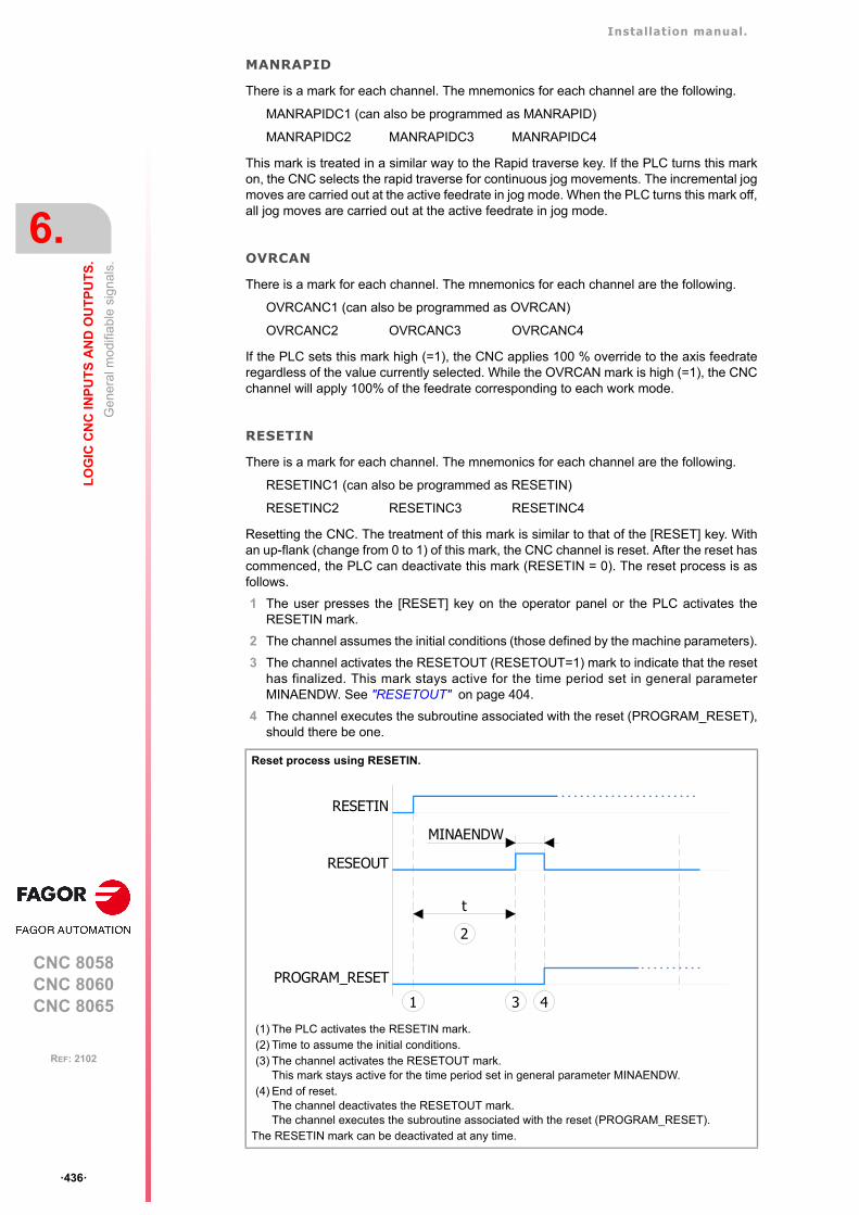
Installation manual.
CNC 8058CNC 8060CNC 8065
6.
LO
GIC
CN
C IN
PU
TS
AN
D O
UT
PU
TS
.
Gen
era
l mo
difia
ble
sign
als.
ꞏ436ꞏ
REF: 2102
MANRAPID
There is a mark for each channel. The mnemonics for each channel are the following.
MANRAPIDC1 (can also be programmed as MANRAPID)
MANRAPIDC2 MANRAPIDC3 MANRAPIDC4
This mark is treated in a similar way to the Rapid traverse key. If the PLC turns this markon, the CNC selects the rapid traverse for continuous jog movements. The incremental jogmoves are carried out at the active feedrate in jog mode. When the PLC turns this mark off,all jog moves are carried out at the active feedrate in jog mode.
OVRCAN
There is a mark for each channel. The mnemonics for each channel are the following.
OVRCANC1 (can also be programmed as OVRCAN)
OVRCANC2 OVRCANC3 OVRCANC4
If the PLC sets this mark high (=1), the CNC applies 100 % override to the axis feedrateregardless of the value currently selected. While the OVRCAN mark is high (=1), the CNCchannel will apply 100% of the feedrate corresponding to each work mode.
RESETIN
There is a mark for each channel. The mnemonics for each channel are the following.
RESETINC1 (can also be programmed as RESETIN)
RESETINC2 RESETINC3 RESETINC4
Resetting the CNC. The treatment of this mark is similar to that of the [RESET] key. Withan up-flank (change from 0 to 1) of this mark, the CNC channel is reset. After the reset hascommenced, the PLC can deactivate this mark (RESETIN = 0). The reset process is asfollows.
1 The user presses the [RESET] key on the operator panel or the PLC activates theRESETIN mark.
2 The channel assumes the initial conditions (those defined by the machine parameters).
3 The channel activates the RESETOUT (RESETOUT=1) mark to indicate that the resethas finalized. This mark stays active for the time period set in general parameterMINAENDW. See "RESETOUT" on page 404.
4 The channel executes the subroutine associated with the reset (PROGRAM_RESET),should there be one.
Reset process using RESETIN.
(1) The PLC activates the RESETIN mark.(2) Time to assume the initial conditions.(3) The channel activates the RESETOUT mark.
This mark stays active for the time period set in general parameter MINAENDW.(4) End of reset.
The channel deactivates the RESETOUT mark.The channel executes the subroutine associated with the reset (PROGRAM_RESET).
The RESETIN mark can be deactivated at any time.
RESEOUT
RESETIN
PROGRAM_RESET
MINAENDW
1 3 4
t
2
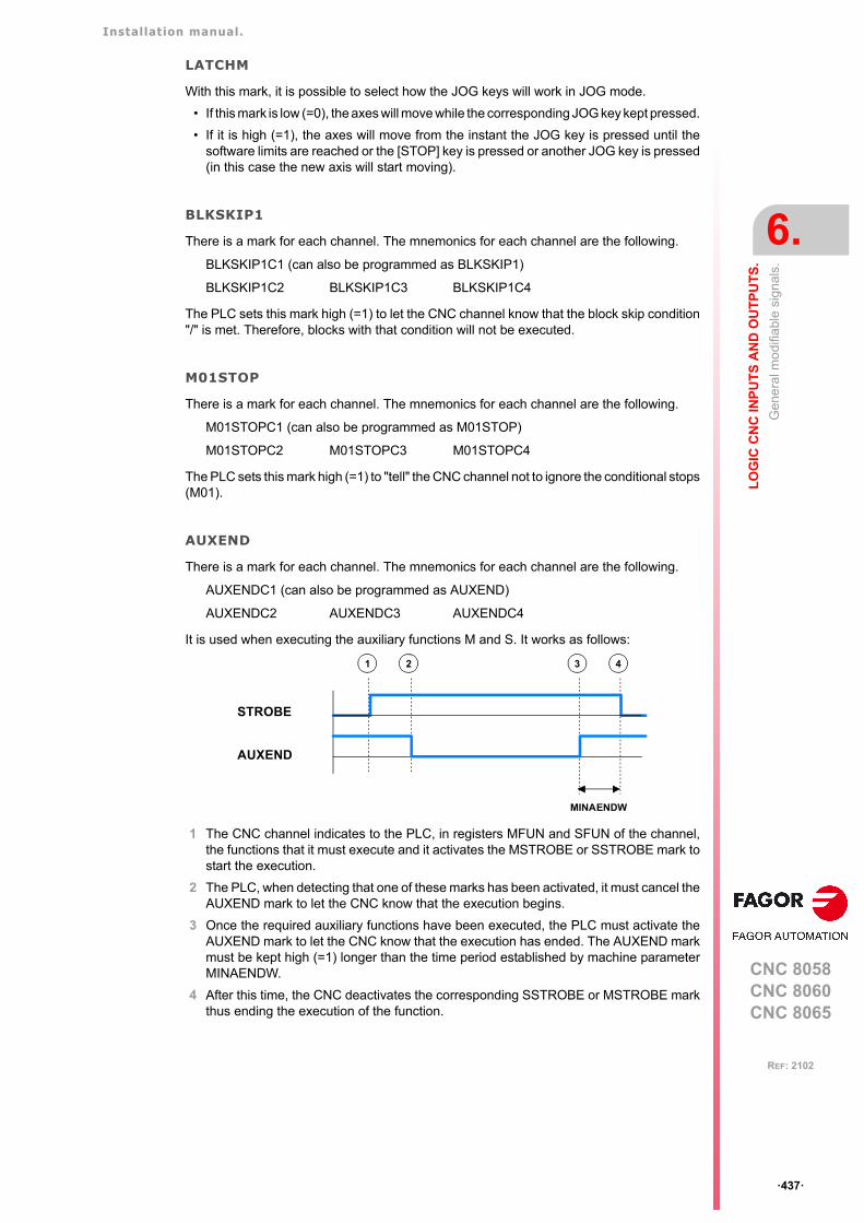
Installation manual.
CNC 8058CNC 8060CNC 8065
LO
GIC
CN
C IN
PU
TS
AN
D O
UT
PU
TS
.
6.
Gen
era
l mo
difia
ble
sign
als.
ꞏ437ꞏ
REF: 2102
LATCHM
With this mark, it is possible to select how the JOG keys will work in JOG mode.
• If this mark is low (=0), the axes will move while the corresponding JOG key kept pressed.
• If it is high (=1), the axes will move from the instant the JOG key is pressed until thesoftware limits are reached or the [STOP] key is pressed or another JOG key is pressed(in this case the new axis will start moving).
BLKSKIP1
There is a mark for each channel. The mnemonics for each channel are the following.
BLKSKIP1C1 (can also be programmed as BLKSKIP1)
BLKSKIP1C2 BLKSKIP1C3 BLKSKIP1C4
The PLC sets this mark high (=1) to let the CNC channel know that the block skip condition"/" is met. Therefore, blocks with that condition will not be executed.
M01STOP
There is a mark for each channel. The mnemonics for each channel are the following.
M01STOPC1 (can also be programmed as M01STOP)
M01STOPC2 M01STOPC3 M01STOPC4
The PLC sets this mark high (=1) to "tell" the CNC channel not to ignore the conditional stops(M01).
AUXEND
There is a mark for each channel. The mnemonics for each channel are the following.
AUXENDC1 (can also be programmed as AUXEND)
AUXENDC2 AUXENDC3 AUXENDC4
It is used when executing the auxiliary functions M and S. It works as follows:
1 The CNC channel indicates to the PLC, in registers MFUN and SFUN of the channel,the functions that it must execute and it activates the MSTROBE or SSTROBE mark tostart the execution.
2 The PLC, when detecting that one of these marks has been activated, it must cancel theAUXEND mark to let the CNC know that the execution begins.
3 Once the required auxiliary functions have been executed, the PLC must activate theAUXEND mark to let the CNC know that the execution has ended. The AUXEND markmust be kept high (=1) longer than the time period established by machine parameterMINAENDW.
4 After this time, the CNC deactivates the corresponding SSTROBE or MSTROBE markthus ending the execution of the function.
STROBE
AUXEND
1 2 3 4
MINAENDW

Installation manual.
CNC 8058CNC 8060CNC 8065
6.
LO
GIC
CN
C IN
PU
TS
AN
D O
UT
PU
TS
.
Gen
era
l mo
difia
ble
sign
als.
ꞏ438ꞏ
REF: 2102
TIMERON
The CNC has a timer to be used at will.
It times in seconds and it is enabled and disabled with this mark. It will be enabled (counting)with TIMERON set high (=1).
To reset and or know its accumulated timing, use the variable: (V.)PLC.TIMER. This variableis accessible from the PLC program, MDI or interface (any supported application).
PLCREADY
This mark indicates whether the PLC is running (=1) or stopped (=0).
• It must be high (=1) for the CNC to allow moving the axes and turning the spindle.
• If set low (=0), the PLC program stops and an error message is displayed.
NOWAIT
There is a mark for each channel. The mnemonics for each channel are the following.
NOWAITC1 NOWAITC2 NOWAITC3 NOWAITC4
It is applied to channel synchronization. The PLC sets this mark high (=1) to cancel all thesynchronizations with the CNC channel.
For example, with the NOWAITC1 signal set to (=1), the waits programmed in any channelwith the #WAIT, instruction and that refer to a mark of channel 1, they finish immediately andthe program execution resumes.
DISCROSS1··DISCROSSn
It is applied to the cross compensation tables defined in the machine parameters. There isa mark for each table.
The PLC sets the mark to (=1) to disable the table. The DISCROSS1 mark is for table 1,DISCROSS2 for table 2 and so on.
EXRAPID
There is a mark for each channel. The mnemonics for each channel are the following.
EXRAPIDC1 (can also be programmed as EXRAPID)
EXRAPIDC2 EXRAPIDC3 EXRAPIDC4
If the PLC activates this mark, the CNC channel enables rapid traverse during the executionof a program for the programmed movements. The behavior of this mark depends on howparameter RAPIDEN has been set.
The treatment of this signal is similar to the rapid key of the operator panel.
Example of how to know the machining time.
CY1() = MOV 0 R100()= CNCWR (R100, PLC.TIMER, M11)
Resets the timer to "0" on power-up.
END
PRGAUTOMAT AND INCYCLE = TIMERON
Timer active while machining.
()= CNCRD (PLC.TIMER, R300, M12)
Register R300 shows the value of the timer.
END
Installation manual.
CNC 8058CNC 8060CNC 8065
LO
GIC
CN
C IN
PU
TS
AN
D O
UT
PU
TS
.
6.
Gen
era
l mo
difia
ble
sign
als.
ꞏ439ꞏ
REF: 2102
PLCABORT
There is a mark for each channel. The mnemonics for each channel are the following.
PLCABORTC1 (can also be programmed as PLCABORT)
PLCABORTC2 PLCABORTC3 PLCABORTC4
If the PLC sets this mark low (=0), the CNC channel aborts the CNCEX command launchedfrom the PLC, but without initializing the conditions of the channel and keeping the historyof the channnel. This mark is only valid when the channel is executing a CNCEX; not in otherprogram or MDI executions.
Once the execution has been canceled, the CNC deactivates this mark and sets the FREEmark of the channel high (=1). See "FREE" on page 412.
The PLCABORT mark is activated without having launched a CNCEX, the mark stays high(=1) until a CNCEX is executed (which will be aborted automatically) or until it is deactivated(RES PLCABORT).
PRGABORT
There is a mark for each channel. The mnemonics for each channel are the following.
PRGABORTC1 (can also be programmed as PRGABORT)
PRGABORTC2 PRGABORTC3 PRGABORTC4
If the PLC sets this mark low (=1), the CNC channel aborts the current execution of the part-program; but without affecting the spindle, the rest of the history is initialized. Then, the CNCresumes the execution of the program from the label indicated in the #ABORT instructionthat is active in the part-program.
If no #ABORT instruction is active in the part-program, the PRGABORT mark has no effect.
NEXTMPGAXIS
This mark may be used to select an axis sequentially for jogging it with the handwheel. Onlythe axes being displayed in the active channel may be selected, regardless of the channelthey belong to. The axes of another channel cannot be selected if they are not beingdisplayed.
This mark is only taken into account when the CNC is in jog mode and the selector is inhandwheel mode. With an up flank of this mark, transition from (=0) to (=1), the CNC behavesas follows.
• If no axis has been selected, it selects the first one that is displayed.
• If there is an axis selected, it selects the next one; if the last axis is selected, it selectsthe first one again.
An axis is de-selected when quitting the handwheel mode using the movement selector andafter a reset.
This mark is meant for handwheels with push-button. On this type of handwheels, the push-button may be used to select, sequentially, the axis to be jogged. The usual thing in thesecases is to connect the push-button of the handwheel to the digital input that will be in chargeof managing the NEXTMPGAXIS mark.
PANELOFFPANELOFF1··PANELOFF8
If the PLC activates one of these marks the CNC disables the corresponding jog panel. Eachmark may be used to disable the jog panel integrated into the CAN bus; the rest of theelements of the bus are not affected. When the keyboard and the operator panel make upa single element, this mark only disables the jog panel.
There is one mark for each jog panel. The PANELOFF1 mark disables the first one of thebus, the PANELOFF2 mark the second one and so on. Both PANELOFF and PANELOFF1are valid for the first jog panel.

Installation manual.
CNC 8058CNC 8060CNC 8065
6.
LO
GIC
CN
C IN
PU
TS
AN
D O
UT
PU
TS
.
Gen
era
l mo
difia
ble
sign
als.
ꞏ440ꞏ
REF: 2102
The "address" switch determines the order of the elements in the CAN bus. The first elementwill be the one with the lowest number and so on. The element with the lowest numbercorresponds to PANELOFF1.
CNCOFF
Setting this PLC mark high (=1) initiates the CNC shut-down sequence. Activating this markis the same as pressing the key combination [ALT]+[F4].
SYNC
There is a register for each channel. The mnemonics for each channel are the following.
SYNC1 SYNC2 SYNC3 SYNC4
This register is used when using, from one channel, a particular spindle for synchronizationeven if the spindle is in another channel. For example, in the case of dual-turret lathe witha single spindle.
• With the G33 function, when threading with a particular spindle.
• With the G95 function, when programming the feedrate as a function of the turning speedof a particular spindle.
To do that, the PLC indicates in channel register SYNC the spindle to be used, only forsynchronization. The SYNC register will take values 1 through 4; when assigning a 0 value,it will use the master spindle of the channel.
The CNC will check the contents of this register at the beginning of the block. If the PLCmodifies this register during the execution of the block, the change will not effective until thebeginning of the next block.
RETRACE
There is a mark for each channel. The mnemonics for each channel are the following.
RETRACEC1 RETRACEC2 RETRACEC3 RETRACEC4
If the PLC sets this mark high (=1) while executing a program in automatic mode, the retracefunction is activated in the selected channel. The retrace function stops the execution of theprogram and starts executing backwards the path traveled so far at the current block plusthe last n blocks executed. The maximum number of blocks to execute in retrace mode isset by machine parameter NRETBLK.
The retrace function may be activated during an interpolation, in the middle of a block andalso at the end of the block, whether the execution was interrupted by M0 or by the singleblock mode.
If the PLC sets this mark high (=1), the CNC finishes the RETRACE function. The retracefunction also ends after M30, with a reset or when the CNC channel sets mark RETRAENDhigh (=1) See "RETRAEND" on page 413.
The retrace function must be enabled in machine parameter RETRACAC.
Address Element PLC mark
0 CNC
1 Remote (I/O) group
2 Jog panel PANELOFF1
3 Remote (I/O) group
4 Remote (I/O) group
5 Keyboard + Jog panel PANELOFF2
Installation manual.
CNC 8058CNC 8060CNC 8065
LO
GIC
CN
C IN
PU
TS
AN
D O
UT
PU
TS
.
6.
Gen
era
l mo
difia
ble
sign
als.
ꞏ441ꞏ
REF: 2102
INHIBITMPG1··INHIBITMPG12
If the PLC turns one of these marks on, it disables the corresponding handwheel. The PLChas a mark for each handwheel, the INHIBITMPG1 mark disables the first handwheel, theINHIBITMPG2 mark the second one and so on.
If the handwheel is disabled, the CNC ignores the pulses coming from the handwheel and,therefore, it does not move the axis. While the handwheel is disabled, the variable associatedwith the handwheel does not save the pulses sent by the handwheel.
If it is an individual handwheel, associated with an axis, the ENABLE(axis) mark of the axiswill stay active. If the handwheel mode is selected in jog mode for that axis, that axis willappear highlighted even if the PLC has disabled the handwheels that could move it.
KEYBD1CH··KEYBD8CH
On power-up, the CNC always assumes the keyboard configuration set in the machineparameters. These registers may be used to change the default behavior of the keyboardswith respect to the channels, set by machine parameters. These registers can associate ajog panel with a particular channel, always with the active channel or restore the configurationdefined in the machine parameters.
VOLCOMP1··VOLCOMP4
If the PLC activates one of these marks (changing it from 0 to 1), the CNC activates thecorresponding volumetric compensation (VOLCOMP parameter). If the PLC deactivatesone of these marks (changing it from 1 to 0), the CNC deactivates the correspondingvolumetric compensation.
All volumetric compensations can be simultaneously active, as long as there are no commonaxes among them. The CNC applies the volumetric compensation after applying theleadscrew compensation and the cross compensation. Volumetric compensation remainsactive after a reset, error or end of program (M30).
(V.)G.HANDP[hw] Number of pulses sent by the handwheel since the system was startedup.
KEYBD1CHꞏꞏKEYBD8CH
Meaning.
0 Configuration defined in the machine parameters.
1 Jog panel assigned to channel 1.
2 Jog panel assigned to channel 2.
3 Jog panel assigned to channel 3.
4 Jog panel assigned to channel 4.
FF Jog panel assigned to the active channel.
Mark. Meaning.
VOLCOMP1 Activate the first volumetric compensation (machine parameter VOLCOMP 1).
VOLCOMP2 Activate the second volumetric compensation (machine parameterVOLCOMP 2).
VOLCOMP3 Activate the third volumetric compensation (machine parameter VOLCOMP 3).
VOLCOMP4 Activate the fourth volumetric compensation (machine parameter VOLCOMP 4).

Installation manual.
CNC 8058CNC 8060CNC 8065
6.
LO
GIC
CN
C IN
PU
TS
AN
D O
UT
PU
TS
.
Gen
era
l mo
difia
ble
sign
als.
ꞏ442ꞏ
REF: 2102
QWERTYOFF1··QWERTYOFF8
If the PLC turns one of these marks on, it disables the corresponding alphanumeric keyboard.Each mark may be used to disable a USB keyboard (10K model) or one integrated into theCAN bus (15" model) ; the rest of the elements of the bus are not affected. The keyboardsare not enabled or disabled immediately, especially when activating the USB keyboard, itmay take a few seconds.
The way the QWERTYOFF1 works depends on the CNC model.
• On the 10K model, this mark affects the alphanumeric keyboard and the softkeys of themonitor (USB interface).
• On the 15" model, this mark affects the softkeys of the monitor (USB interface) and thefirst node of the CAN bus. In order for the mark to affect the keyboard associated withthe central unit, the number of this keyboard must be the lowest one in the bus.
Marks QWERTYOFF2 to QWERTYOFF8 affect the rest of the CAN keyboards, dependingon the logic numbers of the nodes, from lowest to highest.
FLIMITAC
If the PLC activates this mark, the CNC activates the feedrate safety limits (parameterFLIMIT) on all the axes of the system during the execution of the block. If the PLC deactivatesthis mark, the CNC restores the programmed feedrate.
The feedrate safety limit is applied to the movements in automatic (G0, G1, etc.) and in jogmode (jog, handwheels, etc.). This parameter affects neither the threading operations northe independent axis movements, which are executed at the programmed feedrate.
FLIMITACCH
There is a mark for each channel. The mnemonics for each channel are the following.
FLIMITACCHC1 (can also be programmed as FLIMITACCH)
FLIMITACCHC2 FLIMITACCHC3 FLIMITACCHC4
If the PLC activates this mark, the CNC activates the feedrate safety limits (parameterFLIMIT) on all the axes of the channel during the execution of the block. If the PLCdeactivates this mark, the CNC restores the programmed feedrate.
The feedrate safety limit is applied to the movements in automatic (G0, G1, etc.) and in jogmode (jog, handwheels, etc.). This parameter affects neither the threading operations northe independent axis movements, which are executed at the programmed feedrate.
SLIMITAC
If the PLC activates this mark, the CNC activates the speed safety limits (parameter SLIMIT)on all the spindles of the system during the execution of the current block. If the PLCdeactivates this mark, the CNC restores the programmed speed.
PT100OFF1··PT100OFF20
The PT100 inputs are activated via the machine parameters. The PLC has the followingmarks in order to be able to temporarily disable the sensor (for example, during a spindlechange).
If the PLC activates one of these marks, the CNC disables the corresponding sensor(parameter PT100 n). The PT100OFF1 mark corresponds to the input 1 sensor, PT100OFF2is for the input 2 sensor and so forth.

Installation manual.
CNC 8058CNC 8060CNC 8065
LO
GIC
CN
C IN
PU
TS
AN
D O
UT
PU
TS
.
6.
Gen
era
l mo
difia
ble
sign
als.
ꞏ443ꞏ
REF: 2102
INT1··INT4
There is a mark for each channel. The mnemonics for each channel are the following. Hereis an example of the mnemonics for INT1; it is the same for the rest of the marks.
INT1C1 (can also be programmed as INT1)
INT1C2 INT1C3 INT1C4
When the PLC activates one of these marks, the channel interrupts the execution of theprogram and executes the corresponding interruption subroutine associated withparameters INT1SUB to INT4SUB. The CNC executes the subroutine with the currenthistory of the interrupted program (G functions, feedrate, etc.). If the sub-routine ends withM30, the execution of the programme also ends. If the execution of a subroutine ends with#RET, the CNC resumes the execution of the programme from the interruption point andmaintains the changes made to the log by the subroutine (G functions, etc.).
If the program is interrupted (STOP) or no program is in execution (channel in READY state),the execution of the subroutine depends on parameter SUBINTSTOP. Also, in order toexecute the subroutine when no program is in execution, the channel must be in automaticmode; the subroutine cannot be executed from jog mode.
The execution of an interruption subroutine may be interrupted with a STOP, but not byanother interruption subroutine. When a subroutine is interrupted, it is not possible to getinto tool inspection mode.
The CNC cancels the mark when it starts executing the subroutine or when it rejects theexecution of the subroutine.
PROBE1ENAPROBE2ENA
Marks activated by default. These mark indicate that the probe has is enabled. Whenexecuting a G100 or G103 command, the CNC will issue an error message if the mark ofthe active probe (the one selected with #SELECT PROBE) is not enabled. These marks donot limit the monitoring of the safe mode.
These marks should be tested in the subroutines Sub_Probe_Tool_Begin.fst andSub_Probe_Piece_Begin.fst so the subroutine waits until the mark is active.
PROBE1MONITPROBE2MONIT
These marks are associated with the safe mode of the probe. If the mark is active, the probeis in safe mode monitoring collisions.
Loop level monitoring, controlling all the collision scenarios in any of the two probes. TheCNC can monitor the probes connected to the local inputs and to the remote CAN inputs.The CNC monitors the two probe inputs at the same time.
These marks should be tested in the subroutines Sub_Probe_Tool_Begin.fst andSub_Probe_Piece_Begin.fst to warn, if they are deactivated, that the probe is in non-safemode.
LCOUNTALARMOFF1LCOUNTALARMOFF2
These marks refer to the local feedback inputs 1 (LCOUNTALARMOFF1) and 2(LCOUNTALARMOFF2) for the 8065. For the 8060 model, only the first of these(LCOUNTALARMOFF1) has any functionality, as there is only one feedback input.
If the PLC activates one of these marks (by changing it from 0 to 1), it disables thecorresponding local feedback input. If the PLC deactivates one of these marks (by changingit from 1 to 0), it enables the feedback alarms.
When the spindle and the C axis are parameterized in two sets for the same spindle, eachwith its respective feedback while sharing the input signal (although with differentresolutions), the movement of the spindle can sound an alarm for the C feedback. Thesemarks allow the C feedback alarms to be disabled (for a local feedback) when the spindle
Installation manual.
CNC 8058CNC 8060CNC 8065
6.
LO
GIC
CN
C IN
PU
TS
AN
D O
UT
PU
TS
.
Gen
era
l mo
difia
ble
sign
als.
ꞏ444ꞏ
REF: 2102
is in use, although assuming there may be a loss of feedback and that the C axis must bereferenced when re-activating it.
The alarm report is conditioned to the parameter FBACKAL. No alarm is detected if the localfeedback is set to non-differential TTL.
RKIN1··RKIN32
These registers allow for communication between the PLC and user kinematics.
COLLISIONOFFCOLLISIONOFFC1
If the PLC activates this mark (change from 0 to 1), deactivate the FCAS option (collisioncontrol). If the PLC deactivates this mark (change from 1 to 0), activate the FCAS option(collision control).
Installation manual.
CNC 8058CNC 8060CNC 8065
LO
GIC
CN
C IN
PU
TS
AN
D O
UT
PU
TS
.
6.
Mo
difia
ble
sig
nal
s fo
r ax
es
and
spin
dle
s.
ꞏ445ꞏ
REF: 2102
6.9 Modifiable signals for axes and spindles.
When the spindle is working in closed loop (M19 or G63), it behaves like an axis.
The signal names are generic. Replace the word (axis) with the spindle name or with thename or logic number of the axis. For example, the name of the LIMITPOS(axis) mark fora machine with the X, Y, Z, Z2, B axes and spindle S.
LIMITPOSX, LIMITPOSZ2, LIMITPOSB, LIMITPOSS
LIMITPOS3 for the Z axis.
LIMITPOS5 for the B axis.
LIMITPOS(axis)LIMITNEG(axis)
If the PLC sets this mark high (=1), the CNC interprets that the corresponding axis or spindlehas exceeded the positive (POS) or negative (NEG) travel limits.
It stops the axes and the spindle and displays the relevant error message.
To take the axis to the work zone, access the JOG mode and move the axis or spindle thatoverran the travel limit. They can only be moved in the proper direction.
DECEL(axis)
This mark is used during home search. The PLC sets this mark high (=1) to indicate that thehome switch is pressed. The CNC decelerates the axis, it switches from the fast homingfeedrate indicated by machine parameter REFFEED1, to the slow homing feedrate indicatedby the machine parameter REFFEED2.
When searching home on axes that use distance-coded reference marks, the PLC sets thismark to (=1) to indicate that the axis has reached the travel limit. In this case, it is necessaryto reverse the moving direction to go on with the home search.
INHIBIT(axis)
If the PLC sets this mark high (=1) the CNC inhibits any movement of the corresponding axisor spindle. This movement will resume when the PLC sets this mark back low (=0). If theaxis or spindle is moving with other axes, all the axes will stop.
For independent axes and electronic cam, if the PLC sets this signal to (=1), it interrupts thesynchronization movement switching to zero speed. The system waits for the signal todeactivate before resuming the execution and the movement from the interruption point.
For independent axes, this signal also stops the monitoring of the synchronization.
The screens of the automatic and jog modes show the status of this mark.
• For the spindles, the text "Sreal" appears in red when this mark is active for the spindle.The status of the mark is not displayed if the screen does not show this text.
• For the axes, the name of the axis preceding the coordinate appears in red when thismark is active for the axis.
AXISPOS(axis)AXISNEG(axis)
The CNC uses these marks when operating in JOG mode.
If the PLC sets one of these marks high (=1), the CNC will move the relevant axis in theindicated direction: positive (POS) or negative (NEG). The CNC will move the axis at thecorresponding feedrate and selected override (%).
The treatment of these marks is similar to the JOG keys of the operator panel.
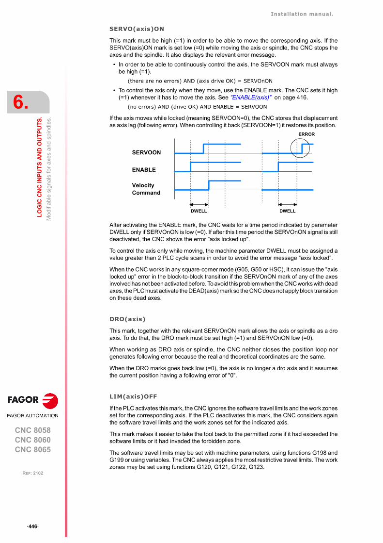
Installation manual.
CNC 8058CNC 8060CNC 8065
6.
LO
GIC
CN
C IN
PU
TS
AN
D O
UT
PU
TS
.
Mo
difia
ble
sig
nal
s fo
r ax
es
and
spin
dle
s.
ꞏ446ꞏ
REF: 2102
SERVO(axis)ON
This mark must be high (=1) in order to be able to move the corresponding axis. If theSERVO(axis)ON mark is set low (=0) while moving the axis or spindle, the CNC stops theaxes and the spindle. It also displays the relevant error message.
• In order to be able to continuously control the axis, the SERVOON mark must alwaysbe high (=1).
(there are no errors) AND (axis drive OK) = SERVOnON
• To control the axis only when they move, use the ENABLE mark. The CNC sets it high(=1) whenever it has to move the axis. See "ENABLE(axis)" on page 416.
(no errors) AND (drive OK) AND ENABLE = SERVOON
If the axis moves while locked (meaning SERVOON=0), the CNC stores that displacementas axis lag (following error). When controlling it back (SERVOON=1) it restores its position.
After activating the ENABLE mark, the CNC waits for a time period indicated by parameterDWELL only if SERVOnON is low (=0). If after this time period the SERVOnON signal is stilldeactivated, the CNC shows the error "axis locked up".
To control the axis only while moving, the machine parameter DWELL must be assigned avalue greater than 2 PLC cycle scans in order to avoid the error message "axis locked".
When the CNC works in any square-corner mode (G05, G50 or HSC), it can issue the "axislocked up" error in the block-to-block transition if the SERVOnON mark of any of the axesinvolved has not been activated before. To avoid this problem when the CNC works with deadaxes, the PLC must activate the DEAD(axis) mark so the CNC does not apply block transitionon these dead axes.
DRO(axis)
This mark, together with the relevant SERVOnON mark allows the axis or spindle as a droaxis. To do that, the DRO mark must be set high (=1) and SERVOnON low (=0).
When working as DRO axis or spindle, the CNC neither closes the position loop norgenerates following error because the real and theoretical coordinates are the same.
When the DRO marks goes back low (=0), the axis is no longer a dro axis and it assumesthe current position having a following error of "0".
LIM(axis)OFF
If the PLC activates this mark, the CNC ignores the software travel limits and the work zonesset for the corresponding axis. If the PLC deactivates this mark, the CNC considers againthe software travel limits and the work zones set for the indicated axis.
This mark makes it easier to take the tool back to the permitted zone if it had exceeded thesoftware limits or it had invaded the forbidden zone.
The software travel limits may be set with machine parameters, using functions G198 andG199 or using variables. The CNC always applies the most restrictive travel limits. The workzones may be set using functions G120, G121, G122, G123.
SERVOON
ENABLE
VelocityCommand
DWELL DWELL
ERROR
Installation manual.
CNC 8058CNC 8060CNC 8065
LO
GIC
CN
C IN
PU
TS
AN
D O
UT
PU
TS
.
6.
Mo
difia
ble
sig
nal
s fo
r ax
es
and
spin
dle
s.
ꞏ447ꞏ
REF: 2102
SPENA(axis)DRENA(axis)
The PLC uses these marks to enable the drives when communicating via Sercor or to enablethe servo drives and inverters when communicating via Mechatrolink. The SPENA(axis)mark corresponds to the "speed enable" signal and the DRENA(axis) to the "drive enable"signal of the device. The operation of these two signals is the following.
The operation of these two signals is the following.
• On PLC power-up, it must cancel both signals.
• For the device to run normally, both signals must be active. The motor will respond toany changes of velocity command.
• If the PLC cancels the DRENA signal (drive enable), the power circuit of the device shutsdown and the motor loses its torque. In this situation, the motor is no longer governedand will turn freely until it stops by inertia.
• If the PLC cancels the SPENA signal (speed enable), the internal velocity command ofthe drive is switched to "0 rpm". In this situation, the motor keeps its torque while brakingand, once stopped, the drive's power circuit shut down and the motor has no torque.
PARKED(axis)
The PLC sets this mark high (=1) to let the CNC know that the corresponding axis or spindleis parked.
For further information, see the consulting signals for axes and spindles: PARK and UNPARKdescribed earlier in this chapter. See "PARK(axis) UNPARK(axis)" on page 418.
LUBRENA(axis)LUBROK(axis)
These marks together with the axis consulting signal LUBR(axis) must be used to lubricatethe axes. See "LUBR(axis)" on page 418.
The LUBRENA mark indicates whether to use this feature (=1) or not (=0). With LUBRENAset to (=1), the CNC acts as follows:
1 When the axis has traveled the distance set by machine parameter DISTLUBRI, it setsthe LUBR mark high (=1) to let the PLC know that the axis must be lubricated.
2 After lubricating the axis, the PLC sets the LUBROK(axis) mark high (=1) to let the CNCknow that the axis has been lubricated.
3 The CNC sets the LUBR mark low (=0) and resets its count to "0".
Remind to set the LUBROK mark low (=0) so the feature works properly. Otherwise, its countwill always stay at "0".
DIFFCOMP(axis)
This mark is used on Gantry axes to correct the position difference between the master andthe slave axes. The slave axis will move until reaching the position of the master axis at thefeedrate set by parameter REFFEED2.
The correction must be enabled in machine parameter DIFFCOMP and it is applied in thefollowing cases.
• With the up-flank of SERVO*ON if DIFFCOMP is set high.
• With the up-flank of DIFFCOMP if SERVO*ON is set high.
This process can only be interrupted with RESET.
FBACKSEL(axis)
The CNC uses this mark when the system has external+internal feedback. See parameterFBACKSRC.
An up flank of this mark switches to external feedback (direct feedback) and a down flankswitches to internal feedback (motor feedback). If the combined feedback is active(parameter FBMIXTIME), it is used with the up flank of this mark.
Installation manual.
CNC 8058CNC 8060CNC 8065
6.
LO
GIC
CN
C IN
PU
TS
AN
D O
UT
PU
TS
.
Mo
difia
ble
sig
nal
s fo
r ax
es
and
spin
dle
s.
ꞏ448ꞏ
REF: 2102
When the type of feedback is internal+external, the CNC uses the internal feedback (motorfeedback) on power-up, when resetting the drive and when initializing the Sercos ring.
The ACTFBACK(axis) mark indicates which is the active feedback. See "ACTFBACK(axis)"on page 421.
DEAD(axis)
When the system has a dead axis, the transition between blocks (blending) where the deadaxis is involved, it issues the "axis locked up" error message. This is due to the delay betweenthe activation of the ENABLE and SERVOON signals .
To avoid this error, the PLC offers this mark that indicates how the CNC must handle thetransitions between blocks when a dead axis is involved.
• If the PLC sets this mark high (=1) whenever the axis is involved in the movement, theCNC does not apply the transition (blend) between blocks; in other words, themovements where the dead axis is involved, they wait a time period set in the DWELLparameter.
• If the PLC sets this mark low (=0), the CNC blends the blocks even when the axis isinvolved in the movement.
This mark must be set high (=1) when the axis is enabled as dead axis and low (=0) whenit is enabled as a live axis.
SWITCH(axis)
When the system has multi-axis groups, this mark may be used to toggle between the variousaxes or spindles of the group. The PLC activates this mark to let the CNC know which axisor spindle of the group is active. If the PLC turns this mark off, the CNC assumes that theaxis or spindle does not belong to the current configuration.
TANDEMOFF(axis)
This mark may be used to temporarily decouple (unslave) the loop of the axes or spindlesinvolved in the tandem so they can be move separately. For example, in a C axis tandem,there is no need to engage each motor which requires generating an oscillation movementon each motor without affecting the other.
This mark refers to the slave axis or spindle of the tandem. If the PLC activates this mark,the slave axis is decoupled from the master and both axes may be moved separately. Theslave axis can only be moved from the PLC through the PLCOFFSET. The master axis maybe moved as usual from the jog panel, from the MDI/MDA mode, etc. When moving themaster axis, the CNC will not generate a velocity command for the slave axis nor will applyany compensation.
Even if the tandem is decoupled, it will remain active in terms of programming, display, etc.The CNC displays the coordinates of the master axis, does not allow programming the slaveaxis and none of the axes may be parked. The CNC can home the master axis and at theend of the home search, the CNC will also initialize the position value of the slave axis (withthe position value of the master).
GANTRYOFF(axis)
This mark refers to the gantry slave axis. If the PLC activates this mark (change from 0 to1), the CNC will decouple the gantry axis and allow for only the master axis to be moved.This mark allows for the adjustment of the gantry and allows for the correction of the axispositions when they have crossed or when they Positioncannot be restored automatically.
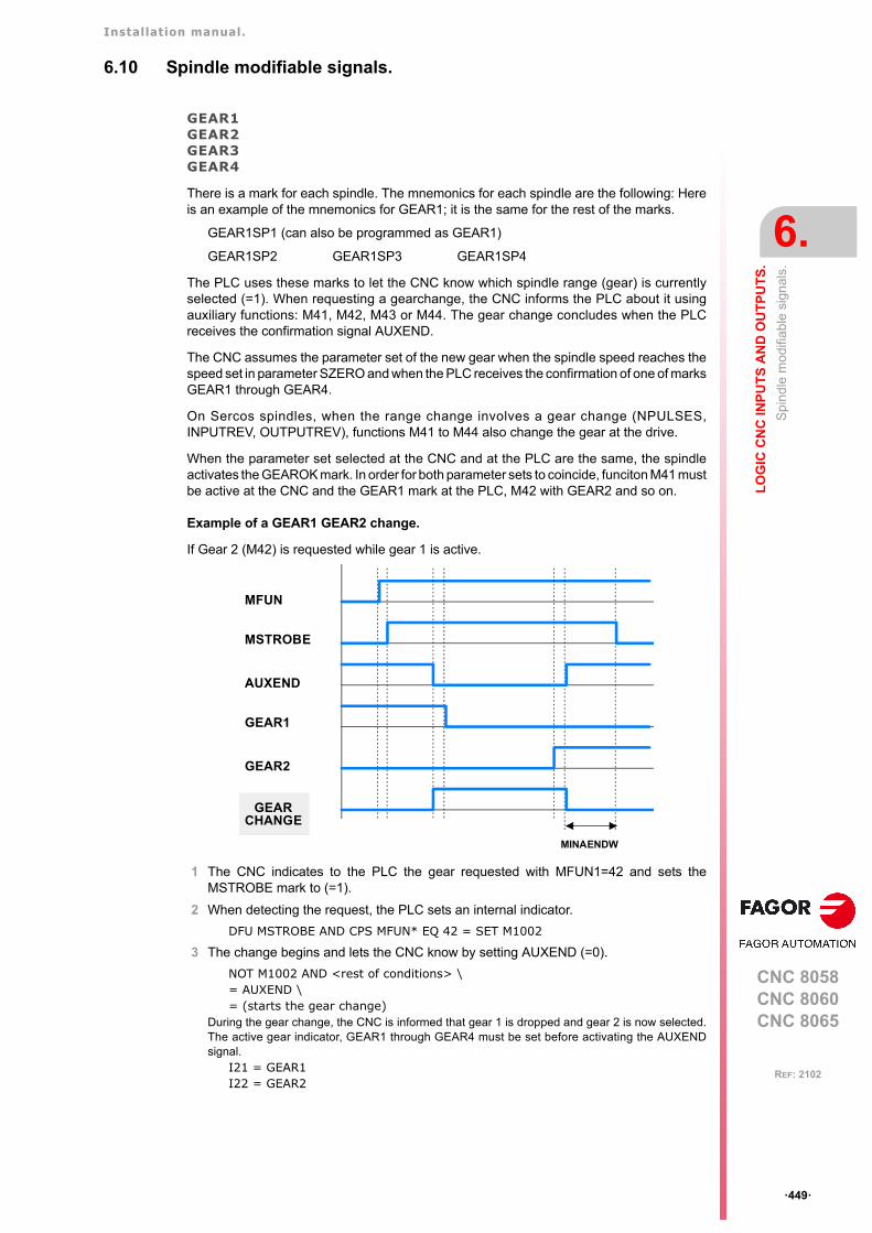
Installation manual.
CNC 8058CNC 8060CNC 8065
LO
GIC
CN
C IN
PU
TS
AN
D O
UT
PU
TS
.
6.
Sp
ind
le m
odi
fiabl
e si
gnal
s.
ꞏ449ꞏ
REF: 2102
6.10 Spindle modifiable signals.
GEAR1GEAR2GEAR3GEAR4
There is a mark for each spindle. The mnemonics for each spindle are the following: Hereis an example of the mnemonics for GEAR1; it is the same for the rest of the marks.
GEAR1SP1 (can also be programmed as GEAR1)
GEAR1SP2 GEAR1SP3 GEAR1SP4
The PLC uses these marks to let the CNC know which spindle range (gear) is currentlyselected (=1). When requesting a gearchange, the CNC informs the PLC about it usingauxiliary functions: M41, M42, M43 or M44. The gear change concludes when the PLCreceives the confirmation signal AUXEND.
The CNC assumes the parameter set of the new gear when the spindle speed reaches thespeed set in parameter SZERO and when the PLC receives the confirmation of one of marksGEAR1 through GEAR4.
On Sercos spindles, when the range change involves a gear change (NPULSES,INPUTREV, OUTPUTREV), functions M41 to M44 also change the gear at the drive.
When the parameter set selected at the CNC and at the PLC are the same, the spindleactivates the GEAROK mark. In order for both parameter sets to coincide, funciton M41 mustbe active at the CNC and the GEAR1 mark at the PLC, M42 with GEAR2 and so on.
Example of a GEAR1 GEAR2 change.
If Gear 2 (M42) is requested while gear 1 is active.
1 The CNC indicates to the PLC the gear requested with MFUN1=42 and sets theMSTROBE mark to (=1).
2 When detecting the request, the PLC sets an internal indicator.
DFU MSTROBE AND CPS MFUN* EQ 42 = SET M1002
3 The change begins and lets the CNC know by setting AUXEND (=0).
NOT M1002 AND <rest of conditions> \= AUXEND \= (starts the gear change)
During the gear change, the CNC is informed that gear 1 is dropped and gear 2 is now selected.The active gear indicator, GEAR1 through GEAR4 must be set before activating the AUXENDsignal.
I21 = GEAR1I22 = GEAR2
MFUN
MSTROBE
AUXEND
GEAR1
GEAR2
CHANGE
MINAENDW
GEAR
Installation manual.
CNC 8058CNC 8060CNC 8065
6.
LO
GIC
CN
C IN
PU
TS
AN
D O
UT
PU
TS
.
Sp
ind
le m
odi
fiabl
e si
gnal
s.
ꞏ450ꞏ
REF: 2102
4 Once the gear change is over, it cancels the indicator (M1002) and it lets the CNC knowby setting AUXEND high (=1).
(GEAR change completed) = RES M1002
The AUXEND mark must be kept high (=1) longer than the time period set by machineparameter MINAENDW so the CNC cancels the MSTROBE mark and concludes thegear change.
PLCCNTLSANALOG
There is one signal for each spindle. The mnemonics for each spindle are the following:
PLCCNTL1 (can also be programmed as PLCCNTL)
PLCCNTL2 PLCCNTL3 PLCCNTL4
SANALOG1 (can also be programmed as SANALOG)
SANALOG2 SANALOG3 SANALOG4
These signals are used with analog spindles, position-Sercos, velocity-Sercos andMechatrolink.
When the PLC sets the PLCCNTL mark high (=1), the spindle decelerates with a ramp untilit stops and it is then controlled by the PLC. The SANALOG register sets the spindlecommand voltage to be applied. The spindle control via PLC is used, for example, foroscillating the spindle during a gear change.
• Analog spindle.
10 V of velocity command correspond to SANALOG = 32767. In other words:
For 4V, program SANALOG = (4x32767)/10 = 13107
For 4V, program SANALOG = (-4x32767)/10 = -13107
• Velocity-Sercos spindle.
The command in SANALOG will be given in 0.0001 rpm.
• Sercos spindle in position.
The command in SANALOG will be given in 0.0001 degrees.
• Mechatrolink spindle.
The command in SANALOG will be given in hundredths of a Hertz.
The command indicated in SANALOG is not applied with a ramp; therefore, it is up to thePLC program to apply the command gradually when necessary.
The spindle reference point is not lost when the spindle is controlled via PLC. There is noneed to home the spindle again when its control is switched back to the CNC.
The PLC has no priority over a spindle synchronization. When attempting to control asynchronized spindle (either master or slave) using PLCCNTL, a warning will be issuedindicating that it is not possible. Also, if the gear change of a synchronized spindle involvesa command from the PLC, this change will not be possible.
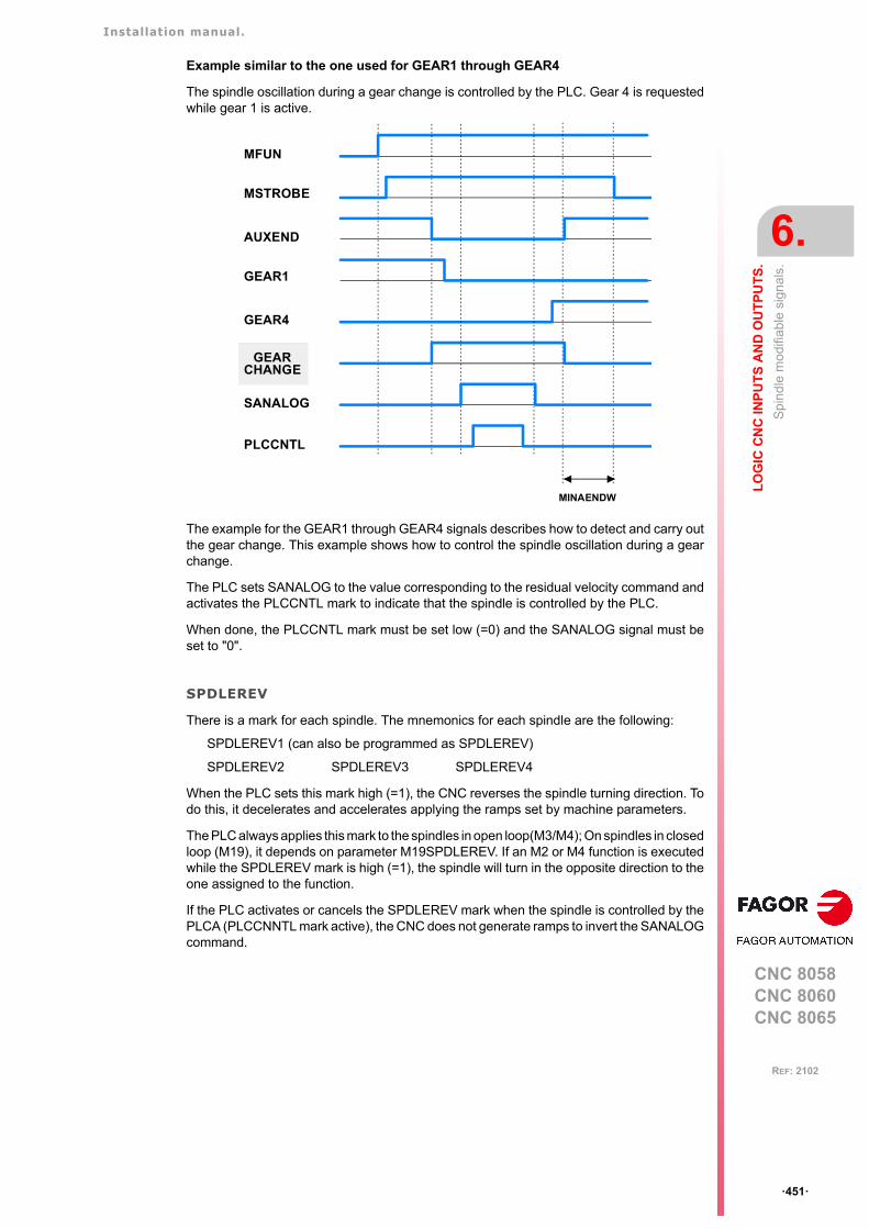
Installation manual.
CNC 8058CNC 8060CNC 8065
LO
GIC
CN
C IN
PU
TS
AN
D O
UT
PU
TS
.
6.
Sp
ind
le m
odi
fiabl
e si
gnal
s.
ꞏ451ꞏ
REF: 2102
Example similar to the one used for GEAR1 through GEAR4
The spindle oscillation during a gear change is controlled by the PLC. Gear 4 is requestedwhile gear 1 is active.
The example for the GEAR1 through GEAR4 signals describes how to detect and carry outthe gear change. This example shows how to control the spindle oscillation during a gearchange.
The PLC sets SANALOG to the value corresponding to the residual velocity command andactivates the PLCCNTL mark to indicate that the spindle is controlled by the PLC.
When done, the PLCCNTL mark must be set low (=0) and the SANALOG signal must beset to "0".
SPDLEREV
There is a mark for each spindle. The mnemonics for each spindle are the following:
SPDLEREV1 (can also be programmed as SPDLEREV)
SPDLEREV2 SPDLEREV3 SPDLEREV4
When the PLC sets this mark high (=1), the CNC reverses the spindle turning direction. Todo this, it decelerates and accelerates applying the ramps set by machine parameters.
The PLC always applies this mark to the spindles in open loop(M3/M4); On spindles in closedloop (M19), it depends on parameter M19SPDLEREV. If an M2 or M4 function is executedwhile the SPDLEREV mark is high (=1), the spindle will turn in the opposite direction to theone assigned to the function.
If the PLC activates or cancels the SPDLEREV mark when the spindle is controlled by thePLCA (PLCCNNTL mark active), the CNC does not generate ramps to invert the SANALOGcommand.
MFUN
MSTROBE
AUXEND
GEAR1
GEAR4
MINAENDW
SANALOG
PLCCNTL
CHANGEGEAR
Installation manual.
CNC 8058CNC 8060CNC 8065
6.
LO
GIC
CN
C IN
PU
TS
AN
D O
UT
PU
TS
.
Sp
ind
le m
odi
fiabl
e si
gnal
s.
ꞏ452ꞏ
REF: 2102
PLCM3PLCM4PLCM5
The PLC offers a mark for each spindle. The mnemonics for each spindle are the following:Here is an example of the mnemonics for PLCM3; it is the same for the rest of the spindles.
PLCM3SP1 (can also be programmed as PLCM3)
PLCM3SP2 PLCM3SP3 PLCM3SP4
The PLC turns this mark on to let the CNC know that it must execute the corresponding Mfunction at the indicated spindle. The spindle must belong to a channel, M functions cannotbe sent to spindles that are not assigned to any channel. The PLC may change the spindlespeed using the variable "(V.)PLC.S.sn", but without generating a gear change even if thegear change is automatic (parameter AUTOGEAR).
These M functions are treated the same way as those executed from the CNC. When theCNC activates one of these marks, the CNC activates the MSTROBE mark and writes thecorresponding M function into the MFUN register. Once the M function has beensynchronized at the PLC (AUXEND signal), the CNC starts sending the velocity commandto that spindle, updates (refreshes) the M function history and deactivates the mark at thePLC.
The CNC will admit M functions even if the channel is in execution (executing a program,jogging an axis, etc.) as long as the channel status is other than "In error" and "Not ready"and the channel is not doing a reset or validating machine parameters. If during toolinspection, the PLC changes the turning direction of a spindle using these marks, the changewill be identified when repositioning and will appear as pending to reposition.
The CNC ignores the PLC requests in the following cases, when the CNC ignores the markset by the PLC and it erases it so the request does not remain pending.
• When the spindle is working as a C axis.
• When the spindle is threading (rigid tapping, normal tapping or electronic threading).
• When the CNC status is "In error" or "Not ready", is doing a reset or validating parameters.
If the PLC activates these marks while synchronizing another M function of the programbeing executed or while homing the spindle, the PLC keeps this mark activated until the CNCcan attend to it.
SLIMITACSPDL
There is a mark for each spindle. The mnemonics for each spindle are the following:
SLIMITACSPDL1 (can also be programmed as SLIMITACSPDL)
SLIMITACSPDL2 SLIMITACSPDL3 SLIMITACSPDL4
If the PLC activates this mark, the CNC activates the speed safety limits (parameter SLIMIT)on the indicated spindle during the execution of the current block. If the PLC deactivates thismark, the CNC restores the programmed speed.
Installation manual.
CNC 8058CNC 8060CNC 8065
LO
GIC
CN
C IN
PU
TS
AN
D O
UT
PU
TS
.
6.
Mod
ifiab
le lo
gic
sig
nals
; las
er.
ꞏ453ꞏ
REF: 2102
6.11 Modifiable logic signals; laser.
LASERON
The PLC activates this mark to indicate that the laser is on.
SHUTTERON
The PLC activates this mark to indicate that the laser source shutter is open.
LASERREADY
The PLC activates this mark to indicate that the laser is ready.
PWMON
This mark may be used to activate and deactivate the PWM via PLC. The PWM is configuredusing the following registers.
Activating the PWM via PLC has priority over activating it from the CNC.
The modifications to the PWM both via program or via PLC are updated (refreshed) withoutwaiting for the PWM cycle in progress to be completed and as continuously as possible withrespect to the previous conditions; in other words, it does not wait for the default signal toset to zero or to one in each change.
During tool inspection, the CNC does not deactivate the PWM This mark may be used todeactivate the PWM viaPLC during tool inspection and resume the PWM at the end of theinspection.
PWMFREQ
PWM frequency, when the PWM has been activated from the PLC (2-5000 Hz; by default, 0).
PWMDUTY
PWM duty cycle, when the PWM has been activated from the PLC (1-5000 tenths of %; bydefault, 500).
ENABLEPWROUT
This mark is active by default. This mark is associated with the power control via an analogoutput associated with the spindle (#PWRCTRL ON [OUT]). The PLC deactivates this markto disable the active power control. The PLC activates this mark to enable the active powercontrol in the CNC; if no power control is active, this mark does nothing.
If the PLC deactivates this mark, the CNC disable the power control, setting the maximumdefined in the instruction #PWRCTRL ON.
Registers. Meaning.
PWMFREQ Frequency of the PWM (between 2 and 5000 Hz; by default, 0).
PWMDUTY Duty cycle of the PWM (between 1 and 1000; by default, 500).
PWM status from theCNC.
PWM status from thePLC.
PWM status.
Off. Off. PWM off.
Active. Off. PWM active from the CNC.
Off. Active. PWM active from the PLC.
Active. Active. PWM active from the PLC.
Installation manual.
CNC 8058CNC 8060CNC 8065
6.
LO
GIC
CN
C IN
PU
TS
AN
D O
UT
PU
TS
.
Mod
ifiab
le lo
gic
sig
nals
; las
er.
ꞏ454ꞏ
REF: 2102
ENABLEPWRDUTY
This mark is active by default. This mark is associated with the PWM duty control(#PWRCTRL ON [DUTY]). The PLC deactivates this mark to disable the active duty control.The PLC activates this mark to enable the active duty control in the CNC; if no duty controlis active, this mark does nothing.
If the PLC deactivates this mark, the CNC disables the duty control, setting the maximumspecified in the instruction #PWMOUT.
ENABLEPWRFREQ
This mark is active by default. This mark is associated with the PWM power control(#PWRCTRL ON [FREQ]). The PLC deactivates this mark to disable the active powercontrol. The PLC activates this mark to enable the active power control in the CNC; if nopower control is active, this mark does nothing.
If the PLC deactivates this mark, the CNC disable the power control, setting the maximumdefined in the instruction #PWMOUT.
ENABLEGAP
This mark is active by default. The PLC deactivates this mark to disable the active gapcontrol. The PLC activates this mark to enable the active gap control in the CNC; if no gapcontrol is active, this mark does nothing.
GAPCOLLISION
The gap control sensor may have a collusion signal connected to the CNC, which shouldbe managed by the PLC via this mark. The PLC activates this mark to indicate that the sensorcollision signal has been received. This mark is not kept in memory. When this mark is active,the CNC will display an error or not, depending on how the parameter GAPCOLLISION hasbeen set.
ENABLELEAP
The PLC deactivates this mark to disable the active leapfrog. The PLC activates this markto enable the active leapfrog in the CNC; if no gap control is active, this mark does nothing.
CVIEWREFRESH
The PLC activates this mark to refresh the Cut_View. For example, cutting sheets longer thanthe table feed, in a single program, is carried out in several stages, moving the sheet betweenone stage and another. At the end of each stage, the Cut_View must be refreshed so thatit shows the new section to be cut.
Installation manual.
CNC 8058CNC 8060CNC 8065
LO
GIC
CN
C IN
PU
TS
AN
D O
UT
PU
TS
.
6.
Mod
ifiab
le s
igna
ls o
f the
ind
epen
den
t int
erp
olat
or.
ꞏ455ꞏ
REF: 2102
6.12 Modifiable signals of the independent interpolator.
The signal names are generic. Replace the text (axis) with the name or logic axis number.
_IXFERINH(axis)
If the PLC sets this mark (=0), the movement of the independent axis ends and remainswaiting for the PLC to activate this mark again. To manage the transfer inhibit in anindependent movement, the PLC also has a general mark per channel (_XFERINH(axis)mark). The CNC evaluates both marks as follows.
• In independent movements programmed from the CNC, it first evaluates the transferinhibit of the channel (_XFERINH mark) and then the particular one of the axis(_IXFERINH(axis) mark).
• In independent movements programmed from the PLC, the transfer inhibit of the channelis evaluated depending on parameter XFITOIND. The CNC always evaluates theparticular transfer inhibit of the axis.
IRESET(axis)
For movements of an independent axis, if the PLC sets this mark to (=1), it interrupts theinstruction in execution and eliminates the instructions pending execution.
For electronic-cam movements, it interrupts the cam synchronization movement switchingto zero speed.
It sets the initial conditions at the independent interpolator of the axis.
IABORT(axis)
For movements of an independent axis, if the PLC sets this mark to (=1), the positioning blockbeing executed (if any) stops, without eliminating also the rest of the positioning blockspending execution.
It only affects positioning blocks; neither the pending instructions nor the synchronizationmovement are eliminated.
XFITOIND Meaning.
Yes The CNC firsts evaluates the transfer inhibit of the channel (_XFERINHmark) and then the particular one of the axis (_IXFERINH(axis) mark).
No The CNC only evaluates the particular transfer inhibit of the axis(_IXFERINH(axis) mark).
Installation manual.
CNC 8058CNC 8060CNC 8065
6.
LO
GIC
CN
C IN
PU
TS
AN
D O
UT
PU
TS
.
Too
l man
age
r m
odi
fiabl
e si
gnal
s.
ꞏ456ꞏ
REF: 2102
6.13 Tool manager modifiable signals.
SETTMEM
There is a mark for each magazine. The mnemonics for each magazine are the following.
SETTMEMZ1 (can also be programmed as SETTMEM)
SETTMEMZ2 SETTMEMZ3 SETTMEMZ4
The PLC sets this mark high (=1) to activate the tool manager emergency.
RESTMEM
There is a mark for each magazine. The mnemonics for each magazine are the following.
RESTMEMZ1 (can also be programmed as RESTMEM)
RESTMEMZ2 RESTMEMZ3 RESTMEMZ4
The PLC sets this mark high (=1) to cancel the tool manager emergency.
CUTTINGON
There is a mark for each channel. The mnemonics for each channel are the following.
CUTTINGONC1 (same as CUTTINGON)
CUTTINGONC2 CUTTINGONC3 CUTTINGONC4
When associating a maximum life span to a tool (monitoring), the CNC checks this mark tofind out whether the tool is machining (=1) or not (=0).
TREJECT
There is a mark for each channel. The mnemonics for each channel are the following.
TREJECTC1 (can also be programmed as TREJECT)
TREJECTC2 TREJECTC3 TREJECTC4
If the PLC sets this mark high (=1), the CNC interprets that the tool must be rejected.
MZTOCH1
There is a mark for each magazine. The mnemonics for each magazine are the following.
MZTOCH1MZ1 (can also be programmed as MZTOCH1)
MZTOCH1MZ2 MZTOCH1MZ3 MZTOCH1MZ4
Use it with an asynchronous magazine or synchronous with arm. The PLC must set this markhigh (=1) after taking the tool from the magazine to the changer arm 1.
CH1TOSPDL
There is a mark for each magazine. The mnemonics for each magazine are the following.
CH1TOSPDLMZ1 (same as CH1TOSPDL)
CH1TOSPDLMZ2 CH1TOSPDLMZ3 CH1TOSPDLMZ4
Use it with an asynchronous magazine or synchronous with arm. The PLC must set this markhigh (=1) after taking the tool from the changer arm 1 to the spindle.
PRG()= CNCRD (G.GS0, R300, M12)
Register R300 shows the status of the G functions.AUTOMAT AND INCYCLE AND NOT B0R300 = CUTTINGON
If it is in automatic mode (AUTOMAT), a (INCYCLE) block is being executed and the G00 function is not active, then, the tool is considered to be machining.
END
Installation manual.
CNC 8058CNC 8060CNC 8065
LO
GIC
CN
C IN
PU
TS
AN
D O
UT
PU
TS
.
6.
Too
l man
age
r m
odi
fiabl
e si
gnal
s.
ꞏ457ꞏ
REF: 2102
SPDLTOCH1
There is a mark for each magazine. The mnemonics for each magazine are the following.
SPDLTOCH1MZ1 (same as SPDLTOCH1)
SPDLTOCH1MZ2 SPDLTOCH1MZ3 SPDLTOCH1MZ4
Use it with an asynchronous magazine with one changer arm. The PLC must set this markhigh (=1) after taking the tool from the spindle to the changer arm 1.
SPDLTOCH2
There is a mark for each magazine. The mnemonics for each magazine are the following.
SPDLTOCH1MZ1 (same as SPDLTOCH1)
SPDLTOCH2MZ2 SPDLTOCH2MZ3 SPDLTOCH2MZ4
Use it with an asynchronous magazine or synchronous with arm. The PLC must set this markhigh (=1) after taking the tool from the spindle to the changer arm 2.
CH1TOMZ
There is a mark for each magazine. The mnemonics for each magazine are the following.
CH1TOMZ1 (can also be programmed as CH1TOMZ)
CH1TOMZ2 CH1TOMZ3 CH1TOMZ4
Use it with an asynchronous magazine or synchronous with arm. The PLC must set this markhigh (=1) after taking the tool from the tool changer arm 1 to the magazine.
CH2TOMZ
There is a mark for each magazine. The mnemonics for each magazine are the following.
CH2TOMZ1 (can also be programmed as CH2TOMZ)
CH2TOMZ2 CH2TOMZ3 CH2TOMZ4
Use it with an asynchronous magazine or synchronous with arm. The PLC must set this markhigh (=1) after taking the tool from the tool changer arm 2 to the magazine.
SPDLTOGR
There is a mark for each channel. The mnemonics for each channel are the following.
SPDLTOGRC1 (can also be programmed as SPDLTOGR)
SPDLTOGRC2 SPDLTOGRC3 SPDLTOGRC4
Use it with a magazine that admits ground tools. The PLC must set this mark high (=1) aftertaking the tool from the spindle to ground.
GRTOSPDL
There is a mark for each channel. The mnemonics for each channel are the following.
GRTOSPDLC1 (can also be programmed as GRTOSPDL)
GRTOSPDLC2 GRTOSPDLC3 GRTOSPDLC4
Use it with a magazine that admits ground tools. The PLC must set this mark high (=1) aftertaking the tool from the ground to the spindle.
MZTOSPDL
There is a mark for each magazine. The mnemonics for each magazine are the following.
MZTOSPDLMZ1 (can also be programmed as MZTOSPDL)
MZTOSPDLMZ2 MZTOSPDLMZ3 MZTOSPDLMZ4
Installation manual.
CNC 8058CNC 8060CNC 8065
6.
LO
GIC
CN
C IN
PU
TS
AN
D O
UT
PU
TS
.
Too
l man
age
r m
odi
fiabl
e si
gnal
s.
ꞏ458ꞏ
REF: 2102
Use it with a synchronous magazine (without arm). The PLC must set this mark high (=1)after taking the tool from the magazine to the spindle.
SPDLTOMZ
There is a mark for each magazine. The mnemonics for each magazine are the following.
SPDLTOMZ1 (can also be programmed as SPDLTOMZ)
SPDLTOMZ2 SPDLTOMZ3 SPDLTOMZ4
Use it with a synchronous magazine (without arm). The PLC must set this mark high (=1)after taking the tool from the spindle to the magazine.
MZROT
There is a mark for each magazine. The mnemonics for each magazine are the following.
MZROTMZ1 (can also be programmed as MZROT)
MZROTMZ2 MZROTMZ3 MZROTMZ4
Use it with a turret type magazine. The PLC must set this mark high (=1) when the turret hasrotated.
TCHANGEOK
There is a mark for each magazine. The mnemonics for each magazine are the following.
TCHANGEOKMZ1 (same as TCHANGEOK)
TCHANGEOKMZ2 TCHANGEOKMZ3 TCHANGEOKMZ4
The PLC must set this mark high (=1) when the tool change has ended (M06).
MZPOS
There is a register for each magazine. The mnemonics for each magazine are the following.
MZPOSMZ1 (can also be programmed as MZPOS)
MZPOSMZ2 MZPOSMZ3 MZPOSMZ4
The PLC must indicate the current magazine position in this register.
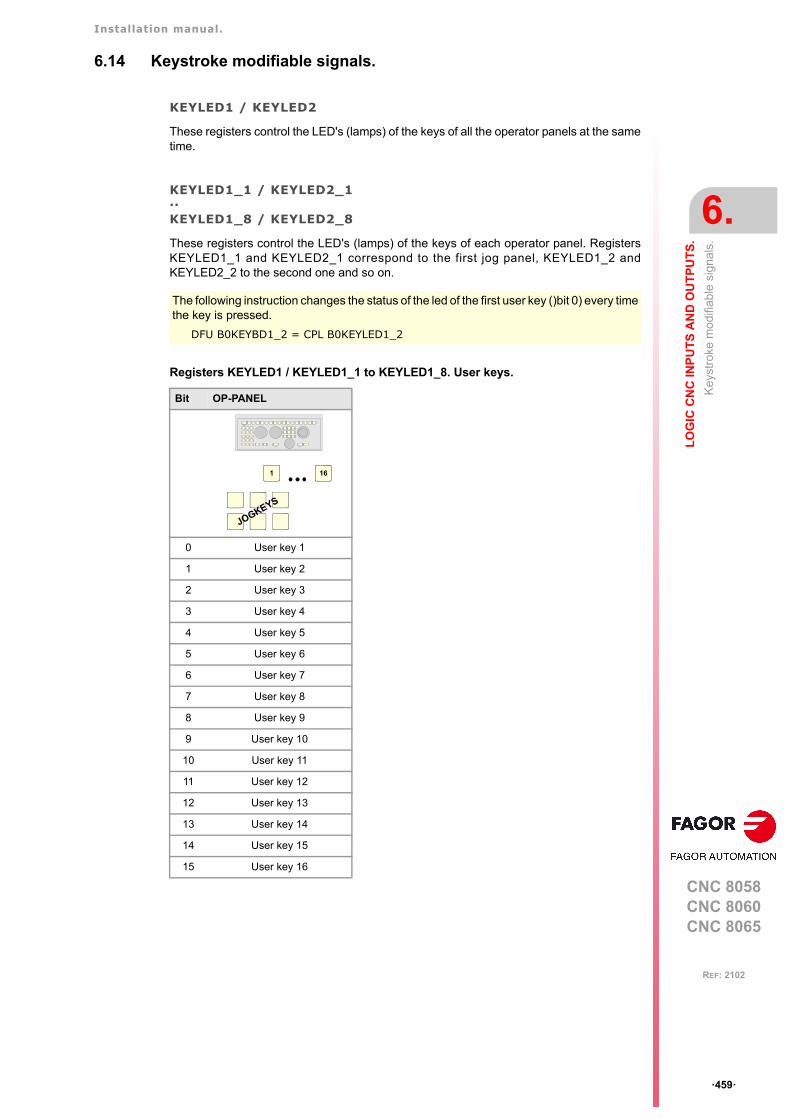
Installation manual.
CNC 8058CNC 8060CNC 8065
LO
GIC
CN
C IN
PU
TS
AN
D O
UT
PU
TS
.
6.
Key
stro
ke m
odifi
able
sig
nals
.
ꞏ459ꞏ
REF: 2102
6.14 Keystroke modifiable signals.
KEYLED1 / KEYLED2
These registers control the LED's (lamps) of the keys of all the operator panels at the sametime.
KEYLED1_1 / KEYLED2_1··KEYLED1_8 / KEYLED2_8
These registers control the LED's (lamps) of the keys of each operator panel. RegistersKEYLED1_1 and KEYLED2_1 correspond to the first jog panel, KEYLED1_2 andKEYLED2_2 to the second one and so on.
Registers KEYLED1 / KEYLED1_1 to KEYLED1_8. User keys.
The following instruction changes the status of the led of the first user key ()bit 0) every timethe key is pressed.
DFU B0KEYBD1_2 = CPL B0KEYLED1_2
Bit OP-PANEL
0 User key 1
1 User key 2
2 User key 3
3 User key 4
4 User key 5
5 User key 6
6 User key 7
7 User key 8
8 User key 9
9 User key 10
10 User key 11
11 User key 12
12 User key 13
13 User key 14
14 User key 15
15 User key 16
1 16
JOGKEYS
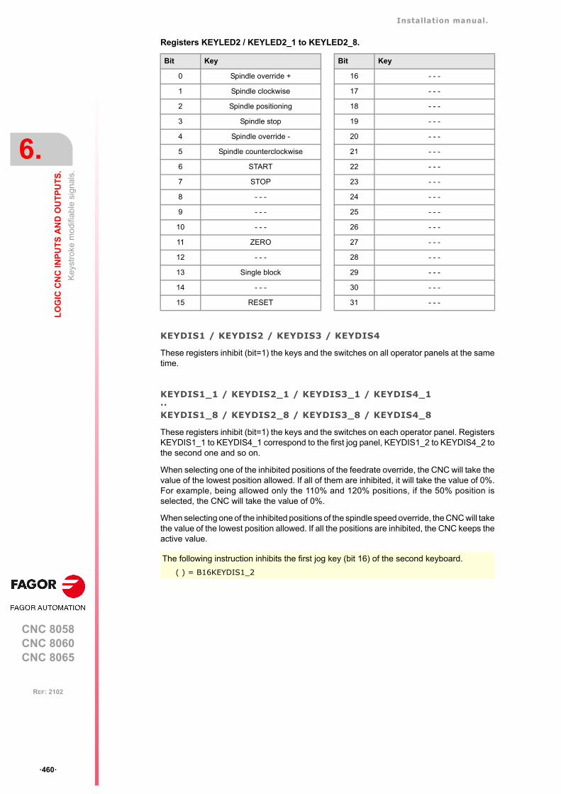
Installation manual.
CNC 8058CNC 8060CNC 8065
6.
LO
GIC
CN
C IN
PU
TS
AN
D O
UT
PU
TS
.
Key
stro
ke m
odifi
able
sig
nals
.
ꞏ460ꞏ
REF: 2102
Registers KEYLED2 / KEYLED2_1 to KEYLED2_8.
KEYDIS1 / KEYDIS2 / KEYDIS3 / KEYDIS4
These registers inhibit (bit=1) the keys and the switches on all operator panels at the sametime.
KEYDIS1_1 / KEYDIS2_1 / KEYDIS3_1 / KEYDIS4_1··KEYDIS1_8 / KEYDIS2_8 / KEYDIS3_8 / KEYDIS4_8
These registers inhibit (bit=1) the keys and the switches on each operator panel. RegistersKEYDIS1_1 to KEYDIS4_1 correspond to the first jog panel, KEYDIS1_2 to KEYDIS4_2 tothe second one and so on.
When selecting one of the inhibited positions of the feedrate override, the CNC will take thevalue of the lowest position allowed. If all of them are inhibited, it will take the value of 0%.For example, being allowed only the 110% and 120% positions, if the 50% position isselected, the CNC will take the value of 0%.
When selecting one of the inhibited positions of the spindle speed override, the CNC will takethe value of the lowest position allowed. If all the positions are inhibited, the CNC keeps theactive value.
Bit Key Bit Key
0 Spindle override + 16 - - -
1 Spindle clockwise 17 - - -
2 Spindle positioning 18 - - -
3 Spindle stop 19 - - -
4 Spindle override - 20 - - -
5 Spindle counterclockwise 21 - - -
6 START 22 - - -
7 STOP 23 - - -
8 - - - 24 - - -
9 - - - 25 - - -
10 - - - 26 - - -
11 ZERO 27 - - -
12 - - - 28 - - -
13 Single block 29 - - -
14 - - - 30 - - -
15 RESET 31 - - -
The following instruction inhibits the first jog key (bit 16) of the second keyboard.
( ) = B16KEYDIS1_2
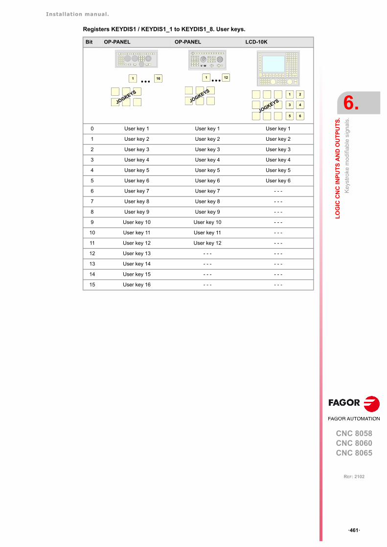
Installation manual.
CNC 8058CNC 8060CNC 8065
LO
GIC
CN
C IN
PU
TS
AN
D O
UT
PU
TS
.
6.
Key
stro
ke m
odifi
able
sig
nals
.
ꞏ461ꞏ
REF: 2102
Registers KEYDIS1 / KEYDIS1_1 to KEYDIS1_8. User keys.
Bit OP-PANEL OP-PANEL LCD-10K
0 User key 1 User key 1 User key 1
1 User key 2 User key 2 User key 2
2 User key 3 User key 3 User key 3
3 User key 4 User key 4 User key 4
4 User key 5 User key 5 User key 5
5 User key 6 User key 6 User key 6
6 User key 7 User key 7 - - -
7 User key 8 User key 8 - - -
8 User key 9 User key 9 - - -
9 User key 10 User key 10 - - -
10 User key 11 User key 11 - - -
11 User key 12 User key 12 - - -
12 User key 13 - - - - - -
13 User key 14 - - - - - -
14 User key 15 - - - - - -
15 User key 16 - - - - - -
1 16
JOGKEYS
CNCOFF
200190
180
170
160
150
140
130
120110
100908070
60
50
40
30
20
10
42
0
FEED
100001000
100101
10010 1
jogX Y Z
+_
4 5 6
+
_
CSS
m/min
ZERO SINGLE RESET
1 12
JOGKEYS1 2
3 4
5 6JOGKEYS
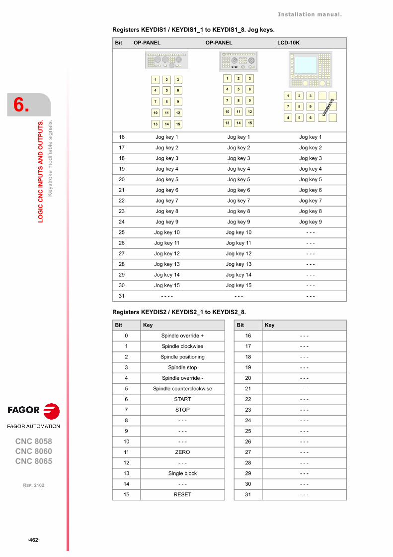
Installation manual.
CNC 8058CNC 8060CNC 8065
6.
LO
GIC
CN
C IN
PU
TS
AN
D O
UT
PU
TS
.
Key
stro
ke m
odifi
able
sig
nals
.
ꞏ462ꞏ
REF: 2102
Registers KEYDIS1 / KEYDIS1_1 to KEYDIS1_8. Jog keys.
Registers KEYDIS2 / KEYDIS2_1 to KEYDIS2_8.
Bit OP-PANEL OP-PANEL LCD-10K
16 Jog key 1 Jog key 1 Jog key 1
17 Jog key 2 Jog key 2 Jog key 2
18 Jog key 3 Jog key 3 Jog key 3
19 Jog key 4 Jog key 4 Jog key 4
20 Jog key 5 Jog key 5 Jog key 5
21 Jog key 6 Jog key 6 Jog key 6
22 Jog key 7 Jog key 7 Jog key 7
23 Jog key 8 Jog key 8 Jog key 8
24 Jog key 9 Jog key 9 Jog key 9
25 Jog key 10 Jog key 10 - - -
26 Jog key 11 Jog key 11 - - -
27 Jog key 12 Jog key 12 - - -
28 Jog key 13 Jog key 13 - - -
29 Jog key 14 Jog key 14 - - -
30 Jog key 15 Jog key 15 - - -
31 - - - - - - - - - -
Bit Key Bit Key
0 Spindle override + 16 - - -
1 Spindle clockwise 17 - - -
2 Spindle positioning 18 - - -
3 Spindle stop 19 - - -
4 Spindle override - 20 - - -
5 Spindle counterclockwise 21 - - -
6 START 22 - - -
7 STOP 23 - - -
8 - - - 24 - - -
9 - - - 25 - - -
10 - - - 26 - - -
11 ZERO 27 - - -
12 - - - 28 - - -
13 Single block 29 - - -
14 - - - 30 - - -
15 RESET 31 - - -
1
4
2
5
3
6
7 8 9
10 11 12
13 14 15
CNCOFF
200190
180
170
160
150
140
130
120110
100908070
60
50
40
30
20
10
42
0
FEED
100001000
100101
10010 1
jogX Y Z
+_
4 5 6
+
_
CSS
m/min
ZERO SINGLE RESET
1
4
2
5
3
6
7 8 9
10 11 12
13 14 15
1 2 3
7 8 9
4 5 6
US
ER
KE
YS
Installation manual.
CNC 8058CNC 8060CNC 8065
LO
GIC
CN
C IN
PU
TS
AN
D O
UT
PU
TS
.
6.
Key
stro
ke m
odifi
able
sig
nals
.
ꞏ463ꞏ
REF: 2102
Registers KEYDIS3 / KEYDIS3_1 to KEYDIS3_8. Feedrate override and movementselector (handwheel, incremental jog or continuous jog).
Registers KEYDIS4 / KEYDIS4_1 to KEYDIS4_8. Spindle speed override selector.
Bit Selector Bit Selector
0 0 % 16 140 %
1 2 % 17 150 %
2 4 % 18 160 %
3 10 % 19 170 %
4 20 % 20 180 %
5 30 % 21 190 %
6 40 % 22 200 %
7 50 % 23 Handwheel x100
8 60 % 24 Handwheel x10
9 70 % 25 Handwheel x1
10 80 % 26 Jog 1
11 90 % 27 Jog 10
12 100 % 28 Jog 100
13 110 % 29 Jog 1000
14 120 % 30 Jog 10000
15 130 % 31 Continuous jog
Bit Selector Bit Selector
0 0 % 16 140 %
1 2 % 17 150 %
2 4 % 18 160 %
3 10 % 19 170 %
4 20 % 20 180 %
5 30 % 21 190 %
6 40 % 22 200 %
7 50 % 23 - - -
8 60 % 24 - - -
9 70 % 25 - - -
10 80 % 26 - - -
11 90 % 27 - - -
12 100 % 28 - - -
13 110 % 29 - - -
14 120 % 30 - - -
15 130 % 31 - - -
Installation manual.
CNC 8058CNC 8060CNC 8065
6.
LO
GIC
CN
C IN
PU
TS
AN
D O
UT
PU
TS
.
Key
stro
ke m
odifi
able
sig
nals
.
ꞏ464ꞏ
REF: 2102
CNC 8058CNC 8060CNC 8065
7
ꞏ465ꞏ
REF: 2102
7. TOOL AND MAGAZINE MANAGEMENT.
To properly configure the tool magazines and the tool change, you must:
• Set the machine parameters.
• Set the tool table and the tool magazine table.
• Write the PLC program.
• Program the subroutine associated with the tool and with the M06 function.
The machine parameters define the number of tool magazines available and theircharacteristics. Up to four magazines may be used and each may be of a different type. See"7.1 Types of tool magazine." on page 467.
When creating the PLC program and the subroutine associated with the tool and with theM06 function, you must bear in mind the number of magazines and channels available. Forthe communication between the tool manager and the PLC, each channel and eachmagazine has its own group of marks and registers.
The PLC maneuver will be different depending on the type of tool magazine. Later sectionsof this chapter show an example for each type of magazine.
About the magazines.
The CNC can have up to four magazines and each may be of a different type. Each magazinehas its own configuration parameters.
The number of magazines is independent from the number of spindles and channelsavailable. A magazine is not associated with any particular channel or spindle; i.e. amagazine may be shared by several channels and a channel can request tools from differentmagazines.
All the magazines can carry out tool changes simultaneously. However, one magazine canonly be involved in a tool change process. If from one channel, one wishes to pick up or leavea tool in a magazine already involved in a tool change, the tool manager will wait for the toolchange to be done before attending to the new request.
Two magazines may be involved in a tool change. The magazine receiving the tool and themagazine from where the new tool is picked up may be different.
About the tools.
Each tool is identified by its number, that is unique for the whole system; it cannot be repeatedin different magazines nor in ground tools.
The list of available tools is saved in the tool table, the only one for the whole system. Thistable indicates the position and the magazine where each tool is located, whether it is aground tool or the tool is active in a channel.
The tools are always stored in the same magazine. When doing a tool change, it is alwaysstored in the magazine from which it was picked up.
The access to the magazine depends on the mechanical configuration of the machine; in other words,to the physical possibility of the machine to access the magazines.i
Installation manual.
CNC 8058CNC 8060CNC 8065
7.
TO
OL
AN
D M
AG
AZ
INE
MA
NA
GE
ME
NT
.
ꞏ466ꞏ
REF: 2102
Ground tools.
A ground tool is a tool that is not stored in any magazine and is loaded manually whenrequested. Ground tools are also defined in the tool table, but they are not associated withany magazine position.
Ground tool loading and unloading is global to the system; it is not associated with anyparticular magazine or channel.
Tool manager.
The CNC has a tool magazine management that knows at all times the location of each tool.When requesting a tool change or tool search, the tool manager "tells" the PLC the operationsto be carried out.
• Take a tool from the magazine and insert it in the spindle.
• Leave the tool of the spindle in the magazine and take another one.
• Leave the spindle tool on the ground.
• Etc.
Depending on the type of magazine and the operation requested, several actions may beneeded sometimes. For example, in some magazines, to take a tool from the spindle to themain magazine, the tool must be carried from the spindle to the changer arm and then fromthe changer arm to the magazine.
It is up to the PLC to control those movements. It must inform the manager about the actionscarried out so it updates its information.
For the communication between the tool manager and the PLC, each channel and magazinehas its own group of marks and registers. See "7.3 Communication between manager andPLC." on page 470.
Subroutines associated with the tool change.
There are two subroutines associated with the tool change.
Subroutines associated with the tool.
The subroutine associated with the tool is executed automatically every time a T function(tool selection) is executed.
There is one subroutine in each channel.
Subroutines associated with the M06 function.
The M06 function executes the tool change. The CNC will manage the tool change andupdate the table for the tool magazine.
It is recommended to set this function in the "M" function table so it executes the subroutinefor the tool changer installed on the machine.
This subroutine is common to the whole system.
Within both subroutines, the "modal" condition of the canned cycles no longer has any influence. Thischaracteristic is restored when the execution of the subroutine ends.i
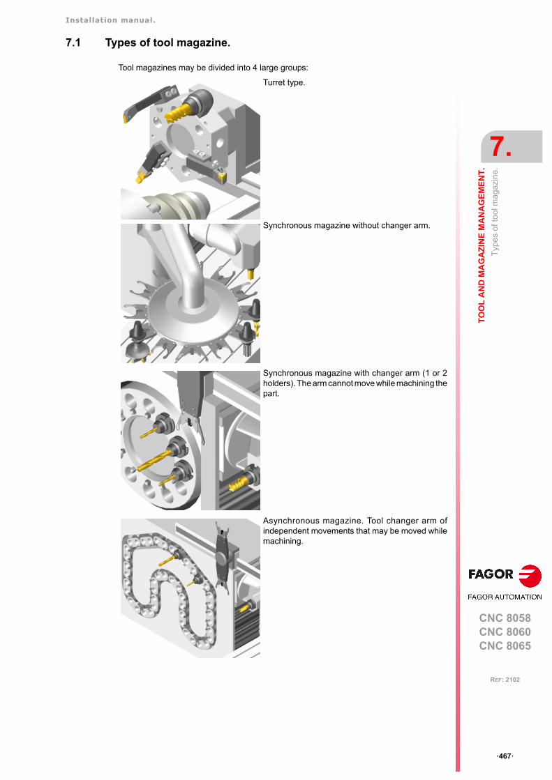
Installation manual.
CNC 8058CNC 8060CNC 8065
TO
OL
AN
D M
AG
AZ
INE
MA
NA
GE
ME
NT
.
7.
Typ
es
of to
ol m
agaz
ine.
ꞏ467ꞏ
REF: 2102
7.1 Types of tool magazine.
Tool magazines may be divided into 4 large groups:
Turret type.
Synchronous magazine without changer arm.
Synchronous magazine with changer arm (1 or 2holders). The arm cannot move while machining thepart.
Asynchronous magazine. Tool changer arm ofindependent movements that may be moved whilemachining.
Installation manual.
CNC 8058CNC 8060CNC 8065
7.
TO
OL
AN
D M
AG
AZ
INE
MA
NA
GE
ME
NT
.
Typ
es
of to
ol m
agaz
ine.
ꞏ468ꞏ
REF: 2102
"Random" or "Non-Random" magazine.
Depending on how the tools are stored in the magazine during a tool change, the magazinemay be either random or non-random. In a random magazine, the tool may occupy anyposition whereas in a non-random magazine, the tools must always occupy the sameposition.
In any case and even when all the magazines are random, the tools are always stored inthe same magazine from which they were picked up.
"Cyclic" or "Non-Cyclic" magazine.
A cyclic magazine requires a tool change command M06 after searching a tool and beforesearching the next one. In a non-cyclic magazine, it is possible to perform severalconsecutive tool searches without necessarily having to change the tool.

Installation manual.
CNC 8058CNC 8060CNC 8065
TO
OL
AN
D M
AG
AZ
INE
MA
NA
GE
ME
NT
.
7.
To
ol ta
ble
, act
ive
tool
tabl
e a
nd to
ol m
aga
zine
tabl
e
ꞏ469ꞏ
REF: 2102
7.2 Tool table, active tool table and tool magazine table
After setting the machine parameters for the tool magazines, define the tool table and thenthe magazine table.
Tool table.
The tool table must contain, among other things, the geometry, type of monitoring and toolsize. All the tools must be defined, including the ground ones.
The tool manager inserts the special tools always in the same tool pocket regardless of thenumber of pockets they occupy.
Tool magazine table.
There is one table for each magazine. Each table shows which tool is in each pocket andon each holder of the changer arm (if any).
Although the magazine table may be initialized manually, it is up to the tool manager todynamically update all its data.
Active-tools table.
The active-tools table shows which tools are active in the spindles.
Example:
Having 10 tools and a 10-position magazine. The tools are small, except T2 that is largeand T4 that has a special size (0 to the left and 1 to the right).
Load the tools one by one in the magazine using the corresponding softkey.
• T1 in position 1.
• T2 in position 3. Verify that it cannot go in position 2 because the tool is too large.
• T3 in position 5. T2 occupies positions 2-3-4.
• T4 in position 6. T4 occupies positions 6-7.
• T5 in position 8.
• T6 in position 9.
• T7 in position 10.
T8, T9 and T10 do not fit in the magazine; therefore, they will be ground tools.
Installation manual.
CNC 8058CNC 8060CNC 8065
7.
TO
OL
AN
D M
AG
AZ
INE
MA
NA
GE
ME
NT
.
Com
mun
ica
tion
betw
een
ma
nage
r a
nd P
LC.
ꞏ470ꞏ
REF: 2102
7.3 Communication between manager and PLC.
For the communication between the tool manager and the PLC, each channel and magazinehas its own group of marks and registers.
The communication between the manager and the PLC takes place in two stages; whenexecuting the T function and when executing the M06 function.
• When executing the T function, the CNC lets the tool manager know about it.
The tool manager sends a command to the PLC to select the next tool in the magazine(if possible).
The CNC continues with the execution of the program without waiting for the toolmanager to complete the operation.
• When executing the M06 function, its associated subroutine is called upon. The M06function must also be programmed inside that subroutine so the CNC "tells" the toolmanager to start making the tool change.
The tool manager sends a command to the PLC to make the change.
The CNC waits for the tool manager to complete the operation before continuing withthe execution of the program.
Considerations and recommendations.
The management of the tool change should be included in the subroutine associated withthe M06 and leave the control of the external devices up to the PLC.
Use the auxiliary functions to govern the various devices (magazine rotation, magazinemovement, tool changer arm, etc.) from the M06 subroutine.
On asynchronous magazines (changer arm with independent movements) when the changeimplies leaving a tool in the magazine, the TCHANGEOK mark may be activated so the CNCgoes on executing the program while the tool is being taken to the magazine.
The CNC maintains compatibility with the marks and registers of previous versions whose mnemonicsdo not refer to any particular channel or magazine. From software version V2.00 on, these signals referto the first channel or magazine accordingly.
i
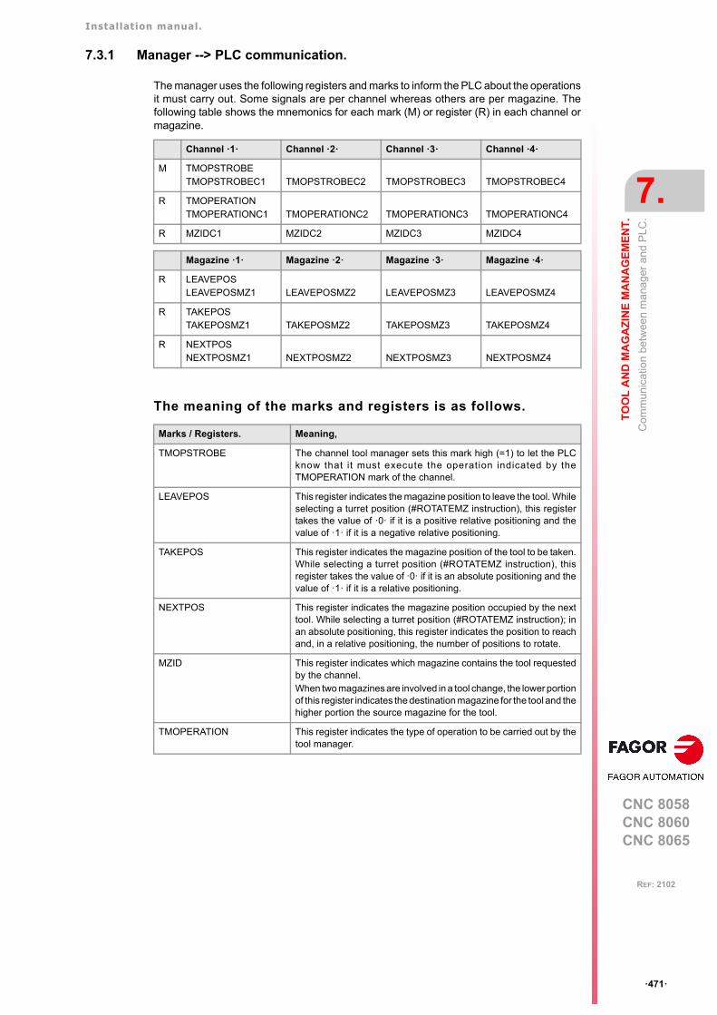
Installation manual.
CNC 8058CNC 8060CNC 8065
TO
OL
AN
D M
AG
AZ
INE
MA
NA
GE
ME
NT
.
7.
Com
mun
ica
tion
betw
een
ma
nage
r a
nd P
LC.
ꞏ471ꞏ
REF: 2102
7.3.1 Manager --> PLC communication.
The manager uses the following registers and marks to inform the PLC about the operationsit must carry out. Some signals are per channel whereas others are per magazine. Thefollowing table shows the mnemonics for each mark (M) or register (R) in each channel ormagazine.
The meaning of the marks and registers is as follows.
Channel ꞏ1ꞏ Channel ꞏ2ꞏ Channel ꞏ3ꞏ Channel ꞏ4ꞏ
M TMOPSTROBETMOPSTROBEC1 TMOPSTROBEC2 TMOPSTROBEC3 TMOPSTROBEC4
R TMOPERATIONTMOPERATIONC1 TMOPERATIONC2 TMOPERATIONC3 TMOPERATIONC4
R MZIDC1 MZIDC2 MZIDC3 MZIDC4
Magazine ꞏ1ꞏ Magazine ꞏ2ꞏ Magazine ꞏ3ꞏ Magazine ꞏ4ꞏ
R LEAVEPOSLEAVEPOSMZ1 LEAVEPOSMZ2 LEAVEPOSMZ3 LEAVEPOSMZ4
R TAKEPOSTAKEPOSMZ1 TAKEPOSMZ2 TAKEPOSMZ3 TAKEPOSMZ4
R NEXTPOSNEXTPOSMZ1 NEXTPOSMZ2 NEXTPOSMZ3 NEXTPOSMZ4
Marks / Registers. Meaning,
TMOPSTROBE The channel tool manager sets this mark high (=1) to let the PLCknow that it must execute the operation indicated by theTMOPERATION mark of the channel.
LEAVEPOS This register indicates the magazine position to leave the tool. Whileselecting a turret position (#ROTATEMZ instruction), this registertakes the value of ꞏ0ꞏ if it is a positive relative positioning and thevalue of ꞏ1ꞏ if it is a negative relative positioning.
TAKEPOS This register indicates the magazine position of the tool to be taken.While selecting a turret position (#ROTATEMZ instruction), thisregister takes the value of ꞏ0ꞏ if it is an absolute positioning and thevalue of ꞏ1ꞏ if it is a relative positioning.
NEXTPOS This register indicates the magazine position occupied by the nexttool. While selecting a turret position (#ROTATEMZ instruction); inan absolute positioning, this register indicates the position to reachand, in a relative positioning, the number of positions to rotate.
MZID This register indicates which magazine contains the tool requestedby the channel.When two magazines are involved in a tool change, the lower portionof this register indicates the destination magazine for the tool and thehigher portion the source magazine for the tool.
TMOPERATION This register indicates the type of operation to be carried out by thetool manager.

Installation manual.
CNC 8058CNC 8060CNC 8065
7.
TO
OL
AN
D M
AG
AZ
INE
MA
NA
GE
ME
NT
.
Com
mun
ica
tion
betw
een
ma
nage
r a
nd P
LC.
ꞏ472ꞏ
REF: 2102
7.3.2 PLC --> Manager communication.
The PLC uses the following marks to inform the manager about the operations that it hascarried out. There is one group of marks for each magazine.
The PLC, depending on the type of magazine, must take some actions to execute theoperations requested by the manager. After ending each one of them, it must activate certainmarks to inform the manager that the action has been completed. The manager sets themback to "0" once they are read.
The following table shows the mnemonics for each mark (M) or register (R) in each channelor magazine.
The meaning of the marks and registers is as follows.
Magazine ꞏ1ꞏ Magazine ꞏ2ꞏ Magazine ꞏ3ꞏ Magazine ꞏ4ꞏ
M MZTOCH1MZTOCH1MZ1 MZTOCH1MZ2 MZTOCH1MZ3 MZTOCH1MZ4
M CH1TOSPDLCH1TOSPDLMZ1 CH1TOSPDLMZ2 CH1TOSPDLMZ3 CH1TOSPDLMZ4
M SPDLTOCH1SPDLTOCH1MZ1 SPDLTOCH1MZ2 SPDLTOCH1MZ3 SPDLTOCH1MZ4
M SPDLTOCH2SPDLTOCH2MZ1 SPDLTOCH2MZ2 SPDLTOCH2MZ3 SPDLTOCH2MZ4
M CH1TOMZCH1TOMZ1 CH1TOMZ2 CH1TOMZ3 CH1TOMZ4
M CH2TOMZCH2TOMZ1 CH2TOMZ2 CH2TOMZ3 CH2TOMZ4
M SPDLTOGRSPDLTOGRC1 SPDLTOGRC2 SPDLTOGRC3 SPDLTOGRC4
M GRTOSPDLGRTOSPDLC1 GRTOSPDLC2 GRTOSPDLC3 GRTOSPDLC4
M MZTOSPDLMZTOSPDLMZ1 MZTOSPDLMZ2 MZTOSPDLMZ3 MZTOSPDLMZ4
M SPDLTOMZSPDLTOMZ1 SPDLTOMZ2 SPDLTOMZ3 SPDLTOMZ4
M MZROTMZROTMZ1 MZROTMZ2 MZROTMZ3 MZROTMZ4
M TCHANGEOKTCHANGEOKMZ1 TCHANGEOKMZ2 TCHANGEOKMZ3 TCHANGEOKMZ4
R MZPOSMZPOSMZ1 MZPOSMZ2 MZPOSMZ3 MZPOSMZ4
Marks / Registers. Meaning,
MZTOCH1 Use it with an asynchronous magazine or synchronous with arm.The PLC must set this mark high (=1) after taking the tool from themagazine to the changer arm 1.
CH1TOSPDL Use it with an asynchronous magazine or synchronous with arm.The PLC must set this mark high (=1) after taking the tool from thechanger arm 1 to the spindle.
SPDLTOCH1 Use it with an asynchronous magazine with one changer arm. ThePLC must set this mark high (=1) after taking the tool from the spindleto the changer arm 1.
SPDLTOCH2 Use it with an asynchronous magazine or synchronous with arm.The PLC must set this mark high (=1) after taking the tool from thespindle to the changer arm 2.
CH1TOMZ Use it with an asynchronous magazine or synchronous witharm. The PLC must set this mark high (=1) after taking the toolfrom the tool changer arm 1 to the magazine.

Installation manual.
CNC 8058CNC 8060CNC 8065
TO
OL
AN
D M
AG
AZ
INE
MA
NA
GE
ME
NT
.
7.
Com
mun
ica
tion
betw
een
ma
nage
r a
nd P
LC.
ꞏ473ꞏ
REF: 2102
CH2TOMZ Use it with an asynchronous magazine or synchronous with arm.The PLC must set this mark high (=1) after taking the tool from thetool changer arm 2 to the magazine.
SPDLTOGR Use it with a magazine that admits ground tools. The PLC must setthis mark high (=1) after taking the tool from the spindle to ground.
GRTOSPDL Use it with a magazine that admits ground tools. The PLC must setthis mark high (=1) after taking the tool from the ground to the spindle.
MZTOSPDL Use it with a synchronous magazine (without arm). The PLC mustset this mark high (=1) after taking the tool from the magazine to thespindle.
SPDLTOMZ Use it with a synchronous magazine (without arm). The PLC mustset this mark high (=1) after taking the tool from the spindle to themagazine.
MZROT Use it with a turret-type magazine and with a synchronousmagazine.The PLC must set this mark high (=1) when the turret has rotated.In the synchronous magazine, it is used to optimize the change byorienting the magazine while machining. The PLC must set this markto (=1) to indicate that the operation has been completed, whetherit has been oriented or not.
TCHANGEOK On asynchronous magazines (with changer arm of independentmovements) the following mark may be activated so the CNC goeson executing the program while the tool is being taken to themagazine.The PLC must set this mark high (=1) to "tell" the manager to go onexecuting the program while the tool is being taken to the magazine.
MZPOS On random magazines, magazine orientations may be optimized ifthe manager knows the position selected at all times. The PLC mustindicate in this register the current position of the magazine; whennot using this register, the PLC must set it to ꞏ0ꞏ.On turret magazines, it is possible to select a position (#ROTATEMZinstruction). The PLC must indicate in this register the currentposition of the magazine; if the register has a value of ꞏ0ꞏ, the PLCwill issue the corresponding error.
Marks / Registers. Meaning,
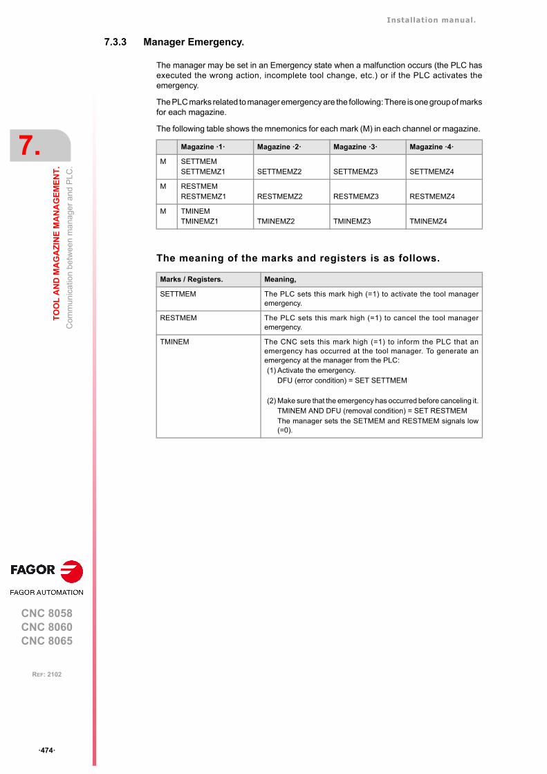
Installation manual.
CNC 8058CNC 8060CNC 8065
7.
TO
OL
AN
D M
AG
AZ
INE
MA
NA
GE
ME
NT
.
Com
mun
ica
tion
betw
een
ma
nage
r a
nd P
LC.
ꞏ474ꞏ
REF: 2102
7.3.3 Manager Emergency.
The manager may be set in an Emergency state when a malfunction occurs (the PLC hasexecuted the wrong action, incomplete tool change, etc.) or if the PLC activates theemergency.
The PLC marks related to manager emergency are the following: There is one group of marksfor each magazine.
The following table shows the mnemonics for each mark (M) in each channel or magazine.
The meaning of the marks and registers is as follows.
Magazine ꞏ1ꞏ Magazine ꞏ2ꞏ Magazine ꞏ3ꞏ Magazine ꞏ4ꞏ
M SETTMEMSETTMEMZ1 SETTMEMZ2 SETTMEMZ3 SETTMEMZ4
M RESTMEMRESTMEMZ1 RESTMEMZ2 RESTMEMZ3 RESTMEMZ4
M TMINEMTMINEMZ1 TMINEMZ2 TMINEMZ3 TMINEMZ4
Marks / Registers. Meaning,
SETTMEM The PLC sets this mark high (=1) to activate the tool manageremergency.
RESTMEM The PLC sets this mark high (=1) to cancel the tool manageremergency.
TMINEM The CNC sets this mark high (=1) to inform the PLC that anemergency has occurred at the tool manager. To generate anemergency at the manager from the PLC:(1) Activate the emergency.
DFU (error condition) = SET SETTMEM
(2) Make sure that the emergency has occurred before canceling it.TMINEM AND DFU (removal condition) = SET RESTMEMThe manager sets the SETMEM and RESTMEM signals low(=0).
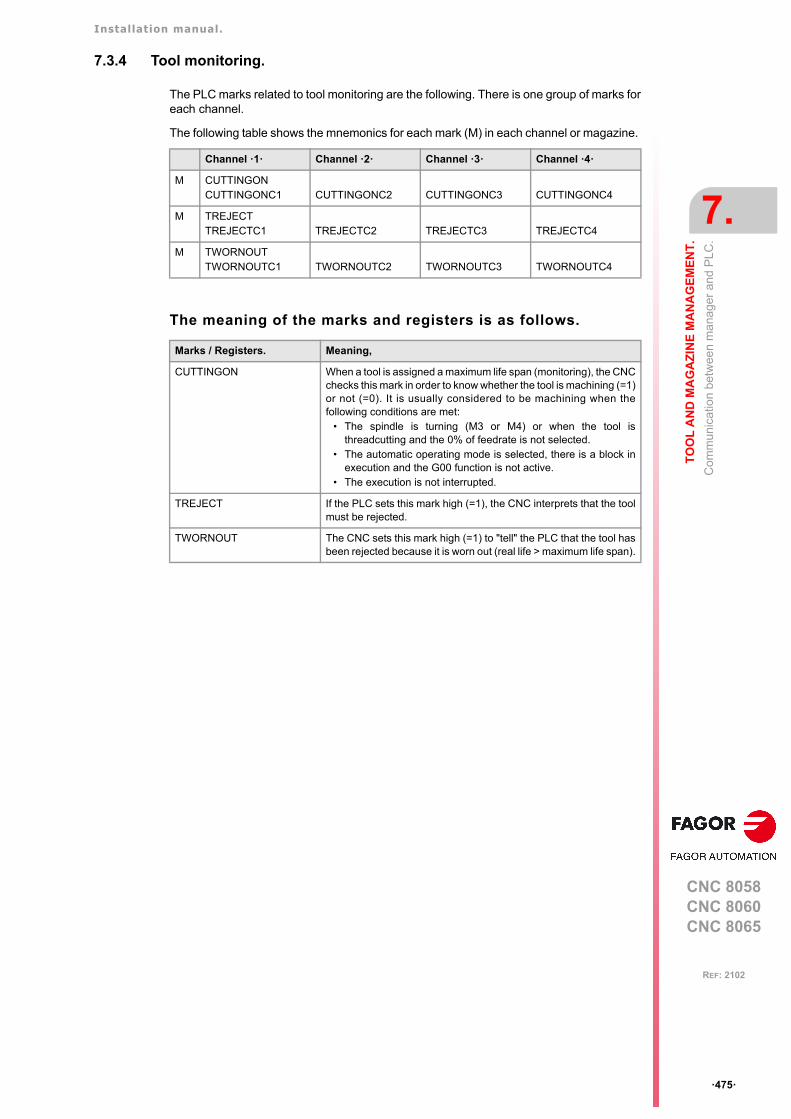
Installation manual.
CNC 8058CNC 8060CNC 8065
TO
OL
AN
D M
AG
AZ
INE
MA
NA
GE
ME
NT
.
7.
Com
mun
ica
tion
betw
een
ma
nage
r a
nd P
LC.
ꞏ475ꞏ
REF: 2102
7.3.4 Tool monitoring.
The PLC marks related to tool monitoring are the following. There is one group of marks foreach channel.
The following table shows the mnemonics for each mark (M) in each channel or magazine.
The meaning of the marks and registers is as follows.
Channel ꞏ1ꞏ Channel ꞏ2ꞏ Channel ꞏ3ꞏ Channel ꞏ4ꞏ
M CUTTINGONCUTTINGONC1 CUTTINGONC2 CUTTINGONC3 CUTTINGONC4
M TREJECTTREJECTC1 TREJECTC2 TREJECTC3 TREJECTC4
M TWORNOUTTWORNOUTC1 TWORNOUTC2 TWORNOUTC3 TWORNOUTC4
Marks / Registers. Meaning,
CUTTINGON When a tool is assigned a maximum life span (monitoring), the CNCchecks this mark in order to know whether the tool is machining (=1)or not (=0). It is usually considered to be machining when thefollowing conditions are met:
• The spindle is turning (M3 or M4) or when the tool isthreadcutting and the 0% of feedrate is not selected.
• The automatic operating mode is selected, there is a block inexecution and the G00 function is not active.
• The execution is not interrupted.
TREJECT If the PLC sets this mark high (=1), the CNC interprets that the toolmust be rejected.
TWORNOUT The CNC sets this mark high (=1) to "tell" the PLC that the tool hasbeen rejected because it is worn out (real life > maximum life span).
Installation manual.
CNC 8058CNC 8060CNC 8065
7.
TO
OL
AN
D M
AG
AZ
INE
MA
NA
GE
ME
NT
.
Var
iab
les
rela
ted
to to
ol m
aga
zine
man
age
men
t.
ꞏ476ꞏ
REF: 2102
7.4 Variables related to tool magazine management.
The variables associated with the magazine that are involved in the tool magazinemanagement are the following. There is one group of variables for each channel. Replacethe [ch] character with the channel number, maintaining the brackets.
V.[ch].TM.MZMODE
Operating mode of the tool magazine manager.
V.[ch].TM.MZSTATUS
Tool manager status.
V.[ch].TM.MZRUN
Tool manager running.
V.[ch].TM.MZWAIT
Tool manager executing a maneuver. It indicates whether to wait or not for the maneuverto end.
There is no need to program it in the subroutine associated with M06. The subroutine itselfwaits for the manager's maneuvers to finish. This way, block preparation is not interrupted.
With a ꞏ0ꞏ value Normal mode (by default and after reset).
With a ꞏ1ꞏ value Magazine loading mode.
With a ꞏ2ꞏ value Magazine unloading mode.
With a ꞏ0ꞏ value Normal.
With a ꞏ1ꞏ value An error has occurred.
With a ꞏ2ꞏ value An error has occurred; but it will wait for the current maneuverto be completed.
With a ꞏ4ꞏ value Emergency.
With a ꞏ0ꞏ value There is no sequence in execution.
With a ꞏ1ꞏ value There is a sequence in execution.
With a ꞏ0ꞏ value No need to wait.
With a ꞏ1ꞏ value It has to wait.
Installation manual.
CNC 8058CNC 8060CNC 8065
TO
OL
AN
D M
AG
AZ
INE
MA
NA
GE
ME
NT
.
7.
Too
l loa
din
g an
d un
load
ing
fro
m th
e m
aga
zine
s.
ꞏ477ꞏ
REF: 2102
7.5 Tool loading and unloading from the magazines.
Tool loading and unloading from the magazine.
Each magazine table has softkeys for initializing, loading and unloading tools in themagazine either manually or automatically. Refer to the operating manual.
The tools may also be loaded and unloaded in the magazine by program or in MDI mode.
Tool loading and unloading from the spindle.
The tools must always be loaded and unloaded in the spindle and on the changer arm inmanual mode from the magazine table. Refer to the operating manual.
Loading the magazine by program or in MDI mode.
The tools are loaded in the magazine by taking them one by one from ground to the magazinegoing through the spindle.
Set the variable: V.TM.MZMODE=1 to "tell" the tool manager that the magazine loadingmode has be chosen.
If a T1 M6 is executed next, the tool manager interprets that T1 must be taken from groundto the magazine going through the spindle and it will let the PLC know by settingTMOPERATION=9.
The subroutine associated with the M06 function and the PLC program must contain themaneuver needed to make the tool change.
After loading the tool, the tool manager updates the magazine table.
Unloading the magazine by program or MDI.
The tools are unloaded from the magazine taking them one by one from the magazine tothe ground going through the spindle.
Set variable: V.TM.MZMODE=2 to "tell" the tool manager that the magazine unloading modehas been chosen.
If a T1 M6 is executed next, the tool manager interprets that T1 must be taken from magazineto the ground going through the spindle and it will let the PLC know by settingTMOPERATION=10.
The subroutine associated with the M06 function and the PLC program must contain themaneuver needed to make the tool change.
After unloading the tool, the tool manager updates the magazine table.
Placing a tool in the spindle by program or in MDI mode
Set variable: V.TM.MZMODE=0 to "tell" the tool manager that the normal mode has beenchosen.
If T1 M6 is executed next, the tool manager checks whether there is already a tool in thespindle (to remove it first) and whether the requested tool is in the magazine or it has to bepicked up from the ground. In any case, it lets the PLC know which operation it must carryout by setting TMOPERATION to the proper value.
The subroutine associated with the M06 function and the PLC program must contain themaneuver needed to make the tool change.
After placing the tool, the tool manager updates the magazine table.
Installation manual.
CNC 8058CNC 8060CNC 8065
7.
TO
OL
AN
D M
AG
AZ
INE
MA
NA
GE
ME
NT
.
Ma
gazi
ne-le
ss s
yste
m.
ꞏ478ꞏ
REF: 2102
7.6 Magazine-less system.
When there is no tool magazine, changing the tool only requires programming the T functionwithout the need for M6. In this circumstances, a programmed M6 function is not interpretedas a tool change, but as just another M function without any special meaning. This does notprevent it from having an associated subroutine like any other M function.
It will be synchronized with the tool manager after the tool change (MZWAIT) after managingthe T block in execution.
Execution of the T function.
1 When the CNC executes the T function, it lets the tool manager know about it.
2 The tool manager sends a command to the PLC to make the change.
3 The CNC waits for the tool manager to complete the operation before continuing withthe execution of the program.
Behavior of function M06.
When there is no tool magazine, the M6 function behaves as follows.
• The M6 function will not activate PLC marks (e.g. DM06) nor will it execute anythingrelated to the tool change (like the tool change subroutine, etc.).
• The M6 function will not be displayed in the M function history.
• The subroutine associated with the M6 function (if it has one) will execute modal cannedcycles or modal subroutines with motion.
• The subroutine associated with M6 will have no special treatment when called upon fromhidden files, canned cycles, etc.
Installation manual.
CNC 8058CNC 8060CNC 8065
TO
OL
AN
D M
AG
AZ
INE
MA
NA
GE
ME
NT
.
7.
Ma
gazi
ne-le
ss s
yste
m.
ꞏ479ꞏ
REF: 2102
7.6.1 Valid operations and marks activated by the PLC with each one of them.
Valid operations of the tool manager for this magazine.
The possible operations in this type of magazine are:
Values of registers TAKEPOS and LEAVEPOS used by themanager.
The TAKEPOS and LEAVEPOS signals do not assume any value. Here is a summary tableof the marks that must be activated by the PLC at the end of each operation.
Example of operation.
The following example shows, assuming that there is no tool in the spindle, it shows thefunctions executed by the CNC, the values sent by the tool manager to the PLC in eachoperation and the marks to be activated by the PLC in each case.
It is a non-random magazine, each tool occupies the position of its own number and T7 andT8 are ground tools.
TMOPERATION Meaning.
0 Do nothing.
3 Insert a ground tool in the spindle.
4 Leave the spindle tool on the ground.
8 Leave the spindle tool on the ground and take a tool from ground.
TM => PLC PLC => TM
TMOPERATION TAKEPOS LEAVEPOS
3 0 0 GRTOSPDL
4 0 0 SPDLTOGR
8 0 0 SPDLTOGR + GRTOSPDL
CNC TMOPERATION TAKEPOS LEAVEPOS
T7 3 0 0 GRTOSPDL
T8 8 0 0 SPDLTOGR + GRTOSPDL
T0 4 0 0 SPDLTOGR
Installation manual.
CNC 8058CNC 8060CNC 8065
7.
TO
OL
AN
D M
AG
AZ
INE
MA
NA
GE
ME
NT
.
Ma
gazi
ne-le
ss s
yste
m.
ꞏ480ꞏ
REF: 2102
7.6.2 Detailed description of the operations of the magazine.
Here is a sample of a detailed description of the valid operations for this magazine. In asystem without magazines, the TAKEPOS, LEAVEPOS, NEXTPOS and MZID signals arenot involved.
TMOPERATION = 3
Insert a ground tool in the spindle.
The sequence of this operation is the following.
1 When the operation is completed, activate the mark: GRTOSPDL.
TMOPERATION = 4
Leave the spindle tool on the ground.
The sequence of this operation is the following.
1 When the operation is completed, activate the mark: SPDLTOGR.
TMOPERATION = 8
Leave the spindle tool on the ground and take a tool from ground.
The sequence of this operation is the following.
1 Leave the tool of the spindle on the ground and activate the mark SPDLTOGR.
2 Leave the ground tool in the spindle and activate the mark GRTOSPDL.
7.6.3 Basic PLC programming.
When executing the T function.
When executing the T function, the tool manager sends to the PLC, in the TMOPERATIONregister, the code for the operation to be carried out.
DFU TMOPSTROBE AND (CPS TMOPERATION EQ 3) = SET GRTOSPDL
A tool change has been requested and TMOPERATION=3. The PLC has taken the toolfrom ground to the spindle.
DFU TMOPSTROBE AND (CPS TMOPERATION EQ 4) = SET SPDLTOGR
A tool change has been requested and TMOPERATION=4. The PLC has taken the toolfrom the spindle to ground.
DFU TMOPSTROBE AND (CPS TMOPERATION EQ 8) = SET SPDLTOGR
A tool change has been requested and TMOPERATION=4. The PLC has taken the toolfrom the spindle to ground.
DFD SPDLTOGR AND (CPS TMOPERATION EQ 8) = SET GRTOSPDL
The manager has canceled the SPDLTOGR mark and TMOPERATION=8. The PLC hastaken the tool from ground to the spindle.
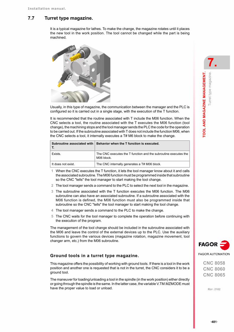
Installation manual.
CNC 8058CNC 8060CNC 8065
TO
OL
AN
D M
AG
AZ
INE
MA
NA
GE
ME
NT
.
7.
Tu
rre
t typ
e m
agaz
ine.
ꞏ481ꞏ
REF: 2102
7.7 Turret type magazine.
It is a typical magazine for lathes. To make the change, the magazine rotates until it placesthe new tool in the work position. The tool cannot be changed while the part is beingmachined.
Usually, in this type of magazine, the communication between the manager and the PLC isconfigured so it is carried out in a single stage, with the execution of the T function.
It is recommended that the routine associated with T include the M06 function. When theCNC selects a tool, the routine associated with the T executes the M06 function (toolchange), the machining stops and the tool manager sends the PLC the code for the operationto be carried out. If the subroutine associated with T does not include the function M06, whenthe CNC selects a tool, it internally executes a T# M6 block to make the change.
1 When the CNC executes the T function, it lets the tool manager know about it and callsthe associated subroutine. The M06 function must be programmed inside that subroutineso the CNC "tells" the tool manager to start making the tool change.
2 The tool manager sends a command to the PLC to select the next tool in the magazine.
3 The subroutine associated with the T function executes the M06 function. The M06subroutine can also have an associated subroutine. If a subroutine associated with theM06 function is defined, the M06 function must also be programmed inside thatsubroutine so the CNC "tells" the tool manager to start making the tool change.
4 The tool manager sends a command to the PLC to make the change.
5 The CNC waits for the tool manager to complete the operation before continuing withthe execution of the program.
The management of the tool change should be included in the subroutine associated withthe M06 and leave the control of the external devices up to the PLC. Use the auxiliaryfunctions to govern the various devices (magazine rotation, magazine movement, toolchanger arm, etc.) from the M06 subroutine.
Ground tools in a turret type magazine.
This magazine offers the possibility of working with ground tools. If there is a tool in the workposition and another one is requested that is not in the turret, the CNC considers it to be aground tool.
The maneuver for loading/unloading a tool in the spindle (in the work position) either directlyor going through the spindle is the same. In the latter case, the variable V.TM.MZMODE musthave the proper value to load or unload.
Subroutine associated withT.
Behavior when the T function is executed.
Exists. The CNC executes the T function and the subroutine executes theM06 block.
It does not exist. The CNC internally generates a T# M06 block.
Installation manual.
CNC 8058CNC 8060CNC 8065
7.
TO
OL
AN
D M
AG
AZ
INE
MA
NA
GE
ME
NT
.
Tu
rre
t typ
e m
agaz
ine.
ꞏ482ꞏ
REF: 2102
7.7.1 Valid operations and marks activated by the PLC with each one of them.
Valid operations of the tool manager for this magazine.
The possible operations in this type of magazine are:
Values of registers TAKEPOS and LEAVEPOS used by themanager.
The TAKEPOS and LEAVEPOS signals can assume the following values.
If TMOPERATION = 15, it is a special case wehre the TAKEPOS, LEAVEPOS andNEXTPOS signals can assume the following values.
Here is a summary table of the TAKEPOS and LEAVEPOS values used by the manager ineach operation as well as the marks that must be activated by the PLC at the end of eachoperation.
TMOPERATION Meaning.
0 Do nothing.
1 Assume the current tool as active tool.
3 Insert a ground tool in the spindle.
4 Leave the spindle tool on the ground.
9 Take a ground tool to the magazine going through the spindle.
10 Take a tool from the magazine and leave on the ground going through thespindle.
11 Orient the turret.
15 Select a turret position.
Value Meaning
0 Do nothing.
# Magazine position.
-4 Ground tool.
Signal. Meaning.
TAKEPOS This register takes the value of ꞏ0ꞏ if it is an absolute positioning and the value of ꞏ1ꞏif it is a relative positioning.
LEAVEPOS This register takes the value of ꞏ0ꞏ if it is a positive relative positioning and the valueof ꞏ1ꞏ if it is a negative relative positioning.
NEXTPOS In an absolute positioning, this register indicates the position to reach and, in arelative positioning, the number of positions to rotate.
TM => PLC PLC => TM
TMOPERATION TAKEPOS LEAVEPOS
1 # 0 MZTOSPDL
3 0 0 GRTOSPDL
4 0 0 SPDLTOGR
9 -4 # GRTOSPDL
10 # -4 SPDLTOGR
11 0 0 MZROT
15 - - - - - - MZROT
Installation manual.
CNC 8058CNC 8060CNC 8065
TO
OL
AN
D M
AG
AZ
INE
MA
NA
GE
ME
NT
.
7.
Tu
rre
t typ
e m
agaz
ine.
ꞏ483ꞏ
REF: 2102
Example of operation.
The following example shows, assuming that there is no tool in the spindle, it shows thefunctions executed by the CNC, the values sent by the tool manager to the PLC in eachoperation and the marks to be activated by the PLC in each case.
It is a non-random magazine, each tool occupies the position of its own number and T7 isa ground tool.
CNC TMOPERATION TAKEPOS LEAVEPOS
T1M6
111
01
00
MZROTMZTOSPDL
T2M6
111
02
00
MZROTMZTOSPDL
T7M6
113
00
00 GRTOSPDL
Installation manual.
CNC 8058CNC 8060CNC 8065
7.
TO
OL
AN
D M
AG
AZ
INE
MA
NA
GE
ME
NT
.
Tu
rre
t typ
e m
agaz
ine.
ꞏ484ꞏ
REF: 2102
7.7.2 Detailed description of the operations of the magazine.
Here is a sample of a detailed description of the valid operations for this magazine. For eachoperation, it indicates which of the TAKEPOS, LEAVEPOS, NEXTPOS and MZID signalsare involved and their meanings. It also shows the sequence to follow to complete theoperation.
The TAKEPOS, LEAVEPOS and NEXTPOS signals can assume the following values.
TMOPERATION = 1
Assume the current tool as active tool.
The sequence of this operation is the following.
1 After ending this operation, activate the MZTOSPDL mark.
TMOPERATION = 3
Insert a ground tool in the spindle.
The sequence of this operation is the following.
1 When the operation is completed, activate the mark: GRTOSPDL.
TMOPERATION = 4
Leave the spindle tool on the ground.
The sequence of this operation is the following.
1 When the operation is completed, activate the mark: SPDLTOGR.
TMOPERATION = 9
Take a ground tool to the magazine going through the spindle.
The sequence of this operation is the following.
1 Leave the ground tool in the spindle and activate the mark GRTOSPDL.
TMOPERATION = 10
Take a tool from the magazine and leave on the ground going through the spindle.
The sequence of this operation is the following.
1 Leave the tool of the spindle on the ground and activate the mark SPDLTOGR.
TMOPERATION = 11
Orient the magazine.
The sequence of this operation is the following.
1 When the operation is completed, activate the mark MZROT.
Value Meaning
0 Do nothing.
# Magazine position.
-4 Ground tool.
TAKEPOS Magazine position to pick up the tool.
TAKEPOS Ground tool.
LEAVEPOS Magazine position to leave the tool.
TAKEPOS Magazine position to pick up the tool.
LEAVEPOS Ground tool.
Installation manual.
CNC 8058CNC 8060CNC 8065
TO
OL
AN
D M
AG
AZ
INE
MA
NA
GE
ME
NT
.
7.
Tu
rre
t typ
e m
agaz
ine.
ꞏ485ꞏ
REF: 2102
TMOPERATION = 15
Select a magazine position.
The sequence of this operation is the following.
1 When the operation is completed, activate the mark MZROT.
TAKEPOS This register takes the value of ꞏ0ꞏ if it is an absolute positioning andthe value of ꞏ1ꞏ if it is a relative positioning.
LEAVEPOS This register takes the value of ꞏ0ꞏ if it is a positive relative positioningand the value of ꞏ1ꞏ if it is a negative relative positioning.
NEXTPOS In an absolute positioning, this register indicates the position to reachand, in a relative positioning, the number of positions to rotate.
Installation manual.
CNC 8058CNC 8060CNC 8065
7.
TO
OL
AN
D M
AG
AZ
INE
MA
NA
GE
ME
NT
.
Tu
rre
t typ
e m
agaz
ine.
ꞏ486ꞏ
REF: 2102
7.7.3 Communication between the PLC and the M06 subroutine.
The communication between the PLC and the M06 subroutine takes place using a seriesof generic marks and registers. The program of the M06 subroutine offered as an exampleuses the following marks and registers.
Communication between the PLC and the M06 subroutine
Marks activated by the M06 subroutine so the PLC activates the relevant mark of the toolmanager.
M functions at the PLC
M functions that imply movements controlled by the PLC:
Set all the M functions with "before-before" synchronization to the program continues afterthe M function is completed.
Mark. Meaning.
M1107 SPDLTOGRThe tool has been taken from the spindle to ground.
M1108 GRTOSPDLThe tool has been taken from ground to the spindle.
M1109 MZTOSPDLAssume the current tool as active tool.
M1110 SPDLTOGRAssume the current tool as active tool.
M1111 MZROTMark that indicates that the magazine has rotated.
Function. Meaning.
M109 Select in the magazine the position indicated by TAKEPOS and insert the tool in thespindle.
M110 Select in the magazine the position indicated by LEAVEPOS and leave the spindletool.
Installation manual.
CNC 8058CNC 8060CNC 8065
TO
OL
AN
D M
AG
AZ
INE
MA
NA
GE
ME
NT
.
7.
Tu
rre
t typ
e m
agaz
ine.
ꞏ487ꞏ
REF: 2102
7.7.4 Program of the M06 subroutine.
%L SUB_MZ_ROT
V.PLC.M[1111]=1#WAIT FOR [V.PLC.M[1111]==0]; MZROT mark to the tool manager.
#RET
%L SUB_SPD_TO_GR ; Remove the tool from the spindle (take it to ground).
#MSG ["Extract tool T%D and press START", V.TM.TOOL]; Message for the operator to extract the tool.
M0 ; Wait for the operation to be completed.#MSG [""] ; Remove message.V.PLC.M[1107]=1 ; SPDLTOGR mark to the tool manager.#WAIT FOR [V.PLC.M[1107]==0]
#RET
%L SUB_GR_TO_SPD ; Insert the ground tool in the spindle.
#MSG ["Insert tool T%D and press START", V.TM.NXTOOL]; Message for the operator to insert the tool.
M0 ; Wait for the operation to be completed.#MSG [""] ; Remove message.V.PLC.M[1108]=1 ; GRTOSPDL mark to the tool manager.#WAIT FOR [V.PLC.M[1108]==0]
#RET
%L SUB_MZ_TO_SPD ; Take the tool from the magazine and insert it in the spindle.
M109 ; Auxiliary function to execute an action.V.PLC.M[1109]=1 ; MZTOSPDL mark to the tool manager.#WAIT FOR [V.PLC.M[1109]==0]
#RET
%L SUB_SPD_TO_MZ ; Leave the spindle tool in the magazine.
M110 ; Auxiliary function to execute an action.V.PLC.M[1110]=1 ; SPDLTOMZ mark to the tool manager.#WAIT FOR [V.PLC.M[1110]==0]
#RET
%L SUB_SPD_GMCHG ; Move the spindle to the manual tool change point.
G1 Z_ F_ ; Move the spindle.#RET
%L SUB_SPD_AUTCHG ; Move the spindle to the automatic tool change point
G1 Z_ F_ ; Move the spindle.#RET
%SUB_M6.nc
#ESBLK ; Begin of single block activation#DSTOP ; STOP key disableM6 ; Order the tool manager to start the tool change.
$IF [[[V.G.FULLSTATUS & 255]<9] | [[V.G.FULLSTATUS & 255]>13]] $IF [[V.G.CNCAUTSTATUS & 4096] | [V.G.CNCAUTSTATUS & 8192]]
V.S.EXECUTION = 0 ; Simulated Theorical or G$ELSE
V.S.EXECUTION = 1 ; Execution$ENDIF
$ELSEV.S.EXECUTION = 0 ; Simulation
$ENDIF
$IF [V.S.EXECUTION == 1] ; CNC in execution
$SWITCH V.PLC.TMOPERATION ; It analyzes the type of operation.
Installation manual.
CNC 8058CNC 8060CNC 8065
7.
TO
OL
AN
D M
AG
AZ
INE
MA
NA
GE
ME
NT
.
Tu
rre
t typ
e m
agaz
ine.
ꞏ488ꞏ
REF: 2102
$CASE 1 ; Assume the current tool as active tool.LL SUB_MZ_TO_SPD
$BREAK
$CASE 3 ; Insert the ground tool in the spindle.LL SUB_SPD_GMCHG ; Move the spindle to the manual tool change point.LL SUB_GR_TO_SPD ; Insert the ground tool in the spindle.
$BREAK
$CASE 4 ; Leave the spindle tool on the ground.LL SUB_SPD_GMCHG ; Move the spindle to the manual tool change point.LL SUB_SPD_TO_GR ; Remove the tool from the spindle.
$BREAK
$CASE 9 ; Take a ground tool to the magazine going through the spindle.
LL SUB_SPD_AUTCHG ; Move the spindle to the automatic tool change pointLL SUB_SPD_TO_MZ ; Leave the spindle tool in the magazine.
$BREAK
$CASE 10 ; Take a tool from the magazine and leave on the ground going through the spindle.
LL SUB_SPD_AUTCHG ; Move the spindle to the automatic tool change pointLL SUB_MZ_TO_SPD ; Take the tool from the magazine to the spindle.
$BREAK
$CASE 11 ; Orient the turret.LL SUB_SPD_AUTCHG ; Move the spindle to the automatic tool change pointLL SUB_MZ_ROT
$BREAK
$ENDSWITCH ; End of analysis of type of operation.
$WHILE V.TM.MZWAIT == 1$ENDWHILE ; Wait for the tool manager.
$ENDIF#DSBLK ; End of single block activation.#ESTOP ; STOP key enable
#RET
Installation manual.
CNC 8058CNC 8060CNC 8065
TO
OL
AN
D M
AG
AZ
INE
MA
NA
GE
ME
NT
.
7.
Tu
rre
t typ
e m
agaz
ine.
ꞏ489ꞏ
REF: 2102
7.7.5 Basic PLC programming.
When executing the -T- function
When executing a T function, the tool manager sends the code TMOPERATION=11 to thePLC. In general, it is an optimization of the change that permits orienting the magazine whilemachining.
DFU TMOPSTROBE AND CPS TMOPERATION EQ 11 = SET MZROT
Activate the MZROT mark to "tell" the tool manager that the operation has finished.
When executing the M06 function
Every time the M06 subroutine ends an action, it lets the PLC know so it activates the relevantmark of the tool manager.
DFU M1107 = SET SPDLTOGRDFD SPDLTOGR = RES M1107
The tool has been taken from the spindle to ground.
DFU M1108 = SET GRTOSPDLDFD GRTOSPDL = RES M1108
The tool has been taken from ground to the spindle.
DFU M1109 = SET MZTOSPDLDFD MZTOSPDL = RES M1109
The tool has been taken from the magazine to the spindle.
DFU M1110 = SET SPDLTOGRDFD SPDLTOGR = RES M1110
The tool has been taken from the spindle to the magazine.
DFU M1111 = SET MZROTDFD MZROT = RES M1111
The magazine has rotated already.
The M06 subroutine uses the following M functions to "tell" the PLC which movements it mustcarry out.
Programming it depends on the type of machine. The auxiliary function will conclude afterexecuting the requested movement.
Certain operations require using the information transferred by the tool manager in thefollowing registers:
Manager emergency signal.
Treatment of the tool manager emergency signal.
DFU B11KEYBD1 AND NOT TMINEM = SET SETTMEMDFU TMINEM = RES SETTMEM
Pressing the USER12 key activates the emergency.
TMINEM = B11KEYLED1
The lamp of the USER12 key turns on when there is an emergency.
TMINEM AND DFU B12KEYBD1 = SET RESTMEM
Pressing the USER13 key removes the emergency.
M109 Select in the magazine the position indicated by TAKEPOS and insert the toolin the spindle.
M110 Select in the magazine the position indicated by LEAVEPOS and leave thespindle tool.
LEAVEPOS This register indicates the magazine position to leave the tool.
TAKEPOS This register indicates the magazine position of the tool to be taken.
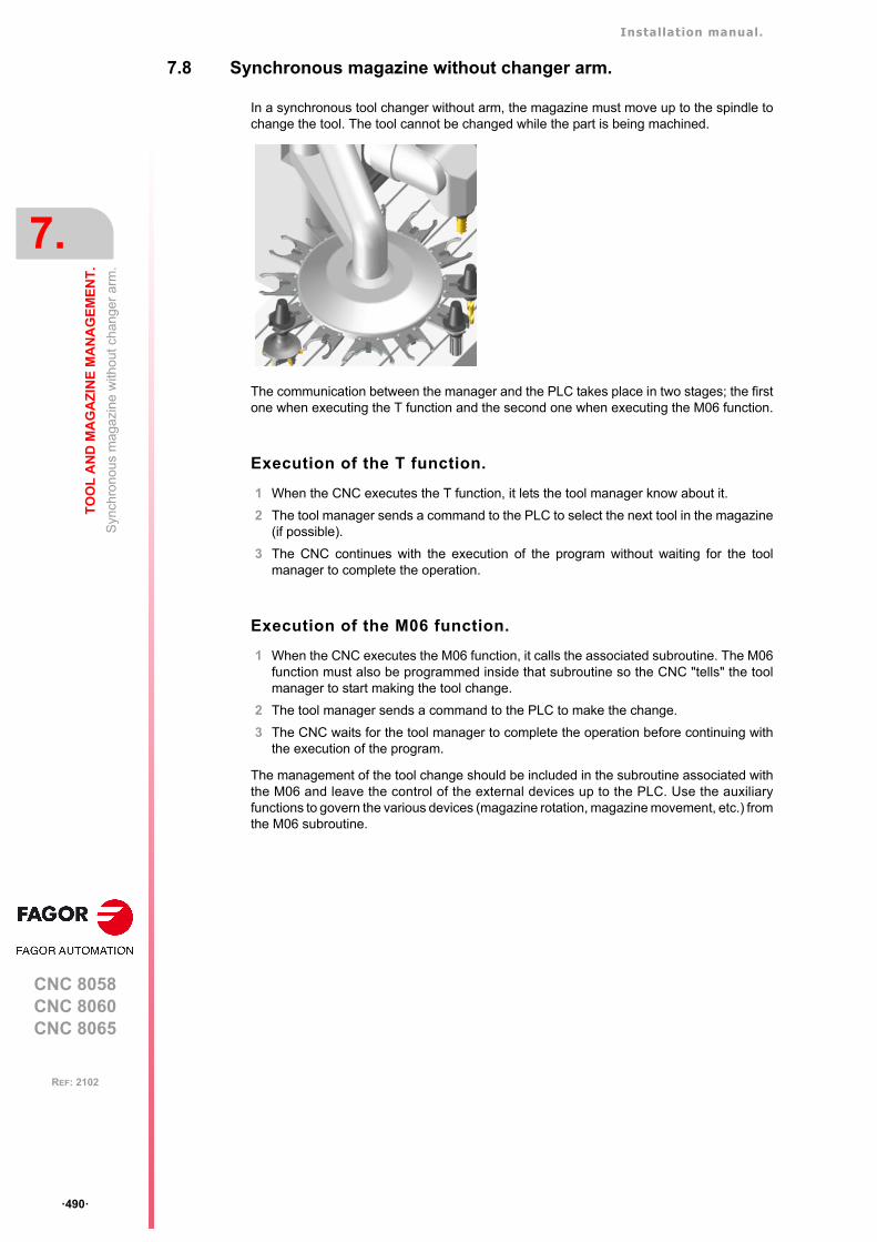
Installation manual.
CNC 8058CNC 8060CNC 8065
7.
TO
OL
AN
D M
AG
AZ
INE
MA
NA
GE
ME
NT
.
Syn
chro
nou
s m
aga
zine
with
out
ch
ange
r ar
m.
ꞏ490ꞏ
REF: 2102
7.8 Synchronous magazine without changer arm.
In a synchronous tool changer without arm, the magazine must move up to the spindle tochange the tool. The tool cannot be changed while the part is being machined.
The communication between the manager and the PLC takes place in two stages; the firstone when executing the T function and the second one when executing the M06 function.
Execution of the T function.
1 When the CNC executes the T function, it lets the tool manager know about it.
2 The tool manager sends a command to the PLC to select the next tool in the magazine(if possible).
3 The CNC continues with the execution of the program without waiting for the toolmanager to complete the operation.
Execution of the M06 function.
1 When the CNC executes the M06 function, it calls the associated subroutine. The M06function must also be programmed inside that subroutine so the CNC "tells" the toolmanager to start making the tool change.
2 The tool manager sends a command to the PLC to make the change.
3 The CNC waits for the tool manager to complete the operation before continuing withthe execution of the program.
The management of the tool change should be included in the subroutine associated withthe M06 and leave the control of the external devices up to the PLC. Use the auxiliaryfunctions to govern the various devices (magazine rotation, magazine movement, etc.) fromthe M06 subroutine.
Installation manual.
CNC 8058CNC 8060CNC 8065
TO
OL
AN
D M
AG
AZ
INE
MA
NA
GE
ME
NT
.
7.
Syn
chro
nou
s m
aga
zine
with
out
ch
ange
r ar
m.
ꞏ491ꞏ
REF: 2102
7.8.1 Valid operations and marks activated by the PLC with each one of them.
Valid operations of the tool manager for this magazine.
The possible operations in this type of magazine are:
Values of registers TAKEPOS and LEAVEPOS used by themanager.
The TAKEPOS and LEAVEPOS signals can assume the following values.
Here is a summary table of the TAKEPOS and LEAVEPOS values used by the manager ineach operation as well as the marks that must be activated by the PLC at the end of eachoperation.
TMOPERATION Meaning.
0 Do nothing.
1 Take a tool from the magazine and insert it in the spindle.
2 Leave the spindle tool in the magazine.
3 Insert a ground tool in the spindle.
4 Leave the spindle tool on the ground.
5 Leave the spindle tool in the magazine and take a tool from the samemagazine.
6 Leave the spindle tool in the magazine and take a tool from ground.
7 Leave the spindle tool on the ground and take a tool from the magazine.
8 Leave the spindle tool on the ground and take a tool from ground.
9 Take a ground tool to the magazine going through the spindle.
10 Take a tool from the magazine and leave on the ground going through thespindle.
11 Orient the magazine.
12 Leave the spindle tool in the magazine and take a tool from the samemagazine (as TMOPERATION=5). It is an optimized operation, only validwhen the magazine is random and the tool is special.
13 Orienting two magazines.
14 Leave the spindle tool in the magazine and take a tool from anothermagazine.
Value Meaning
0 Do nothing.
# Magazine position.
-4 Ground tool.
TM => PLC PLC => TM
TMOPERATION TAKEPOS LEAVEPOS
1 # 0 MZTOSPDL
2 0 # SPDLTOMZ
3 0 0 GRTOSPDL
4 0 0 SPDLTOGR
5 # # SPDLTOMZ + MZTOSPDL
6 -4 # SPDLTOMZ + GRTOSPDL
7 # -4 SPDLTOGR + MZTOSPDL
8 0 0 SPDLTOGR + GRTOSPDL
9 -4 # GRTOSPDL + SPDLTOMZ
Installation manual.
CNC 8058CNC 8060CNC 8065
7.
TO
OL
AN
D M
AG
AZ
INE
MA
NA
GE
ME
NT
.
Syn
chro
nou
s m
aga
zine
with
out
ch
ange
r ar
m.
ꞏ492ꞏ
REF: 2102
Example of operation.
The following example shows, assuming that there is no tool in the spindle, it shows thefunctions executed by the CNC, the values sent by the tool manager to the PLC in eachoperation and the marks to be activated by the PLC in each case.
It is a non-random magazine, each tool occupies the position of its own number and T7, T8and T9 are ground tools.
10 # -4 MZTOSPDL + SPDLTOGR
11 0 0 MZROT
12 # # SPDLTOMZ + MZTOSPDL
13 # 0 MZROT + MZROT
14 # # SPDLTOMZ + MZTOSPDL
CNC TMOPERATION TAKEPOS LEAVEPOS
T1M6
111
01
00
MZROTMZTOSPDL
T2M6
115
02
01
MZROTSPDLTOMZ + MZTOSPDL
T7M6
116
0-4
02
MZROTSPDLTOMZ + GRTOSPDL
T8M6
118
00
00
MZROTSPDLTOGR + GRTOSPDL
T3T4M6
11117
004
00-4
MZROTMZROT
SDPLTOGR + MZTOSPDL
T0M6
112
00
04
MZROTSPDLTOMZ
T9M6
113
00
00
MZROTGRTOSPDL
T0M6
114
00
00
MZROTSPDLTOGR
TM => PLC PLC => TM
TMOPERATION TAKEPOS LEAVEPOS

Installation manual.
CNC 8058CNC 8060CNC 8065
TO
OL
AN
D M
AG
AZ
INE
MA
NA
GE
ME
NT
.
7.
Syn
chro
nou
s m
aga
zine
with
out
ch
ange
r ar
m.
ꞏ493ꞏ
REF: 2102
7.8.2 Detailed description of the operations of the magazine.
Here is a sample of a detailed description of the valid operations for this magazine. For eachoperation, it indicates which of the TAKEPOS, LEAVEPOS, NEXTPOS and MZID signalsare involved and their meanings. It also shows the sequence to follow to complete theoperation.
The TAKEPOS, LEAVEPOS and NEXTPOS signals can assume the following values.
TMOPERATION = 1
Take a tool from the magazine and insert it in the spindle.
The sequence of this operation is the following.
1 After ending this operation, activate the MZTOSPDL mark.
TMOPERATION = 2
Leave the spindle tool in the magazine.
The sequence of this operation is the following.
1 After ending this operation, activate the SPDLTOMZ mark.
TMOPERATION = 3
Insert a ground tool in the spindle.
The sequence of this operation is the following.
1 When the operation is completed, activate the mark: GRTOSPDL.
TMOPERATION = 4
Leave the spindle tool on the ground.
The sequence of this operation is the following.
1 When the operation is completed, activate the mark: SPDLTOGR.
TMOPERATION = 5
Leave the spindle tool in the magazine and take a tool from the same magazine.
The sequence of this operation is the following.
1 Leave the tool of the spindle in the magazine and activate the mark SPDLTOMZ.
2 Leave the tool of the magazine in the spindle and activate the mark MZTOSPDL.
TMOPERATION = 6
Leave the spindle tool in the magazine and take a tool from ground.
The sequence of this operation is the following.
1 Leave the tool of the spindle in the magazine and activate the mark SPDLTOMZ.
2 Leave the ground tool in the spindle and activate the mark GRTOSPDL.
Value Meaning
0 Do nothing.
# Magazine position.
-4 Ground tool.
TAKEPOS=# Magazine position to pick up the tool.
LEAVEPOS=# Magazine position to leave the tool.
TAKEPOS=# Magazine position to pick up the tool.
LEAVEPOS=# Magazine position to leave the tool.
TAKEPOS=-4 Ground tool.
LEAVEPOS=# Magazine position to leave the tool.
Installation manual.
CNC 8058CNC 8060CNC 8065
7.
TO
OL
AN
D M
AG
AZ
INE
MA
NA
GE
ME
NT
.
Syn
chro
nou
s m
aga
zine
with
out
ch
ange
r ar
m.
ꞏ494ꞏ
REF: 2102
TMOPERATION = 7
Leave the spindle tool on the ground and take a tool from the magazine.
The sequence of this operation is the following.
1 Leave the tool of the spindle on the ground and activate the mark SPDLTOGR.
2 Leave the tool of the magazine in the spindle and activate the mark MZTOSPDL.
TMOPERATION = 8
Leave the spindle tool on the ground and take a tool from ground.
The sequence of this operation is the following.
1 Leave the tool of the spindle on the ground and activate the mark SPDLTOGR.
2 Leave the ground tool in the spindle and activate the mark GRTOSPDL.
TMOPERATION = 9
Take a ground tool to the magazine going through the spindle.
The sequence of this operation is the following.
1 Leave the ground tool in the spindle and activate the mark GRTOSPDL.
2 Leave the tool of the spindle in the magazine and activate the mark SPDLTOMZ.
TMOPERATION = 10
Take a tool from the magazine and leave on the ground going through the spindle.
The sequence of this operation is the following.
1 Leave the tool of the magazine in the spindle and activate the mark MZTOSPDL.
2 Leave the tool of the spindle on the ground and activate the mark SPDLTOGR.
TMOPERATION = 11
Orient the magazine.
This operation is an optimization of the tool change that permits orienting the magazine whilemachining. Activate the MZROT mark to indicate that the operation has been completed,whether it has been oriented or not.
TMOPERATION = 12
Leave the spindle tool in the magazine and take a tool from the same magazine (asTMOPERATION=5). It is an optimized operation, only valid when the magazine is randomand the tool is special.
TAKEPOS=# Magazine position to pick up the tool.
LEAVEPOS=-4 Ground tool.
TAKEPOS=-4 Ground tool.
LEAVEPOS=# Magazine position to leave the tool.
TAKEPOS=# Magazine position to pick up the tool.
LEAVEPOS=-4 Ground tool.
TAKEPOS=# Magazine position to pick up the tool.
LEAVEPOS=# Magazine position to leave the tool.
Installation manual.
CNC 8058CNC 8060CNC 8065
TO
OL
AN
D M
AG
AZ
INE
MA
NA
GE
ME
NT
.
7.
Syn
chro
nou
s m
aga
zine
with
out
ch
ange
r ar
m.
ꞏ495ꞏ
REF: 2102
TMOPERATION = 13
Orienting two magazines.
This operation is an optimization of the tool change that permits orienting two magazineswhile machining. Activate the MZROT mark in both magazines to indicate that the operationhas been completed, whether the magazines have been oriented or not.
TMOPERATION = 14
Leave the spindle tool in the magazine and take a tool from another magazine.
The sequence of this operation is the following.
1 Leave the tool of the spindle in the magazine and activate the mark SPDLTOMZ.
2 Leave the tool of the magazine in the spindle and activate the mark MZTOSPDL.
NEXTPOS=# Magazine position to leave the tool.
TAKEPOS=# Magazine position to pick up the tool.
MZID The lower portion of this register indicates the destination magazinefor the tool and the higher portion the source magazine for the tool.
TAKEPOS=# Magazine position to pick up the tool.
LEAVEPOS=# Magazine position to leave the tool.
MZID The lower portion of this register indicates the destination magazinefor the tool and the higher portion the source magazine for the tool.

Installation manual.
CNC 8058CNC 8060CNC 8065
7.
TO
OL
AN
D M
AG
AZ
INE
MA
NA
GE
ME
NT
.
Syn
chro
nou
s m
aga
zine
with
out
ch
ange
r ar
m.
ꞏ496ꞏ
REF: 2102
7.8.3 Communication between the PLC and the M06 subroutine.
The communication between the PLC and the M06 subroutine takes place using a seriesof generic marks and registers. The program of the M06 subroutine offered as an exampleuses the following marks and registers.
Communication between the PLC and the M06 subroutine
Marks activated by the M06 subroutine so the PLC activates the relevant mark of the toolmanager.
M functions at the PLC
M functions that imply movements controlled by the PLC:
Set all the M functions with "before-before" synchronization to the program continues afterthe M function is completed.
Mark. Meaning.
M1107 SPDLTOGRThe tool has been taken from the spindle to ground.
M1108 GRTOSPDLThe tool has been taken from ground to the spindle.
M1109 MZTOSPDLThe tool has been taken from the magazine to the spindle.
M1110 SPDLTOMZThe tool has been taken from the spindle to the magazine.
Function. Meaning.
M109 Select in the magazine the position indicated by TAKEPOS and insert the tool in thespindle.
M110 Select in the magazine the position indicated by LEAVEPOS and leave the spindletool.
Installation manual.
CNC 8058CNC 8060CNC 8065
TO
OL
AN
D M
AG
AZ
INE
MA
NA
GE
ME
NT
.
7.
Syn
chro
nou
s m
aga
zine
with
out
ch
ange
r ar
m.
ꞏ497ꞏ
REF: 2102
7.8.4 Program of the M06 subroutine.
%L SUB_SPD_TO_GR ; Remove the tool from the spindle (take it to ground).
#MSG ["Extract tool T%D and press START", V.TM.TOOL]; Message for the operator to extract the tool.
M0 ; Wait for the operation to be completed.#MSG [""] ; Remove message.V.PLC.M[1107]=1 ; SPDLTOGR mark to the tool manager.#WAIT FOR [V.PLC.M[1107]==0]
#RET
%L SUB_GR_TO_SPD ; Insert the ground tool in the spindle.
#MSG ["Insert tool T%D and press START", V.TM.NXTOOL]; Message for the operator to insert the tool.
M0 ; Wait for the operation to be completed.#MSG [""] ; Remove message.V.PLC.M[1108]=1 ; GRTOSPDL mark to the tool manager.#WAIT FOR [V.PLC.M[1108]==0]
#RET
%L SUB_MZ_TO_SPD ; Take the tool from the magazine and insert it in the spindle.
M109 ; Auxiliary function to execute an action.V.PLC.M[1109]=1 ; MZTOSPDL mark to the tool manager.#WAIT FOR [V.PLC.M[1109]==0]
#RET
%L SUB_SPD_TO_MZ ; Leave the spindle tool in the magazine.
M110 ; Auxiliary function to execute an action.V.PLC.M[1110]=1 ; SPDLTOMZ mark to the tool manager.#WAIT FOR [V.PLC.M[1110]==0]
#RET
%L SUB_SPD_GMCHG ; Move the spindle to the manual tool change point.
G1 Z_ F_ ; Move the spindle.#RET
%L SUB_SPD_AUTCHG ; Move the spindle to the automatic tool change point
G1 Z_ F_ ; Move the spindle.#RET
%SUB_M6.nc
#ESBLK ; Begin of single block activation#DSTOP ; STOP key disableM6 ; Order the tool manager to start the tool change.
$IF [[[V.G.FULLSTATUS & 255]<9] | [[V.G.FULLSTATUS & 255]>13]] $IF [[V.G.CNCAUTSTATUS & 4096] | [V.G.CNCAUTSTATUS & 8192]]
V.S.EXECUTION = 0 ; Simulated Theorical or G$ELSE
V.S.EXECUTION = 1 ; Execution$ENDIF
$ELSEV.S.EXECUTION = 0 ; Simulation
$ENDIF
$IF [V.S.EXECUTION == 1] ; CNC in execution
$SWITCH V.PLC.TMOPERATION ; It analyzes the type of operation.
$CASE 1 ; Take a tool from the magazine and insert it in the spindle.
LL SUB_SPD_AUTCHG ; Move the spindle to the automatic tool change pointLL SUB_MZ_TO_SPD ; Take the tool from the magazine to the spindle.
$BREAK
Installation manual.
CNC 8058CNC 8060CNC 8065
7.
TO
OL
AN
D M
AG
AZ
INE
MA
NA
GE
ME
NT
.
Syn
chro
nou
s m
aga
zine
with
out
ch
ange
r ar
m.
ꞏ498ꞏ
REF: 2102
$CASE 2 ; Leave the spindle tool in the magazine.LL SUB_SPD_AUTCHG ; Move the spindle to the automatic tool change pointLL SUB_SPD_TO_MZ ; Leave the spindle tool in the magazine.
$BREAK
$CASE 3 ; Insert the ground tool in the spindle.LL SUB_SPD_GMCHG ; Move the spindle to the manual tool change point.LL SUB_GR_TO_SPD ; Insert the ground tool in the spindle.
$BREAK
$CASE 4 ; Leave the spindle tool on the ground.LL SUB_SPD_GMCHG ; Move the spindle to the manual tool change point.LL SUB_SPD_TO_GR ; Remove the tool from the spindle.
$BREAK
$CASE 5 ; Leave the spindle tool in the magazine and take another one from the magazine.
LL SUB_SPD_AUTCHG ; Move the spindle to the automatic tool change pointLL SUB_SPD_TO_MZ ; Leave the spindle tool in the magazine.LL SUB_MZ_TO_SPD ; Take the tool from the magazine to the spindle.
$BREAK
$CASE 6 ; Leave the spindle tool in the magazine and take another one from ground.
LL SUB_SPD_AUTCHG ; the spindle to the automatic tool change pointLL SUB_SPD_TO_MZ ; Leave the spindle tool in the magazine.LL SUB_SPD_GMCHG ; Move the spindle to the manual tool change point.LL SUB_GR_TO_SPD ; Insert the ground tool in the spindle.
$BREAK
$CASE 7 ; Leave the spindle tool on the ground and take another one from the magazine.
LL SUB_SPD_GMCHG ; Move the spindle to the manual tool change point.LL SUB_SPD_TO_GR ; Remove the tool from the spindle.LL SUB_SPD_AUTCHG ; Move the spindle to the automatic tool change pointLL SUB_MZ_TO_SPD ; Take the tool from the magazine to the spindle.
$BREAK
$CASE 8 ; Leave the spindle tool on the ground and take another one from ground.
LL SUB_SPD_GMCHG ; Move the spindle to the manual tool change point.LL SUB_SPD_TO_GR ; Remove the tool from the spindle.LL SUB_GR_TO_SPD ; Insert the ground tool in the spindle.
$BREAK
$CASE 9 ; Take a ground tool to the magazine going through the spindle.
LL SUB_SPD_GMCHG ; Move the spindle to the manual tool change point.LL SUB_GR_TO_SPD ; Insert the ground tool in the spindle.LL SUB_SPD_AUTCHG ; Move the spindle to the automatic tool change pointLL SUB_SPD_TO_MZ ; Leave the spindle tool in the magazine.
$BREAK
$CASE 10 ; Take a tool from the magazine and leave on the ground going through the spindle.
LL SUB_SPD_AUTCHG ; Move the spindle to the automatic tool change pointLL SUB_MZ_TO_SPD ; Take the tool from the magazine to the spindle.LL SUB_SPD_GMCHG ; Move the spindle to the manual tool change point.LL SUB_SPD_TO_GR ; Remove the tool from the spindle.
$BREAK
$ENDSWITCH ; End of analysis of type of operation.
$WHILE V.TM.MZWAIT == 1$ENDWHILE ; Wait for the tool manager.$ENDIF#DSBLK ; End of single block activation.#ESTOP ; STOP key enable
#RET
Installation manual.
CNC 8058CNC 8060CNC 8065
TO
OL
AN
D M
AG
AZ
INE
MA
NA
GE
ME
NT
.
7.
Syn
chro
nou
s m
aga
zine
with
out
ch
ange
r ar
m.
ꞏ499ꞏ
REF: 2102
7.8.5 Basic PLC programming.
When executing the -T- function
When executing a T function, the tool manager sends the code TMOPERATION=11 to thePLC. In general, it is an optimization of the change that permits orienting the magazine whilemachining.
In this case, the magazine is not oriented and the MZROT mark is activated to indicate thatthe operation has been completed.
DFU TMOPSTROBE AND CPS TMOPERATION EQ 11 = SET MZROT
Activate the MZROT mark to "tell" the tool manager that the operation has finished.
When executing the M06 function
Every time the M06 subroutine ends an action, it lets the PLC know so it activates the relevantmark of the tool manager.
DFU M1107 = SET SPDLTOGRDFD SPDLTOGR = RES M1107
The tool has been taken from the spindle to ground.
DFU M1108 = SET GRTOSPDLDFD GRTOSPDL = RES M1108
The tool has been taken from ground to the spindle.
DFU M1109 = SET MZTOSPDLDFD MZTOSPDL = RES M1109
The tool has been taken from the magazine to the spindle.
DFU M1110 = SET SPDLTOMZDFD SPDLTOMZ = RES M1110
The tool has been taken from the spindle to the magazine.
DFU M1111 = SET MZROTDFD MZROT = RES M1111
The magazine has rotated already.
The M06 subroutine uses the following M functions to "tell" the PLC which movements it mustcarry out.
Programming it depends on the type of machine. The auxiliary function will conclude afterexecuting the requested movement.
Certain operations require using the information transferred by the tool manager in thefollowing registers:
Manager emergency signal.
Treatment of the tool manager emergency signal.
DFU B11KEYBD1 AND NOT TMINEM = SET SETTMEMDFU TMINEM = RES SETTMEM
Pressing the USER12 key activates the emergency.
TMINEM = B11KEYLED1
The lamp of the USER12 key turns on when there is an emergency.
TMINEM AND DFU B12KEYBD1 = SET RESTMEM
Pressing the USER13 key removes the emergency.
M109 Select in the magazine the position indicated by TAKEPOS and insert the toolin the spindle.
M110 Select in the magazine the position indicated by LEAVEPOS and leave thespindle tool.
LEAVEPOS This register indicates the magazine position to leave the tool.
TAKEPOS This register indicates the magazine position of the tool to be taken.
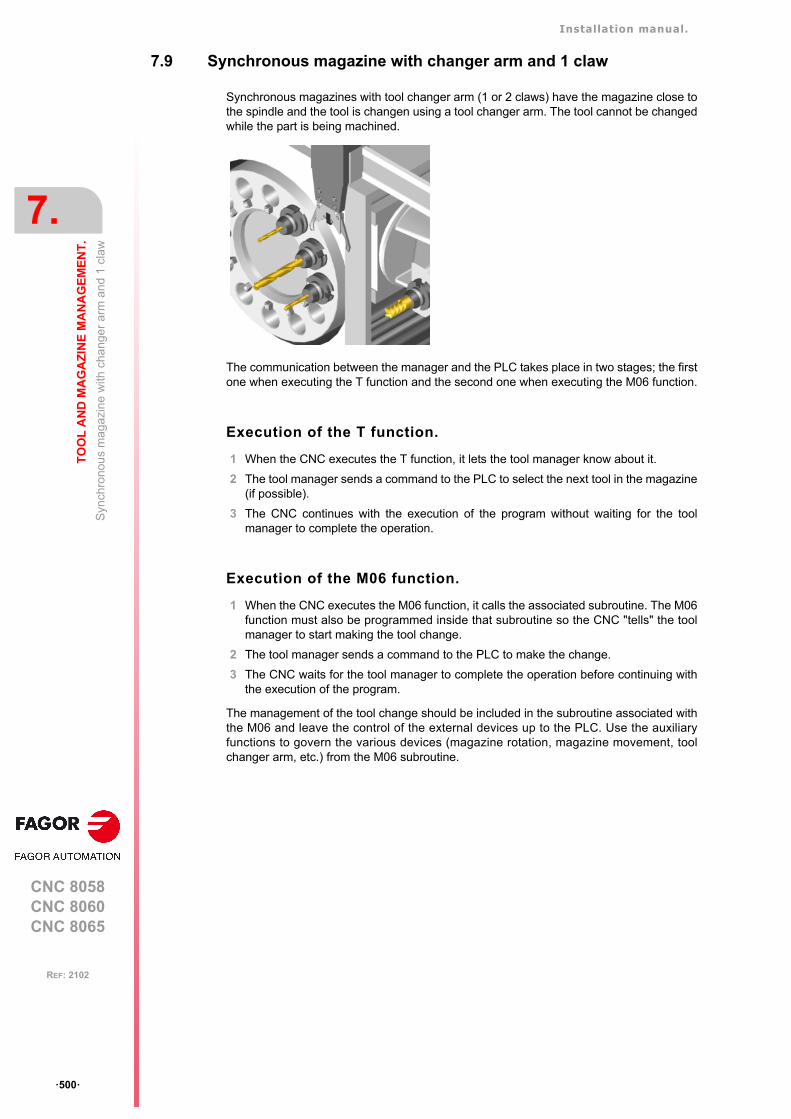
Installation manual.
CNC 8058CNC 8060CNC 8065
7.
TO
OL
AN
D M
AG
AZ
INE
MA
NA
GE
ME
NT
.
Syn
chro
nou
s m
agaz
ine
with
cha
nge
r ar
m a
nd 1
cla
w
ꞏ500ꞏ
REF: 2102
7.9 Synchronous magazine with changer arm and 1 claw
Synchronous magazines with tool changer arm (1 or 2 claws) have the magazine close tothe spindle and the tool is changen using a tool changer arm. The tool cannot be changedwhile the part is being machined.
The communication between the manager and the PLC takes place in two stages; the firstone when executing the T function and the second one when executing the M06 function.
Execution of the T function.
1 When the CNC executes the T function, it lets the tool manager know about it.
2 The tool manager sends a command to the PLC to select the next tool in the magazine(if possible).
3 The CNC continues with the execution of the program without waiting for the toolmanager to complete the operation.
Execution of the M06 function.
1 When the CNC executes the M06 function, it calls the associated subroutine. The M06function must also be programmed inside that subroutine so the CNC "tells" the toolmanager to start making the tool change.
2 The tool manager sends a command to the PLC to make the change.
3 The CNC waits for the tool manager to complete the operation before continuing withthe execution of the program.
The management of the tool change should be included in the subroutine associated withthe M06 and leave the control of the external devices up to the PLC. Use the auxiliaryfunctions to govern the various devices (magazine rotation, magazine movement, toolchanger arm, etc.) from the M06 subroutine.
Installation manual.
CNC 8058CNC 8060CNC 8065
TO
OL
AN
D M
AG
AZ
INE
MA
NA
GE
ME
NT
.
7.
Syn
chro
nou
s m
agaz
ine
with
cha
nge
r ar
m a
nd 1
cla
w
ꞏ501ꞏ
REF: 2102
7.9.1 Valid operations and marks activated by the PLC with each one of them.
Valid operations of the tool manager for this magazine.
The possible operations in this type of magazine are:
Values of registers TAKEPOS and LEAVEPOS used by themanager.
The TAKEPOS and LEAVEPOS signals can assume the following values.
Here is a summary table of the TAKEPOS and LEAVEPOS values used by the manager ineach operation as well as the marks that must be activated by the PLC at the end of eachoperation. In the case of the marks shown between parenthesis, the manager can executethe operations in any order, but it must always execute both.
TMOPERATION Meaning.
0 Do nothing.
1 Take a tool from the magazine and insert it in the spindle.
2 Leave the spindle tool in the magazine.
3 Insert a ground tool in the spindle.
4 Leave the spindle tool on the ground.
5 Leave the spindle tool in the magazine and take a tool from the samemagazine.
6 Leave the spindle tool in the magazine and take a tool from ground.
7 Leave the spindle tool on the ground and take a tool from the magazine.
8 Leave the spindle tool on the ground and take a tool from ground.
9 Take a ground tool to the magazine going through the spindle.
10 Take a tool from the magazine and leave on the ground going through thespindle.
11 Orient the magazine.
13 Orienting two magazines.
14 Leave the spindle tool in the magazine and take a tool from anothermagazine.
Value Meaning
0 Do nothing.
# Magazine position.
-4 Ground tool.
TM => PLC PLC => TM
TMOPERATION TAKEPOS LEAVEPOS
1 # 0 MZTOCH1 + CH1TOSPDL
2 0 # SPDLTOCH1 + CH1TOMZ
3 0 0 GRTOSPDL
4 0 0 SPDLTOGR
5 # # SPDLTOCH1 + CH1TOMZ + MZTOCH1 + CH1TOSPDL
6 -4 # SPDLTOCH1 + (CH1TOMZ & GRTOSPDL)
7 # -4 (SPDLTOGR & MZTOCH1) + CH1TOSPDL
8 0 0 SPDLTOGR + GRTOSPDL
Installation manual.
CNC 8058CNC 8060CNC 8065
7.
TO
OL
AN
D M
AG
AZ
INE
MA
NA
GE
ME
NT
.
Syn
chro
nou
s m
agaz
ine
with
cha
nge
r ar
m a
nd 1
cla
w
ꞏ502ꞏ
REF: 2102
Example of operation.
The following example shows, assuming that there is no tool in the spindle, it shows thefunctions executed by the CNC, the values sent by the tool manager to the PLC in eachoperation and the marks to be activated by the PLC in each case.
It is a non-random magazine, each tool occupies the position of its own number and T7, T8and T9 are ground tools.
9 -4 # GRTOSPDL + SPDLTOCH1 + CH1TOMZ
10 # -4 MZTOCH1 + CH1TOSPDL + SPDLTOGR
11 0 0 MZROT
13 # 0 MZROT + MZROT
14 # # SPDLTOCH1 + CH1TOMZ + MZTOCH1 + CH1TOSPDL
CNC TMOPERATION TAKEPOS LEAVEPOS
T1M6
111
01
00
MZROTMZTOCH1 + CH1TOSPDL
T2M6
115
02
01
MZROTSPDLTOCH1 + CH1TOMZ + MZTOCH1 + CH1TOSPDL
T7M6
116
0-4
02
MZROTSPDLTOCH1 + CH1TOMZ +
GRTOSPDL
T8M6
118
00
00
MZROTSPDLTOGR + GRTOSPDL
T3T4M6
11117
004
00-4
MZROTMZROT
SDPLTOGR + MZTOCH1 + CH1TOSPDL
T0M6
112
00
04
MZROTSPDLTOCH1 + CH1TOMZ
T9M6
113
00
00
MZROTGRTOSPDL
T0M6
114
00
00
MZROTSPDLTOGR
TM => PLC PLC => TM
TMOPERATION TAKEPOS LEAVEPOS
Installation manual.
CNC 8058CNC 8060CNC 8065
TO
OL
AN
D M
AG
AZ
INE
MA
NA
GE
ME
NT
.
7.
Syn
chro
nou
s m
agaz
ine
with
cha
nge
r ar
m a
nd 1
cla
w
ꞏ503ꞏ
REF: 2102
7.9.2 Detailed description of the operations of the magazine.
Here is a sample of a detailed description of the valid operations for this magazine. For eachoperation, it indicates which of the TAKEPOS, LEAVEPOS, NEXTPOS and MZID signalsare involved and their meanings. It also shows the sequence to follow to complete theoperation.
The TAKEPOS, LEAVEPOS and NEXTPOS signals can assume the following values.
TMOPERATION = 1
Take a tool from the magazine and insert it in the spindle.
The sequence of this operation is the following.
1 Take the tool from the magazine with holder 1 and activate the mark MZTOCH1.
2 Insert the tool of holder 1 in the spindle and activate CH1TOSPDL.
TMOPERATION = 2
Leave the spindle tool in the magazine.
The sequence of this operation is the following.
1 Take the tool from the spindle with holder 1 and activate the mark SPDLTOCH1.
2 Leave the tool of holder 1 in the magazine and activate the mark CH1TOMZ.
TMOPERATION = 3
Insert a ground tool in the spindle.
The sequence of this operation is the following.
1 When the operation is completed, activate the mark: GRTOSPDL.
TMOPERATION = 4
Leave the spindle tool on the ground.
The sequence of this operation is the following.
1 When the operation is completed, activate the mark: SPDLTOGR.
TMOPERATION = 5
Leave the spindle tool in the magazine and take a tool from the same magazine.
The sequence of this operation is the following.
1 Take the tool from the spindle with holder 1 and activate the mark SPDLTOCH1.
2 Leave the tool of holder 1 in the magazine and activate the mark CH1TOMZ.
3 Take the tool from the magazine with holder 1 and activate the mark MZTOCH1.
4 Insert the tool of holder 1 in the spindle and activate CH1TOSPDL.
TMOPERATION = 6
Leave the spindle tool in the magazine and take a tool from ground.
Value Meaning
0 Do nothing.
# Magazine position.
-4 Ground tool.
TAKEPOS=# Magazine position to pick up the tool.
LEAVEPOS=# Magazine position to leave the tool.
TAKEPOS=# Magazine position to pick up the tool.
LEAVEPOS=# Magazine position to leave the tool.
TAKEPOS=-4 Ground tool.
LEAVEPOS=# Magazine position to leave the tool.

Installation manual.
CNC 8058CNC 8060CNC 8065
7.
TO
OL
AN
D M
AG
AZ
INE
MA
NA
GE
ME
NT
.
Syn
chro
nou
s m
agaz
ine
with
cha
nge
r ar
m a
nd 1
cla
w
ꞏ504ꞏ
REF: 2102
The sequence of this operation is the following. The tool manager admits the sequence 1-3-2.
1 Take the tool from the spindle with holder 1 and activate the mark SPDLTOCH1.
2 Leave the tool of holder 1 in the magazine and activate the mark CH1TOMZ.
3 Leave the ground tool in the spindle and activate the mark GRTOSPDL.
TMOPERATION = 7
Leave the spindle tool on the ground and take a tool from the magazine.
The sequence of this operation is the following. The tool manager admits the sequence 2-1-3.
1 Leave the tool of the spindle on the ground and activate the mark SPDLTOGR.
2 Take the tool from the magazine with holder 1 and activate the mark MZTOCH1.
3 Insert the tool of holder 1 in the spindle and activate CH1TOSPDL.
TMOPERATION = 8
Leave the spindle tool on the ground and take a tool from ground.
The sequence of this operation is the following.
1 Leave the tool of the spindle on the ground and activate the mark SPDLTOGR.
2 Leave the ground tool in the spindle and activate the mark GRTOSPDL.
TMOPERATION = 9
Take a ground tool to the magazine going through the spindle.
The sequence of this operation is the following.
1 Leave the ground tool in the spindle and activate the mark GRTOSPDL.
2 Take the tool from the spindle with holder 1 and activate the mark SPDLTOCH1.
3 Leave the tool of holder 1 in the magazine and activate the mark CH1TOMZ.
TMOPERATION = 10
Take a tool from the magazine and leave on the ground going through the spindle.
The sequence of this operation is the following.
1 Take the tool from the magazine with holder 1 and activate the mark MZTOCH1.
2 Insert the tool of holder 1 in the spindle and activate CH1TOSPDL.
3 Leave the tool of the spindle on the ground and activate the mark SPDLTOGR.
TMOPERATION = 11
Orient the magazine.
This operation is an optimization of the tool change that permits orienting the magazine whilemachining. Activate the MZROT mark to indicate that the operation has been completed,whether it has been oriented or not.
TAKEPOS=# Magazine position to pick up the tool.
LEAVEPOS=-4 Ground tool.
TAKEPOS=-4 Ground tool.
LEAVEPOS=# Magazine position to leave the tool.
TAKEPOS=# Magazine position to pick up the tool.
LEAVEPOS=-4 Ground tool.
Installation manual.
CNC 8058CNC 8060CNC 8065
TO
OL
AN
D M
AG
AZ
INE
MA
NA
GE
ME
NT
.
7.
Syn
chro
nou
s m
agaz
ine
with
cha
nge
r ar
m a
nd 1
cla
w
ꞏ505ꞏ
REF: 2102
TMOPERATION = 13
Orienting two magazines.
This operation is an optimization of the tool change that permits orienting two magazineswhile machining. Activate the MZROT mark in both magazines to indicate that the operationhas been completed, whether the magazines have been oriented or not.
TMOPERATION = 14
Leave the spindle tool in the magazine and take a tool from another magazine.
The sequence of this operation is the following.
1 Take the tool from the spindle with holder 1 and activate the mark SPDLTOCH1.
2 Leave the tool of holder 1 in the magazine and activate the mark CH1TOMZ.
3 Take the tool from the other magazine with holder ꞏ1ꞏ and activate the mark MZTOCH1.
4 Insert the tool of holder 1 in the spindle and activate CH1TOSPDL.
NEXTPOS=# Magazine position to leave the tool.
TAKEPOS=# Magazine position to pick up the tool.
MZID The lower portion of this register indicates the destination magazinefor the tool and the higher portion the source magazine for the tool.
TAKEPOS=# Magazine position to pick up the tool.
LEAVEPOS=# Magazine position to leave the tool.
MZID The lower portion of this register indicates the destination magazinefor the tool and the higher portion the source magazine for the tool.
Installation manual.
CNC 8058CNC 8060CNC 8065
7.
TO
OL
AN
D M
AG
AZ
INE
MA
NA
GE
ME
NT
.
Syn
chro
nou
s m
agaz
ine
with
cha
nge
r ar
m a
nd 1
cla
w
ꞏ506ꞏ
REF: 2102
7.9.3 Communication between the PLC and the M06 subroutine.
The communication between the PLC and the M06 subroutine takes place using a seriesof generic marks and registers. The program of the M06 subroutine offered as an exampleuses the following marks and registers.
Communication between the PLC and the M06 subroutine
Marks activated by the M06 subroutine so the PLC activates the relevant mark of the toolmanager.
M functions at the PLC
M functions that imply movements controlled by the PLC:
Set all the M functions with "before-before" synchronization to the program continues afterthe M function is completed.
Mark. Meaning.
M1101 MZTOCH1The tool has been taken from the magazine to holder 1.
M1102 CH1TOSPDLThe tool has been taken from holder 1 to the spindle.
M1103 SPDLTOCH1The tool has been taken from the spindle to holder 1.
M1105 CH1TOMZThe tool has been taken from holder 1 to the magazine.
M1107 SPDLTOGRThe tool has been taken from the spindle to ground.
M1108 GRTOSPDLThe tool has been taken from ground to the spindle.
Function. Meaning.
M101 Select in the magazine the position indicated by TAKEPOS and take the tool withholder 1.
M102 Take the tool of holder 1 to the spindle.
M103 Take the spindle tool with holder 1.
M105 Select in the magazine the position indicated by LEAVEPOS and leave the tool ofholder 1.

Installation manual.
CNC 8058CNC 8060CNC 8065
TO
OL
AN
D M
AG
AZ
INE
MA
NA
GE
ME
NT
.
7.
Syn
chro
nou
s m
agaz
ine
with
cha
nge
r ar
m a
nd 1
cla
w
ꞏ507ꞏ
REF: 2102
7.9.4 Program of the M06 subroutine.
%L SUB_MZ_TO_CH1 ; Take the tool from the magazine with holder 1.
M101 ; Auxiliary function to execute an action.V.PLC.M[1101]=1 ; MZTOCH1 mark to the tool manager.#WAIT FOR [V.PLC.M[1101]==0]
#RET
%L SUB_CH1_TO_SPD ; Take the tool of holder 1 to the spindle.
M102 ; Auxiliary function to execute an action.V.PLC.M[1102]=1 ; CH1TOSPDL mark to the tool manager.#WAIT FOR [V.PLC.M[1102]==0]
#RET
%L SUB_SPD_TO_CH1 ; Take the spindle tool with holder 1.
M103 ; Auxiliary function to execute an action.V.PLC.M[1103]=1 ; SPDLTOCH1 mark to the tool manager.#WAIT FOR [V.PLC.M[1103]==0]
#RET
%L SUB_CH1_TO_MZ ; Take the tool of holder 1 to the magazine.
M105 ; Auxiliary function to execute an action.V.PLC.M[1105]=1 ; CH1TOMZ mark to the tool manager.#WAIT FOR [V.PLC.M[1105]==0]
#RET
%L SUB_SPD_TO_GR ; Remove the tool from the spindle (take it to ground).
#MSG ["Extract tool T%D and press START", V.TM.TOOL]; Message for the operator to extract the tool.
M0 ; Wait for the operation to be completed.#MSG [""] ; Remove message.V.PLC.M[1107]=1 ; SPDLTOGR mark to the tool manager.#WAIT FOR [V.PLC.M[1107]==0]
#RET
%L SUB_GR_TO_SPD ; Insert the ground tool in the spindle.
#MSG ["Insert tool T%D and press START", V.TM.NXTOOL]; Message for the operator to insert the tool.
M0 ; Wait for the operation to be completed.#MSG [""] ; Remove message.V.PLC.M[1108]=1 ; GRTOSPDL mark to the tool manager.#WAIT FOR [V.PLC.M[1108]==0]
#RET
%L SUB_SPD_GMCHG ; Move the spindle to the manual tool change point.
G1 Z_ F_ ; Move the spindle.#RET
%L SUB_SPD_AUTCHG ; Move the spindle to the automatic tool change point
G1 Z_ F_ ; Move the spindle.#RET
%SUB_M6.nc
#ESBLK ; Begin of single block activation#DSTOP ; STOP key disableM6 ; Order the tool manager to start the tool change.
$IF [[[V.G.FULLSTATUS & 255]<9] | [[V.G.FULLSTATUS & 255]>13]] $IF [[V.G.CNCAUTSTATUS & 4096] | [V.G.CNCAUTSTATUS & 8192]]
V.S.EXECUTION = 0 ; Simulated Theorical or G$ELSE
V.S.EXECUTION = 1 ; Execution$ENDIF
$ELSEV.S.EXECUTION = 0 ; Simulation
$ENDIF

Installation manual.
CNC 8058CNC 8060CNC 8065
7.
TO
OL
AN
D M
AG
AZ
INE
MA
NA
GE
ME
NT
.
Syn
chro
nou
s m
agaz
ine
with
cha
nge
r ar
m a
nd 1
cla
w
ꞏ508ꞏ
REF: 2102
$IF [V.S.EXECUTION == 1] ; CNC in execution
$SWITCH V.PLC.TMOPERATION ; It analyzes the type of operation.
$CASE 1 ; Take a tool from the magazine and insert it in the spindle.
LL SUB_SPD_AUTCHG ; Move the spindle to the automatic tool change pointLL SUB_MZ_TO_CH1 ; Take the tool from the magazine with holder 1.LL SUB_CH1_TO_SPD ; Take the tool of holder 1 to the spindle.
$BREAK
$CASE 2 ; Leave the spindle tool in the magazine.LL SUB_SPD_AUTCHG ; Move the spindle to the automatic tool change pointLL SUB_SPD_TO_CH1 ; Take the spindle tool with holder 1.LL SUB_CH1_TO_MZ ; Leave the tool of holder 1 in the magazine.
$BREAK
$CASE 3 ; Insert the ground tool in the spindle.LL SUB_SPD_GMCHG ; Move the spindle to the manual tool change point.LL SUB_GR_TO_SPD ; Insert the ground tool in the spindle.
$BREAK
$CASE 4 ; Leave the spindle tool on the ground.LL SUB_SPD_GMCHG ; Move the spindle to the manual tool change point.LL SUB_SPD_TO_GR ; Remove the tool from the spindle.
$BREAK
$CASE 5 ; Leave the spindle tool in the magazine and take another one from the magazine.
LL SUB_SPD_AUTCHG ; Move the spindle to the automatic tool change pointLL SUB_SPD_TO_CH1 ; Take the spindle tool with holder 1.LL SUB_CH1_TO_MZ ; Leave the tool of holder 1 in the magazine.LL SUB_MZ_TO_CH1 ; Take the tool from the magazine with holder 1.LL SUB_CH1_TO_SPD ; Take the tool of holder 1 to the spindle.
$BREAK
$CASE 6 ; Leave the spindle tool in the magazine and take another one from ground.
LL SUB_SPD_AUTCHG ; Move the spindle to the automatic tool change pointLL SUB_SPD_TO_CH1 ; Take the spindle tool with holder 1.LL SUB_CH1_TO_MZ ; Leave the tool of holder 1 in the magazine.LL SUB_SPD_GMCHG ; Move the spindle to the manual tool change point.LL SUB_GR_TO_SPD ; Insert the ground tool in the spindle.
$BREAK
$CASE 7 ; Leave the spindle tool on the ground and take another one from the magazine.
LL SUB_SPD_GMCHG ; Move the spindle to the manual tool change point.LL SUB_SPD_TO_GR ; Remove the tool from the spindle.LL SUB_SPD_AUTCHG ; Move the spindle to the automatic tool change pointLL SUB_MZ_TO_CH1 ; Take the tool from the magazine with holder 1.LL SUB_CH1_TO_SPD ; Take the tool of holder 1 to the spindle.
$BREAK
$CASE 8 ; Leave the spindle tool on the ground and take another one from ground.
LL SUB_SPD_GMCHG ; Move the spindle to the manual tool change point.LL SUB_SPD_TO_GR ; Remove the tool from the spindle.LL SUB_GR_TO_SPD ; Insert the ground tool in the spindle.
$BREAK
$CASE 9 ; Take a ground tool to the magazine going through the spindle.
LL SUB_SPD_GMCHG ; Move the spindle to the manual tool change point.LL SUB_GR_TO_SPD ; Insert the ground tool in the spindle.LL SUB_SPD_AUTCHG ; Move the spindle to the automatic tool change pointLL SUB_SPD_TO_CH1 ; Take the spindle tool with holder 1.LL SUB_CH1_TO_MZ ; Leave the tool of holder 1 in the magazine.
$BREAK
Installation manual.
CNC 8058CNC 8060CNC 8065
TO
OL
AN
D M
AG
AZ
INE
MA
NA
GE
ME
NT
.
7.
Syn
chro
nou
s m
agaz
ine
with
cha
nge
r ar
m a
nd 1
cla
w
ꞏ509ꞏ
REF: 2102
$CASE 10 ; Take a tool from the magazine and leave on the ground going through the spindle.
LL SUB_SPD_AUTCHG ; Move the spindle to the automatic tool change pointLL SUB_MZ_TO_CH1 ; Take the tool from the magazine with holder 1.LL SUB_CH1_TO_SPD ; Take the tool of holder 1 to the spindle.LL SUB_SPD_GMCHG ; Move the spindle to the manual tool change point.LL SUB_SPD_TO_GR ; Remove the tool from the spindle.
$BREAK
$ENDSWITCH ; End of analysis of type of operation.
$WHILE V.TM.MZWAIT == 1$ENDWHILE ; Wait for the tool manager.
$ENDIF#DSBLK ; End of single block activation.#ESTOP ; STOP key enable
#RET
Installation manual.
CNC 8058CNC 8060CNC 8065
7.
TO
OL
AN
D M
AG
AZ
INE
MA
NA
GE
ME
NT
.
Syn
chro
nou
s m
agaz
ine
with
cha
nge
r ar
m a
nd 1
cla
w
ꞏ510ꞏ
REF: 2102
7.9.5 Basic PLC programming.
When executing the -T- function
When executing a T function, the tool manager sends the code TMOPERATION=11 to thePLC. In general, it is an optimization of the change that permits orienting the magazine whilemachining.
In this case, the magazine is not oriented and the MZROT mark is activated to indicate thatthe operation has been completed.
DFU TMOPSTROBE AND CPS TMOPERATION EQ 11 = SET MZROT
Activate the MZROT mark to "tell" the tool manager that the operation has finished.
When executing the M06 function
Every time the M06 subroutine ends an action, it lets the PLC know so it activates the relevantmark of the tool manager.
DFU M1101 = SET MZTOCH1DFD MZTOCH1 = RES M1101
The tool has been taken from the magazine to holder 1.
DFU M1102 = SET CH1TOSPDLDFD CH1TOSPDL = RES M1102
The tool has been taken from holder 1 to the spindle.
DFU M1103 = SET SPDLTOCH1DFD SPDLTOCH1 = RES M1103
The tool has been taken from the spindle to holder 1.
DFU M1105 = SET CH1TOMZDFD CH1TOMZ = RES M1105
The tool has been taken from holder 1 to the magazine.
DFU M1107 = SET SPDLTOGRDFD SPDLTOGR = RES M1107
The tool has been taken from the spindle to ground.
DFU M1108 = SET GRTOSPDLDFD GRTOSPDL = RES M1108
The tool has been taken from ground to the spindle.
The M06 subroutine uses the following M functions to "tell" the PLC which movements it mustcarry out.
Programming it depends on the type of machine. The auxiliary function will conclude afterexecuting the requested movement.
Certain operations require using the information transferred by the tool manager in thefollowing registers:
M101 Select in the magazine the position indicated by TAKEPOS and take the toolwith holder 1.
M102 Take the tool of holder 1 to the spindle.
M103 Take the spindle tool with holder 1.
M105 Select in the magazine the position indicated by LEAVEPOS and leave thetool of holder 1.
LEAVEPOS This register indicates the magazine position to leave the tool.
TAKEPOS This register indicates the magazine position of the tool to be taken.
Installation manual.
CNC 8058CNC 8060CNC 8065
TO
OL
AN
D M
AG
AZ
INE
MA
NA
GE
ME
NT
.
7.
Syn
chro
nou
s m
agaz
ine
with
cha
nge
r ar
m a
nd 1
cla
w
ꞏ511ꞏ
REF: 2102
Manager emergency signal.
Treatment of the tool manager emergency signal.
DFU B11KEYBD1 AND NOT TMINEM = SET SETTMEMDFU TMINEM = RES SETTMEM
Pressing the USER12 key activates the emergency.
TMINEM = B11KEYLED1
The lamp of the USER12 key turns on when there is an emergency.
TMINEM AND DFU B12KEYBD1 = SET RESTMEM
Pressing the USER13 key removes the emergency.
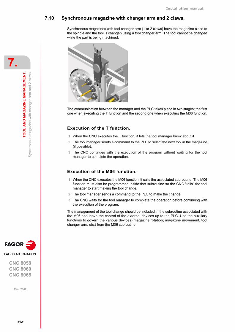
Installation manual.
CNC 8058CNC 8060CNC 8065
7.
TO
OL
AN
D M
AG
AZ
INE
MA
NA
GE
ME
NT
.
Syn
chro
nou
s m
agaz
ine
with
cha
nge
r ar
m a
nd 2
cla
ws.
ꞏ512ꞏ
REF: 2102
7.10 Synchronous magazine with changer arm and 2 claws.
Synchronous magazines with tool changer arm (1 or 2 claws) have the magazine close tothe spindle and the tool is changen using a tool changer arm. The tool cannot be changedwhile the part is being machined.
The communication between the manager and the PLC takes place in two stages; the firstone when executing the T function and the second one when executing the M06 function.
Execution of the T function.
1 When the CNC executes the T function, it lets the tool manager know about it.
2 The tool manager sends a command to the PLC to select the next tool in the magazine(if possible).
3 The CNC continues with the execution of the program without waiting for the toolmanager to complete the operation.
Execution of the M06 function.
1 When the CNC executes the M06 function, it calls the associated subroutine. The M06function must also be programmed inside that subroutine so the CNC "tells" the toolmanager to start making the tool change.
2 The tool manager sends a command to the PLC to make the change.
3 The CNC waits for the tool manager to complete the operation before continuing withthe execution of the program.
The management of the tool change should be included in the subroutine associated withthe M06 and leave the control of the external devices up to the PLC. Use the auxiliaryfunctions to govern the various devices (magazine rotation, magazine movement, toolchanger arm, etc.) from the M06 subroutine.
Installation manual.
CNC 8058CNC 8060CNC 8065
TO
OL
AN
D M
AG
AZ
INE
MA
NA
GE
ME
NT
.
7.
Syn
chro
nou
s m
agaz
ine
with
cha
nge
r ar
m a
nd 2
cla
ws.
ꞏ513ꞏ
REF: 2102
7.10.1 Valid operations and marks activated by the PLC with each one of them.
Valid operations of the tool manager for this magazine.
The possible operations in this type of magazine are:
Values of registers TAKEPOS and LEAVEPOS used by themanager.
The TAKEPOS and LEAVEPOS signals can assume the following values.
Here is a summary table of the TAKEPOS and LEAVEPOS values used by the manager ineach operation as well as the marks that must be activated by the PLC at the end of eachoperation. In the case of the marks shown between parenthesis, the manager can executethe operations in any order, but it must always execute both.
TMOPERATION Meaning.
0 Do nothing.
1 Take a tool from the magazine and insert it in the spindle.
2 Leave the spindle tool in the magazine.
3 Insert a ground tool in the spindle.
4 Leave the spindle tool on the ground.
5 Leave the spindle tool in the magazine and take a tool from the samemagazine.
6 Leave the spindle tool in the magazine and take a tool from ground.
7 Leave the spindle tool on the ground and take a tool from the magazine.
8 Leave the spindle tool on the ground and take a tool from ground.
9 Take a ground tool to the magazine going through the spindle.
10 Take a tool from the magazine and leave on the ground going through thespindle.
11 Orient the magazine.
12 Leave the spindle tool in the magazine and take a tool from the samemagazine (as TMOPERATION=5). It is an optimized operation only valid inthe following types of synchronous magazine.
• Non-random having a tool changer arm with two claws.• Random when having special tools.
13 Orienting two magazines.
14 Leave the spindle tool in the magazine and take a tool from anothermagazine.
Value Meaning
0 Do nothing.
# Magazine position.
-4 Ground tool.
TM => PLC PLC => TM
TMOPERATION TAKEPOS LEAVEPOS
1 # 0 MZTOCH1 + CH1TOSPDL
2 0 # SPDLTOCH2 + CH2TOMZ
3 0 0 GRTOSPDL
4 0 0 SPDLTOGR
5 # # (SPDLTOCH2 & MZTOCH1) + (CH1TOSPDL & CH2TOMZ)
6 -4 # SPDLTOCH2 + (CH2TOMZ & GRTOSPDL)
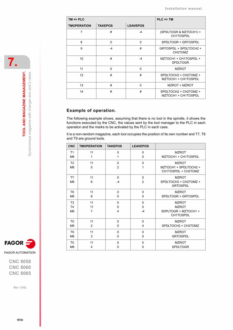
Installation manual.
CNC 8058CNC 8060CNC 8065
7.
TO
OL
AN
D M
AG
AZ
INE
MA
NA
GE
ME
NT
.
Syn
chro
nou
s m
agaz
ine
with
cha
nge
r ar
m a
nd 2
cla
ws.
ꞏ514ꞏ
REF: 2102
Example of operation.
The following example shows, assuming that there is no tool in the spindle, it shows thefunctions executed by the CNC, the values sent by the tool manager to the PLC in eachoperation and the marks to be activated by the PLC in each case.
It is a non-random magazine, each tool occupies the position of its own number and T7, T8and T9 are ground tools.
7 # -4 (SPDLTOGR & MZTOCH1) + CH1TOSPDL
8 0 0 SPDLTOGR + GRTOSPDL
9 -4 # GRTOSPDL + SPDLTOCH2 + CH2TOMZ
10 # -4 MZTOCH1 + CH1TOSPDL + SPDLTOGR
11 0 0 MZROT
12 # # SPDLTOCH2 + CH2TOMZ + MZTOCH1 + CH1TOSPDL
13 # 0 MZROT + MZROT
14 # # SPDLTOCH2 + CH2TOMZ + MZTOCH1 + CH1TOSPDL
CNC TMOPERATION TAKEPOS LEAVEPOS
T1M6
111
01
00
MZROTMZTOCH1 + CH1TOSPDL
T2M6
115
02
01
MZROTMZTOCH1 + SPDLTOCH2 + CH1TOSPDL + CH2TOMZ
T7M6
116
0-4
02
MZROTSPDLTOCH2 + CH2TOMZ +
GRTOSPDL
T8M6
118
00
00
MZROTSPDLTOGR + GRTOSPDL
T3T4M6
11117
004
00-4
MZROTMZROT
SDPLTOGR + MZTOCH1 + CH1TOSPDL
T0M6
112
00
04
MZROTSPDLTOCH2 + CH2TOMZ
T9M6
113
00
00
MZROTGRTOSPDL
T0M6
114
00
00
MZROTSPDLTOGR
TM => PLC PLC => TM
TMOPERATION TAKEPOS LEAVEPOS
Installation manual.
CNC 8058CNC 8060CNC 8065
TO
OL
AN
D M
AG
AZ
INE
MA
NA
GE
ME
NT
.
7.
Syn
chro
nou
s m
agaz
ine
with
cha
nge
r ar
m a
nd 2
cla
ws.
ꞏ515ꞏ
REF: 2102
7.10.2 Detailed description of the operations of the magazine.
Here is a sample of a detailed description of the valid operations for this magazine. For eachoperation, it indicates which of the TAKEPOS, LEAVEPOS, NEXTPOS and MZID signalsare involved and their meanings. It also shows the sequence to follow to complete theoperation.
The TAKEPOS, LEAVEPOS and NEXTPOS signals can assume the following values.
TMOPERATION = 1
Take a tool from the magazine and insert it in the spindle.
The sequence of this operation is the following.
1 Take the tool from the magazine with holder 1 and activate the mark MZTOCH1.
2 Insert the tool of holder 1 in the spindle and activate CH1TOSPDL.
TMOPERATION = 2
Leave the spindle tool in the magazine.
The sequence of this operation is the following.
1 Take the tool from the spindle with holder ꞏ2ꞏ and activate the mark SPDLTOCH2.
2 Leave the tool of holder ꞏ2ꞏ in the magazine and activate the mark CH2TOMZ.
TMOPERATION = 3
Insert a ground tool in the spindle.
The sequence of this operation is the following.
1 When the operation is completed, activate the mark: GRTOSPDL.
TMOPERATION = 4
Leave the spindle tool on the ground.
The sequence of this operation is the following.
1 When the operation is completed, activate the mark: SPDLTOGR.
TMOPERATION = 5
Leave the spindle tool in the magazine and take a tool from the same magazine.
The sequence of this operation is the following. The tool manager also admits the sequences1-2-4-3, 2-1-3-4, 2-1-4-3.
1 Take the tool from the spindle with holder ꞏ2ꞏ and activate the mark SPDLTOCH2.
2 Take the tool from the magazine with holder 1 and activate the mark MZTOCH1.
3 Leave the tool of holder ꞏ2ꞏ in the magazine and activate the mark CH2TOMZ.
4 Insert the tool of holder 1 in the spindle and activate CH1TOSPDL.
TMOPERATION = 6
Leave the spindle tool in the magazine and take a tool from ground.
Value Meaning
0 Do nothing.
# Magazine position.
-4 Ground tool.
TAKEPOS=# Magazine position to pick up the tool.
LEAVEPOS=# Magazine position to leave the tool.
TAKEPOS=# Magazine position to pick up the tool.
LEAVEPOS=# Magazine position to leave the tool.
TAKEPOS=-4 Ground tool.
LEAVEPOS=# Magazine position to leave the tool.

Installation manual.
CNC 8058CNC 8060CNC 8065
7.
TO
OL
AN
D M
AG
AZ
INE
MA
NA
GE
ME
NT
.
Syn
chro
nou
s m
agaz
ine
with
cha
nge
r ar
m a
nd 2
cla
ws.
ꞏ516ꞏ
REF: 2102
The sequence of this operation is the following. The tool manager admits the sequence 1-3-2.
1 Take the tool from the spindle with holder ꞏ2ꞏ and activate the mark SPDLTOCH2.
2 Leave the tool of holder ꞏ2ꞏ in the magazine and activate the mark CH2TOMZ.
3 Leave the ground tool in the spindle and activate the mark GRTOSPDL.
TMOPERATION = 7
Leave the spindle tool on the ground and take a tool from the magazine.
The sequence of this operation is the following. The tool manager admits the sequence 2-1-3.
1 Leave the tool of the spindle on the ground and activate the mark SPDLTOGR.
2 Take the tool from the magazine with holder 1 and activate the mark MZTOCH1.
3 Insert the tool of holder 1 in the spindle and activate CH1TOSPDL.
TMOPERATION = 8
Leave the spindle tool on the ground and take a tool from ground.
The sequence of this operation is the following.
1 Leave the tool of the spindle on the ground and activate the mark SPDLTOGR.
2 Leave the ground tool in the spindle and activate the mark GRTOSPDL.
TMOPERATION = 9
Take a ground tool to the magazine going through the spindle.
The sequence of this operation is the following.
1 Leave the ground tool in the spindle and activate the mark GRTOSPDL.
2 Take the tool from the spindle with holder ꞏ2ꞏ and activate the mark SPDLTOCH2.
3 Leave the tool of holder ꞏ2ꞏ in the magazine and activate the mark CH2TOMZ.
TMOPERATION = 10
Take a tool from the magazine and leave on the ground going through the spindle.
The sequence of this operation is the following.
1 Take the tool from the magazine with holder 1 and activate the mark MZTOCH1.
2 Insert the tool of holder 1 in the spindle and activate CH1TOSPDL.
3 Leave the tool of the spindle on the ground and activate the mark SPDLTOGR.
TMOPERATION = 11
Orient the magazine.
This operation is an optimization of the tool change that permits orienting the magazine whilemachining. Activate the MZROT mark to indicate that the operation has been completed,whether it has been oriented or not.
TAKEPOS=# Magazine position to pick up the tool.
LEAVEPOS=-4 Ground tool.
TAKEPOS=-4 Ground tool.
LEAVEPOS=# Magazine position to leave the tool.
TAKEPOS=# Magazine position to pick up the tool.
LEAVEPOS=-4 Ground tool.
Installation manual.
CNC 8058CNC 8060CNC 8065
TO
OL
AN
D M
AG
AZ
INE
MA
NA
GE
ME
NT
.
7.
Syn
chro
nou
s m
agaz
ine
with
cha
nge
r ar
m a
nd 2
cla
ws.
ꞏ517ꞏ
REF: 2102
TMOPERATION = 12
Leave the spindle tool in the magazine and take a tool from the same magazine (asTMOPERATION=5). It is an optimized operation only valid in the following types ofsynchronous magazine.
• Non-random having a tool changer arm with two claws.
• Random when having special tools.
TMOPERATION = 13
Orienting two magazines.
This operation is an optimization of the tool change that permits orienting two magazineswhile machining. Activate the MZROT mark in both magazines to indicate that the operationhas been completed, whether the magazines have been oriented or not.
TMOPERATION = 14
Leave the spindle tool in the magazine and take a tool from another magazine.
The sequence of this operation is the following.
1 Take the tool from the spindle with holder ꞏ2ꞏ and activate the mark SPDLTOCH2.
2 Leave the tool of holder ꞏ2ꞏ in the magazine and activate the mark CH2TOMZ.
3 Take the tool from the other magazine with holder ꞏ1ꞏ and activate the mark MZTOCH1.
4 Insert the tool of holder 1 in the spindle and activate CH1TOSPDL.
TAKEPOS=# Magazine position to pick up the tool.
LEAVEPOS=# Magazine position to leave the tool.
NEXTPOS=# Magazine position to leave the tool.
TAKEPOS=# Magazine position to pick up the tool.
MZID The lower portion of this register indicates the destination magazinefor the tool and the higher portion the source magazine for the tool.
TAKEPOS=# Magazine position to pick up the tool.
LEAVEPOS=# Magazine position to leave the tool.
MZID The lower portion of this register indicates the destination magazinefor the tool and the higher portion the source magazine for the tool.

Installation manual.
CNC 8058CNC 8060CNC 8065
7.
TO
OL
AN
D M
AG
AZ
INE
MA
NA
GE
ME
NT
.
Syn
chro
nou
s m
agaz
ine
with
cha
nge
r ar
m a
nd 2
cla
ws.
ꞏ518ꞏ
REF: 2102
7.10.3 Communication between the PLC and the M06 subroutine.
The communication between the PLC and the M06 subroutine takes place using a seriesof generic marks and registers. The program of the M06 subroutine offered as an exampleuses the following marks and registers.
Communication between the PLC and the M06 subroutine
Marks activated by the M06 subroutine so the PLC activates the relevant mark of the toolmanager.
M functions at the PLC
M functions that imply movements controlled by the PLC:
Set all the M functions with "before-before" synchronization to the program continues afterthe M function is completed.
Mark. Meaning.
M1101 MZTOCH1The tool has been taken from the magazine to holder 1.
M1102 CH1TOSPDLThe tool has been taken from holder 1 to the spindle.
M1104 SPDLTOCH2The tool has been taken from the spindle to holder 2.
M1106 CH2TOMZThe tool has been taken from holder 2 to the magazine.
M1107 SPDLTOGRThe tool has been taken from the spindle to ground.
M1108 GRTOSPDLThe tool has been taken from ground to the spindle.
Function. Meaning.
M101 Select in the magazine the position indicated by TAKEPOS and take the tool withholder 1.
M102 Take the tool of holder 1 to the spindle.
M104 Take the spindle tool with holder 2.
M106 Select in the magazine the position indicated by LEAVEPOS and leave the tool ofholder 2.
Installation manual.
CNC 8058CNC 8060CNC 8065
TO
OL
AN
D M
AG
AZ
INE
MA
NA
GE
ME
NT
.
7.
Syn
chro
nou
s m
agaz
ine
with
cha
nge
r ar
m a
nd 2
cla
ws.
ꞏ519ꞏ
REF: 2102
7.10.4 Program of the M06 subroutine.
%L SUB_MZ_TO_CH1 ; Take the tool from the magazine with holder 1.
M101 ; Auxiliary function to execute an action.V.PLC.M[1101]=1 ; MZTOCH1 mark to the tool manager.#WAIT FOR [V.PLC.M[1101]==0]
#RET
%L SUB_CH1_TO_SPD ; Take the tool of holder 1 to the spindle.
M102 ; Auxiliary function to execute an action.V.PLC.M[1102]=1 ; CH1TOSPDL mark to the tool manager.#WAIT FOR [V.PLC.M[1102]==0]
#RET
%L SUB_SPD_TO_CH2 ; Take the spindle tool with holder 2.
M104 ; Auxiliary function to execute an action.V.PLC.M[1104]=1 ; SPDLTOCH2 mark to the tool manager.#WAIT FOR [V.PLC.M[1104]==0]
#RET
%L SUB_CH2_TO_MZ ; Take the tool of holder 2 to the magazine.
M106 ; Auxiliary function to execute an action.V.PLC.M[1106]=1 ; CH2TOMZ mark to the tool manager.#WAIT FOR [V.PLC.M[1106]==0]
#RET
%L SUB_SPD_TO_GR ; Remove the tool from the spindle (take it to ground).
#MSG ["Extract tool T%D and press START", V.TM.TOOL]; Message for the operator to extract the tool.
M0 ; Wait for the operation to be completed.#MSG [""] ; Remove message.V.PLC.M[1107]=1 ; SPDLTOGR mark to the tool manager.#WAIT FOR [V.PLC.M[1107]==0]
#RET
%L SUB_GR_TO_SPD ; Insert the ground tool in the spindle.
#MSG ["Insert tool T%D and press START", V.TM.NXTOOL]; Message for the operator to insert the tool.
M0 ; Wait for the operation to be completed.#MSG [""] ; Remove message.V.PLC.M[1108]=1 ; GRTOSPDL mark to the tool manager.#WAIT FOR [V.PLC.M[1108]==0]
#RET
%L SUB_SPD_GMCHG ; Move the spindle to the manual tool change point.
G1 Z_ F_ ; Move the spindle.#RET
%L SUB_SPD_AUTCHG ; Move the spindle to the automatic tool change point
G1 Z_ F_ ; Move the spindle.#RET
%SUB_M6.nc
#ESBLK ; Begin of single block activation#DSTOP ; STOP key disableM6 ; Order the tool manager to start the tool change.
$IF [[[V.G.FULLSTATUS & 255]<9] | [[V.G.FULLSTATUS & 255]>13]] $IF [[V.G.CNCAUTSTATUS & 4096] | [V.G.CNCAUTSTATUS & 8192]]
V.S.EXECUTION = 0 ; Simulated Theorical or G$ELSE
V.S.EXECUTION = 1 ; Execution$ENDIF
$ELSEV.S.EXECUTION = 0 ; Simulation
$ENDIF
Installation manual.
CNC 8058CNC 8060CNC 8065
7.
TO
OL
AN
D M
AG
AZ
INE
MA
NA
GE
ME
NT
.
Syn
chro
nou
s m
agaz
ine
with
cha
nge
r ar
m a
nd 2
cla
ws.
ꞏ520ꞏ
REF: 2102
$IF [V.S.EXECUTION == 1] ; CNC in execution
$SWITCH V.PLC.TMOPERATION ; It analyzes the type of operation.
$CASE 1 ; Take a tool from the magazine and insert it in the spindle.
LL SUB_SPD_AUTCHG ; Move the spindle to the automatic tool change pointLL SUB_MZ_TO_CH1 ; Take the tool from the magazine with holder 1.LL SUB_CH1_TO_SPD ; Take the tool of holder 1 to the spindle.
$BREAK
$CASE 2 ; Leave the spindle tool in the magazine.LL SUB_SPD_AUTCHG ; Move the spindle to the automatic tool change pointLL SUB_SPD_TO_CH2 ; Take the spindle tool with holder 2.LL SUB_CH2_TO_MZ ; Leave the tool of holder 2 in the magazine.
$BREAK
$CASE 3 ; Insert the ground tool in the spindle.LL SUB_SPD_GMCHG ; Move the spindle to the manual tool change point.LL SUB_GR_TO_SPD ; Insert the ground tool in the spindle.
$BREAK
$CASE 4 ; Leave the spindle tool on the ground.LL SUB_SPD_GMCHG ; Move the spindle to the manual tool change point.LL SUB_SPD_TO_GR ; Remove the tool from the spindle.
$BREAK
$CASE 5 ; Leave the spindle tool in the magazine and take another one from the magazine.
LL SUB_SPD_AUTCHG ; Move the spindle to the automatic tool change pointLL SUB_SPD_TO_CH2 ; Take the spindle tool with holder 2.LL SUB_MZ_TO_CH1 ; Take the tool from the magazine with holder 1.LL SUB_CH2_TO_MZ ; Leave the tool of holder 2 in the magazine.LL SUB_CH1_TO_SPD ; Take the tool of holder 1 to the spindle.
$BREAK
$CASE 6 ; Leave the spindle tool in the magazine and take another one from ground.
LL SUB_SPD_AUTCHG ; Move the spindle to the automatic tool change pointLL SUB_SPD_TO_CH2 ; Take the spindle tool with holder 2.LL SUB_CH2_TO_MZ ; Leave the tool of holder 2 in the magazine.LL SUB_SPD_GMCHG ; Move the spindle to the manual tool change point.LL SUB_GR_TO_SPD ; Insert the ground tool in the spindle.
$BREAK
$CASE 7 ; Leave the spindle tool on the ground and take another one from the magazine.
LL SUB_SPD_GMCHG ; Move the spindle to the manual tool change point.LL SUB_SPD_TO_GR ; Remove the tool from the spindle.LL SUB_SPD_AUTCHG ; Move the spindle to the automatic tool change pointLL SUB_MZ_TO_CH1 ; Take the tool from the magazine with holder 1.LL SUB_CH1_TO_SPD ; Take the tool of holder 1 to the spindle.
$BREAK
$CASE 8 ; Leave the spindle tool on the ground and take another one from ground.
LL SUB_SPD_GMCHG ; Move the spindle to the manual tool change point.LL SUB_SPD_TO_GR ; Remove the tool from the spindle.LL SUB_GR_TO_SPD ; Insert the ground tool in the spindle.
$BREAK
$CASE 9 ; Take a ground tool to the magazine going through the spindle.
LL SUB_SPD_GMCHG ; Move the spindle to the manual tool change point.LL SUB_GR_TO_SPD ; Insert the ground tool in the spindle.LL SUB_SPD_AUTCHG ; Move the spindle to the automatic tool change pointLL SUB_SPD_TO_CH2 ; Take the spindle tool with holder 2.LL SUB_CH2_TO_MZ ; Leave the tool of holder 2 in the magazine.
$BREAK

Installation manual.
CNC 8058CNC 8060CNC 8065
TO
OL
AN
D M
AG
AZ
INE
MA
NA
GE
ME
NT
.
7.
Syn
chro
nou
s m
agaz
ine
with
cha
nge
r ar
m a
nd 2
cla
ws.
ꞏ521ꞏ
REF: 2102
$CASE 10 ; Take a tool from the magazine and leave on the ground going through the spindle.
LL SUB_SPD_AUTCHG ; Move the spindle to the automatic tool change pointLL SUB_MZ_TO_CH1 ; Take the tool from the magazine with holder 1.LL SUB_CH1_TO_SPD ; Take the tool of holder 1 to the spindle.LL SUB_SPD_GMCHG ; Move the spindle to the manual tool change point.LL SUB_SPD_TO_GR ; Remove the tool from the spindle.
$BREAK
$ENDSWITCH ; End of analysis of type of operation.
$WHILE V.TM.MZWAIT == 1$ENDWHILE ; Wait for the tool manager.
$ENDIF#DSBLK ; End of single block activation.#ESTOP ; STOP key enable
#RET

Installation manual.
CNC 8058CNC 8060CNC 8065
7.
TO
OL
AN
D M
AG
AZ
INE
MA
NA
GE
ME
NT
.
Syn
chro
nou
s m
agaz
ine
with
cha
nge
r ar
m a
nd 2
cla
ws.
ꞏ522ꞏ
REF: 2102
7.10.5 Basic PLC programming.
When executing the -T- function
When executing a T function, the tool manager sends the code TMOPERATION=11 to thePLC. In general, it is an optimization of the change that permits orienting the magazine whilemachining.
In this case, the magazine is not oriented and the MZROT mark is activated to indicate thatthe operation has been completed.
DFU TMOPSTROBE AND CPS TMOPERATION EQ 11 = SET MZROT
Activate the MZROT mark to "tell" the tool manager that the operation has finished.
When executing the M06 function
Every time the M06 subroutine ends an action, it lets the PLC know so it activates the relevantmark of the tool manager.
DFU M1101 = SET MZTOCH1DFD MZTOCH1 = RES M1101
The tool has been taken from the magazine to holder 1.
DFU M1102 = SET CH1TOSPDLDFD CH1TOSPDL = RES M1102
The tool has been taken from holder 1 to the spindle.
DFU M1104 = SET SPDLTOCH2DFD SPDLTOCH2 = RES M1104
The tool has been taken from the spindle to holder 2.
DFU M1106 = SET CH2TOMZDFD CH2TOMZ = RES M1106
The tool has been taken from holder 2 to the magazine.
DFU M1107 = SET SPDLTOGRDFD SPDLTOGR = RES M1107
The tool has been taken from the spindle to ground.
DFU M1108 = SET GRTOSPDLDFD GRTOSPDL = RES M1108
The tool has been taken from ground to the spindle.
The M06 subroutine uses the following M functions to "tell" the PLC which movements it mustcarry out.
Programming it depends on the type of machine. The auxiliary function will conclude afterexecuting the requested movement.
Certain operations require using the information transferred by the tool manager in thefollowing registers:
M101 Select in the magazine the position indicated by TAKEPOS and take the toolwith holder 1.
M102 Take the tool of holder 1 to the spindle.
M104 Take the spindle tool with holder 2.
M106 Select in the magazine the position indicated by LEAVEPOS and leave thetool of holder 2.
LEAVEPOS This register indicates the magazine position to leave the tool.
TAKEPOS This register indicates the magazine position of the tool to be taken.

Installation manual.
CNC 8058CNC 8060CNC 8065
TO
OL
AN
D M
AG
AZ
INE
MA
NA
GE
ME
NT
.
7.
Syn
chro
nou
s m
agaz
ine
with
cha
nge
r ar
m a
nd 2
cla
ws.
ꞏ523ꞏ
REF: 2102
Manager emergency signal.
Treatment of the tool manager emergency signal.
DFU B11KEYBD1 AND NOT TMINEM = SET SETTMEMDFU TMINEM = RES SETTMEM
Pressing the USER12 key activates the emergency.
TMINEM = B11KEYLED1
The lamp of the USER12 key turns on when there is an emergency.
TMINEM AND DFU B12KEYBD1 = SET RESTMEM
Pressing the USER13 key removes the emergency.
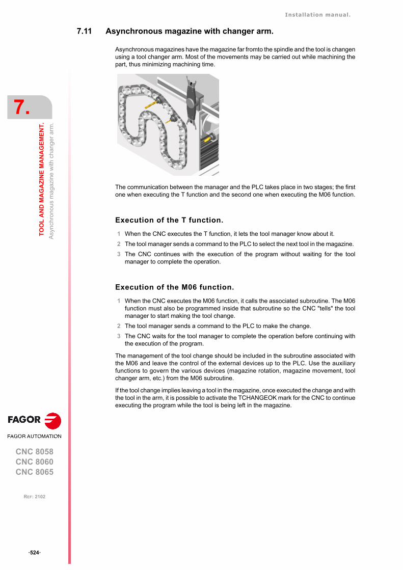
Installation manual.
CNC 8058CNC 8060CNC 8065
7.
TO
OL
AN
D M
AG
AZ
INE
MA
NA
GE
ME
NT
.
Asy
nch
rono
us m
agaz
ine
with
ch
ange
r ar
m.
ꞏ524ꞏ
REF: 2102
7.11 Asynchronous magazine with changer arm.
Asynchronous magazines have the magazine far fromto the spindle and the tool is changenusing a tool changer arm. Most of the movements may be carried out while machining thepart, thus minimizing machining time.
The communication between the manager and the PLC takes place in two stages; the firstone when executing the T function and the second one when executing the M06 function.
Execution of the T function.
1 When the CNC executes the T function, it lets the tool manager know about it.
2 The tool manager sends a command to the PLC to select the next tool in the magazine.
3 The CNC continues with the execution of the program without waiting for the toolmanager to complete the operation.
Execution of the M06 function.
1 When the CNC executes the M06 function, it calls the associated subroutine. The M06function must also be programmed inside that subroutine so the CNC "tells" the toolmanager to start making the tool change.
2 The tool manager sends a command to the PLC to make the change.
3 The CNC waits for the tool manager to complete the operation before continuing withthe execution of the program.
The management of the tool change should be included in the subroutine associated withthe M06 and leave the control of the external devices up to the PLC. Use the auxiliaryfunctions to govern the various devices (magazine rotation, magazine movement, toolchanger arm, etc.) from the M06 subroutine.
If the tool change implies leaving a tool in the magazine, once executed the change and withthe tool in the arm, it is possible to activate the TCHANGEOK mark for the CNC to continueexecuting the program while the tool is being left in the magazine.
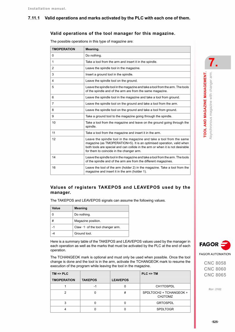
Installation manual.
CNC 8058CNC 8060CNC 8065
TO
OL
AN
D M
AG
AZ
INE
MA
NA
GE
ME
NT
.
7.
Asy
nch
rono
us m
agaz
ine
with
ch
ange
r ar
m.
ꞏ525ꞏ
REF: 2102
7.11.1 Valid operations and marks activated by the PLC with each one of them.
Valid operations of the tool manager for this magazine.
The possible operations in this type of magazine are:
Values of registers TAKEPOS and LEAVEPOS used by themanager.
The TAKEPOS and LEAVEPOS signals can assume the following values.
Here is a summary table of the TAKEPOS and LEAVEPOS values used by the manager ineach operation as well as the marks that must be activated by the PLC at the end of eachoperation.
The TCHANGEOK mark is optional and must only be used when possible. Once the toolchange is done and the tool is in the arm, activate the TCHANGEOK mark to resume theexecution of the program while leaving the tool in the magazine.
TMOPERATION Meaning.
0 Do nothing.
1 Take a tool from the arm and insert it in the spindle.
2 Leave the spindle tool in the magazine.
3 Insert a ground tool in the spindle.
4 Leave the spindle tool on the ground.
5 Leave the spindle tool in the magazine and take a tool from the arm. The toolsof the spindle and of the arm are from the same magazine.
6 Leave the spindle tool in the magazine and take a tool from ground.
7 Leave the spindle tool on the ground and take a tool from the arm.
8 Leave the spindle tool on the ground and take a tool from ground.
9 Take a ground tool to the magazine going through the spindle.
10 Take a tool from the magazine and leave on the ground going through thespindle.
11 Take a tool from the magazine and insert it in the arm.
12 Leave the spindle tool in the magazine and take a tool from the samemagazine (as TMOPERATION=5). It is an optimised operation, valid whenboth tools are special and can collide in the arm or when it is not desirablefor them to coincide in the changer arm.
14 Leave the spindle tool in the magazine and take a tool from the arm. The toolsof the spindle and of the arm are from the different magazines.
16 Leave the tool of the arm (holder 2) in the magazine. Take a tool from themagazine and insert it in the arm (holder 1).
Value Meaning
0 Do nothing.
# Magazine position.
-1 Claw ꞏ1ꞏ of the tool changer arm.
-4 Ground tool.
TM => PLC PLC => TM
TMOPERATION TAKEPOS LEAVEPOS
1 -1 0 CH1TOSPDL
2 0 # SPDLTOCH2 + TCHANGEOK + CH2TOMZ
3 0 0 GRTOSPDL
4 0 0 SPDLTOGR
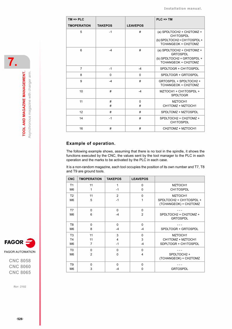
Installation manual.
CNC 8058CNC 8060CNC 8065
7.
TO
OL
AN
D M
AG
AZ
INE
MA
NA
GE
ME
NT
.
Asy
nch
rono
us m
agaz
ine
with
ch
ange
r ar
m.
ꞏ526ꞏ
REF: 2102
Example of operation.
The following example shows, assuming that there is no tool in the spindle, it shows thefunctions executed by the CNC, the values sent by the tool manager to the PLC in eachoperation and the marks to be activated by the PLC in each case.
It is a non-random magazine, each tool occupies the position of its own number and T7, T8and T9 are ground tools.
5 -1 # (a) SPDLTOCH2 + CH2TOMZ + CH1TOSPDL
(b) SPDLTOCH2 + CH1TOSPDL + TCHANGEOK + CH2TOMZ
6 -4 # (a) SPDLTOCH2 + CH2TOMZ + GRTOSPDL
(b) SPDLTOCH2 + GRTOSPDL + TCHANGEOK + CH2TOMZ
7 -1 -4 SPDLTOGR + CH1TOSPDL
8 0 0 SPDLTOGR + GRTOSPDL
9 -4 # GRTOSPDL + SPDLTOCH2 + TCHANGEOK + CH2TOMZ
10 # -4 MZTOCH1 + CH1TOSPDL + SPDLTOGR
11 ##
0#
MZTOCH1CH1TOMZ + MZTOCH1
12 # # SPDLTOMZ + MZTOSPDL
14 -1 # SPDLTOCH2 + CH2TOMZ + CH1TOSPDL
16 # # CH2TOMZ + MZTOCH1
CNC TMOPERATION TAKEPOS LEAVEPOS
T1M6
111
1-1
00
MZTOCH1CH1TOSPDL
T2M6
115
2-1
01
MZTOCH1SPDLTOCH2 + CH1TOSPDL + (TCHANGEOK) + CH2TOMZ
T7M6
06
0-4
02
- - -SPDLTOCH2 + CH2TOMZ +
GRTOSPDL
T8M6
08
0-4
0-4
- - -SPDLTOGR + GRTOSPDL
T3T4M6
11117
34-1
03-4
MZTOCH1CH1TOMZ + MZTOCH1
SDPLTOGR + CH1TOSPDL
T0M6
02
00
04
- - -SPDLTOCH2 +
(TCHANGEOK) + CH2TOMZ
T9M6
03
0-4
00
- - -GRTOSPDL
TM => PLC PLC => TM
TMOPERATION TAKEPOS LEAVEPOS
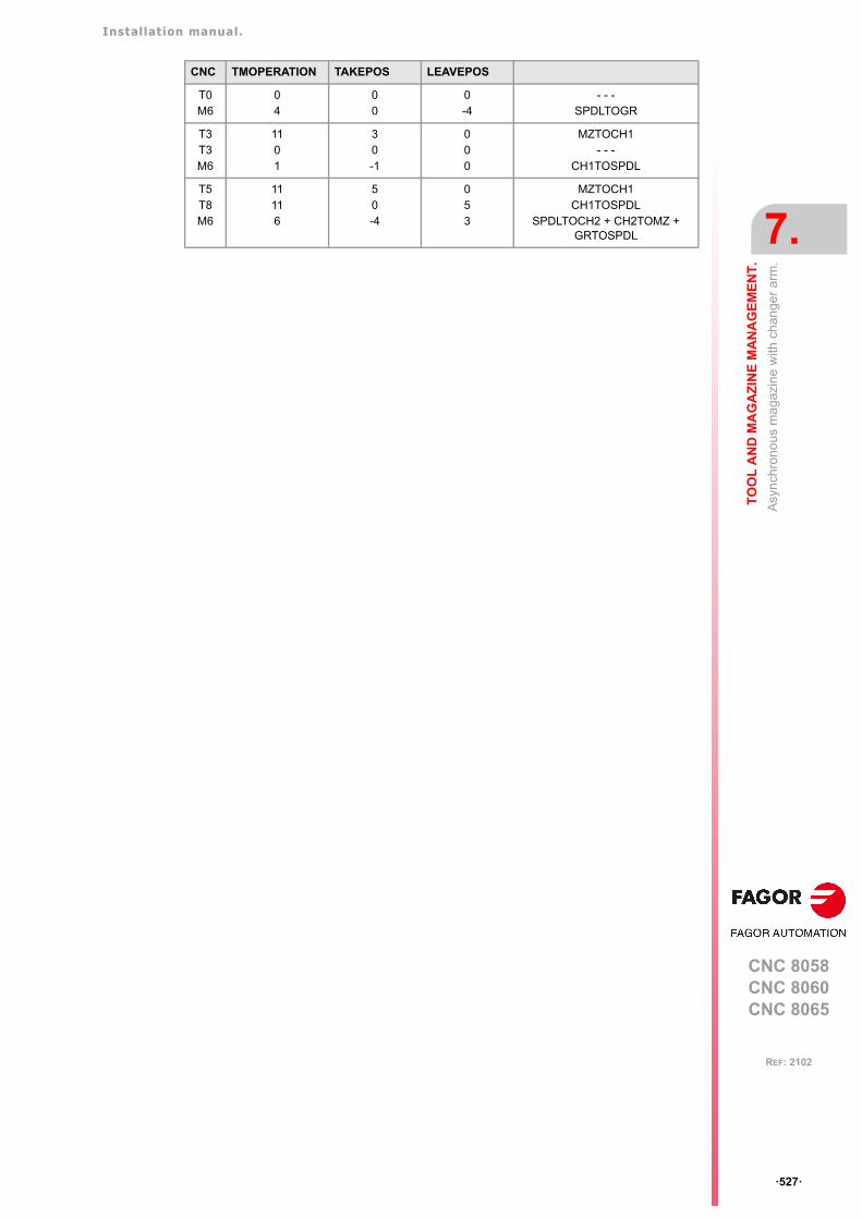
Installation manual.
CNC 8058CNC 8060CNC 8065
TO
OL
AN
D M
AG
AZ
INE
MA
NA
GE
ME
NT
.
7.
Asy
nch
rono
us m
agaz
ine
with
ch
ange
r ar
m.
ꞏ527ꞏ
REF: 2102
T0M6
04
00
0-4
- - -SPDLTOGR
T3T3M6
1101
30-1
000
MZTOCH1- - -
CH1TOSPDL
T5T8M6
11116
50-4
053
MZTOCH1CH1TOSPDL
SPDLTOCH2 + CH2TOMZ +GRTOSPDL
CNC TMOPERATION TAKEPOS LEAVEPOS

Installation manual.
CNC 8058CNC 8060CNC 8065
7.
TO
OL
AN
D M
AG
AZ
INE
MA
NA
GE
ME
NT
.
Asy
nch
rono
us m
agaz
ine
with
ch
ange
r ar
m.
ꞏ528ꞏ
REF: 2102
7.11.2 Detailed description of the operations of the magazine.
Here is a sample of a detailed description of the valid operations for this magazine. For eachoperation, it indicates which of the TAKEPOS, LEAVEPOS, NEXTPOS and MZID signalsare involved and their meanings. It also shows the sequence to follow to complete theoperation.
The TAKEPOS, LEAVEPOS and NEXTPOS signals can assume the following values.
TMOPERATION = 1
Take a tool from the arm and insert it in the spindle.
The sequence of this operation is the following. Previously, while machining (when executingthe T) the manager sends the code: TMOPERATION=11 to take the tool from the magazinewith claw 1.
1 Insert the tool of holder 1 in the spindle and activate CH1TOSPDL.
TMOPERATION = 2
Leave the spindle tool in the magazine.
The sequence of this operation is the following.
1 Take the tool from the spindle with holder ꞏ2ꞏ and activate the mark SPDLTOCH2.
2 Start sending the changer arm to the magazine to leave the tool in holder 2.
3 When the arm leaves the collision zone, activate TCHANGEOK, if so desired, to continueexecuting the program.
4 Leave the tool of holder ꞏ2ꞏ in the magazine and activate the mark CH2TOMZ.
TMOPERATION = 3
Insert a ground tool in the spindle.
The sequence of this operation is the following.
1 When the operation is completed, activate the mark: GRTOSPDL.
TMOPERATION = 4
Leave the spindle tool on the ground.
The sequence of this operation is the following.
1 When the operation is completed, activate the mark: SPDLTOGR.
TMOPERATION = 5
Leave the spindle tool in the magazine and take a tool from the arm. The tools of the spindleand of the arm are from the same magazine.
In this operation, the tool manager admits 2 sequences. Previously, while machining (whenexecuting the T) the manager sends the code: TMOPERATION=11 to take the tool from themagazine with claw 1.
Value Meaning
0 Do nothing.
# Magazine position.
-1 Claw ꞏ1ꞏ of the tool changer arm.
-4 Ground tool.
TAKEPOS=-1 Tool in the changer arm.
LEAVEPOS=# Magazine position to leave the tool.
TAKEPOS=-1 Tool in the changer arm.
LEAVEPOS=# Magazine position to leave the tool.
Installation manual.
CNC 8058CNC 8060CNC 8065
TO
OL
AN
D M
AG
AZ
INE
MA
NA
GE
ME
NT
.
7.
Asy
nch
rono
us m
agaz
ine
with
ch
ange
r ar
m.
ꞏ529ꞏ
REF: 2102
First sequence:
1 Take the tool from the spindle with holder ꞏ2ꞏ and activate the mark SPDLTOCH2.
2 Leave the tool of holder ꞏ2ꞏ in the magazine and activate the mark CH2TOMZ.
3 Insert the tool of holder 1 in the spindle and activate CH1TOSPDL.
Second sequence:
1 Take the tool from the spindle with holder ꞏ2ꞏ and activate the mark SPDLTOCH2.
2 Insert the tool of holder 1 in the spindle and activate CH1TOSPDL.
3 Start sending the changer arm to the magazine to leave the tool in holder 2.
4 When the arm leaves the collision zone, activate TCHANGEOK, if so desired, to continueexecuting the program.
5 Leave the tool of holder ꞏ2ꞏ in the magazine and activate the mark CH2TOMZ.
TMOPERATION = 6
Leave the spindle tool in the magazine and take a tool from ground.
In this operation, the tool manager admits 2 sequences.
First sequence:
1 Take the tool from the spindle with holder ꞏ2ꞏ and activate the mark SPDLTOCH2.
2 Leave the tool of holder ꞏ2ꞏ in the magazine and activate the mark CH2TOMZ.
3 Leave the ground tool in the spindle and activate the mark GRTOSPDL.
Second sequence:
1 Take the tool from the spindle with holder ꞏ2ꞏ and activate the mark SPDLTOCH2.
2 Leave the ground tool in the spindle and activate the mark GRTOSPDL.
3 Start sending the changer arm to the magazine to leave the tool in holder 2.
4 When the arm leaves the collision zone, activate TCHANGEOK, if so desired, to continueexecuting the program.
5 Leave the tool of holder ꞏ2ꞏ in the magazine and activate the mark CH2TOMZ.
TMOPERATION = 7
Leave the spindle tool on the ground and take a tool from the arm.
The sequence of this operation is the following. Previously, while machining (when executingthe T) the manager sends the code: TMOPERATION=11 to take the tool from the magazinewith claw 1.
1 Leave the tool of the spindle on the ground and activate the mark SPDLTOGR.
2 Insert the tool of holder 1 in the spindle and activate CH1TOSPDL.
TMOPERATION = 8
Leave the spindle tool on the ground and take a tool from ground.
The sequence of this operation is the following.
1 Leave the tool of the spindle on the ground and activate the mark SPDLTOGR.
2 Leave the ground tool in the spindle and activate the mark GRTOSPDL.
TAKEPOS=-4 Ground tool.
LEAVEPOS=# Magazine position to leave the tool.
TAKEPOS=-1 Tool in the changer arm.
LEAVEPOS=-4 Ground tool.
Installation manual.
CNC 8058CNC 8060CNC 8065
7.
TO
OL
AN
D M
AG
AZ
INE
MA
NA
GE
ME
NT
.
Asy
nch
rono
us m
agaz
ine
with
ch
ange
r ar
m.
ꞏ530ꞏ
REF: 2102
TMOPERATION = 9
Take a ground tool to the magazine going through the spindle.
The sequence of this operation is the following.
1 Leave the ground tool in the spindle and activate the mark GRTOSPDL.
2 Take the tool from the spindle with holder ꞏ2ꞏ and activate the mark SPDLTOCH2.
3 Start sending the changer arm to the magazine to leave the tool in holder 2.
4 When the arm leaves the collision zone, activate TCHANGEOK, if so desired, to continueexecuting the program.
5 Leave the tool of holder ꞏ2ꞏ in the magazine and activate the mark CH2TOMZ.
TMOPERATION = 10
Take a tool from the magazine and leave on the ground going through the spindle.
The sequence of this operation is the following.
1 Insert the tool of holder 1 in the spindle and activate CH1TOSPDL.
2 Leave the tool of the spindle on the ground and activate the mark SPDLTOGR.
TMOPERATION = 11
Take a tool from the magazine and insert it in the arm.
This operation is an optimization of the tool change that permits placing a tool in claw ꞏ1ꞏof the tool changer arm while machining. This operation may be used in the following cases.
First case. When executing a T function while machining.
1 Take the tool from the magazine with holder 1 and activate the mark MZTOCH1.
Second case. When requesting a new tool and there is another one in holder 1 of the arm.
1 Leave the tool of holder 1 in the magazine and activate the mark CH1TOMZ.
2 Take the tool from the magazine with holder 1 and activate the mark MZTOCH1.
TMOPERATION = 12
Leave the spindle tool in the magazine and take a tool from the same magazine (asTMOPERATION=5). It is an optimised operation, valid when both tools are special and cancollide in the arm or when it is not desirable for them to coincide in the changer arm.
TMOPERATION = 14
Leave the spindle tool in the magazine and take a tool from the arm. The tools of the spindleand of the arm are from the different magazines.
The sequence of this operation is the following. In this operation, the tool manager admits2 sequences. Previously, while machining (when executing the T) the manager sends thecode: TMOPERATION=11 to take the tool from the magazine with claw 1.
1 Take the tool from the spindle with holder 2 and activate the mark SPDLTOCH2.
TAKEPOS=-4 Ground tool.
LEAVEPOS=# Magazine position to leave the tool.
TAKEPOS=# Magazine position to pick up the tool.
LEAVEPOS=-4 Ground tool.
TAKEPOS=# Position occupied by the tool.
TAKEPOS=# Position occupied by the tool.
LEAVEPOS=# Position to leave the tool.
TAKEPOS=# Magazine position to pick up the tool.
LEAVEPOS=# Magazine position to leave the tool.
TAKEPOS=-1 Tool in the changer arm.
LEAVEPOS=# Magazine position to leave the tool.
MZID The lower portion of this register indicates the destination magazinefor the tool and the higher portion the source magazine for the tool.
Installation manual.
CNC 8058CNC 8060CNC 8065
TO
OL
AN
D M
AG
AZ
INE
MA
NA
GE
ME
NT
.
7.
Asy
nch
rono
us m
agaz
ine
with
ch
ange
r ar
m.
ꞏ531ꞏ
REF: 2102
2 Leave the tool of holder 2 in the magazine and activate the mark CH2TOMZ.
3 Insert the tool of holder 1 in the spindle and activate CH1TOSPDL.
TMOPERATION = 16
Leave the tool of the arm (holder ꞏ2ꞏ) in the magazine. Take a tool from the magazine andinsert it in the arm (holder ꞏ1ꞏ). This operation is an optimization of the tool change that permitsplacing the tool of claw ꞏ2ꞏ of the tool changer arm in the magazine.
The sequence of this operation is the following.
1 Leave the tool of holder ꞏ2ꞏ in the magazine and activate the markCH2TOMZ.
2 Take the tool from the magazine with holder 1 and activate the mark MZTOCH1.
TAKEPOS=# Position occupied by the tool.
LEAVEPOS=# Position to leave the tool.
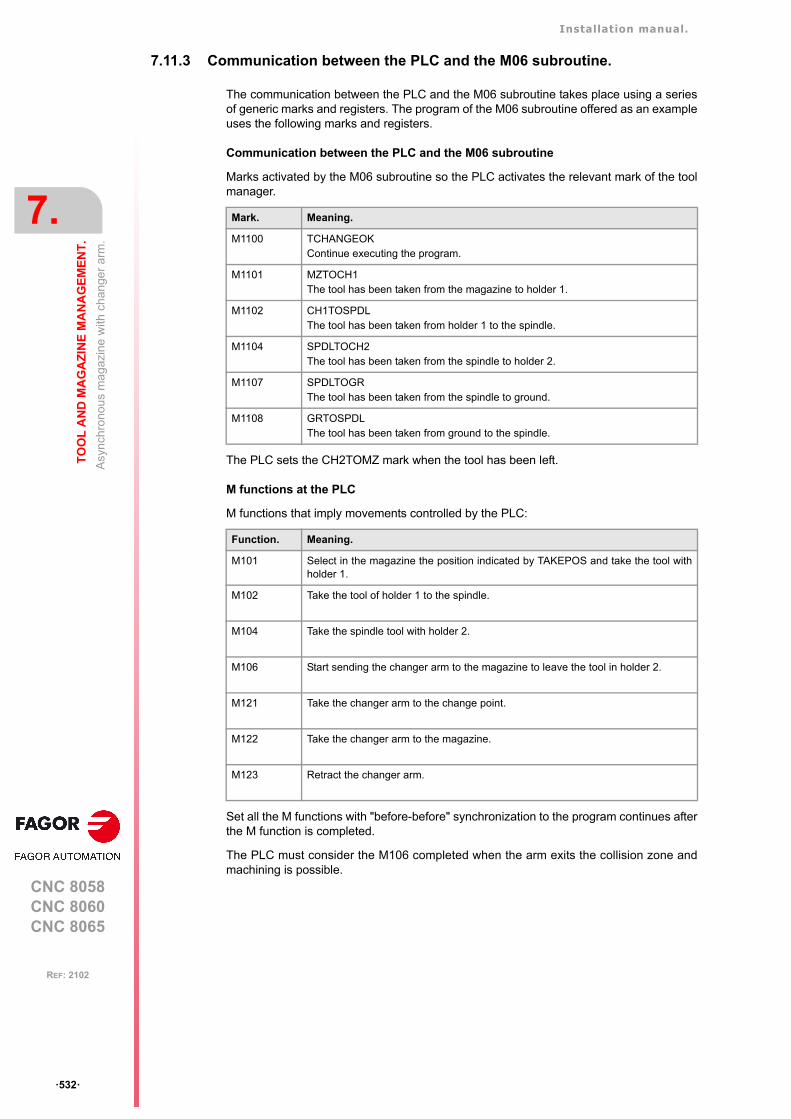
Installation manual.
CNC 8058CNC 8060CNC 8065
7.
TO
OL
AN
D M
AG
AZ
INE
MA
NA
GE
ME
NT
.
Asy
nch
rono
us m
agaz
ine
with
ch
ange
r ar
m.
ꞏ532ꞏ
REF: 2102
7.11.3 Communication between the PLC and the M06 subroutine.
The communication between the PLC and the M06 subroutine takes place using a seriesof generic marks and registers. The program of the M06 subroutine offered as an exampleuses the following marks and registers.
Communication between the PLC and the M06 subroutine
Marks activated by the M06 subroutine so the PLC activates the relevant mark of the toolmanager.
The PLC sets the CH2TOMZ mark when the tool has been left.
M functions at the PLC
M functions that imply movements controlled by the PLC:
Set all the M functions with "before-before" synchronization to the program continues afterthe M function is completed.
The PLC must consider the M106 completed when the arm exits the collision zone andmachining is possible.
Mark. Meaning.
M1100 TCHANGEOKContinue executing the program.
M1101 MZTOCH1The tool has been taken from the magazine to holder 1.
M1102 CH1TOSPDLThe tool has been taken from holder 1 to the spindle.
M1104 SPDLTOCH2The tool has been taken from the spindle to holder 2.
M1107 SPDLTOGRThe tool has been taken from the spindle to ground.
M1108 GRTOSPDLThe tool has been taken from ground to the spindle.
Function. Meaning.
M101 Select in the magazine the position indicated by TAKEPOS and take the tool withholder 1.
M102 Take the tool of holder 1 to the spindle.
M104 Take the spindle tool with holder 2.
M106 Start sending the changer arm to the magazine to leave the tool in holder 2.
M121 Take the changer arm to the change point.
M122 Take the changer arm to the magazine.
M123 Retract the changer arm.
Installation manual.
CNC 8058CNC 8060CNC 8065
TO
OL
AN
D M
AG
AZ
INE
MA
NA
GE
ME
NT
.
7.
Asy
nch
rono
us m
agaz
ine
with
ch
ange
r ar
m.
ꞏ533ꞏ
REF: 2102
7.11.4 Program of the M06 subroutine.
%L SUB_MZ_TO_CH1 ; Take the tool from the magazine with holder 1.
M101 ; Auxiliary function to execute an action.V.PLC.M[1101]=1 ; MZTOCH1 mark to the tool manager.#WAIT FOR [V.PLC.M[1101]==0]
#RET
%L SUB_CH1_TO_SPD ; Take the tool of holder 1 to the spindle.
M102 ; Auxiliary function to execute an action.V.PLC.M[1102]=1 ; CH1TOSPDL mark to the tool manager.#WAIT FOR [V.PLC.M[1102]==0]
#RET
%L SUB_SPD_TO_CH2 ; Take the spindle tool with holder 2.
M104 ; Auxiliary function to execute an action.V.PLC.M[1104]=1 ; SPDLTOCH2 mark to the tool manager.#WAIT FOR [V.PLC.M[1104]==0]
#RET
%L SUB_CH2_TO_MZ ; Start sending the changer arm to the magazine to leave thetool in holder 2.
M106 ; Auxiliary function to execute an action.; The PLC must consider the M106 completed when the arm exits the collision zone and machining is possible.; The PLC sets the CH2TOMZ mark when the tool has been left.
#RET
%L SUB_SPD_TO_GR ; Remove the tool from the spindle (take it to ground).
#MSG ["Extract tool T%D and press START", V.TM.TOOL]; Message for the operator to extract the tool.
M0 ; Wait for the operation to be completed.#MSG [""] ; Remove message.V.PLC.M[1107]=1 ; SPDLTOGR mark to the tool manager.#WAIT FOR [V.PLC.M[1107]==0]
#RET
%L SUB_GR_TO_SPD ; Insert the ground tool in the spindle.
#MSG ["Insert tool T%D and press START", V.TM.NXTOOL]; Message for the operator to insert the tool.
M0 ; Wait for the operation to be completed.#MSG [""] ; Remove message.V.PLC.M[1108]=1 ; GRTOSPDL mark to the tool manager.#WAIT FOR [V.PLC.M[1108]==0]
#RET
%L SUB_SPD_GMCHG ; Move the spindle to the manual tool change point.
G1 Z_ F_ ; Move the spindle.#RET
%L SUB_SPD_AUTCHG ; Move the spindle to the automatic tool change point
G1 Z_ F_ ; Move the spindle.#RET
%L SUB_ARM_TO_CHG ; Take the changer arm to the change point.
M121 ; Auxiliary function to execute an action.#RET
%L SUB_ARM_TO_MZ ; Take the changer arm to the magazine.
M122 ; Auxiliary function to execute an action.#RET
%L SUB_ARM_BACK ; Retract the changer arm.
M123 ; Auxiliary function to execute an action.#RET
Installation manual.
CNC 8058CNC 8060CNC 8065
7.
TO
OL
AN
D M
AG
AZ
INE
MA
NA
GE
ME
NT
.
Asy
nch
rono
us m
agaz
ine
with
ch
ange
r ar
m.
ꞏ534ꞏ
REF: 2102
%SUB_M6.nc
#ESBLK ; Begin of single block activation#DSTOP ; STOP key disableM6 ; Order the tool manager to start the tool change.
$IF [[[V.G.FULLSTATUS & 255]<9] | [[V.G.FULLSTATUS & 255]>13]] $IF [[V.G.CNCAUTSTATUS & 4096] | [V.G.CNCAUTSTATUS & 8192]]
V.S.EXECUTION = 0 ; Simulated Theorical or G$ELSE
V.S.EXECUTION = 1 ; Execution$ENDIF
$ELSEV.S.EXECUTION = 0 ; Simulation
$ENDIF
$IF [V.S.EXECUTION == 1] ; CNC in execution
$SWITCH V.PLC.TMOPERATION ; It analyzes the type of operation.
$CASE 1 ; Take a tool from the magazine and insert it in the spindle.
; Previously, while machining (when executing the T), the tool is taken from the magazine to holder 1.
LL SUB_SPD_AUTCHG ; Move the spindle to the automatic tool change pointLL SUB_ARM_TO_CHG ; Take the changer arm to the change point.LL SUB_CH1_TO_SPD ; Take the tool of holder 1 to the spindle.LL SUB_ARM_BACK ; Retract the changer arm.
$BREAK
$CASE 2 ; Leave the spindle tool in the magazine.LL SUB_SPD_AUTCHG ; Move the spindle to the automatic tool change pointLL SUB_ARM_TO_CHG ; Take the changer arm to the change point.LL SUB_SPD_TO_CH2 ; Take the spindle tool with holder 2.LL SUB_ARM_BACK ; Retract the changer arm.LL SUB_CH2_TO_MZ ; Start sending the changer arm to the magazine to
leave the tool in holder 2.V.PLC.M[1100]=1 ; Order the PLC to activate the TCHANGEOK mark
"telling" the tool manager that it can continue executing.
$BREAK
$CASE 3 ; Insert the ground tool in the spindle.LL SUB_SPD_GMCHG ; Move the spindle to the manual tool change point.LL SUB_GR_TO_SPD ; Insert the ground tool in the spindle.
$BREAK
$CASE 4 ; Leave the spindle tool on the ground.LL SUB_SPD_GMCHG ; Move the spindle to the manual tool change point.LL SUB_SPD_TO_GR ; Remove the tool from the spindle.
$BREAK
$CASE 5 ; Leave the spindle tool in the magazine and take another one from the magazine.
; Previously, while machining (when executing the T), the tool is taken from the magazine to holder 1.
LL SUB_SPD_AUTCHG ; Move the spindle to the automatic tool change pointLL SUB_ARM_TO_CHG ; Take the changer arm to the change point.LL SUB_SPD_TO_CH2 ; Take the spindle tool with holder 2.LL SUB_CH1_TO_SPD ; Take the tool of holder 1 to the spindle.LL SUB_ARM_BACK ; Retract the changer arm.LL SUB_CH2_TO_MZ ; Start sending the changer arm to the magazine to
leave the tool.V.PLC.M[1100]=1 ; Order the PLC to activate the TCHANGEOK mark
"telling" the tool manager that it can continue executing.
$BREAK
Installation manual.
CNC 8058CNC 8060CNC 8065
TO
OL
AN
D M
AG
AZ
INE
MA
NA
GE
ME
NT
.
7.
Asy
nch
rono
us m
agaz
ine
with
ch
ange
r ar
m.
ꞏ535ꞏ
REF: 2102
$CASE 6 ; Leave the spindle tool in the magazine and take another one from ground.
LL SUB_SPD_AUTCHG ; Move the spindle to the automatic tool change pointLL SUB_ARM_TO_CHG ; Take the changer arm to the change point.LL SUB_SPD_TO_CH2 ; Take the spindle tool with holder 2.LL SUB_ARM_BACK ; Retract the changer arm.LL SUB_SPD_GMCHG ; Move the spindle to the manual tool change point.LL SUB_GR_TO_SPD ; Insert the ground tool in the spindle.LL SUB_CH2_TO_MZ ; Start sending the changer arm to the magazine to
leave the tool.V.PLC.M[1100]=1 ; Order the PLC to activate the TCHANGEOK mark
"telling" the tool manager that it can continue executing.
$BREAK
$CASE 7 ; Leave the spindle tool on the ground and take another one from the magazine.
; Previously, while machining (when executing the T), the tool is taken from the magazine to holder 1.
LL SUB_SPD_GMCHG ; Move the spindle to the manual tool change point.LL SUB_SPD_TO_GR ; Remove the tool from the spindle.LL SUB_SPD_AUTCHG ; Move the spindle to the automatic tool change pointLL SUB_ARM_TO_CHG ; Take the changer arm to the change point.LL SUB_CH1_TO_SPD ; Take the tool of holder 1 to the spindle.LL SUB_ARM_BACK ; Retract the changer arm.
$BREAK
$CASE 8 ; Leave the spindle tool on the ground and take another one from ground.
LL SUB_SPD_GMCHG ; Move the spindle to the manual tool change point.LL SUB_SPD_TO_GR ; Remove the tool from the spindle.LL SUB_GR_TO_SPD ; Insert the ground tool in the spindle.
$BREAK
$CASE 9 ; Take a ground tool to the magazine going through the spindle.
LL SUB_SPD_GMCHG ; Move the spindle to the manual tool change point.LL SUB_GR_TO_SPD ; Insert the ground tool in the spindle.LL SUB_SPD_AUTCHG ; Move the spindle to the automatic tool change pointLL SUB_ARM_TO_CHG ; Take the changer arm to the change point.LL SUB_SPD_TO_CH2 ; Take the spindle tool with holder 2.LL SUB_ARM_BACK ; Retract the changer arm.LL SUB_CH2_TO_MZ ; Start sending the changer arm to the magazine to
leave the tool.V.PLC.M[1100]=1 ; Order the PLC to activate the TCHANGEOK mark
"telling" the tool manager that it can continue executing.
$BREAK
$CASE 10 ; Take a tool from the magazine and leave on the ground going through the spindle.
LL SUB_MZ_TO_CH1 ; Take the tool from the magazine with holder 1.LL SUB_SPD_AUTCHG ; Move the spindle to the automatic tool change pointLL SUB_ARM_TO_CHG ; Take the changer arm to the change point.LL SUB_CH1_TO_SPD ; Take the tool of holder 1 to the spindle.LL SUB_ARM_BACK ; Retract the changer arm.LL SUB_SPD_GMCHG ; Move the spindle to the manual tool change point.LL SUB_SPD_TO_GR ; Remove the tool from the spindle.
$BREAK
$ENDSWITCH ; End of analysis of type of operation.
V.PLC.TMOPERATION = 0$WHILE V.TM.MZWAIT == 1$ENDWHILE ; Wait for the tool manager.
$ENDIF#DSBLK ; End of single block activation.#ESTOP ; STOP key enable
#RET
Installation manual.
CNC 8058CNC 8060CNC 8065
7.
TO
OL
AN
D M
AG
AZ
INE
MA
NA
GE
ME
NT
.
Asy
nch
rono
us m
agaz
ine
with
ch
ange
r ar
m.
ꞏ536ꞏ
REF: 2102
7.11.5 Basic PLC programming.
When executing the -T- function
When executing the T function, the tool manager sends to the PLC the code:TMOPERATION=11 to take the next tool in the arm and approach it to the spindle whilemachining.
DFU TMOPSTROBE AND CPS TMOPERATION EQ 11 = ···
The following operations must be carried out:
Send the changer arm to the magazine.
If LEAVEPOS indicates a magazine position, leave the tool of holder 1 in that positionand activate the CH1TOMZ mark.
Take the tool of the TAKEPOS position of the magazine with holder 1. Activate theMZTOCH1 mark to "tell" the tool manager that the tool has been taken.
When executing the M06 function
Every time the M06 subroutine ends an action, it lets the PLC know so it activates the relevantmark of the tool manager.
DFU M1100 = SET TCHANGEOKDFD TCHANGEOK = RES M1100
Continue executing the program.
DFU M1101 = SET MZTOCH1DFD MZTOCH1 = RES M1101
The tool has been taken from the magazine to holder 1.
DFU M1102 = SET CH1TOSPDLDFD CH1TOSPDL = RES M1102
The tool has been taken from holder 1 to the spindle.
DFU M1104 = SET SPDLTOCH2DFD SPDLTOCH2 = RES M1104
The tool has been taken from the spindle to holder 2.
DFU M1107 = SET SPDLTOGRDFD SPDLTOGR = RES M1107
The tool has been taken from the spindle to ground.
DFU M1108 = SET GRTOSPDLDFD GRTOSPDL = RES M1108The tool has been taken from ground to the spindle.
The M06 subroutine uses the following M functions to "tell" the PLC which movements it mustcarry out.
Programming it depends on the type of machine. The auxiliary functions will be completedafter executing the requested movement.
M101 Select in the magazine the position indicated by TAKEPOS and take the toolwith holder 1.
M102 Take the tool of holder 1 to the spindle.
M104 Take the spindle tool with holder 2.
M106 Start sending the changer arm to the magazine to leave the tool in holder 2.
M121 Take the changer arm to the change point.
M122 Take the changer arm to the magazine.
M123 Retract the changer arm.
Installation manual.
CNC 8058CNC 8060CNC 8065
TO
OL
AN
D M
AG
AZ
INE
MA
NA
GE
ME
NT
.
7.
Asy
nch
rono
us m
agaz
ine
with
ch
ange
r ar
m.
ꞏ537ꞏ
REF: 2102
Treatment of the M106 function:
• Completed when the changer arm exits the collision zone and machining is possible.
• Activate the CH2TOMZ mark when the tool has been left to let the tool manager knowthat the tool has been taken from holder 2 to the magazine".
Certain operations require using the information transferred by the tool manager in thefollowing registers:
Manager emergency signal.
Treatment of the tool manager emergency signal.
DFU B11KEYBD1 AND NOT TMINEM = SET SETTMEMDFU TMINEM = RES SETTMEM
Pressing the USER12 key activates the emergency.
TMINEM = B11KEYLED1
The lamp of the USER12 key turns on when there is an emergency.
TMINEM AND DFU B12KEYBD1 = SET RESTMEM
Pressing the USER13 key removes the emergency.
LEAVEPOS This register indicates the magazine position to leave the tool.
TAKEPOS This register indicates the magazine position of the tool to be taken.
Installation manual.
CNC 8058CNC 8060CNC 8065
7.
TO
OL
AN
D M
AG
AZ
INE
MA
NA
GE
ME
NT
.
Asy
nch
rono
us m
agaz
ine
with
ch
ange
r ar
m.
ꞏ538ꞏ
REF: 2102

CNC 8058CNC 8060CNC 8065
8
ꞏ539ꞏ
REF: 2102
8. KEYBOARD SIMULATION VIA THE PLC. KEY CODES.
8.1 Selecting the language and the keyboard distribution.
The keyboard distribution controls the characters that appear on screen when the keys arepressed. So that the characters on the screen to match the keys, the appropriate keyboardlayout must be selected in the operating system. The key codes (scan codes) also dependon the selected keyboard layout.
In order to change the keyboard distribution, the desired input language and keyboarddistribution must be added to Windows.
Adding an input language and a keyboard distribution.
1 Click on the Start menu > Control panel > Regional and language configuration.Depending on how Windows is configured, it may be necessary to first select "Clock,language and region".
Keyboards.
Spanish (Spain). Spanish (Spain). Spanish (Spain).
English (United States). Spanish (Spain). Spanish (Spain).
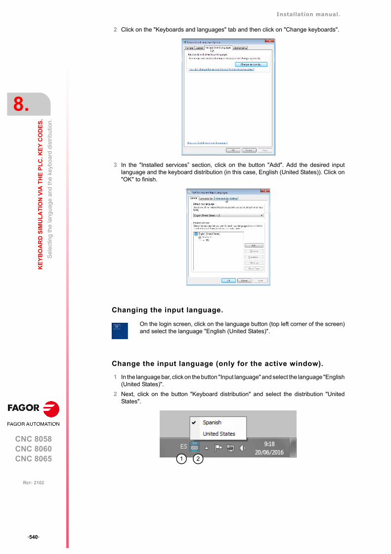
Installation manual.
CNC 8058CNC 8060CNC 8065
8.
KE
YB
OA
RD
SIM
UL
AT
ION
VIA
TH
E P
LC
. KE
Y C
OD
ES
.
Sel
ectin
g th
e la
ngu
age
and
the
key
boar
d di
strib
utio
n.
ꞏ540ꞏ
REF: 2102
2 Click on the "Keyboards and languages" tab and then click on "Change keyboards".
3 In the "Installed services” section, click on the button "Add". Add the desired inputlanguage and the keyboard distribution (in this case, English (United States)). Click on"OK" to finish.
Changing the input language.
Change the input language (only for the active window).
1 In the language bar, click on the button "Input language" and select the language "English(United States)".
2 Next, click on the button "Keyboard distribution" and select the distribution "UnitedStates".
On the login screen, click on the language button (top left corner of the screen)and select the language "English (United States)".
21

Installation manual.
CNC 8058CNC 8060CNC 8065
KE
YB
OA
RD
SIM
UL
AT
ION
VIA
TH
E P
LC
. KE
Y C
OD
ES
.
8.
Key
cod
es.
ꞏ541ꞏ
REF: 2102
8.2 Key codes.
The key codes (scan codes) may be used to determine which is the last key accepted bythe CNC and also to simulate the keyboard from the PLC. Each key is assigned two codes;one for pressing it and another one for releasing it. The code does not depend on the key(printed character), but rather its position on the keyboard (keyboard layout). For example,the code $27 on a "Spanish (Spain)" keyboard layout corresponds to the character "Ñ" andon an "English (United States)" keyboard layout, it corresponds to the character ";". See"8.5.1 Scan codes. "Spanish (Spain)” keyboard layout." on page 545. See "8.5.2 Scancodes. Keyboard distribution "English (United States)"." on page 546.
CNC's own keys.
The keys of the CNC have no associated key code.
• The [START], [STOP] and [RESET] keys may be actuated from the PLC using theCYSTART, _STOP and RESETIN keys respectively.
• The keys that have an associated hotkey, such as those for accessing work modes, maybe simulated through their hotkeys.
• Keys that do not have an associated hotkey cannot be simulated.
• The Fagor logo key cannot be simulated. This key is not found on all keyboards.
The task window ([CTRL] + [A]) shows the list of available hotkeys for the CNC.
Installation manual.
CNC 8058CNC 8060CNC 8065
8.
KE
YB
OA
RD
SIM
UL
AT
ION
VIA
TH
E P
LC
. KE
Y C
OD
ES
.
Key
cod
es.
ꞏ542ꞏ
REF: 2102
8.2.1 Keyboard shortcuts. CNC's own keys.
Work mode. Key. Hotkey.
Task window. [CTRL]+[A]
Main menu. [CTRL]+[SHIFT]+[F1]
Automatic mode. [CTRL]+[F6]
Manual mode. [CTRL]+[F7]
MDI/MDA mode. [CTRL]+[F8]
EDISIMU mode. [CTRL]+[F9]
User tables. [CTRL]+[F10]
Tool and magazine table. [CTRL]+[F11]
Utilities mode. [CTRL]+[F12]
User mode. [SHIFT]+[F1]
Calculator. [CTRL]+[K]
Help. [CTRL]+[F4]
Toolbar to modify the machine dynamics. [CTRL]+[H]
Operations at the CNC. Hotkey.
Previous horizontal menu. [CTRL]+[F1]
Window change. [CTRL]+[F2]
Changing the screen. [CTRL]+[F3]
Two-color key. [ALT]+[B]
Restore a value. [CTRL]+[F5]
"Single block" mode. [CTRL]+[B]
Show/Hide virtual operator panel. [CTRL]+[J]
Show/Hide PLC messages. [CTRL]+[M]
Show/Hide CNC messages. [CTRL]+[O]
Minimize/Restore the CNC. [CTRL]+[W]
Turn the CNC off. [ALT]+[F4]
Channel synchronization window. [ALT]+[S]
Show / hide the window for errors and warnings. [ALT]+[W]
MAINMENU
AUTO
MANUAL
MDI
EDIT
TABLES
TOOLS
UTILITIES
CALC
HELP
?
BACK
FOCUS
NEXT
RECALL
SINGLE
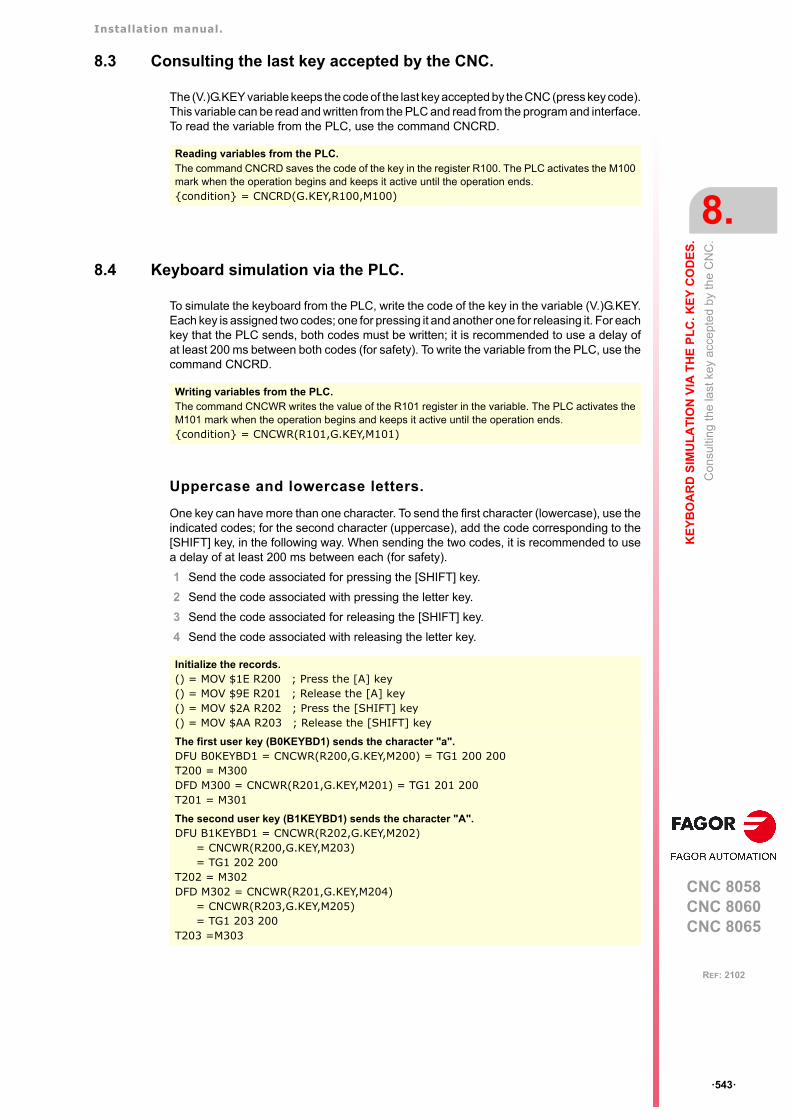
Installation manual.
CNC 8058CNC 8060CNC 8065
KE
YB
OA
RD
SIM
UL
AT
ION
VIA
TH
E P
LC
. KE
Y C
OD
ES
.
8.
Con
sulti
ng th
e la
st k
ey a
ccep
ted
by th
e C
NC
.
ꞏ543ꞏ
REF: 2102
8.3 Consulting the last key accepted by the CNC.
The (V.)G.KEY variable keeps the code of the last key accepted by the CNC (press key code).This variable can be read and written from the PLC and read from the program and interface.To read the variable from the PLC, use the command CNCRD.
8.4 Keyboard simulation via the PLC.
To simulate the keyboard from the PLC, write the code of the key in the variable (V.)G.KEY.Each key is assigned two codes; one for pressing it and another one for releasing it. For eachkey that the PLC sends, both codes must be written; it is recommended to use a delay ofat least 200 ms between both codes (for safety). To write the variable from the PLC, use thecommand CNCRD.
Uppercase and lowercase letters.
One key can have more than one character. To send the first character (lowercase), use theindicated codes; for the second character (uppercase), add the code corresponding to the[SHIFT] key, in the following way. When sending the two codes, it is recommended to usea delay of at least 200 ms between each (for safety).
1 Send the code associated for pressing the [SHIFT] key.
2 Send the code associated with pressing the letter key.
3 Send the code associated for releasing the [SHIFT] key.
4 Send the code associated with releasing the letter key.
Reading variables from the PLC.The command CNCRD saves the code of the key in the register R100. The PLC activates the M100mark when the operation begins and keeps it active until the operation ends.{condition} = CNCRD(G.KEY,R100,M100)
Writing variables from the PLC.The command CNCWR writes the value of the R101 register in the variable. The PLC activates theM101 mark when the operation begins and keeps it active until the operation ends.{condition} = CNCWR(R101,G.KEY,M101)
Initialize the records.() = MOV $1E R200 ; Press the [A] key() = MOV $9E R201 ; Release the [A] key() = MOV $2A R202 ; Press the [SHIFT] key() = MOV $AA R203 ; Release the [SHIFT] key
The first user key (B0KEYBD1) sends the character "a".DFU B0KEYBD1 = CNCWR(R200,G.KEY,M200) = TG1 200 200T200 = M300DFD M300 = CNCWR(R201,G.KEY,M201) = TG1 201 200T201 = M301
The second user key (B1KEYBD1) sends the character "A".DFU B1KEYBD1 = CNCWR(R202,G.KEY,M202)
= CNCWR(R200,G.KEY,M203)= TG1 202 200
T202 = M302DFD M302 = CNCWR(R201,G.KEY,M204)
= CNCWR(R203,G.KEY,M205)= TG1 203 200
T203 =M303
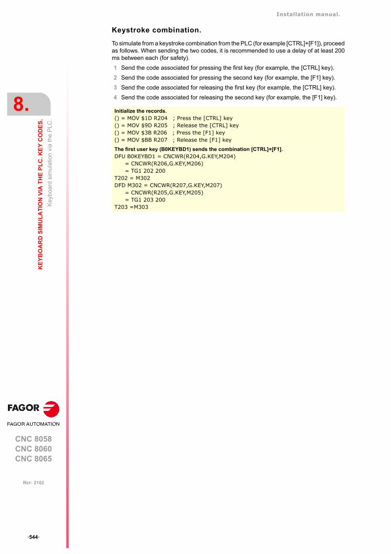
Installation manual.
CNC 8058CNC 8060CNC 8065
8.
KE
YB
OA
RD
SIM
UL
AT
ION
VIA
TH
E P
LC
. KE
Y C
OD
ES
.
Key
boa
rd s
imul
atio
n vi
a th
e P
LC.
ꞏ544ꞏ
REF: 2102
Keystroke combination.
To simulate from a keystroke combination from the PLC (for example [CTRL]+[F1]), proceedas follows. When sending the two codes, it is recommended to use a delay of at least 200ms between each (for safety).
1 Send the code associated for pressing the first key (for example, the [CTRL] key).
2 Send the code associated for pressing the second key (for example, the [F1] key).
3 Send the code associated for releasing the first key (for example, the [CTRL] key).
4 Send the code associated for releasing the second key (for example, the [F1] key).
Initialize the records.() = MOV $1D R204 ; Press the [CTRL] key() = MOV $9D R205 ; Release the [CTRL] key() = MOV $3B R206 ; Press the [F1] key() = MOV $BB R207 ; Release the [F1] key
The first user key (B0KEYBD1) sends the combination [CTRL]+[F1].DFU B0KEYBD1 = CNCWR(R204,G.KEY,M204)
= CNCWR(R206,G.KEY,M206)= TG1 202 200
T202 = M302DFD M302 = CNCWR(R207,G.KEY,M207)
= CNCWR(R205,G.KEY,M205)= TG1 203 200
T203 =M303
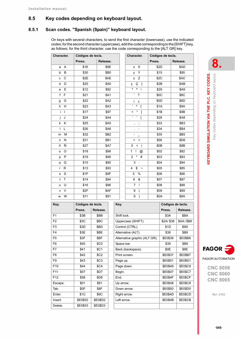
Installation manual.
CNC 8058CNC 8060CNC 8065
KE
YB
OA
RD
SIM
UL
AT
ION
VIA
TH
E P
LC
. KE
Y C
OD
ES
.
8.
Key
cod
es
dep
endi
ng
on k
eybo
ard
layo
ut.
ꞏ545ꞏ
REF: 2102
8.5 Key codes depending on keyboard layout.
8.5.1 Scan codes. "Spanish (Spain)” keyboard layout.
On keys with several characters, to send the first character (lowercase), use the indicatedcodes; for the second character (uppercase), add the code corresponding to the [SHIFT] key,as follows; for the third character, use the code corresponding to the [ALT GR] key.
Character. Códigos de tecla. Character. Códigos de tecla.
Press. Release. Press. Release.
a A $1E $9E x X $2D $AD
b B $30 $B0 y Y $15 $95
c C $2E $AE z Z $2C $AC
d D $20 $A0 ç Ç } $2B $AB
e E $12 $92 º ª \ $29 $A9
f F $21 $A1 ’ ? $0C $8C
g G $22 $A2 ¡ ¿ $0D $8D
h H $23 $A3 ‘ ^ [ $1A $9A
i I $17 $97 + * ] $1B $9B
j J $24 $A4 ´ ¨ { $28 $A8
k K $25 $A5 , ; $33 $B3
l L $26 $A6 . : $34 $B4
m M $32 $B2 - _ $35 $B5
n N $31 $B1 < > $56 $D6
ñ Ñ $27 $A7 0 = | $0B $8B
o O $18 $98 1 ! @ $02 $82
p P $19 $99 2 " # $03 $83
q Q $10 $90 3 ꞏ $04 $84
r R $13 $93 4 $ ~ $05 $85
s S $1F $9F 5 % $06 $86
t T $14 $94 6 & $07 $87
u U $16 $96 7 / $08 $88
v V $2F $AF 8 ( $09 $89
w W $11 $91 9 ) $0A $8A
Key. Códigos de tecla. Key. Códigos de tecla.
Press. Release. Press. Release.
F1 $3B $BB Shift lock. $3A $BA
F2 $3C $BC Uppercase (SHIFT). $2A/ $36 $AA / $B6
F3 $3D $BD Control (CTRL). $1D $9D
F4 $3E $BE Alternative (ALT). $38 $B8
F5 $3F $BF Alternative graphic (ALT GR). $E0$38 $E0$B8
F6 $40 $C0 Space bar. $39 $B9
F7 $41 $C1 Back (backspace). $0E $8E
F8 $42 $C2 Print screen. $E0$37 $E0$B7
F9 $43 $C3 Page up. $E0$51 $E0$D1
F10 $44 $C4 Page down. $E0$49 $E0$C9
F11 $57 $D7 Begin. $E0$47 $E0$C7
F12 $58 $D8 End. $E0$4F $E0$CF
Escape. $01 $81 Up arrow. $E0$48 $E0$C8
Tab. $0F $8F Down arrow. $E0$50 $E0$D0
Enter. $1C $9C Right arrow. $E0$4D $E0$CD
Insert. $E0$52 $E0$D2 Left arrow. $E0$4B $E0$CB
Delete. $E0$53 $E0$D3
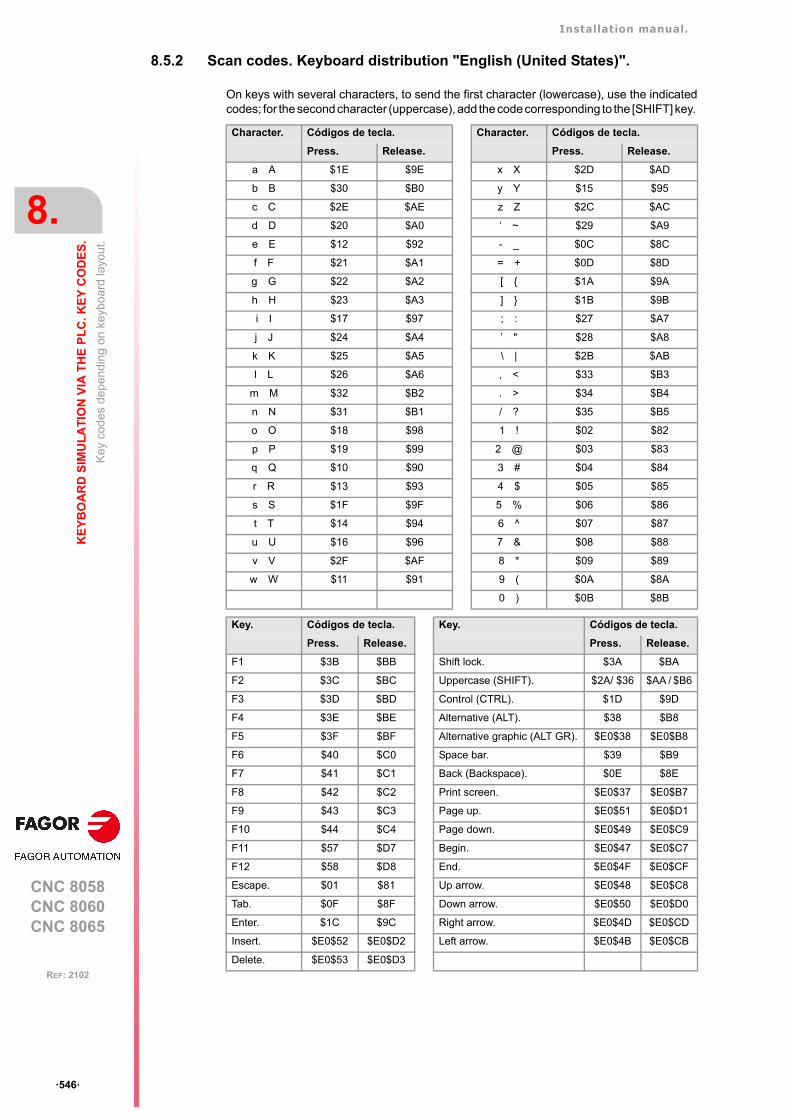
Installation manual.
CNC 8058CNC 8060CNC 8065
8.
KE
YB
OA
RD
SIM
UL
AT
ION
VIA
TH
E P
LC
. KE
Y C
OD
ES
.
Key
cod
es
dep
endi
ng
on k
eybo
ard
layo
ut.
ꞏ546ꞏ
REF: 2102
8.5.2 Scan codes. Keyboard distribution "English (United States)".
On keys with several characters, to send the first character (lowercase), use the indicatedcodes; for the second character (uppercase), add the code corresponding to the [SHIFT] key.
Character. Códigos de tecla. Character. Códigos de tecla.
Press. Release. Press. Release.
a A $1E $9E x X $2D $AD
b B $30 $B0 y Y $15 $95
c C $2E $AE z Z $2C $AC
d D $20 $A0 ‘ ~ $29 $A9
e E $12 $92 - _ $0C $8C
f F $21 $A1 = + $0D $8D
g G $22 $A2 [ { $1A $9A
h H $23 $A3 ] } $1B $9B
i I $17 $97 ; : $27 $A7
j J $24 $A4 ’ " $28 $A8
k K $25 $A5 \ | $2B $AB
l L $26 $A6 , < $33 $B3
m M $32 $B2 . > $34 $B4
n N $31 $B1 / ? $35 $B5
o O $18 $98 1 ! $02 $82
p P $19 $99 2 @ $03 $83
q Q $10 $90 3 # $04 $84
r R $13 $93 4 $ $05 $85
s S $1F $9F 5 % $06 $86
t T $14 $94 6 ^ $07 $87
u U $16 $96 7 & $08 $88
v V $2F $AF 8 * $09 $89
w W $11 $91 9 ( $0A $8A
0 ) $0B $8B
Key. Códigos de tecla. Key. Códigos de tecla.
Press. Release. Press. Release.
F1 $3B $BB Shift lock. $3A $BA
F2 $3C $BC Uppercase (SHIFT). $2A/ $36 $AA / $B6
F3 $3D $BD Control (CTRL). $1D $9D
F4 $3E $BE Alternative (ALT). $38 $B8
F5 $3F $BF Alternative graphic (ALT GR). $E0$38 $E0$B8
F6 $40 $C0 Space bar. $39 $B9
F7 $41 $C1 Back (Backspace). $0E $8E
F8 $42 $C2 Print screen. $E0$37 $E0$B7
F9 $43 $C3 Page up. $E0$51 $E0$D1
F10 $44 $C4 Page down. $E0$49 $E0$C9
F11 $57 $D7 Begin. $E0$47 $E0$C7
F12 $58 $D8 End. $E0$4F $E0$CF
Escape. $01 $81 Up arrow. $E0$48 $E0$C8
Tab. $0F $8F Down arrow. $E0$50 $E0$D0
Enter. $1C $9C Right arrow. $E0$4D $E0$CD
Insert. $E0$52 $E0$D2 Left arrow. $E0$4B $E0$CB
Delete. $E0$53 $E0$D3
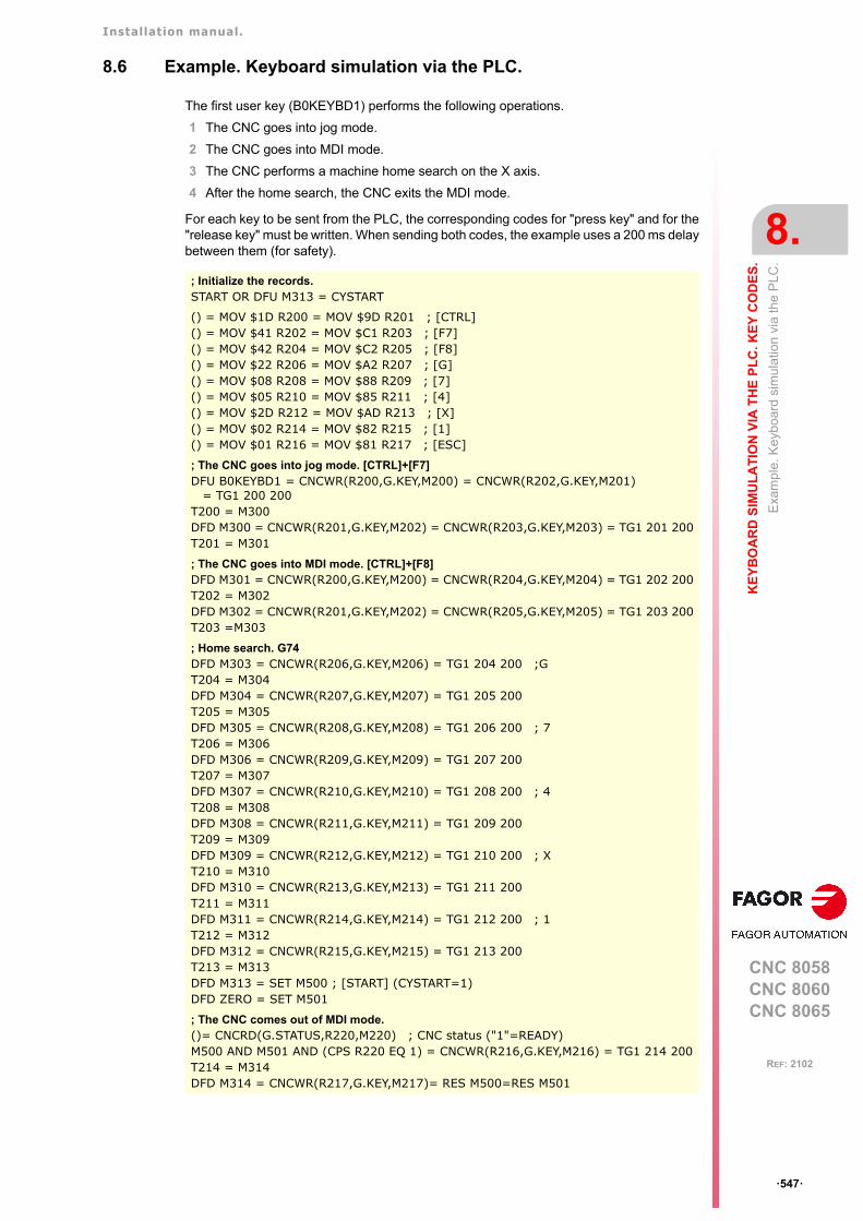
Installation manual.
CNC 8058CNC 8060CNC 8065
KE
YB
OA
RD
SIM
UL
AT
ION
VIA
TH
E P
LC
. KE
Y C
OD
ES
.
8.
Exa
mpl
e. K
eyb
oard
sim
ula
tion
via
the
PLC
.
ꞏ547ꞏ
REF: 2102
8.6 Example. Keyboard simulation via the PLC.
The first user key (B0KEYBD1) performs the following operations.
1 The CNC goes into jog mode.
2 The CNC goes into MDI mode.
3 The CNC performs a machine home search on the X axis.
4 After the home search, the CNC exits the MDI mode.
For each key to be sent from the PLC, the corresponding codes for "press key" and for the"release key" must be written. When sending both codes, the example uses a 200 ms delaybetween them (for safety).
; Initialize the records.START OR DFU M313 = CYSTART
() = MOV $1D R200 = MOV $9D R201 ; [CTRL]() = MOV $41 R202 = MOV $C1 R203 ; [F7]() = MOV $42 R204 = MOV $C2 R205 ; [F8]() = MOV $22 R206 = MOV $A2 R207 ; [G]() = MOV $08 R208 = MOV $88 R209 ; [7]() = MOV $05 R210 = MOV $85 R211 ; [4]() = MOV $2D R212 = MOV $AD R213 ; [X]() = MOV $02 R214 = MOV $82 R215 ; [1]() = MOV $01 R216 = MOV $81 R217 ; [ESC]
; The CNC goes into jog mode. [CTRL]+[F7]DFU B0KEYBD1 = CNCWR(R200,G.KEY,M200) = CNCWR(R202,G.KEY,M201)
= TG1 200 200T200 = M300DFD M300 = CNCWR(R201,G.KEY,M202) = CNCWR(R203,G.KEY,M203) = TG1 201 200T201 = M301
; The CNC goes into MDI mode. [CTRL]+[F8]DFD M301 = CNCWR(R200,G.KEY,M200) = CNCWR(R204,G.KEY,M204) = TG1 202 200T202 = M302DFD M302 = CNCWR(R201,G.KEY,M202) = CNCWR(R205,G.KEY,M205) = TG1 203 200T203 =M303
; Home search. G74DFD M303 = CNCWR(R206,G.KEY,M206) = TG1 204 200 ;GT204 = M304DFD M304 = CNCWR(R207,G.KEY,M207) = TG1 205 200T205 = M305DFD M305 = CNCWR(R208,G.KEY,M208) = TG1 206 200 ; 7T206 = M306DFD M306 = CNCWR(R209,G.KEY,M209) = TG1 207 200T207 = M307DFD M307 = CNCWR(R210,G.KEY,M210) = TG1 208 200 ; 4T208 = M308DFD M308 = CNCWR(R211,G.KEY,M211) = TG1 209 200T209 = M309DFD M309 = CNCWR(R212,G.KEY,M212) = TG1 210 200 ; XT210 = M310DFD M310 = CNCWR(R213,G.KEY,M213) = TG1 211 200T211 = M311DFD M311 = CNCWR(R214,G.KEY,M214) = TG1 212 200 ; 1T212 = M312DFD M312 = CNCWR(R215,G.KEY,M215) = TG1 213 200 T213 = M313DFD M313 = SET M500 ; [START] (CYSTART=1)DFD ZERO = SET M501
; The CNC comes out of MDI mode.()= CNCRD(G.STATUS,R220,M220) ; CNC status ("1"=READY)M500 AND M501 AND (CPS R220 EQ 1) = CNCWR(R216,G.KEY,M216) = TG1 214 200T214 = M314DFD M314 = CNCWR(R217,G.KEY,M217)= RES M500=RES M501
Installation manual.
CNC 8058CNC 8060CNC 8065
8.
KE
YB
OA
RD
SIM
UL
AT
ION
VIA
TH
E P
LC
. KE
Y C
OD
ES
.
Exa
mpl
e. K
eyb
oard
sim
ula
tion
via
the
PLC
.
ꞏ548ꞏ
REF: 2102
CNC 8058CNC 8060CNC 8065
9
ꞏ549ꞏ
REF: 2102
9. CNC VARIABLES.
All information about the CNC variables is in the "CNC Variables" manual, available on FagorAutomat ion's corporate websi te. The name of the elect ronic document isman_8060_8065_var.pdf.
http://www.fagorautomation.com/en/downloads/
Installation manual.
CNC 8058CNC 8060CNC 8065
9.
CN
C V
AR
IAB
LE
S.
ꞏ550ꞏ
REF: 2102
PARTE 2.CONCEPTS.

BLANK PAGE
ꞏ552ꞏ
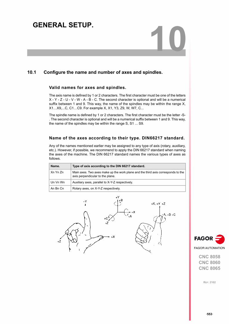
CNC 8058CNC 8060CNC 8065
10
ꞏ553ꞏ
REF: 2102
10.GENERAL SETUP.
10.1 Configure the name and number of axes and spindles.
Valid names for axes and spindles.
The axis name is defined by 1 or 2 characters. The first character must be one of the lettersX - Y - Z - U - V - W - A - B - C. The second character is optional and will be a numericalsuffix between 1 and 9. This way, the name of the spindles may be within the range X,X1…X9,...C, C1…C9. For example X, X1, Y3, Z9, W, W7, C...
The spindle name is defined by 1 or 2 characters. The first character must be the letter -S-. The second character is optional and will be a numerical suffix between 1 and 9. This way,the name of the spindles may be within the range S, S1 ... S9.
Name of the axes according to their type. DIN66217 standard.
Any of the names mentioned earlier may be assigned to any type of axis (rotary, auxiliary,etc.). However, if possible, we recommend to apply the DIN 66217 standard when namingthe axes of the machine. The DIN 66217 standard names the various types of axes asfollows.
Name. Type of axis according to the DIN 66217 standard.
Xn Yn Zn Main axes. Two axes make up the work plane and the third axis corresponds to theaxis perpendicular to the plane.
Un Vn Wn Auxiliary axes, parallel to X-Y-Z respectively.
An Bn Cn Rotary axes, on X-Y-Z respectively.
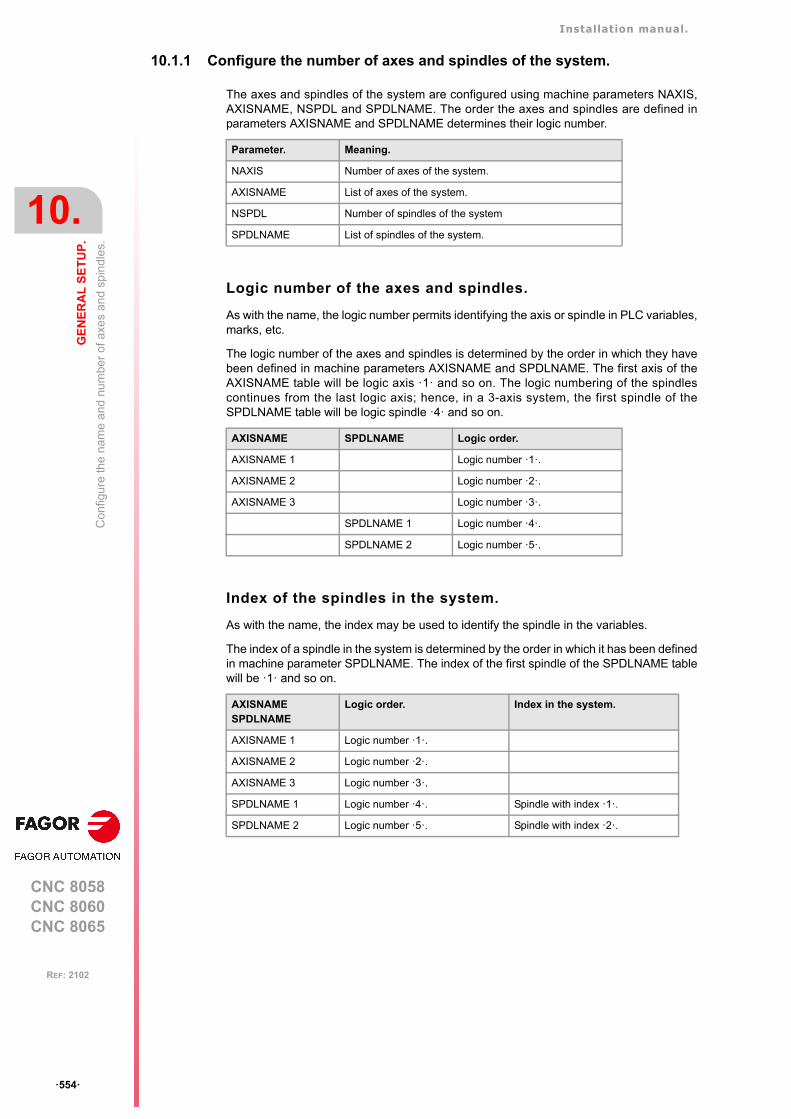
Installation manual.
CNC 8058CNC 8060CNC 8065
10.
GE
NE
RA
L S
ET
UP
.
Con
figu
re th
e n
ame
and
nu
mbe
r of
axe
s an
d sp
ind
les.
ꞏ554ꞏ
REF: 2102
10.1.1 Configure the number of axes and spindles of the system.
The axes and spindles of the system are configured using machine parameters NAXIS,AXISNAME, NSPDL and SPDLNAME. The order the axes and spindles are defined inparameters AXISNAME and SPDLNAME determines their logic number.
Logic number of the axes and spindles.
As with the name, the logic number permits identifying the axis or spindle in PLC variables,marks, etc.
The logic number of the axes and spindles is determined by the order in which they havebeen defined in machine parameters AXISNAME and SPDLNAME. The first axis of theAXISNAME table will be logic axis ꞏ1ꞏ and so on. The logic numbering of the spindlescontinues from the last logic axis; hence, in a 3-axis system, the first spindle of theSPDLNAME table will be logic spindle ꞏ4ꞏ and so on.
Index of the spindles in the system.
As with the name, the index may be used to identify the spindle in the variables.
The index of a spindle in the system is determined by the order in which it has been definedin machine parameter SPDLNAME. The index of the first spindle of the SPDLNAME tablewill be ꞏ1ꞏ and so on.
Parameter. Meaning.
NAXIS Number of axes of the system.
AXISNAME List of axes of the system.
NSPDL Number of spindles of the system
SPDLNAME List of spindles of the system.
AXISNAME SPDLNAME Logic order.
AXISNAME 1 Logic number ꞏ1ꞏ.
AXISNAME 2 Logic number ꞏ2ꞏ.
AXISNAME 3 Logic number ꞏ3ꞏ.
SPDLNAME 1 Logic number ꞏ4ꞏ.
SPDLNAME 2 Logic number ꞏ5ꞏ.
AXISNAMESPDLNAME
Logic order. Index in the system.
AXISNAME 1 Logic number ꞏ1ꞏ.
AXISNAME 2 Logic number ꞏ2ꞏ.
AXISNAME 3 Logic number ꞏ3ꞏ.
SPDLNAME 1 Logic number ꞏ4ꞏ. Spindle with index ꞏ1ꞏ.
SPDLNAME 2 Logic number ꞏ5ꞏ. Spindle with index ꞏ2ꞏ.
Installation manual.
CNC 8058CNC 8060CNC 8065
GE
NE
RA
L S
ET
UP
.
10.
Con
figu
re th
e n
ame
and
nu
mbe
r of
axe
s an
d sp
ind
les.
ꞏ555ꞏ
REF: 2102
10.1.2 Configure the number of axes and spindles of the channels.
In a single-channel or multi-channel system, the axes and spindles defined in the systemmust be distributed among the different channels. The axes and spindles of a channel areconfigured using parameters CHNAXIS, CHAXISNAME, CHNSPDL and CHSPDLNAME.The order the axes and spindles are defined in parameters CHAXISNAME andCHSPDLNAME determines their index in the channel.
A channel may have initially associated with it one, several or no of the axes defined in thesystem. In any case, the number of axes assigned to the channel cannot be higher than thenumber of axes of the system, defined by parameter NAXIS. The sum of the axes assignedto the channels cannot exceed the number of axes of the system either. This is also validfor the spindles.
Index of an axis or spindle in the channel.
As with the name, the index in the channel permits identifying the axis or spindle in PLCvariables, marks, etc.
The logic number of the axes and spindles is determined by the order in which they havebeen defined in machine parameters CHAXISNAME and CHSPDLNAME. The index of thefirst axis of the CHAXISNAME table will be ꞏ1ꞏ and so on. The index of the first spindle ofthe CHSPDLNAME table will be ꞏ1ꞏ and so on.
Parameter. Meaning.
CHNAXIS Number of axes of the channel.
CHAXISNAME List of axes of the channel.
CHNSPDL Number of spindles of the channel.
CHSPDLNAME List of spindles of the channel.
CHAXISNAME CHSPDLNAME Index in the channel.
CHAXISNAME 1 Axis with index ꞏ1ꞏ.
CHAXISNAME 2 Axis with index ꞏ2ꞏ.
CHAXISNAME 3 Axis with index ꞏ3ꞏ.
CHSPDLNAME 1 Spindle with index ꞏ1ꞏ.
CHSPDLNAME 2 Spindle with index ꞏ2ꞏ.
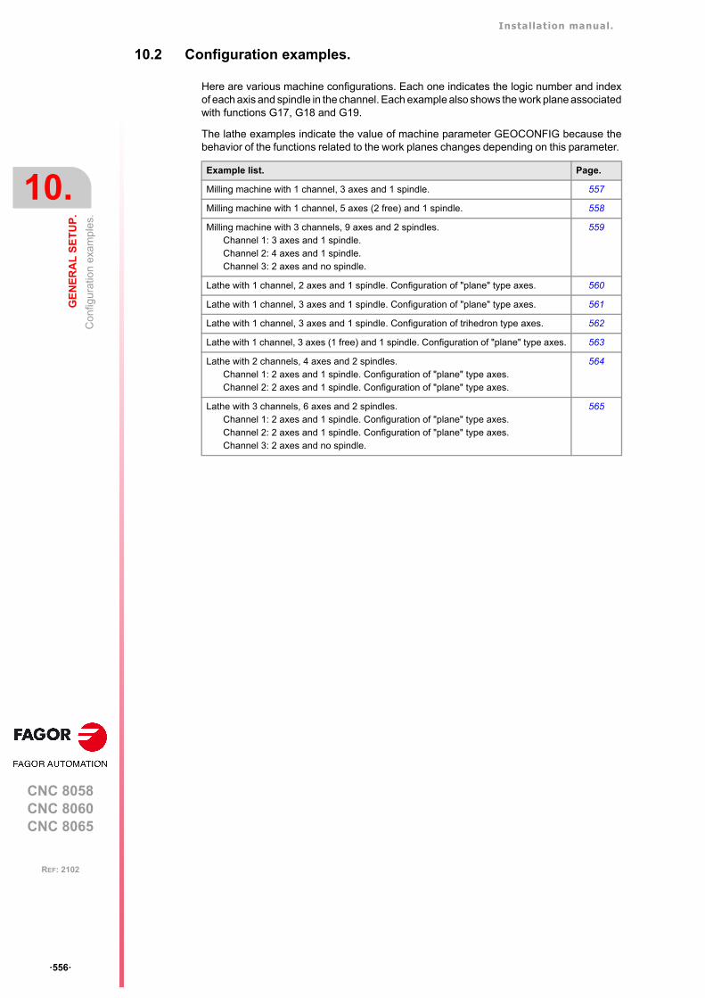
Installation manual.
CNC 8058CNC 8060CNC 8065
10.
GE
NE
RA
L S
ET
UP
.
Con
figur
atio
n e
xam
ple
s.
ꞏ556ꞏ
REF: 2102
10.2 Configuration examples.
Here are various machine configurations. Each one indicates the logic number and indexof each axis and spindle in the channel. Each example also shows the work plane associatedwith functions G17, G18 and G19.
The lathe examples indicate the value of machine parameter GEOCONFIG because thebehavior of the functions related to the work planes changes depending on this parameter.
Example list. Page.
Milling machine with 1 channel, 3 axes and 1 spindle. 557
Milling machine with 1 channel, 5 axes (2 free) and 1 spindle. 558
Milling machine with 3 channels, 9 axes and 2 spindles.Channel 1: 3 axes and 1 spindle.Channel 2: 4 axes and 1 spindle.Channel 3: 2 axes and no spindle.
559
Lathe with 1 channel, 2 axes and 1 spindle. Configuration of "plane" type axes. 560
Lathe with 1 channel, 3 axes and 1 spindle. Configuration of "plane" type axes. 561
Lathe with 1 channel, 3 axes and 1 spindle. Configuration of trihedron type axes. 562
Lathe with 1 channel, 3 axes (1 free) and 1 spindle. Configuration of "plane" type axes. 563
Lathe with 2 channels, 4 axes and 2 spindles.Channel 1: 2 axes and 1 spindle. Configuration of "plane" type axes.Channel 2: 2 axes and 1 spindle. Configuration of "plane" type axes.
564
Lathe with 3 channels, 6 axes and 2 spindles.Channel 1: 2 axes and 1 spindle. Configuration of "plane" type axes.Channel 2: 2 axes and 1 spindle. Configuration of "plane" type axes.Channel 3: 2 axes and no spindle.
565
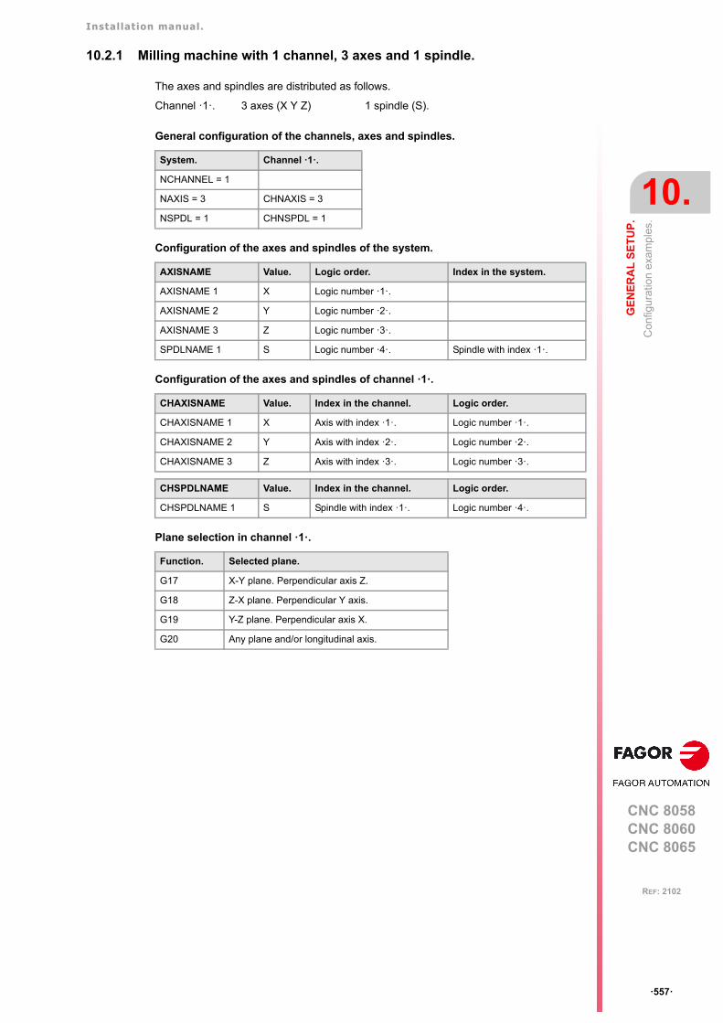
Installation manual.
CNC 8058CNC 8060CNC 8065
GE
NE
RA
L S
ET
UP
.
10.
Con
figur
atio
n e
xam
ple
s.
ꞏ557ꞏ
REF: 2102
10.2.1 Milling machine with 1 channel, 3 axes and 1 spindle.
The axes and spindles are distributed as follows.
General configuration of the channels, axes and spindles.
Configuration of the axes and spindles of the system.
Configuration of the axes and spindles of channel ꞏ1ꞏ.
Plane selection in channel ꞏ1ꞏ.
Channel ꞏ1ꞏ. 3 axes (X Y Z) 1 spindle (S).
System. Channel ꞏ1ꞏ.
NCHANNEL = 1
NAXIS = 3 CHNAXIS = 3
NSPDL = 1 CHNSPDL = 1
AXISNAME Value. Logic order. Index in the system.
AXISNAME 1 X Logic number ꞏ1ꞏ.
AXISNAME 2 Y Logic number ꞏ2ꞏ.
AXISNAME 3 Z Logic number ꞏ3ꞏ.
SPDLNAME 1 S Logic number ꞏ4ꞏ. Spindle with index ꞏ1ꞏ.
CHAXISNAME Value. Index in the channel. Logic order.
CHAXISNAME 1 X Axis with index ꞏ1ꞏ. Logic number ꞏ1ꞏ.
CHAXISNAME 2 Y Axis with index ꞏ2ꞏ. Logic number ꞏ2ꞏ.
CHAXISNAME 3 Z Axis with index ꞏ3ꞏ. Logic number ꞏ3ꞏ.
CHSPDLNAME Value. Index in the channel. Logic order.
CHSPDLNAME 1 S Spindle with index ꞏ1ꞏ. Logic number ꞏ4ꞏ.
Function. Selected plane.
G17 X-Y plane. Perpendicular axis Z.
G18 Z-X plane. Perpendicular Y axis.
G19 Y-Z plane. Perpendicular axis X.
G20 Any plane and/or longitudinal axis.
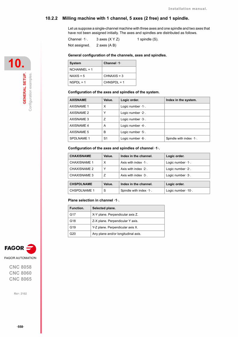
Installation manual.
CNC 8058CNC 8060CNC 8065
10.
GE
NE
RA
L S
ET
UP
.
Con
figur
atio
n e
xam
ple
s.
ꞏ558ꞏ
REF: 2102
10.2.2 Milling machine with 1 channel, 5 axes (2 free) and 1 spindle.
Let us suppose a single-channel machine with three axes and one spindle and two axes thathave not been assigned initially. The axes and spindles are distributed as follows.
General configuration of the channels, axes and spindles.
Configuration of the axes and spindles of the system.
Configuration of the axes and spindles of channel ꞏ1ꞏ.
Plane selection in channel ꞏ1ꞏ.
Channel ꞏ1ꞏ. 3 axes (X Y Z) 1 spindle (S).
Not assigned. 2 axes (A B)
System Channel ꞏ1ꞏ
NCHANNEL = 1
NAXIS = 5 CHNAXIS = 3
NSPDL = 1 CHNSPDL = 1
AXISNAME Value. Logic order. Index in the system.
AXISNAME 1 X Logic number ꞏ1ꞏ.
AXISNAME 2 Y Logic number ꞏ2ꞏ.
AXISNAME 3 Z Logic number ꞏ3ꞏ.
AXISNAME 4 A Logic number ꞏ4ꞏ.
AXISNAME 5 B Logic number ꞏ5ꞏ.
SPDLNAME 1 S1 Logic number ꞏ6ꞏ. Spindle with index ꞏ1ꞏ.
CHAXISNAME Value. Index in the channel. Logic order.
CHAXISNAME 1 X Axis with index ꞏ1ꞏ. Logic number ꞏ1ꞏ.
CHAXISNAME 2 Y Axis with index ꞏ2ꞏ. Logic number ꞏ2ꞏ.
CHAXISNAME 3 Z Axis with index ꞏ3ꞏ. Logic number ꞏ3ꞏ.
CHSPDLNAME Value. Index in the channel. Logic order.
CHSPDLNAME 1 S Spindle with index ꞏ1ꞏ. Logic number ꞏ10ꞏ.
Function. Selected plane.
G17 X-Y plane. Perpendicular axis Z.
G18 Z-X plane. Perpendicular Y axis.
G19 Y-Z plane. Perpendicular axis X.
G20 Any plane and/or longitudinal axis.
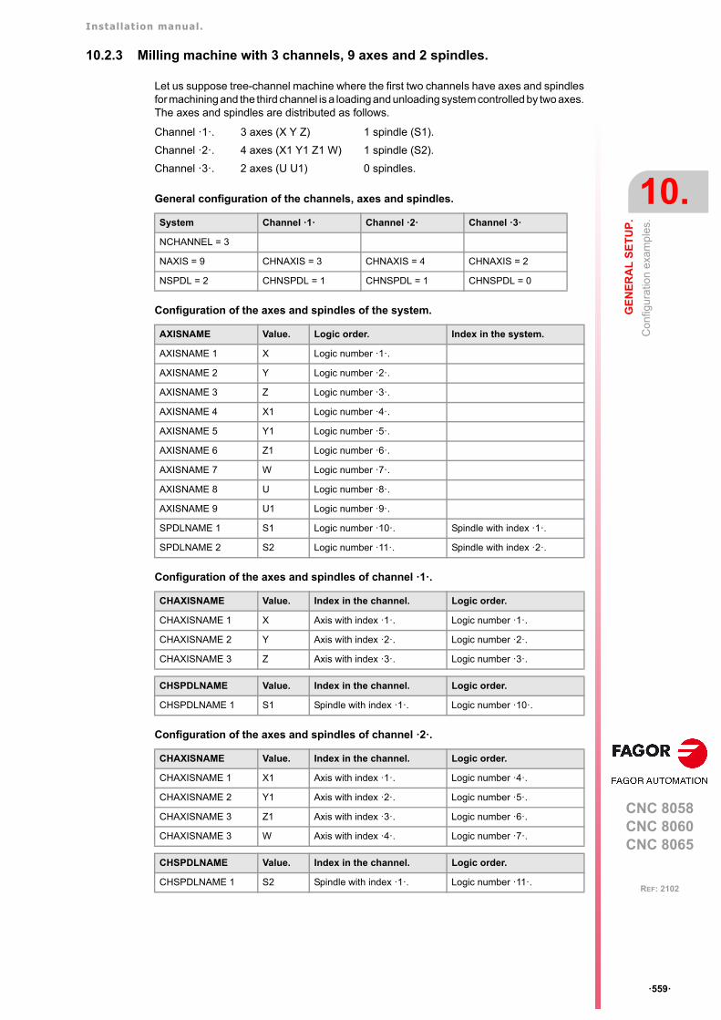
Installation manual.
CNC 8058CNC 8060CNC 8065
GE
NE
RA
L S
ET
UP
.
10.
Con
figur
atio
n e
xam
ple
s.
ꞏ559ꞏ
REF: 2102
10.2.3 Milling machine with 3 channels, 9 axes and 2 spindles.
Let us suppose tree-channel machine where the first two channels have axes and spindlesfor machining and the third channel is a loading and unloading system controlled by two axes.The axes and spindles are distributed as follows.
General configuration of the channels, axes and spindles.
Configuration of the axes and spindles of the system.
Configuration of the axes and spindles of channel ꞏ1ꞏ.
Configuration of the axes and spindles of channel ꞏ2ꞏ.
Channel ꞏ1ꞏ. 3 axes (X Y Z) 1 spindle (S1).
Channel ꞏ2ꞏ. 4 axes (X1 Y1 Z1 W) 1 spindle (S2).
Channel ꞏ3ꞏ. 2 axes (U U1) 0 spindles.
System Channel ꞏ1ꞏ Channel ꞏ2ꞏ Channel ꞏ3ꞏ
NCHANNEL = 3
NAXIS = 9 CHNAXIS = 3 CHNAXIS = 4 CHNAXIS = 2
NSPDL = 2 CHNSPDL = 1 CHNSPDL = 1 CHNSPDL = 0
AXISNAME Value. Logic order. Index in the system.
AXISNAME 1 X Logic number ꞏ1ꞏ.
AXISNAME 2 Y Logic number ꞏ2ꞏ.
AXISNAME 3 Z Logic number ꞏ3ꞏ.
AXISNAME 4 X1 Logic number ꞏ4ꞏ.
AXISNAME 5 Y1 Logic number ꞏ5ꞏ.
AXISNAME 6 Z1 Logic number ꞏ6ꞏ.
AXISNAME 7 W Logic number ꞏ7ꞏ.
AXISNAME 8 U Logic number ꞏ8ꞏ.
AXISNAME 9 U1 Logic number ꞏ9ꞏ.
SPDLNAME 1 S1 Logic number ꞏ10ꞏ. Spindle with index ꞏ1ꞏ.
SPDLNAME 2 S2 Logic number ꞏ11ꞏ. Spindle with index ꞏ2ꞏ.
CHAXISNAME Value. Index in the channel. Logic order.
CHAXISNAME 1 X Axis with index ꞏ1ꞏ. Logic number ꞏ1ꞏ.
CHAXISNAME 2 Y Axis with index ꞏ2ꞏ. Logic number ꞏ2ꞏ.
CHAXISNAME 3 Z Axis with index ꞏ3ꞏ. Logic number ꞏ3ꞏ.
CHSPDLNAME Value. Index in the channel. Logic order.
CHSPDLNAME 1 S1 Spindle with index ꞏ1ꞏ. Logic number ꞏ10ꞏ.
CHAXISNAME Value. Index in the channel. Logic order.
CHAXISNAME 1 X1 Axis with index ꞏ1ꞏ. Logic number ꞏ4ꞏ.
CHAXISNAME 2 Y1 Axis with index ꞏ2ꞏ. Logic number ꞏ5ꞏ.
CHAXISNAME 3 Z1 Axis with index ꞏ3ꞏ. Logic number ꞏ6ꞏ.
CHAXISNAME 3 W Axis with index ꞏ4ꞏ. Logic number ꞏ7ꞏ.
CHSPDLNAME Value. Index in the channel. Logic order.
CHSPDLNAME 1 S2 Spindle with index ꞏ1ꞏ. Logic number ꞏ11ꞏ.
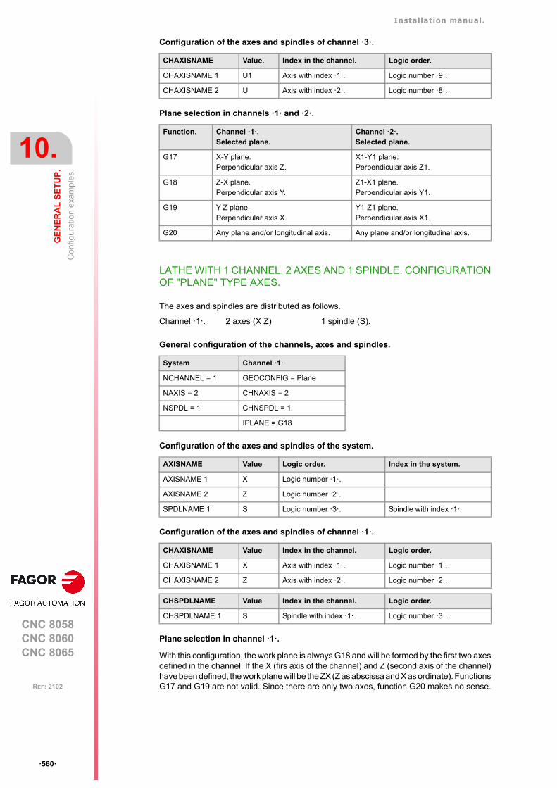
Installation manual.
CNC 8058CNC 8060CNC 8065
10.
GE
NE
RA
L S
ET
UP
.
Con
figur
atio
n e
xam
ple
s.
ꞏ560ꞏ
REF: 2102
Configuration of the axes and spindles of channel ꞏ3ꞏ.
Plane selection in channels ꞏ1ꞏ and ꞏ2ꞏ.
LATHE WITH 1 CHANNEL, 2 AXES AND 1 SPINDLE. CONFIGURATIONOF "PLANE" TYPE AXES.
The axes and spindles are distributed as follows.
General configuration of the channels, axes and spindles.
Configuration of the axes and spindles of the system.
Configuration of the axes and spindles of channel ꞏ1ꞏ.
Plane selection in channel ꞏ1ꞏ.
With this configuration, the work plane is always G18 and will be formed by the first two axesdefined in the channel. If the X (firs axis of the channel) and Z (second axis of the channel)have been defined, the work plane will be the ZX (Z as abscissa and X as ordinate). FunctionsG17 and G19 are not valid. Since there are only two axes, function G20 makes no sense.
CHAXISNAME Value. Index in the channel. Logic order.
CHAXISNAME 1 U1 Axis with index ꞏ1ꞏ. Logic number ꞏ9ꞏ.
CHAXISNAME 2 U Axis with index ꞏ2ꞏ. Logic number ꞏ8ꞏ.
Function. Channel ꞏ1ꞏ. Selected plane.
Channel ꞏ2ꞏ. Selected plane.
G17 X-Y plane.Perpendicular axis Z.
X1-Y1 plane. Perpendicular axis Z1.
G18 Z-X plane. Perpendicular axis Y.
Z1-X1 plane. Perpendicular axis Y1.
G19 Y-Z plane.Perpendicular axis X.
Y1-Z1 plane. Perpendicular axis X1.
G20 Any plane and/or longitudinal axis. Any plane and/or longitudinal axis.
Channel ꞏ1ꞏ. 2 axes (X Z) 1 spindle (S).
System Channel ꞏ1ꞏ
NCHANNEL = 1 GEOCONFIG = Plane
NAXIS = 2 CHNAXIS = 2
NSPDL = 1 CHNSPDL = 1
IPLANE = G18
AXISNAME Value Logic order. Index in the system.
AXISNAME 1 X Logic number ꞏ1ꞏ.
AXISNAME 2 Z Logic number ꞏ2ꞏ.
SPDLNAME 1 S Logic number ꞏ3ꞏ. Spindle with index ꞏ1ꞏ.
CHAXISNAME Value Index in the channel. Logic order.
CHAXISNAME 1 X Axis with index ꞏ1ꞏ. Logic number ꞏ1ꞏ.
CHAXISNAME 2 Z Axis with index ꞏ2ꞏ. Logic number ꞏ2ꞏ.
CHSPDLNAME Value Index in the channel. Logic order.
CHSPDLNAME 1 S Spindle with index ꞏ1ꞏ. Logic number ꞏ3ꞏ.
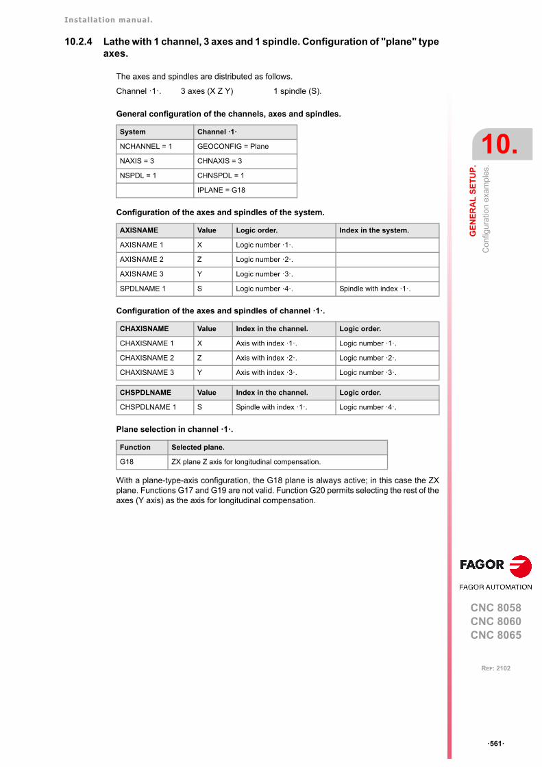
Installation manual.
CNC 8058CNC 8060CNC 8065
GE
NE
RA
L S
ET
UP
.
10.
Con
figur
atio
n e
xam
ple
s.
ꞏ561ꞏ
REF: 2102
10.2.4 Lathe with 1 channel, 3 axes and 1 spindle. Configuration of "plane" typeaxes.
The axes and spindles are distributed as follows.
General configuration of the channels, axes and spindles.
Configuration of the axes and spindles of the system.
Configuration of the axes and spindles of channel ꞏ1ꞏ.
Plane selection in channel ꞏ1ꞏ.
With a plane-type-axis configuration, the G18 plane is always active; in this case the ZXplane. Functions G17 and G19 are not valid. Function G20 permits selecting the rest of theaxes (Y axis) as the axis for longitudinal compensation.
Channel ꞏ1ꞏ. 3 axes (X Z Y) 1 spindle (S).
System Channel ꞏ1ꞏ
NCHANNEL = 1 GEOCONFIG = Plane
NAXIS = 3 CHNAXIS = 3
NSPDL = 1 CHNSPDL = 1
IPLANE = G18
AXISNAME Value Logic order. Index in the system.
AXISNAME 1 X Logic number ꞏ1ꞏ.
AXISNAME 2 Z Logic number ꞏ2ꞏ.
AXISNAME 3 Y Logic number ꞏ3ꞏ.
SPDLNAME 1 S Logic number ꞏ4ꞏ. Spindle with index ꞏ1ꞏ.
CHAXISNAME Value Index in the channel. Logic order.
CHAXISNAME 1 X Axis with index ꞏ1ꞏ. Logic number ꞏ1ꞏ.
CHAXISNAME 2 Z Axis with index ꞏ2ꞏ. Logic number ꞏ2ꞏ.
CHAXISNAME 3 Y Axis with index ꞏ3ꞏ. Logic number ꞏ3ꞏ.
CHSPDLNAME Value Index in the channel. Logic order.
CHSPDLNAME 1 S Spindle with index ꞏ1ꞏ. Logic number ꞏ4ꞏ.
Function Selected plane.
G18 ZX plane Z axis for longitudinal compensation.
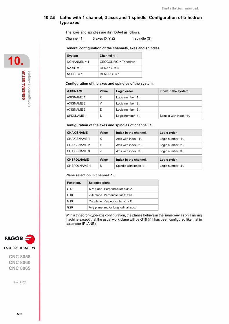
Installation manual.
CNC 8058CNC 8060CNC 8065
10.
GE
NE
RA
L S
ET
UP
.
Con
figur
atio
n e
xam
ple
s.
ꞏ562ꞏ
REF: 2102
10.2.5 Lathe with 1 channel, 3 axes and 1 spindle. Configuration of trihedrontype axes.
The axes and spindles are distributed as follows.
General configuration of the channels, axes and spindles.
Configuration of the axes and spindles of the system.
Configuration of the axes and spindles of channel ꞏ1ꞏ.
Plane selection in channel ꞏ1ꞏ.
With a trihedron-type-axis configuration, the planes behave in the same way as on a millingmachine except that the usual work plane will be G18 (if it has been configured like that inparameter IPLANE).
Channel ꞏ1ꞏ. 3 axes (X Y Z) 1 spindle (S).
System Channel ꞏ1ꞏ
NCHANNEL = 1 GEOCONFIG = Trihedron
NAXIS = 3 CHNAXIS = 3
NSPDL = 1 CHNSPDL = 1
AXISNAME Value Logic order. Index in the system.
AXISNAME 1 X Logic number ꞏ1ꞏ.
AXISNAME 2 Y Logic number ꞏ2ꞏ.
AXISNAME 3 Z Logic number ꞏ3ꞏ.
SPDLNAME 1 S Logic number ꞏ4ꞏ. Spindle with index ꞏ1ꞏ.
CHAXISNAME Value Index in the channel. Logic order.
CHAXISNAME 1 X Axis with index ꞏ1ꞏ. Logic number ꞏ1ꞏ.
CHAXISNAME 2 Y Axis with index ꞏ2ꞏ. Logic number ꞏ2ꞏ.
CHAXISNAME 3 Z Axis with index ꞏ3ꞏ. Logic number ꞏ3ꞏ.
CHSPDLNAME Value Index in the channel. Logic order.
CHSPDLNAME 1 S Spindle with index ꞏ1ꞏ. Logic number ꞏ4ꞏ.
Function. Selected plane.
G17 X-Y plane. Perpendicular axis Z.
G18 Z-X plane. Perpendicular Y axis.
G19 Y-Z plane. Perpendicular axis X.
G20 Any plane and/or longitudinal axis.
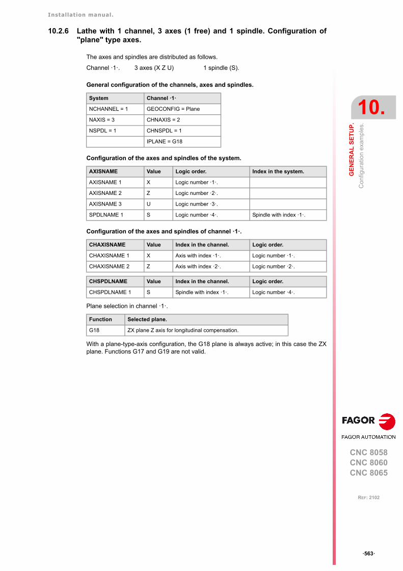
Installation manual.
CNC 8058CNC 8060CNC 8065
GE
NE
RA
L S
ET
UP
.
10.
Con
figur
atio
n e
xam
ple
s.
ꞏ563ꞏ
REF: 2102
10.2.6 Lathe with 1 channel, 3 axes (1 free) and 1 spindle. Configuration of"plane" type axes.
The axes and spindles are distributed as follows.
General configuration of the channels, axes and spindles.
Configuration of the axes and spindles of the system.
Configuration of the axes and spindles of channel ꞏ1ꞏ.
Plane selection in channel ꞏ1ꞏ.
With a plane-type-axis configuration, the G18 plane is always active; in this case the ZXplane. Functions G17 and G19 are not valid.
Channel ꞏ1ꞏ. 3 axes (X Z U) 1 spindle (S).
System Channel ꞏ1ꞏ
NCHANNEL = 1 GEOCONFIG = Plane
NAXIS = 3 CHNAXIS = 2
NSPDL = 1 CHNSPDL = 1
IPLANE = G18
AXISNAME Value Logic order. Index in the system.
AXISNAME 1 X Logic number ꞏ1ꞏ.
AXISNAME 2 Z Logic number ꞏ2ꞏ.
AXISNAME 3 U Logic number ꞏ3ꞏ.
SPDLNAME 1 S Logic number ꞏ4ꞏ. Spindle with index ꞏ1ꞏ.
CHAXISNAME Value Index in the channel. Logic order.
CHAXISNAME 1 X Axis with index ꞏ1ꞏ. Logic number ꞏ1ꞏ.
CHAXISNAME 2 Z Axis with index ꞏ2ꞏ. Logic number ꞏ2ꞏ.
CHSPDLNAME Value Index in the channel. Logic order.
CHSPDLNAME 1 S Spindle with index ꞏ1ꞏ. Logic number ꞏ4ꞏ.
Function Selected plane.
G18 ZX plane Z axis for longitudinal compensation.
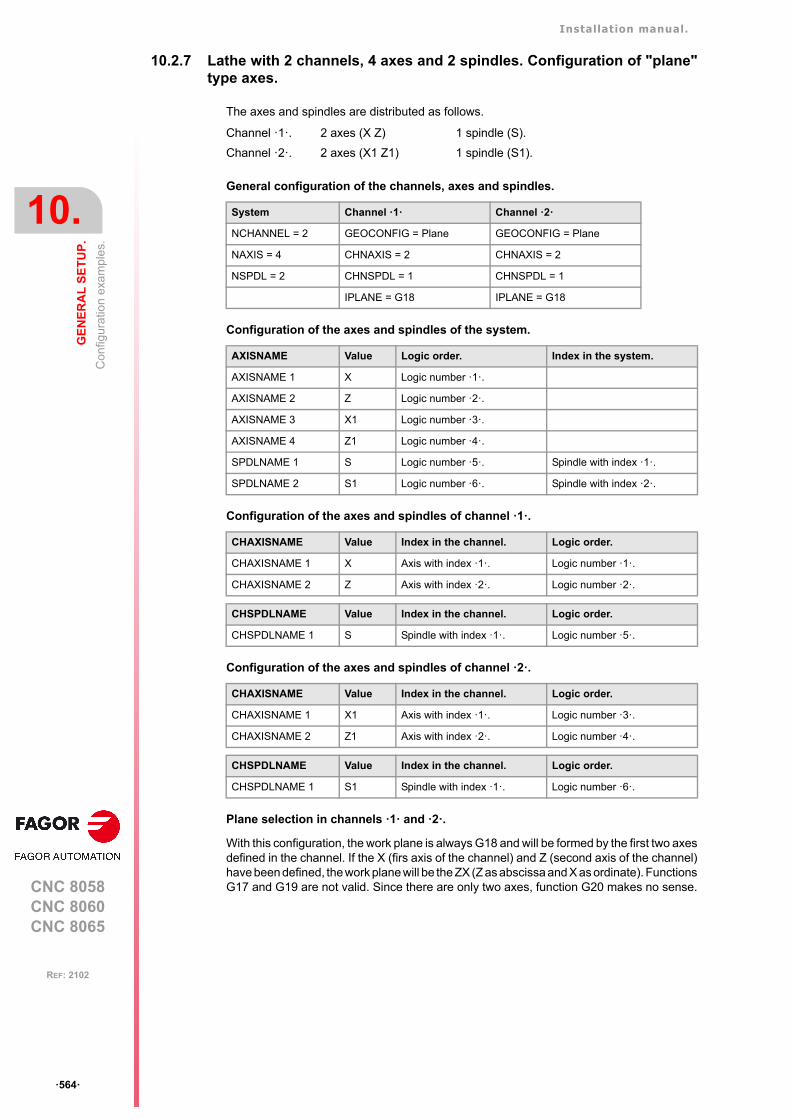
Installation manual.
CNC 8058CNC 8060CNC 8065
10.
GE
NE
RA
L S
ET
UP
.
Con
figur
atio
n e
xam
ple
s.
ꞏ564ꞏ
REF: 2102
10.2.7 Lathe with 2 channels, 4 axes and 2 spindles. Configuration of "plane"type axes.
The axes and spindles are distributed as follows.
General configuration of the channels, axes and spindles.
Configuration of the axes and spindles of the system.
Configuration of the axes and spindles of channel ꞏ1ꞏ.
Configuration of the axes and spindles of channel ꞏ2ꞏ.
Plane selection in channels ꞏ1ꞏ and ꞏ2ꞏ.
With this configuration, the work plane is always G18 and will be formed by the first two axesdefined in the channel. If the X (firs axis of the channel) and Z (second axis of the channel)have been defined, the work plane will be the ZX (Z as abscissa and X as ordinate). FunctionsG17 and G19 are not valid. Since there are only two axes, function G20 makes no sense.
Channel ꞏ1ꞏ. 2 axes (X Z) 1 spindle (S).
Channel ꞏ2ꞏ. 2 axes (X1 Z1) 1 spindle (S1).
System Channel ꞏ1ꞏ Channel ꞏ2ꞏ
NCHANNEL = 2 GEOCONFIG = Plane GEOCONFIG = Plane
NAXIS = 4 CHNAXIS = 2 CHNAXIS = 2
NSPDL = 2 CHNSPDL = 1 CHNSPDL = 1
IPLANE = G18 IPLANE = G18
AXISNAME Value Logic order. Index in the system.
AXISNAME 1 X Logic number ꞏ1ꞏ.
AXISNAME 2 Z Logic number ꞏ2ꞏ.
AXISNAME 3 X1 Logic number ꞏ3ꞏ.
AXISNAME 4 Z1 Logic number ꞏ4ꞏ.
SPDLNAME 1 S Logic number ꞏ5ꞏ. Spindle with index ꞏ1ꞏ.
SPDLNAME 2 S1 Logic number ꞏ6ꞏ. Spindle with index ꞏ2ꞏ.
CHAXISNAME Value Index in the channel. Logic order.
CHAXISNAME 1 X Axis with index ꞏ1ꞏ. Logic number ꞏ1ꞏ.
CHAXISNAME 2 Z Axis with index ꞏ2ꞏ. Logic number ꞏ2ꞏ.
CHSPDLNAME Value Index in the channel. Logic order.
CHSPDLNAME 1 S Spindle with index ꞏ1ꞏ. Logic number ꞏ5ꞏ.
CHAXISNAME Value Index in the channel. Logic order.
CHAXISNAME 1 X1 Axis with index ꞏ1ꞏ. Logic number ꞏ3ꞏ.
CHAXISNAME 2 Z1 Axis with index ꞏ2ꞏ. Logic number ꞏ4ꞏ.
CHSPDLNAME Value Index in the channel. Logic order.
CHSPDLNAME 1 S1 Spindle with index ꞏ1ꞏ. Logic number ꞏ6ꞏ.
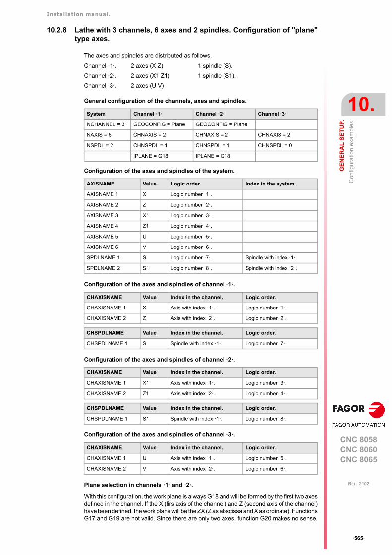
Installation manual.
CNC 8058CNC 8060CNC 8065
GE
NE
RA
L S
ET
UP
.
10.
Con
figur
atio
n e
xam
ple
s.
ꞏ565ꞏ
REF: 2102
10.2.8 Lathe with 3 channels, 6 axes and 2 spindles. Configuration of "plane"type axes.
The axes and spindles are distributed as follows.
General configuration of the channels, axes and spindles.
Configuration of the axes and spindles of the system.
Configuration of the axes and spindles of channel ꞏ1ꞏ.
Configuration of the axes and spindles of channel ꞏ2ꞏ.
Configuration of the axes and spindles of channel ꞏ3ꞏ.
Plane selection in channels ꞏ1ꞏ and ꞏ2ꞏ.
With this configuration, the work plane is always G18 and will be formed by the first two axesdefined in the channel. If the X (firs axis of the channel) and Z (second axis of the channel)have been defined, the work plane will be the ZX (Z as abscissa and X as ordinate). FunctionsG17 and G19 are not valid. Since there are only two axes, function G20 makes no sense.
Channel ꞏ1ꞏ. 2 axes (X Z) 1 spindle (S).
Channel ꞏ2ꞏ. 2 axes (X1 Z1) 1 spindle (S1).
Channel ꞏ3ꞏ. 2 axes (U V)
System Channel ꞏ1ꞏ Channel ꞏ2ꞏ Channel ꞏ3ꞏ
NCHANNEL = 3 GEOCONFIG = Plane GEOCONFIG = Plane
NAXIS = 6 CHNAXIS = 2 CHNAXIS = 2 CHNAXIS = 2
NSPDL = 2 CHNSPDL = 1 CHNSPDL = 1 CHNSPDL = 0
IPLANE = G18 IPLANE = G18
AXISNAME Value Logic order. Index in the system.
AXISNAME 1 X Logic number ꞏ1ꞏ.
AXISNAME 2 Z Logic number ꞏ2ꞏ.
AXISNAME 3 X1 Logic number ꞏ3ꞏ.
AXISNAME 4 Z1 Logic number ꞏ4ꞏ.
AXISNAME 5 U Logic number ꞏ5ꞏ.
AXISNAME 6 V Logic number ꞏ6ꞏ.
SPDLNAME 1 S Logic number ꞏ7ꞏ. Spindle with index ꞏ1ꞏ.
SPDLNAME 2 S1 Logic number ꞏ8ꞏ. Spindle with index ꞏ2ꞏ.
CHAXISNAME Value Index in the channel. Logic order.
CHAXISNAME 1 X Axis with index ꞏ1ꞏ. Logic number ꞏ1ꞏ.
CHAXISNAME 2 Z Axis with index ꞏ2ꞏ. Logic number ꞏ2ꞏ.
CHSPDLNAME Value Index in the channel. Logic order.
CHSPDLNAME 1 S Spindle with index ꞏ1ꞏ. Logic number ꞏ7ꞏ.
CHAXISNAME Value Index in the channel. Logic order.
CHAXISNAME 1 X1 Axis with index ꞏ1ꞏ. Logic number ꞏ3ꞏ.
CHAXISNAME 2 Z1 Axis with index ꞏ2ꞏ. Logic number ꞏ4ꞏ.
CHSPDLNAME Value Index in the channel. Logic order.
CHSPDLNAME 1 S1 Spindle with index ꞏ1ꞏ. Logic number ꞏ8ꞏ.
CHAXISNAME Value Index in the channel. Logic order.
CHAXISNAME 1 U Axis with index ꞏ1ꞏ. Logic number ꞏ5ꞏ.
CHAXISNAME 2 V Axis with index ꞏ2ꞏ. Logic number ꞏ6ꞏ.
Installation manual.
CNC 8058CNC 8060CNC 8065
10.
GE
NE
RA
L S
ET
UP
.
Con
figur
atio
n e
xam
ple
s.
ꞏ566ꞏ
REF: 2102
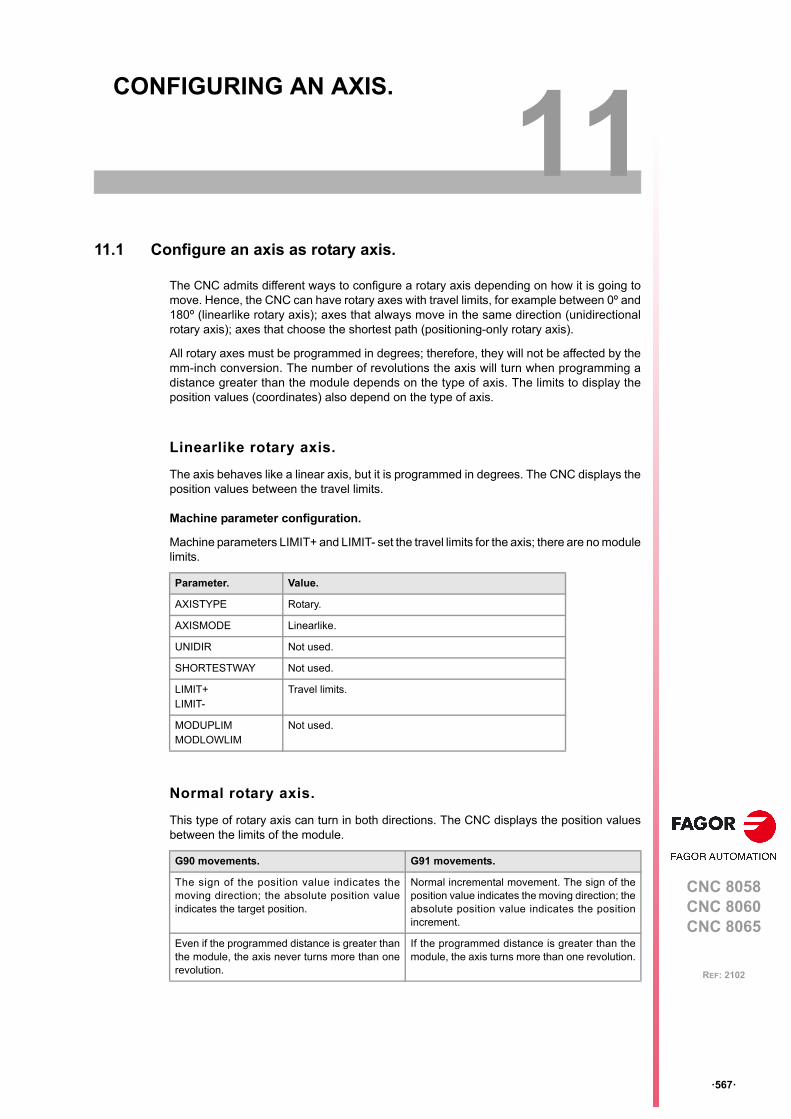
CNC 8058CNC 8060CNC 8065
11
ꞏ567ꞏ
REF: 2102
11.CONFIGURING AN AXIS.
11.1 Configure an axis as rotary axis.
The CNC admits different ways to configure a rotary axis depending on how it is going tomove. Hence, the CNC can have rotary axes with travel limits, for example between 0º and180º (linearlike rotary axis); axes that always move in the same direction (unidirectionalrotary axis); axes that choose the shortest path (positioning-only rotary axis).
All rotary axes must be programmed in degrees; therefore, they will not be affected by themm-inch conversion. The number of revolutions the axis will turn when programming adistance greater than the module depends on the type of axis. The limits to display theposition values (coordinates) also depend on the type of axis.
Linearlike rotary axis.
The axis behaves like a linear axis, but it is programmed in degrees. The CNC displays theposition values between the travel limits.
Machine parameter configuration.
Machine parameters LIMIT+ and LIMIT- set the travel limits for the axis; there are no modulelimits.
Normal rotary axis.
This type of rotary axis can turn in both directions. The CNC displays the position valuesbetween the limits of the module.
Parameter. Value.
AXISTYPE Rotary.
AXISMODE Linearlike.
UNIDIR Not used.
SHORTESTWAY Not used.
LIMIT+LIMIT-
Travel limits.
MODUPLIMMODLOWLIM
Not used.
G90 movements. G91 movements.
The sign of the position value indicates themoving direction; the absolute position valueindicates the target position.
Normal incremental movement. The sign of theposition value indicates the moving direction; theabsolute position value indicates the positionincrement.
Even if the programmed distance is greater thanthe module, the axis never turns more than onerevolution.
If the programmed distance is greater than themodule, the axis turns more than one revolution.
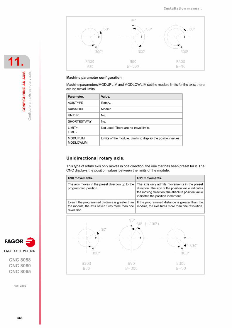
Installation manual.
CNC 8058CNC 8060CNC 8065
11.
CO
NF
IGU
RIN
G A
N A
XIS
.
Co
nfig
ure
an
axi
s a
s ro
tary
axi
s.
ꞏ568ꞏ
REF: 2102
Machine parameter configuration.
Machine parameters MODUPLIM and MODLOWLIM set the module limits for the axis; thereare no travel limits.
Unidirectional rotary axis.
This type of rotary axis only moves in one direction, the one that has been preset for it. TheCNC displays the position values between the limits of the module.
Parameter. Value.
AXISTYPE Rotary.
AXISMODE Module.
UNIDIR No.
SHORTESTWAY No.
LIMIT+LIMIT-
Not used. There are no travel limits.
MODUPLIMMODLOWLIM
Limits of the module. Limits to display the position values.
G90 movements. G91 movements.
The axis moves in the preset direction up to theprogrammed position.
The axis only admits movements in the presetdirection. The sign of the position value indicatesthe moving direction; the absolute position valueindicates the position increment.
Even if the programmed distance is greater thanthe module, the axis never turns more than onerevolution.
If the programmed distance is greater than themodule, the axis turns more than one revolution.
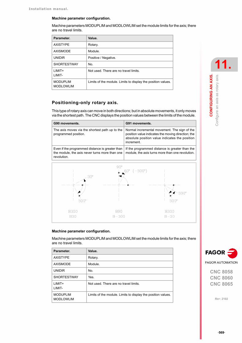
Installation manual.
CNC 8058CNC 8060CNC 8065
CO
NF
IGU
RIN
G A
N A
XIS
.
11.
Co
nfig
ure
an
axi
s a
s ro
tary
axi
s.
ꞏ569ꞏ
REF: 2102
Machine parameter configuration.
Machine parameters MODUPLIM and MODLOWLIM set the module limits for the axis; thereare no travel limits.
Positioning-only rotary axis.
This type of rotary axis can move in both directions; but in absolute movements, it only movesvia the shortest path. The CNC displays the position values between the limits of the module.
Machine parameter configuration.
Machine parameters MODUPLIM and MODLOWLIM set the module limits for the axis; thereare no travel limits.
Parameter. Value.
AXISTYPE Rotary.
AXISMODE Module.
UNIDIR Positive / Negative.
SHORTESTWAY No.
LIMIT+LIMIT-
Not used. There are no travel limits.
MODUPLIMMODLOWLIM
Limits of the module. Limits to display the position values.
G90 movements. G91 movements.
The axis moves via the shortest path up to theprogrammed position.
Normal incremental movement. The sign of theposition value indicates the moving direction; theabsolute position value indicates the positionincrement.
Even if the programmed distance is greater thanthe module, the axis never turns more than onerevolution.
If the programmed distance is greater than themodule, the axis turns more than one revolution.
Parameter. Value.
AXISTYPE Rotary.
AXISMODE Module.
UNIDIR No.
SHORTESTWAY Yes.
LIMIT+LIMIT-
Not used. There are no travel limits.
MODUPLIMMODLOWLIM
Limits of the module. Limits to display the position values.

Installation manual.
CNC 8058CNC 8060CNC 8065
11.
CO
NF
IGU
RIN
G A
N A
XIS
.
Co
nfig
ure
two
axes
as
a ta
ndem
axi
s.
ꞏ570ꞏ
REF: 2102
11.2 Configure two axes as a tandem axis.
A tandem axis consists in two motors mechanically coupled (slaved) and making up a singletransmission system (axis or spindle). Only one axis (master tandem axis) can be displayedand programmed at the CNC. The other axis (slave tandem axis) is not displayed and is notprogrammable; it is controlled by the CNC.
The following aspects may be pointed out in this configuration:
• A tandem axis helps provide the necessary torque to move an axis when a single motoris not capable of supplying enough torque to do it.
• Applying a pre-load torque between the main motor and the slave motor reduces thebacklash on the rack and pinion.
• The rigidity of the rack-and-pinion system is greater than that of long leadscrews.
One of the many applications for the control of a tandem axis has to do with Gantry machines.The following example shows a gantry axis with two tandem axes.
Requirements and limitations of tandem axes.
Each tandem pair (master and slave) must meet the following requirements:
• Each master tandem axis (spindle) admits one single slave tandem axis (spindle).
• A preload may be applied between the two motors.
• Each motor may have a different rated torque.
• The turning direction of each motor may be different from the other's.
• The torque distribution between both motors may be different from 1:1 ratio. For example,on motors whose rated torque is different.
• Both axes and drives must be of the same type (same AXISTYPE and DRIVETYPEparameters for both axes).
• The channel changing permission (parameter AXISEXCH) must be the same in bothaxes.
• Both axes and drives must have the same software limits (same LIMIT+ and LIMIT-parameters for both axes).
• When the axes are rotary, both axes must be of the same type (same AXISMODE andSHORTESTWAY parameters for both axes).
• The fast and slow home search speeds (parameters REFFEED1 and REFFEED2) mustbe the same for both axes.
Example of a tandem axis made up of twopinions and a rack.
Installation manual.
CNC 8058CNC 8060CNC 8065
CO
NF
IGU
RIN
G A
N A
XIS
.
11.
Co
nfig
ure
two
axes
as
a ta
ndem
axi
s.
ꞏ571ꞏ
REF: 2102
11.2.1 Tandem axis configuration. Machine parameters.
The tandem pairs of the system are configured by machine parameters. Each tandem pairhas the following general machine parameters to configure it.
Axes or spindles of the tandem system.
A tandem system can consist of a pair of linear axes, rotary axes or spindles. The pair ofaxes or spindles making up the tandem system is set by machine parameters MASTERAXISand SLAVEAXIS inside the TANDEM table. The axes must be previously defined inparameter AXISNAME and the spindles in parameter SPDLNAME.
The master motor of the tandem, besides generating torque, it is in charge of positioning.The slave motor only provides torque.
The CNC closes the position loop only with the position of the master axis of the tandem.The velocity command of the master axis/spindle of the tandem is also sent to the slaveaxis/spindle of the tandem closing the velocity loop. The tandem control changes the velocitycommand of the master axis/spindle and that of the slave axis/spindle according to the torquedistribution and the selected preload.
Type of servo system and feedback.
Tandem axes or spindles must be velocity-Sercos; if not, both axes will move, but it will notbe a tandem system. All the axes that will be interpolated with the tandem axis must alsooperate in velocity-Sercos mode.
In a tandem system, the master axis or spindle can carry either external or internal feedback.The slave axis or spindle normally uses internal feedback. The tandem does not admitcombined feedback (external+internal).
Considerations for tandem spindles.
• The PLC must enable and disable the SPENA(axis) and DRENA(axis) signals of themaster and slave spindles at the same time.
• Both spindles must be in the same gear (range).
• To control the tandem spindle from the PLC, for example in a gear change, it is onlynecessary to activate the marks PLCCNTL, SPDLEREV and SANALOG of the masterspindle.
Torque load distribution in the tandem.
The torque distribution sets the torque percentage supplied by each motor to obtain the totalnecessary torque in the tandem. The torque distribution in the tandem is defined withparameter TORQDIST that indicates the percentage to be provided by the master motor. Thedifference between the value of this parameter and 100% is the percentage applied to theslave motor.
The torque distribution between both motors may be different from 1:1 ratio; for example,on motors whose rated torque is different. If the motors are identical and they're bothsupposed to output the same torque, this parameter should be set to 50%.
Parameter. Meaning.
TANDEM Table of tandem axes or spindles.
MASTERAXIS Master or main axis/spindle.
SLAVEAXIS Slave axis/spindle.
TORQDIST Torque distribution.
PRELOAD Preload between both motors.
PRELFITI Filter time to apply the preload.
TPROGAIN Proportional gain (Kp) for the tandem.
TINTIME Integral gain (Ki) for the tandem.
TCOMPLIM Compensation limit.
Installation manual.
CNC 8058CNC 8060CNC 8065
11.
CO
NF
IGU
RIN
G A
N A
XIS
.
Co
nfig
ure
two
axes
as
a ta
ndem
axi
s.
ꞏ572ꞏ
REF: 2102
Apply a preload value in the tandem.
The preload is the amount of torque applied before, in both directions, to both motors of thetandem to set a traction between them in order to eliminate the backlash when the tandemis in rest position. In order for the two motors to supply opposite torques, the preload valuemust be greater than the maximum torque needed at all times, including accelerations.
The preload is defined with parameter PRELOAD that indicates the percentage of the ratedtorque of the master motor that will be applied as preload.
Time to apply the preload.
Parameter PRELFITI may be set in order to apply the preload gradually avoiding torque stepsat the tandem compensator. This parameter enables a frst order filter that sets the time ittakes the CNC to apply the preload gradually.
Proportional gain (Kp) for the tandem.
The proportional controller generates an output proportional to the torque error between thetwo motors. The proportional gain may be set with parameter TPROGAIN.
Integral gain (Ki) for the tandem.
The integral controller generates an output proportional to the integral of the torque errorbetween the two motors. The integral gain may be set with parameter TINTTIME.
Applying the preload necessarily implies mechanically joining the master and slave axes that makeup the tandem; otherwise, the motors will move even without control command.
Installation manual.
CNC 8058CNC 8060CNC 8065
CO
NF
IGU
RIN
G A
N A
XIS
.
11.
Co
nfig
ure
two
axes
as
a ta
ndem
axi
s.
ꞏ573ꞏ
REF: 2102
11.2.2 Effect of the preload.
The following diagrams show the effect of pre-load in different situations.
Preload at rest.
Preload with acceleration.
Preload at constant speed. Friction torque > Preload.
Installation manual.
CNC 8058CNC 8060CNC 8065
11.
CO
NF
IGU
RIN
G A
N A
XIS
.
Co
nfig
ure
two
axes
as
a ta
ndem
axi
s.
ꞏ574ꞏ
REF: 2102
Preload at constant speed. Friction torque < Preload.
Preload with deceleration.
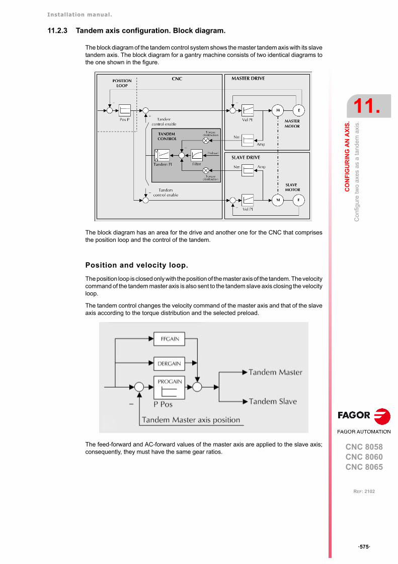
Installation manual.
CNC 8058CNC 8060CNC 8065
CO
NF
IGU
RIN
G A
N A
XIS
.
11.
Co
nfig
ure
two
axes
as
a ta
ndem
axi
s.
ꞏ575ꞏ
REF: 2102
11.2.3 Tandem axis configuration. Block diagram.
The block diagram of the tandem control system shows the master tandem axis with its slavetandem axis. The block diagram for a gantry machine consists of two identical diagrams tothe one shown in the figure.
The block diagram has an area for the drive and another one for the CNC that comprisesthe position loop and the control of the tandem.
Position and velocity loop.
The position loop is closed only with the position of the master axis of the tandem. The velocitycommand of the tandem master axis is also sent to the tandem slave axis closing the velocityloop.
The tandem control changes the velocity command of the master axis and that of the slaveaxis according to the torque distribution and the selected preload.
The feed-forward and AC-forward values of the master axis are applied to the slave axis;consequently, they must have the same gear ratios.
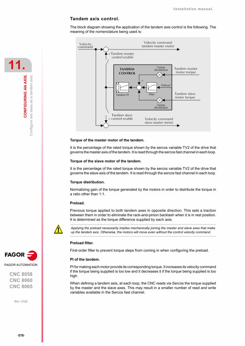
Installation manual.
CNC 8058CNC 8060CNC 8065
11.
CO
NF
IGU
RIN
G A
N A
XIS
.
Co
nfig
ure
two
axes
as
a ta
ndem
axi
s.
ꞏ576ꞏ
REF: 2102
Tandem axis control.
The block diagram showing the application of the tandem axis control is the following. Themeaning of the nomenclature being used is:
Torque of the master motor of the tandem.
It is the percentage of the rated torque shown by the sercos variable TV2 of the drive thatgoverns the master axis of the tandem. It is read through the sercos fast channel in each loop.
Torque of the slave motor of the tandem.
It is the percentage of the rated torque shown by the sercos variable TV2 of the drive thatgoverns the slave axis of the tandem. It is read through the sercos fast channel in each loop.
Torque distribution.
Normalizing gain of the torque generated by the motors in order to distribute the torque ina ratio other than 1:1.
Preload.
Previous torque applied to both tandem axes in opposite direction. This sets a tractionbetween them in order to eliminate the rack-and-pinion backlash when it is in rest position.It is determined as the torque difference supplied by each axis.
Preload filter.
First-order filter to prevent torque steps from coming in when configuring the preload.
PI of the tandem.
PI for making each motor provide its corresponding torque. It increases its velocity commandif the torque being supplied is too low and it decreases it if the torque being supplied is toohigh.
When defining a tandem axis, at each loop, the CNC reads via Sercos the torque suppliedby the master and the slave axes. This may result in a smaller number of read and writevariables available in the Sercos fast channel.
Applying the preload necessarily implies mechanically joining the master and slave axes that makeup the tandem axis. Otherwise, the motors will move even without the control velocity command.
Installation manual.
CNC 8058CNC 8060CNC 8065
CO
NF
IGU
RIN
G A
N A
XIS
.
11.
Co
nfig
ure
two
axes
as
a ta
ndem
axi
s.
ꞏ577ꞏ
REF: 2102
11.2.4 Tandem related variables.
Variables related to general machine parameters.
These variables are read-only synchronous and are evaluated during block preparation.They have generic names. Replace the letter "nb" with numbers, keeping the brackets.
Tandem related variables.
These variables are read/write (R/W) synchronous and are evaluated during execution.They correspond to linear and rotary axes and to the spindle. The mnemonics of the variableshave generic names.
• Replace "Xn" with the name or logic number of the axis.
• Replace the "ch" character with the channel number, maintaining the brackets.
(V.)A.TPIOUT.[Xn] (V.)A.TPIIN.[Xn]
The axis must be a valid tandem master, otherwise, it returns a value of zero.
(V.)A.TORQUE
The PLC reading of this variable comes in tenths (x10).
Variable PRG PLC INT
(V.)MPG.TMASTERAXIS[nb]Tandem [nb]. Logic number of the master axis
R R R
(V.)MPG.TSLAVEAXIS[nb]Tandem [nb]. Logic number of the slave axis
R R R
(V.)MPG.TORQDIST[nb]Tandem [nb]. Torque distribution
R R R
(V.)MPG.PRELOAD[nb]Tandem [nb]. Preload
R R R
(V.)MPG.PRELFITI[nb]Tandem [nb]. Time to apply the preload
R R R
(V.)MPG.TPROGAIN[nb]Tandem [nb]. Proportional gain
R R R
(V.)MPG.TINTIME[nb]Tandem [nb]. Integral gain
R R R
(V.)MPG.TCOMPLIM[nb]Tandem [nb]. Compensation limit
R R R
PRG PLC INT
(V.)[ch].A.TPIIN.xnInput of the PI of the master axis of the tandem (in rpm)
R R R
(V.)[ch].A.TPIOUT.xnOutput of the PI of the master axis of the tandem (in rpm)
R R R
(V.)[ch].A.TFILTOUT.xnOutput of the pre-load filter
R R R
(V.)[ch].A.PRELOAD.xnPreload
R/W R/W R/W
(V.)[ch].A.FTEO.xnVelocity command for Sercos
R R R
(V.)[ch].A.TORQUE.xnCurrent torque in Sercos
R R R
Installation manual.
CNC 8058CNC 8060CNC 8065
11.
CO
NF
IGU
RIN
G A
N A
XIS
.
Co
nfig
ure
two
axes
as
a ta
ndem
axi
s.
ꞏ578ꞏ
REF: 2102
11.2.5 Tandem adjustment procedure.
This procedure must bear in mind the type of machine. In general, the resonance frequencyof a tandem machine is low; therefore, the CNC must generate position commands withoutfrequency components higher than the resonance frequency.
It is recommended to begin the process with low jerk values (lower than 10 m/sec3) and lowKv. They can always be increased in a later readjustment.
Steps for the adjustment.
1 Move both axes independently.
The first step is to ensure the perfect operation of both the master and the slave axesseparately. Also verify that both axes move in the same direction with similar dynamics.
2 Move one of the axes at a slow and constant speed.
• Do not make jerky movements because the second motor is being dragged by thefirst one. In this situation, any acceleration or deceleration forces it to go from oneside of the backlash to the other thus making it jerky.
• Verify that the turning direction of both motors are coherent once the movement hasbeen carried out.
• Verify that the gear ratio in both motors is the same (same feed for same turningspeed).
• Carry out a basic adjustment of the velocity loop so the machine can move. It will bereadjusted later with both motors together.
• Do not set the friction parameters (there is already enough torque to move themachine).
3 Repeat the procedure with the second axis.
When adjusting the loops, use the same parameters if the motors are identical and thetorque distribution is 50%. If the motors are different, the axes must be adjusted so theirdynamic response is the same or very similar. When using AC-forward ("ACFGAIN" =YES), remember that each motor has half the inertia for a 50% torque distribution.
4 Enable the tandem with both motors.
First, disable the PI of he tandem, apply power and verify that the system is at rest.
Then, enter a low proportional value and eliminate the integral value of the PI of thetandem. Without preload, verify that the machine moves and that each motor suppliesits corresponding torque according to the parameter "TORQDIST" (e.g. half the torquefor 50% distribution).
To define the pre-load, monitor the torque of each motor (Sercos variable TV2). Whilestopped, increase the preload gradually until the motors supply torque in oppositedirections.
Having enabled the tandem, move slowly in both directions and verify that it worksproperly. Make sure that it is not jerky and that each motor supplies its correspondingtorque according to parameters "TORQDIST" and "PRELOAD".
Finally, readjust the velocity loop in both motors with the method used normally.
Observe that reversing the turning direction of a motor reverses the direction of the torque and,consequently, it will be necessary to change the direction of its values monitored with drive parametersSP43 and TP85.
i
While changing the parameters of the velocity loop, the best thing would be to change them on bothdrives at the same time. But, since this is not possible, it is recommended to make small changes inthe values or make them while the motor is stopped.
i
Installation manual.
CNC 8058CNC 8060CNC 8065
CO
NF
IGU
RIN
G A
N A
XIS
.
11.
Ana
log
axes
.
ꞏ579ꞏ
REF: 2102
11.3 Analog axes.
11.3.1 Configure the number of the analog output and of the feedback input.
Both the feedback input and the velocity command output are configured by machineparameters. Each axis has the following machine parameters to configure it.
Configure the analog output of the axis.
The velocity command for an analog axis may be taken from an analog output of the remotemodules or of a Sercos drive. It is selected with parameter ANAOUTID. In either case, thisparameter indicates the analog output used for the command.
Managing the analog command from CANfagor remote modules.
In this case, this parameter indicates the number of the analog output used for the command.The analog output modules are numbered following the logic order of the remote groups(rotary switch of the power supply). If there are several analog-output modules in each group,the order is from top to bottom and from left to right. The analog outputs of the first modulewill be 1 through 4, those of the second module 5 through 8 and so on.
Managing the analog command from Sercos drives.
In this case, this parameter indicates the number of the analog output and the drive to beused. The parameter is set with a three-digit number; the first digit indicates the number ofthe analog output to be used (1 or 2) and the other two digits indicate the logic address ofthe drive (1 through 32). The "address" rotary selector switch sets the logic address.
For example, if the parameter is with a value of ꞏ107ꞏ, it indicates that the CNC uses analoginput ꞏ1ꞏ of the drive whose logic address is ꞏ7ꞏ
Configure the feedback input for the axis.
The feedback inputs for an analog axis may be located in remote modules, in a Sercos driveor locally in the central unit itself. It is selected with parameter COUNTERTYPE.
Once it has been determined where the feedback input is, Parameter COUNTERID mustbe set indicating which feedback input will be used (either local or remote) or the drivenumber.
When using the feedback input of a Sercos drive, home search is not possible; therefore,the axis must have absolute feedback.
Parameter. Meaning.
ANAOUTID Number of the analog output associated with the axis.
COUNTERTYPE Type of feedback input for the axis.
COUNTERID Number of the feedback input for the axis.
Parameter. Value.
ANAOUTID 1 - 16
Parameter. Value.
ANAOUTID 101 -132201 - 232
When using the feedback input of a Sercos drive, set drive parameter PP5=-0.0001.i
Installation manual.
CNC 8058CNC 8060CNC 8065
11.
CO
NF
IGU
RIN
G A
N A
XIS
.
Ana
log
axes
.
ꞏ580ꞏ
REF: 2102
Feedback input in CANfagor remote modules.
A counter module is used as feedback input in the remote modules. Parameter COUNTERIDindicates the number of the feedback input to be used.
The counter modules are numbered following the logic order of the remote groups (rotaryswitch of the power supply). If there are several Counter modules in each group, the orderis from top to bottom and from left to right. The counters of the first module will be 1 through4, those of the second module 5 through 8 and so on.
Feedback input in Sercos drives.
In this case, the second feedback input of the drive will always be used. ParameterCOUNTERID indicates the logic address of the drive (from 1 to 32). The "address" rotaryselector switch sets the logic address.
Local feedback input.
The central unit has two feedback inputs. Parameter COUNTERID indicates the feedbackinput being used.
Parameter. Value.
COUNTERTYPE Remote.
COUNTERID Number of the feedback input.
Parameter. Value.
COUNTERTYPE Drive.
COUNTERID Number of the feedback input.
Parameter. Value.
COUNTERTYPE Local.
COUNTERID Number of the feedback input.
Installation manual.
CNC 8058CNC 8060CNC 8065
CO
NF
IGU
RIN
G A
N A
XIS
.
11.
Ana
log
axes
.
ꞏ581ꞏ
REF: 2102
11.3.2 Configure 2 axes with the same feedback input and analog output.
There are machines having 2 axes that are never in the same configuration at the same time,because one of them is always parked; for example when changing spindles with an internalmotor used to move its articulation.
In these cases, both motors are controlled by the same servo drive and there is a singlefeedback input and a single analog output for the CNC. This way, although the motors areidentical, the axes may be totally different, compensations, dynamics, etc.
Configuring the axes.
To use the same feedback input, parameters COUNTERTYPE and COUNTERID of bothaxes must be the same. To use the same analog output, parameter ANAOUTID of both axesmust be identical.
Besides, the motors must necessarily be identical because the following machineparameters must have the same values for both axes.
The PLC routine must include the detection of the active axis and of the parked axis.
Parameter Meaning
ABSFEEDBACK Type of feedback.
SINMAGNI Multiplying factor for the sinusoidal signal.
I0TYPE Reference mark (I0) type.
REFPULSE Flank of the reference signal (I0).
ABSOFF Offset of the feedback device with respect to I0.
EXTMULT External multiplying factor.
I0CODDI1 Pitch between 2 fixed I0 signals
I0CODDI2 Pitch between 2 variable I0 signals

Installation manual.
CNC 8058CNC 8060CNC 8065
11.
CO
NF
IGU
RIN
G A
N A
XIS
.
Mul
ti-ax
is m
ana
gem
ent.
ꞏ582ꞏ
REF: 2102
11.4 Multi-axis management.
A multi-axis group consists of several Sercos axes or spindles controlled by a single drive,although not simultaneously. The axes and spindles may have different dynamics and maybe controlled either by the same motor or by different motors.
The internal (motor) feedback of both axes will be located at the drive whereas the external(direct) feedback of each axis may be located at the remote modules, at a Sercos drive orlocally in the central unit itself. When using a single drive, it is possible to use the freefeedback input of that drive or of another one. Each axis can have its own feedback systemor both axes can share the same feedback system.
Requirements and limitations of a multi-axis group.
The axes associated with the same drive must meet the following requirements.
• Any Sercos axis of the system may be part of a multi-axis group, except those that belongto gantry or tandem axes.
• Since each axis and spindle defined at the CNC can have several parameter sets, thesum of sets of all the axes and/or spindles included in a group must not exceed the 8sets available at the drive. For example, a group may consist of 8 axes with 1 parameterset each, a spindle with 4 sets plus 2 axes with 2 sets each, etc.
• Since the axes are controlled by the same drive, all the axes of a group must have thesame Sercos address (parameter DRIVEID).
• All the axes of a group must work in the same Sercos operating mode, position or speed,(parameter OPMODEP). If the external feedback (direct feedback) of the axis isconnected to a drive, the axis may be operated in either position-Sercos mode or velocity-Sercos mode (velocity-Sercos mode is recommended). If the external feedback (directfeedback) of the axis is connected to local or remote feedback input, the axis can onlywork in velocity-Sercos mode.
• If the external feedback is local or remote, the CNC homes the axis as if it were analog;the drive does not know that the axis has been homed and does not update its positionvalue, it only receives the velocity command. If the external feedback is connected toanother drive, it will not be possible to home the axis.
• The axis being governed by the drive is selected via PLC (mark SWITCH(axis)). The PLCmust either park the axes not governed by the drive or set them as DRO axes.
• For a multi-axis where the same motor controls several axes, the CNC allows dynamicmanagement of the multi-axis. This type of management consists of activating the axes
Multi-axis group composed by two axes, each one controlled by a motor.
Multi-axis group composed by two axes controlled by a single motor.
DR
IVE
MO
DU
LE
Axis A1
Axis A2D
RIV
E M
OD
UL
E
Axis A2
Axis A1
Installation manual.
CNC 8058CNC 8060CNC 8065
CO
NF
IGU
RIN
G A
N A
XIS
.
11.
Mul
ti-ax
is m
ana
gem
ent.
ꞏ583ꞏ
REF: 2102
of the group as they are programmed. To carry out the dynamic management of a multi-axis group, the axes of the group should be configured as dead axes and the DWELL>0parameter defined. The axes use the DWELL parameter as a waiting time before givingan error for not having the SWITCH mark active. The PLC monitors that the ENABLEmark is active in order to engage that axis and activate its mark SWITCH, SERVOON,SPENA and DRENA mark.
• The CNC keeps monitoring (following error, tendency test, etc.) all the axes sharing thedrive even if the axis is not selected.
Behavior of the CNC and the drive on power-up and whenswitching axes.
Behavior of the CNC and the drive on power-up.
On power-up, the drive controls the master axis of the group, the first axis defined in the group(parameter MULAXISNAME_1). The CNC assumes default set of the axis (parameterDEFAULTSET). The PLC program must define the set and the gear assumed by the drive.
Behavior of the CNC and the drive when switching axes.
When the PLC switches an axis and/or spindle at the drive, the PLC routine must define theset and the gear assumed by the drive. The CNC assumes default set (parameterDEFAULTSET).
Parameter matching between the CNC and the Sercos drive
In a multi-axis group, the CNC matches the drive with the general parameters and theparameters of the first set of the master axis. During parameter matching, the CNC only usesthe parameters of the first set of the drive, the rest of the sets of the drive must be set viaDDSSetup or at the drive itself. The CNC uses the following criterion for parameter matching.
• The CNC sends the general parameters of the master axis to the general parametersof the drive.
• The CNC sends the parameters of the default set of the master axis (set defined inparameter DEFAULTSET) to the general parameters or of the first set of the driveaccordingly.
• The CNC sends the gear parameters of the master axis to the gear parameters of thedrive.
The gears that correspond to the slave axes must be set at the drive itself.
The master axis of a multi-axis group continues counting evenwhen it is disabled.
For a multi-axis with a motor controlling two axes, the master axis still continues countingeven when it is disabled. This allows the master axis to be activated without having to doa home search.
Installation manual.
CNC 8058CNC 8060CNC 8065
11.
CO
NF
IGU
RIN
G A
N A
XIS
.
Mul
ti-ax
is m
ana
gem
ent.
ꞏ584ꞏ
REF: 2102
11.4.1 Configuration of a multi-axis group. Machine parameters.
Configuring a multi-axis group.
Multi-axis groups are configured via machine parameters. Each multi-axis group has thefollowing general machine parameters to configure it.
Defining the multi-axis groups of the system.
Parameter MULTIAXIS shows the multi-axis group definition table for defining the numberof groups of the system and the composition of each group.
Parameter MULNGROUP sets the number of multi-axis groups of the system. The tableshows a GROUP_n parameter for each multi-axis group.
Defining the axes or spindles that make up the multi-axis group.
Parameter MULNAXIS sets the number of axes and/or spindles making up the multi-axisgroup. Since each axis or spindle of the CNC can have several parameter sets, the numberof axes of the group is limited by the 8 parameter sets available at the drive. The parametersets of the drive are distributed among all the axes and/or spindles that make up the multi-axis group, so a group may be formed by 8 axes with 1 parameter set for each, 1 spindlewith 4 sets plus 2 axes with 2 sets each, etc.
The table shows a MUMLAXISNAME_n parameter for each axis or spindle that belong tothe multi-axis group. Any Sercos axis of the system may be part of a group, except thosethat belong to gantry or tandem axes. The first axis of the group will be the master axis, theone the drive will use by default; the order of the rest of the axes is irrelevant. On systempower-up, the CNC will use the parameters of the master axis to run the parameter matchingwith the drive.
Setting the drive to be used.
At the axes that belong to a multi-axis group, parameter DRIVESET indicates the set to beactivated at the drive after a set or gear change at the CNC (G112 and M41 to M44). TheCNC sends the changes of Kv, feed-forward (parameter FFGAIN) and AC-forward(parameter ACFGAIN) to the set indicated in this parameter.
Being parameter matching active, the CNC sends the parameters of set ꞏ1ꞏ of the masteraxis to the set ꞏ0ꞏ and to the gear ꞏ1ꞏ (first) of the drive. For the rest of the sets of the masteraxis, the CNC only sends the gear data to the drive; set ꞏ2ꞏ of the CNC to the gear 2 of thedrive and so on. At the master axis of multi-axis group, in order for parameter matching towork properly, this parameter must coincide with the set number where it is; i.e. DRIVESET=1in set ꞏ1ꞏ, DRIVESET=2 in ꞏ2ꞏ and so on. At the slave axis of a multi-axis group, this parameterindicates the gear to be used at the drive. If the axis belongs to a multi-axis group, theparameter does not admit a ꞏ0ꞏ (zero) value.
Parameter. Meaning.
MULTIAXIS Table of multi-axis groups.
MULNGROUP Number of multi-axis groups in the system.
GROUP n Multi-axis groups.
MULNAXIS Number of axes and/or spindles making up the multi-axisgroup.
MULAXISNAME n Name of the axes and/or spindles of the group.
Parameter. Meaning.
DRIVESET Set of the drive to be used.
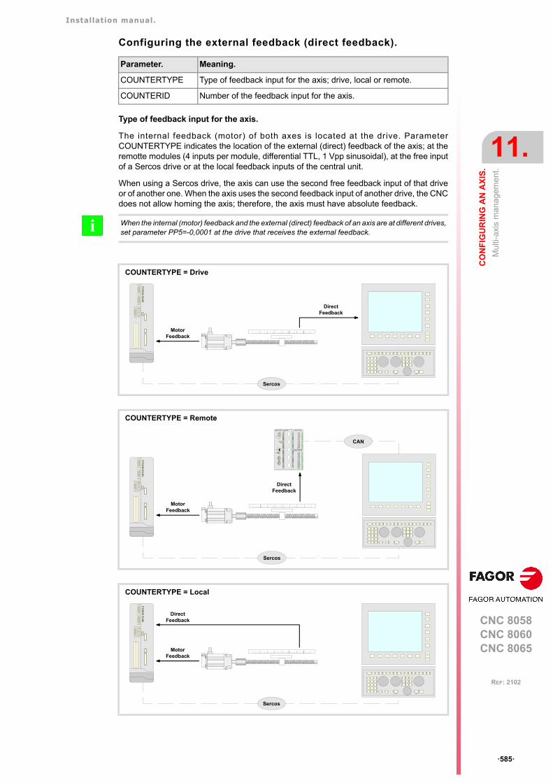
Installation manual.
CNC 8058CNC 8060CNC 8065
CO
NF
IGU
RIN
G A
N A
XIS
.
11.
Mul
ti-ax
is m
ana
gem
ent.
ꞏ585ꞏ
REF: 2102
Configuring the external feedback (direct feedback).
Type of feedback input for the axis.
The internal feedback (motor) of both axes is located at the drive. ParameterCOUNTERTYPE indicates the location of the external (direct) feedback of the axis; at theremotte modules (4 inputs per module, differential TTL, 1 Vpp sinusoidal), at the free inputof a Sercos drive or at the local feedback inputs of the central unit.
When using a Sercos drive, the axis can use the second free feedback input of that driveor of another one. When the axis uses the second feedback input of another drive, the CNCdoes not allow homing the axis; therefore, the axis must have absolute feedback.
Parameter. Meaning.
COUNTERTYPE Type of feedback input for the axis; drive, local or remote.
COUNTERID Number of the feedback input for the axis.
When the internal (motor) feedback and the external (direct) feedback of an axis are at different drives,set parameter PP5=-0,0001 at the drive that receives the external feedback.i
COUNTERTYPE = Drive
COUNTERTYPE = Remote
COUNTERTYPE = Local
MotorFeedback
DirectFeedback
Sercos
DR
IVE
MO
DU
LE
MotorFeedback
DirectFeedback
Sercos
DR
IVE
MO
DU
LE
DIGITAL INPUT
X1
X2
GND
I8
I1
N.C.
I2
I3
I4
I5
I6
I7
GND
I16
I9
N.C.
I10
I11
I12
I13
I14
I15
DIGITAL OUTPUT
X1
X2
GND
O8
O1
+24V
O2
O3
O4
O5
O6
O7
GND
O16
O9
+24V.
O10
O11
O12
O13
O14
O15
COUNTER
X1
X2
X3
X4
X5
GND
CAN L
SHIELD
SHIELD
CAN H
X3
GND
CAN L
SHIELD
SHIELD
CAN H
X2
POWER SUPPLY
4
01FEDCBA
98 7 65 32
ADD MSB
LINE TERM
10
12
ADDRESS
RESET
POWER
SYSTEM READY
+5 ERROR
+5 OVER CURRENT
OVER VOLTAGE+5V
X1
GND IN
CHASIS
GND IN
+24V IN
SYSTEM
READY
CAN
MotorFeedback
DirectFeedback
Sercos
DR
IVE
MO
DU
LE
Installation manual.
CNC 8058CNC 8060CNC 8065
11.
CO
NF
IGU
RIN
G A
N A
XIS
.
Mul
ti-ax
is m
ana
gem
ent.
ꞏ586ꞏ
REF: 2102
Number of the feedback input for the axis.
Depending on the type of feedback, this parameter indicates which feedback input will beused (either local or remote) or the drive number. When two axes will not be in theconfiguration at the same time, the CNC allows using the same feedback input for both axes.
Type of feedback. Number of the feedback input for the axis.
Feedback input in CANfagorremote modules.
A counter module is used as feedback input in the remote modules.This parameter indicates the number of the feedback input beingused. The counter modules are numbered following the logic order of theremote groups (rotary switch of the power supply). If there areseveral Counter modules in each group, the order is from top tobottom and from left to right. The counters of the first module will be1 through 4, those of the second module 5 through 8 and so on.
Feedback input in Sercosdrives.
In this case, the second feedback input of the drive will always beused. The parameter indicates the logic address of the drive (from1 to 32). The "address" rotary selector switch sets the logic address.
Local feedback input. The central unit has two feedback inputs. This parameter indicatesthe feedback input being used.
Installation manual.
CNC 8058CNC 8060CNC 8065
CO
NF
IGU
RIN
G A
N A
XIS
.
11.
Mul
ti-ax
is m
ana
gem
ent.
ꞏ587ꞏ
REF: 2102
11.4.2 Configuration of a multi-axis group. The PLC routine generates an error.
Multi-axis groups are managed from the PLC using one of its marks.
The PLC routine must define the set and the gear assumed by the drive on power-up, togglebetween the various axes or spindle of the group and define the set and gear assumed bythe drive for each change of axis or spindle. The axis or spindle changing process mustconsider the following aspects (assuming that the X axis is active and the X1 axis is parked)
1 Park the X axis.
2 Verify that the X axis is parked.
3 Switch to the X1 axis (SWITCHX1=1).
4 Otherwise, write the parameters at the drive. Verify that the parameters have been writtenat the drive and, if necessary, validate the parameters of the drive
5 Change the set and/or gear at the drive.
6 Verify that the set and/or gear has been changed (mark SERPLCAC) and that the setand/gear of the drive is correct (parameters GV21 and GV25 of the drive).
7 Enable the X1 axis.
PLC signal. Meaning.
SWITCH(axis) The PLC activates this mark to let the CNC know which axis or spindlethat it must govern.
Installation manual.
CNC 8058CNC 8060CNC 8065
11.
CO
NF
IGU
RIN
G A
N A
XIS
.
Mul
ti-ax
is m
ana
gem
ent.
ꞏ588ꞏ
REF: 2102
11.4.3 Changing the set and the gear at the CNC and at the drive.
A set is a bunch of parameters that may be activated and gear is a bunch of parametersspecifically related to gear ratios. The parameters that define the gear are included in theset, one gear per set. A set change activates all its parameters, including those of the gear,whereas a gear change only activates the specific gear-related parameters.
Axes and spindles included in a multi-axis group.
If the axis or spindle does not belong to a multi-axis group, functions G112 and M41 to M44act in the same way at the CNC; but at the drive they activate the programmed gear, not theone defined in parameter DRIVESET.
Spindle and C axis.
Function. CNC Drive.
G112(axes only)
The CNC activates the programmedset.
The drive activates the gear definedin parameter DRIVESET of theprogram set.
M41-M44(spindles only)
The CNC activates the programmedset.
The drive activates the gear definedin parameter DRIVESET of theprogram set.
(V.)A.SETGE.xn Not used. The drive activates the programmedset and/or gear.
Function. CNC Drive.
#CAX ON The CNC activates the set definedin parameter CAXSET.
The drive activates the geardefined in parameter CAXSET.
#CAX OFF The CNC restores the set that wasactive before enabling the spindleas C axis.
The drive restores the gear thatwas active before enabling thespindle as C axis.

Installation manual.
CNC 8058CNC 8060CNC 8065
CO
NF
IGU
RIN
G A
N A
XIS
.
11.
Mul
ti-ax
is m
ana
gem
ent.
ꞏ589ꞏ
REF: 2102
11.4.4 Configuration examples.
Example 1. 2-axis system, each with its own motor.
The system has the following characteristics.
• A single drive controls both axes, each with its own motor.
• Each axis uses a different type of feedback.
Configuration of the multi-axis group.
Configuring the axes.
A1 axis The external (direct) feedback is connected to the drive itself.
A2 axis The external (direct) feedback is connected to the remote modules.
MULTIAXIS GROUP_1
MULNGROUP = 1 MULNAXIS = 2MULAXISNAME_1 = A1MULAXISNAME_2 = A2
DRIVEID OPMODEP FBACKSRC COUNTERTYPE COUNTERID
A1 axis 1 Speed External Drive 1
A2 axis 1 Speed External Remote 1
Sercos
Feedback
DR
IVE
MO
DU
LE
CAN
MotorFeedback
DIGITAL INPUT
X1
X2
GND
I8
I1
N.C.
I2
I3
I4
I5
I6
I7
GND
I16
I9
N.C.
I10
I11
I12
I13
I14
I15
DIGITAL OUTPUT
X1
X2
GND
O8
O1
+24V
O2
O3
O4
O5
O6
O7
GND
O16
O9
+24V.
O10
O11
O12
O13
O14
O15
COUNTER
X1
X2
X3
X4
X5
GND
CAN L
SHIELD
SHIELD
CAN H
X3
GND
CAN L
SHIELD
SHIELD
CAN H
X2
POWER SUPPLY
4
01FE
DCBA98 7 6 5 32
ADD MSB
LINE TERM
10
12
ADDRESS
RESET
POWER
SYSTEM READY
+5 ERROR
+5 OVER CURRENT
OVER VOLTAGE+5V
X1
GND IN
CHASIS
GND IN
+24V IN
SYSTEM
READY
Axis A2
Axis A1
DirectFeedback
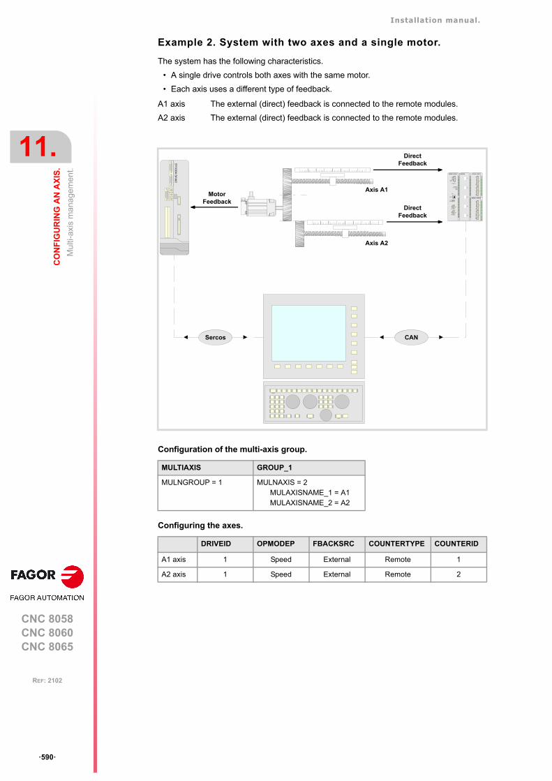
Installation manual.
CNC 8058CNC 8060CNC 8065
11.
CO
NF
IGU
RIN
G A
N A
XIS
.
Mul
ti-ax
is m
ana
gem
ent.
ꞏ590ꞏ
REF: 2102
Example 2. System with two axes and a single motor.
The system has the following characteristics.
• A single drive controls both axes with the same motor.
• Each axis uses a different type of feedback.
Configuration of the multi-axis group.
Configuring the axes.
A1 axis The external (direct) feedback is connected to the remote modules.
A2 axis The external (direct) feedback is connected to the remote modules.
MULTIAXIS GROUP_1
MULNGROUP = 1 MULNAXIS = 2MULAXISNAME_1 = A1MULAXISNAME_2 = A2
DRIVEID OPMODEP FBACKSRC COUNTERTYPE COUNTERID
A1 axis 1 Speed External Remote 1
A2 axis 1 Speed External Remote 2
Sercos
DirectFeedback
DR
IVE
MO
DU
LE
CAN
MotorFeedback
DIGITAL INPUT
X1
X2
GND
I8
I1
N.C.
I2
I3
I4
I5
I6
I7
GND
I16
I9
N.C.
I10
I11
I12
I13
I14
I15
DIGITAL OUTPUT
X1
X2
GND
O8
O1
+24V
O2
O3
O4
O5
O6
O7
GND
O16
O9
+24V.
O10
O11
O12
O13
O14
O15
COUNTER
X1
X2
X3
X4
X5
GND
CAN L
SHIELD
SHIELD
CAN H
X3
GND
CAN L
SHIELD
SHIELD
CAN H
X2
POWER SUPPLY
4
01
FEDCBA9
8 7 6 5 32
ADD MSB
LINE TERM
10
12
ADDRESS
RESET
POWER
SYSTEM READY
+5 ERROR
+5 OVER CURRENT
OVER VOLTAGE+5V
X1
GND IN
CHASIS
GND IN
+24V IN
SYSTEM
READY
Axis A2
Axis A1
DirectFeedback
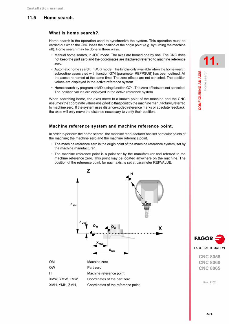
Installation manual.
CNC 8058CNC 8060CNC 8065
CO
NF
IGU
RIN
G A
N A
XIS
.
11.
Hom
e se
arch
.
ꞏ591ꞏ
REF: 2102
11.5 Home search.
What is home search?.
Home search is the operation used to synchronize the system. This operation must becarried out when the CNC loses the position of the origin point (e.g. by turning the machineoff). Home search may be done in three ways.
• Manual home search, in JOG mode. The axes are homed one by one. The CNC doesnot keep the part zero and the coordinates are displayed referred to machine referencezero.
• Automatic home search, in JOG mode. This kind is only available when the home searchsubroutine associated with function G74 (parameter REFPSUB) has been defined. Allthe axes are homed at the same time. The zero offsets are not canceled. The positionvalues are displayed in the active reference system.
• Home search by program or MDI using function G74. The zero offsets are not canceled.The position values are displayed in the active reference system.
When searching home, the axes move to a known point of the machine and the CNCassumes the coordinate values assigned to that point by the machine manufacturer, referredto machine zero. If the system uses distance-coded reference marks or absolute feedback,the axes will only move the distance necessary to verify their position.
Machine reference system and machine reference point.
In order to perform the home search, the machine manufacturer has set particular points ofthe machine; the machine zero and the machine reference point.
• The machine reference zero is the origin point of the machine reference system, set bythe machine manufacturer.
• The machine reference point is a point set by the manufacturer and referred to themachine reference zero. This point may be located anywhere on the machine. Theposition of the reference point, for each axis, is set at parameter REFVALUE.
OM Machine zero
OW Part zero
H Machine reference point
XMW, YMW, ZMW, Coordinates of the part zero
XMH, YMH, ZMH, Coordinates of the reference point.
Z
XOM OW
XMH
XMW
ZMW
ZMH
H
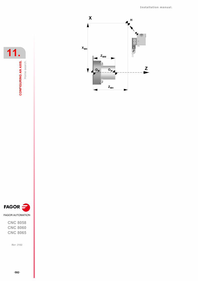
Installation manual.
CNC 8058CNC 8060CNC 8065
11.
CO
NF
IGU
RIN
G A
N A
XIS
.
Hom
e se
arch
.
ꞏ592ꞏ
REF: 2102
X
Z
H
OM OW
ZMH
ZMW
XMH
Installation manual.
CNC 8058CNC 8060CNC 8065
CO
NF
IGU
RIN
G A
N A
XIS
.
11.
Hom
e se
arch
.
ꞏ593ꞏ
REF: 2102
11.5.1 Home search (axes and spindles).
Home search with a feedback system that does not havedistance-coded reference marks.
When the feedback system does not have distance-coded reference marks, the axis mustalways be homed at a specific point of the machine which is referred to as Machine ReferencePoint. The installer must place a home switch for each axis at the machine reference point.
When starting the search, the axis moves in the direction set by parameter REFDIREC andat the feedrate indicated by parameter REFFEED1 until reaching the home switch. Whenthe axis presses the home switch, it starts moving in the opposite direction at the feedrateset by parameter REFFEED2. It keeps on moving after releasing the home switch until theCNC detects a marker pulse (I0) from the feedback device.
Home search with a feedback system that has distance-codedreference marks.
When the feedback system has distance-coded reference marks (coded I0) may bereferenced (homed) at any point of the machine; there is no need for home switches.However, it will be necessary to set the machine reference point if the axis uses leadscrewerror compensation because the amount of error at the machine reference point must be ꞏ0ꞏ.
The axis moves the minimum distance possible, less than 200 mm, in the direction set byparameter REFDIREC and at the feedrate indicated in "REFFEED2" until the CNC receivesa reference marker pulse from the feedback system.. If before receiving the reference signal,the axis presses the home switch, it starts moving in the opposite direction and goes on withthe process getting away from the switch until the CNC receives the reference marker pulseof the feedback system.
Redefine the machine reference point after having dismountedor replaced the feedback system.
Sometimes, to readjust the machine, it is necessary to take down the feedback device, thuswhen putting back up, the new home point might no coincide with the previous one.
Since the home point must still be the same, the difference between the new point and theold point must be assigned to parameter REFSHIFT . This way, when the axis finds the I0,it moves the distance indicated in REFSHIFT and at that point updates its coordinate to thevalue of REFVALUE..
Parameter. Meaning.
I0TYPE Not-distance-coded.
DECINPUT The axis has a home switch.
REFDIREC Home searching direction.
REFFEED1 Fast home searching feedrate.
REFFEED2 Slow home searching feedrate.
Parameter. Value.
I0TYPE Increasing distance-codedDecreasing distance-coded
REFDIREC Home searching direction.
REFFEED2 Slow home searching feedrate.
Parameter. Value.
REFVALUE Position of the reference point.
REFSHIFT Offset of the reference point.
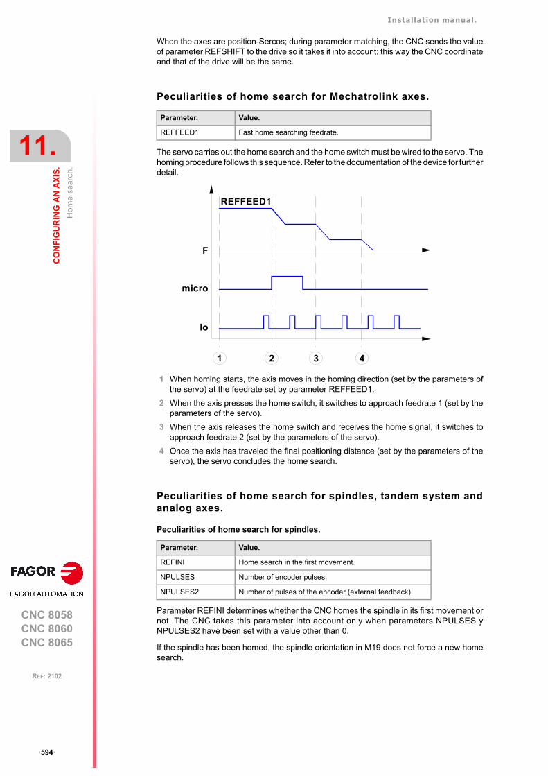
Installation manual.
CNC 8058CNC 8060CNC 8065
11.
CO
NF
IGU
RIN
G A
N A
XIS
.
Hom
e se
arch
.
ꞏ594ꞏ
REF: 2102
When the axes are position-Sercos; during parameter matching, the CNC sends the valueof parameter REFSHIFT to the drive so it takes it into account; this way the CNC coordinateand that of the drive will be the same.
Peculiarities of home search for Mechatrolink axes.
The servo carries out the home search and the home switch must be wired to the servo. Thehoming procedure follows this sequence. Refer to the documentation of the device for furtherdetail.
1 When homing starts, the axis moves in the homing direction (set by the parameters ofthe servo) at the feedrate set by parameter REFFEED1.
2 When the axis presses the home switch, it switches to approach feedrate 1 (set by theparameters of the servo).
3 When the axis releases the home switch and receives the home signal, it switches toapproach feedrate 2 (set by the parameters of the servo).
4 Once the axis has traveled the final positioning distance (set by the parameters of theservo), the servo concludes the home search.
Peculiarities of home search for spindles, tandem system andanalog axes.
Peculiarities of home search for spindles.
Parameter REFINI determines whether the CNC homes the spindle in its first movement ornot. The CNC takes this parameter into account only when parameters NPULSES yNPULSES2 have been set with a value other than 0.
If the spindle has been homed, the spindle orientation in M19 does not force a new homesearch.
Parameter. Value.
REFFEED1 Fast home searching feedrate.
Parameter. Value.
REFINI Home search in the first movement.
NPULSES Number of encoder pulses.
NPULSES2 Number of pulses of the encoder (external feedback).
Io
micro
F
1 2 3
REFFEED1
4
Installation manual.
CNC 8058CNC 8060CNC 8065
CO
NF
IGU
RIN
G A
N A
XIS
.
11.
Hom
e se
arch
.
ꞏ595ꞏ
REF: 2102
The CNC will home the spindle again in the following situations.
• When programming a new home search with function G74, via program or MDI/MDAmode.
• When the spindle exceeds the feedback pulses reading limit.
• After a failure at the Sercos ring.
• When replacing the encoder.
Peculiarities of home search for a tandem system.
In a tandem system, only the master axis is homed; the home search is transparent for theslave that just moves along with the master.
Peculiarities of home search for analog axes homed in parallel.
When programming a home search on several analog axes in parallel; i.e. with the sameindex (for example "G74 X1 Y1 Z1"), the execution sequence is the following.
1 All the axes move at the same time, each one at its feedrate REFFEED1 until each onedetects its home switch. The axes wait on the switch until all the axes involved in the homesearch detect the home switch.
2 Once all the axes have reached their switches, the home search begins sequentially oneach axis at feedrate REFFEED2 starting with the last axis reaching its home switch andfollowing their order according to the logic number of the axes.
3 If any of the axes of the programmed group does not have a home switch, the axis waitsfor the rest of the axes to reach their switches and then starts looking for its referencemark at REFFEED2 feedrate in its corresponding order (sequence).
4 If none of the axes of the programmed group has a home switch, the home search startsat REFFEED2 with the axis having the lowest logic number and when that axis hasfinished, it goes on sequentially with the rest.
Installation manual.
CNC 8058CNC 8060CNC 8065
11.
CO
NF
IGU
RIN
G A
N A
XIS
.
Hom
e se
arch
.
ꞏ596ꞏ
REF: 2102
11.5.2 Home search (gantry axes).
Gantry axes may be homed in the same three ways described for the rest of the axes andspindles. The following requirements must be met when setting the parameters for theGantry axes.
• The type of reference mark (parameter I0TYPE) must be the same for both axes.
• When not using distance-coded reference marks (I0), either both axes or just the masteraxis may have a home switch ( parameter DECINPUT).
Analog axes and velocity-Sercos axes.
Home search with a feedback system that does not have distance-coded referencemarks. The master and slave axes have a home switch.
The CNC starts moving both axes in the direction indicated by parameter REFDIREC of themaster axis. This movement is carried out at the feedrate indicated by parameter REFFEED1of the master axis until any of the axis presses its home switch. After pressing the homeswitch, both axes move at REFFEED2 feedrate of the master axis until the axis that pressedthe home switch detects its reference mark. After detecting the reference mark, the CNCresets the position value of this axis to the value set by parameter REFVALUE and startshoming the second axis.
To home the second axis, both axes move at the feedrate indicated by parameter REFFEED1of the master axis until the second axis presses its home switch. After pressing the homeswitch, both axes move at REFFEED2 feedrate of the master axis until the axis that pressedthe home switch detects its reference mark. After detecting the reference mark, the CNCresets the position value of this axis to the value set by parameter REFVALUE.
If the first axis pressing its home switch was the master and its parameter REFSHIFT is otherthan zero, the slave axis does not start homing until the master axis ends the movementcorresponding to parameter REFSHIFT. The REFSHIFT parameter of the slave axis isapplied when it resets the position value after having detected the reference mark withoutmaking the movement.
Home search with a feedback system that does not have distance-coded referencemarks. Only the master axis has a home switch.
The CNC starts moving both axes in the direction indicated by parameter REFDIREC of themaster axis. This movement is carried out at the feedrate indicated by parameter REFFEED1of the master axis until this axis presses its home switch. After pressing its home switch, bothaxes move at REFFEED2 feedrate of the master axis until the slave axis detects its referencemark. After detecting the reference mark, the CNC resets the position value of the slave axisto the value set by parameter REFVALUE and considering parameter REFSHIFT. To updatethe position value, the axis does not move.
Then, the master axis searches the reference mark. Once the reference mark has beendetected, the CNC resets its position value to the one set by parameter REFVALUE and
Parameter. Meaning.
I0TYPE Reference mark (I0) type. Normal (non-distance-coded) onboth axes.To be defined for the master and slave axes.
DECINPUT The axis has a home switch.To be defined for the master and slave axes.
REFDIREC Home searching direction.To be defined for the master axis.
REFFEED1 Fast home searching feedrate.To be defined for the master axis.
REFFEED2 Slow home searching feedrate.To be defined for the master axis.
REFVALUE Position of the reference point.To be defined for the master and slave axes.
REFSHIFT Offset of the reference point.To be defined for the master and slave axes.
Installation manual.
CNC 8058CNC 8060CNC 8065
CO
NF
IGU
RIN
G A
N A
XIS
.
11.
Hom
e se
arch
.
ꞏ597ꞏ
REF: 2102
considering parameter REFSHIFT. In this case, the axis will move to apply the REFSHIFTvalue.
Home search with a feedback system that has distance-coded reference marks orwhere none of the axes has a home switch.
The CNC starts moving both axes in the direction indicated by parameter REFDIREC of themaster axis. This movement is carried out at the feedrate indicated by parameter REFFEED2of the master axis until the slave axis detects its reference mark. After detecting the referencemark, the CNC resets the position value of this axis to the value set by parameter REFVALUEand considering parameter REFSHIFT if there is one.
Then, the master axis searches the reference mark. After detecting the reference mark, theCNC resets the position value of the master axis to the value set by parameter REFVALUEand considering parameter REFSHIFT if there is one.
Position-Sercos axes
To homing these axes, both must either have distance-coded reference marks or a homeswitch. If both axes have a home switch but do not have distance-coded reference marks,the home switches must be placed in such way that the master axis is not pressing its homeswitch while homing the slave axis (first to one to search its reference mark).
The CNC sends to the drive the command to home the slave axis. In the process, the CNCreads the increment in the real (actual) slave position value and sends it to the master axisas an increment of the theoretical position value, hence making the master axis follow theslave axis only by the lag between the theoretical and real position values.
When the slave axis has been homed, the CNC sends to the drive the command to homethe master axis. In this case, the slave axis follows the master axis.
In order to prevent the axis following the one being homed from jerking due to the changein position value, the CNC makes sure that the increment of the real position valuecorresponds at the most with the homing feedrate (parameter REFFEED1) and that it doesnot exceed the maximum acceleration allowed for that axis.
When both axes have been homed, the CNC takes into account the difference between theposition values to correct it, if so permitted by parameter DIFFCOMP.
Coordinate (position) difference compensation after a homesearch.
The CNC corrects the position difference between the master and the slave axes after theyare homed. The position value correction (compensation) may be applied to any type of axis;analog, position-Sercos and velocity-Sercos.
Position value compensation is enabled by parameter DIFFCOMP and it is applied withmarks DIFFCOMP(axis) and SERVO*ON(axis) as follows.
• With the up-flank of SERVO*ON if DIFFCOMP is active.
• With the up-flank of DIFFCOMP if SERVO*ON is active.
To compensate the position value, the slave axis will move until reaching the position of themaster axis at the feedrate set by parameter REFFEED2. This process can only beinterrupted with RESET. The REFPOIN(axis) mark of both axes is activated when theposition value compensation is completed.
Parameter. Meaning.
DIFFCOMP Compensate for the coordinate (position) differencebetween the two axes after G74.
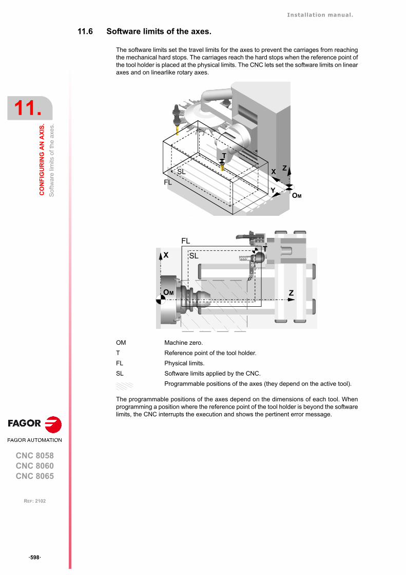
Installation manual.
CNC 8058CNC 8060CNC 8065
11.
CO
NF
IGU
RIN
G A
N A
XIS
.
Sof
twar
e lim
its o
f the
axe
s.
ꞏ598ꞏ
REF: 2102
11.6 Software limits of the axes.
The software limits set the travel limits for the axes to prevent the carriages from reachingthe mechanical hard stops. The carriages reach the hard stops when the reference point ofthe tool holder is placed at the physical limits. The CNC lets set the software limits on linearaxes and on linearlike rotary axes.
The programmable positions of the axes depend on the dimensions of each tool. Whenprogramming a position where the reference point of the tool holder is beyond the softwarelimits, the CNC interrupts the execution and shows the pertinent error message.
OM Machine zero.
T Reference point of the tool holder.
FL Physical limits.
SL Software limits applied by the CNC.
Programmable positions of the axes (they depend on the active tool).
T
SL ZX
YOM
FL
Z
XT
FL
SL
OM
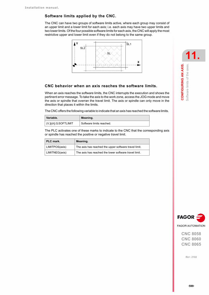
Installation manual.
CNC 8058CNC 8060CNC 8065
CO
NF
IGU
RIN
G A
N A
XIS
.
11.
Sof
twar
e lim
its o
f the
axe
s.
ꞏ599ꞏ
REF: 2102
Software limits applied by the CNC.
The CNC can have two groups of software limits active, where each group may consist ofan upper limit and a lower limit for each axis; i.e. each axis may have two upper limits andtwo lower limits. Of the four possible software limits for each axis, the CNC will apply the mostrestrictive upper and lower limit even if they do not belong to the same group.
CNC behavior when an axis reaches the software limits.
When an axis reaches the software limits, the CNC interrupts the execution and shows thepertinent error message. To take the axis to the work zone, access the JOG mode and movethe axis or spindle that overran the travel limit. The axis or spindle can only move in thedirection that places it within the limits.
The CNC offers the following variable to indicate that an axis has reached the software limits.
The PLC activates one of these marks to indicate to the CNC that the corresponding axisor spindle has reached the positive or negative travel limit.
Variable. Meaning.
(V.)[ch].G.SOFTLIMIT Software limits reached.
PLC mark. Meaning.
LIMITPOS(axis) The axis has reached the upper software travel limit.
LIMITNEG(axis) The axis has reached the lower software travel limit.
SL1SL2
X
Y
SL
Installation manual.
CNC 8058CNC 8060CNC 8065
11.
CO
NF
IGU
RIN
G A
N A
XIS
.
Sof
twar
e lim
its o
f the
axe
s.
ꞏ600ꞏ
REF: 2102
11.6.1 How to set the software travel limits.
Considerations for setting the software travel limits.
The software travel limits may be positive or negative, but the lower limits must be smallerthan the upper ones; otherwise, the axis might not move in any direction.
If when changing the limits, an axis is positioned beyond them, that axis can only be movedin the direction that places it within those limits.
If for an axis, both upper and lower limits of a group are set to ꞏ0ꞏ, the CNC cancels thoselimits on that axis and applies the ones of the other group.
The software limits are always applied in radius, regardless of the setting of parameterDIAMPROG, of the active function G151/G152 and of the method chosen to set them.
Default software travel limits (first software travel limits).
The default software travel limits, those assumed by the CNC on power-up, are set bymachine parameters; if both parameters are set to ꞏ0ꞏ, these limits are canceled.
These software travel limits may be changed by program or MDI using the following functionsand variables. When modifying the limits with these functions or variables, the CNC assumesthose values as the new limits in this group.
Setting both upper and lower limits of an axis to ꞏ0ꞏ cancels the limits, regardless of theirvalues in the machine parameters. In this case, the CNC will apply the second software travellimits to the axis.
The new limits will be maintained after executing an M02 or M30, and after an emergencyor a reset. On power-up or after validating the axis machine parameters the CNC assumesthe software limits set by the machine parameters.
Modifying the software travel limits with functions G198/G199.
When programming G198 or G199, the CNC interprets that the coordinates programmednext set the new software limits.
Depending on the active work mode G90 or G91, the position of the new limits will be definedin absolute coordinates (G90) in the machine reference system or in incremental coordinates(G91) referred to the current active limits.
Parameter. Meaning.
LIMIT+ Upper software travel limits.
LIMIT- Lower software travel limits.
Function. Variable. Meaning.
G198 (V.)[ch].A.NEGLIMIT.xn Lower software travel limits.
G199 (V.)[ch].A.POSLIMIT.xn Upper software travel limits.
G198 X-1000 Y-1000
(New lower limits X=-1000 Y=-1000)
G199 X1000 Y1000
(New upper limits X=1000 Y=1000)
G90 G198 X-800
(New lower limit X=-800)
G91 G198 X-700
(New incremental lower limit X=-1500)
Installation manual.
CNC 8058CNC 8060CNC 8065
CO
NF
IGU
RIN
G A
N A
XIS
.
11.
Sof
twar
e lim
its o
f the
axe
s.
ꞏ601ꞏ
REF: 2102
Second software travel limits.
These software travel limits are set with the following variables that can be written via part-program, MDI, PLC or interface. These variables are initialized on power-up assuming themaximum value possible. When modifying the limits with these variables, the CNC assumesthose values as the new limits in this group.
Setting both upper and lower limits of an axis to ꞏ0ꞏ cancels the limits and the CNC appliesthe first software travel limits to the axis.
Variable. Meaning.
(V.)[ch].A.RTNEGLIMIT.xn Lower software travel limits (second limits).
(V.)[ch].A.RTPOSLIMIT.xn Upper software travel limits (second limits).
Installation manual.
CNC 8058CNC 8060CNC 8065
11.
CO
NF
IGU
RIN
G A
N A
XIS
.
Sof
twar
e lim
its o
f the
axe
s.
ꞏ602ꞏ
REF: 2102
11.6.2 Set the tolerance for an axis located at the software travel limits.
The tolerance for the software travel limits is set with machine parameter SWLIMITTOL. TheCNC applies this tolerance to the active software limits.
This tolerance indicates the maximum variation or oscillation allowed to a real coordinateof an axis referred to the software limits, before issuing an error indicating travel limit overrun.The programmed theoretical movement of the axis is only possible up to the exact limit, butthe real axis coordinate is allowed this margin before the error is issued. When they are DROaxes, the error is also issued when the real coordinate exceeds the limit over the tolerance.
When no theoretical movement has been programmed, the limit overrun error will only beissued when exceeding the tolerance in a sampling period (cycle time); for example, whenhitting the axis causing it to overrun the limits abruptly. In any other case, if no theoreticalmovement has been programmed for the axis, the error will not be issued even if it overrunsthe limits.
Parameter. Meaning.
SWLIMITTOL Software limit tolerance.
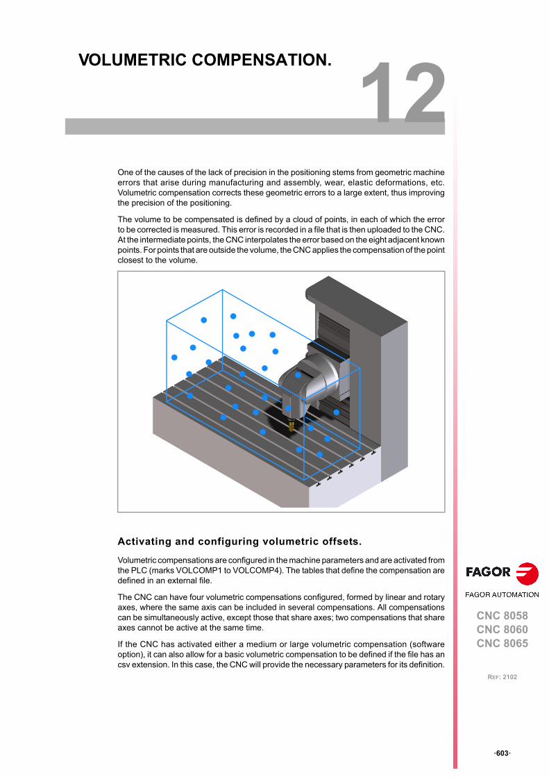
CNC 8058CNC 8060CNC 8065
12
ꞏ603ꞏ
REF: 2102
12.VOLUMETRIC COMPENSATION.
One of the causes of the lack of precision in the positioning stems from geometric machineerrors that arise during manufacturing and assembly, wear, elastic deformations, etc.Volumetric compensation corrects these geometric errors to a large extent, thus improvingthe precision of the positioning.
The volume to be compensated is defined by a cloud of points, in each of which the errorto be corrected is measured. This error is recorded in a file that is then uploaded to the CNC.At the intermediate points, the CNC interpolates the error based on the eight adjacent knownpoints. For points that are outside the volume, the CNC applies the compensation of the pointclosest to the volume.
Activating and configuring volumetric offsets.
Volumetric compensations are configured in the machine parameters and are activated fromthe PLC (marks VOLCOMP1 to VOLCOMP4). The tables that define the compensation aredefined in an external file.
The CNC can have four volumetric compensations configured, formed by linear and rotaryaxes, where the same axis can be included in several compensations. All compensationscan be simultaneously active, except those that share axes; two compensations that shareaxes cannot be active at the same time.
If the CNC has activated either a medium or large volumetric compensation (softwareoption), it can also allow for a basic volumetric compensation to be defined if the file has ancsv extension. In this case, the CNC will provide the necessary parameters for its definition.
Installation manual.
CNC 8058CNC 8060CNC 8065
12.
VO
LU
ME
TR
IC C
OM
PE
NS
AT
ION
.
ꞏ604ꞏ
REF: 2102
Volumetric compensation types.
The CNC has three types of volumetric compensation, which are selectable via itscorresponding software option: basic, medium or large. The “Large volumetriccompensation” option also allows the other two types of compensation to be used: mediumand basic. The “Medium volumetric compensation” also allows for the basic option to beused.
The volumetric compensation includes cross compensation and ballscrew compensation,and therefore it is not necessary to define the latter two; however, if they are defined, theCNC takes them into account. The CNC applies the cross compensation and ballscrewcompensation first, followed by the volumetric compensation.
On the gantry axes, compensation is defined for the master axis and the CNC also appliesit to the slave axis.
Type. Description.
Basic. • The volume to be compensated is defined by up to 25 points on each axis.• This compensation corrects translation errors.• The compensation tables are generated by the calibration application; they
are not editable from the CNC.• The OEM must define all the compensation data (axes that move, axes to
be compensated, position and size of the volume to be compensated, etc.)in the machine parameters and select the file containing the compensationdata.
• The basic compensation is the fastest to calibrate, but it can be less precisethan the others (it corrects fewer error components).
Medium.Large.
• Volume compensation of up to 10 m³ (medium) or more than 10 m³ (large).• This compensation corrects the 21 geometric error components (translation,
rotation and squaring).• The compensation tables are generated by the calibration application; they
are not editable from the CNC.• The OEM must only define the axes to be compensated for the machine
parameters and select the file containing the calibration data. The rest of thedata (axes that move, error to be compensated, etc.) are implicit in the file.
• Medium and large compensations are more precise than basiccompensation, but they are slower to calibrate.
Installation manual.
CNC 8058CNC 8060CNC 8065
VO
LU
ME
TR
IC C
OM
PE
NS
AT
ION
.
12.
Bas
ic v
olu
met
ric c
ompe
nsa
tion.
ꞏ605ꞏ
REF: 2102
12.1 Basic volumetric compensation.
For basic volumetric compensation, it is necessary to define both axes: the one that movesand the one that is compensated. This makes it possible to define another type ofcompensation that does not involve the same three axes; for example, a common crosscompensation or 2D compensation for the falling ram.
12.1.1 Setup. General; machine parameters.
The CNC displays these parameters when loading a file with the extension csv in theparameter VCOMPFILE.
12.1.2 Setup. PLC. General modifiable signals.
All volumetric compensations can be simultaneously active, as long as there are no commonaxes among them. The CNC applies the volumetric compensation after applying theleadscrew compensation and the cross compensation. Volumetric compensation remainsactive after a reset, error or end of program (M30).
Parameter. Meaning.
VOLCOMP MPG This parameter shows the volumetric compensation table.
VMOVAXIS1VMOVAXIS2VMOVAXIS3
MPG Axis whose movement affects another axis. At least one axis mustbe defined. These linear or rotary axes define the volume to becompensated. If it is a gantry axis, it is only necessary to define themaster axis.
NPOINTSAX1NPOINTSAX2NPOINTSAX3
MPG Number of points that define the volume to be compensated for eachaxis. The total number of points for the volume is limited to 15,625,and is calculated in the following manner: NPOINTSAX1 ×NPOINTSAX2 × NPOINTSAX3. The total number of points for thevolume can be distributed among all the axes, up to a maximum of1000 points per axis.
INIPOSAX1INIPOSAX2INIPOSAX3
MPG Initial position of the basic volumetric compensation for theMOVAXIS axis.
INCREAX1INCREAX2INCREAX3
MPG Interval between points for the MOVAXIS axis in basic volumetriccompensation.
VCOMPAXIS1VCOMPAXIS2VCOMPAXIS3
MPG These parameters set the axes to be compensated with volumetriccompensation. The axes may be linear or rotary, and at least oneaxis must be defined. The axes associated with the samecompensation may belong to different channels and they may beinterchanged from one channel to another while the compensationis active. An axis can be included in several different compensations,but compensations that share axes cannot be active at the sametime. If it is a gantry axis, it is only necessary to define the masteraxis; the CNC also applies the compensation to the slave axis.
VCOMPFILE MPG The data to be compensated must be a text file (in csv format). TheOEM or the company responsible for the calibration must generatethis file and define it in the machine parameter VCOMPFILE. Theunits in the file data (millimeters or inches) must be those defined bythe CNC (parameter INCHES).
[MPG] General machine parameter.
PLC signal. Meaning.
VOLCOMP1VOLCOMP2VOLCOMP3VOLCOMP4
PLC_M(R/W)
If the PLC activates one of these marks (changing it from 0 to 1), theCNC activates the corresponding volumetric compensation(parameter VOLCOMP). If the PLC deactivates one of these marks(changing it from 1 to 0), the CNC deactivates the correspondingvolumetric compensation. The mark VOLCOMP1 corresponds tothe first volumetric compensation (parameter VOLCOMP 1); themark VOLCOMP2 is for the second and so forth.
[PLC_M] PLC Mark.(R/W) Modifiable signal.
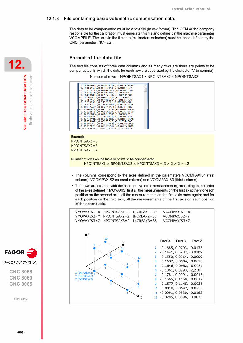
Installation manual.
CNC 8058CNC 8060CNC 8065
12.
VO
LU
ME
TR
IC C
OM
PE
NS
AT
ION
.
Bas
ic v
olu
met
ric c
ompe
nsa
tion.
ꞏ606ꞏ
REF: 2102
12.1.3 File containing basic volumetric compensation data.
The data to be compensated must be a text file (in csv format). The OEM or the companyresponsible for the calibration must generate this file and define it in the machine parameterVCOMPFILE. The units in the file data (millimeters or inches) must be those defined by theCNC (parameter INCHES).
Format of the data file.
The text file consists of three data columns and as many rows are there are points to becompensated, in which the data for each row are separated by the character "," (a comma).
Number of rows = NPOINTSAX1 × NPOINTSAX2 × NPOINTSAX3
• The columns correspond to the axes defined in the parameters VCOMPAXIS1 (firstcolumn), VCOMPAXIS2 (second column) and VCOMPAXIS3 (third column).
• The rows are created with the consecutive error measurements, according to the orderof the axes defined in MOVAXIS; first all the measurements on the first axis; then for eachposition on the second axis, all the measurements on the first axis once again; and foreach position on the third axis, all the measurements of the first axis on each positionof the second axis.
Example.NPOINTSAX1=3NPOINTSAX2=2NPOINTSAX3=2
Number of rows on the table or points to be compensated.NPOINTSAX1 × NPOINTSAX2 × NPOINTSAX3 = 3 × 2 × 2 = 12
Error X, Error Y, Error Z
-0.1685, 0.0703, -0.0135-0.1441, 0.0932, -0.0109-0.1550, 0.0964, -0.00090.1632, 0.0904, -0.00280.1646, 0.0952, 0.0081
-0.1861, 0.0993, -2,230-0.1781, 0.0991, 0.0013-0.1566, 0.1150, 0.00120.1577, 0.1145, -0.00360.0018, 0.0542, -0.0235
-0.0091, 0.0930, -0.0162-0.0285, 0.0896, -0.0033
VMOVAXIS1=X NPOINTSAX1=3 INCREAX1=30 VCOMPAXIS1=XVMOVAXIS2=Y NPOINTSAX2=2 INCREAX2=30 VCOMPAXIS2=YVMOVAXIS3=Z NPOINTSAX3=2 INCREAX3=36 VCOMPAXIS3=Z
1
7
2
8
3
9
4
10
5
11
6
12
1X (INIPOSAX1)Y (INIPOSAX2)Z (INIPOSAX3)
X
Y
Z
2
3
4
5
6
7
8
9
10
11
12
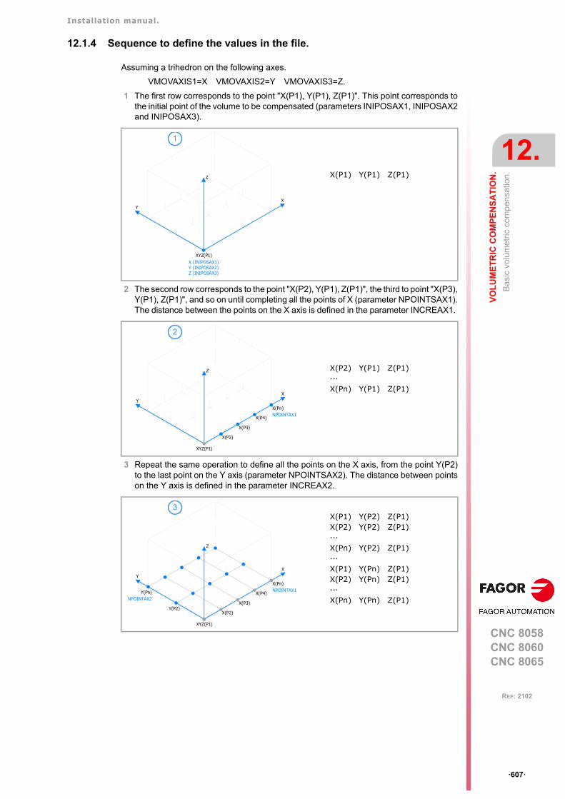
Installation manual.
CNC 8058CNC 8060CNC 8065
VO
LU
ME
TR
IC C
OM
PE
NS
AT
ION
.
12.
Bas
ic v
olu
met
ric c
ompe
nsa
tion.
ꞏ607ꞏ
REF: 2102
12.1.4 Sequence to define the values in the file.
Assuming a trihedron on the following axes.
VMOVAXIS1=X VMOVAXIS2=Y VMOVAXIS3=Z.
1 The first row corresponds to the point "X(P1), Y(P1), Z(P1)". This point corresponds tothe initial point of the volume to be compensated (parameters INIPOSAX1, INIPOSAX2and INIPOSAX3).
2 The second row corresponds to the point "X(P2), Y(P1), Z(P1)", the third to point "X(P3),Y(P1), Z(P1)", and so on until completing all the points of X (parameter NPOINTSAX1).The distance between the points on the X axis is defined in the parameter INCREAX1.
3 Repeat the same operation to define all the points on the X axis, from the point Y(P2)to the last point on the Y axis (parameter NPOINTSAX2). The distance between pointson the Y axis is defined in the parameter INCREAX2.
X
XYZ(P1)X (INIPOSAX1)Y (INIPOSAX2)Z (INIPOSAX3)
Y
Z X(P1) Y(P1) Z(P1)
1
X
XYZ(P1)
X(Pn)
X(P2)
X(P3)
X(P4)
Y
NPOINTAX1
Z X(P2) Y(P1) Z(P1)···X(Pn) Y(P1) Z(P1)
2
XYZ(P1)
Y(P2)X(P2)
X(P3)
X(P4)
X
Z
YX(Pn)NPOINTAX1Y(Pn)
NPOINTAX2
X(P1) Y(P2) Z(P1)X(P2) Y(P2) Z(P1)···X(Pn) Y(P2) Z(P1)···X(P1) Y(Pn) Z(P1)X(P2) Y(Pn) Z(P1)···X(Pn) Y(Pn) Z(P1)
3

Installation manual.
CNC 8058CNC 8060CNC 8065
12.
VO
LU
ME
TR
IC C
OM
PE
NS
AT
ION
.
Bas
ic v
olu
met
ric c
ompe
nsa
tion.
ꞏ608ꞏ
REF: 2102
4 Once all the points on the plane have been defined (coordinate Z(P1)), repeat the sameoperation from point "X(P1), Y(P1), Z(P2)" until the last point on the Z axis (parameterNPOINTSAX3).
XYZ(P1)
Y(P2)X(P2)
X(P3)
X(P4)
X
Z
YX(Pn)NPOINTAX1Y(Pn)
NPOINTAX2 Z(P2)
X(P1) Y(P1) Z(P2)X(P2) Y(P1) Z(P2)···X(Pn) Y(P1) Z(P2)
XYZ(P1)
Y(P2)X(P2)
X(P3)
X(P4)
X
Z
YX(Pn)NPOINTAX1Y(Pn)
NPOINTAX2 Z(P2)
XYZ(P1)
Y(P2)X(P2)
X(P3)
X(P4)
X
Z
YX(Pn)NPOINTAX1Y(Pn)
NPOINTAX2 Z(P2)
Z(Pn)
X(P1) Y(P2) Z(P2)X(P2) Y(P2) Z(P2)···X(Pn) Y(P2) Z(P2)···X(P1) Y(Pn) Z(P2)X(P2) Y(Pn) Z(P2)···X(Pn) Y(Pn) Z(P2)
X(P1) Y(P1) Z(Pn)X(P2) Y(P1) Z(Pn)···X(Pn) Y(P1) Z(Pn)···X(P1) Y(Pn) Z(Pn)X(P2) Y(Pn) Z(Pn)···X(Pn) Y(Pn) Z(Pn)···X(P1) Y(Pn) Z(Pn)X(P2) Y(Pn) Z(Pn)···X(Pn) Y(Pn) Z(Pn)
4
5
6
Installation manual.
CNC 8058CNC 8060CNC 8065
VO
LU
ME
TR
IC C
OM
PE
NS
AT
ION
.
12.
Bas
ic v
olu
met
ric c
ompe
nsa
tion.
ꞏ609ꞏ
REF: 2102
12.1.5 Variables.
The following variables may be accessed from (PRG) the part-program and from theMDI/MDA mode, PLC and (INT) from an external application. For each variable, the tableindicates whether the access is reading (R) or writing (W). PLC access to the variables, forboth reading and writing, will be synchronous. Access to the variables from the part programreturns the value for the block preparation, except when indicated otherwise.
General; machine parameters.
Syntax of the variable.
ꞏtblꞏ Table number.
Variables. PRG PLC INT
(V.)MPG.VMOVAXIS1[tbl](V.)MPG.VMOVAXIS2[tbl](V.)MPG.VMOVAXIS3[tbl]Name of the axis that generates changes when moved.Units: -.
R(*) R R
(V.)MPG.NPOINTSAX1[tbl](V.)MPG.NPOINTSAX2[tbl](V.)MPG.NPOINTSAX3[tbl]Number of points of basic volumetric compensation on each axis.Units: -.
R R R
(V.)MPG.INIPOSAX1[tbl](V.)MPG.INIPOSAX2[tbl](V.)MPG.INIPOSAX3[tbl]Initial position of the basic volumetric compensation for the MOVAXISaxis. Units: -.
R R R
(V.)MPG.INCREAX1[tbl](V.)MPG.INCREAX2[tbl](V.)MPG.INCREAX3[tbl]Interval between points for the MOVAXIS axis in basic volumetriccompensation.Units: -.
R R R
(V.)MPG.VCOMPAXIS1[tbl](V.)MPG.VCOMPAXIS2[tbl](V.)MPG.VCOMPAXIS3[tbl]Name of the axis to be compensated.Units: -.
R(*) R R
(V.)MPG.VCOMPFILE[tbl]File containing volumetric compensation data.Units: -.
R R R
(*) The CNC evaluates the variable during execution (it stops the block preparation).
V.MPG.VMOVAXIS2[1] Name of the second axis on the first volumetriccompensation table.
V.MPG.NPOINTAX2[2] Number of points for the second axis on the secondvolumetric compensation table.
Installation manual.
CNC 8058CNC 8060CNC 8065
12.
VO
LU
ME
TR
IC C
OM
PE
NS
AT
ION
.
Bas
ic v
olu
met
ric c
ompe
nsa
tion.
ꞏ610ꞏ
REF: 2102
General modifiable signals.
Syntax of the variable.
Volumetric compensation.
Syntax of the variable.
ꞏchꞏ Channel number.
ꞏxnꞏ Name, logic number or index of the axis.
Variables. PRG PLC INT
(V.)PLC.VOLCOMP1(V.)PLC.VOLCOMP2(V.)PLC.VOLCOMP3(V.)PLC.VOLCOMP4These variables reflect the value of the marks VOLCOMP1 toVOLCOMP4 of the PLC. If the PLC activates one of these marks(changing it from 0 to 1), the CNC activates the correspondingvolumetric compensation (parameter VOLCOMP). Units: -.
R(*) - R/W
(*) The CNC evaluates the variable during execution (it stops the block preparation).
V.PLC.VOLCOMP1 Volumetric compensation ꞏ1ꞏ.
Variables. PRG PLC INT
(V.)[ch].A.VOLCOMP.xnValue that the volumetric compensation is adding to the axis. If thevolumetric compensation is not active, the variable returns the value to0 (zero).Units: Millimeters, inches or degrees.
R(*) R R
(*) The CNC evaluates the variable during execution (it stops the block preparation).
V.A.VOLCOMP.Z Z axis.
V.A.VOLCOMP.3 Axis with logic number ꞏ3ꞏ.
V.[2].A.VOLCOMP.3 Axis with index ꞏ3ꞏ in the channel ꞏ2ꞏ.
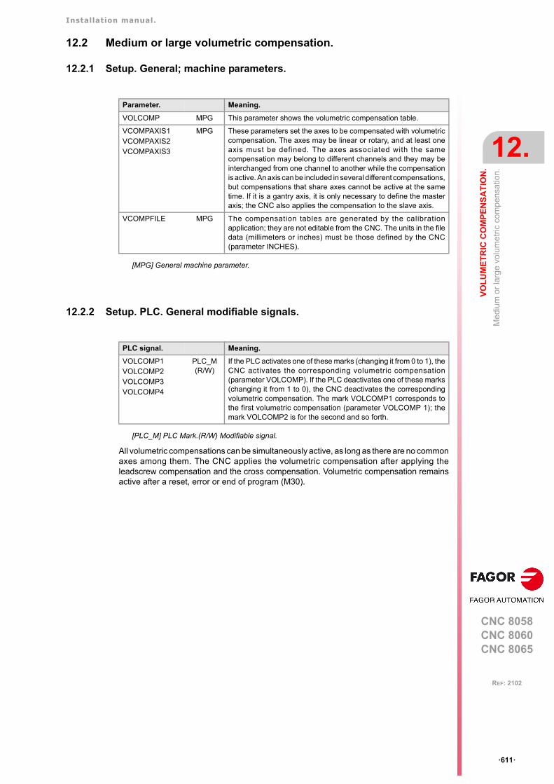
Installation manual.
CNC 8058CNC 8060CNC 8065
VO
LU
ME
TR
IC C
OM
PE
NS
AT
ION
.
12.
Med
ium
or
larg
e vo
lum
etric
com
pens
atio
n.
ꞏ611ꞏ
REF: 2102
12.2 Medium or large volumetric compensation.
12.2.1 Setup. General; machine parameters.
12.2.2 Setup. PLC. General modifiable signals.
All volumetric compensations can be simultaneously active, as long as there are no commonaxes among them. The CNC applies the volumetric compensation after applying theleadscrew compensation and the cross compensation. Volumetric compensation remainsactive after a reset, error or end of program (M30).
Parameter. Meaning.
VOLCOMP MPG This parameter shows the volumetric compensation table.
VCOMPAXIS1VCOMPAXIS2VCOMPAXIS3
MPG These parameters set the axes to be compensated with volumetriccompensation. The axes may be linear or rotary, and at least oneaxis must be defined. The axes associated with the samecompensation may belong to different channels and they may beinterchanged from one channel to another while the compensationis active. An axis can be included in several different compensations,but compensations that share axes cannot be active at the sametime. If it is a gantry axis, it is only necessary to define the masteraxis; the CNC also applies the compensation to the slave axis.
VCOMPFILE MPG The compensation tables are generated by the calibrationapplication; they are not editable from the CNC. The units in the filedata (millimeters or inches) must be those defined by the CNC(parameter INCHES).
[MPG] General machine parameter.
PLC signal. Meaning.
VOLCOMP1VOLCOMP2VOLCOMP3VOLCOMP4
PLC_M(R/W)
If the PLC activates one of these marks (changing it from 0 to 1), theCNC activates the corresponding volumetric compensation(parameter VOLCOMP). If the PLC deactivates one of these marks(changing it from 1 to 0), the CNC deactivates the correspondingvolumetric compensation. The mark VOLCOMP1 corresponds tothe first volumetric compensation (parameter VOLCOMP 1); themark VOLCOMP2 is for the second and so forth.
[PLC_M] PLC Mark.(R/W) Modifiable signal.
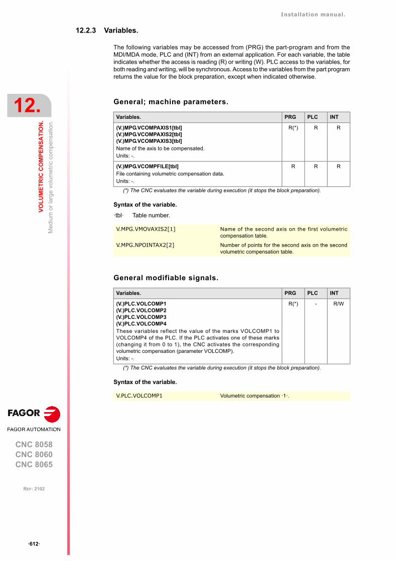
Installation manual.
CNC 8058CNC 8060CNC 8065
12.
VO
LU
ME
TR
IC C
OM
PE
NS
AT
ION
.
Med
ium
or
larg
e vo
lum
etric
com
pens
atio
n.
ꞏ612ꞏ
REF: 2102
12.2.3 Variables.
The following variables may be accessed from (PRG) the part-program and from theMDI/MDA mode, PLC and (INT) from an external application. For each variable, the tableindicates whether the access is reading (R) or writing (W). PLC access to the variables, forboth reading and writing, will be synchronous. Access to the variables from the part programreturns the value for the block preparation, except when indicated otherwise.
General; machine parameters.
Syntax of the variable.
ꞏtblꞏ Table number.
General modifiable signals.
Syntax of the variable.
Variables. PRG PLC INT
(V.)MPG.VCOMPAXIS1[tbl](V.)MPG.VCOMPAXIS2[tbl](V.)MPG.VCOMPAXIS3[tbl]Name of the axis to be compensated.Units: -.
R(*) R R
(V.)MPG.VCOMPFILE[tbl]File containing volumetric compensation data.Units: -.
R R R
(*) The CNC evaluates the variable during execution (it stops the block preparation).
V.MPG.VMOVAXIS2[1] Name of the second axis on the first volumetriccompensation table.
V.MPG.NPOINTAX2[2] Number of points for the second axis on the secondvolumetric compensation table.
Variables. PRG PLC INT
(V.)PLC.VOLCOMP1(V.)PLC.VOLCOMP2(V.)PLC.VOLCOMP3(V.)PLC.VOLCOMP4These variables reflect the value of the marks VOLCOMP1 toVOLCOMP4 of the PLC. If the PLC activates one of these marks(changing it from 0 to 1), the CNC activates the correspondingvolumetric compensation (parameter VOLCOMP). Units: -.
R(*) - R/W
(*) The CNC evaluates the variable during execution (it stops the block preparation).
V.PLC.VOLCOMP1 Volumetric compensation ꞏ1ꞏ.

Installation manual.
CNC 8058CNC 8060CNC 8065
VO
LU
ME
TR
IC C
OM
PE
NS
AT
ION
.
12.
Med
ium
or
larg
e vo
lum
etric
com
pens
atio
n.
ꞏ613ꞏ
REF: 2102
Volumetric compensation.
Syntax of the variable.
ꞏchꞏ Channel number.
ꞏxnꞏ Name, logic number or index of the axis.
Variables. PRG PLC INT
(V.)[ch].A.VOLCOMP.xnValue that the volumetric compensation is adding to the axis. If thevolumetric compensation is not active, the variable returns the value to0 (zero).Units: Millimeters, inches or degrees.
R(*) R R
(V.)[ch].A.PIVOT.xnDistance from the pivot center to the tool tip in machine coordinates.This variable returns the sum of the spindle offsets (parameters TDATA)and the tool offset.
R(*) R R
(*) The CNC evaluates the variable during execution (it stops the block preparation).
V.A.VOLCOMP.Z Z axis.
V.A.VOLCOMP.3 Axis with logic number ꞏ3ꞏ.
V.[2].A.VOLCOMP.3 Axis with index ꞏ3ꞏ in the channel ꞏ2ꞏ.
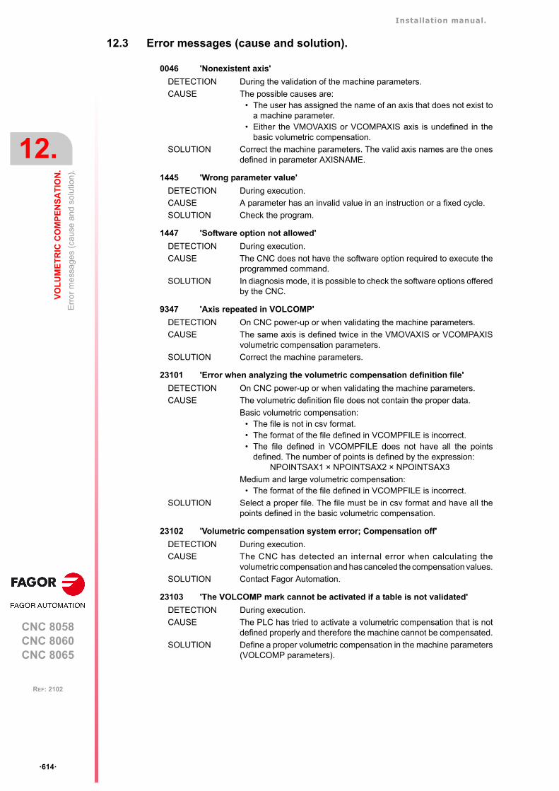
Installation manual.
CNC 8058CNC 8060CNC 8065
12.
VO
LU
ME
TR
IC C
OM
PE
NS
AT
ION
.
Err
or
mes
sag
es (
cau
se a
nd s
olut
ion)
.
ꞏ614ꞏ
REF: 2102
12.3 Error messages (cause and solution).
0046 'Nonexistent axis'
DETECTION During the validation of the machine parameters.
CAUSE The possible causes are:• The user has assigned the name of an axis that does not exist to
a machine parameter.• Either the VMOVAXIS or VCOMPAXIS axis is undefined in the
basic volumetric compensation.
SOLUTION Correct the machine parameters. The valid axis names are the onesdefined in parameter AXISNAME.
1445 'Wrong parameter value'
DETECTION During execution.
CAUSE A parameter has an invalid value in an instruction or a fixed cycle.
SOLUTION Check the program.
1447 'Software option not allowed'
DETECTION During execution.
CAUSE The CNC does not have the software option required to execute theprogrammed command.
SOLUTION In diagnosis mode, it is possible to check the software options offeredby the CNC.
9347 'Axis repeated in VOLCOMP'
DETECTION On CNC power-up or when validating the machine parameters.
CAUSE The same axis is defined twice in the VMOVAXIS or VCOMPAXISvolumetric compensation parameters.
SOLUTION Correct the machine parameters.
23101 'Error when analyzing the volumetric compensation definition file'
DETECTION On CNC power-up or when validating the machine parameters.
CAUSE The volumetric definition file does not contain the proper data.
Basic volumetric compensation:• The file is not in csv format.• The format of the file defined in VCOMPFILE is incorrect.• The file defined in VCOMPFILE does not have all the points
defined. The number of points is defined by the expression:NPOINTSAX1 × NPOINTSAX2 × NPOINTSAX3
Medium and large volumetric compensation:• The format of the file defined in VCOMPFILE is incorrect.
SOLUTION Select a proper file. The file must be in csv format and have all thepoints defined in the basic volumetric compensation.
23102 'Volumetric compensation system error; Compensation off'
DETECTION During execution.
CAUSE The CNC has detected an internal error when calculating thevolumetric compensation and has canceled the compensation values.
SOLUTION Contact Fagor Automation.
23103 'The VOLCOMP mark cannot be activated if a table is not validated'
DETECTION During execution.
CAUSE The PLC has tried to activate a volumetric compensation that is notdefined properly and therefore the machine cannot be compensated.
SOLUTION Define a proper volumetric compensation in the machine parameters(VOLCOMP parameters).
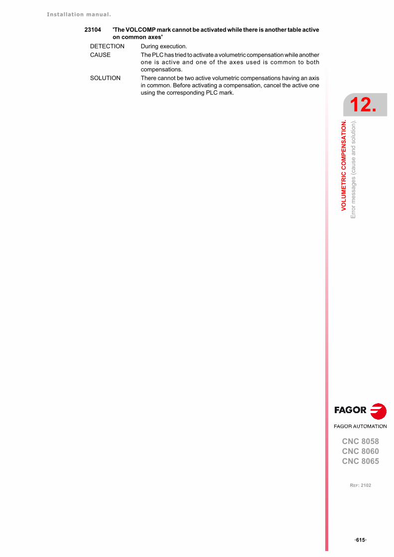
Installation manual.
CNC 8058CNC 8060CNC 8065
VO
LU
ME
TR
IC C
OM
PE
NS
AT
ION
.
12.
Err
or
mes
sag
es (
cau
se a
nd s
olut
ion)
.
ꞏ615ꞏ
REF: 2102
23104 'The VOLCOMP mark cannot be activated while there is another table activeon common axes'
DETECTION During execution.
CAUSE The PLC has tried to activate a volumetric compensation while anotherone is active and one of the axes used is common to bothcompensations.
SOLUTION There cannot be two active volumetric compensations having an axisin common. Before activating a compensation, cancel the active oneusing the corresponding PLC mark.

Installation manual.
CNC 8058CNC 8060CNC 8065
12.
VO
LU
ME
TR
IC C
OM
PE
NS
AT
ION
.
Err
or
mes
sag
es (
cau
se a
nd s
olut
ion)
.
ꞏ616ꞏ
REF: 2102
CNC 8058CNC 8060CNC 8065
13
ꞏ617ꞏ
REF: 2102
13.CONFIGURING THE HSC MODE.
Nowadays, lots of parts are designed using CAD-CAM systems. This type of information islater post-processed to generate a CNC program, usually made up of a large number of veryshort blocks of several mm or just a few tenths of a micron.
In this type of parts, the CNC must be capable to analyze a large number of points in advanceso it can generate a continuous path that goes through (or near) the points of the programwhile keeping (the best way possible) the programmed feedrate and the restrictions ofmaximum acceleration, jerk, etc of each axis and of the path.
Default HSC mode.
The command to execute programs made up of lots of small blocks, typical of high speedmachining, is carried out with a single instruction #HSC. This function offers several waysto work; optimizing part surface finish (SURFACE mode) optimizing the contour error(CONTERROR mode) or the machining speed (FAST mode).
The default machining mode is defined by parameter HSCDEFAULTMODE, where Fagoroffers the SURFACE mode as default. The more sophisticated algorithms of the SURFACEmode obtain more accurate machining. Tests run at Fagor have obtained an averageaccuracy improvement of 25% to 30%. In parallel, the CNC controls machine movementsmore smoothly reducing considerably the vibrations due to part geometry or machinedynamics. Reducing machine vibrations results in higher surface quality of the machinedparts.
Installation manual.
CNC 8058CNC 8060CNC 8065
13.
CO
NF
IGU
RIN
G T
HE
HS
C M
OD
E.
Influ
ence
of
the
type
of a
ccel
era
tion
and
of th
e fil
ters
in H
SC
mo
de.
ꞏ618ꞏ
REF: 2102
13.1 Influence of the type of acceleration and of the filters in HSC mode.
HSC optimizing the chordal error (CONTERROR mode).
In this mode, the CNC modifies the geometry through intelligent algorithms for eliminatingunnecessary points and generating splines or polynomial transitions between blocks alwaysrespecting the error limits set for this mode. This way, the contour is traveled at a variablefeedrate according to the curvature and the programmed parameters (acceleration andfeedrate) but without going beyond the set error limits.
This mode uses this type of acceleration is defined with parameter SLOPETYPE. Thefollowing situations can occur when the type of acceleration has jerk.
• Jerk control permits pretty smooth velocity and acceleration profiles.
In this case, if there is no need to eliminate resonance frequencies, there is no need toactivate filters to make the path smoother. Since there are no filters, the part will be moreaccurate because the path gores through the programmed points. The exception is onsections where the CNC disconnects the spline because it exceeds the error limit and,in that case, it executes a rounding polynomial that passes at a distance from theprogrammed point lower than the error limit.
• Since the HSC mode tries to respect the jerk throughout the path, some irregularities mayresult on the velocity profile, especially at the corners, and, consequently, affect thequality of the surface finish.
In this case, the amount of jerk can be increased at the corners (parameterCORNERJERK) or apply the smoothing frequency in the interpolation of the path(parameter SMOOTHFREQ). Activating the smoothing frequency generates smoothervelocity and acceleration profiles, but increasing the execution time.
The effects of the filters set by the FILTER parameter are added to the effects of the filtersactive in HSC; parameter HSCFILTFREQ for the CONTERROR mode.
HSC optimizing the feedrate (FASTmode).
It is the recommended way (mode) to work in the following circumstances.
• When feedrate is more important than accuracy.
• When the CONTERROR mode does not provide the desired results. When the error withwhich the part has been generated is not significantly lower than the error demanded tothe CONTERROR, the execution is slower and the machined surfaces show ridges.
• When the dynamics of the machine does not respond in wide range of frequencies; i.e.the machine shows resonance or a limited bandwidth.
The FAST mode provides a smoother surface finish at a more constant feedrate. From theprogram, it is possible to indicate the percentage of feedrate to apply, over the maximumthat the CNC can reach depending on the setting of parameters LACC1 and LACC2.Programming it is optional; if not defined, it assumes the percentage set in parameterFASTFACTOR. This parameter affect directly the feedrate when going through the cornersand it must be borne in mind when reaching a compromise between the feedrate at the cornerand its finish quality.
This mode uses linear acceleration, regardless of the setting of parameter SLOPETYPE. Forbest results, it is essential to set parameters LACC1 and LACC2 properly. Since there is nojerk control, a filter is required for all the axes, inserted automatically, to make the machinemovement smoother. The frequency of this filter for all the axis is set in parameterFASTFILTFREQ.
Using axis filters results in smoother velocity and acceleration profiles, but lower precisionat the corners depending on geometry and type of filter. The higher the linear accelerationor the lower the range of frequencies of the machine, the lower the frequency of the filterneeded to generate a greater loss of accuracy to narrow the bandwidth of the system.
The effects of the filters set by the FILTER parameter are added to the effects of the filtersactive in HSC; parameter FASTFILTFREQ for the FAST mode.
Installation manual.
CNC 8058CNC 8060CNC 8065
CO
NF
IGU
RIN
G T
HE
HS
C M
OD
E.
13.
Con
figur
atio
n o
f th
e H
SC
mo
de.
ꞏ619ꞏ
REF: 2102
13.2 Configuration of the HSC mode.
13.2.1 Setup. General; machine parameters.
Parameter. Meaning.
HSCDEFAULMODE MPG Default mode when programming #HSC ON.
FEEDAVRG MPG This parameter enables the adjustment of the feedrateaccording to the block reading speed and their size. Thisadjustment eliminates the need to slow down due to a poorsupply of small blocks; although as a result, the feedratereached is lower, the overall machining time will improve. Theblock reading speed depends on machine parameterPREPFREQ.This parameter is only valid when the acceleration profile istrapezoidal or square sine (parameter SLOPETYPE), that is thedefault acceleration profile for the HSC CONTERROR mode.
SMOOTHFREQ MPG This parameter sets the smoothing frequency in pathinterpolation. This parameter avoids accelerating anddecelerating throughout a path, beyond a particular frequencywhen generating an averaged speed.This parameter is only valid when the acceleration profile istrapezoidal or square sine (parameter SLOPETYPE), that is thedefault acceleration profile for the HSC CONTERROR mode.
CORNER MPG This parameter indicates the maximum angle between twopaths, under which the machining operation is carried out insquare corner mode.
HSCFILTFREQ MPG This parameter activates an automatic FIR filter for all the axesof the channel during the execution in CONTERROR mode. Thisfilter may be used to smooth the response of the axes generatinga smoother tool path and, if necessary, reduce the feedrate sothe path error is adjusted to the programmed path.This parameter inserts a variable (non constant) phase shiftdepending on the frequencies. This phase shift can cause achange on the path if it is not executed at the same feedrate as,for example, when changing the feedrate override percentageor when moving back and forth on the same path.
FASTFACTOR MPG This parameter indicates the feedrate at the corners andindicates the feedrate percentage to be reached, of themaximum that the CNC can reach in FAST mode. Thisparameter indicates the default value and it may be changedfrom the part program.
FTIMELIM MPG The feedrate interpolation in HSC FAST mode improves themachining quality. Parameter FTIMELIM allows limiting the timeit takes the CNC to interpolate the feedrate in each segment.When programmed with a 0 value, the CNC does not interpolatethe feedrate and, therefore, the execution is faster. Whenincreasing the value of this parameter, it increases the maximumtotal execution time allowed; e.g. a value of 200% or 300% willallow an execution time twice or three times as long in theinterpolated segment.In rather large blocks where the feedrate adaptation representsa longer additional time than the one indicated in FTIMELIM, theCNC will adapt the feedrate using the maximum dynamics toavoid unnecessary waste of time.
MINCORFEED MPG Minimum feedrate at the corners. This value should not bemodified because it is possible to exceed the dynamics of theaxes.
FSMOOTHFREQ MPG This parameter sets the smoothing frequency in pathinterpolation for the HSC FAST mode. This parameter avoidsaccelerating and decelerating throughout a path, beyond aparticular frequency when generating an averaged speed. It isonly applied when the HSC FAST mode is active.
[MPG] General machine parameter.
Installation manual.
CNC 8058CNC 8060CNC 8065
13.
CO
NF
IGU
RIN
G T
HE
HS
C M
OD
E.
Con
figur
atio
n o
f th
e H
SC
mo
de.
ꞏ620ꞏ
REF: 2102
13.2.2 Setup. Machine parameters; axis set.
FASTFILTFREQ MPG This parameter activates an automatic "low pass" filter for all theaxes of the channel while executing in HSC FAST mode thatpermits smoothing the response of the axes by generating asmoother path. This filter has the drawback of rounding thecorners slightly. This parameter inserts a constant phase shift regardless of thefrequencies.
FREQRES MPG Resonance frequency that the CNC must eliminate whengenerating the velocity command. This parameter is only validwhen the acceleration profile is trapezoidal or square sine(parameter SLOPETYPE), that is the default acceleration profilefor the HSC CONTERROR mode.
SOFTFREQ MPG Path filter frequency for profiles of linear acceleration. Thisparameter may be used to smooth the velocity profile in HSCFAST mode, which improves machining time and surfacequality. This parameter must be set using the FineTuneapplication.
HSCROUND MPG Default value of the maximum path error in HSC.
SURFFILFREQ MPG This parameter activates an automatic filter for all the axes of thechannel while executing in HSC SURFACE mode that permitssmoothing the response of the axes by generating a smootherpath.
Parameter. Meaning.
[MPG] General machine parameter.
Parameter. Meaning.
CORNERACC MPA This parameter sets the maximum acceleration allowed for theaxis during block transition. If this parameter is set with a ꞏ0ꞏvalue, the maximum acceleration of the axis is respected.
CURVACC MPA Maximum contouring acceleration permitted. If this parameter isset with a ꞏ0ꞏ value, the maximum acceleration of the axis isrespected.
CORNERJERK MPA Maximum Jerk permitted at the corners. If this parameter is setwith a ꞏ0ꞏ value, the maximum jerk of the axis is respected.
CURVJERK MPA Maximum contouring Jerk permitted. If this parameter is set witha ꞏ0ꞏ value, the maximum jerk of the axis is respected.
FASTACC MPA Maximum acceleration permitted (FAST mode). If thisparameter is set with a ꞏ0ꞏ value, the maximum acceleration ofthe axis is respected.
MAXERROR MPA Position error. Maximum axis position error in HSC whenworking outside the plane/trihedron.
[MPA] machine parameter; axes.
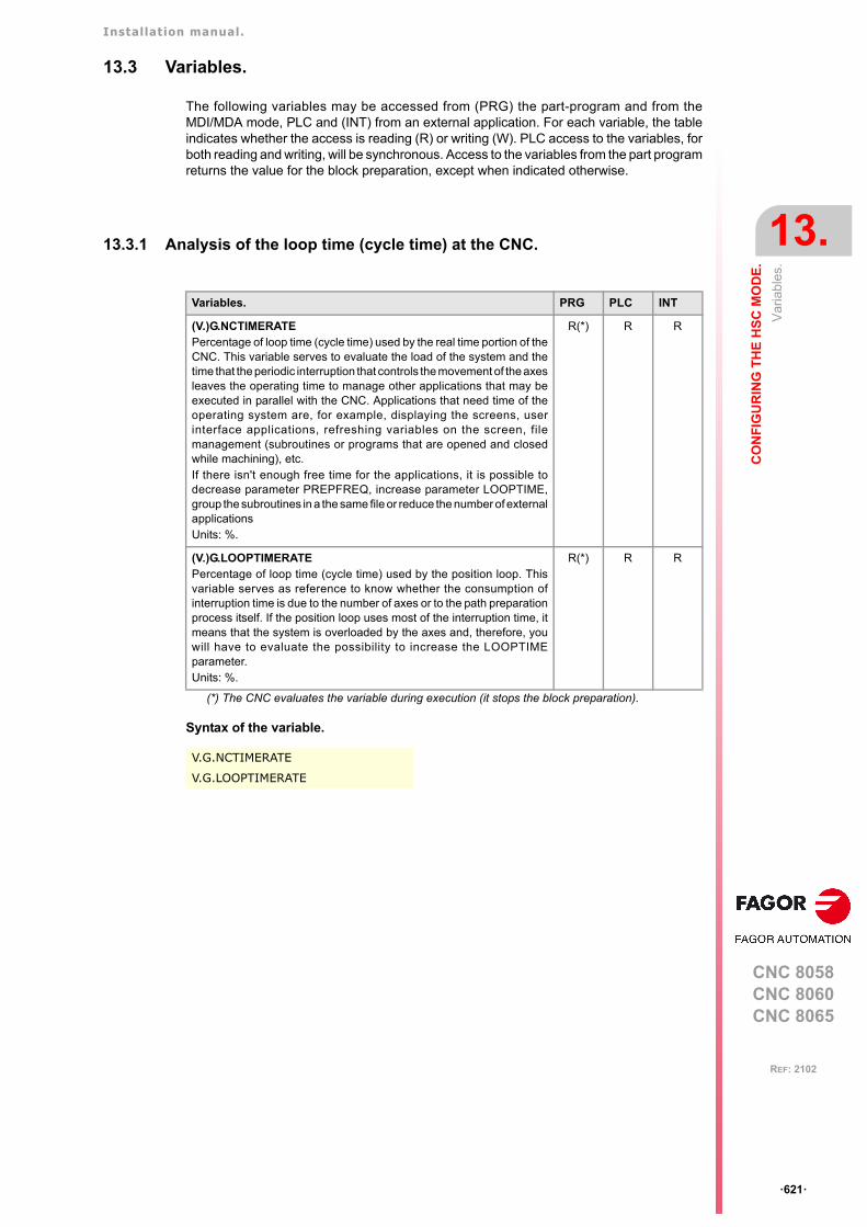
Installation manual.
CNC 8058CNC 8060CNC 8065
CO
NF
IGU
RIN
G T
HE
HS
C M
OD
E.
13.
Var
iabl
es.
ꞏ621ꞏ
REF: 2102
13.3 Variables.
The following variables may be accessed from (PRG) the part-program and from theMDI/MDA mode, PLC and (INT) from an external application. For each variable, the tableindicates whether the access is reading (R) or writing (W). PLC access to the variables, forboth reading and writing, will be synchronous. Access to the variables from the part programreturns the value for the block preparation, except when indicated otherwise.
13.3.1 Analysis of the loop time (cycle time) at the CNC.
Syntax of the variable.
Variables. PRG PLC INT
(V.)G.NCTIMERATEPercentage of loop time (cycle time) used by the real time portion of theCNC. This variable serves to evaluate the load of the system and thetime that the periodic interruption that controls the movement of the axesleaves the operating time to manage other applications that may beexecuted in parallel with the CNC. Applications that need time of theoperating system are, for example, displaying the screens, userinterface applications, refreshing variables on the screen, filemanagement (subroutines or programs that are opened and closedwhile machining), etc.If there isn't enough free time for the applications, it is possible todecrease parameter PREPFREQ, increase parameter LOOPTIME,group the subroutines in a the same file or reduce the number of externalapplicationsUnits: %.
R(*) R R
(V.)G.LOOPTIMERATEPercentage of loop time (cycle time) used by the position loop. Thisvariable serves as reference to know whether the consumption ofinterruption time is due to the number of axes or to the path preparationprocess itself. If the position loop uses most of the interruption time, itmeans that the system is overloaded by the axes and, therefore, youwill have to evaluate the possibility to increase the LOOPTIMEparameter. Units: %.
R(*) R R
(*) The CNC evaluates the variable during execution (it stops the block preparation).
V.G.NCTIMERATE
V.G.LOOPTIMERATE
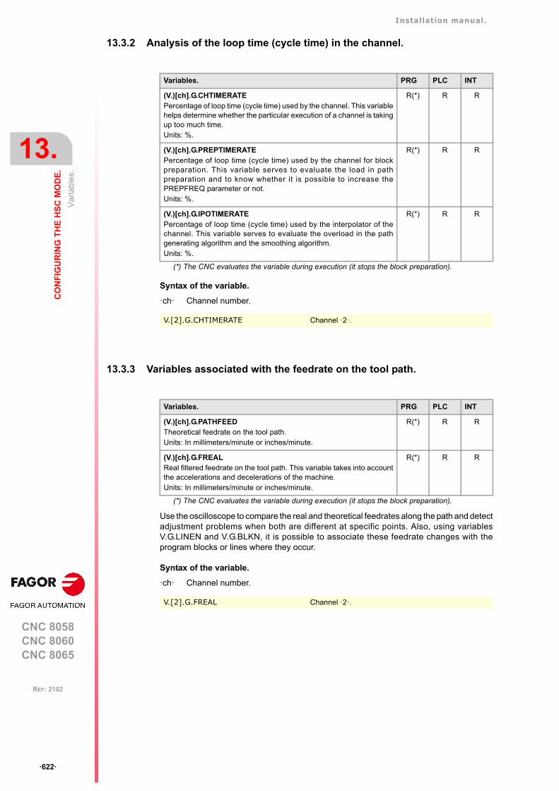
Installation manual.
CNC 8058CNC 8060CNC 8065
13.
CO
NF
IGU
RIN
G T
HE
HS
C M
OD
E.
Var
iabl
es.
ꞏ622ꞏ
REF: 2102
13.3.2 Analysis of the loop time (cycle time) in the channel.
Syntax of the variable.
ꞏchꞏ Channel number.
13.3.3 Variables associated with the feedrate on the tool path.
Use the oscilloscope to compare the real and theoretical feedrates along the path and detectadjustment problems when both are different at specific points. Also, using variablesV.G.LINEN and V.G.BLKN, it is possible to associate these feedrate changes with theprogram blocks or lines where they occur.
Syntax of the variable.
ꞏchꞏ Channel number.
Variables. PRG PLC INT
(V.)[ch].G.CHTIMERATEPercentage of loop time (cycle time) used by the channel. This variablehelps determine whether the particular execution of a channel is takingup too much time.Units: %.
R(*) R R
(V.)[ch].G.PREPTIMERATEPercentage of loop time (cycle time) used by the channel for blockpreparation. This variable serves to evaluate the load in pathpreparation and to know whether it is possible to increase thePREPFREQ parameter or not.Units: %.
R(*) R R
(V.)[ch].G.IPOTIMERATEPercentage of loop time (cycle time) used by the interpolator of thechannel. This variable serves to evaluate the overload in the pathgenerating algorithm and the smoothing algorithm.Units: %.
R(*) R R
(*) The CNC evaluates the variable during execution (it stops the block preparation).
V.[2].G.CHTIMERATE Channel ꞏ2ꞏ.
Variables. PRG PLC INT
(V.)[ch].G.PATHFEEDTheoretical feedrate on the tool path.Units: In millimeters/minute or inches/minute.
R(*) R R
(V.)[ch].G.FREALReal filtered feedrate on the tool path. This variable takes into accountthe accelerations and decelerations of the machine. Units: In millimeters/minute or inches/minute.
R(*) R R
(*) The CNC evaluates the variable during execution (it stops the block preparation).
V.[2].G.FREAL Channel ꞏ2ꞏ.
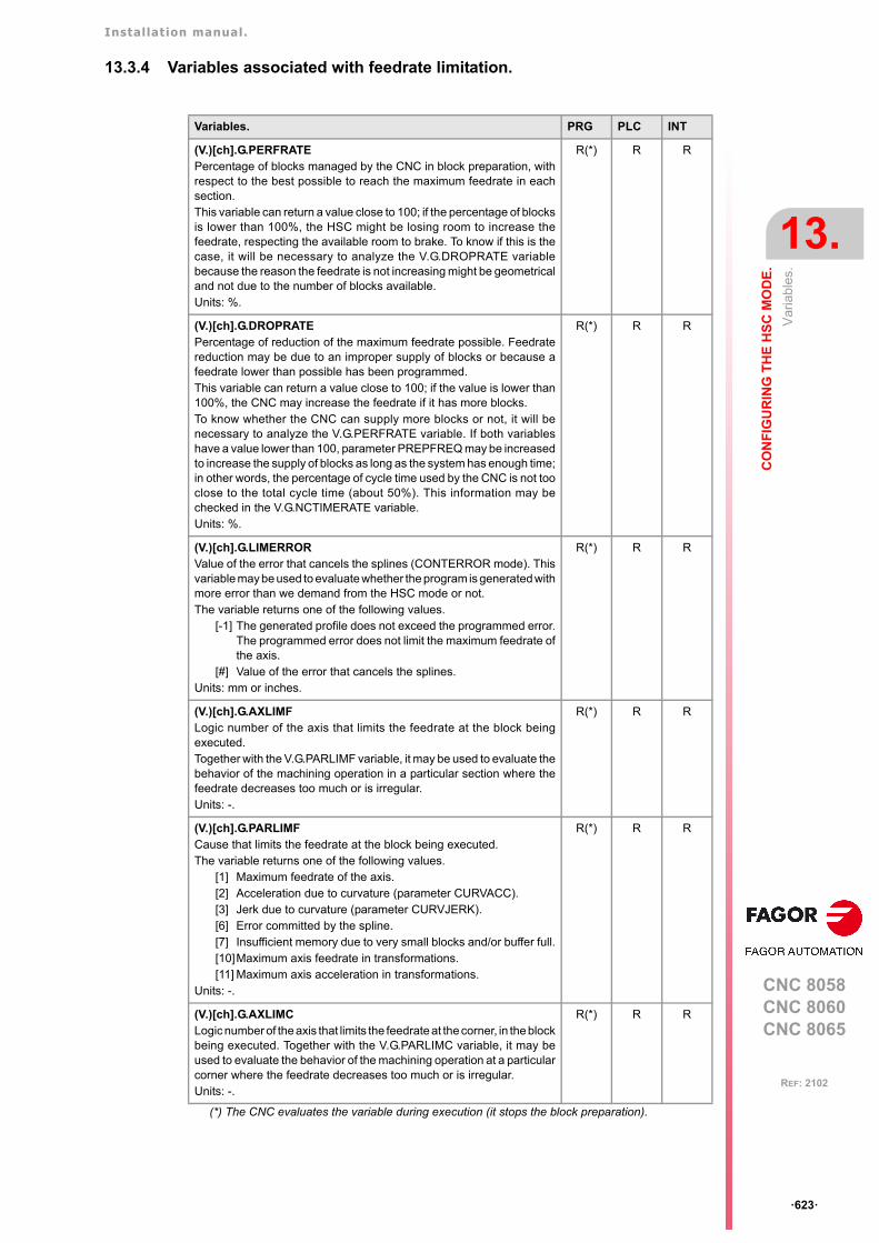
Installation manual.
CNC 8058CNC 8060CNC 8065
CO
NF
IGU
RIN
G T
HE
HS
C M
OD
E.
13.
Var
iabl
es.
ꞏ623ꞏ
REF: 2102
13.3.4 Variables associated with feedrate limitation.
Variables. PRG PLC INT
(V.)[ch].G.PERFRATEPercentage of blocks managed by the CNC in block preparation, withrespect to the best possible to reach the maximum feedrate in eachsection. This variable can return a value close to 100; if the percentage of blocksis lower than 100%, the HSC might be losing room to increase thefeedrate, respecting the available room to brake. To know if this is thecase, it will be necessary to analyze the V.G.DROPRATE variablebecause the reason the feedrate is not increasing might be geometricaland not due to the number of blocks available.Units: %.
R(*) R R
(V.)[ch].G.DROPRATEPercentage of reduction of the maximum feedrate possible. Feedratereduction may be due to an improper supply of blocks or because afeedrate lower than possible has been programmed.This variable can return a value close to 100; if the value is lower than100%, the CNC may increase the feedrate if it has more blocks. To know whether the CNC can supply more blocks or not, it will benecessary to analyze the V.G.PERFRATE variable. If both variableshave a value lower than 100, parameter PREPFREQ may be increasedto increase the supply of blocks as long as the system has enough time;in other words, the percentage of cycle time used by the CNC is not tooclose to the total cycle time (about 50%). This information may bechecked in the V.G.NCTIMERATE variable. Units: %.
R(*) R R
(V.)[ch].G.LIMERRORValue of the error that cancels the splines (CONTERROR mode). Thisvariable may be used to evaluate whether the program is generated withmore error than we demand from the HSC mode or not. The variable returns one of the following values.
[-1] The generated profile does not exceed the programmed error.The programmed error does not limit the maximum feedrate ofthe axis.
[#] Value of the error that cancels the splines.Units: mm or inches.
R(*) R R
(V.)[ch].G.AXLIMFLogic number of the axis that limits the feedrate at the block beingexecuted.Together with the V.G.PARLIMF variable, it may be used to evaluate thebehavior of the machining operation in a particular section where thefeedrate decreases too much or is irregular.Units: -.
R(*) R R
(V.)[ch].G.PARLIMFCause that limits the feedrate at the block being executed.The variable returns one of the following values.
[1] Maximum feedrate of the axis.[2] Acceleration due to curvature (parameter CURVACC).[3] Jerk due to curvature (parameter CURVJERK).[6] Error committed by the spline.[7] Insufficient memory due to very small blocks and/or buffer full.[10]Maximum axis feedrate in transformations.[11] Maximum axis acceleration in transformations.
Units: -.
R(*) R R
(V.)[ch].G.AXLIMCLogic number of the axis that limits the feedrate at the corner, in the blockbeing executed. Together with the V.G.PARLIMC variable, it may beused to evaluate the behavior of the machining operation at a particularcorner where the feedrate decreases too much or is irregular.Units: -.
R(*) R R
(*) The CNC evaluates the variable during execution (it stops the block preparation).
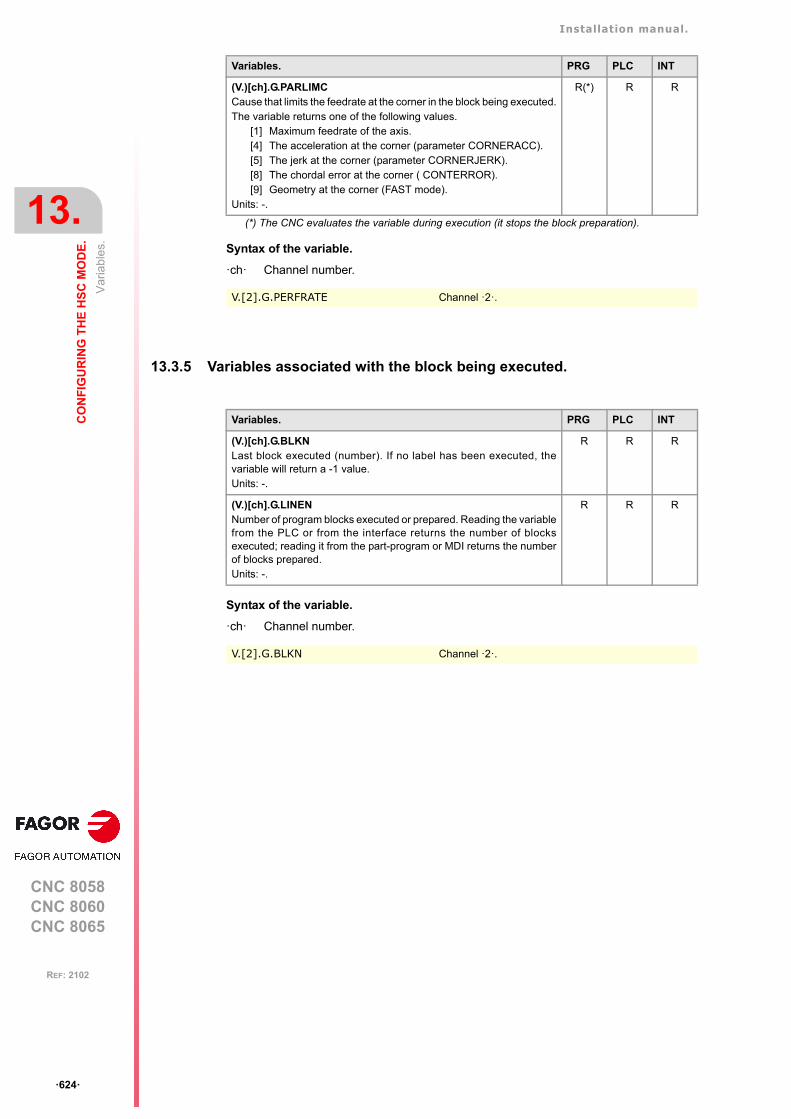
Installation manual.
CNC 8058CNC 8060CNC 8065
13.
CO
NF
IGU
RIN
G T
HE
HS
C M
OD
E.
Var
iabl
es.
ꞏ624ꞏ
REF: 2102
Syntax of the variable.
ꞏchꞏ Channel number.
13.3.5 Variables associated with the block being executed.
Syntax of the variable.
ꞏchꞏ Channel number.
(V.)[ch].G.PARLIMCCause that limits the feedrate at the corner in the block being executed.The variable returns one of the following values.
[1] Maximum feedrate of the axis.[4] The acceleration at the corner (parameter CORNERACC).[5] The jerk at the corner (parameter CORNERJERK).[8] The chordal error at the corner ( CONTERROR).[9] Geometry at the corner (FAST mode).
Units: -.
R(*) R R
V.[2].G.PERFRATE Channel ꞏ2ꞏ.
Variables. PRG PLC INT
(*) The CNC evaluates the variable during execution (it stops the block preparation).
Variables. PRG PLC INT
(V.)[ch].G.BLKNLast block executed (number). If no label has been executed, thevariable will return a -1 value. Units: -.
R R R
(V.)[ch].G.LINENNumber of program blocks executed or prepared. Reading the variablefrom the PLC or from the interface returns the number of blocksexecuted; reading it from the part-program or MDI returns the numberof blocks prepared.Units: -.
R R R
V.[2].G.BLKN Channel ꞏ2ꞏ.
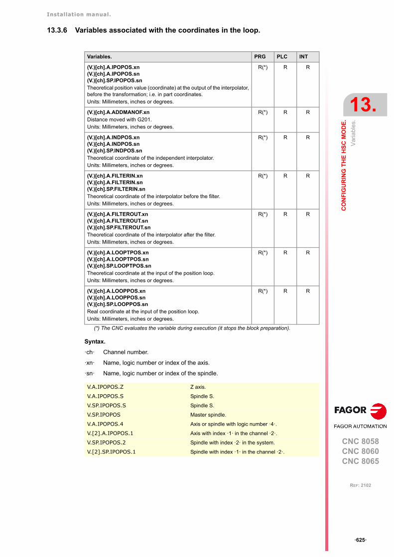
Installation manual.
CNC 8058CNC 8060CNC 8065
CO
NF
IGU
RIN
G T
HE
HS
C M
OD
E.
13.
Var
iabl
es.
ꞏ625ꞏ
REF: 2102
13.3.6 Variables associated with the coordinates in the loop.
Syntax.
ꞏchꞏ Channel number.
ꞏxnꞏ Name, logic number or index of the axis.
ꞏsnꞏ Name, logic number or index of the spindle.
Variables. PRG PLC INT
(V.)[ch].A.IPOPOS.xn(V.)[ch].A.IPOPOS.sn(V.)[ch].SP.IPOPOS.snTheoretical position value (coordinate) at the output of the interpolator,before the transformation; i.e. in part coordinates.Units: Millimeters, inches or degrees.
R(*) R R
(V.)[ch].A.ADDMANOF.xnDistance moved with G201.Units: Millimeters, inches or degrees.
R(*) R R
(V.)[ch].A.INDPOS.xn(V.)[ch].A.INDPOS.sn(V.)[ch].SP.INDPOS.snTheoretical coordinate of the independent interpolator.Units: Millimeters, inches or degrees.
R(*) R R
(V.)[ch].A.FILTERIN.xn(V.)[ch].A.FILTERIN.sn(V.)[ch].SP.FILTERIN.snTheoretical coordinate of the interpolator before the filter.Units: Millimeters, inches or degrees.
R(*) R R
(V.)[ch].A.FILTEROUT.xn(V.)[ch].A.FILTEROUT.sn(V.)[ch].SP.FILTEROUT.snTheoretical coordinate of the interpolator after the filter.Units: Millimeters, inches or degrees.
R(*) R R
(V.)[ch].A.LOOPTPOS.xn(V.)[ch].A.LOOPTPOS.sn(V.)[ch].SP.LOOPTPOS.snTheoretical coordinate at the input of the position loop.Units: Millimeters, inches or degrees.
R(*) R R
(V.)[ch].A.LOOPPOS.xn(V.)[ch].A.LOOPPOS.sn(V.)[ch].SP.LOOPPOS.snReal coordinate at the input of the position loop.Units: Millimeters, inches or degrees.
R(*) R R
(*) The CNC evaluates the variable during execution (it stops the block preparation).
V.A.IPOPOS.Z Z axis.
V.A.IPOPOS.S Spindle S.
V.SP.IPOPOS.S Spindle S.
V.SP.IPOPOS Master spindle.
V.A.IPOPOS.4 Axis or spindle with logic number ꞏ4ꞏ.
V.[2].A.IPOPOS.1 Axis with index ꞏ1ꞏ in the channel ꞏ2ꞏ.
V.SP.IPOPOS.2 Spindle with index ꞏ2ꞏ in the system.
V.[2].SP.IPOPOS.1 Spindle with index ꞏ1ꞏ in the channel ꞏ2ꞏ.
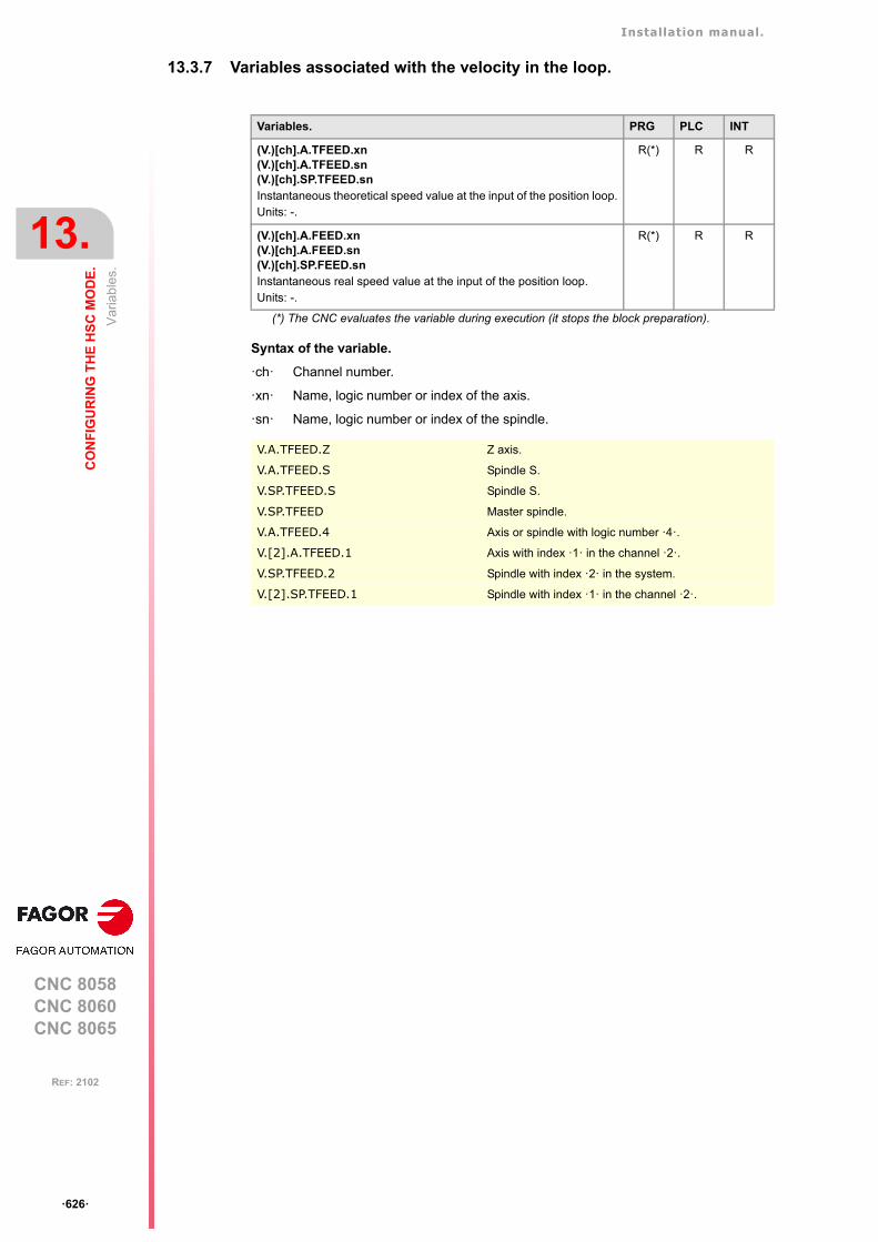
Installation manual.
CNC 8058CNC 8060CNC 8065
13.
CO
NF
IGU
RIN
G T
HE
HS
C M
OD
E.
Var
iabl
es.
ꞏ626ꞏ
REF: 2102
13.3.7 Variables associated with the velocity in the loop.
Syntax of the variable.
ꞏchꞏ Channel number.
ꞏxnꞏ Name, logic number or index of the axis.
ꞏsnꞏ Name, logic number or index of the spindle.
Variables. PRG PLC INT
(V.)[ch].A.TFEED.xn(V.)[ch].A.TFEED.sn(V.)[ch].SP.TFEED.snInstantaneous theoretical speed value at the input of the position loop.Units: -.
R(*) R R
(V.)[ch].A.FEED.xn(V.)[ch].A.FEED.sn(V.)[ch].SP.FEED.snInstantaneous real speed value at the input of the position loop.Units: -.
R(*) R R
(*) The CNC evaluates the variable during execution (it stops the block preparation).
V.A.TFEED.Z Z axis.
V.A.TFEED.S Spindle S.
V.SP.TFEED.S Spindle S.
V.SP.TFEED Master spindle.
V.A.TFEED.4 Axis or spindle with logic number ꞏ4ꞏ.
V.[2].A.TFEED.1 Axis with index ꞏ1ꞏ in the channel ꞏ2ꞏ.
V.SP.TFEED.2 Spindle with index ꞏ2ꞏ in the system.
V.[2].SP.TFEED.1 Spindle with index ꞏ1ꞏ in the channel ꞏ2ꞏ.
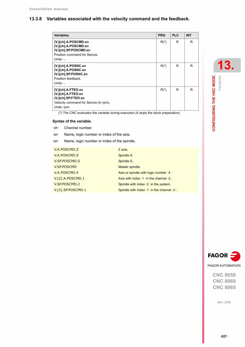
Installation manual.
CNC 8058CNC 8060CNC 8065
CO
NF
IGU
RIN
G T
HE
HS
C M
OD
E.
13.
Var
iabl
es.
ꞏ627ꞏ
REF: 2102
13.3.8 Variables associated with the velocity command and the feedback.
Syntax of the variable.
ꞏchꞏ Channel number.
ꞏxnꞏ Name, logic number or index of the axis.
ꞏsnꞏ Name, logic number or index of the spindle.
Variables. PRG PLC INT
(V.)[ch].A.POSCMD.xn(V.)[ch].A.POSCMD.sn(V.)[ch].SP.POSCMD.snPosition command for Sercos.Units: -.
R(*) R R
(V.)[ch].A.POSNC.xn(V.)[ch].A.POSNC.sn(V.)[ch].SP.POSNC.snPosition feedback.Units: -.
R(*) R R
(V.)[ch].A.FTEO.xn(V.)[ch].A.FTEO.sn(V.)[ch].SP.FTEO.snVelocity command for Sercos (in rpm).Units: rpm.
R(*) R R
(*) The CNC evaluates the variable during execution (it stops the block preparation).
V.A.POSCMD.Z Z axis.
V.A.POSCMD.S Spindle S.
V.SP.POSCMD.S Spindle S.
V.SP.POSCMD Master spindle.
V.A.POSCMD.4 Axis or spindle with logic number ꞏ4ꞏ.
V.[2].A.POSCMD.1 Axis with index ꞏ1ꞏ in the channel ꞏ2ꞏ.
V.SP.POSCMD.2 Spindle with index ꞏ2ꞏ in the system.
V.[2].SP.POSCMD.1 Spindle with index ꞏ1ꞏ in the channel ꞏ2ꞏ.
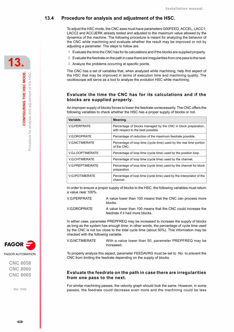
Installation manual.
CNC 8058CNC 8060CNC 8065
13.
CO
NF
IGU
RIN
G T
HE
HS
C M
OD
E.
Pro
cedu
re fo
r an
alys
is a
nd a
dju
stm
ent o
f the
HS
C.
ꞏ628ꞏ
REF: 2102
13.4 Procedure for analysis and adjustment of the HSC.
To adjust the HSC mode, the CNC axes must have parameters G00FEED, ACCEL, LACC1,LACC2 and ACCJERK already tested and adjusted to the maximum value allowed by thedynamics of the machine. The following procedure is meant for analyzing the behavior ofthe CNC while machining and evaluate whether the result may be improved or not byadjusting a parameter. The steps to follow are.
1 Evaluate the time the CNC has for its calculations and if the blocks are supplied properly.
2 Evaluate the feedrate on the path in case there are irregularities from one pass to the next.
3 Analyze the problems occurring at specific points.
The CNC has a set of variables that, when analyzed while machining, help find aspect ofthe HSC that may be improved in terms of execution time and machining quality. Theoscilloscope will serve as a tool to analyze the evolution HSC while machining.
Evaluate the time the CNC has for its calculations and if theblocks are supplied properly.
An improper supply of blocks forces to lower the feedrate unnecessarily. The CNC offers thefollowing variables to check whether the HSC has a proper supply of blocks or not.
In order to ensure a proper supply of blocks to the HSC, the following variables must returna value near 100%.
In either case, parameter PREPFREQ may be increased to increase the supply of blocksas long as the system has enough time; in other words, the percentage of cycle time usedby the CNC is not too close to the total cycle time (about 50%). This information may bechecked with the following variable.
To properly analyze this aspect, parameter FEEDAVRG must be set to ꞏNoꞏ to prevent theCNC from limiting the feedrate depending on the supply of blocks.
Evaluate the feedrate on the path in case there are irregularitiesfrom one pass to the next.
For similar machining passes, the velocity graph should look the same. However, in somepasses, the feedrate could decrease even more and the machining could be less
Variable. Meaning.
V.G.PERFRATE Percentage of blocks managed by the CNC in block preparation,with respect to the best possible.
V.G.DROPRATE Percentage of reduction of the maximum feedrate possible.
V.G.NCTIMERATE Percentage of loop time (cycle time) used by the real time portionof the CNC.
V.G.LOOPTIMERATE Percentage of loop time (cycle time) used by the position loop.
V.G.CHTIMERATE Percentage of loop time (cycle time) used by the channel.
V.G.PREPTIMERATE Percentage of loop time (cycle time) used by the channel for blockpreparation.
V.G.IPOTIMERATE Percentage of loop time (cycle time) used by the interpolator of thechannel.
V.G.PERFRATE A value lower than 100 means that the CNC can process moreblocks.
V.G.DROPRATE A value lower than 100 means that the CNC could increase thefeedrate if it had more blocks.
V.G.NCTIMERATE With a value lower than 50, parameter PREPFREQ may beincreased.
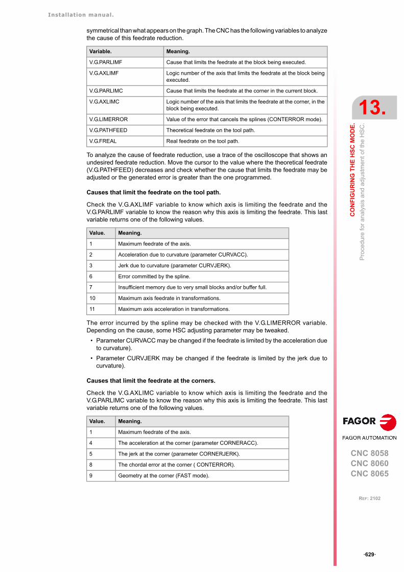
Installation manual.
CNC 8058CNC 8060CNC 8065
CO
NF
IGU
RIN
G T
HE
HS
C M
OD
E.
13.
Pro
cedu
re fo
r an
alys
is a
nd a
dju
stm
ent o
f the
HS
C.
ꞏ629ꞏ
REF: 2102
symmetrical than what appears on the graph. The CNC has the following variables to analyzethe cause of this feedrate reduction.
To analyze the cause of feedrate reduction, use a trace of the oscilloscope that shows anundesired feedrate reduction. Move the cursor to the value where the theoretical feedrate(V.G.PATHFEED) decreases and check whether the cause that limits the feedrate may beadjusted or the generated error is greater than the one programmed.
Causes that limit the feedrate on the tool path.
Check the V.G.AXLIMF variable to know which axis is limiting the feedrate and theV.G.PARLIMF variable to know the reason why this axis is limiting the feedrate. This lastvariable returns one of the following values.
The error incurred by the spline may be checked with the V.G.LIMERROR variable.Depending on the cause, some HSC adjusting parameter may be tweaked.
• Parameter CURVACC may be changed if the feedrate is limited by the acceleration dueto curvature).
• Parameter CURVJERK may be changed if the feedrate is limited by the jerk due tocurvature).
Causes that limit the feedrate at the corners.
Check the V.G.AXLIMC variable to know which axis is limiting the feedrate and theV.G.PARLIMC variable to know the reason why this axis is limiting the feedrate. This lastvariable returns one of the following values.
Variable. Meaning.
V.G.PARLIMF Cause that limits the feedrate at the block being executed.
V.G.AXLIMF Logic number of the axis that limits the feedrate at the block beingexecuted.
V.G.PARLIMC Cause that limits the feedrate at the corner in the current block.
V.G.AXLIMC Logic number of the axis that limits the feedrate at the corner, in theblock being executed.
V.G.LIMERROR Value of the error that cancels the splines (CONTERROR mode).
V.G.PATHFEED Theoretical feedrate on the tool path.
V.G.FREAL Real feedrate on the tool path.
Value. Meaning.
1 Maximum feedrate of the axis.
2 Acceleration due to curvature (parameter CURVACC).
3 Jerk due to curvature (parameter CURVJERK).
6 Error committed by the spline.
7 Insufficient memory due to very small blocks and/or buffer full.
10 Maximum axis feedrate in transformations.
11 Maximum axis acceleration in transformations.
Value. Meaning.
1 Maximum feedrate of the axis.
4 The acceleration at the corner (parameter CORNERACC).
5 The jerk at the corner (parameter CORNERJERK).
8 The chordal error at the corner ( CONTERROR).
9 Geometry at the corner (FAST mode).
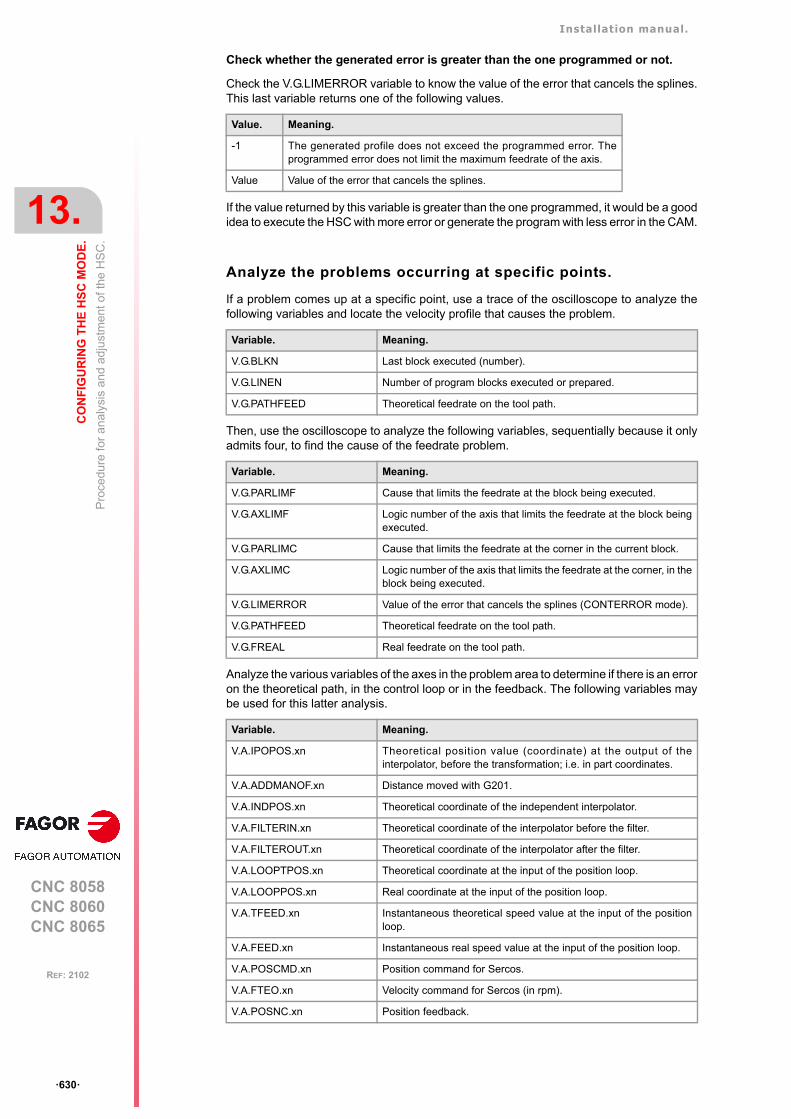
Installation manual.
CNC 8058CNC 8060CNC 8065
13.
CO
NF
IGU
RIN
G T
HE
HS
C M
OD
E.
Pro
cedu
re fo
r an
alys
is a
nd a
dju
stm
ent o
f the
HS
C.
ꞏ630ꞏ
REF: 2102
Check whether the generated error is greater than the one programmed or not.
Check the V.G.LIMERROR variable to know the value of the error that cancels the splines.This last variable returns one of the following values.
If the value returned by this variable is greater than the one programmed, it would be a goodidea to execute the HSC with more error or generate the program with less error in the CAM.
Analyze the problems occurring at specific points.
If a problem comes up at a specific point, use a trace of the oscilloscope to analyze thefollowing variables and locate the velocity profile that causes the problem.
Then, use the oscilloscope to analyze the following variables, sequentially because it onlyadmits four, to find the cause of the feedrate problem.
Analyze the various variables of the axes in the problem area to determine if there is an erroron the theoretical path, in the control loop or in the feedback. The following variables maybe used for this latter analysis.
Value. Meaning.
-1 The generated profile does not exceed the programmed error. Theprogrammed error does not limit the maximum feedrate of the axis.
Value Value of the error that cancels the splines.
Variable. Meaning.
V.G.BLKN Last block executed (number).
V.G.LINEN Number of program blocks executed or prepared.
V.G.PATHFEED Theoretical feedrate on the tool path.
Variable. Meaning.
V.G.PARLIMF Cause that limits the feedrate at the block being executed.
V.G.AXLIMF Logic number of the axis that limits the feedrate at the block beingexecuted.
V.G.PARLIMC Cause that limits the feedrate at the corner in the current block.
V.G.AXLIMC Logic number of the axis that limits the feedrate at the corner, in theblock being executed.
V.G.LIMERROR Value of the error that cancels the splines (CONTERROR mode).
V.G.PATHFEED Theoretical feedrate on the tool path.
V.G.FREAL Real feedrate on the tool path.
Variable. Meaning.
V.A.IPOPOS.xn Theoretical position value (coordinate) at the output of theinterpolator, before the transformation; i.e. in part coordinates.
V.A.ADDMANOF.xn Distance moved with G201.
V.A.INDPOS.xn Theoretical coordinate of the independent interpolator.
V.A.FILTERIN.xn Theoretical coordinate of the interpolator before the filter.
V.A.FILTEROUT.xn Theoretical coordinate of the interpolator after the filter.
V.A.LOOPTPOS.xn Theoretical coordinate at the input of the position loop.
V.A.LOOPPOS.xn Real coordinate at the input of the position loop.
V.A.TFEED.xn Instantaneous theoretical speed value at the input of the positionloop.
V.A.FEED.xn Instantaneous real speed value at the input of the position loop.
V.A.POSCMD.xn Position command for Sercos.
V.A.FTEO.xn Velocity command for Sercos (in rpm).
V.A.POSNC.xn Position feedback.

Installation manual.
CNC 8058CNC 8060CNC 8065
CO
NF
IGU
RIN
G T
HE
HS
C M
OD
E.
13.
The
loo
ps a
nd th
e va
riab
les.
ꞏ631ꞏ
REF: 2102
13.5 The loops and the variables.
Velocity command
(V.)G.PATHFEED
(V.)A.IPOPOS.1
(V.)A.INDPOS.xn
V.A.ADDMANOF.1V.A.MANOF.1
(V.)MPG.IMOVEMACH
INTERPOLATOR
NO
INDEPENDENTINTERPOLATOR
(V.)A.ITPOS.xn
axis 2
axis 3
SLOPE
YES
FILTER
(V.)A.FILTERIN.xn (V.)A.FILTEROUT.xn
axis 1
Movement block
TRANSFOR
V.A.PLCOF.xn
(V.)A.FLWE.xn
V.A.FEED.xn
(V.)A.TFEED.xn
V.A.PLCOF.xn
+
(V.)A.TPOS.xn
-
-
(V.)A.LOOPTPOS.xn
(V.)A.FTEO.xn
(V.)G.ANAO[n]
(V.)MPA.LOOPCHG.xn
(V.)A.POSCMD.xn
V.A.LOOPPOS.xn
(V.)A.FILTEROUT.xn+
+
(V.)A.POS.xn +
(V.)MPA.LOOPCHG.xn
-COMP -DELTA
-
+
(V.)A.ACTFFW.xn(V.)A.ACTACF.xn
+/-
+/-
COMP
DELTA
(V.)A.POSNC.xn(V.)MPA.AXISCHG.xn
+/-
(V.)A.POSNC.xn
(V.)A.POSNC.xn
DRIVE
(V.)MPA.AXISCHG.xn
+/-
Analog
Analog
Sercos Vel.
Sercos Pos.
Sercos Vel.
Sercos Pos.
DELTA
(V.)MPG.PROGAIN
COMP Coordinate compensation due to leadscrew error compensation or tocross compensation.
DELTA Offset on power-up to maintain the coordinate when it was turned off.

Installation manual.
CNC 8058CNC 8060CNC 8065
13.
CO
NF
IGU
RIN
G T
HE
HS
C M
OD
E.
The
loo
ps a
nd th
e va
riab
les.
ꞏ632ꞏ
REF: 2102
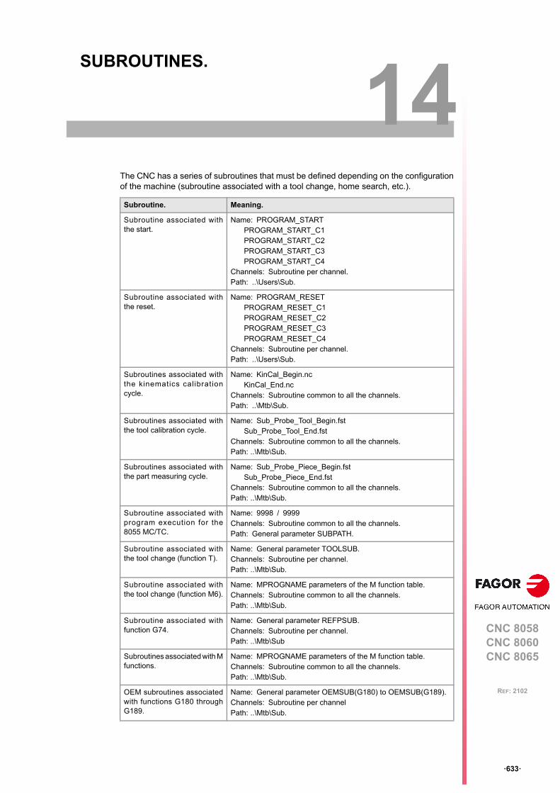
CNC 8058CNC 8060CNC 8065
14
ꞏ633ꞏ
REF: 2102
14.SUBROUTINES.
The CNC has a series of subroutines that must be defined depending on the configurationof the machine (subroutine associated with a tool change, home search, etc.).
Subroutine. Meaning.
Subroutine associated withthe start.
Name: PROGRAM_STARTPROGRAM_START_C1PROGRAM_START_C2PROGRAM_START_C3PROGRAM_START_C4
Channels: Subroutine per channel.Path: ..\Users\Sub.
Subroutine associated withthe reset.
Name: PROGRAM_RESETPROGRAM_RESET_C1PROGRAM_RESET_C2PROGRAM_RESET_C3PROGRAM_RESET_C4
Channels: Subroutine per channel.Path: ..\Users\Sub.
Subroutines associated withthe kinematics calibrationcycle.
Name: KinCal_Begin.ncKinCal_End.nc
Channels: Subroutine common to all the channels.Path: ..\Mtb\Sub.
Subroutines associated withthe tool calibration cycle.
Name: Sub_Probe_Tool_Begin.fstSub_Probe_Tool_End.fst
Channels: Subroutine common to all the channels.Path: ..\Mtb\Sub.
Subroutines associated withthe part measuring cycle.
Name: Sub_Probe_Piece_Begin.fstSub_Probe_Piece_End.fst
Channels: Subroutine common to all the channels.Path: ..\Mtb\Sub.
Subroutine associated withprogram execution for the8055 MC/TC.
Name: 9998 / 9999Channels: Subroutine common to all the channels.Path: General parameter SUBPATH.
Subroutine associated withthe tool change (function T).
Name: General parameter TOOLSUB. Channels: Subroutine per channel.Path: ..\Mtb\Sub.
Subroutine associated withthe tool change (function M6).
Name: MPROGNAME parameters of the M function table.Channels: Subroutine common to all the channels.Path: ..\Mtb\Sub.
Subroutine associated withfunction G74.
Name: General parameter REFPSUB. Channels: Subroutine per channel.Path: ..\Mtb\Sub
Subroutines associated with Mfunctions.
Name: MPROGNAME parameters of the M function table.Channels: Subroutine common to all the channels.Path: ..\Mtb\Sub.
OEM subroutines associatedwith functions G180 throughG189.
Name: General parameter OEMSUB(G180) to OEMSUB(G189). Channels: Subroutine per channelPath: ..\Mtb\Sub.
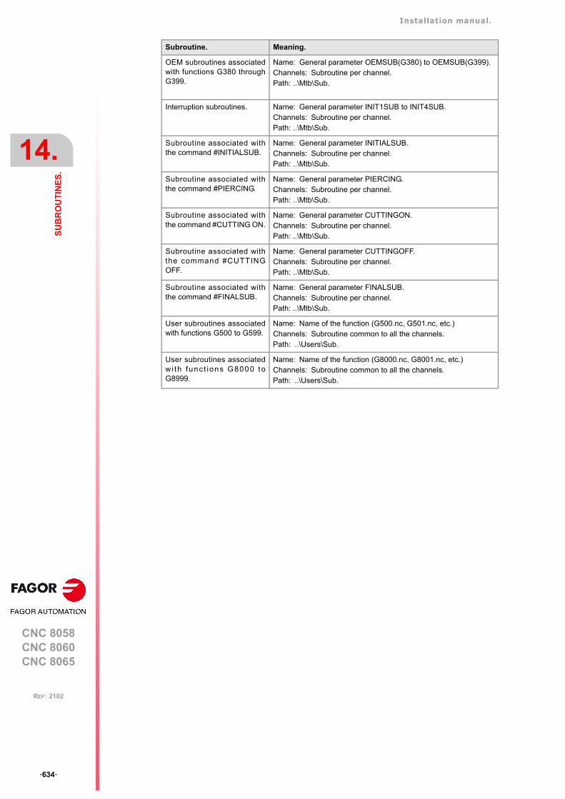
Installation manual.
CNC 8058CNC 8060CNC 8065
14.
SU
BR
OU
TIN
ES
.
ꞏ634ꞏ
REF: 2102
OEM subroutines associatedwith functions G380 throughG399.
Name: General parameter OEMSUB(G380) to OEMSUB(G399). Channels: Subroutine per channel.Path: ..\Mtb\Sub.
Interruption subroutines. Name: General parameter INIT1SUB to INIT4SUB. Channels: Subroutine per channel.Path: ..\Mtb\Sub.
Subroutine associated withthe command #INITIALSUB.
Name: General parameter INITIALSUB.Channels: Subroutine per channel.Path: ..\Mtb\Sub.
Subroutine associated withthe command #PIERCING.
Name: General parameter PIERCING.Channels: Subroutine per channel.Path: ..\Mtb\Sub.
Subroutine associated withthe command #CUTTING ON.
Name: General parameter CUTTINGON.Channels: Subroutine per channel.Path: ..\Mtb\Sub.
Subroutine associated withthe command #CUTTINGOFF.
Name: General parameter CUTTINGOFF.Channels: Subroutine per channel.Path: ..\Mtb\Sub.
Subroutine associated withthe command #FINALSUB.
Name: General parameter FINALSUB.Channels: Subroutine per channel.Path: ..\Mtb\Sub.
User subroutines associatedwith functions G500 to G599.
Name: Name of the function (G500.nc, G501.nc, etc.)Channels: Subroutine common to all the channels.Path: ..\Users\Sub.
User subroutines associatedwi th func t ions G8000 toG8999.
Name: Name of the function (G8000.nc, G8001.nc, etc.)Channels: Subroutine common to all the channels.Path: ..\Users\Sub.
Subroutine. Meaning.
Installation manual.
CNC 8058CNC 8060CNC 8065
SU
BR
OU
TIN
ES
.
14.
Run
sub
rou
tines
fro
m R
AM
(e
xten
sion
*.fs
t).
ꞏ635ꞏ
REF: 2102
14.1 Run subroutines from RAM (extension *.fst).
If the same subroutines are executed repeatedly during execution, it is more efficient to loadthem into the RAM memory of the CNC because this way, they may be accessed faster andexecution time may be consequently optimized. This option is valid for OEM as well as foruser subroutines. To load a subroutine into RAM, it must have the extension fst. The reservedRAM space for subroutines is 5 Mb.
fst user subroutines.
Subroutines with the fst extension that are not saved in the folder..\MTB\Sub. User routineshaving a fst extension are loaded into RAM memory during block preparation. The CNCchecks whether or not it is loaded into RAM memory; if it is not and there is room for it, itloads it.
At the end of the program (M02/M30) or after a reset, if no other channel is executingsubroutines, the CNC deletes them from its RAM memory. This way, if a user subroutinehaving a fst extension is edited or modified, the CNC assumes the changes the next timeit executes it.
OEM (manufacturer's) subroutines.
Subroutines with the fst extension saved in the folder..\MTB\Sub.
• Being the CNC in USER mode, the OEM routines having a fst extension are loaded intoRAM memory when starting up the CNC application.
When the OEM is debugging his subroutines, they must have another extension so thechanges are assumed without having to restart the application. Once they are debugged,the OEM must change the extension of the subroutines to fst so they are loaded into RAMmemory.
• Being the CNC in SETUP mode, the OEM subroutines with an fst extension will be loadedinto RAM memory during the preparation of the blocks. The CNC checks whether or notit is loaded into RAM memory; if it is not and there is room for it, it loads it. At the endof the program (M02/M30) or after a reset, if no other channel is executing subroutines,the CNC deletes them from its RAM memory. This way, the changes made in thesubroutine will be taken into account the next time the program is executed.
Installation manual.
CNC 8058CNC 8060CNC 8065
14.
SU
BR
OU
TIN
ES
.
Sub
rout
ine
asso
ciat
ed w
ith th
e st
art
.
ꞏ636ꞏ
REF: 2102
14.2 Subroutine associated with the start.
For each channel, a subroutine can be associated with the execution start, which can beexecuted by pressing the [START] key, in automatic mode, to start the execution of the entireprogram; that is if no program start point has been selected. The CNC does not call uponthe subroutine either when executing a cycle from the conversational mode. This subroutinemay be used, for example, to have certain machining conditions defined to determine theexecution of user programs.
If the subroutine exists, the CNC will execute it immediately after pressing the [START] key,before starting the program execution. If that subroutine is missing, the CNC executes theprogram directly.
Execution of subroutine
During execution, the CNC displays the name of the subroutine on the general status bar.The CNC does not display the blocks under execution, however, it executes the subroutineas a single block, this means that the block-by-block execution is not affected.
14.2.1 Configure the subroutines.
Name and location of the subroutine.
The name of the subroutine must be PROGRAM_START (without an extension) and it willbe saved in the folder ..\Users\Sub. If there are several channels, there may be a differentsubroutine for each channel, whose name must be PROGRAM_START_Cn, where n is thechannel number (between 1 and 4).
Name. Channel.
PROGRAM_STARTPROGRAM_START_C1
Channel 1. The CNC accepts both names for the subroutineassociated with the first channel and where both subroutines exist,the CNC will execute the PROGRAM_START.
PROGRAM_START_C2 Channel 2.
PROGRAM_START_C3 Channel 3.
PROGRAM_START_C4 Channel 4.
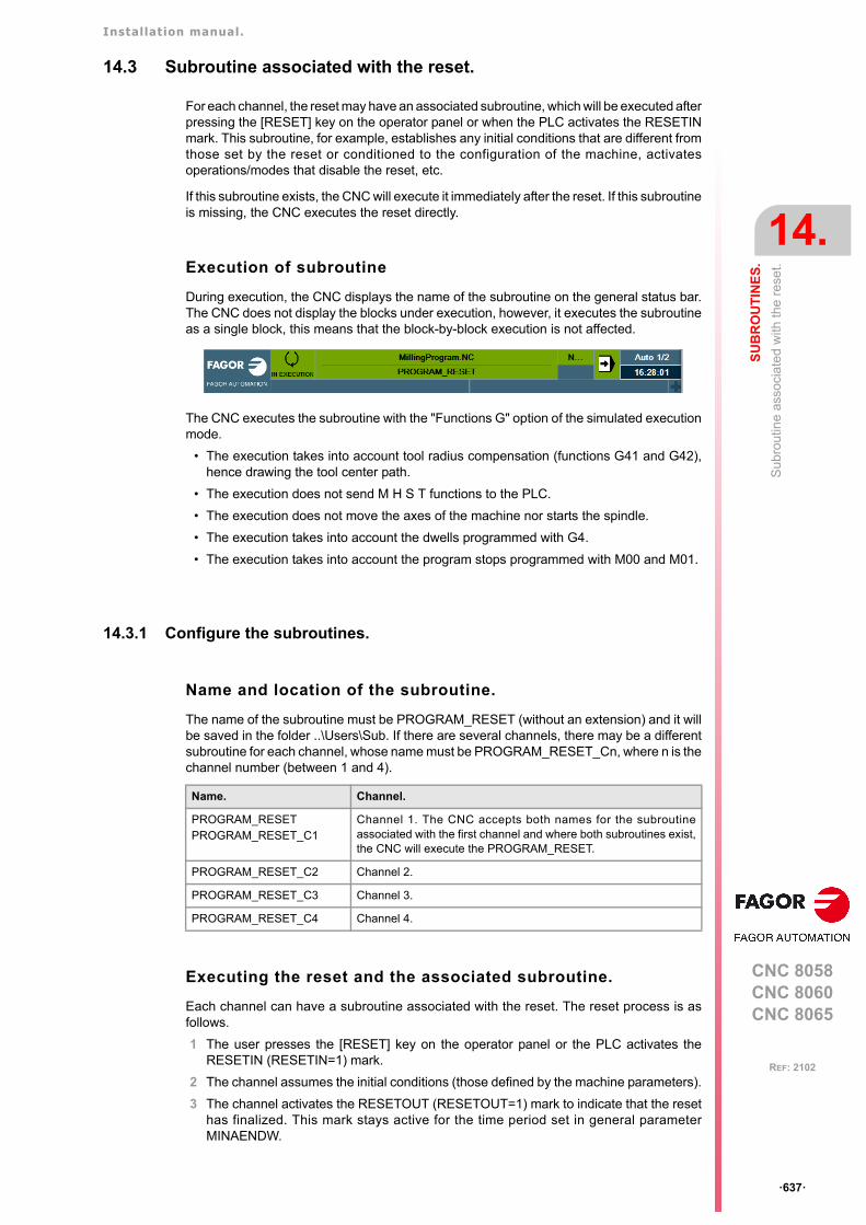
Installation manual.
CNC 8058CNC 8060CNC 8065
SU
BR
OU
TIN
ES
.
14.
Su
brou
tine
asso
ciat
ed w
ith th
e r
ese
t.
ꞏ637ꞏ
REF: 2102
14.3 Subroutine associated with the reset.
For each channel, the reset may have an associated subroutine, which will be executed afterpressing the [RESET] key on the operator panel or when the PLC activates the RESETINmark. This subroutine, for example, establishes any initial conditions that are different fromthose set by the reset or conditioned to the configuration of the machine, activatesoperations/modes that disable the reset, etc.
If this subroutine exists, the CNC will execute it immediately after the reset. If this subroutineis missing, the CNC executes the reset directly.
Execution of subroutine
During execution, the CNC displays the name of the subroutine on the general status bar.The CNC does not display the blocks under execution, however, it executes the subroutineas a single block, this means that the block-by-block execution is not affected.
The CNC executes the subroutine with the "Functions G" option of the simulated executionmode.
• The execution takes into account tool radius compensation (functions G41 and G42),hence drawing the tool center path.
• The execution does not send M H S T functions to the PLC.
• The execution does not move the axes of the machine nor starts the spindle.
• The execution takes into account the dwells programmed with G4.
• The execution takes into account the program stops programmed with M00 and M01.
14.3.1 Configure the subroutines.
Name and location of the subroutine.
The name of the subroutine must be PROGRAM_RESET (without an extension) and it willbe saved in the folder ..\Users\Sub. If there are several channels, there may be a differentsubroutine for each channel, whose name must be PROGRAM_RESET_Cn, where n is thechannel number (between 1 and 4).
Executing the reset and the associated subroutine.
Each channel can have a subroutine associated with the reset. The reset process is asfollows.
1 The user presses the [RESET] key on the operator panel or the PLC activates theRESETIN (RESETIN=1) mark.
2 The channel assumes the initial conditions (those defined by the machine parameters).
3 The channel activates the RESETOUT (RESETOUT=1) mark to indicate that the resethas finalized. This mark stays active for the time period set in general parameterMINAENDW.
Name. Channel.
PROGRAM_RESETPROGRAM_RESET_C1
Channel 1. The CNC accepts both names for the subroutineassociated with the first channel and where both subroutines exist,the CNC will execute the PROGRAM_RESET.
PROGRAM_RESET_C2 Channel 2.
PROGRAM_RESET_C3 Channel 3.
PROGRAM_RESET_C4 Channel 4.
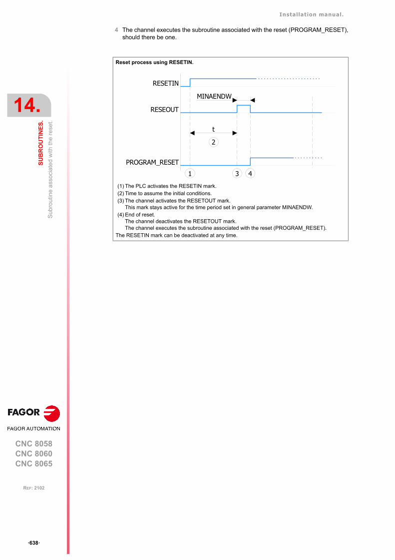
Installation manual.
CNC 8058CNC 8060CNC 8065
14.
SU
BR
OU
TIN
ES
.
Su
brou
tine
asso
ciat
ed w
ith th
e r
ese
t.
ꞏ638ꞏ
REF: 2102
4 The channel executes the subroutine associated with the reset (PROGRAM_RESET),should there be one.
Reset process using RESETIN.
(1) The PLC activates the RESETIN mark.(2) Time to assume the initial conditions.(3) The channel activates the RESETOUT mark.
This mark stays active for the time period set in general parameter MINAENDW.(4) End of reset.
The channel deactivates the RESETOUT mark.The channel executes the subroutine associated with the reset (PROGRAM_RESET).
The RESETIN mark can be deactivated at any time.
RESEOUT
RESETIN
PROGRAM_RESET
MINAENDW
1 3 4
t
2
Installation manual.
CNC 8058CNC 8060CNC 8065
SU
BR
OU
TIN
ES
.
14.
Sub
rout
ine
asso
ciat
ed w
ith 8
055-
MC
and
805
5-T
C p
rogr
ams
(sub
rout
ines
999
8 an
d 99
99).
ꞏ639ꞏ
REF: 2102
14.4 Subroutine associated with 8055-MC and 8055-TC programs(subroutines 9998 and 9999).
In order to be able to execute programs of the 8055 MC/TC, the CNC must have twosubroutines called 9998 and 9999 written in 8070 CNC language. Each program in thelanguage of the 8055 MC/TC has a call to the corresponding subroutine at the beginningand at the end.
Both subroutines must be defined, even if no operation is to be carried out at the beginningor at the end of the part-program, in which case the subroutines will be empty (except forthe end-of-subroutine block). If any of these subroutines are missing, the CNC will issue anerror message every time when trying to execute a 8055-MC or 8055-TC part-program.
14.4.1 Configure the subroutines.
Name and location of the subroutine.
The name of the subroutines is 9998 and 9999. Both subroutines must be saved in the folderpath indicated by the general parameter SUBPATH. All channels use the same subroutines.
Subroutine. Meaning.
9998 Routine that the CNC will execute at the beginning of each programof the 8055-MC and 8055-TC.
9999 Routine that the CNC will execute at the end of each program of the8055-MC and 8055-TC.
Parameter. Meaning.
SUBPATH CHN This parameter indicates the directory, by default, for the usersubroutines and the necessary subroutines to execute 8055-MC and 8055-TC programs.
[CHN] ....... General machine parameter of the channel.
Installation manual.
CNC 8058CNC 8060CNC 8065
14.
SU
BR
OU
TIN
ES
.
Sub
rout
ines
ass
ocia
ted
with
the
kine
mat
ics
calib
ratio
n cy
cle.
ꞏ640ꞏ
REF: 2102
14.5 Subroutines associated with the kinematics calibration cycle.
The kinematics calibration cycle has two associated subroutines (KinCal_Begin.nc andKinCal_End.nc), which the CNC executes before and after the cycle.
Fagor supplies both subroutines as incomplete and it is the manufacturer's responsibility todefine both subroutines. Software updates do not modify any existing subroutines.
14.5.1 Configure the subroutines.
Name and location of the subroutine.
The names of the subroutines are KinCal_Begin.nc and KinCal_End.nc. Both subroutinesmust be saved in the folder ..\Mtb\Sub. All channels use the same subroutines.
Name. Meaning.
KinCal_Begin.nc Subroutine associated with the beginning of the kinematicscalibration cycle.
KinCal_End.nc Subroutine associated with the end of the kinematics calibrationcycle.
Installation manual.
CNC 8058CNC 8060CNC 8065
SU
BR
OU
TIN
ES
.
14.
Sub
rout
ines
ass
ocia
ted
with
the
tool
cal
ibra
tion
cycl
e.
ꞏ641ꞏ
REF: 2102
14.6 Subroutines associated with the tool calibration cycle.
The tool calibration cycle, for both the ISO and the editor, has two associated subroutinesthat the CNC executes before and after the cycle. These subroutines can be used to enablethe probe and indicate if it is in safe mode.
Subroutines and M functions defined in the cycle.
Up to 4 M functions may be defined in each probing cycle to be executed before the cycleand another 4 M functions to be executed afterwards. All these functions may have asubroutine associated with them. When starting the execution, the cycle first executes thesubroutine Sub_Probe_Tool_Begin.fst and then the M-before functions with their associatedsubroutines. At the end of the execution, the cycle executes first the M-after functions withthe i r cor respond ing assoc ia ted subrou t ines and then the subrou t ineSub_Probe_Tool_End.fst.
Management of the PROBE1ENA/PROBE2ENA marks in thesubroutine.
These mark indicate that the probe has is enabled. It is recommended that the OEMmanages both marks from the subroutine Sub_Probe_Tool_Begin.fst, so that executionwaits until the mark is active.
Management of the PROBE1MONIT/PROBE2MONIT marks in thesubroutine.
These marks are associated with the safe mode of the probe. It is recommended that theOEM manages both marks from the subroutine Sub_Probe_Tool_Begin.fst to warn, shouldthey be deactivated, that the probe is in non-safe mode.
14.6.1 Configure the subroutines.
Name and location of the subroutine.
The name of the subroutine is Sub_Probe_Tool_Begin.fst and Sub_Probe_Tool_End.fst.Both subroutines must be saved in the folder ..\Mtb\Sub. All channels use the samesubroutines.
Since it is an OEM subroutine with an .fst extension, the CNC loads this subroutine into theRAM of the CNC. See "14.1 Run subroutines from RAM (extension *.fst)." on page 635.
The subroutines supplied by Fagor provide basic probe management, so they should be adjusted andconfigured appropriately by the OEM. Fagor provides the subroutine Sub_Probe_Tool_Begin.fstassociated with probe input 1 and the subroutine Sub_Probe_Piece_Begin.fst associated with probeinput 2.
Name. Meaning.
Sub_Probe_Tool_Begin.fst Subroutine associated with the beginning of the tool calibrationcycle.
Sub_Probe_Tool_End.fst Subroutine associated with the end of the tool calibration cycle.
Installation manual.
CNC 8058CNC 8060CNC 8065
14.
SU
BR
OU
TIN
ES
.
Sub
rout
ines
ass
ocia
ted
with
the
tool
cal
ibra
tion
cycl
e.
ꞏ642ꞏ
REF: 2102
14.6.2 Example of a subroutine.
Example of a subroutine Sub_Probe_Tool_Begin.fst supplied by Fagor (to beadjusted by the OEM).
Example of a subroutine Sub_Probe_Tool_End.fst supplied by Fagor (to be adjustedby the OEM).
#ESBLK; Activate PROBE1 Hardware by PLC output.
; Check PROBE is READY with PLC Input from Probe Hardware.#MSG["WAIT FOR ENABLING PROBE1"]#WAIT FOR[V.PLC.PROBE1ENA==1]#MSG[""]
; Select PROBE1 input for using in Probing.#SELECT PROBE[1]#FLUSH$IF [V.G.PRBST1==1]
#WARNING["PROBE1 SIGNAL TOUCHING"]M0
$ENDIF
; Check probe in safe mode feature is actived.$IF [V.PLC.PROBE1MONIT==0]
#MSG["PROBE NOT IN SAFE MODE"]$ENDIF#RETDSBLK
#COMMENT BEGINPLC signals to add in the logic:
PROBE1ENA; PROBE1 is enabled confirmation signal to CNC.If not used in PLC, it is actived by default.
PROBE1MONIT; It activates PROBE1 in SAFE mode.If probe is actived in no G100/3 motion, CNC will stop motion and shows an error.If not used in PLC, it is actived by default.
#COMMENT END
#ESBLK;Deactivate PROBE1 Hardware by PLC output
#RETDSBLK
Installation manual.
CNC 8058CNC 8060CNC 8065
SU
BR
OU
TIN
ES
.
14.
Sub
rout
ines
ass
ocia
ted
with
the
part
mea
surin
g cy
cle.
ꞏ643ꞏ
REF: 2102
14.7 Subroutines associated with the part measuring cycle.
The part measuring cycle, for both the ISO and the editor, has two associated subroutinesthat the CNC executes before and after the cycle. These subroutines can be used to enablethe probe and indicate if it is in safe mode.
Subroutines and M functions defined in the cycle.
Up to 4 M functions may be defined in each probing cycle to be executed before the cycleand another 4 M functions to be executed afterwards. All these functions may have asubroutine associated with them. When starting the execution, the cycle executes first thesubroutine Sub_Probe_Piece_Begin.fst and then the M-before functions with theirassociated subroutines. At the end of the execution, the cycle executes first the M-afterfunctions with their corresponding associated subroutines and then the subroutineSub_Probe_Piece_End.fst.
Management of the PROBE1ENA/PROBE2ENA marks in thesubroutine.
These mark indicate that the probe has is enabled. It is recommended that the OEMmanages both marks from the subroutine Sub_Probe_Piece_Begin.fst, so that the executionwaits until the mark is active.
Management of the PROBE1MONIT/PROBE2MONIT marks in thesubroutine.
These marks are associated with the safe mode of the probe. It is recommended that theOEM manages both marks from the subroutine Sub_Probe_Piece_Begin.fst to warn, shouldthey be deactivated, that the probe is in non-safe mode.
14.7.1 Configure the subroutines.
Name and location of the subroutine.
The name of the subroutine is Sub_Probe_Piece_Begin.fst and Sub_Probe_Piece_End.fst.Both subroutines must be saved in the folder ..\Mtb\Sub. All channels use the samesubroutines.
Since it is an OEM subroutine with an .fst extension, the CNC loads this subroutine into theRAM of the CNC. See "14.1 Run subroutines from RAM (extension *.fst)." on page 635.
The subroutines supplied by Fagor provide basic probe management, so they should be adjusted andconfigured appropriately by the OEM. Fagor provides the subroutine Sub_Probe_Tool_Begin.fstassociated with probe input 1 and the subroutine Sub_Probe_Piece_Begin.fst associated with probeinput 2.
Name. Meaning.
Sub_Probe_Piece_Begin.fst Subroutines associated with the start of the part measuring cycle.
Sub_Probe_Piece_End.fst Subroutines associated with the end of the part measuring cycle.
Installation manual.
CNC 8058CNC 8060CNC 8065
14.
SU
BR
OU
TIN
ES
.
Sub
rout
ines
ass
ocia
ted
with
the
part
mea
surin
g cy
cle.
ꞏ644ꞏ
REF: 2102
14.7.2 Example of a subroutine.
Example of a subroutine Sub_Probe_Piece_Begin.fst supplied by Fagor (to beadjusted by the OEM).
Example of a subroutine Sub_Probe_Piece_End.fst supplied by Fagor (to be adjustedby the OEM).
#ESBLK; Activate PROBE 2 Hardware by PLC output.
; Check PROBE is READY with PLC Input from Probe Hardware.#MSG["WAIT FOR ENABLING PROBE2"]#WAIT FOR[V.PLC.PROBE2ENA==1]#MSG[""]
; Select PROBE 2 input for using in Probing.#SELECT PROBE[2]#FLUSH$IF [V.G.PRBST2==1]
#WARNING["PROBE2 SIGNAL TOUCHING"]M0
$ENDIF
; Check probe in safe mode feature is actived.$IF [V.PLC.PROBE2MONIT==0]
#MSG["PROBE NOT IN SAFE MODE"]$ENDIF#RETDSBLK
#COMMENT BEGINPLC signals to add in the logic:
PROBE2ENA; PROBE 2 is enabled confirmation signal to CNC.If not used in PLC, it is actived by default.
PROBE2MONIT; It activates PROBE2 in SAFE mode.If probe is actived in no G100/3 motion, CNC will stop motion and shows an error.If not used in PLC, it is actived by default.
#COMMENT END
#ESBLK;Deactivate PROBE2 Hardware by PLC output
#RETDSBLK
Installation manual.
CNC 8058CNC 8060CNC 8065
SU
BR
OU
TIN
ES
.
14.
Sub
rout
ine
asso
ciat
ed
with
the
too
l cha
nge
(fun
ctio
n T
).
ꞏ645ꞏ
REF: 2102
14.8 Subroutine associated with the tool change (function T).
The subroutine associated with the tool is executed automatically every time a T function(tool selection) is executed. If the M06 function is included in this subroutine, the tool loadingprocess will commence when the "T" code has been executed.
Characteristics of a turret type magazine.
For a turret magazine, it is recommended that the routine associated with T include the M06function. When the CNC selects a tool, the routine associated with T executes the functionM06 (tool change). If the subroutine associated with T does not include the function M06,when the CNC selects a tool, it internally executes a T# M6 block to make the change.
14.8.1 Configure the subroutines.
Assign the subroutine to the command.
Name and location of the subroutine.
This subroutine must be defined in the general parameter TOOLSUB and saved in the folder..\Mtb\Sub. If there are several channels, there may be a different subroutine for eachchannel.
Parameter. Meaning.
TOOLSUB CHN Subroutine associated with "T".
[CHN] ....... General machine parameter of the channel.
Installation manual.
CNC 8058CNC 8060CNC 8065
14.
SU
BR
OU
TIN
ES
.
Su
brou
tine
ass
ocia
ted
with
the
tool
cha
nge
(fun
ctio
n M
6).
ꞏ646ꞏ
REF: 2102
14.9 Subroutine associated with the tool change (function M6).
To properly configure the magazines and the tool change, the routine associated with thetool and the function M06 must be programmed. The M06 function executes the tool change.
It is recommended to set this function in the "M" function table so it executes the subroutinefor the tool changer installed on the machine. The M06 function must also be programmedwithin the subroutine so the CNC prompts the tool manager to start making the tool change.
• When there is no tool magazine, the function M6 behaves like a normal function, as itdoes not execute anything related to the tool change, therefore, it is not necessary toassign this subroutine.
• For a turret magazine, it is recommended that the routine associated with T include theM06 function. When the CNC selects a tool, the routine associated with T executes thefunction M06 (tool change). If the subroutine associated with T does not include thefunction M06, when the CNC selects a tool, it internally executes a T# M6 block to makethe change.
• For other magazines, it is recommended that this function in the "M" function table becustomized, so it executes the subroutine for the tool changer installed on the machine.The M06 function must also be programmed within the subroutine so the CNC promptsthe tool manager to start making the tool change.
Considerations and recommendations.
The management of the tool change should be included in the subroutine associated withthe M06 and leave the control of the external devices up to the PLC. Use the auxiliaryfunctions to govern the various devices (magazine rotation, magazine movement, toolchanger arm, etc) from the M06 subroutine.
14.9.1 Configure the subroutines.
This subroutine must be defined in the “M” function table and saved in the folder ..\Mtb\Sub.See "14.11 Subroutines associated with M functions." on page 648.
Installation manual.
CNC 8058CNC 8060CNC 8065
SU
BR
OU
TIN
ES
.
14.
Sub
rout
ine
ass
oci
ated
with
func
tion
G74
.
ꞏ647ꞏ
REF: 2102
14.10 Subroutine associated with function G74.
Function G74 (machine home search) can be programmed in 2 ways, either by indicatingthe axes and the order in which the axes are referenced or by programming only G74 (withoutaxes). When executing a block that only contains the G74 function (without axes), it callsthe subroutine associated with this function. This subroutine must contain the axes and theorder in which the axes and the spindle must be referenced.
This subroutine is also called when homing the axis in JOG mode without selecting the axes.
14.10.1 Configure the subroutines.
Assign the subroutine to the function.
Name and location of the subroutine.
This subroutine must be defined in the general parameter REFPSUB (by default, sub_ref.nc)and saved in the folder ..\Mtb\Sub. If there are several channels, there may be a differentsubroutine for each channel.
Parameter. Meaning.
REFPSUB CHN Subroutine associated with function G74.
[CHN] ....... General machine parameter of the channel.
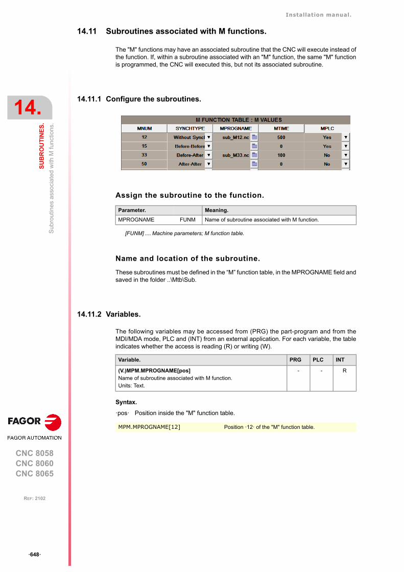
Installation manual.
CNC 8058CNC 8060CNC 8065
14.
SU
BR
OU
TIN
ES
.
Sub
rou
tines
ass
ocia
ted
with
M fu
nctio
ns.
ꞏ648ꞏ
REF: 2102
14.11 Subroutines associated with M functions.
The "M" functions may have an associated subroutine that the CNC will execute instead ofthe function. If, within a subroutine associated with an "M" function, the same "M" functionis programmed, the CNC will executed this, but not its associated subroutine.
14.11.1 Configure the subroutines.
Assign the subroutine to the function.
Name and location of the subroutine.
These subroutines must be defined in the “M” function table, in the MPROGNAME field andsaved in the folder ..\Mtb\Sub.
14.11.2 Variables.
The following variables may be accessed from (PRG) the part-program and from theMDI/MDA mode, PLC and (INT) from an external application. For each variable, the tableindicates whether the access is reading (R) or writing (W).
Syntax.
ꞏposꞏ Position inside the "M" function table.
Parameter. Meaning.
MPROGNAME FUNM Name of subroutine associated with M function.
[FUNM] .... Machine parameters; M function table.
Variable. PRG PLC INT
(V.)MPM.MPROGNAME[pos]Name of subroutine associated with M function.Units: Text.
- - R
MPM.MPROGNAME[12] Position ꞏ12ꞏ of the "M" function table.
Installation manual.
CNC 8058CNC 8060CNC 8065
SU
BR
OU
TIN
ES
.
14.
OE
M s
ubro
utin
es a
ssoc
iate
d w
ith fu
nct
ions
G1
80 to
G18
9 /
G38
0 to
G3
99.
ꞏ649ꞏ
REF: 2102
14.12 OEM subroutines associated with functions G180 to G189 / G380to G399.
The CNC allows the machine manufacturer to define up to 30 subroutines per channel andassociate them with functions G180 through G189 and G380 through G399 in such a waythat when a channel executes one of these functions, it will execute the associatedsubroutine. These OEM subroutines may be executed either in a non-modal or modal wayand it also allows resetting the local parameters of the subroutine.
14.12.1 Configure the subroutines.
Assign the subroutines to the functions.
Name and location of the subroutine.
These subroutines must be defined in the general parameters OEMSUB and saved in thefolder ..\Mtb\Sub. These subroutines can be loaded into RAM (extension fst).
14.12.2 Variables.
The following variables may be accessed from (PRG) the part-program and from theMDI/MDA mode, PLC and (INT) from an external application. For each variable, the tableindicates whether the access is reading (R) or writing (W).
Parameter. Meaning.
OEMSUB (G180)ꞏꞏOEMSUB (G189)
CHN Subroutines associated with functions G180 through G189.
OEMSUB (G380)ꞏꞏOEMSUB (G399)
CHN Subroutines associated with functions G380 through G399.
[CHN] ....... General machine parameter of the channel.
Variable. PRG PLC INT
(V.)[ch].MPG.OEMSUB1ꞏꞏ(V.)[ch].MPG.OEMSUB10OEM subroutines associated with functions G180 through G189.Units: -.
- - R
(V.)[ch].MPG.OEMSUB11ꞏꞏ(V.)[ch].MPG.OEMSUB30OEM subroutines associated with functions G380 through G399.Units: -.
- - R

Installation manual.
CNC 8058CNC 8060CNC 8065
14.
SU
BR
OU
TIN
ES
.
Inte
rrup
tion
subr
outin
es.
ꞏ650ꞏ
REF: 2102
14.13 Interruption subroutines.
The interruption subroutines are defined by the machine manufacturer and will be executedfrom the PLC. When the PLC commands the execution of one of these subroutines, thechannel interrupts the execution of the program and executes the corresponding interruptionsubroutine.
14.13.1 Configure the subroutines.
Assign the subroutines to the functions.
Name and location of the subroutine.
These subroutines must be defined in the general parameters INIT1SUB to INIT4SU andsaved in the folder ..\Mtb\Sub. If there are several channels, there may be a differentsubroutine for each channel.
14.13.2 Variables.
The following variables may be accessed from (PRG) the part-program and from theMDI/MDA mode, PLC and (INT) from an external application. For each variable, the tableindicates whether the access is reading (R) or writing (W).
Syntax.
ꞏchꞏ Channel number.
Parameter. Meaning.
INT1SUBꞏꞏINT4SUB
CHN Interruption subroutines.
[CHN]....... General machine parameter of the channel.
Variable. PRG PLC INT
(V.)[ch].MPG.INT1SUB(V.)[ch].MPG.INT2SUB(V.)[ch].MPG.INT3SUB(V.)[ch].MPG.INT4SUBInterruption subroutines.Units: Text.
- - R
[2].MPG.INT1SUB Channel ꞏ2ꞏ.
Installation manual.
CNC 8058CNC 8060CNC 8065
SU
BR
OU
TIN
ES
.
14.
Sub
rout
ine
ass
oci
ated
with
the
com
man
d #I
NIT
IALS
UB
.
ꞏ651ꞏ
REF: 2102
14.14 Subroutine associated with the command #INITIALSUB.
The command #INITIALSUB has an associated subroutine, which is executed by the CNCalong with the command. This command specifically for laser machines, where thissubroutine must perform the initial laser operations.
14.14.1 Configure the subroutines.
Assign the subroutine to the command.
Name and location of the subroutine.
This subroutine must be defined in the general parameter INITIALSUB (by default,Initialsub.fst) and saved in the folder ..\Mtb\Sub. If there are several channels, there may bea different subroutine for each channel.
Since it is an OEM subroutine with an .fst extension, the CNC loads this subroutine into theRAM of the CNC. See "14.1 Run subroutines from RAM (extension *.fst)." on page 635.
14.14.2 Variables.
The following variables may be accessed from (PRG) the part-program and from theMDI/MDA mode, PLC and (INT) from an external application. For each variable, the tableindicates whether the access is reading (R) or writing (W).
Syntax.
ꞏchꞏ Channel number.
Subroutine specifically for the laser model. The subroutines supplied by Fagor provide basic lasermanagement, so they should be configured appropriately by the OEM. The OEM is responsible forensuring that the subroutine complies with all safety aspects relating to handling the laser.
If this version is updated, the CNC behaves as follows. • For the two first two installation options, the CNC will only copy the subroutines in the folder
..\Mtb\Sub if they do not already exist. • In the third installation option, "rename previous version and install it completely", the CNC always
updates the subroutines.
Parameter. Meaning.
INITIALSUB CHN Subroutine associated with the command #INITIALSUB.
[CHN] ....... General machine parameter of the channel.
Variable. PRG PLC INT
(V.)[ch].MPG.INITIALSUBSubroutine associated with the command #INITIALSUB.Units: Text.
- - R
[2].MPG.INITIALSUB Channel ꞏ2ꞏ.
Installation manual.
CNC 8058CNC 8060CNC 8065
14.
SU
BR
OU
TIN
ES
.
Sub
rout
ine
asso
ciat
ed
with
the
com
ma
nd #
PIE
RC
ING
.
ꞏ652ꞏ
REF: 2102
14.15 Subroutine associated with the command #PIERCING.
The command #PIERCING executes the associated subroutine after updating the piercingvariables ((V.) TTPIR.name). This command is specifically for laser machines, where thissubroutine must perform the initial piercing operations.
Management of the PIERCING mark in the subroutine.
The OEM must manage the PIERCING mark from this subroutine. At the start of thesubroutine (or when the OEM deems it necessary), the OEM must activate the PIERCINGmark (assigning it the value 1) to indicate to the PLC that it must start the piercing operation.At the end of the subroutine (or when the OEM deems it necessary), the OEM mustdeactivate this mark (assigning it the value 0) to indicate to the CNC that it has finished thepiercing operation.
• The instruction #PLC makes it possible to manage a PLC mark from the part or subroutineprogram, without interrupting the block preparation.
• This mark shows the state of the variable V.PLC.PIERCING. The OEM can also use thisvariable in the subroutine associated with the piercing (by default, Piercing.fst) to modifythe status of this mark. Entering this variable interrupts the block preparation.
14.15.1 Configure the subroutines.
Assign the subroutine to the command.
Name and location of the subroutine.
This subroutine must be defined in the general parameter PIERCING (by default,Piercing.fst) and saved in the folder ..\Mtb\Sub. If there are several channels, there may bea different subroutine for each channel.
Since it is an OEM subroutine with an .fst extension, the CNC loads this subroutine into theRAM of the CNC. See "14.1 Run subroutines from RAM (extension *.fst)." on page 635.
Subroutine specifically for the laser model. The subroutines supplied by Fagor provide basic lasermanagement, so they should be configured appropriately by the OEM. The OEM is responsible forensuring that the subroutine complies with all safety aspects relating to handling the laser.
If this version is updated, the CNC behaves as follows. • For the two first two installation options, the CNC will only copy the subroutines in the folder
..\Mtb\Sub if they do not already exist. • In the third installation option, "rename previous version and install it completely", the CNC always
updates the subroutines.
Parameter. Meaning.
PIERCING CHN Subroutine associated with the command #PIERCING.
[CHN]....... General machine parameter of the channel.

Installation manual.
CNC 8058CNC 8060CNC 8065
SU
BR
OU
TIN
ES
.
14.
Sub
rout
ine
asso
ciat
ed
with
the
com
ma
nd #
PIE
RC
ING
.
ꞏ653ꞏ
REF: 2102
14.15.2 Variables.
The following variables may be accessed from (PRG) the part-program and from theMDI/MDA mode, PLC and (INT) from an external application. For each variable, the tableindicates whether the access is reading (R) or writing (W).
Syntax.
ꞏchꞏ Channel number.
Variable. PRG PLC INT
(V.)[ch].MPG.PIERCINGSubroutine associated with the command #PIERCING.Units: Text.
- - R
[2].MPG.PIERCING Channel ꞏ2ꞏ.
Installation manual.
CNC 8058CNC 8060CNC 8065
14.
SU
BR
OU
TIN
ES
.
Sub
rout
ine
ass
oci
ated
with
the
com
ma
nd #
CU
TT
ING
ON
an
d#C
UT
TIN
G O
FF
.
ꞏ654ꞏ
REF: 2102
14.16 Subroutine associated with the command #CUTTING ON and#CUTTING OFF.
The command #CUTTINGON executes the associated subroutine after updating the cuttingvariables ((V.)TTCUT.name). The command #CUTTINGON executes the associatedsubroutine. Both commands are specifically for laser machines, where these subroutinesmust perform the initial associated cutting operations.
Management of the CUTTING mark in the subroutine.
The OEM must manage the CUTTING mark from these subroutines. At the start of theassociated subroutine #CUTTING ON (or when the OEM deems it necessary), the OEMmust activate the CUTTING mark (assigning it a value of 1) to indicate to the PLC that itshould start the cutting operation. At the end of the associated subroutine #CUTTING OFF(or when the OEM deems it necessary), the OEM must deactivate this mark (assigning itthe value 0) to indicate to the CNC that it has finished the piercing operation.
• The instruction #PLC makes it possible to manage a PLC mark from the part or subroutineprogram, without interrupting the block preparation.
• This mark shows the state of the variable V.PLC.CUTTING. The OEM can also use thisvariable in the subroutines associated with cutting (by default, Cuttingon.fst /Cuttingoff.fst) to modify the status of this mark. Entering this variable interrupts the blockpreparation.
14.16.1 Configure the subroutines.
Assign the subroutine to the command.
Name and location of the subroutine.
These subroutines associated must be defined for the general parameters CUTTINGON (bydefault, Cuttingon.fst) and CUTTINGOFF (by default, Cuttingoff.fst). Both subroutines mustbe saved in the folder ..\Mtb\Sub. If there are several channels, there may be a differentsubroutine for each channel.
Since it is an OEM subroutine with an .fst extension, the CNC loads this subroutine into theRAM of the CNC. See "14.1 Run subroutines from RAM (extension *.fst)." on page 635.
Subroutines specifically for the laser model. The subroutines supplied by Fagor provide basic lasermanagement, so they should be configured appropriately by the OEM. The OEM is responsible forensuring that the subroutine complies with all safety aspects relating to handling the laser.
If this version is updated, the CNC behaves as follows. • For the two first two installation options, the CNC will only copy the subroutines in the folder
..\Mtb\Sub if they do not already exist. • In the third installation option, "rename previous version and install it completely", the CNC always
updates the subroutines.
Parameter. Meaning.
CUTTINGON CHN Subroutine associated with the command #CUTTING ON.
CUTTINGOFF CHN Subroutine associated with the command #CUTTING OFF.
[CHN]....... General machine parameter of the channel.
Installation manual.
CNC 8058CNC 8060CNC 8065
SU
BR
OU
TIN
ES
.
14.
Sub
rout
ine
ass
oci
ated
with
the
com
ma
nd #
CU
TT
ING
ON
an
d#C
UT
TIN
G O
FF
.
ꞏ655ꞏ
REF: 2102
14.16.2 Variables.
The following variables may be accessed from (PRG) the part-program and from theMDI/MDA mode, PLC and (INT) from an external application. For each variable, the tableindicates whether the access is reading (R) or writing (W).
Syntax.
ꞏchꞏ Channel number.
Variable. PRG PLC INT
(V.)[ch].MPG.CUTTINGONSubroutine associated with the command #CUTTING ON.Units: Text.
- - R
(V.)[ch].MPG.CUTTINGONSubroutine associated with the command #CUTTING OFF.Units: Text.
- - R
[2].MPG.CUTTINGON Channel ꞏ2ꞏ.
[2].MPG.CUTTINGOFF Channel ꞏ2ꞏ.
Installation manual.
CNC 8058CNC 8060CNC 8065
14.
SU
BR
OU
TIN
ES
.
Su
brou
tine
asso
ciat
ed w
ith th
e co
mm
and
#F
INA
LSU
B.
ꞏ656ꞏ
REF: 2102
14.17 Subroutine associated with the command #FINALSUB.
The command #FINALSUB has an associated subroutine, which is executed by the CNCalong with the command. This command is specifically for laser machines, where thissubroutine must perform the final laser operations.
14.17.1 Configure the subroutines.
Assign the subroutine to the command.
Name and location of the subroutine.
This subroutine must be defined in the general parameter FINALSUB (by default,Finalsub.fst) and saved in the folder ..\Mtb\Sub. If there are several channels, there may bea different subroutine for each channel.
Since it is an OEM subroutine with an .fst extension, the CNC loads this subroutine into theRAM of the CNC. See "14.1 Run subroutines from RAM (extension *.fst)." on page 635.
14.17.2 Variables.
The following variables may be accessed from (PRG) the part-program and from theMDI/MDA mode, PLC and (INT) from an external application. For each variable, the tableindicates whether the access is reading (R) or writing (W).
Syntax.
ꞏchꞏ Channel number.
Subroutine specifically for the laser model. The subroutines supplied by Fagor provide basic lasermanagement, so they should be configured appropriately by the OEM. The OEM is responsible forensuring that the subroutine complies with all safety aspects relating to handling the laser.
If this version is updated, the CNC behaves as follows. • For the two first two installation options, the CNC will only copy the subroutines in the folder
..\Mtb\Sub if they do not already exist. • In the third installation option, "rename previous version and install it completely", the CNC always
updates the subroutines.
Parameter. Meaning.
FINALSUB CHN Subroutine associated with the command #FINALSUB.
[CHN]....... General machine parameter of the channel.
Variable. PRG PLC INT
(V.)[ch].MPG.FINALSUBSubroutine associated with the command #FINALSUB.Units: Text.
- - R
[2].MPG.FINALSUB Channel ꞏ2ꞏ.
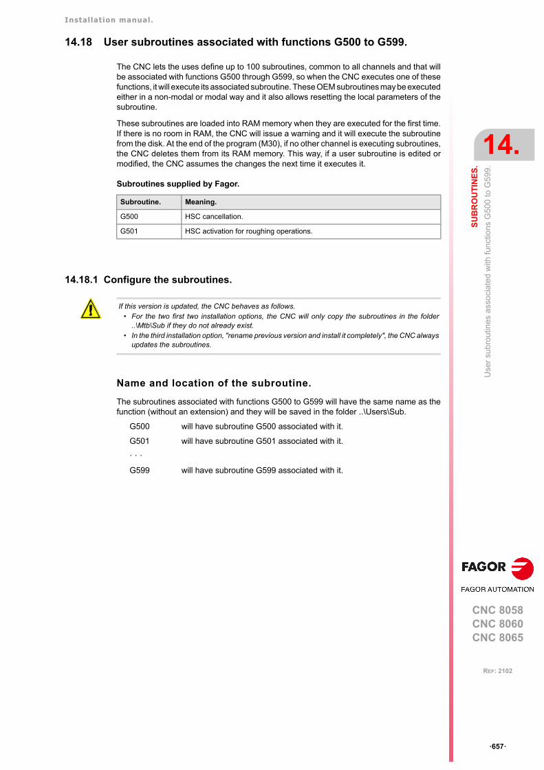
Installation manual.
CNC 8058CNC 8060CNC 8065
SU
BR
OU
TIN
ES
.
14.
Use
r su
brou
tines
ass
oci
ated
with
func
tion
s G
500
to G
599
.
ꞏ657ꞏ
REF: 2102
14.18 User subroutines associated with functions G500 to G599.
The CNC lets the uses define up to 100 subroutines, common to all channels and that willbe associated with functions G500 through G599, so when the CNC executes one of thesefunctions, it will execute its associated subroutine. These OEM subroutines may be executedeither in a non-modal or modal way and it also allows resetting the local parameters of thesubroutine.
These subroutines are loaded into RAM memory when they are executed for the first time.If there is no room in RAM, the CNC will issue a warning and it will execute the subroutinefrom the disk. At the end of the program (M30), if no other channel is executing subroutines,the CNC deletes them from its RAM memory. This way, if a user subroutine is edited ormodified, the CNC assumes the changes the next time it executes it.
Subroutines supplied by Fagor.
14.18.1 Configure the subroutines.
Name and location of the subroutine.
The subroutines associated with functions G500 to G599 will have the same name as thefunction (without an extension) and they will be saved in the folder ..\Users\Sub.
G500 will have subroutine G500 associated with it.
G501 will have subroutine G501 associated with it.
ꞏ ꞏ ꞏ
G599 will have subroutine G599 associated with it.
Subroutine. Meaning.
G500 HSC cancellation.
G501 HSC activation for roughing operations.
If this version is updated, the CNC behaves as follows. • For the two first two installation options, the CNC will only copy the subroutines in the folder
..\Mtb\Sub if they do not already exist. • In the third installation option, "rename previous version and install it completely", the CNC always
updates the subroutines.
Installation manual.
CNC 8058CNC 8060CNC 8065
14.
SU
BR
OU
TIN
ES
.
Use
r su
brou
tines
ass
ocia
ted
with
fun
ctio
ns G
8000
to G
8999
.
ꞏ658ꞏ
REF: 2102
14.19 User subroutines associated with functions G8000 to G8999.
The CNC lets the user define up to 1000 subroutines, common to all channels and associatedwith functions G8000 through G8999, so when the CNC executes one of these functions,it will execute its associated subroutine. These subroutines may be executed either in a non-modal or modal way and it also allows resetting the local parameters of the subroutine.
These subroutines are loaded into RAM memory when they are executed for the first time.If there is no room in RAM, the CNC will issue a warning and it will execute the subroutinefrom the disk. At the end of the program (M30), if no other channel is executing subroutines,the CNC deletes them from its RAM memory. This way, if a user subroutine is edited ormodified, the CNC assumes the changes the next time it executes it.
Some of these subroutines have a function pre-assigned by Fagor, being ProGTL3 languagemacros. If one of these G functions is programmed, the CNC executes the correspondingmacro and not the subroutine.
14.19.1 Configure the subroutines.
Name and location of the subroutine.
The subroutines associated with functions G8000 to G8999 will have the same name as thefunction (without an extension) and they will be saved in the folder ..\Users\Sub.
G8000 The subroutine G8000 will be associated.
G8001 The subroutine G8001 will be associated.
ꞏ ꞏ ꞏ
G8999 The subroutine G8999 will be associated.
If this version is updated, the CNC behaves as follows. • For the two first two installation options, the CNC will only copy the subroutines in the folder
..\Mtb\Sub if they do not already exist. • In the third installation option, "rename previous version and install it completely", the CNC always
updates the subroutines.
Installation manual.
CNC 8058CNC 8060CNC 8065
SU
BR
OU
TIN
ES
.
14.
Ass
ista
nce
for
subr
outin
es.
ꞏ659ꞏ
REF: 2102
14.20 Assistance for subroutines.
14.20.1 Subroutine help files.
Help files may be associated with each OEM subroutine (G180, G380, etc), user subroutine(G500, G800, etc) and each global subroutine called upon using #MCALL or #PCALL andthey will be displayed while editing.
The help window is displayed while editing, after a blank space or tab following a G functionor following the name of the subroutine. The help window is only informative, it cannot beaccessed with the cursor nor browse through it. The help window closes with [ESC], deletingthe key word or going on to another line of the program.
The help window of the subroutines is only available when the editor uses the CNC language;when the editor is enabled for the 8055 CNC, these helps are not available. The help windowof the subroutines is available even when the contextual helps of the editor are disabled.
When the help file is displayed, its text may be inserted into the part-program using the [INS]key.
Edit the help files.
Each subroutine may have two help files; a text file (txt) and an image file (bmp). There'sno need to define both files; either one may be defined alone.
When the help window is only informative, it cannot be accessed with the cursor nor browsethrough it with the page-up-down keys. This is why it is recommended to use short help files;for example, that only contain the description of the parameters of the subroutine. Also, sincethe text of the help file can be inserted into the program ([INS] key), the following isrecommended.
• That the help file contains the line calling the subroutine. Since the user must have writtenpart of the call to display the help window, the editor deletes the call before inserting thehelp text.
• That all the lines of the help file follow the format of a CNC comment, except the linecontaining the call to the subroutine.
Name and location of files.
Name of the help files.
The name of the files must follow the following rule:
Help file example for a subroutine.
G180 P0= P1= P2= P3= P4= P5=#COMMENT BEGIN---------------- G180 ----------------P1 = Movement in XP2 = Movement in YP3 = Movement in ZP4 = Feedrate FP5 = Speed S--------------------------------------#COMMENT END
Subroutine. Name of the help files.
G180-G189G380-G399G500-G599G800-G899G8000-G8999
The name of the files must be the function it is associated with. For example G180.txt y G180.bmp.
#MCALL#PCALL
The name of the files must be the name of the subroutine. For example subroutine.txt and subroutine.bmp.
Installation manual.
CNC 8058CNC 8060CNC 8065
14.
SU
BR
OU
TIN
ES
.
Ass
ista
nce
for
subr
outin
es.
ꞏ660ꞏ
REF: 2102
Where to save the help files.
The machine manufacturer can save the help files in the folders ..\Mtb\Sub\Help and..\Mtb\Sub\Help\{language}. Since the modifications to the MTB directory in the "User" workmode disappear when turning the unit off, the user must save his help files in the folder..\Users\Sub\Help and ..\Users\Sub\Help\{language}.
The CNC looks for the files in the following order and displays the first that it finds, this isthe reason why it is recommended that the user does not define subroutines and/or help fileswith the same name as those of the OEM. If there are no help files, the CNC will not showany help and it will not display an error.
..\Users\Sub\Help\{idioma}
..\Users\Sub\Help
..\Mtb\Sub\Help\{idioma}
..\Mtb\Sub\Help\
For versions V1.60 (8060) y V5.60 (8065), the CNC no longer searches for help files in the followingfolders...\Users\Session\Help\{idioma}..\Mtb\Sub\Help\{idioma}...\Users\Help\{idioma}.
For versions prior to V1.60 (8060) and V5.60 (8065), the CNC first searched for the help files in themanufacturer folders and then in the user folders. For these and later versions, it does so in the oppositeorder.
i
i
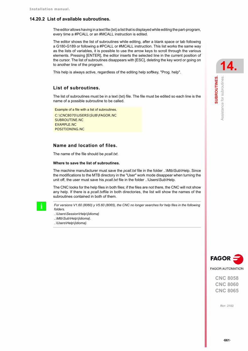
Installation manual.
CNC 8058CNC 8060CNC 8065
SU
BR
OU
TIN
ES
.
14.
Ass
ista
nce
for
subr
outin
es.
ꞏ661ꞏ
REF: 2102
14.20.2 List of available subroutines.
The editor allows having in a text file (txt) a list that is displayed while editing the part-program,every time a #PCALL or an #MCALL instruction is edited.
The editor shows the list of subroutines while editing, after a blank space or tab followinga G180-G189 or following a #PCALL or #MCALL instruction. This list works the same wayas the lists of variables, it is possible to use the arrow keys to scroll through the variouselements. Pressing [ENTER], the editor inserts the selected line in the current position ofthe cursor. The list of subroutines disappears with [ESC], deleting the key word or going onto another line of the program.
This help is always active, regardless of the editing help softkey, "Prog. help".
List of subroutines.
The list of subroutines must be in a text (txt) file. The file must be edited so each line is thename of a possible subroutine to be called.
Name and location of files.
The name of the file should be pcall.txt.
Where to save the list of subroutines.
The machine manufacturer must save the pcall.txt file in the folder ..\Mtb\Sub\Help. Sincethe modifications to the MTB directory in the "User" work mode disappear when turning theunit off, the user must save his pcall.txt file in the folder ..\Users\Sub\Help.
The CNC looks for the help files in both files; if the files are not there, the CNC will not showany help. If there is a pcall.txtfile in both directories, the list will show the names of thesubroutines contained in both of them.
Example of a file with a list of subroutines.
C:\CNC8070\USERS\SUB\FAGOR.NCSUBROUTINE.NCEXAMPLE.NCPOSITIONING.NC
For versions V1.60 (8060) y V5.60 (8065), the CNC no longer searches for help files in the followingfolders...\Users\Session\Help\{idioma}..\Mtb\Sub\Help\{idioma}...\Users\Help\{idioma}.
i
Installation manual.
CNC 8058CNC 8060CNC 8065
14.
SU
BR
OU
TIN
ES
.
Ass
ista
nce
for
subr
outin
es.
ꞏ662ꞏ
REF: 2102
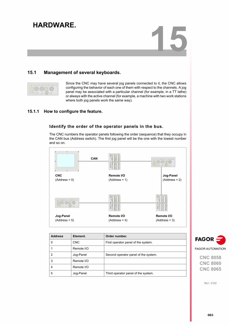
CNC 8058CNC 8060CNC 8065
15
ꞏ663ꞏ
REF: 2102
15.HARDWARE.
15.1 Management of several keyboards.
15.1.1 How to configure the feature.
Identify the order of the operator panels in the bus.
The CNC numbers the operator panels following the order (sequence) that they occupy inthe CAN bus (Address switch). The first jog panel will be the one with the lowest numberand so on.
Since the CNC may have several jog panels connected to it, the CNC allowsconfiguring the behavior of each one of them with respect to the channels. A jogpanel may be associated with a particular channel (for example, in a TT lathe)or always with the active channel (for example, a machine with two work stationswhere both jog panels work the same way).
Address Element. Order number.
0 CNC First operator panel of the system.
1 Remote I/O
2 Jog-Panel Second operator panel of the system.
3 Remote I/O
4 Remote I/O
5 Jog-Panel Third operator panel of the system.
Jog-Panel(Address = 2)
DIGITAL INPUT
X1
X2
GND
I8
I1
N.C.
I2
I3
I4
I5
I6
I7
GND
I16
I9
N.C.
I10
I11
I12
I13
I14
I15
DIGITAL OUTPUT
X1
X2
GND
O8
O1
+24V
O2
O3
O4
O5
O6
O7
GND
O16
O9
+24V.
O10
O11
O12
O13
O14
O15
GND
CAN L
SHIELD
SHIELD
CAN H
X3
GND
CAN L
SHIELD
SHIELD
CAN H
X2
POWER SUPPLY
4
01
FEDCBA
98 7 65 32
ADD MSB
LINE TERM
10
12
ADDRESS
RESET
POWER
SYSTEM READY
+5 ERROR
+5 OVER CURRENT
OVER VOLTAGE+5V
X1
GND IN
CHASIS
GND IN
+24V IN
SYSTEM
READY
DIGITAL INPUT
X1
X2
GND
I8
I1
N.C.
I2
I3
I4
I5
I6
I7
GND
I16
I9
N.C.
I10
I11
I12
I13
I14
I15
DIGITAL OUTPUT
X1
X2
GND
O8
O1
+24V
O2
O3
O4
O5
O6
O7
GND
O16
O9
+24V.
O10
O11
O12
O13
O14
O15
DIGITAL INPUT
X1
X2
GND
I8
I1
N.C.
I2
I3
I4
I5
I6
I7
GND
I16
I9
N.C.
I10
I11
I12
I13
I14
I15
DIGITAL OUTPUT
X1
X2
GND
O8
O1
+24V
O2
O3
O4
O5
O6
O7
GND
O16
O9
+24V.
O10
O11
O12
O13
O14
O15
GND
CAN L
SHIELD
SHIELD
CAN HX3
GND
CAN L
SHIELD
SHIELD
CAN H
X2
POWER SUPPLY
4
01FEDC
BA98 7 65 32
ADD MSB
LINE TERM
10
12
ADDRESS
RESET
POWER
SYSTEM READY
+5 ERROR
+5 OVER CURRENT
OVER VOLTAGE+5V
X1
GND IN
CHASIS
GND IN
+24V IN
SYSTEM
READY
DIGITAL INPUT
X1
X2
GND
I8
I1
N.C.
I2
I3
I4
I5
I6
I7
GND
I16
I9
N.C.
I10
I11
I12
I13
I14
I15
DIGITAL OUTPUT
X1
X2
GND
O8
O1
+24V
O2
O3
O4
O5
O6
O7
GND
O16
O9
+24V.
O10
O11
O12
O13
O14
O15
CAN
CNC(Address = 0)
Remote I/O(Address = 1)
Remote I/O(Address = 4)
Remote I/O(Address = 3)
Jog-Panel(Address = 5)
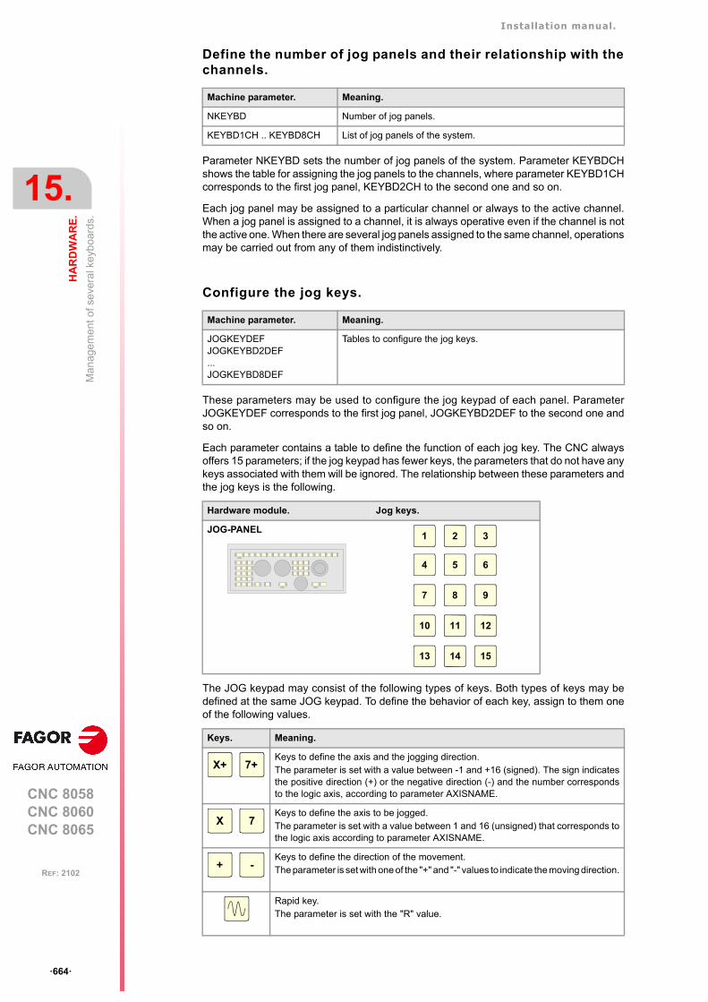
Installation manual.
CNC 8058CNC 8060CNC 8065
15.
HA
RD
WA
RE
.
Man
agem
ent
of s
ever
al k
eyb
oard
s.
ꞏ664ꞏ
REF: 2102
Define the number of jog panels and their relationship with thechannels.
Parameter NKEYBD sets the number of jog panels of the system. Parameter KEYBDCHshows the table for assigning the jog panels to the channels, where parameter KEYBD1CHcorresponds to the first jog panel, KEYBD2CH to the second one and so on.
Each jog panel may be assigned to a particular channel or always to the active channel.When a jog panel is assigned to a channel, it is always operative even if the channel is notthe active one. When there are several jog panels assigned to the same channel, operationsmay be carried out from any of them indistinctively.
Configure the jog keys.
These parameters may be used to configure the jog keypad of each panel. ParameterJOGKEYDEF corresponds to the first jog panel, JOGKEYBD2DEF to the second one andso on.
Each parameter contains a table to define the function of each jog key. The CNC alwaysoffers 15 parameters; if the jog keypad has fewer keys, the parameters that do not have anykeys associated with them will be ignored. The relationship between these parameters andthe jog keys is the following.
The JOG keypad may consist of the following types of keys. Both types of keys may bedefined at the same JOG keypad. To define the behavior of each key, assign to them oneof the following values.
Machine parameter. Meaning.
NKEYBD Number of jog panels.
KEYBD1CH .. KEYBD8CH List of jog panels of the system.
Machine parameter. Meaning.
JOGKEYDEFJOGKEYBD2DEF...JOGKEYBD8DEF
Tables to configure the jog keys.
Hardware module. Jog keys.
JOG-PANEL
Keys. Meaning.
Keys to define the axis and the jogging direction.The parameter is set with a value between -1 and +16 (signed). The sign indicatesthe positive direction (+) or the negative direction (-) and the number correspondsto the logic axis, according to parameter AXISNAME.
Keys to define the axis to be jogged.The parameter is set with a value between 1 and 16 (unsigned) that corresponds tothe logic axis according to parameter AXISNAME.
Keys to define the direction of the movement.The parameter is set with one of the "+" and "-" values to indicate the moving direction.
Rapid key.The parameter is set with the "R" value.
1
4
2
5
3
6
7 8 9
10 11 12
13 14 15
X+ 7+
X 7
+ -
Installation manual.
CNC 8058CNC 8060CNC 8065
HA
RD
WA
RE
.
15.
Man
agem
ent
of s
ever
al k
eyb
oard
s.
ꞏ665ꞏ
REF: 2102
Configure the user keys as jog keys
These parameters may be used to configure the user keys of each panel as jog keys.Parameter USERKEYDEF corresponds to the first jog panel, USERKEYBD2DEF to thesecond one and so on.
Each parameter contains a table to define the function of each user key. The CNC alwaysoffers 16 parameters; if the jog keypad has fewer keys, the parameters that do not have anykeys associated with them will be ignored. The relationship between these parameters andthe user keys is the following.
The meaning of this parameter is similar to that of machine parameter JOGKEYBDkbDEF.To define the behavior of each key, assign to them one of the following values:
• They are defined with a value between 1 and 16 (signed) for the keys that define the axisand the direction. The sign indicates the positive direction (+) or the negative direction(-) and the number corresponds to the logic axis, according to parameter AXISNAME.
• They are defined with a value between 1 and 16 (unsigned) for the keys that only definethe axis.
• They are defined with the "+" and "-" values for the keys that only define the movingdirection.
• They are defined with the "R" value for the rapid key.
The user keys defined this way behave like the jog keys whether they've been defined signedor unsigned and also respect the setting of machine parameter JOGTYPE.
Check the status of the keys.
Registers KEYBD1 y KEYBD2 are a copy of the map of the keys pressed on the last keyboardused. These registers indicate which key has been pressed (bit=1). If there is only onekeyboard, these registers coincide with KEYBD1_1 and KEYBD2_1. When there are severalkeyboards, the contents of these registers are not always the same as KEYBD1_1 andKEYBD2_1; therefore, they may be used indistinctively.
Registers KEYBD1_n and KEYBD2_n indicate (bit=1) which key has been pressed on eachoperator panel. Registers KEYBD1_1 and KEYBD2_1 correspond to the first jog panel,KEYBD1_2 and KEYBD2_2 to the second one and so on.
Machine parameter. Meaning.
USERKEYDEFUSERKEYBD2DEF...USERKEYBD8DEF
Tables to configure the user keys as jog keys.
Hardware module. User keys.
JOG-PANEL
PLC marks and registers. Meaning.
KEYBD1 / KEYBD2 These registers are a copy of the map of the keys pressed on thelast keyboard used.
KEYBD1_1 / KEYBD2_1ꞏꞏKEYBD1_8 / KEYBD2_8
These registers indicate (bit=1) which key has been pressed on eachoperator panel.
1 2 15 16
JOGKEYS
Installation manual.
CNC 8058CNC 8060CNC 8065
15.
HA
RD
WA
RE
.
Man
agem
ent
of s
ever
al k
eyb
oard
s.
ꞏ666ꞏ
REF: 2102
Disable the keys.
Registers KEYDIS1, KEYDIS2 and KEYDIS3 inhibit (bit=1) the keys and the switches onall operator panels at the same time.
Registers KEYDIS1_n, KEYDIS2_n and KEYDIS3_n inhibit (bit=1) the keys and theswitches on each operator panel. Registers KEYDIS1_1 to KEYDIS3_1 correspond to thefirst jog panel, KEYDIS1_2 to KEYDIS3_2 to the second one and so on.
When selecting one of the inhibited positions of the feedrate override, the CNC will take thevalue of the lowest position allowed. If all of them are inhibited, it will take the value of 0%.
Manage the LED's (lamps) of the keys.
Registers KEYLED1 and KEYLED2 control the LED's (lamps) of the keys of all the operatorpanels at the same time.
Registers KEYLED1_n and KEYLED2_n control the LED's (lamps) of the keys of eachoperator panel. Registers KEYLED1_1 and KEYLED2_1 correspond to the first jog panel,KEYLED1_2 and KEYLED2_2 to the second one and so on.
Change the default behavior of the keyboards with respect tothe channels.
These registers may be used to change the default behavior of the keyboards with respectto the channels, set by machine parameters. These registers can associate a jog panel witha particular channel, always with the active channel or restore the configuration defined inthe machine parameters.
PLC marks and registers. Meaning.
KEYDIS1 to KEYDIS3 These registers inhibit (bit=1) the keys and the switches on alloperator panels at the same time.
KEYDIS1_1 to KEYDIS3_1ꞏꞏKEYDIS1_8 to KEYDIS3_8
These registers inhibit (bit=1) the keys and the switches on eachoperator panel.
PLC marks and registers. Meaning.
KEYLED1 / KEYLED2 These registers control the LED's (lamps) of the keys of all theoperator panels at the same time.
KEYLED1_1 / KEYLED2_1ꞏꞏKEYLED1_8 / KEYLED2_8
These registers control the LED's (lamps) of the keys of eachoperator panel.
PLC marks and registers. Meaning.
KEYBD1CH to KEYBD8CH These registers may be used to change the default behavior of thekeyboards with respect to the channels, set by machine parameters.
Value. Meaning.
0 Configuration defined in the machine parameters.
1 Jog panel assigned to channel 1.
2 Jog panel assigned to channel 2.
3 Jog panel assigned to channel 3.
4 Jog panel assigned to channel 4.
FF Jog panel assigned to the active channel.
Installation manual.
CNC 8058CNC 8060CNC 8065
HA
RD
WA
RE
.
15.
Man
agem
ent
of s
ever
al k
eyb
oard
s.
ꞏ667ꞏ
REF: 2102
Disable the jog panels.
If the PLC activates one of these marks the CNC disables the corresponding jog panel. Eachmark may be used to disable the jog panel integrated into the CAN bus; the rest of theelements of the bus are not affected. When the keyboard and the operator panel make upa single element, this mark only disables the jog panel.
There is one mark for each keyboard or jog panel. The PANELOFF1 mark disables the firstone of the bus, the PANELOFF2 mark the second one and so on. Both PANELOFF andPANELOFF1 are valid for the first jog panel.
PLC marks and registers. Meaning.
PANELOFFPANELOFF1 to PANELOFF8
If the PLC sets this one of these marks high (=1) the CNC disablesthe corresponding jog panel.
Address Element PLC mark
0 CNC
1 Remote (I/O) group
2 Jog panel PANELOFF1
3 Remote (I/O) group
4 Remote (I/O) group
5 Jog panel PANELOFF2
Installation manual.
CNC 8058CNC 8060CNC 8065
15.
HA
RD
WA
RE
.
Man
agem
ent
of s
ever
al k
eyb
oard
s.
ꞏ668ꞏ
REF: 2102
15.1.2 Operation of the jog panels.
When enabling a keyboard (PANELOFF mark) and every time there is a keyboard change(press a key, change a switch, etc.), the channel assumes the status of the keys and theposition of the switches of the new keyboard with the active values. If necessary the PLCroutine must include the proper restrictions to avoid sudden feedrate changes due to differentpositions of the feedrate override switch on the different keyboards. It is also recommendedto manage the user keys using up and down flanks to avoid the possible activation of deviceswhen changing keyboards.
Every time the active keyboard is changed, the new keyboard updates at the PLC theinformation on all the marks and registers associated with the keyboard itself (KEYBD1_n,KEYBD2_n, KEYDIS1_n a KEYDIS3_n, KEYLED1_n, KEYLED2_n) and the generic onesassociated with all the keyboards (KEYBD1, KEYBD2, KEYDIS1 to KEYDIS3, KEYLED1,KEYLED2).
Behavior of the keys and the switches.
The keys from the jog panel.
The keys of each jog panel are only effective for each channel with which the keyboard isassociated; whether it is the active channel or not. The following keys have a differentbehavior.
• The [RESET] key affects the channel associated with the keyboard where the key hasbeen pressed and the channels that belong to its group.
• The keys to select the work mode (automatic, jog, etc.) only affect the active channel.
Feedrate override selector.
If the keyboard is associated with a particular channel, an override change only affects thatchannel, even if it belongs to a group. If the keyboard is associated with the active channel,an override change affects all the channels of the system at the same time, whether theybelong to a group or not.
Installation manual.
CNC 8058CNC 8060CNC 8065
HA
RD
WA
RE
.
15.
Con
figu
re a
han
dwhe
el a
s "f
eed
hand
whe
el"
.
ꞏ669ꞏ
REF: 2102
15.2 Configure a handwheel as "feed handwheel".
Usually, when machining a part for the first time, the feedrate is controlled with the switchon the operator panel. The "feed handwheel" allows using one of the handwheels of themachine to control that feedrate depending on how fast the handwheel is turned.
The "feed handwheel" must be managed by the PLC. Usually, this feature is turned on andoff using an external push button or key configured for that purpose.
Know the number of pulses sent by the handwheel.
The following variable reads the number of handwheel pulses.
PLC routine.
The PLC routine must consider the following elements.
• Inhibit via PLC all the positions of the feedrate override switch.
• Detect how much the handwheel has turned (reading - counting - the pulses received).
• Set via PLC the feedrate override depending on the handwheel pulses.
Variable. Meaning.
(V.)G.HANDP[hw] Number of pulses sent by the handwheel since the system wasstarted up.
Example of a PLC routine. The machine has a push button to enable and disable the "feed handwheel" (input I71) and the feedrate control is handled by the second handwheel.
; Resources used in the PLC program.; I71 _____ Push button to enable and disable the "feed handwheel"; R100 _____ Total number of handwheel pulses.; R101 _____ Number of handwheel pulses until previous reading.; R102 _____ Number of handwheel pulses since previous reading.; R103 _____ Calculated percentage of feedrate.; M1000 _____ "Feed handwheel" on.; M1001 _____ Auxiliary mark.
CY1() = ERA R101
Initialize the register that contains the reading (counting) of handwheel pulses.END
PRGDFU I71 = CPL M1000
Every time the button associated with the "feed handwheel" is pressed, complement mark M1000.
NOT M1000= AND KEYDIS3 $FF800000 KEYDIS3= JMP L101
If the "feed handwheel" is not off, inhibit all the positions of the feedrate override switch and resume the execution of the program.
M1000 = MSG1If the "feed handwheel" is on, show a message.
DFU CLK100= CNCRD (G.HANDP[2], R100, M1001)= SBS R101 R100 R102= MOV R100 R101= MLS R102 3 R103= OR KEYDIS3 $7FFFFF KEYDIS3
If the "feed handwheel" is on and an up flank occurs at the clock CLK100, the PLC saves in register R100 the handwheel pulses; calculates in register R102 the pulses received since the previous reading (count); updates register R101 for the next reading; calculates in register R103 the right feedrate override percentage; inhibits all the positions of the feedrate override switch (KEYDIS3).
Installation manual.
CNC 8058CNC 8060CNC 8065
15.
HA
RD
WA
RE
.
Con
figu
re a
han
dwhe
el a
s "f
eed
hand
whe
el"
.
ꞏ670ꞏ
REF: 2102
CPS R103 LT 0 = SBS 0 R103 R103CPS R103 GT 120 = MOV 120 R103
Adjust the value of register R103; ignore the handwheel turning direction (sign) and limit the value to 120%.
DFU CLK100= CNCWR (R103,PLC.FRO, M1001)
Use the up flank at the clock CLK100 to set the calculated feedrate override value.
L101END
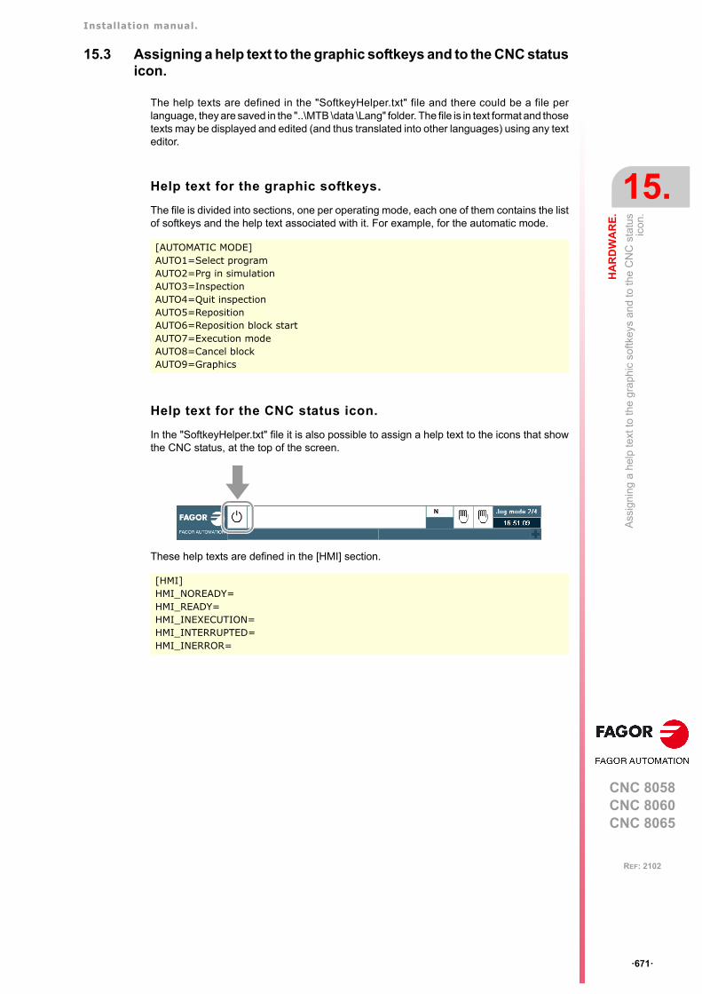
Installation manual.
CNC 8058CNC 8060CNC 8065
HA
RD
WA
RE
.
15.
Ass
igni
ng a
hel
p te
xt to
the
gra
phic
sof
tke
ys a
nd
to th
e C
NC
sta
tus
icon
.
ꞏ671ꞏ
REF: 2102
15.3 Assigning a help text to the graphic softkeys and to the CNC statusicon.
The help texts are defined in the "SoftkeyHelper.txt" file and there could be a file perlanguage, they are saved in the "..\MTB \data \Lang" folder. The file is in text format and thosetexts may be displayed and edited (and thus translated into other languages) using any texteditor.
Help text for the graphic softkeys.
The file is divided into sections, one per operating mode, each one of them contains the listof softkeys and the help text associated with it. For example, for the automatic mode.
Help text for the CNC status icon.
In the "SoftkeyHelper.txt" file it is also possible to assign a help text to the icons that showthe CNC status, at the top of the screen.
These help texts are defined in the [HMI] section.
[AUTOMATIC MODE]AUTO1=Select programAUTO2=Prg in simulationAUTO3=InspectionAUTO4=Quit inspectionAUTO5=RepositionAUTO6=Reposition block startAUTO7=Execution modeAUTO8=Cancel blockAUTO9=Graphics
[HMI]HMI_NOREADY=HMI_READY=HMI_INEXECUTION=HMI_INTERRUPTED=HMI_INERROR=
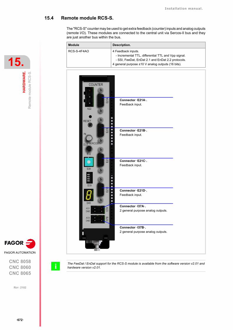
Installation manual.
CNC 8058CNC 8060CNC 8065
15.
HA
RD
WA
RE
.
Re
mo
te m
odul
e R
CS
-S.
ꞏ672ꞏ
REF: 2102
15.4 Remote module RCS-S.
The "RCS-S" counter may be used to get extra feedback (counter) inputs and analog outputs(remote I/O). These modules are connected to the central unit via Sercos-II bus and theyare just another bus within the bus.
Module Description.
RCS-S-4F4AO 4 Feedback inputs.- Incremental TTL, differential TTL and Vpp signal.- SSI, FeeDat, EnDat 2.1 and EnDat 2.2 protocols.
4 general purpose ±10 V analog outputs (16 bits).
Connector ꞏE21Aꞏ.Feedback input.
Connector ꞏE21Bꞏ.Feedback input.
Connector ꞏE21Cꞏ.Feedback input.
Connector ꞏE21Dꞏ.Feedback input.
Connector ꞏI37Aꞏ.2 general purpose analog outputs.
Connector ꞏI37Bꞏ.2 general purpose analog outputs.
The FeeDat / EnDat support for the RCS-S module is available from the software version v2.01 andhardware version v2.01. i
Installation manual.
CNC 8058CNC 8060CNC 8065
HA
RD
WA
RE
.
15.
Re
mo
te m
odul
e R
CS
-S.
ꞏ673ꞏ
REF: 2102
15.4.1 Configure the module like as a node of the Sercos bus.
The Sercos counter is, like the drives, a node tye of the Sercos ring. In terms of parametersetting, Sercos counters have dual identification, physical and logic, as described next.
Physical identification of the module inside the bus.
Each counter must be identified by a number (Sercos ID) using the thumbwheel located onits front plate. That identifier must be unique in the ring, the number is sequential from 1 ton and without skipping any and "n" being the total number of Sercos nodes (including drivesand counters).
Logic identification of the module inside the bus.
The SERCOUNTID table of the general machine parameters allows linking the logic numberof the Sercos counters (1..8) to the physical number set by the thumbwheel of each node(enter in each position of the Sercos ID table associated with that logic position of thecounter).
Although the Sercos ring may have up to 32 nodes, the Sercos counters always occupypositions from 1 to 15.
15.4.2 Configure the analog outputs.
The analog output is configured via machine parameters. Each axis has the followingmachine parameters to configure it.
Configure the analog outputs.
The velocity command for an analog axis may be taken from an analog output of the remotemodules or of a Sercos drive. or of a Sercos counter. It is selected with parametersANAOUTID and ANAOUTID.
Managing the analog command from the Sercos counter.
In this case, parameter ANAOUTID indicates the number of the analog output used for thecommand. The Sercos counters are numbered according to their logic order (parameterSERCOUNTID). The analog outputs of the first module will be 1 through 4, those of thesecond module 5 through 8 and so on.
Parameter. Meaning.
NSERCOUNT Number of Sercos counter nodes in the bus.
SERCOUNTID Thumbwheel identifiers associated with Sercos counters.
Parameter. Meaning.
ANAOUTTYPE Type of analog output associated with the axis.
ANAOUTID Number of the analog output associated with the axis.
Parameter. Value.
ANAOUTTYPE RCS-S module RCS-S (Sercos counter).
ANAOUTID 1 - 4.
Installation manual.
CNC 8058CNC 8060CNC 8065
15.
HA
RD
WA
RE
.
Re
mo
te m
odul
e R
CS
-S.
ꞏ674ꞏ
REF: 2102
15.4.3 Configuration of the feedback inputs.
The feedback inputs are configured via machine parameters. Each axis has the followingmachine parameters to configure it.
Configure the feedback input.
The axis feedback input may be located in the remote modules, at the free feedback of aSercos drive, in a Sercos counter or at the local feedback inputs of the central unit. It isselected with parameters COUNTERTYPE and COUNTERID.
Feedback input for the Sercos counter.
Parameter COUNTERID indicates the number of the feedback input being used. The Sercoscounters are numbered according to their logic order (parameter SERCOUNTID). Thefeedback inputs of the first module will be 1 through 4, those of the second module 5 through8 and so on.
15.4.4 Configure the feedback input for a handwheel.
The handwheel is configured via machine parameters of the jog mode. Each handhwel hasthe following machine parameters to configure it.
Configure the feedback input.
This parameter indicates the location of the handwheel feedback input; at the remotemodules, at the keyboard or at the local feedback inputs of the central unit or in a Sercoscounter. It is selected with parameters COUNTERTYPE and COUNTERID.
Feedback input for the Sercos counter.
Parameter COUNTERID indicates the number of the feedback input being used. The Sercoscounters are numbered according to their logic order (parameter SERCOUNTID). Thefeedback inputs of the first module will be 1 through 4, those of the second module 5 through8 and so on.
Parameter. Meaning.
COUNTERTYPE Type of feedback input for the axis.
COUNTERID Number of the feedback input for the axis.
Parameter. Value.
COUNTERTYPE RCS-S module RCS-S (Sercos counter).
COUNTERID 1 - 32.
Parameter. Meaning.
COUNTERTYPE Type of handwheel feedback input.
COUNTERID Feedback input associated with the handwheel.
Parameter. Value.
COUNTERTYPE RCS-S module RCS-S (Sercos counter).
COUNTERID 1 - 32.
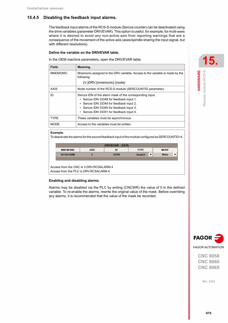
Installation manual.
CNC 8058CNC 8060CNC 8065
HA
RD
WA
RE
.
15.
Re
mo
te m
odul
e R
CS
-S.
ꞏ675ꞏ
REF: 2102
15.4.5 Disabling the feedback input alarms.
The feedback input alarms of the RCS-S module (Sercos counter) can be deactivated usingthe drive variables (parameter DRIVEVAR). This option is useful, for example, for multi-axeswhere it is desired to avoid any non-active axis from reporting warnings that are aconsequence of the movement of the active axis (axes/spindle sharing the input signal, butwith different resolutions).
Define the variable on the DRIVEVAR table.
In the OEM machine parameters, open the DRIVEVAR table.
Enabling and disabling alarms.
Alarms may be disabled via the PLC by writing (CNCWR) the value of 0 in the definedvariable. To re-enable the alarms, rewrite the original value of the mask. Before overridingany alarms, it is recommended that the value of the mask be recorded.
Field. Meaning.
MNEMONIC Mnemonic assigned to the DRV variable. Access to the variable is made by thefollowing:
(V.)DRV.{mnemonic}.{node}
AXIS Node number of the RCS-S module (SERCOUNTID parameter).
ID Sercos IDN of the alarm mask of the corresponding input. • Sercos IDN 33348 for feedback input 1.• Sercos IDN 33349 for feedback input 2.• Sercos IDN 33350 for feedback input 3.• Sercos IDN 33351 for feedback input 4.
TYPE These variables must be asynchronous.
MODE Access to the variables must be written.
Example.To deactivate the alarms for the second feedback input of the module configured as SERCOUNTID=4.
Access from the CNC is V.DRV.RCSALARM.4Access from the PLC is DRV.RCSALARM.4
Installation manual.
CNC 8058CNC 8060CNC 8065
15.
HA
RD
WA
RE
.
Re
mo
te m
odul
e R
CS
-S.
ꞏ676ꞏ
REF: 2102
15.4.6 Parameter setting example.
The system has 2 Sercos counters (nodes 3, 5) and 3 Sercos AXD drives (nodes 1, 2, 4).Plus, the system has the following axes.
• 3 analog axes X Y Z.
• 1 semi-Sercos axis U.
• 1 Sercos axis V.
• 1 handwheel.
• 1 Sercos spindle S.
The connection is as follows:
The parameter could be set as follows.
NODE 1: V Sercos axis.
NODE 2: U Sercos axis.
NODE 3: X analog axis.
Handwheel 1.
Y analog axis.
E21A / ANAOUT2
E21B
ANAOUT1
NODE 4: Sercos spindle S
NODE 5: U axis (second feedback)
Y analog axis.
Z analog axis.
E21B
E21C
E21A / ANAOUT4
NSERCOUNT 2 Number of Sercos axes in the system.
SERCOUNTID1 5 (No common, but valid)
SERCOUNTID2 3
DR
IVE
MO
DU
LE
ID 1
DRIVEID=1
AX
D
V
ID 3
SERCOUNTID=2
RC
S-S
X
DR
IVE
MO
DU
LE
ID 2
DRIVEID=2
AX
D
U
DR
IVE
MO
DU
LE
ID 4
DRIVEID=4
AX
D
S
E21
C
AN
AO
UT
2
ID 5
SERCOUNTID=1
Y
AN
AO
UT
1 E21
B
E2
1A
Z
AN
AO
UT
4
E2
1A
E2
1B
HW
COUNTER
A22
4
01
FEDCBA
98
7 6 5 32
B32
S39
E21
AE
21B
E21
CE
21D
IN
OUT
SERCOS
S38
GND
GND I37
A
GND
GND I37B
RC
S-S
COUNTER
A22
4
01
FEDCBA
98
7 6 5 32
B32
S39
E21
AE
21B
E21
CE
21D
IN
OUT
SERCOS
S38
GND
GND I37
A
GND
GND I37B

Installation manual.
CNC 8058CNC 8060CNC 8065
HA
RD
WA
RE
.
15.
Re
mo
te m
odul
e R
CS
-S.
ꞏ677ꞏ
REF: 2102
Parameters SERCOUNTID1 through SERCOUNTID8 set the order (sequence) of thefeedback inputs. Since SERCOUNTID1=5 and SERCOUNTID2=3, the first feedback inputwill be the first one of node 5.
Axis. Parameter. Value.
X axis. DRIVETYPECOUNTERTYPECOUNTERIDANAOUTTYPEANAOUTID
Analog.Sercos counter.5.Sercos counter.6.
Y axis. DRIVETYPECOUNTERTYPECOUNTERIDANAOUTTYPEANAOUTID
Analog.Sercos counter.3.Sercos counter.5.
Z axis. DRIVETYPECOUNTERTYPECOUNTERIDANAOUTTYPEANAOUTID
Analog.Sercos counter.1.Sercos counter.4.
U axis. DRIVETYPEDRIVEIDOPMODEPFBACKSRCCOUNTERTYPECOUNTERID
Sercos.2.Speed.External.Sercos counter.2.
V axis. DRIVETYPEDRIVEID
Sercos.1.
Handwheel MANPGCOUNTERTYPECOUNTERID
1.Sercos counter.6.
Spindle S DRIVETYPEDRIVEID
Sercos.4.
Installation manual.
CNC 8058CNC 8060CNC 8065
15.
HA
RD
WA
RE
.
Num
ber
the
digi
tal i
npu
ts a
nd o
utp
uts
of t
he
CA
Nop
en
bus.
ꞏ678ꞏ
REF: 2102
15.5 Number the digital inputs and outputs of the CANopen bus.
By default, the CNC numbers the digital inputs sequentially, according to the order of themodules in the bus. When the bus is CANopen, the CNC allows the digital I/O nodes in logicblocks (virtual modules) to be divided, and then to establish the numbering of the I/Os of eachlogic block, assigning a base index to the first one.
• In RIO5 and RIOR nodes, each module is a logic block, several modules cannot begrouped in a block or divide a module into blocks. The logic blocks must have the samenumber and size as the modules physically detected in the bus.
• In the RIO5 nodes, each double module (module with two boards) it counts as two, inother words, two logic blocks.
• In RIOW nodes and third-party nodes, it is possible to display as many logic blocks asdesired, both in number and in size.
Configure the digital inputs.
The digital inputs and outputs are configured via machine parameters.
The configuration must meet the following requirements. If the parameters are not setaccording to these requirements, the CNC will ignore it and it will number the digital inputssequentially according to the order of the modules in the bus.
• The parameters of all I/O nodes of the bus must be set; no node can be left undefined.
• The parameters of all the resources of a node must be set; no I/O can be left without anumber.
• The maximum number of logic blocks in the node will be 64, both for digital inputs anddigital outputs.
• The number of I/Os in a logic block must be other than zero and a multiple of 8 (8, 16,24, 32, ...1024).
• The values of the base index must be comply with the formula "8n + 1" (i.e. 1, 9, 17, 25,etc.).
• The blocks may be distributed at will within the range of resources managed by PLC(1...1024). The PLC admits blanks, but the blocks cannot overlap; in other words, a PLCdigital input or output can only belong to a single node-module of the bus.
Parameter. Meaning.
NDIMOD Total number of digital input logic blocks.Possible values: From 0 to 42 (by default; 0).
DIMODADDR Base addresses of the digital input logic blocks.
MNEMONIC Mnemonic of the logic block.
NODE Node number of the header to which the logic block belongs.Possible values: From 1 to 126 (by default; 0).
BLOCK Number of the logic block.Possible values: From 1 to 64 (by default; 0).
ADDRESS Base address of the logic block.Possible values: From 1 to 1017 (by default, the first valid value).
NDI Number of digital inputs of the module.Possible values: From 8 to 1024 (by default; 0).
Installation manual.
CNC 8058CNC 8060CNC 8065
HA
RD
WA
RE
.
15.
Num
ber
the
digi
tal i
npu
ts a
nd o
utp
uts
of t
he
CA
Nop
en
bus.
ꞏ679ꞏ
REF: 2102
Configure the digital outputs.
The digital inputs and outputs are configured via machine parameters.
The configuration must meet the following requirements. If the parameters are not setaccording to these requirements, the CNC will ignore it and it will number the digital outputssequentially according to the order of the modules in the bus.
• The parameters of all I/O nodes of the bus must be set; no node can be left undefined.
• The parameters of all the resources of a node must be set; no I/O can be left without anumber.
• The maximum number of logic blocks in the node will be 64, both for digital inputs anddigital outputs.
• The number of I/Os in a logic block must be other than zero and a multiple of 8 (8, 16,24, 32, ...1024).
• The values of the base index must be comply with the formula "8n + 1" (i.e. 1, 9, 17, 25,etc.).
• The blocks may be distributed at will within the range of resources managed by PLC(1...1024). The PLC admits blanks, but the blocks cannot overlap; in other words, a PLCdigital input or output can only belong to a single node-module of the bus.
Parameter. Meaning.
NDOMOD Total number of digital output logic blocks.Possible values: From 0 to 42 (by default; 0).
DOMODADDR Base addresses of the digital output logic blocks.
MNEMONIC Mnemonic of the logic block.
NODE Node number of the header to which the logic block belongs.Possible values: From 1 to 125 (by default; 0).
BLOCK Number of the logic block.Possible values: From 1 to 64 (by default; 0).
ADDRESS Base address of the logic block.Possible values: From 1 to 1017 (by default, the first valid value).
NDO Number of digital outputs of the module.Possible values: From 8 to 1024 (by default; 0).

Installation manual.
CNC 8058CNC 8060CNC 8065
15.
HA
RD
WA
RE
.
Num
ber
the
digi
tal i
npu
ts a
nd o
utp
uts
of t
he
CA
Nop
en
bus.
ꞏ680ꞏ
REF: 2102
15.5.1 Example. I/O numbering via machine parameters.
Example 1.
A CANopen bus offers the following groups.
• Node 1: Remote RIO5 group with 1 module of 24 digital inputs.
• Node 2: Remote RIO5 group with 3 module of 24 digital inputs each.
• Node 3: Remote RIO5 group with 2 module of 24 digital inputs each.
In the RIO5 module must be configured as one logic block. Each RIO5 node is to beconfigured as follows.
• The first RIO5 node as a block of 24 inputs from I1 on.
• The second RIO5 node as three blocks of 24 inputs from I49, I73 and I97 on.
• The third RIO5 node as two blocks of 24 inputs from I257 and I129 on.
Parameter. Value. Comment.
NDIMOD 6 In the RIO5 series, each module must be configured as onelogic block. Each double module (module with two boards)it counts as two blocks.
DIMODADDR - - - See the table below.
DIMODADDR
MNEMONIC NODE BLOCK ADDRESS NDI
DIMOD 1 1 (RIO5) 1 1 24
DIMOD 2 2 (RIO5) 1 49 24
DIMOD 3 2 (RIO5) 2 73 24
DIMOD 4 2 (RIO5) 3 97 24
DIMOD 5 3 (RIO5) 1 257 24
DIMOD 6 3 (RIO5) 2 129 24
GND
L
SH
SH
H
X3
GND
L
SH
SH
H
X2
CAN
POWER 24I/16O
ERR
RUN
X4
X5
X6
X7
I13
I24
I1
I12
GND
O16
O9
+24V
GND
O8
O1
+24V
X1
CHS
GND
+24V
4
01
FEDCBA98 7 6 5 32
ADDRESS
SPEED1
0
LT
1
0
DIGITAL IN/OUT
X5
X6
X7
X8
I13
I24
I1
I12
GND
O16
O9
+24V
GND
O8
O1
+24V
X1
X2
X3
X4
I13
I24
I1
I12
GND
O16
O9
+24V
GND
O8
O1
+24V
GND
L
SH
SH
H
X3
GND
L
SH
SH
H
X2
CAN
POWER 24I/16O
ERR
RUN
X4
X5
X6
X7
I13
I24
I1
I12
GND
O16
O9
+24V
GND
O8
O1
+24V
X1
CHS
GND
+24V
4
01
FEDCBA9
8 7 6 5 32
ADDRESS
SPEED1
0
LT
1
0
GND
L
SH
SH
H
X3
GND
L
SH
SH
H
X2
CAN
POWER 24I/16O
ERR
RUN
X4
X5
X6
X7
I13
I24
I1
I12
GND
O16
O9
+24V
GND
O8
O1
+24V
X1
CHS
GND
+24V
4
01
FEDCBA9
8 7 6 5 32
ADDRESS
SPEED1
0
LT
1
0
DIGITAL IN/OUT
X1
X2
X3
X4
I13
I24
I1
I12
GND
O16
O9
+24V
GND
O8
O1
+24V
Group ꞏ1ꞏ Group ꞏ2ꞏ Group ꞏ3ꞏ
24 digital inputs. 24 + 48 digital inputs. 24 + 24 digital inputs.
16 digital outputs. 16 + 32 digital outputs. 16 + 16 digital outputs.

Installation manual.
CNC 8058CNC 8060CNC 8065
HA
RD
WA
RE
.
15.
Num
ber
the
digi
tal i
npu
ts a
nd o
utp
uts
of t
he
CA
Nop
en
bus.
ꞏ681ꞏ
REF: 2102
Example 2.
A CANopen bus offers the following groups.
• Node 1: Remote RIOW group with 16 digital inputs and 8 digital outputs.
• Node 2: Remote RIOW group with 8 digital inputs and 8 digital outputs.
Each RIOW node is to be configured as follows.
• The first RIOW node as 2 blocks, one 8 inputs from I1 on and the other from I33 on. Alsoa block of 8 digital outputs from O81 on.
• The second RIOW node as a block of 8 inputs from I113 on. Also a block of 8 digitaloutputs from O49 on.
Parameter. Value. Comment.
NDIMOD 3 3 blocks; 2 for the first node and 1 for the second one.
DIMODADDR - - - See the table below.
DIMODADDR
MNEMONIC NODE BLOCK ADDRESS NDI
DIMOD 1 1 (RIOW) 1 1 8
DIMOD 2 1 (RIOW) 2 33 8
DIMOD 3 2 (RIOW) 1 113 8
Parameter. Value. Comment.
NDOMOD 2 2 blocks, one per each RIOW node.
DOMODADDR - - - See the table below.
DOMODADDR
MNEMONIC NODE BLOCK ADDRESS NDO
DOMOD 1 1 (RIOW) 1 81 8
DOMOD 2 2 (RIOW) 1 49 8
Node 1 (RIOW)
16 digital inputs.
8 digital outputs
Node 2 (RIOW)
8 digital inputs.
8 digital outputs
4 8
1 5
2 6
3 7
CA
DB
56
78
12
34
ON
STOP
RUN
TX
RXOverflow
I/O
24V 0V
4 8
1 5
2 6
3 7
CA
DB
4 8
1 5
2 6
3 7
AB
C
D
EF
G
H
4 8
1 5
2 6
3 7
AB
C
D
EF
G
H
8DI 8DI 8DO
4 8
1 5
2 6
3 7
AB
C
D
EF
G
H
4 8
1 5
2 6
3 7
CA
DB
4 8
1 5
2 6
3 7
CA
DB
56
78
12
34
ON
STOP
RUN
TX
RXOverflow
I/O
24V 0V
4 8
1 5
2 6
3 7
CA
DB
4 8
1 5
2 6
3 7
A
B
CD
E
F
GH
4 8
1 5
2 6
3 7
A
B
CD
E
F
GH
8DI 8DO
4 8
1 5
2 6
3 7
CA
DB
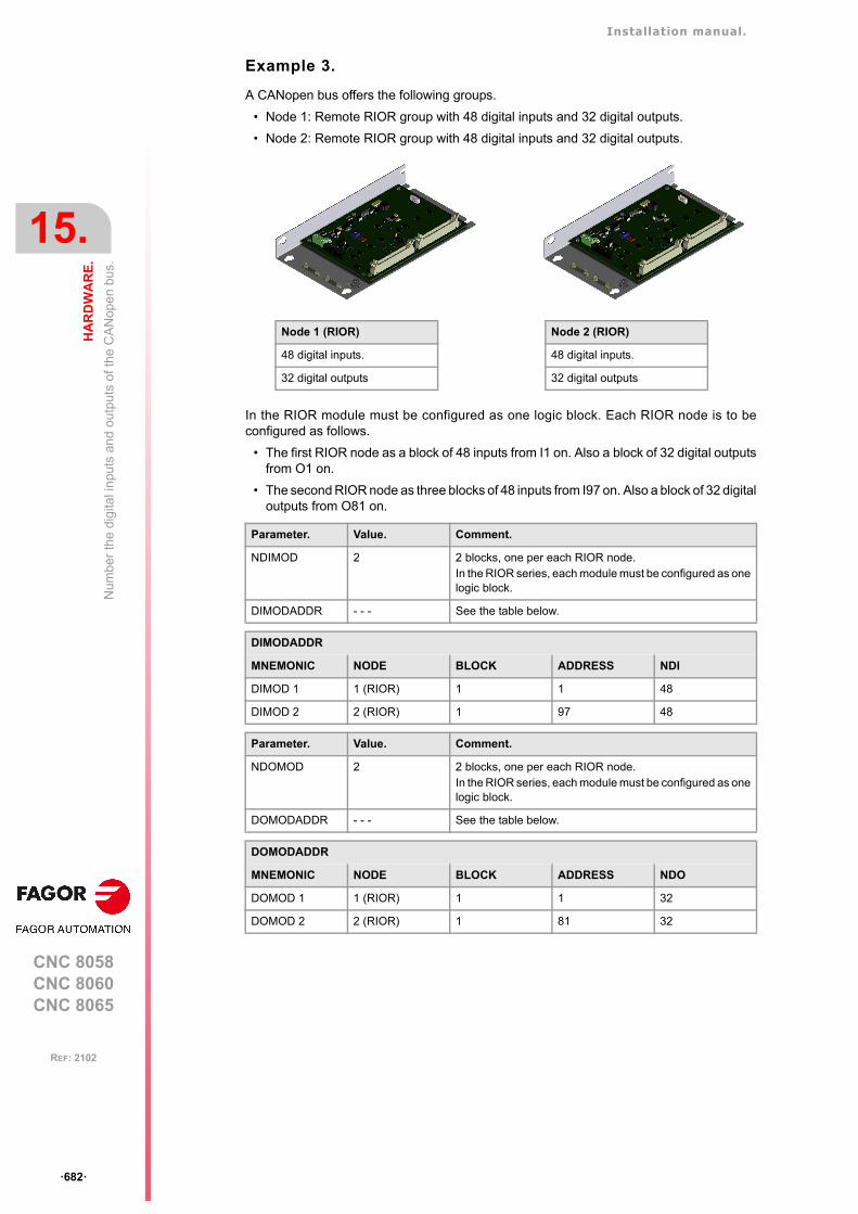
Installation manual.
CNC 8058CNC 8060CNC 8065
15.
HA
RD
WA
RE
.
Num
ber
the
digi
tal i
npu
ts a
nd o
utp
uts
of t
he
CA
Nop
en
bus.
ꞏ682ꞏ
REF: 2102
Example 3.
A CANopen bus offers the following groups.
• Node 1: Remote RIOR group with 48 digital inputs and 32 digital outputs.
• Node 2: Remote RIOR group with 48 digital inputs and 32 digital outputs.
In the RIOR module must be configured as one logic block. Each RIOR node is to beconfigured as follows.
• The first RIOR node as a block of 48 inputs from I1 on. Also a block of 32 digital outputsfrom O1 on.
• The second RIOR node as three blocks of 48 inputs from I97 on. Also a block of 32 digitaloutputs from O81 on.
Parameter. Value. Comment.
NDIMOD 2 2 blocks, one per each RIOR node.In the RIOR series, each module must be configured as onelogic block.
DIMODADDR - - - See the table below.
DIMODADDR
MNEMONIC NODE BLOCK ADDRESS NDI
DIMOD 1 1 (RIOR) 1 1 48
DIMOD 2 2 (RIOR) 1 97 48
Parameter. Value. Comment.
NDOMOD 2 2 blocks, one per each RIOR node.In the RIOR series, each module must be configured as onelogic block.
DOMODADDR - - - See the table below.
DOMODADDR
MNEMONIC NODE BLOCK ADDRESS NDO
DOMOD 1 1 (RIOR) 1 1 32
DOMOD 2 2 (RIOR) 1 81 32
Node 1 (RIOR)
48 digital inputs.
32 digital outputs
Node 2 (RIOR)
48 digital inputs.
32 digital outputs
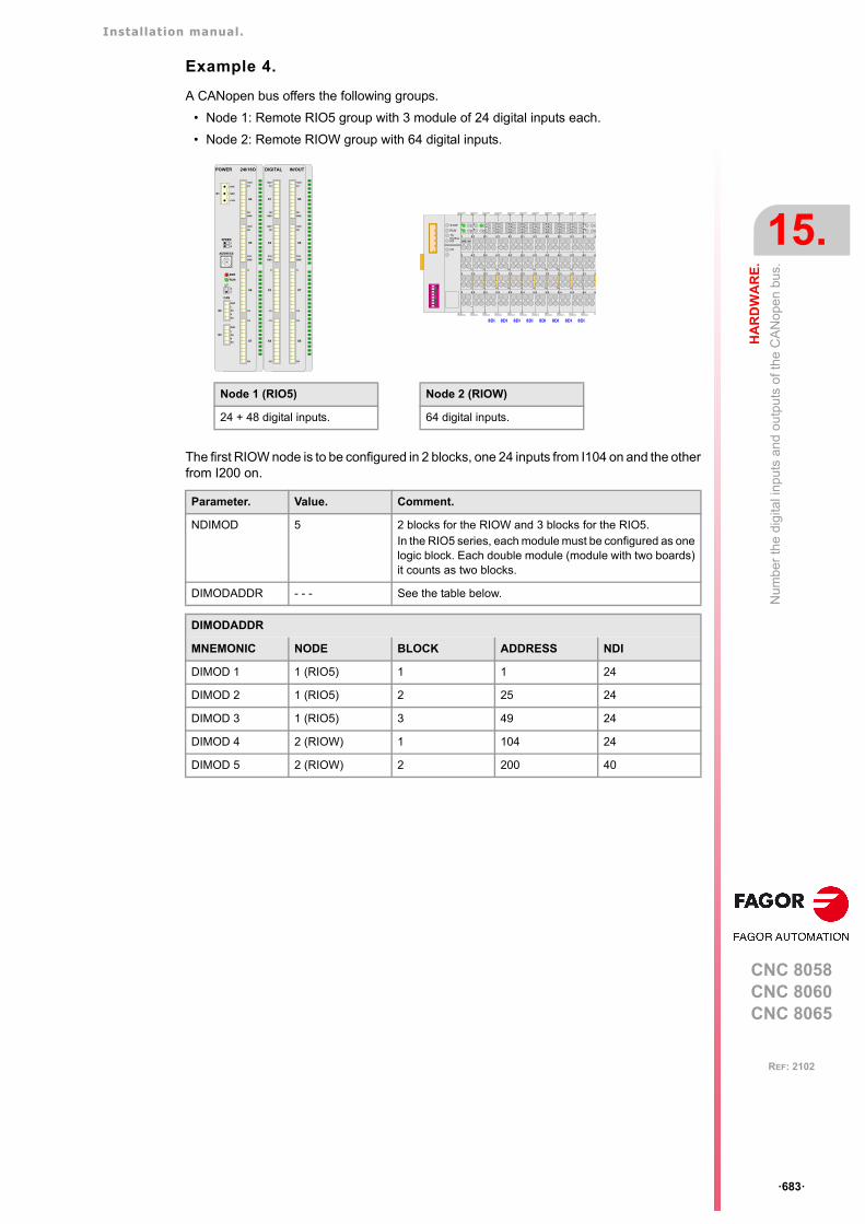
Installation manual.
CNC 8058CNC 8060CNC 8065
HA
RD
WA
RE
.
15.
Num
ber
the
digi
tal i
npu
ts a
nd o
utp
uts
of t
he
CA
Nop
en
bus.
ꞏ683ꞏ
REF: 2102
Example 4.
A CANopen bus offers the following groups.
• Node 1: Remote RIO5 group with 3 module of 24 digital inputs each.
• Node 2: Remote RIOW group with 64 digital inputs.
The first RIOW node is to be configured in 2 blocks, one 24 inputs from I104 on and the otherfrom I200 on.
Parameter. Value. Comment.
NDIMOD 5 2 blocks for the RIOW and 3 blocks for the RIO5. In the RIO5 series, each module must be configured as onelogic block. Each double module (module with two boards)it counts as two blocks.
DIMODADDR - - - See the table below.
DIMODADDR
MNEMONIC NODE BLOCK ADDRESS NDI
DIMOD 1 1 (RIO5) 1 1 24
DIMOD 2 1 (RIO5) 2 25 24
DIMOD 3 1 (RIO5) 3 49 24
DIMOD 4 2 (RIOW) 1 104 24
DIMOD 5 2 (RIOW) 2 200 40
Node 1 (RIO5)
24 + 48 digital inputs.
DIGITAL IN/OUT
X5
X6
X7
X8
I13
I24
I1
I12
GND
O16
O9
+24V
GND
O8
O1
+24V
X1
X2
X3
X4
I13
I24
I1
I12
GND
O16
O9
+24V
GND
O8
O1
+24V
GND
L
SH
SH
H
X3
GND
L
SH
SH
H
X2
CAN
POWER 24I/16O
ERR
RUN
X4
X5
X6
X7
I13
I24
I1
I12
GND
O16
O9
+24V
GND
O8
O1
+24V
X1
CHS
GND
+24V
4
01
FEDCBA98 7 6 5 32
ADDRESS
SPEED1
0
LT
1
0
4 8
1 5
2 6
3 7
CA
DB
56
78
12
34
ON
STOP
RUN
TX
RXOverflow
I/O
24V 0V
4 8
1 5
2 6
3 7
CA
DB
4 8
1 5
2 6
3 7
A
B
C
D
E
F
G
H
4 8
1 5
2 6
3 7
A
B
C
D
E
F
G
H
8DI 8DI
4 8
1 5
2 6
3 7
A
B
C
D
E
F
G
H
8DI
4 8
1 5
2 6
3 7
A
B
C
D
E
F
G
H
8DI
4 8
1 5
2 6
3 7
A
B
C
D
E
F
G
H
8DI
4 8
1 5
2 6
3 7
A
B
C
D
E
F
G
H
8DI
4 8
1 5
2 6
3 7
A
B
C
D
E
F
G
H
8DI
4 8
1 5
2 6
3 7
A
B
C
D
E
F
G
H
8DI
4 8
1 5
2 6
3 7
CA
DB
Node 2 (RIOW)
64 digital inputs.
Installation manual.
CNC 8058CNC 8060CNC 8065
15.
HA
RD
WA
RE
.
Con
figur
e th
e P
T10
0 in
puts
.
ꞏ684ꞏ
REF: 2102
15.6 Configure the PT100 inputs.
To use the PT100 sensors, the CNC must activate the input to which it is connected. Theseinputs are deactivated by default and must only be activated if they have a sensor connectedto them. Likewise, if the input is active in the machine parameter and there is no sensorconnected, the CNC returns the corresponding error.
Configure the PT100 inputs.
General machine parameters.
How the CNC numbers the PT100 inputs.
When numbering the analog inputs, the CNC considers the PT100 inputs as analog inputs.This way, for numbering, the CNC considers the following:
• The RIO5 modules have 6 analog inputs; four analog inputs (AI1..AI4) plus two PT100inputs (AI5..AI6).
• The RIOR modules have 4 analog inputs; the two analog inputs (AI1..AI2) and the twoPT100 inputs (AI3..AI4).
Enable/disable a PT100 sensor from the PLC.
The PT100 inputs are activated via the machine parameters. In order to be able to temporarilydisable the sensor (for example, during a spindle change), the PLC has the following marks.
Parameter. Meaning.
NPT100 Total number of active PT100 inputs.Possible values: From 0 to 10 (by default; 0).
PT100 Table of active PT100 inputs.
PT100 n Analog input associated with the PT100 input.Possible values: From 0 to 32 (by default; 0).
Example.In a system with an RIO5 module (node 1) and an RIOR (node 2), the CNC identifies the analog inputsas follows.
• (address = 0) CNC• (address = 1) RIO5
- Analog inputs. - 1..4 - PT100 inputs. - 5..6
• (address = 2) RIOR- Analog inputs. - 7..8 - PT100 inputs. - 9..10
To have 3 PT100 inputs active (the two of the first module and the first one of the second module),the PT100 parameters may be set as follows.
NPT100 = 3PT100 1 = 5PT100 2 = 6PT100 3 = 9
Parameter. Meaning.
PT100OFF1ꞏꞏPT100OFF20
If the PLC activates one of these marks, the CNC disables thecorresponding sensor (parameter PT100 n).
Installation manual.
CNC 8058CNC 8060CNC 8065
HA
RD
WA
RE
.
15.
Con
figur
e th
e P
T10
0 in
puts
.
ꞏ685ꞏ
REF: 2102
15.6.1 CNC variables.
The following variables may be accessed via part-program or via MDI/MDA mode. Each ofthem indicates whether it may be read (R) or written (W). Reading and writing these variablesinterrupts block preparation.
Syntax of the variables.
nꞏ Number of the analog input or output.
Variable. PRG Meaning.
(V.)G.ANAI[n] R Voltage in volts of analog input [n] or temperature in tenths of adegree if it is a temperature sensor PT100.Units: Volts / tenths of a degree.
(V.)G.ANAO[n] R/W [n] output voltage (in volts).Units: Volts.
V.G.ANAI[3] Voltage of the analog input ꞏ3ꞏ.
V.G.ANAO[3] Voltage of the analog output ꞏ3ꞏ.

Installation manual.
CNC 8058CNC 8060CNC 8065
15.
HA
RD
WA
RE
.
Con
figur
e th
e P
T10
0 in
puts
.
ꞏ686ꞏ
REF: 2102
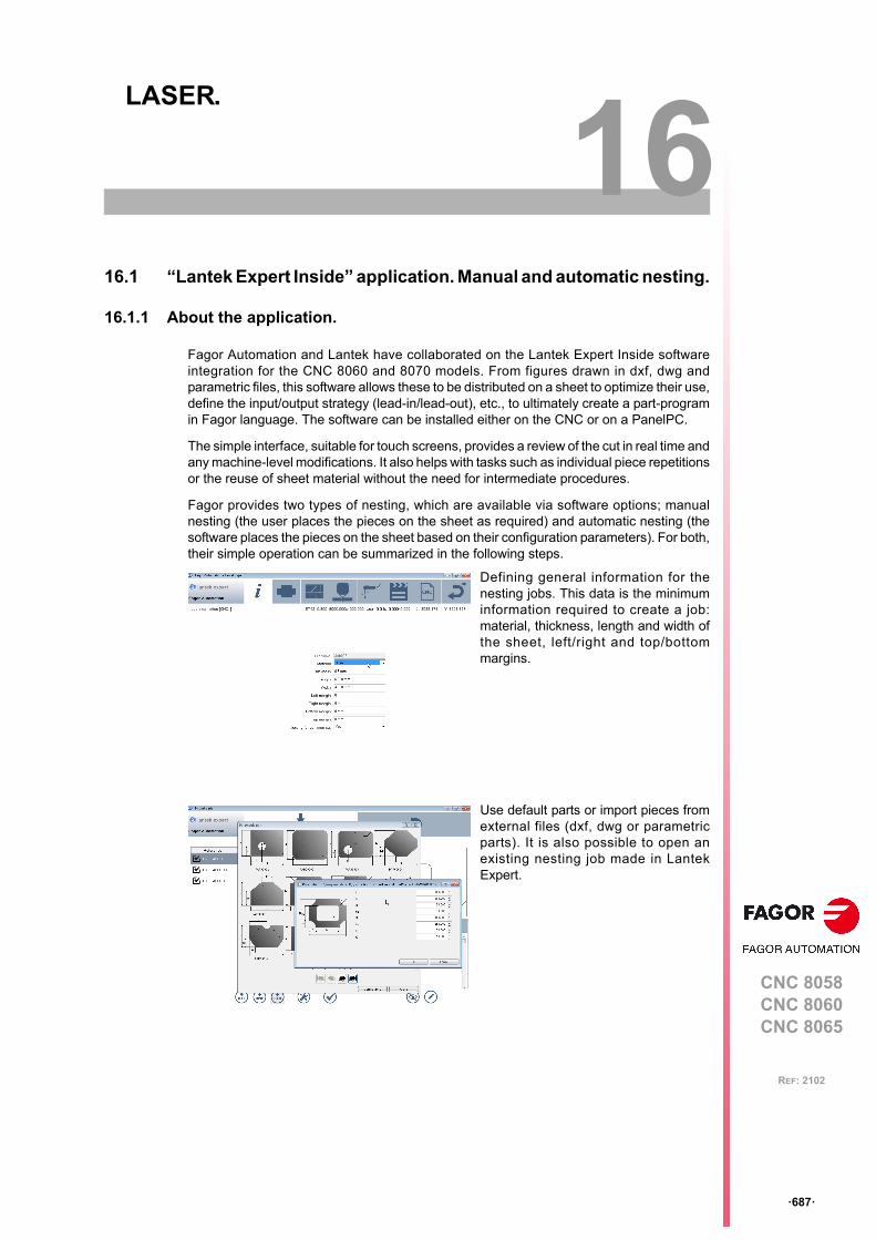
CNC 8058CNC 8060CNC 8065
16
ꞏ687ꞏ
REF: 2102
16.LASER.
16.1 “Lantek Expert Inside” application. Manual and automatic nesting.
16.1.1 About the application.
Fagor Automation and Lantek have collaborated on the Lantek Expert Inside softwareintegration for the CNC 8060 and 8070 models. From figures drawn in dxf, dwg andparametric files, this software allows these to be distributed on a sheet to optimize their use,define the input/output strategy (lead-in/lead-out), etc., to ultimately create a part-programin Fagor language. The software can be installed either on the CNC or on a PanelPC.
The simple interface, suitable for touch screens, provides a review of the cut in real time andany machine-level modifications. It also helps with tasks such as individual piece repetitionsor the reuse of sheet material without the need for intermediate procedures.
Fagor provides two types of nesting, which are available via software options; manualnesting (the user places the pieces on the sheet as required) and automatic nesting (thesoftware places the pieces on the sheet based on their configuration parameters). For both,their simple operation can be summarized in the following steps.
Defining general information for thenesting jobs. This data is the minimuminformation required to create a job:material, thickness, length and width ofthe sheet, left/right and top/bottommargins.
Use default parts or import pieces fromexternal files (dxf, dwg or parametricparts). It is also possible to open anexisting nesting job made in LantekExpert.
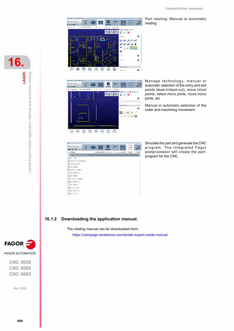
Installation manual.
CNC 8058CNC 8060CNC 8065
16.
LA
SE
R.
“Lan
tek
Exp
ert I
nsid
e” a
pplic
atio
n. M
anu
al a
nd a
uto
ma
tic n
est
ing.
ꞏ688ꞏ
REF: 2102
16.1.2 Downloading the application manual.
The nesting manual can be downloaded from:
https://campaign.lanteksms.com/lantek-expert-inside-manual
Part nesting; Manual or automaticnesting.
Manage techno logy ; manua l o rautomatic selection of the entry and exitpoints (lead-in/lead-out), move in/outpoints, select micro joints, move microjoints, etc.
Manual or automatic selection of theorder and machining movement.
Simulate the part and generate the CNCprogram. The in tegra ted Fagorpostprocessor will create the part-program for the CNC.
Installation manual.
CNC 8058CNC 8060CNC 8065
LA
SE
R.
16.
“Lan
tek
Exp
ert I
nsid
e” a
pplic
atio
n. M
anu
al a
nd a
uto
ma
tic n
est
ing.
ꞏ689ꞏ
REF: 2102
16.1.3 Configuring the application startup.
There are three different ways to startup the nesting.
• The CNC starts up with a .bat file (for example CNC8070L.bat). In this .bat file, add theline, "start c:\Lantek\Expert\Expert.exe". The nesting software starts up after the CNC.
• For the HMI machine parameters, configure the USERKEY key as "Application" andassign it to the path "c:\Lantek\Expert\Expert.exe". The nesting software starts up whenthe user presses the [CUSTOM] key.
• In the file ..\MTB\MMC\Config\Apps.ini add the line"Lantek=c:\Lantek\Expert\Expert.exe". To commence nesting, go into Diagnosis modeand from the horizontal menu select Apps > Lantek.
16.1.4 Accessing the application.
To go from the CNC to the nesting application:
• If only the nesting application and the CNC are open, the [CTRL]+[W] keys alternatelychange from one to the other.
• The [CUSTOM] key accesses the nesting software (if configured by the OEM).
• In Diagnosis mode, from the horizontal menu, select Apps > Lantek (if configured by theOEM).
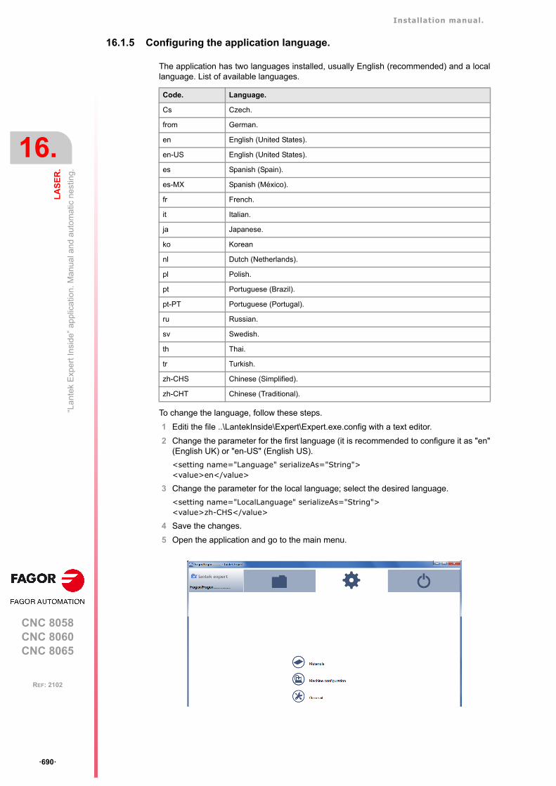
Installation manual.
CNC 8058CNC 8060CNC 8065
16.
LA
SE
R.
“Lan
tek
Exp
ert I
nsid
e” a
pplic
atio
n. M
anu
al a
nd a
uto
ma
tic n
est
ing.
ꞏ690ꞏ
REF: 2102
16.1.5 Configuring the application language.
The application has two languages installed, usually English (recommended) and a locallanguage. List of available languages.
To change the language, follow these steps.
1 Editi the file ..\LantekInside\Expert\Expert.exe.config with a text editor.
2 Change the parameter for the first language (it is recommended to configure it as "en"(English UK) or "en-US" (English US).
<setting name="Language" serializeAs="String"><value>en</value>
3 Change the parameter for the local language; select the desired language.
<setting name="LocalLanguage" serializeAs="String"><value>zh-CHS</value>
4 Save the changes.
5 Open the application and go to the main menu.
Code. Language.
Cs Czech.
from German.
en English (United States).
en-US English (United States).
es Spanish (Spain).
es-MX Spanish (México).
fr French.
it Italian.
ja Japanese.
ko Korean
nl Dutch (Netherlands).
pl Polish.
pt Portuguese (Brazil).
pt-PT Portuguese (Portugal).
ru Russian.
sv Swedish.
th Thai.
tr Turkish.
zh-CHS Chinese (Simplified).
zh-CHT Chinese (Traditional).
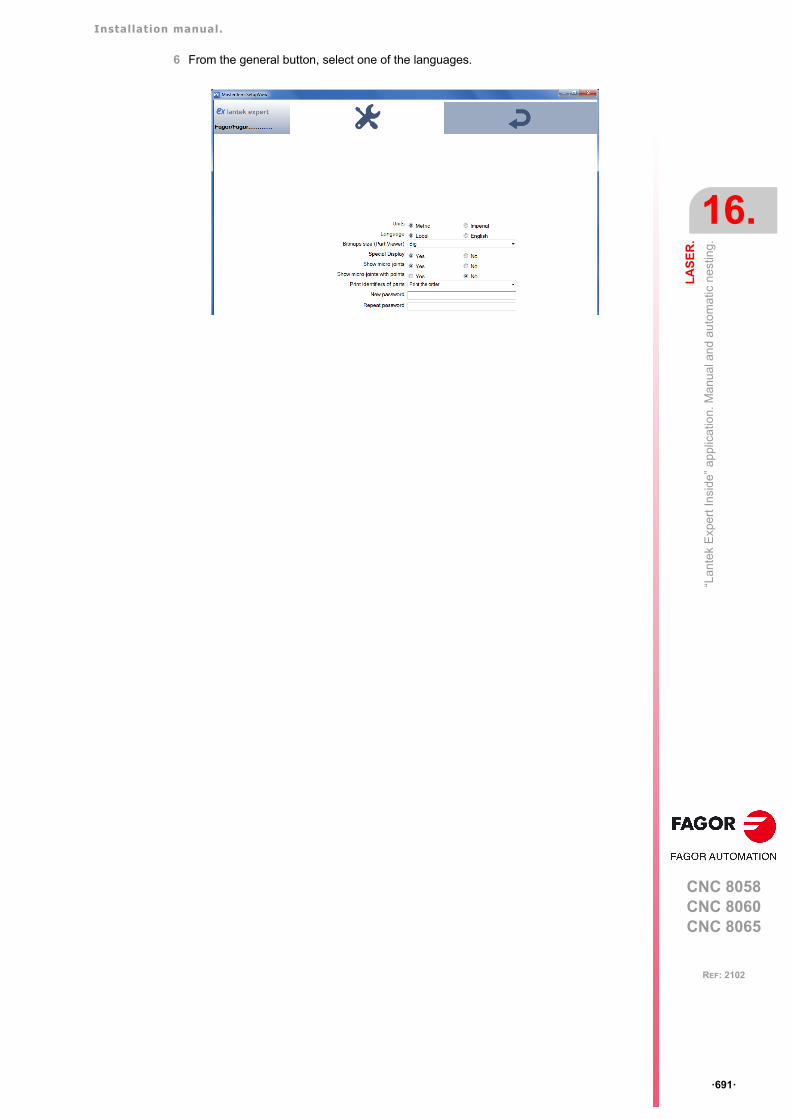
Installation manual.
CNC 8058CNC 8060CNC 8065
LA
SE
R.
16.
“Lan
tek
Exp
ert I
nsid
e” a
pplic
atio
n. M
anu
al a
nd a
uto
ma
tic n
est
ing.
ꞏ691ꞏ
REF: 2102
6 From the general button, select one of the languages.
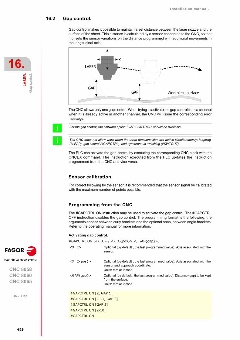
Installation manual.
CNC 8058CNC 8060CNC 8065
16.
LA
SE
R.
Ga
p co
ntro
l.
ꞏ692ꞏ
REF: 2102
16.2 Gap control.
Gap control makes it possible to maintain a set distance between the laser nozzle and thesurface of the sheet. This distance is calculated by a sensor connected to the CNC, so thatit offsets the sensor variations on the distance programmed with additional movements inthe longitudinal axis.
The CNC allows only one gap control. When trying to activate the gap control from a channelwhen it is already active in another channel, the CNC will issue the corresponding errormessage.
The PLC can activate the gap control by executing the corresponding CNC block with theCNCEX command. The instruction executed from the PLC updates the instructionprogrammed from the CNC and vice-versa.
Sensor calibration.
For correct following by the sensor, it is recommended that the sensor signal be calibratedwith the maximum number of points possible.
Programming from the CNC.
The #GAPCTRL ON instruction may be used to activate the gap control. The #GAPCTRLOFF instruction disables the gap control. The programming format is the following; thearguments appear between curly brackets and the optional ones, between angle brackets.Refer to the operating manual for more information.
Activating gap control.
#GAPCTRL ON [<X..C> / <X..C{pos}> <, GAP{gap}>]
LASER
GAPGAP Workpiece surface
X
For the gap control, the software option "GAP CONTROL" should be available.
The CNC does not allow work when the three functionalities are active simultaneously; leapfrog(#LEAP), gap control (#GAPCTRL), and synchronous switching (#SWTOUT).
i
i
<X..C> Optional (by default , the last programmed value). Axis associated with thesensor.
<X..C{pos}> Optional (by default , the last programmed value). Axis associated with thesensor and approach coordinate.Units: mm or inches.
<GAP{gap}> Optional (by default , the last programmed value). Distance (gap) to be keptfrom the surface.Units: mm or inches.
#GAPCTRL ON [Z, GAP 1]
#GAPCTRL ON [Z-11, GAP 2]
#GAPCTRL ON [GAP 5]
#GAPCTRL ON [Z-10]
#GAPCTRL ON

Installation manual.
CNC 8058CNC 8060CNC 8065
LA
SE
R.
16.
Ga
p co
ntro
l.
ꞏ693ꞏ
REF: 2102
Canceling gap control.
#GAPCTRL OFF
Programming from the PLC.
The PLC can activate the gap control by executing the corresponding CNC block with theCNCEX command.
Programming format.
The programming format is the following; the arguments appear between curly brackets andthe optional ones, between angle brackets.
{condition} = CNCEX [{block}, {plc_mark}<,{channel}>]
Execution.
After activating gap control, the axis associated with the sensor moves in programmed feed(if there is no programmed feed, the feed defined in MAXFEED), until detecting the part withthe sensor or the programmed coordinate (POS). If the axis reaches the programmedcoordinate, without receiving the sensor signal, the CNC will show the corresponding erroror not, depending on the GAPTOLCANCEL machine parameter.
The CNC considers that the approach block is complete when the sensor reaches the gapwith the tolerance defined in the GAPTOL machine parameter. Once the part is detected,the CNC will keep the defined gap, including if it detects the part when executing #GAPCTRL,without lowering.
During the approach movement, the CNC is able to stop the movement (signals _STOP o_FEEDHOL). In this case, the axis will remain stationary and without gap control until themovement is resumed.
#GAPCTRL OFF
{condition} Condition to execute the CNCEX command.
{block} Block to be executed.
{plc_mark} Control mark. The PLC activates the mark when the operation begins andkeeps it active until the operation ends.
{channel} Optional (by default, the first channel). Channel where the PLC must executethe block.
{condition] = CNCEX [#GAPCTRL ON [Z, GAP 2], M123]
{condition] = CNCEX [#GAPCTRL OFF], M123]
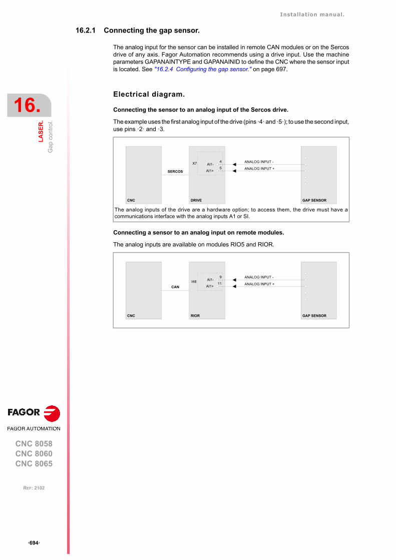
Installation manual.
CNC 8058CNC 8060CNC 8065
16.
LA
SE
R.
Ga
p co
ntro
l.
ꞏ694ꞏ
REF: 2102
16.2.1 Connecting the gap sensor.
The analog input for the sensor can be installed in remote CAN modules or on the Sercosdrive of any axis. Fagor Automation recommends using a drive input. Use the machineparameters GAPANAINTYPE and GAPANAINID to define the CNC where the sensor inputis located. See "16.2.4 Configuring the gap sensor." on page 697.
Electrical diagram.
Connecting the sensor to an analog input of the Sercos drive.
The example uses the first analog input of the drive (pins ꞏ4ꞏ and ꞏ5ꞏ); to use the second input,use pins ꞏ2ꞏ and ꞏ3.
Connecting a sensor to an analog input on remote modules.
The analog inputs are available on modules RIO5 and RIOR.
The analog inputs of the drive are a hardware option; to access them, the drive must have acommunications interface with the analog inputs A1 or SI.
X7
AI1+
AI1-5
4 ANALOG INPUT -
ANALOG INPUT +
DRIVE GAP SENSORCNC
SERCOS
I48AI1+
AI1-11
9 ANALOG INPUT -
ANALOG INPUT +
RIOR GAP SENSORCNC
CAN
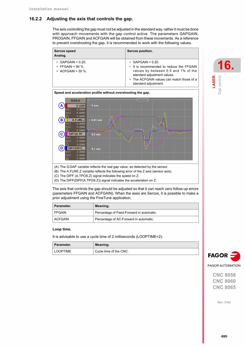
Installation manual.
CNC 8058CNC 8060CNC 8065
LA
SE
R.
16.
Ga
p co
ntro
l.
ꞏ695ꞏ
REF: 2102
16.2.2 Adjusting the axis that controls the gap.
The axis controlling the gap must not be adjusted in the standard way, rather it must be donewith approach movements with the gap control active. The parameters GAPGAIN,PROGAIN, FFGAIN and ACFGAIN will be obtained from these movements. As a referenceto prevent overshooting the gap, it is recommended to work with the following values.
The axis that controls the gap should be adjusted so that it can reach zero follow-up errors(parameters FFGAIN and ACFGAIN). When the axes are Sercos, it is possible to make aprior adjustment using the FineTune application.
Loop time.
It is advisable to use a cycle time of 2 milliseconds (LOOPTIME=2).
Sercos speedAnalog.
Sercos position.
• GAPGAIN = 0.20.• FFGAIN = 90 %.• ACFGAIN = 30 %.
• GAPGAIN = 0.20.• It is recommended to reduce the FFGAIN
values by between 0.5 and 1% of thestandard adjustment values.
• The ACFGAIN values can match those of astandard adjustment.
Speed and acceleration profile without overshooting the gap.
(A) The G.GAP variable reflects the real gap value, as detected by the sensor.(B) The A.FLWE.Z variable reflects the following error of the Z axis (sensor axis).(C) The DIFF (A.TPOS.Z) signal indicates the speed on Z.(D) The DIFF(DIFF(A.TPOS.Z)) signal indicates the acceleration on Z.
Parameter. Meaning.
FFGAIN Percentage of Feed-Forward in automatic.
ACFGAIN Percentage of AC-Forward in automatic.
Parameter. Meaning.
LOOPTIME Cycle time of the CNC.
A
B
C
D
Installation manual.
CNC 8058CNC 8060CNC 8065
16.
LA
SE
R.
Ga
p co
ntro
l.
ꞏ696ꞏ
REF: 2102
16.2.3 Configuring the gap.
Configuring the gap limits.
If the gap exceeds the range defined in the parameters GAPMIN and GAPMAX, the PLCdeactivates the INPOSGAP mark. The CNC will display an error or not, depending on howthe parameter GAPERRORCANCEL has been set. In the event of an error, the CNC stopsthe movement of the axes, according to the braking ramp and controlling the gap during theramp.
If the axis exceeds the tolerance set in the GAPTOL parameter, the PLC deactivates theINTOL mark. The CNC will display an error or not, depending on how the parameterGAPTOLCANCEL has been set. In the event of an error, the CNC stops the movement ofthe axes, according to the braking ramp and controlling the gap during the ramp.
Configure the CNC response when exceeding the gap limits.
Parameter. Meaning.
GAPMIN Minimum permitted value for the gap; below this value, the CNC will showan error or not as defined in the parameter GAPERRORCANCEL.
GAPMAX Maximum permitted value for the gap; above this value, the CNC willshow an error or not as defined in the parameter GAPERRORCANCEL.This parameter should be lower than GAPDISTLIMIT.
GAPTOL This parameter defines a positioning window on the programmed gap,to finish the approach block.
Parameter. Meaning.
GAPERRORCANCEL This parameter indicates if the CNC should cancel the error for gapoutside the range, when the gap exceeds the GAPMIN - GAPMAXrange. Regardless of the value of this parameter, the CNC keepsmonitoring the INPOSGAP mark.
GAPTOLCANCEL This parameter indicates if the CNC should cancel the error for gapoutside the tolerance range, when the gap exceeds the margin definedin the parameter GAPTOL.
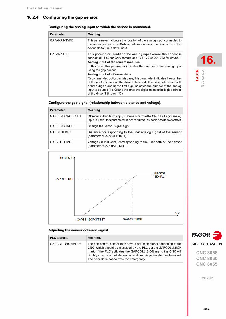
Installation manual.
CNC 8058CNC 8060CNC 8065
LA
SE
R.
16.
Ga
p co
ntro
l.
ꞏ697ꞏ
REF: 2102
16.2.4 Configuring the gap sensor.
Configuring the analog input to which the sensor is connected.
Configure the gap signal (relationship between distance and voltage).
Adjusting the sensor collision signal.
Parameter. Meaning.
GAPANAINTYPE This parameter indicates the location of the analog input connected tothe sensor; either in the CAN remote modules or in a Sercos drive. It isadvisable to use a drive input.
GAPANAINID This parameter identifies the analog input where the sensor isconnected: 1-60 for CAN remote and 101-132 or 201-232 for drives.Analog input of the remote modules.In this case, this parameter indicates the number of the analog inputusing the gap sensor.Analog input of a Sercos drive.Recommended option. In this case, this parameter indicates the numberof the analog input and the drive to be used. The parameter is set witha three-digit number; the first digit indicates the number of the analoginput to be used (1 or 2) and the other two digits indicate the logic addressof the drive (1 through 32).
Parameter. Meaning.
GAPSENSOROFFSET Offset (in millivolts) to apply to the sensor from the CNC. If a Fagor analoginput is used, this parameter is not required, as each has its own offset.
GAPSENSORCH Change the sensor signal sign.
GAPDISTLIMIT Distance corresponding to the limit analog signal of the sensor(parameter GAPVOLTLIMIT).
GAPVOLTLIMIT Voltage (in millivolts) corresponding to the limit path of the sensor(parameter GAPDISTLIMIT).
PLC signals. Meaning.
GAPCOLLISIONMODE The gap control sensor may have a collusion signal connected to theCNC, which should be managed by the PLC via the GAPCOLLISIONmark. If the PLC activates the GAPCOLLISION mark, the CNC willdisplay an error or not, depending on how this parameter has been set.The error does not activate the emergency.
Installation manual.
CNC 8058CNC 8060CNC 8065
16.
LA
SE
R.
Ga
p co
ntro
l.
ꞏ698ꞏ
REF: 2102
16.2.5 Adjusting the sensor position loop.
Adjust with the aid of the oscilloscope.
1 Executing a program when gap control is active.
2 Selecting the variables (V.)G.GAP y (V.)A.GAPCOMP.Z (sensor axis).
3 Attempting to reduce the gap (variable G.GAP) while incrementing the proportional gain(parameter GAPGAIN). Increasing the proportional gain with small increments (e.g.0.05). Using the GAPAPPROACHDYN parameter to adjust the GAPGAIN value duringthe final part of the plate approach, when the CNC has detected the sensor signal.
4 Reducing the filter frequency (machine parameter FREQUENCY) to obtain a softerresponse. Since the gap value increases, increase the proportional gain (machineparameter GAPGAIN).
GAPCONTROL
GAPGAIN Proportional gain applied to the signal sensor, in position. To use values greater than 0.2 (close to 1), it is advisable to use the parameterGAPSENSORFILTER.
GAPAPPROACHDYN Dynamic response during the final part of the movement approaching theplate.
GAPSENSORFILTER Low step filter; it is advisable to define a filter of order 2 and cutofffrequency of 30 Hz.
ORDER Filter order.
FREQUENCY Break frequency.
(V.)G.GAP Actual gap value, detected by the sensor.
(V.)A.GAPCOMP.Z Compensation introduced by gap control into the axis associatedwith the sensor to maintain the gap.
GAP SENSORFEEDBACK
V.G.GAP
POSITIONLOOP
P-GAINGAPCUTOF FILTER
Installation manual.
CNC 8058CNC 8060CNC 8065
LA
SE
R.
16.
Ga
p co
ntro
l.
ꞏ699ꞏ
REF: 2102
16.2.6 PLC signals.
Logic consultation signals.
Modifiable logic signals.
PLC signals. Meaning.
INPOSGAP The CNC activates this mark if the gap is within the range defined by theparameters GAPMIN-GAPMAX. I f the gap exceeds the range de f ined in the parametersGAPMIN-GAPMAX, the CNC disables the INPOSGAP mark and stopsthe movement of the axes. The CNC will display an error or not,depending on how the parameter GAPERRORCANCEL has been set.In the event of an error, the CNC stops the movement of the axes,according to the braking ramp and controlling the gap during the ramp.
INTOL The CNC activates this mark if the gap is within the tolerance limit definedby the parameter GAPTOL regarding the gap value programmed. If the axis exceeds the tolerance set in the GAPTOL parameter, the CNCdeactivates the INTOL mark. The CNC will display an error or not,depending on how the parameter GAPTOLCANCEL has been set. In theevent of an error, the CNC stops the movement of the axes, accordingto the braking ramp and controlling the gap during the ramp.
PLC signals. Meaning.
_FEEDHOL If the PLC sets this mark at a high logic level, the CNC channelmomentarily interrupts the movement of the axes. When the markreturns to the high logic level, the movement of the axes continues. Allthe stops and starts of the axes are carried out with the correspondingacceleration and deceleration.
• This mark does not affect the independent movement of an axis(independent interpolator).
• On hirth axes, if the axis does not stop in a particular position, theCNC does not activate the MATCH(axis) mark.
• This mark does not turn off the laser. If the power control is active,the laser removes the minimum defined power.
If the PLC sets the _FEEDHOL at a low logic level in a motionless block,the CNC continues executing the program until it detects a motion block.The "Freal" text of the screens of the automatic and jog modes showsthe status of this mark. The text appears in red when the _FEEDHOLmark is active. The status of the mark is not displayed if the screen doesnot show this text.
_STOP If the PLC sets this mark at a low logic level, the CNC channel interruptsthe execution of the part program. To resume the execution of theprogram, besides setting this mark at a high logical level, the PLC shouldactivate the CYSTART mark.
• This mark does not affect the independent movement of an axis(independent interpolator), which also does not affect the key[STOP].
• This mark does not turn off the laser.• This mark does not disable gap control, except in approach
movement. In this case, the axis will remain stationary and withoutgap control until the movement is resumed.
The treatment received by the signal _STOP is similar to that given tothe [STOP] key in the CNC. With this signal at a low logic level, all keysremain enabled.
ENABLEGAP This mark is active by default. The PLC deactivates this mark to disablethe active gap control. The PLC activates this mark to enable the activegap control in the CNC; if no gap control is active, this mark does nothing.
GAPCOLLISION The PLC activates this mark to indicate that the collision sensor has beenactivated. This mark is not kept in memory. When this mark is active, theCNC will display an error or not, depending on how the parameterGAPCOLLISIONMODE has been set.
Installation manual.
CNC 8058CNC 8060CNC 8065
16.
LA
SE
R.
Ga
p co
ntro
l.
ꞏ700ꞏ
REF: 2102
16.2.7 Gap compensation examples.
Part with a profile irregularity.
Part with a rising profile.
(V.)G.GAP Actual gap value, detected by the sensor.
(V.)A.POS.Z Z axis. Actual machine coordinators of the sensor.
(V.)A.POS.X Actual machine coordinates for X-axis.
(V.)A.GAPCOMP.Z Compensation introduced by gap control into the axis associatedwith the sensor to maintain the gap.
Installation manual.
CNC 8058CNC 8060CNC 8065
LA
SE
R.
16.
Ga
p co
ntro
l.
ꞏ701ꞏ
REF: 2102
16.2.8 Operating the PLC to remove the axis associated with the gap control.
DFU {conditions} AND NOT M666 AND NOT INCYCLE= RES ENABLEGAP= RES ENABLELEAP= SET IRESETZ= TG1 333 12 ; Dwell, 12 milliseconds.
T333 = M666
DFD M666 = RES IRESETZ= MOVE ABS (Z, 513000,50000000,NULL)
DFDB B10KEYLED1 = SET ENABLEGAP = SET ENABLELEAP
Installation manual.
CNC 8058CNC 8060CNC 8065
16.
LA
SE
R.
Ga
p co
ntro
l.
ꞏ702ꞏ
REF: 2102
CNC 8058CNC 8060CNC 8065
17
ꞏ703ꞏ
REF: 2102
17.CALCULATION OF THE KINEMATICS DIMENSIONS.
The OEM may set up to 6 different kinematics for the same machine. The CNC offers anumber of pre-defined kinematics that may be easily configured by machine parameters.Besides these kinematics, the OEM can integrate 6 additional kinematics.
The dimensions to be set by parameter depend on the type of kinematics, set in parameterTYPE. The following sections show, as examples, the methods to calculate the dimensionsof a kinematics with the help of a probe or a dial indicator.
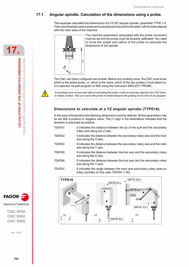
Installation manual.
CNC 8058CNC 8060CNC 8065
17.
CA
LC
UL
AT
ION
OF
TH
E K
INE
MA
TIC
S D
IME
NS
ION
S.
Ang
ular
sp
ind
le. C
alcu
latio
n of
the
dim
ensi
ons
usi
ng a
pro
be.
ꞏ704ꞏ
REF: 2102
17.1 Angular spindle. Calculation of the dimensions using a probe.
This example calculates the dimensions of a YZ 45º angular spindle, parameter TYPE = 6.Then next example uses a probe and a sample part secured to the table, with its sides alignedwith the main axes of the machine.
The CNC can have configured two probes. Before any probing move, the CNC must knowwhich is the active probe, or, which is the same, which of the two probes it must attend to.It is selected via part-program or MDI using the instruction #SELECT PROBE.
Dimensions to calculate at a YZ angular spindle (TYPE=6).
In this type of kinematics the following dimensions must be defined. All the parameters maybe set with a positive or negative value. The (+) sign in the illustrations indicates that thedirection is assumed as positive.
The machine parameters associated with the probe movementmust be set and the probe must be properly calibrated. You needto know the length and radius of the probe to calculate thedimensions of the spindle.
R
L
If a probing move is executed without activating the probe, it will not send any signal to the CNC whenit makes contact. This can cause the probe to break because the probing move will not be stopped.
TDATA1 It indicates the distance between the tip of the quill and the secondaryrotary axis along the Z axis.
TDATA2 It indicates the distance between the secondary rotary axis and the mainaxis along the X axis.
TDATA3 It indicates the distance between the secondary rotary axis and the mainaxis along the Y axis.
TDATA5 It indicates the distance between the tool axis and the secondary rotaryaxis along the X axis.
TDATA6 It indicates the distance between the tool axis and the secondary rotaryaxis along the Y axis.
TDATA7 It indicates the angle between the main and secondary rotary axes onrotary spindles (in this case TDATA7 = 45).
TYPE=6
XYZ
B
C
X
Z
Y
Z
DATA 2(-)DATA 3(+)
DATA 7(+)DATA 6(+)
DATA 1(+)
DATA 5(-)
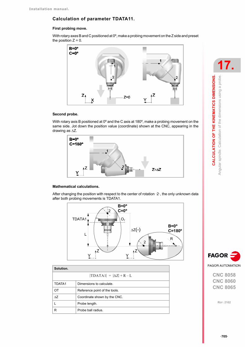
Installation manual.
CNC 8058CNC 8060CNC 8065
CA
LC
UL
AT
ION
OF
TH
E K
INE
MA
TIC
S D
IME
NS
ION
S.
17.
Ang
ular
sp
ind
le. C
alcu
latio
n of
the
dim
ensi
ons
usi
ng a
pro
be.
ꞏ705ꞏ
REF: 2102
Calculation of parameter TDATA11.
First probing move.
With rotary axes B and C positioned at 0º, make a probing movement on the Z side and presetthe position Z = 0.
Second probe.
With rotary axis B positioned at 0º and the C axis at 180º, make a probing movement on thesame side. Jot down the position value (coordinate) shown at the CNC, appearing in thedrawing as Z.
Mathematical calculations.
After changing the position with respect to the center of rotation ꞏ2ꞏ, the only unknown dataafter both probing movements is TDATA1.
Solution.
TDATA1 Dimensions to calculate.
OT Reference point of the tools.
Z Coordinate shown by the CNC.
L Probe length.
R Probe ball radius.
OT
2
TDATA1
Z(-)
2R
YZ
L
B=0ºC=180º
B=0ºC=0º
YZ
TDATA1 Z R L–+=
Installation manual.
CNC 8058CNC 8060CNC 8065
17.
CA
LC
UL
AT
ION
OF
TH
E K
INE
MA
TIC
S D
IME
NS
ION
S.
Ang
ular
sp
ind
le. C
alcu
latio
n of
the
dim
ensi
ons
usi
ng a
pro
be.
ꞏ706ꞏ
REF: 2102
Calculation of parameter TDATA5.
First probing move.
With rotary axes B and C positioned at 0º, make a probing movement on the X side closestto the origin and preset the position X = 0.
Second probe.
With rotary axis B positioned at 0º and the C axis at 180º, make a probing movement on thesame side. Jot down the position value (coordinate) shown at the CNC, appearing in thedrawing as X.
Mathematical calculations.
After changing the position with respect to the center of rotation ꞏ2ꞏ, the only unknown dataafter both probing movements is TDATA5.
XZ
X=0
1
2
B=0ºC=0º
B=0ºC=180º
YX
X=X21
2
2
TDATA5
X(-)
XZ
XY
B=0ºC=180º
B=0ºC=0º
TDATA5
Solution.
TDATA5 Dimensions to calculate.
X Coordinate shown by the CNC.
TDATA5 0 5 Z=
Installation manual.
CNC 8058CNC 8060CNC 8065
CA
LC
UL
AT
ION
OF
TH
E K
INE
MA
TIC
S D
IME
NS
ION
S.
17.
Ang
ular
sp
ind
le. C
alcu
latio
n of
the
dim
ensi
ons
usi
ng a
pro
be.
ꞏ707ꞏ
REF: 2102
Calculation of parameter TDATA6.
First probing move.
With the B and C axes positioned at 0º, make a probing movement on the other X side tomeasure the part whose dimension will be the coordinate shown at the CNC minus thediameter of the probe ball.
Second probe.
With the C rotary axis positioned at 0º and B at -90º, make a probing movement on the firstX side. Take note of the coordinate displayed on the CNC, depicted in the diagram as X’.
Third probing move.
With the C rotary axis positioned at 0º and B at 90º, make a probing movement on the secondX side. Take note of the coordinate displayed on the CNC, depicted in the diagram as X.
Mathematical calculations.
After changing the position with respect to the center of rotation ꞏ1ꞏ, the only unknown dataafter both probing movements is TDATA6.
XZ
B=0ºC=0º
X=D+2R
XZ
B=-90ºC=0º
B=90ºC=0º
1
21 2
1 21
2
1
2
XZ
TDATA1 TDATA6 . cos45
R
X(+)
L
X´(-)
D
B=-90ºC=0º
B=90ºC=0º
B=0ºC=0º
TDATA6 . cos45
X=0
Installation manual.
CNC 8058CNC 8060CNC 8065
17.
CA
LC
UL
AT
ION
OF
TH
E K
INE
MA
TIC
S D
IME
NS
ION
S.
Ang
ular
sp
ind
le. C
alcu
latio
n of
the
dim
ensi
ons
usi
ng a
pro
be.
ꞏ708ꞏ
REF: 2102
Calculation of parameter TDATA2.
First probing move.
With the C rotary axis positioned at 0º and the B axis at 90º, make a probing movement onthe Z side and preset the position Z = 0.
Second probe.
With the C rotary axis positioned at 0º and the B axis at -90º, make a probing movement onthe Z side. Jot down the position value (coordinate) shown at the CNC, appearing in thedrawing as Z.
Solution.
TDATA1 Known dimension.
TDATA6 Dimensions to calculate.
D Length of the part.
X’ X Coordinates shown by the CNC.
L Probe length.
R Probe ball radius.
TDATA6 X X D– 2L– 2 TDATA1–+2 45cos
-------------------------------------------------------------------------------------------=
B=90ºC=0º
XZ
1
2Z=0
B=-90ºC=0º
XZ
1
2 Z=Z
Installation manual.
CNC 8058CNC 8060CNC 8065
CA
LC
UL
AT
ION
OF
TH
E K
INE
MA
TIC
S D
IME
NS
ION
S.
17.
Ang
ular
sp
ind
le. C
alcu
latio
n of
the
dim
ensi
ons
usi
ng a
pro
be.
ꞏ709ꞏ
REF: 2102
Mathematical calculations.
After changing the position with respect to the center of rotation ꞏ1ꞏ, the only unknown dataafter both probing movements is TDATA2.
Solution.
TDATA2 Dimensions to calculate.
TDATA5 Known dimension.
Z Coordinate shown by the CNC.
1
21
2
XZ
B=90ºC=0º
B=-90ºC=0º
TDATA5
TDATA2 Z(+)
TDATA2 0 5 Z TDATA5–=
Installation manual.
CNC 8058CNC 8060CNC 8065
17.
CA
LC
UL
AT
ION
OF
TH
E K
INE
MA
TIC
S D
IME
NS
ION
S.
An
gula
r sp
ind
le. C
alcu
latio
n of
the
dim
ens
ion
s us
ing
a d
ial i
ndi
cato
r.
ꞏ710ꞏ
REF: 2102
17.2 Angular spindle. Calculation of the dimensions using a dialindicator.
This example calculates the dimensions of a YZ 45º angular spindle (same as in the previousexample), parameter TYPE = 6. The next example uses a dial indicator and a cylinder ofknown diameter placed in the spindle.
How to use the dial indicator.
When touching a cylinder with a dial indicator, contact must be made on the outside line ofthe cylinder. Otherwise, there will be a measuring error when presetting the value of thecylinder value. The dial indicator should be as perpendicular as possible to the tangent ofthe surface being measured.
A simple method to place the dial indicator on the most external line of the cylinder is to movethe dial indicator on the circumference of the cylinder. To do that, preset ꞏ0ꞏ on the axis tobe moved. When moving the axis, the needle of the dial indicator will rotate in one directionand after passing the most external point of the cylinder, the needle will rotate in the oppositedirection. Continue with the movement until the needle of the dial indicator reaches its initialvalue. The most external point will be in the middle of the distance traveled by the axis.
TYPE=6
XYZ
B
C
X
Z
Y
Z
DATA 2(-)DATA 3(+)
DATA 7(+)DATA 6(+)
DATA 1(+)
DATA 5(-)
Installation manual.
CNC 8058CNC 8060CNC 8065
CA
LC
UL
AT
ION
OF
TH
E K
INE
MA
TIC
S D
IME
NS
ION
S.
17.
An
gula
r sp
ind
le. C
alcu
latio
n of
the
dim
ens
ion
s us
ing
a d
ial i
ndi
cato
r.
ꞏ711ꞏ
REF: 2102
Calculation of parameter TDATA11.
First contact.
Second contact.
Calculation of parameter TDATA5.
First contact.
1 Position rotary axes B and C at 0º.
2 Place the dial indicator on the table, in thedirection of the Y axis.
3 Move the table in the Y axis until the dialindicator and the cylinder touch each otherat point 1.
4 Preset Y=R so Y=0 coincides with the shaftof the cylinder placed in the spindle.
1 Remove the dial indicator, without looseningit and position the rotary C axis at 180º.
2 Touch with the dial indicator at point 2.
3 Jot down the position value (coordinate)shown at the CNC Y).
Solution.
TDATA1 Dimensions to calculate.
Y Coordinate shown by the CNC.
1 Position rotary axes B and C at 0º.
2 Place the dial indicator on the table, in thedirection of the X axis.
3 Move the table in the X axis until the dialindicator and the cylinder touch each otherat point 1.
4 Preset X=0.
YZ
B=0ºC=0º
1R
B=0ºC=180º
YZ
2
TDATA1
TDATA1 Y=
XZ
B=0ºC=0º
1
TDATA5

Installation manual.
CNC 8058CNC 8060CNC 8065
17.
CA
LC
UL
AT
ION
OF
TH
E K
INE
MA
TIC
S D
IME
NS
ION
S.
An
gula
r sp
ind
le. C
alcu
latio
n of
the
dim
ens
ion
s us
ing
a d
ial i
ndi
cato
r.
ꞏ712ꞏ
REF: 2102
Second contact.
Calculation of parameter TDATA2.
First contact (made when calculating TDATA5).
Second contact.
1 Remove the dial indicator, without looseningit and position the rotary C axis at 180º.
2 Touch with the dial indicator at point 2.
3 Jot down the position value (coordinate)shown at the CNC X).
Solution.
TDATA5 Dimensions to calculate.
X Coordinate shown by the CNC.
1 Keep previous preset.
1 Remove the dial indicator, without looseningit and position the rotary C axis at 0º.
2 Position B rotary axis at 0º.
3 Touch with the dial indicator at point 2.
4 Jot down the position value (coordinate)shown at the CNC X).
Solution.
TDATA1 Dimensions to calculate.
TDATA5 Dimensions to calculate.
X Coordinate shown by the CNC.
B=0ºC=180º
XZ
2
TDATA5
TDATA5 0 5 X=
XZ
B=0ºC=0º
1
TDATA5
XZ
B=180ºC=0º
3
TDATA2
TDATA5
TDATA2 0 5 X TDATA5–=

Installation manual.
CNC 8058CNC 8060CNC 8065
CA
LC
UL
AT
ION
OF
TH
E K
INE
MA
TIC
S D
IME
NS
ION
S.
17.
An
gula
r sp
ind
le. C
alcu
latio
n of
the
dim
ens
ion
s us
ing
a d
ial i
ndi
cato
r.
ꞏ713ꞏ
REF: 2102
Calculation of parameter TDATA6.
First and second contacts.
Third and forth contact.
1 Position rotary axes B and C at 0º.
2 Move the table in the X axis until the dialindicator and the cylinder touch each otherat point 1.
3 Preset X=R so X=0 coincides with the shaftof the cylinder placed in the spindle.
4 Remove the dial indicator, without looseningit and position the B rotary axis at -90º. Touchwith the dial indicator at point 2.
5 Jot down the position value (coordinate)shown at the CNC (Xa).
1 Position rotary axes B and C at 0º.
2 Move the table in the X axis until the dialindicator and the cylinder touch each otherat point 3.
3 Preset X=R so X=0 coincides with the shaftof the cylinder placed in the spindle.
4 Remove the dial indicator, without looseningit and position the B rotary axis at 90º. Touchwith the dial indicator at point 4.
5 Jot down the position value (coordinate)shown at the CNC (Xb).
XZ
B=0ºC=0º
B=-90ºC=0º
XA
1
2
XZ
B=0ºC=0º
B=90ºC=0º
XB
3
4
Solution.
TDATA5 Dimensions to calculate.
X Coordinate shown by theCNC.
XM 0 5 XB XA+ =
TDATA6 2 XM TDATA1– =
YZ
XM
TDATA1
TDATA6
45O
Installation manual.
CNC 8058CNC 8060CNC 8065
17.
CA
LC
UL
AT
ION
OF
TH
E K
INE
MA
TIC
S D
IME
NS
ION
S.
Rot
ary
tab
le. C
alcu
latio
n of
the
dim
ensi
ons
usi
ng a
pro
be.
ꞏ714ꞏ
REF: 2102
17.3 Rotary table. Calculation of the dimensions using a probe.
This example calculates the dimensions of an AB rotary table with a moving range for theA axis between -90º and 90º and for the B axis between 0º and -90º, parameter TYPE = 9.The next example uses a probe and a cylinder of known diameter secured to the table.
The CNC can have configured two probes. Before any probing move, the CNC must knowwhich is the active probe, or, which is the same, which of the two probes it must attend to.It is selected via part-program or MDI using the instruction #SELECT PROBE.
Dimensions to calculate on an AB rotary table (TYPE=9).
In this type of kinematics the following dimensions must be defined. All the parameters maybe set with a positive or negative value. The (+) sign in the illustrations indicates that thedirection is assumed as positive.
The machine parameters associated with the probe movementmust be set and the probe must be properly calibrated. You needto know the length and radius of the probe to calculate thedimensions of the spindle.
R
L
If a probing move is executed without activating the probe, it will not send any signal to the CNC whenit makes contact. This can cause the probe to break because the probing move will not be stopped.
TDATA2 It indicates the position of the secondary rotary axis or the intersection withthe primary axis along the X axis.
TDATA3 It indicates the position of the secondary rotary axis or the intersection withthe primary axis along the Y axis.
TDATA4 It indicates the position of the secondary rotary axis or the intersection withthe primary axis along the Z axis.
TDATA5 It indicates the distance between the secondary and the main rotarytables.
Y
Z TDATA 3(+)
TDATA 4(+)
A
B
TYPE=9
XYZ
TDATA 5(+)
TDATA 2(+)
X
Z
Installation manual.
CNC 8058CNC 8060CNC 8065
CA
LC
UL
AT
ION
OF
TH
E K
INE
MA
TIC
S D
IME
NS
ION
S.
17.
Rot
ary
tab
le. C
alcu
latio
n of
the
dim
ensi
ons
usi
ng a
pro
be.
ꞏ715ꞏ
REF: 2102
Calculation of the coordinates of the A axis.
The diagram shows two different positions that have the center of axis A in common. Thecoordinate for the Y axis is the parameter TDATA3 and the coordinate for the Z axis is Pz.Both coordinates are necessary to calculate the rest of the parameters.
First position.
1 Position rotary axes A and B at -90º.
2 Make a probing movement along the Y axis at point 1. Jot down the position value(coordinate) shown at the CNC, appearing in the drawing as Y1.
3 Make a probing movement along the Z axis at point 1. Jot down the position value(coordinate) shown at the CNC, appearing in the drawing as Z1.
Second position.
1 Position the A rotary axis at 90º and the B axis at -90º.
2 Make a probing movement along the Y axis at point 3. Jot down the position value(coordinate) shown at the CNC, appearing in the drawing as Y2.
3 Make a probing movement along the Z axis at point 4. Jot down the position value(coordinate) shown at the CNC, appearing in the drawing as Z2.
Mathematical calculations.
Solution.
TDATA3Pz
Coordinates of the A axis.
Y1, Z1Y2, Z2
Coordinates shown by the CNC.
R Cylinder radius.
A=90ºB=-90º
A=-90ºB=-90º
YZ
Z1Z2
PZ
R
Y1
Y2
TDATA3
1
3
2
4
TDATA3 0 5 Y1 Y2+ =
Pz 0 5 Z1 Z2 R–+ =
Installation manual.
CNC 8058CNC 8060CNC 8065
17.
CA
LC
UL
AT
ION
OF
TH
E K
INE
MA
TIC
S D
IME
NS
ION
S.
Rot
ary
tab
le. C
alcu
latio
n of
the
dim
ensi
ons
usi
ng a
pro
be.
ꞏ716ꞏ
REF: 2102
Origin preset on the X axis.
1 Keep previous position, A=90º and B=-90º.
2 Probe on the table, in the direction of the X axis.
3 Jot down the position value (coordinate) shown at the CNC, appearing in the drawingas X.
4 Preset X = -r so X=0 coincides with the surface of the table.
Calculation of the rest of the parameters.
The drawing shows two different positions of the B axis while keeping the position of the Aaxis.
First position.
1 Position rotary axes A and B at 0º.
2 Make a probing movement along the X axis at point 1. Jot down the position value(coordinate) shown at the CNC, appearing in the drawing as X1.
3 Make a probing movement along the Z axis at point 2. Jot down the position value(coordinate) shown at the CNC, appearing in the drawing as Z.
4 Preset Z=0.
Second position.
1 Position the A rotary axis at 0º and the B axis at -90º.
2 Make a probing movement along the Z axis at point 3. Jot down the position value(coordinate) shown at the CNC, appearing in the drawing as Z1.
A=90ºB=-90º
r
ZX
X
ZX
A=0ºB=-90º
A=0ºB=0º
X+r
Z
12
3Z1
TDATA2
X1
TDATA5
PZ
TDATA4
FE
E
r

Installation manual.
CNC 8058CNC 8060CNC 8065
CA
LC
UL
AT
ION
OF
TH
E K
INE
MA
TIC
S D
IME
NS
ION
S.
17.
Rot
ary
tab
le. C
alcu
latio
n of
the
dim
ensi
ons
usi
ng a
pro
be.
ꞏ717ꞏ
REF: 2102
Mathematical calculations.
Solution.
According to the shaded frame of the drawing.
Calculation of parameters.
TDATA2TDATA4TDATA5
Parameters to calculate.
Pz Coordinate of the A axis.
Z, Z1X, X1
Coordinates shown by the CNC.
R Cylinder radius.
r Probe ball radius.
E Distance from the table surface to the B axis.
F Distance from the table surface to the A axis.
E 0 5 X1 Z1 2R r+ + + =
F Z Pz–=
TDATA5 F E–=
TDATA4 TDATA4 Pz–=
TDATA2 X r E+ +=
Installation manual.
CNC 8058CNC 8060CNC 8065
17.
CA
LC
UL
AT
ION
OF
TH
E K
INE
MA
TIC
S D
IME
NS
ION
S.
Rot
ary
tab
le. C
alcu
latio
n of
the
dim
ensi
ons
usi
ng a
pro
be.
ꞏ718ꞏ
REF: 2102
CNC 8058CNC 8060CNC 8065
18
ꞏ719ꞏ
REF: 2102
18.DMC (DYNAMIC MACHINING CONTROL).
The choice of machining feedrate depends on the material to be machined, the tool (material,number of teeth, etc.) and the depth of pass. The feedrate for machining is set at the startand remains constant until the end. If the machining conditions change (for example, dueto tool wear), the programmed feedrate may no longer be appropriate, which will have anegative effect on the tool life, machining time, etc.
DMC (dynamic machining control) adapts the feedrate during machining to maintain thecutting power as close as possible to ideal machining conditions. DMC adapts the feedrateby changing the override.
DMC optimizes the use of the machine and the tool, which makes it possible to increase thematerial removal rate (MRR) without impairing the life of the tool, since it is operatingaccording to its rated conditions. Optimization is based on the cutting power to be reached,which is also referred to as target power. This power not only depends on the tool, but alsoon the material and the cutting conditions (feedrate, spindle turning speed, depth of passand sideways step (pass)), and therefore its value must be linked to the entire combinationof the tool+material+cutting conditions.
DMC is only available for milling operations with "Milling" and "Surface milling” operations.This function can be applied to roughing and finishing operations, but this function providesthe most benefits in terms of machining time and tool life in roughing operations.
The DMC is only available for the master spindle, using Fagor digital servo systems (version V9.01or higher). The spindle must be enabled for the DMC in the machine parameter DMCSPDL. i
Installation manual.
CNC 8058CNC 8060CNC 8065
18.
DM
C (
DY
NA
MIC
MA
CH
ININ
G C
ON
TR
OL
).
Set
up.
ꞏ720ꞏ
REF: 2102
18.1 Setup.
18.1.1 Configuring the override limits for the DMC.
These parameters indicate the minimum and maximum percentage of feedrate (feedrateoverride) that DMC (dynamic machining control) can apply on the channel. Both percentagescan be changed in the instruction #DMC ON. The feedrate percentage applied by DMC isadded to that selected using the operator panel switch.
The resulting override (overrideDMC + overrideJOG) may exceed the set limits for bothparameters. The CNC always abides by the maximum limit set in the machine parameterMAXOVR.
If the user selects an override with the switch on the operator panel that is lower thanMINDMCOVR, the CNC inhibits DMC (but does not deactivate it); when the override onceagain exceeds MINDMCOVR, DMC will once again operate as normal.
The feedrate percentage set by the program (variable V.G.PRGFRO) or by the PLC (variableV.PLC.FRO) inhibit DMC, but they do not deactivate it; if canceled, DMC resumes controlover the feedrate percentage.
18.1.2 Enable a spindle to allow the DMC.
18.1.3 Displaying the DMC behavior on the oscilloscope.
The following variables enable the DMC behavior to be displayed on the oscilloscope. See"18.4.4 Machining analysis." on page 731.
The variables and data required for representation on the oscilloscope are found in theConfigDMC.osc file (in the ../Fagor/Tuning file). This file can be loaded in the oscilloscopefrom the softkeys menu, using the normal method.
Parameter. Meaning.
MINDMCOVR Minimum DMC override of all channel axes.
MAXDMCOVR Maximum DMC override of all channel axes.
Override % OverrideDMC % OverrideJOG % 100
-----------------------------------------------------------------------------------------------------=
Parameter. Meaning.
DMCSPDL Spindle with enabled power control. If this parameter is set to ꞏNoꞏ,the CNC cannot enable the DMC for the spindle.
Variables. Description.
(V.)G.LEARNEDPWRSP Target power calculated for DMC in the learning phase (percentageof rated power). This variable does not include the no-load power.Units: Percentage.
(V.)G.DMCACTPWR Active power on the spindle, measured by DMC (percentage of therated power).Units: Percentage.
(V.)G.DMCOVR Feedrate percentage (feed override) calculated by DMC.Units: Percentage.
To access the variables from the oscilloscope, omit the prefix "V." from the mnemonic.
Installation manual.
CNC 8058CNC 8060CNC 8065
DM
C (
DY
NA
MIC
MA
CH
ININ
G C
ON
TR
OL
).
18.
Pro
gram
min
g D
MC
.
ꞏ721ꞏ
REF: 2102
18.2 Programming DMC.
18.2.1 Activating the DMC.
The instruction #DMC ON activates DMC, always on the master spindle. DMC is onlyavailable for milling operations with "Milling" and "Surface milling” operations. DMC can beapplied to roughing and finishing operations, but this function provides the most benefits interms of machining time and tool life in roughing operations.
Programming.
This instruction must be programmed alone in the block. All commands are optional whendefining this instruction.
Programming format.
The programming format is the following; the arguments appear between curly brackets andthe optional ones, between angle brackets.
#DMC ON [<PWRSP {power}> <, OVRMIN{%}> <, OVRMAX{%}> <, FZMIN{feed}> <, FZMAX{feed}>]
Target power or ideal cutting power.
The target power is programmed as a percentage of the rated power of the spindle. Theprogramming of the target power is optional; if it is not programmed, the CNC conducts alearning phase to determine it. See "18.4.1 DMC operation." on page 726.
Feed per tooth.
The feedrate modified with the override obeys the minimum and maximum feedrate per toothset for the tool. So that the CNC can oversee the feedrate per tooth, the number of teethon the tool must be determined from the tool table. See "18.3 Define the tool data." on page725.
PWRSP{power} Target power or ideal cutting power is defined as the percentage of the ratedpower of the spindle.
• Optional; if not programmed, it is calculated by the CNC. • Values: 0 — 100 %.
OVRMIN{%} Minimum override permitted for DMC.• Optional (by default, the machine parameter value MINDMCOVR). • Values: 10 — 100 %.
OVRMAX{%} Maximum override permitted for DMC.• Optional (by default, the machine parameter value MAXDMCOVR). • Values: 100 — 255 %.
FZMIN{feed} Minimum feedrate per tooth permitted during DMC.• Optional; if not programmed or FZMIN > FZMAX, the CNC does not
monitor the minimum feedrate per tooth. • Values: 0 — 99999.9999 mm/tooth
0 — 3937.00787 inches/tooth.
FZMAX{feed} Maximum feedrate per tooth permitted during DMC.• Optional; if not programmed or FZMIN > FZMAX, the CNC does not
monitor the maximum feedrate per tooth. • Values: 0 — 99999.9999 mm/tooth
0 — 3937.00787 inches/tooth.
#DMC ON(The CNC activates DMC with the default values.)(DMC initiates the learning phase to calculate the target power).
#DMC ON [PWRSP 80, OVRMIN 90, OVRMAX 110, FZMIN 0.8, FZMAX 1.3](The CNC activates DMC with the programmed values).
#DMC ON [OVRMIN 90, OVRMAX 110, FZMIN 0.8, FZMAX 1.3](The CNC activates DMC with the programmed values).(DMC initiates the learning phase to calculate the target power).
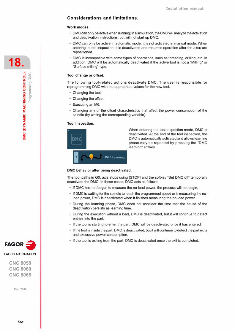
Installation manual.
CNC 8058CNC 8060CNC 8065
18.
DM
C (
DY
NA
MIC
MA
CH
ININ
G C
ON
TR
OL
).
Pro
gram
min
g D
MC
.
ꞏ722ꞏ
REF: 2102
Considerations and limitations.
Work modes.
• DMC can only be active when running; in a simulation, the CNC will analyze the activationand deactivation instructions, but will not start up DMC.
• DMC can only be active in automatic mode; it is not activated in manual mode. Whenentering in tool inspection, it is deactivated and resumes operation after the axes arerepositioned.
• DMC is incompatible with some types of operations, such as threading, drilling, etc. Inaddition, DMC will be automatically deactivated if the active tool is not a "Milling" or"Surface milling” type.
Tool change or offset.
The following tool-related actions deactivate DMC. The user is responsible forreprogramming DMC with the appropriate values for the new tool.
• Changing the tool.
• Changing the offset.
• Executing an M6.
• Changing any of the offset characteristics that affect the power consumption of thespindle (by writing the corresponding variable).
Tool inspection.
DMC behavior after being deactivated.
The tool paths in G0, axis stops using [STOP] and the softkey “Set DMC off” temporallydeactivate the DMC. In these cases, DMC acts as follows:
• If DMC has not begun to measure the no-load power, the process will not begin.
• If DMC is waiting for the spindle to reach the programmed speed or is measuring the no-load power, DMC is deactivated when it finishes measuring the no-load power.
• During the learning phase, DMC does not consider the time that the cause of thedeactivation persists as learning time.
• During the execution without a load, DMC is deactivated, but it will continue to detectentries into the part.
• If the tool is starting to enter the part, DMC will be deactivated once it has entered.
• If the tool is inside the part, DMC is deactivated, but it will continue to detect the part exitsand excessive power consumption.
• If the tool is exiting from the part, DMC is deactivated once the exit is completed.
When entering the tool inspection mode, DMC isdeactivated. At the end of the tool inspection, theDMC is automatically activated and allows learningphase may be repeated by pressing the "DMClearning" softkey.
Installation manual.
CNC 8058CNC 8060CNC 8065
DM
C (
DY
NA
MIC
MA
CH
ININ
G C
ON
TR
OL
).
18.
Pro
gram
min
g D
MC
.
ꞏ723ꞏ
REF: 2102
18.2.2 Deactivating the DMC.
The #DMCºOFF instruction deactivates DMC. The M02 or M30 (end of program) functionsand the reset also deactivate DMC. A spindle stop, function M5, deactivates DMC.
Programming.
This instruction must be programmed alone in the block. This instruction has no commands.
Programming format.
The programming format is:
#DMC OFF
18.2.3 Summary of the variables.
The following variables may be accessed from (PRG) the part-program and from theMDI/MDA mode, PLC and (INT) from an external application. For each variable, the tableindicates whether the access is reading (R) or writing (W). PLC access to the variables, forboth reading and writing, will be synchronous. Access to the variables from the part programreturns the value for the block preparation (it does not stop the preparation), except whenindicated otherwise.
#DMC OFF(The CNC deactivates DMC).
Variables. PRG PLC INT
(V.)[ch].MPG.MINDMCOVRMinimum DMC override of all channel axes.Units: Percentage.
R R R
(V.)[ch].MPG.MAXDMCOVRMaximum DMC override of all channel axes.Units: Percentage.
R R R
(V.)[ch].MPA.DMCSPDL.snSpindle with enabled power control.Units: -.
R R R
(V.)[ch].G.FROActive feedrate (feed override) percentage.Units: Percentage.
R(*) R R
(V.)[ch].G.PRGFROFeedrate (feed override) percentage defined by the program.Units: Percentage.
R/W R R
(V.)[ch].PLC.FROFeedrate (feed override) percentage defined by the PLC.Units: Percentage.
R(*) R/W R
(V.)[ch].G.CNCFROFeedrate percentage (feed override) selected on the switch of theoperator panel.Units: Percentage.
R(*) R R/W
(V.)[ch].G.NCUTTERSTool being prepared. Number of teeth.Units: Teeth.
R/W R R
(V.)[ch].TM.NCUTTERS[offset][Offset] of the active tool. Number of teeth.Units: Teeth.
R/W(*) R/W R/W
(V.)TM.NCUTTERST[tool][offset][Offset] of the [tool]. Number of teeth.Units: Teeth.
R/W(*) R/W R/W
(*) The CNC evaluates the variable during execution (it stops the block preparation).(**) The CNC evaluates the variable during execution, but it stops the block preparation.
Installation manual.
CNC 8058CNC 8060CNC 8065
18.
DM
C (
DY
NA
MIC
MA
CH
ININ
G C
ON
TR
OL
).
Pro
gram
min
g D
MC
.
ꞏ724ꞏ
REF: 2102
(V.)[ch].G.DMCPWRSPTarget power, defined as a percentage of the rated power of the spindle.Value programmed in the PWRSP command of the #DMC ONinstruction.Units: Percentage.
R R R
(V.)[ch].G.DMCOVRMINMinimum feedrate (feed override) percentage allowed for DMC. Valueprogrammed in the OVRMIN command of the #DMC ON instruction.Units: Percentage.
R R R
(V.)[ch].G.DMCOVRMAX Maximum feedrate (feed override) percentage allowed for DMC. Valueprogrammed in the OVRMAX command of the #DMC ON instruction.Units: Percentage.
R R R
(V.)[ch].G.DMCFZMINMinimum feedrate per tooth permitted during DMC. Value programmedin the FZMIN command of the #DMC ON instruction.Units: Millimeters/tooth or inches/tooth.
R R R
(V.)[ch].G.DMCFZMAXMaximum feedrate per tooth permitted during DMC. Value programmedin the FZMAX command of the #DMC ON instruction.Units: Millimeters/tooth or inches/tooth.
R R R
(V.)[ch].G.DMCONDMC status.Units: -.
R(*) R R
(V.)[ch].G.LEARNEDPWRSPTarget power calculated for DMC in the learning phase (percentage ofrated power).Units: Percentage.
R(*) R R
(V.)[ch].G.DMCACTPWRActive power on the spindle, measured by DMC (percentage of the ratedpower).Units: Percentage.
R(*) R R
(V.)[ch].G.DMCOVRFeedrate percentage (feed override) calculated by DMC.Units: Percentage.
R(*) R R
(V.)[ch].G.DMCFZFeedrate per tooth, calculated by DMC.Units: Millimeters/tooth or inches/tooth.
R(*) R R
(V.)[ch].G.DMCNOLOADPWRSpindle power without a load, measured by DMC.Units: Kilowatts.
R(*) R R
(V.)[ch].G.DMCSAVEDTIMETime saved by the DMC action.Units: Seconds.
R(*) R R
Variables. PRG PLC INT
(*) The CNC evaluates the variable during execution (it stops the block preparation).(**) The CNC evaluates the variable during execution, but it stops the block preparation.
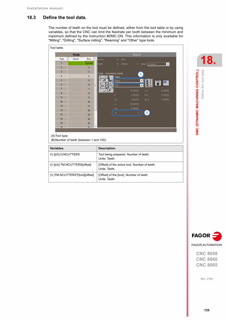
Installation manual.
CNC 8058CNC 8060CNC 8065
DM
C (
DY
NA
MIC
MA
CH
ININ
G C
ON
TR
OL
).
18.
De
fine
the
too
l dat
a.
ꞏ725ꞏ
REF: 2102
18.3 Define the tool data.
The number of teeth on the tool must be defined, either from the tool table or by usingvariables, so that the CNC can limit the feedrate per tooth between the minimum andmaximum defined by the instruction #DMC ON. This information is only available for"Milling", "Drilling", "Surface milling", "Reaming” and "Other” type tools.
Tool table.
(A)Tool type.(B)Number of teeth (between 1 and 100).
Variables. Description.
(V.)[ch].G.NCUTTERS Tool being prepared. Number of teeth.Units: Teeth.
(V.)[ch].TM.NCUTTERS[offset] [Offset] of the active tool. Number of teeth.Units: Teeth.
(V.)TM.NCUTTERST[tool][offset] [Offset] of the [tool]. Number of teeth.Units: Teeth.
B
A
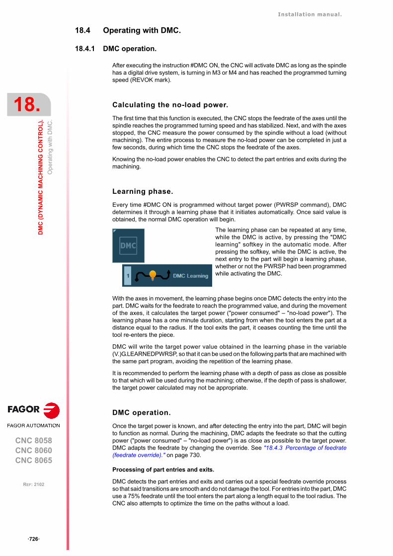
Installation manual.
CNC 8058CNC 8060CNC 8065
18.
DM
C (
DY
NA
MIC
MA
CH
ININ
G C
ON
TR
OL
).
Op
erat
ing
with
DM
C.
ꞏ726ꞏ
REF: 2102
18.4 Operating with DMC.
18.4.1 DMC operation.
After executing the instruction #DMC ON, the CNC will activate DMC as long as the spindlehas a digital drive system, is turning in M3 or M4 and has reached the programmed turningspeed (REVOK mark).
Calculating the no-load power.
The first time that this function is executed, the CNC stops the feedrate of the axes until thespindle reaches the programmed turning speed and has stabilized. Next, and with the axesstopped, the CNC measure the power consumed by the spindle without a load (withoutmachining). The entire process to measure the no-load power can be completed in just afew seconds, during which time the CNC stops the feedrate of the axes.
Knowing the no-load power enables the CNC to detect the part entries and exits during themachining.
Learning phase.
Every time #DMC ON is programmed without target power (PWRSP command), DMCdetermines it through a learning phase that it initiates automatically. Once said value isobtained, the normal DMC operation will begin.
With the axes in movement, the learning phase begins once DMC detects the entry into thepart. DMC waits for the feedrate to reach the programmed value, and during the movementof the axes, it calculates the target power ("power consumed" – "no-load power"). Thelearning phase has a one minute duration, starting from when the tool enters the part at adistance equal to the radius. If the tool exits the part, it ceases counting the time until thetool re-enters the piece.
DMC will write the target power value obtained in the learning phase in the variable(V.)G.LEARNEDPWRSP, so that it can be used on the following parts that are machined withthe same part program, avoiding the repetition of the learning phase.
It is recommended to perform the learning phase with a depth of pass as close as possibleto that which will be used during the machining; otherwise, if the depth of pass is shallower,the target power calculated may not be appropriate.
DMC operation.
Once the target power is known, and after detecting the entry into the part, DMC will beginto function as normal. During the machining, DMC adapts the feedrate so that the cuttingpower ("power consumed" – "no-load power") is as close as possible to the target power.DMC adapts the feedrate by changing the override. See "18.4.3 Percentage of feedrate(feedrate override)." on page 730.
Processing of part entries and exits.
DMC detects the part entries and exits and carries out a special feedrate override processso that said transitions are smooth and do not damage the tool. For entries into the part, DMCuse a 75% feedrate until the tool enters the part along a length equal to the tool radius. TheCNC also attempts to optimize the time on the paths without a load.
The learning phase can be repeated at any time,while the DMC is active, by pressing the "DMClearning" softkey in the automatic mode. Afterpressing the softkey, while the DMC is active, thenext entry to the part will begin a learning phase,whether or not the PWRSP had been programmedwhile activating the DMC.
Installation manual.
CNC 8058CNC 8060CNC 8065
DM
C (
DY
NA
MIC
MA
CH
ININ
G C
ON
TR
OL
).
18.
Op
erat
ing
with
DM
C.
ꞏ727ꞏ
REF: 2102
The target power and the part entries and exits.
To ensure the proper operation of the DMC, the target power (programmed or obtained bylearning) must be at least 20% of the no-load power. If the DMC detects this type of situation,it will display a 3103 warning.
• If the actual values of the no-load power and the target power during machining aresimilar, it is likely that the DMC cannot accurately distinguish the part inputs and outputsor it may detect false inputs or outputs. In this case, it is recommended to check the valueof the target power.
• Programming a higher target power, which is not actually going to be achieved, can meanthat the DMC never detects part inputs and performs all the machining as if the tool wereworking in a vacuum.
For both these reasons, if the actual target power is less than 20% of the no-load power, itis recommended to deactivate the DMC function during this machining process.
Monitoring of consumed power.
During operation, DMC continuously monitors the power consumed by the spindle to detectany problems with the tool or in the machining.
Collision detection.
If the instantaneous power exceeds the target power in a predefined range, the CNCconsiders that a collision has occurred. In this case, the CNC displays warning 3101, stopsthe feedrate of the axes, while keeping the spindle turning (this behavior is the equivalentof having pressed the [STOP] button). After verifying the cause of the warning, the user cancontinue the machining (pressing [START]), enter in tool inspection or terminate theexecution to replace the damaged tool.
Worn tool. Excessive continuous power consumption.
If DMC detects excessive power consumption during a certain amount of time, it understandsthat the tool is worn or deteriorated and displays the warning 3100, without stopping theexecution. The user decides if it is necessary to stop the execution.
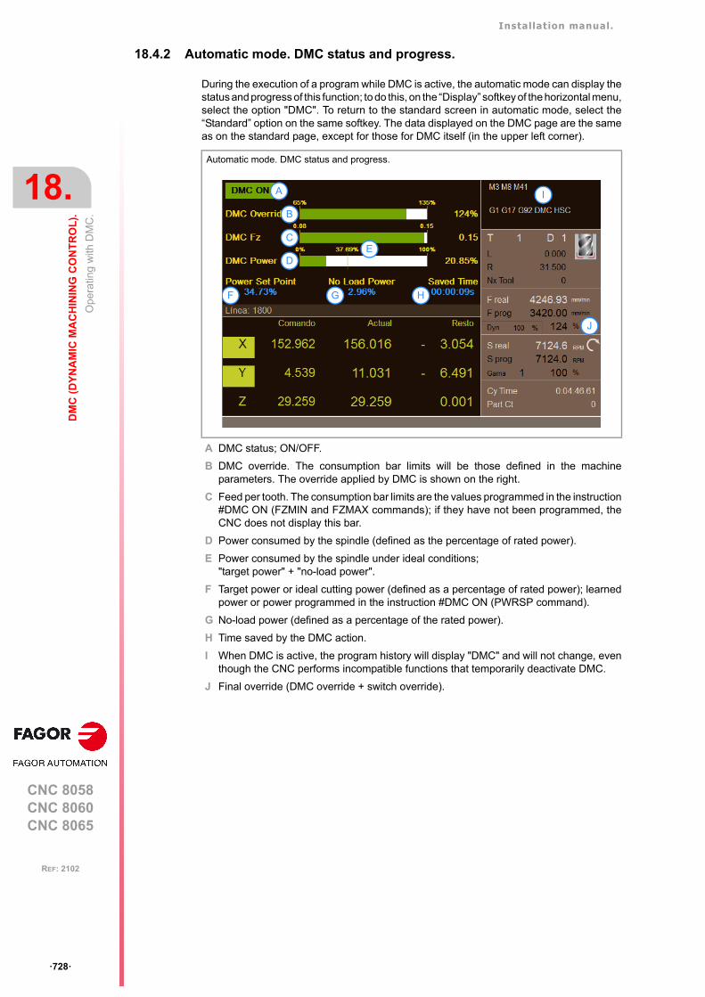
Installation manual.
CNC 8058CNC 8060CNC 8065
18.
DM
C (
DY
NA
MIC
MA
CH
ININ
G C
ON
TR
OL
).
Op
erat
ing
with
DM
C.
ꞏ728ꞏ
REF: 2102
18.4.2 Automatic mode. DMC status and progress.
During the execution of a program while DMC is active, the automatic mode can display thestatus and progress of this function; to do this, on the “Display” softkey of the horizontal menu,select the option "DMC". To return to the standard screen in automatic mode, select the“Standard” option on the same softkey. The data displayed on the DMC page are the sameas on the standard page, except for those for DMC itself (in the upper left corner).
A DMC status; ON/OFF.
B DMC override. The consumption bar limits will be those defined in the machineparameters. The override applied by DMC is shown on the right.
C Feed per tooth. The consumption bar limits are the values programmed in the instruction#DMC ON (FZMIN and FZMAX commands); if they have not been programmed, theCNC does not display this bar.
D Power consumed by the spindle (defined as the percentage of rated power).
E Power consumed by the spindle under ideal conditions;"target power" + "no-load power".
F Target power or ideal cutting power (defined as a percentage of rated power); learnedpower or power programmed in the instruction #DMC ON (PWRSP command).
G No-load power (defined as a percentage of the rated power).
H Time saved by the DMC action.
I When DMC is active, the program history will display "DMC" and will not change, eventhough the CNC performs incompatible functions that temporarily deactivate DMC.
J Final override (DMC override + switch override).
Automatic mode. DMC status and progress.
A
B
C D E
F
F G H
B
C
D
A
E
I
J
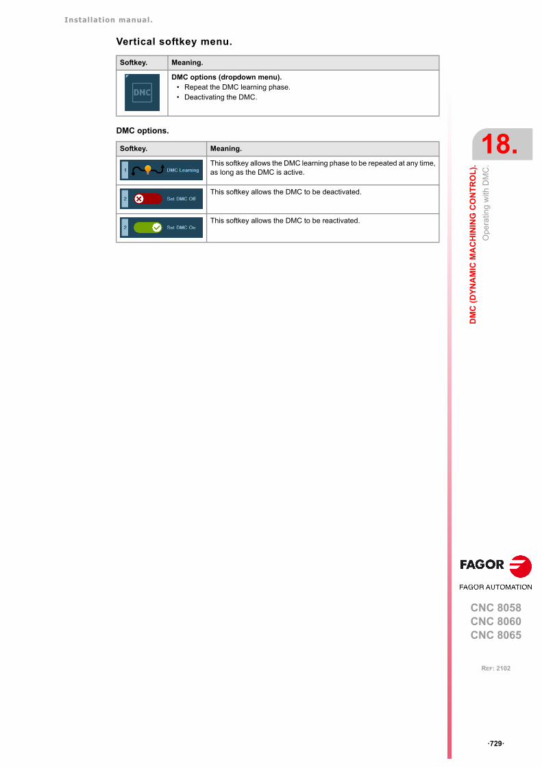
Installation manual.
CNC 8058CNC 8060CNC 8065
DM
C (
DY
NA
MIC
MA
CH
ININ
G C
ON
TR
OL
).
18.
Op
erat
ing
with
DM
C.
ꞏ729ꞏ
REF: 2102
Vertical softkey menu.
DMC options.
Softkey. Meaning.
DMC options (dropdown menu).• Repeat the DMC learning phase.• Deactivating the DMC.
Softkey. Meaning.
This softkey allows the DMC learning phase to be repeated at any time,as long as the DMC is active.
This softkey allows the DMC to be deactivated.
This softkey allows the DMC to be reactivated.

Installation manual.
CNC 8058CNC 8060CNC 8065
18.
DM
C (
DY
NA
MIC
MA
CH
ININ
G C
ON
TR
OL
).
Op
erat
ing
with
DM
C.
ꞏ730ꞏ
REF: 2102
18.4.3 Percentage of feedrate (feedrate override).
The feedrate (feed override) percentage can be set, from highest to lowest priority, by theprogram (variable V.G.PRGFRO), by the PLC (variable V.PLC.FRO) or from the switch onthe operator panel. The value set by the program has the highest priority, while the valuesset from the switch on the operator panel have the lowest priority.
• The percentage set by the program or by the PLC has a higher priority than that set byDMC; both percentages inhibit DMC. To cancel the feedrate percentage set by programor PLC, define its variables with a value of 0 (zero). See "18.4.3 Percentage of feedrate(feedrate override)." on page 730.
• The percentage set by DMC affects the percentage set from the switch.
• DMC can change its override within the limits set by the instruction #DMC ON(commands OVRMIN and OVRMAX); if they are not defined, the limits will be set by themachine parameters MINDMCOVR and MAXDMCOVR. The final override(overrideDMC + overrideJOG) may exceed these limits.
• The CNC always abides by the maximum limit set in the machine parameter MAXOVR.
• If the user selects an override with the switch on the operator panel that is lower thanMINDMCOVR, the CNC inhibits DMC (but does not deactivate it); when the override onceagain exceeds MINDMCOVR, DMC will once again operate as normal.
• The CNC abides by the minimum and maximum feedrate set by the tool in the instruction#DMC ON (commands FZMIN and FZMAX).
Override % OverrideDMC % OverrideJOG % 100
-----------------------------------------------------------------------------------------------------=
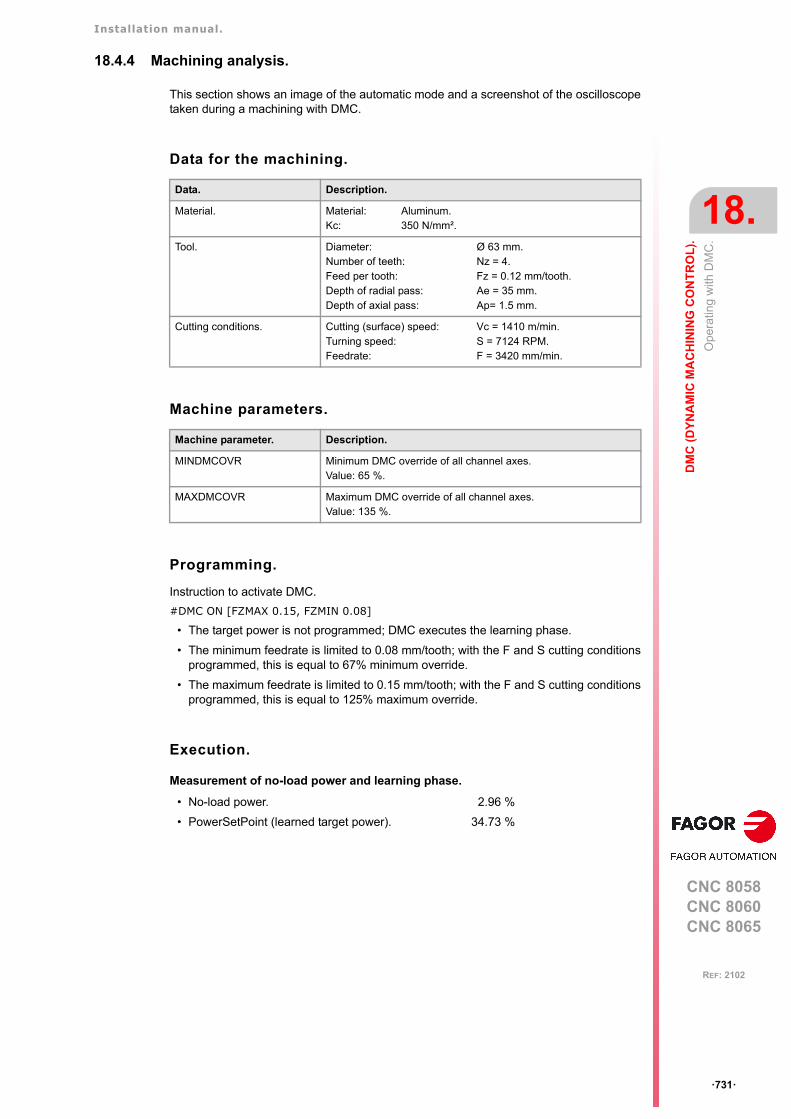
Installation manual.
CNC 8058CNC 8060CNC 8065
DM
C (
DY
NA
MIC
MA
CH
ININ
G C
ON
TR
OL
).
18.
Op
erat
ing
with
DM
C.
ꞏ731ꞏ
REF: 2102
18.4.4 Machining analysis.
This section shows an image of the automatic mode and a screenshot of the oscilloscopetaken during a machining with DMC.
Data for the machining.
Machine parameters.
Programming.
Instruction to activate DMC.
#DMC ON [FZMAX 0.15, FZMIN 0.08]
• The target power is not programmed; DMC executes the learning phase.
• The minimum feedrate is limited to 0.08 mm/tooth; with the F and S cutting conditionsprogrammed, this is equal to 67% minimum override.
• The maximum feedrate is limited to 0.15 mm/tooth; with the F and S cutting conditionsprogrammed, this is equal to 125% maximum override.
Execution.
Measurement of no-load power and learning phase.
Data. Description.
Material. Material: Aluminum.Kc: 350 N/mm².
Tool. Diameter: Ø 63 mm.Number of teeth: Nz = 4.Feed per tooth: Fz = 0.12 mm/tooth.Depth of radial pass: Ae = 35 mm.Depth of axial pass: Ap= 1.5 mm.
Cutting conditions. Cutting (surface) speed: Vc = 1410 m/min.Turning speed: S = 7124 RPM.Feedrate: F = 3420 mm/min.
Machine parameter. Description.
MINDMCOVR Minimum DMC override of all channel axes.Value: 65 %.
MAXDMCOVR Maximum DMC override of all channel axes.Value: 135 %.
• No-load power. 2.96 %
• PowerSetPoint (learned target power). 34.73 %
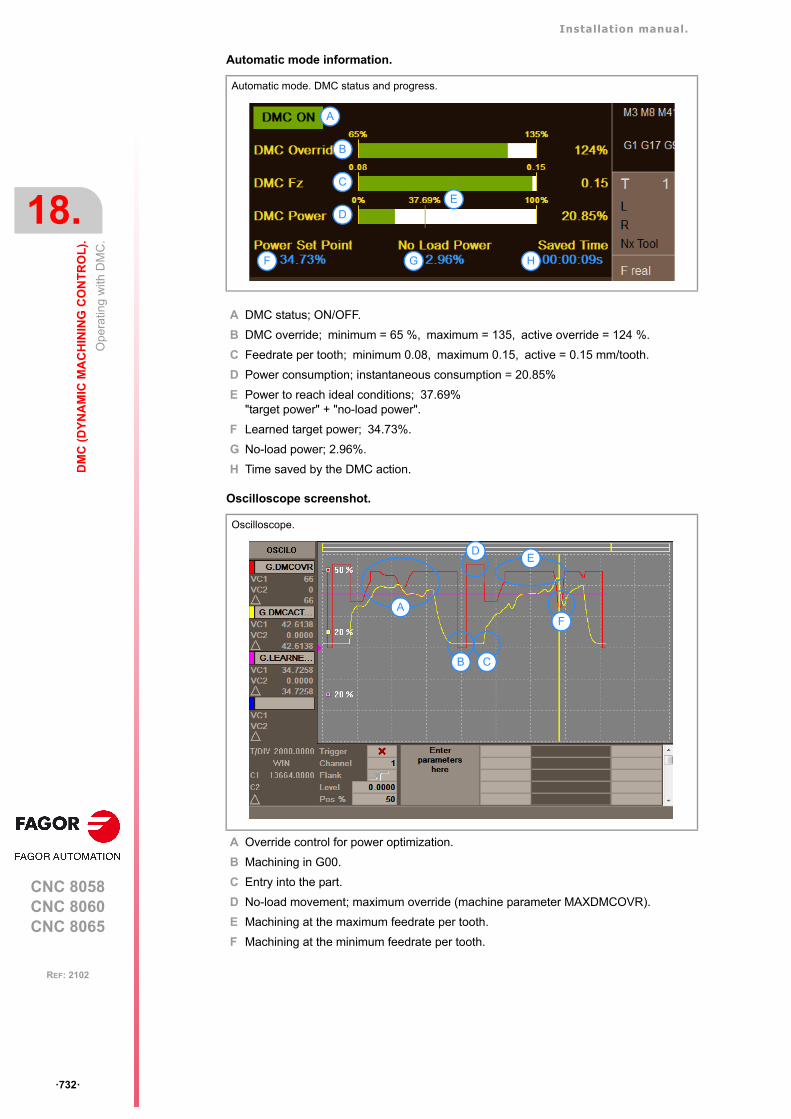
Installation manual.
CNC 8058CNC 8060CNC 8065
18.
DM
C (
DY
NA
MIC
MA
CH
ININ
G C
ON
TR
OL
).
Op
erat
ing
with
DM
C.
ꞏ732ꞏ
REF: 2102
Automatic mode information.
A DMC status; ON/OFF.
B DMC override; minimum = 65 %, maximum = 135, active override = 124 %.
C Feedrate per tooth; minimum 0.08, maximum 0.15, active = 0.15 mm/tooth.
D Power consumption; instantaneous consumption = 20.85%
E Power to reach ideal conditions; 37.69%"target power" + "no-load power".
F Learned target power; 34.73%.
G No-load power; 2.96%.
H Time saved by the DMC action.
Oscilloscope screenshot.
A Override control for power optimization.
B Machining in G00.
C Entry into the part.
D No-load movement; maximum override (machine parameter MAXDMCOVR).
E Machining at the maximum feedrate per tooth.
F Machining at the minimum feedrate per tooth.
Automatic mode. DMC status and progress.
Oscilloscope.
F
E
G H
B
C
D
A
A
B C
E
F
D
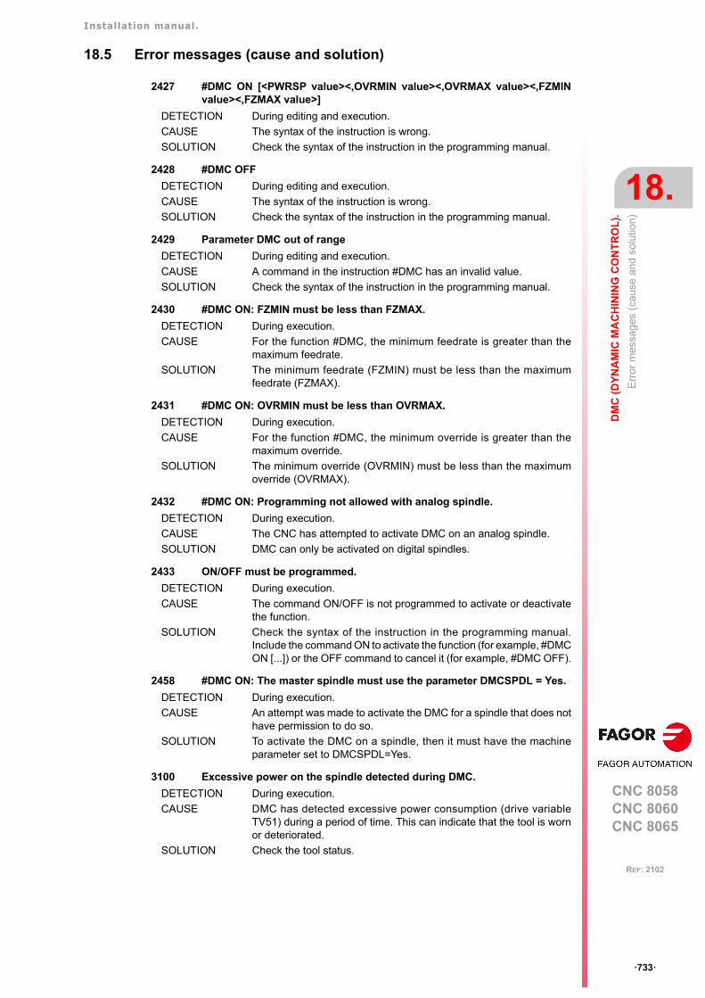
Installation manual.
CNC 8058CNC 8060CNC 8065
DM
C (
DY
NA
MIC
MA
CH
ININ
G C
ON
TR
OL
).
18.
Err
or m
essa
ges
(cau
se a
nd
solu
tion)
ꞏ733ꞏ
REF: 2102
18.5 Error messages (cause and solution)
2427 #DMC ON [<PWRSP value><,OVRMIN value><,OVRMAX value><,FZMINvalue><,FZMAX value>]
DETECTION During editing and execution.
CAUSE The syntax of the instruction is wrong.
SOLUTION Check the syntax of the instruction in the programming manual.
2428 #DMC OFF
DETECTION During editing and execution.
CAUSE The syntax of the instruction is wrong.
SOLUTION Check the syntax of the instruction in the programming manual.
2429 Parameter DMC out of range
DETECTION During editing and execution.
CAUSE A command in the instruction #DMC has an invalid value.
SOLUTION Check the syntax of the instruction in the programming manual.
2430 #DMC ON: FZMIN must be less than FZMAX.
DETECTION During execution.
CAUSE For the function #DMC, the minimum feedrate is greater than themaximum feedrate.
SOLUTION The minimum feedrate (FZMIN) must be less than the maximumfeedrate (FZMAX).
2431 #DMC ON: OVRMIN must be less than OVRMAX.
DETECTION During execution.
CAUSE For the function #DMC, the minimum override is greater than themaximum override.
SOLUTION The minimum override (OVRMIN) must be less than the maximumoverride (OVRMAX).
2432 #DMC ON: Programming not allowed with analog spindle.
DETECTION During execution.
CAUSE The CNC has attempted to activate DMC on an analog spindle.
SOLUTION DMC can only be activated on digital spindles.
2433 ON/OFF must be programmed.
DETECTION During execution.
CAUSE The command ON/OFF is not programmed to activate or deactivatethe function.
SOLUTION Check the syntax of the instruction in the programming manual.Include the command ON to activate the function (for example, #DMCON [...]) or the OFF command to cancel it (for example, #DMC OFF).
2458 #DMC ON: The master spindle must use the parameter DMCSPDL = Yes.
DETECTION During execution.
CAUSE An attempt was made to activate the DMC for a spindle that does nothave permission to do so.
SOLUTION To activate the DMC on a spindle, then it must have the machineparameter set to DMCSPDL=Yes.
3100 Excessive power on the spindle detected during DMC.
DETECTION During execution.
CAUSE DMC has detected excessive power consumption (drive variableTV51) during a period of time. This can indicate that the tool is wornor deteriorated.
SOLUTION Check the tool status.
Installation manual.
CNC 8058CNC 8060CNC 8065
18.
DM
C (
DY
NA
MIC
MA
CH
ININ
G C
ON
TR
OL
).
Err
or m
essa
ges
(cau
se a
nd
solu
tion)
ꞏ734ꞏ
REF: 2102
3101 Excessive power on the spindle detected during DMC. Press START tocontinue.
DETECTION During execution.
CAUSE DMC has detected that the instantaneous power (drive variable TV51)has exceeded the target power in a preset range. This can indicate thatthe tool has collided with the part, and so the CNC stops the axes,keeping the spindle turning.
SOLUTION Check the status of the tool and the machining. The CNC allows theexecution to be resumed by pressing [START], to enter in the toolinspection mode or to finish the execution.
3103 Target power insufficient for the proper operation using DMC.
DETECTION During execution.
CAUSE The values of the no-load power and the target power duringmachining are similar. It is possible that the DMC cannot accuratelydistinguish the part inputs and outputs.
SOLUTION The target power (programmed or obtained by learning) must be atleast 20% of the no-load power. In this case, it is recommended todeactivate the DMC function for this machining process. Programminga higher target power, which is not actually going to be achieved, canmean that the DMC never detects part inputs and performs all themachining as if the tool were working in a vacuum.
CNC 8058CNC 8060CNC 8065
19
ꞏ735ꞏ
REF: 2102
19.HD GRAPHICS.
19.1 Configure the graphics for the rotary axes cycles (ꞏMꞏ model).
In the F3D graphics, the machine configuration (xca file) must be loaded that correspondsto the defined axis configuration. The xca files may be loaded either from the softkey menuor from the program using the instruction #DEFGRAPH.
Defining the machine.
The conf igura t ion f i l es fo r mach ines w i th an indexer a re In thefolder../Fagor/Grafdata/Machines/Mill. All the configurations are designed for a channel;besides the rotary axis of the table (the indexer), they have two other rotary axes on thespindle.
The default configuration of the axes in the xca files is as follows.
If the default configuration and the real configuration of the machine axes are different, asecond file must be edited (with the same name and def extension), with the correctassociation between the two CNC axes and those defined in the xca file. In the folder of eachmachine is a sample def file. If they are going to be copied to another folder, both files mustbe copied (xca and def).
Defining the part.
Each one of these xca files can define and use four parts on the table. To use these parts,the xca file must be modified to add the center of the indexer as an offset with regard to themachine zero. To modify these files, copy both files (xca and def) in the folder ../Mtb/Grafdatao ../Users/Session/Grafdata and change it indicated below.
File. Machine type.
Mill A@table B,[email protected] Machine with the indexer in X.
Mill B@table A,[email protected] Machine with the indexer in Y.
Mill C@table A,[email protected] Machine with the indexer in Z.
Axis 1: X
Axis 2: Y
Axis 3: Z
Axis 4: Rotary axis of the indexer.
Axis 5: First rotary axis of the spindle.
Axis 6: Second rotary axis of the spindle.
For cylindrical parts, their axis of rotation must be the same as for the indexer.i
Example.For a rotary axis, A is the file "Mill A@table B, [email protected]”, in which the axis offset is defined as{translation = "0 0 0"}.<Connection plug="stdPlug@SYS-Tool1" socket="stdSocket@S1" rotation="0 1 0 -90"/><!-- Position of the center of A axis referred to zero machine --><Connection plug="stdPlug@A1" socket="stdSocket@home" translation="0 0 0"/>
The default value "0 0 0” must be replaced with the correct values, for example "-300 -100 -250".<Connection plug="stdPlug@A1" socket="stdSocket@home" translation="-300 -100 -250"/>
Installation manual.
CNC 8058CNC 8060CNC 8065
19.
HD
GR
AP
HIC
S.
Con
figur
e th
e gr
aphi
cs fo
r th
e ro
tary
axe
s cy
cles
(ꞏM
ꞏ m
odel
).
ꞏ736ꞏ
REF: 2102
Positioning the tool.
The graphics position the tool according to the front or longitudinal axis defined in themachine parameters of the linear axes (FACEAXIS and LONGAXIS), and according to theoption selected in the tool table.
If the parameters have not been set for the axes, the default position of the tool in the differentmachine configurations will be as follows:
If the machine parameters LONGAXIS or FACEAXIS change, the CNC must be restarted to that thegraphics take on the new configuration.i
File. Tool default position.
Mill A@table B,[email protected] FACEAXIS = Z LONGAXIS =X
Mill B@table A,[email protected] FACEAXIS = Z LONGAXIS =X
Mill C@table A,[email protected] FACEAXIS = Z LONGAXIS =X

CNC 8058CNC 8060CNC 8065
20
ꞏ737ꞏ
REF: 2102
20.ETHERCAT BUS.
The Q7-A platform has an EtherCAT bus for communication with remote I/O modules (ownor third party). The CNC is the master element of the bus, and the remaining resources willbe shared between nodes (up to 32). The bus master interprets the ENI (EtherCAT NetworkInformation) files generated by a configurator and initializes the slaves connected to the bus.
This bus is compatible with the CAN bus, responsible for the management of keyboards andoperator panels. The CNC may have remote I/Os on both buses simultaneously(CAN/EtherCAT), provided that both buses are not using the same resources.
Resources available in the bus.
Bus configuration process.
1 Use the "KPA EtherCAT Studio" configurator to define the bus topology and generate theENI file with the information from the EtherCAT devices connected to the CNC.
2 Use the "Fagor EtherCAT Mapper" program to map the EtherCAT resources to PLCresources (inputs, outputs and records) and generate the file with the mappinginformation.
3 Copy the xml files created by both programs to folder ../Mtb/Data of the CNC.
• Copy the file created by "KPA EtherCAT Studio" as fagor_ethercatConfFile.xml.
• Copy the file created by "Fagor EtherCAT Mapper" as resourceRouterConf.xml.
Cycle time.
The looptime of the bus is defined by the parameter LOOPTIME.
Resources of the bus. Total in the bus.
Digital inputs. 1024
Digital outputs. 1024
General purpose analog inputs. 40
General purpose analog outputs. 40
Analog inputs for Pt100 temperature sensors. 10
Installation manual.
CNC 8058CNC 8060CNC 8065
20.
ET
HE
RC
AT
BU
S.
Con
figur
e th
e bu
s to
polo
gy.
ꞏ738ꞏ
REF: 2102
20.1 Configure the bus topology.
The topology configurator generates the ENI file containing the information of the EtherCATdevices connected to the CNC. This file must be copied to the folder ../Mtb/Data of the CNCwith the name "fagor_ethercatConfFile.xml". This file also uses the "Fagor EtherCATMapper" program for determining the resources available in the bus.
Fagor supplies the "KPA EtherCAT Studio" configurator under license (from Koening-paGmbH), which can function both in online and offline modes; in both cases the license isrequired.
• In online mode, the configurator is connected to the EtherCAT bus and scans it in orderto detect the modules present in the bus.
• In offline mode, the configurator does not access the EtherCAT bus. The user shouldmanually build the bus topology from the modules stored in the program library.
Fagor delivers a pendrive with the installer and the configurator license "KPA EtherCATStudio". This license is linked to the pendrive; the user will be able to install the configuratoron various computers, but will need to connect the pendrive to use it.
20.1.1 Install the program.
Install the configurator in a PC with Windows 7 32/64 bits or Windows 10 64 bits. Insert thependrive into the USB port and double click on the file "SetupKPA_xx_xx.exe" (where xx_xxindicates the version) to begin the installation. Follow the instructions on the screen tocomplete the process. Once installed, the following icons will appear on the desktop.
Help.
For detailed information on the program operation, refer to the help for the program.
Icon. Function.
Studio.EtherCAT Configurator.
Master (Win64).Access to the EtherCAT modules through the Ethernet network.
KPA Licensing utilities.Access to the user license.
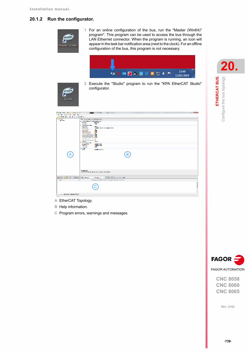
Installation manual.
CNC 8058CNC 8060CNC 8065
ET
HE
RC
AT
BU
S.
20.
Con
figur
e th
e bu
s to
polo
gy.
ꞏ739ꞏ
REF: 2102
20.1.2 Run the configurator.
1 For an online configuration of the bus, run the "Master (Win64)"program". This program can be used to access the bus through theLAN Ethernet connector. When the program is running, an icon willappear in the task bar notification area (next to the clock). For an offlineconfiguration of the bus, this program is not necessary.
2 Execute the "Studio" program to run the "KPA EtherCAT Studio"configurator.
A EtherCAT Topology.
B Help information.
C Program errors, warnings and messages.
A B
C
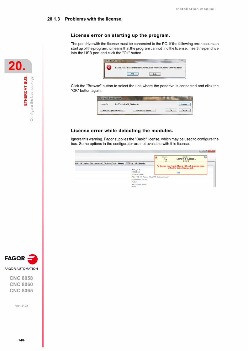
Installation manual.
CNC 8058CNC 8060CNC 8065
20.
ET
HE
RC
AT
BU
S.
Con
figur
e th
e bu
s to
polo
gy.
ꞏ740ꞏ
REF: 2102
20.1.3 Problems with the license.
License error on starting up the program.
The pendrive with the license must be connected to the PC. If the following error occurs onstart up of the program, it means that the program cannot find the license. Insert the pendriveinto the USB port and click the "Ok" button.
Click the "Browse" button to select the unit where the pendrive is connected and click the"OK" button again.
License error while detecting the modules.
Ignore this warning. Fagor supplies the "Basic" license, which may be used to configure thebus. Some options in the configurator are not available with this license.
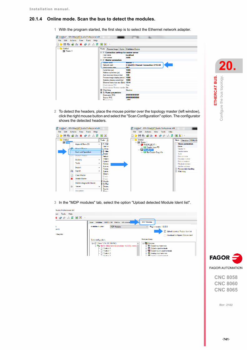
Installation manual.
CNC 8058CNC 8060CNC 8065
ET
HE
RC
AT
BU
S.
20.
Con
figur
e th
e bu
s to
polo
gy.
ꞏ741ꞏ
REF: 2102
20.1.4 Online mode. Scan the bus to detect the modules.
1 With the program started, the first step is to select the Ethernet network adapter.
2 To detect the headers, place the mouse pointer over the topology master (left window),click the right mouse button and select the "Scan Configuration" option. The configuratorshows the detected headers.
3 In the "MDP modules" tab, select the option "Upload detected Module Ident list".
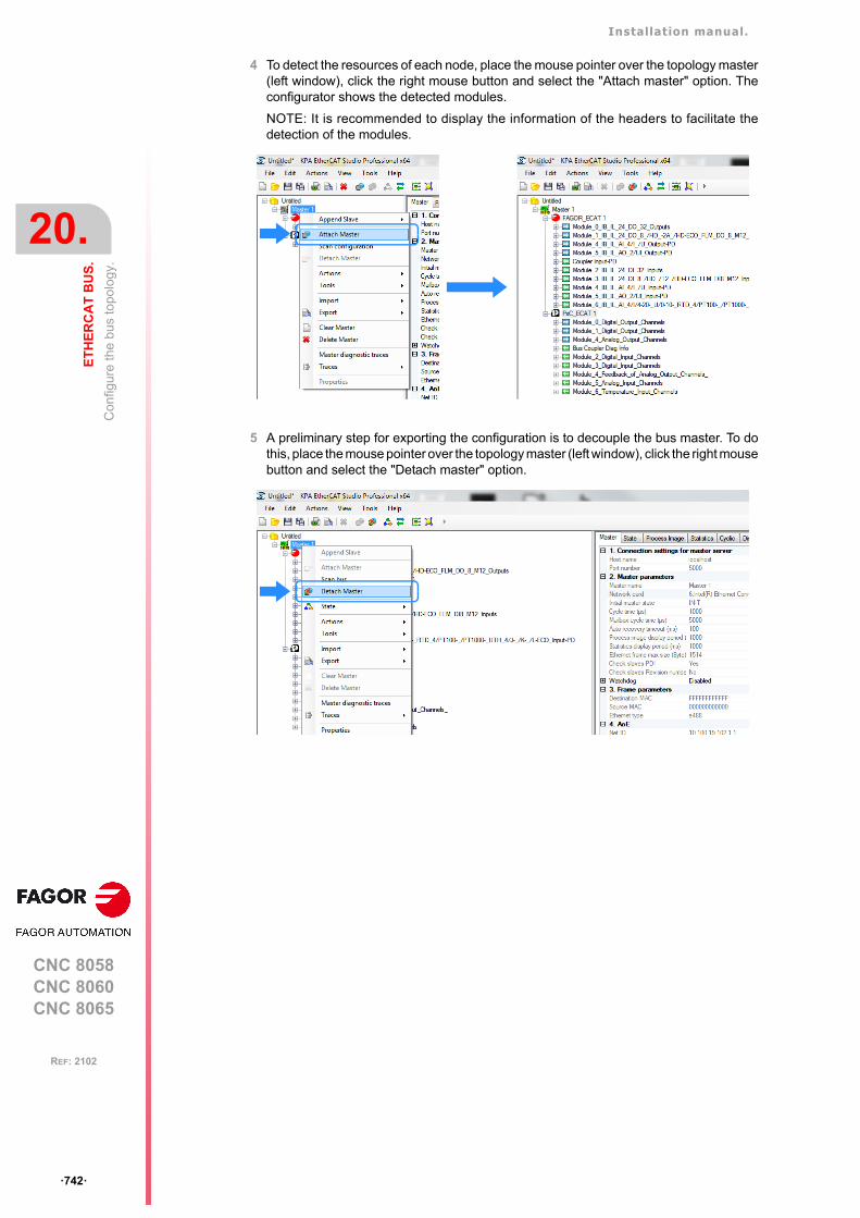
Installation manual.
CNC 8058CNC 8060CNC 8065
20.
ET
HE
RC
AT
BU
S.
Con
figur
e th
e bu
s to
polo
gy.
ꞏ742ꞏ
REF: 2102
4 To detect the resources of each node, place the mouse pointer over the topology master(left window), click the right mouse button and select the "Attach master" option. Theconfigurator shows the detected modules.
NOTE: It is recommended to display the information of the headers to facilitate thedetection of the modules.
5 A preliminary step for exporting the configuration is to decouple the bus master. To dothis, place the mouse pointer over the topology master (left window), click the right mousebutton and select the "Detach master" option.
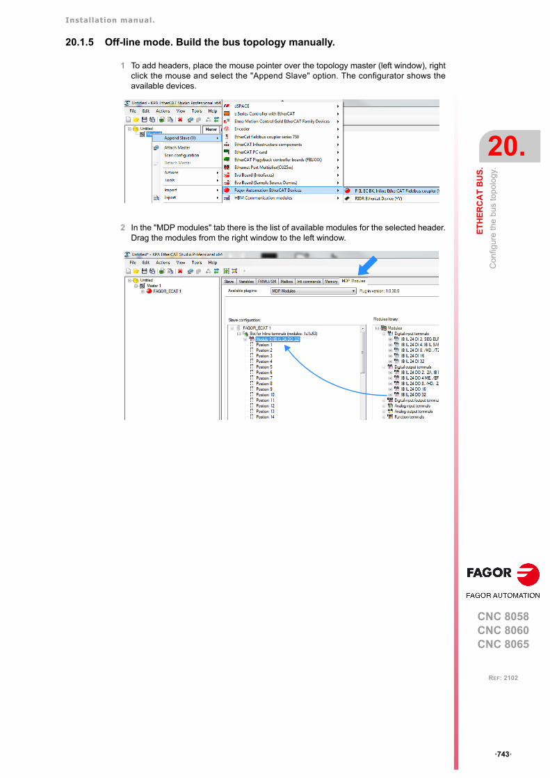
Installation manual.
CNC 8058CNC 8060CNC 8065
ET
HE
RC
AT
BU
S.
20.
Con
figur
e th
e bu
s to
polo
gy.
ꞏ743ꞏ
REF: 2102
20.1.5 Off-line mode. Build the bus topology manually.
1 To add headers, place the mouse pointer over the topology master (left window), rightclick the mouse and select the "Append Slave" option. The configurator shows theavailable devices.
2 In the "MDP modules" tab there is the list of available modules for the selected header.Drag the modules from the right window to the left window.
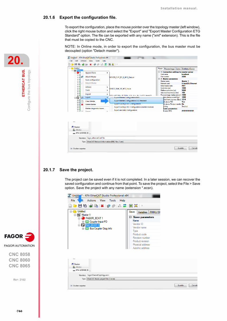
Installation manual.
CNC 8058CNC 8060CNC 8065
20.
ET
HE
RC
AT
BU
S.
Con
figur
e th
e bu
s to
polo
gy.
ꞏ744ꞏ
REF: 2102
20.1.6 Export the configuration file.
To export the configuration, place the mouse pointer over the topology master (left window),click the right mouse button and select the "Export" and "Export Master Configuration ETGStandard" option. The file can be exported with any name ("xml" extension). This is the filethat must be copied to the CNC.
NOTE: In Online mode, in order to export the configuration, the bus master must bedecoupled (option "Detach master").
20.1.7 Save the project.
The project can be saved even if it is not completed. In a later session, we can recover thesaved configuration and continue from that point. To save the project, select the File > Saveoption. Save the project with any name (extension *.ecsn).
Installation manual.
CNC 8058CNC 8060CNC 8065
ET
HE
RC
AT
BU
S.
20.
Con
figur
e th
e bu
s to
polo
gy.
ꞏ745ꞏ
REF: 2102
20.1.8 Copy the configuration file to the CNC.
To copy the configuration file to the CNC (xml file), rename it as "fagor_ethercatConfFile.xml"and copy it to the folder ../Mtb/Data.
Installation manual.
CNC 8058CNC 8060CNC 8065
20.
ET
HE
RC
AT
BU
S.
Map
the
Eth
erC
AT
res
ourc
es to
the
PLC
res
ourc
es.
ꞏ746ꞏ
REF: 2102
20.2 Map the EtherCAT resources to the PLC resources.
The mapping consists of allocating among the available resources in the bus and the PLCresources (inputs, outputs or registers). The digital inputs and outputs are mapped toresources of the same type in the PLC. Analog inputs and outputs are mapped to PLCregisters.
Fagor has the "Fagor EtherCAT Mapper" program to carry out the mapping. From the ENIfile generated by the EtherCAT configurator, this program makes a mapping proposal. Theuser can accept this proposal or perform the necessary modifications, all in a way that helpsensure there are no duplicated resources. Once the mapping is completed, this softwarecreates a file with the description of the routing. This file must be copied to the folder../Mtb/Data of the CNC with the name "resourceRouterConf.xml".
Analog input and output units, and the inputs for PT100 sensors.
These modules send the values to the PLC in the following units.
20.2.1 Install the program.
Although "Fagor EtherCAT Mapper" can be run in the same CNC, it is recommended to installit in an external PC, along with the configurator. Use a PC with Windows 7 32/64 bits orWindows 10 64 bits.
Run the "Setup fagorethercatmapper-x.x.x.exe" file (where x.x.x indicates the version) tobegin the installation. Follow the instructions on the screen to complete the process. Onceinstalled, the following icon will appear on the desktop.
EtherCAT. PLC
Module (0) IB IL 24 DI 8 - HD-ECO I1…I8
Module (1) IB IL 24 DI 32 - HD-PAC I9…I40
Module (2) IB IL 24 DO 8 - HD-ECO O1…O8
Module (3) IB IL 24 DO 32 - HD-PAC O9…O40
Module (4) IB IL AO 2 - UI-PAC R1…R2
Module (5) IB IL AI 4 - U-PAC R3...R6
Resources. Units.
Live analog inputs (V). Tenths of a millivolt.
"Analog inputs in current (mA). Microamperes.
Live analog outputs (V). Tenths of a millivolt.
Analog outputs in current (mA). Microamperes.
Inputs for the temperature sensors Pt100. Tenths of a degree.
Icon. Function.
EtherCAT mapper of resources.
Installation manual.
CNC 8058CNC 8060CNC 8065
ET
HE
RC
AT
BU
S.
20.
Map
the
Eth
erC
AT
res
ourc
es to
the
PLC
res
ourc
es.
ꞏ747ꞏ
REF: 2102
20.2.2 Interface description.
Icon bar and ENI file name loaded.
A. Icon bar and ENI file name loaded.B. Default status bar for mapping of resources.C. Validation of the "Overlapped" option.D. Bus topology (tree view).E. Bus topology (block diagram).
Block. Color and type of resource.
New project.
Generate the project.
Export routed file.
Open a Fagor, ENI or resources file.
View slaves.
Settings.
Help.
Validation of the "Overlapped" option.
A
BC
E
D
Installation manual.
CNC 8058CNC 8060CNC 8065
20.
ET
HE
RC
AT
BU
S.
Map
the
Eth
erC
AT
res
ourc
es to
the
PLC
res
ourc
es.
ꞏ748ꞏ
REF: 2102
Default status bar for mapping of resources.
This bar shows which configuration is assumed by the resources when the ENI is loadedfor the first time (default configuration). Then the allocation of resources can be customizedmanually.
• The "Digital Input" and "Digital Output" files configure the mapping of the digital inputsand outputs.
• The "Register Input" and "Register Output" files map those resources of the EtherCATbus which are not assumed to be digital inputs/outputs to PLC registers. For the Fagormodules, these will be the analog inputs/outputs and the inputs for the temperaturesensors. For third-party modules, it will be necessary to refer to the manufacturer'smanual so that they can be used correctly from the PLC.
• The "Overlapped" file defines whether the layout of resources is permitted in differentmodules. See "20.2.5 Overlapped." on page 752.
Bus topology (tree view).
The first level consists of the bus slaves. By clicking on a slave, the program shows themodules connected to the bus. To show all the slaves, click on the "View Slaves" icon.
The second level consists of the modules that belong to the slave. By clicking on a module,the program shows its list of resources.
Starts. Number of the first input, output or register of the bus.
Offset. Numbering offset between headers. If the offset is zero, the numbering willbe consecutive between headers.
Visible. Shows the numbering on the graphics.

Installation manual.
CNC 8058CNC 8060CNC 8065
ET
HE
RC
AT
BU
S.
20.
Map
the
Eth
erC
AT
res
ourc
es to
the
PLC
res
ourc
es.
ꞏ749ꞏ
REF: 2102
Bus topology (block diagram).
Help.
For detailed information on the operation of the program, refer to the help.
20.2.3 Open a configuration (default mapping).
Load the ENI file created with the configurator. The program allocates the resources asdefined in the status bar.
Block. Color and type of resource.
Blue. Digital inputs.
Purple. Digital outputs.
Red. Mapping of EtherCAT resources to PLC registers.
Gray. Mapping of PLC registers to EtherCAT resources.
Green color. Records of the Fagor analog inputs.
Yellow. Registers of the Fagor analog outputs.
Installation manual.
CNC 8058CNC 8060CNC 8065
20.
ET
HE
RC
AT
BU
S.
Map
the
Eth
erC
AT
res
ourc
es to
the
PLC
res
ourc
es.
ꞏ750ꞏ
REF: 2102
20.2.4 Change the numbering of the resources.
Change the numbering of the resources of the whole bus.
Change the resources on the top navigation bar and the program updates the resources ofthe whole bus. In the following configuration the numbering of the digital inputs and outputshas been changed as follows.
Change the numbering of the resources of a node.
In the block diagram, click on the name of the header and set the start number of theresources of the node.
• Digital inputs. First = 10 Offset = 100
• Digital outputs. First = 21 Offset = 50
Offset = 100
Offset = 100
Click!
Installation manual.
CNC 8058CNC 8060CNC 8065
ET
HE
RC
AT
BU
S.
20.
Map
the
Eth
erC
AT
res
ourc
es to
the
PLC
res
ourc
es.
ꞏ751ꞏ
REF: 2102
Change the numbering of the resources of a module.
In the block diagram, click on a module and set the start number of its resources; theremaining resources are numbered consecutively.
Installation manual.
CNC 8058CNC 8060CNC 8065
20.
ET
HE
RC
AT
BU
S.
Map
the
Eth
erC
AT
res
ourc
es to
the
PLC
res
ourc
es.
ꞏ752ꞏ
REF: 2102
20.2.5 Overlapped.
The "Overlapped" file defines whether the layout of resources is permitted in differentmodules. Every time this option is changed, it should be validated with the "Load filter" iconlocated on the upper right.
Overlapped = Right.
When assigning a resource a number that already exists in the bus, the program rearrangesthe following resources (top numbering). Resources with previous numbering (bottomnumbering) are not changed.
Starts=81
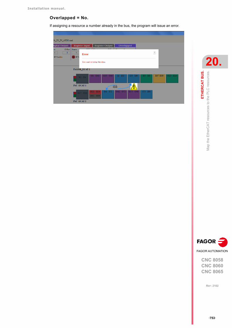
Installation manual.
CNC 8058CNC 8060CNC 8065
ET
HE
RC
AT
BU
S.
20.
Map
the
Eth
erC
AT
res
ourc
es to
the
PLC
res
ourc
es.
ꞏ753ꞏ
REF: 2102
Overlapped = No.
If assigning a resource a number already in the bus, the program will issue an error.
I33
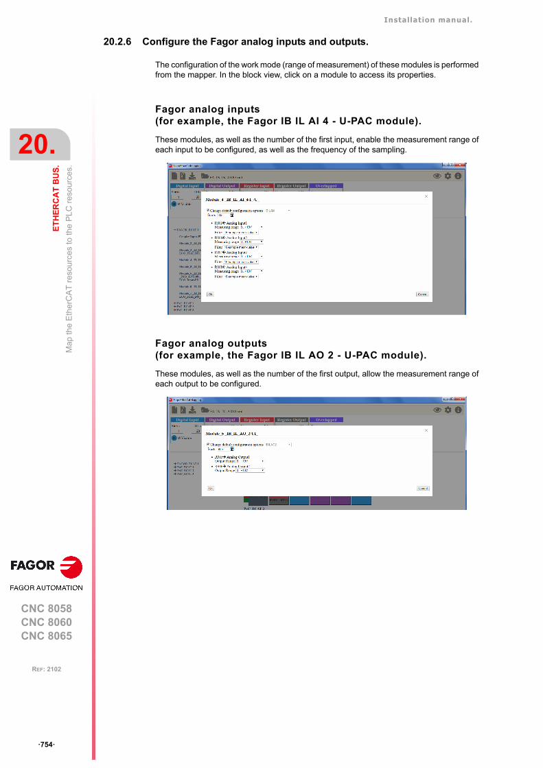
Installation manual.
CNC 8058CNC 8060CNC 8065
20.
ET
HE
RC
AT
BU
S.
Map
the
Eth
erC
AT
res
ourc
es to
the
PLC
res
ourc
es.
ꞏ754ꞏ
REF: 2102
20.2.6 Configure the Fagor analog inputs and outputs.
The configuration of the work mode (range of measurement) of these modules is performedfrom the mapper. In the block view, click on a module to access its properties.
Fagor analog inputs(for example, the Fagor IB IL AI 4 - U-PAC module).
These modules, as well as the number of the first input, enable the measurement range ofeach input to be configured, as well as the frequency of the sampling.
Fagor analog outputs(for example, the Fagor IB IL AO 2 - U-PAC module).
These modules, as well as the number of the first output, allow the measurement range ofeach output to be configured.
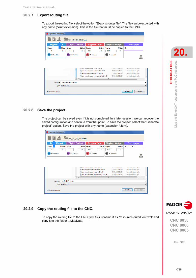
Installation manual.
CNC 8058CNC 8060CNC 8065
ET
HE
RC
AT
BU
S.
20.
Map
the
Eth
erC
AT
res
ourc
es to
the
PLC
res
ourc
es.
ꞏ755ꞏ
REF: 2102
20.2.7 Export routing file.
To export the routing file, select the option "Exports router file". The file can be exported withany name ("xml" extension). This is the file that must be copied to the CNC.
20.2.8 Save the project.
The project can be saved even if it is not completed. In a later session, we can recover thesaved configuration and continue from that point. To save the project, select the "Generateproject" option. Save the project with any name (extension *.fem).
20.2.9 Copy the routing file to the CNC.
To copy the routing file to the CNC (xml file), rename it as "resourceRouterConf.xml" andcopy it to the folder ../Mtb/Data.
Installation manual.
CNC 8058CNC 8060CNC 8065
20.
ET
HE
RC
AT
BU
S.
Dia
gnos
is in
the
CN
C.
ꞏ756ꞏ
REF: 2102
20.3 Diagnosis in the CNC.
20.3.1 General information.
The diagnosis mode provides all the information required of the modules connected to theEtherCAT bus.
General information about the bus.
Information of the slaves.
Module information.
Installation manual.
CNC 8058CNC 8060CNC 8065
ET
HE
RC
AT
BU
S.
20.
Dia
gnos
is in
the
CN
C.
ꞏ757ꞏ
REF: 2102
20.3.2 Error in the slaves.
Error 24499. EtherCAT generic error.
The CNC shows the following generic error when an error in a node is detected. To find outthe details of an error, refer to the diagnosis mode.
Detailed information of the module in error.
The configuration tree identifies the node in error. The right window shows the informationavailable for the module and the error.
Installation manual.
CNC 8058CNC 8060CNC 8065
20.
ET
HE
RC
AT
BU
S.
Dia
gnos
is in
the
CN
C.
ꞏ758ꞏ
REF: 2102
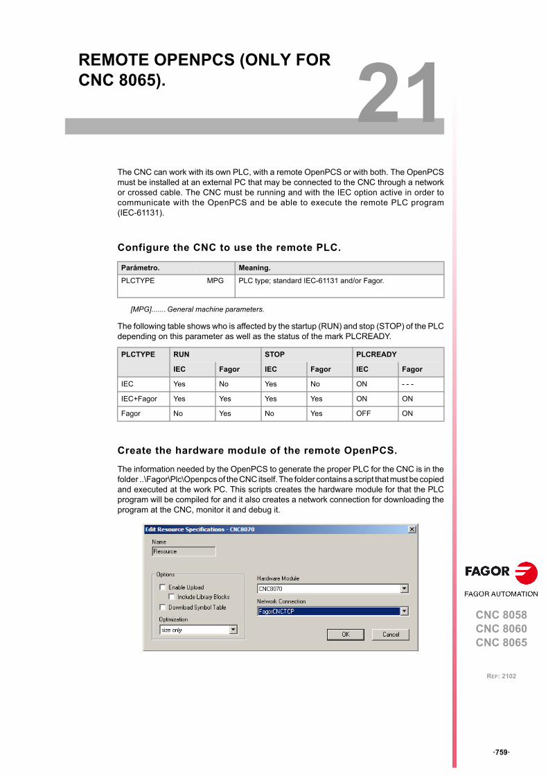
CNC 8058CNC 8060CNC 8065
21
ꞏ759ꞏ
REF: 2102
21.REMOTE OPENPCS (ONLY FOR CNC 8065).
The CNC can work with its own PLC, with a remote OpenPCS or with both. The OpenPCSmust be installed at an external PC that may be connected to the CNC through a networkor crossed cable. The CNC must be running and with the IEC option active in order tocommunicate with the OpenPCS and be able to execute the remote PLC program(IEC-61131).
Configure the CNC to use the remote PLC.
The following table shows who is affected by the startup (RUN) and stop (STOP) of the PLCdepending on this parameter as well as the status of the mark PLCREADY.
Create the hardware module of the remote OpenPCS.
The information needed by the OpenPCS to generate the proper PLC for the CNC is in thefolder ..\Fagor\Plc\Openpcs of the CNC itself. The folder contains a script that must be copiedand executed at the work PC. This scripts creates the hardware module for that the PLCprogram will be compiled for and it also creates a network connection for downloading theprogram at the CNC, monitor it and debug it.
Parámetro. Meaning.
PLCTYPE MPG PLC type; standard IEC-61131 and/or Fagor.
[MPG]....... General machine parameters.
PLCTYPE RUN STOP PLCREADY
IEC Fagor IEC Fagor IEC Fagor
IEC Yes No Yes No ON - - -
IEC+Fagor Yes Yes Yes Yes ON ON
Fagor No Yes No Yes OFF ON
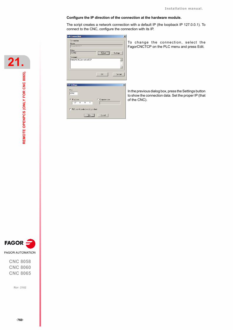
Installation manual.
CNC 8058CNC 8060CNC 8065
21.
RE
MO
TE
OP
EN
PC
S (
ON
LY
FO
R C
NC
80
65).
ꞏ760ꞏ
REF: 2102
Configure the IP direction of the connection at the hardware module.
The script creates a network connection with a default IP (the loopback IP 127.0.0.1). Toconnect to the CNC, configure the connection with its IP.
To change the connec t ion , se lec t theFagorCNCTCP on the PLC menu and press Edit.
In the previous dialog box, press the Settings buttonto show the connection data. Set the proper IP (thatof the CNC).

Installation manual.
CNC 8058CNC 8060CNC 8065
ꞏ761ꞏ
User notes:
REF: 2102

Installation manual.
CNC 8058CNC 8060CNC 8065
ꞏ762ꞏ
User notes:
REF: 2102

Installation manual.
CNC 8058CNC 8060CNC 8065
ꞏ763ꞏ
User notes:
REF: 2102

Fagor Automation S. Coop.Bº San Andrés, 19 - Apdo. 144E-20500 Arrasate-Mondragón, SpainTel: +34 943 719 200
+34 943 039 800Fax: +34 943 791 712E-mail: [email protected]