Class Wise - Classimate Faults and their Physical Properties ...
Upload
independentCategory
view
1download
0
1066 IEEE TRANSACTIONS ON COMPUTERS, VOL. 42, NO. 9, SEPTEMBER ,993
Classification of Faults in Synchronous Sequential Circuits
Irith Pomeranz, Member, IEEE, and
Abstruct- Undetectable and redundant faults in synchronous sequential circuits are analyzed. A distinction is drawn between undetectable faults and faults that are never manifested as output errors. The latter are classified as redundant. It is shown that there are faults for which a test sequence does not exist; however, under certain initial conditions (or initial states) of the circuit, faulty behavior may be observed. Such faults are called partially detectable faults. A partially detectable fault is undetectable, but is not redundant, as it affects circuit operation under some conditions. We observe that the notion of redundancy cannot be separated from the mode of operation of the circuit. ' k o modes of operation are considered, representative of common modes, called the synchronization mode and the free mode. Accordingly, the identification of redundant faults calls for different test generation strategies. ' h o test strategies to generate tests for detectable faults and partial tests for partially detectable faults are defined, called the restricted test strategy and the unrestricted test strategy. Each test strategy is related to a different operation mode, and is suitable for generating tests as well as partial tests under the corresponding mode of operation, and identifying the redundant faults under that mode. We present a complete test procedure for each operation mode, present experimental evidence that partially detectable faults exist, and propose a new definition of a fault coverage measure that accounts for the existence of such faults.
I. INTRODUCTION
HE IMPORTANCE of identifying redundant faults in T combinational circuits has been recognized in facilitating test generation and reducing circuit size. For combinational circuits, undetectable faults are equivalent to redundant faults [l]. Therefore, the terms are used interchangeably to denote faults that cannot be detected, or to signify that lines in the circuit can be replaced by permanent connections to 0 or 1 values. In [l], a fault in a sequential circuit is defined to be redundant if the fault-free and faulty machines are equivalent. Identification of undetectable and redundant faults in synchronous sequential circuits is of great importance because of the complexity of test generation for such circuits. Existing test generation procedures [2]-[29] declare faults as untestable based on different criteria, typically heuristic, depending on the test procedure. Redundant faults in sequential circuits that are tested and operated with hardware reset have been classified in [30] into two categories. Combinationally redundant faults are undetectable under full scan [31], that
Manuscript received April 1, 1991; revised January 17, 1992. This work was supported in part by NSF Grant MIP-9109568 (IP) and by the SDIO/IST Contract N00014-90-1-1793 managed by the U.S. Office of Naval Research (SMR).
The authors are with the Department of Electrical Engineering, University of Iowa, Iowa City, IA 52242.
IEEE Log Number 9208478.
Sudhakar M. Reddy, Fellow, IEEE
is, undetectable even if all state variables are independeiitly controllable and observable. Sequentially redundant faults are undetectable faults that are not combinationally redundant. Sequentially redundant faults were investigated in [30] only for the case where (fault-free) hardware reset is assumed to exist. In [32], redundant faults in synchronizable sequential circuits that do not possess hardware reset are considered. However, the assumptions under which the work is performed are too restrictive. These assumptions include: 1) ignoring the output sequence during the application of a synchronizing sequence, and 2) the use of the single observation time test generation approach (defined later). General definitions of undetectable and redundant faults are required. As a step toward such definitions, the aim of this paper is to present an analysis of the relationships between detectable faults, undetectable faults, redundant faults, test strategy, and Operation mode of the circuit under test.
The test strategies and operation modes under which the analysis is carried out were selected to include existing test generation procedures and existing operation modes, u hile keeping the analysis general and, in particular, independent of the details of any specific test generation procedure. We assume unlimited computation time to eliminate aborted faults from the discussion, and we do not restrict the analysis to any specific physical fault model. Thus, we develop a framework where accurate procedures for identification of undetectable and redundant faults can be developed.
The main contributions of this paper are the new defindion of redundant faults, the distinction drawn between undetectable faults and redundant faults, the introduction of a third cla:;s of faults, called partially detectable faults, which are undetectable but irredundant, and the establishment of the dependznce between redundant faults and operation modes. All these are based on the following observations. A n undeteci able fault may be manifested at an output of the circuit under certain initial operation conditons and a certain input sequence; however, the same undetectable fault may never be manifested at an output under other initial operation conditions. for any input sequence (this is the reason no test for the fault exists). The fault is thus undetectable; however, the fault is irredundant, since it can affect the circuit output under certain initial conditions. For this case, partial tests , which detxt a fault only under certain initial conditions and fail to detect the fault under other initial conditions, are defined. A fault that does not have a partial test is classified as redundant. Moreover, the existence of a partial test, and, therefore, the set of redundant faults, may depend on the circuit mode of
0018-9340/93$03.00 0 1993 IEEE

POMERANZ AND REDDY: CLASSIFICATION OF FAULTS IN SEQUENTIAL CIRCUITS 1067
operation. If circuit operation is always started by applying a sequence X (typically, to synchronize the circuit), a fault may be redundant, whereas the same fault may be irredundant (partially detectable) if no restrictions are put on the initial sequence. As a result of the dependence between redundant faults and operation mode, we refer to redundant faults as operationally redundant . A hierarchy of operation modes based on their operationally redundant faults is shown, and corresponding test generation strategies for the generation of tests and partial tests are defined. The test strategies are also analyzed with respect to the identification of undetectable faults.
Although the results in this paper apply to combinationally redundant faults as well, such faults can be identified using the techniques for identifying redundancies in combinational circuits [2]. These redundancies are independent of opera- tion modes and, hence, are not explicitly considered in the framework presented here.
The paper is organized as follows. A n overview of test strategies and operation modes, together with a preliminary discussion of undetectable faults, operationally redundant faults, and partial tests are given in Section 11. The relationship between test strategy and detectable faults is presented in Section 111. Based on the discussion in Section 111, redundant faults are considered in Section IV. Section V gives a different interpretation of undetectable faults and operationally redundant faults under the various test strategies and operation modes, which is useful for additional analysis of such faults. A test strategy is suggested for every mode of operation in Section VI. Experimental evidence to the existence of partially detectable faults is given in Section VII. A new definition of a fault coverage measure, called the fault detection coefficient, is proposed in Section VIII. Circuits with power-up reset are considered separately in Section IX. Concluding remarks are given in Section X.
11. PRELIMINARIES In this section, we define the test strategies and operation
modes required for the analysis of undetectable and redundant faults. The definitions are aimed at capturing existing test strategies and operation modes. In all cases, state tables are used for illustrating the concepts. State tables have the advantage (e.g., over gate-level descriptions) of supplying in an immediate way complete information on the circuit. State-table faults are considered, without loss of generality, since physical faults have state-table counterparts, for example, every stuck-at fault at the gate level has an equivalent state- table fault [33]. Operation modes are defined first, followed by a definition of test strategies. Partial tests are defined and related to operational redundancy.
Two operation modes are considered. Under the synchro- nization mode, operation always starts with a specified input sequence, denoted by X.X is referred to as the power- up sequence. The length of X is denoted 1x1. In the case where power-up reset exists, 1x1 = 0, and the circuit starts operating from a given reset state, denoted A . If hardware reset exists as a special input, which is always used to reset
TABLE I MACHINE hfl
NS
P S x = O x = l z1z2
A B c 00 B B D 01 c c B 10 D B -4 11
the circuit at the beginning of operation, 1x1 = 1. For a general synchronizing sequence, IX I 2 1. The synchronizing sequence can synchronize the circuit to a single state or to a state within a subset of states.
Under the f.ee mode of operation, no restrictions on power- up sequences exist, and the machine starts operation at the state it happens to be in at that time. For some machines, this mode of operation is the only possible one; for example, frequency dividers with no power-up or hardware reset do not have a synchronizing sequence. More importantly, this mode of operation is useful for the identification of operationally redundant faults when the power-up sequence X has not yet been determined, during the design process, or when there is no single sequence X that is always used.
The two operation modes are illustrated by the following example. Note that the operation mode applies to the fault- free machine and is independent of any faults (which are considered only during test generation).
Example: Consider machine M I given in Table I. 1) Power- up reset, corresponding to a power-up sequence of length zero, would bring the machine to a specific state, say A , when power is turned on. 2) The existence of a reset input can be described as in Table 11. Under T = 0, the machine operates normally. Under T = 1, the next state of the machine is A for every present state and x. If T = 1 is the specified power-up sequence, operation always starts with r = 1, which brings the machine to state A . 3) The machine also has a synchronizing sequence, z = ( O l O ) , which brings the machine to state B , regardless of its initial state. If z = (010) is the specified power-up sequence, the machine is always operated starting with this sequence. 4) An example of a power-up sequence that does not fully synchronize the machine is 2 = (0). The sequence (0) brings M I to states { B , C } , depending on the initial state, thus reducing the ambiguity as to the state of the machine from { A , B , C , D } at time unit i = 1 to { B , C } at time unit i = 2. All of the preceding cases belong to the synchronization mode of operation with various power- up sequences. If no sequence X is specified, for example, since X has not been determined yet, or if no synchronizing sequence exists that reduces the ambiguity with respect to the state of the machine, then the operation falls under the free mode. 0
In all cases, we consider reset as a regular input. It is then possible to consider faults in the reset hardware as regular faults: for example, Table 111 shows machine M I with a fault in the reset hardware that operates only when the machine is in state A or B, and fails to reset the machine when it is in state C or D. The representation of reset as a regular input allows

IEEE TRANSACTIONS ON COMPUTERS, VOL. 42, NO. 9, SEPTEMBER 1993
TABLE IV MACHINE Mz
TABLE I1 MACHINE M I WITH HARDWARE RESET
NS N S T = o 2122 PS x = o x = l 2132
A BIA A 00 A B C A 00 B BIA D 00 B B D A 01 C CIA B 10 C C B A 10 D D I A A 11
P s I = o X = 1 T = l T = o
D B A A 11
TABLE I11 MACHINE Mi WITH A FAULTY HARDWARE RESET
NS
A B C A 00 B B D A 01 C C B C 10 D B A D 11
us to generalize the results with respect to undetectable and redundant faults. Circuits with power-up reset need additional discussion and are treated in a separate section.
Next, we consider two test strategies corresponding to the two operation modes defined earlier. Under the restricted test strategy, all test sequences start with the power-up sequence X. In other words, the search space for test generation is restricted to include only test sequences starting with the sequence X. Again, X can correspond to the application of reset, or can be a synchronizing sequence. The power- up sequence can synchronize the fault-free machine fully or partially. Under the unrestricted test strategy, the search space for test generation is unrestricted, and any sequence can be generated as a test sequence. Note that any reset mechanism existing for the machine is available to the test generator under the unrestricted strategy, and tests can be specified in terms of such a mechanism, when it is useful in generating tests or partial tests. We show that the two test strategies result in the same set of undetectable faults, and, therefore, a fixed power-up sequence can be used to simplify the test generation process. The distinction between the two test strategies is important when partial tests are considered (recall that a partial test is a sequence that exhibits the fault at a primary output under a certain initial states only. A formal definition is given later). Before discussing partially detectable faults and operationally redundant faults in more detail, we need to review test generation approaches described in the literature. This is done next.
Both test strategies defined earlier can be employed under one of the two test generation approaches discussed next. Tests are classified in [2] into two categories. Under a test generation approach called the single observation time approach [34], [37], a fault f is said to be detectable if there exists an input sequence Y such that for every pair of initial states S and Sf of the fault-free and faulty circuits, respectively, the response Z(Y , S ) of the fault-free circuit to Y is different from the response Zf (Y, Sf) of the faulty circuit at a specific time unit i. To conform to the existing test generation procedures, we
further restrict the definition of the single observation time approach to require that the fault-free response be different from the faulty response at time unit i on a spec@ primary output (the same output and time for all initial states). Using D-notation [2], under the restricted single observation time approach, a D or is propagated by the test sequence to a primary output at time i. Under a test generation approach called the multiple observation time approach [34], [37], a fmlt f is said to be detectable if there exists an input sequence Y such that for every pair of initial states S and Sf of the fault-free and faulty circuits, respectively, the response Z(Y, S ) of the fault-free circuit to Y is different from the response Zf(Y,Sf) of the faulty circuit at some time unit (not necessarily the same for all initial state pairs). The idea behind the multiple observation time approach is that, to test a fault, it is sufficient to make the fault-free circuit star5ng at state S1 and the faulty circuit starting at state S2 exhibit different output responses, for all 5’1, Sp. Then, regardless of the initial state, no faulty response appears similar to any fault-free response, and the fault is detected. Since every pair of states is considered separately, to test a circuit under the multiple observation time approach, the response of the circuit under test to the test sequence is obtained at one or more ,ime units, and regarded as a single subsequence, which is compared with the precomputed fault-free subsequences at the same observation times. The multiple observation time approach was suggested in [34] to alleviate some of the problems of current test generation approaches, which result in the inability to achieve high fault coverage in some cases. The two test generation approaches are contrasted in the following example. Faults are given as next state entries S1/S2 or as output entries z1/z2, where Sl (z1) is the fault-free next state (output). and S2(z2) is the faulty next state (output). A transition from Q1 to Q 2 under input I , producing output J , is denoted &I-+ Q2. In the presence of a fault, a transition is denoted
by S1/S2J1:J, Ql /Q2, where SIL &I is a transition cf the
fault-free circuit, and 5 ’ 2 4 Q2 is a transition of the faulty
circuit. Example: Consider M2 given in Table IV. M2 is tested for
the multiple state-table fault given in Table IV, where the next state of states A , B, C, and D under input 0 is A in all cases when the fault is present, instead of the next states B, B, C, and D when the machine is fault free. The following tests are generated under the two test approaches.
Multiple observation: A test for M - under the milltiple observation time approach is (0, 1, 0). The responses af the fault-free and faulty machines starting from all possible initial
I
J
Ji
I
J2

POMERANZ AND REDDY: CLASSIFICATION OF FAULTS IN SEQUENTIAL CIRCUITS 1069
states are as follows: TABLE V MACHINE M3
Fault free: A 3 B A D 3 D , B 3 B A D 5 D , 00 00 11 00 00 11
C ~ C A 10 10 ~3 00 B , D: D A A ~ B
Faulty: A 3 A A A 3 A, B 3 A A A -$ A, 00 00 00 00 00 00
There is no single time unit at which the response of the faulty machine is guaranteed to be different from the response of the fault-free machine regardless of initial states. However, by observing the response of the machine under test at time units 2 and 3, the possible fault-free output subsequences (taken at time units 2 and 3) are (00, 11) for initial states A and B, (10, 00) for initial state C, and (11, 00) for initial state D. The faulty output subsequence (again taken at time units 2 and 3 only) is (00, 00) for all initial states. The fault can, therefore, be detected by applying the input sequence (0, 1, 0) and comparing the output sequence of the circuit under test at time units 2 and 3 to each one of the fault-free output sequences at those times. In general, any number of observation times can be used, and any number of fault-free sequences may result.
Single observation: A test sequence under the single obser- vation approach is (1, 1, 1, 0, 1, 0). The fault-free and faulty responses for all initial states are as follows:
Observing the response of the circuit at time unit 6 detects the fault. The fault-free response is (ll), while the faulty response
As illustrated by the following example, the multiple obser- vation time approach contains as a special case a test approach that requires a single observation time, but relies on multiple fault-free responses to detect a fault.
Example: Consider M 3 given in Table V. A possible test sequence for the fault is T = (0,O). The following responses
is (00). 0
N S PS x = 0 x = 1 21 22
A BIA C 00 B BIA D 01 C CID B 10 D BID A 11
to (0, 0) are obtained for all initial states.
Fault free: A 3 B 3 B , B 3 B: B , 00 01 01
C ~ C : C , D ~ B ~ B . 10 11 01
Faulty: A $ A > A , B z A : A , 00 00 01 0 0 C ; D ; D , D ~ D ~ D .
11 11
One observation of the output sequence at time unit i = 2 is sufficient to determine whether the circuit under test is fault free or faulty. However, in case the machine is fault free, one of two fault-free responses may be observed at i = 2, (01) or (lo), while the faulty responses at i = 2 are (00) and (11). 0
In Section 111, we show that every fault that is detectable under the single observation time approach is also detectable under the multiple observation time approach. Since we are interested in developing a general framework for the identi- fication of undetectable and redundant faults, we concentrate on the multiple observation time approach, and state all results with respect to this approach. No additional detectable faults exist and no irredundant faults are identified as redundant, since the multiple observation time approach uses the most general definition of a test sequence. Accordingly, the fol- lowing definitions of detectable and undetectable faults are used.
Definition 1: A fault f is said to be detectable if there exists an input sequence Y such that for every pair of initial states S and Sf of the fault-free and faulty circuits, respectively, the response Z(Y , S ) of the fault-free circuit to Y is different from the response Z f ( Y , Sf) of the faulty circuit at some time unit (not necessarily the same for all initial state pairs).
Definition 2: A fault f is said to be undetectable if it is not detectable.
Going back to the subject of power-up reset, we claimed earlier that power-up reset, which cannot be represented as a primary input, does not allow a uniform treatment of faults. To explain this point, let us first consider the following example, where reset is represented by a primary input.
Example: Consider MI with the reset fault given in Table 111. (T = 1,x = 1, T = 1,x = 0) is a test sequence for the fault (when x is specified, T = 0 is assumed). The responses of all states to this sequence are the following. For the fault- free machine, under T = 1, the machine goes to state A regardless of the initial state. The following transitions are
4 C -+ A -+ B, where the dash stands for a null response when reset is activated. The response is thus (-, 00, -, 00). For the faulty machine, T = 1 brings the machine to one of
Azo;l r=l z=o - 00

1070 IEEE TRANSACTIONS ON COMPUTERS, VOL. 42, NO. 9, SEYIEMBER 1993
states { A , C, D } , depending on the initial state. Let us consider each one seDaratelv. The followine resDonses are obtained.
" L Az~lc'zlcz<o, c"<lB'~lAzzo, D z ! l A T = l z=o -+ A + . It can be
seen that for each pair of states A / A , A / C , and AID, the 00 - 10 10 - 00 11 - 00
fault-free response is different from the faulty response at time unit 2 or 4, and, therefore, the fault is detected. 0
Wehavefoundatestsequence(r=l ,z= 1 , ~ = l ,z=O) for the machine and the reset fault of Table 111. In general, tests for reset faults require the activation of reset in the middle of a test sequence, after the machine has been brought to a state where the reset failure can be activated. In case of power-up reset, the only way to reset the machine is to turn it off and then on again. However, when the machine is turned off, the previ- ous state is lost, and the test sequence has to be restarted. The case of power-up reset is therefore treated in a separate section.
We now consider redundant faults. Unlike combinational circuits, where an undetectable fault is also redundant, a fault in a sequential circuit can be undetectable under any test strategy, but still affect the circuit operation under certain initial conditions. This point is illustrated by the following example.
Example: Consider machine M4 given in Table VI (using the definitions from [30] for reset state A, the fault is an isomorph-SRF if state B, which is unreachable from A , is ignored, since the state tables for the fault-free and faulty machines are isomorphic, with C and D interchanged). It can be verified that the fault given in Table VI is undetectable under any of the test strategies considered. However, assuming that the faulty machine starts operating from state B and the input sequence (010) is applied, the faulty response is (010) (obtained from the faulty transition sequence B+A+A-+D). The fault-free remonses for all initial states are the followine.
0 1 0
0 1 0 "
A $ C A D Z D , B ~ B + A + C , C ~ D A C ~ D , D ~ D A C ~ 1 0 1 0 1 1 0 0 1
D. Therefore, by observing the output sequence at time units 2 and 3, a faulty output sequence of the machine under test can be differentiated from any fault-free output subsequence, regardless of the initial state of the fault-free machine. The faulty output sequence is (lo), while the fault-free output subsequences are (11), (00), and (01). We conclude that, if under normal operation, the machine happens to start from state B and the sequence (010) is applied, the response of the faulty machine is different from any response that the fault- free machine can produce to (OlO), starting from any initial state. Therefore, (010) is a partial test for state B. However, (010) is not a test sequence, as can be verified by considering the response of the faulty machine starting from state A. The following transitions are obtained: A-+D-+C+C. The response, (01 l), is identical to the fault-free response starting from state A . Since we cannot guarantee that the machine starts from state B ( B is not a reset state), and since for other initial states of the faulty machine, the response to (010) can also be produced by the fault-free machine when it starts from the appropriate initial state, the fault is undetectable by (010) under any test strategy considered. The sequence (010) is, therefore, a partial test, which detects the fault if the faulty machine starts from state B. 0
0 1 0
0 1 1
TABLE VI MACHINE M4
The term operationally redundant fault is used to describe a fault that is not manifested during normal operation in the mode of operation considered. To claim that an undetectable fault is not redundant, a partial test for the fault must exist, as illustrated by the previous example.
Based on the preceding example, we can deduce :hat, depending on the mode of operation, the same fault may or may not be operationally redundant.
Example: If machine M4 is operated in the synchronization mode with reset to state A , the fault of Table VI is never manifested as a faulty output response and, thereforo, is operationally redundant. However, if the machine is opeiated in the synchronization mode with reset to state B, or operated in the free mode, the fault may be manifested as a faulty
0 To summarize, an undetectable fault by any test strategy
may affect the correct operation of the circuit and cause the circuit to exhibit faulty behavior, depending on the initial state of the circuit. This property leads to the definition of pirtial tests, by which the detection of a fault depends on the initial state of the circuit under test, as follows.
Definition 3: A partial test for an initial state Sf o€ the faulty circuit, under the unrestricted test strategy, is an input sequence Y such that for every fault-free initial state 5', the response of the fault-free circuit to Y starting from S , Z(J', S), is different from the response of the faulty circuit starting from
Accordingly, a partially detectable fault is defined as fol- lows.
Definition 4: A partially detectable fault under the unre- stricted test strategy is an undetectable fault for which there exists a partial test under the unrestricted test strategy for at least one initial state Sf of the faulty circuit.
We have similar definitions for the restricted test straLegy. Definition 5: A partial test for an initial state Sf of the
faulty circuit, under the restricted test strategy with power- up sequence X, is an input sequence Y that has X as a prefix, such that for every fault-free initial state S, the response of the fault-free circuit to Y starting from S, Z(Y , .i), is different from the response of the faulty circuit starting from
Accordingly, a partially detectable fault is defined its fol- lows.
Definition 6: A partially detectable fault under the re- stricted test strategy with power-up sequence X is an undetectable fault for which there exists a partial test under the restricted test strategy with power-up sequence X, for at least one initial state Sf of the faulty circuit.
response and, therefore, is operationally irredundant.
Sf, Zf(Y, Sf).
Sf, Zf (Y, Sf).

POMERANZ AND REDDY: CLASSIFICATION OF FAULTS IN SEQUENTIAL CIRCUITS
A fault cannot be guaranteed to be detected by a partial test, but is detected if the circuit starts in a state for which the partial test constitutes a test. A simple way to derive a partial test for a given faulty state using existing test generation procedures is to fix the state of the faulty machine to the given state, and generate a test that is valid regardless of the initial state of the fault-free machine. This strategy is inherent in the test generation procedures that use the multiple observation times strategy [34], [37]. If no partial test exists, the fault can never be manifested at a primary output, under any input sequence: therefore, the fault is redundant. We call it operationally redundant due to the dependence on the operation mode. The following definitions result.
Definition 7: An operationally redundant fault under the free mode of operation is a fault for which no partial test exists under the unrestricted test strategy.
Definition 8: An operationally redundant fault under the synchronization mode of operation with power-up sequence X is a fault for which no partial test exists under the restricted test strategy with power-up sequence X .
Under the definition of [l], a fault is redundant if for every fault-free state there exists an equivalent faulty state and for every faulty state there exists an equivalent fault-free state. This definition may classify as irredundant a fault for which the behavior of the faulty circuit cannot be distinguished from the behavior of the fault-free circuit (under some mode of operation), that is, a fault for which no partial test exists (under the corresponding test strategy) for any faulty state. Machine M7 considered later is such an example. Therefore, Definitions 7 and 8 are more suitable to characterize redundant faults in sequential circuits.
We show in Sections 111 and IV that the set of faults for which partial tests exist under the unrestricted test strategy is larger than the set of faults for which partial tests exist under the restricted test strategy. Differently stated, the dis- tinction between the two test strategies is important when operationally redundant faults are to be identified under the two operation modes defined. The result we show is that the set of operationally redundant faults under the free mode is contained in the set of operationally redundant faults under the synchronization mode. Consequently, operationally redundant faults identified before the power-up sequence is determined remain operationally redundant after such a sequence is fixed.
To summarize, we have, for a given operation mode, the following classes of faults: 1) detectable faults, and 2) un- detectable faults. The latter class is further refined into (2a) partially detectable faults, and (2b) operationally redundant faults.
111. TEST STRATEGIES AND UNDETECTABLE FAULTS
In this section we show a hierarchy of test strategies and test generation approaches based on detectable and partially detectable faults. The results of this section are independent of the operation modes defined. We start by considering the two test generation approaches, single observation time and multiple observation time. We then consider the two
1071
TABLE VI1 MACHINE .\Is
0 P s .v .c z
0 .4 B 0 1 B AfB 1
test strategies defined, the restricted test strategy and the unrestricted test strategy.
Let F,", be the set of faults detectable under the single observation time test approach. Let F$o be the set of faults detectable under the multiple observation time test approach.
Proof: Let f E F,",. Since f is detectable under the single observation time strategy, there exists a test sequence Y for f such that for every pair of initial states S and Sf, Z(Y, S ) is different from Z f ( Y , S f ) at the same time unit, on the same output. Y is therefore a test sequence under the multiple observation time, where a single observation time and a single fault-free sequence are used. Consequently, f is detectable under the multiple observation time strategy, and f E F&,. This applies to every f E Ffo. Therefore, f E Fs", implies
O The sets Ff0, F$o cannot be proved to be equal, even for
reduced and strongly connected machines, as shown by the following example, where a fault f is exhibited, such that f E F&, and f $! F&.
Example: Consider a machine comprised of a D flip-flop whose input is connected to its output. The output of the machine is the Q output of the flip-flop. Let f be the fault a stuck-at 1. The corresponding machine and fault are given in Table VII. The fault-free response starting from A is (01010 . . .), while the fault-free response starting from B is (10101 . . .). For any observation time i, the fault-free response can be both a zero and a one, making the fault undetectable under the single observation time approach. The fault is detectable under the multiple observation time approach as follows. The faulty response starting from A is (0111 . . .), while the faulty response starting from B is (1111 . . .). By observing the output at time units i = 2 and z = 3, the possible fault-free output subsequences are (01) and (lo), whereas the faulty output subsequence is (1 1). Therefore, the fault is detectable under the multiple observation time approach. The fault in Table VI1 is thus contained in the set of detectable faults under the multiple observation time approach, F:o. and not contained in the set of detectable faults under the single observation time
Let us now consider the two test strategies we defined, the restricted and unrestricted test strategies. The following assumptions are used to obtain all the results that follow: 1) Hardware reset is given as a regular primary input (for state tables, cf. Table II), and 2) Theorem 1 established that the set of detectable faults under the multiple observation time approach is larger than the set of detectable faults under the single observation time approach, and, therefore, the multiple observation times approach is used for test generation.
Let F$ be the set of detectable faults under the restricted test strategy, where a sequence X is used as the power-up
Theorem I: Fto F:o.
f E FAo for every f E F,fo, and F,", C Fie.
approach, Fto. 0

1072 IEEE TRANSACTIONS ON COMPUTERS, VOL. 42, NO. 9, SEPTEMBER 1993
sequence. Let Ftn be the set of detectable faults under the unrestricted test strtegy. Note that the sequence X is available to the unrestricted test generator, since we assumed that if X represents a reset machanism, there exists a regular primary input that resets the machine, and this input is available to the unrestricted test generator as well.
Theorem 2: F$ = F2n. Proof:
F$ c F,",. Let f E F$. Then there exists a test sequence Y for f, that has X as a prefix. The same sequence Y can be obtained under the unrestricted test strategy. Therefore, f E F&. This applies to any f E F$, and, therefore, F$ c F&. F2n G F$. Let f E Fin. Then there exists a test sequence Y for f, starting from complete ambiguity with respect to the state of the fault-free and faulty machines. If the test sequence Y is preceded by the sequence X , the ambiguity with respect to the initial state when Y is applied can only be reduced. Therefore, Y is a valid test sequence after X is applied. Therefore, f is detectable by the sequence ( X U ) under the restricted test strategy, and f E F$.
From the two containment relationships, F$ = Ftn. 0 From Theorem 2, the two test strategies are equivalent for
identifying undetectable faults. Therefore, the simpler of the two should be used. In most cases, a fixed power-up sequence would simplify the test generation process. Moreover, it can be shown in a similar way that F x , = Fx, for different power- up sequences X I and X2. As a consequence, if a reset input exists, it should be used to facilitate test generation.
We have seen that undetectable faults can be identified by either of the proposed test strategies. The reason we defined the two test strategies is the difference between them in generating partial tests. In this case, the containment is one-sided, as shown by the following theorem and example. Let Fg be the set of faults for which partial tests exist under the restricted test strategy, where a sequence X is used as the power-up sequence. Let F&, be the set of faults for which partial tests exist under the unrestricted test strategy.
Theorem 3: Fg c FZn. Proof: Let f E F g . Then there exists a partial test Y for
f , that has X as a prefix, and Y distinguishes a state Sf of the faulty machine from every state of the fault-free machine. The same sequence Y can be obtained under the unrestricted test strategy to distinguish between Sf and every fault-free state. Therefore, f E Fun. This applies to any f E F x , and,
The sets F g , F&, cannot be proved to be equal, as shown by the following example, where a fault f is exhibited, such that f E F& and f $! F g .
Example: For M4 given in Table VI, (100) synchronizes the fault-free machine into state D. The same sequence synchronizes the faulty machine into state C. Attempting to complete (100) into a partial test, we consider all possible next states of state DIC. Under input 0, we have the transition DIC>D/C; under input 1, D / C k ' / D . The only new state
therefore F$ C F,',. 0
reached is CID. The transitions out of C / D are C / D 2 L / C
and CIDADIC. No new states are reached. Since the fault- free and faulty responses are always the same during and after (100) is applied, no partial test for the fault exists. Under the unrestricted test strategy, a partial test (010) was shown In a
0 We have presented two main results in this section 1)
For the generation of tests (or, equivalently, the identification of undetectable faults), the two test strategies defined are equivalent. If hardware reset exists, it can be used in all cases, without reducing the accuracy of identifying undetectable faults. 2) For the generation of partial tests, the unrestricted test strategy identifies a larger subset of faults as partially detectable than the restricted test strategy with any powe--up sequence X .
previous example for state B.
Iv . REDUNDANT FAULTS AND OPERATION MODES
In the previous section, we showed that the unrestrkted test strategy identifies a larger subset of faults as partially detectable than the restricted test strategy with any power- up sequence X. The implications on operationally redundant faults are considered in this section.
To identify an operationally redundant fault under the syn- chronization mode of operation with power-up sequence X , we need only consider tests and partial tests that start with the sequence X . All other sequences are never applied to the machine, and, therefore, do not cause any faulty behavior. The restricted test strategy with power-up sequence X shmld therefore be used (cf. Definition 7).
To identify an operationally redundant fault under the free mode of operation, all input sequences must be considered. The unrestricted test strategy should therefore be used for generating tests and partial tests (cf. Definition 8).
As a consequence of the discussion in the previous section with respect to the sets of partially detectable faults unde. the two test strategies, we have the following result. The set of operationally redundant faults under the free mode of operation is contained in the set of operationally redundant faults under the synchronization mode of operation that uses a power-up sequence X .
An important consequence is that operationally redundant faults can be identified even before the mode of operation for the circuit has been finalized; hence, the free mode must be assumed. All operationally redundant faults identified under this mode remain operationally redundant when the rnode is restricted into a synchronization mode with a power-up sequence X .
V. UNDETECTABLE FAULTS, PARTIAL TESTS, AND STATE EQUIVALENCE
In this section, we .show that the concepts of detectable, partially detectable, and operationally redundant faults are related closely to the concept of state equivalence. We analyze this relationship and present conditions under which the set of partially detectable faults is empty, resulting in the situ-
_ _ _ _

POMERANZ AND REDDY: CLASSIFICATION OF FAULTS IN SEQUENTIAL CIRCUITS 1073
TABLE VI11 DIRECT S U M OF FAULT -FREE AND FAULTY h f 6
NS, f PS x = o s = l
A B. 0 -4. 1 B c. 0 B . 1 C c. 1 D. 0 D D , 1 A > 0
A’ D‘, 0 A’. 1 B‘ A‘, 0 B’. 1 C‘ C‘. 1 B’. 0 D’ D‘, 1 C’. 0
ation where an undetectable fault is operationally redundant. Consider the following example.
Example: Consider M,j given in the upper part of Table VIII. To check for state equivalence between the fault-free and faulty machines, we follow [35]. The direct sum of the fault- free and faulty machines is given in Table VIII. The direct sum is obtained by including the two state tables one following the other. The states of the faulty machine have been renamed {S’} to distinguish them from the fault-free states. We now apply the state minimization procedure [4] to the direct sum machine. The following partitions are obtained:
Po = (ABCDA’B’C’D’) Pi = (ABA’B’)(CDC’D’) P2 = (AB’) ( A’B) (CD’) (C’D) P3 = (AB’) ( A’B) (CD’) (C’D).
The machines are equivalent, since for every state of the fault- free machine there exists an equivalent state of the faulty machine, and vice versa. Consequently, for every state of the faulty machine there is a state of the fault-free machine that produces an identical response to any input sequence. Therefore, no test or partial test exists. For further illustra- tion, let us consider the same example in the case where hardware reset is available, and is represented, according to the preceding assumption, as a primary input. The direct sum of Table VI11 is modified by adding a column for T = 1, corresponding to the activation of reset, where the next state entry for the fault-free machine is A for all states, and the next state entry for the faulty machine is A’ for all states. Repeating the state minimization procedure for this machine, we obtain the following partitions. Note that once states A and A’ are distinguished in P2, all states are distinguished, as expected, since after the application of reset, which is fault free in this case, we only need to distinguish A from A’.
Po = (ABCDA’B’C’D’) Pi = (ABA’B’) (CDC’D’) P2 = (AB’) ( A’B) (CD’) (C’D)
p3 = (A)(B’)(A’)(B)(C)(D’)(C’)(D). A test sequence for this machine starts by applying the reset
0 The correspondence between state equivalence and de-
input, and then applying z = (00).
tectability is given by the following theorem.
Theorem 4: A fault f is undetectable if and only if there exists a pair of states S,/S,f such that S1 of the fault-free machine and Sf of the faulty machine are equivalent.
Proof: Assume S1 and Sf are equivalent, then there is no input sequence that distinguishes S1 and Sf. Since the initial state of the machine under test is unknown (even if reset exists, the state before the application of reset is unknown), a test sequence must distinguish every fault-free initial state from every faulty initial state. In particular, a test sequence must distinguish S1 from Sf. However, since S1 and Sf are equivalent, there is no such test sequence. Conversely, assume every pair of states S,/S,f is distinguishable. Let us construct a test sequence T as follows [34]. Initially, T is empty. For every pair of initial states S, /S , f , processed in some order, let us perform the following algorithm. Perform fault simulation for T starting from initial state S1 /Sf. If the fault-free response is different from the faulty response, then stop (consider the next pair). Otherwise, let the final state reached be Pl/P,f. Since PI and Pi are not equivalent, there exists a distinguishing sequence D(P1, P i ) for PI and Pi. Add D(P3, P i ) to T. After all pairs of initial states are considered, if T is applied to the circuit under test, for every pair of possible initial states of the fault-free and faulty machines there exists a time unit at which the fault-free response is different from the faulty response. Therefore T is a test for f under the multiple
Considering partial tests (the unrestricted test strategy is assumed together with the free mode of operation), a partial test exists for an initial state S,f of the faulty machine only if state S,f is not equivalent to any state of the fault-free machine. Otherwise, if S,f is equivalent to some state S of the fault-free machine, no test sequence can be constructed that distinguishes S,f from every fault-free state. However, the condition is not sufficient; that is, a partial test for initial state S,f may not exist even if S,f is not equivalent to any state of the fault-free machine, as illustrated by the following example (we classify such faults as operationally redundant).
Example: Consider the direct sum of the fault-free and faulty machines given in Table IX for a machine M7. From the output values it can be verified that A’ is not equivalent to any fault-free state. It can also be verified that B’ is equivalent to B. Attempting to generate a partial test for A’, we consider the transitions from all fault-free states and from A’ under inputs 0 and 1. If an input 0 is applied, A’ is distinguished from A by the output response, but B and A’ are driven into states B and B’, which are equivalent. Therefore, a partial test cannot start with 0. If an input 1 is applied, A’ is distinguished from B, but A and A’ are driven into states B and B’, which are equivalent. Therefore, a partial test cannot start with 1. Consequently, no partial test exists. Note that this fault would have been classified as irredundant by the definition in [l].
Partially detectable faults cannot be detected unless the circuit under test starts from specific initial states. Therefore, it may be desirable to eliminate such faults. Next we consider conditions under which partial tests do not exist, and every fault is either detectable or operationally redundant. The results
observation time strategy. 0
However, it is redundant by our definition.

14 74 IEEE TRANSACTIONS ON COMPUTERS, VOL. 42, NO. 9, SEPTEMBER 1993
TABLE IX S;. T(S; , S;.) transfers the faulty machine from Sf to some state; let us denote it S,’. S;. is equivalent to S!, otherwise there would be a distinguishing sequence for S; and si, constructed of T(S; , S j ) augmented by the distinguishing sequence of S,’ and S;. We can, therefore, find for every S;, a state S,” to which it is equivalent. Since the machine is reduced, Sil which is equivalent to Sil must be different from S;2 which is equivalent to S .- , otherwise we would have Syl equivalent to Sy2 by transitivity of the state equivalence relation. Since the machine is completely specified and the number of faulty states is not larger than the number of fault- free states, for every faulty state s,” there is a fault-free state
7 For the cases where Theorems 5 and 6 are applicable, every
initial state of the faulty machine is equivalent to some state of the fault-free machine, and, therefore, the output sequence produced by the faulty machine can also be produced by t’ie fault-free machine starting from some initial state. Therefore. a partial test under the unrestricted test strategy cannot be found for a reduced, completely specified, and strongly connected machine or when the faulty machine is strongly connected, if the fault does not increase the number of states of the machine. These results apply to the restricted test strategy as well, due to Theorem 3.
The requirement that the machine in Theorem 6 be reduced can be relaxed by allowing the states sj and s,’ to represcnt subsets of equivalent states. In this case, it is required that ihe number of subsets of equivalent states in the faulty mach ne would not be larger than the number of subsets of equivalznt states in the fault-free machine. The same result then applies, that is, no partial test exists in this case.
An important case where no partial test exists under the restricted test strategy is the following. Consider a circuit operated under the synchronization mode of operation -4th a power-up sequence X . X can correspond to the activation of reset or can be a synchronizing sequence. Suppose that
DIRECX SUM OF FAULT -FREE AND FAULTY MACHINES M7
N S , z P S x = o x = l
A B, 0 B, 1 B B , 1 B , 0
A’ B’, 1 B’, 1 B’ B’, 1 B’, 0
32
are developed for the free mode of operation and the unre- stricted test strategy. The conditions developed can be used t8) guide design and synthesis for testability methods. More
the state table of a machine in ensuring that no partial tests rxist (Le., in ensuring that all faults are either detectable or redundant). First, we show that a partial test does not exist for ;I fault f , that does not increase the number of states of a faulty machine, when the faulty machine is completely specified and .,trongly connected. As this result relates to faulty machines, it may not be practical in guiding the design of the fault-free lnachine. The following result, which applies to the fault-free nachine, may be more useful. A partial test does not exist for a fault f that does not increase the number of states of a reduced, :ompletely specified, and strongly connected machine. These results are proved next.
Theorem 5: Let M be a machine with states {Si: 1 5 i 5 n}. k t Mf, with states {sf: 1 5 i 5 n } , be a faulty machine obtained from M by introducing the fault f . Suppose that f does not increase the number of states of M , Suppose, in addition, that Mf is completely specified and strongly connected. If S{ is equivalent to S; for some i and i, then for every faulty state S,” there exists a fault-free state S; that is equivalent to S,’ (and, consequently, no partial test exists under the unrestricted test strategy).
Proofi Let Sf be equivalent to S;, and let us consider
specifically, we show the importance of strong connectivity of S;. to which it is equivalent.
any state ’,” Other than ’f’ Since Mf is X brings the fault-free machine to a specific state, S. k t connected, there is a transfer sequence T(Sf~ s,”) from sf us consider faults that do not affect the sequence X ; that is, to S,’. T(Sf , S,”) transfers the fault-free machine from S; to some state; let us denote it Sj . Sj is equivalent to S,”, otherwise there would be a distinguishing sequence for S; and Sf, constructed o f T ( S f , s,”) augmented by the distinguishing sequence of sf and sj. Therefore, we can find for every sf 6 a state S; to which it is equivalent.
be a reduced, completely specified, and strongly connected machine with states {si: Let Mf , with states {sf: I nl, be a faulty machine obtained from hl by introducing the fault f . Let f be such that it does not increase the number of states of M . If Sf is
both the fault-free and faulty machines go through the siime transitions, with the same output responses, when X is applied. Under the synchronization mode of operation, all partial t s t s need to be generated under the restricted test strategy, staring with x. For the faults under consideration, x brings both the fault-free and faulty machines to state S. If state S of the fault- free machine is equivalent to state S of the faulty machine, then no test or partial test can be found under the restricted test strategy, and the fault is operationally redundant undei the synchronization mode Of Operation‘
Theorem 6: Let

POMERANZ AND REDDY: CLASSIFICATION OF FAULTS IN SEQUENTIAL CIRCUITS 1075
considered, are then generated by the same test strategy; and 3) unless operationally redundant faults are removed by modifying the circuit, partial tests for operationally redundant faults, which are not operationally redundant under other modes of operation, are generated when possible. Opera- tionally redundant faults are considered although they have no effect on circuit operation, for the following reasons. First, it has been observed [36] that, for combinational circuits, the presence of redundant faults can invalidate a test sequence derived under the single-fault assumption. In the case of synchronous sequential circuits, operationally redundant faults under the mode of operation considered may be operationally irredundant under a different mode of operation, and, therefore, the problem of test sequence invalidation may be resolved. Second, practically, a test generator may fail to generate a test for a detectable fault due to limitations on memory usage or run time. Such a fault may be detected if a different test strategy is employed. The second test strategy can thus increase the coverage of operationally irredundant faults as well. The following test strategies are suggested for the modes of operation considered.
Synchronizution: Tests under the restricted test strategy that start with the power-up sequence X used during operation are generated first. Partial tests are then generated using the same test strategy for operationally irredundant faults. The faults that are not detected or partially detected are operationally redundant, as they will never be exhibited during normal operation that starts with the sequence X . However, partial tests should be generated for the remaining faults under the unrestricted test strategy, unless the operationally redundant faults are removed.
Free: Tests, followed by partial tests, are generated using the unrestricted test strategy. The restricted test strategy cannot produce additional tests or partial tests.
Note that if synthesis or design-for-testability techniques are used to ensure that no partially detectable faults exist, then it is not necessary to attempt to generate partial tests. Note also that partially detectable faults cannot be detected unless the circuit under test starts from specific initial states. Therefore, it may be desirable to eliminate such faults using synthesis or design-for-testability methods. Such methods, which are based on Theorems 5 and 6, are currently under investigation. Theorems 5 and 6 show the importance of strong connectivity in eliminating partially detectable faults. Therefore, modification techniques to make the state diagram of a circuit strongly connected are investigated.
VII. EXPERIMENTAL RESULTS ON PARTIALLY DETECTABLE FAULTS
In this section, we present experimental evidence of the existence of partially detectable faults in benchmark circuits. The free mode of operation is used.
The following approach is taken to identify partially de- tectable faults. First, for every pair SI/Sf of fault-free and faulty states, a distinguishing sequence is searched for using an exhaustive depth-first search over all input combinations (for our nurnoses. some of the state Dairs mav be omitted,
as explained subsequently), Three possible outcomes are then considered.
1) For every state pair Sl/Sf, a distinguishing sequence exists. In this case, the fault is detectable (cf. Theorem 4). The following two cases cover the undetectable faults.
2) For every faulty state Sf, there exists a fault-free state SI such that no distinguishing sequence exists for the pair SI /Sf. In this case, the fault is operationally redundant.
3) There exists a faulty state Sf, such that for every fault- free state SI, a distinguishing sequence exists for the pair SI/Sf. In this case, a partial test may exist, and we attempt to generate such a test for the fault, using the multiple observation time test generation approach starting from the set of initial states { SI/Sf, for all SI}. Partial tests are generated by concatenating painvise distinguishing sequences, similar to [34]. In this case, the search for a partial test is not exhaustive, and two results are possible: a> A partial test is obtained, showing that the fault is partially detectable, or b) no partial test is obtained, in which case the fault may or may not be operationally redundant, and we classify this as an aborted fault.
The preceding procedure is based on first computing dis- tinguishing sequences for all pairs of states. Some pairs may be omitted, as follows. If no distinguishing sequence is found for a pair S,/Sf. no other pair Si/Sf for the same Sf need be considered, since no test or partial test can be generated for faulty state Sf. This observation allows the computation time to be reduced.
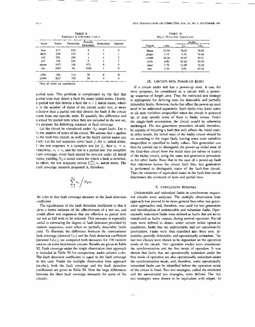
Table X gives the results obtained for ISCAS-89 benchmark circuits s386 and s1494 and for MCNC finite-state machine benchmarks, synthesized by the AT&T logic synthesis system and made available to us by Dr. K-T. Cheng of AT&T. In Table X, after the total number of faults, the number of detectable faults is given. The remaining faults are undetectable. Of the undetectable faults, the number of partially detectable faults is given next, followed by the number of redundant faults. The number of faults for which no partial test could be generated, however, the faults were not proved to be redundant (aborted faults), are given in the last column of Table X. It should be noted that, for planet and sfyr , where large numbers of partially detectable faults were found, most partially detectable faults are detectable if fault-free reset is available [33]. Different implementations of the MCNC benchmarks yield different numbers of partially detectable faults, implying that synthesis has a significant effect on the testability of the circuit.
VIII. FAULT COVERAGE MEASURE
In this section, we consider the effect of partial tests on the fault coverage measure, and propose a new measure that would allow partial tests to be counted.
Traditionally, fault coverage for a given test sequence is defined as the percentage of faults detected by the test sequence, out of all target faults. This definition does not provide any mechanism for estimating the coverage due to
llli i
TABLE X PARTIALLY D ETECTABLE FAULTS
IEEE TRANSACTIONS ON COMPUTERS, VOL. 42, NO. 9, SEPTEMBER 199:;
TABLE XI FAULT DETECTION COEFFICIENT
lircuit Faults Detectable c:i:l& Redundant Aborted -
bou 617 610 4 3 0 dk16 529 523 4 1 1 ex2 301 294 1 4 2 ex3 154 143 5 1 5
planet 1077 104 973 0 0 sty1 1087 56 1030 1 0
m.obs. Circuit s.obs. f.c. f.d.c.
bbara 52.94 70.59 78.05 planet 1.11 9.10 74.46 s1488 43.34 43.47 50.21 s510 0.00 81.03 93.59 sand 1.70 53.89 74.10 styr 1.10 3.96 47.14
s386 384 314 50 0 20 s1494 83ja 792 34 9 0
aNot all faults are considered. --
p,trtial tests. This problem is complicated by the fact that pirtial tests may detect a fault for many initial states. Clearly, a partial test that detects a fault for n - 1 initial states, where 71 is the number of states of the circuit under test, is more eifective than a partial test that detects the fault if the circuit srarts from one specific state. To quantify this difference and account for partial tests when they are included in the test set, ir. e propose the following measure of fault coverage.
Let the circuit be considered under N F target faults. Let n ti: the number of states of the circuit. We assume that n applies 10 the fault-free circuit, as well as the faulty circuit under any t iult. Let the test sequence cover fault f, for n, initial states. I ’ the test sequence is a complete test for fi, then n, = n. Otherwise, n, < n, and the test is a partial test. For complete f iult coverage, every fault should be covered under all initial dates, yielding N F ~ initial states for which a fault is detected. I n effect, the test sequence covers n, initial states. The t ault coverage measure proposed is, therefore,
‘Ne refer to this fault coverage measure as the fault detection -0eflicient .
The significance of the fault detection coefficient is that it $ves a better estimate of the effectiveness of a test set, and Nould allow test sequences that are effective as partial tests >ut not as full tests to be retained. This measure is especially Jseful in estimating the degree of fault detection provided by random sequences, even when no partially detectable faults sxist. To illustrate the difference between the conventional fault coverage (denoted f.c.) and the fault detection coefficient (denoted f.d.c.), we computed both measures for 100 random vectors on some benchmark circuits. Results are given in Table XI. Fault coverage under the single observation time approach is included in Table XI for comparison, under column s.obs. The fault detection coefficient is equal to the fault coverage in this case. Under the multiple observation time approach (m.obs.), both the fault coverage and the fault detection coefficients are given in Table XI. Note the large differences between the three fault coverage measures for some of the circuits.
Ix. CIRCUITS WITH POWER-UP RESET
If a circuit under test has a power-up reset, it can, for most purposes, be considered as a circuit with a power- up sequence of length zero. Thus the restricted test strategy is appropriate for deriving tests for detectable and partially detectable faults. However, faults that affect the power-up reset need to be addressed separately. Such faults may leave some or all state variables unspecified when the circuit is powered up, or may specify some of them to faulty values. Under the single-fault assumption, the circuit would be otherwise unchanged. The test generation procedure should, therefore, be capable of injecting a fault that only affects the initial state. In other words, the initial state of the faulty circuit should he set according to the target fault, leaving some state variables unspecified or specified to faulty values. Test generation can then be carried out to distinguish the power-up initial state of the fault-free circuit from the initial state (or subset of states) of the faulty circuit, using the same test generation procedure as for other faults. Note that in the case of a power-up fault that otherwise leaves the circuit fault free, test generation is performed to distinguish states of the fault-free circuit. Thus the existence of equivalent states in the fault-free circuit determines the existence of tests and partial tests.
X. CONCLUDING REMARKS
Undetectable and redundant faults in synchronous sequen- tial circuits were analyzed. The multiple observation time approach was proved to be more general than other test gener- ation approaches and, therefore, was used for test generation and identification of undetectable and redundant faults. Oper- ationally redundant faults were defined as faults that are never manifested as faulty outputs during normal operation. Par1 ial tests were defined to detect, under certain initial operation conditions, faults that are undetectable and yet operationally irredundant. Faults were thus classified into three sets: je- tectable, partially detectable, and operationally redundant. The last two classes were shown to be dependent on the operation mode of the circuit. Two operation modes were considered: the synchronization and the free mode of operation. It was shown that faults that are operationally redundant under the free mode of operation are also operationally redundant under the synchronization mode, and, therefore, some operationdly redundant faults can be identified before the operation mode of the circuit is fixed. Two test strategies, called the restricted and the unrestricted test strategies, were defined. The :wo test strategies were shown to be equivalent with respec: to

1077 POMERANZ AND REDDY CLASSIFICATION OF FAULTS IN SEQUENTIAL CIRCUITS
detectable faults, but different with respect to partial tests. The relationships between state equivalence, undetectability, and operational redundancy were considered to provide a deeper insight into undetectability and operational redundancy. A description of a test procedure for every mode of operation was given. Experimental results, indicating the existence of partially detectable faults, were presented. Finally, a definition of a fault coverage measure was proposed to account for partial tests.
ACKNOWLEDGMENT
The authors thank Prof. J. Patel of the University of Illinois for many helpful discussions. They also thank the reviewers for their invaluable comments.
REFERENCES
M. Abramovici and M. A. Breuer, “On redundancy and fault detection in sequential circuits,” IEEE Trans. Comput., pp. 864-865, Nov. 1979. M. Abramovici, M. A. Breuer, and A. D. Friedman, Digital Sysrems Testing and Testable Design. H. Fujiwara, Logic Testing and Design for Testability. Cambridge, MA: MIT Press, 1985. F. Hennie, Finite-State Models for Logical Machines. New York: Wiley, 1968. A. D. Friedman and P. R. Menon, Faulr Detection in Digital Circuits. Englewood Cliffs, NJ: Prentice-Hall, 1971. H. Kubo, “A procedure for generating test sequences to detect sequential circuit failures,” N€C Res. Develop., no. 12, Oct. 1968. J. J. Thomas, “Automated diagnostic test programs for digital networks.” Computer Design, pp. 6 3 4 7 , Aug. 1971. P. Muth, “A nine valued circuit model for test generation.” IEEE: Trans. Comput., pp. 6 3 M 3 6 , June 1976. M. A. Breuer and A. D. Friedman, Diagnosis and Reliable Design o j Digital Systems. R. A. Marlett, “EBT: A comprehensive test generation technique for highly sequential circuits,” in Proc. Design Auto. Conf, 1978, pp. 335-339. S . Seshu, “On an improved diagnosis program,” IEEE Trans. Comput., pp. 7 6 7 9 , Feb. 1965. T. J. Snethen, “Simulator-oriented fault test generator.” in Proc. Design Auto. Cunf, 1977, pp. 88-93. R. Steingart, A. W. Nagle, and J. Grason, “RTG: Automatic register level test generator,” in Proc. Design Auto. Con$, June 1985, pp. 803-807. S. Mallela and S. Wu, “A sequential test generation system,” in Proc. Int. Test Conf, Sept. 1985, pp. 57-61. R. A. Marlett, “An effective test generation system for sequential circuits,” in Proc. Design Auto. Con$, June 1986, pp. 2.50-2.56. T. P. Kelsey and K. K. Saluja, “Fast test generation for sequential circuits,” in Proc. Int. Conf Comp. Aided Design, Nov. 1989, pp. 354-357. W-T. Cheng, “The back algorithm for sequential test generation.” in Proc. Int. Conf Comp. Design, Oct. 1988, pp. 6&69. W-T. Cheng and T. J. Chakraborty, “Gentest: An automatic test gen- eration system for sequential circuits.” Computer. pp. 4 3 4 9 . Apr. 1989. T. Ogihara, S. Saruyama, and S. Murai, “Test generation for sequential circuits using individual initial value propagation,” in Proc. I n t . Conf Comp. Aided Design, Nov. 1988, pp. 424427. V. D. Agrawal, K. T. Cheng, and P. Agrawal, “CONTEST: A concurrent test generator for sequential circuits,” in Proc. Design Auto. Conf , June 1988, pp. 84-89. H-K. T. Ma, S. Devadas, A. R. Newton, and A. S-Vincentelli, “Test generation for sequential circuits,” /€E€ Trans., pp. 1081-109.1. Oct. 1988. K-T. Cheng and J. Y. Jou, “Functional test generation for finite state machines,” in Proc. In/. Test Conf, 1990, pp. 162-1 68. R. V. Hudly and S . C. Seth, “Testability analysis of synchronous sequential circuits based on structural data,” in Pror. I n t . Test Cotif, 1989, pp. 364-372.
Computer Science Press, 1990.
Computer Science Press, 1976.
[24] S . M. Thatte and J . A. Abraham, “Test generation for microprocessors,” IEEE Trans. Compur., pp. 429441, June 1980.
[25] K. Sabnani and A. T. Dahbura, “A protocol test generation procedure,” Computer Networks. pp. 285-297, 1988.
[26] A. T. Dahbura, M. U. Uyar, and C. W. Yau, “An optimal test sequence for the JTAGilEEE P114Y.l test access port controller,” in Proc. Int. Test Conf, 1989, pp. 55-62.
[27] M. S. Abadir and H. K. Reghbati, “Functional test generation for digital circuits described using binary decision diagrams,” /E€€ Trans. Comput., pp. 375-379, Apr. 1986.
1281 P. Ashar, A. Ghosh, S. Devadas and A. R. Newton, “Implicit state transition graphs: Applications to sequential logic synthesis and test,” in Proc. Int. Con$ Comp. Aided Design, 1990, pp. 84-87.
[29] V. D. Agrawal, K. T. Cheng, and P. Agrawal, “A directed search method for test generation using concurrent simulator,” / € € E Trans. Computer-Aided Design, pp. 131-138, Feb. 1989.
[30] S. Devadas, H-K. T. Ma, and A. R. Newton, “Redundancies and don’t- cares in sequential logic synthesis,” J . Electronic Testing: Theory and Application, vol. 1, pp. 15-30, Feb. 1990.
1311 E. B. Eichelberger and T. W. Williams, “A logic design structure for LSI testing,” in Proc. 14th Design Auto. Con$, June 1977, pp. 462468.
(321 K. T. Cheng, “On removing redundancy in sequential circuits,’’ in Proc. 28th Design Auto. Con$, June 1991, pp. 164169.
[33] I. Pomeranz and S. M. Reddy, “Test generation for synchronous sequen- tial circuits based on fault extraction,” in Proc. 1991 Int. Conf CAD, Nov. 1991, pp, 4 5 W 5 3 .
1341 1. Pomeranz and S. M. Reddy, “Test generation for synchronous se- quential circuits using multiple observation times,” in Proc. 2 I s t Fuult- Toleranr Comput. Symp., June 1991, pp. 52-59.
[35] Z. Kohavi, Switching and Finire Auromura Theory. New York: McGraw-Hill, 1978.
1361 A. D. Friedman, “Fault detection in redundant circuit\,” IEEE Trans. Comput., pp. 66-73, Feb. 1966.
1371 I . Pomeranz and S. M. Reddy, “The multiple observation time test strategy,” IEEE Trans. Comput., (Special Issue on Fault-Tolerant Com- puting), pp. 627-637, May 1992.
kith Pomeranz (M’89) was born in Tel-Aviv, Is- rael. She received the B.S. degree (summa cum laude) in computer engineering and the D.Sc. degree in electrical engineering from the Technion-Israel Institute of Technology in 1985 and 1989, respec- tively.
From 1989 to 1990. she was a lecturer in the Department of Computer Science at the Technion. She is currently an Assistant Professor in the De- partment of Electrical and Computer Engineering at the University of Iowa. Her research interests
are in testing of VLSI circuits, design for testability. synthesis, and design verification.
Sudhakar Reddy obtained an undergraduate degree in electrical and communication engineering from Osmania University, the M.S. degree from the In- dian Institute of Science, and the Ph.D. degrce in electrical engineering from the University of Iowa, Iowa City.
Dr. Reddy has been active in the areas of testable designs and test generation for logic circuits since 1972. He has been an Associate Editor and twice a Guest Editor of IEEE TRANSACTIONS ON COMPUTERS He is currently on the editorial hoard of the JOURNAL
OF ELECTRONIC TESTING: THEORY A N D APPIJCAI IONS. Since 1968 he has been a member of the faculty of the Department of Electrical and Computer Engineer- ing, University of Iowa, where he is currently the Department Chairman. In 1990, he was named University of Iowa Foundation Distinguished Professor.
Dr. Reddy is a member of Tau Beta Pi, Eta Kappa Nu, and Sigma Xi.
Copyright © 2022 FDOKUMEN