
City of Hendersonville Construction Manual
227
City of Hendersonville Construction Manual
-
Upload
khangminh22 -
Category
Documents
-
view
2 -
download
0
Transcript of City of Hendersonville Construction Manual

City of
Hendersonville
Construction Manual

SPECIFICATIONS

TABLE OF CONTENTS
STANDARD DRAWINGS DRAINAGE STRUCTRES PAGE No.
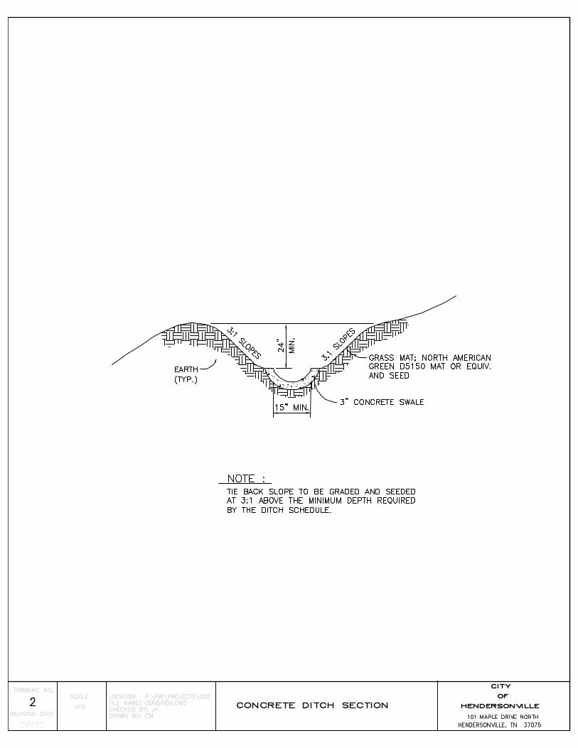
4’ – 6’ Dia. Circular Manhole 1 Concrete Ditch Section 2 Pre-Cast Inlet 3 Ditch Section 4 Grass Ditch Section 5 Concrete Headwall 6 Junction Box Detail 7 Manhole / Inlet 8
EROSION CONTROL
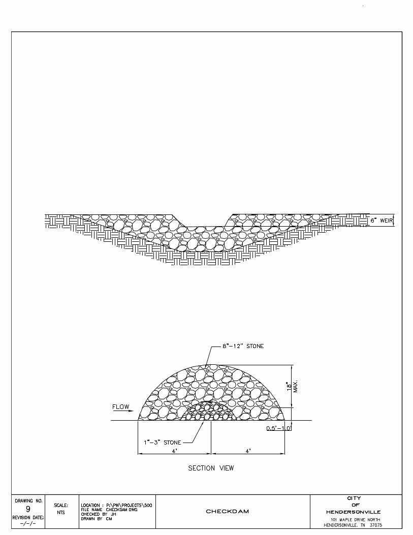
Check Dam 9 Construction Entrance 10 Inlet Protection 11 Rip-Rap 12 Silt Fence 13 Straw Bale Silt Barrier 14
STANDARD STREET SECTIONS
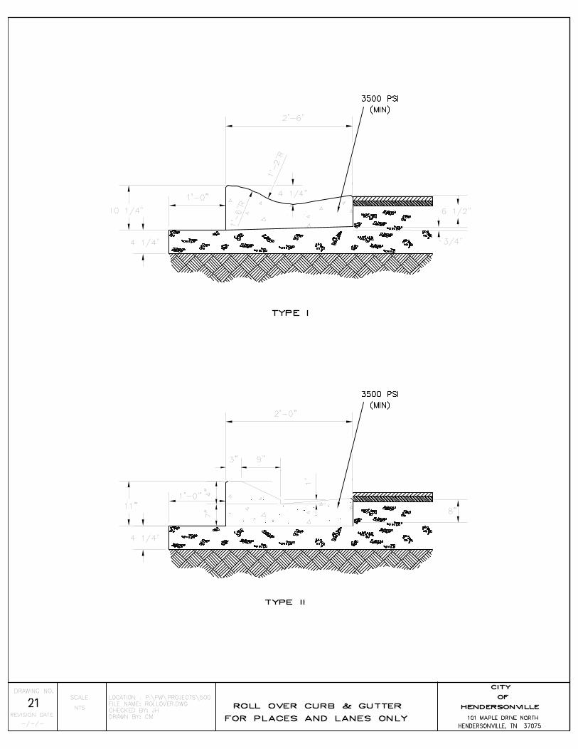
Collector 15 Sub-collector 16 Lane 17 Place – Average Daily Traffic of 100 or less 18 Place – Average Daily Traffic of 100 or more 19 Extruded Concrete Curb Driveway Ramp 20 Roll Over Curb and Gutter for Places and Lanes Only 21 Standard Curb and Gutter 22 Handicapped Ramp Layout 23 Sidewalk 24
SECTION NO. AND TITLE PAGES
02050 Demolition 2 02110 Clearing and Grubbing 4 02210 Grading and Excavating 4 02215 Base and Subgrade Treatment 8 02221 Trenching, Backfilling, and Compaction 16
i

02250 Soil and Erosion Control 31 02271 Rip-Rap 4 02305 Jacking and Boring 3 02444 Chain Link Fences and Gates 3 02451 Guardrails 3 02452 Highway Signs 2 02485 Lawn and Grass Landscaping; Temporary Seeding 4 02486 Lawn and Grass Landscaping; Permanent Seeding 14 02490 Topsoil 3 02491 Sodding 3 02513 Asphalt Concrete Paving 19 02515 Portland Cement Concrete Paving 1 02528 Concrete Sidewalks, Curbs, and Gutters 8 02577 Pavement Marking 2 02721 Storm Drainage Systems 6 03001 Concrete Work 19
ii


SECTION 02050
DEMOLITION PART 1 GENERAL 1.01 WORK INCLUDED
A. Removal and disposal of designated foundations, pavements, concrete, bridges, culverts and other structures.
1.02 RELATED WORK
A. Section 02110: Clearing and Grubbing B. Section 02210: Grading and Excavation
PART 2 PRODUCTS (NOT APPLICABLE) PART 3 EXECUTION 3.01 PREPARATION
A. Prepare adjacent areas to prevent injury, movement or settlement of structures which
are to remain.
B. Make accommodations for pedestrian and vehicular traffic where areas are to be closed.
3.02 DEMOLITION
A. Remove foundations of buildings and structures to a depth of not less than one foot below natural ground, except in the construction area where a depth of not less than two feet below subgrade elevation is required.
B. Break up basement floors to prevent water retention.
C. Remove concrete pavement, parking strip, base, curbs, gutters, sidewalks, driveways,
etc., and dispose of as follows:
1. Dispose of items below subgrade elevation by no more than two feet.
2. Break items more than two feet below subgrade elevation into sizes not to exceed two feet in maximum dimension and leave in place, unless it interferes
HCS 01/03 02050 25

with succeeding items of construction.
3. Stockpile ballast, gravel, bituminous pavement or other pavement materials when required.
D. Fill basements or cavities left by structure removal within the prism of construction
and below subgrade elevation to the level of the surrounding ground and compact in accordance with Section 02210.
3.03 DEBRIS REMOVAL
A. Promptly remove demolition debris from site.
B. Obtain permission from applicable regulatory authority for disposal of debris to waste disposal site.
3.04 MEASUREMENT AND PAYMENT - RESERVED
END OF SECTION
HCS 01/03 02050 26

HCS 01/03 02110 27
SECTION 02110
CLEARING AND GRUBBING PART 1 GENERAL 1.01 WORK INCLUDED
A. Clearing, grubbing, removal and disposal of vegetation, rocks, roots and debris within the limits of the work except objects designated to remain.
B. Preservation from injury or defacement all vegetation and objects to remain.
C. Stripping and stockpiling of topsoil from all areas within the limits of work where
the ground surface is to be modified and the final surface is to be topsoiled under this Contract.
1.02 RELATED WORK
A. Section 02050: Demolition
B. Section 02210: Grading and Excavation 1.03 LIMITS OF WORK
A. Rights-of-way and easement areas established by the City Engineer, and any additional areas as shown on the plans, or deemed necessary by the City Engineer.
B. Approved borrow pit areas.
C. Designated stockpiles of construction material other than borrow material.
1.04 PROTECTION
A. Take reasonable care during construction to avoid damage to vegetation. Where the area to be excavated is occupied by trees, brush, or other uncultivated vegetable growth, clear such growth from the area, and dispose of it in a satisfactory manner. Leave undisturbed any trees, cultivated shrubs, flowers, etc., situated within public rights-of-way and/or easements through private property but not located directly within excavation limits. Transplant small ornamental trees, cultivated shrubs, flowers, etc., located directly within excavation limits so they may be replaced during property restoration operations. Do not remove or disturb any tree larger than six inches (10") in diameter without the permission of the City Engineer or as specified. Take special precautions (including the provision of barricades and the temporary tying back of shrubbery and tree branches) for the protection and preservation of such objects throughout all stages of construction; the Contractor

HCS 01/03 02110 28
will be held liable for any damage that may result to said objects from excavation or construction operations. On the day damage is inflicted, trim any limbs or branches of trees broken during construction operations with a clean cut, and paint with an approved tree pruning compound. Treat tree trunks receiving damage from equipment with a tree dressing.
B. Protect living shrubs and trees not marked for removal and outside the rights-of-way
or easement area by erecting appropriate temporary barricades around the drip line of said trees and wrapping with burlap as necessary for protection during the construction period; method subject to approval by the City Engineer. The same protection is to be provided for living shrubs and trees within the right-of-way or easement area and designated to remain by the City Engineer or on the Plan.
C. Protect bench marks and existing structures, roads, sidewalks, paving and curbs
against damage from vehicular or foot traffic.
D. Maintain designated temporary roadways, walkways and detours, for vehicular and pedestrian traffic.
PART 2 PRODUCTS
(NOT APPLICABLE)
PART 3 EXECUTION 3.01 PREPARATION
A. Maintain benchmarks, monuments and other reference points. Re-establish if disturbed or destroyed at no cost to the City.
3.02 CLEARING AND GRUBBING
A. Clear rights-of-way, easement, borrow pit and other stockpile areas of objectionable material to the ground surface except for trees and stumps. In addition, all trees and stumps in permanent easements shall be cleared to the ground surface prior to construction
B. Cut trees and stumps to within six inches of the ground surface or low water level in
swampy areas where embankments are to be constructed provided undercutting or other corrective measures are not stipulated.
C. Cut trees and remove stumps outside the easement area and marked for removal.
D. Remove low hanging, unsound, or unsightly branches on trees or shrubs designated
to remain.
E. Trim branches of trees extending over the right-of-way or easement to a clear height
HCS 01/03 02110 29
of twenty feet above the ground surface.
F. Grub rights-of-way or easement areas of protruding obstructions.
G. Grub borrow pit and stockpile areas of all objectionable material. Strip overburden of the material to be obtained in stockpile areas.
H. Perform clearing and grubbing well in advance of construction or material removal
activities.
I. All suitable trees removed from privately owned property shall be cut into fireplace lengths (approximately 20") and neatly stacked adjacent to the easement on the property of the affected landowner.
J. Whenever reasonably possible strip topsoil from areas defined in paragraph C of
1.01-Work Included, above. This soil is to be stockpiled along the project in such a manner as to preserve the condition of the topsoil until landscaping operations can take place.
3.03 BACKFILLING AND SURFACE PREPARATION
A. Backfill and compact all depressions resulting from clearing and grubbing with suitable materials in accordance with Section 02210.
1. Backfill embankment areas to natural ground elevation. 2. Backfill excavation areas below finished subgrade to finished subgrade.
B. Perform backfilling a satisfactory distance ahead of construction operations.
C. Prepare areas designated on the drawings to receive erosion control matting to
smooth surfaces that have been shaped, fertilized, and seeded. 3.04 DEBRIS REMOVAL
A. Promptly remove cleared debris from site.
B. Obtain permission from applicable regulatory authority for disposal of debris to waste disposal site.
C. No burning will be allowed in connection with this project.
3.05 MEASUREMENT AND PAYMENT - CLEARING AND GRUBBING – RESERVED 3.06 MEASUREMENT AND PAYMENT - PROTECTION OF LIVING SHRUBS AND
TREES - RESERVED

HCS 01/03 02110 30
END OF SECTION

HCS 01/03 02210 31
SECTION 02210
GRADING AND EXCAVATING PART 1 GENERAL 1.01 WORK INCLUDED
A. Excavating and grading of:
1. Roadways (including the removal of slides). 2. Borrow pits. 3. Waterways and ditches (including structure inlet and outlet ditches, channels,
waterways, etc., event though they extend beyond the highway limits). 4. Intersections. 5. Approaches. 6. Benches under side-hill embankments.
B. Excavating of unsuitable material from roadbed and beneath embankment areas.
C. Excavating selected material found in the roadway which is required for specific use in
the construction.
D. Construction and removal of detours. 1.02 RELATED WORK
A. Section 02050: Demolition
B. Section 023110: Clearing and Grubbing
C. Section 02250: Soil and Erosion Control 1.03 CLASSIFICATION OF EXCAVATION MATERIALS
A. Road and Drainage Excavation (unclassified): all excavation regardless of the nature of the excavated material and channel excavation of 14’ or less.
B. Borrow excavation: material required for construction and obtained from approved
sources outside the rights-of-way limits or other designated areas. Flattening of approved cut slopes graded under previous contracts is permitted for use as borrow provided the material is satisfactory. Borrow material other than solid rock shall be AASHTO A-6 or no worse than the predominant soil type in the roadway excavation, based on AASHTO classification if A-6 is not reasonably available. Removal and placement of borrow is classified as:

HCS 01/03 02210 32
1. Borrow Excavation (solid rock): non-degradable rock which cannot be
economically excavated by the proper use of a power shovel or explosives. 2. Borrow Excavation (unclassified): all approved material including Borrow
Excavation (solid rock). 3. Borrow Excavation (select material): designated material.
C. Channel Excavation (unclassified): removal and disposal of all material excavated from
existing or new channels with a bottom width of more than fourteen feet as shown on the drawings.
D. Solid Rock Excavation: An excavation classification only when it is provided for in the
Bid Form and defined as follows:
1. Excavation of rock which cannot be economically excavated without the use of explosives;
2. Any rock, boulder, fragment of rock or concrete having a volume of at least one-half (1/2) cubic yard or a fragment excavated from a formation having a volume greater than one-half (1/2) cubic yard.
1.04 REFERENCE STANDARDS
A. Determine maximum density and optimum moisture in accordance with the "Standard Method of Test for Moisture Density Relationship of Soils Using a 5.5 Pound Rammer and a 12-inch Drop", ASTM D 698
B. Compact all designated materials to 98% of maximum density unless otherwise
specified.
C. Rock borings or soundings, if provided, are:
1. For information purposes only. 2. No guarantee of existing conditions. 3. No substitute for investigations deemed necessary by Contractor.

HCS 01/03 02210 33
PART 2 PRODUCTS
(NOT APPLICABLE) PART 3 EXECUTION 3.01 PREPARATION
A. Prior to beginning excavation, grading, and embankment operations in any area, install all necessary soil erosion control structures (Section 02250) prior to any clearing, grubbing, and demolition in accordance with Sections 02110 and 02050.
3.02 EMBANKMENT
A. Construct embankments by placing and compacting approved embankment materials:
1. In reasonably close conformity with the lines, grades, and typical cross-sections shown on the drawings or established by the City Engineer.
2. Use Road and Drainage, Channel, and Borrow Excavation materials only. 3. Place roadway embankment materials consisting predominantly of soil in
horizontal layers not to exceed six inches in depth and compact each layer.
B. Provide adequate surface drainage for embankments at all times. 3.03 UNDERCUTTINGS
A. Remove and dispose of unsatisfactory materials:
1. Below grade in cut sections. 2. Areas where embankments are to be placed. 3. Below the foundation elevation of pipe and box culverts.
B. Stripping, stockpiling and placing of topsoil and step-benching for hillside
embankments is not classified as undercutting. 3.04 CLEAN-UP AND DISPOSAL OF DEBRIS - AND EXCESS EXCAVATION
A. Dress for final inspection all excavated and graded areas to within reasonably close conformity to the lines, grades and cross-section shown on the drawings:
1. Producing a uniform, satisfactory finish per the City Engineer or his agent.. 2. Scale rock cuts of all loose fragments and leave in a neat, safe and workmanlike
condition. 3. Clean the entire rights-of-way or easement of all vegetation unless otherwise
specified on the drawings.

HCS 01/03 02210 34
4. Clear and clean all structures of all objectionable materials and obstructions. 5. Perform final dressing prior to sodding or seeding operations when these items
are in the Contract.
B. Dress spoil banks, waste areas, etc., in a satisfactory manner.
C. Dispose of excess material created by trimming slopes, resloping, and shaping outside the rights-of-way.
D. Promptly remove cleared debris from site.
E. Obtain permission from applicable regulatory authority for disposal of debris to waste
disposal site.
F. Satisfactorily dispose of all excess excavated material by hauling to the appropriate landfill.
3.05 MEASUREMENT AND PAYMENT - RESERVED
END OF SECTION

HCS 01/03 02215 35
SECTION 02215
BASE AND SUBGRADE TREATMENT PART 1 GENERAL 1.01 WORK INCLUDED
A. Preparing and stabilizing subgrade to receive a base or pavement.
B. Placing and compacting base material.
C. Placing and compacting stabilized base. 1.02 RELATED WORK
A. Section 02110: Clearing and Grubbing
B. Section 02210: Grading and Excavating
C. Section 02515: Portland Cement Concrete Pavement 1.03 REFERENCE STANDARDS
A. Compact all Subgrade materials to 100% of maximum density unless otherwise specified.
1. Determine maximum density and optimum moisture in accordance with the
"Standard Method of Test for Moisture Density Relationship of Soils Using a 5.5 Pound Rammer and a 12-inch Drop", AASHTO Designation T 99, Method A.
B. Compact Type I Base materials to an average dry density of at least 100% of theoretical
density based upon 83% of a solid volume, unless otherwise specified.
1. No individual test shall be less than 97% of theoretical density. 2. The theoretical density of limestone aggregates shall be based on bulk specific
gravity AASHTO T-85. 3. The theoretical density of all other aggregates shall be based on bulk specific
gravity AASHTO T-84 and T-85.

HCS 01/03 02215 36
C. Compact Type II Base materials to at least 95% of maximum density, unless otherwise specified.
1. No individual test shall be less than 92% of maximum density. 2. Determine maximum density and optimum moisture in accordance with the
"Standard Method of Test for Moisture Density Relationship of Soils Using a 5.5 Pound Rammer and a 12-inch Drop", AASHTO Designation T 99, Method D.
PART 2 PRODUCTS 2.01 MINERAL AGGREGATE MATERIALS - GENERAL
A. Mineral aggregate: sound, tough, and durable fragments of crushed stone, crushed slag, crushed or uncrushed gravel or chert.
B. Fine aggregate: natural sand, silt-clay or other inert materials with similar
characteristics conforming to AASHTO M-6, M-29 and M-45 requirements except as specified herein.
C. Coarse aggregate: AASHTO M-43, except as specified herein, consisting of crushed
stone, crushed slag, crushed or uncrushed gravel, crushed or uncrushed chert, or a combination thereof, or other inert materials with similar characteristics, having hard strong durable pieces free from adherent coatings.
D. Coarse aggregates: graded to standard sizes between the limits specified and to the
gradation requirements set forth in the table on the following page: 2.02 SUBGRADE STABILIZATION MATERIAL
A. Thoroughly pulverize and mix all subgrade and aggregate material until not more than five percent of the material exclusive of gravel or stone is retained on a 2-inch sieve.
B. Add sufficient water during the mixing and compacting operation to provide optimum
moisture content, a determined by AASHTO T 99, plus or minus three percentage points.
2.03 MINERAL AGGREGATE BASE MATERIALS
A. Base aggregates shall conform to the requirements of article 2.01 and shall be of two classes: Type I and Type II.
B. Type I aggregate: crushed stone, crushed slag, crushed gravel or crushed chert and
other fine grained mineral matter.

HCS 01/03 02215 37
1. Crushed stone: free from adherent coatings, clay, or other solid with wear not
exceeding 50% and sodium sulphate soundness loss not exceeding 15%. 2. Crushed slag: quality as for crushed stone having a uniform density. 3. Crushed gravel and chert: screened and all oversize material crushed and fed
back over the screen in a uniform manner. 4. Coarse aggregate wear for those retained on the No. 4 sieve shall not exceed
30%. 5. Material passing the No. 40 sieve: non-plastic, or with a liquid limit not
exceeding 25 and a plasticity index not exceeding 6. 6. Only grading D aggregate shall be used.
C. Furnish test reports on quality of all aggregates for approval by the City Engineer prior
to blending or mixing. If requested by the City Engineer, furnish samples for testing by an independent laboratory. Test methods for aggregate base quality shall be by the following AASHTO methods:
Test Method
Sampling T-2 Percentage of wear T-96 Soundness T-104 Unit weight T-19
Sieve analysis T-27 2.04 CEMENT STABILIZED BASE MATERIALS
A. The City Engineer will determine the proportions of materials to be used that will produce a workable lean concrete.
1. Maximum design slump of 1-1/2 inches, AASHTO T-119. 2. Minimum compressive strength of 500 psi in seven (7) days. 3. Cement content of 200 pounds per cubic yard of concrete. 4. Maximum entrained air of 5 percent. 5. Water reducer quantity as recommended by the manufacturer. 6. Other applicable requirements as stipulated in Section 02515.
HCS 01/03 02215 38
PART 3 EXECUTION 3.01 PREPARATION
A. Clear construction areas as stipulated in Section 02110.
B. Maintain benchmarks, monuments and other reference points. 3.02 SUBGRADE PREPARATION
A. Prepare subgrade in reasonably close conformity with the lines and grades as shown on the drawings or as designated by Engineer.
B. Haul, spread and compact suitable material in sufficient quantity when the roadbed is
below grade.
C. Prepare subgrade across the entire sub-base section when sub-bases are to be constructed on the subgrade.
D. Construction subgrade 12" wider on each side of the base or pavement when forms are
required for the base or pavement.
E. Clear subgrades, as stipulated in Section 02110, requiring reworking to the limits described above.
F. Grade subgrade in such a manner as to provide ready drainage of water from the
subgrade. Maintain ditches and drains during construction. 3.03 SUBGRADE COMPACTION
A. Compact the finished subgrade to not less than 100 percent of the maximum density.
B. When the density requirement is not met, loosen the subgrade by discing, harrowing or other approved methods to a depth of not less than six inches, then reshape and recompact.
C. Moisten and aerate the subgrade material as necessary during mixing and compacting to
provide optimum moisture content.
D. Rework or remove, replace and recompact all soft, yielding material which will not compact readily.
E. Protect subgrade from damage and limit hauling over the finished subgrade to that
which is essential for construction purposes.
HCS 01/03 02215 39
F. Smooth and recompact all ruts or rough places that develop in a completed subgrade.
G. Check the lines, cross-sections and grades of the subgrade as completed for reasonably
close conformity with those shown on the drawings for the bottom of the sub-base, or pavement, or with those established by Engineer.
3.04 SUBGRADE STABILIZATION
A. Add and incorporate granular stabilizing material, with or without additives as required, into the existing subgrade.
B. Replace unsuitable subgrade material with stabilizing material in reasonably close
conformity to the widths and depth shown on the drawings or as directed by the City Engineer.
C. Spread the quantity of aggregate for subgrade treatment, as designated on the drawings
or as directed, by means of a mechanical spreader and thoroughly mix with the subgrade material by means of a mechanical mixer. Spreading and mixing may be performed by other approved methods on short sections to be stabilized, when permitted by the City Engineer.
D. Spread material uniformly by motor grader to the required cross-section and compact.
Accompany compaction operations with sufficient blading by motor graders to assure a smooth, uniform surface.
E. Maintain the complete subgrade until covered by the following stage of construction or
until the project has been completed and accepted. 3.05 PLACING AGGREGATE BASE
A. Place one or more courses of aggregates, and additives, if required, on a prepared subgrade in reasonably close conformity with the lines, grades, thicknesses, and typical cross-sections show on the drawings or established by the City Engineer.
B. Construct mineral aggregate base in one or more layers with a compacted thickness as
shown on the drawings.
C. The subgrade shall be checked and approved by the City Engineer at least 500 feet in advance of spreading any mineral aggregate. This distance may be shortened by permission of the City Engineer to as little as 200 feet between November first and April first or during periods of prolonged wet weather.
D. Mineral aggregate bases shall not be spread on a subgrade that is frozen or contains frost.

HCS 01/03 02215 40
E. Hauling over material already placed will not be permitted until it has been spread,
mixed, shaped, and compacted to the required density. 3.06 MIXING AND SPREADING AGGREGATE BASE
Unless otherwise specified, mix and spread base course materials, including additives if required on the drawings. Furnish sieve analyses of mix gradations for all materials for approval by Engineer prior to beginning work. Methods of sampling and testing shall be in accordance with current AASHTO requirements.
A. Stationary Plant Method - For Type I or II base materials.
1. Mix and add water in an approved stationary mixing plant capable of producing a
well graded mix. 2. Add water and calcium or sodium chloride, if specified, during the mixing
operation in the amount necessary to provide a moisture content satisfactory for compacting.
3. If combining of materials is required to meet the grading requirements, blend prior to mixing by uniformly adding the material. Blending of materials in stockpiles will not be permitted.
4. All material fed into the plant shall travel the full length of the pugmill. 5. After mixing, transport the material for each layer of base to the job site while it
contains the proper moisture content, and spread to the required thickness and cross-section by means of an approved mechanical spreader.
6. Test samples may be taken from the conveyor feeding the mixer or from the mixer output.
B. Road Mix Method (Mechanical Mixer) - For Type II base materials.
1. Place the material for each layer of base course through an aggregate spreader or
windrow-sizing device capable of being adjusted to spread the materials in the proper proportions.
2. After placing, mix the material with an approved mechanical mixing machine of rotary or pug mill type capable of producing a uniform blend.
3. During mixing, add water in the amount sufficient to provide a moisture content satisfactory for compacting.
4. If two or more materials are to be blended on the road, spread each material separately in the necessary proportion prior to blending and mixing, unless moisture control additives are specified.
5. If two or more materials are blended, test samples shall be taken after mixing and before compaction. If blending is not required, test samples may be taken from plant production or stockpiles.
HCS 01/03 02215 41
C. Road Mix Method (Motor Grader) - For Type II base materials.
1. After depositing and uniformly spreading the material for each layer of base course, sprinkle it with water in sufficient quantity to moisten all particles, but not in such quantity that segregation of sizes or softening of the subgrade will occur.
2. Immediately following the application of water, thoroughly mix the material by windrowing and spreading with motor graders until the mixture is uniform throughout, unless moisture control additives are specified or if two or more materials are to be blended.
3. Spread the base material while at optimum moisture content in layers of specified thickness and cross-section by means of approved motor graders.
4. If the required compacted depth of the base course exceeds 6", construct the base in two or more layers of approximate equal thickness. The maximum compacted thickness of any one layer shall not exceed 6" except when vibrating or other approved types of special compacting equipment are used. The compacted depth of a single layer of the base course may be increased to 8" upon approval of Engineer.
5. Immediately following spreading, shape the base material to the required degree of uniformity and smoothness.
6. Compact to the required density prior to any appreciable evaporation of surface moisture. Continuously compact each layer until the minimum density requirement is achieved.
7. Test samples may be taken from stockpiles or plant production. 3.07 COMPACTING AGGREGATE BASES
A. For compaction testing purposes, each completed layer will be divided into lots of approximately 10,000 square yards. Smaller lots may be considered when approved by the City Engineer.
B. Five density tests will be performed on each lot and the results averaged.
3.08 PLACING CEMENT STABILIZED BASE
A. Construct a base of lean concrete on a prepared subgrade or subbase in reasonably close conformity with the lines, grades, thickness and typical cross-section shown on the drawings or as directed by the City Engineer. Unless otherwise specified, construction shall be performed in accordance with the applicable requirements of Section 02515.
B. Offset longitudinal joints 1' from the portland cement concrete pavement joint with the 1' offset located on the median half of the lean concrete base.
C. Form a butt type joint, as directed by the City Engineer, at the end of each days
operation or when there is an interrupt paving operations.

HCS 01/03 02215 42
D. Consolidate by the use of vibratory equipment.
E. Finish the surface to a uniformly closed texture. After strike-off and consolidation, no
additional finishing will be required except that needed to maintain grade alignment and provide the close texture.
F. Insure that the lean concrete base grade alignment is such that portland cement concrete
pavement thickness is not deficient.
G. Reconstruct or replace, at no expense to the owner, bases with back thicknesses not within 1/2" of those shown on the drawings.
H. Do not place Portland Cement Concrete Pavement upon the base until the mixture has
cured for seven (7) days. 3.09 MEASUREMENT AND PAYMENT - SUBGRADE PREPARATION AND STABILIZATION - RESERVED 3.10 MEASUREMENT AND PAYMENT - AGGREGATE BASES - RESERVED 3.11 MEASUREMENT AND PAYMENT - CEMENT STABILIZED BASE - RESERVED
END OF SECTION

HCS 01/03 02221 43
SECTION 02221
TRENCHING, BACKFILLING AND COMPACTION PART 1 GENERAL 1.01 WORK INCLUDED A. Trench Excavation B. Shoring, Bracing, and Sheeting C. Foundations, Bedding, Hunching, Initial Backfill and Final Backfill D. Dewatering or Trenches and Excavations E. In Place Soil and Erosion Control Devices F. In Place Traffic Control Devices G. In Place Dust Control H. In Place safety Control I. Notification to Utility Companies of Intent to Excavate J. Compliance With All Local, State, and Federal Laws 1.02 RELATED WORK A. Section 02050 through Section 03001: Kingsport Tennessee Public Works
Construction Standards B. Occupational Safety and Health Act Standards - Trenching/Excavations 1926.650 -
1926.652 & Appendix A-F C. Tennessee Blasting Standards Act Section 68-44-101 or Latest Revision
PART 2 PRODUCTS AND TERMINOLOGY 2.01 TERMINOLOGY

HCS 01/03 02221 44
A. Foundation: (May not be required) When unstable soil, unyielding solid rock, hard pan or other solid materials are encountered at the bottom of trench, the trench shall be over-excavated to a depth of 6" below the bottom of the pipe barrel backfilled with an approved material, and compacted to 100% of solid rock or 100% of fill material used as determined by ASTM 698. Compacted material shall be placed uniformly with bell holes to support the pipe. In no case shall solid rock exist within six inches of bottom of pipe installed.
NOTE: A foundation in the trench bottom is only required if solid rock, hard pan, unstable soils or other unyielding materials are encountered in the trench bottom. B. Bedding: Bedding is required primarily to bring the trench bottom up to grade. A
compacted minimum depth of 6 inches or more is generally sufficient to provide a uniform and adequate longitudinal support under the piping and the bottom of the trench, with bell holes to support the file. Compaction of the bedding material shall be the same as (A) above.
C. Haunching: That portion of backfill material from the pipe bedding up to the spring
line of the piping - (center-line of pipe). The most important factor affecting pipe performance and deflection is the hunching material used and its density. Hunching materials shall be placed, rammed under and compacted in six inch lifts to provide adequate side support to the pipe while avoiding both vertical and lateral displacement of the pipe from proper alignment during backfilling.
D. Initial Backfill: That portion of the backfill from the spring line (center line) of
piping up to a point 12 inches above the top of pipe. Initial backfill materials shall be placed around and over the piping, compacted in maximum lifts of 6 inches to protect the piping during final backfill. Within the road Right-of-Way, backfill material shall be compacted #67 stone.
E. Final Backfill: That portion of the backfill from the top of initial backfill up to the
final finished grade of trench. Selected backfill materials may or may not be required for final backfill, and special machine or natural compaction may or may not be required for the backfill materials. Within the road Right-of-Way, backfill material shall be compacted #67 stone.
F. Compaction: The process of increasing the density of a soil or aggregate used to
backfill a utility trench, by mechanically forcing the particles of the materials used closer together.
1. Machine compaction of the materials used for a utility trench foundation,
bedding, hunching, and the initial backfill shall be mandatory and is vital so the conduit will retain its shape and structural integrity. Refer to the specific

HCS 01/03 02221 45
section for the degree of compaction required for the backfill materials used. Generally the compaction shall be 100 percent of standard proctor density of material used.
2. Compaction of the final backfill in a utility trench shall be achieved by one of
two methods:
a. Mechanical Compaction: will be required of final backfill under all improved surfaces of streets, alleys, roadways, roadway aprons, curbs, sidewalks, driveways to businesses, and driveways to residences. The final backfill shall be a graded aggregate placed in lifts of six inches, or less, with a mechanical compactor to pass density of 100% as determined by ASTM 698, approximately 145 pounds per cubic foot of graded aggregate materials specified.
b. Natural Compaction: will be required of final backfill under open fields, lawns, or natural grounds which are free of traffic. Attained by the loose placing of the backfill material into the trench from the initial compacted backfill up to the final grade. Then, rolling the surface layer of backfill with the wheels or tracks of the placement equipment, mounding the surface, filling, and maintaining all sunken trenches until final acceptance of the work.

HCS 01/03 02221 46
Appropriate Guide for Estimated Range of Degree of Compaction Versus Embedment Class and Method of Placement as Percent of Standard Proctor Density or Relative Density* For Granular Materials in Parenthesis** Class Embedment
I
II
III
IV
Material Description
Mfg. Granular materials
Sand and gravel soils - clean
Mixed - grain soils
Fine grain soils
Optimum moisture content range limit of % of dry weight
5 - 7
9 - 12
9 - 18
6-30
Soil Consolidation Method
% of Proctor (or Relative) Density Range
Compact by power tamper or rammer
95 - 100 (75 - 100)
95 - 100 (80 - 100)
95 - 100
90 - 100
Density by portable vibrators
80 - 95 (60 - 75)
80 - 95 (60 - 80)
80 - 95
75 - 90
Consolidate by saturation
80 - 95 (60 - 75)
80 - 95 (60 - 80)
Hand placing
60 - 80 (40 - 60)
Hand tamping
60 - 80 (50 - 60)
60 - 80
60 - 75
Dumping
60 - 80 (40 - 60)
60 - 80 (50 - 60)
60 - 80
60 - 75
* Relative density is noted in parenthesis. ** This table serves as an approximate guide defining average Proctor densities attained through various methods of soil consolidation in different classes of soil. The table is intended to provide guidance and is not recommended for design use. Actual design values should be developed by the engineer for specific soils at specific moisture contents. Maximum Height of Cover
HCS 01/03 02221 47
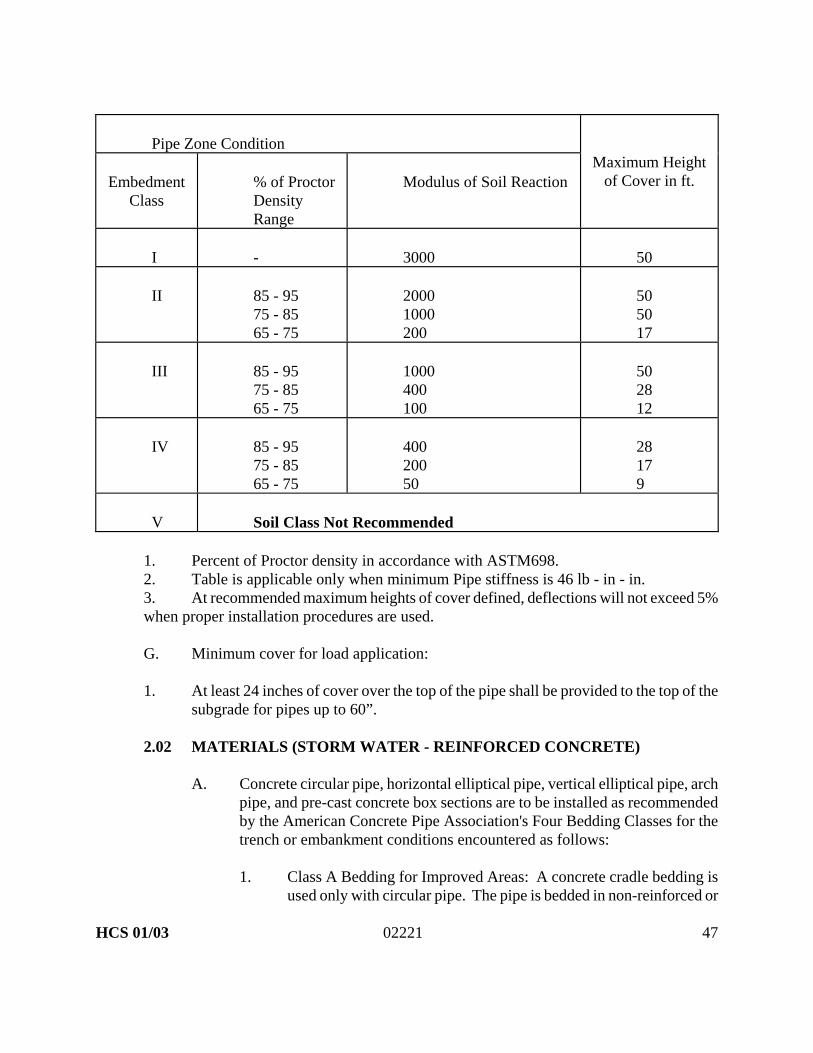
Pipe Zone Condition
Embedment Class
% of Proctor Density Range
Modulus of Soil Reaction
Maximum Height of Cover in ft.
I
-
3000
50
II
85 - 95 75 - 85 65 - 75
2000 1000 200
50 50 17
III
85 - 95 75 - 85 65 - 75
1000 400 100
50 28 12
IV
85 - 95 75 - 85 65 - 75
400 200 50
28 17 9
V
Soil Class Not Recommended
1. Percent of Proctor density in accordance with ASTM698. 2. Table is applicable only when minimum Pipe stiffness is 46 lb - in - in. 3. At recommended maximum heights of cover defined, deflections will not exceed 5% when proper installation procedures are used. G. Minimum cover for load application: 1. At least 24 inches of cover over the top of the pipe shall be provided to the top of the
subgrade for pipes up to 60”. 2.02 MATERIALS (STORM WATER - REINFORCED CONCRETE)
A. Concrete circular pipe, horizontal elliptical pipe, vertical elliptical pipe, arch pipe, and pre-cast concrete box sections are to be installed as recommended by the American Concrete Pipe Association's Four Bedding Classes for the trench or embankment conditions encountered as follows:
1. Class A Bedding for Improved Areas: A concrete cradle bedding is
used only with circular pipe. The pipe is bedded in non-reinforced or

HCS 01/03 02221 48
reinforced concrete extending up the sides for a height equal to one-fourth the outside diameter. The cradle should have a minimum width at least equal to the outside diameter of the pipe plus eight inches. The backfill above the cradle is densely compacted and extends 12 inches above the crown of the pipe. In rock, especially where blasting is likely in the adjacent vicinity, the concrete cradle should be cushioned from the shock of the blasting which can be transmitted through the rock. The concrete arch is an alternate to the concrete cradle for trench installations. The pipe is bedded in carefully compacted granular material extending halfway up the sides of the pipe. The top half of the pipe is covered with non-reinforced or reinforced concrete having a minimum thickness over the top of the pipe of one-fourth the inside pipe diameter. The arch should have a minimum width at least equal to the outside diameter of the pipe plus eight inches.
2. Class B Bedding for Improved Areas: For a shaped subgrade with
granular foundation the bottom of the excavation is shaped to conform to the pipe surface but at least two inches greater than the outside dimensions of the pipe. The width should be sufficient to allow six-tenths of the outside pipe diameter for circular pipe and seven-tenths of the outside span for arch and elliptical pipe to be bedded in fine granular fill placed in the shaped excavation. Densely compacted backfill should be placed at the sides of the pipe to a depth of at least 12 inches above the top of the pipe. A granular foundation without shaping is used only with circular pipe. The pipe is bedded in compacted granular material placed on the flat trench bottom. The granular bedding has a minimum thickness of 6 inches extended at least halfway up the pipe at the sides. The remainder of the side fills, to a minimum depth of 12 inches over the top of the pipe, shall be filled with densely compacted material.
3. Class C Bedding for Unimproved Areas: Class C Bedding is
recommended in unimproved areas only with a shaped subgrade the pipe is bedded with ordinary care in a soil foundation, shaped to fit the lower part of the pipe exterior with reasonable closeness for a width of at least 50 percent of the outside diameter for a circular pipe, and one-tenth of the outside diameter for a circular pipe and box sections. For trench installations the sides and area over the pipe are filled with lightly compacted backfill to a minimum depth of six inches above the top of the pipe. For embankment installations the pipe should not project more than 90 percent of the vertical height of the pipe above the bedding.A granular foundation is used only with a

HCS 01/03 02221 49
circular pipe, and consist of a compacted granular material or densely compacted backfill placed on a flat bottom trench. The bedding material should have the minimum thickness of 6 inches, and extend up the sides for a height of at least one-sixth the outside diameter of the pipe.
4. Class D Bedding: Class D bedding is not recommended for improved
or unimproved areas.
B. Concrete Cradle: Continuous concrete cradle constructed of Class "B" concrete as specified in Section 03001.
C. Concrete Arch: Continuous concrete arch constructed of Class "B" concrete
as specified in Section 03001.
D. Foundation, Bedding, Hunching, Initial Backfill, and Final Backfill:
1. Mineral aggregate, equal to Tennessee Department of Transportation Grading "D" Class A, Section 903.05 - Aggregate for Mineral Aggregate Base and Surface Courses. Commonly called "pug mill" or "pug" with 100 percent passing a 1 ½ inch sieve, 85-100 percent passing a 1 inch sieve, 60-95 percent passing a 3/4 inch sieve, 50-80 percent passing a 3/8 inch sieve, 40-65 percent passing a number 4 sieve, 20-40 percent passing a number 16 sieve, and 9-18 percent passing a number 100 sieve. With a moisture content of 5 to 6 percent by weight.
2.06 MATERIALS (STORM WATER - CORRUGATED METAL PIPE - FOR
UNIMPROVED AREAS ONLY) – NOT IN R.O.W.
A. Foundation: Mineral aggregate, equal to Tennessee Department of Transportation Grading "D" Class A, Section 903.05 - Aggregate for Mineral Aggregate Base and Surface Courses. Commonly called "pug mill" or "pug" with 100 percent passing a 1 ½ inch sieve, 85-100 percent passing a 1 inch sieve, 60-95 percent passing a 3/4 inch sieve, 50-80 percent passing a 3/8 inch sieve, 40-65 percent passing a number 4 sieve, 20-40 percent passing a number 16 inch sieve, and 9-18 percent passing a number 100 sieve. With a moisture content of 5 to 6 percent by weight.

HCS 01/03 02221 50
B. Bedding:
1. Class I Material: Aggregate, angular, 1/4 inch to ½ inch graded stone
including a number of fill materials that have regional significance such as crushed stone.
or
2. Class II Material: Course sand and gravel with a maximum particle dimension of 1 ½ inch including variously graded sand and gravel containing small percentages of fines, generally granular and non-cohesive, either wet or dry. Soil Type GW, GP, SW, and SP.
or
3. Class III Material: Fine sand and clayey gravel, including fine sand, sand-clay mixtures, and gravel-clay mixtures. Soil Type GM, GC, SM, and SC.
or
4. Class IV Material: Soil Class not recommended. or
5. Class V Material: Soil Class not recommended.
C. Haunching (Same as Bedding)
D. Initial Backfill (Same as Bedding)
E. Final Backfill (Same as Bedding) PART 3 EXECUTION
3.01 PREPARATION
A. Prior to trench excavations within a public right-of way, a traffic control plan developed by a licensed professional engineer shall be furnished to, and approved by, the Engineer.
B. Prior to the trench excavation, all barriers, personnel, safety devices, and

HCS 01/03 02221 51
public safety devices shall be in place and approved by the City Engineer.
C. Contractor shall furnish, install, and maintain all barriers, safety devices, traffic control personnel and any other safety device as required by local, state, or federal regulatory authority.
D. All safety and traffic control devices or barriers shall be installed according
to the manual on Uniform Traffic Control Devices, and OSHA of Tennessee.
E. Protect and maintain all existing survey bench marks, monuments, and survey points. Surveying points shall be replaced by the contractor, if removed in association with the trench excavation.
F. Prior to any excavation, all soil and erosion control/abatement devices shall
be in place and approved in writing by the Engineering Inspector assigned to the project by the Engineer.
G. Dewatering of trenches and excavation shall be pumped to silt pit and/or an
erosion control abatement device designed for the purpose.
H. Trench spoil shall be placed upon and within the easement and/or the temporary construction easements only. Any excess spoil placed outside a legal easement will be the responsibility of the contractor.
I. No excavated trenches shall be left open or uncovered overnight.
J. No street, alley or legal right of way shall be closed. One lane of traffic shall
be maintained for emergency and local access at contractors expense and at all times, day or night, unless otherwise directed by the City Engineer.
K. One-half of the traveled portion of a legal street or alley shall just remain
open to traffic at all times, unless otherwise directed by the City Engineer.
L. If permanent pavement repairs cannot be made within five days, a temporary replacement shall be made with a minimum 2 inches of cold mix or hot bituminous seal coat over compacted crushed stone, until a permanent repair can be made.
M. Existing pavement, concrete or asphalt, bases, curbs and gutters, driveways,
and sidewalks shall be mechanically saw cut to a neat construction line.
N. Dust control is mandatory, there will be no exceptions. A dust control plan shall be submitted to the City Engineer and approved in writing prior to any

HCS 01/03 02221 52
excavation within a public street or right-of-way. 3.02 EXCAVATION TRENCHES
A. Excavate and or open only the length of trench and or areas needed for the length of piping and or equipment to be installed in a single work day. At no time shall a trench excavation or excavation for equipment be left open overnight.
B. Perform in such a manner as to form a suitable trench in which to place the
pipe and so as to cause the least inconvenience to the public.
C. Maximum width or trench at the crown of the pipe shall be 2 feet plus the nominal diameter of the pipe.
D. Cut pavement with mechanical saws along neat, straight construction lines.
E. Trench depth: for water lines and sanitary sewage force main - sufficient to
provide minimum cover of 30 inches over the top of the pipe; for gravity sewer lines and storm water piping - as shown on the Plans or as specified.
F. Align trench as shown on the Plans unless a change is necessary to miss an
unforeseen obstruction. At no time shall an alignment be rerouted outside the public right of way or outside an established private utility easement without the expressed consent of the City Engineer.
H. For storm water pipe, fill the bottom of the trench with granular material as
specified herein, see Bedding.
I. When unstable soil is encountered at the trench bottom, a foundation will be required by removing the unstable soil as required to assure support of the pipeline and backfill to the proper grade with approved aggregate.
J. When unyielding solid rock, hard pan or other solid material are encountered
remove the unyielding material encountered in the trench excavation to a depth of 6 inches below the bottom of the pipe barrel, backfill with an approved material, and compact to 100% of fill material used as determined by ASTM 698 to uniformly support the pipe. In no case shall solid rock exist within six inches of the finished pipeline, see Bedding if rock is encountered.
K. When rock borings or soundings are provided, they are for information only
and do not guarantee existing conditions. Make such investigations as

HCS 01/03 02221 53
deemed necessary to determine existing conditions. 3.03 SHEETING, SHORING, BRACING, AND SAFETY DEVICES
A. Subpart "P" Trenching and Excavation Standards 1926.650 and Appendix A-F of the Occupational Safety and Health Acts (OSHA) is made a part of this standard and section.
B. Furnish, install, inspect, and maintain all sheeting, bracing, safety equipment,
etc., as may be required by the above OSHA Standard, to support the sides of any and all excavation and to prevent movement.
C. When necessary or when directed by the City Engineer, furnish, put in place,
and maintain such sheeting, bracing, etc., as may be required to support the side of the excavation and to prevent movement.
D. Take care to prevent voids outside the sheeting.
E. If voids are formed, immediately fill and compact to the standard
specification.
F. Devise plans for performing this work and submit for review.
G. If adjacent facilities will be damaged, remove all sheeting, shoring and bracing after backfill has been placed to a depth of 18 inches over the pipeline.
3.04 USE OF EXPLOSIVES
A. The Contractor shall conduct a preblast survey of the surrounding structures within a minimum of 300 feet of any blasting operation and document condition before any blasting begins. The documentation will include written descriptions, photographs of the structures, and measures of obvious signs of structural distress such as cracks. NOTE: These are minimum acceptable limits and bidding contractors may exceed these limits for his own liability.
B. Conduct all blasting operations in accordance with prevailing municipal,
state or other agency regulations, codes, ordinances, or laws.
C. Exercise due caution when blasting adjacent to existing structures and pipelines.

HCS 01/03 02221 54
D. If structures or pipelines are damaged, promptly replace or repair them at no
expense to the City. Failure to comply with this requirement shall constitute grounds for withholding contract payments until compliance is made.
E. Do not conduct blasting operations within 25 feet of water, sewer, gas, or
other utility lines.
F. Cover all shots with blasting mats to prevent flying material.
G. Tennessee Blasting Standards Act Section 68.44.101, or its latest revision is made a part of this standard.
3.05 DISPOSAL OF EXCAVATED MATERIAL
A. Satisfactorily dispose of all excess excavated material that cannot be used for or is not suitable for embankments or backfill.
3.06 UNAUTHORIZED EXCAVATION
A. All excavation outside or below the proposed lines and grades shown on the Plans or directed by the Engineer.
B. Backfill areas of unauthorized excavation with the type material necessary
(earth, rock, or concrete) to insure the stability of the structure of construction involved.
C. Unauthorized excavation or backfill to replace same shall not be a pay item.
3.07 REMOVAL OF WATER
A. Keep excavated areas free of water while work is in progress. Dewatering of trenches and excavation shall be to a silt pit or an erosion controlled area. (See Soil and Erosion Control).
B. Well-pointing shall be performed if required.
C. Take particular precautions to prevent the displacement of structures or
pipelines as a result of accumulated water and or the lowering of surrounding water table.

HCS 01/03 02221 55
3.08 OBSTRUCTIONS
A. Obstructions shown on the Plans are for information only and do not guarantee their exact locations nor that other obstructions are not present.
B. When utilities or obstructions are not shown on the Plans but are present off
the roadway at the location of the proposed pipeline route, the Contractor may request to relocate the pipeline in the roadway if necessary to avoid disturbing the utility or obstructions.
C. If the relocation is approved, the Contractor shall receive compensation for
additional granular backfill and pavement replacement as measured and paid for under appropriate contract pay items as determined by the City Engineer.
D. Exercise due care in excavating adjacent to existing obstructions and do not
disturb same unless absolutely necessary.
E. In the event obstructions are disturbed, repair or replace as quickly as possible to the condition existing prior to their disturbance. This repair or replacement will not be a pay item.
F. If required by the utility company, pay for the repair or replacement work
performed by the forces of the utility company or other appropriate party at no cost to the City.
G. If replacement or repair of disturbed obstructions is not performed after a
reasonable period of time, the City Engineer may have the necessary work done and deduct the cost of same from payments to the Contractor.
3.09 STORM SEWER BEDDING
A. Use Class A or B bedding for improved areas and Class C bedding in unimproved areas, whichever is shown on the Plans. If not shown, use Class B bedding.
B. Construct Class B bedding in a trench cut in natural ground or compacted
embankment.
1. Bed pipe on 6 inch of graded aggregate material and sufficient additional B material accurately shaped by a template to fit the lower part of the pipe exterior.

HCS 01/03 02221 56
2. Compact in layers not over 6 inches, in loose thickness, around the pipe to a minimum depth of 12 inches over the crown of the pipe.
3. When bell and spigot pipe is to be placed, dig recesses in the bedding
material of sufficient width and depth to accommodate the bell.
C. Construct Class C bedding in a shallow trench.
1. Shape the bedding to fit the lower pipe exterior for the specified embedment.
2. When bell and spigot pipe is to be placed, dig recesses of sufficient
width and depth to accommodate the bell. 3.10 INITIAL BACKFILLING
A. Do not begin backfilling before the grade and alignment of the pipe have been inspected. If backfill material is placed over the pipe before an inspection is made, reopen the trench in order for an inspection to be made.
B. Place backfilling in compacted 6 inch lift, until fill has progressed to 12 inches above the top of the pipe.
1. Deposit and compact graded aggregate material in 6 inch lifts (where
required elsewhere in these specifications or noted on the Plans) or deposit compacted approved soil free from lumps, clods, frozen material or stones in layers approximately 6 inches thick.
2. Compact backfill in 6 inch lifts as specified herein.
3. Use compactors and machines of a suitable type which do not crush
or otherwise damage the pipe. 3.11 FINAL BACKFILLING
A. After the initial backfill has reached a point 12 inches or more above the top of the pipe, perform final backfilling depending upon the location of the work and danger from subsequent settlement.
B. Backfilling in Unimproved Areas: (Natural Compaction)
1. Dispose of and replace all soft or yielding material which is

HCS 01/03 02221 57
unsuitable for trench backfill with suitable material.
2. Deposit backfill to the surface of the ground by dragline, bulldozer, or other suitable equipment in such a manner so as not to disturb the pipe, and compact by wheel or track loading.
3. Neatly round sufficient surplus excavated material over the trench to
compensate for settlement.
4. Dispose of all surplus excavated material.
5. Prior to final acceptance, remove all mounds to the elevation of the surrounding terrain.
C. Backfilling beneath driveways and streets where non-rigid and rigid type
surfacing is to be replaced: (Mechanical Compaction)
1. Backfilling methods and materials for shoulders along streets and highways shall be in accordance with the requirements of the specifications herein or the county, or state departments maintaining the particular roadway or highway.
2. Deposit and compact in 6 inch lifts a graded aggregate material to
completely fill the excavated trench starting at the top of the initial backfill zone to the finished surface.
3. Replace with similar materials, all existing construction which may
be damaged or destroyed as a result of pipe trenching.
4. Where shoulders along state highways have seal coat surfaces, replace with double bituminous seal in accordance with Section 02550, or the requirements of the highway department.
E. Crushed stone for pavement maintenance and shoulder replacement:
1. Where possible, salvage and reuse all base material that is removed
during construction.
2. Haul and place additional material as necessary and in conformance with Section 02215, Base and Subgrade treatment.
3. Wet and thoroughly compact crushed stone and blade to match the
existing surface prior to final acceptance.

HCS 01/03 02221 58
3.15 MEASUREMENT AND PAYMENT - TRENCHING, BEDDING AND
BACKFILLING - RESERVED 3.16 MEASUREMENT AND PAYMENT - SOLID ROCK EXCAVATION -
RESERVED 3.17 MEASUREMENT AND PAYMENT - CRUSHED STONE FOR PAVEMENT
MAINTENANCE AND SHOULDER REPLACEMENT - RESERVED 3.18 MEASUREMENT AND PAYMENT - CRUSHED STONE FOR FINAL
BACKFILL - RESERVED
END OF SECTION

HCS 01/03 02250 59
SECTION 02250 SOIL AND EROSION CONTROL 1.01 WORK INCLUDED
This work shall consist of temporary and or permanent control measurers as shown on the plans or as ordered by the City Engineer or his agent during the life of the contract to control soil erosion and water pollution. Such measures shall include, but are not limited to the use of silt barriers, fiber mats, netting, mulches, grasses, slope drains, and other control devices. Erosion and siltation control measures as described herein shall be applied to any erodible material exposed by any activity within the project limits.
1.02 RELATED WORK
A. Section 02050: Demolition B. Section 02110: Clearing and Grubbing
C. Section 02210: Grading and Excavating
D. Section 02215: Base and Subgrade Treatment
E. Section 02221: Trenching, Backfilling and Compaction
F. Section 02491: Sodding
G. Section 02271: Rip-Rap
H. Section 02490: Topsoil
I. Section 02485: Temporary Seeding
J. Section 02486: Permanent Seeding
K. Section 02722: Sanitary Sewer Systems
L. Section 03001: Concrete Work
M. Section 02605: Utility Separation and Stream Crossings
N. Tennessee Erosion & Sediment Control Handbook
1.03 PRODUCTS
HCS 01/03 02250 60
A. General
1. The City Engineer or his agent has the authority to limit the surface area of
erodible earth material exposed by clearing and grubbing, the surface of erodible earth material exposed by excavation, borrow and fill operations and to direct the Contractor to provide immediate permanent or temporary pollution control measures to prevent contamination of adjacent streams or other watercourses, lakes, ponds, or other water impoundments. Such work may involve the construction of temporary berms, dikes, sediment basins, slope drains, and use of temporary mulches, mats, seeding, or construction entrances, or other control devices or methods as necessary to control erosion.
2. In the event of conflict between these requirements and pollution control
laws, rules, or regulations of other Federal or State or local agencies, the more stringent laws, rules or regulations shall apply.
3. The temporary erosion control features shall be acceptably maintained by the
Contractor until the construction site is stabilized, and he shall remove such installation if ordered by the City Engineer, or his agent. Any materials removed shall become the property of the Contractor.
4. In case of repeated failure to control erosion, pollution and siltation, the City
Engineer or his agent reserves the right to employ outside assistance or to use his own forces to provide the necessary corrective measures. Such incurred direct costs plus project engineering costs will be charged to the party responsible for erosion control.
1.04 GENERAL CRITERIA
A. Stabilization of Denuded Areas and Soil Stockpiles
1. Permanent or temporary soil stabilization must be applied to denuded areas within 15 days after final grade is reached on any portion of the site. Soil stabilization must also be applied within 15 days to denuded areas which may not be at final grade but will remain dormant (undisturbed for longer than 30 days.
Soil stabilization refers to measures which protect soil from the erosive forces of raindrop impact, flowing water and wind. Applicable practices include vegetative establishment, mulching, and the early application of gravel base on areas to be paved. Soil stabilization measures should be selected to be appropriate for the time of year, site conditions, and estimated

HCS 01/03 02250 61
duration of use.
2. Soil stockpiles must be stabilized or protected with sediment trapping measures to prevent soil loss.
B. Establishment of Permanent Vegetation
1. A permanent vegetative cover shall be established on denuded areas not
otherwise permanently stabilized. Permanent vegetation shall not be considered established until a ground cover is achieved which, in the opinion of the City Engineer or his designated agent, is mature enough to control soil erosion satisfactorily and to survive severe weather conditions.
C. Protection of Adjacent Properties
1. Properties adjacent to the site of a land disturbance shall be protected from
sediment deposition. This may be accomplished by preserving a well-vegetated buffer strip around the lower perimeter of the land disturbance, by install perimeter controls such as sediment basins, or by a combination of such measures.
2. Vegetated buffer strips may be used alone only where runoff in sheet flow is
expected. Buffer strips should be at least 20 feet in width. If at any time it is found that a vegetated buffer strip alone is ineffective in stopping sediment movement onto adjacent property, additional perimeter controls must be provided.
D. Timing and Stabilization of Sediment Trapping Measures
1. Sediment basins and traps, perimeter dikes, sediment barriers and other
measures intended to trap sediment on-site must be constructed as a first step in grading and be made functional before upslope land disturbance takes place. Earthen structures such as dams, dikes, and diversions must be seeded and mulched within 15 days of installation.
E. Sediment Basins
1. Stormwater runoff from drainage areas with five acres or greater disturbed
area must pass through a Sediment Basin or other suitable sediment trapping facility with equivalent or greater storage capacity. The City Engineer or agent may require sediment basins or traps for smaller disturbed areas where deemed necessary. The sediment basin requirement may also be waived, by variance, if the City Engineer or agent agrees in writing that site conditions do not warrant its construction.

HCS 01/03 02250 62
F. Cut and Fill Slopes
1. Cut and fill slopes must be constructed in a manner which will minimize
erosion. Consideration must be given to the length and steepness of the slope, the soil type, upslope drainage area, ground water conditions and other applicable factors. Slopes which are found to be eroding excessively within one year of construction must be provided with additional slope stabilizing measures, as directed by the City Engineer, until the problem or problems are corrected.
a. Roughened soil surfaces are generally preferred to smooth surfaces
on slopes.
b. Diversions should be constructed at the top of long steep slopes which have significant drainage areas above the slope. Diversions or terraces may also be used to reduce slope length.
c. Concentrated stormwater shall not be allowed to flow down cut or fill
slopes unless contained within an adequate temporary or permanent channel, flume or slope drain structure.
d. A slope face that crosses a water seepage plane which endangers the
stability of the slope, adequate drainage or other protection shall be provided.
G. Stormwater Management Criteria for Controlling Off-Site Erosion
1. Properties and waterways downstream from development sites shall be
protected from erosion due to increases in the volume, velocity and peak flow rate of stormwater runoff.
To satisfy this requirement, the following criteria shall apply:
a. Concentrated stormwater runoff leaving a development site must be
discharged directly into a well-defined, natural or man-made off-site receiving channel or pipe. If there is no well-defined off-site receiving channel or pipe, one must be constructed to convey stormwater to the nearest adequate channel. Newly constructed channels shall be designed as adequate channels.
b. An adequate channel shall be defined as a natural or man-made channel or pipe which is capable of conveying the runoff from a 25 year storm without overtopping its banks or eroding after development of the site in question.

HCS 01/03 02250 63
c. Runoff rate and channel adequacy must be verified with engineering
calculations.
2. If an existing off-site receiving channel is not an adequate channel, one of the following options shall apply:
a. Obtain legal permission from all downstream property owners and a
permit from the State of Tennessee to improve the receiving channel to an adequate condition. Such improvements shall extend downstream until an adequate channel section is reached.
b. Develop a site design that will not cause the pre-development peak
runoff rate from a 25 year storm to increase. Such a design may be accomplished by enhancing the infiltration capability of the site or by providing on-site stormwater detention measures. The pre-development and post-development peak runoff rates must be verified by engineering calculations.
c. Provide a combination of channel improvement, stormwater
detention, or other measures which is satisfactory to the City Engineer to prevent downstream channel erosion.
3. All channel improvements or modification must comply with all applicable
federal, state, and local laws and regulations. 4. If the applicant chooses an option which includes stormwater detention, he
must provide the City Engineer with a plan for maintenance of the detention facilities. The plan shall set forth the maintenance requirements of the facility and party responsible for performing the maintenance.
5. Increased volumes of concentrated sheet flows which will cause erosion or sedimentation on adjacent property must be diverted to a stable outlet or detention facility.
6. In applying these stormwater management criteria, individual lots in
subdivision developments shall not be considered separate development projects, but rather the subdivision development, as a whole, shall be considered a single development project.
H. Stabilization of Waterways and Outlets
All on-site stormwater conveyance channels shall be designed and constructed to withstand the expected velocity of flow from a 25 year frequency storm without erosion. Stabilization adequate to prevent erosion must also be provided at the

HCS 01/03 02250 64
outlets of all pipes and paved channels.
I. Storm Sewer Inlet Protection
All storm sewer inlets which are made operable during construction shall be protected so that sediment-laden water will not enter the conveyance system without first being filtered or otherwise treated to remove sediment. The conveyance system shall be free of sediment and pipes shall be maintained to full capacity.
J. Working In or Crossing Watercourses
1. Construction vehicles should be kept out of watercourses to the extent
possible. Where in-channel work is necessary, precautions must be taken to stabilize the work area during construction to minimize erosion. The channel (including bed and banks) must always be restabilized immediately after in-channel work is completed.
2. Where a live (wet) watercourse must be crossed by construction vehicles
during construction, a TEMPORARY STREAM CROSSING must be provided with the minimum standard established in the Tennessee Erosion and Sediment Control Handbook, published by the Tennessee Department of Environment and Conservation.
3. All federal, state, and local laws and regulations will apply to Temporary
Stream Crossing. These shall include, but are not limited to:
a. An Aquatic Resources Alteration Permit from the State of Tennessee
b. Rules and regulations of the U.S. Army Corps of Engineers
K. Underground Utility Construction near Streams, Stream Crossings, and General Utility Construction
The construction of underground utility lines shall be subject to the following criteria:
Best management practices for erosion and sediment controls include construction management measures, vegetative controls, and structural controls. Some control practices can be used independently, others must be in combination. Erosion controls are not restricted to the following practices. However, alternative measures must be at least as effective in controlling erosion and sedimentation.
1. Construction Management Techniques or Management Measures

HCS 01/03 02250 65
a. Utility line crossings shall be constructed perpendicular to or as close to 90 degrees as possible to streams in previously undisturbed areas. Crossing angles other than 90 degrees will be allowed if new lines are constructed parallel to existing.
b. The number of stream crossings shall be minimized.
c. Clearing and grubbing must be held to the minimum necessary for
equipment operation.
d. Construction must be sequenced to minimize the exposure time of cleared area. Grading activities must be avoided during months of highly erosive rainfall.
e. Construction must be staged or phased for large projects. Areas of
one phase must be stabilized before another phase can be initiated. Stabilization shall be accomplished by temporally or permanently protecting the disturbed soil surface from rainfall impacts and runoff.
f. Erosion and sediment control measures must be in place and
functional before earth moving operations begin. All control measures must be properly constructed and maintained throughout the construction period.
g. Regular maintenance is vital to the success of an erosion and
sediment control system. Erosion and sediment control measures shall be checked weekly and after each rainfall. During prolonged rainfall, daily checking is necessary.
h. Construction debris must be kept from entering the steam channel.
i. Excavated material from the pipe trench shall not be placed between
the trench and the stream. Instead, it shall be placed on the upslope side of the excavation such that any erosion from it is caught by the trench.
j. Trenches or pits shall be promptly backfilled and stabilized to reduce
the risk of erosion.
k. A specific individual shall be designed to be responsible for erosion and sediment controls on each project site.
l. The disturbed stream banks at all crossings shall be stabilized within
five calendar days of completion of the crossing.

HCS 01/03 02250 66
2. Vegetative Controls
a. A buffer strip of vegetation at least as wide as the stream must be left
along the stream bank whenever possible. On streams less than 15 feet wide, the buffer zone shall extend at least 15 feet back from the water's edge.
b. Unnecessary canopy removal is discouraged. When necessary, trees
and shrubs should be cut so that they fall away from the stream.
c. Vegetative ground cover shall not be destroyed, removed, or disturbed more than 15 calendar days prior to grading.
d. Temporary soil stabilization with appropriate annual vegetation shall
be applied on areas that will remain unfinished for more than 30 calendar days.
e. Permanent soil stabilization with perennial vegetation shall be applies
as soon as possible after final grading.
3. Structural Controls
a. Staked and entrenched straw bales and/or silt fence must be installed along the base of all backfills and cuts, on the downhill side of stockpiled soil, and along stream banks in cleared areas to prevent erosion into streams. Silt fence shall not be placed in flowing stream.
b. All surface water flowing toward the construction area shall be
diverted around the construction area to reduce its erosion necessary.
c. A floating sediment boom may be placed downstream of the construction area to collect the unsettled silt or debris. This device shall be cleaned and maintained on daily basis.
d. Cofferdams constructed with sandbags, plastic or non-erodible
sheeting shall be placed on either side of the proposed line crossing, and extended from bank to bank to prevent the flow of water into the construction area. Water pumped from cofferdams or excavation must be held in properly designed settling basins, dewatering pits, or filter basins until it is at least as clear as upstream water before it is discharged into surface water. Water must be discharged through a pipe or lined channel so that the discharge does not cause erosion and sedimentation.

HCS 01/03 02250 67
e. Streams shall not be used as transportation routes for equipment. A
stabilized pad of clean and properly sized rock must be used for access road construction. Erosion and sediment control measures must be utilized where the stream bank is disturbed.
4. No more than 500 feet of trench are to be opened at one time.
5. Where consistent with safety and space considerations, excavated material is
to be placed on the uphill side of trenches.
6. Trench dewatering devices shall discharge in a manner which will not adversely affect flowing streams, drainage systems or off-site property as follows:
a. Dewatering Pit - A temporary pit approximately 4 feet in diameter at
the bottom will be excavated on the downgrade side of the construction site near the proposed manhole or as directed. The pit will be built and maintained to provide a dry work area in the trench during pipe installation and encasement. Since the excavation of the stream crossing is below the creek bottom, it is expected to be muddy and shall be pumped directly into the silt pit where it can be filtered and allowed to flow overland to the stream. During construction, excavation and filling shall be performed in a manner and sequence that will provide drainage toward the dewatering pit at all times. Under no circumstances shall pipe be laid in water, and no pipe shall be laid when trench conditions or weather are unsuitable for such work.
b. After construction, the dewatering pit shall be backfilled as directed
by the City Engineer.
7. Above Ground Sediment Trap
a. To reduce sediment in runoff, erosion control structures shall be installed promptly during all construction phases.
b. Sediment traps shall be located at least 20 feet from top of bank.
c. To insure that erosion control structures work properly, it is
imperative that sediment be removed; therefore, inspections of maintenance of structures are to be performed on a regular basis.
d. During sediment removal, the contractor shall take care to insure that

HCS 01/03 02250 68
structural components of erosion control structures are not damaged and thus made ineffective.
e. Sediment removed from sediment control structures must be placed at
a site such that runoff from the site shall not contaminate any water of the state.
f. Upon complete removal of sediment traps, special ditches etc., the
area where they were constructed is to be seeded and mulched.
g. Stockpiled topsoil or fill material must be treated so that sediment runoff will not contaminate surrounding areas or enter nearby streams.
h. Water from cofferdams must not be pumped directly into streams.
i. Clearing and grubbing must be held to the minimum width necessary
to accommodate slopes; unnecessary canopy removal (trees, shrubs, etc.)is prohibited.
8. Silt Pit - A sedimentation Pit made of silt fence, located in a grassed area
near the stream crossing but not closer than 20 feet from the top of the bank shall be constructed to act as sedimentation basin on site. This will filter silt-laden water which will be pumped from the dewatering pit prior to draining into the main stream. When the sediment accumulates to one-third of pit capacity, it shall be removed and placed at a site such that runoff from the site shall not contaminate any waters of the state.
9. Floating Sediment Boom
a. Definition - a floating device anchored at the bottom of the streambed
which will be placed downstream of the construction area.
b. Purpose - To collect unsettled silt or debris that has collected in the construction area of the stream
c. Planning Considerations - Each installation is unique due to specific
conditions. The sediment boom should be in place prior to any clearing or construction activities adjacent to the stream.
d. Maintenance - Sediment boom shall be inspected and maintained on a
daily basis. Sediment booms shall be cleaned by raising the bottom (upstream) end in a manner which will trap the sediment on the filter cloth. The sediment can then be removed from the boom and placed

HCS 01/03 02250 69
into the silt fence sediment will not be discharged into the stream.
L. Construction Access Routes
Whenever construction vehicle access routes intersect paved public road, provision must be made into minimize the transport of sediment (mud) by runoff or vehicle tracking onto the paved surface. Where sediment is transported onto a public road surface, the roads shall be cleaned thoroughly at the end of the day unless directed more often. Sediment shall be removed from roads by shoveling or sweeping and be transported to a sediment controlled disposal area. Street washing shall be allowed only after sediment is removed in this manner.
M. Disposal of Temporary Sediment Control Devices
All temporary erosion and sediment control measures shall be disposed of within 30 days after final site stabilization is achieved or after the temporary measures are no longer needed. Trapped sediment and other disturbed soil areas resulting from the disposition of temporary measures shall be permanently stabilized to prevent further erosion and sedimentation.
N. Maintenance
All temporary and permanent erosion and sediment control practices must be maintained and repaired as needed to assure continued performance of their intended function.
1.05 MATERIALS, EXECUTION AND CONSTRUCTION METHODS
A. Straw Bale Barrier
1. Definition - A temporary sediment barrier consisting of a row of entrenched and anchored straw bales.
2. Purpose
a. To intercept and detain small amount of sediment from disturbed
areas of limited extent in order to prevent sediment from leaving the site.
b. To decrease the velocity of sheet flows and low to moderate level
channel flows.
3. Conditions Where Practice Applies

HCS 01/03 02250 70
a. Below disturbed areas subject to sheet and rill erosion.
b. Where the size of the drainage area is no greater than 1/4 acre per 100 feet of barrier length; the maximum slope length behind the barrier is 100 feet; and the maximum slope gradient behind the barrier is 50 percent (2:1).
c. In minor swales or ditch lines where the maximum contributing drainage area is no greater than 2 acres.
d. Where effectiveness is required for less than 3 months.
e. Under no circumstances should straw bale barriers be constructed in
live streams or in swales where there is the possibility of a washout.
4. Planning Considerations Straw bale barriers must not be used in streams and drainage ways where high water velocities and volumes will destroy or impair their effectiveness. Improper placement and installation of the barriers, such as staking the bales directly to the ground with no soil seal or entrenchment, allows undercutting and end flow. This results in additions of rather than removal of sediment from runoff waters. Trapping efficiencies of carefully installed straw bale barriers may drop dramatically due to lack of maintenance.
5. Design Criteria - A formal design is not required. See standard construction
details.
6. Sheet Flow Applications
a. Bales shall be placed in a single row, lengthwise on the contour, with ends of adjacent bales tightly abutting one another.
b. All bales shall be either wire-bound or string-tied. Straw bales shall
be installed so that bindings are oriented around the sides rather than along the tops and bottoms of the bales (in order to prevent deterioration of the bindings).
c. The barrier shall be entrenched and backfilled. A trench shall be
excavated the width of a bale and the length of the proposed barrier to a minimum depth of 4 inches. After the bales are staked and chinked, the excavated soil shall be backfilled against the barrier. Backfill soil shall conform to the ground level on the downhill side and shall be built up to 4 inches against the uphill side of the barrier.
d. Each bale shall be securely anchored by at least two stakes or rebar

HCS 01/03 02250 71
driven through the bale. The first stake in each bale shall be driven toward the previously laid bale to force the bales together. Stakes or rebar shall be driven deep enough into the ground to securely anchor the bales.
e. The gaps between bales shall be chinked (filled by wedging) with
straw to prevent water from escaping between the bales. (Loose straw scattered over the area immediately uphill from a straw bale barrier tends to increase barrier efficiency).
7. Channel Flow Applications
a. Bales shall be placed in a single row, lengthwise, oriented
perpendicular to the contour, with ends of adjacent bales tightly abutting one another.
b. The remaining steps for installing a straw bale barrier for sheet flow
applications apply here, with the following addition.
c. The barrier shall be extended to such a length that the bottoms of the end bales are higher in elevation than the top of the lowest middle bale to assure that sediment-laden runoff will flow either through or over the barrier but not around it.
8. Maintenance
a. Straw bale barriers shall be inspected immediately after each rainfall
and at least daily during prolonged rainfall.
b. Close attention shall be paid to the repair of damaged bales, end runs and undercutting beneath bales.
c. Necessary repairs to barriers or replacement of bales shall be
accomplished promptly.
d. Sediment deposits must be removed when the level of deposition reaches approximately one-half the height of the barrier.
e. Any sediment deposits remaining in place after the straw bale barrier
is no longer required shall be dressed to conform to the existing grade, prepared, seeded, and or sodded as directed by the City Engineer or his agent.
1.06 SILT FENCE

HCS 01/03 02250 72
A. Definition
1. Filter Barrier is a temporary sediment barrier consisting of a filter fabric
stretched across and attached to supporting posts and entrenched. The silt fence is a temporary linear filter barrier constructed of synthetic filter fabric, posts, and wire fence for support.
B. Purpose
1. To intercept and detain small amounts of sediment from disturbed areas
during construction operations in order to prevent sediment from leaving the site.
2. To decrease the velocity of sheet flows and low-to-moderate level channel
flows.
C. Conditions Where Practice Applies
1. Below disturbed areas where erosion would occur in the form of sheet and rill erosion.
2. Where the size of the drainage area is no more than 1/4 acre per 100 fee of
silt fence length; the maximum slope length behind the barrier is 100 feet; and maximum gradient behind the barrier is 50 percent 92:1).
3. In minor swales or ditch lines where the maximum contributing drainage area
is no greater than 2 acres.
4. Under no circumstances should silt fences be constructed in live streams or in swales or ditch lines where flows are likely to exceed 1 cubic foot per second (cfs).
D. Planning Considerations
1. Silt fences may be preferable to straw barriers in some cases. While the
failure rate of silt fences is lower than that of straw barriers, there have been instances in which silt fences were improperly installed. The installation methods outlined here should be followed.
2. Filter barriers are inexpensive structures composed of burlap or standard
weight synthetic filter fabric stapled to wooden stakes. Flow rates through burlap filter barriers are slightly slower and filtering efficiency is significantly higher than for straw bale barriers.

HCS 01/03 02250 73
3. Silt fences composed of a wire support fence and attached synthetic filter
fabric slow the flow rate significantly but have a higher filtering efficiency than burlap. Both woven and non-woven synthetic fabrics are commercially available. The woven fabrics generally display higher strength than the non-woven fabrics. When tested under acid and alkaline water conditions, most of the woven fabrics increase in strength. There is a variety of reactions among the non-woven fabrics. The same is true of testing under extensive ultraviolet radiation. Permeability rates vary regardless of fabric type.
E. Design Criteria
1. No formal design is required, see standard details.
2. Filter barriers shall have an expected usable life of 3 months. They are
applicable in ditch lines, around drop inlets, and at temporary locations where continuous construction changes the earth contour and runoff characteristics and where low or moderate flows (not exceeding 1 cfs) are expected.
3. Silt fences, because they have a much lower permeability than burlap filter
barriers, have their applicability limited to situations in which only sheet or overland flows are expected. They normally cannot filter the volumes of water generated by channel flows, and many of the fabrics do not have sufficient structural strength to support the weight of water pending behind the fence line. Their expected usable life is 6 months.
F. Materials
1. Synthetic filter fabric shall be a pervious sheet of propylene, nylon, polyester
or ethylene yarn and shall be certified by the manufacturer or supplier.
2. Burlap shall be 10-ounce per square yard fabric.
3. Posts for Silt Fences shall be either 4-inch diameter wood or 1.33 pounds per linear foot steel with a minimum length of 5 feet. Steel posts shall have projections for fastening wire to them.
4. Stakes for Filter Barriers shall be 1" x 2" wood (preferred) or equivalent
metal with a minimum length of 3 feet.
5. Wire fence reinforcement for silt fences using standard strength filter cloth shall be a minimum of 42 inches in height, a minimum of 14 gauge and shall have a maximum mesh spacing of 6 inches.

HCS 01/03 02250 74
G. Filter Barrier - This sediment barrier may be constructed using burlap or standard
strength synthetic filter fabric. It is designed for low or moderate flows not exceeding 1 cfs.
1. The height of a filter barrier shall be a minimum of 15 inches and shall not
exceed 18 inches.
2. Burlap or standard strength synthetic filter fabric shall be purchased in a continuous roll and cut to the length of the barrier to avoid the use of joints (and thus improve the strength and efficiency of the barrier).
3. The stakes shall be spaced a maximum of 3 feet apart at the barrier location
and driven securely into the ground (minimum of 8 inches).
4. A trench shall be excavated approximately 4 inches wide and 4 inches deep along the line of stakes and upslope from the barrier.
5. The filter material shall be stapled to the wooden stakes, and 8 inches of the
fabric shall be extended into the trench. Heavy duty wire staples at least 1/2 inch long shall be used. Filter material shall not be stapled to existing trees.
6. The trench shall be backfilled and the soil compacted over the filter material.
7. If a filter barrier is to be constructed across a ditch line or swale, the barrier
shall be of sufficient length to eliminate a=end flow, and the plan configuration shall resemble an arc or horseshoe with the ends oriented upslope.
8. Filter barriers shall be removed when they have served their useful purpose,
but not before the upslope are has been permanently stabilized.
9. Filter barriers and silt fences shall be inspected immediately after each rainfall and at least daily during prolonged rainfall.
1.07 TEMPORARY DIVERSION DIKE OR BERM
A. Definition
1. A temporary ridge of compacted soil located at the top of base of a sloping disturbed area.
B. Purpose

HCS 01/03 02250 75
1. To divert storm runoff from higher drainage areas away from unprotected slopes to a stabilized outlet.
2. To divert sediment-laden runoff from a disturbed area to a sediment trapping
facility.
C. Conditions Where Practice Applies
1. Wherever stormwater runoff must be temporarily diverted to protect disturbed slopes or retain sediments on site during construction.
D. Planning Considerations
1. A temporary diversion dike is intended to divert overland sheet flow to a
stabilized outlet or a sediment trapping facility during establishment of permanent stabilization on sloping disturbed areas. When used at the top of a slope, the structure protects exposed slopes by keeping upland runoff away. When used at the base of a slope the structure protects adjacent and downstream areas by diverting sediment-laden runoff to a sediment trapping facility.
E. Design Criteria
1. No formal design is required. The following criteria shall be met:
a. Drainage Area - The maximum allowable drainage area is 5 acres.
b. Height - The minimum allowable height measured from the upslope
side of the dike is 24 inches.
c. Side Slopes - 1.5:1 or flatter. (Minimum base width of 6 feet)
d. Grade - The channel behind the dike shall have a positive grade to a stabilized outlet. If the channel slope is less than or equal to 2 percent, the channel shall be stabilized.
e. Outlet
1. The diverted runoff, if free of sediment, must be released
through a stabilized outlet or channel.
2. Sediment-laden runoff must be diverted and released through a sediment trapping facility.

HCS 01/03 02250 76
F. Construction
1. Whenever feasible, the dike should be built before construction begins on the project.
2. The dike should be adequately compacted to prevent failure.
3. Temporary or permanent seeding and mulch shall be applied to the dike
within 15 calendar days of construction.
4. The dike should be located to minimize damages by construction operations and traffic.
G. Maintenance
1. The measure shall be inspected after every storm and repairs made to the
dike, flow channel and outlet, as necessary. Approximately once every week whether a storm has occurred or not, the measure shall be inspected and repairs made if needed. Damages caused by construction traffic or other activity must be repaired before the end of each working day.
1.08 DIVERSION
A. Definition
1. A channel constructed across a slope with a supporting ridge on the lower side.
B. Purpose
1. To reduce slope length and to intercept and divert stormwater runoff to
stabilized outlets at non-erosive velocities.
C. Conditions Where Practice Applies
1. Where runoff from higher areas may damage property, cause erosion, or interfere with the establishment of vegetation on lower areas.
2. Where slope length needs to be reduced to minimize soil loss.
D. Planning Considerations
1. Diversions can be useful tools for managing surface water flows and
preventing soil erosion. On moderately sloping areas, they may be placed at

HCS 01/03 02250 77
intervals to trap and divert sheet flow before it has a chance to concentrate and cause rill and gully erosion. They may be placed at the top of cut or fill slopes to keep runoff from upland drainage areas off the slope. They can also be used to protect structures, parking lots, adjacent properties, and other special areas from flooding.
2. Diversions are preferable to other types of man-made stormwater conveyance
systems because they more closely simulate natural flow patterns and characteristics. Flow velocities are generally kept to a minimum. When properly coordinated into the landscape design of a site, diversions can be visually pleasing as well as functional.
3. As with any earthen structure, it is very important to establish adequate
vegetation as soon as possible after installation. It is equally important to stabilize the drainage area above the diversion so that sediment will not enter and accumulate in the diversion channel.
E. Design Criteria
1. Location
a. Diversion location shall be determined by considering outlet
conditions, topography, land use, soil type, length of slope, seepage planes (where seepage is a problem) and the development layout.
2. Capacity
a. The diversion channel must have a minimum capacity to carry the
runoff expected from a 25 year frequency storm with a freeboard of at least 0.3 foot.
b. Diversions designed to protect homes, schools, industrial buildings,
road, parking lots, and comparable high-risk areas, and those designed to function in connection with other structures, shall have sufficient capacity to carry peak runoff expected from a storm frequency consistent with the hazard involved.
3. Channel Design - The Diversion channel may be parabolic, trapezoidal or v-
shaped.
4. Ridge Design - The supporting ridge cross-section shall meet the following criteria:
a. The side slopes shall be no steeper than 2:1.

HCS 01/03 02250 78
b. The width at the design water elevation shall be a minimum of 6 feet.
c. The minimum freeboard shall be 0.3 foot.
d. The design shall include a 10 percent settlement factor.
5. Outlet - Diversions shall have adequate outlets which will convey
concentrated runoff with erosion.
6. Stabilization
a. Unless otherwise stabilized, the ridge and channel shall be seeded and mulched within 15 calendar days of installation.
b. Disturbed areas draining into the diversion shall be seeded and
mulched prior to or at the time the diversion is constructed.
F. Construction
1. All trees, brush, stumps, obstructions, and other objectionable material shall be removed and disposed of so as not to interfere with the proper functioning of the diversion.
2. The diversion shall be excavated or shaped to line, grade, and cross-section
as required to meet the criteria specified herein, free of irregularities which will impede flow.
3. Fills shall be compacted as needed to prevent unequal settlement that would
cause damage in the complete diversion.
4. All earth removed and not needed in construction shall be spread or disposed of so that it will not interfere with the functioning of the diversion.
G. Maintenance
Before final stabilization, the diversion should be inspected after every rainfall. Sediment shall be removed from the ditch line and repairs made as necessary. Seeded areas which fail to establish a vegetative cover shall be reseeded as necessary.
1.09 TEMPORARY SEDIMENT TRAP
A. Definition

HCS 01/03 02250 79
A small temporary ponding area, formed by constructing an earthen embankment with a gravel outlet, across a drainage swale.
B. Purpose
To detain sediment-laden runoff from small disturbed areas long enough to allow the majority of the sediment to settle out.
C. Conditions Where Practice Applies
1. Below drainage areas of 5 acres or less.
2. Where the sediment trap will be used no longer than 12 months. (The
maximum useful life is 18 months).
3. The sediment trap may be constructed either independently or in conjunction with a Temporary Diversion Dike.
D. Planning Considerations
Sediment traps should be used only for small drainage areas. If the contributing drainage area is greater than 5 acres, refer to Sediment Basins Criteria.
Sediment must be periodically removed from the trap. Plans should detail how this sediment is to be disposed of, such as by use in fill areas on site or by removal to an approved off-site dump.
Sediment traps, along with other perimeter controls, shall be installed before any land disturbance takes place in the drainage area.
E. Design Criteria
1. Trap Capacity
a. The sediment trap must have an initial storage volume of 67 cubic
yards per acre of drainage area, measured from the low point of the ground to the crest of the gravel outlet. Sediment should be removed from the basis when the volume is reduced by one-half.
b. For a natural basin, the volume may be approximated as follows:
V = 0.4 x A x D

HCS 01/03 02250 80
where,
V = the storage volume in ft.3A = the surface area of the flooded area at the crest of the outlet, in ft.2D = the maximum depth, measured from the low point in the trap to the crest of the outlet, in ft.
2. Excavation
If excavation is necessary to attain the required storage volume, side slopes should be no steeper than 2:1
3. Outlet
The outlet for the sediment trap shall consist of a crushed stone action section of the embankment located at the low point in the basin. The minimum length of the outlet shall be 6 feet times the acreage of the drainage area. The crest of the outlet must be at least 1 foot below the top of the embankment to insure that the flow will travel over the stone and not the embankment. This outlet shall be constructed of appropriately sized, clean, crushed stone.
4. Embankment Cross-Section
The maximum height of the sediment trap embankment shall be 5 feet as measured from the low point. Minimum top widths (W) and various embankment heights (H) are shown in the following Figure. Side slopes of the embankment shall be 2:1 or flatter.
5. Removal
Sediment traps must be removed after the contributing drainage area is stabilized.
F. Construction
1. The area under the embankment shall be cleared, grubbed, and stripped of
any vegetation and root mat. To facilitate cleanout, the pool area should be cleared.
2. Fill material for the embankment shall be free of roots or other woody
vegetation, organic material, large stones, and other objectionable material. The embankment should be compacted in 8-inch layers by traversing with construction equipment.

HCS 01/03 02250 81
3. Construction operations shall be carried out in such a manner that erosion
and water pollution are minimized.
4. The structure shall be removed and the area stabilized when the upslope drainage area has been stabilized.
5. All cut and fill slopes shall be 2:1 or flatter.
G. Maintenance
1. Sediment shall be removed and the trap restored to its original dimension
when the sediment has accumulated to 1/2 the design volume of the trap. Sediment removed from the basin shall be deposited in a suitable area and in such a manner that it will not erode.
2. The structure should be checked regularly to insure that it is structurally
sound and has not been damaged by erosion or construction equipment. The height of the outlet should be checked to insure that its center is at least one foot below the top of the embankment.
1.10 TEMPORARY SEDIMENT BASIN
A. Definition
A temporary basin with a controlled stormwater release structure, formed by constructing an embankment of compacted soil across a drainage way.
B. Purpose
To detain sediment-laden runoff from disturbed areas long enough for the majority of the sediment to settle out.
C. Conditions Where Practice Applies
Below disturbed areas greater than 5 acres. There must be sufficient space and appropriate topography for the construction of a temporary impoundment. These structures are limited to a useful life of 18 months unless they are designed as permanent ponds by a qualified professional engineer.
D. Planning Considerations
1. Effectiveness
Sediment basins are at best only 70-80 percent effective in trapping sediment

HCS 01/03 02250 82
which flows into them. Therefore, they should be used in conjunction with erosion control practices such as temporary seeding, mulching, diversion dikes, etc. to reduce the amount of sediment flowing into the basin.
2. Location
To improve the effectiveness of the basin, it should be located so as to intercept the largest possible amount of runoff from the disturbed area. The best locations are generally low areas and natural drainage ways below disturbed areas. Drainage into the basin can be improved by the use of diversion dikes and ditches. The basin must not be located in a live stream, but should be located to trap sediment-laden runoff before it enters the stream. The basin should not be located where its failure would result in the loss of life or interruption of the use of service of public utilities or roads.
3. Multiple Use
Sediment basins may be designed as permanent structures to remain in place after construction is completed. These structures may be desirable for stormwater detention purpose. Wherever these structures are to become permanent, or if they exceed the size limitations of the design criteria, they must be designed as permanent ponds by a qualified professional engineer. Permanent ponds are beyond the scope of these standards and specifications.
E. Design Criteria
The design of sediment basins shall be submitted to the City Engineer for approval of construction prior to installation.
1. Vegetative Stabilization
The embankment and emergency spillway of the sediment basin shall be stabilized with temporary vegetation within 15 days of completion of the basin.
2. Erosion and Sediment Control
The construction of the sediment basin shall be carried out in a manner such that it does not result in any undue sediment problems downstream.
3. Safety
All state and local requirements shall be met concerning fencing and signs warning the public of the hazards of soft sediment and flood waters.

HCS 01/03 02250 83
F. Maintenance
1. The embankment of the basin should be checked regularly to insure that it is
structurally sound and has not been damaged by erosion or construction equipment.
2. The emergency spillway should be checked regularly to insure that its lining
is well established and erosion resistant.
3. The basin should be checked after each runoff-producing rainfall for sediment cleanout. When the sediment reaches the cleanout level, is shall be removed and properly disposed of.
1.11 CHECK DAMS
A. Definition
Small temporary dams constructed across a swale or drainage ditch.
B. Purpose
To reduce the velocity of concentrated stormwater flows, thereby reducing erosion of the swale or ditch. This practice also traps small amount of sediment generated in the ditch itself. However, this is not a sediment trapping practice and should not be used as such.
C. Conditions Where Practice Applies
1. This practice is limited to use in small open channels which drain 10 acres or
less. It should not be used in a live stream. Some specific applications include:
a. Temporary ditches or swales which, because of their short length of
service, cannot receive a non-erodible lining but still need some protection to reduce erosion.
b. Permanent ditches or swales which for some reason cannot receive a
permanent non-erodible lining for an extended period of time.
c. Either temporary or permanent ditches or swales which need protection during the establishment of grass linings.
D. Planning Considerations

HCS 01/03 02250 84
1. Check dams can be constructed of stone.
2. If stone check dams are used in grass-lined channels which will be mowed,
care should be taken to remove all the stone from the dam when the dam is removed. This should include any stone which has washed downstream.
3. Since log check dams are embedded in the soil, their removal will result in
more disturbance of the soil than will removal of stone check dams. Consequently, extra care should be taken to stabilize the area when log dams re used in permanent ditches or swales.
E. Specifications
1. No formal design is required for check dam; however, the following criteria
should be adhered to when specifying check dams.
2. The drainage area of the ditch or swale being protected should not exceed 5 acres. The maximum height of the check dam should be 2 feet. The center of the check dam must be at least 6 inches lower than the outer edges. The cross-sections of the dams should be as shown for logs and stone. The maximum spacing between the dams should be such that the toe of the upstream dam is at the same elevation as the top of the downstream dam.
3. Stone check dams should be constructed of 2- to 3- inch stone. The stone
should be placed according to the configuration shown. Hand or mechanical placement will be necessary to achieve complete coverage of the ditch or swale and to insure that the center of the dam is lower than the edges.
F. Sediment Removal
While this practice is not intended to be used primarily for sediment trapping, some sediment will accumulate behind the check dams. Sediment should be removed from behind the check dams when it has accumulated to one-half of the original height of the dam.
G. Removal
Check dams may be removed when their useful life has been completed. In temporary ditches and swales, check dams should be removed and the ditch filled in when it is no longer needed. In permanent structures, check dams should be removed when a permanent lining can be installed. In the case of grass-lined ditches, check dams should be removed when the grass has matured sufficiently to protect the ditch or swale. The area beneath the check dams should be seeded and mulched

HCS 01/03 02250 85
immediately after they are removed.
H. Maintenance
1. Check dams should be monitored for sediment accumulation after each significant rainfall. Sediment should be removed when it reaches one-half of the original height or before.
2. Regular inspections should be made to insure that the center of the dam is
lower than the edges. Erosion caused by high flows around the edges of the dam should be corrected immediately.
1.12 RIPRAP
A. Definition
A permanent, erosion-resistant ground cover of large, loose, angular stone.
B. Purposes
1. To protect the soil surface from the erosive forces of concentrated runoff.
2. To slow the velocity of concentrated runoff while enhancing the potential for infiltration.
3. To stabilize slopes with seepage problems and/or non-cohesive soils.
C. Conditions Where Practice Applies
To soil-water interfaces where the soil conditions, water turbulence and velocity, expected vegetative cover, etc., are such that the soil may erode under the design flow conditions. Riprap may be used, as appropriate, at storm drain outlets, on channel banks and/or bottoms, roadside ditches, drop structures, at the toe of slopes, etc.
D. Design Criteria
See Standard Section 02271
1. Riprap at Outlets
The stabilized discharge structure must be provided. Design criteria for sizing the stone and determining the dimensions of riprap pads used at the outlets of drainage structures are contained in the standard details.

HCS 01/03 02250 86
2. Riprap for Channel Stabilization
a. The TDEC Division of Water Pollution Control must be contacted
prior to any stream channel disturbance.
b. Riprap for channel stabilization shall be designed to be stable for the condition of bank-full flow in the reach of channel being stabilized. Riprap shall extend up the banks of the channel to a height equal to the maximum depth of flow or to a point where vegetation can be established to adequately protect the channel.
c. The riprap size to be used in a channel bend shall extend upstream
from the point of curvature and downstream from the point of tangency a distance of at least 5 times the channel bottom width. The riprap shall extend across the bottom and up both sides of the channel.
d. Where riprap is used only for bank protection and does not extend
across the bottom of the channel, riprap shall be keyed into the bottom of the channel to a minimum depth equal to the thickness of the blanket and shall extend across the bottom of the channel the same distance.
3. Riprap for Slope Stabilization
Riprap for slope stabilization shall be designed so that the natural angle of the repose of the stone mixture is grater than the gradient of the slope being stabilized.
E. Maintenance
Once a riprap installation has been completed, it should require very little maintenance. It should, however, be inspected periodically to determine if high flows have caused scour beneath the riprap or dislodged any of the stone. If repairs are needed, they should be accomplished immediately.
1.13 CONSTRUCTION ROAD STABILIZATION
A. Definition
The temporary stabilization of access roads, subdivision roads, parking areas and other on-site vehicle transportation routes with stone immediately after grading.

HCS 01/03 02250 87
B. Purposes
1. To reduce the erosion of temporary roadbeds by construction traffic during wet weather.
2. To reduce the erosion and therefore regrading of permanent roadbeds
between the time of initial grading and final stabilization.
C. Conditions Where Practice Applies
Wherever stone-base roads or parking areas are constructed, whether permanent or temporary, for use by construction traffic.
D. Planning Considerations
1. Areas which are graded for construction vehicle transport and parking purposes are especially susceptible to erosion. The exposed soil surface is continually disturbed, leaving no opportunity for vegetative stabilization. Such areas also tend to collect and transport runoff waters along their surfaces. During wet weather, they often become muddy quagmires which generate significant quantities of sediment that may pollute nearby streams or be transported off site on the wheels of construction vehicles. Dirt roads can become so unstable during wet weather that they are virtually unusable.
2. Immediate stabilization of such areas with stone may cost money at the onset,
but it may actually save money in the long run by increasing the usefulness of the road during wet weather.
3. Permanent roads and parking areas should be paved as soon as possible after
grading. However, it is understandable that funds for this purpose may not be available in the early phases of the development project. As an alternative, the early application of stone may solve potential erosion and stability problems and eliminate later costs. Some of the stone may also remain in place for use as part of the final base course of the road.
E. Specifications
1. Temporary Access Roads and Parking Areas
a. Temporary roads shall follow the contour of the natural terrain to the
extent possible. Slopes should not exceed 8 percent.
b. Temporary parking areas should be located on naturally flat areas to minimize grading. Grades should be sufficient to provide the

HCS 01/03 02250 88
drainage but should not exceed 4 percent.
c. Roadbeds shall be at least 14 feet wide for one-way traffic and 20 feet wide for two-way traffic.
d. All cuts and fills shall be 2:1 or flatter to the extent possible.
e. Drainage ditches shall be provided as needed and shall be designed
and constructed to carry anticipated storm flows.
f. The roadbed or parking surface shall be cleared of all vegetation, roots and other objectionable material.
g. A 6-inch course of clean aggregate shall be applied immediately after
grading or the completion of utility installation within the right-of-way. Filter fabric may be applies to roadbed for additional stability in accordance with fabric manufacturer's specifications.
F. Gravel Construction Entrance
1. A gravel construction entrance is a pad of crushed stone that reduces the
tracking of mud onto a paved street. To construct the pad, place a layer of 6 inch stone across the full width of the vehicle ingress and egress area. The stone pad should be a least 100 feet along and at least 6 to 9 inches thick. Additional stone may have to be added periodically to maintain the proper functioning of the pad.
2. If the crushed stone does not adequately remove the mud from vehicle
wheels, the wheels should be hosed off before the vehicle enters a public street. The washing should be done on an area covered with crushed stone, and the waste water should drain to a sediment trap or sediment barrier.
G. Permanent Roads and Parking Areas
Permanent roads and parking areas shall be designed and constructed in accordance with applicable Tennessee Department of Transportation (TDOT) or local criteria except that an initial base course of gravel of at least 6 inches shall be applied immediately following grading.
H. Vegetation
All roadside ditches, cuts, fills and disturbed areas adjacent to parking areas and roads shall be stabilized with appropriate temporary or permanent vegetation according to the applicable standards and specifications contained in this handbook.

HCS 01/03 02250 89
I. Both temporary and permanent roads and parking areas may require periodic top
dressing with new gravel. Seeded areas adjacent to the roads and parking areas should be checked periodically to insure that a vigorous stand of vegetation is maintained. Roadside ditches and other drainage structures should be checked regularly to insure that they do not become clogged with silt or other debris.
J. Method of Measurement - Reserved
K. Basis of Payment - Reserved
END OF SECTION

HCS 01/03 02271 89
SECTION 02271 RIP-RAP PART 1 GENERAL 1.01 WORK INCLUDED
A. Preparation of Foundation.
B. Placing of rubble stone, concrete block or sacked sand-cement rip-rap. 1.02 RELATED WORK
A. Section 02110: Clearing and Grubbing
B. Section 02210: Grading and Excavation
C. Section 03001: Concrete Work PART 2 PRODUCTS 2.01 RIP-RAP
A. Description
This work shall consist of furnishing and placing, one or more classes of crushed or fractured limestone on a prepared surface in accordance with these specifications and in reasonably close conformity with the sizes, thicknesses and typical cross-section shown on the Plans or established by the Engineer.
B. Materials
All material used in this construction, in addition to the general requirements of these specifications, unless otherwise stipulated, shall conform to the following:
Class I Stones ranging in weight (approx. size) 1 lb (1 1/2" X 1 1/2" X 1 1/2") to 12 lbs. (5" X 5" X 5") with 75% greater than 8 lbs.
Class II

HCS 01/03 02271 90
Stones ranging in weight (approx. size) 12 lbs ( 5" X 5" X 5") to 70 lbs (9" X 9" X 9") with 75% greater than 50 lbs.
Class III Stones ranging in weight (approx. size) 70 lbs (9" X 9" X 9") to 165 lbs (1' X 1' X 1') with 75% greater than 135 lbs.
Class IV Stones ranging in weight (approx. size) 165 lbs (1' X 1' X 1') to 550 lbs (1 1/2' X 1 1/2' X 1 1/2') with 75% greater than 300 lbs.
2.02 GROUT
A. Mix 1 part Portland cement, 4 parts sand and sufficient water to make grout flow into and fill voids.
B. Fine Aggregate Sand:
1) AASHTO M-45: hard, strong, durable uncoated mineral or rock particles
free of injurious amounts of organics or other deleterious substances. 2) Sand for grout: uniformly graded from coarse to fine within the following
limits:
Total Percent Sieve Size Passing by Weight 8 100 50 15 - 40 100 0 - 10 200 0 - 5
3) Test aggregate, when required, by methods of AASHTO:
Sampling T-2 Clay lumps T-112 Coal and lignite T-113 Material passing 200 sieve T-11 Organic impurities T-21 Mortar-making properties T-71 Sieve analysis T-27 Soundness (sulfates) T-104 Soundness (freezing and thawing) T-103 Light weight particles T-149
C. Portland Cement:

HCS 01/03 02271 91
1) AASHTO M-85 or ASTM C-150.
2) Sample and test Portland Cement, when required, by the methods of
AASHTO:
Soundness T-107 Sampling T-127 Chemical Analysis T-105
Fineness: Turbidimeter T-98 Air permeability T-153 Time of Setting: Gillmore needles T-154 Vicat needles T-131 Air Content of Mortar T-137 Normal Consistency T-129 Tensile Strength T-132 Compressive Strength T-106 False Set T-186 Light weight particles T-149
PART 3 EXECUTION 3.01 PREPARATION OF FOUNDATION
Immediately prior to the construction of rip-rap, the sand filter bed, filter fabric surface or natural ground surface shall be trimmed within reasonably close conformity to the lines and grades, indicated on the plans or as directed by the Engineer. The natural ground or sand filter bed shall be thoroughly compacted by the use of the hand or mechanical tamps. On slopes the bottom of the rip-rap shall be placed at least 2 feet below the material ground surface, unless otherwise directed.
3.02 RIP-RAP
Rip rap shall be constructed upon the prepared foundation by machine or hand placing, so that the stones shall be as close together as is practicable in order to reduce the voids to a minimum.
When rip rap is constructed in more than one layer, it shall be placed so that it will be thoroughly tied together with the large stone protruding from one layer into the other.

HCS 01/03 02271 92
The standard depth of rip rap shall be 12 inches for Class I and Class II, 18 inches for Class III, and 24 inches for Class IV, unless otherwise directed; and in no instance shall be less than 10 inches in depth.
The main stone shall be thoroughly "Chinked" or filled with the smaller stones by throwing them over the surface in any manner that is practical to fill the voids. Knapping the stones will not be required, except stones protruding more than r inches above what is considered normal surface of the stones.
3.03 GROUTED RIP-RAP
A. Hand or machine place rip-rap upon a prepared foundation as described in section 3.01 so that the stone will be as close together as is practicable to reduce voids.
B. Place the stone in such a manner as to stagger all joints as far as it is possible, then
fill voids with grout. 3.04 SACKED SAND-CEMENT RIP-RAP
A. Fill sacks, approximately 3/4 full with a mixture of sand and cement.
B. Place sacks as close together as possible to reduce voids. 3.05 MEASUREMENT AND PAYMENT RIP-RAP - RESERVED END OF SECTION

HCS 01/03 02305 93
SECTION 02305
JACKING AND BORING PART 1 GENERAL 1.01 WORK INCLUDED
A. Placing casing and carrier pipe by boring and jacking under highways, roadways, and railroads.
1.02 RELATED WORK - RESERVED 1.03 REGULATIONS AND PERMITS
A. Permits for crossing highways or railroads will be obtained by the Contractor / Developer.
B. For highway crossings, satisfy the Highway Department to the extent of the Owner's
posted surety bonds. All surety bonds shall be obtained by the Contractor/Developer/Owner.
C. For railroad crossings, furnish certificates of insurance in amounts established by the
railroad company, naming the railroad as the insured. PART 2 PRODUCTS 2.01 STEEL CASING PIPE
A. Minimum yield strength of 35,000 psi.
B. Minimum thickness:
Nominal Diameter (inches) Minimum Thickness (inches)
Under 14 0.188 14 - 16 0.219 18 0.250 20 0.281 22 0.312 24 0.344 26 0.375 28 - 30 0.406 32 0.438

HCS 01/03 02305 94
34 - 36 0.469 38 - 42 0.500
C. Where casing pipes are to be installed under railroads, provide casing pipes per railroad
standards.
D. Steel casing pipe shall be of continuous weld construction and installed with welded joints.
2.02 CARRIER PIPE
A. Carrier pipe installed in the casing pipe shall be as specified under the appropriate utility regulations.
PART 3 EXECUTION 3.01 GENERAL REQUIREMENTS
A. Perform all crossings according to the requirements of the governing highway department or Railroad Company.
B. Notify the appropriate authorities involved and request their supervisory services
during construction.
C. Provide necessary safeguards to protect the crossing.
D. Where bored highway installations are not shown on the plans, open cut the crossing and provide a casing pipe.
3.02 INSTALLATION
A. Perform all crossings in the manner shown on the drawings, except as otherwise directed by the highway department or railroad company.
B. Dry bore an opening under the crossing.
C. Jack the casing pipe, of the type and size specified, into the bored opening.
D. Install the appropriate carrier pipe into the casing pipe.
E. Test the carrier pipe according to the appropriate specification.
3.03 MEASUREMENT AND PAYMENT - BORING AND JACKING - RESERVED

HCS 01/03 02305 95
END OF SECTION

HCS 01/03 02444 96
SECTION 02444
CHAIN LINK FENCES AND GATES
PART 1 GENERAL 1.01 WORK INCLUDED
A. Fence fabric and parts
B. Excavation for post bases
C. Concrete anchorage
D. Gates and hardware 1.02 RELATED WORK
A. Section 02210: Grading and Excavation
B. Section 03001: Concrete Work PART 2 PRODUCTS 2.01 FABRIC
A. No. 9 Gauge, chain link open hearth steel wire, hot-dipped galvanized after weaving with a minimum coating of 1.2 ounces of zinc per sq. ft. woven in a 2" diamond mesh. Top and bottom selvage to be twisted and barbed, unless otherwise specified or directed by the Engineer.
2.02 POSTS
A. Line Posts: 2 1/2" O.D. schedule 40, hot-dipped galvanized steel pipe meeting ASTM A-120 and weighing 3.65 pounds per foot
B. Top Rail: 1 5/8" O.D hot-dipped galvanized steel pipe weighing 2.27 pounds per foot
meeting ASTM A-120.
C. End and Corner Posts: 3" O.D. schedule 40 hot-dipped galvanized steel pipe meeting ASTM A-120 and weighing 5.79 pounds per foot.
D. Braces: meet the requirements for top rails as shown above.

HCS 01/03 02444 97
2.03 GATES
A. Fabric for Gates: same as for adjacent fence and meeting the requirements of Article 2.01.
B. Posts: Schedule 40 hot-dipped galvanized steel pipe meeting ASTM A-120 O.D.
dependent on gate leaf size, as follows: 1. Gate leaf 8 ft. or less: 3" 2. Gate leaf greater than 8' but less than 12': 4" 3. Gate leaf greater than 12' but less than 18': 6 5/8 4. Gate leaf greater than 18': 8 5/8"
C. Framing for Gates: 2" O.D. Schedule 40 hot-dipped galvanized steel pipe meeting
ASTM A-120 and weighing 2.72 lbs. per ft. and horizontal center brace of 1 5/8" O.D. meeting same.
2.04 HARDWARE AND FITTINGS
A. Galvanized steel. PART 3 EXECUTION 3.01 INSTALLATION
A. Install line posts, corner posts, top rails, fabric and gates, to provide a rigid structure for fence of height as shown on the drawings.
B. Use manufacturer's standard fittings, fasteners and hardware.
C. Maximum Post Spacing: 10’ or as specified by Engineer.
D. Install line, corner and terminal posts plumb and set in Class "B" concrete as specified
in Section 03001.
E. Set post to within 6" from concrete footing bottom.
F. Position fabric bottom 2" above finished grade with tension wire stretched taut between posts.
G. Pass top rail through line post to form continuous bracing.
H. Install center and bottom brace rail on corner and gate leaves.
I. Fasten fabric to top rail, line posts, braces and bottom tension wire with wire ties on 15"

HCS 01/03 02444 98
centers, maximum.
J. Attach fabric to end, corner, and gate posts with tension bars and clips.
K. Stretch fabric between terminal posts or at 100 foot intervals, whichever is least.
L. Install gates using fabric to match fence with 3 hinges per leaf, latch and catches. 3.02 MEASUREMENT AND PAYMENT - RESERVED END OF SECTION

HCS 01/03 02451 99
SECTION 02451
GUARDRAILS PART I GENERAL 1.01 WORK INCLUDED
A. Constructing anchor blocks and approach ends.
B. Guardrail assembly including appurtenant work to make connections to existing structures, if required.
PART 2 PRODUCTS 2.01 METAL BEAM RAILS
A. Corrugated sheet steel made of open hearth or electric furnace steel shaped into a "W" shaped beam with a projected width of not less than 12 inches and a depth of not less than 3".
B. Class "A" guardrail: not less than 10 gauge; Class "B" guardrail not less than 12 gauge.
C. Blanked to proper shape, fabricated, and ready for assembly when delivered. No
punching, drilling, cutting or welding will be permitted in the field.
D. Straight, uniform sections rolled or rounded to eliminate sharp edges. Reject warped or deformed plates.
E. Holes in the beam at posts shall be slotted to facilitate erection and permit expansion
and contraction.
F. All steel guardrail members shall be marked by the manufacturer or fabricator indicating brand name, gauge, weight, coating weight per square foot, and manufacturers heat number.
G. Requirements for Beam Strength:

HCS 01/03 02451 100
Traffic Face Up Traffic Face Down
Maximum Maximum Gauge of Load Deflection Load Deflection
Class Sheet lb. Inches lb. Inches
A 10 2000 2.0 1600 2.0 A 10 3000 3.0 2400 3.0 B 12 1500 2.0 1200 2.0 B 12 2000 3.0 1600 3.0
2.03 TERMINAL OR END SECTIONS
A. Use end caps or flares per TDOT specifications.
2.04 POSTS
A. Galvanized steel "H" sections conforming to TDOT specifications. Posts will be 4” x 6” wide by 5’-9” long.
B. Wooden posts of pressure treated pine and cable at terminus ends.
2.05 GUARDRAIL HARDWARE
A. Splice bolts, anchor bolts, and nuts shall conform to the requirements of ASTM A-307 and shall be galvanized in accordance with ASTM A-153.
B. End caps, splice joints, anchor assemblies and all other items to complete the railing
shall meet the requirements of ASTM A-36 and shall be galvanized in accordance with AASHTO M-111 or ASTM A-153.
2.06 GUARDRAIL DIMENSIONS
A. In accordance with Tennessee Department of Transportation standard drawings S-GR-l through 10 inclusive, and M-42-151 through 155 inclusive.
PART 3 EXECUTION

HCS 01/03 02451 101
3.01 POSTS
A. Set all posts reasonably true to the lines and grades shown on the plans or established by the Engineer at a maximum 12’ – 6” centers.
B. Dig or drill holes to the depth indicated on the plans; or drive posts by approved
methods and equipment, provided the posts are in the proper position and free of distortion and burring or any other damage.
1) Size all post holes that are dug or drilled to permit proper setting of the posts, and
allow sufficient room for backfilling and tamping.
2) Backfill and tamp holes with selected earth or other suitable materials in layers not to exceed 4 inches in thickness. When backfilling and tamping is completed, the posts or anchors shall be held securely in place.
3) Backfill post holes that are drilled in rock and holes for anchor posts or devices
shall be backfilled with concrete. 3.02 TERMINUS A. Shall be sloped into the ground with wooden posts. 3.03 MEASUREMENT AND PAYMENT - RESERVED END OF SECTION

HCS 01/03 02452 102
SECTION 02452
HIGHWAY SIGNS PART 1 GENERAL 1.01 WORK INCLUDED
A. Construction of foundations and supports.
B. Fabricating, assembling, and erecting ground mounted highway signs. PART 2 PRODUCTS 2.01 ALUMINUM SIGNS
A. Flat Sheets and Plates
1) Alloy 6061-T6 or 5052-H38 meeting the requirements of ASTM B-209.
2) Size and sheet thickness to be as shown on the drawings. 2.03 STEEL SIGNS
A. Flat Sheet and Plates: ASTM A-36 and ASTM A-123.
B. Mounting Hardware: ASTM a-307 and ASTM A-153. 2.04 REFLECTIVE SHEETING
A. AASHTO M-268. Colors shall conform to the "Tennessee Manual on Uniform Traffic Control Devices for Streets and Highways", latest edition. Reflectivity shall be High Intensity.
2.05 FABRICATION
A. Preparation of sign surfaces, application of reflective sheeting, painting and handling shall conform to the Tennessee Department of Transportation's "Standard Specifications for Road and Bridge Construction".
2.06 SIGN SUPPORTS

HCS 01/03 02452 103
A. Required lengths and weights of posts are shown on the drawings.
B. Supports shall be one of the following:
1) U-shaped steel posts: ASTM A-499 and ASTM A-123. 2) Steel square tube perforated posts: ASTM A-446 and ASTM A-123. 3) U-shaped aluminum -alloy posts: ASTM B-221, alloy 6061, T6.
PART 3 EXECUTION 3.01 ERECTION
A. Construct highway signs and devices in accordance with the "Tennessee Manual on Uniform Traffic Control Devices for Streets and Highways", latest edition.
B. Construct signs at the locations and within reasonably close conformity to the lines and
grades indicated on the Plans or as otherwise directed by the Engineer. 3.02 MEASUREMENT AND PAYMENT - HIGHWAY SIGNS - RESERVED
END OF SECTION

HCS 01/03 02485 104
SECTION 02485
LAWN AND GRASS LANDSCAPING TEMPORARY SEEDING
PART 1 GENERAL 1.01 WORK INCLUDED
A. The establishment of a temporary vegetative cover on disturbed areas by seeding with appropriate rapidly growing annual plants.
B. Temporary seeding of exposed soil surfaces that are not to be graded to a final grade
line for a period of thirty (30) days to one (1) year.
C. Such areas include denuded areas, soil stock piles, dikes, dams, sides of sediment/detention basins, temporary road banks, excavated utility trenches, etc.
1.02 RELATED WORK
A. Section 02110: Clearing and Grubbing
B. Section 02210: Grading and Excavating
C. Section 02050: Demolition
D. Section 02221: Trenching, Backfilling and Compaction
E. Section 02250: Soil and Erosion Control
F. Section 02486: Lawn and Grass Landscaping
G. Section 02490: Topsoil PART 2 PRODUCTS 2.01 PLANT SELECTION
A. Select plants appropriate to the season and site conditions from the following:

HCS 01/03 02485 105
TEMPORARY SEEDING PLANT MATERIALS, SEEDING RATES AND DATES
Species
Seeding Rate Acre1000 ft2
Seeding Dates
3/1 5/1 8-15 4-30 8-15 11-1
Plant Characteristics
Oats (Avena sativae)
3 bu
(100 lbs)
2 lbs
X
-
-
Use Spring oats.
Rye
(Secale cereale)
3 bu
(170 lbs)
3 lbs
X
-
-
Use for fall seedings, winter cover.
Tolerates cold and drought.
German Millet (Setaria italica)
60 lbs
1.5 lb
-
X
-
Warm season annual. Dies at first
frost.
Annual Ryegrass (Lolium multi-
florum)
60 lbs
1.5 lb
X
-
X
Do not use where volunteers would be
a problem later.
Weeping lovegrass (Eragrostis curvula)
3 lbs
1 oz
-
X
-
Short lived perennial; 2 - 3 years. Tolerates hot, dry slopes and acid,
infertile soils. Korean Lespedezac
(Lespedeza stipulacea)
20 lbs
.5 lb
X
X
-
Warm season annual legume.
Tolerates acid soil.
Crimson Clover d
(Trifolium incarnatum)
15 lbs
6 oz.
-
-
X
Cool season annual legume; begins
growth in fall and dies in late spring.
Notes: a. Not used b. Not used c. May be used as half the seeding rate of any spring seeding, with a grass or grain. d. May be used as half the seeding rate of any fall seeding, with a grass or grain. x. May be planted between these dates. -. May not be planted between these dates.

HCS 01/03 02485 106
2.02 MULCHES
ORGANIC MULCH MATERIALS AND APPLICATION RATES MULCHES
RATES Per AcrePer 1000 ft2
NOTES
Straw
1.5 - 2 tons
70 - 90 lbs
Free from weeds and coarse matter. Must be anchored. Spread with mulch blower or by hand.
Wood Fiber
1000 - 2000 lbs
25 - 50 lbs
Fibers 4mm or longer. Do not use alone in winter or during hot, dry weather. Apply as slurry.
Corn Stalks
4 - 6 tons
185 - 275 lbs
Cut or shredded in 4 - 6" lengths. Air-dried. Do not use in fine turf areas. Apply with mulch blower or by hand.
Wood Chips
4 - 6 tons
185 - 275 lbs
Free of coarse matter. Air-dried. Treat with 12lbs nitrogen per ton. Do not use in fine turf areas. Apply with mulch blower, chip handler, or by hand.
Bark Chips Shredded Bark
50 - 70 cu yds
1 - 2 cu yds
Free of coarse matter. Air-dried. Do not use in fine turf areas. Apply with mulch blower, chip handler or by hand.
PART 3 EXECUTION 3.01 SEEDING
A. Prior to seeding, install all necessary erosion control practices such as dikes, waterways, and basins, etc.
B. To control erosion on bare soil surfaces, plants must be able to germinate and grow.
Seedbed preparation is essential, and the following shall be executed prior to seeding:
1. Liming: Where soils are known to be highly acid (pH 5.5 and lower), lime should be applied at the rate of two tons of pulverized agricultural limestone per acre.

HCS 01/03 02485 107
2. Fertilizer: Shall be applied as 450 lbs./acre of 10-20-20 (10 lbs./1,000 sq. ft.) or equivalent. Lime and fertilizer shall be incorporated into the top 2 to 4 inches of the soil.
3. Surface Roughening: If the area has been recently loosened or disturbed, no
further roughening is required.
When the area is compacted, crusted, or hardened, the soil surface shall be loosened by discing, raking, harrowing, or other acceptable means.
4. Tracking: Tracking with bulldozer cleats is most effective on sandy soils. This
practice often causes undue compaction of the soil surface, especially in clayey soils, and does not aid plant growth as effectively as other methods of surface roughening.
3.02 SEEDING
A. Seed shall be evenly applied with a cyclone seeder, drill, cultipacker seeder or hydroseeder. Small grains shall be planted no more than one inch deep. Grasses and legumes shall be planted no more than 1/4 inch deep.
3.03 MULCHING
A. Seedings made in fall for winter cover shall be mulched except that hydromulches (wood fiber) will not be considered adequate.
B. At other times of the year, seedings made on slopes in excess of 4:1, or on adverse soil
conditions, or during excessively hot or dry weather, shall be mulched.
C. Seedings made during optimum spring and summer seeding dates, with favorable soil and site conditions, will not require mulch.
3.04 RE-SEEDING
A. Areas which fail to establish vegetative cover adequate to prevent rill erosion and 90% coverage will be re-seeded as soon as such areas are identified.
3.05 MEASUREMENT AND PAYMENT - RESERVED END OF SECTION

HCS 01/03 02486 108
SECTION 02486 LAWN AND GRASS LANDSCAPING PERMANENT SEEDING PART 1 GENERAL 1.01 WORK INCLUDED
A. Preparation of landscape area including loosening, pulverizing and fertilizing.
B. Placement of seed, sprigging, sod and topsoil including mulch, where
required.
C. Watering of landscaping. 1.02 RELATED WORK
A. Section 02110: Clearing and Grubbing
B. Section 02490: Standard Specification for Topsoil
C. Section 02491: Standard Specification for Sodding
D. Section 02210: Grading and Excavating
E. Section 02050: Demolition
F. Section 02250: Soil and Erosion Control
G. Section 02485: Lawn and Grass Landscaping
H. Section 02221: Trenching, Backfilling and Compaction

HCS 01/03 02486 109
PART 2 PRODUCTS 2.01 SEED MATERIALS
A. Certified seen will be used for all permanent seeding whenever possible. Certified seed is inspected by the Tennessee Crop Improvements Association of the certifying agency in other states. The seed must meet published standards and bear an official "Certified Seed" label.
B. Legume seed - Legume seed should be inoculated with the inoculant
appropriate to the species. Seed of lespedezas, crown vetch, and clovers should be scarified to promote uniform germination.
C. Apply seed uniformly with a cyclone seeder, drill, cultipacker seeder, or
hydroseeder on a firm, friable seedbed. Maximum seeding depth should be 1/4 inch.
D. Hydroseeding - To avoid seed damage, when a machinery breakdown of 30
minutes to 2 hours occurs, 50% more seed shall be added to the tank, based on the proportion of the slurry remaining in the tank. Beyond 2 hours, a full rate of new seed will be required.
Often hydroseeding contractors prefer not to apply lime in their rigs as it is abrasive. In inaccessible areas, lime may have to be applied in pelletized or liquid form, separately. Rates of wood filer should be at least 2000 lbs. per acre. Surface roughening is particularly important when hydroseeding, as a roughened slope will provide some natural coverage of lime. fertilizer and seed.
E. Legume inoculants should be applied at four times the recommended rate
when inoculant is included in the hydroseeder slurry. 2.02 SEED QUALITY CRITERIA
A. Where certified seed is not available, the minimum requirements for grass and legume seed used in vegetative establishment shall be as follows:
1. All seed shall be labeled to show that it meets the requirements of the
State Seed Law. 2. All seed shall be subject to re-testing by a recognized seed laboratory. 3. All seed used shall have been tested within the six (6) months
immediately preceding the date of sowing. 4. Inoculant - The inoculant for treating legume seed in the seed

HCS 01/03 02486 110
mixtures shall be a pure culture of nitrogen-fixing bacteria prepared for the species. Inoculants shall not be used later than the date indicated on the container. Twice the supplier's recommended rate of inoculant will be used on dry seeding; four times the recommended rate if hydroseeded.
5. The quality of the seed used shall be shown on the bag tags to conform to the guidelines in the following table:
Minimum Maximum Seed Purity % Germination %
LEGUMES Crownvetch 95 65 Lespedeza, Korean 97 85 Lespedeza, Sericea 98 85
GRASSES Bluegrass, Kentucky 80 85 Fescue, Red 97 80 Fesque, Tall(Ky-31) 97 85 Redtop 90 85 Reed Canarygrass 96 80 Ryegrass 98 85 Weeping Lovegrass 95 87
OTHER ANNUALS German Millet 99 80 Oats 98 80 Rye 98 85
6. Seed containing prohibited or restricted noxious weeds shall not be
accepted.
7. Seed should not contain in excess of 0.5% weed seed.
8. To calculate percent pure live seed, multiply germination times purity and divide by 100.

HCS 01/03 02486 111
Example: Ky-31 Tall Fescue with a germination of 8 percent and a purity of 97 percent, 97 x 85 = 8245. 8245 | 100 = 82.45 percent pure live seed.
2.03 SELECTION OF PLANT MATERIALS AND MIXTURES
A. Land Use: A prime consideration in selecting which plants to establish is the intended use of the land. All of these uses-residential, industrial, commercial, recreational-can be separated into two categories: High-maintenance and low-maintenance.
B. High-maintenance areas will be mowed frequently, limed and fertilized
regularly and will either receive intense use (e.g., athletics) or require maintaining to anaesthetic standard(home lawns). Grasses used for these situations must be fine-leaved and attractive in appearance, able to form tight sod, and be long-lived perennials. They must be well adapted to the geographic area where they are planted, because constant mowing puts turf under great stress. Sites where high-maintenance vegetative cover is desirable include homes, industrial parks, schools, churches, and some recreational areas.
C. Low-maintenance areas will be mowed infrequently or not at all; lime and
fertilizer may not be applied on a regular basis; the areas will not be subjected to intense use, nor required to have a uniform appearance. These plants must be able to persist with little maintenance over long periods of time. Grass and legume mixtures are favored for these sites because legumes are capable of fixing nitrogen from the air for their own use, and the use of the plants around them. Such mixed stands are better able to withstand adverse conditions. Sites that would be suitable for low-maintenance vegetation include steep slopes, stream or channel banks, some commercial properties, and "utility turf" areas such as roadbanks.
2.04 SEEDING MIXTURES FOR VARIOUS SITE CONDITIONS

HCS 01/03 02486 112
Site Conditions
Seeding Mixtures
Rates
Per Acre In lbs
Rates
Per 1000 ft2
In lbs
3/15 to
5/1
5/1 to
8/15
08/15
to 10/1
High Maintenance Lawns
Kentucky bluegrass - a blend of 4 or more varieties - 100% (no variety shall be more than 30% of total mixture). Note: Up to 50% of the mixture may be red fescue, where lawns are shaded.
140
3
X
No
X
High Maintenance Lawns
Tall fescue -- 8-% Kentucky bluegrass (Kenblue or So. Dakota Cert.) 10% Note: May also be used in low maintenance lawns.
200
6
X
No
X
Low Maintenance Lawns
Tall fescue 50% Landio clover 10% Red Clover 10% Korean lespedeza 15% Annual ryegrass 15%
80
2
X
(a,b) X
X
Low Maintenance Lawns
Tall fescue 50% Sericea Lespedeza 30% Annual ryegrass 15% Redtop 5%
70
1.5
X
(a) X
X
Slopes
Crown Vetch 50% Perennial ryegrass 40% Redtop 10%
40
1
X
No
X
Slopes
Flat pea 50% Tall fescue 50%
80
2
X
No
X Droughty Areas
Tall fescue 65% Reed canary grass 20% Annual ryegrass 15%
80
2
X
No
X
Droughty Areas
Tall fescue 60% Serices lespedeza 30% Redtop 10%
70
1.5
X
(a) X
X
a) May 15, use 10 lbs./A german millet or 2 lbs./A weeping lovegrass in place of annual ryegrass or redtop. b) May 15, omit Korean lespedeza and increase red clover to 20% of mixture.

HCS 01/03 02486 113
2.05 LIME AND FERTILIZER
A. Lime and fertilizer needs should be determined by silt tests.
B Under unusual conditions where it is not possible to obtain a soil test, the following soil amendments will be applied:
1. LIME: 3 tons/acre pulverized agricultural limestone (140 lbs./100
ft2).
2. FERTILIZER: Mixed grasses and legumes: 1900 lbs./acre 5-20-10 (25 lbs/1000 ft2).
Legume stands only: 1000 lbs./acre 5-20-10 (25 lbs./1000 ft2).
Grass stand only: 1000 lbs./acre 5-20-10 and 300 lbs. of 38-0-0 in spring (7 lbs/100 ft2).
1000 lbs./acre 10-20-10 and 300 lbs. of 38-0-0 in fall (7 lbs./1000 ft2)
Other fertilizer formulations may be used, provided they can supply the same amounts and proportions of plant nutrients.
C. Incorporation - Lime and fertilizer shall be incorporated into the top 4-6 inch
of the soil by discing or other means. When applying lime and fertilizer with a hydroseeder, apply to a rough, loose surface.
2.06 MULCHING
A. All permanent seeding must be mulched immediately upon completion of seed application, with organic mulch as follows:

HCS 01/03 02486 114
Organic Mulch Materials and Application Rates Mulches
Rates per Acre
Rates per 1000 ft2
Notes
Straw
1.5 - 2 tons
70 - 90 lbs
Free from weeds and coarse matter. Spread with mulch blower by hand
Wood Fiber
1000 - 2000 lbs
25 - 50 lbs
Fibers 4mm or longer. Do not use alone in water or during hot, dry weather. Apply as slurry.
Corn Stalks
4 - 6 tons
185 - 275 lbs
Cut or shredded in 4 - 6" lengths. Air-dried. Do not use in fine turf areas. Apply with mulch blower or by hand.
Wood Chips
4 - 6 tons
185 - 275 lbs
Free of coarse matter. Air-dried. Treat with 12 lbs nitrogen per ton. Do not use in fine turf areas. Apply with mulch blower, chip handler, or by hand.
Bark Chips Shredded Bark
50 - 70 cu yds
1 - 2 cu yds
Free of coarse matter. Air-dried. Do not use in fine turf areas. Apply with mulch blower, chip handler or by hand treated for termites.
B. Mulch materials shall be spread uniformly, by hand or machine.
C. When spreading straw mulch by hand, divide the area to be mulched into
approximately 1,000 sq.ft sections and place 70-90 lbs. (1-1/2 to 2 bales) of straw in each section to facilitate uniform distribution.
D. Straw mulch must be anchored immediately after spreading to prevent
windblow. Other organic mulches listed in The Materials and Application Rates Table do not require anchoring. The following methods of anchoring straw may be used:
1. Mulch anchoring tool: This is a tractor-drawn implement designed to
punch mulch into the soil surface. This method provides maximum erosion control with straw. It is limited to use on slopes no steeper than 3:1, where equipment can operate safely. Machinery shall be operated on the contour.
2. Liquid mulch binders: Application of liquid mulch binders and tackifiers should be heaviest at edges of areas and at crests of ridges

HCS 01/03 02486 115
and banks, to prevent windblow. The remainder of the area should have binder applied uniformly. Binders may be applied after mulch is spread or may be sprayed into the mulch as it is being blown onto the soil. Applying straw and binder together is the most effective method.
The following types of binders may be used:
a. Asphalt--Any type of asphalt thin enough to be blown from
spray equipment is satisfactory. Recommended for use are rapid curing (RC-70, RC-250, RC-800), medium curing (MC-250, MC-800) and emulsified asphalt (SS-1, CSS-1, CMS-2, MS-2, RS-1, RS-2, CRS-1, and CRS-2).
Apply asphalt at 0.10 gallon per square yard (10 gal./1000 ft. 480 gal./acre). Do not use heavier applications as it may cause the straw to "perch" over rills. All asphalt designations are from the Asphalt Institute Specifications.
b. Synthetic binders--Chemical binders such as Petroset,
Terratack and Aerospray may be used as recommended by the manufacturer to anchor mulch. These are expensive and therefore usually used in small areas or in residential areas where asphalt may be a problem. (Use of trade names does not constitute an endorsement).
3. Mulch nettings--lightweight plastic, cotton, or paper nets may be
stapled over the according to manufacturer's recommendations (See NETS AND MATS, below),
4. Peg and twine--Because it is labor-intensive, this method is feasible
only in small areas where other methods cannot be used. Drive 8-to-10 inch wooden pegs to within 3 inches of the soil surface, every 4 feet in all directions. Stakes may be driven before or after straw is spread. Secure mulch by stretching twine between pegs in a crisscross-within-a-square pattern. Turn twine 2 or more times around each peg.
2.07 JUTE MESH

HCS 01/03 02486 116
A. Excelsior blankets are considered protective mulches and may be used alone on erodible soils and during all times of year.
B. Jute net shall be heavy, uniform cloth woven of single jute yarn, which if 36 to 48
inches wide shall weigh an average of 1.2 pounds per linear yard.
C. Other products designed to control erosion shall conform to manfacturer's specification and should be applied in accordance with manufacturer's instructions provided those instructions are at least as stringent as this specification. Examples of these products are Erosionet, Holdgro, Weedchek, and Curlex. (Use of trade names does not indicate endorsement of products). In no case shall these products cover less than 30% of the soil surface.
2.08 STAPLES
Staples will be made of plain iron wire, No. 8 gauge or heavier, and will be 6 inches or more in length.
2.09 WATER
A. Free from harmful organisms or other objectionable material. PART 3 EXECUTION 3.01 SEEDBED REQUIREMENTS
A. Vegetation should not be established on sloped that are unsuitable due to inappropriate soil texture, poor internal structure or internal drainage, volume of overland flow, or excessive steepness, until measures have been taken to correct these problems.
B. To maintain a good stand of vegetation, the soil must meet certain minimum
requirements as a growth medium. The existing soil must have these criteria:
1. Enough fine-grained material to maintain adequate moisture and nutrient supply
2. Sufficient pore space to permit root penetration. A bulk density of 1.2 to 1.5
indicates that sufficient pore space is present. A fine granular or crumb-like structure is also favorable.
3. Sufficient depth of soil to provide an adequate root zone. The depth to rock
or impermeable layers such as hardpans shall be 12 inches or more, except on

HCS 01/03 02486 117
slopes steeper than 2:1 where the addition of soil is not feasible.
4. A favorable pH range for plant growth. If the soil acid that a pH range of 6.0-7.0 cannot be attained by addition of pH-modifying materials, then the soil is considered an unsuitable environment for plant roots.
5. Freedom from toxic amounts of materials harmful to plant growth.
6. Freedom from excessive quantities of roots, branches, large stones, large
clods of earth, or trash of any kind. Clods and stones may be left on slopes steeper than 3:1 if they are to be hydroseeded.
C. If any of the above criteria cannot be met, i.e., if the existing soil is too coarse, dense,
shallow. acid, or contaminated to foster vegetation, then topsoil shall be applied in accordance with TOPSOILING, (SECTION 02490).
3.02 SEEDING
A. Topsoil is to be placed as needed to provide a minimum of 4" of topsoil up to the finished surface of the area to be seeded, unless otherwise directed by the Engineer. Whenever reasonably possible, the original topsoil is to be reused in order to minimize the amount of topsoil which must be hauled in. Both stockpiled topsoil from the original ground surface and hauled in topsoil shall be placed such as to restore the surface of the earth and the soil profile to its former condition as nearly as is reasonably possible.
B. Scarify, disc, harrow, rake, or otherwise work each area to be of 4 seeded until it has
been loosened and pulverized to a depth of 4" to 6" or as directed by the City Engineer
C. Uniformly incorporate fertilizer into the soil for a depth of approximately 4 - 6" at
the rate specified in Section @ .05 of this specification.
D. Fertilizer needs not be incorporated in the soil as specified above when mixed with seed in water and applied with power sprayer equipment (hydroseeder).
E. Sow seed of the specified group as soon as preparation of the seedbed has been
completed.
F. Sow uniformly by means of a rotary seeder, hydraulic equipment, or other satisfactory means at the rate specified in Section 2.04.
G. Do not perform seeding during windy weather, or when the ground surface is frozen,
wet or otherwise non-tillable. No seeding shall be performed during November
HCS 01/03 02486 118
through February unless otherwise permitted.
H. When specified, provide seeding with mulch:
1. Spread organic mulch evenly over the seeded area.
2. Organic straw mulch shall be held in place by use of a mulch binder.
3. Cover bridges, guardrails, signs, and appurtenances if the mulch binder is applied.
3.03 SPRIGGING
A. Lightly incorporate fertilizer into the soil for depth 112" at the rate of:
1. 20 lbs. per 1000 square feet for grade 10-10-10 or equivalent.
B. Perform sprigging during September-November or April-May and only when the soil is in tillable or workable condition.
C. Do not set crowns during windy weather or when the ground surface is frozen.
D. Set crowns as soon as preparation of the sprig bed has been completed.
E. Set crowns at the rate of three sprigs per square yard by means of a tree-planting bar or equal.
F. When specified, perform mulching before sprigging:
1. Spread mulch material evenly over the area to be planted at the rate of 100
lbs. per 1000 square feet. This rate may be varied by the Engineer depending upon the texture and condition of the mulch material and the ground surface.
2. Cover with a uniform layer of mulch so that 20 to 25 percent of the ground is
visible. The mulch shall be loose enough to allow sunlight to penetrate and air to circulate slowly, but thick enough to partially shade the ground and to reduce erosion.
3. Hold the mulch in place with mulch binders applied at the rate directed by
the Engineer, not to exceed 0.1 gallons per square yard, as required to hold the mulch in place.
3.04 NETS AND MATS

HCS 01/03 02486 119
A. Nets may be used alone on level areas, on slopes no steeper than 3:1, waterways, and
in STORMWATER CONVEYANCE CHANNELS.
B. When mulching is done in late fall or during June, July and August, or where soil is highly erodible, net should only be used in conjunction with an organic mulch such as straw.
C. When net and organic mulch are used together, the net should be installed over the
mulch except when the mulch is wood fiber. Wood fiber may be sprayed on top of the installed net.
D. Prior to installation:
1. Shape and grade as require the waterway, channel, slope or the area to be
protected.
2. Remove all rocks, clods, or debris larger than 2 inches in diameter that will prevent contact between the net and the soil surface.
3. When open-weave nets are used, lime, fertilizer and seed may be applied
either before or after laying the net. When excelsior matting is used, they must be applied before the mat is laid.
E. Laying the Net:
1. Start laying net from top of channel or top of slope and unroll down grade.
2. Allow to lay loosely on soil--do not stretch.
3. To secure net: Upslope ends of net should be buried in a slot or trench no
less than 6 inches deep. Tamp earth firmly over net. Staple the net every 12 inches across the top end.
4. Staples shall be placed down the center of net strips at 3-foot intervals. DO
NOT STRETCH net when applying staples.
5. Joining strips: insert new roll of net in trench, as with upslope ends of net. Overlap the end of the previous roll 18 inches, turn under 6 inches, and staple across end of roll just below anchor slot and at the end of the turned-under net every 12 inches.
6. At bottom of slopes: Lead net out onto a level area before anchoring. Turn
ends under 6 inches, and staple across end every 12 inches.
HCS 01/03 02486 120
7. Check slots: On highly erodible soils and on slopes steeper than 4:1, erosion
check slots should be made every 15 feet. Insert a fold of net into a 6-inch and tamp firmly. Staple at 12-inch intervals across the downstream portion of the net.
8. Rolling: After installation, stapling, and seeding, net should be rolled to
insure firm contact between net and soil.
F. Maintenance
All mulches should be inspected periodically, in particular after rainstorm, to check for rill erosion. Where erosion is observed, additional mulch should be applied. Net should be inspected after rainstorms for dislocation or failure. If washouts or breakage occur, re-install net as necessary after repairing damage to the slop. Inspections should take palace up until grasses are firmly established. Where mulch is used in conjunction with ornamental plantings, inspect periodically throughout the year to determine if mulch is maintaining coverage of the soil surface; repair as needed.
3.05 MAINTENANCE OF NEW SEEDINGS
A. New seedings should be supplied with adequate moisture. Supply water as needed, especially late in the season, in abnormally hot or dry weather, or on adverse sites. Water application rates should be controlled to prevent runoff. Inadequate amounts of water may be more harmful than no water.
B. Re-seeding: Inspect seeded areas for failure and make necessary repairs and
reseedings with in the same season, if possible.
1. If vegetative cover is inadequate to prevent rill erosion and 90% cover, overseed and fertilize in accordance with soil test results.
2. If a stand has less than 40% cover, re-evaluate choice of plant materials and
quantities of lime and fertilizer. Re-establish the stand following seedbed preparation and seeding recommendations, omitting lime and fertilizer in the absence of soil test results. NOTE: if vegetation has failed to grow, soil must be tested to determine if acidity or nutrient imbalances are responsible.
C. Fertilization: Seedlings should be fertilized one year after planting to insure proper
stand density.
1. To established all grass stand, apply 500 lbs/acre of 10-20-10 (12 lbs./1000 ft2) between August 15 and November 15. (The first fall following seeding)

HCS 01/03 02486 121
2. To legume-and-grass stands o@ pure legume stands, apply 500 lbs./acre of 0-
20-20 (12 lbs./1000 ft.2) in early May or between August 15 - October 15.
D. Generally, a stand of vegetation cannot be determined to be fully established until soil cover has been maintained for one full year from planting. Disturbed areas which are to be stabilized with permanent vegetation must be seeded or planted within 15 days after final grade is reached unless temporary stabilization is applied.
3.06 MEASUREMENT AND PAYMENT - RESERVED END OF SECTION

HCS 01/03 02452 102
SECTION 02487
IRRIGATION SYSTEMS PART 1 GENERAL 1.01 WORK INCLUDED
A. Installation of pipes, connections, meters, heads, backflow preventers, electrical connections and all other items necessary for irrigation system installation.
PART 2 PRODUCTS 2.01 METERS
A. Refer to the Hendersonville Utility District specifications for type and installation of meters.
2.02 BACKFLOW PREVENTER
A. Refer to the Hendersonville Utility District specifications for type and installation of backflow preventer.
2.03 PIPE A. Pipe shall be class 200 PVC meeting ASTM ??????? 2.04 ROTORS
A. Rotors shall be short range, gear driven TORO MINI – 8 or equivalent. 2.06 COUPLERS
A. Couplers shall be TORO Quick Coupler model 474-00 or equivalent 2.07 ELECTRIC PLASTIC VALVES ZONE AND GPM DESIGNATIONS
A. Valves shall be 1” electric, TORO Model 254-06-04 or equivalent. 2.08 SLEEVES
A. Sleeves shall be steel and shall have 3/16” wall thickness.

HCS 01/03 02452 103
2.09 GATE VALVES
A. Gate valves shall be Hammond Isolation valves model 667-1-1/2 or equivalent. 2.10 COMMAND CONTROLLER A. Controller shall be the TORO Custom Command Controller; 12 station controller
model CC-P12 or equivalent. Wall-mount with weatherproof lockable cabinet with sufficient electrical rating.
PART 3 EXECUTION 3.01 CONSTRUCTION
A. All irrigation equipment shall be installed prior to any plantings. Sod and seed are acceptable prior to installation.
B. All conduit sleeves shall be installed prior to any concrete placement at drives. This
includes but is not limited to curb and gutter.
3.02 MEASUREMENT AND PAYMENT - IRRIGATION - RESERVED
END OF SECTION

HCS 01/03 02490 122
SECTION 02490 TOPSOIL PART 1 GENERAL 1.01 WORK INCLUDED
A. Placement of selected topsoil on a prepared foundation, where required. 1.02 RELATED WORK
A. Section 02110: Clearing and Grubbing B. Section 02210: Grading and Excavating C. Section 02485: Lawn and Grass Landscaping, Temporary Seeding D. Section 02486: Lawn and Grass Landscaping, Permanent Seeding E. Section 02491: Sodding F. Section 02250: Soil and Erosion Control
PART 2 PRODUCTS 2.01 DESCRIPTION
A. Topsoil shall consist of a soil conforming to the requirements of these specifications, obtained from locations indicated on the plans or approved by the Engineer, and placed in conformity with the provisions and at locations specified.
B. Suitable topsoil which has been stripped off of excavation and embankment areas of
roadway construction projects shall be stockpiled as directed by the Engineer and later used before additional topsoil is hauled to the work site. Unsuitable material shall not be included in these stockpiles and shall be wasted as directed by the Engineer.
2.02 MATERIALS
A. Topsoil shall consist of the natural loam, sandy loam, silt loam, or clay loam humus-bearing solid adapted to the sustenance of plant life, and such topsoil shall be neither excessively acid or alkaline.
B. Topsoil shall be free from foreign material such as hard pan, stones larger than one
inch diameter, concrete, cinders, brick asphalt, or other undesirable materials. It shall also be reasonably free from weeds and objectionable plant material.

HCS 01/03 02490 123
PART 3 EXECUTION 3.01 CONSTRUCTION REQUIREMENTS
A. All areas designated to be covered with topsoil shall be undercut or filled to such a degree so that when covered to the required depth with topsoil the finished work will be in accordance with the required lines, grades, slopes, and cross sections.
B. All areas from which topsoil is procured shall be cleared, if necessary, by means of
mowing weeds or other vegetation to a height of approximately six (6) inches and freed from any litter such as brush, rock or foreign material of objectionable size or quantity.
C. The available humus bearing soil shall then be stripped off to such depth as available,
or as necessary to produce sufficient volume to cover the designated areas to the required depths, taking all practicable care to avoid incorporation of any of the underlying sterile soil therewith.
The topsoil thus stripped from these areas may be stockpiled on any convenient place on the right of way so that it can be reclaimed and spread on the areas designated, or it may be placed directly on the designated areas provided they have been prepared to receive the same.
D. After the areas upon which the topsoil is to be placed have been prepared and
finished to the required lines, grades, slopes, and cross section, the topsoil shall be placed and spread thereon to a uniform depth as shown on the plans or required in the contract, or if none is shown, to a depth of three (3) inches.
E. All clods and lumps shall be broken down by means of harrows, discs, or other
appropriate equipment to provide a uniformly textured soil. Rocks, twigs, large clods that will not break down, and other foreign material shall be removed and the entire surface shall be dressed to present a uniform appearance. Rolling will not be required.
F. If the quantity of topsoil available in the right of way is insufficient, the Contractor
shall make up the deficiency with topsoil from a source outside the right of way. 3.02 MEASUREMENT AND PAYMENT - RESERVED 3.03 BASIS OF PAYMENT – RESERVED END OF SECTION

HCS 01/03 02491 125
SECTION 02491 SODDING PART 1 GENERAL 1.01 WORK INCLUDED
A. Placement of selected sod on a prepared foundation, where required. 1.02 RELATED WORK
A. Section 02110: Clearing and Grubbing B. Section 02210: Grading and Excavating C. Section 02485: Lawn and Grass Landscaping, Temporary Seeding D. Section 02486: Lawn and Grass Landscaping, Permanent Seeding E. Section 02490: Topsoil F: Section 02250: Soil and Erosion Control
PART 2 PRODUCTS 2.01 DESCRIPTION
A. Sodding shall consist of furnishing and placing sod at all locations shown on the Plans or where directed by the Engineer, and in conformity with these specifications.
2.02 Materials
A. Sod shall consist of a live, dense, well rooted growth permanent grasses, free of weeds and weedy grasses. All sod shall be cleanly cut in strips having a reasonably uniform thickness of not less than 2 1/2 inches, a reasonable uniform width of not less than 8 inches, and a length of not less than 12 inches. Sod shall be Kentucky 31 Fescue, Bluegrass, or Bermudagrass.
B. Fertilizer shall be Grade 15-15-15 commercial grade and shall conform to local,
state, and federal fertilizer laws. The fertilizer shall be furnished in standard containers with the name, weight and guaranteed analysis of the contents clearly labeled.
C. Limestone shall be ground limestone containing not less than 85 percent of total
carbonates, and shall be ground to such fineness that 85 percent will pass through a No. 10 mesh sieve.

HCS 01/03 02491 126
D. Ammonium Nitrate shall be standard commercial product and have a minimum of 33 percent nitrogen.
PART 3 EXECUTION 3.01 CONSTRUCTION METHODS
A. Sod shall be set or reset only when the soil is moist and favorable to growth. Setting will be as follows unless permission is granted by the Engineer.
Kentucky 31 Fescue -- Anytime weather permits Bermudagrass -- April 15 thru August 14 Bluegrass - March 1 thru April 30; September 1 thru October 31
B. The area to be sodded shall be constructed to the lines and grades indicated on the
plans or as directed by the Engineer, and the surface loosened to a depth of not less than 3 inches with a rake or other device. If necessary, it shall be sprinkled until saturated at least one inch in depth and kept moist until the sod is placed thereon. Immediately before placing the sod, the fertilizer shall be uniformly applied at the rate of 8 pounds of Grade 15-15-15, or equivalent, per 1,000 sq.ft. Agricultural limestone shall be applied at the rate of 75 pounds per 1,000 sq.ft.
C. The sod shall be placed on the prepared surface with the edges in close contact, and,
as far as possible, in a position to break joints. Sod strips should be laid across the slope - not up and down. The sod shall be fitted tightly in the space placed and shall be pounded into place. The entire area should be thoroughly covered with sod.
D. Sod shall be placed as soon as practical after removal from the point or origin, and
shall be kept moist in the interim. Immediately after placing, it shall be thoroughly wetted and rolled with a satisfactory roller.
E. On steep slopes and channels sod shall be fastened to the ground with wire staples or
wood pegs. Where surface water cannot be diverted from flowing over the face of slopes, install a strip of heavy jute or plastic netting and fasten tight along the crown or top of the slope for extra protection against lifting and undercutting of sod.
F. The sod shall be watered as directed by the Engineer for a period of 2 weeks after
which ammonium nitrate shall be applied at the rate of 3.5 pounds per 1,000 sq. ft. and the sod given a final watering.
G. The Contractor shall not allow any equipment or material placed on any planted area,
and shall erect suitable barricades and guards to prevent his equipment, labor or the public from traveling on or over any area planted with sod.

HCS 01/03 02491 127
H. It shall be the obligation of the Contractor to secure a satisfactory growth of grass before final acceptance of the project.
3.02 MEASUREMENT AND PAYMENT - RESERVED END OF SECTION

HCS 01/03 02513 128
SECTION 02513
ASPHALTIC CONCRETE PAVING PART 1 GENERAL 1.01 WORK INCLUDED
A. Mixing, spreading, compacting and finishing of bituminous pavements for base, leveling and surface courses on roads, parking lots, and other areas.
1.02 RELATED WORK
A. Section 02110: Clearing and Grubbing B. Section 02210: Grading and Excavation C. Section 02215: Base and Subgrade Treatment D. Section 02577: Pavement Marking
PART 2 PRODUCTS 2.01 GENERAL REQUIREMENTS FOR ALL MIXES
A. Mineral aggregate shall meet the general requirements of Section 02215 and additional requirements specified for each type paving mixture.
B. Furnish test reports for aggregate and bituminous materials to be approved for quality
by the City Engineer prior to incorporation into the mix.
C. The City Engineer may require samples of aggregate, bituminous material, or the plant mixed material for testing by an independent laboratory.
D. All methods of sampling and testing will be in accordance with current AASHTO
methods for use on highway materials.
E. Submit a job-mix formula for approval by the City Engineer, for each mix to be used on the project to establish:
1) Percentage of each size aggregate to be used in the mix. 2) Percentage of bituminous material. 3) Discharge temperature of the mix.
F. The job-mix formula, shall be within the range established for each type mix with

HCS 01/03 02513 129
allowable tolerances as follows:
Aggregate passing a 3/8 inch sieve and larger +_ 7% Aggregate passing No. 4 sieve +_ 5% Aggregate passing No. 8 to No. 5 sieves +_ 4% Aggregate passing No. 100 to No. 200 sieves +_ 2% Bitumen +_ 0.4% Temperature of mix +_ 20 deg. F.
G. Submit a new job-mix formula if a change in materials is made or if an unsatisfactory
mixture results.
H. Bituminous mixing plants, either batch or continuous, sufficiently equipped and coordinated to provide paving mixes in an amount necessary for orderly prosecution of the work and to:
1) Produce a uniform mixture having complete and uniform coating of all aggregate
and a uniform distribution of the bituminous material in the mix. 2) Accurately proportion each size aggregate and bituminous material required by
the job-mix formula.
I. Haul mix in trucks equipped with:
1) Clean, tight, smooth metal beds which have been coated to prevent the material from adhering to the beds.
2) A canvas cover, or cover of suitable material, to protect the mix during transit. 3) Insulation, if required, so that the mix can be delivered to the paving machine at
the specified temperature or not more than 25 degrees F. less than the discharge temperature at the plant.
J. Do not place bituminous mixed material when the surface on which the material to be
placed is wet or otherwise unsuitable; the air temperature is below 40 degrees F.; or when other conditions would prevent the proper placing and compacting of the mix.
2.02 BITUMINOUS REQUIREMENTS - HOT MIX PAVEMENTS
A. Conform to article 2.01.
B. Hot mix ingredients: fine and coarse aggregate, chemical additive (if required), fill (if required), and asphalt cement of penetration gauge 60-70 or 85-100 meeting the requirements of AASHTO M-20 for the grade used.
C. Chemical additive: heat-stable, anti-stripping containing no ingredient harmful nor
altering the characteristics of the bituminous material. Use the percentage of additive recommended by the manufacturer.

HCS 01/03 02513 130
D. Hot Mix Plant:
1) Storage tanks capable of heating and maintaining the bituminous material at a uniform temperature between 275 and 325 degrees F. before begin introduced into the mixer.
2) Heat and dry aggregates to a uniform temperature between 225 and 325 degrees F. without damaging or contaminating the aggregate.
3) For batch plants, include a means of accurately weighing each size aggregate and the bituminous material. Use platform truck scales at continuous mixing plants.
4) Use twin pugmill type mixers that adequately heat and produce a uniform mixtures with a temperature of not less than 275 degrees F. at the time it is discharged from the mixer. In the case of aggregates containing absorbed moisture causing boiling or foaming, the discharge temperature may be reduced to 225 degrees F.
5) Mixing time: batch plants - as required to produce a uniform non-segregated mix that is satisfactory to the City Engineer; continuous mixing plants - as determined by current AASHTO requirements.
2.03 HOT MIX BASE
A. Conform to Articles 2.01 and 2.02.
B. Coarse aggregates (retained on the No. 4 sieve): crushed stone, crushed slab, or a combination of these materials conforming to AASHTO M-62, except that the sulphate soundness loss shall not exceed 9%. Crushed slag shall not contain more than 20% by weight of glassy particles.
C. Fine aggregate: crushed stone or crushed slab, stockpiled separately from the coarse
aggregate with sodium sulphate soundness loss not exceeding 15%.
D. Combined course and fine aggregate grading:
Percent Passing
Sieve Size by Weight
2" 100 1-1/2" 75-100 3/4" 45-70 3/8" 30-55
No. 4 20-40 No. 8 10-30 No. 30 5-20 No. 200 0-8
E. Proportions, by weight, of the total mixture:

HCS 01/03 02513 131
Mineral Aggregate 94.0 to 97.5% Asphalt Cement 2.5 to 6.0%
2.04 HOT MIX BINDER
A. Conform to Articles 2.01 and 2.02.
B. Coarse aggregate (retained on the No. 4 sieve): crushed stone, crushed slag, crushed gravel, or a combination of these materials with a sodium sulphate soundness loss not exceeding 9% and no crushed slag containing more than 20%, by weight, of glassy particles.
C. Fine aggregate: natural sand; sand manufactured from stone gravel or slag; or a combination of these material with a sodium sulphate soundness loss not exceeding 15% and natural sand finer than 200 mesh not exceeding 5%.
D. Combined coarse and fine aggregate grading:
Percent Passing
Sieve Size By Weight
1-1/2" 100 3/4" 65-90
No. 4 30-55 No. 8 20-45 No. 30 8-25 No. 100 1-12 No. 200 0-7
E. The combination of aggregates and bitumen will be such that the mixture shall have a
stability of at least 1000 pounds when tested in accordance with ASTM D-1559.
F. Proportions, by weight, of the total mixture:
Mineral Aggregate 94.0 to 97.5% Asphalt Cement 2.5 to 6.0%
2.05 HOT MIX LEVELING COURSE
A. Conform to Articles 2.01 and 2.02. B. Coarse Aggregate: as in article 2.04, Hot Mix Binder
C. Fine Aggregate: as in article 2.04, Hot Mix Binder.
D. Combined coarse and fine aggregate grading:

HCS 01/03 02513 132
Percent Passing
Sieve By Weight 3/4" 100 3/8" 60-85
No. 8 20-40 No. 30 7-22
No. 100 1-12 No. 200 0-8
E. Aggregate-bitumen combination: as in article 2.04, Hot Mix Binder.
F. Mixture Proportions: as in article, Hot Mix Binder.
2.06 HOT MIX SURFACE COURSE (CRUSHED LIMESTONE)
A. Conform to articles 2.01 and 2.02.
B. Coarse aggregate (retained on the No. 4 sieve): crushed limestone with a sodium sulphate soundness loss not exceeding 9% meeting AASHTO M-62 with the above exceptions.
C. Fine aggregate: natural or manufactured sand with material finer than 200 mesh in
natural sand not exceeding 5%; meeting ASTM D-1073 except:
1) When used on traffic lanes, use aggregate of not less than 50% crushed limestone and not more than 50% or less than 45% natural sand or sand manufactured from siliceous material.
2) When used for non-traffic lane construction, aggregate may be composed entirely or in part of crushed limestone, but not more than 50% natural sand.
3) When used for curb construction, the material passing the No. 200 sieve shall be 5-10%.
4) Mineral filler, Portland cement, or limestone dust meeting the requirements of AASHTO M-17 shall be added to the mix, if required, to meet gradation requirements and shall be considered a part of the limestone percentage.
5) Not more than 5% of the natural sand shall be retained on the No. 4 sieve.
D. Combined coarse and fine aggregate grading: Percent Passing
Sieve Size By Weight
1/2" 100 3/8" 88-100 No. 4 56-80

HCS 01/03 02513 133
No. 8 40-60 No. 30 18-38 No. 50 8-26 No. 100 5-15 No. 200 2-10
E. Proportions, by weight, of the total mixture:
Mineral Aggregate 92.0 to 95.0% Asphalt Cement 5.0 to 8.0%
2.07 HOT MIX SURFACE COURSE (CRUSHED GRAVEL, SLAG OR GRANITE)
A. Conform to articles 2.01 and 2.02.
B. Treat asphalt cement with a heat-stable, anti-stripping additive blended at the terminal or at the mixing plant.
C. Coarse aggregate (retained on the No. 4 sieve): meeting AASHTO M-62, except:
1) Sodium sulphate soundless loss not exceeding 9%. 2) Use crushed gravel of siliceous particles, processed from
washed material; with at least 85% having one or more fractured faces. 3) Use crushed slag with not more than 30% glassy particles. 4) Do not use limestone or other aggregates tending to polish under traffic.
D. Fine aggregate: natural sand, granite, screenings, slag screenings, or a combination of
these materials meeting ASTM D-1073, except:
1) When the combined aggregate includes crushed gravel or natural sand, use agricultural limestone in an amount of not less than 10% nor more than 20% of the aggregate, by weight.
2) Agricultural limestone will also be permitted, as specified, in crushed slag or crushed granite aggregate if required to meet gradation requirements.
E. The combined coarse and fine aggregates, with the required amount of bitumen, will
comply with the following Marshall test criteria:
Minimum Stability 1200 Pounds Void Content 3-7% Flow 8-15%
F. Mineral filler may be added, if required, in an amount not to exceed 5% of the
aggregate, by weight. G. Combined coarse and fine aggregate grading:

HCS 01/03 02513 134
Percent Passing Sieve Size By Weight
1/2" 100 3/8" 88-100 No. 4 56-80 No. 8 40-60 No. 30 18-38 No. 50 8-26 No. 100 5-15 No. 200 2-10
2.08 HOT MIX LEVELING COURSE FOR WEARING SURFACE
A. Conform to articles 2.01 and 2.02.
B. Coarse aggregate: crushed stone, crushed gravel, or crushed slag with:
1) Crushed gravel processed from washed material and consisting of siliceous particles, or which at least 50% of the material retained on the No. 4 sieve shall have one or more fractured faces.
2) No uncrushed particles. 3) The absorption of the gravel retained on the No. 4 sieve shall not exceed 5%
when tested in accordance with AASHTO T-85.
C. Fine aggregate: natural sand, crushed slab sand, stone screenings, or agricultural limestone with:
1) When the coarse aggregate of the combined aggregate is crushed stone, use not
less than 40% nor more than 50%, by weight, natural sand or crushed slag sand.
2) When the crushed aggregate of the combined aggregate is crushed gravel or crushed slag, use not less than 15% nor more than 40% stone screenings or agricultural limestone.
D. The combined coarse and fine aggregates with the required amount of bitumen, shall
have a stability of not less than 800 pounds when tested in accordance with ASTM D-1559.
E. Combined coarse and fine aggregates grading:
Percent Passing Sieve Size By Weight
3/4% 100 3/8% 70-100 No. 8 40-70

HCS 01/03 02513 135
No. 30 20-50 No. 100 2-12 No. 200 0-8
F. Proportions, by weight, of the total mixture:
Mineral Aggregate 93.0 to 96.0% Asphalt Cement 4.0 to 7.0%
2.09 GENERAL REQUIREMENTS - COLD MIX PAVEMENTS
A. Conform to Article 2.01.
B. Cold mix ingredients: fine and coarse aggregates and emulsified asphalt, mixing grade AE-3.
C. Emulsified asphalt: homogeneous and of such stability that it will remain uniform
while being mixed with dry aggregate. The emulsion shall thoroughly coat and adhere firmly to the surface of the mineral aggregate and show no signs of re-emulsifying after being incorporated into the work. The emulsion shall meet the following requirements.
1) Distillation to a temperature of 500 degrees F., not more than 30% distillate, by
weight, with oil portion not more than 6% by volume. 2) Viscosity, saybolt-furol, 122 degrees F., sec. shall be 50 plus, and pumpable. 3) Settlement test at 5 days, not more than 5% (Settlement shall be waived if the
emulsion is manufactured and used in less than five days). 4) Stone coating test, at least 90% coated. 5) Tests on Residue from Distillation:
(a) Float test at 140 degrees, F., not less than 200 sec. (b) Ductility at 77 degrees F., not less than 40 cm. (c) Solubility in CC14, not less than 97.5%.
(d) Ash by ignition, not more than 2%. 6) Base asphalt: show a negative result when tested with
standard Naphtha Solvent. 7) Test emulsion in accordance with AASHTO-T-5A, except as follows:
(a) Spot Test, AASHTO T-102 (b) Solubility in CC14, AASHTO T-44
(c) Float test, AASHTO T-50 (d) Stone Coating Test, AASHTO T-59, except mix the aggregate and
emulsion for five minutes then drench with approximately twice its volume of tap water at room temperature.

HCS 01/03 02513 136
D. Cold Mix Mixing Plant: meet the requirements of article 2.01, except:
1) If the storage tanks for bituminous material are equipped to heat the material, the temperature of the bituminous material shall not exceed 180 degrees F. when combined with the aggregate.
2) Dry the aggregate sufficiently to remove all surface moisture and heat to a temperature that will produce the discharge temperature of the mixture specified in the job-mix formula if the mixer is not heated. The temperature of the mixture shall not be less than 100 degrees F. nor more than 200 degrees F.
3) Mixing time for both batch and continuous mixing plants shall be that required to produce a uniform, homogeneous mixture that is satisfactory to the City Engineer.
E. Cold mix shall be for temporary patching only. 2.10 COLD MIX BASE
A. Conform to articles 2.01 and 2.09.
B. Aggregate: crushed stone or crushed slab meeting AASHTO M-62 except:
1) Sodium sulphate soundness loss shall not exceed 9%. 2) Crushed slag: not more than 20%, by weight, of glass
particles. 3) Produce in two fractions, separated on a 1-1/2" screen. 4) Choker aggregate: crushed stone, crushed slag, or crushed gravel of size No. 68.
C. Combined aggregate size grading:
Percent Passing
Sieve Size By Weight 3" 100 2-1/2" 95-100
D. Proportions, by weight, of total mixture:
Mineral Aggregate 95.0 to 97.0% Emulsified Asphalt 3.0 to 5.0%
2.11 COLD MIX SURFACE COURSE
A. Conform to articles 2.01 and 2.09.
B. The mix may be transported directly to the project site for spreading or may be stockpiled. Stockpiled material shall show no stripping or weather

HCS 01/03 02513 137
damage.
C. Aggregate: crushed stone or crushed slag meeting AASHTO M-63, except:
1) Sodium sulphate soundness loss shall not exceed 9%. 2) Crushed slag retained on the No. 4 sieve shall not contain more than 20% of
glassy particles. 3) Aggregate for this mixture shall be Size No. 68. 4) Choker aggregate: size No. 8 of crushed stone, crushed slag, or crushed gravel.
D. Proportion, by weight, of total mixture:
Mineral Aggregate 93.0 to 95.0% Emulsified Asphalt 5.0 to 7.0%
2.12 PRIME COAT
A. Bituminous material: emulsified asphalt.
B. Emulsified Asphalt, Grade AE-P:
Minimum MaximumViscosity 10 50 Furol at 77 Degrees F Settlement at 5 days 5% Sieve Test 1.10% Distillation to 500 degrees F Distillate, by weight 55% Oil Portion of Distillate 12% Tests on Residue Float Test 140 degrees F., Sec. 20 Soluble in CC14 97.5%
The settlement test shall be waived if the emulsion is used in less than 5 days. The base asphalt shall show a negative result when tested by the spot test. The emulsion shall be tested in accordance with AASHTO T-59 except:
1. Spot test, AASHTO T-102 2. Solubility in CC14, AASHTO T-44
3. Float test, AASHTO T-50
D. Application temperature for the bituminous material:

HCS 01/03 02513 138
RC - 70 80 degrees - 150 degrees F. RC - 250 100 degrees - 175 degrees F. AE - P 60 degrees - 140 degrees F.
2.13 TACK COAT
A. Bituminous Material: emulsified asphalt.
B. Emulsified Asphalt:
1) Grade SS-1, RD-1, and RS-2 meeting the requirements of AASHTO M-140 for thegrade specified.
2) Grade AE03 shall meet the requirements of article 2.09.
C. Application temperature for the bituminous materials:
RC-70 80 degrees - 150 degrees F. RC-250 100 degrees - 175 degrees F. SS-1 60 degrees - 140 degrees F. RS-1 60 degrees - 140 degrees F. RS-2 60 degrees - 140 degrees F. AE-3 60 degrees - 140 degrees F.
2.14 DOUBLE BITUMINOUS SURFACE TREATMENT
A. Double Bituminous Surface Treatment: bituminous mat composed of between 50 and 65 pounds per square yard of mineral aggregate bonded with bituminous material.
B. Bituminous Material: emulsified asphalt (AASHTO M-140) grade RS-2
C. Mineral Aggregate: AASHTO M-43, except:
1) The sodium sulfate soundness loss shall not exceed 9%. 2) Crushed slag aggregate retained on the No. 4 sieve shall not contain more than
20%, by weight, of glassy particles. 3) The amount of material finer than 200 mesh shall not exceed 1%. 4) Testing may be required by the City Engineer for bituminous film retention.
When required, test in accordance with AASHTO T-182. Retention must be in excess of 95% or use a satisfactory chemical additive.
5) Aggregate in mat: Size No. 6 and the aggregate used in the seal shall be size No. 7.
D. Application Temperature ranges:

HCS 01/03 02513 139
1) RC-800 (175 - 250 degrees F) 2) RC-3000 (200 - 275 degrees F) 3) RS-2 ( 60 - 140 degrees F)
E. Only apply to a surface that is dry and clean, between April
first and November first, and when the air temperature is above 60 degrees F in the shade.
F. Aggregate shall be approved by the City Engineer based on test reports and sieve
analysis to be furnished by the Contractor. The bituminous material shall be accepted based on laboratory analysis furnished with each shipment of material.
PART 3 EXECUTION 3.01 PREPARATION
A. Construct bases and subgrades in conformance with Section 02210.
B. Obtain approval of Engineer for the mix and surface to be treated prior to placing any materials.
C. Protect all adjacent trees, surfaces and structures from the bituminous material during
construction.
D. Prepare all receiving surfaces in reasonably close conformity with the lines, grades and cross-sections shown on the drawings.
3.02 LIMITATIONS FOR HOT MIX PAVEMENTS
A. Place bituminous plant mix only on an accepted subgrade.
B. The subgrade and the surface upon which the bituminous plant mix is placed shall be free of excessive moisture.
C. Place in accordance with the temperature limitations of the following table and only
when weather conditions otherwise permit the pavement to be properly placed, compacted and finished.
Temperature Limitations
Minimum Placement Compacted Temperature air or Thickness Surface Whichever
is less Less than 1-1/2" 50 degrees F. 1/2 or More 40 degrees F.

HCS 01/03 02513 140
3.03 MIXING HOT MIX PAVEMENTS
A. Measure and combine dried aggregates and the bituminous material within the mixer
in the amount specified by the job-mix formula.
B. After the required materials have been introduced into the mixer, mix until a complete and uniform coating of the particles and a thorough distribution of the bituminous material throughout the aggregate is secured.
C. Wet-mixing time shall be determined by the City Engineer for each
plant and type of aggregate used, but in no case less than 25 seconds for batch plants and 40 seconds for continuous mix plants.
D. The temperature of the completed mixture, (determined at the time it is dumped from
the mixer) made with aggregates containing absorbed moisture which causes foaming or boiling shall be not less than 225 degrees F.
E. The temperature for Grading A-S mixture shall be between 225 and 275 degrees F.
3.04 SPREADING AND FINISHING HOT AND COLD MIX PAVEMENTS
A. Deliver and spread bituminous mixtures in ample time to secure thorough compaction during daylight hours.
B. Deposit the mixture in the paver hopper within 25 degrees F. of the temperature at
which it was discharged from the mixer.
C. Place the mixture upon an approved surface, spread and strike off to the established line, grade and elevation by means of approved asphalt paving machines.
D. Echelon paving will not be permitted on 2-lane projects where traffic is being
maintained.
E. Control alignment of the outside edge of the pavement by present control string lines.
F. For multi-course pavement, the longitudinal joint in one layer shall offset that in the layer immediately before by approximately one foot; for 2 lanes of width, the joint in the top layer shall be at the centerline or at lane lines if the roadway is more than two lanes in width.
G. Coordinate plant production and paving operations so that a uniform continuity of
operation is maintained.
H. Use automatic screen controls of either the string line or ski type grade reference system on all work regardless of the paver width.

HCS 01/03 02513 141
1) The string line reference system may be required on new construction. 2) If the base has been finished with equipment having automatic grade control
or the contractor demonstrates that an alternate method of spreading and finishing will result in a satisfactory riding surface, the City Engineer may conditionally waive the string line requirement and authorize use of the ski type reference system.
3) The City Engineer may at any time require the use of a string line reference system, even if previously waived, if the line system will result in a superior riding surface.
4) When the string line system is required on a multi-course pavement, use at least two courses exclusive of the surface course.
5) For the ski type system use the maximum practical length not less than forty feet.
6) Pavement lanes previously placed with automatic controls or to form grade may serve as longitudinal control reference for placing adjacent lanes by utilizing a ski or joint matching shoe.
I. String line reference system: suitable wire or twine supported by approved devices
compatible with the automatic paver control system.
1) The string line and supports shall be capable of maintaining the line and grade designated by the Plans at the point of support while withstanding the tension necessary to prevent sag in excess of 1/4" between support spaced 50 feet apart.
2) Install additional supports to provide a minimum spacing of 25 feet, or less as directed by the City Engineer, to remove the apparent deviation of the string line from theoretical grade.
3) Establish the reference system from the control points prescribed on the plans. 4) Maintain the reference system until its use is no longer required. 5) The string line reference system shall be complete in place at least 300 feet in
advance of the point where the pavement is being placed.
J. Automatic screen controls will not be required on section where service connections or other conditions interfere with their efficient operation.
K. On areas where irregularities or unavoidable obstacles make the use of mechanical
spreading and finishing equipment impracticable, take the mixture from the hopper of the spreading machine and distribute immediately into place by means of suitable shovels and other tools and spread with rakes and lutes in a uniformly loose layer of such depth as will result in completed course having the required thickness.
3.05 COMPACTION OF HOT AND COLD MIX PAVEMENTS
A. After the bituminous mixture has been spread, struck off, an surface irregularities adjusted, it shall be thoroughly compacted.

HCS 01/03 02513 142
B. The method employed must be approved by the City Engineer and be capable of
compacting the mixture to the specified density while it is in a workable condition.
C. If specified that density testing is not required, employ a system of compaction for roadway pavement which has previously produced required densities. A control strip and random density samples may be employed to aid the City Engineer in evaluating the system.
D. Minimum Roller Requirements:
1) For each paver 16 feet wide or less use two rollers. 2) For each paver 16-26 feet wide, use three rollers. 3) For each paver 26 feet wide or more, use four rollers. 4) Increase the number of rollers if the required results are not begin obtained.
E. The minimum number of rollers listed above may, with the approval of the City
Engineer, may be on the following types of construction:
1) On shoulder construction 2) On incidental construction such as bridge approaches, driveways, etc. 3) On projects containing less than 10,000 square yards of bituminous pavement.
F. Begin rolling at the low side and proceed longitudinally parallel to the road
centerline.
1) When paving in echelon or abutting a previously placed lane, roll the longitudinal joint first, followed by the regular rolling procedure.
2) When paving an echelon, do not compact within six inches of an edge where an adjacent lane is to be placed.
3) Roll at a slow uniform speed with the drive wheels nearer the paver and keep as nearly as possible in continuous operation.
4) Continue rolling until all roller marks are eliminated.
G. To prevent adhesion of the mixture to the rollers, properly moisten with water or water mixed with very small quantities of detergent or other approved material. An excess of liquid shall not be used.
H. Do not park or refuel rollers on the bituminous pavements.
3.06 REQUIRED DENSITY OF HOT MIX PAVEMENTS
A. Bituminous plant mix base, Grading A and B (Black Base and Binder). Density will be 100% of maximum theoretical density. Density requirements for these mixes will be waived if placed in lifts of two inches or less.

HCS 01/03 02513 143
B. Bituminous plant mix base, Grading C (Leveling). Same as for Grading A and B except, density requirements of this mix will be waived if placed in lifts of 1-1/4" or less.
C. Bituminous plant mix base, Grading C-W (Leveling-Wearing). ). Density will be
100% of maximum theoretical density. Density requirements on this mix will be waived if placed in lifts 1-1/4" or less.
D. Bituminous sand-gravel binder or surface course. Density will be 100% of maximum
theoretical density.
E. Asphaltic concrete surface course, Grading D and E. Density will be 100% of maximum theoretical density with no individual test less than 98%. When these mixes are used for shoulder construction, the average density shall not be less than 95% of maximum theoretical density. Density requirements for these mixes will be waived if placed in lifts of one inch or less.
F. For density testing purposes, divide the pavement into lots of approximately 1,200
square ft. Perform one density test in each lot and compare the average results with the requirements listed above.
3.07 JOINTS FOR HOT MIX PAVEMENTS
A. Rollers shall not pass over the unprotected end of a freshly laid mixture unless authorized by the Engineer.
B. Form transverse joints by cutting back on the previous run to expose the full depth of
the course.
C. When directed by the Engineer, use a brush coat of bituminous material on contact surfaces of transverse joints just before additional mixture is placed against the previously rolled material.
3.08 SEPARATING COLD MIX AGGREGATES
A. Produce the aggregate for the bituminous mixtures in two fractions: 1) Separate Mix No. 1 on the 1-1/4", 1-1/2" or 1-3/4" screen. 2) Separate Mix No. 2 on the 1" or 1-1/4" screen.
3.09 MIXING COLD MIX PAVEMENTS
A. Measure and combine the aggregate and the bituminous material within the mixer in the amount specified by the job-mix formula.
B. The temperature of the bituminous material shall not exceed 180 degrees F. when
combined with the mineral aggregate.

HCS 01/03 02513 144
C. Mix the materials until a complete and uniform coating of the aggregate particles and
a thorough distribution of the bituminous material throughout the aggregate is secured.
D. The mixing time will be determined by the Engineer for each plant and type of
aggregate used.
E. The temperature of the completed mixture, determined at the time it is dumped from the mixer, shall not be less than 110o F nor more than 200o F.
3.10 PLACING PRIME COAT
A. Seasonal and temperature limitations for applying bituminous prime coat shall conform to the same requirements as those specified for the succeeding stage of construction except the prime may be applied to a surface that is slightly damp, but not wet.
B. Apply bituminous material to the width of the section to be primed with a pressure
distributor at a uniform, continuous spread of 0.30 to 0.35 gallons per square yard.
C. Correct any areas containing an excess of deficiency of priming material by adding blotter material or bituminous material.
D. If after the bituminous material has been applied, it fails to penetrate before the time
the roadway must be used by traffic, spread dry cover material between 8 and 12 pounds per square yard, to prevent damage to the primed surface. Avoid an excess of cover material.
3.11 PLACING TACK COAT
A. Immediately after cleaning the surface, apply bituminous material with a pressure distributor at a rate not exceeding 0.05 gallon of residual bitumen per square yard for all materials except asphalt cement. Tack coat will be a uniform spray.
B. For asphalt cement AC-20, apply at the rate of 0.05 to 0.10 gallons per square yard.
C. Allow the tacked surface to dry until it is in a proper condition to receive the next
course.
D. Apply only so far in advance of the paving operations as is necessary to obtain the proper condition of tackiness.
E. Protect the tack coat from damage until the next course is placed.
3.12 DOUBLE BITUMINOUS SURFACE TREATMENT

HCS 01/03 02513 145
A. Make the first application of bituminous material by pressure distributors at a uniform
rate of between 0.38 and 0.442 gallons per square yard.
B. Each width of spread shall not be less than one-half the surface to be treated.
C. Before beginning each spread, lay building paper across the roadway surfaces with the forward edge exactly coinciding with the end of the preceding covered spread.
D. Start distributors on the paper, the width of which shall be such that the full force of
all nozzles shall be in effect before the forward edge of the paper is reached.
E. Correct all defects in any application, at once.
F. Treat areas which are inaccessible to the distributor either with hand sprays or pouring pots.
G. If less than the full width of roadway is being treated, do not spread aggregate on the
inside 6" of either the first of second application until the adjacent lane has been treated.
H. Immediately after each application, cover uniformly with Size No. 6 mineral
aggregate reasonably free of surface moisture.
I. Spread the aggregate by self-propelled mechanical spreaders between 30 and 40 pounds per square yard. Back the truck on the aggregate being spread and not on or over uncovered bituminous material.
J. The length of spread of bituminous material shall not be in excess of that which trucks
loaded with cover material can immediately cover.
K. Apply the second application of bituminous material in the same manner as the first application., at a uniform rate between 0.30 and 0.35 gallon per square yard as established by the City Engineer
L. Spread mineral aggregate, Size No. 7, in the same manner as the first spread at a rate
of 20 to 25 pounds per square yard.
M. Hand-brown each spread of cover aggregate for uniform coverage. Place additional aggregate by hand on thin or bare areas.
N. Roll the entire surface, beginning at the edges and progressing to the center, within 30
minutes after spreading. Initial rolling shall normally be done with a pneumatic tire roller, followed by steel wheel rolling.
O. Allow the first application to cure for such length of time as deemed necessary before

HCS 01/03 02513 146
the second application is begun. Immediately before the second application of bituminous material, roll the surface with a steel-wheel roller.
P. Repeat the same rolling and curing procedures required in making the first application
for the second application.
Q. Allow slow-moving traffic to use sections of the roadway where the bituminous material has been covered with mineral aggregate.
3.13 MEASUREMENT AND PAYMENT OF BITUMINOUS PAVEMENT AND
COVER MATERIALS - RESERVED 3.14 MEASUREMENT AND PAYMENT OF PRIME COAT - RESERVED 3.15 MEASUREMENT AND PAYMENT OF TACK COAT - RESERVED 3.16 MEASUREMENT AND PAYMENT OF DOUBLE BITUMINOUS SURFACE
TREATMENT - RESERVED END OF SECTION

HCS 01/03 02515 147
SECTION 02515
PORTLAND CEMENT CONCRETE PAVING PART 1 GENERAL - RESERVED PART 2 PRODUCTS - RESERVED PART 3 EXECUTION - RESERVED END OF SECTION

HCS 01/03 02528 148
SECTION 02528
CONCRETE SIDEWALKS, CURBS, AND GUTTERS PART 1 GENERAL 1.01 WORK INCLUDED
A. Form work complete with shoring, bracing and anchorage.
B. Concrete reinforcement complete with required supports, spacers and related accessories.
C. Cast-in-place concrete for curbs, gutters and sidewalks.
D. Joint work
1.02 RELATED WORK
A. Section 02110: Clearing and Grubbing
B. Section 02210: Grading and Excavation
C. Section 02215: Base and Subgrade Treatment
D. Section 03001: Concrete Work
E. Section 02050: Demolition
F. Section 02250: Soil and Erosion Control PART 2 PRODUCTS 2.01 CONCRETE
A. Standard 4000 psi plant mix concrete containing Type I cement, unless otherwise specified by the City Engineer.
2.02 TREE GRATES
A. Neenah-Foundry Company model # R-8829-180 degree round x tree grates and frames with an outside diameter of 43 5/8", unless otherwise specified by the City Engineer. Note: Two 180 degree sections are required for each tree grate, and four 90 degree

HCS 01/03 02528 149
frames are required for each tree grate. 2.03 BRICK PAVERS
A. Standard 4" X 8" X 1 1/4" pedestrian and light traffic brick pavers (manufactured per ASTM C902-84) shall be used unless otherwise specified by the Engineer.
2.04 FORM MATERIALS
A. Either wood or metal, free from warp with sufficient strength to resist the pressure of the concrete without springing, extending for the full depth of concrete.
B. Concrete forms must be clean, tight and their interior surfaces coated with form oil or
parting agent to allow removal of the forms from the hardened concrete without damaging the surface of the concrete.
C. Use curbed forms of proper radius on sections requiring radial formwork.
D. Use a metal strike-off template to shape the top surface of gutters or sidewalks.
2.05 JOINT MATERIALS
A. Use 1/4" thick preformed felt material, unless otherwise specified by the Engineer.
B. Cut to full cross-section of curb, gutter and/or sidewalk.
C. Joints should be true, even and of satisfactory appearance. 2.06 RIGID NON-METALLIC UNDERGROUND ELECTRICAL CONDUIT
A. Carlon Type 80 or approved equal, wall rigid PVC conduit installed per NEC, Article 347. 2.07 REBAR AND WELDED FIBER FABRIC A. See Section 3001 Concrete Work for specifications on rebar and welded wire fabric. PART 3 EXECUTION 3.01 PREPARATION
A. Clear construction area in accordance with Section 02110.
B. Compact subgrade by tamping or rolling as specified in Section 02215.

HCS 01/03 02528 150
C. Thoroughly wet base or subgrade prior to placing concrete. 3.02 FORMWORK
A. Place forms so finished concrete will be true to line, grade and cross-sections as shown on the drawings.
B. Forms should have uniform section lengths - maximum of 10 feet and minimum of 5
feet.
C. Brace and stake forms to maintain vertical and horizontal alignment until their removal.
D. Carefully set templates and leave in place until the concrete has set sufficiently to hold its shape. Remove templates while forms are still in place.
E. Provide expansion joints between new construction and all adjoining construction and
around all existing or new utility appurtenances extending into sidewalks, unless otherwise specified by the Engineer.
F. Expansion joints are to be placed 40 foot maximum intervals. They shall be used every
25 feet on 5 foot wide sidewalks, 30 feet on 6 foot wide sidewalks, etc.
G. Sidewalks and pads should be placed on a stone granular base of not less than two inches (4").
H. The contractor shall be responsible for the proper removal and disposal of existing
concrete sidewalks. I. Curb shall be placed on compacted sub-base. J. All sidewalks shall conform to ADA requirements with no more than a 2% (1/4” per
foot ) cross-slope. K. Sidewalks along arterials in residential drives shall be 6 feet wide with WWF (welded
wire fabric) and 8 feet wide in commercial drives with WWF.
3.03 CONCRETE PLACING
A. Deposit the concrete on the base:
1) When central or transit mixed concrete is used, place the mixture where it will require as little rehandling as possible.
2) Continuously place between transverse joints without the use of intermediate bulkheads.

HCS 01/03 02528 151
3) Perform necessary hand spreading with shovels, or other approved tools. 4) Do not allow workmen to walk in the freshly mixed concrete with boots or shoes
coated with foreign substances.
B. Consolidate concrete against and along the faces of all forms and along the full length and on both sides of all joint assemblies, by means of vibrators inserted in the concrete.
1) Do not permit vibrators to come in contact with a joint assembly, the grade, or a
side form. 2) Do not operate the vibrator longer than 5 seconds in any one location.
C. Deposit concrete as near to expansion and contraction joints as possible without
disturbing them, but do not dump from the discharge bucket or hopper onto a joint assembly.
D. Should any concrete materials fall on or be worked into the surface of a complete slab,
remove immediately by approved methods. 3.05 FINISHING CONCRETE
A. When necessary, strike-off concrete using traverse templates resting on the side of the form.
B. Remove the templates, then the forms when concrete has set sufficiently to hold its
shape.
C. Finish surface with floats and straightedge, when required, to a smooth even finish.
D. Round edges at templates and expansion joints with an edging tool of 1/4 inch radius.
E. Remove all tool marks with a wetted brush or wooden float.
F. Clean the top and ends of expansion joint material and trim to slightly below concrete surface.
G. Remove forms, without exerting pressure on the concrete, at any time when such
removal will not damage the concrete.
H. Protect concrete work until work has been accepted.
I. After forms have been removed, cover concrete with a moisture proof membrane to insure proper hydration occurs.

HCS 01/03 02528 152
J. Remedy damaged work, that has not been accepted, by removing and reconstructing each section that is damaged.
3.06 FINISHING SIDEWALKS
A. When the surface of the concrete is free from water, and just before concrete obtains its final set, finish and sweep lightly with a broom in order to produce a sandy texture.
B. The longitudinal (lengthwise) surface variation shall not be more than 1/4 inch under a
12 foot straightedge, nor more than 1/8 inch under a 5 foot transverse (widthwise) section.
C. The surface of the concrete shall be so finished as to drain completely at all times.
D. Round edges with an edging tool having a radium of 1/2 inch.
E. Divide the surface of the sidewalk into blocks by use of grooving tool.
1) Contraction joints may be machine cut into sidewalk finish after concrete has
attained its initial set.
2) Contraction joints that are machine cut may not be less than one-fourth of the total sidewalk thickness in depth, nor less than one (1) inch.
3) Contraction joints may be struck into place by means of templates.
4) Contraction joints placed by means of a template are to be no less than one-
fourth of the total sidewalk thickness, nor less than one inch.
H. Contraction joints should be placed at a maximum of ten (10) foot intervals, but not less than five (5) foot shall be placed equal to the width of sidewalk.
I. Do not allow pedestrians, vehicles, or loads upon concrete sidewalks until twenty-four
(24) hours after finishing concrete, or until the City Engineer has determined that the concrete has attained sufficient strength for such loads.
3.07 FINISHING CURBS AND GUTTERS
A. No plastering will be permitted. B. Unless otherwise specified, the edges of the curb and gutter shall be rounded to a radius
of 3/4 inch.
C. Finish the back of curbs not less than 3 inch below the top of backfill against the curb.

HCS 01/03 02528 153
D. When the use of curb machines is permitted, finish as specified above except that contraction joints may be sawed a minimum depth of 1/4 the thickness of the section at intervals not less than 6 feet nor more than 10 feet.
3.08 TREE GRATE INSTALLATION
A. Tree grate frame shall be assembled by connecting four individual framing members by means of a 1/2 inch stainless steel bolt three inches long.
B. The frame, when assembled, will be circular and have an outside diameter of 43 5/8
inches.
C. Sufficient concrete will be placed under the frame to bring it up to grade with the sidewalk. A minimum of 1 inch of concrete will be placed under frame to provide an adequate foundation.
D. Concrete will also be placed around frame hubs in a manner as to ensure adequate
stability for the frame, as determined by the City Engineer.
E. Brick pavers will be machine cut and placed perpendicularly around and flush with the grate frame.
F. The tree grate halves will be assembled and lowered into the frame after the concrete
has had adequate time to harden. 3.09 TREE GRATE SPACING
Tree grate spacing will be determined in the field by the City Engineer. 3.10 WEEP HOLE INSTALLATION
A. Three-fourth inch diameter weep holes shall be installed from the sand beds to the street curb and gutter. Spacing of the weep holes shall be eight (8) feet on centers.
B. A minimum of two (2) weeps shall be installed into each sand bed and extended
through the concrete curb to aid in drainage. C. Install a twelve (12) inch by twelve (12) inch drainage member (Mirafi 140N or equal)
over each weep hole or pipe. Filter fabric shall be placed under the sand bed.
D. Weep holes will be constructed on a slight slope as to aid in drainage. 3.11 BRICK PAVER INSTALLATION

HCS 01/03 02528 154
A. Standard four (4) inch by eight and one-fourth (8 1/4) inch brick pavers shall be used unless otherwise specified by the City Engineer.
B. Brick pavers shall be free from unsightly abrasions and cracks.
C. Brick pavers shall be laid in a one (1) inch sand bedding.
D. The sand bedding shall be screeded and compacted. Sand shall be poured and screeded,
but not compacted.
E. Brick pavers shall be laid in sand bedding in a neat and orderly fashion. Spacing between pavers should be minimized as much as possible to insure a tight, compact fitting.
3.12 RIGID NON-METALLIC UNDERGROUND ELECTRICAL INSTALLATION
A. Where tree wells are specified, furnish and install one run of one inch underground electrical conduit under the concrete sidewalk into each tree well.
B. Extend an electrical feed conduit from one of the tree wells to a location outside the
sidewalk construction area and cap for use as directed by the Engineer.
C. Stub each conduit a minimum of six (6) inches into each tree well and stub the electrical feed conduit up a minimum of six (6) inches above the finished grade. Cap each stub out.
D. Install a metallic pull wire in each conduit.
E. No electrical wiring will be required under the sidewalk contract unless specified on
drawings. PART 4 CONSTRUCTION STANDARDS 4.01 DRIVEWAYS
The construction of driveways shall be subject to city ordinances and city standard curb cuts, sidewalk crossing.
4.03 MEASUREMENT AND PAYMENT – SIDEWALKS - RESERVED 4.04 MEASUREMENT AND PAYMENT - BASE MATERIAL - RESERVED

HCS 01/03 02528 155
4.05 MEASUREMENT AND PAYMENT - CURBS AND GUTTERS - RESERVED 4.06 MEASUREMENT AND PAYMENT - SIDEWALK REMOVAL - RESERVED 4.07 MEASUREMENT AND PAYMENT - TREE GRATES - RESERVED 4.08 MEASUREMENT AND PAYMENT - BRICK PAVERS - RESERVED 4.09 MEASUREMENT AND PAYMENT - UNDERGROUND ELECTRICAL
CONDUIT - RESERVED END OF SECTION

HCS 01/03 02577 156
SECTION 02577
PAVEMENT MARKING PART 1 GENERAL 1.01 WORK INCLUDED
A. Marking of pavement including surface preparation and painting on bituminous or concrete surfaces.
1.02 ACCEPTANCE PROCEDURE
A. Typical sample analysis
B. Certification that paint meets requirements PART 2 PRODUCTS 2.01 READY MIXED PAINT
A. White or Yellow, as shown on drawings.
B. Alkyd resin, Type F traffic paint.
C. Drying time - 3 - 5 minutes when heated to application temperature.
D. Application temperature - 120° to 130° F.
E. Conform to AASHTO M-248, Type I, II, or III.
F. Each paint container shall be labeled showing details of paint, application procedure and date of manufacture.
G. Thermoplastic material per TDOT standards.
PART 3 EXECUTION 3.01 Perform pavement marking in accordance with the "Manual on Uniform Traffic Control
Devices for Streets and Highways", published by FHWA. 3.02 Apply marking in strict accordance with the manufacturers recommendations.

HCS 01/03 02577 157
3.03 Mark pavement in close conformity to the lines, dimensions, patterns, locations and details shown on the drawings or established by the Engineer.
3.04 MEASUREMENT AND PAYMENT - PAVEMENT MARKING - RESERVED
END OF SECTION

HCS 01/03 02721 158
SECTION 02721
STORM DRAINAGE SYSTEMS PART 1 GENERAL 1.01 WORK INCLUDED
A. Installation of storm drainage system. 1.02 RELATED WORK
A. Section 02221: Trenching, Backfilling and Compaction
B. Section 02305: Boring and Jacking
C. Section 02605: Separation of Piped Utilities
D. Section 03001: Concrete Work PART 2 PRODUCTS NOTE: Only Class 3 (reinforced) concrete pipe products shall be used under streets and or
roadways. Concrete or masonry boxes shall be used to separate different pipe products. 2.01 CONCRETE PIPE (CP)
A. Culverts: AASHTO M-170 or ASTM C-76
B. Elliptical Culverts: AASHTO M-207 or ASTM C-507
C. Reinforced Low-Head: ASTM C-361 2.02 CORRUGATED PLASTIC, POLYETHYLENE PIPE UNDERDRAINS, AND
DOUBLE WALLED HDPE
A. AASTHO M-252
B. Flexible extruded pipe with circular or slotted perforations C. Not allowed in Right-of-Way.
2.03 CORRUGATED METAL PIPE (GALVANIZED) CULVERTS (CMP)

HCS 01/03 02721 159
A. Corrugated Metal Pipe: AASHTO M-36, Type I
B. Corrugated Metal Pipe Arches: AASHTO M-36, Type II
C. Corrugated Metal Pipe Underdrains: AASHTO M-36, Type III. Unless otherwise
specified, any of the classes covered may be furnished and shall be Type I pipe with circular or slotted perforations.
D. Structural Plate for Pipes, Pipe Arches, and Arches: AASHTO M-167 for galvanized
corrugated structural plates and fasteners. E. Not allowed in Right-of-Way
2.05 CORRUGATED ALUMINUM ALLOY CULVERTS AND UNDERDRAINS
A. Corrugated Aluminum Pipe: AASHTO M-196, Type I pipe.
B. Corrugated Aluminum Pipe Arches: AASHTO M-196, Type II.C. Corrugated Aluminum Underdrains: AASHTO M-196, Type III. Unless otherwise specified, any of the classes covered may be furnished. All pipe shall be perforated.
D. Aluminum Alloy Structural Plate: AASHTO M-219. E. Not allowed in Right-of-Way.
2.06 CONCRETE MATERIALS
A. Class "A" in accordance with Section 03001. 2.07 BRICK
A. AASHTO M-91 or ASTM C-32 for the grade specified.
B. Clay or shale, Grade MS or MM.
C. Test brick by AASHTO T-32. D. To be used for leveling and repair of existing catch basins only.
2.08 MASONRY CEMENT
A. AASHTO M-150, ASTM C-91.
B. Methods of sampling and testing of masonry cement, when required, shall be by the
HCS 01/03 02721 160
methods of AASHTO:
Sampling T-127 Fineness T-192 Normal Consistency T-129 Soundness T-107 Time of Setting T-154 Specific Gravity T-133 Staining Test T-105 Compressive Strength T-106 Plastic Consistency T-162 Air Content T-137 Mixing of Mortar T-162
C. Fine Aggregate: AASHTO M-45 consisting of hard, strong, durable uncoated mineral
or rock particles free from injurious amounts of organic or other deleterious substances.
1) Sand for mortar shall be uniformly graded from coarse to fine within the following limits:
Total Percent
Sieve Size Passing by Weight
8 10 50 15-40 100 0-10 200 0-5
2) Methods of test for fine aggregate, when required, shall be by the following
methods of AASHTO:
Sampling T-2 Organic Impurities T-21 Mortar Making Properties T-71 Sieve Analysis T-27 Material Passing 200 Sieve T-11
D. Mix mortar in the following proportions:
1) 1 part masonry cement 2) 2 parts fine aggregate 3) Hydrated lime not exceeding 10% of the cement used 4) Water free of injurious substances, added to form a stiff workable paste.

HCS 01/03 02721 161
2.09 CASTINGS FOR FRAMES, GRATES AND COVERS
A. Gray Iron, Class 30, AASHTO M-108; John Bouchard 3305 and 3080 with environmental statement of “FLOWS TO CREEK” with directional arrow.
B. Bituminous paint finish not affected by hot or cold weather.
PART 3 EXECUTION 3.01 PREPARATION
A. Prior to laying pipe, prepare a suitable bedding according to Section 02221.
B. Before placing pipe in the trench, field inspect for cracks or other defects; remove defective pipe from the construction site.
C. Swab the interior of the pipe to remove all undesirable material.
D. Prepare the bell end and remove undesirable material from the gasket and gasket recess.
3.02 INSTALLING STORM SEWER PIPE
A. Lay pipe in a straight line on a uniform grade from structure to structure with the bell or groove end upgrade.
B. Firmly support each section through out its length and form a close concentric joint
with the adjoining pipe.
C. Make junctions and turns with standard or special fittings.
D. Do not open up more trench at any time than pumping facilities are able to dewater.
E. Whenever the work ceases, close the end of the pipe with a tight fitting plug or cover.
F. All storm sewer pipes shall be constructed to give a mean velocities, when flowing full, of not less than 3.0 feet per second.
3.03 CAST-IN-PLACE CONCRETE CATCH BASINS
A. Perform all concrete construction in accordance with Section 03001.
B. Inverts: Class A concrete of the shapes indicated on the Plans and constructed to cause the least possible resistance to flow. The shape of the inverts shall conform uniformly to inlet and outlet pipes with a smooth and uniform finish.

HCS 01/03 02721 162
3.04 BRICK CATCH BASINS – FOR OR LEVELING REPAIR ONLY
A. Do not construct brick masonry in freezing weather nor when the bricks contain frost.
B. Select brick for exposed surfaces, corners, etc., from brick approved for color and uniformity.
C. All brick and the receiving bed shall be thoroughly cleaned and well moistened with
water immediately before being laid.
D. Lay all brick in freshly made mortar, in a substantial and workmanlike manner and true to the liens and grade indicated on the Plans.
E. Arrange headers and stretchers to thoroughly bond the masonry and, unless otherwise
indicated or directed, alternate headers and stretchers with consecutive courses breaking joints.
F. Face joints shall be neatly struck, using the weather joint.
G. Finish joints properly as the laying of brick progresses with each not less than 1/4" nor
more than 1/2" in thickness.
H. Do not use spalls or bats except in shaping around irregular openings or when unavoidable to finish out a course, in which case, place a full brick at the corner and the bat in the interior of the course.
I. Filling materials for the interior of the walls shall be of the same quality as used in the
face of the unit, unless otherwise indicted on the Plans.
J. The surface of brick masonry against which embankment or backfill is to be placed, shall be neatly plastered with mortar to a thickness of not less than 1/2", and the mortar shall be finished to a true and uniform surface. The mortar shall be protected and kept wet for 48 hours after completion.
3.05 CATCHBASIN - INLET AND OUTLET PIPES
A. Extend inlet and outlet pipes through the walls of catch basins, for a sufficient distance beyond the outside surface to allow for connections, cut off flush with the wall on the inside surface, unless otherwise directed.
B. The concrete or brick and mortar shall be so constructed around the pipes as to prevent
leakage and form a neat connection. 3.06 CASTINGS AND FITTINGS

HCS 01/03 02721 163
A. Handle in a manner that will prevent damage. Reject all damaged castings and fittings. B. Place all castings and fittings in the positions indicated on the Plans and set true to line
and grade.
C. If castings are to be set in concrete or cement mortar, place all anchors or bolts and position before the concrete or mortar. The casting shall not be disturbed until the mortar or concrete has set.
D. When castings are to be placed upon previously constructed masonry, the bearing
surface of masonry shall be brought true to line and grade and present an even bearing surface in order that the entire face or back of the casting will come in contact with the masonry. Castings shall be set in mortar beds or anchored to the masonry as indicated on the plans.
E. All castings shall be set firm and snug and shall not rattle.
3.07 MEASUREMENT AND PAYMENT – CATCHBASINS - RESERVED 3.08 MEASUREMENT AND PAYMENT - STORM SEWERS - RESERVED END OF SECTION

HCS 01/03 03001 164
SECTION 03001
CONCRETE WORK PART 1 GENERAL 1.01 WORK INCLUDED A. Formwork, complete with shoring, bracing, and anchorage. B. Concrete reinforcing, complete with supports, spacers and accessories. C. Cast-in-place Concrete. 1.02 RELATED WORK A. Section 02110: Clearing and Grubbing B. Section 02210: Grading and Excavation C. Section 02215: Base and Subgrade Treatment PART 2 PRODUCTS 2.01 AGGREGATE MATERIALS A. Fine Aggregate: Natural sand or other inert materials with similar characteristics
conforming to AASHTO M-6 with the following exceptions:
1) Freeze-thaw tests for soundness will not be required. 2) Wash fine aggregates in the processing operations. 3) Process limestone or dolomite from material which has been scalped to
remove quarry fines. 4) The material from which the fine aggregate is processed shall have a
maximum wear of 40% by the Los Angeles test. 5) Deleterious substances shall not exceed 0.5% by weight for clay lumps,
coal and lignite and 3.0% for material passing the No. 200 sieve and other deleterious substances.
6) Well graded from coarse to fine and, when tested by means of laboratory sieves, conforming to:
Total Percent

HCS 01/03 03001 165
Sieve Size Passing by Weight
3/8 inch 100 No. 4 95-100 No. 16 60-90 No. 50 10-30 No. 100 0-10 No. 200 0-3
B. Coarse Aggregate: Crushed stone, crushed slag, gravel, chert, or a
combination thereof, or other inert materials with similar characteristics, having hard strong durable pieces free from adherent coatings conforming for AASHTO-M-43, except as specified otherwise.
1) Graded to standard sizes between the limits specified conforming to the
gradation requirements set forth in the table on the following page: 2) Furnish coarse aggregate for concrete base and pavement in two sizes:
No. 4 and No. 67. The two sizes shall be manufacturered to produce Size 467, when combined in the proper proportions at the batching plant.
3) Coarse aggregate for structural concrete shall be Size No. 57 or Size
No. 67, as specified or directed.
4) Coarse aggregate for concrete curbing placed by machine-extrusion methods shall be Size No. 7 or 78.
5) Conform to AASHTO M-80, except that the amount of deleterious
substances shall not exceed the following limits:
Maximum Percent By Weight
a. Soft or non-durable fragments
(fragments which are structurally weak, such as shale, soft sand- stone, limonite concretions, gypsum, weathered schist or cemented gravel) 3.0
b. Coal or lignite 1.0 c. Clay lumps 0.25 d. Material passing the No. 200 sieve 0.75 e. Thin or elongated pieces (length
greater than five (5) times average thickness) 10.0

HCS 01/03 03001 166
f. Other local deleterious substances 1.0 g. Items a, b, c, d, and f, combined
shall not exceed 5.0%
B. Aggregate Test Methods: By the following AASHTO tests, when required:
Sampling T-2 Material passing 200 sieve T-11 Clay lumps T-112 Coal and lignite T-113 Sieve analysis T-27 Soundness (sulfates) T-104 Soundness (freezing & thawing) T-103
1) For fine aggregate add:
Organic impurities T-21 Mortar-making properties T-71 Light weight particles T-149
2) For coarse aggregate add:
Percentage of wear T-96 Unit weight (slag) T-19
2.02 CEMENT
A. Use portland cement unless otherwise specified.
B. Portland Cement: AASHTO M-85 or ASTM C-150.
1) Test by the following AASHTO methods, when required:
Soundness T-107 Sampling T-127 Chemical Analysis T-105 Fineness:
Turbidimeter T-98 Air permeability T-153
Time of Setting: Gillmore needles T-154 Vicat needles T-131
Air Content of Mortar T-137 Normal Consistency T-129 Tensile Strength T-132 Compressive Strength T-106 False Set T-186

HCS 01/03 03001 167
C. Portland Blast Furnace Slag Cement: AASHTO M-151 or ASTM C-205.
1) Test by the following AASHTO methods, when required:
Sampling T-127 Chemical Analysis T-105 Fineness by Wet Sieving T-192 Time of Setting:
Gillmore needles T-154 Vicat needles T-131
Air Content of Mortar T-137 Normal Consistency T-129 Tensile Strength T-132 Compressive Strength T-106 False Set T-186
D. Portland Blast Furnace Slag Cement: AASHTO M-151 or ASTM C-205.
1) Test by the following AASHTO methods, when required:
Sampling T-127 Chemical Analysis T-105 Fineness by Wet Sieving T-192 Time of Setting:
Gillmore needles T-154 Vicat needles T-131
Air Content of Mortar T-137 Compressive Strength T-106 Tensile Strength T-132 Heat of Hydration ASTM C-186
2.03 WATER
A. Either potable or reasonably clean and free of oil, salt, acid, alkali, sugar, vegetable matter, sewage or other injurious foreign matter. Test water not known to be potable in accordance with AASHTO T-26.
2.04 CHEMICAL ADDITIVES:
A. Conform to AASHTO M-194, ASTM C-494, ASTM C-260, and AASHTO M-154 covering the following 6 types:
Type A - Water reducing admixtures Type B - Retarding admixtures Type C - Accelerating admixtures

HCS 01/03 03001 168
Type D - Water reducing and retarding admixtures Type E - Water reducing and accelerating admixtures
2.05 AIR-ENTRAINING ADMIXTURES
A. ASTM C-260, CSA A-23, or AASHTO M-154. 2.06 CONCRETE PROPORTIONING
A. Base Proportioning on a predetermined cement content.
B. Adjust the quantity of water to meet slump requirements, not exceeding the maximum allowed.
C. Unless otherwise specified, air entrainment shall be 5% with a tolerance of
plus 3% or minus 2%.
D. Submit a mix design to Engineer for approval prior to commencing work.
E. Collect compression test specimens using ASTM C-31 or AASHTO T-23.
F. Test compression strength specimens using ASTM C-39 or AASHTO T-22.
G. Test slump using ASTM C-143 or AASHTO T-119.
2.07 CONCRETE CLASSIFICATIONS
A. Class A Concrete (Structures): Unless otherwise specified and shown on the Plans, all concrete shall be Class A.
1) Fine Aggregate: Proportion by dry weight of fine to coarse aggregates
between 30-45%.
2) Coarse Aggregates: Sizes as follows:
Size No. 57 - Structural Concrete Size No. 57 or No. 67 - Prestressed and precast concrete Size No. 7 or No. 78 - Extruded concrete curbs
3) Minimum Compressive Strength: 28 day, 4000 psi, average any 3
cylinders.
4) Slump: 1 to 3 inches for mass concrete and heavy reinforced section; 2 to 4 inches for slabs, columns, girders, walls, etc. Vary consistency to meet job requirements, provided there is no increase in the maximum water-cement ration specified in the mix design.

HCS 01/03 03001 169
5) Mixing Water: Deduct the moisture content of the aggregate from the
amount of mixing water required.
B. Class "P" Concrete (Base and Pavement):
1) Fine Aggregate: Do not use sand manufactured from limestone for traffic lane pavements.
2) Coarse Aggregate: Size No. 67.
3) Minimum Compressive Strength: 14 day, 3500 psi, average of any 3
cylinders.
4) Slump: 1/2 - 1-1/2 inches, workable consistency.
5) Mixing Water: Include surface moisture but not moisture absorbed by the aggregate.
C. Class B Concrete: Use for anchors, kickers, encasement for pipelines,
subfoundations, mass footings, and fill, unless otherwise specified.
1) Fine Aggregate: Proportion by dry weight of fine to coarse aggregates between 30-45%. Test for potential alkali reactivity per ASTM C-289-71. Use natural river sand or specially approved manufactured sand, only.
2) Coarse Aggregate: Size No. 57.
3) Minimum Cement Content: 5.0 bags (470 lbs) per cubic yard.
4) Minimum Compressive Strength: 28 day, 2500 psi, average of any 3
cylinders
5) Slump: 5 to 8 inches for pipe encasements and 2 to 4 inches in subfoundations and other specified areas.
6) Mixing Water: Maximum amount of water per 94 lb. bag of portland
cement shall be 6.5 gallons. Deduct the moisture content of the aggregate from the amount of water required.
D. Testing of materials for concrete shall be done by an independent commercial testing laboratory approved by the City Engineer. Tests shall be arranged and be paid for by the contractor. Reports of tests shall be promptly submitted to the City Engineer.
2.08 CONCRETE MIXING
HCS 01/03 03001 170
A. Obtain approval of all equipment prior to commencement of concrete placing operations.
B. Mix and handle concrete in accordance with the general requirements of the TDOT. C. Give Engineer free access to the mixing site for inspection of equipment and mixing
operations. D. Check and compensate for, if applicable, moisture content of aggregates prior to
mixing. E. Mix batches only in quantities required for immediate use. F. Remove from the project site, all concrete reaching the site in a preset condition or
which fails slump requirements. G. Project Site and Central Plant Mixers: 1) Furnish equipment sufficient to accurately measure, weigh and control all
materials entering the mixer. 2) Discharge the entire batch from the mixer prior to recharging. 3) Do not exceed the mixer capacity rating. 4) Maintain drum rotation peripheral speed of 200 feet per minute. 5) Start mixing time when all solid materials are in mixer drum. 6) Mix water before 1/4 of the mixing time has elapsed. 7) Mix a minimum of 1-1/2 minutes for the first cubic yard; add 15 seconds for
each cubic or fraction of a cubic yard thereafter. 8) For a Project Site Mixer: furnish equipment necessary for quality control at
least equal to that obtained in an acceptable central plant. 9) For Central Plant Mixer: furnish loading tickets showing class of concrete,
project name and number, time of batching, and batch weights of each material to City Engineer prior to placing concrete.
H. Truck Mixers: 1) Provide watertight, revolving drum truck mixers which maintain a uniform
distribution of materials throughout the mix.

HCS 01/03 03001 171
2) First 30 seconds of mixing must be done at the proportioning plant. 3) Measure, weigh and control solid materials at the proportioning plant. 4) Equip truck mixer with a mixing water tank capable of accurately measuring
water. 5) All water may be added at project site to prevent pre0set conditions. 6) Mix a minimum of 50 revolutions after all ingredients are in the drum at a
minimum speed of 4 r.p.m. and a maximum peripheral drum speed of 225 feet per minute.
7) Mix a maximum of 150 revolutions at speeds in excess of 6 r.p.m. 2.09 TRANSPORTING A. Transport only in approved truck mixers, truck agitators, or non-agitating trucks. B. On site mixing in the truck will be approved in hot weather or when the logistics of
material handling requires it. C. If strength or slump tests are not found to be uniform, truck mixing will not be
allowed. 2.10 CONCRETE CURING MATERIALS A. Cure all concrete surfaces not protected by forms by keeping the surface moist or by
the application or a membrane-forming curing compound. B. Initially, wet cure for a period of at least 24 hours. During the initial curing period,
keep the surface moist and protected by burlap mats or other approved materials. C. Water: Water used in curing portland cement concrete shall not contain any
substance which will damage the surface of the concrete. D. Sand and Earth: Free of stones or other materials which will damage the surface of
the concrete. E. Liquid Membrane-Forming Compounds: AASHTO M-148. F. Polyethylene Sheeting: AASHTO M-171. G. Burlap: AASHTO M-182, Class 3 or 4. H. Straw: Reasonably clean and free of any material that will damage the surface of
the concrete.

HCS 01/03 03001 172
2.11 EXPANSION AND CONSTRUCTION JOINTS A. Preformed Bituminous Fillers: AASHTO M-33. B. Hot-Poured Elastic Type: AASHTO M-173. C. Preformed Elastomeric Compression Joint Seals: AASHTO M-260. 2.12 REINFORCEMENT STEEL Includes plain and deformed steel bars, cold-drawn steel wire or fabricated forms of these
materials: A. Bar Reinforcement for Concrete Structures: 1) Steel bars for reinforcement of concrete structures shall be billet steel bars
conforming to the requirements of ASTM A-615, grade 40 or 60. 2) Reinforcing bars shall be deformed and shall have minimum section areas:

HCS 01/03 03001 173
Sizes and Areas of Reinforcing Bars Dimensions are for Round Sections
Bar Designation
Number see note (a)
Nominal
Diameter in Inches
Cross-Sectional Area in Sq. In.
Perimeter Inches
Weight
Pounds per Ft.
2" dia.
.250
.05
.786
.167
see note (b)
3" dia.
.375
.11
1.178
.376
4" dia.
.500
.20
1.571
.668
5" dia.
.625
.31
1.963
1.043
6" dia.
.750
.44
2.356
1.503
7" dia.
.875
.60
2.749
2.044
8" dia.
1.000
.79
3.142
2.670
9" dia.
1.128
1.00
3.544
3.400
10" dia.
1.270
1.27
3.990
4.303
11" dia.
1.410
1.56
4.430
5.313
NOTES:
(a) Bar numbers denote nominal diameters of round bars in eights-of-inch.
The nominal diameter of a deformed bar is equivalent to the diameter of a plain bar having the same weight per linear foot as the deformed bar.
(b) 1/4 inch diameter bar in plain round only.
B. Dowel Bars: Plain steel bars. C. Tie Bars: Deformed in accordance with ASTM A-305 except that No. 2 bars may
be either deformed or plain. Tie bars which are to be bent during construction shall conform to ASTM C-615 grade 40.
D. Welded Steel Wire Fabric: Welded steel wire fabric for concrete reinforcement
shall: 1) Conform to the requirements of ASTM A-185 for smooth wire or ATN A-47
for deformed wire.

HCS 01/03 03001 174
2) Wire used in the manufacture of welded wire fabric shall conform to Cold Drawn Steel Wire ASTM A-82.
3) When wire is ordered by size number, the following relationship between size
number, diameter, and area shall apply: Nominal Nominal Nominal Nominal Size Diameter Area Size Diameter Area No. (In.) (In.²) No. (In.) (In.²) W31 0.628 0.310 W6 0.276 0.060 W30 0.618 0.300 W5.5 0.265 0.055 W28 0.597 0.280 W5 0.252 0.050 W26 0.575 0.260 W4.5 0.239 0.045 W24 0.553 0.240 W4 0.226 0.040 W22 0.529 0.220 W3.5 0.211 0.035 W20 0.505 0.200 W3 0.195 0.030 W18 0.479 0.180 W2.5 0.178 0.025 W16 0.451 0.160 W2 0.160 0.020 W14 0.422 0.140 W1.5 0.138 0.015 W12 0.391 0.120 W1.2 0.124 0.012 W10 0.357 0.100 W1 0.113 0.010 W8 0.319 0.080 W0.5 0.080 0.005 W7 0.299 0.070 E. Fabricated Materials: Steel bar, rod mats or welded steel fabric shall conform to
ASTM A-184 and A-185. F. Metal Support: Support for tie bars and reinforcing bars shall conform to current
CRST Standards.
G. Expansion Dowel Caps: Use 32 gauge sheet metal indented to provide a limiting stop for a minimum 1" movement of the dowel bar.
PART 3 EXECUTION 3.01 PREPARATION A. Clear construction area in accordance with Section 02110. B. Prepare base and/or subgrade in accordance with Section 02215. 3.02 FORMWORK A. Erect forms: 1) True to line, grade and cross-section

HCS 01/03 03001 175
2) Mortar tight and sufficiently rigid to prevent distortion due to the pressure of the concrete and construction operations.
3) Held in place with studs or uprights and walling, sufficiently braced and tied to prevent the opening of formwork joints.
B. Chamfer all exposed edges with 3/4" strips that are straight, of uniform width and
dressed. C. Remove wood devices to separate forms before placing concrete within 4" of such
devices. D. Form Lumber: 1) Dressed at least on 1 side and 2 edges. 2) Plywood or similar material for forms may be used if they are substantial, of
uniform thickness, and are mortar tight when in position.
E. Construct metal ties or anchors to permit removal to a depth of at least 1" from the face without injury to the concrete.
F. Leave openings along the bottom of walls to permit cleaning prior to placing
concrete. Close such openings prior to placing concrete.
G. Treat forms with an approved coating to prevent the adherence of concrete. Do not use any material that will adhere to or discolor the concrete.
H. Do not use metal forms which do not line up properly, are not true to shape or which
have rust, grease or other foreign matter on them. 3.03 FALSEWORK A. Support falsework on sills resting on rigid solid rock foundations, driven piles or
earth borne footings. B. Do not use earth borne footing if, in the Engineer's opinion, the soil cannot support
the superimposed loads. C. Construct falsework to support the forms without distortion or settlement. D. Provide "tell-tales" to observe falsework movement. 3.04 REINFORCEMENT A. Accurately bend, without heating, reinforcing steel to the forms and dimensions shown on the drawings, if required.

HCS 01/03 03001 176
B. Bend in one plane, unless otherwise specified. C. Uncoated bars of 3/4" or less which have single bends may be bent in the field.
Perform all other bending in the shop prior to shipment. D. Furnish reinforcement in full lengths without splices as shown on the drawings,
unless otherwise indicated. E. Where splicing is approved: 1) For bars, rigidly clamp splices with at least 2 metal clips placed 3" from the
ends or securely wire in place. 2) For fabric, overlap sheets not less than 12" and securely wire the overlapped
sections. F. Clean all reinforcement of all foreign matter that will reduce the bond, prior to
placing concrete. G. Accurately place reinforcement and firmly hold in place as shown on the drawings: 1) Fasten with wire clips or wire at each intersection. 2) Securely space reinforcement from forms and adjacent reinforcement with
precast concrete or mortar blocks, metal spacers or approved devices. 3) Do not use wood, brick or gravel for spacers. H. Obtain approval of reinforcement from City Engineer prior to placing concrete. 3.05 DRAINAGE AND WEEP HOLES A. Construction in the manner shown on the drawings. B. Backfill structures, when required, by placing a 1 foot by 1 foot wire basket filled
with coarse aggregate of size 7, 8, 57, 67, 68, or 78 of T.D.O.T. specifications. 3.06 EXPANSION JOINTS A. Use expansion devices as shown on the drawings. B. Securely anchor in position, true to line and grade. C. Chamfer joint edges as shown on the drawings. D. Construct open joints using forms permitting removal without injury to concrete.

HCS 01/03 03001 177
E. Construct filled joints with premolded filler, 1/2" thick. F. Thoroughly clean and seal joints when required. 3.07 PLACING CONCRETE A. Obtain approval of forms and reinforcement prior to placing concrete. B. Coat forms immediately before placing. C. Place concrete only during daylight hours. D. Thoroughly work concrete with approved tools to force aggregate from the surface
and bring mortar against the forms to produce a smooth finish, free of water, air pockets or honeycomb.
E. Correct forms bulging or settlement before proceeding with placement. F. After the initial set and prior to final set, do not jar or strain projecting
reinforcement. G. Place concrete to avoid segregation of materials and displacement of reinforcement. H. Compact the concrete using mechanical vibrators: 1) Work concrete around reinforcement, fixtures and into corners and angles of
the forms. 2) Do not prolong to the point where segregation occurs. 3) Where necessary supplement by hand spading. I. Feather-edge construction joints are not permitted, nor are transverse or longitudinal
joints through spans, except where specified. J. Do not stop or temporarily discontinue concreting within 18" of any finished surface
unless an 18" thick coping is provided. K. In resuming work, draw forms tightly against concrete faces. L. Clean and roughen concrete surfaces to be bonded and soak with clean water prior
to proceeding with placement. 3.08 REMOVAL OF FORMS AND FALSEWORK

HCS 01/03 03001 178
A. Remove forms for vertical surfaces not carrying loads in from 12 to 48 hours. B. In cold, damp or freezing weather, leave forms in place until the concrete has
sufficiently set. C. Remove forms with care not to mar or strain the concrete. D. Remove or cut metal form ties in a neat workmanlike manner. E. Fill all holes with cement mortar mixed in the same proportions as the concrete used. F. Leave forms and supports under concrete structure until: 1) A tested compressive strength of 3000 psi is attained. 2) Minimum of 7 days not counting days with temperatures below 40 degrees F.
or 21 days whichever occurs first. G. Leave forms until all concrete in continuous slabs have been placed a sufficient time
as stipulated above. 3.09 DEFECTIVE CONCRETE A. Remove and replace all concrete which: 1) Is bulged, uneven or shows honeycombing that cannot be repaired. 2) Has a 28-day strength less than the minimum specified. 3.10 FINISHING CONCRETE A. Finish concrete surfaces immediately after form removal. B. Minimum Finish: Class I for all surfaces. C. Class II or Applied Texture Finish for: 1) Curb tops and outside faces 2) Sidewalk slabs 3) Retaining, wing and end walls 4) Those surfaces shown on the drawings D. Class I, Ordinary Surface Finish: 1) Remove all fins and irregularities where surfaces are to be exposed or
waterproofed.

HCS 01/03 03001 179
2) Clean, saturate with water and point and true all holes, honeycombs and other
defects. 3) Mortar for pointing shall be mixed in the proportions of the concrete class
used and shall not be more than 30 minutes old. 4) Tool and clean mortar and concrete from all joints. 5) Leave joint filler exposed for its full length with clean and true edges. 6) Rub all surfaces not repairable as specified for Class II finishes. E. Class II, Rubbed Finish ( When approved by the Engineer): 1) Start concrete rubbing as soon as conditions permit. 2) Keep concrete saturated until starting rubbing. 3) Low pointing mortar to thoroughly set. 4) Rub surfaces using a wetted wooden block or a medium coarse carborundum
stone. 5) Rub until all irregularities have been removed, all voids filled and a uniform
surface has been obtained. 6) Leave the paste produced by rubbing in place. 7) Do not brush finish or paint with grout. 8) Rub final finish with a fine carborundum stone and water until the entire
surface is of uniform texture and color. 9) Rub with burlap to remove loose powder after the surface has dried. F: Applied Texture Finish: 1) Initially prepare surface as for Class I. 2) Remove all foreign substances and surface moisture. 3) Shield and mask surfaces not receiving the coated finish. 4) Cracks over 1/8" wide are to be veed out and filled.

HCS 01/03 03001 180
5) Apply the textured finish by spray only at the rate of 45 square feet per gallon with heavy duty spray equipment.
6) The finish color shall be as near as practicable to rubbed concrete finish color. 3.11 CURING A Do not expose the concrete for more than one-half hour between stages of curing or
during the curing period. B Immediately after finishing when marring of the concrete will not occur, cover and
cure the entire surface of the newly placed concrete in accordance with one of four methods.
C Completely cover all surfaces and edges with the curing substance. D. Maintain the curing substance in place for 72 hours after placement of concrete. E. Cotton or Burlap Mats: 1) The mats used shall extend at least twice the thickness of the pavement
beyond the edges of the slab. 2) Prior to being placed, saturate the mats thoroughly with water. 3) Place and weight down the mats to cause them to remain in intimate contact
with the surface. 4) Keep the mats fully wetted during curing, unless otherwise specified. F. Waterproof Paper: 1) Lap the units at least 18 inches. 2) Place and weight down to cause it to remain in intimate contact with the
surface covered. 3) The paper shall extend beyond the edges of the slab at least twice the
thickness of the pavement. 4) If laid longitudinally with paper not manufactured in sizes which provide this
width, cement together in such a manner that the joints do not open up or separate during the curing period.
5) Wet the surface of the pavement prior to placing paper.

HCS 01/03 03001 181
G. Impervious Membrane Method: 1) Spray the surface uniformly with white pigmented curing compound
immediately after finishing the surface and before the set of the concrete has taken place.
2) If the pavement is cured initially with jute or cotton mats, apply upon removal
of the mat. 3) Do not apply curing compound during rainfall. 4) Apply the curing compound under pressure by mechanical sprayers at the rate
recommended by the manufacturer but not less than one gallon to each 150 square feet.
5) The spraying equipment shall be of the fully atomizing type equipped with a
tank agitator. 6) At the time of use, thoroughly mix the pigment to uniformly disperse it
throughout the vehicle. 7) Continuously stir the compound by effective mechanical means. 8) Hand spraying of odd widths, shapes or concrete surfaces exposed by the
removal of forms will be permitted. 9) Do not apply the curing compound to the inside faces of joints to be sealed. 10) Should the film become damaged during the curing period, repair the
damaged portions immediately with additional compound. 11) Upon removal of side forms, protect exposed areas immediately by applying
curing treatment equal to that provided for the surface. H. White Polyethylene Sheeting: 1) Lap the units at least 18 inches. 2) Place and weight down to cause it to remain in intimate contact with the
surface covered. 3) The sheeting used shall extend beyond the edges of the slab at least twice the
thickness of the pavement. 4). Wet the surface of the pavement prior to placing the sheeting.

HCS 01/03 03001 182
I. Curing in Cold Weather: 1) When concrete is being placed and the air temperature may be expected to
drop below 35 degrees F., sufficiently supply suitable blanketing material along the work.
2) Any time the temperature may be expected to reach the freezing point spread
the material over the pavement to a sufficient depth to prevent freezing of the concrete.
3) Take care not to mar the concrete surface. 4) Maintain such protection not less than 5 days. 5) This method is in addition to other curing methods specified above rather than
being a substitute therefor. 6) The Contractor shall be responsible for the quality and strength of concrete
placed during cold weather, and any concrete injured by freezing action shall be removed and replaced at his expense.
3.12 MEASUREMENT AND PAYMENT - RESERVED
END OF SECTION

01/96 TPWCS-KPT 16000−1
SECTION 16000 ELECTRICAL WORK PART 1 GENERAL 1.01 WORK INCLUDED
The complete electrical system for lighting, power, control, and other purposes, as herein specified and/or indicated on the drawings, consisting generally of but not limited to: raceways; fittings; boxes; conductors; switch gear; panel boards; transformers; circuit breakers; switches; wiring devices; lighting fixtures and lamps; motor controls; all necessary electrical connections to equipment furnished under other sections of the specifications and all cutting and patching required for the electrical work.
The work required under this Section includes all work necessary to provide complete and coordinated electrical services from the local utility company at each site.
1.02 CODES AND FEES
A. All work shall be installed in accordance with the applicable provisions of the local codes, the National Electrical Code, and the National Electrical Safety Code.
B. All electrical materials shall have Underwriter's approval where applicable,
and shall be so labeled where UL labeling is customary. 1.03 PROTECTION AND CLEANING
Work shall be protected at all times. Conduit openings shall be closed with caps or plugs until permanent connections are made. Fixtures and equipment shall be covered, if necessary, to protect against dirt, water, chemical or mechanical damage or defacement. The installation of fixtures liable to damage shall be deferred by the Architect.
1.04 OPERATING INSTRUCTIONS
A. Furnish the services of competent personnel to instruct the Owner's personnel in the proper operation and maintenance of all equipment.

01/96 TPWCS-KPT 16000−2
B. Furnish and deliver to the Owner three (3) sets of operating instructions for all equipment installed under this contract, including shop drawings, piping diagrams, wiring diagrams, maintenance recommendations and information concerning replacement parts.
1.05 GUARANTEE
The Contractor shall guarantee all work to be in accordance with contract requirements and free from defective or inferior materials, equipment, and workmanship for a period of one year, and Contractor shall guarantee that all equipment is of proper size and design and so installed as to produce the capacities and results specified and shown on the drawings.
1.06 DATA AND DRAWINGS
A. Electrical drawings are generally diagrammatic, and where not dimensioned or detailed, indicate approximate locations and general arrangements of electrical work. All electrical work offsets, rises, and fittings are not necessarily shown; however, provide these as required by the conditions involved.
B. Structure dimensions: TAKE THESE FROM CERTIFIED AND SHOP
DRAWINGS: AND FROM ACTUAL MEASUREMENTS MADE BY ELECTRICAL SECTION OF EACH STRUCTURE INVOLVED.
C. Equipment NOT furnished by Electrical Section but requiring electrical
connections: from other Sections and others furnishing this equipment, determine exact electrical connection requirements therefor; locations and arrangements of electrical connections indicated for this equipment are APPROXIMATE ONLY.
PART 2 MATERIALS AND PRODUCTS 2.01 MATERIALS
A. Equipment and materials used in the work shall be in accordance with the contract documents; of the best quality and grade for the use intended; shall be new and unused; and shall be the manufacturer's latest standard or current model for which replacement parts are readily available.
B. All electrical equipment shall conform to applicable NEMA Standards
whether specified hereinafter or not, and to other applicable Standards which may be specified hereinafter.
2.02 CONDUIT AND FITTINGS, EXCEPT UNDERGROUND DUCTS

01/96 TPWCS-KPT 16000−3
A. Conduits: These shall be zinc coated rigid steel, zinc coated steel electric
metallic tubing (hereinafter referred to as "thin wall conduit"), ANSI Specification C80.5 rigid aluminum, Carlon Type 80 or as approved UL listed heavy wall rigid PVC, as applicable. In each case where the conduit type is indicated, specified, or required by the Codes, install only the indicated, specified, or Code required; OTHERWISE, conduit usage shall be as follows:
1. Embedded in concrete: rigid steel, thin wall, or PVC conduit.
2. In contact with ground: rigid steel or PVC conduit.
3. For supporting fixture, outlet boxes, and other devices and equipment
which are not directly anchored to the building structure: rigid steel or rigid aluminum conduit, with all joints and connections threaded.
4. Flexible connections: flexible steel conduit (Greenfield), in short
lengths only, at each motor connection and other locations requiring flexibility; of liquid-tight type where exposed to weather or excessive moisture.
5. All other locations: thin wall, rigid steel, rigid aluminum, or PVC
conduit, as applicable.
6. DO NOT INSTALL ALUMINUM CONDUIT UNDERGROUND, IN CONTACT WITH GROUND, OR EMBEDDED IN CONCRETE.
B. Conduit Fittings: For Metallic conduit, fittings shall be zinc coated steel, cast
aluminum, or cast zinc. For PVC conduit, fittings shall be of the same material and make as those of the conduit. All fittings exposed to weather shall be weatherproof type.
2.03 PULL BOXES, JUNCTION BOXES, WIRING GUTTERS, AND FREE
STANDING ENCLOSURES
A. General: Pull boxes, junction boxes, and wiring gutters shall be of the types and minimum sizes indicated or as required for the conditions involved where types and sizes are not indicated. Before installation, check proposed locations of boxes and gutters with the architectural, structural, and mechanical drawings, and locate each box and gutter so that it will be accessible in the finished project.
B. Underground Boxes: These shall be Hope HD6000 galvanized cast iron

01/96 TPWCS-KPT 16000−4
strictly watertight submersible type, with wide flanges on box top, neoprene cover gasket, cover bolted on with stainless steel bolts, and threaded hubs for all conduit connections.
C. Above-Ground Boxes and Gutters: These shall be galvanized steel of at least
Code gage for each size involved, and of weatherproof construction where exposed to weather.
D. Enclosures shall be of size and type shown on Plans.
2.04 OUTLET BOXES
A. General: Outlet boxes and covers shall be steel or cast ferrous metal with zinc or other suitable metallic rustproof coating, or cast aluminum, all of the proper sizes and types to accommodate the conduits, conductors, connections, devices, fixtures, architectural conditions, and structural conditions involved.
B. Special Box Requirements:
1. Exposed-to-weather outlet boxes shall be cast metal, with threaded
hubs and gasketed covers, all strictly weatherproof.
2. Floor boxes for floor outlet devices shall be Steel City Series 88, with floor adjusting rings and appropriate type floor plates for attaching the outlet devices thereto.
2.05 WIRES, JOINTS, AND SPLICES, 600 VOLTS AND LESS
A. Lighting and power wire shall be copper only; types shall be as follows:
1. Where type is indicated: indicated type only.
2. High temperature and other special conditions: types NEC approved for the conditions involved.
3. Special system wire: as recommended by the manufacturer of the
equipment involved.
B. Identification:
1. General: All wires shall be identified as required by NEC.
2. Control and special systems wire: These shall be color coded throughout, or identified at each terminal and junction point with a

01/96 TPWCS-KPT 16000−5
suitable permanently attached tag or label.
C. Joints and Splices: Make these with suitable solderless connectors, in the various boxes, gutters, and similar locations, but not in any conduit. Leave enough wire slack to permit at least one splice or joint to be remade in case of fault.
1. Branch circuit, control, and special system wire joints: Use Ideal,
Buchanan, 3M, or similar tool-applied or twist-on type connectors.
2. All other wire joints: Use Ilsco tin plated aluminum type pressure connectors, or suitable brass, bronze, or copper pressure type connectors.
3. Insulate all joints and splices with suitable insulating sleeves or caps
integral with connectors or separate therefrom, or with vinyl plastic insulating tape.
2.06 TRANSFORMERS: (600 VOLTS AND LESS)
A. Transformers shall be Westinghouse, General Electric, Hevi-Duty, Sorgel, or as approved enclosed dry type, each with at least 2-1/2% FCAN taps, NEMA standard sound level, and 150 C maximum temperature rise.
2.07 PANELBOARDS
A. General: Panelboards shall be Westinghouse, Square D, ITE, General Electric, or as approved, circuit breaker or fusible switch type as specified below. Capacities, quantities of overcurrent protective devices, mounting type (surface or flush), and special requirements (if any) for each panelboard shall be as indicated on drawings. Each panelboard shall have a lockable door with a circuit director card and card holder. All panelboards shall be keyed alike; furnish one key for each lock; deliver these to the Owner's authorized representative, and obtain representative's signed receipt therefor. Where two or more flush panelboards are mounted side-by-side, boxes and trims of all panelboards in each individual groups shall be the same size and type.
1. Unless otherwise indicated and otherwise specified, load centers will
not be permitted.
B. Types of Panelboards: Each panelboard shall be of type required to accommodate application involved, and indicated or available fault current at panelboard. Overcurrent protective device type shall be:

01/96 TPWCS-KPT 16000−6
1. Branch circuit panelboards: Molded case circuit breakers. Where indicated or required, circuit breakers shall have ground fault tripping devices.
2. Distribution panelboards: Molded case circuit breakers.
C. Circuiting: Circuit numbers shown on drawings indicate specific panelboard
to which each branch circuit shall be connected, and specific outlets which shall be connected to each branch circuit, and unless otherwise indicated, these circuit numbers do not necessarily indicate actual number to same numbered branch circuit, and connect each branch circuit to indicated panelboard. In each individual panelboard:
1. Balance active circuits on panelboard busses, and leave spare circuit
breakers equally divided among panelboard busses, as nearly as practicable.
2. Connect each underground wire of each 3 and 4 wire common neutral
circuit to a different panelboard bus. 3. Group conveniently at the top of panelboard all breakers used for
switching lights not having wall or other switches, and neatly painted handles of such breakers with white durable quick-drying automobile touch-up or other similar type lacquer for each identification as light switches. This does not apply to any panelboard in which ALL circuit breakers serve as lighting switches.
2.08 DISCONNECT SWITCHES, MOTOR STARTERS, AND SEPARATE
CIRCUIT BREAKERS
A. General: Except as otherwise specified below, Electrical Section shall provide disconnect switches, circuit breakers, and motor starters for all motors and other electrically operated equipment regardless of who furnishes and/or installs that equipment. Types and locations are not indicated.
1. These devices which are located on other equipment shall be as
specified under the corresponding headings; these devices NOT located on other equipment shall be as specified below, and shall be separately mounted.
2. Separately mounted disconnect switches, circuit breakers, and motor
starters shall be Westinghouse, General Electric, Square D, Allen-Bradley, ITE or equal. Enclosure types shall be: NEMA 3R for devices exposed to weather; NEC required type for devices in other special locations; and NEMA 1 type for devices in other locations. Each circuit breaker and each disconnect switch, including those

01/96 TPWCS-KPT 16000−7
integral with motor starters, shall have padlocking means.
B. Disconnect Switches: These shall be: non-fused safety switches where overcurrent protection is required; and fused safety switches or circuit breakers (as indicated) where overcurrent protection is required; except that other suitable properly rated switches may be used for fractional hp motors and other small loads.
C. Circuit Breakers: These shall be molded case type.
D. Manual Motor Starters: These shall have neon motor-running pilot lights and
proper size overload protective devices for the motors involved; and shall be surface mounted in equipment rooms and unfinished areas, and flush mounted in finished areas. Where manual motor starters are not indicated, small manually controlled motors shall be controlled directly by the panelboard circuit breakers.
E. Magnetic Motor Starters: Each of these shall have built-in devices as
indicated, and shall have in each pole a separate overload protective device of proper rating for the motor controlled by the starter. Except as otherwise specified below, each magnetic starter shall have a built-in control circuit transformer to supply 120 volts to the control circuit. All control circuits extending outside of starter enclosures shall operate on overcurrent-protected 120 volts.
1. Built-in control circuit transformers shall be omitted: where 120 volts
is available directly from motor feeder within starter enclosure; where one or more 120 volt control circuits from sources outside of starter enclosures are indicated; and where ALL control devices and control circuitry are contained entirely within the starter enclosure, in which case the holding coil and control devices may operate directly on the motor feeder voltage.
2.09 MOTOR CONTROL CENTERS - WHERE SHOWN
A. Motor control centers shall be Westinghouse, Square D, ITE, General Electric, or equal standing metal enclosed assemblies, NEMA type B Class I construction with 20" X 90" sections, complete with copper or aluminum busses, bused disconnect switches, motor starters, pilot lights, selector switches, and other devices, of the types, sizes, quantities, electrical characteristics, capacities, and suggested arrangements as indicated. Each entire motor control center shall be completely assembled, bussed, wired, and finish painted at the factory into sections to facilitate shipment to the job site, ready for field assembly and installation.

01/96 TPWCS-KPT 16000−8
B. Disconnect Switches, Selector Switches, Pilot Lights, and Other Devices: Each magnetic starter shall be provided with a fused disconnect switch, and a selector switch, as indicated. Each selector switch shall be provided with a red pilot light to indicate motor running and a green pilot light to indicate motor not running. All pilot lights shall be transformer type, with 6 - 8 volt lamps in place. Each disconnect switch shall have padlocking means.
C. Overload Protective Devices: Each fuse and each magnetic starter and fuse
overload protective device shall be of the proper size to serve the motor or other item controlled thereby. Each three (3) phase starter shall have three (3) overload protective devices (one in each phase).
D. Holding Coils and Control Circuits: These shall operate on 120 volts. E. Control Circuit Transformers: Except where 120 volts are directly available
from the motor control center supply feeder, each individual motor starter shall have a separate built-in control transformer to supply the required 120 volts for the control circuit. Control circuits shall have overcurrent protection as required by NEC.
F. Identification: Identify each selector switch and each pilot light with the
proper legend plate. Identify each other device and control with a laminated plastic nameplate engraved with the designation of the equipment controlled thereby, and securely attached to the device door.
G. Shop Drawings: Before fabrication, submit shop drawings of proposed motor
control centers, and a complete schedule of proposed identification data. 2.10 WIRING DEVICES
A. General:
1. Wiring devices shall be Bryant, Hubbell, Arrow-Hart, Leviton, Sierra, Slater, General Electric, or other makes as approved or as specified below. Types of wiring devices required for this project shall be indicated on the drawings, or suitable for the application involved if type is not indicated; qualities, ratings, and other requirements of wiring devices shall be as specified below. All wiring device types specified below may not necessarily be required for this project; disregard specifications for devices which are neither indicated nor required for this project.
2. Receptacle configurations shall conform to NEMA standards.
3. Exposed finishes shall be: for each device with a plastic plate, same

01/96 TPWCS-KPT 16000−9
color as that of plate; for devices with stainless steel plates, ivory or brown; and for all other devices, brown or black.
B. Devices: Qualities, ratings and other requirements shall be:
1. Wall switches: 20A 120-277VAV, single or double pole, 3 or 4-way
as applicable; Bryant 4900 series; Hubbell 1220 series; A-H 1991 series. Where indicated as WEATHERPROOF, the above-specified switch is FS condulet, with Bryant 7420, Hubbell 7420, or A-H 7420 spring door cover.
2. Wall switches with pilot lights: 15A 120-277VAC switch with neon pilot light; Bryant 4641 and 1375; A-H QST1 and T1720.
3. Duplex receptacles: 20A 125V 2 pole 3 wire grounding; Bryant 5352;
Hubbell 5362; A-H 5735-S. Where indicated WEATHERPROOF, the above-specified duplex receptacle in FS Condulet, with Bryant 868, Hubbell 5206, or A-H 4500 double lift spring door cover.
4. Ground fault circuit interrupter receptacles: 20A 125V feed-thru
duplex 5ma sensitivity type with test and reset buttons; A-H 1595-F; Leviton 6398.
5. Single receptacles: 20A 125V 2 pole 3 wire grounding; Bryant 5361;
Hubbell 5361; A-H 5861.
6. Single receptacles: 20A 250V 2 pole 3 wire grounding; Bryant 5461; Hubbell 5461; A-H 9861.
7. Heavy duty receptacles: 250V 2 pole 3 wire grounding, 30A or 50A
as required; Bryant 9630FR and 9650FR; Hubbell 9330 and 9367; A-H 5700 and 5709.
8. Flush floor receptacles: 20A 125V 2 pole 3 wire grounding: above
specified single receptacle with Steel City 889 and P90-2 receptacle and floor plates.
9. Standing floor receptacles: 20A 125V 2 pole 3 wire grounding; above
specified duplex receptacle in Steel City SFH50 outlet fitting.
10. Clock Outlets: 15A 125V 2 pole 3 wire grounding; Bryant 2828-GS; Hubbell 7707-55; A-H 5/08; with stainless steel plate.
11. Other devices not specified above: as indicated on the drawings.
C. Device Plates: Unless otherwise specified or inapplicable to the devices

01/96 TPWCS-KPT 16000−10
involved, plates shall be: emergency circuit devices, red plastic; toilet and lavatory rooms, satin finish stainless steel; other finished areas, ivory plastic; and unfurnished areas, brown plastic for flush devices, and zinc coated steel for surface devices.
PART 3 COORDINATION 3.01 The Electric Utility Company will
A. Furnish and install pole mounted and/or pad mounted service transformers as required.
B. Provide metering equipment to electrical contractor for mounting on
customers service pole, or building wall, and/or pedestal enclosure for electrical underground service.
C. Provide high voltage (primary) service, from (primary) side of service
transformers to utility electric distribution system.
D. Connecting the customers electrical service conductors to load side (secondary) of service transformer and/or utility distribution service lines.
E. Furnish and install concrete pad for single phase pad mounted transformers.
3.02 Contractor shall:
A. Provide customers electrical service equipment to weatherhead(s) on customers service poles and/or to secondary side of pad mounted transformer enclosure as directed by utility company.
B. Leave free line ends on customers electrical service conductors as directed by
Electric Utility Company.
C. Make arrangements with Electric Utility Company for their service and metering work, PAY ALL CHARGES THEREFOR, AND INCLUDE COST THEREOF IN CONTRACT PRICE.
D. Furnish and install pedestal mounted meter centers for underground electrical
service as directed by utility company for underground service to sites not enclosed by buildings or where customer service poles cannot be furnished and installed at the site.
E. Furnish and install concrete pad for three phase pad mounted transformers.
F. Furnish and install a "CT" cabinet when three-phase power service is

01/96 TPWCS-KPT 16000−11
specified. Cabinet shall be weather proof and approved by the local power company before installing.
PART 4 EXECUTION 4.01
A. Work shall be installed under the constant supervision of a competent superintendent and by skilled licensed electricians.
B. All apparatus and equipment shall be installed and connected in accordance
with the best engineering practices and in accordance with the manufacturer's recommendations. All auxiliary wiring, relays, contractors, controllers, and electrical connections of any description recommended by the manufacturer and required for the proper operation of all items of equipment furnished and installed complete are to be part of this section.
C. Install all equipment in accordance with applicable manufacturer's drawings
and recommendations.
D. Contractor agrees to assume responsibility for liability, workmanship, and quality of materials concerning work sublet to others. Before contract is sublet, submit in writing the names of proposed subcontractor and obtain written approval thereof.
4.02 CONDUIT
A. Run exposed conduit, trays, and other wireways parallel to the principal parts of the building. Wireways shall be run concealed when provisions are made in floors, walls, ceilings, and chases through all finished areas.
B. Conduits and other raceways shall be kept as close as possible to ceilings,
walls, columns, etc., and shall be installed in such an orderly manner as to take up a minimum of space and allow a maximum of head room.
C. Provide templates, layout drawings, and supervision to ensure correct
placement of anchors in concrete.
D. Excavate and backfill as required for the electrical work. Cut bottoms and trenches to the proper lines and grades to provide firm and continuous support for the underground electrical work, and to provide 24" MINIMUM depth from finished grade to tops of all exterior underground electrical work. Sheet and brace excavations as required to protect personnel and adjacent structures.
E. After the underground electrical work has been installed and approved, place

01/96 TPWCS-KPT 16000−12
all backfill in 8" maximum thickness loose layers, and compact each layer to at least the density of the adjacent undisturbed site soil, using pneumatic or other suitable power tampers. Mass backfilling (backfilling without tamping) is prohibited.
F. Warning tape for buried electrical work: install detectable warning tape
directly over every device by burying tape as close to the surface as possible but no less than 6" beneath finished grade. Tape shall be Reef Industries, Inc., "Terra Tape D", or as approved, composition metallized foil-plastic film laminate bearing imprint describing the type of buried electrical work. All materials shall be specifically formulated for prolonged use underground.
G. General: Ream ends of all conduits after cutting. Prior to wire pulling, keep
all open conduit ends plugged, and swab out all trapped conduits in which water or moisture has collected. Where conduits are concealed in walls, install these conduits so that the exposed wall faces will not be marred.
H. PVC Conduits: Solvent weld all joints between PVC materials, with cement
furnished by the conduit manufacturer. Provide suitable adapters where PVC conduits are coupled to metallic conduits. Provide a rigid steel elbow at the base of each exposed riser from below-ground and below-floor to above-ground and above-floor.
I. Conduit routing, general: Wiring herein for locations where concealed and
exposed conduits are required and/or permitted. Where conduit routings are detailed or dimensioned, install conduits accordingly; OTHERWISE, install concealed conduits with the shortest practicable path, and install all exposed conduits in straight, level, and plumb lines, parallel with or at right angles with beams, walls, ceilings, and other building lines.
J. Riser elbows: Provide a galvanized rigid steel conduit elbow as the base of
each duct riser from below-ground and below-floor to above-ground and above-floor, coupled to the horizontal end of PVC conduit with a suitable adapter.
K. Supports and spacers: Provide these as required to securely hold conduits in
proper position to and during concrete placing, with required spacing between adjacent conduits.
L. Concrete Encasement: This shall be as detailed; if not detailed, concrete shall
be at least 3" thick below, above, and on each side of the duct assembly. (Concrete Section, with 5/8" maximum size aggregate.)
M. Grounding Conductor: For each run of one or more PVC conduits in an
underground duct assembly, provide a single stranded copper grounding

01/96 TPWCS-KPT 16000−13
conductor, buried directly in the ground below the concrete encasement, and connected to the above-ground metallic conduit system at each end of the duct run.
4.03 OUTLET BOXES
A. Before installation, check proposed location of each outlet box with the architectural, structural, and civil drawings, locate each outlet box so that it will be accessible and interference-free in the finished project.
B. Set each concealed box flush with finished surfaces, and so that exposed
finished surfaces will not be marred.
C. Install each wall switch on the knob side of the door involved. Before placing each wall switch box, verify the applicable door swing with the architectural drawings, and locate the wall switch box accordingly.
D. Where equipment is served by exposed flexible cords, locate the outlet box as
near as practicable to the equipment connection point, to minimize flexible cord length.
4.04 HANGERS, SUPPORTS AND SLEEVES
A. Securely attach all hangers, supports, and devices to the building structure with anchors suitable for the types of building construction involved. Provide all necessary pipe, angle iron, "Unistrut", "Kindorf", or other suitable steel auxiliary supports for the electrical work.
B. Hangers and supports for conduits and raceways shall be standard conduit or
raceway straps, or other suitable clamping devices. Trapeze hangers may be used for groups of suspended horizontal conduits, with each conduit clamped to each trapeze bar. Perforated strap iron hangers will not be permitted.
C. Maximum hanger or support spacings for all conduits shall be as required by
the Codes. Support non-concrete encased underground conduits by laying with full length bearing on firm trench bottoms. Support each riser conduit at each building floor level.
D. Adequately support all boxes, gutters, panelboards, switches, starters,
fixtures, and other devices and equipment. Where supporting method is indicated or detailed, provide supports accordingly; OTHERWISE, supports shall be as required by the Codes, and as approved.
E. Provide all necessary sleeves for conduits and other electrical items through
concrete masonry construction where electrical items are not installed prior

01/96 TPWCS-KPT 16000−14
to concrete placing and masonry laying. Sleeves through concrete walls, concrete columns, and concrete beams shall be IPS steel pipe or rigid steel conduit, flush with finished concrete surfaces. Sleeves for all exposed conduits passing through floors (except slabs on ground) where water on floor can pass through the opening shall be galvanized IPS pipe or galvanized rigid steel conduit extending 2" above finished floor, and flush with slab below. Other sleeves may be sheet metal or plastic.
4.05 GROUNDING
A. Ground electrical equipment and conductors as required by NEC and other applicable electrical codes.
1. Panelboards served by individual transformers: ground panelboard
neutral busses to earth grounding system. 4.06 FUSES
A. Provide fuses of types and sizes, in place, for each device requiring fuses. Unless otherwise indicated, fuses shall be nonrenewable lag type. Fuses shall be Bussman, General Electric, or equal.
1. Spare fuses: Furnish three (3) spare fuses of each size and type
required for the electrical system, deliver these to the Owner's authorized representative in a suitable clearly labeled box, and obtain representative's signed receipt therefor.
4.07 TYPE OF SYSTEM. WIRING METHOD
A. Electrical system characteristics: These shall be as indicated. In addition, whether indicated or not, provide low voltage (less than 120 volts) wiring for controls and other purposes, as required for the complete electrical system.
B. Enclosures: Regardless of voltage or use, install wiring in conduits and metal
or other enclosures, unless otherwise indicated or otherwise specified.
C. Finished areas: Conceal conduits below floors, within slab, within walls, within pipe chases, above suspended ceiling, and within other building construction, in offices, rest rooms, and other finished areas, unless otherwise indicated.
D. Unfinished areas: Install above-floor conduits exposed in areas where pipe
chases or suspended ceilings are not indicated or concealing is otherwise impracticable, in mechanical and electrical equipment rooms, manufacturing areas, warehouse or storage areas, and other unfinished areas.

01/96 TPWCS-KPT 16000−15
E. SPECIAL NOTE, MAINTENANCE LIFT AREAS: Whether indicated or
not, arrange electrical work to avoid interference with traveling cars and rail, their accessories; provide rises, offsets, and fittings as required to accomplish this.
F. Flexible Cords: Exposed flexible cords approved for the purposes involved
shall be used to connect equipment where indicated or specified, and where equipment is factory furnished with or factory arranged for flexible cord connections only. However, in each such case, install the supply outlet as near as practicable to the equipment served thereby, and use the shortest practicable length of exposed flexible cord between the equipment and the outlet. If a receptacle is used as an outlet, the receptacle and the cord plug shall be 3 or 4 wire (as applicable) grounding twist-lock type.
4.08 EQUIPMENT LISTS, SHOP DRAWINGS AND SAMPLES
A. Submit to the Engineer for approval, within sixty (60) days after receipt of NOTICE-TO-PROCEED with the work a complete list of materials, equipment and accessories proposed for use, including complete descriptions and specifications of any proposed substitutions, manufacturer's shop drawings, and roughing-in work. Submit five (5) copies of all items for approval and furnish additional copies if required for installation purposes.
B. Submission material and all shop drawings for the various items of
equipment shall be marked with the respective mark number or identification of the equipment show on the drawings or specified. The shop drawings shall list all ratings, capacities, accessories, and other pertinent data to show that the proposed item is as called for and as specified.

01/96 TPWCS-KPT 16000−16
C. Shop drawings shall show all sizes and details or required concrete and steel machine foundation, locations of anchor bolts, physical dimensions of equipment, capacity characteristics of equipment, and all other work pertinent to details. Steel racks or stands for mechanical apparatus shall be furnished and installed as part of the mechanical work.
PART 5 5.01 TEST, INSPECTIONS, ADJUSTMENTS AND CLEAN-UP
A. High voltage cables (over 600 volts): Before energizing, perform a direct current high potential test on each cable in each circuit operating at more than 600 volts, at a test voltage and in accordance with recommendations of the cable manufacturer for the type and voltage rating of the cables involved, and generally as specified below. Maintain test voltage on each cable for fifteen (15) minutes. Continuously record cable leakage current at not more than one minute intervals, as measured by a DC milliammeter connected in a series with the high voltage test transformer ground. Increase test voltage at a slow uniform rate from zero to required test voltage with a suitable variable voltage regulator. Begin testing time when cable test voltage has reached that which is recommended by the cable manufacturer. Submit the satisfactorily passed high potential tests.
B. Other wiring, 600 volts and less: Make installation tests with a "Megger",
demonstrate that neither short circuits not ground faults exist, and that wiring complies with NEC.
C. Furnish suitable testing equipment, give the Engineer and all applicable
authorities ample advance notice of all proposed tests and readiness of work for inspections, and conduct each test in their presence, as approved. Do not conceal electrical work until all necessary inspections have been made and all required tests have been approved by the Engineer and all applicable authorities.
D. Put entire electrical system in operation, test all equipment, remedy all
defects, and make all necessary adjustments. Demonstrate that the entire system functions satisfactorily, as specified, as indicated, and as approved.
E. After electrical system has been tested and before any field painting is
commenced, clean up all electrical work thoroughly. Remove all foreign matter which has accumulated in all fixtures, equipment, and enclosures. Clean all fixtures, glassware, and reflectors, and clean and polish all other surfaces that are not to be painted so that they present a new and acceptable appearance.
5.02 FEEDER, STARTER, SWITCH, PROTECTIVE DEVICE, AND OTHER

01/96 TPWCS-KPT 16000−17
ELECTRICAL DEVICE SIZES
A. Capacities of feeders, motor starters, circuit breakers, switches, protective devices, and other electrical devices indicated to be furnished and installed by Electrical Section for electrically operated equipment, regardless of who furnishes and/or installs that equipment, are based upon the average horsepower and/or electrical ratings of the bypes and sizes of electrically operated equipment upon which designs of the mechanical, electrical, and other systems are based. HORSEPOWER AND/OR ELECTRICAL RATINGS OF ELECTRICALLY OPERATED EQUIPMENT INDICATED ON ELECTRICAL DRAWINGS SHALL NOT LIMIT SIZES OF THE ELECTRICALLY OPERATED EQUIPMENT AND CAPACITY OF THE ELECTRICAL WORK THEREFOR.
1. Before commencing electrical work for electrically operated
equipment, Electrical Section shall: check horsepower and/or electrical rating of each individual electrically operated equipment items, regardless of who furnishes and/or installs that equipment; and adjust sizes of all applicable feeders, motor starters, circuit breakers, switches, protective devices, and other electrical devices furnished by Electrical Section, as required to provide proper protection and satisfactory operation of the electrically operated equipment actually installed. This includes increasing to next larger size, or decreasing to next smaller size, all feeders, circuit breakers, starters, switches, protective devices, and other electrical devices involved, as required to match capacities of corresponding electrically operated equipment actually installed, except that no sizes shall be decreased without approval.
B. Switches, circuit breakers, motor starters, protective devices, and other
electrical devices furnished by other Sections and by others for installation and/or wiring by Electrical Section, are specified elsewhere to have adequate capacities to serve the electrically operated equipment for which they are furnished. However, before installing and/or wiring each of these devices, Electrical Section shall check each individual device's electrical rating with the horsepower and/or electrical rating of the corresponding electrically operated equipment actually installed, regardless of who furnishes and/or installs the devices and equipment. Electrical Section shall not install and/or wire any device that is found to be the incorrect size, and shall see to it that correctly sized devices are furnished by the applicable Section and other applicable persons in all cases.
C. The intent and requirement of the above is to obtain a coordinated electrical
system and above all shall be done by Electrical Section as part of the contract.

01/96 TPWCS-KPT 16000−18
PART 6 IDENTIFICATION 6.01 Identification of Circuits and Equipment
Identification designation all correspond to those indicated on the electrical
drawings.
A. Panelboards:
1. Clearly typewrite on each panelboard directory card the designations of the fixtures, outlets, and equipment served by each device in the panelboard.
2. Identify each entire panelboard assembly with a 1" minimum height
laminated plastic nameplate engraved with 1/2" minimum height characters showing panelboard designation, and securely attach to the inside of panelboard door over directory card.
B. Separately enclosed devices: Identify each separately enclosed circuit
breaker, disconnect switch, magnetic motor starter, and manual motor starter, by attaching to the device cover a metal or plastic nameplate clearly and permanently lettered with the description and location of the equipment controlled by the device.
C. Switchboard and motor control center equipment: Identify devices on this
equipment as specified in the corresponding Articles describing the equipment.PART 7 MEASUREMENT AND PAYMENT - ELECTRICAL WORK
A. When provided for on the Bid Form, payment for Electrical Work as above
specified will be paid for at the Contract lump sum price. When not provided for on the Bid Form, payment for Electrical Work will not be made directly, but will be included in the payment for the items with which it is associated.
END OF SECTION

01/96 16050−1 TPWCS-KPT
SECTION 16050 ELECTRICAL BASIC MATERIALS & METHODS PART 1 GENERAL 1.01 BASIC REQUIREMENTS
A. Equipment and materials used in the work shall be in accordance with the contract documents; of the best quality and grade for the use intended; shall be new and unused; and shall be the manufacturer's latest standard or current model for which replacement parts are readily available.
B. Work shall be installed under the constant supervision of a competent superintendent
and by skilled competent electricians.
C. All apparatus and equipment shall be installed and connected in accordance with the best engineering practices and in accordance with the manufacturer's recommendations. All auxiliary wiring, relays, contractors, controllers, and electrical connections of any description recommended by the manufacturer and required for the proper operation of all items of equipment furnished and installed complete.
1.02 ELECTRICAL WIRING FOR EQUIPMENT OF OTHER SECTIONS
A. General
1. All electrical wiring of every description required to operate all equipment furnished by other Sections shall be done by the Electrical Section, except as otherwise specified hereinafter. Read carefully all other Sections in which electrically operated equipment is specified, and include in the electrical work all electric wiring required for the proper operation of the equipment, whether indicated on the electrical drawings or not. Coordinate the Electrical section work with that of all other Sections that furnish equipment requiring electrical connections.
2. All control devices required to operate the equipment shall be furnished by
the Section that furnishes the equipment, unless otherwise specified. All control devices which are not factory mounted on the equipment and require electrical connections ONLY shall be installed by the Electrical Section. All control devices which are not factory mounted on the equipment and require piping, linkage, remote bulb, or other mechanical connections as well as electrical connections shall be installed by the Section that furnishes the
01/96 16050−2 TPWCS-KPT
equipment involved, ready for electrical connections.
3. Outlet locations indicated on the electrical drawings for motors, controls, and other electrically operated items of other Sections are APPROXIMATE ONLY, as the actual wiring requirements are not necessarily identical for the various makes of each item of equipment involved. However, the Electrical Section shall locate all outlets and arrange all wiring to properly serve the equipment ACTUALLY INSTALLED, generally as indicated on the electrical drawings, but EXACTLY in accordance with rough-in sheets and/or wiring diagrams furnished by the other Sections involved.
4. The necessary wiring diagrams shall be furnished by the Section that
furnished the equipment involved, and after these are approved, do all wiring accordingly.
B. Wiring NOT Included: Wiring which is factory installed on equipment.
C. Wiring Included: Generally, equipment of other Sections requiring wiring includes
but shall not be limited to the following items:
1. Package Pumping Stations
2. Pumps
3. Level Controls and Pump Control Panel 1.03 HANGERS, SUPPORTS AND SLEEVES
A. Securely attach all hangers, supports, and devices to the building structure with anchors suitable for the types of building construction involved. Provide all necessary pipe, angle iron, "Unistrut", "Kindorf", or other suitable steel auxiliary supports for the electrical work.
B. Hangers or supports for conduits and raceways shall be standard conduit or raceway
straps, or other suitable clamping devices. Trapeze hangers may be used for groups of suspended horizontal conduits, with each conduit clamped to each trapeze bar. Perforated strap iron hangers will not be permitted.
C. Maximum hanger or support spacings for all conduits shall be as required by the
Codes. Support non-concrete encased underground conduits by laying with full length bearing on firm trench bottoms. Support each riser conduit at each building floor level.

01/96 16050−3 TPWCS-KPT
D. Adequately support all boxes, gutters, panelboards, switches, starters, fixtures, and other devices and equipment. Where supporting method is indicated or detailed, provide supports accordingly; OTHERWISE, supports shall be as required by the Codes, and as approved.
E. Provide all necessary sleeves for conduits and other electrical items passing through
concrete masonry construction where electrical items are not installed prior to concrete placing and masonry laying. Sleeves through concrete walls, concrete columns, and concrete beams shall be IPS steel pipe or rigid steel conduit, flush with finished concrete surfaces. Sleeves for all exposed conduits passing through floors (except slabs on ground) where water on floor can pass through the opening shall be galvanized IPS pipe or galvanized rigid steel conduit extending 2" above finished floor, and flush with slab below. Other sleeves may be sheet metal or plastic.
PART 2 PRODUCTS 1.01 CONDUIT AND FITTINGS, EXCEPT UNDERGROUND DUCTS
A. Conduits: These shall be zinc coated rigid steel, zinc coated steel electric metallic tubing (hereinafter referred to as "thin wall conduit"), ANSI Specification C80.5 rigid aluminum, Carlon Type 80 or as approved UL listed heavy wall rigid PVC, as applicable. In each case where the conduit type is indicated, specified, or required by the Codes, install only the indicated, specified, or Code required; OTHERWISE, conduit usage shall be as follows:
1. Embedded in concrete: rigid steel, thin wall, or PVC conduit.
2. In contact with ground: rigid steel or PVC conduit.
3. For supporting fixture, outlet boxes, and other devices and equipment which
are not directly anchored to the building structure: rigid steel or rigid aluminum conduit, with all joints and connections threaded.
4. Flexible connections: flexible steel conduit (Greenfield"), in short lengths
only, at each motor connection and other location requiring flexibility; of liquid-tight type where exposed to weather or excessive moisture.
5. All other locations: thin wall, rigid steel, rigid aluminum, or PVC conduit, as
applicable.
6. DO NOT INSTALL ALUMINUM CONDUIT UNDERGROUND, IN CONTACT WITH GROUND, OR EMBEDDED IN CONCRETE.
01/96 16050−4 TPWCS-KPT
B. Conduit Fittings: For metallic conduit, fittings shall be zinc coated steel, cast aluminum, or cast zinc . For PVC conduit, fittings shall be of the same material and make as those of the conduit. All fittings exposed to weather shall be weatherproof type.
C. Installation:
1. General: Ream ends of all conduits after cutting. Prior to wire pulling, keep
all open conduit ends plugged, and swab out all trapped conduits in which water or moisture has collected. Where conduits are concealed in walls, install these conduits so that the exposed wall faces will not be marred.
2. PVC conduits: Solvent weld all joints between PVC materials, with cement
furnished by the conduit manufacturer. Provide suitable adapters where PVC conduits are coupled to metallic conduits. Provide a rigid steel elbow at the base of each exposed riser from below-ground and below-floor to above-ground and above-floor.
3. Conduit routing, general: See TYPE OF SYSTEM, METHOD OF WIRING
herein for locations where concealed and exposed conduits are required and/or permitted. Where conduit routings are detailed or dimensioned, install conduits accordingly; OTHERWISE, install concealed conduits with the shortest practicable path, and install all exposed conduits in straight, level, and plumb lines, parallel with or at right angles with beams, walls, ceilings, and other building lines.
4. Riser elbows: Provide a galvanized rigid steel conduit elbow at the base of
each duct riser from below ground and below-floor to above-ground and above-floor, coupled to the horizontal end of PVC conduit with a suitable adapter.
5. Supports and spacers: Provide these as required to securely hold conduits in
proper position to and during concrete placing, with required spacing between adjacent conduits.
C. Concrete Encasement: This shall be as detailed; if not detailed, concrete shall be at
least 3" thick below, above, and on each side of the duct assembly. (Concrete Section, with 5/8" maximum size aggregate).
D. Grounding Conductor: For each run of one or more PVC conduits in an underground
duct assembly, provide a single stranded copper grounding conductor, buried directly in the ground below the concrete encasement, and connected to the above-ground metallic conduit system at each end of the duct run.

01/96 16050−5 TPWCS-KPT
1.02 PULL BOXES, JUNCTION BOXES, WIRING GUTTERS, AND FREE STANDING ENCLOSURES
A. General: Pull boxes, junction boxes, and wiring gutters shall be of the types and
minimum sizes indicated, or as required for the conditions involved where types and sizes are not indicated. Before installation, check proposed locations of boxes and gutters with the architectural, structural, and mechanical drawings, and locate each box and gutter so that it will be accessible in the finished project.

01/96 16050−6 TPWCS-KPT
B. Underground Boxes: These shall be Hope HD6000 galvanized cast iron strictly watertight submersible type, with wide flanges on box top, neoprene cover gasket, cover bolted on with stainless steel bolts, and threaded hubs for all conduit connections.
C. Above-Ground Boxes and Gutters: These shall be galvanized steel of at least Code
gage for each size involved, and of weatherproof construction where exposed to weather.
D. Enclosures shall be of size and type shown on Plans.
1. Where indicated, boxes for underground conduits shall be above ground and
encased in concrete pedestals, as detailed. 1.03 OUTLET BOXES
A. General: Outlet boxes and covers therefor shall be steel or cast ferrous metal with zinc or other suitable metallic rustproof coating, or cast aluminum, all of the proper sizes and types to accommodate the conduits, conductors, connections, devices, fixtures, architectural conditions, and structural conditions involved.
B. Special Box Requirements:
1. Exposed-to-weather outlet boxes shall be cast metal, with threaded hubs and
gasketed covers, all strictly weatherproof.
2. Floor boxes for floor outlet devices shall be Steel City Series 88, with floor adjusting rings and appropriate type floor plates for attaching the outlet devices thereto.
C. Installations:
1. Before installation, check proposed location of each outlet box with the
architectural, structural, and civil drawings, and locate each outlet box so that it will be accessible and interference-free in the finished project.
2. Set each concealed box flush with finished surfaces, and so that exposed
finished surfaces will not be marred.
3. Install each wall switch on the knob side of the door involved. Before placing each wall switch box, verify the applicable door swing with the architectural drawings, and locate the wall switch box accordingly.
4. Where equipment is served by exposed flexible cords, locate the outlet box as

01/96 16050−7 TPWCS-KPT
near as practicable to the equipment connection point, to minimize flexible cord length.
1.04 WIRE, JOINTS, AND SPLICES, 600 VOLTS AND LESS
A. Lighting and power wire shall be copper only; types shall be as follows:
1. Where type is indicated: indicated type only.
2. High temperature and other special conditions: types NEC approved for the conditions involved.
3. Special system wire: as recommended by the manufacturer of the equipment
involved.
B. Identification:
1. General: All wires shall be identified as required by NEC
2. Control and special systems wire: These shall be color coded throughout, or identified at each terminal and junction point with a suitable permanently attached tag or label.
C. Joints and Splices: Make these with suitable solderless connectors, in the various
boxes, gutters, and similar locations, but not in any conduit. Leave enough wire slack to permit at least one splice or joint to be remade in case of fault.
1. Branch circuit, control, and special system wire joints: Use ideal, Buchanan,
3M, or similar tool-applied or twist-on type connectors.
2. All other wire joints: Use Ilsco tin plated aluminum type pressure connectors, or suitable brass, bronze, or copper pressure type connectors.
3. Insulate all joints and splices with suitable insulating sleeves or caps integral
with the connectors or separate therefrom, or with vinyl plastic insulating tape.
1.05 TRANSFORMERS (600 VOLTS AND LESS)
A. Transformers shall be Westinghouse, General Electric, Hevi-Duty, Sorgel, or as approved enclosed dry type, each with at least 2-1/2% FCAN taps, NEMA standard sound level, and 150 C. maximum temperature rise.
1.06 PANELBOARDS
01/96 16050−8 TPWCS-KPT
A. General: Panelboards shall be Westinghouse, Square D, ITE, General Electric, or as
approved, circuit breaker or fusible switch type as specified below. Capacities, quantities of overcurrent protective devices, mounting type (surface or flush), and special requirements (if any) for each panelboard shall be as indicated on drawings. Each panelboard shall have a lockable door with a circuit director card and card holder. All panelboards shall be keyed alike; furnish one key for each lock; deliver these to the Owner's authorized representative, and obtain his signed receipt therefor. Where 2 or more flush panelboards are mounted side-by-side, boxes and trims of all panelboards in each individual group shall be same size and type.
1. Unless otherwise indicated or otherwise specified, load centers will not be
permitted.
B. Types of Panelboards: Each panelboard shall be of type required to accommodate application involved, and indicated or available fault current at panelboard. Overcurrent protective device type shall be:
1. Branch circuit panelboards: Molded case circuit breakers. Where indicated
or required, circuit breakers shall have ground fault tripping devices.
2. Distribution panelboards: Molded case circuit breakers.
C. Circuiting: Circuit numbers shown on drawings indicate specific panelboard to which each branch circuit shall be connected, and specific outlets which shall be connected to each branch circuit, and unless otherwise indicated, these circuit numbers do not necessarily indicate actual number to same numbered branch circuit, and connect each branch circuit, and connect each branch circuit to indicated panelboard. In each individual panelboard:
1. Balance active circuits on panelboard busses, and leave spare circuit breakers
equally divided among panelboard busses, as nearly as practicable.
2. Connect each underground wire of each 3 and 4 wire common neutral circuit to a different panelboard bus.
3. Group conveniently at top of panelboard all breakers used for switching
lights not having wall or other switches, and neatly pained handles of all such breakers with white durable quick-drying automobile touch-up or other similar type lacquer for each identification as light switches. This does not apply to any panelboard in which ALL circuit breakers serve as lighting switches.
1.07 DISCONNECT SWITCHES, MOTOR STARTERS, AND SEPARATE

01/96 16050−9 TPWCS-KPT
CIRCUIT BREAKERS
A. General: Except as otherwise specified below, Electrical Section shall provide disconnect switches, circuit breakers, and motor starters for all motors and other electrically operated equipment regardless of who furnishes and/or installs that equipment. Types and locations are not indicated.
1. These devices which are located on other equipment shall be as specified
under the corresponding headings; these devices NOT located on other equipment shall be as specified below, and shall be separately mounted.
2. Separately mounted disconnect switches, circuit breakers, and motor starters
shall be Westinghouse, General Electric, Square D, Allen-Bradley, ITE, or equal. Enclosure types shall be: NEMA 3R for devices exposed to weather; NEC required type for devices in other special locations; and NEMA 1 type for devices in other locations. Each circuit breaker and each disconnect switch, including those integral with motor starters, shall have padlocking means.
B. Disconnect Switches: These shall be: non-fused safety switches where overcurrent
protection is required; and fused safety switches or circuit breakers (as indicated) where overcurrent protection is required; except that other suitable properly rated switches may be used for fractional hp motors and other small loads.
C. Circuit Breakers: These shall be molded case type.
D. Manual Motor Starters: These shall have neon motor-running pilot lights and proper
size overload protective devices for the motors involved; and shall be surface mounted in equipment rooms and unfinished areas, and flush mounted in finished area. Where manual motor starters are not indicated, small manually controlled motors shall be controlled directly by the panelboard circuit breakers.
E. Magnetic Motor Starters: Each of these shall have built-in devices as indicated, and
shall have in each pole a separate overload protective device of proper rating for the motor controlled by the starter. Except as otherwise specified below, each magnetic starter shall have a built-in control circuit transformer to supply 120 volts to the control circuit. All control circuits extending outside of starter enclosures shall operate on overcurrent-protected 120 volts.
1. Built-in control circuit transformers shall be omitted: where 120 volts is
available directly from motor feeder within starter enclosure; where one or more 120 volt control circuits from sources outside of starter enclosures are indicated; and where ALL control devices and control circuitry are contained entirely within the starter enclosure, in which case the holding coil and control devices

01/96 16050−10 TPWCS-KPT
may operate directly on the motor feeder voltage. 1.08 MOTOR CONTROL CENTERS - WHERE SHOWN:
A. Motor control centers shall be Westinghouse, Square D, ITE, General Electric, or equal standing metal enclosed assemblies, NEMA Type B Class I construction with 20" x 90" sections, complete with copper or aluminum busses, fused disconnect switches, motor starters, pilot lights, selector switches, and other devices, of the types, sizes, quantities, electrical characteristics, capacities, and suggested arrangements as indicated. Each entire motor control center shall be completely assembled, bussed, wired, and finish painted at the factory into sections to facilitate shipment to the job site, ready for field assembly and installation.
B. Disconnect Switches, Selector Switches, Pilot Lights, and Other Devices: Each
magnetic started shall be provided with a fused disconnect switch, and a selector switch, as indicated. Each selector switch shall be provided with a red pilot light to indicate motor running and a green pilot light to indicate motor not running. All pilot lights shall be transformer type, with 6-8 volt lamps in place. Each disconnect switch shall have padlocking means.
C. Overload Protective Devices: Each fuse and each magnetic starter and fuse overload
protective device shall be of the proper size to serve the motor or other item controlled thereby. Each 3 phase starter shall have 3 overload protective devices (one in each phase).
D. Holding Coils and Control Circuits: These shall operate on 120 volts.
E. Control Circuit Transformers: Except where 120 volts are directly available from the
motor control center supply feeder, each individual motor starter shall have a separate built-in control transformer to supply the required 120 volts for the control circuit. Control circuits shall have overcurrent protection as required by NEC.
F. Identification: Identify each selector switch and each pilot light with the proper
legend plate. Identify each other device and control with a laminated plastic nameplate engraved with the designation of the equipment controlled thereby, and securely attached to the device door.
G. Shop Drawings: Before fabrication, submit shop drawings of proposed motor control
centers, and a complete schedule of proposed identification data. 1.09 WIRING DEVICES
A. General

01/96 16050−11 TPWCS-KPT
1. Wiring devices shall be Bryant, Hubbell, Arrow-Hart, Leviton, Sierra, Slater, General Electric, or other makes as approved or as specified below. Types of wiring devices required for this project shall be as indicated on the drawings, or suitable for the application involved if type is not indicated; qualities, ratings, and other requirements of wiring devices shall be as specified below. All wiring device types specified below may not necessarily be required for this project; disregard specifications for devices which are neither indicated nor required for this project.
2. Receptacle configurations shall conform to NEMA standards.
3. Exposed finishes shall be: for each device with a plastic plate, same color as
that of plate; for devices with stainless steel plates, ivory or brown; and for all other devices, brown or black.
B. Devices: Qualities, ratings, and other requirements shall be:
1. Wall switches: 20A 120-277VAV, single or double pole, 3 or 4-way as
applicable; Bryant 4900 series; Hubbell 1220 series; A-H 1991 series. Where indicated as WEATHERPROOF, the above-specified switch in FS Condulet, with Bryant 7420, Hubbell 7420, or A-H 7420 spring door cover.
2. Wall switches with pilot lights: 15A 120-277VAC switch with neon pilot
light; Bryant 4641 and 1375; A-H QST1 and T1720.
3. Duplex receptacles: 20A 125V 2 pole 3 wire grounding; Bryant 5352; Hubbell 5362; A-H 5735-S. Where indicated WEATHERPROOF, the above-specified duplex receptacle in FS Condulet, with Bryant 868, Hubbell 5206, 0r A-H 4500 double lift spring door cover.
4. Ground fault circuit interrupter receptacles: 20A 125V feed-thru duplex 5 ma
sensitivity type with test and reset buttons; A-H 1591-F; Leviton 6398.
5. Single receptacles: 20A 125V 2 pole 3 wire grounding; Bryant 5361; Hubbell 5361; A-H 5861.
6. Single receptacles: 20A 250V 2 pole 3 wiring grounding; Bryant 5461;
Hubbell 5461; A-H 9861.7. Heavy duty receptacles: 250V 2 pole 3 wire grounding, 30A or 50A as required; Bryant 9630FR and 9650FR; Hubbell 9330 and 9367; A-H 5700 and 5709.
8. Flush floor receptacles: 20A 125V 2 pole 3 wire grounding; above specified
single receptacle with Steel City 889 and P90-2 receptacle and floor plates.
01/96 16050−12 TPWCS-KPT
9. Standing floor receptacles: 20A 125V 2 pole 3 wire grounding; above specified duplex receptacle in Steel City SFH40 outlet fitting.
10. Clock outlets: 15A 125V 2 pole 3 wire grounding; Bryant 2828-GS; Hubbell
7707-55; A-H 5/08; with stainless steel plate.
11. Other devices not specified above: as indicated on the drawings.
C. Device Plates: Unless otherwise specified or inapplicable to the devices involved, plates shall be: emergency circuit devices, red plastic; toilet and lavatory rooms, satin finish stainless steel; other finished areas, ivory plastic; and unfurnished areas, brown plastic for flush devices, and zinc coated steel for surface devices.
PART 3 EXECUTION
A. Run exposed conduit, trays, and other wireways parallel to the principal parts of the building. Wireways shall be run concealed when provisions are made in floors, walls, ceilings, and chases through all finished areas.
B. Conduits and other raceways shall be kept as close as possible to ceilings, walls,
columns, etc., and shall be installed in such an orderly manner as to take up a minimum of space and allow a maximum of headroom.
C. Provide templates, layouts drawings, and supervision to ensure correct placement of
anchors in concrete. PART 4 MEASUREMENT AND PAYMENT - ELECTRICAL WORK
A. When provided for on the Bid Form, payment for Electrical Work as above specified will be paid for at the Contract lump sum price. When not provided for on the Bid Form, payment for Electrical Work will not be made directly, but will be included in the payment for the items with which it is associated.
END OF SECTION

01/96 16550-1 TPWCS-KPT
SECTION 16550 HIGHWAY LIGHTING PART 1 GENERAL 1.01 WORK INCLUDED
A. Installing lighting systems including standards, conductor cable, conduit, luminaires, service poles, and all accessories needed for the lighting system.
PART 2 PRODUCTS 2.01 GENERAL REQUIREMENTS
A. Lighting materials shall consist of new materials, which meet applicable Tennessee Department of Transportation, AASHTO, and ASTM Standards.
B. Furnish the Engineer a list of materials proposed for use, prior to
construction.
C. Upon request, furnish samples of materials and/or notarized certificate by the manufacturer that the materials meet the requirements of these specifications and referenced standards.
2.02 SPUN ALUMINUM LIGHTING STANDARDS
A. An aluminum shaft having a base welded to the lower end complete with anchor bolts.
B. Castings:
1) All structural castings - Aluminum Association Alloy 356-T6. 2) Non-structural castings - Alloy No. 43. 3) Sand castings - ASTM B-26. Permanent mold castings - ASTM
B-108.
C. Shaft: spun from one piece of seamless tubing Alloy 6063, conforming to ASTM B221, with a post fabrication strength of T6 temper.
D. Anchor base: one-piece cast aluminum, welded to the lower end of the
shaft by the Metallic-Arc-Consumable-Electrode-Inert Gas-Shielded

01/96 16550-2 TPWCS-KPT
Process.
E. When transformer bases are specified, cast of Aluminum Association Alloy 356-T6, conforming to ASTN B-26 or B-108.
F. When bracket arms are specified, fabricate from aluminum alloy pipe or
tapered tubes.
1) Pipe: Schedule 40 pipe of Aluminum Alloy 6063-T6, ASTM B-241.
2) Tapered tubes: Aluminum Alloy 6063-T6, ASTM B-221. 3) Cast aluminum clamps: Cast of Alloy No. 43.
G. Anchor bolts: High strength structural bolts conforming to ASTM A-325
and zinc coated conformance with ASTM A-153.
H. Hardware (bolts, nuts, and washers): Aluminum or stainless steel. 2.03 STEEL LIGHTING STANDARDS
A. A steel shaft having a base welded to the lower end complete with anchor bolts.
1) Gray iron castings: ASTM A-126, Class A, A 48, or Class 20. 2) Steel castings: ASTM A-27, GRade 65-35.
B. Anchor bases: One-piece cast construction, secured to the lower end of
the shaft by two continuous electric arc welds.
C. The shaft may have only one longitudinal electrically welded joint and shall not have any intermediate horizontal joints or welds. The shaft shall be fabricated from not less than No. 11 gauge corrosion resistant steel conforming to ASTM A-242 or ASTM A-375. Cold roll after fabrication to flatten the weld. The shaft shall have a minimum guaranteed yield strength of 48,000 psi.
D. When bracket arms are specified, fabricate from nominal two inch
diameter, or larger, Schedule 40 pipe conforming to ASTM A-120 and galvanized in accordance with ASTM A-386 and A-385.
E. Anchor bolts: as specified for spun aluminum standard.
F. Hardware (bolts, nuts, and washers): stainless steel.

01/96 16550-3 TPWCS-KPT
G. Steel light standards shall be galvanized in accordance with ASTM A-123. Galvanizing of hardware and anchor bolts shall meet the requirements of ASTM A-153.
2.04 CONDUCTOR CABLE
A. The size and type of conductor cable shall be as shown on the Plans and shall be in compliance with the National Electrical Safety Code, and local codes.
B. The conductor cable shall conform to applicable ASTM Specifications as follows:
Material Designation
1. Tinned Soft or Annealed
Copper Wire for Electrical Purposes ASTM B-33
2. Concentric-Lay-Stranded Copper
Conductors, Hard, Medium Hard, or Soft ASTM B-8
3. Lead-Coated and Lead-Alloy-
Coated Soft Copper Wire for Electrical Purposes ASTM D-189
4. Polyethylene Insulated Wire
and Cable ASTM D-1351 5. Ozone-Resisting Butyl Rubber
Insulation for Wire and Cable ASTM D-574
6. Synthetic Rubber Performance,
Moisture-Resisting Insulation for Wire and Cable ASTM D-1521
7. Synthetic Rubber Insulation
for Wire and Cable, 90 degree C. Operation ASTM D-1523
8. Synthetic Rubber Heat and
Moisture Resisting Insulation for Wire and Cable, 75 Degree C. ASTM D-1679

01/96 16550-4 TPWCS-KPT
9. Heavy-Duty Black Neoprene Sheath for Wire and Cable ASTM D-752
10. General Purpose Neoprene Sheath
for Wire and Cable ASTM D-753
C. Sample and test the cable by the procedures outlined in ASTM D-470.2.05 PEASSEMBLED CABLE AND DUCT
A. Two rubber insulated neoprene sheathed conductors meeting the
requirements of article 2.04, laid parallel and preassembled in a polyethylene duct.
B. Polyethylene duct: manufactured from medium density polyethylene and
flexible enough to allow easy coiling and uncoiling at 10 degrees Centigrade. Meeting the following requirements:
PROPERTY REQUIREMENT TEST
METHOD Tensile Strength 2500 psi Minimum ASTM D-638 Elongation 400 Percent Minimum ASTM D-638 Melt Index .5 Maximum ASTM D-1238 Carbon Black Content 1.0 to 3.0 Percent ASTM D-1603 Density of Base Resin 0.926-0.940 ASTM D-1505 Brittle Temperature - 80% Non-Failure -75 degrees C. ASTM D-746 Environmental Stress crack resistance maximum failure per 10 specimens after 48 hours 2 ASTM D-1693 Impact Resistance 0.9 ft. lbs./inch
of notch ASTM D-256 Method A
2.06 METALLIC CONDUIT
A. Rigid Steel Conduit: Conform to FSS WW-C-581 or ASA C-80.1 and either hop dip galvanized, metallized galvanized, electro-galvanized, or sherardized.
B. Flexible Metal Conduit: FSS WW-C-566, galvanized.
C. Aluminum Conduit: FSS WW-C-540.
D. Welded Steel Pipe: Hot dipped galvanized inside and out conforming to

01/96 16550-5 TPWCS-KPT
ASTM A-120. 2.07 NON-METALLIC RIGID CONDUIT
A. Conform to Federal Specifications for conduit and fittings:
1) Bituminized homogeneous fiber, FSS W-C-581; 2) Bituminized fiber laminated wall, FSS W-C-575; 3) Asbestos cement or fire clay cement, FSS W-C-571; 4) Plastics, FSS L-C-740.
2.08 METALLIC CONDUIT FITTINGS
A. Galvanized steel conforming to WW-C-581, or ASA C 80.4. 2.09 LUMINAIRES AND LAMPS
A. Luminaires shall be complete including ballast, lamps, insulating transformer, when required, and incidental hardware and wiring.
B. The luminaires shall include either mercury vapor flourescent,
incandescent, or sodium light sources as indicated on the Plans. 2.10 FITTINGS, PULL BOXES, AND BENDS
A. Conform to requirements of the National Electrical Code, and be compatible with adjacent conduit and materials.
2.11 RELAYS, SWITCHES, CONTROL CABINETS
A. Conform to the requirements of the National Electrical Code with details shown on the Plans.
2.12 WOOD SERVICE POLES AND CROSSARMS
A. Treated Southern Pine, of the dimensions shown on the Plans, conforming to ASA 05.1.
B. The poles shall be treated with either creosote oil conforming to ASTM
D390 or penthachloro-phenol in petroleum solvent in accordance with ASTM D-1272.
C. Sampling and testing of preservative: FSS TT-W-571.

01/96 16550-6 TPWCS-KPT
2.13 GUYING HARDWARE
A. Zinc-coated wire strand, zinc-coated anchor rod, four-way expanding anchor and accessories.
B. Wire strand: ASTM A475.
C. The anchor rod, anchor and accessories shall be hot-dipped galvanized.
2.14 GROUNDING MATERIALS
A. As shown on the Plans. 2.15 SPLICING MATERIALS
A. As shown on the Plans. 2.16 DRAG WIRE
A. 9-gauge galvanized iron wire, unless otherwise specified. 2.17 PHOTOELECTRIC RELAYS
A. As shown on the Plans. PART 3 EXECUTION 3.01 Install roadway lighting systems at the locations shown on the drawings. 3.02 Furnish all material and perform all work in strict accordance with the latest
revision of the National Electrical Code, and National Electrical Safety Code, and the codes, regulations, and rules prevailing in the area in which the work is being performed, insofar as they apply.
3.03 All equipment necessary for the satisfactory performance of the work shall be on
the project and approved before construction will be permitted to begin. 3.04 MEASUREMENT AND PAYMENT - RESERVED
END OF SECTION

01/96 TPWCS-KPT
17000−1
SECTION 17000 TUNNEL - STEEL LINER PLATE 1.01 GENERAL
A. The work required under this Section shall consist of the complete construction of a tunnel for the purpose of installing sanitary sewer lines or water lines, using tunnel steel liner plates, to the line, grade and dimensions as shown on the drawings.
B. It shall be the responsibility of the Contractor to fully determine the specific site
constraints and conditions which affect the work and to determine the appropriate materials, methods, and procedures necessary for the complete installation of the proposed tunnel. Notice is given to the Contractor that all tunneling operations must be approved by the Tennessee Department of Transportation prior to commencing tunneling activities.
C. The Contractor shall submit the proposed tunnel liner system, together with full
documentation of the engineering design, for review by the City Engineer before construction.
1.02 MATERIALS - LINER PLATES
A. Liner Plates shall be Manufactured from steel conforming to ASTM A569. Plates shall be accurately curved to suit the tunnel cross section and shall be of uniform fabrication to allow plates of similar curvature to be interchanged.
B. All plates shall be formed to provide circumferential flanged joints. Longitudinal
joints may be flanged or offset lap seam type. All plates shall be punched for bolting on both longitudinal and circumferential seams or joints. Bolt spacing in circumferential flanges shall be in accordance with the manufacturer's standard spacing and shall be a multiple of the plate length so that the plates having the same curvature shall be interchangeable and will permit staggering of the longitudinal seams.
Bolt spacing at flanged longitudinal seams shall be in accordance with the manufacturer's standard spacing. For lapped longitudinal seams, bolt size and spacing shall be in accordance with the manufacturers spacing.

01/96 TPWCS-KPT
17000−2
C. Grout nipples shall be two inch (2") minimum diameter tapped couplings welded into place over holes cut in the liner plate. Tapped holes shall be provided with a pipe plug screwed in place. Grout shall consist of one (1) part Portland cement, two (2) parts masonry lime, four (4) parts mortar sand, 2% of an approved admixture, i.e. Bentonite, Septamine Stearex, or Hydrocide Liquid, and where required, a retardant. The quantity of mixing water used shall be that which will produce a workable mixture of grout capable of being pumped into the voids created by the tunneling.
Brick, mortar, and concrete for sealing ends of tunnel shall be the same as specified for manhole construction.
D. Tunnels constructed of structural steel tunnel liner plates shall be circular in section
and shall be of the diameter as shown on the Drawings. Thickness of the metal for tunnel liner plates shall be not less than 12 gauge for two-flange plates or 8 gauge for four-flange plates. After fabrication steel tunnel liner plates shall be hot dipped galvanized and, before delivery to job site, shall be fully bituminous coated for a minimum dry film, thickness of fifty (50) mils.
E. Bolts shall conform to ASTM A 307 Grade A, as amended to date, and shall be hot-
dip galvanized in accordance with ASTM A 153, as amended to date. 1.03 EXECUTION
A. Construct the tunnel by the appropriate tunnel method accepted by the City Engineer. Completely line the tunnel with structural steel liner plates meeting all requirements specified herein.
B. The tunneling operation is to commence from a pit that is a minimum of 12' long and
4' wider than the diameter of the tunnel, bottom to grade, and sheeted and shored, if necessary. Furnish line and grade stakes.
C. All excavation for the entire length of the tunnel shall be done by tunneling,
proceeding from the outlet or downstream end of the conduit. Trim the periphery of the tunnel smooth to fit the outside of the steel liner plate as nearly as is practical.
D. Install the steel liner plates immediately after the excavated material has been
removed. Do not remove material more than 24" ahead of the installed liner plates.

01/96 TPWCS-KPT
17000−3
E. Provide all necessary bracing, bulkheads, and/or shields to ensure complete safety to
all traffic at all times during the progress of the work, and perform the work in such a manner as to not interfere with normal traffic over the work.
F. All liner plates for the full length of a specified tunnel shall be of one type only and
shall be assembled in accordance with the manufacturer's instructions. Longitudinal seams shall be staggered between rings.
G. Any plates that are damaged during handling or placing, shall be replaced by the
Contractor at his expense, except that small areas with minor damage may be prepared by the Contractor as directed by the City Engineer.
H. At the end of each day's construction, the excavated tunnel wall shall be fully and
properly lined with liner plates and all voids occurring between the liner plate and the tunnel wall shall be force-grouted. The grout shall be forced through the grouting holes in the plates with such pressure that all voids will be completely filled. Grout material and method of grouting shall be approved by the City Engineer.
1.04 MEASUREMENT AND PAYMENT - TUNNELS
A. Tunnel in earth: When provided for on the bid form, payment for tunnels as specified in earth will be paid for at the unit cost per foot, per specified diameter. When not provided for on the bid form, payment for tunneling will not be made directly, but will be included in the payment for the item with which it is associated.
B. Tunnel in rock: When provided for on the bid form, payment for tunnels as specified
in rock will be paid for at the unit cost per foot, per specified diameter. When not provided for on the bid form, payment for tunneling will not be made directly, but will be included in the payment for the item with which it is associated.
END OF SECTION