CuveWaters Construction Manual # 2
54
IN COOPERATION WITH INDUSTRY PARTNERS CuveWaters Construction Manual # 2 Rectangular Underground Tank Documentation and Work Instructions for Participants of Training on Rainwater Harvesting Construction
-
Upload
khangminh22 -
Category
Documents
-
view
1 -
download
0
Transcript of CuveWaters Construction Manual # 2
IN COOPERATION WITH INDUSTRY PARTNERS
CuveWaters Construction Manual # 2
Rectangular Underground Tank
Documentation and Work Instructions for Participants
of Training on Rainwater Harvesting Construction

2
Cuve Waters
Technische Universität Darmstadt
Institut IWAR
Fachgebiet Wasserversorgung und Grundwasserschutz
Franziska-Braun Str. 7
64287 Darmstadt
Germany
www.iwar.tu-darmstadt.de
in cooperation with:
ISOE - Institute for Social-Ecological Research
Hamburger Allee 45
60486 Frankfurt am Main
Germany
www.isoe.de
and
One World Consultants Ltd., Kenya
www.cuvewaters.net
1st version, March 2015
3
Lead Authors:
Andre Müller (TU Darmstadt)
Isaac Kariuki (One World Consultants, Kenya)
Alexander Jokisch (TU Darmstadt)
Robert Witkowski (TU Kaiserslautern)
All publications of this series:
Water Storage:
#1 Ferrocement Tank
#2 Rectangular Underground Tank
#3 Pond
Horticulture and related Infrastructure
#4 Greenhouse
#5 Drip Irrigation
#6 Sustainable Techniques and Practices for Water Harvesting and Conservation and their Effective Application in Resource Poor Agricultural Production
(copy provided by the Water Research Commission South Africa)
Underground Tank Construction Manual
4
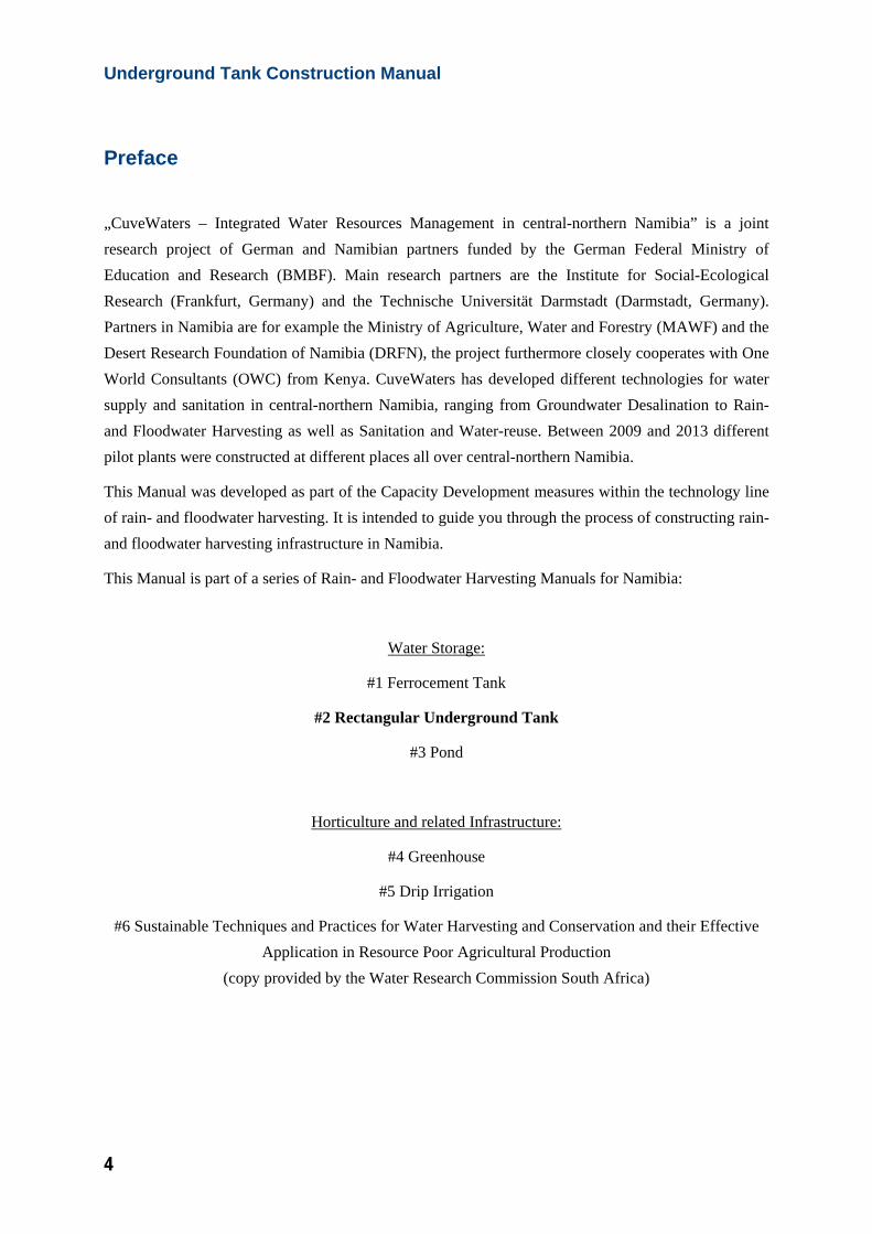
Preface
„CuveWaters – Integrated Water Resources Management in central-northern Namibia” is a joint research project of German and Namibian partners funded by the German Federal Ministry of Education and Research (BMBF). Main research partners are the Institute for Social-Ecological Research (Frankfurt, Germany) and the Technische Universität Darmstadt (Darmstadt, Germany). Partners in Namibia are for example the Ministry of Agriculture, Water and Forestry (MAWF) and the Desert Research Foundation of Namibia (DRFN), the project furthermore closely cooperates with One World Consultants (OWC) from Kenya. CuveWaters has developed different technologies for water supply and sanitation in central-northern Namibia, ranging from Groundwater Desalination to Rain- and Floodwater Harvesting as well as Sanitation and Water-reuse. Between 2009 and 2013 different pilot plants were constructed at different places all over central-northern Namibia.
This Manual was developed as part of the Capacity Development measures within the technology line of rain- and floodwater harvesting. It is intended to guide you through the process of constructing rain- and floodwater harvesting infrastructure in Namibia.
This Manual is part of a series of Rain- and Floodwater Harvesting Manuals for Namibia:
Water Storage:
#1 Ferrocement Tank
#2 Rectangular Underground Tank
#3 Pond
Horticulture and related Infrastructure:
#4 Greenhouse
#5 Drip Irrigation
#6 Sustainable Techniques and Practices for Water Harvesting and Conservation and their Effective Application in Resource Poor Agricultural Production
(copy provided by the Water Research Commission South Africa)

5
For more information on organisational, institutional and other general aspects of rain- and floodwater harvesting please have a look in the “CuveWaters Rain- and Floodwater Harvesting Toolkit”.
For more information on the CuveWaters project please visit http://www.cuvewaters.net
Alexander Jokisch
Technische Universität Darmstadt
Darmstadt, 02.03.2015
Underground Tank Construction Manual
6
About
CuveWaters Construction Manual # 2 – Rectangular Underground Tank
CuveWaters – Integrated Water Resources Management in Namibia
2015
This manual is also available on http://www.cuvewaters.net/Publications
For more information on Rainwater Harvesting in Namibia please contact
Alexander Jokisch
Technische Universität Darmstadt
Institute IWAR
Franziska Braun Str. 7
64287 Darmstadt, Germany
or
Alexia Krug von Nidda, Cuvewaters Project Coordination
Institute for Social-Ecological Research
Hamburger Allee 45
60486 Frankfurt, Germany
“CuveWaters – Integrated Water Resources Management in Namibia” is sponsored by:
7
Table of Content
Preface ............................................................................................................................................ 4
About .............................................................................................................................................. 6
1 Preliminary considerations ........................................................................................................... 9
1.1 Materials & Tools Preparation ................................................................................................ 9
1.2 Siting recommendations ........................................................................................................ 10
1.3 Tank volume and other dimensions ....................................................................................... 10
2 General Work Instructions ......................................................................................................... 13
2.1 How to mix and use concrete ................................................................................................ 13
2.2 How to compact concrete ...................................................................................................... 14
2.3 How to mix and use mortar/plaster ....................................................................................... 15
2.4 How to use bituminous paint ................................................................................................. 16
2.5 How to mix cement slurry ..................................................................................................... 16
2.6 How to make the steel reinforcement for the foundation ...................................................... 16
2.7 How to make the steel reinforcement for the sidewall .......................................................... 17
2.8 How to prepare the formwork for concreting the sidewalls .................................................. 20
2.9 How to make the formwork for concreting the roof .............................................................. 21
2.10 How to make the steel reinforcement for the roof ................................................................. 24
3 Detailed Work Instructions – Construction Diary ................................................................... 26
3.1 Day 1: Siting, Excavation, and Preparation ........................................................................... 26
3.2 Day 2: Concreting the foundation and preparing the sidewalls. ............................................ 28
3.3 Day 3: Constructing the walls of the tank (part 1). ............................................................... 31
3.4 Day 4: Constructing the walls of the tank (part 2). ............................................................... 34
3.5 Day 5: Constructing the walls of the tank (part 3). ............................................................... 36
3.6 Day 6: Concreting the final segment of the sidewall. ............................................................ 37
3.7 Day 7: Finishing the walls and constructing the support pillar. ............................................ 38
3.8 Day 8: Constructing the formwork for and concreting of the roof. ....................................... 42
3.9 Day 9: Plastering the roof and constructing the manhole. ..................................................... 44
3.10 Day 10: Finishing the manhole and doing several minor steps. ............................................ 46

8
4 Estimated Bill of Material .......................................................................................................... 48
5 Bill of Tools .................................................................................................................................. 49
6 Construction Procedure Table ................................................................................................... 50
7 Maintenance of the Underground Tank .................................................................................... 53
7.1 Visual inspections .................................................................................................................. 53
7.2 Cleaning the tank ................................................................................................................... 53
7.3 Repair of cracks ..................................................................................................................... 54
9
1 Preliminary considerations
Before beginning with the construction work of the underground tank, preliminary considerations and work instructions should be read carefully. Indication of days means working days of 8 hours, although this may vary from one day to another. Days for curing / drying of concrete and mortar are mentioned separately at each part of the construction process. The labor needed for the construction process as described is 5 workers. At least one of them should be skilled in construction.
The construction manual describes how to build a 50 m³ reinforced concrete underground tank as conducted during the CuveWaters project for development and implementation of rainwater harvesting as a part of an Integrated Water Resources Management (IWRM) system. An example for such a rectangular underground tank can be found at the rain water harvesting field lab at University of Namibia (UNAM) “Engineer José Eduardo dos Santos Campus”, Ongwediva.
1.1 Materials & Tools Preparation
Ideally, most materials (see bill of materials) should be purchased and brought on site before start of construction or at least until needed at construction site. Storage facilities for materials, especially for cement and small items as well as for tools, should be provided at or close to construction site. The materials should be stored secure against weather conditions (e.g. rain, wind, and extreme heat) and theft. Tools needed for construction of the underground tank should be available for the period of construction.
Material supply
All materials needed for construction can be obtained from hardware shops that can be found all over Namibia. In central-northern Namibia you will find the necessary materials for example in the following shops:
- Oshana Build it, Ongwediva (recommended, first choice)
- Benz Building Supplies, Ongwediva (recommended, second choice)
- Pennypichers, Ongwediva
- Pupkewitz Megabuild, Oshakati
- Chico, Oshakati
Underground Tank Construction Manual
10
Please keep in mind that prices can differ in the different shops and seasonal variations are also common. So plan your construction site and the material supply well in advance and compare the prices in the different shops. Most hardware shops offer delivery of the materials for reasonable fees.
Sand
Especially sand can in most cases also be found locally close to the Oshanas, this option is normally much cheaper. Locals normally know where sand suitable for construction purposes can be found and can also deliver the sand for reasonable prices. Always check this sand for its quality especially its salt content!
Cement
For the construction of tanks and other infrastructure we recommend the use of cement made by Ohorongo Cement Factory only! For all constructions the 32.5R cement is sufficient!
1.2 Siting recommendations
Study the building which shall be used for water collection and how water runs off from the roof. Consider where the down-pipes are and how they be connected to the tank. Choose the site for the tank, in a way which allows that the rainwater can easily flow from the roof catchment into the tank. Also consider where the water has to be supplied to when stored in the underground tank. For an underground tank, there is always a type of pump necessary to supply water in a comfortable way. If no pump is installed, water can be removed from the tank with a bucket as well. In any case make sure that there is enough space to place a pump or use a bucket.
Stay at least 10 m away (depending on soil conditions) from any building. Usually, the lower side of the building is the best site for a tank, since the water runs off into the tank more easily.
Stay away from trees (at least 10 m) as their roots can destroy the tank.
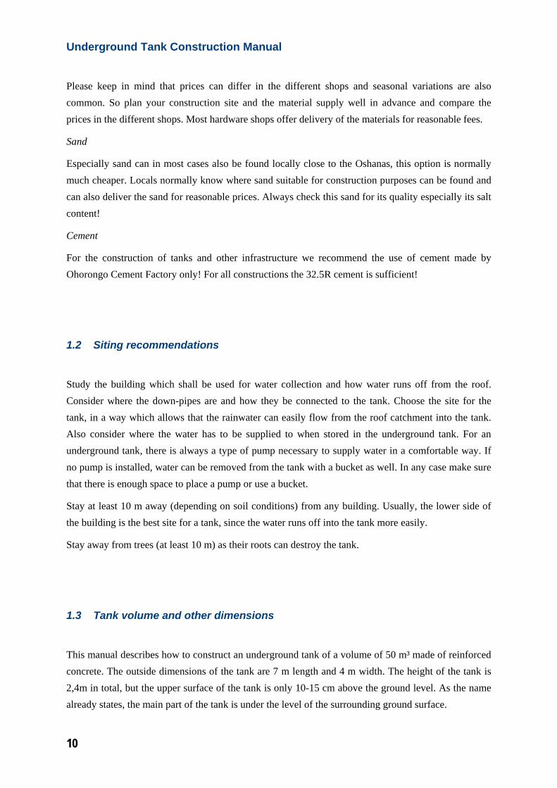
1.3 Tank volume and other dimensions
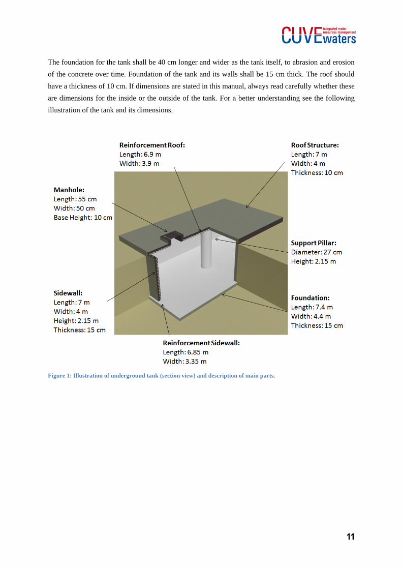
This manual describes how to construct an underground tank of a volume of 50 m³ made of reinforced concrete. The outside dimensions of the tank are 7 m length and 4 m width. The height of the tank is 2,4m in total, but the upper surface of the tank is only 10-15 cm above the ground level. As the name already states, the main part of the tank is under the level of the surrounding ground surface.
11
The foundation for the tank shall be 40 cm longer and wider as the tank itself, to abrasion and erosion of the concrete over time. Foundation of the tank and its walls shall be 15 cm thick. The roof should have a thickness of 10 cm. If dimensions are stated in this manual, always read carefully whether these are dimensions for the inside or the outside of the tank. For a better understanding see the following illustration of the tank and its dimensions.
Figure 1: Illustration of underground tank (section view) and description of main parts.
Underground Tank Construction Manual
12
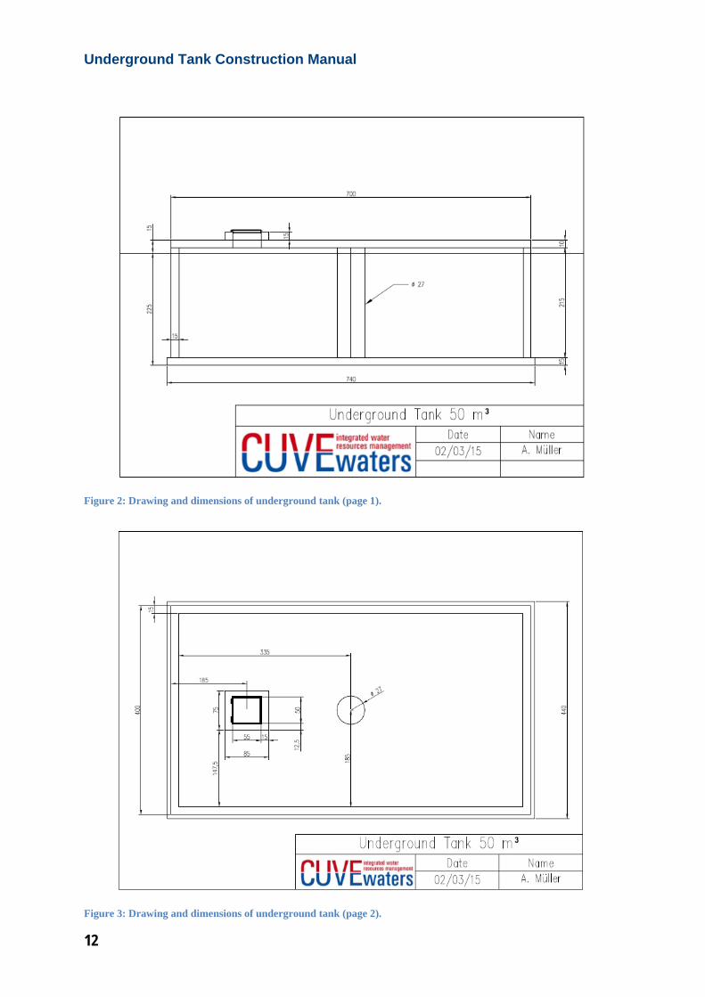
Figure 2: Drawing and dimensions of underground tank (page 1).
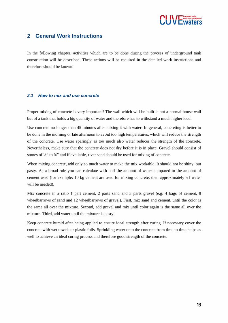
Figure 3: Drawing and dimensions of underground tank (page 2).
13
2 General Work Instructions
In the following chapter, activities which are to be done during the process of underground tank construction will be described. These actions will be required in the detailed work instructions and therefore should be known:
2.1 How to mix and use concrete
Proper mixing of concrete is very important! The wall which will be built is not a normal house wall but of a tank that holds a big quantity of water and therefore has to withstand a much higher load.
Use concrete no longer than 45 minutes after mixing it with water. In general, concreting is better to be done in the morning or late afternoon to avoid too high temperatures, which will reduce the strength of the concrete. Use water sparingly as too much also water reduces the strength of the concrete. Nevertheless, make sure that the concrete does not dry before it is in place. Gravel should consist of stones of ½” to ¾” and if available, river sand should be used for mixing of concrete.
When mixing concrete, add only so much water to make the mix workable. It should not be shiny, but pasty. As a broad rule you can calculate with half the amount of water compared to the amount of cement used (for example: 10 kg cement are used for mixing concrete, then approximately 5 l water will be needed).
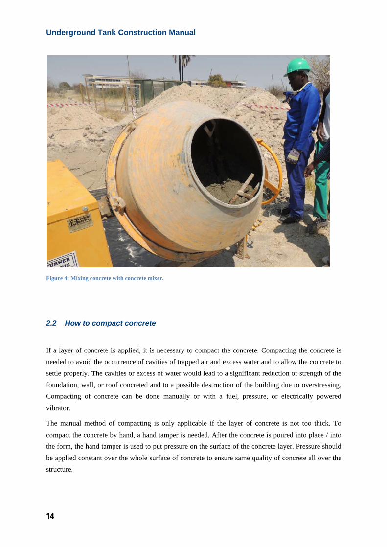
Mix concrete in a ratio 1 part cement, 2 parts sand and 3 parts gravel (e.g. 4 bags of cement, 8 wheelbarrows of sand and 12 wheelbarrows of gravel). First, mix sand and cement, until the color is the same all over the mixture. Second, add gravel and mix until color again is the same all over the mixture. Third, add water until the mixture is pasty.
Keep concrete humid after being applied to ensure ideal strength after curing. If necessary cover the concrete with wet towels or plastic foils. Sprinkling water onto the concrete from time to time helps as well to achieve an ideal curing process and therefore good strength of the concrete.
Underground Tank Construction Manual
14
Figure 4: Mixing concrete with concrete mixer.
2.2 How to compact concrete
If a layer of concrete is applied, it is necessary to compact the concrete. Compacting the concrete is needed to avoid the occurrence of cavities of trapped air and excess water and to allow the concrete to settle properly. The cavities or excess of water would lead to a significant reduction of strength of the foundation, wall, or roof concreted and to a possible destruction of the building due to overstressing. Compacting of concrete can be done manually or with a fuel, pressure, or electrically powered vibrator.
The manual method of compacting is only applicable if the layer of concrete is not too thick. To compact the concrete by hand, a hand tamper is needed. After the concrete is poured into place / into the form, the hand tamper is used to put pressure on the surface of the concrete layer. Pressure should be applied constant over the whole surface of concrete to ensure same quality of concrete all over the structure.
15
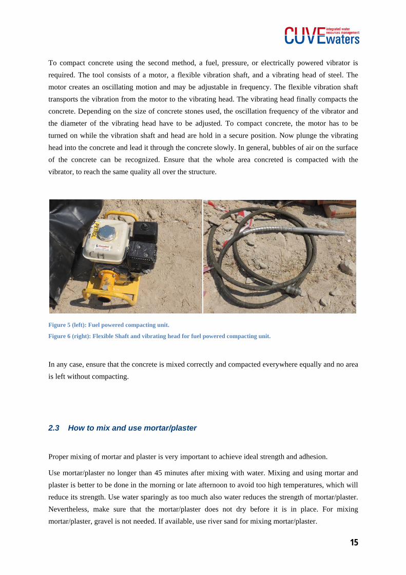
To compact concrete using the second method, a fuel, pressure, or electrically powered vibrator is required. The tool consists of a motor, a flexible vibration shaft, and a vibrating head of steel. The motor creates an oscillating motion and may be adjustable in frequency. The flexible vibration shaft transports the vibration from the motor to the vibrating head. The vibrating head finally compacts the concrete. Depending on the size of concrete stones used, the oscillation frequency of the vibrator and the diameter of the vibrating head have to be adjusted. To compact concrete, the motor has to be turned on while the vibration shaft and head are hold in a secure position. Now plunge the vibrating head into the concrete and lead it through the concrete slowly. In general, bubbles of air on the surface of the concrete can be recognized. Ensure that the whole area concreted is compacted with the vibrator, to reach the same quality all over the structure.
Figure 5 (left): Fuel powered compacting unit.
Figure 6 (right): Flexible Shaft and vibrating head for fuel powered compacting unit.
In any case, ensure that the concrete is mixed correctly and compacted everywhere equally and no area is left without compacting.
2.3 How to mix and use mortar/plaster
Proper mixing of mortar and plaster is very important to achieve ideal strength and adhesion.
Use mortar/plaster no longer than 45 minutes after mixing with water. Mixing and using mortar and plaster is better to be done in the morning or late afternoon to avoid too high temperatures, which will reduce its strength. Use water sparingly as too much also water reduces the strength of mortar/plaster. Nevertheless, make sure that the mortar/plaster does not dry before it is in place. For mixing mortar/plaster, gravel is not needed. If available, use river sand for mixing mortar/plaster.
Underground Tank Construction Manual
16
Mix mortar/plaster in a ratio 1 part cement, and 3 parts sand (e.g. 1 bag of cement and 3 wheelbarrows of sand). First, mix sand and cement, until color is the same all over the mixture. Second, add water. When mixing mortar/plaster, add only so much water to make the mix workable. It should not be shiny, but pasty.
Keep mortar and plaster humid after being applied to ensure ideal strength after curing. If necessary cover with wet towels or plastic foils. Sprinkling water to the mortar or plaster from time to time helps as well to achieve an ideal curing process and therefore good strength of the mortar/plaster.
2.4 How to use bituminous paint
Bituminous paint is a helpful treatment to improve the water tightness of concrete. Read instructions carefully that come with the bituminous paint. In general, no special preparation or conditioning is necessary. Nevertheless, stirring the paint before use ensures the correct quality and texture of the paint. Use a broad brush to apply a layer of bituminous paint to the outside wall of an underground tank to reduce water leakage from the tank to the soil which surrounds the tank. At the same time bituminous paint protects the concrete against deterioration due to salt or other components of the soil.
2.5 How to mix cement slurry
Cement slurry, which is also called NIL, is a liquid to pasty mixture of cement and water only. It is used to increase the water tightness of ferrocement and concrete and therefore avoidance of water leakages. Mix cement with water in a proper sized can or bucket. The slurry shall not be too pasty to allow an easy application to the wall. Nevertheless, the slurry shall not be too watery to ensure its sealing function.
2.6 How to make the steel reinforcement for the foundation
The dimension of the foundation of the 50 m³ underground tank are 7.4 m in length, 4.4 m in width and 15 cm in height. To avoid corrosion of the steel mesh over the lifetime, no steel may later on stick out of the concrete. Accordingly, the dimensions of the reinforcement are 7.3 m length and 4.3 m width. Therefore some of the reinforcement steel meshes have to be cut with a bolt
17
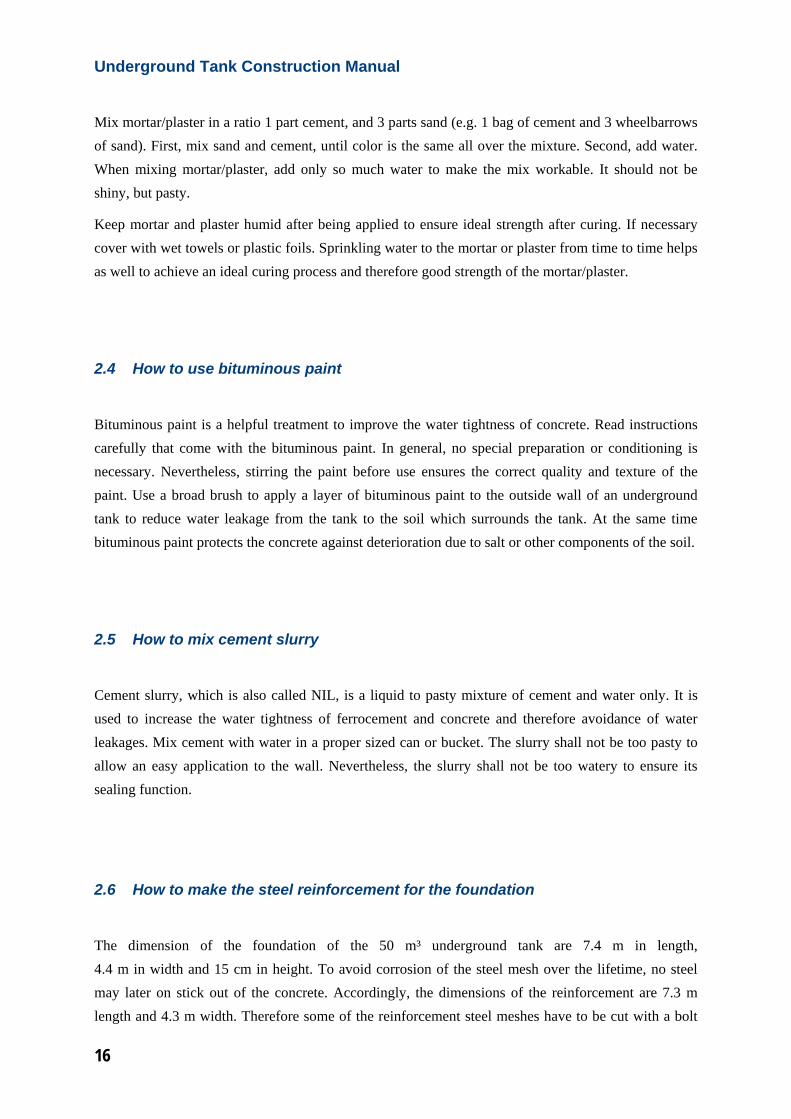
cutter to an appropriate length when they are put in place in the pit. The weld meshes have to be placed on top of the first layer of concrete of the foundation, when the concrete is still fresh and workable (more details to be found in the construction diary). When placing and cutting the reinforcement steel mesh, ensure that single meshes have an overlap of 20 cm each. Use binding wire to tie the overlapping meshes together every 10 to 15 cm. This is necessary to ensure the correct strength of the reinforced concrete and to avoid early disruption and leakage of the tank.
Figure 7: Overlapping reinforcement steel meshes connected with binding wire.
2.7 How to make the steel reinforcement for the sidewall
The preparation of the steel welded mesh for the sidewalls needs some more steps than the preparation of the reinforcement for the foundation does. In general, make sure that all steps are completed with caution, so the reinforcement will strengthen the concrete sufficiently. Always have in mind that the tank and especially the sidewalls will have to stand high loads due to the large amount of water that will be stored in the tank.
Underground Tank Construction Manual
18
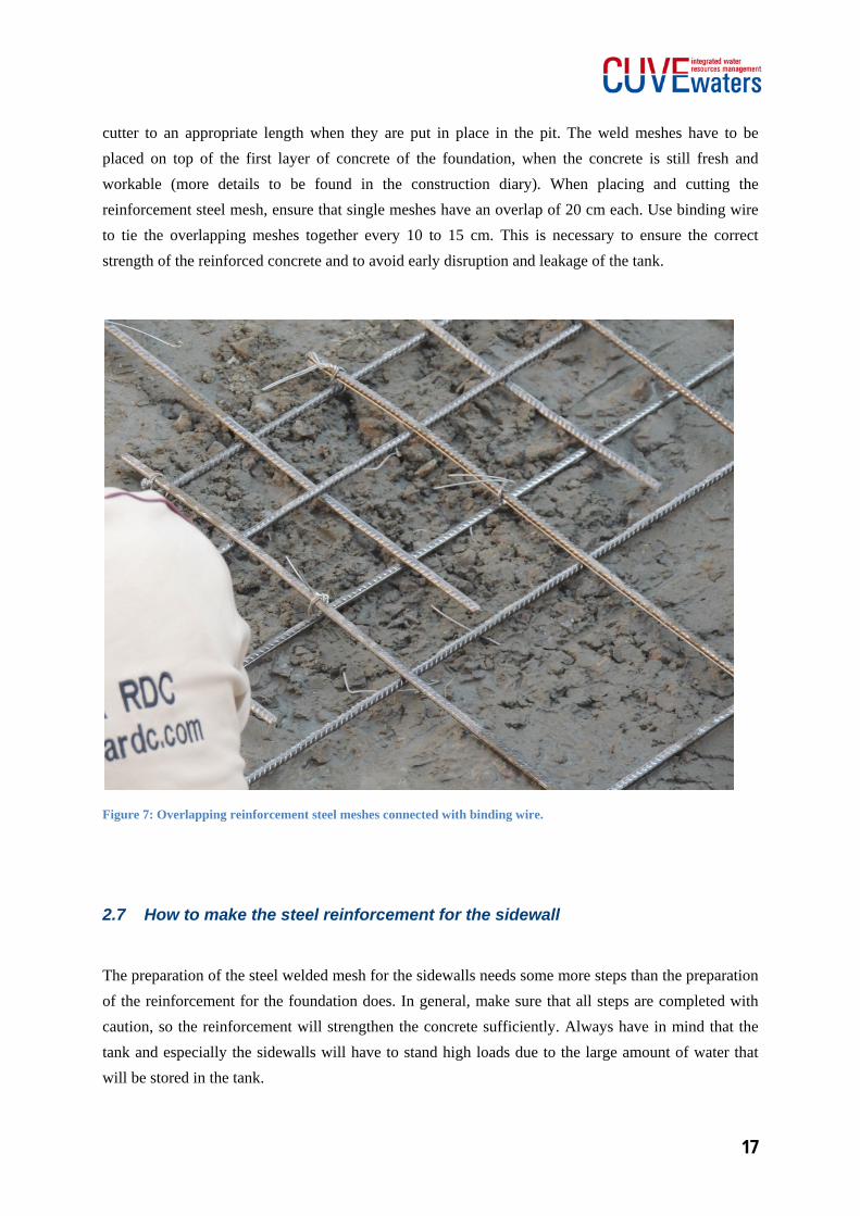
The reinforcement of the sidewall will consist of 4 pieces of steel welded mesh. Lay the first mesh onto the ground and bend the small protruding steel bars of one of the long sides upwards in an angle of 90°. This is necessary for a correct fixation of the reinforcement of the sidewall to the reinforcement of the foundation. Afterwards, bend the whole mesh in the middle of the long side in an angle of 90° to form a radius. It is helpful to use an iron bar or wooden pole of appropriate length to ensure the welded steel mesh is bent equally throughout the whole width of the mesh. Both sides of the bent steel mesh will have a length of 3 m.
Figure 8: Preparation of welded steel mesh: bending an angle of 90°.
The second mesh has to be prepared in a similar way. First, the short protruding bars on one of the long sides have to be bent upwards. Then, the steel welded mesh has to be bent in an angle of 90° upwards at a length of around 4 m. This will lead to a long side of 4 m and a short side of 2 m length. For preparation of the 3rd and 4th steel welded meshes, the steps described above for meshes 1 and 2 have to be repeated.
19
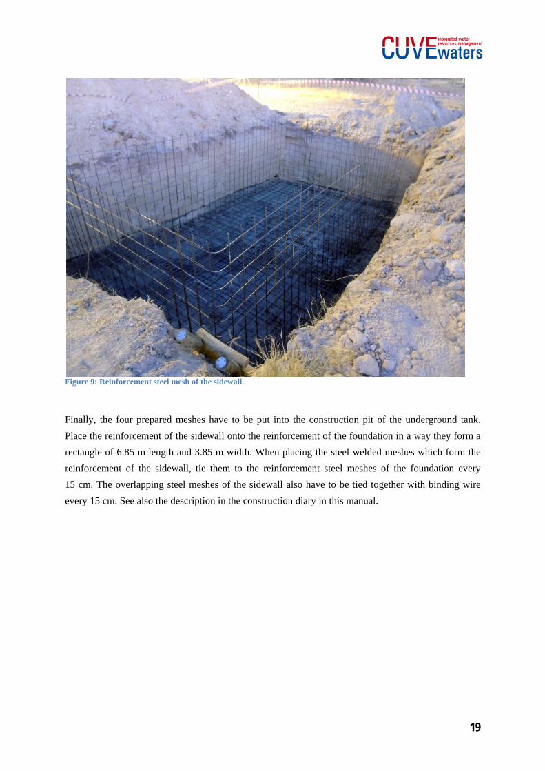
Figure 9: Reinforcement steel mesh of the sidewall.
Finally, the four prepared meshes have to be put into the construction pit of the underground tank. Place the reinforcement of the sidewall onto the reinforcement of the foundation in a way they form a rectangle of 6.85 m length and 3.85 m width. When placing the steel welded meshes which form the reinforcement of the sidewall, tie them to the reinforcement steel meshes of the foundation every 15 cm. The overlapping steel meshes of the sidewall also have to be tied together with binding wire every 15 cm. See also the description in the construction diary in this manual.
Underground Tank Construction Manual
20
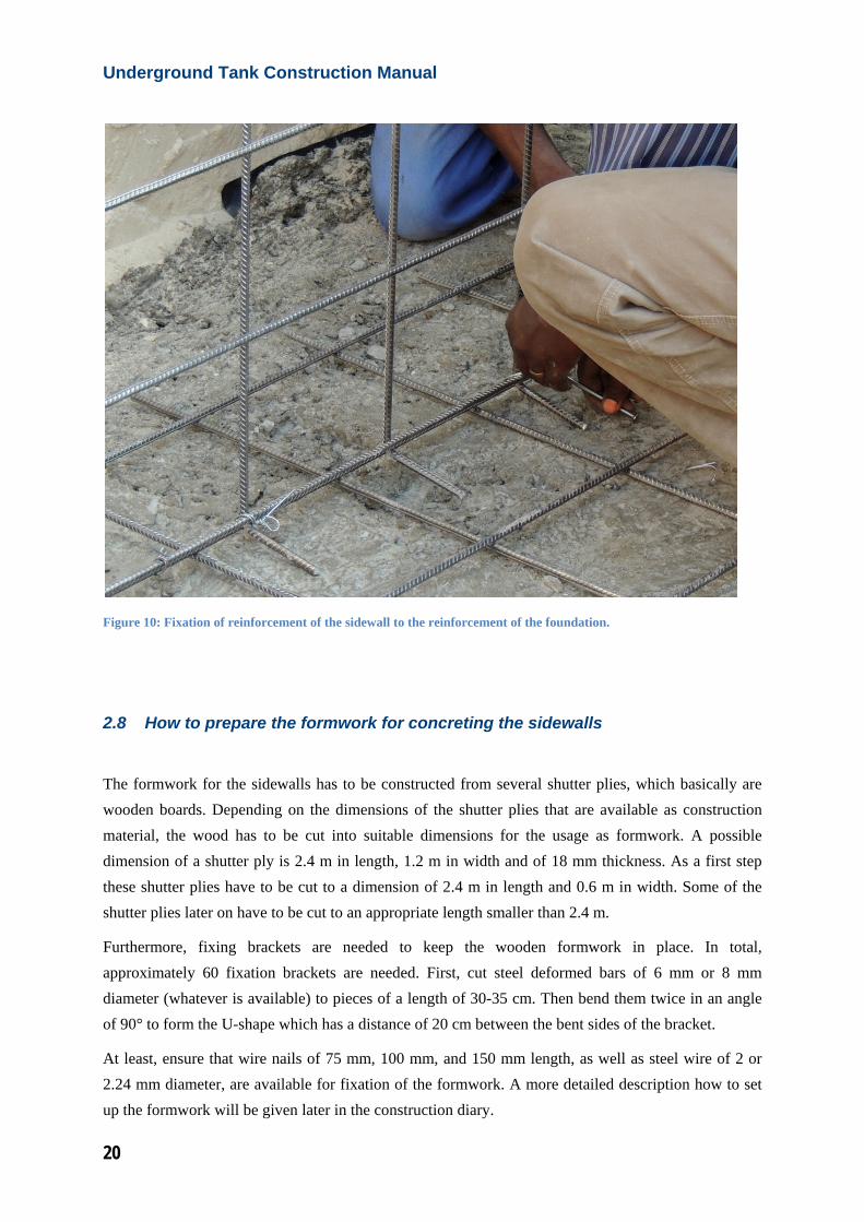
Figure 10: Fixation of reinforcement of the sidewall to the reinforcement of the foundation.
2.8 How to prepare the formwork for concreting the sidewalls
The formwork for the sidewalls has to be constructed from several shutter plies, which basically are wooden boards. Depending on the dimensions of the shutter plies that are available as construction material, the wood has to be cut into suitable dimensions for the usage as formwork. A possible dimension of a shutter ply is 2.4 m in length, 1.2 m in width and of 18 mm thickness. As a first step these shutter plies have to be cut to a dimension of 2.4 m in length and 0.6 m in width. Some of the shutter plies later on have to be cut to an appropriate length smaller than 2.4 m.
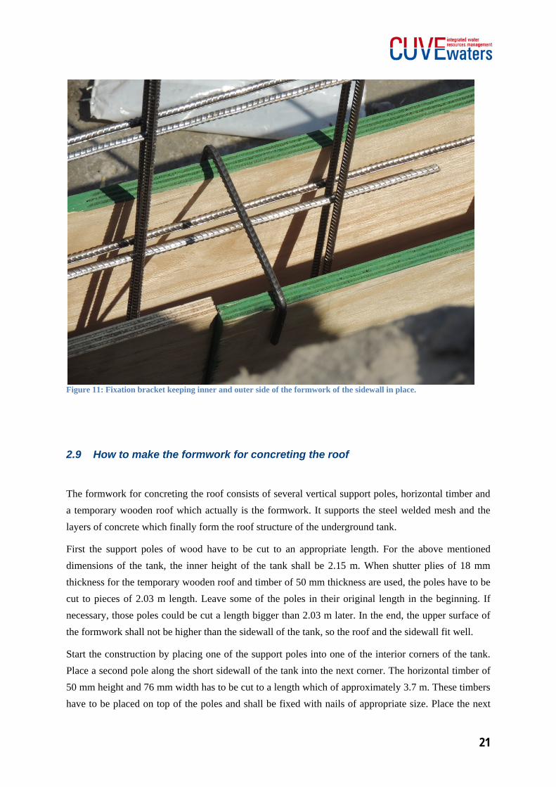
Furthermore, fixing brackets are needed to keep the wooden formwork in place. In total, approximately 60 fixation brackets are needed. First, cut steel deformed bars of 6 mm or 8 mm diameter (whatever is available) to pieces of a length of 30-35 cm. Then bend them twice in an angle of 90° to form the U-shape which has a distance of 20 cm between the bent sides of the bracket.
At least, ensure that wire nails of 75 mm, 100 mm, and 150 mm length, as well as steel wire of 2 or 2.24 mm diameter, are available for fixation of the formwork. A more detailed description how to set up the formwork will be given later in the construction diary.
21
Figure 11: Fixation bracket keeping inner and outer side of the formwork of the sidewall in place.
2.9 How to make the formwork for concreting the roof
The formwork for concreting the roof consists of several vertical support poles, horizontal timber and a temporary wooden roof which actually is the formwork. It supports the steel welded mesh and the layers of concrete which finally form the roof structure of the underground tank.
First the support poles of wood have to be cut to an appropriate length. For the above mentioned dimensions of the tank, the inner height of the tank shall be 2.15 m. When shutter plies of 18 mm thickness for the temporary wooden roof and timber of 50 mm thickness are used, the poles have to be cut to pieces of 2.03 m length. Leave some of the poles in their original length in the beginning. If necessary, those poles could be cut a length bigger than 2.03 m later. In the end, the upper surface of the formwork shall not be higher than the sidewall of the tank, so the roof and the sidewall fit well.
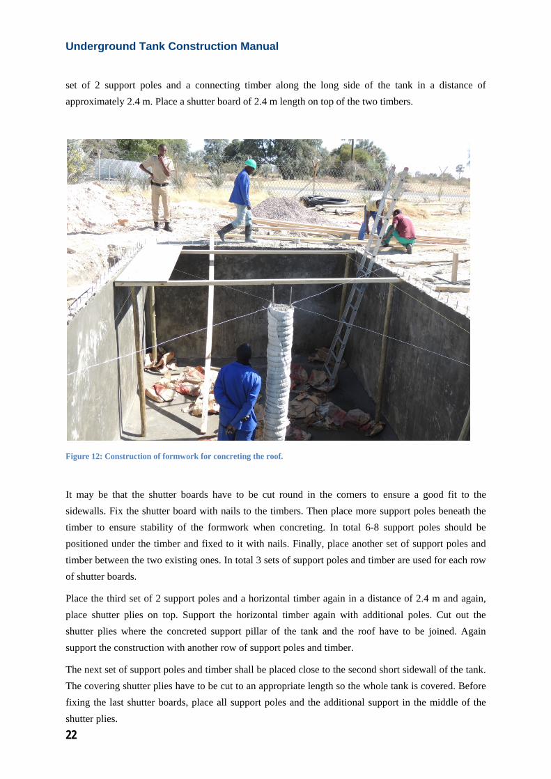
Start the construction by placing one of the support poles into one of the interior corners of the tank. Place a second pole along the short sidewall of the tank into the next corner. The horizontal timber of 50 mm height and 76 mm width has to be cut to a length which of approximately 3.7 m. These timbers have to be placed on top of the poles and shall be fixed with nails of appropriate size. Place the next
Underground Tank Construction Manual
22
set of 2 support poles and a connecting timber along the long side of the tank in a distance of approximately 2.4 m. Place a shutter board of 2.4 m length on top of the two timbers.
Figure 12: Construction of formwork for concreting the roof.
It may be that the shutter boards have to be cut round in the corners to ensure a good fit to the sidewalls. Fix the shutter board with nails to the timbers. Then place more support poles beneath the timber to ensure stability of the formwork when concreting. In total 6-8 support poles should be positioned under the timber and fixed to it with nails. Finally, place another set of support poles and timber between the two existing ones. In total 3 sets of support poles and timber are used for each row of shutter boards.
Place the third set of 2 support poles and a horizontal timber again in a distance of 2.4 m and again, place shutter plies on top. Support the horizontal timber again with additional poles. Cut out the shutter plies where the concreted support pillar of the tank and the roof have to be joined. Again support the construction with another row of support poles and timber.
The next set of support poles and timber shall be placed close to the second short sidewall of the tank. The covering shutter plies have to be cut to an appropriate length so the whole tank is covered. Before fixing the last shutter boards, place all support poles and the additional support in the middle of the shutter plies.
23
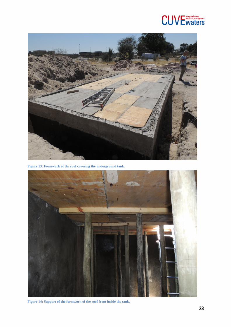
Figure 13: Formwork of the roof covering the underground tank.
Figure 14: Support of the formwork of the roof from inside the tank.
Underground Tank Construction Manual
24
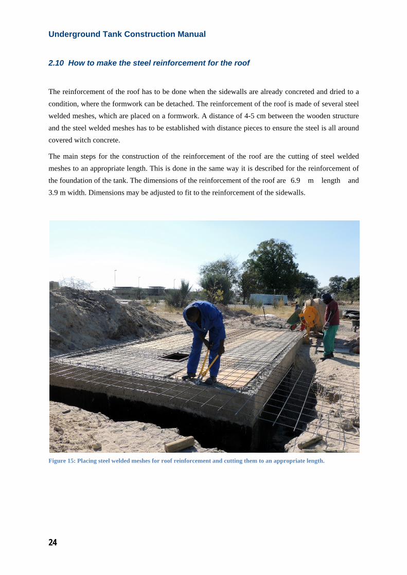
2.10 How to make the steel reinforcement for the roof
The reinforcement of the roof has to be done when the sidewalls are already concreted and dried to a condition, where the formwork can be detached. The reinforcement of the roof is made of several steel welded meshes, which are placed on a formwork. A distance of 4-5 cm between the wooden structure and the steel welded meshes has to be established with distance pieces to ensure the steel is all around covered witch concrete.
The main steps for the construction of the reinforcement of the roof are the cutting of steel welded meshes to an appropriate length. This is done in the same way it is described for the reinforcement of the foundation of the tank. The dimensions of the reinforcement of the roof are 6.9 m length and 3.9 m width. Dimensions may be adjusted to fit to the reinforcement of the sidewalls.
Figure 15: Placing steel welded meshes for roof reinforcement and cutting them to an appropriate length.
25
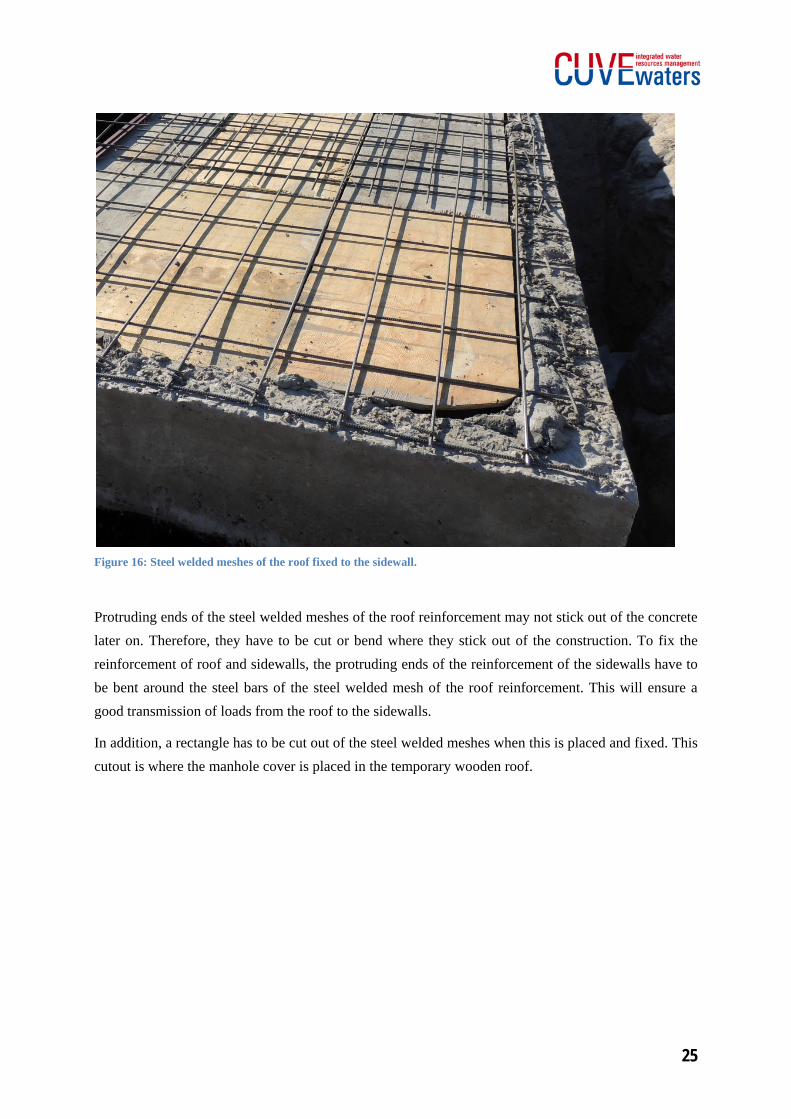
Figure 16: Steel welded meshes of the roof fixed to the sidewall.
Protruding ends of the steel welded meshes of the roof reinforcement may not stick out of the concrete later on. Therefore, they have to be cut or bend where they stick out of the construction. To fix the reinforcement of roof and sidewalls, the protruding ends of the reinforcement of the sidewalls have to be bent around the steel bars of the steel welded mesh of the roof reinforcement. This will ensure a good transmission of loads from the roof to the sidewalls.
In addition, a rectangle has to be cut out of the steel welded meshes when this is placed and fixed. This cutout is where the manhole cover is placed in the temporary wooden roof.
Underground Tank Construction Manual
26
3 Detailed Work Instructions – Construction Diary
The sequence of actions for construction of a concreted underground tank described below is an ideal one for experienced workers. Depending on manpower and experience, the overall construction time may be longer than this. Sequence may be changed depending on availability of manpower, materials and tools as well as for weather conditions or other reasons. Some of the steps should be done parallel to work most efficiently. Ensure that all material and tools needed for construction are available at the time they are needed.
Concrete should be sprinkled with each morning and each evening to support proper curing for sufficient strength and long durability of the tank. This instruction is not repeated in the daily work instruction, so keep it in mind for the whole construction phase.
3.1 Day 1: Siting, Excavation, and Preparation
Work instructions:
• Choose a site for the underground tank according to the considerations in chapter 1.2.
• Mark the dimensions of the tank on the ground to indicate where the excavation work has to be done. The excavation hole should be 8 m long and 5m wide. The depth should be 2.25 m.
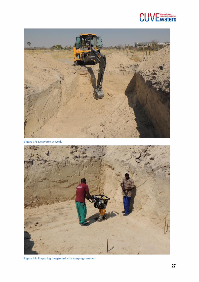
• Excavation can either be done by hand or using an excavator (this option is much faster). In any case ensure there is enough free space where the spoil/excavated soil can be stored.
• Fence the excavation site from the surrounding are with barrier tape to avoid people come too close to the excavation and from falling into the hole!
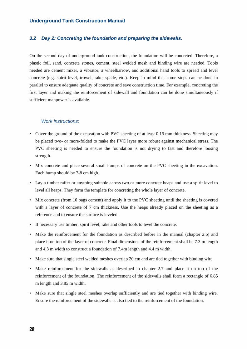
• When excavation work is finished, the ground of the excavation has to be prepared for the loads that will be constructed upon. Use a tamping rammer or plate compactor, to compact the ground and ensure a sufficient soil bearing capacity.
27
Figure 17: Excavator at work.
Figure 18: Preparing the ground with tamping rammer.
Underground Tank Construction Manual
28
3.2 Day 2: Concreting the foundation and preparing the sidewalls.
On the second day of underground tank construction, the foundation will be concreted. Therefore, a plastic foil, sand, concrete stones, cement, steel welded mesh and binding wire are needed. Tools needed are cement mixer, a vibrator, a wheelbarrow, and additional hand tools to spread and level concrete (e.g. spirit level, trowel, rake, spade, etc.). Keep in mind that some steps can be done in parallel to ensure adequate quality of concrete and save construction time. For example, concreting the first layer and making the reinforcement of sidewall and foundation can be done simultaneously if sufficient manpower is available.
Work instructions:
• Cover the ground of the excavation with PVC sheeting of at least 0.15 mm thickness. Sheeting may be placed two- or more-folded to make the PVC layer more robust against mechanical stress. The PVC sheeting is needed to ensure the foundation is not drying to fast and therefore loosing strength.
• Mix concrete and place several small humps of concrete on the PVC sheeting in the excavation. Each hump should be 7-8 cm high.
• Lay a timber rafter or anything suitable across two or more concrete heaps and use a spirit level to level all heaps. They form the template for concreting the whole layer of concrete.
• Mix concrete (from 10 bags cement) and apply it to the PVC sheeting until the sheeting is covered with a layer of concrete of 7 cm thickness. Use the heaps already placed on the sheeting as a reference and to ensure the surface is leveled.
• If necessary use timber, spirit level, rake and other tools to level the concrete.
• Make the reinforcement for the foundation as described before in the manual (chapter 2.6) and place it on top of the layer of concrete. Final dimensions of the reinforcement shall be 7.3 m length and 4.3 m width to construct a foundation of 7.4m length and 4.4 m width.
• Make sure that single steel welded meshes overlap 20 cm and are tied together with binding wire.
• Make reinforcement for the sidewalls as described in chapter 2.7 and place it on top of the reinforcement of the foundation. The reinforcement of the sidewalls shall form a rectangle of 6.85 m length and 3.85 m width.
• Make sure that single steel meshes overlap sufficiently and are tied together with binding wire. Ensure the reinforcement of the sidewalls is also tied to the reinforcement of the foundation.
29
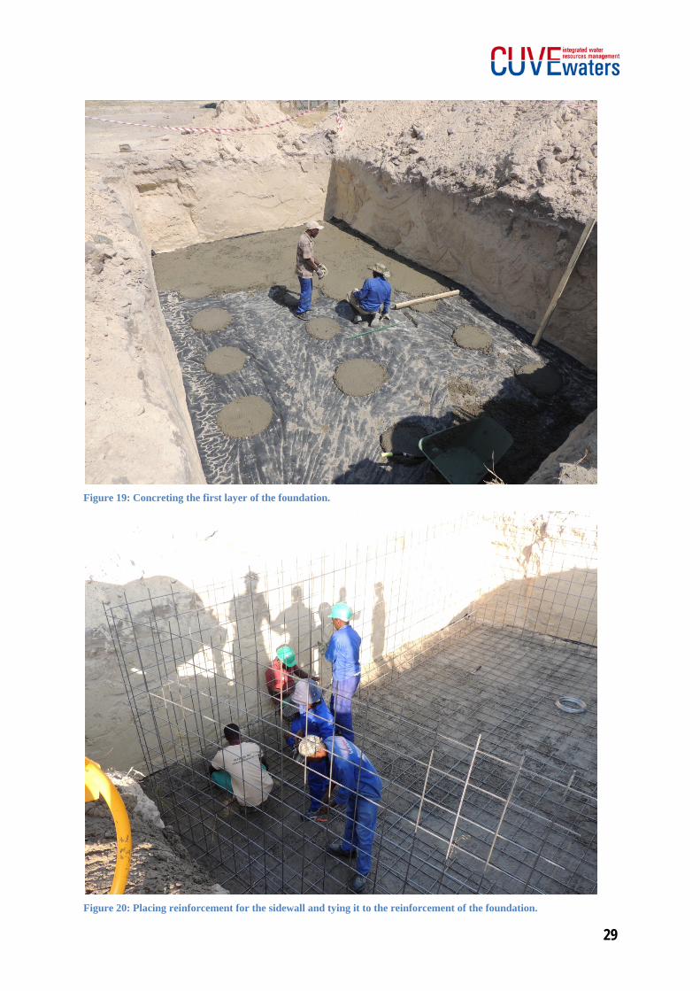
Figure 19: Concreting the first layer of the foundation.
Figure 20: Placing reinforcement for the sidewall and tying it to the reinforcement of the foundation.
Underground Tank Construction Manual
30
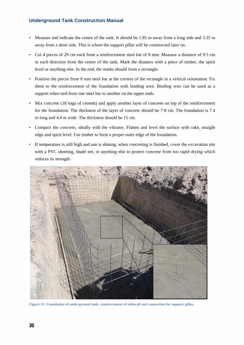
• Measure and indicate the centre of the tank. It should be 1.85 m away from a long side and 3.35 m away from a short side. This is where the support pillar will be constructed later on.
• Cut 4 pieces of 20 cm each from a reinforcement steel bar of 8 mm. Measure a distance of 9.5 cm in each direction from the centre of the tank. Mark the distance with a piece of timber, the spirit level or anything else. In the end, the marks should form a rectangle.
• Position the pieces from 8 mm steel bar at the corners of the rectangle in a vertical orientation. Fix them to the reinforcement of the foundation with binding wire. Binding wire can be used as a support when tied from one steel bar to another on the upper ends.
• Mix concrete (18 bags of cement) and apply another layer of concrete on top of the reinforcement for the foundation. The thickness of the layer of concrete should be 7-8 cm. The foundation is 7.4 m long and 4.4 m wide. The thickness should be 15 cm.
• Compact the concrete, ideally with the vibrator. Flatten and level the surface with rake, straight edge and spirit level. Use timber to form a proper outer edge of the foundation.
• If temperature is still high and sun is shining, when concreting is finished, cover the excavation site with a PVC sheeting, shade net, or anything else to protect concrete from too rapid drying which reduces its strength.
Figure 21: Foundation of underground tank, reinforcement of sidewall and connection for support pillar.
31
3.3 Day 3: Constructing the walls of the tank (part 1).
On the third day of construction, concreting of the sidewall will be started. Therefore, the wooden formwork has to be built, positioned and fixed in place. Finally, concrete has to be filled into the formwork and to be compacted with the vibrating head of the compactor or manually.
Work instructions:
• Measure, mark and cut shutter boards as described before in this manual. Altogether 20 pieces of 2.4 m length, 60 cm width, and 18 mm thickness are needed.
• As described in chapter 2.8, make the U-shaped fixation brackets from 6 or 8 mm steel bars. Therefore, cut steel bar to a length of 30–35 cm and bend it twice in an angle of 90°. The long leg of the bracket shall have a length of 20 cm.
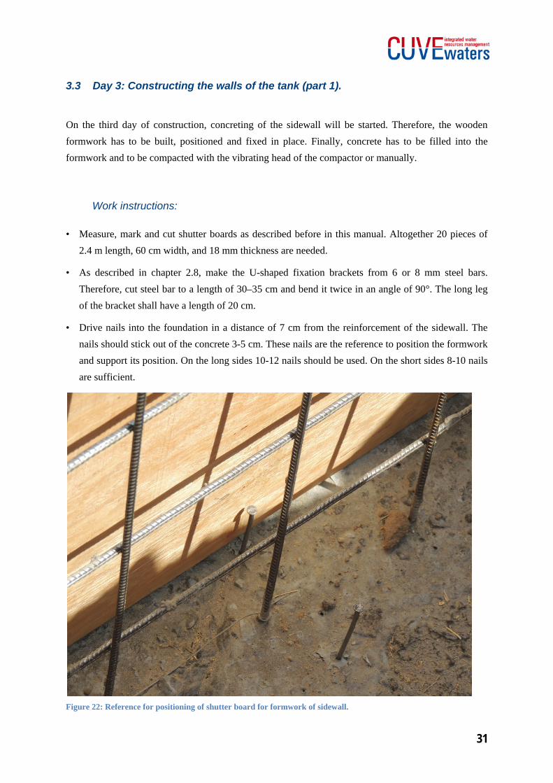
• Drive nails into the foundation in a distance of 7 cm from the reinforcement of the sidewall. The nails should stick out of the concrete 3-5 cm. These nails are the reference to position the formwork and support its position. On the long sides 10-12 nails should be used. On the short sides 8-10 nails are sufficient.
Figure 22: Reference for positioning of shutter board for formwork of sidewall.

Underground Tank Construction Manual
32
• Start placing the shutter boards for the formwork in any corner inside the tank. Place the first shutter board upright on the short side of the tank along the reference line in the foundation made of nails.
• The second shutter board continues on the short side of the wall but has to be cut to an appropriate length. Theoretically, a length of 1.3 m is necessary to construct the formwork, but check the correct length practically by positioning the third shutter board around the corner along the long side of the wall. The 2nd board should be cut to line up with the inner side of the 3rd shutter board.
• Place shutter boards to the outside of the tank. Position the boards according to the reference made by nails. For the short side of the tank the second board on the outside theoretically, shall be cut to 1.6 m length, but again check the ideal length practically.
• Continue to place shutter boards inside and outside the tank. Cut the boards to an appropriate length in the corners. Measure the ideal lengths as described before.
• Use wire nails to join the shutter boards together where two form a corner.
Figure 23: Positioning of shutter boards while constructing the formwork of the sidewall.
• Shutter plies from inside and outside the tank have to be hold in position by the fixing brackets. Place them on the upper edged of the boards.
33
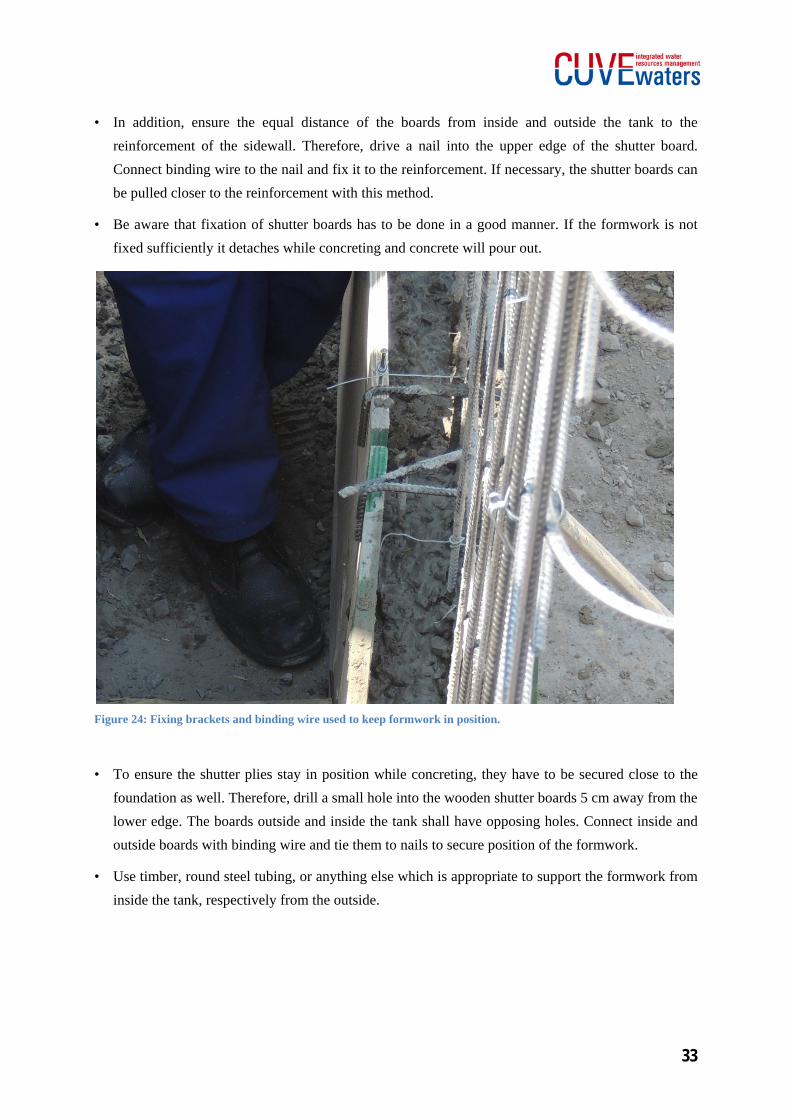
• In addition, ensure the equal distance of the boards from inside and outside the tank to the reinforcement of the sidewall. Therefore, drive a nail into the upper edge of the shutter board. Connect binding wire to the nail and fix it to the reinforcement. If necessary, the shutter boards can be pulled closer to the reinforcement with this method.
• Be aware that fixation of shutter boards has to be done in a good manner. If the formwork is not fixed sufficiently it detaches while concreting and concrete will pour out.
Figure 24: Fixing brackets and binding wire used to keep formwork in position.
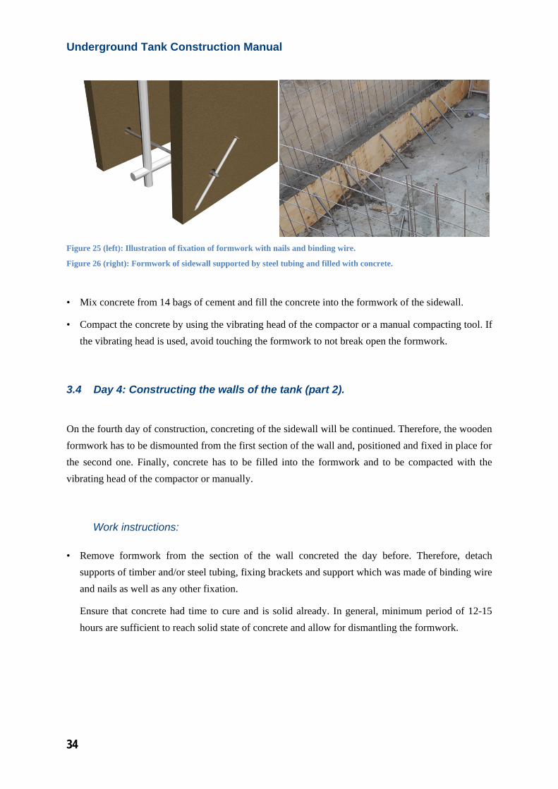
• To ensure the shutter plies stay in position while concreting, they have to be secured close to the foundation as well. Therefore, drill a small hole into the wooden shutter boards 5 cm away from the lower edge. The boards outside and inside the tank shall have opposing holes. Connect inside and outside boards with binding wire and tie them to nails to secure position of the formwork.
• Use timber, round steel tubing, or anything else which is appropriate to support the formwork from inside the tank, respectively from the outside.
Underground Tank Construction Manual
34
Figure 25 (left): Illustration of fixation of formwork with nails and binding wire.
Figure 26 (right): Formwork of sidewall supported by steel tubing and filled with concrete.
• Mix concrete from 14 bags of cement and fill the concrete into the formwork of the sidewall.
• Compact the concrete by using the vibrating head of the compactor or a manual compacting tool. If the vibrating head is used, avoid touching the formwork to not break open the formwork.
3.4 Day 4: Constructing the walls of the tank (part 2).
On the fourth day of construction, concreting of the sidewall will be continued. Therefore, the wooden formwork has to be dismounted from the first section of the wall and, positioned and fixed in place for the second one. Finally, concrete has to be filled into the formwork and to be compacted with the vibrating head of the compactor or manually.
Work instructions:
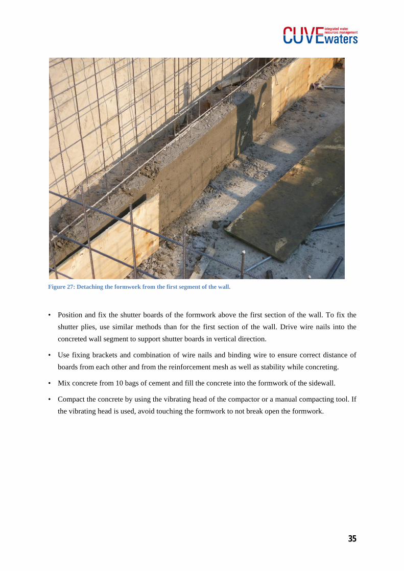
• Remove formwork from the section of the wall concreted the day before. Therefore, detach supports of timber and/or steel tubing, fixing brackets and support which was made of binding wire and nails as well as any other fixation.
Ensure that concrete had time to cure and is solid already. In general, minimum period of 12-15 hours are sufficient to reach solid state of concrete and allow for dismantling the formwork.
35
Figure 27: Detaching the formwork from the first segment of the wall.
• Position and fix the shutter boards of the formwork above the first section of the wall. To fix the shutter plies, use similar methods than for the first section of the wall. Drive wire nails into the concreted wall segment to support shutter boards in vertical direction.
• Use fixing brackets and combination of wire nails and binding wire to ensure correct distance of boards from each other and from the reinforcement mesh as well as stability while concreting.
• Mix concrete from 10 bags of cement and fill the concrete into the formwork of the sidewall.
• Compact the concrete by using the vibrating head of the compactor or a manual compacting tool. If the vibrating head is used, avoid touching the formwork to not break open the formwork.
Underground Tank Construction Manual
36
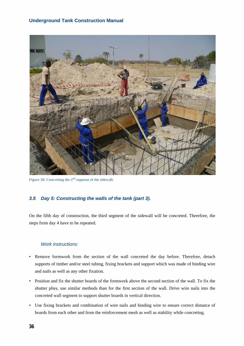
Figure 28: Concreting the 2nd segment of the sidewall.
3.5 Day 5: Constructing the walls of the tank (part 3).
On the fifth day of construction, the third segment of the sidewall will be concreted. Therefore, the steps from day 4 have to be repeated.
Work instructions:
• Remove formwork from the section of the wall concreted the day before. Therefore, detach supports of timber and/or steel tubing, fixing brackets and support which was made of binding wire and nails as well as any other fixation.
• Position and fix the shutter boards of the formwork above the second section of the wall. To fix the shutter plies, use similar methods than for the first section of the wall. Drive wire nails into the concreted wall segment to support shutter boards in vertical direction.
• Use fixing brackets and combination of wire nails and binding wire to ensure correct distance of boards from each other and from the reinforcement mesh as well as stability while concreting.
37
• Mix concrete from 10 bags of cement and fill the concrete into the formwork of the sidewall.
• Compact the concrete by using the vibrating head of the compactor or a manual compacting tool. If the vibrating head is used, avoid touching the formwork to not break open the formwork.
3.6 Day 6: Concreting the final segment of the sidewall.
On the sixth day of construction, concreting of the sidewall will be finished. Therefore, the wooden formwork has to be detached from the third segment of the wall, positioned above it and fixed in place. Indication has to be done to fill concrete into the form to the correct height. Finally, concrete has to be filled in and compacted with the vibrating head of the compactor or manually.
Work instructions:
• Remove formwork from the section of the wall concreted the day before. Therefore, detach supports of timber and/or steel tubing, fixing brackets and support which was made of binding wire and nails as well as any other fixation.
• Position and fix the shutter boards of the formwork above the third section of the wall. To fix the shutter plies, use similar methods than for the other sections of the wall. Drive wire nails into the concreted wall segment to support shutter boards in vertical direction.
• Use fixing brackets and combination of wire nails and binding wire to ensure correct distance of boards from each other and from the reinforcement mesh as well as stability while concreting.
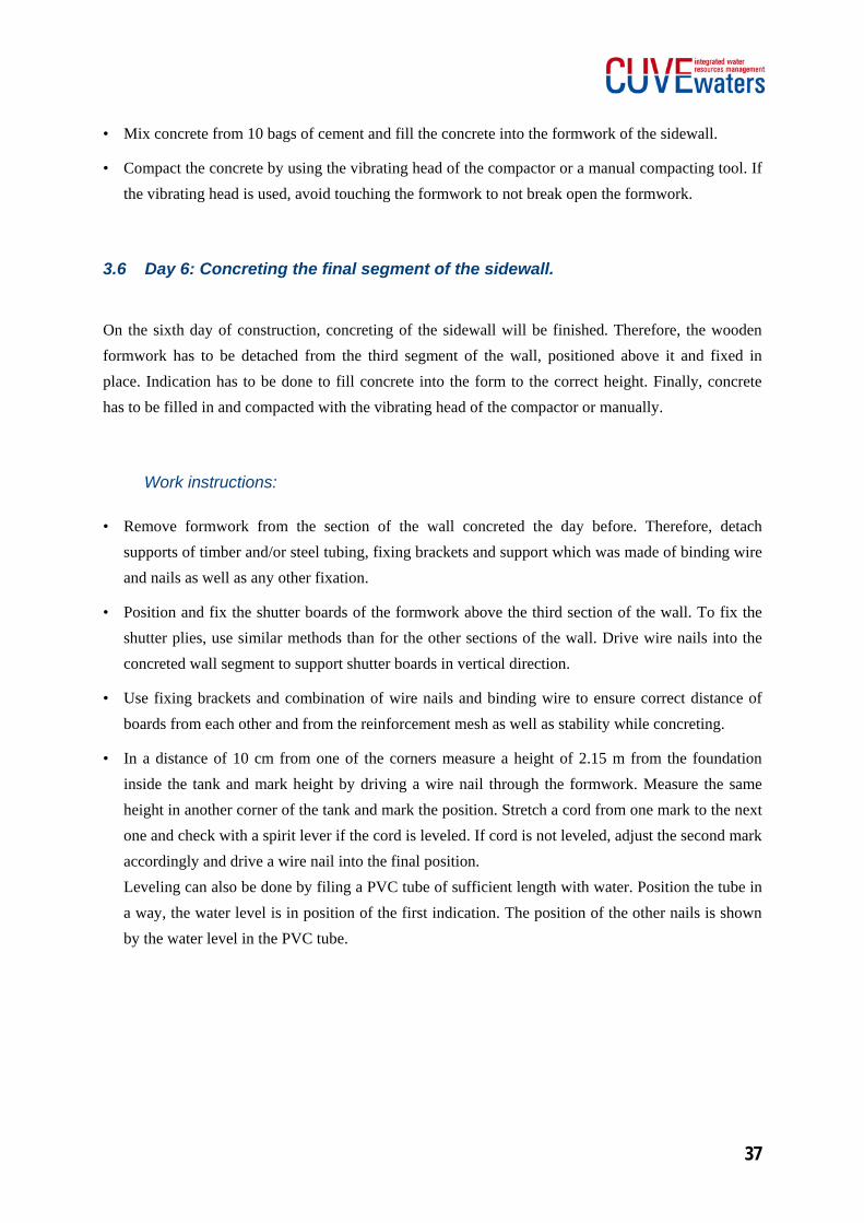
• In a distance of 10 cm from one of the corners measure a height of 2.15 m from the foundation inside the tank and mark height by driving a wire nail through the formwork. Measure the same height in another corner of the tank and mark the position. Stretch a cord from one mark to the next one and check with a spirit lever if the cord is leveled. If cord is not leveled, adjust the second mark accordingly and drive a wire nail into the final position. Leveling can also be done by filing a PVC tube of sufficient length with water. Position the tube in a way, the water level is in position of the first indication. The position of the other nails is shown by the water level in the PVC tube.
Underground Tank Construction Manual
38
• Drive more nails into the formwork to indicate leveled height of the concrete to be filled in. For the long sides 4-6 nails each side should be used as indication. Go on measuring and marking in leveled positions at all of the sides of the tank. For the short sides 3-4 nails each side is sufficient for indication.
Figure 29: Indication of height for concrete to be filled into formwork.
• Mix concrete from 6 bags of cement and fill the concrete into the formwork of the sidewall. The concrete should be filled to the height indicated before by wire nails.
• Compact the concrete by using the vibrating head of the compactor or a manual compacting tool. If the vibrating head is used, avoid touching the formwork to not break open the formwork.
3.7 Day 7: Finishing the walls and constructing the support pillar.
After the walls were constructed, they need to be finished by applying a special treatment from inside and outside the tank. This treatment will ensure water tightness over time as well as good quality of stored water. The outside treatment is the application of bituminous paint. It avoids that water and salt from the surrounding soil soak into the concrete. From the inside a layer of plaster and cement slurry have to be apply to the sidewalls. This ensures low water diffusion through the wall. In addition, the
39
smooth surface reduces the accumulation of dirt and bacteria on the walls. Besides finishing the sidewalls, the support pillar will be constructed. It will convey the loads from the roof to the foundation and increases stability and durability of the tank. Finishing the sidewalls and construction of support pillar can be done simultaneously if sufficient manpower is available.
Work instructions:
• Remove formwork from the section of the wall concreted the day before. Therefore, detach supports of timber and/or steel tubing, fixing brackets and support which was made of binding wire and nails as well as any other fixation.
• Clean the floor of the underground tank from construction materials and tools not needed for the work of the day. As well clean the floor from dirt and rests of concrete etc.
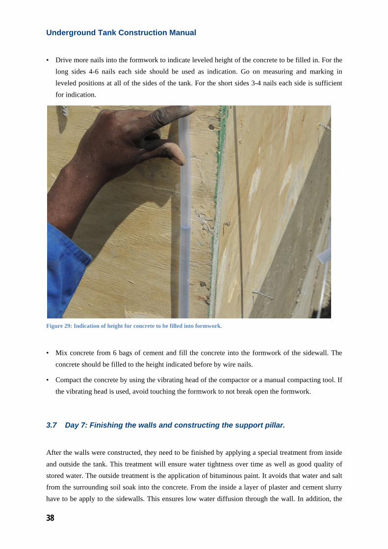
• Apply bituminous paint on the outside wall as describe before in chapter 2.4 of this manual. The paint should be applied from the lower edge of the sidewall up to 20 cm beneath the upper edge of the wall. Ensure that the bituminous paint is applied equally and no parts are left without paint.
Figure 30: Application of bituminous paint to the outside of the walls.
• When bituminous paint has dried (minimum 3-4 hours), the trench around the tank can be refilled with soil.
Underground Tank Construction Manual
40
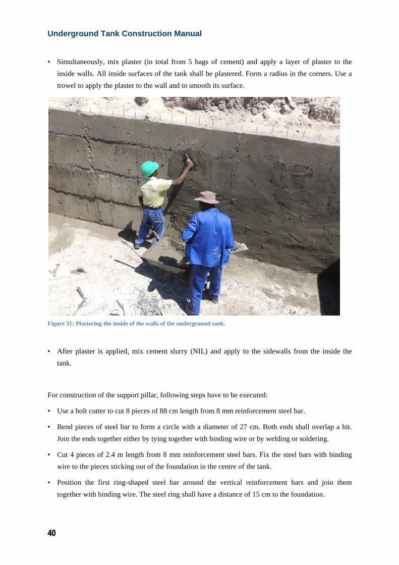
• Simultaneously, mix plaster (in total from 5 bags of cement) and apply a layer of plaster to the inside walls. All inside surfaces of the tank shall be plastered. Form a radius in the corners. Use a trowel to apply the plaster to the wall and to smooth its surface.
Figure 31: Plastering the inside of the walls of the underground tank.
• After plaster is applied, mix cement slurry (NIL) and apply to the sidewalls from the inside the tank.
For construction of the support pillar, following steps have to be executed:
• Use a bolt cutter to cut 8 pieces of 88 cm length from 8 mm reinforcement steel bar.
• Bend pieces of steel bar to form a circle with a diameter of 27 cm. Both ends shall overlap a bit. Join the ends together either by tying together with binding wire or by welding or soldering.
• Cut 4 pieces of 2.4 m length from 8 mm reinforcement steel bars. Fix the steel bars with binding wire to the pieces sticking out of the foundation in the centre of the tank.
• Position the first ring-shaped steel bar around the vertical reinforcement bars and join them together with binding wire. The steel ring shall have a distance of 15 cm to the foundation.
41
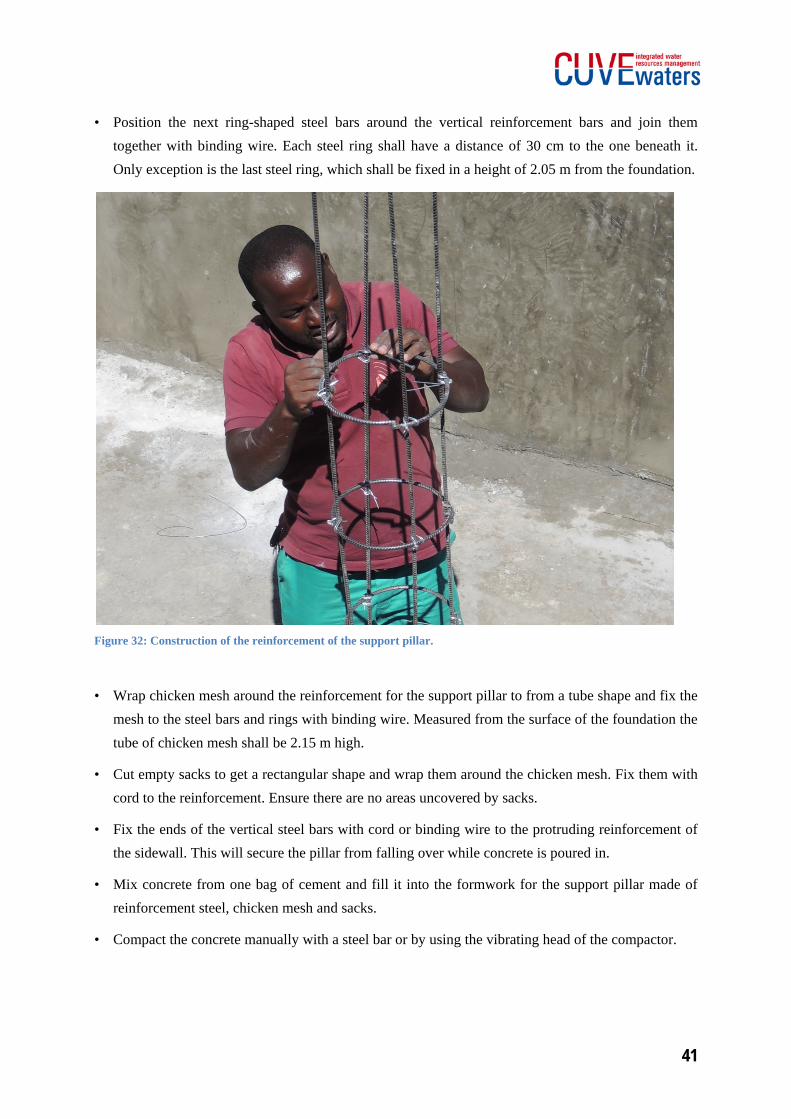
• Position the next ring-shaped steel bars around the vertical reinforcement bars and join them together with binding wire. Each steel ring shall have a distance of 30 cm to the one beneath it. Only exception is the last steel ring, which shall be fixed in a height of 2.05 m from the foundation.
Figure 32: Construction of the reinforcement of the support pillar.
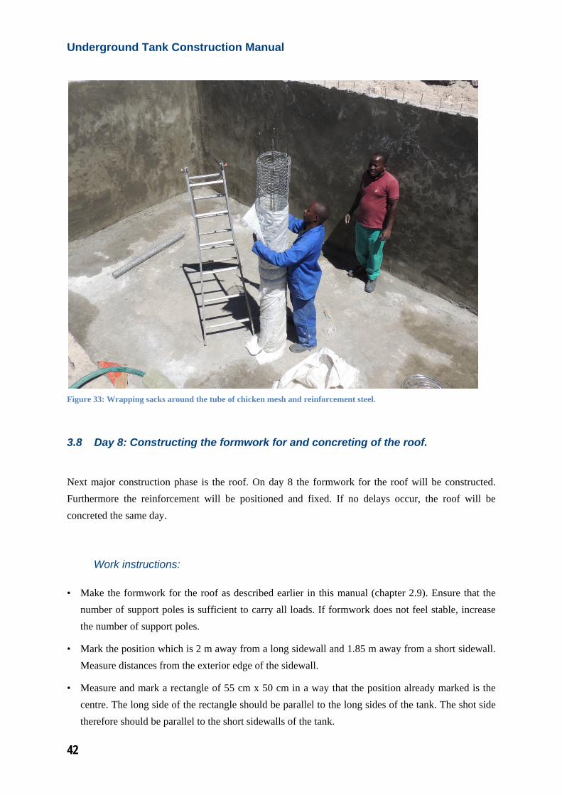
• Wrap chicken mesh around the reinforcement for the support pillar to from a tube shape and fix the mesh to the steel bars and rings with binding wire. Measured from the surface of the foundation the tube of chicken mesh shall be 2.15 m high.
• Cut empty sacks to get a rectangular shape and wrap them around the chicken mesh. Fix them with cord to the reinforcement. Ensure there are no areas uncovered by sacks.
• Fix the ends of the vertical steel bars with cord or binding wire to the protruding reinforcement of the sidewall. This will secure the pillar from falling over while concrete is poured in.
• Mix concrete from one bag of cement and fill it into the formwork for the support pillar made of reinforcement steel, chicken mesh and sacks.
• Compact the concrete manually with a steel bar or by using the vibrating head of the compactor.
Underground Tank Construction Manual
42
Figure 33: Wrapping sacks around the tube of chicken mesh and reinforcement steel.
3.8 Day 8: Constructing the formwork for and concreting of the roof.
Next major construction phase is the roof. On day 8 the formwork for the roof will be constructed. Furthermore the reinforcement will be positioned and fixed. If no delays occur, the roof will be concreted the same day.
Work instructions:
• Make the formwork for the roof as described earlier in this manual (chapter 2.9). Ensure that the number of support poles is sufficient to carry all loads. If formwork does not feel stable, increase the number of support poles.
• Mark the position which is 2 m away from a long sidewall and 1.85 m away from a short sidewall. Measure distances from the exterior edge of the sidewall.
• Measure and mark a rectangle of 55 cm x 50 cm in a way that the position already marked is the centre. The long side of the rectangle should be parallel to the long sides of the tank. The shot side therefore should be parallel to the short sidewalls of the tank.
43
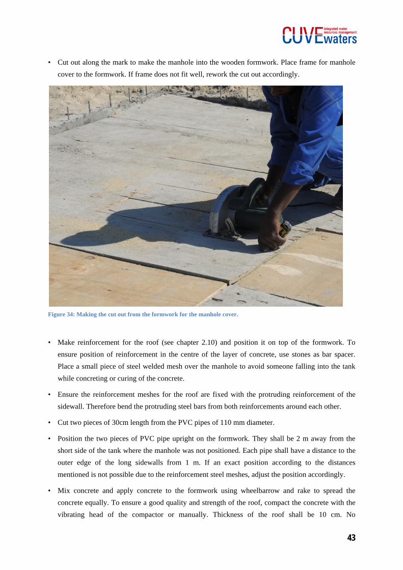
• Cut out along the mark to make the manhole into the wooden formwork. Place frame for manhole cover to the formwork. If frame does not fit well, rework the cut out accordingly.
Figure 34: Making the cut out from the formwork for the manhole cover.
• Make reinforcement for the roof (see chapter 2.10) and position it on top of the formwork. To ensure position of reinforcement in the centre of the layer of concrete, use stones as bar spacer. Place a small piece of steel welded mesh over the manhole to avoid someone falling into the tank while concreting or curing of the concrete.
• Ensure the reinforcement meshes for the roof are fixed with the protruding reinforcement of the sidewall. Therefore bend the protruding steel bars from both reinforcements around each other.
• Cut two pieces of 30cm length from the PVC pipes of 110 mm diameter.
• Position the two pieces of PVC pipe upright on the formwork. They shall be 2 m away from the short side of the tank where the manhole was not positioned. Each pipe shall have a distance to the outer edge of the long sidewalls from 1 m. If an exact position according to the distances mentioned is not possible due to the reinforcement steel meshes, adjust the position accordingly.
• Mix concrete and apply concrete to the formwork using wheelbarrow and rake to spread the concrete equally. To ensure a good quality and strength of the roof, compact the concrete with the vibrating head of the compactor or manually. Thickness of the roof shall be 10 cm. No
Underground Tank Construction Manual
44
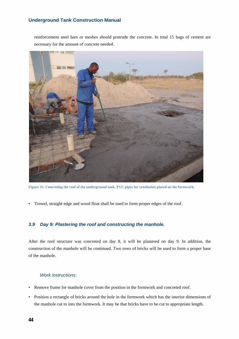
reinforcement steel bars or meshes should protrude the concrete. In total 15 bags of cement are necessary for the amount of concrete needed.
Figure 35: Concreting the roof of the underground tank. PVC pipes for ventilation placed on the formwork.
• Trowel, straight edge and wood float shall be used to form proper edges of the roof.
3.9 Day 9: Plastering the roof and constructing the manhole.
After the roof structure was concreted on day 8, it will be plastered on day 9. In addition, the construction of the manhole will be continued. Two rows of bricks will be used to form a proper base of the manhole.
Work instructions:
• Remove frame for manhole cover from the position in the formwork and concreted roof.
• Position a rectangle of bricks around the hole in the formwork which has the interior dimensions of the manhole cut to into the formwork. It may be that bricks have to be cut to appropriate length.
45
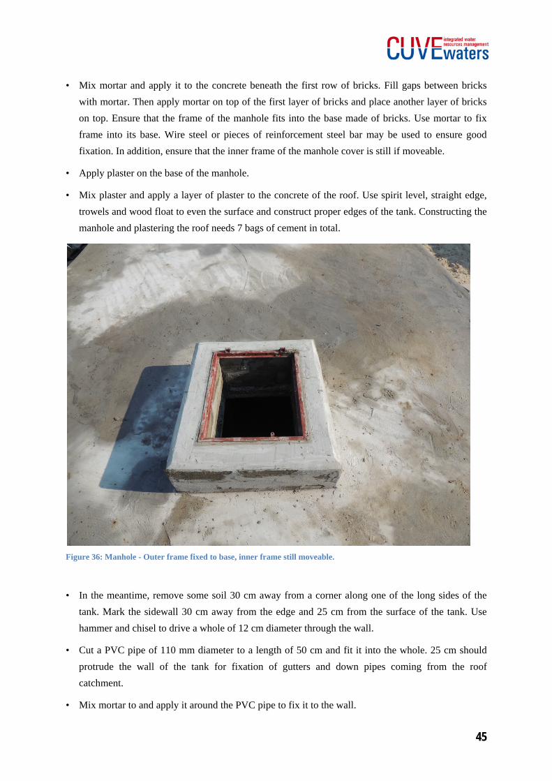
• Mix mortar and apply it to the concrete beneath the first row of bricks. Fill gaps between bricks with mortar. Then apply mortar on top of the first layer of bricks and place another layer of bricks on top. Ensure that the frame of the manhole fits into the base made of bricks. Use mortar to fix frame into its base. Wire steel or pieces of reinforcement steel bar may be used to ensure good fixation. In addition, ensure that the inner frame of the manhole cover is still if moveable.
• Apply plaster on the base of the manhole.
• Mix plaster and apply a layer of plaster to the concrete of the roof. Use spirit level, straight edge, trowels and wood float to even the surface and construct proper edges of the tank. Constructing the manhole and plastering the roof needs 7 bags of cement in total.
Figure 36: Manhole - Outer frame fixed to base, inner frame still moveable.
• In the meantime, remove some soil 30 cm away from a corner along one of the long sides of the tank. Mark the sidewall 30 cm away from the edge and 25 cm from the surface of the tank. Use hammer and chisel to drive a whole of 12 cm diameter through the wall.
• Cut a PVC pipe of 110 mm diameter to a length of 50 cm and fit it into the whole. 25 cm should protrude the wall of the tank for fixation of gutters and down pipes coming from the roof catchment.
• Mix mortar to and apply it around the PVC pipe to fix it to the wall.
Underground Tank Construction Manual
46
3.10 Day 10: Finishing the manhole and doing several minor steps.
On day 10 the manhole will be finished. Furthermore the ventilation tube of the tank will be optimized and the water inlet will be prepared.
Work instructions:
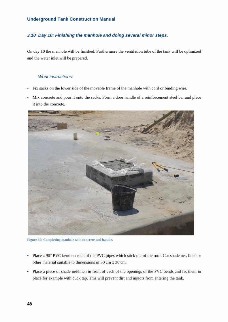
• Fix sacks on the lower side of the movable frame of the manhole with cord or binding wire.
• Mix concrete and pour it onto the sacks. Form a door handle of a reinforcement steel bar and place it into the concrete.
Figure 37: Completing manhole with concrete and handle.
• Place a 90° PVC bend on each of the PVC pipes which stick out of the roof. Cut shade net, linen or other material suitable to dimensions of 30 cm x 30 cm.
• Place a piece of shade net/linen in front of each of the openings of the PVC bends and fix them in place for example with duck tap. This will prevent dirt and insects from entering the tank.
47
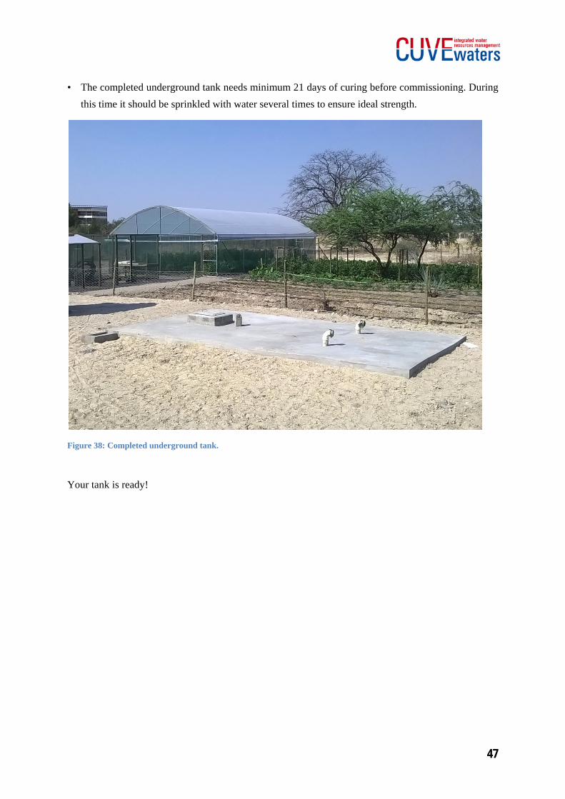
• The completed underground tank needs minimum 21 days of curing before commissioning. During this time it should be sprinkled with water several times to ensure ideal strength.
Figure 38: Completed underground tank.
Your tank is ready!
Underground Tank Construction Manual
48
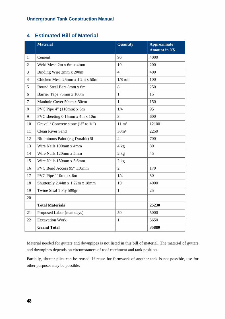
4 Estimated Bill of Material Material Quantity Approximate
Amount in N$
1 Cement 96 4000
2 Weld Mesh 2m x 6m x 4mm 10 200
3 Binding Wire 2mm x 200m 4 400
4 Chicken Mesh 25mm x 1.2m x 50m 1/8 roll 100
5 Round Steel Bars 8mm x 6m 8 250
6 Barrier Tape 75mm x 100m 1 15
7 Manhole Cover 50cm x 50cm 1 150
8 PVC Pipe 4” (110mm) x 6m 1/4 95
9 PVC sheeting 0.15mm x 4m x 10m 3 600
10 Gravel / Concrete stone (½” to ¾”) 11 m³ 12100
11 Clean River Sand 30m³ 2250
12 Bituminous Paint (e.g Durabit) 5l 4 700
13 Wire Nails 100mm x 4mm 4 kg 80
14 Wire Nails 120mm x 5mm 2 kg 45
15 Wire Nails 150mm x 5.6mm 2 kg
16 PVC Bend Access 95° 110mm 2 170
17 PVC Pipe 110mm x 6m 1/4 50
18 Shutterply 2.44m x 1.22m x 18mm 10 4000
19 Twine Sisal 1 Ply 500gr 1 25
20
Total Materials 25230
21 Proposed Labor (man days) 50 5000
22 Excavation Work 1 5650
Grand Total 35880
Material needed for gutters and downpipes is not listed in this bill of material. The material of gutters and downpipes depends on circumstances of roof catchment and tank position.
Partially, shutter plies can be reused. If reuse for formwork of another tank is not possible, use for other purposes may be possible.
49
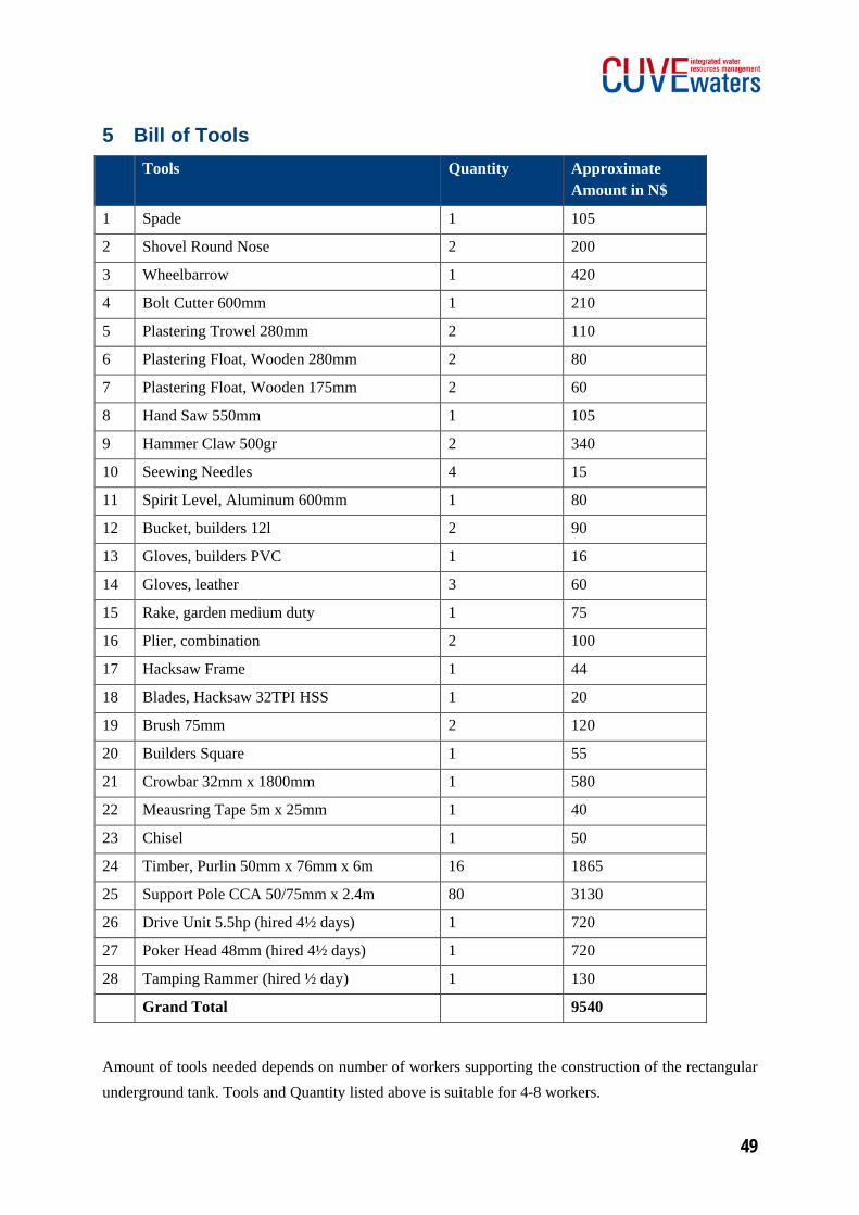
5 Bill of Tools Tools Quantity Approximate
Amount in N$
1 Spade 1 105
2 Shovel Round Nose 2 200
3 Wheelbarrow 1 420
4 Bolt Cutter 600mm 1 210
5 Plastering Trowel 280mm 2 110
6 Plastering Float, Wooden 280mm 2 80
7 Plastering Float, Wooden 175mm 2 60
8 Hand Saw 550mm 1 105
9 Hammer Claw 500gr 2 340
10 Seewing Needles 4 15
11 Spirit Level, Aluminum 600mm 1 80
12 Bucket, builders 12l 2 90
13 Gloves, builders PVC 1 16
14 Gloves, leather 3 60
15 Rake, garden medium duty 1 75
16 Plier, combination 2 100
17 Hacksaw Frame 1 44
18 Blades, Hacksaw 32TPI HSS 1 20
19 Brush 75mm 2 120
20 Builders Square 1 55
21 Crowbar 32mm x 1800mm 1 580
22 Meausring Tape 5m x 25mm 1 40
23 Chisel 1 50
24 Timber, Purlin 50mm x 76mm x 6m 16 1865
25 Support Pole CCA 50/75mm x 2.4m 80 3130
26 Drive Unit 5.5hp (hired 4½ days) 1 720
27 Poker Head 48mm (hired 4½ days) 1 720
28 Tamping Rammer (hired ½ day) 1 130
Grand Total 9540
Amount of tools needed depends on number of workers supporting the construction of the rectangular underground tank. Tools and Quantity listed above is suitable for 4-8 workers.
UndergroundTank Construction Manual
50
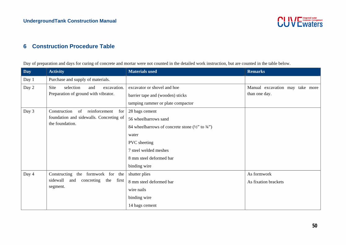
6 Construction Procedure Table
Day of preparation and days for curing of concrete and mortar were not counted in the detailed work instruction, but are counted in the table below.
Day Activity Materials used Remarks
Day 1 Purchase and supply of materials.
Day 2 Site selection and excavation. Preparation of ground with vibrator.
excavator or shovel and hoe
barrier tape and (wooden) sticks
tamping rammer or plate compactor
Manual excavation may take more than one day.
Day 3 Construction of reinforcement for foundation and sidewalls. Concreting of the foundation.
28 bags cement
56 wheelbarrows sand
84 wheelbarrows of concrete stone (½” to ¾”)
water
PVC sheeting
7 steel welded meshes
8 mm steel deformed bar
binding wire
Day 4 Constructing the formwork for the sidewall and concreting the first segment.
shutter plies
8 mm steel deformed bar
wire nails
binding wire
14 bags cement
As formwork
As fixation brackets
Underground Tank Construction Manual
51
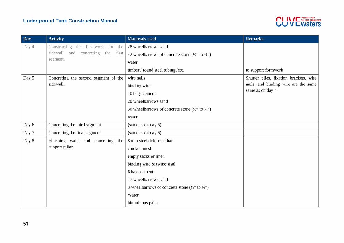
Day Activity Materials used Remarks
Day 4 Constructing the formwork for the sidewall and concreting the first segment.
28 wheelbarrows sand
42 wheelbarrows of concrete stone (½” to ¾”)
water
timber / round steel tubing /etc.
to support formwork
Day 5 Concreting the second segment of the sidewall.
wire nails
binding wire
10 bags cement
20 wheelbarrows sand
30 wheelbarrows of concrete stone (½” to ¾”)
water
Shutter plies, fixation brackets, wire nails, and binding wire are the same same as on day 4
Day 6 Concreting the third segment. (same as on day 5)
Day 7 Concreting the final segment. (same as on day 5)
Day 8 Finishing walls and concreting the support pillar.
8 mm steel deformed bar
chicken mesh
empty sacks or linen
binding wire & twine sisal
6 bags cement
17 wheelbarrows sand
3 wheelbarrows of concrete stone (½” to ¾”)
Water
bituminous paint
Underground Tank Construction Manual
52
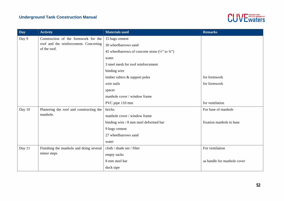
Day Activity Materials used Remarks
Day 9 Construction of the formwork for the roof and the reinforcement. Concreting of the roof.
15 bags cement
30 wheelbarrows sand
45 wheelbarrows of concrete stone (½” to ¾”)
water
3 steel mesh for roof reinforcement
binding wire
timber rafters & support poles
wire nails
spacer
manhole cover / window frame
PVC pipe 110 mm
for formwork
for formwork
for ventilation
Day 10 Plastering the roof and constructing the manhole.
bricks
manhole cover / window frame
binding wire / 8 mm steel deformed bar
9 bags cement
27 wheelbarrows sand
water
For base of manhole
fixation manhole to base
Day 11 Finishing the manhole and doing several minor steps
cloth / shade net / filter
empty sacks
8 mm steel bar
duck tape
For ventilation
as handle for manhole cover
53
7 Maintenance of the Underground Tank
If the underground tank is properly constructed and cured it should last at least 30 years. Maintenance of the tank is of low effort, but nevertheless it has to be done regularly. In this chapter easy but important instructions for cleaning and repairing the tank will be given.
7.1 Visual inspections
The condition of the tank shall be monitored continuously. Check if all visible parts of the tank are in a good condition. No cracks and no continuously wet ground directly next to the tank should be visible. In addition, a visible inspection should be done from inside the tank when it is empty. If any crack was observed, it should be evaluated how long and deep it is. The position of the crack is important as well. Small cracks, which only affect the surface, in general do not harm function and safety of the tank. They may be repaired within the next maintenance activity. Cracks in the sidewall which go along with wet leakage of water, can lead to increasing loss of water in a short period of time. Repair works should be planned as soon as possible. Deep and long cracks in the roof do not show wet area and do not lead to a leakage (since the water level is below the roof). Nevertheless, the stability and security of the tank may be at risk in the long run. Repair works should be initiated soon. In addition, it should be ensured, that no big additional loads are placed on the roof of the tank until the crack is repaired.
During the visual inspections, it must also be checked, whether the gutters are in good condition. Furthermore, filters to avoid insects and dirt from entering the tank should be checked. In case of damages filters shall be repaired or exchanged.
7.2 Cleaning the tank
Once every year the tank should be drained completely and all accumulated soil and dirt must be removed. If an annual cleaning seems not suitable, check if two-year or three-year cleaning cycles are possible. In case of increased periods of usage, keep in mind that water quality decreases when cleaning is reduced. Best time for cleaning is directly before start of the wet season, when the tank is already empty or close to be empty. For proper cleaning the tank shall be emptied with a pump, buckets and/or sheets or a sponge. When the floor of the underground tank is dry, remove soil and dirt remaining on the tank floor by use of broom, waste cloth, etc.. The cleaning procedure will assure that water stored in the tank during the next wet season will be as clean as possible.
Underground Tank Construction Manual
54
7.3 Repair of cracks
Repair of cracks can require different amount of effort. Small cracks without influence on function and water tightness shall be repaired by applying a thin layer of mortar to the crack. This is a cosmetic repair only.
Cracks on the sidewall that go along with water leakage, need some more effort. Ideally, repair work is done when tank is empty. One attempt to repair a crack going along with leakage is to fill the crack with mortar. This shall be done from inside the tank first. Mortar should be kept humid to allow gentle shrinking. Mortar should be applied to the cracks in two or three layers, depending on the length and deepness of the crack. Finally a layer of cement slurry shall be applied to the repaired area and the area around to increase water tightness.
If filling the crack with mortar from inside the tank does not help or seems not sufficient for a very long or deep crack, another method has to be used. Use hammer and chisel to remove mortar around the crack until reinforcement of the sidewall is visible. Clean the area from dust and dirt before going on with the repair. If crack seems to continue through the outer part of the sidewall, excavation of surrounding soil is needed later on. From the inside, apply a layer of concrete on to the reinforcement of the sidewall. Place chicken mesh on top of the first layer of concrete and cover with a thin layer of mortar and another layer of concrete. Depending on the dimensions of the spot to be repaired, two or more layers of mortar, chicken mesh, and concrete shall be applied. Keep the area humid to ensure gentle shrinkage of mortar and concrete while drying. The area which was repaired shall be finished with a layer of cement slurry and cover of plaster. If the crack was inside and outside the tank, start and finish the inside before excavation and repair of the outside. In addition, bituminous paint shall be used to seal the outer surface of the tank after repair and before closing the excavation.