City of Columbia Engineering Regulations Manual
750
City of Columbia Engineering Regulations Manual
-
Upload
khangminh22 -
Category
Documents
-
view
0 -
download
0
Transcript of City of Columbia Engineering Regulations Manual

City of Columbia Engineering
Regulations Manual

City of Columbia Engineering Regulations - TOC-ii
City of Columbia Engineering Regulations Table of Contents
Paragraph Description Page no.
Part 1: New Development 1.1 General ................................................................................................................... 1-1 1.2 Engineer’s Report ................................................................................................... 1-1 1.3 Plans ....................................................................................................................... 1-3 1.4 Revisions to Approved Plan ................................................................................... 1-6 1.5 Specifications ......................................................................................................... 1-6 1.6 Approved Plans Construction Requirements .................................................................... 1-6 1.7 Record Drawings ................................................................................................................ 1-8 1.8 Resubmission of Plan ........................................................................................... 1-10 1.9 Vicinity Map ......................................................................................................... 1-11
Part 2: Water Distribution System Design Standards 2.1 General ................................................................................................................... 2-1 2.2 System Design Criteria ........................................................................................... 2-1 2.3 System Design ........................................................................................................ 2-5 2.4 Separation of Water Mains and Sewers................................................................. 2-6 2.5 Valve, Air Relief, Meter and Blow-Off Chambers ................................................... 2-7 2.6 Hydrants ................................................................................................................. 2-8 2.7 Surface Water Crossings ........................................................................................ 2-8 2.8 Cross Connections .................................................................................................. 2-8 2.9 Pumping Facilities Planning Standards .................................................................. 2-9
Part 3: Design of Sanitary Sewers 3.1 General ................................................................................................................... 3-1 3.2 System Design Criteria ........................................................................................... 3-1 3.3 Specification for Design of Pump Stations ............................................................. 3-6
Part 4: Application Of The Columbia Drainage Ordinance, Storm Sewer Design 4.1 General ................................................................................................................... 4-1 4.2 Design Procedures ................................................................................................. 4-1 4.3 Design Basis ............................................................................................................ 4-1 4.4 Forms ..................................................................................................................... 4-3 4.5 Ordinance ............................................................................................................... 4-9
Part 5: Specification For Roadway Design 5.1 General ................................................................................................................... 5-1 5.2 Road System Design Criteria .................................................................................. 5-1 5.3 Road Designation ................................................................................................... 5-2 5.4 Traffic Data ............................................................................................................. 5-2 5.5 Subgrade Soil Support Value ......................................................................................5-4 5.6 Traffic Growth Rate ................................................................................................ 5-4 5.7 Coefficients of Relative Strength of Pavement Component Layers .........................5-4 5.8 Structural Number (SN).......................................................................................... 5-5

City of Columbia Engineering Regulations - TOC-iii
5.9 Stage Construction ................................................................................................. 5-5 5.10 Pavement Thickness Design Methods ................................................................... 5-5 5.11 Parking ................................................................................................................. 5-19 5.12 Drainage ............................................................................................................... 5-19 5.13 Geometrics ........................................................................................................... 5-19 5.14 Complete Streets ................................................................................................. 5-29
Part 6: Procedures For The Subdivision Of land 6.1 General .................................................................................................................. 6-1 6.2 Sketch Plan Review ................................................................................................ 6-1 6.3 Preliminary Plat (Construction Drawings) ............................................................. 6-1 6.4 Final Plat Approval ................................................................................................. 6-3 6.5 Form No. 2 ............................................................................................................. 6-9 6.6 Form No. 3 ........................................................................................................... 6-10 6.7 Sample Procedures for Sanitary Sewer Construction Permitting Under Delegated Review Program Letter ...................................................................... 6-11 6.8 Sample Request for 208/201 Plan Conformance Certification ........................... 6-14 6.9 Delegated Review Program Checklist .................................................................. 6-15
Part 7: Water Main Extension 7.1 General ................................................................................................................... 7-1 7.2 Water Main Extension Agreement ......................................................................... 7-1 7.3 Procedures ............................................................................................................. 7-1 7.4 Applications for Individual Services ....................................................................... 7-3 7.5 Sample Water Main Extension Agreement ............................................................ 7-4
Part 8: Sanitary Sewer Main Extension 8.1 General ................................................................................................................... 8-1 8.2 Sanitary Sewer Main Extension Agreement .......................................................... 8-1 8.3 Procedures ............................................................................................................. 8-1 8.4 Applications for Individual Services ....................................................................... 8-3 8.5 Sample Sanitary Sewer Agreement ....................................................................... 8-4
Part 9: Pedestrian, Bicycle, and Complete Streets Design Guidelines 9.1 Introduction ........................................................................................................... 9-1 9.2 Pedestrian Facilities ............................................................................................... 9-3 9.3 Sidewalks ................................................................................................................ 9-8 9.4 Pedestrians at Intersections ................................................................................ 9-14 9.5 Crossings, Beacons and Signals for Pedestrians .................................................. 9-24 9.6 Shared Use Paths and Off Street Facilities ........................................................... 9-29 9.7 Path/ Roadway Crossing Types ................................................................................ 9-37 9.8 Bicycle Facilities ................................................................................................... 9-42 9.9 Shared Roadways ..................................................................................................... 9-48 9.10 Separated Bikeways ................................................................................................. 9-53 9.11 Protected Bike Lanes ............................................................................................ 9-62 9.12 Bikeways at Intersections ..................................................................................... 9-70 9.13 Crossing Beacons and Signals for Bicycles ........................................................... 9-84 9.14 Retrofitting Streets to Add Bikeways ................................................................... 9-90

City of Columbia Engineering Regulations - TOC-iv
9.15 Transit and Bicycle Wayfinding ............................................................................ 9-95 9.16 Bicycle Support Facilities ...................................................................................... 9-98 9.17 Bikeway Maintenance ........................................................................................ 9-106 9.18 Trail System Standards ....................................................................................... 9-110
Part 10: Encroachment Permit: Street/ Road not Owned by City Of Columbia 10.1 When to Obtain Permit ........................................................................................ 10-1 10.2 Approval by City Engineer .................................................................................... 10-1 10.3 Approval by Appropriate Agency ......................................................................... 10-1 10.4 Where to Obtain Permit Forms ........................................................................... 10-1 10.5 Information Required for Permit ......................................................................... 10-1 10.6 Tree Root Protection ............................................................................................ 10-2 10.7 Sample Agreement............................................................................................... 10-3
Part 11: Application For City Encroachment Permit 11.1 General Information ............................................................................................ 11-1 11.2 Who Must Obtain Permit ..................................................................................... 11-1 11.3 Boring Required On Major Streets ....................................................................... 11-1 11.4 Emergency Cutting ............................................................................................... 11-1 11.5 Inspections ........................................................................................................... 11-1 11.6 Bond Required ..................................................................................................... 11-2 11.7 Construction And Relocation Costs ..................................................................... 11-2 11.8 Permit Fee ............................................................................................................ 11-2 11.9 Construction ......................................................................................................... 11-2 11.10 Tree Root Protection ............................................................................................ 11-2 11.11 Ordinance ............................................................................................................. 11-3
Part 12: Application For new Water Service 12.1 General ................................................................................................................. 12-1 12.2 Agencies Assigning Street Numbers .................................................................... 12-1 12.3 Required Verifications .......................................................................................... 12-1 12.4 Procedures for Resumption of Water Service ...................................................... 12-2 12.5 Fire Protection Systems ....................................................................................... 12-2 12.6 Long Line Service .................................................................................................. 12-2 12.7 Cross Connection Control/ Backflow Prevention................................................. 12-5 12.8 Main Line Water Taps ........................................................................................................ 12-6 12.9 Special Power of Attorney Form .......................................................................... 12-7
Part 13: Specification For Application For Sanitary Sewer Service 13.1 How To Apply ....................................................................................................... 13-1 13.2 Agencies Assigning Street Numbers .................................................................... 13-1 13.3 Required Verification ........................................................................................... 13-1 13.4 Service Connection Within SCDHPT Right-Of-Way ................................................ 13-1 13.5 Emergency Permit Procedure (South Carolina Department of Transportation) .. 13-2 13.6 Sewer Tapping Fees .............................................................................................. 13-2 13.7 Sewage Treatment Plant Expansion Fees............................................................. 13-3 13.8 Availability of Sanitary Sewer Service .................................................................. 13-4

City of Columbia Engineering Regulations - TOC-v
13.9 Sewage Pumping Station Surcharge .................................................................... 13-4
Part 14: Instructions To bidders 14.1 Receipt and Opening of Bids ................................................................................ 14-1 14.2 Preparation of Bid ................................................................................................ 14-1 14.3 Addenda and Interpretations .............................................................................. 14-2 14.4 Time for Receiving Bids ........................................................................................ 14-3 14.5 Withdrawal of Bids ............................................................................................... 14-3 14.6 Bidders Present .................................................................................................... 14-3 14.7 Telegraphic Modification ...................................................................................... 14-3 14.8 Qualifications of Bidder ....................................................................................... 14-3 14.9 Business License ................................................................................................... 14-4 14.10 Bid Security .......................................................................................................... 14-4 14.11 Liquidated Damages for Failure to Enter Into Contract ....................................... 14-5 14.12 Time of Completion and Liquidated Damages ..................................................... 14-5 14.13 Conditions of Work ....................................................................................................... 14-5 14.14 Subsurface Exploration ........................................................................................ 14-5 14.15 Specifications and Schedules ............................................................................... 14-6 14.16 Time of Performance ........................................................................................... 14-6 14.17 Samples ................................................................................................................ 14-6 14.18 Withholding for Nonresidents ............................................................................. 14-6 14.19 Security for Faithful Performance ........................................................................ 14-7 14.20 Insurance .............................................................................................................. 14-7 14.21 Accident Prevention ............................................................................................. 14-9 14.22 Power of Attorney ................................................................................................ 14-9 14.23 Notice of Special Conditions .............................................................................. 14-10 14.24 Laws and Regulations ......................................................................................... 14-10 14.25 Method of Award - Lowest Responsible Bidder ................................................ 14-10 14.26 Signature to Bids ................................................................................................ 14-10 14.27 Bids for All or Part .............................................................................................. 14-11 14.28 Construction Schedule and Periodic Estimates ................................................. 14-11 14.29 Payment ............................................................................................................. 14-11 14.30 Special Notice to Bidders on Contracts Over $1,000,000.00 ............................. 14-12 14.31 Indemnification .................................................................................................. 14-12 14.32 Subcontracting Outreach Program .................................................................... 14-13 14.33 Mentor-Protégé Program ................................................................................... 14-13 14.34 Local Business Enterprise ................................................................................... 14-14 14.35 Proposal Bid for Unit Price Contracts ................................................................ 14-15 14.36 Proposal Bid for Stipulated Sum Contracts ........................................................ 14-16 14.37 Bid Bond ............................................................................................................. 14-18 14.38 Equal Employment Opportunity ........................................................................ 14-20 14.39 Subcontracting Outreach Program Agreement ................................................. 14-22 14.40 Business Information Records ........................................................................... 14-23 14.41 Subcontracting Outreach Program Documentation Form................................. 14-24 14.42 Contract Form .................................................................................................... 14-25 14.43 Notice To Proceed Form ..................................................................................... 14-27 14.44 Performance-Payment Bond ............................................................................. 14-28

City of Columbia Engineering Regulations - TOC-vi
14.45 AIA Document A201, 1997 ................................................................................. 14-30 14.46 Subcontracting Outreach Program Policies and Procedures ............................. 14-44
Part 15: General Specifications 15.1 Definitions of Terms ..................................................................................................... 15-1 15.2 Laws and Regulations ........................................................................................... 15-6 15.3 Contract and Contract Documents ...................................................................... 15-6 15.4 Required Provisions Deemed Inserted ................................................................ 15-7 15.5 Notice and Service Thereof .................................................................................. 15-7 15.6 Prohibited Interests ............................................................................................. 15-7 15.7 Encroachment Permits, Rights-of-way, Easements and Suspension of Work ...... 15-8 15.8 Photographs ......................................................................................................... 15-8 15.9 Video Taping of Project ........................................................................................ 15-8 15.10 Indemnity ............................................................................................................. 15-9 15.11 Contract Security .................................................................................................. 15-9 15.12 Assignments ....................................................................................................... 15-10 15.13 Subcontracting ................................................................................................... 15-10 15.14 Mutual Responsibility of Contractors ................................................................ 15-10 15.15 Separate Contracts ............................................................................................. 15-11 15.16 Contractor’s Obligation ...................................................................................... 15-11 15.17 Payments by Contractor .................................................................................... 15-12 15.18 Contractor’s Local/ Field Office.......................................................................... 15-12 15.19 Supervision ......................................................................................................... 15-12 15.20 Organization, Superintendence, Construction Progress ................................... 15-13 15.21 Inspection by Agencies ...................................................................................... 15-14 15.22 Additional Instructions and Detail Drawings ..................................................... 15-14 15.23 Correlation of Plans and Specifications ............................................................. 15-14 15.24 Ownership of Drawings ...................................................................................... 15-14 15.25 Submittals Prior to Construction ....................................................................... 15-15 15.26 Benchmark ......................................................................................................... 15-18 15.27 Materials, Services, and Facilities ...................................................................... 15-18 15.28 “Or Equal” (Substitute Materials) ...................................................................... 15-18 15.29 Standard Products and Materials Not Specified ................................................ 15-20 15.30 Product Data ...................................................................................................... 15-20 15.31 Samples .............................................................................................................. 15-20 15.32 Patents .................................................................................................................... 15-21 15.33 Delivery, Storage, and Handling ......................................................................... 15-21 15.34 Contractor’s Title to Materials ........................................................................... 15-22 15.35 Inspection and Testing Materials, Quality, and Guarantees .............................. 15-22 15.36 Material Testing .......................................................................................................... 15-23 15.37 Experience of Manufacturer .............................................................................. 15-26 15.38 Completed Portions of Work .................................................................................... 15-27 15.39 Changes in Work ......................................................................................................... 15-27 15.40 Claims for Extra Work ................................................................................................. 15-27 15.41 Estimated Quantities of Work ................................................................................... 15-28 15.42 Time for Completion, Liquidated Damages, and No Damages for Delays ......... 15-28 15.43 Construction Schedule and Periodic Estimates ................................................. 15-29

City of Columbia Engineering Regulations - TOC-vii
15.44 Procedures for Submitting Pay Requests .......................................................... 15-30 15.45 Acceptance of Work, Final Payment, and Closeout Procedures ....................... 15-33 15.46 Record Drawing ................................................................................................. 15-35 15.47 Acceptance of Final Payment as Release .......................................................... 15-35 15.48 General Warranty for One Year After Completion of Contract ........................ 15-36 15.49 Right of City to Terminate Contract .................................................................. 15-36 15.50 Termination for Convenience and Suspension of Work ................................... 15-36 15.51 Reporting on Job Retention and Creation ......................................................... 15-37 15.52 Wages and Overtime Computation ................................................................... 15-38 15.53 Protection of Material, Work, and Property; and Injuries to Persons and Property ............................................................................................................. 15-39 15.54 Safety Regulations ............................................................................................. 15-40 15.55 Protection of Employees’ Lives and Health ....................................................... 15-40 15.56 Weather Conditions and Emergency ................................................................. 15-41 15.57 Mobilization ....................................................................................................... 15-41 15.58 Surveys, Lines, Grades, Stakes, and Templates ................................................. 15-42 15.59 Clean Up and Restoration .................................................................................. 15-42 15.60 Use of Explosives ............................................................................................... 15-43 15.61 Sediment and Erosion Control ........................................................................... 15-43 15.62 Construction Near or Under Drainage Pipes, Sewers, and Ditches .................. 15-44 15.63 Unclassified Excavation/ Geotechnical Investigation ........................................ 15-44 15.64 Excavation and Trench Stabilization .................................................................. 15-45 15.65 Dewatering ........................................................................................................ 15-46 15.66 Backfilling ........................................................................................................... 15-46 15.67 Flowable Fill ....................................................................................................... 15-47 15.68 Maintenance of Traffic ...................................................................................... 15-48 15.69 Access Roads ...................................................................................................... 15-49 15.70 Ingress and Egress to Public or Private Premises .............................................. 15-50 15.71 Rights-of-ways and Easement Clearing ............................................................. 15-50 15.72 Existing Utilities and Structures ......................................................................... 15-52 15.73 Interruption of Service....................................................................................... 15-53 15.74 Conflicts With and Relocation of Existing Utilities ............................................ 15-53 15.75 Ordinance Relating to Utility Lines in Streets .................................................... 15-53 15.76 Replacing Shoulder Material ............................................................................. 15-57 15.77 Asphalt Paving, Repairing, and/or Resurfacing Roadways ................................ 15-57 15.78 Removing, Milling, and Disposing of Asphalt Pavement ................................... 15-58 15.79 Remove and Replace Concrete and Asphalt Drives .......................................... 15-58 15.80 Concrete Curb and Gutter and Concrete Sidewalks .......................................... 15-59 15.81 Pavement Markings ........................................................................................... 15-59 15.82 Protection of Tree Root Zones Within Street Right-of-way .............................. 15-60 15.83 Re-establishment of Property Irons .................................................................. 15-65
Part 16: Specifications For Water Distribution System, Materials, And Construction 16.1 General ................................................................................................................. 16-1 16.2 Construction Materials ........................................................................................ 16-3 16.3 Construction Methods ......................................................................................... 16-9

City of Columbia Engineering Regulations - TOC-viii
16.4 Testing and Disinfection ..................................................................................... 16-14 16.5 Measurement and Payment .............................................................................. 16-15 16.6 General Warranty for Three Years After Completion of Contract ...................... 16-19
Part 17: Specifications For Sanitary Sewer 17.1 General ................................................................................................................. 17-1 17.2 Construction Materials ........................................................................................ 17-4 17.3 Construction Methods ....................................................................................... 17-10 17.4 Testing for Acceptance of Sanitary Sewers ........................................................ 17-24 17.5 Measurement and Payment .............................................................................. 17-25
Part 18: Specifications For Roadway improvements, Materials, And Construction 18.1 General ................................................................................................................. 18-1 18.2 Construction Materials ........................................................................................ 18-1 18.3 Construction Methods ......................................................................................... 18-2 18.4 Testing Methods ................................................................................................... 18-2 18.5 Measurement and Payment ................................................................................ 18-2
Part 19: Specifications For Fencing Materials 19.1 General ................................................................................................................. 19-1 19.2 Construction Materials ........................................................................................ 19-1
Part 20: Specifications For Sodding, Fertilizing, And Seeding 20.1 General ................................................................................................................. 20-1 20.2 Construction Materials ........................................................................................ 20-1 20.3 Construction Methods ......................................................................................... 20-2 20.4 Testing (Omitted) ................................................................................................. 20-3 20.5 Measurement and Payment ................................................................................ 20-3
Part 21: Sanitary Sewer Service Agreement
Part 22: Flood Damage Prevention Ordinance 22.1 Ordinance ............................................................................................................. 22-1
Part 23: Minority And Female business Enterprise Program 23.1 Policy .................................................................................................................... 23-1 23.2 Resolution ............................................................................................................ 23-2
Part 24: Specifications For Pressure Reducing Valve Housing 24.1 General ................................................................................................................. 24-1 24.2 Building Excavation and Fill .................................................................................. 24-1 24.3 Floor ..................................................................................................................... 24-2 24.4 Masonry Work ............................................................................................................... 24-2 24.5 Portland Cement Concrete .................................................................................. 24-3 24.6 Reinforcing Steel .................................................................................................. 24-3 24.7 Horizontal Joint Reinforcement ........................................................................... 24-4 24.8 Anchors and Ties .................................................................................................. 24-4

City of Columbia Engineering Regulations - TOC-ix
24.9 Fastenings ............................................................................................................ 24-4 24.10 Mortar and Grout Mixing .................................................................................... 24-4 24.11 Erection Conditions ............................................................................................. 24-5 24.12 Metal Doors and Frames ..................................................................................... 24-5 24.13 Finish Hardware ................................................................................................... 24-6 24.14 Miscellaneous Metal Work .................................................................................. 24-6 24.15 Painting ................................................................................................................ 24-7
Part 25: Specifications For Altitude Valve Vault 25.1 General ................................................................................................................. 25-1 25.2 Materials .............................................................................................................. 25-1 25.3 Concrete Masonry Work .............................................................................................. 25-3 25.4 Altitude Valve Vault Cover .................................................................................... 25-4
Part 26: Procedures For Easement Acquisition 26.1 Procedures ........................................................................................................... 26-1
Part 27: Procedures For Acceptance Of Existing Streets 27.1 Purpose ................................................................................................................ 27-1 27.2 Scope .................................................................................................................... 27-1 27.3 Design and Construction Standards ..................................................................... 27-1 27.4 Procedures ........................................................................................................... 27-1
Part 28: Digital Data Submission Standards 28.1 Standards ............................................................................................................. 28-1 28.2 Appendix A ........................................................................................................... 28-4 28.3 Appendix B ........................................................................................................... 28-6
Part 29: Fats, Oils, And Grease Management Regulation 29.1 Purpose ................................................................................................................ 29-1 29.2 Definitions ............................................................................................................ 29-1 29.3 Grease Traps and Grease Interceptors ................................................................ 29-2 29.4 FOG Registration and New Grease Trap/ Grease Interceptor Inspection
Procedure ............................................................................................................ 29-7 29.5 Inspection Procedure......................................................................................... 29-10 29.6 Violations ........................................................................................................... 29-11
Part 30: Specifications For Grease Traps And Grease Interceptors 30.1 General ................................................................................................................. 30-1 30.2 Definitions ............................................................................................................ 30-1 30.3 Design and Construction Requirements .............................................................. 30-2 30.4 Inspection for Acceptance ................................................................................... 30-5 30.5 Attachment A: Standard Grease Interceptor ....................................................... 30-6 30.6 Attachment B: Standard Grease Interceptor In Series ........................................ 30-7 30.7 Attachment C : Grease Trap and Grease Interceptor Sizing Guide ...................... 30-8 30.8 Attachment D: Grease Trap Specification Sheet Example ................................... 30-9

City of Columbia Engineering Regulations - TOC-x
Part 31: Specifications For Commercial Swimming Pool backwash And Drainage 31.1 General ................................................................................................................. 31-1 31.2 Definitions ............................................................................................................ 31-1 31.3 Design and Construction Requirements .............................................................. 31-2 31.4 Plan Review for Acceptance ................................................................................. 31-3 31.5 Attachment A: Commercial Swimming Pool Discharge Application Form........... 31-3
Part 32: Local Limits for Industrial Discharges of Wastewater
32.1 General ................................................................................................................. 32-1 32.2 Definitions ............................................................................................................ 32-1 32.3 Local Limits ........................................................................................................... 32-2 32.4 Compliance Monitoring ....................................................................................... 32-3
List of Figures Figure Description Page no.
Part 1: Submission of Plans Figure 1-1. Vicinity Map .............................................................................................................. 1-8 Figure 1-2. Vicinity Map Legend .................................................................................................. 1-8
Part 3: Design of Sanitary Sewers Figure 3-1. PS1A - Wet Well and Vault Section Detail ...........................................................3-15 Figure 3-2. PS1B - Wet Well and Vault Plan Detail .................................................................3-16 Figure 3-3. PS1C - Wet Well and Vault Plan Detail (2) ...........................................................3-17 Figure 3-4. PS2 - Typical Pump Station Site Plan ....................................................................3-18 Figure 3-5. PS3 - Weather-Durable Emergency Contact Sign ................................................3-19 Figure 3-6. PS4A - Typical Fence and Gate Detail (1) .............................................................3-20 Figure 3-7. PS4B - Typical Fence and Gate Detail (2) .............................................................3-21 Figure 3-8. PS5 - Typical Pump Controls Canopy Detail .........................................................3-22 Figure 3-9. PS6 - Bypass Pumping Connection Detail ............................................................3-23 Figure 3-10. PS7 - Air Release Valve in Manhole Detail ...........................................................3-24 Figure 3-11. PS8 – Tap Mounted Pressure Gauge Assembly ...................................................3-25 Figure 3-12. PS9 - Yard Hydrant Detail .....................................................................................3-26 Figure 3-13. PS10 - Steel Bollard Detail ....................................................................................3-27 Figure 3-14. PS11-Magmeter Vault Detail ...............................................................................3-28 Figure 3-15. E1A - Electrical Drawing Index .............................................................................3-29 Figure 3-16. E1B - Legend and Details ......................................................................................3-30 Figure 3-17. E1C - Junction Box Elevation ................................................................................3-31 Figure 3-18. E1D - I/O Riser Diagram .......................................................................................3-32 Figure 3-19. E2A - Schedule and Notes ....................................................................................3-33 Figure 3-20. E2B - One-Line Diagram .......................................................................................3-34 Figure 3-21. E2C - Control Panel Elevation ...............................................................................3-35 Figure 3-22. E3A - Schedule and Notes ....................................................................................3-36 Figure 3-23. E3B - One-Line Diagram .......................................................................................3-37 Figure 3-24. E3C - Control Panel Elevation ...............................................................................3-38 Figure 3-25. E4A – Typical Pump Station RTU Fabrication & Panel Layout .............................3-39

City of Columbia Engineering Regulations - TOC-xi
Figure 3-26. E4B – Typical Pump Station RTU Bill of Materials ................................................3-40 Figure 3-27. E4C – Typical Pump Station RTU Wiring 1 of 3 ....................................................3-41 Figure 3-28. E4D – Typical Pump Station RTU Wiring 2 of 3 ....................................................3-42 Figure 3-29. E4E – Typical Pump Station RTU Wiring 3 of 3 ....................................................3-43 Figure 3-30. E5A – Typical Control Panel Layout & Fabrication ...............................................3-44 Figure 3-31. E5B – Typical Control Panel Layout & Fabrication 2 ............................................3-45 Figure 3-32. E5C – Typical Control Panel Bill of Materials .......................................................3-46 Figure 3-33. E5D – Typical Control Panel Wiring 1 of 2 ...........................................................3-47 Figure 3-34. E5E – Typical Control Panel Wiring 2 of 2 ............................................................3-48
Part 4: Application Of The Columbia Drainage Ordinance, Storm Sewer Design Figure 4-1. Sketch Illustrating Storm Drainage Ordinance 4-22
Part 5: Specification For Roadway Design Figure 5-1. Data Sheet No. 1 - Traffic Data for Pavement Loading 5-10

City of Columbia Engineering Regulations - TOC-xii
Figure 5-2. Data Sheet No. 1 - Example #1 5-11 Figure 5-3. Data Sheet No. 1 - Example #2 5-12 Figure 5-4. Data Sheet No. 2 - 20-Year Traffic Analysis Design Chart 5-13 Figure 5-5. Data Sheet No. 2 - Example #1 5-14 Figure 5-6. Data Sheet No. 2 - Example #2 5-15 Figure 5-7. Data Sheet No. 3 - Coefficients of Relative Strength for Flexible Pavement
Components 5-16
Figure 5-8. Data Sheet No. 3 - Example #1 5-17 Figure 5-9. Data Sheet No. 3 - Example #2 5-18 Figure 5-10. Standard Road Sections - Residential Street, Collectors and Industrial
Streets, and Arterial Streets 5-30
Part 9: Pedestrian, bicycle, and Complete Streets Design guidelines Figure 9-1. Pedestrian Space Usage 9-4 Figure 9-2. Wheelchair Space Usage 9-6 Figure 9-3. Runner Space Usage 9-7 Figure 9-4. Zones In The Sidewalk Corridor 9-8 Figure 9-5. Sidewalk Obstructions And Driveway Ramps 9-10 Figure 9-6. Street Trees and Street Furniture 9-11 Figure 9-7. Green Features and Lighting 9-12 Figure 9-8. Accessible Bus Stop Design 9-13 Figure 9-9. Marked Crosswalks 9-14 Figure 9-10. Median Refuge Islands 9-15 Figure 9-11. Minimizing Curb Radii 9-17 Figure 9-12. Curb Extensions 9-18 Figure 9-13. Advanced Yield Line or Stop Bar 9-19 Figure 9-14. Parking Control 9-20 Figure 9-15. ADA Compliant Curb Ramps 9-21 Figure 9-16. Pedestrians at Railroad Grade Crossings 9-22 Figure 9-17. Accommodating Pedestrians at Signalized Crossings 9-24 Figure 9-18. Active Warning Beacons (RRFB) 9-26 Figure 9-19. Hybrid Warning Beacon (HAWK) For Mid-Block Crossing 9-27 Figure 9-20. Route Users To Signalized Crossings 9-28 Figure 9-21. General Design Practice 9-29 Figure 9-22. Greenways In Abandoned Rail Corridors 9-31 Figure 9-23. Greenways In Active Rail Corridors 9-33 Figure 9-24. Local Neighborhood Access ways 9-34 Figure 9-25. Shared Use Paths Along Roadways 9-35 Figure 9-26. Marked/Unsignalized Crossings 9-37 Figure 9-27. Full Traffic Signal Crossings 9-38 Figure 9-28. Undercrossings 9-39 Figure 9-29. Overcrossings 9-41 Figure 9-30. Standard Bicycle Rider Dimensions 9-43 Figure 9-31. Shared Roadways 9-46 Figure 9-32. Separated Bikeways 9-46 Figure 9-33. Cycle Tracks 9-46

City of Columbia Engineering Regulations - TOC-xiii
Figure 9-34. Shared Use Paths 9-46 Figure 9-35. Facility Continua 9-47 Figure 9-36. Signed Shared Roadways 9-48 Figure 9-37. Marked Shared Roadways 9-49 Figure 9-38. Bicycle Boulevards 9-50 Figure 9-39. Advisory Bike Lane 9-51 Figure 9-40. Shoulder Bikeways 9-53 Figure 9-41. Conventional Bike Lane 9-54 Figure 9-42. Bike Lane Adjacent To On-Street Parking 9-55 Figure 9-43. Bikeways And Diagonal Parking 9-56 Figure 9-44. Left Side Bike Lane 9-58 Figure 9-45. Contra Flow Bike Lane 9-59 Figure 9-46. Buffered Bike Lane 9-60 Figure 9-47. Uphill Bicycle Climbing Lane 9-61 Figure 9-48. Cycle Track Separation And Placement 9-62 Figure 9-49. One-Way Cycle Tracks 9-63 Figure 9-50. Two Way Cycle Tracks 9-64 Figure 9-51. Driveways And Minor Street Crossings 9-65 Figure 9-52. Major Street Crossings 9-67 Figure 9-53. Bicycle Transit Bypass 9-68 Figure 9-54. Bike Box 9-70 Figure 9-55. Bike Lanes at Right Turn Only Lanes 9-72 Figure 9-56. Colored Bike Lanes In Conflict Areas 9-73 Figure 9-57. Combined Bike Lane/Turn Lane 9-75 Figure 9-58. Intersection Crossing Markings 9-76 Figure 9-59. Two-Stage Turn Box 9-78 Figure 9-60. Bicyclists at Single Lane Roundabouts 9-79 Figure 9-61. Bike Lanes at High Speed Interchanges 9-80 Figure 9-62. Bike/Ped Facilities at Diverging Diamond Interchanges 9-81 Figure 9-63. Bikeways at Railroad Grade Crossings 9-83 Figure 9-64. Active Warning Beacons 9-84 Figure 9-65. Hybrid Warning Beacon (HAWK) for Bicycle Route Crossing 9-85 Figure 9-66. Bicycle Detection and Actuation 9-87 Figure 9-67. Bicycle Signal Heads 9-89 Figure 9-68. Roadway Widening 9-90 Figure 9-69. Lane Narrowing 9-91 Figure 9-70. Lane Reconfiguration 9-93 Figure 9-71. Parking Reduction 9-94 Figure 9-72. Transit Wayfinding 9-95 Figure 9-73. Confirmation Signs 9-96 Figure 9-74. Turn Signs 9-96 Figure 9-75. Decisions Signs 9-96 Figure 9-76. Bikeway Wayfinding Sign Placement 9-97 Figure 9-77. Bicycle Racks 9-98 Figure 9-78. On-Street Bicycle Corral 9-100 Figure 9-79. Bicycle Lockers 9-101

City of Columbia Engineering Regulations - TOC-xiv
Figure 9-80. Secure Parking Area (SPA) 9-102 Figure 9-81. Bicycle Parking at Transit 9-103 Figure 9-82. Bike Share Station Placement 9-105 Figure 9-83. Drainage Grates 9-108
Part 11: Application For City Encroachment Permit Figure 11-1. Typical Permanent Repair Section and Typical Multi-Duct System 11-5
Part 15: General Specifications Figure 15-1. Typical Permanent Repair Section and Typical Multi-Duct System 15-56 Figure 15-2. Details for Protection of Tree Root Zones Within Street R.O.W. 15-64
Part 16: Specifications For Water Distribution System, Materials, And Construction Figure 16-1. Typical Service Connections 16-20 Figure 16-2. Typical Meter Box for Meters 3” and Above 16-21 Figure 16-3. Typical Repair Sections 16-22 Figure 16-4. Standard Hydrant Detail 16-23 Figure 16-5. Alternate Method of Fire Hydrant Installation 16-24 Figure 16-6. Typical Permanent Repair Sections 16-25 Figure 16-7. Typical Repair Sections 16-26 Figure 16-8. Typical Repair Sections 16-27 Figure 16-9. Air Release Valve 16-28 Figure 16-10. Valve Box Protector Ring Detail; Gate Valve Box Detail 16-29 Figure 16-11. Butterfly Valve Box Detail 16-30 Figure 16-12. Concrete Pipe Encasement 16-31 Figure 16-13. Standard Pipe Bedding and Backfilling Detail - Backfill for Ductile Iron Pipe
and Backfill for Gray Cast Iron Pipe 16-32
Figure 16-14. Standard Pipe Bedding and Backfilling Detail - Backfill for Prestressed Concrete Cylinder Pipe
16-33
Figure 16-15. Standard Pipe Bedding and Backfilling Detail - PVC Pipe 16-34 Figure 16-16. Thrust Block Detail - Plug and Dead End Mains 16-35 Figure 16-17. Thrust Block Details - Concrete Blocking Dimensions 16-36 Figure 16-18. Top Slab - Hatch Reinforcement Detail 16-37 Figure 16-19. Meter Pit in Traffic Area 16-38 Figure 16-20. Typical Meter Box for Meters 4” and Above 16-39 Figure 16-21. Routing of Tracer Wire Inside Valve Box 16-40
Part 17: Specifications For Sanitary Sewer Figure 17-1. Standard Ditch Backfill Detail 17-30 Figure 17-2. Concrete Pipe Encasement 17-31 Figure 17-3. Granular Cradle 17-32 Figure 17-4. Concrete Cradle 17-33 Figure 17-5. Typical Permanent Repair Section 17-34 Figure 17-6. Granular/ Concrete Cradle Volumes 17-35 Figure 17-7. Service Wye 17-36 Figure 17-8. Precast Manhole Details 17-37 Figure 17-9. Inside drop Manhole 17-38

City of Columbia Engineering Regulations - TOC-xv
Figure 17-10. Typical Section Showing Bottom of Manhole 17-39 Figure 17-11. Typical Repair Sections - A 17-40 Figure 17-12. Typical Repair Sections - B 17-41 Figure 17-13. Typical Repair Sections - C 17-42 Figure 17-14. Standard Pipe Bedding and Backfilling Detail PVC Pipe 17-43
Part 18: Specifications For Roadway improvements, Materials, And Construction Figure 18-17. Curb and Gutter Details 18-3 Figure 18-18. Driveway Details For Existing Curb Openings 18-4 Figure 18-19. Driveway Details Where Curb Cut Is Required - Radius
Section 18-5
Figure 18-20. Alley Return Details 18-6 Figure 18-21. Pavement Joint Details 18-7 Figure 18-22. Joint for Full Width Pour 18-8 Figure 18-23. Standard Alley Drop Inlet 18-9 Figure 18-24. Special Inlet Details 18-10 Figure 18-25. Standard Round Top Inlet 18-11 Figure 18-26. Standard Curb Inlet 18-12 Figure 18-27. Standard Road Sections 18-13
Part 19: Specifications For Fencing Materials Figure 19-1. Standard Design for Fencing - Typical Fence Corner 19-4 Figure 19-2. Standard Design for Fencing - Typical Fence Line Span 19-5 Figure 19-3. Standard Design for Fencing - Typical Double Swing Drive Gate 19-6 Figure 19-4. Standard Design for Fencing - Typical Fence Layout Plan 19-7 Figure 19-5. Standard Design for Fencing - Typical Truss Rod Band, Typical Stretcher Bar
Band. and Typical Gate Keeper 19-8 Figure 19-6. Standard Design for Fencing - Typical Extension Arm Gate, End, and Line Posts
19-9 Figure 19-7. Standard Design for Fencing - Typical Extension Arm Corner and Angle Posts
19-10 Figure 19-8. Standard Design for Fencing - Typical Guard for Swale 19-11 Figure 19-9. Standard Design for Fencing - Typical Fence Corner 19-12 Figure 19-10. Standard Design for Fencing - Typical Fence Line Span 19-13 Figure 19-11. Standard Design for Fencing - Typical Double Swing Drive Gate 19-14 Figure 19-12. Standard Design for Fencing - Typical Hinging 19-15
Part 24: Specifications For Pressure Reducing Valve Housing Figure 24-1. PRV Housing - Pilaster Detail 24-9 Figure 24-2. PRV Housing - Hoist Beam & Bearing Detail 24-10 Figure 24-3. PRV Housing - Lintel & Hoist Beam Detail 24-11
Part 25: Specifications For Altitude Valve Vault Figure 25-1. Altitude Valve Vault Detail 25-5

City of Columbia Engineering Regulations - TOC-xvi
Part 30: Specifications For grease Traps And grease interceptors Figure 30-1. Standard Grease Interceptor 30-6 Figure 30-2. Standard Grease Interceptor In Series 30-7 Figure 30-3. Grease Trap and Grease Interceptor Sizing Guide 30-8 Figure 30-4. Grease Trap Specification Sheet Example 30-9
List of Tables Table Description Page no.
Part 3: Design of Sanitary Sewers Table 3-1. Minimum Slope by Sewer Size 3-2 Table 3-2. Pump Station Pump Conditions and Ranges 3-13 Table 3-3. Attachment C: Directional (YAGI) Antenna for Radio Communication 3-111 Table 3-4. Attachment C: RF Transmission Cable 3-111 Table 3-5. Attachment D: Conductor Color Code 3-127
Part 5: Specification For Roadway Design Table 5-1. Design Capacities for Arterial Streets and Urban Highways 5-19 Table 5-2. Suggested Corner Sight Distance at Intersections 5-20 Table 5-3. Length of Grade-Feet by Percent Upgrade 5-21 Table 5-4. Minimum Length for Super Elevation Runoff for 2-Lane
Pavements 5-21
Table 5-5. Normal Pavement or Surfacing Cross Slopes 5-22 Table 5-6. Effective Road Width Due to Restricted Lateral Clearances Under
Uninterrupted Flow Conditions
5-24 Table 5-7. Minimum Width of Usable Shoulders 5-26 Table 5-8. Shoulder Cross Slopes 5-27 Table 5-9. Suggested Earth Slopes for Design 5-27 Table 5-10. Recommended Illumination Levels 5-28
Part 9: Pedestrian, bicycle, and Complete Streets Design guidelines Table 9-1. Pedestrian Characteristics by Age 9-3 Table 9-2. Disabled Pedestrian Design Considerations 9-4 Table 9-3. Wheelchair User Typical Speed 9-5 Table 9-4. Wheelchair User Design Considerations 9-6 Table 9-5. Runner Typical Speed 9-6 Table 9-6. Sidewalk Widths 9-9 Table 9-7. Bicycle as Design Vehicle - Typical Dimensions 9-44 Table 9-8. Bicycle as Design Vehicle - Typical Speed 9-44
Part 13: Specification For Application For Sanitary Sewer Service Table 13-1. Unit Contributory Loadings to All Domestic Wastewater Treatment Facilities 13-4
Part 14: instructions To bidders Table 14-1. Indicators and Points for Documenting Subcontractor Outreach Efforts 14-48

City of Columbia Engineering Regulations - TOC-xvii
Part 15: general Specifications Table 15-1. FTE Calculation Example: Lifecycle of a 4 Month Project 15-38
Part 16: Specifications For Water Distribution System, Materials, And Construction Table 16-1. Steel Casing Pipe Sizing 16-5 Table 16-2. Trench Widths 16-11
Part 17: Specifications For Sanitary Sewer Table 17-1. Ductile Iron Pipe Size and Minimum Pressure Class 17-4 Table 17-2. Steel Pipe (Casing) Diameter and Thickness 17-6 Table 17-3. Unimproved Surface Minimum Trench Width 17-12 Table 17-4. Improved Surface Minimum Trench Width 17-12 Table 17-5. Granular Backfill Percent Passing by Sieve Size 17-16 Table 17-6. Granular Cradle Gradations Percent Passing by Sieve Size 17-17
Part 19: Specifications For Fencing Materials Table 19-1. Gate Post Tabulations 19-2
Part 20: Specifications For Sodding, Fertilizing, And Seeding Table 20-1. Seeding Mixtures 20-1
Part 28: Digital Data Submission Standards Table 28-1. Graphic File (.dxf) Specifications 28-4 Table 28-2. Metadata Text File (‘metadat.txt’) Specifications 28-6
Part 32: Local Limits for Industrial Discharges of Wastewater Table 32.1 Maximum Allowable Limits 32-3 Table 32.2 Minimum Monitoring Frequencies 32-4
List of Forms Form Description Page no.
Part 1: New Development Form 1-1. Drainage Certification Language 1-7
Part 4: Application Of The Columbia Drainage Ordinance, Storm Sewer Design Form 4-1. Form 4A 4-4 Form 4-2. Form 4B 4-5 Form 4-3. Form 4C 4-7 Form 4-4. Form 4D 4-8 Form 4-5. Ordinance - Application’s Certification Statement 4-20 Form 4-6. Ordinance - Design Certification Statement 4-20
Part 5: Specification For Roadway Design Form 5-1. Complete Streets Agreement Form 5-34

City of Columbia Engineering Regulations - TOC-
Part 6: Procedures For The Subdivision Of land Form 6.4.1. Record Drawing Checklist 6-4 Form 6-4. Required Easement Language 6-
10 Form 6.4.2. Infiltration Certification 6-6 Form 6.4.3. Engineer’s Certification 6-6 Form 6-4. Storm Drain Certification Language 6-11 Form 6-5. Form No. 2 6-9 Form 6-6. Form No. 3 6-10 Form 6-7. Sample Procedures for Sanitary Sewer Construction Permitting Under
Delegated Review Program Letter 6-11
Form 6-8. Sample Request for 208/201 Plan Conformance Certification 6-14 Form 6-9. Delegated Review Program Checklist 6-15
Part 7: Water Main Extension Form 7-1. Sample Water Main Extension Agreement 7-4
Part 8: Sanitary Sewer Main Extension Form 8-1. Sample Sanitary Sewer Agreement 8-4
Part 10: Encroachment Permit: Street/ Road not Owned by City Of Columbia Form 10-1. Sample Agreement 10-3
Part 12: Application For new Water Service Form 12-1. Sample Water Service Availability Acknowledgement 12-3 Form 12-2. Special Power of Attorney Form 12-8
Part 14: instructions To bidders Form 14-1. Proposal Bid for Unit Price Contracts 14-15 Form 14-2. Proposal Bid for Stipulated Sum Contracts 14-16 Form 14-3. Bid Bond 14-18 Form 14-4. Subcontracting Outreach Program Agreement 14-22 Form 14-5. Business Information Records 14-23 Form 14-6. Subcontracting Outreach Program Documentation Form 14-24 Form 14-7. Contract Form 14-25 Form 14-8. Notice To Proceed Form 14-27 Form 14-9. Performance-Payment Bond 14-28
Part 31: Specifications For Commercial Swimming Pool backwash And Drainage Form 31-1. Commercial Swimming Pool Discharge Application Form 31-4
City of Columbia Engineering Regulations - 1-i
City of Columbia Engineering Regulations PART 1: New Development
Table of Contents
Paragraph Description Page no. 1.1 General 1-1 1.2 Engineer’s Report 1-1 1.3 Plans 1-3 1.4 Revisions to Approved Plan 1-6 1.5 Specifications 1-6 1.6 Approved Plans Construction
Requirements 1-6
1.7 Record Drawings 7 1.8 Resubmission of Plan 8 1.9 Vicinity Map 9
List of Figures
Figure Description Page no. Figure 1-1. Vicinity Map 1-8 Figure 1-2. Vicinity Map Legend 1-8
List of Forms
Form Description Page no. Form 1-1. Drainage Certification Language 1-7

City of Columbia Engineering Regulations - 1-1
City of Columbia Engineering Regulations PART 1: New Development
1.1 General All reports, final plans and specifications should be submitted at least two weeks prior to the date on which action by the City Engineer is desired. Preliminary plans and the engineer’s report may be submitted for review prior to the preparation of final plans. No approval for construction can be issued until final, complete, detailed plans and specifications have been submitted to the reviewing authority and found to be satisfactory. All plans for projects located within the City limits of the City of Columbia must be submitted through the Planning Commission in accordance with City Subdivision Regulations. Documents submitted for formal approval shall include, but not be limited to:
1.1.1 Summary of the basis of design, where applicable.
1.1.2 Operation requirements, where applicable.
1.1.3 General layout.
1.1.4 Detailed plans.
1.1.5 Specifications.
1.2 Engineer’s Report
The engineer’s report for improvements should, where pertinent, present the following information:
1.2.1 General information, including:
1.2.1.1 Description of existing facilities (water works, sewerage facilities, etc.).
1.2.1.2 Identification of the area served.
1.2.1.3 Name and mailing address of the owner or developer.
1.2.2 Extent of proposed system, including:
1.2.2.1 Description of the nature and extent of the area to be served.
1.2.2.2 Provisions for extending the proposed system to include additional areas.
1.2.2.3 Appraisal of the future requirements for service, including existing and potential
industrial, commercial, institutional and other needs.
1.2.3 Alternate plans – Where two or more solutions exist for providing service, each of which is feasible and practicable, discuss the alternate plans and give reasons for selecting the one recommended, including financial considerations.
City of Columbia Engineering Regulations - 1-2
1.2.4 Soil, ground water conditions, and foundation problems, including:
1.2.4.1 Description of the character of the soil through which water mains are to be laid.
1.2.4.2 Description of foundation conditions prevailing at sites of proposed structures.
1.2.4.3 Description of the approximate elevation of ground water in relation to subsurface
structures.
1.2.5 Water consumption and sewage generated, including:
1.2.5.1 Description of the population trends as indicated by the estimated population which will be served by the proposed system.
1.2.5.2 The estimated number of new lots to be served each year until the subdivision is “built
out”.
1.2.6 Fire flow requirements, including:
1.2.6.1 Requirements of the American Insurance Association and related agencies as to fire flows required or recommended in the service area involved (where applicable).
1.2.6.2 Fire flow which will be made available by the proposed or enlarged system. (See design
criteria, Part 2.1.)
1.2.7 Sewerage system available – Describe the existing system and sewage treatment works, with special reference to their relationship to existing or proposed water works structures which may affect the operation of the water supply system, or which may affect the quality of the supply.
1.2.8 Automatic equipment – Provide supporting data justify automatic equipment, including
servicing requirements, pump curves and operation manuals.
1.2.9 Project site, including:
1.2.9.1 Discussion of various sites (pumping stations, etc.) considered and advantages of the recommended ones.
1.2.9.2 Proximity of residences, industries, and other establishments.
1.2.9.3 Presence of any potential sources of pollution that may influence the quality of the
supply or interfere with the effective operation of the water works system, such as sewage absorption systems, septic tanks, privies, cesspools, sink holes, refuse and garbage dumps, etc.
1.2.10 Financing, including:
1.2.10.1 Estimated cost of integral parts of the system.

City of Columbia Engineering Regulations - 1-3
1.2.10.2 Detailed estimated annual cost of operation.
1.2.11 Easements
1.2.11.1 Easements for future expansion of the water and sewer systems to serve adjacent
property. These must be reserved at 600’ intervals along the boundary of the property to allow future connection to the system being constructed within the subdivision. Reasonable deviations from the 600’ rule to allow alignment with future streets, property lines, etc., will be considered.
1.2.11.2 Easements for water, sewer and storm drain facilities shall be provided on private
property. In new subdivisions, easements may be within street rights-of-way provided the easement predates the filing or recording date of the subdivision plat. Other exceptions are made for temporary lines and deep sanitary sewer lines where there is little probability of future grade conflict with highway construction. These must be justified in detail.
1.2.11.3 Easements for water main, sanitary sewer, and storm drain extensions to serve a new
area must be provided by the developer unless specifically addressed in the extension agreement between the City and developer. See Easement Table
1.2.11.4
City of Columbia Department of Utilities and Engineering Standard Widths for Utility Easements (8” pipe diameter and below)
Utility Depth Easement Width 7.5 ft. or Less 15 ft.
7.6 ft. - 10.0 ft. 20 ft.
10.1 ft. - 12.5 ft. 25 ft.
12.6 ft. - 15.0 ft. 30 ft.
15.1 ft. - 17.5 ft. 35 ft.
17.6 ft. - 20.0 ft. 40 ft.
NOTE: All utility easements are to be located centered on and around the utility and its appurtenances. Easement widths shall not vary between manholes. Minimum easement width is 15 feet. The depth of the utility is measured from the invert of the pipe at the deepest point to the finished grade.

City of Columbia Engineering Regulations - 1-4
1.3 Plans Plans for improvements should, where pertinent, provide the following:
1.3.1 General layout, including:
1.3.1.1 Suitable title.
1.3.1.2 Name of municipality.
1.3.1.3 Vicinity map drawn to 1” = 1,000’ scale of the area or institution to be served (See
example, Part 1.7). This applies only to water construction plans.
1.3.1.4 Scale, in feet.
1.3.1.5 North point.
1.3.1.6 USGS datum.
1.3.1.7 Boundaries of the municipality or area to be served, including boundaries of any proposed phasing.
1.3.1.8 Date, address and name of the designing engineer.
1.3.1.9 Imprint of seal and signature of professional engineer.
1.3.2 Detailed plans, including but not limited to:
1.3.2.1 Topographical map of the property, sometimes referred to as a site development plan,
showing lot layout, lot and block numbers, street width and names, etc., is to be used as a base map. Upon this map is to be superimposed the system being designed, i.e., water, sanitary sewer or storm drain.
1.3.2.2 Construction plan and profile sheets must be drawn to a scale of not less than 1”=100’.
They must carry the seal and signature of a professional engineer registered in the State of South Carolina on each sheet. The plan sheet size shall be 24”x36”. These plans are not to be confused with the requirements in Paragraph 1.2.2.1.
1.3.2.3 The plans must show the proposed name of the subdivision, owner and/or sub divider,
graphic scale, north point and date.
1.3.2.4 The plan shall show the acreage to be subdivided, and the boundaries of the tract with all bearings and distances indicated. The boundary survey shall be to such a degree of accuracy that the error of closure shall comply with the standards set forth by the South Carolina Board of Engineering Examiners.
1.3.2.5 Existing conditions to be shown shall include:

City of Columbia Engineering Regulations - 1-5
1.3.2.5.1 Topography by contours at vertical intervals of not more than five (5) feet. Mean Sea Level Datum is Required and this must be so stated on the plans. In those instances, where mean sea level bench datum is not reasonably close, the City will set a bench at or near your proposed work.
1.3.2.5.2 Deleted.
1.3.2.5.3 In case of resubdivision, a copy of the existing plat with proposed resubdivision
superimposed thereon.
1.3.2.5.4 Location of streams, lakes, swamps and land subject to flooding based on 100 year frequency flood. (See City of Columbia Sediment and Erosion Control and Drainage Ordinance.)
1.3.2.5.5 Location of existing property lines on adjoining property and buildings on the property
to be subdivided.
1.3.2.5.6 Location and ownership and rights-of-way of streets, roads, railroads and utility lines either on or adjacent to the property to be subdivided. Specify whether utility lines are in easements or street rights-of-way and show location of poles or towers.
1.3.2.5.7 Size and location of existing sewers, water mains, drains, culverts or other underground
facilities within the street or within the rights-of-way of streets or roads adjoining the tract. Grades and invert elevations of existing sewers shall be shown.
1.3.2.5.8 Location of existing trees (to include type and size), streetlights (to type of pole and
fixture), type of road signage and pavement markings.
1.3.2.5.9 The acreage of each drainage area affecting the proposed subdivision, both onsite and offsite.
1.3.2.5.10 All elevations shall be expressed in Mean Sea Level Datum and so indicated on the plans.
1.3.2.5.11 Location of the City limit lines and County lines, if applicable.
1.3.2.6 Proposed conditions to be shown shall include:
1.3.2.6.1 Layout of streets, road and alleys, with widths and road names, and type of gutter /
drainage system.
1.3.2.6.2 Construction plans for streets showing natural and finished grades and cross-sections (if applicable).
1.3.2.6.3 Layout of all lots; scaled dimensions on lots; lot and block numbers, existing utility
easements with width and use.
1.3.2.6.4 Construction plan and profile for sanitary sewers (if applicable) with grade, pipe size and material, location of manholes and points of discharge.

City of Columbia Engineering Regulations - 1-6
1.3.2.6.5 Plan and profile for storm drainage system with grade, pipe sizes, material, and location of outlets. Sediment and Erosion Control measures and storm drains shall be designed in accordance with the City of Columbia Sediment and Erosion Control and Storm Drainage Ordinance. Plans shall show sufficient off-site information and include method and computations where indicated. Transmittal letter shall include the statement by a registered engineer or architect that sediment and erosion controls and storm drain design meets the requirements of the City ordinance. For certain projects as defined in state law, the certification may be signed by a duly registered landscape architect.
1.3.2.6.6 Construction plans for water supply system with pipe sizes, material and location of
hydrants and valves. The site development plan is acceptable for this purpose provided the plan is on 24”x36” sheets. Otherwise separate water construction plans will be required.
1.3.2.7 Submittal Requirements.
1.3.2.7.1 For projects inside the City limits plans must be submitted to the City Planning
Commission by delivery to the Zoning Administrator’s Office, First Floor, 1136 Washington Street, and payment of applicable fees for processing and review. Submit five (5) copies of sketch plans; seven (7) copies of Preliminary Plat (construction drawings); or five copies of the final plot with one set of record drawings in mylar form, as applicable. When submitting construction plans for sanitary sewer, submit two extra sets of plans for submittal by the City to SCDHEC for permitting purposes.
1.3.2.7.2 For projects outside the City Limits, submit tow complete sets of plans for water
construction and four sets of plans for sanitary sewer construction as applicable.
1.4 Revisions to Approved Plan
Any deviations from approved plans or specifications affecting capacity, hydraulic conditions, operating units, the functioning of water treatment processes, or the quality of water to be delivered, must be approved by the reviewing authority before such changes are made. Revised plans or specification should be submitted in time to permit the review and approval of such plans or specifications before any construction work, which will be affected by such changes, is begun.
1.5 Specifications
One set of complete, detailed, technical specifications shall be supplied for the proposed project.
Approved Plans Construction Requirements
1.6.1 The developer must provide the City Engineer forty-eight (48) hours’ notice prior to
beginning construction. This request can be made to the Utilities Project Coordinator at 803-545-3400. Once the developer’s contractor provides a work notice and the City confirms all preconstruction requirements have been met (permits, insurance, etc.), the contractor must hold an on-site pre-construction conference with the City inspector prior to performing any

City of Columbia Engineering Regulations - 1-7
work on the project. The purpose of this meeting is to allow the contractor and inspector to review the plans and approval letter, as well as discuss concerns either party may have. This is a mandatory meeting, no exceptions! The contractor shall call the inspector at 803-545-3400 to schedule the meeting. The best time to contact the inspector is from 8:00 a.m. - 9:30 a.m.
1.6.2 The developer through his engineer must provide the project contractor a copy of the approval letter which must be maintained on site until construction is completed (permit to operate issued).
1.6.3 In the event any of the work related to water and sanitary sewer on the project is to be
performed within public street or road rights-of-way or in an existing City easement by other than City of Columbia forces, indemnification of the City in accordance with Chapter 11, Article III, Section 11-71 of the City Code is required. Proof of insurance must be provided prior to beginning construction. Should additional information regarding this be required, please contact Engineering Administrator at 545-3400.
1.6.4 All grading of areas where water and sanitary sewer lines are approved for construction must
be completed prior to installation of the pipe. If for any reason the grades are changed, thereby reducing the required minimum cover over these lines, the developer shall bear the expense of correcting line depth to that specified by current City Regulations.
1.6.5 The developer through his engineer is responsible for conducting final inspections of systems
to be deeded to the City for operation and maintenance. Inspections must be coordinated with the Department of Engineering Inspector.
1.6.6 The developer shall be responsible for installation of individual services off of the proposed
main(s). The developer/builder shall be responsible for maintaining the accessibility, visibility and functionality of all water service lines and water meter boxes until the water meter is installed by the City of Columbia. If the aforementioned requirements are violated, the developer/builder shall be held responsible for all associated costs for installation of new service connection at his own expense including but not limited to the payment for the new tap fee. The City may require the developer/builder to hire an independent contractor to install a new tap, meter box and associated appurtenances solely at his own cost. The developer must obtain a prior approval from City before allowing the contractor to install a tap on the City’s active water main. Service will be provided following City acceptance of the water and sanitary sewer system(s), DHEC granting a permit to operate and the owner's application, receipt and acceptance of all appropriate deeds, easements, and record drawings and payment of appropriate fees. All costs of any installation and/or materials for installation of 4” and larger water main connection/tap and/or fire hydrant installation/relocation shall be the responsibility of the applicant. The cost shall include but not be limited to connection to the main, cutting and repairing pavement, and restoration required to install the connection/tap. If applicable, all 4” and larger water meters shall be purchased from the City of Columbia Utilities and Engineering Department (803-545-3400). Installation of tap and/or meters shall be by a City approved contractor hired by the owner at the owner’s expense. A list of approved contractors shall be provided by the

City of Columbia Engineering Regulations - 1-8
Utilities and Engineering Department. Installation of this service and/or connection, must be coordinated with the City of Columbia Utility inspector and approved prior to operation.
1.6.7 Backflow prevention devices meeting South Carolina Department of Health and
Environmental Control Regulations are required for all water service connections. In low hazard situations where 3/4" and 1" meters are contracted for, dual backflow valves will be installed by City Forces with the meter. Where meters larger than 1" and/or service to high hazard projects are proposed, the developer shall be responsible through his engineer for specifying type of backflow preventer and shall be responsible for installation thereof. Type of device must be determined prior to application for service. This information shall be furnished with the application since this data must be maintained as a part of the water customer record. Installation of backflow prevention material must be completed before meters will be set.
The backflow device must be tested by a certified backflow inspector. The results are to be
submitted to the City’s Cross Connection Control Program within 10 days after the installation of the water meter. Failure to comply may result in the interruption of water service. For any questions, please call 545-3923.
1.6.8 The proposed water and sanitary sewer mains must be deeded to the City of Columbia prior
to final acceptance of the system(s) for operation and maintenance. 1.6.9 For projects being developed under bond, the bonded plat showing all utility easements to
be granted to the City of Columbia must be submitted for approval. These easements must be dedicated exclusively to the City prior to final approval of the bonded plat and the selling of individual lots.
1.6 Record Drawings
Requirements for record drawings submitted for acceptance by the City:
1.6.1 The record drawing shall conform substantially to the approved construction drawings and be submitted on disk in electronic format as required by Part 28 of this manual and in the form of a mylar, marked “record drawing” in the title block. It shall be drawn to a scale not smaller than 1”=100’ and will include the following information:
1.6.1.1 Name of subdivision, and name and address of the fee simple title holder conveying the
improvements and easements to the City.
1.6.1.2 Graphic scale, north point and date.
1.6.1.3 Vicinity map (record drawing) drawn to a scale of 1”=1,000’ showing the relationship of the subdivision to the surrounding area. This applies only to water system drawings.
1.6.1.4 Street names and ownership and lot and block numbers.

City of Columbia Engineering Regulations - 1-9
1.6.1.5 Tax map sheet number, block number and lot number.
1.6.1.6 Topography by contours at vertical intervals of not more than five (5) feet depicting final or finished conditions after all construction is complete. Mean Sea Level Datum is required and this must be so stated on the face of the plans.
1.6.1.7 Sufficient data to determine readily and reproduce on the ground the location, bearing
and length of every road right-of-way line, subdivision boundary line, and block line whether curved or straight.
1.6.1.8 Newly installed roads shall be identified in plain view, profile of the centerline, and
cross sections. Storm drainage systems shall be shown in plan and profile. All inverts and throats of constructed storm drainage boxes, as well as size, material and slope of storm drainage pipes shall be identified.
1.6.1.9 All dimensions to the nearest one-tenth of a foot and angles to the nearest minutes.
1.6.1.10 Location and description of monuments.
1.6.1.11 All rights-of-way, easements, and areas to be dedicated to public use with the purpose
of each stated.
1.6.1.12 The following signed certificate shall appear on the final record drawing which is submitted:
1.6.1.12.1 “I hereby certify that the street, storm drainage system, sanitary sewer system and water
system in Subdivision as shown on the Plat dated prepared by has been installed in accordance with the Preliminary Plat (Construction Drawings) approved .”
Registered Engineer, State of South Carolina
1.6.1.12.2 State Plane Coordinate System data of all valves, bends, fire hydrants, individual service lines and all installed appurtenances on water system. State Plane Coordinate System data for sanitary sewer lines, manholes, wyes, and all installed appurtenances on the sewer system shall be shown, including the record drawing plan and profile. All line work shall be identified by length, size and material. All profile sheets shall show length, size, material, and slope. Coordinate System data stormdrain lines, manholes, catch basins, junction boxes, and all installed appurtenances on the storm drain system shall be shown, including the record drawing plan and profile. All line work shall be identified by length, size and material. All profile sheets shall show length, size, material, and slope. Coordinate System data for all underground electrical and irrigation systems that feed publicly owned and maintained property or utilities. All line work shall be identified by length, size and material to include both wiring and conduit. Location of all handholes, valve boxes and meters shall be identified. Where utility lines run through easements or rights-of-way their location in relation to easement lines must be shown. Location data shall be referenced to stable physical features such as curb corners, building corners, property corners, etc. Construction line station numbers will not be as references.

City of Columbia Engineering Regulations - 1-10
1.6.1.12.3 State Plane Coordinate System data of all trees, streetlights, street signs, traffic control
devices.
1.8 Resubmission of Plan Construction plan approval shall be valid for only two (2) years. In the event required improvements have not been constructed within that time, the plans must be resubmitted for approval subject to ordinances and regulations in effect on that date.

City of Columbia Engineering Regulations - 1-11
1.9 Vicinity Map
Figure 1-1. Vicinity Map
Figure 1-2. Vicinity Map Legend

City of Columbia Engineering Regulations - 2-i
City of Columbia Engineering Regulations PART 2: Water Distributions Systems Design Standards
Table of Contents
Paragraph Description Page no. 2.1 General 2-1 2.2 System Design Criteria 2-1 2.3 System Design 2-5 2.4 Separation of Water Mains and Sewers 2-6 2.5 Valve, Air Relief, Meter and Blow-Off Chambers 2-7 2.6 Hydrants 2-8 2.7 Surface Water Crossings 2-8 2.8 Cross Connections 2-8 2.9 Pumping Facilities Planning Standards 2-9

City of Columbia Engineering Regulations - 3-1
City of Columbia Engineering Regulations PART 2: Water Distribution System Design Standards
2.1 General The following water supply planning standards are based on Federal, State and local health requirements and engineering design criteria. “Ten States Standards” shall apply where applicable. All installations, whether public or privately owned, are to deliver water to the consumer which meet the bacteriological and chemical quality standards of the S.C. Department of Health and Environmental Control. If a building is to be constructed, a building permit must be issued by the governing authority. If power is required, the electrical inspector must approve the wiring prior to requesting electrical service from the utility company.
2.1.1 Water mains should not be located in contaminated areas. If a water main must run
through a contaminated site, the pipe material must protect the water system from contamination. This includes water mains that are designed within 10’ of a septic tank or tile field
2.1.2 Water Services and Plumbing – Water services and plumbing shall conform to relevant
plumbing codes.
2.1.3 Water Pressure in System – The system shall be designed to maintain a minimum pressure of 20 pounds per square inch at all points in the distribution system under all conditions of flow.
2.1.4 Disinfection of Water Mains – (See Part 16, Section, 4.0 Testing and Sterilizing). The
specifications shall include detailed procedures for the adequate flushing, disinfection, and bacteriological testing of all water mains.
2.1.5 Metering – Each service connection shall be metered in accordance with Chapter 23, Art
III Sec 23-69, Code of Ordinances, City of Columbia.
2.1.6 These criteria are applicable to all developments including but not limited to residential, commercial and industrial developments, subdivisions and/or parks requiring water service from the City of Columbia.
2.2 System Design Criteria
Distribution mains shall be a minimum 6-inch diameter and arranged so that they are interconnected at intervals such that no loop exceeds 2,400’ of 6” C=100 pipe. Hydraulic equivalent lengths of any pipe size are acceptable. EXAMPLE: The C=100 6” diameter pipe loop is 2,400 feet in circumference (around the block). The maximum equivalent length across this loop equals 332.0 feet. No combination of pipe length and diameter in a loop shall exceed this equivalent length. Thus, the maximum length around an 8” loop will be approximately 9,600 L.F. Distance between fire hydrants will be measured along the traveled way. All water distribution

City of Columbia Engineering Regulations - 3-2
systems shall be designed using C=100 to provide fire protection with minimum requirements as follows:
2.2.1
2.2.2
2.2.2.1
2.2.2.1.1
2.2.2.1.2
2.2.2.2
2.2.2.2.1
2.2.2.2.2
2.2.2.3
2.2.2.3.1
2.2.2.3.2
2.2.2.4
2.2.2.4.1
Valves shall be located at the intersection with other water mains. Minimum requirements will be two valves for a tee intersection and three for a cross intersection. Valve spacing shall not exceed 1,000 feet in any case. Hydrants and Flows
Low density residential: (4 units or less per acre)
Fire hydrants shall be located at each intersection and hydrants shall be spaced no greater than 1,000 feet.
The minimum calculated fire hydrant flow shall be 750 gpm plus 75% of peak demand of the development, 20 psi minimum residual pressure is required at 75% of peak demand. In no case will the residual pressure on the highest building site be less than 35 psi during peak demand.
High density residential: (5 units and over per acre)
For areas of single family homes or duplexes, hydrants shall not be over 600 feet apart and have a calculated minimum flow of 750 gpm plus 75% peak demand of the development, 20 psi residual pressure is required at 75% of peak demand. In no case will the residual pressure on the highest building site be less than 35 psi during peak demand.
For areas, consisting of triplexes, apartments, dormitories, condominiums etc., hydrants shall not be over 500 feet apart and have a calculated minimum flow of 1,000 gpm plus 75% peak demand of the development, 25 psi residual pressure is required at 75% of peak demand. In no case will the residual pressure on the highest building site be less than 35 psi during peak demand.
Commercial areas:
For small, isolated commercial districts, the water system shall be designed the same as apartments and dormitories.
For large shopping centers and high-density downtown areas, the maximum hydrant spacing shall be 500 feet and have a minimum flow of 1,000 gpm with 30-psi residual pressure. In no case will the residual pressure on the highest building site be less than 35 psi during peak demand.
Industrial areas:
For isolated industrial sites, the maximum hydrant spacing shall be 500 feet and have a minimum flow of 1,500 gpm with 40-psi residual pressure.

City of Columbia Engineering Regulations - 3-3
2.2.2.4.2 For concentrated industrial sites, the primary water system shall be designed the same as for isolated industrial sites. Additional industrial fire requirements shall be the responsibility of the industry.
2.2.3 Minimum Design Criteria:
2.2.3.1 Flow Requirements:
2.2.3.1.1 Average demand – 135 gallons per capita per day.
2.2.3.1.2 Ratio of maximum day to average day = 2.38.
2.2.3.1.3 Ratio of maximum hourly demand to average demand = 4.2.
2.2.3.1.4 Reserve fire storage in accordance with National Board of Fire Underwriters
2.2.3.1.5 Maximum storage for “balancing” or make up water – 25% of maximum day for first
construction, accepted practice thereafter.
2.2.3.1.6 Coincident demand – 1.79 times average daily demand.
2.2.3.1.7 Design residual pressure is the expected residual pressure at the connection point taking the new connection demand into account.
2.2.3.1.8 Coincident demand plus fire flow or peak demand, whichever is greater, shall be used to
size subdivision piping.
2.2.3.2 Pipe:
2.2.3.2.1 Pipe three (3) inches in diameter and smaller shall be schedule 80 PVC. Pipe four (4) inches through eight (8) inches in diameter may be PVC C-900 or ductile iron pipe. Pipe twelve (12) inches in diameter or larger shall be ductile iron pipe or reinforced concrete pipe. Waterline proposed along a side property line shall be ductile iron pipe. All pipe used shall meet all specifications listed herein.
2.2.3.2.2 In no case will water main piping be less than six-inch diameter except four (4) inch
diameter may be used, when properly sized, for court and cul-de-sac streets that do not require a fire hydrant or extensions to adjacent properties. Approval of 4” pipe shall be at the discretion of the City.
2.2.3.2.3 All pipe used must have working pressure rating at least two times the expected static
pressure. When static pressure is 75 psi or greater, DIP shall be used.
2.2.3.2.4 The City of Columbia does not accept 1”, 1.25”, 2”, 2.5”, 3” 10”, 14” and 20” pipe for use in its water distribution system.
2.2.3.2.5 Asbestos – Cement pipe is not approved for water distribution system design.

City of Columbia Engineering Regulations - 3-4
2.2.3.3 The “Equivalent Initial Flow” method may be used for determining the design residual pressure to be used at the delivery point for water to a new subdivision or service. This data will be furnished by the City Engineer’s office at a charge of $175.00 per test. One-week advance notice is required to provide this data.
2.2.3.3.1 Deviation and description of this method is available from the City Engineer.
2.2.3.3.2 Any other “accepted practice” method may be used; however, minimum pipe sizing will
be checked by the City Engineer’s office using this method and subdivision piping must meet minimum requirements indicated by this method.
2.2.4 Interim Design Standards for proposed connections to existing water distribution
systems newly acquired by the City of Columbia:
2.2.4.1 Proposed connections to any newly acquired existing system must meet standards established by South Carolina Department of Health and Environmental Control and State Primary Drinking Water Regulations, with regard to fire flows, until such time as the existing system can be brought into conformance with City Standards.
2.2.4.2 Fire flow, as described in DHEC Regulations, shall be provided.
2.2.4.3 With the exception of the hydraulic analysis for fire flows, all other requirements of City
Regulations and Specifications shall apply.
2.2.4.4 Once any newly acquired existing system has been brought into compliance with City standards, proposed connections must comply with normal design standards.
2.2.4.5 Cover – All distribution mains shall be provided with sufficient earth or other suitable
cover. Minimum cover depth will be as follows:
2.2.4.6 Minor subdivision piping, 8-inch diameter and less, 30-inch minimum cover. If conditions prevent a minimum of 30 inches of cover, then pipe material shall be steel, DIP, or other approved material and if exposed shall be insulated to prevent freezing. Thermal plastic pipe shall not be used above grade.
2.2.4.7 12-inch diameter, 36-inch minimum cover.
2.2.4.8 16-inch diameter and larger, 48-inch minimum cover.
2.2.4.9 Piping 12” or larger to be located outside a dedicated easement (inside dedicated right-
of-way) shall have a 48-inch minimum cover. Piping less than 12” to be located outside a dedicated easement shall have a 36” minimum cover. This depth shall be measured from the low point of the cross section of the existing road right-of-way. The road right-of-way shall include embankments, ditches and other such appurtenances adjacent to the road. The Contractor shall be required to coordinate this work with the Engineer/Inspector.

City of Columbia Engineering Regulations - 3-5
2.2.4.10 The Contractor shall be required to have all road crossings tested by an approved laboratory that will certify that the backfill material has been compacted to 95% maximum density as determined by AASHTO-00 procedures.
2.2.4.11 Special conditions other than those listed shall be approved in writing by the City
Engineer.
2.2.5 Easement Requirements – Water mains shall be installed in private easements which must be dedicated to the exclusive use of the City of Columbia. These easements must be granted prior to the date the final plat for the property being developed is recorded and must be shown on the final plat.
2.2.5.1 Additionally, easements must be reserved at approximately 600 feet intervals along the
boundary of the property under development to allow future connections to the water system being proposed by the developer. The exact location of these additional easements will be determined by the City Engineer when the proposed water plans are submitted for review and approval prior to construction.
2.2.5.2 Refer to Detail Easement Acquisition at the end of Part 2 to determine width of required
easements.
2.2.6 Materials – Pipe selected shall have been manufactured in conformity with City of Columbia specifications for water main construction.
2.3 System Design
2.3.1 Dead ends shall be minimized by looping of all mains.
2.3.1.1 Post hydrants shall be installed on all dead end mains greater than 200 feet in length. All
post hydrants must meet current City Regulations (Part 16, Standard Detail). Where dead-end mains 6” or larger occur, they should be provided with a hydrant for flushing purposes.
2.3.1.2 Permanent post hydrants shall be installed in locations that will prevent potential
drainage problems. The runoff shall not be allowed to drain into existing or future yards. If possible, the post hydrant shall be located in an area which allows the flow to be directed into drainage structures (catch basins, etc.). Post hydrants shall not be directed towards creeks but over ground where possible. The City Engineer reserves the right to disapprove post hydrant locations based on potential drainage problems.
2.3.1.3 No flushing device shall be directly connected to any sewer.
2.3.1.4 Readily accessible means of flushing all water mains at a minimum velocity of 2.5 feet
per second shall be provided.
2.3.1.5 A minimum residual pressure of 20 psi must be maintained while providing flushing flow plus maximum peak hourly flow.

City of Columbia Engineering Regulations - 3-6
2.3.1.6 Blow-offs (or other flushing devises) shall be required where changing pipe size, unless the engineer can demonstrate there is adequate pressure to flush the lines. Plans shall indicate size of blow-off.
2.4 Separation of Water Mains and Sewers
2.4.1 General – The following factors should be considered in providing adequate separation:
2.4.1.1 Materials and type of joints for water and sewer pipes.
2.4.1.2 Soil conditions.
2.4.1.3 Service and branch connections into the water main and sewer line.
2.4.1.4 Compensating variations in the horizontal and vertical separations.
2.4.1.5 Space for repair and alterations of water and sewer pipes.
2.4.1.6 Off-setting of pipes around manholes.
2.4.2 Parallel installation:
2.4.2.1 Normal conditions – Water mains shall be laid at least 10 feet horizontally from any
sanitary sewer, storm sewer or sewer manhole, whenever possible; the distance shall be measured edge-to-edge.
2.4.2.2 It is laid in a separate trench.
2.4.2.3 Unusual conditions – When local conditions prevent a horizontal separation of 10 feet, a
water main may be laid closer to a storm or sanitary sewer provided that; the bottom of the water main is at least 18” above the top of the sewer.
2.4.2.4 In cases where it is not practical to maintain a ten-foot separation, the City and DHEC
may allow deviation on a case by case basis, if supported by data from the design engineer. Such deviation may allow installation of the water main closer to a sewer, provided that the water main is laid in a separate trench or on an undisturbed earth shelf located on one side of the sewer at such an elevation that the bottom of the water main is at least 18” above the top of the sewer.
2.4.2.5 When it is impossible to obtain the distances specified in this section, the City and DHEC
may allow an alternate design. Any alternate design shall allow enough distance to make repairs to one of the lines without damaging the other.
2.4.3 Vertical Separation – Whenever sewers must cross under water mains, the sewer shall
be laid at such an elevation that the top of the sewer is at least 18 inches below the bottom of the water main. When the elevation of the sewer cannot be buried to meet the above requirements, the water main shall be relocated to provide this separation or reconstructed with slip-on mechanical joint or prestressed concrete cylinder pipe for a

City of Columbia Engineering Regulations - 3-7
distance of ten feet on each side of the sewer. One full length of water main should be centered over the sewer so that both joints will be as far from the sewer as possible.
2.4.3.1 Where this vertical separation cannot be obtained, the sewer shall be constructed of
materials and with joints that are equivalent to water main standards of construction and shall be pressure tested to assure water tightness prior to backfilling.
2.4.4 Water mains shall not be laid less than 25’ horizontally from any portion of a
wastewater tile field or spray field or it will otherwise be protected by an acceptable method approved by SCDHEC.
2.4.5 Crossings:
2.4.5.1 Normal conditions – Water mains crossing house sewers, storm sewers or sanitary sewer
shall be laid to provide a separation of at least 18 inches between the bottom of the water main and the top of the sewer, whenever possible.
2.4.5.2 Unusual conditions – When local conditions prevent a vertical separation as previously
described the following construction shall be used:
2.4.5.3 Water mains passing over or under sewer mains should be constructed of the materials described in 4.3 of this section.
2.4.5.4 Water mains passing under sewers shall, in addition, be protected by providing:
2.4.5.4.1 A vertical separation of at least 18 inches between the bottom of the sewer and the top
of the water main.
2.4.5.4.2 Adequate structural support for the sewers or storm drain to prevent excessive deflection of joints and settling on and breaking the water mains.
2.4.5.4.3 That the length of water pipe be centered at the point of crossing so that the joints will
be equidistant and as far as possible from the sewer.
2.4.5.4.4 Sewer manholes – No water pipe shall pass through or come into contact with any part of a sewer or sewer manhole.
2.4.5.4.5 Storm drain manholes – No water pipe shall pass through or come into contact with any
part of a storm drain pipe or storm drain manhole/structure.
2.5 Valve, Air Relief, Meter and blow-Off Chambers
2.5.1 Chambers or pits containing valves, blow-offs, meters or other such appurtenances to a distribution system, shall not be connected directly to any storm drain or sanitary sewer, nor shall blow-offs or air-relief valves be connected directly to any sanitary sewer.
2.5.2 Such chambers or pits shall be drained to the surface of the ground where they are not
subject to flooding by surface water, or to absorption pits underground.

City of Columbia Engineering Regulations - 3-8
2.6 Hydrants
2.6.1 Hydrant drains shall drain to the ground surface or to dry wells, provided exclusively for that purpose. (See construction specification details).
2.6.2 Hydrant drains shall not be connected to or located within ten feet of sanitary sewers or
storm drains.
2.6.3 Where post-type hydrants are proposed, they must meet the requirements of blow-offs. Post hydrants shall not be used on water lines smaller than 3” in diameter.
2.7 Surface Water Crossings
Surface water crossings, both over and under water, present special problems which should be discussed with the reviewing authority before final plans are prepared.
2.7.1 Above-water crossings – The pipe shall be:
2.7.1.1 Adequately supported.
2.7.1.2 Protected from damage and freezing.
2.7.1.3 Accessible for repair or replacement.
2.7.2 Underwater crossings –
2.7.2.1 A minimum pipe cover of 2’ will be provided for all underground stream crossings. If the
crossing is greater than 15’ in width a blow off must be provided on the side opposite the supply service.
2.7.2.2 The pipe shall be of special construction having flexible watertight joints. DIP shall be
used with any mechanical joints being installed in lock.
2.7.2.3 Valves shall be provided at both ends of water crossings so that the section can be isolated for test or repair; the valves shall be easily accessible and not subject to flooding.
2.7.2.4 Sampling taps shall be available at each end of the crossing.
2.7.2.5 Permanent taps shall be made for testing and locating leaks.
2.8 Cross Connections
2.8.1 There shall be no physical connection between the distribution system and any pipes,
pumps, hydrants, or tanks whereby unsafe water or other contaminating material may be discharged or drawn into the system.
2.8.2 The approval of the reviewing authority shall be obtained for interconnections between
potable water supplies.
City of Columbia Engineering Regulations - 3-9
2.8.3 Neither steam condensate nor cooling water from engine jackets or other heat exchange devices shall be returned to the potable water supply.
2.8.4 Water Loading Stations – To prevent contamination of the public water supply, the
following criteria must be met:
2.8.4.1 Air Gap – A device must be installed on the fill line to provide an air break and prevent a submerged discharge line.
2.8.4.2 Hose Length – The fill line hose and cross connection control device must be constructed
so that when hanging freely it will terminate at least 2 feet above the ground surface.
2.8.4.3 Fill Line Terminus – The discharge of the fill line must be unthreaded and constructed to prevent the attachment of additional hose, piping or other appurtenances.
2.8.5 No bypasses shall be allowed unless the bypass is also equipped with an equal, approved
back-flow prevention device.
2.8.6 High hazard category cross connections shall require an air gap separation or an approved reduced pressure backflow preventer.
2.8.7 Reduced pressure principal backflow prevention assemblies shall not be installed in any
area location subject to possible flooding. This includes pits or vaults which are not provided with a gravity drain to the ground’s surface that is capable of exceeding the discharge rate of the relief valve. Generally, if installed in a pit, the drain line shall be two times the size of the line entering the backflow prevention device. The drain cannot empty into any type of ditch, storm drain, or sewer, which could flood water back into the pit.
2.8.8 All piping up to the inlet of the backflow prevention device must be suitable for potable
water. The pipe must be a AWWA or NSF approved. Black steel pipe cannot be used on the inlet side of the device.
2.8.9 Fire line sprinkler systems and dedicated fire lines, except those in the high hazard
category shall be protected by an approved double check valve assembly.
2.9 Pumping Facilities Planning Standards
2.9.1 General – Pumping facilities shall be designed to maintain the sanitary quality of pumped water. Subsurface pits or pump rooms and inaccessible installations should be avoided. No pumping station shall be subject to flooding. (See Columbia Drainage Ordinance & Richland County Drainage Regulations).
2.9.2 Location – The pumping station shall be so located that the proposed site will meet the
requirements of the sanitary protection of the water quality, hydraulics of the system and be protected against interruption of service by fire, flood or any other hazard.
2.9.3 Site Protection – The station shall be:

City of Columbia Engineering Regulations - 3-10
2.9.3.1 Elevated to the minimum of two feet above the 100 year return frequency flood elevation, or protected to such elevation.
2.9.3.1.1 No station shall be located in the regulatory floodway as determined by Corps of
Engineers maps, etc.
2.9.3.2 Accessible at all times.
2.9.3.3 Graded around station so as to lead surface drainage away from the station.
2.9.3.4 Protected to prevent vandalism and entrance by unauthorized persons or animals.
2.9.4 Surface Water Facilities – Pump stations normally associated with the distribution system shall:
2.9.4.1 Have adequate space for the installation of additional units if needed, and for the safe
servicing of all equipment;
2.9.4.2 Be of durable character, fire and weather resistant and with outward opening doors.
2.9.4.3 Have floor elevation of at least six inches above finished grade.
2.9.4.4 Have underground structure water-proofed.
2.9.4.5 Have all floors drained without impairing the quality of water being handled and if equipment is contained on the floor, the floor shall slope at least three inches in every ten feet to the pint of drainage.
2.9.4.6 Provide suitable outlet for drainage from pump glands without discharging onto the
floor.
2.9.5 Suction Well – Suction wells shall:
2.9.5.1 Be watertight.
2.9.5.2 Have floors sloped to permit complete removal of water.
2.9.5.3 Be covered or otherwise protected against contamination, including pump lubricants.
2.9.6 Equipment Servicing – Pump stations shall be provided with:
2.9.6.1 Crane-ways, hoist beams, eyebolts, or other adequate facilities for servicing or removal of pumps, motors, or other heavy equipment.
2.9.6.2 Openings in floors, roofs, fences or wherever else needed for removal of heavy or bulky
equipment.
2.9.7 Stairways and Ladders – Stairways or ladders shall:

City of Columbia Engineering Regulations - 3-11
2.9.7.1 Be provided between all floors, in pits or compartments which must be entered in accordance with OSHA rules and regulations.
2.9.7.2 Have handrails on both sides, and treads of nonslip materials in accordance with OSHA
rules and regulations.
2.9.7.3 Stairs are preferred in areas where there is frequent traffic or where supplies are transported by hand. They shall have risers not exceeding nine inches and treads wide enough for safety.
2.9.8 Heating – Provision shall be made for adequate heating for:
2.9.8.1 The comfort of the operator.
2.9.8.2 The safe and efficient operation of the equipment.
2.9.8.3 In pump houses not occupied by personnel, only enough heat need be provided to
prevent freezing of equipment or treatment process.
2.9.9 Ventilation – Ventilation shall conform to the building code. Adequate ventilation shall be provided for all pumping stations. Forced ventilation of at least six changes of air per hour shall be provided for:
2.9.9.1 All rooms, compartments, pits and other enclosures below grade floor.
2.9.9.2 Any area where unsafe atmosphere may develop or where excessive heat may be built
up.
2.9.10 Dehumidification – In areas where excess moisture could cause hazards to safety or damage to equipment, means for Dehumidification shall be provided.
2.9.11 Lighting – Pump stations shall be adequately lighted throughout. All electrical work shall
conform to the requirements of the City Electrical Code.
2.9.12 Sanitary and Other Connections – Except in the cases of small automatic stations or where such facilities are otherwise available, all pumping stations shall be provided with potable water, lavatory and toilet facilities. Plumbing must be so installed as to prevent contamination of the public water supply. Wastes shall be discharged in accordance with the rules, regulations and requirements of the City or County having jurisdiction over the site.
2.9.13 Pumps – At least two pumping units shall be provided. If only two units are provided,
each shall be capable of carrying the peak demand. If more than two units are installed, they shall have sufficient capacity so that any one pump can be taken out of service and the remaining pumps are capable of carrying the peak demand. The pumping units shall:
2.9.13.1 Have ample capacity to supply the peak demand without dangerous overloading.

City of Columbia Engineering Regulations - 3-12
2.9.13.2 Be driven by a prime mover able to operate against the maximum head and air temperature which may be encountered.
2.9.13.3 Have spare parts and tools readily available.
2.9.14 Suction Lift – Suction left shall:
2.9.14.1 Be avoided, if possible.
2.9.14.2 Be within allowable limits, preferably less than 15 feet.
2.9.14.3 If suction lift is necessary, provision shall be made for priming the pumps.
2.9.15 Priming – Prime water must not be of lesser sanitary quality than that of the water being
pumped. Means shall be provided to prevent backsiphonage in accordance with “Ten States Standards.” When an air-operated ejector is used, the screened intake shall draw clean air from a point at least 10 feet above the ground or other source of contamination, unless the air is filtered by apparatus approved by the reviewing authority. Vacuum priming may be used.
2.9.16 Booster pumps – Booster pumps shall be located or controlled so that:
2.9.16.1 They will not produce negative pressure in their suction line.
2.9.16.2 The intake pressure shall be at least 20 psi when pump is in normal operation.
2.9.16.3 Automatic cutoff pressure shall be at least 20 psi in the suction line.
2.9.16.4 Automatic or remote control devices shall have a range between the start and cutoff
pressure which will prevent excessive cycling.
2.9.16.5 Inline Booster Pumps – In addition to the other requirements of this section, inline booster pumps shall be accessible for servicing and repairs.
2.9.17 Automatic and Remote Controlled Stations – All automatic stations should be provided
with automatic signaling apparatus which will report when the station is out of service. All remote controlled stations shall be electronically operated and controlled and shall have signaling apparatus of proven performance. Installation of electrical equipment shall conform with the National Electrical Code and the City of Columbia Electrical Code.
2.9.18 Appurtenances:
2.9.18.1 Valves – Pumps shall be adequately valved to permit satisfactory operation, maintenance
and repair of the equipment. If foot valves are necessary, they shall have a net valve area of at least two and one half times the area of the suction pipe and they shall be screened. Each pump shall have a positive acting check valve on the discharge side between the pump and shutoff valve.
2.9.18.2 Piping – In general piping shall:
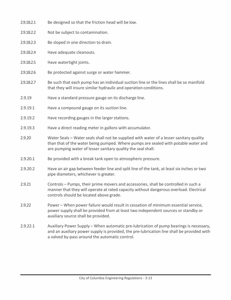
City of Columbia Engineering Regulations - 3-13
2.9.18.2.1 Be designed so that the friction head will be low.
2.9.18.2.2 Not be subject to contamination.
2.9.18.2.3 Be sloped in one direction to drain.
2.9.18.2.4 Have adequate cleanouts.
2.9.18.2.5 Have watertight joints.
2.9.18.2.6 Be protected against surge or water hammer.
2.9.18.2.7 Be such that each pump has an individual suction line or the lines shall be so manifold that they will insure similar hydraulic and operation conditions.
2.9.19 Have a standard pressure gauge on its discharge line.
2.9.19.1 Have a compound gauge on its suction line.
2.9.19.2 Have recording gauges in the larger stations.
2.9.19.3 Have a direct reading meter in gallons with accumulator.
2.9.20 Water Seals – Water seals shall not be supplied with water of a lesser sanitary quality
than that of the water being pumped. Where pumps are sealed with potable water and are pumping water of lesser sanitary quality the seal shall:
2.9.20.1 Be provided with a break tank open to atmospheric pressure.
2.9.20.2 Have an air gap between feeder line and split line of the tank, at least six inches or two
pipe diameters, whichever is greater.
2.9.21 Controls – Pumps, their prime movers and accessories, shall be controlled in such a manner that they will operate at rated capacity without dangerous overload. Electrical controls should be located above grade.
2.9.22 Power – When power failure would result in cessation of minimum essential service,
power supply shall be provided from at least two independent sources or standby or auxiliary source shall be provided.
2.9.22.1 Auxiliary Power Supply – When automatic pre-lubrication of pump bearings is necessary,
and an auxiliary power supply is provided, the pre-lubrication line shall be provided with a valved by-pass around the automatic control.

City of Columbia Engineering Regulations - 3-i
City of Columbia Engineering Regulations PART 3: Design of Sanitary Sewers
Table of Contents
Paragraph Description Page no. 3.1 General 3-1 3.2 System Design Criteria 3-1 3.3 Specification for Design of Pump Stations 3-6
List of Figures
Figure Description Page no. Figure 3-1. PS1A - Wet Well and Vault Section Detail 3-15 Figure 3-2. PS1B - Wet Well and Vault Plan Detail 3-16 Figure 3-3. PS1C - Wet Well and Vault Plan Detail (2) 3-17 Figure 3-4. PS2 - Typical Pump Station Site Plan 3-18 Figure 3-5. PS3 - Weather-Durable Emergency Contact Sign 3-19 Figure 3-6. PS4A - Typical Fence and Gate Detail (1) 3-20 Figure 3-7. PS4B - Typical Fence and Gate Detail (2) 3-21 Figure 3-8. PS5 - Typical Pump Controls Canopy Detail 3-22 Figure 3-9. PS6 - Bypass Pumping Connection Detail 3-23 Figure 3-10. PS7 - Air Release Valve in Manhole Detail 3-24 Figure 3-11. PS8 - Tap Mounted Pressure Gauge Assembly 3-25 Figure 3-12. PS9 - Yard Hydrant Detail 3-26 Figure 3-13. PS10 - Steel Bollard Detail 3-27 Figure 3-14. PS11 - Magmeter Vault Detail 3-28 Figure 3-15. E1A - Electrical Drawing Index 3-29 Figure 3-16. E1B - Legend and Details 3-30 Figure 3-17. E1C - Junction Box Elevation 3-31 Figure 3-18. E1D - I/O Riser Diagram 3-32 Figure 3-19. E2A - Schedule and Notes 3-33 Figure 3-20. E2B - One-Line Diagram 3-34 Figure 3-21. E2C - Control Panel Elevation 3-35 Figure 3-22. E3A - Schedule and Notes 3-36 Figure 3-23. E3B - One-Line Diagram 3-37 Figure 3-24. E3C - Control Panel Elevation 3-38 Figure 3-25. E4A - Typical Pump Station RTU Fabrication & Panel Layout 3-39 Figure 3-26. E4B - Typical Pump Station RTU Bill of Materials 3-40 Figure 3-27. E4C - Typical Pump Station RTU Wiring 1 of 3 3-41 Figure 3-28. E4D - Typical Pump Station RTU Wiring 2 of 3 3-42 Figure 3-29. E4E - Typical Pump Station RTU Wiring 3 of 3 3-43 Figure 3-30. E5A - Typical Control Panel Layout & Fabrication 1 3-44 Figure 3-31. E5B - Typical Control Panel Layout & Fabrication 2 3-45 Figure 3-32. E5C - Typical Control Panel Bill of Materials 3-46 Figure 3-33. E5D - Typical Control Panel Wiring 1 of 2 3-47 Figure 3-34. E5E - Typical Control Panel Wiring 2 of 2 3-48

City of Columbia Engineering Regulations - 3-ii
List of Tables
Table Description Page no. Table 3-1. Minimum Slope by Sewer Size 3-2 Table 3-2. Pump Station Pump Conditions and Ranges 3-13 Table 3-3 Attachment C: Conductor Color Code 3-127
City of Columbia Engineering Regulations - 3-1
City of Columbia Engineering Regulations PART 3: Design of Sanitary Sewers
3.1 General The City Engineer will approve plans for new systems, extensions, or replacement sewers only when designed according to the “separate plan”, in which rainwater from roofs, streets, and other areas, and ground water from foundation drains are excluded. Sanitary sewers 15 inches and smaller shall be VCP or PVC with an approved joint. Sanitary sewers 18 inches and larger may be concrete with approved joints and an approved liner. Sewers shall not be constructed under street paving except for crossings. Variations must be approved, in writing, by the City Engineer.
3.1.1 Sewer systems should be designed for the estimated ultimate tributary population,
except in considering parts of the system that can be readily increased in capacity. Similarly, consideration should be given to the maximum anticipated capacity of institutions, industrial parks, etc.
3.2 System Design Criteria
In determining the required capacities of sanitary sewers, the following factors shall be considered:
3.2.1 General information, including
3.2.1.1 Maximum hourly sewage flow.
3.2.1.2 Additional maximum sewage or waste flow from industrial plants.
3.2.1.3 Ground water infiltration.
3.2.1.4 Topography of area.
3.2.1.5 Location of waste treatment plant.
3.2.1.6 Depth of excavation.
3.2.1.7 Pumping requirements.
3.2.1.8 The proposed sanitary sewers, above the point where there are 375 acres in the
drainage basin or the pipe size is 15”, whichever is greater, must be adequately designed to handle the effluent at the ultimate land holding capability. Downstream from this point, design based on the Central Midlands Regional Planning Council’s 20-year projected population figures will be acceptable, provided easements 5 feet wide are furnished, to provide for future installation of parallel lines. Additionally, where at least 30% of a drainage area is already developed, a population density at least equal to that of the existing development must be used for the entire drainage area.

City of Columbia Engineering Regulations - 3-2
3.2.2 Per Capita Flow – New sewer systems shall be designed on the basis of an average daily per capita flow of sewage of not less than 100 gallons per day. This figure is assumed to cover normal infiltration, but an additional allowance should be made where conditions are unfavorable. Generally, the sewers should be designed to carry, when running full, not less than the following daily per capita contributions of sewage, exclusive of sewage or other waste flow from industrial plants:
Q = (10x104xP) (I 14 ) ÷ 4÷√P
Where “P” is the population in thousands.
3.2.3 Alternate Method – When deviations from the foregoing per capita rates are demonstrated, a description of the procedure used for sewer design shall be included. Such design will be approved at the discretion of the City Engineer.
3.2.4 Minimum size – No sewer shall be less than eight inches in diameter. Wyes for services
lines shall have a minimum branch size of six inches and must be installed with an 8” by 6” service wye.
3.2.5 Depth – In general, sewers shall be sufficiently deep so as to receive sewage from
basements and to prevent freezing. Sanitary sewers shall have a minimum cover of three feet between manholes except that they may be encased or constructed of cast iron if this depth cannot be achieved.
3.2.6 Slope
3.2.6.1 All sewers shall be so designed and constructed to give mean velocities, when flooding
full, of not less than 2.0 feet per second, based on Manning’s formula. The following are the minimum slopes which should be provided; however, slopes greater than these are desirable:
Table 3-1. Minimum Slope by Sewer Size
Sewer Size
Minimum Slope in Feet per 100 Feet
8” 0.40 10” 0.28 12” 0.22 14” 0.17 15” 0.15 16” 0.14 18” 0.12 21” 0.10 24” 0.08 27” 0.067 30” 0.058 36” 0.046

City of Columbia Engineering Regulations - 3-3
3.2.6.2 Under special conditions, if detailed justifiable reasons are given, slopes slightly less than those required for the 2.0 feet per second velocity when flowing full may be permitted. Such decreased slopes will only be considered where the depth of flow will be 0.3 of the diameter or greater for design average flow. Whenever such decreased slopes are selected, the Engineer must furnish with his report his computations of the depths of flow in such pipes at minimum, average, and daily or hourly rates of flow. It must be recognized that decreased slopes may cause additional sewer maintenance expense. Sewers shall be laid with uniform slope between manholes.
3.2.6.3 Sewers on 20% slope or greater shall be anchored securely with concrete anchors or
equal, spaced as follows:
3.2.6.3.1 Not over 36 feet center to center on grades 20% and up to 35%.
3.2.6.3.2 Not over 24 feet center to center on grades 35% and up to 50%.
3.2.6.3.3 Not over 16 feet center to center on grades 50% and over.
3.2.7 Alignments – Sewers 24 inches or less shall be laid with straight alignment between manholes.
3.2.8 Increasing Size – When a smaller sewer joins a larger one, the invert of the larger sewer
shall be lowered sufficiently to maintain the same energy gradient. An approximate method for securing these results is to place the 0.8 depth point of both sewers at the same elevation.
3.2.9 High Velocity Protection – Where velocities greater than 15 feet per second are attained,
special provisions shall be made to protect against displacement by erosion and shock.
3.2.10 Materials – The material selected for construction shall be adapted to local conditions, such as character of industrial wastes, possibility of septicity, soil characteristics, exceptionally heavy external loadings, abrasion and similar problems. Cement asbestos pipe is not approved for sanitary sewer construction. Where the proposed material is not covered in Columbia specifications, installation specifications shall contain appropriate requirements based on the criteria, standards and requirements established by industry in its technical publications. Requirements shall be set forth in the specifications for the pipe and method of bedding and backfilling thereof so as not to damage the pipe nor its joints, impede cleaning operations and future tapping, nor create excessive side fill pressures nor ovulation of the pipe, nor seriously impair flow capacity. All sewers shall be designed to prevent damage from superimposed loads. Proper allowance for loads on the sewer shall be made because of the width and depth of trench. When standard strength sewer pipe is not sufficient, the additional strength needed may be obtained by using extra strength pipe or by special construction.
3.2.11 Joints and Infiltration – In general, DIP or PVC joints are required although other
materials will be considered for approval. The method of making joints and materials used should be included in the specifications. Sewer joints shall be designed to minimize infiltration and to prevent the entrance of roots. Leakage tests shall be specified. This

City of Columbia Engineering Regulations - 3-4
may include appropriate water or low-pressure air testing. The leakage outward or inward (exfiltration or infiltration) shall not exceed 200 gallons per inch of pipe diameter per mile per day for any section of the system. The use of television camera or other visual methods for inspection prior to placing the sewer in service is required. Results of such tests shall be certified to the City Engineer in writing by a registered engineer.
3.2.12 Sanitary sewers shall be constructed of ductile iron at stream crossings.
3.2.13 Calculations – Computations should be presented, in a tabular form, to indicate depths
and velocities at minimum, average and maximum daily waste flow for the different sizes of sewers proposed.
3.2.14 Manholes
3.2.14.1 Location – Manholes shall be installed at the end of each line; at all changes in grade,
size, or alignment; at all intersections; and at distances not greater than 400 feet for sewers 15 inches or less, and 500 feet for sewers 18 inches to 30 inches, except that distances up to 600 feet may be approved in cases where adequate modern cleaning equipment for such spacing is provided. Greater spacing may be permitted in larger sewers and in those carrying a settled effluent. Lampholes may not be used.
3.2.14.2 Drop Type – A drop pipe should be provided for a sewer entering a manhole at an
elevation of 24 inches or more above the manhole invert. Where the difference in elevation between the incoming sewer and the manhole invert is less than 24 inches, the invert should be filleted to prevent solid deposition.
3.2.14.3 Diameter – The minimum diameter of manholes shall be 48 inches; larger diameters are
preferable. For sewer pipes in sizes eight inches up to 15 inches, manholes are to be a minimum of four feet in diameter. For sewer pipes 18 inches and larger, manholes are to be a minimum of five feet in diameter.
3.2.14.4 Manhole Depth – The four-foot diameter manhole shall have a minimum depth of four
feet and a maximum depth of less than 12 feet measured from the top of pipe to the top of the ring. Manholes of larger diameter shall be proportionately deeper. This provides for proper corbel construction.
3.2.14.5 Flow Channel – The flow channel through manholes should be made to conform in
shape and slope to that of the sewers.
3.2.14.6 Water tightness – Watertight manhole covers are to be used wherever the manhole tops may be flooded by street runoff or high water and where the manhole covers are below the base flood elevation (BFE). Manholes or brick shall be waterproofed on the exterior with plaster coatings; supplemented by a bituminous waterproof coating where ground water conditions are unfavorable.
3.2.14.7 Electrical – Electrical equipment installed or used in manholes shall conform to
paragraph 3.1.18.3.10.

City of Columbia Engineering Regulations - 3-5
3.2.15 Inverted Siphons – Only if approved by the City Engineer, inverted siphons should have not less than two barrels, with a minimum pipe size of six inches and shall be provided with necessary appurtenances for convenient flushing and maintenance; the manholes shall have adequate clearances for rodding; and in general, sufficient head shall be provided and pipe sizes selected to secure velocities of at least 3.0 feet per second for average flows. The inlet and outlet details shall be arranged so that either barrel may be taken out of service for cleaning.
3.2.16 Sewer Extensions – In general, sewer extensions shall be allowed only if the receiving
sewage treatment plant is either;
3.2.16.1 Capable of adequately processing the added hydraulic and organic load; or,
3.2.16.2 Provision of adequate treatment facilities on a time schedule acceptable to the approving agency is assured.
3.2.17 Protection of Water Supplies
3.2.17.1 Water Supply Interconnections – There shall be no physical connection between a public
or private potable water supply system and a sewer, or appurtenance thereto which would permit the passage of any sewage or polluted water into the potable supply.
3.2.17.2 Relation to Water Works Structures – While no general statement can be made to cover
all conditions, it is generally recognized that sewers shall meet the requirements of the approving agency with respect of minimum distances from public water supply wells or other water supply sources and structures.
3.2.17.3 Relation to Water Mains
3.2.17.3.1 Horizontal Separation – Whenever possible, sewers should be laid at least ten feet,
horizontally, from any existing or proposed water main. Should local conditions prevent a lateral separation of ten feet, a sewer may be laid closer than ten feet to a water main if:
3.2.17.3.1.1 It is laid in a separate trench.
3.2.17.3.1.2 It is laid in the same trench with the water mains located at one side on a bench of
undisturbed earth.
3.2.17.3.1.3 In either case the elevation of the crown of the sewer is at least 18 inches below the invert of the water main.
3.2.17.3.2 Vertical Separation – Whenever sewers must cross under water mains, the sewer shall
be laid at such an elevation that the top of the sewer is at least 18 inches below the bottom of the water main. When the elevation of the sewer cannot be buried to meet the above requirements, the water main shall be relocated to provide this separation or reconstructed with slip-on or mechanical-joint cast-iron pipe or prestressed concrete cylinder pipe for a distance of ten feet on each side of the sewer. One full length of water

City of Columbia Engineering Regulations - 3-6
main should be centered over the sewer so that both joints will be as far from the sewer as possible.
3.2.17.3.3 Special Conditions – When it is impossible to obtain proper horizontal and vertical
separation as stipulated above, the water main shall be constructed of slip-on or mechanical-joint cast-iron pipe or prestressed concrete cylinder pipe and the sewer constructed of mechanical-joint cast-iron pipe, and both services should be pressure tested to assure water tightness.
3.2.17.4 Relation to Storm Drain Systems
3.2.17.4.1 Horizontal Separation – Whenever possible, sewers should be laid at least five feet,
horizontally, from any existing or proposed storm drain pipes or structures. Should local conditions prevent a lateral separation of five feet, a sewer main may be laid closer than five feet to a storm drain pipe main if:
3.2.17.4.1.1 It is laid in the same trench with the storm drain pipe main located at one side on a
bench of undisturbed earth.
3.2.17.4.2 Vertical Separation – Whenever sewers must cross storm drains, the sewer shall be laid at such an elevation that the top of the sewer is at least 18 inches below the bottom of the water main. When the elevation of the sewer cannot be buried to meet the above requirements, the water main shall be relocated to provide this separation or reconstructed with slip-on or mechanical-joint cast-iron pipe or prestressed concrete cylinder pipe for a distance of ten feet on each side of the sewer. One full length of water main should be centered over the sewer so that both joints will be as far from the sewer as possible.
3.2.17.4.3 Special Conditions – When it is impossible to obtain proper horizontal and vertical
separation as stipulated above, the water main shall be constructed of slip-on or mechanical-joint cast-iron pipe or prestressed concrete cylinder pipe and the sewer constructed of mechanical-joint cast-iron pipe, and both services should be pressure tested to assure water tightness.
3.3 Specification for Design of Pump Stations
The standards in this section are applicable to all pump stations that the City will own and maintain. This section is intended for pump stations with reliable design capacities of less than 1000 gpm serving domestic wastewater. For pump stations with larger reliable design capacities, or stations serving wastewater other than domestic, please contact the City for additional requirements and design standards. All sewage pumping stations that will be turned over to the City for ownership and maintenance shall be reviewed during design before being bid for construction, and after completion of construction to ensure compliance with these standards. Failure to meet these requirements may result in denial of taking ownership of the pump station, force main, and appurtenances until the requirements are met. The standards listed below are minimum City of Columbia design standards. The written standards in combination with the standard details and referenced documents are all

City of Columbia Engineering Regulations - 3-7
included as a part of the standard. These should be adhered to, with good engineering practice. If a variation or exception is needed to maintain good engineering practices, please provide an explanation supporting the type of variation, and the reason for the variation for review by the City for acceptance. A submittal of a variance request does not guarantee approval. The developer is responsible for securing and paying all application and permit fees and costs associated with and incurred for the pump station before final acceptance. The City will take ownership of the pump station upon final acceptance, at which time billing for utilities will be transferred to the City of Columbia.
3.3.1 GENERAL - In general pumping stations will only be approved where gravity service is
not possible.
3.3.1.1 Pump stations shall not be subject to flooding. Pump stations should remain fully operational and accessible during the 25-year flood. Temporary facilities expected to be in service from five to ten years shall be protected from the 25-year frequency storm in accordance with the Columbia Drainage Ordinance. Pump station structures, electrical and mechanical equipment shall be protected from physical damage by flooding to the 100-year flood elevation. Permanent structures which have a life expectancy of more than ten years shall be 2 feet above the 100-year flood plain or one foot above the base flood elevation, whichever is more stringent. It is important that the station be readily accessible.
3.3.1.2 All pump stations and force mains shall meet the requirements of SCDHEC Standards for
Wastewater Facility Construction R.61-67 and Ten States Standards, latest edition.
3.3.1.3 Pump Station sites, collection system, force main, access road, and any other appurtenances that are to be owned and maintained by the City are to be deeded over to the City per the City property requirements for pump stations.
3.3.1.4 All paints and coatings to be applied must meet or exceed manufacturer’s
recommendations for the specific application.
3.3.1.5 Provide flood elevation, and base flood elevation (where applicable) on drawings and record drawings. List surveyor information including company, date, and datum.
3.3.2 PUMP STATION SITE AND EQUIPMENT - The size of the site provided for the pumping
station must be a minimum of 60 feet by 60 feet. The pumping station site must be fenced with an access gate. The fence shall be a 6-foot-tall standard galvanized fence with eight-gauge wire (not coated) with 3 strand barbed wire. Wooden fences or other decorative fences are not allowed as a substitution. However, a wooden or decorative fence is allowed outside of the galvanized fence for screening and aesthetic purposes but must be located outside of the City’s pump station property and be maintained by the property owner.
3.3.2.1 A double swing gate shall be provided at the pump station site access. The gate shall consist of two 8-foot gates with self-holding latches and a recessed center latch point.

City of Columbia Engineering Regulations - 3-8
3.3.2.2 The fence shall have a City standard weather durable emergency contact sign attached
at a location visible from the access road.
3.3.2.3 An all-weather access road a minimum of 12 feet wide shall be provided for access to the pump station site. The road shall consist of a minimum of 6-inches of crusher run stone and must be capable of supporting 36,000-pound vehicles. A permanent easement, a minimum of 20 feet wide, must be furnished centered along the access road.
3.3.2.4 The entire pump station site within the limits of the fencing shall be crusher run stone
that meets the same minimum requirements as specified for the all-weather access road unless specified otherwise.
3.3.2.5 Pump stations shall be designed to be submersible type stations.
3.3.2.6 Pump station wet wells shall be round. Wet wells shall be sized for sewer shed basin
build-out condition utilizing sound engineering practice and standards and shall include design information such as Metcalf and Eddy land use flow projections, topographic maps, land use maps, zoning, population projections, the study of available land for development, and other available City or County planning studies which may include the sewer shed area. Coordination with the City’s Hydraulic Engineer may be required to collaborate on design flow for build-out conditions.
3.3.2.7 The wet well shall be positioned inside the fence so as to allow easy access with a
vacuum or boom truck.
3.3.2.8 A by-pass pumping connection utilizing Bauer fittings shall be provided close to the entrance and easily accessible with a truck.
3.3.2.9 Pump station wet well and valve vaults to be sized for build-out conditions and shall be
large enough to accommodate future pump sizes.
3.3.2.10 Valve vaults shall be of sufficient inside depth to house valves and appurtenances with enough clearance but shall be shallow enough to not be defined as a confined space.
3.3.2.11 Wet well access hatch to be aluminum double door by Halliday, Bilco or approved equal
with spring assist. Access hatch to be sized to provide the ability to remove pumps and future pumps sized for build-out conditions, as well as provide easy access to guide rails and float hangars. Access hatch to be a minimum 4-foot by 4-foot and shall be cast into the wet-well.
3.3.2.12 Wet well shall be provided with a ductile iron vent with a 90-degree elbow on the end
with a 24-mesh stainless steel screen. The entire vent shall be coated with Light Grey 32GR Tnemec paint or approved equal.
3.3.2.13 Pumps to be submersible Flygt pumps. A minimum of two identical pumps are to be
installed. In addition to the pumps installed, an additional identical spare pump shall be provided and delivered to the City Metro Wastewater Treatment Plant. Pumps are to be

City of Columbia Engineering Regulations - 3-9
designed with a design capacity that will be able to handle maximum anticipated peak flows with any one pump out of service.
3.3.2.14 The design of the pumping station shall include the submission of the proposed flows to
the City for review in accordance with the City’s Capacity Assurance Program for approval of the downstream receiving collection system to ensure that there is adequate capacity to handle the proposed flows and pumping rates. The extent of the downstream collection system requiring evaluation, as well as the criteria for evaluation, shall be determined by the City.
3.3.2.15 Pumps to be provided with Flygt standard guide rails with spacing that will also
accommodate build-out condition pumps. Guide rails may be welded for wet wells up to 23 feet deep as long as the extension rail added to the 20-foot section is no longer than 3 feet in length. A smaller internal pipe which fits within the rails should extend at least 3 inches into each rail being welded together. The finished weld should be smooth with the exterior of the welded sections so as not to interfere with the pump guide rail bracket when removing or installing the pumps. Any wet well requiring more than three feet extension rail shall use an intermediate guide rail bracket attached to the discharge pipe.
3.3.2.16 All hardware shall be stainless steel including, but not limited to, lifting chains, bolts,
nuts, guide rails, anchors, bolts, nuts, washers, screws, etc.
3.3.2.17 Each pump to include a 3/8-inch PC 316 stainless steel lifting chain.
3.3.2.18 Provide two Flygt or approved equal flat bolted stainless-steel plates with 4 hooks minimum on each on opposite sides of the wet well access.
3.3.2.19 Level sensors shall be provided to be read using a submersible level transducer as
defined in the Remote Telemetry Unit, Instrumentation, and supervisory control and data acquisition (SCADA) System Interface Specification for wet wells. All pump stations shall have a float switch backup system with floats as defined in the Remote Telemetry Unit, Instrumentation, and SCADA System Interface Specification that is in place and operates in case of level sensor failure as further defined in the SCADA specifications. Pneumatic bubbler systems are not acceptable.
3.3.2.20 Wet well interior (excluding the bottom) and all exposed piping in the wet well shall be
coated with Raven 405 coating with a minimum of 120 mils.
3.3.2.21 The wet well floor shall have a minimum slope of one to one to the hopper bottom. The horizontal area of the hopper bottom shall be no greater than necessary for proper installation and function of the pump inlet.
3.3.2.22 Valve vault shall be less than 4 feet deep and a minimum 4-foot by 4-foot size for a
4-inch discharge and 4-foot by 6-foot for a 6-inch discharge.
3.3.2.23 Valve vault to have an access hatch that opens to expose the entire vault, matching the size of the vault interior. The hatch shall be a traffic rated aluminum access hatch and

City of Columbia Engineering Regulations - 3-10
shall be cast into the valve vault.
3.3.2.24 A drain from the valve vault to the wet well shall be provided with a minimum 4-inch drain at a minimum 1% slope. A duckbill flap or approved equal shall be used on the interior of the wet well on the end of the drain line from the valve vault. The valve shall be installed in accordance with manufacturer recommendations and positioned as to not interfere with pump removal and be visible and readily accessible from the wet well hatch opening (i.e., not behind guide rails, etc.). A removable screen shall be installed on the intake side of the drain to prevent debris from entering the drain.
3.3.2.25 Safety grating shall be provided in the wet well. Provide hinged aluminum grating panels
in access hatch openings to provide protection against fall through accidents when the access hatch is open. Aluminum grating panels shall be constructed from aluminum “I” bar construction, be rated for a minimum load rating of 300 lbs. per sq. ft., include a positive latch to hold safety grate open when in the open position, include lockable safety grates, spring assisted lifting handle, have 316 stainless steel mounting hardware, and have an orange powder coating finish. Attach access hatch safety grate to concrete below access hatch frame. For openings greater than 53” wide, provide two panels.
3.3.2.26 All exposed piping, fittings, and valves shall be painted with 09SF Spearmint Green/
Safety Tnemec paint or approved equal.
3.3.2.27 No check valves shall be installed inside of the wet well. Check valves shall be located within the valve vault between the pump and the shut-off valve.
3.3.2.28 A strap on magmeter vault and associated appurtenances shall be provided on the
site. Vault shall be located to allow accurate meter readings without influence from adjacent fittings and appurtenances. Piping within the vault shall be PVC and match force main size. The vault to have a double leaf access hatch, shall be traffic rated aluminum, and shall be cast into the valve vault.
3.3.2.29 A water supply with a minimum 4-inch service shall be installed to the site with a Mueller or approved equal post hydrant as well as a yard hydrant. The hydrants shall be frost and freeze proof and shall be anti-siphon. All water related items shall be coordinated with the Water Division within the City of Columbia for fees, preferences, and standards.
3.3.2.30 A testable backflow preventer and meter shall be provided for the water service to the
site. The meter and backflow preventer shall be located in separate meter boxes. All water related items shall be coordinated with the Water Division within the City of Columbia for fees, preferences, and standards.
3.3.2.31 Two hoses shall be provided at the site. A 25-foot industrial 2-inch hose with an
adjustable brass spray nozzle and a 25-foot 3/4-inch hose with an adjustable brass spray nozzle shall be provided. A weatherproof hose rack shall be provided for each hose.
3.3.2.32 Check valves 12-inches and smaller shall be Mueller A-2606-6-01B1 flanged end with rubber disc facing swing type lever and weight.

City of Columbia Engineering Regulations - 3-11
3.3.2.33 Pressure gauges shall be 4-inch diameter quick disconnect Ashcroft or WIKA that are
glycerin filled and accurate within 0.5% of the total scale range. Each gauge shall be mounted with a saddle tap for 1-inch stainless steel pipe with 2 ball valves and an isolator ring such as ONYX with the pressure gauge mounted to the isolator ring. The gauges shall have type 316L stainless steel housing and components and shall provide a top limit above the pump shutoff head. Provide optimal design point to be approximately at 50% of the total range of the gauge. Pressure gauges to be installed with a stainless steel shut-off ball valve with handle. Pressure gauge to face upward for optimal visibility from above without entry into the vault. Three pressure gauges shall be provided, 1 on the discharge end of each pump just before the check valve, and one on the force main on the discharge end after the tee where both pump discharges combine into one common force main. All three gauges shall be located within the valve vault.
3.3.2.34 Stainless steel shut-off ball valves 3-inches and smaller shall be full port with a lever
handle operator, and a three-piece body that is in-line serviceable without removing the valve from the line. Acceptable manufacturers include Series 60 as manufactured by Whitey or Apollo Series 86R-200 as manufactured by Conbraco, CF Ball Valve Series F12 as manufactured by CF Fluid Controls, or V3P-1000 as manufactured by Velan. Stainless steel ball valves 3 to 4 inches shall be regular port stainless steel ball valves with an oval handle operator, top entry design, fully serviceable without removing the valve body from the line, Seal body cover to body section with fully closed spiral wound graphite gasket, and adjustable two-piece packing gland and pre-compressed solid packing rings. Acceptable manufacturers include Series “TE-150/300/600” as manufactured by Velan.
3.3.2.35 Surge relief valves shall be provided if required in the valve vault. Valves shall have a cast
iron body and shall be GA Industries 625-D or approved equal. Valve shall provide a full opening of the pipeline area in the open position. The requirement of a limit switch shall be determined by the City based on force main and pump conditions and should be verified before final design.
3.3.2.36 Plug valves shall be Dezurik. Provide worm gear and hand wheel operator on 4 inches
and larger. On sizes less than 4-inches ball valves shall be used with quarter turn lever type operator.
3.3.2.37 Air release valves shall be ARI D-025 HDPE and shall be housed in a manhole with an
open bedded bottom. Air release valves shall be located outside of the pump station site fence where possible.
3.3.2.38 Anchor bolts for the pump discharge stand must be J-type stainless steel cast in place in
the wet well floor.
3.3.2.39 Two level indicators shall be marked on the inside of the wet well at a pre-measured distance for the use of draw-down tests. The markings should be clearly visible without entering the wet well and shall be resistant to fading or reduced visibility over time due to debris or build-up. The pre-measured distance and diameter of the wet well shall be

City of Columbia Engineering Regulations - 3-12
written clearly above the higher of the two levels and readable from outside of the wet well. The markings shall not be such to void the warranty of the coating on the interior of the wet well.
3.3.2.40 A canopy shall be provided on the pump station site that covers the panels. See the
standard canopy detail. The canopy shall be painted Tnemec medium bronze 85BR and shall be on a minimum 6-inch pad that spans the extents of the canopy. Engineer is responsible for reviewing the standard canopy detail and making modifications to ensure the canopy is structurally sound and adjusting as needed to increase the requirements. The standard detail shown is a minimum requirement and may not be sufficient for all sites. A light should be installed under the canopy with a switch with dual 48-inch LED lights or similar.
3.3.2.41 A 20 foot creosoted southern pine service/light pole with all-weather exterior light
switches, and exterior LED flood lights shall be provided at the pump station site and shall be positioned to flood the wet well access, valve vault access, and the front of the control panel and electrical equipment with light. Flood lights to be Philips Stonco GP Flood Series Floodlighting GP3 (Medium) LED. Heavy duty light switch and receptacle with gasket cover and weatherproof plates shall be provided outside of the control panels at the site near or on the light pole.
3.3.2.42 Wet well shall be sized for build-out conditions. All conditions listed below shall be met
for current design and future build-out design conditions by simple adjustments in level controls or changing of pumps.
3.3.2.43 When called to run the pumps shall not run less than the manufacturer’s
recommendations or 1 minute, whichever is longer.
3.3.2.44 The reliable pumping capacity (defined as one pump on in a duplex station) shall be higher than the peak inflow rate in gpm into the pump station.
3.3.2.45 The pump station shall be designed to run no more than 6 cumulative hours a day.
3.3.2.46 Pumps should be selected that have an operating point at or near peak efficiency.
3.3.2.47 Pumps shall be capable of passing spheres of at least three inches in diameter. Pump
suction and discharge openings shall be at least four (4) inches in diameter.
3.3.2.48 Pump stations may be required to have screening mechanisms before the pumps if larger solids will be received by the station, or if wastewater received is determined to be more solids than typical domestic wastewater.
3.3.2.49 Force mains shall be adequately sized to handle the design peak flow of the contributing
sewer shed and within industry standards for velocity.
3.3.2.50 The force main should enter the gravity sewer system at a point not more than two feet above the flow line of the receiving manhole entering through either an inside or outside drop at the manhole. The receiving manhole shall be lined with Raven 405 120

City of Columbia Engineering Regulations - 3-13
mil coating for new manholes. If the receiving manhole is an existing manhole, see the City’s standard Manhole Lining specification for approved Type 3 or Type 4 manhole linings for force main discharge manholes.
3.3.2.51 A combination air release valve for sewage application shall be placed at high points in
the force main to prevent air locking. Air release valves shall be located outside of the pump station site fence where possible. Air release valves within the pump station site are preferred to be located within the valve vault if possible. A short body valve may be required.
3.3.2.52 At design flow, a cleaning velocity of at least two feet per second shall be maintained in
the force main.
3.3.2.53 Pump Station Drawings Shall include a chart showing pump conditions and ranges such as the one below:
Table 3-2. Pump Station Pump Conditions and Ranges
Condition (Pumps On)
Flow Per Pump GPM
TDH Feet
Total Pump Station Flow GPM
One Pump XX XX XX Two Pumps XX XX XX
3.3.3 BACK-UP POWER - Natural gas generator shall be provided on all pump station sites and
shall be capable of running all equipment as a secondary power source in case of a power failure. Generator shall meet a minimum of the standards in the City’s Natural Gas Fueled Engine Driven Generator Specification as outlined in Attachment A.
3.3.3.1 All generator support structures, concrete pads, site layout, etc. shall be designed
accordingly for a complete standby power system at each location.
3.3.4 SCADA - Provide equipment, services, and associated components to meet the City’s standard Remote Telemetry Unit, Instrumentation and SCADA System Interface Specification Attachment B and associated Standard Construction Details.
3.3.5 ELECTRICAL - Provide equipment, services, and associated components to meet the
City’s Attachment C Pump Station Electrical Requirements Specification and associated Standard Construction Details.
3.3.6 OTHER REQUIREMENTS - Authorized supplier of check valves shall be present on-
site during installation to set valve weight and make adjustments as necessary to meet design conditions as intended by the Engineer.
3.3.6.1 Contractor responsible for the design, installation, and operation of by-pass pumping
operations or pumping and hauling operations needed to complete the work for the construction of the pump station and its appurtenances, including the force main. Contractor to submit a plan to the Engineer for review of operations, which should include any requests and supporting reasoning for creating surcharge conditions within the sewer system that will need to be considered and reviewed by the City as well as the

City of Columbia Engineering Regulations - 3-14
Engineer. The City’s review of the proposed conditions does not relieve the Contractor of any responsibility and liability of these operations, including overflows, damage to property or the sewer system, and meeting the requirements of other regulatory agencies.
3.3.6.2 Contractor to submit to the Engineer written certification from the coating
manufacturer demonstrating the persons applying the Raven 405 coating are certified in the application. The application shall have a standard manufacturer’s warranty from defects.
3.3.6.3 A preconstruction conference of Metro WWTP personnel with the Contractor and
Engineer will be held at the pump station site.
3.3.6.4 A full set up Operations and Maintenance Manuals shall be provided for the SCADA system, pumps, motors, control panel, generator, ATS, and any other appurtenances provided on the site. 2 hard copies and 1 electronic PDF copy shall be provided to the City before ownership transfer. The manuals shall include, but not be limited to, operational instructions, emergency procedures, maintenance schedules, pump curves, parts list, tools, spare parts, etc. Contractor to coordinate with the City to determine what asset information is to be provided by the Contractor necessary for Cityworks before the completion of the project.
3.3.6.5 A training session shall be conducted covering all O&M aspects of the pump station
including, but not limited to operational instructions, emergency procedures, maintenance schedules etc. for City staff. The training shall be recorded on video and a copy of the video shall be provided in electronic format.
3.3.6.6 The following spare parts are to be delivered to the City before close-out:
3.3.6.6.1 3 sets of O-rings and seals for each pump.
3.3.6.6.2 1 spare pump and cable.
3.3.6.6.3 1 spare pressure transmitter/level control.
3.3.6.6.4 All recommended spare parts as listed in the SCADA/Electrical/Stand-By Power
Specifications.
3.3.6.7 All spare parts shall be delivered to the Metro Wastewater Treatment Plant. A clear record of the items delivered, the date, and who they were delivered to, and a signed notification acknowledging the receipt of each part shall be documented and included in project close-out documentation.
3.3.6.8 Contractor to follow City requirements for commissioning and decommissioning pump stations and equipment. The latest requirements will be provided upon request.
3.3.7 STANDARD DETAILS - The following is a list of the standard details for pump stations
including electrical details. Electronic versions of these standard details are available on the City website.

City of Columbia Engineering Regulations - 3-15
3.3.7.1 PS1A - Wet Well and Vault Section Detail
Figure 3-1. PS1A - Wet Well and Vault Section Detail

City of Columbia Engineering Regulations - 3-16
3.3.7.2 PS1B - Wet Well and Vault Plan Detail
Figure 3-2. PS1B - Wet Well and Vault Plan Detail

City of Columbia Engineering Regulations - 3-17
3.3.7.3 PS1C - Wet Well and Vault Plan Detail (2)
Figure 3-3. PS1C - Wet Well and Vault Plan Detail (2)

City of Columbia Engineering Regulations - 3-18
3.3.7.4 PS2 - Typical Pump Station Site Plan
Figure 3-4. PS2 - Typical Pump Station Site Plan

City of Columbia Engineering Regulations - 3-19
3.3.7.5 PS3 - Weather-Durable Emergency Contact Sign
Figure 3-5. PS3 - Weather-Durable Emergency Contact Sign

City of Columbia Engineering Regulations - 3-20
3.3.7.6 PS4A - Typical Fence and Gate Detail (1)
Figure 3-6. PS4A - Typical Fence and Gate Detail (1)

City of Columbia Engineering Regulations - 3-21
3.3.7.7 PS4B - Typical Fence and Gate Detail (2)
Figure 3-7. PS4B - Typical Fence and Gate Detail (2)

City of Columbia Engineering Regulations - 3-22
3.3.7.8 PS5 - Typical Pump Controls Canopy Detail
Figure 3-8. PS5 - Typical Pump Controls Canopy Detail

City of Columbia Engineering Regulations - 3-23
3.3.7.9 PS6 - Bypass Pumping Connection Detail
Figure 3-9. PS6 - Bypass Pumping Connection Detail

City of Columbia Engineering Regulations - 3-24
3.3.7.10 PS7 - Air Release Valve in Manhole Detail
Figure 3-10. PS7 - Air Release Valve in Manhole Detail

City of Columbia Engineering Regulations - 3-25
3.3.7.11 PS8 - Tap Mounted Pressure Gauge Assembly
Figure 3-11. PS8 - Tap Mounted Pressure Gauge Assembly

City of Columbia Engineering Regulations - 3-26
3.3.7.12 PS9 - Yard Hydrant Detail
Figure 3-12. PS9 - Yard Hydrant Detail
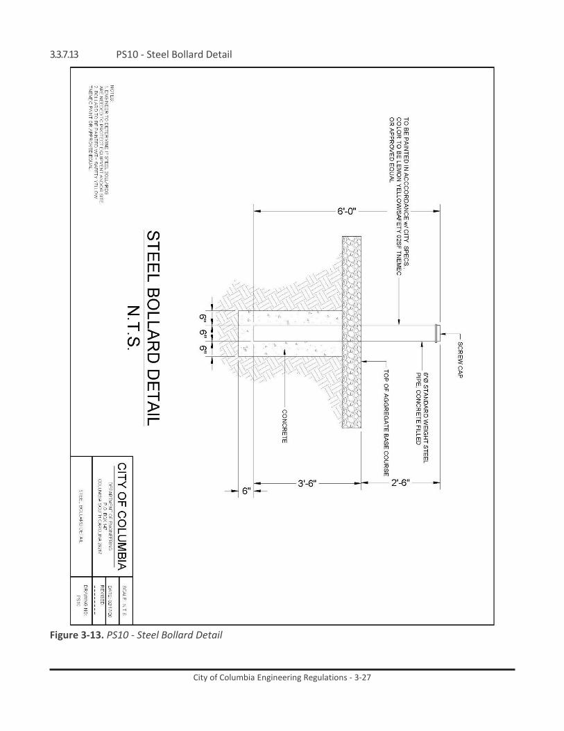
City of Columbia Engineering Regulations - 3-27
3.3.7.13 PS10 - Steel Bollard Detail
Figure 3-13. PS10 - Steel Bollard Detail

City of Columbia Engineering Regulations - 3-28
3.3.7.14 PS11 - Magmeter Vault Detail
Figure 3-14. PS11 - Magmeter Vault Detail
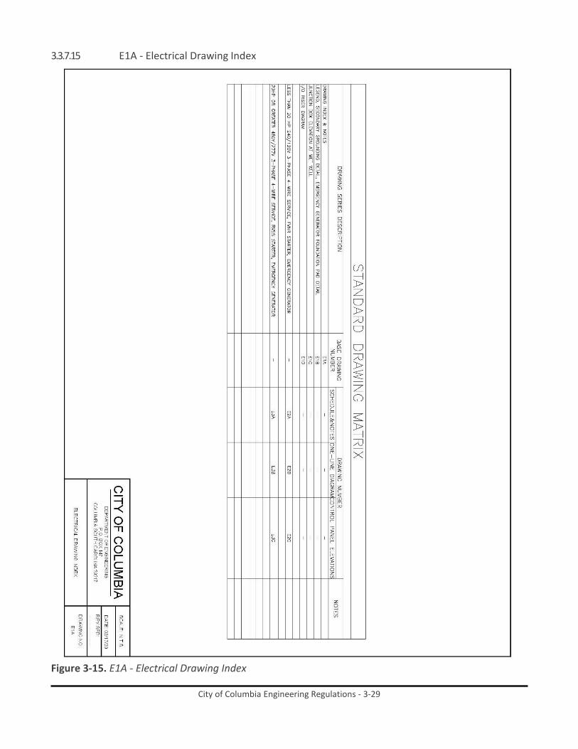
City of Columbia Engineering Regulations - 3-29
3.3.7.15 E1A - Electrical Drawing Index
Figure 3-15. E1A - Electrical Drawing Index

City of Columbia Engineering Regulations - 3-30
3.3.7.16 E1B - Legend and Details
Figure 3-16. E1B - Legend and Details

City of Columbia Engineering Regulations - 3-31
3.3.7.17 E1C - Junction Box Elevation
Figure 3-17. E1C - Junction Box Elevation

City of Columbia Engineering Regulations - 3-32
3.3.7.18 E1D - I/O Riser Diagram
Figure 3-18. E1D - I/O Riser Diagram

City of Columbia Engineering Regulations - 3-33
3.3.7.19 E2A - Schedule and Notes
Figure 3-19. E2A - Schedule and Notes

City of Columbia Engineering Regulations - 3-34
3.3.7.20 E2B - One-Line Diagram
Figure 3-20. E2B - One-Line Diagram

City of Columbia Engineering Regulations - 3-35
3.3.7.21 E2C - Control Panel Elevation
Figure 3-21. E2C - Control Panel Elevation

City of Columbia Engineering Regulations - 3-36
3.3.7.22 E3A - Schedule and Notes
Figure 3-22. E3A - Schedule and Notes

City of Columbia Engineering Regulations - 3-37
3.3.7.23 E3B - One-Line Diagram
Figure 3-23. E3B - One-Line Diagram

City of Columbia Engineering Regulations - 3-38
3.3.7.24 E3C - Control Panel Elevation
Figure 3-24. E3C - Control Panel Elevation

City of Columbia Engineering Regulations - 3-39
3.3.7.25 E4A - Typical Pump Station RTU Fabrication & Panel Layout
Figure 3-25. E4A - Typical Pump Station RTU Fabrication & Panel Layout

City of Columbia Engineering Regulations - 3-40
3.3.7.26 E4B - Typical Pump Station RTU Bill of Materials
Figure 3-26. E4B - Typical Pump Station RTU Bill of Materials

City of Columbia Engineering Regulations - 3-41
3.3.7.27 E4C - Typical Pump Station RTU Wiring 1 of 3
Figure 3-27. E4C - Typical Pump Station RTU Wiring 1 of 3

City of Columbia Engineering Regulations - 3-42
3.3.7.28 E4D -- Typical Pump Station RTU Wiring 2 of 3
Figure 3-28. E4D - Typical Pump Station RTU Wiring 2 of 3

City of Columbia Engineering Regulations - 3-43
3.3.7.29 E4E - Typical Pump Station RTU Wiring 3 of 3
Figure 3-29. E4E - Typical Pump Station RTU Wiring 3 of 3

City of Columbia Engineering Regulations - 3-44
3.3.7.30 E5A - Typical Control Panel Layout & Fabrication 1
Figure 3-30. E5A - Typical Control Panel Layout & Fabrication 1

City of Columbia Engineering Regulations - 3-45
3.3.7.31 E5B - Typical Control Panel Layout & Fabrication 2
Figure 3-31. E5B - Typical Control Panel Layout & Fabrication 2

City of Columbia Engineering Regulations - 3-46
3.3.7.32 E5C - Typical Control Panel Bill of Materials
Figure 3-32. E5C - Typical Control Panel Bill of Materials

City of Columbia Engineering Regulations - 3-47
3.3.7.33 E5D - Typical Control Panel Wiring 1 of 2
Figure 3-33. E5D - Typical Control Panel Wiring 1 of 2

City of Columbia Engineering Regulations - 3-48
3.3.7.34 E5E - Typical Control Panel Wiring 2 of 2
Figure 3-34. E5E - Typical Control Panel Wiring 2 of 2

City of Columbia Engineering Regulations - 3-49
3.3.8 Attachment A: Natural Gas Fueled Engine Driven Generator ATTACHMENT A
NATURAL GAS FUELED ENGINE DRIVEN GENERATOR
PART 1. GENERAL
1.01. SCOPE OF WORK
A. Furnish all labor, materials and equipment and incidentals, and install one natural gas fueled engine driven standby generator unit with automatic transfer switch and appurtenances and required supporting systems in a factory type skintight weatherproof sound attenuating enclosure as specified herein. The manufacturer or manufacturer’s representative shall furnish installation technical assistance, start-up operation, field testing, operator training, first year service contract, and operation and maintenance manuals.
B. The engine driven generator shall have a standby power rating (site rated) of not less than kVA, kW, at 80% lagging power factor, with 480 volt, three phase, 60 hertz output. The alternator shall be three wire, grounded wye connected, complete with excitation system and controls.
C. Arrange the generator for automatic starting and stopping and load transfer upon failure of the normal source of power. Closed transition or parallel operation with the Electric Utility Power Company is not required. Transfer of generator power to and from connected facility electrical loads will be open transition transfer.
D. All equipment and controls specified in this Section shall be new and be considered part of the engine driven generator package. The generator manufacturer or his/her licensee shall furnish the generator package in its entirety as specified. The engine driven generator package shall be complete and shall include all equipment and controls necessary for a fully operational standby electric power supply.
E. Furnish the following for each unit:
1. Industry standard pipeline natural gas fueled, spark ignited engine with attached alternator.
2. Generator main circuit breaker.
3. Unit mounted radiator with engine driven fan, for cooling of the engine jacket water including engine mounted and engine driven circulating pump.
4. Entire exhaust system including catalyst and air fuel ratio controls if required to meet US EPA emissions regulations,
5. Engine exhaust silencer, flexible connection, exhaust pipe, hangars, pipe supports, and rain mounted inside the enclosure.
6. Fuel system piping, appurtenances and accessories installed inside of the generator outdoor enclosure, including the natural secondary fuel

City of Columbia Engineering Regulations - 3-50
regulator, battery operated gas fuel inlet solenoid valve, filter, pressure gauge, and flexible connector as specified herein installed in the fuel supply piping.
7. Skid mounted factory piping, wiring, and valves.
8. Flexible connectors and/or expansion joints for field piping connections to the generator unit.
9. Factory manufactured weather protective, sound attenuating, skintight enclosure for outdoor installation of the generator set equipment.
10. Combination engine/alternator instrument and control panel wired, tested and shock mounted at the alternator end of the unit.
11. Engine mounted electric starter with battery, battery cables, and battery charger.
12. Generator structural steel base including neoprene pad type vibration isolators.
F. Provide the services of the generator manufacturer’s representative for delivery, installation technical support, set-up, start-up, testing, and training of the Owner’s personnel.
1.02. SUBMITTALS
A. Submit shop drawings and product data to establish compliance with this section, including the following:
1. Shop drawings, catalog cuts, brochures, and other materials required to completely describe the systems and equipment.
2. Assembly drawings with identification, description, and dimensions of each separately installed sub-assembly or piece of equipment and associated piping connection schematics.
3. Certificate of Compliance for Seismic Design of Non-Structural Components and Systems in accordance with ASCE 7, Section 13 and the IBC, for the generator assembly, enclosure, and accessory components attached to the generator assembly and enclosure, demonstrating that the equipment and its mounting system and anchorage have been tested or analyzed to withstand specified seismic demands.
4. Equipment base drawings indicating the size and location of bolt holes for mounting and anchorage, and location of conduit stub-ups.
a. Details of anchorage of the equipment to the foundation including anchor bolt type, size, material, embedment depth, and minimum edge distance.
b. Summary of maximum vertical and horizontal reactions at each anchor bolt considering all applicable loads and load combinations.
5. Performance specifications of all items of equipment.

City of Columbia Engineering Regulations - 3-51
6. Description of the generator control panel showing panel layout, location, functional description, features, and options.
7. Internal electrical, instrumentation, control, and wiring diagrams.
8. Identification of all wiring connections to external systems and equipment, including numbered terminal strip identification.
9. Details of the proposed battery charger and starting battery, including cold cranking amps and ampere hour ratings.
10. Information on the proposed generator set engine jacket water treatment chemicals and generator starting battery electrolyte, including Material Safety Data Sheets.
11. The manufacturer, model, size, attenuation curve, and design back pressure for the silencing equipment as offered to accomplish the specified sound silencing for this installation.
12. Details of the main generator circuit breaker showing location, dimensions, ratings, trip curves, and enclosure details.
13. Details of the catalytic system for engine emissions control showing the manufacturer, manufacturer’s experience, construction of the catalytic unit, and catalyst performance data if required to assure that the exhaust emissions of the generator unit are in accordance with the specification limitations.
14. Details of the jacket water heater and jacket water treatment.
15. Load analysis utilizing the loads as specified herein, to demonstrate that the proposed unit will start and carry the specified loads.
16. Alternator rating data sheet showing the alternator selection of frame size, output rating, efficiency, temperature rise, windings, reactances, resistances, full load current, and full load heat rejection.
17. Copy of EPA Certificate of Conformity of engine emissions in accordance with 40 CFR 1048.
18. Description of the factory manufactured, weather protected, sound attenuating enclosure including dimensions, materials and methods of construction, conformance to standards, description of all accessories and components, color charts of available colors, and enclosure circuit wiring diagrams.
19. Details of the arrangement of the exhaust piping system within the enclosure.
20. Statement certifying the maximum combined noise level from the engine exhaust and the mechanical noise from the enclosure when the generator unit is operating at full rated standby load, stated in dbA at 50 feet from the unit in any direction.

City of Columbia Engineering Regulations - 3-52
21. Manufacturer’s certified shop test record of the engine driven generator unit performed in accordance with specifications.
22. Draft copy of the written service contract specified herein.
23. Draft copy of the warranty specified herein.
B. Submit responses to the following:
1. Engine Data
a. Manufacturer
b. Model
c. Number and arrangement of cylinders
d. RPM
e. Bore x stroke (inches)
f. Displacement (cubic inches)
g. Maximum power at rated rpm (brake horsepower)
h. Brake Mean Effective Pressure (BMEP) at rated kilowatt output (including any parasitic loads and alternator efficiency) (psi)
i. Piston speed (feet per minute)
j. Aspiration
k. Make and model of governor
l. Make and model of overspeed shutdown device.
m. Maximum allowable engine exhaust back pressure (inches water column)
n. Engine cold cranking amperes
o. Minimum and maximum engine fuel gas supply pressure (inches water column)
2. Alternator Data
a. Manufacturer
b. Model
c. Rated kVA
d. Rated kW
e. Voltage
f. Rated Amperes
g. Power Factor
h. Temperature rise above 40 degrees C ambient
1) Stator by thermometer (degrees C)
City of Columbia Engineering Regulations - 3-53
2) Field by resistance (degrees C)
i. Class of insulation
j. Alternator efficiency including excitation losses and at 80% power factor
1) Full load (percent)
2) Three quarters load (percent)
3) Half load (percent)
k. Subtransient reactance (xd”) (per unit) or (ohms)
3. Guaranteed fuel consumption rate (at generator terminals with natural gas fuel @ 905 BTU/cubic foot low heat value)
a. Full load (cubic feet per hour)
b. Three quarters load (cubic feet per hour)
c. Half load (cubic feet per hour)
4. Generator unit and accessories
a. Weight of skid mounted unit (pounds)
b. Overall length (inches)
c. Overall width (inches)
d. Overall height (inches)
e. Exhaust pipe size (inches)
5. Enclosure
a. Total weight of enclosure and generator (pounds)
b. Length (inches)
c. Width (inches)
d. Height (inches)
6. Exhaust gas emission data at full load at engine exhaust outlet:
a. Temperature (degrees F)
b. Flow (ACFM)
c. Carbon Monoxide (CO) (grams/BHP hr.)
d. Nitrogen Oxides (NOx) (grams/BHP hr.)
e. Non-methane, non-ethane hydrocarbons (NMNEHC) (grams/BHP hr.)
f. Exhaust oxygen (percent)
7. Exhaust gas emission data at full load at catalyst outlet:
a. Temperature (degrees F)

City of Columbia Engineering Regulations - 3-54
b. Flow (ACFM)
c. Carbon Monoxide (CO) (grams/BHP hr.)
d. Nitrogen Oxides (NOx) (grams/BHP hr.)
e. Non-methane, non-ethane hydrocarbons (NMNEHC) (grams/BHP hr.)
f. Exhaust oxygen (percent)
8. Radiator fan cooling air volume (CFM)
9. Radiator fan power (BHP)
10. Radiator fan pressure rise (inches water column)
11. Combustion air volume (CFM)
12. Full load heat rejection to enclosure by engine and alternator (BTU/min)
13. Full load heat rejection to engine coolant (BTU/min)
14. Nominal cold cranking ampere rating of the starting battery
1.03. REFERENCE STANDARDS
A. Design, manufacture, and assembly of elements of the equipment herein specified shall be in accordance with published standards of the following:
1. American Gear Manufacturers Association (AGMA)
2. American Institute of Steel Construction (AISC)
3. American Iron and Steel Institute (AISI)
4. American National Standards Institute (ANSI)
5. American Petroleum Institute (API)
6. American Society of Civil Engineers (ASCE)
7. American Society of Mechanical Engineers (ASME)
8. American Society for Testing and Materials (ASTM)
9. American Welding Society (AWS)
10. American Bearing Manufacturers Association (ABMA)
11. Factory Mutual Engineering and Research Corp. (FM)
12. Institute of Electrical and Electronics Engineers (IEEE)
13. Instrument Society of America (ISA)
14. International Building Code (IBC)
15. International Standards Organization (ISO)
16. National Electrical Code (NEC)
17. National Electrical Manufacturers Association (NEMA)
18. National Fire Protection Association (NFPA)

City of Columbia Engineering Regulations - 3-55
19. Occupational Safety and Health Administration (OSHA)
20. Society of Automotive Engineers (SAE)
21. The Society for Protective Coatings (SPC)
22. Underwriters Laboratories (UL)
B. Where reference is made to one of the above standards, the revision in effect at the time of bid opening shall apply.
1.04. QUALITY ASSURANCE
A. Build the generator from components that are coordinated, and prototype tested to operate as a unit. The manufacturer shall maintain a permanent service organization and supply of spare parts in place at the time of the bid within 100 miles of the project site.
B. Design and build the unit in accordance with NFPA 110, Standard for Emergency and Standby Power Systems, Level 2, Type 60; NFPA 37, Standard for Installation and Use of Stationary Combustion Engines and Gas Turbines; and NEC 701, Legally Required Standby Systems. Build and certify the unit construction is in accordance with UL 2200, Stationary Engine Generator Assemblies. The generator set shall be manufacturer certified to be EPA certified for stationary emergency standby use and shall comply with the requirements of US EPA CFR 40 part 1048 and 40 CFR 60, Subpart JJJJ as applicable for spark ignited engines utilized in generator set applications.
C. The load on the standby generator may include motors started on solid state starters that represent up to 90% of the generator’s standby rating. Coordinate design of the generator and its voltage regulation system with the supplier of the solid state starters and other non-linear devices to assure that sufficient alternator reactance is provided to limit the line harmonics to acceptable levels as specified in IEEE Standard 519 and to assure that the voltage regulation system will provide stable operation in the presence of such harmonics.
D. The engine will be equipped with a speed control as installed on the engine shall meet ISO 8528-5 Class 1 response and stability performance specification requirements and shall provide +/- 0.25% steady state frequency variation during steady state operating conditions from no load to full load. The furnished generator set shall meet all applicable requirements of BS5514, SAE J1349, ISO3046, and DIN6271 standards
E. The unit shall be of such physical dimensions to fit into the space provided as indicated on the Drawings.
F. Should equipment that differs from the equipment described in this section be offered and determined to be equal to that specified such equipment shall be acceptable only on the basis that any revisions in the design and/or construction of the structure, piping, appurtenant equipment, electrical work, etc., required to accommodate such a substitution shall be made at no additional cost to the Owner and be as approved by the Engineer.

City of Columbia Engineering Regulations - 3-56
Modifications required to accommodate product substitutions shall not extend the contract time.
G. Design and build the engine driven generator for standby service at all points within the specified range of operation, without overheating or excessive vibration or strain. Components shall require only that degree of maintenance as applicable to the specific type of equipment. Design and build all parts and components for interchangeability so that replacement parts may be installed without additional fitting or machining.
H. Furnish the services of a factory trained service technician, specifically trained on the type of equipment specified. Submit qualifications of the service technician for approval. The service technician shall be present on– site for a total of one man-day, exclusive of travel time, to perform equipment check-out, leveling and alignment, coordination of electrical and gas piping field connections, start-up, testing, and calibration of the unit.
1.05. SERVICE CONTRACT
A. Provide to the Owner at the time of acceptance of the unit a written [five (5) year service contract for the engine driven generator and support systems, as furnished, commencing on the date of acceptance of the unit. Include all costs associated with the service contract in the price bid and furnish a copy of this contract to the Owner at the time of acceptance. This service contract does not supersede or replace the manufacturer’s equipment warranty as specified herein.
1. The service contract provided by the generator set manufacturer’s authorized service organization shall provide performance of the manufacturer’s recommended preventive maintenance requirements and guidelines, and shall include quarterly equipment inspections of the generator equipment and an engine lubricating oil filter and oil change and disposal of removed engine oil on the forth visit. to assure the safe and dependable operation for the standby power system throughout the first year of operation for standby service with up to 300 hours per year of operation.
2. The preventive maintenance shall include all maintenance service at the recommended service intervals as published in the manufacturer’s literature, and as required to maintain the equipment warranty in full effect. The service contract shall include as a minimum an inspection to sample and analyze lubricating oil; change lubricating oil and filters; check/replace air filters; check belts; sample and analyze coolant; check coolant level and condition, inspect ignition system; inspect governor and control system; check heaters; inspect fuel supply system, exhaust system, starting battery, battery charger, and battery charging alternator; check and adjust output voltage and frequency; and operate the unit to confirm proper operation.

City of Columbia Engineering Regulations - 3-57
1.06. WARRANTY
A. Furnish a written five year (60 months) extended warranty from the equipment manufacturer to the Owner, on all defects in material, parts, or workmanship of the generator set equipment furnished under this Section when operated as a standby unit for up to 300 hours per year. The warranty shall extend from the date of acceptance of the equipment and shall include all parts, labor, and transportation for replacing any defective components of the equipment as furnished.
1.07. SPARE PARTS ALLOWANCE
A. The generator supplier shall include in the bid price an allowance of $[ ] for spare parts that are not covered under the equipment warranty, to be selected by the Owner. Submit a spare parts list that includes manufacturer’s recommended spare parts, with parts prices current to the date of submittal, and information relevant to parts supply and ordering. Submit this information in time for review and approval prior to start-up and site testing of the unit.
1.08. MAINTENANCE
A. Submit operating and maintenance instructions covering all equipment furnished under this Section. Prepare the instructions specifically for this installation and include all required cuts, drawings, equipment lists, descriptions, etc., that are required to instruct operating and maintenance personnel unfamiliar with such equipment.
1.09. UNIT PERFORMANCE
A. Select the engine driven generator to be adequate to start one [ ]HP, three phase, Code Letter [ ], pump motor using a [full voltage] [solid state reduced in-rush] starter, along with [ ] kVA of single phase miscellaneous load at 0.9 power factor; and with a transient voltage dip not to exceed 30% of rated voltage.
B. The unit rating shall not be less than [ ] kW. Provide an oversized alternator or enhanced voltage regulator as required for motor starting and to carry non-linear loads. The specified unit site rating is the minimum acceptable for the specified loads and shall be increased if required to meet the load starting or running requirements as specified herein.
C. The engine driven generator set, and all of its components shall provide stable operation under all operating conditions that the station load may impose.
D. Under steady load conditions, from zero load to full-rated load, voltage regulation shall be within plus or minus 1%, and frequency regulation shall be within plus or minus 0.25% (0.15 hertz).
E. Upon application or removal of 75% rated resistive load in one step, the transient voltage dip or overshoot shall not exceed 25% of rated voltage and recovery to steady state operation shall be within ten seconds.

City of Columbia Engineering Regulations - 3-58
1.10. DELIVERY, STORAGE AND HANDLING
A. All mechanical and electrical equipment shall be coated, wrapped and otherwise protected from snow, rain, drippings of any sort, dust, dirt, mud, flood and condensed water vapor during shipment and while installed in place during construction. The protective coverings shall remain in place until the work areas are substantially free of all construction dust and debris.
B. Package and crate the unit for shipment and provide treatment for long periods of storage.
1.11. PROJECT/ SITE REQUIREMENTS
A. House the complete engine driven generator unit in a factory type skintight weather protective sound attenuating enclosure for outdoor installation. Arrange the unit for automatic unattended operation and for positive and successful quick starting within an outdoor ambient temperature down to minus 20 deg. C. Design all equipment housed within the generator enclosure for a maximum operating temperature based upon a maximum ambient temperature of 40 deg. C plus the temperature rise that will occur within the enclosure either during generator operation or with maximum solar heating when the generator is not in operation. Factory assemble the generator unit with the outdoor enclosure, mounting frame, and accessories as specified herein, ready for installation on a concrete foundation with available connection for electric and gas supply pipe. The unit shall not require field assembly.
B. The engine driven generator unit within its enclosure, in combination with the engine exhaust silencer, with the generator in operation at full load, shall have an average overall sound pressure level of not more than 70 dB(A), reference 21 micro-newtons per square meter, measured at a distance of 50 feet from the enclosure in any horizontal direction at an elevation of 5 feet above ground level, measured in accordance with NEMA standards. There shall be no pure tone. It shall be the responsibility of the engine driven generator unit manufacturer to choose the engine exhaust silencer and the sound attenuating properties of the enclosure to meet these criteria.
C. The altitude at the project site will not be in excess of 1000 feet above sea level.
D. The heat sink for rejection of heat from the engine jacket shall be a unit mounted closed loop radiator utilizing an engine mounted and engine driven fan to discharge air through the radiator core and through a generator room wall mounted radiator discharge air louver to outdoors. Design the radiator and engine fan to dissipate all required heat loads with the generator running at full rated output and with 40 deg. C ambient outdoor air. No other source of cooling as available or will be permitted.
E. Certify engine exhaust emissions in compliance with EPA Designation Emissions Standard under the provisions of 40 CFR 1048, control of Emissions for New, Large Non-road Spark-Ignition Engines, 40 CFR 60.4231, 40 CFR

City of Columbia Engineering Regulations - 3-59
90.103, and 40 CFR 60, Subpart JJJJ and current amendments as they apply to non-road stationary spark ignited emergency engines. Design the engine and fuel control system to limit the exhaust emissions of the engine to the limits imposed by these regulations.
F. Design and build all non-building structures and provide seismic restraint of nonstructural components to withstand seismic demands to provide post seismic event functionality in accordance with ASCE 7, Section 13 and the IBC.
G. Design the enclosure base and attachment to the concrete foundation to support the gravity loads, dynamic loads, wind loads and seismic forces to conform to ASCE 7, Section 13 and the IBC. Furnish and install anchorage in accordance with the manufacturer’s requirements, sized and quantity as determined by the anchorage calculations required in this Section.
H. Enclosure exterior length and width dimensions shall fit in the space available on-site.
PART 2. PRODUCTS
2.01. GENERAL
A. The spark ignited engine driven generator set shall be a factory assembled unit and shall be as manufactured by Caterpillar/Olympian. Units offered at a kilowatt rating in excess of their published rating are not acceptable.
B. The generator shall be rigid, neat in appearance and shall allow easy access to the various parts for maintenance purposes. Enclose all parts to prevent the throwing or dripping of oil.
C. The generator shall be pre-piped and pre-wired to the greatest extent possible. Provide separate pre-wired terminal boxes on the generator skid for AC and DC wiring. All wiring terminations for connection to field wiring shall be within terminal boxes utilizing numbered terminal strips.
D. Mount the close coupled engine and alternator assembly on a rigid, welded, fabricated steel base, sized to maintain the correct alignment of all system components. Fabricate the base of steel I-beam, channel, or box section, braced and reinforced as required to maintain alignment between the engine and the alternator. Mount the engine-alternator assembly on the base utilizing rubber pad type vibration isolators and felt washers. Mount the engine radiator and battery support separately on the base, independent of the engine-alternator assembly. The complete generator unit shall be free from harmful torsional or excessive vibration during all ranges of generator set operation, from no load to full load. Shop prime and finish paint all exposed surfaces of the structural steel members of the fabricated base frame in accordance with the manufacturer’s standard practice.
2.02. ENGINE
A. The spark ignited engine shall be water cooled, four stroke cycle, naturally aspirated or turbo-charged, with controlled ignition gas regulation, variable

City of Columbia Engineering Regulations - 3-60
timing control, and calibrated carburetion system, manufacturer specifically designed and equipped for operation on natural gas fuel (905 BTU/cu ft. low heat value). Provide a carburetor calibrated to the fuel supply, secondary gas pressure regulator sized and set for the gas flow and pressure requirement of the engine, and electronic solid-state spark ignition system. The engine shall develop sufficient power output rating for the alternator output, alternator efficiency, radiator fan power, and other miscellaneous parasitic loads.
B. The engine shall have a digital ignition system with an automatic fuel carburetor. The timing system shall include an electronic magneto. The engine shall be equipped with a secondary gas pressure regulator to accept an industry standard pipeline natural gas fuel supply of between 10 – 15 inches of H2O pressure and volume of gas required for continuous full load generator set operation. Furnish an engine installed gas solenoid valve which shall be activated by the generator set controls to be automatically energized to open anytime the generator set is cranking and running and shall automatically close anytime the generator is shut down for any reason, either normally or in safety or emergency shutdown conditions. The valve is to be controlled and operated by the generator’s DC battery control voltage and generator set operational controls.
C. Intake and exhaust valves shall be heat resisting alloy steel with high tungsten chrome alloy steel exhaust valve seat inserts.
D. An engine driven gear type lube oil pump complete with a replaceable element full flow oil filter shall provide full pressure, full flow lubrication to all engine components. Furnish an installed oil drain line valve inside the enclosure and piped to the outside of the enclosure for easy access when draining the engine oil. Provide a crankcase breather in accordance with emissions limitations as specified in this Section.
E. Provide dry type combustion air intake filter(s) to protect working parts of the engine from dirt and grit. Filters shall have replaceable elements and shall be equipped with service indicators.
F. Provide a 12 or 24 VDC generator set battery ignition system, including engine starting motor and solenoid, distributor/ignition coil, radio suppression and an automatic battery charging alternator with transistorized voltage regulator.
G. Design the engine and fuel control system, in conjunction with use of an oxidation catalyst after treatment, to limit the exhaust emissions of the engine as required per current EPA standards.
2.03. SYSTEMS
A. Governor
1. The governor actuator shall be electronic type, DC motor driven, capable of maintaining isochronous regulation from no load to full rated load within 0.25% of rated frequency.

City of Columbia Engineering Regulations - 3-61
2. The governor controller shall be all electric, mounted in the generator
control panel. The governor controller shall have the capability for manual adjustment of speed setting, speed droop, and load limit. Speed droop shall be adjustable from 0 to 5% from no load to full load. The governor controller shall not cause electromagnetic interference.
3. The governor actuator and the governor controller shall be as manufactured by Woodward Governor Co., Barber Coleman, or equal, and shall operate on the direct current voltage from the engine starting battery.
4. Furnish a separate overspeed shutdown device that shall instantly stop the engine in case of preset overspeed or the operation of various protective devices as later specified.
B. Fuel System
1. The spark ignited engine will be connected to a utility furnished industry pipeline natural gas service complete with meter and primary regulator located outside the enclosure. Natural gas supplied to the engine will have a low heat value of 905 BTU per standard cubic foot and will be at a minimum pressure of ten to fourteen inches of water column at the maximum gas flow rate required by the generator set during all ranges of operation. Contractor shall confirm with the Utility gas company that the appropriate natural gas volume and pressure is to be supplied and available for consumption use by the generator set engine during all ranges of generator set operation, from no load to full load, and at all times.
2. The gas supply piping inside the enclosure shall include an appropriately sized diameter gas pressure gauge with a scale of 0 to 30 inches of water column complete with petcock, one electric (DC) solenoid operated natural gas fuel shut-off valve, one wye-type dry fuel strainer, and one flexible connector to the engine fuel supply connection. Provide a vent to outdoors from the secondary regulator if required by the regulator design. Furnish all fuel piping completely piped inside the enclosure, ready for single point connection of field piping external to the enclosure. Interior piping shall be black steel and of a size recommended by the engine manufacturer.
3. For an engine requiring n exhaust a catalyst system to conform to the specified exhaust emissions limitations, provide an air-to-fuel ratio controller on the engine fuel system to maintain the correct air to fuel ratio for operation of the exhaust catalytic system.
4. All parts of the fuel system shall be installed in full compliance with OSHA Standard 1910.106 and shall meet the approval of, and be installed in complete compliance with, all applicable local, State and Federal codes, laws and regulations.

City of Columbia Engineering Regulations - 3-62
5. Generators shall be capable of starting and operating at temperatures
below freezing. Fuel system shall be capable of satisfactory operation at a minimum of 20-degrees Fahrenheit below freezing (12-degrees F). Generator fuel system shall be heated as required for low temperature operations.
C. Radiator Cooling System
1. The engine shall be radiator cooled with a blower or pusher type fan mechanically driven by the engine. The engine driven radiator fan and generator enclosure intake and discharge louvers shall provide a static pressure restriction of less than 0.5 inches of water in addition to the losses through the radiator, to move the required air flow through the intake louver and discharge plenum and louver to provide the cooling required by the unit. The radiator shall incorporate flanges for attachment of a flexible duct connection to the exhaust plenum. Provide guards for fan, belts, and hot surfaces in accordance with OSHA regulations and UL 2200. The cooling system shall be adequate for cooling the engine at full rated load with an outdoor ambient temperature of 40 degrees C plus the temperature rise corresponding to the heat given off by the alternator and equipment hot surfaces. Provide a coolant low level switch in the radiator top tank, wired to the low coolant alarm on the generator control panel.
2. Furnish an engine driven, centrifugal coolant pump equipped with a mechanical seal to circulate the coolant through the engine and radiator. Provide an automatic temperature regulator for the engine coolant that will maintain pre-set temperature without restricting the rates of flow of coolant through the engine.
3. Coolant shall be for use in ambient temperatures which may range from -20 to 40 degrees C and shall be a 50% ethylene glycol antifreeze solution conforming to ASTM D-4985 and D-5345. The coolant shall be premixed extended life type and shall contain additives as recommended by the engine manufacturer for the prevention of both scale formation and corrosion in the engine water jackets and cooling system components that are in contact with the engine coolant. Coolant with additives shall be as manufactured by the NALCO Chemical Company, Dow Chemical, Aqua Laboratory, or approved equal.
4. Provide an engine mounted thermostatically controlled heater for the engine coolant system to maintain not less than 32 degrees C in the engine jacket to assure quick start and load transfer with an ambient temperature of -20 degrees C. The heater shall include valves or quick disconnects to allow isolation and removal of the heater without draining the engine cooling system. The heater shall have a minimum rating of 1000 watts when operated on a 120-volt AC single phase power supply. Provide a grounded plug to connect to a 120-volt AC receptacle.

City of Columbia Engineering Regulations - 3-63
5. Provide a valved drain on the cooling system piped to the exterior of the
enclosure. Provide flexible connectors at all connections of off-skid piping to the engine.
D. Electric (Battery) Starting System
1. Provide an engine mounted, 12- or 24-volt DC solenoid shift electric starter with solenoid capable of withstanding six (6) consecutive cranking periods of fifteen seconds cranking each separated by fifteen seconds of rest.
2. The starting battery shall be low maintenance, long life, lead acid type, especially designed for spark ignited engine cranking service. Battery shall be of a capacity as recommended by the battery manufacturer for the necessary break-away current, cold cranking amperes, and ampere hour capacity for six consecutive cranking periods of fifteen seconds each, or for ninety seconds of continuous cranking without being recharged and with a battery temperature of ten degrees C and with the engine jacket maintained at 30 degrees C. The battery shall be manufactured by Delco, Exide, Caterpillar, or equal.
3. Furnish a skid mounted battery box specifically designed for battery service. Furnish full insulated battery covers. Furnish and install battery cables with terminals and connections for connecting the battery to the electric starter. Furnish all connectors and hardware, cables, grease, and lifting device.
4. Furnish an automatic battery charger for charging the starting battery. The charger shall be UL listed, solid state, electronic, fully automatic, float/equalize-type. The battery charger shall have automatic voltage sensing determined by the state of the battery and reducing to milliamp current on fully charged battery. Charger shall be for 120-volt AC, single phase, 60 hertz alternating current input. Provide conduit and wire for the charger to a junction box installed inside of the enclosure for field wiring service power connection by the Contractor. The charger shall be not less than five (5) Amperes D.C. output capacity. Arrange the charger for wall mounting inside the generator enclosure. The battery charger shall provide control power to the generator control panel when the generator is not running with correct voltage and current output to provide proper battery charge rate for maximum battery life and control panel power requirements.
5. Provide an automatic thermostatically controlled battery pad heater rated 120-volt, single phase power supply to maintain the battery temperature at a minimum of 10 degrees C when the ambient temperature is -20 degrees C. The heater shall automatically shut off when the battery temperature attains 30 degrees C. Provide a grounded plug to connect to a 120-volt AC receptacle located inside of the enclosure.

City of Columbia Engineering Regulations - 3-64
E. Exhaust System
1. Furnish an exhaust silencer as manufactured by GT Exhaust, Silex innovations, Donaldson; Nelson, or equal, of aluminized steel construction, mounted and piped inside the enclosure. The silencer shall have not less than a critical rating and in combination with the catalyst, if used, shall attenuate the sum of the octave band levels converted to A-weighted sound pressure levels such that the noise level from the engine exhaust plus mechanical noise from the enclosure will conform to the noise limitation specified herein. There shall be no Puretone. Size the silencer to operate within the maximum allowable backpressure of the engine, when installed in the exhaust piping system as furnished.
2. Furnish a three-way, non-selective catalytic reduction unit for stoichiometric spark ignited engines, if required to meet the emissions requirements specified herein. The catalyst shall be a separate unit or shall be permanently built into the silencer housing. The catalyst housing shall be of stainless steel to provide the corrosion resistance required to allow the housing to be insulated to control heat rejection from the surface of the housing. The housing shall include 1/2-inch pipe taps before and after the catalytic element to allow monitoring of the exhaust gas flow upstream and downstream of the catalytic element.
3. Connect the exhaust silencer to the engine with a stainless-steel bellows type exhaust expansion joint. The expansion joint shall be as recommended by the engine manufacturer for the maximum operating temperature of the exhaust, engine vibration, and for expansion of the exhaust system caused by a 650 deg. C temperature change. The expansion joint shall adapt to the engine exhaust outlet connection and shall provide a flanged or threaded connection to the exhaust silencer.
4. Exhaust pipe shall be light wall exhaust tube as manufactured by GT Exhaust Systems, of Type 304 stainless steel, with clamp type joints. Exhaust pipe shall be of the size recommended by the engine manufacturer. All exhaust line elbows shall be long radius.
5. The exhaust pipe roof penetration shall be with an insulated Type 321 stainless steel or aluminum thimble designed to accommodate the specified exhaust pipe and allow a minimum 1 in air gap between the thimble and the pipe. There shall be no heat conduction path between the exhaust pipe and the roof. The roof thimble shall project above the finished roof and shall include Type 321 stainless steel or aluminum exterior rain flashing and insulation as required to protect the enclosure. Roof thimble shall be as manufactured by GT Exhaust Systems or equal. All portions of the exhaust system above the rain collar and exposed to the weather shall be of aluminum or Type 321 stainless steel construction. The open space between the exhaust pipe and the roof thimble shall allow for ventilation and shall include screening or mesh to prevent the entrance of insects.

City of Columbia Engineering Regulations - 3-65
6. Terminate the exhaust pipe vertically with a Type 321 stainless steel
counterbalanced rain cap with bronze bushings. The rain cap shall be weighted such that the cap will open completely out of the exhaust air flow, causing no obstruction or deflection when the engine is running at rated speed without load.
7. Cover the interior exhaust system with insulation to limit the interior temperature rise of the enclosure and shield heat sensitive components from the exhaust pipe heat and provide operator protection in accordance with UL 2200 during generator operation. The insulation shall not contain asbestos or asbestos bearing products. Furnish and install all required steel support framing and hanger bands for supporting the silencer from the interior of the enclosure.
8. The entire installation shall meet with the Engineer’s approval. It is the intent of this specification to provide complete compliance with all applicable local, State and Federal codes, laws and regulations.
2.04. ENGINE INSTRUMENTATION AND CONTROLS
A. The engine driven generator shall include a combination engine/alternator control panel, shock mounted in a unit mounted NEMA 1 enclosure located at the alternator end of the unit, and oriented to be easily viewed through the open weatherproof enclosure doors. The control panel shall be all electronic type with two-line alpha-numeric digital displays visible in any lighting condition. Panel construction shall conform to UL 508 for industrial control panels. Provide all interconnecting wiring between the engine/ alternator set and the control panel. Direct communication with the control panel shall be with an environmentally sealed membrane keypad. The control system shall be PLC based. Furnish all software, instructions, and interconnecting cables required for PC communication with the control panel for adjustment and diagnostics.
1. Information displayed on the face of the panel shall include, but not be limited to, the following indications:
a. Lubricating oil pressure
b. Coolant temperature
c. AC volts, 0.5% accuracy
d. AC Amperes, 0.5% accuracy
e. Frequency meter, 0.5% accuracy
f. Output power (kW and kVA) (total and per phase)
g. Power factor
h. Non-resetting elapsed time meter calibrated in hours and tenths of hours
i. DC volts

City of Columbia Engineering Regulations - 3-66
j. Tachometer
k. Diagnostics for servicing
l. Emergency shutdown condition indication lamps for each shutdown condition with logic to maintain lockout condition and fault light until reset.
2. Operators on the panel shall include:
a. RUN-OFF-AUTO selector switch
b. Emergency stop mushroom type push button.
c. Voltage control
d. Alarm test/reset pushbuttons.
e. Phase selector switch
3. The panel shall also include:
a. Necessary fuses
b. Alternator voltage regulator
c. Engine control module.
d. Governor controller.
B. The control panel shall include a complete automatic engine start control that operates in response to closing a remote contact and stop control that operates in response to opening the remote contact.
1. The engine control module shall provide automatic cyclic cranking for at least four 15 second cranking periods separated by 15 second rest periods. If the engine fails to start after the last cranking cycle, the cranking limiter shall terminate further cranking and activate the over crank alarm. The cranking limiter shall automatically disengage the starter when the engine fires and accelerates to operating speed.
2. The generator controls shall include a three-position switch with the following positions: RUN OFF AUTO. In RUN, the engine shall start and run with load transfer controlled from a remote location; in OFF, the engine shall stop and shall not start; in AUTO, the engine shall start, run and stop from a remote two-wire signal from the automatic transfer switch furnished. Load transfer shall occur when the unit attains rated voltage and frequency.
3. The generator controls shall include an automatic cool-down timer, to allow the engine to continue to operate after load transfer back to the normal power supply, to cool down prior to automatic shut-down. The timer shall be adjustable from 0 to 10 minutes and shall be engaged when the selector switch is in the AUTO position.
4. Should any of the protective sensors on the generator activate, the engine control shall immediately shut down the engine.

City of Columbia Engineering Regulations - 3-67
C. Control panel face shall include an installed emergency stop pushbutton.
Arrange the controls to accept operation of a remote contact to provide for remote emergency stop. Emergency stop shall over-ride all other controls to immediately shut off the fuel supply and shutdown /stop the generator set concurrently with tripping open the generator circuit breaker.
D. Furnish a remote emergency stop switch mounted on the exterior of the generator enclosure in an easily accessible location as determined by the Owner. The remote emergency stop switch shall be mushroom head type, housed in a NEMA 4X wall mount enclosure, permanently labeled as “Generator Emergency Stop”.
E. Provide automatic shutdowns with fault light alarm indicators for each of the following conditions:
1. High coolant temperature
2. Low coolant level
3. Low lubricating oil pressure
4. Engine overspeed
5. Engine over crank
6. Over voltage
7. Low natural gas supply (Gas pressure sensing switch provided by Contractor and wired to generator controls)
8. Emergency Stop
F. The controls shall include automatic pre-alarms for the following conditions with fault lights for each:
1. Low coolant temperature
2. Approach high coolant temperature
3. Approach low lube oil pressure
4. Switch not in AUTO position
5. Low battery voltage
6. Generator breaker tripped
7. Battery charger alarm
G. The control panel shall include an audible alarm horn to signal any of the alarm shut down or pre-alarm conditions. Alarms shall not reset, and the alarm horn shall not shut off until manually acknowledged, and fault lights shall not reset until the fault is resolved. Provide lamp test pushbutton and alarm acknowledge pushbutton.
H. Arrange the control panel to accept remote dry contact closure for generator circuit breaker tripped alarm and battery charger failure alarm and remote emergency stop, and low natural gas supply; display the alarm condition as

City of Columbia Engineering Regulations - 3-68
an individual labeled alarm on the alarm panel; and include the alarm condition in the remote common pre-alarm output.
I. The controls shall include one normally open and one normally closed electrical relay dry contact rated 10 amperes at 120 volts AC, for operation of a remote alarm on activation of any one or more of the pre-alarm conditions listed above, and shall include one normally open and one normally closed electrical relay dry contact, rated 10 amperes at 120 volts AC, for operation of a remote alarm on activation of any one or more of the shut-down conditions listed above.
J. The control panel shall include three sets of normally open/normally closed dry contacts, rated 10 amperes at 120 volts AC that shall activate upon engine run.
K. Arrange the generator control panel for the following field wiring connections. Provide numbered terminal strip connections for each.
1. Remote start/stop - dry contact closure input from the automatic transfer switch - battery voltage pair
2. Remote emergency stop - dry contact open input from the remote emergency stop station – battery voltage pair.
3. Generator breaker open - dry contact closure input from the generator main breaker –battery voltage pair.
4. Engine run - three dry contact open/close output from the generator control panel for remote connection – 120-volt pairs
5. Generator shut-down alarm – dry contact open/close output from the generator control panel for remote connection – 120-volt pair
6. Generator trouble alarm – dry contact open/close output from the generator control panel for remote connection – 120-volt pair.
7. Battery charger fault – dry contact closure input from the battery charger – battery voltage pair.
8. Natural gas supply fault – dry contact closure input from Contractor furnished gas supply sensing switch- battery voltage pair
9. Generator control switch in remote – dry contact closed when Auto/ Manual switch is in the Remote position
2.05. ALTERNATOR AND EXCITATION SYSTEM
A. The alternator shall be of the open drip proof bracket type, especially designed for connection to the engine and shall be for the power output characteristics as described herein, designed to start and operate the specified loads. The alternator shall have Class H insulation with a temperature rise in accordance with NEMA MGI-22.40 under full rated load operation, but in no case shall exceed 125 Deg. C rise. The alternator shall have Amortisseur windings.

City of Columbia Engineering Regulations - 3-69
B. The alternator shall be as manufactured by Caterpillar/Olympian. It shall have
a forged or cast alloy steel flanged shaft for direct connection through a flywheel type coupling or adapter and disc coupling to the engine and shall be of the single bearing type with anti-friction bearing.
C. Brace the alternator windings to withstand any possible short circuit stresses. The windings shall withstand overheating or stresses caused by harmonics generated by pulse width modulated variable frequency drives and solid-state starters. The alternator shall be “Radio Interference Proof” (RIP) and the “Telephone Influence Factor” (TIF) shall be within the limits of Section 9, ANSI C50.12.
D. The alternator shall be brushless with a rotating permanent magnet generator type excitation system with Class H insulation.
E. The alternator shall include a complete voltage regulating system that shall hold the alternator voltage output within the limits specified herein. The voltage regulator shall be solid state digital (Volts/Hz) with RFI filters and associated controls. The voltage regulator shall provide regulation within 0.25% no load to full load, with temperature drift of not more than 0.5%. The regulator shall maintain precise control of the alternator output with up to 20% harmonic distortion in the output voltage. Provide means in the control panel for a minimum of plus or minus 5% manual voltage adjustment while the unit is running.
F. The alternator stator core shall be 2/3 pitch. Stator, rotor, and exciter insulation shall all be NEMA Class H insulation system as defined by NEMA MG1-1.65. The alternator insulation must be certified under UL 1446 Standard. Stator copper windings shall be random, or form wound construction. Provide 100% epoxy varnish impregnation and a coat of epoxy asphalt insulating material to increase resistance to abrasive dust or sand, high humidity, and light acidic, oil, or salt-laden atmospheres, as well as to prevent fungus growth. Enclosure shall be drip proof guarded and shall include rodent screens.
G. Alternator rotor poles shall be of individually insulated steel punchings. Poles shall be vacuum impregnated with fungus resistant thermosetting synthetic varnish and baked for maximum moisture resistance, high dielectric strength and high bonding qualities. Braze cage connections for strong construction and permanent electrical characteristics.
H. Provide a directional blower on the alternator shaft to draw cooling air from the exciter end, over the rotor poles and through louvered openings in the drive end.
I. The alternator shall have a permanently lubricated anti friction bearing. The designed bearing life, based on the B 10 curve of the American Bearing Manufacturers Association, shall be not less than 40,000 hours.
J. Provide an automatically controlled generator anti-condensation space heater rated 120 volt AC, single phase power supply to maintain not less than

City of Columbia Engineering Regulations - 3-70
32 degrees C temperature within the alternator enclosure with an outdoor ambient temperature of minus 23 degrees C to prevent the accumulation of condensation within the alternator enclosure under outdoor ambient conditions. Provide conduit and wire for the jacket water heater to a junction box installed inside of the enclosure for field wiring service power connection by the Contractor.
K. The alternator shall include a NEMA I terminal box, sized to NEC clearances, and located to provide convenient arrangement inside the enclosure for access to the circuit breaker and wiring terminations. Provide potential transformers and current transformers in the terminal box for on board monitoring of generator output voltage and current.
L. At any balanced load between 75 and 100% rated output, the difference in line-to-neutral voltage among the three phases shall not exceed 1% of the average line-to-neutral voltage. Under an unbalanced load, consisting of 25% load at 1.0 power factor placed between any phase and neutral and zero load on each of the other two phases, the maximum simultaneous difference in voltage between the three line-to- neutral phases shall not exceed 3% of rated line to neutral voltage.
2.06. GENERATOR MAIN CIRCUIT BREAKER
A. Furnish one, three pole, circuit breaker for three phase overloads and/or short circuit protection. Current ratings shall be as required to protect the generator unit from overload or short circuit and shall be as shown on the Electrical Drawings. The circuit breaker shall operate automatically during overload and short circuit conditions. Circuit breaker shall be UL listed and rated per NEC requirements to carry the full ampere load of the generator. The circuit breaker shall include auxiliary contacts wired to the generator control panel to provide alarm if the breaker is in the “Tripped” position. The short circuit rating of the generator circuit breaker shall be not less than 35,000 Amps RMS symmetrical.
1. Provide a generator mounted UL/CSA Listed main line AC circuit breaker, solid state trip, 3 pole molded case, NEMA 1/IP22 for the purpose of providing an AC electrical load circuit interrupting and protection device for the generator. The circuit breaker shall have an LS or LI adjustable electronic trip with current sensors that shall monitor each phase for each pole of the circuit breaker. Generator exciter field circuit breakers do not meet this requirement and are not acceptable. The breaker shall be furnished with a shunt trip to be connected to engine/generator safety shutdowns for safety trip opening of the circuit breaker with the occurrence of any generator set safety or emergency shutdown. Breaker shall be housed in an extension terminal box which is isolated from vibrations induced by the generator set. Mechanical type lugs, sized for the circuit breaker feeders shown on Drawings, shall be supplied on the load side of breaker.

City of Columbia Engineering Regulations - 3-71
2.07. SOUND ATTENUATED WEATHERPROOF HOUSING
A. Enclose the skid mounted generator unit, battery, battery charger, and exhaust silencer in a factory manufactured sound attenuated weather protected skintight enclosure designed to meet the conditions set forth below. The enclosure shall comply with the National Electrical Code (NEC), and the National Fire Protection Association (NFPA) for clearance around electrical equipment as specified. The enclosure shall conform to the following design criteria:
1. Rigidity wind test equal to 115 mph
2. Roof load equal to 50 lbs. per sq. ft.
3. Rain test equal to 4-in per hour
4. The enclosure shall bear a label certifying compliance with UL 2200.
B. The enclosure shall have an interior width as required to provide minimum clearances on the sides and end of the generator set. The enclosure shall provide for continuous, unobstructed access on the two sides of the generator. The dimensions of the enclosure shall be such as to provide space for and NEC clearances for the generator set, the generator circuit breaker, and the generator control panel.
C. The enclosure shall be of lift-off design, consisting of a roof, walls, louvers, and hoods/baffles of frameless panel construction epoxy powder coated steel sheet minimum thickness of 0.080-in. All fasteners shall be concealed stainless steel self-tapping screws. Camber the roof to aid in rain runoff. Provide insulation in the walls and roof as required to meet the specified noise limitation criteria specified herein. Color shall be manufacturer’s standard. Submit available color options.
D. The base and underframe shall consist of two wide flange “I” beam or channel longitudinal skids, with fabricated steel cross members. Overlay cross members with 1/8-in thick steel plate welded to the cross members to provide a solid floor. A 3/4-inch pressure treated wood subfloor may be used between the cross members and the steel deck to provide further sound attenuation and for acoustic isolation of the generator and base assembly. Provide mounting to attach the lift-off enclosure to the base. Provide steel tapping plates coordinated with the generator set manufacturer, for anchoring the equipment within the enclosure. Provide floor openings for electric conduit stub-up where required for conduit wiring access to the equipment within the enclosure. The floor shall incorporate a diked perimeter to form a containment area for spilled fluids such as coolant and lubricating oil. The diked volume shall be at least 150% of the greatest fluid volume contained within the engine. The dike shall have steel edges welded and/or caulked to the floor. The conduit stub-up and any other floor penetrations shall be diked. The diked area may form the containment within itself, or it may slope and drain to a storage volume. All portions of the diked area shall be accessible for cleaning without removing covers or floor plates.

City of Columbia Engineering Regulations - 3-72
E. Provide four-point lifting lugs at or near the corners of the enclosure base,
with capacity for rigging the entire assembly. Provide two electrical grounding lugs mounted on the base for connection of the grounding system.
F. Provide access doors on each side of the enclosure of sufficient quantity and opening to provide full access to each side of the generator set for maintenance and NEC required access and clearances to the generator circuit breaker. Doors shall consist of a steel frame with skin material matching the enclosure. Doors shall be fully gasketed to form a weather tight perimeter seal and include interior insulation the same as the wall insulation. Hinges shall be forged aluminum or stainless steel with stainless steel pins. Door handles/latches shall be of stainless steel, shall firmly latch the door closed, and shall incorporate means to apply a padlock. Doors shall provide a full 180-degree swing to provide unobstructed access to the enclosure interior when open. Provide a stainless-steel hold-open latch on each door.
G. Air handling during operation of the generator set shall be as follows: Air shall enter the enclosure through a louver, flow past the alternator and engine, pass through the radiator fan and radiator, and discharge through a louver. The system shall not exceed 0.5-inch w.g. total external static pressure to ensure adequate airflow for cooling and combustion. Louvers shall be of formed and extruded steel and shall be screened with stainless steel coarse mesh screen. Louvers shall incorporate hoods or baffles as required to provide the specified sound attenuation.
H. The enclosure shall include hardware to internally mount the specified exhaust silencer and maintain the weatherproof integrity of the system.
I. Power supply for the jacket water heater, alternator space heater, battery charger, and one duplex grounded ground fault protected convenience outlet shall be hard wired to junction boxes for field wiring connection of AC service power by the Contractor. Furnish a four gang GFCI outlet box located to power the jacket heater, battery charger, and battery heater and for easy accessibility for use with portable equipment with conduit and wire extending to the junction box. All wiring shall be XHHW type and shall run within galvanized rigid steel conduit.
J. All openings in the enclosure shall be screened, baffled, or otherwise closed to prevent the entrance of insects and rodents.
K. The housing shall have OSHA approved signs on all four sides of the enclosure reading “Danger High Voltage”.
L. It is the intent of this Specification to provide complete compliance with all applicable codes, laws and regulations.
2.08. AUTOMATIC TRANSFER SWITCH
A. Furnish, install, test and place into operation the automatic transfer switch with features, accessories and enclosure as specified herein. Automatic transfer switches shall be rated for [ ] amperes, 480 volts, 3 phase, 4 wire,

City of Columbia Engineering Regulations - 3-73
solidly grounded, 65,000 AIC withstand/closing rating. The automatic transfer switch shall consist of an inherently double throw, 3 pole power transfer switch unit and a controller interconnected to provide complete automatic operation and shall have three-position operation: closed to normal source, open, closed to standby source. Time delay between opening of the closed contacts and closing of the open contacts shall be a minimum of 400 milliseconds to allow for voltage decay before transfer is complete.
B. Submit shop drawings and product data as follows:
1. Equipment outline drawings and master drawing index showing elevation, plan and interior views, dimensions, weight, anchor bolt pattern and front panel layouts.
2. Provide a list of all options, special features and ratings.
3. Conduit entrance drawings.
4. Furnish complete Bill of Materials indicating manufacturer’s part numbers.
5. Assembly ratings including short circuit rating, voltage and continuous current.
6. Cable terminal sizes.
7. Instruction and renewal parts books.
C. Quality Assurance
1. The automatic transfer switches shall be UL 1008 listed for use in standby systems in accordance with Sections 517, 700, 701 and 702 of the National Electrical Code.
2. The automatic transfer switch shall be certified to ISO 9001 International Quality Standard and the manufacturer shall have third party certification verifying quality assurance in design, development, production, installation, and servicing.
3. The automatic transfer switch shall be ASCO 300 Series.
D. Features and Accessories
1. The following accessories shall be furnished:
a. An adjustable time delay of 0 to 30 seconds shall be provided to override momentary normal source outages and delay all transfer and engine starting signals, factory set at 3 seconds.
b. Adjustable time delay on retransfer to normal shall be provided. Time delay shall be automatically bypassed if the generator fails and the normal source is available. Time delay shall be field adjustable from 0 to 30 minutes. (Set at 30 minutes).

City of Columbia Engineering Regulations - 3-74
c. An unloaded running time delay for generator cool down shall be
provided. Time delay shall be field adjustable from 0 to 60 minutes. (Factory set at 5 minutes).
d. Time delayed neutral position with field adjustable timer. Neutral position shall delay transfer switch operation in a neutral state to prevent re-energizing the system while motors are spinning. Timing shall be set in the field based on each specific site motors.
e. A time delay on transfer to standby shall be provided, factory set at 5 seconds but field adjustable up to 5 minutes.
f. Auxiliary contact to close when normal fails (for engine start).
g. Close differential adjustable relay under voltage protection on all three phases of the normal and standby sources, set to drop out at 80% of rated voltage and pick up at 90% of rated voltage. Over voltage relay protection shall drop out at 104% of rated voltage and pick up at 2% below trip.
h. Close differential adjustable relay under frequency sensing on all three phases of the generator source, set to drop out at 85% of rated frequency and pickup at 90% rated frequency. Over frequency relay protection shall drop out at 104% of rated frequency and pick up at 2% below trip.
i. Voltage unbalance relay shall be set to drop out at 5% and pick up at 1% below drop out.
j. Auxiliary Contacts
1) One to close when normal fails (Status to computer)
2) One to open on standby (Combustion air damper control)
3) One to close on standby (Status to computer)
4) One to close on standby (Generator Supplying Load)
5) One to open on standby (Spare)
6) One to close on normal (Status to computer)
7) One to open on normal (Spare)
k. A green pilot light to indicate when the automatic transfer switch is connected to the normal source. A red pilot light to indicate when the automatic transfer switch is connected to the standby source.
E. Enclosure
1. The automatic transfer switch shall be furnished with a NEMA 4X, 316 stainless steel enclosure.
F. Signage

City of Columbia Engineering Regulations - 3-75
1. The automatic transfer switch shall be furnished with a sign on all doors
marked DANGER - 480 VOLTS - KEEP OUT. Letters shall not be less than 1-in high, 1/4-in stroke. Signs shall be laminated plastic, engraved white letters with a red background.
G. Field Testing
1. Perform the following minimum tests and checks on the automatic transfer switch:
a. Megger incoming line terminals and buses, phase-to-phase and phase-to-ground after disconnecting devices sensitive to megger voltage.
b. Check polarity and continuity.
c. Check mechanical interlocks for proper operation.
d. Test ground connections for continuity and resistance.
e. Adjust unit doors.
f. Check control circuit interlocking and continuity. Provide external source of control power for this test.
g. Adjust timing devices to their correct settings.
h. Simulate power failure and demonstrate that the engine-generator automatically starts, and the electrical load is transferred to standby power.
i. Simulate restoration of normal power.
2.09. SURFACE PREPARATION AND SHOP PAINTING
A. The engine driven generator set, and associated equipment shall be shop primed and finished coated in accordance with the manufacturer’s standard practice prior to shipment. Furnish an adequate supply of touch up paint.
2.10. SHOP TEST
A. Shop test the complete engine driven generator unit and the generator control panel prior to shipment. Submit the complete certified test record. The tests shall demonstrate that the unit will operate successfully and meet the specified operational requirements. The manufacturer shall furnish all instruments, filters, fuel gas, electric power and load banks for the test.
B. The shop test shall include operation on a reactive load bank at 0.8 power factor at rated standby load. During operation, test and record voltage and frequency regulation, and voltage and current balance to confirm compliance with this specification. Perform tests to demonstrate transient response from zero load to full load, zero load to half load, and half load to full load. Test each of the automatic alarm and shut-down devices and record the settings at which the automatic devices actually alarmed and/or stopped the engine. Submit copies of the shop test record.

City of Columbia Engineering Regulations - 3-76
C. During the factory test, take readings and record results for each of the
following:
1. Time
2. Ambient temperature.
3. Load:
a. Volts [for each phase]
b. Amps [for each phase]
c. Kilowatts
d. Frequency
e. [Power Factor]
f. Engine Speed
4. Engine jacket water temperature
5. Lubricating oil pressure
D. The model generator to be furnished shall be manufacturer factory prototype tested in accordance with IEEE Standard 115 with report data included in the Submittals and generator Operation and Maintenance manuals. Testing shall include the following:
1. Cold resistance of all windings
2. Insulation resistance of all windings
3. Polarity of field coils
4. High potential on all windings
5. Open circuit saturation
PART 3. EXECUTION
3.01. INSTALLATION
A. Provide the services of a factory field representative to check the installation of the generator unit and appurtenances, to ensure installation in accordance with the manufacturer’s recommendations, perform check-out and start-up services, and conduct the field test.
B. Mount the generator enclosure skid base on a concrete foundation and level to provide equal bearing for all supports as work of this section. Utilize grout or other approved means to level the mounting surface of the foundation to provide equal bearing for all supports. Furnish and install anchors in accordance with the submitted foundation design. Connect the unit to field wiring and to fuel supply piping.
C. Installation shall include furnishing all required coolant and lubricants in accordance with the manufacturer’s recommendations.
City of Columbia Engineering Regulations - 3-77
3.02. EQUIPMENT START-UP
A. After installation and manufacturer’s representative check of the installed equipment, operate the unit to demonstrate its ability to operate continuously without vibration, jamming, leakage or overheating and to perform specified functions.
B. Comply with manufacturer’s operating and maintenance instructions during start up and operation.
C. Promptly correct improper installation of equipment.
D. Cooperate with supplier of equipment at time of startup and in making of all final adjustments necessary to place equipment in satisfactory working order. Startup shall not commence without the presence of the manufacturer’s representative.
3.03. FIELD TEST
A. Upon completion of installation and as soon as conditions permit, test the generator unit, controls, and appurtenances for acceptance, including load bank testing and operation under actual operating conditions, to demonstrate that operation is satisfactory. Before conducting the on-site field tests, submit a copy of the proposed field test log sheet. Prior to scheduling the test, notify the Engineer in writing that all requirements and provisions of the Contract Documents have been fulfilled, that all apparatus has been cleaned, properly adjusted, and is ready for operation, and that the Operation and Maintenance manuals have been submitted. Perform testing in the presence of the Engineer.
B. The test shall consist of four (4) hours of continuous operation of the engine driven generator unit at unity power factor using a temporary portable resistive load bank. Load bank testing load on the generator set shall be adjusted, starting with half hour intervals each at 1/4 load, 1/2 load, and 3/4 load followed by the remaining time at full load. Furnish the load bank plus all connecting cables, metering equipment, and other equipment or devices required, and fuel to perform the load bank testing. During the test, take and record the same readings as outlined under Shop Test, at 15-minute intervals.
C. As part of the field test, test each of the automatic alarm and shutdown devices and record the respective values at which the devices will alarm and/ or stop the engine. Perform any adjustments required in the alarm settings to make the operating values correspond to those recommended by the engine manufacturer and as recorded during the shop test. Verify that each alarm point activates the designated remote alarm contact and that the monitoring and alarm connections to the supervisory control and data acquisition (SCADA) system will activate the corresponding indications at the SCADA panel. Test the remote emergency stop. Testing shall include verification of proper voltage regulation, transient voltage dip and recovery time, and voltage and current balance.

City of Columbia Engineering Regulations - 3-78
D. After the load bank test has been completed, connect the generator to the
facility load, and perform additional testing utilizing the main circuit breaker to simulate a utility power failure, to demonstrate the generator unit’s ability to meet the automatic starting, load transfer, and motor starting requirements as specified herein, utilizing facility load as available. Operate the facility on generator power for at least 30 minutes then restore utility power via the main circuit breaker, to cause the transfer switching to reset and shut down the generator. Record generator operating parameters as specified above.
E. The Contractor shall provide a person qualified to conduct sound pressure level testing, and test instrumentation, to take and record octave band sound pressure level readings at the time of the onsite field test, when operating the generator at maximum available station load (no load bank operation). The sound pressure readings shall be within the limits permitted by this specification. If changes are necessary to accomplish the required silencing, perform revisions as required and retest.
F. If the standby power supply system fails to fulfill the requirements of this specification, perform corrections and retest the system to assure full compliance at no additional cost to the Owner.
3.04. TRAINING
A. The equipment manufacturer shall furnish the services of a factory representative who has complete knowledge of proper operation and maintenance for a minimum of one, eight hour working day to instruct representatives of the Owner and the Engineer in the proper operation and maintenance of the equipment.
B. Training shall be provided at the site and timed to accommodate all working shifts, including some late evenings, and early mornings. The instruction period shall be scheduled at least ten working days in advance with the Owner and shall take place prior to start-up and acceptance of the equipment by the Owner. Training shall include system operations, preventive maintenance, and troubleshooting.
C. Submit, at least 30 working days prior to the start of training, a training syllabus that includes the above requirements, proposed dates and times for training, and instructor resume. Training may not commence until the first draft of the O&M manual has been submitted for review.
END OF ATTACHMENT A

City of Columbia Engineering Regulations - 3-79
3.3.9 Attachment B: Remote Telemetry Unit, Instrumentation and SCADA System Interface
ATTACHMENT B REMOTE TELEMETRY UNIT, INSTRUMENTATION AND SCADA SYSTEM INTERFACE
PART 1. GENERAL
1.01. SCOPE OF WORK
A. The Contractor shall utilize the services of the pre-selected Instrumentation and Control System Integrator to furnish a new remote telemetry unit (RTU), instrumentation and control devices, and system integration of the new RTU into the City’s existing supervisory control and data acquisition (SCADA) system. Primary components of this system shall include:
B. The new RTU will monitor the new Pump Control Panel via hardwired I/O and serial or Ethernet communications as specified below The RTU shall include a programmable logic controller (PLC), communications devices (cellular and/or fiber optics), and other ancillary components as required to interface to the City’s existing SCADA system
C. Communication shall be by cellular.
D. Programming for the human machine interface (HMI) software and PLC- based RTU shall follow the Metro Wastewater Treatment SCADA Standards and Conventions document.
1.02. DUPLEX PUMP STATIONS - LESS THAN 100 HP
A. For pump stations using motors of less than 100 horsepower, the following I/O originating in either the RTU or the Pump Control Panel shall be monitored by the SCADA system:
Digital Input #1: Pump Control Panel AC Power Loss, Phase Failure, or Phase Reversal
Digital Input #2: Pump Station Control Power Alarm Digital Input #3: Pump Station Wet Well High Level Alarm Digital Input #4: Pump #1 - Run Status Digital Input #5: Pump #1 - In Auto Digital Input #6: Pump #1 - Failure Alarm Digital Input #7: Pump #2 - Run Status Digital Input #8: Pump #2 - In Auto Digital Input #9: Pump #2 - Failure Alarm Digital Input #10: Automatic Transfer Switch Position (See Note 1 below.) Digital Input #11: Generator Run Status Digital Input #12: Generator Common Alarm Digital Input #13: Generator in Auto Mode Digital Input #14: Generator Emergency Stop Digital Input #15: Generator Supplying Load Digital Input #16: Pump Station Wet Well High-High Level Alarm Digital Input #17: Pump Station Wet Well Low Level Alarm Digital Input #18: AC Power Surge Protection Device Failure Digital Input #19: RTU Door Open
City of Columbia Engineering Regulations - 3-80
Digital Input #20: Loss of Float Control Power Analog Input #1: Wet Well Level Analog Input #2: Spare Analog Input #3: Spare Analog Input #4: Spare Digital Input #21: Pump #1 Overload Digital Input #22: Pump #1 Overload Digital Input #23: RTU 24VDC Power Fail Digital Input #24: RTU Door Open Digital Input #25: Low Fuel Tank Level Digital Input #26: Spare Digital Input #27: Spare Digital Input #28: RTU Enclosure High Temperature
Note 1: The position of the Automatic Transfer Switch (ATS) is to be monitored for stations which have permanently installed generators.
1.03. PUMP STATIONS - EQUAL TO OR GREATER THAN 100 HP
A. For pump stations using motors of equal to or greater than 100 horsepower, the following I/O originating in either the RTU or the Pump Control Panel shall be monitored by the SCADA system (See Note 2 below):
Digital Input #1: Pump #1 - Run Status Digital Input #2: Pump #1 - In Auto Digital Input #3: Pump #1 - Failure/Thermal Overload Alarm Digital Input #4: Pump #2 - Run Status Digital Input #5: Pump #2 - In Auto Digital Input #6: Pump #2 - Failure/Thermal Overload Alarm Digital Input #7: High Wet Well Level Alarm Digital Input #8: Spare Digital Input #9: Low Wet Well Level Alarm Digital Input #10: Generator Run Status Digital Input #11: Generator Common Alarm Digital Input #12: Generator in Auto Mode Digital Input #13: Generator Emergency Stop Digital Input #14: Generator Supplying Load Digital Input #15: AC Power Surge Protection Device Failure Digital Input #16: Pump Control Panel AC Power Loss, Phase Failure, or
Phase Reversal Digital Input #17: Automatic Transfer Switch Position
(See Note 1 below.) Digital Input #18: Spare Digital Input #19: RTU Loss of AC Power Digital Input #20: RTU Door Open/Closed Status Analog Input #1: Wet Well Level Analog Input #2: Spare Analog Input #3: Spare Analog Input #4: Spare Serial Input #1: Pump #1 - Ground Current Fault

City of Columbia Engineering Regulations - 3-81
Serial Input #2: Pump #1 - Thermal Overload Fault Serial Input #3: Pump #1 - Jam Fault Serial Input #4: Pump #1 - Current Phase Imbalance Fault Serial Input #5: Pump #1 - Overcurrent Fault Serial Input #6: Pump #1 - Current Phase Loss Fault Serial Input #7: Pump #1 - Motor Temperature Sensor Fault Serial Input #8: Pump #1 - Voltage Phase Imbalance Fault Serial Input #9: Pump #1 - Voltage Phase Loss Fault Serial Input #10: Pump #1 - Voltage Phase Reversal Fault Serial Input #11: Pump #1 - Undervoltage Fault Serial Input #12: Pump #1 - Overvoltage Fault Serial Input #13: Pump #1 - Overpower Fault Serial Input #14: Pump #1 - Controller Internal Temperature Serial Input #15: Pump #1 - Line 3 to Line 1 Voltage Serial Input #16: Pump #1 - Line 1 to Line 2 Voltage Serial Input #17: Pump #1 - Line 2 to Line 3 Voltage Serial Input #18: Pump #1 - Power Factor Serial Input #19: Pump #1 - Active Power Serial Input #20: Pump #1 - Reactive Power Serial Input #21: Pump #1 - Line 1 Current Serial Input #22: Pump #1 - Line 2 Current Serial Input #23: Pump #1 - Line 3 Current Serial Input #24: Pump #1 - Altistart Thermal Overload Alarm Serial Input #25: Pump #2 - Ground Current Fault Serial Input #26: Pump #2 - Thermal Overload Fault Serial Input #27: Pump #2 - Jam Fault Serial Input #28: Pump #2 - Current Phase Imbalance Fault Serial Input #29: Pump #2 - Overcurrent Fault Serial Input #30: Pump #2 - Current Phase Loss Fault Serial Input #31: Pump #2 - Motor Temperature Sensor Fault Serial Input #32: Pump #2 - Voltage Phase Imbalance Fault Serial Input #33: Pump #2 - Voltage Phase Loss Fault Serial Input #34: Pump #2 - Voltage Phase Reversal Fault Serial Input #35: Pump #2 - Undervoltage Fault Serial Input #36: Pump #2 - Overvoltage Fault Serial Input #37: Pump #2 - Overpower Fault Serial Input #38: Pump #2 - Controller Internal Temperature Serial Input #39: Pump #2 - Line 3 to Line 2 Voltage Serial Input #40: Pump #2 - Line 2 to Line 2 Voltage Serial Input #41: Pump #2 - Line 2 to Line 3 Voltage Serial Input #42: Pump #2 - Power Factor Serial Input #43: Pump #2 - Active Power Serial Input #44: Pump #2 - Reactive Power Serial Input #45: Pump #2 - Line 1 Current Serial Input #46: Pump #2 - Line 2 Current Serial Input #47: Pump #2 - Line 3 Current Serial Input #48: Pump #2 - Altistart Thermal Overload Alarm

City of Columbia Engineering Regulations - 3-82
Note 1: The position of the Automatic Transfer Switch (ATS) is to be monitored for stations which have permanently installed generators.
Note 2: For pump stations with more than 2 pumps, consult with the City of Columbia for I/O requirements.
1.04. TECHNICAL SERVICES
A. The Instrumentation and Control System Integrator shall provide both engineering and system integration services during the course of this project as described herein.
B. Provide all project management and system design services required to insure a fully functional SCADA system which meets the intended system functionality as described herein.
C. Prepare and submit detailed shop drawings as submittals for approval.
D. Develop and fully annotate all PLC programming. As-built PLC program and configuration files shall be furnished to the Owner in their native formats.
E. Develop and fully document all HMI applications software. As-built HMI program and configuration files shall be furnished to the Owner in their native formats.
F. Provide the onsite services of a factory trained field service engineer to startup, calibrate, and place into service all computer hardware, instrumentation, communication equipment, PLC-based control panels, and other ancillary devices and equipment as required to achieve a fully operational and functional system.
G. Provide the onsite services of a factory trained software engineer to startup the system and to work with the factory trained field service technician to thoroughly test the entire system. Results of all testing shall be documented in writing on a site by site basis, and record copies shall be furnished to the Owner.
H. Provide the onsite services of a factory trained field service technician to perform training of personnel in the area of troubleshooting the specific equipment supplied.
I. Provide the onsite services of a factory trained software engineer to perform training of personnel in the area of the human-machine-interface (HMI) applications software as applied specifically to this system.
J. Provide the onsite services of a factory trained field service technician and factory trained software engineer to make repairs to the system during the one-year warranty period.
1.05. QUALITY ASSURANCE
A. The Instrumentation and Control System Integrator shall maintain a staff of service engineers and technicians that are full-time employees of the integrator and are headquartered within a 100-mile radius of the City of Columbia, South Carolina.

City of Columbia Engineering Regulations - 3-83
B. The Instrumentation and Control System Integrator shall provide or supply all
testing, calibration, start-up, preparation of operation and maintenance manuals, and operator training specified herein, without additional cost to the Owner.
C. The Instrumentation and Control System Integrator shall design and furnish a complete, integrated and functionally operating system warranted to perform the intended functions as herein specified.
D. The Instrumentation and Control System Integrator shall be a certified member of the Control System Integrator Association (CSIA).
E. The pre-approved Instrumentation and Control System Integrators are:
1. CITI, LLC, Charlotte, North Carolina.
F. Alternative suppliers must submit a minimum of three (3) references of projects of similar scope and size completed in the last five years, the name of the licensed Professional Engineer on staff who will seal the design, and the firm’s South Carolina Certificate of Authorization to practice consulting engineering in the State and a copy of their South Carolina Electrical Contractor’s License.
1.06. SUBMITTALS
A. Comply with other pertinent provisions of this specification.
B. Product data: Within 60 calendar days after the Contractor has received the Owner’s Notice to Proceed, submit:
1. Component manufacturing data sheet indicating pertinent data and identifying each component by item number and nomenclature as indicated on the drawings and in the specifications.
2. Component drawing showing dimensions, mounting and external connection details.
3. System wiring schematics, each on a single drawing with full description of operation. Component identification on the schematic shall be as indicated above.
4. A system schematic of the hardware with the component manufacturing data sheets for each item, including all system peripherals.
5. A printed copy of each control and monitoring screen and each regulator report form. A complete description of each screen shall accompany the print.
C. Provide Operation and Maintenance manuals.
1. Operating instructions shall incorporate a functional description of the entire system, including the system schematics which reflect “as-built” modifications.

City of Columbia Engineering Regulations - 3-84
2. Special maintenance requirements particular to the system shall be
clearly defined along with special calibration and test procedures.
3. As part of the operation and maintenance manuals, provide three hard copies of the program used to program the programmable logic controller, fully commented and documented.
D. Purchase any and all software packages required for the system in the name of the Owner. All warrantees associated with the hardware and software shall be in the name of the Owner.
E. Provide to Engineer for approval any changes, additions, corrections, etc. required to the Bid Documents that are needed to accommodate the system being proposed. The changes, additions, corrections, etc. shall be at the Contractor’s expense and shall be included in his Bid.
1.07. COORDINATION OF WORK
A. Coordinate work of this Section with work of other sections. The Instrumentation and Control System Integrator shall be responsible for reviewing the contract documents that could affect this portion of the work.
B. Plans and specifications, especially instrumentation/electrical and wiring requirements, have been formulated in an attempt to satisfy the conditions for any system proposed. However, a vendor may find that some changes or additional conduit and wiring from that indicated may be required to accommodate particular equipment being proposed. Should this be the case, the vendor shall include in his bid price, all changes or additional requirements necessary for the system. After award of contract, revised drawings must be submitted for approval indicating any changes prior to any changes being implemented.
1.08. PRODUCT DELIVERY, HANDLING AND STORAGE
A. Schedule the delivery of the equipment to coordinate with the project completion schedule. Each item of equipment to be tagged with identifying number shown on the Shop Drawings.
B. Contractor’s attention is directed to the fact that equipment has delicate components and extreme care shall be taken in handling to avoid internal and/or external damages.
C. Damaged equipment will not be accepted.
D. Equipment not for immediate use shall be stored inside a building, with enclosures under protective coverings and shall be fully protected from moisture, extreme heat and vibration.
1.09. WARRANTY
A. Systems supplier shall furnish a hardware and software maintenance contract for the computer system, providing a response 24 hours a day, 7 days a week, 365 days a year, for the length of the one (1) year warranty period, from written acceptance.

City of Columbia Engineering Regulations - 3-85
1. For any service visit during this period, provide the Owner and Engineer
with a written report stating the reason for equipment failure and recommendations to prevent recurrence.
B. At the end of this period, the maintenance contract shall be made available for transfer to the Owner.
PART 2. PRODUCTS
2.01. GENERAL
A. The total control and monitoring system shall consist of a series of individual control and monitoring subsystems, each configured to perform a specific function associated with the total plant operational scheme.
B. All equipment and materials shall be new, unused and proved by previous use of similar products to be completely suitable for the service intended.
C. All of the equipment shall be the manufacturer’s latest and proven design. Specifications and drawings call attention to certain features but do not purport to cover all details entering into the design of the SCADA system. The completed system shall be compatible with the functions required and other equipment furnished by the Contractor.
D. All electrical components of the system shall be powered by 120V, single phase, 60 cycle current, except as otherwise indicated or specified.
E. All contacts for control, remote motor operated, or electrically operated equipment shall be rated not less than 10 amperes on 120V unless otherwise specified herein.
F. All systems and individual components, whether panel or field mounted units, shall be protected from voltage and/or current surges which may originate as a result of lightning or other external causes.
1. Protective equipment to be provided by the Instrumentation and Control System Integrator and installed in accordance with his recommendations.
2. Schematics of the instruments submitted for approval to the Engineer shall indicate how this protection will be provided and identify the items of equipment which shall be used for this purpose.
G. System manufacturer to supply “as-built” drawings containing all necessary information for proper maintenance and operation of the system.
1. Wire log table showing connections (wire terminations) between all furnished components to be supplied to facilitate field wiring.
2. Interconnection information between system components and equipment found in other sections of these Specifications shall be complete with all necessary interconnection information.
3. Notes which refer to equipment manufacturer’s drawings for proper interconnection will not be acceptable.
4. Provide within 30 days after startup and after any field modifications.

City of Columbia Engineering Regulations - 3-86
2.02. PLC-BASED REMOTE TELEMETRY UNITS (RTUS)
A. General
1. Each PLC-based Remote Telemetry Unit (RTU) shall be comprised of a programmable logic controller (PLC) with radio, modem, or fiber transceiver, surge arrestors, relays, power supplies, terminal strips, solar shields, heater and thermostat, circuit breakers, utility light, GFI utility outlet, enclosure, and other appurtenances as required for a fully functioning and fully operational system.
B. Enclosure
1. The programmable logic controller (PLC) and associated required components shall be housed in a metallic enclosure and shall be constructed in accordance with the following requirements.
2. Materials of Construction and Rating for Outdoor Panels: For panels mounted outdoors, the RTU enclosure shall be constructed of #304 stainless steel unless otherwise noted and shall meet or exceed the NEMA 4X rating. Access doors shall have continuous stainless-steel hinges and approved latching. Internal bracing shall be supplied as required for rigidity. Provide 3-point padlockable door handle.
a. Solar Shields: For panels mounted outdoors, each RTU enclosure shall be provided with top, front, and side solar shields. Solar shields shall be constructed of aluminum and shall be painted white.
b. The top solar shield shall overhang the side solar shields.
c. Four (4) 1½” long by ¼” diameter weld studs shall be stud-welded to the RTU enclosure for each solar shield.
d. For sites which will have a canopy covering the RTU panel only a front solar shield will be required.
3. Materials of Construction and Rating for Indoor Panels: For panels mounted indoors, the RTU enclosure shall be constructed of painted carbon steel unless otherwise noted and shall meet or exceed the NEMA 4 rating. Access doors shall have continuous stainless-steel hinges and 3-point latch. Internal bracing shall be supplied as required for rigidity.
4. Heat Load Calculations: The Instrumentation and Control System Integrator shall perform heat load calculations and will ensure that the enclosure is properly sized to allow for adequate cooling.
5. RTU Door Open/Closed Limit Switch: A single pole double throw (SPDT) limit switch shall be mounted on the door of the RTU enclosure. When the RTU door is open (i.e., “normal” state), the normally closed contact of the limit switch will be wired to operate the RTU LED utility light. When the RTU door is closed, the normally open contact of the limit switch will “make” to generate an “RTU Door Closed” signal directly wired to one of the PLC’s digital inputs.

City of Columbia Engineering Regulations - 3-87
6. Heater and Thermostat: An electronic heater and thermostat shall be
supplied inside each RTU enclosure to prevent condensation.
7. Corrosion Protection: Anti-corrosion inhibitor blocks shall be mounted inside each RTU enclosure to reduce corrosion. Corrosion inhibitors shall be Hoffman Model A-HCI10E or equal.
8. Utility Light: An LED linear light bar fixture shall be mounted to the top inside of the RTU panel using stud welds. When the RTU door is opened, the LED utility light will be switched on by the SPDT door limit switch specified above.
C. Power Distribution
1. AC Power Surge Protector: An Edco AC power surge protector shall be installed integral to the RTU to provide transient and surge protection for incoming AC power.
2. Circuit Breakers: Two (2) circuit breakers shall be provided integral to the RTU panel. One circuit breaker shall provide branch circuit protection for the RTU’s internal DC power supplies. The second circuit breaker shall provide protection for the duplex GFI utility outlet specified below.
3. Duplex GFI Utility Outlet: A separate duplex GFI utility outlet, protected by the AC power surge protector and a circuit breaker, shall be installed in the RTU enclosure to provide AC power for test equipment or other uses. Uninterruptible Power Supply (UPS): The RTU must remain powered for a limited time in the event of commercial AC power failure. A 120VAC UPS unit shall be provided in accordance with UL requirements. Furnish the APC BE750G
4. DC Power Supplies: All DC power supplies shall be protected via indicating 3 AG size fast acting fuses. Indicating fuse holders shall be utilized and shall be DIN-rail-mounted.
D. Programmable Logic Controller and I/O
1. Programmable Logic Controller: Provide one (1) Allen-Bradley MicroLogix 1400 programmable logic controller (#1766-L32AWA).
2. Minimum I/O Complement: As a minimum, the PLC supplied for each RTU shall support the following minimum available I/O complement: 28 digital (120VAC discrete) inputs, 4 analog inputs (4-20 mA or 1-5 VDC). Analog input module #1762-IF4 shall be used. Actual I/O shall be supplied in accordance with the table included herein.
3. Digital Input Signal Surge Protection: All PLC digital inputs, including spare digital inputs, shall be individually fused. A minimum of four (4) spare digital inputs shall be provided and fully wired to accommodate utility signals such as AC power failure and RTU door open/closed.
4. Analog Input Signal Surge Protection: Each PLC analog input, including spare analog inputs, shall be protected from field generated current or

City of Columbia Engineering Regulations - 3-88
voltage transients or surges using 3-stage surge/transient suppression devices. The first level of protection shall be via a 1/4 Amp 3AG size fast acting fuse. Secondary and tertiary protection shall be fulfilled using a combination of a three terminal gas discharge tube and a metallic oxide varistor (MOV) surge protector with current limiting resistors. Analog signal surge protectors shall be Phoenix Contact or equal.
5. Field Wiring Terminations: All field wiring terminations for digital signals shall be made to terminal strips capable of accommodating up to #12 AWG wire. Terminal strips shall be mounted using DIN rails. Acceptable terminal strips shall be manufactured by Weidmuller, Phoenix Contact, Allen-Bradley, or Square D. Factory-printed wire labels shall be used to identify the panel terminal number for each field wire terminated in the panel.
E. Communications
1. The RTU shall support the following communications hardware. The specific communications supplied shall be based upon the results of a cellular analysis performed by the Instrumentation and Control System Integrator and his subsequent recommendation.
a. Primary communication method (Cellular):
1) Cellular Modem: Sierra Wireless (Verizon)
2) Cellular Router: Mikrotik RB/750 or approved equal.
3) Cellular Antenna: Furnish and mount an antenna as required to achieve -80dB or better signal strength.
4) SIM Card to be provided by the City. Provide minimum 4 weeks lead time to the City for delivery.
2. Communications Protocol: The RTU shall be capable of communicating with the SCADA system using the following industry standard communications protocols: Modbus Serial or RTU, Modbus TCP/IP, or Ethernet/IP.
F. Options
1. Where identified herein provide one or more of the following options.
a. Ethernet switch, unmanaged. b. Ethernet switch, managed.
c. Other custom or special options as identified herein or as shown on the contract drawings.
PART 3. EXECUTION
3.01. SURFACE CONDITIONS
A. Examine the areas and conditions under which work of this Section will be performed. Correct conditions detrimental to timely and proper completion of the work. Do not proceed until unsatisfactory conditions are corrected.

City of Columbia Engineering Regulations - 3-89
3.02. INSTALLATION
A. Coordinate as required with other trades to assure proper and adequate provision in the work of those trades for interface with the work of this Section.
B. Install the work of this Section in strict accordance with the original design and the manufacturer’s recommended installation procedures as approved by the Engineer, anchoring all components firmly into position for long life under hard use.
C. Perform all wiring.
1. Final connections and/or terminations for all 120 volt and higher power wiring indicated on the electrical drawings and in this division of the specifications shall be made by the electrical contractor unless otherwise noted.
2. Final connections and/or terminations for all signal, data and low voltage control wiring indicated on the electrical drawings and in this division of the specifications (shielded cable, fiber optic cable and #14 AWG wiring) shall be made by the appropriate system or equipment vendor or integrator unless noted otherwise.
3. Equipment supplied under other divisions of the specifications that require electrical connections under this division shall be provided with Engineer approved wiring and termination diagrams.
3.03. APPLICATIONS SOFTWARE DEVELOPMENT
A. The existing Wonderware System Platform application shall be modified as required to include 3-D graphics displays for each new or improved remote site. Reports, graphics displays, real-time trends, historical trends, security, and alarming shall be developed or modified by the Instrumentation and Control System Integrator via a collaborative effort including the Engineer and Owner. Graphics displays shall be designed by the Instrumentation and Control System Integrator for each new or improved remote site.
B. Graphics displays shall be fully colorized representations of the various plant facilities and shall be based upon plan and elevation representations of the facilities taken from AutoCAD drawings provided by the Owner/Engineer.
C. Screen development and attribute names shall comply with the Metro Wastewater Treatment SCADA Standards and Conventions document.
D. Include development and testing for WIN911 Emergency Alarm Callout System.
E. Furnish and configure a Tier-2 Wonderware System Platform Historian Server to receive and store replicate data from all existing (Tier-1) Servers.

City of Columbia Engineering Regulations - 3-90
3.04. GRAPHIC DISPLAY DESIGN MEETING AND SUBMITTALS
A. A two (2) hour graphic display design meeting shall be held with the Engineer and Owner’s personnel to discuss specific details of overall design of the graphic displays including discussions of the particular signals which are to be displayed on each graphic display.
B. Prior to the meeting the instrumentation and control system vendor shall submit detailed sketches of the proposed graphics displays to the Engineer for review.
C. This meeting can be conducted via conference call or onsite at the Owner’s or Engineer’s Office.
3.05. PROCESS CONTROL STRATEGY DESIGN MEETING AND SUBMITTALS
A. A two (2) hour process control strategy design meeting shall be held with the Engineer and Owner’s personnel to discuss specific details of the control strategies which are to be developed for the system.
B. Prior to the meeting the instrumentation and control system vendor shall submit a detailed narrative for each of the proposed control strategies to the Engineer for review.
C. This meeting can be conducted via conference call or onsite at the Owner’s or Engineer’s Office.
3.06. REPORT DEVELOPMENT DESIGN MEETING AND SUBMITTALS
A. A two (2) hour report strategy design meeting shall be held with the Engineer and Owner’s personnel to discuss specific details of integration of RTU data into HACH WIMS.
B. This meeting can be conducted via conference call or onsite at the Owner’s or Engineer’s Office.

City of Columbia Engineering Regulations - 3-91
3.07. PLC APPLICATION DEVELOPMENT
A. The Instrumentation and Control System Integrator will coordinate with the Owner and Engineer to develop the following PLC application features for interface with the SCADA system.
1. Estimated inflow calculations.
2. Pump draw down estimates for each cycle of each pump.
3. Elapsed run time and start counter calculations for each pump. These values shall be displayed in the SCADA graphic display screens.
4. Other features as desired by the Owner.
B. PLC naming conventions and program elements shall comply with the Metro Wastewater Treatment SCADA Standards and Conventions document.
3.08. SPARE PARTS
A. Provide qty. (5) fuses of the type used for digital inputs.
B. Spare parts shall be delivered to the Owner at time of final acceptance and before final payment.
3.09. TRAINING
A. System supplier to provide operation and maintenance training for Owner’s personnel to ensure their adequate knowledge of use of the system.
B. Training to be conducted on-site by instructors thoroughly familiar with operation of the system, with training divided into three general areas as follows:
1. Analog and digital hardware maintenance training:
a. Instruct Owner’s maintenance personnel in the proper preventative maintenance and repair tasks associated with system maintenance.
b. For analog instrumentation, include detailed instruction of calibration and checking along with familiarization training for basic repair and maintenance tasks that are expected to be encountered.
c. For computer hardware maintenance, include general familiarization with computer hardware and peripheral devices with instruction is preventative maintenance tasks associated primarily with peripheral devices. It is not intended that this course will produce trained computer maintenance technicians.
d. Include detailed instruction in maintenance and repair work associated with the computer process I/O subsystem.
2. Operator familiarization training:
a. Instruct Owner’s operating personnel in the proper use of the analog and digital process control system.

City of Columbia Engineering Regulations - 3-92
b. Include instruction in the system control steps and basic interface
with the computer system.
c. Provide sufficient training to Owner’s operating personnel so they can respond to the normal tasks required for operation of the plant.
3. Supervisor and application software training:
a. Provide supervisory personnel with a working knowledge of all application software supplied.
b. Include basic digital and computer concepts, process control concepts, database configuration, report configuration, graphic display configuration, and control strategy development.
4. Follow-up Training:
a. Approximately 60 days after system start-up follow-up training shall be provided.
b. The training shall answer any questions on the day to day use of the system.
3.10. START-UP SERVICES
A. Upon final completion of all components determine date of start-up jointly with Engineer, Owner and Contractor.
B. System supplier to be responsible for placing of SCADA equipment and systems in operation.
C. System supplier to provide qualified personnel on the job site until successful operation of system is attained.
D. Technical services: Upon completion of equipment installation, the Instrumentation and Control System Integrator shall provide services of a field service engineer for a period of not less than one (1) 8-hour days for start-up of the SCADA and telemetry system.
END OF ATTACHMENT B

City of Columbia Engineering Regulations - 3-93
3.3.10 Attachment C: Pump Station Electrical Requirements ATTACHMENT C
PUMP STATION ELECTRICAL REQUIREMENTS PART 1. GENERAL
1.01. DESCRIPTION
A. The work covered by this specification section includes but is not necessarily limited to the following items of work:
1. Electrical service, distribution equipment and control equipment for pump station construction.
2. Coordination with the electric utility for power and metering.
1.02. SCOPE OF WORK
A. This specification section covers the construction requirements for the complete electrical system and shall be used in conjunction with the Standard Plate Details and Drawings. Provide all materials, labor, equipment, and supervision to install electrical systems. The work shall consist of, but shall not be limited to, the installation of the following:
1. Install new service, electrical distribution, emergency generator and control equipment for a new pump station.
2. Coordination with utility for power service indicated.
1.03. CODES AND PERMITS
A. All work shall be done in accordance with the 2014 Edition of the National Electrical Code (NEC), applicable local ordinances and regulations of local utility company. All permits and inspections certificates shall be paid for by the Contractor.
B. Installation at the wet well shall conform to the requirements of NFPA 820.
1.04. WARRANTY
A. The Contractor shall warrant to the Owner that all work shall be free from defects and will conform to the contract documents. This warranty shall extend not less than one year from the date of beneficial use.
1.05. WORKMANSHIP AND MATERIAL
A. Workmanship: All work necessary to complete the project shall be executed in a thorough, neat and workmanlike manner.
B. Materials: All materials shall be new, and equipment included in Underwriters Label Service shall bear that label.
C. Substitutions: Model numbers indicated herein or shown on the drawings are the Basis of Design. The Contractor may submit for review complete manufacturer information necessary for evaluation of proposed equal equipment. The Owner or Owner’s representative shall have the sole

City of Columbia Engineering Regulations - 3-94
discretion and approval/disapproval authority in this matter. Her/his decisions are final. The approval or disapproval of any submitted item will be considered only if submitted ten days before the bid. Each request shall include a description of the proposed substitute, the name of material or equipment for which it is to be substituted, drawings, cuts, performance and test data for an evaluation and a statement from the equipment manufacturer’s representative that the items to be substituted meet or exceed the specifications of the item specified.
D. Costs: If the Contractor chooses to provide approved substitute equipment, which meets all the aforementioned requirements but has different characteristics, which causes any additional costs, he shall bear all costs associated with that substitution. All changes shall be coordinated with the Engineer, Owner and General Contractor.
1.06. COMPLETION OF WORK
A. Testing: At the completion of work, a test shall be made, and the entire system shall be shown to be in perfect working condition. The following shall be made available to personnel conducting the test:
1. Electrician with hand tools
2. Accurate voltmeter
3. Clamp-on ammeter
4. Test lamp
5. Phase rotation indicator
6. Complete electrical specifications and drawings with addenda and revisions.
B. Submittal: Upon completion of work, submit for approval three bound copies of the following:
1. Certificate of Final Inspection from local authorities
2. Details of operations and maintenance of equipment. This shall include corrected shop drawings, wiring diagrams, spare parts list and recommended maintenance procedure.
3. Grounding Testing Results
C. Instruction: After completion and at a time convenient to the Owner, qualified mechanics shall thoroughly familiarize the Owner’s personnel with the operation and the maintenance of the items listed under “Submittal”.
D. Guarantee: All equipment and materials furnished, and all work performed under this section of specifications shall be guaranteed to be free of defective materials and workmanship for a period of one year (unless a longer period is specified elsewhere herein) after final acceptance of the work by the Owner. Upon notice from the Owner of failure of any part of the guaranteed equipment or failure of systems to operate properly during the guarantee.

City of Columbia Engineering Regulations - 3-95
period, the affected part or parts shall be promptly replaced with new parts by the Contractor at no additional cost to the Owner. All labor required to perform guarantee shall be included as part of the complete guarantee warranty.
E. Warranties: Provide manufacturer’s equipment warranties prior to final inspection.
1.07. EQUIPMENT REQUIRING ELECTRICAL SERVICE
A. Review all specification sections and drawings for equipment requiring electrical service. Provide service to and make connections to all such equipment.
B. Drawings are based on design loads of one manufacturer. If equipment actually furnished have loads, numbers of connections, or voltages other than those indicated on the drawings, then control equipment, feeders, and overcurrent devices shall be adjusted as required, at no additional cost to the owner. Such adjustments are subject to review by the Engineer.
C. Catalog numbers indicated with equipment, devices and lighting fixtures are for convenience only. Errors or obsolescence shall not relieve the furnishing of items which meet the technical description given in specifications, noted, or required by function designated.
1.08. PRODUCT DELIVERY, STORAGE, HANDLING AND PROTECTION
A. Provide a dry, weather-tight space for storing materials. Store packaged materials in original undamaged condition with manufacturer’s labels and seals intact. Handle and store material in accordance with standards to prevent damage. Equipment and materials shall not be installed until such time as the environmental conditions of the job site are suitable. Replace damaged materials.
1.09. CORROSION PROTECTION
A. Coat rigid aluminum conduit and vertical structural aluminum supports with two coats of 3M Scotchrap pipe primer and two overlapping layers of 3M Scotchrap 51 tape.
1.10. DRAWINGS
A. The drawings indicate the general arrangement of electrical equipment, based on one manufacturer’s product. Coordinate installation of equipment with all other trades. Do not scale drawings for connection locations. Bring all discrepancies to the immediate attention of the Engineer.
B. Contractor shall install and circuit all electrical work as indicated on drawings unless specific building construction requires a change or rerouting of this work. He shall keep a record of the location of all concealed work, including the underground utility lines. He shall document all changes in the manner specified by the General Conditions, Special Conditions and Supplementary General Conditions to the Mechanical and Electrical Work.

City of Columbia Engineering Regulations - 3-96
1.11. CUTTING, PATCHING, EXCAVATING AND BACKFILLING
A. All cutting and patching required to carry out the work shall be provided under other Specification Sections.
B. All excavation and backfilling required to install conduit shall be provided under this Section. Backfill shall be compacted as required under other Specification Sections.
1.12. MATERIALS
A. Materials specified by manufacturer’s name shall be used unless written permission for substitution is issued by the owner or owner’s representative.
B. All materials shall be new and in accordance with applicable standards, i.e., Underwriters’ Laboratories National Electrical Manufacturer Association (NEMA), Institute of Electrical and Electronic Engineers (IEEE), American National Standards Institute (ANSI), UL approved equipment shall bear UL label. Similar material shall be the product of one manufacturer.
C. Materials of the same type shall be the product of one manufacturer.
1.13. SHOP DRAWINGS
A. The Contractor shall submit for review by the Engineer a complete schedule and data of materials and equipment to be incorporated in the work. Submittals shall be supported by descriptive material, such as catalogs, cuts, diagrams, performance curves, and charts published by the manufacturer, to show conformance to specification and drawing requirements; model numbers alone will not be acceptable. Complete electrical characteristics shall be provided for all equipment.
B. Submittals shall be made for each of the following items: Enclosed Circuit Breakers Material List Automatic Transfer Switches Wiring Devices Generator Junction Boxes Lighting Fixtures Surge Protection Device Reduced Voltage Solid State Starters SCADA System Pump Control Panel Cable Support Grips Full Voltage Non-Reversing Starters Cable Support Bracket Float Switches Level Transducer Raceways and Fittings Explosionproof Conduit Sealing Fittings Explosionproof Cable Gland Fittings Watertight Connectors

City of Columbia Engineering Regulations - 3-97
C. Each individual submittal item for materials and equipment shall be marked
to show specification section and paragraph number which pertains to the item.
D. Prior to submitting shop drawings, review the submittal for compliance with the Contract Documents and place a stamp or other confirmation thereon which states that the submittal complies with Contract requirements. Submittals without such verification will be returned disapproved without review.
1.14. SERVICE
A. The electrical service shall be coordinated with the electrical utility.
1. Aerial services shall originate in a weatherhead installed adjacent to termination of a utility furnished secondary service drop.
2. Underground service shall originate in the secondary compartment of a utility furnished pad mounted transformer or a utility pedestal.
B. The electrical service shall be either 240/120V, 3 phase, 4 wire Delta or 480/277V, 3 phase, 4 wire Wye.
C. Complete metering systems shall be provided. Install the system in accordance with the utility standards. Coordinate meter location with local utility and provide channel rack for mounting of meter.
D. Application and payment of fees related to the electrical service and meter shall be paid by the Contractor and/or the developer. Upon project acceptance, ownership and billing will be transferred to the City of Columbia.
1.15. RECORD DRAWINGS
A. At the time of final inspection, provide three (3) sets of data on electrical equipment used in the project. This data shall be in bound form (two sets) and electronic (PDF on CD), and shall include the following items:
1. Shop drawings on equipment listed above.
2. Data sheets indicating electrical characteristics of all devices.
3. Data sheets on all lighting fixtures indicating voltage, lamp, and ballast used in each fixture.
4. Test results required by “Electrical Systems Operation Test.”
5. As-Built laminated schematic drawing.
1.16. ELECTRICAL SYSTEMS OPERATIONAL TEST
A. Prior to final inspection, the following systems or equipment shall be tested and reported as herein specified.
1. Each ground rod installation shall be tested after all connections to ground rods are made. Ground rod installations shall be tested by “fall of potential” measuring method using ground resistance test meter and two auxiliary electrodes driven into the earth, interconnected through

City of Columbia Engineering Regulations - 3-98
the meter with the ground rod installation being tested. Placement of auxiliary electrodes shall be in accordance with operating instructions of test meter, but in no case shall auxiliary current electrodes be placed within seventy feet of the grounding system being tested. Test data shall indicate placement of auxiliary electrodes with respect to system being tested, where data readings were taken, and lowest resistance recorded.
2. Three (3) typewritten copies of the test shall be submitted to the Engineer for approval.
1.17. SITE INVESTIGATION
A. Prior to submitting bids of the project, visit the site of the work to become aware of existing conditions which may affect the cost of the project.
PART 2. PRODUCTS
2.01. BRANCH CIRCUIT BREAKERS - DUPLEX PUMP CONTROLLER
A. Provide circuit breakers as an integral part of the Duplex pump controller.
B. Branch circuit breakers shall be bolt on, quick make, quick break, NEMA Rated thermal magnetic type. Two and three pole breakers shall be common internal trip. Tie handles are not acceptable. Breakers shall be ambient compensated type at 50 degrees C.
C. Each circuit shall be identified.
D. Provide an equipment grounding bar for termination of equipment ground conductors.
E. Minimum interrupting rating shall be as shown on the drawings.
F. Provide products of Square D, Eaton, or GE.
2.02. DEVICES
A. Duplex receptacles shall be a NEMA 5 20R type WR ground fault type installed within duplex pump control panel. Provide Hubbell GFR5362SG.
2.03. GROUNDING
A. Grounding conductors shall be green insulated copper, bare copper conductor or black insulated conductor with green tape.
B. Ground rods shall be 3/4-inch x 10-foot copper-bonded. Provide products of Eritech.
2.04. CONDUIT SYSTEM
A. Provide complete conduit system including boxes, fittings, supports, etc. Conduits shall be rigid aluminum conduits above grade and schedule 80 PVC below grade.
B. Transition from below grade PVC to above grade rigid aluminum shall be made with a rigid aluminum elbow and not a PVC elbow. Provide corrosion protection per paragraph 1.09.

City of Columbia Engineering Regulations - 3-99
C. Rigid aluminum fittings shall be standard aluminum threaded couplings,
threaded hubs and elbows; set screw or on-threaded fittings are not permitted. Non-metallic conduit fittings shall be of the same material as the conduit furnished and shall be the product of the same manufacturer.
D. Rigid aluminum conduit shall be utilized for all conduits routed to the pump station wet wells or any other classified areas.
2.05. CONDUCTORS
A. Provide all conductors specified or required for proper operation of systems. Conductors shall be copper and shall be No. 12 AWG unless otherwise indicated. For No. 12 and No.10, use Type XHHW solid conductor, for No.8 through No. 4/0, use Type XHHW stranded, for No.250MCM and larger use Type RHW.
B. All conductors shall have size, grade of insulation, voltage and manufacturer’s name permanently marked on the outer cover at regular intervals and shall be readable from all junction boxes and panels.
2.06. JUNCTION BOXES
A. Junction boxes shall be stainless steel NEMA 4X with hinged door and quarter-turn latch.
2.07. CIRCUIT BREAKERS
A. Circuit breakers shall be of the ampacity, class, and NEMA Rated as shown on the drawings, terminals shall be suited for 60 degrees C or 75 degrees C conductors. All separately mounted breakers shall be in NEMA 4X 316 stainless steel enclosures. Breakers used for service disconnects shall be labeled as such. Factory installed ground terminals and neutrals (S/N) shall be provided in all enclosures. Breakers shall be Eaton, Square D or G.E.
2.08. FLOAT SWITCHES AND LEVEL TRANSDUCER
A. Refer to the SCADA specifications for acceptable float switches and level transducer manufacturers and products.
2.09. FULL VOLTAGE/ NON-REVERSING (FVNR) MAGNETIC STARTERS
A. Magnetic starters shall be across-the-line non-combination type.
B. Magnetic starters shall be NEMA size one unless other size is shown on the drawings or unless larger size is required by actual motor controlled. Starters shall be provided in the open frame configuration for mounting in the pump control panel. Starters shall be for operation on a three-phase 460-volt system, the control coil shall be coordinated with/by the control panel fabrication shop.
C. Each magnetic starter shall have solid state overload protection. Control voltage shall be 120 volts provided from a separate source. Provide fuse for control coil. Provide hand-off-automatic switch. Interlocks shall be provided

City of Columbia Engineering Regulations - 3-100
to provide control sequence indicated on the drawings and in these specifications.
D. Solid state overload protection shall be Square D SSOLR.
2.10. REDUCED VOLTAGE SOLID STATE STARTER (RVSS)
A. Reduced voltage solid state starter shall be NEMA sized for use with the specific horsepower, three phase 460-volt squirrel cage induction motor indicated on the plans. The reduced voltage solid state starter shall be of the solid-state type using SCR’s to provide reduced voltage starting with high starting torque and smooth stepless acceleration to full speed. Maximum motor in-rush current during starting shall be 250% of normal motor full load amps. Acceleration shall be set for 30 seconds from start to full voltage. Reduced voltage starter shall be mounted in the pump control panel.
B. Provide shorting contactor to remove SCR’s from the system once the motor reaches full speed.
C. Current sensing for motor overload shall be electronic type set at 115% of normal motor full load amps. The electronic overload device shall allow for motor starting current up to 350% of motor full load amps for not more than 40 seconds. Overload beyond limits specified herein shall trip the motor control circuit in less than 1 Hz. The electronic current sensing device shall also provide phase imbalance protection to remove the motor from the line should voltage levels be unbalanced more than 7-1/2%. The control system shall also remove the motor from the line within 45 seconds should the motor become stalled for any reason.
D. Provide programmable controlled stop on torque ramp, 0.5 to 60 seconds.
E. Control power shall be 120 volts AC from the pump control panel. The electronic control shall contain pilot lamps to indicate the following:
1. Control Power On
2. Trip Condition Due to Load Unbalance.
3. Trip Condition Due to Overload or Locked Rotor
F. An oil-tight pilot lamp indicating motor running shall be mounted on the compartment door.
G. Provide products of Square D (Altistart 48), no substitutions permitted.
2.11. PUMPING STATION CONTROL PANELS
A. Furnish and install control panel housed in a NEMA 4X 316 stainless steel enclosure, with heavy duty three-point latch, door within door construction for operation on 480/277 volt, 3 phase, 4 wire Wye 60 hertz service or 240/120 volt, 3 phase, 4 wire Delta, 60 hertz service, as indicated on the Engineer’s construction drawings. The enclosure shall include an inner door for the mounting of control and indication devices. The control panel shall bear a UL service entrance label.

City of Columbia Engineering Regulations - 3-101
B. Provide panel with insulated neutral bus and ground bus attached to the
panel interior. Provide copper braided jumper between interior (back plate) and enclosure ground bus.
C. For each pump motor there shall be included an individual motor circuit breaker, FVNR starter or reduced voltage solid state starter, as indicated on the drawings, manual reset, hand off auto selector switch, green running light and elapsed time meter and amp meter for Phase B. Provide door mounted pilot lamps for a high level alarm and phase failure/under voltage alarm. Provide alarm light mounted as shown on drawings. Provide 20-amp single pole breakers in control panel to serve auxiliary loads shown on the drawings. Provide phase failure/under voltage relay to de-energize motors and to provide signal alarm to SCADA. All components shall be NEMA rated.
D. Units shall be pre-calibrated to match motors and control characteristics and factory sealed to ensure trip setting in tamperproof. A 24-volt control circuit transformer with disconnect and overload protection shall be included with an automatic electrical alternator for use with the level sensor function.
E. Note that only the 24-volt control voltage shall be used in the wet well sensor circuits. Provide intrinsically safe barriers on float conductors. The remainder of the controls shall be designed to operate on 120-volt, 60 hertz, single phase. The complete unit shall be completely tested and inspected at the factory prior to shipment. Complete electrical diagrams, dimensional drawings, and functional description shall be provided for approval by the Engineer.
F. Provide field terminals for remote indication in the separate RTU Control Panel. Provide the digital and analog signals specified in Attachment B.
G. Contract documents show separately mounted main breaker, generator breaker and automatic transfer switch.
H. Panel Components:
1. Pump Controller, as described herein.
2. Elapsed Time Meters: Per pump required door mounted.
3. Hand off Auto Switch per pump door mounted.
4. Pump Running pilot lamp (LED) per pump – door mounted.
5. Pump Fault pilot lamp (LED) per pump – door mounted.
6. High level pilot lamp (LED) door mounted.
7. Phase failure/under voltage pilot lamp (LED) door mounted.
8. AMP Meter B Phase Door Mounted.
9. FVNR/RVSS starters for each pump provided.
10. Motor Circuit breaker for each pump provided.
11. Protective relays and auxiliary relays. Relays shall be Schneider Electric RXM ice cube relays.

City of Columbia Engineering Regulations - 3-102
12. Terminal blocks for all connections.
13. Vapor tight and waterproof alarm beacon (LED) with wire guard mounted as shown on drawings.
14. Intrinsically safe relays and panel barriers for all float switches.
15. Pump Over Temperature Alarm pilot lamp (LED) per pump – door mounted.
16. Pump Moisture Alarm pilot lamp (LED) per pump – door mounted.
2.12. CONTROLS
A. The following control features shall be furnished:
1. Lead/Lag Pump Control based upon wet well level.
2. Pump Alternation.
3. Back-up Pump Control by the local Pump Control Panel Floats in the event of failure of either the MPC or the analog level transducer.
4. Pumps shall not operate 1 minute after loss and restoration of power. Set the controls so only one pump can start at a time.
2.13. PUMP CONTROLLER
A. Provide one (1) Mercoid series MPC level controller for primary control of the pumps.
B. The pump controller shall utilize the submersible level transducer for pump control in a Lead/Lag configuration with automatic alternation. Level setpoints shall be determined at the time of field installation and testing.
2.14. SUBMERSIBLE LEVEL TRANSDUCER
A. Provide one (1) submersible level transducer with 4 to 20 mA analog output proportional to wet well level. Provide a minimum of 40 feet of polyurethane cable (0-15psi range) or optional length as required by site conditions.
B. The submersible level transducer shall be the Bird Cage Model BC001 PN 01004AA/FM as manufactured by Blue Ribbon Corporation or approved equal.
2.15. FLOAT SWITCHES
A. Provide two (2) ITT Flygt ENM-10 level regulator switches with adequate cable length for this application or approved equal.
B. Floats shall be used for independent secondary pump control in the event of the failure of the pump controller or submersible level instrument. One float switch shall detect high-high level and shall start all pumps; the second float switch shall detect low level and shall stop all pumps. Float elevations shall be determined at the time of field installation and testing, nominally to be outside the normal operating range of the primary pump controller.

City of Columbia Engineering Regulations - 3-103
PART 3. EXECUTION
3.01. CONDUIT SYSTEMS
A. Exposed conduits shall be installed parallel or at right angles to structures.
B. Support exposed conduits at 5-foot intervals. Individual runs of conduits shall be supported by one whole conduit straps; groups of conduits shall be supported on B-Line B24AL channel or approved equal.
C. Conduit support devices shall be B-Line B2000 series Stainless Steel Conduit clamps or approved equal.
D. Rigid aluminum conduit shall be attached to sheet metal enclosures with threaded hubs.
E. All conduits installed below grade shall be schedule 80 PVC and shall be installed 24 inches below finished grade. Where conduits turn up provide rigid aluminum elbow.
F. Protect conduits against dirt, plaster, etc., with conduit plugs. Plug shall remain in place until all masonry is complete.
G. All rigid aluminum conduits entering or exiting concrete, rigid aluminum elbows below grade/buried, and aluminum structural support members embedded in concrete, shall be protected with two coats of Scotchrap Pipe Primer and two overlapping layers of Scotchrap 51 tape. Protection shall extend through concrete to 6” above concrete or grade.
H. All conduits entering electrical equipment from below grade and wet well shall be sealed with electrical putty in accordance with the NEC.
3.02. CONDUCTORS
A. All conductors shall be color coded as follows: Table 3-3. Attachment C: Conductor Color Code
System Voltage Phase A Phase B Pace C Neutral 480/277V, 3 phase, 4 wire Wye Brown Orange Yellow Grey
240/120V, 3 phase, 4 wire Delta Black Orange (High Leg) Red White
240/120V, 1 phase, 3 wire Black Red --- White Ground: Green
Branch circuits must be connected as indicated.
B. Splices in branch circuit conductors shall be made with Scotchlok insulated connectors, Ideal Wing Nuts, or Buchanan Steel Crimping Sleeves, and nylon caps. Splices in motor junction boxes, wiring troughs and splices in conductors larger than No. 8 AWG shall be made with long barrel, tin plated compression crimps and insulated with heavy wall, 600V rated hear shrinkable tubing.
C. Only one conductor shall be installed under terminal of individual circuit breaker or mechanical lug.

City of Columbia Engineering Regulations - 3-104
D. All field control wiring shall be labeled with type-written, heat-shrinkable
wire markers.
3.03. EQUIPMENT CONNECTIONS
A. All equipment requiring electrical connections shall be connected under this section of these specifications. Where electrical connection to equipment requires specific locations, such locations shall be obtained from shop drawings. Do not scale drawings for location of conduit stub ups to serve specific equipment.
B. Electrical circuits to equipment furnished under other sections of these specifications are based on design loads. If actual equipment furnished has loads other than design loads, electrical circuits and protective devices shall be revised to be compatible with equipment furnished and in compliance with the National Electrical Code at no additional cost to the Owner.
C. Equipment furnished under other sections of these specifications to be connected under this section of the specifications shall consist of, but not be limited to, the following:
D. Pumping Station Equipment
E. The Contractor’s attention is directed to other sections of these specifications, where equipment requiring electrical service is specified, to become aware of the scope of work under this section of these specifications requiring electrical service and connections to equipment specified elsewhere.
3.04. GROUNDING
A. The neutral conductor shall be grounded to a ground rod system. The system grounding conductors shall be Bare Copper size as indicated on the plans. Provide three ground rods in a delta configuration 20’ apart.
B. All non-current carrying parts of electrical equipment shall be grounded. The continuity of the ground shall be maintained using a green insulated grounding conductor installed in all raceways.
C. Ground rods shall be installed with the top of the rod 12 inches below finished grade. Connections to ground rods shall be made with chemical weld connections.
D. Upon completion of the ground rod installation the Contractor shall record the ground reading. This ground reading shall not be taken within 48 hours of rainfall. Results of ground readings shall be forwarded immediately to the Engineer. Provide additional rods as required. The resistance to ground shall be below 5 OHMS.
E. Grounding terminal of receptacles shall be grounded to grounding conductor and to outlet box with green insulated pigtail with 10/32 washer head machine screw.

City of Columbia Engineering Regulations - 3-105
3.05. SURGE PROTECTION
A. Surge protection device (SPD) equipment shall be mounted where shown on the drawings. Overcurrent protection and connections shall be made with conductors as recommended by the manufacturer.
B. Grounding shall be provided in accordance with manufacturer’s recommendations and requirements.
C. SPDs shall include status dry contacts for use at remote PLC/RTU’s.
3.06. EQUIPMENT IDENTIFICATION
A. All electrical equipment shall be identified with engraved plastic nameplates or engraved device plates. Surface mounted equipment shall have identification attached to the outside cover. Pull boxes and junction boxes shall be identified. Outlet boxes for fixtures and devices need not be identified.
B. Nameplate shall be affixed to enclosures with stainless steel screws.
3.07. SPARE PARTS
A. Provide one complete set of fuses, four control relays, one intrinsically safe barrier, and one full set of thermals for motor starters.
B. Spare parts shall be delivered to the owner at time of final acceptance and before final payment.
3.08. GUARANTEE AND TEST
A. Upon completion of the project all systems shall be tested for proper operation as directed by the Engineer or his representative. Equipment covers, i.e., panelboard, motor controls, etc., shall be removed where required for inspection of internal wiring. The Contractor shall furnish the personnel, tools and necessary equipment to inspect and test the system.
B. Where ground readings are required, the Contractor shall provide a typewritten copy of certification of ground reading. Data shall indicate date readings were taken and lowest resistance recorded.
C. All systems and component parts shall be guaranteed for one year from date of final acceptance of the completed project. Defects found during this guarantee period shall be promptly corrected at no additional cost to the Owner.
3.09. PREPARATION OF FINAL APPLICATION FOR PAYMENT
A. Fill in Application for Payment form as specified for progress payments.
B. Submit all Project Record Documents.
C. Submit all test reports.
END OF ATTACHMENT C

City of Columbia Engineering Regulations - 4-i
City of Columbia Regulations PART 4: Applications of the Columbia Drainage Ordinance, Storm Sewer Design Table of Contents
Paragraph Description Page no. 4.1 General 4-1 4.2 Design Procedures 4-1 4.3 Design Basis 4-1 4.4 Forms 4-3 4.5 Ordinance 4-9
List of Figures
Figure Description Page no. Figure 4-1. Sketch Illustrating Storm Drainage Ordinance 4-22
List of Forms
Form Description Page no. Form 4-1. Form 4A 4-4 Form 4-2. Form 4B 4-5 Form 4-3. Form 4C 4-7 Form 4-4. Form 4D 4-8 Form 4-5. Ordinance - Application’s Certification Statement 4-20 Form 4-6. Ordinance - Design Certification Statement 4-20

City of Columbia Engineering Regulations - 4-1
City of Columbia Engineering Regulations PART 4: Application of the Columbia Drainage Ordinance, Storm Sewer Design
4.1 General All drainage computations and storm sewer improvements shall be in accordance with the Columbia Drainage Ordinance and the Flood Plain Insurance Program. Flooding from major streams as well as local flash flooding will be considered in design.
4.1.1 The Engineering Report and plans shall conform to specifications of Part 1.
4.1.2 On small projects, such as a single building, or buildings on one lot, computations need
not be submitted with plans. The engineer or architect must state over his signature that the proposed plan meets the Columbia Drainage Ordinance and/or the Flood Damage Prevention Ordinance requirements. For certain projects as defined in state law the certification may be signed by a duly registered landscape architect.
4.1.3 On small projects, engineer’s certification may be waived when the project is located in
an existing subdivision and when the owner will sign a “hold harmless” statement. (See Item 4.3.1.)
4.2 Design Procedures
In determining the required capacities of storm sewers, the following factors are to be considered:
4.2.1 Imperviousness of the soil, selection of runoff coefficient.
4.2.2 Time of concentration from the upper reaches of the drainage area to the several design
points.
4.2.3 Area of the drainage area.
4.2.4 Flow to be expected for the 10, 25, 50 and 100 year return frequency storm.
4.2.5 Water surface elevation of storm water thus calculated.
4.3 Design basis
4.3.1 Flow
4.3.1.1 Major and minor streams, as defined in the Columbia Drainage Ordinance, shall be designed to carry the 25-year storm within the improved section of the channel, the 50 year storm within the dedicated drainage easement and the 100 year storm must be contained one foot below the low point of the structure.
4.3.1.2 Flow in channels shall be determined by Manning’s equation or Kutter’s formula.

City of Columbia Engineering Regulations - 4-2
4.3.1.3 Runoff may be determined by the “Rational Method.” Other “accepted practice” methods will be approved provided such method produces similar results with regard to runoff.
4.3.1.4 Time of concentration shall be determined using the longest path “L” from the upper
reaches of the drainage area of the design point. Care should be exercised when determining the average slope over the distance “L”.
4.3.1.5 Runoff coefficients used shall be in accordance with the Columbia Drainage Ordinance.
4.3.1.6 Nomographs for solution of t and I, such as those published in Seelye’s DATA BOOK FOR
CIVIL ENGINEERS, are acceptable.
4.3.2 Drainage Materials
4.3.2.1 Structures of reinforced concrete, HDPE (corrugated outside, smooth inside), are acceptable provided trench loads and superimposed loads are considered and the proper “n” value applied in accordance with good practice. All types of pipe must be installed according to manufacturer’s guidelines.
4.3.2.2 Junction boxes may require sweeps for direction of flow if deemed necessary based on
conditions. This is most likely to be required in cases of 48” or larger pipe or 90 degree turn.
4.3.2.3 Grades will be such as to produce minimum velocities of 2 f.p.s. Velocities up to 20 f.p.s.
are acceptable provided adequate blocking is provided and that this velocity is reduced so as to prevent erosion at the outlet end of the structure.
4.3.2.4 Depth of Cover
4.3.2.5 Structures shall have adequate cover to prevent damage from traffic and from other
structures. All structures and pipe must be installed according to manufacturer’s guidelines.
4.3.2.5.1 Depth at inlets shall be such that the distance from the water surface above the inlet to
the water surface in the pipe will be equal to or exceed the velocity head (v2/2g) of water in the pipe.
4.3.2.6 The street paving and curb and gutter may be utilized to carry a part of the 25 year
return frequency rain. Flow allowed in the curb and gutter is the difference between the 10 and 25 year return frequency storm.
4.3.2.7 Easement
4.3.2.8 All storm drain pipes proposed to be owned and maintained by the City of Columbia shall have a minimum easement width of 20’, of which 15’ shall be continuous on one side of the pipe. Pipes 36” and above or greater than 10’ in depth shall be 25’. Larger easements may be required based on pipe size, location and access feasibility. Additional ingress/egress easements may be required if necessary for maintenance purposes.

City of Columbia Engineering Regulations - 4-3
4.4 Forms

City of Columbia Engineering Regulations - 4-4
4.4.1 Form 4A
Engineering Division , 20 City of Columbia Columbia, S.C.
Property owner and Address: Property Location:
I hereby request that the storm drainage for the proposed be approved and I understand and agree that:
a. It shall be incumbent upon the property owner to determine if existing drainage meets the
requirements of the proposed use of the property.
b. The property owner shall hold the City harmless from any or all claims or damages should flooding occur.
c. Changes in the Columbia Code of Ordinances may void this agreement prior to the issuance
of a building permit. I hereby acknowledge and agree to the conditions stated above.
Date Signature
Property Owner
Approval: Date City Engineer
PR-41B

City of Columbia Engineering Regulations - 4-5
4.4.2 Form 4B
Engineering Division , 20 City of Columbia Columbia, S.C.
Property owner and Address: Property Location:
I hereby request that the storm drainage for the proposed be approved and I understand and agree that:
a. The property is below the 100 year flood plain elevation as shown on the Army Corps of
Engineers Flood Boundary and Floodway Maps. The 100 year frequency flood elevation in this area, as determined from these maps, is approximately feet mean sea level. The City of Columbia Code of Ordinances, Chapter 3, Section 6-3127, requires that the floor elevation of all structures erected within areas designated as flood plain areas shall be protected from flood hazards by filling the building site to an elevation of not less than two (2) feet above the regulatory flood level with such elevations extending not less than twenty-five (25) feet outward from the base of the structure. In the event this cannot be accomplished, the Code of Ordinances provides that service facilities such as electrical, heating and cooling equipment shall not be less than two (2) feet above the regulatory flood level and the floor elevation must be not less than two (2) feet above the regulatory flood level. Therefore, the minimum floor elevation must be MSL and the service facilities such as electrical, heating and cooling equipment must be above elevation MSL.
b. Prior to storm drainage approval, the property owner shall provide the City with a property
plat showing mean sea level elevations at all property irons, midway of property lines and midway of property. In addition, the property owner shall provide certification by a registered land surveyor that states the first floor was constructed at or above MSL.
c. It shall be incumbent upon the property owner to determine if existing drainage meets the
requirements of the proposed use of the property and does not result in a negative impact to the operation of the system upstream or downstream of the property

City of Columbia Engineering Regulations - 4-6
d. The property owner shall hold the City harmless from any or all claims or damages should flooding occur.
e. Changes in the Columbia Code of Ordinances may void this agreement prior to the issuance
of a building permit.
f. It is understood that this agreement has no effect on flood insurance rates. I hereby acknowledge and agree to the conditions stated above.
Date Signature
Property Owner
Approval: Date City Engineer
PR-41C

City of Columbia Engineering Regulations - 4-7
4.4.3 Form 4C
Engineering Division , 20 City of Columbia Columbia, S.C.
Property owner and Address: Property Location:
I hereby request that the storm drainage for the proposed be approved and I understand and agree:
The property is within the regulatory flood area. It is estimated that the ground surface in my
yard will be inundated by the regulatory flood to a depth of approximately feet.
My signature below indicates that I understand that the temporary structure will be inundated to some extent from time to time and will hold the City harmless from any and all claims should flooding occur.
I hereby acknowledge and agree to the conditions stated above.
Date Signature
Property Owner
Approval: Date City Engineer
PR-41D

City of Columbia Engineering Regulations - 4-8
4.4.4 Form 4D
Engineering Division , 20 City of Columbia Columbia, S.C.
Property owner and Address: Property Location:
I hereby request that the storm drainage for the proposed be approved and I understand and agree:
a. The property may be within the regulatory flood area as indicated on
maps (copy attached).
My signature below indicates that I understand that the temporary structure may be inundated to some extent from time to time and will hold the City harmless from any and all claims should flooding occur.
I hereby acknowledge and agree to the conditions stated above.
Date Signature
Property Owner
Approval: Date City Engineer
PR-41E

City of Columbia Engineering Regulations - 4-9
Ord. 90-98
4.5 Ordinance
ORDINANCE
AMENDING 1979 CODE OF ORDINANCES OF THE CITY OF COLUMBIA, SOUTH CAROLINA, PART 6, CHAPTER 5 STORM DRAINAGE
BE IT ORDAINED BY THE MAYOR AND COUNCIL THIS 14TH DAY OF NOVEMBER, 1990, THAT THE 1979 CODE OF ORDINANCES OF THE CITY OF COLUMBIA, SOUTH CAROLINA, PARTY 6, CHAPTER 5 STORM
DRAINAGE, IS AMENDED AS FOLLOWS:
Sec. 6-5001. Purpose and Scope It is the intent of this ordinance to protect the general health, safety and welfare of the public
from hazards and damages of flooding from the various drainage areas in the City, to provide clean and sanitary channels for runoff; to prevent pollution of watersheds, streams and natural drainage channels, to prevent the encroachment of buildings or improvements on natural drainage channels; to protect natural scenic areas; and to provide for the conservation of the natural resources of the area. All subdivisions of land and all developments or improvements of any character which affect drainage in any portion of the City shall be subject to the provisions of these regulations.
1. The title of the chapter is amended to read: Sediment and Erosion Control and Storm
Drainage.
Sec. 6-5002. Definitions is amended to read as follows: The following definitions apply to words and terms used in this chapter. All other words shall
have their customary meanings.
(1) City Engineer: Means the City of Columbia Engineer
(2) Construction: Any building or erection of a structure or any preparation for same.
(3) Developer: The owner of property or his agent engaged in the subdivision or improvement of land or the construction of structures upon the land within the City, or who makes application for plan approval and a grading permit under the provisions of this ordinance.
(4) Drainage: A general term applied to the removal of surface or subsurface water from a given
area either by gravity via natural means or by systems constructed to so remove water, commonly applied herein to surface water.
(5) Drainage system: The surface and subsurface system for removal of water from the land,
including both the natural elements of streams, marshes, swales, and ponds, whether of an intermittent or continuous nature, and the man-made elements such as improved open channels, ditches, culverts, retention facilities, and enclosed storm sewers.
(6) Embankment or fill: A deposit of soil, rock or other material placed by man.
(7) Erosion: The general process by which soil and rock fragments are detached and moved by
the action of wind, water, ice, and gravity, either naturally or induced.

City of Columbia Engineering Regulations - 4-10
Ord. 90-98
(8) Erosion and sediment control plan: A plan which adequately describes necessary land management practices and control measures, including a timetable or schedule for their implementation, which is necessary to effectively minimize soil erosion and sedimentation, prepared and approved as provided herein for application to a particular land area.
(9) Flood: A temporary rise in the level of water which results in inundation of areas not
ordinarily covered by water.
(10) Grading: Any displacement or re-arrangement of soil by stripping, excavating, filling, stockpiling, or any combination thereof and including the land in its excavated or filled state.
(11) Grading permit: A certificate issued to allow performance of work pursuant to an approved
erosion and sediment control plan prepared under the provisions of this ordinance.
(12) Land: Any ground, soil or earth including marshes, swamps, drainage ways, and areas not permanently covered by water.
(13) Land distribution: Any activity involving the clearing, grading, transporting, filling, and any
other activity which causes the land to be exposed to the danger of erosion.
(14) Primary and secondary drainage channels:
a. Primary drainage channel: A drainage channel, stream or creek which drains an area of five hundred (500) acres or more.
b. Secondary drainage channel: A drainage channel, stream or creek which drains an area
of less than five hundred (500) acres.
(15) Run-off: The portion of the precipitation on the land which reaches the drainage system.
(16) Sedimentation: The process which operates at or near the surface of the ground, the deposit of soil, debris, and other materials from either water or land on other ground surfaces or in water channels.
(17) Structure: Anything constructed or erected, the use of which requires a location on the
ground, or attached to something having a location on the ground including, but not limited to, tennis courts, swimming pools, fences, buildings, parking areas, and roads.
(18) Vegetation: All plant growth, including trees, shrubs, grasses and mosses.
Sec. 6-5003. Responsibility for Improvements – Storm Drain.
a. Primary Drainage Channels: The improvements of Primary drainage channels shall be the long-range responsibility of the developer and the City. The developer of land or improvements within an area containing a primary drainage channel shall design, plan and carry out his developments in a manner that will not interfere with or restrict the natural flow of water materially change the condition of runoff within the calculated area below the one hundred (100) year maximum flood elevation. Increased runoff and change in primary

City of Columbia Engineering Regulations - 4-11
Ord. 90-98
channels which are created by such developments within primary drainage areas shall be the planning responsibility of the developer and shall be made in accordance with the provisions of this ordinance. The developer may construct the primary channel improvements. If the developer chooses not to construct the necessary primary channel improvements, then the City may make these improvements but is not obligated to construct the improvements within any specific time period.
b. Secondary Drainage Channels: The improvement of secondary drainage areas and its
channels shall be the responsibility of the developer.
Sec. 6-5004. Method of Calculating Stream Flow and Runoff – Storm Drain. The following formula and values shall be used for calculating all stream flow and runoff for the
regulations established herein:
a. The following rainfall frequencies shall be used in the calculations for storm water runoff and facility design depending upon the size of the watershed.
Size-Acres Frequency-Years 500 - + 50
40 - 500 25 0 - 40 10
b. Runoff from primary areas greater than five hundred (500) acres may be computed by
accepted engineering principles (such as the Kravens Modified Method) as approved by the City Engineer.
c. Runoff from secondary drainage areas of five hundred (500) acres or less shall be determined
by the Rational Formula:
Q = (A) (I) (R)
Q equals flow in cubic feet per second
A equals area to be drained in acres, determined by field surveys for areas less than one hundred (100) acres, and by latest government quadrangle maps for larger areas.
I equals percent of imperviousness of the area; may vary between seventy to ninety
percent (70 to 90%). Coefficients lower than these indicated values may be used; however, in such instances individual block calculations will be submitted with plans.
R equals rate of rainfall over entire drainage area in inches per hour, based on time for
concentration and latest government records for area.
d. The size of closed storm sewers, open channels, culverts, and bridges shall be determined by using the Manning Formula which may be modified for use with runoff determined by the Rational Formula to:
1.486 R2/3 S1/2 A Q = N

City of Columbia Engineering Regulations - 4-12
Ord. 90-98
Q equals discharge in cubic feet per second.
A equals cross-sectional area of water in conduit in square feet.
R equals hydraulic radius of water in conduit.
S equals mean slope of hydraulic gradient in feet of vertical rise per foot of horizontal distance.
N equals roughness coefficient.
Note: The City will not accept drainage pipes less than 18” in diameter.
Sec. 6-5005. Primary Drainage Channel Requirements – Storm Drain.
All primary drainage channels which are located within or immediately adjacent to an improvement, development or subdivision shall be protected and improved by the developer as follows:
a. Drainage easement of satisfactory width to provide working room for construction and
maintenance shall be deeded to the City/County. All storm drain pipes proposed to be owned and maintained by the City of Columbia shall have a minimum easement width of 20’, of which 15’ shall be continuous on one side of the pipe. Larger easements may be required based on pipe size, location and access feasibility. Additional ingress/egress easements may be required if necessary for maintenance purposes. All land having an elevation below the 50 year flood elevation for the final improved channel and not protected by levees or dikes or fill shall be dedicated for the purpose of providing drainage and/or utility easement use. Levees, dikes and other fill materials shall not be allowed within the flood plain unless by specific approval of the City Engineer.
b. The existing channel lying within or immediately adjacent to the subdivision or parcel of land
proposed for development or redevelopment shall be cleaned to provide for the free flow of water, and the channel shall be straightened, widened and improved to the extent required to prevent overflow, resulting from a fifty (50) year frequency rainfall, beyond the limits of the dedicated drainage easement provided herein. Proper stabilization methods shall be used, as approved by the City Engineer, to ensure the integrity of the side slopes.
c. Site improvements shall provide for the grading of all building pads (footing elevation) to an
elevation one (1) foot above the one hundred (100) year frequency flood and for a distance of twenty-five (25) feet from the building pad to the one hundred (100) year level or the property line. Certain type structures are permitted within the flood plain if properly “floodproofed” in compliance with the zoning ordinance and building code.
d. Whenever channel improvements are carried out, sodding, backsloping, cribbing, and other
bank protection shall be designed and constructed to control erosion for the anticipated conditions and flow resulting from a fifty (50) year frequency rainfall.
e. Drainage channels located within street easements shall be placed in an enclosed storm
sewer except under the following conditions:

City of Columbia Engineering Regulations - 4-13
Ord. 90-98
1. Where a paved street surface at least two (2) lanes wide is provided on both sides of an improved channel so as to provide access to abutting properties, or
2. For lots with a double-street-frontage, an open drainage channel is permitted between
the rear lot line and the paved street; provided that access from the street to the lot is prohibited both at the time of construction and in the future.
3. When a condition outlined in either above is present, adequate space shall be dedicated
as Right-of-Way to provide for maintenance of an improved drainage channel and its bank.
f. Culverts, bridges, and other drainage structures shall be constructed in accordance with the
specifications and design criteria of the City when the City shall have present or future maintenance responsibility.
Sec. 6-5006. Secondary Drainage Channels and Surface Requirements – Storm Drain.
Drainage easements of satisfactory width to provide working room for construction and maintenance as determined by the City Engineer shall be deeded to the City for all drainage improvements. Easements shall be a minimum width of 20’, of which 15’ shall be continuous on one side of the pipe. Larger easements may be required based on pipe size, location and access feasibility. Additional ingress/egress easements may be required if necessary for maintenance purposes.
a. Secondary drainage channels which have a primary function of collecting surface water from
adjacent properties or intercepting and diverting side hill drainage shall be improved open channels.
b. Secondary drainage channels which have a primary function of transporting water through
the block or collecting water from cross channels and which have a drainage area of less than forty (40) acres shall be improved with closed storm sewers; and where the secondary drainage channel has a drainage area of greater than forty (40) acres, an improved open channel or closed storm sewer shall be provided. When the unit area to be drained is less than four (4) acres, the City Engineer may modify the requirements of the first part of this provision to permit a paved open channel, designed for use as a sidewalk, having a minimum width of five (5) feet or meeting current ADA standards and provided with six (6) inch curbs.
c. Site improvements shall provide for the grading of all building pads (footing elevation) to an
elevation one (1) foot above the one hundred (100) year frequency flood and for a distance of twenty-five (25) feet from the building pad to the one hundred (100) year level or to the property line. Certain type structures are permitted within the flood plain if properly “floodproofed” in conformance with the zoning ordinance and building code.
d. Drainage channels located within street easements shall be placed in an enclosed storm
sewer except under the following conditions.
1. Where a paved street surface at least two (2) lanes is provided for both sides of an improved channel so as to provide access to abutting properties, or

City of Columbia Engineering Regulations - 4-14
Ord. 90-98
2. For lots with a double-street-frontage, an open drainage channel is permitted between the rear lot line and the paved street; provided that access from the street to the lot is prohibited at the time of construction and in the future.
3. When a condition in either above is present, adequate width shall be dedicated as street
right-of-way to provide for the improved drainage channel and its bank.
e. Developments:
1. Single-family residential, duplex or mobile home development: Site grading shall be carried out in such a manner that surface water from each dwelling lot will flow directly to a storm sewer, improved channel, sodded swale, or paved street without running more than two hundred (200) feet.
2. Commercial, industrial, multi-family and institutional development: Roofs, paved areas,
yards, courts, courtyards and other impervious surfaces shall be drained into a storm sewer system. Exception: Such drainage may flow directly into a street, curb and gutter system or improved channel when of small area and approved by the City Engineer.
f. Surface water collected on streets shall be diverted to storm drains at satisfactory intervals to
prevent overflow of the street. Six (6) inch high curbs and gutters are permitted to carry surface drainage during a twenty-five (25) year frequency rain for the area and grades involved. Drainage area allowed for surface flow on streets at a point of diversion shall not exceed twenty (20) acres, regardless of flow.
g. Open Channels:
1. Open channels shall be provided with an improved sanction that will carry the runoff
from a rain of fifty (50) year frequency with protection against channel erosion.
2. Whenever an improved open channel is required or authorized for a secondary drainage channel under the provisions of this ordinance and the channel crosses residential lots which were developed under a Planned Unit Development or where the channel improvement will be designed as an area that will be maintained by a property owner’s association, the Planning Commission staff may recommend a modification of the requirements of the first part of this provisions to permit a channel designed in keeping with landscaping architectural plans, providing all hydraulic requirements to support the overflow resulting from a one hundred (100) year frequency rainfall are met in such a manner as to prevent flooding of all building pads and the modifications are approved by the City Engineer.
Sec. 6-5007. Design Criteria for Improvements – Storm Drain.
a. Bridge and Culvert Requirements: All flow of water across continuous streets or alleys shall be
through culverts or bridges. Bridges and culverts shall be sized to accommodate a fifty (50) year frequency rain, without increasing the depth of flow in the channel. Design of bridges and culverts shall conform to the current South Carolina State Highway Department construction specifications.

City of Columbia Engineering Regulations - 4-15
Ord. 90-98
b. Closed Storm Sewers: Closed storm sewers shall be constructed of precast or prefabricated pipe or built in place of closed box design to conform with City construction specifications. Sizing shall be calculated by the Manning Formula; provided that storm sewers carrying runoff from streets may be designed to serve a ten (10) year frequency rain for the drainage area involved, provided that overflow from a one hundred (100) year frequency rain can reach a suitable outlet without inundating any building pad.
c. Open Paved Storm Drainage: Open paved storm drainage channels shall be constructed in
accordance with City specifications. Side slopes above the paved section shall be shaped and sodded on a slope of three horizontal to one vertical (3:1) or flatter. Fences shall not be erected closer than one (1) foot (measured horizontally) to the edge of the paved section.
Sec. 6-5008. Drainage Areas Outside of Channel Easement – Storm Drain.
The City Engineer shall require improvements to preclude any backup of tail water inundating any areas outside of the dedicated drainage easement in the subdivision or development as a result of a fifty (50) year frequency flood or which might inundate a building pad which is one (1) foot above the one hundred (100) year frequency flood elevation.
Sec. 6-5009. Administration – Storm Drain.
Prior to authorization of any building permit by the Building Official, the City Engineer shall review and approve all such stream flow and storm runoff calculations as he may require of a developer under the terms of this ordinance; and the City Engineer shall have authority to resolve differences in engineering interpretations of all required fifty (50) and one hundred (100) year flood elevations necessary to this ordinance.
Sec. 6-5010. Violation – Storm Drain.
The violation of this ordinance shall be a misdemeanor.
Sec. 6-5011. Conflict with Other Laws – Storm Drain. Whenever the provision of this Article imposes more restrictive standards than required under
any other ordinance, the standards herein contained shall prevail. Whenever the provisions of any other ordinance require more restrictive standards than are required herein, the requirements of such other ordinance shall prevail.
Sec. 6-5012. Flood Plan Exemption – Storm Drain.
The provisions of this chapter shall not apply within the established regulatory flood plain as shown on the flood boundary and floodway maps filed with the City Engineer by the Federal Insurance Administration of the Federal Emergency Management Agency on March 6, 1981. (Ord. No. 81-11, 3/25/81).
Sec. 6-5013. APPROVED PLAN AND PERMIT REQUIRED FOR LAND DISTURBANCE - SEDIMENT
AND EROSION CONTROL Unless otherwise provided in this ordinance, the surface of land in Columbia shall not be
disturbed or changed for any purposes whatsoever, but not including those exemptions outlined in Section 6-5014, except in accordance with an erosion and sedimentation control plan approved by the City Engineer prior to any grading, construction or land disturbance of any nature. The permit shall be valid for a period of two years.

City of Columbia Engineering Regulations - 4-16
Ord. 90-98
Sec. 6-5014. EXEMPTIONS - SEDIMENT AND EROSION CONTROL The provisions of this ordinance shall not apply to:
(1) Agricultural and silvicultural land management and cultural practices, or to the construction
of on-farm buildings and structures used in a farming operation.
(2) Construction or land improvement of a single family residence or its accessory buildings. A single family residence property owner may make land improvements on his single lot without an approved erosion and sediment control plan and without obtaining a grading permit.
(3) Mining and mineral resource extraction operations conducted in accordance with a valid
minim permit issued by the Mining and Reclamation Division of the South Carolina Land Resources Commission.
(4) Emergency repairs or maintenance of existing structures and facilities which requires ground
to broken. The responsible person shall notify the City Engineer in writing within five working days of such emergency repairs and maintenance actions.
(5) Construction or land improvement by a state or federal agency conducted in accordance with
a state or federal land management program.
(6) Construction of transmission lines for electricity, water, telephone, gas, sanitary sewers, storm sewers, and other utilities which require disturbance of less than two (2) acres of natural ground surface.
(7) Construction by public service districts, utility companies, Lexington or Richland County, and
the City of Columbia when plans for such construction or improvements include a sedimentation control plan which is certified by a registered professional engineer or architect to be in conformity with this ordinance. Plans may be certified by a registered landscape architect or Tier B land surveyor as empowered by State law.
Sec. 6-5015. APPLICATION FOR PLAN APPROVAL AND PERMIT - SEDIMENT AND EROSION
CONTROL The developer or his representative must submit seven (7) copies of an erosion and sediment
control plan prepared in accordance with Section 6-5-23 – Section 6-5025 of this ordinance to the staff of the Columbia Planning Commission. The plan shall be certified to be in conformity with the ordinance by the applicant and by a registered professional engineer or architect. A registered landscape architect or Tier B land surveyor may certify plans as empowered by State Law. The plans must be accompanied by application in writing to the City Engineer for a grading permit to disturb or change land in Columbia.
Sec. 6-5016. APPLICATION FEE - SEDIMENT AND EROSION CONTROL
Applications for plan approval and a grading permit shall be accompanied by a non-refundable fee, payable to the City of Columbia. The amount of the application fee shall be determined according to an established schedule. Please see the land disturbance fee schedule on the updated amendment.

City of Columbia Engineering Regulations - 4-17
Ord. 90-98
Sec. 6-5017. APPROVAL OR DISAPPROVAL OF APPLICATION - SEDIMENT AND EROSION CONTROL
(a) The Columbia Planning commission shall forward two copies of the erosion and sediment control plan to the City Engineer. If the plan conforms with the requirements of this ordinance, the City Engineer shall issue the grading permit to the applicant.
(b) If the erosion and sediment control plan does not conform with the requirements of this
ordinance, the plan shall be disapproved and the City Engineer shall not issue the grading permit. Written notice of denial of the permit, indicating the reason or reasons for plan disapproval, shall be forwarded to the applicant.
(c) Review of erosion and sediment control plan shall be completed within thirty (30) days or less
from the date of submittal until the time a decision is rendered, either approving or disapproving the plan. If, at the end of the thirty (30) day period, a decision has not been rendered, the plan shall be deemed approved and a grading permit issued on demand.
(d) If an erosion and sediment control plan is disapproved and the grading permit denied, the
applicant may elect to revise the plan to conform with the provisions of this ordinance and resubmit the application and plan. No additional application fee shall be required for such resubmissions.
(e) The start of actual construction must be schedule with the City Engineer.
Sec. 6-5018. VARIANCES AND EXCEPTIONS - SEDIMENT AND EROSION CONTROL
(a) The City Engineer shall have the authority to grant variances and exceptions to any of the
provisions of this ordinance in response to application to him showing undue hardship. Such variance or exception must be in harmony with the general purpose and intent of this ordinance.
(b) The City Engineer may waive the requirements of Section 6-5015 if he determines that the
square footage of the area to be disturbed is negligible and the nature of the disturbing activity is inconsequential. Such waiver shall not waive compliance with the other provisions of this ordinance.
Sec. 6-5019. APPEALS - SEDIMENT AND EROSION CONTROL
(a) Any person aggrieved by any decision of the City Engineer under this Ordinance may appeal
to the Planning Commission within sixty (60) days upon written notice to the Secretary of the Planning Commission.
(b) Any person aggrieved by the decision on an appeal to the Planning Commission may appeal
to the court of competent jurisdiction, which shall hear the same. Such appeal shall be filed within thirty (30) days after the Planning Commission decision.
Sec. 6-5020. OTHER AUTHORIZATIONS OR REQUIREMENTS - SEDIMENT AND EROSION CONTROL
Where any other authorization, bonds or other sureties are required by applicable laws, regulations, ordinances or decisions of the City Engineer pertaining to any part of the proposed work to

City of Columbia Engineering Regulations - 4-18
Ord. 90-98
be done under the erosion and sediment control plan, the applicant shall, upon request, furnish the City Engineer with satisfactory evidence that such requirements have been met before the commencement of work under an approved plan and grading permit.
Sec. 6-5021. EXTENSION OF TIME - SEDIMENT AND EROSION CONTROL
If the applicant is unable to complete the work within the time specified in the approved plan and grading permit, he may, prior to the expiration of such time, present in writing a request to the City Engineer for an extension of time, setting forth the reasons for the requested extension. The City Engineer shall approve or deny the request for an extension of time and may make approval subject to such additional erosion and sediment control measures as may be reasonably required.
Sec. 6-5022. RESPONSIBILITY OF APPLICANT - SEDIMENT AND EROSION CONTROL
The applicant shall be responsible for carrying out the prepared work in accordance with the approved erosion and sediment control plan and grading permit, and in compliance with the requirements of this ordinance.
Sec. 6-5023. GUIDELINES FOR PREPARATION OF SEDIMENT AND EROSION CONTROL PLANS
Sediment and erosion control plans shall be prepared according to the following guidelines, as applicable, prior to submission to the City Engineer. Plans shall include appropriate measures and practices for erosion and sediment control, installed in a timely sequence during the development process, and maintained to insure their proper functioning.
(1) Tracts of land vary in suitability for development based on drainage patterns, topography, and
soils. Consider the major characteristics of the land area and the kinds of soil in selecting appropriate control measures and practices.
(2) Expose the smallest practical area of land for the least possible time during development.
(3) When feasible, retain and protect natural vegetation. Save topsoil, where practical, for
replacing on graded areas.
(4) Use temporary plant cover, mulching, and/or structures to control runoff and protect areas subject to erosion during construction.
(5) Provide for handling the increased runoff caused by changed soil and surface conditions.
Emphasis shall be placed on conservation of existing on-site soil. Effective means include the use of diversion ditches, grasses or surfaced waterways and outlets, enlarged and protected drainage channels, grade control structures, and effective use of street gutters and storm sewers.
(6) Use sediment basins or other forms of silt traps, where practical, to remove heavy sediment
loads from runoff waters leaving the disturbed area.
(7) Install the permanent vegetative cover and the long-term erosion protection measures or structures as soon as practical in the development process. (See Section 6-5024).

City of Columbia Engineering Regulations - 4-19
Ord. 90-98
Sec. 6-5024. CONTENTS OF PLAN AND APPLICATION - SEDIMENT AND EROSION CONTROL The sediment and erosion control plan and application for grading permit shall include, but not
be limited to, the following data as applicable:
(1) A vicinity map at a scale of 1” = 1,000’ sufficient to locate the site and to show the relationship of the site to its general surroundings.
(2) A site plan, drawn to a scale of not less than 1” = 100’ on 24” x 36” sheets and supporting
specifications and schedules showing:
(a) The boundary lines of the site on which the work is to be performed including the approximate acreage of the site.
(b) Existing contours with intervals of not more than five (5) feet. Contours shall extend 100
feet outside the side boundary lines unless waived by the City Engineer.
(c) Proposed physical improvements on the side including present development and future utilization, if known.
(d) All drainage provisions, flood protection provisions, erosion and sediment control
measures, vegetative practices, or other protective devices to be utilized in connection with, or as a part of, the proposed work.
(e) Provisions for erosion control during construction (temporary) and during the life of the
facility (permanent). Such provisions shall include a timing schedule and sequence of operations indicating the anticipated starting and completion dates of the particular development sequence, and the estimated time of exposure of each disturbed area prior to completion of effective erosion and sediment control measures. Specifications accompanying the plan shall include, as appropriate, seeding mixes and application rates, type of sod, seedbed preparation, lime and fertilizer application, mulching, and other related data.
(f) A complete and adequate grading plan for on-site borrow pits and material processing
facilities, where applicable, including provisions for adequate drainage in such areas.
(g) A general description of the predominant soil types on the site.
(h) The name and address of the owner, developer, and petitioner, and the individual responsible for satisfactory completion of the work described in the plan, if different from the above.
(i) Title, scale, north arrow, date and signature of the individual or organization preparing
the plan, with seal when applicable.
(j) The plan and application shall be supported by such supplemental reports, specifications, data, and additional information as the City Engineer may reasonably require, including but not limited to finished contours, elevations, dimensions, locations,

City of Columbia Engineering Regulations - 4-20
Ord. 90-98
slopes, storm drainage computations, and field investigation reports on soils, drainage, and flooding.
(3) Applicant’s Certification Statement
“I (We) hereby certify that all clearing, grading, construction and/or development will be done pursuant to this plan.”
Date Permit Applicant
(4) Design Certification Statement (Amended by Ordinance dated 4/1/92)
I hereby certify that this plan is designed to meet storm drainage requirements and to contain silt on the property concerned to the maximum extent feasible. Provisions for erosion and sediment control and storm drainage are in accordance with the Columbia Sediment and Erosion Control and Storm Drainage Ordinance.
Date Permit Applicant
Sec. 6-5025. PLAN SPECIFICATIONS AND REQUIREMENTS - SEDIMENT AND EROSION CONTROL
(a) All runoff water must be diverted away from all fill slopes or conveyed down the slope in a
pipe or hard surface flume. Water and discharge is to be in a protected channel or waterway. Pipe outlets must be protected to reduce velocity of water. Adjacent landowners must be protected from damage by discharge of storm water.
Sample criteria for the above is found in Soil Conservation Service (SCS) Handbook, Erosion and Sediment Control in Developing Areas, SCLRC.
(b) All diversions, waterways, dikes, dams, etc. in fact any structures installed must meet
standards and specifications set forth in SCS Handbook, Erosion and Sediment Control in Developing Areas.
(c) Vegetation Plan for Disturbed Area
(1) Plantings or seedings as contained in the critical area Stabilization Section of SCS
Handbook, Erosion and Sediment Control in Developing Areas, must be used.
Sec. 6-5026. ADMINISTRATION AND ENFORCEMENT - SEDIMENT AND EROSION CONTROL
(a) Inspection The City Engineer of his authorized representative shall periodically inspect the work done
under the approved plan and grading permit, as deemed advisable. Upon completion of such work, he

City of Columbia Engineering Regulations - 4-21
Ord. 90-98
shall make a final inspection to determine if the work has been completed in accordance with the plan and permit.
(b) Enforcement
When the City Engineer or his authorized representative finds that the work done or not done under any grading permit issued under the provisions of this ordinance fails to conform to the approved plan, he may, as he deems necessary, by written order direct conformance to the plan, to include the issuance of a written order to comply, to suspend work, or to revoke the permit issued, or seek redress through legal action, or to withhold the release of permanent electric power to the site.
(c) Violations and Penalties
(1) Any person who willfully violates the provisions of Section 6-5013 through Section
6-5026 of this ordinance shall be deemed guilty of a misdemeanor, and upon conviction, shall be imprisoned for not more than six (6) months or fined not more than one thousand dollars ($1,000.00) or both.
(2) The governing body of the City of Columbia or its appointed agent may obtain injunctive
relief to enjoin violations of the provisions of this ordinance and any person damaged as a result of such violations may, upon a proper showing of such damages, obtain payment therefore by a civil action.
Sec. 6-5027. RELATIONSHIP WITH OTHER LAWS, REGULATIONS, AND ORDINANCES - SEDIMENT
AND EROSION CONTROL Whenever the provisions of this ordinance impose more restrictive standards than are required
in or under any other law, regulation, or ordinance, the requirements herein contained shall prevail. Whenever the provisions of any law, regulation, or ordinance require more restrictive standards than are required herein, the requirements of such law, regulation, or ordinance shall prevail.
The effective date of this ordinance is November 14, 1990.
Requested by:
Approved by:
City Manager
s/
Attest:
Approved as to form:
s/ City Attorney City Clerk
Introduced
Final Reading

City of Columbia Engineering Regulations - 4-22
Ord. 90-98
Figure 4-1. Sketch Illustrating Storm Drainage Ordinance

City of Columbia Engineering Regulations - 5-
City of Columbia Engineering Regulations PART 5: Specification for Roadway Design
Table of Contents Paragraph Description Page no.
5.1 General 5-1 5.2 Road System Design Criteria 5-1 5.3 Road Designation 5-2 5.4 Traffic Data 5-2 5.5 Subgrade Soil Support Value 5-4 5.6 Traffic Growth Rate 5-4 5.7 Coefficients of Relative Strength of Pavement Component Layers 5-4 5.8 Structural Number (SN) 5-5 5.9 Stage Construction 5-5 5.10 Pavement Thickness Design Methods 5-5 5.11 Parking 5-19 5.12 Drainage 5-19 5.13 Geometrics 5-19 5.14 Complete Streets 5-29
List of Figures
Figure Description Page no. Figure 5-1. Data Sheet No. 1 - Traffic Data for Pavement Loading 5-10 Figure 5-2. Data Sheet No. 1 - Example #1 5-11 Figure 5-3. Data Sheet No. 1 - Example #2 5-12 Figure 5-4. Data Sheet No. 2 - 20-Year Traffic Analysis Design Chart 5-13 Figure 5-5. Data Sheet No. 2 - Example #1 5-14 Figure 5-6. Data Sheet No. 2 - Example #2 5-15 Figure 5-7. Data Sheet No. 3 - Coefficients of Relative Strength for Flexible Pavement
Components
5-16 Figure 5-8. Data Sheet No. 3 - Example #1 5-17 Figure 5-9. Data Sheet No. 3 - Example #2 5-18 Figure 5-10. Standard Road Sections - Residential Street, Collectors and Industrial Streets, and
Arterial Streets
5-30
List of Tables
Table Description Page no. Table 5-1. Design Capacities for Arterial Streets and Urban Highways 5-19 Table 5-2. Suggested Corner Sight Distance at Intersections 5-20 Table 5-3. Length of Grade-Feet by Percent Upgrade 5-21 Table 5-4. Minimum Length for Super Elevation Runoff for 2-Lane
Pavements 5-21

City of Columbia Engineering Regulations - 5-
Table 5-5. Normal Pavement or Surfacing Cross Slopes 5-22 Table 5-6. Effective Road Width Due to Restricted Lateral Clearances Under Uninterrupted
Flow Conditions
5-24 Table 5-7. Minimum Width of Usable Shoulders 5-26 Table 5-8. Shoulder Cross Slopes 5-27 Table 5-9. Suggested Earth Slopes for Design 5-27 Table 5-10. Recommended Illumination Levels 5-28
List of Forms
Form Description Page no. Form 5-1. Complete Streets Agreement Form 5-34

City of Columbia Engineering Regulations - 5-1
City of Columbia Engineering PART 5: Specification for Roadway Design
5.1 General
5.1.1 Roadways and sidewalks must be designed in accordance with current City, SCDOT, International Fire Code: Appendix D and ADA regulations. Additional design guide lines can be found in part 9 of these regulations. Roadways should be designed for the anticipated traffic density 20 years from the proposed date of construction. Special conditions such as long range planning studies, proposed zoning, industrial parks, proposed and future interstate facilities, etc., should be considered in the design. This section also includes design for existing streets and sidewalks that require repair or to be replaced.
5.1.2 Roadway Signing and Pavement Markings
5.1.2.1 Signing on public streets shall be provided by the developer, and shall include, but not
be limited to, the following: Street Markers, Stop Signs, Yield Signs, and Warning Signs. The signing shall conform to the current Manual on Uniform Traffic Control Devices (MUTCD) published by the Federal Highway Administration.
5.1.2.2 Pavement markings shall be provided by the developer, and shall include, but not be
limited to, the following: Stop Bars, Centerlines, Lane Lines, and Parking Spaces. The signing shall conform to the current MUTCD.
5.1.2.3 The developer shall submit a roadway signing and marking plan to the Public Works
Department for review and approval.
5.2 Road System Design Criteria
5.2.1 In determining the required number of lanes, as well as pavement strength, the following factors shall be considered:
5.2.1.1 Road Designation
5.2.1.2 Traffic Data: DHV, ADT, Per cent of Trucks (T)
5.2.1.3 Soil Characteristics and Strength
5.2.1.4 Traffic Growth Rate
5.2.1.5 Pavement Strengths
5.2.1.6 Structural Number
5.2.1.7 Stage Development
5.2.1.8 Parking

City of Columbia Engineering Regulations - 5-2
5.2.1.9 Drainage
5.2.1.10 Geometrics
5.3 Road Designation Road designation shall be one of the following:
5.3.1 Residential (minor/local)
5.3.2 Collector
5.3.3 Industrial or Commercial
5.3.4 Arterial
5.3.5 The designation of the above will be made by the City Engineer, based upon the
functional classification map. Additionally, the designer may be required to incorporate the Complete Streets policy as described in Section 5.13 as dictated through the Developmental Services process.
5.3.6 The following right-of-way widths shall be minimum for each respective road
designation:
5.3.6.1 Residential (minor/local) 50 feet
5.3.6.2 Collector - 60 feet
5.3.6.3 Industrial or Commercial 80 feet
5.3.6.4 Arterial - 100 feet
5.3.7 The following driving lane pavement widths shall be a minimum for each respective road designation, under the conditions described, and as shown in the Standard Road Sections.
5.3.7.1 Residential (minor/local) 27’ Back to Back of Curb
5.3.7.2 Collector - 36’ Face to Face of Curb
5.3.7.3 Industrial or Commercial 36’ Face to Face of Curb
5.3.7.4 Arterial - 52’ Face to Face of Curb
5.3.8 The designer shall discuss the parking conditions for each roadway with the Parking
Director. Wider driving surfaces will be contingent upon the parking conditions and the traffic density.
5.4 Traffic Data
The following information will be provided for each proposed road improvement:

City of Columbia Engineering Regulations - 5-3
5.4.1 ADT, Average Daily Traffic, the daily traffic flow in both directions of travel, for a 24-hour period.
5.4.2 DHV, Design Hour Volume, the 30th highest hourly volume of the year is designated the
DHV. If this information is not readily available DHV may be calculated at 12% of the ADT.
5.4.3 T, Percentage of Trucks, the quantity of trucks during the ADT or DHV, expressed as a percent of that total traffic. For the purpose here, light delivery trucks, such as panels and pickups, are considered as passenger cars. In light of actual field data, T can be considered 10% on arterials, 5% on collector and residential. Special conditions must be discussed with the City Engineer for the industrial road designation.
5.4.3.1 Trucks shall be further identified as follows, during the actual traffic counting:
5.4.3.1.1 2DT – Unit truck, two axles
5.4.3.1.2 3SU – Unit truck, three axles
5.4.3.1.3 2S1 – Semi truck, two axles on cab, one axle on trailer
5.4.3.1.4 2S2 – Semi truck, two axles on cab, two axles on trailer
5.4.3.1.5 5AX – Truck with 5 axles or more
5.4.3.2 In lieu of the actual traffic count to determine T, and utilizing the percentage provided in
Section 5.3.3 the following road designations shall contain the respective road groups as follows:
5.4.3.2.1 Residential (minor or local) – Road Group B
5.4.3.2.2 Collector – Road Group D
5.4.3.2.3 Arterial – Road Group G
5.4.3.2.4 Industrial or Commercial – Road Group J
5.4.4 Road group loads and their effect on pavement design as related to these road groups is
as shown on Data Sheet 1 of the design sheets.
5.4.5 Average one-way ADT, or when the 20 year ADT is calculated based upon section 5.9.4, shall be as follows: In City – 55%, In near city suburbs (5. mile radius) – 65%.
5.4.6 Lane Factor – In two lane roads the total one-way traffic factor is 1.0. In four lane roads
the most heavily traveled lane will be the right most lane and a factor of 0.8 will be applied to the total one-way traffic. In six lane roads the most heavily traveled lane will be the right lane also, and a factor of 0.7 will be applied to the total one-way traffic.

City of Columbia Engineering Regulations - 5-4
5.5 Subgrade Soil Support Value In the case of proposed new construction, the soil support value of the subgrade soil will be provided by the triaxial shear test; modulus of deformation will be developed by laboratory testing and correlated with the accompanying oil support scale to provide these data. This value is requested also for staged road work (overlays) and road widening work. In lieu of an actual soils evaluation, a value of 1.50 may be used for the value of S.
5.6 Traffic growth Rate
A figure of 4% per year has been identified as the growth rate characterizing traffic within the United States. This figure should be used for forecasting anticipated ADT with the pavement design life. Other figures from local expertise are acceptable, when qualified as acceptable by the City Engineer.
5.7 Coefficients of Relative Strength of Pavement Component layers
The required thickness of a given layer or layers varies with their respective tensile strength. This strength is expressed in terms of a relative coefficient. The estimated values of coefficients of the pavement components used in AASHO Interim Guide for the Design of Flexible Pavement Structures and AASHO Road Test Equations Applied to the Design of Bituminous Pavements in Illinois are utilized in this standard. It is to be understood that these coefficients may change if and when future studies are made to more accurately evaluate their respective tensile strength. At that time the City Engineer will provide updated coefficients for incorporation with these standards.
5.7.1 The designer is to be aware that the minimum pavement thickness for the particular
road designation is as follows and as shown in the standard road sections on Drawing #RD-1:
5.7.1.1 Residential (minor/local) - 1 ½” Asphaltic concrete surface course
6” Macadam base course 6” Compacted subgrade
5.7.1.2 Collector - 2 ½” Asphaltic concrete surface course
6” Macadam base course 6” Compacted subgrade
5.7.1.3 Industrial or Commercial - 4” Asphaltic concrete surface course
6” Macadam base course 6” Compacted subgrade
5.7.1.4 Arterial - 5 ½” Asphaltic concrete surface course
8” Macadam base course 6” Compacted subgrade

City of Columbia Engineering Regulations - 5-5
5.8 Structural number (Sn) An index number derived from an analysis of traffic and design features which may be converted to pavement thickness. This is done through the use of suitable factors related to the type of material being used. This dimensionless number reflects the necessary thicknesses of the various road building courses, i.e., subbase, base course, binder and/ or leveling course, surface course and existing surface course, and their respective coefficient of relative strength which when totaled together for the final pavement design must equal or exceed the SN.
5.9 Stage Construction
Various items of road construction such as pavement courses, lane requirements, for future traffic density, or other sequential work must have the approval of the City Engineer prior to acceptance by the City of Columbia.
5.10 Pavement Thickness Design Methods
The following explains the use of Data Sheets 1, 2, and 3 accompanying the Road Design Standards. The two examples following this description should further elaborate upon the method of designing pavements. Without a pavement design sealed by a professional engineer, the minimum pavement thickness shall be 8” base and 3” of asphalt surface course and subbase and compaction requirements according to SCDOT 2007 (or latest edition) Standard Specifications for Highway Construction.
5.10.1 Sheet 1 is a summary of the traffic data, sheet 2 is a nomograph relating the soil support
value and the equivalent daily 18 KIP single axle load application s to the Structural Number, and sheet 3 provides the coefficients of relative strength for flexible pavement components.
5.10.2 Most of the first two lines of Sheet 1 are obvious. The percent trucks (T), road and
designation, and number of lanes are derived from the traffic count (ADT) and the design standards. In the event that this is to be a new road, this information will be obtained from the City Engineer. Section 5.3 of the Design Standards provides information in lieu of an actual traffic count.
5.10.3 With the results of the traffic count (ADT) columns 1 and 2 and the per cent trucks, (T)
can be inserted. The 20-year figure is obtained from the design criteria or by the utilization of growth rates acceptable to the City Engineer.
5.10.4 The average one way ADT is derived from the design criteria, section 5.3.5, and is
inserted in column 3. Average one way trucks, are computed to be T multiplied by column 3 with the result divided by 100 and then inserted in column 4. The truck weight, column 5, represents either the design criteria road group equivalent 18 KIP applications per 100 trucks, or a computed equivalent 18 KIP applications per 100 trucks. The design criteria road group is as shown in Table I. The computed value is calculated by utilizing the traffic count, and the percent trucks T, with the actual quantity of each respective truck designation as described in the design criteria. The number of trucks of each respective designation when multiplied by its equivalent 18 KIP per 100 vehicles of a

City of Columbia Engineering Regulations - 5-6
type (Table II), and then divided by 100 will be the equivalent truck weight figure based on the traffic count (ADT).
5.10.5 Column 6 is obtained by multiplying Column 5 by Column 4. Column 7 is obtained by
going to Table III and selecting the appropriate lane factor, based upon the number of lanes in the project. Column 8 is obtained by multiplying Column 7 by Column 6. Column 8 becomes one point on the nomograph on Data Sheet 2, and is plotted as the equivalent daily 18 KIP single axle load applications.
5.10.6 The Soil Support Value, or the modulus of deformation is obtained through a soils test
and is a measure of the bearing strength of the supporting subgrade under the pavement components. In lieu of a field test the value in the design criteria may be employed for S. The triaxial shear test is utilized for the field determination of the value of S, or the modulus of deformation, and becomes the second point on the nomograph shown on data sheet 2, under its appropriate scale shown.
5.10.7 The two points described in the preceding paragraphs describe a straight line, which is
extended to intersect with the line segment designated SN on Data Sheet 2. The value of SN is obtained and used as a total pavement strength measure, which is to be equaled or exceeded by the total of the respective pavement section strengths. This formula employed is SN = T1a1 +T2a2+T3a3+T4a4
5.10.7.1 T1 = thickness of surface bituminous courses, in inches
5.10.7.2 T2 = thickness of surface course, in inches
5.10.7.3 T3 = thickness of base course, in inches
5.10.7.4 T4 = thickness of subbase course, in inches
5.10.7.5 A1, a2, a3, a4 = Coefficients of Relative Strengths which are obtained from Data Sheet 3
accompanying this example.
5.10.8 When the aforementioned equation computes to equal or exceed the SN obtained from the nomograph, the design pavement is valid and may be proposed. The designer should verify that the minimum asphaltic thickness, 1 ½”, has been used in the surface courses and that the minimum pavement thickness for each component or its equivalent is in accord with that established for its respective road designation.
5.10.9 Example 1. Twenty-four-hour traffic count (ADT) from the field reflects the following:
4,650 vehicles, of which there were 284 trucks, in the classification as follows: 2DT-243, 3SU-28, 2S1-10, 2S2-3, 5AX-0. A soils test indicates a Soil Support Value of 2.25.
5.10.10 Prior to starting calculations, note that the ADT indicates the road will carry a
designation of either a collector or arterial road. Minimum Collector standards are paving width 36’ F to F of curb, 2 ½” asphaltic concrete surface course, 6” macadam base course, 6” compacted subbase course. Minimum arterial standards are paving width 52’ F to F of curb, 5 1/2” asphaltic concrete surface course, 8” macadam base course and 6”

City of Columbia Engineering Regulations - 5-7
compacted subbase course. Discussion should be held with the City Engineer to determine the appropriate road designation.
5.10.11 The % trucks T is 284 / 4650 = 0.061 or 6.1%. The ADT for the next 20 years, based upon
4% annual growth, is approximate 1.8 times 4650 = 8370, 8370 x .061 = 511 trucks. This example will assume the road has been designated as an in-City Collector, and will be two lanes. The average one way ADT factor is obtained from Table IV with this information the traffic on one lane will be 0.55 x 4650 or 2558 presently, 0.55 x 8370 or 4604 in 20 years. This data is inserted in Column 3.
5.10.12 The truck percentages for each respective designation are changed by the same amount,
0.55 x 243 – 133.6 2DT, 0.55 x 28 – 15.4 3SU, 0.55 x 10 – 5.5 2S2, 0.55 x 3 – 1.65 2S2, and 0.55 x 0 – 05AX. Note the total trucks 133.6 + 15.4 + 5.5 + 1.65 = 156.15 approximately equal to 0.55 x 284. These figures are inserted in column 4. At this point the example continues with present day figures for the calculations. To calculate the truck weight, we compute the following, utilizing Table II of data sheet 1 and the approximate quantity of each respective truck designation.
5.10.12.1 133.5 x 17.83 = 15.26
156.15
5.10.12.2 15.4 x 62.69 = 6.18 156.15
5.10.12.3 5.5 x 76.91 = 2.71
156.15
5.10.12.4 1.65 x 109.88 = 1.16 156.15
5.10.12.5 0 x 109.14 = 0
156.15
5.10.13 Totals 25.31 equivalent 18 KEP applications per 100 trucks. This value becomes the truck weight, Column 5.
5.10.14 Column 6, adjusted trucks, reflects the product of truck weight, Column 5, times the
average one way trucks, Column 4, divided by 100 since the truck weight is predicated upon 18 KIP load applications per 100 trucks. This calculates to 25.31 x 156 / 100 or 39.5 and is inserted in Column 6.
5.10.15 Since this is tow lane the total one-way factor is unity, from Table III and shown in
Column 7. Critical lane traffic Column 6 times Column 7, 39.5 x 1.0 = 39.5.
5.10.16 Use 39.5 as one point to plot the equivalent daily 18 KIP single axle load applications, and plot the soil support value of 2.25 as a second point. The resulting straight line intersects a Structural Number (SN) of 3.49, as shown on data sheet 2.

City of Columbia Engineering Regulations - 5-8
5.10.17 Depending upon the engineering criteria involved in the road design, i.e., earth work, haul, etc., and utilizing the Coefficients of data sheet 3, the first attempt at a pavement design may be to employ an asphaltic concrete surface course of 4” times its Coefficient, resulting in SN of 3.49 = 4” x 0.44 + a2 t2 = a3T3 or a2T2 + a3T3 = 1.73, (3.49 – 1.76); the 6” compacted subbase can be brought in from the quarry and calculates to 0.12 x 6” or 0.72 thus SN = 1.76 + 0.72 + a2T2 or a2T2 = 1.01 to be made up in the base course. An average hot laid sand asphalt base course with a Coefficient 0.225 will result in 1.01 / 0.225 or 4.49 of base, say 4 ½”. The final equation reads a1 T1 + a2 T2 +a2 T3 = SN, or 1.76 + 0.72 +1.02 = 3.50, approximately equal to the 3.r9 required. Obviously various multiples of pavement structures could be utilized to compute the required Structural Number (SN) and the appropriate pavement design.
5.10.18 The SN for the collector’s minimum standards is 2.51. The designer is encouraged to
compute the required pavement design based upon the 20 year ADT, and the minimum design standard SN of 2.51. Sheet 1 and 2 of example 1 reflects the SN, extended for 20 years, and the designer should observe the change in Structural Number (SN) is only 0.24 or less than 1” of asphaltic concrete, for this particular example (3.73 – 3.49 = 0.24), and 1” of asphaltic concrete has a coefficient of 0.44.
5.10.19 Example 2. This example illustrates a road serving a small subdivision, to be constructed
in the future. No traffic counts are available. However, a soils study indicates a Soils Support Value of 1.75. The City Engineer, in conjunction with the Traffic Department, indicates an anticipated ADT of 437 vehicles for this type of in-city subdivision road at its proposed location, and designates the road as residential.
5.10.20 The following is an analysis for present day values only, with the 20-year figure left as an
exercise for the designer:
5.10.20.1 From the design criteria section 5.3.3 the % trucks (T) is fixed to be 5% and the truck weight is determined to be Road Group B, section 5.3.3.2. Column 2 is thus 437 vehicles; Column 3 is 437 x .55 or 240 vehicles. The .55 reflects the maximum single lane per cent of the ADT. Column 4 is 240 x .05 or 12.00 trucks. Truck weight is determined as 23.14 equivalent 18 KIP applications per 100 trucks, from Table I, and is Column 5. Column 6 is based upon 100 trucks; since we have 12 trucks it is computed to be 9.12 x 23.14 = 2.78. Since there are only two lanes the lane factor, column 7 is unity and Column 8 become 1 x 2.78 = 2.78. This value, along with the Soil Support Value (S) of 1.75 from the soils test, establish the two points on the nomograph data sheet 2, which establishes a Structural Number (SN) of 2.42.
5.10.21 Utilizing data sheet 3, with the tabulated coefficients it appears as though an extra inch
of hot laid asphalt concrete over the minimum is required. These computations are a1 T1 + a2 T2 + a3 T3 = SN or .44 x 2 ½” + .16 x 6” + .075 x 6” or 1.10 + 0.96 + 0.45 = 2.51. 2.51 being greater than 2.42 makes the design valid.
5.10.22 The reason for the initial estimate of an additional inch of hot laid asphalt concrete is
that the minimum standards for a residential road designation result in Structural Number (SN) of 2.07. Also note that average values of the Coefficient a 2 and a3 have

City of Columbia Engineering Regulations - 5-9
been used (See data sheet 3), in this calculation. It may be feasible to utilize the top grade of material in the subbase and top grade macadam base material with a resulting value of a2 T2 equal to 6” x 0.20 or 1.20 for the base, and a3 T3 equal to 6” x 0.10 or 0.60 for the subbase leaving 2.42 – 0.60 – 1.20 equal to 0.62 for the hot laid asphalt concrete which allows the minimum thickness of 1 ½” to suffice, (ie. 1 ½” x 0.44 = 0.66, greater than 0.62).
5.10.23 Other combinations of pavement components can be utilized to make up the value of
SN. This is left to the discretion of the designer.

City of Columbia Engineering Regulations - 5-10
Figure 5-1. Data Sheet No. 1 - Traffic Data for Pavement Loading

City of Columbia Engineering Regulations - 5-11
Figure 5-2. Data Sheet No. 1 - Example #1

City of Columbia Engineering Regulations - 5-12
Figure 5-3. Data Sheet No. 1 - Example #2

City of Columbia Engineering Regulations - 5-13
Figure 5-4. Data Sheet No. 2 - 20-Year Traffic Analysis Design Chart

City of Columbia Engineering Regulations - 5-14
Figure 5-5. Data Sheet No. 2 - Example #1

City of Columbia Engineering Regulations - 5-15
Figure 5-6. Data Sheet No. 2 - Example #2

City of Columbia Engineering Regulations - 5-16
DATA SHEET 3
COEFFICIENTS OF RELATIVE STRENGTH FOR FLEXIBLE PAVEMENT COMPONENTS
Pavement Components Coefficients
a1 a2 a3
Surface Course Hot Laid Asphaltic Concrete Surface 0.44 Hot Laid Asphaltic Concrete Binder 0.44 Bituminous Surfacing 0.35
Old Surface Old asphalt concrete surface course 0.26 Old asphalt concrete binder course 0.26 Old sand asphalt 0.21 Bituminous Surfacing 0.21
Base
Earth Type Base Course (Grd. Surf. Material) 0.08 - 0.12* Earth Type Base Course (Pit Material) 0.12 - 0.20* Macadam Base Course 0.12 – 0.20* Cement Stabilized Earth Base Course 0.20 Hot Laid Asphalt Base Course 0.20 – 0.25* Stabilized Aggregate Base Course 0.12 – 0.20* Hot Laid Asphalt Aggregate Base Course 0.34 Cement Stabilized Aggregate Base Course 0.34 Old PCC Pavement 0.40
Subbase Earth Type Subbase Course (Grd. Surf. Material) 0.05 – 0.10* Earth Type Subbase Course (Pit Material) 0.08 – 0.12* Soil Aggregate Subbase Course 0.08 – 0.12* Cement Stabilized Earth Subbase 0.15
(*) Coefficient dependent on quality of material available.
Note: In general, in computing SN for resurfaced flexible pavements, the coefficient for the former
surface be no greater than 0.6 of its original value, that for the former base be no greater than 0.7 of its original value, and that for the former subbase be no greater than 0.8 of its original value.
Figure 5-7. Data Sheet No. 3 - Coefficients of Relative Strength for Flexible Pavement Components

City of Columbia Engineering Regulations - 5-17
DATA SHEET 3 - EXAMPLE 1
COEFFICIENTS OF RELATIVE STRENGTH FOR FLEXIBLE PAVEMENT COMPONENTS
Pavement Components Coefficients
a1 a2 a3
Surface Course Hot Laid Asphaltic Concrete Surface 0.44 Hot Laid Asphaltic Concrete Binder 0.44 Bituminous Surfacing 0.35
Old Surface Old asphalt concrete surface course 0.26 Old asphalt concrete binder course 0.26 Old sand asphalt 0.21 Bituminous Surfacing 0.21
Base
Earth Type Base Course (Grd. Surf. Material) 0.08 - 0.12* Earth Type Base Course (Pit Material) 0.12 - 0.20* Macadam Base Course 0.12 – 0.20* Cement Stabilized Earth Base Course 0.20 Hot Laid Asphalt Base Course 0.20 – 0.25* Stabilized Aggregate Base Course 0.12 – 0.20* Hot Laid Asphalt Aggregate Base Course 0.34 Cement Stabilized Aggregate Base Course 0.34 Old PCC Pavement 0.40
Subbase Earth Type Subbase Course (Grd. Surf. Material) 0.05 – 0.10* Earth Type Subbase Course (Pit Material) 0.08 – 0.12* Soil Aggregate Subbase Course 0.08 – 0.12* Cement Stabilized Earth Subbase 0.15
(*) Coefficient dependent on quality of material available.
Note: In general, in computing SN for resurfaced flexible pavements, the coefficient for the former
surface be no greater than 0.6 of its original value, that for the former base be no greater than 0.7 of its original value, and that for the former subbase be no greater than 0.8 of its original value.
Figure 5-8. Data Sheet No. 3 - Example #1

City of Columbia Engineering Regulations - 5-18
DATA SHEET 3 - EXAMPLE 2
COEFFICIENTS OF RELATIVE STRENGTH FOR FLEXIBLE PAVEMENT COMPONENTS
Pavement Components Coefficients
a1 a2 a3
Surface Course Hot Laid Asphaltic Concrete Surface 0.44 Hot Laid Asphaltic Concrete Binder 0.44 Bituminous Surfacing 0.35
Old Surface Old asphalt concrete surface course 0.26 Old asphalt concrete binder course 0.26 Old sand asphalt 0.21 Bituminous Surfacing 0.21
Base
Earth Type Base Course (Grd. Surf. Material) 0.08 - 0.12* Earth Type Base Course (Pit Material) 0.12 - 0.20* Macadam Base Course 0.12 – 0.20* Cement Stabilized Earth Base Course 0.20 Hot Laid Asphalt Base Course 0.20 – 0.25* Stabilized Aggregate Base Course 0.12 – 0.20* Hot Laid Asphalt Aggregate Base Course 0.34 Cement Stabilized Aggregate Base Course 0.34 Old PCC Pavement 0.40
Subbase Earth Type Subbase Course (Grd. Surf. Material) 0.05 – 0.10* Earth Type Subbase Course (Pit Material) 0.08 – 0.12* Soil Aggregate Subbase Course 0.08 – 0.12* Cement Stabilized Earth Subbase 0.15
(*) Coefficient dependent on quality of material available.
Note: In general, in computing SN for resurfaced flexible pavements, the coefficient for the former
surface be no greater than 0.6 of its original value, that for the former base be no greater than 0.7 of its original value, and that for the former subbase be no greater than 0.8 of its original value.
Figure 5-9. Data Sheet No. 3 - Example #2

City of Columbia Engineering Regulations - 5-19
5.11 Parking Parking geometry will be parallel to the flow of traffic, unless otherwise approved by the City Engineer.
5.12 Drainage
Surface storm water facilities are covered under a different design section. Whenever preliminary borings for a proposed roadway, or construction of proposed underground utilities such as water, sanitary sewer, gas, telephone, electric lines, etc., indicated that water bearing soils will be encountered at, or below, grade where pavement components are to be installed, the minimum requirements will be for the installation of sub-surface section drains with appropriate filter material i.e., open graded drain rock blended with coarse concrete sand. The minimum size of section drain pipe will be 4”, where short lengths of roadway, or gradual slopes (less than 10%) are to be constructed. Larger drains shall be installed as required.
5.12.1 Some standards of typical surface storm water facilities are included with these
standards for road paving.
5.13 Geometrics This section addresses itself to the road features which provide safety and esthetics to the motoring public.
5.13.1 Design Hour Volume. As derived by actual traffic counts, or as calculated by the method
in Section 5.3.2 the DHV may be utilized to determine the necessary number of traffic lanes, in accordance with the following Table 5-1:
Table 5-1. Design Capacities for Arterial Streets and Urban Highways
Type of Highway
Design Capacity, Passenger Cars Per Hours
Per 12-Foot Lane Major Suburban Highway with Moderate Interference from Cross Traffic and Roadsides: Level of Service “C” 700-900
Major Suburban Highway, Considerable Interference from Cross Traffic and Roadsides: Level of Service “C” 500-700
Arterial Street, Traffic Signals Average One Mile Or More Apart, Parking Prohibited and Refuge Provided for Stalled Vehicles; Level of Service “C”
400-600
Arterial Street, Traffic Signals Less than One Mile Apart, Parking Prohibited
As Governed by Capacity of Intersections
5.13.2 Level of Service “C” for Urban and Suburban Arterials is defined as: service volumes
about 0.80 of capacity with average overall travel speeds of 20 mph. Operating conditions at most intersections approximate load factor of 0.3. Peak hour factor is approximately 0.85. Traffic flow still stable with acceptable delays.
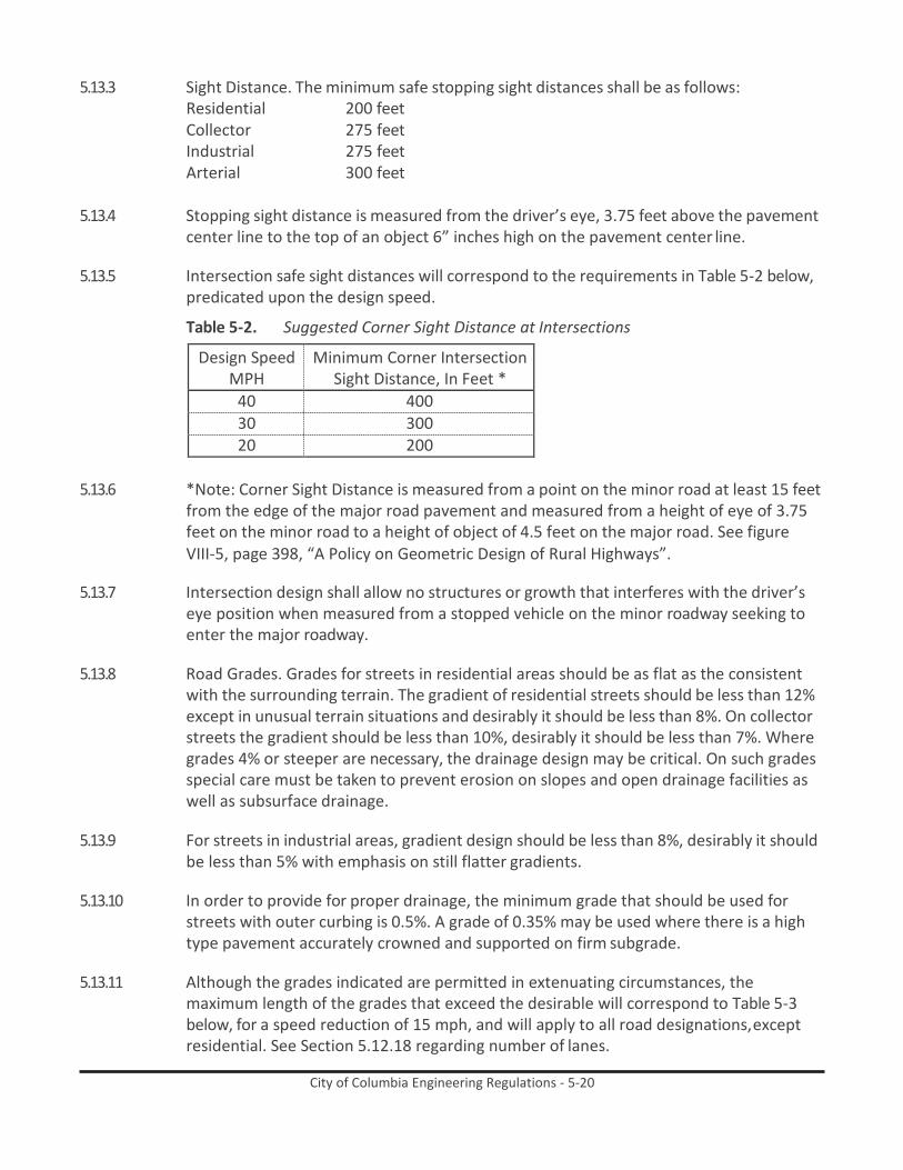
City of Columbia Engineering Regulations - 5-20
5.13.3 Sight Distance. The minimum safe stopping sight distances shall be as follows: Residential 200 feet Collector 275 feet Industrial 275 feet Arterial 300 feet
5.13.4 Stopping sight distance is measured from the driver’s eye, 3.75 feet above the pavement
center line to the top of an object 6” inches high on the pavement center line.
5.13.5 Intersection safe sight distances will correspond to the requirements in Table 5-2 below, predicated upon the design speed.
Table 5-2. Suggested Corner Sight Distance at Intersections
Design Speed MPH
Minimum Corner Intersection Sight Distance, In Feet *
40 400 30 300 20 200
5.13.6 *Note: Corner Sight Distance is measured from a point on the minor road at least 15 feet
from the edge of the major road pavement and measured from a height of eye of 3.75 feet on the minor road to a height of object of 4.5 feet on the major road. See figure VIII-5, page 398, “A Policy on Geometric Design of Rural Highways”.
5.13.7 Intersection design shall allow no structures or growth that interferes with the driver’s
eye position when measured from a stopped vehicle on the minor roadway seeking to enter the major roadway.
5.13.8 Road Grades. Grades for streets in residential areas should be as flat as the consistent
with the surrounding terrain. The gradient of residential streets should be less than 12% except in unusual terrain situations and desirably it should be less than 8%. On collector streets the gradient should be less than 10%, desirably it should be less than 7%. Where grades 4% or steeper are necessary, the drainage design may be critical. On such grades special care must be taken to prevent erosion on slopes and open drainage facilities as well as subsurface drainage.
5.13.9 For streets in industrial areas, gradient design should be less than 8%, desirably it should
be less than 5% with emphasis on still flatter gradients.
5.13.10 In order to provide for proper drainage, the minimum grade that should be used for streets with outer curbing is 0.5%. A grade of 0.35% may be used where there is a high type pavement accurately crowned and supported on firm subgrade.
5.13.11 Although the grades indicated are permitted in extenuating circumstances, the
maximum length of the grades that exceed the desirable will correspond to Table 5-3 below, for a speed reduction of 15 mph, and will apply to all road designations, except residential. See Section 5.12.18 regarding number of lanes.

City of Columbia Engineering Regulations - 5-21
Table 5-3. Length of Grade-Feet by Percent Upgrade
5.13.12 Alignment – Where deflection angle or more than ten (10) degrees occurs in the
alignment of a marginal access or minor street or road, a curve of reasonable radius shall be introduced. A curve shall be introduced at any change in direction of a collector, industrial or arterial roadway. On arterials, the center line radius or curvature shall be determined by the City Engineer. On Collector and Industrial roads the center line radius or curvature shall not be less than four hundred (400) feet. On residential roads the center line radius of curvature shall not be less than one hundred fifty (150) feet.
5.13.13 Where curves are super elevated, lower values of the radius of curvature may apply. In
no case will the residential radius of curvature be less than 115 feet, and the collector, or industrial radius of curvatures be less than 275 feet.
5.13.14 Elevation – Super elevation is advantageous for street operation. Super elevation should
be provided on collector streets wherever operating speeds will not be low.
5.13.15 Where super elevation is used, street curbs should be designed for a maximum super elevation rate of 0.04 to 0.06 feet per foot. Minimum length or super elevation runoff is shown in Table 5-4.
Table 5-4. Minimum Length for Super Elevation Runoff for 2-Lane Pavements
Super Elevation Rate Feet Per Foot
L-Length of runoff in feet for Design Speed, MPH, of: 20 30 40 50 60
.02 50 100 125 150 175
.04 50 100 125 150 175
.06 50 110 125 150 175 For roadways greater than two lanes, the design will proceed as required by the City Engineer.

City of Columbia Engineering Regulations - 5-22
5.13.16 Pavement Crown – Pavement cross slope should be adequate to provide proper drainage. Cross slope normally should be as shown in Table 5 where there are flush shoulders adjacent to the travel way. Where there are outer curbs, cross slopes steeper by about a 1/16 to 1/8 inch per foot are desirable on the lane adjacent to the curb.
Table 5-5. Normal Pavement or Surfacing Cross Slopes
Surface Type
Range in rate of cross slope Inch Per Foot Foot Per Foot
High 1/8 – ¼ .01 -.02 Intermediate 3/16 – 3/8 .015 - .03
Low ¼ - ½ .02 - .04
5.13.17 Number of Lanes. Two moving traffic lanes plus additional width for curb and gutter, shoulders or parking are usually sufficient for most residential streets. On collector streets there should be provisions for four or more moving lanes except where the street is to be one-way in which case two moving lanes maybe the ultimate number that need be provided.
5.13.18 In industrial areas where there will be several mid-block left turns, it is recommended
that an additional continuous two-way left turn lane in the center be provided.
5.13.19 The number of lanes to be provided on streets with a current ADT or 2,000 or more should be determined by highway capacity analysis of the design traffic volumes. Desirably such analysis should be made for future design traffic. Stage development may be considered for those streets on which four or more lanes for moving traffic is indicated.
5.13.20 On collector, arterial, and industrial road designations, where the design exceeds both
the maximum slope and length and the actual traffic count indicates a T of more than 5% in the case of a collector, or more than 10% on arterials/industrial, a 12’ climbing clane is required for the maximum length of the pavement in the positive direction.
5.13.21 Median – Roadways designed for four or more lanes should include widths for
appropriate median treatment whenever practical. There are substantial advantages for each increment in median width and it should be made as wide as practicable for the specific conditions. General types of street median treatment will need the following widths: (1) paint of stripe separations, 2 to 4 feet in width (2) narrow raised or curbed sections, 4 to 6 feet in width (3) paint striped or curbed sections providing space for separate left turn lanes, 14 to 18 feet in width.
5.13.22 On residential roads, median openings will be provided as necessary to serve abutting
property and the traffic demand. They will be kept at a minimum. On collector streets, median openings will be provided at major street and minor street intersections and at reasonably spaced driveways serving motor traffic generators such as shopping centers. Median openings should be designed to include left turn lanes. Care should be taken to locate openings only where there is adequate sight distance.

City of Columbia Engineering Regulations - 5-23
5.13.23 Curbing – Roadways normally are designed with curbs for high utilization of available widths for control of drainage, protection of pedestrians, for delineation for a more finished appearance, for safety, and to assist in the orderly development of the roadside. The curb on the right of traffic should b 6” high.
5.13.24 On divided streets, the type of median curb should be determined in conjunction with
the median width and the type of turning movement control to be affected. Where mid-block left turn movements are permitted and the median width is usually under 10 feet, a well delineated flush or rounded raised median separator 2” to 4” high is effective in channelizing traffic. This serves to avoid excessive travel distances and concentrations of turns at intersections. Where traver-sable wider medians are appropriate, they may be either flush or bordered with flat sloping lip curbs only a few inches high. On narrow and intermediate width medians and on some wide medians where cross median movements are undesirable or hazardous, a barrier curb should be used usually 6 to 8” high with a steep face. A high barrier curb or a central metal or high concrete barrier should be used with positive separation of opposing traffic is essential and there is no need for pedestrian crossings.
5.13.25 Steep faced curbs 6” or higher adjacent to moving traffic lanes should be offset from
lane paving at least one foot. Where there is integral curb and gutter, construction, the gutter pan width, normally 12 to 18 inches, should be used as the offset distance.
5.13.26 Barrier or roll type curbing is acceptable upon approval of the City Engineer.
5.13.27 Manually poured in place (hand formed), extruded or precast curbing is acceptable.
Curbing style is to be a harmonious match to the curbing already in existence in the surrounding environs. Where curbing does not exist in the surrounding environs the City Engineer will be the final authority on the requirement for the installation of curbing and the particular type.
5.13.28 Gutter will accompany all new curbing installations, with the following exception: Where
existing curbing is curb only and no gutter, the designer is to verify the requirement for curbing with the City Engineer.
5.13.29 The accompanying standard illustrates acceptable types of curb and gutter. Other styles
must be approved by the City Engineer.
5.13.30 Sidewalks – Sidewalks will be provided along both sides of roadways used for pedestrian access to schools, parks, shopping areas, transit stops and along all roadway with a commercial designation. In residential areas sidewalks will be provided on both sides of the roadway. The sidewalks should be located as far as practical from the traffic lanes; the outer edge of the sidewalk should be placed one foot from the property line, in the dedicated right-of-way. All new construction, addition or modification of sidewalks, driveways with through sidewalks and wheel chair ramps, must meet current ADA standards and SCDOT Standard Drawings No. 720-405-00, 720-410-00, 720-45-00, 720-905-01, and 720-905-02; Located in the SCDOT Standard Drawings for Road Construction book.

City of Columbia Engineering Regulations - 5-24
5.13.31 The minimum width of sidewalk is to be four feet or current ADA requirements in Residentially zoned areas. Commercially zoned areas shall have a minimum width of sidewalk of six feet.
5.13.32 If border areas between the roadway and the sidewalk are installed, they should be a
minimum of two feet in width, ideally the border area should be eight to twelve feet in width. Any landscape areas located in the right of way must be approved by the Forestry and Beautification Superintendent prior to installation. Irrigation may be required depending on species and location.
5.13.33 Driveways – Driveways will be regulated as to the width of entrance, placement with
respect to property lines and street intersections, vertical alignment, number of entrances to a single property, sight distance, drainage, parking, setback, lighting and signing and must be in accordance with SCDOT standards. The angle of entry shall be 90 degrees.
5.13.33.1 Driveways crossing sidewalks shall meet current ADA requirements.
5.13.34 Clearance to Obstructions – All roadways shall have a horizontal clearance of at least two
feet between the face of curb, or edge of shoulder, and vertical obstructions, such as utility poles, fire hydrants, lighting poles, etc. Table 6 below reflects the effect of lateral clearance on lane capacity. Table 5-6. Effective Road Width Due to Restricted Lateral Clearances Under
Uninterrupted Flow Conditions
Clearance From Pavement Edge To
Obstruction. Both Sides (Ft.)
Effective Width of Two
12-Ft Lanes (Ft)
Capacity of Two 12-Ft
Lanes (% of Ideal)
6 24 100 4 22 92 2 20 83 0 17 72
5.13.35 Guardrail is not to being used, except where there is hazard to motorists and
pedestrians; such points as fixed objects along the pavement edge, fills on steep grades, long through fills, or fills on sharp curvatures; other pints especially hazardous are along water courses, escarpments, along deep ditches in cuts, particularly with rock exposed, and similar locations. The more dangerous points along a highway are obvious from the plans, but the overall need for guardrail is best determined by field inspection as the grading nears completion. The need for guardrails on fills is related to the slope. Generally, they may be omitted where it is practicable to provide slopes of 4:1 or flatter. In some cases, it is economical to flatten embankment slopes to 4:1 or less instead of constructing guardrail, provided right-of-way is available. Where guardrail cost per linear foot is four times the cost of fill per cubic yard, it’ generally more economical to flatten slopes from 2:1 to 4:1 on fills up to 15 feet in height. Saving in maintenance cost increases the fill depth at which it is economical to flatten slopes rather than use

City of Columbia Engineering Regulations - 5-25
guardrail. However, where there is an accident prone situation, even with flat slopes, guardrails are usually warranted. The basic principle for the use of guardrail to protect traffic from hazards is that guardrail will be used when the severity of an accident involving the hazard would be greater than the severity of an accident involving the protective guardrail.
5.13.36 Vertical clearance between the proposed center line of the road pavement and any
elevated facility such as a bridge, walkway, tree limb, etc., shall be 15.0’ minimum.
5.13.37 Intersection Design- Intersections, including median openings, should be designed with adequate corner sight distance (See Table 5-2) and the area kept free of obstacles. The corner sight distance for collector roadways will be a minimum of 300 feet and desirably should be 400 feet or more. For residential roadways the minimum corner sight distance will be 200 feet and desirably should be 300 feet or more. In order to maintain the minimum sight distance, restrictions on height of embankment, locations of buildings and screening fences may be necessary. Any landscaping in the sight distance triangle should be low growing with a maximum height that will not interfere with a passenger vehicle operator’s line of sight.
5.13.38 It is desirable that intersecting streets meet at approximately a 90-degree angle. The
alignment design should be adjusted so as to avoid an angle of intersection of less than 60 degrees. Closely spaced offset intersections are to be a minimum of 200 feet.
5.13.39 The intersection area and area where vehicles store while waiting to enter the
intersection should be designed with a flat grad; the maximum grade on the approach leg should be no more than 5 percent.
5.13.40 Radii of 25 feet are adequate for passenger vehicles. These will be provided at residential
streets where there is little occasion for trucks to turn, or at major intersections where there are parking lanes. Where the street has sufficient capacity to retain the curb lane as a parking lane for the foreseeable future, parking should be restricted for appropriate distances from the crossing.
5.13.41 Radii of 30 feet or more at collector streets should be provided where feasible so that a
truck can turn without excessive lane encroachment.
5.13.42 Radii of 40 feet or more, and preferably three-centered compound curves or simple curves with tapers to fit the paths of appropriate design vehicles, should be provided where large truck combinations and buses turn frequently. Larger radii are also desirable where speed reductions would cause problems. This applies to the arterial and industrial road designations.
5.13.43 Radii dimensions should be coordinated with cross-walk distances or special designs to
make crosswalks safer for pedestrians.
5.13.44 Corner curb radii on two-way streets have little effect on left turning movements. Where the width of an arterial street is equivalent to four or more lanes, generally there is no problem of encroachment by left turning vehicles.

City of Columbia Engineering Regulations - 5-26
5.13.45 Road Side Development – The tree categories of planting are: (a) Tree Planting – The primary purpose is aesthetic improvement in undeveloped areas where a higher type of planting is not justified and to preserve the naturalistic appearance by replacement of trees removed by construction; (b) Functional Planting – The primary purpose is erosion control, traffic safety, reduction of fire hazard or screening traffic from adjacent property, the aesthetic effect derived being of secondary benefit. (c) Landscaping – The primary purpose is aesthetic improvement of the right-of-way and the preservation of property values of adjacent development, the functional benefits thereby obtained being secondary. The City is not responsible for the maintenance of landscaped areas adjacent to individual properties or within a median/island unless specifically approved by the Superintendent of Forestry and Beautification. Such approval will not occur within residential areas.
5.13.46 As sight distance and safety are of primary importance, these considerations must not
be subordinated to aesthetics. Applicable horizontal and vertical sight distance standards are set forth in 5.12.3 and 5.12.35. All planting shall be such that sight distances is equal to or greater than that required by the design standards for all intersections.
5.13.47 Proposed planting shall provide the initial or ultimate horizontal and vertical sight
distance required by the design speed of the project. Particular attention should be paid to planting on the inside of curbs, in median areas and on cut slopes so that designed sight distances in the adjacent traffic lanes may be retained.
5.13.48 Shoulders – The shoulder portion of roadways serves a bifold purpose, namely: a) to
accommodate stopped vehicles in emergencies; b) for lateral support of base and surface courses. Shoulder widths vary from about 2 feet on minor roads to about 12 feet or more on major roads, where the entire shoulder may be stabilized or have an all-weather treatment.
5.13.49 As a general guide for developing design shoulder widths, Table 7 will be useful.
Table 5-7. Minimum Width of Usable Shoulders
Current
ADT
Design Volume Usable Shoulder Width, Feet DHV Minimum Desirable
50-250 4 6 250-400 4 8 400-750 100-200 6 10
200-400 8 10 over 400 8 12

City of Columbia Engineering Regulations - 5-27
5.13.50 Table 8 is provided as a general guide for the design of shoulder cross slopes.
Table 5-8. Shoulder Cross Slopes
Type of Surface
Shoulder Cross Slopes Inch Per Foot Foot Per Foot
No Pavement Edge Curbs Bituminous 3/8 - 5/8 .03 - .05 Gravel or Crushed Stone ½ - ¾ .04 - .06 Turf 1 .08 With Curbs at Pavement Edge Bituminous ¼ .02 Gravel or Crushed Stone ¼ - ½ .02 - .04 Turf 3/8 – ½ .03 - .04
5.13.51 The selection of surface treatment for shoulders should be guided not only by traffic
volume and climatic conditions, but also by the desired contrast between shoulder and pavement. The contrast should be sufficient so that during involvement weather the shoulder is easily distinguished from the pavement. The contrast should be in both color and texture. Pavement edge lines are effective means for shoulder delineation where there is lack of shoulder contrast.
5.13.52 Side Slopes – The maximum rate of side slope will depend on the stability of local soils as
determined by local experience. Slopes should be as flat as feasible and other factors should be considered to determine the design slope. Flat side slopes increase safety by providing maneuver area in emergencies, are more stable than steep slopes, aid in the establishment of plant growth, and simplify maintenance work. The intersection of slope planes should be well rounded.
5.13.53 Table 5-9 illustrates side slopes for fill sections.
Table 5-9. Suggested Earth Slopes for Design
Earth Slope Horizontal to Vertical for Type of Terrain Height of Cut
or Fill. Feet
Flat or Rolling
Moderately
Steep
Steep 0-4 6:1 4:1 4:1
4-10 4:1 3:1 2:1 10-15 3:1 2-1/2:1 1-3/4:1 15-20 2:1 2:1 1-1/2:1*
over 20 2:1 1-1/2:1* 1-1/2:1 * In clay or silty soils subject to erosion, slopes steeper than 2:1 should be avoided.
5.13.54 Appurtenances – This covers such diversity as separate lane storage for left turns,
additional lane feet to accommodate public transportation, erosion control, retaining walls, fencing, noise control, ramps, etc. which are of importance in roadway design work, but are presently not standardized. These standards intend for their consideration

City of Columbia Engineering Regulations - 5-28
and treatment by the designer as merited by traffic, zoning and the actual conditions as they exist, or are anticipated to exist, in the field.
5.13.55 Street Lighting
5.13.55.1 The City of Columbia provides standard, overhead-feed wood-pole lighting, leased from
SCE&G, for publicly-owned streets within City limits at no additional charge to residents.
5.13.55.2 In the event the developer wishes to provide decorative (underground-feed) lighting, the developer shall sign the standard acknowledgement document waiving the City- provided lighting, and submit plans to the Public Works Department detailing the proposed lighting layout, wiring, and meter points, and a corresponding photometric diagram. General illumination standards are shown in the following table:
Table 5-10. Recommended Illumination Levels
Road Classification
Area Classification
Average Light Level (Footcandles) *
Uniformity Ratio (Average to Minimum)
Collector
Commercial 1.2 4 to 1 Intermediate 0.9
Residential 0.6
Local Commercial 0.9
6 to 1 Intermediate 0.7 Residential 0.4
Sidewalks Intermediate 0.6
6 to 1 Residential 0.2 Intersections 0.8
* - Based upon asphalt road surface with diffuse or slightly specular reflectance. Decorative lighting poles and fixtures shall be selected from City-approved vendors, and shall conform to City standard designs. A listing of approved vendors may be obtained from the Public Works Department.
5.13.56 Roadway Signing and Pavement Markings
5.13.56.1 Signing on public streets shall be provided by the developer, and shall include, but not
be limited to, the following: Street Markers, Stop Signs, Yield Signs, and Warning Signs. The signing shall conform to the current Manual on Uniform Traffic Control Devices (MUTCD) published by the Federal Highway Administration.
5.13.56.2 Pavement markings shall be provided by the developer, and shall include, but not be
limited to, the following: Stop Bars, Centerlines, Lane Lines, and Parking Spaces. The signing shall conform to the current MUTCD.
5.13.56.3 The developer shall submit a roadway signing and marking plan to the Public Works
Department for review and approval.
5.13.56.4 All traffic control devices shall be approved by the Traffic Engineer in advance of installation.

City of Columbia Engineering Regulations - 5-29
5.14 Complete Streets
City of Columbia (DRAFTED FROM SCDOT EDM-22 – Feb. 23, 2003) May 2009
Subject: Policy for Complete Streets Considerations for Bicycle Facilities
Primary Departments: Preconstruction, Traffic Engineering, Engineering, Construction Management, Maintenance
Upon adoption of Resolution R2008-053, by Columbia City Council, where it is affirmed that bicycling accommodations should be a routine part of the City’s planning, design, construction, and operating activities, and will be included in the everyday operations of our transportation system, and
In order to provide guidance to City of Columbia Department personnel, the attached typical sections have been developed to supplement the following guidelines for the selection and design of bicycle facilities on all new projects. In addition, typical sections have been included to give guidance on how to restripe existing five-lane sections to accommodate bicycle facilities.

City of Columbia Engineering Regulations - 5-30
Figure 5-10. Standard Road Sections - Residential Street, Collectors and Industrial Streets, and Arterial
Streets

City of Columbia Engineering Regulations - 5-31
10/07/02
The following describes shared roadways and bike lanes/paved shoulders and gives guidance on their design requirements for new projects. Other design considerations for bicycle accommodations are also addressed.
For guidance of any bicycle facility not specifically addressed below, the City of Columbia Departments will refer to AASHTO, Guide for the Development of Bicycle Facilities, Manual of Uniform Traffic Control Devices and/or South Carolina Department of Transportation’s Standard Specifications for Highway Construction.
A. Shared Roadways
Description
Shared roadways are the way most bicycle travel in the United States occurs. This type of facility can be used to accommodate bicyclists without signing and striping the roadway for bicycle travel. This type of facility works well to accommodate bicycles through urban areas that are not considered high bicycle- demand corridors or where other constraints do not allow the development of a bike lane/paved shoulder.
Design Considerations
On urban sections (curb and gutter), an outside travel lane width of fourteen (14) feet is the minimum recommended width for a shared-use lane. The gutter pan is not to be included in the width of the shared roadway. On stretches of roadways with grades greater than five percent, consideration should be given to providing a 15-foot travel lane width. Shared roadway widths greater than fourteen (14) feet that extend continuously along a stretch of roadway may encourage the undesirable operation of two motor vehicles, especially in urban areas, and are therefore not recommended as shared use roadways and consideration should be given to striping the additional width. The Department’s Pedestrian and Bicycle Coordinator and Traffic Engineering can provide assistance in determining the need for a shared roadway as opposed to bike lanes/paved shoulders. On rural sections (shoulder), criteria should be used as described in the bike lanes/paved shoulders section of this document.
b. Bike Lanes/Paved Shoulders
Description
This type of facility incorporates bicyclists into a roadway by utilizing a bike lane/paved shoulder adjacent to the motor vehicle traffic. A bike lane should be a lane specifically signed and marked as indicated in the Manual on Uniform Traffic Control Devices (Part 9). A paved shoulder may be used to accommodate bicycle travel without specific markings and signs present. A bike lane provides for more predictable movements by the motorist and bicyclist. Bike lanes should be one-way facilities and carry bike traffic in the same direction as adjacent motor vehicle traffic. This type of facility should be used where the Department desires to provide continuity to other bicycle facilities or designate preferred routes through high demand corridors, such as any of our designated South Carolina bicycle touring routes or a municipality’s bikeway. The Department’s Pedestrian and Bicycle Coordinator and Traffic Engineering can provide assistance in determining the need for bike lanes as opposed to a shared roadway.

City of Columbia Engineering Regulations - 5-32
10/07/02
Design Considerations
On rural sections (shoulder) with ADT greater than 500, bike lanes/paved shoulders should be a minimum of four (4) feet wide in each direction to accommodate bicycle travel. The bike lanes/paved shoulders will have a cross slope of 24H:1V (4.17%). Where motor vehicle speeds exceed 50 mph or the percentage of trucks, buses, and recreational vehicles are greater than five percent of the ADT, consideration should be given to providing a minimum six (6) feet of width to accommodate bicycle travel adjacent to the higher speeds (50 mph or greater) and to lessen the effect of windblast from the larger vehicles. On rural sections (shoulder) with ADT less than 500, paving two (2) feet of the earthen shoulder will be adequate to better accommodate bicyclists.
On urban sections (curb and gutter), bike lanes/paved shoulders should be a minimum of four (4) feet wide to accommodate bicycle travel. The bike lanes/paved shoulders will have a cross slope of 24H:1V (4.17%). The gutter pan is not to be included in the width of the bike lane/paved shoulder. Where the percentage of trucks, buses, and recreational vehicles are greater than five percent of the ADT, consideration should be given to providing a minimum six (6) feet of width. Where motor vehicle speeds are 50 mph or greater, Department guidelines for shoulder widths should be utilized as defined in the SCDOT Highway Design Manual, thus giving the bicyclist either eight (8) or ten (10) feet of paved shoulder width to utilize.
C. Other Design Considerations for bicycle Facilities
Paving Existing Shoulders
In order for a shoulder to be usable to a bicyclist, it must be paved. Adding or improving paved shoulders often can be the best way to accommodate bicyclists in rural areas and benefit motor vehicle traffic. Paved shoulders have the added benefits of not only accommodating bicyclists, but also they can extend the service life of the road surface since edge deterioration will be significantly reduced. It is currently Department policy to provide two (2) feet of paved shoulder width on all new projects utilizing earthen shoulders. Where practical and attainable, a minimum width of four (4) feet should be paved on the shoulder to provide for bicycle facilities where the ADT of the road is greater than 500.
Where constraints do not allow obtaining the indicated widths, any additional width can be beneficial to a bicyclist.
Resurfacing/Restriping Existing Roadways
When the Department desires to accommodate bicycle facilities by resurfacing/restriping existing roadways, lane or median widths may be narrowed to obtain the desired bicycle facility. Roadways designated as being on the National or South Carolina Truck Network or roadways where the percentage of trucks, buses, and recreational vehicles are greater than five percent of the ADT should have lane widths of twelve (12) feet. Where conditions allow utilizing lane widths narrower than twelve (12) feet to accommodate bicycle facilities, the impacts of the narrower lane widths to motor vehicle traffic should be determined. Guidance on selecting the proper lane width for a roadway can be found in Chapters 19 through 22 of the SCDOT Highway Design Manual.

City of Columbia Engineering Regulations - 5-33
10/07/02
A flush /painted median width of fifteen (15) feet is indicated by the South Carolina Highway Design Manual, but the width can be reduced to twelve (12) feet to accommodate bicycle facilities on an existing roadway or existing project. Median widths less than twelve (12) feet are not recommended where posted speeds are greater than 35 mph and the percentage of trucks, buses, and recreational vehicles is greater than five percent of the ADT.
Drainage Inlet Grates
Where practical, drainage inlets should be placed outside of the bicycle facility. Where this is not practical, hydraulically efficient, bicycle-safe grates should be utilized and should be placed or adjusted to be flush with the adjacent pavement surface. On bridges, a minimum of four (4) feet from the edge of the travel lane should be clear of drainage inlets.
Longitudinal Rumble Strips
Longitudinal rumble strips shall not be used where bicycle traffic is expected to occur.
Bridges
In general, bridge widths should match the approach roadway widths (travelway plus bike lanes/paved shoulders). However, in determining the width for major water crossings, consider the cost of the structure, traffic volume, and potential for future width requirements.
Valley Gutter Sections
The guidelines for shared roadways and bike lanes/paved shoulders will be utilized to accommodate bicycle facilities on roadways with valley gutter. Due to the fact that valley gutter sections are typically used on low volume, two-lane secondary roadways, the cross slope of the paved shoulder/bike lane should be 48H:1V (2.08%).

City of Columbia Engineering Regulations - 5-34
10/07/02
STATE OF SOUTH CAROLINA )
) ACKNOWLEDGEMENT
COUNTY OF RICHLAND )
Whereas, is in the process of developing a subdivision to be known as XXXXX;
Whereas, desires to provide streetlights within XXXXX with
such streetlights to be located in the public right-of-way;
Whereas, the City of Columbia is willing to provide standard streetlights within XXXXX with such standard streetlights to be located in the public right-of-way;
Whereas, instead of the standard streetlights offered to be provided by the City of Columbia,
desires and has requested decorative streetlighting within XXXXX with such decorative streetlighting to be located in the public right-of-way;
NOW THEREFORE, acknowledges the City of Columbia’s ability
and willingness to provide standard streetlighting within XXXXX with such standard streetlighting to be located in the public right-of-way;
further acknowledges and agrees that it waives and/or
refuses the offer by the City of Columbia to provide standard streetlighting;
further acknowledges that will contract directly with SCE&G to provide the desired decorative streetlighting and that the City of Columbia shall have no obligation to provide streetlighting in XXXXX in the public right-of-way.
WITNESS:
By:
(Print Name):
Title:
Date:

City of Columbia Engineering Regulations - 6-i
City of Columbia Engineering Regulations PART 6: Procedures for the Subdivision of Land
Table of Contents
Paragraph Description Page no. 6.1 General 6-1 6.2 Sketch Plan Review 6-1 6.3 Preliminary Plat (Construction Drawings) 6-1 6.4 Final Plat Approval 6-3 6.5 Form No. 2 6-9 6.6 Form No. 3 6-10 6.7 Sample Procedures for Sanitary Sewer Construction Permitting Under
Delegated Review Program Letter
6-11 6.8 Sample Request for 208/201 Plan Conformance Certification 6-14 6.9 Delegated Review Program Checklist 6-15
List of Forms
Form Description Page no. Form 6-1. Record Drawing Checklist 6-4 Form 6-4. Required Easement Language 6-6 Form 6-2. Infiltration Certification 6-6 Form 6-3. Engineer’s Certification 6-6 Form 6-5. Storm Drain Certification Language 6-6 Form 6-6. Form No. 2 6-9 Form 6-7. Form No. 3 6-10 Form 6-8. Sample Procedures for Sanitary Sewer Construction Permitting Under Delegated
Review Program Letter
6-11 Form 6-9. Sample Request for 208/201 Plan Conformance Certification 6-14 Form 6-10. Delegated Review Program Checklist 6-15

City of Columbia Engineering Regulations - 6-1
City of Columbia Engineering Regulations PART 6: Procedures for the Subdivision of Land
6.1 General The procedure for review and approval of a subdivision plat consists of three separate steps. These are:
6.1.1 Sketch plan review by Planning Commission or its staff.
6.1.2 Review and approval of Preliminary Plat, and
6.1.3 Review and approval of final Plat.
6.2 Sketch Plan Review
The subdivider or his representative shall present seven (7) copies of a sketch plan to the staff of the Planning Commission Plans should be delivered to the zoning Administrator, 1136 Washington Street, Columbia, SC 29201. Telephone number (803) 545-3333. The sketch plan shall be prepared in accordance with procedures set forth in City of Columbia Subdivision Regulations.
6.3 Preliminary Plat (Construction Drawings)
The subdivider or his representative shall submit seven (7) copies of a Preliminary Plat (Construction drawings) to the staff of the Planning Commission at the address shown in section 6.1 above. The construction drawings shall be prepared in accordance with procedures set forth in Part 1, City of Columbia Regulations and City of Columbia Subdivision Regulations.
6.3.1 Preliminary Engineering Report – If a water system is proposed for the development, a
preliminary engineering report should be submitted to the South Carolina Department of Health and Environmental Control, 2600 Bull Street, Columbia, S.C. 29201. The report should be submitted at least four (4) weeks prior to submission of construction drawings. When the preliminary engineering report is approved, submit three (3) copies of the permit to construct directly to the South Carolina Department of Health and Environmental Control. It should be noted that construction plans for sanitary sewers meeting the criteria for processing under SCDHEC’s Delegated Review Program will not be submitted directly to SCDHEC. The procedures described in the letter attached hereto as Section 6.6 will be followed instead.
6.3.2 A copy of the preliminary engineering report (s) shall be submitted to the City Engineer,
1136 Washington Street, P.O. Box 147, Columbia, SC 29201. Telephone number (803) 545-3400. The report (s) shall be prepared in accordance with procedures set forth in Part 1, City of Columbia Regulations.
6.3.3 Annexation – If the property being subdivided is contiguous to the City limits, see Part 8,
Section 8.0.2 for procedures.

City of Columbia Engineering Regulations - 6-2
6.3.4 Easements – Attention is directed to the requirement for granting easements to the City of Columbia to provide for the operation, maintenance, and future extension of water, sanitary sewer, and storm drainage systems within the subdivision, as applicable. It is important to note that two copies of all off-site easements necessary for construction of the facilities to be deeded to the City must be submitted with the preliminary plat (construction drawings).
6.3.5 Water Main Extension – The City of Columbia will extend water service into those areas
inside City limits not presently served by its water system in accordance with procedures set forth in Part 7, City of Columbia Regulations.
6.3.6 Sanitary Sewer Extension – The City of Columbia will extend sanitary sewer service into
those areas inside City limits not presently served by its sewer system in accordance with procedures set forth in Part 8, City of Columbia Regulations.
6.3.7 Use of Septic Tanks – If the use of septic tanks is anticipated, the subdivider must:
6.3.7.1 Make application to the appropriate County Health Department.
6.3.7.1.1 Richland County Health Department
1221 Gregg Street Columbia, SC 29201 Telephone (803) 254-4186
6.3.7.1.2 Lexington County Environmental Health Department
212 South Lake Drive Lexington, SC 29072 Telephone (803) 356-8113
6.3.7.2 Request an I&E report from the appropriate County Soil and Water Conservation District.
6.3.7.2.1 Richland County Soil and Water Conservation District
2020 Hampton Street Columbia, SC 29201 Telephone (803) 765-5806
6.3.7.2.2 Lexington County Soil and Water Conservation District
Lexington County Memorial Building Lexington, SC 29072 Telephone (803) 359-3165
6.3.7.3 Submit a copy of the I&E report obtained in subparagraph 6.2.6.2 above along with the
Preliminary Plat (construction drawings) to the South Carolina Department of Health & Environmental Control, 2600 Bull Street, Columbia, SC 29201.
6.3.8 Construction – Following approval of the Preliminary Plat (construction drawings) the
subdivider may begin construction provided:

City of Columbia Engineering Regulations - 6-3
6.3.8.1 All necessary permits to construct have been received from the South Carolina Department of Health and Environmental Control. Refer to section 6.2.1 above.
6.3.8.2 All necessary highway encroachment permits have been received from the South
Carolina Department of Transportation, City or County. The encroachment permit application shall be entirely completed by the owner/developer and forwarded to the City of Columbia Engineering Department for review and subsequent submittal to the appropriate right of way agency. All encroachment applications shall identify the City of Columbia as the sole applicant. Prior to construction (if applicable) an encroachment permit shall be approved by the appropriate right-of-way agency.
6.3.8.3 Developer must follow requirements in 1.6 of these engineering regulations.
6.4 Final Plat Approval
Following completion of the physical development of all or an approved phase or part of the areas shown on the approved Preliminary Plat (construction drawings), the subdivider or his representative shall provide an electronic copy of plans meeting Part 28 of this manual along with a .pdf copy, and five (5) prints of the Final Plat to the Planning Commission at the address shown in Section 6.1 above. The Final Plat shall be prepared in accordance with Procedures set forth in Record Drawing Checklist, City of Columbia Regulations and City of Columbia Subdivision Regulations.

City of Columbia Engineering Regulations - 6-4
6.4.1Record Drawing Checklist Date
Project Name
Project Location
City File Number
Engineering Firm
Engineer’s Name
Engineer’s Phone #
Engineer’s Email
Please make a selection for ALL items on this checklist, and submit the completed checklist along with Record Drawings and applicable attachments. If any item requires additional notes/explanation, please provide the necessary information in “Notes” at the end of the section.
General/Format – Verify or Indicate if the following are correct (see City’s sample): 1. Yes No N/A City’s Record Drawing sample used
2. Yes No N/A Does Record Drawing conform to approved Construction Plans and
Approval Letter? Note: City does not determine meter size 3. Yes No N/A Two paper copies of drawings, size 24” x 36”
4. Yes No N/A Plans with multiple sheets are stapled
5.
Yes
No
N/A
Drawings should consist of a cover sheet, plan sheet(s) and profile sheet(s). Notes: 1. This item is N/A for water projects; 2. Showing both plan and profile view on one sheet only acceptable on small projects
6. Yes No N/A All off-site easements obtained using City prepared documents and
approved by the City’s Real Estate Division
7. Yes
No
N/A
No easements for water, sewer, or storm drainage shown in dedicated (existing) public road right-of-way. Note: Does not apply to roadways not yet dedicated and/or privately owned roadways
8. Yes No N/A Use standard symbols for appurtenances/fittings such as meter
boxes, fire hydrants, valves, plugs, manholes, junction boxes, etc. 9.
Yes No N/A No copyright statements on record drawings or associated off-site easement exhibits
10. Yes
No
N/A
Is the project location within 5 miles of the nearest city boundary line?
11. Notes
Title Block - Indicate if the following are included:

City of Columbia Engineering Regulations - 6-5
1. Yes No N/A Title Block included on all Plan and Profile Sheets
2. Yes No N/A “Project Name”; must identify subdivision or project name, phase
number if applicable, City, County and State where project is located 3.
Yes No N/A “Prepared For”; must identify legal entity name, mailing address, and contact information for client including email if available
4. Yes No N/A “Prepared By”; must identify engineering firm, engineer’s name, and
P.E.’s license number responsible for drawing 5.
Yes No N/A “Last Revised”; must identify date of revisions and provide comments explaining items revised as of that date
6.
Notes
Cover Sheet - Indicate if the following are included:
1. Yes No N/A Name of the Subdivision or Project and City File number
2. Yes
No
N/A
State “Record Drawing Date , 20 ”; Notes: 1. Do not use older label of “As-Built”; 2. Record Drawing date should not pre- date project approval letter date and should not be the same date as construction plan date
3. Yes No N/A Show “General Notes” for project. See Record Drawing Notes section
of this checklist 4. Yes No N/A Name and address of the developer
5. Yes No N/A Name, address, and email of the property owner
6. Yes No N/A Name and address of the water provider
7. Yes No N/A Name and address of the sanitary sewer provider
8. Yes No N/A Name and address of the storm drainage provider
9. Yes No N/A Vicinity map, with North arrow
10.
Notes

City of Columbia Engineering Regulations - 6-6
Plan Sheet(s) - Indicate if the following are included: 1.
Yes No N/A Identify graphic scale (must use 10, 20, 30, 40, 50, or 60; 100 only if necessary)
2. Yes
No
N/A
Blow-ups/insets for all fire hydrants and/or hydrant valves and elsewhere as deemed appropriate; identify graphic scale of blow- up/inset
3. Yes No N/A North Arrow; specify if North Arrow is magnetic, true or grid (magnetic
preferred) 4. Yes No N/A Show and label phase lines
5. Yes
No
N/A
Label tax map number and owner’s information for subject property and all adjacent properties. Verify current information at richlandonline.com and www.lex-co.com
6. Yes No N/A Label City File number in lower right quadrant
7. Yes No N/A Show bearings (degrees, minutes, and seconds) and distances for all
sanitary sewer mains, storm drainage lines and street boundaries 8.
Yes No
N/A
Label distances for all water mains and service lines (call out). Call outs should indicate size of pipe, material of pipe, and distance of pipe from fitting to fitting. Distances must be provided to nearest one-tenth of a foot
9. Yes
No
N/A
Label distances for all sanitary sewer mains, service lines, and storm drainage lines. Stated distance should match distances shown on profile sheet
10. Yes
No
N/A
Location data: Two (2) locations (tie point references) are required for the point of beginning and the end of all new lines; at least one (1) location must be provided on all fittings/appurtenances such as valves, hydrants, bends, reducers, meter boxes, blow offs, cleanouts, manholes, and catch basins, etc. These tie points should tie the distances between said fitting to a stable physical feature such as true property corner or building corner
11. Yes No N/A Label lot numbers, buildings and, existing/new pubic and/or private
roadways and most current tax map number(s) with ownership 12.
Yes No N/A Bends on water drawings must be identified by size (degrees) and noted as vertical, if the bend is a vertical bend
13. Yes No N/A Location of utility lines within easement relative to easement
boundaries 14.
Yes No N/A Show and label easements for all utilities (power, gas, etc.) on subject properties
15. Yes
No
N/A
Label easements for City utilities as “ ’_ Exclusive City of Columbia Water, Sanitary Sewer, Storm Drainage Easement.” Note: See “Easement Language” information below
16. Yes
No
N/A
Contours (2’ or more accurate) must be labeled and show multiple locations for ease of following. Top nut of hydrant may be substituted for elevation purposes

City of Columbia Engineering Regulations - 6-7
Plan Sheet(s) - Indicate if the following are included: 17. Yes No N/A Provide location and description of monuments (benchmarks)
18. Yes No N/A Label road names and identify ownership of roadway and width of
road right-of-way 19.
Yes No
N/A
Water/sewer/storm drainage lines cannot arbitrarily end at phase lines; there must be proper termination of the line (plug, manhole, etc.) A utility line cannot end at a tee
20. Yes No N/A Show sewer profiles including separations for all other utilities meeting
Ten State Standards 21.
Yes No
N/A
Identify all rights-of-way, easements, and areas to be dedicated for public use shown along with the purpose of each stated, including but not limited to power line rights of way, gas line rights of way, water, sanitary sewer, and storm drainage easements, public roadways
22. Yes No N/A Label City File Number(s) and project name for existing lines being tied
to 23.
Yes No N/A Identify meter box(es) and/or sewer clean out for each lot, with references (tie points)
24.
Notes
Profile Sheet(s) – Indicate if the following are included:
1. Yes No N/A Identify horizontal and graphic scales for each profile
2. Yes
No
N/A
Label station numbers on all manholes, junction boxes, catch basins, etc. Also, show distances of main lines along profile view. Distances and station numbers should correlate
3. Yes No N/A Show size, material, and slope between manholes, and lengths of all
sanitary sewer lines on plan view and profiles 4. Yes No N/A Label City File number in lower right quadrant
5.
Notes
Record Drawing Notes - Indicate if the following are included:
1. Yes No N/A Tax map parcel numbers of subject site in General Notes section of
Cover Sheet

City of Columbia Engineering Regulations - 6-8
Record Drawing Notes - Indicate if the following are included:
2. Yes
No
N/A
Ten State Standards in General Notes section of Cover Sheet –“Ten State Standards maintained between water, sewer, and storm drainage”
3. Yes No N/A Easement language regarding service lines, in General Notes section of
Cover Sheet (see “Easement Language,” included below)
4. Yes
No
N/A
If sewer provided through septic tank, state “DHEC Septic Tank Approval Letter dated , expires five (5) years from date of issue” in General Notes section
5. Yes No N/A Provide mean sea level datum and state in statement form
6.
Yes
No
N/A
Identify in statement form to who new roadways will be conveyed (SCDOT, City or County). Only use approved roadway names/do not change roadway names without approval
7. Yes No N/A Other notes deemed appropriate and specific to the project
8.
Notes
Attachments - Indicate if the following are included:
1. Yes No N/A Off-site easement documentation, if applicable
2. Yes No N/A Must submit Sewer Acceptance Letter upon receipt (if sewer to be
treated by non-City entity) 3.
Yes No N/A Form 2 – Developer’s Certification (not required for CIP); See City of Columbia Engineering Regulations section 6.5
4. Yes No N/A Form 3 – Lien Waiver Form signed by Contractor (not required for
CIP); See City of Columbia Engineering Regulations section 6.6 5. Yes No N/A Itemized Materials List
6. Yes No N/A Sewer Approval Letter (if applicable)
7.
Yes
No
N/A
Provide copy of recorded deed for subject properties of the developer/owner being developed as part of this project (not required on CIP unless pipe installed on City-owned property)
8.
Yes
No
N/A
Provide copy of recorded mortgage on subject properties of the developer/owner being developed as part of this project (not required on CIP unless pipe installed on City-owned property)
9.
Yes
No
N/A
Copy of encroachment permits for new water, sewer and/or storm drainage lines constructed within dedicated (existing) public roadways and/or r i g h t s -of-way. Note: The City applies for encroachment permits upon receipt of encroachment applications.

City of Columbia Engineering Regulations - 6-9
Attachments - Indicate if the following are included:
10.
Notes
Certifications, Seals and Signatures - Indicate if the following are included:
1.
Yes
No
N/A
Infiltration certification on all sewer drawings: “I hereby certify that the infiltration/exfiltration does not exceed 200 gallons per-day per- inch of pipe diameter per-mile of sewer pipe including manholes for any section of the system.”
2. Yes No N/A Certification Statement included on appropriate sheet(s)
3. Yes No N/A Record Drawing Date and City’s Approval Date are correct in
Certification Statement 4. Yes No N/A SC Professional Engineer Seal, Signature, and Date (on each sheet)
5. Yes No N/A Engineering Firm’s Certificate of Authorization Seal (on each sheet)
6.
Notes

City of Columbia Engineering Regulations - 6-10
The following is the Engineers Certification Statement to be used:
ENGINEER’S CERTIFICATION
THESE RECORD DRAWINGS ARE A COMPILED REPRESENTATION OF THE CONSTRUCTED PROJECT. I HEREBY CERTIFY THAT TO THE BEST OF MY KNOWLEDGE AND BELIEF, BASED ON OBSERVATIONS DURING CONSTRUCTION, MY ASSESSEMENT OF THE COMPLETED WORK AND REVIEW OF THE “AS-BUILT” SURVEY, THE PROJECT INCLUDING…
Water Mains Sewer Force Mains Sanitary Sewer System Lift Station/Pump Station Storm Drainage System Reclaimed Water Mains Streets
WAS COMPLETED BY THE CONTRACTOR IN ACCORDANCE WITH THE INTENT OF THE PERMITS, APPROVED PLANS, AND SPECIFICATIONS
ENGINEER’S SIGNATURE & DATE: Date: NAME: SOUTH CAROLINA LICENSE NO: (AFFIX SEAL HERE)
INFORMATION PROVIDED BY:
GENERAL CONTRACTOR Name: Address: Phone #: S.C. License Number:
SURVEYOR Name: Address: Phone #: S.C. License Number:
Easement language format:
Main lines and future extensions – ex: “15’ Exclusive City of Columbia Water Easement” Service Lines should be covered in a note: “There is a 10’ Exclusive City of Columbia water/sewer easement on all service lines from the main line to the meter/cleanout” (Only in subdivisions)

City of Columbia Engineering Regulations - 6-11
Storm Drain Certification language: I hereby certify that the storm drainage system for was installed in accordance with the City of Columbia approval letter dated , and meets storm drainage requirements and contained silt on the property concerned to the maximum extent feasible. Provisions for erosion and sediment control and storm drainage were met in accordance with the Columbia Sediment and Erosion Control and Storm Drainage Ordinance.
Note: If the City of Columbia will not be operating and maintaining the drainage system, the statement must be in letter format on the engineer’s letterhead. The statement must be signed and sealed by the Engineer of Record and must provide his P.E. Registration number (reference City Regulations Manual, page 14, items 3 & 4, under “Storm Sewer Design). Final submittal:
Record drawings are final (all requested revisions addressed, signed and sealed) All required documents for the project must be submitted on legal-size paper, including executed utility
deeds, Declaration of Covenant, and Partial Mortgage Release (In instances where there is no mortgage on the property, the Owner must return form to the City identifying the project name and address with the notation, “There is no mortgage on this property.”)
One disk with “.pdf” of drawings, matching paper copy exactly One disk with drawings in file type “.dwg” (separate disk from pdf copy)
Submittal to DHEC Final Package to DHEC must include:
1. Engineer‘s Certification Letter: The Engineer must certify that the project has been built in accordance
with the permitted plans and with good engineering practices. The certification is based upon periodic observation of the construction by the project engineer or a representative of his/her office. Infiltration Certification must also be included for all sewer projects.
2. City’s Ownership, Operation & Maintenance Letter (O&M Letter): This letter will be provided by the City of Columbia upon receipt of all required documents (deeds, covenants, etc.) approved pressure tests, bacteriological test, and final inspection by the City’s Utility Inspector.
3. Pressure, Bacteriological and Fire Hydrant Flow Test Results: Test results will be issued with the City’s O&M Letter.
4. Two (2) Sets of Record Drawings
Complete package to be submitted by the Engineer to DHEC at:
Central Midlands District Environmental Quality Control P.O. Box 156 State Park, South Carolina 29147
regarding submittal format}

City of Columbia Engineering Regulations - 6-12

City of Columbia Engineering Regulations - 6-13
6.4.2 Infiltration Certification “I hereby certify that the infiltration/exfiltration does not exceed 200 gallons per day per inch of pipe diameter per mile of sewer pipe including manholes for any section of the system.”
Registered Engineer, State of South Carolina, P.E. Number
6.4.3 Engineer’s Certification “I hereby certify that the streets, storm drainage system, sanitary sewer system and water system for as shown on the Record Drawings dated , prepared by , has been installed in accordance with the Construction Drawings approved .”
Registered Engineer, State of South Carolina, P.E. Number
6.4.4 Required Easement Language Main lines and future extensions - “Exclusive 15’ City of Columbia Water Easement Service Lines can be covered in a note: “There is a 10’ Exclusive City of Columbia water/ sewer easements on all service lines from the main line to the meter/cleanout” (Only in subdivisions)
6.4.5 Storm Drain Certification Language
I hereby certify that the storm drainage system for was installed in accordance with the City of Columbia approval letter dated , and meets storm drainage requirements and contained silt on the property concerned to the maximum extent feasible. Provisions for erosion and sediment control and storm drainage were met in accordance with the Columbia Sediment and Erosion Control and Storm Drainage Ordinance.
6.4.6 Final Record Drawing Review Package to the City of Columbia Must Include:
6.4.6.1Five (5) Sets of 24x36 Record Drawings, including two digital submittals (one in Adobe Acrobat PDF format and one in AutoCAD DWg format as described in Part 28 of this document). Digital submission will replace Mylar submittals at the completion and approval of the project.
6.4.6.2Originally signed Form 2, signed by the developer, identifying the project name, location, phase and City File Number on Form
6.4.6.3Originally signed Form 3 (a/k/a Lien Waiver), signed by the utility contractor, identifying the project name, location, phase and City File Number. Form 3 must be signed and certified by authorized representative of the utility company
6.4.6.4Itemized Materials List on Utility Contractor’s Company letterhead, identifying project name, location, phase and City File Number

City of Columbia Engineering Regulations - 6-14
6.4.6.5 Sewer Approval Letter (if Sewer is Provided by entity other than City of Columbia), identifying the project name, location, and City File Number
6.4.6.6 Deed to the property (a/k/a Title to Real Estate), identifying the project name, location, phase and City File Number
6.4.6.7 Completed Record Drawing Checklist Identifying project name, location, phase and City File Number
6.4.6.8 Note: Record drawings must be submitted along with executed utility deeds, declaration of covenant (where applicable), and Partial Mortgage Release (In instances where there is no mortgage on the property, the Owner must return form to the City identifying the project name and address with the notation, “There is no mortgage on this property.”) Declaration of Covenant, Partial Mortgage Release and utility deeds must be submitted as legal (8 ½” 14”) documents.
6.4.7 Final Package to DHEC Must Include:
6.4.7.1 Engineer‘s Certification Letter. The Engineer must certify that the project has been built
in accordance with the permitted plans and with good engineering practices. The certification is based upon periodic observation of the construction by the project engineer or a representative of his/her office. Infiltration Certification must also be included for all sewer projects.
6.4.7.2 The City’s Ownership, Operation & Maintenance Letter (O&M Letter). This letter will be
provided by the City of Columbia upon receipt of all required documents (deeds, covenants, etc.) approved pressure tests, bacteriological test and final inspection by the City’s Utility Inspector
6.4.7.3 Pressure, Bacteriological and Fire Hydrant Flow Test Results (Test results will be issued
with the City’s O&M Letter)
6.4.7.4 Two (2) Sets of Record Drawings
6.4.8 The Complete Package Must Be Submitted By the Engineer to: Central Midlands District Environmental Quality Control P.O. Box 156 State Park, South Carolina 29147
6.4.9 Form No. 2 – The subdivider or his designated representative shall submit Form No. 2,
“Request for Approval & Acceptance of Installation”. See sample Form No.2. Form No. 2 may be obtained by contacting the City Engineer at the address or telephone number shown in Section 6.2.7.2 above.
6.4.10 Form No. 3 – The subdivider or his designated representative shall submit Form No. 3,
“Lien Waiver Form” signed by the Utility Contractor who installed the improvements, to the City Engineer before said improvements will be accepted by the City. See Form No. 3.

City of Columbia Engineering Regulations - 6-15
Form No. 3 may be obtained by contacting the City Engineer at the address or telephone number shown in Section 6.2.72 above.
6.4.11 Material List – The subdivider or his designated representative shall furnish to the City
Engineer a detailed quantity list of all materials used on the project. This materials list must be signed by the Utility Contractor who installed the improvements.
6.4.12 Following receipt of acceptable record drawings and the laboratory report certifying the
water system is free from harmful bacteria, the City Engineer, or his representative, will conduct a final inspection of the water and sanitary sewer systems.
6.4.13 Following successful completion of the final inspection, the City Engineer will prepare
deeds and easements for those utilities to be accepted by the City for operation and maintenance. When these deeds and easements have been properly executed and accepted by the City Engineer, the letter of acceptance by the City for operation and maintenance will be issued.
6.4.14 Permit to Operate – Before the City can place the subdivision water and/or sanitary
sewer system(s) in operation, a permit to operate must be granted by the South Carolina Department of Health and Environmental Control. Since SCDHEC no longer performs final inspections on a routine basis, the project developer through his engineer must assume this responsibility. The engineer’s inspection must be coordinated with the City Engineer’s final inspection.
6.4.14.1 Submittals Required – In order to obtain the permit to operate the developer’s engineer
must submit to SCDHEC properly certified as built plans, laboratory test results for water mains, infiltration certification for sanitary sewers, and a letter from the City accepting the utilities for operation and maintenance.

City of Columbia Engineering Regulations - 6-16
6.5 Form no. 2
, 20
Division of Engineering City of Columbia Columbia, South Carolina
Gentlemen:
I certify that the described streets, sidewalks, storm drainage facilities, sanitary sewer mains,
pump stations, manholes, sewer pump stations and appurtenances, water mains, valves, and appurtenances (strike items not applicable) have been installed in accordance with approved plans and specifications and request that the Utilities and Engineering Department approve and accept this installation.
The work to be accepted under this request is for and is more
particularly described by being located , in County,
I further certify that all outstanding encumbrances associated with these installations have been
satisfied and that the above described work is free of all liens.
This request includes permission for City employees and equipment to enter upon the property described hereon for the purpose of doing any maintenance and repairs deemed necessary to protect the operational integrity of the systems. It is understood and agreed that I will be billed, and pay for any maintenance/repairs required prior to final acceptance of the deeds for these systems by the City.
Date
Developer
APPROVED ENGINEERING DIVISION:
Inspector Date
City Engineer Date

City of Columbia Engineering Regulations - 6-17
6.6 Form no. 3
, 20
LIEN WAIVER FORM
TO WHOM IT MAY CONCERN:
The undersigned in consideration of and other valuable consideration, the receipt whereof is hereby acknowledged, and in order to induce The City of Columbia to accept a deed to the property herein described do hereby waive and release to the owners of said property and the said The City of Columbia of any and all liens or right to liens upon said property or upon the improvements, now or hereafter thereon, or upon the monies or right to liens being on account of labor or services, material, fixtures or apparatus heretofore furnished or to be furnished at any time hereafter by the undersigned.
The property subject to said liens or right to liens is hereby released and is described as follows:
(Enter name of project, including phase designation if appropriate.)
Signed and sealed this day of , 20 .
By: Title

City of Columbia Engineering Regulations - 6-11
06/23/92
6.7 Sample Procedures for Sanitary Sewer Construction Permitting under Delegated Review Program letter
October 24, 1991
Re: Procedures for Sanitary Sewer Construction Permitting Under Delegated Review Program
The City of Columbia has been delegated authority to perform construction plan review for The South Carolina Department of Health and Environmental Control related to the permitting of sanitary sewer construction. In an effort to minimize delays in permitting sanitary sewer construction, DHEC established a Delegated Review Program (DRP) which is available to Publicly Owned Treatment Works (POTW’s) that have an internal review program. Review is limited to all gravity line extensions 16” diameter or smaller; lift stations with a design size of 2,000 gallons per minute or smaller; and force mains 16” diameter or smaller from lift stations tying to a gravity sewer. The program does not include pressure sewers, STEP systems, small diameter sewer service systems, wastewater treatment facilities (new, modifications or expansions), or effluent outfall construction (gravity force mains or pump stations) from wastewater treatment facilities.
The program has been designed so that once the delegated entity has completed its review and
obtained all appropriate approvals, a packet will be forwarded to DHEC for construction permitting. If the approval packet is complete, the construction permit should be granted within three working days.
Systems that are to be operated and maintained by the City of Columbia with treatment
provided at the Metro Wastewater Treatment Plant (NPDES Permit No. SC0020940) will be reviewed by the Department of Utilities and Engineering. Following approval by the City, plans and associated documents will be forwarded to DHEC’s Bureau of Water Pollution Control for permitting. No direct submittals will be accepted by DHEC if they meet the criteria for processing under the DRP.
In addition to the two sets of construction plans normally sent to the City for review, the
following is required:

City of Columbia Engineering Regulations - 6-12
10/07/02
1. Three additional sets of proposed construction plans (sanitary sewer plan and profile). Specifications will not be required since the City’s specifications have been pre-approved and are on file with the Domestic Wastewater Division.
2. Two copies of the appropriate design calculations including flow and pump stations calculations
with a copy of the pump curve. The flow calculations should be based on the DHEC publication entitled “Guidelines for Unit Contributory Loadings of Wastewater Treatment Facilities”. These documents must be signed and sealed by the developer’s engineer.
3. Two copies of an 8 ½” x 11” location map. This should be separate from the plans. Even if there is a
location map on the plans, DHEC still requires separate maps on an 8 ½” x 11” sheet of paper.
4. A $75.00 check made payable to South Carolina Department of Health and Environmental Control (S.C.D.H.E.C.).
5. One copy of an overall layout sheet of the wastewater system separate from the plans. This layout
must show the proposed sewer lines and their sizes and include existing streets and sewer lines. The proposed sewer lines must be highlighted to be easily identified. This sheet must be sent by DHEC to the Development Board when the project is permitted. There is no scale requirement for this sheet.
6. Two copies of any required off-site easements necessary to build the project. Technical review will
be undertaken upon receipt of plans by the City; however, the packet will not be forwarded to DHEC until required easements have been obtained. The City is available to assist in preparing necessary documents. Contact U&E office at (803) 545-3400 and ask for the right of way representative.
7. The original South Carolina Department of Health and Environmental Control application for
permit to construct properly completed with the appropriate signatures and one copy.
8. The approved 208 Plan certification from the designated council of governments must be provided. The designated council of governments for this area is Central Midlands Regional Planning Council.
9. A South Carolina Water Resources Certification for crossings of navigable water bodies and/or any
other related agency approval letters if required. The mailing address and telephone number for the South Carolina Water Resources Commission is 1201 Main Street, Suite 1100, Columbia, SC 29201, telephone 737-0800.

City of Columbia Engineering Regulations - 6-13
06/23/92
Where the City review requires revisions of drawings, the project engineer will be notified so that plans may be revised and resubmitted. The City can no longer issue letters with technical conditions.
When plans are approved and required related documents received, the project will be
submitted to DHEC. At this time, a letter will be sent to the appropriate local government planning office informing them that plans were approved and submitted for permitting. This letter will set forth non technical requirements by the City. Copies will be disseminated to all interested parties. It is important to note that work and materials must conform to City Specifications. This is to include infiltration certification, and preparation of record drawings.
Since DHEC no longer performs final inspections on a routine basis, the project developer
through his engineer must assume this responsibility. Inspections must be coordinated with the Department of Utilities and Engineering Inspector.
Sample copies of the 208 Plan certification and a DHEC DRP checklist are furnished to assist in
assembling required data.

City of Columbia Engineering Regulations - 6-14
10/07/02
6.8 Sample Request for 208/201 Plan Conformance Certification
DATED:
TO: Central Midlands Regional Planning Council 236 Stoneridge Drive Columbia, SC 29210
SUBJECT: Request for 208/201 plan conformance certification.
Please review the following project and complete Sections 10 and 11.
1. Project Name:
2. County:
3. General Location: See attached map. (8 ½” X 11” sheet)
4. Type of Action for Review: Construction Permit Request
5. Type Project:
6. Type Waste: Volume (GPD):
7. Disposal Method:
8. Consulting Engineer: Phone:
9. POTW Contact: Scott Rogers
Phone: (803) 545-3400
10. This project (is) (is not) in conformance with the 208/201 Plan.
11. Comments:
Signature of Certifying Officer and Title Date
Return with any attached comments to the following address of the POTW participating in the Delegated Review Program:
Name: Department of Engineering Address: P.O. Box 147 City: Columbia, SC 29217

City of Columbia Engineering Regulations - 6-15
10/16/96
6.9 Delegated Review Program Checklist
DELEGATED REVIEW PROGRAM CHECKLIST FOR CONSTRUCITON SUBMITTAL
Yes No N/A
1. Transmittal letter noting DRP submittal. By City
2. Three (3) copies of plans and specifications (omit spec., City has approved standard specs on file with DHEC)
3. Two (2) copies of appropriate design calculations including flow and pump station calculations with a copy of pump curve(s). The documents must be signed and sealed by the project engineer.
4. Two (2) copies of a 8 ½” x 11” detailed location map (must be separate from plans)
5. A $75.00 check made payable to South Carolina Department of Health and Environmental Control (S.C.D.H.E.C.)
6. One (1) copy of overall layout sheet of the wastewater system separate from the plans.* This layout must show the proposed sewer lines and their sizes and include existing streets and sewer lines. The proposed sewer lines must be highlighted to be easily identified. * (Master plan of proposed development)
7. Two (2) copies of off-site easements.
8. The original application for permit to construct and one (1) copy.
9. A letter of acceptance from the entity providing the treatment of wastewater. If the owner of the WWTP will not own, operate and maintain the proposed sewer system, then a separate letter on the ownership and O&M from the responsible utility must be submitted.
By City
10. One (1) copy of the approved 208 Plan Certification (from designated COGs only).
11. One (1) copy of the Water Resources Certification (if applicable).

City of Columbia Engineering Regulations - 7-i
City of Columbia Engineering Regulations PART 7: Water Main Extension
Table of Contents
Paragraph Description Page no. 7.1 General 7-1 7.2 Water Main Extension Agreement 7-1 7.3 Procedures 7-1 7.4 Applications for Individual Services 7-3 7.5 Sample Water Main Extension Agreement 7-4
List of Forms
Form Description Page no. Form 7-1. Sample Water Main Extension Agreement 7-4

City of Columbia Engineering Regulations - 7-1
City of Columbia Regulations PART 7: Water Main Extension
7.1 General Water service will be extended into those areas not presently served by the City of Columbia water system in accordance with the following:
7.1.1 Inside City Limits – the City will install within a reasonable time after request an
adequate water main to the property requiring service. The City is responsible for extensions to master parcels within the City limits and not to individual parcels that have been subdivided.
7.1.2 Outside City Limits – There are two alternatives for extending water mains to provide
service. Under the first, and most common, the person requesting service may execute a water main extension agreement with the City, thereby obtaining City participation in the cost of the water main extension. Refer to Section 7.2 for procedures for executing a water main extension agreement. The second method is for the person requesting service to retain an engineer to design and prepare construction plans for the water main extension. Following approval of construction plans by the City Engineer, the person requiring service lets a contract for construction of water main extension. The design, plans and construction must comply with City design criteria and regulations. This method carries no city participation in the cost of engineering or construction, and the water main, along with necessary easements, must be deeded to the City at no cost to the City. Refer to Parts I and II of these regulations for procedures for Submission of Plans and Design Criteria.
7.1.3 Outside City Limits but Contiguous to City Limits – It is City practice to provide service
only after the property is annexed into the City. Following annexation Section 7.0.1 above will apply. See Part 8, Section 8.0.2 for Procedures for Annexation.
7.2 Water Main Extension Agreement
A water main extension agreement is a contract entered into between the city and the person or persons requesting water service wherein the City agrees to provide water service to property outside the City limits not presently served by the City’s water system. See sample water main extension agreement, paragraph 7.5.
7.3 Procedures
The procedures for water main extension agreements are as follows:
7.3.1 Execution of Water Main Extension Agreement. In those areas outside the City limits, but not contiguous to the City limits, the developer may obtain service by entering into a water main extension agreement with the City.
7.3.1.1 To initiate a water main extension agreement, contact the City of Columbia, Department
of Utilities and Engineering, 1136 Washington Street, P.O. Box 147, Columbia, SC 29217. Telephone number: (803) 545-3400.

City of Columbia Engineering Regulations - 7-2
7.3.2 Water Main Size. The City Engineer shall establish and/or approve the size of the water main deemed adequate to serve the property requiring service.
7.3.3 Design of Water Main Extension. Construction plans for the proposed water main
extension shall be prepared by a registered professional engineer, licensed to practice in South Carolina, and shall be submitted in accordance with procedures set forth in Part 1, City of Columbia Regulations
7.3.4 Cost of the Water Main Extension. The developer’s total cost of construction shall be
equal to the actual contract cost for installation of the water main, plus engineering fees not to exceed 10% of the actual contract cost, plus actual off-site easement acquisition costs not to exceed the cost per linear foot specified in the sanitary sewer main extension agreement. The engineer shall provide the City with an estimate of the total cost of construction prior to execution of a water main extension agreement. This estimate of cost shall be subject to approval by the City Engineer.
7.3.5 Extension of Water Main. Following execution of a water main extension agreement, the
developer shall install the water main to the boundary of the property requiring service.
7.3.6 City Participation in Cost. The City will pay the developer the cost of the water main extended to the boundary of the property to be served in accordance with the terms, conditions and limitations established in the agreement. The developer shall sustain any costs in excess of the amount to be paid by the City.
7.3.7 Construction of the Water Distribution System to serve the interior of the property is the
responsibility of the person or persons requesting service.
7.3.7.1 The interior water distribution system shall be installed in accordance with plans and specifications submitted to and approved by the City Engineer. Part 1, City of Columbia Regulations contains guidelines for the submission of plans.
7.3.8 All water main construction, both interior and off-site, shall be under the supervision of
the City Engineer.
7.3.9 The water main extension and such portions of the interior water distribution system as may be approved and accepted by the City shall be deeded to the City by the Owner along with any easements required by the City.
7.3.10 Construction of the interior water distribution system may be carried out concurrently
with construction of the water main extension to the boundary of the property requiring service.
7.3.11 Establishment of Water Service – Water service to the property will be established
following:
7.3.11.1 Execution of the water main extension agreement.
7.3.11.2 Completion of the water main extension.

City of Columbia Engineering Regulations - 7-3
7.3.11.3 Approval, acceptance, and deeding of the water mains, both interior and off-site to the City.
7.3.11.4 Payment of applicable meter installation fees. Refer to Part 12, City of Columbia
Regulations.
7.4 Applications for individual Services i.e., water meters, will be accepted upon satisfactory completion of construction and:
7.4.1 Receipt of properly prepared and certified record drawing plans from the engineer.
7.4.2 Receipt of Engineering Division Form 2, executed by the developer, requesting
acceptance of the water system. Refer to part 6, paragraph 6.3.2.
7.4.3 Receipt of Engineering Division Form 3, Waiver of Lien, and list of materials installed from the contractor installing the water system. Refer to part 6, paragraph 6.3.3
7.4.4 Satisfactory completion of pressure and bacteriological testing of the water system.
7.4.5 Approval of the sanitary sewer system for service by the City Engineer; or evidence of
approved wastewater disposal system if not served by City sewer.
7.4.6 Issuance of building and plumbing permits by the appropriate Building Official/ Inspections Department.
7.4.7 All requirements have been met for installation of 25% of the meters in the project, or
phase of the project if phasing has been approved. The limitations to 25% of the meters will be automatically lifted upon receipt and acceptance of the deeds and easements executed by the developer.

City of Columbia Engineering Regulations - 7-4
7.5 Sample Water Main Extension Agreement
STATE OF SOUTH CAROLINA ) WATER MAIN EXTENSION AGREEMENT
COUNTY OF RICHLAND )
THIS AGREEMENT made this day of , 20 , by and between , hereinafter called the Developer and the City of Columbia, hereinafter called the City. WITNESSETH:
For and in consideration of the mutual covenants of the parties, it is agreed as follows:
1. The Developer agrees:
a. To install, entirely at its own expense, a water main extension of appropriate size as
approved by the City’s Director of Engineering to serve the Developer’s property which is describe as .
The Developer understands and agrees that no construction of the water main shall be commenced until all plans and specifications, including field change orders, have been approved by the City’s Director of Engineering and this Agreement is fully executed. The water main so extended to serve Developer’s property shall run from the boundary of Developer’s property and shall connect to the City’s existing water system at a location approved by the City’s Director of Engineering.
b. To install any required water distribution system internal to its property identified above
in accordance with plans approved by the City’s Director of Engineering and to provide one or more connection points at the boundary of its property as required by the City’s Director of Engineering.
c. That is shall construct the water main and distribution system described above within
exclusive easements approved by the City’s Director of Engineering. The Developer understands and agrees that for the purpose of determining the total cost of construction of the water main extension, the cost of easements shall be actual costs not to exceed $ per linear foot.
d. That upon completion of construction and final inspection and approval by the City, it
shall convey by deed tot eh City marketable title, free of encumbrances, to all of the following:
(1) The water main and all associated fixtures and real property necessary for its operation and maintenance.
(2) So much of the internal water distribution system as may be required by the City.
(3) All easements related to those items listed in (1) and (2) above.
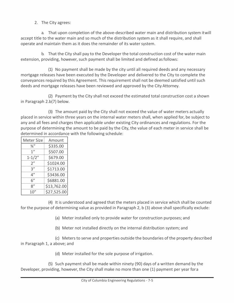
City of Columbia Engineering Regulations - 7-5
2. The City agrees:
a. That upon completion of the above-described water main and distribution system it will accept title to the water main and so much of the distribution system as it shall require, and shall operate and maintain them as it does the remainder of its water system.
b. That the City shall pay to the Developer the total construction cost of the water main
extension, providing, however, such payment shall be limited and defined as follows:
(1) No payment shall be made by the city until all required deeds and any necessary mortgage releases have been executed by the Developer and delivered to the City to complete the conveyances required by this Agreement. This requirement shall not be deemed satisfied until such deeds and mortgage releases have been reviewed and approved by the City Attorney.
(2) Payment by the City shall not exceed the estimated total construction cost a shown
in Paragraph 2.b(7) below.
(3) The amount paid by the City shall not exceed the value of water meters actually placed in service within three years on the internal water meters shall, when applied for, be subject to any and all fees and charges then applicable under existing City ordinances and regulations. For the purpose of determining the amount to be paid by the City, the value of each meter in service shall be determined in accordance with the following schedule:
Meter Size Amount ¾” $335.00 1” $507.00
1-1/2” $679.00 2” $1024.00 3” $1713.00 4” $3436.00 6” $6881.00 8” $13,762.00
10” $27,525.00
(4) It is understood and agreed that the meters placed in service which shall be counted for the purpose of determining value as provided in Paragraph 2, b (3) above shall specifically exclude:
(a) Meter installed only to provide water for construction purposes; and
(b) Meter not installed directly on the internal distribution system; and
(c) Meters to serve and properties outside the boundaries of the property described
in Paragraph 1, a above; and
(d) Meter installed for the sole purpose of irrigation.
(5) Such payment shall be made within ninety (90) days of a written demand by the Developer, providing, however, the City shall make no more than one (1) payment per year for a

City of Columbia Engineering Regulations - 7-6
maximum of three (3) years from the date of the completion and acceptance of the water main by the City. If no demand is received from the Developer within three (3) years after construction is effectively completed, the City may compute the amount due and tender it to the Developer within ninety (90) days after the expiration of the three-year period.
(6) Once demand is made by the Developer, or upon the expiration of three (3) years,
whichever occurs first, the number of meters actually placed in service shall be determined and no meters subsequently installed shall be used to determine the amount to be paid by the City.
(7) The total cost of construction shall be equal to the actual contract cost, plus
engineering not to exceed 10% and actual off-site easement acquisition costs not to exceed $ per linear foot for any easement. The estimated cost of construction of the water main under this Agreement is $ . The engineer designing the water main extension shall certify both the amount of his fee, and its receipt, to the City’s Director of Engineering.
3. It is mutually agreed by the parties that:
a. Applications for individual services, i.e., water meters, will be accepted upon satisfactory
completion of construction of water mains and:
(1) Receipt of properly prepared and certified “record drawing” plans.
(2) Receipt of Engineering Division Form #2, executed by the Developer, requesting acceptance of the water system.
(3) Receipt of Engineering Division Form #3, Waiver of Lien and list of materials installed
from the contractor installing the water system.
(4) Satisfactory completion of pressure and bacteriological testing of the water system.
(5) Approval of the sanitary sewer system for service by the City’s Director of Engineering; or evidence of an approved wastewater disposal system if not served by City sewer.
(6) Receipt of SCDHEC Permit to Operate.
(7) The building permit and plumbing permit for the residential units, building or other
facilities to be served have been issued by the appropriate Building Official or Inspection Department.
b. Applications shall not be accepted for the project or phase of the project if phasing is approved, until the deeds and easements executed by the Developer are received and approved by the City’s Director of Engineering.
c. The effective completion date of construction of the water main shall be the date the
City receives all items in Paragraph 3a above excepting item (7). No meters to be counted to determine the amount to be paid by the City will be set prior to that date.
d. If at any future time should any part of the property described hereinabove become
contiguous to the City limits of Columbia, the Developer, its/his/her or their heir(s), successor(s) and/or

City of Columbia Engineering Regulations - 7-7
assign(s) will cause all of said property to be annexed to the City of Columbia. The Developer agrees to execute simultaneous herewith a covenant, in its/his/her or their heir(s), successor(s) and/or assign(s) to cause said property to be annexed to the City, should any part of the property become contiguous to the limits of Columbia.
Failure to comply with the above will result in the City terminating existing service or refusing to
extend service to any portion of the property not then served by the line referred to hereunder. Service will be reinstated or service will be governed by the other terms and conditions herein. Additionally, service will not reinstated until such time as all required fees and costs required by the City for reinstatement have been paid to the City.
4. This Agreement shall be binding on the parties, their heirs, successors and assigns.

City of Columbia Engineering Regulations - 7-8
(CORPORATE SIGNATURE PAGE)
IN WITNESS WHEREOF, the undersigned have hereunto set their hands and seals on the date first hereinabove written.
WITNESSETH:
(NAME OF DEVELOPER)
BY:
THE CITY OF COLUMBIA
BY:
STATE OF SOUTH CAROLINA ) COUNTY OF ) ACKNOWLEDGEMENT
The foregoing instrument was acknowledged before me this day of , 20
by of on behalf of the within-named Party. (Name of Officer and Title) (City and State)
NOTARY PUBLIC FOR
MY COMMISSION EXPIRES
STATE OF SOUTH CAROLINA ) COUNTY OF ) ACKNOWLEDGEMENT
The foregoing instrument was acknowledged before me this day of , 20
by of on behalf of the within-named Party. (Name of Officer and Title) (City and State)
NOTARY PUBLIC FOR
MY COMMISSION EXPIRES

City of Columbia Engineering Regulations - 7-9
(INDIVIDUAL SIGNATURE PAGE)
IN WITNESS WHEREOF, the undersigned have hereunto set their hands and seals on the date first hereinabove written.
WITNESSETH:
(NAME OF DEVELOPER)
BY:
THE CITY OF COLUMBIA
BY:
STATE OF SOUTH CAROLINA ) COUNTY OF ) ACKNOWLEDGEMENT
The foregoing instrument was acknowledged before me this day of , 20
by the within-named Party.
NOTARY PUBLIC FOR
MY COMMISSION EXPIRES
STATE OF SOUTH CAROLINA ) COUNTY OF ) ACKNOWLEDGEMENT
The foregoing instrument was acknowledged before me this day of , 20
by the within-named Party.
NOTARY PUBLIC FOR
MY COMMISSION EXPIRES

City of Columbia Engineering Regulations - 8-i
City of Columbia Engineering Regulations PART 8: Sanitary Sewer Main Extension
Table of Contents
Paragraph Description Page no. 8.1 General 8-1 8.2 Sanitary Sewer Main Extension Agreement 8-1 8.3 Procedures 8-1 8.4 Applications for Individual Services 8-3 8.5 Sample Sanitary Sewer Agreement 8-4
List of Forms
Form Description Page no. Form 8-1. Sample Sanitary Sewer Agreement 8-4

City of Columbia Engineering Regulations - 8-1
City of Columbia Engineering Regulations PART 8: Sanitary Sewer Main Extension
8.1 General Service will be extended into those areas not presently served by the City of Columbia sanitary sewer system in accordance with the following:
8.1.1 Inside City Limits – The City will install, within a reasonable time after request, an
adequate sanitary sewer main to the property requiring service. The City is responsible for extensions to master parcels within the City limits and not to individual parcels that have been subdivided.
8.1.2 Outside City Limits – There are two alternatives for extending sanitary sewer mains to
provide service. The first, and most common, is for the person requesting service to enter into a Sanitary Sewer Main Extension Agreement with the City. This agreement provides for City participation in the cost of engineering and construction. The person requesting service must retain in engineer to complete studies to determine feasibility, best method and cost of providing service and to prepare construction plans. Refer to Section 8.2 for procedures for execution of the Sanitary Sewer Main Extension Agreement. The second alternative is for the person requesting service to have his engineer design and prepare construction plans for the extension. Following approval of the construction plans by the City Engineer, the person requesting service lets a contract for construction. The design, plans and construction must comply with City Design Criteria and Regulations. This method does not allow City participation in the cost of engineering or construction. Refer to Parts 1 and 3 for procedures for Submission of Plans and Design Criteria.
8.1.3 Outside City Limits but Contiguous to City Limits – It is City practice to provide service
only after the property is annexed into the City. Following annexation, Section 8.0.1 above will apply.
8.2 Sanitary Sewer Main Extension Agreement
A Sanitary Sewer Main Extension Agreement is a contract entered into between the City and the person or persons requesting sanitary sewer service wherein the City agrees to provide sanitary sewer service to property outside the City limits not presently served by the City’s sanitary sewer system. See sample Sanitary Sewer Main Extension Agreement attached. Refer to paragraph 8.4.
8.3 Procedures
The procedures for Sanitary Sewer Main Extension Agreements are as follows:
8.3.1 Execution of Sanitary Sewer Main Extension Agreement – In those areas outside the City limits, but not contiguous to the City limits, the developer may obtain service by entering into a Sanitary Sewer Main Extension Agreement with the City.

City of Columbia Engineering Regulations - 8-2
8.3.2 Sanitary Sewer Main Size. The City Engineer shall establish and/or approve the size of the sanitary sewer main deemed adequate to serve the property requiring service.
8.3.3 Design of the Sanitary Sewer Main Extension. Construction plans for the proposed
sanitary sewer extension shall be prepared by a registered professional engineer, licensed to practice in South Carolina, and shall be submitted in accordance with procedures set forth in Part 1, City of Columbia Regulations.
8.3.4 Cost of the Sanitary Sewer Main Extension. The developer’s total cost of construction
shall be equal to the actual contract cost for installation of the gravity sewer main, plus engineering fees not to exceed 10% of the actual contract cost, plus actual off-site easement acquisition costs not to exceed the cost per linear foot specified in the sanitary sewer main extension agreement. The engineer shall provide the City with an estimate of the total cost of construction prior to execution of a sanitary sewer main extension agreement. This estimate of cost shall be subject to approval by the City Engineer.
8.3.5 Extension of sanitary sewer main – Following execution of a Sanitary Sewer Main
Extension Agreement, the developer shall install the sanitary sewer main to the boundary of the property requiring service.
8.3.6 City Participation is Cost. The City will pay the developer the cost of the sanitary sewer
main extended to the boundary of the property to be served in accordance with the terms, conditions and limitations established in the sanitary sewer main extension agreement. The developer shall sustain any costs in excess of the amount to be paid by the City.
8.3.7 Construction of Sanitary Sewer Collector System – Construction of the sanitary sewer
collector system to serve the interior of the property is the responsibility of the person or persons requesting service.
8.3.7.1 The interior sanitary sewer collection system shall be installed in accordance with plans
and specifications submitted to and approved by the City Engineer. Part 1, City of Columbia Regulations contains guidelines for the submission of plans.
8.3.8 All sanitary sewer main construction, both interior and off-site, shall be under the
supervision of the City Engineer.
8.3.9 The sanitary sewer main extension and such portions of the interior sanitary sewer collection system as may be approved and accepted by the City shall be deeded to the City by the Owner, along with any easements required by the City.
8.3.10 Construction of the interior sanitary sewer collection system may be carried out
concurrently with construction of the sanitary sewer main extension to the boundary of the property requiring service.
8.3.11 Establishment of Sanitary Sewer Service. Sanitary sewer service to the property will be
established following:

City of Columbia Engineering Regulations - 8-3
8.3.11.1 Execution of the sanitary sewer main extension agreement.
8.3.11.2 Completion of the sanitary sewer main extension.
8.3.11.3 Approval, acceptance, and deeding of the sanitary sewer mains, both interior and off-site, extension and collector systems to the City.
8.3.11.4 Payment of applicable tap and sewer plant expansion fees. Refer to Part 13, City of
Columbia Regulations.
8.4 Applications for individual Services i.e., sewer taps, will be accepted upon completion of construction and:
8.4.1 Receipt of properly prepared and certified record drawing plans by the engineer.
8.4.2 Receipt of Engineering Division Form 2, executed by the developer requesting
acceptance of the sewer system. Refer to Part 6, paragraph 6.3.2.
8.4.3 Receipt of Engineering Division Form 3, Waiver of Lien, and list of material installed from the contractor installing the sanitary sewer system. Refer to Part 6, paragraph 6.3.3.
8.4.4 Receipt of certification from the developer’s engineer that infiltration/exfiltration is
within limits specified in City Regulations.
8.4.5 Receipt of certification from the developer’s engineer of the actual quantities installed and measured in the field and that the engineering fees as established and approved herein were received.

City of Columbia Engineering Regulations - 8-4
8.5 Sample Sanitary Sewer Agreement
STATE OF SOUTH CAROLINA ) SANITARY SEWER MAIN EXTENSION AGREEMENT COUNTY OF RICHLAND )
THIS AGREEMENT entered into this day of , 20 , by
and between , hereinafter known as the Developer and the City of Columbia, hereinafter known as the City.
For the sum of Five ($5.00) Dollars and the mutual promises herein contained, the parties agree
as follows:
1. The Developer will install, or cause to be installed, a sanitary sewer line, with all associated pump stations, fixtures and equipment as shall be required to serve property of the Developer located . The sanitary sewer trunk line shall be constructed from Point “A” to Point “B” as shown on the map which is on file in the office of the City’s Director of Engineering under file reference , and incorporated herein by reference.
2. Prior to construction, the Developer will submit construction plans to the City’s Director of
Engineering for review and approval. Construction plans shall be prepared by the registered professional engineer licensed to practice in South Carolina and shall conform to the standards of design, construction and material normally used and required by the City.
3. The engineering fees shall be established in accordance with the “Suggested Median Fees
for Professional Engineering Services” as recommended by the National Society of Professional Engineers, and shall be subject to the approval of the City’s Director of Engineering.
4. The Developer will be responsible for obtaining all easements necessary for the construction
of the sanitary sewer line described above. In the event condemnation is required, the City agrees, in its name, to promptly commence and prosecute such condemnation. The Developer understands and agrees that for the purpose of determining the total cost of construction of the sanitary sewer extension, the cost of easements shall be actual costs not to exceed $ per lineal foot.
5. The construction cost shall be determined by letting a contract for the installation of the
sanitary sewer main extension. The letting of the contract shall conform to the following conditions.
a. The project will be approved for advertisement by the City.
b. The project will be advertised for a minimum of two weeks in both “The State” newspaper and “The Black News.”
c. Proof of advertisement will be provided to the City prior to the bid opening.
d. Bids will be forwarded to the City’s Department of Engineering to be opened jointly by
the City and the Developer as specified in the advertisement for bids, with the City Clerk and the City’s Director of Engineering or their representatives in attendance.

City of Columbia Engineering Regulations - 8-5
e. The contract will be awarded to the lowest responsible bidder. The City shall determine whether bidder is responsible, and approve the award of the contract. The City shall have the authority to waive technicalities and reject any or all bids and to approve such awards as, in its opinion appears to be in the best interest of the City.
f. A minimum of three bids must be received prior to the bid opening.
6. The total cost for extending the sanitary sewer main to the boundary of the property to be
served shall be determined as the sum of the engineering fees, easement acquisition costs, and the construction costs including materials and labor for installation of the gravity portion of the sanitary sewer main. The final total cost shall be determined by the City’s Director of Engineering with construction cots being based on unit bid prices previously approved and actual quantities installed and measured in the field. The estimated total cost is agreed to be $ . It is understood and agreed that the estimated cost is the maximum amount that the City will pay to the Developer. Expenditures not covered on the bid proposal form for which payment under this Agreement is desired, must be submitted as change orders by the Developer’s engineer to the Developer, contractor and City’s Director of Engineering in turn for approval.
7. Payment of the total cost for this sanitary sewer extension shall be the responsibility of the
Developer.
8. Prior to placing the sanitary sewer main extension in service the registered professional engineer who prepared the construction plans shall certify in writing the actual quantities installed and measured in the field, that the engineering fees, as established and approved herein, were received and that construction meets all specifications and requirements of the City. The Developer’s engineer shall provide the City with “record drawing” plans.
9. In consideration of the payment described in Paragraph 7 above, the City shall issue sewer
tap certificates to the Developer. The number of sewer tap certificates issued shall be determined by dividing the total cost for the sanitary sewer extension, excluding the costs of pump stations and force mains, by three hundred dollars ($300.00). (or other costs, excluding sewer plant expansion fees, for a single family residence as established in the ordinances on the date of execution of this Agreement by the City) and rounding to the next lower whole number. The sewer tap certificates so issued shall be negotiable as payment for sewer taps within the property to be served as described in Paragraph 1 above provided, however, they shall not be negotiable as payment of sewer plant expansion fees.
10. The City will charge each new connection a sewer tap fee, a sewer plant expansion fee and
monthly sewer service charge according to the then applicable rates; provided, however, the sewer tap certificates issued hereunder may be surrendered in lieu of the then prevailing sewer tap fee charge for one single residential tap, or its equivalent, when used in multiples for commercial taps. It is understood and agreed that sewer service charges at rates set by City Ordinance shall commence 60 days after the date of the Sewer Service Permit, or on the date of connection to the system, whichever is earlier.
11. It is understood that present City policy is to provide sewer service to areas contiguous to
the City only upon annexation of the area to the City. The Developer agrees that at any future time should any part of the property described hereinabove become contiguous to the City limits of

City of Columbia Engineering Regulations - 8-6
Columbia, the Developer, its/his/her or their heir)s), successor(s) and/or assign (s) will cause all of said property to be annexed to the City. The Developer agrees to execute simultaneous herewith a covenant, in recordable form and to run with the land, that requires the Developer, its/his/her or their heir(s), successor(s) and/or assign(s) to cause said property to be annexed to the City should any part of the property become contiguous to the City limits of Columbia.
Failure to comply with the above will result in the City terminating existing service or refusing to
extend service to any portion of the property not then served by the line referred to hereunder. Service will be reinstated or service will extend only when such property is annexed to the City, all of which shall be governed by the other terms and conditions herein. Additionally, service will not be reinstated until such time as all required fees and costs required by the City for reinstatement have been paid to the City.
12. Construction of the sanitary sewer collection system to serve the interior of the property is
the responsibility of the Developer. The interior collection system shall be installed according to plans and specifications submitted to, and approved by, the City’s Director of Engineering; said installation to be under the supervision of the City’s Director of Engineering. Construction of the sanitary sewer collection system may be accomplished concurrently with construction of the sanitary sewer main being extended to the boundary of the property to be served.
13. Such portions of the sanitary sewer collection system as may be approved and accepted
by the City shall be deeded to the City, at no cost to the City, by the Developer. Said deed shall include such easements as necessary for ingress, egress, operation and maintenance.
14. Application for individual services, i.e., sewer taps, will be accepted upon completion of
construction and:
a. Receipt and approval of deeds by the City’s Director of Engineering. (Refer to Paragraph 13 above).
b. Receipt of properly prepared and certified “record drawing” plans. (Refer to Paragraph 8 above).
c. Receipt of Engineering Division Form 2, executed by the Developer, requesting acceptance of the sewer system.
d. Receipt of Engineering Division Form 3, Waiver of Lien, and list of materials installed,
from the contractor installing the sanitary sewer system.
e. Receipt of certification from the Developer’s engineer that infiltration/exfiltration is within limits specified is within limits specified in City Regulations.
f. Receipt of certification from the Developer’s engineer of the actual quantities installed
and measured in the field and that the engineering fees as established and approve herein were received.
g. Receipt of SCDHEC Permit to Operate.

City of Columbia Engineering Regulations - 8-7
h. Plumbing Permits for the structure for which application is being made have been issued by the appropriate Building Official/Inspections Department.
i. All requirements have been met for installation of the water meters in the project, or
phase of the project if phasing has been approve. (Refer to Part 7 of the City of Columbia Regulations.)
15. The applications for service shall not be accepted for the subdivision, or phase of the subdivision if phasing has been approved, until all requirements of this Agreement have been met, the tap certificates referred to herein have been issued to the Developer, and the interior water and sewer systems have been deeded to and accepted by the City.
16. The terms and conditions of this Agreement shall be binding on the parties, their heirs,
successors and/or assigns.

City of Columbia Engineering Regulations - 8-8
(CORPORATE SIGNATURE PAGE)
IN WITNESS WHEREOF, the undersigned have hereunto set their hands and seals on the date first hereinabove written.
WITNESSETH:
(NAME OF DEVELOPER)
BY:
THE CITY OF COLUMBIA
BY:
STATE OF SOUTH CAROLINA ) COUNTY OF ) ACKNOWLEDGEMENT
The foregoing instrument was acknowledged before me this day of , 20
by of on behalf of the within-named Party. (Name of Officer and Title) (City and State)
NOTARY PUBLIC FOR
MY COMMISSION EXPIRES
STATE OF SOUTH CAROLINA ) COUNTY OF ) ACKNOWLEDGEMENT
The foregoing instrument was acknowledged before me this day of , 20
by of on behalf of the within-named Party. (Name of Officer and Title) (City and State)
NOTARY PUBLIC FOR
MY COMMISSION EXPIRES

City of Columbia Engineering Regulations - 8-9
(INDIVIDUAL SIGNATURE PAGE)
IN WITNESS WHEREOF, the undersigned have hereunto set their hands and seals on the date first hereinabove written.
WITNESSETH:
(NAME OF DEVELOPER)
BY:
THE CITY OF COLUMBIA
BY:
STATE OF SOUTH CAROLINA ) COUNTY OF ) ACKNOWLEDGEMENT
The foregoing instrument was acknowledged before me this day of , 20
by the within-named Party.
NOTARY PUBLIC FOR
MY COMMISSION EXPIRES
STATE OF SOUTH CAROLINA ) COUNTY OF ) ACKNOWLEDGEMENT
The foregoing instrument was acknowledged before me this day of , 20
by the within-named Party.
NOTARY PUBLIC FOR
MY COMMISSION EXPIRES

City of Columbia Engineering Regulations - 9-i
City of Columbia Engineering Regulations PART 9: Pedestrian, Bicycle, and Complete Streets Design Guidelines
Table of Contents
Paragraph Description Page no. 9.1 Introduction 9-1 9.2 Pedestrian Facilities 9-3 9.3 Sidewalks 9-8 9.4 Pedestrians at Intersections 9-14 9.5 Crossings, Beacons and Signals for Pedestrians 9-24 9.6 Shared Use Paths and Off Street Facilities 9-29 9.7 Path/ Roadway Crossing Types 9-37 9.8 Bicycle Facilities 9-42 9.9 Shared Roadways 9-48 9.10 Separated Bikeways 9-53 9.11 Protected Bike Lanes 9-62 9.12 Bikeways at Intersections 9-70 9.13 Crossing Beacons and Signals for Bicycles 9-84 9.14 Retrofitting Streets to Add Bikeways 9-90 9.15 Transit and Bicycle Wayfinding 9-95 9.16 Bicycle Support Facilities 9-98 9.17 Bikeway Maintenance 9-106
List of Figures
Figure Description Page no. Figure 9-1. Pedestrian Space Usage 9-4 Figure 9-2. Wheelchair Space Usage 9-6 Figure 9-3. Runner Space Usage 9-7 Figure 9-4. Zones In The Sidewalk Corridor 9-8 Figure 9-5. Sidewalk Obstructions And Driveway Ramps 9-10 Figure 9-6. Street Trees and Street Furniture 9-11 Figure 9-7. Green Features and Lighting 9-12 Figure 9-8. Accessible Bus Stop Design 9-13 Figure 9-9. Marked Crosswalks 9-14 Figure 9-10. Median Refuge Islands 9-15 Figure 9-11. Minimizing Curb Radii 9-17 Figure 9-12. Curb Extensions 9-18 Figure 9-13. Advanced Yield Line or Stop Bar 9-19 Figure 9-14. Parking Control 9-20 Figure 9-15. ADA Compliant Curb Ramps 9-21
Part 9 is adapted from Appendix I: Walk Bike Columbia! Pedestrian, Bicycle, and Complete Streets Design Guidelines.

City of Columbia Engineering Regulations - 9-ii
Figure 9-16. Pedestrians at Railroad Grade Crossings 9-22 Figure 9-17. Accommodating Pedestrians at Signalized Crossings 9-24 Figure 9-18. Active Warning Beacons (RRFB) 9-26 Figure 9-19. Hybrid Warning Beacon (HAWK) For Mid-Block Crossing 9-27 Figure 9-20. Route Users To Signalized Crossings 9-28 Figure 9-21. General Design Practice 9-29 Figure 9-22. Greenways In Abandoned Rail Corridors 9-31 Figure 9-23. Greenways In Active Rail Corridors 9-33 Figure 9-24. Local Neighborhood Access ways 9-34 Figure 9-25. Shared Use Paths Along Roadways 9-35 Figure 9-26. Marked/Unsignalized Crossings 9-37 Figure 9-27. Full Traffic Signal Crossings 9-38 Figure 9-28. Undercrossings 9-39 Figure 9-29. Overcrossings 9-41 Figure 9-30. Standard Bicycle Rider Dimensions 9-43 Figure 9-31. Shared Roadways 9-46 Figure 9-32. Separated Bikeways 9-46 Figure 9-33. Cycle Tracks 9-46 Figure 9-34. Shared Use Paths 9-46 Figure 9-35. Facility Continua 9-47 Figure 9-36. Signed Shared Roadways 9-48 Figure 9-37. Marked Shared Roadways 9-49 Figure 9-38. Bicycle Boulevards 9-50 Figure 9-39. Advisory Bike Lane 9-51 Figure 9-40. Shoulder Bikeways 9-53 Figure 9-41. Conventional Bike Lane 9-54 Figure 9-42. Bike Lane Adjacent To On-Street Parking 9-55 Figure 9-43. Bikeways And Diagonal Parking 9-56 Figure 9-44. Left Side Bike Lane 9-58 Figure 9-45. Contra Flow Bike Lane 9-59 Figure 9-46. Buffered Bike Lane 9-60 Figure 9-47. Uphill Bicycle Climbing Lane 9-61 Figure 9-48. Cycle Track Separation And Placement 9-62 Figure 9-49. One-Way Cycle Tracks 9-63 Figure 9-50. Two Way Cycle Tracks 9-64 Figure 9-51. Driveways And Minor Street Crossings 9-65 Figure 9-52. Major Street Crossings 9-67 Figure 9-53. Bicycle Transit Bypass 9-68 Figure 9-54. Bike Box 9-70 Figure 9-55. Bike Lanes at Right Turn Only Lanes 9-72 Figure 9-56. Colored Bike Lanes In Conflict Areas 9-73 Figure 9-57. Combined Bike Lane/Turn Lane 9-75 Figure 9-58. Intersection Crossing Markings 9-76 Figure 9-59. Two-Stage Turn Box 9-78 Figure 9-60. Bicyclists at Single Lane Roundabouts 9-79 Figure 9-61. Bike Lanes at High Speed Interchanges 9-80

City of Columbia Engineering Regulations - 9-iii
Figure 9-62. Bike/Ped Facilities at Diverging Diamond Interchanges 9-81 Figure 9-63. Bikeways at Railroad Grade Crossings 9-83 Figure 9-64. Active Warning Beacons 9-84 Figure 9-65. Hybrid Warning Beacon (HAWK) for Bicycle Route Crossing 9-85 Figure 9-66. Bicycle Detection and Actuation 9-87 Figure 9-67. Bicycle Signal Heads 9-89 Figure 9-68. Roadway Widening 9-90 Figure 9-69. Lane Narrowing 9-91 Figure 9-70. Lane Reconfiguration 9-93 Figure 9-71. Parking Reduction 9-94 Figure 9-72. Transit Wayfinding 9-95 Figure 9-73. Confirmation Signs 9-96 Figure 9-74. Turn Signs 9-96 Figure 9-75. Decisions Signs 9-96 Figure 9-76. Bikeway Wayfinding Sign Placement 9-97 Figure 9-77. Bicycle Racks 9-98 Figure 9-78. On-Street Bicycle Corral 9-100 Figure 9-79. Bicycle Lockers 9-101 Figure 9-80. Secure Parking Area (SPA) 9-102 Figure 9-81. Bicycle Parking at Transit 9-103 Figure 9-82. Bike Share Station Placement 9-105 Figure 9-83. Drainage Grates 9-108
List of Tables
Table Description Page no. Table 9-1. Pedestrian Characteristics by Age 9-3 Table 9-2. Disabled Pedestrian Design Considerations 9-4 Table 9-3. Wheelchair User Typical Speed 9-5 Table 9-4. Wheelchair User Design Considerations 9-6 Table 9-5. Runner Typical Speed 9-6 Table 9-6. Sidewalk Widths 9-9 Table 9-7. Bicycle as Design Vehicle - Typical Dimensions 9-44 Table 9-8. Bicycle as Design Vehicle - Typical Speed 9-44

City of Columbia Engineering Regulations - 9-1
City of Columbia Engineering Regulations PART 9: Pedestrian, Bicycle, and Complete Streets Design
Guidelines 9.1 Introduction
This technical handbook is intended to assist the City of Columbia in the selection and design of pedestrian, bicycle, transit facilities. The following sections pull together best practices by facility type from public agencies and municipalities nation¬wide. Within the design sections, treatments are covered within a single sheet tabular format relaying important design information and discussion, example photos, schematics (if applicable), and existing summary guidance from current or upcoming draft standards. Existing standards are referenced throughout and should be the first source of information when seeking to implement any of the treatments featured here.
9.1.1 National Standards
9.1.1.1 The Federal Highway Administration’s Manual on Uniform Traffic Control Devices
(MUTCD) defines the standards used by road managers nationwide to install and maintain traffic control devices on all public streets, highways, bikeways, and private roads open to public traffic. The MUTCD is the primary source for guidance on lane striping requirements, signal warrants, and recommended signage and pavement markings.
The National Committed on Traffic Control Devices (NUTCD) has submitted draft language for consideration in future editions of the MUTCD to include contemporary bicycle facilities. Guidance for these treatments are evolving, and practitioners should reference future editions of national guidance to understand current best practice.
To further clarify the MUTCD, the FHWA created a table of contemporary bicycle facilities that lists various bicycle-related signs, markings, signals, and other treatments and identifies their official status (e.g., can be implemented, currently experimental). See Bicycle Facilities and the Manual on Uniform Traffic Control Devices.1
Bikeway treatments not explicitly covered by the MUTCD are often subject to experiments, interpretations and official rulings by the FHWA. The MUTCD Official Rulings is a resource that allows website visitors to obtain information about these supplemen- tary materials. Copies of various documents (such as incoming request letters, response letters from the FHWA, progress reports, and final reports) are available on this website.2
American Association of State Highway and Transportation Officials (AASHTO) Guide for the Development of Bicycle Facilities, updated in June 2012 provides guidance on dimensions, use, and layout of specific bicycle facilities. The standards and guidelines presented by AASHTO provide basic information, such as minimum sidewalk widths,
1 Bicycle Facilities and the Manual on Uniform Traffic Control Devices. (2011). FHWA. http://www.fhwa.dot.gov/ environment/bikeped/mutcd_bike.htm
2 MUTCD Official Rulings. FHWA. http://mutcd.fhwa.dot.gov/orsearch.asp

City of Columbia Engineering Regulations - 9-2
bicycle lane dimensions, detailed striping requirements and recommended signage and pavement markings.
The National Association of City Transportation Officials’ (NACTO3) Urban Bikeway Design Guide and Urban Streets Design Guide is the newest publication of nationally recognized street design guidelines, and offers guidance on the current state
of the practice designs. The NACTO Urban Bikeway Design Guide is based on current practices in the best cycling cities in the world. The intent of the guide is to offer substantive guidance for cities seeking to improve bicycle transportation in places where competing demands for the use of the right of way present unique challenges. All of the NACTO Urban Bikeway Design Guide treatments are in use internationally and in many cities around the US.
Offering similar guidance for pedestrian design, the 2004 AASHTO Guide for the Planning, Design and Operation of Pedes- trian Facilities provides comprehensive guidance on planning and designing for people on foot.
Some of these treatments are not directly referenced in the current versions of the AASHTO Guide or the MUTCD, although many of the elements of these treatments are found within these documents. In all cases, engineering judgment is recommended to ensure that the application makes sense for the context of each treatment, given the many complexities of urban
9.1.2 Local Standards
9.1.2.1 The South Carolina Department of Transportation has published a variety of additional
resources for designing bicycle and pedestrian facilities. These include the SCDOT Highway Design Manual, SCDOT Traffic Calming Design Guidelines, SCDOT Traffic Signal Design Guidelines and SCDOT Access and Roadside Management Standards. In recent years, SCDOT has also issued several Traffic Engineering Guidelines, and Engineering Directive Memorandums for such treatments as pedestrian hybrid beacons, shared lane markings, rumble strips and other complete streets treatments.
9.1.3 Additional US Federal Guidelines
9.1.3.1 Meeting the requirements of the Americans with Disabilities Act (ADA) is an important
part of any bicycle and pedestrian facility project. The United States Access Board’s proposed Public Rights-of-Way Accessibility Guidelines4 (PROWAG) and the 2010 ADA Standards for Accessible Design5 (2010 Standards) contain standards and guidance for the construction of accessible facilities. This includes requirements for sidewalk curb ramps, slope requirements, and pedestrian railings along stairs.
3 http://nacto.org/ 4 http://www.access-board.gov/prowac/ 5 http://www.ada.gov/2010ADAstandards_index.htm

City of Columbia Engineering Regulations - 9-3
The 2011 AASHTO: A Policy on Geometric Design of Highways and Streets commonly referred to as the “Green Book,” contains the current design research and practices for highway and street geometric design.
9.2 Pedestrian Facilities
9.2.1 Design Needs of Pedestrians
9.2.1.1 Types of Pedestrians - Pedestrians have a variety of characteristics and the
transportation network should accommodate a variety of needs, abilities, and possible impairments. Age is one major factor that affects pedestrians’ physical characteristics, walking speed, and environmental perception. Children have low eye height and walk at slower speeds than adults. They also perceive the environment differently at various stages of their cognitive development. Older adults walk more slowly and may require assistive devices for walking stability, sight, and hearing. The table below summarizes common pedestrian characteristics for various age groups.
The MUTCD recommends a normal walking speed of 3.5 feet per second when calculating the pedestrian clearance interval at traffic signals. The walking speed can drop to 3 feet per second for areas with older populations and persons with mobil¬ity impairments. While the type and degree of mobility impairment varies greatly across the population, the transportation system should accommodate these users to the greatest reasonable extent.
The table below summarizes common physical and cognitive impairments, how they affect personal mobility, and recom¬mendations for improved pedestrian-friendly design.
9.2.1.2 Pedestrian Characteristics by Age6
Table 9-1. Pedestrian Characteristics by Age
Age Characteristics
0-4 Learning to walk Requires constant adult supervision Developing peripheral vision and depth perception
5-8 Increasing independence, but still requires supervision Poor depth perception
9-13
Susceptible to “darting out” in roadways Insufficient judgment Sense of invulnerability
14-18 Improved awareness of traffic environment Insufficient judgment
19-40 Active, aware of traffic environment 41-65 Slowing of reflexes
6 Source: AASHTO. Guide for the Planning, Design, and Operation of Pedestrian Facilities, Exhibit 2-1. 2004.

City of Columbia Engineering Regulations - 9-4
Age Characteristics
65+ Difficulty crossing street Difficulty hearing vehicles approaching from behind Vision loss
9.2.1.3 Pedestrian Space Usage
Figure 9-1. Pedestrian Space Usage
9.2.1.4 Disabled Pedestrian Design Considerations
Table 9-2. Disabled Pedestrian Design Considerations
Impairment Effect on Mobility Design Solution
Wheelchair and Scooter
Users
Difficulty propelling over uneven or soft surfaces.
Firm, stable surfaces and structures, including ramps or beveled edges.
Cross-slopes cause wheelchairs to veer downhill.
Cross-slopes of less than two percent.
Require wider path of travel. Sufficient width and maneuvering space.
Walking Aid
Users
Difficulty negotiating steep grades and cross slopes; decreased stability.
Smooth, non-slipperly travel surface.
Slower walking speed and reduced endurance; reduced ability to react.
Longer pedestrian signal cycles, shorter crossing distances, median refuges, and street furniture.

City of Columbia Engineering Regulations - 9-5
Impairment Effect on Mobility Design Solution
Hearing Impairment
Less able to detect oncoming hazards at locations with limited sight lines (e.g. driveways, angled inter- sections, channelized right turn lanes) and complex intersections.
Longer pedestrian signal cycles, clear sight distances, highly visible pedestrian signals and markings.
Vision Impairment
Limited perception of path ahead and obstacles; reliance on memory; reliance on non-visual indicators (e.g. sound and texture).
Accessible text (larger print and raised text), accessible pedestrian signals (APS), guide strips and detectable warning surfaces, safety barriers, and lighting.
Cognitive
Impairment
Varies greatly. Can affect ability to perceive, recognize, understand, interpret, and respond to information.
Signs with pictures, universal symbols, and colors, rather than text.
9.2.2 Design Needs of Wheelchair Users - As the American population ages, the number of people using mobility assistive devices (such as manual wheel¬chairs, powered wheelchairs) increases.
Manual wheelchairs are self-propelled devices. Users propel themselves using push rims attached to the rear wheels. Braking is done through resisting wheel movement with the hands or arm. Alternatively, a second individual can control the wheelchair using handles attached to the back of the chair.
Power wheelchairs user battery power to move the wheelchair. The size and weight of power wheelchairs limit their ability to negotiate obstacles without a ramp.
Maneuvering around a turn requires additional space for wheelchair devices. Providing adequate space for 180 degree turns at appropriate locations is an important element for accessible design.
ADA inadequacies should be inventoried in an ADA transition plan and addressed in a systematic fashion.
9.2.2.1 Wheelchair User Typical Speed
Table 9-3. Wheelchair User Typical Speed
User Typical Speed Manual Wheelchair 3.6 mph Power Wheelchair 6.8 mph

City of Columbia Engineering Regulations - 9-6
9.2.2.2 Wheelchair User Design Considerations
Table 9-4. Wheelchair User Design Considerations
Effect on Mobility Design Solution Difficulty propelling over uneven or soft surfaces.
Firm, stable surfaces and structures, including ramps or beveled edges.
Cross-slopes cause wheelchairs to veer downhill. Cross-slopes of less than two percent.
Pavement lip over 1/4” due to settling or root buckling.
Grind down pavement or replace sidewalk section.
Ramp slope difficult for wheelchair users to climb. Ensure 8.3% ramp slope.
9.2.2.3 Wheelchair Space Usage
Figure 9-2. Wheelchair Space Usage
9.2.3 Design Needs of Runners - Running is an important recreation and fitness activity commonly performed on shared use paths. Many runners prefer softer surfaces (such as rubber, bare earth or crushed rock) to reduce impact. Runners can change their speed and direction frequently. If high volumes are expected, controlled interaction or separation of different types of users should be considered.
9.2.3.1 Runner Typical Speed
Table 9-5. Runner Typical Speed
User Typical Speed Runner 6.2 mph

City of Columbia Engineering Regulations - 9-7
9.2.4 Runner Space Usage
Figure 9-3. Runner Space Usage

City of Columbia Engineering Regulations - 9-8
9.3 Sidewalks
9.3.1 Zones In The Sidewalk Corridor
Parking Lane/
Enhancement Zone
Edge
Zon
e*
Furnishing Zone
Pedestrian Through Zone Frontage Zone
The parking lane can act as a flexible space to further buffer the sidewalk from moving traffic. Curb extensions and bike corrals may occupy this space where appropriate.
The furnishing zone buffers pedestrians from the adjacent roadway, and is also the area where elements such as street trees, signal poles, signs, and other street furniture are properly located.
The through zone is the area intended for pedestrian travel. This zone should be entirely free of permanent and temporary objects.
Wide through zones are needed in downtown areas or where pedestrian flows are high.
The Frontage Zone allows pedestrians a comfortable “shy” distance from the building fronts. It provides opportunities for window shopping, to place signs, planters, or chairs.
Not applicable if adjacent to a landscaped space.
* In the edge zone there should be a 6 inch wide curb
Figure 9-4. Zones In The Sidewalk Corridor
9.3.1.1 Description - Sidewalks are the most fundamental element of the walking network, as they provide an area for pedestrian travel separated from vehicle traffic. A variety of con- siderations are important in sidewalk design. Providing adequate and accessible facilities can lead to increased numbers of people walking, improved safety, and the creation of social space.
9.3.1.2 Discussion - Sidewalks should be more than areas to travel; they should provide places
for people to interact. There should be places for standing, visiting, and sitting. Sidewalks should contribute to the character of neighborhoods and business districts, strengthen their identity, and be an area where adults and children can safely participate in public life.

City of Columbia Engineering Regulations - 9-9
9.3.1.3 Materials and Maintenance - Sidewalks are typically constructed out of concrete and are separated from the roadway by a curb or gutter and sometimes a landscaped space. Colored, patterned, or stamped concrete can add distinctive visual appeal.
9.3.1.4 Additional References and Guidelines
9.3.1.4.1 USDOJ. ADA Standards for Accessible Design. 2010.
9.3.1.4.2 United States Access Board. Proposed Accessibility Guidelines for Pedestrian Facilities in
the Public-Right-of-Way (PROWAG). 2011. AASHTO. Guide for the Planning, Design, and Operation of Pedestrian Facilities. 2004.
9.3.1.4.3 NACTO. Urban Street Design Guide. 2013. SCDOT. Highway Design Manual. 2003.
9.3.2 Sidewalk Widths
Table 9-6. Sidewalk Widths
Street
Classification
Parking Lane/ Enhancement
Zone
Furnishing
Zone*
Pedestrian Through Zone+
Frontage
Zone
Total Local Streets Varies 2 - 8 feet 4 - 6 feet N/A 6 - 14 feet Commercial/ Downtown
Areas
Varies
4 - 8 feet
6 - 12 feet
2.5 - 10 feet
11 - 30 feet
Arterials and Collectors Varies 2 - 8 feet 4 - 8 feet 2.5 - 5 feet 8 -21 feet
* Furnishing Zone - Seating for outdoor dining is most common and functional in furnishing zones of 6 ft., although narrower configurations are possible. + Pedestrian Through Zone - Six feet enables two pedestrians (including wheelchair users) to walk side-by-side, or to pass each other comfortably
9.3.2.1 Description - The width and design of sidewalks will vary depending on street context,
functional classification, and pedestrian demand. Below are preferred widths of each sidewalk zone according to general street type. Standardizing sidewalk guidelines for different areas of the city, dependent on the above listed factors, ensures a minimum level of quality for all sidewalks.
9.3.2.2 Guidance - Sidewalk width should be determined based on desired user comfort. While
a 3-foot-wide through zone may accommodate a single person walking, it is inadequate for two people to walk side-by-side or comfortably pass other users. Designers should strive for sidewalk conditions that allow for side-by-side walking and comfortable passing.
9.3.2.3 Discussion - It is important to provide adequate width along a sidewalk corridor. Two
people should be able to walk side-by-side and pass a third comfortably. In areas of high demand, sidewalks should contain adequate width to accommodate the high volumes

City of Columbia Engineering Regulations - 9-10
and different walking speeds of pedestrians. The Americans with Disabilities Act requires a 4-foot clear width in the pedestrian zone plus 5 foot passing areas every 200 feet.
9.3.2.4 Materials and Maintenance - Sidewalks are typically constructed out of concrete and are
separated from the roadway by a curb or gutter and sometimes a landscaped boulevard. Surfaces must be firm, stable, and slip resistant.
9.3.2.5 Additional References and Guidelines
9.3.2.5.1 USDOJ. ADA Standards for Accessible Design. 2010.
9.3.2.5.2 United States Access Board. Proposed Accessibility Guidelines for Pedestrian Facilities in
the Public-Right-of-Way (PROWAG). 2011.
9.3.2.5.3 AASHTO. Guide for the Planning, Design, and Operation of Pedestrian Facilities. 2004.
9.3.2.5.4 NACTO. Urban Street Design Guide. 2013.
9.3.2.5.5 SCDOT. Highway Design Manual. 2003.
9.3.3 Sidewalk Obstructions And Driveway Ramps
Dipping the entire sidewalk at the driveway approaches keeps the crossslope at a constant grade. This is the least-preferred driveway option.
Where constraints preclude a planter strip, wrapping the sidewalk around the driveway allows the sidewalk to still remain level.
When sidewalks abut hedges, fences, or buildings, an additional two feet of lateral clearance should be added to provide appropriate shy distance.
Planter strips allow sidewalks to remain level, with the driveway grade change occurring within the planter strip.
When sidewalks abut angled on-street parking, wheel stops should be used to prevent vehicles from overhanging in the sidewalk.
Figure 9-5. Sidewalk Obstructions And Driveway Ramps

City of Columbia Engineering Regulations - 9-11
9.3.3.1 Description - Obstructions to pedestrian travel in the sidewalk corridor typically include driveway ramps, curb ramps, sign posts, utility and signal poles, mailboxes, fire hydrants and street furniture.
9.3.3.2 Guidance - Reducing the number of accesses reduces the need for special provisions.
This strategy should be pursued first.
Obstructions should be placed between the sidewalk and the roadway to create a buffer for increased pedestrian comfort.
9.3.3.3 Discussion - Driveways are a common sidewalk obstruction, especially for wheelchair
users. When constraints only allow curb-tight sidewalks, dipping the entire sidewalk at the driveway approaches keeps the cross-slope at a constant grade. However, this may be uncomfortable for pedestrians and could create drainage problems behind the sidewalk.
9.3.3.4 Materials and Maintenance - Sidewalks are typically constructed out of concrete and are
separated from the roadway by a curb or gutter and sometimes a landscaped space. Surfaces must be firm, stable, and slip resistant.
9.3.3.5 Additional References and Guidelines
9.3.3.5.1 USDOJ. ADA Standards for Accessible Design. 2010.
9.3.3.5.2 United States Access Board. Proposed Accessibility Guidelines for Pedestrian Facilities in
the Public-Right-of-Way (PROWAG). 2011.
9.3.3.5.3 AASHTO. Guide for the Planning, Design, and Operation of Pedestrian Facilities. 2004.
9.3.3.5.4 SCDOT. Highway Design Manual. 2003.
9.3.4 Pedestrian Amenities
9.3.4.1 Description - A variety of streetscape elements can define the pedestrian realm, offer protection from moving vehicles, and enhance the walking experience. Key features are presented below.
9.3.4.1.1 Street Trees - In addition to their aesthetic and
environmental value, street trees can slow traffic and improve safety for pedestrians. Trees add visual interest to streets and narrow the street’s visual corridor, which may cause drivers to slow down. It is important that trees do not block light or the vision triangle.
9.3.4.1.2 Street Furniture - Providing benches at key rest areas and viewpoints encourages people of all ages to use the walkways by ensuring that they have a place to rest along the way. Benches should be 20” tall to accommodate
Figure 9-6. Street Trees and Street Furniture

City of Columbia Engineering Regulations - 9-12
elderly pedestrians comfortably. Benches can be simple (e.g., wood slats) or more ornate (e.g., stone, wrought iron, concrete). If alongside a parking zone, street furniture should be placed to minimize interference with passenger loading
9.3.4.1.3 Green Features - Green stormwater strategies may include
bioretention swales, rain gardens, tree box filters, and pervious pavements (pervious concrete, asphalt and pavers).
Bioswales are natural landscape elements that manage water runoff from a paved surface. Plants in the swale trap pollutants and silt from entering a river system.
9.3.4.1.4 Lighting - Pedestrian scale lighting improves visibility for both pedestrians and motorists - particularly at intersections. Pedestrian scale lighting can provide a vertical buffer between the sidewalk and the street, defining pedestrian areas.
Figure 9-7. Green Features and Lighting
9.3.4.2 Discussion - Additional pedestrian amenities such as banners, public art, special paving, along with historical elements and cultural references, promote a sense of place. Public activities should be encouraged and commercial activities such as dining, vending and advertising may be permitted when they do not interfere with safety and accessibility.
Pedestrian amenities should be placed in the furnishing zone on a sidewalk corridor. See Zones in the Sidewalk Corridor for a discussion of the functional parts of a sidewalk. Signs, meters, tree wells should go between parking spaces.
9.3.4.3 Materials and Maintenance - Establishing and caring for your young street trees is
essential to their health. Green features may require routine maintenance, including sediment and trash removal, and clearing curb openings and overflow drains.
9.3.4.4 Additional References and Guidelines
9.3.4.4.1 United States Access Board. Proposed Accessibility Guidelines for Pedestrian Facilities in
the Public-Right-of-Way (PROWAG). 2011.
9.3.4.4.2 NACTO. Urban Street Design Guide. 2013.

City of Columbia Engineering Regulations - 9-13
9.3.5 Accessible Bus Stop Design
Figure 9-8. Accessible Bus Stop Design
9.3.5.1 Description - Bus stops should be connected to a continuous sidewalk and be located with adequate right of way to provide amenities such as shelters, benches and bike racks for users. The bus stop should offer direct pedestrian connectivity to adjacent destinations. Bus stops should be placed in a conspicuous, well-lit location to improve safety and reduce vandalism.
Bus stops should be designed to accommodate all users through the Americans with Disabilities Act accessibility requirements.
9.3.5.2 Guidance - Successful stop design provides good pedestrian traffic flow and thoughtful
placement of amenities while meeting ADA accessibility requirements.
9.3.5.2.1 Site fixtures should be placed at the back of the site, allowing for pedestrian flow adjacent to the street.
9.3.5.2.2 A 5’ minimum clear area should be maintained between any site fixtures and the street.
9.3.5.2.3 The boarding and alighting areas should also be kept clear of obstacles. This includes
benches, trash receptacles, trees, utility poles, newsracks, etc.
9.3.5.2.4 The space for front door boarding and alighting should be a minimum of 5’ wide (6’ preferred) and the space for each of the rear doors should be a minimum of 10’ wide (16’ preferred).
9.3.5.3 Discussion - Far-side bus stops have been shown to offer advantages for pedestrians and
motorists – by improving visibility of pedestrians at crosswalks and not disrupting motor vehicle turning movements. For bus stops located at intersections, far-side bus stops should be utilized wherever possible.
9.3.5.4 Materials and Maintenance - Regularly inspect transit stops and keep clear of debris and
trash.

City of Columbia Engineering Regulations - 9-14
9.3.5.5 Additional References and Guidelines
9.3.5.5.1 USDOJ. ADA Standards for Accessible Design. 2010.
9.3.5.5.2 United States Access Board. Proposed Accessibility Guidelines for Pedestrian Facilities in the Public-Right-of-Way (PROWAG). 2011.
9.3.5.5.3 AASHTO. Guide for the Planning, Design, and Operation of Pedestrian Facilities. 2004.
9.4 Pedestrians at intersections
9.4.1 Marked Crosswalks
Figure 9-9. Marked Crosswalks
9.4.1.1 Description - A marked crosswalk signals to motorists that they must stop for pedestrians and encourages pedestrians to cross at designated locations. Installing crosswalks alone will not necessarily make crossings safer especially on multi-lane roadways. At mid-block locations, crosswalks can be marked where there is a demand for crossing and there are no nearby marked crosswalks.
9.4.1.2 Guidance - At signalized intersections, all crosswalks should be marked. At un-signalized
intersections, crosswalks may be marked under the following conditions:
9.4.1.2.1 At a complex intersection, to orient pedestrians in finding their way across.
9.4.1.2.2 At an offset intersection, to show pedestrians the shortest route across traffic with the least exposure to vehicular traffic and traffic conflicts.
9.4.1.2.3 At an intersection with visibility constraints, to position pedestrians where they can best
be seen by oncoming traffic.

City of Columbia Engineering Regulations - 9-15
9.4.1.2.4 At an intersection within a school zone on a walking route.
9.4.1.3 Discussion - Continental crosswalk markings should be used at crossings with high pedestrian use or where vulnerable pedestrians are expected, including: school crossings, across arterial streets for pedestrian-only signals, at mid-block crosswalks, and at intersections where there is expected high pedestrian use and the crossing is not controlled by signals or stop signs.
9.4.1.4 Materials and Maintenance - Because the effectiveness of marked crossings depends
entirely on their visibility, maintaining marked crossings should be a high priority. Thermoplastic markings offer increased durability than conventional paint.
9.4.1.5 Additional References and Guidelines
9.4.1.5.1 FHWA. Manual on Uniform Traffic Control Devices. (3B.18). 2009.
9.4.1.5.2 AASHTO. Guide for the Planning, Design, and Operation of Pedestrian Facilities. 2004.
9.4.1.5.3 FHWA. Safety Effects of Marked vs. Unmarked Crosswalks at Uncontrolled Locations.
2005.
9.4.1.5.4 FHWA. Crosswalk Marking Field Visibility Study. 2010.
9.4.1.5.5 NACTO. Urban Street Design Guide. 2013.
9.4.2 Median Refuge Islands
Figure 9-10. Median Refuge Islands
9.4.2.1 Description - Median refuge islands are located at the mid-point of a marked crossing and help improve pedestrian safety by allowing pedestrians to cross one direction of traffic at a time. Refuge islands minimize pedestrian exposure by shortening crossing distance and increasing the number of available gaps for crossing.

City of Columbia Engineering Regulations - 9-16
9.4.2.2 Guidance
9.4.2.2.1 Can be applied on any roadway with a left turn center lane or median that is at least 6’ wide.
9.4.2.2.2 Appropriate at signalized or unsignalized crosswalks
9.4.2.2.3 The refuge island must be accessible, preferably with an at-grade passage through the
island rather than ramps and landings.
9.4.2.2.4 The island should be at least 6’ wide between travel lanes (to accommodate bikes with trailers and wheelchair users) and at least 20’ long.
9.4.2.2.5 On streets with speeds higher than 25 mph there should also be double centerline
marking, reflectors, and “KEEP RIGHT” signage.
9.4.2.3 Discussion - If a refuge island is landscaped, the landscaping should not compromise the visibility of pedestrians crossing in the crosswalk. Shrubs and ground plantings should be no higher than 1 ft. 6 in.
On multi-lane roadways, consider configuration with active warning beacons for improved yielding compliance.
9.4.2.4 Materials and Maintenance - Refuge islands may collect road debris and may require
somewhat frequent maintenance. Refuge islands should be visible to snow plow crews and should be kept free of snow berms that block access.
9.4.2.5 Additional References and Guidelines
9.4.2.6 FHWA. Manual on Uniform Traffic Control Devices. 2009.
9.4.2.7 AASHTO. Guide for the Planning, Design, and Operation of Pedestrian Facilities. 2004.
9.4.2.8 NACTO. Urban Bikeway Design Guide. 2012.
9.4.2.9 NACTO. Urban Street Design Guide. 2013.
9.4.2.10 SCDOT. Traffic Calming Guidelines. 2006.

City of Columbia Engineering Regulations - 9-17
9.4.3 Minimizing Curb Radii
Figure 9-11. Minimizing Curb Radii
9.4.3.1 Description - The size of a curb’s radius can have a significant impact on pedestrian comfort and safety. A smaller curb radius provides more pedestrian area at the corner, allows more flexibility in the placement of curb ramps, results in a shorter crossing distance and requires vehicles to slow more on the intersection approach. During the design phase, the chosen radius should be the smallest possible for the circumstances.
9.4.3.2 Guidance
9.4.3.2.1 The radius may be as small as 3 ft. where there are no turning movements, or 5 ft.
where there are turning movements, adequate street width, and a larger effective turning radius created by parking or bike lanes.
9.4.3.2.2 The designer should differentiate between two types of vehicles:
9.4.3.2.2.1 The Design Vehicle: the frequent user that should be able to make a turn at the
intersection with ease.
9.4.3.2.2.2 The Intersection Check Vehicle, the infrequent user that must be able to accomplish the turn, but may involve occupying adjacent or opposing lanes temporarily during the maneuver.
9.4.3.3 Discussion - Several factors govern the choice of curb radius in any given location. These
include the desired pedestrian area of the corner, traffic turning movements, street classifications, design vehicle turning radius, intersection geometry, and whether there is parking or a bike lane (or both) between the travel lane and the curb.
9.4.3.4 Materials and Maintenance - Improperly designed curb radii at corners may be subject
to damage by large trucks.
9.4.3.5 Additional References and Guidelines

City of Columbia Engineering Regulations - 9-18
9.4.3.6 AASHTO. Guide for the Planning, Design, and Operation of Pedestrian Facilities. 2004.
9.4.3.7 AASHTO. A Policy on Geometric Design of Highways and Streets. 2004.
9.4.3.8 NACTO. Urban Street Design Guide. 2013.
9.4.4 Curb Extensions
Figure 9-12. Curb Extensions
9.4.4.1 Description - Curb extensions minimize pedestrian exposure during crossing by shortening crossing distance and giving pedestrians a better chance to see and be seen before committing to crossing. They are appropriate for any crosswalk where it is desirable to shorten the crossing distance and there is a parking lane adjacent to the curb.
9.4.4.2 Guidance
9.4.4.2.1 In most cases, the curb extensions should be designed to transition between the
extended curb and the running curb in the shortest practicable distance.
9.4.4.2.2 For purposes of efficient street sweeping, the minimum radius for the reverse curves of the transition is 10 ft. and the two radii should be balanced to be nearly equal.
9.4.4.2.3 Curb extensions should terminate one foot short of the parking lane to maximize
bicyclist safety.
9.4.4.3 Discussion - If there is no parking lane, adding curb extensions may be a problem for bicycle travel and truck or bus turning movements.
9.4.4.4 Materials and Maintenance - Planted curb extensions may be designed as a bioswale, a
vegetated system for stormwater management.
9.4.4.5 Additional References and Guidelines

City of Columbia Engineering Regulations - 9-19
9.4.4.5.1 AASHTO. Guide for the Planning, Design, and Operation of Pedestrian Facilities. 2004.
9.4.4.5.2 AASHTO. A Policy on Geometric Design of Highways and Streets. 2004.
9.4.4.5.3 NACTO. Urban Street Design Guide. 2013.
9.4.5 Advanced Yield Line or Stop Bar
Figure 9-13. Advanced Yield Line or Stop Bar
9.4.5.1 Description - Advance stop bars and yield lines increase pedestrian comfort and safety
by stopping motor vehicles well in advance of marked crosswalks, allowing vehicle operators a better line of sight of pedestrians and giving inner lane motor vehicle traffic time to stop for pedestrians.
9.4.5.2 Guidance
9.4.5.2.1 On streets with at least two travel lanes in each direction.
9.4.5.2.2 Prior to a marked crosswalk
9.4.5.2.3 In one or both directions of motor vehicle travel
9.4.5.2.4 Recommended 15-50 feet or more in advance of the crosswalk
9.4.5.2.5 A “Stop Here for Pedestrians” sign should accompany the advance stop bar
9.4.5.3 Discussion - If a bicycle lane is present, mark the advance stop bar or yield line to permit
bicyclists to stop at the crosswalk ahead of the stop bar.

City of Columbia Engineering Regulations - 9-20
9.4.5.4 Materials and Maintenance - Because the effectiveness of markings depends entirely on their visibility, maintaining markings should be a high priority.
9.4.5.5 Additional References and Guidelines
9.4.5.5.1 FHWA. Manual on Uniform Traffic Control Devices. 2009.
9.4.6 Parking Control
Figure 9-14. Parking Control
9.4.6.1 Description - Parking control involves restricting or reducing on-street parking near intersections or other locations with high pedestrian activity, such as bus stops, driveways, bridge or tunnel entrances, and school zones. Locating parking away from the intersection improves motorist’s visibility on the approach to the intersection and crosswalk. Improved sight lines at intersections reduces conflicts between motorists and pedestrians.
9.4.6.2 Guidance - Curb extensions, NO PARKING signage, or curb paint can be used to keep the
approach to intersections clear of parked vehicles.
At “T” and offset intersections, where the boundaries of the intersection may not be obvious, this prohibition should be made clear with signage.
Parking should not be allowed within any type of intersection adjacent to schools, school crosswalks, and parks. This includes “T” and offset intersections.
SCDOT Access and Roadside Management Standards recommend a minimum 20 foot clearance from signalized intersections, 30 feet from stop-controlled intersections, and 50 feet from railway or highway crossings.
9.4.6.3 Discussion - In areas where there is high parking demand parking compact vehicles may
be allowed within “T” or offset intersections and on either side of the crosswalk. At these locations, signs will be placed to prohibit parking within the designated crosswalk

City of Columbia Engineering Regulations - 9-21
areas, and additional enforcement should be provided, particularly when the treatment is new.
9.4.6.4 Materials and Maintenance - Signage and striping require routine maintenance.
9.4.6.5 Additional References and Guidelines
9.4.6.5.1 AASHTO. Guide for the Planning, Design, and Operation of Pedestrian Facilities. 2004.
9.4.6.5.2 AASHTO. A Policy on Geometric Design of Highways and Streets. 2004.
9.4.6.5.3 SCDOT. Access and Roadside Management Standards. 2012.
9.4.7 ADA Compliant Curb Ramps
Figure 9-15. ADA Compliant Curb Ramps
9.4.7.1 Description - Curb ramps are the design elements that allow all users to make the transition from the street to the sidewalk. There are a number of factors to be considered in the design and placement of curb ramps at corners. Properly designed curb ramps ensure that the sidewalk is accessible from the roadway. A sidewalk without a curb ramp can be useless to someone in a wheelchair, forcing them back to a driveway and out into the street for access.
Although diagonal curb ramps might save money, they create potential safety and mobility problems for pedestrians, including reduced maneuverability and increased interaction with turning vehicles, particularly in areas with high traffic volumes. Diagonal curb ramp configurations are the least preferred of all options.
9.4.7.2 Guidance
9.4.7.2.1 The landing at the top of a ramp shall be at least 4 feet long and at least the same width
as the ramp itself.
9.4.7.2.2 The ramp shall slope no more than 1:12, with a maximum cross slope of 2.0%.

City of Columbia Engineering Regulations - 9-22
9.4.7.2.3 If the ramp runs directly into a crosswalk, the landing at the bottom will be in the roadway.
9.4.7.2.4 If the ramp lands on a dropped landing within the sidewalk or corner area where
someone in a wheelchair may have to change direction, the landing must be a minimum of 5’-0” long and at least as wide as the ramp, although a width of 5’-0” is preferred.
9.4.7.3 Discussion - The edge of an ADA compliant curb ramp may be marked with a tactile
warning device (also known as truncated domes) to alert people with visual impairments to changes in the pedestrian environment. Contrast between the raised tactile device and the surrounding infrastructure is important so that the change is readily evident. These devices are most effective when adjacent to smooth pavement so the difference is easily detected. The devices should provide color contrast so partially sighted people can see them.
9.4.7.4 Materials and Maintenance - It is critical that the interface between a curb ramp and the
street be maintained adequately. Asphalt street sections can develop potholes at the foot of the ramp, which can catch the front wheels of a wheelchair.
9.4.7.5 Additional References and Guidelines
9.4.7.5.1 United States Access Board. Accessibility Guidelines for Buildings and Facilities. 2002.
9.4.7.5.2 United States Access Board. Proposed Accessibility Guidelines for Pedestrian Facilities in
the Public-Right-of-Way (PROWAG). 2011.
9.4.7.5.3 USDOJ. ADA Standards for Accessible Design. 2010.
9.4.7.5.4 SCDOT. Highway Design Manual. 2003.
9.4.8 Pedestrians at Railroad Grade Crossings
Figure 9-16. Pedestrians at Railroad Grade Crossings

City of Columbia Engineering Regulations - 9-23
9.4.8.1 Description - Locations where sidewalks must cross railroad tracks are problematic for pedestrians, particularly for those with mobility or vision impairments.
Wheelchair and scooter casters can easily get caught in the flangeway gap, and slippery surfaces, degraded rough materials, or elevated track height can cause tripping hazards for all pedestrians.
Angled track crossings also limit sight triangles, impacting the ability to see oncoming trains.
9.4.8.2 Guidance
9.4.8.2.1 Bells or other audible warning devices may be included in the flashing-light signal
assembly to provide additional warning for pedestrians and bicyclists.
9.4.8.2.2 Pedestrians need clear communication and warning to know that they may encounter a train and when a train is coming. Provide clear definition of where the safest place to cross is.
9.4.8.2.3 The crossing should be as close as practical to perpendicular with tracks. Ensure clear
lines of sign and good visibility so that pedestrians can see approaching trains
9.4.8.2.4 The crossing must be level and flush with the top of the rail at the outer edge and between the rails.
9.4.8.2.5 Flangeway gaps should not exceed 2.5 in (3.0 in for tracks that carry freight.)
9.4.8.3 Discussion - Crossing design and implementation is a collaboration between the railroad
company and highway agency. The railroad company is responsible for the crossbucks, flashing lights and gate mechanisms, and the highway agency is responsible for advance warning markings and signs. Warning devices should be recommended for each specific situation by a qualified engineer based on various factors including train frequency and speed, path and trail usage and sight distances.
9.4.8.4 Materials and Maintenance - Surfaces must be firm, stable, and slip resistant. Concrete
or rubber are the preferred materials for use at railroad crossings. Rubber may become slippery when wet and degrade over time. (AASHTO 2012)
9.4.8.5 Additional References and Guidelines
9.4.8.5.1 AASHTO. Planning, Design, and Operation of Ped. Facilities. 2004.
9.4.8.5.2 FHWA. Manual on Uniform Traffic Control Devices. 2009.
9.4.8.5.3 FHWA. Railroad-Highway Grade Crossing Handbook. 2007.
9.4.8.5.4 TRB. TCRP 17: Integration of Light Rail Transit into City Streets. 1996.

City of Columbia Engineering Regulations - 9-24
9.4.8.5.5 Rails-to-Trails Conservancy. Rails-with-Trails: A Preliminary Assessment of Safety and Grade Crossings. 2005.
9.5 Crossings, beacons and Signals for Pedestrians
9.5.1 Accommodating Pedestrians at Signalized Crossings
Figure 9-17. Accommodating Pedestrians at Signalized Crossings
9.5.1.1 Description
9.5.1.1.1 Pedestrian Signal Head - Pedestrian signal indicators demonstrate to pedestrians when to cross at a signalized crosswalk. All traffic signals should be equipped with pedestrian signal indications except where pedestrian crossing is prohibited by signage. An Accessible Pedestrian Signal (APS) using audible and/or vibrotactile indication should be provided for pedestrians upon detection/actuation.
Countdown pedestrian signals are particularly valuable for pedestrians, as they indicate whether a pedestrian has time to cross the street before the signal phase ends. Countdown signals should be used at all signalized intersections.
9.5.1.1.2 Signal Timing - Providing adequate pedestrian crossing time is a critical element of the
walking environment at signalized intersections. The MUTCD recommends traffic signal timing to assume a pedestrian walking speed of 4’ per second, meaning that the length

City of Columbia Engineering Regulations - 9-25
of a signal phase with parallel pedestrian movements should provide sufficient time for a pedestrian to safely cross the adjacent street.
At crossings where older pedestrians or pedestrians with disabilities are expected, crossing speeds as low as 3’ per second may be assumed. Special pedestrian phases can be used to provide greater visibility or more crossing time for pedestrians at certain intersections.
In busy pedestrian areas such as downtowns, the pedestrian signal indication should be built into each signal phase, eliminating the requirement for a pedestrian to actuate the signal by pushing a button.
9.5.1.2 Discussion - When push buttons are used, they should be located so that someone in a
wheelchair can reach the button from a level area of the sidewalk without deviating significantly from the natural line of travel into the crosswalk, and marked (for example, with arrows) so that it is clear which signal is affected.
In new construction, APS should be installed wherever pedestrian signals are installed. New accessible signals should be prioritized where insufficient acoustic information exists — at all times — to permit safe crossing at a particular intersection or crosswalk. See http://www.apsguide.org/ for more information.
9.5.1.3 Materials and Maintenance - It is important to repair or replace traffic control
equipment before it fails. Consider semi-annual inspections of controller and signal equipment, intersection hardware, and loop detectors.
9.5.1.4 Additional References and Guidelines
9.5.1.4.1 United States Access Board. Proposed Accessibility Guidelines for Pedestrian Facilities in
the Public-Right-of-Way (PROWAG). 2011.
9.5.1.4.2 AASHTO. Guide for the Planning, Design, and Operation of Pedestrian Facilities. 2004.
9.5.1.4.3 NACTO. Urban Street Design Guide. 2013.

City of Columbia Engineering Regulations - 9-26
9.5.2 Active Warning Beacons (RRFB)
Figure 9-18. Active Warning Beacons (RRFB)
9.5.2.1 Description - Enhanced marked crossings are unsignalized crossings with additional treatments designed to increase motor vehicle yielding compliance on multi-lane or high volume roadways.
These enhancements include pathway user or sensor actuated warning beacons, Rectangular Rapid Flash Beacons (RRFB) shown below, or in-roadway warning lights.
9.5.2.2 Guidance - Guidance for marked/unsignalized crossings applies.
9.5.2.2.1 Warning beacons shall not be used at crosswalks controlled by YIELD signs, STOP signs,
or traffic control signals.
9.5.2.2.2 Warning beacons shall initiate operation based on user actuation and shall cease operation at a predetermined time after the user actuation or, with passive detection, after the user clears the crosswalk.
9.5.2.3 Discussion - Rectangular rapid flash beacons show the most increased compliance of all
the warning beacon enhancement options.
A study of the effectiveness of going from a no-beacon arrangement to a two-beacon RRFB installation increased yielding from 18 percent to 81 percent. A four-beacon arrangement raised compliance to 88%. Additional studies of long term installations show little to no decrease in yielding behavior over time.
9.5.2.4 Materials and Maintenance - Locate markings out of wheel tread when possible to
minimize wear and maintenance costs. Signing and striping need to be maintained to help users understand any unfamiliar traffic control.

City of Columbia Engineering Regulations - 9-27
9.5.2.5 Additional References and Guidelines
9.5.2.5.1 NACTO. Urban Bikeway Design Guide. 2012.
9.5.2.5.2 FHWA. Manual on Uniform Traffic Control Devices. 2009.
9.5.2.5.3 FHWA. MUTCD - Interim Approval for Optional Use of Rectangular Rapid Flashing Beacons (IA-11). 2008.
9.5.2.5.4 SCDOT. Traffic Engineering Guideline TG-33: Rectangular Rapid Flash Beacons.
9.5.3 Hybrid Warning Beacon (HAWK) For Mid-Block Crossing
Figure 9-19. Hybrid Warning Beacon (HAWK) For Mid-Block Crossing
9.5.3.1 Description - Pedestrian hybrid beacons provide a high level of comfort for crossing users through the use of a red-signal indication to stop conflicting motor vehicle traffic.
Hybrid beacon installation faces only cross motor vehicle traffic, stays dark when inactive, and uses a unique ‘wigwag’ signal phase to indicate activation. Vehicles have the option to proceed after stopping during the final flashing red phase, which can reduce motor vehicle delay when compared to a full signal installation.
9.5.3.2 Guidance - Hybrid beacons (illustrated here) may be installed without meeting traffic
signal control warrants if roadway speed and volumes are excessive for comfortable path crossings.
FHWA does not allow bicycle signals to be used with Hybrid beacons, though some cities have done so successfully.
To maximize safety when used for bicycle crossings, the flashing ‘wig-wag’ phase should be very short and occur after the pedestrian signal head has changed to a solid “DON’T WALK” indication as bicyclists can enter an intersection quickly.
9.5.3.3 Discussion - Shared use path signals are normally activated by push buttons but may also
be triggered by embedded loop, infrared, microwave or video detectors. The maximum

City of Columbia Engineering Regulations - 9-28
delay for activation of the signal should be two minutes, with minimum crossing times determined by the width of the street.
Each crossing, regardless of traffic speed or volume, requires additional review by a registered engineer to identify sight lines, potential impacts on traffic progression, timing with adjacent signals, capacity and safety.
9.5.3.4 Materials and Maintenance - Hybrid beacons are subject to the same maintenance
needs and requirements as standard traffic signals. Signing and striping need to be maintained to help users understand any unfamiliar traffic control.
9.5.3.5 Additional References and Guidelines
9.5.3.5.1 SCDOT. Traffic Guideline TG-26: Pedestrian Hybrid Beacon Guideline
9.5.3.5.2 FHWA. Pedestrian Hybrid Beacon Guide - Recommendations and Case Study. 2014.
9.5.3.5.3 NACTO. Urban Bikeway Design Guide. 2012.
9.5.3.5.4 FHWA. Manual on Uniform Traffic Control Devices. 2009.
9.5.4 Route Users To Signalized Crossings
Figure 9-20. Route Users To Signalized Crossings
9.5.4.1 Description - Path crossings within approximately 400 feet of an existing signalized intersection with pedestrian crosswalks are typically diverted to the signalized intersection to avoid traffic operation problems when located so close to an existing signal. For this restriction to be effective, barriers and signing may be needed to direct path users to the signalized crossing. If no pedestrian crossing exists at the signal, modifications should be made.
9.5.4.2 Guidance - Path crossings should not be provided within approximately 400 feet of an
existing signalized intersection. If possible, route path directly to the signal.
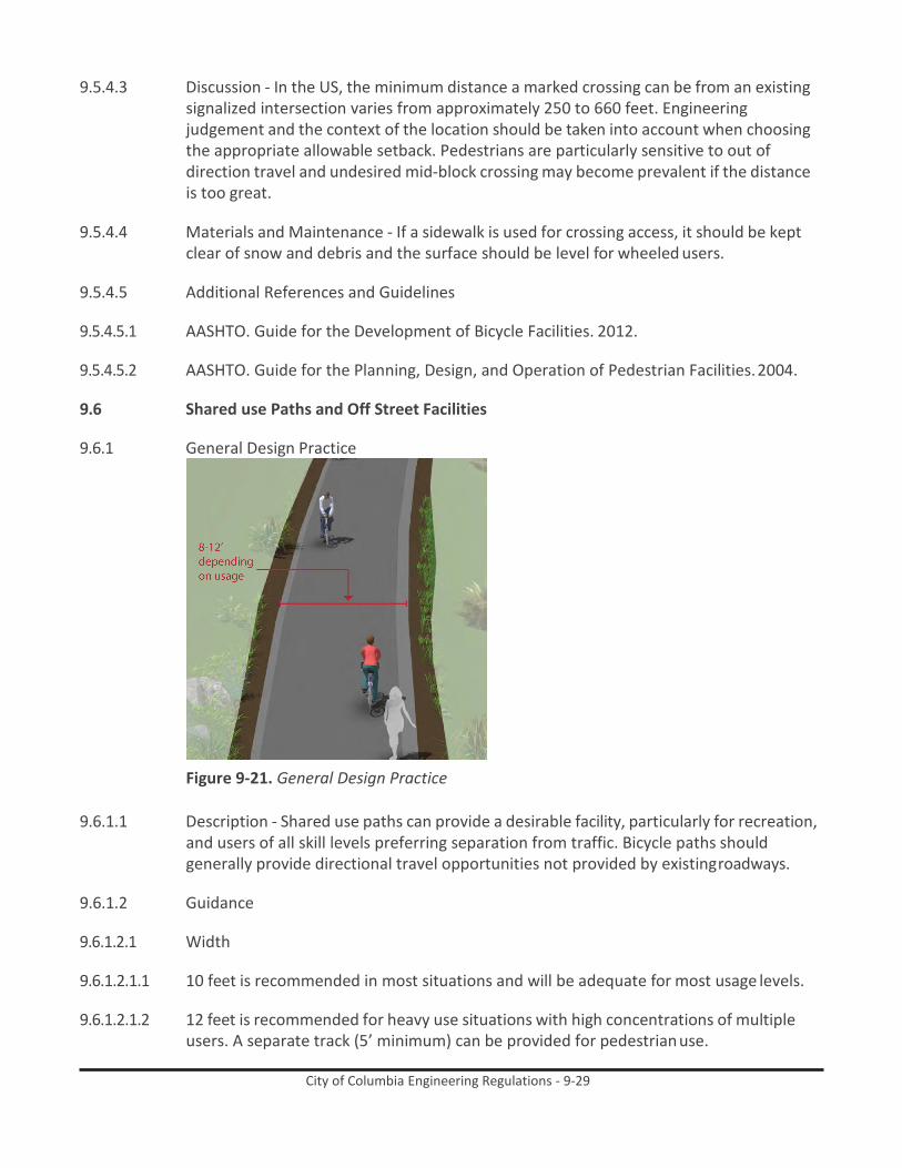
City of Columbia Engineering Regulations - 9-29
9.5.4.3 Discussion - In the US, the minimum distance a marked crossing can be from an existing signalized intersection varies from approximately 250 to 660 feet. Engineering judgement and the context of the location should be taken into account when choosing the appropriate allowable setback. Pedestrians are particularly sensitive to out of direction travel and undesired mid-block crossing may become prevalent if the distance is too great.
9.5.4.4 Materials and Maintenance - If a sidewalk is used for crossing access, it should be kept
clear of snow and debris and the surface should be level for wheeled users.
9.5.4.5 Additional References and Guidelines
9.5.4.5.1 AASHTO. Guide for the Development of Bicycle Facilities. 2012.
9.5.4.5.2 AASHTO. Guide for the Planning, Design, and Operation of Pedestrian Facilities. 2004.
9.6 Shared use Paths and Off Street Facilities
9.6.1 General Design Practice
Figure 9-21. General Design Practice
9.6.1.1 Description - Shared use paths can provide a desirable facility, particularly for recreation, and users of all skill levels preferring separation from traffic. Bicycle paths should generally provide directional travel opportunities not provided by existing roadways.
9.6.1.2 Guidance
9.6.1.2.1 Width
9.6.1.2.1.1 10 feet is recommended in most situations and will be adequate for most usage levels.
9.6.1.2.1.2 12 feet is recommended for heavy use situations with high concentrations of multiple
users. A separate track (5’ minimum) can be provided for pedestrian use.

City of Columbia Engineering Regulations - 9-30
9.6.1.2.1.3 In constrained conditions for short distances, 8 foot width may be acceptable.
9.6.1.2.2 Lateral Clearance
9.6.1.2.2.1 A 2 foot or greater shoulder on both sides of the path should be provided. An additional foot of lateral clearance (total of 3’) is required by the MUTCD for the installation of signage or other furnishings.
9.6.1.2.2.2 If bollards are used at intersections and access points, they should be colored brightly
and/or supplemented with reflective materials to be visible at night.
9.6.1.2.3 Overhead Clearance
9.6.1.2.3.1 Clearance to overhead obstructions should be 8 feet minimum, with 10 feet recommended.
9.6.1.2.4 Striping
9.6.1.2.4.1 When striping is required, use a 4 inch dashed yellow centerline stripe with 4 inch solid
white edge lines.
9.6.1.2.4.2 Solid centerlines can be provided on tight or blind corners, and on the approaches to roadway crossings.
9.6.1.3 Discussion - Terminate the path where it is easily accessible to and from the street
system, preferably at a controlled intersection or at the beginning of a dead-end street.
9.6.1.4 Materials and Maintenance - Asphalt is the most common surface for bicycle paths. The use of concrete for paths has proven to be more durable over the long term. Saw cut concrete joints rather than troweled improve the experience of path users.
9.6.1.5 Additional References and Guidelines
9.6.1.5.1 AASHTO. Guide for the Development of Bicycle Facilities. 2012.
9.6.1.5.2 FHWA. Manual on Uniform Traffic Control Devices. 2009.Flink, C. Greenways: A Guide To
Planning Design And Development. 1993.
9.6.2 Greenways In River And Utility Corridors
9.6.2.1 Description - Utility and waterway corridors often offer excellent shared use path development and bikeway gap closure opportunities. Utility corridors typically include powerline and sewer corridors, while waterway corridors include canals, drainage ditches, rivers, and beaches. These corridors offer excellent transportation and recreation opportunities for bicyclists of all ages and skills.
9.6.2.2 Guidance

City of Columbia Engineering Regulations - 9-31
9.6.2.2.1 Shared use paths in utility corridors should meet or exceed general design practices. If additional width allows, wider paths, and landscaping are desirable.
9.6.2.2.2 Access Points - Any access point to the path should be well-defined with appropriate
signage designating the pathway as a bicycle facility and prohibiting motor vehicles.
9.6.2.2.3 Path Closure - Public access to the shared use path may be prohibited during the following events:
9.6.2.2.3.1 Canal/flood control channel or other utility maintenance activities
9.6.2.2.3.2 Inclement weather or the prediction of storm conditions
9.6.2.3 Discussion - Similar to railroads, public access to flood control channels or canals may be undesirable. Hazardous materials, deep water or swift current, steep, slippery slopes, and debris all may constitute risks for public access. Appropriate fencing may be desired to keep path users within the designated travel way. Creative design of fencing is encouraged to make the path facility feel welcoming to the user.
9.6.2.4 Materials and Maintenance - Asphalt is the most common surface for bicycle paths. The
use of concrete for paths has proven to be more durable over the long term. Saw cut concrete joints rather than troweled improve the experience of path users.
9.6.2.5 Additional References and Guidelines
9.6.2.5.1 AASHTO. Guide for the Development of Bicycle Facilities. 2012.
9.6.2.5.2 FHWA. Manual on Uniform Traffic Control Devices. 2009.Flink, C. Greenways: A Guide To
Planning Design And Development. 1993.
9.6.3 Greenways In Abandoned Rail Corridors
Figure 9-22. Greenways In Abandoned Rail Corridors
9.6.3.1 Description - Commonly referred to as Rails-to-Trails or Rail-Trails, these projects convert vacated rail corridors into off-street paths. Rail corridors offer several advantages, including relatively direct routes between major destinations and generally flat terrain.

City of Columbia Engineering Regulations - 9-32
In some cases, rail owners may rail-bank their corridors as an alternative to a complete abandonment of the line, thus preserving the rail corridor for possible future use.
The railroad may form an agreement with any person, public or private, who would like to use the banked rail line as a trail or linear park until it is again needed for rail use. Municipalities should acquire abandoned rail rights-of-way whenever possible to preserve the opportunity for trail development.
9.6.3.2 Guidance - Shared use paths in abandoned rail corridors should meet or exceed general
design practices. If additional width allows, wider paths, and landscaping are desirable.
In full conversions of abandoned rail corridors, the subbase, superstructure, drainage, bridges, and crossings are already established. Design becomes a matter of working with the existing infrastructure to meet the needs of a rail-trail.
If converting a rail bed adjacent to an active rail line, see Shared Use Paths in Active Rail Corridors.
9.6.3.3 Discussion - It is often impractical and costly to add material to existing railroad bed fill
slopes. This results in trails that meet minimum path widths, but often lack preferred shoulder and lateral clearance widths.
Rail-to-trails can involve many challenges including the acquisition of the right of way, cleanup and removal of toxic substances, and rehabilitation of tunnels, trestles and culverts. A structural engineer should evaluate existing railroad bridges for structural integrity to ensure they are capable of carrying the appropriate design loads.
9.6.3.4 Materials and Maintenance - Asphalt is the most common surface for bicycle paths. The
use of concrete for paths has proven to be more durable over the long term. Saw cut concrete joints rather than troweled improve the experience of path users.
9.6.3.5 Additional References and Guidelines
9.6.3.5.1 AASHTO. Guide for the Development of Bicycle Facilities. 2012.
9.6.3.5.2 FHWA. Manual on Uniform Traffic Control Devices. 2009.
9.6.3.5.3 Flink, C. Greenways: A Guide To Planning Design And Development. 1993.

City of Columbia Engineering Regulations - 9-33
9.6.4 Greenways In Active Rail Corridors
Figure 9-23. Greenways In Active Rail Corridors
9.6.4.1 Description - Rails-with-Trails projects typically consist of paths adjacent to active railroads. It should be noted that some constraints could impact the feasibility of rail- with-trail projects. In some cases, space needs to be preserved for future planned freight, transit or commuter rail service. In other cases, limited right-of-way width, inadequate setbacks, concerns about safety/trespassing, and numerous crossings may affect a project’s feasibility.
9.6.4.2 Guidance - Shared use paths in utility corridors should meet or exceed general design
standards. If additional width allows, wider paths, and landscaping are desirable.
If required, fencing should be a minimum of 5 feet in height with higher fencing than usual next to sensitive areas such as switching yards. Setbacks from the active rail line will vary depending on the speed and frequency of trains, and available right-of-way.
9.6.4.3 Discussion - Railroads may require fencing with rail-with-trail projects. Concerns with
trespassing and security can vary with the volume and speed of train traffic on the adjacent rail line and the setting of the shared use path, i.e. whether the section of track is in an urban or rural setting.
9.6.4.4 Materials and Maintenance - Asphalt is the most common surface for bicycle paths. The
use of concrete for paths has proven to be more durable over the long term. Saw cut concrete joints rather than troweled improve the experience of path users.
9.6.4.5 Additional References and Guidelines
9.6.4.5.1 AASHTO. Guide for the Development of Bicycle Facilities. 2012.
9.6.4.5.2 FHWA. Manual on Uniform Traffic Control Devices. 2009.

City of Columbia Engineering Regulations - 9-34
9.6.4.5.3 FHWA. Rails-with-Trails: Lessons Learned. 2002.
9.6.5 Local Neighborhood Accessways
Figure 9-24. Local Neighborhood Accessways
9.6.5.1 Description - Neighborhood accessways provide residential areas with direct bicycle and pedestrian access to parks, trails, greenspaces, and other recreational areas. They most often serve as small trail connections to and from the larger trail network, typically having their own rights-of-way and easements.
Additionally, these smaller trails can be used to provide bicycle and pedestrian connections between dead-end streets, cul-de-sacs, and access to nearby destinations not provided by the street network.
9.6.5.2 Guidance
9.6.5.2.1 Neighborhood accessways should remain open to the public.
9.6.5.2.2 Trail pavement shall be at least 8’ wide to accommodate emergency and maintenance
vehicles, meet ADA requirements and be considered suitable for multi-use.
9.6.5.2.3 Trail widths should be designed to be less than 8’ wide only when necessary to protect large mature native trees over 18” in caliper, wetlands or other ecologically sensitive areas.
9.6.5.2.4 Access trails should slightly meander whenever possible.
9.6.5.3 Discussion - Neighborhood accessways should be designed into new subdivisions at
every opportunity and should be required by City/County subdivision regulations.
For existing subdivisions, Neighborhood and homeowner association groups are encouraged to identify locations where such connects would be desirable. Nearby residents and adjacent property owners should be invited to provide landscape design input.

City of Columbia Engineering Regulations - 9-35
9.6.5.4 Materials and Maintenance - Asphalt is the most common surface for bicycle paths. The use of concrete for paths has proven to be more durable over the long term. Saw cut concrete joints rather than troweled improve the experience of path users.
9.6.5.5 Additional References and Guidelines
9.6.5.5.1 AASHTO. Guide for the Development of Bicycle Facilities. 2012.
9.6.5.5.2 FHWA. Manual on Uniform Traffic Control Devices. 2009.
9.6.5.5.3 FHWA. Federal Highway Administration University Course on Bicycle and Pedestrian
Transportation. Lesson 19: Greenways and Shared Use Paths. 2006.
9.6.5.5.4 NACTO. Urban Street Design Guide. 2013.
9.6.6 Shared Use Paths Along Roadways
Figure 9-25. Shared Use Paths Along Roadways
9.6.6.1 Description - Shared Use Paths along roadways, also called Sidepaths, are a type of path that run adjacent to a street.
Because of operational concerns it is generally preferable to place paths within independent rights-of-way away from roadways. However, there are situations where existing roads provide the only corridors available.
Along roadways, these facilities create a situation where a portion of the bicycle traffic rides against the normal flow of motor vehicle traffic and can result in wrong-way riding where bicyclists enter or leave the path.
The AASHTO Guide for the Development of Bicycle Facilities cautions practitioners of the use of two-way sidepaths on urban or suburban streets with many driveways and street crossings.
In general, there are two approaches to crossings: adjacent crossings and setback crossings, illustrated below.
9.6.6.2 Guidance

City of Columbia Engineering Regulations - 9-36
9.6.6.2.1 Guidance for sidepaths should follow that for general design practises of shared use paths.
9.6.6.2.2 A high number of driveway crossings and intersections create potential conflicts with
turning traffic. Consider alternatives to sidepaths on streets with a high frequency of intersections or heavily used driveways.
9.6.6.2.3 Where a sidepath terminates special consideration should be given to transitions so as
not to encourage unsafe wrong-way riding by bicyclists.
9.6.6.2.4 Crossing design should emphasize visibility of users and clarity of expected yielding behavior. Crossings may be STOP or YIELD controlled depending on sight lines and bicycle motor vehicle volumes and speeds.
9.6.6.3 Discussion - The provision of a shared use path adjacent to a road is not a substitute for
the provision of on-road accommodation such as paved shoulders or bike lanes, but may be considered in some locations in addition to on-road bicycle facilities.
To reduce potential conflicts in some situations, it may be better to place one-way sidepaths on both sides of the street.
9.6.6.4 Materials and Maintenance - Asphalt is the most common surface for bicycle paths. The
use of concrete for paths has proven to be more durable over the long term. Saw cut concrete joints rather than troweled improve the experience of path users.
9.6.6.5 Additional References and Guidelines
9.6.6.5.1 AASHTO. Guide for the Development of Bicycle Facilities. 2012.
9.6.6.5.2 NACTO. Urban Bikeway Design Guide. See entry on Raised Cycle Tracks. 2012.

City of Columbia Engineering Regulations - 9-37
9.7 Path/ Roadway Crossing Types
9.7.1 Marked/Unsignalized Crossings
Figure 9-26. Marked/Unsignalized Crossings
9.7.1.1 Description - A marked/unsignalized crossing typically consists of a marked crossing area, signage and other markings to slow or stop traffic. The approach to designing crossings at mid-block locations depends on an evaluation of vehicular traffic, line of sight, pathway traffic, use patterns, vehicle speed, road type, road width, and other safety issues such as proximity to major attractions.
When space is available, using a median refuge island can improve user safety by providing pedestrians and bicyclists space to perform the safe crossing of one side of the street at a time.
See Active Warning Beacons (RRFB) and Hybrid Warning Beacons (HAWK) for more information on enhanced bicycle and pedestrian crossing treatments at unsignalized crossings locations.
9.7.1.2 Guidance
9.7.1.2.1 Maximum traffic volumes
9.7.1.2.1.1 ≤9,000-12,000 Average Daily Traffic (ADT) volume
9.7.1.2.1.2 Up to 15,000 ADT on two-lane roads, preferably with a median
9.7.1.2.1.3 Up to 12,000 ADT on four-lane roads with median
9.7.1.2.2 Maximum travel speed
9.7.1.2.2.1 35 MPH

City of Columbia Engineering Regulations - 9-38
9.7.1.2.3 Minimum line of sight
9.7.1.2.3.1 25 MPH zone: 155 feet
9.7.1.2.3.2 35 MPH zone: 250 feet
9.7.1.2.3.3 45 MPH zone: 360 feet
9.7.1.3 Discussion - Unsignalized crossings of multi-lane arterials over 15,000 ADT may be possible with features such as sufficient crossing gaps (more than 60 per hour), median refuges, and/or active warning devices like rectangular rapid flash beacons or in- pavement flashers, and excellent sight distance. For more information see the discussion of active warning beacons.
On roadways with low to moderate traffic volumes (<12,000 ADT) and a need to control traffic speeds, a raised crosswalk may be the most appropriate crossing design to improve pedestrian visibility and safety.
9.7.1.4 Materials and Maintenance - Locate markings out of wheel tread when possible to
minimize wear and maintenance costs.
9.7.1.5 Additional References and Guidelines
9.7.1.5.1 AASHTO. Guide for the Development of Bicycle Facilities. 2012.
9.7.1.5.2 FHWA. Manual on Uniform Traffic Control Devices. 2009.
9.7.2 Full Traffic Signal Crossings
Figure 9-27. Full Traffic Signal Crossings
9.7.2.1 Description - Signalized crossings provide the most protection for crossing path users through the use of a red-signal indication to stop conflicting motor vehicle traffic.

City of Columbia Engineering Regulations - 9-39
A full traffic signal installation treats the path crossing as a conventional 4-way intersection and provides standard red-yellow-green traffic signal heads for all legs of the intersection.
9.7.2.2 Guidance - Full traffic signal installations must meet MUTCD pedestrian, school or
modified warrants. Additional guidance for signalized crossings:
9.7.2.2.1 Located more than 300 feet from an existing signalized intersection
9.7.2.2.2 Roadway travel speeds of 40 MPH and above
9.7.2.2.3 Roadway ADT exceeds 15,000 vehicles
9.7.2.3 Discussion - Shared use path signals are normally activated by push buttons but may also be triggered by embedded loop, infrared, microwave or video detectors. The maximum delay for activation of the signal should be two minutes, with minimum crossing times determined by the width of the street.
Each crossing, regardless of traffic speed or volume, requires additional review by a registered engineer to identify sight lines, potential impacts on traffic progression, timing with adjacent signals, capacity and safety.
9.7.2.4 Materials and Maintenance - Traffic signals require routine maintenance. Signing and
striping need to be maintained to help users understand any unfamiliar traffic control.
9.7.2.5 Additional References and Guidelines
9.7.2.5.1 FHWA. Manual on Uniform Traffic Control Devices. 2009.
9.7.2.5.2 NACTO. Urban Bikeway Design Guide. 2012.
9.7.3 Undercrossings
Figure 9-28. Undercrossings
9.7.3.1 Description - Bicycle/pedestrian undercrossings provide critical non-motorized system links by joining areas separated by barriers such as railroads and highway corridors. In

City of Columbia Engineering Regulations - 9-40
most cases, these structures are built in response to user demand for safe crossings where they previously did not exist.
There are no minimum roadway characteristics for considering grade separation. Depending on the type of facility or the desired user group grade separation may be considered in many types of projects.
9.7.3.2 Guidance
9.7.3.2.1 14-foot minimum width, greater widths preferred for lengths over 60 feet.
9.7.3.2.2 10-foot minimum height.
9.7.3.2.3 The undercrossing should have a centerline stripe even if the rest of the path does not
have one.
9.7.3.2.4 Lighting should be considered during the design process for any undercrossing with high anticipated use or in culverts and tunnels.
9.7.3.3 Discussion - Safety is a major concern with undercrossings. Shared use path users may
be temporarily out of sight from public view and may experience poor visibility themselves. To mitigate safety concerns, an undercrossing should be designed to be spacious, well-lit, equipped with emergency call boxes at each end and completely visible for its entire length from end to end.
9.7.3.4 Materials and Maintenance - 14-foot width allows for maintenance vehicle access.
Potential problems include conflicts with utilities, drainage, flood control and vandalism.
9.7.3.5 Additional References and Guidelines
9.7.3.5.1 AASHTO. Guide for the Development of Bicycle Facilities. 2012.
9.7.3.5.2 AASHTO. Guide for the Planning, Design, and Operation of Pedestrian Facilities. 2004.

City of Columbia Engineering Regulations - 9-41
9.7.4 Overcrossings
Figure 9-29. Overcrossings
9.7.4.1 Description - Bicycle/pedestrian overcrossings provide critical non-motorized system links by joining areas separated by barriers such as deep canyons, waterways or major transportation corridors. In most cases, these structures are built in response to user demand for safe crossings where they previously did not exist.
There are no minimum roadway characteristics for considering grade separation. Depending on the type of facility or the desired user group grade separation may be considered in many types of projects.
Overcrossings require a minimum of 17 feet of vertical clearance to the roadway below versus a minimum elevation differential of around 12 feet for an undercrossing. This results in potentially greater elevation differences and much longer ramps for bicycles and pedestrians to negotiate.
9.7.4.2 Guidance - 8-foot minimum width, 14 feet preferred. If overcrossing has any scenic vistas
additional width should be provided to allow for stopping. A separate 5-foot pedestrian area may be provided for facilities with high bicycle and pedestrian use.
10 foot headroom on overcrossing; clearance below will vary depending on feature being crossed.
Roadway: 17 feet Freeway: 18.5 feet Heavy Rail Line: 23 feet
The overcrossing should have a centerline stripe even if the rest of the path does not have one.
9.7.4.3 Discussion - Overcrossings for bicycles and pedestrians typically fall under the Americans
with Disabilities Act (ADA), which strictly limits ramp slopes to 5% (1:20) with landings at 400 foot intervals, or 8.33% (1:12) with landings every 30 feet.

City of Columbia Engineering Regulations - 9-42
Overcrossings pose potential concerns about visual impact and functional appeal, as well as space requirements necessary to meet ADA guidelines for slope.
9.7.4.4 Materials and Maintenance - Potential issues with vandalism.
Overcrossings can be more difficult to clear of snow than undercrossings.
9.7.4.5 Additional References and Guidelines
9.7.4.5.1 AASHTO. Guide for the Development of Bicycle Facilities. 2012.
9.7.4.5.2 AASHTO. Guide for the Planning, Design, and Operation of Pedestrian Facilities. 2004.
9.8 Bicycle Facilities7
9.8.1 Design Needs of Bicyclists - The purpose of this section is to provide the facility designer with an understanding of how bicyclists operate and how their bicycle influences that operation. Bicyclists, by nature, are much more affected by poor facility design, construction and maintenance practices than motor vehicle drivers. Bicyclists lack the protection from the elements and roadway hazards provided by an automobile’s structure and safety features. By understanding the unique characteristics and needs of bicyclists, a facility designer can provide quality facilities and minimize user risk.
9.8.1.1 Bicycle as a Design Vehicle - Similar to motor vehicles, bicyclists and their bicycles exist in
a variety of sizes and configurations. These variations occur in the types of vehicle (such as a conventional bicycle, a recumbent bicycle or a tricycle), and behavioral characteristics (such as the comfort level of the bicyclist). The design of a bikeway should consider reasonably expected bicycle types on the facility and utilize the appropriate dimensions.
The figure below illustrates the operating space and physical dimensions of a typical adult bicyclist, which are the basis for typical facility design. Bicyclists require clear space to operate within a facility. This is why the minimum operating width is greater than the physical dimensions of the bicyclist. Bicyclists prefer five feet or more operating width, although four feet may be minimally acceptable.
In addition to the design dimensions of a typical bicycle, there are many other commonly used pedal-driven cycles and accessories to consider when planning and designing bicycle facilities. The most common types include tandem bicycles, recumbent bicycles, and trailer accessories. The figure and table below summarize the typical dimensions for bicycle types.
7 Source: AASHTO Guide for the Development of Bicycle Facilities, 4th Edition. 2012.

City of Columbia Engineering Regulations - 9-43
9.8.1.2 Standard Bicycle Rider Dimensions
Figure 9-30. Standard Bicycle Rider Dimensions

City of Columbia Engineering Regulations - 9-44
9.8.1.3 Bicycle as Design Vehicle - Typical Dimensions
Table 9-7. Bicycle as Design Vehicle - Typical Dimensions
Bicycle Type Feature Typical Dimensions Upright Adult Bicyclist
Physical width 2 ft. 6 in Operating width (Minimum) 4 ft. Operating width (Preferred) 5 ft. Physical length 5 ft. 10 in Physical height of handlebars 3 ft. 8 in
Operating height 8 ft. 4 in Eye height 5 ft. Vertical clearance to obstructions (tunnel height, lighting, etc)
10 ft.
Approximate center of gravity 2 ft. 9 in - 3 ft. 4 in
Recumbent Bicyclist Physical length 8 ft. Eye height 3 ft. 10 in
Tandem Bicyclist Physical length 8 ft.
Bicyclist with child trailer Physical length 10 ft. Physical width 2 ft. 6 in
9.8.1.4 Bicycle as Design Vehicle - Typical Speed
Table 9-8. Bicycle as Design Vehicle - Typical Speed
Bicycle Type Feature Typical Speed
Upright Adult Bicyclist
Paved level surfacing 15 mph Crossing Intersections 10 mph
Downhill 30 mph Uphill 5 -12 mph
Recumbent Bicyclist Paved level surfacing 18 mph *Tandem bicycles and bicyclists with trailers have typical speeds equal to or less than upright adult bicyclists.
9.8.1.5 Design Speed Expectations - The expected speed that different types of bicyclists can
maintain under various conditions also influences the design of facilities such as shared use paths. The table to the right provides typical bicyclist speeds for a variety of conditions.
9.8.1.6 Types of Bicyclists - It is important to consider bicyclists of all skill levels when creating a
non-motorized plan or project. Bicyclist skill level greatly influences expected speeds and behavior, both in separated bikeways and on shared roadways. Bicycle infrastructure should accommodate as many user types as possible, with decisions for separate or

City of Columbia Engineering Regulations - 9-45
parallel facilities based on providing a comfortable experience for the greatest number of people.
The bicycle planning and engineering professions currently use several systems to classify the population which can assist in understanding the characteristics and infrastructure preferences of different bicyclists. The current AASHTO Guide to the Development of Bicycle Facilities encourages designers to identify their rider type based on the trip purpose (Recreational vs Transportation) and on the level of comfort and skill of the rider (Causal vs Experienced). A more detailed framework for understanding of the US population’s relationship to transportation focused bicycling is illustrated in the figure below. Developed by planners in Portland, OR8 and supported by research9, this classification provides the following alternative categories to address varying attitudes towards bicycling in the US:
9.8.1.6.1 Strong and Fearless (approximately 1% of population) – Characterized by bicyclists that
will typically ride anywhere regardless of roadway conditions or weather. These bicyclists can ride faster than other user types, prefer direct routes and will typically choose roadway connections -- even if shared with vehicles -- over separate bicycle facilities such as shared use paths.
9.8.1.6.2 Enthused and Confident (5-10% of population) – This user group encompasses bicyclists
who are fairly comfortable riding on all types of bikeways but usually choose low traffic streets or shared use paths when available. These bicyclists may deviate from a more direct route in favor of a preferred facility type. This group includes all kinds of bicyclists such as commuters, recreationalists, racers and utilitarian bicyclists.
9.8.1.6.3 Interested but Concerned (approximately 60% of population) – This user type comprises
the bulk of the cycling population and represents bicyclists who typically only ride a bicycle on low traffic streets or shared use paths under favorable weather conditions. These bicyclists perceive significant barriers to their increased use of cycling, specifically traffic and other safety issues. These people may become “Enthused & Confident” with encouragement, education and experience.
9.8.1.6.4 No Way, No How (approximately 30% of population) – Persons in this category are not
bicyclists, and perceive severe safety issues with riding in traffic. Some people in this group may eventually become more regular cyclists with time and education. A significant portion of these people will not ride a bicycle under any circumstances.
9.8.2 Bicycle Facility Selection Guidelines
9.8.2.1 The specific bicycle facility type that should be provided depends on the surrounding
environment (e.g. auto speed and volume, topography, and adjacent land use) and expected bicyclist needs (e.g. bicyclists commuting on a highway versus students riding to school on residential streets).
8 Roger Geller, City of Portland Bureau of Transportation. Four Types of Cyclists. http://www.portlandonline.com/
transportation/index.cfm?&a=237507. 2009. 9 Dill, J., McNeil, N. Four Types of Cyclists? Testing a Typology to Better Understand Bicycling Behavior and Potential. 2012.

City of Columbia Engineering Regulations - 9-46
9.8.2.2 Facility Selection Guidelines - There are no ‘hard and fast’ rules for determining the most appropriate type of bicycle facility for a particular location – roadway speeds, volumes, right-of-way width, presence of parking, adjacent land uses, and expected bicycle user types are all critical elements of this decision. Studies find that the most significant factors influencing bicycle use are motor vehicle traffic volumes and speeds. Additionally, most bicyclists prefer facilities separated from motor vehicle traffic or located on local roads with low motor vehicle traffic speeds and volumes. Because off-street pathways are physically separated from the roadway, they are perceived as safe and attractive routes for bicyclists who prefer to avoid motor vehicle traffic. Consistent use of treatments and application of bikeway facilities allow users to anticipate whether they would feel comfortable riding on a particular facility, and plan their trips accordingly. This section provides guidance on various factors that affect the type of facilities that should be provided.
9.8.3 Facility Classification
9.8.3.1 Description - Consistent with bicycle facility
classifications throughout the nation, these Bicycle Facility Design Guidelines identify the following classes of facilities by degree of separation from motor vehicle traffic.
9.8.3.1.1 Shared Roadways are bikeways where bicyclists and cars operate within the same travel lane, either side by side or in single file depending on roadway configuration. The most basic type of bikeway is a signed shared roadway. This facility provides continuity with other bicycle facilities (usually bike lanes), or designates preferred routes through high- demand corridors.
Shared Roadways may also be designated by pavement markings, signage and other treatments including directional signage, traffic diverters, chicanes, chokers and /or other traffic calming devices to reduce vehicle speeds or volumes. Such treatments often are associated with Neighborhood Greenways.
9.8.3.1.2 Separated Bikeways, such as bike lanes, use
signage and striping to delineate the right-of- way assigned to bicyclists and motorists. Bike lanes encourage predictable movements by both bicyclists and motorists.
Figure 9-31. Shared Roadways
Figure 9-32. Separated Bikeways
Figure 9-33. Cycle Tracks
Figure 9-34. Shared Use Paths

City of Columbia Engineering Regulations - 9-47
9.8.3.1.3 Cycle Tracks are exclusive bike facilities that combine the user experience of a separated path with the on-street infrastructure of conventional bike lanes.
9.8.3.1.4 Shared Use Paths are facilities separated from roadways for use by bicyclists and
pedestrians.
9.8.4 Facility Continua - The following continua illustrate the range of bicycle facilities applicable to various roadway environments, based on the roadway type and desired degree of separation. Engineering judgment, traffic studies, previous municipal planning efforts, community input and local context should be used to refine criteria when developing bicycle facility recommendations for a particular street. In some corridors, it may be desirable to construct facilities to a higher level of treatment than those recommended in relevant planning documents in order to enhance user safety and comfort. In other cases, existing and/ or future motor vehicle speeds and volumes may not justify the recommended level of separation, and a less intensive treatment may be acceptable.
Figure 9-35. Facility Continua
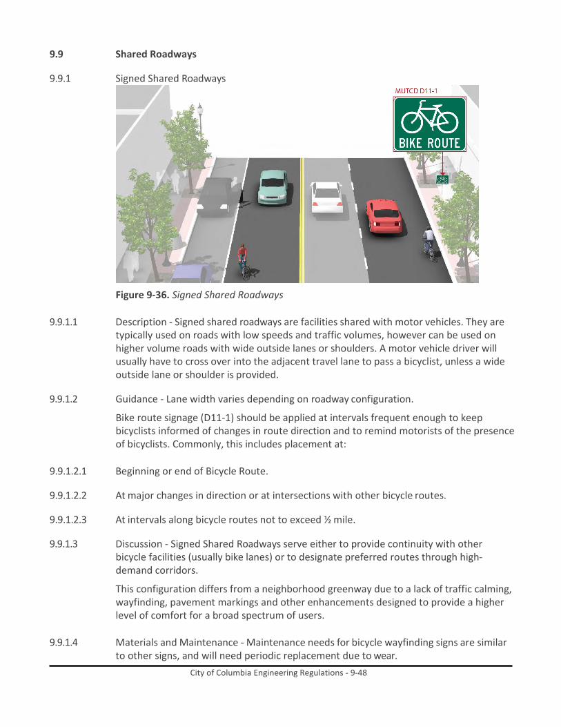
City of Columbia Engineering Regulations - 9-48
9.9 Shared Roadways
9.9.1 Signed Shared Roadways
Figure 9-36. Signed Shared Roadways
9.9.1.1 Description - Signed shared roadways are facilities shared with motor vehicles. They are typically used on roads with low speeds and traffic volumes, however can be used on higher volume roads with wide outside lanes or shoulders. A motor vehicle driver will usually have to cross over into the adjacent travel lane to pass a bicyclist, unless a wide outside lane or shoulder is provided.
9.9.1.2 Guidance - Lane width varies depending on roadway configuration.
Bike route signage (D11-1) should be applied at intervals frequent enough to keep bicyclists informed of changes in route direction and to remind motorists of the presence of bicyclists. Commonly, this includes placement at:
9.9.1.2.1 Beginning or end of Bicycle Route.
9.9.1.2.2 At major changes in direction or at intersections with other bicycle routes.
9.9.1.2.3 At intervals along bicycle routes not to exceed ½ mile.
9.9.1.3 Discussion - Signed Shared Roadways serve either to provide continuity with other
bicycle facilities (usually bike lanes) or to designate preferred routes through high- demand corridors.
This configuration differs from a neighborhood greenway due to a lack of traffic calming, wayfinding, pavement markings and other enhancements designed to provide a higher level of comfort for a broad spectrum of users.
9.9.1.4 Materials and Maintenance - Maintenance needs for bicycle wayfinding signs are similar
to other signs, and will need periodic replacement due to wear.

City of Columbia Engineering Regulations - 9-49
9.9.1.5 Additional References and Guidelines
9.9.1.5.1 AASHTO. Guide for the Development of Bicycle Facilities. 2012.
9.9.1.5.2 FHWA. Manual on Uniform Traffic Control Devices. 2009.
9.9.2 Marked Shared Roadways
Figure 9-37. Marked Shared Roadways
9.9.2.1 Description - A marked shared roadway is a general purpose travel lane marked with shared lane markings (SLM) used to encourage bicycle travel and proper positioning within the lane.
In constrained conditions, the SLMs are placed in the middle of the lane. On a wide outside lane, the SLMs can be used to promote bicycle travel to the right of motor vehicles.
In all conditions, SLMs should be placed outside of the door zone of parked cars.
9.9.2.2 Guidance
9.9.2.2.1 May be used on streets with a speed limit of 35 mph or under. Lower than 30 mph speed limit preferred.
9.9.2.2.2 In constrained conditions, preferred placement is in the center of the travel lane to
minimize wear and promote single file travel.
9.9.2.2.3 Minimum placement of SLM marking centerline is 11 feet from edge of curb where on-street parking is present, 4 feet from edge of curb with no parking. If parking lane is wider than 7.5 feet, the SLM should be moved further out accordingly.
9.9.2.3 Discussion - If collector or arterial, this should not be a substitute for dedicated bicycle
facilities if space is available.

City of Columbia Engineering Regulations - 9-50
Bike Lanes should be considered on roadways with outside travel lanes wider than 15 feet, or where other lane narrowing or removal strategies may provide adequate road space. SLMs shall not be used on shoulders, in designated bike lanes, or to designate bicycle detection at signalized intersections. (MUTCD 9C.07)
9.9.2.4 Materials and Maintenance - Placing SLMs between vehicle tire tracks will increase the
life of the markings and minimize the long-term cost of the treatment.
9.9.2.5 Additional References and Guidelines
9.9.2.5.1 SCDOT. TG-24: Use of Shared Lane Marking Symbols.
9.9.2.5.2 AASHTO. Guide for the Development of Bicycle Facilities. 2012.
9.9.2.5.3 FHWA. Manual on Uniform Traffic Control Devices. 2009.
9.9.2.5.4 NACTO. Urban Bikeway Design Guide. 2012.
9.9.3 Bicycle Boulevards
Figure 9-38. Bicycle Boulevards
9.9.3.1 Description - Bicycle boulevards are low-volume, low-speed streets modified to enhance bicyclist comfort by using treatments such as signage, pavement markings, traffic calming and/or traffic reduction, and intersection modifications. These treatments allow through movements of bicyclists while discouraging similar through-trips by non-local motorized traffic.
9.9.3.2 Guidance
9.9.3.2.1 Signs and pavement markings are the minimum treatments necessary to designate a
street as a bicycle boulevard.

City of Columbia Engineering Regulations - 9-51
9.9.3.2.2 Bicycle boulevards should have a maximum posted speed of 25 mph. Use traffic calming to maintain an 85th percentile speed below 22 mph.
9.9.3.2.3 Implement volume control treatments based on the context of the bicycle boulevard,
using engineering judgment. Target motor vehicle volumes range from 1,000 to 3,000 vehicles per day.
9.9.3.2.4 Intersection crossings should be designed to enhance safety and minimize delay for
bicyclists.
9.9.3.3 Discussion - Bicycle boulevard retrofits to local streets are typically located on streets without existing signalized accommodation at crossings of collector and arterial roadways. Without treatments for bicyclists, these intersections can become major barriers along the bicycle boulevard and compromise safety.
Traffic calming can deter motorists from driving on a street. Anticipate and monitor vehicle volumes on adjacent streets to determine whether traffic calming results in inappropriate volumes. Traffic calming can be implemented on a trial basis.
9.9.3.4 Materials and Maintenance - Vegetation should be regularly trimmed to maintain
visibility and attractiveness.
9.9.3.5 Additional References and Guidelines
9.9.3.5.1 Alta Planning + Design and IBPI. Bicycle Boulevard Planning and Design Handbook. 2009. BikeSafe. Bicycle countermeasure selection system.
9.9.3.5.2 Ewing, Reid. Traffic Calming: State of the Practice. 1999.
9.9.3.5.3 Ewing, Reid and Brown, Steven. U.S. Traffic Calming Manual. 2009.
9.9.4 Advisory Bike Lane
Figure 9-39. Advisory Bike Lane

City of Columbia Engineering Regulations - 9-52
9.9.4.1 Description - Advisory bike lanes are bicycle priority areas delineated by dotted white lines, separated from a narrow automobile travel area. The automobile zone should be configured narrowly enough so that two cars cannot pass each other in both directions without crossing the advisory lane line.
Motorists may only enter the bicycle zone when no bicycles are present. Motorists must overtake with caution due to potential oncoming traffic.
9.9.4.2 Guidance - Advisory bike lanes can be used on roadways where the following conditions
exist:
9.9.4.2.1 Motor vehicle traffic is <4000 motor vehicles per day (<2000 preferred).
9.9.4.2.2 Advisory bike lane width of 5 to 7 ft.
9.9.4.2.3 Minimum 2-way motor vehicle travel lane width of 13-18 feet.
9.9.4.2.4 No centerline on roadway.
9.9.4.3 Discussion - Most appropriate when roadways are straight with few bends, inclines or sightline obstructions. Consider the use of colored pavement within the bicycle priority area to discourage unnecessary encroachment by motorists or parked vehicles. This treatment requires a request to experiment to be implemented on roadways funded with federal transportation dollars.
9.9.4.4 Materials and Maintenance - Paint can wear more quickly in high traffic areas or in
winter climates. Bicycle lanes should be cleared of snow through routine snow removal operations.
9.9.4.5 Additional References and Guidelines
9.9.4.5.1 City of Minneapolis. Request To Experiment. July 2010.

City of Columbia Engineering Regulations - 9-53
9.10 Separated bikeways
9.10.1 Shoulder Bikeways
Figure 9-40. Shoulder Bikeways
9.10.1.1 Description - Typically found in less-dense areas, shoulder bikeways are paved roadways with striped shoulders (4’+) wide enough for bicycle travel. Shoulder bikeways often, but not always, include signage alerting motorists to expect bicycle travel along the roadway. Shoulder bikeways should be considered a temporary treatment, with full bike lanes planned for construction when the roadway is widened or completed with curb and gutter. This type of treatment is not typical in urban areas and should only be used where constraints exist.
9.10.1.2 Guidance - If 4 feet or more is available for bicycle travel, the full bike lane treatment of
signs, legends, and an 8” bike lane line would be provided.
9.10.1.2.1 If it is not possible to meet minimum bicycle lane dimensions, a reduced width paved shoulder can still improve conditions for bicyclists on constrained roadways. In these situations, a minimum of 3 feet of operating space should be provided.
9.10.1.2.2 Rumble strips are not recommended on shoulders used by bicyclists unless there is a
minimum 4-foot clear path. 12 foot gaps every 40-60 feet should be provided to allow access as needed.
9.10.1.3 Discussion - A wide outside lane may be sufficient accommodation for bicyclists on
streets with insufficient width for bike lanes but which do have space available to provide a wider (14’-16’) outside travel lane. Consider configuring as a marked shared roadway in these locations.
9.10.1.4 Materials and Maintenance - Paint can wear more quickly in high traffic areas or in
winter climates. Shoulder bikeways should be cleared of snow through routine snow removal operations.
9.10.1.5 Additional References and Guidelines

City of Columbia Engineering Regulations - 9-54
9.10.1.5.1 SCDOT. EDM 53: Installation of Rumble Strips.
9.10.1.5.2 AASHTO. Guide for the Development of Bicycle Facilities. 2012.
9.10.1.5.3 FHWA. Manual on Uniform Traffic Control Devices. 2009.
9.10.2 Conventional Bike Lane
Figure 9-41. Conventional Bike Lane
9.10.2.1 Description - Bike lanes designate an exclusive space for bicyclists through the use of pavement markings and signage. The bike lane is located adjacent to motor vehicle travel lanes and is used in the same direction as motor vehicle traffic. Bike lanes are typically on the right side of the street, between the adjacent travel lane and curb, road edge or parking lane.
Many bicyclists, particularly less experienced riders, are more comfortable riding on a busy street if it has a striped and signed bikeway than if they are expected to share a lane with vehicles.
9.10.2.2 Guidance
9.10.2.2.1 4 foot minimum when no curb and gutter is present.
9.10.2.2.2 5 foot minimum when adjacent to curb and gutter or 3 feet more than the gutter pan
width if the gutter pan is wider than 2 feet.
9.10.2.2.3 14.5 foot preferred from curb face to edge of bike lane. (12 foot minimum).
9.10.2.2.4 7 foot maximum width for use adjacent to arterials with high travel speeds. Greater widths may encourage motor vehicle use of bike lane.

City of Columbia Engineering Regulations - 9-55
9.10.2.3 Discussion - Wider bicycle lanes are desirable in certain situations such as on higher speed arterials (45 mph+) where use of a wider bicycle lane would increase separation between passing vehicles and bicyclists. Appropriate signing and stenciling is important with wide bicycle lanes to ensure motorists do not mistake the lane for a vehicle lane or parking lane. Consider buffered bike lanes when further separation is desired.
9.10.2.4 Materials and Maintenance - Paint can wear more quickly in high traffic areas or in
winter climates. Bicycle lanes should be cleared of snow through routine snow removal operations.
9.10.2.5 Additional References and Guidelines
9.10.2.5.1 SCDOT. EDM 22: Considerations for Bicycle Facilities.
9.10.2.5.2 AASHTO. Guide for the Development of Bicycle Facilities. 2012.
9.10.2.5.3 FHWA. Manual on Uniform Traffic Control Devices. 2009.
9.10.2.5.4 NACTO. Urban Bikeway Design Guide. 2012.
9.10.3 Bike Lane Adjacent To On-Street Parking
Figure 9-42. Bike Lane Adjacent To On-Street Parking
9.10.3.1 Description - Bike lanes designate an exclusive space for bicyclists through the use of pavement markings and signage. The bike lane is located adjacent to motor vehicle travel lanes and is used in the same direction as motor vehicle traffic. Bike lanes are typically on the right side of the street, between the adjacent travel lane and curb, road edge or parking lane.
Many bicyclists, particularly less experienced riders, are more comfortable riding on a busy street if it has a striped and signed bikeway than if they are expected to share a lane with vehicles.

City of Columbia Engineering Regulations - 9-56
9.10.3.2 Guidance
9.10.3.2.1 12-foot minimum from curb face to edge of bike lane.
9.10.3.2.2 14.5 foot preferred from curb face to edge of bike lane.
9.10.3.2.3 7-foot maximum for marked width of bike lane. Greater widths may encourage vehicle loading in bike lane. Configure as buffered bicycle lanes when a wider facility is desired.
9.10.3.3 Discussion - Bike lanes adjacent to on-street parallel parking require special treatment in
order to avoid crashes caused by an open vehicle door. The bike lane should have sufficient width to allow bicyclists to stay out of the door zone while not encroaching into the adjacent vehicular lane. Parking stall markings, such as parking “Ts” and double white lines create a parking side buffer that encourages bicyclists to ride farther away from the door zone.
9.10.3.4 Materials and Maintenance - Paint can wear more quickly in high traffic areas or in
winter climates. Bicycle lanes should be cleared of snow through routine snow removal operations.
9.10.3.5 Additional References and Guidelines
9.10.3.5.1 AASHTO. Guide for the Development of Bicycle Facilities. 2012.
9.10.3.5.2 FHWA. Manual on Uniform Traffic Control Devices. 2009.
9.10.3.5.3 NACTO. Urban Bikeway Design Guide. 2012.
9.10.4 Bikeways And Diagonal Parking
Figure 9-43. Bikeways and Diagonal Parking
9.10.4.1 Description - In certain areas with high parking demand such as urban commercial areas, diagonal parking can be used to increase parking supply.

City of Columbia Engineering Regulations - 9-57
Back-in diagonal parking improves sight distances between drivers and bicyclists when compared to conventional head-in diagonal parking. Back-in parking is best paired with a dedicated bicycle lane.
Conventional front-in diagonal parking is not compatible or recommended with the provision of bike lanes, as drivers backing out of conventional diagonal parking have limited visibility of approaching bicyclists. Under these conditions, shared lane markings should be used to guide bicyclists away from reversing automobiles.
9.10.4.2 Guidance
9.10.4.2.1 Front-in Diagonal Parking
9.10.4.2.1.1 Shared lane markings are the preferred facility with front-in diagonal parking
9.10.4.2.2 Back-in Diagonal Parking
9.10.4.2.2.1 5-foot minimum marked width of bike lane
9.10.4.2.2.2 Parking bays are sufficiently long to accommodate most vehicles (so vehicles do not
block bike lane)
9.10.4.3 Discussion - Back-in diagonal parking provides other benefits including loading and unloading of the trunk at the curb rather than in the street, passengers (including children) are directed by open doors towards the curb and there is no door conflict with bicyclists. While there may be a learning curve for some drivers, back-in diagonal parking is typically an easier maneuver than conventional parallel parking.
9.10.4.4 Materials and Maintenance - Paint can wear more quickly in high traffic areas or in
winter climates. Bicycle lanes should be cleared of snow through routine snow removal operations.
9.10.4.5 Additional References and Guidelines
9.10.4.5.1 AASHTO. Guide for the Development of Bicycle Facilities. 2012.

City of Columbia Engineering Regulations - 9-58
9.10.5 Left Side Bike Lane
Figure 9-44. Left Side Bike Lane
9.10.5.1 Description - Left-side bike lanes are conventional bike lanes placed on the left side of one-way streets or two-way median divided streets.
Left-side bike lanes offer advantages on streets with heavy delivery or transit use, frequent parking turnover on the right side or other potential conflicts that could be associated with right-side bicycle lanes.
9.10.5.2 Guidance - Follow guidance for conventional bike lanes.
Signage should accompany left-side bicycle lanes to clarify proper use by bicyclists to reduce wrong-way riding.
Bicycle through lanes should be provided to the right of vehicle left turn pockets to reduce conflicts at intersections.
9.10.5.3 Discussion - Intersection treatments such as bike boxes and bike signals should be
considered to assist in the transition from left-side bike lanes to right-side bike lanes.
9.10.5.4 Materials and Maintenance - Paint can wear more quickly in high traffic areas or in winter climates. Bicycle lanes should be cleared of snow through routine snow removal operations.
9.10.5.5 Additional References and Guidelines
9.10.5.5.1 AASHTO. Guide for the Development of Bicycle Facilities. 2012.
9.10.5.5.2 FHWA. Manual on Uniform Traffic Control Devices. 2009.
9.10.5.5.3 NACTO. Urban Bikeway Design Guide. 2012.

City of Columbia Engineering Regulations - 9-59
9.10.6 Contra Flow Bike Lane
Figure 9-45. Contra Flow Bike Lane
9.10.6.1 Description - Contra-flow bike lanes provide bidirectional bicycle access on a roadway that is one-way for motor vehicle traffic. This treatment can provide direct access and connectivity for bicyclists and reducing travel distances. Contra-flow bike lanes can also be used to convert two-way motor vehicle traffic to one-way to reduce traffic volumes where desired.
9.10.6.2 Guidance
9.10.6.2.1 The contra-flow bike lane should be 5-7 feet wide and marked with a solid double yellow
line and appropriate signage. Bike lane markings should be clearly visible to ensure that the contra-flow lane is exclusively for bicycles. Coloration should be considered in the bike lane.
9.10.6.2.2 Signage specifically allowing bicycles at the entrance of the contra flow lane is
recommended.
9.10.6.3 Discussion - Because of the opposing direction of travel, contra-flow bike lanes increase the speed differential between bicyclists and motor vehicles in the adjacent travel lane. If space permits consider a buffered bike lane or cycle track configuration to provide additional separation.
9.10.6.4 Materials and Maintenance - Paint can wear more quickly in high traffic areas or in
winter climates. Bicycle lanes should be cleared of snow through routine snow removal operations.
9.10.6.5 Additional References and Guidelines
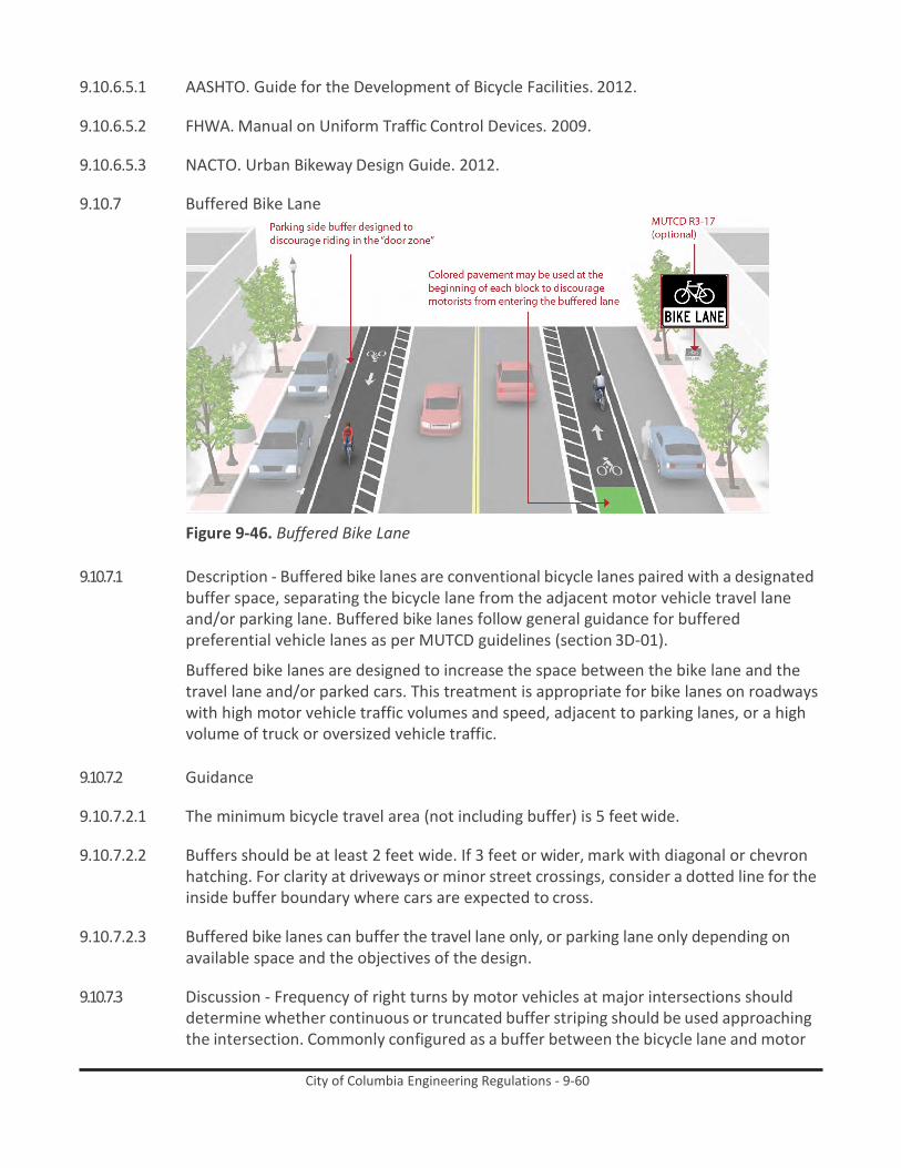
City of Columbia Engineering Regulations - 9-60
9.10.6.5.1 AASHTO. Guide for the Development of Bicycle Facilities. 2012.
9.10.6.5.2 FHWA. Manual on Uniform Traffic Control Devices. 2009.
9.10.6.5.3 NACTO. Urban Bikeway Design Guide. 2012.
9.10.7 Buffered Bike Lane
Figure 9-46. Buffered Bike Lane
9.10.7.1 Description - Buffered bike lanes are conventional bicycle lanes paired with a designated buffer space, separating the bicycle lane from the adjacent motor vehicle travel lane and/or parking lane. Buffered bike lanes follow general guidance for buffered preferential vehicle lanes as per MUTCD guidelines (section 3D-01).
Buffered bike lanes are designed to increase the space between the bike lane and the travel lane and/or parked cars. This treatment is appropriate for bike lanes on roadways with high motor vehicle traffic volumes and speed, adjacent to parking lanes, or a high volume of truck or oversized vehicle traffic.
9.10.7.2 Guidance
9.10.7.2.1 The minimum bicycle travel area (not including buffer) is 5 feet wide.
9.10.7.2.2 Buffers should be at least 2 feet wide. If 3 feet or wider, mark with diagonal or chevron
hatching. For clarity at driveways or minor street crossings, consider a dotted line for the inside buffer boundary where cars are expected to cross.
9.10.7.2.3 Buffered bike lanes can buffer the travel lane only, or parking lane only depending on
available space and the objectives of the design.
9.10.7.3 Discussion - Frequency of right turns by motor vehicles at major intersections should determine whether continuous or truncated buffer striping should be used approaching the intersection. Commonly configured as a buffer between the bicycle lane and motor

City of Columbia Engineering Regulations - 9-61
vehicle travel lane, a parking side buffer may also be provided to help bicyclists avoid the ‘door zone’ of parked cars.
9.10.7.4 Materials and Maintenance - Paint can wear more quickly in high traffic areas or in
winter climates. Bicycle lanes should be cleared of snow through routine snow removal operations.
9.10.7.5 Additional References and Guidelines
9.10.7.5.1 AASHTO. Guide for the Development of Bicycle Facilities. 2012.
9.10.7.5.2 FHWA. Manual on Uniform Traffic Control Devices. (3D-01). 2009.
9.10.7.5.3 NACTO. Urban Bikeway Design Guide. 2012.
9.10.8 Uphill Bicycle Climbing Lane
Figure 9-47. Uphill Bicycle Climbing Lane
9.10.8.1 Description - Uphill bike lanes (also known as “climbing lanes”) enable motorists to safely pass slower-speed bicyclists, thereby improving conditions for both travel modes.
9.10.8.2 Guidance
9.10.8.2.1 Uphill bike lanes should be 6-7 feet wide (wider lanes are preferred because extra
maneuvering room on steep grades can benefit bicyclists).
9.10.8.2.2 Can be combined with shared lane markings for downhill bicyclists who can more closely match prevailing traffic speeds.
9.10.8.3 Discussion - This treatment is typically found on retrofit projects as newly constructed
roads should provide adequate space for bicycle lanes in both directions of travel.

City of Columbia Engineering Regulations - 9-62
Accommodating an uphill bicycle lane often includes delineating on-street parking (if provided), narrowing travel lanes and/or shifting the centerline if necessary.
9.10.8.4 Materials and Maintenance - Paint can wear more quickly in high traffic areas or in
winter climates. Bicycle lanes should be cleared of snow through routine snow removal operations.
9.10.8.5 Additional References and Guidelines
9.10.8.5.1 NACTO. Urban Bikeway Design Guide. 2012.
9.10.8.5.2 AASHTO. Guide for the Development of Bicycle Facilities. 2012.
9.10.8.5.3 FHWA. Manual on Uniform Traffic Control Devices. 2009.
9.11 Protected bike lanes
9.11.1 Cycle Track Separation And Placement
Figure 9-48. Cycle Track Separation And Placement
9.11.1.1 Description - Protection is provided through physical barriers and can include bollards, parking, a planter strip, an extruded curb, or on-street parking. Cycle tracks using these protection elements typically share the same elevation as adjacent travel lanes.
Raised cycle tracks may be at the level of the adjacent sidewalk or set at an intermediate level between the roadway and sidewalk to separate the cycle track from the pedestrian area.
9.11.1.2 Guidance
9.11.1.2.1 Cycle tracks should ideally be placed along streets with long blocks and few driveways or
mid-block access points for motor vehicles. Cycle tracks located on one-way streets have fewer potential conflict areas than those on two-way streets.

City of Columbia Engineering Regulations - 9-63
9.11.1.2.2 In situations where on-street parking is allowed, cycle tracks shall be located between the parking lane and the sidewalk (in contrast to bike lanes).
9.11.1.3 Discussion - Sidewalks or other pedestrian facilities should not be narrowed to
accommodate the cycle track as pedestrians will likely walk on the cycle track if sidewalk capacity is reduced. Visual and physical cues (e.g., pavement markings & signage) should be used to make it clear where bicyclists and pedestrians should be travelling. If possible, separate the cycle track and pedestrian zone with a furnishing zone.
9.11.1.4 Materials and Maintenance - In cities with winter climates, barrier separated and raised
cycle tracks may require special equipment for snow removal.
9.11.1.5 Additional References and Guidelines
9.11.1.5.1 NACTO. Urban Bikeway Design Guide. 2012.
9.11.2 One-Way Cycle Tracks
Figure 9-49. One-Way Cycle Tracks
9.11.2.1 Description - One-way cycle tracks are physically separated from motor traffic and distinct from the sidewalk. Cycle tracks are either raised or at street level and use a variety of elements for physical protection from passing traffic.
9.11.2.2 Guidance
9.11.2.2.1 7 foot recommended minimum to allow passing.
9.11.2.2.2 5 foot minimum width in constrained locations.
9.11.2.2.3 When placed adjacent to parking, the parking buffer should be three feet wide to allow
for passenger loading and to prevent door collisions.

City of Columbia Engineering Regulations - 9-64
9.11.2.2.4 When placed adjacent to a travel lane, one-way raised cycle tracks may be configured with a mountable curb to allow entry and exit from the bicycle lane for passing other bicyclists or to access vehicular turn lanes.
9.11.2.3 Discussion - Special consideration should be given at transit stops to manage bicycle and
pedestrian interactions. Driveways and minor street crossings are unique challenges to cycle track design. Parking should be prohibited within 30 feet of the intersection to improve visibility. Color, yield markings and “Yield to Bikes” signage should be used to identify the conflict area and make it clear that the cycle track has priority over entering and exiting traffic. If configured as a raised cycle track, the crossing should be raised so that the sidewalk and cycle track maintain their elevation through the crossing.
9.11.2.4 Materials and Maintenance - In cities with winter climates, barrier separated and raised
cycle tracks may require special equipment for snow removal.
9.11.2.5 Additional References and Guidelines
9.11.2.5.1 NACTO. Urban Bikeway Design Guide. 2012.
9.11.3 Two Way Cycle Tracks
Figure 9-50. Two Way Cycle Tracks
9.11.3.1 Description - Two-way cycle tracks are physically separated cycle tracks that allow bicycle movement in both directions on one side of the road. Two-way cycle tracks share some of the same design characteristics as one-way cycle tracks, but may require additional considerations at driveway and side-street crossings.
A two-way cycle track may be configured as a protected cycle track at street level with a parking lane or other barrier between the cycle track and the motor vehicle travel lane and/or as a raised cycle track to provide vertical separation from the adjacent motor vehicle lane.
9.11.3.2 Guidance

City of Columbia Engineering Regulations - 9-65
9.11.3.2.1 12 foot recommended minimum for two-way facility
9.11.3.2.2 8 foot minimum in constrained locations
9.11.3.2.3 When placed adjacent to parking, the parking buffer should be three feet wide to allow for passenger loading and to prevent door collisions.
9.11.3.3 Discussion - Cycle tracks will require careful assessment of intersection traffic operation,
including traffic signal control, to ensure safe and efficient travel is maintained. Turning movements should be guided by separated signals for bicycles and conflicting motor vehicles. Transitions into and out of two-way cycle tracks should be simple and easy to use to deter bicyclists from continuing to ride against the flow of traffic.
At driveways and minor intersections, bicyclists riding against roadway traffic in two-way cycle tracks may surprise pedestrians and drivers not expecting bidirectional travel. Appropriate signage is recommended.
9.11.3.4 Materials and Maintenance - In cities with winter climates barrier, separated and raised
cycle tracks may require special equipment for snow removal.
9.11.3.5 Additional References and Guidelines
9.11.3.5.1 NACTO. Urban Bikeway Design Guide. 2012.
9.11.3.5.2 ITE. Separated Bikeways. 2013.
9.11.4 Driveways And Minor Street Crossings
Figure 9-51. Driveways And Minor Street Crossings
9.11.4.1 Description - The added separation provided by cycle tracks creates additional considerations at intersections that should be addressed.
City of Columbia Engineering Regulations - 9-66
At driveways and crossings of minor streets a smaller fraction of automobiles will cross the cycle track. Bicyclists should not be expected to stop at these minor intersections if the major street does not stop.
9.11.4.2 Guidance
9.11.4.2.1 If raised, maintain the height of the cycle track through the crossing, requiring
automobiles to cross over.
9.11.4.2.2 Remove parking 30 feet prior the intersection.
9.11.4.2.3 Use colored pavement markings and/or shared lane markings through the conflict area.
9.11.4.2.4 Place warning signage to identify the crossing.
9.11.4.3 Discussion - At these locations, bicyclist visibility is important, as a buffer of parked cars or vegetation can reduce the visibility of a bicyclist traveling in the cycle track. Markings and signage should be present that make it easy to understand where bicyclists and pedestrians should be travelling. Access management should be used to reduce the number of crossings of driveways on a cycle track. Driveway consolidations and restrictions on motorized traffic movements reduce the potential for conflict.
9.11.4.4 Materials and Maintenance - In cities with winter climates, barrier separated and raised
cycle tracks may require special equipment for snow removal.
9.11.4.5 Additional References and Guidelines
9.11.4.5.1 NACTO. Urban Bikeway Design Guide. 2012.

City of Columbia Engineering Regulations - 9-67
9.11.5 Major Street Crossings
Figure 9-52. Major Street Crossings
9.11.5.1 Description - Cycle tracks approaching major intersections must minimize and mitigate potential conflicts and provide connections to intersecting facility types.
Cycle track crossings of signalized intersections can also be accomplished through the use of a bicycle signal phase which reduces conflicts with motor vehicles by separating bicycle movements from any conflicting motor vehicle movements.
9.11.5.2 Guidance
9.11.5.2.1 Drop cycle track buffer and transition to bike lane 16’ in advance of the intersection.
9.11.5.2.2 Remove parking 16’ -50’ in advance of the buffer termination.
9.11.5.2.3 Use a bike box or advanced stop line treatment to place bicyclists in front of traffic.
9.11.5.2.4 Use colored pavement markings through the conflict area.
9.11.5.2.5 Provide for left-turning movements with two-stage turn boxes.

City of Columbia Engineering Regulations - 9-68
9.11.5.2.6 Consider using a protected phase bicycle signal to isolate conflicts between bicyclists and motor vehicle traffic.
9.11.5.2.7 In constrained conditions with right turn only lanes, consider transitioning to a shared
bike lane/turn lane.
9.11.5.3 Discussion - Signalization utilizing a bicycle signal head can also be set to provide cycle track users a green phase in advance of vehicle phases. The length of the signal phase will depend on the width of the intersection.
The same conflicts exist at non-signalized intersections. Warning signs, special markings and the removal of on-street parking in advance of the intersection can raise visibility and awareness of bicyclists.
9.11.5.4 Materials and Maintenance - In cities with winter climates, barrier separated and raised
cycle tracks may require special equipment for snow removal.
9.11.5.5 Additional References and Guidelines
9.11.5.5.1 AASHTO. Guide for the Development of Bicycle Facilities. 2012.
9.11.5.5.2 FHWA. Manual on Uniform Traffic Control Devices. 2009.
9.11.5.5.3 NACTO. Urban Bikeway Design Guide. 2012.
9.11.6 Bicycle Transit Bypass
Figure 9-53. Bicycle Transit Bypass

City of Columbia Engineering Regulations - 9-69
9.11.6.1 Description - The bicycle lane transit bypass is a channelized lane for bicycles designed to allow bicyclists to pass stopped buses, and prevent conflicts with buses pulling to the curb. This is particularly helpful on corridors with high volumes of transit vehicles and bicyclists, where “leapfrogging” may occur.
9.11.6.2 Guidance
9.11.6.2.1 Appropriate in areas with high volumes of buses and bicyclists.
9.11.6.2.2 6 foot minimum width bypass lane.
9.11.6.2.3 Transit island should be wide enough to hold all waiting transit riders.
9.11.6.3 Discussion - Ensure an adequate width bicycle lane where the bypass lane rejoins the
roadway so that bicyclists do not encroach into adjacent lanes.
Conflicts with pedestrians may be increased over conventional bus stop designs. Consider railings to direct pedestrians to a single location where they may cross to the sidewalk.
9.11.6.4 Materials and Maintenance - The channelized bicycle lane may require additional
sweeping to maintain free of debris.
9.11.6.5 Additional References and Guidelines
9.11.6.5.1 NACTO. Urban Bikeway Design Guide. 2012.
9.11.6.5.2 NACTO. Urban Street Design Guide. 2013.

City of Columbia Engineering Regulations - 9-70
9.12 Bikeways at intersections
9.12.1 Bike Box
Figure 9-54. Bike Box
9.12.1.1 Description - A bike box is a designated area located at the head of a traffic lane at a signalized intersection that provides bicyclists with a safe and visible space to get in front of queuing motorized traffic during the red signal phase. Motor vehicles must queue behind the white stop line at the rear of the bike box.
At locations with downhill grades or high speed bicycle travel, intersections will require additional safety measures to prevent conflicts between bicyclists proceeding straight and motorists turning right. Potential enhancements include designing the intersection to include a separate right turn lane, prohibiting all vehicle right turns, and/or providing an exclusive signal phase for bicycles.
9.12.1.2 Guidance
9.12.1.2.1 14’ minimum depth

City of Columbia Engineering Regulations - 9-71
9.12.1.2.2 A “No Turn on Red” (MUTCD R10-11) sign shall be installed overhead to prevent vehicles from entering the Bike Box.
9.12.1.2.3 A “Stop Here on Red” sign should be post-mounted at the stop line to reinforce
observance of the stop line.
9.12.1.2.4 A “Yield to Bikes” sign should be post-mounted in advance of and in conjunction with an egress lane to reinforce that bicyclists have the right-of-way going through the intersection.
9.12.1.2.5 An ingress lane should be used to provide access to the box.
9.12.1.2.6 A supplemental “Wait Here” legend can be provided in advance of the stop bar to
increase clarity to motorists.
9.12.1.3 Discussion - Bike boxes are considered experimental by the FHWA. Bike boxes should be placed only at signalized intersections, and right turns on red shall be prohibited for motor vehicles. Bike boxes should be used in locations that have a large volume of bicyclists and are best utilized in central areas where traffic is usually moving more slowly. Prohibiting right turns on red improves safety for bicyclists yet does not significantly impede motor vehicle travel.
9.12.1.4 Materials and Maintenance - Because the effectiveness of markings depends entirely on
their visibility, maintaining markings should be a high priority.
9.12.1.5 Additional References and Guidelines
9.12.1.5.1 NACTO. Urban Bikeway Design Guide. 2012.
9.12.1.5.2 FHWA. Interim Approval (IA-14) has been granted. Requests to use green colored pavement need to comply with the provisions of Paragraphs 14 through 22 of Section 1A.10. 2011.

City of Columbia Engineering Regulations - 9-72
9.12.2 Bike Lanes at Right Turn Only Lanes
Figure 9-55. Bike Lanes at Right Turn Only Lanes
9.12.2.1 Description - The appropriate treatment at right-turn lanes is to place the bike lane between the right-turn lane and the rightmost through lane or, where right-of-way is insufficient, to use a shared bike lane/turn lane.
The design (right) illustrates a bike lane pocket, with signage indicating that motorists should yield to bicyclists through the conflict area.
9.12.2.2 Guidance
9.12.2.2.1 At auxiliary right turn only lanes (add lane):
9.12.2.2.1.1 Continue existing bike lane width; standard width of 5 to 6 feet or 4 feet in constrained
locations.
9.12.2.2.1.2 Use signage to indicate that motorists should yield to bicyclists through the conflict area.
9.12.2.2.1.3 Consider using colored conflict areas to promote visibility of the mixing zone.
9.12.2.2.2 Where a through lane becomes a right turn only lane:
9.12.2.2.2.1 Do not define a dotted line merging path for bicyclists.

City of Columbia Engineering Regulations - 9-73
9.12.2.2.2.2 Drop the bicycle lane in advance of the merge area.
9.12.2.2.2.3 Use shared lane markings to indicate shared use of the lane in the merging zone.
9.12.2.3 Discussion - For other potential approaches to providing accommodations for bicyclists at intersections with turn lanes, please see guidance on shared bike lane/turn lane, bicycle signals, and colored bike facilities.
9.12.2.4 Materials and Maintenance - Because the effectiveness of markings depends entirely on
their visibility, maintaining markings should be a high priority.
9.12.2.5 Additional References and Guidelines
9.12.2.5.1 AASHTO. Guide for the Development of Bicycle Facilities. 2012.
9.12.2.5.2 FHWA. Manual on Uniform Traffic Control Devices. 2009.
9.12.2.5.3 NACTO. Urban Bikeway Design Guide. 2012.
9.12.3 Colored Bike Lanes In Conflict Areas
Figure 9-56. Colored Bike Lanes In Conflict Areas
9.12.3.1 Description - Colored pavement within a bicycle lane increases the visibility of the facility and reinforces priority of bicyclists in conflict areas.
9.12.3.2 Guidance

City of Columbia Engineering Regulations - 9-74
9.12.3.2.1 Green colored pavement was given interim approval by the Federal Highways Administration in March 2011. See interim approval for specific colored pavement standards.
9.12.3.2.2 The colored surface should be skid resistant and retro-reflective.
9.12.3.2.3 A “Yield to Bikes” sign should be used at intersections or driveway crossings to reinforce
that bicyclists have the right-of-way in colored bike lane areas.
9.12.3.3 Discussion - Evaluations performed in Portland, OR, St. Petersburg, FL and Austin, TX found that significantly more motorists yielded to bicyclists and slowed or stopped before entering the conflict area after the application of the colored pavement when compared with an uncolored treatment.
9.12.3.4 Materials and Maintenance - Because the effectiveness of markings depends entirely on
their visibility, maintaining markings should be a high priority.
9.12.3.5 Additional References and Guidelines
9.12.3.5.1 FHWA. Interim Approval (IA-14) has been granted. Requests to use green colored pavement need to comply with the provisions of Paragraphs 14 through 22 of Section 1A.10. 2011.
9.12.3.5.2 NACTO. Urban Bikeway Design Guide. 2012.

City of Columbia Engineering Regulations - 9-75
9.12.4 Combined Bike Lane/Turn Lane
Figure 9-57. Combined Bike Lane/Turn Lane
9.12.4.1 Description - The combined bike lane/turn lane places a standard-width bike lane on the left side of a dedicated right turn lane. A dotted line delineates the space for bicyclists and motorists within the shared lane. This treatment includes signage advising motorists and bicyclists of proper positioning within the lane.
This treatment is recommended at intersections lacking sufficient space to accommodate both a standard through bike lane and right turn lane.
9.12.4.2 Guidance
9.12.4.2.1 Maximum shared turn lane width is 13 feet; narrower is preferable.
9.12.4.2.2 Bike Lane pocket should have a minimum width of 4 feet with 5 feet preferred.
9.12.4.2.3 A dotted 4 inch line and bicycle lane marking should be used to clarify bicyclist
positioning within the combined lane, without excluding cars from the suggested bicycle area.
9.12.4.2.4 A “Right Turn Only” sign with an “Except Bicycles” plaque may be needed to make it
legal for through bicyclists to use a right turn lane.

City of Columbia Engineering Regulations - 9-76
9.12.4.3 Discussion - Case studies cited by the Pedestrian and Bicycle Information Center indicate that this treatment works best on streets with lower posted speeds (30 MPH or less) and with lower traffic volumes (10,000 ADT or less). May not be appropriate for high-speed arterials or intersections with long right turn lanes. May not be appropriate for intersections with large percentages of right-turning heavy vehicles.
9.12.4.4 Materials and Maintenance - Locate markings out of tire tread to minimize wear.
Because the effectiveness of markings depends on their visibility, maintaining markings should be a high priority.
9.12.4.5 Additional References and Guidelines
9.12.4.5.1 NACTO. Urban Bikeway Design Guide. 2012.
9.12.5 Intersection Crossing Markings
Figure 9-58. Intersection Crossing Markings
9.12.5.1 Description - Bicycle pavement markings through intersections indicate the intended path of bicyclists through an intersection or across a driveway or ramp. They guide bicyclists on a safe and direct path through the intersection and provide a clear boundary between the paths of through bicyclists and either through or crossing motor vehicles in the adjacent lane.
9.12.5.2 Guidance
9.12.5.2.1 See MUTCD Section 3B.08: “dotted line extensions”
9.12.5.2.2 Crossing striping shall be at least six inches wide when adjacent to motor vehicle travel
lanes. Dotted lines should be two-foot lines spaced two to six feet apart.

City of Columbia Engineering Regulations - 9-77
9.12.5.2.3 Chevrons, shared lane markings, or colored bike lanes in conflict areas may be used to increase visibility within conflict areas or across entire intersections. Elephant’s Feet markings are common in Europe and Canada.
9.12.5.3 Discussion - Additional markings such as chevrons, shared lane markings, or colored bike
lanes in conflict areas are strategies currently in use in the United States and Canada. Cities considering the implementation of markings through intersections should standardize future designs to avoid confusion.
9.12.5.4 Materials and Maintenance - Because the effectiveness of marked crossings depends
entirely on their visibility, maintaining marked crossings should be a high priority.
9.12.5.5 Additional References and Guidelines
9.12.5.5.1 AASHTO. Guide for the Development of Bicycle Facilities. 2012.
9.12.5.5.2 FHWA. Manual on Uniform Traffic Control Devices. (3A.06). 2009.
9.12.5.5.3 NACTO. Urban Bikeway Design Guide. 2012.

City of Columbia Engineering Regulations - 9-78
9.12.6 Two-Stage Turn Box
Figure 9-59. Two-Stage Turn Box
9.12.6.1 Description - Two-stage turn queue boxes offer bicyclists a safe way to make left turns at multi-lane signalized intersections from a right side cycle track or bike lane.
On right side cycle tracks, bicyclists are often unable to merge into traffic to turn left due to physical separation, making the provision of two-stage left turn boxes critical. Design guidance for two-stage turns apply to both bike lanes and cycle tracks.
9.12.6.2 Guidance
9.12.6.2.1 The queue box shall be placed in a protected area. Typically this is within an on-street
parking lane or cycle track buffer area.

City of Columbia Engineering Regulations - 9-79
9.12.6.2.2 6’ minimum depth of bicycle storage area
9.12.6.2.3 Bicycle stencil and turn arrow pavement markings shall be used to indicate proper bicycle direction and positioning.
9.12.6.2.4 A “No Turn on Red” (MUTCD R10-11) sign shall be installed on the cross street to prevent
vehicles from entering the turn box.
9.12.6.3 Discussion - Two-Stage Turn boxes are considered experimental by FHWA.
While two stage turns may increase bicyclist comfort in many locations, this configuration will typically result in higher average signal delay for bicyclists due to the need to receive two separate green signal indications (one for the through street, followed by one for the cross street) before proceeding.
9.12.6.4 Materials and Maintenance - Paint can wear more quickly in high traffic areas or in
winter climates.
9.12.6.5 Additional References and Guidelines
9.12.6.5.1 NACTO. Urban Bikeway Design Guide. 2012.
9.12.7 Bicyclists at Single Lane Roundabouts
Figure 9-60. Bicyclists at Single Lane Roundabouts
9.12.7.1 Description - In single lane roundabouts it is important to indicate to motorists, bicyclists and pedestrians the right-of-way rules and correct way for them to circulate, using appropriately designed signage, pavement markings, and geometric design elements.
9.12.7.2 Guidelines
9.12.7.2.1 25 mph maximum circulating design speed.

City of Columbia Engineering Regulations - 9-80
9.12.7.2.2 Design approaches/exits to the lowest speeds possible.
9.12.7.2.3 Encourage bicyclists navigating the roundabout like motor vehicles to “take the lane.”
9.12.7.2.4 Maximize yielding rate of motorists to pedestrians and bicyclists at crosswalks.
9.12.7.2.5 Provide separated facilities for bicyclists who prefer not to navigate the roundabout on the roadway.
9.12.7.3 Discussion - Research indicates that while single-lane roundabouts may benefit bicyclists
and pedestrians by slowing traffic, multi-lane roundabouts may present greater challenges and significantly increase safety problems for these users.
9.12.7.4 Materials and Maintenance - Signage and striping require routine maintenance.
9.12.7.5 Additional References and Guidelines
9.12.7.5.1 AASHTO. Guide for the Development of Bicycle Facilities. 2012.
9.12.7.5.2 FHWA. Roundabouts: An Informational Guide. 2000.
9.12.7.5.3 TRB. Roundabouts: An Informational Guide, Second Edition. NCHRP 672. 2010.
9.12.8 Bike Lanes at High Speed Interchanges
Figure 9-61. Bike Lanes at High Speed Interchanges
9.12.8.1 Description - Some arterials may contain high speed freeway-style designs such as merge lanes and exit ramps, which can create difficulties for bicyclists. The entrance and exit lanes typically have intrinsic visibility problems because of low approach angles and feature high speed differentials between bicyclists and motor vehicles.

City of Columbia Engineering Regulations - 9-81
Strategies to improve safety focus on increasing sight distances, creating formal crossings, and minimizing crossing distances.
9.12.8.2 Guidance
9.12.8.2.1 Entrance Ramps: Angle the bike lane to increase the approach angle with entering
traffic. Position crossing before drivers’ attention is focused on the upcoming merge.
9.12.8.2.2 Exit Ramps: Use a jug handle turn to bring bicyclists to increase the approach angle with exiting traffic, and add yield striping and signage to the bicycle approach.
9.12.8.3 Discussion - While the jug-handle approach is the preferred configuration at exit ramps,
provide the option for through bicyclists to perform a vehicular merge and proceed straight through under safe conditions.
9.12.8.4 Materials and Maintenance - Locate crossing markings out of wheel tread when possible
to minimize wear and maintenance costs.
9.12.8.5 Additional References and Guidelines
9.12.8.5.1 AASHTO. Guide for the Development of Bicycle Facilities. 2012.
9.12.8.5.2 FHWA. Manual on Uniform Traffic Control Devices. 2009.
9.12.8.5.3 FHWA. Bicycle and Pedestrian Transportation. Lesson 15: Bicycle Lanes. 2006.
9.12.9 Bike/Ped Facilities at Diverging Diamond Interchanges
Figure 9-62. Bike/Ped Facilities at Diverging Diamond Interchanges

City of Columbia Engineering Regulations - 9-82
9.12.9.1 Description - The Diverging Diamond Interchange (DDI) is a modern interchange configuration designed to reduce conflict points and improve safety and performance for automobile users.
Highway interchanges are not typically comfortable for bicyclists or pedestrians due to the high speed and volume of motor vehicle traffic. Key design features at conflict areas in DDIs should be included to improve the experience for vulnerable road users such as bicyclists and pedestrians.
9.12.9.2 Guidance
9.12.9.2.1 A buffered bike lane or cycle track approaching the interchange offers a lower stress
approach for bicyclists.
9.12.9.2.2 Through bike lane striping provides clear priority for bicyclists at right turn ‘add lane’ on-ramps.
9.12.9.2.3 Raised crosswalks increase yielding compliance at the channelized right turn on- and
off- ramps.
9.12.9.2.4 A raised bike lane provides separation from moving traffic, and provides an added buffer for pedestrians.
9.12.9.2.5 Median island offers a safe refuge from moving traffic.
9.12.9.3 Discussion - The on-ramps should be configured as a right-turn-only “add lane” to assert
through bicyclist priority. The center running island may provide a physical barrier between the auto lanes and the cycle track or pedestrian way to provide additional protection. Elephant’s feet markings (shown) offer more visibility through the intersection than conventional dotted line extensions.
9.12.9.4 Materials and Maintenance - Maintenance issues of DDIs are very similar to other types
of interchanges.
9.12.9.5 Additional References and Guidelines
9.12.9.5.1 TRB. NCHRP 674: Crossing Solutions at Roundabouts and Channelized Turn Lanes for Pedestrians with Vision Disabilities. 2011.
9.12.9.5.2 Missouri DOT. Engineering Policy Guide. 234.6 Diverging Diamond Interchanges. 2012.

City of Columbia Engineering Regulations - 9-83
9.12.10 Bikeways at Railroad Grade Crossings
Figure 9-63. Bikeways at Railroad Grade Crossings
9.12.10.1 Description - Bikeways that cross railroad tracks at a diagonal may cause steering difficulties or loss of control for bicyclists due to slippery surfaces, degraded rough materials, and the size of the flangeway gaps.
Angled track crossings also limit sight triangles, impacting the ability to see oncoming trains.
Bicyclist crashes at railroad tracks are often sudden and unexpected. Improvements to track placement, surface quality, flangeway opening width and crossing angle can minimize risks to people riding.
9.12.10.2 Guidance
9.12.10.2.1 6 ft. minimum shoulder/bike lane width.
9.12.10.2.2 If the skew angle is less than 45 degrees, special attention should be given to the
sidewalk and bicycle alignment to improve the approach angle to at least 60 degrees (90 degrees preferred where possible).
9.12.10.2.3 Consider posting W-10 or W-12 signs to alert bicyclists.
9.12.10.2.4 Sight triangles of 50 feet by 100 feet will be provided at the railroad and street right of
way. (Sight triangles are measured from the centerline of the railroad track.
9.12.10.3 Discussion - Crossing design and implementation is a collaboration between the railroad company and highway agency. The railroad company is responsible for the crossbucks, flashing lights and gate mechanisms, and the highway agency is responsible for advance warning markings and signs. Warning devices should be recommended for each specific situation by a qualified engineer based on various factors including train frequency and speed, path and trail usage and sight distances.

City of Columbia Engineering Regulations - 9-84
9.12.10.4 Materials and Maintenance - Concrete is the preferred material for use at bikeway railroad crossings. Rubber crossings are ridable when new and dry, but become slippery when wet and degrade over time. (AASHTO 2012)
9.12.10.5 Additional References and Guidelines
9.12.10.5.1 AASHTO. Guide for the Development of Bicycle Facilities. 2012.
9.12.10.5.2 FHWA. Manual on Uniform Traffic Control Devices. 2009.
9.12.10.5.3 TRB. TCRP 17: Integration of Light Rail Transit into City Streets. 1996.
9.12.10.5.4 FHWA. Railroad-Highway Grade Crossing Handbook. 2007.
9.12.10.5.5 Rails-to-Trails Conservancy. Rails-with-Trails: A Preliminary Assessment of Safety and Grade Crossings. 2005.
9.13 Crossing beacons and Signals for bicycles
9.13.1 Active Warning Beacons
Figure 9-64. Active Warning Beacons
9.13.1.1 Description - Active warning beacons are user actuated illuminated devices designed to increase motor vehicle yielding compliance at crossings of multi lane or high volume roadways.
Types of active warning beacons include conventional circular yellow flashing beacons, in-roadway warning lights, or Rectangular Rapid Flash Beacons (RRFB).
9.13.1.2 Guidance - Warning beacons shall not be used at crosswalks controlled by YIELD signs,
STOP signs or traffic signals.

City of Columbia Engineering Regulations - 9-85
Warning beacons shall initiate operation based on pedestrian or bicyclist actuation and shall cease operation at a predetermined time after actuation or, with passive detection, after the pedestrian or bicyclist clears the crosswalk.
9.13.1.3 Discussion - Rectangular rapid flash beacons have the highest compliance of all the
warning beacon enhancement options.
A study of the effectiveness of going from a no-beacon arrangement to a two-beacon RRFB installation increased yielding from 18 percent to 81 percent. A four-beacon arrangement raised compliance to 88 percent. Additional studies over long term installations show little to no decrease in yielding behavior over time.
9.13.1.4 Materials and Maintenance - Depending on power supply, maintenance can be minimal.
If solar power is used, RRFBs can run for years without issue.
9.13.1.5 Additional References and Guidelines
9.13.1.5.1 NACTO. Urban Bikeway Design Guide. 2012.
9.13.1.5.2 FHWA. Manual on Uniform Traffic Control Devices. 2009.
9.13.1.5.3 FHWA. MUTCD - Interim Approval for Optional Use of Rectangular Rapid Flashing Beacons (IA-11). 2008.
9.13.1.5.4 SCDOT. Traffic Engineering Guideline TG-33: Rectangular Rapid Flash Beacons.
9.13.2 Hybrid Warning Beacon (HAWK) for Bicycle Route Crossing
Figure 9-65. Hybrid Warning Beacon (HAWK) for Bicycle Route Crossing
9.13.2.1 Description - A hybrid beacon, formerly known as a High-intensity Activated CrosswalK (HAWK), consists of a signal-head with two red lenses over a single yellow lens on the major street, and pedestrian and/or bicycle signal heads for the minor street. There are no signal indications for motor vehicles on the minor street approaches.

City of Columbia Engineering Regulations - 9-86
Hybrid beacons are used to improve non-motorized crossings of major streets in locations where side-street volumes do not support installation of a conventional traffic signal or where there are concerns that a conventional signal will encourage additional motor vehicle traffic on the minor street. Hybrid beacons may also be used at mid-block crossing locations.
9.13.2.2 Guidance - Hybrid beacons may be installed without meeting traffic control signal
warrants if roadway speed and volumes are excessive for comfortable user crossing.
9.13.2.2.1 If installed within a signal system, signal engineers should evaluate the need for the hybrid signal to be coordinated with other signals.
9.13.2.2.2 Parking and other sight obstructions should be prohibited for at least 100 feet in
advance of and at least 20 feet beyond the marked crosswalk to provide adequate sight distance.
9.13.2.3 Discussion - The hybrid beacon can significantly improve the operation of a bicycle route,
particularly along neighborhood greenway corridors. Because of the low traffic volumes on these facilities, intersections with major roadways are often unsignalized, creating difficult and potentially unsafe crossing conditions for bicyclists.
Each crossing, regardless of traffic speed or volume, requires additional review by a registered engineer to identify sight lines, potential impacts on traffic progression, timing with adjacent signals, capacity and safety.
9.13.2.4 Materials and Maintenance - Hybrid beacons are subject to the same maintenance
needs and requirements as standard traffic signals. Signing and striping need to be maintained to help users understand any unfamiliar traffic control.
9.13.2.5 Additional References and Guidelines
9.13.2.5.1 FHWA. Pedestrian Hybrid Beacon Guide. 2014.
9.13.2.5.2 SCDOT. TG-26: Pedestrian Hybrid Beacon Guideline.
9.13.2.5.3 NACTO. Urban Bikeway Design Guide. 2012.
9.13.2.5.4 FHWA. Manual on Uniform Traffic Control Devices. 2009.
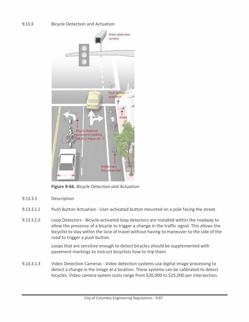
City of Columbia Engineering Regulations - 9-87
9.13.3 Bicycle Detection and Actuation
Figure 9-66. Bicycle Detection and Actuation
9.13.3.1 Description
9.13.3.1.1 Push Button Actuation - User-activated button mounted on a pole facing the street.
9.13.3.1.2 Loop Detectors - Bicycle-activated loop detectors are installed within the roadway to allow the presence of a bicycle to trigger a change in the traffic signal. This allows the bicyclist to stay within the lane of travel without having to maneuver to the side of the road to trigger a push button.
Loops that are sensitive enough to detect bicycles should be supplemented with pavement markings to instruct bicyclists how to trip them.
9.13.3.1.3 Video Detection Cameras - Video detection systems use digital image processing to
detect a change in the image at a location. These systems can be calibrated to detect bicycles. Video camera system costs range from $20,000 to $25,000 per intersection.

City of Columbia Engineering Regulations - 9-88
9.13.3.1.4 Remote Traffic Microwave Sensor Detection (RTMS) - RTMS is a system which uses frequency modulated continuous wave radio signals to detect objects in the roadway. This method marks the detected object with a time code to determine its distance from the sensor. The RTMS system is unaffected by temperature and lighting, which can affect standard video detection.
9.13.3.2 Discussion - Proper bicycle detection should meet two primary criteria: 1) accurately
detects bicyclists and 2) provides clear guidance to bicyclists on how to actuate detection (e.g., what button to push, where to stand).
Bicycle loops and other detection mechanisms can also provide bicyclists with an extended green time before the light turns yellow so that bicyclists of all abilities can reach the far side of the intersection.
9.13.3.3 Materials and Maintenance - Signal detection and actuation for bicyclists should be
maintained with other traffic signal detection and roadway pavement markings.
9.13.3.4 Additional References and Guidelines
9.13.3.4.1 AASHTO. Guide for the Development of Bicycle Facilities. 2012.
9.13.3.4.2 FHWA. Manual on Uniform Traffic Control Devices. 2009.
9.13.3.4.3 NACTO. Urban Bikeway Design Guide. 2012.

City of Columbia Engineering Regulations - 9-89
9.13.4 Bicycle Signal Heads
Figure 9-67. Bicycle Signal Heads
9.13.4.1 Description - A bicycle signal is an electrically powered traffic control device that should only be used in combination with an existing traffic signal. Bicycle signals are typically used to improve identified safety or operational problems involving bicycle facilities. Bicycle signal heads may be installed at signalized intersections to indicate bicycle signal phases and other bicycle-specific timing strategies. Bicycle signals can be actuated with bicycle sensitive loop detectors, video detection, or push buttons.
Bicycle signals are typically used to provide guidance for bicyclists at intersections where they may have different needs from other road users (e.g., bicycle-only movements).
9.13.4.2 Guidance - Specific locations where bicycle signals have had a demonstrated positive
effect include:
9.13.4.2.1 Those with high volume of bicyclists at peak hours
9.13.4.2.2 Those with high numbers of bicycle/motor vehicle crashes, especially those caused by turning vehicle movements

City of Columbia Engineering Regulations - 9-90
9.13.4.2.3 At T-intersections with major bicycle movement along the top of the “T.”
9.13.4.2.4 At the confluence of an off-street bike path and a roadway intersection
9.13.4.2.5 Where separated bike paths run parallel to arterial Streets
9.13.4.3 Discussion - Local municipal code should be checked or modified to clarify that at intersections with bicycle signals, bicyclists should only obey the bicycle signal heads. For improved visibility, smaller (4 inch lens) near-sided bicycle signals should be considered to supplement far-side signals.
9.13.4.4 Materials and Maintenance - Bicycle signal heads require the same maintenance as
standard traffic signal heads, such as replacing bulbs and responding to power outages.
9.13.4.5 Additional References and Guidelines
9.13.4.5.1 FHWA. MUTCD - Interim Approval for Optional Use of a Bicycle Signal Face (IA-16). 2013.
9.13.4.5.2 NACTO. Urban Bikeway Design Guide. 2012.
9.14 Retrofitting Streets to Add bikeways
9.14.1 Roadway Widening
Figure 9-68. Roadway Widening
9.14.1.1 Description - Bike lanes can be accommodated on streets with excess right-of-way through shoulder widening. Although roadway widening incurs higher expenses compared with re-striping projects, bike lanes can be added to streets currently lacking

City of Columbia Engineering Regulations - 9-91
curbs, gutters and sidewalks without the high costs of major infrastructure reconstruction.
9.14.1.2 Guidance
9.14.1.2.1 Guidance on bicycle lanes applies to this treatment.
9.14.1.2.2 4 foot minimum width when no curb and gutter is present.
9.14.1.2.3 6 foot width preferred.
9.14.1.3 Discussion - Roadway widening is most appropriate on roads lacking curbs, gutters and
sidewalks.
If it is not possible to meet minimum bicycle lane dimensions, a reduced width paved shoulder can still improve conditions for bicyclists on constrained roadways. In these situations, a minimum of 3 feet of operating space should be provided.
9.14.1.4 Materials and Maintenance - The extended bicycle area should not contain any rough
joints where bicyclists ride. Saw or grind a clean cut at the edge of the travel lane, or feather with a fine mix in a non-ridable area of the roadway.
9.14.1.5 Additional References and Guidelines
9.14.1.5.1 AASHTO. Guide for the Development of Bicycle Facilities. 2012.
9.14.2 Lane Narrowing
Figure 9-69. Lane Narrowing
9.14.2.1 Description - Lane narrowing utilizes roadway space that exceeds minimum standards to provide the needed space for bike lanes. Many roadways have existing travel lanes that

City of Columbia Engineering Regulations - 9-92
are wider than those prescribed in local and national roadway design standards, or which are not marked. Most standards allow for the use of 11 foot and sometimes 10 foot wide travel lanes to create space for bike lanes.
9.14.2.2 Guidance
9.14.2.2.1 Vehicle lane width:
9.14.2.2.1.1 Before: 10-15 feet
9.14.2.2.1.2 After: 10-11 feet
9.14.2.2.2 Bicycle lane width:
9.14.2.2.2.1 Guidance on bicycle lanes applies to this treatment.
9.14.2.3 Discussion -Special consideration should be given to the amount of heavy vehicle traffic
and horizontal curvature before the decision is made to narrow travel lanes. Center turn lanes can also be narrowed in some situations to free up pavement space for bike lanes.
AASHTO supports reduced width lanes in A Policy on Geometric Design of Highways and Streets: “On interrupted-flow operation conditions at low speeds (45 mph or less), narrow lane widths are normally adequate and have some advantages.”
9.14.2.4 Materials and Maintenance - Repair rough or uneven pavement surface. Use bicycle
compatible drainage grates. Raise or lower existing grates and utility covers so they are flush with the pavement.
9.14.2.5 Additional References and Guidelines
9.14.2.5.1 AASHTO. Guide for the Development of Bicycle Facilities. 2012.
9.14.2.5.2 SCDOT. EDM 22: Considerations for Bicycle Facilities.
9.14.2.5.3 NACTO. Urban Street Design Guide. 2013.
9.14.2.5.4 SCDOT. Traffic Calming Guidelines. 2006.

City of Columbia Engineering Regulations - 9-93
9.14.3 Lane Reconfiguration
Figure 9-70. Lane Reconfiguration
9.14.3.1 Description - The removal of a single travel lane will generally provide sufficient space for bike lanes on both sides of a street. Streets with excess vehicle capacity provide opportunities for bike lane retrofit projects.
9.14.3.2 Guidance
9.14.3.2.1 Vehicle lane width: Width depends on project. No narrowing may be needed if a lane is
removed.
9.14.3.2.2 Bicycle lane width: Guidance on bicycle lanes applies to this treatment.
9.14.3.3 Discussion - Depending on a street’s existing configuration, traffic operations, user needs and safety concerns, various lane reduction configurations may apply. For instance, a four-lane street (with two travel lanes in each direction) could be modified to provide one travel lane in each direction, a center turn lane, and bike lanes. Prior to implementing this measure, a traffic analysis should identify potential impacts.
9.14.3.4 Materials and Maintenance - Repair rough or uneven pavement surface. Use bicycle
compatible drainage grates. Raise or lower existing grates and utility covers so they are flush with the pavement.
9.14.3.5 Additional References and Guidelines
9.14.3.5.1 AASHTO. Guide for the Development of Bicycle Facilities. 2012.
9.14.3.5.2 FHWA. Evaluation of Lane Reduction “Road Diet” Measures on Crashes. Publication
Number: FHWA-HRT-10-053. 2010.
9.14.3.5.3 NACTO. Urban Street Design Guide. 2013.

City of Columbia Engineering Regulations - 9-94
9.14.4 Parking Reduction
Figure 9-71. Parking Reduction
9.14.4.1 Description - Bike lanes can replace one or more on-street parking lanes on streets where excess parking exists and/or the importance of bike lanes outweighs parking needs. For example, parking may be needed on only one side of a street. Eliminating or reducing on-street parking also improves sight distance for bicyclists in bike lanes and for motorists on approaching side streets and driveways.
9.14.4.2 Guidance
9.14.4.2.1 Vehicle lane width: Parking lane width depends on project. No travel lane narrowing may
be required depending on the width of the parking lanes.
9.14.4.2.2 Bicycle lane width: Guidance on bicycle lanes applies to this treatment.
9.14.4.3 Discussion - The City of Columbia has bonds issued against future parking revenue which requires any paid parking removed from the street be relocated elsewhere. Removing or reducing on-street parking to install bike lanes requires comprehensive outreach to the affected businesses and residents. Prior to reallocating on-street parking for other uses, a parking study should be performed to gauge demand and to evaluate impacts to people with disabilities.
9.14.4.4 Materials and Maintenance - Repair rough or uneven pavement surface. Use bicycle
compatible drainage grates. Raise or lower existing grates and utility covers so they are flush with the pavement
9.14.4.5 Additional References and Guidelines
9.14.4.5.1 AASHTO. Guide for the Development of Bicycle Facilities. 2012.

City of Columbia Engineering Regulations - 9-95
9.14.4.5.2 AASHTO. A Policy on Geometric Design of Highways and Streets. 2004.
9.15 Transit and bicycle Wayfinding
9.15.1 Transit Wayfinding
Figure 9-72. Transit Wayfinding
9.15.1.1 Description - Transit wayfinding is important primarily for informing the public on where to access transit, and to assist users in making educated route plans to reach their destinations. Well planned and designed transit wayfinding can encourage people to use transit – likewise, poorly designed transit wayfinding can discourage transit use. Taking trips with transit involves several important steps that can be generalized into three phases:
9.15.1.1.1 Trip planning – locating a destination and deciding what mode or modes to utilize for the
trip.
9.15.1.1.2 Trip segment assessment – understanding the necessary steps required to successfully reach a destination.
9.15.1.1.3 En route decision points – successfully judging options and navigating transfers between
transit routes or modes within the trip.
9.15.1.2 Guidance - There are several media for providing wayfinding information to transit users - most often oral communication, signage (static and dynamic), pamphlets and digital communication are used. All can be effective means of conveying wayfinding information, and typically a combination of all should be considered. For the purposes of these Design Guidelines, we will be focusing on information conveyance through wayfinding signage.
9.15.1.2.1 Signs should be mounted to be conspicuous against other signs, advertising, and other
visual clutter. Consideration must also be given to local ordinances and protection against vandalism.

City of Columbia Engineering Regulations - 9-96
hensive signing and/or
9.15.1.2.2 Sign must be visible to bus passengers inside bus when bus is at stop.
9.15.1.2.3 Consider use of duplicate sign with 3-in. raised letters/symbols in location suitable for approach to within 3 in., with Grade II Braille under each character.
9.15.1.2.4 Bus stop signage should include the transit system logo/name, transit information
telephone number, names of streets and landmarks where bus stop is located, and route number(s) serving the bus stop.
9.15.1.3 Discussion - Signage siting is an important aspect of transit wayfinding. In order to be
noticed and effective, information must be perceived at or shortly before the decision point. Signage site characteristics to consider include light levels, density of people using the facility, ceiling heights and corridor widths. (from TCRP Report 12: Guidelines for Transit Facility Signing and Graphics)
9.15.1.4 Materials and Maintenance - Maintenance needs for transit wayfinding signs are similar
to other signs and will need periodic replacement due to wear.
9.15.1.5 Additional References and Guidelines
9.15.1.5.1 OCTA. Bus Stop Safety and Design Guidelines. 2004. TCRP. Report 12: Guidelines for Transit Facility Signing and Graphics. 1996.
9.15.2 Bikeway Wayfinding Sign Types
9.15.2.1 Description - A bicycle wayfinding system consists of compre
pavement markings to guide bicyclists to their destinations along preferred bicycle routes. There are three general types of wayfinding signs:
9.15.2.1.1 Confirmation Signs - Indicate to bicyclists that they are on a designated bikeway. Make motorists aware of the bicycle route.
Can include destinations and distance/time. Do not include arrows.
9.15.2.1.2 Turn Signs - Indicate where a bikeway turns from one street
onto another street. Can be used with pavement markings.
Include destinations and arrows.
9.15.2.1.3 Decisions Signs - Mark the junction of two or more bikeways.
Inform bicyclists of the designated bike route to access key destinations. Includes destinations and arrows and distances.
Travel times are optional but recommended.
Figure 9-73. Confirmation Signs
Figure 9-74. Turn Signs
Figure 9-75. Decisions Signs

City of Columbia Engineering Regulations - 9-97
9.15.2.2 Discussion - There is no standard color for bicycle wayfinding signage. Section 1A.12 of the MUTCD establishes the general meaning for signage colors. Green is the color used for directional guidance and is the most common color of bicycle wayfinding signage in the US, including those in the MUTCD.
9.15.2.3 Materials and Maintenance - Maintenance needs for bicycle wayfinding signs are similar
to other signs and will need periodic replacement due to wear.
9.15.2.4 Additional References and Guidelines
9.15.2.4.1 AASHTO. Guide for the Development of Bicycle Facilities. 2012.
9.15.2.4.2 FHWA. Manual on Uniform Traffic Control Devices. 2009.
9.15.2.4.3 NACTO. Urban Bikeway Design Guide. 2012.
9.15.3 Bikeway Wayfinding Sign Placement
Figure 9-76. Bikeway Wayfinding Sign Placement
9.15.3.1 Guidance - Signs are typically placed at decision points along bicycle routes – typically at the intersection of two or more bikeways and at other key locations leading to and along bicycle routes.
9.15.3.1.1 Decisions Signs - Near-side of intersections in advance of a junction with another bicycle
route.
Along a route to indicate a nearby destination.
9.15.3.1.2 Confirmation Signs - Every ¼ to ½ mile on off-street facilities and every 2 to 3 blocks along on-street bicycle facilities, unless another type of sign is used (e.g., within 150 ft. of a turn or decision sign). Should be placed soon after turns to confirm destination(s). Pavement markings can also act as confirmation that a bicyclist is on a preferred route.

City of Columbia Engineering Regulations - 9-98
9.15.3.1.3 Turn Signs - Near-side of intersections where bike routes turn (e.g., where the street ceases to be a bicycle route or does not go through). Pavement markings can also indicate the need to turn to the bicyclist.
9.15.3.2 Discussion - It can be useful to classify a list of destinations for inclusion on the signs
based on their relative importance to users throughout the area. A particular destination’s ranking in the hierarchy can be used to determine the physical distance from which the locations are signed. For example, primary destinations (such as the downtown area) may be included on signage up to 5 miles away. Secondary destinations (such as a transit station) may be included on signage up to two miles away. Tertiary destinations (such as a park) may be included on signage up to one mile away.
9.15.3.3 Materials and Maintenance - Maintenance needs for bicycle wayfinding signs are similar
to other signs and will need periodic replacement due to wear.
9.15.3.4 Additional References and Guidelines
9.15.3.4.1 AASHTO. Guide for the Development of Bicycle Facilities. 2012.
9.15.3.4.2 FHWA. Manual on Uniform Traffic Control Devices. 2009.
9.15.3.4.3 NACTO. Urban Bikeway Design Guide. 2012.
9.16 bicycle Support Facilities
9.16.1 Bicycle Racks
Figure 9-77. Bicycle Racks
9.16.1.1 Description - Short-term bicycle parking is meant to accommodate visitors, customers, and others expected to depart within two hours. It should have an approved standard rack, appropriate location and placement, and weather protection. The Association for Pedestrian and Bicycle Professionals (APBP) recommends selecting a bicycle rack that:
9.16.1.1.1 Supports the bicycle in at least two places, preventing it from falling over.

City of Columbia Engineering Regulations - 9-99
9.16.1.1.2 Allows locking of the frame and one or both wheels with a U-lock.
9.16.1.1.3 Is securely anchored to ground.
9.16.1.1.4 Resists cutting, rusting and bending or deformation.
9.16.1.2 Guidance
9.16.1.2.1 2’ minimum from the curb face to avoid ‘dooring.’
9.16.1.2.2 Close to destinations; 50’ maximum distance from main building entrance.
9.16.1.2.3 Minimum clear distance of 6’ should be provided between the bicycle rack and the property line.
9.16.1.2.4 Should be highly visible from adjacent bicycle routes and pedestrian traffic.
9.16.1.2.5 Locate racks in areas that cyclists are most likely to travel.
9.16.1.2.6 Post signage that clearly indicates mopeds and motorcycles are prohibited from parking
at bike racks. Direct mopeds/motorcycles to designated moped/ motorcycle parking areas.
9.16.1.3 Discussion - Some types of bicycle racks may meet design criteria, but are discouraged
except in limited situations. This includes undulating “wave” racks, schoolyard “wheel bender” racks, and spiral racks. (See illustration above).
Decorative racks may enhance the aesthetic nature of a streetscape, but the custom design should not interfere with the functionality of the rack. Standard “U” racks are preferred over decorative racks in most regular installations, but decorative racks may be preferred in special districts or in areas with space constraints.
9.16.1.4 Materials and Maintenance - Use of proper anchors will prevent vandalism and theft.
Racks and anchors should be regularly inspected for damage. Educate snow removal crews to avoid burying racks during winter months.
9.16.1.5 Additional References and Guidelines
9.16.1.5.1 AASHTO. Guide for the Development of Bicycle Facilities. 2012.
9.16.1.5.2 APBP. Bicycle Parking Guide 2nd Edition. 2010.

City of Columbia Engineering Regulations - 9-100
9.16.2 On-Street Bicycle Corral
Figure 9-78. On-Street Bicycle Corral
9.16.2.1 Description - Bicycle corrals (also known as on-street bicycle parking) consist of bicycle racks grouped together in a common area within the street traditionally used for automobile parking. Bicycle corrals are reserved exclusively for bicycle parking and provide a relatively inexpensive solution to providing high-volume bicycle parking. Bicycle corrals can be implemented by converting one or two on-street motor vehicle parking spaces into on-street bicycle parking. Each motor vehicle parking space can be replaced with approximately 6-10 bicycle parking spaces.
Bicycle corrals move bicycles off the sidewalks, leaving more space for pedestrians, sidewalk café tables, etc. Because bicycle parking does not block sightlines (as large motor vehicles would do), it may be possible to locate bicycle parking in ‘no-parking’ zones near intersections and crosswalks.
9.16.2.2 Guidance - See guidelines for sidewalk bicycle rack placement and clear zones.
9.16.2.2.1 Bicyclists should have an entrance width from the roadway of 5’ – 6’.
9.16.2.2.2 Can be used with parallel or angled parking.
9.16.2.2.3 Parking stalls adjacent to curb extensions are good candidates for bicycle corrals since
the concrete extension serves as delimitation on one side.
9.16.2.3 Discussion - In many communities, the installation of bicycle corrals is driven by requests from adjacent businesses, and is not a city-driven initiative. In such cases, the city does not remove motor vehicle parking unless it is explicitly requested. In other areas, the city provides the facility and business associations take responsibility for the maintenance of the facility. Communities can establish maintenance agreements with the requesting business. Bicycle corrals can be especially effective in areas with high bicycle parking demand or along street frontages with narrow sidewalks where parked bicycles would be detrimental to the pedestrian environment.

City of Columbia Engineering Regulations - 9-101
9.16.2.4 Materials and Maintenance - Physical barriers may obstruct drainage and collect debris. Establish a maintenance agreement with neighboring businesses. In snowy climates the bicycle corral may need to be removed during the winter months.
9.16.2.5 Additional References and Guidelines
9.16.2.5.1 APBP. Bicycle Parking Guide 2nd Edition. 2010.
9.16.3 Bicycle Lockers
Figure 9-79. Bicycle Lockers
9.16.3.1 Description - Bicycle lockers are intended to provide long-term bicycle storage for employees, students, residents, commuters, and others expected to park more than two hours. Long-term facilities protect the entire bicycle, its components and accessories against theft and against inclement weather, including snow and wind-driven rain.
Bicycle lockers provide space to store a few accessories or rain gear in addition to containing the bicycle. Some lockers allow access to two users - a partition separating the two bicycles can help users feel their bike is secure. Lockers can also be stacked, reducing the footprint of the area, although that makes them more difficult to use.
9.16.3.2 Guidance
9.16.3.2.1 Minimum dimensions: width (opening) 2.5’; height 4’; depth 6’.
9.16.3.2.2 4 foot side clearance and 6 foot end clearance.
9.16.3.2.3 7 foot minimum distance between facing lockers.
9.16.3.2.4 Locker designs that allow visibility and inspection of contents are recommended for
increased security.
9.16.3.2.5 Access is controlled by a key or access code.
9.16.3.3 Discussion - Long-term parking facilities are more expensive to provide than short-term facilities, but are also significantly more secure. Although many bicycle commuters

City of Columbia Engineering Regulations - 9-102
would be willing to pay a nominal fee to guarantee the safety of their bicycle, long-term bicycle parking should be free wherever automobile parking is free. Potential locations for long-term bicycle parking include transit stations, large employers, and institutions where people use their bikes for commuting and not consistently throughout the day.
9.16.3.4 Materials and Maintenance - Regularly inspect the functioning of moving parts and
enclosures. Change keys and access codes periodically to prevent access to unapproved users.
9.16.3.5 Additional References and Guidelines
9.16.3.5.1 AASHTO. Guide for the Development of Bicycle Facilities. 2012.
9.16.3.5.2 APBP. Bicycle Parking Guide 2nd Edition. 2010.
9.16.4 Secure Parking Area (SPA)
Figure 9-80. Secure Parking Area (SPA)
9.16.4.1 Description - A Secure Parking Area for bicycles, also known as a Bike SPA or Bike & Ride (when located at transit stations), is a semi-enclosed space that offers a higher level of security than ordinary bike racks. Accessible via key-card, combination locks, or keys, Bike SPAs provide high-capacity parking for 10 to 100 or more bicycles. Increased security measures create an additional transportation option for those whose biggest concern is theft and vulnerability.
9.16.4.2 Guidance - Bike SPAs may be stand alone or integrated into the ground floor of parking
garage structure. Key features may include:
9.16.4.2.1 Closed-circuit television monitoring.
9.16.4.2.2 Double high racks & cargo bike spaces.
9.16.4.2.3 Bike repair station with bench.

City of Columbia Engineering Regulations - 9-103
9.16.4.2.4 Bike tube and maintenance item vending machine.
9.16.4.2.5 Bike lock “hitching post” – allows people to leave bike locks.
9.16.4.2.6 Secure access for users.
9.16.4.3 Discussion - Long-term parking facilities are more expensive to provide than short-term facilities, but are also significantly more secure. Although many bicycle commuters would be willing to pay a nominal fee to guarantee the safety of their bicycle, long-term bicycle parking should be free wherever automobile parking is free. Bike SPAs are ideal for transit centers, airports, train stations, or wherever large numbers of people might arrive by bicycle and need a secure place to park while away.
9.16.4.4 Materials and Maintenance - Regularly inspect the functioning of moving parts and
enclosures. Change keys and access codes periodically to prevent access to unapproved users.
9.16.4.5 Additional References and Guidelines
9.16.4.5.1 AASHTO. Guide for the Development of Bicycle Facilities. 2012.
9.16.4.5.2 APBP. Bicycle Parking Guide 2nd Edition. 2010.
9.16.5 Bicycle Parking at Transit
Figure 9-81. Bicycle Parking at Transit
9.16.5.1 Description - Bicycle parking facilities, such as securement devices (bike racks and storage lockers), may be provided at bus stops by local jurisdictions or adjacent property owners for the convenience of bicyclists using transit.

City of Columbia Engineering Regulations - 9-104
Bicycle parking facilities discourage the practice of locking bicycles onto bus facilities or onto adjacent property. By confining bicycles to one area, securement devices can reduce visual clutter and maintain appropriate pedestrian clearances. Below are guidelines for the placement of bicycle parking facilities.
9.16.5.2 Guidance
9.16.5.2.1 Locate securement devices or bicycle lockers away from other pedestrian or bus patron
activities to improve safety and reduce congestion.
9.16.5.2.2 Coordinate the location of bicycle parking facilities with existing on-site or street lighting.
9.16.5.2.3 Ensure parked bikes are visible at all times. Do not locate bicycle parking where views are restricted by a bus shelter, landscaping, or existing site elements, such as walls.
9.16.5.2.4 Design and placement of bicycle parking facilities should complement other transit
furniture at bus stop.
9.16.5.2.5 Covered or weather protected parking locations is an important bonus to bicyclists.
9.16.5.3 Discussion - There are two bicycle locker facilities avaible for secure parking at transit stops. A key based locker is a long term rental, typically provided by the transit agency. A key based system allows access to only one individual. An alternative bicycle locker is a code or combo based system. These lockers allow users to rent the locker on a need-only basis.
9.16.5.3.1 Materials and Maintenance - Regularly inspect the functioning of long-term parking
moving parts and enclosures. Change keys and access codes periodically to prevent access to unapproved users.
9.16.5.4 Additional References and Guidelines
9.16.5.4.1 AASHTO. Guide for the Development of Bicycle Facilities. 2012.
9.16.5.4.2 APBP. Bicycle Parking Guide 2nd Edition. 2010.
9.16.5.4.3 FHWA. Federal Highway Administration University Course on Bicycle and Pedestrian
Transportation. Lesson 18: Bicycle and Pedestrian Connections to Transit. 2006.

City of Columbia Engineering Regulations - 9-105
9.16.6 Bike Share Station Placement
Figure 9-82. Bike Share Station Placement
9.16.6.1 Description - Bike sharing is a nonmotorized transportation service, typically structured to provide users point-to-point transportation for short distance trips. Users pick up a bicycle at self-serve bike sharing stations and return it to the same or other station at the end of their trip.
Bike sharing stations holds the automated customer kiosk and bicycle docks.
9.16.6.2 Guidance - Bike sharing station should be placed in safe, convenient and highly visible locations. If they are intended to support transit stations, they should be visible from the entrance/exit of the station. Placement:
9.16.6.2.1 On-street stations are placed within the parking lane of a street. On-street stations are
accessible from within the street. These stations are typically located adjacent to on- street bicycle facilities such as bike lanes.
9.16.6.2.2 Sidewalk stations are located on the furnishing or frontage zone of a wide sidewalk.
9.16.6.2.3 Public space stations are located in plazas or parks. These locations may be privately
owned.
9.16.6.3 Discussion - Two-sided stations may be provided in locations with adequate access from both sides, and offer the potential for increased station capacity given a certain footprint.
Solar powered stations should be placed in locations with access to sunlight for a portion of the day, and have 11 ft. vertical clearance.

City of Columbia Engineering Regulations - 9-106
9.16.6.4 Materials and Maintenance - Provide a 1 ft. gap between on-street stations and the curb of the sidewalk to allow for water drainage and debris removal.
9.16.6.5 Additional References and Guidelines
9.16.6.5.1 FHWA. Bike Sharing in The United States: State of the Practice and Guide to
Implementation. 2012.
9.17 Bikeway Maintenance
9.17.1 Sweeping
9.17.1.1 Description - Bicyclists often avoid shoulders and bike lanes filled with gravel, broken glass and other debris; they will ride in the roadway to avoid these hazards, potentially causing conflicts with motorists. Debris from the roadway should not be swept onto sidewalks (pedestrians need a clean walking surface), nor should debris be swept from the sidewalk onto the roadway. A regularly scheduled inspection and maintenance program helps ensure that roadway debris is regularly picked up or swept.
9.17.1.2 Guidance
9.17.1.2.1 Establish a seasonal sweeping schedule that prioritizes roadways with major bicycle
routes.
9.17.1.2.2 Sweep walkways and bikeways whenever there is an accumulation of debris on the facility.
9.17.1.2.3 In curbed sections, sweepers should pick up debris; on open shoulders, debris can be
swept onto gravel shoulders.
9.17.1.2.4 Pave gravel driveway approaches to minimize loose gravel on paved roadway shoulders.
9.17.1.2.5 Perform additional sweeping in the Spring to remove debris from the Winter.
9.17.1.2.6 Perform additional sweeping in the Fall in areas where leaves accumulate.
9.17.2 Signage
9.17.2.1 Description - Bike lanes, shared shoulders, Bicycle Boulevards and paths all have different signage types for wayfinding and regulations. Such signage is vulnerable to vandalism or wear, and requires periodic maintenance and replacement as needed.
9.17.2.2 Guidance
9.17.2.2.1 Check regulatory and wayfinding signage along bikeways for signs of vandalism, graffiti,
or normal wear.
9.17.2.2.2 Replace signage along the bikeway network as-needed.

City of Columbia Engineering Regulations - 9-107
9.17.2.2.3 Perform a regularly-scheduled check on the status of signage with follow-up as necessary.
9.17.2.2.4 Create a Maintenance Management Plan.
9.17.3 Roadway Surface
9.17.3.1 Description - Bicycles are much more sensitive to subtle changes in roadway surface
than are motor vehicles. Various materials are used to pave roadways, and some are smoother than others. Compaction is also an important issue after trenches and other construction holes are filled. Uneven settlement after trenching can affect the roadway surface nearest the curb where bicycles travel. Sometimes compaction is not achieved to a satisfactory level, and an uneven pavement surface can result due to settling over the course of days or weeks. When resurfacing streets, use the smallest chip size and ensure that the surface is as smooth as possible to improve safety and comfort for bicyclists.
9.17.3.2 Guidance
9.17.3.2.1 Maintain a smooth pothole-free surface.
9.17.3.2.2 Ensure that on new roadway construction, the finished surface on bikeways does not
vary more than ¼”.
9.17.3.2.3 Maintain pavement so ridge buildup does not occur at the gutter-to-pavement transition or adjacent to railway crossings.
9.17.3.2.4 Inspect the pavement 2 to 4 months after trenching construction activities are
completed to ensure that excessive settlement has not occurred.
9.17.3.2.5 If chip sealing is to be performed, use the smallest possible chip on bike lanes and shoulders. Sweep loose chips regularly following application.
9.17.3.2.6 During chip seal maintenance projects, if the pavement condition of the bike lane is
satisfactory, it may be appropriate to chip seal the travel lanes only. However, use caution when doing this so as not to create an unacceptable ridge between the bike lane and travel lane.
9.17.4 Pavement Overlays
9.17.4.1 Description - Pavement overlays represent good opportunities to improve conditions for
bicyclists if done carefully. A ridge should not be left in the area where bicyclists ride (this occurs where an overlay extends part-way into a shoulder bikeway or bike lane). Overlay projects also offer opportunities to widen a roadway, or to re-stripe a roadway with bike lanes.
9.17.4.2 Guidance
9.17.4.2.1 Extend the overlay over the entire roadway surface to avoid leaving an abrupt edge.

City of Columbia Engineering Regulations - 9-108
9.17.4.2.2 If the shoulder or bike lane pavement is of good quality, it may be appropriate to end the overlay at the shoulder or bike lane stripe provided no abrupt ridge remains.
9.17.4.2.3 Ensure that inlet grates, manhole and valve covers are within ¼ inch of the finished
pavement surface and are made or treated with slip resistant materials.
9.17.4.2.4 Pave gravel driveways to property lines to prevent gravel from being tracked onto shoulders or bike lanes.
9.17.5 Drainage Grates
Figure 9-83. Drainage Grates
9.17.5.1 Description - Drainage grates are typically located in the gutter area near the curb of a roadway. Drainage grates typically have slots through which water drains into the municipal storm sewer system. Many older grates were designed with linear parallel bars spread wide enough for a tire to become caught so that if a bicyclist were to ride on them, the front tire could become caught in the slot. This would cause the bicyclist to tumble over the handlebars and sustain potentially serious injuries.
9.17.5.2 Guidance
9.17.5.2.1 Require all new drainage grates be bicycle-friendly, including grates that have horizontal
slats on them so that bicycle tires and assistive devices do not fall through the vertical slats.
9.17.5.2.2 Create a program to inventory all existing drainage grates, and replace hazardous grates
as necessary – temporary modifications such as installing rebar horizontally across the grate should not be an acceptable alternative to replacement.
9.17.6 Gutter To Pavement Transition
9.17.6.1 Description - On streets with concrete curbs and gutters, 1 to 2 feet of the curbside area
is typically devoted to the gutter pan, where water collects and drains into catch basins. On many streets, the bikeway is situated near the transition between the gutter pan and the pavement edge. This transition can be susceptible to erosion, creating potholes and a rough surface for travel.
The pavement on many streets is not flush with the gutter, creating a vertical transition between these segments. This area can buckle over time, creating a hazardous condition for bicyclists.
9.17.6.2 Guidance

City of Columbia Engineering Regulations - 9-109
9.17.6.2.1 Ensure that gutter-to-pavement transitions have no more than a ¼” vertical transition.
9.17.6.2.2 Examine pavement transitions during every roadway project for
new construction, maintenance activities, and construction project activities that occur in streets.
9.17.6.2.3 Inspect the pavement 2 to 4 months after trenching
construction activities are completed to ensure that excessive settlement has not occurred.
9.17.6.2.4 Provide at least 3 feet of pavement outside of the gutter seam.
9.17.7 Landscaping
9.17.7.1 Description - Bikeways can become inaccessible due to overgrown
vegetation. All landscaping needs to be designed and maintained to ensure compatibility with the use of the bikeways. After a flood or major storm, bikeways should be checked along with other roads, and fallen trees or other debris should be removed promptly
9.17.7.2 Guidance
9.17.7.2.1 Ensure that shoulder plants do not hang into or impede passage along
bikeways
9.17.7.2.2 After major damage incidents, remove fallen trees or other debris from bikeways as quickly as possible
9.17.8 Maintenance Management Plan
9.17.8.1 Description - Bikeway users need accommodation during construction
and maintenance activities when bikeways may be closed or unavailable. Users must be warned of bikeway closures and given adequate detour information to bypass the closed section. Users should be warned through the use of standard signing approaching each affected section (e.g., “Bike Lane Closed,” “Trail Closed”), including information on alternate routes and dates of closure. Alternate routes should provide reasonable directness, equivalent traffic characteristics, and be signed.
9.17.8.2 Guidance
9.17.8.2.1 Provide fire and police departments with map of system, along
with access points to gates/bollards
9.17.8.2.2 Enforce speed limits and other rules of the road
City of Columbia Engineering Regulations - 9-110
9.17.8.2.3 Enforce all trespassing laws for people attempting to enter adjacent private
properties 9.18 Trail System Standards
9.18.1 Introduction. These standards shall act as general guidance for anyone designing trails within the existing or planned greenway and/or trail system that will ultimately be owned and/or maintained by the City of Columbia. All designs, equipment selections, and specifications are subject to final approval by the City and may be dependent on the special needs/circumstances of the particular project. Projects located in zoning overlay districts may be subject to different equipment standards.
9.18.2 Purpose: The first greenway map for the City of Columbia appeared in the 1903 Plan by Kelsey and Guild entitled The Improvements of Columbia South Carolina – Reports to the Civic League. Many other plans over time have suggested individual elements of such as system. Plan Columbia Land Use Plan incorporated a greenways and connections map, and was formally adopted by City Council in 2015. That same year, the City adopted a comprehensive pedestrian and bicycle plan entitled Walk Bike Columbia, which made detailed recommendations for pedestrian, bicyclist, and multi-use facility locations throughout the City. These two documents define a system of movement and recreation throughout the community. Columbia Compass: Envision 2036 seeks to build upon these efforts through the development of a clearer and articulate trail system map for the community.
9.18.3 Definitions:
9.18.3.1 Trail: a planned, marked, and established path or route that may be found through recreational lands, lands left in a natural state, parks, plazas, and urban streets through the community.
9.18.3.2 Trail System: a planned network of naturalized greenways, urban trails, and trails in rail corridors that provides connectivity to and between natural areas, residential areas, commercial centers, and points of interest.
9.18.3.3 Spur Trails: Spur trails provide connections from main network of the trail system to destinations that are not directly adjacent to the main route. Spur trails may serve to provide connections to specific residential, commercial, or natural areas, or employment centers, schools, or other points of interest.
9.18.3.4 Clear Height: Clear height is the designated vertical travelway of a trail. For compliance purposes, this width is measured plumb to the trail, from trail surface, within the designated clear width.
9.18.3.5 Clear Width: Clear width is the designated horizontal travelway of a trail. For compliance purposes, this width is measured between the interior face of each railing, curb, or bull rail. Projections of up to 12 inches into the required clear width may be allowed for items

City of Columbia Engineering Regulations - 9-111
such as lighting, hand rails, and call boxes. Projections should be standardized per one side were possible, so users can expect projections. All projections shall comply to ADA standards.
Diagram: Clear Width
9.18.4 Trail Classifications. The City recognizes three classifications of trails within the City’s trail system consisting of Urban Trails, Naturalized Greenways, and Trails in Rail Corridors. Urban trails and naturalized greenways are further defined by anticipated level of use and whether pedestrians and bicyclists share a facility or utilize separate facilities along the same trail corridor. The trail system classification of use is based upon heavy or light volumes of users for a given location. These classifications as noted are again more closely defined based upon if users are combined or sharing the same trail or if they are separated and have a unique facility based upon travel or use mode. In the cases of separated facilities, the trail type is then categorized based upon pedestrians or cyclist. Trails in rail corridors are not characterized by use levels and should always utilize shared facilities, however these trails are split into two subtypes- trails within abandoned rail corridors and trails beside active rail corridors.

City of Columbia Engineering Regulations - 9-112
Figure 1: Diagram of trail types and subtypes
9.18.4.1 Trail Types: The three types of trails are defined as follows:
9.18.4.1.1 Urban Trails: Urban trails are existing or proposed linear trails within the City usually found along streets and roadways, and other developed areas. Along urban trails, special attention to street design, plantings, and other amenities is made in order to accommodate pedestrians, bicyclists, and other users. Urban trails may be comprised of multi-use facilities or

City of Columbia Engineering Regulations - 9-113
separated facilities by user type, and these trails may also traverse through plazas, parks, or other public spaces. Urban trails are further categorized as heavy use or light use.
9.18.4.1.2 Naturalized Greenways: Naturalized greenways represent existing or proposed linear trails that are found in areas that have been left natural or are being returned to a natural state. Such areas generally have significant tree cover or native plantings and may include significant open areas. Naturalized greenways tend to be adjacent to environmentally significant features such as waterways or wetlands. Multi-use facilities are typically comprised of a paved (asphalt or concrete) surface or boardwalk. Naturalized greenways may connect to urban trails and/or adjacent residential or commercial development, and make connections from various built and natural features throughout the community. Connections to separated off-road facilities for either pedestrians or bicyclists may also be incorporated along naturalized greenways. Naturalized greenways are further categorized as heavy use or light use.
9.18.4.1.3 Trails in Rail Corridors: Rail-trails are multipurpose public paths created from former or along existing railroad corridors. These paths are flat or gently sloping, making them easily accessible.1 Such trails are often built within abandoned rail corridors, however they may also be located parallel to existing active rail corridors.
9.18.4.1.4 Other Facility Types: Other types of facilities that may be found connecting to trails may include: sidewalks, paths, on- or off-road bike facilities, and hiking trails. Standards for these other facility types are also set forth in Part 9.
9.18.4.2 Usage Subtypes: The further subdivision of trail types by anticipated usage provides for the development of usage-specific requirements for facility width, the provision of equipment, and the location of amenities. Usage, as indicated in the trail system map (Figures 2 & 3) is based upon three factors: the current density (2016 Census) of the population that is within ¼ to ½ mile of the trails; anticipated and projected population growth (Central Midlands Council of Governments 2018); and the vision set forth by the future land use maps (City of Columbia). The anticipated volume of users will increase over time and as connectivity grows. Usage subtypes are as follows:
9.18.4.2.1 Heavy Use. A heavy use trail is one that will have the highest number of users at peak periods once the system is fully link together. Heavy use trails require a 14-foot clear facility width, whether comprised of an approved paved surface or boardwalk.
9.18.4.2.2 Light use. A light use trail may have lighter usage due to a variety of factors, such as an increased distance to denser areas or points of interest. Light use trails require a 12-foot trail or boardwalk; in areas that may see higher volumes or which contain points of interest along the trail bump outs at designated intervals or at these points of interest are encouraged.
1 http://www.railstotrails.org/

9.18.5 Trail System Map. The illustrative trail system maps below indicate facility types and usage subtypes.
Figure 2: Illustrative trail system map showing regional system; trails outside of the City of Columbia are shown to illustrate future or possible network connections.

Figure 3: Detailed illustrative map of trail system core.

City of Columbia Engineering Regulations - 9-116
9.18.6 Facility Standards
Facility standards set forth in this section are specific to multi-use trails and some standards vary by trail type and subtype. These standards are set forth specific to multi-use trails within the mapped system, and are meant to expand upon the standards set forth for shared use paths and greenways in other sections of Part 9. Standards for separated (bike and pedestrian) facilities can be found in Part 9: Sections 1 through 17 of the Pedestrian, Bicycle, Complete Streets, and Trail System Design Guidelines of the City of Columbia Engineering Regulations. The following standards apply to all trail types and subtypes:
9.18.6.1. Right-of-way. Where trails traverse private property, rights-of-way in excess of the trail width shall be obtained to provide for adequate maintenance. Right-of-way width shall be at least twenty (20) feet wide, and right-of-way centerline shall match the centerline of the designed trail surface. Right-of-way height, if limited by the right-of-way agreement, shall be written to include a total height which extends from the surface of the ground to at least 10 feet above the surface of the trail.
9.18.6.2. Clear Height. A minimum clear height of eight feet, four inches (8’4”) from the surface of the greenway must be provided for.
9.18.6.3 ADA Accessibility. All greenways must be designed to be compliant with current ADA standards.
9.18.6.4 Tree Protection and Health. Trees located within the 50’ surveyed swath which are in poor condition or which are non-native, invasive species as defined by the Southeast Exotic Pest Plant Council may be marked for removal and if so, should be removed prior to greenway construction. Grand trees in fair or good condition shall be flagged and protected during construction using best practices. In no case shall any part of the proposed greenway surface, structure, or utility trenching be located within the radius of the structural root zone of any trees to remain on site; where the greenway surface, structure, or utility trenching will encroach into the structural root zone of a tree, the path must be realigned or the tree must be removed prior to construction to prevent future maintenance issues. The structural root zone is defined as the zone of rapid root taper that provides the tree stability against wind throw, and is calculated as follows:
Radius of the Structural Root Zone (in feet) = Inches of Diameter at Breast Height (DBH) x 1/3. No utility trenching shall occur in areas where conduit shall be encased beneath concrete pathways.
9.18.6.5 Curve Radii. Curve radii must be designed to allow for the turning radii of parks maintenance equipment, as defined by the Parks and Recreation Department at the time of design.
9.18.6.6 Sight Distance. Sight distance shall be designed to accommodate all user types and speeds anticipated for the specific context, at both the average and max user speeds of each user type within the context.
9.18.6.7 Signage. Multi-use trail signage shall be used at start and ending of the trail and at points of access. Wayfinding or other directional signage may be required. Signage design shall be coordinated to match the City’s adopted wayfinding system. All signage shall include a vandalism-proof coating.
9.18.6.8 Power Supply. Electrical conduit shall be buried, and boxes for lights shall be provided, with junction boxes at every light for conduit. Junction boxes should be a Quazite 12” x 12” x 12” with electric on the lid, or equivalent, as approved by the City. When installing emergency call boxes and/or cameras, the electrical circuit must remain on at all times, which will require photo controls on each light or the installation of a

City of Columbia Engineering Regulations - 9-117
dedicated circuit for call boxes and/or cameras. All conduit shall be sized with additional capacity necessary to accommodate future camera installation. Box locations will be determined after the photometric plan has been done. Additional requirements, including those related to power for facilities and events and the use of or installation of new duct banks, may be identified on a case-by-case basis.
9.18.6.9 Railings. Where railings or vertical safety barriers are required, they must be constructed out of painted aluminum.
9.18.6.10 Parking. Parking may be required at trailheads or key locations, and the required number of spaces should be defined both by the anticipated level of use and the context for the parking area. Access to parking areas may be required to be restricted by gates or other access controls. Where trail connections are made from residential streets, signage regulating on-street parking may be required.
9.18.6.11 Restrooms. ADA accessible restrooms should be placed at major trail heads and appropriate locations along trail as deemed necessary per anticipated volume of users. Typical restrooms will be located along high pedestrian traffic routes and with high use trail amenities such as parking for security, maintenance and utility access. Building orientation should locate entrances toward the most visible areas and away from prevailing winds. Design must comply with all building codes and accommodate all users as defined in the design process and review. The design process should also consider other amenities such as trail maintenance storage and staff accommodation. Whether restrooms are required along a proposed trail segment, and their approximate location(s) (if required), shall be determined at the conceptual design phase by the Trail Administrative Adjustment Committee.
9.18.6.12 General Site Fixtures. General site fixtures may include: cameras, lighting, site furnishings, call boxes, or other such items. All general site fixtures shall have a black powder coat finish unless otherwise specified. Equipment brands, where applicable, are listed below with each site fixture.
9.18.6.12.1 Lighting. Lighting shall be an LED Granville full cut off fixture or a contemporary fixture (pending review) that could be selected on a project-specific basis. A photometric plan will be provided indicating the lighting design, location, and specifications. Lighting shall be directionally focused down and along the trail surface, and shall provide a minimum foot-candle rating of 0.5 foot-candles along the trail surface. Light may be cast downward 360 degrees from the light source or may only be directed 180 degrees, based upon design and site specifics. Electrical conduit shall be buried, and boxes for lights shall be provided, with conduit pulled no more than 500 feet between boxes. Box locations will be determined after the photometric plan has been done. When a trail enters a public plaza park, or other defined area with design guidelines, the lighting shall coordinate with the public plaza, park, or defined area.
9.18.6.12.2 Mileage markings and signage. Mileage markings and signage shall be placed so as to be visible from both directions of travel, and shall be located at trailheads and along the trail in quarter-mile intervals. The design of such markings and signage must be approved by the City of Columbia.
9.18.6.12.3 Call Boxes. Call boxes are required by the Columbia Police Department on all trails; the required interval for call box placement may also vary per project.
9.18.6.12.4 Site Furnishings. All site furnishings shall be located outside of the defined clear width of the trail. In addition to the required site furnishings listed below, water fountains (Equipment specification:

City of Columbia Engineering Regulations - 9-118
Most Dependable Fountains Model 10155 SM Water Fountain) and bicycle repair stations (Equipment specification: Dero FIXIT Bicycle Tire Station) may be required by the City on a project-specific basis at trailheads and gateways. The following are required site furnishings for all multi-use trails.
9.18.6.12.4.1 Mutt mitts. Mutt mitts shall be placed at a distance of ¼ mile increments on heavy use trails or trails in and along rail corridors; mutt mitts shall be placed at a distance of ½ mile increments on light use trails. Equipment specification: Mutt Mitt Pet Waste Station.
9.18.6.12.4.2 Waste receptacles. Trash and recycling receptacles shall be provided at a distance of ¼ mile increments on heavy use trails or trails in and along rail corridors; waste receptacles shall be placed at a distance of ½ mile increments on light use trails. Equipment specification: Victor Stanley ES-242 Trash Receptacle with recycle lid and band for recycling receptacle.
9.18.6.12.4.3 Seating. Benches shall be located outside of the clear width of the trail and shall be placed at ¼ mile intervals on heavy use trails or trails in and along rail corridors and at ½ mile intervals on light use trails. Seating intervals may be shifted and/or increased to provide seating at key locations as reviewed or approved by the City on a project-specific basis. Benches shall be mounted to a concrete slab which is poured adjacent to the trail surface. Equipment specification: Victor Stanley EVA Bench; all steel slats in black, center armrest, and both in ground and surface mount as needed.
(Insert images of items when document is to be formatted)
9.18.6.13 Trail Development in Flood Hazard Areas. Trail development in special flood hazard areas must be designed with functionality and sustainability in mind. In addition to designing for and obtaining a flood development permit, the following standards must be adhered to ensure the longevity of the trail system:
9.18.6.13.1 Footings. Footings for boardwalk piers must be larger and deeper and designed to withstand scouring during flood events. 9.18.6.13.2 Paved trails. Asphalt shall not be installed in flood hazard areas; poured concrete is the only acceptable material for paved trails in flood hazard areas. Poured concrete must include a vertical footer adjacent to the area of anticipated flooding which is constructed at a depth and width great enough to withstand scouring of floodwaters during a flood event while preventing the undermining of the concrete pathway. 9.18.6.13.3 Electrical equipment. Any electrical equipment or conduits installed for the purposes of greenway amenities shall be flood proofed/sealed to prevent water intrusion within flood hazard areas. 9.18.6.13.4 Breakaway design. Any vertical elements located within the flow trajectory must be designed to breakaway in the event of flooding so as not to further compromise the structural integrity of the trail surface.
9.18.6.14 Additional Standards. Additional requirements including power for facilities and events may be identified on a case-by-case basis.
9.18.7. Facility-specific standards. Additional facility standards vary by facility type and subtype, and address the following categories:

City of Columbia Engineering Regulations - 9-119
9.18.7.1 Trail Construction Materials. Multi-use trails are generally constructed out of asphalt with concrete banding, however construction materials may be adjusted in flood-prone or environmentally sensitive areas to include concrete surfaces or composite boardwalks. Where driveway locations will result in heavily-loaded traffic crossing the trail surface for access, the trail construction materials must be designed to accommodate and withstand these vehicular loads.
9.18.7.2 Trail Width. Providing for adequate and appropriate trail width is essential to an interconnected trail system. The users of trails experience the trail at a human scale, and appropriate trail width is necessary to provide for safe passage and to avoid potential conflict among user types. The anticipated volume of users will increase over time and as connectivity grows. As such, providing for adequate and appropriate width of facilities is important from the onset, and required widths correspond to anticipated usage.
9.18.7.3 Directional and/or Use Markings and Signage. Directional and/or use markings and signage may be provided on the trail surface to identify the direction of travel or to delineate a user-specific path for pedestrians or bicyclists. The design of such markings and signage must be approved by the City of Columbia.
9.18.7.4 Spur Trails. Trails connections not included within the trail system map may be considered as an addition to said map, or may be considered separately as spur trails. The width and design of spur trails shall be based on anticipated usage and may vary throughout the trail system, however spur trails must allow for drivable service vehicle access, and spur trail connections to the trail system must be designed to provide for curve radii that allows service vehicles to safely access the trail system.
9.18.8 Urban Trail Standards. Urban Trails can take on a number of forms, but are developed along existing roadways and are part of the urban fabric. Some urban trails may be developed as a combination of facilities such as a sidewalk or bike lane to accommodate users. In some cases, urban trails will traverse parks, plazas, and other similar spaces open public spaces. Where facilities are separated by use type (bike and pedestrian), facilities shall comply with Part 9: Pedestrian, Bicycle, Complete Streets, and Trail System Design Guidelines of the City of Columbia Engineering Regulations.
Standards for Multi-use Urban Trails are separated into heavy use and light use. An additional subtype, specific to the Innovista Trail, is also listed. Additional standards for boardwalks are identified, however boardwalks will fall under and be guided by the standards set forth for Urban Multi-use Heavy Use or Urban Multi-use Light Use trails below; where standards set forth for the trail subtype and boardwalks do not align with one another, the more restrictive shall apply.
9.18.8.1 Urban Multi-use Heavy Use Trail Standards
9.18.8.1.1 Construction Material. Multi-use trails integrated into urban infrastructure as sidepaths along roadways shall be comprised of concrete or asphalt pathways. Where asphalt is utilized, multi-use trails should include a one (1) foot wide concrete band along both sides. Where these trails traverse parks, plazas, or other open spaces, the hardscaped surface may be modified to a more decorative but acceptable material in order to match the park or plaza design. Construction materials shall also be adjusted in flood-prone or environmentally sensitive areas to include concrete surfaces or composite boardwalks. Asphalt shall not be used in flood prone areas and shall transition to concrete.
9.18.8.1.2 Minimum Trail Width. A paved clear width of 14 feet is required.

City of Columbia Engineering Regulations - 9-120
9.18.8.1.3 Lighting. Lighting shall be affixed to a poured concrete pad.
9.18.8.2 Urban Multi-use Light Use Trail Standards
9.18.8.2.1 Construction Material. Multi-use trails integrated into urban infrastructure as sidepaths along roadways shall be comprised of concrete or asphalt pathways. Where asphalt is utilized, multi-use trails should include a one (1) foot wide concrete band along both sides. Where these trails traverse parks, plazas, or other open spaces, the hardscaped surface may be modified to a more decorative but acceptable material in order to match the park or plaza design. Construction materials may also be adjusted in flood-prone or environmentally sensitive areas to include concrete surfaces or composite boardwalks. Asphalt shall not be used in flood prone areas and shall transition to concrete.
9.18.8.2.2 Minimum Trail Width. A paved clear width of 12 feet is required. 9.18.8.2.3 Lighting. Lighting shall be affixed to a poured concrete pad.
9.18.8.3 Innovista Trail Standards. The Innovista Trail is a specialty trail which travels along Wayne and Pulaski streets as well as the railroad, between Hampton and Catawba streets, and shall comply to the following standards.
9.18.8.3.1 Trail Construction Materials and Minimum Trail Width. The paved trail width shall be 20 feet, comprised of a nine (9) foot wide strip of asphalt and a 10 foot wide strip of concrete and a one (1) foot wide concrete band shall be provided on the exposed asphalt edge.
9.18.8.3.2 Directional Markings: markings on the asphalt shall provide bike symbols for directional purpose and a dash line to separate directional use. Pedestrian symbol shall be used on the concrete area identifying the pedestrian area.
9.18.8.3.4 General Site Fixtures All site features shall match Innovista design standards.
9.18.8.3.4.1 Lighting. Shall coordinate with Innovista design standards. In the case of the trail extending north of Gervais Street lighting shall be a LED full cut off Granville Fixture.
9.18.8.4 Urban Multi-use Boardwalk Standards. In urban conditions boardwalks should be used sparingly. However, there may be selected areas where the use of a boardwalk is necessary, or a boardwalk may be preferred to allow a user to access a specific amenity or viewpoint.
9.18.8.4.1 Minimum Trail Width. Boardwalks in areas identified as heavy use shall be designed with either a clear width of 14 feet or a clear width of 12 feet with bump outs placed at an average interval of 200 feet. Boardwalks in areas identified as light use shall be designed with either a clear width of 12 feet or a clear width of 10 feet with bump outs placed at an average interval of 200 feet. Where bump outs are utilized for heavy or light use boardwalks, they may include furnishings or site fixtures but shall be no less than four (4) feet wide by 15 feet long.
9.18.8.4.2 Boardwalk Materials. Specific to boardwalk construction, railings and vertical safety barriers must be constructed out of painted aluminum; chain link fencing is not a permissible barrier. Composite decking must be utilized.

City of Columbia Engineering Regulations - 9-121
9.18.8.4.3 Structural Design. The boardwalk, inclusive of any pullouts, must be designed to accommodate specific fully-loaded vehicles as specified by the City (and any other agency accepting maintenance, if applicable) on a per-project basis. Signed and sealed engineered plans must indicate that the design meets or exceeds the required load level.
9.18.8.4.4 Lighting. In addition to the standards set forth above, it is preferred that the boardwalk lighting be installed in line with the railing, vertical safety barrier, or other vertical element. In no case shall the lighting interfere with the required clear width.
9.18.8.4.5 Call Boxes. It is preferred that call boxes are installed in line with the railing or vertical barrier system or at a pull off and outside the required clear zone. The distance between conduit access points shall be no more than 500 feet. Electrical conduit shall be accessible from the top of the deck for repair purposes.
9.18.8.4.6 Site Furnishings. Site furnishings shall be installed as specified under the requirements set forth in 9.18.6.12.4, however furnishings on opposing sides of the trail shall be staggered at least 50 feet from one.
9.18.9 Naturalized Greenway Standards. Naturalized greenways can take on a number of forms, but are developed green spaces, most often as a component of a greater linear park. Some greenways may be developed as a backbone through a natural area, off of which smaller, use-specific trails may be developed. In some situations, greenways may contain spaces for scenic overlooks, fields, picnic areas, or other non-hardscaped amenities. Where transitions occur along roadways, facilities may be separated by use type (bike and pedestrian). In such cases, facilities shall comply with Pedestrian, Bicycle, Complete Streets, and Trail System Design Guidelines of the City of Columbia Engineering Regulations.
Standards for Multi-use Naturalized Greenways are separated into heavy use and light use. Additional standards for boardwalks are identified, however boardwalks will fall under and be guided by the standards set forth for Heavy Use Multi-use Naturalized Greenway trails or Light Use Multi-use Naturalized Greenway trails below; where standards set forth for the trail subtype and boardwalks do not align with one another, the more restrictive shall apply.
9.18.9.1 Heavy Use Multi-use Naturalized Greenway Trail Standards
9.18.9.1.1 Construction Material. Multi-use trails along naturalized areas shall be comprised of asphalt pathways with a one (1) foot wide concrete band along both sides. Where these trails traverse parks, plazas, or other open spaces, the hardscaped surface may be modified to a more decorative but acceptable material in order to match the park or plaza design. Construction materials may also be adjusted in flood-prone or environmentally sensitive areas to include concrete surfaces or composite boardwalks.
9.18.9.1.2 Minimum Trail Width. A paved clear width of 14 feet is required. 9.18.9.1.3 Lighting. Lighting shall be required along all Naturalized Greenway trails, however innovative solutions to unique site specific situations shall be consider and unique solutions may be used on a case by case basis with designs approved by the City of Columbia Trail Administrative Adjustment Committee.
9.18.9.2 Light Use Multi-use Naturalized Greenway Trail Standards
9.18.9.2.1 Construction Material. Multi-use trails along naturalized areas shall be comprised of asphalt pathways with a one (1) foot wide concrete band along both sides. Where these trails traverse parks, plazas, or other open spaces, the hardscaped surface may be modified to a more decorative but acceptable material

City of Columbia Engineering Regulations - 9-122
in order to match the park or plaza design. Construction materials may also be adjusted in flood-prone or environmentally sensitive areas to include concrete surfaces or composite boardwalks.
9.18.9.2.2 Minimum Trail Width. A paved clear width of 12 feet is required. 9.18.9.2.3 Lighting. Lighting shall be required along all Naturalized Greenway trails, however innovative solutions to unique site specific situations shall be consider and unique solutions may be used on a case by case basis with designs approved by the City of Columbia Trail Administrative Adjustment Committee.
9.18.9.3 Multi-use Naturalized Greenway Boardwalk Standards. Boardwalks should be used sparingly, but may be appropriate in more environmentally sensitive areas. However, there may be selected areas where the use of a boardwalk is necessary, or a boardwalk may be preferred to allow a user to access a specific amenity or viewpoint.
9.18.9.3.1 Minimum Trail Width. Boardwalks in areas identified as heavy use shall be designed with either a clear width of 14 feet or a clear width of 12 feet with bump outs placed at an average interval of 200 feet. Boardwalks in areas identified as light use shall be designed with either a clear width of 12 feet or a clear width of 10 feet with bump outs placed at an average interval of 200 feet. Where bump outs are utilized for heavy or light use boardwalks, they may include furnishings or site fixtures but shall be no less than four (4) feet wide by 15 feet long.
9.18.9.3.2 Boardwalk Materials. Specific to boardwalk construction, railings and vertical safety barriers must be constructed out of painted aluminum; chain link fencing is not a permissible barrier. Composite decking must be utilized for decking.
9.18.9.3.3 Structural Design. The boardwalk, inclusive of any pullouts, must be designed to accommodate specific fully-loaded vehicles as specified by the City (and any other agency accepting maintenance, if applicable) on a per-project basis. Signed and sealed engineered plans must indicate that the design meets or exceeds the required load level.
9.18.9.3.4 Lighting. In addition to the standards set forth above, it is preferred that the boardwalk lighting be installed in line with the railing, vertical safety barrier, or other vertical element. In no case shall the lighting interfere with the required clear width.
9.18.9.3.5 Call Boxes. It is preferred that call boxes are installed in line with the railing or vertical barrier system or at a pull off and outside the required clear zone. The distance between conduit access points shall be no more than 500 feet. Electrical conduit shall be accessible from the top of the deck for repair purposes.
9.18.9.3.6 Site Furnishings. Site furnishings shall be installed as specified under the requirements set forth in 9.18.6.12.4, however furnishings on opposing sides of the trail shall be staggered at least 50 feet from one another.
9.18.10 Standards for Trails in and along Rail Corridors. Trails in rail corridors are divided into two subcategories: trails in abandoned rail corridors and trails along active rail corridors. Trails in rail corridors will rarely require boardwalks, however additional standards specific to boardwalk development are also specified. The standards set forth below in subsections 9.18.10.1 through 9.18.10.2 apply to all trails in or alongside rail corridors. Standards specific to subtypes of trails in and along rail corridors and boardwalk construction in and along these corridors are set forth in subsections 9.18.10.3, 9.18.10.4, and 9.18.10.5.

City of Columbia Engineering Regulations - 9-123
9.18.10.1 Construction Material. Multi-use trails in or along rail corridors shall be comprised of asphalt pathways with a one (1) foot wide concrete band along both sides. Where these trails traverse parks, plazas, or other open spaces, the hardscaped surface may be modified to a more decorative but acceptable material in order to match the park or plaza design. Construction materials may also be adjusted in flood-prone or environmentally sensitive areas to include concrete surfaces or composite boardwalks.
9.18.10.2 Lighting. Lighting shall be affixed to a poured concrete pad.
9.18. 10.3 Standards for Trails in Abandoned Rail Corridors
9.18.10.3.1 Minimum Trail Width. A paved clear width of 14 feet is required. 9.18.10.4 Standards for Trails Along Active Rail Corridors
9.18.10.4.1 Minimum Trail Width. A paved clear width of 12 feet is required. 9.18.10.4.2 Rail Crossings. Where the multi-use path crosses active rail lines, crossing design shall, at a minimum, adhere to the safety and best practices guidance, including but not limited to that set forth by the Walk Bike Columbia master plan and the City of Columbia engineering standards.
9.18.10.5 Boardwalk Standards for Trails in and along Rail Corridors. Boardwalks should be used sparingly in and along rail corridors. However, there may be selected areas where the use of a boardwalk is necessary, or a boardwalk may be preferred to allow a user to access a specific amenity or viewpoint.
9.18.10.5.1 Minimum Trail Width. Boardwalks in abandoned rail corridors shall be designed with either a clear width of 14 feet or a clear width of 12 feet with bump outs placed at an average interval of 200 feet. Boardwalks along active rail corridors shall be designed with either a clear width of 12 feet or a clear width of 10 feet with bump outs placed at an average interval of 200 feet. Where bump outs are utilized for boardwalks in abandoned or active rail corridors, they may include furnishings or site fixtures but shall be no less than four (4) feet wide by 15 feet long.
9.18.10.5.2 Boardwalk Materials. Specific to boardwalk construction, railings and vertical safety barriers must be constructed out of painted aluminum; chain link fencing is not a permissible barrier. Composite decking must be utilized.9.18.10.6.3
9.18.10.5.3 Structural Design. The boardwalk, inclusive of any pullouts, must be designed to accommodate specific fully-loaded vehicles as specified by the City (and any other agency accepting maintenance, if applicable) on a per-project basis. Signed and sealed engineered plans must indicate that the design meets or exceeds the required load level. Structural design for boardwalks in active rail corridors shall address the impact of adjacent rail travel on the structure, to include mitigation of vibrations and other such structural concerns.
9.18.10.5.4 Lighting. In addition to the standards set forth above, it is preferred that the boardwalk lighting be installed in line with the railing, vertical safety barrier, or other vertical element. In no case shall the lighting interfere with the required clear width.
9.18.10.5.5 It is preferred that call boxes are installed in line with the railing or vertical barrier system or at a pull off and outside the required clear zone. The distance between conduit access points shall be no more than 500 feet. Electrical conduit shall be accessible from the top of the deck for repair purposes.

City of Columbia Engineering Regulations - 9-124
9.18.10.5.6 Site Furnishings. Site furnishings shall be installed as specified under the Urban Multi-use Trail subtype requirements above, however furnishings on opposing sides of the trail shall be staggered at least 50 feet from one another.
9.18.11 Administrative Adjustment. An Administrative adjustment may be requested and granted on a case by case basis.
9.18.11.1 Purpose: The purpose of this subsection is to establish a uniform mechanism to approve minor deviations from these standards.
9.18.11.2 Applicability. The procedures and standards in this sub section (9.18) apply to the review of and decisions on designees of infrastructure items for trails within the existing and planned trail system.
9.18.11.3 Trail Administrative Adjustment Committee. The Administrative Adjustment committee shall consist of the Parks Director, Parks Planner, Planning Administrator, Urban Design Planner, Bike and Pedestrian Planner, Traffic Engineer, and City Engineer. Each representative retains the right to appoint a qualified designee from their department or division to serve on the committee in their stead. The Committee may request the presence and/or comments of additional staff or experts in order to provide contextual information on a project specific basis.
9.18.11.4 Administrative Adjustment Decision Standards. An Adjustment shall be approved upon the finding that the situation or request demonstrated that all of the following standards are met:
9.18.11.4.1 The administrative adjustment is consistent with the character of the development on surrounding land and is compatible with current and future planned infrastructure.
9.18.11.4.2 The administrative adjustment:
9.18.11.4.2.1 Is required to compensate for some unusual aspect of the site.
9.18.11.4.2.2 Supports the overall goals of providing for connectivity, access, and anticipated usage levels.
9.18.11.4.2.3 Is proposed to save healthy existing trees, endangered plant life, or make accommodations for wildlife habitat or ecosystem functions.
9.18.11.4.3 The administrative adjustment will not pose a danger to the public health or safety
9.18.11.4.4 An adverse impact will be mitigated, to the maximum extent practicable.
9.18.11.4.5 The administrative adjustment will not impede the standard maintenance and repairs of the trail or greenway.
9.18.11.4.6 The trail section is not submitted to a series of multiple administrative adjustment that result in a reduction and quality of the trail.
9.18.11.4.7 Administrative adjustments may be granted for the following:
9.18.11.4.7.1 Width. Variations in width may be allowed in instances where constraints do not allow for greater width. In constrained areas, a reduction of width may be appropriate. If a reduction in width is

City of Columbia Engineering Regulations - 9-125
requested due to constraints, the reduction in width shall solely be requested for constrained areas as specified on a site plan, and where constraints are not present the full clear width shall be required. The clear width of the trail shall not be reduced to less than 10-feet; in extreme circumstances the administrative committee may consider greater reductions for very short distances where crossings are required (under a bridge, across railroad tracks, etc.). where reductions less than 10 feet are granted special signage, traffic calming, and/or other elements may be required to ensure safety
9.18.11.4.7.2 Location of site furnishings or fixtures. Variations in locations of site furnishings or fixtures may be allowed in instances where constraints are present at the required intervals, or where points of interest or overlooks make a shift in the otherwise required placement reasonable.
9.18.11.4.7.3 Materials and equipment types. Variations in materials or equipment types may be allowed if the material or equipment required by this section is either unavailable or inappropriate for the specific project. Where such variation is requested, information regarding the suitability of such material may be required, and substitute material and equipment types must be approved by the City of Columbia.

City of Columbia Engineering Regulations - 10-i
City of Columbia Engineering Regulations PART 10: Encroachment Permit: Street/Road not Owned by City of Columbia
Table of Contents
Paragraph Description Page no. 10.1 When to Obtain Permit 10-1 10.2 Approval by City Engineer 10-1 10.3 Approval by Appropriate Agency 10-1 10.4 Where to Obtain Permit Forms 10-1 10.5 Information Required for Permit 10-1 10.6 Tree Root Protection 10-2 10.7 Sample Agreement 10-3
List of Forms
Form Description Page no. Form 10-1. Sample Agreement 10-3

City of Columbia Engineering Regulations - 10-1
City of Columbia Engineering Regulations PART 10: Encroachment Permits: Streets/Roads not Owned by City of
Columbia 10.1 When to Obtain Permit
Where work is contemplated within the rights-of-way of roads/streets maintained by the South Carolina Department of Highways and Public Transportation, Lexington County, Richland County or the Town of Irmo, a permit must be obtained. When the work involves facilities belonging, or to be conveyed, to the City for operation and maintenance, the permit application must be submitted in the City’s name. The developer is required to provide a one-year warranty to the City for workmanship prior to the City signing or submitting the encroachment permit.
10.2 Approval by City Engineer
The completed application with required sketch, must be presented to the City Engineer for verification and authentication prior to submission to the appropriate agency.
10.3 Approval by Appropriate Agency
Following review and authentication, the Department of Utilities and Engineering will submit the application to the appropriate agency.
10.4 Where to Obtain Permit Forms
Application forms may be obtained from the Department of Utilities and Engineering, 1136 Washington Street, Columbia, South Carolina. Or, the District Engineer’s Office, South Carolina Department of Highways and Public Transportation, Shop Road, Columbia; Richland County Engineer’s Office, 400 Powell Road, Columbia; Lexington County Engineer’s Office, 212 South Lake Road, Lexington; and the Town of Irmo can provide forms for their respective jurisdictions.
10.5 Information Required for Permit
Information required for the application form is as follows:
10.5.1 The appropriate name, road number and street number.
10.5.2 Location of proposed work in relation to road right-of-way.
10.5.3 Location of all structures to include trees, catch basins, manholes, street lights, utilities, curbs. Permit shall also indicate distance between proposed work and existing facilities.
10.5.4 Pavement width.
10.5.5 Length and width of pavement crossing. Indicate whether crossing is to be bored or cut,
depending upon type of construction.
10.5.6 Written description of work to be accomplished.

City of Columbia Engineering Regulations - 10-2
10.6 Tree Root Protection Attention is directed to Section 75.0, Part 15, General Specifications, of these regulations. Installation of underground cables, conduits, pipes, etc., shall conform to those requirements for protection of tree roots within street rights-of-way.

City of Columbia Engineering Regulations - 10-3
10.7 Sample Agreement
Agreement between the City of Columbia and the South Carolina Department of Highways and Public Transportation To Allow the City to Install Routine Service Connections Without a Permit for Each Individual Connection
STATE OF SOUTH CAROLINA ) AGREEMENT )
COUNTY OF RICHLAND )
This agreement made and entered into this day of , 20 , by and between the City of Columbia (hereinafter called the City) and the South Carolina Department of Highways and Public Transportation (hereinafter called the Department).
WHEREAS, it is the desire of the City to enter into an agreement with the Department whereby
the City will be allowed to make routine service connections to the City’s water and sewer lines located within the Department’s right-of-way for streets and highways;
WITNESSETH, that in consideration of the mutual undertakings hereinafter set out, the City and
the Department agree:
A. A routine service connection shall be defined as a pipe not greater than 6” in diameter providing service to residences, commercial buildings, institutional buildings, and other such buildings. It excludes subdivisions and other areas that water might be conveyed for the purpose of reselling and sewer lines that serve as collectors.
B. The present procedure of submitting prior written application for encroachment permits
and the granting thereof by the Department for routine service connections will be discontinued and City forces will proceed with a written permit approved by the City Engineer. All work will be performed by City forces and will be confined to City-owned facilities.
C. This agreement will be limited to service connections to existing facilities and will not apply
to construction projects (new installations). Furthermore, this agreement, except as hereinafter provided, shall only apply to crossings that do not require the cutting of pavements. All pavement crossings will be by the dry bore method and no cutting or other disruption of existing pavements shall be made until the Department’s local Resident Maintenance Engineer’s office for the County in which the work is being performed has been notified.
D. The City’s procedure for pavement repair, inspection, and enforcement as set forth in the
City Ordinance relating to the installation of utility lines now being applied to all city streets inside the City limits, including all work by City forces outside the City limits, will be continued. This procedure also includes inspection at the time the work is being done, and follow-up inspection within 60 days and again one year after the service connection is completed.
E. Adequate provisions shall be made for the protection of the highway traffic at all times.
Necessary detours, barricades, warning signs, and watchmen shall be provided by and at the expense of the City. The work shall be planned and carried out so that there will be the least possible

City of Columbia Engineering Regulations - 10-4
inconvenience to the highway traffic. The city agrees to observe all rules and regulations of the Department while carrying on the work contemplated herein and take all other precautions that circumstances warrant.
F. All work shall conform to the Specification set forth in the City Ordinance. Adequate
provisions shall be made for maintaining the proper drainage of the highway. All work shall be subject to the supervision and satisfaction of the Department.
G. If, in the opinion of the State Highway Engineer, it should ever become necessary to move or
remove the encroachment, or any part thereof, contemplated herein, on account of change in location of the highway, widening of the highway or for any other sufficient reason, such moving or removing shall be done on demand of the Department at the expense of the City.
H. If, and when, the encroachment contemplated herein shall be moved or removed, either on
demand of the Department or at the option of the City, the highway and facility shall immediately be restored to their original condition at the expense of the City.
I. All work in connection with the construction, maintenance, moving or removing of the
encroachment contemplated herein shall be done by and at the expense of the City.
J. It is distinctly understood that this agreement does not in any wise grant or release any rights lawfully possessed by the abutting property owners. Any such rights necessary shall be secured from said abutting property owners by the City.
K. Once each week the City shall provide the District Engineer two copies of the written report
listing each routine service connection made during the preceding week. This report shall furnish the location and other pertinent information regarding the installation.
L. All other service connections, except routine service connections as described herein, and
all other work within the rights-of-way are excluded from this agreement, and are subject to written permit by the Department prior to performing such work.
M. The City agrees to assume any and all liability the Department might otherwise have in
connection with accidents or injuries to persons, or damage to property, including the highway, that may be caused by the construction, maintenance, use, moving or removing of the encroachment contemplated herein and agrees to indemnify the Department for any liability incurred or damage sustained by reason of the past, present, or future existence of said encroachment, provided for under this agreement.
N. This agreement may be cancelled immediately upon written notice by the parties hereto.
Further more, this agreement shall be renewed on , 20 , and January 1 of each successive year thereafter.

City of Columbia Engineering Regulations - 10-5
WITNESS: THE CITY OF COLUMBIA
BY:
As to City
WITNESS: S.C. DEPARTMENT OF HIGHLWAYS AND PUBLIC TRANSPORTATION
BY:
State Highway Engineer
APPROVED:
Chief Commissioner

City of Columbia Engineering Regulations - 11-i
City of Columbia Engineering Regulations PART 11: Application for City Encroachment
Table of Contents
Paragraph Description Page no. 11.1 General Information 11-1 11.2 Who Must Obtain Permit 11-1 11.3 Boring Required On Major Streets 11-1 11.4 Emergency Cutting 11-1 11.5 Inspections 11-1 11.6 Bond Required 11-2 11.7 Construction And Relocation Costs 11-2 11.8 Permit Fee 11-2 11.9 Construction 11-2 11.10 Tree Root Protection 11-2 11.11 Ordinance 11-3
List of Figures
Figure Description Page no. Figure 11-1. Typical Permanent Repair Section and Typical Multi-Duct System 11-5

City of Columbia Engineering Regulations - 11-1
City of Columbia Engineering Regulations PART 11: Application for City Encroachment Permit
11.1 General information
11.1.1 Application for City encroachment permit may be made and permit form secured at the Department of Utilities and Engineering, second floor, 1136 Washington Street, Columbia, South Carolina. The request for such permit shall be accompanied by an appropriate drawing, if applicable, showing the location of the proposed utility installation and any other pertinent information necessary to determine conflicts with other utilities requested by the City Engineer.
11.2 Who Must Obtain Permit
11.2.1 All utility companies, both public and private, oil companies, gas companies, pipeline
companies, contractors, developers, engineers or any person, firm or corporation or association not specifically excluded by law, desiring to construct, install or locate a pipeline, utility line, cable or other facility within the right-of-way of highways or streets within the City.
11.3 Boring Required On Major Streets
11.3.1 Only bored cased crossing shall be permitted within the paved portion of major or
arterial streets, except when soil and other conditions make boring impractical as determined by the City Engineer or when an emergency is deemed to exist. All crossings shall be a minimum of twenty-four (24) inches below the paved surface unless otherwise specifically approved by the City Engineer.
11.4 Emergency Cutting
11.4.1 An emergency shall be deemed to exist when the preservation of the peace, health and
safety of the City and the inhabitants thereof is jeopardized. The determination of an emergency shall be made by an official of the utility, designated in writing and filed with the City Engineer. In crossing a major or arterial roadway when it is deemed an emergency, a cut may be made only after written approval by the designated official of the utility. This approval must be forwarded to the Director of Utilities and Engineering within twenty-four (24) hours after the cut is made. A permit fee to cover inspection shall be charged and the applicant shall be responsible for permanent repair of the cut in accordance with the current City specifications.
11.5 Inspections
11.5.1 The line, boring or paving cut repair must be inspected by a third party inspection
service approved by the City for compliance with ADA and quality of workmanship. All repairs must match existing finishes. The report must include preconstruction and post construction pictures. The inspection report must be submitted and approved by the Department of Utilities and Engineering within 30 days of completion of the project and

City of Columbia Engineering Regulations - 11-2
again one (1) year from that date during which period the applicant and/or owner shall remain liable for cost of repairs and any damages which may be due the City arising from the work performed.
11.6 Bond Required
11.6.1 In addition to the permit fee to cover inspection, the applicant shall file with the City
Clerk a bond in the sum of $5,000.00 per location approved by the City Manager and the City Attorney as to form.
11.7 Construction and Relocation Costs
11.7.1 Prior to construction of any underground utility line, pipeline, cable line, etc., under a
paved street the applicant shall agree as a condition of the permit that the construction of said underground utility line, pipeline, cable line, etc., shall be constructed at the applicant’s sole risk and expense and that upon demand by the city, when such demand is deemed necessary for a public street purpose, any such underground utility line, pipeline, cable line, etc., shall be relocated by the applicant at the applicant’s sole expense.
11.8 Permit Fee
At the time of filing the application, a permit fee to cover inspection shall be paid to the City in the amount of $10.00.
11.9 Construction
The construction will be accomplished in accordance with specifications of the City Engineer as shown on the attached drawing.
11.10 Tree Root Protection
Attention is required to Section 75.0, Part 15, General Specifications, of these regulations. Installation of underground cables, conduits, pipes, etc., shall conform to those requirements for protection of tree roots within street rights-of-way.

City of Columbia Engineering Regulations - 11-3
Ord. 77-32
11.11 Ordinance
Amending Chapter 30 of the City code by Adding Article VIII Relating to Installation of Utility Lines in City Streets
WHEREAS, it is deemed necessary an in the public interest to establish a policy for the
construction of utility lines pertaining to all utility companies, both public and private, oil companies, gas companies, pipeline companies, contractors, developers, engineers or any person, firm or corporation not specifically excluded by law, desiring to construct, install or locate a pipeline, utility line, cable or other facility within the paved portion of major or arterial roadways, highways, or streets, now, therefore,
BE IT ORDAINED by the City Council of the City of Columbia, South Carolina, this 3rd day of
January, 1978, that Chapter 30 of the Code is amended by adding the following:
ARTICLE VIII-UTILITIES
Sec. 30-150. Permit Required.
a. Prior to constructing any underground pipeline, utility line, cable line, etc., under a paved public street a permit shall be secured from the office of the City Engineer. The request for such permit shall be accompanied by an appropriate drawing, if applicable, showing the location of the proposed utility installation and any other pertinent information necessary to determine conflicts with other utilities requested by the City Engineer.
b. The construction will be accomplished in accordance with specifications of the City Engineer
as shown on the attached drawing.
c. At the time of filing the application a permit fee to cover inspection shall be paid to the City in the amount of $10.00.
Sec. 30-151. Boring Required on Major Streets.
Only bored or cased crossings shall be permitted within the paved portion of major or arterial
streets, except when soil and other conditions make boring impractical as determined by the City Engineer or when an emergency is deemed to exist. All crossings shall be a minimum of twenty-four (24) inches below the paved surface unless otherwise specifically approved by the City Engineer.
Sec. 30-152. Emergency Cutting.
An emergency shall be deemed to exist when the preservation of the peace, health and safety
of the City and the inhabitants thereof is jeopardized. The determination of any emergency shall be made by an official of the utility designated in writing filed with the City Engineer. In crossing a major or arterial roadway when it is deemed an emergency, a cut may be made only after written approval by the designated official of the utility which must be forwarded to the City Engineer within twenty-four (24) hours after the cut is made. A paving cut permit fee to cover inspection shall be charged, and the

City of Columbia Engineering Regulations - 11-4
Ord. 77-32
applicant shall be responsible for permanent repair of the cut in accordance with the current City specifications.
Sec. 30-153. Inspections.
The line, boring or paving cut repair must be inspected and approved by the City Engineer upon
completion of the project and again one (1) year from that date during which period the applicant and/ or owner shall remain liable for cost of repairs and any damages which may be due the City arising from such work.
Sec. 30-154. Bond Required.
In addition to the permit fee to cover inspection, the applicant shall file with the City Clerk a
bond in the sum of $5,000.00 approved by the City Manager and the city Attorney as to form.
Sec. 30-155. Construction and Relocation Costs.
Prior to construction of any underground utility line, pipeline, cable line, etc., under a paved street the applicant shall agree as a condition of the permit that the construction of said underground utility line, pipeline, cable line, etc., shall be constructed at the applicant’s sole risk and expense and that upon demand by the City, when such demand is deemed necessary for a public street purpose, any such underground utility line, pipeline, cable line, etc., shall be relocated by the applicant at the applicant’s sole expense.
This ordinance shall be effective on January 3, 1978.
Requested by: s/
Mayor s/ City Manager
Approved by:
s/ City Manager ATTEST: Approved as to form:
s/ City Clerk
s/ Introduced: City Attorney
Final Reading:

City of Columbia Engineering Regulations - 11-5
Figure 11-1. Typical Permanent Repair Section and Typical Multi-Duct System
City of Columbia Engineering Regulations - 12-i
City of Columbia Engineering Regulations PART 12: Application for New Water Service
Table of Contents
Paragraph Description Page no. 12.1 General 12-1 12.2 Agencies Assigning Street Numbers 12-1 12.3 Required Verifications 12-1 12.4 Procedures for Resumption of Water Service 12-2 12.5 Fire Protection Systems 12-2 12.6 Long Line Service 12-2 12.7 Cross Connection Control/ Backflow Prevention 12-5 12.8 Main Line Water Taps 12-6 12.9 Special Power of Attorney Form 12-7
List of Forms
Form Description Page no. Form 12-1. Sample Water Service Availability Acknowledgement 12-3 Form 12-2. Special Power of Attorney Form 12-8

City of Columbia Engineering Regulations - 12-1
City of Columbia Engineering Regulations PART 12: Application for New Water Service
12.1 General Application for new water service involves a contractual arrangement which requires the signature of the property owner or his legally appointed representative. See attached special power of attorney form. Application for new service must be made at the Department of Utilities and Engineering, seventh floor, 1136 Washington Street, Columbia, South Carolina. The applicant must provide the street and number where water service is desired; whether the service is to be residential or commercial and whether the building(s) is served by septic tank, City sanitary sewer system, or other sanitary sewer system.
12.2 Agencies Assigning Street numbers
The agencies authorized to assign street numbers are:
12.2.1 Inside the Columbia City Limits: Department of Utilities and Engineering, seventh floor, 1136 Washington Street, Columbia, S.C.
12.2.2 Richland County: Planning Dept., 2020 Hampton St., Columbia, S.C.
12.2.3 Lexington County: Planning and GIS Dept., 212 Southlake Road, Lexington, S.C.
12.3 Required Verifications
A department staff member verifies the following:
12.3.1 That service is available and adequate.
12.3.2 That the location to be served is inside/outside the City limits. If outside but contiguous to city limits, applicant is informed that the property owner must petition to be annexed or execute a Declaration of Covenant for contiguous properties, prior to being served
12.3.3 That the location of service will be within a private easement, City street, Highway
Department right-of-way, or County road. This is done to determine what type permit, if any is required.
12.3.4 That the customer is aware that he will be responsible for having a plumber install all
piping, and in some cases, a backflow prevention device on the building side of the meter. See Paragraph 12.9.
12.3.5 That the customer is aware that he will be responsible for having his plumber or building
contractor construct the meter box for all meters 4” in diameter or larger. Construction shall be in accordance with plans and specifications contained in the City’s standard details and shall be completed prior to meter installation.

City of Columbia Engineering Regulations - 12-2
12.4 Procedures for Resumption of Water Service
12.4.1 If the meter has not been removed, applicant may make request for service resumption to the Customer Service Division, First Floor, 1136 Washington Street, Columbia, S.C. Payment of all back service charges and a fee as specified in Section 5-4002 of the City Code of Ordinances for turning on water is required prior to resumption of service.
12.4.2 If the meter has been removed, applicant may make request for service resumption to
the Water Customer Service Division, First Floor, 1136 Washington Street, Columbia, S.C. A determination will be made at that time to reinstate the service or treat the request as a new service. If the service is to be reinstated, payment of all back service charges and a fee as specified in Section 23-62 and 23-144 of the City Code of Ordinances for replacing the meter shall be made prior to resumption of service.
12.5 Fire Protection Systems
12.5.1 When the application for service is for a private fire protection system, the pertinent
portions of the requirements stated above shall apply. Fees for fire protection system meters are specified in Section 23-147. Installation shall be by a city approved contractor hired by the owner at the owner’s expense. A list of approved contractors shall be provided by the Utilities and Engineering Department prior to the purchase and installation of a water meter to serve a fire protection sprinkler system. Installation including service and connection, must be coordinated with the City of Columbia inspector and approved prior to operation.
12.6 Long Line Service
12.6.1 In some instances, water service is not available to the property, but service can be
provided by a service line across adjoining property. The City does not recommend such service and cannot accept any responsibility for service beyond the meter. No long line service will be approved which is longer than 1,500 lineal feet. When the property owner so requests, this type service will be reviewed by the Director of Utilities and Engineering or City Engineer and may be approved subject to the following conditions:
12.6.1.1 The property to be served is single family residential only. This type service cannot be
approved for commercial or other uses.
12.6.1.2 The property owner shall accept in writing, all responsibility for the level of service beyond the meter.
12.6.1.3 The property owner must acquire any easements required, size, install and maintain the
service line from the meter to his residence.
12.6.1.4 Only one residence can be connected to each meter.

City of Columbia Engineering Regulations - 12-3
12.6.2 The Property Owner Shall Sign an Acknowledgement as Shown on the Attached Sample.
DATE
OWNER’S NAME ADDRESS
Dear [:
Re: Water Service Availability; Property Shown on [ County Tax Map Sheet #[
This is in response to your request for water service availability to the referenced property.
Water service is not presently available to your property. However, your request to have a water meter installed from the City’s existing [“ water main within an easement along [ is approved provided it is understood and agreed that:
a. Water service is for residential use only.
b. The City cannot accept any responsibility for the level of service past the meter.
c. You will retain responsibility for proper sizing, installation, operation and maintenance of the service line from the water meter to your residence.
d. You will be responsible for obtaining easements required for installation of your service line. A copy of the recorded easement(s) must be presented at the time of application and payment for water service.
e. No more than one residence may be connected to each meter or service line.
f. Service to properties contiguous to the City limits shall not be provided until a Declaration of Covenant for contiguous property, in such form as approved by the City of Columbia Legal Department, has been filed for all contiguous property of the owner in the area and has been properly executed for public recording. Service to property outside the City limits which is not contiguous shall not be provided until a Declaration of Covenant, in such form as shall not be provided until a Declaration of Covenant, in such form as approved by the City of Columbia Legal Department, has been properly executed for public recording. The Declaration of Covenant must include, as an exhibit, a current copy of the recorded deed for the property and shall run with the land. Water service to all properties outside of the corporate limits of Columbia is provided subject to approval by Columbia City Council and such rules, regulations and policies as City Council may from time to time establish or amend. Please contact Special Services at 803-545-3400 for more information regarding the Declaration of Covenant.
g. A recorded deed of the property to be served must be provided prior to the property

City of Columbia Engineering Regulations - 12-4
owner’s application for the water meter.

City of Columbia Engineering Regulations - 12-5
h. A fire service charge will be included in your monthly water bill. Adequate fire protection may not presently be available to serve this property.
If you desire to proceed on the basis stated above, please indicate your agreement by your
signature below and return the original to this office for file. The duplicate is for your file.
The meter will be installed after application and payment of appropriate fees.
Yours very truly,
Engineering Technician III, Supervisor
Date Property Owner’s Signature

City of Columbia Engineering Regulations - 12-6
12.7 Cross Connection Control/ backflow Prevention
12.7.1 Each consumer connection to the City’s water system is required to be protected by a backflow prevention device appropriate for the proposed use. See Section 23-144 and 23-145 of the City of Columbia code of Ordinances. Dual check valve devices 1” in diameter and smaller are installed by City Forces at the time of meter installation. Appropriate fees are assessed and collected at the time of application for service. All other devices must be purchased and installed by the person requesting service. Installation must be made by a plumber certified to install and test such devices.
12.7.1.1 The Cross Connection Control Section, Water Maintenance Division, will determine the
degree of hazard and the device appropriate for each specific application. Any question or controversy not resolved by the general guidelines herein will be referred to the Cross Connection Control Section for resolution. Call 803-545-3923.
12.7.1.2 Definition of Terms. The devices referred to herein are:
12.7.1.2.1 The reduced pressure type is a reduced pressure backflow preventer which is used in
applications that have the potential to present a high degree of hazard to the public health. These devices must be installed in a water-free vault or above ground. They must be inspected and certified annually.
12.7.1.2.2 The double check valve assembly (D.C.V.A.) consists of two single check valves housed in
separate bodies, mounted in tandem with a gate valve on each end. These units are used for lesser hazards that involve potential contamination, but no hazard to the public health. They must be inspected and certified annually.
12.7.1.2.3 The dual check valve device consists of two check valves housed in a single body. It is
installed in line on the building side of the meter. It is used in relatively low hazard applications, such as private residences.
12.7.2 Backflow prevention devices usually appropriate for the various uses are shown below.
12.7.2.1 Residential Devices
Domestic use, dual check valve device in sized ¾”, 1”, 1 ½” and 2” Irrigation use, D.C.V.A. double-type device in sizes 1 ½” and 2”
12.7.2.2 Commercial Irrigation
All sizes to be D.C.V.A. double-type device
12.7.2.3 Interconnections Between Water Systems In the event there is a second source of water serving the property, it must be physically separate from the system served by City water, or the property owner must protect the safety of the City’s water system by the installation of a double check valve assembly backflow preventer on the building side of the water meter. A reduced pressure backflow preventer may be required in certain applications as determined by the Cross Connection Control Section.

City of Columbia Engineering Regulations - 12-7
12.8 Main line Water Taps
12.8.1 The cost for the installation of main lines taps as established by the City Engineer shall include all materials, labor, equipment and road repair required for the installation of a tapping sleeve, valve and box. This cost also includes extending the water main to the edge of the road right-of-way when the existing water main is located within the same right-of-way or within an easement contiguous to the road right-of-way. In the event that the existing water main is within an easement not contiguous to the road right-of-way, the main will be extended to the edge of that easement. The City Engineer reserves the right to amend this practice upon review of construction plans.

City of Columbia Engineering Regulations - 12-8
12.9 Special Power of Attorney Form
INSTRUCTIONS FOR EXECUTION OF SPECIAL POWER OF ATTORNEY FORM
• The property owner(s) must sign the instrument for it to be valid in the presence of two (2) witnesses.
• The property owner(s) sign(s) on the signature line(s) to the right of the page.
• The witnesses sign on the signature lines to the left of the page.
• The second witness can also be a notary Public for your state.
• The notary Public should sign his/her name where designated; insert the State and County where the document is executed; fill in the date his/her commission expires; and affix his/her seal if the document is executed outside of the State of South Carolina.
BRING THE ORIGINAL SIGNED SPECIAL POWER OF ATTORNEY FORM INTO OUR OFFICE WHEN APPLYING/ PAYING FOR METER/ TAP INSTALLATION FEES.
BRING A COPY OF THE RECORDED DEED IF THIS PROPERTY IS OUTSIDE OF THE CITY OF COLUMBIA’S CITY LIMITS. YOU MAY OBTAIN A COPY OF THE RECORDED DEED AT THE COUNTY COURTHOUSE (where the property is located).
THIS INSTRUMENT WILL NEED TO BE RECORDED AT THE COURTHOUSE IN THE COUNTY WHERE THE OWNER RESIDES.
If you are unclear on these instructions, please call our office at 803-545-3400 and ask for Special Services.
PLEASE MAKE SURE THAT THE NAME(S) OF THE OWNER(S) OR BUSINESS(ES) LISTED ON THE DEED MATCHES UP WITH THE NAME(S) OF THE OWNER(S) OR BUSINESS(ES) ON THE SPECIAL POWER OF ATTORNEY, AS WELL AS WHO IS SIGNING THE DOCUMENTS AND THEIR TITLE.

City of Columbia Engineering Regulations - 12-9
STATE OF SOUTH CAROLINA ) SPECIAL POWER OF ATTORNEY )
COUNTY OF )
KNOWN All MEN by THESE PRESENTS THAT ,
being the owner of property identified as lot , block , on Sheet , of
Tax Maps of the County of , State of South Carolina, last
revised , has/have made, constituted and appointed and by these presents do make,
constitute and appoint , whose mailing
address is , my true and lawful
attorney for me and in my name, place and stead, and for my use and benefit, as my act and deed, to
do and execute or to concur with persons jointly interested with myself therein in the doing or
executing of, all or nay of the following acts, deeds, and things, that is to say:
, (PROPERTY OWNER)
(TITLE) gives him/her all necessary authority to apply to the City of Columbia for the installation of a
water meter and/or sanitary sewer connection to serve my property at
, (PROPERTY ADDRESS)
And to execute and deliver all necessary contracts and instruments to secure such service, including but not limited to, the execution of an agreement, contract and/or Declaration of Covenant. And giving unto the said attorney in fact full authority and power to do and perform any and all other acts necessary or incident to the performance and execution of the powers herein granted with the power to do and perform all acts authorized hereby as full to all intents and purposes as the grantor might or could if personally present.
Unless sooner revoked, the power herein shall expire at midnight on the day of
, .
in WITNESS WHEREOF, (owner) has
hereunto set his/her/its hand and seal this day of , .

City of Columbia Engineering Regulations - 12-
WITNESS:
(WITNESS #1 SIGNATURE) (OWNER’S SIGNATURE AND TITLE)
(WITNESS #2 SIGNATURE) (OWNER’S SIGNATURE AND TITLE)
STATE OF ) ACKNOWLEDGEMENT COUNTY OF )
The foregoing instrument was acknowledge before me this day of ,
by the within-named Grantor(s).
(NOTARY PUBLIC)
NOTARY PUBLIC FOR (STATE)
MY COMMISSION EXPIRES

City of Columbia Engineering Regulations - 13-i
City of Columbia Engineering Regulations PART 13: Specification for Application for Sanitary Sewer
Services Table of Contents
Paragraph Description Page no. 13.1 How To Apply 13-1 13.2 Agencies Assigning Street Numbers 13-1 13.3 Required Verification 13-1 13.4 Service Connection Within SCDHPT Right-Of-Way 13-1 13.5 Emergency Permit Procedure (South Carolina Department of Transportation) 13-2 13.6 Sewer Tapping Fees 13-2 13.7 Sewage Treatment Plant Expansion Fees 13-3 13.8 Availability of Sanitary Sewer Service 13-4 13.9 Sewage Pumping Station Surcharge 13-4
List of Tables
Table Description Page no. Table 13-1. Unit Contributory Loadings to All Domestic Wastewater Treatment Facilities 13-4

City of Columbia Engineering Regulations - 13-1
City of Columbia Engineering Regulations PART 13: Specification for Applications for Sanitary Sewer
Services 13.1 How to Apply
Application for sanitary sewer service involves a contractual arrangement that requires the signature of the property owner or his legally appointed representative. See attached special power of attorney form. Application must be made at the Department of Utilities and Engineering, seventh floor, 1136 Washington Street, Columbia, SC. The applicant must provide the street and number where service is desired.
13.2 Agencies Assigning Street numbers
The agencies assigning street numbers are:
13.2.1 Inside the Columbia City Limits: Department of Utilities and Engineering, seventh floor, 1136 Washington Street, Columbia, South Carolina.
13.2.2 Richland County: Planning Dept., 2020 Hampton St., Columbia, South Carolina.
13.2.3 Lexington County: Planning and GIS Dept., 212 Southlake Road, Lexington, South
Carolina.
13.3 Required Verification A department staff member verifies the following:
13.3.1 That service is available and the system has the capacity to accept the additional loading.
13.3.2 That location to be served is inside/outside the City. If outside but contiguous to City
Limits, then applicant is informed that the property owner must petition to be annexed or execute a Declaration of Covenant for contiguous property prior to being served.
13.3.3 That location of service will be within a private easement; City street, Department of
Transportation right-of-way or County road. This is done to determine what type permit is required.
13.3.4 That if the service is for a residence, is it served by a sewage pump station meeting the
criteria stated in Section 13.8? If yes, the work order and any other necessary records shall be properly annotated to insure the surcharge is billed.
13.4 Service Connection Within SCDHPT Right-Of-Way
If the location for service connection is within a South Carolina Department of Transportation right-of-way, there will be a delay in making the tap. The Department of Utilities and Engineering must prepare and forward to the South Carolina Department of Transportation an application for permission to work within the Department of Transportation right-of-way. Under normal conditions, the permit is received form the South Carolina Department of Transportation within two or four weeks. There are similar

City of Columbia Engineering Regulations - 13-2
requirements for rights-of-way under the jurisdiction of Richland County or Lexington County.
13.5 Emergency Permit Procedure (South Carolina Department of Transportation)
13.5.1 If an applicant states that the connection is needed immediately and is an emergency,
the Department of Utilities and Engineering will prepare, as quickly as possible, the application and sketch required by the South Carolina Department of Transportation. The city will then allow the applicant to deliver the application and sketch to the office of the Maintenance Engineer, South Carolina Department of Transportation. The Maintenance Engineer will prepare a permit granting the Department of Utilities and Engineering permission for City forces to make the sewer tap.
13.6 Sewer Tapping Fees
See current City Code Section 23-148.
Sec. 23-148. Sewer tapping fees.
(a) Tapping charges for sewer connections shall be:
(1) Taps installed by developer/owner: $300 for each tap.
(2) Taps installed by city forces: $1,300 for each tap.
(b) Taps are required as follows:
(1) Single-family residence: One tap.
(2) Single-family mobile home: One tap.
(3) Multifamily unit: One tap per dwelling unit.
(4) Separate laundry facilities on the same premises restricted to use by residents of the multifamily units only: One tap for every two washing machines using not more than 40 gallons per wash cycle. Larger machines shall require one tap each.
(5) Hotels and motels: One tap plus one-half tap per room.
(6) Day school: One tap for each 20 students and staff (average daily attendance).
(7) Institutions (except nursing homes and hospitals) having sleeping facilities (i.e.,
penitentiary, reformatory, boarding school, full-time care facility): One tap for each four beds.
(8) Contaminated groundwater: One tap for each 400 gallons, or portion thereof,
or estimated average input per day into the sewer system.

City of Columbia Engineering Regulations - 13-3
(9) All others: The number of taps shall be computed by the city engineer in accordance with the criteria of the state board of health on the basis of one tap for each 400 gallons, or portion thereof, of estimated average input per day into the sewer system.
(Code 1979, § 5-4004; Ord. No. 97-57, 9-17-97; Ord. No. 2006-049, 11-15-06)
13.7 Sewage Treatment Plant Expansion Fees In addition to the sewer tapping fees enumerated above, Section 23-152 of the Code of Ordinance establishes a sewage treatment plant expansion fee. This fee must be paid at the time application for service is made, or an extended payment plan agreement must be executed.
Sec. 23-152. Sewer plant expansion fee.
(a) Amount. In addition to those fees established and required by section 23-148, a
sewer plant expansion fee shall be required to be paid prior to each sewer service connection to offset the cost of constructing increased treatment plant and collection system capacity or capital expenditures to retain current system capacity in accordance with the capital improvements plan of the City of Columbia. The costs of construction or expenditures to retain current system capacity shall include design and engineering costs, materials, labor and debt service on any bonds which may be issued to provide the intended plant capacity increase. The amount of the expansion fee for each connection shall be computed by multiplying the number of taps required for each application in accordance with section 23-148 times $1,320.00 from July 1, 2007 until December 31, 2007 and times $2,640.00 thereafter.
(b) Extended payment. At the time of application for the sewer service connection,
applicant may elect to pay the entire fee in full or pay the fee, or any portion thereof, in forty-eight (48) equal monthly installments with interest thereon at the rate of seven and one-half (7.5%) percent per annum. The monthly payments for the plant expansion fee shall be added to and collected with the monthlysewer bill for the property to be served commencing with the first sewer bill, and shall be collectible in the same manner as any other sewer charges by the City of Columbia. In the event of the sale of the property being served by the sewer connection, the unpaid portion of the fee subject to extended payment in accordance with this section shall be immediately due and payable unless Purchaser(s) assume the extended payment obligation at closing. Until Purchaser(s) apply for transfer of sewer service and/or assume or pay in full the unpaid extended payment, no further sewer service shall be provided to such property.
(Code 1979, §§ 5-4009, 5-4010; Ord. No. 2006-050, 11-15-06; Ord. No. 2006-108, 5-16- 07)

City of Columbia Engineering Regulations - 13-4
13.8 Availability of Sanitary Sewer Service In order to be available to provide SERVICE, the sanitary sewer main must be located within the boundary of the property to be served, or within the right-of-way of a road or street adjoining the property. Sanitary sewer service lines that must cross intervening private property to reach the sanitary sewer main shall not be approved. All sanitary sewer service lines are subject to the plumbing code of the City or County having jurisdiction as to material, size, depth of lay and length.
13.9 Sewage Pumping Station Surcharge
In addition to the Sanitary Sewer Service charges, a surcharge of $8.00 per month for residences served by small sewage pump stations. A small pump station is defined as one which serves 50 or fewer residences. When the number of residences actually served by a pump station exceeds 50, the surcharge shall be removed from the billings for residences served by that particular station. The surcharge shall apply only to sewage pump stations accepted by the City for operation and maintenance on or after March 1, 1992.
Table 13-1. Unit Contributory Loadings to All Domestic Wastewater Treatment Facilities
Unit Contributory Loadings to All Domestic Wastewater Treatment Facilities
Type of Establishment Hydraulic Loading (GPD)
A. Airport: 1. Per Employee 8 2. Per Passenger 4
B. Apartments, Condominiums, Patio Homes: 1. Three (3) Bedrooms (Per Unit) 300 2. Two (2) Bedrooms (Per Unit) 225 3. One (1) Bedroom (Per Unit) 150
C. Assembly Halls: (Per Seat) 4 D. Barber Shop:
1. Per Employee 8 2. Per Chair 75
E. Bars, Taverns: 1. Per Employee 8 2. Per Seat, Excluding Restaurant 30
F. Beauty Shop: 1. Per Employee 8 2. Per Chair 94
G. Boarding House, Dormitory: (Per Resident) 38 H. Bowling Alley:
1. Per Employee 8 2. Per Lane, No Restaurant, Bar or Lounge 94
61-67, Appendix A. Unit Contributory Loadings to All Domestic Wastewater Treatment Facilities.

City of Columbia Engineering Regulations - 13-5
Unit Contributory Loadings to All Domestic Wastewater Treatment Facilities (cont.)
Type of Establishment Hydraulic
Loading (GPD) I. Camps:
1. Resort, Luxury (Per Person) 75 2. Summer (Per Person) 38 3. Day, with Central Bathhouse (Per Person) 26 4. Travel Trailer (Per Site) 131
J. Car Wash: (Per Cash Washed) 56 K. Churches: (Per Seat) 2 L. Clinics, Doctor’s Office:
1. Per Employee 11 2. Per Patient 4
M. Country Club, Fitness Center, Spa: (Per Member) 38 N. Dentist Office:
1. Per Employee 11 2. Per Chair 6 3. Per Suction Unit; Standard Unit 278 4. Per Suction Unit; Recycling Unit 71 5. Per Suction Unit; Air Generated Unit 0
O. Factories, Industries:
1. Per Employee 19 2. Per Employee, with Showers 26 3. Per Employee, with Kitchen 30 4. Per Employee, with Showers and Kitchen 34
P. Fairgrounds: (Average Attendance, Per Person) 4 Q. Grocery Stores: (Per Person, No Restaurant or Food Preparation) 19 R. Hospitals:
1. Per Resident Staff 75 2. Per Bed 150
S. Hotels: (Per Bedroom, No Restaurant) 75 T. Institutions: (Per Resident) 75 U. Laundries: (Self Service, Per Machine) 300 V. Marinas: (Per Slip) 23 W. Mobile Homes: (Per Unit) 225 X. Motels: (Per Unit, No Restaurant) 75 Y. Nursing Homes:
1. Per Bed 75 2. Per Bed, with Laundry 113
Z. Office, Small Stores, Business, Administration Buildings: (Per Person, No Restaurant) 19
AA. Picnic Parks: (Average Attendance, Per Person) 8 61-67, Appendix A. Unit Contributory Loadings to All Domestic Wastewater Treatment Facilities.

City of Columbia Engineering Regulations - 13-6
Unit Contributory Loadings to All Domestic Wastewater Treatment Facilities (cont.)
Type of Establishment Hydraulic
Loading (GPD) BB. Prison/ Jail:
1. Per Employee 11 2. Per Inmate 94
CC. Residences: (Per House, Unit) 300 DD. Rest Areas, Welcome Centers:
1. Per Person 4 2. Per Person, with Showers 8
EE. Rest Homes:
1. Per Bed 75 2. Per Bed, with Laundry 113
FF. Restaurants:
1. Fast Food Type, Not Twenty Four (24) Hours (Per Seats) 30 2. Twenty Four (24) Hour Restaurant (Per Seat) 53 3. Drive-In (Per Car Served) 30 4. Vending Machine, Walk-up Deli (Per Person) 30
GG. Schools, Day Care:
1. Per Person 8 2. Per Person, with Cafeteria 11 3. Per Person, with Cafeteria, Gym and Showers 15
HH. Service Stations:
1. Per Employee 8 2. Per Car Served 8 3. Car Wash (Per Car Washed) 56
II. Shopping Centers, Large Department Stores, Malls: (Per Person, No Restaurant) 19
JJ. Stadiums, Coliseums: (Per Seat, No Restaurant) 4 KK. Swimming Pools: (Per Person, with Sewer Facilities and Showers) 8 LL. Theaters: Indoor (Per Seat), Drive In (Per Stall) 4 61-67, Appendix A. Unit Contributory Loadings to All Domestic Wastewater Treatment Facilities.

City of Columbia Engineering Regulations - 14-i
City of Columbia Engineering Regulations PART 14: Instructions to Bidders
Table of Contents Paragraph Description Page no.
14.1 Receipt and Opening of Bids 14-1 14.2 Preparation of Bid 14-1 14.3 Addenda and Interpretations 14-2 14.4 Time for Receiving Bids 14-3 14.5 Withdrawal of Bids 14-3 14.6 Bidders Present 14-3 14.7 Telegraphic Modification 14-3 14.8 Qualifications of Bidder 14-3 14.9 Business License 14-4 14.10 Bid Security 14-4 14.11 Liquidated Damages for Failure to Enter Into Contract 14-5 14.12 Time of Completion and Liquidated Damages 14-5 14.13 Conditions of Work 14-5 14.14 Subsurface Exploration 14-5 14.15 Specifications and Schedules 14-6 14.16 Time of Performance 14-6 14.17 Samples 14-6 14.18 Withholding for Nonresidents 14-6 14.19 Security for Faithful Performance 14-7 14.20 Insurance 14-7 14.21 Accident Prevention 14-9 14.22 Power of Attorney 14-9 14.23 Notice of Special Conditions 14-10 14.24 Laws and Regulations 14-10 14.25 Method of Award - Lowest Responsible Bidder 14-10 14.26 Signature to Bids 14-10 14.27 Bids for All or Part 14-11 14.28 Construction Schedule and Periodic Estimates 14-11 14.29 Payment 14-11 14.30 Special Notice to Bidders on Contracts Over $1,000,000.00 14-12 14.31 Indemnification 14-12 14.32 Subcontracting Outreach Program 14-13 14.33 Mentor-Protégé Program 14-13 14.34 Local Business Enterprise 14-14 14.35 Proposal Bid for Unit Price Contracts 14-15 14.36 Proposal Bid for Stipulated Sum Contracts 14-16 14.37 Bid Bond 14-18 14.38 Equal Employment Opportunity 14-20 14.39 Subcontracting Outreach Program Agreement 14-22 14.40 Business Information Records 14-23

City of Columbia Engineering Regulations - 14-ii
14.41 Subcontracting Outreach Program Documentation Form 14-24 14.42 Contract Form 14-25 14.43 Notice To Proceed Form 14-27 14.44 Performance-Payment Bond 14-28 14.45 AIA Document A201, 1997 14-30 14.46 Subcontracting Outreach Program Policies and Procedures 14-44
List of Tables
Table Description Page no. Table 14-1. Indicators and Points for Documenting Subcontractor Outreach Efforts 14-48
List of Forms
Form Description Page no. Form 14-1. Proposal Bid for Unit Price Contracts 14-15 Form 14-2. Proposal Bid for Stipulated Sum Contracts 14-16 Form 14-3. Bid Bond 14-18 Form 14-4. Subcontracting Outreach Program Agreement 14-22 Form 14-5. Business Information Records 14-23 Form 14-6. Subcontracting Outreach Program Documentation Form 14-24 Form 14-7. Contract Form 14-25 Form 14-8. Notice To Proceed Form 14-27 Form 14-9. Performance-Payment Bond 14-28

City of Columbia Engineering Regulations - 14-1
City of Columbia Engineering Regulations PART 14: Instructions to Bides
14.1 Receipt and Opening of bids
14.1.1 The Mayor and City Council of The City of Columbia, S.C. (herein called the “Owner”), invite bids on the forms included in the Bidding Documents, all blanks of which must be appropriately filled in. BID #XXX-XX-XX-XXX will be received electronically via Bid Online until 2:00 o’clock P.M. EST, XXXXXX, 20XX , and then at said office publicly opened and read aloud.
14.1.2 The Owner may consider informal any bid not prepared and submitted in accordance
with the provisions hereof and may waive any informalities or reject any or all bids. Any bid may be withdrawn prior to the above scheduled time for the opening of bids or authorized postponement thereof. Any bid received after the time and date specified shall not be considered. No bidder may withdraw a bid within sixty (60) days after actual date of the opening thereof.
14.1.3 At the time of the opening of bids, each Bidder will be presumed to have inspected the
site and to have read and be thoroughly familiar with the Plans and Contract Documents (including all Addenda). The failure or omission of any Bidder to examine any form, instrument, or document shall in no way relieve any Bidder from any obligation in respect to his bid.
14.1.4 SALES TAX AND/OR USE TAX - Bidders shall include in amounts bid payment of State
Sales Tax and/or Use Tax on all taxable materials specified to be furnished by the Contractor and incorporated into the work under this contract.
14.2 Preparation of bid
14.2.1 Each bid must be submitted on the prescribed form and shall be accompanied by a
properly completed Compliance Statement with regard to Executive Order 11246. All bids must be based on the predetermined wage scale set forth by the U. S. Department of Labor where such wage scales are applicable. All blank spaces for bid prices must be filled in, in ink or typewritten, and the foregoing Compliance Statement must be fully completed and executed when submitted. The Contractor shall not remove and submit the PROPOSAL pages separate from the volume of contract documents, but shall submit his proposal bound with the completed volume of documents, including all pages correctly assembled.
14.2.2 Each bidder, whether a resident or nonresident of this State and whether a license has
been issued to him or not, is required to show evidence of being licensed before his bid for this project is opened or considered by affixing the bidder’s South Carolina Contractor’s license number on the outside of the sealed bid envelope. If such information is not provided, the bid will not be opened or considered by the owner.
City of Columbia Engineering Regulations - 14-2
14.2.2.1 All bidders must fully comply with S.C.Code Ann Section 40-11-5, et.seq. (CumSup. 1998).
14.2.3 Bids which are incomplete, unbalanced, conditional, or obscure, or which contain
additions not called for, erasures, alterations, or irregularities of any kind, or which do not comply with the Instructions to Bidders may be rejected at the option of the Owner.
14.2.4 The correct total amount bid for the complete work is defined as the correct sum total of
the amounts bid for the individual items in the Proposal. The correct amount bid for each unit price item is defined as the correct product of the quantity listed for the item times the unit bid price. In case of error in the extension of prices, the UNIT PRICE will govern. Erasures or other changes in the bids must be explained or noted over the signature of the bidder.
14.2.5 Bidders or their authorized agents are expected to examine the site, the maps, drawings,
specifications, circulars, schedule and other instructions pertaining to the work, which will be open to their inspection. Failure to do so will be at the bidder’s own risk, and he cannot secure relief on the plea of error in the bid.
14.2.6 If more than one bid be offered by any one party, by or in the name of his or their clerk,
partner, or other person, all such bids may be rejected. This shall not prevent a bidder from submitting alternative bids when called for. A party who has quoted prices on materials to a bidder is not thereby disqualified from quoting prices to other bidders or from submitting a bid directly for the materials or work.
14.2.7 Each bid shall be accompanied by a bid bond using the form contained in the contract
(BID BOND pages 1 and 2) and executed by a bonding company duly authorized and licensed to do business in the State of South Carolina, or by a certified check payable to the order of The City of Columbia, and drawn upon a national bank or a bank and trust company doing business in the State of South Carolina, in an amount equal to five (5) percent of the amount of the bid, as evidence of good faith by the bidder. The deposits of the three lowest bidders will be held until the successful bidder has entered into a contract and furnished bond, or all bids have been rejected. FAILURE TO USE THE BID BOND FORM CONTAINED IN THE BID PROPOSAL FORMS (BID BOND, PAGES 1 & 2), WITHOUT MODIFICATION, WILL RESULT IN REJECTION OF THE BID.
14.3 Addenda and interpretations
14.3.1 If any person contemplating submitting a bid for the proposed contract is in doubt as to
the true meaning of any part of the plans, specifications, or other proposed contract documents, he may submit to the City Engineer a written request for an interpretation thereof. The persons submitting the request will be responsible for its prompt delivery. Any interpretation of the proposed documents will be made only by addendum duly issued and a copy of such addendum will be mailed or delivered to each person receiving a set of such documents. The City Engineer will not be responsible for any other explanation or interpretations of the proposed documents.

City of Columbia Engineering Regulations - 14-3
14.3.2 The estimated quantities contained in the proposal are for the purpose of comparing bids. These quantities are not guaranteed and payment will be made on the basis of the work as actually executed at the unit price in the proposal as accepted.
14.4 Time for Receiving bids
Bids received prior to the time of opening will be securely kept, unopened. The official whose duty it is to open them will decide when the specified time has arrived and no bid received thereafter will be considered. No responsibility will be attached to the owner for the premature opening of a bid not properly addressed and identified. Unless specifically authorized, telegraphic bids will not be considered.
14.5 Withdrawal of bids
Bids may be withdrawn on written or telegraphic request received from bidders prior to the time fixed for opening. Negligence on the part of the bidder in preparing the bid confers no right for the withdrawal of the bid after it has been opened.
14.6 bidders Present
At the time fixed for the opening of bids, their contents will be made public for the information of bidders and others properly interested, who may be present either in person or by representative.
14.7 Telegraphic Modification
Any bidder may modify his bid by telegraphic communication at any time prior to the scheduled closing time for receipt of bids, provided such telegraphic communication is received by the Owner prior to the closing, and provided further the Owner is satisfied that a written confirmation of the telegraphic modification over the signature of the bidder was mailed prior to the closing time. The telegraphic communication should not reveal the bid price but should provide the addition and subtraction or other modification so that the final prices or terms will not be known by the Owner until the sealed bid is opened. If written confirmation is not received within two days from the closing time, consideration may not be given to the telegraphic modification, unless it is to the best interest of the City.
14.8 Qualifications of bidder
14.8.1 The owner may make such investigations as he deems necessary to determine the ability
of the bidder to perform the work, and the bidder shall furnish to the owner all such information and data for this purpose as the Owner may request.
14.8.2 The Owner reserves the right to reject any bid if the evidence, submitted by, or
investigation of, such bidder fails to satisfy the Owner that such bidder is properly qualified to carry out the obligations of the contract and to complete the work contemplated therein.

City of Columbia Engineering Regulations - 14-4
14.9 business license
14.9.1 Every contractor *** maintaining an office or offices or place of business in the City of Columbia, who for a fixed price, commission, fee or wage, or other consideration, undertakes to construct or supervise the construction, alteration, or repair of any building or to provide any type of contractual services whatsoever shall pay a license fee as follows on his gross contract business done inside and outside of the City of Columbia:
14.9.1.1 On gross contract business not exceeding $25,000 $60.50
14.9.1.2 On each additional $1,000 or fraction thereof of gross contract business physically
performed within the City of Columbia $90
14.9.1.3 On each additional $1,000 or fraction thereof of gross contract business physically performed outside the City of Columbia on which a license fee has not been paid to a city or town $12
14.9.2 Every contractor *** who does not maintain an office or place of business in the City of
Columbia, but who, for a fixed price, commission, fee or wage, or other consideration undertakes to construct or supervise the construction, alteration, or repair of any building or to provide any type of contractual services whatsoever, shall pay a license fee as follows on his gross business performed within the corporate limits of the City of Columbia:
14.9.2.1 On gross contract business not exceeding $25,000 $90.75
14.9.2.2 On each additional $1,000 or fraction thereof gross contract business $1.80
14.9.3 The total license fee for the full amount of the contract(s) shall be paid to the City before
any part of the contract(s) is executed. The license that is issued will permit the contractor to complete the job(s) for which the original license was issued even though the work is continued after the thirty-first day of December of any year.
14.10 bid Security
Each bid must be accompanied by a certified check or by a bid bond using the form contained in the contract (BID BOND pages 1 and 2) for an amount equal to at least five (5) percent of the amount of the bid, to guarantee that the successful bidder will, within ten (10) days from the date of the notice of award of contract, enter into a contract with the Owner, and execute to said Owner a performance and payment bond, the said contract and bond to be in the form set forth in the contract, bond and specifications referred to in the Advertisement for Bids. If for any reason whatever, the Bidder withdraws from the competition after opening of the bids, or refuses to execute the required contract and performance and payment bond, if his bid is accepted, the Owner may retain the amount of the certified check, or proceed on the bid bond.
Such checks or bid bonds will be returned to all except the three lowest bidders within one week after the opening of bids, and the remaining checks or bid bonds will be returned promptly after the Owner and the successful bidder have executed the

City of Columbia Engineering Regulations - 14-5
contract. FAILURE TO USE THE BID BOND FORM CONTAINED IN THE BID PROPOSAL FORMS (BID BOND, PAGES 1 & 2), WITHOUT MODIFICATION, WILL RESULT IN REJECTION OF THE BID.
14.11 liquidated Damages for Failure to Enter into Contract
The successful bidder, upon his failure or refusal to execute and deliver the contract and bonds required within ten (10) days after he has received notice of the acceptance of his bid, shall forfeit to the Owner, as liquidated damages, for such failure or refusal the security deposited with his bid.
14.12 Time of Completion and liquidated Damages
Bidder must agree to commence work on or before a date to be specified in a written “Notice to Proceed” from the Owner and to fully complete the project within the number of consecutive calendar days thereafter as indicated on the Bid Form. Bidder must agree to pay as liquidated damages the sum indicated in the Contract Documents for each consecutive day thereafter that the work remains incomplete, as hereinafter provided in General Specifications. Signing of the proposal form signifies such agreement.
14.13 Conditions of Work
14.13.1 Each bidder must inform himself fully of the conditions relating to the construction of
the project and the employment of labor thereon. Failure to do so will not relieve a successful bidder of his obligation to furnish all material and labor necessary to carry out the provisions of his contract. Insofar as possible, the Contractor, in carrying out his work, must employ such methods or means as will not cause any interruption of or interference with the work of any other Contractor or utility company. All information given on the drawings or in the contract documents relating to subsurface conditions, existing pipes, and other structures is from the best sources at present available to the Owners. All such information is furnished only for the information and convenience of the Contractor. It is agreed and understood that the Owners do not warrant or guarantee that the conditions, pipes, or other structures encountered during construction will be the same as those indicated on the drawings or in the contract documents.
14.13.2 The Owner will not furnish any labor, material or supplies unless specifically provided for
in the contract.
14.14 Subsurface Exploration All information available to the Owner, if any, on subsurface conditions will be made available for examination by prospective bidders. However, it is understood and agreed that the Owner shall in no way be held responsible for interpretation of this information, its accuracy or its thoroughness. Prospective bidders shall make any subsurface explorations they believe necessary to verify and supplement information received from the Owner.

City of Columbia Engineering Regulations - 14-6
14.15 Specifications and Schedules
14.15.1 The specifications, special provisions, schedules and drawings which form the basis of any bid will be considered as part thereof and will form a part of the contract. Copies of these papers, together with a copy of Standard Contract Form, including authorized additions or deletions, if any, will be furnished to or made available for the inspection of bidders by the office indicated in the published “Advertisement for Bids.”
14.15.2 It is the intent of the plans and specifications that one shall supplement the other, but
not necessarily duplicate one another. Any work called for in one and omitted in the other shall be executed as if called for in both in order that the work under the contract be fully completed according to the complete design as determined and decided by the Engineer.
14.15.3 In case of discrepancies in the plans, calculated dimensions shall govern. The plans shall
govern where omissions occur in the Specifications as to items of equipment, materials or quantities. It shall be the responsibility of the Bidder to call to the attention of the Engineer obvious omissions of such magnitude as to affect the strength, adequacy, function, operation, completeness, or cost of any part of the work in ample time for amendment by Addendum prior to the opening date.
14.16 Time of Performance
When not otherwise specified, the bidder must state the least number of calendar days (Counting Sundays and Holidays) after date of receipt of “Notice to Proceed” in which he will commence performance, and the number of calendar days after the date of receipt of “Notice to Proceed” in which he will complete the work. In stating time the bidder should make due allowances for difficulties which may be encountered. The bidder shall not be excused because of difficulties, whether of weather or other factors, whether anticipated or not, unless by formal written suspension of the work by the City Engineer.
14.17 Samples
When samples are required, they must be submitted by the Bidder so as to reach the office designated prior to the hour set for opening the bids. Samples shall be furnished free of expense to the Owner, properly marked for identification, and accompanied by a list when there is more than one sample. The Owner reserves the right to mutilate or destroy any sample submitted whenever it may be considered necessary to do so for the purpose of testing. Samples not so mutilated or destroyed when no longer required to be retained in connection with the award or delivery of supplies, will be returned at the Bidder’s expense, if such return is requested in the bid.
14.18 Withholding for nonresidents
14.18.1 The attention of Contractors is called to Part 2, Act No. 855, ACTS OF THE GENERAL
ASSEMBLY OF SOUTH CAROLINA for 1958, entitled “WITHOLDING FOR NON- RESIDENTS” which provides in part that “Any municipality ************* hiring or contracting or having a contract with any nonresident taxpayer conducting a business of temporary nature carried on within this State, where such contract exceeds ten

City of Columbia Engineering Regulations - 14-7
thousand ($10,000) dollars or could reasonably be expected to exceed ten thousand ($10,000) dollars, shall withhold two (2) percent of each and every payment made to such non-residents.
14.18.2 The conditions set forth in subsection A (2) may be waived by the South Carolina Tax
Commission, provided the payee shall assure the Tax Commission by bond, secured by an insurance company licensed by the South Carolina Insurance Commission, or deposit of securities subject to approval by the State Treasurer, or cash which shall bear interest, that the Payee will comply with all applicable provisions of the Income Tax Act of 1926, as amended, and with the withholding requirements insofar as his obligations as a withholding agent is concerned.” Proof of such coverage shall be filed with the Engineer before work is started.
14.18.3 If the Contractor fails to comply with the requirements of the South Carolina Tax
Commission, two percent (2%) of each and every payment made to the Contractor shall be retained by the City to satisfy such requirements.
14.19 Security for Faithful Performance
14.19.1 Simultaneously with his delivery of the executed contract, the Contractor shall furnish a
surety bond or bonds in an amount at least equal to one hundred (100) percent of the amount of the contract price as security for the faithful performance of this contract and for payment of all persons performing labor on the project under this contract and furnishing materials in connection with this contract as specified in General Specifications included herein. The surety bond, must be issued by a surety company licensed in the State of South Carolina with an “A” minimum rating of performance as stated in the most current publication of Best Key Rating Guide, Property Liability. Each Bond shall be accompanied by a “Power of Attorney” authorizing the attorney-in-fact to bind the surety and certified to include the date of the Bond. Said surety shall be subject to approval by the Owner’s attorney.
14.19.2 The Owner reserves the right to accept or reject the qualifications of any bonding
company submitted by the Contractor.
14.20 insurance
14.20.1 The Contractor shall procure and shall maintain during the life of this contract, whether such operation be by himself or by a subcontractor or anyone directly or indirectly employed by either of them, such insurance as required by statute, ordinance or this contract, to adequately protect the Owner from any claims or damages, including bodily injury or death, which may arise from them during operations under this contract.
14.20.1.1 The insurance requirements set forth in these instructions are established to provide
assurance that as a minimum the Contractor shall perform the indemnification required by paragraph 31.0 et.seq.
14.20.1.2 All insurance required shall be primary insurance as respects the City, its officials,
employees and volunteers. Any insurance or self-insurance maintained by the City, its

City of Columbia Engineering Regulations - 14-8
officials, employees, or volunteers shall be in excess of insurance provided by the Contractor and shall not contribute to it.
14.20.1.3 Insurance shall be obtained for not less than the limits of liability as specified in these
instructions.
14.20.1.4 The Contractor shall include all subcontractors as insured under its policies or shall furnish separate certificates and endorsements for each subcontractor. All coverage for subcontractors shall be the same as provided in these instructions for the Contractor.
14.20.1.5 Each insurance policy required by these instructions shall be endorsed to state that
coverage shall not be suspended, voided, canceled by either party, reduced in coverage or in limits unless minimum thirty (30) days prior written notice is given with the exception of (10) days prior written notice for nonpayment of premiums only, by certified mail, return receipt requested, has been given to the City.
14.20.2 Worker’s Compensation Insurance: The Contractor shall procure and shall maintain
during the life of this contract, Workman’s Compensation Insurance for all of the employees to be engaged in work on the project under this contract, and in case any such work is sublet, the Contractor shall require the subcontractor similarly to provide Workmen’s Compensation Insurance for all of the latter’s employees to be engaged in such work unless such employees are covered by the protection afforded by the Contractor’s Workmen’s Compensation Insurance. The Contractor shall not permit any person who is not protected by Worker’s Compensation Insurance or a properly approved self-insured Worker’s Compensation Program to perform any activity related to this contract.
14.20.3 Liability Insurance: The Contractor shall procure and maintain for the duration of the
contract insurance against claims for any injuries to persons or damages to property which may arise from or in connection with the performance of the work hereunder by the Contractor, his agents, representatives, employees or subcontractors. The City of Columbia shall be specifically covered as an insured in all liability policies obtained in compliance with the provisions of this paragraph. The amount of such insurance shall be as follows:
14.20.3.1 Commercial General Liability Insurance: Coverage at least as broad as Insurance Service
Office Form CG 00 01 11 85 in an amount not less than $1,000,000.00 per occurrence and $2,000,000.00 aggregate combined single limit for bodily injury, personal injury, and property damage.
14.20.3.2 Automobile Liability Insurance: $500,000.00 combined single limit per accident for
bodily injury and property damage.
14.20.4 Owner’s and Contractor’s Protective Liability Insurance: In addition to all other insurance requirements contained in these instructions, the Contractor shall provide a separate policy of Owner’s and Contractor’s Protective Liability Insurance issued in the name of the City in an amount not less than $1,000,000.00 per occurrence combined single limit

City of Columbia Engineering Regulations - 14-9
for bodily injury, personal injury, and property damage with an aggregate liability, not less than $2,000,000.00. Coverage shall be at least as broad as provided in Insurance Service Office Form CG 00 09 11 85.
14.20.4.1 Excess Liability Policy naming the contractor or other person who will be performing the
activity as insured and also naming the City as an additional insured in an amount not less than $2,000,000.00 for bodily injury, personal injury, property damage and products completed operations. (Coverage shall be at least as broad as provided for in the most current version of the Insurance Services Office Form applicable to such policy.)
14.20.5 Builder’s Risk Insurance: For the full contract price with the City as an insured and the
Contractor as an additional insured.
14.20.6 Flood Insurance: The Contractor is required to carry, during the construction period, flood insurance for projects located in designated flood hazard areas in which the Federal Flood Insurance is available.
14.20.7 Proof of Coverage of Insurance: The Contractor shall furnish the City with a certificate
showing satisfactory proof of carriage of the insurance required and such insurance shall be approved by the City prior to commencing work on his contract nor shall the Contractor allow any subcontractor to commence work on his subcontract until all similar insurance required of the subcontractor has been so obtained and approved.
14.20.8 Scope of Insurance: The insurance required under Items 20.3, 20.4, 20.5, and 20.6
hereof shall provide adequate protection for the Contractor and his subcontractors, respectively, as well as the Owner, against damage claims which may arise from operations under this contract, whether such operations be by the insured or by anyone directly or indirectly employed by him.
14.20.9 Special Hazards: The Contractor’s and his subcontractor’s Public Liability and Property
Damage Insurance shall provide adequate protection against the following special hazards: Use of explosives, excavation, shoring and electrical hazards.
14.21 Accident Prevention
Precaution shall be exercised at all times for the protection of persons and property. The safety provisions of applicable laws, building and construction codes shall be observed. Machinery, equipment, and other hazards shall be guarded in accordance with the safety provisions of the Manual of Accident Prevention in Construction, published by the Associated General Contractors of America, to the extent that such provisions are not in contravention of applicable laws.
14.22 Power of Attorney
Attorneys-in-fact who sign bid bonds or contract bonds must file with each bond a certified and effectively dated copy of their power of attorney.

City of Columbia Engineering Regulations - 14-10
14.23 notice of Special Conditions
14.23.1 Attention is particularly called to those parts of the contract documents and specifications which deal with the following:
14.23.1.1 Inspection and testing of materials.
14.23.1.2 Insurance requirements.
14.23.1.3 Wage rates.
14.23.1.4 Stated allowance.
14.23.1.5 Nondiscrimination in employment.
14.24 laws and Regulations
The Bidder’s attention is directed to the fact that all applicable State laws, municipal ordinances, and the rules and regulations of all authorities having jurisdiction over construction of the project shall apply to the contract throughout and they will be deemed to be included in the contract the same as though herein written in full.
14.25 Method of Award - lowest Responsible bidder
14.25.1 The contract will be awarded, if it is awarded, to the lowest responsible bidder. Owner
will decide which is the lowest responsible bidder, and in determining such bidder, the following elements will be considered for each bidder:
14.25.1.1 Maintains a permanent place of business.
14.25.1.2 Has adequate plant, equipment and personnel to perform the work properly and
expeditiously.
14.25.1.3 Has suitable financial status to meet obligation incident to the work.
14.25.1.4 Has appropriate technical experience.
14.25.2 The Owner reserves the right to waive any formalities or to reject any or all bids and to make such awards, as in the opinion of the City, appears to be to the best interest of the City.
14.26 Signature to bids
Each bid must give the full business address of the bidder and be signed by him with his usual signature. Bids by partnerships must furnish the full names of all partners and must be signed with the partnership name by one of the members of the partnership or by an authorized representative, followed by the signature and designation of the person signing. Bids by corporations must be signed with the legal name of the corporation, followed by the names of the state of incorporation and by the signature and designation of the president, secretary, or other person authorized to bind it in the

City of Columbia Engineering Regulations - 14-11
matter. The name of each person signing shall also be typed or printed below the signature.
A bid by a person who affixed to his signature the word “president”, “secretary”, “agent”, or other designation, without disclosing his principal, may be held to be the bid the individual signing. When requested by the Owner, satisfactory evidence of the authority of the officer signing in behalf of the corporation shall be furnished.
14.27 bids for All or Part
Where bids are not qualified by specific limitation, the Owner reserves the right of awarding all or any of the schedules according to its best interest. Unless otherwise required in the specifications, bids for supplies shall be submitted in accordance with the numbered item or items given in the schedule. Alternative bids will not be considered unless called for on proposal forms or in the SPECIAL PROVISIONS.
14.28 Construction Schedule and Periodic Estimates
14.28.1 Immediately after execution and delivery of the contract and before the first partial
payment is made, the Contractor shall deliver to the City an estimated construction progress schedule in form satisfactory to the City, showing the proposed dates of commencement and completion of each of the various subdivisions of work required under the contract documents and the anticipated amount of each monthly payment that will become due the Contractor in accordance with the progress schedule.
14.28.1.1 The Contractor shall also furnish: (a) a detailed estimate, giving a complete breakdown
of the contract price; and (b) periodic itemized estimates of work done for the purpose of making partial payments thereon. The costs employed in making up any of these schedules will be used only for determining the basis of partial payments and will not be considered as fixing a basis for additions to or deductions from the contract price.
14.28.2 Equipment delivery schedule: The Contractor shall also prepare a schedule of anticipated
shipping dates for materials and equipment. It is intended that equipment and materials be so scheduled as to arrive at the job site just prior to time for installation to prevent excessive materials on hand for inventory and the necessity for extensive storage facilities at the job site.
14.29 Payment
14.29.1 On or before the fifteenth (15) day of each month, the City will pay to the Contractor
ninety (90) percent of the value of the work performed, less aggregate of previous payments, as estimated by the City Engineer, provided the Contractor submits his estimate on or before the third day of the month. Estimates submitted later will require additional time for processing for payment.
14.29.1.1 In preparing estimates, the material delivered on the site and preparatory work done
may be taken into consideration.

City of Columbia Engineering Regulations - 14-12
14.29.1.2 All material and work covered by partial payments made shall thereupon become the sole property of the City, but this provision shall not be construed as relieving the Contractor from the sole responsibility for the care and protection of materials and work upon which payments have been made or the restoration of any damaged work, or as a waiver of the right of the City to require the fulfillment of all the terms of the contract.
14.29.2 Upon final completion and acceptance by the City of all work covered under this
contract, the City will pay to the Contractor the amount remaining to be paid him under the contract. The final pay request must include a materials list.
14.30 Special notice to bidders on Contracts Over $1,000,000.00
14.30.1 On EPA funded projects, the Environmental Protection Agency requires a pre-award
conference if a proposed construction contract exceeds one million dollars to determine if the prospective contractor is in compliance with the Equal Employment Opportunity requirements of Executive Order 11246 of September 24, 1965.
14.30.2 In such instances, the Environmental Protection Agency may schedule a meeting at
which the prospective contractor must specify what affirmative action he has taken or proposes to take to assure equal employment opportunity which must be approved by the Environmental Protection Agency before award of the contract will be authorized.
14.31 indemnification
14.31.1 The Contractor will indemnify and hold harmless the Owner and the Engineer and their
agents and employees from and against all claims, damages, losses and expenses, including attorney’s fees arising out of or resulting from the performance of the work, provided that any such claims, damage, loss or expense is attributable to bodily injury, sickness, disease or death, or the injury to or destruction of tangible property, or taking of property, including the loss of use resulting therefrom; and is caused in whole or in part by any negligent or willful act or omission of the Contractor and Subcontractor, anyone directly or indirectly employed by any of them or anyone for whose acts any of them may be liable.
14.31.2 In any and all claims against the Owner or Engineer or any of their agents or employees,
by any employee of the Contractor, any Subcontractor, anyone directly or indirectly employed by any of them, or anyone for whose acts any of them may be liable, the indemnification obligation shall not be limited in any way by any limitation on the amount or type of damages, compensation or benefits payable by or for the Contractor or any Subcontractor under workmen’s compensation acts, disability benefit acts or other employee benefit acts.
14.31.3 The obligation of the Contractor under this paragraph shall not extend to the liability of
the Engineer, his agents or employees arising out of the preparation or approval of maps, drawings, opinions, reports, surveys, change orders, designs or specifications.
14.31.4 The Contractor agrees to and fully indemnify, defend, hold harmless and reimburse the
Owner, the Engineer and their respective agents, employees and successors from and

City of Columbia Engineering Regulations - 14-13
against any and all losses, liabilities, judgments, expenses, costs and all claims for damages of any nature whatsoever: • relating to or arising out of any action or failure to act; or, • resulting from a taking of property, real or personal, or by inverse condemnation; or, • relating to or arising out of the performance or failure to perform any of the
obligations required by the contract; or, • resulting from failure to comply with or violation of any local, state or federal
regulation by the Contractor, its subcontractors, officers, agents and employees or for anyone for whose acts any of them may be liable for. Losses, liabilities, expenses and claims for damages shall include, but not limited to, civil and criminal fines and penalties, judgments, loss of use and/or services, bodily injury, injury to or the taking of real or personal property, defense costs and attorney’s fees.
14.32 Subcontracting Outreach Program
14.32.1 The attention of bidders is directed to the Subcontracting Outreach Program. All bidders
are required to comply with the terms and conditions of this policy stated in this section if specified.
14.32.2 The Subcontracting Outreach Program documentation and forms contained in the bid
documents are required to be submitted with the bidder’s proposal on the day the bids are opened. Failure to submit the required documentation within the appropriate time frame will cause a bid to be rejected as non-responsive.
14.32.3 The Contractor shall identify all subcontractors and vendors, including disadvantaged
businesses, to be used on this project on the sheet provided as part of the bid proposal. The Contractor shall require all subcontractors and vendors to keep their bids confidential. The Contractor shall, in performance of the Contract, only use those subcontractors and vendors upon which the Contractor’s bid was based. Subcontractor and vendor substitutions shall only be made upon the Owner’s approval. The Contractor shall enter into contracts with those subcontractors and vendors, in the same dollar amount upon which the Contractor’s bid was based, prior to award of the Contract. Such contracts shall be contingent upon award of the Contract by the Owner and the Owner’s Notice to Proceed to the Contractor. Each pay request shall identify the dollar amount that will be paid to each subcontractor and vendor for work performed and materials/ products furnished under the Contract. The Contractor shall provide the name of each subcontractor and vendor and a description of the work performed and materials/ products furnished by each subcontractor and vendor and the dollar amount to be paid to each subcontractor and vendor.
14.33 Mentor-Protégé Program
14.33.1 The City of Columbia shall encourage, where economically feasible, establishment of
mentor-protégé relationships to ensure contracting opportunities for all businesses, including minority / women / small business enterprises. The Mentor-Protégé Program

City of Columbia Engineering Regulations - 14-14
(MPP) helps develop private sector business relationships and enhances the contracting capabilities of minority-owned business enterprises (MBE), women-owned business enterprises (WBE), and small business enterprises (SBE). In order to provide opportunities for growth and to encourage hands-on business relationships, certain capital improvement projects may be designated by the City of Columbia as Mentor- Protégé Program projects.
14.33.2 If the City of Columbia determines that participation in the City’s Mentor-Protégé
Program is required for this project, in order to be deemed responsive, a bid must be submitted by a participant in the Mentor-Protégé Program who is in compliance with the guidelines of the Program. Before Notice of Award, a Mentor-Protégé Implementation Plan must be submitted and the successful bidder must substantially comply with the terms of the Implementation Plan for the duration of the project. For more information about the Mentor-Protégé Program contact City of Columbia Office of Business Opportunity.
14.34 local business Enterprise
14.34.1 The Local Business Enterprise (LBE) preference program shall apply to any City contract
procured by competitive sealed bidding or by requests for proposals which is not procured pursuant to State or federal guidelines that prohibit or restrict local preferences of this kind. All bidders should thoroughly familiarize themselves with the City of Columbia Local Business Enterprise preference program and ensure that their bid(s) are in full compliance with any and all applicable provisions included therein.

City of Columbia Engineering Regulations - 14-15
14.35 Proposal bid for unit Price Contracts
PROPOSAL
BID FOR UNIT PRICE CONTRACTS
TO THE HONORABLE MAYOR AND CITY COUNCIL:
LADIES AND GENTLEMEN:
The undersigned bidder hereby declares that the names of all persons interested in this proposal as principals appear in the blank spaces hereinafter provided for such purpose; that this proposal is in all respects fair and without collusion; that the bidder has examined the location of the proposed work, the advertisement, the instructions to bidder, the specifications, the contract, the plans and drawings herein referred to and fully understands the same and agrees and accepts the terms and conditions thereof; that it is understood that the estimated quantities are only approximate and are given for the purpose of comparing bids upon a uniform basis; and that said estimate shall in no way affect the unit prices to be paid for the work.
The undersigned bidder hereby agrees that he will furnish at his own cost and expense all of the
materials, except those agreed to be furnished by the City as hereinafter set out, and all the necessary labor, tools, apparatus, machinery, equipment, transportation and all other things which may be required to fully and properly perform all the terms, covenants, provisions and agreements of the annexed contract.
The undersigned hereby agrees to do said work and furnish said materials as prescribed in the
contract and specifications and according to the plans and requirements of the contract and specifications in a first class manner at the following unit prices:
Addendum No. Date
Addendum No. Date
Addendum No. Date
Addendum No. Date

City of Columbia Engineering Regulations - 14-16
14.36 Proposal bid for Stipulated Sum Contracts
PROPOSAL
BID FOR STIPULATED SUM CONTRACTS
TO THE HONORABLE MAYOR AND CITY COUNCIL:
LADIES AND GENTLEMEN:
The undersigned bidder hereby declares that the names of all persons interested in this proposal as principals appear in the blank spaces hereinafter provided for such purpose; that this proposal is in all respects fair and without collusion; that the bidder has examined the location of the proposed work, the advertisement, the instructions to bidder, the specifications, the contract, the plans and drawings herein referred to and fully understands the same and agrees and accepts the terms and conditions thereof.
The undersigned bidder hereby agrees that he will furnish at his own cost and expense all of the
materials, except those agreed to be furnished by the City as hereinafter set out, and all the necessary labor, tools, apparatus, machinery, equipment, transportation and all other things which may be required to fully and properly perform all the terms, covenants, provisions and agreements of the annexed contract.
The undersigned hereby agrees to do said work and furnish said materials as prescribed in the
contract and specifications and according to the plans and requirements of the contract and specifications in a first class manner at the following unit prices:
Addendum No. Date
Addendum No. Date
Addendum No. Date
Addendum No. Date

City of Columbia Engineering Regulations - 14-17
The undersigned proposes and agrees to begin the work on a date to be specified in a written order of the Owner and to complete the amount of work herein contemplated within consecutive calendar days from and including the said date of commencement.
The bidder hereby agrees to enter into a contract to begin and complete said work according to
plans, specifications and all the terms and conditions of the advertisement, instructions to bidder, and of the proposal, and within ten (10) days from the date of acceptance of this proposal, will furnish the required bonds and insurance.
Attached hereto is a bid bond or certified check for the sum of
($ ) Dollars payable to The City of Columbia, which check shall be held by the City (1) until the successful bidder shall have executed, as required, the contract and bond, and (2) in the event that the contract is awarded to the undersigned and he shall fail to execute, as required, the contract and bond, then the said check shall be retained as and for liquidated damages for such failures, otherwise the said check shall be returned to the undersigned.
The undersigned hereby agrees that the City has the right to reject any or all bids and the
undersigned shall not dispute the quantities used in preparing the bids.
Respectfully submitted,
SEAL (if bid is by a Corporation) Signature of Person, Firm or
Corporation Making Bid
Title
Business Address
S.C. Contractor’s License No:

City of Columbia Engineering Regulations - 14-18
14.37 bid bond
BID BOND
KNOW ALL MEN BY THESE PRESENTS that we, the undersigned as Principal, and . As Surety, are hereby held and firmly bound unto The City of Columbia, South Carolina, as owner, in the penal sum of for payment of which, well and truly to be made, we hereby jointly and severally bind ourselves, our heirs, executors, personal representatives, administrators, successors and assigns.
Signed this day of ,
The condition of the above obligation is such that whereas the Principal has submitted to the CITY OF COLUMBIA a certain bid, attached hereto and hereby made a part to enter into a contract in writing, for the .
NOW, THEREFORE:
(a) If said Bid shall be rejected, or in the alternate,
(b) If said Bid shall be accepted, and the Principal shall execute and deliver a contract in
the Form of Contract attached hereto (properly completed in accordance with said Bid) and shall furnish a bond for his faithful performance of contract, and for the payment of all persons performing labor or furnishing materials in connection therewith, and shall in all other respects perform the agreement created by the acceptance of said Bid,
Then this obligation shall be void, otherwise the same shall remain in force and effect; it being expressly understood and agreed that the liability of the Surety for any and all claims hereunder shall, in no event, exceed the penal amount of this obligation as herein stated.
The Surety, for value received, hereby stipulates and agrees that obligations of said Surety and its bond shall be in no way impaired or affected by any extension of the time within which the Owner may accept such Bid; and said Surety does hereby waive notice of any such extension.

City of Columbia Engineering Regulations - 14-19
IN WITNESS WHEREOF, the Principal and the Surety have hereunto set their hands and seals, and such of them as are corporations have caused their corporate seals to be hereto affixed and these presents to be signed by their proper officers, the day and year first set forth above.
Attest Principal
Attest Surety
SEAL By:
Countersigned
By Attorney-in-Fact, State of South Carolina
CERTIFICATE AS TO CORPORATE PRINCIPAL
I, , certify that I am the secretary of the corporation
named as principal in the within bond; that , who signed the said
bond on behalf of the principal was then the of the said
corporation and duly authorized to sign on the said corporation’s behalf; that I know the signatory’s
signature and the signatory’s signature on the within bond is genuine; and, that the said bond was duly
signed, sealed and attested to, for and on behalf of the said corporation.
(Corporate Seal)
By: Its: Secretary
(Power-of-attorney for person signing for surety company must be attached to bond.)

City of Columbia Engineering Regulations - 14-20
14.38 Equal Employment Opportunity
A. During the performance of this Contract, the Contractor agrees as follows:
1. The Contractor shall not discriminate against any employee, or applicant for employment, because of race, religion, color, sex, or national origin. As used herein, the words “shall not discriminate” shall mean and include, without limitation, recruited, whether by advertising or other means; compensated, whether in the form of rates of pay, or other forms of compensation; selected for training including apprenticeship; promoted; upgraded; demoted; downgraded; transferred, laid-off; and terminated.
2. The Contractor shall in all solicitation or advertisement for employees, placed by
or on behalf of the Contractor, state that all qualified applicants will receive consideration for employment without regard to race, religion, color, sex or national origin.
3. The Contractor shall send to each labor union or representative of the workers,
with which the Contractor has a collective bargaining agreement or other contract or understanding, a notice advising the labor union or worker’s representative of the Contractor’s commitments under the Equal Employment Opportunity program of the Owner and under this Article and shall post copies of the notice in conspicuous places available to employees and applicants for employment.
4. The Contactor and his subcontractors shall file compliance reports at reasonable
times and intervals with the Owner in the form and to the extent prescribed by the Owner. Compliance reports filled at such times as directed shall contain information as to the employment practices, policies, programs and statistics of the Contractor and their subcontractors.
B. The Owner is committed to ensuring full and equitable participation by
subcontracting businesses in provision of goods and services on the contractual basis. Bidders shall be fully informed of the Subcontracting Outreach Program as set forth in the contract documents. The program requires bidders to make subcontracting opportunities available to a broad base of qualified subcontractors and to meet or exceed the mandatory level of subcontracting participation. The Owner supports a healthy, free market system that seeks to include responsible businesses and provide maximum opportunities for business growth and development.
C. The Contractor shall identify all subcontractors and vendors, including Disadvantaged
Business Enterprises, Disabled Veteran Business Enterprises and Other Business Enterprises, to be used on this project on the sheet provided as part of the bid proposal. The Contractor shall require all subcontractors and vendors to keep their bids confidential. The Contractor shall, in performance of the Contract, only use those subcontractors and vendors upon which the Contractor’s bid was based.

City of Columbia Engineering Regulations - 14-21
Subcontractor and vendor substitutions shall only be made upon the Owner’s approval. The Contractor shall enter into contracts with those subcontractors and vendors, in the same dollar amount upon which the Contractor’s bid was based, prior to award of the Contract. Such contracts shall be contingent upon award of the Contract by the Owner and the Owner’s Notice to Proceed to the Contractor. Further, such contracts shall constitute a Condition Precedent to the Owner’s obligation to pay for any work performed under the Contract for Construction. Each pay request shall identify the dollar amount that will be paid to each subcontractor and vendor for work performed and materials/products furnished under the Contract. The Contractor shall provide the name of each subcontractor and vendor and a description of the work performed and materials/products furnished by each subcontractor and vendor and the dollar amount to be paid to each subcontractor and vendor.

City of Columbia Engineering Regulations - 14-22
14.39 Subcontracting Outreach Program Agreement
Project #
SUBCONTRACTING OUTREACH PROGRAM AGREEMENT
I, , hereby certify that I
am of the named Contractor in the forgoing Bid; that I have
read the requirements of the Contract Documents related to Subcontracting Outreach Program
utilization for the Project, and hereby agree to comply with all requirements of the Contract Documents
related to issuance of the Notice of Award.
By:
Name: (Print of Type)
Title:
Subscribed and Sworn to before me this day of , 20
(Notary Public Signature)
My Commission Expires:

City of Columbia Engineering Regulations - 14-23
14.40 business information Records
Project Number and Description Business Information Records
The Bidder shall list all subcontractors and vendors, who will be providing subcontracting services, furnishing materials, etc. for this project. The list shall be submitted in the format provided below. Any proposed changes from the list shall be submitted in writing to the Owner prior to initiation of any action, with the reason for the proposed changes.
Business Name and Address
Contact Name and Telephone Number
Service/Materials to be
Provided
Anticipated Cost of Services/Materials ($
Value)
Contractor
By
Date

Project # Subcontracting Outreach Program Documentation Form
To be Completed by Contractor
This Section to be Completed by City Staff
Item
Indicator
Points Earned/ Available To be Awarded on a
Pass/ Fail basis (Circle as appropriate)
Documentation Attached
Documentation To Follow
Date Approvable Documentation Received by City
Date Approvable Documentation Received by City (Check Appropriate Box for Each
Item)
1
2
Achievement of Advisory DBE/DVBE/OBE Subcontractor Participation Levels Pre-Bid Meeting Attendance
0
0
0 5
3
4
Identification of Sufficient Subcontracting Work Broad Based Advertisement
0
10
0 10 5 Written Notice to Subcontractors 0 10 6 Follow-up to Initial Solicitations 0 10
7
8
9
Provision of Plans, Specifications and Requirements Request for Assistance from Recruitment/ Placement Agencies Documentation of Subcontractor Negotiation
0
10
0
10
0 25
10 Assistance with Bonds, Credit Lines and Insurance
0
10
Total Points Earned Per Contractor
Company Name:
SC Contractor’s License Number:
TOTAl
Date
Initials
I have complied with the requirements of the Subcontracting Outreach Program. There is documentation to support awarding points as indicated above. Failure to provide approvable documentation in the designated time frame will result in failure to meet the requirements of the program, therefore, the bid will be rejected as non-responsive.
Contractor’s Signature Date:
14.41 Subcontracting O
utreach Program Docum
entation Form
City of Columbia Engineering Regulations - 14-24

City of Columbia Engineering Regulations - 14-25
14.42 Contract Form
CONTRACT
THIS AGREEMENT made this day of , 2000, by and between The City of Columbia, South Carolina, herein called “Owner” acting herein through its
City Manager , (title of authorized official)
and STRIKE OUT (a corporation) (a partnership) INAPPLICABLE (an individual doing business as TERMS )
Of , County of , State of
, hereinafter called “Contractor.”
WITNESSETH: That for and in consideration of the payments and agreements hereinafter
mentioned, to be made and performed by the OWNER, the CONTRACTOR hereby agrees with the OWNER to commence and complete the construction described as follows: , hereinafter called the project, for the sum of ($ ) Dollars and extra work in connection therewith, under the terms as stated in the Specifications and Contract documents, and at his/its/their own proper cost and expense to furnish all the material, supplies, machinery, equipment, tools, superintendence, labor, insurance, and other accessories and service necessary to complete the said project in accordance with the conditions and prices stated in the Proposal, the instruction to Bidders, the General Conditions of the Contract or General Specifications, he construction specifications, provisions of the contract documents, the plans, which include all maps, plats, blue prints, and other drawings and printed or written explanatory matter thereof.
The Contractor hereby agrees to commence work under this contract on or before a date to be
specified in a written “Notice to Proceed” of the OWNER and to fully complete the project within consecutive calendar days thereafter. The “Notice To Proceed” shall be issued in the form of the specimen Notice To Proceed annexed hereto. The giving of notice to proceed by owner is a condition precedent to the duty of the contractor to proceed by owner is a condition precedent to the duty of the contractor to proceed with the work of this project and to the duty of the owner to pay for such work. Any work performed or other services rendered by the contractor prior to the giving of the “Notice to Proceed” is performed or rendered at the sole risk of the contractor. The Contractor further agrees to pay liquidated damages in the amount of two hundred fifty ($250.00) dollars for each consecutive calendar day that the work remains incomplete following the contract completion date established in the Notice To Proceed.

City of Columbia Engineering Regulations - 14-26
The Owner agrees to pay the Contractor in current funds for the performance of the contract, subject to additions and deductions, as provided in the contract documents.
IN WITNESS WHEREOF, the parties to these presents have executed this contract in four (4)
counterparts, each of which shall be deemed an original in the year and day first above mentioned.
(SEAL) THE CITY OF COLUMBIA, SOUTH CAROLINA Attest:
By
City Clerk City Manager
(SEAL)
(Contractor)
By
Witnesses (Title)
(Address)
NOTE: Secretary of the Owner should attest. If Contractor is a corporation, Secretary should attest.
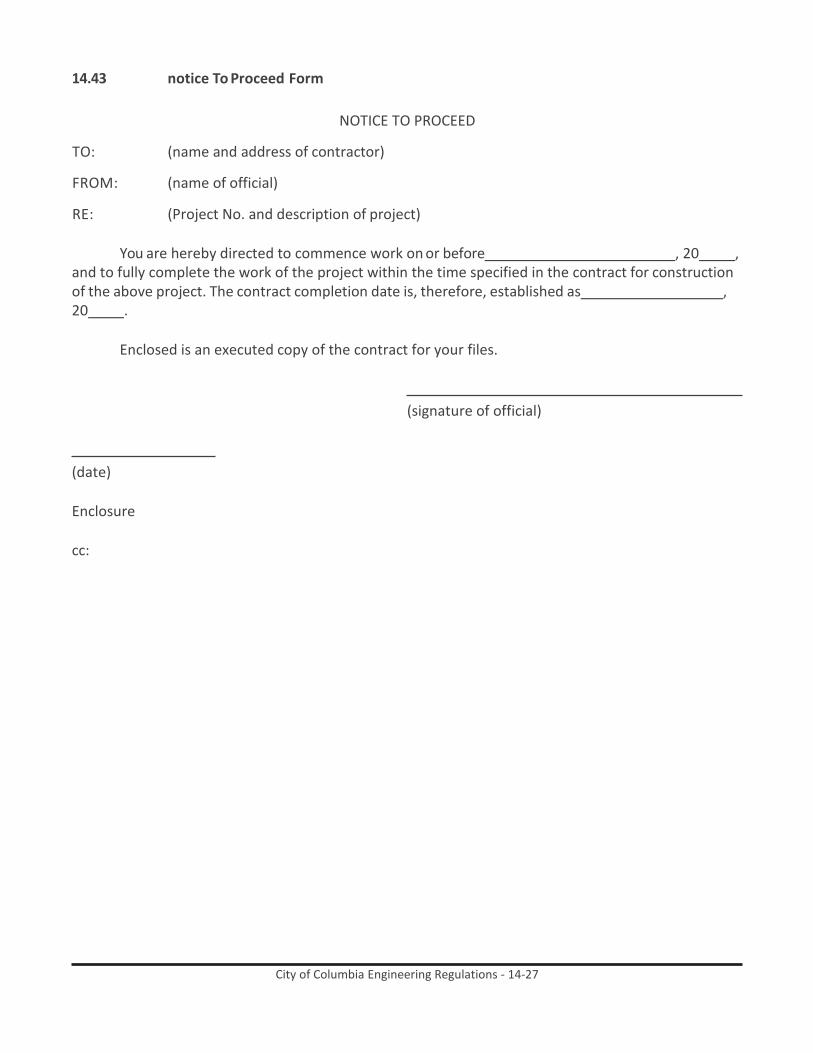
City of Columbia Engineering Regulations - 14-27
14.43 notice To Proceed Form
NOTICE TO PROCEED
TO: (name and address of contractor)
FROM: (name of official)
RE: (Project No. and description of project)
You are hereby directed to commence work on or before , 20 , and to fully complete the work of the project within the time specified in the contract for construction of the above project. The contract completion date is, therefore, established as , 20 .
Enclosed is an executed copy of the contract for your files.
(signature of official)
(date)
Enclosure
cc:

City of Columbia Engineering Regulations - 14-28
14.44 Performance-Payment bond
PERFORMANCE-PAYMENT BOND
KNOW ALL MEN BY THESE PRESENTS That we (1) ,
a (2) , hereinafter called Principal, and (3) ,
State of , hereinafter called Surety, are held and
firmly bound unto the (4) The City of Columbia, South Carolina, hereinafter called Owner, in the penal
sum of ($ ) dollars in lawful money of the United
States, for the payment of which sum well and truly to be made, we bind ourselves, our heirs,
executors, administrators, personal representatives and successors, jointly and severally, firmly by these
presents.
THE CONDITION OF THIS OBLIGATION is such that whereas the Principal entered into a certain contract with the Owner dated the day of , a copy of which is hereto attached and made a part hereof for supplying certain
NOW, THEREFORE, if the Principal shall well, truly and faithfully perform its duties, all the
undertakings, covenants, term, conditions and agreements of said contract during the original term thereof, and nay extensions thereof which may be granted by the Owner, with or without notice to the Surety and if he shall satisfy all claims and demands incurred under such contract, and shall fully indemnify and save harmless the Owner from all costs and damages which it may suffer by reason of failure to do so, and shall reimburse and repay the Owner all outlay and expense which the Owner may incur in making good default, and shall promptly make payment to all person, firms, subcontractors and corporations furnishing materials for or performing labor in the prosecution of the work provided for in such contract, and any authorized extension or modification thereof, including all amounts due for materials, lubricants, oil, gasoline, coal, and coke, repairs on machinery, equipment and tools, consumed or used in connection with the construction of such work, and all insurance premiums on said work, and for all labor performed in such work, whether by subcontractor or otherwise, thence this obligation shall be void; otherwise, to remain in full force and effect.
PROVIDED FURTHER that the said Surety, for value received, hereby stipulates and agrees that
no change, extension of time, alteration or addition to terms of the contract or to the work to be performed thereunder or the specifications accompanying the same shall in any way effect its obligation on this bond, and it does hereby waive notice of any change, extension of time, alteration or addition to the terms of contract or to the work or to the specifications.

City of Columbia Engineering Regulations - 14-29
PROVIDED FURTHER that no final settlement between the Owner and the Contractor shall abridge the right of any beneficiary hereunder, whose claim may be unsatisfied.
IN WITNESS WHEREOF this instrument is executed in counterparts each one of
which shall be deemed an original this day of .
ATTEST:
Principal Secretary Principal
(SEAL) By
Witness Address
Witness
ATTEST:
Surety Secretary Surety
(SEAL) By
Witness Address
Witness
1. Name of Contractor 2. Corporation, Partnership, Individual 3. Name of Surety 4. Name of Owner
South Carolina Registered Agent
5. If partnership, all partners should execute Bond
(Attach Power of Attorney where applicable)
NOTES: Date of Bond must not be prior to date of Contract.

City of Columbia Engineering Regulations - 14-30
14.45 AiA Document A201, 1997
AiA Document A201, 1997

City of Columbia Engineering Regulations - 14-31
CITY OF COLUMBIA MODIFICATION TO AIA DOCUMENT A201, 1997 EDITION
SUPPLEMENTARY CONDITIONS TO THE GENERAL CONDITIONS OF THE CONTRACT FOR CONSTRUCTION
EFFECT OF SUPLLEMENTARY CONDITIONS
The following supplementary conditions modify, delete and/or add to the GENERAL CONDITIONS. Where any article, paragraph or subparagraph in the GENERAL CONDITIONS in supplemented by one of the following paragraphs, the provisions of such article, paragraph, or subparagraph shall remain in effect and the supplemental provisions shall be considered as added thereto. Where any article, paragraph or subparagraph in the GENERAL CONDITIONS is amended, voided, or superseded by any of the following paragraphs, the provision of such article, paragraph or subparagraph not so amended, voided, or superseded shall remain in effect.
ARTICLE 1 - CONTRACT DOCUMENTS: Add the following:
1.1.1.1 The instructions to Bidders, addenda and the Contractor’s Bid shall be part of the Contract
Documents.
1.1.6.1 In the event of conflict between the specifications and drawings, the provision of the specifications shall govern.
1.1.7.1 After the words, “Project Manual is” add the word “usually.”
1.1.8 Wherever the word “ARCHITECT” appears in the GENERAL CONDITIONS, substitute
therefore: “ARCHITECT/ENGINEER” (“A/E”).
1.1.9 Wherever the phrase “Form of Agreement” appears in the General Conditions, substitute therefore the term “contract.”
Modify subparagraph as follows:
1.5.2 Delete the word “generally.”
ARTICLE 2 - OWNER Modify subparagraph as follows
2.1.1 Delete the second and third sentences of this subparagraph. Last line delete “authorized”
and substitute therefore “designated.”
2.1.2 Delete subparagraph 2.1.2 in its entirety
2.2.1 Delete subparagraph 2.2.1 in its entirety

City of Columbia Engineering Regulations - 14-32
2.2.3 Delete the last sentences of this subparagraph.
2.2.4 Delete subparagraph 2.2.4 in its entirety.
2.2.5 Delete subparagraph 2.2.5 in its entirety and substitute the following:
“2.2.5 The A/E or Owner will furnish to the Contractor, free of charge, fifteen (15) copies of the Drawings and Specification and will furnish at actual cost of reproduction as many additional copies as each Contractor may require.”
Add the following subparagraphs:
“2.4.2 The Owner reserves the right to perform any work on the site, whether within or without
the scope of this contract, necessary to correct any conditions which at the sole discretion of the Owner pose a hazard to the health or safety of its employees or the general public. Such work will only be done on any emergency basis. If practical under the circumstances, the Contractor shall be given notice of any such conditions and given a reasonable opportunity to correct them. If work is done by the Owner pursuant to this subparagraph which is necessitated by any act or failure to act of the Contractor, the costs associated with such work shall be deducted from any sums due the Contractor and a written Change Order adjusting the contract sum will be issued.”
ARTICLE 3 - CONTRACTOR Modify subparagraphs as follows:
3.1.2 After the words “Contract Documents” add the words “and submittals approved pursuant
to paragraph 3.12.”
3.2.1 In the first sentence after the words “Subparagraph 2.2.3” add the words “and other information known to the Contractor.” In the first sentence delete the words “of any existing” and substitute and “verify field.” Delete the second sentence in its entirety.
Add the following subparagraphs:
3.2.1.1 The following principles shall govern the settlement of disputes which may arise over
discrepancies in the contract of documents: (a) as between figures given on drawings and the scaled measurements, the figures shall govern – no measurements should be taken by scale as working dimensions except on large-scale drawings not dimensions in detail; (b) as between large-scale drawings and small-scale drawings, the larger scale shall govern; (c) as between drawings and specification, requirements of the specifications shall govern; and (d) as between the Form of Agreement and the Specifications, requirements or the Form of Agreement shall govern. The principles set forth herein shall not alter provision of Article 1.2.
Modify subparagraphs as follows:

City of Columbia Engineering Regulations - 14-33
3.2.2 In the first sentence delete the word “design”, add the word “inconsistencies” after the word “errors”; delete the word “noted” and substitute the word “discovered”; and, place a period after the word “Architect.” Delete the remainder of the first sentence beginning with the word “but.” Delete the second sentence in its entirety.
3.2.2 Delete the first and third sentences of this Subparagraph.
3.2.3 Delete the third, fourth and fifth sentences of this Subparagraph.
3.7.1.1 Each subcontractor shall apply for, obtain, and pay the cost of a permit and inspection fees
for inspection services for his contract portion of the work.
3.7.1.2 The City of Columbia Code of Ordinances requires Certificates to Occupancy upon project completion. It shall be the responsibility of the General Contractor to obtain these permits from the City Inspection Department.
Modify subparagraph 3.8.1 by deleting from said subparagraph the word “but the Contractor shall not be required to employ persons or entities against which the Contractor makes reasonable objection.”
Add the following subparagraphs:
3.8.4 The amount due the Contractor for any allowances shall be based upon certified copies of
invoices from suppliers and subcontractors and shall not included any costs provided for in Paragraph 3.8.2.2.
3.9.2 The superintendent shall maintain a written daily log of the progress of the work and all
communications to or from the architect or Owner. This log shall be kept at the job site and shall be available for inspection upon request by the A/E or Owner.
3.10.1.1 This schedule shall indicate the dates for the starting and completion of various stages of
construction and shall be revised monthly as required by the conditions of the work. This schedule shall be broken down into work items as the Owner may require for proper review.
3.10.1.2 The Contractor shall submit, along with the initial progress schedule, a shop drawing
schedule showing items requiring review or approval by the A/E. The shop drawing schedule shall show the time requiring approval and the date receipt of approval is required.”
Modify Subparagraph 3.10.3 by deleting the word “general.”
Modify Subparagraph 3.11.1 by deleting the word “field” and substituting the word “any.”
Modify Subparagraph 3.12.9 by deleting the second sentence.

City of Columbia Engineering Regulations - 14-34
Modify Subparagraph 3.18.1 by deleting the words “and to the extent claims, damages, losses or expenses are not covered by Project Management Protective Liability Insurance purchased by the Contractor in accordance with paragraph 11.3”
ARTICLE 4 - ADMINISTRATION OF THE CONTRACT
Modify subparagraph as follows:
4.1.1 Substitute the following in lieu of subparagraph 4.1.1: 4.1.1 The Architect is the person
designated by the Owner to act in the capacity as Architect under this agreement. The term includes the architect’s authorized representative.
4.1.2 Third line following”…Owner” delete “the Contractor.”
4.1.3 Delete subparagraph 4.1.3 in its entirety.
Add the following:
4.1.4 In the Specifications or on the Drawings, where the words “as directed,” “as required,” “as
approved,” “as permitted,” or words of like effect are used, Contractor shall understand that direction, requirement, approval or permission of A/E is intended. Similar words “approved,” “acceptable,” “satisfactory,” or words of like import mean approved by, acceptable to or satisfactory to A/E.”
Modify as follows:
4.2.1 Second and third lines following “construction” delete “until final payment is due,” and add
therefore “during the warranty period.”
4.2.1 First sentence delete the words “as a representative of the Owner.”
4.2.5 After the words “Architect’s evaluations” add the words “and observations.”
4.2.6 Delete the last sentence of this subparagraph.
4.2.10 Delete this subparagraph and insert the following in lieu thereof: “4.2.10 If a Project Representative is provided, his duties, responsibilities and limitations of authority shall be as set forth in DUTIES, RESPONSIBILITIES AND LIMITATIONS OF AUTHORITY OF FULL- TIME PROJECT REPRESENTATIVE, AIA DOCUMENT B352, latest edition, copy of which will be provided to Owner, Contractor and Project Representative.”
4.2.12 Delete the second sentence of this subparagraph.
Add the following:

City of Columbia Engineering Regulations - 14-35
“4.2.14 During the twelfth month of the one year construction warranty, the A/E and Contractor will conduct a full and final inspection. The A/E will coordinate with the Contractor to set a date for this inspection. The A/E shall prepare a list of all discrepancies and send a copy to the Owner and the party responsible for correcting the discrepancies. The A/E shall notify the Owner in writing when all repairs have been accomplished.”
Modify subparagraph 4.3.2 first line, by deleting the words, “either party” and by substituting the word “Contractor” therefore, and last sentence by deleting, “and the other party” and by substituting the word “Owner” therefor.
Modify subparagraph 4.3.3, by deleting the words “or as provided in Subparagraph 9.7.1 and Article 14.”
Modify subparagraph 4.3.4 by deleting the sentence commencing on line 13 which reads “Claims by either party…notice of the decision.”
4.3.6 Delete this subparagraph in its entirety.
4.3.10 Modify 4.3.10 by deleting the words “and Owner waive claims against each other” and
substitute “waives claims against the Owner.” Delete the work “mutual” throughout.
Modify 4.3.10.1 by deleting the word “Owner” and substituting “Contractor” therefore.
4.4.1 Modify subparagraph 4.4.1 by deleting the words “mediation, arbitration or” wherever such words appear.
4.4.2 Modify subparagraph 4.4.2 by deleting the word “approve the claim” in section (3) and
substituting the words “recommend approval of the Claim by the other party.”
4.4.5 Modify subparagraph 4.4.5 by deleting the second sentence in its entirety.
4.4.6 Delete subparagraph 4.4.6 in its entirety.
4.4.8 Delete subparagraph 4.4.8 in its entirety.
4.5 Delete paragraph 4.5 in its component subparagraphs 4.5.1 through 4.5.3 inclusive entirely.
4.6 Delete paragraph 4.6 and its component subparagraphs 4.6.1 through 4.6.6 inclusive entirely.
ARTICLE 5 - SUBCONTRACTORS
5.2.3 Modify subparagraph 5.2.3 by substituting the word “or” for the word and so the text will
read “Contract Sum or Contract Time” on the fourth line.
Add the following subparagraph:

City of Columbia Engineering Regulations - 14-36
5.3.2 The Contractor shall assure the Owner, by affidavit or in such other manner as the Owner may approve, that all agreements between the Contractor and his subcontractors incorporate the provisions of subparagraph 5.3.1 as necessary to preserve and protect the rights of the Owner and the A/E under the Contract Documents with respect to the work to be performed by subcontractors so that the subcontracting thereof will not prejudice such rights.”
5.4.2 Delete subparagraph 5.4.2 in its entirety.
ARTICLE 6 - CONSTRUCTION BY OWNER OR BY SEPARATE CONTRACTORS
6.1.4 Delete subparagraph 6.1.4 in its entirety
6.2.3 Delete the second sentence of the subparagraph in its entirety.
6.3.1 Modify this subparagraph by deleting the words “the Architect” fro the last sentence.
ARTICLE 7 - CHANGES IN THE WORK
Add the following:
“7.1.2.1 Change Orders and Construction Change directives are effective only after approval by the
Owner.
Add the following subparagraphs:
“7.1.4 In determining the total cost or credit to the Owner resulting from a change in the work, the allowances for overhead and profit combined, including the total cost to the Owner, shall not exceed the percentages herein scheduled, as follows:
(1) For the Prime Contractor, for any work performed by his own forces, 15% of the direct cost;
(2) For each Subcontractor involved, work performed by his own forces, 15% of the direct cost;
(3) For the Prime Contractor, for work performed by his Subcontractor, &5 of the amount due the Subcontractor.”
7.3.6.6 The “direct cost” as used herein may include all items of labor or materials, the use of
power tools and power equipment and all such items of cost as public liability, workers’ compensation insurance, pro rate charges for additional time of foreman, social security, and old age and unemployment insurance and bond premiums. Among the items to be considered as overhead are insurance other than that mentioned above, supervision, travel, superintendent, timekeepers, clerks, watchmen, small tools, incidental job burdens, general office expense, field office overhead, home office overhead, extended overhead of

City of Columbia Engineering Regulations - 14-37
any kind, impact damages, delay damages, and all other items, costs or expenses not included in the direct cost as defined above.”
Modify subparagraph as follows:
7.3.8 Delete the subparagraph 7.3.8 in its entirety and substitute therefore: “Only fully executed
Change Orders, signed by the Contractor, Architect/Engineer and Owner may be included in the Applications for Payment.” If the Owner and the Contractor do not agree with the adjustment in contract time or the method for determining it, the adjustment or the method shall be referred to the Architect for determination.
ARTICLE 8 - TIME
8.2.2 Modify the first sentence of subparagraph 8.2.2 by deleting the words “and Owner” at the
end of the sentence.
8.3 Delay and Extension of Time: Delete paragraph including subparagraphs 8.3.1, 8.3.2, and 8.3.3 in their entirety and substitute therefore the following:
“8.3 Delay and Extension of Time:
8.3.1 Completion time stipulated under other sections of the Contract Documents may be extended by Change Order or Construction Change Directive to provide one additional work day for each full work day that the Contractor is prevented from working by reason of one or more of the following causes:
.1 Unforeseeable causes beyond the control and without the fault or negligence of the Contractor, including but not limited to, catastrophes and/or acts of God, acts of another Contractor in the performance of a separate contract with the Owner, epidemics, quarantine restrictions, strikes or freight embargoes;
.2 An unusual amount of severe weather to such an extent as to be definitely abnormal and beyond conditions that may be reasonably anticipated. For the purpose of this contract, a total of three(3) working days per calendar month shall be anticipated as “normally bad or severe weather, “ and such time will not considered justification for an extension of time;
.3 Stoppage of work ordered by Owner for reasons over which Contractor has no control.
8.3.1.4 The Contractor shall, within ten (10) days after the beginning of such delay, notify the
Owner and A/E in writing of the cause of the delay. The A/E will then ascertain the facts and extent of delay, and notify the Contractor within ten (10) days of the Owner’s decision in the matter. Notice of delay and requests for extension of time shall set forth the cause and number of additional working days contractor desires contract extended.

City of Columbia Engineering Regulations - 14-38
8.3.2 No claims for extension of time will be considered when based on delays caused by conditions existing at the time bids were received and of which the Contractor might be reasonably expected to have full knowledge at the time of bidding, or upon delays caused by failure on the part of the Contractor to anticipate properly the requirements of the work contracted fro as to materials, labor and equipment. All claims for extension of time shall be made in writing to the A/E with the next application for payment; otherwise they shall be waived.
8.3.3 Completion date stipulated under other sections of the Contract Documents may be
extended by Change Order to compensate for additional work that may be ordered by Owner, provided such work is over and beyond scope of work covered by original contractor, and is of such nature as to materially affect date of completion.
8.3.4 The Contractor shall not be entitled to any claim or compensation for damages on account
of hindrances or delays from any cause whatsoever, but if occasioned by any act of God, or by any act or omission on the part of the Owner, such act, hindrance, or delay may entitle the Contractor to an extension of time in which to complete the work which shall be determined by the A/E, provided that the Contractor will give notice in writing of the cause of such act, hindrance or delay within ten (10) days after its occurrence.
8.3.5 In the event Contractor is delayed at any time in the progress of the work, extension of
time shall be the Contractor’s sole remedy for any such delay (except for Contractor’s right to terminate this Agreement pursuant to any applicable provisions of the Owner- Contractor Agreement) unless the same shall have been caused by acts constituting intentional interference by the Owner with Contractor’s performance of the work and where and to the extent that such acts continue after the Contractor’s notice to the Owner of such interference. Written notice of intentional interference by the Owner must be given within ten (10) days of the occurrence or the claim is waived. The Owner’s exercise of any of its rights under any applicable provisions of Article 7 of the General Conditions, regardless of the extent of number of changes in the work or requirement of corrections or re-execution of any of the work, shall not under any circumstances by construed as intentional interference with the Contractor’s performance of the work.”
ARTICLE 9 - PAYMENT AND COMPLETION
Add the following subparagraph:
“9.2.1.1 The Form of the Schedule of Values shall be AIA G703, continuation Sheet, latest edition.”
Modify subparagraph as follows:
9.3.1 Third lien following “notarized,” delete “if required.”
Delete subparagraph 9.3.1.1 in its entirety and substitute therefore:

City of Columbia Engineering Regulations - 14-39
“9.3.1.1 The Form of the Application for Payment shall be AIA G702 Application and Certificate for Payment with the AIA G703 Continuation Sheet, latest edition. Computer generated Applications for Payment will be acceptable only if the computer generated form conforms exactly to the G702 Application and Certificate of Payment with the AIA G703 Continuation Sheet.”
9.3.1.2 Modify this subparagraph by deleting the words “unless such work has been performed by
others whom the Contractor intends to pay” and substitute therefore the words “because of a dispute or other reason.”
Add the following subparagraphs:
“9.3.1.3 The A/E will authorize, as provided in Paragraph 9.4 and 9.5, monthly payment to equal to
90 per cent of the portion of the contract sum properly allocable to labor, material and equipment suitably stored until the work if fifty (50%) per cent complete.
.1 At the time the work is fifty (50%) per cent complete and providing that the Contractor is on or ahead of the schedule as determined by the Architect/Engineer and the work is satisfactory and in the absence of other good and sufficient reasons, the Contractor may request in writing, and prior to pay application, that the retention be reduced to five (5%) per cent of the amount due. Accompanied with the written request of retainage reduction the Contractor shall submit AIA G704A Consent of Surety to Reduction in or Partial Release of Retainage, latest edition.
.2 The full contract retainage may be reinstated if the manner and progress of the work does not remain satisfactory to the Architect/Engineer.”
Add the following subparagraph:
“9.3.2.1 Rental equipment such as, but not limited to, mobile equipment, pans, forms, scaffolding,
compressors, etc., shall not be considered material stored.”
Modify the following:
9.4.2 In the first sentence after the words “Architect’s evaluation of the work” and “observations at the site.”
Modify the following:
9.6.7 Delete this subparagraph in its entirety.
9.7.1 Fourth line following “Architect,” delete “or awarded by arbitratin.”
9.8.1 Delete the words “or a designated portion thereof.”

City of Columbia Engineering Regulations - 14-40
9.8.2 Delete the words “or a portion thereof” wherever these words appear in the subparagraph.
9.8.3 Delete the words “or designated portion thereof” wherever these words appear in the
subparagraph.
9.8.4 Delete the words “or a portion thereof” wherever these words appear in the subparagraph.
9.8.5 Delete the second sentence in its entirety, and substitute therefore the following: “Upon
substantial completion of the work as certified by the A/E, the Owner shall make payment making any appropriate adjustments in retainage for the work provided for in the Contract Documents.
Add the following:
“9.10.1.1 When the Contractor is ready for final inspection, he shall give notice to the A/E with a
copy to the Owner in the following words: The work on the contract for (show name if improvement or project as it appears in the Form of Agreement) having been fully completed, except as stipulated herein below, it is requested that a final inspection be made promptly by the A/E. The following work is incomplete through no fault or negligence of the Contract or: (list any work the Contractor regards as exceptionable and after each item substantiate why its incompleteness is not due to his fault or negligence).
9.10.1.2 No final inspection shall be made until such time as the A/E and the Owner have received a
letter in exact form indicated above.
9.10.1.3 The balance payable under conditions stated shall reflect retainage for thrice the value of uncompleted work, as determined by the A/E.”
9.10.3 Delete subparagraph 9.10.3 in its entirety.
9.10.4 Delete subparagraph 9.10.4 in its entirety.
9.10.5 Delete the words “except those previously made in writing and identified by that payee as
unsettled at the time of final application for payment” and add the words “against the Owner.”
ARTICLE 10 - PROTECTION OF PERSONS AND PROPERTY
Add the following subparagraph:
10.3.3 Delete subparagraph 10.3.3 in its entirety.
10.5 Delete paragraph 10.5 in its entirety.

City of Columbia Engineering Regulations - 14-41
10.6.2 The Owner reserves the right to perform any work on the site necessary to correct any conditions which pose a hazard to the health or safety of employees or the general public.”
ARTICLE 11 - INSURANCE AND BONDS
Delete Paragraphs 11.1 through 11.5 inclusive and all component subparagraphs contained in Paragraphs 11.1 through 11.5.2, inclusive and substitute therefor the following:
11.1 The Contractor shall purchase and maintain in a company or companies acceptable to the
Owner all insurance as specified in the Instructions to Bidders. The Owner shall be designated as an additional insured on all insurance policies and certificates of Insurance.
11.2 Contractor shall simultaneously with his delivery of the executed contract provide and pay
the cost of Performance and Payment bonds, in the form of City of Columbia “PERFORMANCE – PAYMENT BOND.” The Bond shall be in the full amount of the Contract Sum, issued by a Surety Company licensed in South Carolina, which Surety Company must be listed in the current version of United States Treasury Department Circular 570. Each Bond shall be accompanied by a “Power of Attorney” authorizing the attorney-in-fact to bind the surety and certified to include the date of the Bond.
11.3 The Owner reserves the right to accept or reject the qualifications of any bonding company
submitted by the Contractor.”
ARTICLE 12 - UNCOVERING AND CORRECTION OF WORK
12.2.2.1 Modify subparagraph 12.2.2.1 by deleting the second and third sentences of said subparagraph.
12.2.23 Delete the subparagraph in its entirety.
ARTICLE 13 - MISCELLANEOUS PROVISIONS
Add the following subparagraphs:
13.1.1.1 By executing a contract for the Project, the Contractor agrees to submit itself to the
jurisdiction of the Courts of the State of South Carolina for all matters arising or to arise hereunder, including but not limited to performance of said contract and payment of all licenses and taxes of whatever nature applicable thereto.
13.2.2 Delete this subparagraph in its entirety.
Add the following subparagraph:
13.5.2.1 Materials subject to test shall be inspected by a testing agency selected by the A/E and
satisfactory to the Owner. The Contractor shall defray the costs of tests conducted pursuant to laws, ordinances, rules, regulations or order of any public authority having

City of Columbia Engineering Regulations - 14-42
jurisdiction; the costs of test conducted for his own information and in his own interest: and the cost of tests which are named in the Technical Sections of the Specifications as test to be paid for by the Contractor. Otherwise, the Owner will pay expenses of routine initial testing. Where materials or methods fail to meet requirements by initial test, the Contractor shall defray costs of subsequent test until requirements are met.”
Delete Paragraph 13.6 Interest and Subparagraph 13.6.1.
ARTICLE 14 - TERMINATION OR SUSPENSION OF THE CONTRACT
14.1.1 Modify subparagraph 14.1.1 by deleting subparagraphs 14.1.1.3 and 14.1.1.4.
14.1.2 Delete subparagraph 14.1.2 in its entirety.
14.1.3 Modify subparagraph 14.1.3 by deleting the words “or 14.1.2” and the words commencing
on line 3 which read “and for proven loss...profit and damages.”
Modify following subparagraphs:
14.2.2 Delete the following beginning on Lines 1 and 2 “upon the certification by the Architect that sufficient cause exists to justify such action.”
Modify the following subparagraphs:
14.2.2.3 Delete the last sentence which reads “Upon request……the work.”
Add the following subparagraphs:
14.2.2.3.1 The Owner shall not be required to proceed in completing the work at the lowest possible costs.
14.2.2.3.2 The costs of finishing the work may include but not be limited to: (1) cost of labor and
material, (2) additional architectural services, (3) costs of advertising or bidding, (4) attorney fees, (5) administrative costs, and (6) all other costs or expenses directly or indirectly related to the termination.
Modify 14.2.4 by deleting the words “and not expressly waived.”
14.2.5 Allowing the Contractor to re-enter the project and continue the work shall not constitute
a rescission of the seven day notice previously given. If the Contractor fails or refuses to correct the conditions which gave rise to termination notice, the Owner may terminate the contract without any additional notice.”
Modify subparagraph 14.3.2 to read as follows:

City of Columbia Engineering Regulations - 14-43
14.3.2 An adjustment shall be made for increases in the cost of performance of the Contract, including profit on the increased cost of performance, caused by suspension, delay or interruption ordered in writing by the Owner. No adjustment shall be made to the extent:
.1 that performance is, was or would have been so suspended, delayed or interrupted by another cause for which the Contractor is responsible; or
.2 that an equitable adjustment is made or denied under another provision of this Contract.
END OF SUPPLEMENTARY CONDITIONS

City of Columbia Engineering Regulations - 14-44
14.46 Subcontracting Outreach Program Policies and Procedures
CITY ADMINISTRATIVE POLICIES AND PROCEDURES ’19-3
City of Columbia, South Carolina SUBCONTRACTING OUTREACH PROGRAM
March 2003
Contents
Program Summary 2
A. General 3
B. Subcontractor Outreach and Participation 3
C. Definitions 3
D. Mandatory Subcontractor Outreach Efforts 5
E. Documentation of Subcontractor Outreach Efforts 5
F. Contract Award 9
G. Subcontractor Substitution 10
H. Falsification of Sub-Agreement 10
I. Submission of Final Subcontracting Report 10

City of Columbia Engineering Regulations - 14-45
SUBCONTRACTING OUTREACH PROGRAM SUMMARY
The Subcontracting Outreach Program applies to City-funded construction contracts of Two Hundred Thousand and No/100 ($200,000.00) Dollars or more. When Federal or State funding sources impose additional requirements, those requirements as defined in the contract documents replace the requirements of this program.
The City of Columbia is committed to maximizing subcontracting opportunities for all qualified and available firms. Bidders should be fully informed of the Subcontracting Outreach Program as set forth in this document.
Subcontract 20%:
To be eligible for award of this project, the bidder must subcontract a minimum percentage of its bid to qualified available subcontractors, as indicated below. These subcontractor participation levels will be evaluated on an annual basis to ensure the appropriateness of those levels. The bidder must list all subcontractors, regardless of amount. Failure to list subcontractors and subcontracting amounts with the bid sufficient to meet or exceed the mandatory subcontracting and subcontracting amounts with the bid sufficient to meet or exceed the mandatory subcontracting participation level will cause a bid to be rejected as non-responsive.
Parks 20% Pipelines (water and sewer) 20%
Pump Stations 20% Street Improvements 20%
Traffic Signals/Street Lighting 20% Buildings Project by project (not to exceed 49%)
Miscellaneous projects 20%
Submit Outreach Documentation
To be eligible for award of this project, the bidder must submit documentation of its subcontractor outreach effort either with the bid proposal, or separately with the City agency receiving the bids within five (5) calendar days following the close of business on the day bids are opened. Failure to submit required documentation within this time frame will cause a bid to be rejected as non- responsive. For assistance or further information about the Subcontracting Outreach Program, contact the Equal Business Opportunity Office.

City of Columbia Engineering Regulations - 14-46
SUBCONTRACTING OUTREACH PROGRAM
A. General
This program is subject to policies and requirements established by the City Manger=s Office. The City is committed to ensuring full and equitable participation by subcontracting businesses in provision of goods and services on a contractual basis. Bidders shall be fully informed of the Subcontracting Outreach Program as set forth in this document. Failure to comply with the City=s Subcontracting Outreach Program will cause a bid to be rejected as non-responsive.
Terms and conditions of this Subcontracting Outreach Program apply to City-funded construction project of Two Hundred Thousand and No/100 ($200,000.00) Dollars or more. At the City=s sole discretion, these requirements may be waived in advance on projects deemed inappropriate for subcontracting participation at the specified level. When State and/or Federal funding sources require affirmative action goals, those goals as defined in the contract documents replace requirements of this Subcontracting Outreach Program.
B. Subcontractor Outreach and Participation
This Subcontracting Outreach Program requires bidders to make subcontracting opportunities available to a broad base of qualified subcontractors and achieve a minimum of 20% (may be higher for construction of buildings) subcontractor participation.
C. Definitions
1. Disadvantaged Business Enterprise (DBE): A business which is at least fifty-one percent
(51%) owned and operated by one or more socially and economically disadvantaged individuals and whose management and daily operation is controlled by the qualifying party or parties. In the case of a publicly-owned business, at least fifty-one percent (51%) of the stock must be owned by and the business operated by socially and economically disadvantaged individuals.
2. Disabled Veteran Business Enterprise (DVBE): A business which is at least fifty-one
percent (51%) owned and operated by one or more veterans with a service-related disability and whose management and daily business operation is controlled by the qualifying party or parties.
3. Other Business Enterprise (OBE): A business which does not otherwise qualify as a
Disadvantaged Business Enterprise or a Disabled Veteran Business Enterprise.
4. Subcontractor Outreach Efforts: Affirmative steps taken by a bidder prior to bid opening to ensure maximum effort to recruit subcontractors, including Disadvantaged Business Enterprises (DBEs), Disabled Veteran Business Enterprises (DVBEs) and Other Business Enterprises (OBEs), as sources of supplies, construction and other services whenever possible. Required steps for documenting outreach efforts are outlined in Paragraph E of this document.

City of Columbia Engineering Regulations - 14-47
5. Subcontract: Agreement between a prime contractor and an individual, firm or corporation for performance of particular portion or portions of work for which prime contractor has obligated itself.
6. Subcontractor: An individual, firm or corporation having a direct contract with prime
contractor for performance of portion or portions of work to be contracted under the contract, including furnishing of labor, materials or equipment.
7. Vendor and/or Supplier: A firm that owns operates or maintains a store, warehouse or
other establishment in which material or supplies required for performance of the contract are brought, kept in stock and regularly sold to the public in the usual course of business. As its principal business and in its own name, the firm must engage in purchase and sale of products in question. A vendor and/or supplier of bulk items such as steel, cement, stone and petroleum products need not keep such products in stock if it operates distribution equipment.
8. Manufacturer: An individual, firm or corporation operating or maintaining a factory or
establishment that produces on the premises materials or supplies obtained by the contractor.
9. Subcontractor Participation: Disadvantaged Business Enterprises (DBEs) Disabled
Veterans Business Enterprises (DVBEs) and Other Business Enterprises (OBEs) will be recognized as participants in a contract according to the following criteria:
(a) For credit to be allowed toward respective subcontractor participation levels as a
DBE or DVBE firms, such entities must be certified by the City in accordance with the definitions under Paragraph C, Items 1 and 2, and identified by the bidder as such in bid documents for data collection purposes.
(b) A subcontractor must perform a commercially useful function for credit to be
allowed toward subcontractor participation levels. A subcontractor must be responsible for execution of a distinct element of work and must carry out its responsibility by actually performing, managing and supervising the work.
(c) In computing level of subcontractor participation, recognition for materials and/or
supplies is limited to sixty percent (60%) of amount to be paid to vendor for such materials/supplies unless vendor manufactures or substantially alters materials/ supplies.
D. Mandatory Subcontractor Participation Goal
The City has incorporated a mandatory subcontractor participation goal to enhance competition and maximize subcontracting opportunities. Based on review of subcontractor usage on City projects, the mandatory goal is:
MANDATORY Subcontractor Participation goal
20%

City of Columbia Engineering Regulations - 14-48
(May be higher for construction of building projects)
Failure to meet the subcontractor participation goal will cause a bid to be rejected as non-responsive.
Based on availability data for the preceding three years, the Chief of the Equal Business Opportunity Office shall annually establish advisory subcontract participation levels on an industry basis (e.g., construction, goods, services, and professional services) for each of the following classification of firms: Disadvantaged Business Enterprise (DBE), Disabled Veteran Business Enterprise (DVBE), and Other Business Enterprise (OBE). These DBE, DVBE, and OBE advisory subcontract participation levels shall be advisory only and shall not constitute a basis for determination of noncompliance or disqualification.
E. Documentation of Subcontractor Outreach Efforts
All documentation must be submitted with the bid proposal or within five (5) calendar days following close of business on the day bids are opened. Failure to submit required documentation to the contracting agency within this time frame will render a bid non-responsive. The City may request additional information to validate or clarify; such information must be submitted promptly upon request.
It is the policy of the City of Columbia to provide all subcontractors an equal opportunity to participate in performance of City contracts. Bidders assist the City in implementing this policy by taking reasonably steps to ensure all qualified businesses, including Disadvantaged Business Enterprises (DBEs), Disabled Veteran Business Enterprises (DBVEs), and Other Business Enterprises (OBEs), have equal opportunity to compete for and participate in City contracts.
Documentation of a bidder=s outreach efforts will be reviewed by the Chief of the Equal Business Opportunity Office or the appropriate procurement officer, according to the indicators listed below to verify that bidder made subcontracting opportunities available to a broad base of qualified subcontractors, negotiated in good faith with interested subcontractors, and did not reject any bid for unlawful discriminatory reasons.
Failure to achieve a minimum of 80 out of 100 points will render a bid non-responsive and will result in its rejection. Indicator points are awarded on a pass/fail basis, i.e., either full or zero points can be achieved for compliance with each item as set forth below:
Table 14-1. Indicators and Points for Documenting Subcontractor Outreach Efforts
Indicator Points 1. Achievement of advisory DBE/DVBE/OBE subcontractor participation levels No Points 2. Pre-Bid Meeting attendance 5 Points 3. Identification of sufficient subcontracting work 10 Points 4. Broad-based advertisement 10 Points 5. Written notice to subcontractors 10 Points 6. Follow-up to initial solicitations 10 Points 7. Provisions of plans specifications and requirements 10 Points 8. Request for assistance form recruitment/placement agencies 10 Points

City of Columbia Engineering Regulations - 14-49
Indicator Points 9. Documentation of subcontractor negotiation 25 Points 10. Assistance with bonds, credit lines and insurance 10 Points
POSSIBLE TOTAL 100 Points
1. Achievement of advisory DBE/DVBE/OBE subcontractor participation levels No Points
Failure to meet advisory DBE/DVBE/OBE subcontractor participation levels is not a basis for disqualification or determination of non-compliance with this policy.
2. Pre-Bid Meeting attendance 5 Points
Bidder attended pre-bid meeting schedule by the City to inform all bidders of requirements for subject project. If bidder certifies in writing prior to pre-bid meeting that it was already informed of project requirements, the City may waive requirement for pre-bid meeting attendance.
Required documentation: a) Attend pre-bid meeting and be listed on attendance sheet; or b) Submit letter requesting waiver prior to pre-bid meeting.
3. Identification of sufficient subcontracting work 10 Points
Bidder identification and selected specific work items in subject project to be performed by sub- bidders. Bidder subdivided total contract work requirements into smaller portions or quantities to permit maximum active participation.
Required documentation: Content of advertisement (Indicator 4) and written notices to subcontractors (Indicator 5) will demonstrate compliance with this objective.
4. Broad-based advertisement 10 Points
Not less than ten (10) calendar days prior to bid submittal, bidder conducted an advertising campaign designed to reach all segments of the Columbia community by advertising in newspapers, trade association publications, special interest publications, trade journals, community papers or other media. Advertisements must be specific to the project, not generic, and may not be a plan holder advertisement provided by the publication. Advertisements shall be published on at least three (3) separate days in newspapers of general circulation; one of such newspapers shall be of daily circulation. Advertisements must be worded to ensure it does not exclude or limit potential number of potential respondents and must include:
Required documentation: Submit copies of advertisements and proof of publication dates.
5. Written notice to subcontractors 10 Points
Not less than ten (10) calendar days prior to bid submittal, bidder provided written notice of its interest in receiving sub-bids on subject contract to DBE, DVBE, and OBE business enterprises with an interest in performance of identified work items. Contents of letters must include:

City of Columbia Engineering Regulations - 14-50
X City of Columbia=s project name; X Name of bidder; X Areas of work available for subcontracting; X Contact person=s name and phone number; X Information on availability of plans and specifications; and
X Bidder=s policy concerning assistance to subcontractors in obtaining bonds, credit lines and/or insurance.
Required documentation: Submit copy of each letter sent to subcontractors for each item of work to be performed. If only one master notification, submit letter with list of recipients. Faxed copies must include fax transmittal confirmation slip slowing date and time of transmission. Mailed letters must include copies of metered envelopes or certified mail receipts.
6. Follow-up to initial solicitations 10 Points
Bidder followed up initial solicitations of written notice to subcontractors to determine interest in specific portions of project work, answered questions, recorded phone quotes, and recorded subcontractor=s interest in bidding on any portion of subject project.
Required documentation: Submit copy of telephone logs including name of caller, name of company called, phone number, contract person, time, date, and result of conversation. Telephone logs must be submitted to demonstrate follow-up with all contractors to whom written notices were sent.
7. Provisions of plans, specifications, and requirements 10 Points
Bidder provided interested sub-bidders with access to plans, specifications, and requirements for subject project.
Required documentation: Content of advertisements (Indicator 4) and written notices to subcontractors (Indicator 5) will demonstrate compliance with this Indicator.
8. Request for assistance from recruitment/placement agencies 10 Points
Not less than fifteen (15) calendar days prior to bid submittal, bidder requested and retained assistance from agencies that recruit and place subcontractors. Other organizations and trade associations that promote subcontractor participation may also be contacted.
Required documentation: Submit copy of each letter sent to outreach agencies requesting assistance in recruiting subcontractors. Faxed copies must include fax transmittal confirmation slip showing date and time of transmission. Mailed letters must include copies of metered envelopes or certified mail receipts. Content of letters must include City of Columbia=s project name, name of bidder, and contact person=s name and phone number.

City of Columbia Engineering Regulations - 14-51
9. Documentation of subcontractor negotiation 25 Points
Bidder negotiated in good faith with interested subcontractors and has rejected no bid for other than legitimate business reasons.
Required documentation: Submit a) Copies of all subcontractor bids or quotes received; and b) Summary sheet organized by work type listing subcontractor company names with bide amounts for each work type. Identify selected subcontractor for each work type. If bidder elects to use own forces to perform a work type, include bid to show own costs for the work.
10. Assistance with bonds, credit lines, and insurance 10 Points
Bidder made efforts to advise and assist interested subcontractors in obtaining bonds, credit lines, and insurance required for subject project.
Required documentation: Content of advertisements (Indicator 4) and written notices to subcontractors (Indicator 5) will determine compliance with this objective.
F. Contract Award
The City reserves the right to reject any and all bids. Award of contract will be to the lowest responsible bidder whose proposal complies with the city policies as determined by evaluation of submitted documentation.
G. Subcontractor Substitution
The level of listed subcontractor participation shall be maintained for duration of the contract.
1. Contractor shall request prior approval from the City contracting agency for all
substitutions of subcontractors.
2. Written request shall provide name of listed subcontractor, name of replacement subcontractor, reason for substitution, work type and dollar amount.
3. The selection process for a substitute subcontractor shall be evaluated for fairness and
outreach efforts.
(a) Contractor shall submit all documentation of subcontractor outreach efforts to the Chief of the Equal Business Opportunity Office for review.
(b) Evidence of fraud or unlawful discrimination in substitution of subcontractors will
result in sanctions including assessment of penalty fines, termination of contract, or debarment.
4. Substitution of any subcontractor without the prior written approval of the City Manager
shall be deemed to constitute a material breach of contract. The harm that shall accrue to the public is difficult to accurately estimate in advance. Consequently, the Contractor

City of Columbia Engineering Regulations - 14-52
and the City shall jointly agree that a reasonable forecast of such damages is not less than ten (10%) percent of the subcontract price, and that the parties intend that such sum shall constitute liquidated damages as the best estimate of the harm accruing to the City.
5. This section does not replace applicable South Carolina Procurement Code provisions.
H. Falsification of Sub-Agreement
Falsification or misrepresentation of a sub-agreement as to company name, contract amount, and/or actual work performed by subcontractor will result in sanctions including assessment of penalty fines, termination of contract, or debarment.
I. Submission of Final Subcontracting Report
Contractor must submit Final Subcontracting Report to City contracting agency within fifteen (15) calendar days after final inspection of contract work. Failure to comply will result in assessment of liquidated damages.

City of Columbia Engineering Regulations - 15-i
City of Columbia Engineering Regulations PART 15: General Specifications
Table of Contents Paragraph Description Page no.
15.1 Definitions of Terms 15-1 15.2 Laws and Regulations 15-6 15.3 Contract and Contract Documents 15-6 15.4 Required Provisions Deemed Inserted 15-7 15.5 Notice and Service Thereof 15-7 15.6 Prohibited Interests 15-7 15.7 Encroachment Permits, Rights-of-way, Easements and Suspension of Work 15-8 15.8 Photographs 15-8 15.9 Video Taping of Project 15-8 15.10 Indemnity 15-9 15.11 Contract Security 15-9 15.12 Assignments 15-10 15.13 Subcontracting 15-10 15.14 Mutual Responsibility of Contractors 15-10 15.15 Separate Contracts 15-11 15.16 Contractor’s Obligation 15-11 15.17 Payments by Contractor 15-12 15.18 Contractor’s Local/ Field Office 15-12 15.19 Supervision 15-12 15.20 Organization, Superintendence, Construction Progress 15-13 15.21 Inspection by Agencies 15-14 15.22 Additional Instructions and Detail Drawings 15-14 15.23 Correlation of Plans and Specifications 15-14 15.24 Ownership of Drawings 15-14 15.25 Submittals Prior to Construction 15-15 15.26 Benchmark 15-18 15.27 Materials, Services, and Facilities 15-18 15.28 “Or Equal” (Substitute Materials) 15-18 15.29 Standard Products and Materials Not Specified 15-20 15.30 Product Data 15-20 15.31 Samples 15-20 15.32 Patents 15-21 15.33 Delivery, Storage, and Handling 15-21 15.34 Contractor’s Title to Materials 15-22 15.35 Inspection and Testing Materials, Quality, and Guarantees 15-22 15.36 Material Testing 15-23 15.37 Experience of Manufacturer 15-26 15.38 Completed Portions of Work 15-27 15.39 Changes in Work 15-27 15.40 Claims for Extra Work 15-27

City of Columbia Engineering Regulations - 15-ii
15.41 Estimated Quantities of Work 15-28 15.42 Time for Completion, Liquidated Damages, and No Damages for Delays 15-28 15.43 Construction Schedule and Periodic Estimates 15-29 15.44 Procedures for Submitting Pay Requests 15-30 15.45 Acceptance of Work, Final Payment, and Closeout Procedures 15-33 15.46 Record Drawing 15-35 15.47 Acceptance of Final Payment as Release 15-35 15.48 General Warranty for Three Years After Completion of Contract 15-36 15.49 Right of City to Terminate Contract 15-36 15.50 Termination for Convenience and Suspension of Work 15-36 15.51 Reporting on Job Retention and Creation 15-37 15.52 Wages and Overtime Computation 15-38 15.53 Protection of Material, Work, and Property; and Injuries to Persons and
Property
15-39 15.54 Safety Regulations 15-40 15.55 Protection of Employees’ Lives and Health 15-40 15.56 Weather Conditions and Emergency 15-41 15.57 Mobilization 15-41 15.58 Surveys, Lines, Grades, Stakes, and Templates 15-42 15.59 Clean Up and Restoration 15-42 15.60 Use of Explosives 15-43 15.61 Sediment and Erosion Control 15-43 15.62 Construction Near or Under Drainage Pipes, Sewers, and Ditches 15-44 15.63 Unclassified Excavation/ Geotechnical Investigation 15-44 15.64 Excavation and Trench Stabilization 15-45 15.65 Dewatering 15-46 15.66 Backfilling 15-46 15.67 Flowable Fill 15-47 15.68 Maintenance of Traffic 15-48 15.69 Access Roads 15-49 15.70 Ingress and Egress to Public or Private Premises 15-50 15.71 Rights-of-ways and Easement Clearing 15-50 15.72 Existing Utilities and Structures 15-52 15.73 Interruption of Service 15-53 15.74 Conflicts With and Relocation of Existing Utilities 15-53 15.75 Ordinance Relating to Utility Lines in Streets 15-53 15.76 Replacing Shoulder Material 15-57 15.77 Asphalt Paving, Repairing, and/or Resurfacing Roadways 15-57 15.78 Removing, Milling, and Disposing of Asphalt Pavement 15-58 15.79 Remove and Replace Concrete and Asphalt Drives 15-58 15.80 Concrete Curb and Gutter and Concrete Sidewalks 15-59 15.81 Pavement Markings 15-59 15.82 Protection of Tree Root Zones Within Street Right-of-way 15-60 15.83 Re-establishment of Property Irons 15-65

City of Columbia Engineering Regulations - 15-iii
List of Figures
Figure Description Page no. Figure 15-1. Typical Permanent Repair Section and Typical Multi-Duct System 15-56 Figure 15-2. Details for Protection of Tree Root Zones Within Street R.O.W. 15-64
List of Tables
Table Description Page no. Table 15-1. FTE Calculation Example: Lifecycle of a 4 Month Project 15-38

City of Columbia Engineering Regulations - 15-1
City of Columbia Engineering Regulations PART 15: General Specifications
15.1 Definitions of Terms
15.1.1 Whenever in these specifications and in the contract, or any documents or instruments pertaining to construction where these specifications govern the following terms are used, the intent and meaning shall be interpreted as follows:
15.1.1.1 A.A.S.H.T.O. - American Association of State Highway and Transportation Officials.
15.1.1.2 A.D.A. - Americans with Disabilities Act of 1990
15.1.1.3 A.N.S.I. - American National Standards Institute.
15.1.1.4 A.S.T.M. - American Society for Testing Materials.
15.1.1.5 A.W.W.A. - American Water Works Association.
15.1.2 Advertisement for Bids – The notice calling attention of bidders to the time and place for
receiving bids, containing a brief description of the work and briefly setting forth the requirements and conditions for submission of proposals.
15.1.3 Bid Bond – The security to be furnished by the bidder as a guaranty of good faith that he
will enter into a contract with the City and to execute the required bond covering the work contemplated, if same is awarded to him.
15.1.4 Bidder – Any individual, partnership, firm or corporation acting directly or through a duly
authorized representative, submitting a proposal for the work contemplated.
15.1.5 Bridges – Water-way structures having a clear span in excess of 12 feet.
15.1.6 City – The City, as owner of the project, acting through its authorized representatives.
15.1.7 Council – The duly elected Council of the City.
15.1.8 Contract – The written agreement covering the performance of the work. The contract shall include the Proposal, Plans, Specifications, Special Provisions, Work Order, Contract Bond, Insurance Certificates, Addenda and all other documents pertinent to the contract. It shall also include any and all supplemental, signed, written agreements duly authorized by the owner which may be executed to complete the work, in accordance with the intent of the plans and specifications, in an acceptable manner.
15.1.9 Contract Period – The period from the date specified in the contract for the
commencement of work to the date specified for its completion, both dates, inclusive.

City of Columbia Engineering Regulations - 15-2
15.1.10 Contract Sum – The aggregate sum obtained by multiplying the number of units of each class of work, as shown on the contract, by the unit prices specified in the contract for the class of work.
15.1.11 Contractor – The individual, partnership, firm or corporation executing a contract acting
directly or through his lawful agents or employees, who is primarily liable for the acceptable performance of the work for which he was contracted and also for the payment of all legal debts pertaining to the work.
15.1.12 Contractor-(Sub) – Any person, firm, or corporation who has, with the approval of the
Engineer, contracted with the Contractor to execute and perform in his stead all or part of the contract.
15.1.13 Design Engineer – The representative of the City directly in charge of the work.
15.1.14 Drainage – Drainage is the system of pipes, drainageways, ditches, and structures by
which surface or subsurface waters are collected and conducted from the streets, alleys, or adjacent properties.
15.1.15 Employee – Any person working on the project to which these specifications apply, and
who is under the direction or control of, or receives compensation from the Contractor or sub-contractor.
15.1.16 Engineer - City Engineer or his duly authorized representative.
15.1.17 Equipment – All machinery, together with the necessary supplies for upkeep and
maintenance and also all tools and apparatus necessary for the proper construction and acceptable completion of the work.
15.1.18 Extra Work – Work performed by the Contractor, authorized by formal Change Order
signed by the City Engineer, in order to complete the contract in an acceptable manner but for which there is no basis of payment provided in the contract.
15.1.19 Inspector – An authorized representative of the Engineer assigned to make all necessary
inspection of the work performed or being performed, or for the materials furnished or being furnished by the Contractor.
15.1.20 Intention of Terms – Whenever, in these specifications or upon the plans the words
“directed”, “required”, “permitted”, “ordered”, “prescribed”, “designed”, or words of like import are used, it shall be understood that the direction, requirement, permission, order, designation, or prescription of the Engineer is intended and similarly, the words “approved”, “acceptable”, “satisfactory”, or words of like import, shall mean approved by, or acceptable to or satisfactory to the Engineer subject in each to the final determination of the City Manager.
15.1.20.1 Any reference to a paragraph of sub-paragraph within a section shall include the general
provisions of the section or sections and paragraph pertinent thereto.

City of Columbia Engineering Regulations - 15-3
15.1.21 Instructions to Bidders – The clauses setting forth, in detail, the information relative to the proposed work and requirements for the submission of Proposals.
15.1.22 Item – A specified class of work on which definite prices are set forth in the proposal or
in the contract.
15.1.23 Laboratory – The official testing laboratories of the City or such other laboratories as may be designated by the Engineer.
15.1.24 Landscaping – The planning, planting, establishing and caring for trees, shrubs, vines and
other vegetation to provide shade, reduce dust, control erosion or improve the general appearance of the project.
15.1.25 Lump Sum – Total price for an item or items of work regardless of the number of units of
work to be performed.
15.1.26 Maximum Density and Optimum Moisture Content – The term “maximum density” as applied to the compaction of soils an similar materials shall be construed as the greatest density obtainable from the material passing a ¾+” mesh sieve when it is compacted in the manner prescribed in current A.A.S.H.O. Method of Test 5-90 or the current Standard Proctor Method. Optimum moisture content shall be construed as the percentage of moisture corresponding to the maximum density in the above described test.
15.1.27 Notice of Award – A written notice to the successful bidder stating that his bid has been
accepted and that, in accordance with the terms of the Advertisement for Bids and Specifications, he is required to execute the contract and furnish satisfactory contract bond.
15.1.28 Notice to Proceed – A written notice to the Contractor of the date on which he is to
begin the prosecution of the work for which he has contracted.
15.1.29 Or Equal” Clause – “Or equal” shall be construed to mean that material or equipment will be acceptable only when, in the judgment of the Engineer, they are composed of parts of equal quality, or equal workmanship and finish, designed and constructed to perform or accomplish the desired result as efficiently as the indicated brand, pattern, grade, class, make of model. Written approval will be obtained from the Engineer prior to installation.
15.1.30 O.S.H.A. - Occupational Safety and Health Act.
15.1.31 Official Publications – The official publications and the formal resolutions and notices
relative to the proposed improvements that are required by law to be published in a prescribed manner and that have actually been published in accordance with the statues relating thereto. Attention is directed to the fact that these official publications are by statute vested with all of the force and effect of contract obligations.

City of Columbia Engineering Regulations - 15-4
15.1.32 Owner – The owner is any public agency which, through its authorized representatives and governing body, has authorized the project and can by their own acts bind the City in the accompanying contract.
15.1.33 Performance and Payment Bond – The approved form of security furnished by the
Contractor and his Surety as a guarantee of good faith and ability on the part f the Contractor to execute the work in accordance with the terms of the plans, specifications and contract, and the payment of all debt pertaining to the work and the maintenance of the work as provided by law of by these specifications.
15.1.34 Plans – The official plans, working drawings or supplemental drawings or exact
reproductions thereof, approved by the City, official copies of which are on file in the Department of Utilities and Engineering and which show the location, character, dimensions, and detail of the work to be done and which are to be considered as part f the contract, supplementary to these specifications.
15.1.35 Project – A project for the accomplishment of the improvement of certain municipal
streets, alleys, sewers, data, etc., based on a program of improvement adopted by the City Council.
15.1.36 Proposal – The written offer of the bidder, when submitted on the approved Proposal
Form, to perform the contemplated work and furnish the necessary materials in accordance with the provision of the plans and these specifications.
15.1.37 Proposal Form – The approved form on which the written offer of formal bid is to be
prepared and submitted for the construction to be done.
15.1.38 Public Agency – Public agency means a Municipality or other political subdivision; or a tax-supported organization.
15.1.39 Right-of-way – All lands or other property interests provided or acquired for the
construction of the improvement and its appurtenances.
15.1.40 Roadbed – The area between the inside slopes of ditches or tops of fills slopes.
15.1.41 Roadway – The part of the right-of-way included between the outside lines of the slopes, gutters and side ditches of the road.
15.1.42 S.C.D.O.T. – South Carolina Department of Transportation
15.1.43 Shoulders – That portion of the road, street, or alley lying outside of the surfaced areas.
15.1.44 Sodding – The transplanting of established turf in the form of blocks or strips usually
referred to as “sods”.
15.1.45 Special Provisions – The specific clauses setting of the conditions or requirements peculiar to the project under consideration, covering work or material involved in the

City of Columbia Engineering Regulations - 15-5
Proposal and estimate, which are not thoroughly or satisfactorily stipulated in these specifications.
15.1.46 Specifications – The directions, provisions, and requirements contained herein,
supplemented by special provisions, pertaining to the method and manner of performing the work, or to the quantities, or the qualities of materials to be furnished under the contract.
15.1.47 Station – One hundred (100) lineal feet.
15.1.48 Structures – As used in these specifications, structures shall mean culverts, including
headwalls and endwalls, drainage construction such as storm sewers, gutters, catch basins, drop inlets, manholes, retaining walls and other construction which may be encountered in the building of the improvements.
15.1.49 Sub-grade – That portion of the road, street or alley upon which the base-course is to be
placed.
15.1.50 Superintendent – The executive representative for the Contractor present on the work site at all times during progress, authorized to receive and fulfill instruction from the Engineer and capable of superintending the work efficiently.
15.1.51 Supplemental Agreement – A written Proposal and Agreement executed by the
Contractor and by the City, with the consent of the Contractor’s Surety covering work not included in the Plans and Proposal which is necessary to the proper completion of the project.
15.1.52 Surety – The corporate body or individuals which are bound by the contract bond and
the payment bond with and for the Contractor, and which engage to be responsible for the entire and satisfactory fulfillment of the contract and for the payment of all lawful debts incurred in fulfilling the contract.
15.1.53 Surfacing – The combined subbase, base and surface course of pavement shall be
considered as a single unit, excluding shoulders, unless otherwise denoted.
15.1.54 The Work – All work including the furnishing of materials, tools, equipment, incidentals, etc., to be performed by the Contractor under the terms of the contract, plans and specifications.
15.1.55 Turf – The mass of matter, roots, of grass and certain other low-growing plants, including
the layer of soil in which they are growing and the plant growth showing above. The density and quality of the turf mat will be influenced by the environmental conditions and service requirements, but in general maximum coverage with a minimum yield is desired, as distinct from agricultural productions.
15.1.56 Turfing – The process involved in the planting and development of turf, including
preparation and improvement of soil, sowing, or planting, cultural practices and other operations necessary to its establishment and maintenance.

City of Columbia Engineering Regulations - 15-6
15.1.57 Working Day – A working day shall be any day other than a legal holiday or Sunday. Sundays or holidays on which the Contractor’s forces engage in regular work, requiring the presence of an inspector, will be considered as working days.
15.1.58 Working Time – The working time, stated in the Proposal and the contract, shall be given
as a definite number of working days or as the date by which all work shall be completed as an essential part of the contract. When the notice to Contractors and Proposal form set forth the date of commencement and date of completion, then the contract period shall be the period from the specified date for beginning the work, to the specified date of completion, both dates inclusive. The contract period may be extended by the City as provided in these specifications, in which event the contract period includes the new date of completion.
15.2 laws and Regulations
15.2.1 The Contractor shall keep himself fully informed of all Federal, State, City and County
laws, ordinances and regulation in any manner affecting those engaged or employed in the work, or the materials used in the work, and of all orders and decrees of bodies or tribunals having any jurisdiction or authority over same. If any discrepancy or inconsistency is discovered in this contract, or in the drawings or specifications herein referred to, in relation to any such laws, ordinances, regulation, order or decree, he shall immediately report the same in writing to the City. He shall at all times observe and comply with all such existing and future laws, ordinances, and regulations, and shall protect the surety, the City and their agents against any claims or liability arising from or based on the violation of any such law, ordinance, regulation, order or decree, whether by himself or by his employees.
15.3 Contract and Contract Documents
15.3.1 The instructions to bidders, contractor’s bid, plans, specifications and addenda shall
form part of this contract and the provisions thereof shall be as binding upon the parties hereto as if they were herein fully set forth. The tables of contents, titles, headings, running headlines and marginal notes contained herein and in said documents are solely to facilitate reference to various provisions of the contract documents and in no way affect, limit or cast light on the interpretation of the provisions to which they refer.
15.3.2 Projects shall be constructed in accordance with the references made in the Contract
Documents, Plans, Specifications and/or Special Provisions; however, payment shall be made as shown in the Bid Form included in the Contract Documents. Reference to any standards, specifications, manuals, and/or test designations of the American Society for Testing Materials, the American Association of State Highway and Transportation Officials, Federal Specifications, South Carolina Department of Transportation, the City of Columbia, County or any other recognized national organization shall mean it is all inclusive and shall be the current version in effect at the time the Contract is bid whether it is identified by a number and/or year of adoption. “All inclusive” shall mean to include all supplemental specifications, amendments and any other addenda associated with the standards, specifications and manual or test designation. Reference

City of Columbia Engineering Regulations - 15-7
to the “Department” or “SCDOT” in the South Carolina Department of Transportation Specifications shall be changed to “Owner/Engineer” unless otherwise noted.
15.4 Required Provisions Deemed inserted
15.4.1 Each and every provision of law or clause required by law to be inserted in this contract
shall be deemed to be inserted herein, and the contract shall be read and enforced as though it were included herein. If through mistake or otherwise any such provision is not inserted, or is not correctly inserted, then upon the application of either party the contract shall be amended to make such insertion or correction.
15.5 Notice and Service Thereof
15.5.1 All notices herein provided shall be considered as having been given upon being placed
in the United States Mail, certified, postage prepaid, addressed to the contractor at the address herein set forth in the contract documents or to such other address as may be given to the City in writing.
15.5.2 All notices required to be delivered to the City shall, unless otherwise specified in writing
to the Contractor, be delivered to the City Engineer, City of Columbia, Columbia, South Carolina, and any notice to or demand upon the City shall be sufficiently given if delivered to the office of said City Engineer, or if deposited in the United States Mail, certified, postage prepaid, in each case addressed to said City Engineer of the City of Columbia, South Carolina, unless otherwise specified in writing to the contractor by the City Engineer.
15.6 Prohibited interests
15.6.1 No official of the City, who is authorized in such capacity and on behalf of the City to
negotiate, make, accept, approve, or to take part in negotiating, making, accepting, or approving any architectural, engineering, inspection, construction or material supply contract or ay subcontract in connection with the construction of the project, shall become directly or indirectly interested personally in this contract or in any part hereof. No officer, employee, architect, attorney, engineer, or inspector of or for the City, who is authorized in such capacity, and on behalf of the City to exercise any legislative, executive, supervisory or other similar functions in connection with the construction of the project, shall become directly or indirectly interested personally in this contract or in any part thereof, any material supply contract, subcontract, insurance contract, or any contract pertaining to the project.
15.6.2 The City shall, at its sole option and discretion, have the right to terminate this contract
for any reason whatsoever by providing the Contractor with a notice of termination to be sent by registered mail, return receipt requested. A termination for default under Section 29.0 of this contract shall, if wrongfully made, be treated as a termination for convenience under this clause. Whenever the Contractor is terminated for convenience under this clause or is wrongfully terminated under any other clause of this contract, the Contractor shall only be entitled to the actual direct costs of all labor and material

City of Columbia Engineering Regulations - 15-8
expended on the job prior to the effective date of the termination plus 15% or the Contractor shall be entitled to be paid a pro-rate percentage of the total contract price which is equal to its percent of completion, whichever of the two methods provides the lowest sum to be paid to the Contractor. In no event shall the Contractor be entitled to anticipatory profit or damages for any termination under this clause. In no event shall the Contractor be entitled to assert a claim in quantum meruit or any other measure of damages other than that stated herein.
15.7 Encroachment Permits, Rights-of-way, Easements and Suspension of Work
15.7.1 The City shall furnish all necessary permits, land and rights-of-way necessary for the
carrying out of this contract and the completion of the work herein contemplated, and will use due diligence in acquiring said encroachment permits, land and right-of-way as speedily as possible with the exception of obtaining additional temporary construction easements that the Contractor deems necessary in the performance of the contract. It is possible that all encroachment permits, lands and rights-of-way may not be obtained as herein contemplated before construction begins, in which event the Contractor shall begin his work upon such land and rights-of-way as the City may have previously acquired, and no claim for damages whatsoever will be allowed by reason of the delay in obtaining the remaining lands and right-of-way. Should the City be prevented or enjoined from proceeding with the work, or from authorizing its prosecution, either before or after the commencement, by reason of any litigation or by reason of its ability to procure any lands or rights-of-way for said work, the contractor shall not be entitled to make or assert claim for damage by reason of said delay or to withdraw from the contract except by consent of the City; but time for completion of the work will be extended to such time as the City determines, such determination to be set forth in writing.
15.7.2 In the event the Contractor obtains permissions for temporary easements, copies of all
documents shall be submitted to the Engineer for approval and filing.
15.7.3 There will be no separate payment for these requirements. All cost for this work shall be included in other bid items.
15.8 Photographs
15.8.1 The contractor will be responsible for obtaining photographs in and adjacent to the
construction area prior to beginning construction. The back of each photograph shall be annotated with the date, location (approximate station number), and direction of view (i.e., “looking north”, etc.). There is no direct payment for this item, the cost of which shall be included in other bid items.
15.9 Video Taping of Project
15.9.1 The contractor shall video tape the entire project route, with an Engineer’s
representative in attendance, prior to the start of construction. The Engineer must be given 48 hours prior notice. Audio will be included on the tape with the property being

City of Columbia Engineering Regulations - 15-9
videoed identified by tax map number and street address. It is VERY IMPORTANT that the Contractor thoroughly documents the preexisting conditions of any and all roads, walkways, and parking lots which he will utilize including those used for access outside area of construction. A copy of this video will be given to the Engineer immediately following taping/copying.
15.9.2 At the completion of the project the contractor shall repeat the above requirement.
15.9.3 These video tapes are to protect the contractor from undue claims. If ANY situation
arises where a claim is made by a party for damages by the Contractor, the Contractor must have documented prior evidence to the contrary or the City must side with the party making such claims, regardless if condition was pre-existing or not.
15.9.4 There is no direct payment for this item, the cost of which shall be included in other bid
items.
15.10 Indemnity
15.10.1 The Contractor agrees to and fully indemnify, defend, hold harmless and reimburse the Owner, the Engineer and their respective agents, employees and successors from and against any and all losses, liabilities, judgments, expenses, costs and all claims for damages of any nature whatsoever: • relating to or arising out of any action or failure to act; or, • resulting from a taking of property, real or personal, or by inverse condemnation; or, • relating to or arising out of the performance or failure to perform any of the
obligations required by the contract; or, • resulting from failure to comply with or violation of any local, state or federal
regulation by the Contractor, its subcontractors, officers, agents and employees or for anyone for whose acts any of them may be liable for. Losses, liabilities, expenses and claims for damages shall include, but not limited to, civil and criminal fines and penalties, judgments, loss of use and/or services, bodily injury, injury to or the taking of real or personal property, defense costs and attorney’s fees.
15.11 Contract Security
15.11.1 The Contractor shall furnish a performance and payment bond in an amount at least
equal to one hundred (100) percent of the contract prices as security for the faithful performance of this contract, as security for the payment of all persons performing labor on the project under this contract and furnishing materials in connection with the contract. The performance bond and payment bond may be in one or in separate instruments in accordance with local law. Before final acceptance, each bond must be approved by the City.

City of Columbia Engineering Regulations - 15-10
15.12 Assignments
15.12.1 The Contractor shall not assign the whole or any part of this contract or any money due or to become due hereunder without written consent of the City. In case the Contractor assigns all or any part of any moneys due or to become due under this contract, the instrument of assignment shall contain a clause substantially to the effect that it is agreed that the right of the assignee in and to any moneys due or to become due to the Contractor shall be subject to prior claims of all persons, firms and corporations for services rendered or materials supplied for the performance of the work called for in this contract.
15.13 Subcontracting
15.13.1 The Contractor may utilize the services of specialty subcontractors on those parts of the
work which under normal contracting practices are performed by specialty subcontractors.
15.13.2 The Contractor shall not award any work to any subcontractor without prior written
approval of the City, which approval will not be given until the Contractor submits to the City a written statement concerning the proposed award to the subcontractor, which statement shall contain such information as the City may require.
15.13.3 The Contractor shall be as fully responsible to the City for the acts and omissions of his
subcontractors, and of persons either directly or indirectly employed by them, as he is for the acts and omissions of persons directly employed by him.
15.13.4 The Contractor shall cause appropriate provisions to be inserted in all subcontracts
relative to the work to bind subcontractors to the Contractor by the terms of the General Specifications and other contract documents insofar as applicable to the work of subcontractors and to give the contractor the same power as regards terminating any subcontractor that the City may exercise over the Contractor under any provisions of the contract documents.
15.13.5 Nothing contained in this contract shall serve to create any contractual relationship
between any subcontractor and the City.
15.14 Mutual Responsibility of Contractors
15.14.1 If through acts of neglect on the part of the Contractor, any other contractor or any subcontractor shall suffer loss or damage on the work, the Contractor agrees to settle with such other contractor or subcontractor by agreement or arbitration if such other contractor or subcontractor will so settle. If such other contractor or subcontractor shall assert any claim against the City on account of any damage alleged to have been sustained, the City shall notify the Contractor, who shall indemnify and save harmless the City against any such claim.

City of Columbia Engineering Regulations - 15-11
15.15 Separate Contracts
15.15.1 The contractor shall coordinate his operations with those of other contractors. Cooperation will be required in the arrangement for the storage of materials and in the detailed execution of the work. The Contractor, including his subcontractor, shall keep informed of the progress and the detail work of other contractors and shall notify the Engineer immediately of lack of progress or defective workmanship on the part of other contractors. Failure of a contractor to give notice of lack of progress or defective workmanship by others shall be construed as acceptance by him of the status of the work as being satisfactory for proper coordination with his own work.
15.16 Contractor’s Obligation
15.16.1 The Contractor shall have the sole responsibility of determining the best and proper
method or means of construction and the Owner or the Engineer acting in behalf of the Owner shall not be held responsible for determining or suggesting a method or means of construction, except as expressly indicated in the contract documents.
15.16.2 The Contractor shall, in good workmanlike manner, do and perform all work and furnish
all supplies and materials, machinery, equipment, facilities and means, except as herein otherwise expressly specified, necessary or proper to perform and complete all the work required by this contract, within the time herein specified, in accordance with the provisions of this contract and said specifications, and in accordance with the plans and drawings covered by this contract and any and all supplemental plans an drawings, and in accordance with the directions of the Engineer as given from time to time during the progress of the work. He shall furnish, erect, maintain, and remove such construction plant and such temporary works as may be required. The Contractor shall observe, comply with, and be subject to all terms, conditions, requirements and limitations of the contract and specifications, and shall do, carry on, and complete the entire work to the satisfaction of the Engineer and the City.
15.16.3 The Contractor will at all times have one complete set of all contract documents (special
provisions, specifications, drawings, bulletins, etc.) maintained at the project sites and the Contractor’s person in charge must be familiar with all phases of the project.
15.16.4 The Contractor agrees to personally see to the execution of the contract and not to
sublet any portion of the same without the consent, in writing, of the City. The Contractor shall be responsible for the faithful completion of that part of the work. The subletting will not release the Contractor from any of his obligations or requirements under this contract.
15.16.5 The Contractor shall immediately remove and reconstruct or replace, at his own
expense, all work or materials not in accordance with this contract. The payment of estimates, including certain work or materials, shall not be considered as an acceptance of that work or those materials at any time before the final acceptance of the entire work and materials included in the contract.

City of Columbia Engineering Regulations - 15-12
15.17 Payments by Contractor
15.17.1 The Contractor shall pay for the following:
15.17.1.1 For all transportation and utility services not later than the twentieth (20) day of the calendar month following that in which services are rendered;
15.17.1.2 For all materials, tools, and other expendable equipment to the extent of ninety (90)
percent of the cost thereof not later than the twentieth (20) day of the calendar month following that in which such materials, tools, and equipment are delivered at the site of the project, and the balance of the cost thereof not later than the thirtieth (30) day following the completion of that part of the work in or on which such materials, tools, and equipment are incorporated or used; and
15.17.1.3 To each of his subcontractors not later than the fifth (5) day following each payment to
the Contractor, the respective amounts allowed the Contractor on account of the work performed by his subcontractors to the extent of each subcontractor’s interest therein.
15.18 Contractor’s local/ Field Office
15.18.1 The Contractor shall maintain a field office, with telephone, in the general area of the
work, and will be required to have a responsible representative on call at all times.
15.18.2 Should the Contractor so desire, he may build shanties or provide other structures for housing men, tools, machinery and supplies, but they will only be permitted at approved places, and their surroundings shall be maintained at all times in a sanitary and satisfactory manner. On or before the completion of the work, all such structures shall be removed, together with all rubbish and trash, at the expense of the Contractor.
15.18.3 Upon completion of the contract, the Contractor shall remove the field office and all
such temporary facilities from the site and leave the premises in a condition acceptable to the City Inspector. In the event the Contractor leases or rents office space for the field office, the Contractor shall vacate the rented or leased space in a condition acceptable to the property owner.
15.19 Supervision
15.19.1 The work shall be conducted under the general direction of the Engineer and will be
inspected by inspectors appointed by him. However, in no case will the Engineer or Inspector be responsible for the supervision of the work. The inspectors will keep a record of work done and see that the location and limit marks are kept in proper order. The presence of an inspector shall not relieve the Contractor of responsibility for the proper execution of the work.
15.19.2 The Contractor shall furnish at his own expense such labor, organization and materials as
may be reasonably necessary in inspecting and supervising the work. Should the Contractor refuse, neglect, or delay compliance with this requirement, the specified

City of Columbia Engineering Regulations - 15-13
facilities may be furnished and maintained by the City and the cost thereof deducted from any amounts due, or to become due the Contractor.
15.19.3 Unless otherwise provided for in these specifications, all expense of inspection will be
borne by the Contractor.
15.19.4 It is understood that any instruction or decision given by the Engineer is to be considered the instruction or decision of the City, where, under the terms of this contract, such decision rests with the Engineer.
15.19.5 The work shall be entirely under the control of the Engineer, and he, or his authorized
representative, shall have access to same at all times. The Engineer may require the Contractor to dismiss any employee he deems to be incompetent or careless.
15.20 Organization, Superintendence, Construction Progress
15.20.1 The Contractor shall employ only competent, experienced and skilled foremen and
personnel in charge of their particular class of work. The Contractor shall give his personal superintendence to the work or shall have a competent superintendent or foreman present at all times when the work is in progress who shall have full authority to act for the Contractor. Whenever the Contractor is absent from any part of the work, the Superintendent or Foreman in charge of that particular work shall receive and execute the instructions of the Engineer. It is understood that such representative shall be acceptable to the Engineer and shall be one who can be continued in that capacity for the particular job involved unless he ceases to be on the Contractor’s payroll.
15.20.2 The Contractor shall, upon request of the Engineer, immediately remove any
Superintendent, Foreman or employee considered by the Engineer to be incompetent or disorderly.
15.20.3 The Contractor shall employ an ample force of properly experienced workers and
provide construction equipment properly adapted to the work, of sufficient capacity and efficiency to accomplish the work in a safe and workmanlike manner, at a rate of progress satisfactory to the City. The equipment shall be maintained in a good working order and provision shall be made for immediate emergency repairs. No reduction in the capacity of the equipment employed on the work shall be made that negatively impacts the rate of the work. The measure of the capacity of the equipment and work force shall be its actual performance on the work to which these specifications apply. Award of this contract shall not be construed as a guaranty by the City that the equipment and work force listed by the Contractor for use on this contract is adequate for the performance of the work.
15.20.4 Should the Contractor fail to maintain a rate of progress which, in the opinion of the City,
will complete work within the time limit specified, the City may require that additional work forces be added, if necessary, during additional periods or shifts, or additional equipment, or both, be placed on the work, or a reorganization of work forces and/or equipment be effected in order that the progress of the work be brought up to schedule

City of Columbia Engineering Regulations - 15-14
and so maintained. Should the Contractor refuse or neglect to increase the number of workers, working period, and/or equipment, or to reorganize the sequencing of the work in the manner satisfactory to the City, the latter may proceed under the provisions of the contract to rectify the conditions.
15.21 Inspection by Agencies
15.21.1 The representatives of the South Carolina Department of Health and Environmental
Control and certain Local, State and Federal agencies shall have access to the work wherever it is, in preparation or progress, and the Contractor shall provide proper facilities for such access and inspection. Upon contractor’s request, the City Engineer’s office will enumerate those agencies that shall have access to the work.
15.22 Additional instructions and Detail Drawings
15.22.1 The Contractor will be furnished additional instructions and detail drawings as necessary
to carry out the work included in the contract. The additional drawings and instructions thus supplied to the Contractor will coordinate with the contract documents and will be so prepared that they can be reasonably interpreted as part thereof. The Contractor shall carry on the work in accordance with the additional detail drawings and instructions. The Contractor and the Engineer will prepare jointly: (a) a schedule fixing the dates at which special detail drawings will be required, such drawings, if any to be furnished by the Engineer in accordance with said schedule, and (b) a schedule fixing the respective dates for the submission of shop drawings, the beginning of manufacture, testing and installation of materials, supplies and equipment, and the completion of the various parts of the work; each such schedule to be subject to change from time to time in accordance with the progress of the work.
15.23 Correlation of Plans and Specifications
15.23.1 The contract, plans and specifications are to interpreted as mutually explanatory or
supplementary, and therefore any features shown in one and not in the other shall have the same force and effect as if shown in both, and shall be fully executed. Prior to execution of the work, the Contractor shall check all drawings and specifications, and shall immediately report all errors, discrepancies, conflicts and omissions discovered therein to the Engineer. All such errors, discrepancies, conflicts, and omissions will be adjusted by the Engineer, and adjustment by the Contractor without prior approval shall be at his own risk. The settlement of any complication arising from such adjustments shall be made by the Contractor at his own expense and to the satisfaction of the City.
15.24 Ownership of Drawings
15.24.1 All drawings, specifications, and memoranda relating to the work are the property of the
City and are to be carefully used and returned to the City at completion, or cessation of the work for any cause.
15.24.2 Contract Documents to be Furnished: Five (5) sets of the plans and specifications will be
furnished to the Contractor without charge. Additional sets can be secured from the

City of Columbia Engineering Regulations - 15-15
Engineer upon request at cost of reproduction. The Contractor shall have available on the project site at all times one (1) copy of each of said plans and specifications.
15.25 Submittals Prior to Construction
15.25.1 At the Preconstruction Meeting, the Contractor shall provide schedules and submittals
that are required in the Contract Documents including, but not limited, to the following:
15.25.1.1 Construction progress and sequencing schedules: The Contractor shall deliver to the City an estimated construction progress and sequencing schedule in form satisfactory to the City. It shall show the proposed dates of commencement and completion of each of the various subdivisions of work required under the contract documents along with the order and/or sequencing of the work.
15.25.1.2 Construction meeting dates, times and location
15.25.1.3 Names of certified testers, plants, laboratories, and/or licenses
15.25.1.4 Names and contact information of responsible persons
15.25.1.5 Material testing procedures and schedules
15.25.1.6 Complete preliminary schedules for shop drawings, product data, and samples including
a list of each required submittal and the times for submitting, reviewing, and processing each submittal
15.25.1.7 Equipment delivery schedule – The Contractor shall prepare a schedule of anticipated
shipping dates for materials and equipment. It is intended that equipment and materials be so scheduled as to arrive at the job site just prior to time for installation to prevent excessive materials on hand for inventory and the necessity for extensive storage facilities at the job site.
15.25.1.8 Payroll schedule
15.25.1.9 The Contractor shall also furnish a schedule of values for all work with a detailed
estimate and a complete breakdown of the contract price; and periodic itemized estimates of work done that shall be used as a basis for the Contractor’s applications for payment. The costs employed in making up any of these schedules will be used only for determining the basis of partial payments and will not be considered as fixing a basis for additions to or deductions from the contract price. The sum of all values listed in the schedule shall not exceed the total contract sum.
15.25.2 The Contractor shall provide copies of photographs and videotapes taken of the extents
of the project prior to the start of all demolition and construction work to document existing conditions. Photographs shall include a description of the view including, but not limited to, the location, direction, etc.

City of Columbia Engineering Regulations - 15-16
15.25.3 Shop drawings and Submittals: Prior to the beginning of construction, the Contractor shall submit (4) copies of each submittal and/or shop drawing for the City of Columbia’s use; Contractor shall provide additional copies as needed for their records. Submittal and shop drawing review shall be limited to general design requirements only and shall not relieve the Contractor from responsibility for errors and/or omissions or responsibility for resulting consequences due to deviations from the Contract Documents. Changes shall not be made to any submittal after it has been reviewed; a new submittal must be presented for review and approval if changes are requested.
15.25.3.1 Shop drawings and/or submittals shall include the information listed below:
15.25.3.1.1 Project Name as shown on the Contract Document Cover.
15.25.3.1.2 Prime Contractor and Applicable Subcontractor.
15.25.3.1.3 Name of Engineer of Record.
15.25.3.1.4 Owner’s Name.
15.25.3.1.5 Applicable Specification and Drawings Reference.
15.25.3.1.6 A stamp signed and dated by the Contractor stating that the Contractor has checked the
materials and/or equipment for conformance with the Contract Documents, plans and specifications and that the Contractor has satisfied the Contractor’s obligations under the Contract Documents.
15.25.3.1.7 A place for the Engineer to stamp.
15.25.3.2 Submittals that do not comply with the requirements listed above may be returned to
the Contractor for re-submittal. Submittals that are acceptable will be reviewed and returned with comments/notes to the contractor not later than 15 working days after receipt by the City of Columbia. The need for re-submittals will not be a basis for an extension of contract time for the Contractor.
15.25.3.3 The inclusion of the Contractor’s signature and date on the submittals and shop
drawings warrants that the Contractor has determined and verified that all product identification, field measurements, quantities, applicable standards, specified performance and design criteria, construction criteria, installation requirements, relation to adjacent or critical features of the work or materials, catalog numbers and all other data have been checked and meet the requirements of the Contract Documents. Additionally, the Contractor is verifying that catalog data, manufacturer’s technical data and/or shop drawings show complete information on material composition, test results, physical properties, dimensions, diagrams, procedures, methodology, performance curves, schedules, templates, patterns, calculations, instructions, etc. and that all are suitable with respect to their intended use, fabrication, shipping, handling, storage, assembly and installation per the Contract Documents. Product data includes standard printed information on materials, products, and systems. Manufacturer’s standard printed recommendations shall include application and use of all products, compliance

City of Columbia Engineering Regulations - 15-17
with standards, labels and seals, verification of field measurements, special coordination requirements, catalog data and manufacturer’s technical data complete with material composition, physical properties, and dimensions of all material used during the course of the project. The product data shall also include the manufacturer’s recommendations for the handling and storage of materials and repair of damaged materials. Required data shall be collected into one submittal for each unit of work or system and each copy shall be marked to show which choices and options are applicable to the project.
15.25.3.4 Materials and items installed in the work that have not been approved through the
submittal and/or shop drawing process shall be removed and an approved product shall be installed and/or constructed at the Contractor’s expense. Review and approval of submittals will not extend to, nor does it in any way relieve the Contractor of Contractor’s responsibilities for means, methods, techniques, sequences and procedures of construction, and safety precautions and programs incident to performing the work unless such is specifically and expressly called for by the Contract Documents.
15.25.3.5 Contractor shall give specific written notice of any variations from the Contract
Documents on all submittals. This notice shall be both a written communication separate from the shop drawing and/or submittal; and, in addition, by a specific notation made on each shop drawing or submittal for review and approval of each such variation.
15.25.3.6 The Contractor shall attach current documentation, certifications, the current Approval
List published by SCDOT, etc. to appropriate submittals for review and approval by the Engineer. Submittals are required for Contractors, plants, materials, etc. that are required to be certified and/or approved by the South Carolina Department of Transportation (SCDOT). Failure of the Contractor to attach the proper documentation to the submittals may result in delays of reviews and approvals.
15.25.3.7 The Contractor shall be responsible for providing updated certifications/approvals prior
to expiration of such. Uncertified and/or unapproved Contractors, materials, plants, etc. shall not participate in or perform work on this project until such time as documentation is provided to the Engineer showing recertification and/or approval.
15.25.3.8 The Contractor shall make the required corrections as noted on the submittals and shall
return the required number of corrected copies of shop drawings and/or submittals as required for review and approval. The Contractor shall direct specific attention in writing to the required corrections and any additional revisions other than the corrections called for on previous submittals.
15.25.3.9 The Contractor shall not receive time extensions or additional cost for expired
certifications and/or delays to submittal reviews and approvals.
15.25.4 Review and approval of schedules and submittals by the Engineer will not impose responsibilities on the City or interfere with or relieve the Contractor from the Contractor’s full responsibilities.

City of Columbia Engineering Regulations - 15-18
15.25.5 There will be no direct payment for this work, the cost of which shall be included in other bid items.
15.26 benchmark
15.26.1 The benchmark is provided on the plans.
15.27 Materials, Services, and Facilities
15.27.1 It is understood that, except as otherwise specifically stated in the contract documents,
the Contractor shall provide and pay for all materials, labor, tools, equipment, water, gas, lights, power, transportation, superintendence, taxes, insurance, temporary contraction of every nature and all other services and facilities of every nature whatsoever necessary to execute, complete, and deliver the work within the specified time.
15.27.2 In order to use water from a fire hydrant, the Contractor shall apply for a temporary
hydrant meter. The City of Columbia shall waive all fees for such application for this project. However, the Contractor shall be responsible for all water usage fees.
15.27.3 Any work necessary to be performed after regular working hours, on Sundays, or legal
holidays, shall be performed without additional expense to the Owner.
15.28 “Or Equal” (Substitute Materials)
15.28.1 Whenever an item of material or equipment is specified or described in the Contract Documents by using the name of a proprietary item or the name of a particular Supplier, the specification or description is intended to establish the type, function, appearance, and quality required. Unless the specification or description contains or is followed by words reading that no like, equivalent, or “or-equal” item or no substitution is permitted, other items of material, products or equipment of other Suppliers may be submitted to the City for review under the circumstances described below:
15.28.2 “Or-Equal” Items: If in the Engineer’s discretion an item of material, product or
equipment proposed by the Contractor is functionally equal to that named and sufficiently similar so that no change in related work will be required, it may be considered by the Engineer as an “or-equal” item, in which case review and approval of the proposed item may, in the Engineer’s sole discretion, be accomplished without compliance with some or all of the requirements for approval of proposed substitute items. For the purposes of this Paragraph, a proposed item of material, product or equipment will be considered functionally equal to an item so named if it is determined that all of the following are met:
15.28.2.1 It is at least equal in materials of construction, quality, durability, appearance, strength,
and design characteristics,
15.28.2.2 It will reliably perform its intended function and achieve the results imposed by the design concept of the completed Project as a functioning whole,

City of Columbia Engineering Regulations - 15-19
15.28.2.3 It has a proven record of performance and availability of responsive service,
15.28.2.4 The Contractor certifies that, if approved and incorporated into the Project, there will be no increase in Contract Times or cost, and it will conform substantially to the detailed requirements of the item shown in the Contract Documents.
15.28.3 Substitute Items:
15.28.3.1 If in the Engineer’s discretion, an item of material, product or equipment proposed by
the Contractor does not qualify as an “or-equal” item under the above Section, they will consider a proposed substitute item.
15.28.3.2 The Contractor shall submit sufficient information to allow the Engineer to determine
that the item of material or equipment proposed is essentially equivalent to that named and an acceptable substitute thereof. Requests for review of proposed substitute items of material, product or equipment will not be accepted by the Engineer from anyone other than the Contractor.
15.28.3.3 The Engineer will require for review supplemental in addition to the General
Requirements as the Engineer deems appropriate under the circumstances.
15.28.3.4 The Contractor shall request to use substitute materials, products and/or equipment in writing and shall provide the Engineer certification that the proposed substitute will:
15.28.3.4.1 Perform the functions and achieve the results called for in the plans and the design.
15.28.3.4.2 Be similar in substance to that specified.
15.28.3.4.3 Be suited to the same use in the same conditions as that specified.
15.28.3.5 The Contractor shall:
15.28.3.5.1 State the extent, if any, to which the use of the proposed substitute will prejudice the
Contractor’s achievement of project completion.
15.28.3.5.2 State whether or not the use of the proposed substitute item in the work will require a change in any of the Contract Documents (or in the provisions of any other direct contract with the City for other work on the Project) to adapt the design to the proposed substitute item.
15.28.3.5.3 State whether or not incorporation or use of the proposed substitute item in connection
with the work is subject to payment of any license or other fee.
15.28.3.5.4 Identify all variations and differences of the proposed substitute item from that specified.
15.28.3.5.5 Identify available engineering, sales, maintenance, repair and replacement services.

City of Columbia Engineering Regulations - 15-20
15.28.3.5.6 Prepare an itemized estimate of the cost or credits that will result directly or indirectly from the use of the proposed item, including cost of redesign and claims of other Contractors affected by any resulting changes.
15.28.4 Any item which the bidder desires to substitute as an “or equal” in preparing his bid shall
be presented to the Engineer in writing (minimum of four (4) copies for the City’s use – Contractor shall provide additional copies for his use), with all necessary information required to make an evaluation, at least fifteen (15) days prior to the bid opening. This will allow time for evaluation and issuing of an addendum. Any modification required due to the proposed “or equal” and not on the plans shall be the responsibility of the Contractor.
15.29 Standard Products and Materials Not Specified
15.29.1 The Contractor shall provide all materials and equipment required to complete the
project as shown on the plans and in accordance with the contract documents. Materials not specified elsewhere shall be of such manufacture as is generally accepted for that portion of the work to which they pertain. The bid sheet is intended to be a comprehensive representation of all labor and materials required to complete the project as shown on the plans. Unless otherwise specified in these Special Provisions, unit prices shall include all necessary labor and materials necessary to complete the work as shown on the plans and as described in the contract documents. Items not specifically identified on the bid sheet shall be considered incidental to the construction project and costs for such items shall be reflected in the unit price provided for the portion of the work to which the incidental items pertain.
15.30 Product Data
15.30.1 Product data includes standard printed information on materials, products, and systems.
Manufacturer’s standard printed recommendations for application and use of all products shall be included as well as their compliance with standards, application of labels and seals, notation that field measurements have been checked, and special coordination requirements. It shall include the catalog data and manufacturer’s technical data showing complete information on material composition, physical properties, and dimensions of all material used during the course of the project. The product data shall also include the manufacturer’s recommendations for the handling and storage of materials and their recommendations for the repair of damaged materials. Required data shall be collected into one submittal for each unit of work or system, and each copy shall be marked to show which choices and options are applicable to the project. The submittal shall be delivered to the Engineer for review and approval. The review and approval by the Engineer does not relieve the Contractor of meeting the contract requirements.
15.31 Samples
15.31.1 Samples include both fabricated and unfabricated physical examples of materials,
products, and units of work, both as complete units and as smaller portions of units of

City of Columbia Engineering Regulations - 15-21
work, either for limited visual inspection or, where indicated, for more detailed testing and analysis. Units shall be provided that are identical to the final condition of proposed materials or products for the work. A full set of optional samples shall be provided where the Engineer’s selection is required. Samples shall also be prepared to match the Engineer’s sample where indicated. Information shall be included with each sample to show generic description, source or product name and manufacturer, limitations, and compliance with standards.
15.32 Patents
15.32.1 The Contractor shall hold and save the City and its officers, agents, servants, and
employees harmless from liability of any nature or kind, including cost and expense for, or on account of, any patented or unpatented invention, process, article, or appliance manufactured or used in the performance of the contract, including its use by the City, unless otherwise specifically stipulated in the contract documents.
15.32.2 If the Contractor uses any design, device or materials covered by letter, patent, or
copyright, he shall provide for such use by suitable agreement with the City for such patented or copyrighted design, device or material. It is mutually agreed and understood that, without exception, the contract prices shall include all royalties or costs arising from the used of such design, device or materials in any way involved in the work. The Contractor and/or his Sureties shall indemnify and save harmless the City from any and all claims for the infringement by reason of the use of such patented or copyrighted design, device or materials or any trademark or copyright in connection wit work agreed to be performed under this contract, and shall indemnify the City for any cost, expense or damage which it may be obliged to pay by reason of such infringement at any time during the prosecution of the work or after completion of the work.
15.33 Delivery, Storage, and Handling
15.33.1 All materials furnished by the Contractor shall be delivered and distributed at the site by
the Contractor. No materials will be furnished by the Owner unless otherwise noted.
15.33.2 The Contractor shall deliver, store, and handle pipe and fittings and any other materials as recommended by manufacturer and required to prevent damage.
15.33.3 If the coating, lining, etc. of new pipe and fittings become damaged before or during
installation, it shall be repaired as recommended by the manufacturer or replaced as required by the Engineer at the Contractor’s expense, before proceeding further.
15.33.4 In distributing the material at the site of the work, each piece shall be unloaded opposite
or near the place where it is to be laid in the trench.
15.33.5 There shall be no direct payment for these items, the cost of which shall be included in other bid items.

City of Columbia Engineering Regulations - 15-22
15.34 Contractor’s Title to Materials
15.34.1 No materials or supplies for the work shall be purchased by the Contractor or by any Subcontractor subject to any chattel mortgage, conditional sales contract, or other agreement by which an interest is retained by the seller. The Contractor warrants that he has good title to all materials and supplies used by him, free from all liens, claims or encumbrances.
15.35 Inspection and Testing Materials, Quality, and Guarantees
15.35.1 All work done and all materials furnished, whether incorporated in the work or not, all
processes of manufacture, and all methods of construction shall be at all times and places subject to the inspection of the Engineer or his inspector(s) on the work site, or at the place of shipment, delivery, or manufacture of materials to insure that the work done and materials furnished under this contract conform in every respect to the plans, specifications and instructions.
15.35.2 The Engineer shall have the right to mark rejected materials to distinguish them as such.
The Contractor shall furnish the inspector with the necessary facilities and assistance for carrying out his duties. The work and materials shall be supervised by the Engineer and the inspectors to obtain the finished product in accordance with the plans, specifications and contract with as little inconvenience to the public as possible. The City shall not assume any liabilities of the Contractor or relieve him of any of his obligations.
15.35.3 All materials, supplies and parts, or assemblies thereof, entering into the work shall be
tested as specified herein or otherwise required, according to approved methods for the particular type and class of work.
15.35.4 The inspection and testing of materials and finished articles to be incorporated in the
work shall be made by persons, laboratories, or agencies approved by the City. The cost of such inspection and testing shall be paid by the Contractor.
15.35.5 When required, all tests and trials shall be made in the presence of the authorized
representative of the Engineer. When the presence of the inspector is not required, sworn statements in duplicate of the tests made and the results thereof shall be furnished to the Engineer as soon as possible after completion of tests.
15.35.6 Where standard published specifications of recognized authorities or organizations are
specified, the latest revision of such specification at the time the work is executed shall govern, unless otherwise authorized or directed.
15.35.7 Materials of construction, particularly those upon which the strength and durability of
the structure may depend, shall be subject to inspection and testing to establish conformance with specifications and suitability for uses intended.
15.35.8 All materials, parts and equipment furnished and incorporated in the work shall be high
grade, free from defects and imperfections, of recent manufacture and unused.

City of Columbia Engineering Regulations - 15-23
Workmanship shall be of the highest grade and in accordance with the best modern standard practice.
15.35.9 The City Engineer shall determine the quality and quantity of the several kinds of work
and materials which are included in this contract. He shall determine all questions relating to lines, levels and dimensions of the work, and interpretations of the plans and specifications.
15.35.10 Where the specifications call for certified copies of mill or shop tests to establish
conformance with the specifications, it shall be the responsibility of the Contractor to assure the delivery of such certifications to the City Engineer.
15.35.11 No materials or finished articles shall be incorporated in the work until such materials
and finished articles have passed any required tests. The Contractor shall promptly segregate and remove rejected material or finished articles from the site of the work. Failure to condemn the material on preliminary inspection shall not be grounds for acceptance if defects are found later.
15.35.12 The testing and approval of materials by the laboratory, or laboratories, shall not relieve
the Contractor of his obligations to fulfill his contract and guarantee workmanship and materials. The Contractor may, at his option, and at his own expense, cause such other test to be conducted as he may deem necessary to assure suitability, strength and durability of any material or finished article.
15.35.13 The Engineer shall be the final judge of the quality and suitability of the work, materials,
processes of manufacture, and methods of construction for the purposes for which they are used. Should they fail to meet his approval and/or do not conform to the requirements of the specifications, upon notice from the Engineer, they shall be removed from the work, forthwith reconstructed, made good, replaced and/or corrected as the case may be by the Contractor at his own expense. Rejected materials shall immediately be removed from the site. If, in the opinion of the Engineer, it is undesirable to replace any defective or damaged materials or to reconstruct or correct any portion of the work injured or not performed in accordance with the Contract Documents, the compensation to be paid to the Contractor hereunder shall be reduced by such amount that, in the judgment of the Engineer, shall be equitable.
15.36 Material Testing
15.36.1 The Contractor is responsible for providing the Engineer a copy of the proposed Quality
Control and Quality Acceptance Program for review and for maintaining such program for the duration of the project. This program shall include all activities necessary for the design, production, placement, inspection, compaction, sampling, and testing of subgrade, base coarse, concrete, flowable fill, asphalt and all other materials as required in the Contract Documents and in accordance with South Carolina Department of Transportation Standard Specifications for Highway Construction, latest edition, with supplemental specifications.

City of Columbia Engineering Regulations - 15-24
15.36.2 Tests required per these Contract Documents are considered a necessary part of the work. The Contractor shall make all arrangements for such tests, inspections, and approvals with a testing laboratory certified by the South Carolina Department of Transportation and acceptable to the City. The Contractor shall bear all related cost of tests, inspections and approvals and shall give the City Inspector timely notice (minimum of 48 hours) of when and where tests and inspections are to be made so that Inspector can be present for such procedures.
15.36.3 The Contractor shall provide the Engineer copies of the Contractor-selected South
Carolina Department Of Transportation Certified material testing laboratories and a current organizational chart including names, telephone numbers and current certifications of personnel responsible for the Quality Control Program, testing, inspection, etc. on the project at the Pre-Construction Meeting. All tests performed shall be under the supervision of certified personnel or it may result in non-payment, delay and/or reduction in payment for the material of concern.
15.36.4 The Contractor shall submit a signed and certified written report, in duplicate, of each
inspection, test, or similar quality control and quality assurance service performed to the Engineer within three (3) working days of the performed service; this copy can be faxed but will be considered a copy. All original final written reports shall be turned over to the Engineer at substantial completion of the project. Written reports and attached forms of each inspection, test or similar service shall be complete and accurate, shall specify the test locations on a drawing, shall specify the tests performed, shall include the methods used to perform the test and shall be signed, stamped and dated by the certified person in the firm. Any reports or forms that are not completely filled out and/or signed and dated by the certified party may not be accepted by the City of Columbia and may result in non-payment, delay and/or reduction in payment. Receipt of these reports by the Engineer shall not relieve the Contractor of the responsibility of notifying the Engineer of any noted testing deficiencies or to make adjustments and/or corrections to any materials and/or items that do not meet the testing requirements.
15.36.5 The Contractor shall manage and coordinate all material testing and sequencing of
activities to avoid the necessity of removing and replacing construction work to accommodate inspections and tests. The Contractor is responsible for scheduling times for inspections, testing, taking samples, and similar activities and shall be responsible for ensuring all tests are performed in accordance with the Contract Documents and South Carolina Department of Transportation Standard Specifications for Highway Construction, latest edition and the supplemental specifications. The City Inspector may require the Contractor to perform additional testing of questionable materials and/or construction methods for verification that the resulting product(s) meets the required specifications at no cost to the City. Failure to comply with this requirement may result in non-payment, delay and/or reduction of payment. Decisions regarding acceptance, rejection or acceptance at an adjusted price will be based on the material testing results that are within the specification limits.

City of Columbia Engineering Regulations - 15-25
15.36.6 If testing, inspection and/or approval reveal that portions of the work fail and/or do not comply with the Contract Documents, all cost for the correction and re-testing of the work shall be borne by the Contractor.
15.36.7 Hot Mix Asphalt (HMA):
15.36.7.1 This project is considered Low Tonnage Paving according to the South Carolina
Department of Transportation (SCDOT) latest specifications and Supplemental Technical Specifications for Hot Mix Asphalt (HMA) Quality Assurance.
15.36.7.2 The Contractor shall coordinate the required plant acceptance tests as identified in
Section 3.6.2 of the referenced Supplemental Technical Specification in 1.7.1 at a frequency of one (1) test per 500 tons, or a minimum of three (3) tests over the life of the project if the amount installed is spread over more than three (3) days, whichever is greater. Each core will be tested for the presence of hydrated lime in the mix. All documentation and test results shall be submitted to the Engineer in accordance with SCDOT specifications and copies may be provided to SCDOT when applicable to SCDOT- owned streets. If any of the tested properties fail to meet the job mix formula requirements, the Contractor shall follow the procedures as outlined in Sections 3.7 of the referenced Supplemental Technical Specifications.
15.36.7.3 In-place Density and Thickness Determination in the Roadway/Travel Lane:
15.36.7.3.1 Resurfacing:
15.36.7.3.2 The determination of the in-place density and thickness of asphalt and binder courses will be based on the core data for each day’s production. A minimum of two (2) 6-inch cores will be obtained for each day of asphalt pavement work.
15.36.7.3.3 Specification Limits for In-Place Density will be in accordance with SCDOT specifications
based on the Percent of Theoretical Maximum Density for all types of intermediate and surface courses. Pavements that do not meet the specification requirements will be removed and replaced at no additional cost to the City.
15.36.7.3.4 The average pavement thickness must be equal or greater than the plan thickness with
no individual measurement thinner than the minimum thickness minus 0.25. Pavements that do not meet these minimum thickness requirements will either be removed and replaced or overlaid at the discretion of the Engineer at no additional cost to the City.
15.36.7.4 Full Depth Patching:
15.36.7.4.1 The Contractor shall maintain an approved density gauge on site during all HMA placing
and compaction operations and use the gauge to assist in the quality control of the compaction process.
15.36.7.5 If the asphalt mixture is obviously contaminated, segregated, or otherwise unacceptable,
the Contractor shall perform tests to determine if the material meets the specifications.

City of Columbia Engineering Regulations - 15-26
Failure to meet the specifications shall result in rejection, removal and replacement at the Contractor’s expense.
15.36.8 No additional payments will be made to the Contractor for performance of this work.
15.36.9 Soils Testing
15.36.9.1 The Contractor shall have a testing agency to sample and test soils at the site of the
work. All soils testing shall be conducted by a testing laboratory qualified and approved by the City to perform the required sampling, analysis, testing and report services.
15.36.9.2 Reports for moisture-density tests shall include the date, the location of the tests, the
evaluation or depth at which the test was taken, the maximum dry density, and the moisture contents as well as moisture-density curves for each change in sample. The report shall also include the plastic index (PI) and liquid limit classification for each change in sample in accordance with SCDOT standards and specifications.
15.36.9.3 Written reports shall be forwarded to the Engineer within the required time frame. The
Contractor shall submit all the required Proctor and Classification soil tests prior to construction.
15.36.10 The sampling and testing frequency of backfill, compaction, subbase, base course,
concrete, asphalt and all other materials shall be altered from testing frequencies established by SCDOT due to the length of the project. Testing frequencies shall be increased to insure adequate assurance of the Contractor’s Quality Control and Quality Acceptance Program. If the material is obviously contaminated, segregated, excessively wet or otherwise unacceptable, the Contractor shall perform tests to determine if the material meets the specifications.
15.36.11 No separate payment will be made for testing, inspecting, meetings, travel expenses,
direct costs, overhead, profit, insurance, costs for expendable supplies, certifications, materials, equipment, mileage, disposal fees, or any other activities or expenses associated with the performance of testing.
15.36.12 At the City of Columbia’s discretion, any materials may be submitted to a qualified
testing lab approved by the City.
15.36.13 Payment for all testing shall be the Contractor’s responsibility. No separate payment will be made by the City of Columbia.
15.37 Experience of Manufacturer
15.37.1 The manufacturer of materials shall submit to the City, when requested by the City
Engineer, evidence of having consistently produced materials of satisfactory quality and performance for a period of at least two years.

City of Columbia Engineering Regulations - 15-27
15.38 Completed Portions of Work
15.38.1 The owner reserves the right to accept and use any portion of the completed work deemed necessary by the City Engineer to protect the public health and safety.
15.39 Changes in Work
15.39.1 No changes in the work covered by the contract documents shall be made without
having prior written approval of the City. Charges or credits for the work covered by the approved change shall be determined by one, or a combination of the following methods:
15.39.1.1 Unit bid prices previously approved.
15.39.1.2 An agreed lump sum.
15.39.1.3 The actual cost of:
15.39.1.3.1 Labor, including foreman.
15.39.1.3.2 Materials entering permanently into the work.
15.39.1.3.3 The ownership or rental cost of construction plant and equipment during the time of use
on the extra work.
15.39.1.3.4 Power and consumable supplies for the operation of power equipment.
15.39.1.3.5 Insurance.
15.39.1.3.6 Social Security, old age and unemployment contributions.
15.39.1.3.7 In addition to the actual costs, there can be added a fixed fee to be agreed upon by the Contractor and the City, but not to exceed 15 percent of the estimated cost of the work. The fee shall be compensation to cover the cost of supervision, overhead, bond, profit and any other general expense.
15.39.2 The Contractor shall include a breakdown of all materials, labor and equipment
necessary to perform the work and shall furnish satisfactory bills, payrolls and vouchers covering all items of cost and when requested, provide the City access to accounts relating thereto.
15.40 Claims for Extra Work
15.40.1 Without invalidating the contract, the City may order extra work or make changes by
altering, adding to or deducting from the work, the contract sum being adjusted accordingly, and the consent of the surety being obtained where necessary or desirable. All the work of the kind bid upon shall be paid for at the price stipulated in the proposal, and no claims for any extra work or materials shall be allowed unless the work is ordered in writing by the City, or the Engineer acting officially for the City, and the price is stated

City of Columbia Engineering Regulations - 15-28
in such order. Extra work shall be performed only upon the receipt of change orders. Without a written order, the Contractor shall not be entitled to payment for extra work.
15.41 Estimated Quantities of Work
15.41.1 The estimated quantities of work to be done and materials to be furnished under this
contract, shown in any of the documents, including the proposal, are given for use in comparing bids, and the right is especially reserved except as herein otherwise specifically limited, to increase or diminish them as may be deemed reasonably necessary or desirable by the City to complete the work contemplated by this contract, and such increase or diminution “shall in no way vitiate” this contract, nor shall nay such increase or diminution give cause for claims or liability for damages. Payment for such alterations will be made based on the pricing derived from the Contractor’s bid prices.
15.42 Time for Completion, liquidated Damages, and no Damages for Delays
15.42.1 It is hereby understood and mutually agreed by and between the Contractor and the
City that the time for completion as specified in the contract is an essential condition of the contract. It is further mutually understood and agreed that the work embraced in this contract shall be commenced on a date to be specified in the notice to proceed.
15.42.2 The Contractor agrees that said work shall be prosecuted regularly, diligently and
interruptedly at such rate of progress as will insure full completion thereof within the time specified. It is expressly understood and agreed, by and between the Contractor and the City, that the time for completion of the work described herein is a reasonable time for completion of same, taking into consideration the average climatic range and usual industrial conditions prevailing in this locality.
15.42.3 If the Contractor shall neglect, fail or refuse to compete the work within the time herein
specified, or any proper extension thereof granted by the City, then the Contractor does hereby agree, as a part consideration for the awarding of this contract, to pay to the City the amount specified in the contract, not as a penalty but as liquidated damages for such breach of contract as hereinafter set forth, for each and every calendar day that the Contractor shall be in default after the time stipulated in the contract for completing the work. The said amount is fixed and agreed upon by and between the Contractor and the City because of the impracticability and extreme difficulty of fixing and ascertaining the actual damages the City would sustain and said amount shall be retained from time to time by the City from current periodic estimates.
15.42.4 It is further agreed that time is of the essence of each and every portion of this contract
and of the specifications wherein a definite and certain length of time is fixed for the performance of any act whatsoever; and where under the contract an additional time is allowed for the completion of the work, the new time limit fixed by such extension shall be of the essence of this contract. Provided, that the Contractor shall not be charged with liquidated damages or any excess cost when the delay in completion of the work is due to:

City of Columbia Engineering Regulations - 15-29
15.42.4.1 Any preference, priority or allocation order duly issued by the Government.
15.42.4.2 Unforeseeable cause beyond the control and without the fault or negligence of the Contractor, including but not restated to acts of God, or of the public enemy, acts of the City, acts of another contractor in the performance of a contract with the City; fires, floods, epidemics, quarantine, restrictions, strikes, freight embargos, unusually severe weather; and
15.42.4.3 Any delays of subcontractors or suppliers occasioned by any of the causes specified in
the above two subsections of this article.
15.42.5 Provided, further, that the Contractor shall, within seven (7) days from the beginning of such delay, unless the City shall grant a further period of time prior to the date of final settlement of the contract, notify the City in writing of the causes of delay. The City shall ascertain eh facts and extent of delay and notify the Contractor within a reasonable time of its decision in the matter, and grant such extension of time as it shall deem suitable and just.
15.42.6 The contractor agrees to make no claim for damages, additional payment or
additional compensation because of any disruption, hindrance or delay in the performance of this contract occasioned by any act, omission to act, or for any cause whatsoever by the City or any of its representatives, whether such act, omission to act or cause is avoidable or unavoidable. Contractor agrees that any such claim shall be fully compensated for by an extension of time to complete the performance of this contract and such extension of time shall be Contractor’s sole and EXCLUSIVE REMEDY for any disruption, hindrance or delay in the performance of this contract.
15.43 Construction Schedule and Periodic Estimates
15.43.1 After execution and delivery of the contract and before the first partial payment is made,
the Contractor shall deliver to the City an estimated construction progress schedule in form satisfactory to the City. It shall show the proposed dates of commencement and completion of each of the various subdivisions of work required under the contract documents and the anticipated amount of each monthly payment that will become due the Contractor in accordance with the progress schedule.
15.43.2 The Contractor shall also furnish: (a) a detailed estimate, giving a complete breakdown
of the contract price; and (b) periodic itemized estimates of work done for the purpose of making partial payments thereon. The costs employed in making up any of these schedules will be used only for determining the basis of partial payments and will not be considered as fixing a basis for additions to or deductions from the contract price.
15.43.2.1 Equipment delivery schedule – The Contractor shall also prepare a schedule of
anticipated shipping dates for materials and equipment. It is intended that equipment and materials be so scheduled as to arrive at the job site just prior to time for installation to prevent excessive materials on hand for inventory and the necessity for extensive storage facilities at the job site.

City of Columbia Engineering Regulations - 15-30
15.43.2.2
15.44
15.44.1
15.44.2
15.44.3
15.44.4
City’s Right to Withhold Certain Amounts and Make Application Thereof – The Contractor agrees that he will indemnify and save the City harmless from all claims growing out of the lawful demands of subcontractors, laborers, workmen, mechanics, materialmen, and furnishers of machinery and parts thereof, equipment, power tools, and all supplies, including commissary, incurred in the performance of this contract. The Contractor shall, at the City’s request, furnish satisfactory evidence that all obligations of the nature hereinabove designated have been paid discharged, or waived. If the Contractor fails to do this the City may, after having served written notice on the Contractor, either pay unpaid bills, of which the City has written notice, or withhold from the Contractor’s unpaid compensation a sum of money deemed reasonably sufficient to pay any and all lawful claims. When satisfactory evidence is furnished that all liabilities have been fully discharged, payment to the Contractor shall be resumed in accordance with the terms of this contract. In no event shall the provisions of this paragraph be construed to impose any obligations upon the City to either the Contractor or his surety. In paying any unpaid bills of the Contractor, the City shall be deemed the agent of the contractor, and any payment so made by the City shall be considered as payment made under the contract to the Contractor, and the City shall not be liable to the Contractor for any such payment made in good faith.
Procedures for Submitting Pay Requests
The contractor shall submit his estimate for payment on or before the third day of each month. The City will pay to the contractor ninety (90) percent of the value of the work performed, as estimated by the City Engineer, less the aggregate of previous payments, on or before the fifteenth (15) day of each month. Estimates that are submitted later will require additional time for processing for payment.
Requests for payment will be made using the owner’s standardized Application for Payment. Construction Management will provide the Contractor a copy of the documents on disc, electronically and/or in hard copy form prior to the first pay request. The contractor must reference the project name, description, and owner’s project number on all pay requests.
All requests for payment must be addressed to the City Construction Management Division and mailed to P.O. Box 147, Columbia, SC 29217 or emailed to [email protected]. The Application for Payments must be signed and dated. If Construction Management makes any changes prior to payment, the contractor will be mailed a remittance copy reflecting those changes.
The Contractor shall submit for review a completed itemized Application for Payment to the City Inspector that includes the work completed as of the date the application is submitted, with supporting documentation showing the extents of the work and/or quantities in the request for payment. Supporting documentation shall be in a form such as drawings that represent the actual measurements and dimensions so they can be field verified and/or used in subsequent Applications for Payment. Previous quantities paid shall also be shown in the supporting documentation for comparison purposes and

City of Columbia Engineering Regulations - 15-31
for tracking previous quantities paid and the respective locations at which they were paid.
15.44.5 Submittal of an itemized Application for Payment and supporting documentation by the
Contractor shall indicate that the Contractor has inspected those portions of the work included in the application and has determined and certifies that all portions of the work are in compliance with the Contract Documents and that the quantities submitted for payment are true and accurate.
15.44.6 The City Inspector will review the submitted itemized Application for Payment and will
indicate in writing either recommendation for payment or request corrections/ adjustments prior to recommending payment and return such to the Contractor. The Contractor shall make the necessary corrections and resubmit the Application. Errors and/or discrepancies discovered by the City Inspector in the Application for Payment and/or any supporting documentation will be noted and returned to the Contractor for correction. Such errors and/or discrepancies may result in delay of payment to the Contractor.
15.44.7 Recommendations for payment will constitute a representation by the City Inspector
based on supporting data and documentation that, to the best of the City Inspector’s knowledge, information and belief, the work has progressed to the point indicated. However, recommendation for payment does not waive claims for defects, does not constitute acceptance of work not in accordance with the Contract Documents, does not indicate that the work was constructed in accordance with the Contract Documents and does not relieve the Contractor of the responsibility to correct any deficiencies or damaged work that may be found at a later date.
15.44.8 If payment is requested on a basis of materials not yet incorporated into the work but
which are delivered, suitably stored, and verified by the Inspector, the bill of sale, invoice, or other documentation shall be submitted with the Application for Payment warranting to the City of Columbia that the materials are free and clear of all Liens and evidenced that the materials are covered by appropriate property insurance or other arrangements showing protection of materials.
15.44.9 The City of Columbia may withhold, in whole or in part, payments previously made to
such extent as may be necessary in the City’s opinion to protect the City from loss for which the Contractor is responsible, including loss resulting from acts and/or omissions of the Contractor’s employees, subcontractors and their agents and employees, and other persons or entities performing portions of the work for, or on behalf of, the Contractor or any of its subcontractors because of, but not limited to, the following:
15.44.9.1 Defective work not remedied;
15.44.9.2 Third party claims filed or reasonable evidence indicating probable filing or such claims
unless security acceptable to the City is provided by the Contractor;

City of Columbia Engineering Regulations - 15-32
15.44.9.3 Failure of the Contractor to make payments properly to subcontractors or for labor, materials and/or equipment;
15.44.9.4 Reasonable evidence that the work cannot be completed for the unpaid balance of the
Contract Sum;
15.44.9.5 Damage to the City or another Contractor;
15.44.9.6 Reasonable evidence that the work will not be completed within the Contract Time, and that the unpaid balance would not be adequate to cover actual or liquidated damages for the anticipated delay; or
15.44.9.7 Persistent and repeated failure to carry out the work in accordance with the Contract
Documents, Plans and Specifications.
15.44.10 City’s Right to Withhold Certain Amounts and Make Application Thereof - The Contractor agrees that he will indemnify and save the City harmless from all claims growing out of the lawful demands of subcontractors, laborers, workmen, mechanics, materialmen, and furnishers of machinery and parts thereof, equipment, power tools, and all supplies, including commissary, incurred in the performance of this contract. The Contractor shall, at the City’s request, furnish satisfactory evidence that all obligations of the nature hereinabove designated have been paid discharged, or waived. If the Contractor fails to do this the City may, after having served written notice on the Contractor, either pay unpaid bills, of which the City has written notice, or withhold from the Contractor’s unpaid compensation a sum of money deemed reasonably sufficient to pay any and all lawful claims. When satisfactory evidence is furnished that all liabilities have been fully discharged, payment to the Contractor shall be resumed in accordance with the terms of this contract. In no event shall the provisions of this paragraph be construed to impose any obligations upon the City to either the Contractor or his surety. In paying any unpaid bills of the Contractor, the City shall be deemed the agent of the contractor, and any payment so made by the City shall be considered as payment made under the contract to the Contractor, and the City shall not be liable to the Contractor for any such payment made in good faith.
15.44.11 The owner will make payments for undisputed work within 21 days from receipt of the
Application for Payment by owner. Disputed work will be addressed in writing to the contractor.
15.44.11.1 All material and work covered by partial payment shall become the sole property of the
City. This provision shall not be construed as relieving the Contractor of the sole responsibility for the care and protection of materials and work upon which payments have been made, the restoration of any damaged work, or as a waiver of the right of the City to require the fulfillment of all terms of the contract.
15.44.12 Upon completion and final acceptance by the City of all work covered under this
contract, the City will pay to the Contractor the amount remaining to be paid him under the contract.

City of Columbia Engineering Regulations - 15-33
15.45 Acceptance of Work, Final Payment, and Closeout Procedures
15.45.1 When the Contractor considers the work to be complete, he shall notify the City Inspector of such in writing and shall include a comprehensive list of items that are incomplete and/or deficient, the value of the incomplete/deficient work and the reason why the work is incomplete and/or deficient. Failure to include all items on the comprehensive list of incomplete/deficient work does not relieve the Contractor of his responsibility to complete the work in accordance with the Contract Documents and does not indicate a waiver of the correction of such work by the City of Columbia.
15.45.2 The Engineer will review the comprehensive list for the purpose of determining if the
work is sufficiently complete to schedule inspections. If they determine that the work is not sufficiently complete, they will notify the Contractor of such in writing. The Contractor will complete and/or correct the items and will submit another comprehensive list to the Engineer for review.
15.45.3 After submittal and review of the Record Drawings, the Contractor shall submit a written
request for individual inspections of the various components of the work, i.e. sewer systems, water, storm, pavements, etc. The Inspector and Contractor shall schedule inspections of the work to determine the status of completion. Any items or construction found to be incomplete, damaged or not in accordance with the Contract Documents will be noted in writing with a copy provided to the Contractor. If the City of Columbia determines the work is not ready for inspection, the inspection will be cancelled and the Contractor will be notified in writing giving the reason therefore. There shall be no time extensions given to the Contractor when it is determined that the work is not ready for inspections.
15.45.4 The Contractor shall provide the Inspector a schedule acceptable to the City of Columbia
of when the work will be corrected and/or completed. After completion of all work, the Contractor shall submit a request for another inspection in writing and the above- mentioned process will be repeated.
15.45.5 The Warranty for the project will not begin until all portions of the work have been
inspected and the work has been accepted by the City of Columbia.
15.45.6 Operating Test – Before acceptance of the whole or any part of the work, it shall be subjected to test to determine that it is in accordance with the contract drawings and specifications. The Contractor shall maintain all work in first-class condition for a thirty (30) day operating period after the work has been completed, the final inspection has been made, and the Engineer has notified the Contractor in writing that the work has been finished to his satisfaction. The retained percentage, as provided herein, will not become due or payable to the Contractor until after the thirty (30) day operating period has expired.
15.45.7 Cleaning Up - Before the work is considered complete, all rubbish and unused material
due to or connected with the construction must be removed and the premises left in a condition satisfactory to the City. Streets, curbs, cross-walks, pavements, sidewalks,

City of Columbia Engineering Regulations - 15-34
fence and other public and private property disturbed or damaged shall be restored to their former condition. Final acceptance will be withheld until such work is finished.
15.45.8 Prior to the submission of final payment request, the Contractor shall submit the
following to the Engineer:
15.45.8.1 Videotapes and television inspection reports and photographs as required.
15.45.8.2 All Record Drawings, stamped, signed and dated by a registered surveyor licensed to practice in the state of South Carolina.
15.45.8.3 All material testing results including tests that failed along with follow up tests showing
that the materials passed.
15.45.8.4 Submit all records as required in the Contract Documents in binders that are labeled with the project name, date, subject matter of contents and/or identification for easy reference. Records shall include, but not be limited to, specific warranties, workmanship bonds, certifications, product data and installation information, deviations in products installed on the project, and any other information associated with the work.
15.45.9 The Contractor shall submit the following to the City of Columbia prior to the City
releasing final payment and retainage:
15.45.9.1 An affidavit that payrolls, bills for materials and equipment, and other indebtedness connected with the project for which the City or the City’s property might be responsible or encumbered (less amounts withheld by the City) have been paid or otherwise satisfied.
15.45.9.2 A certificate evidencing that insurance required by the Contract Documents to remain in
force after final payment is currently in effect and will not be canceled or allowed to expire until at least 30 days’ prior written notice has been given to the City.
15.45.9.3 A written statement that the Contractor knows of no substantial reason that the
insurance will not be renewable to cover the period required by the Contract Documents.
15.45.9.4 Consent of surety, if any, to final payment.
15.45.9.5 Data establishing payment or satisfaction of obligations, such as receipts, releases and
waivers of liens, claims, security interests or encumbrances arising out of the Contract, to the extent and in such form as may be designated by the City. Final acceptance of the work will not be granted and the retained percentage will not be due or payable until the Contractor has furnished the City proper and satisfactory evidence under oath that all claims for labor and material employed or used in the construction of the work under this contract have been settled, and that no legal claims can be filed against the City for such labor or materials.

City of Columbia Engineering Regulations - 15-35
15.45.10 The making of final payment and retainage shall constitute a waiver of Claims by the City except those arising from:
15.45.10.1 Liens, claims, security interests or encumbrances arising out of the Contract and
unsettled.
15.45.10.2 Failure of the work to comply with the requirements of the Contract Documents.
15.45.10.3 Terms of special warranties required by the Contract Document.
15.45.11 Final Payment – Upon compliance with the above requirements, the Engineer will issue a certificate of final acceptance of the work. The Contractor shall then prepare his final estimate. After review and approval of the final estimate by the Engineer and the City, the payment shall become due.
15.46 Record Drawing
15.46.1 Prior to the Contractor’s written request of walk-throughs and/or inspections and
submission of final payment request, the Contractor shall prepare and provide the Engineer two (2) sets of as-built record drawings stamped, signed and dated by a registered surveyor licensed to practice in the state of South Carolina certifying that all locations, dimensions and facilities are accurately shown or indicated on the Record Drawings.
15.46.2 Coordinates on the as-built drawings shall be based on South Carolina State Plane
Coordinate System: NAVD 88 Vertical Control and NAD 83 Horizontal Control. The Contractor shall provide the Engineer a digital file of the surveyed points including elevations on a CD in which the data can be downloaded into the City of Columbia’s GIS map and CAD file.
15.46.3 The plans shall also be marked showing distances to permanent points such as property
irons, property corners and other unmovable items for every new installation below grade – building corners are not acceptable unless they coincide with the property corner. The Contractor shall include the type, size and depth of all utility installations.
15.46.4 Record drawings shall be considered incidental to the construction and will not be paid
for separately.
15.47 Acceptance of Final Payment as Release
15.47.1 The acceptance by the Contractor of final payment shall and shall operate as a release to the City of all claims and all liability to the Contractor for all things done or furnished in connection with this work and for every act and neglect of the City and others relating to or arising out of this work. No payment, final or otherwise, shall operate to release the Contractor or his sureties from any obligations under this contract or the performance and payment bond.

City of Columbia Engineering Regulations - 15-36
15.48 General Warranty for One Year After Completion of Contract
15.48.1 For a period of at least one year after the completion of the contract, the contractor warrants the fitness and soundness of all work done and material sand equipment put in place under the contract. Neither the certificate of final acceptance, payment of the final estimate, nor any provision in the Contract Document, nor partial or entire occupancy of the premises by the City shall constitute an acceptance of work not done in accordance with the Contract Documents, nor relive the Contractor of liability in respect to any express warranties or responsibility for faulty materials or workmanship. The Contractor shall remedy any defects in the work and pay for any damage to other work resulting therefrom, which shall appear within a period of one year from the date of final acceptance of the work unless a longer period is specified. The City will give notice of observed defects with reasonable promptness.
15.49 Right of City to Terminate Contract
15.49.1 In the event any of the provisions of this contract are violated by the Contractor or by
any of his subcontractors, the City may serve written notice upon the Contractor and the surety of its intention to terminate the contract. Notices shall contain the reasons for the intention to terminate the contract. Unless within then (10 days after the serving of the notice the violation or delay ceases and satisfactory arrangements for correction are made, the contract shall cease and terminate. In the event of termination, the City shall immediately serve notice thereof upon the surety and the Contractor. The surety shall have the right to take over and perform the contract; provided, however, if the surety does not commence performance thereof within ten (10 days from the date of the mailing of notice of termination, the City may take over the work and prosecute same to completion by contract at the expense of the Contractor. The Contractor and his surety shall be liable to the City for any excess cost occasioned the City there by, and in such event the City may take possession of and utilize in completing the work any materials, appliances and plant that may be on the site of the work and necessary thereto.
15.49.2 If the Contractor should die, be declared incompetent, bankrupt or insolvent, or make an
assignment for the benefit of creditors during the term of his contract, the City may terminate the contract in the manner and under the procedure set forth above with the exception that no notices to the Contractor shall be required. However, the City must make a reasonable effort to notify the estate of the Contractor, his guardian, assignee, or legal representative of the intention to terminate and fact of termination, if there is any guardian, assignee, or legal representative at the time the City desires to terminate.
15.50 Termination for Convenience and Suspension of Work
15.50.1 Should the City be prevented or enjoined from proceeding with the work, or from
authorizing its prosecution, either before or after the commencement, by reason of any litigation, rules, regulations, laws, or ordinances of another governmental entity, the Contractor shall not be entitled to make or assert claims for damage by reason of said delay or to withdraw from the contract except by consent of the City. The time for

City of Columbia Engineering Regulations - 15-37
completion of the work shall be extended to such time as the City determines, such determination to be set forth in writing.
15.51 Reporting on Job Retention and Creation
15.51.1 On City projects that are being funded in whole or in part by stimulus money, the
successful bidder will be required to report an estimate of jobs directly created or retained by the proposed project in conjunction with the submittal of each pay request. The Contractor will be required to report an aggregate number for the cumulative jobs created or retained for each payment period. Contractors will also be asked to provide a narrative description of the employment impact.
15.51.2 On projects not being funded by stimulus money, the City of Columbia is requesting
assistance from the successful bidder in monitoring how City projects are helping to retain and/or create job positions.
15.51.3 Reporting requirements include the following:
15.51.3.1 The Contractor shall report an estimate of jobs directly created or retained by the
project in conjunction with the submittal of each pay request. The Contractor shall report an aggregate number for the cumulative jobs created or retained for each payment period. The Contractor will also be asked to provide a narrative description of the employment impact. A job created is a new position created and filled or an existing unfilled position that is filled as a result of this project; a job retained is an existing position that would not have been continued to be filled were it not for this project. A job cannot be counted as both created and retained.
15.51.3.2 The estimate of the number of jobs required by this contract should be expressed as
“full-time equivalent” (FTE), which is calculated as total hours worked in jobs created or retained divided by the number of hours in a full-time schedule, as defined by the Contractor (see Calculation Methodology for more information). The FTE estimates must be reported cumulatively each pay period.
15.51.3.3 The Contractor must include in the aggregate number and the narrative description an
estimate of jobs created and retained by their subcontractors.
15.51.3.4 The Contractor should not attempt to report on the employment impact on materials suppliers and central service providers (so-called “indirect” jobs) or on the local community (“induced” jobs). Employees who are not directly charged to this project, who, nonetheless, provide critical indirect support, e.g., clerical/administrative staff preparing reports, institutional review board staff members, departmental administrators, are NOT counted as jobs created/retained.
15.51.3.5 The narrative should include a brief description of the types of jobs created or retained.
This description may rely on job titles, broader labor categories, or the Contractor’s existing practice for describing jobs as long as the terms used are widely understood and describe the general nature of the work.

City of Columbia Engineering Regulations - 15-38
15.51.4 Calculation Methodology:
15.51.4.1 The requirement for reporting jobs is based on a simple calculation used to avoid overstating the number of other than full-time, permanent jobs. This calculation converts part-time or temporary jobs into “full-time equivalent” (FTE) jobs. In order to perform the calculation, the Contractor will need the total number of hours worked on this project. The Contractor will also need the number of hours in a full-time schedule for a pay period. The formula for reporting can be represented as: FTE= Cumulative Hours Worked
Cumulative Hours in a Full-time Schedule
15.51.4.2 Example:
15.51.4.2.1 Assume that a Contractor is preparing its first payment application and that the Contractor required two full-time employees and one part-time employee working half days for the quarter. Also assume that the Contractor’s full-time schedule for the period is 173 hours (2080 hours in a work-year divided by 12). To convert hours worked to number of FTE for the first period, aggregate all hours worked and divide by the number of hours in a full-time schedule for the period. In this example, full-time hours worked (173 hrs x 2 employees = 346 hrs) + part-time hours worked (87 hrs) ÷ number of hours in a full-time schedule for the period (173 hrs) = 2.5 FTE reported in the first period report. Because jobs are reported cumulatively each period, this same number of FTE would be reported for the second period if the same number of employees worked the same number of hours.
15.51.4.2.2 Reporting is cumulative across the project lifecycle, and will not reset at the beginning of
each calendar or fiscal year. In the example above, the 2.5 FTE reported in the first report will stay the same through the project lifecycle, assuming the same number of employees work the same number of hours. The table below shows the FTE calculations through the lifecycle of a 4-month project that uses full-time, part-time, and temporary workers. Table 15-1. FTE Calculation Example: Lifecycle of a 4 Month Project
Period 1st pay period
2nd pay period
3rd pay period
4th pay period
Full Time Schedule 173 346 519 692 Full Time Employee 1 173 346 519 692 Full Time Employee 2 173 346 519 692 Part Time Employee (1/2) 87 174 261 348 Temporary Employee 0 0 43 86 Total Hours Worked 433 866 1342 1818 FTE per Period 2.50 2.50 2.58 2.63
15.52 Wages and Overtime Computation
15.52.1 The Contractor and each of his subcontractors shall comply with all applicable Federal, State and local laws or ordinances with respect to the hours worked by laborers and

City of Columbia Engineering Regulations - 15-39
mechanics engaged in work on the project and with respect to compensation for overtime.
15.53 Protection of Material, Work, and Property; and injuries to Persons and Property
15.53.1 The Contractor shall at all times take reasonable and proper precautions to protect and
safeguard the City’s, public and private property, including his own work and all materials of every description both before and after use in the work, from damage or injury or loss in connection with this contract.
15.53.2 The Contractor shall at all times take reasonable and proper precautions to protect and
safeguard persons and animals, and must maintain public safety during execution of this contract.
15.53.3 The Contractor shall furnish, erect, install and maintain all necessary temporary works
which shall include, but not be limited to, barricades, fences, railings, warning signs, traffic control devices and lights for protection of his work and excavations at night. A sufficient number of lights shall be placed about the work and shall be kept burning from twilight to sunrise. Barricades, warning signs, traffic control devices and other safety devices shall meet the requirements of OSHA, South Carolina Department of Transportation and City of Columbia requirements. No work will commence until the Contractor has secured approval from the agency responsible for the right-of-way in which construction is proposed.
15.53.4 The Contractor shall be held responsible for all injuries to persons and animals and for all
damages to the property of the Owner or others caused by or resulting from the negligence of himself, his employees or his agents, during the progress of or in connection with the prosecution of the work, whether within the limits of the work under the contract proper or as extra work.
15.53.5 The Contractor must, as far as practical and consistent with good construction, permit
access to private and public property and leave fire hydrants, catch basins, streets, etc., free from encumbrances.
15.53.6 The Contractor must restore, replace or make good at his own expense, unless such was
caused directly by errors contained in the Contract, by the City, or its duly authorized representatives, any and all damage, loss, or injury to persons, animals, and/or property caused by any negligence of omission or commission on his part or on the part of his agent, including sidewalks, curbing, sodding, pipes, conduits, sewers, buildings, fences, retaining walls, tanks, power lines, or any other private or public property to a condition of equal or better comparison to the condition of the property when he entered upon the work.
15.53.7 In case of failure on the part of the Contractor to restore such property or make good
such damage, the Owner may upon forty-eight (48) hours notice proceed to repair, rebuild, or otherwise restore such property as may be deemed necessary, and the cost

City of Columbia Engineering Regulations - 15-40
thereof will be deducted from any money due or which may become due under this contract.
15.53.8 The Contractor shall indemnify and hold harmless the Owner or the Engineer acting in
behalf of the Owner from all suits and actions that may be brought against it by reason of any injury, or alleged injury, to the person or property of another resulting from negligence or carelessness in the execution of the work, or on account of any negligent act or omission, or improper methods or means of construction on the part of the Contractor, his representatives, or employees.
15.54 Safety Regulations
15.54.1 All methods of construction including, but not limited to, trenching, sheeting and
bracing, boring and jacking and pipeline construction shall be done in accordance with the latest O.S.H.A. regulations. A trench box or trench shield may be used in lieu of sheeting when permitted by O.S.H.A.
15.54.2 In conformance with OSHA requirements, excavations greater than 20 feet shall be
designed and certified by a Professional Engineer, registered in the State of South Carolina. Certified copies of all such excavation bracing design shall be submitted to the Engineer for review and approval. Design must be submitted to the Engineer prior to the start of work and before any pay requests will be approved; however, submittal does not relieve the Contractor of his responsibility for the design.
15.54.3 The Contractor is fully and solely responsible for complying with all laws, regulations,
ordinances, and governmental orders pertaining to safety in the performance of this Contract. He shall be responsible for employing adequate safety measures and for taking all actions that are reasonably necessary to protect the life, health, work and safety of the public and adjacent properties during construction of the project. The Contractor shall conform to OSHA requirements and regulations while operating in a confined space that requires a permit.
15.54.4 The Contractor shall submit to the Engineer for review and comment a written site-
specific Safety Plan for this project at the Pre-Construction Meeting. Any comments provided by the Engineer on the Safety Plan shall not in any way relieve the Contractor of any responsibility or liability for the Safety Plan and will not constitute grounds for contract time extensions or delays if submittal of the written Safety Plan is delayed.
15.54.5 The Contractor shall have a designated, qualified and experienced safety representative
at the site whose duties and responsibilities shall be the prevention of accidents and the maintenance and supervision of safety practices, precautions and programs.
15.54.6 All associated cost for this work shall be included in other bid items.
15.55 Protection of Employees’ lives and Health
15.55.1 In order to protect the lives and health of his employees under the contract, the
Contractor shall comply with all pertinent provisions of the Occupational Safety and

City of Columbia Engineering Regulations - 15-41
Health Act and the “Manual of Accident Prevention of Construction” issued by the Associated General Contractors of America, Inc., and shall maintain an accurate record of all cases of death, occupational disease, and injury requiring medical attention or causing loss of time from work, arising out of and in the course of employment on work under the contract. The Contractor alone shall be responsible for the safety, efficiency and adequacy of his plant, appliances and methods, and for any damage which may result from their failure or their improper construction, maintenance or operation.
15.56 Weather Conditions and Emergency
15.56.1 In the event of temporary suspension of work or during inclement weather, or whenever
the Engineer shall direct, the Contractor and subcontractors shall provide an enclosure or special protection from weather and will cause his subcontractors to protect carefully his and their work and materials against damage or injury from the weather without additional cost to the City. If, in the opinion of the Engineer, any work or materials are damaged or injured by reason of failure of the Contractor or his subcontractors to protect their work, such materials shall be removed and replaced at the expense of the Contractor. Partial payments under the contract will not relieve the Contractor from this responsibility. When materials and work at the site which have been partly paid for are not adequately protected by the Contractor, such materials will be protected by the City at the expense of the Contractor, and no further partial payment will be made thereon.
15.56.2 The Contractor shall at all times (including nights, weekends or holidays) have a
responsible person available to act in case of emergency repairs whom the Owner may contact. Upon notification of any emergency work necessary, the Contractor’s representative shall immediately take steps to make such repairs as may be required.
15.56.3 In case of any emergency which threatens loss or injury of property and/or safety or life,
the Contractor will be allowed to act, without previous instructions from the Engineer, in a diligent manner. He shall notify the Engineer immediately thereafter. Any claim for compensation by the Contractor due to such extra work shall be promptly submitted to the Engineer for approval.
15.56.4 Where the Contractor has not taken action but has notified the Engineer of an
emergency threatening injury to persons or damage to the work or any adjoining property that is not in any way related or due to the Contractor’s work, negligence or performance, he shall act as instructed or authorized by the Engineer. The amount of reimbursement claimed by the Contractor on account of any emergency action shall be determined in the manner provided in the item entitled “Changes in Work” in these specifications.
15.57 Mobilization
15.57.1 This work consists of preparatory work and operations, including those necessary for
movement of personnel, equipment, supplies, and incidentals to the project site; the establishment of offices, buildings, and other facilities necessary for work on the project;

City of Columbia Engineering Regulations - 15-42
the cost of bonds and any required insurance; and other preconstruction expenses necessary for start of the work, excluding the cost of construction materials.
15.57.2 Mobilization costs shall not exceed 5% of the subtotal of all other bid prices, excluding
mobilization. Bidders found to have exceeded this requirement will have their mobilization costs adjusted down to meet the 5% threshold with all other unit costs remaining the same.
15.58 Surveys, lines, grades, Stakes, and Templates
15.58.1 The Contractor shall be responsible for providing construction staking and for verifying
the accuracy of all construction staking prior to the beginning of construction. The Contractor’s execution of the work shall conform with any and all requirements stated or shown in encroachment permits, easement descriptions and/or plats applications to the work.
15.58.2 Coordinates on the plans are based on South Carolina State Plane Coordinate System:
NAVD 88 Vertical Control and NAD 83 Horizontal Control unless otherwise noted. The data collection methods used for this project may be survey grade, mapping grade GPS equipment and/or a combination of both.
15.58.3 There shall be no additional payment for this item, the cost of which shall be included in
other bid items.
15.59 Clean up and Restoration
15.59.1 As the work progresses, disturbed areas shall be completely restored at a rate consistent with the rate of the utility installation. There shall never be any more than 400 linear feet of unrestored trench from pipe installation, as measured along the trench line. All work in this area must be completed including the reestablishment of permanent services, closing of all excavated pits, restoration of pavement, shoulders, ditches, etc. prior to continuation of project. This distance shall not be exceeded without prior approval of the Engineer.
15.59.2 The Contractor shall clean up frequently and dispose of all surplus materials and refuse,
rubbish, scrap materials, false work, temporary structures, foundations and debris of every nature caused by his operations, to the end that at all times the site of the work shall present a neat, orderly and workmanlike appearance.
15.59.3 The Contractor shall store his apparatus, materials, supplies and equipment in such
orderly fashion at the site of the work as will not unduly interfere with the progress of his work or the work of any other contractors.
15.59.4 Upon completion of the work, the Contractor shall restore to pre-existing or better
condition all public and private property and areas damaged and/or disturbed by, during or as a result of construction activities. Areas should be restored as soon as possible or as directed by the Engineer or City Inspector.

City of Columbia Engineering Regulations - 15-43
15.59.5 Damage to areas of undeveloped land shall be kept to a minimum. All necessary action should be taken to avoid disturbing or destroying plants and animals that are protected by Local, State, and/ or Federal governments.
15.59.6 All grass areas that are disturbed must be replaced with sod of the same type of grass.
Seeding such areas is unacceptable. The Contractor will be solely responsible for adequately watering the new sod 3 times a week for the first 2 weeks once the sod has been placed.
15.59.7 The Contractor shall be responsible for cleaning equipment and disposing of unused
material in a workmanlike manner and shall inform the Engineer of his plans prior to working.
15.59.8 Combustible, worthless matter will be disposed of in a manner consistent with Air
Quality Control and Solid Waste Management Ordinances and State regulations as designated by the Engineer and approved by the appropriate authorities.
15.59.9 There will be no direct payment for clean up. All costs associated with restoration shall
be included in the unit price as indicated on the Bid Form.
15.60 Use of Explosives
15.60.1 Should the Contractor elect to use explosives to loosen rock or for any other purposes in the prosecution of the work, he shall obtain the required permits and the written permission of the Engineer. The City Fire Chief and Police Chief shall be notified. If construction is outside the City Limits, the Contractor shall be responsible for determining whether a County permit is required and for obtaining any permit so required. The Contractor’s methods and procedures in the transportation, handling, storage and use of explosives shall comply with requirements of Federal and State laws, County regulations, if applicable, City regulations, the Standard Fire Prevention Code and O.S.H.A. Rules and Regulations. The Contractor shall be responsible for and shall repair at his expense any damage caused by lasting or accidental explosions.
15.60.2 Blasting for excavation will be permitted only after securing the approval of the Engineer
and only when proper precautions are taken for the protection of persons and property. The hours of blasting will be fixed by the Engineer. The Contractor’ methods and procedures in blasting shall conform to requirements of laws and regulations listed in the paragraph above.
15.61 Sediment and Erosion Control
15.61.1 During construction, protective measures shall be taken and maintained to minimize
silting and road shoulder erosion in disturbed areas and adjacent to the work being performed during construction. The Contractor shall fully comply with the South Carolina Land Resources Conservation Commission’s Standards for Stormwater Management and Sediment Reduction, the South Carolina Department of Health and Environmental Control’s Standards for Stormwater Management, the Richland County’s Sediment and Erosion Control Ordinance, and the City of Columbia’s Sediment and

City of Columbia Engineering Regulations - 15-44
Erosion Control Ordinance as applicable. The Contractor shall furnish all erosion control devices and take any erosion control measures necessary to comply with these ordinances and standards. Fines assess to the City of Columbia due to the Contractor’s noncompliance with the stormwater management requirements will be deducted from the Contractor’s pay estimate.
15.61.2 The Contractor must perform inspections on sediment and erosion control devices daily
at locations that are disturbed by construction activities including, but not limited to, storage areas, at discharge locations and at vehicle exit and entrance site locations. Observed deficiencies shall be corrected immediately.
15.61.3 The Contractor must protect All storm drain structures and systems from sediment
and debris. if excavated material or fill material washes into existing storm drainage systems and/or yards, the Contractor shall be responsible for immediate clean-up at no additional cost to the City. All materials must be covered by a thick plastic to prevent dust and erosion. The Contractor shall prevent all construction materials including, but not limited to, wood materials such as form work, macadam base, stone, concrete materials, soils, concrete and flowable fill truck washouts, steel debris, cardboard, etc. from entering the storm drainage system.
15.61.4 All excavated material and/or delivered materials (macadam base, stone, etc.) must be
covered by methods that will prevent dust and erosion. The Contractor shall use all means necessary, throughout construction of the project, to prevent dust from becoming a nuisance to the public, to neighbors, and to other work being performed on or near the site.
15.61.5 All costs associated with sediment and erosion control shall be included in other bid
items.
15.62 Construction near or under Drainage Pipes, Sewers, and Ditches
15.62.1 Special attention shall be given to construction near existing drainage ditches. The Contractor shall be responsible for re-establishing proper drainage in the area to the satisfaction of the Engineer. Shoulders, side slopes and bottoms of disturbed drainage ditches shall be re-established to proper grade and cross section and properly stabilized by grassing as specified. In addition, all drain pipes shall be cleared.
15.62.2 There will be no direct payment for any costs associated with this work, the cost of
which shall be included in other bid items.
15.63 Unclassified Excavation/ Geotechnical Investigation
15.63.1 All excavation is unclassified. No borings or soil investigations have been done by the City of Columbia. The Contractor shall assume all risks of unforeseen ground conditions encountered and shall be responsible for completing the project as specified regardless of these conditions.

City of Columbia Engineering Regulations - 15-45
15.63.2 If any subsurface condition information is available to the City, it will be made available for examination by prospective bidders. However, it is understood and agreed that the City shall in no way be held responsible for interpretation of this information, its accuracy or its thoroughness. Prospective bidders shall make such subsurface explorations as they believe necessary to verify and supplement information received from the City.
15.63.3 No direct payment will be made for rock excavation, if encountered, or varying ground
conditions that may affect the Contractor’s ability to complete the work. Rock shall be excavated to a depth of six (6) inches below the bottom of the pipe subgrade elevation as shown on the plans or as directed by the Engineer. The Contractor shall backfill to the subgrade elevation with suitable materials approved by the Engineer. Such material shall be properly compacted and shaped into the required elevation and cross section. The cost of these items will be included in the other bid items.
15.63.4 When the removal of existing structures or materials is classified separately as a contract
pay item, payment will be made in accordance with the contract price; otherwise, such work will be considered as incidental work and will not be paid for directly, but its cost shall be included in the unit price for other items of work. In either case, such price or prices shall be full compensation for all labor, materials, tools, equipment, and incidentals necessary to complete the work.
15.64 Excavation and Trench Stabilization
15.64.1 Where work space will permit, trenches may be excavated by machine, provided that by
so doing, public and private improvements will not be subjected to an unreasonable amount of damage; otherwise, hand excavation shall be employed.
15.64.2 The trench shall be so braced and drained that the workmen may work in it safely and
efficiently. A trench box or trench shield may be used in lieu of sheeting when permitted by O.S.H.A. When close-sheeting is used, it shall be so driven as to prevent adjacent soil from entering the trench either below or through such sheeting. Sheeting and bracing that have been ordered left in place shall be cut off at the elevation ordered by the Engineer. Trench bracing, except that ordered left in place, may be removed when the backfilling has reached the respective levels of bracing. Sheeting, except that ordered left in place, may be removed after the backfilling has been completed or has been brought to an elevation that permits its safe removal.
15.64.3 The width of the trench shall be ample to permit the pipe to be laid and joined properly,
and the backfill to be placed and compacted as specified. Trenches shall be of such extra width, when required, as will permit the convenient placing of timber supports, sheeting and bracing, and handling of specials.
15.64.4 All excavated material shall be piled in a manner that will not endanger the work and
that will avoid obstructing sidewalks, driveways and travel lanes. Fire hydrants under pressure, valve pit covers, valve boxes, curb stop boxes and other utility control shall be

City of Columbia Engineering Regulations - 15-46
left unobstructed and accessible. Gutters shall be kept clear or other satisfactory provisions made for street drainage. Natural watercourses shall not be obstructed.
15.64.5 Where the excavation is carried beyond or below the lines and grades given by the
Engineer, the Contractor shall, at his expense, refill all such excavated space with suitable material as approved by the Engineer.
15.64.6 Any costs associated with trench stabilization including but not limited to use of
sheeting, shoring, bracing, and trench boxes shall be borne by the contractor. There will be no direct payment for this item, the cost of which shall be included in the unit bid prices for pipe installation.
15.65 Dewatering
15.65.1 The Contractor shall keep trenches and excavated areas as well as the construction site
free from water. The Contractor shall remove all water, including rainwater, encountered during trench and sub-structure work by pumps, drains, and other approved methods.
15.65.2 A dewatering system of sufficient capacity to remove water on a continuous basis shall
be provided. Dewatering shall be performed in such a manner that removal of soil particles is held to a minimum. The discharge of dewatering shall be conducted into a sediment trap that complies with the requirements of all erosion and sediment control standards mentioned in these Contract Documents. No sanitary sewer shall be used for disposal of trench water.
15.65.3 There will be no direct payment for dewatering, the cost of which shall be included in
bid prices for pipe installation. The Contractor shall maintain access to adjacent areas at all times.
15.66 Backfilling
15.66.1 The Contractor shall be solely responsible for determining all existing soil conditions.
Where the excavated material is unsuitable backfill material, the Contractor shall provide select backfill material. There will be no direct payment for providing and compacting selected backfill material or for the proper disposal of the unsuitable backfill material. Thus, it is extremely critical that the Contractor takes whatever steps he deems necessary to determine all existing soils and conditions so that he can bid accordingly. All material used in backfilling shall be a selected soil that meets all SCDOT specifications. A Soils Testing Company must approve ALL selected backfill material as meeting all SCDOT standards and specifications and provide written confirmation to the Engineer and the SCDOT. At the time of use, the selected granular backfill shall be free of frozen lumps and foreign materials that may have become mixed with it during handling.
15.66.2 All selected backfill material shall be placed and compacted in a maximum of 6-inch lifts
and shall be tested by an approved Soils Testing Company to determine the compaction. A qualified technician shall acquire samples of soil to perform moisture-density tests according to ASTM D698. During backfilling, a minimum of one moisture- density test and maximum of two moisture-density tests shall be performed per lift for every 500

City of Columbia Engineering Regulations - 15-47
feet of construction. Each 6-inch lift must have a minimum compaction of 95% the standard Proctor maximum dry density. If at any time a representative from the City and/or SCDOT arrives on site and finds the Contractor backfilling material in greater lifts than 6-inches, the Contractor shall remove all selected backfill material within the last 300 L.F. of the trench and begin proper backfilling and compacting again, all at the Contractor’s expense.
15.66.3 The Contractor shall submit all soils testing results to the City and SCDOT in a timely
fashion. The reports shall include the location where the soil was tested, a description of the types of soils used in backfilling for each road and a written confirmation that all of the selected backfill soils meet all SCDOT standards, signed and dated by the certified tester.
15.66.4 It shall be the responsibility of the Contractor to hire a Soils Testing Company and to pay
for all testing and analysis needed to meet all requirements of these specifications and the requirements of the SCDOT.
15.66.5 There will be no direct payment for this, the cost of which will be included in other bid
items. There will be NO additional payment for ANY additional material that may be needed due to slumping of trench walls.
15.67 Flowable Fill
15.67.1 Flowable fill used as backfill shall be in accordance with SCDOT Standard Specifications
for Highway Construction, latest edition and latest supplemental technical specifications. Flowable Fill Mix Designs along with compressive test results from the same mix design shall be submitted for approval by the City of Columbia prior to the start of construction.
15.67.2 The selection of flowable fill shall be as specified or otherwise approved by the Engineer.
The Contractor is responsible for producing a mix design that is excavatable per SCDOT requirements. The Contractor shall provide the Engineer a certification from the supplier stating that it meets these requirements. The Contractor shall provide sampling and testing results of flowable fill and the materials used to produce it at the discretion of the Engineer at no additional cost. The expected 28-day compressive strength is 150 psi maximum. If the compressive strength exceeds this strength, the Contractor shall redesign the mix so that the compressive strength is not exceeded. The flowable fill shall exhibit no settlement. The Contractor shall use all necessary construction techniques to assure that the finished material will perform as intended.
15.67.3 All delivery tickets for flowable fill placed on the project shall be submitted for review.
Each ticket shall contain the project designation, date, time, class and quantity of flowable fill, proportions of actual ingredients, quantity of water withheld and quantity of water added prior to placing on the project. Each ticket shall be signed by the deliverer and Contractor indicating that the material meets the specifications and that all information provided is correct. All mixes that do not meet SCDOT specifications, including the compressive strength, whether determined by test results or by field observations, will be rejected by the City.

City of Columbia Engineering Regulations - 15-48
15.67.4 Flowable fill shall be used as backfill in areas where trenches are within three (3) feet from the edge of the pavement and in open cuts along or across roadways. Flowable fill shall be placed up to the bottom of the base course or street repair as applicable.
15.67.5 Payment for flowable fill backfill used in the paved roadway will be included and paid for
in the appropriate bid item on the Bid Form. The Contractor shall provide actual quantities of flowable fill used as backfill material on this particular job by furnishing the Engineer all flowable fill delivery tickets with the particular job and job number typed on each ticket, the date the flowable fill was placed and the location in which it was placed at the time the work is accomplished. OR- There will be no direct payment for the use of flowable fill.
15.68 Maintenance of Traffic
15.68.1 The Contractor shall implement the traffic control plans as provided as a part of this
project in accordance with the SCDOT standard specifications, the Manual On Uniform Traffic Control Devices (MUTCD), and all addenda to date. All proposed changes to traffic control plans shall first be approved by the City of Columbia, SCDOT, and/or Richland County before implementation. The Contractor may implement Traffic Control only after receiving approval from the Engineer. The Engineer will not be responsible for delays to the Contractor due to his failure to abide by this requirement.
15.68.2 The Contractor is responsible for furnishing, installing and maintaining all signs,
construction barricades, supplemental warning lights, cones, drums, flashing arrow boards, arrow boards with truck-mounted attenuators, changeable message signs, truck-mounted “Prepare To Stop” signs, temporary concrete barriers and pavement markings as required through the duration of the project in accordance with the MUTCD, the SCDOT Standard Specifications for Highway Construction, and the Special Provisions. All traffic control devices shall be kept operational when in use and all signs shall be kept legible and plumb day and night during their use.
15.68.3 In the event the Engineer finds Traffic Controls are not being provided as outlined, then
the Contractor will be notified. If the condition is not promptly corrected, then all work shall be suspended until such conditions are corrected. During such suspension, the charging of work time shall be continued. The Engineer shall have the authority to withhold partial payment for any work on this contract if traffic control is not being provided in accordance with the Special Provisions.
15.68.4 The Contractor shall provide flaggers near all intersections or any areas of this project
where construction and/or equipment create a “blind spot” for oncoming or turning traffic.
15.68.5 The Contractor shall be required to provide individuals who are properly trained in traffic
control practices. The job duties of these individuals shall be restricted to providing quality assurance of the traffic control installation. The Contractor shall be required to have a person in charge of the traffic control on the job site at all times when construction activities are in progress.

City of Columbia Engineering Regulations - 15-49
15.68.6 Maintenance of traffic control devices shall be performed in accordance with these Specifications and as deemed necessary by the Engineer. When maintenance of traffic control devices is required, the Contractor shall be required to give the Engineer a prior notification before conducting any maintenance activities. Traffic control maintenance performed without proper notification may be rejected by the Engineer. Also, traffic control maintenance performed without proper notification or which fails to meet required performance levels due to poor workmanship and/or factory defects shall be rejected and corrected at the Contractor’s expense. The Engineer shall immediately notify the Contractor and the Contractor shall be required to begin corrective measures immediately. Failure to comply with these requirements shall result in an immediate suspension on all work.
15.68.7 It is the Contractor’s responsibility to notify property owners, in writing, at least seven
(7) business days in advance of any inconvenience, which will be caused to each owner due to construction. The Contractor’s contact name and telephone number shall be included in the written notice. The Contractor shall not cut off access to any more driveways than is absolutely necessary at any given time.
15.68.8 The Contractor shall be responsible for the immediate removal of such traffic hazards as
mud, debris, loose stone, and trash as may be washed or spilled on the traveled roadway as a result of the construction work.
15.68.9 Storage of material and equipment shall not be permitted within 15 feet of a travel lane
unless in an area protected by guardrail or temporary concrete barrier.
15.68.10 In addition to the limitations in the plans, the City Inspector and/or Engineer may further restrict the length of roadway on which the Contractor may work.
15.68.11 All construction exposed to pedestrian traffic including, but not limited to, temporary
by-pass piping, temporary service connections, pits and trenches shall comply with all requirements as set forth by the most recent version of the American with Disabilities Act and the MUTCD.
15.68.12 No individual measurement will be made of temporary construction signs, traffic cones,
drums, warning lights, arrow boards, arrow boards with truck-mounted attenuators, changeable message signs, truck-mounted “Prepare to Stop” signs, flaggers, or construction barricades. These items and all costs associated with traffic control will be included in the lump sum for Traffic Control.
15.69 Access Roads
15.69.1 All streets, roads and drives used by the Contractor for access to and from the site of his
work shall be protected from damage. If the areas are disturbed during construction of the project, they shall be restored to their preconstruction condition or better, unless noted otherwise. Any such damage done shall be repaired immediately, and left in good condition at the end of the construction period.

City of Columbia Engineering Regulations - 15-50
15.69.2 Where the work is not accessible from existing streets and roads, the Contractor shall prepare necessary roads, and grade or otherwise smooth irregular terrain, along the right-of-way and/or easement so that material and power equipment may be moved to and operated on and along the site. Any work done under the foregoing requirements will be subject to the Engineer’s approval. Easements and/or permission to construct such roads must be in the possession of the contractor.
15.69.3 There will be no direct payment for this work. The costs of this work shall be included in
other bid items.
15.70 Ingress and Egress to Public or Private Premises
15.70.1 At crossings and other locations as may be directed by the City Engineer, open trenches shall be bridged in a secure manner to prevent interruption of travel upon roadways, sidewalks and driveways to public or private premises. The material used and the mode of constructing such bridges and approaches must be satisfactory to the Engineer. The cost of all such work must be included in the unit bid prices for other items.
15.71 Rights-of-ways and Easement Clearing
15.71.1 The right-of-ways and/or easement areas are intended to provide reasonable access and
working area for efficient operations to be performed within the restrictions shown on the plans. The Contractor shall be responsible for organizing his operations to perform within the restrictions shown on the plans.
15.71.2 The Contractor shall clear only that portion of the rights-of-ways and/or easements
necessary for construction of the project, including removing and replacing or disposing obstructions. Obstructions may include, but not be limited to, signs, lights, mailboxes, walls, fences, buildings, debris, brush and trees, including stumps, etc. The work shall be performed in strict accordance with easement agreements and/or permits between the City and property owners and the Contractor shall maintain proper barricades and watchpersons to keep the public and utilities safe during these operations. Precautions shall be taken by adequate sheeting or other approved method to prevent any cave-in or disturbance beyond the easement or right-of-way limits or damage to improvements within the easement and/or right-of-way. No object, tree, building, structure, etc. partially encroaching on the right-of-way and/or easement, or located so as not to interfere with the construction operations shall be removed unless specifically noted on the plans or as directed by the Engineer.
15.71.3 The Contractor shall take all precautions to avoid disturbing areas outside of the scope
of work covered in the Contract Documents. If it is found that the Contractor damaged areas outside of the work covered in the Contract Documents due to negligence as determined by the Engineer and/or City Inspector, the Contractor shall be solely responsible for all repairs at no additional cost to the City.
15.71.4 The Contractor shall familiarize himself with the existing conditions and be prepared to
adequately care for and safeguard himself and the Owner from damage. It is the practice

City of Columbia Engineering Regulations - 15-51
of the City to permit property owners to extend their terraces, lawns, shrubbery and other plantings into the right-of-way of the street. The Contractor is strongly advised to review the existing landscaping within the proposed construction area. Trees and shrubbery in developed areas and along the trench line shall not be disturbed unless absolutely necessary, and subject to the approval of the Engineer. The Contractor shall take all measures necessary to preserve and replant all ornamental shrubbery and trees that absolutely require removal. Any deciduous tree or ornamental shrubbery damaged by the Contractor will be replaced and replanted with the same variety and of similar size at the Contractor’s expense. Ornamental shrubbery and tree branches shall be temporarily tied back, where appropriate, to minimize damage. Trees which receive damage to branches shall be trimmed of those branches to improve the appearance of the tree. Tree trunks receiving damage from equipment shall be treated with a tree dressing. The Contractor will be required to maintain replaced and/or replanted trees and shrubbery for a period of 12 months and any other work deemed necessary by the Engineer.
15.71.5 Where trenches cross private property through established lawns, sod shall be neatly
cut, removed, carefully stored, kept watered and maintained in suitable condition until it is replaced by the Contractor. All topsoil, whether underlying lawn areas or not, shall be removed for its full depth and kept separate from general excavated materials until it is replaced. All grass areas that are disturbed must be replaced with sod of the same type of grass; seeding such areas is unacceptable. The Contractor will be required to do all maintenance necessary to keep sodded areas as well as all plants in a satisfactory condition during construction and for a period of twelve (12) months after final payment. This shall include, but not be limited to, trimming, mowing, repairing washes, replacing plants, and applying: topsoil, sod, fertilizer, and/or mulch to areas where a satisfactory stand of grass has not been achieved. Once sod is replaced, the Contractor shall be responsible for adequately watering the sod three times a week for two weeks.
15.71.6 The Contractor will be responsible for locating and protecting private underground
irrigation systems along the route and for any damage caused and the workmanship of the repair to these systems in the prosecution of his work under this contract.
15.71.7 At all locations where existing fences must be removed to permit construction of the
project, the Contractor shall remove such fences and reset the fences in their original location and condition. Fences shall be replaced on the same day as removed. As necessary, the Contractor shall provide such temporary fencing, or employ other safeguards, as required to prevent animals from wandering to other lands.
15.71.8 No additional trees outside the easement or construction area shall be removed without
the approval from the Engineer. Before any tree is cut down, the tree shall be completely topped in an acceptable manner approved by the Engineer so as to protect all utilities, public and private properties. All trees so cut shall be sawed into commercial lengths and stacked adjacent to the right-of-way and/or easement for the property owner if required or requested by the owner. The Contractor shall be responsible for removing branches, foliage, stumps, brush, and other debris resulting from the clearing of the construction site. If any structures and/or utilities are damaged during the removal of a

City of Columbia Engineering Regulations - 15-52
tree or brush, the Contractor shall replace the damaged portions at his/her own expense as directed by the Engineer.
15.71.9 The Contractor shall furnish, maintain and operate at all times such equipment as is
necessary to keep the streets and easements along the construction route in good condition throughout the life of the contract. All material piles, equipment and pipe which may serve as obstructions to traffic shall be enclosed by fences or barricades and shall be protected by proper lights when the visibility is poor. The rules and regulations of O.S.H.A. and appropriate authorities respecting safety provisions shall be observed.
15.71.10 There shall be no direct payment for this work. All costs associated with this work
including, but not limited to, labor, materials, equipment and apparatus not specifically mentioned herewith or noted, but which are incidental and necessary to complete the work shall be included in other bid items. Any structures or items damaged shall be replaced at the Contractor’s expense.
15.72 Existing Utilities and Structures
15.72.1 NO UTILITY OR FIELD VERFICATION HAS BEEN PERFORMED. The following may
exist in the construction areas: water works, storm drainage, sewer mains, gas mains, telephone, fiber optics, power lines & power poles, sprinkler systems, and other utilities. The Contractor shall familiarize himself with the existing conditions and be prepared to adequately care for and safeguard himself and the Owner from damage.
15.72.2 The Contractor shall proceed with caution when performing excavation of any kind so
that the exact location of underground structures, both known and unknown, may be determined so as to not damage or disturb existing underground or above ground utilities. The Contractor must protect and support all utilities during execution of the work. There may be above ground and underground utilities in the designated work area; existing lines may not be shown on the plans. The approximate position of certain underground utilities is shown on the plans for information only. The Contractor shall locate these and other possible unknown utility lines by use of an electronic pipe finder, or other means he may prefer, and shall excavate and expose all existing underground lines in advance of any excavation work under this contract. When the Contractor has located all utilities, he shall be responsible for planning and coordinating the required work around the existing utilities.
15.72.3 Prior to proceeding with trench excavation, the Contractor shall contact the Palmetto
utility Protection Service, telephone 1-800-922-0983 and such other utility companies in the area as necessary to aid in locating above and underground services.
15.72.4 The Contractor is responsible for exact location of all utilities within and adjacent to the
project areas. The Contractor shall be solely responsible and liable for any damage (i.e. such as cutting or disturbing, etc.) to any utilities, services, poles and other structures resulting from or incident to the Contractor’s performance of these projects and shall be replaced or repaired at the Contractor’s expense. The Contractor shall be responsible for notifying appropriate companies to protect or move the affected

City of Columbia Engineering Regulations - 15-53
facilities, if any of the specified work is in the area of these affected facilities. However, in the event of a break in an existing utility, the Contractor shall immediately notify the responsible official of the organization operating the utility that it is interrupted. The Contractor shall lend all possible assistance in restoring services and shall assume all cost, charges or claims connected with the interruption and repair of such service if the location of said utility was marked by the owner thereof prior to excavation.
15.72.5 The power and communication companies may require that all poles within 5 feet of
construction be held in place during construction by their own forces, and will bill time and expenses. The Contractor is advised to familiarize himself with the proposed routing and location of utility poles before the submittal of bid.
15.72.6 All costs associated with “Existing Utilities and Structures” shall be included in other bid
items and no additional cost will be considered.
15.73 Interruption of Service
15.73.1 No valve or other control device on the City of Columbia’s or any utility company’s existing utility systems shall be operated by the contractor without permission from the City Engineer or utility company’s representative.
15.74 Conflicts With and Relocation of Existing utilities
15.74.1 Existing utilities, utility poles and/or guy wires may be located near or across the
proposed utility and/or may be located within the construction area. The Contractor shall be responsible for contacting the proper utility company and/or owner and for coordinating and performing all tasks necessary to construct the project in accordance with the Contract Documents. Tasks may include, but not be limited to, obtaining any and all permits, coordinating with the utility company for temporary and/or permanent relocations and/or supports, and for paying for all associated costs.
15.74.2 All utility adjustments must be coordinated with the Engineer and property owner prior
to making the adjustments. The Contractor shall make advanced arrangements with property owners if utility service is to be interrupted at any time.
15.74.3 Utility companies may bill for time and expenses for the above items. All of the above
costs, including utility relocation, utility support, and/or potential repair should any utility be damaged during construction, shall be the responsibility of the Contractor. The Contractor is specifically advised to familiarize himself with the proposed route and location of utilities before the submittal of the bid.
15.74.4 There shall be no direct payment for any costs associated with this work, the cost of
which shall be included in other bid items.
15.75 Ordinance Relating to utility lines in Streets
15.75.1 All installation of utility lines in streets shall conform to the following ordinance:

City of Columbia Engineering Regulations - 15-54
COLUBMIA CITY CODE OF ORDINANCES CHAPTER 22 – STREETS, SIDEWALKS AND OTHER PUBLIC PLACES ARTiClE V. UTILITY INSTALLATIONS in STREETS*
*Cross references: Utilities and Engineering generally, Ch. 23.
Sec. 22-131. Permit.
(a) Required: submission of plans. Prior to constructing any underground pipeline, utility line,
cable line, etc., under a paved public street, a permit shall be secured from the office of the City Engineer. The request for the permit shall be accompanied by an appropriate drawing, if applicable, showing the location of the proposed utility installation and any other pertinent information necessary to determine conflicts with other utilities as requested by the City Engineer.
(b) Specifications for construction. The construction will be accomplished in accordance with
specifications of the City Engineer.
(c) Fee. At the time of filing the application, a permit fee to cover inspection shall be paid to the City in the amount of $10.00.
(Code 1979, § 4-2102)
Sec. 22-4.Boring required on major streets.
Only bored on cased crossings shall be permitted within the paved portion of major or arterial streets, except when soil and other conditions make boring impractical as determined by the city Engineer, or when an emergency is deemed to exist. All crossings shall be a minimum of 24 inches below the paved surface unless otherwise specifically approved by the City Engineer.
(Code 1979, § 4-2102)
Sec. 22-5.Emergency cutting.
An emergency shall be deemed to exist when the preservation of the peace, health and safety of the City and its inhabitants are jeopardized. The determination of an emergency shall be made by an official of the utility designated in writing filed with the city Engineer. In crossing a major or arterial roadway when it is deemed an emergency, a cut may be made only after written approval by the designated official of the utility, which must be forwarded to the City Engineer within 24 hours after the cut is made. A paving cut permit fee to cover inspection shall be charged, and the applicant shall be responsible for permanent repair of the cut in accordance with the current specifications.
(Code 1979, § 4-2103)

City of Columbia Engineering Regulations - 15-55
Sec. 22-6. Inspections.
Line, boring or paving cut repairs must be inspected and approved by the City Engineer upon completion of the project and again one year from that date, during which period the permit applicant and/or owner shall remain liable for the cost of repairs and any damages which may be due the City arising from such work.
(Code 1979, § 4-2105)
Sec. 22-7. Bond. (This section does not apply to projects under City contract.)
In addition to the permit fee to cover inspection, the applicant for a permit under this article shall file with the City Clerk a bond in the sum of $5,000.00 approved by the City Manager and the City Attorney as to form.
(Code 1979, § 4-2105)
Sec. 22-8. Payment of costs of construction and relocation.
Prior to construction of any underground utility line, pipeline, cable line, etc., under a paved street, the applicant shall agree as a condition of the permit that the underground utility line, pipeline, cable line, etc., shall be constructed at the applicant’s sole risk and expense, and that upon demand by the City, when such demand is deemed necessary for a public street purpose, any underground utility line, pipeline, cable line, etc., shall be relocated by the applicant at the applicant’s sole expense.
(Code 1979, § 4-2106)
Sec. 22-9. Underground Utilities.
It shall be unlawful to erect, construct, maintain or use any pole, overhead wires or associated structure for new service or in replacement of existing service, excepting such poles as are necessary to support street lighting, traffic signals, and transmission lines above 43,000 volts.
(Ord. No. 2005-012, 2-16-05)
Sec. 22-138–22-160. Reserved.

City of Columbia Engineering Regulations - 15-56
Figure 15-1. Typical Permanent Repair Section and Typical Multi-Duct System

City of Columbia Engineering Regulations - 15-57
15.76 Replacing Shoulder Material
15.76.1 Where utility lines are to be laid in the shoulder of paved streets and where shoulders have not been surface-treated, the Contractor will be required to remove and stockpile the select material used in the construction of the shoulders. If the removed material is select material, it shall be replaced and compacted to full depth of material in its original position. If the removed materials are not select materials and are unsuitable materials, the Contractor shall dispose of the unsuitable materials and backfill with compacted select materials. The Contractor shall supply at his own cost select material needed to supplement the select material so removed.
15.76.2 There will be no direct payment for this item, the cost of which shall be included in other
bid items.
15.77 Asphalt Paving, Repairing, and/or Resurfacing Roadways
15.77.1 All asphalt materials, construction and its installation on SCDOT, County and/or City of Columbia streets shall comply with SCDOT standards and specifications, latest edition, and shall be the type shown on the plans, as described in the Special Provisions, as required by permits and/or as directed by the Engineer.
15.77.2 Before base is to receive a layer of hot mix asphalt (HMA), the subgrade and stone base,
if applicable, shall be compacted to 100% Standard Proctor unless otherwise noted. A tack coat conforming to SCDOT standards must first be applied to the existing asphalt, saw cut edges, utility features, milled surfaces, etc.
15.77.3 The top surface of the new asphalt shall be flush with the top surface of the existing
adjacent asphalt. There will be no valley or peak at the repair site due to the construction work or resurfacing of the roads. No resurfacing will be allowed over concrete gutter and feathering edges of resurfacing is prohibited.
15.77.4 Pavement conditions may vary over the scope of the project. Pavement replacement and
repair shall be per the plans, permits, as directed by the Engineer, or shall match the pre- existing pavement type and thickness.
15.77.5 The Contractor shall hire a paving Contractor that meets all the requirements of SCDOT
and the Contract Documents. The paving Contractor must be approved by SCDOT prior to paving any streets. The Contractor is responsible for obtaining approval prior to the start of the paving operations.
15.77.6 The Contractor is advised that the City of Columbia does NOT apply asphalt binder cost
adjustments to asphalt paving, repairing and/or resurfacing roadways as well as any indirect asphalt related items associated with city utility projects.
15.77.7 Payment for this work shall be included in the unit bid item on the Bid Form and shall
include all costs associated with the work such as labor, materials, equipment, hauling, disposal, and all apparatus not specifically mentioned herewith or noted, but which are incidental and necessary to complete the work specified.

City of Columbia Engineering Regulations - 15-58
15.78 Removing, Milling, and Disposing of Asphalt Pavement
15.78.1 All pavement to be removed and/or milled will be done in accordance with South Carolina Department of Transportation specifications, as shown on the plans and/or as directed by the Engineer.
15.78.2 Pavement Removal
15.78.2.1 All excavations and trenches in the existing roadway are to be saw cut to produce clean
edges. If saw cut edges of roadway and patches are damaged during construction, they shall be saw cut again to produce clean edges. All pavements removed shall be properly disposed of by the Contractor and are not to be used as fill.
15.78.2.2 Measurement for payment will be measured per linear feet as indicated on the bid form.
All costs associated with this work such as labor, materials, equipment, hauling, disposal, saw cutting and all apparatus not specifically mentioned herewith or noted, but which are incidental and necessary to complete the work specified shall be included in the unit bid price.
15.78.3 Milling
15.78.3.1 Where installation of the utility line is inside the paved area and the construction is
generally paralleling the centerline of the roadway, or where shown on the plans and/or permit, the entire roadway shall be resurfaced. The Contractor shall mill the existing pavement at locations shown on the drawings to the depth and width indicated on the plans, permits, or as directed by the Engineer.
15.78.3.2 On streets with existing curb and gutter, the existing asphalt pavement shall be milled to
a uniform depth below the edge of the gutter prior to resurfacing. The milled surface shall be reasonably smooth and free of scarification marks or other damages. All asphalt millings shall be properly disposed of by the Contractor.
15.78.3.3 Payment for this item shall be based on quantities determined by field measurements
taken by the Contractor in the presence of the City Inspector and/or Engineer at the unit cost listed in the Bid Form and shall include all costs associated with the work such as labor, materials, equipment, hauling, disposal, and all apparatus not specifically mentioned herewith or noted, but which are incidental and necessary to complete the work specified.
15.79 Remove and Replace Concrete and Asphalt Drives
15.79.1 All materials, construction and its installation on SCDOT, City of Columbia streets and
right-of-ways and/or easements shall comply with SCDOT standards and specifications, latest edition, and shall match the type and thickness of the existing pavement, as required by permits, or as directed by the Engineer, unless otherwise noted herein.
15.79.2 Where trenches cross concrete and asphalt drives a minimum of six (6) feet from the
expansion joint or change in pavement material, remove and replace the pavement from

City of Columbia Engineering Regulations - 15-59
the edge of the trench to the road by saw cutting the pavement. Where the trench cut is less than six (6) feet from the expansion joint, remove and replace the whole section of the drive to the first expansion joint. Where there are cracks in the pavement, saw cut a straight edge beyond the crack, remove and replace the pavement from the saw cut.
15.79.3 All openings in the existing pavement are to be saw cut so as to produce clean edges. If
saw cut edges of existing pavement surface are damaged during construction, they shall be saw cut again to produce clean edges. All concrete and asphalt removed shall be properly disposed of by the Contractor. They are not to be used as fill.
15.79.4 The top surface of the new pavement shall be flush with the top surface of the existing
adjacent pavement. There will be no valley or peak at the repair site due to the installation of the pavement or flowable fill.
15.79.5 Measurement for payment will be measured along the construction centerline as listed
in the Bid Proposal and shall include labor, materials, testing, equipment and apparatus not specifically mentioned herewith or noted, but which are incidental and necessary to complete the work specified. There will be no additional payment for trench width due to soil conditions, obstructions, etc.
15.80 Concrete Curb and Gutter and Concrete Sidewalks
15.80.1 Removed and/or damaged curb and gutters shall be replaced from joint to joint with
2500 psi concrete to the depth, section, and alignment of the existing curbs and gutters unless noted otherwise in the contract documents. Concrete shall be cut on a straight and true line, along expansion joints, using a powered concrete saw.
15.80.2 Removed and/or damaged sidewalks shall be replaced from joint to joint with 2500 psi
concrete to the depth of the existing sidewalk, but not less than 4 inches unless noted otherwise in the contract documents. Concrete shall be cut on a straight and true line, along expansion joints, to a minimum depth of 2 inches, using a powered concrete saw. The remaining depth can be sheared off by use of pneumatic tools.
15.80.3 The Contractor shall provide all labor, tools, equipment and materials necessary to
complete this work including, but not limited to, saw cutting, proper disposal of all debris and removed materials, hauling, proper preparation of the subgrade including compaction, form work, curing and all other operations necessary to complete the work..
15.80.4 Payment for this work may or not be made as indicated in the Bid Form for each project.
15.81 Pavement Markings
15.81.1 The Contractor shall apply temporary pavement markings as required in accordance with
SCDOT specifications. Permanent pavement markings shall be thermoplastic in accordance with SCDOT specifications to match pre-existing markings including reflectors.

City of Columbia Engineering Regulations - 15-60
15.81.2 The Contractor shall use fast dry paint or thermoplastic for temporary pavement markings that are white or yellow in color as required that match pre-existing pavement marking patterns. Ensure that temporary markings are on SCDOT’s Qualified Products Listing or have been tested and approved by the OMR and are in conformance with applicable SCDOT Specifications, SCDOT Standard Drawings, and the MUTCD.
15.81.3 The Contractor shall apply permanent thermoplastic pavement markings, with raised
pavement markers (reflectors) as applicable, within the limits of the project to delineate the travel lanes, channel traffic and match pre-existing pavement markings on the final pavement surface course. Contractor shall ensure that permanent markings are on SCDOT’s Qualified Products Listing or are certified as meeting SCDOT specifications (provide manufacturer’s certification to the Engineer with the submittal) and are in conformance with applicable SCDOT Specifications and Standard Drawings and the MUTCD.
15.81.4 The Contractor shall apply temporary and permanent markings that are the color,
pattern, width and length prescribed by the MUTCD, SCDOT and/or the Engineer as applicable. This work includes supplying all necessary labor, equipment and materials for the correct application of the marking material to the pavement surface and protecting pavement markings during installation.
15.81.5 Do not apply paint that is more than 12 months old.
15.81.6 Ensure that the markings are straight and uniform in curvature and conform uniformly to
tangents, curves and transitions. Make certain that symbols and markings are of the dimensions shown in the SCDOT Standard Drawings and the MUTCD or as directed by the Engineer.
15.81.7 There shall be no direct payment for temporary pavement markings, for establishing
control points or guides for applying pavement markings, for removing existing pavement markings or for repairing damage to pavement surfaces that occurred during the construction operation. This work is considered incidental to the work under this section and the cost of which shall be included in other bid items. There may or may not be payment for permanent pavement markings as indicated on the Bid Form.
15.82 Protection of Tree Root Zones Within Street Right-of-way
15.82.1 The tree root zone is defined as the area extending outward from the face of the tree in
all directions a distance of one (1) foot for each inch of diameter of the tree trunk measured 4.5 feet above the natural ground surface. Trenches shall not be permitted within this zone.
15.82.2 All pipes, conduits and similar underground structures shall be installed by the dry bore
method. The minimum ground cover over the top of such pipes or conduits shall be 24 inches. Dry bores shall be placed as shown on detail DB-1 attached hereto.
15.82.3 Installations of Tree Protection Barrier

City of Columbia Engineering Regulations - 15-61
15.82.3.1 A tree protection barrier shall be constructed around each existing tree that is to remain on site. Each barrier shall be constructed immediately after the demolition and hand removal of pavement within ten feet of the tree and BEFORE any additional demolition – or construction- related activities occur.
15.82.3.2 The established protected perimeter around the tree shall be based on one foot in
radius per one inch of the tree diameter as measured 4.5 feet above grade (e.g. A seven inch diameter tree will have a protected area with a 7 foot radius and 14 foot diameter around the tree.) unless shown otherwise on the plans.
15.82.4 Demolition Near Trees
15.82.4.1 Concrete and other pavement within a ten-foot radius of the tree trunks shall be broken
up with a jackhammer and removed to prevent root and root crown injuries. Attempts to lift large sections of concrete near the tree would likely result in lifting of roots and abrasion injuries and shall be avoided.
15.82.4.2 Pavements outside the ten-foot radius can be lifted in large sections provided they are
not dragged or pushed into the tree trunk or major roots. Care must be taken to prevent demolition equipment such as loaders from striking the tree canopy or trunk.
15.82.4.3 When removing/loading demolition debris, loaders shall not scoop materials from below
the existing grade, thereby avoiding inadvertent digging and damage in the root area.
15.82.4.4 Once pavements have been demolished and removed, no equipment shall be permitted to park or idle under the canopy of the trees, thereby avoiding soil compaction, mechanical damage to surface roots and heat injury from exhaust to tree canopies.
15.82.4.5 The removal of electric conduits and water standpipes that have grown into the trunks
and root systems could damage trees. Pipes and conduit shall be cut off close to the tree; do not remove portions underneath the bark or wood. Do not remove bark growing around the pipe, conduit or other attachments.
15.82.4.6 Any overhead poles or other infrastructure removed near trees shall not be pushed or
allowed to fall into the canopies. Equipment used to remove these items shall not operate from under a tree canopy.
15.82.5 Methods of Excavation Near Tree:
15.82.5.1 For the installation of utility lines the contractor shall consult with the City of Columbia
Forestry and Beautification Division prior to trenching to establish an acceptable method of excavation. The City of Columbia Construction Administrator and /or Forestry and Beautification Department shall approve the method of excavation and shall be one of the methods described in this section.
15.82.5.2 Equipment for Excavation Near Roots

City of Columbia Engineering Regulations - 15-62
15.82.5.2.1 Air Spade – Soil excavation near tree roots and/or to determine location of tree roots in the areas outline below shall be conducted with a model 2000 Air Spade equipped with a 225 scfm (6.23/ min.) nozzle. Further specifications for this spade and ordering information is available.
15.82.5.2.2 Compressor – The Air Spade and nozzle combination listed above requires a 250 scfm or
greater air compressor. Air compressors with less pressure will overheat during use and cause poor tool performance.
15.82.5.2.3 Sewer Vacuum – A sewer vacuum can be used to remove the soil dislodged by the Air
Spade if it cannot be easily blown clear of the hole or trench.
15.82.5.2.4 Boring under tree roots shall be an acceptable method for excavation for the installation of utilities in order to avid cutting roots. Bores shall be at a minimum depth of 30”.
15.82.5.3 Interval Exploratory or Test Trenches shall be dug with the Air Spade to determine the
location of roots before any digging within the established protected perimeter area around the tree based on a radius equal to one foot per one inch of tree diameter as measured 4.5 feet above grade.
15.82.6 Test trenches
15.82.6.1 Test trenches shall be eight inches deep and four to six inches wide.
15.82.6.2 Root Conflicts
15.82.6.2.1 When roots are encountered in test trenches, they shall not be cut if they are larger than
2 inches in diameter or are closer than the established protected perimeter area around the tree based on a radius equal to one foot for every inch of tree diameter as measured 4.5 feet above grade (e.g. A seven inch diameter tree will have a protected area with a 7 foot radius and 14 foot diameter around the tree.).
15.82.6.2.2 Roots smaller than 2 inches in diameter that must be severed shall be cut with a hand
pruning saw.
15.82.6.2.3 Paints and wound treatments shall not be used on any cut surfaces.
15.82.7 Soil and Material Storage – No excavated soils, fill dirt, amended soils or other materials shall be stored under the canopy of any protected trees.
15.82.8 Avoiding Tree Trunk and Branch Damage
15.82.8.1 Mechanical - Care shall be taken not to contact the canopy when operating large
equipment or vehicles in the proximity of any protected trees.
15.82.8.2 Heat – Equipment and trucks shall not be operated or left idling under the canopy of any protected trees, so that no damage occurs from radiant heat or exhaust. Paving

City of Columbia Engineering Regulations - 15-63
equipment is particularly damaging and shall not be operated under the tree canopies any longer than is required to pave the area.
15.82.9 Uncovered Roots – When roots have been excavated, but not cut, they shall not remain
uncovered for more than two days.
15.82.10 Severed Roots – Roots that have necessarily been pruned shall be recovered with soil within one hour.
15.82.11 Installation of Utilities Near Trees
15.82.11.1 Traffic Light Poles – Because installation of traffic light poles near trees has a high
likelihood of causing damage to the tree branches and major roots, an arborist from the City of Columbia Forestry & Beautification Department shall be on site when this work is being done.
15.82.11.2 Buried Wiring and Plumbing Near Trees – Wiring for the streetlights or traffic lights,
communication conduits, or plumbing for irrigation which is in conflict with roots 2 inches or greater in diameter or is closer than the established protected perimeter area around the tree shall be installed in a trench dug by an air spade and the conduit and/or plumbing fitted around the tree roots.
15.82.11.3 Sewer Service Lines – Where existing sewer lines are identified to run in areas with roots
2 inches or greater in diameter or is closer than the established protected perimeter area around a tree an arborist from the City of Columbia Forestry & Beautification Department shall be consulted before digging for line replacement begins to discuss possible alternatives to avoid damaging tree roots. Once a mutually acceptable method has been identified, the arborist shall remain on site until work on the sewer service line is completed.
15.82.11.4 Water Service Lines – When the trench for water service lines is located in an area with
roots 2 inches or greater in diameter or is closer than the established protected perimeter area around a tree, digging shall be done with an Air Spade and the pipes installed beneath the tree roots.

City of Columbia Engineering Regulations - 15-64
Figure 15-2. Details for Protection of Tree Root Zones Within Street R.O.W.

City of Columbia Engineering Regulations - 15-65
15.83 Re-establishment of Property Irons
15.83.1 Any property iron disturbed during construction shall be re-established by a registered land surveyor. There shall be no additional payment to the Contractor for these services.

City of Columbia Engineering Regulations - 16-i
City of Columbia Engineering Regulations PART 16: Specifications for Water Distribution System, Materials,
and Construction Table of Contents
Paragraph Description Page no. 16.1 General 16-1 16.2 Construction Materials 16-3 16.3 Construction Methods 16-9 16.4 Testing and Disinfection 16-14 16.5 Measurement and Payment 16-15 16.6 General Warranty for Three Years After Completion of Contract 16-19
List of Figures
Figure Description Page no. Figure 16-1. Typical Service Connections 16-20 Figure 16-2. Typical Meter Box for Meters 3” and Above 16-21 Figure 16-3. Typical Repair Sections 16-22 Figure 16-4. Standard Hydrant Detail 16-23 Figure 16-5. Alternate Method of Fire Hydrant Installation 16-24 Figure 16-6. Typical Permanent Repair Sections 16-25 Figure 16-7. Typical Repair Sections 16-26 Figure 16-8. Typical Repair Sections 16-27 Figure 16-9. Air Release Valve 16-28 Figure 16-10. Valve Box Protector Ring Detail; Gate Valve Box Detail 16-29 Figure 16-11. Butterfly Valve Box Detail 16-30 Figure 16-12. Concrete Pipe Encasement 16-31 Figure 16-13. Standard Pipe Bedding and Backfilling Detail - Backfill for Ductile Iron Pipe and
Backfill for Gray Cast Iron Pipe 16-32
Figure 16-14. Standard Pipe Bedding and Backfilling Detail - Backfill for Prestressed Concrete Cylinder Pipe 16-33
Figure 16-15. Standard Pipe Bedding and Backfilling Detail - PVC Pipe 16-34 Figure 16-16. Thrust Block Detail - Plug and Dead End Mains 16-35 Figure 16-17. Thrust Block Details - Concrete Blocking Dimensions 16-36 Figure 16-18. Top Slab - Hatch Reinforcement Detail 16-37 Figure 16-19. Meter Pit in Traffic Area 16-38 Figure 16-20. Typical Meter Box for Meters 4” and Above 16-39 Figure 16-21. Routing of Tracer Wire Inside Valve Box 16-40

City of Columbia Engineering Regulations - 16-2
List of Tables
Table Description Page no. Table 16-1. Steel Casing Pipe Sizing 16-5 Table 16-2. Trench Widths 16-11

City of Columbia Engineering Regulations - 16-3
City of Columbia Engineering Regulations PART 16: Specifications for Water Distribution System, Materials,
and Construction 16.1 General
These specifications contemplate the complete installation of certain water mains, valves and appurtenances incident to the construction of water main extensions to be connected to the City of Columbia, South Carolina, Water Works System. Construction detail drawings WC#1 through WC#11, WC#13 through WC#18 attached are a part of these specifications. No project will be constructed that does not comply with Part 2, Water Distribution System Design Standards. It is understood that all standards cited in the text shall refer to the latest revision of that standard under the same standard number or to superseding standards under a new number.
16.1.1 Pipe shall be installed at the locations shown on the plans and to the position, alignment
and grade shown thereon, or in the event of grade conflict, as directed by the Engineer. All pipe, fittings, packing, jointing materials, valves, and fire hydrants shall conform to section C of the AWWA Standards. All associated hardware shall have a minimum working pressure of Class 250.
16.1.1.1 All pipe used must have working pressure rating at least two times the expected static
pressure.
16.1.2 All pipe, special castings and fittings for water distribution shall be furnished in weights, classes, and/or thickness in accordance with specifications as outlined herein and in the proposal form.
16.1.3 Pipe four (4) inches through (8) inches in diameter may be PVC C-900 or ductile iron
pipe. Pipe twelve (12) inches in diameter or larger shall be ductile iron pipe. All pipe used shall meet all specifications listed herein.
16.1.3.1 The City of Columbia does not accept 1”, 1.25”, 2”, 2.5”, 3”, 10”, 14” and 20” pipe for use
in its water distribution system for water mains.
16.1.4 Water used for construction, testing and disinfection will be furnished by the City through approved connections to the City water system. Check valves to reduce possibility of contamination will be furnished by the contractor when directed by the City Engineer. Water mains, which have been previously used for conveying potable water, may be reused provided they meet applicable criteria from AWWA Section C, ANSI/NSF 61, and ASTM D1786 or D2241. The mains must be thoroughly cleaned and restored practically to their original condition. Otherwise, only the use of new materials must be specified.
16.1.5 All materials furnished by the contractor shall be delivered and distributed at the site by
the contractor. Materials furnished by the owner shall be picked up by the contractor at points designated by the City and hauled to the distribution site.

City of Columbia Engineering Regulations - 16-4
16.1.6 In distributing the material at the site of the work, each piece shall be unloaded opposite or near the place where it is to be laid in the trench.
16.1.7 Pipe shall be so handled that the coating and lining will not be damaged. If, however, any
part of the coating or lining is damaged, the repair shall be made by the contractor at his expense in a manner satisfactory to the engineer.
16.1.8 The water main shall be laid and maintained to the required lines and grades with
fittings, valves, and hydrants at the required locations; spigots centered in bells; and all valve and hydrant stems plumb.
16.1.9 The contractor shall proceed with caution in the excavation and preparation of the
trench so that the exact location of underground structures, both known and unknown, may be determined, and he shall be held responsible for the repair of such structures when broken or otherwise damaged.
16.1.10 All pipe shall be laid to the depth shown on the contract drawings. Any variations
therefrom shall be made only at the order of the engineer.
16.1.11 Ledge rock, boulders, and large stones shall be removed to provide a clearance of at least six inches below and on each side of all pipe, valves, and fittings for pipes 24 inches in diameter or less, and nine inches for pipes larger than 24 inches in diameter. The specified minimum clearances are the minimum clear distances that will be permitted between any part of the pipe and appurtenances being laid and any part, projection, or point of such rock, boulder, or stone.
16.1.12 The trench shall be dug so that the pipe can be laid to the alignment and depth required,
and it shall be excavated only so far in advance of pipelaying as specified or permitted by the engineer. The trench shall be so braced and drained that the workmen may work in it safely and efficiently. It is essential that the discharge of the trench dewatering pumps be conducted to natural drainage channels, drains, or storm sewers.
16.1.13 The width of the trench shall be ample to permit the pipe to be laid and joined properly,
and the backfill to be placed and compacted as specified. Trenches shall be of such extra width, when required, as will permit the convenient placing of timber supports, sheeting and bracing, and handling of specials. No extra payment will be allowed for this work, the cost of which will be included in the contractor’s unit bid prices.
16.1.14 Galvanized steel pipe is not acceptable for usage within the City of Columbia’s water
system. Ductile iron, PVC-C900 pipe and HDPE (main lines) and CTS 3408 tubing (3/4” and 2” service lines) are acceptable.
16.1.15 Post hydrants shall be installed on all dead end water mains greater than 200 feet in
length. All post hydrants must meet current City Regulations (Part 16, Standard Detail). Where dead-end mains 8” or larger occur, they shall be provided with a hydrant for flushing purposes.
16.1.15.1 Permanent post hydrants shall be installed in locations that will prevent potential drainage problems. The runoff shall not be allowed to drain into existing or future yards.

City of Columbia Engineering Regulations - 16-5
If possible, the post hydrant shall be located in an area which allows the flow to be directed into drainage structures (catch basins, etc.). Post hydrants shall not be directed toward creeks but over ground where possible. The City Engineer reserves the right to disapprove post hydrant locations based on potential drainage problems.
16.2 Construction Materials
16.2.1 All materials and products which come into contact with drinking water must be certified
as meeting the specifications of the American National Standards Institute/National Sanitation Foundation (ANSI/NSF) Standard 61, Drinking Water System Components – Health Effects.
16.2.2 “Lead free” pipe, pipe fittings, solder and flux must be used in installation of all water
mains. Pipe and pipe fittings containing no more than 8.0 percent lead are considered “lead free”. Solder and flux containing no more than 0.2 percent lead are considered “lead free”.
16.2.3 Gaskets, O-rings, and other products used for jointing pipes, setting meters or valves, or
other appurtenances which will expose the material to water shall not be made of natural rubber or any other material which will support microbiological growth. Lubricants which will support microbiological growth shall not be used for slip-on joints. The use of vegetable shortening is prohibited.
16.2.4 Ductile Iron Pipe
16.2.4.1 Ductile iron pipe will be designed in accordance with ANSI specification A US Pipe 21.50
(AWWA C150) for a normal working pressure of 150 psi and Laying Condition “2”. The pipe shall be manufactured in accordance with ANSI specification A 21.51 (AWWA C151). Joints shall be Bell and Spigot, Push-on (McWane Tyton American Fastite, or equivalent), or Mechanical; unless otherwise called for on the proposal form. Pipe will be cement lined and seal-coated in accordance with ANSI specification A 21.4 (AWWA C104). Pipe used must have working pressure rating at least two times the expected static pressure.
16.2.5 Reinforced Concrete Pipe
16.2.5.1 Reinforced concrete pipe is not approved for water distribution system construction.
16.2.6 Asbestos-Cement Pipe
16.2.6.1 Asbestos–cement pipe is not approved for water distribution system construction.
16.2.7 Polyvinyl Chloride (PVC) Pipe
16.2.7.1 Polyvinyl chloride pipe shall conform to the specifications of the American Water Works
Association Standard for Polyvinyl Chloride (PVC) Pressure pipe, 4” through 8”, for water, specification C900, with the following supplemental specifications:
16.2.7.2 All polyvinyl chloride pipe shall be Pressure Class 150 and shall meet the requirements of DR18. Joints shall be Bell and Spigot, similar to Johns-Manville’s “Blue Brute”,

City of Columbia Engineering Regulations - 16-6
Robintech’s “White Knight”, or approved equal. Pipe used must have working pressure rating at least two times the expected static pressure. PVC pipe is not acceptable for usage where static pressure is above 75 psi.
16.2.7.3 Installation shall be in accordance with ANSI/ASTM D 2321. Only Class I, II, and III
embedment materials, as defined in paragraph 6 and Figure 1, may be used in bedding, haunching, or initial backfill.
16.2.7.3.1 When installing C900 PVC pipe, all fittings and valves are to be installed with retaining
glands (Megalugs or approved equal), in addition to concrete thrust blocks (see section 3.10).
16.2.7.4 Where PVC or Polyethylene pipe is used in water main construction, a continuous #12
gauge blue insulated cooper tracer wire, approved by the manufacturer for direct burial, shall be installed in the trench and taped to the top of the pipe using 2” duct tape. The tape shall be wrapped a minimum of 2 times around the pipe. The tracer wire shall terminate at each valve and meter and be arranged to allow connection of equipment for tracking pipe and prevent interference of operating the valve or meter. Tracer wire shall also be installed to the ends of the service lines. Underground waterproof connectors must be used on all splices. All connectors must be thoroughly wrapped in electrical tape.
16.2.7.5 PVC pipe is not approved for use within 15 feet of a building or structure.
16.2.8 Fittings
16.2.8.1 All fittings shall be in accordance with ANSI specification A21.10 (AWWA C110) and ANSI
specification A21.11 (AWWA C111). The joints shall be Bell and Spigot, Push-on (McWane Tyton, American Fastite, or equivalent) or Mechanical; unless otherwise called for on the proposal form. Compact ductile iron mechanical joint fittings, shall be in accordance with ANSI specifications A21.53 (AWWA C153). Size on size tapping sleeves shall be mechanical joints. Smaller taps onto larger lines may use fabricated tapping sleeves. All main line taps are required to use a tapping saddle.
16.2.8.2 Fittings will be cement-lined and seal-coated in accordance with ANSI specification A21.4
(AWWA C104).
16.2.8.3 Fittings, four inch through 24 inch sizes, shall be Pressure Class 350 and 30 inch through 48 inch sizes shall be Pressure Class 250.
16.2.9 Specials and Fitting for Reinforced Concrete Pipe
16.2.9.1 Specials and fittings for reinforced concrete steel cylinder pipe shall conform to the
details in accordance with American Water Works Association’s standard specifications C 301.
16.2.10 Service Lines
16.2.10.1 Service lines to each lot shall be provided to the property lines or edge of easements

City of Columbia Engineering Regulations - 16-7
where called for on the plans or instructed by the City Engineer. Service line connections shall be spaced to prevent cracking on PVC pipe. Spacing shall be as determined by pipe manufacturer’s criteria and approved by the City Engineer.
16.2.10.1.1 Service lines 1 inch and smaller in diameter will be type K soft copper or Polyethylene PE
3408 Class 160-SDR-9 cts. Service connections to mains of all materials shall be made by the use of a service tapping saddle and corporation stop. All water service piping serving ¾” meters shall be a minimum of 1” in diameter (from main to the meter).
16.2.10.1.2 Installation fittings for polyethylene tubing will be brass fittings with compression
connections. Corporation stops ¾ inch through 2 inch size shall be Mueller P-25008, McDonald 4701B-22 or 4704B-22, or approved equal meeting class 250. Curb stops ¾ inch through 2 inch size shall be Mueller B25170, Hays 4302 CJ, Ford B41-333W, McDonald 6102WT or 6102W, or approved equal. All compression connections are to be used with a steel or plastic (maximum of 1” in length) insert liner at each connection made.
16.2.10.1.3 Service lines one and one half (1 ½”) inches through two (2”) inches in diameter may be
polyethylene tubing or CTS 3408 tubing.
16.2.10.1.4 Service lines 4 inches and larger must meet same requirements as for water mains.
16.2.10.1.5 Backflow prevention devices are required for all water service connections. Double check valve and reduced pressure principle backflow prevention assemblies must be selected from the SCDHEC approved list. Also, each assembly must be tested by a certified tester upon installation, once annually thereafter, and after any repairs. Refer to Part 12, Section 12.9 – Cross Connection Control/Backflow Prevention.
16.2.10.1.6 Backflow preventer and ¾ -inch pressure reducing valve will be installed on homeowner
side of the water meter. Contractor to provide warranty for 3 months after final completion of project.
16.2.11 Steel Casing Pipe
16.2.11.1 Steel casing pipe for underground installation by dry bore and jacking shall be
manufactured in accordance with ANSI specification A53. The steel pipe shall be Type S, Grade B, plain end beveled. Steel casing pipe, sizes 28 inches and larger shall conform to standard pipe dimensions contained in USA Standard USAS B36. All steel casing pipe shall be furnished in 20 foot lengths, all joints welded. The minimum wall thicknesses shall be as follows: Table 16-1. Steel Casing Pipe Sizing
Normal Diameter (inches)
Normal Thickness (inches)
Under 14 0.250 14 and 16 0.281
Normal Diameter (inches)
Normal Thickness (inches)

City of Columbia Engineering Regulations - 16-8
18 0.312 20 0.312 22 0.344 24 0.375 26 0.375
28 and 30 0.406 32 0.438
34 and 36 0.469 38, 40 and 42 0.500
16.2.11.2 When casing is installed without benefit of a protective coating, and said casing is not cathodically protected, the wall thickness shown above shall be increased to the nearest standard size which is a minimum of 0.063 inch greater than the thickness shown except for diameters under 12 ¾ inches.
16.2.12 Mechanical Joint Restraints
16.2.12.1 Restraints for ductile iron pipe shall be mechanical joint restraints conforming to the
requirements of ASTM A536-84. Restraints shall be restrain type such as “Mega-Lug” by EBAA Iron Company or approved equal.
16.2.12.2 Joints shall be restrain type such as “Lok-Fast” or “Lok-Ring” by American Cast Iron
Company or “TR FLEX” by U.S. Pipe and Foundry Company. All bolts shall be pre-coated Coating shall be of the same grade and quality as the coating on the outside of the pipe.
16.2.12.3 Mechanical joint restraints shall be used at all valves and fittings or as directed by the
Engineer.
16.2.12.4 Mechanical couplings shall be installed in accordance with the mechanical coupling manufacturer’s recommended procedures.
16.2.13 Fire Hydrants (Standard Details)
16.2.13.1 All fire hydrants shall conform to the American Water Works Association’s standard C502
and shall be guaranteed for two hundred fifty (250) pounds water working pressure. Each hydrant shall have a six (6) inch hub connection, one standard pumper nozzle and two nozzles for 2 ½ inch diameter hose. Hose threads to be National Standard.
16.2.13.2 Hydrants shall be of the size commercially recognized as five and one fourth (5 ¼) inch
hydrants. Hydrants shall include all materials necessary to bring the hydrant to its location above finished grade, including extensions or offset fittings. Provide an offset fitting at sloped areas where required for the hydrant connections to be located above finished grade. Locate the offset between the shut-off valve and hydrant. Provide Grade Lok as manufactured by Assured Flow Sales, Inc. or approved equal.
16.2.13.2.1 During fire hydrant installation, all fire hydrant valves are to be restrained as close to the main line as possible with an approved hydrant tee.
16.2.13.3 Operating nuts shall open right.

City of Columbia Engineering Regulations - 16-9
16.2.13.4 Hydrants approved for use are as follows:
Mueller – Centurion M&H Style 929 Reliant (Epoxy Shoe Only) CLOW – Medallion Series American-Darling B-84-B-5
16.2.13.5 Additional fire hydrants will be reviewed for approval upon request. Written approval
from the City Engineer must be obtained in order to use any fire hydrant not listed in Section 2.12.4.
16.2.14 Gate Valves (Standard Detail)
16.2.14.1 Gate valves 3” through 12” may be resilient seated gate valves conforming to the
American Water Works Association standard specification C 509. Resilient seated valves shall have internal ferrous metal surfaces fully coated with durable epoxy and have integrally cast bronze stem nut and be designed for external stern failure when excessive closing torque is applied with no failure of the pressure retaining parts.
16.2.14.2 All gate valves shall be equipped with cast iron valve boxes and covers of the adjustable
or extension type, similar to the type now being used where required by the City of Columbia and weighing approximately ninety-three pounds. Provide and install an extension stem for all gate valves where the operator nut is more than 60” below finished grade. Valves shall open left.
16.2.14.3 Gate valves 24 inches and larger shall be mechanical joint and equipped with beveled
gears enclosed in grease cases with grease fittings and with by-pass, scrapers and rollers. These valves shall have two such valve boxes each, one for operating stem on bevel gear and one by-pas valve.
16.2.14.4 Hand wheel valves are not approved for use in the City of Columbia water system other
than the meter pit.
16.2.15 Butterfly Valves
16.2.15.1 Butterfly valves shall meet the American Water Works Association standard specification C504 – rubber seat for Class 250. The butterfly valves shall be mechanical joint, flanged, push-on or combinations thereof, and furnished with manual operators. Provide and install an extension stem for all butterfly valves where the operator nut is more than 60” below finished grade. Valves shall open left.
16.2.16 Air Release Valves

City of Columbia Engineering Regulations - 16-10
16.2.16.1 At each high point along the water main the Contractor shall install an air release valve as follows:
16.2.16.1.1 Crispin type “N”, Model No. P10 with ¼ inch orifice; APCO Model No. 200A with ¼ inch
orifice, or Val-Matic Model No. 38 with 3/16 inch orifice, or approved equal, are authorized for use. All shall have a working pressure of 0 to 150 psi, and a 1 inch NPT connection. The valve shall be attached to the pipe line by means of a 1 inch corporation stop, 1 inch type K copper tubing or polyethylene tubing, 1 inch curb stop, and shall be housed in a cast iron meter box. Contractor is to coordinate the location of the air release valve so that it is located on the high point of the water main as it is actually installed in the field. See Standard Detail)
16.2.16.1.2 Automatic air release valves shall not be used in situations where flooding of the
manhole or chamber may occur.
16.2.17 Check Valves
16.2.17.1 Check valves shall be approved by City Engineer prior to installation of the City’s system.
16.2.17.2 Check valves must be accessible.
16.2.18 Polyethylene Encasement
16.2.18.1 Ductile iron pipe, fittings, valves and other appurtenances installed at locations where the water main crosses an existing metal utility line shall be encased in polyethylene in accordance with ANSI and AWWA C105 where called for on the plan.
16.2.19 Concrete
16.2.19.1 This section includes all concrete work required, of every description, shown or
specified, including pavements, bedding concrete, thrust blocks, etc. All materials incorporated in the concrete shall conform to the South Carolina Department of Transportation Standard Specification for Highway Construction, latest edition.
16.2.20 Reinforcing Steel
16.2.20.1 Reinforcing steel shall be of new billet steel intermediate grade made by the open
hearth process, conforming to the requirements of the “Standard Specifications for Billet Steel Concrete Reinforcement Bars”, Serial Designation C15-33 of the ASTM A615. Bars must be deformed in rolling, and the design of the deformation shall be in accordance with ASTM Designation A615. In addition to the reinforcing indicated on the plans, the Contractor shall furnish all necessary support bars, tie bards, etc., required for properly supporting and spacing the bars in the forms. The reinforcement will be subject to field inspection for rust, shape and dimensions.
16.2.21 Meter Pits

City of Columbia Engineering Regulations - 16-11
16.2.21.1 For separate lines designed for the meter pit, there shall be a valve at the tee. If the line is not designated only for the pit there shall be a valve installed prior to the pit. See detail.
16.2.21.2 If a prefabricated meter lid is used the lid shall have a 48” aluminum opening (see
Standard Detail
16.2.21.3 Meter pits shall be located inside the right-of-way (adjacent to the right-of-way/property line) and outside of traffic and parking areas. Special approval from the City will need to be obtained if located in traffic area.
16.2.21.4 If special approval is granted, meter pits located in traffic areas shall be designed to meet
all load bearing requirements (see Standard Detail.)
16.2.21.5 See Standard Detail for by pass line requirements pertaining to facilities which are 24 hour or critical operations.
16.3 Construction Methods
16.3.1 Clearing and Grubbing
16.3.1.1 The contractor shall do all necessary clearing and grubbing along the line of the work;
however, he will not be allowed to remove or otherwise damage any trees or shrubbery other than those which, in the opinion of the City Engineer in conjunction with the Forestry and Beautification Superintendent, are necessary for the protection of the work. All work shall be in accordance with easement agreements between the City and property owners. Easements may be reviewed in the office of the City Engineer. One copy will be furnished to the successful bidder on his request.
16.3.1.2 Upon completion of the work the Contractor will be required to dispose of all surplus
material and rubbish and restore all public and private property which has been damaged in the course of the work. The work and services outlined under “Clearing and Grubbing” will not be paid for as such and the Contractor shall distribute the cost for performing such work and services among the various items on which unit prices are called for.
16.3.2 Trenching
16.3.2.1 All trenches and excavation shall be backfilled immediately after the pipes are laid
therein, unless other protection of the pipe line is directed. The backfill material shall be selected and deposited with special attention to proper bedding of the pipe. Except where special methods of bedding and tamping are provided for, clean earth, sand or rock dust shall be solidly tamped about the pipe. Minimum cover shall be as follows:
16.3.2.2 Minor subdivision piping, 8 inch diameter and less, 30 inch minimum cover.
16.3.2.3 Twelve-inch diameter, 36-inch minimum cover.

City of Columbia Engineering Regulations - 16-12
16.3.2.4 Sixteen-inch diameter and larger, 48-inch minimum cover.
16.3.2.5 Piping 12” or larger to be located outside a dedicated easement (inside dedicated right- of-way) shall have a 48-inch minimum cover. Piping less than 12” to be located shall have a 36” minimum cover. This depth shall be measured from the low point of the cross section of the existing road right-of-way. The road right-of-way shall include embankments, ditches and other such appurtenances adjacent to the road. The Contractor shall be required to coordinate this work with the Engineer/Inspector. Any piping to be located inside SCDOT right-of-way must meet SCDOT requirements.
16.3.2.6 The Contractor shall be required to have all road crossings tested by an approved
laboratory that will certify that the backfill material has been compacted to 95% maximum density as determined by AASHTO-99 procedures.
16.3.2.7 Special conditions other than those listed shall be approved in writing by the City
Engineer.
16.3.2.8 Separation of water mains and sanitary sewers shall be in accordance with “Ten State Standards”.
16.3.2.9 Trenching shall be in accordance with AWWA C-600, Section 3.1 and 3.2. Minimum
trench width shall be pipe diameter plus two feet. All excavated materials which are unsuitable for backfilling the trench shall be wasted in an area provided by the Contractor and approved by the City Engineer.
16.3.2.10 The bottom of the trenches shall be graded in such a manner as to provide a firm
bearing for the pipe. The use of boards or other material to support the pipe will not be permitted. Continuous and uniform bedding shall be provided in the trench for all buried pipe. Any soft or unstable foundations encountered shall be removed and replaced with suitable material and thoroughly compacted. Bell holes shall be of sufficient size to allow proper construction.
16.3.2.11 The Contractor shall perform all excavation of every description and of whatever
substances encountered, to the depth indicated on the drawings or as otherwise specified by the City. During excavation, material suitable for backfilling shall be piled in an orderly manner, a sufficient distance from the banks of the trench to avoid overloading and to prevent slides or cave-ins. OSHA regulations shall govern.
16.3.2.12 Where trenching is in a paved area, the pavement and base shall be removed a
minimum of 12 inches on each side of the trench in order to place the edge of the new paving upon undisturbed soil. All work in streets shall conform to most recent Code of Ordinances for the City of Columbia.
16.3.2.13 Where trenching is adjacent to slopes, either cuts or fills, the Contractor will not be
permitted to level or alter or otherwise damage these slopes for the purpose of using any equipment such as trenching machines or back-hoes, unless special permission, in writing, is given the Contractor by the City Engineer, and the Contractor is cautioned to examine the locations of the proposed water lines with this in mind.

City of Columbia Engineering Regulations - 16-13
16.3.2.14 Trench widths shall be as follows when construction is under an improved surface: Table 16-2. Trench Widths
Nominal Pipe Diameter (inches)
Minimum in Earth and Rock (inches)
4 36 6 36 8 36
12 36 16 40 18 42 24 54 30 60 36 66 42 72 48 78 54 84 60 96
16.3.2.15 To protect persons from injury and to avoid property damage, adequate barricades,
construction signs, torches, warning lanterns and guards as required shall be placed and maintained during the progress of the construction work. All material piles, equipment, and pipe that may serve as obstructions to traffic shall be enclosed by fences or barricades and shall be protected by proper lights when the visibility is poor. Safety rules and regulations of local authorities shall be observed.
16.3.2.16 All excavations shall be dewatered properly before laying pipe. Where running sand is
encountered, dewatering shall be done by well pointing whenever possible. Where soil conditions are not favorable for use of well points, French drains of crushed stone or gravel shall be constructed to suitably located sumps and the water removed by bailing or pumping.
16.3.3 Backfilling and Unsuitable Backfill Material
16.3.3.1 Where the excavated material is unsuitable for backfill purposes, the Contractor shall
furnish satisfactory material wasted from trench excavation in other locations, or from other sources selected by him and approved by the City Engineer. Approved flowable fill material may be required depending on location and conditions of applicable permits.
16.3.3.2 Backfill shall be in accordance with Section 3.5 AWWA C-600. The Contractor shall
provide geotechnical tests confirming backfill is suitable upon request by the City.
16.3.3.3 In backfilling trenches the material shall first be carefully placed around the pipe and thoroughly tamped up to the elevation of the top of the pipe in layers not exceeding six inches in thickness by means of power-driven tampers; the remainder of the trench shall then be filled in layers not more than six inches in thickness and each layer thoroughly tamped with power-driven tampers. Where backfilling material is too wet for satisfactory

City of Columbia Engineering Regulations - 16-14
tamping, the material shall be allowed to dry or dry material shall be hauled in. The Contractor will be held responsible for settlement over all trenches and, where necessary, he shall add material which shall be thoroughly tamped in the prescribed manner.
16.3.3.4 All backfilling of excavated portions requiring pavement replacement shall be
mechanically tamped in six inch layers, using heavy duty tampers, such as pneumatic tampers with tamping foot attachment. Each layer shall be thoroughly tamped to a density equivalent to at least 95 percent of an AASHTO T-00-49 Proctor Curve.
16.3.3.5 The Contractor will be required to furnish, maintain and operate at all times such
equipment as is necessary to keep the streets along the route of operation in good condition throughout the life of this contract. This work and service will not be paid for as such and the Contractor shall distribute his cost for performing such work and services among the various items on which unit prices are called for.
16.3.3.6 Excavated rock shall not be mixed with material selected for the tamped backfill under
and around the pipe. Stones, other than crushed bedding, shall not come in contact with the pipe and shall not be within 6 inches of the pipe.
16.3.3.7 All surplus rock excavated shall be removed and disposed at locations approved by the
City.
16.3.3.8 Whenever the trenches have not been properly filled, or if settlement occurs, they shall be refilled, smoothed off and finally made to conform to the surface of the ground by the Contractor. Backfill shall be carefully placed and the original surface restored to the full satisfaction of the Engineer.
16.3.4 Rock Excavation
16.3.4.1 Wherever “rock” is used as the name of an excavated material, it shall mean boulders or
pieces of rock, concrete, or masonry measuring one-half (1/2) cubic yard or more, hard shale or solid ledge rock and masonry which, in the opinion of the Engineer, requires for its removal the continuous use of pneumatic tools or drills and blasting.
16.3.4.2 Before payment is allowed for rock excavation, the contractor shall be required to
demonstrate that the material cannot be removed “by hand pick” or by power operated excavator or shovel. No payment will be made for Rock Excavation unless air tools or explosives were used by the contractor. No payment will be made for Rock Excavation unless the Engineer determines that the material meets the above criteria, and gives written approval for payment prior to excavation.
16.3.4.3 Should the Contractor elect to use explosives to loosen rock or for any other purposes in
the prosecution of the work, he shall obtain the required permits and the written permission of the Engineer. The City Fire Chief and Police Chief shall be notified. If construction is outside the City Limits, the Contractor shall be responsible for determining whether a County permit is required and for obtaining any permit so required. The Contractor’s methods and procedures in the transportation, handling,

City of Columbia Engineering Regulations - 16-15
storage and use of explosives shall comply with requirements of Federal and State laws, County regulations, if applicable, City regulations, the Standard Fire Prevention Code and O.S.H.A. Rules and Regulations. The Contractor shall be responsible for and shall repair at his expense any damage caused by blasting or accidental explosions.
16.3.4.4 Blasting for excavation will be permitted only after securing the approval of the Engineer
and only when proper precautions are taken for the protection of persons and property. The hours of blasting will be fixed by the Engineer. The Contractor’s methods and procedures in blasting shall conform to requirements of laws and regulations listed in item 3.4.
16.3.5 Connection to Existing Water Main
16.3.5.1 The Contractor will be required to use a City approved contractor to connect the
proposed mains with existing mains. Special permission from the City Engineer must be obtained prior to the Contractor making any connections to existing prestressed concrete cylinder pipe. The approximate locations of existing mains and connections are noted on plans but it will be incumbent upon the Contractor to ascertain the exact locations of these mains.
16.3.6 Earth Cushion
16.3.6.1 Where water mains are laid over rock or under sanitary sewers, storm drains, gas lines,
water mains, telephone ducts or other buried structures, the water mains shall be laid so as to provide a minimum six-inch earth cushion between the proposed mains and the existing structures, unless relief from this restriction is given by the City Engineer in any specific location. In any case minimum separation required for sanitary sewers shall conform to “Ten State Standards”.
16.3.7 Joints for Existing Prestressed Concrete Cylinder Pipe
16.3.7.1 After connections have been made, the exposed metal areas shall be grouted with a
cement grout in accordance with the manufacturer’s direction and the joints shall be protected against too rapid drying and against damage until final set has taken place.
16.3.7.2 Special permission from the City Engineer must be obtained prior to the Contractor
making any connections between new construction and existing prestressed concrete cylinder pipe as called for on all the plans. Cost of this work shall not be paid for directly, but will be included in other bid items.
16.3.8 Pipe Laying
16.3.8.1 Pipe laying shall be in accordance with AWWA C-600, Section 3.3 and 3.4 except figure 1
and figure 2, laying conditions.
16.3.8.2 Closure of Open Pipes. The ends of all dead end pipes shall be securely closed to prevent entry of contaminants prior to backfill of the trench as specified on the plans. At the end of the work day or at any time the work is to be left unattended, the open end of all

City of Columbia Engineering Regulations - 16-16
pipes shall be securely closed with manufactured plugs, to prevent the entry of trash, debris or vermin.
16.3.9 Setting Valves, Fittings, and Hydrants
16.3.9.1 Valves, fittings and hydrants shall be set in accordance with AWWA C-600 sections 3.6
and 3.7. Appurtenances not covered therein shall be set in a manner approved by the Engineer. Hydrants are to be set in accordance with Standard Details herein. Valves located at fittings shall be set within 10’ of the fitting unless approved by City.
16.3.9.2 During fire hydrant installation all fire hydrant valves are to be restrained as close to the
main line as possible with an approved hydrant tee.
16.3.10 Concrete Thrust Blocks, Anchors, and Piers
16.3.10.1 When directed by the Engineer or where called for on the plans, the Contractor shall install concrete blocks, anchors, and piers to support the pipe and to prevent movement at bends placed in the line. The Engineer will direct the Contractor as to the size, shape, and extent of such concrete blocking. See Standard Details. For pipe sizes larger than 30”, the Engineer shall determine the soil bearing capacity and specify in detail the type and extent of restraint required.
16.3.10.2 Before placing metal reinforcement, it shall be free from rust, scale, or other coatings
that will destroy or reduce the bond. Reinforcement shall be formed to the dimensions indicated on the plans. Cold bends shall be made around a pin having a diameter of four or more times the least dimensions of the bar. Metal reinforcement shall not be bent or straightened in a manner that will injure the material. Metal reinforcement shall be accurately placed and secured, and the design shall be approved by the Engineer.
16.3.10.3 Reinforcement shall be placed in strict accordance with the details of the approved shop
drawings. The reinforcement in walls, slabs, beams and foundations shall be spaced by means of approved chairs or precast mortar or concrete blocks. All intersections of reinforcement shall be wired together except that laps and splices shall be separated to allow development of proper bond for each bar. The minimum clear distance between spliced bars shall not be less than the largest of the following: (1) the bar diameter, (2) one inch, (3) one and one-third times the maximum size of the coarse aggregate. Placing plans and bending diagrams (shop drawings) furnished by the fabricator shall show sufficient plan, elevation and sectional views which, in the opinion of the Engineer, will permit accurate checking and placing of all reinforcement.
16.4 Testing and Disinfection
16.4.1 All pipe, fittings, and valves shall be thoroughly cleaned before being placed in the line.
Before any section of line is placed in service it shall be disinfected. Three-fourths (3/4) inch outlets shall be provided as required to insure adequate sampling of water during disinfection tests. Two samples of water will be taken from the main twenty-four hours apart and will be examined at the Columbia Water Plant Laboratory with the results including both coliform and non-coliform growth. Prior to sampling, the chlorine residual

City of Columbia Engineering Regulations - 16-17
must be reduced to normal system residual levels or be non-detectable in those systems not chlorinating. These samples must show the water line to be absent of total coliform bacteria. The chlorine residual must also be measured and reported. If the membrane filter of analysis is used for the coliform analysis, non-coliform growth must also be reported. The Contractor shall continue the disinfection until water in the line has been approved. The number of sites depends on the amount of new construction but must include all dead-end lines, be representative of the water in the newly constructed mains, and shall be collected a minimum of every 1,200 linear feet. Water samples will be collected and sampled by the City of Columbia’s Laboratory upon completion of construction, submittal and approval of record drawings, receipt of Form #2 signed by the developer and Form #3 signed by the contractor who installed the water main. Approved test are valid for 30 days and will be released to the Engineer of record upon receipt of all required and properly executed deeds. Failure to submit these required deeds within the 30-day period; will result in the expiration of the approved water samples, therefore requiring a re-test. It will be the responsibility of the developer to retain a state approved private lab to conduct all such re-test and bear all associated expenses. Disinfection by the contractor shall be accomplished in accordance with AWWA C651 or revisions thereof. If the non-coliform growth is greater tan eighty (80) colonies per one hundred (100) milliliters, the sample result is invalid and must be repeated.
16.4.2 The Contractor will be required to test each section of line between valves at a pressure
of 150 pounds per square inch or 1.5 times the operating pressure, whichever is greater. This pressure shall be maintained for not less than two hours or as much longer as the Engineer may require in order to detect any leakage or defective material. Any makeup water required shall be carefully measured and the leakage shall not exceed the requirement of AWWA C600 section 4. Any leaking or sweating joints shall be corrected. The equation used for the leakage must be included in the specifications. This specification is to be used for all types of pipe. No test section shall be accepted if the leakage exceeds the limits determined by the formula below:
a.1.= nd p.5
7400 In which a.l. is the allowable leakage in gallons per hour; n is the number of joints in the length of pipeline being tested; d is the normal diameter of the pipe in inches; and p is the average test pressure during the test period in pounds per square inch gauge. A leakage test shall be implemented as per AWWA Standard C600, latest edition, Section 4.2.
16.5 Measurement and Payment
16.5.1 Water Main Pipe Measurement and Payment
16.5.1.1 Payment for water mains will be made on the basis of measurements taken as
prescribed, at the unit prices bid by the Contractor. This price shall include all labor, equipment, and materials (not including fittings, specials, and valves) necessary for furnishing, installing, making connections to existing mains, backfilling, (including removal of unsuitable material and replacement with suitable material) installing in

City of Columbia Engineering Regulations - 16-18
existing casings, testing, disinfection, and all other work incident to the complete installation of these mains in accordance with these specifications.
16.5.1.2 Payment for water main shall include all costs associated with ensuring minimum cover
is maintained for the entire length of the water main.
16.5.1.3 Measurement for payment for water mains will be taken along the center line of the mains and will include all fittings and valves encountered in making these measurements. Measurements will be made through casings and payment will be made as specified herein.
16.5.2 Ductile Iron Fittings and Specials
16.5.2.1 Ductile iron fittings and specials will be measured per each and paid for at the unit price
bid by the Contractor. This price shall include all labor and equipment and all materials, necessary for installing, making connections to existing mains, backfilling, testing, disinfecting and all other work incident to the complete installation of these ductile iron fittings in accordance with these specifications.
16.5.3 Valve With Box
16.5.3.1 Valves with necessary boxes will be measured per each and will be paid for at the unit
price bid by the Contractor. This price shall include all material, labor, and equipment necessary for installing, furnishing, backfilling, testing, disinfecting and all other work incident to the complete installation of these valves, with necessary boxes, in accordance with these specifications.
16.5.4 Fire Hydrants
16.5.4.1 Fire hydrants will be measured per each and will be paid for at the unit price bid by the
Contractor. This price shall include all labor and equipment and all materials including extensions and fittings necessary for hydrant installation. Blocking, valves, and pipe will be paid for separately.
16.5.5 Tapping Sleeves and Valves
16.5.5.1 Tapping sleeves and valves will be measured per each and paid for at the unit price bid
by the Contractor. This price shall include all labor and equipment and all materials, (except concrete blocking) incident to making the taps and the complete installation of the sleeves and valves. It’s understood that the price bid by the Contractor on this item includes both tapping sleeves and valves and no additional allowance will be made for either the sleeve or the valve.
16.5.6 Concrete Thrust Blocks, Anchors, and Piers
16.5.6.1 This work will be paid for at the unit price bid by the Contractor. This price shall include
all material, labor, and equipment necessary for furnishing, excavating, forming, installing, backfilling, and all other work incident to the complete installation of the

City of Columbia Engineering Regulations - 16-19
concrete blocks, anchors, and piers in accordance with these specifications and details shown on the plans. Payment will be made to neat lines of construction shown on the plans, no allowance being made for extra ditch width.
16.5.7 Connecting to Existing Mains
16.5.7.1 These shall be no direct payment for connecting to the existing mains. Ductile iron
fittings and specials used in making the connections will be measured and paid for at the unit price bid by the Contractor.
16.5.8 Testing and Disinfection
16.5.8.1 The work and materials, involved in testing and disinfection the water mains will not be
paid for directly, the cost of which shall be included in other bid items.
16.5.9 Remove and Replace Paving
16.5.9.1 Where pavement is encountered as shown on the plans, the work will be paid for at the unit bid price per lineal foot and shall be measured along the centerline of construction. Extra width will not be measured for payment.
16.5.9.2 The unit bid price for this item includes all labor, tools, equipment and materials
necessary to complete the work. The unit bid price shall also include the cost of using flowable fill as backfill material and/or compaction to 95% maximum density as determined by AASHTO T-99 procedures. All compaction testing shall be certified by an approved laboratory. The unit bid price shall also include the cost of removing all paving materials which are not suitable for backfilling the trench from the job. There will be no extra payment for any of the above work, the cost of which shall be included in the unit bid price for “Remove and Replace Paving”.
16.5.10 Remove and Replace Asphalt Drive and Remove and Replace Concrete Drive
16.5.10.1 This work will be paid for at the unit bid price per lineal foot. Measurement for payment
will be along the centerline of construction. Extra width will not be measured for payment.
16.5.10.2 The unit price bid for this item shall include all labor, tools, equipment and materials
necessary to accomplish the work and shall include the cost of removing all paving materials which are not suitable for backfill in the trench from the job. This work shall be completed within three days after the initial cutting.
16.5.11 Resurface Existing Pavement
16.5.11.1 Payment for resurface existing pavement will be made at the unit bid price per square
yard in accordance with field measurements of area made by the City Engineer. The Contractor shall furnish the Engineer all asphalt weight tickets at the time the work is accomplished. The computed yield, arrived at by dividing the weight of asphalt used by the measured area shall be a minimum of 200 pounds per square yard. In those areas

City of Columbia Engineering Regulations - 16-20
where the work is acceptable to the South Carolina Department of Transportation and the City Engineer, yet the computed yield is less than 200 pounds per square yard, payment will be made for the item in direct ratio of the square of the actual yield to the square of 200 pounds per square yard.
16.5.12 Portland Concrete Cement Sidewalk
16.5.12.1 Concrete sidewalk shall be measured for payment based on the amount of sidewalk
ordered removed and replaced by the Engineer. The width used for computing quantities shall be the actual width of the sidewalk unless specified otherwise by the Engineer. The unit price per square foot for this item will be complete payment.
16.5.13 Air Release Valves
16.5.13.1 Air release valves will be measured per each and be paid for at the unit price bid by the
contractor. This payment shall include all labor and equipment and all materials incident to installation of the air release valves, including the corporation stop, curb stop, copper tubing and meter box.
16.5.14 Steel Casing Pipe
16.5.14.1 The payable boring footage will be the distance shown on the plans or as specified by
the Engineer. The unit bid price per lineal foot of “Steel Casing Pipe” shall include all labor, materials, tools, and equipment necessary to install the casing.
16.5.15 Rock Excavation
16.5.15.1 Where rock excavation is to be measured for payment, quantities will be determined by
the Engineer. Rock required to be removed shall be computed by the cubic yard. Dimensions for pay purposes shall be the difference in elevation between the top and bottom of the rock as determined by the Engineer and the specified ditch width for the pipe size being laid. Where rock is encountered in the bottom of the trench, the maximum depth for payment purposes will be six (6) inches below the bottom of the pipe.
16.5.15.2 Payment shall be made at the contract unit price per cubic yard for rock excavation.
These prices shall be full compensation for furnishing all materials, for all preparation and excavation of rock, for backfilling the excavated trench to the bottom of the pipe with selected backfill material and for all labor, equipment, tools and incidentals necessary to complete the item.
16.5.16 Unsuitable Backfill Material
16.5.16.1 Where the excavated material is unsuitable for backfill purposes, the Contractor shall
furnish satisfactory material wasted from trench excavation in other locations, or from other sources selected by him. The Contractor shall not be paid directly for the disposal of unsatisfactory material, or the furnishing of suitable backfill material. These costs shall be included in other bid items.

City of Columbia Engineering Regulations - 16-21
16.5.17 Concrete Encasement
16.5.17.1 Measurement shall be made along the centerline of the pipe and the pay quantity shall be determined from Standard Detail attached.
16.5.17.2 Payment for furnishing concrete encasement will be at the unit price per cubic yard for
the class of concrete stated in the proposal, such price to be paid in addition to that paid per foot of water main. The unit price stated in the proposal shall include the cost of additional depth of excavation, the furnishing and placing of concrete and laying of pipe to line and grade on bricks.
16.6 general Warranty for Three years After Completion of Contract
16.6.1 For a period of at least three years after the completion of the contract, the contractor
warrants the fitness and soundness of all work done and materials and equipment put in place under the contract. Neither the certificate of final acceptance, payment of the final estimate, nor any provision in the Contract Document, nor partial or entire occupancy of the premises by the City Shall constitute an acceptance of work not done in accordance with the Contract Documents, nor relieve the Contractor of liability in respect to any express warranties or responsibility for faulty materials or workmanship. The Contractor shall remedy any defects in the work and pay for any damage to work resulting therefrom, which shall appear within a period of three years from the date of final acceptance of the work unless a longer period is specified. The City will give notice of observed defects with reasonable promptness. If the contractor deems the defect is not related to his work, the contractor must prove so by consultation with City Engineer at the site at no charge to the City of Columbia.

City of Columbia Engineering Regulations - 16-22
Figure 16-1. Typical Service Connections

City of Columbia Engineering Regulations - 16-23
Figure 16-2. Typical Meter Box for Meters 3” and Above

City of Columbia Engineering Regulations - 16-24
Figure 16-3. Typical Repair Sections

City of Columbia Engineering Regulations - 16-25
Figure 16-4. Standard Hydrant Detail

City of Columbia Engineering Regulations - 16-26
Figure 16-5. Alternate Method of Fire Hydrant Installation

City of Columbia Engineering Regulations - 16-27
Figure 16-6. Typical Permanent Repair Sections

City of Columbia Engineering Regulations - 16-28
Figure 16-7. Typical Repair Sections

City of Columbia Engineering Regulations - 16-29
Figure 16-8. Typical Repair Sections
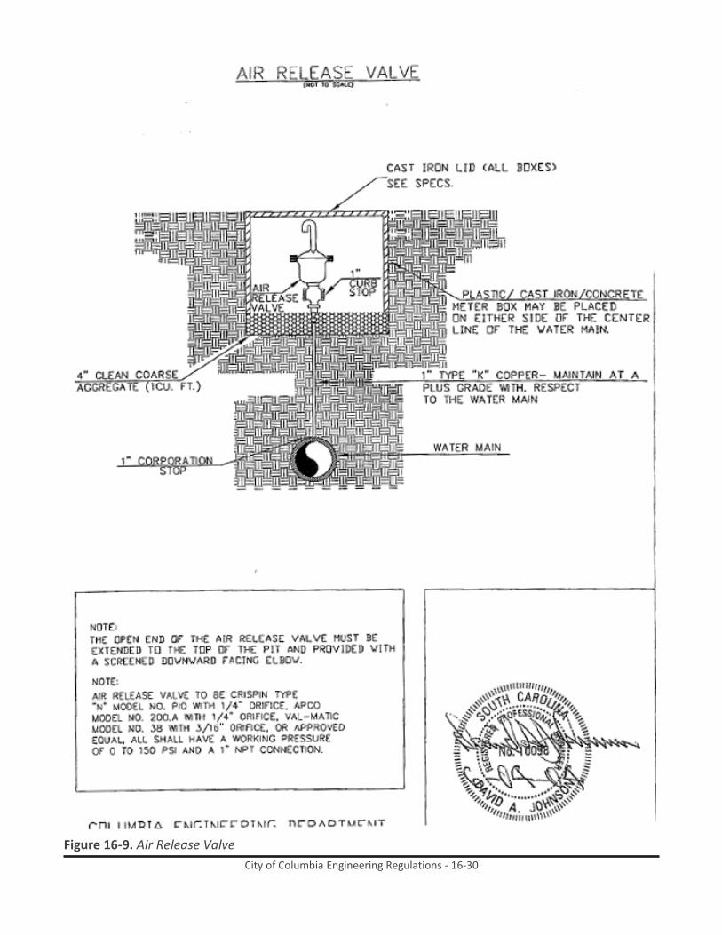
City of Columbia Engineering Regulations - 16-30
Figure 16-9. Air Release Valve

City of Columbia Engineering Regulations - 16-31
Figure 16-10. Valve Box Protector Ring Detail; Gate Valve Box Detail

City of Columbia Engineering Regulations - 16-32
Figure 16-11. Butterfly Valve Box Detail

City of Columbia Engineering Regulations - 16-33
Figure 16-12. Concrete Pipe Encasement

City of Columbia Engineering Regulations - 16-34
Figure 16-13. Standard Pipe Bedding and Backfilling Detail - Backfill for Ductile Iron Pipe and Backfill for Gray Cast Iron Pipe

City of Columbia Engineering Regulations - 16-35
Figure 16-14. Standard Pipe Bedding and Backfilling Detail - Backfill for Prestressed Concrete Cylinder Pipe
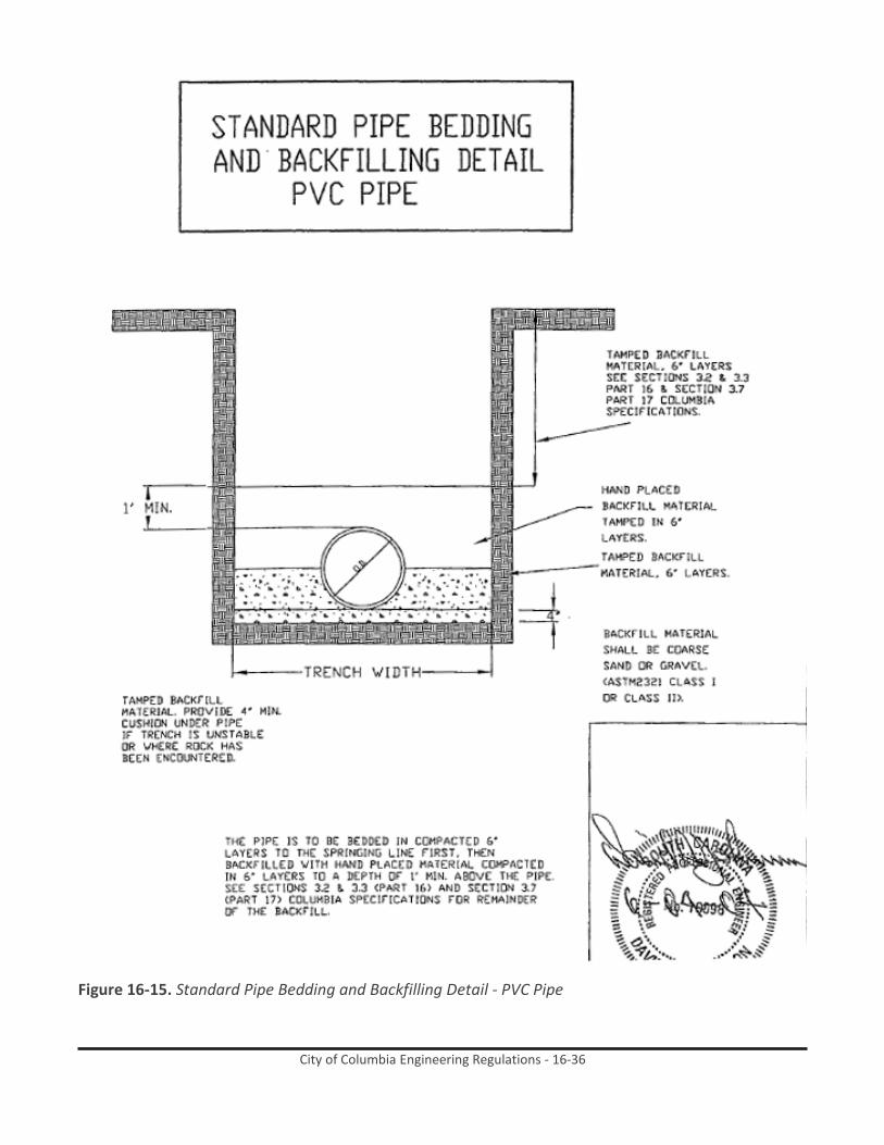
City of Columbia Engineering Regulations - 16-36
Figure 16-15. Standard Pipe Bedding and Backfilling Detail - PVC Pipe

City of Columbia Engineering Regulations - 16-37
Figure 16-16. Thrust Block Detail - Plug and Dead End Mains

City of Columbia Engineering Regulations - 16-38
Figure 16-17. Thrust Block Details - Concrete Blocking Dimensions

City of Columbia Engineering Regulations - 16-39
Figure 16-18. Top Slab - Hatch Reinforcement Detail

City of Columbia Engineering Regulations - 16-40
Figure 16-19. Meter Pit in Traffic Area

City of Columbia Engineering Regulations - 16-41
Figure 16-20. Typical Meter Box for Meters 4” and Above

City of Columbia Engineering Regulations - 16-42
Figure 16-21. Routing of Tracer Wire Inside Valve Box

City of Columbia Engineering Regulations - 17-i
City of Columbia Engineering Regulations PART 17: Specifications for Sanitary Sewer
Table of Contents
Paragraph Description Page no. 17.1 General 17-1 17.2 Construction Materials 17-4 17.3 Construction Methods 17-10 17.4 Testing for Acceptance of Sanitary Sewers 17-24 17.5 Measurement and Payment 17-25
List of Figures
Figure Description Page no. Figure 17-1. Standard Ditch Backfill Detail 17-30 Figure 17-2. Concrete Pipe Encasement 17-31 Figure 17-3. Granular Cradle 17-32 Figure 17-4. Concrete Cradle 17-33 Figure 17-5. Typical Permanent Repair Section 17-34 Figure 17-6. Granular/ Concrete Cradle Volumes 17-35 Figure 17-7. Service Wye 17-36 Figure 17-8. Precast Manhole Details 17-37 Figure 17-9. Inside Drop Manhole Detail 17-38 17-39 17-40 Figure 17-10. Typical Section Showing Bottom of Manhole 17-39 Figure 17-11. Typical Repair Sections - A 17-40 Figure 17-12. Typical Repair Sections - B 1 Figure 17-13. Typical Repair Sections - C 2 Figure 17-14. Standard Pipe Bedding and Backfilling Detail PVC Pipe 3
List of Tables
Table Description Page no. Table 17-1. Ductile Iron Pipe Size and Minimum Pressure Class 17-4 Table 17-2. Steel Pipe (Casing) Diameter and Thickness 17-6 Table 17-3. Unimproved Surface Minimum Trench Width 17-12 Table 17-4. Improved Surface Minimum Trench Width 17-12 Table 17-5. Granular Backfill Percent Passing by Sieve Size 17-16 Table 17-6. Granular Cradle Gradations Percent Passing by Sieve Size 17-17

City of Columbia Engineering Regulations - 17-1
City of Columbia Engineering Regulations PART 17: Specifications for Sanitary Sewer
17.1 General Construction detail drawings are a part of these specifications. No project will be constructed that does not comply with Part 3, Design of Sanitary Sewers.
17.1.1 These specifications cover materials and procedures for the complete installation of
certain sanitary sewers and appurtenances incident to the construction of extensions to be connected to the City of Columbia, South Carolina Sewerage System. All construction, repair and replacement of sanitary sewer mains, service connections and appurtenances shall be carried out in accordance with these standard specifications, General Specifications, any Special Provisions, and in conformity with the line and grade as shown on the plans.
17.1.2 Pipe and appurtenances shall be installed at the locations shown on the plans and to the
position, alignment and grade shown thereon, or in the event of grade conflicts, as directed by the Engineer. The Contractor shall erect, mark and maintain suitable barricades to protect the work and maintain public safety.
17.1.3 All pipe, special castings and fittings for sanitary sewer construction shall be furnished in
accordance with specifications as outlined herein and in the Special Provisions and proposal form.
17.1.4 Sewer Pipe – Pipe for sanitary sewers shall be SDR polyvinyl chloride (PVC) pipe,
centrifugally cast fiberglass reinforced polymer mortar pipe (CCFRPMP) or, where indicated, ductile iron pipe. All pipe shall be first quality, with smooth interior and exterior surfaces, free from cracks, blisters, honeycombs and other imperfections, and true to theoretical shapes and forms throughout the full length. Pipe material shall be consistent from manhole to manhole unless approved by City Engineer using fitting as specified in Section 2.1.1. All pipe shall be subject to inspection by the Engineer at the pipe plant, trench, or other point of deliver, for the purpose of culling and rejecting pipe, independent of laboratory tests, which does not conform to the requirements of these specifications. Such pipe shall be marked by the Engineer and the Contractor shall remove it from the project site upon notice being received of its rejection. All sewer pipe shall be tested by an independent laboratory, approved by the City Engineer, in accordance with applicable specifications. Character of tests shall be as follows:
17.1.4.1 Ductile Iron Pipe: As required by ANSI A21.6, latest revision
17.1.4.2 SDR Polyvinyl Chloride (PVC) Pipe: As required by ANSI/ASTM D 3034-78.
17.1.5 Water used for construction and testing will be furnished by the City through approved
connections to the City water system. Check valves to reduce possibility of contamination will be furnished by the contractor when directed by the City Engineer.

City of Columbia Engineering Regulations - 17-2
17.1.6 All materials furnished by the Contractor shall be delivered and distributed at the site by the Contractor. Materials furnished by the owner shall be picked up by the Contractor at points designated by the City and hauled to the distribution site.
17.1.7 Sewer pipe and appurtenances shall be loaded and unloaded by lifting with hoists or
skidding so as to avoid shock or damage. Under no circumstances shall such materials by dropped. Pipe handled on skidways shall not be skidded or rolled against pipe already on the ground.
17.1.8 In distributing the material at the site of the work, each piece shall be unloaded opposite
or near the place where it is to be laid in the trench.
17.1.9 Pipe shall be so handled that the coating and lining will not be damaged. If, however, any part of the coating or lining is damaged, the repair shall be made by the Contractor at his expense in a manner satisfactory to the Engineer.
17.1.10 Affidavit of Compliance – The manufacturer shall furnish an affidavit that all material
delivered does comply with the requirements of these specifications.
17.1.11 The Contractor shall proceed with caution in the excavation and preparation of the trench so that the exact location of underground structures, both known and unknown, may be determined. He shall be held responsible for the repair of such structures when broken or otherwise damaged.
17.1.12 All pipe shall be laid to the depth shown on the contract drawings. Any variation
therefrom shall be made only at the order of the Engineer.
17.1.12.1 All sanitary sewer mains, services, and fittings with less than 3’ or greater than 12’ of cover must be constructed of DIP.
17.1.12.2 Minimum distance from the top of ring to top of pipe for manholes shall be four feet for
four feet diameter manholes. Larger diameter manholes shall be proportionately deeper.
17.1.12.3 Depths less than specified above required special approval by the engineer. It shall be incumbent upon the Contractor to determine if such approval has been granted. Work not meeting this specification shall be removed and replaced properly at no expense to the City.
17.1.13 Ledge rock, boulders, and large stones shall be removed to provide a clearance of at
least six inches below and on each side of all pipe, and fittings. The specified minimum clearance is the minimum clear distance that will be permitted between any part of the pipe and appurtenance being laid and any part, projection, or point of rock, boulder, or stone.
17.1.14 The trench shall be dug so that the pipe can be laid to the alignment and depth
required. The trench shall be so braced and drained that the workmen may work in it safely and efficiently. It is essential that the discharge of trench dewatering pumps be conducted to natural drainage channels, drains, or storm sewers. The length of trench

City of Columbia Engineering Regulations - 17-3
excavated in advance of the pipe laying, shall be kept to a minimum, and in no case shall it exceed three hundred (300) feet unless specifically authorized by the Engineer. In no case shall two consecutive intersections be closed to traffic due to uncompleted work. Each intersection must be opened to traffic before closing of the next one.
17.1.15 The width of the trench shall be ample to permit the pipe to be laid and joined properly,
and the backfill to be placed and compacted as specified. Trenches shall be of such extra width, when required, as will permit the convenient placing of timber supports, sheeting and bracing, and handling of specials. No extra payment will be allowed for this work, the cost of which will be included in the Contractor’s unit bid prices.
17.1.16 Construction in Easements – In easements across private property, the Contractor shall
confine all operations to the easement area and shall be responsible and liable for all damage outside of the easement area. Trees, fences, shrubbery or other type of surface improvements located in easements shall be protected during construction. The provisions above shall apply to all easement areas as well as to public rights-of-way. Precautions shall be taken by adequate sheeting or other approved method to prevent any cave-in or disturbance beyond the easement limits or damage to improvements within the easement. In general, the easement area is intended to provide reasonable access and working area for efficient operations to be performed within the restrictions shown on the plans. The Contractor shall be responsible for organizing his operations to perform within the restrictions shown on the plans. When requested, the owner shall make available to the bidders and furnish to the contractor a copy of the construction easements. (See General Specifications).
17.1.17 Barricades, Guards and Safety Provisions – To protect persons from injury and to avoid
property damage, adequate barricades, construction signs, torches, lanterns and guards as required shall be place and maintained by the Contractor at his expense during the progress of the construction. All material piles, equipment and pipe which may serve as obstructions to traffic shall be enclosed by fences or barricades and shall be protected by proper lights when the visibility is poor. The rules and regulations of O.S.H.A. and appropriate authorities respecting safety provisions shall be observed. (See General Specifications).
17.1.18 Protection of Property and Surface Structures – Trees, shrubbery, fences, poles and all
other property and surface structures shall be protected during construction operations unless their removal is authorized by the Engineer. Any fences, poles or other manmade surface improvements which are moved or disturbed by the Contractor shall be restored to their original condition, after construction is completed, at the Contractor’s expense. Any trees, shrubbery or other vegetation which are approved or ordered for removal by the Engineer shall be removed completely, including stumps and roots, by the Contractor. Responsibility for any damage or claims for damage caused by construction operations to shrubbery or other landscape improvements which were not authorized for removal by the Engineer shall be assumed by the Contractor.

City of Columbia Engineering Regulations - 17-4
17.2 Construction Materials
17.2.1 Ductile Iron Pipe – Ductile iron pipe shall be manufactured in accordance with ANSI specification A 21.51 (AWWA C151) of latest revision. Joints shall be Bell and Spigot, Push-on (Glamorgan Tyton, American Fastite, Clow Bell-Tite, or equivalent), or mechanical; unless otherwise called for on the proposal form. Pipe will be seal-coated in accordance with ANSI specification A 21.4 (AWWA C104) of latest revision.
17.2.2 All pipes shall have a minimum pressure rating as indicated on the following table, and
corresponding minimum wall thickness unless otherwise approved or specified: Table 17-1. Ductile Iron Pipe Size and Minimum Pressure Class
Pipe Sizes (inches)
Minimum Pressure Class (psi)
4 - 12 350 14 - 18 250 24 - 48 200
17.2.3 Joints shall be push-on unless otherwise specified. All fittings shall be standard push-on.
Joints shall conform to AWWA C111.
17.2.4 The appropriate gaskets shall be provided for joints. Gaskets for flange joints shall be made of 1/8 inch thick cloth and reinforced rubber gaskets may be ring type of full face.
17.2.5 Interior lining: Ductile iron pipe and fittings shall be lined with polyethylene, calcium
aluminates cement or a ceramic epoxy, as specified below:
17.2.5.1 Linings shall cover all exposed surfaces of pipe and fittings subject to contact with sewer liquid or gas.
17.2.5.2 The lining of the pipe barrel shall extend from spigot end through the socket to the edge
of the gasket sealing area or recess for pipe using push-on gaskets and to the edge of the gasket seat for mechanical joints.
17.2.5.3 The lining shall also cover the exterior of the spigot end from the end of the pipe to
beyond the gasket sealing area.
17.2.5.4 The lining in fittings shall cover the interior surfaces including socket areas. All linings shall be hermetically sealed at the ends.
17.2.6 Lining Materials: Ductile iron pipe shall be lined with one of the following lining systems
or an approved equal:
17.2.6.1 Protector 401 Ceramic Epoxy lining as manufactured by Vulcan Chemical Technologies, Inc., with a nominal thickness of 40 mils. The lining shall be installed by an approved applicator in accordance with the manufacturer’s specifications.

City of Columbia Engineering Regulations - 17-5
17.2.6.2 American Polybond Plus lining as manufactured by American Ductile Iron Pipe Company with a nominal thickness of 60 mils. The lining shall be installed at the pipe manufacturer’s plant and in accordance with their specifications.
17.2.6.3 SewperCoat as manufactured by Lafarge Calcium Aluminates. The calcium aluminate
lining shall be applied at a minimum thickness of 0.125 inches. Pipe lined with this lining shall be Ductile Iron H2 Sewer Safe pipe as manufactured by Griffin Pipe Products Company. The lining shall be installed at the manufacturer’s plant and in accordance with their specifications.
17.2.7 Flexible Compression, Factory Fabricated Joints –Couplings and transition fittings must
be a Shielded Sewer Mission Flex-Seal ARC or Harco fitting or approved equal.
17.2.8 Vitrified Clay Pipe – Vitrified clay pipe is not approved for construction of sanitary sewers.
17.2.9 Concrete Pipe – Concrete pipe is not approved for construction of sanitary sewers.
17.2.10 Cast Iron Soil Pipe – Cast iron soil pipe is not approved for construction of sanitary
sewers.
17.2.11 SDR Polyvinyl Chloride (PVC) Pipe – PVC pipe and fittings must meet ANSI/ASTM D 3034-78 and shall be installed in accordance with ANSI/ASTM D 2321-74. Only Class I, II, and III embedment materials, as defined in paragraph 6 in figure 1 may be used in bedding, haunching and initial backfill. Minimum wall thickness for PVC pipe shall be SDR 35 for all sanitary sewer mains and all sanitary sewer laterals.
17.2.11.1 Flexible Compression, Factory Fabricated Joints –Couplings and transition fittings must
be a Shielded Sewer Mission Flex-Seal ARC or Harco fitting or approved equal.
17.2.12 Centrifugally Cast Fiberglass Reinforced Polymer Mortar Pipe (CCFRPMP)
17.2.12.1 Pipe Material
17.2.12.1.1 Manufacturer shall use only polyester resin systems with a proven history of performance in the application of manufacturing pipe for gravity sewer.
17.2.12.1.2 The reinforcing glass fibers used to manufacture the components shall be of the highest
quality E-glass filaments with binder and sizing compatible with impregnating resins.
17.2.12.1.3 Manufacturer shall use silica sand comprised of 98% silica with a maximum moisture content of 0.2%.
17.2.12.2 Construction of CCFRPMP
17.2.12.2.1 The pipe shall be manufactured by the centrifugal cast process.
17.2.12.2.2 The interior surface shall be manufactured using a resin with minimum 50% elongation
in accordance with ASTM D638.

City of Columbia Engineering Regulations - 17-6
17.2.12.2.3 The exterior shall be comprised of a sand and resin which provides UV protection with no other special coatings.
17.2.12.2.4 The outside diameter shall be in accordance with ASTM D3262 for sizes 18-inch through
48-inch. For other diameters, dimensions will be in accordance with manufacturer’s standard dimensions.
17.2.12.2.5 Pipe shall be supplied in nominal lengths of 20 feet.
17.2.12.2.6 Provide wall thickness in accordance with manufacturer’s stated design thickness to
provide a minimum pipe stiffness of SN 72 (nominal stiffness of 72 psi) in accordance with ASTM D2412 test method.
17.2.12.2.7 The 50-year strain corrosion value shall not be less than 0.9% as determined with ASTM
D3681 and ASTM D3262.
17.2.12.3 Joints
17.2.12.3.1 The pipe shall be field connected with fiberglass sleeve couplings with elastomeric sealing gaskets. The joints must meet the performance requirements of ASTM D4161.
17.2.12.3.2 The manufacturer shall supply elastomeric gaskets in accordance with ASTM F477.
17.2.12.4 The manufacturer shall be HOBAS Pipe, USA or pre-approved equal.
17.2.13 Asbestos – Cement Pipe – Asbestos cement pipe is not approved for construction of
sanitary sewers.
17.2.14 Steel Pipe (Casing) – Steel casing pipe for underground installation by dry bore and jacking shall be manufactured in accordance with ANSI Specification A 53 or latest revision. The steel casing pipe shall be Type S, Grade B, plain end beveled steel contained in USA Standard USAS B36 or latest revision. All steel casing pipe shall be furnished in 20 feet lengths, all joints welded. The minimum wall thickness shall be as follows: Table 17-2. Steel Pipe (Casing) Diameter and Thickness
Nominal Diameter (inches)
Nominal Thickness (inches)
Under 14 0.188 14 and 16 0.219
18 0.250 20 0.281 22 0.312 24 0.344 26 0.375
28 and 30 0.406 32 0.469
38, 40 and 42 0.500

City of Columbia Engineering Regulations - 17-7
17.2.14.1 Steel casing pipe shall have a minimum yield strength of 35,000 psi.
17.2.14.2 When casing pipe is installed without a protective coating and is not cathodically protected, the wall thickness shown above shall be increased to the next standard size.
17.2.15 Brick – Common brick shall conform to the specifications of the ASTM, Serial Designation
C62, or latest revision.
17.2.15.1 Portland Cement concrete brick shall conform to the specifications of the ASTM, Serial Designation C55-71 for grade “N” brick, or latest revision.
17.2.15.2 Brick for manholes shall be grade “MS” or equal and shall conform to ASTM C32.
17.2.16 Manhole Ring and Cover: All manhole ring and covers shall have bearing surfaces ground
so that the covers will fit solidly in all positions and insure a tight fit. This specification is applicable for ductile iron and cast iron castings. Ductile iron castings shall be manufactured from iron conforming to ASTM A536 grade 80-55-06 as noted in section 3.2 of AASHTO M306-04. Cast iron castings shall be manufactured from iron conforming to ASTM A48 Class 35B as noted in section 3.1 of AASHTO M306-04. All manhole ring and covers shall be marked “City of Columbia” and “Sanitary Sewer”. Only heavy duty manhole ring and covers are to be used, and this apply for both traveled and non- traveled way.
17.2.16.1 Watertight Manhole Frame and Cover: Where watertight manhole and covers are
required, castings for covers shall be as follows: • East Jordan Iron Works, Inc. (EIJW) model # 1033 HingeCo • Neenah Foundry model “Lift Mate” • US Foundry model #750-KI.
17.2.16.2 Standard Frame and Cover: Standard manhole and covers shall be as follows:
• East Jordan Iron Works, Inc. (EJIW) model # 1045 frame and 1040A cover • Neenah Foundry R-1642 ring & cover • US Foundry model # 755-NC.
17.2.16.3 Additional castings will be reviewed for approval upon request.
17.2.16.4 Steps: No steps shall be placed in manholes.
17.2.16.5 Cleanouts
17.2.16.5.1 Cleanouts shall be placed on all sewer service laterals.
17.2.16.5.2 The bodies of clean out ferrules shall conform in thickness to that required for pipe and
fittings of the same material. The cleanout plug shall be of heavy brass or PVC, not less than one-eighth (1/8) of an inch thick and shall be provided with a recessed socket for removal. Both ferrule and plug shall have ANSI Standard tapered threads.
17.2.16.5.3 Clean-outs shall be installed at the property line, right-of-way, or edge of easement for

City of Columbia Engineering Regulations - 17-8
each service connection. Cleanouts shall also be installed at every change in direction of the service line. Cleanouts shall be of the same class and material used for the sanitary sewer main. Cleanouts shall be installed flush with the finished grade and must be protected from land scaping, traffic, and maintenance.
17.2.16.5.4 Cleanout Box: Cleanout boxes will be marked “Sewer Cleanout” and shall be as follows:
• East Jordan Iron Works, Inc. (EJIW) model #V8502 • US Foundry model # 7637-VA.
17.2.17 Drop Manholes – Where the free drop in manholes exceeds two feet, measured from
the invert of the inlet sewer to the invert of the outlet sewer, the Contractor shall construct drop manholes in accordance with detailed plans. Materials and workmanship shall be in accordance with the General Specifications.
17.2.18 Precast Concrete Manhole Sections – Precast concrete sections, if used, shall conform to
the ASTM Tentative Specifications for Precast Reinforced Concrete Manhole Risers and Tops, Designation C478, with the following exceptions and additional requirements. All precast concrete sections shall be lined as specified hereinbefore for concrete pipe.
17.2.18.1 Type II cement shall be used except as otherwise approved.
17.2.18.2 Manhole steps are specified under Item 2.9.4. Steps shall be cast into the section as it is
made.
17.2.18.3 Sections shall be steam cured and shall not be shipped until at least five days after having been cast.
17.2.18.4 Minimum wall thickness shall be five (5) inches.
17.2.18.5 Acceptance of the sections will be on the basis of material tests and inspection of the
completed product.
17.2.18.6 Domes shall be of the eccentric type.
17.2.18.7 Joints in riser sections shall be gasket type conforming to ASTM Designation C361 series, or others approved by the Engineer.
17.2.18.8 No more than two lift holes may be cast or drilled in each section.
17.2.18.9 The date of manufacture and the name or trademark of manufacturer shall be clearly
marked on the inside of the barrel.
17.2.19 Portland Cement Concrete – Portland cement concrete for structures shall conform to Section 701 of the SCDOT Standard Specifications for Highway Construction, latest edition.
17.2.19.1 The 28-day compressive strength of concrete shall not be less than 3000 psi which shall be demonstrated by standard compressive tests. Each test shall consist of duplicate

City of Columbia Engineering Regulations - 17-9
cylinders and not less than one test shall be made for each 50 cubic yards. One cylinder of each pair shall be tested after seven days and shall have a compressive strength of not less than 2000 psi.
17.2.19.2 Concrete shall contain not less than six sacks of cement per cubic yard and not more
than six gallons of water per sack of cement, including water contained in aggregate.
17.2.20 Concrete and Masonry Mortar – This section includes all concrete work required, of every description, shown or specified, including pavements, bedding concrete, thrust blocks, etc.
17.2.20.1 All materials incorporated shall conform to the SCDOT Standard Specifications for
Highway Construction, latest edition.
17.2.21 Reinforcing Steel – Reinforcing steel shall be of new billet steel intermediate grade made by the open hearth process, conforming to the requirements of the “Standard Specifications for Billet Steel Concrete Reinforcement Bars”, Serial Designation C15-33 of the ASTM Designation A615-68. Bars must be deformed in rolling, and the design of the deformation shall be in accordance with ASTM designation A615-68. In addition to the reinforcing indicated on the plans, the Contractor shall furnish all necessary support bars, tie bars, etc., required for properly supporting and spacing the bars in the forms. The reinforcement will be subject to field inspection for rust, shape and dimensions.
17.2.21.1 Wire mesh used as reinforcement shall be of the size and spacing shown on the plans.
The wire mesh shall comply with ASTM-A-185.
17.2.22 Fencing – See Standard Fencing Specifications.
17.2.23 Paving Materials- Subbase, base and surfacing materials used for replacing existing pavements or constructing new pavements shall conform to the SCDOT Standard Specifications for Highway Construction, latest edition.
17.2.24 Portland Cement Mortar – Portland Cement Mortar shall consist of Portland cement,
fine aggregate and water.
17.2.24.1 Ingredients – All materials for mortar shall conform to requirements of the SCDOT Standard Specifications where applicable and the following specifications:
17.2.24.1.1 Portland Cement – ASTM Designation C150, Section 501, Concrete Materials.
17.2.24.1.2 Sand – 501.04 Fine Aggregate; Section 501, Concrete Materials.
17.2.24.1.3 Water – 501.06 Water; Section 501, Concrete Materials.
17.2.24.2 All equipment, tools and machinery used in mixing and handling mortar shall be
approved by the Engineer.

City of Columbia Engineering Regulations - 17-10
17.2.24.3 Composition – The proportions of Portland cement, fine aggregate and water shall be such as to produce a plastic mortar. The workability shall be consistent with the type of work for which it is used in order to secure the best results.
17.2.24.3.1 The mortar as specified for the several types of work, shall be proportioned one-part
cement and three parts by volume fine aggregate.
17.2.24.3.2 Proportioning of batches shall be by volume unless otherwise shown on the plans or specified in the Special Provisions. One sack of cement weighing ninety-four (94) pounds shall be considered on (1) cubic foot. Correction for bulking of the fine aggregate shall be made as directed by the Engineer.
17.2.24.4 Admixture
17.2.24.4.1 Lime – Lime which has been thoroughly air slaked may be added, up to ten (10) percent
of the cement content of the mix to increase the workability of the mortar, upon approval of or direction of the Engineer. Lime shall conform to ASTM Specifications, Designation C 141.
17.2.24.4.2 Commercial Admixtures – Commercial admixtures to increase the workability of mortar
or concrete will not be used unless specifically approved in writing by the Engineer.
17.2.25 All other materials, not herein specified shall conform to applicable sections of SCDOT Standard Specifications for Highway Construction, latest edition.
17.3 Construction Methods
17.3.1 Order of Construction – The construction of all sewers shall begin at the low point in the
line in every case working toward the high point. Each section of sewer pipe shall be specified to be laid to the appropriate line and grade, as designed, working in the upstream direction with the bell end laid upgrade.
17.3.2 Excavation in Advance of Construction – The amount of trench excavated approximately
to grade shall not exceed one hundred fifty (150) feet, and no trench excavation whatever shall be made farther than three hundred (300) feet in advance of sewer construction, unless specifically authorized by the Engineer.
17.3.3 Use of Explosives – Should the Contractor elect to use explosives to loosen rock or for
any other purposes in the prosecution of the work, he shall obtain the required permits and the written permission of the Engineer. The City Fire Chief and Police Chief shall be notified. If construction is outside the City Limits, the Contractor shall be responsible for determining whether a County permit is required and for obtaining any permit so required. The Contractor shall be responsible for and shall make good any damage caused by blasting or accidental explosions. All necessary precautions shall be taken by the Contractor as required by Federal and State laws, County regulations, if applicable, City regulations, the Standard Fire Prevention Code and O.S.H.A. Rules and Regulations. (See General Specifications.)
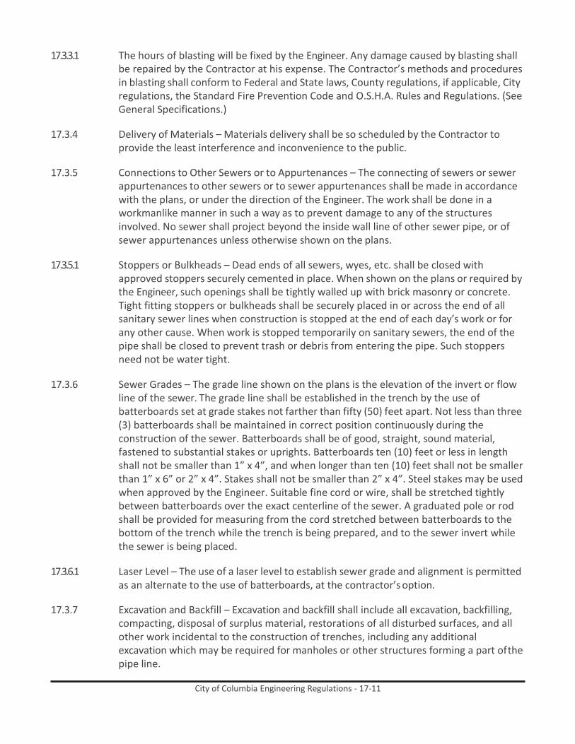
City of Columbia Engineering Regulations - 17-11
17.3.3.1 The hours of blasting will be fixed by the Engineer. Any damage caused by blasting shall be repaired by the Contractor at his expense. The Contractor’s methods and procedures in blasting shall conform to Federal and State laws, County regulations, if applicable, City regulations, the Standard Fire Prevention Code and O.S.H.A. Rules and Regulations. (See General Specifications.)
17.3.4 Delivery of Materials – Materials delivery shall be so scheduled by the Contractor to
provide the least interference and inconvenience to the public.
17.3.5 Connections to Other Sewers or to Appurtenances – The connecting of sewers or sewer appurtenances to other sewers or to sewer appurtenances shall be made in accordance with the plans, or under the direction of the Engineer. The work shall be done in a workmanlike manner in such a way as to prevent damage to any of the structures involved. No sewer shall project beyond the inside wall line of other sewer pipe, or of sewer appurtenances unless otherwise shown on the plans.
17.3.5.1 Stoppers or Bulkheads – Dead ends of all sewers, wyes, etc. shall be closed with
approved stoppers securely cemented in place. When shown on the plans or required by the Engineer, such openings shall be tightly walled up with brick masonry or concrete. Tight fitting stoppers or bulkheads shall be securely placed in or across the end of all sanitary sewer lines when construction is stopped at the end of each day’s work or for any other cause. When work is stopped temporarily on sanitary sewers, the end of the pipe shall be closed to prevent trash or debris from entering the pipe. Such stoppers need not be water tight.
17.3.6 Sewer Grades – The grade line shown on the plans is the elevation of the invert or flow
line of the sewer. The grade line shall be established in the trench by the use of batterboards set at grade stakes not farther than fifty (50) feet apart. Not less than three (3) batterboards shall be maintained in correct position continuously during the construction of the sewer. Batterboards shall be of good, straight, sound material, fastened to substantial stakes or uprights. Batterboards ten (10) feet or less in length shall not be smaller than 1” x 4”, and when longer than ten (10) feet shall not be smaller than 1” x 6” or 2” x 4”. Stakes shall not be smaller than 2” x 4”. Steel stakes may be used when approved by the Engineer. Suitable fine cord or wire, shall be stretched tightly between batterboards over the exact centerline of the sewer. A graduated pole or rod shall be provided for measuring from the cord stretched between batterboards to the bottom of the trench while the trench is being prepared, and to the sewer invert while the sewer is being placed.
17.3.6.1 Laser Level – The use of a laser level to establish sewer grade and alignment is permitted
as an alternate to the use of batterboards, at the contractor’s option.
17.3.7 Excavation and Backfill – Excavation and backfill shall include all excavation, backfilling, compacting, disposal of surplus material, restorations of all disturbed surfaces, and all other work incidental to the construction of trenches, including any additional excavation which may be required for manholes or other structures forming a part of the pipe line.

City of Columbia Engineering Regulations - 17-12
17.3.7.1 Surface Removal – along the proposed pipe lines as indicated on the plans, the Contractor shall remove the surface materials only to such widths as will permit a trench to be excavated which will afford sufficient room for proper efficiency and proper construction. Where sidewalks, driveways, pavements and curb and gutter are encountered, care shall be taken to protect such against fracture or disturbance beyond reasonable working limits. In areas specified on the plans, the top twelve (12) inches shall be piled separately and preserved so that it may be restored after the remainder of the backfill is replaced.
17.3.7.2 Excavation by Hand or Machine – Where working space will permit, trenches may be
excavated by machine, provided that by so doing, public and private improvements will not be subjected to an unreasonable amount of damage, otherwise hand excavation shall be employed.
17.3.7.3 Width of Excavation – The bottom width of the trench at and below the top of the pipe,
and inside any sheeting and bracing used, shall not be less than the widths shown in the following tables:
17.3.7.3.1 When construction is under an unimproved surface the following table shows the
minimum trench widths: Table 17-3. Unimproved Surface Minimum Trench Width
17.3.7.3.2 When construction is under an improved surface, the following table shows the minimum trench widths: Table 17-4. Improved Surface Minimum Trench Width
17.3.7.3.3 The strength or class of pipe shall be as indicated on the plans or Special Provisions.
Pipe Size Width 6” 2’6’ 8” 2’6”
10” 2’6” 12” 2’8” 15” 2’10” 18” 3’2” 21” 3’8” 24” 4’0”
Paper Size Width 27” 4’3” 30” 4’7” 33” 5’4” 36” 5’8” 42” 6’3” 48” 6’10” 54” 7’11” 60” 8’6”
Paper Size Width 66” 9’1” 72” 9’8” 78” 10’3” 84” 10’10” 90” 11’5” 96” 12’0”
102” 12’7” 108” 13’2”
Pipe Size Width 6” 3’0” 8” 3’0”
10” 3’0” 12” 3’0” 15” 3’0” 18” 3’5” 21” 3’9” 24” 4’6”
Paper Size Width 27” 4’9” 30” 5’0” 33” 5’9” 36” 6’1” 42” 6’9” 48” 7’4” 54” 7’11” 60” 9’0”
Paper Size Width 66” 9’7” 72” 10’2” 78” 10’9” 84” 11’4” 90” 11’7” 96” 12’6”
102” 13’1” 108” 13’8”

City of Columbia Engineering Regulations - 17-13
17.3.7.3.4 Trench sheeting and bracing or a trench shield shall be used when required by the rules and regulations of O.S.H.A. The bottom of the trench excavation shall conform to the details shown on the plan.
17.3.7.4 Excavation Below Grade – Where the excavation is carried beyond or below the lines and
grades given by the Engineer, the Contractor shall, at his expense, refill all such excavated space with suitable material as approved by the Engineer.
17.3.7.5 Rock Excavation - Rock excavation shall consist of igneous, metamorphic and
sedimentary rock, concrete or masonry which cannot be excavated without blasting or the use of rippers, hoe-rams, or pavement breakers and all boulders or other detached stones each having a volume of ½ cubic yard or more as determined by physical or visual measurement. If there is not a bid item listed in the proposal form for this excavation, it shall be measured and paid for as Unclassified Excavation.
17.3.7.5.1 Rock shall be excavated to a depth of 6 inches below the bottom of the pipe subgrade
elevation as shown on the plans or as directed by the Engineer. The Contractor shall backfill to the subgrade elevation with material approved by the Engineer. Such material shall be properly compacted and shaped into the required elevation and cross-section.
17.3.7.5.2 Before payment is allowed for rock excavation, the Contractor shall be required to
demonstrate that the material cannot be removed “by hand pick” or by power operated excavator or shovel. No payment will be made for Rock Excavation unless the Engineer determines that the material meets the above criteria, and gives written approval for payment prior to excavation.
17.3.7.5.3 Should the Contractor elect to use explosives to loosen rock or any other purposes in the
prosecution of the work, he shall obtain the required permits and written permission of the Engineer. The City Fire Chief and Police Chief shall be notified. If construction is outside the City limits, the Contractor shall be responsible for determining whether a County permit is required and for obtaining any permit so required. The Contractor’s methods and procedures in the transportation, handling, storage and use of explosives shall comply with requirements of Federal and State laws, County regulations, if applicable, City regulations, the Standard Fire Prevention Code and O.S.H.A. Rules and Regulations. The Contractor shall be responsible for and shall repair at his own expense any damage caused by blasting or accidental explosions.
17.3.7.5.4 Blasting for excavation will be permitted only after securing the approval of the Engineer
and only when proper precautions are taken for the protection of persons and property. The hours of blasting will be fixed by the Engineer. The Contractor’s methods and procedures in blasting shall conform to requirements of laws and regulations listed in item 3.7.5.
17.3.7.6 Subsurface Exploration – All information available to the City, if any, on subsurface
conditions will be made available for examination by prospective bidders. However, it is understood and agreed that the City shall in no way be held responsible for interpretation of this information, its accuracy or its thoroughness. Prospective bidders

City of Columbia Engineering Regulations - 17-14
shall made such subsurface explorations as they believe necessary to verify and supplement information received from the City.
17.3.7.7 Exploratory Excavation – Whenever, in the opinion of the Engineer, it is necessary to
explore and excavate to determine the best line and grade for construction of the proposed pipe line, the Contractor shall make explorations and excavations for such purposes.
17.3.7.8 Braced and Sheeted Trenches – Open-cut trenches shall be sheeted and braced or
otherwise protected as required by any governing Federal or State laws and municipal ordinances, and as may be necessary to protect life, property, or the work. In any event, the minimum protection shall conform to the recommendations in O.S.H.A. Safety and Health Standards for Construction. A sand box or trench shield may be used in lieu of sheeting when permitted by O.S.H.A. and approved by the Engineer. When close- sheeting is used, it shall be so driven as to prevent adjacent soil from entering the trench either below or through such sheeting.
17.3.7.8.1 Where sheeting and bracing are used, the trench width shall be increased as directed by
the Engineer. The Engineer may order the sheeting driven to the full depth of the trench or to such additional depth as may be required for the protection of the work. Where soil in the lower limits of the trench has the stability to meet the O.S.H.A. standards, the Engineer at his discretion may permit the Contractor to stop the driving of sheeting at such designated elevation above the trench bottom. The granting of permission by the Engineer, however, shall not relieve the Contractor in any degree from his full responsibility under the contract. Sheeting and bracing which have been ordered left in place shall be cut off at the elevation ordered by the Engineer. Trench bracing, except that ordered left in place, may be removed when the backfilling has reached the respective levels of such bracing. Sheeting, except that ordered left in place, may be removed after the backfilling has been completed or has been brought to an elevation that permits its safe removal.
17.3.7.9 Trenches With Sloping Sides, Limited – The Contractor may, at his option, where working
conditions and rights-of-way permit (as determined by the Engineer), excavate pipe line trenches with sloping sides, but with the following limitations:
17.3.7.9.1 In general, only braced and vertical trenches will be permitted in traveled streets, alleys
or narrow easements.
17.3.7.9.2 Where trenches with sloping sides are permitted, the slopes shall not extend below the top of the sewer. Trench excavations below this point shall be made with vertical sides, with widths meeting those specified hereinbefore for the various sizes of pipe.
17.3.7.10 Short Tunnels – In some instances, the proximity of trees, fire hydrants, sidewalks and
other obstructions may be a hindrance to open-cut excavation. In such cases, the Contractor shall excavate by means of short tunnels in order to protect such obstructions against damage. Such short tunnel work shall be considered incidental to the construction of the pipe line and shall not be grounds for extra payment or payment for

City of Columbia Engineering Regulations - 17-15
tunnel work. Where such obstructions are shown on the plan, payment will be made at the contract unit price or as extra work in accordance with Item 5.0.
17.3.7.11 Piling Excavated Material – All excavated material shall be piled in a manner that will not
endanger the work and that will avoid obstructing sidewalks and driveways. Fire hydrants under pressure, valve pit covers, valve boxes, curb stop boxes, or other utility controls shall be left unobstructed and accessible. Gutters shall be kept clear or other satisfactory provisions made for street drainage. Natural watercourses shall not be obstructed.
17.3.7.12 Removal of Water – The Contractor shall at all times during construction provide and
maintain ample means and devices with which to promptly remove and properly dispose of all water entering and excavations or other parts of the work until all work to be performed therein has been completed. No sanitary sewer shall be used for disposal of trench water, unless specifically approved by the Engineer and then only if the trench water does not ultimately arrive at existing pumping or sewage treatment facilities.
17.3.7.13 Structure Protection – Temporary support, adequate protection and maintenance of all
underground and surface structures, drains, sewers and other obstructions encountered in the progress of the work shall be furnished by the Contractor at his expense and under the direction of the Engineer. The structures which may have been disturbed shall be restored upon completion of the work.
17.3.7.14 Deviations Occasioned by Other Structures or Utilities – Wherever obstructions are
encountered during construction that require alteration of a plan, the Engineer shall change the plans and order a deviation from the line and grade or arrange with the owners of the structures for the removal, relocation or reconstruction of the obstructions. Where gas, water, telephone, electrical, hot water, steam or other existing utilities are an impediment to the alignment of the proposed pipe line, the Engineer shall order a change in grade or alignment or shall arrange with the owners of the utilities for their removal. If a change in line or grade of a sanitary sewer is necessary, the Engineer will order the addition of any manholes needed. Cost of removal, modification and/or replacement of existing structures or utilities shall be borne by the City.
17.3.7.15 Protection of Utilities and Structures – The Contractor shall proceed with caution in the
excavation and preparation of the trench so that the exact location of underground structures may be determined. Prior to proceeding with trench excavation the Contractor shall contact all utility companies in the area to aid in locating their underground services.
17.3.7.15.1 The Contractor shall take all reasonable precautions against damage to existing utilities.
However, in the event of a break in an existing water main, gas main, sewer or underground cable, he shall immediately notify the responsible official of the organization operating the utility interrupted. The Contractor shall lend all possible assistance in restoring services and shall assume all cost, charges or claims connected with the interruption and repair of such services if the location of said utility was marked by the owner thereof prior to excavation.

City of Columbia Engineering Regulations - 17-16
17.3.7.15.2 Contractor shall protect all structures from damage during construction.
17.3.7.16 Backfill – All sanitary sewer pipe and services shall be bedded on a minimum of 4” of gravel and backfilled with gravel up to the spring line.
17.3.7.16.1 Backfill material above the granular cradle to a point twelve (12) inches above the top of
the pipe shall be placed in layers of six (6) inches thickness, loose measure, and each in such manner as not to disturb or injure the pipe. The balance of the backfill material shall be placed in uniform layers of twelve (12) inches thickness, loose measure, and each layer shall be compacted by ramming or tamping with tools approved by the Engineer. All compaction shall not be less than 95% standard proctor, for the soil.
17.3.7.16.2 Where called for on the plans, those areas where sewers are crossing open areas where
early settlement is not critical, backfill from 12” from the top of the pipe to the surface, shall be made by any acceptable method which will not dislodge or damage the pipe or cause bridging action in the trench. Only selected excavated material free from clods or stones shall be used in backfilling up to twelve (12) inches above the top of the pipe. Water-soaking or other methods of trench settlement will not be required in this case. Excess material shall be neatly rounded over the top of the trench as directed by the Engineer to allow reshaping of the surface to level out any uneven settlement that may occur.
17.3.7.17 Selected Granular Backfill – Where called for on the plans, material conforming to this
specification for selected granular backfill shall be laced and compacted in those locations shown on the plans. Where sewers, water mains, or other pipe conduits are constructed under permanent type pavements, driveways or sidewalks, selected granular backfill shall be used to fill the trench to the bottom of the permanent type surface to be reconstructed and shall be compacted by either water jetting or mechanical methods before the permanent surface is constructed.
17.3.7.17.1 Materials for selected granular backfill shall consist of sand, stone sand, crushed stone,
pit run or crushed gravel, or crushed boiler slag well graded within the following limits. Selected granular backfill shall be reasonably free from an excess of soft and unsound particles and other objectionable matter.
17.3.7.17.1.1 Selected Granular Backfill
Table 17-5. Granular Backfill Percent Passing by Sieve Size Sieve Size Percent Passing
Type 1-1/2” 1” ½” #4 #8 #16 #100 #200 A B C
D
100 90-100 60-100 40-80 25-60 20-45 0-15 100 60-95 40-60 15-45 5-15 84-100 0-40 0-10 100 94-100 45-85 0-10
17.3.7.17.1.2 Granular materials from local deposits, graded reasonably close to the limits specified
above, and approved by the Engineer, may be used for selected granular backfill.

City of Columbia Engineering Regulations - 17-17
17.3.7.17.2 At the time of use, the selected granular backfill shall be free of frozen lumps and foreign materials that may have become mixed with it during handling.
17.3.7.18 Granular Cradle – Granular cradle shall be required only where indicated on the
drawings or special provisions, or where ordered by the Engineer. Material from granular cradle shall be stone screenings, crushed stone, pit run gravel, washed gravel, crushed boiler slag or other granular materials approved by the Engineer. Granular cradle shall be well graded within the limits stated below and shall be free from excess of soft or unsound particles or other objectionable matter. The type of granular cradle to be used in specific location will be designated by the Engineer.
17.3.7.18.1 For reasonably good non-granular foundation conditions, Type A, or Type C granular
cradle will be designated. Where, in the opinion of the Engineer, the foundation conditions are not suitable for use of one of the above types of granular cradle then Type B granular cradle or concrete cradle may be used. The actual selection is to be made by the Engineer. Granular cradle shall be allowed for separate payment only in the locations where the use of these items is specified or ordered by the Engineer. A change in type of cradle material shall not be made unless a minimum of two (2) cubic yards of material is allowed for payment.
17.3.7.18.1.1 Granular Cradle Gradations
Table 17-6. Granular Cradle Gradations Percent Passing by Sieve Size Sieve Size Percent Passing
Type 1-1/2” 1” ½” #4 #8 #16 #100 #200 A
b C
100 90-100 60-100 40-80 25-60 20-45 0-15 100 60-95 10-30 0-5 100 60-95 40-60 15-45 5-15
17.3.7.18.1.2 Granular materials, from local deposits, graded reasonably close to the limits specified
above and approved by the Engineer for use as granular cradle may be used.
17.3.7.18.2 Where the natural foundation soil, on which sewer pipes are to be bedded, consists of material suitable in its natural state for shaping and bedding a sewer, no granular cradle will be required. Where granular cradle is not required, the trench ahead of the pipe shall not be excavated below a plane one-twelfth (1/12) the inside diameter of the pipe above the flow line of the sewer. The pipelayer shall excavate the remainder of the trench to conform to the outside of the bottom of the pipe in order that the barrel of the pipe will have a bearing of not less than one-fourth (1/4) of its circumference and for not less than three-fourths (3/4) of its length. Bell holes shall be dug for bell and socket around the pipe from the outside. Under no condition shall they be so shallow that the pipe will be supported by the bell. After the joint is made, the bell hole shall be carefully filled with sand, fine earth or clay without tamping.
17.3.7.19 Unsuitable Soil – When soil conditions require the removal of unsuitable materials below
the depth of the bedding shown on the plan, the Contractor shall replace the materials removed with granular cradle of the grade approved by the Engineer.

City of Columbia Engineering Regulations - 17-18
17.3.7.20 Concrete Cradle – Where subgrade conditions, in the opinion of the Engineer, warrant extra precautions for the bedding of pipe the Engineer may order the construction of a concrete cradle in conformance with the size and dimensions indicated on standard detail SSC-4. All concrete used in concrete cradle shall have a minimum compressive strength of twenty-five hundred (2,500) psi at twenty-eight (28) days.
17.3.7.21 Compacting Backfill – When called for on the plans, trench backfill shall be compacted
by jetting the water-soaking in the manner described below. The trench compaction shall be started at the point of lowest elevation of the trench and worked up along the trench. Jetting and water-soaking shall not begin until the trench has been backfilled to within six (6) inches of the finished surface.
17.3.7.21.1 Jet Holes – The holes through which water is injected into the backfill shall be centered
over the trench backfill and at longitudinal intervals of not more than six (6) feet. Additional holes shall be provided if deemed necessary by the Engineer to secure adequate settlement. All holes shall be jetted and shall be carried to a point one (1) foot above the pipe. Drilling the holes by means of augers or other mechanical means will not be permitted. Care shall be taken in jetting so as to prevent direct contact with, or other disturbances of the pipe.
17.3.7.21.2 Water Soaking – Water required for jetting and water soaking shall be provided as set
forth in Special Provisions. The water shall be injected at a pressure and rate just sufficient to sink the holes at a moderate rate. After a hole has been jetted to the required depth, the water shall continue to be injected until it begins to overflow the surface. An approved soil auger shall be used for boring test holes. As soon as the jetting and water soaking has been completed, all holes shall be filled with soil and compacted. Surface depressions resulting from backfill substance caused by jetting and water soaking shall be filled and recompacted by tamping or rolling to the satisfaction of the Engineer.
17.3.7.22 Unsuitable Backfill Material – Where there is a deficiency of suitable backfill material,
due to a rejection of part or all of the excavated material as unsatisfactory for backfill purposes, and other bedding materials are not specified, the Contractor shall furnish satisfactory backfill material wasted from trench excavation in other locations or from other sources furnished by the Contractor. Backfill furnished and disposal of unsatisfactory material under these circumstances shall not be paid for directly, the cost of which is to be included in other bid items.
17.3.8 Tunnel – Where shown on the plans or where specifically authorized by the Engineer,
pipe lines shall be constructed in tunnels. This work will be done in accordance with requirements of any permits obtained by the City from railroads or state or county highway departments, or in accordance with the following paragraphs.
17.3.8.1 Carrier Pipe materials shall be shown on the plans, in these specifications or as
described in the special provisions.

City of Columbia Engineering Regulations - 17-19
17.3.8.2 Requirements for excavation and laying and for joints shall be those applicable for the type of pipe line involved, unless otherwise specified.
17.3.8.3 The tunnel shall be only of sufficient width and height to provide free working space.
The sides and roof of the tunnel shall be braced sufficiently to support the external loads and to prevent caving, bulging, and settlement of the earth.
17.3.8.4 The Contractor shall backfill all tunnels with well compacted sand, fine gravel or stone
screenings as rapidly as the conditions permit.
17.3.8.5 The backfill material shall be deposited in the tunnel in such a manner as not to injure or disturb the pipe. The filling of the tunnel shall be carried on simultaneously on both sides of the pipe in such a manner that injurious side pressures do not occur. Special care shall be taken to compact the backfill under the haunches of the pipe. The remainder of the tunnel, or such portion of the remainder as may be possible, shall then be backfilled by one of the following methods, at the option of the Contractor, if in the opinion of the Engineer, the method is practicable.
17.3.8.5.1 The material shall be deposited in uniform layers not to exceed twelve (12) inches thick
(loose measure) and such layer either inundated or deposited in water.
17.3.8.5.2 The tunnel shall be backfilled with loose material or only partly backfilled at a time, if necessary, and settlement secured in either case by introducing water through holes jetted into the material to a point approximately two (2) feet above the top of the pipe.
17.3.8.5.3 If neither of the above methods is practicable or can be used for only a portion of the
backfill, the remainder of the tunnel shall be completely backfilled with material carefully deposited in uniform layers and each layer compacted by ramming or tamping with tools approved by the Engineer.
17.3.8.6 When sheeting and bracing have been used, sufficient bracing shall be left across the
trench as the backfilling progresses to hold the sides and top firmly in place without caving or settlement before the backfilling material shall be filled in a manner meeting the approval of the Engineer.
17.3.8.7 Any depressions which may develop within the area involved in the construction
operations due to settlement of the backfilling material shall be filed in a manner meeting the approval of the Engineer.
17.3.8.8 Use of Casing Pipe – The Contractor may, subject to the approval of the Engineer, use
metal casing pipe as a tunnel liner in place of timber shoring. The diameter, gauge and type of such pipe, method of placing and method of installing carrier pipe within it shall be subject to the approval of the Engineer. The entire void space between tunnel liners and the pipe shall be filled with compacted sand or other approved material if such method of construction is used.
17.3.8.9 Jacking or Boring of Pipe – The Contractor may, subject to the approval of the Engineer,
use special cast iron pipe bored into position with or without tunnel liners, for tunneled

City of Columbia Engineering Regulations - 17-20
sections of pipe. In such cases all conditions of performance of the work shall be subject to the approval for the Engineer.
17.3.8.10 Restoration of Surfaces – Restoration of surfaces shall include the removal of the existing
surface, the disposal of surplus material, and the construction of new surfaces as indicated on the plans or special provisions. The type of surface restoration required shall be shown on the plans or described in the special provisions.
17.3.9 Temporary Surface Over Trench – Wherever conduits are constructed under traveled
roadways, driveways, sidewalks, or other traveled surfaces, a temporary surface may be placed over the top of the trench as soon as possible after compaction, when approved by the Engineer. The temporary surface shall consist of a minimum of six (6) inches of coarse aggregate conforming to the current specifications of the SCDOT.
17.3.9.1 The top of the temporary surface shall be smooth and meet the grade of the adjacent
undisturbed surface. The temporary surface shall be maintained at the Contractor’s expense until final restoration of the street surface is completed as specified. No permanent restoration of street surface shall be initiated until authorized by the Engineer. The temporary surfacing shall be required over the entire width of the trench.
17.3.9.2 Where ordered by the Engineer, dust control over temporary surfaces shall be
accomplished by the Contractor.
17.3.9.3 Payment for temporary surface over trench will not be paid for directly, the cost to be included in the items Remove and Replace Pavement, Remove and Replace Driveways and Remove and Replace Sidewalks.
17.3.10 Removal of Pavement, Sidewalk, Driveway and Curb – Wherever the pipe is located
along or across an improved surface, the width of the trench shall be held as nearly as possible to the width specified. Where brick or concrete pavement, sidewalk, driveway or curbing is cut, the width of the cut will exceed the actual width of the top of the trench, in accordance with Standard Detail SSC-5. Exposed surfaces of Portland cement or asphaltic concrete shall be cut with a pavement saw before breaking. Care shall be taken in cutting to insure that a straight joint is sawed.
17.3.11 Replacement of Permanent Type Pavement, Sidewalks, Driveways, Curbs, Gutters and
Structures – The Contractor shall restore (unless otherwise specified or ordered by the Engineer) all permanent type pavements, sidewalks, driveways, curbs, gutters, shrubbery, fences, poles and other property and surface structures removed or disturbed during or as a result of construction operations to a condition which is equal in appearance and quality to the condition that existed before the work began. The surface of all improvements shall be constructed of the same material and match in appearance the surface of the improvement which was removed. All work shall be in accordance with applicable details shown on the plans and in these specifications. Any sidewalk or driveway crossing a sidewalk is removed, it shall be replaced in accordance with latest version of ADA requirements.

City of Columbia Engineering Regulations - 17-21
17.3.11.1 Materials shall conform to SCDOT Standard Specifications for Highway Construction, latest edition.
17.3.12 Sewer Pipe Laying – Laying of sewer pipe shall be accomplished to line and grade in the
trench only after it has been dewatered and the foundation and/or bedding has been prepared. Mud, silt, gravel and other foreign material shall be kept out of the pipe and off the jointing surfaces.
17.3.12.1 All pipe laid shall be retained in position so as to maintain alignment and joint closure
until sufficient backfill has been completed to adequately hold the pipe in place. All pipe shall be laid to conform to the prescribed line and grade shown on the plans, within the limits that follow. At least three batterboards shall be maintained in position during all pipe laying operations, unless a laser beam is used.
17.3.12.2 Variance from established line and grade shall not be greater than one thirty-second
(1/32) of an inch, per inch of pipe diameter and not to exceed one-half (1/2) inch provided that any such variation does not result in a level or reverse sloping invert; provided also, that variation in the invert elevation between adjoining ends of pipe, due to non-concentricity of joining surface and pipe interior surfaces, does not exceed one sixty-fourth (1/64) inch per inch of pipe diameter, or one-half (1/2) inch maximum.
17.3.12.3 The sewer pipe, unless otherwise approved by the Engineer, shall be laid up grade from
point of connection on the existing sewer or from a designated starting point. The sewer pipe shall be installed with the bell end forward or upgrade, unless approved otherwise. When pipe laying is not in progress the forward end of the pipe shall be kept tightly closed with an approved temporary plug.
17.3.13 Sewer Pipe and Water Main Separation – Sanitary sewers, house sewers or storm drains
that are laid in the vicinity of pipe lines designated to carry potable water shall meet the following conditions:
17.3.13.1 Parallel Installation – Sewers and Water Mains – Normal Conditions – Any sanitary sewer,
storm sewer or sewer manhole shall be located at least ten feet horizontally from water mains, whenever possible; the distance shall be measured from edge to edge.
17.3.13.2 Unusual Conditions – When local conditions prevent a horizontal separation of ten feet,
a storm or sanitary sewer may be laid closer to a water main provided that:
17.3.13.2.1 The bottom of the water main is at least 18 inches above the top of the sewer.
17.3.13.2.2 Where this vertical separation cannot be obtained, the sewer shall be constructed of materials and with joints that are equivalent to water main standards of construction.
17.3.13.3 Crossing – Sewers and Water Mains – Normal Conditions – Water mains crossing house
sewers, storm sewers or sanitary sewers shall be laid to provide a separation of at least 18 inches between the bottom of the water main and the top of the sewer.

City of Columbia Engineering Regulations - 17-22
17.3.13.4 Unusual Conditions – When local conditions prevent a vertical separation of 18”, the sanitary sewer shall be constructed of cast iron pipe meeting water main specifications.
17.3.14 Sewer Line Connections – No existing sewer shall be connected to a sanitary sewer
unless specifically authorized in each instance by the Engineer. Storm drains and drain tiles shall not be connected to a sanitary sewer.
17.3.15 Service Wyes and Risers – Where the depth of the sewer invert is greater than twelve
(12) feet below the surface of the ground, a service riser shall be constructed to an elevation as shown in the plans or as directed by the Engineer.
17.3.15.1 The service riser shall be constructed with a minimum six (6) inch wye branch as shown
on the standard detail No.SSC-7, or as shown in the plans.
17.3.15.2 The riser pipe shall extend to the proper elevation and shall terminate with a manufactured plug.
17.3.15.3 Extreme care shall be taken in backfilling around risers. Where the excavated material is
not suitable for this purpose in the opinion of the Engineer, granular material shall be placed around the riser.
17.3.16 Sewer Manholes – Sewer manholes shall be constructed so that no water pipe or other
conduit is in contact with or enclosed by any part of a sewer or sewer manhole.
17.3.16.1 Manholes shall be leak-tight and may be constructed of precast units, Portland cement concrete brick or cast-in-place concrete, all in accordance with plans and these specifications.
17.3.16.2 Strength – All concrete used in manhole construction shall have a minimum compressive
strength of thirty-five hundred (3,500) psi at twenty-eight (28) days. Strength determination shall be in accordance with ASTM C39, unless otherwise approved by the Engineer.
17.3.16.3 Steps – Manhole steps shall be furnished and installed as shown on the plans.
17.3.16.4 Cast-in-Place Bases – Unless otherwise specified, cast-in-place bases shall be at least six
(6) inches in thickness and shall extend at least six (6) inches radially outside of the outside dimension of the manhole section.
17.3.16.5 Brick Manholes – Brick manholes are not approved for sanitary sewer construction.
17.3.16.6 Precast Manholes – Precast manholes shall be constructed with a cast-in-place base as
specified.
17.3.16.6.1 Precast base sections are not approved.
17.3.16.6.2 All lift holes in precast elements for sanitary sewer manholes shall be completely filled with an approved bitumastic material. All joints between precast elements on sanitary

City of Columbia Engineering Regulations - 17-23
sewer manholes shall be made with an approved bitumastic material with a minimum 12” width or an approved rubber gasket.
17.3.16.6.3 The first precast section shall be placed on the monolithic base structure before the
base has taken initial set, and shall be carefully adjusted to true grade and alignment with all inlet pipes properly installed so as to form an integral watertight unit; or the section shall be mortared into a suitable groove provided in the top of the monolithic base. The first section shall be uniformly supported by the base concrete, and shall not bear directly on any of the pipes.
17.3.16.6.4 Precast sections shall be placed and aligned to provide vertical sides and vertical
alignment of the ladder rungs. The completed manhole shall be rigid, true to dimensions, and be watertight. In areas where the ground water table is expected to reach above the invert of the sanitary sewer manholes, the exterior of the manhole shall be sealed with bitumastic material if called for in the special provisions.
17.3.16.7 Inlet and Outlet Pipe – Pipe or tile placed in the masonry for inlet or outlet connections
shall extend through the wall and beyond the outside surface of the wall a sufficient distance to allow for connections, and the masonry shall be carefully constructed around them so as to prevent leakage along the outer surfaces. Openings must be core-drilled in the wall of the manhole.
17.3.16.8 Excavating and Backfilling Manholes – In order to permit the joints to be mortared
properly and also to permit proper compaction of the backfill material, the excavation shall be made to a diameter of at least six (6) inches greater than the diameter of the structure.
17.3.16.9 Placing Castings – Castings placed on concrete or masonry shall be bolted to the
manhole and set in full mortar beds. The mortar shall be mixed in proportion of one (1) part cement to three (3) parts sand, by volume, based on dry materials. Castings shall be set accurately to the finished elevation so that no subsequent adjustment will be necessary.
17.3.16.10 Manholes in Paved Streets – Where work is in paved streets or areas which have been
brought to grade, not more than sixteen (16) inches shall be provided between the top of the cone or slab and the underside of the manhole casting ring for adjustment of the casting ring to street grade.
17.3.16.11 Streets or Alleys With No Established Grade – The top of the manhole casting shall be
flush with the street surface unless otherwise directed by the Engineer.
17.3.17 Fittings – Service sewers shall be connected to the wye, or riser provided in the public sewer where such is available, utilizing approved fittings or adapters. Where no wye, or riser is provided or available, connections shall be made by machine-made tap and suitable saddle, or other method approved by the Engineer.
17.3.18 Cleanouts – Cleanouts are not approved for construction on the Columbia Sewer System.

City of Columbia Engineering Regulations - 17-24
17.3.19 Pipe Covering and Embankment – This section of the specifications applies to the construction of pipe covering and embankment. Pipe covering shall be constructed where the invert of the pipe is so shallow that placing of earth over the pipe becomes necessary to provide a minimum depth of cover. Pipe cover and embankment shall be constructed where the invert of the pipe is above the existing ground and it becomes necessary to construct an embankment upon which the pipe and pipe covering is to be placed. The embankment and cover shall be constructed to lines shown on the drawings.
17.3.19.1 Pipe Bed – The area upon which the embankment for the pipe bed is to be placed shall
be stripped to the extent the Engineer directs to provide a firm bedding.
17.3.19.1.1 The embankment upon which the pipe is to be installed shall be constructed up to the springing line in six (6) inch lifts, each lift being compacted to a density equal to ninety- five percent (95%) of AASHO T99 density. The material used in constructing the embankment shall be such that it will readily compact to required density. The Contractor may use any type of compacting equipment he wished provided the required end result is obtained, and provided no damage occurs to surface or subsurface improvements.
17.3.19.1.2 Pipe Cover – The pipe cover material above compacted embankment shall be placed
without compaction, and shall be shaped to the required section.
17.3.19.1.3 Source of Material – The source of material shall be that which is specified in the special provisions.
17.4 Testing for Acceptance of Sanitary Sewers
17.4.1 Testing sanitary sewers for acceptability shall be conducted by the infiltration testing
technique, as specified or approved by the Engineer.
17.4.2 Test Sections – Unless otherwise specified or directed by the Engineer the first section of sanitary sewer constructed of approximately 1,200 feet in length or the entire length of the sewer if it is less than 1,200 feet shall be tested by the infiltration method before additional excavation is permitted.
17.4.2.1 The Contractor may, at his option, divide the first section of sewer into subsections of
more convenient length for testing. If the section or subsection tested does not pass the leakage tests it shall be repaired and the test repeated until a satisfactory test is obtained. Excavation shall not proceed beyond the first 1,200 feet test section until test results for the entire 1,200 feet are satisfactory.
17.4.3 Allowable Leakage for Sanitary Sewer – Infiltration flow shall be measured by a 90-
degree V notch weir with free fall discharge or other means acceptable to the Engineer. All gravity sewer shall be designed and specified such that the leakage outward (exfiltration) or inward (infiltration) shall not exceed two hundred (200) gallons per inch of pipe diameter per mile per day.
17.4.3.1 The result in infiltration tests shall be certified by a registered professional engineer.

City of Columbia Engineering Regulations - 17-25
17.5 Measurement and Payment
17.5.1 Work under this section will be measured and paid for as specified below. Wherever units of measure, i.e., lineal feet, each, and similar units of measurement are mentioned in the proposal, it shall be interpreted to mean the unit installed in accordance with the plans and specifications, and ready for use.
17.5.2 Sewer Pipe – Sewer pipe will be measured from center to center of manholes and depth
of cut from invert to original ground line at centerline. The original ground line will be determined immediately prior to the beginning of trench excavation. It is the Contractor’s responsibility to notify the Engineer 24 hours in advance so that the Engineer may take measurements.
17.5.2.1 Payment will be made at the unit prices per lineal foot as stated in the proposal for the
type of pipe specified, including pipe placed in steel casing pipe, and shall include cost of all necessary materials, tools, equipment, excavation, bedding, backfilling, cleanup, testing, etc.
17.5.3 Ductile Iron Sewers – Where ductile iron pipe is shown in lieu of vitrified clay sewer pipe,
measurement and payment will be made in accordance with Item 5.2.
17.5.3.1 Cast Iron Sewers in Steel Casing Pipe – Where PVC and/or ductile iron pipe is placed in steel casing pipe, measurement will be along the centerline of the pipe.
17.5.3.1.1 Payment will be made at the unit bid price per lineal foot and shall include all necessary
materials, tools and equipment necessary to install and grout the ductile iron carrier pipe inside the casing. The unit bid price does not include the casing pipe. See Sections 2.1 and 2.2.
17.5.3.2 Ductile Iron Sewers in Tunnels – When ductile iron pipe is placed in tunnels,
measurement will be along the centerline of the pipe.
17.5.3.2.1 Payment will be made at the unit bid price per lineal foot and shall include all necessary materials, tools and equipment necessary to install and grout the cast iron carrier pipe inside the tunnel lining. Unit bid price does not include the tunnel. See Section 5.8.
17.5.4 Service Sewers – Measurement shall be along the pipe from the outside surface of the
main sewer to the extreme end of the last pipe or fitting placed. Measurement shall be to the nearest one (1) foot.
17.5.4.1 Measurement for service risers shall be from invert of the service wye to the top of the
riser fitting along the centerline of the pipe. Measurement shall be to the nearest one (1) foot.
17.5.4.2 Payment for SERVICE SEWERS shall be at the unit contract price per lineal foot for
SERVICE SEWERS of the size indicated. Payment for WYES shall be at the unit contract price per each. Payment for SERVICE RISERS shall be at the unit contract price per foot for SERVICE RISERS of the size indicated. Bends, adapters and plugs shall be considered

City of Columbia Engineering Regulations - 17-26
as incidental to the construction and all costs thereof shall be included in other pay items of the proposal.
17.5.4.3 Payment for cut-in connections to main sewers where no wye branch exists shall be at
the contract unit price for wye branches.
17.5.5 Manholes – Manholes more than six (6’) feet in depth shall be measured to the nearest one-tenth (0.10) of a foot, from invert of the outlet pipe vertically to the top of the casting, for the purpose of determining the additional depth of manhole to be paid for at the unit bid price per vertical foot in additional to the base price for each.
17.5.5.1 Drop manhole connections shall be measured to the nearest one-tenth (0.10) of a foot,
from invert of the inlet pipe to the invert of the manhole.
17.5.5.2 Payment for each MANHOLE shall consist of a basic price per each, complete with frame, cover, base and steps, plus a unit price per foot, for all depth in excess of six (6’) feet, plus a unit price per vertical foot for each DROP MANHOLE CONNECTION where they occur. Where more than one (1) type or size designation is shown on the drawings or called for in the special provisions, each shall be covered by a separate bid item of the following form:
17.5.5.2.1 “Type ----------------------------- (or size) MANHOLE, each.
17.5.5.2.2 ADDITIONAL DEPTH OF MANHOLE, per vertical foot.
17.5.5.2.3 DROP MANHOLE CONNECTION, per vertical foot.
17.5.5.3 The unit contract prices shall be full compensation for furnishing and constructing
manholes, complete in place, including excavation and connection to existing sewers.
17.5.6 Watertight Manhole Frame and Cover – The unit bid price for the item WATERTIGHT MANHOLE FRAME AND COVER shall include all labor, tools, materials and equipment for furnishing and installing this lid in lieu of a standard manhole ring and cover.
17.5.7 Steel Casing Pipe – The payable boring footage will be the distance shown on the plans
or as specified by the Engineer. The unit bid price per lineal foot of STEEL CASING PIPE shall include all labor, materials, tools, and equipment necessary to install the casing. (See Section 2.8). Unit bid price does not include the carrier pipe.
17.5.8 Tunnel – TUNNEL will be paid for at the unit prices bid per lineal foot for TUNNEL for the
various type and sizes for the actual length of tunnel work as shown on the plans. Payment shall include all labor, materials and equipment necessary to construct the tunnel, complete in place, including excavation and backfill, shoring and bracing, furnishing and laying casing pipe where required and all other work necessary for a complete installation. Unit bid price does not include the carrier pipe.
17.5.9 Concrete Cradle – Measurement shall be made along the centerline of the pipe and the
pay quantity shall be determined from Standard Detail SSC#6 attached.

City of Columbia Engineering Regulations - 17-27
17.5.9.1 Payment for furnishing CONCRETE CRADLE shall be made at the contract unit price per cubic yard for CONCRETE CRADLE. The contract price for CONCRETE CRADLE shall also include the cost of removing and disposing of the material replaced by the CONCRETE CRADLE. Unit price does not include the pipe.
17.5.10 Concrete Encasement – Measurement shall be made along the centerline of the pipe
and the pay quantity shall be determined from Standard Detail SSC #6 attached.
17.5.10.1 Payment for furnishing CONCRETE ENCASEMENT will be at the unit price per cubic yard of class of concrete stated in the proposal, such price to be paid in addition to that paid per foot of sewer for the various depths encountered. The unit price stated in the proposal shall include the cost of additional depth of excavation, the furnishing and placing of concrete and laying of pipe to line and grade on bricks. See Standard Detail SSC #2.
17.5.11 Granular Cradle – Measurement of GRANULAR CRADLE shall be made by the cubic yard
in place, based on the quantities per lineal foot for the respective size of conduit, as shown on Standard Detail SSC #6.
17.5.11.1 Payment for GRANULAR CRADLE shall be made at the contract unit price per cubic yard
for the type of GRANULAR CRADLE used. The contract unit price for GRANULAR CRADLE shall also include the cost of removing and disposing of the materials replaced by the GRANULAR CRADLE.
17.5.11.2 When ordered by the Engineer, payment for additional depth of GRANULAR CRADLE
shall be made at the contract unit price per cubic yard for GRANULAR CRADLE measured in place.
17.5.12 Selected Granular Backfill – Measurement shall be made along the centerline of the pipe
and the pay quantity shall be determined from Standard Detail SSC #6 attached.
17.5.12.1 Payment shall be made at the contract unit price per cubic yard for SELECTED GRANULAR BACKFILL. SELECTED GRANULAR BACKFILL in excess of the maximum quantity as herein specified shall be furnished and placed by the Contractor at his own expense.
17.5.13 Crushed Stone – CRUSHED STONE, to be used in stabilizing the bottom of trenches, etc.,
will be measured and paid for per ton at the unit priced bid by the Contractor for CRUSHED STONE, which price shall include the material and the labor incident to the placing of the stone and any additional extra depth of trench or excavation necessary to accommodate the CRUSHED STONE.
17.5.14 Unclassified Excavation – UNCLASSIFIED EXCAVATION will not be paid for separately,
the cost of which shall be included in the unit price for other items of work.
17.5.14.1 When the removal of existing structures or materials is classified separately as a contract pay item, payment will be made in accordance with the contract price; otherwise such work will be considered as incidental work and will not be paid for directly, but its cost

City of Columbia Engineering Regulations - 17-28
shall be included in the unit price for other items of work. In either case, such price or prices shall be full compensation for all labor, materials, tools, equipment and incidentals necessary to complete the work and in the case of pavement cut and removal, shall include the cost of the required permit for cutting pavement, unless cost of permit fees are included as a bid item in the proposal.
17.5.15 Exploratory Excavation – The cost of such excavation, where ordered by the Engineer,
will be paid at the contract unit price per cubic yard for “EXPLORATORY EXCAVATION”.
17.5.16 Rock Excavation – Where ROCK EXCAVATION is to be measured for payment, quantities will be determined by the Engineer. Rock required to be removed shall be computed by the cubic yard. Dimensions for pay purposes shall be the difference in elevation between the top and bottom of the rock as determined by the Engineer and the specified ditch width for the pipe size being laid. Where rock is encountered in the bottom of the trench, the maximum depth for payment purposes will be six (6) inches below the bottom of the pipe.
17.5.16.1 Payment shall be made at the contract unit price per cubic yard for ROCK EXCAVATION.
These process shall be full compensation for furnishing all materials, for all preparation and excavation of rock, for backfilling the excavated trench to the bottom of the pipe which selected backfill material (3.7.22), and for all labor, equipment, tools and incidentals necessary to complete the item.
17.5.17 Remove and Replace Paving – Where excavation in pavement is required the work will
be paid for at the unit bid price per lineal foot for REMOVE AND REPLACE PAVEMENT and shall be measured along the centerline of construction. Extra width will not be measured for payment.
17.5.17.1 The unit bid price for this time includes all labor, tools, equipment and materials
necessary to complete the work. The unit bid price shall also include the cost of using flowable fill as backfill material and/or compaction to 95% maximum density as determined by AASHTO T-9 procedures. All compaction testing shall be certified by an approved laboratory. The unit bid price shall also include the cost of removing all paving materials which are not suitable for backfilling the trench from the job. There will be no extra payment for any of the above work, the cost of which shall be included in the unit bid price for “Remove and Replace Paving”.
17.5.18 Remove and Replace Asphalt Drive and Remove and Replace Concrete Drive – This work
will be paid for at the unit bid price per lineal foot for REMOVE AND REPLACE ASPHALT DRIVEWAY or REMOVE AND REPLACE CONCRETE DRIVE. Measurement for payment will be along the centerline of construction. Extra width will not be measured for payment.
17.5.18.1 The unit price bid for this item shall include all labor, tools, equipment and materials
necessary to accomplish the work and shall include the cost of removing all paving materials which are not suitable for backfill in the trench from the job.

City of Columbia Engineering Regulations - 17-29
17.5.19 Resurface Existing Pavement – Payment for RESURFACING EXISTING PAVEMENT will be made at the unit bid price per square yard in accordance with field measurements of area made by the City Engineer. The Contactor shall furnish the Engineer all asphalt weight tickets at the time the work is accomplished. The computed yield, arrived at by dividing the weight of asphalt used by the measured area shall be a minimum of 150 pounds per square yard. In those areas where the work is acceptable to the State Department of Public Transportation and the City Engineer, yet the computed yield is less than 150 pounds per square yard, payment will be made for the item in direct ratio of the square of the actual yield to the square of 150 pounds per square yard.
17.5.20 PC Concrete Sidewalk – Concrete sidewalk shall be measured for payment based on the
amount of sidewalk ordered removed and replaced by the Engineer. The width used for computing quantities shall be the actual width of the sidewalk unless specified otherwise by the Engineer. The unit bid price per square foot for this item will be complete payment for the above work.
17.5.21 Sheeting and Bracing – Payment for SHEETING AND BRACING, except when ordered
left in place, and all other work incidental to SHEETING AND BRACING shall not be made separately unless specified or as shown on the plans or as directed by the Engineer, but shall be included in the contract price for other items.
17.5.21.1 Payment for timber sheeting ordered left in place shall be made at the contract unit
price per 1,000 board feet of TIMBER SHEETING LEFT IN PLACE.
17.5.21.2 Payment for STEEL SHEET PILING when specified shall be made at the contract unit price per square foot for STEEL SHEET PILING.
17.5.21.3 Payment for STEEL SHEET PILING ordered left in place shall be made at the contract
unit price per square foot for STEEL SHEET PILING LEFT IN PLACE.
17.5.22 Sodding, Fertilizing and Seeding – Measurement of surfaces to be sodded or seeded shall be made of the area within the rights-of-way designated by the Engineer for restoration. Payment shall be made at the contract unit bid price to the nearest one- tenth (0.10) acre, for FERTILIZING AND SEEDING of class specified. The cost of restoring areas beyond the right-of-way, designated by the Engineer, shall be borne by the Contractor.
17.5.23 Connections to Other Sewers or to Appurtenances – The lump sum price for making
connections to other sanitary sewers and appurtenances shall be full compensation for removing, repairing and/or replacing pipe and/or structures and shall be full compensation for the completed work in place including all materials, labor, tools and equipment.

City of Columbia Engineering Regulations - 17-30
Figure 17-1. Standard Ditch Backfill Detail

City of Columbia Engineering Regulations - 17-31
Figure 17-2. Concrete Pipe Encasement

City of Columbia Engineering Regulations - 17-32
Figure 17-3. Granular Cradle

City of Columbia Engineering Regulations - 17-33
Figure 17-4. Concrete Cradle

City of Columbia Engineering Regulations - 17-34
Figure 17-5. Typical Permanent Repair Section

City of Columbia Engineering Regulations - 17-35
Figure 17-6. Granular/ Concrete Cradle Volumes

City of Columbia Engineering Regulations - 17-36
Figure 17-7. Service Wye

City of Columbia Engineering Regulations - 17-37
Figure 17-8 Precast Manhole Detail

City of Columbia Engineering Regulations - 17-38
Figure 17-9- Inside Drop Manhole Detail

City of Columbia Engineering Regulations - 17-39
Figure 17-10. Typical Section Showing Bottom of Manhole

City of Columbia Engineering Regulations - 17-40
Figure 17-11. Typical Repair Sections - A

City of Columbia Engineering Regulations - 17-41
Figure 17-12. Typical Repair Sections - B

City of Columbia Engineering Regulations - 17-42
Figure 17-13. Typical Repair Sections - C

City of Columbia Engineering Regulations - 17-43
Figure 17-14. Standard Pipe Bedding and Backfilling Detail PVC Pipe

City of Columbia Engineering Regulations - 18-i
City of Columbia Engineering Regulations PART 18: Specifications for Roadway Improvements, Materials,
and Construction Table of Contents
Paragraph Description Page no. 18.1 General 18-1 18.2 Construction Materials 18-1 18.3 Construction Methods 18-2 18.4 Testing Methods 18-2 18.5 Measurement and Payment 18-2
List of Figures
Figure Description Page no. Figure 18-1. Curb and Gutter Details 18-3 Figure 18-2. Driveway Details For Existing Curb Openings 18-4 Figure 18-3. Driveway Details Where Curb Cut Is Required - Radius
Section 18-5
Figure 18-4. Alley Return Details 18-6 Figure 18-5. Pavement Joint Details 18-7 Figure 18-6. Joint for Full Width Pour 18-8 Figure 18-7. Standard Alley Drop Inlet 18-9 Figure 18-8. Special Inlet Details 18-10 Figure 18-9. Standard Round Top Inlet 18-11 Figure 18-10. Standard Curb Inlet 18-12 Figure 18-11. Standard Road Sections 18-13

City of Columbia Engineering Regulations - 18-1
City of Columbia Engineering Regulations PART 18: Specifications for Roadway Improvements, Materials,
and Construction 18.1 General
18.1.1 These specifications contemplate the installation of new roadways, the resurfacing/
widening of existing roadways, and appurtenant roadway work within the road right-of- way, all in the corporate limits of the City of Columbia.
18.1.2 Roadway improvements will be installed at the locations shown on the plans and to the
position, alignment and grade shown thereon. In the event of conflict in the vertical grading established, resolution of the conflict shall be as directed by the City Engineer.
18.1.3 Water used for construction will be furnished by the City through approved connections
to the city water system. Check valves to reduce the possibility of contamination will be furnished by the contractor when directed by the City Engineer.
18.1.4 In distributing material and equipment at the site of the work, the Contractor shall
locate them so that interference with traffic and ingress/egress shall be at a minimum.
18.1.5 All materials furnished by the contractor shall be delivered and distributed at the site by the Contractor. Materials furnished by the City shall be picked up by the Contractor at points designated by the City and hauled to the work site.
18.1.6 The Contractor shall proceed with caution in excavating so that the exact location of
underground structures, both known and unknown, may be determined. He shall be held responsible for the repair of such structures when broken or otherwise damaged.
18.1.7 Where there is a conflict between the General Specifications and Special Provisions, the
Special Provisions shall govern.
18.1.8 Roadways identified to be resurfaced resulting from and following utility installation shall be milled prior to resurfacing unless otherwise and specifically approved by the City Engineer. This is necessary to avoid drainage problems that occur when elevations are modified due to overlays.
18.2 Construction Materials
18.2.1 Materials used in the building of new roadways, the resurfacing and widening of existing
roadways, and appurtenant roadway work will be in accordance with the South Carolina Department of Highways and Public Transportation Standard Specifications, latest edition.
18.2.2 Standard Drawings. The attached drawings #RD-1, RI-1 through RI-10, represent typical
details of construction and materials to be used in the course of roadway construction.

City of Columbia Engineering Regulations - 18-2
They are meant to illustrate acceptable standards; approved equals must be submitted to the City Engineer for his approval prior to their use in the City’s system.
18.2.3 Where there is a conflict between the South Carolina Department of Highways and
Public Transportation Department’s Standard Specifications, and the Special Provisions, the Special Provisions will govern.
18.3 Construction Methods
18.3.1 Construction methods used in the building of new roadways, the resurfacing and
widening of existing roadways, and appurtenant roadway work will be in accordance with the South Carolina Department of Highways and Public Transportation’s Standard Specifications, latest edition.
18.3.2 Where there is a conflict between the South Carolina Department of Highways and
Public Transportation’s Standard Specifications and the Special Provisions, the Special Provisions shall govern.
18.4 Testing Methods
18.4.1 Frequency (minimum) of testing the new roadway, the resurfacing and widening of
existing roadways, and appurtenant road work shall be as described in the South Carolina Department of Highways and Public Transportation’s Standard Specifications, latest edition. Special Provisions may delineate additional testing.
18.4.2 The materials to be tested will be supplied by the Contractor. Personnel, tools, and
equipment necessary for the Engineer or his representative to take samples will also be supplied by the Contractor.
18.4.2.1 The cost of minimum testing required by the standard specifications for highway
construction will be borne by the Contractor except as specified in the Special Provisions.
18.4.3 Test locations selected will be solely at the discretion of the City Engineer, or his representative.
18.5 Measurement and Payment
18.5.1 Measurement of in place completed work shall be in accordance with the South Carolina
Department of Highways and Public Transportation’s Standard Specifications, latest edition.

City of Columbia Engineering Regulations - 18-3
Figure 18-17. Curb and Gutter Details

City of Columbia Engineering Regulations - 18-4
Figure 18-18. Driveway Details For Existing Curb Openings

City of Columbia Engineering Regulations - 18-5
Figure 18-19. Driveway Details Where Curb Cut Is Required - Radius Section

City of Columbia Engineering Regulations - 18-6
Figure 18-20. Alley Return Details

City of Columbia Engineering Regulations - 18-7
Figure 18-21. Pavement Joint Details

City of Columbia Engineering Regulations - 18-8
Figure 18-22. Joint for Full Width Pour

City of Columbia Engineering Regulations - 18-9
Figure 18-23. Standard Alley Drop Inlet

City of Columbia Engineering Regulations - 18-10
Figure 18-24. Special Inlet Details

City of Columbia Engineering Regulations - 18-11
Figure 18-25. Standard Round Top Inlet

City of Columbia Engineering Regulations - 18-12
Figure 18-26. Standard Curb Inlet

City of Columbia Engineering Regulations - 18-13
Figure 18-27. Standard Road Sections

City of Columbia Engineering Regulations - 19-i
City of Columbia Engineering Regulations PART 19: Specifications for Fencing Materials
Table of Contents
Paragraph Description Page no. 19.1 General 19-1 19.2 Construction Materials 19-1
List of Figures
Figure Description Page no. Figure 19-1. Standard Design for Fencing - Typical Fence Corner 19-4 Figure 19-2. Standard Design for Fencing - Typical Fence Line Span 19-5 Figure 19-3. Standard Design for Fencing - Typical Double Swing Drive Gate 19-6 Figure 19-4. Standard Design for Fencing - Typical Fence Layout Plan 19-7 Figure 19-5. Standard Design for Fencing - Typical Truss Rod Band, Typical Stretcher Bar Band.
and Typical Gate Keeper
19-8 Figure 19-6. Standard Design for Fencing - Typical Extension Arm Gate, End, and Line Posts 19-9 Figure 19-7. Standard Design for Fencing - Typical Extension Arm Corner and Angle Posts 19-10 Figure 19-8. Standard Design for Fencing - Typical Guard for Swale 19-11 Figure 19-9. Standard Design for Fencing - Typical Fence Corner 19-12 Figure 19-10. Standard Design for Fencing - Typical Fence Line Span 19-13 Figure 19-11. Standard Design for Fencing - Typical Double Swing Drive Gate 19-14 Figure 19-12. Standard Design for Fencing - Typical Hinging 19-15
List of Tables
Table Description Page no. Table 19-1. Gate Post Tabulations 19-2

City of Columbia Engineering Regulations - 19-1
City of Columbia Engineering Regulations PART 19: Specifications for Fencing Materials
19.1 General These specifications cover materials and installation requirements for chain link fence with gates and other appurtenances.
19.1.1 The Contractor shall furnish the City Engineer with shop drawings of fencing, gates, etc.
for his approval.
19.1.2 The Contractor shall do all necessary clearing, grubbing and grading along the line of work and shall furnish all materials and all labor for the installation of the fencing.
19.1.3 Upon completion of the work, the Contractor will be required to dispose of all surplus
materials and rubbish and to restore all property which has been damaged in the course of work.
19.1.4 The fence is to be erected along the lines established by the City Engineer and the
bottom of the fabric is to be held as uniformly as practicable two (2”) inches above finish grade.
19.2 Construction Materials
19.2.1 Fabric
19.2.1.1 Fabric shall be woven to a height and of a gauge called out in the Special Provisions.
19.2.1.2 Fabric shall be woven in a two (2”) inch mesh from steel wire. Fabric shall be hot-dip
galvanized after weaving with heavy zinc coating. Top and bottom salvages have a twisted and barbed finish; barbing to be done by cutting wire on a bias.
19.2.1.3 Tensile Strength: Wire of which the fabric is made shall have a minimum tensile strength
of 80,000 pounds per square inch.
19.2.1.4 Galvanizing Test: The City of Columbia, acting through its Engineer, reserves the right to test the fabric used. Test to be in accordance with ASTM A90-69 or latest revision. This test to be made at Contractor’s expense.
19.2.2 Barbed Wire: Barbed wire shall be of the four-point pattern composed of two strands of
12-gauge steel wire with 14 gauge barbs spaced on five (5”) inch centers. Barbed wire to be galvanized after weaving or galvanized before weaving when using aluminum barbs.
19.2.3 Line Posts: Use hot-dip galvanize 2 3/8” O.D. steel pipe weighing a minimum of 3.65
pounds per lineal foot. No used, rerolled or open seam material will be permitted in posts or rails.

City of Columbia Engineering Regulations - 19-2
19.2.4 Terminal Posts: End, corner and pull posts shall be hot-dip galvanized steel pipe 3” O.D. – 5.79 pounds per lineal foot. Gate posts shall be hot-dip galvanized steel pipe in accordance with the following tabulations: Table 19-1. Gate Post Tabulations
Gate Frame
Gate Opening
Gate Post Minimum Weight
Per Lin. Ft. 2” O.D. Single to 6’ or Double to 12’Incl 3” O.D. 5.79
2” O.D. Single Over 6’ to 13; or Double Over 12’ to 26’ Incl. 4” O.D. 9.11
2” O.D. Single Over 13’ to 18’ or Double Over 26’ to 36’ Incl. 6-5/8” O.D. 18.97
2” O.D. Single Over 18’ or Double Over 36’ 8-5/8” O.D. 24.70
19.2.5 Post Spacing: Posts to be spaced in line of fence not farther apart than 10 ft. centers.
19.2.6 Post Setting: All posts to be set plumb and to be set in concrete footings of proper size and shape as shown in Standard Details FC #3 and FC #4 to furnish a foundation and support sufficient to withstand any strain or shock ordinarily brought to bear on a fence of this character. A liberal factor of safety is to be provided.
19.2.7 Extension Arms: Line post arms shall be of pressed steel, end and corner post arms of
malleable iron or pressed steel: gate posts to have ball top. Each arm to carry three barbed wires at an angle of 45 degrees; the top most barbed wire approximately 12 inches above the fabric and approximately 12 inches from fence line as shown in Standard Details FC #6 and FC #7. Barbed wires to be securely fastened in slots by heavy wire pins. Arms having projection to be bent down over barbed wires may not be used. All components shall be hot-dip galvanized.
19.2.8 Top and Bottom Rail (Standard Detail FC #2): Shall be hot-dip galvanized steel pipe 1 5/8”
O.D., or “H” Section, weight 2.27 lbs. per lineal foot; provided with couplings approximately every 20 feet. Couplings are to be outside sleeve type and at least 7 inches long; one coupling in every five to have a heavy spring to take up expansion and contraction. Top rail to pass through base of line post tops and form a continuous brace from end to end of each stretch of fence. Top and bottom rail to be securely fastened to terminal posts by pressed steel connections.
19.2.9 Braces (Standard Detail FC #1): Shall be hot-dip galvanized. Brace material to be same as
top rail. To be spaced midway between top rail and bottom rail and to extend from terminal post to first adjacent line post, and from gate post to first adjacent line post. Braces are to be securely fastened to posts by suitable pressed steel connections, then trussed from line post back to terminal post with 3/8” round rod.
19.2.10 Fittings: Shall be hot-dip galvanized. All fittings are to be malleable cast iron, or pressed
steel.

City of Columbia Engineering Regulations - 19-3
19.2.11 Fabric Bands: Fabric is to be fastened to line posts with aluminum fabric bands spaced approximately 16 inches (to handle 8’ fence) apart, and to top rail with tie wires spaced approximately 24 inches apart.
19.2.12 Gates (Standard Drawings FC #3, FC #4 and FC #5): Gate frames shall be constructed of
2” minimum outside diameter standard pipe, nominal weight 2.72 pounds per foot, hot-dip galvanized steel pipe, securely welded. Fabric to match the fence shall be installed in the frame by means of tension bars with hook bolts. Each frame shall be provided with 3/8” diameter adjustable truss rods. Bottom hinge to be heavy malleable iron ball and socket type designed to carry the weight of the gate. Upper hinge to be wrap around type with malleable base and pressed steel strap. Each gate to be equipped with positive type latching device with provision for padlocking. All gates to be provided with center plunger rod catch and semi-automatic outer catches to secure gates in opened position. Gate size shall be as called out in the Special Provisions.

City of Columbia Engineering Regulations - 19-4
Figure 19-1. Standard Design for Fencing - Typical Fence Corner

City of Columbia Engineering Regulations - 19-5
Figure 19-2. Standard Design for Fencing - Typical Fence Line Span

City of Columbia Engineering Regulations - 19-6
Figure 19-3. Standard Design for Fencing - Typical Double Swing Drive Gate

City of Columbia Engineering Regulations - 19-7
Figure 19-4. Standard Design for Fencing - Typical Fence Layout Plan
City of Columbia Engineering Regulations - 19-8
Figure 19-5. Standard Design for Fencing - Typical Truss Rod Band, Typical Stretcher Bar Band. and
Typical Gate Keeper

City of Columbia Engineering Regulations - 19-9
Figure 19-6. Standard Design for Fencing - Typical Extension Arm Gate, End, and Line Posts

City of Columbia Engineering Regulations - 19-10
Figure 19-7. Standard Design for Fencing - Typical Extension Arm Corner and Angle Posts

City of Columbia Engineering Regulations - 19-11
Figure 19-8. Standard Design for Fencing - Typical Guard for Swale

City of Columbia Engineering Regulations - 19-12
Figure 19-9. Standard Design for Fencing - Typical Fence Corner

City of Columbia Engineering Regulations - 19-13
Figure 19-10. Standard Design for Fencing - Typical Fence Line Span

City of Columbia Engineering Regulations - 19-14
Figure 19-11. Standard Design for Fencing - Typical Double Swing Drive Gate

City of Columbia Engineering Regulations - 19-15
Figure 19-12. Standard Design for Fencing - Typical Hinging

City of Columbia Engineering Regulations - 20-i
City of Columbia Engineering Regulations PART 20: Specifications for Sodding, Fertilizing, and Seeding
Table of Contents
Paragraph Description Page no. 20.1 General 20-1 20.2 Construction Materials 20-1 20.3 Construction Methods 20-2 20.4 Testing (Omitted) 20-3 20.5 Measurement and Payment 20-3
List of Tables
Table Description Page no. Table 20-1. Seeding Mixtures 20-1

City of Columbia Engineering Regulations - 20-1
City of Columbia Engineering Regulations PART 20: Specifications for Sodding, Fertilizing, and Seeding
20.1 General
20.1.1 At locations indicated on the plans, in the special provisions, or where designated by the Engineer, the Contractor shall prepare seed beds, furnish and spread fertilizers, and furnish and plant the seed specified herein on disturbed areas.
20.1.2 Any disturbed areas, which had established grass (sod), must be replaced with sod. Any
seeding in these areas shall be considered temporary.
20.1.3 The Contractor shall water seeded areas and sodded areas until grass has become established.
20.2 Construction Materials
20.2.1 Fertilizer shall be standard commercial 10-08-6 or 10-7-4 grade, uniform in composition,
free flowing and suitable for application with approved equipment, delivered to the site in bags or other convenient containers, each fully labeled, conforming to applicable State Laws.
20.2.2 Lime shall be ground limestone containing all of the finer particles obtained in the
grinding process and ground sufficiently fine so that not less than 80 per cent will pass through a No. 8 sieve. The calcium carbonate equivalent must be at least 80 per cent. One or both must be greater than 80 so that the multiplication of the per cent of calcium carbonate equivalent by the per cent of material passing through the No. 8 sieve will be equal to or be in excess of 0.72. The moisture content at the time of shipment must not exceed 8 per cent.
20.2.3 The classes of Seeding Mixture shall consist of one or more of the classes listed below.
Seeding Mixtures form the specified class shall be designated by the Engineer, based on the season of the year when seeding operations are performed.
20.2.3.1 Seeding Mixtures
Table 20-1. Seeding Mixtures Locations Seeds Lbs./Acre Season to Use
1 – Sunny Bermuda, hulled 25 February through
April Bermuda, unhulled 25 Rye grass, Italian 150
2 – Sunny Bermuda, hulled 25 May through
September 15 Bermuda, unhulled 25 Millet, brown top 25

City of Columbia Engineering Regulations - 20-2
Locations Seeds Lbs./Acre Season to Use 3 – Sunny Bermuda, unhulled 60 September 15
through February Rye grass, Italian 150 4 – Shady Substitute carpet grass for Bermuda in 1,
2 and 3 40 All season
5 – Step Slopes Lespedeza, Sericea (Clay Soils) Add to 1, 2, 3 and 4 25
OR 6 - Love grass, weeping (Sandy Soils) Add to
1, 2, 3 and 4 30
Use Dolomitic Limestone at one ton per acre. Use 500 lbs. of 10-10-10 Fertilizer per acre.
20.2.3.2 Hydro Seeding Steep Slopes:
20.2.3.2.1 After proper preparation – use the following: • ½ lb. unhulled Bermuda seed / 1,000 sq.ft. • ½ lb. hulled Bermuda seed / 1,000 sq. ft. • 8 lbs. 12-4-8 Fertilizer / 1,000 sq.ft. • 35 lbs. wood fibre with tack /1,000 sq.ft. • *4 lbs. Italian Rye grass seed / 1,000 sq.ft. (September 15 – Mark) • *Substitute ¾ lb. Brown top Millet / 1,000 sq.ft. from April to September 15
20.3 Construction Methods
20.3.1 After the areas to be seeded have been brought to the proper grades and cleared on all
stones, boulders and debris, the areas shall be thoroughly tilled to a depth of at least three (3) inches by discing, harrowing or other approved methods until the condition of the soil is acceptable to the Engineer. If, as a result of a rain, a crust is formed over the prepared surface, the surface shall again be placed in a suitable condition for planting.
20.3.2 Fertilizer shall be distributed uniformly at the rate of four hundred (400) pounds per
acre, over the area indicated to be fertilized, and shall be incorporated into the soil to a depth of at least three (3) inches by discing, harrowing or other approved methods acceptable to the Engineer. The incorporation of fertilizer may be a part of the tillage operation specified above.
20.3.3 Lime shall be distributed uniformly on all areas to be fertilized at the rate of one (1) ton
to one (1) acre and shall be incorporated in the soil to a depth of at least three (3) inches by discing, harrowing, or other methods acceptable to the Engineer, immediately following or simultaneously with the incorporation of the fertilizer.
20.3.4 Seeding Methods – No seed shall be sown during high winds or when the ground is not
in a proper condition for seeding or shall any seed to sown until the purity test has been completed for the seeds to be used, and shows that the seed meets the noxious weed

City of Columbia Engineering Regulations - 20-3
free requirements. Equipment shall be operated in a manner to insure complete coverage of the entire area to be seeded. When seed or fertilizer is applied with a hydraulic seeder, the rate of application shall be not less than 1,000 gallons of slurry per acre. This slurry shall contain the proper quantity of seed or fertilizer specified per acre. When using a hydraulic seeder, the fertilizer and seed shall be applied n two separate operations.
20.3.5 Within 12 hours, all seed areas, shall be rolled at right angles to the run-off with an
approved type roller or cultipacker to compact the seed bed and place the seed in contact with the soil. On areas seeded with a hydraulic seeder, rolling shall not be required.
20.3.6 The optimum depth for seeding shall be one quarter (1/4) inch.
20.3.7 All legumes shall be inoculated with the proper bacteria in the amounts and manner
recommended by the manufacturer of the inoculant before sowing or being mixed with other seeds for sowing. The inoculant shall be furnished by the Contractor and shall be approved by the Engineer. The seed shall be sown as soon as possible after inoculation and seed that has been standing more than five hours after inoculation shall be reinoculated before sowing. If legumes are applied by hydro seeder, three times the normal amount of inoculant shall be used. The Contractor shall furnish the inoculant and the cost of furnishing same shall be included in the contract unit price per acre for seeding of the class specified.
20.3.8 The classes of seeding mixtures shall consist of one or more of the classes listed. Seeding
Mixtures from the specified classes shall be designated by the Engineer, based on the season of the year when seeding operations are performed.
20.3.9 Replacement of sodded areas – At locations specified, or shown on the plans, or
designated by the Engineer, the Contractor shall remove and carefully store the sod. Upon compaction of the trench in a manner satisfactory to the Engineer, the sod shall be replace in a neat, workman like manner, over a minimum of two (2) inches of topsoil. Any deficiency in sod necessary to restore the surface to a condition comparable to that which existed before construction operations began will be furnished by the Contractor unless other specified.
20.4 Testing (Omitted)
20.5 Measurement and Payment
20.5.1 Sodding, Fertilizing and Seeding – Measurement of surfaces to be sodded or seeded
shall be made of the area within the right-of-way designated by the Engineer for restoration. Payments shall be made at the contact unit price per acre measured to the nearest one-tenth (0.10) acre as specified. The cost of restoring areas beyond the right- of-way, designated by the Engineer, shall be borne by the Contractor.

City of Columbia Engineering Regulations - 21-1
City of Columbia Engineering Regulations PART 21: Sanitary Sewer Service Agreements
DELETED

City of Columbia Engineering Regulations - 22-i
City of Columbia Engineering Regulations PART 22: Flood Damage Prevention Ordinance
Table of Contents
Paragraph Description Page no. 22.1 Ordinance 22-1

City of Columbia Engineering Regulations - 22-1
Ord. 90-96
City of Columbia Engineering Regulations PART 22: Flood Damage Prevention Ordinance
22.1 Ordinance
Amending 1979 Code of Ordinances of The City of Columbia, South Carolina, Part 6, Chapter 12 Flood Damage Prevention
BE IT ORDAINED by the Mayor and Council this 3rd day of October, 1990, that the 1979 Code of
Ordinances of The City of Columbia, South Carolina, Part 6, Chapter 12 Flood Damage Prevention, is amended as follows:
1. Article B, Section 6-12011 Definitions of terms, is amended by inserting the following:
(11) Existing construction means any structure for which the “Start of construction” commenced
before August 26, 1981.
(12) Existing manufactured home park or subdivision means a manufactured home park or subdivision for which the construction of facilities for servicing the lots which the manufactured homes are to be affixed (including at a minimum the installation of utilities, the construction of streets, and either final site grading or the pouring of concrete pads) is completed before August 26, 1981.
(13) Expansion to an existing manufactured home park of subdivision means the preparation of
additional sites by the construction of facilities for servicing the lots on which the manufactured homes are to be affixed (including the installation of utilities, the construction of streets, and either final site grading or the pouring of concrete pads).
2. (11) Flood or flooding through (18) Highest adjacent grade are renumbered (14) through (21).
3. (22) is added as follows:
(22) Historic structure means any structure that is:
a. Listed individually in the National Register of Historic Places (a listing maintained by the Department of Interior) or preliminary determined by the Secretary of the Interior as meeting the requirements for individual listing on the National Register:
b. Certified or preliminarily determined by the Secretary of the Interior as contributing to the
historical significance of a registered historic district or a district preliminary determined by the Secretary to quality as a registered historic district:
c. Individually listed on a state inventory of historic places in states with historic preservation
programs which have been approved by the Secretary of the Interior; or

City of Columbia Engineering Regulations - 22-2
Ord. 90-96
d. Individually listed on a local inventory of historic places in communities with historic preservation programs that have been certified either: 1. by an approved state program as determined by the Secretary of the Interior, or 2. directly by the Secretary of the Interior in states without approved programs.
4. (20) Manufactured home is re-numbered (23), (19) Mean sea level is re-numbered (24),
(21) National geodetic vertical datum (NGVD) is re-numbered (25).
5. (22) is amended to read as follows:
(26) New construction means structures for which the “start of construction” commenced on or after the effective date of this chapter. The term also includes any subsequent improvements to such structure.
6. (27) and (28) are added as follows:
(27) New manufactured home park or subdivision means a manufactured home park or
subdivision for which the construction of facilities for servicing the lots on which the manufactured homes are to be affixed (including at a minimum the installation of utilities, the construction of streets, and either final site grading or the pouring of concrete pads) is completed on or after the effective date hereof.
(28) Recreational vehicle means a vehicle which is:
a. built on a single chassis;
b. 400 square feet or less when measured at the largest horizontal projection;
c. designed to be self-propelled or permanently towable by a light duty truck; and
d. designed primarily not for use as a permanent dwelling but as temporary living quarters for
recreational, camping, travel or seasonal use.
7. (23) Start of construction is re-numbered (29), (24) Structure is renumbered (30).
8. (31) is added as follows:
(31) Substantial damage means damage of any origin sustained by a structure whereby the cost or restoring the structure to its before damaged condition would equal or exceed 50 per cent of the market value of the structure before the damage occurred.
9. (25) Substantial improvement is re-numbered (32).
10. (33) is added as follows:
(33) Substantially improved existing manufactured home parks or subdivision is where the
repair, reconstruction, rehabilitation or improvement of the streets, utilities and pads equal or exceed

City of Columbia Engineering Regulations - 22-3
Ord. 90-96
50 per cent of the value of the streets, utilities and pads before the repair, reconstruction or improvement commenced.
11. (26) is re-numbered (34).
12. Article E, Section 6-12052 Specific standards, is amended by inserting the following:
(4) Standards for manufactured homes and recreational vehicles.
(a) All manufactured homes placed, or substantially improved, on individual lots or parcels, in expansions to existing manufactured home parks or subdivisions, or in substantially improved manufactured home parks or subdivisions, must meet all the requirements for new construction, including elevation and anchoring.
(b) All manufactured homes placed or substantially improved in an existing manufactured
home park or subdivision must be elevated so that:
(i) the lowest floor of the manufactured home is elevated no lower than two (2) feet above the level of the base flood elevation; or
(ii) the manufactured home chassis is supported by reinforced piers or other foundation
elements of at least an equivalent strength, of no less than 36 inches in height above grade;
(iii) the manufactured home must be securely anchored to the adequately anchored
foundation system to resist flotation, collapse and lateral movement;
(iv) in an existing manufactured home park or subdivision on which a manufactured home has incurred “substantial damage” as the result of a flood, any manufactured home placed or substantially improved must meet the standards of Article E, Section 6-12052 (4) (a) or (b) above.
(c) All recreational vehicles placed on sites must either
(i) be fully licensed and ready for highway use, or
(ii) the recreational vehicle must meet all the requirements for new construction including
anchoring and elevation requirements of Article E, Section 6-12052 (4) (b) (i) and (iii) above.
A recreation vehicle is ready for highway us if it is on its wheels or jacking system, is attached to the site only by quick disconnect type utilities and security devices, and has no permanently attached structures.
13. (4) Floodways is re-numbered (5).

City of Columbia Engineering Regulations - 22-4
Ord. 90-96
Requested by:
Approved by:
/s
/s ATTEST: City Manager
Approved as to form:
/s /s City Attorney City Clerk
Introduced September 19, 1990 Final Reading October 3, 1990

City of Columbia Engineering Regulations - 22-5
Ord. 88-5
ORDINANCE
Amending 1979 Code of Ordinances of The City of Columbia, South Carolina, Part 6, Chapter 12 Flood Damage Prevention, by Repealing Entire Chapter and Adopting new Chapter 12
BE IT ORDAINED by the Mayor and Council this 3rd day of February, 1988, that the 1979 Code of Ordinances of The City of Columbia, South Carolina, Part 6, Chapter 12 Flood Damage Prevention, is hereby repealed and new Chapter 12 is adopted as shown on attached.
Requested by:
/s MAYOR
Approved by:
/s
ATTEST:
Approved as to Form:
/s /s City Attorney City Clerk
Introduced: 1/20/88
Final Reading: 2/3/88

City of Columbia Engineering Regulations - 22-6
Ord. 88-5
FLOOD DAMAGE PREVENTION ORDINANCE
ARTICLE 1. STATUTORY AUTHORIZATION, FINDINGS OF FACT, PURPOSE AND OBJECTIVES
SECTION A. STATUTORY AUTHORIZATION
The Legislature of the State of South Carolina has in Act No. 283 of 1975 delegated the responsibility to (statutes)
local governmental units to adopt regulations designed to promote the public health, safety and general welfare of its citizenry. Therefore, the City Council of the City of Columbia, South
(governing body) Carolina does ordain as follows:
SECTION B. FINDINGS OF FACT
(1) The flood hazard areas of the City of Columbia are subject to periodic inundation
which results in loss of life and property, health and safety hazards, disruption of commerce and governmental services, extraordinary public expenditures for flood protection and relief, and impairment of the tax base, all of which adversely affect the public health, safety and general welfare.
(2) These flood losses are caused by the cumulative effect of obstructions in flood
plains causing increases in flood heights and velocities, and by the occupancy in flood hazard areas by uses vulnerable to floods or hazardous to other lands which are inadequately elevated, flood-proofed, or otherwise protected form flood damages.
SECTION C. STATEMENT OF PURPOSE
It is the purpose of this ordinance to promote the public health, safety and general welfare to minimize public and private losses due to flood conditions in specific areas by provisions designed to:
(1) restrict or prohibit uses which are dangerous to health, safety and property due to
water, erosion, flood heights and velocities;
(2) require that uses vulnerable to floods, including facilities which serve such uses, be protected against flood damage at the time of initial construction;
(3) control the alteration of natural flood plains, stream channels, and natural
protective barriers which are involved in the accommodation of flood waters;
(4) control filling, grading, dredging and other development which may increase erosion or flood damage; and ,
(5) prevent or regulate the construction of flood barriers which will unnaturally divert
flood waters or which may increase flood hazards to other lands.

City of Columbia Engineering Regulations - 22-7
Ord. 88-5
SECTION D. OBJECTIVES
The objectives of this ordinance are:
(1) to protect human life and health;
(2) to minimize expenditures of public money for costly flood control projects;
(3) to minimize the need for rescue and relief efforts associated with flooding and generally undertaken at the expense of the general public;
(4) to minimize prolonged interruptions;
(5) to minimize damage to public facilities and utilities such as water and gas mains,
electric, telephone and sewer lines, streets and bridges located in flood plains;
(6) to help maintain a stable tax base by providing for the sound use and development of flood prone areas in such a manner as to minimize future flood blight arms; and,
(7) to insure that potential home buyers are notified that property is in a flood are.
ARTICLE 2. DEFINITIONS
Unless specifically defined below, words or phrases used in this ordinance shall be interpreted so as to give them the meaning they have in common usage and to give this ordinance its most reasonable application.
“Addition (to an existing building)” means any walled and roofed expansion to the perimeter of a building in which the addition is connected by a common loadbearing wall other than a fire wall. Any walled and roofed addition which is connected by a fire wall or is separated by independent perimeter loadbearing walls is new construction.
“Appeal” means a request for a review from the City Engineer
(local administrator)
“Area of shallow flooding” means a designated AO Zone on a community’s Flood Insurance Rate Map (FIRM) with base flood depths from one to three feet where a clearly defined channel does not exist, where the path of flooding is unpredictable and indeterminate, and where velocity flow may be evident.
“Area of special flood hazard” is the land in the flood plain within a community subject to a one percent or greater chance of flooding in any given year.
“Base flood” means the flood having a one percent chance of being equaled or exceeded in any given year.

City of Columbia Engineering Regulations - 22-8
Ord. 88-5
“Basement” means that portion of a building having its first floor subgrade (below ground level) on all sides.
“Breakaway wall” means a wall that is not part of the structural support of the building and is intended through its design and construction to collapse under specific lateral loading forces without causing damage to the elevated portion of the building or the supporting foundation system.
“Building” means any structure build for support, shelter, or enclosure for any occupancy or storage.
“Development” means any man-made changes to improved or unimproved real estate, including, but not limited to, buildings or other structures, mining, dredging, filling, grading, paving, excavation, drilling operations, or permanent storage of materials.
“Elevated building” means a non-basement building built to have the lowest floor elevated above the ground level by means of fill, solid foundation perimeter walls, pilings, columns (posts and piers), shear walls, or breakaway walls.
“Flood” or “flooding” means a general and temporary condition of partial or complete inundation of normally dry land areas from the unusual and rapid accumulation of surface waters from any source.
“Flood Hazard Boundary Map (FHBM)” means an official map of a community, issued by the Federal Emergency Management Agency, where the boundaries of the areas of special flood hazard have been defined as Zone A.
“Flood Insurance Rate Map (FIRM)” means an official map of a community, on which the Federal Emergency Management Agency has delineated both the areas of special flood hazard and the risk premium zones applicable to the community.
“Flood Insurance Study” is the official report provided by the Federal Emergency Management Agency. The report contains flood profiles, as well as the Flood Boundary and Floodway Map and the water surface elevation of the base flood.
“Floodway” means the channel of a river or other watercourse and the adjacent land areas that must be reserved in order to discharge the base flood without cumulatively increasing the water surface elevation more than one foot.
“Floor” means the top surface of an enclosed area in a building (including basement), I.e.., top of a slab in concrete slab construction or top of wood flooring in wood frame construction. The term does not include the floor of a garage used solely for parking vehicles.
“Functional dependent facility” means a facility which cannot be used for its intended purpose unless it is located or carried out in close proximity to water, such as a dock. The term does not include long- term storage, manufacture, sales, or service facilities.
“Highest adjacent grade” means the highest natural elevation of the ground surface, prior to construction, next to the proposed walls of a structure.

City of Columbia Engineering Regulations - 22-9
Ord. 88-5
“Mean Sea Level” means the average height of the sea for all stages of the tide. It is used as a referenced for establishing various elevations within the flood plain. For the purpose of this ordinance, the term is synonymous with National Geodetic Vertical Datum (NGVD).
“Manufactured home” means a structure, transportable in one or more sections, which is built on a permanent chassis and designed to be used with or without a permanent foundation when connected to the required utilities. The term also includes park trailers, travel trailers, and similar transportable structures placed on a site for 180 consecutive days or longer and intended to “be improved property.
“National Geodetic Vertical Data (NGVD)” as corrected in 1929 is a vertical control used as a reference for establishing various elevations within the flood plain.
“New construction” means structures for which the “start of construction” commenced on or after the effective date of this ordinance.
“Start of construction” includes substantial improvements, and means the date the building permit was issued, provided the actual start of construction, repair, reconstruction, or improvement was within 180 days of the permit date. The actual start means the first placement of permanent construction of a structure (including a manufactured home) on a site, such as the pouring of slabs or footings, installation of piles, construction of columns, or any work beyond the stage of excavation or the placement of a manufactured home on a foundation. Permanent construction does not include land preparation, such as clearing, grading or filling; nor does it include the installation of streets and/or walkways; nor does it include excavation for basement, footings, piers or foundations or the erection of temporary forms; nor does it include the installation on the property of accessory buildings, such as garages or sheds not occupied as dwelling units or not part of the main structure.
“Structure” means a walled and roofed building that is principally above ground, a manufactured home, a gas or liquid storage tank, or other man-made facilities or infrastructures.
“Substantial improvement” means any combination of repairs, reconstruction, alteration, or improvements to a structure in which the cumulative cost equals or exceeds fifty percent of the market value of the structure. The market value of the structure should be (1) the appraised value of the structure prior to the start of the initial repair or improvement, or (2) in the case of damage, the value of the structure prior to the damage occurring. For the purposes of this definition, “substantial improvement” is considered to occur when the first alteration of any wall, ceiling, floor, or other structural part of the building commences, whether or not that alteration affects the external dimensions of the structure. The term does not, however, include any project for improvement of a structure required to comply with existing health, sanitary, or safety code specifications which are solely necessary to assure safe living conditions.
“Variance” is a grant of relief from the requirements of this ordinance which permits construction in a manner otherwise prohibited by this ordinance where specific enforcement would result in unnecessary hardship.

City of Columbia Engineering Regulations - 22-10
Ord. 88-5
ARTICLE 3. GENERAL PROVISIONS
SECTION A. LANDS TO WHICH THIS ORDINANCE APPLIES
This ordinance shall apply to all areas of special flood hazard within the jurisdiction of the City of Columbia.
SECTION B. BASIS FOR ESTABLISHING THE AREAS OF SPECIAL FLOOD HAZARD
The areas of special flood hazard identified by the Federal Emergency Management Agency in its Flood Insurance Study for the City of Columbia, and any other supporting data, and any revisions thereto, are adopted by reference and declared to be a part of this ordinance.
SECTION C. ESTABLISHMENT OF DEVELOPMENT PERMIT
A Development Permit shall be required in conformance with the provisions of this ordinance prior to the commencement of any development activities.
SECTION D. COMPLIANCE
No structure or land shall hereafter be located, extended, converted, or structurally altered without full compliance with the terms of this ordinance and other applicable regulations.
SECTION E. ABROGATION AND GREATER RESTRICTIONS
This ordinance is not intended to repeal, abrogate, or impair any existing easements, covenants, or deed restrictions. However, where this ordinance and another conflict or overlap, whichever imposes the more stringent restrictions shall prevail.
SECTION F. INTERPRETATION
In the interpretation and application of this ordinance all provisions shall be: (1) considered as minimum requirements; (2) liberally construed in favor of the governing body, and; (3) deemed neither to limit nor repeal any other powers granted under state statutes.
SECTION G. WARNING AND DISCLAIMER OF LIABILITY
The degree of flood protection required by this ordinance is considered reasonably for regulatory purposes and is based on scientific and engineering considerations. Larger floods can and will occur on rare occasions. Flood heights may be increased by man-made or natural causes. This ordinance does not imply that land outside the areas of special flood hazard or uses permitted within such areas will be free from flooding or flood damages. This ordinance shall not create liability on the part of the City of Columbia or by any officer or employee thereof for flood damages that result from reliance on this ordinance or any administrative decision made thereunder.

City of Columbia Engineering Regulations - 22-11
Ord. 88-5
SECTION H. PENALTIES FOR VIOLATION
Violation of the provisions of this ordinance or failure to comply with any of its requirements, including violation of conditions and safeguards established in connection with grants of variance or special exceptions, shall constitute a misdemeanor. Each day such violation continues shall be considered a separate offense. Nothing herein contained shall prevent the City of Columbia from taking such other lawful action as is necessary to prevent or remedy any violation.
ARTICLE 4. ADMINISTRATION
SECTION A. DESIGNATION OF CITY ENGINEER
(local administrator)
The City Engineer is hereby appointed to administer and implement the provisions of this (local administrator)
ordinance.
SECTION B. PERMIT PROCEDURES
Application for a Development Permit shall be made to the City Engineer on forms (local administrator)
furnished by him or her prior to any development activities, and may include, but not be limited to, the following; plans in duplicate drawn to scale showing the nature, location, dimensions, and elevations of the area in question; existing or proposed structures, fill, storage of materials, drainage, facilities, and the location of the foregoing. Specifically, the following is required:
(1) Application Stage.
(a) Elevation in relation to mean sea level of the proposed lowest floor (including
basement) of all structures;
(b) Elevation in relation to mean sea level to which any non-residential structure will be flood-proofed;
(c) Certification from a registered professional engineer or architect that the
non-residential flood-proofed structure will meet the flood-proofing criteria in Article 5, Section B (2);
(d) Description of the extent to which any watercourse will be altered or relocated
as a result of proposed development, and;
(2) Construction Stage.
Provide a floor elevation or flood-proofing certification after the lowest floor is completed. Upon placement of the lowest floor or flood-proofing by whatever construction means, it shall be the duty of the permit holder to submit to the City Engineer a certification of the elevation of
(local administrator)

City of Columbia Engineering Regulations - 22-12
Ord. 88-5
the lowest floor or flood-proofed elevation, asbuilt, in relation to mean sea level. Said certification shall be prepared by or under the direct supervision of a registered land surveyor or professional engineer and certified by same. When flood-proofing is utilized for a particular building, said certification shall be prepared by or a under the direct supervision of a professional engineer of architect and certified by same. Any work undertaken prior to submission of the certification shall be at the permit holder’s risk. The City Engineer shall review the floor elevation survey data submitted. Deficiencies
(local administrator) detected by such review shall be corrected by the permit holder immediately and prior to further progressive work being permitted to proceed. Failure to submit the survey or failure to make said corrections required hereby, shall be cause to issue a stop-work order for the project.
SECTION C. DUTIES AND RESPONSIBILITIES OF THE CITY ENGINEER
Duties of the City Engineer shall include, but not be limited to:
(local administrator)
(1) Review all development permits to assure that the permit requirements of this ordinance have been satisfied.
(2) Advise permittee that additional federal or state permits may be required, and if
specific federal or state permit requirements are known, require that copies of such permits be provided and maintained on file with the development permit.
(3) Notify adjacent communities and the Water Resources Commission prior to any
alteration or relocation of a watercourse, and submit evidence of such notification to the Federal Emergency Management Agency.
(4) Assure that maintenance is provided within the altered or relocated portion of said
watercourse so that the flood-carrying capacity is not diminished.
(5) Verify and record the actual elevation (in relation to mean sea level) of the lowest floor (including basement) of all new or substantially improved structures in accordance with Article 4, Section B (2).
(6) Verify and record the actual elevation (in relation to mean sea level) to which the
new or substantially improved structures have been flood-proofed, in accordance with Article 4, Section B (2).
(7) When flood-proofing is utilized for a particular structure, the City Engineer
(local administrator) shall obtain certification from a registered professional engineer or architect, in accordance with Article5, Section B (2).
(8) Where interpretation is needed as to the location of boundaries of the areas of
special flood hazard (for example, where there appears to be a conflict between a mapped boundary and actual field conditions) the City Engineer shall make
(local administrator)

City of Columbia Engineering Regulations - 22-13
Ord. 88-5
the necessary interpretation. The person contesting the location of the boundary shall be given a reasonable opportunity to appeal the interpretation as provided in this article.
(9) When base flood elevation data or floodway data have not been provided in
accordance with Article 3, Section B, then the City Engineer shall obtain, (local administrator)
review, and reasonably utilize any base flood elevation data available from a federal, state or other source, in order to administer the provisions of Article 5.
(10) All records, pertaining to the provisions of this ordinance shall be maintained in the
office of the City Engineer and shall be open for public inspection. (local administrator)
SECTION D. VARIANCE PROCEDURES
(1) The Building Board of Adjustments and Appeals as established by (appeal board)
Columbia City Council shall hear and decide appeals and requests for variances (local unit)
from the requirements of this ordinance.
(2) The Building Board of Adjustments and Appeals shall hear and decide appeals when (appeal board)
it is alleged there is an error in any requirement, decision, or determination made by the City Engineer in the enforcement of administration of this
(local administrator) ordinance.
(3) Any person aggrieved by the decision of the
Building Board of Adjustment and Appeals or any taxpayer may appeal such (appeal board)
decision to the Court of Common Pleas , as provided by State Law. (name of appropriate court)
(4) Variances may be issued for the reconstruction, rehabilitation or restoration of
structures listed on the National Register of Historic Places or the State Inventory of Historic Places without regard to the procedures set forth in the remainder of this section, except for Article 4, Section D (8) (a) and (d), and provided the proposed reconstruction, rehabilitation or restoration will not result in the structure losing its historical designation.
(5) In passing upon such applications, the Building Board of Adjustments and Appeals
(appeal board) shall consider all technical evaluations, all relevant factors, all standards specified in other sections of this ordinance, and:

City of Columbia Engineering Regulations - 22-14
Ord. 88-5
(a) the danger that materials may be swept onto other lands to the injury of others;
(b) the danger to life and property due to flooding or erosion damage;
(c) the susceptibility of the proposed facility and its contents to flood damage and
the effect of such damage on the individual owner;
(d) the importance of the services provided by the proposed facility to the community;
(e) the necessity of the facility to a waterfront location, in the case of a
functionally dependent facility;
(f) the availability of alternative locations, not subject to flooding or erosion damage, for the proposed use;
(g) the compatibility of the proposed use with existing and anticipated
development;
(h) the relationship of the proposed use to the comprehensive plan and flood plain management program for that area;
(i) the safety of access to the property in times of flood for ordinary and
emergency vehicles;
(j) the expected heights, velocity, duration, rate of rise and sediment transport of the flood waters and the effects of wave action, if applicable, expected at the site, and;
(k) the cost of providing governmental services during and after flood conditions
including maintenance and repair of public utilities and facilities such as sewer, gas, electrical, and water systems, and streets and bridges.
(6) Upon consideration of the factors listed above, and the purposes of this ordinance,
the Building Board of Adjustments and Appeals may attach such conditions to the (appeal board)
granting of variances as it deems necessary to further the purposes of this ordinance.
(7) Variance shall not be issued within any designated floodway if any increase in flood
levels during the base flood discharge would result.
(8) Conditions for Variances:
(a) Variances shall only be issued upon a determination that the variance is the minimum necessary, considering the flood hazard, to afford relief; and in the instance of a historical building, a determination that the variance is the

City of Columbia Engineering Regulations - 22-15
Ord. 88-5
minimum necessary so as not to destroy the historic character and design of the building;
(b) Variances shall only be issued upon (i) a showing of good and sufficient cause,
(ii) a determination that failure to grant the variance would result in exceptional hardship, and; (iii) a determination that the granting of a variance will not result in increased flood heights, additional threats to public safety, extraordinary public expense, create nuisance, cause fraud on or victimization of the public, or conflict with existing local laws or ordinances.
(c) Any applicant to whom a variance is granted shall be given written notice
specifying the difference between the base flood elevation and the elevation to which the structure is to be built and starting that the cost of flood insurance will be commensurate with the increased risk resulting from the reduced lowest floor elevation.
(d) The City Engineer shall maintain the records of all appeal
(local administrator) actions and report any variances to the Federal Emergency Management Agency upon request.
ARTICLE 5. PROVISIONS FOR FLOOD HAZARD REDUCTION
SECTION A. GENERAL STANDARDS
In all areas of special flood hazard the following provisions are required:
(1) New construction and substantial improvements shall be anchored to prevent flotation, collapse or lateral movement of the structure;
(2) Manufactured homes shall be anchored to prevent flotation, collapse, or lateral
movement. Methods of anchoring may include, but are not limited to, use of over-the-top or frame ties to ground anchors. This standard shall be in addition to and consistent with applicable state requirements for resisting wind forces.
(3) New construction and substantial improvements shall be constructed with
materials and utility equipment resistant to flood damage;
(4) New construction and substantial improvements shall be constructed by methods and practices that minimize flood damage;
(5) Electrical, heating, ventilation, plumbing, air conditioning, equipment, and other
service facilities shall be designated and/or located so as to prevent water from entering or accumulating within the components during conditions of flooding.
(6) New and replacement water supply systems shall be designed to minimize or
eliminate infiltration of flood waters into the system;

City of Columbia Engineering Regulations - 22-16
Ord. 88-5
(7) New and replacement sanitary sewage systems shall be designed to minimize or eliminate infiltration of flood waters into the systems and discharges from the systems into flood waters;
(8) On-site waste disposal systems shall be located and constructed to avoid
impairment to them or contamination from them during flooding, and;
(9) Any alteration, repair, reconstruction or improvements to a structure which is in compliance with the provisions of this ordinance, shall meet the requirements of “new construction” as contained in this ordinance.
SECTION B. SPECIFIC STANDARDS
In all areas of special flooding hazard where base flood elevation data have been provided, as set forth in Article 3, Section B, or Article 4, Section C (9), the following provisions are required:
(1) Residential Construction – New construction or substantial improvement of any
residential structure shall have the lowest floor, including basement, elevated no lower than two (2) feet above the base flood elevation. Should solid foundation perimeter walls be used to elevate a structure, openings sufficient to facilitate the unimpeded movements of flood waters shall be provided in accordance with standards of Article 5, Section B (3).
(2) Non-residential Construction – New construction or substantial improvement of any
commercial, industrial, or non-residential structure shall have the lowest floor, including basement, elevated no lower than two (2) feet above the level of the base flood elevation. Structures located in all A-zones may be flood-proofed in lieu of being elevated provided that all areas of the structures below the required elevation are water tight walls substantially impermeable to the passage of water, and use structural components having the capability of resisting hydrostatic and hydrodynamic loads and the effects of buoyancy. A registered professional engineer or architect shall certify that the standards of this subsection are satisfied. Such certification shall be provided to the official as set forth in Article 4, Section B (2).
(3) Elevated Buildings – New construction or substantial improvements of elevated
building that include fully enclosed areas formed by foundation and other exterior walls below the base flood elevation shall be designed to preclude finished living space and designed to allow for the entry and exit of flood waters to automatically equalize hydrostatic flood forces on exterior walls.
(a) Designs for complying with this requirement must either be certified by a
professional engineer or architect or meet the following minimum criteria:
(i) Provide a minimum of two openings having a total net area of not less than one square inch for every square foot of enclosed area subject to flooding;

City of Columbia Engineering Regulations - 22-17
Ord. 88-5
(ii) the bottom of all opening shall be no higher than one foot above grade; and,
(iii) Openings may be equipped with screens, louvers, valves or other
coverings or devices provided they permit the automatic flow of flood waters in both directions.
(b) Electrical, plumbing and other utility connections are prohibited below the
base flood elevation;
(c) Access to the enclosed area shall be the minimum necessary to allow for parking of vehicles (garage door) or limited storage of maintenance equipment used in connection with the premises (standard exterior door) or entry to the living area (stairway or elevator); and
(d) The interior portion of such enclosed area shall not be partitioned or finished
into separate rooms
(4) Floodways – Located within areas of special flood hazard established in Article 3, Section B, are areas designed as floodways. Since the floodway is an extremely hazardous area due to the velocity of flood waters which carry debris, potential projectiles and has erosion potential, the following provisions shall apply;
(a) Prohibited encroachments, including fill, new construction, substantial
improvements and other developments unless certification (with supporting technical data) by a professional engineer is provided demonstrating that encroachment shall not result in any increase in flood levels during the base flood discharge;
(b) If Article 5, Section B (4) (a) is satisfied, all new construction and substantial
improvements shall comply with all applicable flood hazard reduction provisions of Article 5.
(c) Prohibt the placement of manufactured homes (mobile homes), except in an
existing manufactured homes (mobile homes) park or subdivision. A replacement manufactured home may be placed on a lot in an existing manufactured home park or subdivision provided the anchoring standards or Article 5, Section A (2), and the elevation standards of Article 5, Section B (1) are met.
SECTION C. STANDARDS FOR STREAMS WITHOUT ESTABLISHED BASE FLOOD ELEVATIONS
AND/OR FLOODWAYS.
Located within the areas of special flood hazard established in Article 3, Section B, where small streams exist but where no base flood data have been provided or where no floodways have been provided, the following provisions apply:

City of Columbia Engineering Regulations - 22-18
Ord. 88-5
(1) No encroachments, including fill material or structures shall be located within a distance of the stream bank equal to five (5) times the width of the stream at the top of the bank or twenty feet each side from top to bank, whichever is greater, unless certification by a professional engineer is provided demonstrating that such encroachments shall not result in any increase in flood levels during the occurrence of the base flood discharge.
(2) New construction or substantial improvements of structures shall be elevated or flood-proofed to elevations established in accordance with Article 4, Section C (9).
SECTION D. STANDARDS FOR SUBDIVISION PROPOSALS
(1) All subdivision proposals shall be consistent with the need to minimize flood damage;
(2) All subdivision proposals shall have public utilities and facilities such as sewer, gas, electrical and water systems located and constructed to minimize flood damage;
(3) All subdivision proposals shall have adequate drainage provided to reduce exposure to flood hazards, and;
(4) Base flood elevation data shall be provided for subdivision proposals and other proposed development (including manufactured homes parks and subdivisions) which is greater than the lesser of fifty lots or five acres.
SECTION E. STANDARDS FOR AREAS OF SHALLOW FLOODING (AO ZONES)
Located within the areas of special flood hazard established in Article 3, Section B, are areas designed as shallow flooding areas. These areas have special flood hazards associated with base flood depths of one to three feet (1’-3’) where a clearly defined channel does not exist and the path of flooding is unpredictable and indeterminate; therefore, the following provisions apply:
(1) All new construction and substantial improvements of residential structures shall
have the lowest floor, including basement, elevated to the depth number on the Flood Insurance Rate Map, in feet, above the highest adjacent grade. If not depth number is specified, the lowest floor, including basement, shall be elevated, at least two (2) feet above the highest adjacent grade.
(2) All new construction and substantial improvements of non-residential structures
shall:
(a) have the lowest floor, including basement, elevated to the depth number specified on the Flood Insurance Rate Map, in feet, above the highest adjacent grade. If no depth number is specified, the lowest floor, including basement shall be elevated at least two (2) feet above the highest adjacent grade, or;
(b) together with attendant utility and sanitary facilities be completely flood-
proofed to or above that level so that any space below that level is watertight

City of Columbia Engineering Regulations - 22-19
Ord. 88-5
with walls substantially impermeable to the passage of water and with structural components having the capability of resisting hydrostatic and hydrodynamic loads and effects of buoyancy.

City of Columbia Engineering Regulations PART 23: Minority and Female Business Enterprise Program
Table of Contents
Paragraph Description Page no. 23.1 Policy 23-1 23.2 Resolution 23-2
City of Columbia Engineering Regulations - 23-i

City of Columbia Engineering Regulations PART 23: Minority and Female Business Enterprise Program
23.1 Policy
It is the policy of the City of Columbia that local Minority and Female Business Enterprises (MBE and FBE) shall be afforded full opportunity to participate in the construction of City projects.
The term “Local Minority and Female Business Enterprise” or “Local MBE and FBE” shall be
consistent with the definition as found under Amendment Number 95507 of the Small Business Act of 1978 and must be a business enterprise with its principal office physically located in the City of Columbia Metropolitan statistical area which is licensed pursuant to the City’s licensing provisions and expends funds to provide for the expenses of the Government of the City of Columbia. Further information concerning this definition may be obtained from the office of the City’s Purchasing Agent.
The City Manager shall suggest a level for local MBE and FBE participation on each specific
prime contact involving $25,000.00 or more. Each bidder or proposer shall make a good faith effort to meet or exceed the suggested level of participation.
Each prime contractor or prime contracts involving $25,000.00 or more are required to provide
a list of all minority contractors contracted and the results of those contacts and document that a good faith effort has been made by the contractor to utilize local Minority and Female Business Enterprises by using the criteria set fort in Resolution R-90-68.
City of Columbia Engineering Regulations - 23-1
Rev. 7/07/99

City of Columbia Engineering Regulations - 23-2
Ord. 88-5
23.2 Resolution
RESOLUTION
Establishing a Minority and Female Business Enterprise Program
WHEREAS, The South Carolina General Assembly has declared that business firms owned and operated by minority persons historically have been restricted from full participation in or free enterprise system to a degree disproportionate to other businesses, and that it is in the state’s best interest to assist minority-owned businesses to develop fully as a part of policies and programs which are designed to promote balanced economic and community growth; and
WHEREAS, The City of Columbia recognizes that it has a particular responsibility to promote
participation of local Minority Business Enterprises (MBE’s) in the Columbia Metropolitan Area in furtherance of the State policy, and to promote participation of local Female Business Enterprises (FBE’s); NOW, THEREFORE,
BE IT RESOLVED by the Mayor and Council of The City of Columbia, South Carolina, this 4th day
of June, 1986, as follows:
1. Policy. It is the policy of The City of Columbia that local MBE’s and FBE’s shall be afforded the opportunity to participate fully in the overall procurement process of The City of Columbia.
2. Objectives. The objectives of the MBE & FBE Program are to take specific steps to ensure
non-discriminatory results and practices in the future, to involve local MBE’s and FBE’s fully in the City’s procurement process.
3. Applicability. Except as otherwise provided herein, the resolution shall also apply to any
federally-assisted activity with subcontracting possibilities.
4. Definitions.
A. “Minority” means a person who is a citizen or lawful permanent resident of the United States and who is:
(i) Black (a person having origins in any of the black racial groups of Africa);
(ii) Hispanic (a person of Mexican, Puerto Rican, Cuban, Central of South
American, or other Spanish culture or origin, regardless of race);
(iii) Asian American (a person having origins in any of the original peoples of the Far East, Southeast Asia, the Indian subcontinent, or the Pacific Islands);
(iv) American Indian and Alaskan Native (a person having origins in any of the
original peoples of North America).
B. The term “Local Minority Business Enterprise” or “Local MBE” shall be consistent with the definition as found under Amendment Number 95507 of the Small Business Act of 1978 and

City of Columbia Engineering Regulations - 23-3
Ord. 88-5
must be a business enterprise with its principal office physically located in the City of Columbia metropolitan statistically area which is licensed pursuant to the City’s licensing provisions and expends funds to provide for the expense of the Government of The City of Columbia.
(i) A “socially and economically disadvantaged small business” means any small
business concern which:
(a) Is at least fifty-one (51%) percent owned and controlled by one or more citizens of the United States who are determined to be socially and economically disadvantaged.
(b) In the case of a concern which is a corporation, fifty-one (51%)
percent of all classes of voting stock of such corporation must be owned and controlled by an individual determined to be socially and economically disadvantaged.
(c) In the case of a concern which is a partnership, fifty-one (51%)
percent of the partnership interest must be owned by an individual or individuals determined to be socially and economically disadvantaged and whose management and daily business operations are controlled by individuals determined to be socially and economically disadvantaged. Such individuals must be involved in the daily management and operations of the business concerned.
C. The term “Local Female Business Enterprise” or “Local FBE” shall mean a business
enterprise with its principal office physically located in the City of Columbia metropolitan statistical area, which is licensed pursuant to the City’s licensing provisions, which expends funds to provide for the expense of the Government of The City of Columbia, and which is at least fifty-one (51%) percent owned and controlled by one or more citizens of the United States who are female.
5. Discrimination Prohibited. No person shall be excluded from participation in, denied the
benefits of, or otherwise discriminated against in connection with the award and performance of any City of Columbia or federally-assisted contract on the grounds of race, color, national origin, or sex.
6. Local MBE & FBE Liaison Officer. The City Manager shall designate a Local MBE & FBE
Liaison Officer who shall administer the Local MBE & FBE Program. The Local MBE & FBE Liaison Officer shall be responsible for developing, managing, and implementing the Local MBE & FBE Program on a day-to-day basis; for carrying out technical assistance activities for disseminating information on available business opportunities so that Local MBE’s and FBE’s are provided an equitable opportunity to bid on all procurements; and such other responsibilities as are set forth in this resolution.
7. Procedures to Ensure that Local MBE’s and FBE’s Have an Equitable Opportunity to
Compete for Contracts and Subcontracts. The City shall use the following techniques to facilitate MBE and FBE participation in contracting activities:
A. Arrange bid solicitations, time for the submission of bids and bid specifications so as
to include the participation of local MBE’s and FBE’s at no loss to the City.
B. All prime contractors on procurements costing $25,000.00 or more will be required to complete a certification listing all minority contractors contacted and results thereof.

City of Columbia Engineering Regulations - 23-4
Ord. 88-5
C. All bid specifications will require prime contractors to make reasonable efforts to utilize local MBE’s and FBE’s.
D. The City, to the extent economically and legally feasible, will break down larger
contracts into smaller contracts to include the participation of small business.
E. The City will seek local MBE and FBE participation from major suppliers and Contractors by encouraging meaningful participation in minority-majority cooperative efforts by providing specifications in a timely manner to local MBE’s and FBE’s, majority Contractors and business associations, and by restricted competitive negotiations where appropriate and allowable.
F. The City will provide technical assistance to Local MBE’s and FBE’s.
G. The City will hold periodically seminars or workshops to acquaint the business community with the requirements and scope of its procurement activities. These sessions will be coordinated with organizations that are familiar with the willing to reduce problems experienced by Local MBE’s and FBE’s.
H. The City will utilize local minority owned banks wherever feasible.
I. The City will maintain accurate records of the participation of MBE’s and FBE’s.
J. It is the intent of this policy to aid local MBE’s and FBE’s and such businesses in the
Columbia Metropolitan statistical area as meet the definitions of MBE’s and FBE’s and that they shall be afforded full opportunity to participate in procurement through the goals and procedures established herein, provided that the integrity of the bidding procedures and process of awarding contracts to the low acceptable bidders is maintained.
8. Directory. The city shall have available resources, including directories or lists, to facilitate
in the identification of MBE’s and FBE’s with capabilities available to bidders in their efforts to meet the Local MBE & FBE requirements.
9. Procurement Goals. Specific procurement goals shall be developed by the City Manager
with the recommendation of the Local MBE and FBE Liaison Officer and reported to City Council for consideration and approval annually.
10. Contract Goals. The City Manager shall establish contract goals for local MBE participation on each specific prime contract involving $25,000.00 or more with which the bidder or proposer must make a good faith effort to meet or exceed or demonstrate that it could not meet.
11. Records and Reports. The Local MBE & FBE Liaison Officer shall maintain such records and provide such reports quarterly to the City Manager to ensure full compliance with the Local MBE & FBE Program.
12. Complaints. Any complaint received by the City of Columbia concerning the Local MBE &
FBE Program will be investigated by the Local MBE & FBE Liaison Officer and resolution of same included in periodic reports.

City of Columbia Engineering Regulations - 23-5
Ord. 88-5
13. Additional Rules and Regulations. The Local MBE & FBE Liaison Officer may, with the approval of the City Manager, promulgate additional rules and regulations not inconsistent with this resolution or any Federal or State Law, regulation or grant requirement.
14. Local MBE & FBE Program Period. This Local MBE & FBE Program shall be effective for the
remainder of the current fiscal year and shall continue for subsequent fiscal years unless amended or rescinded by the council. The council shall annually review the Local MBE & FBE Program including, but not limited to, its overall goals.
This resolution shall be in full force and effect immediately upon passage thereof.
Requested by:
s/ s/
MAYOR
Approved by:
s/ City Manager ATTEST:
Approved as to form:
s/ City Attorney
s/ City Clerk
Introduced June 4, 1986
Final Reading June 4, 1986

City of Columbia Engineering Regulations - 23-6
RESOLUTION
Amending Resolution $-86-10 Relating to Minority and Female Business Enterprise Program
WHEREAS, the United State Supreme Court has rendered a decision which affects certain provisions of Resolution R-86-10 adopted on June 4, 1986, and it appears that modifications are necessary to preserve the validity of permissible concepts therein, NOW, THEREFORE,
BE IT RESOLVED by the Mayor and Council this 2nd day of August, 1989, that Resolution R-86-
10 adopted on June 4, 1986, is hereby amended as follows:
1. Section 7b. is amended to read:
“All prime contractors on procurements costing $25,000.00 or more will be requested to provide a list of all minority contractors contacted and result thereof.”
2. Section 7c. is amended to read:
“Suggested bid specifications will request prime contractors to make reasonable efforts to utilize
local MBE’s and FBE’s.”
3. Section 9. Procurement Goals. Is amended to read:
“Suggested levels of MBE and FBE participation shall be developed by the City Manager and reported to City Council.”
4. Section 10. Contract Goals. is amended to read:
“The City Manager shall suggest contract goals for local MBE participation on each prime
contract involving $25,000.00 or more and the bidders shall be encouraged to make a good faith effort to meet or exceed the suggested goals.”
Requested by:
s/ s/
Approved by:
s/ City Manager ATTEST:
Approved as to form:
s/ City Attorney s/
City Clerk

City of Columbia Engineering Regulations - 23-7
Introduced
Final Reading

City of Columbia Engineering Regulations - 23-8
R-90-68
RESOLUTION
Amending Resolution R-86-10 Relating to Minority and Female Business Enterprise Program
BE IT RESOLVED by the Mayor and Council this 19th day of December, 1990, that Resolution R-86-10 adopted on June 4, 1986, is hereby amended as follows:
Section 7c. is amended to read:
All bid specifications will require prime contractors to make good faith efforts to utilize local MBE’s and FBE’s.
Good faith efforts can be demonstrated by the following:
(1) Attending pre-solicitation or pre-bid meetings that are scheduled by the City to inform M/
FBE’s of contracting, subcontracting and supply opportunities.
(2) Advertising in general circulation, trade association, and minority-focus media concerning subcontracting opportunities.
(3) Providing written notice to a reasonable number of specific M/FBE’s that their interest in
the contract is being solicited, in sufficient time to allow the M/FBE’s to participate.
(4) Following up initial solicitations of interest by contacting M/FBE’s to determine with certainty whether the M/FBE’s are interested.
(5) Identifying and selecting portions of the work to be performed by M/FBE’s in order to
increase the likelihood of M/FBE participation (including, where appropriate, breaking down contracts into economically feasible units to facilitate M/FBE participation).
(6) Providing interested M/FBE’s with equal access to specifications, plans, and requirements
of the contract.
(7) Negotiating fairly with interested M/FBE’s, not rejecting F/FBE’s as unqualified without sound reasons based on a thorough investigation of their capabilities.
(8) Using the services of available minority community organizations, minority contractors’
groups, local, state and federal minority business assistance offices, and other organizations that provide assistance in the recruitment and placement of M/FBE’s.
(9) Assisting interested M/FBE’s in obtaining bonding, lines of credit or insurance required by
the apparent low bidder.
Requested by:
Approved by: MAYOR

City of Columbia Engineering Regulations - 23-9
R-90-68
City Manager ATTEST:
Approved as to form:
City Attorney
City Clerk
Introduced December 19,1990
Final Reading December 19,1990

City of Columbia Engineering Regulations - 24-i
City of Columbia Engineering Regulations PART 24: Specifications for Pressure Reducing Valve Housing
Table of Contents
Paragraph Description Page no. 24.1 General 24-1 24.2 Building Excavation and Fill 24-1 24.3 Floor 24-2 24.4 Masonry Work 24-2 24.5 Portland Cement Concrete 24-3 24.6 Reinforcing Steel 24-3 24.7 Horizontal Joint Reinforcement 24-4 24.8 Anchors and Ties 24-4 24.9 Fastenings 24-4 24.10 Mortar and Grout Mixing 24-4 24.11 Erection Conditions 24-5 24.12 Metal Doors and Frames 24-5 24.13 Finish Hardware 24-6 24.14 Miscellaneous Metal Work 24-6 24.15 Painting 24-7
List of Figures
Figure Description Page no. Figure 24-1. PRV Housing - Pilaster Detail 24-9 Figure 24-2. PRV Housing - Hoist Beam & Bearing Detail 24-10 Figure 24-3. PRV Housing - Lintel & Hoist Beam Detail 24-11

City of Columbia Engineering Regulations - 24-1
City of Columbia Engineering Regulations PART 24: Specifications for Pressure Reducing Valve Housing
24.1 General
24.1.1 The work under this section covers construction of the building used to house the pressure reducing valve assembly. Construction detail drawings PRV #1 through PRV #3 attached hereto are a part of these specifications.
24.2 Building Excavation and Fill
24.2.1 The extent of Building Excavation and Fill shall extend a minimum of two (2) feet beyond
the building perimeter.
24.2.2 Site Preparation and Excavation
24.2.2.1 Site preparation will include the removal of all surface vegetation, organic laden topsoils, existing fill, and any other unsuitable surface materials. After stripping, the exposed subgrade will be evaluated by the Engineer to confirm that all unsuitable materials have been removed.
24.2.3 Grading
24.2.3.1 Grading shall cover the building site and its surrounds.
24.2.4 Placement and Compaction
24.2.4.1 Place backfill materials in layers not more than 8” in loose depth for materials
compacted by heavy compaction equipment and not more than 4” in loose depth for material compacted by hand-operated tampers.
24.2.4.2 Before compaction, moisten or aerate layer as necessary to provide the optimum
moisture content of the soil material. Compact each layer to the required percentage of maximum dry density or relative dry for each area classification. Do not place backfill material in surfaces that are muddy.
24.2.4.3 Place backfill materials evenly adjacent to structures, to the required elevations. Take
care to prevent, wedging action of the backfill against structures by carrying the material uniformly around the structure to approximately the same elevation in each lift.
24.2.5 Compaction Requirements
24.2.5.1 Compact soil to not less than 95 percent of a soils maximum dry density as compared to
the Standard Proctor Compaction Test (ASTM D698-70). The Contractor will be responsible for all testing required to assure the above compaction requirements are met.

City of Columbia Engineering Regulations - 24-2
24.3 Floor Site shall be graded and leveled; floor shall be a concrete slab reinforced with wire mesh cast on a layer of crushed stone bedding. A vapor barrier shall be installed under the concrete slab.
24.4 Masonry Work
The work includes furnishing all materials and equipment and performing all labor necessary to construct the masonry work indicated or specified herein. Masonry work shall be coordinated with the work of other trades.
24.4.1 Materials: Cement, lime and other cementitious materials shall be delivered to the site
and stored in unbroken bags, barrels, or other approved containers, plainly marked and labeled with the manufacturer’s names and brands. Such materials shall be stored in dry, weather tight sheds or enclosures, and shall be stored and handled in a manner which will prevent the inclusion of foreign materials and damage by water or dampness. Masonry units shall be handled with care to avoid chipping and breakage. Materials stored on newly constructed floors shall be stacked in such a manner that the uniformly distributed loading does not exceed 50 psf. Masonry materials shall be properly protected from contact with the earth and exposure to the weather, and shall be kept dry until used. Materials containing frost or ice, and cement and lime which have been wetted by rain or other water prior to incorporation in mortar, shall not be used.
24.4.1.1 Concrete Masonry Units shall be of modular dimensions, and shall be either air, water or
steam cured. Units shall be stored before use a minimum of 28 days for air cured units; 10 days for steam or water cured units; and 3 days for units cured with steam at a pressure of 120 to 150 psi and at a temperature of 350 to 365 degrees F for at least 5 hours. Surfaces of units which are to be left exposed in the finished work, or which are to be painted, shall be relatively smooth with a uniform texture. Surfaces of units to receive plaster or stucco shall be sufficiently rough to provide a suitable bond.
24.4.1.2 Hollow Load-Bearing Units: Units shall be made with normal weight aggregates and shall
conform to ASTM C90. Grade N-I units shall be provided for exterior and foundation walls.
24.4.1.3 Portland Cement Mortar – Portland Cement Mortar shall consist of Portland cement,
fine aggregate and water.
24.4.1.3.1 Ingredients – All materials for mortar shall conform to requirements of the SCDHPT Standard Specifications where applicable and the following specification:
24.4.1.3.1.1 Portland Cement – ASTM Designation C150; SCDHPT Standard Specifications Section
501, Concrete Materials.
24.4.1.3.1.2 Sand – SCDHPT Standard Specifications Section 501 ASTM Designation C144, 501.04 Fine Aggregate; Section 501, Concrete Materials.

City of Columbia Engineering Regulations - 24-3
24.4.1.3.1.3 Water – SCDHPT Standard Specifications Section 501.06 Water; Section 501, Concrete Materials:
24.4.1.3.2 All equipment, tools and machinery used in mixing and handling mortar shall be
approved by the Engineer.
24.4.1.3.3 Composition – The proportions of Portland cement, fine aggregate and water shall be such as to produce a plastic mortar. The workability shall be consistent with the type of work for which it is used in order to secure the best results.
24.4.1.3.3.1 The mortar are specified for the several types of work, shall be proportioned one part
cement and three parts fine aggregate.
24.4.1.3.3.2 Proportioning of batches shall be by volume unless otherwise shown on the plans or specified in the Special Provisions. One sack of cement weigh in ninety-four (94) pounds shall be considered one (1) cubic foot. Correction for bulking of the fine aggregate shall be made as directed by the Engineer.
24.4.1.3.4 Admixture
24.4.1.3.4.1 Lime – Lime which has been thoroughly air slaked may be added in quantities up to ten
(10) percent of the cement content of the mix to increase the workability of the mortar, upon approval of or at the direction of the Engineer. Lime shall conform to ASTM Specifications, Designation C141.
24.4.1.3.4.2 Commercial Admixtures – Commercial admixtures to increase the workability of mortar
or concrete will not be used unless specifically approved in writing by the Engineer.
24.5 Portland Cement Concrete Portland cement concrete for structures shall conform to Section 701 of the SCDHPT Standard Specification for Highway Construction, latest edition.
24.5.1 The 28-day compressive strength of concrete shall be not less than 3000 psi which shall
be demonstrated by standard compressive tests. Each test shall consist of duplicate cylinders and not less than one test shall be made for each 50 cubic yards. One cylinder of each pair shall be tested after seven days and shall have a compressive strength of not less than 2000 psi.
24.5.2 Concrete shall contain not less than six sacks of cement per cubic yard and not more
than six gallons of water per sack of cement, including water contained in aggregate.
24.6 Reinforcing Steel Reinforcing steel shall be of new billet steel, intermediate grade, made by the open hearth process, conforming to the requirement of the “Standard Specifications for Billet Steel Concrete Reinforcement Bars”, Serial Designation C15-3 of the ASTM Designation A615-80. In addition to the reinforcing indicated on the plans, the Contractor shall furnish all necessary support bars, tie bars, etc., required for properly supporting and

City of Columbia Engineering Regulations - 24-4
spacing the bars in the forms. The reinforcement will be subject to field inspection for rust, shape and dimensions.
24.6.1 Wire mesh used as reinforcement shall be of the size and spacing shown on the plans.
The wire mesh shall comply with ASTM-A-185.
24.7 Horizontal Joint Reinforcement Joint reinforcements shall be fabricated from cold drawn steel wire conforming to ASTM Specification A 82. The wire shall be either copper-clad steel or zinc-coated after fabrication. Reinforcement shall consist of two or more parallel longitudinal wires, not less than 0.1620 inch in diameter, weld connected with cross wires not less than 0.1483 inch diameter. The out-to-out spacing of the longitudinal wires shall be 1-1/2 to 1-3/4 inches less than the actual width of the wall. The distance between welded contacts of cross wires with each longitudinal wire shall not exceed 6 inches for smooth wire and 16 inches for deformed wire. Joint reinforcement shall be provided in flat sections not less than 10 feet in length, except that corner reinforcements and other special shapes may be less in length.
24.8 Anchors and Ties
Shall be of approved designs and shall be of zinc coated steel, or of non-corrodible metal having the equivalent total strength of steel types. Zinc-coated materials shall be coated by the hot-dip process after fabrication.
24.9 Fastenings
Suitable galvanized bots or other approved metal fastenings shall be provided as necessary.
24.10 Mortar and grout Mixing
Materials shall be measured in approved containers, which will insure that the specified proportions of materials will be controlled and accurately maintained during the progress of the work. Measuring materials with shovels will not be permitted. Unless specified otherwise, mortar and grout shall be mixed in proportions by volume. The aggregates shall be introduced and mixed in such a manner that the materials will be distributed uniformly throughout the mass. A sufficient amount of water shall be added gradually and the mass further mixed, not less than 3 minutes, nor more than 5 minutes, until a mix of the plasticity necessary for the purposes intended is obtained. The materials shall be machine-mixed in approved mixers, of the type in which the quantity of water can be controlled accurately and uniformly. Hand mixing may be used only when specifically approved. Mortar boxes, pans and/or mixer drums shall be kept clean and free of debris or dried mortar. The mix shall be used before the initial setting of the cement has taken place; retempering of mortar or grout in which cement has started to set will not be permitted. Anti-freeze compounds, salts, or any other substance used to lower the freezing point of the mix will not be permitted. Mortar joints shall be 3/8 inch.
24.10.1 Mortar for Block Work – The color of cement and sand used in mortar for exposed work
shall produce, without the admixture of any coloring matter, a mortar of uniform shade.

City of Columbia Engineering Regulations - 24-5
24.11 Erection Conditions Masonry shall not be laid when the air temperature is below 40° F. on a falling thermometer or when it appears probable that temperatures below 40° will be encountered before the mortar has set unless adequate means are provided for protecting the work from freezing. Work will not be permitted with, or no, frozen materials. Scaffolding shall be inspected regularly and shall be amply strong, well braced and securely tied in position. Overloading of scaffolding will not be permitted. Tops of exposed walls and partitions shall be covered with a waterproof membrane, well secured in place, when not being worked on.
24.11.1 Workmanship – Masonry walls shall be carried up level and plumb all around. One
section of the walls shall not be carried up in advance of the others unless specifically approved. Unfinished work shall be stepped back for joining with new work; toothing will not be permitted except where specified or specifically approved by the Engineer. Heights of masonry shall be checked with an instrument at each floor, and at sills and heads of openings, to maintain the level of the walls. Masonry units shall be handled with care to avoid chipping, cracking and spalling of the work of others, shall be performed by masonry mechanics.
24.11.2 Openings and Accessories – Door and window frames, louvered openings, anchors,
pipes, ducts and conduits shall be built in carefully and neatly as the masonry work progresses. Ties and anchors shall be placed accurately as shown or herein specified as the work progresses. Grouting of ties or anchors into hardened mortar or grout will not be permitted. Spaces around metal door frames shall be filled solidly with mortar. Structural steelwork, bolts, anchors, insets, plugs, ties, lintels and miscellaneous metal work specified elsewhere shall be placed in position as the work progresses.
24.11.3 Cleaning – During construction, care shall be taken continuously to keep the exposed
faces clean of mortar and other stains. When mortar joints reach thumbprint hardness and are tooled, the exposed work shall be brushed with a soft fiber brush to remove adhering mortar, and a wood paddle shall be used to remove more tenacious material. Bases of walls shall be protected from splash stains by covering the adjacent round with sand, sawdust, or polyethylene. At the completion of the masonry work, holes in exposed masonry shall be pointed, and defective joints shall be cut out and tuck pointed solidly with mortar which has been retempered one to two hours after original mixing.
24.11.4 Caulking – All exterior joints where masonry abuts other construction shall be raked
approximately ½ inch and filled with an approved non-staining caulking compound.
24.12 Metal Doors and Frames All doors and frames shall be the standard products of manufacturers regularly engaged in the production of metal doors and frames.
24.12.1 Metal Louvers for Doors – Where louvers are indicated they shall be of the inverted “V’
or “Y” shaped type, about 1-1/2 inches wide across the open ends of the members, visionproof, and fixed. Louvers shall be made of furniture steel; the slats shall be installed on 1 inch centers providing a clear space of ½ inch between slats, shall prevent

City of Columbia Engineering Regulations - 24-6
drafts, afford maximum air delivery, and shall admit light. Frames shall be steel channels of suitable size. The top and bottom members of all louvers shall be designed to prevent the collection of dust. They shall be secured to the doors in accordance with the manufacturer’s standard practice. A rewireable type of metal frame, screened with 18 x 12 mesh copper screen cloth, shall be fastened to the back of each louver.
24.12.2 Rustproofing – The door and frames may be given a rust-resisting treatment and letallic
primer in accordance with the manufacturer’s standard practice, in lieu of paint. Upon completion of the shop work, all marred surfaces shall be re-coated thoroughly.
24.13 Finish Hardware
The work includes furnishing and installing a finish hardware necessary for the complete finish of the buildings. All hardware shall, as far as practicable, be of one manufacturer’s make. Hardware for application on metal shall be made to standard templates, and the templates shall be furnished to the metal door and frame manufacturer.
24.13.1 Location – Hardware on hinged doors shall be located as follows, unless indicated or
specified otherwise.
24.13.1.1 Locks – Knobs shall be installed on doors at the same height from the floor throughout the buildings. The center of door knobs shall be approximately 37 inches above the finish floor.
24.13.1.2 Hinges shall be located as follows:
24.13.1.2.1 Top Hinge – Not over 9 ¾ inches from the inside of frame rabbet at head to center of
hinge.
24.13.1.2.2 Bottom Hinge – Not over 10-3/8 inches from finished floor to center of hinge.
24.13.1.2.3 Center Hinge – Midway between top and bottom hinges.
24.13.2 Keys – Two tagged keys shall be furnished for each lock. All entrance doors to the building shall be keyed alike.
24.14 Miscellaneous Metal Work
The work includes furnishing all materials, labor, tools, etc., to provide the miscellaneous metal work as indicated or specified complete.
24.14.1 General Requirements- Steel and iron shall be standard, well finished, structural shapes,
or commercial grade, bar steel or bar iron. Steel pipe shall be standard weight. Welding shall conform to applicable requirements of 1.0-63 of the American Welding Society. All finished and/or machined faces shall be true to line and level. Structural steel shall conform to ASTM A 36-67. Rolled shapes shall conform to the dimensions and weights of Regular Series Shapes of the AISC.
24.14.2 Workmanship and Finish shall be equal to the best practice of modern shops for the
respective work. Exposed surfaces shall have smooth finish and sharp, well defined lines

City of Columbia Engineering Regulations - 24-7
and arises. Sections shall be well formed to shape and size with sharp lines and angles; curved work shall be sprung evenly to curves. All necessary rabbets, lugs and brackets shall be provided so that the work can be assembled in a neat and substantial manner. Holes for bots and screws shall be drilled. Fastenings shall be concealed where practicable. Thickness of metal details of assembly and supports shall provide ample strength and stiffness. Joints exposed to the weather shall be formed to exclude water. Metal work shall be countersunk properly to receive hardware and provided with the proper bevels and clearance. Work shall be fabricated and installed in a manner that will insure rigidity and will provide close fittings of sections. Cutting shall be done by shearing, sawing or flame cuttings; if flame cut, the metal shall be ground back to smooth sound material.
24.14.3 Anchors, Bolts and Miscellaneous Fastenings shall be provided where indicated, where
necessary for securing work in the place, and for anchoring machines and other mechanical and electrical equipment in place. Sizes and spacing of anchors and bolts not specified or otherwise indicated shall be as required for their purpose. All anchor bolts shall be cadmium plated steel.
24.14.4 Inserts and Sleeves – Inserts of suitable and approved type shall be provided where
necessary for the support of piping, mechanical equipment or apparatus, or other work.
24.15 Painting The work includes providing all labor, material and equipment for field painting doors and vents. Painting of an item which has a factory finish will not be required, unless the finish has been damaged. Painting shall be done at such times as the Contractor and Engineer may agree upon in order that dust-free and neat work be obtained. All painting shall be done strictly in accordance with the manufacturer’s instructions and shall be performed in a manner satisfactory to the Engineer.
24.15.1 Preparation of Surface – All surfaces to be painted shall be prepared in a workmanship
like manner with the objective of obtaining a smooth, clean and dry surface. No painting shall be done before the prepared surfaces are approved by the Engineer.
24.15.1.1 Metal – Rust, dust and scale, as well as all other loose or foreign substances, shall be
removed by cleaning, wire-brushing, chipping or sand-blasting. Cleaned metal shall be primed or painted, as specified, immediately after cleaning to prevent new rusting.
24.15.2 Quality of Paint – The paint products shall be approved by the Engineer.
24.15.2.1 Colors where not specified shall be as selected by the Engineer. All materials shall be
brought to the job site in the original sealed and labeled containers of the paint manufacturer, and shall be subject to inspection by the Engineer.
24.15.3 Application of Paint – The painter shall apply each coating at the rate specified for brush
application by the manufacturer. If material has thickened or must be diluted for application by spraygun, the coating shall be built up to the same film thickness achieved with undiluted material. In other words, one gallon of paint as originally furnished by the

City of Columbia Engineering Regulations - 24-8
manufacturer must not cover a greater square foot area when applied by spraygun than when applied unthinned by brush.
24.15.4 Thinners – Where thinning is necessary, only the products of the manufacturer
furnishing the paint, and for the particular purpose, shall be allowed, and all such thinning shall be done strictly in accordance with the manufacturer’s instructions, as well as with the full knowledge and approval of the Engineer.
24.15.5 Painting Schedule – All surfaces to be painted shall be finished in accordance with the
following schedule:
24.15.5.1 All exposed ferrous metals, including doors, vents, etc., shall be painted as follows:
24.15.5.1.1 Shop Priming – All steel and iron shall receive a priming coat of approved quality.
24.15.5.1.2 Field Priming – Wherever the priming coat is damaged, the metal shall be cleaned and touched up, using same material as shop prime.
24.15.5.1.3 Finish Coats – Two coats of approved Metal Paint.

City of Columbia Engineering Regulations - 24-9
Figure 24-1. PRV Housing - Pilaster Detail

City of Columbia Engineering Regulations - 24-10
Figure 24-2. PRV Housing - Hoist Beam & Bearing Detail

City of Columbia Engineering Regulations - 24-11
Figure 24-3. PRV Housing - Lintel & Hoist Beam Detail

City of Columbia Engineering Regulations - 25-i
City of Columbia Engineering Regulations PART 25: Specifications for Altitude Valve
Table of Contents
Paragraph Description Page no. 25.1 General 25-1 25.2 Materials 25-1 25.3 Concrete Masonry Work 25-3 25.4 Altitude Valve Vault Cover 25-4
List of Figures
Figure Description Page no. Figure 25-1. Altitude Valve Vault Detail 25-5

City of Columbia Engineering Regulations - 25-1
City of Columbia Engineering Regulations PART 25: Specifications for Altitude Valve
25.1 General
25.1.1 The work under this section covers construction of an underground vault to house an altitude valve, a check valve and miscellaneous valves and fittings.
25.2 Materials
25.2.1 Portland Cement Concrete
25.2.1.1 Portland cement concrete for structures shall conform to Section 701 of the SCDHPT
Standard Specifications for Highway Construction, latest edition.
25.2.1.2 The 28-day compressive strength of concrete shall be not less than 3000 psi which shall be demonstrated by standard compressive tests. Each test shall consist of duplicate cylinders and not less than one test shall be made for each 50 cubic yards. One cylinder of each pair shall be tested after seven days and shall have a compressive strength of not less than 2000 psi.
25.2.1.3 Concrete shall contain not less than six sacks of cement per cubic yard and not more
than six gallons of water per sack of cement, including water contained in aggregate.
25.2.2 Reinforcing Steel – Reinforcing steel shall be of new billet steel intermediate grade made by the open hearth process, conforming to the requirement of the “Standard Specification C15-33 of the ASTM Designation A615-80. In addition to the reinforcing indicated on the plans, the Contractor shall furnish all necessary support bars, tie bars, etc, required for properly supporting and spacing the bars in the forms. The reinforcement will be subject to field inspection for rust, shape and dimensions.
25.2.3 Horizontal Joint Reinforcement: Joint reinforcements shall be fabricated from cold drawn
steel wire conforming to ASTM Specification A82. The wire shall be either, copper- clad steel, or zinc-coated after fabrication. Reinforcement shall consist of two or more parallel longitudinal wires, not less than 0.1620-inch in diameter, weld connected with cross wires, not less and 0.1483-inch diameter. The out-to-out spacing of the longitudinal wires shall be 1-1/2 to 1-3/4 inches less than the actual width of the masonry. The distance between welded contacts of cross wires with each longitudinal wire shall not exceed 6-inches for smooth wire and 16-inches for deformed wire. Joint reinforcement shall be provided in flat sections, not less than 10 feet in length, except that corner reinforcements and other special shapes may be less in length.
25.2.4 Concrete Masonry Units
25.2.4.1 Concrete Masonry Units shall be of modular dimensions, and shall be either air, water or
steam cured. Units shall be stored before use a minimum of 28 days for air cured units; 10 days for steam or water cured units; and 3 days for units cured with steam at a

City of Columbia Engineering Regulations - 25-2
pressure of 120 to 150 psi and at a temperature of 350 to 365 degrees F for at least 5 hours. Surfaces of units which are to be left exposed in the finished work, or which are to be painted, shall be relatively smooth with a uniform texture. Surfaces of units to receive plaster or stucco shall be sufficiently rough to provide a suitable bond.
25.2.4.2 Hollow Load-Bearing Units: Units shall be made with normal weight aggregates and shall
conform to ASTM C90. Grade N-I units shall be provided for exterior and foundation alls.
25.2.5 Portland Cement Mortar – Portland Cement Mortar shall consist of Portland cement, fine aggregate and water.
25.2.5.1 Ingredients – All materials for mortar shall conform to requirements of the SCDHPT
Standard Specifications where applicable and the following specifications:
25.2.5.1.1 Portland Cement – ASTM Designation C150, SCDHPT Standard Specifications, Section 501, Concrete Materials.
25.2.5.1.2 Sand – ASTM Designation C144; SCDHPT Standard Specifications Section, 501.04 Fine
Aggregate; Section 501, Concrete Materials.
25.2.5.1.3 Water – SCDHPT Standard Specifications Section, 501.06 Water; Section 501, Concrete Materials.
25.2.5.2 All equipment tools and machinery used in mixing and handling mortar shall be
approved by the Engineer.
25.2.5.3 Composition – The proportions of Portland cement, fine aggregate and water shall be such as to produce a plastic mortar. The workability shall be consistent with the type of work for which it is used in order to secure the best results.
25.2.5.3.1 The mortar as specified for the several types of work, shall be proportioned one part
cement and three parts fine aggregate.
25.2.5.3.2 Proportioning of batches shall be by volume unless otherwise shown on the plans or specified in the Special Provisions. One sack of cement weighing ninety-four (94) pounds shall be considered one (1) cubic foot. Correction for bulking of the fine aggregate shall be made as directed by the Engineer.
25.2.5.4 Admixture
25.2.5.4.1 Lime – Lime which has been thoroughly air slaked may be added in quantities up to ten
(10) percent of the cement content of the mix to increase the workability of the mortar, upon approval of or at the direction of the Engineer. Lime shall conform to ASTM Specifications, Designations C 141.
25.2.5.4.2 Commercial Admixtures – Commercial admixtures to increase the workability of mortar
or concrete will not be used unless specifically approved in writing by the Engineer.

City of Columbia Engineering Regulations - 25-3
25.2.6 All other materials, not herein specified shall conform to applicable sections of SCDHPT Standard Specifications for Highways Construction, latest edition.
25.3 Concrete Masonry Work
25.3.1 Delivery and Storage: Cement, line and other cementitious materials shall be delivered
to the site and stored in unbroken bags, barrels, or other approved containers, plainly marked and labeled with the manufacturer’s names and brands. Mortar materials shall be stored in dry weather tight sheds or enclosures, and shall be stored and handled in a manner which will prevent the inclusion of foreign materials and damage by water or dampness. Masonry units shall be handled with care to avoid chipping and breakage. Masonry materials shall be properly protected from contact with the earth and exposure to the weather, and shall be kept dry until used. Materials containing frost or ice, and cement and lime which have been wetted by rain or other water prior to incorporation in mortar, shall not be used.
25.3.2 Materials: Masonry work of the types indicated shall be provided. The source of supply
for materials which will affect the appearance of the finished work shall not be changed after the work has started.
25.3.3 Erection Conditions: Masonry shall not be laid when the air temperature is below 40
degrees F on a falling thermometer, or when it appears probable that temperatures below 40 degrees F will be encountered before the mortar has set, unless adequate means are provided for protecting the work from freezing. Work will not be permitted with or on frozen materials. Masonry work may be started at 34 degrees F on a rising thermometer. Scaffolding shall be inspected regularly and shall be amply strong, well braced and securely tied in position. Overloading of scaffolding will not be permitted.
25.3.4 Workmanship: Masonry walls shall be carried up level and plumb all around. One section
of the walls (other than reinforced walls) shall not be carried up in advance of the others, unless specifically approved. Unfinished work shall be stepped back for joining with new work. Toothing will not be permitted, except where specified or specifically approved. Masonry units shall be handled with care to avoid chipping, cracking and spalling of faces and edges. Drilling, cutting, fitting and patching to accommodate the work of others, shall be performed by masonry mechanics. Masonry shall be cut with masonry saws in exposed work, where directed. Chases of approved dimensions for pipes and other purposes shall be provided where indicated or necessary.
25.3.5 Erection
25.3.5.1 Mortar and Grout Mixing: Materials shall be measured in approved containers, which
will insure that the specified proportions of materials will be controlled and accurately maintained during the progress of the work. Measuring materials with shovels will not be permitted. Unless specified otherwise, mortar and grout shall be mixed in proportions by volume. The aggregates shall be introduced and mixed in such a manner that the materials will be distributed uniformly throughout the mass. A sufficient otherwise, mortar and grout shall be mixed in proportions by volume. The aggregates

City of Columbia Engineering Regulations - 25-4
shall be introduced and mixed in such a manner that the material will be distributed uniformly throughout the mass. A sufficient amount of water shall be added gradually and the mass further mixed, not less than 3 minutes, until a mix of the plasticity necessary for the purposes intended is obtained. The materials shall be machine mixed in approved mixers, of the type in which the quantity of water can be controlled accurately and uniformly. (Hand mixing may be used, only when specifically approved.) Mortar boxes, pans, and/or mixer drums shall be kept clean and free of debris or dried mortar. The mix shall be used before the initial setting of the cement has taken place. Anti-freeze compounds, salts, or any other substance used to lower the freezing point of the mix, will not be permitted. Mortar joints shall be 3/8 inch.
25.3.5.2 Concrete Masonry Unit Work: The first course of concrete masonry units shall be laid in
a full bed of mortar for the full width of the units; the succeeding courses shall be laid with broken joints. The bed joints of concrete masonry unit shall be formed by applying the mortar to the entire top surfaces of the inner and outer face shells, and the head joints shall be formed by applying the mortar for a width of about one inch to the ends of the adjoining units laid previously. The mortar for joints shall be smooth, not furrowed, and shall be of such thickness that it will be forced out of the joints as the units are being placed in position. Where anchors, bolts and ties occur within the cells of the units, such cells shall be filled with mortar or grout as the work progresses. Metal lath shall be placed under cells before they are filled. Concrete brick shall be used for bonding walls, working out the coursing, topping out walls under sloping slabs, distributing concentrated loads, backing brick headers, and elsewhere as required. Concrete masonry units shall not be dampened before or during laying.
25.4 Altitude Valve Vault Cover
25.4.1 Vault Cover: The vault’s cover shall be ¼” floor plate, non-skid steel, with two hinged
inspection lids to be placed as directed by the engineer. The plate shall be of adequate dimensions to completely cover the vault.

City of Columbia Engineering Regulations - 25-5
Figure 25-1. Altitude Valve Vault Detail

City of Columbia Engineering Regulations - 26-i
City of Columbia Engineering Regulations PART 26: Procedures for Easement Acquisition
Table of Contents
Paragraph Description Page no. 26.1 Procedures 26-1
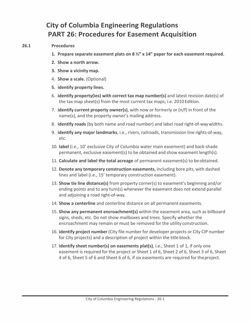
City of Columbia Engineering Regulations - 26-1
City of Columbia Engineering Regulations PART 26: Procedures for Easement Acquisition
26.1 Procedures
1. Prepare separate easement plats on 8 ½” x 14” paper for each easement required.
2. Show a north arrow.
3. Show a vicinity map.
4. Show a scale. (Optional)
5. identify property lines.
6. identify property(ies) with correct tax map number(s) and latest revision date(s) of the tax map sheet(s) from the most current tax maps; i.e. 2010 Edition.
7. identify current property owner(s), with now or formerly or (n/f) in front of the name(s), and the property owner’s mailing address.
8. identify roads (by both name and road number) and label road right-of-way widths.
9. identify any major landmarks, i.e., rivers, railroads, transmission line rights-of-way, etc.
10. label (i.e., 10’ exclusive City of Columbia water main easement) and back-shade permanent, exclusive easement(s) to be obtained and show easement length(s).
11. Calculate and label the total acreage of permanent easement(s) to be obtained.
12. Denote any temporary construction easements, including bore pits, with dashed lines and label (i.e., 15’ temporary construction easement).
13. Show tie line distance(s) from property corner(s) to easement’s beginning and/or ending points and to any turn(s) whenever the easement does not extend parallel and adjoining a road right-of-way.
14. Show a centerline and centerline distance on all permanent easements.
15. Show any permanent encroachment(s) within the easement area, such as billboard signs, sheds, etc. Do not show mailboxes and trees. Specify whether the encroachment may remain or must be removed for the utility construction.
16. identify project number (City file number for developer projects or City CIP number for City projects) and a description of project within the title block.
17. identify sheet number(s) on easements plat(s), i.e., Sheet 1 of 1, if only one easement is required for the project or Sheet 1 of 6, Sheet 2 of 6, Sheet 3 of 6, Sheet 4 of 6, Sheet 5 of 6 and Sheet 6 of 6, if six easements are required for the project.

City of Columbia Engineering Regulations - 27-i
City of Columbia Engineering Regulations PART 27: Procedures for Acceptance of Existing Streets
Table of Contents
Paragraph Description Page no. 27.1 Purpose 27-1 27.2 Scope 27-1 27.3 Design and Construction Standards 27-1 27.4 Procedures 27-1

City of Columbia Engineering Regulations - 27-1
City of Columbia Engineering Regulations PART 27: Procedures for Acceptance of Existing Streets
27.1 Purpose To establish procedures for the acceptance of existing streets that were constructed to be privately owned and maintained, but whose Owner now wants to transfer ownership to the City.
27.2 Scope
These procedures shall apply to all streets that were proposed and constructed as privately owned and maintained streets outside the jurisdiction and inspection of the City Engineer. All readers are cautioned that the current Subdivision Regulations require that any new street must meet the City’s standards for design and construction, whether public or private. These procedures are to be construed as a mechanism for avoiding this requirement.
27.3 Design and Construction Standards
In order to be considered for acceptance by the City, all streets must meet the City’s standards for design and construction as of the date they are offered. Or, the Owner must, at his sole expense, take those actions necessary to bring the street into compliance with these standards before acceptance by the City.
27.4 Procedures
27.4.1 The Owner must furnish the city with properly certified record drawings and
specifications. These plans shall be in electronic format per Part 28 of this manual and mylar form and must contain plan view, profile of the centerline, cross sections and construction details. In addition, he must furnish a recordable boundary survey plat showing the right-of-way to be conveyed and the location of improvements within the right-of-way. These items should be accompanied by a letter stating the owner’s formal request that the City accept the street.
27.4.2 The City Engineer in conjunction with the Public Works Director will review the record
drawings and specifications, and conduct a physical inspection of the premises. The Owner shall furnish such additional information, including laboratory test results of the materials, as the City Engineer may require to determine the actual conditions above and below the surface.
27.4.3 When the City Engineer has determined that the street meets City specifications he will
notify the Administrative Division of the Department of Utilities and Engineering.
27.4.4 The Administrative Division will furnish the Legal Department with necessary plats, metes and bounds description and other information necessary to prepare a deed to real estate. When the deed is returned from the Legal Department, it will be forwarded to the Owner for execution.

City of Columbia Engineering Regulations - 27-2
27.4.5 When the executed deed is received, it will be transmitted to the Legal Department for final legal review, consideration by City Council as appropriate and recording.
27.4.6 Upon notice that the deed has been sent for recording by the Legal Department, the
Administrative Division shall notify the Owner and the Street Division that henceforth the City will own and maintain the street.

City of Columbia Engineering Regulations - 28-i
City of Columbia Engineering Regulations PART 28: Digital Data Submission Standards
Table of Contents
Paragraph Description Page no. 28.1 Standards 28-1 28.2 Appendix A 28-4 28.3 Appendix B 28-6
List of Tables
Table Description Page no. Table 28-1. Graphic File (.dxf) Specifications 28-4 Table 28-2. Metadata Text File (‘metadat.txt’) Specifications 28-6

City of Columbia Engineering Regulations - 28-1
City of Columbia Engineering Regulations PART 28: Digital Data Submission Standards
Updated: 02/16/2016
28.1 Standards
Purpose: The purpose of this document is to provide a set of standards for digital data that is submitted to the City of Columbia. The need for these standards has arisen due to the universal use of different technologies that aide the process of planning and development design review. Geographic Information Systems (GIS) and Computer Aided Drafting (CAD) have become prominent technologies that are used in the review process.
These standards are designed to assist in efficiently transferring data among consultants, the city, and other agencies (i.e. Richland/Lexington County, State, Federal, etc). In addition to making data more easily transferrable, these standards will also help to streamline the process in which data is entered into the GIS. This is extremely important because the City of Columbia is becoming more geocentrically focused in its approach to asset management. This inherently means that the city depends upon complete and spatially accurate data. The standards within this document will help to maintain the spatial accuracy of city assets. Much of this document is adopted from Richland County digital data submission standards as to make data more easily transferrable between the City of Columbia and the county since both entities have interests in each other’s activities.
in addition to standard paper documents, any engineering plan that is submitted to the City of Columbia must have the additional digital files submitted:
• A completed original CAD drawing in .dwg or .dxf format. This file shall include all layers and graphic
elements included in the submitted paper document (text, legend, scale, labels, etc.). This file will include features classified in the standard layers defined in Appendix A. If the drawing contains layers that are not included in Appendix A, then a list of these layers shall also be submitted (ASCII text file labeled: ‘xlyrspec.txt’). The completed CAD drawing file should contain text in standard fonts that can be read without third-party software.
• A metadata text file containing information listed in Appendix B. This file includes submittal
information as well as technical parameters that may be necessary to review if problems in data conversion occur. The ASCII text file will be labeled ‘metadat.txt’.
• An ASCII text file containing elevation points. When submitting plans that include surveyed ground
surfaces, a separate ASCII text file containing all elevation points shall be delivered.
• When possible, a File geodatabase shall be provided with the appropriate feature datasets and feature classes containing the collected data. The horizontal and vertical positional accuracies should be included within the attribute table of each feature class. Any attributes to be collected in the field must be agreed upon by the City of Columbia and the contractor before the contract is approved.

City of Columbia Engineering Regulations - 28-2
These attributes shall be filled out as completely as possible. Any shortcomings shall be explained in a separate text file.
Additionally, digitally submitted data must meet the following requirements:
• Final Record Drawing .pdf and .dwg must be submitted electronically through email. You will be
notified if a CD ROM or DVD is required.
• All drawing elements shall be submitted referencing South Carolina State Plane (SCSP) Coordinates. Features in drawing files that are stored in drawing units must be translated to represent real world locations as referenced by SCSP coordinates. As specified in the SC Code of Laws Chapter 2, Title 27 (The South Carolina Coordinate Act, amended 31Mar89), elements referencing SCSP (formally identified as the South Carolina Coordinate System) will utilize the north American Datum of 1983 (nAD83) HARn for horizontal control and be measured in international Feet (not uS Survey Foot). Vertical control will reference the north American Vertical Datum of 1988 (nAVD88) and shall include measures using the uS Survey Foot. The SCSP system includes a single zone identified as Federal Information Processing Standard zone 3900 (FIPS 3900). Caution must be exercised in performing all conversions involving submitted data to ensure the correct use of the International Foot. Errors in conversion can exceed four linear feet. It is not the intention of the City of Columbia to replicate legal surveys. With this in mind, control of plan features may be tied to the SCSP system using traditional surveying or GPS methods. The method employed to gain geodetic control shall be identified in the submitted ‘metadata.txt’ file.
• Drawing features shall include layer names as indicated in Appendix A. Features other than those
thematically defined by the individual layer name/description shall not be included in that layer.
• No annotation shall be included in any feature layer and no feature shall be included in any annotation layer. Annotation for each layer shall be placed in annotation layers as specified in Appendix A.
• Closure is critical in converting drawing elements to GIS features. Parcels/lots (layer #2 PARCEL1),
subdivision boundaries (layer#3: SUBDIV1), rights-of-way (layer #4: ROW1), and common areas (layer #5: COMAREA1), Buildings (layer #7: BLDG1), Pavement Edge (Layer #16: PAVEDGE1), Easements (layer #26: EAS), Building Setbacks (layer #27 EASBLD), Buffers (layer #28 BUFF), Floodplains (layer #30: FP), Floodway (layer #31: FW) Wetlands, (layer #32 WETLANDS) must be snapped closed
• No polylines or annotation shall be stored in blocks. Explode all blocks that do exist.
• All City of Columbia required layers shall be made visible prior to submission – all other layers can be
turned off.
• Submitted .dxf files shall contain only complete parcel polygon features. All partial polygons (parcel boundaries) shown for reference in drawings (.dwg files) are not to be included in the PARCEL layer (Appendix A). Such features can be included in an unnamed layer in the submitted .dxf file.

City of Columbia Engineering Regulations - 28-3
• All coordinates shall be delivered in a single, comma-delimited ASCII text file. Each line of the file shall contain easting, northing, and elevation values (in SCSP coordinates) for a single point as exampled below: Easting, Northing, Elevation 2012374.63, 853633.30343, 447.52 2012371.81, 853642.06532, 447.49 2012370.56, 853651.25382, 447.62 202369.81, 853660.04853, 448.02
• Additional layers (not identified in Appendix A) may utilize any open layer beyond the 60 reserved
layers. As outlined above, a list of these layers shall also be submitted (ASCII text file labeled: ‘slyrspec.txt’)

City of Columbia Engineering Regulations - 28-4
28.2 Appendix A
Table 28-1. Graphic File (.dxf) Specifications
Color Number Layer Name Feature Type Layer Description 1 BLDG1 Polyline Building/structure outline or footprint 2 PARCEL1 Polyline Parcel/lot boundaries 3 SUBDIV1 Polyline Subdivision boundaries 4 ROW1 Polyline Rights of way delineating private/public land boundary 5 COMAREA1 Polyline Public areas such as street islands/community entrances 6 GCP1 Point Ground control points (existing, surveyed, or GPSed) 7 POLE1 Point Lamp poles, power poles, traffic light poles, etc. 8
9
10 GAS Polyline Gas pipe 11 ELECTR Polyline Electrical lines 12 TELCO Polyline Phone lines 13 CTVFIBR Polyline Cable TV and/or fiber datacom lines 14
15
16 PAVEDGE1 Polyline Edge of pavement 17 CNTRLIN1 Polyline Street/road centerlines (paved and unpaved) 18 SIDEWLK1 Polyline Sidewalks (including ramps, if any) 19 CURB1 Polyline Curb/gutter 20 CARPRK1 Polyline Parking lots 21 RAIL1 Polyline Railroads 22 HYDLIN1 Polyline Linear hydrography, creeks/streams 23 HYDPOL1 Polyline Polygonal hydrography, lakes/ponds 24
25
26 EAS Polyline Utilities, wildlife, transp., storm drainage/detention, etc. 27 EASBLD Polyline Building setback 28 BUFF Polyline Buffers (riparian, vegetation, etc.) 29
30 FP Polyline Flood plain 31 FW Polyline Flood way 32 WETLAND Polyline Wetlands 33
34
35 SDLINK Polyline Storm drain culvert, ditch, pipe, etc. 36 SDNODE Point Storm drain structure (manhole, junction box, etc.) 37 SDTEXT Text Annotation describing storm drainage (SD) features 38
39 SSLINK Polyline Sanitary sewer pipe

City of Columbia Engineering Regulations - 28-5
Color Number Layer Name Feature Type Layer Description 40 SSNODE Point Sanitary sewer manholes, pumps, junctions, etc. 41 SSTEXT Text Annotation describing sanitary sewer (SS) features 42
43 WTRLINK Polyline Water pipe 44 WTRNODE Point Water access/junction box, valves, etc. 45 FIREHYD Point Fire hydrant 46 WTRTEXT Text Annotation describing water service (WTR) features 47 CTOUR1 Polyline Un-broken contour lines (* design/as-built) 48
49
50
51 LOTNUM1 Text Proposed parcel lot number 52 LOTDIM1 Text Bearings, distances, acreage, and x/y of POB 53 SUBNAM1 Text Subdivision name 54 RDNAME1 Text Street/road name 55 RDNAME2 Text Road number (Federal, State, County highways, etc.) 56 PAVTYPE1 Text * Pavement type 57 RAILNAM1 Text Railroad name 58 HYDNAM1 Text Hydrographic feature name 59 EASTYPE Text Type of easement (utility, transp., wildlife, storm, etc.) 60 CTOURVAL Text Elevation of individual contours
* Level 56 - Pavement type (PAVTYPE1) shall include the following standard surface designations: • Asphalt Concrete • Bituminous Surfacing • Concrete • Gravel • Dirt

City of Columbia Engineering Regulations - 28-6
28.3 Appendix b
Table 28-2. Metadata Text File (‘metadat.txt’) Specifications
Subdivision Name: Submittal Date: County: City:
Parent Parcel #: Number of Lots:
Type of Geodetic Control:
Monument Reference: Y / N Traverse to Monument Referenced Monument Name/Number: Distance to Monument: GPS Unit Type: PDOP of Control Points: Differentially Corrected: Y / N Elevation Reference: Y / N
Prepared by/Firm Name:
Engineer of Record:
Drawing/File Name:
Software/Version Used:

City of Columbia Engineering Regulations - 29-i
City of Columbia Engineering Regulations PART 29: Fats, Oils, and Grease Management Regulation
Table of Contents
Paragraph Description Page no. 29.1 Purpose 29-1 29.2 Definitions 29-1 29.3 Grease Traps and Grease Interceptors 29-2 29.4 FOG Registration and New Grease Trap/ Grease Interceptor Inspection
Procedure
29-7 29.5 Inspection Procedure 29-10 29.6 Violations 29-11

City of Columbia Engineering Regulations - 29-1
City of Columbia Engineering Regulations PART 29: Fats, Oils, and Grease Management Regulation
29.1 Purpose This regulation will be enforced in conjunction with the City of Columbia, South Carolina, Code of Ordinances, Chapter 23 (Chapter 23), and establishes uniform registration, operating, maintenance, cleaning, and inspection requirements designed to limit and control the discharge of fats, oils, and grease from Food Service Establishments (FSEs) into the City’s wastewater collection system. The objectives of this regulation include the following:
29.1.1 To reduce the introduction of excessive amounts of fats, oils, and grease into City of
Columbia (City) wastewater collection system;
29.1.2 To reduce fats, oils, and grease related build-up to the City’s wastewater collection system that could lead to clogging or blocking of the sewer lines, causing backup and flooding of streets, residences, and commercial buildings, resulting in potential liability to the City;
29.1.3 To establish uniform identification numbers along with registration procedures and
Global Positioning System Coordinates to be input into GIS to identify food service establishments located within the City wastewater service area;
29.1.4 To establish operation, cleaning, and maintenance requirements for food service
establishments with grease traps and/or grease interceptors;
29.1.5 To establish inspection procedures and requirements for food service establishments with grease traps and/or grease interceptors;
29.1.6 To establish review procedures and reporting requirements for food service
establishments installing new grease traps and/or grease interceptors; and
29.1.7 To establish enforcement procedures for violations of Chapter 23 and any provision of this regulation.
29.2 Definitions
29.2.1 Director means the City’s Director of Utilities and Engineering.
29.2.2 Fats, Oils, and Grease (FOG) means any material, either liquid or solid, composed
primarily of fats, oils, and grease from animal or vegetable sources.
29.2.3 Food Service Establishment (FSE) means any commercial facility, including, by way of example and without limitation, restaurants, motels, hotels, cafeterias, hospitals, schools, bars, and any other facility which, in the sole discretion of the City, must install a Grease Trap or Grease Interceptor prior to discharging kitchen or food preparation wastewater into the City’s wastewater collection system. This definition includes, but is

City of Columbia Engineering Regulations - 29-2
not limited to, any establishment which is required to have a South Carolina Department of Health and Environmental Control (SCDHEC) food service license and/or permit.
29.2.4 FSE Owner or Owner means, in the case of an individually owned FSE, the Owner(s) and/
or proprietor(s) of the FSE. Where the FSE is a franchise operation, the Owner of the franchise is the responsible person and/or entity and is considered the FSE Owner. Where the FSE is owned by a corporation, the corporate representative, as designated on the FOG Registration form, is deemed to be authorized to act on behalf of the corporation. Where two or more FSEs share a common Grease Interceptor, the FSE Owner is any individual and/or entity who owns and/or assumes, maintains, or exercises control of the Grease Interceptor or the property on which the Grease Interceptor is located, as well as any individual and/or entity who utilizes or will utilize the shared Grease Interceptor.
29.2.5 Gray Water means all of the liquid contained in a Grease Trap or Grease Interceptor that
lies below the floating grease layer and above the bottom solids layer.
29.2.6 Grease means a material, either liquid or solid, composed primarily of fats, oils, and grease from animal or vegetable sources. The terms “FOG,” “oil and grease,” and “oil and grease substances” shall all be included within this definition and these terms may be used interchangeably.
29.2.7 Grease Hauler means a person or entity that collects the contents of Grease Traps and/
or Grease Interceptors and transports the contents to an approved recycling or disposal facility. A Grease Hauler may also provide other services to FSEs related to Grease Trap and/or Grease Interceptor cleaning and maintenance.
29.2.8 Grease Interceptor means a large underground concrete vault located outside of an FSE
designed to collect, contain, or remove Grease from the waste stream while allowing the sub-straight or Gray Water to discharge to the wastewater collection system by gravity.
29.2.9 Grease Trap means a device located within an FSE designed to collect, contain, separate,
or remove Grease from the waste stream while allowing the sub-straight waste or Gray Water to discharge to the wastewater collection system by gravity.
29.2.10 Inspector or City Staff means an employee of the City, who under the authority of the
Director, has responsibility for implementing and who does implement any FOG management regulations.
29.2.11 Program means the contents of this regulation, Part 29, as implemented by the Director,
Inspectors, and City Staff.
29.3 grease Traps and grease interceptors
29.3.1 Requirements: All FSEs located within the City of Columbia wastewater service area are required to have a Grease Trap and/or Grease Interceptor properly installed and maintained in accordance with the following: this regulation - Fats, Oils, and Grease Management – Part 29; Specifications for Grease Traps and Grease Interceptors

City of Columbia Engineering Regulations - 29-3
Regulation - Part 30; and all applicable requirements of the City’s most recently adopted version of the International Plumbing Code.
29.3.2 New FSEs: FSEs which are proposed or newly constructed, and existing FSEs undergoing
a change of use which necessitates the issuance of a new SCDHEC food service permit, expansion, or renovation to provide food services, are considered New FSEs. All New FSEs are required to install Grease Traps and/or Grease Interceptors, as appropriate, in compliance with the City of Columbia Grease Trap and Interceptor Sizing Guide (located at Specifications for Grease Traps and Interceptors Regulation - Part 30, Attachment C). New FSEs are required to operate, maintain, clean, and repair their Grease Traps and Grease Interceptors according to and in compliance with all applicable provisions contained in this regulation. In situations where it is not feasible for a New FSE to install an underground Grease Interceptor, the New FSE is required to install adequate and approved Grease Traps for use on individual fixtures, including, but not limited to: pot sinks, mop sinks, pre-rinse sinks, wok ovens, floor drains, and any other drains where the potential for introduction of Grease exists. In such cases, Grease Traps will be considered adequate and will be approved by the City only if a flow control device is placed on the inlet that prevent overloading and a sample port is placed on the outlet of each Grease Trap.
29.3.3 Existing FSEs: Except as provided in Subsection 3.3.1 below, Existing FSEs, which are
those FSEs already operating with Grease Traps and/or Grease Interceptors that were installed prior to the effective date of this regulation, will generally be permitted to operate and maintain existing Grease Traps and Grease Interceptors provided they are in proper operating condition and are maintained, cleaned, and repaired in accordance with all applicable provisions contained in this regulation and/or Chapter 23. In the event of noncompliance with this regulation or Chapter 23, the City may, in its sole discretion: (1) allow modifications to be made by the FSE, at the FSE’s own expense, to the existing Grease Trap or Grease Interceptor in order to bring it into compliance; or (2) require that the existing FSE install, at its own expense, a new Grease Trap and/or Grease Interceptor that meets the requirements of this and all other applicable laws and regulations including, without limitation, Specifications for Grease Traps and Interceptors Regulation - Part 30 and Chapter 23.
29.3.3.1 Grease Traps and Grease Interceptors installed prior to the effective date of this
regulation. If a Grease Trap or Grease Interceptor installed prior to the effective date of this regulation does not allow for measurement and sampling to demonstrate that the Grease Trap or Grease Interceptor is in compliance with this regulation and Chapter 23, the FSE must modify or replace the Grease Trap or Grease Interceptor as provided below no later than December 31, 2018:
(a) The City, in its sole discretion, may approve a proposed modification of an existing
Grease Trap or Grease Interceptor which allows for measurement and sampling of the existing Grease Trap or Grease Interceptor to demonstrate that the Grease Trap or Grease Interceptor is in compliance with this regulation and Chapter 23. Any proposed modification to meet this requirement must be submitted to the City for review no later than June 30, 2018; or

City of Columbia Engineering Regulations - 29-4
(b) If not modified pursuant to (a) above, the existing Grease Trap or Grease Interceptor must be replaced with a new Grease Trap or Grease Interceptor, as appropriate, in compliance with the City of Columbia Grease Trap and Interceptor Sizing Guide (located at Specifications for Grease Traps and Interceptors Regulation - Part 30, Attachment C).
29.3.4 Plumbing Connections: Grease Traps and Grease Interceptors shall be installed in
accordance with the requirements contained in all applicable local plumbing codes. Any Grease Trap and/or Grease Interceptor shall be located in the FSE’s lateral sewer line between all fixtures which may introduce Grease into the City’s wastewater collection system. Wastewater from domestic facilities and other similar fixtures shall not be introduced into a Grease Trap and/or Grease Interceptor by the FSE under any circumstances.
29.3.5 Grease Traps. All Grease Traps shall be installed in accordance with the City’s most
recently adopted version of the International Plumbing Code. Each FSE shall operate and maintain its Grease Trap in accordance with the following criteria:
29.3.5.1 Sizing. All Grease Traps shall be sized in accordance with the City of Columbia Grease
Trap and Interceptor Sizing Guide (located at Specifications for Grease Traps and Grease Interceptors Regulation - Part 30, Attachment C).
29.3.5.2 Flow control device and sample port. FSEs are responsible for equipping Grease Traps
with a device on the inlet side to control the rate of flow through the Grease Trap. The rate of flow shall not exceed the manufacturer’s rated capacity in gallons per minute for each Grease Trap. FSEs are also responsible for equipping Grease Traps with a sample port on the outlet side.
29.3.5.3 Installation, inspection, cleaning, and maintenance. Each FSE shall be solely responsible
for the cost of Grease Trap installation, inspection, cleaning, and maintenance. Each FSE must either contract with a Grease Hauler cleaning service or develop a written protocol for and perform its own Grease Trap cleaning and maintenance procedures that meet the requirements of this Program. Cleaning shall include the complete removal of all floating materials, Gray Water, and bottom solids from the Grease Trap. The return of Gray Water back into the Grease Trap or into the City’s the wastewater collection system is prohibited. Grease Trap cleaning must include removing/scraping excess solids from walls, floors, baffles, and inlet and outlet piping. It is the responsibility of each FSE to inspect its Grease Trap during and after the pumping and cleaning procedure to ensure that the Grease Trap is properly cleaned out and that the structure is sound and all fittings and fixtures inside the Grease Trap are in working condition and are functioning properly. The FSE Owner must have documentation consisting of inspection, cleaning, and maintenance logs on site in accordance with and demonstrating compliance with this regulation and must be able to produce the documentation immediately upon request of the Inspector and/or City Staff.
29.3.5.4 Grease Trap Cleaning Frequency. Cleaning and maintenance should generally be
performed in accordance with the Grease Trap manufacturer’s recommendations.

City of Columbia Engineering Regulations - 29-5
However, despite this provision, cleaning and maintenance must be performed as often as and in the manner necessary to achieve full compliance with Chapter 23 and this regulation, even if such cleaning and maintenance exceeds that recommended by the manufacturer.
29.3.5.5 Inspection. Grease Traps shall be inspected by the Inspector as often as necessary in the
City’s sole discretion to ensure compliance with Chapter 23, and this regulation, and to determine if proper cleaning and maintenance schedules as set forth herein are being adhered to by the FSE. FSEs with Grease Traps are responsible for having qualified staff on hand during any inspection to open and close the Grease Trap.
29.3.5.6 Repairs and replacement. Each FSE shall be solely responsible for the cost, scheduling,
and performance of all repairs and replacements to its Grease Trap(s), including, without limitation, any and all repairs and replacements that may be required by the Inspector and/or City Staff under this Program.
29.3.6 Grease Interceptors: Grease Interceptors shall be designed and installed in accordance
with Specifications for Grease Traps and Interceptors – Part 30 and the City’s most recently adopted version of the International Plumbing Code. In the event of a conflict between the two, the most stringent requirements shall apply. Each FSE shall operate and maintain its Grease Interceptor in accordance with the following criteria:
29.3.6.1 Installation, inspection, cleaning, and maintenance. Each FSE shall be solely responsible
for the costs of installing, inspecting, pumping, cleaning, and maintaining its Grease Interceptor(s). All FSEs that have Grease Interceptors shall utilize a Grease Hauler to properly dispose of Grease Interceptor contents. Cleaning shall include the complete removal of all Grease Interceptor contents including floating materials, Gray Water, and bottom solids. The return of Gray Water back into the Grease Interceptor or into the City’s wastewater collection system is prohibited. Grease Interceptor cleaning must be performed as often as and in a manner necessary to achieve compliance with Chapter 23 and this regulation. Such cleaning may include removing/scraping and/or hydroscrubbing excessive solids from the walls, floors, baffles and all interior plumbing. It shall be the responsibility of each FSE to inspect its Grease Interceptor during the pumping and cleaning procedure to ensure that the Grease Interceptor is properly cleaned out and that the structure is sound and all fittings and fixtures inside the Grease Interceptor are in working condition and functioning properly. The FSE Owner must have documentation consisting of inspection, cleaning, and maintenance logs on site in accordance with and demonstrating compliance with this regulation and must be able to produce the documentation immediately upon request of the Inspector and/or City Staff.
29.3.6.2 Grease Interceptor cleaning frequency. Each FSE shall have its Grease Interceptor(s)
cleaned at a minimum frequency of twice per year. In addition to this required cleaning, each FSE shall determine an additional frequency at which its Grease Interceptor(s) shall be cleaned in accordance and in compliance with each of the following criteria:

City of Columbia Engineering Regulations - 29-6
29.3.6.2.1 When the floatable Grease layer exceeds six inches in depth as measured with an approved dipping method;
29.3.6.2.2 When the settleable solids layer exceeds eight inches in depth as measured with an
approved dipping method;
29.3.6.2.3 When the total volume of captured Grease and solid material displaces more than 25 percent of the capacity of the Grease Interceptor as calculated with an approved dipping method; or
29.3.6.2.4 When the Grease Interceptor is not retaining/capturing FOG so as to comply with the
requirements of Chapter 23 and this regulation.
29.3.6.3 Inspection. Grease Interceptors may be inspected by the Inspector as often as necessary in the City’s sole discretion to ensure compliance with this Program, including, without limitation, to determine if proper cleaning and maintenance schedules are being adhered to by the FSE. FSEs with Grease Interceptors that are inaccessible to the Inspector are responsible for having staff readily available during any inspection to provide access to and to open and close the Grease Interceptor for the Inspector. It is the sole responsibility of the FSE to provide the City with access to any inaccessible Grease Interceptor.
29.3.6.4 Repairs and replacement. Each FSE shall be responsible for the cost, scheduling, and
performance of all repairs and replacements to its Grease Interceptor(s), including, without limitation, any and all repairs and replacements that may be required by the Inspector and/or City Staff under the Program.
29.3.7 Additives. The introduction of chemicals, enzymes, emulsifiers, live bacteria or other
grease cutters or additives into the wastewater collection system is generally prohibited by the City. On very rare occasions the City may, in its sole discretion, approve an FSE’s use of additives. FSEs seeking to introduce additives must, prior to their introduction into Grease Traps or Grease Interceptors, submit the following information to the Department of Utilities and Engineering Wastewater Compliance Section for review and consideration: Material Safety Data Sheets and any other applicable information concerning the composition, frequency of use, and mode of action of the proposed additive(s) and a written statement outlining the FSE’s proposed use of the additive(s). The FSE may only use the additives if and when the City grants the FSE permission to do so in writing and then may only do so in accordance with the specific parameters set forth by the City therein. Permission to use any specific additive may be withdrawn by the City at any time, upon the City’s providing written notice to the FSE.
29.3.8 Alternative Grease Removal Devices or Technologies. The use of alternative Grease
removal devices and technologies, such as automatic grease removal systems, are generally prohibited by the City. On rare occasions, the City may, in its sole discretion, approve the use of this technology and these devices on a case-by-case basis. An FSE may only use alternative Grease removal devices or technologies after receiving permission to do so in writing from the City and then may only do so in accordance with

City of Columbia Engineering Regulations - 29-7
the specific parameters set forth by the City therein. Permission to use any alternative Grease removal devices or technologies may be withdrawn by the City at any time, upon the City’s providing written notice to the FSE.
29.3.9 Recordkeeping. Each FSE shall maintain records required hereunder in a bound logbook
kept on site at the FSE describing and documenting all cleaning, maintenance, and repairs performed for each Grease Trap and Grease Interceptor including the date and time of each pump out or cleaning and details regarding same; records documenting and detailing any maintenance and/or repairs, and the dates on which such maintenance and/or repairs were performed and completed; and any other records documenting and related to the cleaning, maintenance, and/or repairs for each Grease Trap or Grease Interceptor. The logbook must be made available by the FSE for review by the Inspector and/or City Staff upon request during an inspection. In addition to the records specified above, each FSE shall also maintain a file on-site which contains the following information:
29.3.9.1 A copy of the FSE’s FOG Registration form submitted to the City pursuant to Section 4.0
below; and
29.3.9.2 Receipts evidencing and identifying (at least by name, address, and service(s) provided) any individuals and/or entities performing cleaning, maintenance, and/or repairs on each Grease Trap and/or Grease Interceptor including, without limitation, Grease pumpers, Grease Haulers, plumbers, and parts suppliers.
Failure to maintain complete records in accordance with the Program as specified herein or to provide such records to the Inspector and/or City Staff upon request constitutes a violation of this regulation. All records required of an FSE under this regulation must be maintained for the time period consisting of the two (2) years immediately preceding the date of the most recent inspection of the FSE by the City, and for any time period thereafter.
29.3.10 Disposal. It is the responsibility of each FSE Owner to ensure that wastes removed from
each of its Grease Traps and/or Grease Interceptors are properly disposed of at a facility permitted to receive such wastes.
29.4 FOg Registration and new grease Trap/ grease interceptor inspection Procedure
29.4.1 Registration Requirements for FSEs. Each FSE shall be subject to the FOG Registration
requirements in this Section 4.0. This FOG Registration is required in addition to any other permits, registrations, or business license(s) which may be required of the FSE by federal, state, or local law or regulation.
29.4.2 Registration Form. The City shall provide or make available a FOG Registration form for
all FSEs located within the City’s wastewater service area. All Existing FSEs are required to submit a completed FOG Registration to the City at the address shown on the form no later than thirty (30) calendar days after receiving notification by the City that registration is required. Failure to do so will constitute a violation of this regulation. New FSEs are required to submit a completed FOG Registration to the City at the address

City of Columbia Engineering Regulations - 29-8
shown on the form prior to beginning construction as described in Section 4.5 below. Each FOG Registration form submitted shall include the following information:
29.4.2.1 FSE Owner’s name, title, and contact information; FSE contact name, title, and contact
information, if different from the FSE Owner; FSE water and sewer account holder contact information; name of FSE; physical address of FSE; telephone number of FSE; and business mailing address of FSE if different from physical address;
29.4.2.2 A description of the type of food service activities to be performed at the FSE;
29.4.2.3 Seating capacity of the FSE;
29.4.2.4 A copy of calculations demonstrating how the size of each Grease Trap and/or Grease
Interceptor was determined; a set of plumbing drawings or sketches, including floor plans and riser diagrams; and a site plan showing the location of the sewer discharge(s) and the location of any exterior Grease Interceptors, where applicable (drawings or sketches must have sufficient enough detail to show the location of all kitchen equipment and plumbing fixtures with drains, floor drains, sewer connections, and all Grease Traps and Grease Interceptors);
29.4.2.5 For FSEs with Grease Traps, documentation demonstrating that
(a) the Grease Trap is equipped with a device on the inlet side to control the rate of
flow through the Grease Trap such that the rate of flow does not exceed the manufacturer’s rated capacity in gallons per minute for each Grease Trap; and
(b) the Grease Trap is equipped with a sample port on the outlet side;
29.4.2.6 Total hours of operation each day;
29.4.2.7 Executed statement of the FSE Owner certifying that the FSE Owner has received, read,
understands, and agrees to abide by Fats, Oils, and Grease Management – Part 29; Specifications for Grease Traps and Grease Interceptors Regulation - Part 30; Chapter 23, as well as any other applicable federal, state, and local laws and regulations governing the FSE; that the information provided in the FOG Registration form is accurate; that the FOG Registration form was completed at the FSE Owner’s direction and with the FSE Owner’s approval; that the FSE Owner understands that providing false information or violating the provisions of the above-stated laws and/or regulations may result in termination of the FSE’s water and/or sewer service, and/or revocation of the FSE’s permitted water and/or sewer capacity; and that if the FSE’s water and/or sewer service is terminated, the FSE will have to submit a new FOG Registration form and/or reapply for water and/or sewer service with the City and bear all associated costs; and
29.4.2.8 All other information regarding the description of the FSE’s operations, including,
without limitation, information regarding the FSE’s Grease Traps and Grease Interceptors, and treatment of same, as identified on the FOG Registration form.

City of Columbia Engineering Regulations - 29-9
29.4.3 FSEs with Shared Grease Interceptor(s). In situations where FSEs share one or more Grease Interceptors, the owner of each Grease Interceptor and any FSE and FSE Owner who utilizes or will utilize the shared Grease Interceptor are collectively responsible for completion and submission of the FOG Registration form to the City within the time period required in this regulation, for identifying all FSEs connected to each Grease Interceptor in the FOG Registration form, and for ensuring that all FSEs connected to that Grease Interceptor comply with this regulation, as well as Chapter 23. All FSEs connected to the shared Grease Interceptor shall be subject to inspections under this regulation. In the event the identity of an FSE connected to the shared Grease Interceptor changes or in the event that an additional FSE connects to the shared Grease Interceptor, the owner of the shared Grease Interceptor, the FSE Owner, and any FSE utilizing or who will utilize the shared Grease Interceptor must submit an updated FOG Registration form identifying the change or the additional FSE to the City at least thirty (30) calendar days prior to the change and prior to the additional FSE connecting to the shared Grease Interceptor.
29.4.4 New Grease Trap/Grease Interceptor Inspection Procedure.
29.4.4.1 FSE – New Facilities. After a completed and satisfactory FOG Registration form has been
submitted to the City, the FSE may proceed with installation and/or construction of the Grease Trap and/or Grease Interceptor. When installation and/or construction of the Grease Trap and/or Grease Interceptor is completed, the FSE Owner shall notify the City that the FSE is ready for inspection. The FSE Owner shall notify the City prior to covering any exterior Grease Interceptors. During the inspection, the information contained in the FOG Registration form will be verified and the FSE’s Grease Traps and/or Grease Interceptors will be inspected. If any Grease Trap or Grease Interceptor requires maintenance or repairs, if any incorrect information has been given, or in the event of noncompliance with any portion of this regulation, the Inspector will issue a written notice requiring that the FSE correct any deficiencies, including a required time schedule for repairs to be effected prior to a second inspection. Second inspections will be performed after a minimum of ten (10) calendar days have elapsed to allow the FSE to implement appropriate and necessary corrective action(s) to correct the deficiencies. If the FSE is not in compliance at the second inspection, the FSE Owner must complete any additional maintenance and/or repairs or take whatever other action may be required for compliance, and resubmit the FOG Registration form. Failure to comply with any portion of this regulation after resubmission of the FOG Registration form may result in enforcement action pursuant to Chapter 23, including, but not limited to, termination or denial of the FSE’s water and/or sewer service.
29.4.4.2 FSE – Existing Facilities. All Existing FSEs are required to submit a completed FOG
Registration form to the City at the address shown on the form no later than thirty (30) calendar days after receiving notification by the City that registration is required. Failure to do so will constitute a violation of this regulation. A new FOG Registration form must be submitted upon change in ownership of the FSE or changes in operations or plumbing changes or additions, including, without limitation, a change of use which necessitates the issuance of a new SCDHEC food service permit; remodeling or expansion of the food preparation area; and/or modifications to the kitchen waste plumbing system. No new

City of Columbia Engineering Regulations - 29-10
Grease Trap or Grease Interceptor may be placed into service until the City has conducted an inspection pursuant to the procedures set forth in Section 4.5.1 above.
29.5 inspection Procedure
All FSEs are subject to inspection as follows:
29.5.1 Inspections. The Inspector and City Staff may inspect FSEs at any time during business hours in order to verify continued compliance with all applicable laws and regulations, including, without limitation, requirements of this regulation and Chapter 23. All FSEs which have submitted a FOG Registration will be inspected on a regular basis. Inspections shall include, without limitation, all equipment, food processing and storage areas that discharge into the Grease Traps and/or Grease Interceptors at the FSE. The Inspector and/or City Staff shall also inspect the FSE’s logbook and other records and data required to be kept hereunder; Grease Trap(s) and/or Grease Interceptor(s); and may check the level of the Grease Trap and/or Grease Interceptor contents and take samples and/or photographs as deemed necessary in the Inspector’s sole discretion. If noncompliance is identified by the Inspector and/or City Staff during an inspection, the Inspector will, after the inspection, issue the FSE a written notice of violation directing the FSE to correct any deficiency. The FSE will be scheduled for re-inspection at the time denoted in the notice of violation.
29.5.2 Re-inspections. The Inspector and City Staff will re-inspect FSEs that are issued a notice
of violation within the time period specified in the notice of violation. The Inspector shall inspect, without limitation, any repairs made or other corrective measures taken by the FSE with regard to any noted violations and will subsequently provide written notice of compliance or non-compliance to the FSE as the case may be. If, upon re-inspection, the FSE has corrected all of the deficiencies which resulted in the issuance of the notice of violation and the FSE is in full compliance with all other requirements of the Program, the FSE will be notified by the City that it is in compliance.
29.5.3 Access and Cooperation During Inspections. Upon the request of the Inspector and other
duly authorized employees or agents of the City, each FSE shall allow the Inspector and other duly authorized employees or agents of the City, including, without limitation, City Staff, access to all parts of the FSE premises for inspection, observation, records examination, measurement, sampling, testing and for other purposes in accordance with the provisions of this regulation. The refusal of any FSE to allow the Inspector and/or City Staff entry to or upon the FSE’s premises, or an FSE’s failure to cooperate in any manner during the course of an inspection, shall constitute an immediate violation of this regulation, which may result in enforcement action pursuant to Section 6.4 of this regulation.
29.5.4 Non-Compliance: In the event of continuing non-compliance after re-inspection, the FSE
Owner will be notified that continued failure to comply within the time period designated by the City may result in enforcement action pursuant to Chapter 23, including, but not limited to, termination of water and/or sewer service.

City of Columbia Engineering Regulations - 29-11
29.6 Violations
29.6.1 Notices of Violation. Deficiencies that will result in a finding of noncompliance and issuance of a notice of violation under this Program include the following:
29.6.1.1 Failure of the FSE to allow the Inspector or City Staff access to all parts of the FSE
premises for inspection, observation, records examination, measurement, sampling, testing and for other purposes in accordance with the provisions of this regulation shall constitute an immediate violation;
29.6.1.2 Failure of the FSE to properly operate, maintain, clean, and/or repair a Grease
Interceptor and/or Grease Trap in accordance with this regulation;
29.6.1.3 Failure of the FSE to report changes in operations or plumbing changes or additions, including, without limitation, a change of use which necessitates the issuance of a new SCDHEC food service permit; remodeling or expansion of the food preparation area; and/or modifications to the kitchen waste plumbing system;
29.6.1.4 Where the FSE is operating an irreparable or defective Grease Trap and/or Grease
Interceptor that is in need of replacement;
29.6.1.5 Failure to report a sale or change in ownership of the FSE by submitting a new FOG Registration form within the thirty (30) days and in accordance with the procedures set forth in this regulation;
29.6.1.6 Failure of the FSE to have or maintain plumbing connections to a Grease Trap or Grease
Interceptor in compliance with the requirements of this regulation;
29.6.1.7 Failure of the FSE to submit a completed FOG Registration within thirty (30) days after the date of notification by the City that such an application is required to be submitted;
29.6.1.8 Where the FSE is contributing FOG to the City’s wastewater collection system in
quantities in excess of the allowable limits as established in Chapter 23;
29.6.1.9 Failure of the FSE to maintain and/or retain, or to produce upon the Inspector or City Staff’s request, records as required under this regulation for the time period delineated in this Program;
29.6.1.10 Where the FSE has no Grease management in place;
29.6.1.11 Where the FSE Owner and/or any user of a shared Grease Interceptor has failed to
identify to the City all FSEs connected to the shared Grease Interceptor in the FOG Registration form in accordance with the requirements of this regulation;
29.6.1.12 Where the FSE previously received a notice of violation under this Program and, upon re-
inspection, the FSE remained in noncompliance;

City of Columbia Engineering Regulations - 29-12
29.6.1.13 Where the FSE, in the sole discretion of the City, has engaged in bad-faith failure or has refused to comply with a notice of violation issued under this Program or has failed to otherwise cooperate with the Inspector and/or City Staff as required by this regulation; and
29.6.1.14 Any other noncompliance with the Program, this regulation, or Chapter 23.
29.6.2 Schedules of Compliance. Failure to comply with this regulation may result in the
following notices of violation with the compliance schedules noted. However, nothing in this Section 6.2 precludes the City from taking immediate enforcement against an FSE in violation of this regulation or Chapter 23:
29.6.2.1 A notice of violation may be issued to the FSE by the City with the following compliance
schedule in situations where an Inspector determines:
(a) that the FSE’s Grease Trap and/or Grease Interceptor is irreparable or defective and must be replaced.
(b) that an FSE has no Grease management in place;
(c) that the FSE has undergone a change of use which necessitates the issuance of a
new SCDHEC food service license and/or permit, remodeling, expansion of the food preparation area, or modifications to the kitchen waste plumbing system and has failed to comply with the requirements of Section 3.2 of this regulation;
(d) that the FSE does not have or does not properly maintain plumbing connections to
a Grease Trap or Grease Interceptor in compliance with this regulation.
FSEs receiving a notice of violation for any deficiency identified above will be required, within fifteen (15) days of the date of the notice of violation, to submit a corrective action plan to the City for consideration, outlining and detailing the scope of work, including a timeline for completion, that meets the requirements set forth in this Program, Specifications for Grease Traps and Grease Interceptors Regulation - Part 30, and Chapter 23. If the City approves the corrective action plan, the FSE must construct the improvements at its own expense. Construction must be complete within forty-five (45) days of the date of the City’s written approval of the corrective action plan. A pre- construction inspection will be scheduled by the City and the FSE is responsible for notifying the City at least twenty-four (24) hours in advance of the start of construction in order that this inspection can be scheduled.
29.6.2.2 A notice of violation may be issued to the FSE by the City with a fifteen (15) day
compliance schedule in situations where an Inspector determines:
(a) that the FSE has failed to adequately clean, maintain, repair, or replace a Grease Trap or Grease Interceptor as determined by the City in accordance with this Program;

City of Columbia Engineering Regulations - 29-13
(b) that the FSE is contributing FOG to the City’s wastewater collection system in quantities in excess of the allowable limits as established by the City in Chapter 23;
(c) that the FSE has been sold or undergoes a change of ownership or in operations
and a new FOG Registration form is not submitted by the New FSE Owner in accordance with the requirements of this regulation;
(d) that the FSE has been notified by the City that it must submit a completed FOG
Registration form and the FSE has failed to do so within thirty (30) days of the date of notification;
(e) that the FSE Owner and/or any user of a shared Grease Interceptor has failed to
identify to the City all FSEs connected to the shared Grease Interceptor in the FOG Registration form in accordance with the requirements of this regulation;
(f) that the FSE has failed to produce, maintain, or retain maintenance logs, files, or
other records required to be kept under this regulation for the time period consisting of the two (2) years immediately preceding the date of the most recent inspection at the FSE and any time period thereafter; or
(g) that the FSE has otherwise failed to comply with the Program in any other manner
set forth in this regulation.
29.6.2.3 A notice of violation will be issued to the FSE by the City with a seven (7) day compliance schedule in situations where an Inspector determines:
(a) that the FSE previously received a notice of violation under this Program and, upon
re-inspection, the FSE remained in noncompliance; or
(b) that the FSE is, in the sole discretion of the City, has engaged in bad-faith failure or has refused to comply with a notice of violation issued under this Program or has failed to otherwise cooperate with the Inspector and/or City Staff as required by this regulation.
29.6.3 Corrective Action. Where a FSE receives three (3) notices of violation within a one-year
time period under this Program, the FSE will be automatically placed on a corrective action plan by the City that is designed to bring the Grease Trap and/or Grease Interceptor into compliance within the period of time specified in the corrective action plan. An FSE may be placed on a corrective action plan for a single violation or combination of violations when, in the discretion of the City, such violation(s) are of a nature or severity which warrants the imposition of a corrective action plan to bring the FSE into compliance with this regulation.
29.6.4 Other Enforcement Action. Any FSE which violates Chapter 23 or this regulation shall be
subject to such other enforcement action as allowed by and in accordance with Chapter 23 and applicable state law, including, but not limited to:
(a) A civil penalty not to exceed two thousand dollars for each day of violation;

City of Columbia Engineering Regulations - 29-14
(b) Termination of water or wastewater service pursuant to Section 23-111 of Chapter 23; and
(c) Criminal penalties pursuant to Section 23-112 of Chapter 23.

City of Columbia Engineering Regulations - 30-i
City of Columbia Engineering Regulations PART 30: Specifications for Grease Traps and Grease
Interceptors Table of Contents
Paragraph Description Page no. 30.1 General 30-1 30.2 Definitions 30-1 30.3 Design and Construction Requirements 30-2 30.4 Inspection for Acceptance 30-5 30.5 Attachment A: Standard Grease Interceptor 30-6 30.6 Attachment B: Standard Grease Interceptor In Series 30-7 30.7 Attachment C : Grease Trap and Grease Interceptor Sizing Guide 30-8 30.8 Attachment D: Grease Trap Specification Sheet Example 30-9
List of Figures
Figure Description Page no. Figure 30-1. Standard Grease Interceptor 30-6 Figure 30-2. Standard Grease Interceptor In Series 30-7 Figure 30-3. Grease Trap and Grease Interceptor Sizing Guide 30-8 Figure 30-4. Grease Trap Specification Sheet Example 30-9

City of Columbia Engineering Regulations - 30-1
City of Columbia Engineering Regulations PART 30: Specifications for Grease Traps and Grease Interceptors 30.1 General
30.1.1 This section includes guidelines and requirements for design and installing Grease Traps
and Grease Interceptors. Construction details GR #1 and GR #2 attached hereto as Attachment A and Attachment B, respectively, are part of these specifications.
30.1.2 Grease Traps or Grease Interceptors shall be provided by each Food Service
Establishment (FSE) for the proper handling of liquid wastes containing significant amounts of fats, oils, and grease as specified in the Fats, Oils, and Grease Management Regulation - Part 29 (Part 29). All Grease Traps and Grease Interceptors installed by FSEs must be in compliance with Part 29 and the specifications herein and shall be located so as to be readily and easily accessible for cleaning and inspection. All Grease Traps and Grease Interceptors shall be supplied by and properly cleaned and maintained by the FSE Owner at its own expense in accordance with and as provided in Part 29.
30.1.3 All FSEs, new or existing, requesting sewer service from the City of Columbia (the City),
shall submit a FOG Registration form in accordance with Part 29 prior to receiving sewer service.
30.1.4 It is the intent of this specification to provide specific standards for the location, design,
installation and construction of Grease Traps and Grease Interceptors in accordance with the requirements stated herein. Failure to comply with this specification shall result in the denial or discontinuance of water and/or sewer service.
30.2 Definitions
30.2.1 Fats, Oils, and Grease (FOG) means any material, either liquid or solid, composed
primarily of fats, oils, and grease from animal or vegetable sources.
30.2.2 Food Service Establishment (FSE) means any commercial facility, including, by way of example and without limitation, restaurants, motels, hotels, cafeterias, hospitals, schools, bars, and any other facility which, in the sole discretion of the City, must install a Grease Trap or Grease Interceptor prior to discharging kitchen or food preparation wastewater into the City’s wastewater collection system. This definition includes, but is not limited to, any establishment which is required to have a South Carolina Department of Health and Environmental Control (SCDHEC) food service license and/or permit.
30.2.3 FSE Owner or Owner means, in the case of an individually owned FSE, the Owner(s) and/
or proprietor(s) of the FSE. Where the FSE is a franchise operation, the Owner of the franchise is the responsible person and/or entity and is considered the FSE Owner. Where the FSE is owned by a corporation, the corporate representative, as designated on the FOG Registration form, is deemed to be authorized to act on behalf of the

City of Columbia Engineering Regulations - 30-2
corporation. Where two or more FSEs share a common Grease Interceptor, the FSE Owner is any individual and/or entity who owns and/or assumes, maintains, or exercises control of the Grease Interceptor or the property on which the Grease Interceptor is located, as well as any individual and/or entity who utilizes or will utilize the shared Grease Interceptor.
30.2.4 Gray Water means all of the liquid contained in a Grease Trap or Grease Interceptor that
lies below the floating grease layer and above the bottom solids layer.
30.2.5 Grease means a material, either liquid or solid, composed primarily of fats, oils, and grease from animal or vegetable sources. The terms “FOG”, “oil and grease,” and “oil and grease substances” shall all be included within this definition and may be used interchangeably.
30.2.6 Grease Interceptor means a large underground concrete vault located outside of an FSE
designed to collect, contain, or remove FOG from the waste stream while allowing the sub-straight or Gray Water to discharge to the wastewater collection system by gravity.
30.2.7 Grease Trap means device located within an FSE that is designed to collect, contain,
separate, or remove FOG from the waste stream while allowing the sub-straight waste or Gray Water to discharge to the wastewater collection system by gravity.
30.3 Design and Construction Requirements
30.3.1 New FSEs
30.3.1.1 Non-cooking intensive FSEs, as determined by the City, may be allowed to utilize Grease
Traps. Examples of FSEs which might be determined to be non-cooking intensive FSEs are identified in City of Columbia Grease Trap and Grease Interceptor Tank Sizing Guide (attached hereto as Attachment C); however, these FSEs are provided by way of example only. The City will make a determination on the applicable sizing guide formula for an FSE on a case-by-case basis.
30.3.1.2 All New FSEs (as defined in Section 3.2 of Part 29), with the exception of non-cooking
intensive FSEs as determined by the City, are required to install a Grease Interceptor sized in accordance with the City of Columbia Grease Trap and Grease Interceptor Tank Sizing Guide (Attachment C). A Grease Trap or Grease Interceptor must be sized in accordance with the formulae set forth in (A), (B), or (C) of the City of Columbia Grease Trap and Grease Interceptor Tank Sizing Guide (Attachment C) unless the City approves sizing calculations signed and sealed by a registered professional engineer in accordance with the Fixture Unit Calculation Method set forth in (D) of the City of Columbia Grease Trap and Grease Interceptor Tank Sizing Guide (Attachment C). No Grease Interceptor less than 1,000 gallons total capacity will be approved for installation by the City unless acceptable engineering calculations sealed by a professional engineer registered in the state of South Carolina and demonstrating that a smaller size has satisfactory capacity are provided by the FSE Owner to the City and are approved by the City. The City retains sole discretion to approve or deny approval of a Grease Interceptor less than 1,000

City of Columbia Engineering Regulations - 30-3
gallons total capacity in all circumstances, even in the event such engineering calculations are provided.
30.3.1.3 All New FSEs must submit, for each Grease Trap and Grease Interceptor, cut sheets,
plans, and specifications. These documents must be submitted to the City prior to the FSE’s installation of the Grease Trap and/or Grease Interceptor. An approval letter for each new Grease Trap or Grease Interceptor must be issued by the City to the FSE prior to construction and/or installation of the Grease Trap and/or Grease Interceptor by the new FSE.
30.3.1.4 The construction and location criteria for Grease Interceptors must be in accordance
with Environmental Protection Agency (EPA) Guidance Document, On site Wastewater Treatment and Disposal Systems, Chapter 8.
30.3.1.5 No New FSE will be allowed to initiate operations until proper Grease Traps and/or
Grease Interceptors, as appropriate, are installed by the FSE in accordance with this Part 30 and Part 29, and are approved by the City.
30.3.1.6 For cases in which underground-type Grease Interceptors are appropriate but not
feasible to install in the City’s sole discretion, new FSEs must install approved Grease Traps in accordance with this Part 30 and Part 29 for use on individual fixtures, including, without limitation, pot sinks, mop sinks, pre-rinse sinks, wok ovens, floor drains and other potentially grease containing drains. In such cases, Grease Traps will be considered acceptable by the City only if approved flow control fittings are placed on the inlet that prevent overloading and a sample port is placed on the outlet of each Grease Trap.
30.3.1.7 FSE’s shall not connect dishwashers, garbage grinders, or domestic sewer to any Grease
Trap or Grease Interceptor.
30.3.1.8 All Grease Traps and Grease Interceptors must be installed by a properly licensed plumbing contractor.
30.3.2 Existing FSEs
30.3.2.1 All existing FSEs (as defined in Section 3.2 of Part 29) must have Grease Traps and Grease
Interceptors approved by the City in accordance with Part 29.
30.3.2.2 In cases where existing FSEs do not already have a Grease Interceptor installed and where the installation of an outdoor Grease Interceptor is feasible in the City’s sole discretion, the Grease Interceptor must be installed by the FSE in accordance with this Part 30 and must be approved by the City in writing in advance of installation.
30.3.2.3 Sizing of any Grease Trap or Grease Interceptor must be in accordance with the City of
Columbia Grease Trap and Interceptor Sizing Guide (attached as Attachment C).
30.3.2.4 Grease Interceptors must be located as close to the source of the wastewater service line at the building as physically possible, while remaining accessible for maintenance.

City of Columbia Engineering Regulations - 30-4
30.3.2.5 Existing FSEs shall not connect new dishwashers, garbage grinders, or domestic sewer to any Grease Trap or Grease Interceptor. The City, in its sole discretion, may grant a variance to this requirement in circumstances in which the City determines that compliance with this requirement would be unduly burdensome or impractical due to physical condition or layout of the FSE.
30.3.2.6 New flow control devices, Grease Traps, or Grease Interceptors must be pre-approved
prior to installation.
30.3.3 Grease Traps
30.3.3.1 Prior to installation, design for all Grease Traps must be submitted by the FSE to the City for approval with supporting calculations, cut sheets, and/or sizing charts, including a sizing chart similar to requirements set forth in the City of Columbia Grease Trap Specification Sheet Example (attached as Attachment D). Satisfactory proof of minimum Grease Trap capacity, as specified in the City of Columbia Grease Trap and Interceptor Sizing Guide (attached as Attachment C) must also be provided to the City by the FSE for all Grease Traps prior to installation. A Grease Trap must be sized in accordance with the formulae set forth in (A), (B), or (C) of the City of Columbia Grease Trap and Grease Interceptor Tank Sizing Guide (Attachment C) unless the City approves sizing calculations signed and sealed by a registered professional engineer in accordance with the Fixture Unit Calculation Method set forth in (D) of the City of Columbia Grease Trap and Grease Interceptor Tank Sizing Guide (Attachment C).
30.3.4 Grease Interceptors
All FSE’s Grease Interceptors must meet each of the following requirements:
30.3.4.1 A Grease Interceptor must be sized in accordance with the formulae set forth in (A), (B), or (C) of the City of Columbia Grease Trap and Grease Interceptor Tank Sizing Guide (Attachment C) unless the City approves sizing calculations signed and sealed by a registered professional engineer in accordance with the Fixture Unit Calculation Method set forth in (D) of the City of Columbia Grease Trap and Grease Interceptor Tank Sizing Guide (Attachment C).
30.3.4.2 Provide precast or cast in place minimum 4000 psi concrete vaults; The City, in its sole
discretion, may allow the use of other materials upon written request for approval prior to installation.
30.3.4.3 Open top inlet tee must extend to 24” from the bottom of the vault;
30.3.4.4 The vault shall have a baffle wall with a minimum 3” air gap for venting at the top and an
open top tee extending to 12” from the bottom of the vault;
30.3.4.5 Open top outlet tee must extend to 12” from the bottom of the vault;
30.3.4.6 Access Manholes shall be provided by the FSE directly above all three tees for inspection and maintenance;

City of Columbia Engineering Regulations - 30-5
30.3.4.7 Two-way cleanouts must be provided by the FSEs on the inlet and outlet lines;
30.3.4.8 Anti-flotation design with proper base course and compacted sub-grade should be considered to prevent settling where conditions warrant;
30.3.4.9 The FSE must design vault top and manhole covers for HS-20 rated loading where
applicable; and
30.3.4.10 All Grease Interceptors shall be located where they are easily accessible for inspection, cleaning, and maintenance.
30.3.5 Standard Grease Interceptor Details
30.3.5.1 FSEs must comply with standard details GR #1 (Attachment A) and GR #2 (Attachment B)
for standard Grease Interceptor installation.
30.3.5.2 Grease Interceptors may be installed in series if volume required is more than 1500 gallons. When installed in series, the first tank shall not have a baffle or center tee (see standard detail GR #2, Attachment B).
30.3.6 Access Manholes
30.3.6.1 The minimum access opening dimensions shall be a minimum of 24” in diameter.
30.3.6.2 An access opening shall be provided by the FSE above the inlet, baffle wall, and outlet
tees and shall be easily removable by one person.
30.3.6.3 A minimum 6” diameter traffic rated clean out with a concrete collar extending down through the vault top may be provided by the FSE above the baffle wall tee in lieu of an access manhole.
30.3.6.4 Manhole Frame and Cover requirements:
30.3.6.4.1 Provide grey iron castings, ASTM A48, Class 30 Iron;
30.3.6.4.2 Machine all bearing surfaces;
30.3.6.4.3 Acceptable manufacturer: US Foundry Model 680; and
30.3.6.4.4 Provide HS-20 rated frame and cover where applicable.
30.4 Inspection for Acceptance
30.4.1 The FSE must notify the City 48 hours in advance, during the normal work week, when
the Grease Interceptor is ready for final inspection by the City and the City must give final approval prior to the FSE covering any Grease Interceptor.
30.4.2 Where the City denies approval of the Grease Trap and/or Grease Interceptor is denied
for a new FSE, the City may elect to submit a request to the appropriate building official

City of Columbia Engineering Regulations - 30-6
requesting that certificates of occupancy be withheld until the Grease Trap and/or Grease Interceptor is constructed in accordance with this specification and is approved by the City.
30.5 Attachment A: Standard grease interceptor
Figure 30-1. Standard Grease Interceptor

City of Columbia Engineering Regulations - 30-7
30.6 Attachment b: Standard grease interceptor in Series
Figure 30-2. Standard Grease Interceptor In Series

City of Columbia Engineering Regulations - 30-8
30.7 Attachment C : grease Trap and grease interceptor Sizing guide
Figure 30-3. Grease Trap and Grease Interceptor Sizing Guide

City of Columbia Engineering Regulations - 30-9
30.8 Attachment D: grease Trap Specification Sheet Example
Figure 30-4. Grease Trap Specification Sheet Example

City of Columbia Engineering Regulations - 31-i
City of Columbia Engineering Regulations PART 31: Specifications for Commercial Swimming Pool Backwash
and Drainage Table of Contents
Paragraph Description Page no. 31.1 General 31-1 31.2 Definitions 31-1 31.3 Design and Construction Requirements 31-2 31.4 Plan Review for Acceptance 31-3 31.5 Attachment A: Commercial Swimming Pool Discharge Application Form 31-3
List of Forms
Form Description Page no. Form 31-1. Commercial Swimming Pool Discharge Application Form 31-4

City of Columbia Engineering Regulations - 31-1
City of Columbia Engineering Regulations PART 31: Specifications for Commercial Swimming Pool Backwash
and Drainage 31.1 General
31.1.1 This section includes guidelines and requirements for Commercial Swimming Pool
Backwash and Drainage. Commercial Swimming Pool Discharge Application Form attached hereto as Attachment A is part of these specifications.
31.1.2 All new Commercial Swimming Pool filter backwash and drainage discharge connections
must meet these specifications and must receive approval from the City of Columbia (the City) prior to installation.
31.2 Definitions
31.2.1 Backwash means the act of cleaning filter media by means of reverse flow through the
filter media or water containing any amount of matter removed from the filter media by the act of cleaning the filter media.
31.2.2 Commercial Swimming Pool means an artificial structure either above or below the
ground surface to provide for such recreational uses as bathing, swimming, diving, wading, spraying, sliding, floating, rafting, or other similar usage which is not built in connection with a single family residence, or duplex (two living units within a single structure) and the use of which is not confined to the family of the residence and their private guests.
31.2.3 Filter means any apparatus containing filter media which is intended to physically
remove suspended particles from pool water.
31.2.4 Filter Backwash Piping means the piping which extends from the backwash outlet of the filter to its terminus at the point of disposal.
31.2.5 Main Body of the Pool means the major portion of the pool body excluding any recesses,
niches, coves, etc.
31.2.6 Main Drain means the outlet(s) at the bottom of the pool. These outlets are suction/ gravity outlets connected to the recirculation piping.
31.2.7 Main Drain Piping means the piping connecting the main drain to either the pump
suction, surge tank, or the vacuum filter.
31.2.8 Surge Tank means an approved fixture or device of such material, shape, and capacity as to adequately receive the surge water from indirect or direct overflows, so constructed to be easily cleaned.

City of Columbia Engineering Regulations - 31-2
31.3 Design and Construction Requirements
31.3.1 Discharge of pool filter backwash
31.3.1.1 Pool filter backwash must discharge through dedicated filter backwash piping, and must be valved. The filter backwash piping discharge connection must be completely separated from the pool main drain. Pool filter backwash piping must be connected only to the sanitary sewer system, unless prior approval to discharge elsewhere is granted by the City Engineer. Pool filter backwash discharges must meet the following requirements:
31.3.1.1.1 An interceptor tank must be installed between the filter and the point at which the
discharge enters the sanitary sewer system. The tank must include baffle structures for oil, grease, and solids/sand/soil separation. A standard grease interceptor can be utilized (minimum 1,000 gallons), see City of Columbia Engineering Regulations Part 30: Specifications for Grease Traps and Grease Interceptors, Attachment A.
31.3.1.1.2 A pH between 6 and 9 standard units must be maintained for all discharges, and
demonstrated with monthly monitoring.
31.3.1.1.3 A discharge log (showing, at a minimum, the date, rate and duration of the discharge) must be kept onsite. All discharges through this discharge connection must be logged.
31.3.1.1.4 A Total Dissolved Solids baseline sampling must be conducted to determine long term
monitoring requirements and/or to determine effects on wastewater treatment plant loading.
31.3.1.1.5 City of Columbia personnel must be granted access to the filter backwash system for
inspection.
31.3.1.1.6 All logs related to this discharge connection must be submitted to the City of Columbia Wastewater Division each January for the previous year.
31.3.1.1.7 Capacity Assurance Plan approval documentation is required prior to acceptance.
31.3.2 Discharge of Non-Backwash from the Pool Main Drain
31.3.2.1 Pool main drain piping must be provided, must be completely separated from the filter
backwash piping, and must be valved. The main drain piping must discharge to a vegetated land area when possible. Otherwise, the main drain piping must be routed to the storm drainage system in a location approved by the City Engineer. The main drain piping must only convey non-backwash (e.g. water from the main body of the pool, water from the surge tank). Non-backwash may not discharge to the sanitary sewer system under any circumstances. The following requirements apply to the main drain piping discharge:
31.3.2.1.1 The discharge must be dechlorinated to achieve a Total Residual Chlorine concentration
of no more than 0.5 mg/L.

City of Columbia Engineering Regulations - 31-3
31.3.2.1.2 The discharge must have a pH between 6 and 9 standard units.
31.4 Plan Review for Acceptance
31.4.1 A City of Columbia Commercial Swimming Pool Discharge Form must be completed and submitted to City of Columbia Subdivision Plan Review for approval. Three (3) sets of plans illustrating the pool layout, including, but not limited to, all site plans, and all related discharge connections, must accompany the form.
31.5 Attachment A: Commercial Swimming Pool Discharge Application Form
(Next page)

ColumbiaSCWater.Net
City of Columbia Engineering Regulations - 31-4 Page 1 of 3
PO Box 147 | Columbia, SC 29217 | (803) 545-3400
Facility Name:
Facility Address:
Contact Name:
Contact Phone: Contact Email:
Filter Type:
Does the pool filter backwash discharge to a dedicated line, separate from the main pool drain, and routed to the Sanitary
Sewer System? Yes No N/A
Does the pool filter backwash pass through a tank or
interceptor, meeting all design criteria, prior to entering the Sanitary Sewer System?
Yes
No
N/A
Is a monitoring system in place (or planned) to ensure the pH of
the pool filter backwash remains between 6 and 9 standard units?
Yes
No
N/A
Is a discharge log present (or planned) onsite to log each
discharge including, at a minimum, the date, rate and duration of each discharge?
Yes
No
N/A
Has a Total Dissolved Solids baseline sampling been conducted to determine long term requirements?
Yes
No
N/A
Will City of Columbia personnel be granted access to the filter backwash system for inspection?
Yes
No
N/A
Is a program in place (or planned) to submit discharge logs
related to the filter backwash discharge annually in January for the previous year?
Yes
No
N/A
Has a Capacity Assurance Plan been approved? Yes No N/A
Is the main pool drain routed to the land or the Storm Drainage System?
Yes
No
N/A

ColumbiaSCWater.Net
City of Columbia Engineering Regulations - 31-5 Page 3 of 3
Is a procedure in place (or planned) to ensure discharges through the main drain are dechlorinated to achieve a TRC of no more than 0.5 mg/L?
Yes
No
N/A
Is a procedure in place (or planned) to ensure discharges through the main drain have a pH between 6 and 9 standard units?
Yes
No
N/A
Date of Capacity Assurance Plan Approval:
Name of Capacity Assurance Plan Approver:
Comments:
The pool design must meet the City of Columbia Commercial Swimming Pool Discharge Requirements. All Plans, Specifications, etc. necessary to demonstrate compliance with the applicable requirements must be submitted along with this form.
Certifications and Reviews on the next page.

ColumbiaSCWater.Net
City of Columbia Engineering Regulations - 31-6 Page 3 of 3
Responsible Party Certification
Responsible Party Signature:
Responsible Party Name (Printed):
Date:
City of Columbia Wastewater Review
Approved Disapproved (see Comments below)
Wastewater Reviewer Signature:
Wastewater Reviewer Name (Printed):
Comments:
City of Columbia Stormwater Review
Approved Disapproved (see Comments below)
Stormwater Reviewer Signature:
Stormwater Reviewer Name (Printed):
Comments:

City of Columbia Engineering Regulations - 32-i
City of Columbia Engineering Regulations PART 32: Local Limits for Industrial Discharges of Wastewater
Table of Contents Paragraph Description Page no.
32.1 General ................................................................................................................. 32-1 32.2 Definitions ............................................................................................................ 32-1 32.3 Local Limits ........................................................................................................... 32-2 32.4 Compliance Monitoring ........................................................................................ 32-3
List of Tables
Table Description Page no. Table 32.1 Maximum Allowable Limits 32-3 Table 32.2 Minimum Monitoring Frequencies 32-4

City of Columbia Engineering Regulations - 32-1
City of Columbia Engineering Regulations PART 32: Local Limits for Industrial Discharges of Wastewater
32. Local Limits for Industrial Discharges of Wastewater 32.1. General
32.1.1. This regulation will be enforced in conjunction with the City of Columbia, South Carolina, Code
of Ordinances, Chapter 23 (Chapter 23), and establishes local limits for industrial discharges of wastewater pursuant to Section 23-104 of Chapter 23 and as required by S.C. Reg. 61-9.403.5.
32.2. Definitions
32.2.1. Director means the City’s Director of Utilities or Engineering.
32.2.2. Interference means a discharge which, alone or in conjunction with a discharge or discharges from other sources, both: (1) Inhibits or disrupts the POTW, its treatment processes or operations or its sludge processes, use or disposal; and (2) Therefore is a cause of a violation of any requirement of the POTW’s NPDES permit (including an increase in the magnitude or duration of a violation) or of the prevention of sewage sludge or disposal in compliance with the following statutory provisions and regulations or permits issued thereunder (or more stringent State or local regulations): Section 405 of the Clean Water Act, the Solid Waste Disposal Act (SWDA) (including title II more commonly referred to as the Resource Conservation and Recovery Act (RCRA), and including State regulations contained in any State sludge management plan prepared pursuant to subtitle D of SWDA), the Clean Air Act, the Toxic Substances Control Act, and the Marine, Research and Sanctuaries Act, and the South Carolina Pollution Control Act.
32.2.3. Local Limit means a specific discharge limits developed and enforced by the city on industrial users to implement the general and specific discharge prohibitions listed in S.C. Reg. 61-9.403.5(a)(1) and (b).
32.2.4. Pass through means a discharge which exits the POTW into water of the State or of the United States in quantities or concentrations which, alone or in conjunction with a discharge or discharges from other sources, is a cause of violation of any requirement of the POTW’s NPDES permit (including an increase in the magnitude or duration of a violation).

City of Columbia Engineering Regulations - 32-2
32.2.5. POTW means all or any part of the lateral sewers, collecting sewers, district sewers, intercepting sewers, wastewater pumping stations, waste treatment facilities and outfall sewers owned by the City and/or administered by the City.
32.3. Local Limits
32.3.1. In addition to any limits required by federal or state law or regulation, the Director is also authorized to establish Local Limits pursuant to Section 23-104 of Chapter 23 and S.C. Reg. 61-9.403.5(c).
32.3.2. The City of Columbia has developed Local Limits based on a maximum allowable headworks loading analysis to protect against Pass Through and Interference at the POTW.
32.3.3. The City of Columbia has established the maximum allowable industrial leadings in Table 32.1. The maximum allowable industrial loading in Table 1 for each pollutant is the maximum combined loading that will be received by the POTW from its permitted significant industrial users to protect against Pass Through and Interference.
32.3.4. The Director of his or her designee is authorized to establish a user-specific daily maximum limit for each pollutant for each permitted significant industrial user such that the total permitted loading shall not exceed the maximum allowable industrial loading in Table 32.1. Limits shall be established at the discretion of the Director and his or her designee and may be based on the nature of the significant industrial user’s operations, the applicability of federal pretreatment standards, historical monitoring data, or the industrial user’s compliance status.
32.3.5. The daily maximum limits applied to each permitted industrial user may be mass-based or concentration-based or a combination of both. The limits apply at the designated sampling point identified in the industrial users permit.
32.3.6. For permitted industrial users also subject to one or more categorical pretreatment standard in 40 CFR Parts 404 through 471, monthly average limits will be developed for each pollutant in the standard as required to comply with federal regulations. When federal limits and local limits exist for the same pollutant parameter the most stringent limit will apply.

City of Columbia Engineering Regulations - 32-3
TABLE 32.1. MAXIMUM ALLOWABLE LIMITS
POLLUTANT MONTHLY AVERAGE MAIL (PPD)1
MAXIMUM DAY MAIL (PPD)
Arsenic 37.8 37.8
Cadmium 13.93 13.93
Chromium, Total 555.73 555.73
Copper 210.89 210.89
Cyanide 52.6 52.6
Lead 5.68 5.68
Mercury 1.8 1.8
Molybdenum 54.59 54.59
Nickel 148.7 148.7
Selenium 49.61 49.61
Silver 3.51 3.51
Zinc 105.66 105.66
1 Based on one sampling event per month
Note 1: All loadings for metals are for total metals unless otherwise indicated.
Note 2: Mercury shall be limited to less than the method detection limit using EPA Analytical Method 245.1 or using an approved analytical method in 40 CFR Part 136 with a lower method detection limit.
32.4. Compliance Monitoring The City of Columbia has established minimum monitoring frequencies in Table 32.2 based on the permitted daily maximum flow. These monitoring frequencies are minimum frequencies, and more frequent monitoring may be required depending upon the nature of the industrial user’s operations and the pollutants being discharged. Increased frequency of monitoring is at the discretion of the City of Columbia. Table 32.2: Minimum Monitoring frequencies
Permitted Flow (GPD)
Monitoring Frequency (conventional pollutants,
inorganics)
GC or GC/MS organics
Metals, Cyanide, Phenols, other
0-50,000 1/month 2/year 2/year 50,001-240,000 2/month 2/year 4/year
>240,001 Weekly 2/year 4/year Industrial users may not have an established limit for any of the parameters listed in Table 1 if the control authority determines that reasonable potential is not present.