General Construction Inspector Training Manual - Oregon.gov
501
General Construction Inspector Training Manual 2018-2019
-
Upload
khangminh22 -
Category
Documents
-
view
0 -
download
0
Transcript of General Construction Inspector Training Manual - Oregon.gov

General Construction Inspector Training Manual
2018-2019
Gen
era
l Co
nstru
ction
Insp
ecto
rTra
inin
g M
an
ual
2018-2019
Gen
era
l Co
nstru
ction
Insp
ecto
rTra
inin
g M
an
ual
2018-2019
Gen
era
l Co
nstru
ction
Insp
ecto
rTra
inin
g M
an
ual
2018-2019
Gen
era
l Co
nstru
ction
Insp
ecto
rTra
inin
g M
an
ual
2018-2019
November 14, 2018
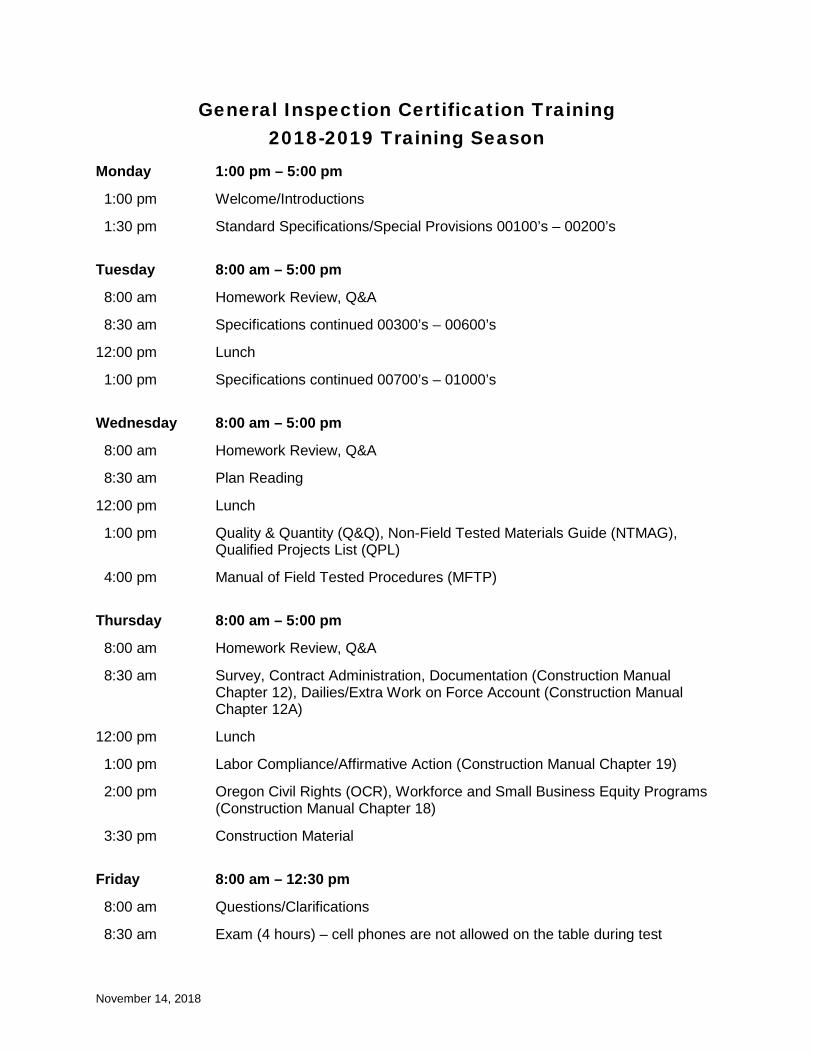
General Inspection Certification Training 2018-2019 Training Season
Monday 1:00 pm – 5:00 pm
1:00 pm Welcome/Introductions
1:30 pm Standard Specifications/Special Provisions 00100’s – 00200’s
Tuesday 8:00 am – 5:00 pm
8:00 am Homework Review, Q&A
8:30 am Specifications continued 00300’s – 00600’s
12:00 pm Lunch
1:00 pm Specifications continued 00700’s – 01000’s
Wednesday 8:00 am – 5:00 pm
8:00 am Homework Review, Q&A
8:30 am Plan Reading
12:00 pm Lunch
1:00 pm Quality & Quantity (Q&Q), Non-Field Tested Materials Guide (NTMAG), Qualified Projects List (QPL)
4:00 pm Manual of Field Tested Procedures (MFTP)
Thursday 8:00 am – 5:00 pm
8:00 am Homework Review, Q&A
8:30 am Survey, Contract Administration, Documentation (Construction Manual Chapter 12), Dailies/Extra Work on Force Account (Construction Manual Chapter 12A)
12:00 pm Lunch
1:00 pm Labor Compliance/Affirmative Action (Construction Manual Chapter 19)
2:00 pm Oregon Civil Rights (OCR), Workforce and Small Business Equity Programs (Construction Manual Chapter 18)
3:30 pm Construction Material
Friday 8:00 am – 12:30 pm
8:00 am Questions/Clarifications
8:30 am Exam (4 hours) – cell phones are not allowed on the table during test

INSERT TAB
Table of Contents
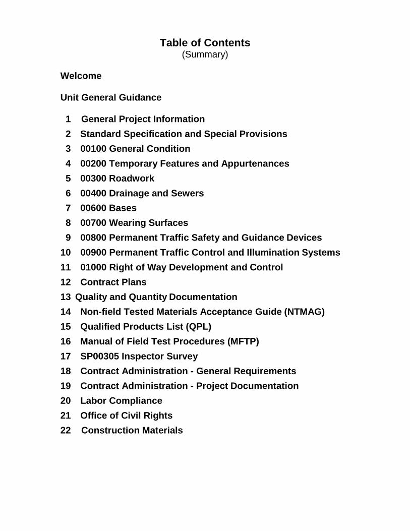
Table of Contents (Summary)
Welcome Unit General Guidance
1 General Project Information 2 Standard Specification and Special Provisions 3 00100 General Condition 4 00200 Temporary Features and Appurtenances 5 00300 Roadwork 6 00400 Drainage and Sewers 7 00600 Bases 8 00700 Wearing Surfaces 9 00800 Permanent Traffic Safety and Guidance Devices
10 00900 Permanent Traffic Control and Illumination Systems 11 01000 Right of Way Development and Control 12 Contract Plans 13 Quality and Quantity Documentation 14 Non-field Tested Materials Acceptance Guide (NTMAG) 15 Qualified Products List (QPL) 16 Manual of Field Test Procedures (MFTP) 17 SP00305 Inspector Survey 18 Contract Administration - General Requirements 19 Contract Administration - Project Documentation 20 Labor Compliance 21 Office of Civil Rights 22 Construction Materials

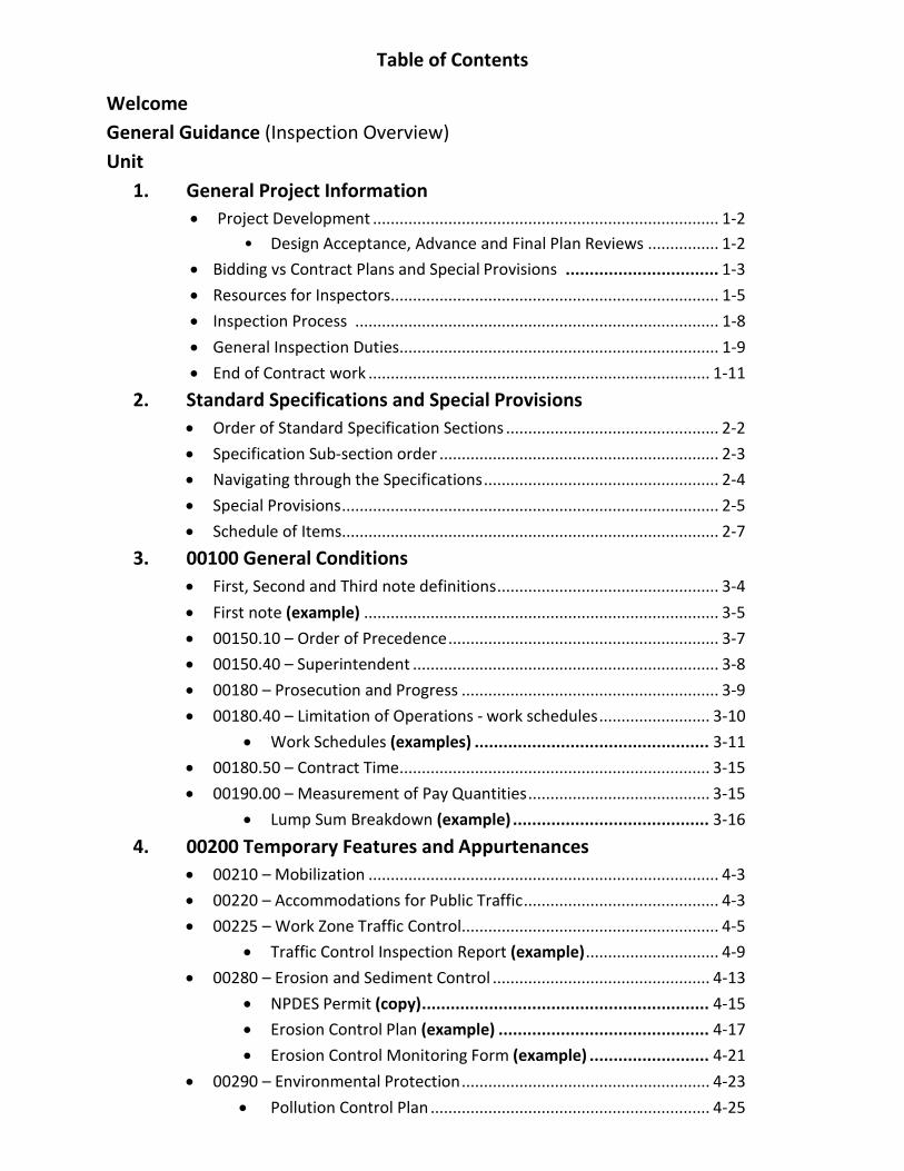
Table of Contents
Welcome General Guidance (Inspection Overview) Unit
1. General Project Information • Project Development .............................................................................. 1-2
• Design Acceptance, Advance and Final Plan Reviews ................ 1-2 • Bidding vs Contract Plans and Special Provisions ................................ 1-3 • Resources for Inspectors .......................................................................... 1-5 • Inspection Process .................................................................................. 1-8 • General Inspection Duties ........................................................................ 1-9 • End of Contract work ............................................................................. 1-11
2. Standard Specifications and Special Provisions • Order of Standard Specification Sections ................................................ 2-2 • Specification Sub-section order ............................................................... 2-3 • Navigating through the Specifications ..................................................... 2-4 • Special Provisions ..................................................................................... 2-5 • Schedule of Items ..................................................................................... 2-7
3. 00100 General Conditions • First, Second and Third note definitions .................................................. 3-4 • First note (example) ................................................................................ 3-5 • 00150.10 – Order of Precedence ............................................................. 3-7 • 00150.40 – Superintendent ..................................................................... 3-8 • 00180 – Prosecution and Progress .......................................................... 3-9 • 00180.40 – Limitation of Operations - work schedules ......................... 3-10
• Work Schedules (examples) ................................................. 3-11 • 00180.50 – Contract Time ...................................................................... 3-15 • 00190.00 – Measurement of Pay Quantities ......................................... 3-15
• Lump Sum Breakdown (example) ......................................... 3-16
4. 00200 Temporary Features and Appurtenances • 00210 – Mobilization ............................................................................... 4-3 • 00220 – Accommodations for Public Traffic ............................................ 4-3 • 00225 – Work Zone Traffic Control .......................................................... 4-5
• Traffic Control Inspection Report (example) .............................. 4-9 • 00280 – Erosion and Sediment Control ................................................. 4-13
• NPDES Permit (copy) ............................................................ 4-15 • Erosion Control Plan (example) ............................................ 4-17 • Erosion Control Monitoring Form (example) ......................... 4-21
• 00290 – Environmental Protection ........................................................ 4-23 • Pollution Control Plan ............................................................... 4-25
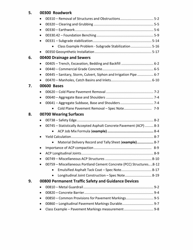
5. 00300 Roadwork • 00310 – Removal of Structures and Obstructions ................................... 5-2 • 00320 – Clearing and Grubbing ............................................................... 5-5 • 00330 – Earthwork ................................................................................... 5-6 • 00330.42 – Foundation Benching ............................................................ 5-9 • 00331 – Subgrade stabilization .............................................................. 5-14
• Class Example Problem - Subgrade Stabilization ...................... 5-16 • 00350 Geosynthetic Installation ............................................................ 5-17
6. 00400 Drainage and Sewers • 00405 – Trench, Excavation, Bedding and Backfill .................................. 6-2 • 00440 – Commercial Grade Concrete ...................................................... 6-5 • 00445 – Sanitary, Storm, Culvert, Siphon and Irrigation Pipe ................. 6-7 • 00470 – Manholes, Catch Basins and Inlets........................................... 6-10
7. 00600 Bases • 00620 – Cold Plane Pavement Removal .................................................. 7-2 • 00640 – Aggregate Base and Shoulders .................................................. 7-4 • 00641 – Aggregate Subbase, Base and Shoulders ................................... 7-4
• Cold Plane Pavement Removal – Spec Note ............................. 7-9
8. 00700 Wearing Surfaces • 00738 – Safety Edge ................................................................................. 8-2 • 00745 – Statistically Accepted Asphalt Concrete Pavement (ACP) ......... 8-3
• ACP Job Mix Formula (example) ............................................. 8-4 • Yield Calculation ....................................................................................... 8-7
• Material Delivery Record and Tally Sheet (example) ................ 8-7 • Importance of ACP compaction ............................................................. 8-9 • ACP Longitudinal Joints ............................................................................ 8-9 • 00749 – Miscellaneous ACP Structures ................................................. 8-10 • 00759 – Miscellaneous Portland Cement Concrete (PCC) Structures.. .. 8-12
• Emulsified Asphalt Tack Coat – Spec Note ................................ 8-17 • Longitudinal Joint Construction – Spec Note ............................ 8-19
9. 00800 Permanent Traffic Safety and Guidance Devices • 00810 – Metal Guardrail .......................................................................... 9-2 • 00820 – Concrete Barrier ......................................................................... 9-4 • 00850 – Common Provisions for Pavement Markings ............................. 9-5 • 00860 – Longitudinal Pavement Markings Durable ................................. 9-7 • Class Example – Pavement Markings measurement ............................... 9-8
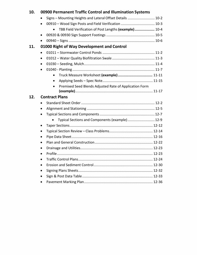
10. 00900 Permanent Traffic Control and Illumination Systems • Signs – Mounting Heights and Lateral Offset Details ............................ 10-2 • 00910 – Wood Sign Posts and Field Verification ................................... 10-3
• TBB Field Verification of Post Lengths (example) ................... 10-4 • 00920 & 00930 Sign Support Footings .................................................. 10-5 • 00940 – Signs ......................................................................................... 10-6
11. 01000 Right of Way Development and Control • 01011 – Stormwater Control Ponds ...................................................... 11-2 • 01012 – Water Quality Biofiltration Swale ............................................ 11-3 • 01030 – Seeding, Mulch ......................................................................... 11-4 • 01040 - Planting ..................................................................................... 11-7
• Truck Measure Worksheet (example) ................................. 11-11 • Applying Seeds – Spec Note .................................................... 11-15 • Premixed Seed Blends Adjusted Rate of Application Form
(example) ................................................................................ 11-17 12. Contract Plans
• Standard Sheet Order ............................................................................ 12-2 • Alignment and Stationing ...................................................................... 12-5 • Typical Sections and Components ......................................................... 12-7
• Typical Sections and Components (example) ............................ 12-9 • Taper Sections ...................................................................................... 12-12 • Typical Section Review – Class Problems ............................................. 12-14 • Pipe Data Sheet .................................................................................... 12-16 • Plan and General Construction ............................................................ 12-22 • Drainage and Utilities........................................................................... 12-23 • Profile ................................................................................................... 12-23 • Traffic Control Plans ............................................................................. 12-24 • Erosion and Sediment Control ............................................................. 12-30 • Signing Plans Sheets ............................................................................. 12-32 • Sign & Post Data Table ......................................................................... 12-33 • Pavement Marking Plan ....................................................................... 12-36
13. Quality and Quantity Documentation • Overview of Material Quality Resources ............................................... 13-2 • Quality and Quantity Checklist (example) ......................................... 13-5 • Field Inspection Report (FIR) .................................................................. 13-7
• Field Inspection Report (example) ........................................ 13-9 • Field Inspection Sticker (example) ...................................... 13-10
• 00165.35(b) – Quality Compliance Certificate ..................................... 13-11 • Quality Compliance Certificate (example) ........................... 13-12
• 00165.35 (a) – Test Result Certificate .................................................. 13-14
• Test Result Certificate (example) .................................................... 13-16
• 00160.20(a) – Buy America .................................................................. 13-15 • Equipment List and Drawings .............................................................. 13-17 • 00165.35(d) – Certificate of Material Origin (CMO) ............................ 13-19
• CMO (example) ................................................................. 13-20 • ODOT Material Reports ........................................................................ 13-21 • ODOT Materials Inspection Report (example) ................................. 13-23 • ODOT Material Lab Inspection Report ................................................. 13-24
• ODOT Material Lab Inspection Report (example) ................ 13-23 • 00170.85(b) – Warranty Requirements ............................................... 13-26 • Field Tested Material Conformance – Compaction Test Report ......... 13-27 • Paynotes “Installation Sheets”............................................................. 13-28
• Paynote (example) .................................................................. 13-29 • Flagging Tickets .................................................................................... 13-30 • Weigh Memos (Truck Tickets) ............................................................. 13-30
14. Non-field Tested Materials Acceptance Guide (NTMAG) • NTMAG Overview ............................................................................... 14-2 • Class Example Problems .................................................................... 14-4 • Class Problems ................................................................................... 14-9
15. Qualified Products List (QPL) • Qualified List and Approved List ............................................................ 15-2 • QPL Organization ................................................................................... 15-3 • Reinforcing Steel .................................................................................... 15-6 • Class Problems ....................................................................................... 15-8
16. Manual of Field Test Procedures (MFTP) • Quality Assurance Program Overview ................................................... 16-2 • Roles & Responsibilities ......................................................................... 16-4 • Small Quantity Guide ............................................................................. 16-5 • Organization and How to Use MFTP ...................................................... 16-6 • Building a Road Class (example 1) using MFTP ..................................... 16-8

17. SP 00305 Inspector Survey • Construction Surveying Manual for Contractors ....................................... 17-2 • Side Slope Ratios and Distances ................................................................. 17-2 • Reading Slope Stakes and Slope Stake Example ........................................ 17-4
18. Contract Administration – General Requirements • Types of Work – Contract, Additional, Extra, Disputed Work ................... 18-2
• Contractor’s Notice of Differing Site Conditions (example) ......... 18-5 • Contract Change Orders............................................................................. 18-3
• CCO (example) .............................................................................. 18-6 • Extra Work Orders ..................................................................................... 18-7
• Extra Work Order (example) ........................................................ 18-9 • Daily Force Account Record (example) ................................... 18-11
• Disagreements, Protests and Claims ....................................................... 18-13 • Types of Disputes ..................................................................................... 18-14
19. Contract Administration – Project Documentation • Daily Inspection Report .............................................................................. 19-2 • Public Records and Record Retention ........................................................ 19-6 • Region Assurance Specialist (RAS) ............................................................. 19-8
• Document Review Report (DRR) (example) ............................... 19-10 • Quarterly Release of Retainage ............................................................... 19-11 • Contract Payment System (CPS) .............................................................. 19-12
20. Contract Administration – Labor Compliance • Prevailing Wage Requirements .................................................................. 20-2 • Required Postings ...................................................................................... 20-3 • Prevailing Wage Complaint Form (example) .......................................... 20-5 • Employee Interview Reports (example) ................................................ 20-9
21. Office of Civil Rights – Workforce & Small Business Equity Program • Disadvantaged Business Enterprise (DBE) ................................................. 21-2 • Commercially Useful Function ................................................................... 21-4 • Daily DBE Trucking Log ............................................................................... 21-7 • Commercially Useful Function Form (CUF Form 3B) ............................... 21-12 • Equal Employment Opportunity (EEO) .................................................... 21-14 • OJT/Apprenticeship Program ................................................................... 21-16

22. Construction Materials • Moisture Density Relationship (Maximum Dry Density) ........................... 22-2 • Compaction Testing ................................................................................... 22-5 • ODOT TM-158 – Deflection Testing ........................................................... 22-6 • Specific Gravity ........................................................................................... 22-7 • Specific Gravity Example 1 and 2 ............................................................... 22-8 • Gradation of Materials ............................................................................... 22-9 • Specific Gravity Problem .......................................................................... 22-11
Dailies – Examples
PCMS Handbook
INSERT TAB
Welcome
General Construction Inspector December 2018
Introduction i-1
1
Welcome to the General Inspectors Certification Training
2018-2019 Training Season
Housekeeping Items
Restrooms
Scheduled breaks
Refreshments provided
Lunch on your own
Turn cell phone ringers off
Construction Training Hotline(503) 986-4336
2
General Construction Inspector December 2018
Introduction i-2
Training Manual
3
Resources Used during Training
2018 Standard Specifications (Student)
Calculator (Student)
General Construction Inspector Training Manual (Student)
OR 126: Cornerstone Dr. to Terry St. Section Plans and Special Provisions (Classroom)
Resource Manual (Classroom)
– Manual of Field Test Procedures (Select Sections)
– January 2018 Non-Field Tested Materials Guide
– January 2018 Qualified Products List
– Construction Manual (Select Chapters)
4
General Construction Inspector December 2018
Introduction i-3
Resources Used during Training
5
OREGONSTANDARD
SPECIFICATIONSFOR CONSTRUCTION
2018
APWA
6
General Construction Inspector December 2018
Introduction i-4
7
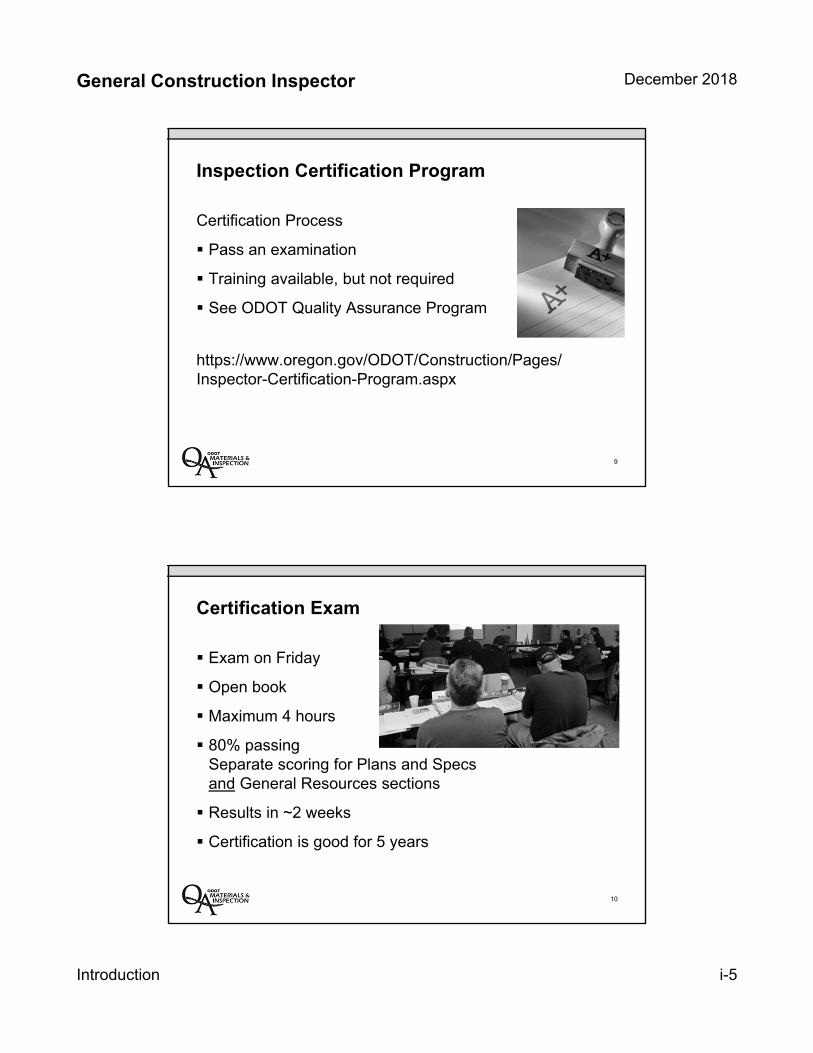
Section 4D from Manual of Field Test Procedures (MFTP)
Non-Field Tested Materials Acceptance Guide (NTMAG)
Qualified Products List (QPL)
Chapters 12, 12G, 19 from Construction Manual
Section 3
Section 4
Section 5
Sections 6, 7 & 8
Inspection Certification Program
Who is required to be certified?
All inspectors
Program makes allowances fornon-certified personnel
8
General Construction Inspector December 2018
Introduction i-5
Inspection Certification Program
Certification Process
Pass an examination
Training available, but not required
See ODOT Quality Assurance Program
https://www.oregon.gov/ODOT/Construction/Pages/Inspector-Certification-Program.aspx
9
Certification Exam
Exam on Friday
Open book
Maximum 4 hours
80% passing Separate scoring for Plans and Specs and General Resources sections
Results in ~2 weeks
Certification is good for 5 years
10

General Construction Inspector December 2018
Introduction i-6
Training Objectives
Define inspectors roles, responsibilities and authority.
Identify contract documents and resources and how to use them.
Explain project documentation requirements.
Provide an overview of key inspection elements and materials.
Provide individuals with the basic tools and knowledge to become productive and successful certified inspectors.
11
12
Ask questions!
Ask questions!
Don’t try to memorize!Don’t try to memorize!

INSERT TAB
General Guidance

General Construction Inspector General Guidance
January 2015

Oregon Department of Transportation General Construction Inspector Training 2015-2016
1
General Construction Inspector General Guidance Table of Contents Role of Construction Inspector ..................................................................................... 3
Documentation ................................................................................................................ 4
Inspector Resources ....................................................................................................... 4
Order of Precedence ..................................................................................................... 5
Specifications and Plans ................................................................................................ 6
Navigating the Specifications ........................................................................................ 7
Navigating the Plans ...................................................................................................... 8
Plan Set Organization .................................................................................................... 9
Basic Plan Reading ..................................................................................................... 10
Select Plan Components ............................................................................................. 11
Standard Drawings ....................................................................................................... 18
Summary Table ............................................................................................................. 18
Summary of General Inspection Resources ................................................................ 19
Review: Putting It All Together .................................................................................... 20
General Inspection Navigation: Where to Start ........................................................... 21
Standard Specifications Review .................................................................................. 22
Non-Field Tested Materials Guide (NTMAG) .............................................................. 23
Qualified Products List (QPL) ...................................................................................... 23

Oregon Department of Transportation General Construction Inspector Training 2015-2016
2

Oregon Department of Transportation General Construction Inspector Training 2015-2016
3
SS 00150.01 Inspector’s
Authority and Duties include
the responsibility to orally
reject defective materials…
General Guidance
Role of Construction Inspector The construction inspector has the toughest job in construction. The Inspector has the responsibility and authority to point out deviations from specifications, but has no corresponding authority to approve changes, even though they might be minor. The Inspector’s function begins and ends with seeing that construction operations produce the results called for in the plans and specifications. If an Inspector has the quality of firmness coupled with patience, and judgment inherent with a desire to be correct but practical, then they will fulfill their intended function on the construction team.
Inspectors must work constantly to achieve a high standard of excellence in the administration and quality control of construction projects. Each Inspector has the responsibility to perform in such a manner that their personal goals and the owner/designer goals are in harmony. Since an Inspector is isolated from immediate supervisory resources and guidance much of the time, they must be able and comfortable in making many individual judgments throughout the workday affecting the quality of construction. The Inspector represents the owner at the site of work and is empowered to enforce the provision of the Contract. The Inspector is authorized to reject materials and workmanship not in conformance with contract requirements.
The Inspector must be mature, confident, patient, meticulous in duties, and be a person of integrity who also possesses good judgment. There are innumerable attributes that make up a good Inspector. An unknown author once described an Inspector best by defining what they are not:
An Inspector is NOT a designer, although they must be able to read plans and speak with designers.
An Inspector is NOT a surveyor, although they must understand surveying principles.
An Inspector is NOT a superintendent, although they must know construction and good planning.
An Inspector is NOT a policeman, although they must secure compliance with the Contract.
An Inspector is NOT a lawyer, although they must understand and enforce Contract Law.
An Inspector is NOT a carpenter or other tradesman, although they must recognize qualified people.
An Inspector is NOT an accountant, although they must be able to keep detailed records.
Oregon Department of Transportation General Construction Inspector Training 2015-2016
4
The ideal Inspector must have desire, reasonableness, firmness, good judgment, knowledge, and courtesy. Their interactions with construction crews must be friendly and firm without familiarity, and must be conducted with the skill of a diplomat. The fundamental requirements for a good Inspector are:
Knowledge – It is of paramount importance that the Inspector has knowledge of the work inspected.
Common Sense – The means to synchronize knowledge and specifications; apply one to the other.
Observation – see with eyes as well as considered thought about the image observed.
Physical Tools – Measuring devices, testing equipment, notebook, pencil; and the ability to use them.
Courtesy – Valid criticism; how one says it can drastically effect how one receives it.
Documentation The importance of documentation on a construction project cannot be stressed enough. It is critical for recording quantities and quality of materials placed which allows the contractor to be paid and the Agency confirmation of quality. It is also critical to provide a history of how the project was built for future reference like for making adjustments in the contract time. In addition, it could be important for providing information for the Agency in resolving a dispute. The ODOT Construction Manual has a complete chapter on Project Records. To assist the Inspector, excerpts from the chapter are included in the General Inspection Training Manual under the documentation tab.
Inspector Resources Inspectors have many resources available to help them perform their job duties effectively. The most important construction resources are the project plans, special provisions and Oregon Standard Specifications, Volumes 1 and 2. These resources will be discussed in later sections.
Other important resources that may be referred to in the plans or specifications include:
The Manual of Field Test Procedures (Brown Book): The Brown Book applies to testing done at the jobsite like compaction and/or materials sampled at the jobsite like aggregate or concrete. The manual provides several sections including a description of the ODOT Quality Assurance Program; testing requirements and test methods for various materials used; report forms and examples; and The Field Tested Materials Acceptance Guide for Type D or E Projects Only.
Oregon Department of Transportation General Construction Inspector Training 2015-2016
5
The Field Tested Materials Acceptance Guide for Type D or E Projects section is important for inspectors to understand as it details what tests are to be performed; who is to perform them and how frequently they must be performed. While the Quality Control Compliance Specialist (QCCS) is responsible for monitoring the testing, oftentimes it is the inspector’s responsibility to notify the QCCS when testing will be needed. Also, it is important to be aware that the testing is occurring and that, where possible, test results are documented in the Inspector’s Daily Report.
The Non-Field Tested Materials Acceptance Guide: Non-field tested materials include items like sediment barrier, geotextile, steel piling and bolts. The Guide provides a table of the materials covered along with a list of the required acceptance (quality) documents. A flow chart with guidance on how to use the NFTMG is included in the NTMAG tab in the General Construction Inspection Training Manual. For more navigational tips, refer to the Review Section of this Supplement.
Qualified Products List: The "QUALIFIED PRODUCTS LIST" (QPL) is a comprehensive list of all finished products which have been evaluated and/or used by the Oregon DOT. Because there are items that are used over and over on projects, it makes sense to maintain a list of products that have been used and don’t need to be re-evaluated every time they are to be incorporated. If an item is required to be taken from the QPL, the Non-Field Tested Materials Guide will provide direction to the QPL. For more navigational tips, refer to the Review Section of this Supplement.
Construction Manual: An additional useful publication is
the Construction Manual which you may find in the office bound in an orange binder. The Manual provides background and procedural guidance for Volume 1 of the Oregon Standard Specifications. Chapter 12, Project Records is of particular interest to an inspector as it provides guidance on preparing Daily Reports/Diaries and Quality Documentation, etc.
Order of Precedence Many documents may be referenced for a project and sometimes conflicting information is included. For example, the project plans may call out for a given dimension and the special provisions have something different. To reconcile the differences, an order of
Oregon Department of Transportation General Construction Inspector Training 2015-2016
6
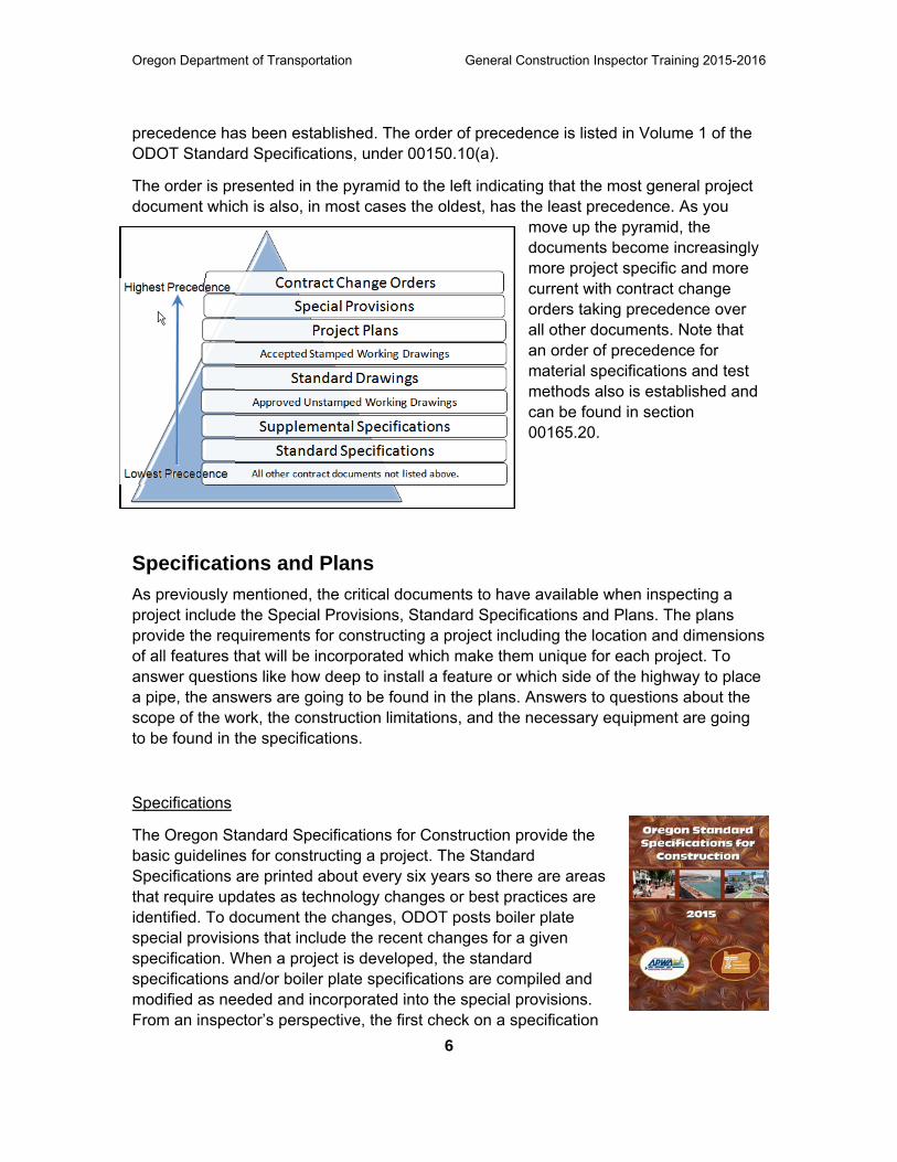
precedence has been established. The order of precedence is listed in Volume 1 of the ODOT Standard Specifications, under 00150.10(a).
The order is presented in the pyramid to the left indicating that the most general project document which is also, in most cases the oldest, has the least precedence. As you
move up the pyramid, the documents become increasingly more project specific and more current with contract change orders taking precedence over all other documents. Note that an order of precedence for material specifications and test methods also is established and can be found in section 00165.20.
Specifications and Plans As previously mentioned, the critical documents to have available when inspecting a project include the Special Provisions, Standard Specifications and Plans. The plans provide the requirements for constructing a project including the location and dimensions of all features that will be incorporated which make them unique for each project. To answer questions like how deep to install a feature or which side of the highway to place a pipe, the answers are going to be found in the plans. Answers to questions about the scope of the work, the construction limitations, and the necessary equipment are going to be found in the specifications.
Specifications
The Oregon Standard Specifications for Construction provide the basic guidelines for constructing a project. The Standard Specifications are printed about every six years so there are areas that require updates as technology changes or best practices are identified. To document the changes, ODOT posts boiler plate special provisions that include the recent changes for a given specification. When a project is developed, the standard specifications and/or boiler plate specifications are compiled and modified as needed and incorporated into the special provisions. From an inspector’s perspective, the first check on a specification

Oregon Department of Transportation General Construction Inspector Training 2015-2016
7
Searching for a Specification
Specification Organization
should be to the special provisions which may or may not refer back to the standard specifications.
Navigating the Specifications The Oregon Standard Specifications for Construction include two volumes. Volume 1 contains Part 00100 and covers the defined terms, the bidding process and contractual relationships. Essentially, it covers the rules of the contract between the Agency and the Contractor. Volume 2 contains Parts 00200 through 03000 which describe the actual details of how a design feature is going to be constructed.
Believe it or not, ODOT standard specifications and special provisions (Sections 00200 through 01999) subsections are organized in the same way. The figure to the right shows the general organization of the subsections. Each specification will have unique subsections like scope, labor, construction, etc. but the individual subsections will always be listed under X.00 for Scope; X.30 for Labor and X.40 for construction, etc. For example, if the question was, “What type of labor is required for Pipe Lining?” it could be answered by looking under 00410.30 (Pipe Lining, Personnel Qualifications). If the question was, “How is pipe lining measured?” The answer could be found by referencing 00410.80 (Pipe Lining, Measurement).
Sometimes, however, more effort is required. Navigating the specifications could be as easy as referring to the table of contents and/or index. The key to finding answers in the specifications is to not give up – and be sure to read the entire subsection. The flow chart is provided as a tool to assist in searching the specifications. For more navigational tips, refer to the Review Section of this Supplement.
Special Provisions and Schedule of Items
Oregon Department of Transportation General Construction Inspector Training 2015-2016
8
An alternate method to find a specification is to refer to the special provisions. If the question is specific to a construction project, there should be a related bid item. The special provisions include a Schedule of Items toward the end of the document, which lists all of the project bid items with a specification reference. Hence, if the bid item can be found then the specification can be found.
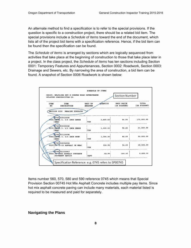
The Schedule of Items is arranged by sections which are logically sequenced from activities that take place at the beginning of construction to those that take place later in a project. In the class project, the Schedule of Items has ten sections including Section 0001: Temporary Features and Appurtenances, Section 0002: Roadwork, Section 0003: Drainage and Sewers, etc. By narrowing the area of construction, a bid item can be found. A snapshot of Section 0006 Roadwork is shown below:
Items number 560, 570, 580 and 590 reference 0745 which means that Special Provision Section 00745 Hot Mix Asphalt Concrete includes multiple pay items. Since hot mix asphalt concrete paving can include many materials, each material listed is required to be measured and paid for separately.
Navigating the Plans
Oregon Department of Transportation General Construction Inspector Training 2015-2016
9
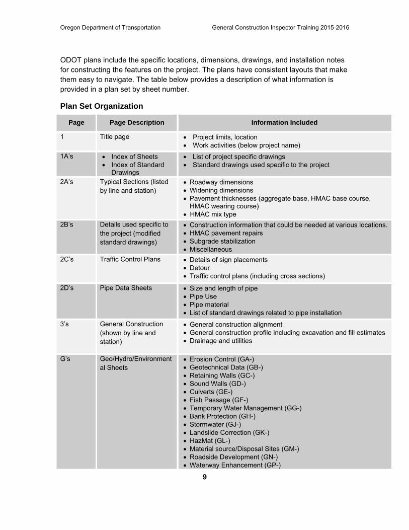
ODOT plans include the specific locations, dimensions, drawings, and installation notes for constructing the features on the project. The plans have consistent layouts that make them easy to navigate. The table below provides a description of what information is provided in a plan set by sheet number.
Plan Set Organization
Page Page Description Information Included
1 Title page Project limits, location Work activities (below project name)
1A’s Index of Sheets Index of Standard
Drawings
List of project specific drawings Standard drawings used specific to the project
2A’s Typical Sections (listed by line and station)
Roadway dimensions Widening dimensions Pavement thicknesses (aggregate base, HMAC base course,
HMAC wearing course) HMAC mix type
2B’s Details used specific to the project (modified standard drawings)
Construction information that could be needed at various locations. HMAC pavement repairs Subgrade stabilization Miscellaneous
2C’s Traffic Control Plans Details of sign placements Detour Traffic control plans (including cross sections)
2D’s Pipe Data Sheets Size and length of pipe Pipe Use Pipe material List of standard drawings related to pipe installation
3’s General Construction (shown by line and station)
General construction alignment General construction profile including excavation and fill estimates Drainage and utilities
G’s Geo/Hydro/Environmental Sheets
Erosion Control (GA-) Geotechnical Data (GB-) Retaining Walls (GC-) Sound Walls (GD-) Culverts (GE-) Fish Passage (GF-) Temporary Water Management (GG-) Bank Protection (GH-) Stormwater (GJ-) Landslide Correction (GK-) HazMat (GL-) Material source/Disposal Sites (GM-) Roadside Development (GN-) Waterway Enhancement (GP-)
Oregon Department of Transportation General Construction Inspector Training 2015-2016
10
Page Page Description Information Included
Rockfall Mitigation (GQ-)
Drawing Numbers
From Bridge See plan index (Sheet 1A) for what is included.
Drawing Numbers
From Traffic See plan index (Sheet 1A) for what is included. Most common sheets include:
Permanent Pavement Markings Permanent Signing Illumination Plans Signal Plans
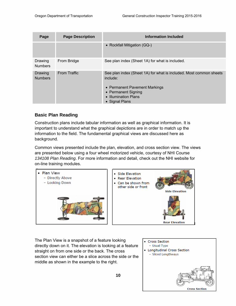
Basic Plan Reading Construction plans include tabular information as well as graphical information. It is important to understand what the graphical depictions are in order to match up the information to the field. The fundamental graphical views are discussed here as background.
Common views presented include the plan, elevation, and cross section view. The views are presented below using a four wheel motorized vehicle, courtesy of NHI Course 134108 Plan Reading. For more information and detail, check out the NHI website for on-line training modules.
The Plan View is a snapshot of a feature looking directly down on it. The elevation is looking at a feature straight on from one side or the back. The cross section view can either be a slice across the side or the middle as shown in the example to the right.
Oregon Department of Transportation General Construction Inspector Training 2015-2016
11
Image courtesy of NHI Course 134108
In the cross section view to the right, a section has been “sliced” away and the inside of the armored car is seen from the side. The inside of the car is also shown. In a drawing, dotted lines show parts not seen, such as the tires or other parts that cannot be seen.
Select Plan Components Alignment
When building a project, oftentimes more than one roadway segment includes work activities. Each roadway segment is an alignment with a unique designation. The designation may apply to an off-ramp or an adjoining street or separate alignments on divided highways. For example, for a project constructed in Lane County for the Beltline Highway, one alignment was designated BL for Belt Line while another alignment was designated EBO for East Bound Off-ramp. Information in the plan set will be tied to an alignment which can typically be found on the Title Sheet.
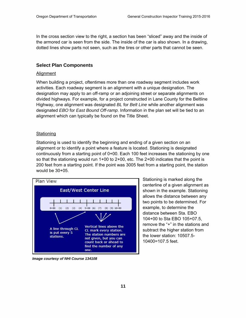
Stationing
Stationing is used to identify the beginning and ending of a given section on an alignment or to identify a point where a feature is located. Stationing is designated continuously from a starting point of 0+00. Each 100 feet increases the stationing by one so that the stationing would run 1+00 to 2+00, etc. The 2+00 indicates that the point is 200 feet from a starting point. If the point was 3005 feet from a starting point, the station would be 30+05.
Stationing is marked along the centerline of a given alignment as shown in the example. Stationing allows the distance between any two points to be determined. For example, to determine the distance between Sta. EBO 104+00 to Sta EBO 105+07.5, remove the “+” in the stations and subtract the higher station from the lower station: 10507.5-10400=107.5 feet.
Oregon Department of Transportation General Construction Inspector Training 2015-2016
12
Example of construction note with direction Rt. designated.
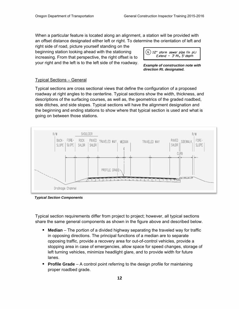
Typical Section Components
When a particular feature is located along an alignment, a station will be provided with an offset distance designated either left or right. To determine the orientation of left and right side of road, picture yourself standing on the beginning station looking ahead with the stationing increasing. From that perspective, the right offset is to your right and the left is to the left side of the roadway.
Typical Sections – General
Typical sections are cross sectional views that define the configuration of a proposed roadway at right angles to the centerline. Typical sections show the width, thickness, and descriptions of the surfacing courses, as well as, the geometrics of the graded roadbed, side ditches, and side slopes. Typical sections will have the alignment designation and the beginning and ending stations to show where that typical section is used and what is going on between those stations.
Typical section requirements differ from project to project; however, all typical sections share the same general components as shown in the figure above and described below.
Median – The portion of a divided highway separating the traveled way for traffic in opposing directions. The principal functions of a median are to separate opposing traffic, provide a recovery area for out-of-control vehicles, provide a stopping area in case of emergencies, allow space for speed changes, storage of left turning vehicles, minimize headlight glare, and to provide width for future lanes.
Profile Grade – A control point referring to the design profile for maintaining proper roadbed grade.
Oregon Department of Transportation General Construction Inspector Training 2015-2016
13
Traveled Way – The area of roadway surface designed for vehicular movement (traffic lanes) between fog lines.
Paved Shoulder – The portion of the roadway contiguous with the traveled way for emergency use recovery of out of control vehicles, accommodation of pedestrians, bicyclists, and stopped vehicles, and for lateral support of subbase rock, base rock, and surface courses.
Rock Shoulder – The shoulder created with rock drainage material used to cover the ends of the surface courses and bases, and for additional area for recovery of out of control vehicles.
Curb – Edging along a street or roadway.
Foreslope – Negative slope of drainage channel. Slope must accommodate recovery of out of control vehicles.
Backslope – Positive slope of drainage channel. Slope must accommodate recovery of out of control vehicles.
Typical Sections – ODOT
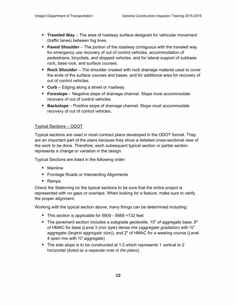
Typical sections are used in most contract plans developed in the ODOT format. They are an important part of the plans because they show a detailed cross-sectional view of the work to be done. Therefore, each subsequent typical section or partial section represents a change or variation in the design.
Typical Sections are listed in the following order:
Mainline
Frontage Roads or Intersecting Alignments
Ramps
Check the Stationing on the typical sections to be sure that the entire project is represented with no gaps or overlaps. When looking for a feature, make sure to verify the proper alignment.
Working with the typical section above, many things can be determined including:
This section is applicable for 5800 - 5668 =132 feet
The pavement section includes a subgrade geotextile, 15″ of aggregate base, 6″ of HMAC for base (Level 3 (mix type) dense mix (aggregate gradation) with ¾″ aggregate (largest aggregate size)), and 2″ of HMAC for a wearing course (Level 4 open mix with ¾″ aggregate)
The side slope is to be constructed at 1:2 which represents 1 vertical to 2 horizontal (listed as a separate note in the plans).
Oregon Department of Transportation General Construction Inspector Training 2015-2016
14
ODOT Typical Section
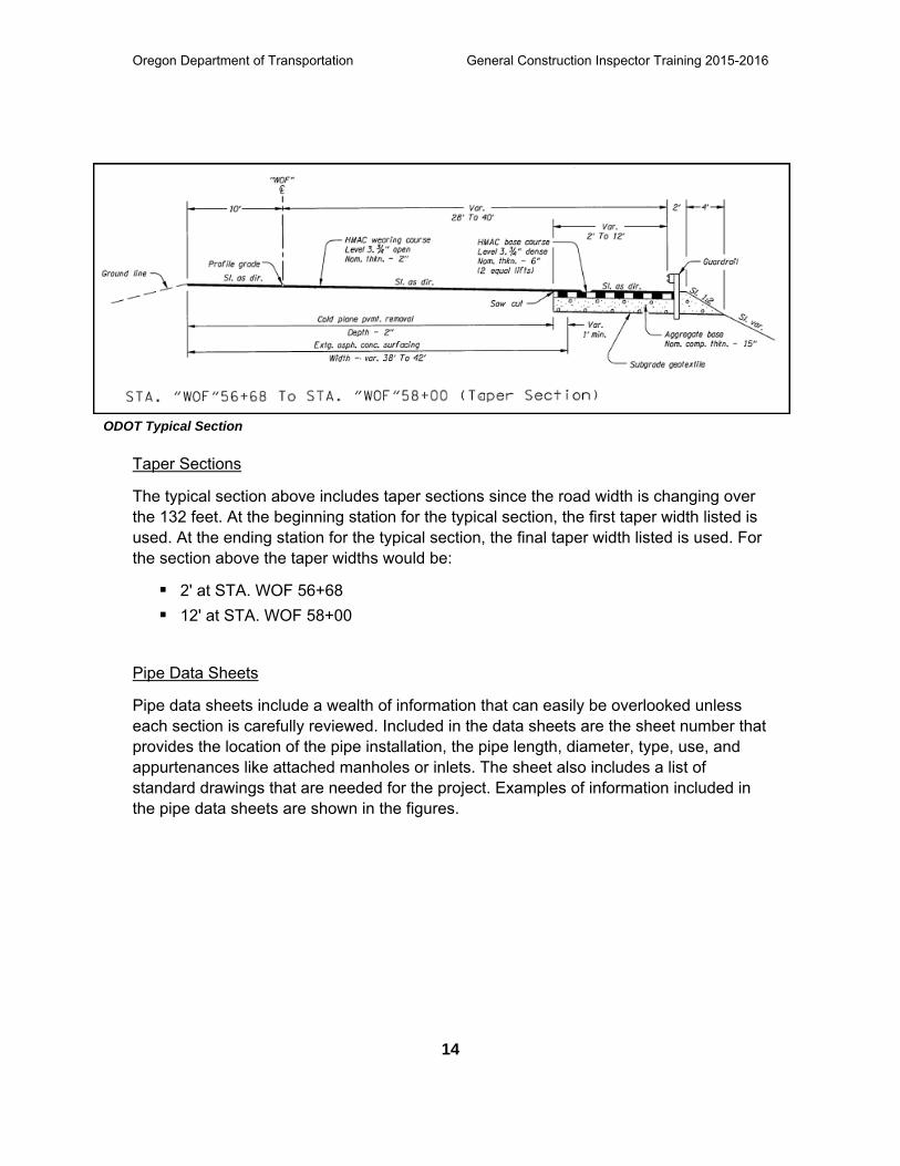
Taper Sections
The typical section above includes taper sections since the road width is changing over the 132 feet. At the beginning station for the typical section, the first taper width listed is used. At the ending station for the typical section, the final taper width listed is used. For the section above the taper widths would be:
2' at STA. WOF 56+68
12' at STA. WOF 58+00
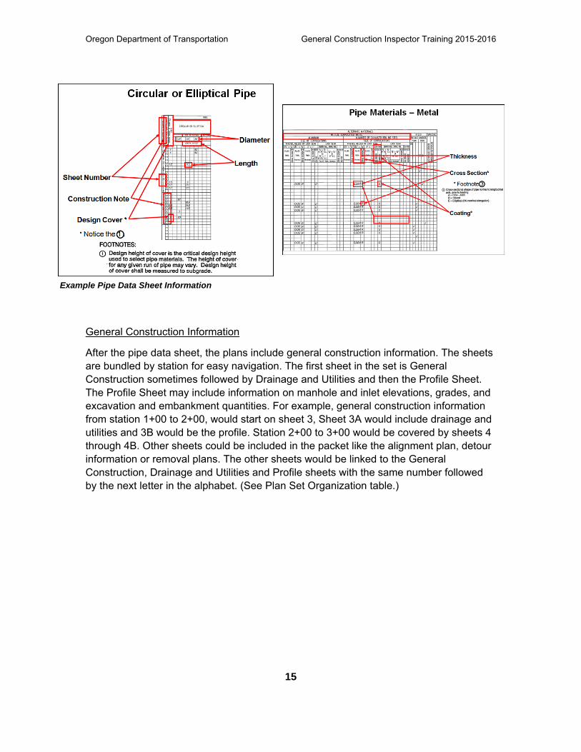
Pipe Data Sheets
Pipe data sheets include a wealth of information that can easily be overlooked unless each section is carefully reviewed. Included in the data sheets are the sheet number that provides the location of the pipe installation, the pipe length, diameter, type, use, and appurtenances like attached manholes or inlets. The sheet also includes a list of standard drawings that are needed for the project. Examples of information included in the pipe data sheets are shown in the figures.
Oregon Department of Transportation General Construction Inspector Training 2015-2016
15
Example Pipe Data Sheet Information
General Construction Information
After the pipe data sheet, the plans include general construction information. The sheets are bundled by station for easy navigation. The first sheet in the set is General Construction sometimes followed by Drainage and Utilities and then the Profile Sheet. The Profile Sheet may include information on manhole and inlet elevations, grades, and excavation and embankment quantities. For example, general construction information from station 1+00 to 2+00, would start on sheet 3, Sheet 3A would include drainage and utilities and 3B would be the profile. Station 2+00 to 3+00 would be covered by sheets 4 through 4B. Other sheets could be included in the packet like the alignment plan, detour information or removal plans. The other sheets would be linked to the General Construction, Drainage and Utilities and Profile sheets with the same number followed by the next letter in the alphabet. (See Plan Set Organization table.)
Oregon Department of Transportation General Construction Inspector Training 2015-2016
16
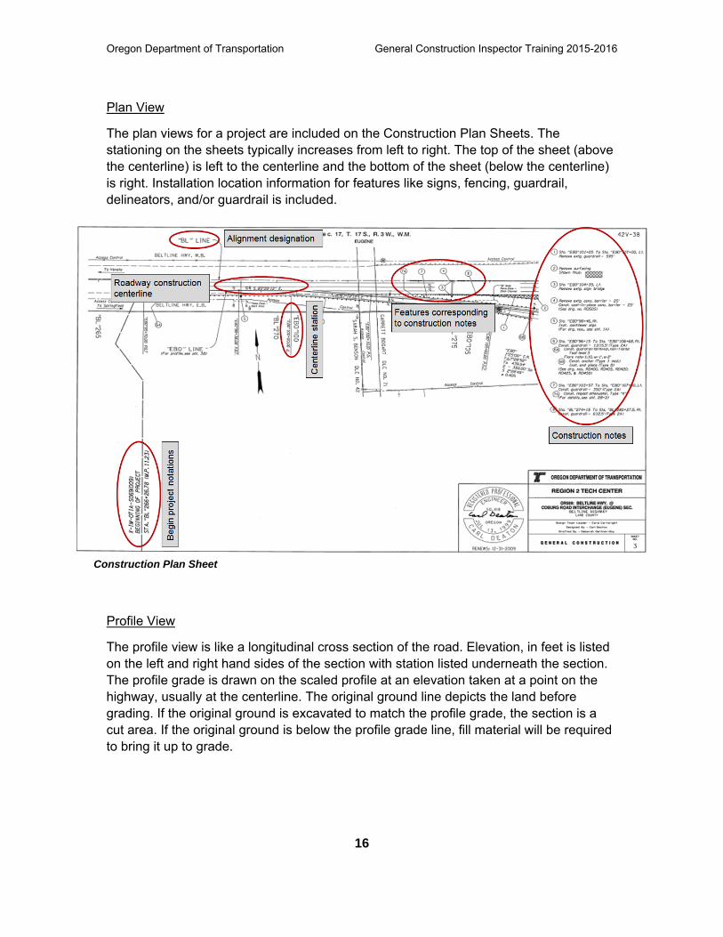
Construction Plan Sheet
Plan View
The plan views for a project are included on the Construction Plan Sheets. The stationing on the sheets typically increases from left to right. The top of the sheet (above the centerline) is left to the centerline and the bottom of the sheet (below the centerline) is right. Installation location information for features like signs, fencing, guardrail, delineators, and/or guardrail is included.
Profile View
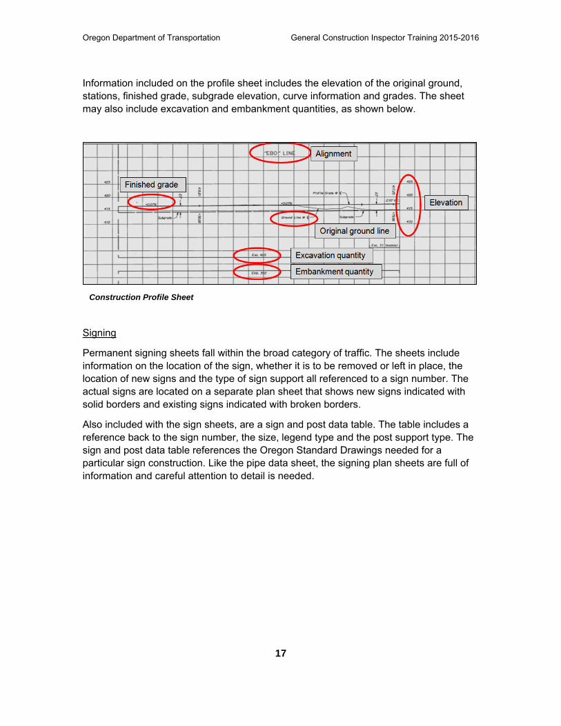
The profile view is like a longitudinal cross section of the road. Elevation, in feet is listed on the left and right hand sides of the section with station listed underneath the section. The profile grade is drawn on the scaled profile at an elevation taken at a point on the highway, usually at the centerline. The original ground line depicts the land before grading. If the original ground is excavated to match the profile grade, the section is a cut area. If the original ground is below the profile grade line, fill material will be required to bring it up to grade.
Oregon Department of Transportation General Construction Inspector Training 2015-2016
17
Information included on the profile sheet includes the elevation of the original ground, stations, finished grade, subgrade elevation, curve information and grades. The sheet may also include excavation and embankment quantities, as shown below.
Signing
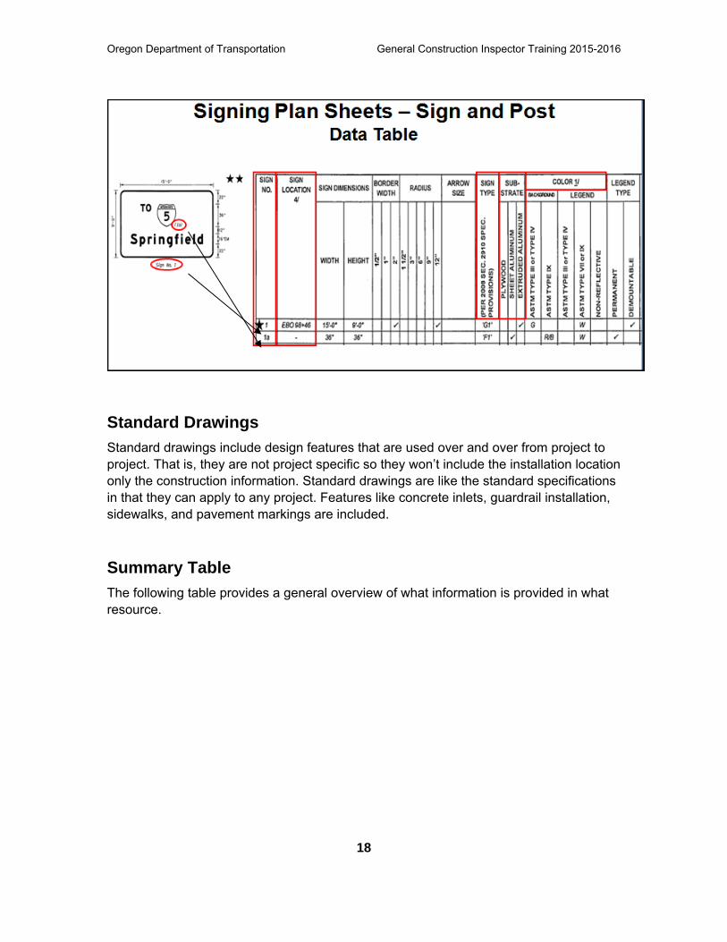
Permanent signing sheets fall within the broad category of traffic. The sheets include information on the location of the sign, whether it is to be removed or left in place, the location of new signs and the type of sign support all referenced to a sign number. The actual signs are located on a separate plan sheet that shows new signs indicated with solid borders and existing signs indicated with broken borders.
Also included with the sign sheets, are a sign and post data table. The table includes a reference back to the sign number, the size, legend type and the post support type. The sign and post data table references the Oregon Standard Drawings needed for a particular sign construction. Like the pipe data sheet, the signing plan sheets are full of information and careful attention to detail is needed.
Construction Profile Sheet
Oregon Department of Transportation General Construction Inspector Training 2015-2016
18
Standard Drawings Standard drawings include design features that are used over and over from project to project. That is, they are not project specific so they won’t include the installation location only the construction information. Standard drawings are like the standard specifications in that they can apply to any project. Features like concrete inlets, guardrail installation, sidewalks, and pavement markings are included.
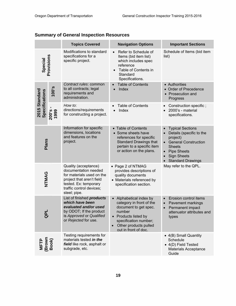
Summary Table The following table provides a general overview of what information is provided in what resource.
Oregon Department of Transportation General Construction Inspector Training 2015-2016
19
Summary of General Inspection Resources
Topics Covered Navigation Options Important Sections Sp
ecia
l Pr
ovis
ions
Modifications to standard specifications for a specific project.
Refer to Schedule of Items (bid item list) which includes spec reference
Table of Contents in Standard Specifications.
Schedule of Items (bid item list)
201
5 St
anda
rd
Spec
ifica
tions
100
’s Contract rules: common
to all contracts; legal requirements and administration.
Table of Contents Index
Authorities Order of Precedence Prosecution and
Progress
200
’s -
1999
How to: directions/requirements for constructing a project.
Table of Contents Index
Construction specific ; 2000’s - material
specifications.
Plan
s
Information for specific dimensions, locations and features on the project.
Table of Contents Some sheets have
references for specific Standard Drawings that pertain to a specific item or action on the plans.
Typical Sections Details (specific to the
project) General Construction
Sheets Pipe Sheets Sign Sheets Standard Drawings
NTM
AG
Quality (acceptance) documentation needed for materials used on the project that aren’t field tested. Ex: temporary traffic control devices; steel; pipe.
Page 2 of NTMAG provides descriptions of quality documents
Materials referenced by specification section.
May refer to the QPL.
QPL
List of finished products which have been evaluated and/or used by ODOT; If the product is Approved or Qualified or Rejected for use.
Alphabetical index by category in front of the document to get spec. number
Products listed by specification number;
Other products pulled out in front of doc.
Erosion control items Pavement markings Permanent impact
attenuator attributes and types
MFT
P (B
row
n B
ook)
Testing requirements for materials tested in the field like rock, asphalt or subgrade, etc.
4(B) Small Quantity Schedule
4(D) Field Tested Materials Acceptance Guide

Oregon Department of Transportation General Construction Inspector Training 2015-2016
20
Review: Putting It All Together By now all of the resources available for inspection should be familiar. This section includes a quick review of navigating the materials available to you.
Can you list the information provided in each resource?
Oregon Department of Transportation General Construction Inspector Training 2015-2016
21
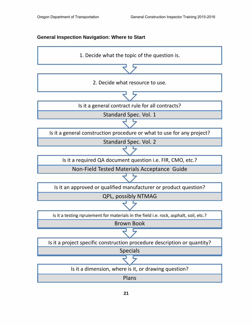
General Inspection Navigation: Where to Start
Is it a dimension, where is it, or drawing question?
Plans
Is it a project specific construction procedure description or quantity?
Specials
Is it a testing rqruiement for materials in the field i.e. rock, asphalt, soil, etc.?
Brown Book
Is it an approved or qualified manufacturer or product question?
QPL, possibly NTMAG
Is it a required QA document question i.e. FIR, CMO, etc.?
Non‐Field Tested Materials Acceptance Guide
Is it a general construction procedure or what to use for any project?
Standard Spec. Vol. 2
Is it a general contract rule for all contracts?
Standard Spec. Vol. 1
2. Decide what resource to use.
1. Decide what the topic of the question is.
Oregon Department of Transportation General Construction Inspector Training 2015-2016
22
Standard Specifications Review Standard Specifications Vol. 1 and Vol. 2 include Contract Rules and General Construction Procedures or Materials common to all contracts. There are two methods for navigating the Standard Specifications: Table of Contents and Index Method. Either method will get you to where you need to go. The Table of Contents method will take longer if you don’t know where to start. The Index method is quicker if you know what the topic of question is. The methods are summarized below.
Table of Contents
a. Each general section is broken down to specific sections in the Table of Contents
b. To use this method, decide what the topic of the question is and what the general section of the topic deals with.
c. Once you find the General Section look down the list of Specific Sections to see which specific section your topic pertains to and go to that specific section.
d. Once you are in a Specific Section then decide which Subsection you are dealing with.
Table of Contents Example:
What are the requirements for removal and salvaging guardrail?
o This is a general construction procedure.
o Topic is removing and salvaging guardrail.
o General section would be Permanent Traffic Safety and Guidance Devices -800
o Part 800 starts on page toc-29. The Specific Section would be 810 – Metal Guardrail.
o Look down the subsection list and find Salvaged Materials – page 533.
Index
To use this method, decide what the topic of the question is, then look in the index for that specific topic.
Index Example:
What are the requirements for removal and salvaging guardrail?
o This is a general construction procedure.
Oregon Department of Transportation General Construction Inspector Training 2015-2016
23
o Topic is removing and salvaging guardrail.
o Look in the Index for this topic.
o Index – page 17 has Removal – guardrail page 73, but it has Remove and Salvage Guardrail page 533.
o The second one fits our topic better, so start there.
Non-Field Tested Materials Guide (NTMAG) This Resource will show all of the required Quality Acceptance Documentation needed, if any, for a given material. This document will also reference the QPL if the product needs to be off of the QPL list.
Definitions of each Quality Acceptance Document on the first page of NTMAG.
Set up in Standard Specification order. Starting with 00225 and working up.
Navigating the Non-Field Tested Materials Guide Acceptance includes:
Decide what topic of question is.
Look in Standard Specifications for the Specification number for that topic.
Look in NTMAG for that specification number topic.
Read what Quality Acceptance Document is required, if any, and who needs to submit them.
Qualified Products List (QPL) This resource is a list of manufacturers and products that have been evaluated by ODOT that is either on an approved/qualified list or a rejected list.
Navigating the QPL includes:
Decide what topic of question is.
Look in Standard Specifications for the Specification number for that topic.
Look in Project Special Provisions for any change to the Standard Specifications or Special Directions.
Look in NTMAG for that specification number topic and find out what quality documentation needs to go with that material if any.
Look in QPL under that specification number to find the specific product or manufacturer.


INSERT TAB
Unit 1
General Project Info
General Construction Inspector December 2018
General Project Information 1-1
Unit 1General Project
Information
General Construction Inspector December 2018
General Project Information 1-2
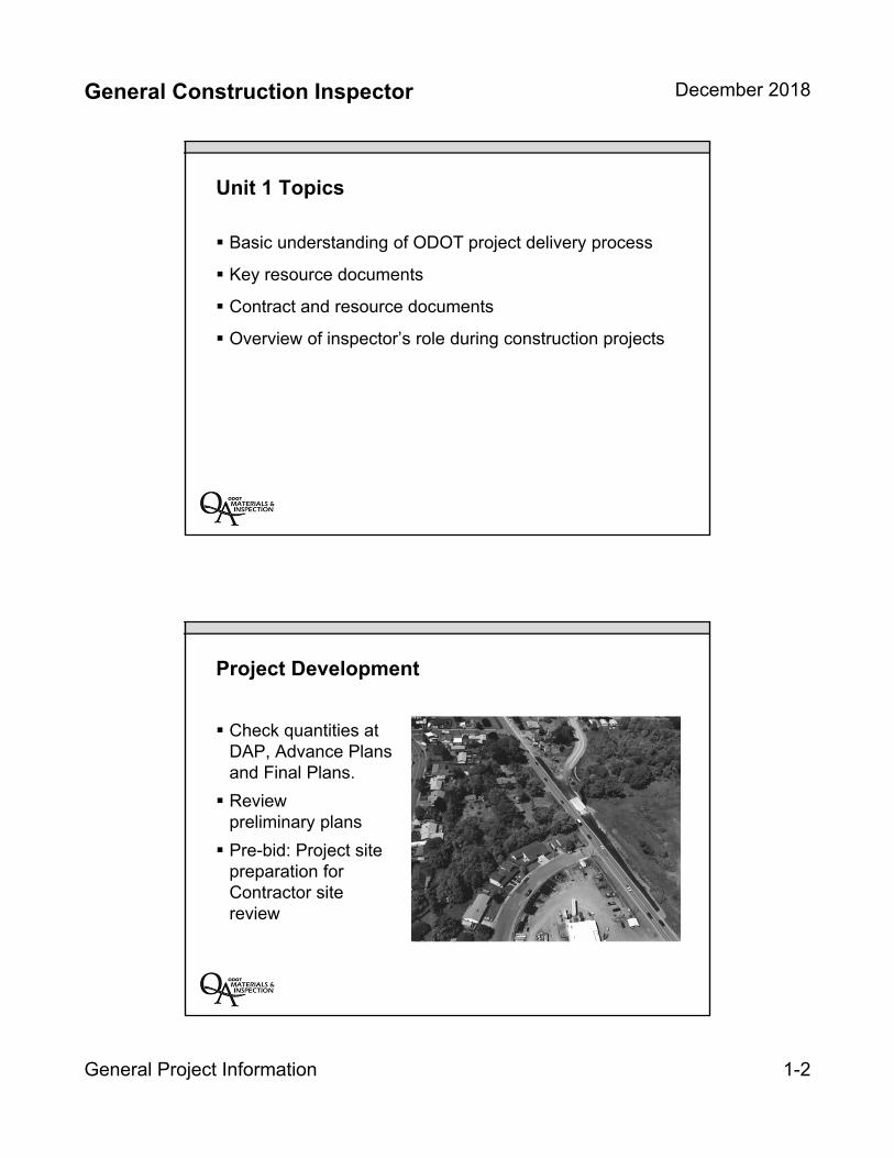
Unit 1 Topics
Basic understanding of ODOT project delivery process
Key resource documents
Contract and resource documents
Overview of inspector’s role during construction projects
Project Development
Check quantities at DAP, Advance Plans and Final Plans.
Reviewpreliminary plans
Pre-bid: Project site preparation for Contractor site review
General Construction Inspector December 2018
General Project Information 1-3
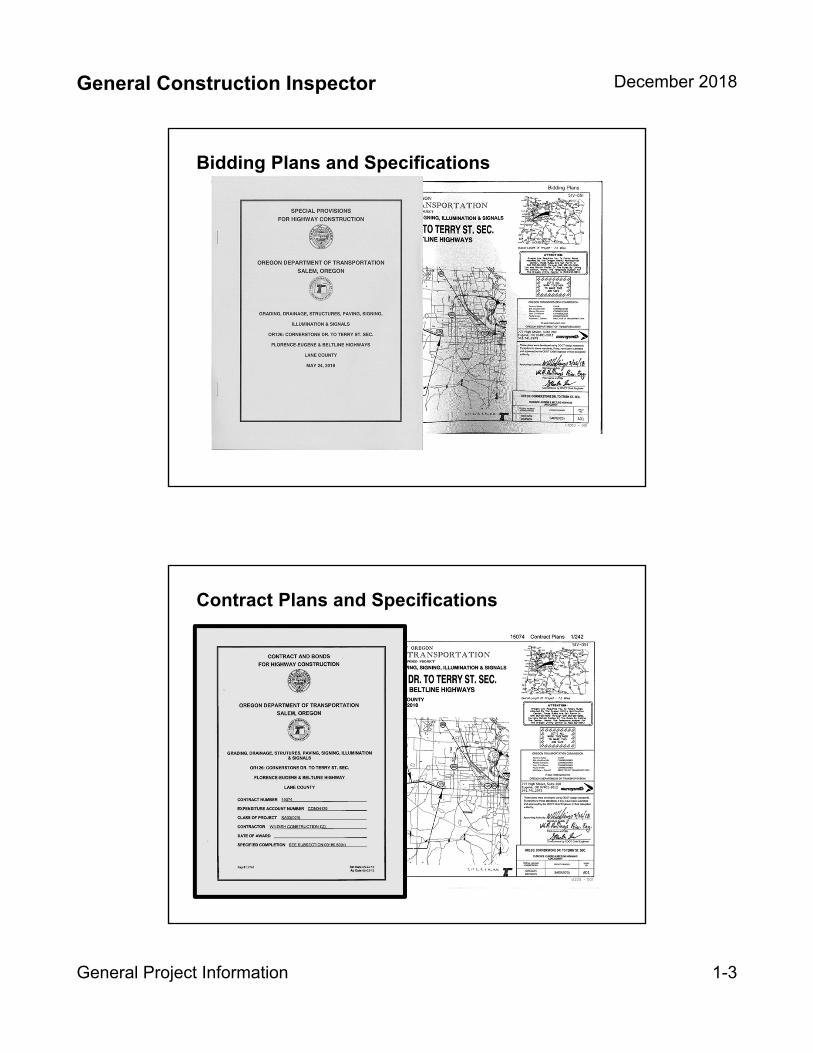
Bidding Plans and Specifications
Contract Plans and Specifications
General Construction Inspector December 2018
General Project Information 1-4
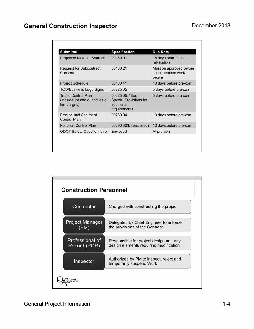
Submittal Specification Due Date
Proposed Material Sources 00160.01 15 days prior to use or fabrication
Request for Subcontract Consent
00180.21 Must be approved before subcontracted work begins
Project Schedule 00180.41 10 days before pre-con
TOD/Business Logo Signs 00225.05 5 days before pre-con
Traffic Control Plan(Include list and quantities of temp signs)
00225.05, *See Special Provisions for additional requirements
5 days before pre-con
Erosion and Sediment Control Plan
00280.04 10 days before pre-con
Pollution Control Plan 00290.30(b)(enclosed) 10 days before pre-con
ODOT Safety Questionnaire Enclosed At pre-con
Construction Personnel
Charged with constructing the projectContractor
Delegated by Chief Engineer to enforce the provisions of the Contract
Project Manager (PM)
Responsible for project design and any design elements requiring modification
Professional of Record (POR)
Authorized by PM to inspect, reject and temporarily suspend WorkInspector

General Construction Inspector December 2018
General Project Information 1-5
Resources for Inspectors
Daily Resources
Complete set of ContractPlans
Standard Specifications
Special Provisions (brown specials should include all addendums)
Approved Submittals
Inspection Forms
Additional Resources
Qualified Product List
ODOT Non-Field Tested Materials Guide
Applicable Inspectors Checklists
ODOT Manual of Field Test Procedures (QCCS’s)
ODOT Construction Manual (used by PM’s for uniformity in administering projects)
Oregon Standard Specifications
for Construction
OREGONSTANDARD
SPECIFICATIONSFOR CONSTRUCTION
2018
APWA
General Construction Inspector December 2018
General Project Information 1-6
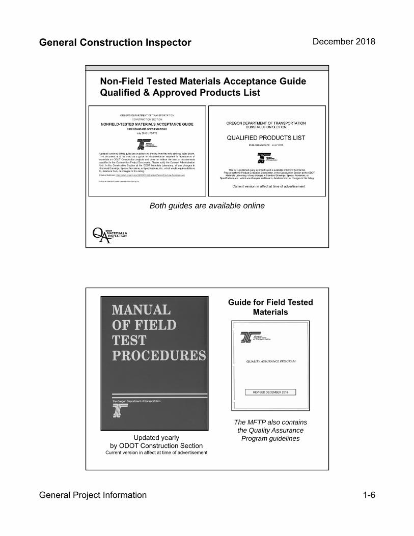
Both guides are available online
Non-Field Tested Materials Acceptance Guide Qualified & Approved Products List
Current version in affect at time of advertisement
Guide for Field Tested Materials
The MFTP also contains the Quality Assurance
Program guidelinesUpdated yearly by ODOT Construction Section
Current version in affect at time of advertisement
REVISED DECEMBER 2018
General Construction Inspector December 2018
General Project Information 1-7
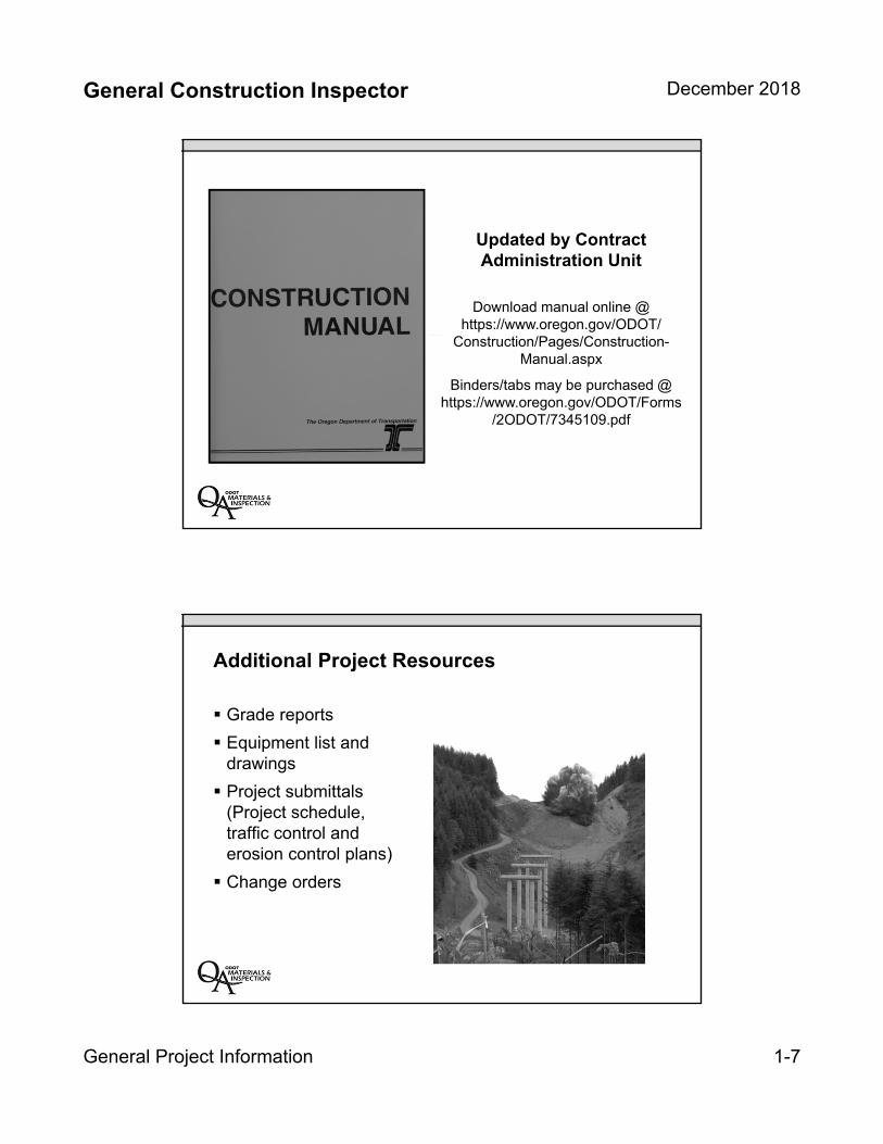
Download manual online @ https://www.oregon.gov/ODOT/
Construction/Pages/Construction-Manual.aspx
Binders/tabs may be purchased @https://www.oregon.gov/ODOT/Forms
/2ODOT/7345109.pdf
Updated by Contract Administration Unit
Additional Project Resources
Grade reports
Equipment list and drawings
Project submittals (Project schedule, traffic control and erosion control plans)
Change orders

General Construction Inspector December 2018
General Project Information 1-8
Before Construction Begins
Review Plans andSpecial Provisions
Document existingsite conditions
Verify survey control
Review qualitydocument requirement(Q&Q)
Inspection Process(During Construction)
Daily meeting withsuperintendent
Thorough earlyinspections
Notify superintendent ofany problems or issuesas early as possible

General Inspector Duties
Review construction activity
Review contractor three week look ahead schedule
o Document discrepancies or unanticipated changes
o Review plans and specifications for impeding work
Meet at the beginning of construction shift with project superintendent
o Discuss daily construction activity
o Present potential issues
Attend weekly construction meeting (if applicable)
Review traffic control
Check effectiveness of traffic control plan
Check acceptability of traffic control devices
Verify flaggers and Traffic Control Supervisors are properly certified
Monitor flagged traffic queues
Receive and review Traffic Control Inspection Reports (if applicable)
Review Erosion Control
Check effectiveness of erosion control plan
Check functionality of erosion control devices
Monitor waterways (if applicable)
Monitor construction equipment and site conditions for possible pollution
Receive and review weekly Erosion and Sediment Control Monitoring reports
Ensure quality of materials and workmanship on project
Review plans and specifications
Actively inspect material and workmanship for contract compliance
o Verify quality documentation of materials
o Verify delivered material is same as covered by quality documents
o Fill out Field Inspection Report for delivered/installed materials
Monitor quality control testing and frequency
o Verify testing technicians are properly certified
o Witness deflection testing
o Periodically observe all other quality control testing
Monitor Portland Cement Concrete (PCC) and Asphalt Cement Pavement (ACP) placements for
contract compliance
1-9
Measure quantity of materials and workmanship on project
Fill out Flagging Ticket for manned flagging station hours
Take notes of field measurement of materials placed
o Use basic geometry and simple equations
o Identify location and date of location of placement to incorporate into paynotes
Collect all weigh memos and document time and location of delivery
o Verify random check weighing are in compliance with specifications
o Verify contractor is determine empty haul weights of vehicles at least twice per day
o Total daily material totals to submit for payment
Create Installation sheets “Paynotes” for work performed
Use previously prepared notes to specifically identify location and dates of installation along
with field measurements
Construction Documentation
Photograph construction activity
Photograph delivered material
Document construction progress
Fill out Daily General Inspection Report
Labor and Civil Rights Compliance (Periodic Responsibilities)
Conduct employee interviews
Monitor Disadvantage Business Entrepreneur (DBE) subcontractors
o Fill out Commercial Useful Function (CUF) Reports
o Randomly verify DBE trucking subcontractors
Monitor OJT trainees activities (if applicable)
1-10
General Construction Inspector December 2018
General Project Information 1-11
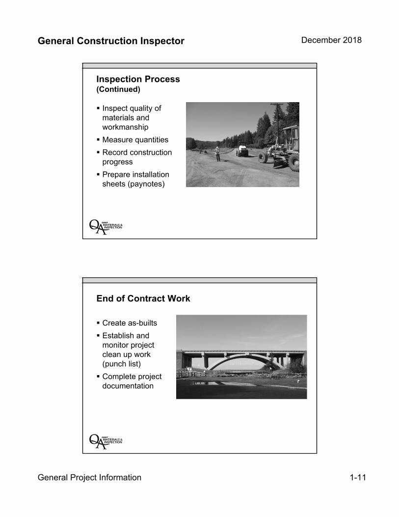
Inspection Process (Continued)
Inspect quality ofmaterials andworkmanship
Measure quantities
Record constructionprogress
Prepare installationsheets (paynotes)
End of Contract Work
Create as-builts
Establish andmonitor projectclean up work(punch list)
Complete projectdocumentation
General Construction Inspector December 2018
General Project Information 1-12
Unit 1 Review
Overview of inspector’s role during construction projects
Basic understanding of ODOT project delivery process
Key resource documents
Differentiated between Contract and resource documents

INSERT TAB
Unit 2
Standard Specs/Specials
General Construction Inspector December 2018
Standard Specifications 2-1
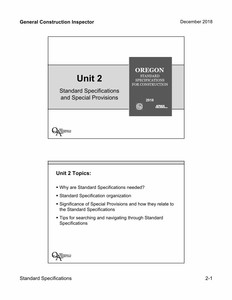
Unit 2Standard Specifications and Special Provisions
Unit 2 Topics:
Why are Standard Specifications needed?
Standard Specification organization
Significance of Special Provisions and how they relate to the Standard Specifications
Tips for searching and navigating through Standard Specifications
General Construction Inspector December 2018
Standard Specifications 2-2
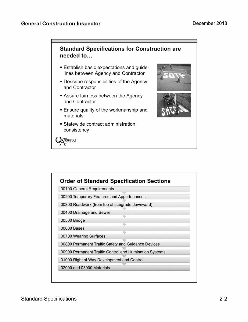
Standard Specifications for Construction are needed to…
Establish basic expectations and guide-lines between Agency and Contractor
Describe responsibilities of the Agency and Contractor
Assure fairness between the Agency and Contractor
Ensure quality of the workmanship and materials
Statewide contract administration consistency
Order of Standard Specification Sections
02000 and 03000 Materials
01000 Right of Way Development and Control
00900 Permanent Traffic Control and Illumination Systems
00800 Permanent Traffic Safety and Guidance Devices
00700 Wearing Surfaces
00600 Bases
00500 Bridge
00400 Drainage and Sewer
00300 Roadwork (from top of subgrade downward)
00200 Temporary Features and Appurtenances
00100 General Requirements

General Construction Inspector December 2018
Standard Specifications 2-3
The Technical Resource List
The Technical Resource List for the 2018 Standard Specifications is at the following website:
https://www.oregon.gov/ODOT/Business/Documents/technical_resource_list.pdf
Specification Sections: 00200 through 01999
Most subsections structured this way.
General Construction Inspector December 2018
Standard Specifications 2-4
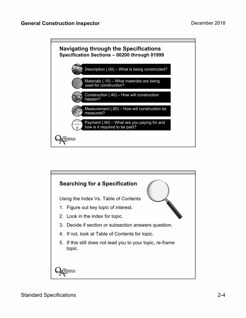
Navigating through the SpecificationsSpecification Sections – 00200 through 01999
Description (.00) – What is being constructed?
Materials (.10) – What materials are being used for construction?
Construction (.40) – How will construction happen?
Measurement (.80) – How will construction be measured?
Payment (.90) – What are you paying for and how is it required to be paid?
Searching for a Specification
Using the Index Vs. Table of Contents
1. Figure out key topic of interest.
2. Look in the index for topic.
3. Decide if section or subsection answers question.
4. If not, look at Table of Contents for topic.
5. If this still does not lead you to your topic, re-frame topic.
General Construction Inspector December 2018
Standard Specifications 2-5
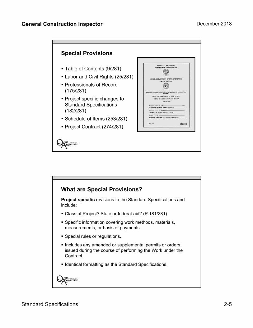
Special Provisions
Table of Contents (9/281)
Labor and Civil Rights (25/281)
Professionals of Record (175/281)
Project specific changes to Standard Specifications (182/281)
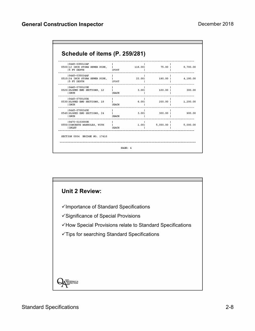
Schedule of Items (253/281)
Project Contract (274/281)
What are Special Provisions?
Project specific revisions to the Standard Specifications and include:
Class of Project? State or federal-aid? (P.181/281)
Specific information covering work methods, materials, measurements, or basis of payments.
Special rules or regulations.
Includes any amended or supplemental permits or orders issued during the course of performing the Work under the Contract.
Identical formatting as the Standard Specifications.
General Construction Inspector December 2018
Standard Specifications 2-6
Why do we have Special Provisions?
Change a Standard Specification for a Specific Project.
Add or remove sections or subsections from Standard Specifications for a Specific Project.
Specify estimated quantities for bidding purposes.
Provide boiler plate provisions
Other items included:
– Wage determinations
– Survey requirements
– Bid Item schedules
How do Special Provisions relate to Standard Specifications?
Changes only the referenced specific Standard Section.
Changes only the referenced specific Standard Subsection.
When a discrepancy is caused by a special provision section, the special provision always takes precedence over the standard specification.
General Construction Inspector December 2018
Standard Specifications 2-7
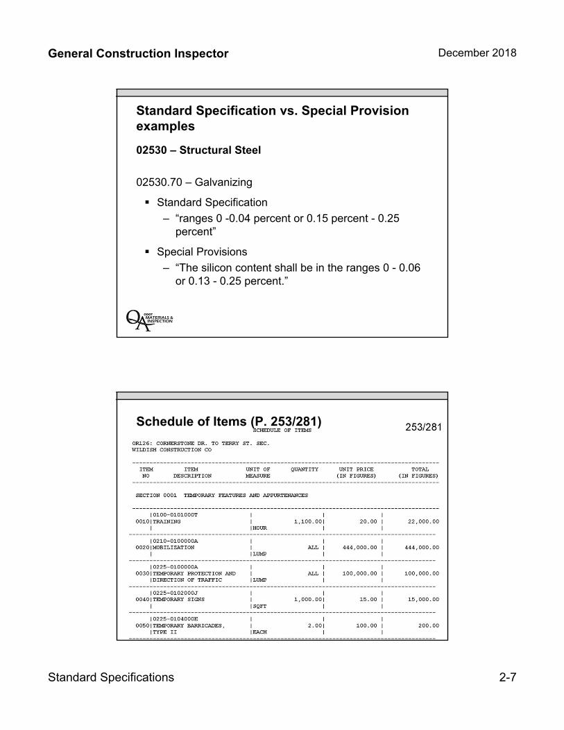
Standard Specification vs. Special Provision examples
02530 – Structural Steel
02530.70 – Galvanizing
Standard Specification
– “ranges 0 -0.04 percent or 0.15 percent - 0.25 percent”
Special Provisions
– “The silicon content shall be in the ranges 0 - 0.06 or 0.13 - 0.25 percent.”
Schedule of Items (P. 253/281)
General Construction Inspector December 2018
Standard Specifications 2-8
Schedule of items (P. 259/281)
Unit 2 Review:
Importance of Standard Specifications
Significance of Special Provisions
How Special Provisions relate to Standard Specifications
Tips for searching Standard Specifications
INSERT TAB
Unit 3
00100 – General Conditions
General Construction Inspector December 2018
00100 – General Conditions 3-1
Unit 300100
General Conditions
General Construction Inspector December 2018
00100 – General Conditions 3-2
Unit 3 Topics:
Basic ODOT construction terminology
Inspector project authority and legal requirements
Order of document precedence
General quality of materials and workmanshiprequirements
Basics for measurement of quantity
00100 – General Conditions
General Contract Conditions (Agency and Contractor)
Legalities
Responsibilities
Documentation requirements
Disagreements and claims
General Construction Inspector December 2018
00100 – General Conditions 3-3
00100 – General Conditions
Organization (110)
Scope of Work (140)
Control of Work (150)
Source of Material (160)
Quality of Material (165)
Prosecution and Progress (180)
Measurement of Pay Quantity (190)
Conventions
Grammar
Capitalization ofterms
Abbreviations
General Construction Inspector December 2018
00100 – General Conditions 3-4
Definitions
First notification
Second notification
Third notification
00140 – Purpose of Contract
Typical sections
Agency-requiredchanges in the work
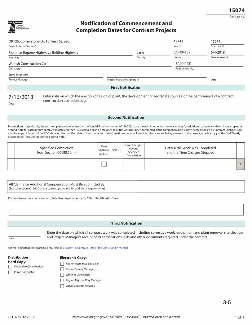
http://www.oregon.gov/ODOT/HWY/CONSTRUCTION/HwyConstForms1.shtml734-3233 (12-2013) 1 of 1
Contract No.
15074
Notification of Commencement and Completion Dates for Contract Projects
Project Name (Section)
OR126: Cornerstone Dr. To Terry St. Sec.Key No.
19743Contract No.
15074
Highway
Florence-Eugene Highway / Beltline HighwayCounty
LaneEA No.
CON04139Date of Award
6/4/2018
Contractor
Wildish Construction CoFederal Aid No.
SA00(023)
Project Manager
Steve Schultz PE
Project Manager Signature Date
First Notification
Date
7/16/2018 Enter date on which the erection of a sign or plant, the development of aggregate sources, or the performance of a contract construction operation began.
Second Notification
Instructions: If applicable, list each completion date as listed in the Special Provisions under 00180.50(h). Use the Add Another button to add lines for additional completion dates. Issue a separate Second Note for each interim completion date and then issue a final Second Note once all of the work has been completed. If the completion date(s) have been modified by Contract Change Order, attach a copy of Page 1 of the CCO showing the modified date. If the completion date(s) are time counts or liquidated damages are being assessed to the project, attach a copy of the final Weekly Statement of Time Charges to the Second Note.
Specified Completion from Section 00180.50(h)
Date Changed by CCO
CCO No.
Days Charged Beyond
Specified Completion
Date(s) the Work Was Completed and the Time Charges Stopped
X
All Claims for Additional Compensation Must Be Submitted By: (See subsection 00199.30 of the contract provisions for additional requirements)
Known items necessary to complete the requirements for "Third Notification" are:
Third Notification
Date
Enter the date on which all contract work was completed including corrective work, equipment and plant removal, site cleanup, and Project Manager's receipt of all certifications, bills and other documents required under the contract.
For more information regarding time, refer to Chapter 13, Contract Time of the Construction Manual.
Distribution Hard Copy:
Original to Construction
Prime Contractor
Region Assurance Specialist
Region Survey Manager
Office of Civil Rights
Region Right of Way Manager
ODOT Contract Services
Electronic Copy:
3-5

3-6
General Construction Inspector December 2018
00100 – General Conditions 3-7
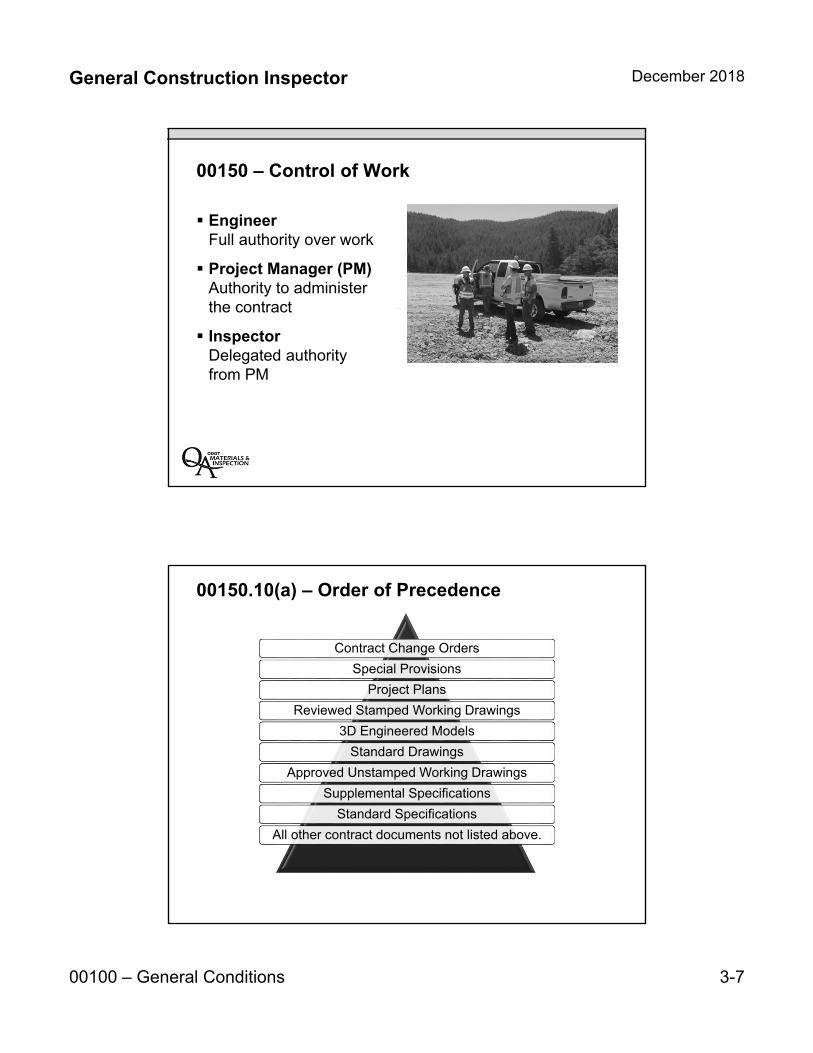
00150 – Control of Work
EngineerFull authority over work
Project Manager (PM)Authority to administerthe contract
InspectorDelegated authorityfrom PM
00150.10(a) – Order of Precedence
Contract Change Orders
Special Provisions
Project Plans
Reviewed Stamped Working Drawings
3D Engineered Models
Standard Drawings
Approved Unstamped Working Drawings
Supplemental Specifications
Standard Specifications
All other contract documents not listed above.
General Construction Inspector December 2018
00100 – General Conditions 3-8
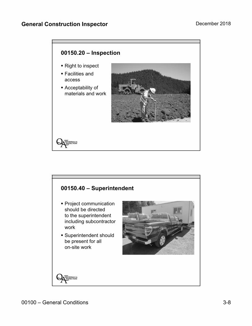
00150.20 – Inspection
Right to inspect
Facilities andaccess
Acceptability ofmaterials and work
00150.40 – Superintendent
Project communicationshould be directedto the superintendentincluding subcontractorwork
Superintendent shouldbe present for allon-site work

General Construction Inspector December 2018
00100 – General Conditions 3-9
00160 – Source of Materials and 00165 – Quality of Materials
Ordering, producing, and furnishing materials
Materials Acceptance Guides
00180 – Prosecution and Progress
Prime Contractorshall direct andcoordinate all work
Project Manager mustapprove subcontractorbefore they beginworking
General Construction Inspector December 2018
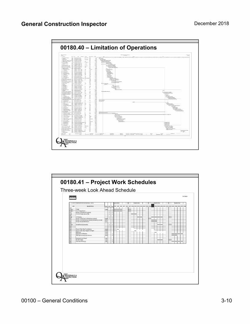
00100 – General Conditions 3-10
00180.40 – Limitation of OperationsProject Schedule
00180.41 – Project Work SchedulesThree-week Look Ahead Schedule
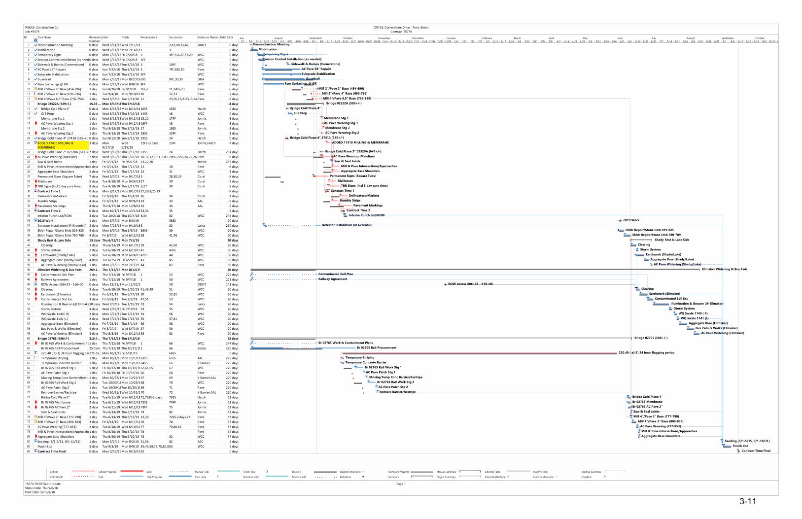
ID Task Name Remaining
Duration
Start Finish Predecessors Successors Resource Names Total Slack
1 Preconstruction Meeting 0 days Wed 7/11/18Wed 7/11/18 2,47,48,61,62 ODOT 0 days
2 Mobilization 0 days Wed 7/11/18Mon 7/16/181 3 0 days
3 Temporary Signs 0 days Mon 7/16/18Fri 7/20/18 2 4FF,5,6,27,37,29 WCC 0 days
4 Erosion Control Installation (as needed)0 days Wed 7/18/18Fri 7/20/18 3FF WCC 0 days
5 Sidewalk & Ramps (Cornerstone) 0 days Mon 8/13/18Tue 8/14/18 3 10FF WCC 0 days
6 AC Pave 28" Repairs 0 days Sun 7/22/18 Thu 8/23/18 3 7FF,8SS,10 Pave 0 days
7 Subgrade Stabilization 0 days Sun 7/22/18 Thu 8/23/18 6FF WCC 0 days
8 Guardrail 0 days Mon 7/23/18Mon 8/27/186SS 9FF,30,35 D&A 0 days
9 Rem Surfacings @ GR 0 days Mon 7/23/18Wed 8/8/18 8FF WCC 0 days
10 Mill 2"/Pave 2" Base (454-696) 1 day Sun 8/26/18 Fri 9/7/18 5FF,6 11,14SS,23 Pave -6 days
11 Mill 2"/Pave 4" Base (696-736) 1 day Tue 9/4/18 Mon 9/10/1810 12,23 Pave -7 days
12 Mill 4"/Pave 6.5" Base (736-758) 1 day Wed 9/5/18 Tue 9/11/18 11 23,76,16,21FS+3 daysPave -8 days
13 Bridge 02522A (589+/-) 15.33 ... Mon 8/13/18Thu 9/13/18 -3 days
14 Bridge Cold Plane 4" 0 days Mon 8/13/18Mon 8/13/1810SS 15SS Hatch 0 days
15 Cl 2 Prep 0 days Wed 8/15/18Thu 8/16/18 14SS 16 WCC 0 days
16 Membrane Stg 1 1 day Wed 9/12/18Wed 9/12/1815,12 17FF Jonnic -3 days
17 AC Pave Wearing Stg 1 1 day Wed 9/12/18Wed 9/12/1816FF 18 Pave -3 days
18 Membrane Stg 2 1 day Thu 9/13/18 Thu 9/13/18 17 19SS Jonnic -3 days
19 AC Pave Wearing Stg 2 1 day Thu 9/13/18 Thu 9/13/18 18SS 23FF Pave -3 days
20 Bridge Cold Plane 4" 17410 (535+/-) 0 days Sun 8/12/18 Sun 8/12/18 23SS 24 Hatch 0 days
21 ADDED 17410 MILLING &
MEMBRANE
3 days Mon
9/17/18
Wed
9/19/18
12FS+3 days 23FF Jonnic,Hatch -7 days
22 Bridge Cold Plane 2" 02520A (641+/-)2 days Wed 9/12/18Thu 9/13/18 23SS 24 Hatch 261 days
23 AC Pave Wearing (Mainline) 7 days Wed 9/12/18Thu 9/20/18 10,11,12,19FF,21FF 20SS,22SS,24,25,26,32Pave -8 days
24 Saw & Seal Joints 1 day Fri 9/21/18 Fri 9/21/18 23,22,20 Jonnic 256 days
25 Mill & Pave Intersections/Approaches5 days Fri 9/21/18 Thu 9/27/18 23 30 Pave -8 days
26 Aggregate Base Shoulders 5 days Fri 9/21/18 Thu 9/27/18 23 31 WCC -3 days
27 Permanent Signs (Square Tube) 7 days Wed 9/5/18 Mon 9/17/183 28,30,29 Coral -8 days
28 Mailboxes 5 days Tue 9/18/18 Mon 9/24/1827 30 Coral -5 days
29 TBB Signs (Incl 5 day cure time) 8 days Tue 9/18/18 Thu 9/27/18 3,27 30 Coral -8 days
30 Contract Time 1 0 days Mon 9/17/18Mon 9/17/1827,28,8,25,29 -8 days
31 Delineators/Markers 5 days Fri 9/28/18 Thu 10/4/18 26 34 Coral -3 days
32 Rumble Strips 4 days Fri 9/21/18 Wed 9/26/1823 33 AAL -5 days
33 Pavement Markings 8 days Thu 9/27/18 Mon 10/8/1832 34 AAL -5 days
34 Contract Time 2 0 days Mon 10/1/18Mon 10/1/1833,31 35 -5 days
35 Interim Punch List/ROM 3 days Tue 10/2/18 Thu 10/4/18 8,34 82 WCC 242 days
36 2019 Work 1 day Mon 6/3/19 Mon 6/3/19 38SS 20 days
37 Detector Installation (@ Greenhill) 2 days Mon 7/23/18Mon 9/10/183 82 Lantz 260 days
38 Shldr Repair/Stone Emb 819-825 4 days Mon 6/3/19 Thu 6/6/19 36SS 39 WCC 20 days
39 Shldr Repair/Stone Emb 780-789 4 days Fri 6/7/19 Wed 6/12/1938 41,76 WCC 20 days
40 Shady Rest & Lake Side 13 days Thu 6/13/19 Mon 7/1/19 20 days
41 Clearing 3 days Thu 6/13/19 Mon 6/17/1939 42,50 WCC 20 days
42 Storm System 2 days Tue 6/18/19 Wed 6/19/1941 43SS WCC 50 days
43 Earthwork (Shady/Lake) 5 days Tue 6/18/19 Mon 6/24/1942SS 44 WCC 50 days
44 Aggregate Base (Shady/Lake) 4 days Tue 6/25/19 Fri 6/28/19 43 45 WCC 50 days
45 AC Pave Widening (Shady/Lake) 1 day Mon 7/1/19 Mon 7/1/19 44 82 Pave 50 days
46 Ellmaker Widening & Bus Pads 269.1... Thu 7/12/18 Mon 8/12/19 20 days
47 Contaminated Soil Plan 1 day Thu 7/12/18 Fri 9/7/18 1 52 WCC 229 days
48 Railway Agreement 1 day Thu 7/12/18 Fri 9/7/18 1 50 WCC 221 days
49 ROW Access 506+33 - 516+00 0 days Mon 12/31/18Mon 12/31/18 50 ODOT 141 days
50 Clearing 3 days Tue 6/18/19 Thu 6/20/19 41,48,49 51 WCC 20 days
51 Earthwork (Ellmaker) 5 days Fri 6/21/19 Thu 6/27/19 50 52,81 WCC 20 days
52 Contaminated Soil Exc 3 days Fri 6/28/19 Tue 7/2/19 47,51 53 WCC 20 days
53 Illumination & Beacon (@ Ellmaker)10 days Wed 7/3/19 Tue 7/16/19 52 54 Lantz 20 days
54 Storm System 3 days Wed 7/17/19Fri 7/19/19 53 55 WCC 20 days
55 WQ Swale 1140 ( R) 2 days Mon 7/22/19Tue 7/23/19 54 56 WCC 20 days
56 WQ Swale 1141 (L) 2 days Wed 7/24/19Thu 7/25/19 55 57,81 WCC 20 days
57 Aggregate Base (Ellmaker) 5 days Fri 7/26/19 Thu 8/1/19 56 58 WCC 20 days
58 Bus Pads & Walks (Ellmaker) 4 days Fri 8/2/19 Wed 8/7/19 57 59 WCC 20 days
59 AC Pave Widening (Ellmaker) 3 days Thu 8/8/19 Mon 8/12/1958 82 Pave 20 days
60 Bridge 02765 (686+/-) 219.4... Thu 7/12/18 Thu 6/13/19 62 days
61 Br 02765 Work & Containment Plans1 day Thu 7/12/18 Fri 9/7/18 1 66 WCC 244 days
62 Br 02765 Rail Procurement 25 days Thu 7/12/18 Thu 10/11/181 66 Bekos 220 days
63 220.40 ( e)(1) 24 hour flagging period175 da... Mon 10/1/18Fri 5/31/19 64SS 0 days
64 Temporary Striping 1 day Mon 10/1/18Mon 10/1/1863SS 65SS AAL 228 days
65 Temporary Concrete Barrier 1 day Mon 10/1/18Mon 10/1/1864SS 66 K Barrier 228 days
66 Br 02765 Rail Work Stg 1 5 days Fri 10/12/18 Thu 10/18/1862,61,65 67 WCC 220 days
67 AC Pave Patch Stg 1 1 day Fri 10/19/18 Fri 10/19/18 66 68 Pave 220 days
68 Moving Temp Conc Barrier/Restripe1 day Mon 10/22/18Mon 10/22/1867 69 K Barrier,AAL 220 days
69 Br 02765 Rail Work Stg 2 5 days Tue 10/23/18Mon 10/29/1868 70 WCC 220 days
70 AC Pave Patch Stg 2 1 day Tue 10/30/18Tue 10/30/1869 71 Pave 220 days
71 Remove Barrier/Restripe 1 day Wed 10/31/18Wed 10/31/1870 72 K Barrier,AAL 220 days
72 Bridge Cold Plane 4" 2 days Tue 6/11/19 Wed 6/12/1971,76SS-2 days 73SS Hatch 62 days
73 Br 02765 Membrane 2 days Tue 6/11/19 Wed 6/12/1972SS 74FF Jonnic 62 days
74 Br 02765 AC Pave 2" 2 days Tue 6/11/19 Wed 6/12/1973FF 75 Jonnic 62 days
75 Saw & Seal Joints 1 day Thu 6/13/19 Thu 6/13/19 74 82 Jonnic 62 days
76 Mill 4"/Pave 3" Base (777-798) 1 day Thu 6/13/19 Thu 6/13/19 12,39 72SS-2 days,77 Pave 57 days
77 Mill 4"/Pave 3" Base (808-853) 2 days Fri 6/14/19 Mon 6/17/1976 78 Pave 57 days
78 AC Pave Wearing (777-853) 2 days Tue 6/18/19 Wed 6/19/1977 79,80,82 Pave 57 days
79 Mill & Pave Intersections/Approaches1 day Thu 6/20/19 Thu 6/20/19 78 Pave 62 days
80 Aggregate Base Shoulders 1 day Thu 6/20/19 Thu 6/20/19 78 82 WCC 57 days
81 Seeding (3/1-5/15, 9/1-10/31) 1 day Mon 9/2/19 Mon 9/2/19 51,56 82 AEC 5 days
82 Punch List 5 days Tue 9/3/19 Mon 9/9/19 35,45,59,78,75,80,81,3783 WCC 5 days
83 Contract Time Final 0 days Mon 9/16/19Mon 9/16/1982 0 days
Preconstruction Meeting
Mobilization
Temporary Signs
Erosion Control Installation (as needed)
Sidewalk & Ramps (Cornerstone)
AC Pave 28" Repairs
Subgrade Stabilization
Guardrail
Rem Surfacings @ GR
Mill 2"/Pave 2" Base (454-696)
Mill 2"/Pave 4" Base (696-736)
Mill 4"/Pave 6.5" Base (736-758)
Bridge 02522A (589+/-)
Bridge Cold Plane 4"
Cl 2 Prep
Membrane Stg 1
AC Pave Wearing Stg 1
Membrane Stg 2
AC Pave Wearing Stg 2
Bridge Cold Plane 4" 17410 (535+/-)
ADDED 17410 MILLING & MEMBRANE
Bridge Cold Plane 2" 02520A (641+/-)
AC Pave Wearing (Mainline)
Saw & Seal Joints
Mill & Pave Intersections/Approaches
Aggregate Base Shoulders
Permanent Signs (Square Tube)
Mailboxes
TBB Signs (Incl 5 day cure time)
Contract Time 1
Delineators/Markers
Rumble Strips
Pavement Markings
Contract Time 2
Interim Punch List/ROM
2019 Work
Detector Installation (@ Greenhill)
Shldr Repair/Stone Emb 819-825
Shldr Repair/Stone Emb 780-789
Shady Rest & Lake Side
Clearing
Storm System
Earthwork (Shady/Lake)
Aggregate Base (Shady/Lake)
AC Pave Widening (Shady/Lake)
Ellmaker Widening & Bus Pads
Contaminated Soil Plan
Railway Agreement
ROW Access 506+33 - 516+00
Clearing
Earthwork (Ellmaker)
Contaminated Soil Exc
Illumination & Beacon (@ Ellmaker)
Storm System
WQ Swale 1140 ( R)
WQ Swale 1141 (L)
Aggregate Base (Ellmaker)
Bus Pads & Walks (Ellmaker)
AC Pave Widening (Ellmaker)
Bridge 02765 (686+/-)
Br 02765 Work & Containment Plans
Br 02765 Rail Procurement
220.40 ( e)(1) 24 hour flagging period
Temporary Striping
Temporary Concrete Barrier
Br 02765 Rail Work Stg 1
AC Pave Patch Stg 1
Moving Temp Conc Barrier/Restripe
Br 02765 Rail Work Stg 2
AC Pave Patch Stg 2
Remove Barrier/Restripe
Bridge Cold Plane 4"
Br 02765 Membrane
Br 02765 AC Pave 2"
Saw & Seal Joints
Mill 4"/Pave 3" Base (777-798)
Mill 4"/Pave 3" Base (808-853)
AC Pave Wearing (777-853)
Mill & Pave Intersections/Approaches
Aggregate Base Shoulders
Seeding (3/1-5/15, 9/1-10/31)
Punch List
Contract Time Final
7/1 7/8 7/15 7/22 7/29 8/5 8/12 8/19 8/26 9/2 9/9 9/16 9/23 9/30 10/7 10/14 10/21 10/28 11/4 11/11 11/18 11/25 12/2 12/9 12/16 12/23 12/30 1/6 1/13 1/20 1/27 2/3 2/10 2/17 2/24 3/3 3/10 3/17 3/24 3/31 4/7 4/14 4/21 4/28 5/5 5/12 5/19 5/26 6/2 6/9 6/16 6/23 6/30 7/7 7/14 7/21 7/28 8/4 8/11 8/18 8/25 9/1 9/8 9/15 9/22 9/29 10/6 10/13 10/20
July August September October November December January February March April May June July August September October
Critical
Critical Split
Critical Progress
Task
Split
Task Progress
Manual Task
Start-only
Finish-only
Duration-only
Baseline
Baseline Split
Baseline Milestone
Milestone
Summary Progress
Summary
Manual Summary
Project Summary
External Tasks
External Milestone
Inactive Task
Inactive Milestone
Inactive Summary
Deadline
Wildish Construction Co
Job #3574
OR126: Cornerstone Drive - Terry Street
Contract 15074
15074 18-09 Sept Update
Status Date: Thu 9/6/18
Print Date: Sat 9/8/18
Page 1
3-11

3-12

9/7/2018
3574 C15074 OR126 Cornerstone - Terry September September September September
LOC DESCRIPTION 9/4 9/5 9/6 9/7 9/8 9/9 9/10 9/11 9/12 9/13 9/14 9/15 9/16 9/17 9/18 9/19 9/20 9/21 9/22 9/23 9/24 9/25 9/26 9/27 9/28
24
25 6+3 2" Mill Hatch x
26 6+3 2" & 4" Base Pave x x
27 Bridge 17410 Base?? (added) x x
28 2 2" & 2.5" Base second lifts x x
29
30 8 2" Wearing x x
31 Bridge 17410 Prep for Membrane (added) Hatch x x
32 Bridge 17410 Membrane (added) (w/wearing course) Jonnic x
33 Bridge 02522A Membrane Jonnic x
34
35 38 Grind/Pave Approaches x x
36
37
38 Square Tube Sign Foundations Coral Days
39 Square Tube Sign Supports & Signs Coral Days
40 Mailboxes Coral Days
41 Delineators & Markers Coral x
42 TBB Signs (Pending Mfg & Delivery) Coral x
43
44 Pavement Cure (5 days) AAL
45 Rumble Strips AAL x
46 Pavement Markings AAL x
47
SUB QC Flag
3-13

3-14
General Construction Inspector December 2018
00100 – General Conditions 3-15
00180.50 – Contract Time
Contract completiondate
Second Notificationissued at end ofcontract work
Liquidated damages
00190 – Measurement of Pay Quantities
Rounding of Quantities
MeasurementGuidelinesEngineer’s decision is final
Lump Sum Bidbreakdowns
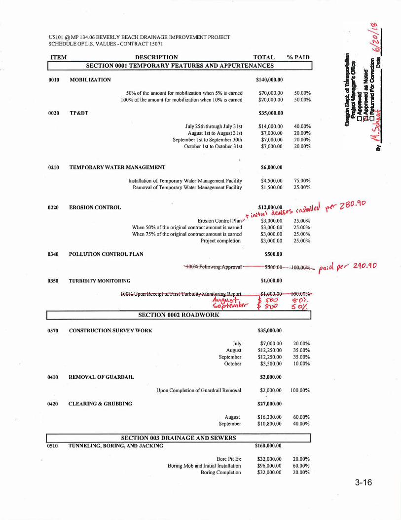
USIOI @MP 134.06 BEVERLY BEACH DRAINAGE IMPROVEMENT PROJECT SCHEDULE OF L.S. VALUES - CONTRACT 15071
ITEM
0010
0020
0210
0220
0340
0350
0370
0410
0420
0510
DESCRIPTION TOTAL %PAID SECTION 0001 TEMPORARY FEATURES AND APPURTENANCES
MOBILIZATION $140,000.00
50% of the amount for mobilization when 5% is earned $70,000.00 50.00% 100% ofthe amount for mobilization when 10% is earned $70,000.00 50.00%
TP&DT $35,000.00
July 25th through July 31st $14,000.00 40.00% August !st to August 31st $7,000.00 20.00%
September I st to September 30th $7,000.00 20.00% October 1st to October 31st $7,000.00 20.00%
TEMPORARY WATER MANAGEMENT $6,000.00
Installation of Temporary Water Management Facility $4,500.00 75.00% Removal of Temporary Water Management Facility $1,500.00 25.00%
EROSION CONTROL I J J(' ?80,'\O$12,000.00 • M•\ t r . £-
1" ini°"'"' 1.e-,u,,c; \ Erosion Control Plan/ $3,000.00 25.00%
When 50% of the original contract amount is earned $3,000.00 25.00% When 75% of the original contract amount is earned $3,000.00 25.00%
Project completion $3,000.00 25.00%
POLLUTION CONTROL PLAN $500.00
TURBIDITY MONITORING
-te0%-FoHowing-,&qJprova,t-J ---UM:00--l-00,00%._ f 4; J.. pe I" Z q O • 'l 0
$1,000.00
SECTION 0002 ROADWORK I
CONSTRUCTION SURVEY WORK $35,000.00
$7,000.00 $12,250.00 $12,250.00 $3,500.00
REMOVAL OF GUARDAIL
July August
September October
Upon Completion of Guardrail Removal
CLEARING & GRUBBING
August September
SECTION 003 DRAINAGE AND SEWERS TUNNELING, BORING, AND JACKING
Bore Pit Ex Boring Mob and Initial Installation
Boring Completion
$2,000.00
20.00% 35.00% 35.00% 10.00%
$2,000.00 100.00%
$27,000.00
$16,200.00 $10,800.00
$160,000.00
$32,000.00 $96,000.00 $32,000.00
60.00% 40.00%
20.00% 60.00% 20.00%
3-16
General Construction Inspector December 2018
00100 – General Conditions 3-17
Key Inspection Points
Know your level of delegated authority
Check the schedule (3-week look ahead)
Be proactive, anticipate problems
Point out early to Contractor and PM non-specificationmaterials and workmanship
Be professional
Know your resources and contacts
Unit 3 Review:
Basic ODOT construction terminology
Inspector project authority and legal requirements
Order of document precedence
Quality of materials and workmanship requirements
Basics for measurement of quantity

INSERT TAB
Unit 4
00200 – Temporary Features
General Construction Inspector December 2018
00200 – Temporary Features & Appurtenances 4-1
Unit 400200
Temporary Features & Appurtenances
00200 – Temporary Features and Appurtenances
Mobilization (00210)
Accommodations for Public Traffic (00220)
Work Zone Traffic Control (00225)
Erosion and Sediment Control (00280)
Environmental Protection (00290)
2
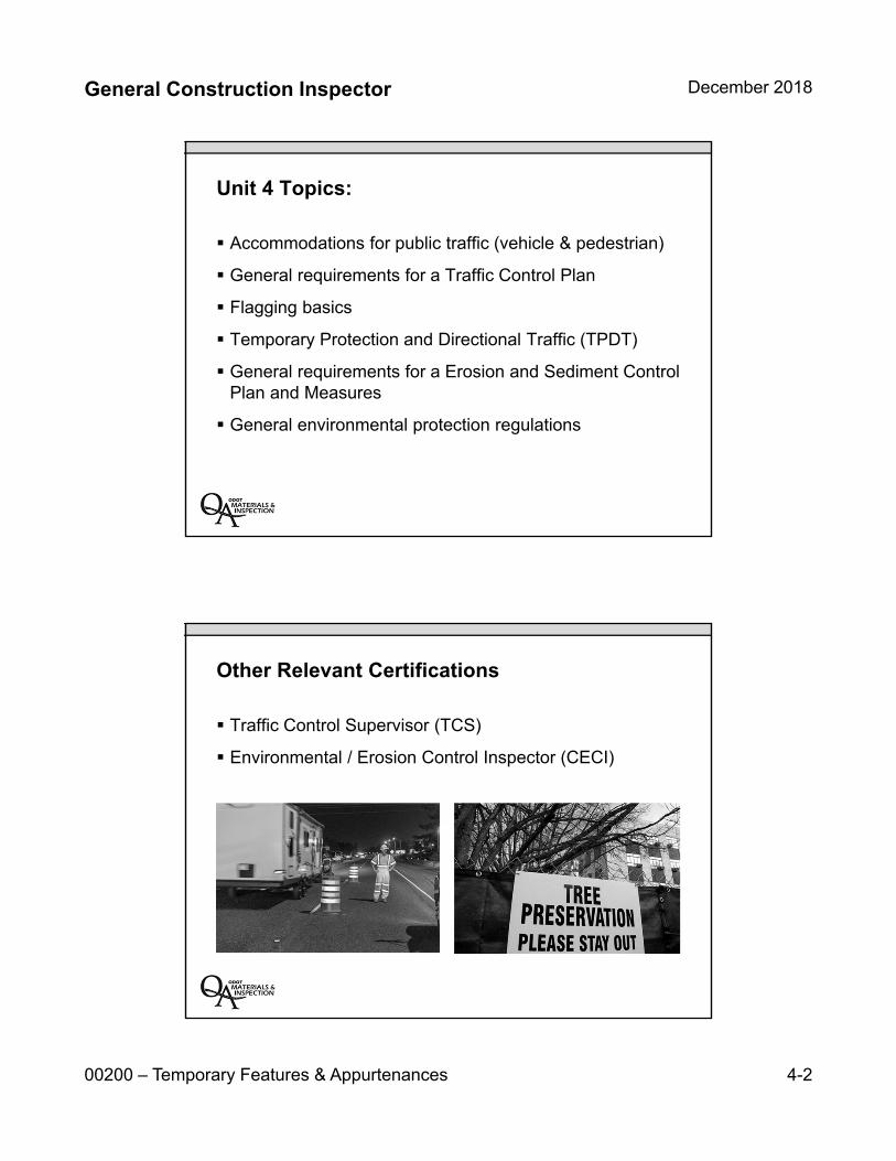
General Construction Inspector December 2018
00200 – Temporary Features & Appurtenances 4-2
Unit 4 Topics:
Accommodations for public traffic (vehicle & pedestrian)
General requirements for a Traffic Control Plan
Flagging basics
Temporary Protection and Directional Traffic (TPDT)
General requirements for a Erosion and Sediment Control Plan and Measures
General environmental protection regulations
Other Relevant Certifications
Traffic Control Supervisor (TCS)
Environmental / Erosion Control Inspector (CECI)
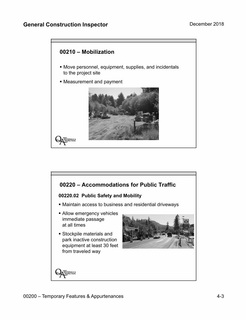
General Construction Inspector December 2018
00200 – Temporary Features & Appurtenances 4-3
00210 – Mobilization
Move personnel, equipment, supplies, and incidentals to the project site
Measurement and payment
00220 – Accommodations for Public Traffic
00220.02 Public Safety and Mobility
Maintain access to business and residential driveways
Allow emergency vehicles immediate passageat all times
Stockpile materials and park inactive construction equipment at least 30 feet from traveled way
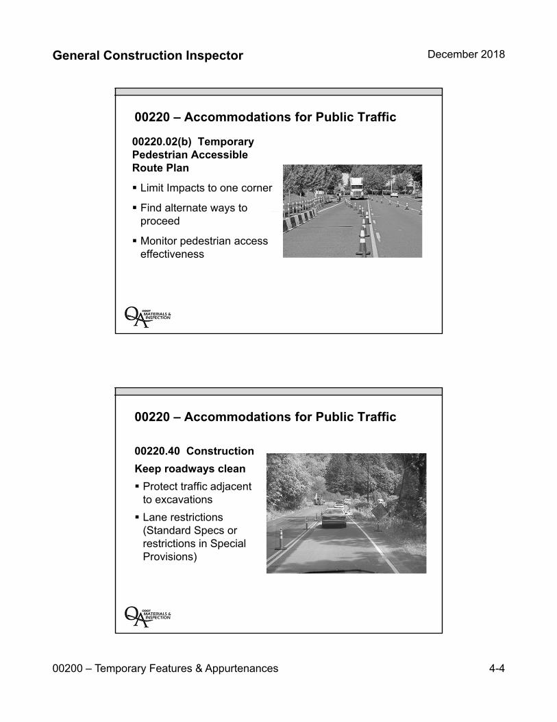
General Construction Inspector December 2018
00200 – Temporary Features & Appurtenances 4-4
00220 – Accommodations for Public Traffic
00220.02(b) Temporary Pedestrian Accessible Route Plan
Limit Impacts to one corner
Find alternate ways to proceed
Monitor pedestrian access effectiveness
00220 – Accommodations for Public Traffic
00220.40 Construction
Keep roadways clean
Protect traffic adjacent to excavations
Lane restrictions (Standard Specs or restrictions in Special Provisions)
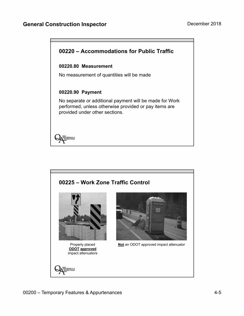
General Construction Inspector December 2018
00200 – Temporary Features & Appurtenances 4-5
00220 – Accommodations for Public Traffic
00220.80 Measurement
No measurement of quantities will be made
00220.90 Payment
No separate or additional payment will be made for Work performed, unless otherwise provided or pay items are provided under other sections.
Properly placed ODOT approved
impact attenuators
Not an ODOT approved impact attenuator
00225 – Work Zone Traffic Control
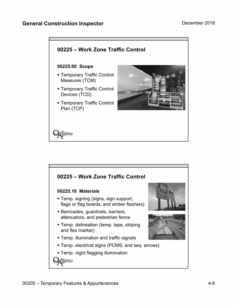
General Construction Inspector December 2018
00200 – Temporary Features & Appurtenances 4-6
00225 – Work Zone Traffic Control
00225.00 Scope
Temporary Traffic Control Measures (TCM)
Temporary Traffic Control Devices (TCD)
Temporary Traffic Control Plan (TCP)
00225 – Work Zone Traffic Control
00225.10 Materials
Temp. signing (signs, sign support, flags or flag boards, and amber flashers)
Barricades, guardrails, barriers, attenuators, and pedestrian fence
Temp. delineation (temp. tape, striping and flex marker)
Temp. illumination and traffic signals
Temp. electrical signs (PCMS, and seq. arrows)
Temp. night flagging illumination
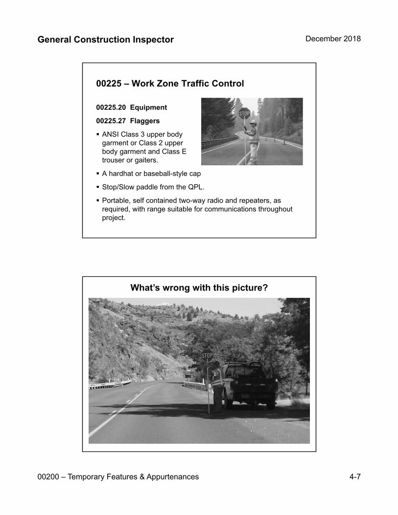
General Construction Inspector December 2018
00200 – Temporary Features & Appurtenances 4-7
00225 – Work Zone Traffic Control
00225.20 Equipment
00225.27 Flaggers
ANSI Class 3 upper body garment or Class 2 upper body garment and Class E trouser or gaiters.
A hardhat or baseball-style cap
Stop/Slow paddle from the QPL.
Portable, self contained two-way radio and repeaters, as required, with range suitable for communications throughout project.
What’s wrong with this picture?
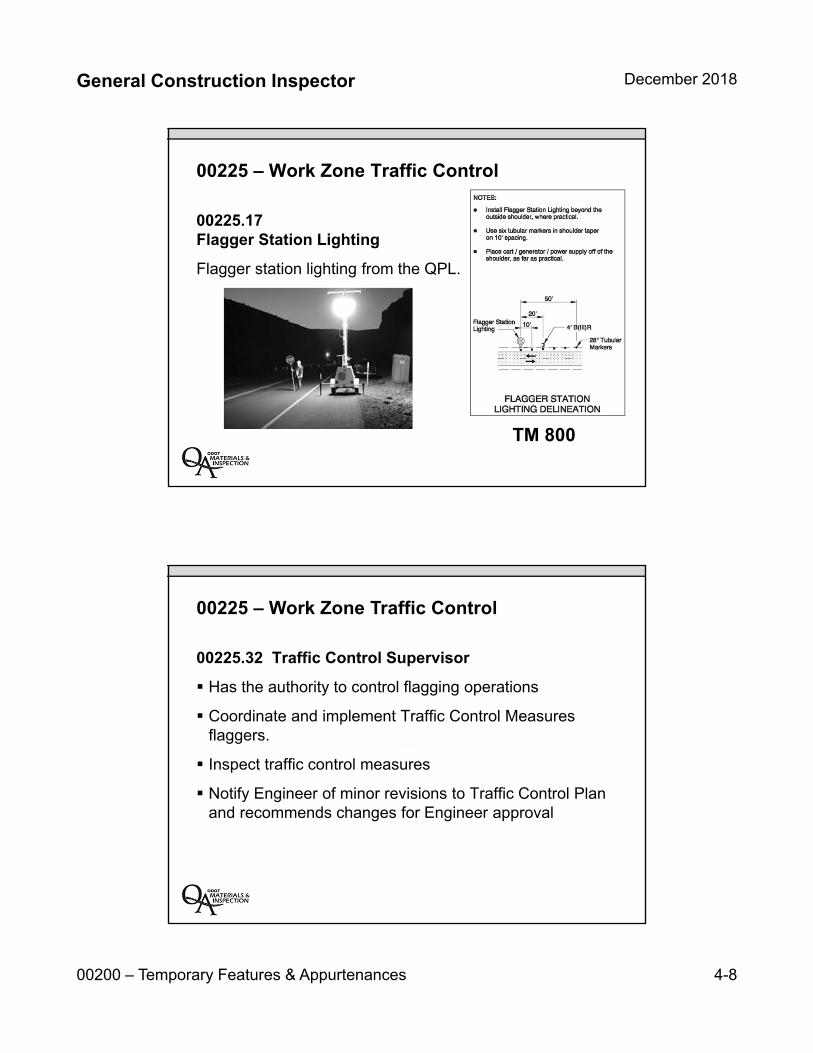
General Construction Inspector December 2018
00200 – Temporary Features & Appurtenances 4-8
00225 – Work Zone Traffic Control
00225.17 Flagger Station Lighting
Flagger station lighting from the QPL.
TM 800
00225 – Work Zone Traffic Control
00225.32 Traffic Control Supervisor
Has the authority to control flagging operations
Coordinate and implement Traffic Control Measuresflaggers.
Inspect traffic control measures
Notify Engineer of minor revisions to Traffic Control Planand recommends changes for Engineer approval

I
I
Project Information
-------···---· ·-·----------------·-·- . ---·
Traffic Control Inspection Report
OR126: Cornerstone to Terry 15074
0 -c; t) 0 t>;,1 ArrivalTime . I Departure Time 1
Sun Mon Tue Wed Thu Fri Sat
Day � 0 0 0 0 0 0 Clear Pt. Cloud Cloudy Shower Rain Snow
Weather 0 0 • 0 0 0 1 o•-32• 32•-so· so•.70• zo•-s3• Over 83°
Temp 0 � 0 0 o ·Calm light Medium Strong
Wind 0 <I> 0 0 Dry Low Med High
Humidity 0 0 0 II
Stage and Phase of Project (include TCP#):
TM Drawing#
·1JY1 f<5o cl? R..-,,/Jf,, -;nvJ"� 'Tl)
Placed Equipment #/Type/Item
Date/Time
f?,,,J A-- "S I
81'-r� q I
P::.-A- 5 I I
RvM Auf. . '>"17.t 11'5 LJ i. 2- I
RvM/JJl,.J: -�'lb.1.;IK 2S#r> I
I I
I
I
I I I
I
Variable Message Board z.. Message 1 / Message 2 tJc-r
Contract No.
Today's Operations (include queues, traffic conditions, TCM clconliness/per!ormance, &TCP maint.i
J,--o� t- L- I 1/ C .£,, 7Jc., ,'° J ;v tr /J-�jl7J. lf- ,4 - L-hv_6_
-7�4-�,clc C0r1/llet)L ,:j£r C2..#G&i£<5 � Al 7$s 11/o-,J. Si},-VJ;,...,; J- Cl"'WC-e l l-ed}Ov-e. ·7lJ £#;'11,
Location
E: /I 1t?,H)(£R
""' /
Location (Engr. Station or MP)
'- �#? ,J� <.,.771,vf- ·rA / C // 44,.4//f d
/ -. .
Bo .Ji-. i:::-Mt:J .<
/_,; /') < 1./ r". JG,.
/J�
Removed Date/Time
I I I I I
I
I I I I I I I I
I
Location (Station#) of Missing or Damaged Devices/ Maintenance Action Taken (limit 500 characters)
TCS's Name (printed) Certification Number
ODOT Inspector's Signature ODOT Inspector's Name (printed) Certification Number Date
Submit original to Project Manager; cc Project Inspector. 4-9

4-10

General Construction Inspector December 2018
00200 – Temporary Features & Appurtenances 4-11
00225 – Work Zone Traffic Control
00225.40 Construction
Install, inspect, move, operate, maintain, and remove temporary TCD according to the plans and specifications.
Temporary TCD are to remain the property of thecontractor
Existing TCD shall remain in operation throughout thecontract or until replaced by new and permanent TCD
00225 – Work Zone Traffic Control
Turn ≠ Tipped!
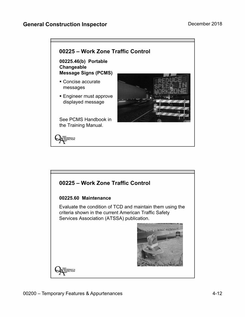
General Construction Inspector December 2018
00200 – Temporary Features & Appurtenances 4-12
00225 – Work Zone Traffic Control
00225.46(b) Portable Changeable Message Signs (PCMS)
Concise accuratemessages
Engineer must approvedisplayed message
See PCMS Handbook in the Training Manual.
00225 – Work Zone Traffic Control
00225.60 Maintenance
Evaluate the condition of TCD and maintain them using the criteria shown in the current American Traffic Safety Services Association (ATSSA) publication.
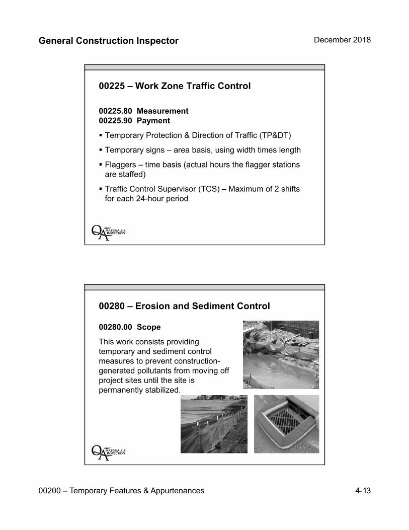
General Construction Inspector December 2018
00200 – Temporary Features & Appurtenances 4-13
00225 – Work Zone Traffic Control
00225.80 Measurement00225.90 Payment
Temporary Protection & Direction of Traffic (TP&DT)
Temporary signs – area basis, using width times length
Flaggers – time basis (actual hours the flagger stationsare staffed)
Traffic Control Supervisor (TCS) – Maximum of 2 shiftsfor each 24-hour period
00280 – Erosion and Sediment Control
00280.00 Scope
This work consists providing temporary and sediment control measures to prevent construction-generated pollutants from moving off project sites until the site is permanently stabilized.

General Construction Inspector December 2018
00200 – Temporary Features & Appurtenances 4-14
NPDES Permit
00280 – Erosion and Sediment Control
Erosions and Sediment Control Plan (ESCP)
Monitoring site conditions
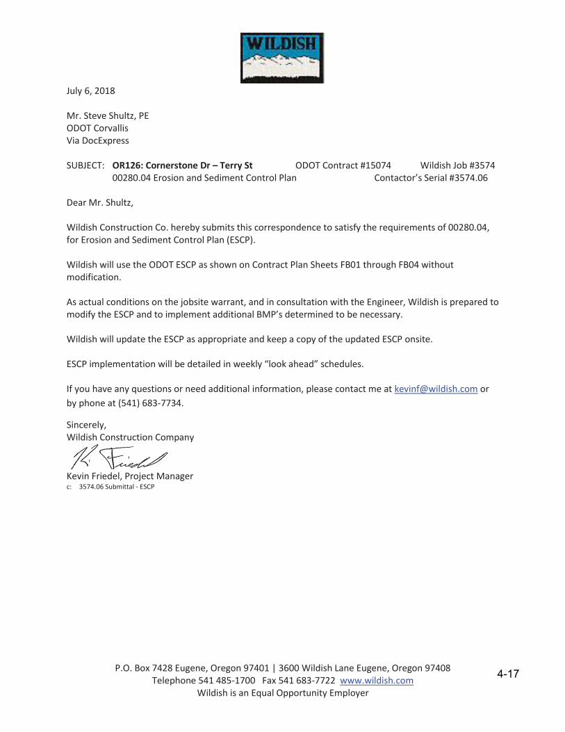
P.O. Box 7428 Eugene, Oregon 97401 | 3600 Wildish Lane Eugene, Oregon 97408 Telephone 541 485-1700 Fax 541 683-7722 www.wildish.com
Wildish is an Equal Opportunity Employer
July 6, 2018
Mr. Steve Shultz, PE ODOT Corvallis Via DocExpress
SUBJECT: OR126: Cornerstone Dr – Terry St ODOT Contract #15074 Wildish Job #3574 00280.04 Erosion and Sediment Control Plan Contactor’s Serial #3574.06
Dear Mr. Shultz,
Wildish Construction Co. hereby submits this correspondence to satisfy the requirements of 00280.04, for Erosion and Sediment Control Plan (ESCP).
Wildish will use the ODOT ESCP as shown on Contract Plan Sheets FB01 through FB04 without modification.
As actual conditions on the jobsite warrant, and in consultation with the Engineer, Wildish is prepared to modify the ESCP and to implement additional BMP’s determined to be necessary.
Wildish will update the ESCP as appropriate and keep a copy of the updated ESCP onsite.
ESCP implementation will be detailed in weekly “look ahead” schedules.
If you have any questions or need additional information, please contact me at [email protected] or by phone at (541) 683-7734.
Sincerely, Wildish Construction Company
Kevin Friedel, Project Manager c: 3574.06 Submittal - ESCP
4-17

4-18
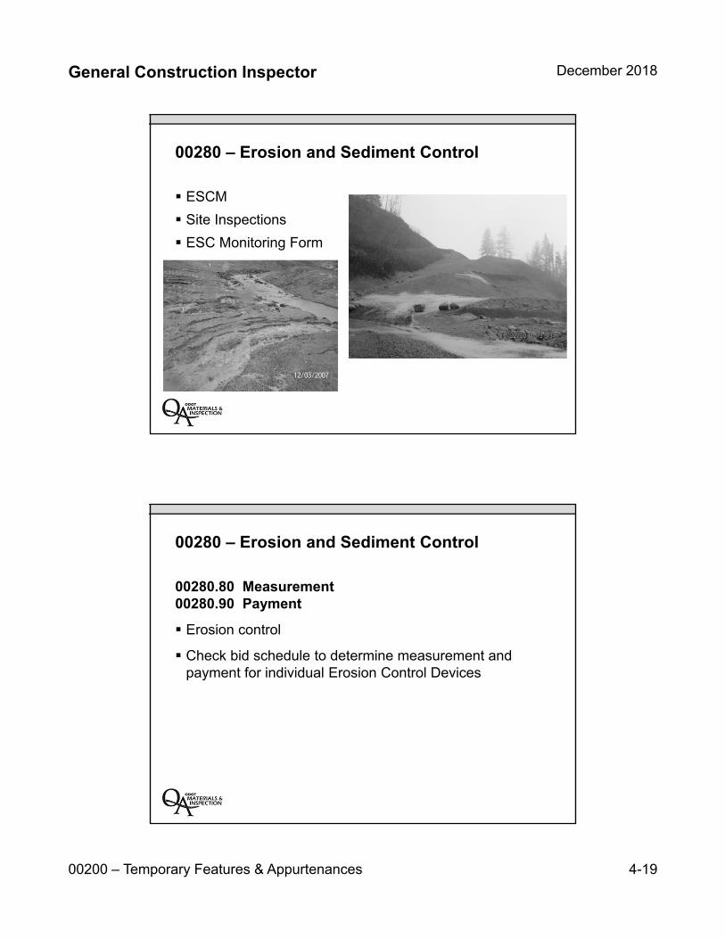
General Construction Inspector December 2018
00200 – Temporary Features & Appurtenances 4-19
00280 – Erosion and Sediment Control
ESCM
Site Inspections
ESC Monitoring Form
00280 – Erosion and Sediment Control
00280.80 Measurement00280.90 Payment
Erosion control
Check bid schedule to determine measurement andpayment for individual Erosion Control Devices

4-20
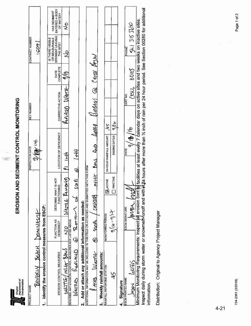
\i,
7_;
ER
OS
ION
AN
D S
ED
IME
NT
CO
NT
RO
L M
ON
ITO
RIN
G
PR
OJE
CT
NA
ME
1.Id
entify
the
eros
ion
cont
rol m
easu
res
from
ES
CP
:
ER
OS
ION
CO
NT
RO
L M
EA
SU
RE
S
DE
SC
RIB
E A
NY
ER
OS
I
W4TTLe::i
FU
NC
TIO
N A
S
DE
SIG
NE
D?
DE
SC
RIB
E W
HA
T I
S N
OT
FU
NC
TIO
NIN
G
.fc. 1'4.
t-AtN
c2,
�,,,
_,_/\_
J2.
Add
or a
ttach
any
add
ition
al in
form
atio
n as
nee
ded:
INS
PE
CTIO
N D
ATE
t-'6
LO
CA
TIO
N O
F D
EF
ICIE
NC
Y
AD
DIT
ION
AL
IN
FO
RM
ATIO
N M
AY
BE
IN
CLU
DE
D I
N T
HIS
FIE
LD
OR
ATT
AC
HE
DA
ND
SU
BM
ITTE
D VVl
TH
TH
IS F
OR
M
t 3.
Wee
kly
rain
fall
amou
nts:
RAIN
FA
LL
RE
PO
RTIN
G S
TA
TIO
N
,�5
4.Si
_g_nat
ure
ES
CM
PR
INT
ED
NA
ME
j"C,1)
"1 fn(!J
�·
IN<k'r
MO
NIT
OR
ING
PE
RIO
D
l?il-ACT
IVE
24--
HO
UR
RA
INF
ALL A
MO
UN
T:
W_'-fJ -
q/1:r
□INA
CTIV
E E
ND
ING
DA
TE
S:
KE
Y N
UM
BE
R
CO
RR
EC
TIV
E A
CT
ION
DA
TE
CO
MP
LE
TE
�V'1
,45
'1/(w
CE
RT
NO
.
{KiCl,
�
0 ID 5
CO
NT
RA
CT
NU
MB
ER
IS T
HE
RE
VIS
IBLE
OR
ME
AS
UR
AB
LE
SE
DIM
EN
T L
EAV
ING
TH
E S
ITE
?
C,
j,J
PH
ON
E
HA
S S
ED
IME
NT
EN
TE
RE
D A
BO
DY
OF
WAT
ER
?
/Jo
5'11
'3 [S'
)b"/0
M
inim
um M
onito
ring
Req
uire
men
ts: l
nspe
ct[a
ll er
osio
n co
nt
Insp
ect d
aily
dur
ing
stor
m w
ater
or s
now
mei
l½'un
off a
nd w
ith
info
rmat
ion.
faci
litie
s at
leas
t eve
'ry 7
cal
enda
r da
ys o
n ac
tive
site
s an
d tw
o w
eeks
on
inac
tive
site
s.
4 ho
urs
after
mor
e th
an ½
inch
of r
ain
per 2
4 ho
ur p
erio
d. S
ee S
ectio
n 00
280
for a
dditi
onal
Dis
tribu
tion:
Orig
inal
to A
genc
y Pr
ojec
t Man
ager
734-
236
1 (3
/20
18)
Pa
ge
1 o
f2
4 -20
4-21

4-22
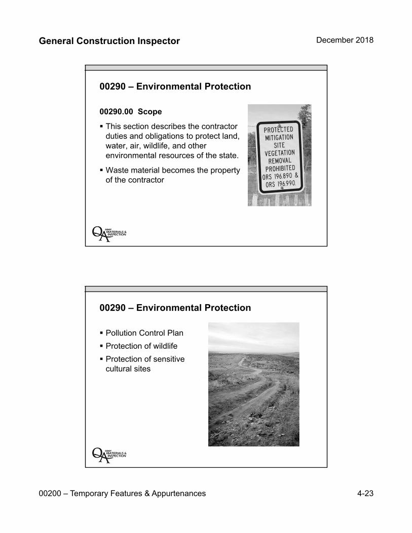
General Construction Inspector December 2018
00200 – Temporary Features & Appurtenances 4-23
00290 – Environmental Protection
00290.00 Scope
This section describes the contractorduties and obligations to protect land,water, air, wildlife, and otherenvironmental resources of the state.
Waste material becomes the propertyof the contractor
00290 – Environmental Protection
Pollution Control Plan
Protection of wildlife
Protection of sensitivecultural sites

4-24
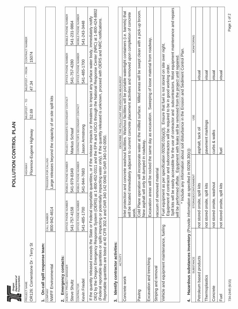
734-
2445
(6/1
5)P
age
1 of
2
POLL
UTI
ON
CO
NTR
OL
PLA
N
PR
OJE
CT
NA
ME
OR
126:
Cor
ners
tone
Dr -
Ter
ry S
tH
IGH
WA
Y
Flor
ence
-Eug
ene
Hig
hway
MIL
EP
OS
T –
TO
52.6
9M
ILE
PO
ST
– F
RO
M
47.3
4C
ON
TRA
CT
NU
MB
ER
1507
4
1.O
n-ca
ll sp
ill re
spon
se te
am:
CO
MP
AN
Y
NW
FF E
nviro
nmen
tal
CA
LL N
UM
BE
R
800-
942-
4614
TRIG
GE
RS
FO
R C
ALL
ING
Larg
e re
leas
es b
eyon
d th
e ca
paci
ty o
f on
site
spi
ll ki
ts
2.Em
erge
ncy
cont
acts
:A
GE
NC
Y P
RO
JEC
T M
AN
AG
ER
Ste
ve S
hultz
OFF
ICE
PH
ON
E N
UM
BE
R
541-
757-
4158
MO
BIL
E P
HO
NE
NU
MB
ER
541-
979-
8349
PR
OJE
CT
MA
NA
GE
R'S
SE
CO
ND
AR
Y C
ON
TAC
T
Mar
kus
Sch
aaf
OFF
ICE
PH
ON
E N
UM
BE
R
541-
757-
4280
MO
BIL
E P
HO
NE
NU
MB
ER
541-
231-
9864
CO
NTR
AC
TOR
Kev
in F
riede
lO
FFIC
E P
HO
NE
NU
MB
ER
541-
485-
1700
MO
BIL
E P
HO
NE
NU
MB
ER
541-
944-
7683
CO
NTR
AC
TOR
'S S
EC
ON
DA
RY
CO
NTA
CT
Jaso
n A
rmst
rong
OFF
ICE
PH
ON
E N
UM
BE
R
541-
485-
1700
MO
BIL
E P
HO
NE
NU
MB
ER
541-
243-
3448
If th
e qu
antit
y re
leas
ed e
xcee
ds th
e S
tate
or F
eder
al re
porta
ble
quan
titie
s, o
r if t
he re
leas
e im
pact
s or
thre
aten
s to
impa
ct a
ny s
urfa
ce w
ater
bod
y, im
med
iate
ly n
otify
D
EQ
by
the
Ore
gon
Em
erge
ncy
Res
pons
e S
yste
m (O
ER
S) a
t 1-8
00-4
52-0
311
and
the
EP
A a
nd U
SC
G th
roug
h th
e N
atio
nal R
espo
nse
Cen
ter (
NR
C) a
t 1-8
00-4
24-8
802
(Fed
eral
repo
rtabl
e qu
antit
ies
or s
pills
impa
ctin
g or
pot
entia
lly im
pact
ing
wat
er o
nly)
. If t
he q
uant
ity re
leas
ed is
unk
now
n, p
roce
ed w
ith O
ER
S a
nd N
RC
not
ifica
tions
. R
epor
tabl
e qu
antit
ies
are
liste
d at
40
CFR
302
.4 a
nd O
AR
340
142
004
0 to
OA
R 3
40-1
42-0
050.
3.Id
entif
y co
ntra
ctor
act
iviti
es:
AC
TIV
ITY
DE
SC
RIB
E T
HE
PO
LLU
TAN
T P
RE
VE
NTI
ON
ME
AS
UR
ES
*
Con
cret
e w
ork
Inle
t pro
tect
ion
and
conc
rete
was
hout
faci
litie
s. W
asho
ut fa
cilit
ies
will
be
porta
ble
wat
ertig
ht c
onta
iner
s (i.
e. b
arre
ls) t
hat
will
be
loca
ted
imm
edia
tely
adj
acen
t to
curr
ent c
oncr
ete
plac
emen
t act
iviti
es a
nd re
mov
ed u
pon
com
plet
ion
of c
oncr
ete
wor
k.P
avin
gC
old
Pla
ne o
pera
tion
will
inco
rpor
ate
wat
er a
t the
mill
led
surfa
ce.
Mill
ed a
reas
will
be
swep
t cle
an w
ith a
pic
k-up
bro
om.
N
ew a
spha
lt w
ill o
nly
be d
umpe
d in
road
way
.E
xcav
atio
n an
d tre
nchi
ngE
xcav
atio
n ar
eas
will
be
rock
ed th
e sa
me
day
as e
xcav
atio
n. S
wee
ping
of l
oose
mat
eria
l fro
m ro
adw
ay.
Stri
ping
and
rem
oval
vacu
um o
f rem
oved
mat
eria
lV
ehic
le a
nd e
quip
men
t mai
nten
ance
, fue
ling
Fue
l equ
ipm
ent a
s pe
r spe
cific
atio
n 00
290.
03(a
)(3)
. E
nsur
e th
at fu
el is
not
sto
red
on s
ite o
ver n
ight
.
Equ
ipm
ent o
f con
tract
or a
nd s
ubco
ntra
ctor
s w
ill b
e re
quire
d to
be
in g
ood
wor
king
ord
er.
S
pill
kits
will
be
easi
ly a
cces
sibl
e fo
r the
use
of c
ontra
ctor
and
sub
cont
ract
ors.
Mos
t equ
ipm
ent m
aint
enan
ce a
nd re
pairs
w
ill b
e pe
rform
ed o
ffsite
. E
quip
men
t with
leak
s w
ill b
e re
mov
ed fr
om th
e pr
ojec
t unt
il re
paire
d.*
Incl
ude
any
info
rmat
ion
abou
t soi
l dis
turb
ance
in th
e E
rosi
on a
nd S
edim
ent C
ontro
l Pla
n.4.
Haz
ardo
us s
ubst
ance
s in
vent
ory
(Pro
vide
info
rmat
ion
as s
peci
fied
in 0
0290
.30(
c)):
SU
BS
TAN
CE
STO
RA
GE
/CO
NTA
INM
EN
TU
SE
MO
NIT
OR
ING
Pet
role
um b
ased
pro
duct
sno
t sto
red
onsi
te, s
pill
kits
asph
alt,
tack
oil
visu
al
Ther
mop
last
ics
not s
tore
d on
site
, spi
ll ki
tspa
vem
ent m
arki
ngs
visu
al
Con
cret
eno
t sto
red
onsi
te, w
asho
utcu
rbs
& w
alks
visu
al
Fuel
not s
tore
d on
site
, spi
ll ki
tsfu
elvi
sual
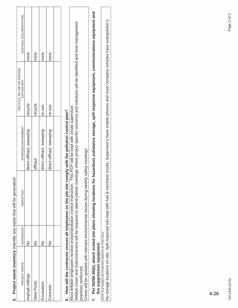
734-
2445
(6/1
5)P
age
2 of
2
5.Pr
ojec
t was
te in
vent
ory
(Iden
tify
any
was
te th
at w
ill b
e ge
nera
ted)
:
PR
OJE
CT
WA
STE
HA
ZAR
DO
US
?R
ED
UC
TIO
NS
TOR
AG
E/C
ON
TAIN
ME
NT
RE
CY
CLE
, RE
-US
E O
R D
ISP
OS
E,
EX
PLA
IN W
HY
DIS
PO
SA
L D
OC
UM
EN
TATI
ON
Asp
halt
mill
ings
No
dire
ct o
ffhau
l, sw
eepi
ng
recy
cle
none
Ste
el P
osts
No
offh
aul
recy
cle
none
Exc
avat
ion
No
dire
ct o
ffhau
l, sw
eepi
ngre
-use
none
Con
cret
eN
odi
rect
offh
aul,
swee
ping
re-u
seno
ne
6.H
ow w
ill th
e co
ntra
ctor
ens
ure
all e
mpl
oyee
s on
the
job
site
com
ply
with
the
pollu
tion
cont
rol p
lan?
Mos
t Wild
ish
empl
oyee
s re
ceiv
e er
osio
n/po
llutio
n co
ntro
l ins
truct
ion.
Thi
s P
CP
will
be
kept
with
ons
ite s
uper
viso
r. W
ildis
h cr
ews
and
Sub
cont
ract
ors
will
be
requ
ired
to a
ttend
jobs
ite m
eetin
gs w
here
pro
ject
spe
cific
con
cern
s an
d so
lutio
ns w
ill b
e id
entif
ied
and
best
man
agem
ent
prac
tices
rein
forc
ed.
Cre
ws
will
be
upda
ted
with
rele
vant
env
ironm
enta
l iss
ues
durin
g w
eekl
y sa
fety
mee
tings
.
7.Pe
r 002
90.3
0(b)
, atta
ch s
cale
d si
te p
lans
sho
win
g lo
catio
ns fo
r haz
ardo
us s
ubst
ance
sto
rage
, spi
ll re
spon
se e
quip
men
t, co
mm
unic
atio
ns e
quip
men
t and
fire
supp
ress
ion
equi
pmen
t.N
OTE
FIL
E N
AM
ES
OF
PLA
N D
OC
UM
EN
TS IN
TH
IS F
IELD
No
stor
age
loca
tions
on
site
. Spi
ll re
spon
se k
its k
ept w
ith fu
el &
mec
hani
c tru
cks.
Sup
ervi
sor's
hav
e m
obile
pho
nes
and
mos
t com
pany
veh
icle
s ha
ve e
xtin
guis
her's
.
4-26

General Construction Inspector December 2018
00200 – Temporary Features & Appurtenances 4-27
00290 – Environmental Protection
00290.30(a-1) Turbidity
Monitor
Notify PM of discharge
00290 – Environmental Protection
Migratory Bird Act
Tree removal
Active nests

General Construction Inspector December 2018
00200 – Temporary Features & Appurtenances 4-28
Environmental ProtectionFish and Fish Habitat
In-water work periods
Environmental Protection
De-fishing operations and containment

General Construction Inspector December 2018
00200 – Temporary Features & Appurtenances 4-29
Key Inspection Points
Safety priority to public, contractor, yourself
Minimize impact to public and community
Look at the overall project site at least once per day
Adhere to the TCP and ESCP or modify if necessary
Work closely with Contractor to prevent erosion issues
Stop work if preventative devices are not effective
Keep water confined and away from unprotected slopes
Know the Region Environmental Coordinator (REC)
Unit 4 Review:
Accommodations to public traffic
Traffic Protection and Directional Traffic (TPDT)
General requirements for a Traffic Control Plan
Basics of flagging
General requirements for a Erosion and Sediment ControlPlan and Measures
General Environmental Protection regulations

INSERT TAB
Unit 500300 – Roadwork
General Construction Inspector December 2018
00300 – Roadwork 5-1
Unit 500300
Roadwork
00300 – Roadwork
Removal of Structures and Obstructions (310)
Clearing and Grubbing (320)
Earthwork (330)
Subgrade Stabilization (331)
Geosynthetic Installation (350)
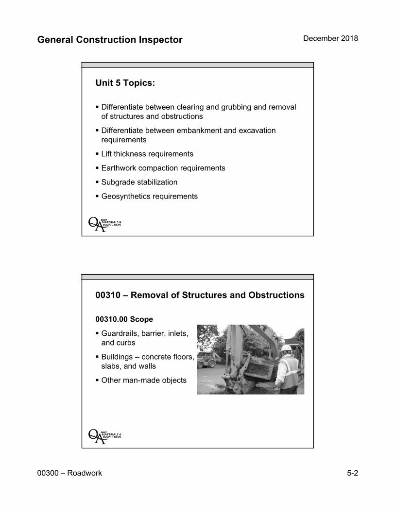
General Construction Inspector December 2018
00300 – Roadwork 5-2
Unit 5 Topics:
Differentiate between clearing and grubbing and removal of structures and obstructions
Differentiate between embankment and excavation requirements
Lift thickness requirements
Earthwork compaction requirements
Subgrade stabilization
Geosynthetics requirements
00310 – Removal of Structures and Obstructions
00310.00 Scope
Guardrails, barrier, inlets, and curbs
Buildings – concrete floors, slabs, and walls
Other man-made objects

General Construction Inspector December 2018
00300 – Roadwork 5-3
00310 – Removal of Structures and Obstructions
00310.40 Construction
Guardrail / barrier protection
When abutting work is to remain, make saw cuts to prevent damage
Remove obstructions at least two feet below subgrade
Scarify pavements
Breakup slabs and walls
00310 – Removal of Structures and Obstructions
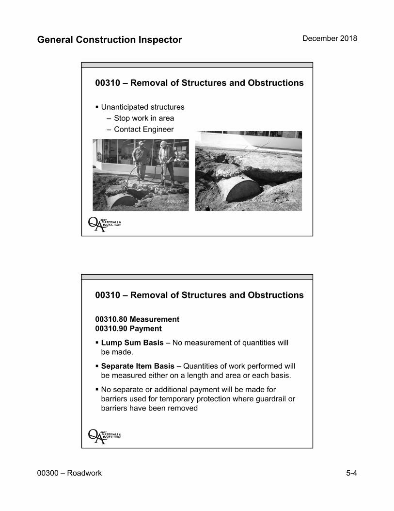
General Construction Inspector December 2018
00300 – Roadwork 5-4
00310 – Removal of Structures and Obstructions
Unanticipated structures
– Stop work in area
– Contact Engineer
00310 – Removal of Structures and Obstructions
00310.80 Measurement00310.90 Payment
Lump Sum Basis – No measurement of quantities will be made.
Separate Item Basis – Quantities of work performed will be measured either on a length and area or each basis.
No separate or additional payment will be made for barriers used for temporary protection where guardrail or barriers have been removed
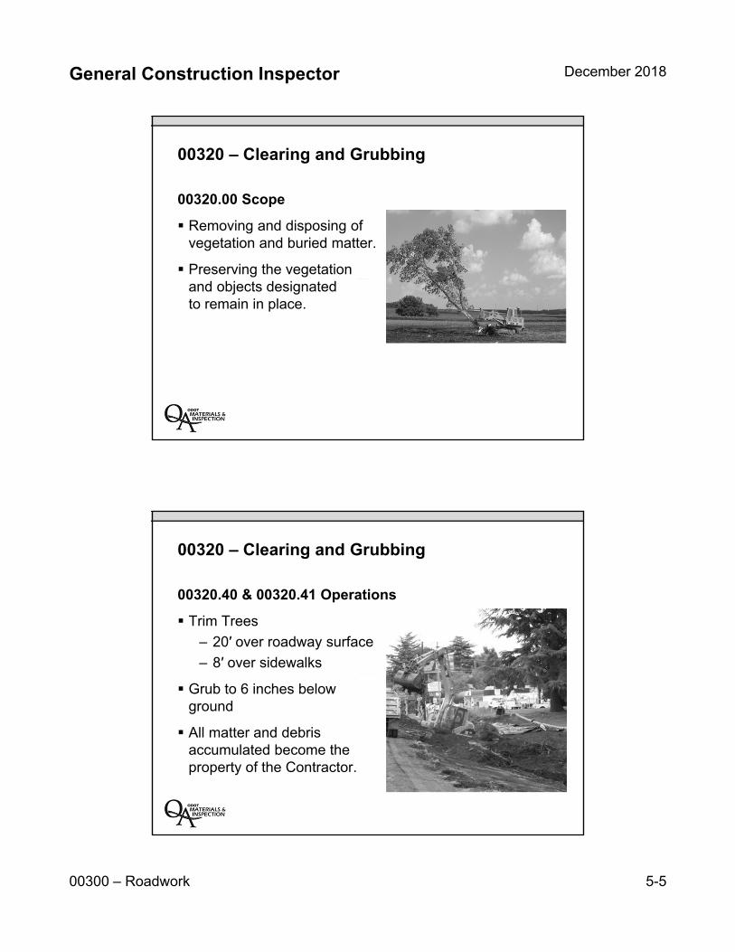
General Construction Inspector December 2018
00300 – Roadwork 5-5
00320 – Clearing and Grubbing
00320.00 Scope
Removing and disposing of vegetation and buried matter.
Preserving the vegetation and objects designated to remain in place.
00320 – Clearing and Grubbing
00320.40 & 00320.41 Operations
Trim Trees
– 20′ over roadway surface
– 8′ over sidewalks
Grub to 6 inches below ground
All matter and debris accumulated become the property of the Contractor.
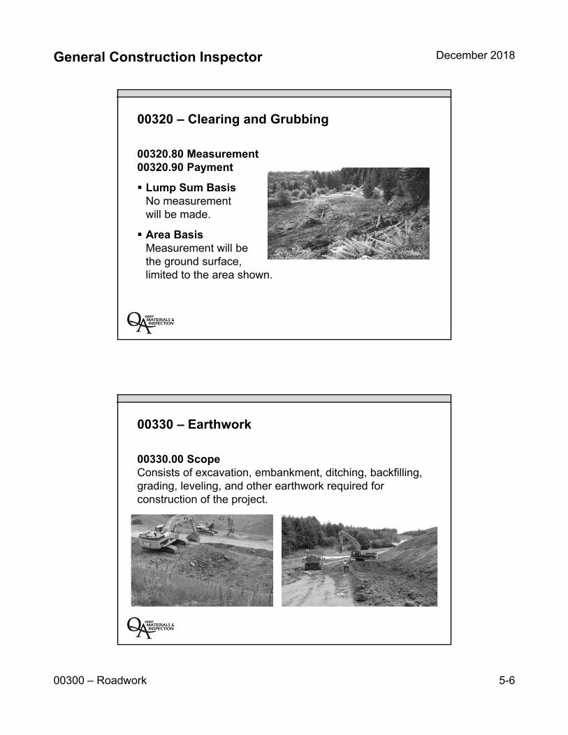
General Construction Inspector December 2018
00300 – Roadwork 5-6
00320 – Clearing and Grubbing
00320.80 Measurement00320.90 Payment
Lump Sum BasisNo measurement will be made.
Area BasisMeasurement will be the ground surface, limited to the area shown.
00330 – Earthwork
00330.00 Scope Consists of excavation, embankment, ditching, backfilling, grading, leveling, and other earthwork required for construction of the project.
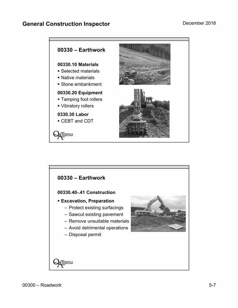
General Construction Inspector December 2018
00300 – Roadwork 5-7
00330 – Earthwork
00330.10 Materials
Selected materials
Native materials
Stone embankment
00330.20 Equipment
Tamping foot rollers
Vibratory rollers
0330.30 Labor
CEBT and CDT
00330 – Earthwork
00330.40-.41 Construction
Excavation, Preparation
– Protect existing surfacings
– Sawcut existing pavement
– Remove unsuitable materials
– Avoid detrimental operations
– Disposal permit
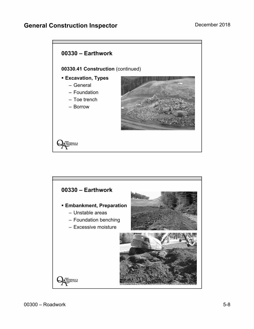
General Construction Inspector December 2018
00300 – Roadwork 5-8
00330 – Earthwork
00330.41 Construction (continued)
Excavation, Types
– General
– Foundation
– Toe trench
– Borrow
00330 – Earthwork
Embankment, Preparation
– Unstable areas
– Foundation benching
– Excessive moisture
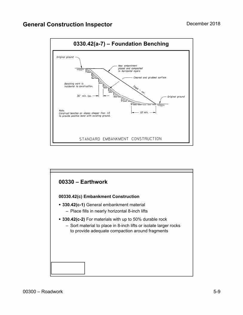
General Construction Inspector December 2018
00300 – Roadwork 5-9
0330.42(a-7) – Foundation Benching
00330 – Earthwork
00330.42(c) Embankment Construction
330.42(c-1) General embankment material
– Place fills in nearly horizontal 8-inch lifts
330.42(c-2) For materials with up to 50% durable rock
– Sort material to place in 8-inch lifts or isolate larger rocks to provide adequate compaction around fragments

General Construction Inspector December 2018
00300 – Roadwork 5-10
00330 – Earthwork
00330.42(c) Embankment Construction (continued)
330.42(c-2-d) For materials with more than 50% durable rock
– Manipulate rocks to minimize voids and form dense mass
– Lift thickness may be increased to 15 inches
– If percent passing the #200 is visibly less than 20%, rock fragment size and lift thickness may be increased to average maximum size of rock, but not to exceed 36 inches
330.42(c-2-e) for materials with nondurable rock
– Pulverize non-durable rock to 12 inches and place in 12-inch horizontal lifts
00330 – Earthwork
00330.42(d)Stone Embankment Construction
Rock fragments larger than 15 inches but no larger than 36 inches may be incorporated
Material in upper foot embankments or within 1 foot of culvert shall not exceed 3 inches in size
Deflection test according to ODOT TM158
General Construction Inspector December 2018
00300 – Roadwork 5-11
00330 – Earthwork
00330.43 Earthwork Compaction
Earthwork compaction tested according to MFTP
Moisture-density testable materials
– Route hauling trucks over full width of the embankment area
– Deflection testing according TM 158
– Density/moisture
00330 – Earthwork
00330.43 Construction (continued)
Non-moisture-density testable materials
– Check Special Provisions
– 12-inch nearly horizontal lifts
– Compact each layer with a minimum of four full coverages
– Deflection test TM 158
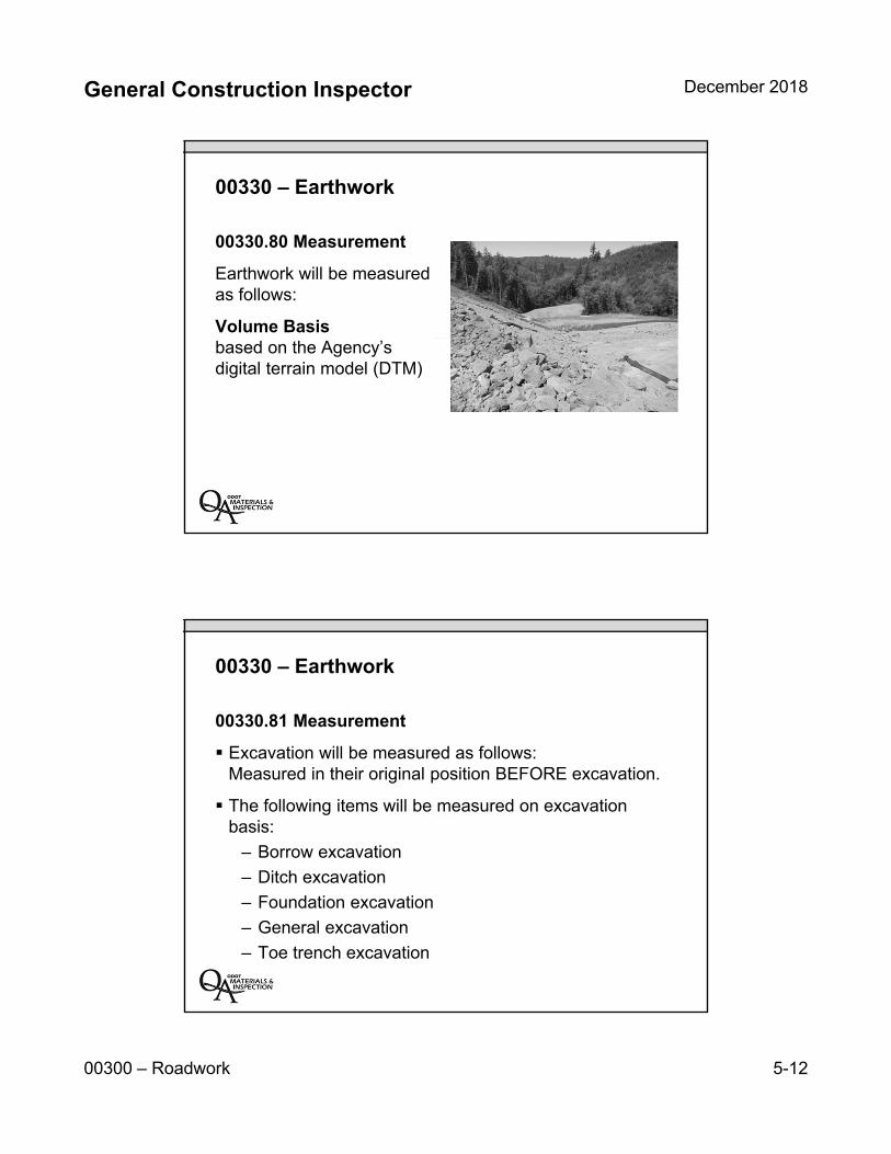
General Construction Inspector December 2018
00300 – Roadwork 5-12
00330 – Earthwork
00330.80 Measurement
Earthwork will be measured as follows:
Volume Basisbased on the Agency’s digital terrain model (DTM)
00330 – Earthwork
00330.81 Measurement
Excavation will be measured as follows:Measured in their original position BEFORE excavation.
The following items will be measured on excavation basis:
– Borrow excavation
– Ditch excavation
– Foundation excavation
– General excavation
– Toe trench excavation
General Construction Inspector December 2018
00300 – Roadwork 5-13
00330 – Earthwork
00330.82 Measurement
Embankment will be measured as follows:Measured in their final embankment position. Measure-ment will be limited to lines, grades, and slopes of the ORIGINALground contours established before the Contractor begins any work on the project.
The following items will be measured on embankment basis:
– Embankment in place
– Stone embankment
– Extra for selected _______ material
00330 – Earthwork
00330.90 Payment The accepted quantities of earthwork performed under this section will be paid at the contract unit price, per unit of measurement, for each item that appears in the contract Bid Items.
What is the basis of performance for earthwork on contract 14785? excavation or embankment project?
Verify in Special Provisions
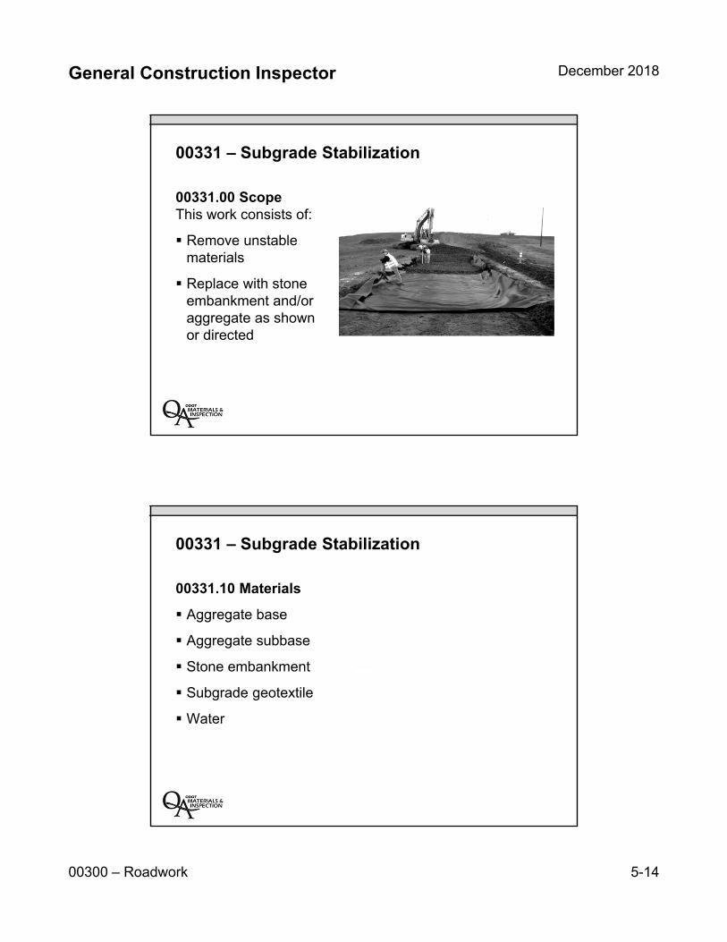
General Construction Inspector December 2018
00300 – Roadwork 5-14
00331 – Subgrade Stabilization
00331.00 ScopeThis work consists of:
Remove unstable materials
Replace with stone embankment and/or aggregate as shown or directed
00331 – Subgrade Stabilization
00331.10 Materials
Aggregate base
Aggregate subbase
Stone embankment
Subgrade geotextile
Water
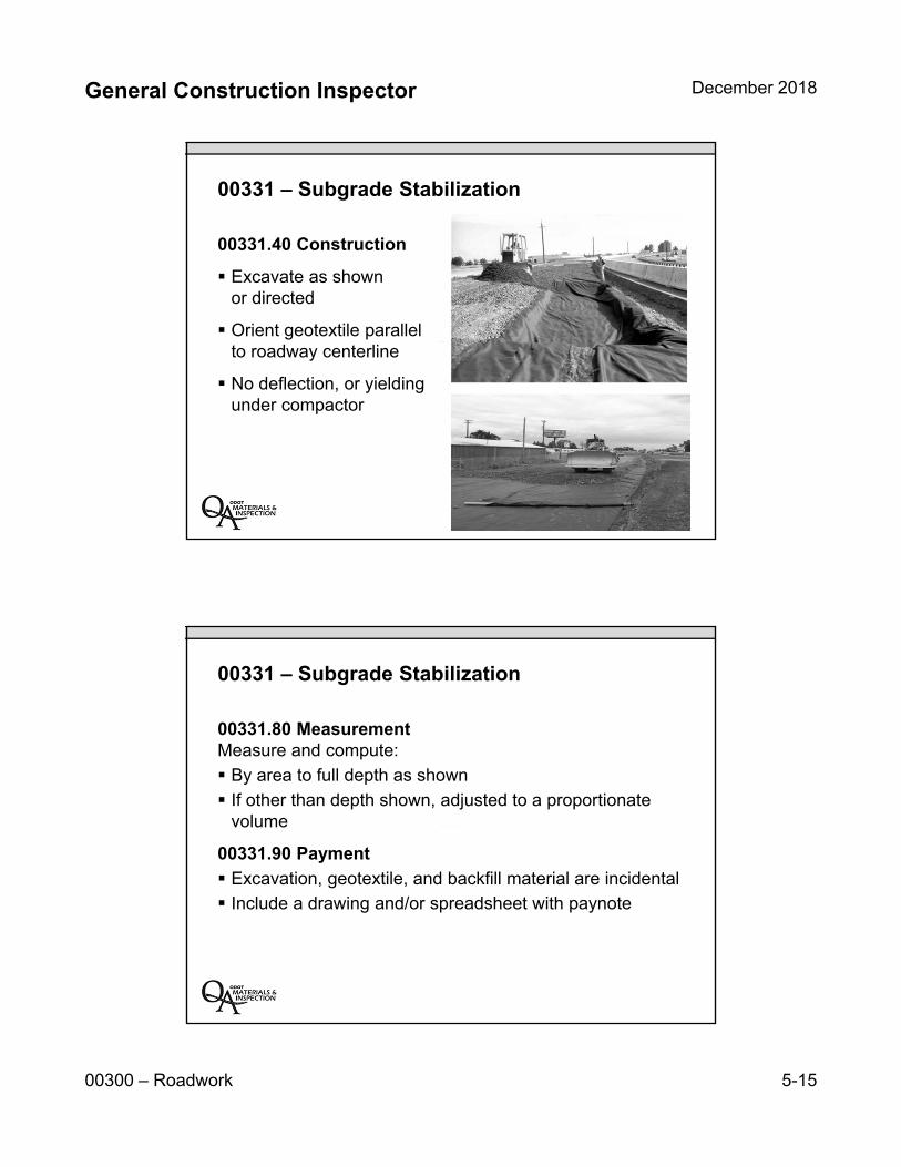
General Construction Inspector December 2018
00300 – Roadwork 5-15
00331 – Subgrade Stabilization
00331.40 Construction
Excavate as shown or directed
Orient geotextile parallel to roadway centerline
No deflection, or yielding under compactor
00331 – Subgrade Stabilization
00331.80 Measurement Measure and compute:
By area to full depth as shown
If other than depth shown, adjusted to a proportionate volume
00331.90 Payment
Excavation, geotextile, and backfill material are incidental
Include a drawing and/or spreadsheet with paynote
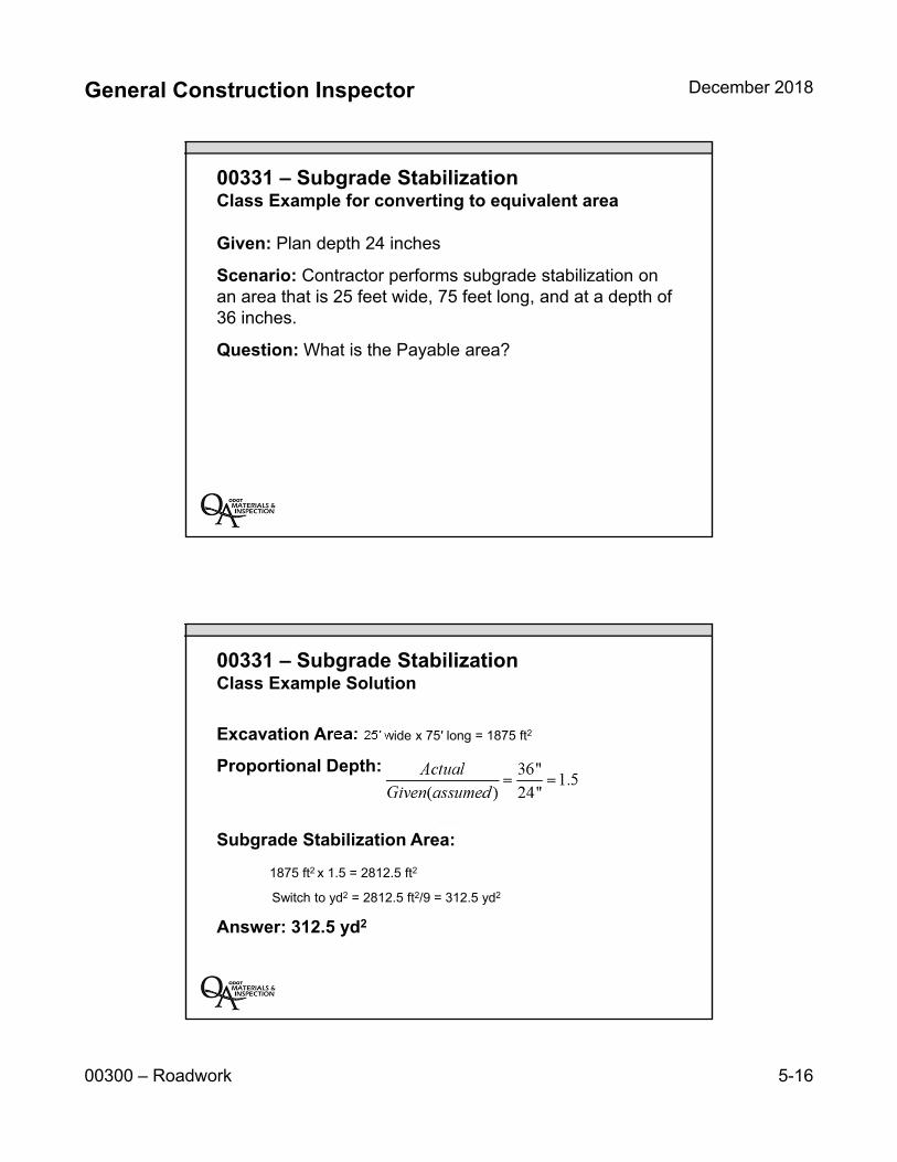
General Construction Inspector December 2018
00300 – Roadwork 5-16
00331 – Subgrade StabilizationClass Example for converting to equivalent area
Given: Plan depth 24 inches
Scenario: Contractor performs subgrade stabilization on an area that is 25 feet wide, 75 feet long, and at a depth of 36 inches.
Question: What is the Payable area?
00331 – Subgrade StabilizationClass Example Solution
Excavation Area: 25′ wide x 75′ long = 1875 ft2
Proportional Depth:
Subgrade Stabilization Area:
1875 ft2 x 1.5 = 2812.5 ft2
Switch to yd2 = 2812.5 ft2/9 = 312.5 yd2
Answer: 312.5 yd2
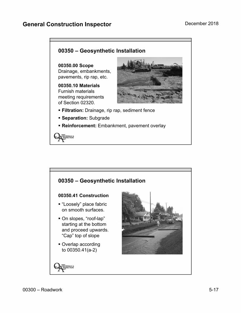
General Construction Inspector December 2018
00300 – Roadwork 5-17
00350 – Geosynthetic Installation
00350.00 Scope Drainage, embankments, pavements, rip rap, etc.
00350.10 MaterialsFurnish materials meeting requirements of Section 02320.
Filtration: Drainage, rip rap, sediment fence
Separation: Subgrade
Reinforcement: Embankment, pavement overlay
00350 – Geosynthetic Installation
00350.41 Construction
“Loosely” place fabric on smooth surfaces.
On slopes, “roof-lap” starting at the bottom and proceed upwards. “Cap” top of slope
Overlap according to 00350.41(a-2)
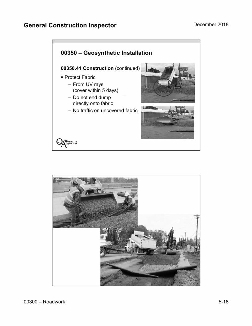
General Construction Inspector December 2018
00300 – Roadwork 5-18
00350 – Geosynthetic Installation
00350.41 Construction (continued)
Protect Fabric
– From UV rays (cover within 5 days)
– Do not end dump directly onto fabric
– No traffic on uncovered fabric

General Construction Inspector December 2018
00300 – Roadwork 5-19
00350 – Geosynthetic Installation
00350.80 Measurement00350.90 Payment
Payment will be in full for furnishing and placing all materials, and for furnishing all equipment, labor, and incidentals necessary to complete the work as specified.
No payment for construction laps, seams, joints, or repair patches.
Key Inspection Points
Look for soft spots in subgrade
Perform informal deflection testing
Identify maximum depth and limits of stabilization. Do it once, do it right
Keep project site stable
Diligence on geosynthetic measurement
Estimate quantities of excavation or embankment
Resolve quantity discrepancies as soon as possible
General Construction Inspector December 2018
00300 – Roadwork 5-20
Unit 5 Review:
Clearing and grubbing and removal of structures and obstructions
Embankment and excavation requirements
Earthwork compaction requirements
Subgrade stabilization requirements
Geosynthetics requirements
INSERT TAB
Unit 6 00400 – Drainage & Sewers
General Construction Inspector December 2018
00400 – Drainage and Sewers 6-1
Unit 6 00400
Drainage and Sewers
00400 – Drainage and Sewers
Trench Excavation, Bedding, and Backfill (405)
Commercial Grade Concrete (440)
Sanitary, Storm, Culvert, Siphon, and Irrigation Pipe (445)
Manholes, Catch Basins, and Inlets (470)
General Construction Inspector December 2018
00400 – Drainage and Sewers 6-2
Unit 6 Topics:
Trench excavation and materials
Commercial grade concrete
Sanitary, storm, culvert pipe materials
Pipe measurement and payment
Manholes and inlets construction
00405 – Trench Excavation, Bedding & Backfill
00405.00 ScopeExcavating trenches, constructing trench foundations, placing bedding, pipe zone material and backfill for all pipe under 72 inches.
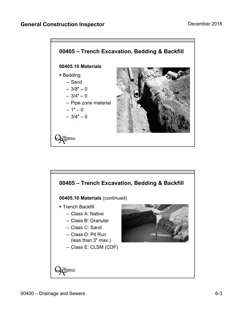
General Construction Inspector December 2018
00400 – Drainage and Sewers 6-3
00405 – Trench Excavation, Bedding & Backfill
00405.10 Materials
Bedding
– Sand
– 3/8″ – 0
– 3/4″ – 0
– Pipe zone material
– 1″ – 0
– 3/4″ – 0
00405 – Trench Excavation, Bedding & Backfill
00405.10 Materials (continued)
Trench Backfill
– Class A: Native
– Class B: Granular
– Class C: Sand
– Class D: Pit Run (less than 3″ max.)
– Class E: CLSM (CDF)
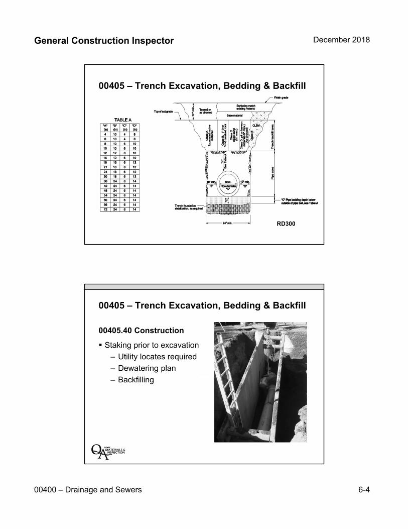
General Construction Inspector December 2018
00400 – Drainage and Sewers 6-4
00405 – Trench Excavation, Bedding & Backfill
RD300
00405 – Trench Excavation, Bedding & Backfill
00405.40 Construction
Staking prior to excavation
– Utility locates required
– Dewatering plan
– Backfilling
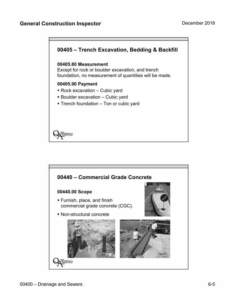
General Construction Inspector December 2018
00400 – Drainage and Sewers 6-5
00405 – Trench Excavation, Bedding & Backfill
00405.80 MeasurementExcept for rock or boulder excavation, and trench foundation, no measurement of quantities will be made.
00405.90 Payment
Rock excavation – Cubic yard
Boulder excavation – Cubic yard
Trench foundation – Ton or cubic yard
00440 – Commercial Grade Concrete
00440.00 Scope
Furnish, place, and finish commercial grade concrete (CGC).
Non-structural concrete
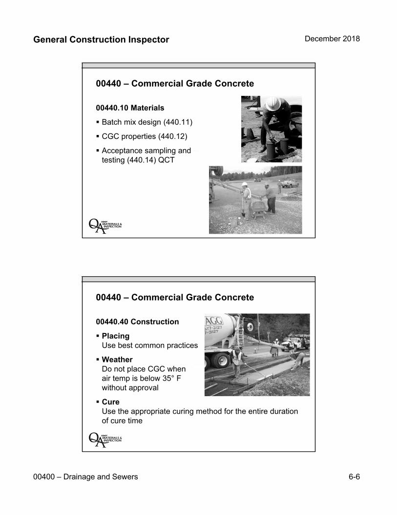
General Construction Inspector December 2018
00400 – Drainage and Sewers 6-6
00440 – Commercial Grade Concrete
00440.10 Materials
Batch mix design (440.11)
CGC properties (440.12)
Acceptance sampling and testing (440.14) QCT
00440 – Commercial Grade Concrete
00440.40 Construction
PlacingUse best common practices
WeatherDo not place CGC when air temp is below 35° F without approval
CureUse the appropriate curing method for the entire duration of cure time

General Construction Inspector December 2018
00400 – Drainage and Sewers 6-7
00440 – Commercial Grade Concrete
00440.80 MeasurementNo measurement of quantities will be made for CGC.
00440.90 PaymentNo separate or additional payment will be made for CGC. Payment will be included inpayment for appropriate items under which this Work is required.
00445 – Sanitary, Storm, Culvert, Siphon & Irrigation Pipe
00445.00 Scope This Work includes constructing joints and connections to other drainage structures or systems at the locations and grades shown or as directed.
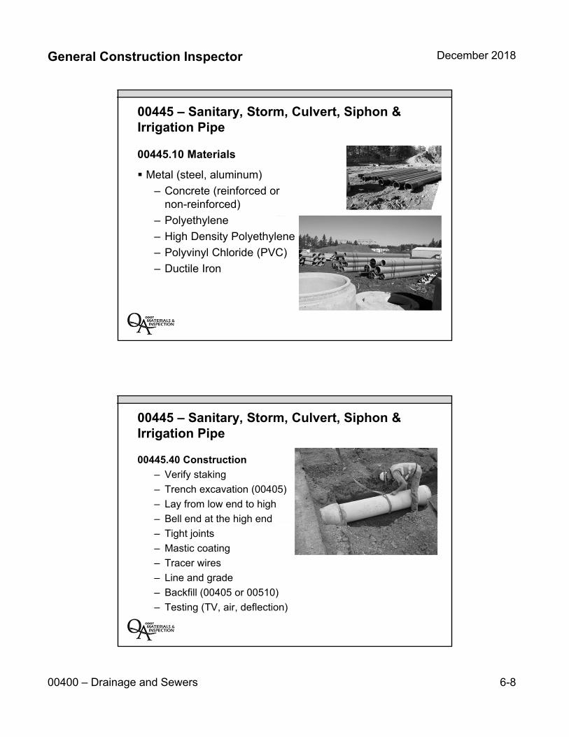
General Construction Inspector December 2018
00400 – Drainage and Sewers 6-8
00445 – Sanitary, Storm, Culvert, Siphon & Irrigation Pipe
00445.10 Materials
Metal (steel, aluminum)
– Concrete (reinforced or non-reinforced)
– Polyethylene
– High Density Polyethylene (HDPE)
– Polyvinyl Chloride (PVC)
– Ductile Iron
00445 – Sanitary, Storm, Culvert, Siphon & Irrigation Pipe
00445.40 Construction
– Verify staking
– Trench excavation (00405)
– Lay from low end to high
– Bell end at the high end
– Tight joints
– Mastic coating
– Tracer wires
– Line and grade
– Backfill (00405 or 00510)
– Testing (TV, air, deflection)
General Construction Inspector December 2018
00400 – Drainage and Sewers 6-9
00445 – Sanitary, Storm, Culvert, Siphon & Irrigation Pipe
00445.80 Measurement Pipes
LengthAlong pipe flow line from center to center of manholes, inlets, special sections or the ends of the pipe
Depth
– Excavation areas: The depth is the maximum vertical distance from flow line and original ground or subsurface (whichever is less)
– Embankment areas: The depth is the maximum vertical distance flow line and the surface of the constructed embankment
00445 – Sanitary, Storm, Culvert, Siphon & Irrigation Pipe
00445.90 Payment
Pipe – ft
Tees, wyes, slip joints, sloped end sections, safety end sections, concrete pipe anchors, and concrete closure collars – each
Concrete in blocks – yd3
Reinforcement in blocks – Lump sum or lb.
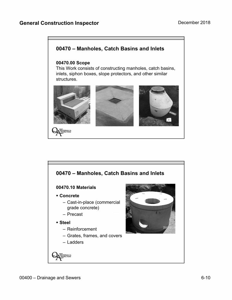
General Construction Inspector December 2018
00400 – Drainage and Sewers 6-10
00470 – Manholes, Catch Basins and Inlets
00470.00 Scope This Work consists of constructing manholes, catch basins, inlets, siphon boxes, slope protectors, and other similar structures.
00470 – Manholes, Catch Basins and Inlets
00470.10 Materials
Concrete
– Cast-in-place (commercialgrade concrete)
– Precast
Steel
– Reinforcement
– Grates, frames, and covers
– Ladders

General Construction Inspector December 2018
00400 – Drainage and Sewers 6-11
00470 – Manholes, Catch Basins and Inlets
00470.40 Construction
Verify staking
– Excavate and backfill per Section 00405
– Firm foundation
– Orientation of structure
– Plumb structure
– Water tight joints
– Hydrostatic and vacuumtesting
00470 – Manholes, Catch Basins and Inlets
00470.80 MeasurementMeasurement is per each complete unit
00470.90 PaymentPayment is per each complete unit

General Construction Inspector December 2018
00400 – Drainage and Sewers 6-12
Key Inspection Points:
Safety around trench work priority
Verify manhole and Inlet locations and grades
Work around underground conflicts
Ensure proper compaction, especially in roadway prism
Be proactive to make sure elements will be functional (water will flow)
Document any changes made in location and/or elevation of pipes or units
Unit 6 Review:
Trench excavation and materials
Commercial grade concrete
Sanitary, storm, culvert pipe materials
Pipe measurement and payment
Manholes and inlets construction
INSERT TAB
Unit 7 00600 – Bases
General Construction Inspector December 2018
00600 – Bases 7-1
Unit 700600Bases
00600 – Bases
Cold Plane Pavement Removal (00620)
Aggregate Base and Shoulders (00640)
Aggregate Subbase, Base, and Shoulders (00641)
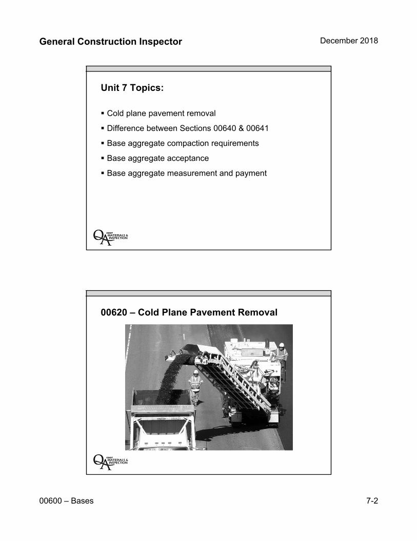
General Construction Inspector December 2018
00600 – Bases 7-2
Unit 7 Topics:
Cold plane pavement removal
Difference between Sections 00640 & 00641
Base aggregate compaction requirements
Base aggregate acceptance
Base aggregate measurement and payment
00620 – Cold Plane Pavement Removal
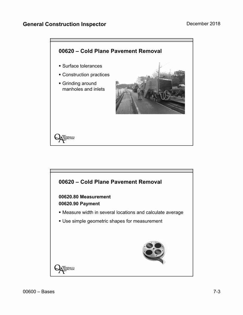
General Construction Inspector December 2018
00600 – Bases 7-3
00620 – Cold Plane Pavement Removal
Surface tolerances
Construction practices
Grinding aroundmanholes and inlets
00620 – Cold Plane Pavement Removal
00620.80 Measurement
00620.90 Payment
Measure width in several locations and calculate average
Use simple geometric shapes for measurement
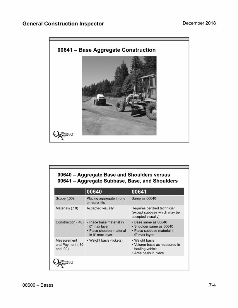
General Construction Inspector December 2018
00600 – Bases 7-4
00641 – Base Aggregate Construction
00640 – Aggregate Base and Shoulders versus00641 – Aggregate Subbase, Base, and Shoulders
00640 00641Scope (.00) Placing aggregate in one
or more liftsSame as 00640
Materials (.10) Accepted visually Requires certified technician (except subbase which may be accepted visually)
Construction (.40) • Place base material in 6" max layer
• Place shoulder material in 9" max layer
• Base same as 00640• Shoulder same as 00640• Place subbase material in
9" max layer
Measurement and Payment (.80 and .90)
• Weight basis (tickets) • Weight basis• Volume basis as measured in
hauling vehicle• Area basis in place
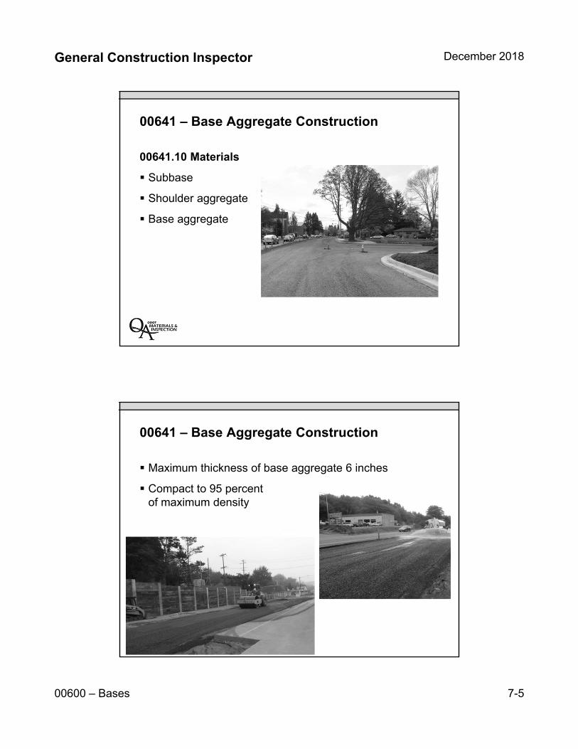
General Construction Inspector December 2018
00600 – Bases 7-5
00641 – Base Aggregate Construction
00641.10 Materials
Subbase
Shoulder aggregate
Base aggregate
00641 – Base Aggregate Construction
Maximum thickness of base aggregate 6 inches
Compact to 95 percent of maximum density
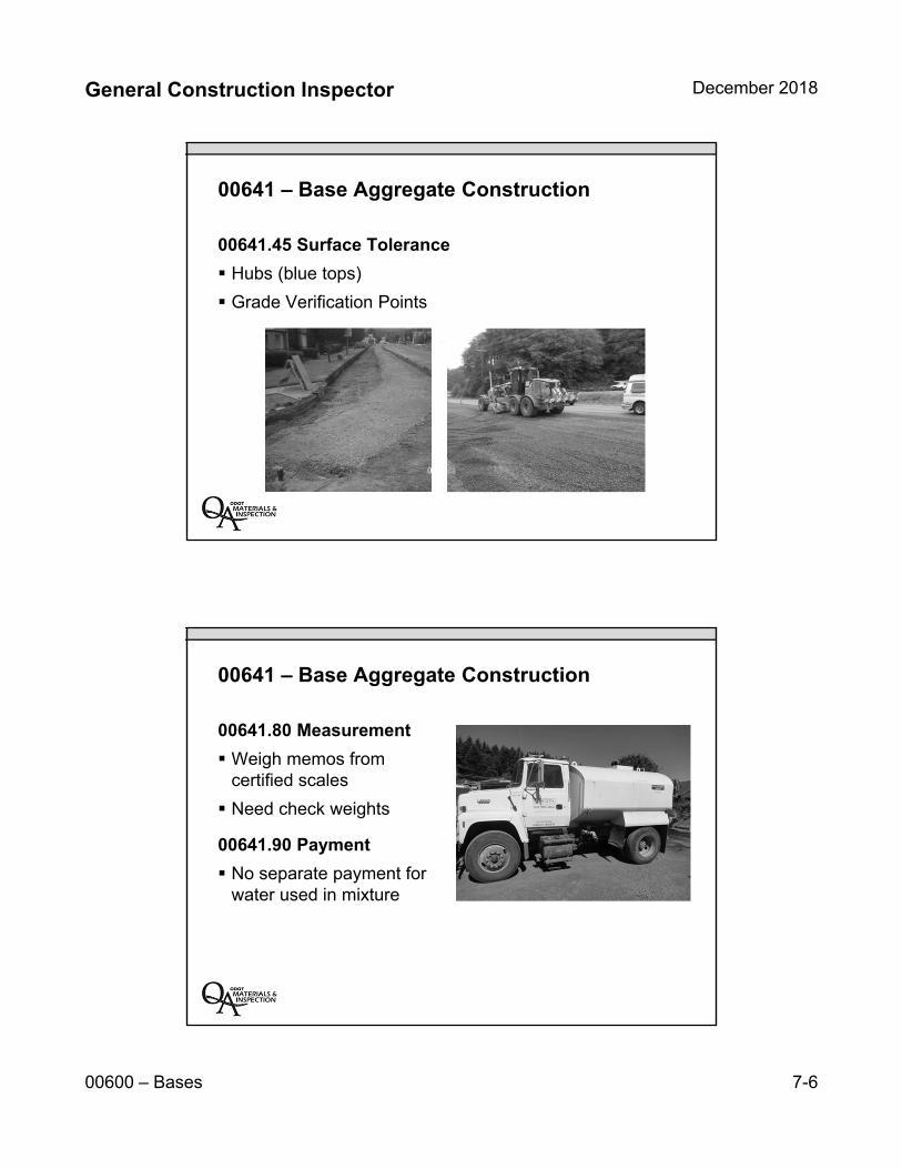
General Construction Inspector December 2018
00600 – Bases 7-6
00641 – Base Aggregate Construction
00641.45 Surface Tolerance
Hubs (blue tops)
Grade Verification Points
00641 – Base Aggregate Construction
00641.80 Measurement
Weigh memos from certified scales
Need check weights
00641.90 Payment
No separate payment for water used in mixture
General Construction Inspector December 2018
00600 – Bases 7-7
Key Inspection Points:
Make sure Contractor does not overwork base aggregate
May be difficult to compact gravel source base aggregate
Have a positive way to verify quantity of base aggregate
– Many similar aggregates are incidental to work
• Pipe zone material
Have Grade Verification Points and compaction resultsprior to paving
Timely collection and summary of tickets
Unit 7 Review:
Cold plane pavement removal
Difference between Sections 640 & 641
Base aggregate acceptance
Base aggregate compaction requirements
Base aggregate measurement and payment

7-8
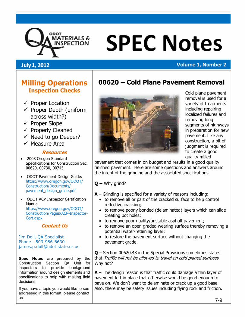
Milling Operations Inspection Checks
Proper Location Proper Depth (uniform
across width?) Proper Slope Properly Cleaned Need to go Deeper? Measure Area
Resources • 2008 Oregon Standard
Specifications for Construction Sec.00620, 00730, 00745
• ODOT Pavement Design Guide:https://www.oregon.gov/ODOT/Construction/Documents/pavement_design_guide.pdf
• ODOT ACP Inspector CertificationManualhttps://www.oregon.gov/ODOT/Construction/Pages/ACP-Inspector-Cert.aspx
Contact Us
Jim Doll, QA SpecialistPhone: [email protected]
Spec Notes are prepared by theConstruction Section QA Unit forinspectors to provide background information around design elements and specifications to help with making field decisions.
If you have a topic you would like to see addressed in this format, please contact us.
00620 – Cold Plane Pavement Removal
Cold plane pavement removal is used for a variety of treatments including repairing localized failures and removing long segments of highways in preparation for new pavement. Like any construction, a bit of judgment is required to create a good quality milled
pavement that comes in on budget and results in a good quality finished pavement. Here are some questions and answers around the intent of the grinding and the associated specifications.
Q -- Why grind?
A – Grinding is specified for a variety of reasons including: to remove all or part of the cracked surface to help control reflective cracking;
to remove poorly bonded (delaminated) layers which can slide creating pot holes;
to remove poor quality/unstable asphalt pavement; to remove an open graded wearing surface thereby removing a potential water-retaining layer;
to restore the pavement surface without changing the pavement grade.
Q – Section 00620.43 in the Special Provisions sometimes states that Traffic will not be allowed to travel on cold planed surfaces. Why not?
A – The design reason is that traffic could damage a thin layer of pavement left in place that otherwise would be good enough to pave on. We don’t want to delaminate or crack up a good base. Also, there may be safety issues including flying rock and friction.
7-9

Q – What happens if we grind deeper than the design?
A – Grinding deeper may result in leaving a thin section of pavement that could become dislodged and delaminate. In some areas, like shoulders, aggregate base may be encountered. Going deeper can result in significant pavement quantity overruns. If an extra ½” of mix is required for 500 feet for a 14-foot wide section, the added mix is more than 20 tons. It adds up!
Q – So then, how deep is deep enough?
A – For most situations, the design section should be adequate. For delaminated pavements, once the grinding starts, it is the inspector’s duty to verify that adequate preparation has been made. Check for loose chunks or slabs of material that are left after the pavement has been swept. Can you kick off pieces around the edges? Can you dislodge large sections easily either with your boot or shovel?
Loose and delaminated sections need to be removed which should be readily accomplished with a shovel. When in doubt, check with your PM! The photo below shows a pavement ready for an inlay that was partially delaminated. The loose
slabs have been removed and the pavement swept. While it might not look perfect, all broken edges are
gone and the remaining section adheres well to the layer below it. Once prepared, try to minimize the truck traffic on the pavement to reduce the potential for dislodging more material.
Q – What happens if we are overrunning our quantities and decide to grind a thinner section?
A – Grinding thinner can increase the potential for reflective cracking or increase the potential to leave delaminated pavement sections in place that will lead to shoving and pot holes. With an open graded wearing surface, we typically don’t want to leave an open graded layer under a dense graded pavement because it can trap water and lead to
future problems. Also, depending on the pavement design, a thinner pavement could compromise the pavement life as the design may require new HMAC thickness to accommodate future traffic.
Q – We are done with the grinding, what should we look for during sweeping?
A – Per the specifications (00730.42 and 00745.42), prior to applying tack, remove all material, loose or otherwise, that will reduce adhesion of the tack by brooming, flushing with water, or other approved methods. Dust behind a fast-moving vehicle driving on the milled surface is an indicator of inadequate preparation. The areas to pay close attention to are the corners as shown in the graphic.
Q – The sweeping is done, can we start paving?
A – Maybe. If traffic has been running on the cold planed surface, Section 00620.43 states that …Before beginning paving operations, make repairs to the existing cold planed surface as directed. The intent of the specification is to locate any areas that have cracked or delaminated under traffic. Also, Section 00745.42 requires Preparation of Underlying Surfaces which refers to Section 00610 Reconditioning Existing Roadway which requires removal of unstable material. Now, back to the boilerplate for Section 00620.43, Payment for the repairs will be made according to Section 00196. Bottom line, repair the failed sections caused by traffic and pay for it as Extra Work.
Q – What’s important about applying tack?
A –After the pavement is swept, per 00745.42 all surfaces that will be next to new HMAC, should be tack coated. This includes the edges of the trench; many joint failures have been attributed to missing tack. Be sure that enough tack is placed and that the trucks are not picking it up during paving. The goal is to glue the pavement layers together for long term performance.
7-10

INSERT TAB
Unit 8 00700 – Wearing Surfaces
General Construction Inspector December 2018
00700 –Wearing Surfaces 8-1
Unit 800700
Wearing Surfaces
00700 – Roadwork
Asphalt Concrete Pavement (ACP) (745)
Miscellaneous ACP Structures (749)
Miscellaneous PCC Structures (759)

General Construction Inspector December 2018
00700 –Wearing Surfaces 8-2
Unit 8 Topics:
Basics of Asphalt Concrete Pavement (ACP)
ACP measurement and payment
Construction of miscellaneous ACP structures
Construction of miscellaneous PCC structures
00738 – Safety Edge
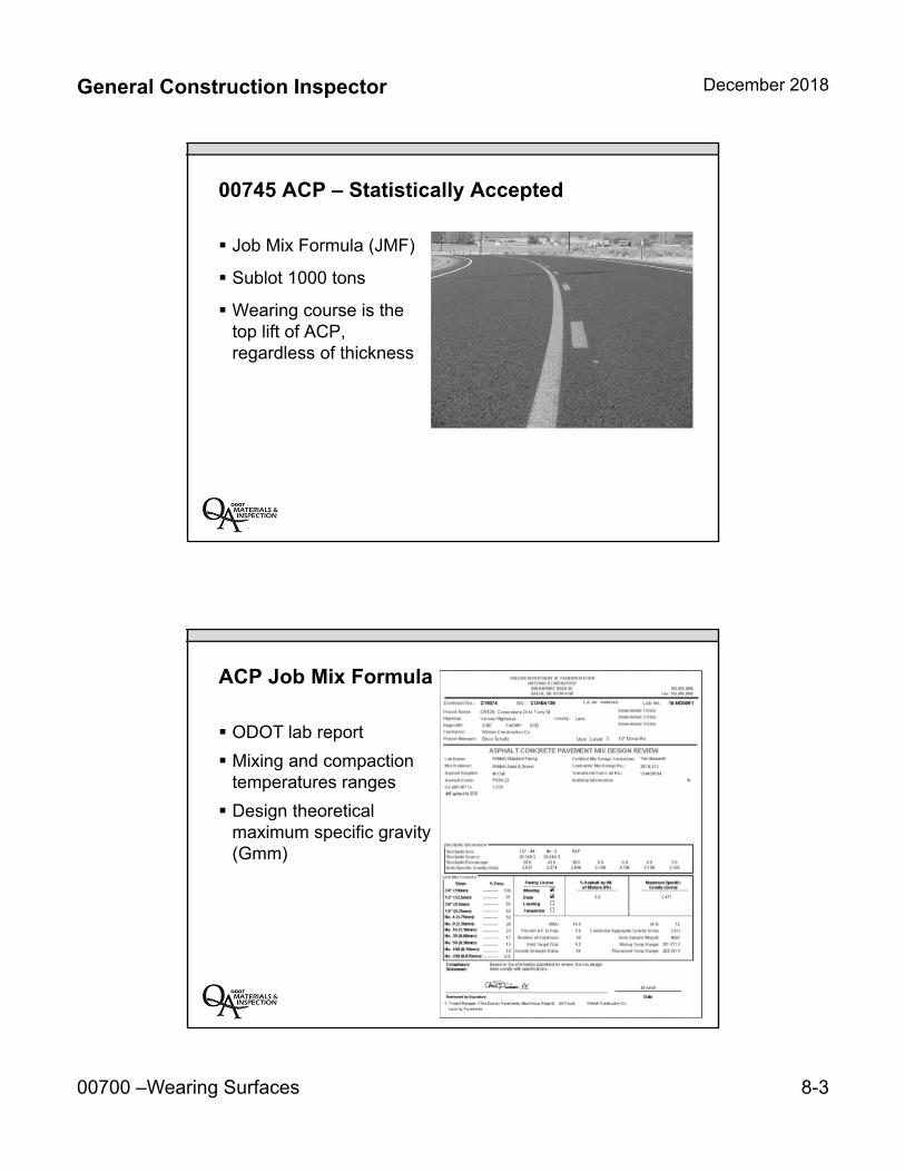
General Construction Inspector December 2018
00700 –Wearing Surfaces 8-3
00745 ACP – Statistically Accepted
Job Mix Formula (JMF)
Sublot 1000 tons
Wearing course is thetop lift of ACP,regardless of thickness
ACP Job Mix Formula
ODOT lab report
Mixing and compactiontemperatures ranges
Design theoreticalmaximum specific gravity(Gmm)
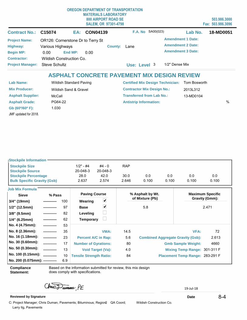
OREGON DEPARTMENT OF TRANSPORTATIONMATERIALS LABORATORY
800 AIRPORT ROAD SESALEM, OR 97301-4798
503.986.3000Fax: 503.986.3096
Contract No.: C15074 EA: CON04139
ASPHALT CONCRETE PAVEMENT MIX DESIGN REVIEW
Lab No. 18-MD0051
Project Name: OR126: Cornerstone Dr to Terry St
Highway: Various Highways
Begin MP: 0.00 End MP: 0.00
County: Lane
Contractor: Wildish Construction Co.
Project Manager: Steve Schultz Use: Level 3 1/2" Dense Mix
Amendment 1 Date:
Amendment 2 Date:
Lab Name: Wildish Standard Paving Certified Mix Design Technician: Tom Bosworth
Mix Producer: Wildish Sand & Gravel
Asphalt Supplier: McCall
Asphalt Grade: PG64-22
Contractor Mix Design No.: 2013L312
Transferred from Lab No.: 13-MD0104
JMF updated for 2018.
Stockpile Information
Stockpile Size
Stockpile Source
Stockpile Percentage
Bulk Specific Gravity (Gsb)
28.0
20-048-3
2.637
1/2" - #4 #4 - 0
20-048-3
42.0
2.574
RAP
30.0
2.646
0.0
0.100
0.0
0.100
0.0
0.100
0.0
0.100
Job Mix Formula
Sieve % Pass
3/4" (19mm) 100
1/2" (12.5mm) 97
3/8" (9.5mm) 82
No. 4 (4.75mm): 53
No. 8 (2.36mm): 35
No. 30 (0.60mm): 17
No. 200 (0.075mm): 6.9
-----------
-----------
-----------
-----------
-----------
-----------
-----------
Paving Course
Leveling
Wearing
Base
% Asphalt by Wt.
of Mixture (Pb)
5.8
Maximum Specific
Gravity (Gmm):
2.471
VMA: 14.5
Percent A/C in Rap: 5.6
Number of Gyrations: 80
Void Target (Va): 4.0
Tensile Strength Ratio: 84
Combined Aggregate Gravity (Gsb): 2.613
Compliance
Statement:
Based on the information submitted for review, this mix design does comply with specifications.
Reviewed by Signature Date
Gmb Sample Weight: 4660
Mixing Temp Range: 301-311 F
Placement Temp Range: 283-291 F
Temporary
Antistrip Information: %
VFA: 72
Gb (60º/60º F): 1.030
C: Project Manager; Chris Duman, Pavements; Bituminous; Region QA Coord; 2
Larry Ilg, Pavements
Wildish Construction Co.
F.A. No SA00(023)
Amendment 3 Date:
1/4" (6.25mm) 62-----------
No. 16 (1.18mm): 23-----------
No. 50 (0.30mm): 13-----------
No. 100 (0.15mm): 10-----------
19-Jul-18
2
8-4
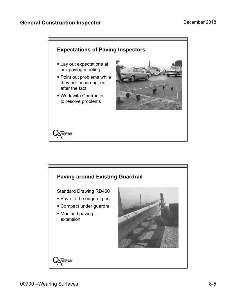
General Construction Inspector December 2018
00700 –Wearing Surfaces 8-5
Expectations of Paving Inspectors
Lay out expectations atpre-paving meeting
Point out problems whilethey are occurring, notafter the fact
Work with Contractorto resolve problems
Paving around Existing Guardrail
Standard Drawing RD400
Pave to the edge of post
Compact under guardrail
Modified pavingextension
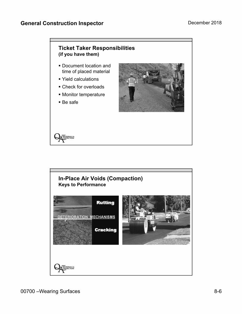
General Construction Inspector December 2018
00700 –Wearing Surfaces 8-6
Ticket Taker Responsibilities(if you have them)
Document location andtime of placed material
Yield calculations
Check for overloads
Monitor temperature
Be safe
In-Place Air Voids (Compaction)Keys to Performance
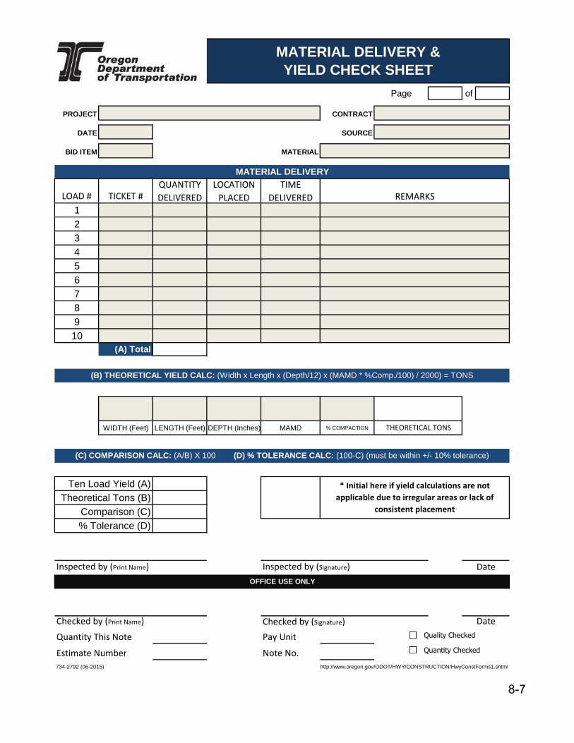
Page of
PROJECT CONTRACT
DATE SOURCE
BID ITEM MATERIAL
LOAD # TICKET #
QUANTITY
DELIVERED
LOCATION
PLACED
TIME
DELIVERED
12345678910
(A) Total 0.00
WIDTH (Feet) LENGTH (Feet) DEPTH (Inches) MAMD % COMPACTION
0.00#VALUE!#VALUE! #VALUE!
Inspected by (Print Name) Inspected by (Signature)
Checked by (Signature)
Quantity This Note Pay Unit
Estimate Number Note No.
734-2792 (06-2015) http://www.oregon.gov/ODOT/HWY/CONSTRUCTION/HwyConstForms1.shtml
Date
MATERIAL DELIVERY
* Initial here if yield calculations are not
applicable due to irregular areas or lack of
consistent placement
% Tolerance (D)
DateChecked by (Print Name)
Comparison (C)
Ten Load Yield (A)Theoretical Tons (B)
OFFICE USE ONLY
MATERIAL DELIVERY & YIELD CHECK SHEET
(B) THEORETICAL YIELD CALC: (Width x Length x (Depth/12) x (MAMD * %Comp./100) / 2000) = TONS
(C) COMPARISON CALC: (A/B) X 100 (D) % TOLERANCE CALC: (100-C) (must be within +/- 10% tolerance)
0.00THEORETICAL TONS
REMARKS
Quality Checked
Quantity Checked
8-7
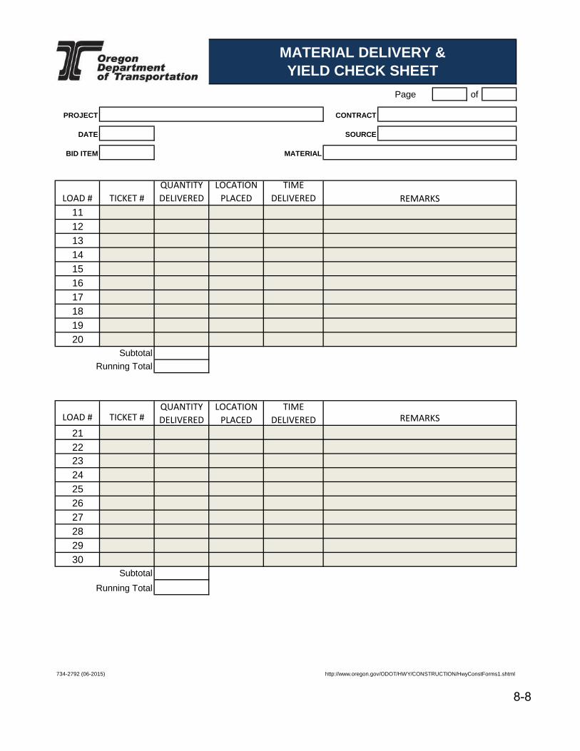
Page of
PROJECT CONTRACT
DATE SOURCE
BID ITEM MATERIAL
LOAD # TICKET #
QUANTITY
DELIVERED
LOCATION
PLACED
TIME
DELIVERED
11121314151617181920
Subtotal 0.00
Running Total
LOAD # TICKET #QUANTITY
DELIVERED
LOCATION
PLACED
TIME
DELIVERED
21222324252627282930
Subtotal 0.00
734-2792 (06-2015) http://www.oregon.gov/ODOT/HWY/CONSTRUCTION/HwyConstForms1.shtml
MATERIAL DELIVERY & YIELD CHECK SHEET
Running Total
REMARKS
REMARKS
8-8

General Construction Inspector December 2018
00700 –Wearing Surfaces 8-9
Importance of Compaction
Improves mechanicalstability
Improves resistance topermanent deformation
Reduces moisturepenetration
Improves fatigue resistance
Reduces low-temperaturecracking potential
ACP Longitudinal Joints
Offset joints by at least6 inches
For wear course, placeat lane lines or fog lines(will require surveyif layout is complex)
Construct tight, even,and straight joints
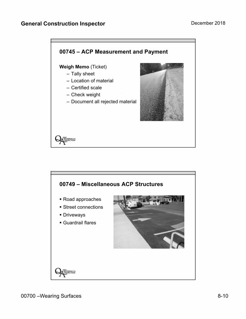
General Construction Inspector December 2018
00700 –Wearing Surfaces 8-10
00745 – ACP Measurement and Payment
Weigh Memo (Ticket)
– Tally sheet
– Location of material
– Certified scale
– Check weight
– Document all rejected material
00749 – Miscellaneous ACP Structures
Road approaches
Street connections
Driveways
Guardrail flares
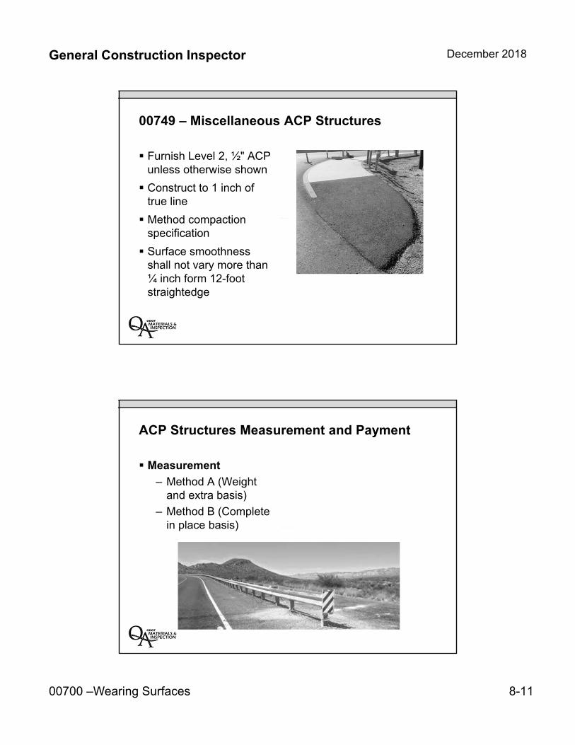
General Construction Inspector December 2018
00700 –Wearing Surfaces 8-11
00749 – Miscellaneous ACP Structures
Furnish Level 2, ½" ACPunless otherwise shown
Construct to 1 inch oftrue line
Method compactionspecification
Surface smoothnessshall not vary more than¼ inch form 12-footstraightedge
ACP Structures Measurement and Payment
Measurement
– Method A (Weightand extra basis)
– Method B (Completein place basis)
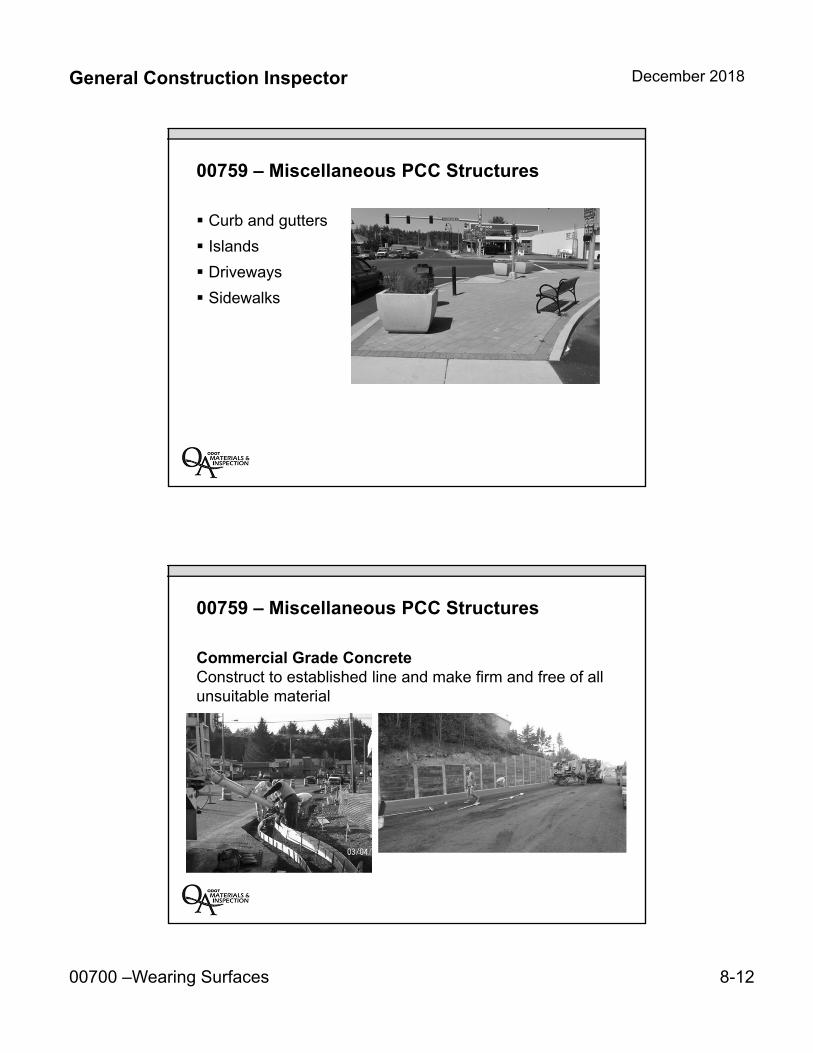
General Construction Inspector December 2018
00700 –Wearing Surfaces 8-12
00759 – Miscellaneous PCC Structures
Curb and gutters
Islands
Driveways
Sidewalks
00759 – Miscellaneous PCC Structures
Commercial Grade ConcreteConstruct to established line and make firm and free of all unsuitable material
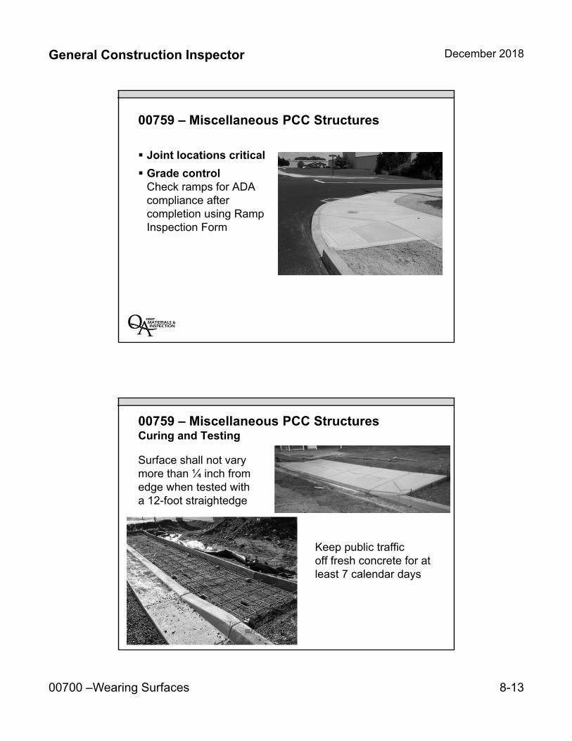
General Construction Inspector December 2018
00700 –Wearing Surfaces 8-13
00759 – Miscellaneous PCC Structures
Joint locations critical
Grade controlCheck ramps for ADAcompliance aftercompletion using RampInspection Form
00759 – Miscellaneous PCC StructuresCuring and Testing
Keep public traffic off fresh concrete for at least 7 calendar days
Surface shall not vary more than ¼ inch from edge when tested with a 12-foot straightedge

General Construction Inspector December 2018
00700 –Wearing Surfaces 8-14
00759 – Miscellaneous PCC Structures
00759.80 Measurement 00759.90 Payment
Volume and area basiswill be limited to neatlines
Length along the face ofstructure, including curbtapers or depressedlengths at driveways andramps
Key Inspection Points:
Note when paver stops or rollers are not running
Be proactive with paving…contact resources (PQME)if issues arise
Pay attention to joints (longitudinal and transverse)
QCT and visual acceptance of CGC
Verify lines and grades prior to placing concrete
Pay attention to ADA ramps
This is not an exhaustive review of ACP…take HMAC class
General Construction Inspector December 2018
00700 –Wearing Surfaces 8-15
Unit 8 Review:
Safety edge (Special Provision)
Asphalt Concrete Pavement (ACP)
ACP measurement and payment
Construction of Miscellaneous ACP structures
Construction of Miscellaneous PCC Structures

8-16
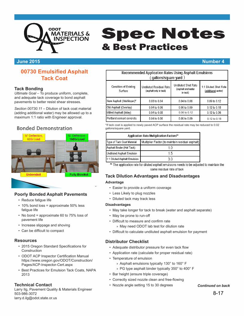
Spec Notes & Best Practices
June 2015 Number 4
00730 Emulsified Asphalt Tack Coat
Tack BondingUltimate Goal – To produce uniform, complete, and adequate tack coverage to bond asphalt pavements to better resist shear stresses.
Section 00730.11 – Dilution of tack coat material (adding additional water) may be allowed up to a maximum 1:1 ratio with Engineer approval.
Poorly Bonded Asphalt Pavements• Reduce fatigue life• 10% bond loss = approximate 50% less
fatigue life• No bond = approximate 60 to 75% loss of
pavement life• Increase slippage and shoving• Canbedifficulttocompact
Resources• 2015OregonStandardSpecificationsfor
Construction• ODOTACPInspectorCertificationManual https://www.oregon.gov/ODOT/Construction/Pages/ACP-Inspector-Cert.aspx
• Best Practices for Emulsion Tack Coats, NAPA 2013
Technical ContactLarry Ilg, Pavement Quality & Materials [email protected]
Tack Dilution Advantages and DisadvantagesAdvantage• Easier to provide a uniform coverage• Less Likely to plug nozzles• Diluted tack may track less
Disadvantages• May take longer for tack to break (water and asphalt separate)• May be prone to run-off• Difficulttomeasureandconfirmrate
» May need ODOT lab test for dilution rate• Difficulttocalculateundilutedasphaltemulsionforpayment
Distributor Checklist• Adequatedistributorpressureforeventackflow
• Application rate (calculate for proper residual rate)• Temperature of emulsion
» Asphalt emulsions typically 130° to 160° F» PG type asphalt binder typically 350° to 400° F
• Bar height (ensure triple coverage)• Correctlysizednozzlecleanandfree-flowing
• Nozzle angle setting 15 to 30 degrees Continued on back
( )
*If tack coat is applied to newly paved ACP surface the residual rate may be reduced to 0.02gallons/square yard.
0.06 to 0.12
0.12 to 0.18
8-17
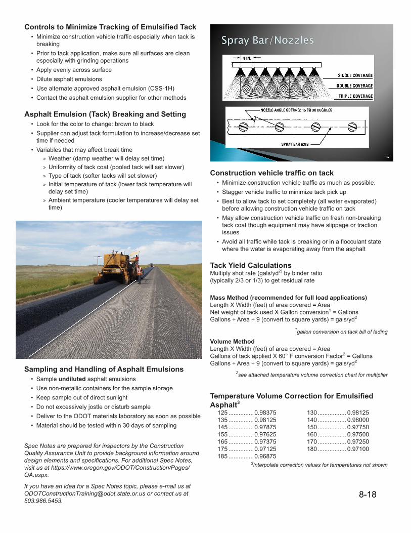
Controls to Minimize Tracking of Emulsified Tack• Minimizeconstructionvehicletrafficespeciallywhentackis
breaking• Prior to tack application, make sure all surfaces are clean
especially with grinding operations• Apply evenly across surface• Dilute asphalt emulsions• Use alternate approved asphalt emulsion (CSS-1H)• Contact the asphalt emulsion supplier for other methods
Asphalt Emulsion (Tack) Breaking and Setting• Look for the color to change: brown to black• Supplier can adjust tack formulation to increase/decrease set
time if needed• Variables that may affect break time
» Weather (damp weather will delay set time)» Uniformity of tack coat (pooled tack will set slower)» Type of tack (softer tacks will set slower)» Initial temperature of tack (lower tack temperature will
delay set time)» Ambient temperature (cooler temperatures will delay set
time)
Sampling and Handling of Asphalt Emulsions• Sample undiluted asphalt emulsions• Use non-metallic containers for the sample storage• Keep sample out of direct sunlight• Do not excessively jostle or disturb sample• Deliver to the ODOT materials laboratory as soon as possible• Material should be tested within 30 days of sampling
Construction vehicle traffic on tack• Minimizeconstructionvehicletrafficasmuchaspossible.
• Staggervehicletraffictominimizetackpickup
• Best to allow tack to set completely (all water evaporated)beforeallowingconstructionvehicletrafficontack
• Mayallowconstructionvehicletrafficonfreshnon-breakingtack coat though equipment may have slippage or tractionissues
• Avoidalltrafficwhiletackisbreakingorinaflocculantstatewhere the water is evaporating away from the asphalt
Tack Yield CalculationsMultiply shot rate (gals/yd2) by binder ratio (typically 2/3 or 1/3) to get residual rate
Mass Method (recommended for full load applications)Length X Width (feet) of area covered = AreaNet weight of tack used X Gallon conversion1 = GallonsGallons ÷ Area ÷ 9 (convert to square yards) = gals/yd2
1gallon conversion on tack bill of lading
Volume MethodLength X Width (feet) of area covered = AreaGallons of tack applied X 60° F conversion Factor2 = GallonsGallons ÷ Area ÷ 9 (convert to square yards) = gals/yd2
2see attached temperature volume correction chart for multiplier
Temperature Volume Correction for Emulsified Asphalt3
125 ...............0.98375 130 ................. 0.98125135 ...............0.98125 140 ................. 0.98000145 ...............0.97875 150 ................. 0.97750155 ...............0.97625 160 ................. 0.97500165 ...............0.97375 170 ................. 0.97250175 ...............0.97125 180 ................. 0.97100185 ...............0.96875
3Interpolate correction values for temperatures not shown
Spec Notes are prepared for inspectors by the Construction Quality Assurance Unit to provide background information around design elements and specifications. For additional Spec Notes, visit us at https://www.oregon.gov/ODOT/Construction/Pages/QA.aspx.
If you have an idea for a Spec Notes topic, please e-mail us at [email protected] or contact us at 503.986.5453.
8-18

SPEC Notes July 2, 2013 Number 3
Longitudinal Joint Construction
Discuss longitudinal joint construction atpre-pave meeting
Stagger joints at least 6” horizontallyfrom layer below
Follow all best practices for HMACplacement
Apply tack including face of the joint Overlap existing lane 1” +/-0.5” (overlap
milled edge 0.5” for inlays) Avoid pushing material away from the
joint. Don’t rake! First pass of breakdown roller should be
on the hot mat 6” from the cold joint orwith a 6” overhang on the cold mat.
Check compacted joint to ensure thatoverlap height is 0.1”, confirming that nobridging occurred.
Resources
2008 Oregon Standard Specifications for Construction Sec. 00745.61 ODOT ACP Inspector Certification Manualhttps://www.oregon.gov/ODOT/Construction/Pages/ACP-Inspector-Cert.aspx Longitudinal joint training through FHWA, Asphalt Institute http://www.asphaltinstitute.org/public/engineering/longitudinal-joint-information.dot
Technical Contact
Larry Ilg, Pavement Quality & Mat’ls Engineer
Phone: 503-986-3072
Spec Notes are prepared by the Construction Section QA Unit for inspectors to provide background information around design elements and specifications.
If you have a topic you would like to see addressed in
this format, please contact Jim Doll at ODOT.
745.61 Longitudinal Joints
All pavements have one internal weakness – joints.
Premature joint failures are the result of a combination of low density, permeability, segregation and lack of adhesion at the interface. According to a recent FHWA and Asphalt Institute study, improving HMAC joint quality is probably the single most important thing that can be done to improve pavement performance.
Q – So what’s so bad about raking?
A – Raking can remove material away from the pavement edge creating a trench area that does not get adequately compacted. As shown in Figure 1 on the next page.
If the red material (Box A) is removed from the hot mat, the roller bridges the area as shown in Box B. When the mat is finally compacted, the area under the wedge of material has experienced no compaction (Box C) so has a high void content and is most likely more permeable than the surrounding mat.
8-18
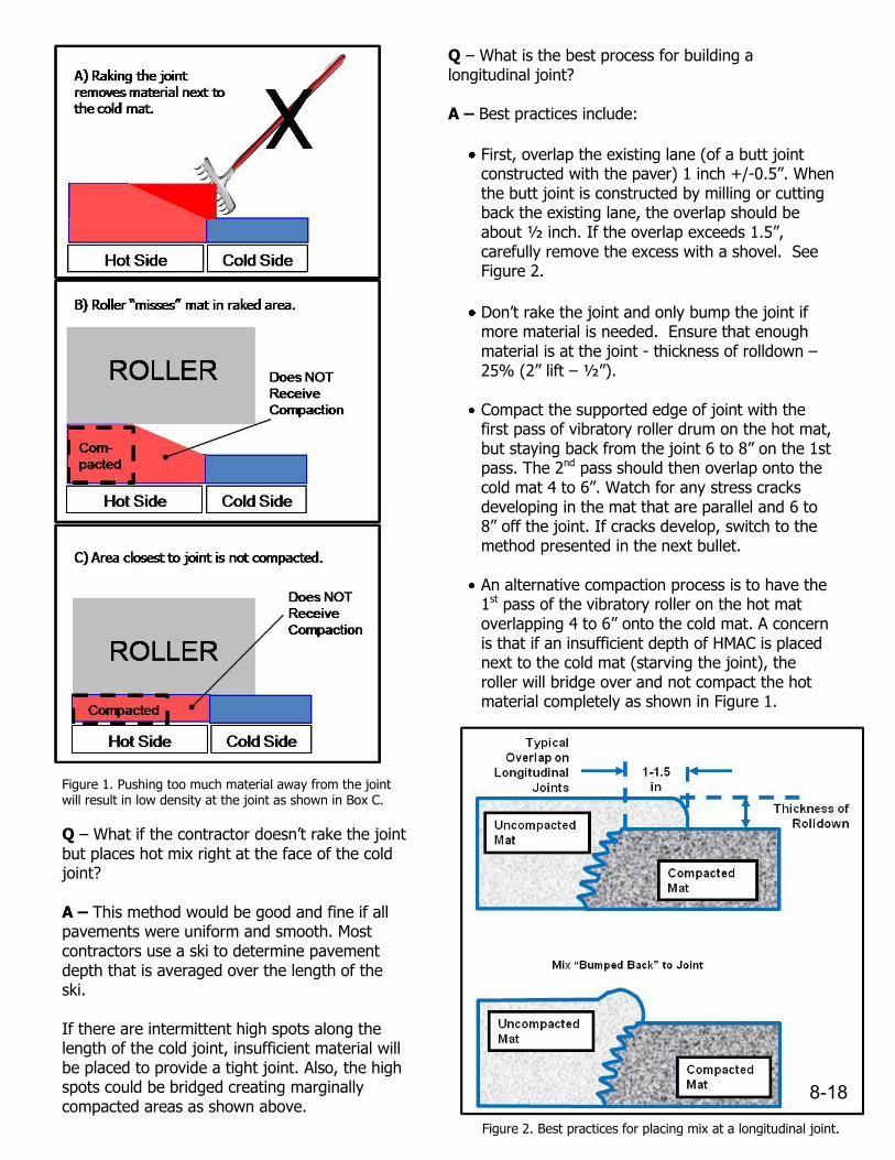
Q – What if the contractor doesn’t rake the joint but places hot mix right at the face of the cold joint?
A – This method would be good and fine if all pavements were uniform and smooth. Most contractors use a ski to determine pavement depth that is averaged over the length of the ski.
If there are intermittent high spots along the length of the cold joint, insufficient material will be placed to provide a tight joint. Also, the high spots could be bridged creating marginally compacted areas as shown above.
Q – What is the best process for building a longitudinal joint?
A – Best practices include:
First, overlap the existing lane (of a butt joint constructed with the paver) 1 inch +/-0.5”. When the butt joint is constructed by milling or cutting back the existing lane, the overlap should be about ½ inch. If the overlap exceeds 1.5”, carefully remove the excess with a shovel. See Figure 2.
Don’t rake the joint and only bump the joint if more material is needed. Ensure that enough material is at the joint - thickness of rolldown – 25% (2” lift – ½”).
Compact the supported edge of joint with the first pass of vibratory roller drum on the hot mat, but staying back from the joint 6 to 8” on the 1st pass. The 2nd pass should then overlap onto the cold mat 4 to 6”. Watch for any stress cracks developing in the mat that are parallel and 6 to 8” off the joint. If cracks develop, switch to the method presented in the next bullet.
An alternative compaction process is to have the 1st pass of the vibratory roller on the hot mat overlapping 4 to 6” onto the cold mat. A concern is that if an insufficient depth of HMAC is placed next to the cold mat (starving the joint), the roller will bridge over and not compact the hot material completely as shown in Figure 1.
Ensure that when the joint is completed, the overlap thickness is no more than 0.1” higher to ensure no bridging ever occurred. Figure 1. Pushing too much material away from the joint
will result in low density at the joint as shown in Box C.
Figure 2. Best practices for placing mix at a longitudinal joint.
8-18
INSERT TAB
Unit 9 00800 – Perm. Traffic Devices
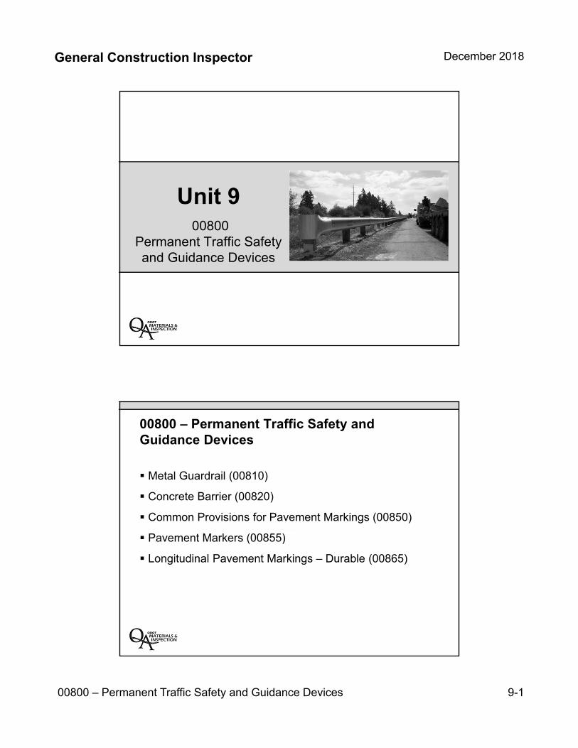
General Construction Inspector December 2018
00800 – Permanent Traffic Safety and Guidance Devices 9-1
Unit 900800
Permanent Traffic Safety and Guidance Devices
00800 – Permanent Traffic Safety and Guidance Devices
Metal Guardrail (00810)
Concrete Barrier (00820)
Common Provisions for Pavement Markings (00850)
Pavement Markers (00855)
Longitudinal Pavement Markings – Durable (00865)

General Construction Inspector December 2018
00800 – Permanent Traffic Safety and Guidance Devices 9-2
Unit 9 Topics:
Metal guardrail installation
Concrete barrier installation
Standard length of guardrail and barrier
Pavement marking provisions
Striping installation
Striping measurement and payment
00810 – Metal Guardrail
00810.10 Materials
Guardrail terminals form QPL
Blocks and posts of same type through guardrail run
Salvage materials may be used if Engineer approves

General Construction Inspector December 2018
00800 – Permanent Traffic Safety and Guidance Devices 9-3
00810 – Metal Guardrail
00810.40 Construction
New Installation – Do not leave posts exposed to traffic for more than 24 hours before installing rail (see 00310.40(a) for replacing guardrail)
Excavate to the lines and grades and depths shown
Set all posts within ½-inch tolerance
00810 – Metal Guardrail
Count Method12½-foot standard length
Length MethodCenter to center of end posts

General Construction Inspector December 2018
00800 – Permanent Traffic Safety and Guidance Devices 9-4
00820 – Concrete Barrier
00820.10 Materials
Cast-in-place or precast barrier
Re-use of barrier is allowed if in good condition and proper quality documentation
Repair or reject damaged barrier
00820 – Concrete Barrier
00820.40 Construction
Cast-in-place barrier using fixed forms
Coat top and sides of all permanent barrier with a minimum of two coasts of paint from QPL
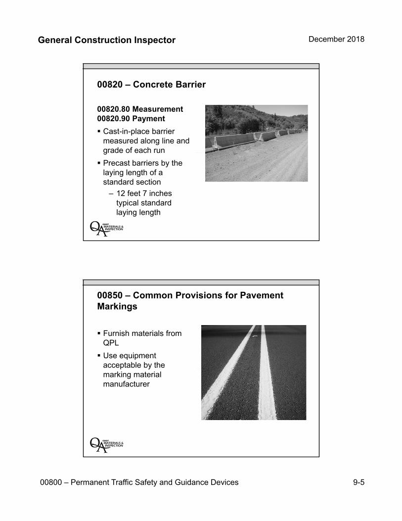
General Construction Inspector December 2018
00800 – Permanent Traffic Safety and Guidance Devices 9-5
00820 – Concrete Barrier
00820.80 Measurement 00820.90 Payment
Cast-in-place barrier measured along line and grade of each run
Precast barriers by the laying length of a standard section
– 12 feet 7 inches typical standard laying length
00850 – Common Provisions for Pavement Markings
Furnish materials from QPL
Use equipment acceptable by the marking material manufacturer
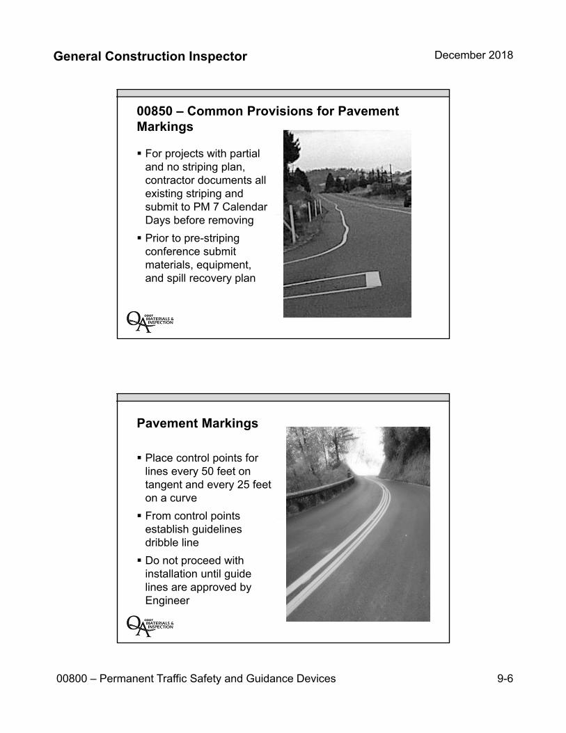
General Construction Inspector December 2018
00800 – Permanent Traffic Safety and Guidance Devices 9-6
00850 – Common Provisions for Pavement Markings
For projects with partial and no striping plan, contractor documents all existing striping and submit to PM 7 Calendar Days before removing
Prior to pre-striping conference submit materials, equipment, and spill recovery plan
Pavement Markings
Place control points for lines every 50 feet on tangent and every 25 feet on a curve
From control points establish guidelines dribble line
Do not proceed with installation until guide lines are approved by Engineer
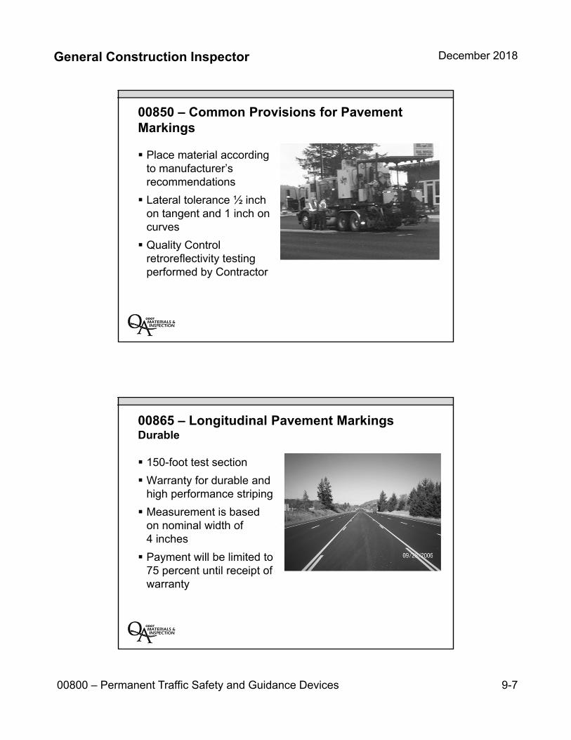
General Construction Inspector December 2018
00800 – Permanent Traffic Safety and Guidance Devices 9-7
00850 – Common Provisions for Pavement Markings
Place material according to manufacturer’s recommendations
Lateral tolerance ½ inch on tangent and 1 inch on curves
Quality Control retroreflectivity testing performed by Contractor
00865 – Longitudinal Pavement Markings Durable
150-foot test section
Warranty for durable and high performance striping
Measurement is based on nominal width of 4 inches
Payment will be limited to 75 percent until receipt of warranty
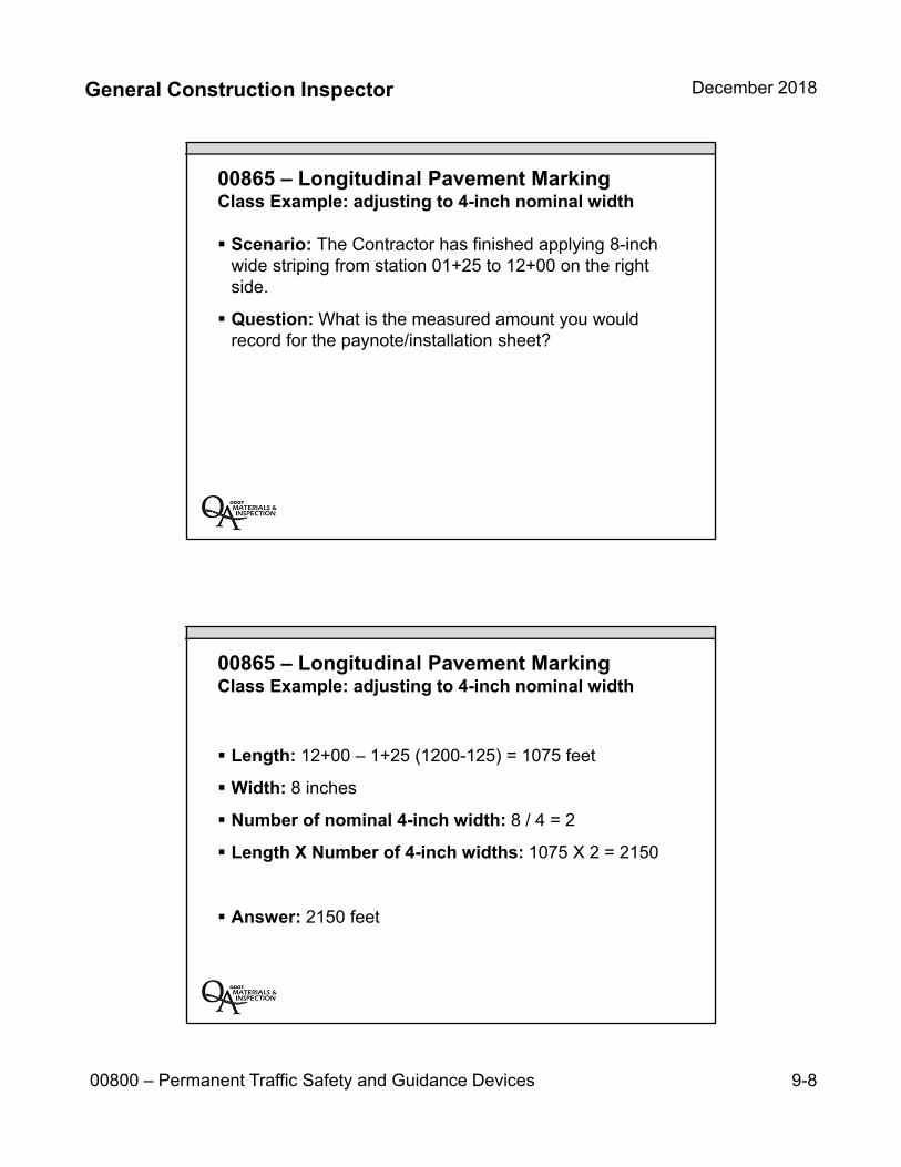
General Construction Inspector December 2018
00800 – Permanent Traffic Safety and Guidance Devices 9-8
00865 – Longitudinal Pavement MarkingClass Example: adjusting to 4-inch nominal width
Scenario: The Contractor has finished applying 8-inch wide striping from station 01+25 to 12+00 on the right side.
Question: What is the measured amount you would record for the paynote/installation sheet?
00865 – Longitudinal Pavement Marking Class Example: adjusting to 4-inch nominal width
Length: 12+00 – 1+25 (1200-125) = 1075 feet
Width: 8 inches
Number of nominal 4-inch width: 8 / 4 = 2
Length X Number of 4-inch widths: 1075 X 2 = 2150
Answer: 2150 feet
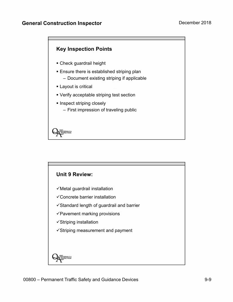
General Construction Inspector December 2018
00800 – Permanent Traffic Safety and Guidance Devices 9-9
Key Inspection Points
Check guardrail height
Ensure there is established striping plan
– Document existing striping if applicable
Layout is critical
Verify acceptable striping test section
Inspect striping closely
– First impression of traveling public
Unit 9 Review:
Metal guardrail installation
Concrete barrier installation
Standard length of guardrail and barrier
Pavement marking provisions
Striping installation
Striping measurement and payment

INSERT TAB
Unit 1000900 – Perm. Traffic Systems
General Construction Inspector December 2018
00900 – Permanent Traffic Control and Illumination Systems 10-1
Unit 10 00900
Permanent Traffic Control and Illumination Systems
Photo courtesy of Oregon DOT Flickr
00900 – Permanent Traffic Control and Illumination Systems
Wood Sign Posts (00910)
Sign Support Footings (00920)
Metal Sign Supports (00930)
Signs (00940)
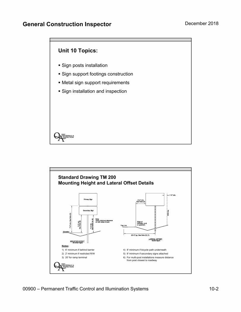
General Construction Inspector December 2018
00900 – Permanent Traffic Control and Illumination Systems 10-2
Unit 10 Topics:
Sign posts installation
Sign support footings construction
Metal sign support requirements
Sign installation and inspection
Standard Drawing TM 200 Mounting Height and Lateral Offset Details
Notes:
1) 6′ minimum if behind barrier
2) 2′ minimum if restricted R/W
3) 20′ for ramp terminal
4) 8′ minimum if bicycle path underneath
5) 8′ minimum if secondary signs attached
6) For multi-post installations measure distance from post closest to roadway
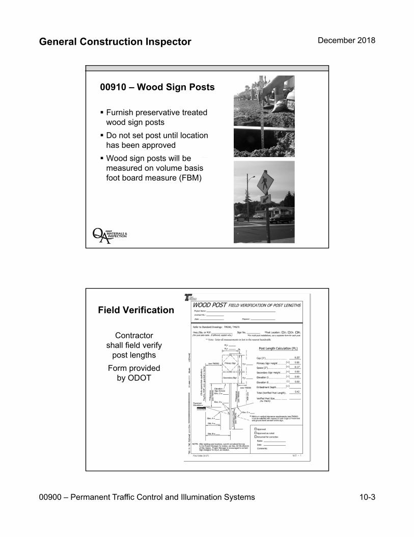
General Construction Inspector December 2018
00900 – Permanent Traffic Control and Illumination Systems 10-3
00910 – Wood Sign Posts
Furnish preservative treatedwood sign posts
Do not set post until locationhas been approved
Wood sign posts will bemeasured on volume basisfoot board measure (FBM)
Field Verification
Contractor shall field verify
post lengths
Form providedby ODOT
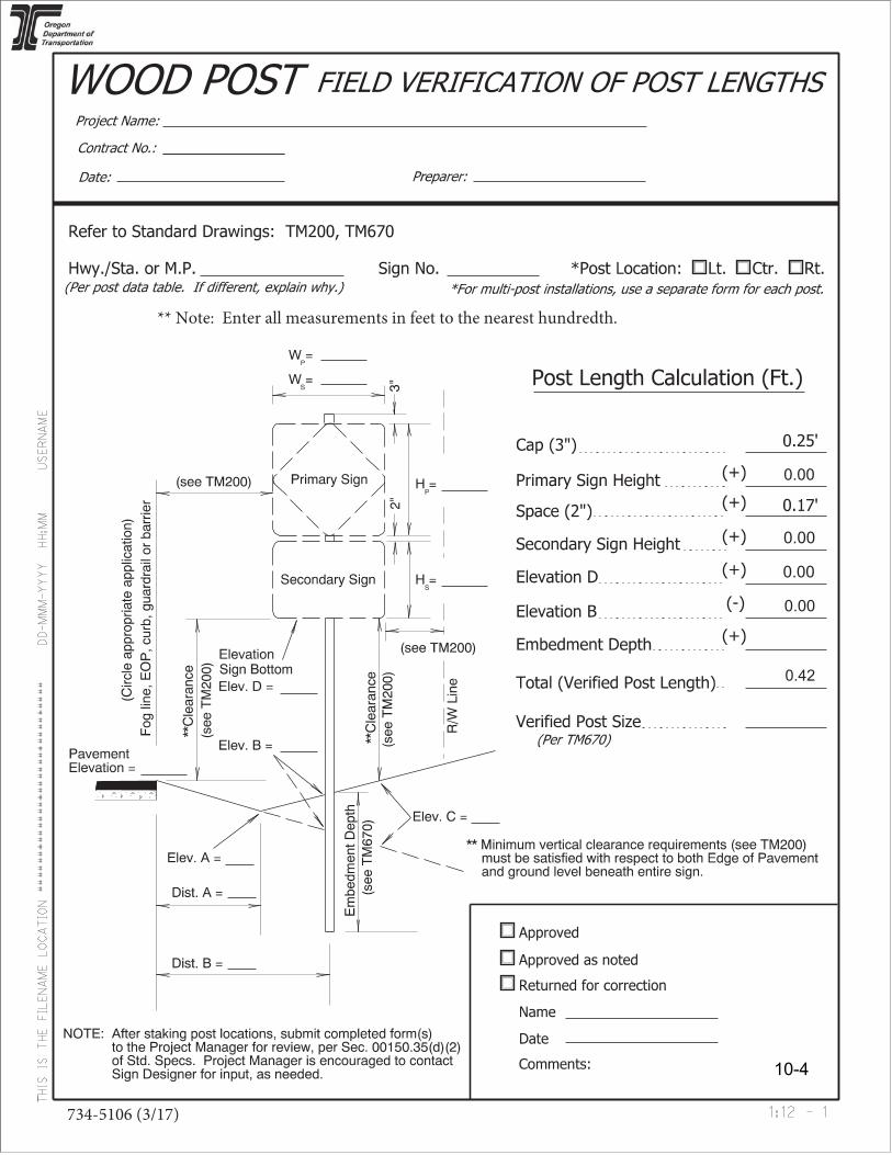
0.00
0.00
0.00
0.00
0.42
10-4

General Construction Inspector December 2018
00900 – Permanent Traffic Control and Illumination Systems 10-5
00920 – Sign Support Footings
Commercial grade concrete
During concrete placement,accurately and securely holdin place all anchor bolts orpost stubs until concrete has set
No measurement of quantities willbe made
00930 – Metal Sign Supports
Submit working drawingsfor all structural metalwork except TBB & MPB
Overhead and butterflysign supports shall haveidentifying tags
No measurement ofquantities will be made
– Estimated quantitieswill be listed inSpecial Provisions
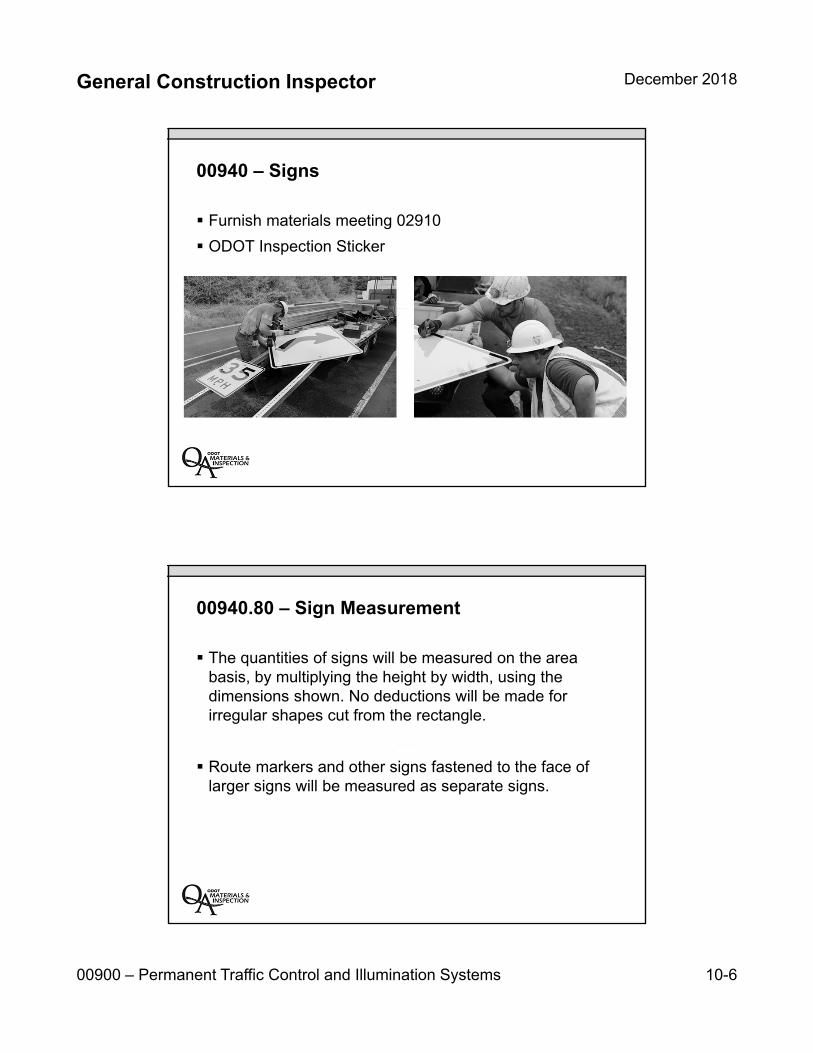
General Construction Inspector December 2018
00900 – Permanent Traffic Control and Illumination Systems 10-6
00940 – Signs
Furnish materials meeting 02910
ODOT Inspection Sticker
00940.80 – Sign Measurement
The quantities of signs will be measured on the areabasis, by multiplying the height by width, using thedimensions shown. No deductions will be made forirregular shapes cut from the rectangle.
Route markers and other signs fastened to the face oflarger signs will be measured as separate signs.
General Construction Inspector December 2018
00900 – Permanent Traffic Control and Illumination Systems 10-7
00940.90 – Sign Payment
The accepted quantities of Work performed under this Section will be paid for at the Contract unit price, per unit of measurement, for the following items:
Pay Item Unit of Measurement
(a) Signs, Standard Sheeting, Extruded Aluminum ............................. Square Foot
(b) Signs, Standard Sheeting, Sheet Aluminum ................................... Square Foot
(c) Signs, Standard Sheeting, Plywood ................................................ Square Foot
(d) Signs, Type IX Sheeting, Extruded Aluminum ................................ Square Foot
(e) Signs, Type IX Sheeting, Sheet Aluminum ..................................... Square Foot
(f) Signs, Type IX Sheeting, Plywood .................................................. Square Foot
Key Inspection Points
Make sure sign locations areproperly surveyed
Utilities marked prior to installation
Signs should have ODOTinspection sticker when theyarrive on the project site.
Make sure signs are visible
Verify signs for accuracy ordamage once delivered to theproject site

General Construction Inspector December 2018
00900 – Permanent Traffic Control and Illumination Systems 10-8
Unit 10 Review:
Sign posts installation
Sign support footings construction
Metal sign support requirements
Sign installation and inspection
INSERT TAB
Unit 11 01000-Right of Way Dev.
General Construction Inspector December 2018
01000 – Right of Way Development and Control 11-1
Unit 1101000
Right of Way Development and Control
01000 – Right of Way Development and Control
Water Quality Biofiltration Swale Special Provision (01012)
Seeding (01030)
Planting (01040)
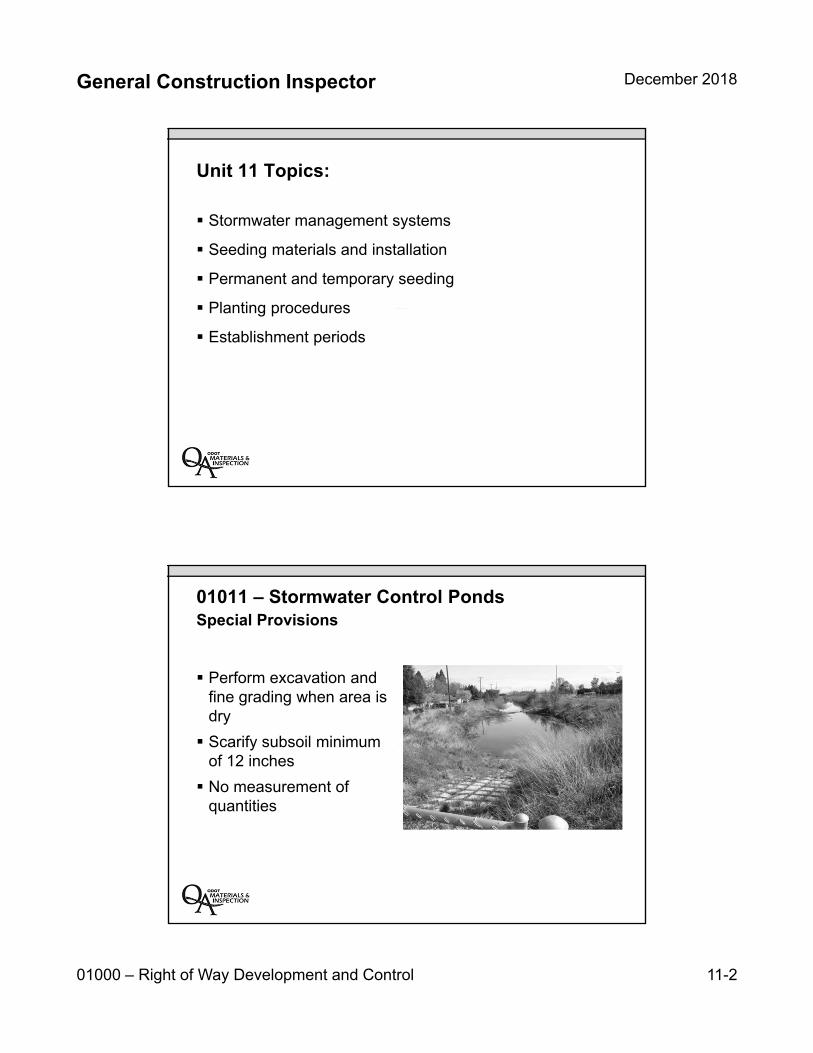
General Construction Inspector December 2018
01000 – Right of Way Development and Control 11-2
Unit 11 Topics:
Stormwater management systems
Seeding materials and installation
Permanent and temporary seeding
Planting procedures
Establishment periods
01011 – Stormwater Control PondsSpecial Provisions
Perform excavation and fine grading when area is dry
Scarify subsoil minimum of 12 inches
No measurement of quantities

General Construction Inspector December 2018
01000 – Right of Way Development and Control 11-3
01012 – Water Quality Biofiltration SwaleSpecial Provision
Water Quality Seeding meeting 01012.12
Compact each lift with a water filled landscape roller
Estimated material quantities are provide in specials
No measurement of quantities
Stormwater Management Systems
Make sure Contractor understands purpose of system
Verify location and elevation of inlets
Grade to lines established
Provide feedback to designer
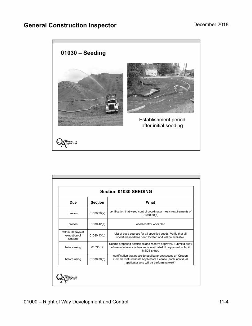
General Construction Inspector December 2018
01000 – Right of Way Development and Control 11-4
01030 – Seeding
Establishment period after initial seeding
Section 01030 SEEDING
Due Section What
precon 01030.30(a)certification that weed control coordinator meets requirements of
01030.30(a)
precon 01030.42(a) weed control work plan
within 60 days of execution of
contract01030.13(g)
List of seed sources for all specified seeds. Verify that all specified seed has been located and will be available.
before using 01030.17Submit proposed pesticides and receive approval. Submit a copy
of manufacturers federal registered label. If requested, submit MSDS sheet.
before using 01030.30(b)certification that pesticide applicator possesses an Oregon Commercial Pesticide Applicators License (each individual
applicator who will be performing work)

General Construction Inspector December 2018
01000 – Right of Way Development and Control 11-5
01030.13 Seed – Labels, Quality, Pure Live Seed, Inspection, Mixes
Look for:
Testing date
Compliance with Oregon and federal seed regulations
Not sprouted, moldy, wet or damaged
As many as
2.5 million / lb!
01030.15 – Mulch
Certified weed-free straw
Cellulose fiber from QPL
Verify application rate
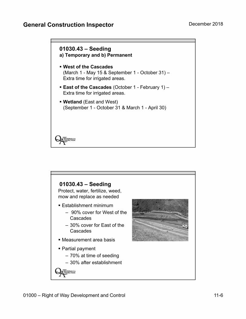
General Construction Inspector December 2018
01000 – Right of Way Development and Control 11-6
01030.43 – Seedinga) Temporary and b) Permanent
West of the Cascades (March 1 - May 15 & September 1 - October 31) –Extra time for irrigated areas.
East of the Cascades (October 1 - February 1) –Extra time for irrigated areas.
Wetland (East and West) (September 1 - October 31 & March 1 - April 30)
01030.43 – SeedingProtect, water, fertilize, weed, mow and replace as needed
Establishment minimum
– 90% cover for West of the Cascades
– 30% cover for East of the Cascades
Measurement area basis
Partial payment
– 70% at time of seeding
– 30% after establishment
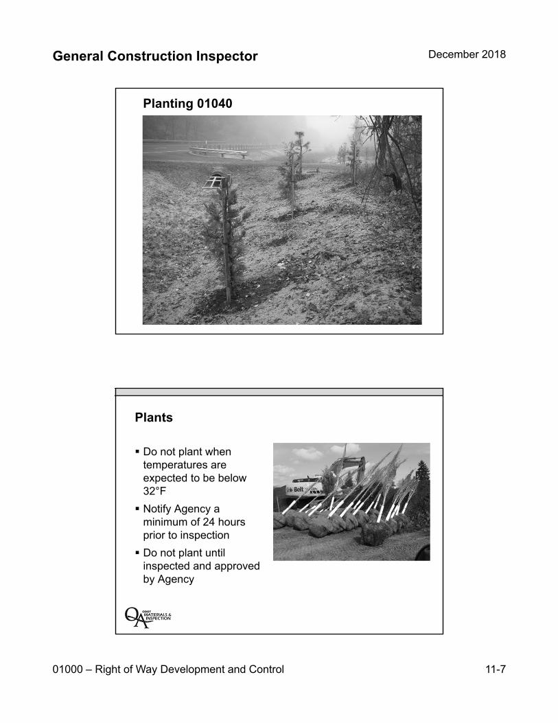
General Construction Inspector December 2018
01000 – Right of Way Development and Control 11-7
Planting 01040
Plants
Do not plant when temperatures are expected to be below 32°F
Notify Agency a minimum of 24 hours prior to inspection
Do not plant until inspected and approved by Agency

General Construction Inspector December 2018
01000 – Right of Way Development and Control 11-8
Section 01040 PLANTINGDue Section What
within 90 calendar days of award of
contract01040.04(a) Planting Work Plan
before arranging procurement of
materials01040.04(a) List of project materials for approval
before planting 01040.13(a)(1) Soil fertility analysis of existing soils performed
by a certified lab. (2) Soil amendments report
before planting 01040.13(b) (1) Soil Bio-amendments report
20 days before furnishing topsoil
01040.14
(1) Give agency notice of intent to use source (2) Provide access to the agency to the source
(3) Provide a 20-pound representative soil sample for testing (4) Obtain approval of source
prior to construction 01040.15 Submit 15-pound sample of soil conditioner for approval.
prior to use 01040.16 Approval of soil amendments
90 days after execution of contract
01040.19(e) List of nursery sources for specified plants
Topsoil
Submit topsoil for testing
Do not place topsoil until passing laboratory report
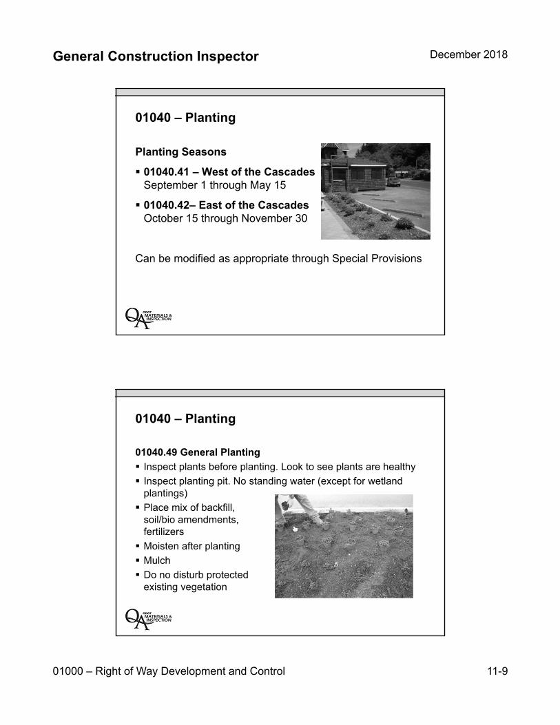
General Construction Inspector December 2018
01000 – Right of Way Development and Control 11-9
01040 – Planting
Planting Seasons
01040.41 – West of the Cascades September 1 through May 15
01040.42– East of the CascadesOctober 15 through November 30
Can be modified as appropriate through Special Provisions
01040 – Planting
01040.49 General Planting
Inspect plants before planting. Look to see plants are healthy
Inspect planting pit. No standing water (except for wetland plantings)
Place mix of backfill, soil/bio amendments, fertilizers
Moisten after planting
Mulch
Do no disturb protectedexisting vegetation
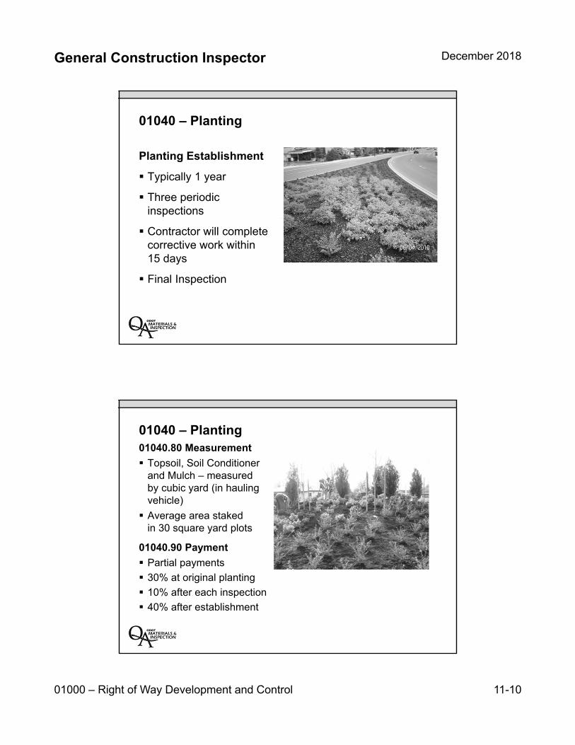
General Construction Inspector December 2018
01000 – Right of Way Development and Control 11-10
01040 – Planting
Planting Establishment
Typically 1 year
Three periodicinspections
Contractor will completecorrective work within15 days
Final Inspection
01040 – Planting01040.80 Measurement
Topsoil, Soil Conditionerand Mulch – measuredby cubic yard (in haulingvehicle)
Average area stakedin 30 square yard plots
01040.90 Payment
Partial payments
30% at original planting
10% after each inspection
40% after establishment
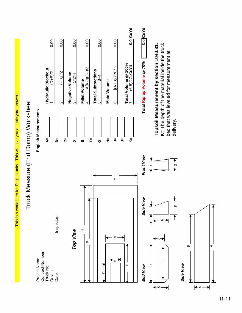
A=
Driv
er:
1.0.
00D
ate:
B
=2.
0.00
C=
To
p V
iew
D=
3.0.
00
AE=
B4.
0.00
F= G=
5.0.
00D
H=
FG
CI=
6.0.
00
J=E
K=
7.0.
0C
uYd
En
d V
iew
Sid
e V
iew
Fro
nt
Vie
w0.
0C
uYd
CD
F
KJ
IH
EG
Sid
e V
iew
B
K
A
[(A+B
)/2]*
C*K
Mai
n Vo
lum
e
Tops
oil M
easu
rem
ent b
y se
ctio
n 10
40.8
1.
K=
The
dept
h of
the
mat
eria
l ins
ide
the
truck
be
d th
at w
as le
vele
d fo
r mea
sure
men
t at
deliv
ery.
Con
tract
Num
ber:
Truc
k N
o:
Insp
ecto
r:
Hyd
raul
ic B
lock
out
(F+G
)/2
1*2*
H
A(K
-J)(
C-I)
/2
This
is a
wor
kshe
et fo
r Eng
lish
units
. Th
is w
ill g
ive
you
a cu
bic
yard
ans
wer
.
Engl
ish
Mea
sure
men
ts
Truc
k M
easu
re (E
nd D
ump)
Wor
kshe
etP
roje
ct N
ame:
3+4
Neg
ativ
e Vo
lum
e
Fille
t Vol
ume
Tota
l Sub
trac
tions
Tota
l Rip
rap
Volu
me
@ 7
0%
(6-5
)/27=
CuY
dTo
tal V
olum
e @
100
%
(D+E
)/2
11-11

11-12
General Construction Inspector December 2018
01000 – Right of Way Development and Control 11-13
Key Inspection Points
Verify and inspect seed mix and plants at time of delivery
Make sure the Contractor properly prepares the ground
Verify correct seeding or planting season
Disturb as little existing vegetation as possible
Contact Region Environmental Coordinator (R.E.C.) orProject Biologist with questions
Unit 11 Review:
Stormwater management systems
Seeding materials and installation
Permanent and temporary seeding
Planting practices
Establishment periods

11-14
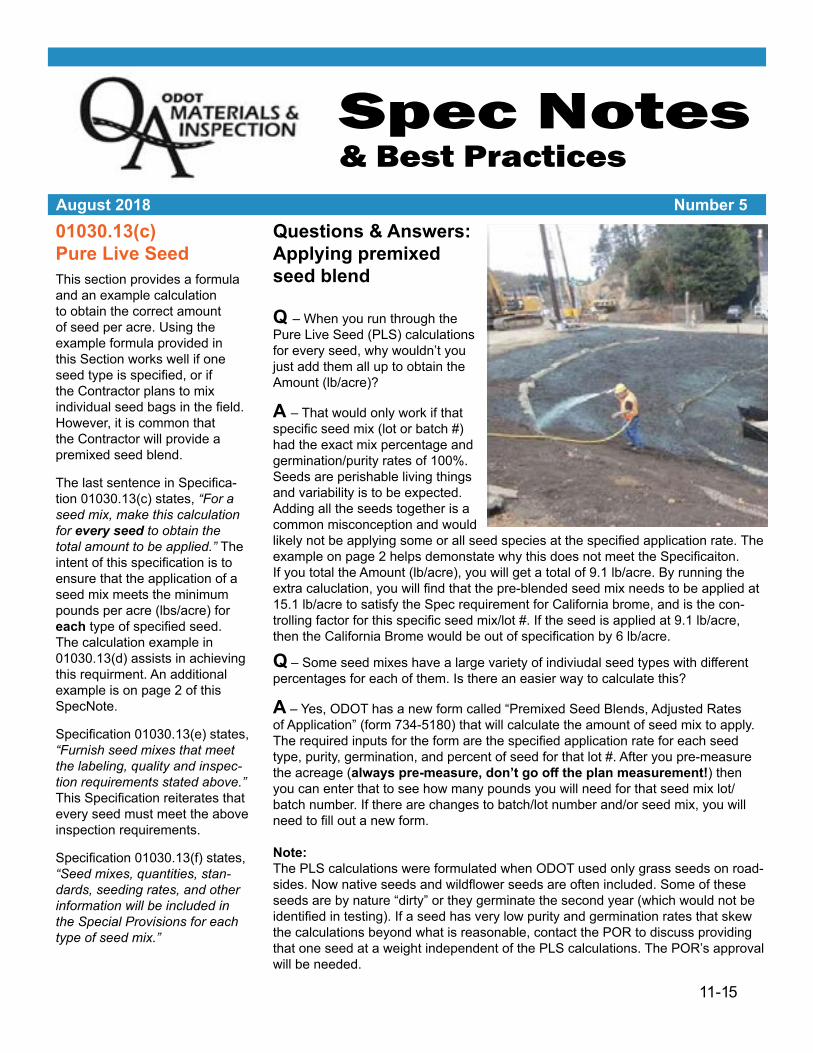
Spec Notes & Best Practices
August 2018 Number 501030.13(c) Pure Live SeedThis section provides a formula and an example calculation to obtain the correct amount of seed per acre. Using the example formula provided in this Section works well if one seed type is specified, or if the Contractor plans to mix individual seed bags in the field. However, it is common that the Contractor will provide a premixed seed blend.
The last sentence in Specifica-tion 01030.13(c) states, “For a seed mix, make this calculation for every seed to obtain the total amount to be applied.” The intent of this specification is to ensure that the application of a seed mix meets the minimum pounds per acre (lbs/acre) for each type of specified seed. The calculation example in 01030.13(d) assists in achieving this requirment. An additional example is on page 2 of this SpecNote.
Specification 01030.13(e) states, “Furnish seed mixes that meet the labeling, quality and inspec-tion requirements stated above.” This Specification reiterates that every seed must meet the above inspection requirements.
Specification 01030.13(f) states, “Seed mixes, quantities, stan-dards, seeding rates, and other information will be included in the Special Provisions for each type of seed mix.”
Questions & Answers: Applying premixed seed blend
Q – When you run through thePure Live Seed (PLS) calculations for every seed, why wouldn’t you just add them all up to obtain the Amount (lb/acre)?
A – That would only work if thatspecific seed mix (lot or batch #) had the exact mix percentage and germination/purity rates of 100%. Seeds are perishable living things and variability is to be expected. Adding all the seeds together is a common misconception and would likely not be applying some or all seed species at the specified application rate. The example on page 2 helps demonstate why this does not meet the Specificaiton. If you total the Amount (lb/acre), you will get a total of 9.1 lb/acre. By running the extra caluclation, you will find that the pre-blended seed mix needs to be applied at 15.1 lb/acre to satisfy the Spec requirement for California brome, and is the con-trolling factor for this specific seed mix/lot #. If the seed is applied at 9.1 lb/acre, then the California Brome would be out of specification by 6 lb/acre.
Q – Some seed mixes have a large variety of indiviudal seed types with differentpercentages for each of them. Is there an easier way to calculate this?
A – Yes, ODOT has a new form called “Premixed Seed Blends, Adjusted Ratesof Application” (form 734-5180) that will calculate the amount of seed mix to apply. The required inputs for the form are the specified application rate for each seed type, purity, germination, and percent of seed for that lot #. After you pre-measure the acreage (always pre-measure, don’t go off the plan measurement!) then you can enter that to see how many pounds you will need for that seed mix lot/batch number. If there are changes to batch/lot number and/or seed mix, you will need to fill out a new form.
Note:The PLS calculations were formulated when ODOT used only grass seeds on road-sides. Now native seeds and wildflower seeds are often included. Some of these seeds are by nature “dirty” or they germinate the second year (which would not be identified in testing). If a seed has very low purity and germination rates that skew the calculations beyond what is reasonable, contact the POR to discuss providing that one seed at a weight independent of the PLS calculations. The POR’s approval will be needed.
11-15
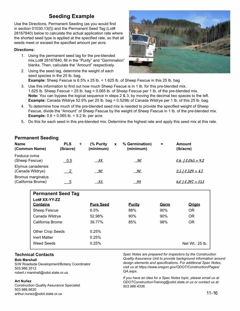
Spec Notes are prepared for inspectors by the Construction Quality Assurance Unit to provide background information around design elements and specifications. For additional Spec Notes, visit us at https://www.oregon.gov/ODOT/Construction/Pages/QA.aspx.
If you have an idea for a Spec Notes topic, please email us at [email protected] or contact us at 503.986.4336.
Technical ContactsBob MarshallS/W Roadside Development/Botany [email protected]
Art NuñezConstruction Quality Assurance [email protected]
Seeding ExampleUse the Directions, Permanent Seeding (as you would find in section 01030.13(f)) and the Permanent Seed Tag (Lot# 28167840) below to calculate the actual application rate where the shorted seed type is applied at the specified rate, so that all seeds meet or exceed the specified amount per acre.
Directions:1. Using the permanent seed tag for the pre-blended
mix,Lot# 28167840, fill in the “Purity” and “Germination”blanks. Then, calculate the “Amount” respectively.
2. Using the seed tag, determine the weight of eachseed species in the 25 lb. bag.Example: Sheep Fescue is 6.5% x 25 lb. = 1.625 lb. of Sheep Fescue in this 25 lb. bag
3. Use this information to find out how much Sheep Fescue is in 1 lb. for this pre-blended mix.1.625 lb. Sheep Fescue ÷ 25 lb. bag = 0.065 lb. of Sheep Fescue per 1 lb. of the pre-blended mix.Note: You can bypass the logical sequence in steps 2 & 3, by moving the decimal two spaces to the left.Example: Canada Wildrye 52.9% per 25 lb. bag = 0.529lb of Canada Wildrye per 1 lb. of this 25 lb. bag.
4. To determine how much of the pre-blended seed mix is needed to provide the specified weight of SheepFescue, divide the “Amount” of Sheep Fescue by the weight of Sheep Fescue in 1 lb. of the pre-blended mix.Example: 0.6 ÷ 0.065 lb. = 9.2 lb. per acre
5. Do this for each seed in this pre-blended mix. Determine the highest rate and apply this seed mix at this rate.
Permanent SeedingName PLS ÷ (% Purity x % Germination) = Amount(Common Name) (lb/acre) (minimum) (minimum) (lb/acre)
Festuca ovina (Sheep Fescue) 0.5 .88 .90 0.6 / 0.065 = 9.2Elymus canadensis (Canada Wildrye) 2 .90 .90 2.5 / 0.529 = 4.7Bromus marginatus (California Brome) 5 .85 .98 6.0 / 0.397 = 15.1
Permanent Seed TagLot# XX-YY-ZZContains Pure Seed Purity Germ OriginSheep Fescue 6.5% 88% 90% OR
Canada Wildrye 52.98% 90% 90% OR
California Brome 39.77% 85% 98% OR
Other Crop Seeds 0.25%
Inert Matter 0.25%Weed Seeds 0.25% Net Wt.: 25 lb.
11-16

Pro
ject
Nam
e (S
ectio
n)C
ontr
act N
o.
(Sub
)Con
trac
tor
See
d M
ix T
ype
Lot/B
atch
No.
III
IIIIV
VV
IV
IIV
III
See
dS
pec
ifie
d
(lb
./acr
e)P
uri
ty %
Ger
m. %
Ad
just
ed P
LS
(l
b. p
er a
cre)
% o
f S
eed
(th
is lo
t#/m
ix)
lb. o
f S
eed
per
1 lb
(th
is lo
t#/m
ix)
lb. o
f th
is S
eed
Ble
nd
N
eed
ed p
er A
cre
(th
is lo
t#/m
ix)
Spi
ke B
entg
rass
0.5
99.6
6%90
.00%
0.6
0.6
1.50
%0.
015
40.0
Cal
iforn
ia B
rom
e24
.598
.83%
88.0
0%28
.2##
27.0
0%0.
270
104.
4
Cam
as G
rass
3.5
97.7
5%88
.00%
4.1
4.1
3.50
%0.
035
117.
1
Slo
ugh
Sle
dge
3.5
99.6
9%91
.00%
3.9
3.9
3.50
%0.
035
111.
4
Tuf
ted
Hai
rgra
ss1.
899
.07%
91.0
0%1.
91.
95.
00%
0.05
038
.0
Mea
dow
Bar
ley
37.0
95.1
8%93
.00%
41.8
##38
.00%
0.38
011
0.0
Pat
h R
ush
0.1
97.3
2%98
.00%
0.1
0.1
0.50
%0.
005
20.0
Sic
kle
Kee
led
Lupi
ne17
.599
.95%
90.0
0%19
.5##
19.0
0%0.
190
102.
6
#DIV
/0!
##0.
000
#DIV
/0!
#DIV
/0!
##0.
000
#DIV
/0!
#DIV
/0!
##0.
000
#DIV
/0!
#DIV
/0!
##0.
000
#DIV
/0!
#DIV
/0!
###D
IV/0
!
#DIV
/0!
###D
IV/0
!
#DIV
/0!
###D
IV/0
!
#DIV
/0!
###D
IV/0
!
#DIV
/0!
###D
IV/0
!
#DIV
/0!
##0.
000
#DIV
/0!
#DIV
/0!
##0.
000
#DIV
/0!
#DIV
/0!
##0.
000
#DIV
/0!
98.0
0%1.
40%
0.55
%11
7.1
0.05
%1.
910
0.00
%22
2.6
*sho
uld
be c
lose
to 1
00%
734-
5180
(08
-10-
2018
)
Pre
mix
ed S
eed
Ble
nds
Adj
uste
d R
ates
of A
pplic
atio
n F
orm
Exa
mpl
eC
####
#
Ent
er C
ontr
acto
r or
Sub
cont
ract
or N
ame
Per
man
ent S
eedi
ngL0
3/S
L1
CO
LU
MN
See
d %
Oth
er C
rop
See
d %
RE
SU
LT
SW
eed
See
d %
Gre
ates
t Am
ount
Cal
c. (
from
col
umn
VIII
) =
Iner
t Mat
eria
l %
Pre
mea
sure
d A
cre
=T
otal
%*
Gre
ates
t Am
ount
Cal
c. x
Pre
mea
sure
d A
cre
=
11-17

INSERT TAB
Unit 12 Contract Plans

General Construction Inspector December 2018
Contract Plans 12-1
Unit 12Contract Plans
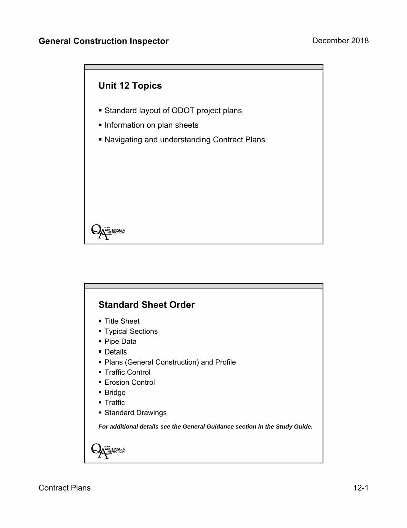
General Construction Inspector December 2018
Contract Plans 12-1
Unit 12 Topics
Standard layout of ODOT project plans
Information on plan sheets
Navigating and understanding Contract Plans
Standard Sheet Order
Title Sheet Typical Sections Pipe Data Details Plans (General Construction) and Profile Traffic Control Erosion Control Bridge Traffic Standard Drawings
For additional details see the General Guidance section in the Study Guide.
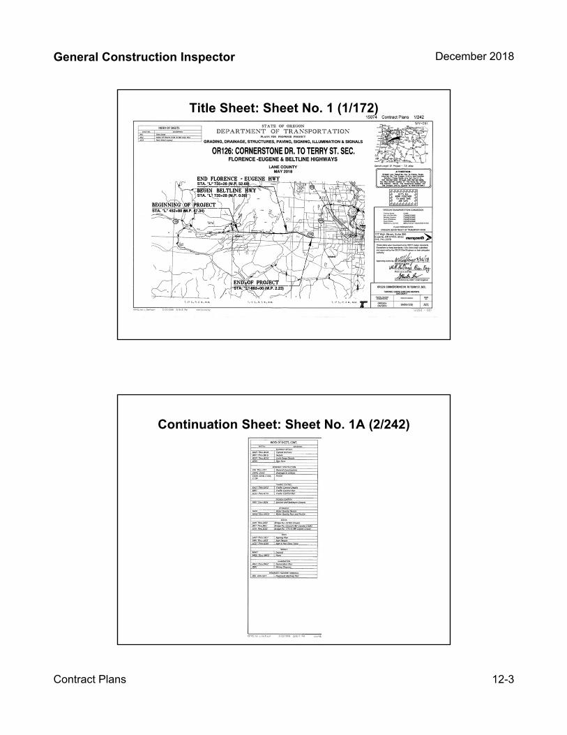
General Construction Inspector December 2018
Contract Plans 12-3
Title Sheet: Sheet No. 1 (1/172)
Continuation Sheet: Sheet No. 1A (2/242)
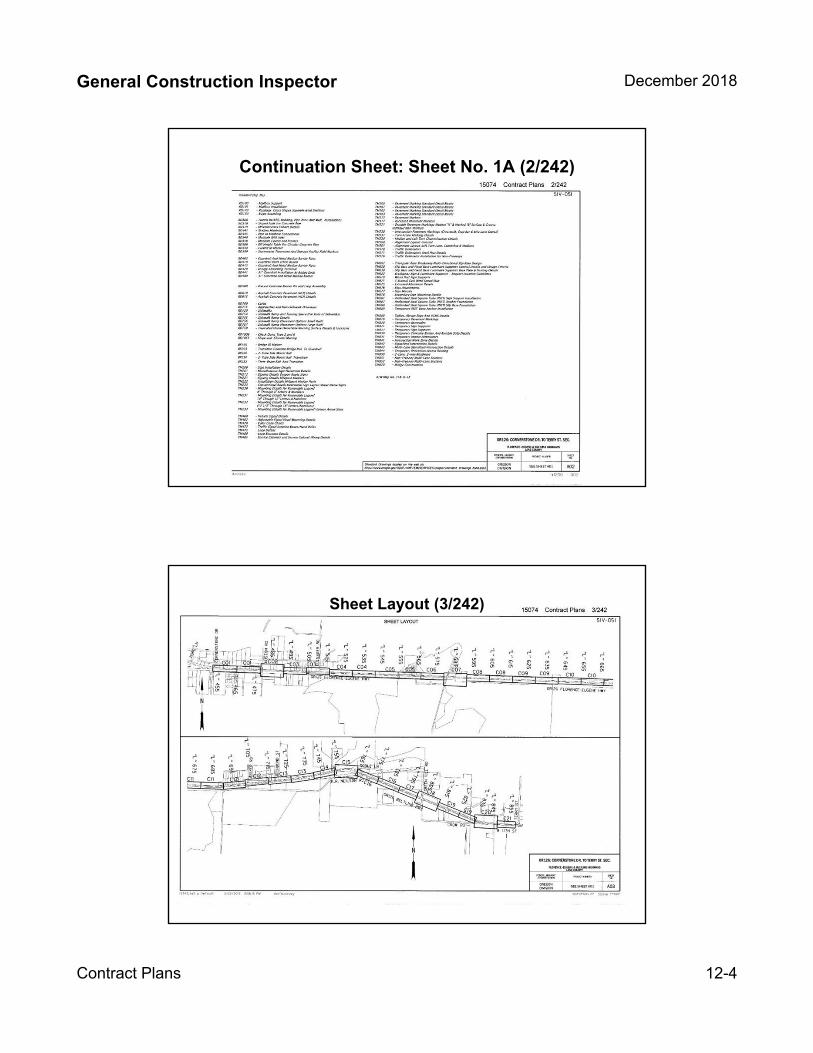
General Construction Inspector December 2018
Contract Plans 12-4
Continuation Sheet: Sheet No. 1A (2/242)
Sheet Layout (3/242)

General Construction Inspector December 2018
Contract Plans 12-5
Alignment and Stationing
Method to the Madness (for most plan sets)
Look at Title Sheet for alignment designations
Look at Typical Sections for corresponding alignments
Look at General Construction Plan and Profile Sheets to match roadways with alignments
Alignment and StationingMost Plans have the Alignments designated on the Title Sheet
that correspond to the typical section alignments.
Typical Section
Title Sheet
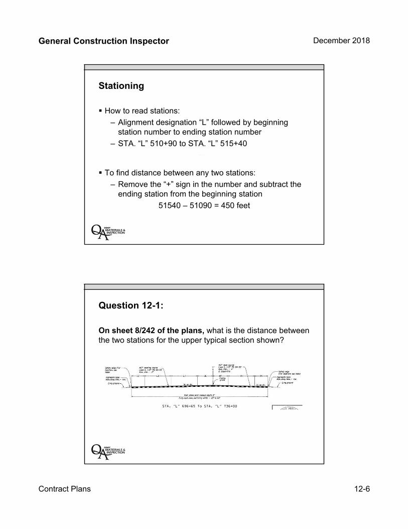
General Construction Inspector December 2018
Contract Plans 12-6
Stationing
How to read stations:
– Alignment designation “L” followed by beginningstation number to ending station number
– STA. “L” 510+90 to STA. “L” 515+40
To find distance between any two stations:
– Remove the “+” sign in the number and subtract theending station from the beginning station
51540 – 51090 = 450 feet
Question 12-1:
On sheet 8/242 of the plans, what is the distance between the two stations for the upper typical section shown?
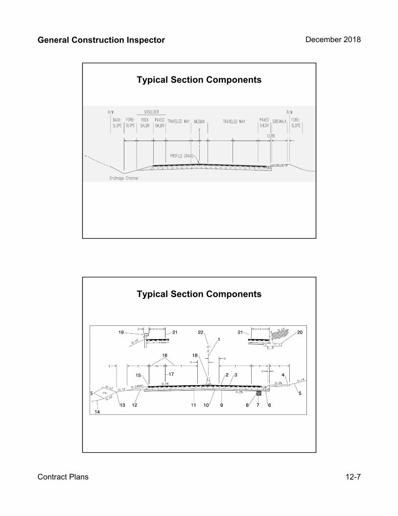
General Construction Inspector December 2018
Contract Plans 12-7
Typical Section Components
Typical Section Components

12-8
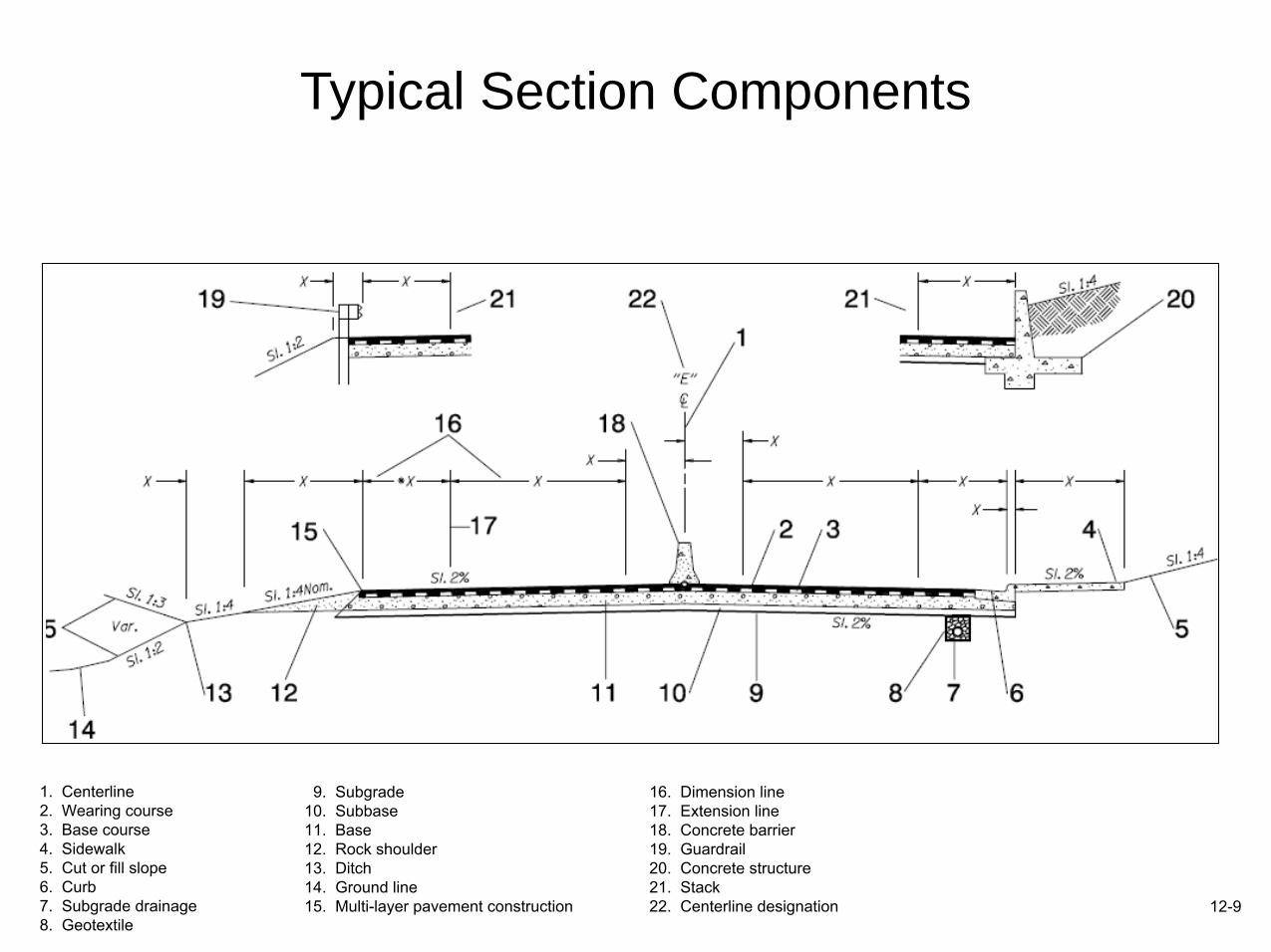
Typical Section Components
1. Centerline2. Wearing course3. Base course4. Sidewalk5. Cut or fill slope6. Curb7. Subgrade drainage8. Geotextile
9. Subgrade10. Subbase11. Base12. Rock shoulder13. Ditch14. Ground line15. Multi-layer pavement construction
16. Dimension line17. Extension line18. Concrete barrier19. Guardrail20. Concrete structure21. Stack22. Centerline designation 12-9

12-10
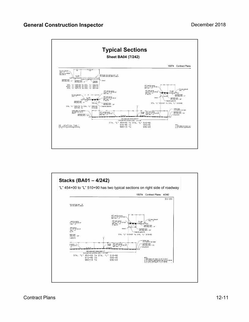
General Construction Inspector December 2018
Contract Plans 12-11
Typical SectionsSheet BA04 (7/242)
Stacks (BA01 – 4/242)
“L” 454+00 to “L” 510+90 has two typical sections on right side of roadway

General Construction Inspector December 2018
Contract Plans 12-12
No asterisk
One asterisk
Taper Sections (asterisk example)
Sheet 2A-2 (6/172)
1. Match the asterisks between the stationing and the designated width2. Read from left to right (left most station applies to the left number;
right most station applies to the right number)
Taper Sections (asterisk example)
STA. “D” 34+00 to STA. “D” 37+00 – Read these from left to right
To determine width of Roadway at “D” 34+00, start on left side and read to right side.
6′+12′+12′+4′ = 34′
Now determine width of Roadway at *“D” 38+00
6′+12′+( (12+4) / 2 = 8) + 4′ = 30′
Now determine width of Roadway at *“D” 39+00.
6′+12′+4′ +4′ = 26′
Sheet 2A-2 (6/172)
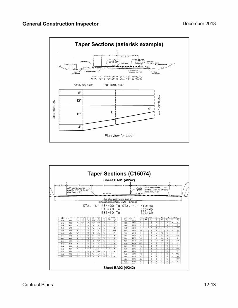
General Construction Inspector December 2018
Contract Plans 12-13
Taper Sections (asterisk example)
“D” 37+00 = 34' “D” 38+00 = 30'
*”D” 39+
00 = 26'
12'“D” 34+
00 = 34'
6'
Plan view for taper
12' 8'
4'
4'
Taper Sections (C15074)Sheet BA01 (4/242)
Sheet BA02 (4/242)
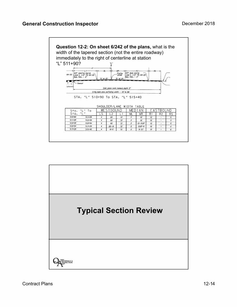
General Construction Inspector December 2018
Contract Plans 12-14
Question 12-2: On sheet 6/242 of the plans, what is the width of the tapered section (not the entire roadway) immediately to the right of centerline at station “L” 511+90?
Typical Section Review
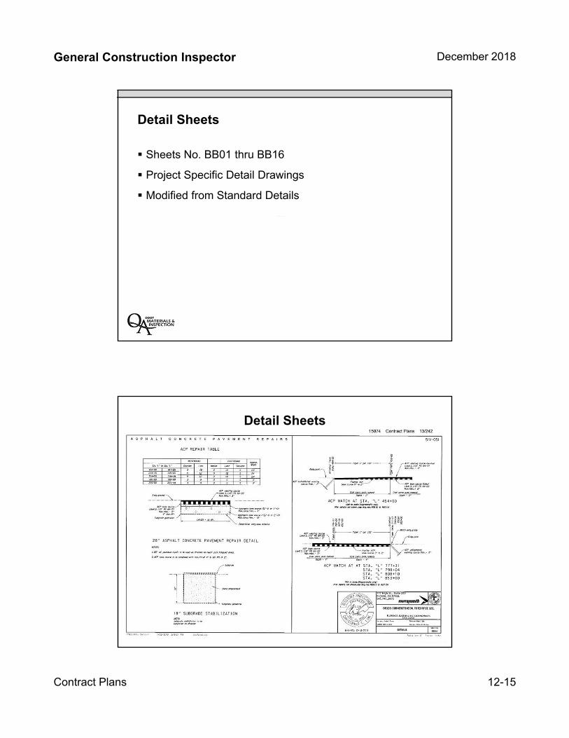
General Construction Inspector December 2018
Contract Plans 12-15
Detail Sheets
Sheets No. BB01 thru BB16
Project Specific Detail Drawings
Modified from Standard Details
Detail Sheets
Sheet 2B (8/172)

General Construction Inspector December 2018
Contract Plans 12-16
Detail Section Review
Pipe Data Sheet
Sheet BD01 (28/242)
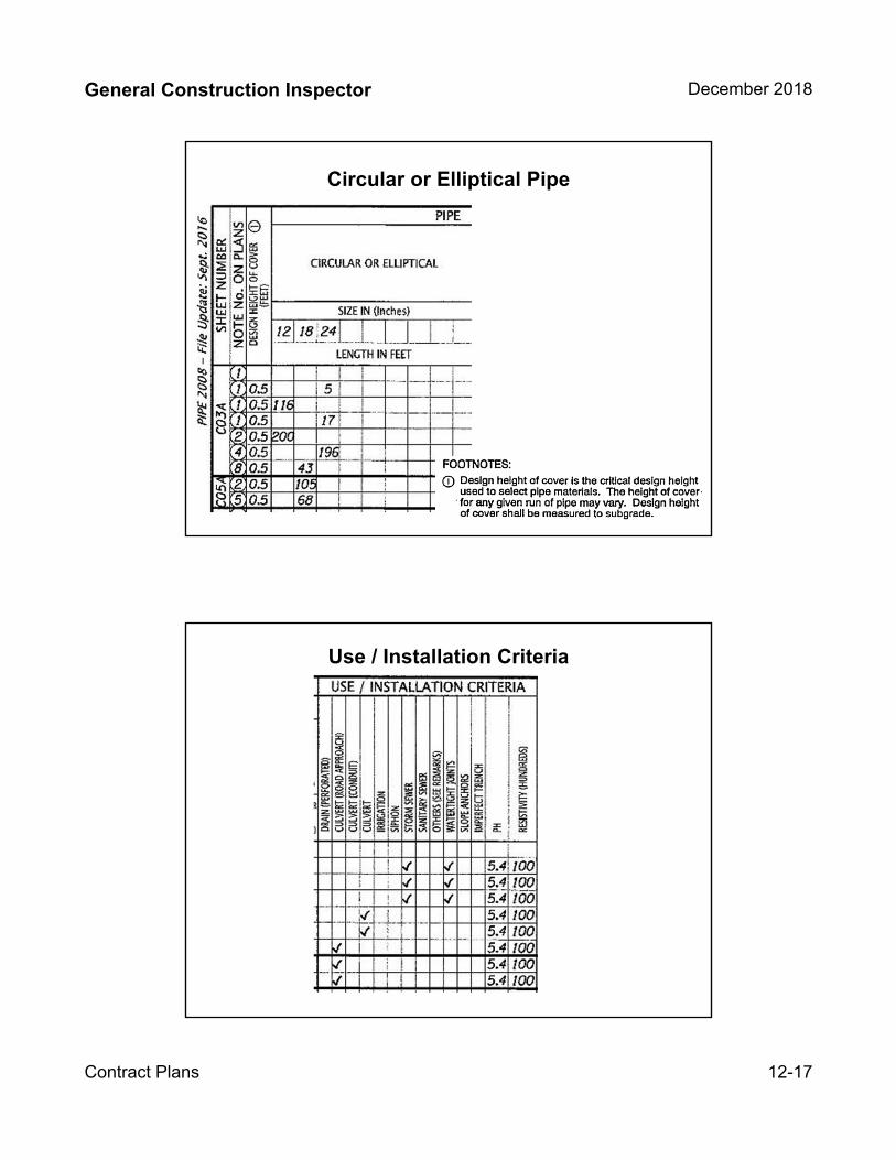
General Construction Inspector December 2018
Contract Plans 12-17
Circular or Elliptical Pipe
27
Use / Installation Criteria
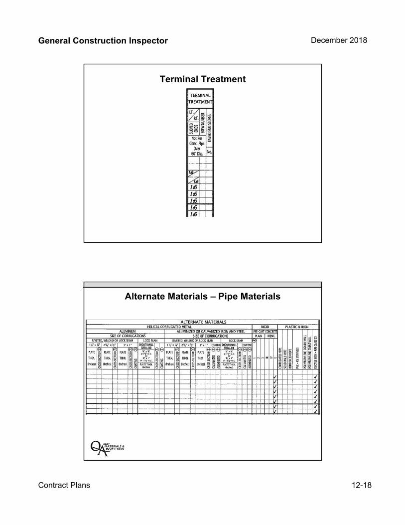
General Construction Inspector December 2018
Contract Plans 12-18
Terminal Treatment
Alternate Materials – Pipe Materials

General Construction Inspector December 2018
Contract Plans 12-19
Alternate Materials –Pipe Materials
Appurtenances and Remarks
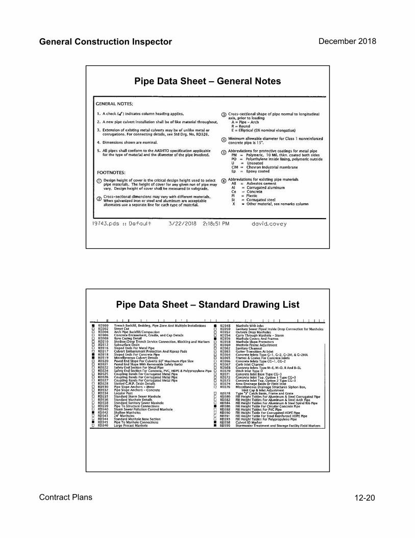
General Construction Inspector December 2018
Contract Plans 12-20
Pipe Data Sheet – General Notes
Pipe Data Sheet – Standard Drawing List
General Construction Inspector December 2018
Contract Plans 12-21
Pipe Data Sheet Review
Plans and Profile
Roadway Construction Plans Sheets 3, 4, etc.
Alignments
General Construction
General Construction Notes
Drainage and Utilities
Drainage Notes
Construction Profiles
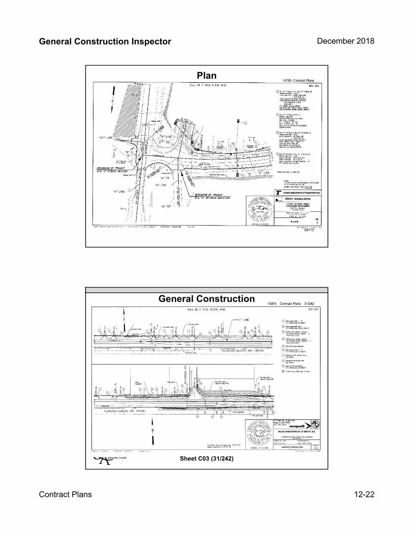
General Construction Inspector December 2018
Contract Plans 12-22
Plan
General Construction
Sheet C03 (31/242)
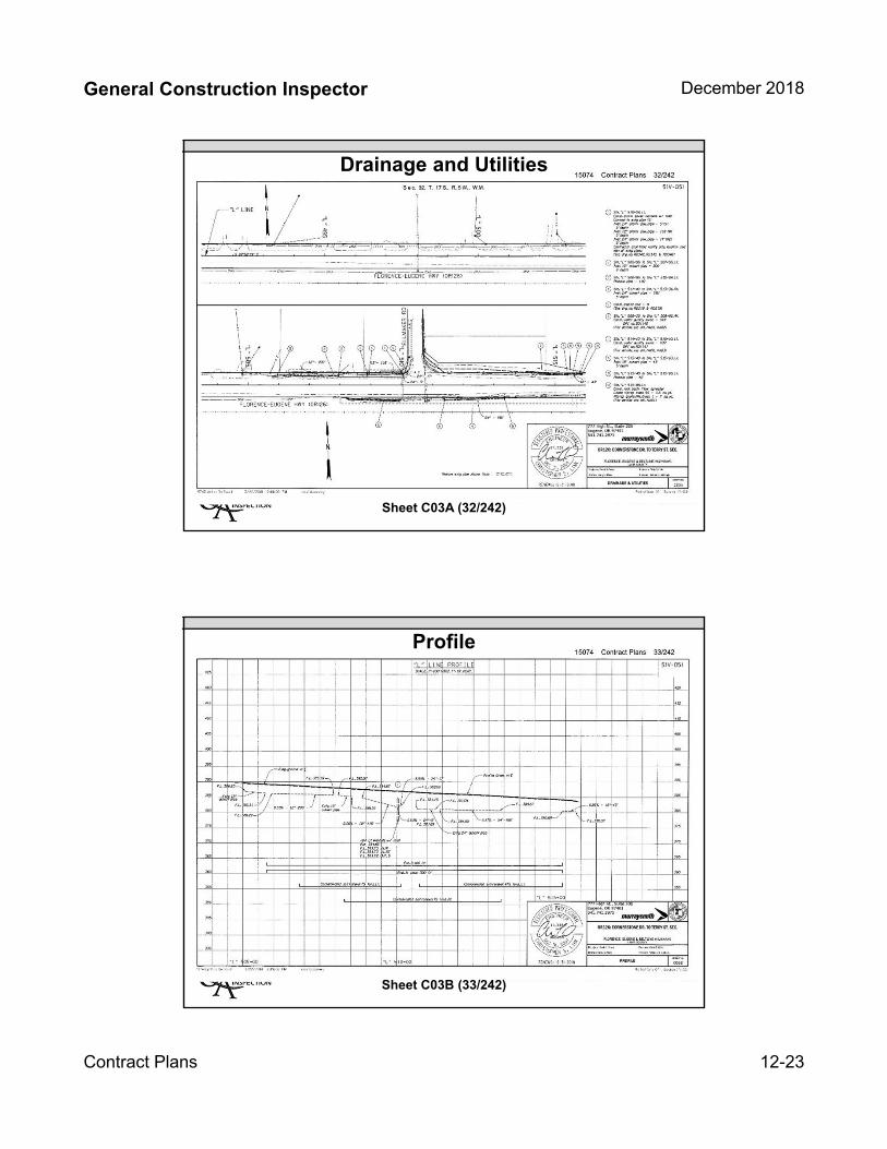
General Construction Inspector December 2018
Contract Plans 12-23
Drainage and Utilities
Sheet C03A (32/242)
Profile
Sheet C03B (33/242)

General Construction Inspector December 2018
Contract Plans 12-24
Plans and Profile Review
The four primary functions of a TCP are to provide:
Efficient traffic flow
Enhanced safety
Minimized inconvenience
Adequate mobility for allroad users
Traffic Control Plans
Information on traffic control plan development can be found in the TCP Design Manual found at https://www.oregon.gov/ODOT/Engineering/Pages/TCP-Manual.aspx
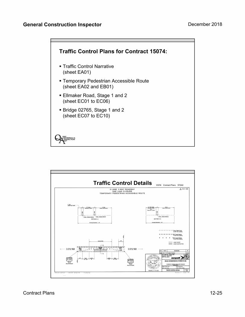
General Construction Inspector December 2018
Contract Plans 12-25
Traffic Control Narrative(sheet EA01)
Temporary Pedestrian Accessible Route(sheet EA02 and EB01)
Ellmaker Road, Stage 1 and 2(sheet EC01 to EC06)
Bridge 02765, Stage 1 and 2(sheet EC07 to EC10)
Traffic Control Plans for Contract 15074:
Traffic Control Details
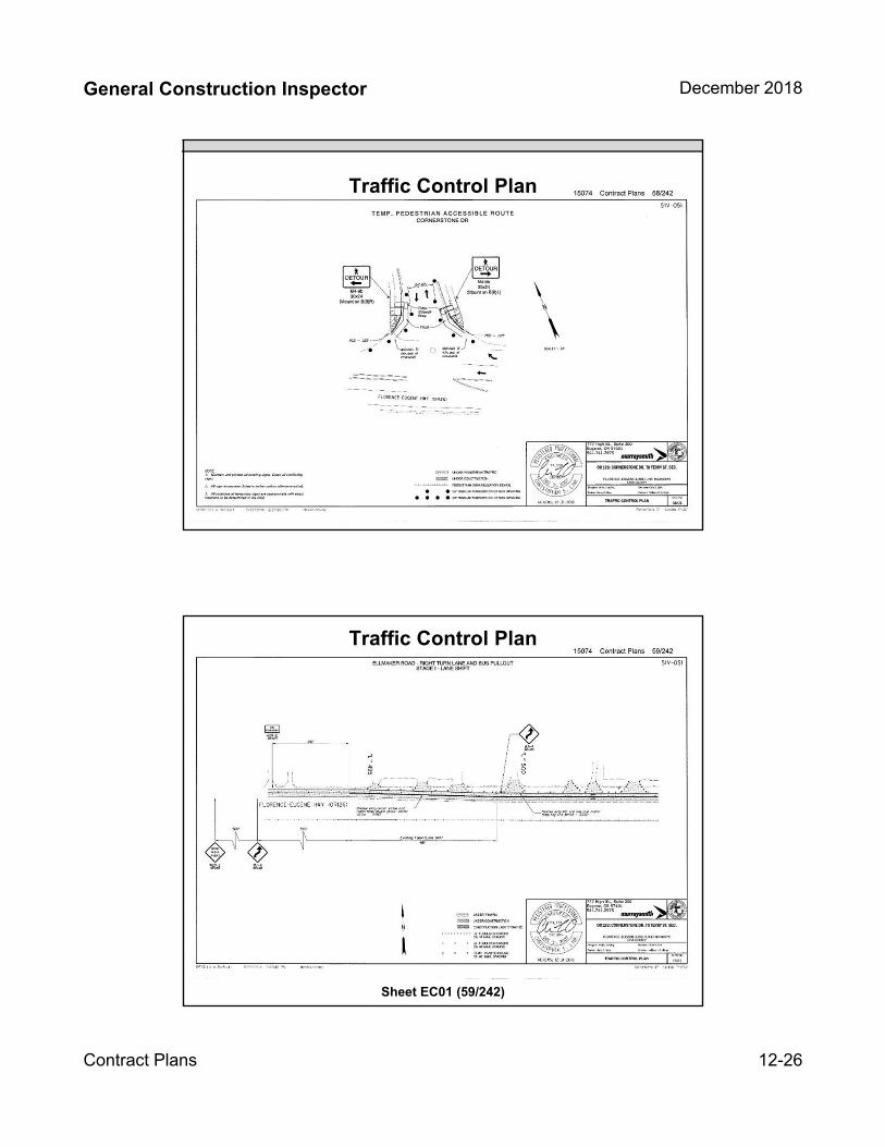
General Construction Inspector December 2018
Contract Plans 12-26
Traffic Control Plan
Traffic Control Plan
Sheet EC01 (59/242)
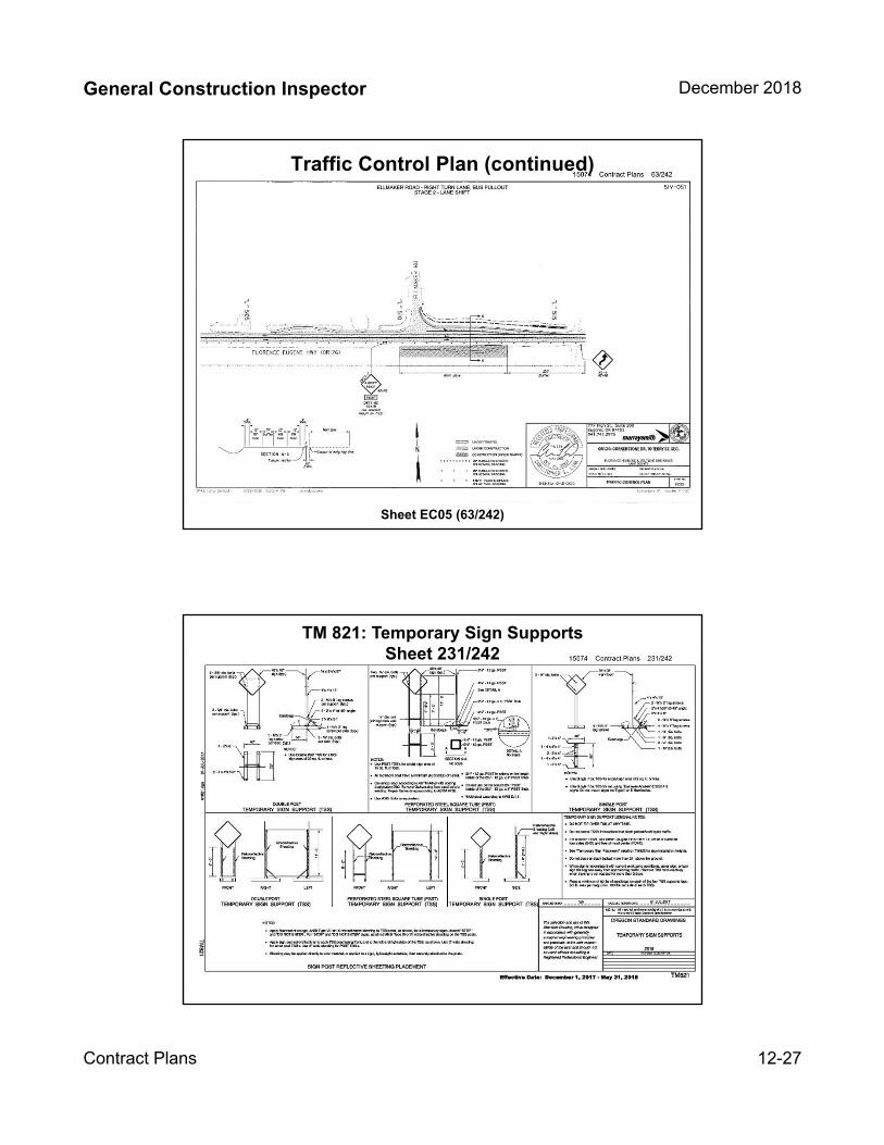
General Construction Inspector December 2018
Contract Plans 12-27
Traffic Control Plan (continued)
Sheet EC05 (63/242)
TM 821: Temporary Sign SupportsSheet 231/242

General Construction Inspector December 2018
Contract Plans 12-28
TM 820: Temporary BarricadesSheet 166/172
Traffic Control Plans Review
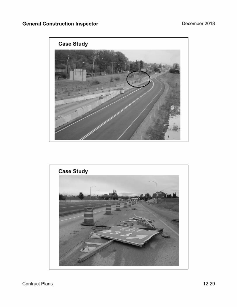
General Construction Inspector December 2018
Contract Plans 12-29
Case Study
Case Study
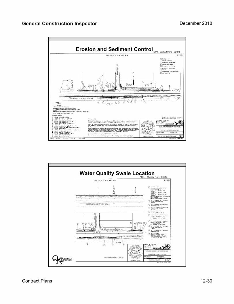
General Construction Inspector December 2018
Contract Plans 12-30
Erosion and Sediment Control
Water Quality Swale Location
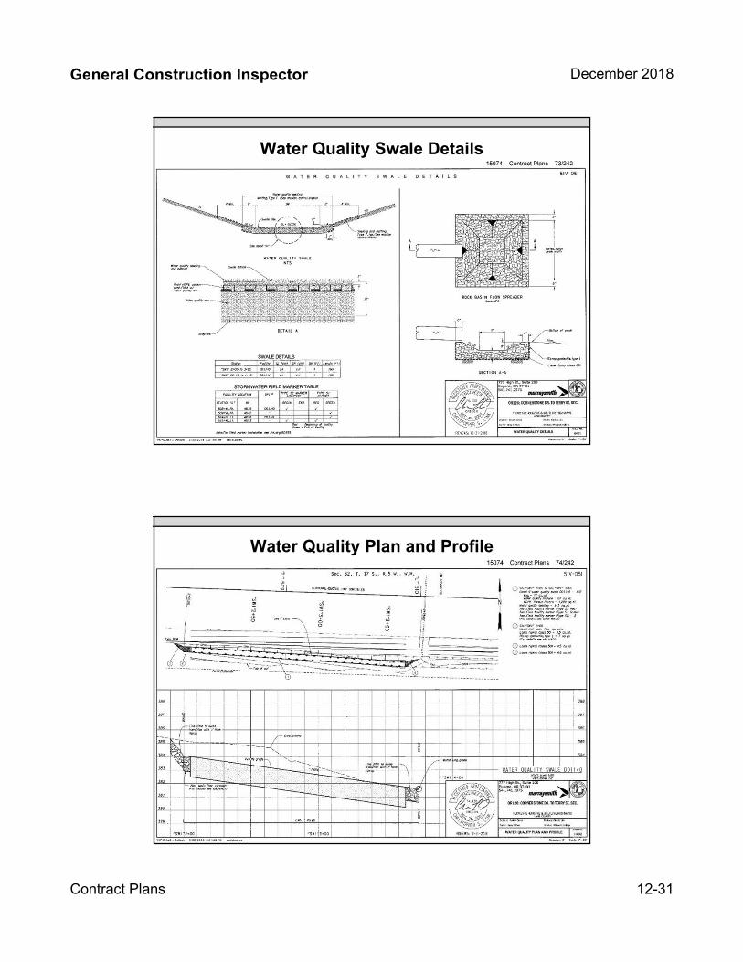
General Construction Inspector December 2018
Contract Plans 12-31
Water Quality Swale Details
Water Quality Plan and Profile

General Construction Inspector December 2018
Contract Plans 12-32
Signing Plan SheetsSheet LA01 (83/242)
Remove Existing sign #21and Sign support
Signing Plan SheetsSheet LA03 (85/242)
Install new sign #72 on a perforated steel tube sign support

General Construction Inspector December 2018
Contract Plans 12-33
Sign Detail Sheets
Sign and Post Data Table

General Construction Inspector December 2018
Contract Plans 12-34
Sign and Post Data Table (Sheet 111/242)
Sign and Post Data Table (Sheet 111/242) continued
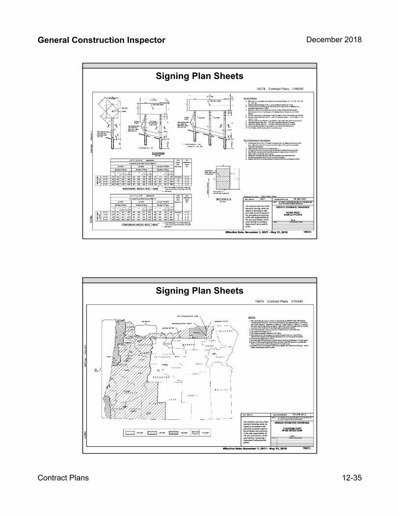
General Construction Inspector December 2018
Contract Plans 12-35
Signing Plan Sheets
Signing Plan Sheets
General Construction Inspector December 2018
Contract Plans 12-36
Signing Review
65
Pavement Marking Plan
Sheets Q01 – Q21
In addition to Layout and Legend Q01 contains
– Standard Drawing list
– General Notes
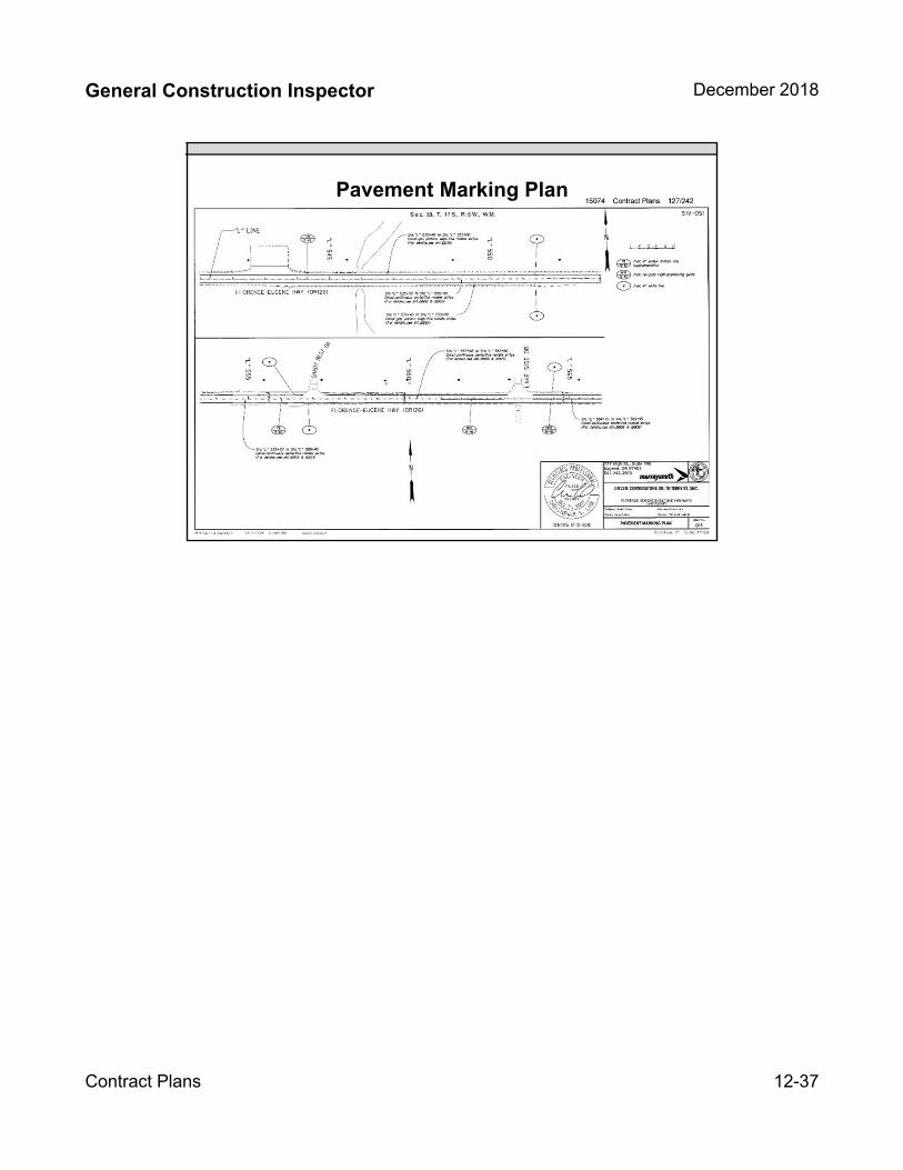
General Construction Inspector December 2018
Contract Plans 12-37
Pavement Marking Plan


INSERT TAB
Unit 13Quality & Quantity
General Construction Inspector December 2018
Quality and Quantity Documentation 13-1
Unit 13
Quality and Quantity Documentation
Unit 13 Topics:
Overview of Quality Documents
Overview of Quantity Documents
Quality and Quantity sheet
Field Inspection Reports (FIR)
Installation Sheets (Paynotes)
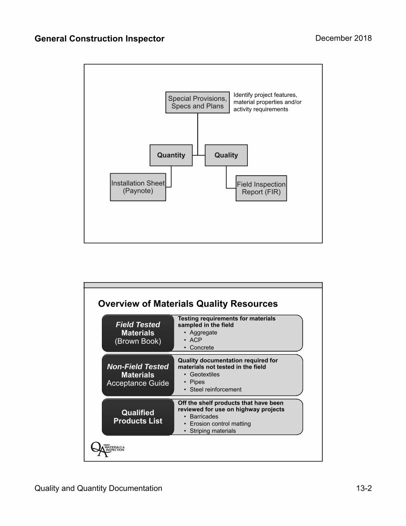
General Construction Inspector December 2018
Quality and Quantity Documentation 13-2
Quality
Field Inspection Report (FIR)
Special Provisions, Specs and Plans
Quantity
Installation Sheet (Paynote)
Identify project features, material properties and/or activity requirements
Overview of Materials Quality Resources
Testing requirements for materials sampled in the field
• Aggregate• ACP• Concrete
Field Tested Materials
(Brown Book)
Quality documentation required for materials not tested in the field
• Geotextiles• Pipes• Steel reinforcement
Non-Field Tested Materials
Acceptance Guide
Off the shelf products that have been reviewed for use on highway projects
• Barricades• Erosion control matting• Striping materials
Qualified Products List
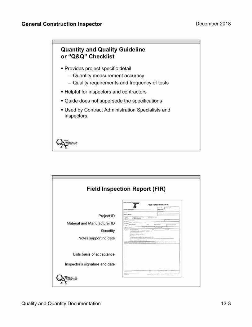
General Construction Inspector December 2018
Quality and Quantity Documentation 13-3
Quantity and Quality Guideline or “Q&Q” Checklist
Provides project specific detail
– Quantity measurement accuracy
– Quality requirements and frequency of tests
Helpful for inspectors and contractors
Guide does not supersede the specifications
Used by Contract Administration Specialists andinspectors.
Field Inspection Report (FIR)
Project ID
Quantity
Material and Manufacturer ID
Notes supporting data
Inspector’s signature and date
Lists basis of acceptance
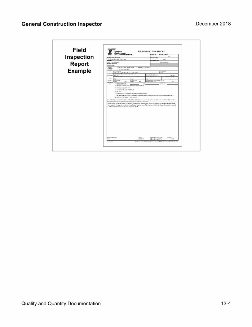
General Construction Inspector December 2018
Quality and Quantity Documentation 13-4
Field Inspection
Report Example
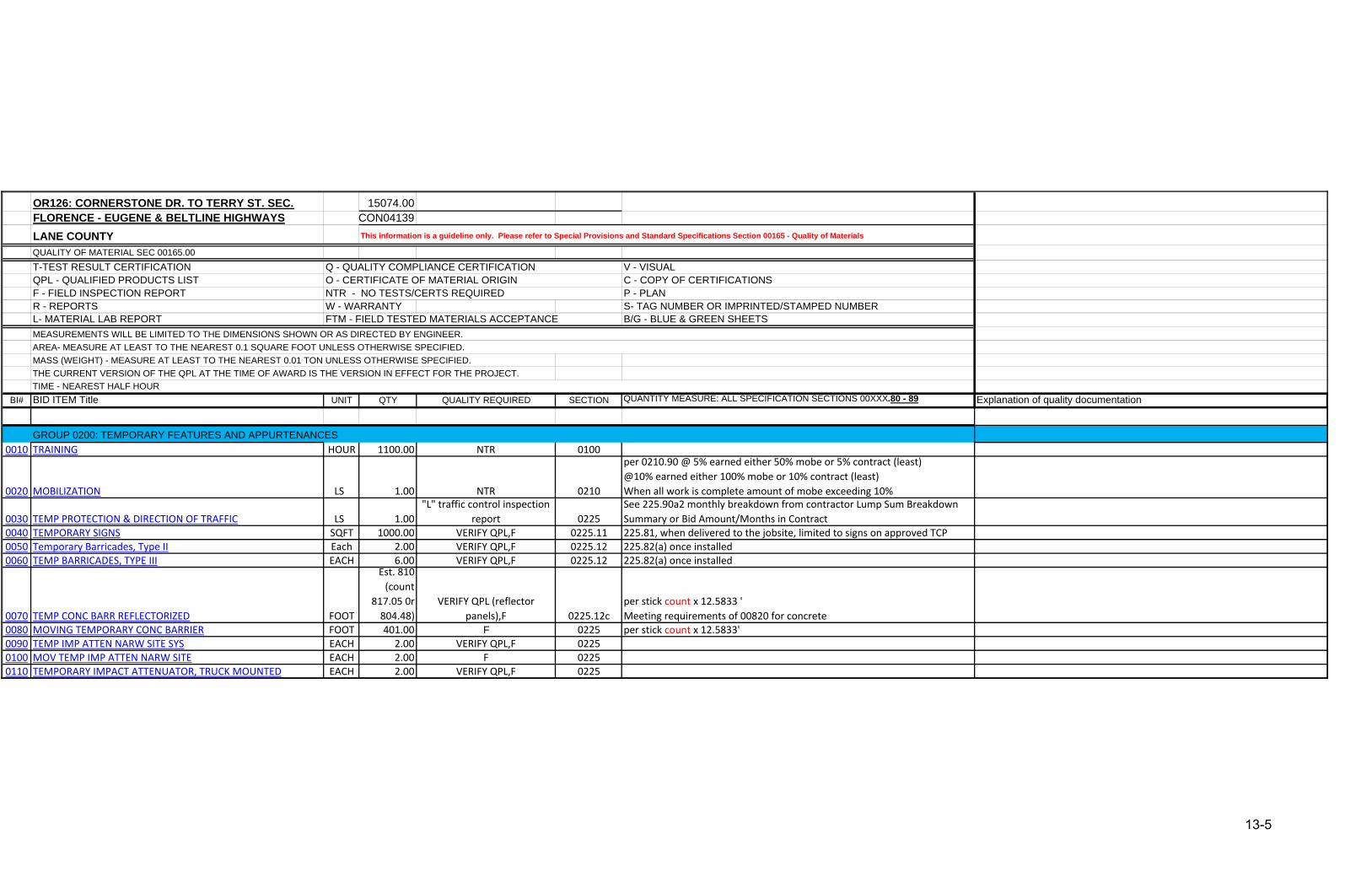
OR126: CORNERSTONE DR. TO TERRY ST. SEC. 15074.00FLORENCE - EUGENE & BELTLINE HIGHWAYS CON04139LANE COUNTYQUALITY OF MATERIAL SEC 00165.00T-TEST RESULT CERTIFICATION V - VISUALQPL - QUALIFIED PRODUCTS LIST C - COPY OF CERTIFICATIONS F - FIELD INSPECTION REPORT P - PLANR - REPORTS W - WARRANTY S- TAG NUMBER OR IMPRINTED/STAMPED NUMBERL- MATERIAL LAB REPORT B/G - BLUE & GREEN SHEETS
MASS (WEIGHT) - MEASURE AT LEAST TO THE NEAREST 0.01 TON UNLESS OTHERWISE SPECIFIED. THE CURRENT VERSION OF THE QPL AT THE TIME OF AWARD IS THE VERSION IN EFFECT FOR THE PROJECT.
BI# BID ITEM Title UNIT QTY QUALITY REQUIRED SECTION QUANTITY MEASURE: ALL SPECIFICATION SECTIONS 00XXX.80 - 89 Explanation of quality documentation
GROUP 0200: TEMPORARY FEATURES AND APPURTENANCES0010 TRAINING HOUR 1100.00 NTR 0100
0020 MOBILIZATION LS 1.00 NTR 0210
per 0210.90 @ 5% earned either 50% mobe or 5% contract (least)@10% earned either 100% mobe or 10% contract (least)When all work is complete amount of mobe exceeding 10%
0030 TEMP PROTECTION & DIRECTION OF TRAFFIC LS 1.00"L" traffic control inspection
report 0225See 225.90a2 monthly breakdown from contractor Lump Sum Breakdown Summary or Bid Amount/Months in Contract
0040 TEMPORARY SIGNS SQFT 1000.00 VERIFY QPL,F 0225.11 225.81, when delivered to the jobsite, limited to signs on approved TCP0050 Temporary Barricades, Type II Each 2.00 VERIFY QPL,F 0225.12 225.82(a) once installed0060 TEMP BARRICADES, TYPE III EACH 6.00 VERIFY QPL,F 0225.12 225.82(a) once installed
0070 TEMP CONC BARR REFLECTORIZED FOOT
Est. 810 (count
817.05 0r 804.48)
VERIFY QPL (reflector panels),F 0225.12c
per stick count x 12.5833 'Meeting requirements of 00820 for concrete
0080 MOVING TEMPORARY CONC BARRIER FOOT 401.00 F 0225 per stick count x 12.5833'0090 TEMP IMP ATTEN NARW SITE SYS EACH 2.00 VERIFY QPL,F 02250100 MOV TEMP IMP ATTEN NARW SITE EACH 2.00 F 02250110 TEMPORARY IMPACT ATTENUATOR, TRUCK MOUNTED EACH 2.00 VERIFY QPL,F 0225
TIME - NEAREST HALF HOUR
This information is a guideline only. Please refer to Special Provisions and Standard Specifications Section 00165 - Quality of Materials
MEASUREMENTS WILL BE LIMITED TO THE DIMENSIONS SHOWN OR AS DIRECTED BY ENGINEER.AREA- MEASURE AT LEAST TO THE NEAREST 0.1 SQUARE FOOT UNLESS OTHERWISE SPECIFIED.
Q - QUALITY COMPLIANCE CERTIFICATIONO - CERTIFICATE OF MATERIAL ORIGINNTR - NO TESTS/CERTS REQUIRED
FTM - FIELD TESTED MATERIALS ACCEPTANCE
13-5
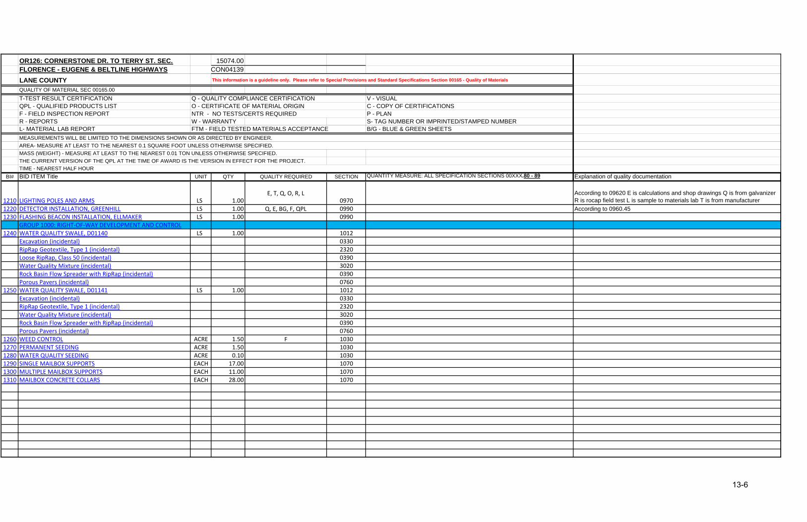
OR126: CORNERSTONE DR. TO TERRY ST. SEC. 15074.00FLORENCE - EUGENE & BELTLINE HIGHWAYS CON04139LANE COUNTYQUALITY OF MATERIAL SEC 00165.00T-TEST RESULT CERTIFICATION V - VISUALQPL - QUALIFIED PRODUCTS LIST C - COPY OF CERTIFICATIONS F - FIELD INSPECTION REPORT P - PLANR - REPORTS W - WARRANTY S- TAG NUMBER OR IMPRINTED/STAMPED NUMBERL- MATERIAL LAB REPORT B/G - BLUE & GREEN SHEETS
MASS (WEIGHT) - MEASURE AT LEAST TO THE NEAREST 0.01 TON UNLESS OTHERWISE SPECIFIED. THE CURRENT VERSION OF THE QPL AT THE TIME OF AWARD IS THE VERSION IN EFFECT FOR THE PROJECT.
BI# BID ITEM Title UNIT QTY QUALITY REQUIRED SECTION QUANTITY MEASURE: ALL SPECIFICATION SECTIONS 00XXX.80 - 89 Explanation of quality documentationTIME - NEAREST HALF HOUR
This information is a guideline only. Please refer to Special Provisions and Standard Specifications Section 00165 - Quality of Materials
MEASUREMENTS WILL BE LIMITED TO THE DIMENSIONS SHOWN OR AS DIRECTED BY ENGINEER.AREA- MEASURE AT LEAST TO THE NEAREST 0.1 SQUARE FOOT UNLESS OTHERWISE SPECIFIED.
Q - QUALITY COMPLIANCE CERTIFICATIONO - CERTIFICATE OF MATERIAL ORIGINNTR - NO TESTS/CERTS REQUIRED
FTM - FIELD TESTED MATERIALS ACCEPTANCE
1210 LIGHTING POLES AND ARMS LS 1.00E, T, Q, O, R, L
0970According to 09620 E is calculations and shop drawings Q is from galvanizer R is rocap field test L is sample to materials lab T is from manufacturer
1220 DETECTOR INSTALLATION, GREENHILL LS 1.00 Q, E, BG, F, QPL 0990 According to 0960.451230 FLASHING BEACON INSTALLATION, ELLMAKER LS 1.00 0990
GROUP 1000: RIGHT‐OF‐WAY DEVELOPMENT AND CONTROL1240 WATER QUALITY SWALE, D01140 LS 1.00 1012
Excavation (incidental) 0330RipRap Geotextile, Type 1 (incidental) 2320Loose RipRap, Class 50 (incidental) 0390Water Quality Mixture (incidental) 3020Rock Basin Flow Spreader with RipRap (incidental) 0390Porous Pavers (incidental) 0760
1250 WATER QUALITY SWALE, D01141 LS 1.00 1012Excavation (incidental) 0330RipRap Geotextile, Type 1 (incidental) 2320Water Quality Mixture (incidental) 3020Rock Basin Flow Spreader with RipRap (incidental) 0390Porous Pavers (incidental) 0760
1260 WEED CONTROL ACRE 1.50 F 10301270 PERMANENT SEEDING ACRE 1.50 10301280 WATER QUALITY SEEDING ACRE 0.10 10301290 SINGLE MAILBOX SUPPORTS EACH 17.00 10701300 MULTIPLE MAILBOX SUPPORTS EACH 11.00 10701310 MAILBOX CONCRETE COLLARS EACH 28.00 1070
13-6
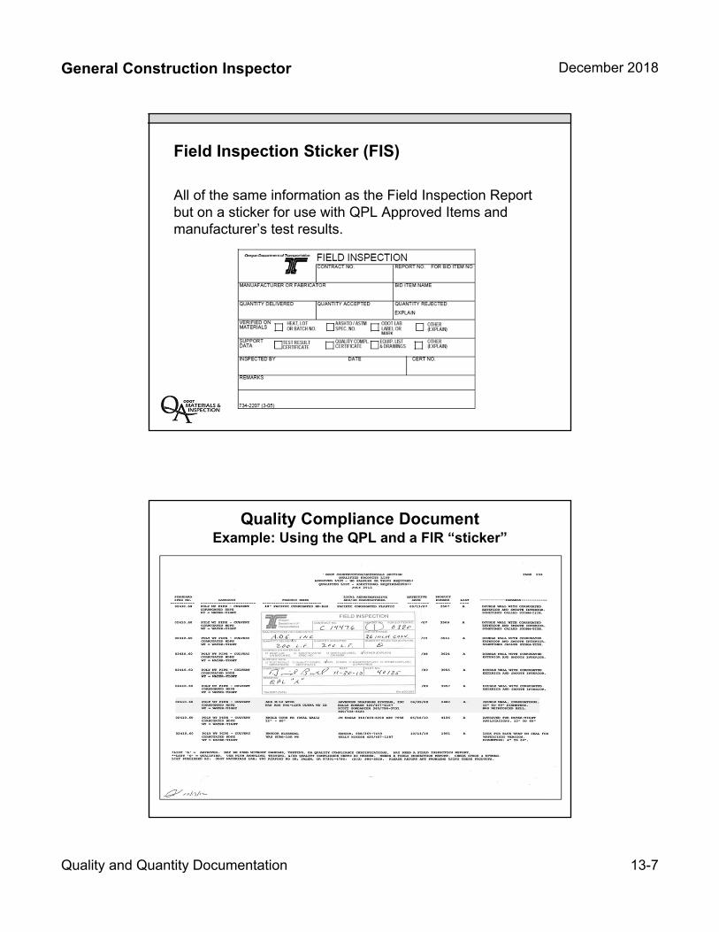
General Construction Inspector December 2018
Quality and Quantity Documentation 13-7
Field Inspection Sticker (FIS)
All of the same information as the Field Inspection Report but on a sticker for use with QPL Approved Items and manufacturer’s test results.
Quality Compliance DocumentExample: Using the QPL and a FIR “sticker”

13-8

REPORT NO. FOR BID ITEM NO.
1
REASON FOR THIS REPORT
TYPE OF MATERIAL DATE DELIVERED
SOURCE OF MATERIAL (MANUFACTURER OR FABRICATOR)
QUANTITY APPROVED
TOTAL APPROVEDTO DATE 600
ESTIMATED TOTAL REQUIRED 650 NA
SUPPORTING DATA I- TEST
WHERE INSPECTED DATE INSPECTOR SIGNATURE CERT NO.43139
734-3469 (1-2007)
REMARKS AND EXPLANATIONS, MATERIALS DESCRIPTIONS, DATES OF MANUFACTURE, HEAT AND LOT NOS. DAMAGED OR SUBSTANDARD MATERIALS, REASONS FOR REJECTION AND DISPOSITION OF REJECTED MATERIALS.
Field 5/2/2017 Joe Inspector
UNIT
Feet
QUANTITY DELIVERED
MATERIALS
DELIVERED
FOR
PROJECT
DELIVERED TO (NAME OFCONTRACTOR/SUBCONTRACTOR)
QUANTITY REJECTED (EXPLAIN)
0450
LABORATORY REPORT NO.
450SAMPLE DATA SHEET NO. FOR SAMPLE SENT TO MATERIALS LAB FOR TESTS
12 Inch Corrugated Polyethylene Culvert Pipe 5/2/2017
ADS, Inc. JRT, Inc
Steve Schultz
HIGHWAY F.A. PROJECT NO.
HSIP-S009(455)PROJECT MANAGERPacific Coast Highway
FIELD INSPECTION REPORT
CONTRACT NO.
14861
340PROJECT NAME (SECTION)
US 101 @ NE Devils Lake Road
INSPECTION OF MATERIAL MATERIALS ON HAND
OTHER (EXPLAIN)
Verified in the field that the ADS, Inc. HDPE corrugated pipe delivered was 12 inch in diameter and stamped AASHTO M294, Type D, which is in accordance with the specification requirements of 00445.11 and 02415.10. Also verfied that this material is on the Qualified Products List, product number 3435.
MATERIALS INSPECTION LABORATORY REPORT NO.
MATERIALS LABORATORY INSPECTION LABEL OR MARK.
TEST RESULTS CERTIFICATE
QUALITY COMPLIANCE CERTIFICATE
CONFORMANCE TO EQUIPMENT LIST AND DRAWINGS (EXPLAIN)
CERTIFICATE OF MATERIAL ORIGIN FOR PERMANENTLY INCORPORATED IRON OR STEEL MATERIALS AND THEIR COATINGS ON FEDERAL AID PROJECTS
FIELD TESTS OR OBSERVATIONS (EXPLAIN)
QPL ITEM
13-9
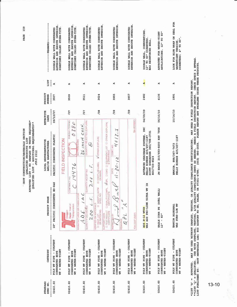
ST
ANDARD
S
PE
C
NO
.
------
--0
24
10
. 6
0
02
41
0.
60
02
41
0.
60
02
41
0.
60
02
41
0.
60
02
41
0.
60
02
41
0.
60
02
41
0.
60
02
41
0.
60
CA
TE
GO
RY
---
-----
PO
LY
'W'r
PI
PE
-
CUL
VE
RT
C
ORR
UGA
TE
D
HOP
E
wr
= WA
TE
R-
TI
GH
T
PO
LY
wr
PI
PE
-
CUL
VER
T
CO
RRU
GA
TE
D
HOP
E
WT=
WAT
ER
-T
IG
HT
PO
LY
WT
P
IP
E
-C
UL
VE
RT
C
ORR
UGA
TED
HO
PE
WT
= WA
TE
R-
TI
GH
T
PO
LY
WT
PI
PE
-
CU
LV
ER
T
CO
RRUGATE
D
HOP
E
WT
= WA
TE
R-
TI
GH
T
PO
LY
WT
P
IP
E
-C
UL
VE
RT
C
ORR
UG
AT
ED
HO
PE
WT
= WA
TE
R-
TI
GH
T
PO
LY
WT
PI
PE
-
CUL
VER
T
CO
RR
UG
AT
ED
HO
PE
WT
= WA
TE
R-
TI
GB
T
PO
LY
WT
PI
PE
-
CUL
VE
RT
C
ORR
UG
AT
ED
HO
PE
W
T=
WAT
ER
-T
IG
HT
PO
LY
WT
P
IP
E
-C
UL
VERT
C
OR
RU
GAT
ED
B
DP
E
WT
= WA
TE
R-
TI
GH
T
PO
LY
WT
P
IP
E
-C
ULVE
RT
C
OR
RU
GA
TE
D
BD
PE
W
T=
WAT
ER
-T
IG
HT
. O
DO
T
CO
NS
TR
UC
TI
ON
/MA
TE
RIAL
S
SE
CT
IO
N
QU
ALI
FI
ED
P
RO
DU
CT
S
LI
ST
A
PP
RO
VED
LI
ST
-N
O
SJ\MP
LE
S
OR
T
ES
TS
R
EQ
UI
RE
D*
Q
UA
LI
FI
ED
L
IS
T -
ADD
IT
IO
NAL
RE
QU
IREMENT
S•
•
JULY
20
12
PR
OD
UC
T NA
ME
L
OC
AL
R
EP
RE
SEN
TA
TI
VE
A
ND
/O
R MANUF
AC
TUR
ER
E
FF
EC
TI
VE
D
AT
E
------
------
·--------------------
18
" P
AC
IF
IC
C
ORR
UG
AT
ED
HO
-B
&S
P
AC
IF
IC
C
ORR
UG
AT
ED
PL
AS
TI
C
09
/1
3/
07
FIE
LD
IN
SP
EC
TIO
N
]�
rego
n D
epa
rtment
of
Tra
ns
po
rta
tion
IC
ON C
CT
;�
I-( 7
"1r
rJ FO
r;;I J
B;
o
MA
NU
FAC
TUR
ER O
R F
ABR
ICAT
OR
s
iB'ff
E'i:1
NAM
E
_A. O
.• ((
NC
i�
1111t..
1-I
cv
1-v
. Q
UAN
TITY
DEL
IVER
D
QUA
NTI
TY A
CC
EPT
ED
QUA
NTIT
Y R
EJE
CTE
D (E
XPL
AIN
)
2-.(!)
o L-
, F.
2-tJ P
L.
F.
VER
IFIE
D O
N M
ATER
IALS
D
HE
AT. L
OT
D
AA
SHT
O/A
STM
D
OD
OT
LAB
LABE
L i.f
oTH
ER (E
XPL
AIN
) O
R B
ATC
H N
O
SPE
C. N
O.
OR
MAR
K S
UPP
OR
T D
ATA
□TE
ST
RES
ULT
□ o
uAu
Tv c
oM
PL
da
PL
□ c
Mo
□ E
QU
IPM
ENT
LIS
T rJ
OTH
ER <E
XPL
AIN)
C
ERTI
FIC
ATE
CER
TIFI
CAT
E &
DR
AWIN
GS
INS
P ';9,D
BY
• /2
. //
'✓�
-::J...v'(...t"
R
EMAR
KS
I ti
�
PL
1
A
734-
2207
(5/
07)
DA
TE
I CER
T NO
tl·-
?t:>
,1
2
tf�
ll
. .C
Stk
#203
263
/07
/07
/0
8
/09
/0
9
AD
S
N-
12
WT
IB
A
DVA
NC
ED
D
RAI
NA
GE
S
YS
TEM
S,
IN
C
KEL
LY
K
OKE
SH
4
25
/4
57
-1
18
7
SC
OT
T
GO
RDAN
IE
R
36
0/
79
8-
37
31
8
00
/7
33-
85
23
04
/0
9/
09
WA
S AD
S
PR
O-
LI
NK
U
LT
RA
WT
IB
EA
GL
E
CO
RR
P
E
(DUAL
WA
LL
) 1
2"
-6
0"
BAN
CO
R
BL
UE
SEAL
WA
S
SURE
-L
OK
WT
JM
E
AG
LE
3
10
/6
93
-82
00
E
XT
79
58
BA
NC
OR
, 8
88
/3
67
-7
47
3
KEL
LY
K
OKE
SH
4
25
/4
57
-1
18
7
06
/1
0/
10
10
/1
4/
10
PR
OD
UC
T
NDMBE
R
35
07
35
09
35
11
36
24
39
55
39
57
24
82
41
36
18
91
LI
ST
A
A A
A
A
A
A
A
A
*L
IS
T
'A'
=
AP
PR
OV
ED
.
MAY
B
E
US
ED
WI
TH
OU
T
SJ\MP
LE
S,
TE
ST
IN
G,
OR
Q
UA
LI
TY
C
OMP
LI
AN
CE
C
ER
TI
FI
CA
TI
ON
S.
MAY
N
EED
A
F
IE
Lll
I
NS
PE
CT
IO
N
RE
PO
RT
.
PA
GE
1
59
------
------
REMARKS---
------
---D
OU
BL
E WA
LL
WI
TH
CO
RR
UG
AT
ED
EX
TE
RI
OR
AND
S
MOO
TH
I
NT
ER
I�
R.
S
OME
TI
MES
C
AL
LE
D
ST
ORM-
TI
TE
.
DO
UB
LE
WA
LL
WI
TH
C
ORR
UG
AT
ED
E
XT
ER
IO
R
AND
S
MO
OT
H
INT
ER
IO
R.
S
OMET
IME
S
CA
LL
ED
S
TO
RM-T
IT
E.
DO
UB
LE
WAL
L W
IT
H C
ORR
UG
AT
ED
EXT
ER
IO
R AN
D
SM
OO
TH
I
NT
ER
IO
R.
S
OME
TI
MES
C
AL
LED
S
TO
RM-T
IT
E.
DO
UB
LE
WAL
L W
IT
H
CO
RR
UG
AT
ED
EXT
ER
IO
R
AN
D
SM
OO
TH
I
NTE
RI
OR
.
DO
UB
LE
WALL
WI
TH
CO
RR
UG
AT
ED
EX
TE
RI
OR
AN
D
SM
OOT
H
IN
TE
RI
OR
.
DO
UB
LE
W
AL
L W
IT
H
CO
RR
UG
AT
ED
EXT
ER
IO
R
AND
SM
OOT
H
IN
TE
RI
OR
.
DO
UBL
E WAL
L,
CO
RR
UG
AT
IO
NS
.
12
"
TO
6
0"
DI
AMET
ER
S.
BAS
RE
IN
FO
RC
ED
B
EL
L.
AP
PR
OVED
F
OR
WAT
ER
-T
IG
HT
A
PP
LI
CA
TI
ON
S,
12
" T
O
60
"
LO
OK
F
OR
BL
UE W
RA
P O
N
SE
AL
F
OR
W
AT
ER
TI
GH
T VE
RS
IO
N.
lli
l\MET
ER
S:
4"
TO
6
0"
,
**
LI
ST
'Q
' =
Q
UAL
IF
IE
D.
US
E
WI
TH
S
AMPL
IN
G,
TE
ST
IN
G,
&/
OR
Q
UAL
IT
Y
COMP
LI
AN
CE
C
ER
TS
A
S
NE
ED
ED
.
NE
ED
S
A
FI
EL
D
IN
SP
EC
TI
ON
RE
PO
RT
. C
HE
CK
S
PE
CS
&
NE"l'MA
G.
LI
ST
P
UB
LI
SHE
D
BY
: O
llO
T
MAT
ERI
AL
S
LA
B;
80
0
AI
RP
OR
T
RD
S
E;
SA
LEM
, O
R
97
30
1-
47
98
; (5
03
) 9
86
-3
05
9.
PL
EA
SE
R
EP
OR
T
ANY
P
RO
BL
EMS
U
SI
NG
T
HE
SE
P
ROll
UC
TS
,
13-4
13-10
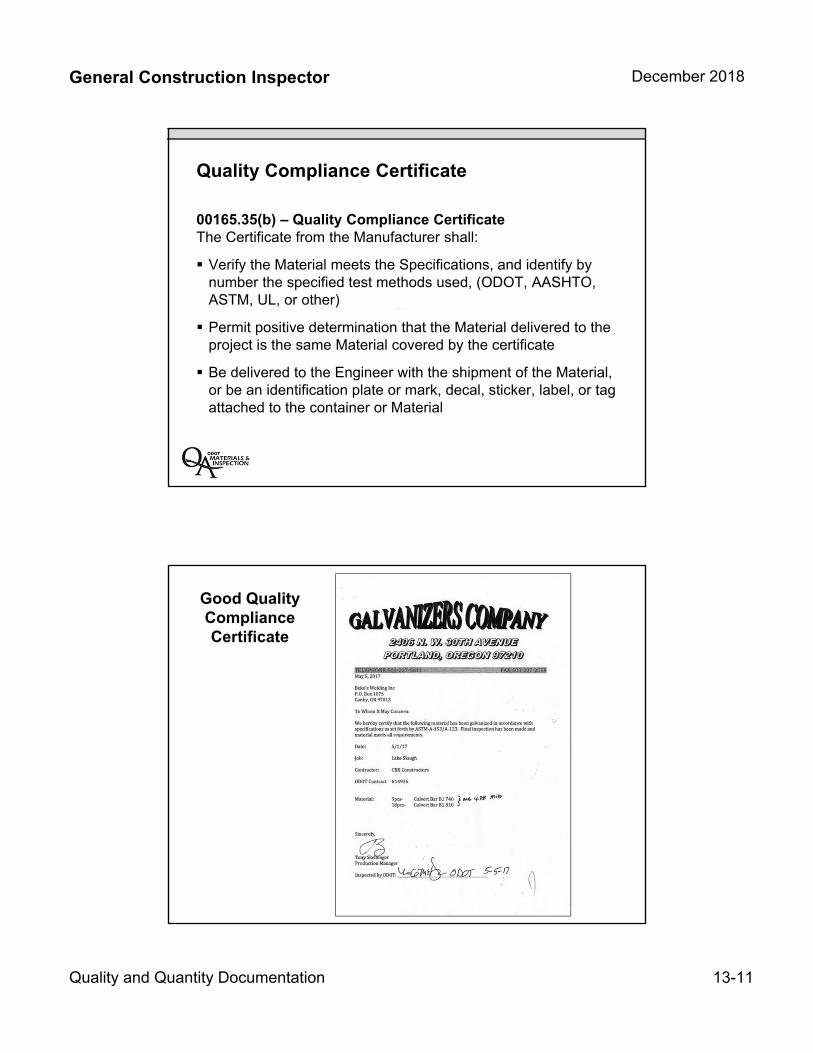
General Construction Inspector December 2018
Quality and Quantity Documentation 13-11
Quality Compliance Certificate
00165.35(b) – Quality Compliance CertificateThe Certificate from the Manufacturer shall:
Verify the Material meets the Specifications, and identify bynumber the specified test methods used, (ODOT, AASHTO,ASTM, UL, or other)
Permit positive determination that the Material delivered to theproject is the same Material covered by the certificate
Be delivered to the Engineer with the shipment of the Material,or be an identification plate or mark, decal, sticker, label, or tagattached to the container or Material
Good Quality Compliance Certificate
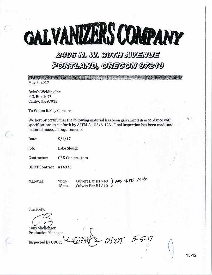
(
' .
tJ1Tff!J IJZ cw. 3lJi]f](] � �
� if)7&{J(j)
l�1.li!iJR'1Ymliii!l�ltil�t;�1iiitk4fiii'�iti�\iW-k��i-jl�11_.����-iMay 5, 2017
Beko's Welding Inc P.O. Box 1075 Canby, OR 97013
To Whom It May Concern:
We hereby certify that the following material has been galvanized in accordance with specifications as set forth by ASTM-A-153/A-123. Final inspection has been made and material meets all requirements.
Date:
Job:
Contractor:
5/1/17
Lake Slough
CBK Constructors
ODOT Contract #14936
Material:
Sincerely,
9pcs-18pcs-
Culvert Bar B1 740 1 f+l){p 44 JfJ ffJi/4;Culvert Bar B1 810 j
� Production Manager
Inspected by ODOT: \:l-:Gz 1lit� () tXJr � � J7
13-12
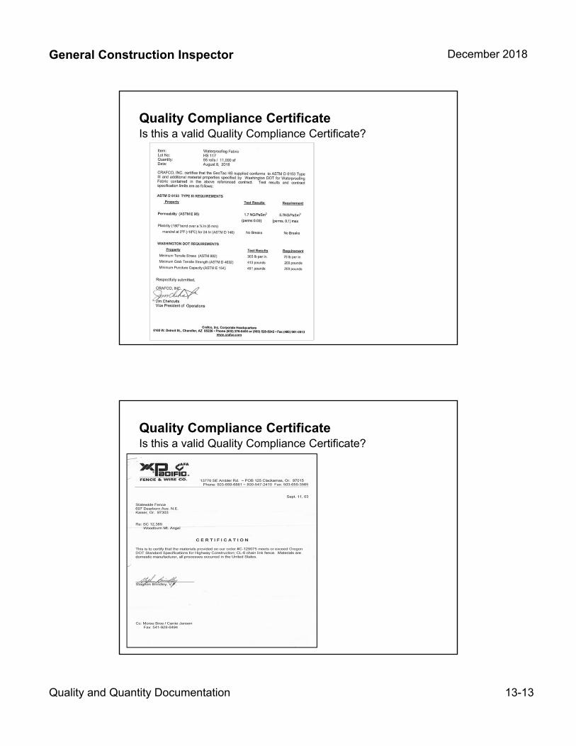
General Construction Inspector December 2018
Quality and Quantity Documentation 13-13
Quality Compliance CertificateIs this a valid Quality Compliance Certificate?
Quality Compliance CertificateIs this a valid Quality Compliance Certificate?
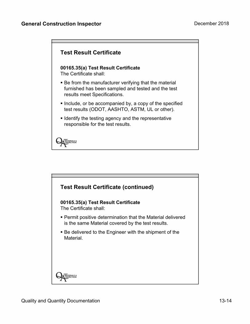
General Construction Inspector December 2018
Quality and Quantity Documentation 13-14
Test Result Certificate
00165.35(a) Test Result CertificateThe Certificate shall:
Be from the manufacturer verifying that the materialfurnished has been sampled and tested and the testresults meet Specifications.
Include, or be accompanied by, a copy of the specifiedtest results (ODOT, AASHTO, ASTM, UL or other).
Identify the testing agency and the representativeresponsible for the test results.
Test Result Certificate (continued)
00165.35(a) Test Result CertificateThe Certificate shall:
Permit positive determination that the Material deliveredis the same Material covered by the test results.
Be delivered to the Engineer with the shipment of theMaterial.
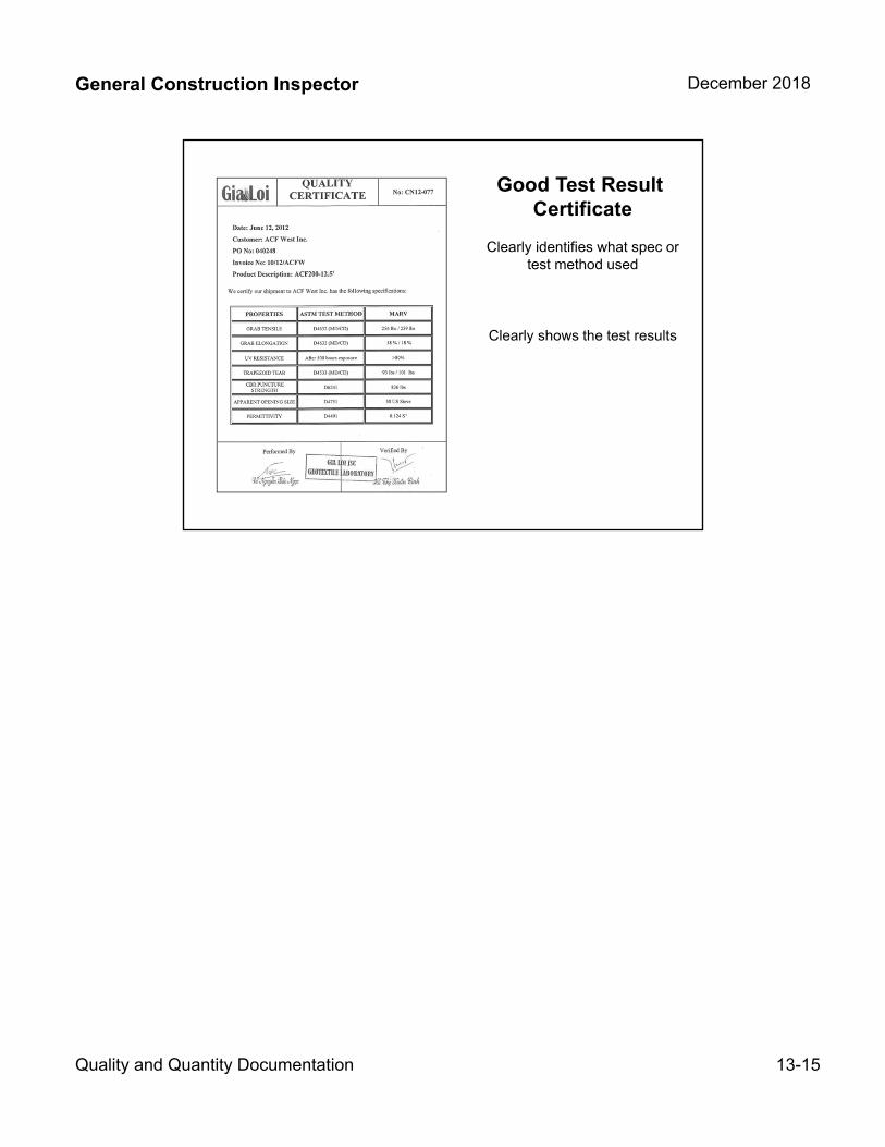
General Construction Inspector December 2018
Quality and Quantity Documentation 13-15
Good Test Result Certificate
Clearly identifies what spec or test method used
Clearly shows the test results
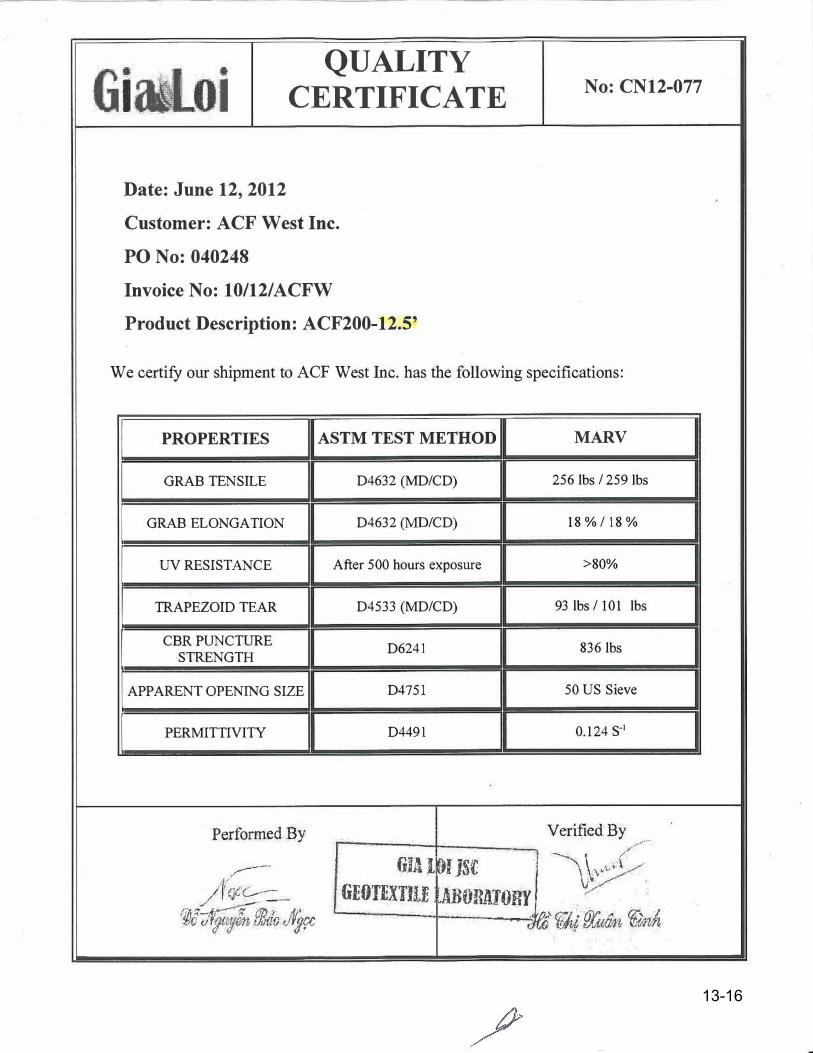
---�----
QUALITY
6. - L .lall: 0 11 CERTIFICATE No: CN12-077
Date: June 12, 2012
Customer: ACF West Inc.
PO No: 040248
Invoice No: 10/12/ACFW
Product Description: ACF200-12.5'
We certify our shipment to ACF West Inc. has the following specifications:
I PROPERTIES
GRAB TENSILE
I GRAB ELONGATION
I UV RESISTANCE
I TRAPEZOID TEAR
I
CBR PUNCTURE STRENGTH
I APPARENT OPENING SIZE
I PERMITTIVITY
Performed By
. .,,,..----· /VcJCC--
/ ---
:@t;lq;)n PJJdo J�
ASTM TEST METHOD MARV
D4632 (MD/CD) 256 lbs / 259 lbs
D4632 (MD/CD) 18%/18%
After 50 0 hours exposure >80%
D4533 (MD/CD) 93 lbs/ 101 lbs
D6241 836 lbs
D4751 50 US Sieve
D4491 0.124 s-1
VerifiedBy
6141, .. /,-···
�IJS[ I � \ _( . .. k \ ,•''.,:./
vlBOR�TORl' _ 1/ . · GEO'fEXTllE . � . �· . . u .. ,._ ' ..
- . , d) ({� Bu«Mi �nh
13-16

General Construction Inspector December 2018
Quality and Quantity Documentation 13-17
Equipment List and Drawings
00165.35(c) Equipment List and DrawingsThese consist of lists of proposed Equipment and Materials, such as:
– Shop drawings
– Material lists
– Equipment lists
– Catalog description
– Manufacturer’s brochures
Submit these lists to the Engineer for review of conformance with the Specifications
Equipment List and Drawings
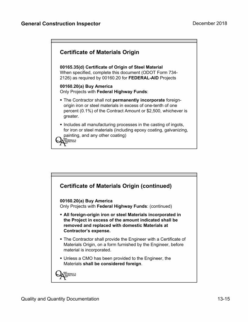
General Construction Inspector December 2018
Quality and Quantity Documentation 13-15
Certificate of Materials Origin
00165.35(d) Certificate of Origin of Steel MaterialWhen specified, complete this document (ODOT Form 734-2126) as required by 00160.20 for FEDERAL-AID Projects
00160.20(a) Buy AmericaOnly Projects with Federal Highway Funds:
The Contractor shall not permanently incorporate foreign-origin iron or steel materials in excess of one-tenth of onepercent (0.1%) of the Contract Amount or $2,500, whichever isgreater.
Includes all manufacturing processes in the casting of ingots,for iron or steel materials (including epoxy coating, galvanizing,painting, and any other coating)
Certificate of Materials Origin (continued)
00160.20(a) Buy AmericaOnly Projects with Federal Highway Funds: (continued)
All foreign-origin iron or steel Materials incorporated inthe Project in excess of the amount indicated shall beremoved and replaced with domestic Materials atContractor’s expense.
The Contractor shall provide the Engineer with a Certificate ofMaterials Origin, on a form furnished by the Engineer, beforematerial is incorporated.
Unless a CMO has been provided to the Engineer, theMaterials shall be considered foreign.
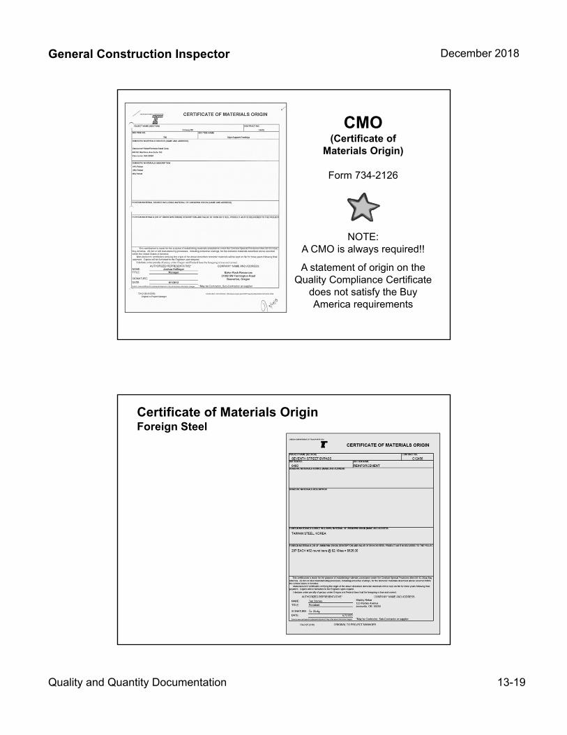
General Construction Inspector December 2018
Quality and Quantity Documentation 13-19
CMO (Certificate of
Materials Origin)
Form 734-2126
NOTE:A CMO is always required!!
A statement of origin on the Quality Compliance Certificate
does not satisfy the Buy America requirements
Certificate of Materials OriginForeign Steel
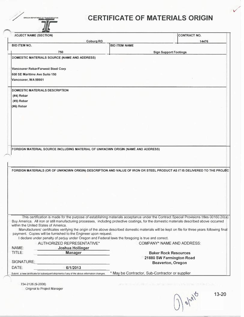
/ OREGONOEPARTMENT OF TRANSPORTATION CERTIFICATE OF MATERIALS ORIGIN
Jr �OJECT NAME (SECTION)
Coburg RD BID ITEM NO.
750
DOMESTIC MATERIALS SOURCE (NAME AND ADDRESS)
Va�couver Rebar/Farwest Steel Corp
600 SE Maritime Ave Suite 150 Vancouver, WA .98661
DOMESTIC MATERIALS DESCRIPTION (#4) Rebar (#5) Rebar
(#6) Rebar
IBID ITEM NAME
'CONTRACT NO.
14476
Sign Support Footings
FOREIGN MATERIAL SOURCE INCLUDING MATERIAL OF UNKNOWN ORIGIN (NAME AND ADDRESS)
FOREIGN MATERIALS (OR OF UNKNOWN ORIGIN) DESCRIPTION AND VALUE OF IRON OR STEEL PRODUCT AS IT IS DELIVERED TO THE PROJEC
This certification is made for the purpose of establishing materials acceptance under the Contract Special Provisions titles 00160.20(a)
Buy America. All iron or still manufacturing processes, including protective coatings, for the domestic materials described above occurred within the United States of America.
Manufacturers' certificates verifying the origin of the above described domestic materials will be kept on file for three years following final payment. Copies will be furnished to the Engineer upon request.
I declare under penalty of pe�uy under Oregon and Federal laws the foregoing is true and correct.
NAME: TITLE:
SIGNATURE:
DATE:
AUTHORIZED REPRESENTATIVE* COMPANY* NAME AND ADDRESS: Joshua Hollinger
Manager
6/1/2013
Baker Rock Resources
21880 SW Farmington Road
Beaverton, Oregon
Subrrit a new certificate for subsequent shipments if any of the above infonnation changes. * May be Contractor, Sub-Contractor or supplier
734-2126 (9-2006) Original to Project Manager
✓
13-20

General Construction Inspector December 2018
Quality and Quantity Documentation 13-21
Unknown Casing SourceMarked as Temporary
ODOT Material Reports
ODOT Materials Inspection ReportIssued by Milwaukie or Eugene Structural MaterialsInspection Crew
Laboratory ReportIssued by the Salem Central Materials Lab

INSPECTION REPORT Materials Laboratory, 800 Airport Road SE, Salem OR 97301
·-=
- ,me: · lnapection No. j Coburg Interchange 12754
tllghway County Contract No.
Pacific Highway Lane C14476 ContraclOr FA Project No. . ... Expendttun, Account
Wildish Construction Co HPP-S001 (305) CON03330 Project Manager Reported By Date Distributed
Lemos. Chuck Sabel, Jim Shipment Of Shipping Point
loes!lnatron SEP O 5 2012
galv 2" x 54" F1554 Gr 55 anchor rods and hardware Portland OR Jobsite Consigned To SpeclHcalion Bid Item No,
Cascade Lighting ASTM F1554 Gr 55 980 Inspected At lnspectod By Date lnspectod
Portland Bolt & Manufacturing Co. Inc. Sabel, Jim 9--4-12 Report No.
!Quantity Represented r
uanlity Previously Reported Total Quantity Reported
Quantity Unit Description Bid Item No. Comments
32 ea 2" X 54" galv F1554 Gr 55 anchor rods 12" TOE 5 1/2" TOE 980
160 ea 2" galv A563DH hvy hex nuts
128 ea 2" galv F436 washers Ii
4 ea 1 1/2" x 27 1/2" dia. Anchor plates A572 Gr 50 Ii
p
rest Results Certificates and Certificate of Materials Origin are on file. Units are subject to field inspection for final acceptance pursuant to
the current edition of the Oregon Standard Specifications for Construction. -····-·······"·'····· . ... . , "····'··-·'"··" .... " ... .• , . ,. ... .. • •-'-• -,T-----a.-,~= "m"= -,~,--•••~=• "···· ·- -• • •••••••rn••• •
--····-·········-
MATERIAL REPRESENTED BY THIS REPORT Based on:
FIELD USE ONLY
� DOES 0 DOES NOT COMPLY WITH SPECIFICATIONS Inspection� Certification � Lab 0
Structure Services Engineer
FlELr
S,
. NO)
l31DITEMNO. QUANTITY ACCEPTED TOTAL TO DATE QUANTITY REJECTED lEXPLAINI
C9-&o At..L ALL
r,'IATERIAL..Ref'RESENTEO BY LAB REPORT ABOVE RECEIVED ON JOB VERIFIED BY □ SAMPLE NUMBER. □ AASHTO/ASTM MARK
�EMARKS
DISTRIBUTION: Files
� ODOT TAG MARK □ OTHER (EXPLAIN BELOW
Portland Matenals Lab Lemos, Chuck
e-INSPECTED BY
(} &_:JJ f?vtA:-J} .. ...
W1ld1sh Constructmn Co
DATE
9 / 2.o / 12
Page: 1 of 1
13-23

General Construction Inspector December 2018
Quality and Quantity Documentation 13-22
Quality Compliance Document
Milwaukie Structural Inspection Crew
Note: CMO is on file at the Materials Laboratory
Using the ODOT Lab Inspection Report with the
“built-in” FIR
Non-Field Tested Materials
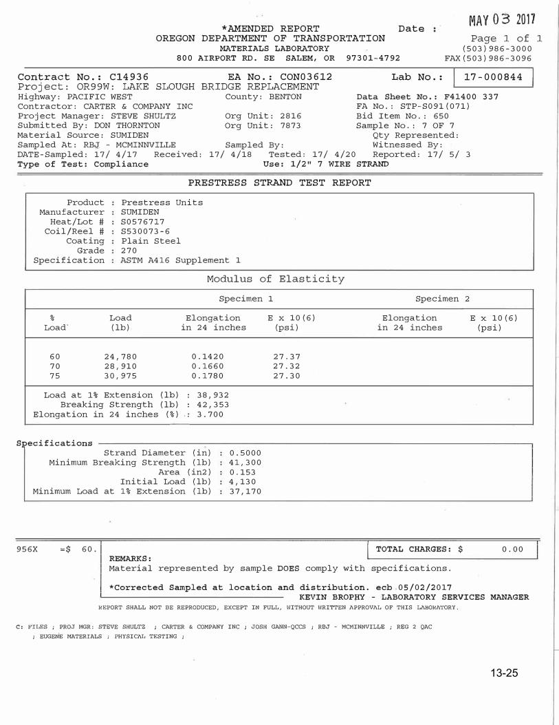
*AMENDED REPORT Date MAY 03 2017
OREGON DEPARTMENT OF TRANSPORTATION
MATERIALS LABORATORY 800 AIRPORT RD. SE SALEM, OR 97301-4792
Page 1 of 1 (503)986-3000
FAX(503)986-3096
Contract No.: Cl4936 EA No.: CON03612 Lab No.: 17-000844
Project: OR99W: LAKE SLOUGH BRIDGE REPLACEMENT Highway: PACIFIC WEST Contractor: CARTER & COMPANY INC Project Manager: STEVE SHULTZ Submitted By: DON THORNTON Material Source: SUMIDEN Sampled At: RBg - MCMINNVILLE DATE-Sampled: 17/ 4/17 Received: Type of Test: Compliance
County: BENTON
Org Unit: 2816 Org Unit: 7873
Data Sheet No.: F41400 FA No.: STP-S091(071) Bid Item No.: 650 Sample No.: 7 OF 7
Qty Represented: Sampled By: Witnessed By:
17/ 4/18 Tested: 17/ 4/20 Reported: 17/ 5/ 3 Use: 1/2 11 7 WIRE STRAND
PRESTRESS STRAND TEST REPORT
Product Manufacturer
Heat/Lot# Coil/Reel#
Coating Grade
Specification
Prestress Units SUMIDEN S0576717 S530073-6 Plain Steel 270 ASTM A416 Supplement 1
Modulus of Elasticity
Specimen 1 Specimen 2
337
% Load Elongation E X 10(6) Elongation E X 10(6) Load· (lb) in 24 inches
60 24,780 0.1420 70 28,910 0.1660 75 30,975 0. 1780
Load at 1% Extension (lb) : 38,932Breaking Strength (lb) ; 42,353
Elongation in 24 inches (%) . . 3.700
Specifications Strand Diameter (in)
Minimum Breaking Strength (lb) Area (in2)
Initial Load (lb) Minimum Load at 1% Extension (lb)
956X :c:$ 60. REMARKS:
0.5000 41,300 0.153 4,130 37,170
(psi) in 24 inches
27.37 27.32 27.30
I TOTAL CHARGES: $
Material represented by sample DOES comply with specifications.
*Corrected Sampled at location and distribution. ecb 05/02/2017
(psi)
0.00
KEVIN BROP�Y - LABORATORY SERVICES MANAGER REPORT SHALL NOT BE REPRODUCED, EXCEPT IN FULL, WITHOUT WRITTEN APPROVAL OF THIS LABORA'fORY.
C, FILES ; PROJ MGR: STEVE SHULTZ ; CARTER & COMPANY INC ; JOSH GANN-QCCS ; RBJ - MCMINNVILLE ; REG 2 QAC
; EUGEN.E MATERIALS ; PHYSICAL TESTING ;
13-25
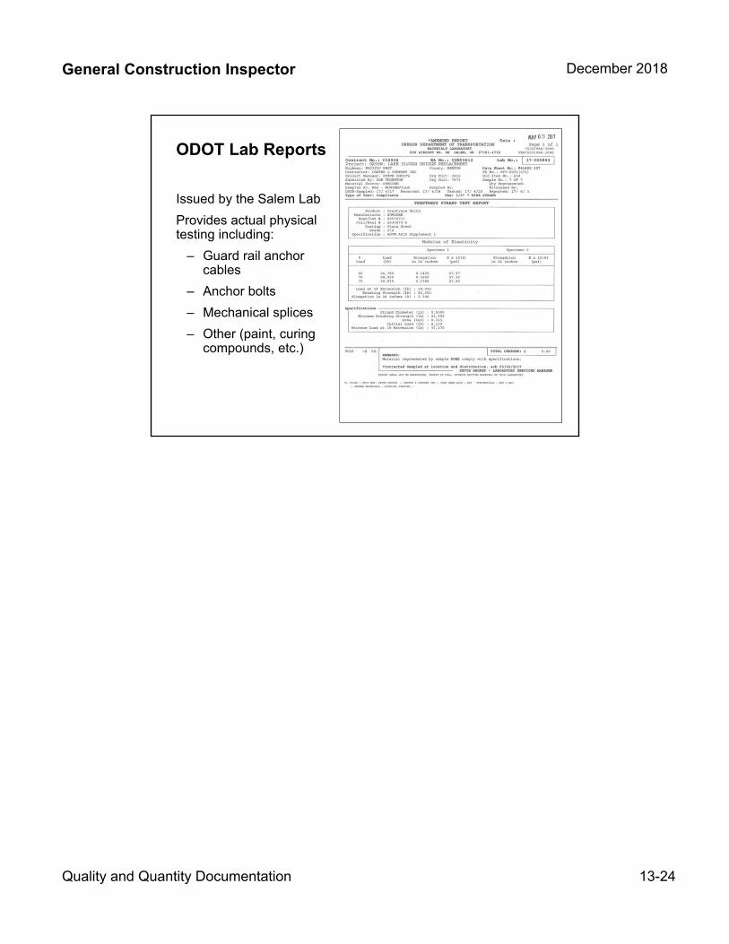
General Construction Inspector December 2018
Quality and Quantity Documentation 13-24
ODOT Lab Reports
Issued by the Salem Lab
Provides actual physical testing including:
– Guard rail anchorcables
– Anchor bolts
– Mechanical splices
– Other (paint, curingcompounds, etc.)
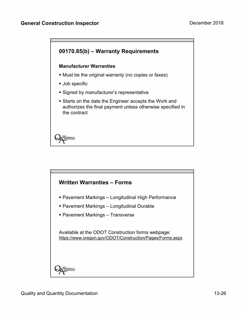
General Construction Inspector December 2018
Quality and Quantity Documentation 13-26
00170.85(b) – Warranty Requirements
Manufacturer Warranties
Must be the original warranty (no copies or faxes)
Job specific
Signed by manufacturer’s representative
Starts on the date the Engineer accepts the Work andauthorizes the final payment unless otherwise specified inthe contract
Written Warranties – Forms
Pavement Markings – Longitudinal High Performance
Pavement Markings – Longitudinal Durable
Pavement Markings – Transverse
Available at the ODOT Construction forms webpage:https://www.oregon.gov/ODOT/Construction/Pages/Forms.aspx
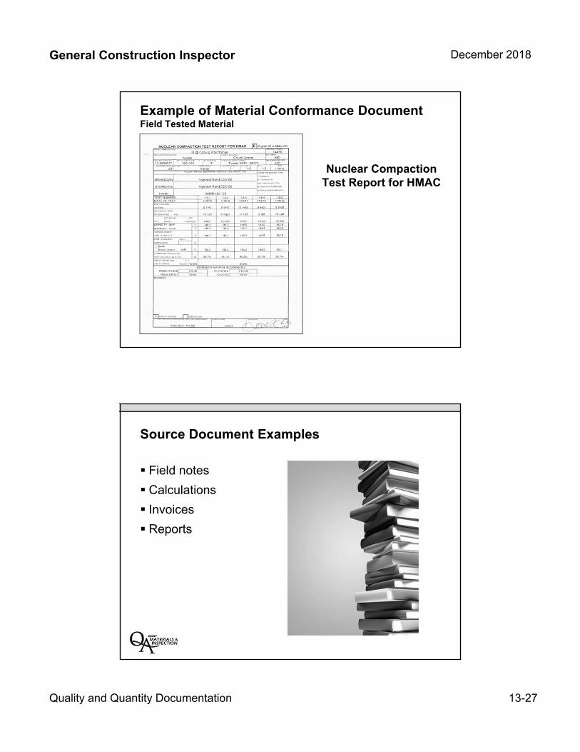
General Construction Inspector December 2018
Quality and Quantity Documentation 13-27
Example of Material Conformance DocumentField Tested Material
Nuclear Compaction Test Report for HMAC
Source Document Examples
Field notes
Calculations
Invoices
Reports

General Construction Inspector December 2018
Quality and Quantity Documentation 13-28
Must include the following:
Project identification
Pay Item identification
Specific location ofinstallation
Dates (installed / checked)
Signatures (inspector/checker)
Installation Sheetor “Paynotes”Form 734-2605
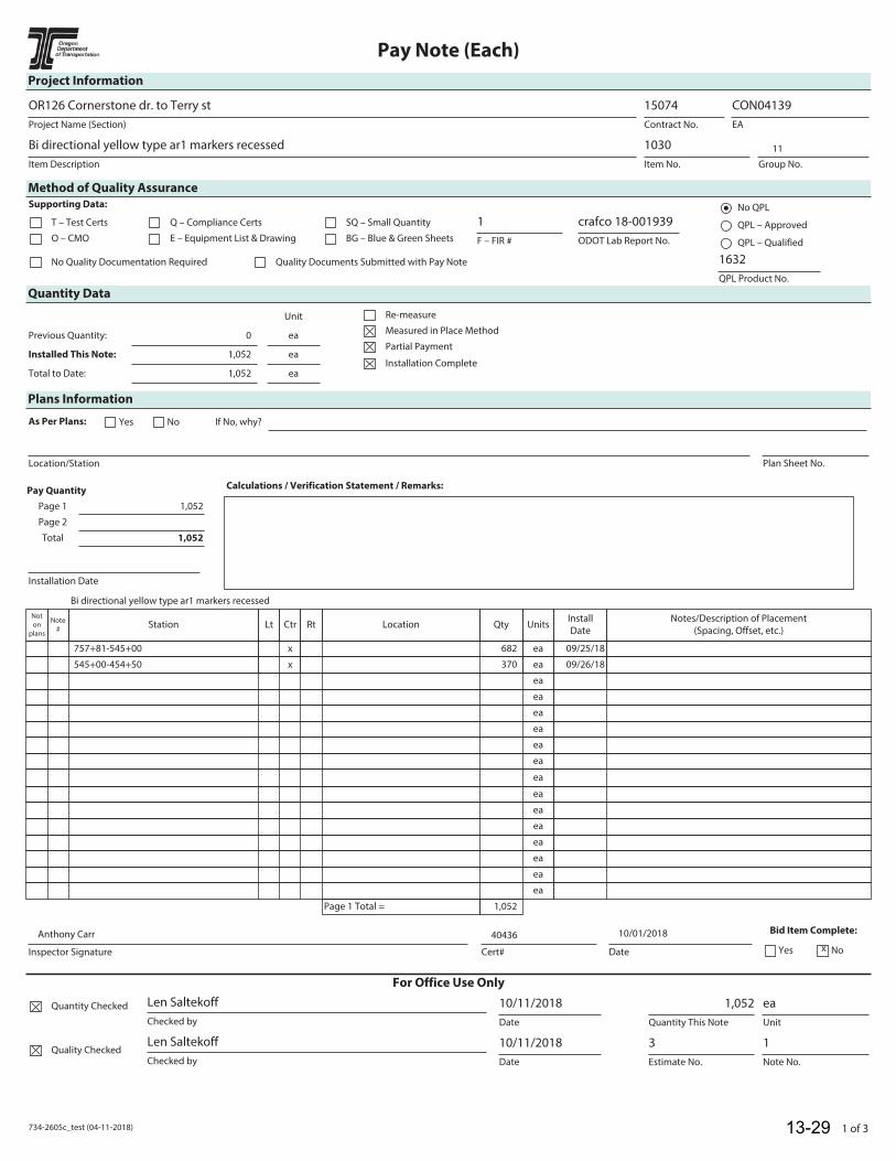
734-2605c_test (04-11-2018) 1 of 3
Pay Note (Each)
Project Information
Project Name (Section)
OR126 Cornerstone dr. to Terry st
Contract No.
15074
EA
CON04139
Item Description
Bi directional yellow type ar1 markers recessed
Item No.
1030
Group No.
Method of Quality Assurance
Supporting Data:
T – Test Certs
O – CMO
Q – Compliance Certs
E – Equipment List & Drawing
SQ – Small Quantity
BG – Blue & Green Sheets F – FIR #
1
ODOT Lab Report No.
crafco 18-001939No QPL
QPL – Approved
QPL – Qualified
No Quality Documentation Required Quality Documents Submitted with Pay Note
QPL Product No.
1632
Quantity Data
Unit
Previous Quantity: 0 ea
Installed This Note: 1,052 ea
Total to Date: 1,052 ea
Re-measure
Measured in Place Method
Partial Payment
Installation Complete
Plans Information
As Per Plans: Yes No If No, why?
Location/Station
Calculations / Verification Statement / Remarks:
Installation Date
Pay Quantity
Page 1 1,052
Page 2
Total 1,052
Plan Sheet No.
Bi directional yellow type ar1 markers recessed
Not
on
plans
Note
#Station Lt Ctr Rt Location Qty Units
Install
Date
Notes/Description of Placement
(Spacing, Offset, etc.)
757+81-545+00 x 682 ea 09/25/18
545+00-454+50 x 370 ea 09/26/18
ea
ea
ea
ea
ea
ea
ea
ea
ea
ea
ea
ea
ea
ea
Page 1 Total = 1,052
Inspector Signature Date
Bid Item Complete:
Yes NoCert#
For Office Use Only
Quantity Checked
Checked by
Len Saltekoff
Date
10/11/2018
Quantity This Note
1,052
Unit
ea
Quality CheckedChecked by
Len Saltekoff
Date
10/11/2018
Note No.
1
Estimate No.
3
13-29
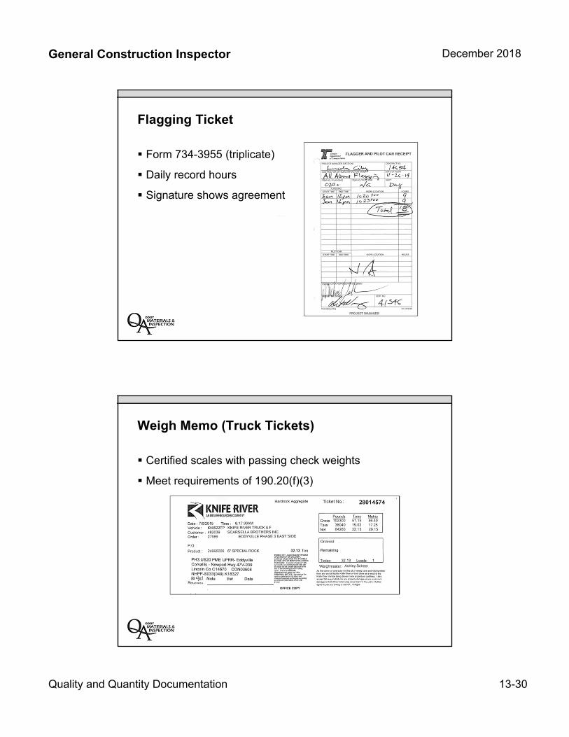
General Construction Inspector December 2018
Quality and Quantity Documentation 13-30
Flagging Ticket
Form 734-3955 (triplicate)
Daily record hours
Signature shows agreement
Weigh Memo (Truck Tickets)
Certified scales with passing check weights
Meet requirements of 190.20(f)(3)
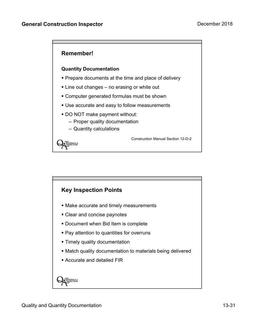
General Construction Inspector December 2018
Quality and Quantity Documentation 13-31
Remember!
Quantity Documentation
Prepare documents at the time and place of delivery
Line out changes – no erasing or white out
Computer generated formulas must be shown
Use accurate and easy to follow measurements
DO NOT make payment without:
– Proper quality documentation
– Quantity calculations
Construction Manual Section 12-D-2
Key Inspection Points
Make accurate and timely measurements
Clear and concise paynotes
Document when Bid Item is complete
Pay attention to quantities for overruns
Timely quality documentation
Match quality documentation to materials being delivered
Accurate and detailed FIR
General Construction Inspector December 2018
Quality and Quantity Documentation 13-32
Unit 13 Review:
Quality Documents
Quantity Documents
Quality and Quantity sheet
Field Inspection Reports (FIR)
Installation Sheets (Paynotes)
Weigh Memos

INSERT TAB
Unit 14 NTMAG
General Construction Inspector December 2018
NTMAG 14-1
Unit 14Non-Field Tested Materials
Acceptance Guide
Unit 14 Topics:
Navigation of the Non-Field Tested Materials Acceptance Guide (NTMAG)
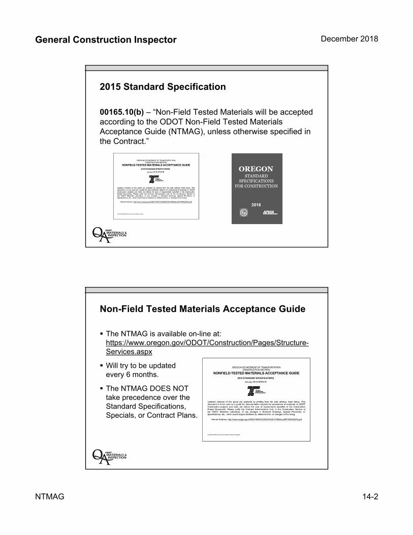
General Construction Inspector December 2018
NTMAG 14-2
2015 Standard Specification
00165.10(b) – “Non-Field Tested Materials will be accepted according to the ODOT Non-Field Tested Materials Acceptance Guide (NTMAG), unless otherwise specified in the Contract.”
Non-Field Tested Materials Acceptance Guide
The NTMAG is available on-line at: https://www.oregon.gov/ODOT/Construction/Pages/Structure-Services.aspx
Will try to be updated every 6 months.
The NTMAG DOES NOT take precedence over the Standard Specifications, Specials, or Contract Plans.
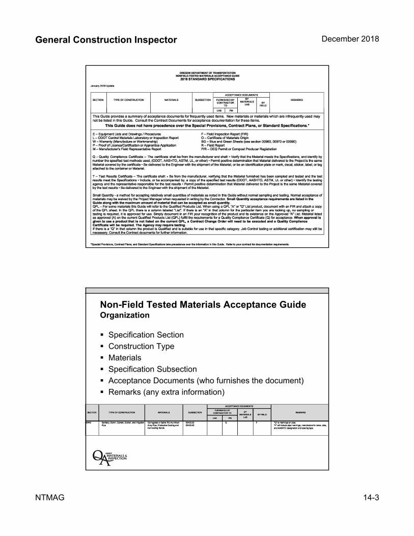
General Construction Inspector December 2018
NTMAG 14-3
Non-Field Tested Materials Acceptance GuideOrganization
Specification Section
Construction Type
Materials
Specification Subsection
Acceptance Documents (who furnishes the document)
Remarks (any extra information)
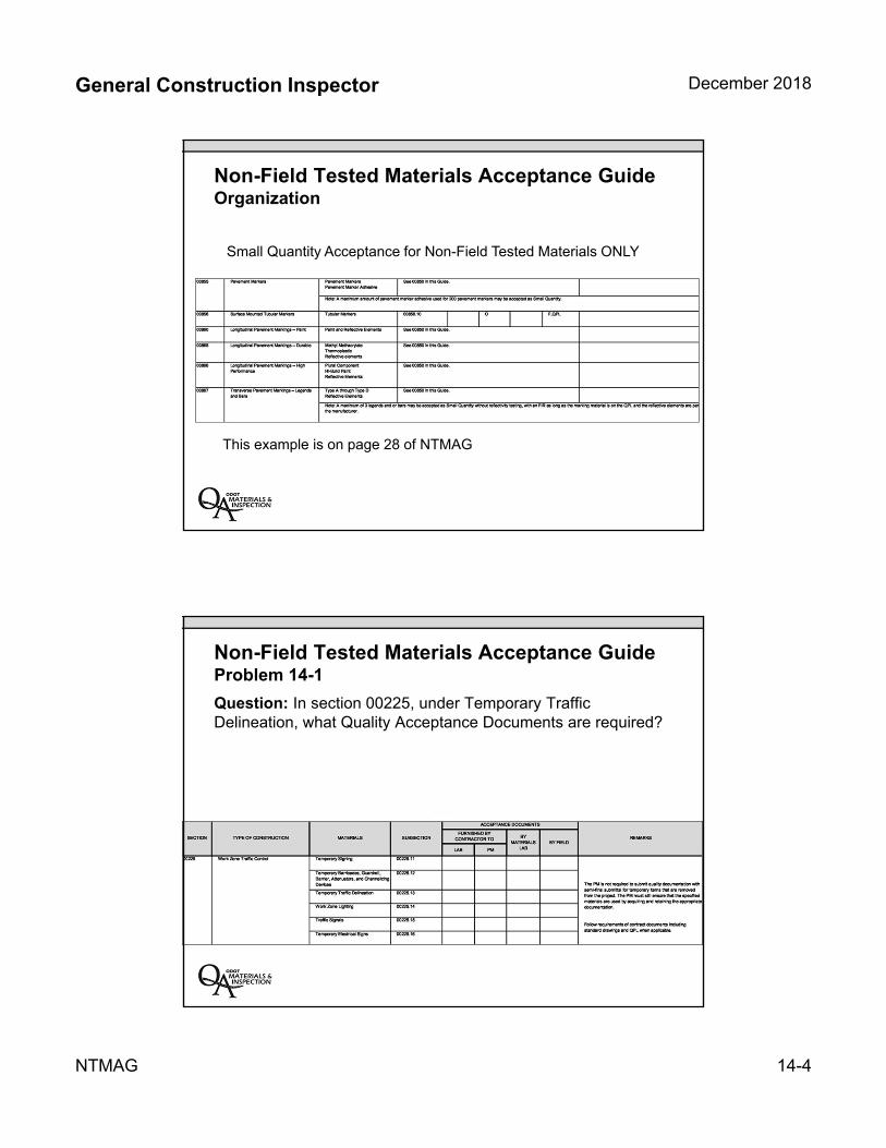
General Construction Inspector December 2018
NTMAG 14-4
Non-Field Tested Materials Acceptance Guide Organization
Small Quantity Acceptance for Non-Field Tested Materials ONLY
This example is on page 28 of NTMAG
Non-Field Tested Materials Acceptance Guide Problem 14-1
Question: In section 00225, under Temporary Traffic Delineation, what Quality Acceptance Documents are required?
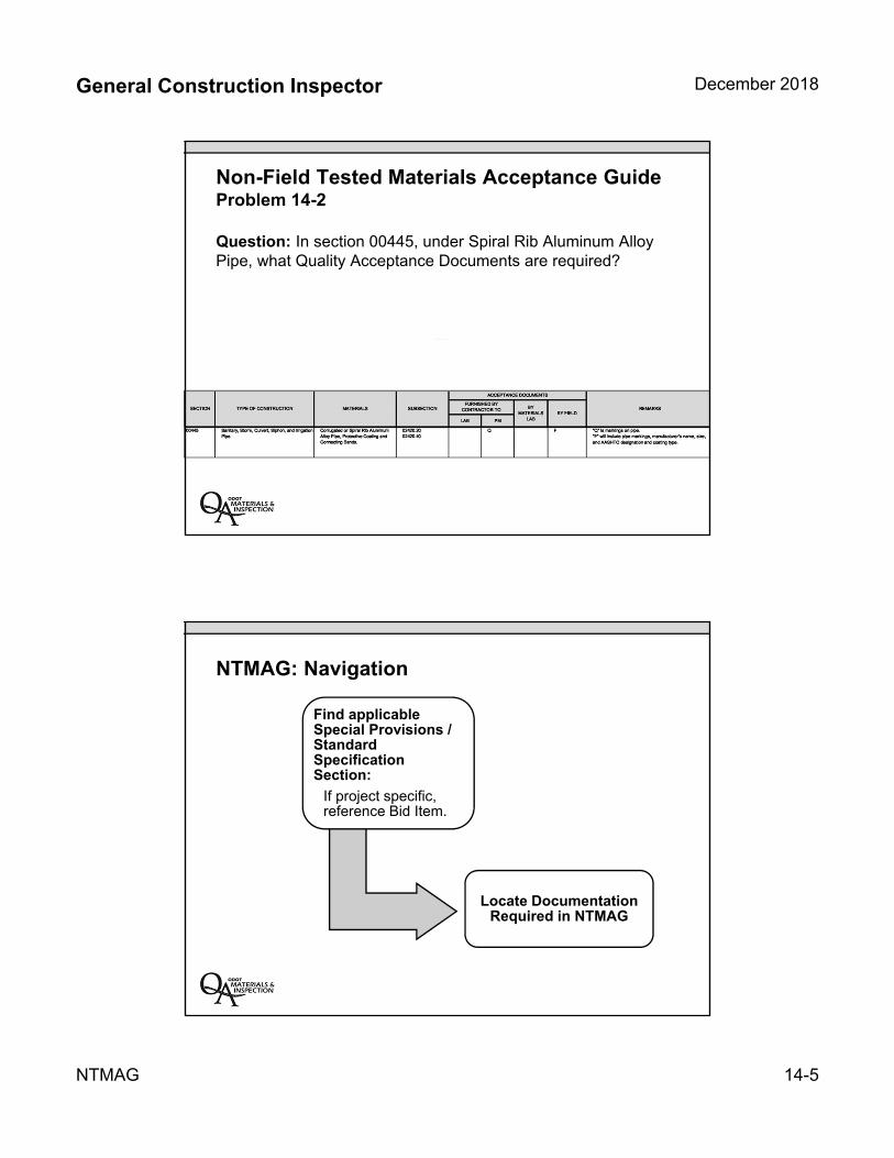
General Construction Inspector December 2018
NTMAG 14-5
Non-Field Tested Materials Acceptance Guide Problem 14-2
Question: In section 00445, under Spiral Rib Aluminum Alloy Pipe, what Quality Acceptance Documents are required?
NTMAG: Navigation
Find applicable Special Provisions / Standard Specification Section:
If project specific, reference Bid Item.
Locate Documentation Required in NTMAG
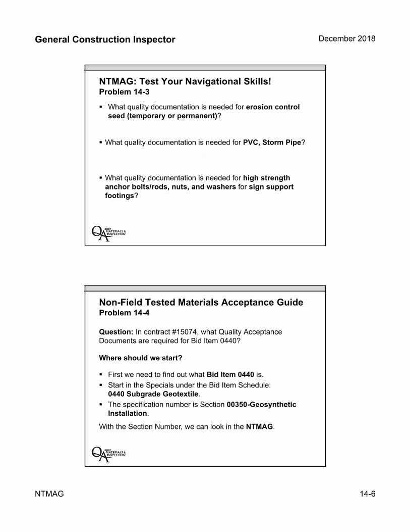
General Construction Inspector December 2018
NTMAG 14-6
NTMAG: Test Your Navigational Skills! Problem 14-3
What quality documentation is needed for erosion control seed (temporary or permanent)?
What quality documentation is needed for PVC, Storm Pipe?
What quality documentation is needed for high strength anchor bolts/rods, nuts, and washers for sign support footings?
Non-Field Tested Materials Acceptance Guide Problem 14-4
Question: In contract #15074, what Quality Acceptance Documents are required for Bid Item 0440?
Where should we start?
First we need to find out what Bid Item 0440 is.
Start in the Specials under the Bid Item Schedule: 0440 Subgrade Geotextile.
The specification number is Section 00350-Geosynthetic Installation.
With the Section Number, we can look in the NTMAG.

General Construction Inspector December 2018
NTMAG 14-7
Non-Field Tested Materials Acceptance Guide Problem 14-4 (continued)
Question: On contract #14785, what Quality Acceptance Documents are required for Bid Item 0290?
Section – 00350 Type of Construction – Geosynthetic Installation Material – Geotextile Fabric
Non-Field Tested Materials Acceptance Guide Problem 14-4 (continued)
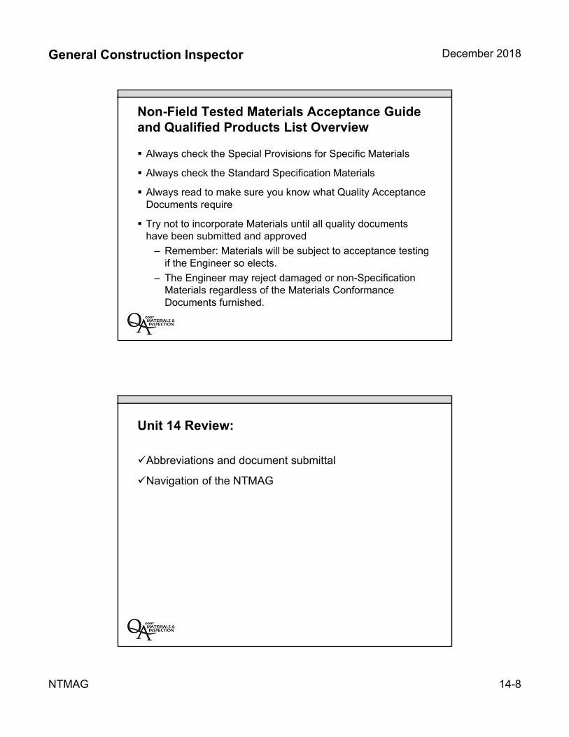
General Construction Inspector December 2018
NTMAG 14-8
Non-Field Tested Materials Acceptance Guide and Qualified Products List Overview
Always check the Special Provisions for Specific Materials
Always check the Standard Specification Materials
Always read to make sure you know what Quality Acceptance Documents require
Try not to incorporate Materials until all quality documents have been submitted and approved
– Remember: Materials will be subject to acceptance testing if the Engineer so elects.
– The Engineer may reject damaged or non-Specification Materials regardless of the Materials Conformance Documents furnished.
Unit 14 Review:
Abbreviations and document submittal
Navigation of the NTMAG
General Construction Inspector December 2018
NTMAG 14-9
Non-Field Tested Materials Acceptance Guide Problem 14-5
Scenario: The Contractor is going to use steel for concrete reinforcement from a manufacturer that is NOT Approved on the QPL. What Quality Acceptance Documents must the Contractor supply to incorporate the steel?
Non-Field Tested Materials Acceptance Guide Class Problem 14-5
Scenario: The Contractor is going to use steel for concrete reinforcement from a manufacturer that is NOT Approved on the QPL. What Quality Acceptance Documents must the Contractor supply to incorporate the steel?
General Construction Inspector December 2018
NTMAG 14-10
Non-Field Tested Materials Acceptance Guide Class Problem 14-5 (continued)
Scenario: The Contractor is going to use steel for concrete reinforcement from a manufacturer that is NOT Approved on the QPL. What Quality Acceptance Documents must the Contractor supply to incorporate the steel?
Non-Field Tested Materials Acceptance Guide Class Problem 14-5 (continued)
Scenario: The Contractor is going to use steel for concrete reinforcement from a manufacturer that is NOT Approved on the QPL. What Quality Acceptance Documents must the Contractor supply to incorporate the steel?
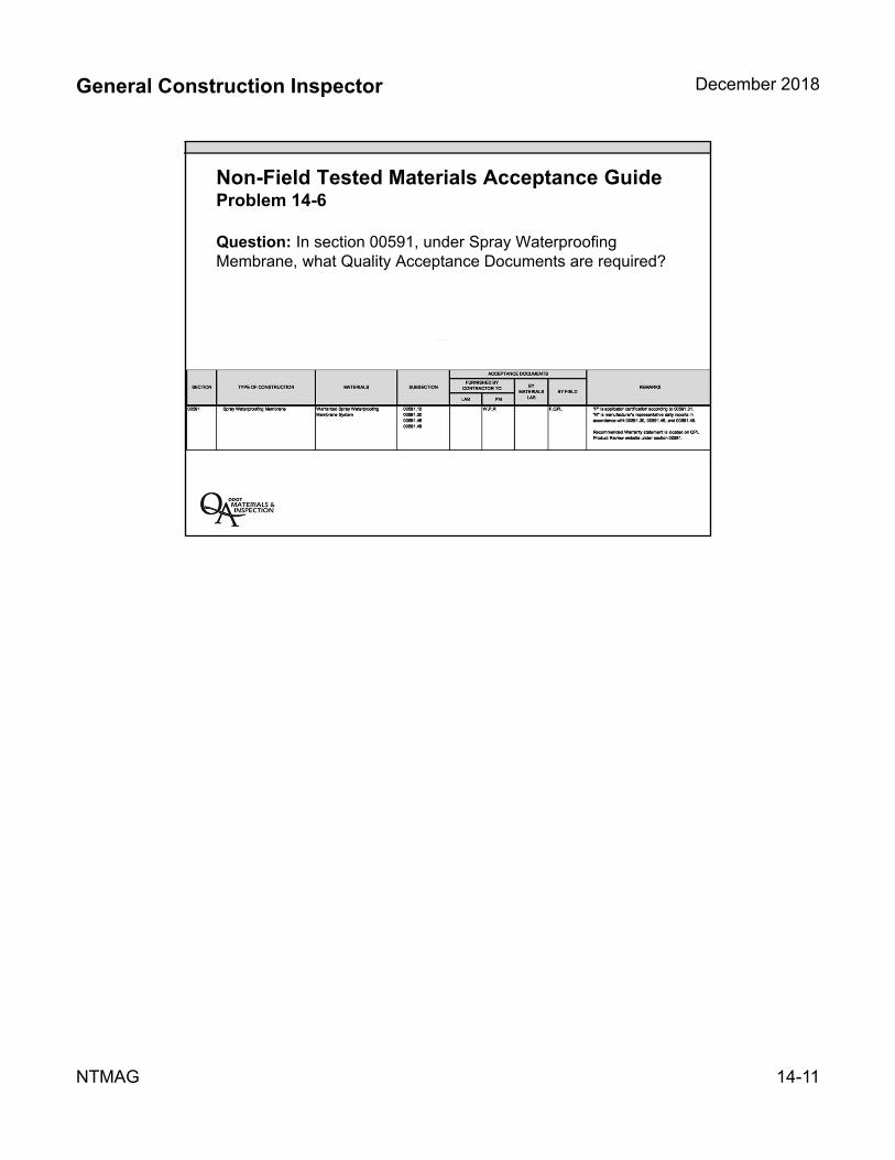
General Construction Inspector December 2018
NTMAG 14-11
Non-Field Tested Materials Acceptance Guide Problem 14-6
Question: In section 00591, under Spray Waterproofing Membrane, what Quality Acceptance Documents are required?


INSERT TAB
Unit 15 QPL
General Construction Inspector December 2018
QPL 15-1
Unit 15Qualified Products List
Unit 15 Topics:
Approved and qualified products
Navigation of Qualified Products List (QPL)
Review reinforcing steel identification (Appendix A)
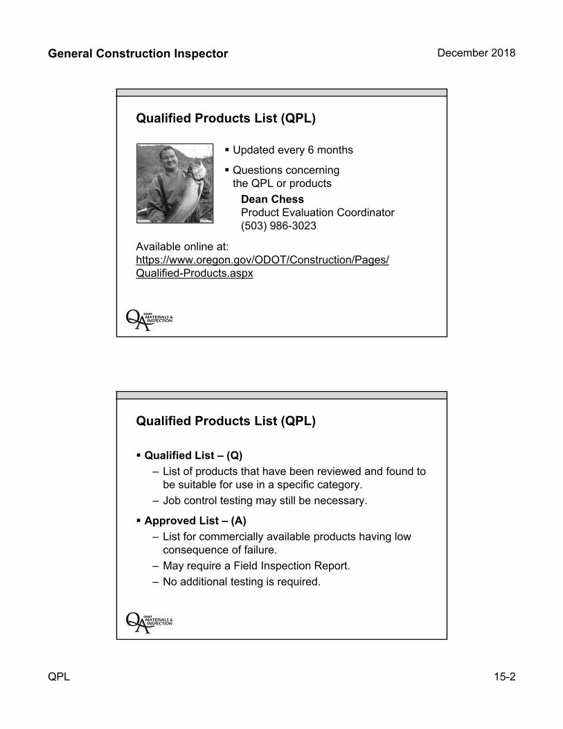
General Construction Inspector December 2018
QPL 15-2
Qualified Products List (QPL)
Updated every 6 months
Questions concerning the QPL or products
Dean Chess Product Evaluation Coordinator(503) 986-3023
Available online at:https://www.oregon.gov/ODOT/Construction/Pages/Qualified-Products.aspx
Qualified Products List (QPL)
Qualified List – (Q)
– List of products that have been reviewed and found to be suitable for use in a specific category.
– Job control testing may still be necessary.
Approved List – (A)
– List for commercially available products having low consequence of failure.
– May require a Field Inspection Report.
– No additional testing is required.
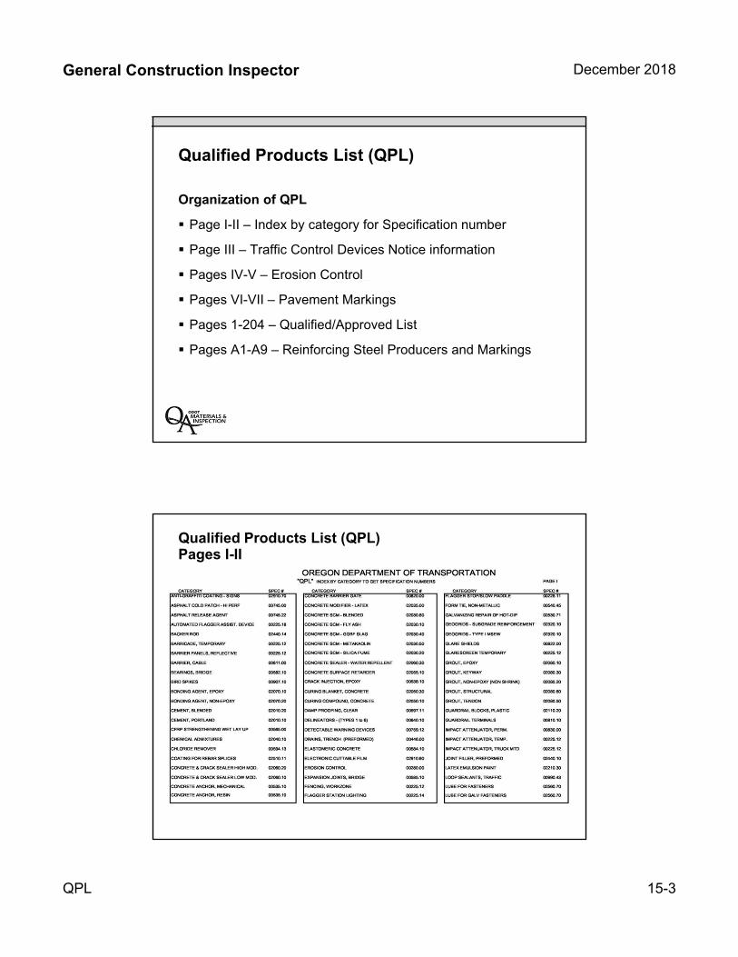
General Construction Inspector December 2018
QPL 15-3
Qualified Products List (QPL)
Organization of QPL
Page I-II – Index by category for Specification number
Page III – Traffic Control Devices Notice information
Pages IV-V – Erosion Control
Pages VI-VII – Pavement Markings
Pages 1-204 – Qualified/Approved List
Pages A1-A9 – Reinforcing Steel Producers and Markings
Qualified Products List (QPL)Pages I-II
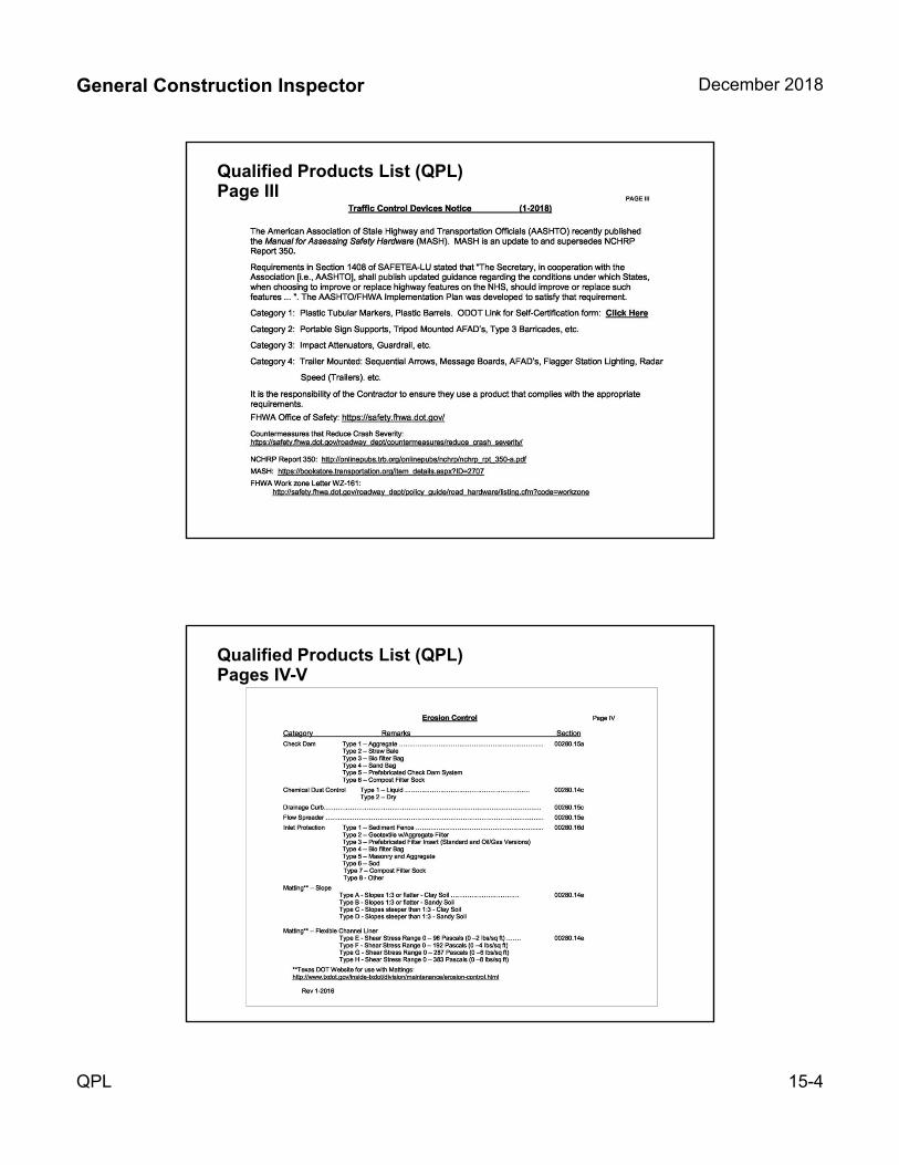
General Construction Inspector December 2018
QPL 15-4
Qualified Products List (QPL)Page III
Qualified Products List (QPL)Pages IV-V
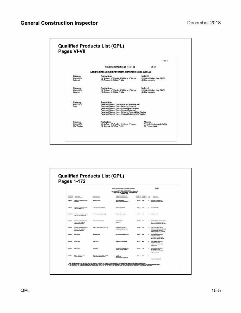
General Construction Inspector December 2018
QPL 15-5
Qualified Products List (QPL)Pages VI-VII
Qualified Products List (QPL)Pages 1-172
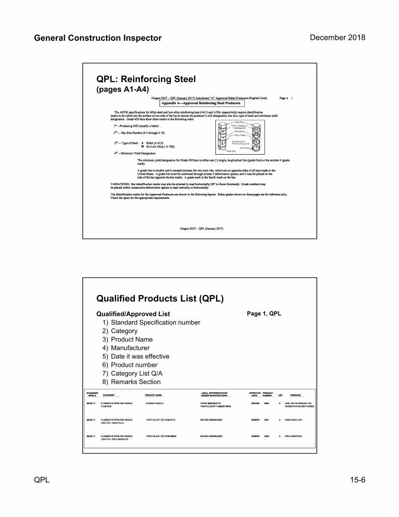
General Construction Inspector December 2018
QPL 15-6
QPL: Reinforcing Steel (pages A1-A4)
Qualified Products List (QPL)
Qualified/Approved List1) Standard Specification number2) Category3) Product Name4) Manufacturer5) Date it was effective6) Product number7) Category List Q/A8) Remarks Section
Page 1, QPL
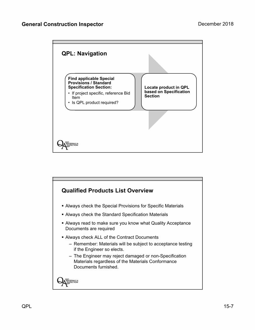
General Construction Inspector December 2018
QPL 15-7
QPL: Navigation
Find applicable Special Provisions / Standard Specification Section:
• If project specific, reference Bid Item
• Is QPL product required?
Locate product in QPL based on Specification Section
Qualified Products List Overview
Always check the Special Provisions for Specific Materials
Always check the Standard Specification Materials
Always read to make sure you know what Quality Acceptance Documents are required
Always check ALL of the Contract Documents
– Remember: Materials will be subject to acceptance testing if the Engineer so elects.
– The Engineer may reject damaged or non-Specification Materials regardless of the Materials Conformance Documents furnished.
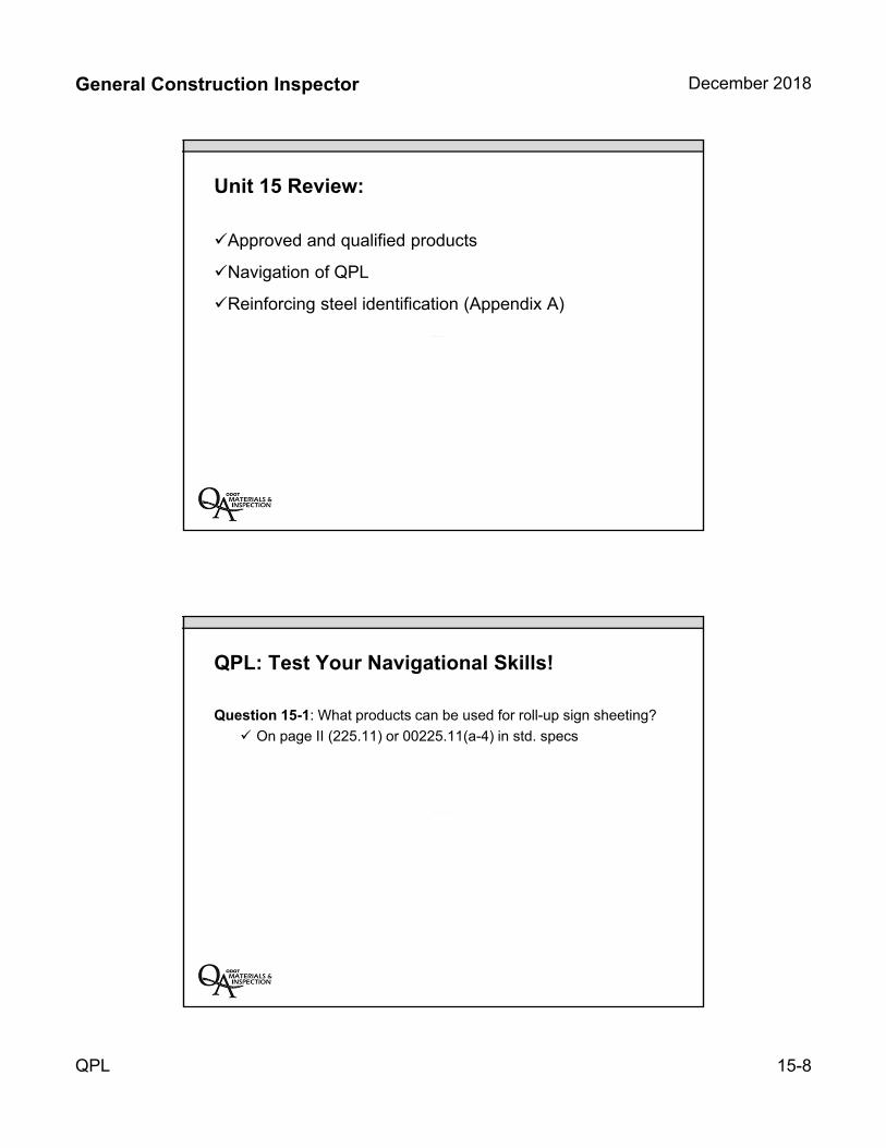
General Construction Inspector December 2018
QPL 15-8
Unit 15 Review:
Approved and qualified products
Navigation of QPL
Reinforcing steel identification (Appendix A)
QPL: Test Your Navigational Skills!
Question 15-1: What products can be used for roll-up sign sheeting?
On page II (225.11) or 00225.11(a-4) in std. specs
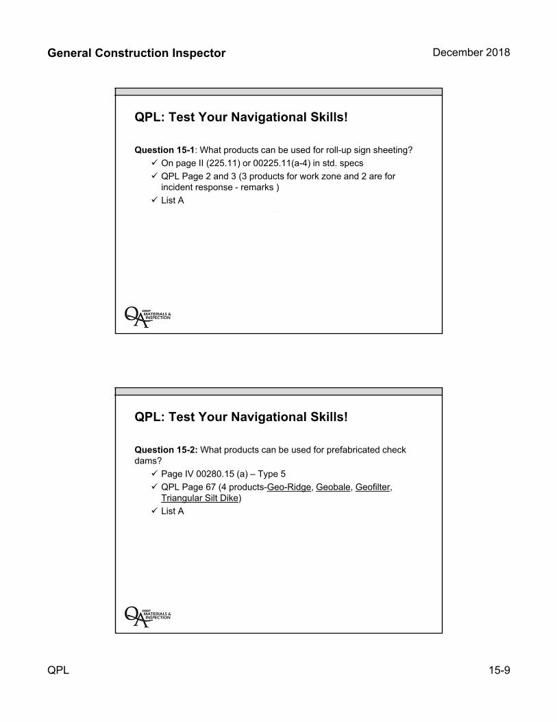
General Construction Inspector December 2018
QPL 15-9
QPL: Test Your Navigational Skills!
Question 15-1: What products can be used for roll-up sign sheeting?
On page II (225.11) or 00225.11(a-4) in std. specs
QPL Page 2 and 3 (3 products for work zone and 2 are for incident response - remarks )
List A
QPL: Test Your Navigational Skills!
Question 15-2: What products can be used for prefabricated check dams?
Page IV 00280.15 (a) – Type 5
QPL Page 67 (4 products-Geo-Ridge, Geobale, Geofilter, Triangular Silt Dike)
List A

General Construction Inspector December 2018
QPL 15-10
Qualified Products List (QPL) Class Example Problem 15-3
Scenario: The Contractor on our project has delivered Deltaline BTR non-reflective temporary removable tape to our project for temporary pavement markings. Can we allow the Contractor to use the tape?
Qualified Products List (QPL) Class Problems
Question 15-4: The Contractor is going to place White Method B, Sprayed Surface, Thermoplastic longitudinal profiled pavement markings. How many products are available and what quality documentation is required?
General Construction Inspector December 2018
QPL 15-11
Qualified Products List (QPL) Class Problem
Question 15-5: What is the maximum allowable slope when using Terra Mulch for temporary erosion control mulching?

INSERT TAB
Unit 16 MFTP
General Construction Inspector December 2018
Manual of Field Test Procedures 16-1
Unit 16Manual of Field Test
Procedures
The MFTP also contains the Quality Assurance
Program guidelines
Updated yearly by ODOT Construction Section
Current Version in affect at time of advertisement
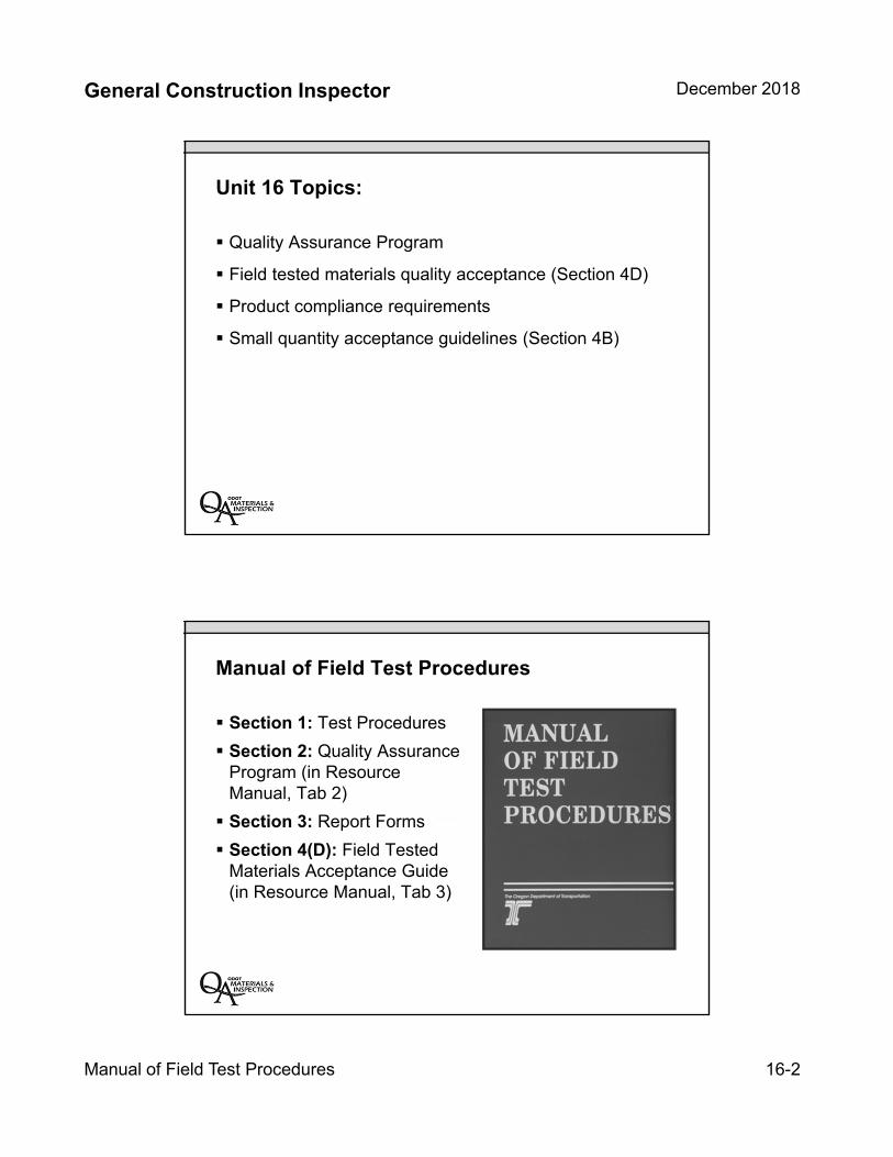
General Construction Inspector December 2018
Manual of Field Test Procedures 16-2
Unit 16 Topics:
Quality Assurance Program
Field tested materials quality acceptance (Section 4D)
Product compliance requirements
Small quantity acceptance guidelines (Section 4B)
Manual of Field Test Procedures
Section 1: Test Procedures
Section 2: Quality Assurance Program (in Resource Manual, Tab 2)
Section 3: Report Forms
Section 4(D): Field Tested Materials Acceptance Guide (in Resource Manual, Tab 3)
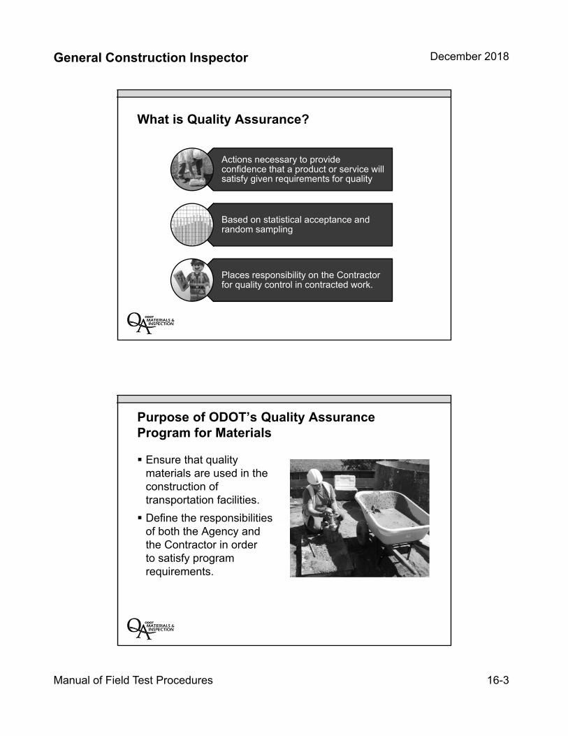
General Construction Inspector December 2018
Manual of Field Test Procedures 16-3
What is Quality Assurance?
Actions necessary to provide confidence that a product or service will satisfy given requirements for quality
Based on statistical acceptance and random sampling
Places responsibility on the Contractor for quality control in contracted work.
Purpose of ODOT’s Quality Assurance Program for Materials
Ensure that quality materials are used in the construction of transportation facilities.
Define the responsibilities of both the Agency and the Contractor in order to satisfy program requirements.

General Construction Inspector December 2018
Manual of Field Test Procedures 16-4
Separation of Roles
Agency
Project Manager
QCCS
Inspector
QA Staff
Contractor
QC Staff
Roles & Responsibilities
Construction Contractor must:
Follow ODOT’s QA Program
Provide written QC Plan to PM
Furnish Materials/Products meeting specifications
Provide certified labs and technicians
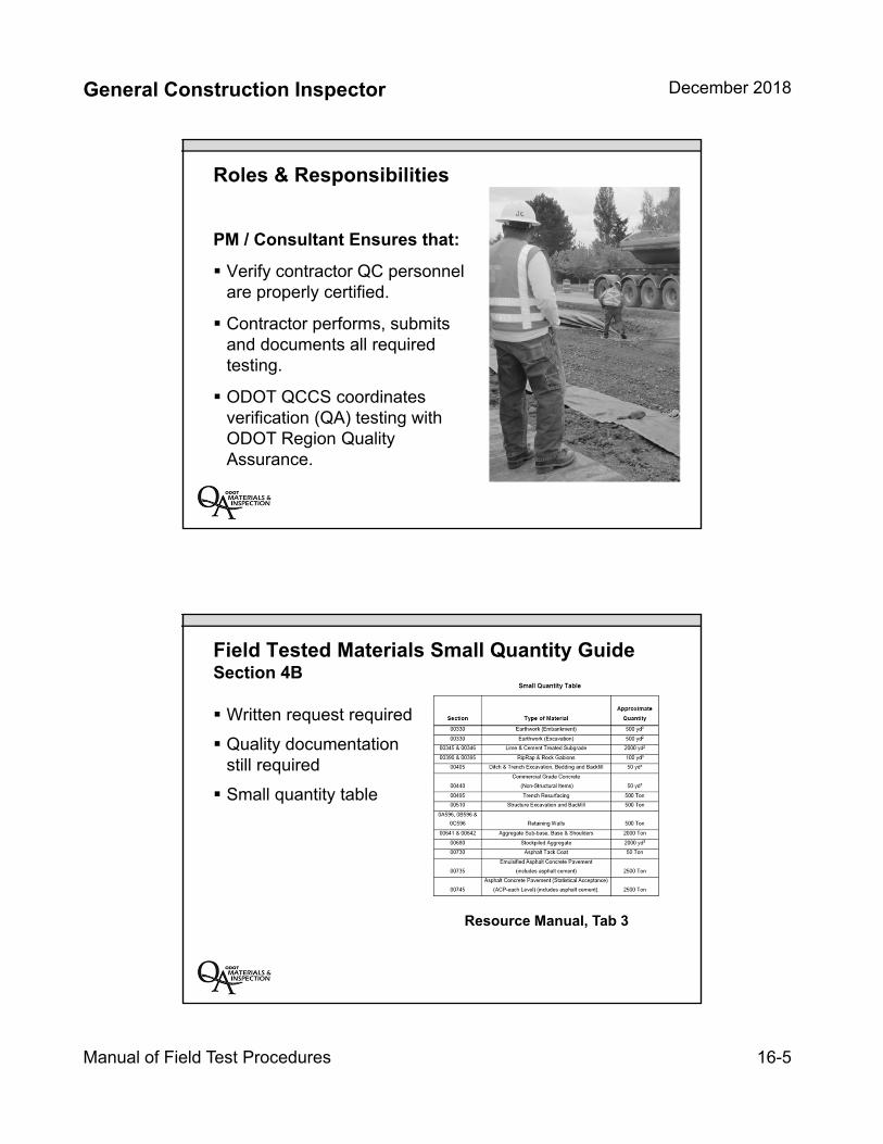
General Construction Inspector December 2018
Manual of Field Test Procedures 16-5
Roles & Responsibilities
PM / Consultant Ensures that:
Verify contractor QC personnel are properly certified.
Contractor performs, submits and documents all required testing.
ODOT QCCS coordinates verification (QA) testing with ODOT Region Quality Assurance.
Field Tested Materials Small Quantity GuideSection 4B
Written request required
Quality documentation still required
Small quantity table
Resource Manual, Tab 3
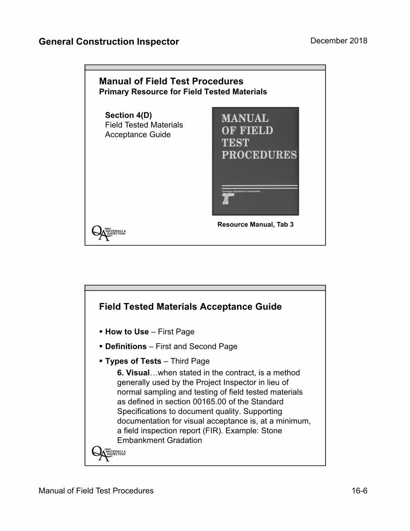
General Construction Inspector December 2018
Manual of Field Test Procedures 16-6
Manual of Field Test ProceduresPrimary Resource for Field Tested Materials
Section 4(D)Field Tested Materials Acceptance Guide
Resource Manual, Tab 3
Field Tested Materials Acceptance Guide
How to Use – First Page
Definitions – First and Second Page
Types of Tests – Third Page
6. Visual…when stated in the contract, is a method generally used by the Project Inspector in lieu of normal sampling and testing of field tested materials as defined in section 00165.00 of the Standard Specifications to document quality. Supporting documentation for visual acceptance is, at a minimum, a field inspection report (FIR). Example: Stone Embankment Gradation
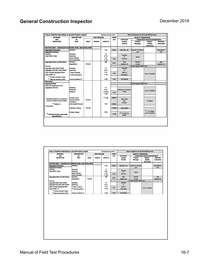
General Construction Inspector December 2018
Manual of Field Test Procedures 16-7

General Construction Inspector December 2018
Manual of Field Test Procedures 16-8
MFTP – Section 4(D)Example 1
Building a road:
3,000 square yards of subgrade stabilization
Place 10,000 tons aggregate base
Place 3,000 tons HMAC
MFTP – Section 4(D)Example 1
Building a road:
3,000 square yards of subgrade stabilization
Place 10,000 tons aggregate base
Place 3,000 tons ACP
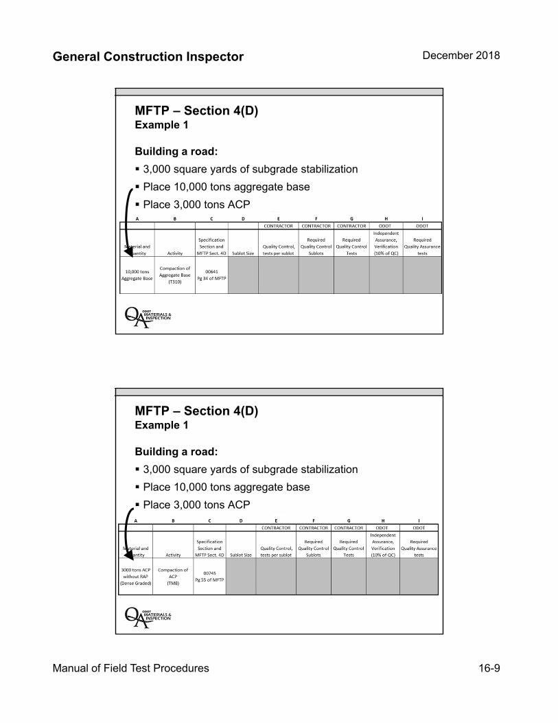
General Construction Inspector December 2018
Manual of Field Test Procedures 16-9
MFTP – Section 4(D)Example 1
Building a road:
3,000 square yards of subgrade stabilization
Place 10,000 tons aggregate base
Place 3,000 tons ACP
MFTP – Section 4(D)Example 1
Building a road:
3,000 square yards of subgrade stabilization
Place 10,000 tons aggregate base
Place 3,000 tons ACP

General Construction Inspector December 2018
Manual of Field Test Procedures 16-10
MFTP – Section 4(D)Example 1 – Answers
Key Inspection Points
Small quantity acceptance still needs proper quality documentation
Keep track of what type and quantity of field tested materials being delivered
Communicate with QCCS or someone tracking testing
Check in with technicians
Understand scope and role of visual acceptance
Do not accept failing tests
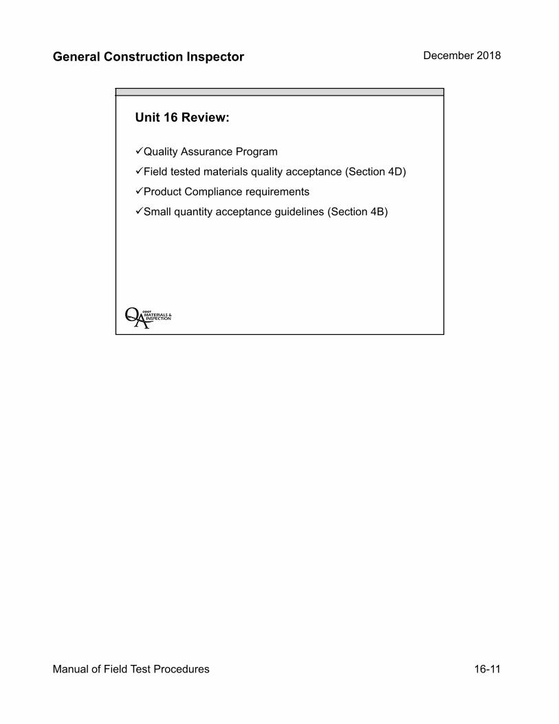
General Construction Inspector December 2018
Manual of Field Test Procedures 16-11
Unit 16 Review:
Quality Assurance Program
Field tested materials quality acceptance (Section 4D)
Product Compliance requirements
Small quantity acceptance guidelines (Section 4B)

INSERT TAB
Unit 17 Inspector Survey
General Construction Inspector December 2018
Inspector Survey 17-1
Unit 17Inspector Survey
Unit 17 Topics
Understand basic slope references
Read construction stakes
Review survey specifications
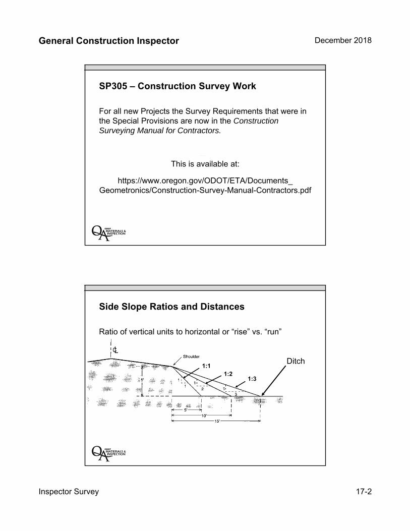
General Construction Inspector December 2018
Inspector Survey 17-2
SP305 – Construction Survey Work
For all new Projects the Survey Requirements that were in the Special Provisions are now in the Construction Surveying Manual for Contractors.
This is available at:
https://www.oregon.gov/ODOT/ETA/Documents_Geometronics/Construction-Survey-Manual-Contractors.pdf
Side Slope Ratios and Distances
Ditch1:1
1:21:3
Ratio of vertical units to horizontal or “rise” vs. “run”
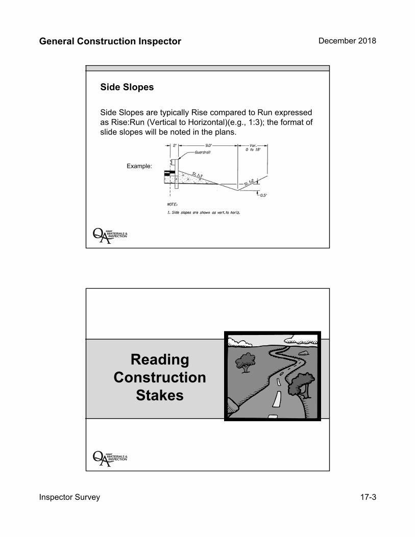
General Construction Inspector December 2018
Inspector Survey 17-3
Side Slopes
Side Slopes are typically Rise compared to Run expressed as Rise:Run (Vertical to Horizontal)(e.g., 1:3); the format of slide slopes will be noted in the plans.
Example:
Reading Construction
Stakes
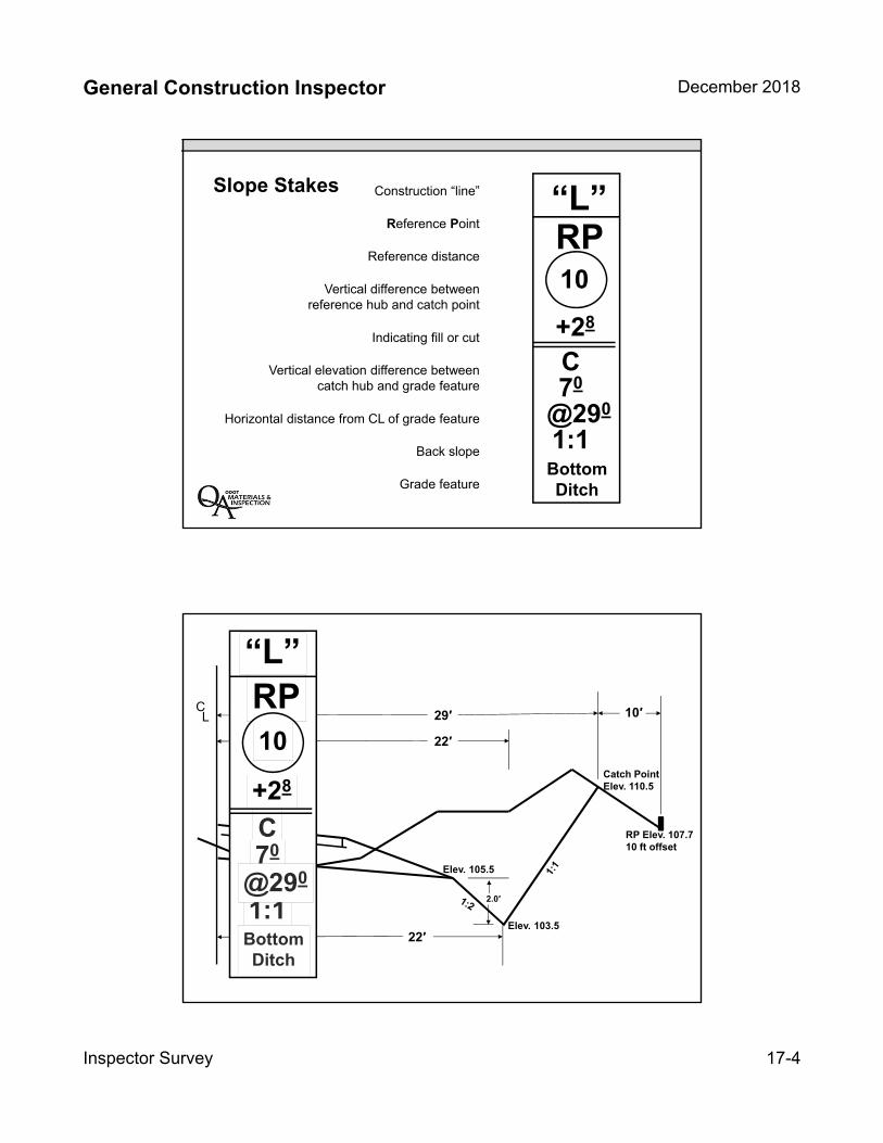
General Construction Inspector December 2018
Inspector Survey 17-4
Slope Stakes
10
RP
+28
C70
@290
1:1
“L”
BottomDitch
Construction “line”
Reference Point
Reference distance
Vertical difference betweenreference hub and catch point
Indicating fill or cut
Vertical elevation difference between catch hub and grade feature
Horizontal distance from CL of grade feature
Back slope
Grade feature
CL
2.0′
22′
22′
Elev. 105.5
Elev. 103.5
Catch PointElev. 110.5
RP Elev. 107.710 ft offset
29′ 10′RP10
+28
C70
1:1@290
“L”
BottomDitch
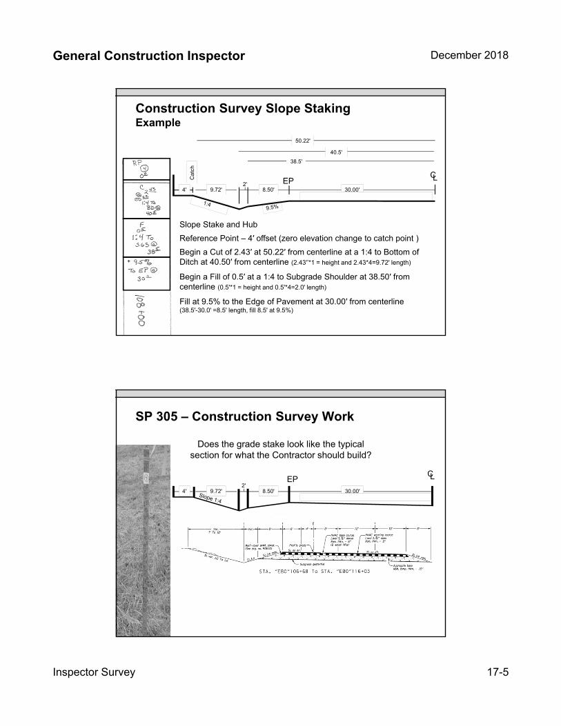
General Construction Inspector December 2018
Inspector Survey 17-5
Construction Survey Slope StakingExample
Slope Stake and Hub
Reference Point – 4′ offset (zero elevation change to catch point )
Begin a Cut of 2.43′ at 50.22′ from centerline at a 1:4 to Bottom of Ditch at 40.50′ from centerline (2.43'’*1 = height and 2.43*4=9.72' length)
9.72'4'
Begin a Fill of 0.5′ at a 1:4 to Subgrade Shoulder at 38.50′ from centerline (0.5'*1 = height and 0.5'*4=2.0' length)
2'
Fill at 9.5% to the Edge of Pavement at 30.00′ from centerline (38.5'-30.0' =8.5' length, fill 8.5' at 9.5%)
8.50' 30.00'
CLEP
+
50.22'
40.5'
Ca
tch
38.5'
SP 305 – Construction Survey Work
Does the grade stake look like the typical section for what the Contractor should build?
CL
+
9.72'4'2'
8.50' 30.00'
EP
General Construction Inspector December 2018
Inspector Survey 17-6
00305.80 – Measurement
No measurement of quantities will be made for construction survey work.
00305.90 – Payment
Paid at lump sum.
Includes all material, equipment, labor, and incidentals necessary to complete the Work .
No additional payment for temporary protection and direction of traffic.
No additional payment for preparing surveying documents.
Key Inspection Points
Review survey stakes as they are being set
Ask surveyor questions regarding protocol for staking and marking on slope stakes.
Ask prime contractor to manage surveyor sub-contractor
12
INSERT TAB
Unit 18
CA – General Requirements
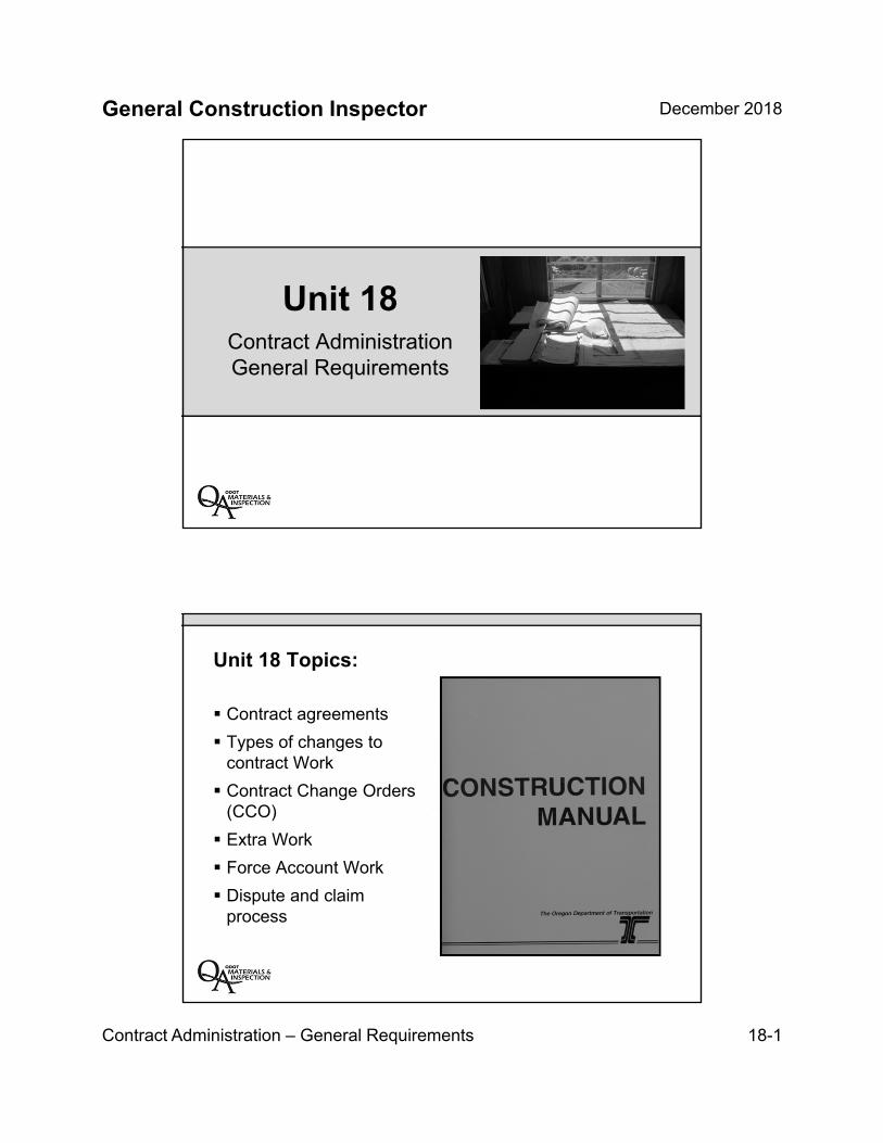
General Construction Inspector December 2018
Contract Administration – General Requirements 18-1
Unit 18Contract Administration General Requirements
Unit 18 Topics:
Contract agreements
Types of changes tocontract Work
Contract Change Orders(CCO)
Extra Work
Force Account Work
Dispute and claimprocess
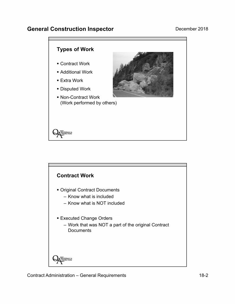
General Construction Inspector December 2018
Contract Administration – General Requirements 18-2
Types of Work
Contract Work
Additional Work
Extra Work
Disputed Work
Non-Contract Work(Work performed by others)
Contract Work
Original Contract Documents
– Know what is included
– Know what is NOT included
Executed Change Orders
– Work that was NOT a part of the original ContractDocuments
General Construction Inspector December 2018
Contract Administration – General Requirements 18-3
Additional Work
Increased quantities of Work
– Within the scope of the Contract
– Established unit price
How much is too much?
– 00140.30 Agency-required changes
– 00195.20 Changes to Plans or Character of Work
Changed Work
00195.20(b) Significant Changed Work
Character of the Work has changed
Requires an adjustment of the Contract
General Construction Inspector December 2018
Contract Administration – General Requirements 18-4
Extra Work
Work NOT included in the Contract…but necessary to complete the Project
Often due to errors or oversight during projectdevelopment
Requires an adjustment of the Contract
Disputed Work
00140.65 allows the Contractor to dispute ChangeOrders, written orders, and oral orders
Contractor is required to provide notice of protest
Work proceeds but is tracked by both Parties
Eventually is converted to another type of Work or results in a Claim
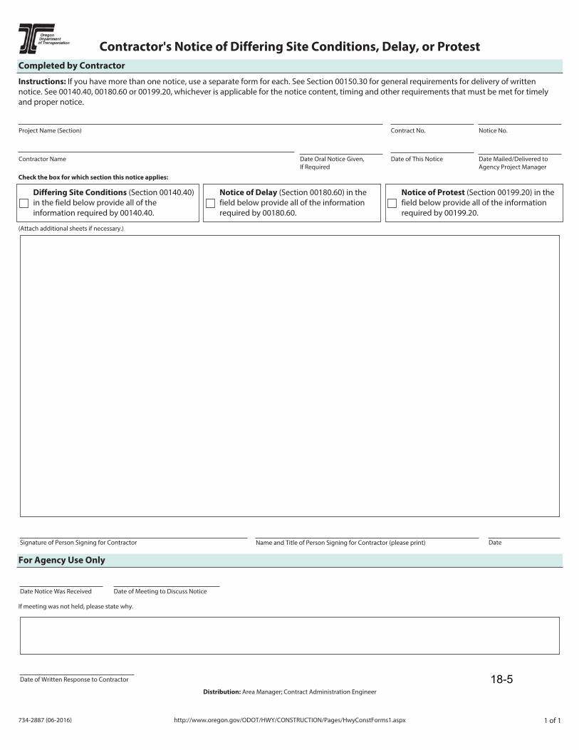
734-2887 (06-2016) http://www.oregon.gov/ODOT/HWY/CONSTRUCTION/Pages/HwyConstForms1.aspx 1 of 1
Contractor's Notice of Differing Site Conditions, Delay, or ProtestCompleted by Contractor
Instructions: If you have more than one notice, use a separate form for each. See Section 00150.30 for general requirements for delivery of written notice. See 00140.40, 00180.60 or 00199.20, whichever is applicable for the notice content, timing and other requirements that must be met for timely and proper notice.
Project Name (Section) Contract No.
Date Oral Notice Given, If Required
Date of This NoticeContractor Name
Notice No.
Date Mailed/Delivered to Agency Project Manager
Check the box for which section this notice applies:
(Attach additional sheets if necessary.)
Differing Site Conditions (Section 00140.40) in the field below provide all of the information required by 00140.40.
Notice of Delay (Section 00180.60) in the field below provide all of the information required by 00180.60.
Notice of Protest (Section 00199.20) in the field below provide all of the information required by 00199.20.
Signature of Person Signing for Contractor Name and Title of Person Signing for Contractor (please print) Date
For Agency Use Only
Date Notice Was Received Date of Meeting to Discuss Notice
If meeting was not held, please state why.
Date of Written Response to Contractor
Distribution: Area Manager; Contract Administration Engineer
18-5
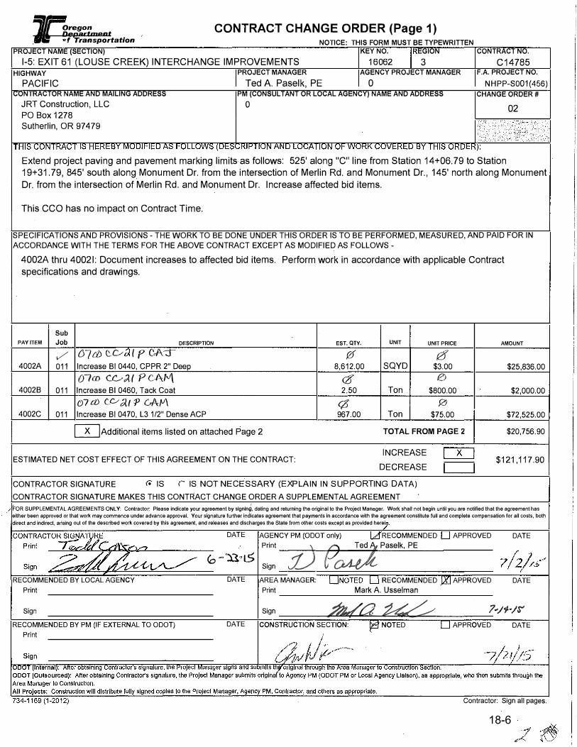
1 g����fment CONTRACT CHANGE ORDER (Page 1) /Jj .,, Transportation NOTICE: THIS FORM MUST BE TYPEWRITTEN
PROJECT NAME (SECTION) KEY NO. EGION CONTRACT NO. 1-5: EXIT 61 (LOUSE CREEK) INTERCHANGE IMPROVEMENTS 16062 3 C14785
HIGHWAY PROJECT MANAGER AGENCY PROJECT MANAGER F.A. PROJECT NO.PACIFIC Ted A. Paselk, PE O NHPP-S001(456)
CONTRACTOR NAME AND MAILING ADDRESS PM (CONSUL TANT OR LOCAL AGENCY) NAME AND ADDRESS CHANGE ORDER# JRT Construction, LLC 0 PO Box 1278 Sutherlin, OR 97 4 79
02
Extend project paving and pavement marking limits as follows: 525' along "C" line from Station 14+06.79 to Station 19+31.79, 845' south along Monument Dr. from the intersection of Merlin Rd. and Monument Dr., 145' north along Monument Dr. from the intersection of Merlin Rd. and Monument Dr. Increase affected bid items.
This CCO has no impact on Contract Time.
SPECIFICATIONS AND PROVISIONS - THE WORK TO BE DONE UNDER THIS ORDER IS TO BE PERFORMED, MEASURED, AND PAID FOR IN ACCORDANCE WITH THE TERMS FOR THE ABOVE CONTRACT EXCEPT AS MODIFIED AS FOLLOWS -
4002A thru 40021: Document increases to affected bid items. Perform work in accordance with applicable Contract specifications and drawings.
Sub
PAY ITEM Job DESCRIPTION EST. QTY. UNIT UNIT PRICE
✓ tY7d) tv Ip CA-::r- {2f 0 4002A 011 Increase Bl 0440, CPPR 2" Deep 8,612.00 SQYD $3.00
07co C.0.;l( P Ct\M <1I 0
40028 011 Increase Bl 0460, Tack Coat 2.50 Ton $800.00 0 7 a> c_,c, c;{f P C-A f.l\ (6 0
4002C 011 Increase Bl 0470, L3 1/2" Dense ACP 967.00 Ton $75.00
[TIAdditional items listed on attached Page 2 TOTAL FROM PAGE 2
INCREASE ESTIMATED NET COST EFFECT OF THIS AGREEMENT ON THE CONTRACT:
DECREASE
CONTRACTOR SIGNATURE r. IS r IS NOT NECESSARY (EXPLAIN IN SUPPORTING DATA) CONTRACTOR SIGNATURE MAKES THIS CONTRACT CHANGE ORDER A SUPPLEMENTAL AGREEMENT
AMOUNT
$25,836.00
$2,000.00
$72,525.00
$20,756.90
$121,117.90
FOR SUPPLEMENTAL AGREEMENTS ONLY: Contractoc Please indicate your agreement by slgnln�. dating and returning the original to the Project Manager. Work shall not begin until you are notified that the agreement has either been approved or that work may commence under advance approval. Your signature further indicates agreement that payments in accordance with the agreement constitute full and complete compensation for all costs, both direct and indirect, arising out of the described work covered by this agreement, and releases and discharges the State from other costs except as provided herei
RECOMMENDED BY LOCAL AGENCY Print
Sign RECOMMENDED BY PM (IF EXTERNAL TO ODOT)
DATE
eo--n�t5 DATE
DATE
AGENCY PM (ODOT only) RECOMMENDED Print
V Sign AREA MANAGER: Print
Sign
9;:;;J,, Paselk, PE
{: RECOMMENDED
Mark A. Usselman
;l;Jq/a � CONSTRUCTION SECTION: NOTED
APPROVED DATE
APPROVED DATE
7.,1,-1� APPROVED DATE
Contractor: Sign all pages.
18-6

General Construction Inspector December 2018
Contract Administration – General Requirements 18-7
Contract Change Orders
What are they?Written ordermodifying oradding Work
How are theyused?
Extra Work Orders
Extra Work ordered by the Engineer to be performed asForce Account Work (Section 00197)
– Very tedious and cumbersome
When are they used?
– If the Engineer and the Contractor cannot agree on aprice for Extra Work

18-8

EXTRA WORK ORDER Oregon Department TO BE PERFORMED ON A FORCE ACCOUNT BASIS
of Transportation
PROJECT NAME (SECTION) FFO - US20 PME: UPRR - EDDYVILLE (PHASE 3)
HIGHWAY
CORVALLIS-NEWPORT HWY CONTRACTOR NAME AND MAILING ADDRESS SCARSELLA BROS INC PoBox68697 Seattle WA 98168-0697
PROJECT MANAGER
Steve Schultz PE
NOTICE: THIS FORM MUST BE TYPEWRITTEN KEY NO. REGION CONTRACT NO.
18327 2 C14670 AGENCY PM
NA
F.A. PROJECT NO. NHPP-S033(049)
PM (CONSUL TANT OR LOCAL AGENCY) NAME AND ADDRESS EWO NO.
01
BJOB 000
THE FOLLOWING FORCE ACCOUNT WORK TO BE PERFORMED AND PAID FOR IN ACCORDANCE WITH THE CONTRACT TERMS: DESCRIPTION AND LOCATION OF EXTRA WORK:
Eddy B inlet repair per attachment "A"
D Attach copy of PM's written prior authorization to Contractor to perform work. ESTIMATE OF QUANTITIES AND COSTS
Estimated Tracked Costs (Labor +Equipment): Construct Access - M3 line per contract - No additional cost Water Management - sandbag dam + pumping cost - $1500
78" pipe disassembly/re-assembly - $5000
Excavating channell+Forming for concrete check dam - $3000
Concrete check dam(12 yds) - $2000
Total Estimated Cost= $16,121.90
Existing Bid Items: Bl 420 Type# Riprap Geotextile(120 SY) - $193.20
Bl 580 Impervious Liner (120 SY) - $1200
Bl 500 Loose Rip Rap, Class 200(60CY) - $3213
Bl 1170 Aggregate Base (1 Ton) - $15.70
REASON WORK DESIGN (E PM
PAY ITEM CODE TYPE OR I) (E OR I) DESCRIPTION
ESTIMATED
AMOUNT
Eddy B Inlet Repair $16,121.90
Labor cost estimates under $10,000 or having industrial accident insurance rates 25% or less may use the standard calculation §197.30(a) when billing labor costs (Form 1863A). Labor cost estimates greater than $10,000 or having industrial accident insurance rates greater than 25% shall use §197.30(b) when billing labor costs (Form 1863B).
The labor estimate for this Force Account: r lllleets f;, Does Not lllleet the criteria for §197.30(b)
The contractor has elected to use: P § 197 .30( a) Standard Calculation r §197 .30(b) Actual Costs f or Force Account labor costs
RECOMMENDED BY LOCAL AGENCY
Sign
RECOMMENDED BY PM (IF EXTERNAL TO ODOT)
Sign
DATE
DATE
Sign
Sign
RECOMMENDED APPROVED
RECOMMENDED APPROVED
�r ky ��d.e/ ( &/4(.e;to")
DATE
DATE
APPROVED DATE
ODOT {Internal): The Project Manager signs and submits the original through the Area Manager to Construction Secti ODOT {Outsourced): The Project Manager submits original to Agency PM {ODOT PM or Local Agency Liaison), as appropriate, who then submits through the Area Manager to Construction. All Projects: Construction will distribute fully signed copies to the Project Manager, Agency PM, and others as appropriate.
734-3208 ( 1-2012)18-9
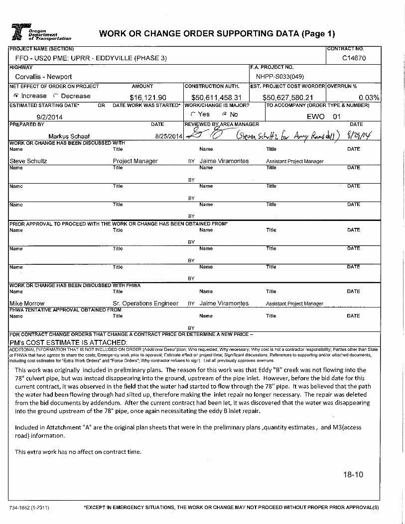
18-10
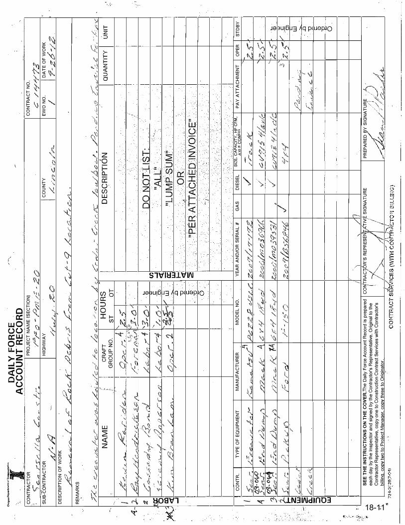
�M
�-
f of 1
l�
�
--� -
CON
TRA
CTO
R \,
r.;-c
.;?
rs
,..,...._
l�t ·.f c
it....-SU
B-CO
NTR
ACT
OR A
.,/·�_,q
DE
SCRI
PTIO
N O
F W
ORK
DA
ILY
F
OR
CE
A
CC
OU
NT
.RE
CO
RD
L
-/-r-
,,::,.
-·
"'1.
i
-
-.,
PRO
JECT
NA
ME
(SEC
TIO
N)
/';;:/:
o -
/J/7Z
,;;
-.2
0
HIG
HWA
Y ✓";,/
.A f
.1. 1.
Z-0
,
--
ICOU
NTY
re /
/,' .:::.
·:::i ,,
,..,
,,.,
_
--CO
NTR
ACT
NO
. c.:::
/ "1/
Ar' 7
3
EWO
NO
.
I IDA
TE O
F W
ORK
4
-cf
�/-✓'
,! -,,c.
,t;;,..
•
,,{::,
,. -
G,
,1---
,,o
r6
·---,
.,..c.:::.,_�
. , G
w��
�-· I
�
;C
JF1
LJC.-
✓'
, C
v✓
--/ ..
:=;}
h,-
C./
2'\_
. c:.
✓- -
o
,:.,/ I
;
,.Z
c./
0 .
/:., .,-
C-./1...
•RE
MA
RKS
�c
C::..,,,V
c.o·-1
/-cL
/·c:,.
,r-,::..,.....
/0-.5
· /
_:,_,.-.J
,..,-/
co
/ /
c-
/4 c:.
o-
.,i-_,
cr,
. A
i•r
C
r_.,
-� ., . --
C✓
Lc
,-_,r
e /c
J ,6
' .
,.. ,,u
. a
< --
.,, _;;r"
. d'
• '
· ,
#
r. -
J::
-.-.
·' ·e,
f. -
C:: �
' ..,
.,
,-.--::;
...,.�.
, _,,;
1.,.,,...·
i_f
.__...
/'-1...,
t.,...
,...
✓ , _,..
,-t:.....
,. C
•·
. ,.,;/
IY
J . )- :z u;c
·o , Dl
I
<(
..J
I 4 J
)-.
I- 2
w
. aE
C.
::,
d
w
NA
ME
'
,;,
£'r'-""
�-�/-.,
.... 11c K
c< F
/ :,-
,le.. /1.
,.
_,e;::_,
,. ,,
/-1'>
.,,.,r:/
r,, c
_ l'z:
-.i c
;;-.-i,,
: ✓
---
~!
·:,
,
-,/
I'":
n--
,;· c
.x
·-_,.
,,.,:_,,-
/"�
• -f
/1
<5
,;;:: ,
r.::.
.n ...
• j
/
/ n
D C
: ,.,-
S-,-::;.-
✓1 .
.,,f.._,-�
;.
....
I ,,
,, f./ �
'3 r
.cr;t.,_-
.,p�
A/
.rr
..,.,.,.�
CR
AF
T
GR
OU
P N
O.
0/::,
,.-.,,---:.
4.
/.. __
, \,
C J-'-
\
.•
--
✓-
e" /
A ,
,;i__,I
J
L ,:;_
./2.--:
,,.,.
-4
.,,< 6..
,D,,::,,
,--1-
o,.,
_,-
1
-.
. /
HO
UR
S
I D
ES
CR
IPT
ION
Q
UA
NT
ITY
ST
O
T
'z�
v
')
�
,.,,,-
•O
DO
NO
T U
ST
: '3
--ei✓
L.
(I)
....
-� "A
LL"
/,.-
rj/
..J
CJ)
<(
�� /
L.
"LU
MP
SU
M"
w
a:
-w
..D
I-
OR
-g
<(
.
_,.
..
2!
"PE
RA
TT
AC
HE
D I
NV
OIC
E"
CON
TR.
"..- ,:lG
c:-.:...
.. !,,_,..
tl�CJ
-o�
.5
�:'L,
,r.
l)I.J- e>
<t: fJ
,::.,,,--
"� I_,,
<:
--�
,::;
_(
....
,,:,;' C::
..c:,
·. y /'
•✓:::° .,-"
"-�rt
TYPE
OF
EQU
IPM
ENT
✓:::
/-
eWC
-r:.L.,�✓
,1;!'
/-..,/
-
,l: �·�
c::l .o
,_,.d. ,."4..,
. ,--"I
,-/
_;:-,,.._
e,·-/
/) ..,,
/1A
./
) r
/:Y
/ -/ lil
"'l-�
c::....;;C
{;_st ,,.
MA
NUF
ACT
URER
,,-'-'
1�;:r-
,_......1-}
.,.1.•
�C::,.
·,
FJ,,•�
�·
If/
/?7
.cr-.
e-i
c
i\ /
J)
rc_
,::.., I
<= �4
r
' •::
;,/
l""c
,rc
MO
DEL
NO
.
.,,o�
,.--=:.z
fl ::
,.,.-.'.:i,c
r:
,,. /
4/ ,,;,
f'�
,-L>
y 1
/ _,,,
'C;l
. v
--
d
6· ,
,:-'1
/
,,r,..-1
'
/_;
-/
_':) . (
')
/ !
YEA
R A
ND/
OR
SERI
AL
#
ZC-
_,.,.r;,:
,,/�
7-/
•�T_,,?
..,_,.,,,
"'
I'
. /!
.:
zc:.
c;(
;//:17
c;1 ii'
6<i
'Cf:
"'/,�--
..- ""
"'YO
-�
/
Zc:
r✓(,;
' ,,,-
:iv .:i
, .5--d
. -,.
/."I'/ , .
x, -··
/ ;:.
-e: c
I
b _:,
}ro/6
,-
'\ '
/7
• • I
GA
S DI
ESEL
✓
✓
.
✓-
✓
SE
E T
HE
IN
ST
RU
CT
ION
S O
N T
HE
CO
VE
R.T
he
Dai
ly F
orce
Acc
ount
Rec
ord
is p
repa
red
each
day
by
th·e
Insp
ecto
r and
sig
ned
by th
e C
ontra
ctor
's R
epre
sent
ativ
e. O
rigin
al to
the
Con
tract
or R
epre
sent
ativ
e, c
opy
one
to C
onst
ruct
ion
Con
tract
Ser
vice
s w
ith C
ontra
ctor
's _ b
illina
. coo
v tw
o to
Pro
iect
Man
aaer
coo
v th
ree
to O
riain
ator
.
co
ITTR
Ac
plR
's """
l''�' S
,GN
ATU
RE
II
I 'A
. I
I ·-
.,.
I I
;
-
-,
,
-,,.._
I
(i,
SIZE
, CA
PACI
TY, H
P CF
M,
·PAY
ATT
ACH
MEN
T O
PER
'""
,: CO
N<=l
r.
;-;..
0--
G /
(:
C:. v'
::1/ 5
•f;l�
[ I(' ,1-
c.v·•-z
,,>l
r:✓/
". c.l
C
";-" ,i
�-t7l
,f-�
;· _,,
:;l "
'1 , ---
-'
-'• I ,�:
1.,A!
"', s::
. c:;,.
PREP
ARE
D B
Y SI
GN
ATU
R,E.
/ ),
----Z..
,'5'""
"z,S
�
----,::, -
.:;;
2,
,/!,
;c�d
{
//
/ /
, //
/�
.,.;,(
{ , •
. �/4
..tr.-<'
h �
,/ -;
,l �
, .
0
,lAL
UN
IT
STDB
Y
-
L..
(I)
/ .s CJ)
'- w
..D
-g
tJ
6
:;-
18-1
18-11

18-12

General Construction Inspector December 2018
Contract Administration – General Requirements 18-13
Disagreements, Protests and Claims
Required Notices
00195.30 No adjustment benefitting the Contractor isallowed without proper notice
00195.40 Contractor shall immediately file a writtennotice
00199.20 Protest Procedure
– Oral Notice
– Written Notice
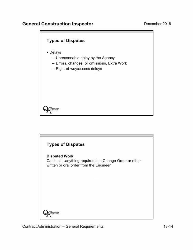
General Construction Inspector December 2018
Contract Administration – General Requirements 18-14
Types of Disputes
Delays
– Unreasonable delay by the Agency
– Errors, changes, or omissions, Extra Work
– Right-of-way/access delays
Types of Disputes
Disputed WorkCatch all…anything required in a Change Order or other written or oral order from the Engineer
General Construction Inspector December 2018
Contract Administration – General Requirements 18-15
Dispute Resolution


INSERT TAB
Unit 19 CA – Project Documentation
General Construction Inspector December 2018
Contract Administration – Project Documentation 19-1
Unit 19Project Documentation
Unit 19 Topics
Daily Reports
Public Records
Region Assurance Specialist (RAS) Role
Quarterly Release of Retainage
CPS – How to Request Access
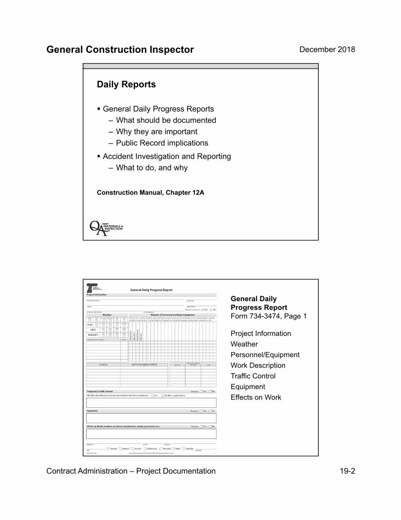
General Construction Inspector December 2018
Contract Administration – Project Documentation 19-2
Daily Reports
General Daily Progress Reports
– What should be documented
– Why they are important
– Public Record implications
Accident Investigation and Reporting
– What to do, and why
Construction Manual, Chapter 12A
General Daily Progress ReportForm 734-3474, Page 1
Project Information
Weather
Personnel/Equipment
Work Description
Traffic Control
Equipment
Effects on Work

General Construction Inspector December 2018
Contract Administration – Project Documentation 19-3
General Daily Progress ReportForm 734-3474, Page 2
Materials rejectedProject visitorsRemarks
General Daily Progress ReportForm 734-3474, Page 3
Pictures!
Pictures!
Pictures!
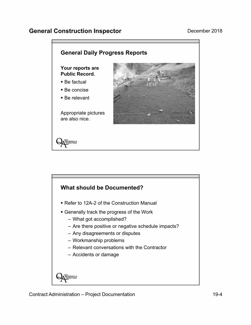
General Construction Inspector December 2018
Contract Administration – Project Documentation 19-4
General Daily Progress Reports
Your reports are Public Record.
Be factual
Be concise
Be relevant
Appropriate pictures are also nice.
What should be Documented?
Refer to 12A-2 of the Construction Manual
Generally track the progress of the Work
– What got accomplished?
– Are there positive or negative schedule impacts?
– Any disagreements or disputes
– Workmanship problems
– Relevant conversations with the Contractor
– Accidents or damage
General Construction Inspector December 2018
Contract Administration – Project Documentation 19-5
What should NOT be documented?
Personal opinions…even if they are positive
Irrelevant information
General Daily Progress Reports
Four years from now you should be able to answer a few questions.
General Construction Inspector December 2018
Contract Administration – Project Documentation 19-6
General Daily Progress Reports
When, exactly, did the earthwork begin?
What caused the delay?
Who was involved in the conversation?
Did the Contractor follow their schedule?
Was the corrective work completed? When?
Was the superintendent present and in control of the work?
How much work was completed that day?
Public Records
Public Record:
…any writing that contains information relating to the conduct of the public’s business…prepared, owned, used or retained by a public body regardless of physical form or characteristics.
ORS 192.410(4)(a)
General Construction Inspector December 2018
Contract Administration – Project Documentation 19-7
Public Records
Writing:
…handwriting, typewriting, printing, photographing and every means of recording, including letters, words, pictures, sounds, or symbols, or combination thereof, and all papers, maps, files, facsimiles or electronic recordings.
ORS 192.410(6)
Public Records
Don’t create documents that you wouldn’t want in the newspaper
– Including e-mails, letters, text messages, inappropriate photos, etc.
– Keep it professional
– No personal opinions
General Construction Inspector December 2018
Contract Administration – Project Documentation 19-8
How long should documents be kept?
Contract Administration Documents
– Includes: e-mail, paper files, electronic files
– Must be kept 20 years after final payment
– Structures, such as bridges, require longer retention times
The Region Assurance Specialists (RAS)
Their role in helping to assure documentation compliance

General Construction Inspector December 2018
Contract Administration – Project Documentation 19-9
The Goals for the Region Assurance Specialist (RAS)
Provide early, timely project documentation reviews in theProject Managers office
Review the organization and documentation process
Provide technical help to inspectors and ContractAdministration Specialist
Valued resource to ODOT, Local Agency and ConsultantProject Managers
Documentation Review Report (DRR)Form 734-1903
List of comments, missing items or deficiencies
Distributed to Contract Administration Specialist,APM or PM
RAS reviews through Doc Express
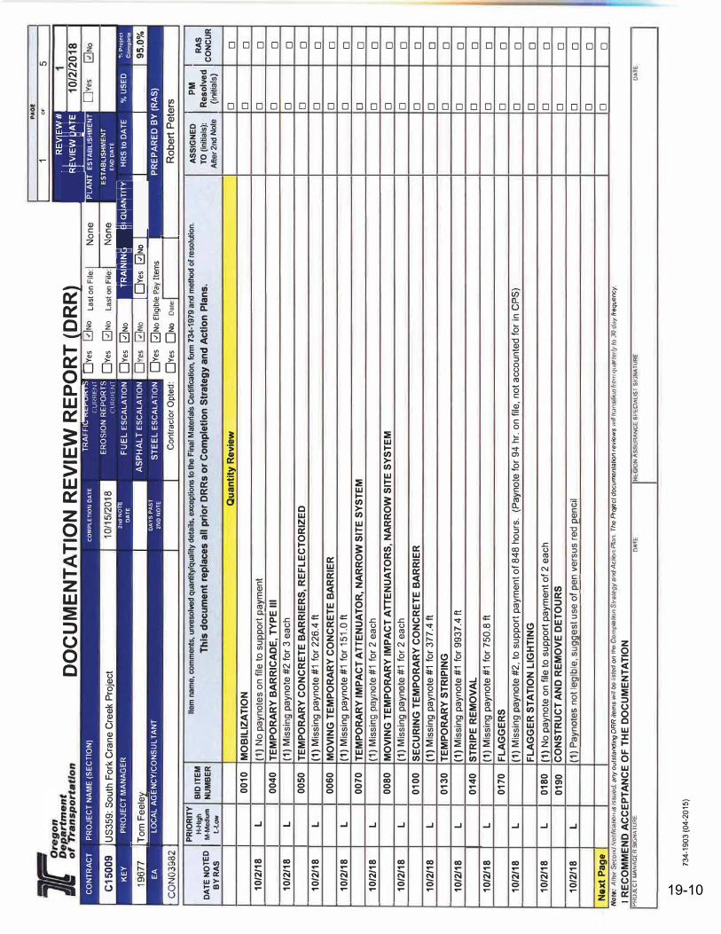
PA
O£
OF
5
DO
CU
ME
NTA
TIO
N R
EV
IEW
RE
PS)
RT
(OR
R)
.ijffaif
·foif
10
I2I2
01
s
OYe
s-0
N1>
TRA
FFIC
RE
POR
TS
currn
r m
ER
OS
ION
RE
POR
TS
C'.UIU
<ENT
OYe
s C
ON
TRA
CT
PRO
JEC
T N
AM
E (S
EC
TIO
N)
CO
MP
LE
TIO
N D
AT
E
-US
359:
Sou
th F
ork
Cran
e Cr
eek
Proj
ect
li.JN
o La
st o
n Fi
le: �
ne
OYe
s 0
No
PLA
NT
ESTA
BLIS
HMEN
T
ESTA
BLIS
HMEN
T E
NO
DA
TE
KE
Y P
RO
JEC
T M
AN
AG
ER
[ Tom
Fee
ley
:Zn
d N
OTE
DA
TE
FU
EL
ESC
ALA
TIO
N
AS
PH
ALT
ES
CA
LATI
ON
ST
EE
L E
SC
ALA
TIO
N
OYe
s 0
No
OYe
s 0
No
HR
S to
DA
TE
!•@
j{jj{lc
,=jt-\'
0,mfi
OYe
s 0
No
% U
SED
"/
, P
roje
c1
Co
mp
fele-
EA
�
LOCA
L A
GE
NC
Y
�
/CO
NS
UL T
AN
T D
AY
S P
AS
T
2N
D N
OT
E
a-.,a
r O
otea
OYe
s 0
No
Elia
ible
Pa
OYe
s O
No
Dac
e:
PR
EP
AR
ED
BY
(R
AS
)
IR
ob
ert
Pe
ters
PRIO
RIT
Y
BID
ITE
M
Item
nam
e, c
omm
ents
, unr
esol
ved
quan
tity/
qual
ity d
etai
ls, e
xcep
tions
to th
e Fi
nal M
ateri
als
Cer
tifica
tion,
fonn
734
-197
9 an
d m
etho
d of
reso
lutio
n.
AS
SIG
NE
D
I P
M
IR
AS
H-
High
D
ATE
NO
TED
I M
-Med
ium
B
Y R
AS
L-
Low
10/2
/18
L
10/2
/18
L
10/2
/18
L
10/2
/18
L
10/2
/18
L
10/2
/18
L
10/2
/18
L
10/2
/18
L
10/2
/18
L
10/2
/18
L
10/2
/18
L
10/2
/18
L
Nex
t P
age
NU
MB
ER
0010
0040
0050
0060
0070
0080
0100
0130
0140
0170
I 0
18
0
0190
Th
is d
ocu
men
t re
plac
es a
ll p
rio
r D
RR
s o
r C
om
plet
ion
Str
ateg
y an
d A
ctio
n P
lan
s.
MO
BIL
IZA
TIO
N
(1)N
o pa
ynot
es o
n fil�
to s
uppo
rt_Ji_ay
men
tT
EM
PO
RA
RY
BA
RR
ICA
DE
, TY
PE
Ill
(1)
Miss
ing
payn
ote
#2 fo
r 3 e
ach
TE
MP
OR
AR
Y C
ON
CR
ET
E B
AR
RIE
RS
, RE
FL
EC
TO
RIZ
ED
(1
)M
issin
g pa
ynot
e #1
for 2
26.4
ftM
OV
ING
TE
MP
OR
AR
Y C
ON
CR
ETE
BA
RR
IER
(1
)M
issin
g pa
ynot
e #1
for 1
51.0
ft
Qu
anti
ty R
evie
w
TE
MP
OR
AR
Y IM
PA
CT
ATT
EN
UA
TO
R, N
AR
RO
W S
ITE
SY
ST
EM
(1
) M
issin
g pa
ynot
e #1
for 2
eac
hM
OV
ING
TE
MP
OR
AR
Y IM
PA
CT
ATT
EN
UA
TO
RS
, NA
RR
OW
SIT
E S
YS
TE
M
(1)
Miss
ing
payn
ote
#1 fo
r 2 e
ach
SE
CU
RIN
G T
EM
PO
RA
RY
CO
NC
RE
TE B
AR
RIE
R
(1)
Miss
ing
payn
ote
#1 fo
r 377
.4 ft
TE
MP
OR
AR
Y S
TR
IPIN
G
(1)
Miss
ing
payn
ote
#1 fo
r 993
7.4
ft
ST
RIP
E R
EM
OV
AL
(1
)M
issin
g pa
ynot
e #1
for 7
50.8
ftF
LA
GG
ER
S
(1)
Miss
ing
payn
ote
#2, t
o su
ppor
t pay
men
t of 8
48 h
ours
. (P
ayno
te fo
r 94
hr. o
n file
, not
acc
ount
ed fo
r in
CPS)
FL
AG
GE
R S
TA
TIO
N L
IGH
TIN
G
{1)
No p
ayno
te o
n file
to s
uppo
rt pa
ymen
t of 2
eac
h C
ON
ST
RU
CT
AN
D R
EM
OV
E D
ET
OU
RS
{1)
Payn
otes
not
legi
ble,
sugg
est u
se o
f_pe11
verSlJ
s re
d J)e
ncil
No
ra:
All
"' �
Ofl
fl No
f///f:R
/�11
,s ls
suo
rJ. a
ny
ou
tsta
nding
OR
R it
em
s w
ill oo
liSI
IJII o
n Ina
Co
mp//J
t/on
Str
ateg
y B
IPd
Act
,011
Pkm
. T
he Pr
oje
ct d
ocu
me
nta
lion
re
vie
ws
wfq
lra
nsi
llf)n
/rp
m r1
11ar
ler/y
IQ JQ
dny
freq
uen
cy.
I RE
CO
MM
EN
D A
CC
EP
TAN
CE
OF
TH
E D
OC
UM
EN
TA
TIO
N
Pll
OJE
CI
MANA
GE
R S
IGN
A.H
IR
E
□A
l"E
�E
OION I\
SSUl',\
NCt S
Pkc;t
llUSl
SIG
l'll\TU
RE
734-
1903
(04-
2015
)
TO (
initi
als)
: R
eso
lved
C
ON
CU
R
Afte
r 2nd
Not
e (in
itial
s)
□
□
□
□
□
□
□
□
□
□
□
□
□
□
□
□
□
□
□
□
□
□
□
□
□
□
□
□
□
□
□
□
□
□
□
□
□
□
□
□
□
□
□
□
□
□
□
□
□
□
□
□
□
□
OA
T
19-10
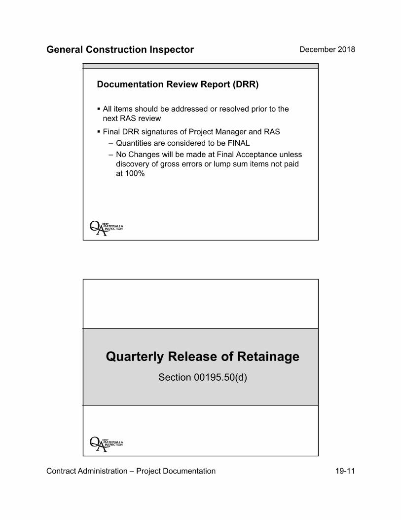
General Construction Inspector December 2018
Contract Administration – Project Documentation 19-11
Documentation Review Report (DRR)
All items should be addressed or resolved prior to thenext RAS review
Final DRR signatures of Project Manager and RAS
– Quantities are considered to be FINAL
– No Changes will be made at Final Acceptance unlessdiscovery of gross errors or lump sum items not paidat 100%
Quarterly Release of Retainage
Section 00195.50(d)

General Construction Inspector December 2018
Contract Administration – Project Documentation 19-12
00195.50(d) – Quarterly Release of Retainage
Release of the amounts retained will only be consideredfor Pay Items that have been satisfactorily completed.
A Pay Item will be considered satisfactorily completedonly if all of the Work for the Pay Item is complete and allcontractual requirements pertaining to the Pay Item andWork have been satisfied.
Beginning with the fourth month after First Notificationand every third month thereafter, the agency will releaseretainage for satisfactorily completed Pay Items.
Contract Payment System
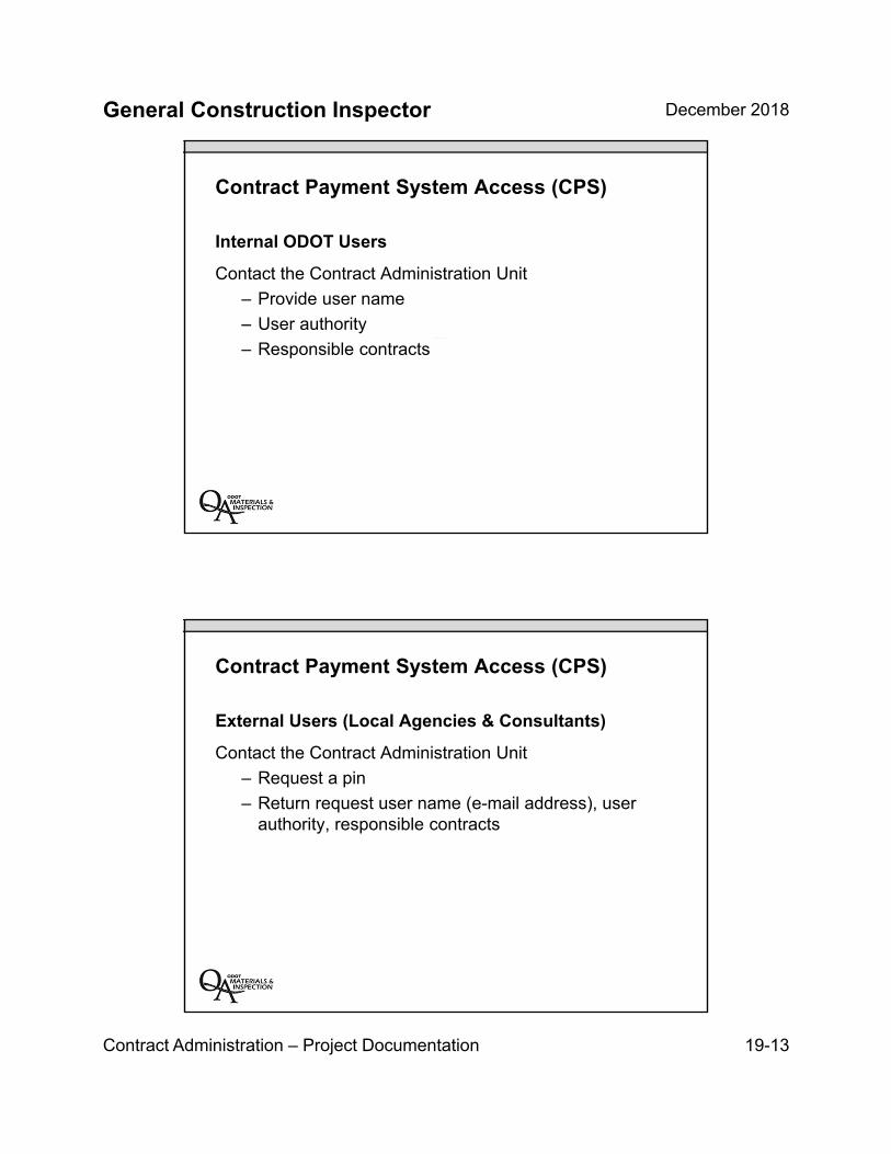
General Construction Inspector December 2018
Contract Administration – Project Documentation 19-13
Contract Payment System Access (CPS)
Internal ODOT Users
Contact the Contract Administration Unit
– Provide user name
– User authority
– Responsible contracts
Contract Payment System Access (CPS)
External Users (Local Agencies & Consultants)
Contact the Contract Administration Unit
– Request a pin
– Return request user name (e-mail address), userauthority, responsible contracts

General Construction Inspector December 2018
Contract Administration – Project Documentation 19-14
The Contract Payment System Retainage Tool & Reports
Contact:
James SealyODOT Contract Payments Specialist
Key Inspection Points
General Dailies are a necessary evil and the mostimportant document
A good picture is worth a thousand words
Region Assurance Specialist is a resource
Address items noted on Document Review Report
Stay organized by writing paynotes and keep up with yourdocumentation. Don’t wait until the end of the month!!!!
General Construction Inspector December 2018
Contract Administration – Project Documentation 19-15
Unit 19 Review
Daily Reports
Public Records
Region Assurance Specialist (RAS) Role
Quarterly Release of Retainage
CPS – How to Request Access


INSERT TAB
Unit 20
CA – Labor Compliance

General Construction Inspector December 2018
Contract Administration – Labor Compliance 20-1
Unit 20Labor Compliance
Unit 20 Topics:
Prevailing wage
Employee interviews
Inspector’s role for labor compliance

General Construction Inspector December 2018
Contract Administration – Labor Compliance 20-2
CM: Chapter 19 – Labor Compliance
Prevailing Wage Requirements
Davis-Bacon & Related Acts (DBRA) apply to Federal-Aidconstruction contracts valued at $2,000 or more.
Bureau of Labor & Industries (BOLI)
– Requirements apply to state-funded projects of$50,000 or more
– And to off highway system federal-aid projects.
CM: Chapter 19 – Labor Compliance
Prevailing Wage Requirements
For public works contracts that are subject to bothFederal DBRA and BOLI,
A wage rate comparison must be made, and
Workers are paid the higher of the two wage rates.

General Construction Inspector December 2018
Contract Administration – Labor Compliance 20-3
Important
Required Postings
Contractor must post the “Employee Rights” poster at thejob site.
Wage rates, benefit plan information, and work schedulesare required to be posted at the job site.
Chapter 19 – Labor Compliance
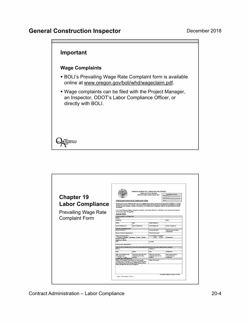
General Construction Inspector December 2018
Contract Administration – Labor Compliance 20-4
Important
Wage Complaints
BOLI’s Prevailing Wage Rate Complaint form is availableonline at www.oregon.gov/boli/whd/wageclaim.pdf.
Wage complaints can be filed with the Project Manager,an Inspector, ODOT’s Labor Compliance Officer, ordirectly with BOLI.
Chapter 19Labor CompliancePrevailing Wage Rate Complaint Form
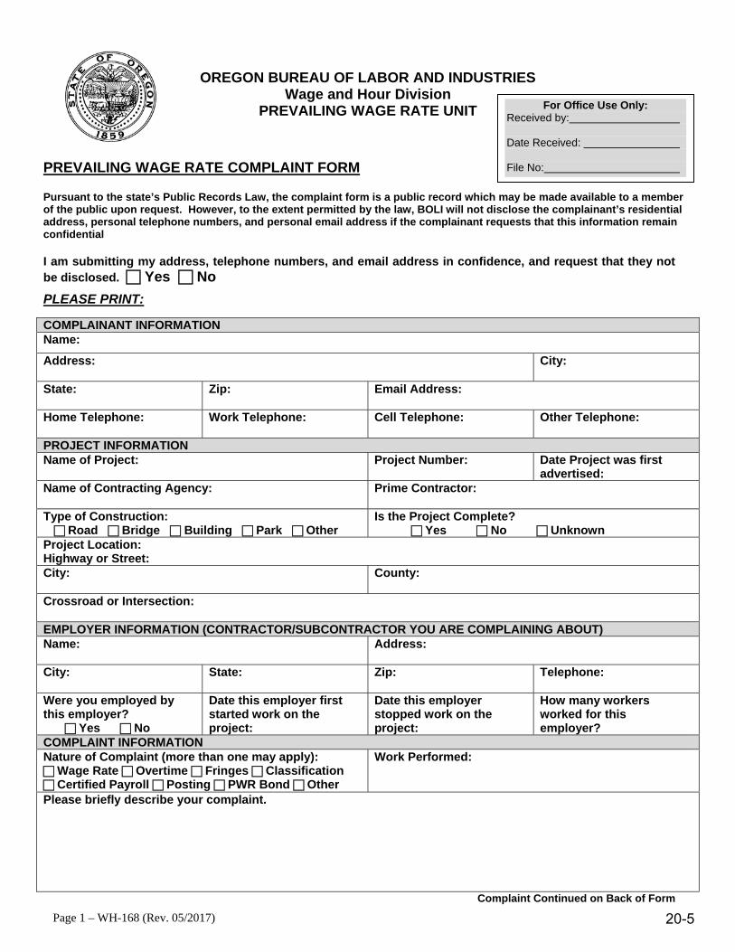
Page 1 – WH-168 (Rev. 05/2017)
OREGON BUREAU OF LABOR AND INDUSTRIES Wage and Hour Division
PREVAILING WAGE RATE UNIT
PREVAILING WAGE RATE COMPLAINT FORM
Pursuant to the state’s Public Records Law, the complaint form is a public record which may be made available to a member of the public upon request. However, to the extent permitted by the law, BOLI will not disclose the complainant’s residential address, personal telephone numbers, and personal email address if the complainant requests that this information remain confidential
I am submitting my address, telephone numbers, and email address in confidence, and request that they not be disclosed. Yes NoPLEASE PRINT:
COMPLAINANT INFORMATION Name:
Address: City:
State: Zip: Email Address:
Home Telephone: Work Telephone: Cell Telephone: Other Telephone:
PROJECT INFORMATION Name of Project: Project Number: Date Project was first
advertised: Name of Contracting Agency: Prime Contractor:
Type of Construction: Road Bridge Building Park Other
Is the Project Complete? Yes No Unknown
Project Location: Highway or Street: City: County:
Crossroad or Intersection:
EMPLOYER INFORMATION (CONTRACTOR/SUBCONTRACTOR YOU ARE COMPLAINING ABOUT) Name: Address:
City: State: Zip: Telephone:
Were you employed by this employer? Yes No
Date this employer first started work on the project:
Date this employer stopped work on the project:
How many workers worked for this employer?
COMPLAINT INFORMATION Nature of Complaint (more than one may apply): Wage Rate Overtime Fringes Classification Certified Payroll Posting PWR Bond Other
Work Performed:
Please briefly describe your complaint.
Complaint Continued on Back of Form
For Office Use Only:Received by:
Date Received:
File No:
20-5
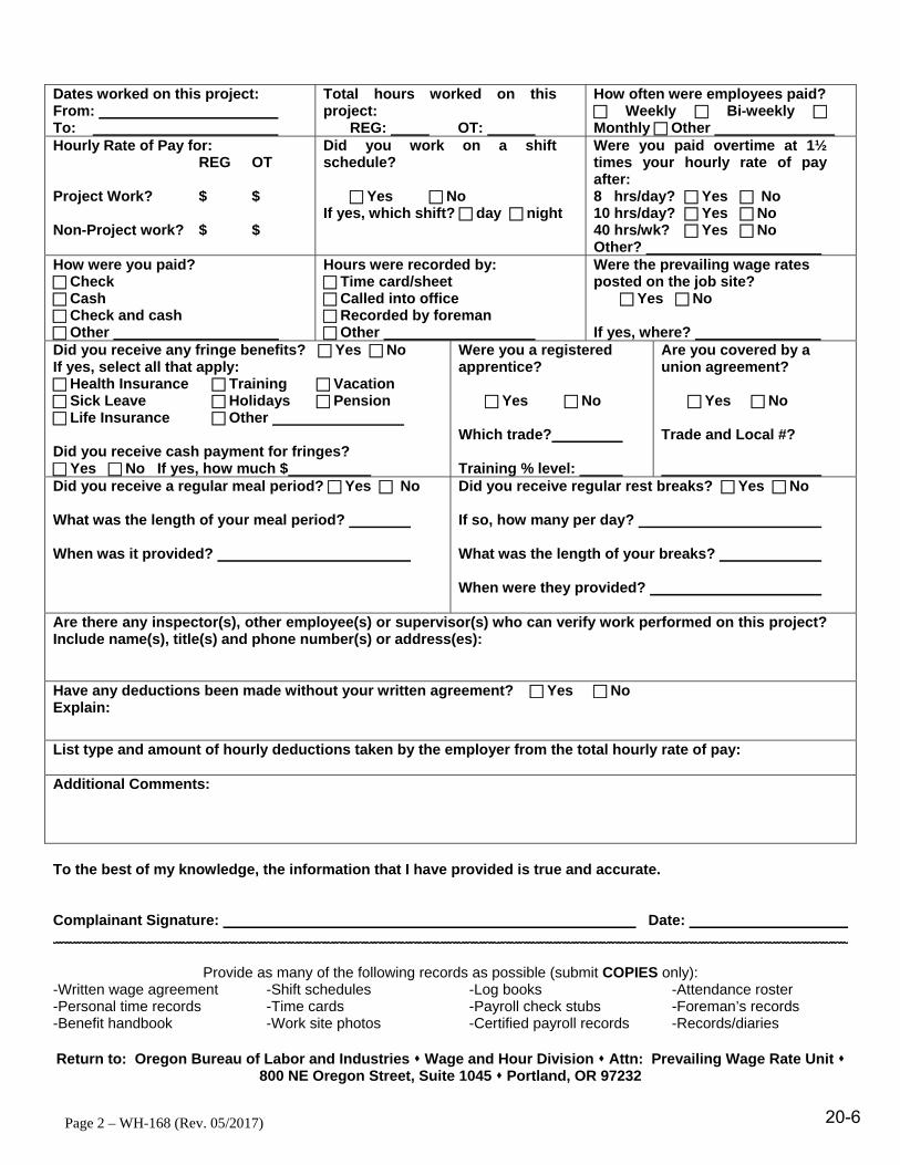
Page 2 – WH-168 (Rev. 05/2017)
Dates worked on this project: From: To:
Total hours worked on this project:
REG: OT:
How often were employees paid? Weekly Bi-weekly Monthly Other
Hourly Rate of Pay for: REG OT
Project Work? $ $
Non-Project work? $ $
Did you work on a shift schedule?
Yes No If yes, which shift? day night
Were you paid overtime at 1½ times your hourly rate of pay after: 8 hrs/day? Yes No 10 hrs/day? Yes No 40 hrs/wk? Yes No Other?
How were you paid? Check Cash Check and cash Other
Hours were recorded by: Time card/sheet Called into office Recorded by foreman Other
Were the prevailing wage rates posted on the job site? Yes No
If yes, where? Did you receive any fringe benefits? Yes No If yes, select all that apply: Health Insurance Training Vacation Sick Leave Holidays Pension Life Insurance Other
Did you receive cash payment for fringes? Yes No If yes, how much $
Were you a registered apprentice?
Yes No
Which trade?
Training % level:
Are you covered by a union agreement?
Yes No
Trade and Local #?
Did you receive a regular meal period? Yes No
What was the length of your meal period?
When was it provided?
Did you receive regular rest breaks? Yes No
If so, how many per day?
What was the length of your breaks?
When were they provided?
Are there any inspector(s), other employee(s) or supervisor(s) who can verify work performed on this project? Include name(s), title(s) and phone number(s) or address(es):
Have any deductions been made without your written agreement? Yes No Explain:
List type and amount of hourly deductions taken by the employer from the total hourly rate of pay:
Additional Comments:
To the best of my knowledge, the information that I have provided is true and accurate.
Complainant Signature: Date:
Provide as many of the following records as possible (submit COPIES only): -Written wage agreement -Shift schedules -Log books -Attendance roster-Personal time records -Time cards -Payroll check stubs -Foreman’s records-Benefit handbook -Work site photos -Certified payroll records -Records/diaries
Return to: Oregon Bureau of Labor and Industries Wage and Hour Division Attn: Prevailing Wage Rate Unit 800 NE Oregon Street, Suite 1045 Portland, OR 97232
20-6

General Construction Inspector December 2018
Contract Administration – Labor Compliance 20-7
CM: Chapter 19 – Labor Compliance
Inspector’s General Daily Progress Reports
Workers are to be paid for the classification of work theyare performing.
Note any classification/wage issues observed or reported.
Note crews working that day and equipment used.
CM: Chapter 19 – Labor Compliance
Inspector’s General Daily Progress Reports (continued)
Note if individuals are working in different classificationsthroughout the work day.
Can be compared to Employee Interview Reports andCertified Payroll Reports to check classification andwages paid.
Are instrumental in prevailing wage complaintinvestigations.
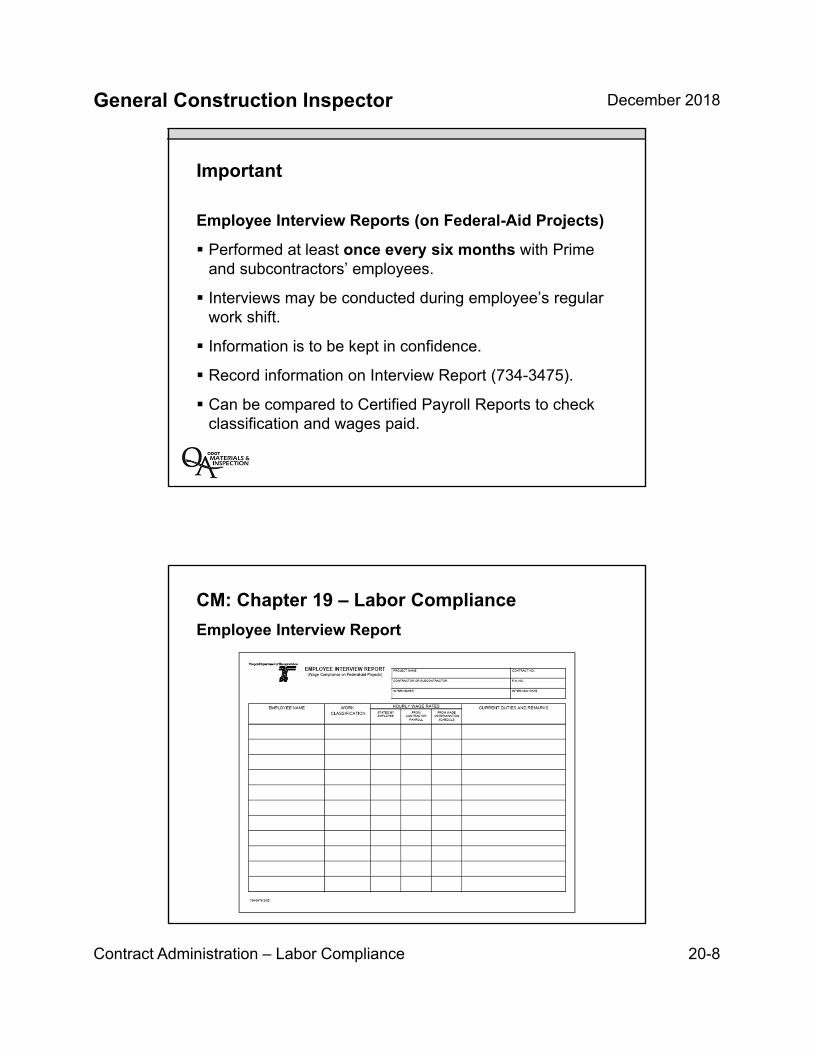
General Construction Inspector December 2018
Contract Administration – Labor Compliance 20-8
Important
Employee Interview Reports (on Federal-Aid Projects)
Performed at least once every six months with Primeand subcontractors’ employees.
Interviews may be conducted during employee’s regularwork shift.
Information is to be kept in confidence.
Record information on Interview Report (734-3475).
Can be compared to Certified Payroll Reports to checkclassification and wages paid.
CM: Chapter 19 – Labor Compliance
Employee Interview Report
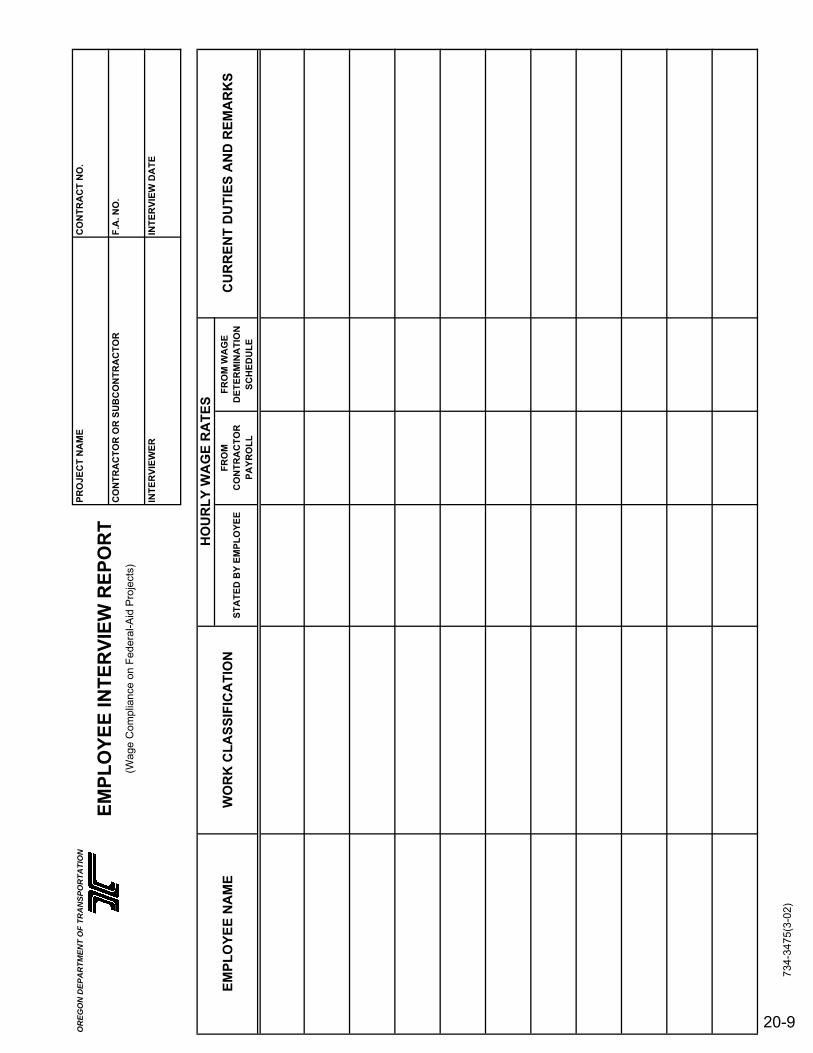
OR
EG
ON
DE
PA
RT
ME
NT
OF
TR
AN
SP
OR
TA
TIO
NC
ON
TR
AC
T N
O.
CO
NT
RA
CT
OR
OR
SU
BC
ON
TR
AC
TO
RF
.A. N
O.
INT
ER
VIE
WE
RIN
TE
RV
IEW
DA
TE
ST
AT
ED
BY
EM
PL
OY
EE
FR
OM
C
ON
TR
AC
TO
R
PA
YR
OL
L
FR
OM
WA
GE
D
ET
ER
MIN
AT
ION
S
CH
ED
UL
E
PR
OJE
CT
NA
ME
WO
RK
CL
AS
SIF
ICA
TIO
NC
UR
RE
NT
DU
TIE
S A
ND
RE
MA
RK
S
(Wag
e C
ompl
ianc
e on
Fed
eral
-Aid
Pro
ject
s)
EM
PL
OY
EE
INT
ER
VIE
W R
EP
OR
T
EM
PL
OY
EE
NA
ME
HO
UR
LY
WA
GE
RA
TE
S
734-
3475
(3-0
2)
20-9

20-10
General Construction Inspector December 2018
Contract Administration – Labor Compliance 20-11
CM: Chapter 19 – Labor Compliance
Sample Employee Interview questions:
– What type of work do you perform?
– What equipment or tools do you use?
– What’s your hourly rate of pay?
– Do you have a benefit plan(s)? (Medical, retirement)
CM: Chapter 19 – Labor Compliance
Sample Employee Interview questions (continued)
– Do you know how to access your benefit plan(s)?
– What schedule are you working?
– Has your schedule changed since you started workon this project?
General Construction Inspector December 2018
Contract Administration – Labor Compliance 20-12
Lessons for Inspectors
Employee interviews every 6 months
Interview Prime and subcontractor employees
Forward questions or complaints to ODOT LaborCompliance Officer
Keep accurate labor records in General Daily ProgressReports
Unit 20 Review:
Prevailing wage
Employee interviews
Inspector’s role for labor compliance

INSERT TAB
Unit 21
OCR – Equity Program
General Construction Inspector December 2018
Office of Civil Rights 21-1
Unit 21Workforce & Small Business
Equity Program
Unit 21 Topics:
Role of inspector for these programs
Aspirational targets and contract goals
Commercially useful function (CUF) criteria
DBE Trucking
EEO, ADA and Workforce
General Construction Inspector December 2018
Office of Civil Rights 21-2
Construction Manual: Chapter 18 Workforce and Small Business Equity Programs
Contracts with Federal funding may include up to four different Workforce and Small Business Equity programs:
Disadvantaged Business Enterprise (DBE)
Equal Employment Opportunity (EEO)
On-the-Job Training (OJT)/Apprenticeship
Tribal Employment Rights Ordinance (TERO)
DBE Program
Key Monitoring & Compliance Topics
Policy
Goals and commitments
Termination or substitution of DBE’s
CUF reviews
Summary Reports of Subcontractors Paid

General Construction Inspector December 2018
Office of Civil Rights 21-3
DBE Program Policy
Set by the Director of ODOT
Ensure non-discrimination in USDOT-assisted contracts
Level playing field for DBEs to compete fairly
Narrowly tailored program
Ensure only eligible firms participate
Help remove barriers to participation of DBEs
Developing DBEs to compete outside the program
Give same priority as compliance with other legal obligations to USDOT
DBE Program: Goals and Commitments
There are DBE contract goals and an Overall DBE Goal
Current Overall DBE Goal: 11.6% (RN 5.0%, RC 6.6%)
When OCR assigns a DBE goal to a project, the Prime must commit sufficient work to DBEs to meet the goal
DBE requirements are in the Special Provisions
PM staff monitors DBE program compliance throughout project
OCR Field Coordinator provides project compliance review and technical assistance
General Construction Inspector December 2018
Office of Civil Rights 21-4
Race-Conscious vs Race-Neutral
Race-conscious DBE participation means a measure or program that is focused specifically on assisting only DBE’s and excludes participation by others= DBE contract goals.
Race-neutral DBE participation means any participation by a DBE through customary competitive procurement procedures= **DBE’s win contracts without mandating their participation.
** Small contracting, unbundling, maintenance programs, bonding, access to capital, etc.
DBE CUF Reviews
ODOT may only credit payments toward DBE goals if the DBE performs a CUF
According to Normal Industry Practices
General Construction Inspector December 2018
Office of Civil Rights 21-5
When to Perform a CUF Evaluation
The PM or designated representative must perform at least one CUF review for every DBE:
For each 12-month period the DBE works on the Project (early or peak is better than waiting until the end)
When a significant change in the operation of the DBE occurs (new equipment is used or work crews change)
When a significant Change Order affects the DBE’s Work (for example, a new type of work is added)
After termination and substitution of a DBE (for the new DBE)
FIVE factors must be evaluated when determining whether a DBE is performing a
“Commercially Useful Function”
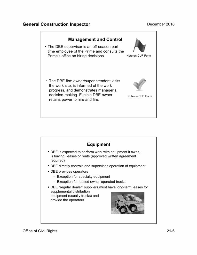
General Construction Inspector December 2018
Office of Civil Rights 21-6
• The DBE firm owner/superintendent visits the work site, is informed of the work progress, and demonstrates managerial decision-making. Eligible DBE owner retains power to hire and fire.
• The DBE supervisor is an off-season part time employee of the Prime and consults the Prime’s office on hiring decisions. Note on CUF Form
Management and Control
Note on CUF Form
Equipment
DBE is expected to perform work with equipment it owns,is buying, leases or rents (approved written agreement required)
DBE directly controls and supervises operation of equipment
DBE provides operators
– Exception for specialty equipment
– Exception for leased owner-operated trucks
DBE “regular dealer” suppliers must have long-term leases for supplemental distribution equipment (usually trucks) and provide the operators
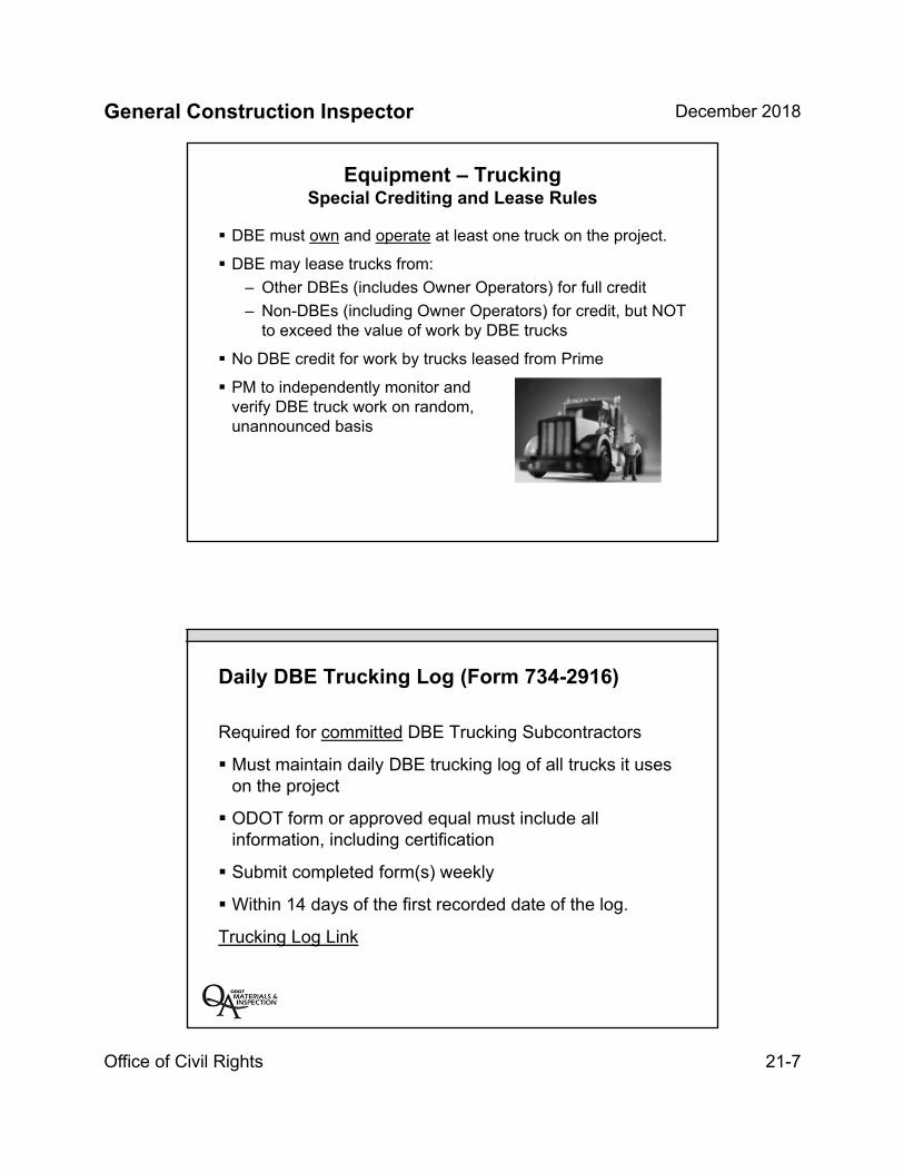
General Construction Inspector December 2018
Office of Civil Rights 21-7
Equipment – TruckingSpecial Crediting and Lease Rules
DBE must own and operate at least one truck on the project.
DBE may lease trucks from:
– Other DBEs (includes Owner Operators) for full credit
– Non-DBEs (including Owner Operators) for credit, but NOT to exceed the value of work by DBE trucks
No DBE credit for work by trucks leased from Prime
PM to independently monitor and verify DBE truck work on random, unannounced basis
Daily DBE Trucking Log (Form 734-2916)
Required for committed DBE Trucking Subcontractors
Must maintain daily DBE trucking log of all trucks it uses on the project
ODOT form or approved equal must include all information, including certification
Submit completed form(s) weekly
Within 14 days of the first recorded date of the log.
Trucking Log Link
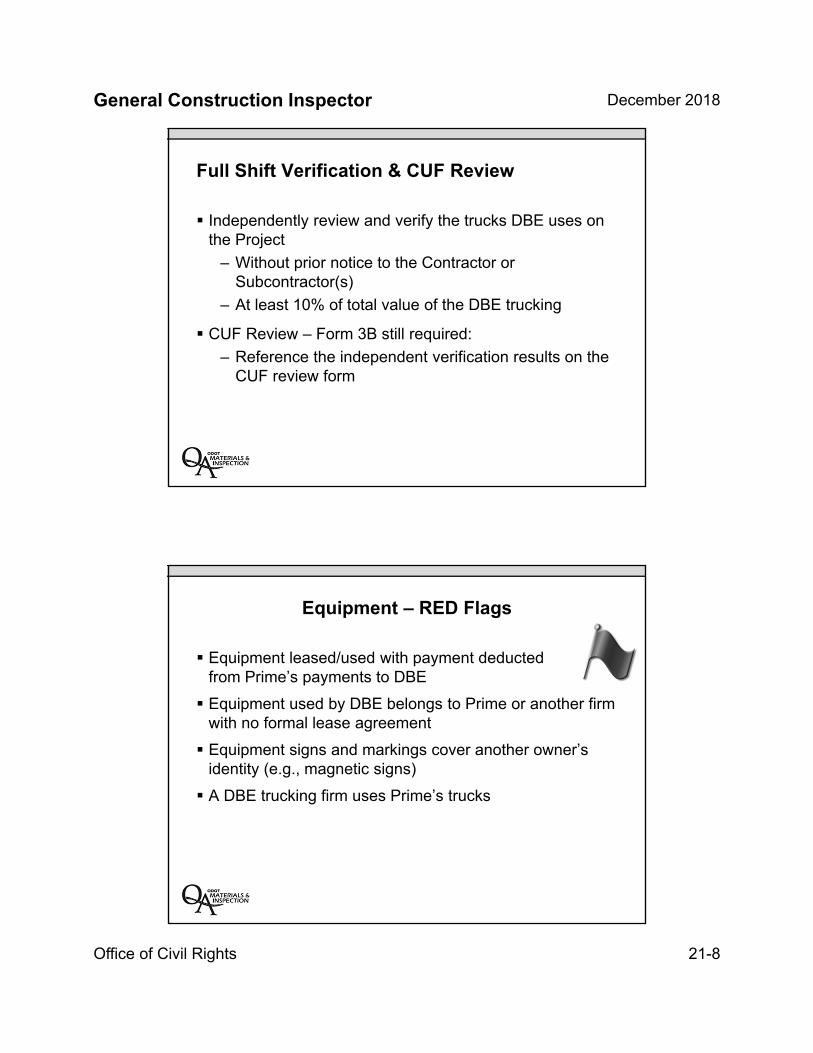
General Construction Inspector December 2018
Office of Civil Rights 21-8
Full Shift Verification & CUF Review
Independently review and verify the trucks DBE uses on the Project
– Without prior notice to the Contractor or Subcontractor(s)
– At least 10% of total value of the DBE trucking
CUF Review – Form 3B still required:
– Reference the independent verification results on the CUF review form
Equipment – RED Flags
Equipment leased/used with payment deducted from Prime’s payments to DBE
Equipment used by DBE belongs to Prime or another firm with no formal lease agreement
Equipment signs and markings cover another owner’s identity (e.g., magnetic signs)
A DBE trucking firm uses Prime’s trucks
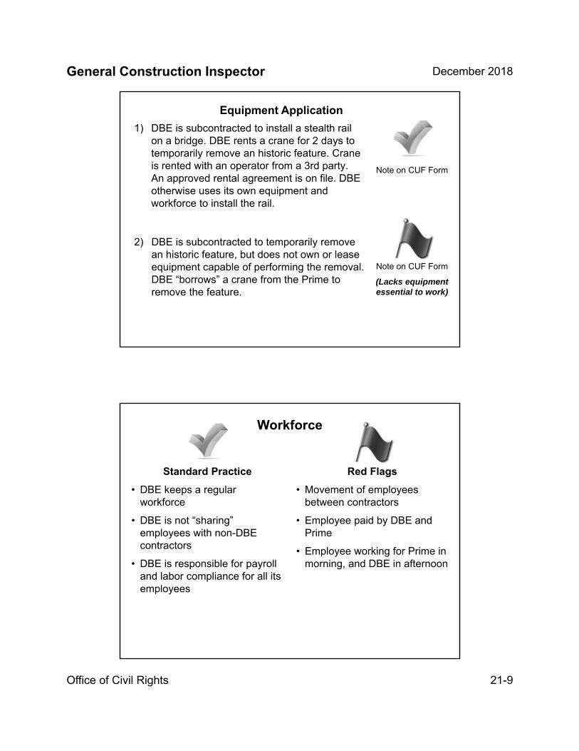
General Construction Inspector December 2018
Office of Civil Rights 21-9
1) DBE is subcontracted to install a stealth rail on a bridge. DBE rents a crane for 2 days to temporarily remove an historic feature. Crane is rented with an operator from a 3rd party. An approved rental agreement is on file. DBE otherwise uses its own equipment and workforce to install the rail.
2) DBE is subcontracted to temporarily remove an historic feature, but does not own or lease equipment capable of performing the removal. DBE “borrows” a crane from the Prime to remove the feature.
Note on CUF Form
(Lacks equipment essential to work)
Equipment Application
Note on CUF Form
Workforce
Standard Practice
• DBE keeps a regular workforce
• DBE is not “sharing” employees with non-DBE contractors
• DBE is responsible for payroll and labor compliance for all its employees
Red Flags
• Movement of employees between contractors
• Employee paid by DBE and Prime
• Employee working for Prime in morning, and DBE in afternoon
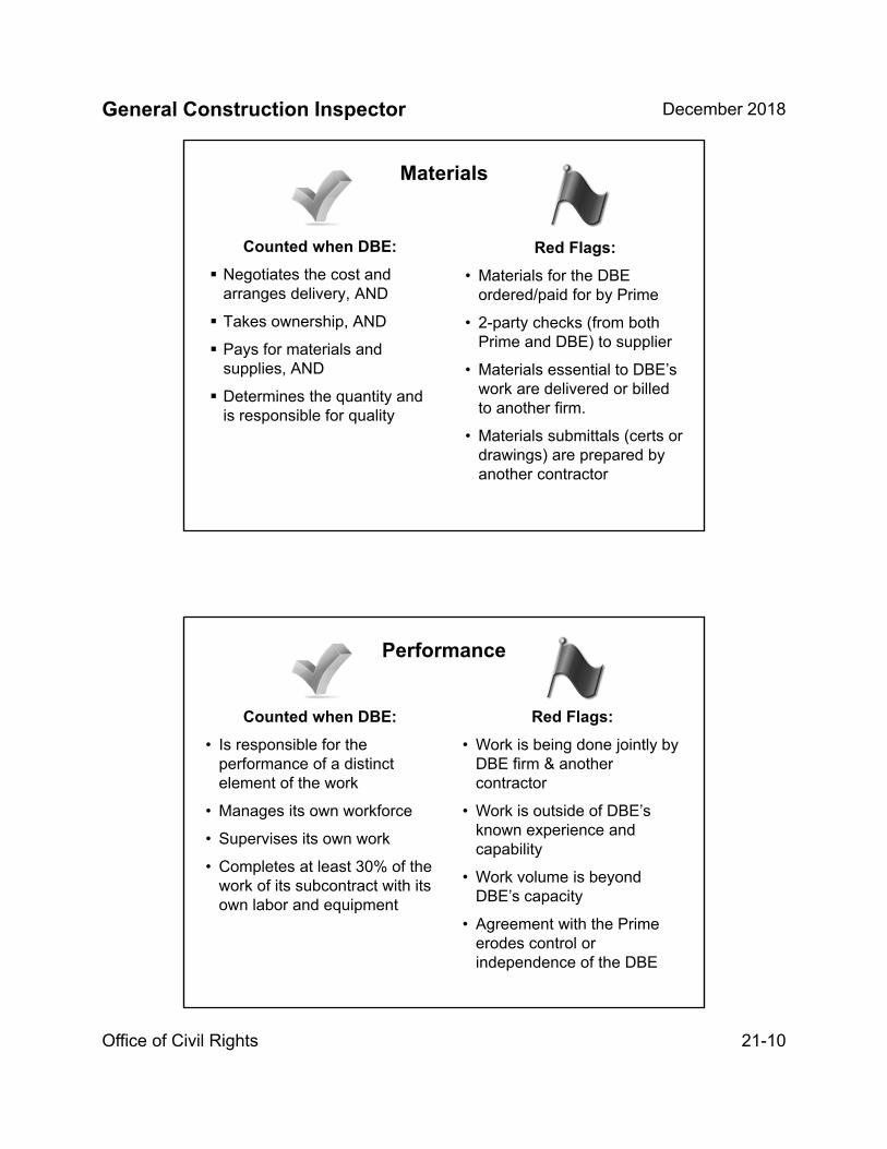
General Construction Inspector December 2018
Office of Civil Rights 21-10
Counted when DBE:
Negotiates the cost and arranges delivery, AND
Takes ownership, AND
Pays for materials and supplies, AND
Determines the quantity and is responsible for quality
Materials
Red Flags:
• Materials for the DBE ordered/paid for by Prime
• 2-party checks (from both Prime and DBE) to supplier
• Materials essential to DBE’s work are delivered or billed to another firm.
• Materials submittals (certs or drawings) are prepared by another contractor
Performance
Counted when DBE:
• Is responsible for the performance of a distinct element of the work
• Manages its own workforce
• Supervises its own work
• Completes at least 30% of the work of its subcontract with its own labor and equipment
Red Flags:
• Work is being done jointly by DBE firm & another contractor
• Work is outside of DBE’s known experience and capability
• Work volume is beyond DBE’s capacity
• Agreement with the Prime erodes control or independence of the DBE

General Construction Inspector December 2018
Office of Civil Rights 21-11
Inspector’s Role: Observations and Daily Reports
Keep accurate records of equipment used
Keep accurate records of crews working that day
Keep accurate records of whether the DBE is performing work with its own labor/equipment
Keep accurate records and watch out for workforce overlap between DBE/Prime/other contractors
Information noted on the Inspector’s Daily Reports may help you when completing the CUF Review Form 3B.
Addressing Red Flags
Not every red flag means DBE fraud, but every red flagyou observe should be reported:
• On the CUF Review Form 3B (734-2165) and
• To the Project Manager for review and follow-up with the FC
• Contact the OCR FC for technical assistance
See the DBE Work Plan Proposal Form 3A (734-2165A) to identify how DBE said it would perform its work. Note discrepancies!
=

General Construction Inspector December 2018
Office of Civil Rights 21-12
Give Details:- What did you see?- How do you know?- Who told you?
Start when DBE mobilizesonto the job.
Compare with Form 3A –are there any changes?
DBE CUF (Form 3B)
Check/ComparePayrolls and note
the datesthat you checked.
CUF Reviewer signs and notes the datesof the Daily Reports or other documents
(e.g., delivery tickets) that show the DBE
was on site or performed the work.
Project Manager mustsign off on the review.
State here whether DBE performed a
CUF:
“In Compliance” or
“Not in Compliance”

General Construction Inspector December 2018
Office of Civil Rights 21-13
Who and When – CUF Review Process
PM designated staff (usually the Project Inspector) must perform a CUF review of each DBE working on the Project
PM reviews and approves (comments, recommendations, findings)
Field Coordinator review and provides comments, concurrence
Office of Civil Rights (OCR) enters CUF information into database
PM consults with FC or OCR on any required corrective action
TAKEAWAY: A DBE does NOT perform a CUF if……it is merely an extra participant in a transaction,
contract, or project through which funds are passed to obtain the appearance of DBE participation.
Reporting
DBE regulations require ODOT to collect and monitor payment data for all subcontractors.
ODOT is required to report DBE/MWESB utilization and payment data to:
» FHWA
» Governor’s Office
» Legislature
Note: If there is no compliant CUF record or payment data, we are not allowed to report the DBE payments to FHWA!
General Construction Inspector December 2018
Office of Civil Rights 21-14
Equal Employment Opportunity (EEO) Program
Ensures equal employment opportunity to all individuals regardless of:
Race
Religion
Sex
Color
National origin
Age
Disability
Sexual Orientation
Gender Identity
EEO Program – Posting RequirementsEqual Employment Opportunity is THE LAW
This poster is available in both English and Spanish versions.
Poster needs to be up at the job site accessible to employees.
Inspectors should routinely check the poster is up at the beginning of projects.
Contained in and applies to all federal-aid contracts and subcontracts valued $10,000 or more.
General Construction Inspector December 2018
Office of Civil Rights 21-15
Americans with Disabilities Act (ADA)
The ADA is a federal law that applies to all projects, regardless of funding source.
All ODOT new facilities are built to current standards or guidance. Alterations to existing facilities trigger specific responsibilities.
All ADA requests or complaints need to be forwarded to OCR. ODOT is required to document all ADA requests and complaints and how they are resolved.
Title VI
No Person in the United States shall, on the grounds of race, color, or national origin, be excluded from participation in,
be denied the benefits of, or be subjected to discrimination in any program or activity receiving federal financial assistance.
Title VI applies to all programs and activities of Federal-aid recipients, sub recipients, and contractors
whether those programs and activities are federally funded or not.
Impact on project management and construction staff
Project Managers have 72 hours to address a complaint from when the complaint is received.

General Construction Inspector December 2018
Office of Civil Rights 21-16
OJT/Apprenticeship Program Purpose
To ensure skilled workers are trained and available by offering training in the highway construction trades
Use affirmative actions to recruit from a diverse pool of applicants including minorities and women
Apprentices are often brand new to construction trades.
Know who the project apprentices are and what trade they are registered under (can only be one).
If your project has OJT/Apprenticeship(A federally required program that may be required on state funded projects)
Number of hours is included in the training special provisions
Number of hours is a bid item (ROA = $20/hour)
Contractor is to submit a Training Program at the pre-construction meeting, indicating how they intend to fill the requirement.
– Training can be subcontracted
PM’s office forwards Training Program and Apprentice/Trainee Approval Requests to Civil Rights FC for approval
Inspectors need to know who the trainees/apprentices are and type of work they are performing
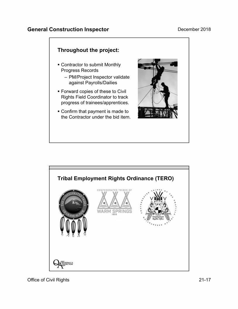
General Construction Inspector December 2018
Office of Civil Rights 21-17
Throughout the project:
Contractor to submit Monthly Progress Records
– PM/Project Inspector validate against Payrolls/Dailies
Forward copies of these to Civil Rights Field Coordinator to track progress of trainees/apprentices.
Confirm that payment is made to the Contractor under the bid item.
Tribal Employment Rights Ordinance (TERO)

General Construction Inspector December 2018
Office of Civil Rights 21-18
Key Inspection Points
Fill out CUF reports when DBE is on site
Complete necessary DBE trucking verifications
Pay attention to trainees and apprentices
Keep accurate records of sub equipment and operators
Pay attention to DBE activities and coordination
Contact Civil Rights if any questions arise
Make sure proper postings are on site
Unit 21 Review:
Role of inspector for Office of Civil Rights programs
Aspirational targets and contract goals
Commercially useful function (CUF) criteria
DBE trucking
EEO and Workforce
INSERT TAB
Unit 22
Construction Materials
General Construction Inspector December 2018
Materials 22-1
Unit 22Construction Materials
Unit 22 Objectives
Provide an understanding of basic material properties
Compaction
Moisture/density relationship of soils and aggregate
Specific gravity
Gradation (sieve analysis)
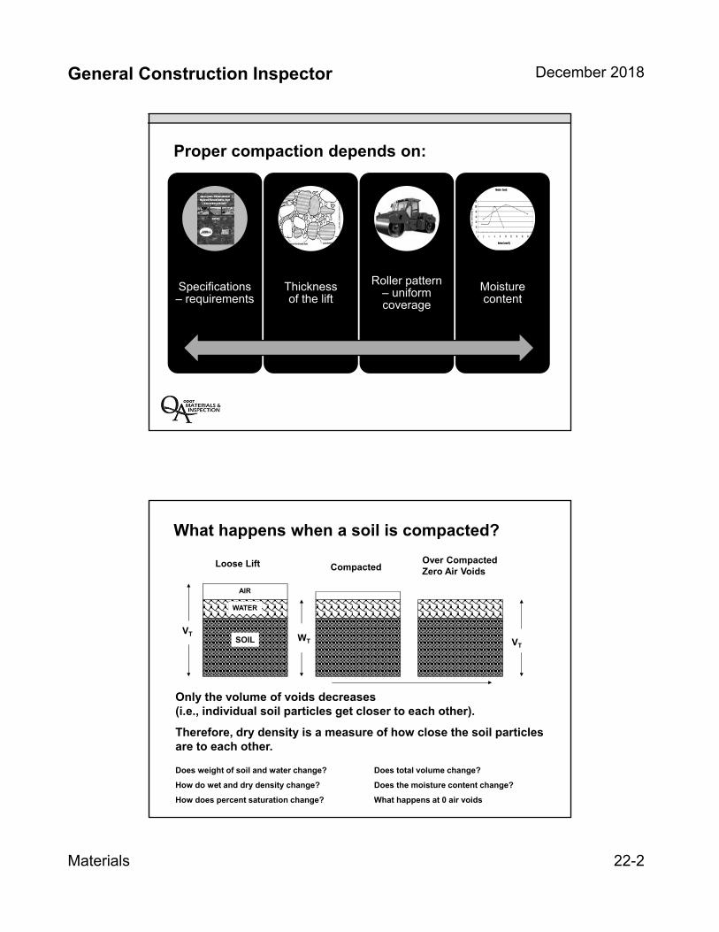
General Construction Inspector December 2018
Materials 22-2
Proper compaction depends on:
Specifications – requirements
Thickness of the lift
Roller pattern – uniform coverage
Moisture content
What happens when a soil is compacted?
Loose Lift CompactedOver Compacted Zero Air Voids
VT
VT WT
Increasing Energy
Only the volume of voids decreases (i.e., individual soil particles get closer to each other).
Therefore, dry density is a measure of how close the soil particles are to each other.
Does weight of soil and water change? Does total volume change?
How do wet and dry density change? Does the moisture content change?
How does percent saturation change? What happens at 0 air voids
WATER
AIR
SOIL
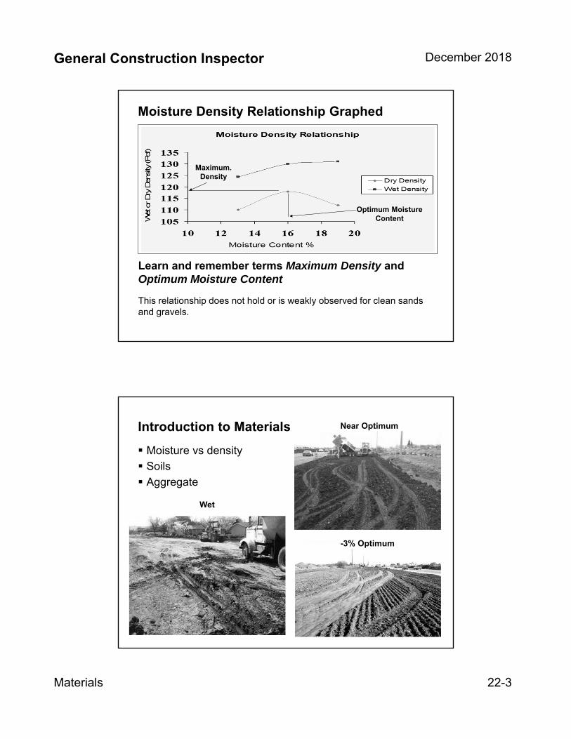
General Construction Inspector December 2018
Materials 22-3
Moisture Density Relationship Graphed
Learn and remember terms Maximum Density and Optimum Moisture Content
This relationship does not hold or is weakly observed for clean sands and gravels.
Optimum Moisture Content
Maximum. Density
Introduction to Materials
Moisture vs density
Soils
Aggregate
Near Optimum
-3% Optimum
Wet
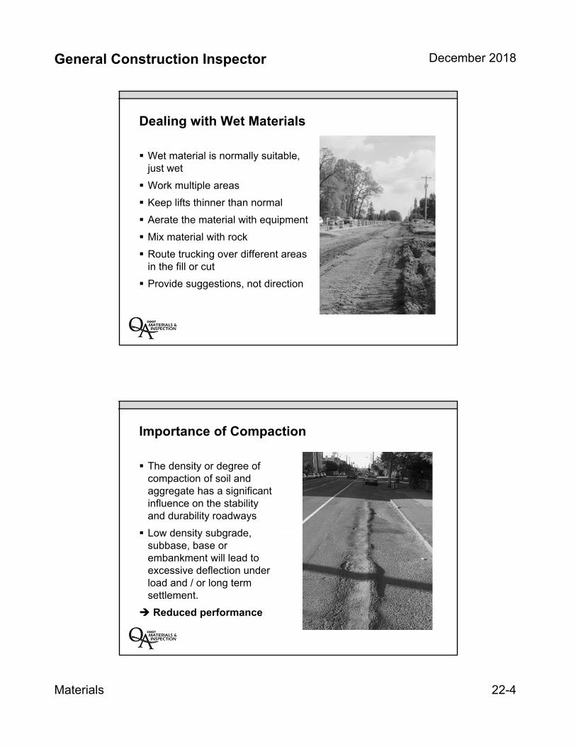
General Construction Inspector December 2018
Materials 22-4
Dealing with Wet Materials
Wet material is normally suitable, just wet
Work multiple areas
Keep lifts thinner than normal
Aerate the material with equipment
Mix material with rock
Route trucking over different areas in the fill or cut
Provide suggestions, not direction
Importance of Compaction
The density or degree of compaction of soil and aggregate has a significant influence on the stability and durability roadways
Low density subgrade, subbase, base or embankment will lead to excessive deflection under load and / or long term settlement.
Reduced performance

General Construction Inspector December 2018
Materials 22-5
Performing Compaction Testing
Two Test Methods
Deflection TestingODOT TM158
Nuclear Density Testing
– AASHTO T310
– ODOT TM8
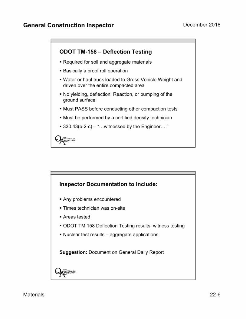
General Construction Inspector December 2018
Materials 22-6
ODOT TM-158 – Deflection Testing
Required for soil and aggregate materials
Basically a proof roll operation
Water or haul truck loaded to Gross Vehicle Weight and driven over the entire compacted area
No yielding, deflection. Reaction, or pumping of the ground surface
Must PASS before conducting other compaction tests
Must be performed by a certified density technician
330.43(b-2-c) – “…witnessed by the Engineer….”
Inspector Documentation to Include:
Any problems encountered
Times technician was on-site
Areas tested
ODOT TM 158 Deflection Testing results; witness testing
Nuclear test results – aggregate applications
Suggestion: Document on General Daily Report
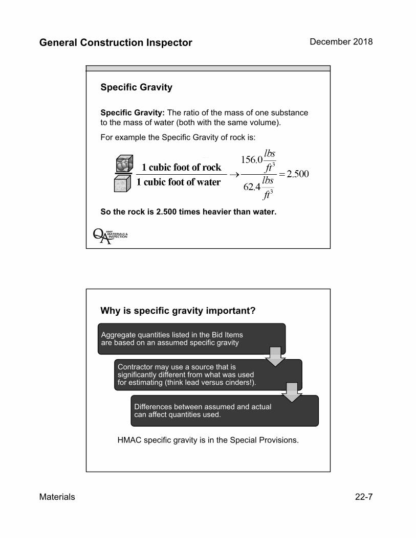
General Construction Inspector December 2018
Materials 22-7
Specific Gravity
Specific Gravity: The ratio of the mass of one substance to the mass of water (both with the same volume).
For example the Specific Gravity of rock is:
So the rock is 2.500 times heavier than water.
Why is specific gravity important?
HMAC specific gravity is in the Special Provisions.
Aggregate quantities listed in the Bid Items are based on an assumed specific gravity
Contractor may use a source that is significantly different from what was used for estimating (think lead versus cinders!).
Differences between assumed and actual can affect quantities used.
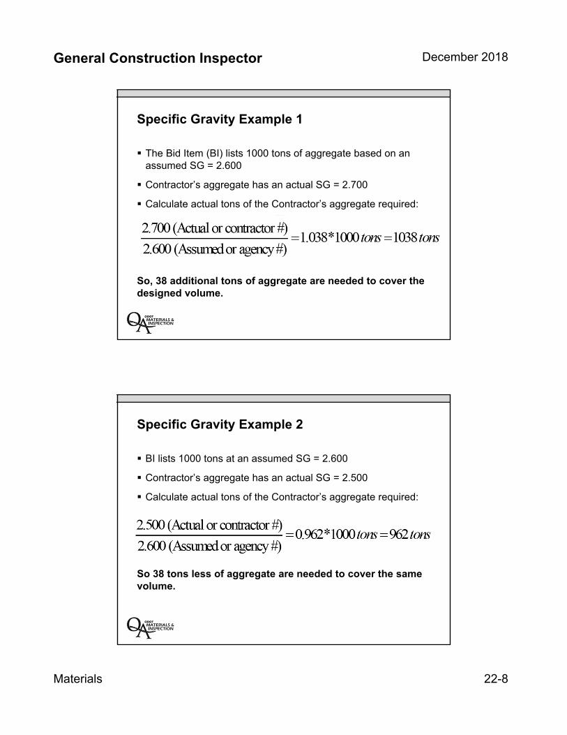
General Construction Inspector December 2018
Materials 22-8
Specific Gravity Example 1
The Bid Item (BI) lists 1000 tons of aggregate based on an assumed SG = 2.600
Contractor’s aggregate has an actual SG = 2.700
Calculate actual tons of the Contractor’s aggregate required:
So, 38 additional tons of aggregate are needed to cover the designed volume.
Specific Gravity Example 2
BI lists 1000 tons at an assumed SG = 2.600
Contractor’s aggregate has an actual SG = 2.500
Calculate actual tons of the Contractor’s aggregate required:
So 38 tons less of aggregate are needed to cover the same volume.

General Construction Inspector December 2018
Materials 22-9
Gradation of Materials
Gradation of Materials (Sieve Analysis)
Gradation determined by sieve analysis
Reveals the size makeup of materials from largest to smallest
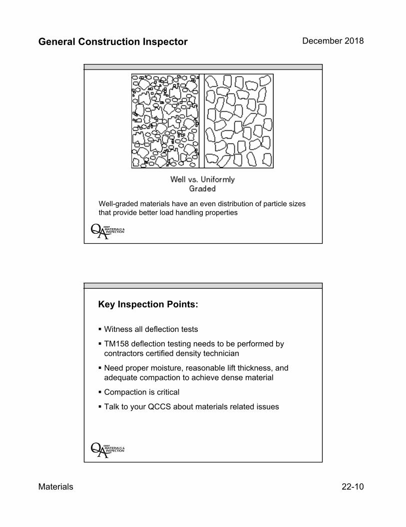
General Construction Inspector December 2018
Materials 22-10
Well-graded materials have an even distribution of particle sizes that provide better load handling properties
Key Inspection Points:
Witness all deflection tests
TM158 deflection testing needs to be performed by contractors certified density technician
Need proper moisture, reasonable lift thickness, and adequate compaction to achieve dense material
Compaction is critical
Talk to your QCCS about materials related issues
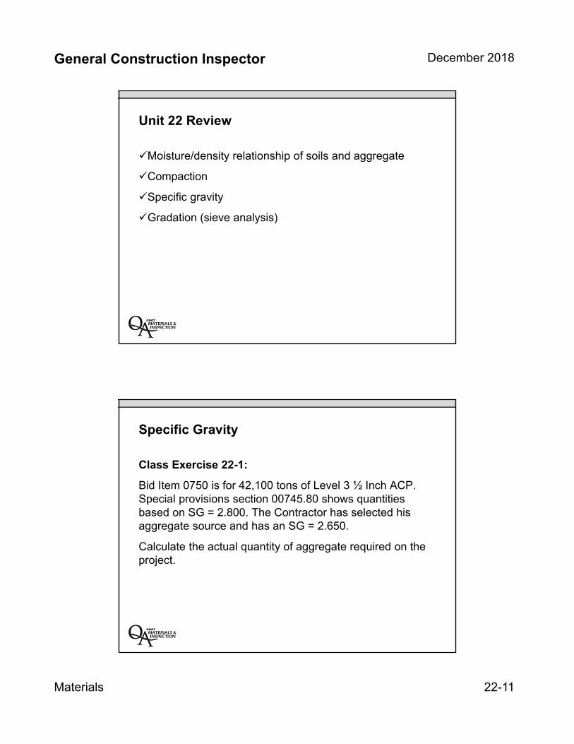
General Construction Inspector December 2018
Materials 22-11
Unit 22 Review
Moisture/density relationship of soils and aggregate
Compaction
Specific gravity
Gradation (sieve analysis)
Specific Gravity
Class Exercise 22-1:
Bid Item 0750 is for 42,100 tons of Level 3 ½ Inch ACP. Special provisions section 00745.80 shows quantities based on SG = 2.800. The Contractor has selected his aggregate source and has an SG = 2.650.
Calculate the actual quantity of aggregate required on the project.

INSERT TAB
Unit 23 Dailies

1
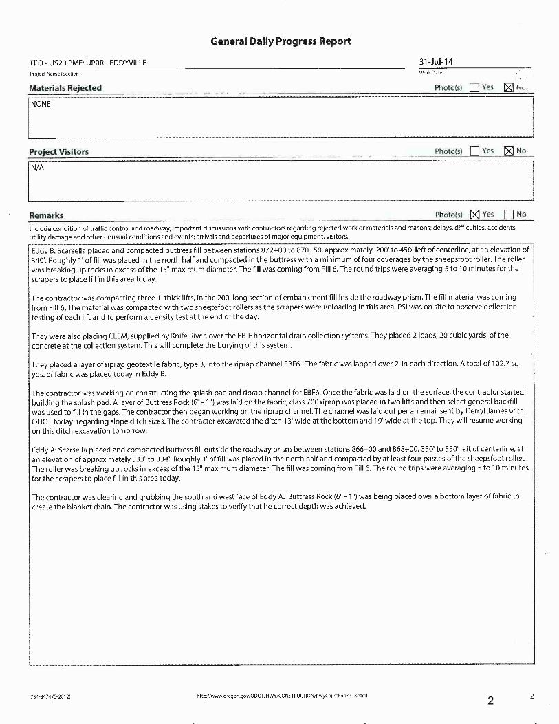
2
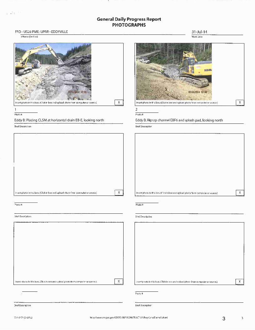
3

4
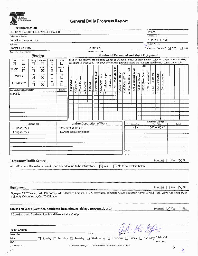
5

6
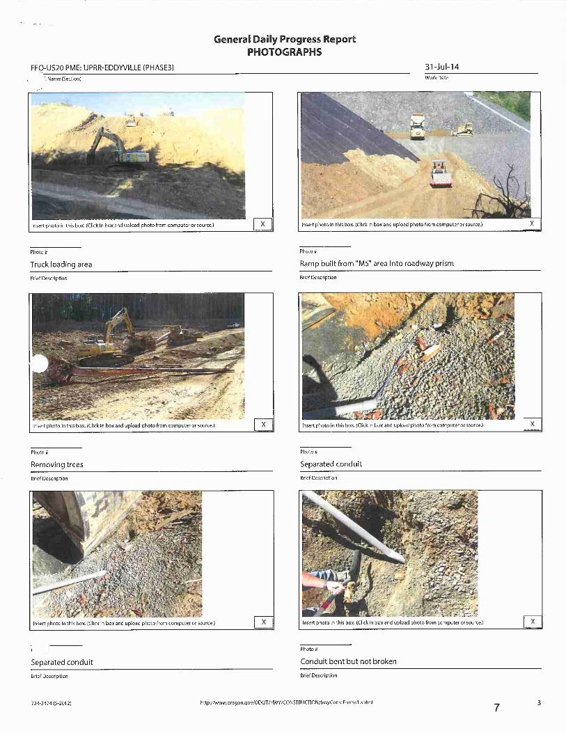
7

8
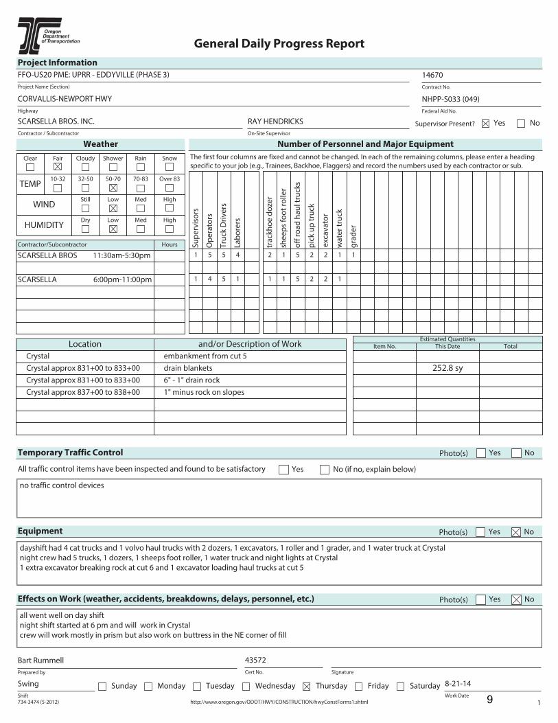
734-3474 (5-2012) http://www.oregon.gov/ODOT/HWY/CONSTRUCTION/hwyConstForms1.shtml 1
General Daily Progress Report
Project Information
Project Name (Section)
FFO-US20 PME: UPRR - EDDYVILLE (PHASE 3)
Contract No.
14670
Highway
CORVALLIS-NEWPORT HWY
Federal Aid No.
NHPP-S033 (049)
Contractor / Subcontractor
SCARSELLA BROS. INC.
On-Site Supervisor
RAY HENDRICKS Supervisor Present? NoYes
Weather Number of Personnel and Major Equipment
Clear Fair Cloudy Shower Rain Snow
TEMP10-32 32-50 50-70 70-83 Over 83
WINDStill Low Med High
HUMIDITYDry Low Med High
Contractor/Subcontractor Hours
SCARSELLA BROS 11:30am-5:30pm
SCARSELLA 6:00pm-11:00pm
The first four columns are fixed and cannot be changed. In each of the remaining columns, please enter a heading
specific to your job (e.g., Trainees, Backhoe, Flaggers) and record the numbers used by each contractor or sub.
Su
pe
rvis
ors
Op
era
tors
Tru
ck D
riv
ers
La
bo
rers
1 5 5 4
1 4 5 1
tra
ckh
oe
do
zer
she
ep
s fo
ot
roll
er
off
ro
ad
ha
ul t
ruck
s
pic
k u
p t
ruck
exc
av
ato
r
2 1 5 2 2
1 1 5 2 2
wa
ter
tru
ck
gra
de
r
1 1
1
Location and/or Description of Work
Crystal embankment from cut 5
Crystal approx 831+00 to 833+00 drain blankets
Crystal approx 831+00 to 833+00 6" - 1" drain rock
Crystal approx 837+00 to 838+00 1" minus rock on slopes
Estimated QuantitiesItem No. This Date Total
252.8 sy
Temporary Traffic Control Photo(s) Yes No
All traffic control items have been inspected and found to be satisfactory Yes No (if no, explain below)
no traffic control devices
Equipment Photo(s) Yes No
dayshift had 4 cat trucks and 1 volvo haul trucks with 2 dozers, 1 excavators, 1 roller and 1 grader, and 1 water truck at Crystal
night crew had 5 trucks, 1 dozers, 1 sheeps foot roller, 1 water truck and night lights at Crystal
1 extra excavator breaking rock at cut 6 and 1 excavator loading haul trucks at cut 5
Effects on Work (weather, accidents, breakdowns, delays, personnel, etc.) Photo(s) Yes No
all went well on day shift
night shift started at 6 pm and will work in Crystal
crew will work mostly in prism but also work on buttress in the NE corner of fill
Prepared by
Bart Rummell
Cert No.
43572
Signature
Shift
Swing Sunday Monday Tuesday Wednesday Thursday Friday SaturdayWork Date
8-21-14
9

734-3474 (5-2012) http://www.oregon.gov/ODOT/HWY/CONSTRUCTION/hwyConstForms1.shtml 2
General Daily Progress Report
Project Name (Section)
FFO-US20 PME: UPRR - EDDYVILLE (PHASE 3)
Work Date
8-21-14
Materials Rejected Photo(s) Yes No
none
Project Visitors Photo(s) Yes No
none
Remarks Photo(s) Yes No
Include condition of traffic control and roadway; important discussions with contractors regarding rejected work or materials and reasons; delays, difficulties, accidents,
utility damage and other unusual conditions and events; arrivals and departures of major equipment, visitors.
10:00 am- Arrived at Crystal to help Kim/ODOT surveyor with the work in Crystal. Samone' and Andrea also present. 11:30 am- Took over inspection
duties for Bill R. See Bill's daily report for information. Volvo truck hauling 1" minus and 6"-1" drain rock for placement. 1:00 pm- Laborer's install drain
blankets on the NWesterly slope in the geogrid area approx. station 831+00 to 833+00 +/- and excavator places 6"-1" rock with blankets. 3:00 pm- PSI
takes tests at Crystal roadway prism for 364' - 365' elevation and crew is working on the 365' - 366' grade now. They also placed embankment in the
buttress approx. sta. 834+50 to 837+00 +/- and in the NE corner by the drainage ditch. 4:30 pm- Inspector had grade checker place grade stakes for the
12" lift for the night shift. Inspector talked with Ray/Scarsella about lift thickness and will get a better handle on it tonight. 5:15 pm- Crew is finished for
the day and crew bus is picking up workers. 6:00 pm- The night crew will work in Crystal hauling from cut 5 and start in the roadway prism continuing
with the day shifts lift. Crew is also filling the NE corner of the buttress back by the drainage ditch. 6:15 pm- First truck load arrives in Crystal. Ray will
start off with 4 haul trucks and add a fifth when the water truck driver is finished. Ray had talk with his dozer operator and the lift will match the grade
stakes set by the Dennis/Scarsella grade checker. 10:40 pm- Inspector leaves job site. Anthony will remain until shift ends. See his daily report for
information. Most of the embankment was in the roadway prism but a little on swing shift went into the buttress. PSI should test the roadway prism
before placing the next lift.
10
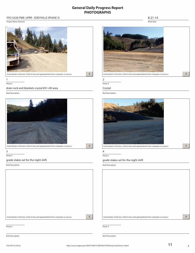
734-3474 (5-2012) http://www.oregon.gov/ODOT/HWY/CONSTRUCTION/hwyConstForms1.shtml 3
Work Date
8-21-14Project Name (Section)
FFO-US20 PME: UPRR - EDDYVILLE (PHASE 3)
General Daily Progress Report
PHOTOGRAPHS
Insert photo in this box. (Click in box and upload photo from computer or source.)
Photo #
1
Brief Description
drain rock and blankets crystal 831+00 area
X Insert photo in this box. (Click in box and upload photo from computer or source.)
Photo #
2
Brief Description
Crystal
X
Insert photo in this box. (Click in box and upload photo from computer or source.)
Photo #
3
Brief Description
grade stakes set for the night shift
X Insert photo in this box. (Click in box and upload photo from computer or source.)
Photo #
4
Brief Description
grade stakes set for the night shift
X
Insert photo in this box. (Click in box and upload photo from computer or source.)
Photo #
Brief Description
X Insert photo in this box. (Click in box and upload photo from computer or source.)
Photo #
Brief Description
X
11

12
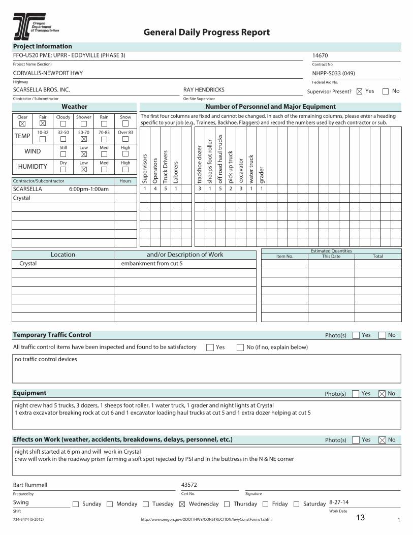
734-3474 (5-2012) http://www.oregon.gov/ODOT/HWY/CONSTRUCTION/hwyConstForms1.shtml 1
General Daily Progress Report
Project Information
Project Name (Section)
FFO-US20 PME: UPRR - EDDYVILLE (PHASE 3)
Contract No.
14670
Highway
CORVALLIS-NEWPORT HWY
Federal Aid No.
NHPP-S033 (049)
Contractor / Subcontractor
SCARSELLA BROS. INC.
On-Site Supervisor
RAY HENDRICKS Supervisor Present? NoYes
Weather Number of Personnel and Major Equipment
Clear Fair Cloudy Shower Rain Snow
TEMP10-32 32-50 50-70 70-83 Over 83
WINDStill Low Med High
HUMIDITYDry Low Med High
Contractor/Subcontractor Hours
SCARSELLA 6:00pm-1:00am
Crystal
The first four columns are fixed and cannot be changed. In each of the remaining columns, please enter a heading
specific to your job (e.g., Trainees, Backhoe, Flaggers) and record the numbers used by each contractor or sub.
Su
pe
rvis
ors
Op
era
tors
Tru
ck D
riv
ers
La
bo
rers
1 4 5 1
tra
ckh
oe
do
zer
she
ep
s fo
ot
roll
er
off
ro
ad
ha
ul t
ruck
s
pic
k u
p t
ruck
exc
av
ato
r
3 1 5 2 3
wa
ter
tru
ck
gra
de
r
1 1
Location and/or Description of Work
Crystal embankment from cut 5
Estimated QuantitiesItem No. This Date Total
Temporary Traffic Control Photo(s) Yes No
All traffic control items have been inspected and found to be satisfactory Yes No (if no, explain below)
no traffic control devices
Equipment Photo(s) Yes No
night crew had 5 trucks, 3 dozers, 1 sheeps foot roller, 1 water truck, 1 grader and night lights at Crystal
1 extra excavator breaking rock at cut 6 and 1 excavator loading haul trucks at cut 5 and 1 extra dozer helping at cut 5
Effects on Work (weather, accidents, breakdowns, delays, personnel, etc.) Photo(s) Yes No
night shift started at 6 pm and will work in Crystal
crew will work in the roadway prism farming a soft spot rejected by PSI and in the buttress in the N & NE corner
Prepared by
Bart Rummell
Cert No.
43572
Signature
Shift
Swing Sunday Monday Tuesday Wednesday Thursday Friday SaturdayWork Date
8-27-14
13
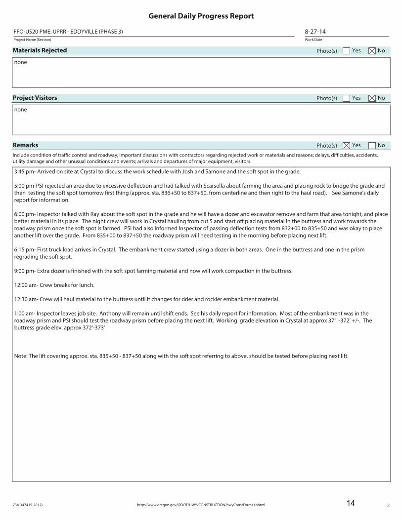
734-3474 (5-2012) http://www.oregon.gov/ODOT/HWY/CONSTRUCTION/hwyConstForms1.shtml 2
General Daily Progress Report
Project Name (Section)
FFO-US20 PME: UPRR - EDDYVILLE (PHASE 3)
Work Date
8-27-14
Materials Rejected Photo(s) Yes No
none
Project Visitors Photo(s) Yes No
none
Remarks Photo(s) Yes No
Include condition of traffic control and roadway; important discussions with contractors regarding rejected work or materials and reasons; delays, difficulties, accidents,
utility damage and other unusual conditions and events; arrivals and departures of major equipment, visitors.
3:45 pm- Arrived on site at Crystal to discuss the work schedule with Josh and Samone and the soft spot in the grade.
5:00 pm-PSI rejected an area due to excessive deflection and had talked with Scarsella about farming the area and placing rock to bridge the grade and
then testing the soft spot tomorrow first thing (approx. sta. 836+50 to 837+50, from centerline and then right to the haul road). See Samone's daily
report for information.
6:00 pm- Inspector talked with Ray about the soft spot in the grade and he will have a dozer and excavator remove and farm that area tonight, and place
better material in its place. The night crew will work in Crystal hauling from cut 5 and start off placing material in the buttress and work towards the
roadway prism once the soft spot is farmed. PSI had also informed Inspector of passing deflection tests from 832+00 to 835+50 and was okay to place
another lift over the grade. From 835+00 to 837+50 the roadway prism will need testing in the morning before placing next lift.
6:15 pm- First truck load arrives in Crystal. The embankment crew started using a dozer in both areas. One in the buttress and one in the prism
regrading the soft spot.
9:00 pm- Extra dozer is finished with the soft spot farming material and now will work compaction in the buttress.
12:00 am- Crew breaks for lunch.
12:30 am- Crew will haul material to the buttress until it changes for drier and rockier embankment material.
1:00 am- Inspector leaves job site. Anthony will remain until shift ends. See his daily report for information. Most of the embankment was in the
roadway prism and PSI should test the roadway prism before placing the next lift. Working grade elevation in Crystal at approx 371'-372' +/-. The
buttress grade elev. approx 372'-373'
Note: The lift covering approx. sta. 835+50 - 837+50 along with the soft spot referring to above, should be tested before placing next lift.
14
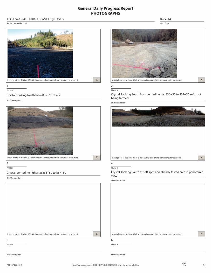
734-3474 (5-2012) http://www.oregon.gov/ODOT/HWY/CONSTRUCTION/hwyConstForms1.shtml 3
Work Date
8-27-14Project Name (Section)
FFO-US20 PME: UPRR - EDDYVILLE (PHASE 3)
General Daily Progress Report
PHOTOGRAPHS
Insert photo in this box. (Click in box and upload photo from computer or source.)
Photo #
1
Brief Description
Crystal: looking North from 835+50 rt side
X Insert photo in this box. (Click in box and upload photo from computer or source.)
Photo #
2
Brief Description
Crystal: looking South from centerline sta: 836+50 to 837+50 soft spot
being farmed
X
Insert photo in this box. (Click in box and upload photo from computer or source.)
Photo #
3
Brief Description
Crystal: centerline right sta: 836+50 to 837+50
X Insert photo in this box. (Click in box and upload photo from computer or source.)
Photo #
4
Brief Description
Crystal: looking South at soft spot and already tested area in panoramic
view
X
Insert photo in this box. (Click in box and upload photo from computer or source.)
Photo #
5
Brief Description
X Insert photo in this box. (Click in box and upload photo from computer or source.)
Photo #
6
Brief Description
X
15

16
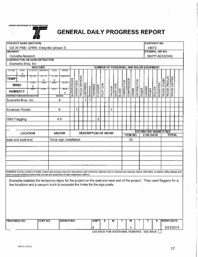
17
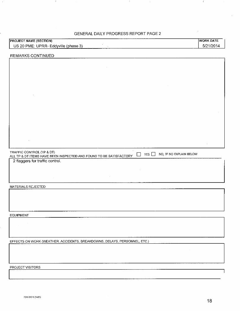
18
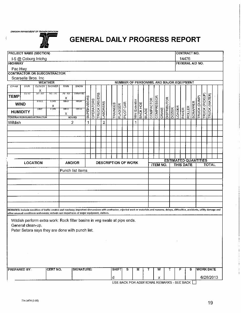
19
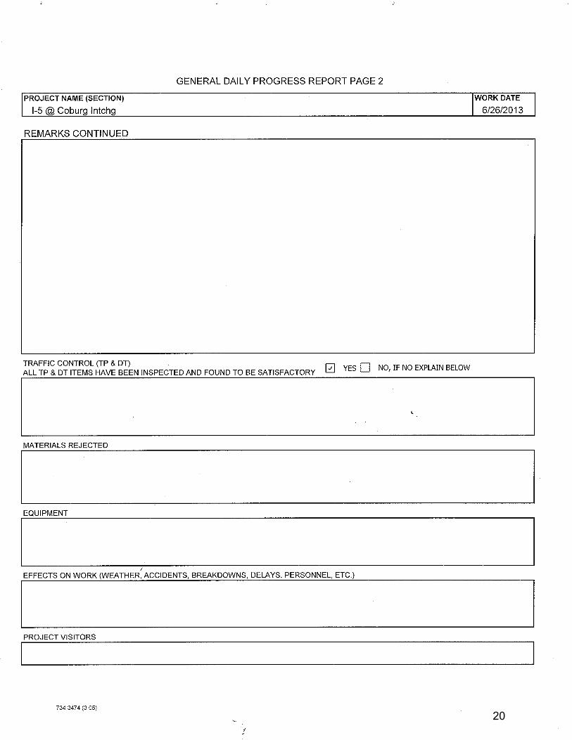
20
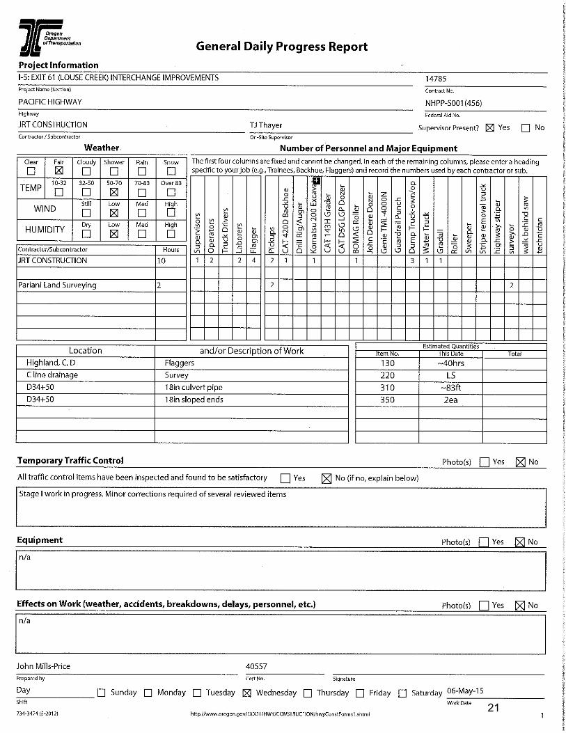
21
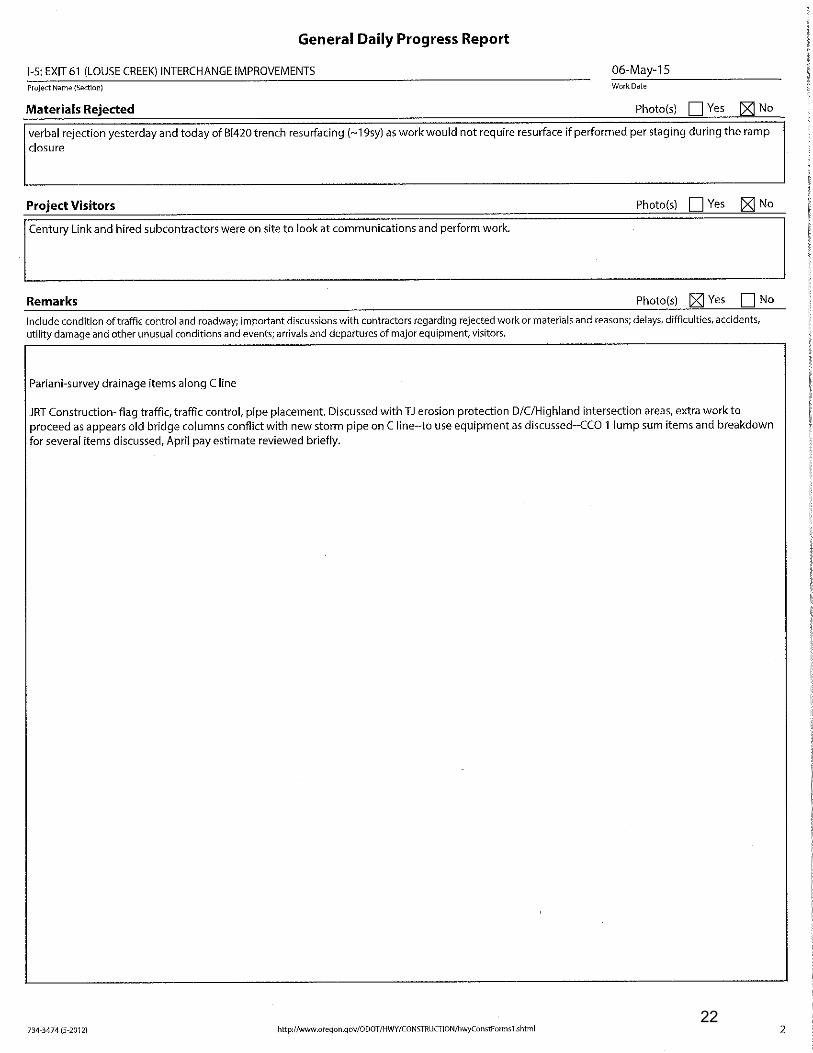
22
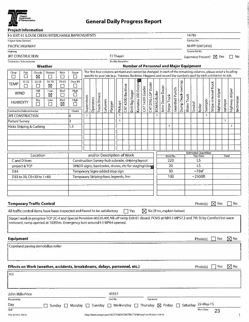
23
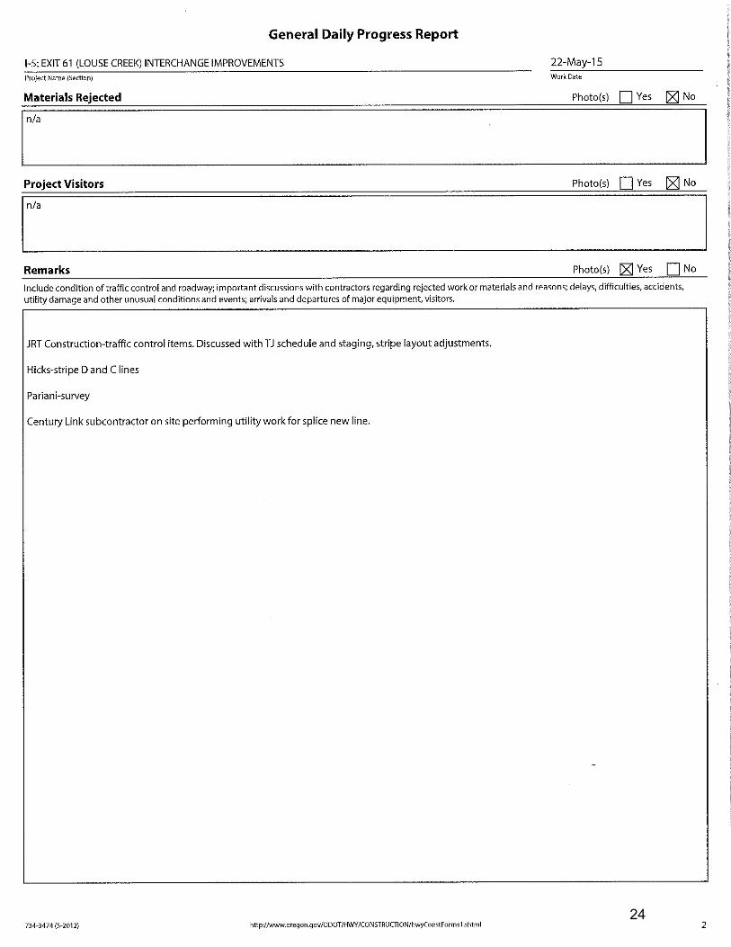
24

25

26
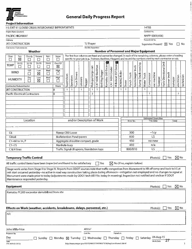
27
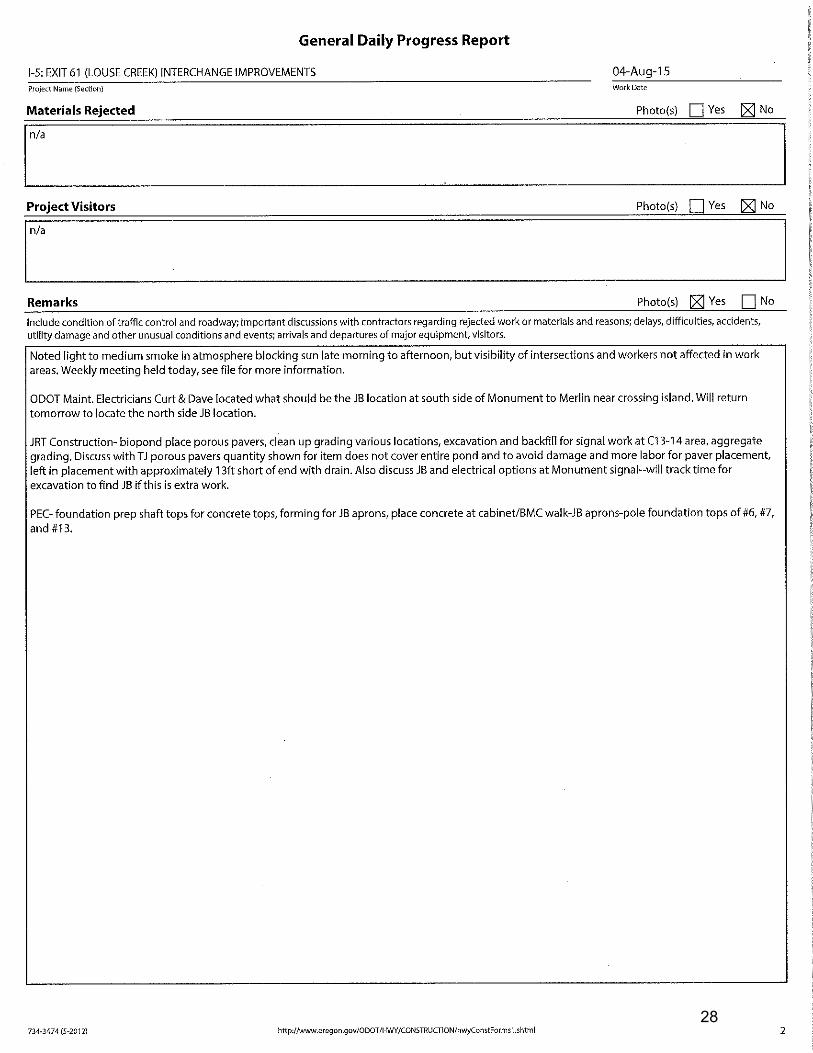
28

INSERT TAB
Unit 24 PCMS Handbook

Portable Changeable Message Sign Handbook
2nd Edition – September 2018
Technical Services Branch Traffic-Roadway Section
Traffic Standards and Asset Management Unit
Oregon PCMS Handbook Page i
September 2018 Title Page
Portable Changeable Message Sign Handbook2nd Edition – August 2018
Justin King, P.E.State Work Zone EngineerTraffic Standards & Asset Management [email protected]
Sarah McCrea, P.E.Work Zone Traffic AnalystTraffic Standards & Asset Management [email protected]
Oregon Department of TransportationTechnical Services BranchTraffic-Roadway Sectionhttps://www.oregon.gov/ODOT/Engineering/Pages/Work-Zone.aspx
Oregon PCMS Handbook Page ii
September 2018 Table of Contents
TABLE OF CONTENTS
INTRODUCTION .................................................................................1
WHEN TO USE A PCMS .....................................................................2
EQUIPMENT ........................................................................................3
PLACEMENT........................................................................................5 Site Selection ............................................................................................... 5 Sight Distance & Visibility.......................................................................... 9
MESSAGES.........................................................................................10 Display ....................................................................................................... 10 Symbols and Graphics ............................................................................... 11 Message Content........................................................................................ 11 Credibility .................................................................................................. 13 Standard Messages..................................................................................... 15 Non-Standard Messages............................................................................. 15 Message Exceptions................................................................................... 19 Speeds ........................................................................................................ 20 Speed Detection Feature on PCMS............................................................ 21 Locations and Distances............................................................................. 22 Times, Days and Dates............................................................................... 24 Security ...................................................................................................... 26 Standard Abbreviations.............................................................................. 26
REFERENCES ....................................................................................30
Oregon PCMS Handbook Page iii
September 2018 Table of Contents
APPENDIX A – STANDARDIZED MESSAGES .............................32 Advance Notification ................................................................................. 33 Detours and Road Closures........................................................................ 34 Flagging and Traffic Signals...................................................................... 35 Lane Closures or Traffic Pattern Changes ................................................. 36 Bridge or Tunnel Work.............................................................................. 37 Shoulder or Median Work.......................................................................... 38 Road Surface Conditions (Rough, debris, oil, fresh paint, etc.)................. 39 Trucks ........................................................................................................ 40 Slow Moving Operations ........................................................................... 40 Motorcycles................................................................................................ 41 Rolling Slowdowns.................................................................................... 41 Snow and Ice – Warnings .......................................................................... 41 Snow and Ice – Regulatory Conditions...................................................... 42 Dust, Fog, Fire, or Smoke .......................................................................... 43 Crash, Stalled Vehicle, or Other Incidents................................................. 44 Other General Warnings ............................................................................ 45
APPENDIX B – SETUP CHECKLIST...............................................46 Need ........................................................................................................... 46 Placement................................................................................................... 46 Message...................................................................................................... 46
PCMS MESSAGE WORKSHEET......................................................47

Oregon PCMS Handbook Page 1
September 2018 Introduction
INTRODUCTION The purpose of this handbook is to provide basic information for the safe and effective use of a Portable Changeable Message Sign (PCMS). This handbook will illustrate proper setup and delineation for a PCMS, as well as provide users with a variety of example messages for a broad range of roadway activities.
A PCMS is a large electronic sign used to display programmable, dynamic messages to provide traffic with timely warnings, guidance, or notification of approaching roadway conditions.
Also known as a portable variable message sign (PVMS), this handbook may be used in Oregon for roadway maintenance activities, incident management, other short-term activities, and long-term construction projects on Oregon roadways.
National and Oregon state standards, policies, and specifications that apply to PCMS are found in the Manual on Uniform Traffic Control Devices (MUTCD) [1], the Oregon Standard Specifications for Construction [2], theOregon Temporary Traffic Control Handbook (OTTCH) [3], and ODOT Standard Drawing TM 800.
The contents of this handbook are based on guidance found in the following:
Manual on Uniform Traffic Control Devices (MUTCD) [1]FHWA’s Portable Changeable Message Sign Handbook [4]Oregon Temporary Traffic Control Handbook (OTTCH) [3]Texas Transportation Institute’s (TTI) Development of a Field Guide for Portable Changeable Message Sign Use in Work Zones [5]
Other available studies, guidelines, and research were also referenced in the compilation of this handbook. A complete list of referred works is available in the References section.
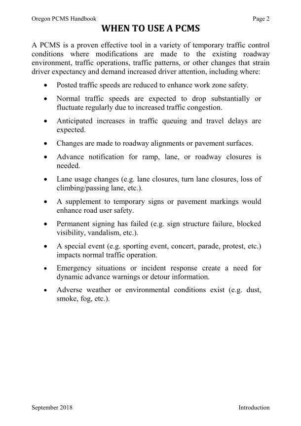
Oregon PCMS Handbook Page 2
September 2018 Introduction
WHEN TO USE A PCMS A PCMS is a proven effective tool in a variety of temporary traffic control conditions where modifications are made to the existing roadway environment, traffic operations, traffic patterns, or other changes that strain driver expectancy and demand increased driver attention, including where:
Posted traffic speeds are reduced to enhance work zone safety.
Normal traffic speeds are expected to drop substantially or fluctuate regularly due to increased traffic congestion.
Anticipated increases in traffic queuing and travel delays are expected.
Changes are made to roadway alignments or pavement surfaces.
Advance notification for ramp, lane, or roadway closures is needed.
Lane usage changes (e.g. lane closures, turn lane closures, loss of climbing/passing lane, etc.).
A supplement to temporary signs or pavement markings would enhance road user safety.
Permanent signing has failed (e.g. sign structure failure, blocked visibility, vandalism, etc.).
A special event (e.g. sporting event, concert, parade, protest, etc.)impacts normal traffic operation.
Emergency situations or incident response create a need fordynamic advance warnings or detour information.
Adverse weather or environmental conditions exist (e.g. dust, smoke, fog, etc.).
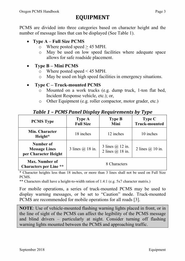
Oregon PCMS Handbook Page 3
September 2018 Equipment
EQUIPMENT PCMS are divided into three categories based on character height and the number of message lines that can be displayed (See Table 1).
Type A – Full Size PCMSo Where posted speed > 45 MPH.o May be used on low speed facilities where adequate space
allows for safe roadside placement.
Type B – Mini PCMSo Where posted speed < 45 MPH.o May be used on high speed facilities in emergency situations.
Type C – Truck-mounted PCMSo Mounted on a work trucks (e.g. dump truck, 1-ton flat bed,
Incident Response vehicle, etc.); or,o Other Equipment (e.g. roller compactor, motor grader, etc.)
Table 1 – PCMS Panel Display Requirements by Type
PCMS Type Type AFull Size
Type BMini
Type CTruck-mounted
Min. Character Height* 18 inches 12 inches 10 inches
Number of Message Lines
per Character Height3 lines @ 18 in. 3 lines @ 12 in.
2 lines @ 18 in. 2 lines @ 10 in.
Max. Number of Characters per Line ** 8 Characters
* Character heights less than 18 inches, or more than 3 lines shall not be used on Full SizePCMS.** Characters shall have a height-to-width ration of 1.4:1 (e.g. 5x7 character matrix.)
For mobile operations, a series of truck-mounted PCMS may be used to display warning messages, or be set to “Caution” mode. Truck-mounted PCMS are recommended for mobile operations for all roads [3].
NOTE: Use of vehicle-mounted flashing warning lights placed in front, or in the line of sight of the PCMS can affect the legibility of the PCMS message and blind drivers – particularly at night. Consider turning off flashing warning lights mounted between the PCMS and approaching traffic.
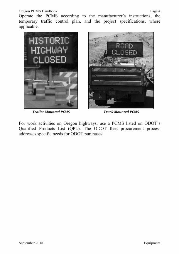
Oregon PCMS Handbook Page 4
September 2018 Equipment
Operate the PCMS according to the manufacturer’s instructions, the temporary traffic control plan, and the project specifications, where applicable.
For work activities on Oregon highways, use a PCMS listed on ODOT’s Qualified Products List (QPL). The ODOT fleet procurement process addresses specific needs for ODOT purchases.
Trailer Mounted PCMS Truck Mounted PCMS

Oregon PCMS Handbook Page 5
September 2018 Placement
PLACEMENT Locate and align the PCMS to provide maximum legibility and time for public traffic to interpret and respond appropriately to the message.
Site Selection Locate a suitable site for the PCMS and adjust for road conditions as follows:
1. Straight, flat, level sections of roadway where practical.2. Site should be safely accessible by maintenance/towing vehicle.3. PCMS unit should be visible from ½ mile in day and nighttime
conditions.4. PCMS message using 18 inch characters should be legible from 600
feet (min.) at night and 800 feet (min.) during daylight conditions.5. Mini or Truck-mounted PCMS should be legible from 650 ft (min.)
under daylight or nighttime conditions.
PCMS located near a pullout for accessibility
6. PCMS unit shall be located behind a traffic barrier or delineated using the PCMS Installation Detail on ODOT Standard Drawing TM800, or as shown in the OTTCH [3], Chapter 4.
Delineated PCMS using TM800 detail
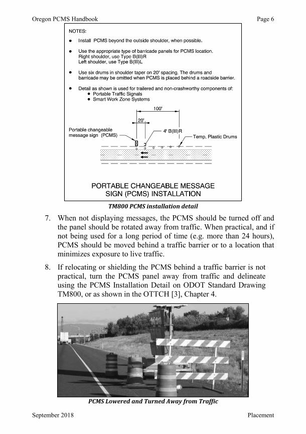
Oregon PCMS Handbook Page 6
September 2018 Placement
TM800 PCMS installation detail
7. When not displaying messages, the PCMS should be turned off and the panel should be rotated away from traffic. When practical, and if not being used for a long period of time (e.g. more than 24 hours), PCMS should be moved behind a traffic barrier or to a location that minimizes exposure to live traffic.
8. If relocating or shielding the PCMS behind a traffic barrier is not practical, turn the PCMS panel away from traffic and delineate using the PCMS Installation Detail on ODOT Standard Drawing TM800, or as shown in the OTTCH [3], Chapter 4.
PCMS Lowered and Turned Away from Traffic

Oregon PCMS Handbook Page 7
September 2018 Placement
9. For detours, locate PCMS far enough in advance of route decision points to allow road users to perform necessary lane changes or turns to access the alternate route.
10. PCMS should be located away from existing or temporary regulatory, guide, warning or other critical signs according to Table 2, below:
Table 2 – PCMS Spacing Table Roadway Type Posted Speed (mph) Spacing (ft)*
Freeways 1000Non-Freeway,
Rural Highway 700
Non-Freeway,High-Speed 45 – 55 500
Urban Arterials 30 – 40 350Urban, Low-Speed < 30 100
* Consider increased spacing on multi-lane roads.
11. Locate PCMS away from high driver workload areas (e.g. busy intersections, ramps, freeway decision points, etc. [6]). If ideal sites are limited, place PCMS as far into driver’s cone of vision, as practical, to optimize visibility of the messages.
High driver workload areas can affect PCMS visibility
PCMS too far beyond driver’s cone of vision
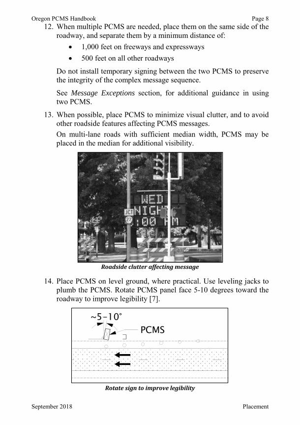
Oregon PCMS Handbook Page 8
September 2018 Placement
12. When multiple PCMS are needed, place them on the same side of the roadway, and separate them by a minimum distance of:
1,000 feet on freeways and expressways 500 feet on all other roadways
Do not install temporary signing between the two PCMS to preservethe integrity of the complex message sequence.
See Message Exceptions section, for additional guidance in using two PCMS.
13. When possible, place PCMS to minimize visual clutter, and to avoid other roadside features affecting PCMS messages. On multi-lane roads with sufficient median width, PCMS may be placed in the median for additional visibility.
Roadside clutter affecting message
14. Place PCMS on level ground, where practical. Use leveling jacks to plumb the PCMS. Rotate PCMS panel face 5-10 degrees toward the roadway to improve legibility [7].
Rotate sign to improve legibility

Oregon PCMS Handbook Page 9
September 2018 Placement
Sight Distance & Visibility Horizontal and vertical curves, foliage, buildings, or other roadside features may hide a PCMS. The PCMS may need to be located further from the decision point to give motorists enough time to read the messages.
NOTE: PCMS message using 18 inch characters should be legible from 600 feet (min.) at night and 800 feet (min.) during daylight conditions.
Mini or Truck-mounted PCMS should be legible from 650 ft (min.) under daylight or nighttime conditions.
When displaying messages, the bottom of the panel shall be a minimum of 7feet above the roadway in urban areas, and 5 feet above the roadway in rural areas, measured at the edge of the nearest traffic lane.
Proper height provides maximum message visibility After the PCMS has been positioned, with the panel at the proper height and rotated to face traffic, verify the PCMS is unobstructed and the messages can be read from the distances shown above.
Field verify PCMS visibility after installation
7 ft min

Oregon PCMS Handbook Page 10
September 2018 Messages
MESSAGES The primary purpose of a PCMS is to provide traffic with timely information to facilitate safe movement through the area or work zone.
Display A complete PCMS “Message” is made of two individual, alternating messages. Each individual message is known as a “Phase” or “Panel”.Each phase should be displayed for at least 2 seconds. Complex phases may take longer to process and understand [6]. The total display time for both phases should be no greater than 8 seconds.Drivers traveling at the posted speed should be able to read the entire message at least twice – allowing time to read the message, process it, and take an appropriate action.A PCMS message shall conform to the following:
A maximum of 3 lines per phase.A maximum of 8 characters per line.A maximum of 2 phases (panels) per complete message unless stated otherwise in Message Exceptions.
In developing a message for a PCMS, use the following best practices:Each phase contains an independent piece of information and can beunderstood on its own.Use all upper-case letters, and center justify each line.If using only one phase, display the phase continuously. Avoid flashing the same phase repeatedly.Do not use animation, rapid flashing, dissolving, exploding, horizontal or vertical scrolling, or other techniques for displaying phases.Requirements for character heights and number of message lines can be found in Table 1.Characters shall have a height-to-width ration of 1.4:1 (e.g. 5x7 character matrix).Spacing between characters in a word shall be 25% – 40% of thecharacter height. Spacing between words in a message shall be 75%– 100% of the character height. Spacing between lines shall be 50%– 75% of the character height.
Oregon PCMS Handbook Page 11
September 2018 Messages
A PCMS may be used to display arrows and chevrons to simulate a sequential arrow board. Do not combine arrows/chevrons and text on the same phase. Arrows and chevrons used on a PCMS must comply with the MUTCD.
Symbols and Graphics Messages shall be displayed in amber color (590 nanometers (nominal) wavelength) and use upper-case letters and numbers unless stated otherwise, below.
Newer PCMS technologies allow graphical displays that duplicate many standard signs or sign legends – including route shields and other common sign symbols with no apparent loss of resolution or recognition when compared to a static version of the same sign. PCMS having this ability are known as, “full matrix” signs, many of which have the ability to display messages/graphics in full color. See Table 2A-5 in the MUTCD for a list of common uses of sign color.
Route shields and common sign symbols (e.g. “Flagger Ahead” symbol) shall only be displayed if they can duplicate exactly the standard sign symbol in the correct color(s), as shown in the FHWA Standard Highway Signs (SHS) and ODOT Sign Policy and Guidelines. Information on displaying symbols on a PCMS is given in Chapter 2L of the MUTCD.
NOTE: A PCMS shall not display animation, rapid flashing, dissolving, exploding, scrolling, or other graphic elements that distracts road users.
Message Content PCMS shall only display traffic operational, regulatory, warning, and guidance information, and shall not display advertising messages on a PCMS or its supports. A PCMS should be used to supplement conventional signing and pavement markings, not substitute for them.
The message should be as brief as practical and should contain three thoughts – with each thought preferably shown on its own line:
1. The problem or situation that the road user will encounter.2. The location or distance to or the timing of occurrence.3. The recommended driver action.
For Oregon State highways, advance notification of extended road or lane closures shall be limited to two weeks (max.) before the closure takes place [6], unless otherwise shown in a Traffic Control Plan; or, as directed by an ODOT Region Traffic Engineer/Manager, ODOT Construction Project Manager, District Manager, or their representative.
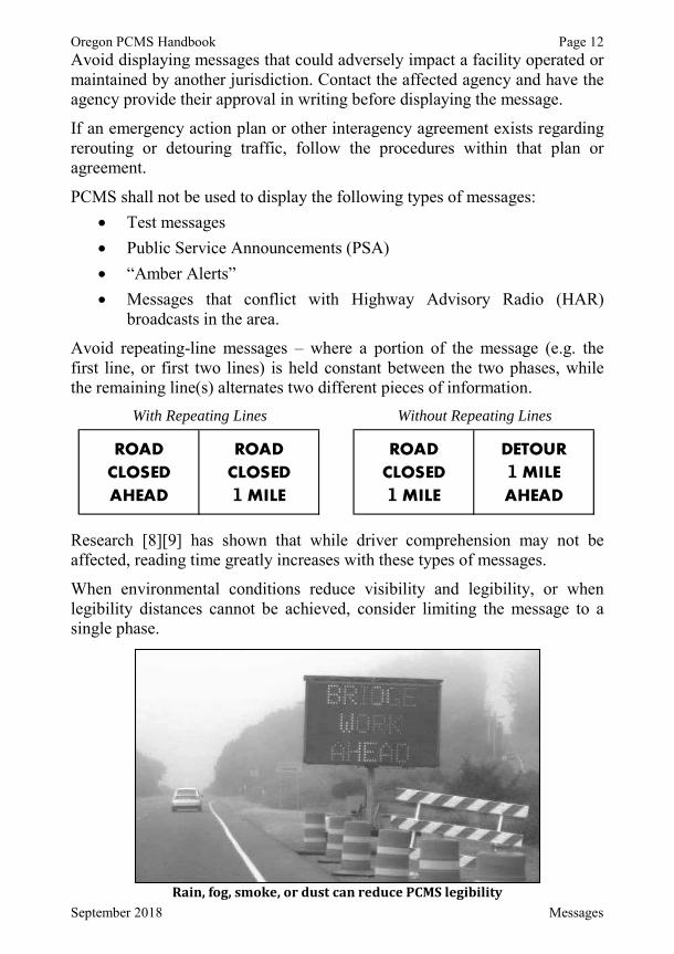
Oregon PCMS Handbook Page 12
September 2018 Messages
Avoid displaying messages that could adversely impact a facility operated or maintained by another jurisdiction. Contact the affected agency and have the agency provide their approval in writing before displaying the message.
If an emergency action plan or other interagency agreement exists regarding rerouting or detouring traffic, follow the procedures within that plan or agreement.
PCMS shall not be used to display the following types of messages:Test messagesPublic Service Announcements (PSA)“Amber Alerts”Messages that conflict with Highway Advisory Radio (HAR) broadcasts in the area.
Avoid repeating-line messages – where a portion of the message (e.g. the first line, or first two lines) is held constant between the two phases, while the remaining line(s) alternates two different pieces of information.
With Repeating Lines Without Repeating Lines
Research [8][9] has shown that while driver comprehension may not be affected, reading time greatly increases with these types of messages.
When environmental conditions reduce visibility and legibility, or when legibility distances cannot be achieved, consider limiting the message to a single phase.
Rain, fog, smoke, or dust can reduce PCMS legibility
1 11

Oregon PCMS Handbook Page 13
September 2018 Messages
Credibility Message credibility is an extremely important consideration in properly operating a PCMS. Messages must provide timely, reliable, accurate, and relevant information.
Messages should avoid using generic ‘signal’ words – DANGER, WARNING, CAUTION, etc. Research [7] indicates these types of words may not be interpreted as intended, and often do not affect motorist driving patterns or behaviors.
Many factors reduce PCMS credibility [10], including information that is:
Inaccurate – Messages do not reflect current roadway conditions (e.g. warning of Flaggers ahead when no flagging work is being conducted).Outdated – Poorly timed PCMS messages impair their effectiveness (e.g. Ramp closure warnings for a ramp that reopened one week ago).Irrelevant – Messages displayed on mainline for a distant side road location (e.g. PCMS message displayed on a freeway for a local street paving operation that makes no impact to freeway traffic).Repetitive – Displaying the same, generic message for 2 continuous weeks or more in a high-traffic, urban area. Motorists will likely begin to ignore the message, rendering the PCMS ineffective.Poorly Designed – Poorly structured, misspelled, overly-abbreviated, slang messages result in confusion and ineffectiveness (e.g. “TK NXT EXT 201A – RD CLOSD AHD”).Obvious – Displaying messages that describe a condition already apparent to drivers (e.g. Displaying, “EXPECT DELAYS” to three lanes of bumper-to-bumper traffic).

Oregon PCMS Handbook Page 14
September 2018 Messages
Trivial – “USE CAUTION”, “SLOW”, even “ROAD WORKAHEAD” on a PCMS quickly become ignored by drivers, forcing PCMS to lose their effectiveness in changing driver behavior.
Avoid displaying overly simplistic messages that add little value to other signs or devices used in the work zone. Provide drivers with clear reasons for focusing their attention and changing their driving behaviors as they enter and drive through the work zone – e.g. “WORKERS IN ROAD” or “LANE NARROWS”.
Oregon PCMS Handbook Page 15
September 2018 Messages
Standard Messages Motorists need more time to read unusual or complex messages – specific road names, dates, times, etc. Being able to quickly read and process amessage results in faster driver response times. Standard messages should be used wherever practical [7][10]. See Appendix A for a variety of StandardMessages.
Non-Standard Messages If the Standard Messages from Appendix A are not adequate for a given condition or application, a custom message may be developed.On state highways, if a custom, non-standard message is needed, the message shall be approved by an ODOT Region Traffic Engineer/Manager, ODOT Construction Project Manager, District Manager, or their representative, where applicable.Use the PCMS Message Worksheet in Appendix B to plan the message[11]. Following approval, store the Message Worksheet with the PCMS.Consider the following factors when creating a custom message:
1. Keep the message simple, brief, legible, and clear. An effective message provides adequate information to drivers. Ineffective messages result in frustration, confusion, even decreased safety.Messages that are too short, vague or generic may cause drivers to:
Drive in a manner different than intendedMisinterpret the messageBecome confused, angry, frustrated, even violentIgnore the message completely
Too much information – overly complex, 3 or more phases, etc. – may cause drivers to:
Not be able to read entire messageBecome overly distracted by the message trying to read it allIgnore the message.
Keep messages concise. Motorists can only process a limited amount of information in a given amount of time. Research [12] suggests the maximum number of words in a message, including both phases, should not exceed:
8 words on roads with a posted speed of 55 mph and less7 words on freeways
Oregon PCMS Handbook Page 16
September 2018 Messages
2. Messages should address the following items:a. Problem – e.g. Left lane is closed, detour is aheadb. Location – e.g. Lane closure in 1 mile, drivers use Exit 214 for
detour c. Time – e.g. Closures occur Tuesday – Friday, 8 p.m. – 6 a.m. d. Action – e.g. Drivers must exit and prepare to stop
The above list is generally in order of importance. Choose the most important information to display – given the circumstances, message size limit, and desired driver response.
Add an attention statement if the message is being directed at a specific group of drivers or vehicle classification (e.g. Through-traffic; or, All trucks).
In the example of an approaching low bridge, a problem statement is needed, plus a height restriction announcement and the detour route(s).A PCMS message might look like the following:
NOTE: If a height limit measurement includes 10” or 11”, the message may be rounded down to 9” to save on character needs.If the roadway is closed to all vehicles, the message may become:
3. Avoid using unnecessary words – articles of speech (a, an, the) unless the intent of the message becomes unclear without them.
4. Avoid using abbreviations, when possible.a. If necessary, follow guidance in the Standard Abbreviation
section below.
1
1

Oregon PCMS Handbook Page 17
September 2018 Messages
b. For abbreviations not listed, create an abbreviation using the following techniques:
i. By removing one or more vowels – commonly near the end of the word:“EXIT” may become, “EXT”“CANYON” may become, “CANYN”“SEASIDE” may become, “SEASID” or “SEASD”
ii. If necessary, a combination of vowels and extra consonants may be deleted:“WILLAMETTE” might become, “WILLAMET”
iii. A combination of removing vowels and letters from the end of a word until it is the desired length.“OVERWEIGHT” may become, “OVRWEIGH”
Research [7] shows truncated abbreviations are easier to recognize and comprehend than conventional or contracted abbreviations.Example: EMERGENCY: “EMERGENC” may be more recognizable than, “EMERGNC” or, “EMRGNCY”Example: SHOULDER: “SHOULDR” may be more recognizable than, “SHLDR” or “SHLDER”
c. Do not use a period with abbreviations.
5. Messages should be made of meaningful pieces of informationunderstood as independent phases.
a. A single phase display is preferred.b. Use a maximum of two phases for a given message.c. Split message components where it makes the most sense.
AVOID PREFERRED
d. Reduce the message length or complexity during heavy traffic volumes, bad weather, or other demanding driving environments.
e. Use two signs for complex or longer messages.
1 1

Oregon PCMS Handbook Page 18
September 2018 Messages
6. Do not display expected, unessential, or implied actions or information [7]. For example:
a. Drivers will expect to have to merge right when they read:
Displaying, “TRAFFIC MERGE RIGHT” on the second panel may be used; but, a description of the work activity, condition, or hazard on the second phase may be more useful to drivers:
b. “FOLLOW DETOUR” uses fewer words than, “FOLLOW DETOUR ROUTE” to display the same critical information.
c. “FLAGGER AHEAD” is more critical than, “EXPECT DELAYS”, and still implies potential delays.
2
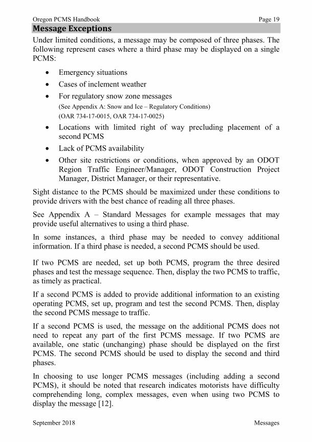
Oregon PCMS Handbook Page 19
September 2018 Messages
Message Exceptions Under limited conditions, a message may be composed of three phases. The following represent cases where a third phase may be displayed on a single PCMS:
Emergency situationsCases of inclement weatherFor regulatory snow zone messages(See Appendix A: Snow and Ice – Regulatory Conditions)(OAR 734-17-0015, OAR 734-17-0025)
Locations with limited right of way precluding placement of a second PCMSLack of PCMS availabilityOther site restrictions or conditions, when approved by an ODOT Region Traffic Engineer/Manager, ODOT Construction Project Manager, District Manager, or their representative.
Sight distance to the PCMS should be maximized under these conditions to provide drivers with the best chance of reading all three phases.
See Appendix A – Standard Messages for example messages that may provide useful alternatives to using a third phase.
In some instances, a third phase may be needed to convey additional information. If a third phase is needed, a second PCMS should be used.
If two PCMS are needed, set up both PCMS, program the three desired phases and test the message sequence. Then, display the two PCMS to traffic, as timely as practical.
If a second PCMS is added to provide additional information to an existing operating PCMS, set up, program and test the second PCMS. Then, display the second PCMS message to traffic.
If a second PCMS is used, the message on the additional PCMS does not need to repeat any part of the first PCMS message. If two PCMS are available, one static (unchanging) phase should be displayed on the first PCMS. The second PCMS should be used to display the second and third phases.
In choosing to use longer PCMS messages (including adding a second PCMS), it should be noted that research indicates motorists have difficulty comprehending long, complex messages, even when using two PCMS to display the message [12].

Oregon PCMS Handbook Page 20
September 2018 Messages
Speeds Speed messages on a PCMS should be limited to advisory or warning messages. Speed messages should be used to supplement regulatory posted speed signs, such as:
or
When displaying speed reduction messages [6]:
Provide a reason drivers should slow down, such as:
or
Do not display safety campaign messages on PCMS, such as, “CLICK IT OR TICKET”, “DONT DRINK & DRIVE”, or other public service messages.For extended work (i.e. 1 year or longer), use a PCMS during the first week or two of the project, and after any major condition changes. Use passive traffic controls at other times.Place the first PCMS 500 to 1000 feet upstream from the condition or hazard. The PCMS may be placed before or after the initial advance warning sign (e.g. ROAD WORK AHEAD), but should not block this critical sign, nor have the PCMS messages blocked by it.

Oregon PCMS Handbook Page 21
September 2018 Messages
Speed Detection Feature on PCMS Speed detection devices can be fitted onto a PCMS and used to provide vehicle speed information on the display. A PCMS used to display instantaneous vehicle speeds can be used for a wide range of conditions –roadside hazards, adverse weather conditions, traffic incidents, pavement condition, heavy congestion, etc. [13]. A PCMS with this feature can encourage speed limit compliance and reduce the speed of vehicles through a work zone. Speed zone compliance is increased when a reason for the reduced speed is displayed on the PCMS [14].
When displaying approach speeds:
Display the PCMS in conjunction with a Speed Limit sign.Use the following message:
Consider the following before using a PCMS with speed detection capability:
If used for more than 4 weeks, periodic police enforcement should be arranged to reinforce and maintain the effectiveness of the PCMS.Check the radar each time the PCMS is set up. Calibrate and adjust, as necessary, to ensure accuracy.The radar should be aimed to measure the speeds of vehicles traveling in the fastest moving lane, at no more than 10 seconds of distance upstream from the PCMS location.On roadways with posted speeds of 50 mph or greater, speeds of vehicles traveling more than 25 mph over the speed limit should not be displayed on the PCMS.In work zones, the first PCMS should be positioned 500 to 1000 feet upstream of the hazard, so drivers have time to read and interpret the message, and react before reaching the hazard.
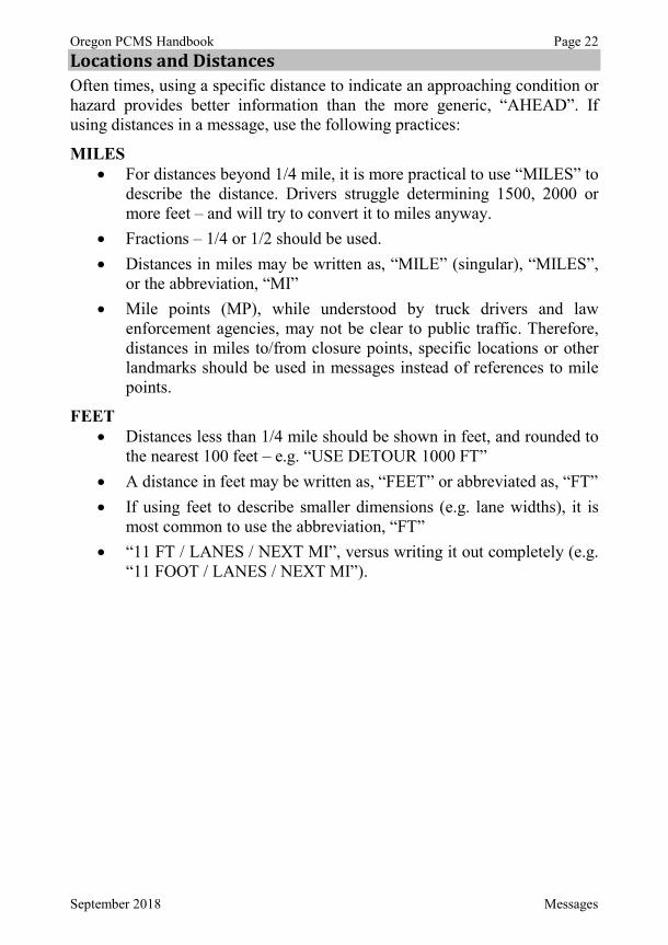
Oregon PCMS Handbook Page 22
September 2018 Messages
Locations and Distances Often times, using a specific distance to indicate an approaching condition or hazard provides better information than the more generic, “AHEAD”. If using distances in a message, use the following practices:
MILESFor distances beyond 1/4 mile, it is more practical to use “MILES” to describe the distance. Drivers struggle determining 1500, 2000 or more feet – and will try to convert it to miles anyway. Fractions – 1/4 or 1/2 should be used.Distances in miles may be written as, “MILE” (singular), “MILES”, or the abbreviation, “MI”Mile points (MP), while understood by truck drivers and law enforcement agencies, may not be clear to public traffic. Therefore, distances in miles to/from closure points, specific locations or other landmarks should be used in messages instead of references to mile points.
FEETDistances less than 1/4 mile should be shown in feet, and rounded to the nearest 100 feet – e.g. “USE DETOUR 1000 FT”A distance in feet may be written as, “FEET” or abbreviated as, “FT”If using feet to describe smaller dimensions (e.g. lane widths), it is most common to use the abbreviation, “FT”“11 FT / LANES / NEXT MI”, versus writing it out completely (e.g. “11 FOOT / LANES / NEXT MI”).
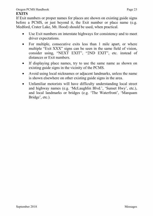
Oregon PCMS Handbook Page 23
September 2018 Messages
EXITSIf Exit numbers or proper names for places are shown on existing guide signs before a PCMS, or just beyond it, the Exit number or place name (e.g. Medford, Crater Lake, Mt. Hood) should be used, when practical.
Use Exit numbers on interstate highways for consistency and to meet driver expectations.For multiple, consecutive exits less than 1 mile apart, or where multiple “Exit XXX” signs can be seen in the same field of vision, consider using, “NEXT EXIT”, “2ND EXIT”, etc. instead of distances or Exit numbers.If displaying place names, try to use the same name as shown on existing guide signs in the vicinity of the PCMS.Avoid using local nicknames or adjacent landmarks, unless the name is shown elsewhere on other existing guide signs in the area.Unfamiliar motorists will have difficulty understanding local street and highway names (e.g. ‘McLaughlin Blvd.’, ‘Sunset Hwy’, etc.), and local landmarks or bridges (e.g. ‘The Waterfront’, ‘Marquam Bridge’, etc.).
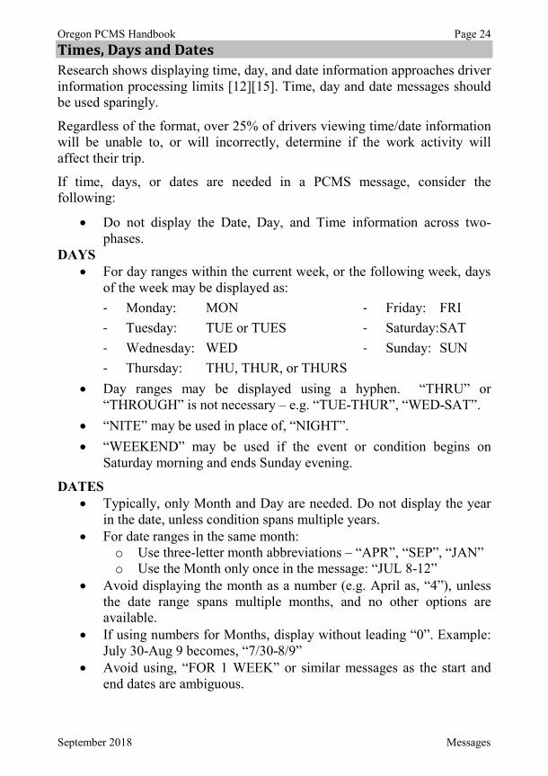
Oregon PCMS Handbook Page 24
September 2018 Messages
Times, Days and Dates Research shows displaying time, day, and date information approaches driverinformation processing limits [12][15]. Time, day and date messages should be used sparingly.
Regardless of the format, over 25% of drivers viewing time/date information will be unable to, or will incorrectly, determine if the work activity will affect their trip.
If time, days, or dates are needed in a PCMS message, consider the following:
Do not display the Date, Day, and Time information across two-phases.
DAYSFor day ranges within the current week, or the following week, days of the week may be displayed as:- Monday: MON - Friday: FRI- Tuesday: TUE or TUES - Saturday:SAT- Wednesday: WED - Sunday: SUN- Thursday: THU, THUR, or THURSDay ranges may be displayed using a hyphen. “THRU” or “THROUGH” is not necessary – e.g. “TUE-THUR”, “WED-SAT”.“NITE” may be used in place of, “NIGHT”.“WEEKEND” may be used if the event or condition begins on Saturday morning and ends Sunday evening.
DATESTypically, only Month and Day are needed. Do not display the year in the date, unless condition spans multiple years.For date ranges in the same month:
o Use three-letter month abbreviations – “APR”, “SEP”, “JAN”o Use the Month only once in the message: “JUL 8-12”
Avoid displaying the month as a number (e.g. April as, “4”), unless the date range spans multiple months, and no other options are available.If using numbers for Months, display without leading “0”. Example:July 30-Aug 9 becomes, “7/30-8/9”Avoid using, “FOR 1 WEEK” or similar messages as the start and end dates are ambiguous.
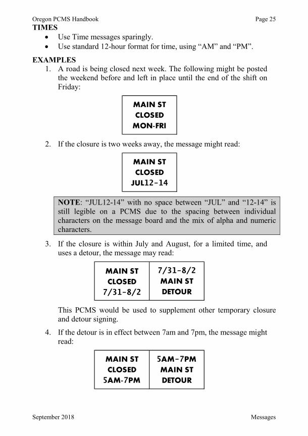
Oregon PCMS Handbook Page 25
September 2018 Messages
TIMESUse Time messages sparingly.Use standard 12-hour format for time, using “AM” and “PM”.
EXAMPLES1. A road is being closed next week. The following might be posted
the weekend before and left in place until the end of the shift on Friday:
2. If the closure is two weeks away, the message might read:
NOTE: “JUL12-14” with no space between “JUL” and “12-14” is still legible on a PCMS due to the spacing between individual characters on the message board and the mix of alpha and numeric characters.
3. If the closure is within July and August, for a limited time, and uses a detour, the message may read:
This PCMS would be used to supplement other temporary closure and detour signing.
4. If the detour is in effect between 7am and 7pm, the message might read:
12-14
7/31-8/2
7/31-8/2
5 7
5 -7
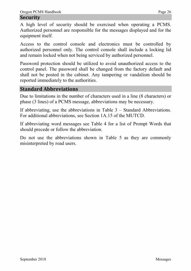
Oregon PCMS Handbook Page 26
September 2018 Messages
Security A high level of security should be exercised when operating a PCMS.Authorized personnel are responsible for the messages displayed and for the equipment itself.
Access to the control console and electronics must be controlled by authorized personnel only. The control console shall include a locking lid and remain locked when not being serviced by authorized personnel.
Password protection should be utilized to avoid unauthorized access to the control panel. The password shall be changed from the factory default and shall not be posted in the cabinet. Any tampering or vandalism should be reported immediately to the authorities.
Standard Abbreviations Due to limitations in the number of characters used in a line (8 characters) or phase (3 lines) of a PCMS message, abbreviations may be necessary.
If abbreviating, use the abbreviations in Table 3 – Standard Abbreviations.For additional abbreviations, see Section 1A.15 of the MUTCD.
If abbreviating word messages see Table 4 for a list of Prompt Words that should precede or follow the abbreviation.
Do not use the abbreviations shown in Table 5 as they are commonly misinterpreted by road users.
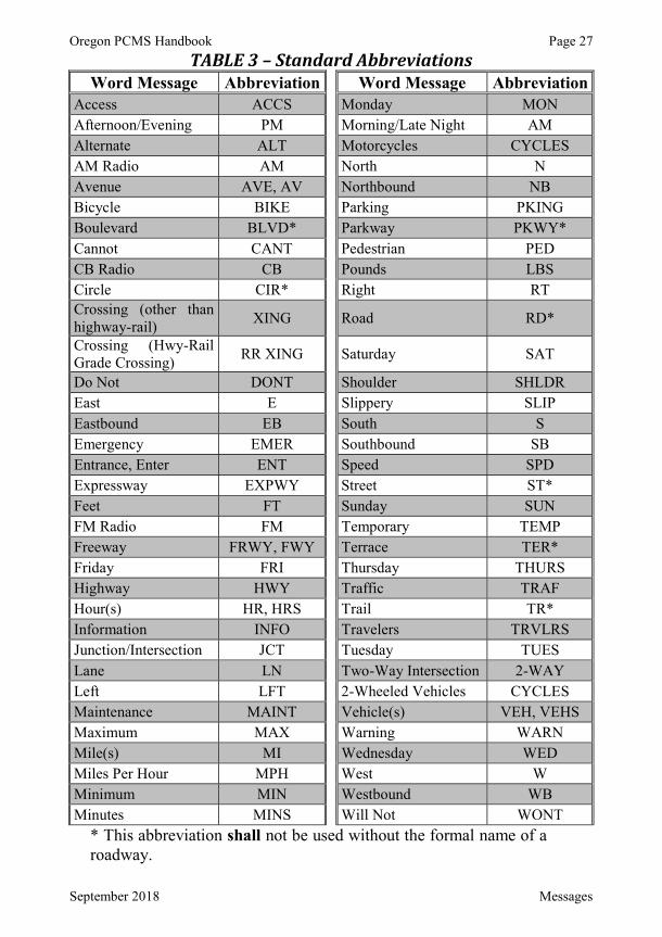
Oregon PCMS Handbook Page 27
September 2018 Messages
TABLE 3 – Standard Abbreviations Word Message Abbreviation Word Message Abbreviation
Access ACCS Monday MONAfternoon/Evening PM Morning/Late Night AMAlternate ALT Motorcycles CYCLESAM Radio AM North NAvenue AVE, AV Northbound NBBicycle BIKE Parking PKINGBoulevard BLVD* Parkway PKWY*Cannot CANT Pedestrian PEDCB Radio CB Pounds LBSCircle CIR* Right RTCrossing (other than highway-rail) XING Road RD*
Crossing (Hwy-Rail Grade Crossing) RR XING Saturday SAT
Do Not DONT Shoulder SHLDREast E Slippery SLIPEastbound EB South SEmergency EMER Southbound SBEntrance, Enter ENT Speed SPDExpressway EXPWY Street ST*Feet FT Sunday SUNFM Radio FM Temporary TEMPFreeway FRWY, FWY Terrace TER*Friday FRI Thursday THURSHighway HWY Traffic TRAFHour(s) HR, HRS Trail TR*Information INFO Travelers TRVLRSJunction/Intersection JCT Tuesday TUESLane LN Two-Way Intersection 2-WAYLeft LFT 2-Wheeled Vehicles CYCLESMaintenance MAINT Vehicle(s) VEH, VEHSMaximum MAX Warning WARNMile(s) MI Wednesday WEDMiles Per Hour MPH West WMinimum MIN Westbound WBMinutes MINS Will Not WONT
* This abbreviation shall not be used without the formal name of a roadway.
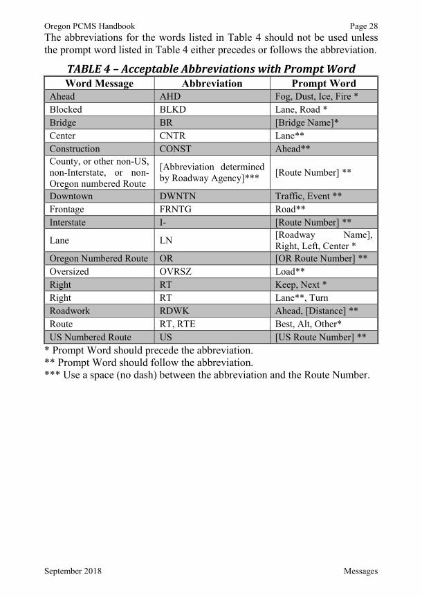
Oregon PCMS Handbook Page 28
September 2018 Messages
The abbreviations for the words listed in Table 4 should not be used unless the prompt word listed in Table 4 either precedes or follows the abbreviation.
TABLE 4 – Acceptable Abbreviations with Prompt WordWord Message Abbreviation Prompt Word
Ahead AHD Fog, Dust, Ice, Fire *Blocked BLKD Lane, Road *Bridge BR [Bridge Name]*Center CNTR Lane**Construction CONST Ahead**County, or other non-US, non-Interstate, or non-Oregon numbered Route
[Abbreviation determined by Roadway Agency]*** [Route Number] **
Downtown DWNTN Traffic, Event **Frontage FRNTG Road**Interstate I- [Route Number] **
Lane LN [Roadway Name], Right, Left, Center *
Oregon Numbered Route OR [OR Route Number] **Oversized OVRSZ Load**Right RT Keep, Next *Right RT Lane**, TurnRoadwork RDWK Ahead, [Distance] **Route RT, RTE Best, Alt, Other*US Numbered Route US [US Route Number] **
* Prompt Word should precede the abbreviation.** Prompt Word should follow the abbreviation.*** Use a space (no dash) between the abbreviation and the Route Number.
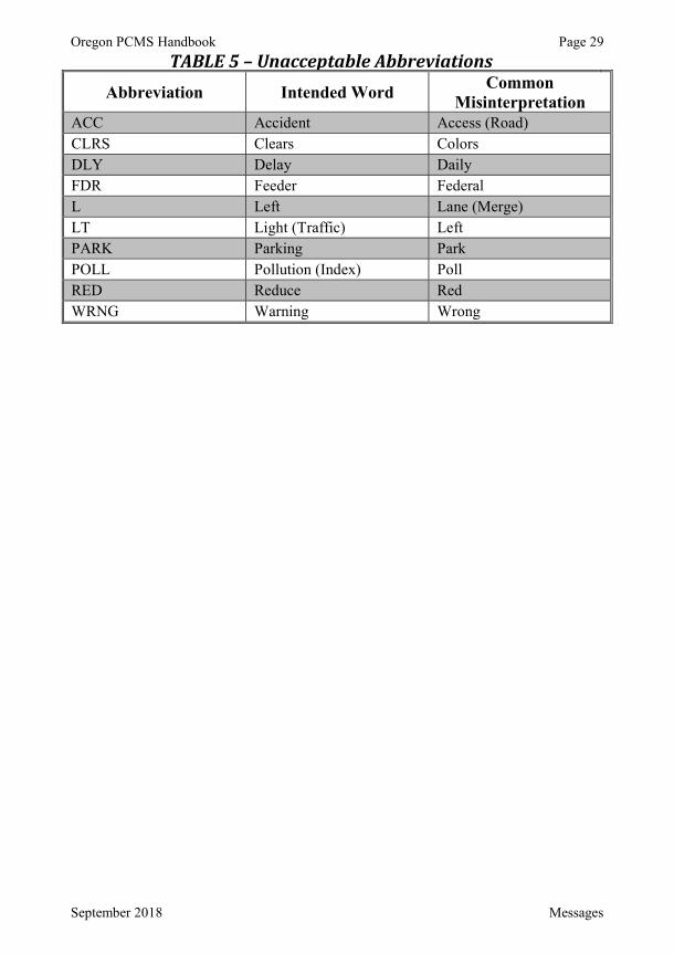
Oregon PCMS Handbook Page 29
September 2018 Messages
TABLE 5 – Unacceptable AbbreviationsAbbreviation Intended Word Common
MisinterpretationACC Accident Access (Road)CLRS Clears ColorsDLY Delay DailyFDR Feeder FederalL Left Lane (Merge)LT Light (Traffic) LeftPARK Parking ParkPOLL Pollution (Index) PollRED Reduce RedWRNG Warning Wrong
Oregon PCMS Handbook Page 30
September 2018 References
REFERENCES [1] Federal Highway Administration, Manual on Uniform Traffic Control
Devices for Streets and Highways, 2009 ed., Washington, D.C., 2009.
[2] Oregon Department of Transportation, Oregon Standard Specifications for Construction, 2018 ed., Salem, Oregon: Oregon Department of Transportation, 2018. [Online]. Available: https://www.oregon.gov/ODOT/Business/Documents/2018_STANDARD_ SPECIFICATIONS.pdf. [Accessed 28 August 2018].
[3] Oregon Department of Transportation, "Oregon Temporary Traffic Control Handbook for Operations of Three Days or Less," September 2016. [Online]. Available: https://www.oregon.gov/ODOT/Engineering/Docs_TrafficEng/OTTCH-v2011.pdf. [Accessed 28 August 2018].
[4] Federal Highway Administration, "Portable Changeable Message Sign Handbook," 2003. [Online]. Available: https://www.fhwa.dot.gov/publications/research/infrastructure/pavements/ltpp/reports/03066/. [Accessed 28 August 2018].
[5] G. L. Ullman, C. L. Dudek and B. R. Ullman, "Development of a Field Guide for Portable Changeable Message Sign Use in Work Zones," Texas Department of Transportation, College Station, Texas, 2005.
[6] J. L. Campbell, C. M. Richard, J. L. Brown, M. G. Lichty, J. Graham and M. O'Laughlin, "NCHRP Report 600: Human Factors Guidelines for Road Systems: Collection C: Chapter 19," 2008. [Online]. Available: http://onlinepubs.trb.org/onlinepubs/nchrp/nchrp_rpt_600C.pdf.[Accessed 13 July 2012].
[7] D. R. Proffitt and M. M. Wade, "Creating Effective Variable Message Signs: Human Factors Issues," Virginia Transportation Research Council, Charlottesville, Virginia, 1998.
[8] C. L. Dudek and G. L. Ullman, "Flashing Messages, Flashing Lines, and Alternating One Line on Changeable Message Signs," Transportation Research Record: Journal of the Transportation Research Board, vol. 1803, pp. 94-101, 2002.
[9] C. L. Dudek, S. D. Schrock and G. L. Ullman, "Impacts of Using Dynamic Features to Display Messages on Changeable Message Signs," Federal Highway Administration, Washington, D.C., 2005.
[10] C. L. Dudek, "Changeable Message Sign Operation and Messaging Handbook," Federal Highway Administration, Washington, D.C., 2004.
Oregon PCMS Handbook Page 31
September 2018 References
[11] Florida Department of Transportation, "Plans Preparation Manual," 1 January 2009. [Online]. Available: http://www.dot.state.fl.us/rddesign/PPMManual/2012/Volume1/.[Accessed 27 August 2012].
[12] J. L. Campbell and C. M. Richard, "NCHRP Report 600: Human Factors Guidelines for Road Systems: Collection A: Chapter 13," 2008. [Online]. Available:http://onlinepubs.trb.org/onlinepubs/nchrp/nchrp_rpt_600A.pdf.[Accessed 14 August 2012].
[13] Maryland State Highway Administration, "Use of Portable Changeable Message Signs with Speed Display in Work Zones," Maryland State Highway Administration, Baltimore, Maryland, 2005.
[14] J. L. Campbell, M. G. Lichty, J. L. Brown, C. M. Richard, J. S. Graving,J. Graham, M. O'Laughlin, D. Torbic and D. Harwood, "NCHRP Report 600: Human Factors Guidelines for Road Systems," 2012. [Online]. Available: http://onlinepubs.trb.org/onlinepubs/nchrp/nchrp_rpt_600Second.pdf.[Accessed 23 October 2012].
[15] G. L. Ullman, B. R. Ullman, C. L. Dudek, A. Williams and G. Pesti, "Advance Notification Messages and Use of Sequential Portable Changeable Message Signs in Work Zones," Texas Department of Transportation, Austin, Texas, 2005.
[16] American Association of State Highway and Transportation Officials, Highway Safety Manual, 1st ed., Washington, D.C.: AASHTO, 2010.
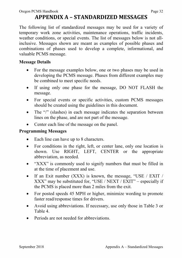
Oregon PCMS Handbook Page 32
September 2018 Appendix A – Standardized Messages
APPENDIX A – STANDARDIZED MESSAGES The following list of standardized messages may be used for a variety of temporary work zone activities, maintenance operations, traffic incidents, weather conditions, or special events. The list of messages below is not all-inclusive. Messages shown are meant as examples of possible phases and combinations of phases used to develop a complete, informational, and valuable PCMS message.
Message Details
For the message examples below, one or two phases may be used in developing the PCMS message. Phases from different examples may be combined to meet specific needs.If using only one phase for the message, DO NOT FLASH the message.For special events or specific activities, custom PCMS messages should be created using the guidelines in this document. The “/” (slashes) in each message indicates the separation between lines on the phase, and are not part of the message.Center each line of the message on the panel.
Programming Messages
Each line can have up to 8 characters.For conditions in the right, left, or center lane, only one location is shown. Use RIGHT, LEFT, CENTER or the appropriate abbreviation, as needed.“XXX” is commonly used to signify numbers that must be filled in at the time of placement and use.If an Exit number (XXX) is known, the message, “USE / EXIT / XXX” may be substituted for, “USE / NEXT / EXIT” – especially if the PCMS is placed more than 2 miles from the exit.For posted speeds 45 MPH or higher, minimize wording to promote faster read/response times for drivers.Avoid using abbreviations. If necessary, use only those in Table 3 or Table 4.Periods are not needed for abbreviations.

Oregon PCMS Handbook Page 33
September 2018 Appendix A – Standardized Messages
Message Categories
Advance Notification Detours and Road ClosuresFlagging and Signals Dust, Fog, Fire and Smoke Bridge and Tunnel Work Shoulder and Median WorkRoad Surface Conditions TrucksSlow Moving Operations MotorcyclesRolling Slowdown Operations Snow and Ice – WarningsSnow and Ice –Regulatory Conditions
Lane Closures, Traffic Pattern Changes
Crash, Stalled Vehicle or Other Incident
Other General Warnings
Advance Notification # Phase 1 Phase 2
0100 WORKERS / IN ROAD / X MILE(S)SLOW FOR / WORKERS / IN
ROAD
0101 WORKERS / AHEAD / SLOWWORKZONE / SLOW TO / XX
MPH
0102 WORKERS / AHEAD IN / LFT LANE
SLOWDOWN / IN / WORKZONE
0103 REDUCE / SPEED IN / WORKZONE
WORKERS / X MILE(S) / AHEAD
0104 PAVING / NEXT / X MILE(S)CAUTION / WORKERS / ON
RIGHT
0105 OR XXX / CLOSED / JUL15-18 TO COAST / USE / OR XXX
0106 ROADWORK / MON-THUR / NIGHTS
MON-THUR / DETOUR / 9PM-6AM
0107 NIGHT / LANE / CLOSURES EXPECT / DELAYS / XPM-XAM
0108 2 LANES / CLOSED / MON-THUR EXPECT / DELAYS / XPM-XAM
0109 ROADWORK / PAST / OR XXX THRU / TRAFFIC / USE I-XX
0110 USE / DETOUR / THUR-SUNTHUR-SUN / BAKER RD /
CLOSED

Oregon PCMS Handbook Page 34
September 2018 Appendix A – Standardized Messages
Detours and Road Closures # Phase 1 Phase 2
0200 DETOUR / AHEAD / X MILE(S) FOLLOW / DETOUR / SIGNS
0201 DETOUR / NEXT / LEFT FOLLOW / SIGNS / TO ORXXX
0202 DETOUR / AHEAD / 1000 FT USE / EXIT XXX / TO ORXXX
0203 DETOUR / X MILE(S) / AHEAD FOLLOW / DETOUR / TO I-XXX
0204 FREEWAY / BLOCKED / AHEAD PREPARE / TO / STOP
0205 FREEWAY / CLOSED / AHEAD ALL VEH / MUST / EXIT
0206 FREEWAY / CLOSED / 2 MILES USE / NEXT / EXIT
0207 I-XXX / CLOSED / AT EX(XXX) DETOUR / USING / HWY XXX
0208 RAMP / CLOSED / XX MILES DETOUR / NEXT / EXIT
0209 ROAD / CLOSED / AHEAD LOCAL / TRAFFIC / ONLY
0210 ROAD / CLOSED / X MILE(S) USE / DETOUR
0211 ROAD / CLOSED / AT MP XX USE / CANYN RD / DETOUR
0212 ROAD / NARROWS / AHEAD LANES / NARROW / 1/2 MILE
0213ROADWORK / NEAR / DOWNTOWN
THRU / TRAF USE / I-XXX
0214 US XXX / CLOSED / XX MILES US XXX / DETOUR / EXIT XX
0215 USE / DETOUR / ROUTE FOLLOW / DETOUR / SIGNS
0216 USE / DETOUR / AHEAD TURN / NEXT / RIGHT
0217 DETOUR / USE / I-XXX TURN / RIGHT / 1/4 MILE
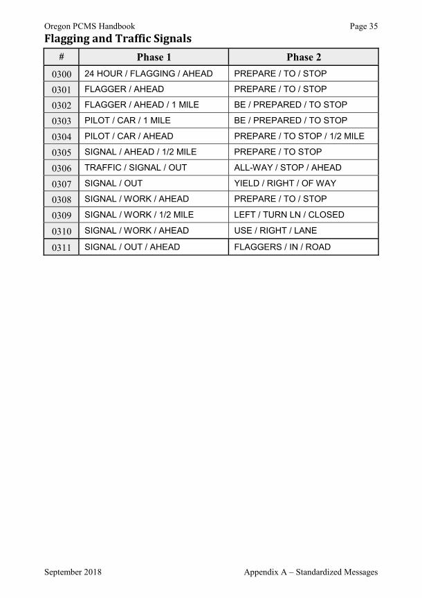
Oregon PCMS Handbook Page 35
September 2018 Appendix A – Standardized Messages
Flagging and Traffic Signals # Phase 1 Phase 2
0300 24 HOUR / FLAGGING / AHEAD PREPARE / TO / STOP
0301 FLAGGER / AHEAD PREPARE / TO / STOP
0302 FLAGGER / AHEAD / 1 MILE BE / PREPARED / TO STOP
0303 PILOT / CAR / 1 MILE BE / PREPARED / TO STOP
0304 PILOT / CAR / AHEAD PREPARE / TO STOP / 1/2 MILE
0305 SIGNAL / AHEAD / 1/2 MILE PREPARE / TO STOP
0306 TRAFFIC / SIGNAL / OUT ALL-WAY / STOP / AHEAD
0307 SIGNAL / OUT YIELD / RIGHT / OF WAY
0308 SIGNAL / WORK / AHEAD PREPARE / TO / STOP
0309 SIGNAL / WORK / 1/2 MILE LEFT / TURN LN / CLOSED
0310 SIGNAL / WORK / AHEAD USE / RIGHT / LANE
0311 SIGNAL / OUT / AHEAD FLAGGERS / IN / ROAD
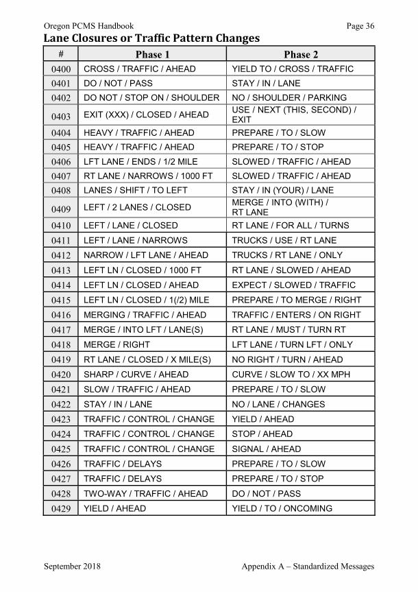
Oregon PCMS Handbook Page 36
September 2018 Appendix A – Standardized Messages
Lane Closures or Traffic Pattern Changes # Phase 1 Phase 2
0400 CROSS / TRAFFIC / AHEAD YIELD TO / CROSS / TRAFFIC
0401 DO / NOT / PASS STAY / IN / LANE
0402 DO NOT / STOP ON / SHOULDER NO / SHOULDER / PARKING
0403 EXIT (XXX) / CLOSED / AHEADUSE / NEXT (THIS, SECOND) / EXIT
0404 HEAVY / TRAFFIC / AHEAD PREPARE / TO / SLOW
0405 HEAVY / TRAFFIC / AHEAD PREPARE / TO / STOP
0406 LFT LANE / ENDS / 1/2 MILE SLOWED / TRAFFIC / AHEAD
0407 RT LANE / NARROWS / 1000 FT SLOWED / TRAFFIC / AHEAD
0408 LANES / SHIFT / TO LEFT STAY / IN (YOUR) / LANE
0409 LEFT / 2 LANES / CLOSEDMERGE / INTO (WITH) / RT LANE
0410 LEFT / LANE / CLOSED RT LANE / FOR ALL / TURNS
0411 LEFT / LANE / NARROWS TRUCKS / USE / RT LANE
0412 NARROW / LFT LANE / AHEAD TRUCKS / RT LANE / ONLY
0413 LEFT LN / CLOSED / 1000 FT RT LANE / SLOWED / AHEAD
0414 LEFT LN / CLOSED / AHEAD EXPECT / SLOWED / TRAFFIC
0415 LEFT LN / CLOSED / 1(/2) MILE PREPARE / TO MERGE / RIGHT
0416 MERGING / TRAFFIC / AHEAD TRAFFIC / ENTERS / ON RIGHT
0417 MERGE / INTO LFT / LANE(S) RT LANE / MUST / TURN RT
0418 MERGE / RIGHT LFT LANE / TURN LFT / ONLY
0419 RT LANE / CLOSED / X MILE(S) NO RIGHT / TURN / AHEAD
0420 SHARP / CURVE / AHEAD CURVE / SLOW TO / XX MPH
0421 SLOW / TRAFFIC / AHEAD PREPARE / TO / SLOW
0422 STAY / IN / LANE NO / LANE / CHANGES
0423 TRAFFIC / CONTROL / CHANGE YIELD / AHEAD
0424 TRAFFIC / CONTROL / CHANGE STOP / AHEAD
0425 TRAFFIC / CONTROL / CHANGE SIGNAL / AHEAD
0426 TRAFFIC / DELAYS PREPARE / TO / SLOW
0427 TRAFFIC / DELAYS PREPARE / TO / STOP
0428 TWO-WAY / TRAFFIC / AHEAD DO / NOT / PASS
0429 YIELD / AHEAD YIELD / TO / ONCOMING
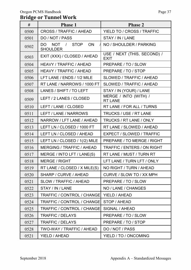
Oregon PCMS Handbook Page 37
September 2018 Appendix A – Standardized Messages
Bridge or Tunnel Work # Phase 1 Phase 2
0500 CROSS / TRAFFIC / AHEAD YIELD TO / CROSS / TRAFFIC
0501 DO / NOT / PASS STAY / IN / LANE
0502 DO NOT / STOP ON /SHOULDER
NO / SHOULDER / PARKING
0503 EXIT (XXX) / CLOSED / AHEADUSE / NEXT (THIS, SECOND) / EXIT
0504 HEAVY / TRAFFIC / AHEAD PREPARE / TO / SLOW
0505 HEAVY / TRAFFIC / AHEAD PREPARE / TO / STOP
0506 LFT LANE / ENDS / 1/2 MILE SLOWED / TRAFFIC / AHEAD
0507 RT LANE / NARROWS / 1000 FT SLOWED / TRAFFIC / AHEAD
0508 LANES / SHIFT / TO LEFT STAY / IN (YOUR) / LANE
0509 LEFT / 2 LANES / CLOSEDMERGE / INTO (WITH) / RT LANE
0510 LEFT / LANE / CLOSED RT LANE / FOR ALL / TURNS
0511 LEFT / LANE / NARROWS TRUCKS / USE / RT LANE
0512 NARROW / LFT LANE / AHEAD TRUCKS / RT LANE / ONLY
0513 LEFT LN / CLOSED / 1000 FT RT LANE / SLOWED / AHEAD
0514 LEFT LN / CLOSED / AHEAD EXPECT / SLOWED / TRAFFIC
0515 LEFT LN / CLOSED / 1(/2) MILE PREPARE / TO MERGE / RIGHT
0516 MERGING / TRAFFIC / AHEAD TRAFFIC / ENTERS / ON RIGHT
0517 MERGE / INTO LFT / LANE(S) RT LANE / MUST / TURN RT
0518 MERGE / RIGHT LFT LANE / TURN LFT / ONLY
0519 RT LANE / CLOSED / X MILE(S) NO RIGHT / TURN / AHEAD
0520 SHARP / CURVE / AHEAD CURVE / SLOW TO / XX MPH
0521 SLOW / TRAFFIC / AHEAD PREPARE / TO / SLOW
0522 STAY / IN / LANE NO / LANE / CHANGES
0523 TRAFFIC / CONTROL / CHANGE YIELD / AHEAD
0524 TRAFFIC / CONTROL / CHANGE STOP / AHEAD
0525 TRAFFIC / CONTROL / CHANGE SIGNAL / AHEAD
0526 TRAFFIC / DELAYS PREPARE / TO / SLOW
0527 TRAFFIC / DELAYS PREPARE / TO / STOP
0528 TWO-WAY / TRAFFIC / AHEAD DO / NOT / PASS
0521 YIELD / AHEAD YIELD / TO / ONCOMING
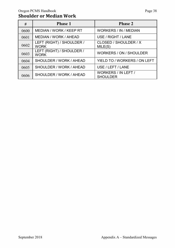
Oregon PCMS Handbook Page 38
September 2018 Appendix A – Standardized Messages
Shoulder or Median Work # Phase 1 Phase 2
0600 MEDIAN / WORK / KEEP RT WORKERS / IN / MEDIAN
0601 MEDIAN / WORK / AHEAD USE / RIGHT / LANE
0602LEFT (RIGHT) / SHOULDER / WORK
CLOSED / SHOULDER / X MILE(S)
0603LEFT (RIGHT) / SHOULDER /WORK WORKERS / ON / SHOULDER
0604 SHOULDER / WORK / AHEAD YIELD TO / WORKERS / ON LEFT
0605 SHOULDER / WORK / AHEAD USE / LEFT / LANE
0606 SHOULDER / WORK / AHEADWORKERS / IN LEFT / SHOULDER

Oregon PCMS Handbook Page 39
September 2018 Appendix A – Standardized Messages
Road Surface Conditions (Rough, debris, oil, fresh paint, etc.) # Phase 1 Phase 2
0700 ABRUPT / EDGE / RIGHT
0701 ACTIVE / SLIDES / AHEAD REDUCE / SPEED
0702 DEBRIS / ON / ROAD KEEP / LEFT
0703 DEBRIS / ON / ROAD RIGHT / LANE / CLOSED
0704 DEBRIS / ON / ROAD PREPARE / TO / STOP
0705 DEBRIS / ON / ROAD EXPECT / DELAYS
0706 FRESH / OIL / ON ROAD
0707 NO / CENTER / STRIPE KEEP / RIGHT
0708 NO / LANE / LINES
0709 NO / LANE / LINES KEEP RT / EXCEPT / TO PASS
0710 NO / SHOULDER DO / NOT / STOP
0711 ROAD / FLOODED / 1/2 MILE
0712 ROCKS / ON / ROADWAY
0713 ROUGH / PAVEMENT / AHEAD PREPARE / TO / SLOW
0714 ROUGH / ROAD / AHEAD
0715 ROUGH / ROAD / AHEAD DIP / AHEAD / 1/2 MILE
0716 SLIDE / BLOCKS / ROAD PREPARE / TO / STOP
0717 SLIDE / ON / ROAD KEEP / RIGHT
0718 SOFT / SHOULDER
0719 WATER / ACROSS / ROAD
0720 WET / PAINT STAY / IN / LANE
0721 WET / PAINT PASS TO / LEFT
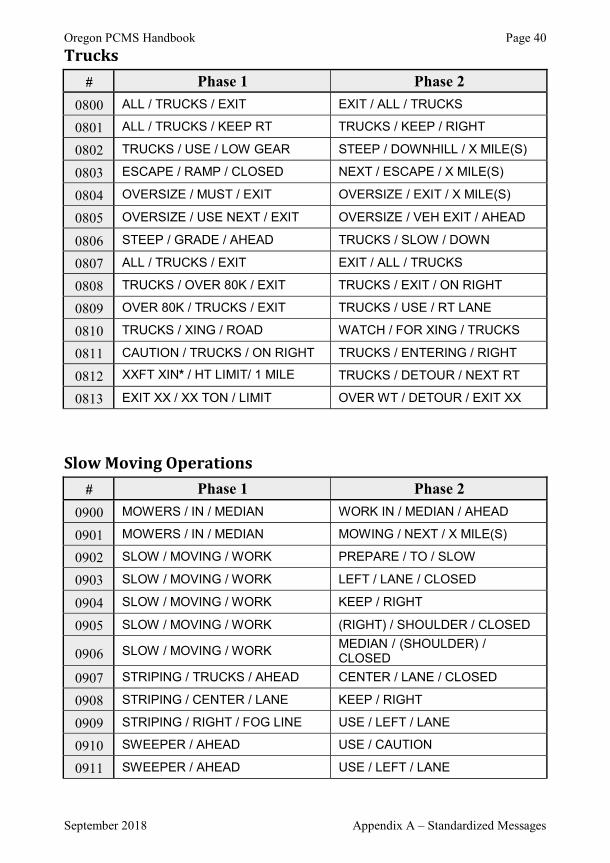
Oregon PCMS Handbook Page 40
September 2018 Appendix A – Standardized Messages
Trucks # Phase 1 Phase 2
0800 ALL / TRUCKS / EXIT EXIT / ALL / TRUCKS
0801 ALL / TRUCKS / KEEP RT TRUCKS / KEEP / RIGHT
0802 TRUCKS / USE / LOW GEAR STEEP / DOWNHILL / X MILE(S)
0803 ESCAPE / RAMP / CLOSED NEXT / ESCAPE / X MILE(S)
0804 OVERSIZE / MUST / EXIT OVERSIZE / EXIT / X MILE(S)
0805 OVERSIZE / USE NEXT / EXIT OVERSIZE / VEH EXIT / AHEAD
0806 STEEP / GRADE / AHEAD TRUCKS / SLOW / DOWN
0807 ALL / TRUCKS / EXIT EXIT / ALL / TRUCKS
0808 TRUCKS / OVER 80K / EXIT TRUCKS / EXIT / ON RIGHT
0809 OVER 80K / TRUCKS / EXIT TRUCKS / USE / RT LANE
0810 TRUCKS / XING / ROAD WATCH / FOR XING / TRUCKS
0811 CAUTION / TRUCKS / ON RIGHT TRUCKS / ENTERING / RIGHT
0812 XXFT XIN* / HT LIMIT/ 1 MILE TRUCKS / DETOUR / NEXT RT
0813 EXIT XX / XX TON / LIMIT OVER WT / DETOUR / EXIT XX
Slow Moving Operations # Phase 1 Phase 2
0900 MOWERS / IN / MEDIAN WORK IN / MEDIAN / AHEAD
0901 MOWERS / IN / MEDIAN MOWING / NEXT / X MILE(S)
0902 SLOW / MOVING / WORK PREPARE / TO / SLOW
0903 SLOW / MOVING / WORK LEFT / LANE / CLOSED
0904 SLOW / MOVING / WORK KEEP / RIGHT
0905 SLOW / MOVING / WORK (RIGHT) / SHOULDER / CLOSED
0906 SLOW / MOVING / WORKMEDIAN / (SHOULDER) / CLOSED
0907 STRIPING / TRUCKS / AHEAD CENTER / LANE / CLOSED
0908 STRIPING / CENTER / LANE KEEP / RIGHT
0909 STRIPING / RIGHT / FOG LINE USE / LEFT / LANE
0910 SWEEPER / AHEAD USE / CAUTION
0911 SWEEPER / AHEAD USE / LEFT / LANE
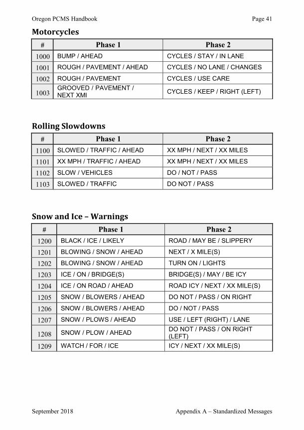
Oregon PCMS Handbook Page 41
September 2018 Appendix A – Standardized Messages
Motorcycles # Phase 1 Phase 2
1000 BUMP / AHEAD CYCLES / STAY / IN LANE
1001 ROUGH / PAVEMENT / AHEAD CYCLES / NO LANE / CHANGES
1002 ROUGH / PAVEMENT CYCLES / USE CARE
1003GROOVED / PAVEMENT / NEXT XMI
CYCLES / KEEP / RIGHT (LEFT)
Rolling Slowdowns # Phase 1 Phase 2
1100 SLOWED / TRAFFIC / AHEAD XX MPH / NEXT / XX MILES
1101 XX MPH / TRAFFIC / AHEAD XX MPH / NEXT / XX MILES
1102 SLOW / VEHICLES DO / NOT / PASS
1103 SLOWED / TRAFFIC DO NOT / PASS
Snow and Ice – Warnings # Phase 1 Phase 2
1200 BLACK / ICE / LIKELY ROAD / MAY BE / SLIPPERY
1201 BLOWING / SNOW / AHEAD NEXT / X MILE(S)
1202 BLOWING / SNOW / AHEAD TURN ON / LIGHTS
1203 ICE / ON / BRIDGE(S) BRIDGE(S) / MAY / BE ICY
1204 ICE / ON ROAD / AHEAD ROAD ICY / NEXT / XX MILE(S)
1205 SNOW / BLOWERS / AHEAD DO NOT / PASS / ON RIGHT
1206 SNOW / BLOWERS / AHEAD DO / NOT / PASS
1207 SNOW / PLOWS / AHEAD USE / LEFT (RIGHT) / LANE
1208 SNOW / PLOW / AHEADDO NOT / PASS / ON RIGHT (LEFT)
1209 WATCH / FOR / ICE ICY / NEXT / XX MILE(S)
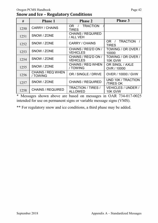
Oregon PCMS Handbook Page 42
September 2018 Appendix A – Standardized Messages
Snow and Ice – Regulatory Conditions # Phase 1 Phase 2 Phase 3
1250 CARRY / CHAINSOR / TRACTION /TIRES
1251 SNOW / ZONECHAINS / REQUIRED/ ALL VEH
1252 SNOW / ZONE CARRY / CHAINSOR / TRACTION / TIRES
1253 SNOW / ZONECHAINS / REQ’D ON /VEHICLES
TOWING / OR OVER / 10000
1254 SNOW / ZONECHAINS / REQ’D ON /VEHICLES
TOWING / OR OVER / 10K GVW
1255 SNOW / ZONECHAINS / REQ WHEN/ TOWING
OR SINGL / AXLE OVR / 10000
1256CHAINS / REQ WHEN/ TOWING OR / SINGLE / DRIVE OVER / 10000 / GVW
1257 SNOW / ZONE CHAINS / REQUIREDUND 10K / TRACTION/TIRES OK
1258 CHAINS / REQUIREDTRACTION / TIRES / ALLOWED
VEHICLES / UNDER / 10K GVW
* Messages shown above are based on messages in OAR 734-017-0025intended for use on permanent signs or variable message signs (VMS).
** For regulatory snow and ice conditions, a third phase may be added.
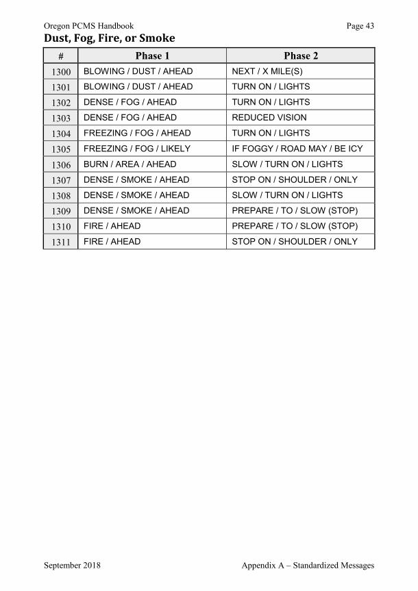
Oregon PCMS Handbook Page 43
September 2018 Appendix A – Standardized Messages
Dust, Fog, Fire, or Smoke # Phase 1 Phase 2
1300 BLOWING / DUST / AHEAD NEXT / X MILE(S)
1301 BLOWING / DUST / AHEAD TURN ON / LIGHTS
1302 DENSE / FOG / AHEAD TURN ON / LIGHTS
1303 DENSE / FOG / AHEAD REDUCED VISION
1304 FREEZING / FOG / AHEAD TURN ON / LIGHTS
1305 FREEZING / FOG / LIKELY IF FOGGY / ROAD MAY / BE ICY
1306 BURN / AREA / AHEAD SLOW / TURN ON / LIGHTS
1307 DENSE / SMOKE / AHEAD STOP ON / SHOULDER / ONLY
1308 DENSE / SMOKE / AHEAD SLOW / TURN ON / LIGHTS
1309 DENSE / SMOKE / AHEAD PREPARE / TO / SLOW (STOP)
1310 FIRE / AHEAD PREPARE / TO / SLOW (STOP)
1311 FIRE / AHEAD STOP ON / SHOULDER / ONLY
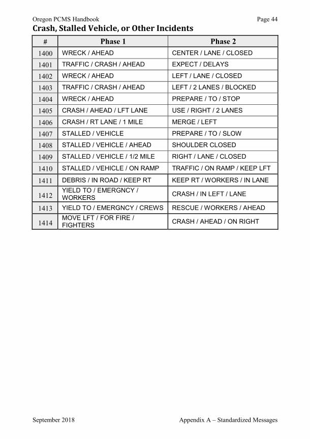
Oregon PCMS Handbook Page 44
September 2018 Appendix A – Standardized Messages
Crash, Stalled Vehicle, or Other Incidents # Phase 1 Phase 2
1400 WRECK / AHEAD CENTER / LANE / CLOSED
1401 TRAFFIC / CRASH / AHEAD EXPECT / DELAYS
1402 WRECK / AHEAD LEFT / LANE / CLOSED
1403 TRAFFIC / CRASH / AHEAD LEFT / 2 LANES / BLOCKED
1404 WRECK / AHEAD PREPARE / TO / STOP
1405 CRASH / AHEAD / LFT LANE USE / RIGHT / 2 LANES
1406 CRASH / RT LANE / 1 MILE MERGE / LEFT
1407 STALLED / VEHICLE PREPARE / TO / SLOW
1408 STALLED / VEHICLE / AHEAD SHOULDER CLOSED
1409 STALLED / VEHICLE / 1/2 MILE RIGHT / LANE / CLOSED
1410 STALLED / VEHICLE / ON RAMP TRAFFIC / ON RAMP / KEEP LFT
1411 DEBRIS / IN ROAD / KEEP RT KEEP RT / WORKERS / IN LANE
1412YIELD TO / EMERGNCY / WORKERS
CRASH / IN LEFT / LANE
1413 YIELD TO / EMERGNCY / CREWS RESCUE / WORKERS / AHEAD
1414MOVE LFT / FOR FIRE / FIGHTERS
CRASH / AHEAD / ON RIGHT
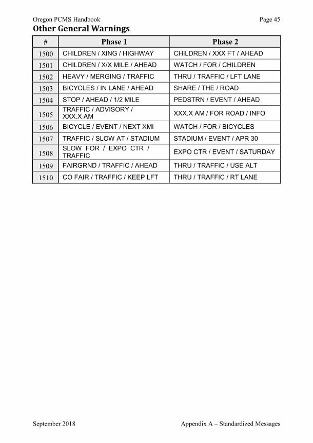
Oregon PCMS Handbook Page 45
September 2018 Appendix A – Standardized Messages
Other General Warnings # Phase 1 Phase 2
1500 CHILDREN / XING / HIGHWAY CHILDREN / XXX FT / AHEAD
1501 CHILDREN / X/X MILE / AHEAD WATCH / FOR / CHILDREN
1502 HEAVY / MERGING / TRAFFIC THRU / TRAFFIC / LFT LANE
1503 BICYCLES / IN LANE / AHEAD SHARE / THE / ROAD
1504 STOP / AHEAD / 1/2 MILE PEDSTRN / EVENT / AHEAD
1505TRAFFIC / ADVISORY /XXX.X AM XXX.X AM / FOR ROAD / INFO
1506 BICYCLE / EVENT / NEXT XMI WATCH / FOR / BICYCLES
1507 TRAFFIC / SLOW AT / STADIUM STADIUM / EVENT / APR 30
1508SLOW FOR / EXPO CTR / TRAFFIC
EXPO CTR / EVENT / SATURDAY
1509 FAIRGRND / TRAFFIC / AHEAD THRU / TRAFFIC / USE ALT
1510 CO FAIR / TRAFFIC / KEEP LFT THRU / TRAFFIC / RT LANE

Oregon PCMS Handbook Page 46
September 2018 PCMS Message Worksheet
APPENDIX B – SETUP CHECKLIST
Need Could a static sign be used to send the same message?
Is the static sign readily available?
Placement Is the PCMS visible from at least ½ mile away?
Can the message be read from at least 800 feet away during the day? At least 600 feet away during the night?
If two PCMS are used, they are separated by at least 1000 feet and on the same side of the road?
Message Is each phase understandable by itself?
Does the PCMS Message give drivers new information or add clarity?
Does the PCMS warn the motorist of a problem ahead?
Have standard abbreviations been used?
Are there no more than 2 phases on each PCMS?
Is each phase displayed for at least 2 seconds?
Is the total display time for both phases less than 8 seconds?
Is the message free of animation (scrolling or flashing)?
Are correct lanes, highways, exit numbers, days, dates, and/or times displayed?
Are messages, display characteristics, and dates and times of display documented in the project diary?
When work is to begin within seven days, replace calendar dates (e.g. MAY 25-27) with days of the week (e.g. TUE-THUR).
Turn PCMS off and rotate display away from traffic when not in use.
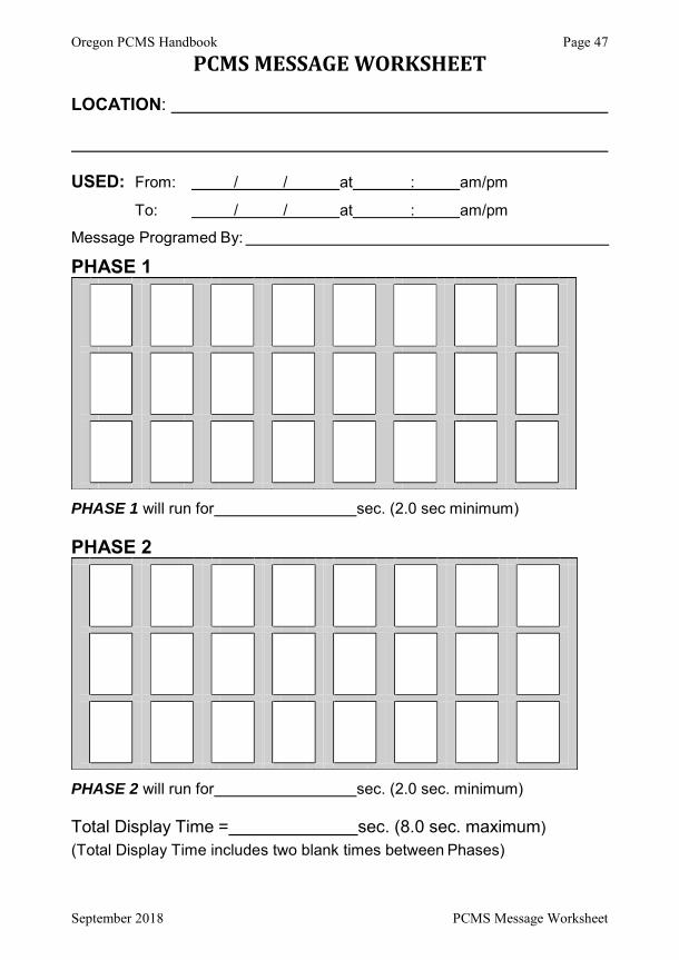
Oregon PCMS Handbook Page 47
September 2018 PCMS Message Worksheet
PCMS MESSAGE WORKSHEET
LOCATION:
USED: From: / / at : am/pm
To: / / at : am/pm
Message Programed By:
PHASE 1
PHASE 1 will run for sec. (2.0 sec minimum)
PHASE 2
PHASE 2 will run for sec. (2.0 sec. minimum)
Total Display Time = sec. (8.0 sec. maximum)
(Total Display Time includes two blank times between Phases)