Substructure - Oregon.gov
52
Section 9 Substructure 9.1 Periodic Checks 1 Construction Tolerances 2 Beam Seats 7 MSE Walls 21 Other Walls 30 ODOT Video, Part 9/12: Substructures 36 Backfilling 37
-
Upload
khangminh22 -
Category
Documents
-
view
4 -
download
0
Transcript of Substructure - Oregon.gov

Section 9
Substructure
9.1 Periodic Checks 1
Construction Tolerances 2
Beam Seats 7
MSE Walls 21 Other Walls 30
ODOT Video, Part 9/12: Substructures 36 Backfilling 37

Substructure Section 9.1
January, 20201
Substructure
A bridge substructure includes the:
• Foundation
• Abutments, columns or piers
• Crossbeams, pilecaps and beam seats
Periodic Checks
It is necessary to periodically check and recheck forms as work progresses.

Substructure Section 9.1
January, 20202
Locations to Check
• The bottom and top of footings.
• The tops of columns.
• The beam seats.
• Any construction joints for which a specified elevation is shown on the plans.
Construction Tolerances

00540.40
443
00540.30 Quality Control Personnel - In addition to the certified technicians required in 02001.50 provide and designate an individual to be present at the placement site at all times during concrete placements for projects with more than 100 cubic yards of structural concrete and for all high performance concrete, and who is authorized and responsible for acceptance and rejection of materials.
Construction 00540.40 Tolerances - The following tolerances apply to cast-in-place Structures:
(a) Foundation Footings:
(1) Lateral Alignment:
• Actual (as cast) location of the center of gravity: 0.02 times width of footing in the direction of misplacement, but not more than 2 inches
• Supporting masonry: 1/2 inch (2) Level or Vertical Alignment:
• Top of footing supporting masonry: 1/2 inch
• Top of other footings: minus 2 inches to plus 1/2 inch (3) Cross-Sectional Dimensions:
a. Horizontal dimension of formed members: minus 1/2 inch to plus 2 inches b. Horizontal dimension of unformed members cast against Soil:
• Less than and equal to 2 feet: minus 1/2 inch to plus 3 inches
• Over 2 feet and less than and equal to 6 feet: minus 1 1/2 inch to plus 6 inches
• Over 6 feet: minus 1/2 inch to plus 12 inches c. Vertical dimension (thickness): 0 to plus 6 inches
(4) Relative Alignment - Footing side and top surfaces may slope with respect to the specified plane at a rate not to exceed 1 inch in 10 feet.
(b) All Other Structural Members:
(1) Vertical Alignment:
• Exposed surfaces: 3/4 inch
• Concealed surfaces: 1 1/2 inches
• Construction joints: 0 to minus 3 inches (2) Lateral Alignment - Centerline alignment: 1 inch (3) Level Alignment:
a. Profile grade: 1 inch b. Top of other concrete surfaces and horizontal grooves:

00540.41
444
• Exposed: 3/4 inch
• Concealed: 1 1/2 inches c. On ramps, sidewalks and intersections, in any direction, the gap below a 12 foot unleveled straightedge resting on high spots shall not exceed 1/4 inch. d. On bridge decks, in any direction the gap below a 12 foot unleveled straightedge does not vary from the testing edge by more than 1/8 inch.
(4) Cross-Sectional Dimensions:
• Bridge slabs and decks vertical dimension (thickness): minus 1/8 inch to plus 1/4 inch
• Members such as columns, beams, piers, walls and others (slab thickness only): minus 1/4 inch to plus 1/2 inch
• Openings through members: 1/2 inch (5) Relative Alignment:
a. Location of openings through members: 1/2 inch b. Formed surfaces may slope with respect to the specified plane at a rate not to exceed the following amounts in 10 feet:
• Watertight joints: 1/8 inch
• Other exposed surfaces: 1/2 inch
• Concealed surfaces: 1 inch c. Unformed exposed surfaces, other than Pavements and sidewalks, may slope with respect to the specified plane at a rate not to exceed the following amounts:
• In 10 feet: 1/4 inch
• In 20 feet: 3/8 inch 00540.41 Design of Falsework for Vertical Pressures:
(a) Submittal of Working Drawings and Calculations - Submit stamped falsework Plans and design calculations according to 00150.35, except as modified below. Ensure the falsework designer prepares a Falsework Design Summary and completes a Falsework Design Checklist to accompany the Plans and calculations. Include in the summary a list of each falsework member with its:
• Assumed dead and live loads
• Allowable and design stresses
• Allowable and calculated deflections
• Design references and derivations for design formulas
• Documentation for computer-generated calculations The Falsework Design Checklist is included in the Special Provisions.

Substructure Section 9.1
January, 20203
Construction Tolerance Example
10 ft x 10 ft spread footing
Alignment is right of centerline by 6 inches.
Is this acceptable?
Construction Tolerance Example Key
10 ft x 10 ft spread footing
Alignment is right of centerline by 6 inches.
Is this acceptable?
Tolerance = 0.02 (width of footing) but not > 2″
Tolerance = 0.02 (10 ft) = 0.2 ft = 2 3/8″ > 2″
So Tolerance = 2″
The footing alignment does not meet specifications.

Substructure Section 9.1
January, 20204
Pier Cap Alignment Exercise
4″ Off Center
Is This Acceptable?
1′ 10″ 1′ 2″
Ensure proper support under the structure.

Substructure Section 9.1
January, 20205
Footing support?
Footing support?

Substructure Section 9.1
January, 20206
Check base for proper grades.
Sides Uneven

Substructure Section 9.1
January, 20207
Beam Seats
Beam Seats
Things to consider:
• Elevation
• Level
• Good consolidation
• Alignment

Substructure Section 9.1
January, 20208
Calculating Beam Seat Elevation
Sagging Span?

Beam Seat Elevation Calculation
1 Girder Cambers Measured Max Camber @ Midspan
Beam
in
in
in
in
in
in
2 Controlling Maximum Camber in = ft
3 Deflection Due To Deck, Rail + AC in = ft
4 (a) Min. Beam Buildup in = ft
(b) Cross‐slope Buildup @ Girder Centerline
(Flange Width)/2 Cross‐slope
ft x ft/ft = ft
(c)Extra Buildup @ Girder Centerline (4a+4b) ft
(Horiz & vert curvature require additional adjustment)
5 Total Buildup = #2 ‐ #3 + 4c ft
6 Finish Grade Elevation Finish Grade Elevation ft
7 Deck Thickness in = ft
8 Total Buildup (#5) ft
9 Girder Height in = ft
10 Bearing Pad + Grout Thickness in = ft
11 Top of Beam Seat Elevation = ft
(#6 ‐ #7 ‐ #8 ‐ #9 ‐ #10)


Substructure Section 9.1
January, 20209
10º Curve, 8% Cross-slope
Cross-Slope Buildup Example(At Girder Centerline)
Super-elevation = 8%
Girder Flange Width = 4 ft
Cross-Slope Buildup = 0.08ft/ft x 2 ft = 0.16 ft

Beam Seat Elevation Calculation
1 Girder Cambers Measured Max Camber @ Midspan
Beam
in
in
in
in
in
in
2 Controlling Maximum Camber in = ft
3 Deflection Due To Deck, Rail + AC in = ft
4 (a) Min. Beam Buildup in = ft
(b) Cross‐slope Buildup @ Girder Centerline
(Flange Width)/2 Cross‐slope
ft x ft/ft = ft
(c)Extra Buildup @ Girder Centerline (4a+4b) ft
(Horiz & vert curvature require additional adjustment)
5 Total Buildup = #2 ‐ #3 + 4c ft
6 Finish Grade Elevation Finish Grade Elevation ft
7 Deck Thickness in = ft
8 Total Buildup (#5) ft
9 Girder Height in = ft
10 Bearing Pad + Grout Thickness in = ft
11 Top of Beam Seat Elevation = ft
(#6 ‐ #7 ‐ #8 ‐ #9 ‐ #10)

Substructure Section 9.1
January, 202010
Cross-Slope Buildup Exercise(At Girder Centerline)
Super-elevation = 6%
Girder Flange Width = 2 ft
Cross-Slope Buildup =
Crest Vertical Curve
• Buildup on beams is less at the ends of the beam than on a level grade
• Common on Overpasses
• Top of hills

Substructure Section 9.1
January, 202011
Sag Vertical Curve
• At bottom of hills (creeks tend to be at low spots)
• Buildup on beams is more at the ends of the beam than on a level grade
Vertical Curve Correction
(G2-G1)
2LV = D2
G1= Initial Grade
G2= Final Grade
L= Length of Curve
D= Distance to Point On Curve

Substructure Section 9.1
January, 202012
Vertical Curve Correction Example
(G2-G1)
2LV = D2
G1= + 0.04 ft/ft
G2= - 0.02 ft/ft
L= 200 ft
D= 100 ft
V = (-0.02 ft/ft - 0.04 ft/ft)(100′)2/(2(200′)
V = -1.50 ft
Vertical Curve Correction Exercise
(G2-G1)
2LV = D2
G1= + 0.02 ft/ft
G2= - 0.02 ft/ft
L= 200 ft
D= 100 ft
V =


Beam Seat Elevation Calculation Example
Situation: You are the inspector on a bridge project which will be placing a cast in place concrete deck on precast girders. The precast girders have not been placed yet and the contractor is constructing a concrete footing. The contractor has given you their calculated Beam Seat Elevations at each Girder centerline/Bent centerline intersection and has asked for a verification. Given: Measured maximum camber (Cb) of each precast beam. This information can be obtained from the precast manufacture’s office or field verified independently. G1 = 3.50” G2 = 3.75” G3 = 3.25” G4 = 3.75” G5 = 4.00”
Given: Maximum deflection (DD,R&AC) due to Deck, Rail and AC. This information should be given on the bridge detail plan sheets. Check with the Bridge Designer as required. Maximum Deflection (DD,R&AC) = 1.50” Given: . Girder Height = 8’ . Girder Flange Width = 4’ . Deck Thickness = 9” . Cross Slope = .03ft/ft . Min. Beam Buildup= 1” . Bearing Pad thickness = 1.50” . Grout Layer thickness = 0.50” . Finish Grade Elevation @ Controlling Girder Centerline/Bent Centerline = 2000.00’

Beam Seat Elevation Calculation Example
1 Girder Cambers Measured Max Camber @ Midspan
Beam
G1 3.5 in
G2 3.75 in
G3 3.25 in
G4 3.75 in
G5 4 in
in
2 Controlling Maximum Camber 4 in = 0.333 ft
3 Deflection Due To Deck, Rail + AC 1.5 in = 0.125 ft
4 (a) Min. Beam Buildup 1 in = 0.083 ft
(b) Cross‐slope Buildup @ Girder Centerline
(Flange Width)/2 Cross‐slope
2 ft x 0.03 ft/ft = 0.060 ft
(c)Extra Buildup @ Girder Centerline (4a+4b) 0.143 ft
(Horiz & vert curvature require additional adjustment)
5 Total Buildup = #2 ‐ #3 + 4c 0.352 ft
6 Finish Grade Elevation Finish Grade Elevation 2000.00 ft
7 Deck Thickness 9 in = 0.750 ft
8 Total Buildup (#5) 0.352 ft
9 Girder Height 96 in = 8.000 ft
10 Bearing Pad + Grout Thickness 2 in = 0.167 ft
11 Top of Beam Seat Elevation = 1990.73 ft
(#6 ‐ #7 ‐ #8 ‐ #9 ‐ #10)
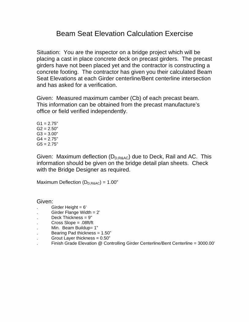
Beam Seat Elevation Calculation Exercise
Situation: You are the inspector on a bridge project which will be placing a cast in place concrete deck on precast girders. The precast girders have not been placed yet and the contractor is constructing a concrete footing. The contractor has given you their calculated Beam Seat Elevations at each Girder centerline/Bent centerline intersection and has asked for a verification. Given: Measured maximum camber (Cb) of each precast beam. This information can be obtained from the precast manufacture’s office or field verified independently. G1 = 2.75” G2 = 2.50” G3 = 3.00” G4 = 2.75” G5 = 2.75”
Given: Maximum deflection (DD,R&AC) due to Deck, Rail and AC. This information should be given on the bridge detail plan sheets. Check with the Bridge Designer as required. Maximum Deflection (DD,R&AC) = 1.00” Given: . Girder Height = 6’ . Girder Flange Width = 2’ . Deck Thickness = 9” . Cross Slope = .08ft/ft . Min. Beam Buildup= 1” . Bearing Pad thickness = 1.50” . Grout Layer thickness = 0.50” . Finish Grade Elevation @ Controlling Girder Centerline/Bent Centerline = 3000.00’

Beam Seat Elevation Calculation Exercise
1 Girder Cambers Measured Max Camber @ Midspan
Beam
G1 2.75 in
G2 2.5 in
G3 3 in
G4 2.75 in
G5 2.75 in
in
2 Controlling Maximum Camber in = ft
3 Deflection Due To Deck, Rail + AC in = ft
4 (a) Min. Beam Buildup 1 in = 0.083 ft
(b) Cross‐slope Buildup @ Girder Centerline
(Flange Width)/2 Cross‐slope
ft x ft/ft = ft
(c)Extra Buildup @ Girder Centerline (4a+4b) ft
(Horiz & vert curvature require additional adjustment)
5 Total Buildup = #2 ‐ #3 + 4c ft
6 Finish Grade Elevation Finish Grade Elevation ft
7 Deck Thickness in = ft
8 Total Buildup (#5) ft
9 Girder Height in = ft
10 Bearing Pad + Grout Thickness in = ft
11 Top of Beam Seat Elevation = ft
(#6 ‐ #7 ‐ #8 ‐ #9 ‐ #10)

Substructure Section 9.1
January, 202013
Excessive Beam Buildup?
Raised Beam Seat & Extended Bolts

Substructure Section 9.1
January, 202014
Deck Grades Between Stages Miss By 5″
Bents Had Straight Cross Slope
• Beam Seats Should Have Been In A Straight Line

Substructure Section 9.1
January, 202015
Consolidation?
Beam Seats for Steel Plate Girders

Substructure Section 9.1
January, 202016
Beam Seats for Steel Plate Girders
Beam PedestalAlignment?

Substructure Section 9.1
January, 202017
Box Beam on Pad?
Consolidation?

Substructure Section 9.1
January, 202018
Beam Seat Cure?
Low Slump Concrete in “E” Beam?

Substructure Section 9.1
January, 202019
Low Slump Concrete?
Concrete Surface Treatments

Substructure Section 9.1
January, 202020
Concrete Surface Treatments
Concrete Surface Treatments
Substructure Section 9.1
January, 202021
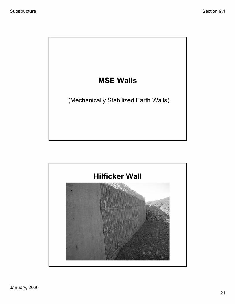
MSE Walls
(Mechanically Stabilized Earth Walls)
Hilficker Wall

Substructure Section 9.1
January, 202022
Wire Placed on Compacted Level Surface
Fine Wire Mesh Against Wire Cage Wall

Substructure Section 9.1
January, 202023
Bottom Panel Interlaces with Top Panel
MSE Wall
• Reinforced Earth Company
• Cruciform Panel

Substructure Section 9.1
January, 202024
Straps Placed on Level Compacted Surface
Straps Cross at Corners

Substructure Section 9.1
January, 202025
Support Wall During Construction
Check Gap Distance

Substructure Section 9.1
January, 202026
Wall Panel Spacers
Fabric at Block Wall Joints

Substructure Section 9.1
January, 202027
Compact Material in Thin Lifts
Coating on Strap?

Substructure Section 9.1
January, 202028
Welded Strap with No Coating?
Hilficker MSE Wall with Concrete Face Poured in Place

Substructure Section 9.1
January, 202029
MSE Wall Setting on Concrete Footing
Concrete Face Poured on Span Side of Wall
Spread Footing on Top of MSE Wall

Substructure Section 9.1
January, 202030
Other Walls
Gabion Wall

Substructure Section 9.1
January, 202031
Block Wall
Secant Pile Wall

Substructure Section 9.1
January, 202032
Soldier Pile& Tieback
Wall
Soldier Pile& Tieback
Wall

Substructure Section 9.1
January, 202033
Soldier Pile& Tieback
Wall
Forming Up To Pour Facade

Substructure Section 9.1
January, 202034
Shear Studs & Rebar Placement
Soldier Pile & Tieback Wall

Substructure Section 9.1
January, 202035
Soil Nail Wall
Soil Nail Wall

Substructure Section 9.1
January, 202036
Soil Nail Wall
View ODOT, Part 9/12

Substructure Section 9.1
January, 202037
Backfilling
Backfilling (00510.48(a))
• If under roadway or end panels and not covered by other spec, place according to 00330.42 & 43.
– Placed in layers of 8 inches or less.
00330.42 (c)(1)
– Each layer compacted to 95 % of maximum density. 00330.43 (b)(2)(b)

Substructure Section 9.1
January, 202038
Embankment Construction @ Bridge Ends (00510.47)
• According To 00330.42 (c-7)
For 100 ft, Place & Compact Before Bridge Construction
Unless An Engineered Fill, Place Selected Stone Backfill Material Per 00330.15
6” Maximum Size
Is This Good Material Under An End Panel?

Substructure Section 9.1
January, 202039
Hard To Compact Spots
Use The Right Size Equipment

Substructure Section 9.1
January, 202040
Backfilling (00510.48 (a))
• Do not place unbalanced loading until 7 days and 100% design strength.
• Do not place against other concrete until 3 days & 40% design strength
Bridge Abutment & Retaining Wall Backfill (00510.48 (b))
• Do not place until superstructure elements are set, pinned and tensioned.
• Place @ front of retaining wall before back of wall.
• For Single Span Bridge With Abutments, Keep backfill heights within 2 ft of each other.

Substructure Section 9.1
January, 202041
Granular Structure Backfill (00510.13)