Cisco Broadband Access Center Administration Guide 3.9
338
Americas Headquarters Cisco Systems, Inc. 170 West Tasman Drive San Jose, CA 95134-1706 USA http://www.cisco.com Tel: 408 526-4000 800 553-NETS (6387) Fax: 408 527-0883 Cisco Broadband Access Center 3.9 Administrator Guide December, 2014 Text Part Number: OL-32130-01
-
Upload
khangminh22 -
Category
Documents
-
view
2 -
download
0
Transcript of Cisco Broadband Access Center Administration Guide 3.9

Cisco Broadband Access Center 3.9 Administrator Guide
December, 2014
Americas HeadquartersCisco Systems, Inc.170 West Tasman DriveSan Jose, CA 95134-1706 USAhttp://www.cisco.comTel: 408 526-4000
800 553-NETS (6387)Fax: 408 527-0883
Text Part Number: OL-32130-01

THE SPECIFICATIONS AND INFORMATION REGARDING THE PRODUCTS IN THIS MANUAL ARE SUBJECT TO CHANGE WITHOUT NOTICE. ALL STATEMENTS, INFORMATION, AND RECOMMENDATIONS IN THIS MANUAL ARE BELIEVED TO BE ACCURATE BUT ARE PRESENTED WITHOUT WARRANTY OF ANY KIND, EXPRESS OR IMPLIED. USERS MUST TAKE FULL RESPONSIBILITY FOR THEIR APPLICATION OF ANY PRODUCTS.
THE SOFTWARE LICENSE AND LIMITED WARRANTY FOR THE ACCOMPANYING PRODUCT ARE SET FORTH IN THE INFORMATION PACKET THAT SHIPPED WITH THE PRODUCT AND ARE INCORPORATED HEREIN BY THIS REFERENCE. IF YOU ARE UNABLE TO LOCATE THE SOFTWARE LICENSE OR LIMITED WARRANTY, CONTACT YOUR CISCO REPRESENTATIVE FOR A COPY.
The Cisco implementation of TCP header compression is an adaptation of a program developed by the University of California, Berkeley (UCB) as part of UCB’s public domain version of the UNIX operating system. All rights reserved. Copyright © 1981, Regents of the University of California.
NOTWITHSTANDING ANY OTHER WARRANTY HEREIN, ALL DOCUMENT FILES AND SOFTWARE OF THESE SUPPLIERS ARE PROVIDED “AS IS” WITH ALL FAULTS. CISCO AND THE ABOVE-NAMED SUPPLIERS DISCLAIM ALL WARRANTIES, EXPRESSED OR IMPLIED, INCLUDING, WITHOUT LIMITATION, THOSE OF MERCHANTABILITY, FITNESS FOR A PARTICULAR PURPOSE AND NONINFRINGEMENT OR ARISING FROM A COURSE OF DEALING, USAGE, OR TRADE PRACTICE.
IN NO EVENT SHALL CISCO OR ITS SUPPLIERS BE LIABLE FOR ANY INDIRECT, SPECIAL, CONSEQUENTIAL, OR INCIDENTAL DAMAGES, INCLUDING, WITHOUT LIMITATION, LOST PROFITS OR LOSS OR DAMAGE TO DATA ARISING OUT OF THE USE OR INABILITY TO USE THIS MANUAL, EVEN IF CISCO OR ITS SUPPLIERS HAVE BEEN ADVISED OF THE POSSIBILITY OF SUCH DAMAGES.
Cisco and the Cisco logo are trademarks or registered trademarks of Cisco and/or its affiliates in the U.S. and other countries. To view a list of Cisco trademarks, go to this URL: www.cisco.com/go/trademarks. Third-party trademarks mentioned are the property of their respective owners. The use of the word partner does not imply a partnership relationship between Cisco and any other company. (1110R)
Any Internet Protocol (IP) addresses and phone numbers used in this document are not intended to be actual addresses and phone numbers. Any examples, command display output, network topology diagrams, and other figures included in the document are shown for illustrative purposes only. Any use of actual IP addresses or phone numbers in illustrative content is unintentional and coincidental.
Cisco Broadband Access Center 3.9 Administrator Guide© 2014 Cisco Systems, Inc. All rights reserved.

OL-32130-01
C O N T E N T S
Preface xv
Broadband Access Center Overview 1-1
Features and Benefits 1-1
Supported Technology 1-3
CWMP Technology 1-3
TR-196 1-3
Broadband Access Center Architecture 2-1
Cisco BAC Deployment 2-1
Architecture 2-2
Regional Distribution Unit 2-4
Device Provisioning Engines 2-4
DPE Extension 2-5
DPE Licensing 2-5
Provisioning Groups 2-6
Discovery of ACS URL 2-6
Provisioning Group Scalability 2-7
Cisco BAC Process Watchdog 2-7
SNMP Agent 2-7
Logging 2-7
Cisco Prime Access Registrar 2-8
RADIUS 2-8
Cisco Prime Network Registrar 2-8
DHCP 2-9
LeaseQuery 2-9
Configuration Workflows and Checklists 3-1
Component Workflows 3-1
RDU Checklist 3-1
DPE Checklist 3-2
Technology Workflows 3-3
iiiCisco Broadband Access Center 3.9 Administrator Guide
Contents
RDU Configuration Workflow 3-3
Preregistering Device Data in Cisco BAC 3-4
DPE Configuration Workflow 3-5
Configuring CWMP Service on the DPE 3-6
Configuring HTTP File Service on the DPE 3-7
Configuring HTTP Auth Service on the DPE 3-8
Provisioning Group Configuration Workflow 3-8
Configuring Home Provisioning Group Redirection Service on the DPE 3-9
CPE Management Overview 4-1
CWMP Overview 4-1
Cisco BAC Device Object Model 4-2
Property Hierarchy 4-4
Custom Properties 4-4
Discovering CPE Parameters 4-4
Multi-Instance Object Support 4-5
Configuration Template 4-6
Firmware Rules Template 4-13
Parameter Discovery 4-15
Display Live Data Operation 4-15
Instance Sorting 4-16
Instruction Generation and Processing 4-16
Device Configuration Synchronization 4-17
Device Deployment in Cisco BAC 4-19
Preregistered Devices 4-19
Unregistered Devices 4-20
Initial Provisioning Flows 4-20
For Preregistered Devices 4-21
For Unregistered Devices 4-21
Assigning Devices to Provisioning Groups 4-22
Explicit Assignment 4-22
Automatic Membership 4-22
Combined Approach 4-23
Device Diagnostics 4-23
Configuring SNMP Trap for CPEs 4-24
Configuration Templates Management 5-1
Overview 5-1
ivCisco Broadband Access Center 3.9 Administrator Guide
OL-32130-01
Contents
Features of Cisco BAC Templates 5-3
Parameters 5-6
Parameter List for Single Instance Object 5-7
Parameter List for Multiple Instance Objects 5-7
Notification 5-8
Configuring Notification 5-8
Access Control 5-9
Configuring Access Control 5-9
Prerequisites 5-9
Expressions 5-11
MaintenanceWindow 5-11
Configuring Prerequisites 5-13
Authoring Configuration Templates 5-14
Custom Properties 5-16
Using Parameter Substitution 5-17
Using Includes 5-18
Using Conditionals 5-19
Using the Configuration Utility 5-23
Running the Configuration Utility 5-23
Adding a Template to Cisco BAC 5-24
Validating XML Syntax for a Local Template File 5-24
Validating XML Syntax for a Template Stored in Cisco BAC 5-25
Testing Template Processing for a Local Template File 5-26
Testing Template Processing for a Template Stored in Cisco BAC 5-26
Testing Template Processing for a Cisco BAC Template File and a Device 5-27
Firmware Management 6-1
Overview 6-1
Firmware Management Mechanisms 6-2
Firmware Rule Templates 6-2
Direct Firmware Management 6-4
Managing Firmware Files 6-5
Authoring Firmware Rules Templates 6-6
Expression and Regular Expression 6-7
Internal Firmware File vs. External Firmware File 6-10
InternalFirmwareFile 6-10
vCisco Broadband Access Center 3.9 Administrator Guide
OL-32130-01
Contents
ExternalFirmwareFile 6-11
Sample Firmware Rules Template 6-11
Using Template Constructs with Firmware Rule Templates 6-13
Using Parameter Substitution 6-14
Using Includes 6-14
Using Conditionals 6-15
Parameter Dictionaries 7-1
Overview 7-1
Using Default Dictionaries 7-2
Custom Dictionaries 7-3
Parameter Dictionary Syntax 7-3
Sample Parameter Dictionary 7-4
Managing Parameter Dictionaries through User Interface 7-6
Adding Parameter Dictionaries 7-6
Viewing Parameter Dictionaries 7-7
Deleting Parameter Dictionaries 7-7
Replacing Parameter Dictionaries 7-7
CPE History and Troubleshooting 8-1
Device History 8-1
Configuring Device History 8-4
Enabling Device History 8-4
Viewing Device History 8-4
Configuring Device History Size 8-5
Device History Records 8-5
Device Faults 8-6
Retrieving Device Faults 8-7
Managing Chatty Clients 8-9
Device Troubleshooting 8-9
Configuring Device Troubleshooting 8-10
Enabling Troubleshooting for a Device 8-10
Disabling Troubleshooting for a Device 8-11
viCisco Broadband Access Center 3.9 Administrator Guide
OL-32130-01
Contents
Viewing List of Devices in Troubleshooting Mode 8-11
Viewing Device Troubleshooting Log 8-12
Managing Cisco Broadband Access Center 9-1
Cisco BAC Process Watchdog 9-1
Using Cisco BAC Process Watchdog from the Command Line 9-2
Enabling SNMP Trap for Cisco BAC Process Watchdog 9-3
Administrator User Interface 9-4
Command Line Interface 9-5
Accessing the DPE CLI from a Local Host 9-5
Accessing the DPE CLI from a Remote Host 9-5
SNMP Agent 9-5
Cisco BAC Tools 9-6
Database Management 10-1
Understanding Failure Resiliency 10-1
Database Files 10-2
Database Storage File 10-2
Database Transaction Log Files 10-2
Automatic Log Management 10-3
Miscellaneous Database Files 10-3
Disk Space Requirements 10-3
Handling Out of Disk Space Conditions 10-4
Backup and Recovery 10-4
Database Backup 10-4
Database Recovery 10-5
Database Restore 10-6
Changing Database Location 10-7
Monitoring Cisco Broadband Access Center 11-1
Syslog Alert Messages 11-1
Message Format 11-1
RDU Alerts 11-2
DPE Alerts 11-2
Watchdog Agent Alerts 11-4
Access Registrar Extension Point Alerts 11-5
Monitoring Servers by Using SNMP 11-5
SNMP Agent 11-6
viiCisco Broadband Access Center 3.9 Administrator Guide
OL-32130-01
Contents
MIB Support 11-6
Using the snmpAgentCfgUtil.sh Tool 11-6
Adding a Host 11-7
Deleting a Host 11-7
Adding an SNMP Agent Community 11-8
Deleting an SNMP Agent Community 11-9
Starting the SNMP Agent 11-9
Stopping the SNMP Agent 11-9
Configuring an SNMP Agent Listening Port 11-10
Changing the SNMP Agent Location 11-10
Setting Up SNMP Contacts 11-10
Displaying SNMP Agent Settings 11-11
Specifying SNMP Notification Types 11-11
Monitoring Server Status 11-12
Using the Administrator User Interface 11-12
Using the DPE CLI 11-12
Monitoring Performance Statistics 11-14
Understanding perfstat.log 11-15
Using runStatAnalyzer.sh 11-15
Monitoring STUN Statistics 11-17
Understanding stunstatistics.log 11-17
STUN Binding Information 11-18
Using dumpStunBindingInfo.sh 11-18
Traffic Profiling 11-18
Configuring CWMP Service 12-1
CWMP Service Configuration 12-1
Configuring Service Ports on the DPE 12-2
Connection Request Service 12-2
Configuring Connection Request Options 12-3
Configuring Authentication 12-3
Autogenerating Connection Request Passwords 12-4
Configuring Connection Request Methods 12-5
Configuring External URLs on DPE 12-10
Disabling Connection Requests 12-11
Configuring Reachability 12-11
Discovering Data from Devices 12-12
viiiCisco Broadband Access Center 3.9 Administrator Guide
OL-32130-01
Contents
Configuring Data Discovery 12-12
Troubleshooting Data Discovery 12-13
Automatic IMEI Update 12-15
Provisioning Group Scalability and Failover 12-16
Redundancy in Cisco BAC 12-16
Local Redundancy 12-16
Regional Redundancy 12-16
DPE Load-Balancing 12-17
Using DNS Round Robin 12-17
Using a Hardware Load Balancer 12-17
Adding DPE to a Provisioning Group 12-18
Configuring CWMP Service Security 13-1
Overview 13-1
Key and Certificate Management in Cisco BAC 13-2
Configuring SSL Service 13-3
Configuring DPE Keystore by Using the Keytool 13-3
Using the Keytool Commands 13-5
Generating Server Certificate Keystore and Private Key for a New Certificate 13-6
Displaying Self-Signed Certificate 13-7
Generating a Certificate-Signing Request 13-7
Importing Signing Authority Certificate into Cacerts Keystore 13-8
Importing the Signed Certificate into Server Certificate Keystore 13-9
Importing Certificates for Client Authentication 13-10
Configuring Security for DPE Services 13-11
Configuring SSL on a DPE 13-11
Enabling SSL for the CWMP Service 13-11
Enabling SSL for the HTTP File Service 13-12
Configuring CPE Authentication 13-13
Shared Secret Authentication 13-13
Client Certificate Authentication 13-16
External Client Certificate Authentication 13-16
Authentication Options in Cisco BAC 13-17
Configuring Security for RDU Services 13-18
RDU Authentication Mode Settings 13-19
ixCisco Broadband Access Center 3.9 Administrator Guide
OL-32130-01
Contents
TACACS+ Authentication and Authorization in RDU 13-19
Signed Configuration for Devices 13-20
Signature Expiration 13-20
Signature Regeneration 13-20
Configuration Interfaces 13-20
Monitoring the Signed Configuration Feature 13-21
Troubleshooting Signed Configuration Feature 13-22
Custom Vendor Specific Attribute (VSA) in RADIUS Response 13-22
Adding Custom VSA 13-22
Property Format Based on Type 13-23
CWMP Device Operations 14-1
Overview 14-1
Connection Modes for Device Operations 14-2
Immediate Mode 14-2
On-Connect Mode 14-3
Asynchronous Mode 14-5
Conditional Execution 14-6
Managing a Device’s Provisioning Group 14-6
Redirecting CPE to Home Provisioning Group 14-7
Correcting a Device’s Provisioning Group 14-8
Understanding the Administrator User Interface 15-1
Configuring the Administrator User Interface 15-1
Accessing the Administrator User Interface 15-2
Logging In 15-2
Logging Out 15-4
Understanding the Administrator User Interface Icons 15-4
Using the Administrator User Interface 16-1
User Management 16-1
Administrator 16-1
Read/Write User 16-2
Read-Only User 16-2
Adding a New User 16-2
Modifying Users 16-3
Deleting Users 16-4
Device Management 16-4
xCisco Broadband Access Center 3.9 Administrator Guide
OL-32130-01
Contents
Manage Devices Page 16-4
Searching for Devices 16-5
Device Management Controls 16-7
Viewing Device Details 16-7
Managing Devices 16-10
Adding Device Records 16-11
Modifying Device Records 16-11
Deleting Device Records 16-11
Viewing Device History 16-12
Regenerating Device Instructions 16-12
Relating and Unrelating Devices 16-13
Performing Operations on Devices 16-14
Group Management 16-18
Managing Group Types 16-18
Adding a Group Type 16-19
Modifying Group Types 16-20
Deleting Group Types 16-20
Managing Groups 16-20
Adding a New Group or Subgroup 16-20
Modifying a Group or Subgroup 16-21
Deleting Groups or Subgroups 16-22
Relating/Unrelating Groups to Groups 16-22
Viewing Group Details 16-22
Viewing Servers 16-22
Viewing Device Provisioning Engines 16-22
Viewing Network Registrar Extension Point Details 16-25
Viewing Provisioning Groups 16-26
Viewing Regional Distribution Unit Details 16-27
Configuring Broadband Access Center 17-1
Configuring the Class of Service 17-1
Adding a Class of Service 17-4
Modifying a Class of Service 17-4
Deleting a Class of Service 17-5
Configuring Custom Properties 17-6
Configuring Defaults 17-9
xiCisco Broadband Access Center 3.9 Administrator Guide
OL-32130-01

Contents
Selecting Configuration Options 17-9
CWMP Defaults 17-10
RDU Defaults 17-13
System Defaults 17-14
TACACS+ Defaults 17-16
Managing Files 17-18
Adding Files 17-20
Viewing Files 17-21
Replacing Files 17-21
Exporting Files 17-22
Deleting Files 17-22
Managing License Keys 17-23
Adding and Modifying a License 17-24
Managing DPE Feature Pack Extensions 17-24
Writing a New Class for DPE Feature Pack Extensions 17-25
Managing RDU Extensions 17-26
Writing a New Class for RDU 17-27
Installing RDU Custom Extensions 17-28
Viewing RDU Extensions 17-29
Publishing Provisioning Data 17-29
Publishing Datastore Changes 17-29
Modifying Publishing Plug-In Settings 17-29
Configuring Lease Query 17-30
Updating the Location of FAP at Group Level in the Grid 17-31
Configuring BAC and the Device for CIG 17-31
Updating the Location of FAP at Chassis Level 17-33
Configuring BAC and the Device for CIC 17-33
Configuring Location Verification for UMTS 17-35
Configuring 2G Scan and 3G Scan Capability of LTE 17-35
Configuring Static Neighbor List of LTE 17-35
Configuring Remote Reset for Tampered LTE FAP 17-37
Scripting Framework 18-1
Overview 18-1
Script’s Shared Scope 18-1
Extension Script 18-2
xiiCisco Broadband Access Center 3.9 Administrator Guide
OL-32130-01
Contents
Integrating Extension Scripts in BAC 18-3
Adding Extension Points to the Device Property 18-3
Configuring Extensions for Unknown Devices 18-4
Verifying Extension Scripts Availability in DPE Cache 18-5
Verifying Status of the Extensions in DPE 18-5
RDU and DPE Connection Management 19-1
TCP Connection Management 19-1
Heart Beat 19-1
RDU Batch Concurrency 19-2
Non-concurrent Commands 19-2
Long-Running Batch 19-3
DPE-RDU Synchronization 19-3
Cisco BAC Support Tools and Advanced Concepts 20-1
Using the deviceExport.sh Tool 20-1
Using the disk_monitor.sh Tool 20-4
Using the resetAdminPassword.sh Tool 20-5
Using the runEventMonitor.sh Tool 20-5
Using the changeARProperties.sh Tool 20-8
Using the changeNRProperties.sh Tool 20-9
Obtaining the Key Performance Indicators (KPI) for BAC 20-10
Configuring the Properties for Generating the .csv File 20-10
Troubleshooting Broadband Access Center 21-1
Troubleshooting Checklist 21-1
Logging 21-2
Log Levels and Structures 21-3
Configuring Log Levels 21-4
Rotating Log Files 21-4
RDU Logs 21-5
Viewing the rdu.log File 21-5
Viewing the audit.log File 21-5
The RDU Log Level Tool 21-5
DPE Logs 21-8
Viewing the dpe.log File 21-8
Access Registrar Logs 21-8
xiiiCisco Broadband Access Center 3.9 Administrator Guide
OL-32130-01

Contents
FAQs on Provisioning Cisco Broadband Access Center A-1
How do I enable or disable Network Registrar extensions? A-1
I N D E X
xivCisco Broadband Access Center 3.9 Administrator Guide
OL-32130-01
Preface
The Cisco Broadband Access Center 3.9 Administrator Guide describes concepts and configurations related to Cisco Broadband Access Center, which is called Cisco BAC throughout this guide.
This chapter provides an outline of the other chapters in this guide, detailed information about related documents that support this Cisco BAC release, and demonstrates the styles and conventions used in the guide.
Note This document is to be used in conjunction with the documentation listed in Product Documentation, page xviii.
This chapter contains the following information:
• Audience, page xv
• Organization, page xvi
• Conventions, page xvii
• Product Documentation, page xviii
• Related Documentation, page xviii
AudienceThe Cisco Broadband Access Center 3.9 Administrator Guide is written for system administrators involved in automating large-scale provisioning for broadband access. The network administrator should be familiar with these topics:
• Basic networking concepts and terminology.
• Network administration.
xvCisco Broadband Access Center 3.9 Administrator Guide
OL-32130-01
Chapter
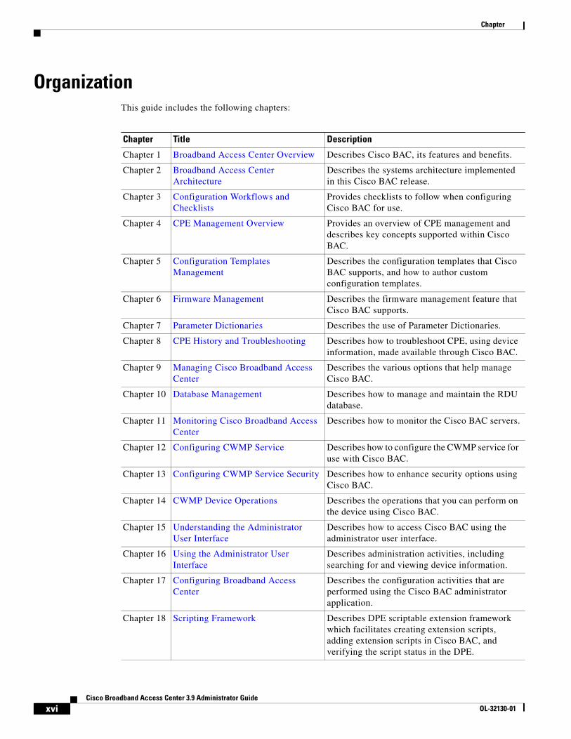
OrganizationThis guide includes the following chapters:
Chapter Title Description
Chapter 1 Broadband Access Center Overview Describes Cisco BAC, its features and benefits.
Chapter 2 Broadband Access Center Architecture
Describes the systems architecture implemented in this Cisco BAC release.
Chapter 3 Configuration Workflows and Checklists
Provides checklists to follow when configuring Cisco BAC for use.
Chapter 4 CPE Management Overview Provides an overview of CPE management and describes key concepts supported within Cisco BAC.
Chapter 5 Configuration Templates Management
Describes the configuration templates that Cisco BAC supports, and how to author custom configuration templates.
Chapter 6 Firmware Management Describes the firmware management feature that Cisco BAC supports.
Chapter 7 Parameter Dictionaries Describes the use of Parameter Dictionaries.
Chapter 8 CPE History and Troubleshooting Describes how to troubleshoot CPE, using device information, made available through Cisco BAC.
Chapter 9 Managing Cisco Broadband Access Center
Describes the various options that help manage Cisco BAC.
Chapter 10 Database Management Describes how to manage and maintain the RDU database.
Chapter 11 Monitoring Cisco Broadband Access Center
Describes how to monitor the Cisco BAC servers.
Chapter 12 Configuring CWMP Service Describes how to configure the CWMP service for use with Cisco BAC.
Chapter 13 Configuring CWMP Service Security Describes how to enhance security options using Cisco BAC.
Chapter 14 CWMP Device Operations Describes the operations that you can perform on the device using Cisco BAC.
Chapter 15 Understanding the Administrator User Interface
Describes how to access Cisco BAC using the administrator user interface.
Chapter 16 Using the Administrator User Interface
Describes administration activities, including searching for and viewing device information.
Chapter 17 Configuring Broadband Access Center
Describes the configuration activities that are performed using the Cisco BAC administrator application.
Chapter 18 Scripting Framework Describes DPE scriptable extension framework which facilitates creating extension scripts, adding extension scripts in Cisco BAC, and verifying the script status in the DPE.
xviCisco Broadband Access Center 3.9 Administrator Guide
OL-32130-01
Chapter
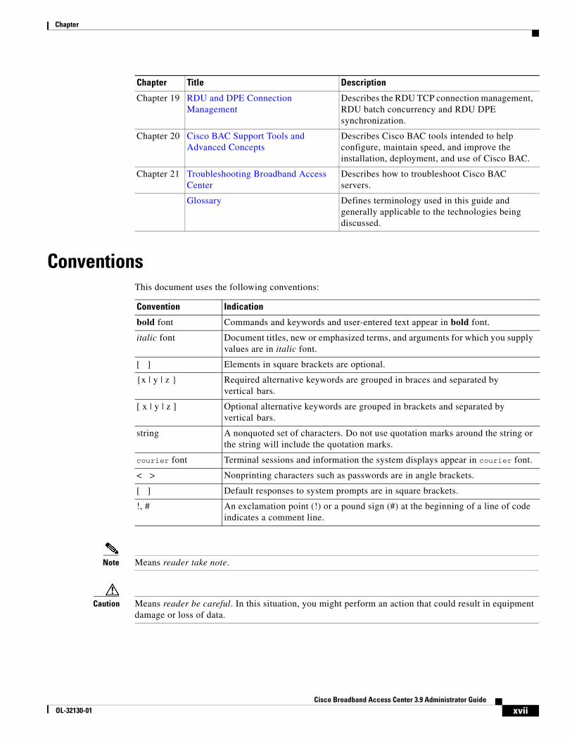
ConventionsThis document uses the following conventions:
Note Means reader take note.
Caution Means reader be careful. In this situation, you might perform an action that could result in equipment damage or loss of data.
Chapter 19 RDU and DPE Connection Management
Describes the RDU TCP connection management, RDU batch concurrency and RDU DPE synchronization.
Chapter 20 Cisco BAC Support Tools and Advanced Concepts
Describes Cisco BAC tools intended to help configure, maintain speed, and improve the installation, deployment, and use of Cisco BAC.
Chapter 21 Troubleshooting Broadband Access Center
Describes how to troubleshoot Cisco BAC servers.
Glossary Defines terminology used in this guide and generally applicable to the technologies being discussed.
Chapter Title Description
Convention Indication
bold font Commands and keywords and user-entered text appear in bold font.
italic font Document titles, new or emphasized terms, and arguments for which you supply values are in italic font.
[ ] Elements in square brackets are optional.
{x | y | z } Required alternative keywords are grouped in braces and separated by vertical bars.
[ x | y | z ] Optional alternative keywords are grouped in brackets and separated by vertical bars.
string A nonquoted set of characters. Do not use quotation marks around the string or the string will include the quotation marks.
courier font Terminal sessions and information the system displays appear in courier font.
< > Nonprinting characters such as passwords are in angle brackets.
[ ] Default responses to system prompts are in square brackets.
!, # An exclamation point (!) or a pound sign (#) at the beginning of a line of code indicates a comment line.
xviiCisco Broadband Access Center 3.9 Administrator Guide
OL-32130-01
Chapter
Product Documentation
Note We sometimes update the printed and electronic documentation after original publication. Therefore, you should also review the documentation on Cisco.com for any updates.
You can view the marketing and user documents for Cisco Broadband Access Center at:
http://www.cisco.com/en/US/products/sw/netmgtsw/ps529/tsd_products_support_series_home.html
The following document gives you the list of user documents for Cisco Broadband Access Center 3.8: http://www.cisco.com/en/US/docs/net_mgmt/broadband_access_center/3.8/documentation/overview/Cisco_Broadband_Access_Center_Documentation_Overview_38.html
Related Documentation
Note We sometimes update the printed and electronic documentation after original publication. Therefore, you should also review the documentation on Cisco.com for any updates.
The following document gives you the list of user documents for Cisco Prime Network Registrar 8.1:
http://www.cisco.com/en/US/docs/net_mgmt/prime/network_registrar/8.1/doc_overview/guide/CPNR_8_1_Doc_Guide.html
The following document gives you the list of user documents for Cisco Access Registrar 5.0:
http://www.cisco.com/en/US/docs/net_mgmt/access_registrar/5.0/roadmap/guide/PrintPDF/ardocgd.html
xviiiCisco Broadband Access Center 3.9 Administrator Guide
OL-32130-01
CiscoOL-32130-01
C H A P T E R 1
Broadband Access Center OverviewThis chapter provides an overview of Cisco Broadband Access Center (Cisco BAC).
Cisco BAC automates the tasks of provisioning and managing customer premises equipment (CPE) in a broadband service provider network.
With the high-performance capabilities of Cisco BAC, you can scale the product to suit networks of virtually any size, even those with millions of CPE. It also offers high availability, made possible by the product’s distributed architecture and centralized management.
Cisco BAC supports provisioning and managing of CPE by using the Broadband Forum’s CPE WAN Management Protocol (CWMP), a standard defined in the TR-069 specification. Cisco BAC integrates the capabilities defined in TR-069 to increase operator efficiency and reduce network-management problems.
Cisco BAC supports devices based on the TR-069, TR-098, TR-104, TR-106, TR-181, and TR-196 standards. These devices include Ethernet and ADSL gateway devices, wireless gateways, Home Node-B (HNB) gateways, VoIP ATAs, and other devices compliant with CWMP. Cisco BAC also provides for runtime-extensible data models to support any upcoming data-model standards or any vendor-specific data models based on CWMP.
Cisco BAC provides such critical features as redundancy and failover. Cisco BAC can be integrated into new or existing environments through the use of a provisioning application programming interface (API) that lets you control how Cisco BAC operates.
You can use the provisioning API to register devices in Cisco BAC, assign device configuration policies, execute any CWMP operations on the CPE, and configure the entire Cisco BAC provisioning system.
This chapter includes the following sections:
• Features and Benefits, page 1-1
• Supported Technology, page 1-3
Features and BenefitsCisco BAC helps service providers provision and manage the rapidly expanding number of home networking devices.
Cisco BAC supports mass-scale provisioning and managing of small cell devices that function as mini 3G cell tower in customer premises and backhaul call using the customer’s internet connection. Apart from supporting the small cell devices, Cisco BAC also supports provisioning and managing of Digital Life Controller (DLC) devices based on TR-069 protocol.
This section describes the basic features and benefits that the Cisco BAC architecture offers:
1-1 Broadband Access Center 3.9 Administrator Guide
Chapter 1 Broadband Access Center OverviewFeatures and Benefits
• Configuration management: Vastly simplified in Cisco BAC through configuration templates, which provide an easy, yet flexible mechanism to assign configurations for CPE. You can use the template-processing mechanism to customize configurations for millions of devices by using a small number of templates.
By using these XML-based templates, you can set configuration parameters and values, and notification and access controls on a device. Configuration templates allow:
– Conditionals, to include or exclude sections of a template based on, among others, Cisco BAC property values.
– Includes, to include template content from other files.
– Parameter substitution, to substitute Cisco BAC property values into template parameters.
– Prerequisites, to evaluate whether the template is applicable to a device at given time.
• Firmware management: Maintaining and distributing sets of firmware image files to corresponding CPE through the Cisco BAC system. A firmware rules template, associates the firmware image files to groups of devices. Cisco BAC uses the rules in the associated firmware rules template to evaluate the firmware that is downloaded to the device.
Using the firmware management feature, you can view firmware information on devices, add firmware images to the database, and apply the image files to specific CPE.
• Massive scalability: Enhanced by partitioning CPE into provisioning groups; each provisioning group is responsible for only a subset of the CPE. A provisioning group is designed to be a logical (typically geographic) grouping of servers, usually consisting of one or more Device Provisioning Engines (DPEs).
The number of devices in a provisioning group depends on the load and deployment conditions. You can add additional provisioning groups to the deployment, if required.
• Standards-based security: Cisco BAC is designed to provide a high degree of security by using CWMP, outlined in the TR-069 standard. The CWMP security model is also designed to be scalable. It is intended to allow basic security to accommodate less robust CPE implementations, while allowing greater security for those that can support more advanced security mechanisms.
Cisco BAC integrates the Secure Sockets Layer (SSL) version 3.0 and the Transport Layer Security (TLS) version 1.0 protocols into its CWMP ACS implementation. By using HTTP over SSL/TLS (also known as HTTPS), Cisco BAC provides confidentiality and data integrity, and allows certificate-based authentication between the various components.
• Easy integration with back-end systems, using Cisco BAC mechanisms such as:
– The Cisco BAC Java API, which can be used to perform all provisioning and management operations.
– The Cisco BAC publishing extensions, which are useful in writing RDU data into another database.
– The Cisco BAC Data Export tool, with which you can write device information from the Cisco BAC system to a file.
– The SNMP agent, which simplifies integration for monitoring Cisco BAC.
– The DPE command line interface, which simplifies local configuration when you use it to copy and paste commands.
• Extensive server management: Cisco BAC provides extensive server performance statistics, thereby enabling monitoring and troubleshooting.
1-2Cisco Broadband Access Center 3.9 Administrator Guide
OL-32130-01
Chapter 1 Broadband Access Center OverviewSupported Technology
• Device diagnostics and troubleshooting: You use this feature to focus on a single device and collect diagnostics information for further analysis. Cisco BAC provides several features to assist diagnosis:
– Device history—Provides a detailed history of significant events that occur in a device provisioning lifecycle.
– Device faults—Detects devices with recurring faults, which can cause bottlenecks and affect network performance.
– Device troubleshooting—Provides detailed records of device interactions with Cisco BAC servers for a set of devices that are designated for such troubleshooting.
– Direct device operations—Operations such as IP Ping and Get Live Data can be run on the device for more insight.
• Multi-instance object support: This feature introduces support for discovering and updating the CPE parameters associated with multiple object instances, without specifying the actual instance number. The multi-instance object support in the template, adds the flexibility to apply the configuration on selective object instances.
• Scriptable framework: This feature introduces the scriptable extension service which facilitates running the Java scripts based DPE extensions. This feature also provides the support to load and unload the extensions dynamically without restarting the DPE.
Supported TechnologyThis Cisco BAC release supports the provisioning and managing of CPE only through CWMP, outlined in the TR-069 specification. However, virtually any data models based on TR-069, TR-098, TR-104, TR-106, TR-181, and TR-196 extensions are supported.
CWMP TechnologyTR-069 is a standard for remote management of CPE. This standard defines CWMP, which enables communication between CPE and an autoconfiguration server (ACS).
CWMP details a mechanism that increases operator efficiency and reduces network management problems through its primary capabilities. These capabilities include:
• Autoconfiguration
• Firmware Management
• Status and Performance Monitoring
• Device Diagnostics and Troubleshooting
In addition to CWMP, the TR-069 specification defined a version 1.0 of the data model for Internet Gateway Device (IGD), which has since been expanded by TR-098. CWMP, as defined in TR-069, works with any data model extended from CWMP, including those defined in TR-098, TR-104, TR-106, TR-181, and TR-196, upcoming new ones, or those that are vendor specific.
TR-196
TR-196 standard provides the data model for the Femto Access Point (FAP) for remote management purposes using the TR-069 CWMP.
1-3Cisco Broadband Access Center 3.9 Administrator Guide
OL-32130-01
Chapter 1 Broadband Access Center OverviewSupported Technology
The Cisco BAC template-based mechanism to assign configurations for devices is enhanced to support the TR-196 devices in the service provider's network. Cisco BAC provides two additional parameter dictionary files to support the following TR-196 data models:
• TR-196 Issue 1 Amendment 1
• TR-196 Issue 2 and TR-181 Issue 2 Amendment 2
Cisco BAC also provides a Generally Available (GA) scriptable extensions targeting residential 3G and LTE features of above TR-196 data models. You can use the corresponding properties to configure the extension and the TR-196 data model to be used for any device.
The support for discovering multiple objects instances associated with a parameter, is also available for TR-196 devices.
1-4Cisco Broadband Access Center 3.9 Administrator Guide
OL-32130-01
CiscoOL-32130-01
C H A P T E R 2
Broadband Access Center ArchitectureThis chapter describes the system architecture implemented in this Cisco Broadband Access Center (Cisco BAC) release.
This chapter includes the following sections:
• Cisco BAC Deployment, page 2-1
• Architecture, page 2-2
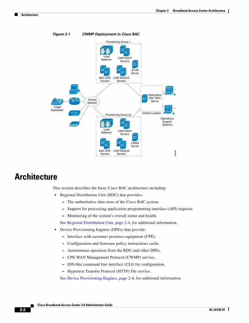
Cisco BAC DeploymentCisco BAC provisions devices are based on the TR-069, TR-098, TR-104, TR-106, TR-181, and TR-196 standards. This includes Ethernet and ADSL gateway devices, wireless gateways, Home Node-B (HNB) gateways, VoIP ATAs, and other devices compliant with the CPE WAN Management Protocol (CWMP).
Figure 2-1 represents a typical, fully redundant, CWMP deployment in a Cisco BAC network.
2-1 Broadband Access Center 3.9 Administrator Guide
Chapter 2 Broadband Access Center ArchitectureArchitecture
Figure 2-1 CWMP Deployment in Cisco BAC
ArchitectureThis section describes the basic Cisco BAC architecture including:
• Regional Distribution Unit (RDU) that provides:
– The authoritative data store of the Cisco BAC system.
– Support for processing application programming interface (API) requests.
– Monitoring of the system’s overall status and health.
See Regional Distribution Unit, page 2-4, for additional information.
• Device Provisioning Engines (DPEs) that provide:
– Interface with customer premises equipment (CPE).
– Configuration and firmware policy instructions cache.
– Autonomous operation from the RDU and other DPEs.
– CPE WAN Management Protocol (CWMP) service.
– IOS-like command line interface (CLI) for configuration.
– Hypertext Transfer Protocol (HTTP) file service.
See Device Provisioning Engines, page 2-4, for additional information.
IP
OperationsSupportSystems
RedundantBAC RDU
Server
Central Location
AccessNetwork
28
43
84
TargetSubscriber
Provisioning Group 1
BAC DPEServers
CAR RADIUSServers
CNR DHCPServers
LoadBalancer
STUNServer
Provisioning Group [n]
BAC DPEServers
CAR RADIUSServers
CNR DHCPServers
LoadBalancer
CHMSServer
2-2Cisco Broadband Access Center 3.9 Administrator Guide
OL-32130-01
Chapter 2 Broadband Access Center ArchitectureArchitecture
• STUN server:
– Supports a UDP based connection request mechanism defined in TR069 Annex G to allow Cisco BAC to initiate a session with a CPE that is operating behind a NAT Gateway.
• Cisco Management Heartbeat Server (CMHS) server:
– A new connection request method that allows Cisco BAC to send connection requests to DLC devices through the CMHS server, using BAC north bound API interfaces or BAC Admin UI.
• Client API that provides total client control over the system’s capabilities.
• Provisioning Groups that provide:
– Logical grouping of DPE servers, PAR-RADIUS servers and CNR-DHCP servers in a redundant cluster.
– Redundancy and scalability
See Provisioning Groups, page 2-6, for additional information.
• The Cisco BAC process watchdog that provides:
– Administrative monitoring of all critical Cisco BAC processes.
– Automated process restart capability.
– Ability to start and stop Cisco BAC component processes.
– Ability to send the SNMP trap if any BAC process fails to start or stop, or stops unexpectedly. SNMP trap is a mechanism that the trap receiver uses to get the information about the process or component failure. A SNMP trap is also sent if Cisco BAC process watchdog fails to start on any of the servers that run Cisco BAC components. Cisco BAC process watchdog reports all the critical conditions of BAC components through SNMP trap.
See Cisco BAC Process Watchdog, page 2-7, for additional information.
2-3Cisco Broadband Access Center 3.9 Administrator Guide
OL-32130-01
Chapter 2 Broadband Access Center ArchitectureArchitecture
• An administrator user interface that provides:
– Support for adding, deleting, and modifying CWMP devices; searching for devices, retrieving device details, and running device operations.
– Support for configuring global defaults and defining custom properties.
– Ability to view additional performance statistics.
– Management of firmware rules and configuration templates.
See Administrator User Interface, page 9-4, for additional information.
• An SNMP agent that supports:
– Third-party management systems.
– SNMP version v2.
– SNMP Notification.
See SNMP Agent, page 2-7, for additional information.
• Cisco Network Registrar servers that provide:
– Dynamic Host Configuration Protocol (DHCP).
See Cisco Prime Network Registrar, page 2-8, for additional information.
Regional Distribution Unit The Regional Distribution Unit (RDU) is the primary server in the Cisco BAC provisioning system. It is installed on a server running the Solaris 10 or Linux 5.x operating system.
The functions of the RDU include:
• Managing preprovisioned and discovered data from devices.
• Generating instructions for DPEs and distributing them to DPE servers for caching.
• Cooperating with DPEs to keep them up to date.
• Processing API requests for all Cisco BAC functions.
• Managing the Cisco BAC system.
The RDU supports the addition of new technologies and services through an extensible architecture.
Cisco BAC currently supports one RDU per installation. Use of clustering software from Veritas or Sun is recommended for providing RDU failover. Use of RAID (Redundant Array of Independent Disks) shared storage is recommended in such a setup.
Device Provisioning EnginesThe Device Provisioning Engine (DPE) communicates with the CPE on behalf of the RDU to perform provisioning or management functions.
The RDU generates instructions that the DPE must perform on the device. These instructions are distributed to the relevant DPE servers, where they are cached. These instructions are then used during interactions with the CPE to perform tasks, such as configuration of devices, firmware upgrades, and data retrieval.
Each DPE caches information for up to 500,000 devices, and multiple DPEs can be used to ensure redundancy and scalability.
2-4Cisco Broadband Access Center 3.9 Administrator Guide
OL-32130-01
Chapter 2 Broadband Access Center ArchitectureArchitecture
The DPE manages these activities:
• Synchronization with RDU to retrieve the latest set of instructions for caching.
• Communication with CPE using HTTP and HTTPS for file download service.
• Authentication and encryption of communication with CPE.
• Authenticate and Authorize CPE by processing the request from RADIUS server.
The DPE is installed on a server that is running the Solaris 10 or Linux 5.x operating system. The DPE is configured and managed by using the CLI, which you can access locally or remotely using Telnet. See the Cisco Broadband Access Center 3.8 DPE CLI Reference, for specific information on the CLI commands that a DPE supports.
See these sections for other important information:
• DPE Licensing, page 2-5
• DPE-RDU Synchronization, page 19-3
Also, familiarize yourself with the concept of instruction generation, which is described in Instruction Generation and Processing, page 4-16.
DPE Extension
The DPE extension interface provides several levels of extensibility that range from ability to make minor changes to existing behavior via an extension to a complete overhaul of DPE behavior that allows it to perform any logic with HTTP or CWMP. It can even function independent of the RDU. The DPE extension simply augments the existing CWMP behavior.
However, when DPE is extended in such a way that RDU is either not required or is not used to store all device records, alternative licensing is needed. The Feature Pack licensing feature, described in DPE Licensing, page 2-5, provides the alternative licenses.
DPE Licensing
Licensing controls the number of DPEs (nodes) that you can use. If you attempt to install more DPEs than you are licensed to have, those new DPEs will not be able to register with the RDU, and will be rejected. Existing licensed DPEs remain online.
Note For licensing purposes, a registered DPE is considered to be one node.
Whenever you change licenses, by adding a license, extending an evaluation license, or through the expiration of an evaluation license, the changes take immediate effect.
When you delete a registered DPE from the RDU database, a license is freed. Since the DPEs automatically register with the RDU, you must take the DPE offline if the intention is to free-up the license. Then, delete the DPE from the RDU database by using the RDU administrator user interface.
Note The functions enabled using a specific license, continue to operate even when the corresponding license is deleted from the system.
2-5Cisco Broadband Access Center 3.9 Administrator Guide
OL-32130-01
Chapter 2 Broadband Access Center ArchitectureArchitecture
Cisco BAC now provides a mechanism to license DPE extension feature packs. The feature pack licenses indicate the count of the devices that can be processed by the feature pack extension. The feature pack licenses can be added to the RDU through Cisco BAC admin UI or API independently with or without CWMP / DPE licenses.
DPEs that are rejected during registration because of licensing constraints, do not appear in the administrator user interface. To determine the license state, you need to examine the log files of the RDU and the DPE.
Provisioning GroupsA provisioning group is designed to be a logical (typically geographic) grouping of servers that usually consist of one or more DPEs, CNR-DHCP servers and PAR-RADIUS servers. Each DPE in a given provisioning group, caches identical sets of instructions from the RDU; thus enabling redundancy and load balancing.
A single provisioning group can handle the provisioning needs of up to 500,000 devices. As the number of devices grows past 500,000, you can add additional provisioning groups to the deployment.
Note The servers for a provisioning group are not required to reside at a regional location, they can just as easily be deployed in the central network operations center.
For more information, see:
• Discovery of ACS URL, page 2-6
• Provisioning Group Scalability, page 2-7
Discovery of ACS URL
In the distributed architecture that Cisco BAC provides, the RDU is the centralized aggregation point that never directly interacts with a CPE. Any required interactions with the CPE are delegated to the provisioning group.
Each device identifies the provisioning group to which it connects by the URL of a single autoconfiguration server (ACS); in other words, the DPE. Until the URL is updated, the device contacts the DPE at the same URL.
All redundant DPEs in a given provisioning group, must share a single ACS URL. The RDU has to be aware of the URL that is associated with each provisioning group and, by extension, of all DPEs in that provisioning group. The RDU uses its knowledge of the provisioning group’s ACS URL to redirect devices to a new provisioning group, when required.
The RDU automatically learns the provisioning group’s ACS URL from DPE registrations; or the ACS URL is configured on the provisioning group object, using the API or the administrator user interface. For information on configuring the ACS URL, see Provisioning Group Configuration Workflow, page 3-8.
The CPE can determine the ACS (DPE) URL in one of two ways:
• By preconfiguring the URL on the device. This ACS URL is the configured URL of the Cisco BAC server that is associated with each provisioning group. The URL is preconfigured on the device before it is shipped to the customer, and is also known as the assigned URL.
2-6Cisco Broadband Access Center 3.9 Administrator Guide
OL-32130-01
Chapter 2 Broadband Access Center ArchitectureArchitecture
• By discovering the URL via DHCP. This ACS URL is returned in response to a DHCP Discover, a DHCP Request, or a DHCP Inform. This mechanism is limited to deployments of primary Internet gateway devices, because it requires the ability to make DHCP requests to the WAN side.
Note Assigning a URL using preconfiguration is a more secure mechanism than one discovered using DHCP.
Provisioning Group Scalability
Provisioning groups enhance the scalability of the Cisco BAC network by making each provisioning group responsible for only a subset of devices. This partitioning of devices can be along regional groupings or any other policy that the service provider defines. When the size of the provisioning group is restricted, the DPEs can be more effective in caching the necessary information.
To scale a deployment, the service provider can:
• Upgrade existing DPE server hardware.
• Add DPE servers to a provisioning group.
• Add provisioning groups.
Cisco BAC Process WatchdogThe Cisco BAC process watchdog is an administrative agent that monitors the runtime health of all Cisco BAC processes. This watchdog process ensures that if a process stops unexpectedly, it is automatically restarted.
The Cisco BAC process watchdog can be used as a command line tool to start, stop, restart, and determine the status of any monitored processes.
See Cisco BAC Process Watchdog, page 9-1, for additional information on how to manage the monitored processes.
SNMP Agent Cisco BAC provides basic SNMP v2-based monitoring of the RDU and the DPE servers. The Cisco BAC SNMP agents support SNMP informs and traps. You can configure the SNMP agent on the DPE by using snmp-server CLI commands, and on the RDU by using the SNMP configuration command-line tool.
See Monitoring Servers by Using SNMP, page 11-5, for additional information on the SNMP configuration command line tool, and the Cisco Broadband Access Center 3.8 DPE CLI Reference, for additional information on the DPE CLI.
LoggingLogging of events is performed at the DPE and the RDU. In some unique situations, DPE events are additionally logged at the RDU to give them higher visibility. Log files are located in their own log directories and can be examined by using any text processor.
2-7Cisco Broadband Access Center 3.9 Administrator Guide
OL-32130-01
Chapter 2 Broadband Access Center ArchitectureArchitecture
You can compress the files for easier e-mailing to the Cisco Technical Assistance Center or system integrators for troubleshooting and fault resolution. You can also access the RDU and the DPE logs from the administrator user interface.
For detailed information on log levels and structures, and how log files are numbered and rotated, see Logging, page 21-2.
Cisco Prime Access RegistrarCisco Prime Access Registrar is a RADIUS (Remote Authentication Dial-In User Service) server that enables multiple dial-in Network Access Server (NAS) devices to share a common authentication, authorization, and accounting database.
For additional information on Prime Access Registrar, see the User Guide for Cisco Prime Access Registrar 6.0.1 and Installation Guide for Cisco Prime Access Registrar 6.0.
RADIUSPAR is based on a client/server model, which supports AAA (authentication, authorization, and accounting). The client is the Network Access Server (NAS) and the server is PAR. The client passes user information onto the RADIUS server and acts on the response it receives.
The server, on the other hand, is responsible for receiving user access requests, authenticating and authorizing users, and returning all necessary configuration information that the client can then pass on to the user.
Cisco BAC supports RADIUS for device authentication. PAR provides an extension mechanism to allow customization of RADIUS requests and responses. Cisco BAC handles the Authentication and Authorization request through this extension.
If both authentication and authorization are passed, the returned data also contains the GRID ID of the device, which can be used by the HNB-gateway.
Cisco Prime Network Registrar Cisco Prime Network Registrar provides the DHCP functionality in Cisco BAC. The DHCP extension points on Network Registrar integrate Cisco BAC with Network Registrar. Using these extensions, the CNR registers itself with Cisco BAC.
Note Cisco Network Registrar (CNR) is re-branded to Cisco Prime Network Registrar starting with the 8.0 release.
For additional information on Cisco Prime Network Registrar, see the Cisco Prime Network Registrar 8.1 User Guide, Cisco Prime Network Registrar 8.1 CLI Reference Guide, and Cisco Prime Network Registrar 8.1 Installation Guide.
2-8Cisco Broadband Access Center 3.9 Administrator Guide
OL-32130-01
Chapter 2 Broadband Access Center ArchitectureArchitecture
DHCPThe DHCP server automates the process of configuring IP addresses on IP networks. The protocol performs many of the functions that a system administrator carries out when connecting a device to a network. DHCP automatically manages network-policy decisions and eliminates the need for manual configuration. This feature adds flexibility, mobility, and control to networked device configurations.
LeaseQueryThe LeaseQuery feature allows you to request lease information from the Network Registrar DHCP servers. In this release, the LeaseQuery feature is being used by Connection Request and Femto Authorization Service.
The Connection Request performs the LeaseQuery by providing the list of DHCP servers, whereas the Femto Authorization Service performs the LeaseQuery, using the provisioning group. In case of Femto Authorization Service, the DPE sends DHCP LeaseQuery messages only to the DHCP servers registered for the device's provisioning group, which prevents querying all DHCP servers in the network.
Among all responses, the response from the server that last communicated with the devices, is taken as the authoritative answer.
In earlier Cisco BAC versions, the LeaseQuery feature relied on the operating system to select the source interface and the source port for sending LeaseQuery requests. In this release, you can configure the RDU to use a specific interface and source port.
For detailed information on configuring LeaseQuery in this Cisco BAC release, see Configuring Lease Query, page 17-30.
2-9Cisco Broadband Access Center 3.9 Administrator Guide
OL-32130-01

Chapter 2 Broadband Access Center ArchitectureArchitecture
2-10Cisco Broadband Access Center 3.9 Administrator Guide
OL-32130-01
CiscoOL-32130-01
C H A P T E R 3
Configuration Workflows and ChecklistsThis chapter is divided into two major sections that define the processes to follow when configuring Cisco Broadband Access Center (Cisco BAC) components to support various technologies.
This chapter includes the following sections:
• Component Workflows, page 3-1
• Technology Workflows, page 3-3
Component WorkflowsThis section describes the workflows you must follow to configure each Cisco BAC component for the technologies supported by Cisco BAC. These configuration tasks are performed before configuring Cisco BAC to support specific technologies.
The component workflows described in this section are arranged in a checklist format and include:
• RDU Checklist
• DPE Checklist
RDU ChecklistTable 3-1 identifies the workflow to follow when configuring the RDU.
Table 3-1 RDU Workflow Checklist
Procedure Refer to...
1. Configure the system syslog service for use with Cisco BAC.
Installation Guide for Cisco Broadband Access Center 3.9
2. Access the Cisco BAC administrator user interface. Configuring the Administrator User Interface, page 15-1
3. Change the admin password. Configuring the Administrator User Interface, page 15-1
4. Add the appropriate license keys. Managing License Keys, page 17-23
3-1 Broadband Access Center 3.9 Administrator Guide
Chapter 3 Configuration Workflows and ChecklistsComponent Workflows
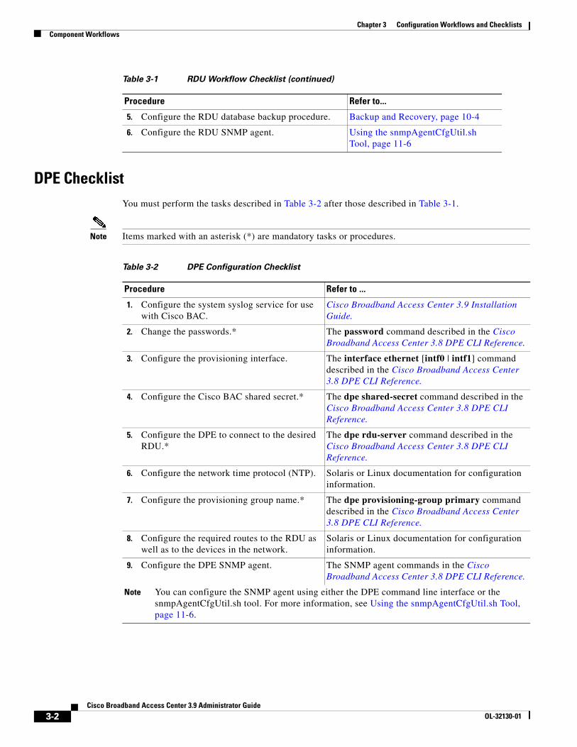
DPE ChecklistYou must perform the tasks described in Table 3-2 after those described in Table 3-1.
Note Items marked with an asterisk (*) are mandatory tasks or procedures.
5. Configure the RDU database backup procedure. Backup and Recovery, page 10-4
6. Configure the RDU SNMP agent. Using the snmpAgentCfgUtil.sh Tool, page 11-6
Table 3-1 RDU Workflow Checklist (continued)
Procedure Refer to...
Table 3-2 DPE Configuration Checklist
Procedure Refer to ...
1. Configure the system syslog service for use with Cisco BAC.
Cisco Broadband Access Center 3.9 Installation Guide.
2. Change the passwords.* The password command described in the Cisco Broadband Access Center 3.8 DPE CLI Reference.
3. Configure the provisioning interface. The interface ethernet [intf0 | intf1] command described in the Cisco Broadband Access Center 3.8 DPE CLI Reference.
4. Configure the Cisco BAC shared secret.* The dpe shared-secret command described in the Cisco Broadband Access Center 3.8 DPE CLI Reference.
5. Configure the DPE to connect to the desired RDU.*
The dpe rdu-server command described in the Cisco Broadband Access Center 3.8 DPE CLI Reference.
6. Configure the network time protocol (NTP). Solaris or Linux documentation for configuration information.
7. Configure the provisioning group name.* The dpe provisioning-group primary command described in the Cisco Broadband Access Center 3.8 DPE CLI Reference.
8. Configure the required routes to the RDU as well as to the devices in the network.
Solaris or Linux documentation for configuration information.
9. Configure the DPE SNMP agent. The SNMP agent commands in the Cisco Broadband Access Center 3.8 DPE CLI Reference.
Note You can configure the SNMP agent using either the DPE command line interface or the snmpAgentCfgUtil.sh tool. For more information, see Using the snmpAgentCfgUtil.sh Tool, page 11-6.
3-2Cisco Broadband Access Center 3.9 Administrator Guide
OL-32130-01
Chapter 3 Configuration Workflows and ChecklistsTechnology Workflows
Technology WorkflowsThis section describes the tasks that you must perform when configuring Cisco BAC to support specific technologies; in this case, CWMP. These configuration tasks are performed after configuring Cisco BAC components.
The CWMP technology workflows described in this section are arranged in a checklist format and include:
• RDU Configuration Workflow, page 3-3
• DPE Configuration Workflow, page 3-5
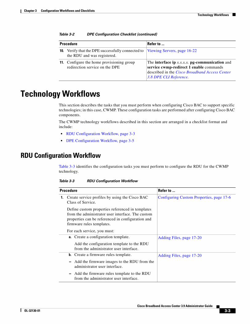
RDU Configuration WorkflowTable 3-3 identifies the configuration tasks you must perform to configure the RDU for the CWMP technology.
10. Verify that the DPE successfully connected to the RDU and was registered.
Viewing Servers, page 16-22
11. Configure the home provisioning group redirection service on the DPE
The interface ip x.x.x.x. pg-communication and service cwmp-redirect 1 enable commands described in the Cisco Broadband Access Center 3.8 DPE CLI Reference.
Table 3-2 DPE Configuration Checklist (continued)
Procedure Refer to ...
Table 3-3 RDU Configuration Workflow
Procedure Refer to ...
1. Create service profiles by using the Cisco BAC Class of Service.
Define custom properties referenced in templates from the administrator user interface. The custom properties can be referenced in configuration and firmware rules templates.
For each service, you must:
Configuring Custom Properties, page 17-6
a. Create a configuration template.
Add the configuration template to the RDU from the administrator user interface.
Adding Files, page 17-20
b. Create a firmware rules template.
– Add the firmware images to the RDU from the administrator user interface.
– Add the firmware rules template to the RDU from the administrator user interface.
Adding Files, page 17-20
3-3Cisco Broadband Access Center 3.9 Administrator Guide
OL-32130-01
Chapter 3 Configuration Workflows and ChecklistsTechnology Workflows
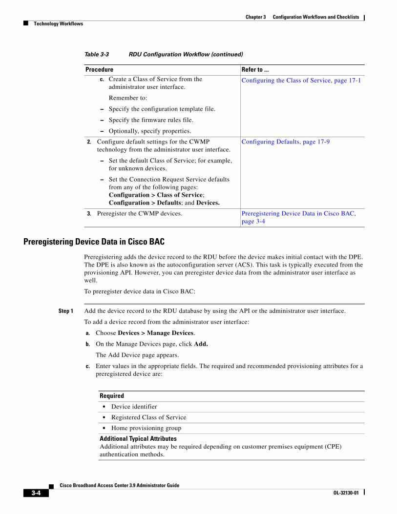
Preregistering Device Data in Cisco BAC
Preregistering adds the device record to the RDU before the device makes initial contact with the DPE. The DPE is also known as the autoconfiguration server (ACS). This task is typically executed from the provisioning API. However, you can preregister device data from the administrator user interface as well.
To preregister device data in Cisco BAC:
Step 1 Add the device record to the RDU database by using the API or the administrator user interface.
To add a device record from the administrator user interface:
a. Choose Devices > Manage Devices.
b. On the Manage Devices page, click Add.
The Add Device page appears.
c. Enter values in the appropriate fields. The required and recommended provisioning attributes for a preregistered device are:
c. Create a Class of Service from the administrator user interface.
Remember to:
– Specify the configuration template file.
– Specify the firmware rules file.
– Optionally, specify properties.
Configuring the Class of Service, page 17-1
2. Configure default settings for the CWMP technology from the administrator user interface.
– Set the default Class of Service; for example, for unknown devices.
– Set the Connection Request Service defaults from any of the following pages: Configuration > Class of Service; Configuration > Defaults; and Devices.
Configuring Defaults, page 17-9
3. Preregister the CWMP devices. Preregistering Device Data in Cisco BAC, page 3-4
Table 3-3 RDU Configuration Workflow (continued)
Procedure Refer to ...
Required
• Device identifier
• Registered Class of Service
• Home provisioning group
Additional Typical AttributesAdditional attributes may be required depending on customer premises equipment (CPE) authentication methods.
3-4Cisco Broadband Access Center 3.9 Administrator Guide
OL-32130-01
Chapter 3 Configuration Workflows and ChecklistsTechnology Workflows
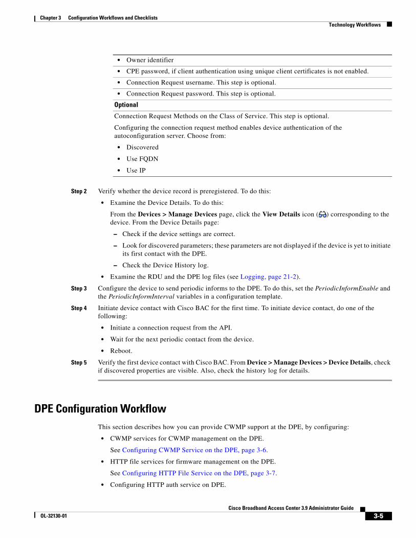
Step 2 Verify whether the device record is preregistered. To do this:
• Examine the Device Details. To do this:
From the Devices > Manage Devices page, click the View Details icon ( ) corresponding to the device. From the Device Details page:
– Check if the device settings are correct.
– Look for discovered parameters; these parameters are not displayed if the device is yet to initiate its first contact with the DPE.
– Check the Device History log.
• Examine the RDU and the DPE log files (see Logging, page 21-2).
Step 3 Configure the device to send periodic informs to the DPE. To do this, set the PeriodicInformEnable and the PeriodicInformInterval variables in a configuration template.
Step 4 Initiate device contact with Cisco BAC for the first time. To initiate device contact, do one of the following:
• Initiate a connection request from the API.
• Wait for the next periodic contact from the device.
• Reboot.
Step 5 Verify the first device contact with Cisco BAC. From Device > Manage Devices > Device Details, check if discovered properties are visible. Also, check the history log for details.
DPE Configuration WorkflowThis section describes how you can provide CWMP support at the DPE, by configuring:
• CWMP services for CWMP management on the DPE.
See Configuring CWMP Service on the DPE, page 3-6.
• HTTP file services for firmware management on the DPE.
See Configuring HTTP File Service on the DPE, page 3-7.
• Configuring HTTP auth service on DPE.
• Owner identifier
• CPE password, if client authentication using unique client certificates is not enabled.
• Connection Request username. This step is optional.
• Connection Request password. This step is optional.
Optional
Connection Request Methods on the Class of Service. This step is optional.
Configuring the connection request method enables device authentication of the autoconfiguration server. Choose from:
• Discovered
• Use FQDN
• Use IP
3-5Cisco Broadband Access Center 3.9 Administrator Guide
OL-32130-01
Chapter 3 Configuration Workflows and ChecklistsTechnology Workflows
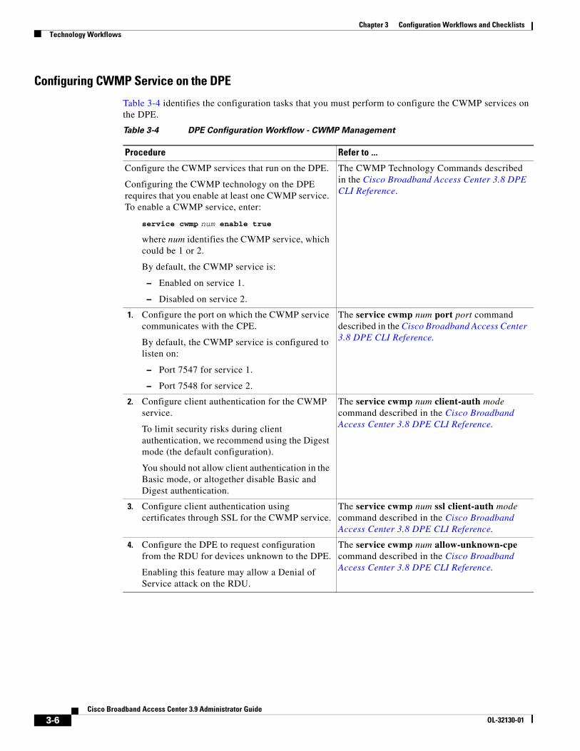
Configuring CWMP Service on the DPE
Table 3-4 identifies the configuration tasks that you must perform to configure the CWMP services on the DPE.
Table 3-4 DPE Configuration Workflow - CWMP Management
Procedure Refer to ...
Configure the CWMP services that run on the DPE.
Configuring the CWMP technology on the DPE requires that you enable at least one CWMP service. To enable a CWMP service, enter:
service cwmp num enable true
where num identifies the CWMP service, which could be 1 or 2.
By default, the CWMP service is:
– Enabled on service 1.
– Disabled on service 2.
The CWMP Technology Commands described in the Cisco Broadband Access Center 3.8 DPE CLI Reference.
1. Configure the port on which the CWMP service communicates with the CPE.
By default, the CWMP service is configured to listen on:
– Port 7547 for service 1.
– Port 7548 for service 2.
The service cwmp num port port command described in the Cisco Broadband Access Center 3.8 DPE CLI Reference.
2. Configure client authentication for the CWMP service.
To limit security risks during client authentication, we recommend using the Digest mode (the default configuration).
You should not allow client authentication in the Basic mode, or altogether disable Basic and Digest authentication.
The service cwmp num client-auth mode command described in the Cisco Broadband Access Center 3.8 DPE CLI Reference.
3. Configure client authentication using certificates through SSL for the CWMP service.
The service cwmp num ssl client-auth mode command described in the Cisco Broadband Access Center 3.8 DPE CLI Reference.
4. Configure the DPE to request configuration from the RDU for devices unknown to the DPE.
Enabling this feature may allow a Denial of Service attack on the RDU.
The service cwmp num allow-unknown-cpe command described in the Cisco Broadband Access Center 3.8 DPE CLI Reference.
3-6Cisco Broadband Access Center 3.9 Administrator Guide
OL-32130-01
Chapter 3 Configuration Workflows and ChecklistsTechnology Workflows
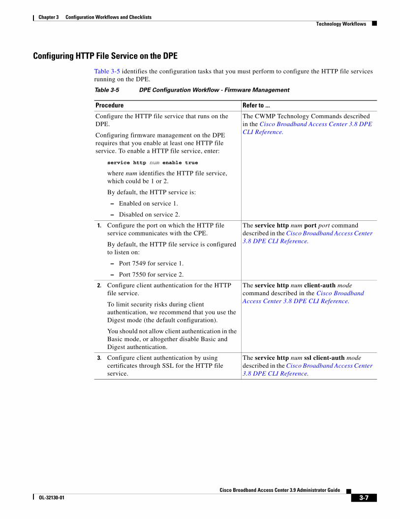
Configuring HTTP File Service on the DPE
Table 3-5 identifies the configuration tasks that you must perform to configure the HTTP file services running on the DPE.
Table 3-5 DPE Configuration Workflow - Firmware Management
Procedure Refer to ...
Configure the HTTP file service that runs on the DPE.
Configuring firmware management on the DPE requires that you enable at least one HTTP file service. To enable a HTTP file service, enter:
service http num enable true
where num identifies the HTTP file service, which could be 1 or 2.
By default, the HTTP service is:
– Enabled on service 1.
– Disabled on service 2.
The CWMP Technology Commands described in the Cisco Broadband Access Center 3.8 DPE CLI Reference.
1. Configure the port on which the HTTP file service communicates with the CPE.
By default, the HTTP file service is configured to listen on:
– Port 7549 for service 1.
– Port 7550 for service 2.
The service http num port port command described in the Cisco Broadband Access Center 3.8 DPE CLI Reference.
2. Configure client authentication for the HTTP file service.
To limit security risks during client authentication, we recommend that you use the Digest mode (the default configuration).
You should not allow client authentication in the Basic mode, or altogether disable Basic and Digest authentication.
The service http num client-auth mode command described in the Cisco Broadband Access Center 3.8 DPE CLI Reference.
3. Configure client authentication by using certificates through SSL for the HTTP file service.
The service http num ssl client-auth mode described in the Cisco Broadband Access Center 3.8 DPE CLI Reference.
3-7Cisco Broadband Access Center 3.9 Administrator Guide
OL-32130-01
Chapter 3 Configuration Workflows and ChecklistsTechnology Workflows
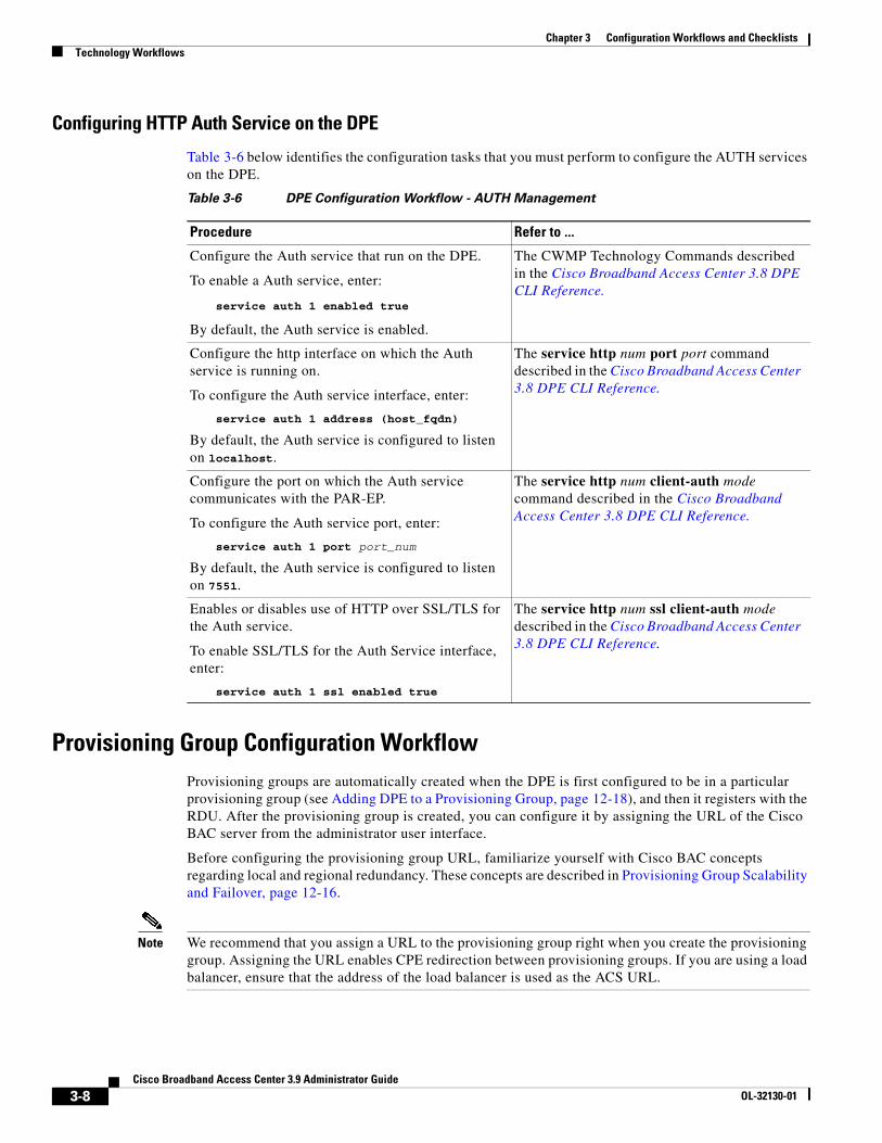
Configuring HTTP Auth Service on the DPE
Table 3-6 below identifies the configuration tasks that you must perform to configure the AUTH services on the DPE.
Provisioning Group Configuration WorkflowProvisioning groups are automatically created when the DPE is first configured to be in a particular provisioning group (see Adding DPE to a Provisioning Group, page 12-18), and then it registers with the RDU. After the provisioning group is created, you can configure it by assigning the URL of the Cisco BAC server from the administrator user interface.
Before configuring the provisioning group URL, familiarize yourself with Cisco BAC concepts regarding local and regional redundancy. These concepts are described in Provisioning Group Scalability and Failover, page 12-16.
Note We recommend that you assign a URL to the provisioning group right when you create the provisioning group. Assigning the URL enables CPE redirection between provisioning groups. If you are using a load balancer, ensure that the address of the load balancer is used as the ACS URL.
Table 3-6 DPE Configuration Workflow - AUTH Management
Procedure Refer to ...
Configure the Auth service that run on the DPE.
To enable a Auth service, enter:
service auth 1 enabled true
By default, the Auth service is enabled.
The CWMP Technology Commands described in the Cisco Broadband Access Center 3.8 DPE CLI Reference.
Configure the http interface on which the Auth service is running on.
To configure the Auth service interface, enter:
service auth 1 address (host_fqdn)
By default, the Auth service is configured to listen on localhost.
The service http num port port command described in the Cisco Broadband Access Center 3.8 DPE CLI Reference.
Configure the port on which the Auth service communicates with the PAR-EP.
To configure the Auth service port, enter:
service auth 1 port port_num
By default, the Auth service is configured to listen on 7551.
The service http num client-auth mode command described in the Cisco Broadband Access Center 3.8 DPE CLI Reference.
Enables or disables use of HTTP over SSL/TLS for the Auth service.
To enable SSL/TLS for the Auth Service interface, enter:
service auth 1 ssl enabled true
The service http num ssl client-auth mode described in the Cisco Broadband Access Center 3.8 DPE CLI Reference.
3-8Cisco Broadband Access Center 3.9 Administrator Guide
OL-32130-01
Chapter 3 Configuration Workflows and ChecklistsTechnology Workflows
To configure the ACS URL of a provisioning group from the administrator user interface:
Step 1 On the primary navigation bar, click Servers > Provisioning Groups.
The Manage Provisioning Groups page appears.
Step 2 Click the identifier link of the correct provisioning group.
The View Provisioning Group Details page appears.
Step 3 In the Provisioning Group Properties area, enter the URL in the ACS URL field.
Note Remember that the URL that you configure overrides the discovered ACS URL.
Step 4 Click Submit.
The provisioning group now contacts Cisco BAC at the URL that you configured.
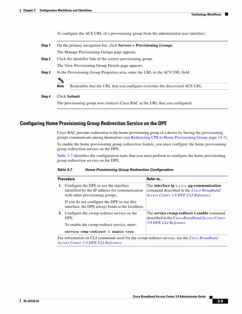
Configuring Home Provisioning Group Redirection Service on the DPE
Cisco BAC provides redirection to the home provisioning group of a device by having the provisioning groups communicate among themselves (see Redirecting CPE to Home Provisioning Group, page 14-7).
To enable the home provisioning group redirection feature, you must configure the home provisioning group redirection service on the DPE.
Table 3-7 identifies the configuration tasks that you must perform to configure the home provisioning group redirection service on the DPE.
Table 3-7 Home Provisioning Group Redirection Configuration
Procedure Refer to...
1. Configure the DPE to use the interface identified by the IP address for communication with other provisioning groups.
If you do not configure the DPE to use this interface, the DPE always binds to the localhost.
The interface ip x.x.x.x. pg-communication command described in the Cisco Broadband Access Center 3.8 DPE CLI Reference.
2. Configure the cwmp-redirect service on the DPE.
To enable the cwmp-redirect service, enter:
service cwmp-redirect 1 enable true
The service cwmp-redirect 1 enable command described in the Cisco Broadband Access Center 3.8 DPE CLI Reference
For information on CLI commands used for the cwmp-redirect service, see the Cisco Broadband Access Center 3.8 DPE CLI Reference.
3-9Cisco Broadband Access Center 3.9 Administrator Guide
OL-32130-01

Chapter 3 Configuration Workflows and ChecklistsTechnology Workflows
3-10Cisco Broadband Access Center 3.9 Administrator Guide
OL-32130-01
CiscoOL-32130-01
C H A P T E R 4
CPE Management OverviewThis chapter describes the management of customer premises equipment (CPE) by using the CPE WAN Management Protocol for Cisco Broadband Access Center (BAC).
This chapter includes the following sections:
• CWMP Overview, page 4-1
• Cisco BAC Device Object Model, page 4-2
• Discovering CPE Parameters, page 4-4
• Multi-Instance Object Support, page 4-5
• Instruction Generation and Processing, page 4-16
• Device Deployment in Cisco BAC, page 4-19
• Initial Provisioning Flows, page 4-20
• Assigning Devices to Provisioning Groups, page 4-22
• Device Diagnostics, page 4-23
• Configuring SNMP Trap for CPEs, page 4-24
CWMP OverviewCisco BAC communicates with CPE through the CPE WAN Management Protocol (CWMP) according to parameters described in the TR196, TR-069, and other related data model specifications. CWMP encompasses secure management of CPE, including:
• Autoconfiguration and dynamic service provisioning
• Firmware management
• Device diagnostics
• Performance and status monitoring
Cisco BAC supports devices based on the TR-069, TR-098, TR-104, TR-106, TR-181, and TR-196 standards. This support includes Ethernet and ADSL gateway devices, wireless gateways, VoIP ATAs, and other devices compliant with CWMP. This release also provides for runtime-extensible data models to support any upcoming data-model standards or any vendor-specific data models.
4-1 Broadband Access Center 3.9 Administrator Guide
Chapter 4 CPE Management OverviewCisco BAC Device Object Model
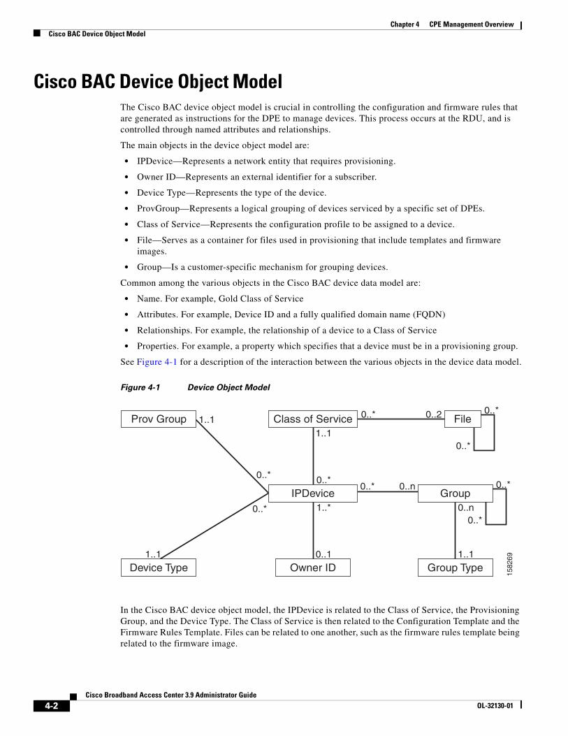
Cisco BAC Device Object ModelThe Cisco BAC device object model is crucial in controlling the configuration and firmware rules that are generated as instructions for the DPE to manage devices. This process occurs at the RDU, and is controlled through named attributes and relationships.
The main objects in the device object model are:
• IPDevice—Represents a network entity that requires provisioning.
• Owner ID—Represents an external identifier for a subscriber.
• Device Type—Represents the type of the device.
• ProvGroup—Represents a logical grouping of devices serviced by a specific set of DPEs.
• Class of Service—Represents the configuration profile to be assigned to a device.
• File—Serves as a container for files used in provisioning that include templates and firmware images.
• Group—Is a customer-specific mechanism for grouping devices.
Common among the various objects in the Cisco BAC device data model are:
• Name. For example, Gold Class of Service
• Attributes. For example, Device ID and a fully qualified domain name (FQDN)
• Relationships. For example, the relationship of a device to a Class of Service
• Properties. For example, a property which specifies that a device must be in a provisioning group.
See Figure 4-1 for a description of the interaction between the various objects in the device data model.
Figure 4-1 Device Object Model
In the Cisco BAC device object model, the IPDevice is related to the Class of Service, the Provisioning Group, and the Device Type. The Class of Service is then related to the Configuration Template and the Firmware Rules Template. Files can be related to one another, such as the firmware rules template being related to the firmware image.
1582
69
Prov Group Class of Service0..*
0..*
0..*
0..*
File
Device Type Owner ID
0..*
0..*
0..* 0..21..1
Group0..* 0..n
1..1
1..1
0..*
1..*
0..1
Group Type
0..n
1..1
IPDevice
4-2Cisco Broadband Access Center 3.9 Administrator Guide
OL-32130-01
Chapter 4 CPE Management OverviewCisco BAC Device Object Model
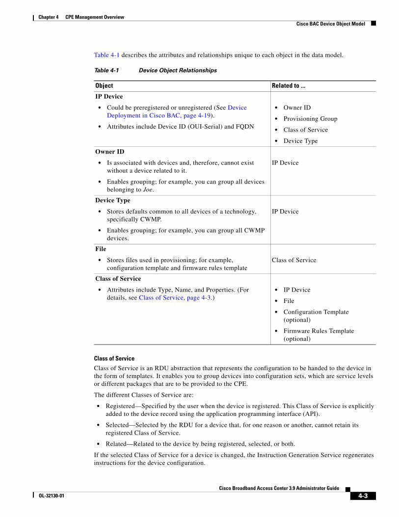
Table 4-1 describes the attributes and relationships unique to each object in the data model.
Class of Service
Class of Service is an RDU abstraction that represents the configuration to be handed to the device in the form of templates. It enables you to group devices into configuration sets, which are service levels or different packages that are to be provided to the CPE.
The different Classes of Service are:
• Registered—Specified by the user when the device is registered. This Class of Service is explicitly added to the device record using the application programming interface (API).
• Selected—Selected by the RDU for a device that, for one reason or another, cannot retain its registered Class of Service.
• Related—Related to the device by being registered, selected, or both.
If the selected Class of Service for a device is changed, the Instruction Generation Service regenerates instructions for the device configuration.
Table 4-1 Device Object Relationships
Object Related to ...
IP Device
• Could be preregistered or unregistered (See Device Deployment in Cisco BAC, page 4-19).
• Attributes include Device ID (OUI-Serial) and FQDN
• Owner ID
• Provisioning Group
• Class of Service
• Device Type
Owner ID
• Is associated with devices and, therefore, cannot exist without a device related to it.
• Enables grouping; for example, you can group all devices belonging to Joe.
IP Device
Device Type
• Stores defaults common to all devices of a technology, specifically CWMP.
• Enables grouping; for example, you can group all CWMP devices.
IP Device
File
• Stores files used in provisioning; for example, configuration template and firmware rules template
Class of Service
Class of Service
• Attributes include Type, Name, and Properties. (For details, see Class of Service, page 4-3.)
• IP Device
• File
• Configuration Template (optional)
• Firmware Rules Template (optional)
4-3Cisco Broadband Access Center 3.9 Administrator Guide
OL-32130-01
Chapter 4 CPE Management OverviewDiscovering CPE Parameters
If the registered Class of Service for a device is changed, it regenerates instructions for the generated device configuration even if it is not the selected Class of Service, since it could impose a policy that would change the selected Class of Service.
Other concepts related to the device data model are:
• Property Hierarchy, page 4-4
• Custom Properties, page 4-4
Property HierarchyWhile processing configuration templates for substitutable parameters, Cisco BAC searches objects for this property using a certain order called Property Hierarchy.
Cisco BAC properties allow you to access and store data in Cisco BAC using the API. Preprovisioned, discovered, and status data can be retrieved through the properties of corresponding objects, using the API. Properties also enable you to configure Cisco BAC at the appropriate level of granularity (from system level to device groups and to individual devices).
The Cisco BAC property hierarchy gives you the flexibility to define system-wide or service class defaults that can be overridden by individual devices.
Cisco BAC allows you to store any number of properties on objects in its data model. You can reference these properties in configuration templates or firmware rules. You can use properties in this property hierarchy:
1. Device
2. Group (priority is set through the Group Type, see Managing Group Types, page 16-18)
3. Provisioning Group
4. Class of Service
5. Device Type
6. System Defaults
Custom PropertiesCustom properties allow for the definition of new properties, which can then be stored on any object via the API.
Custom properties are variable names defined in the RDU, and must not contain any spaces. The template parser works from bottom up when locating properties in the hierarchy and converts the template option syntax. For detailed information, see Custom Properties, page 5-16.
Discovering CPE ParametersCisco BAC is enabled to read CPE parameters using Remote Procedure Calls (RPCs) as defined in CWMP. This is made possible through the Data Synchronization Instruction. This instruction discovers data from the CPE device, reports it to the RDU, and keeps the RDU up-to-date when CPE device data changes.
4-4Cisco Broadband Access Center 3.9 Administrator Guide
OL-32130-01
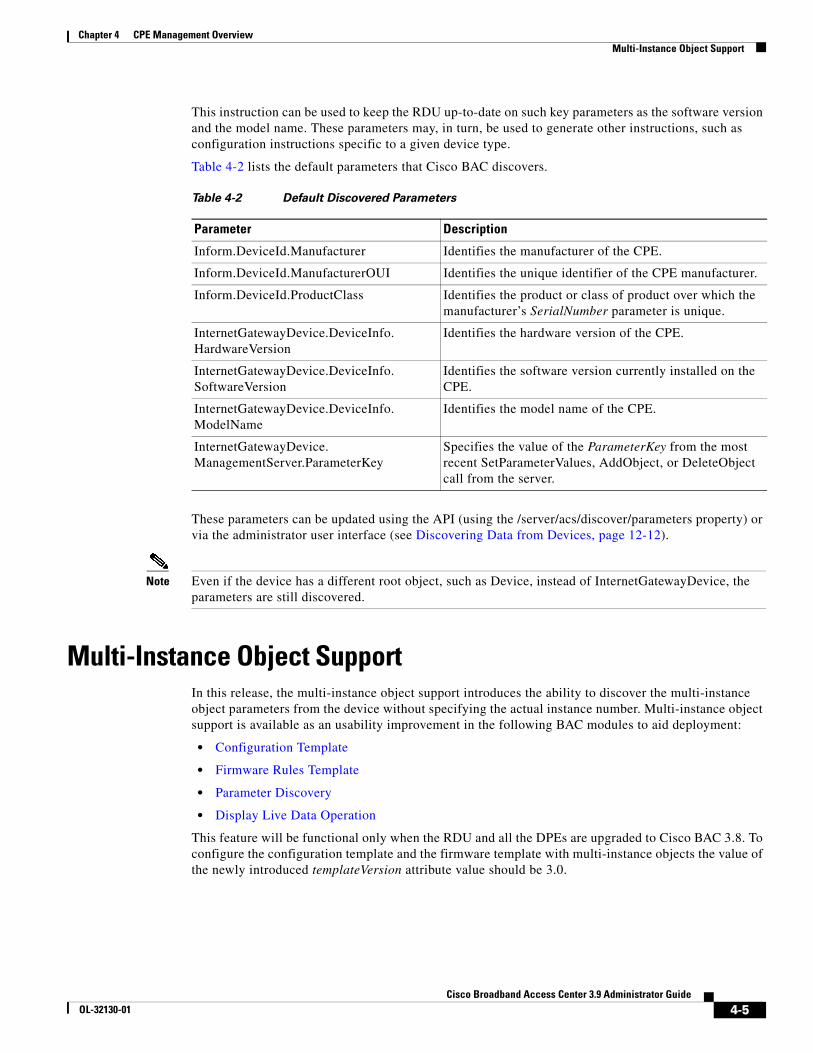
Chapter 4 CPE Management OverviewMulti-Instance Object Support
This instruction can be used to keep the RDU up-to-date on such key parameters as the software version and the model name. These parameters may, in turn, be used to generate other instructions, such as configuration instructions specific to a given device type.
Table 4-2 lists the default parameters that Cisco BAC discovers.
These parameters can be updated using the API (using the /server/acs/discover/parameters property) or via the administrator user interface (see Discovering Data from Devices, page 12-12).
Note Even if the device has a different root object, such as Device, instead of InternetGatewayDevice, the parameters are still discovered.
Multi-Instance Object SupportIn this release, the multi-instance object support introduces the ability to discover the multi-instance object parameters from the device without specifying the actual instance number. Multi-instance object support is available as an usability improvement in the following BAC modules to aid deployment:
• Configuration Template
• Firmware Rules Template
• Parameter Discovery
• Display Live Data Operation
This feature will be functional only when the RDU and all the DPEs are upgraded to Cisco BAC 3.8. To configure the configuration template and the firmware template with multi-instance objects the value of the newly introduced templateVersion attribute value should be 3.0.
Table 4-2 Default Discovered Parameters
Parameter Description
Inform.DeviceId.Manufacturer Identifies the manufacturer of the CPE.
Inform.DeviceId.ManufacturerOUI Identifies the unique identifier of the CPE manufacturer.
Inform.DeviceId.ProductClass Identifies the product or class of product over which the manufacturer’s SerialNumber parameter is unique.
InternetGatewayDevice.DeviceInfo.HardwareVersion
Identifies the hardware version of the CPE.
InternetGatewayDevice.DeviceInfo.SoftwareVersion
Identifies the software version currently installed on the CPE.
InternetGatewayDevice.DeviceInfo.ModelName
Identifies the model name of the CPE.
InternetGatewayDevice.ManagementServer.ParameterKey
Specifies the value of the ParameterKey from the most recent SetParameterValues, AddObject, or DeleteObject call from the server.
4-5Cisco Broadband Access Center 3.9 Administrator Guide
OL-32130-01
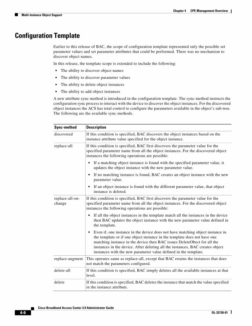
Chapter 4 CPE Management OverviewMulti-Instance Object Support
Configuration TemplateEarlier to this release of BAC, the scope of configuration template represented only the possible set parameter values and set parameter attributes that could be performed. There was no mechanism to discover object names.
In this release, the template scope is extended to include the following:
• The ability to discover object names
• The ability to discover parameter values
• The ability to delete object instances
• The ability to add object instances
A new attribute sync-method is introduced in the configuration template. The sync-method instructs the configuration sync process to interact with the device to discover the object instances. For the discovered object instances the ACS has total control to configure the parameters available in the object’s sub-tree. The following are the available sync-methods.
Sync-method Description
discovered If this condition is specified, BAC discovers the object instances based on the instance attribute value specified for the object instance.
replace-all If this condition is specified, BAC first discovers the parameter value for the specified parameter name from all the object instances. For the discovered object instances the following operations are possible:
• If a matching object instance is found with the specified parameter value, it updates the object instance with the new parameter value.
• If no matching instance is found, BAC creates an object instance with the new parameter value.
• If an object instance is found with the different parameter value, that object instance is deleted.
replace-all-on-change
If this condition is specified, BAC first discovers the parameter value for the specified parameter name from all the object instances. For the discovered object instances the following operations are possible:
• If all the object instances in the template match all the instances in the device then BAC updates the object instance with the new parameter value defined in the template.
• Even if, one instance in the device does not have matching object instance in the template or if one object instance in the template does not have one matching instance in the device then BAC issues DeleteObect for all the instances in the device. After deleting all the instances, BAC creates object instances with the new parameter value defined in the template.
replace-augment This operates same as replace-all, except that BAC retains the instances that does not match the parameters configured.
delete-all If this condition is specified, BAC simply deletes all the available instances at that level.
delete If this condition is specified, BAC deletes the instance that match the value specified in the instance attribute.
4-6Cisco Broadband Access Center 3.9 Administrator Guide
OL-32130-01
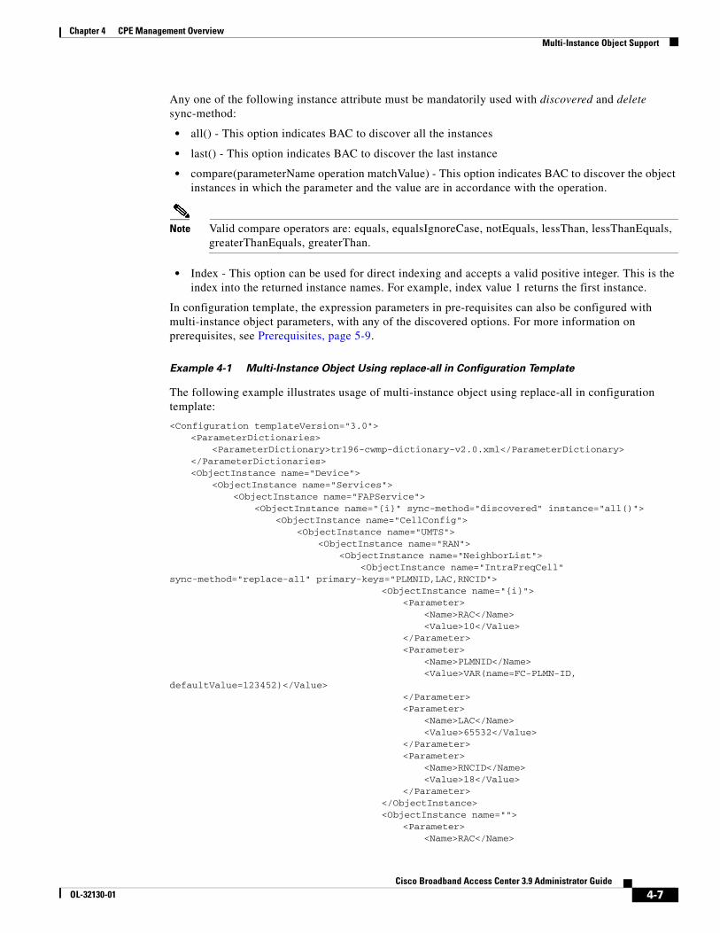
Chapter 4 CPE Management OverviewMulti-Instance Object Support
Any one of the following instance attribute must be mandatorily used with discovered and delete sync-method:
• all() - This option indicates BAC to discover all the instances
• last() - This option indicates BAC to discover the last instance
• compare(parameterName operation matchValue) - This option indicates BAC to discover the object instances in which the parameter and the value are in accordance with the operation.
Note Valid compare operators are: equals, equalsIgnoreCase, notEquals, lessThan, lessThanEquals, greaterThanEquals, greaterThan.
• Index - This option can be used for direct indexing and accepts a valid positive integer. This is the index into the returned instance names. For example, index value 1 returns the first instance.
In configuration template, the expression parameters in pre-requisites can also be configured with multi-instance object parameters, with any of the discovered options. For more information on prerequisites, see Prerequisites, page 5-9.
Example 4-1 Multi-Instance Object Using replace-all in Configuration Template
The following example illustrates usage of multi-instance object using replace-all in configuration template:
<Configuration templateVersion="3.0"><ParameterDictionaries>
<ParameterDictionary>tr196-cwmp-dictionary-v2.0.xml</ParameterDictionary></ParameterDictionaries><ObjectInstance name="Device">
<ObjectInstance name="Services"><ObjectInstance name="FAPService">
<ObjectInstance name="{i}" sync-method="discovered" instance="all()"><ObjectInstance name="CellConfig">
<ObjectInstance name="UMTS"><ObjectInstance name="RAN">
<ObjectInstance name="NeighborList"><ObjectInstance name="IntraFreqCell"
sync-method="replace-all" primary-keys="PLMNID,LAC,RNCID"><ObjectInstance name="{i}">
<Parameter><Name>RAC</Name><Value>10</Value>
</Parameter> <Parameter>
<Name>PLMNID</Name><Value>VAR(name=FC-PLMN-ID,
defaultValue=123452)</Value></Parameter><Parameter>
<Name>LAC</Name><Value>65532</Value>
</Parameter><Parameter>
<Name>RNCID</Name><Value>18</Value>
</Parameter></ObjectInstance><ObjectInstance name="">
<Parameter><Name>RAC</Name>
4-7Cisco Broadband Access Center 3.9 Administrator Guide
OL-32130-01
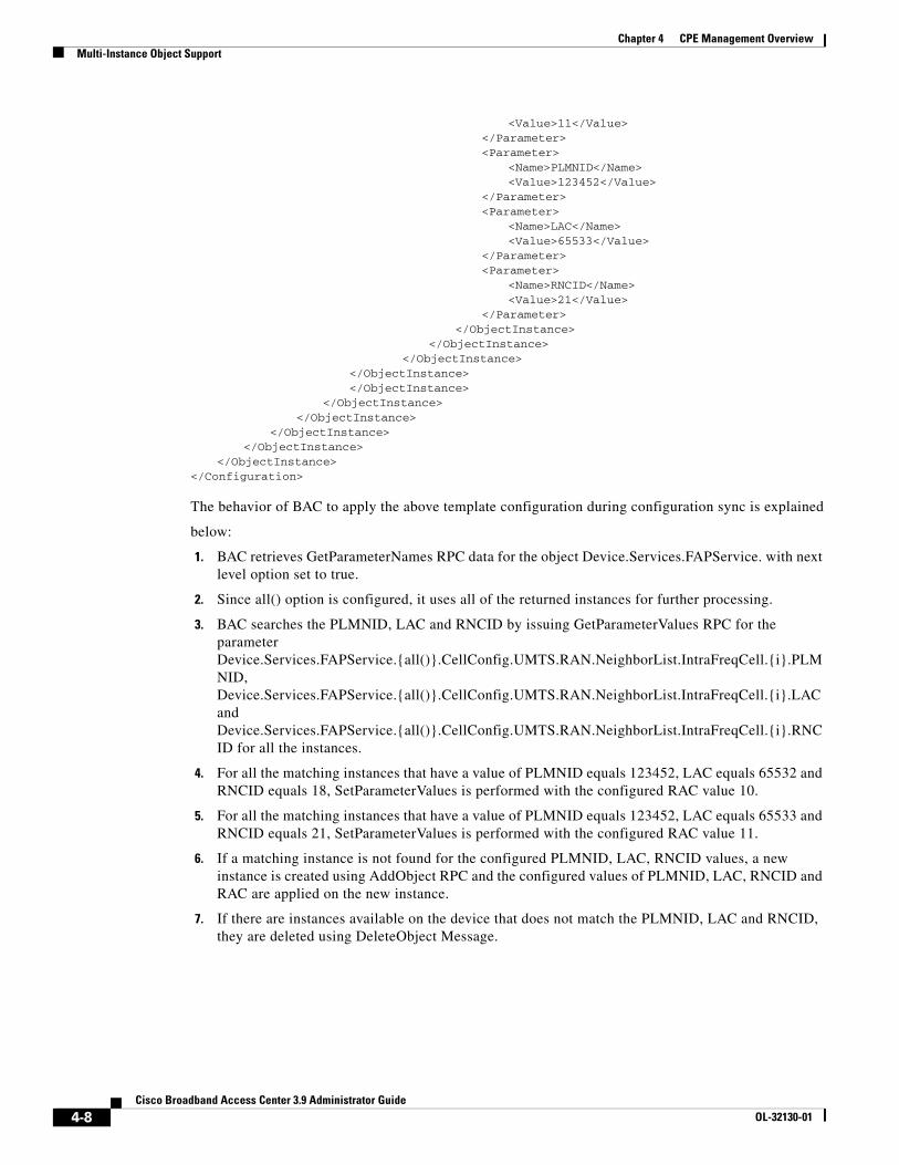
Chapter 4 CPE Management OverviewMulti-Instance Object Support
<Value>11</Value></Parameter> <Parameter>
<Name>PLMNID</Name><Value>123452</Value>
</Parameter><Parameter>
<Name>LAC</Name><Value>65533</Value>
</Parameter><Parameter>
<Name>RNCID</Name><Value>21</Value>
</Parameter></ObjectInstance>
</ObjectInstance></ObjectInstance>
</ObjectInstance> </ObjectInstance> </ObjectInstance>
</ObjectInstance></ObjectInstance>
</ObjectInstance></ObjectInstance>
</Configuration>
The behavior of BAC to apply the above template configuration during configuration sync is explained
below:
1. BAC retrieves GetParameterNames RPC data for the object Device.Services.FAPService. with next level option set to true.
2. Since all() option is configured, it uses all of the returned instances for further processing.
3. BAC searches the PLMNID, LAC and RNCID by issuing GetParameterValues RPC for the parameter Device.Services.FAPService.{all()}.CellConfig.UMTS.RAN.NeighborList.IntraFreqCell.{i}.PLMNID, Device.Services.FAPService.{all()}.CellConfig.UMTS.RAN.NeighborList.IntraFreqCell.{i}.LAC and Device.Services.FAPService.{all()}.CellConfig.UMTS.RAN.NeighborList.IntraFreqCell.{i}.RNCID for all the instances.
4. For all the matching instances that have a value of PLMNID equals 123452, LAC equals 65532 and RNCID equals 18, SetParameterValues is performed with the configured RAC value 10.
5. For all the matching instances that have a value of PLMNID equals 123452, LAC equals 65533 and RNCID equals 21, SetParameterValues is performed with the configured RAC value 11.
6. If a matching instance is not found for the configured PLMNID, LAC, RNCID values, a new instance is created using AddObject RPC and the configured values of PLMNID, LAC, RNCID and RAC are applied on the new instance.
7. If there are instances available on the device that does not match the PLMNID, LAC and RNCID, they are deleted using DeleteObject Message.
4-8Cisco Broadband Access Center 3.9 Administrator Guide
OL-32130-01
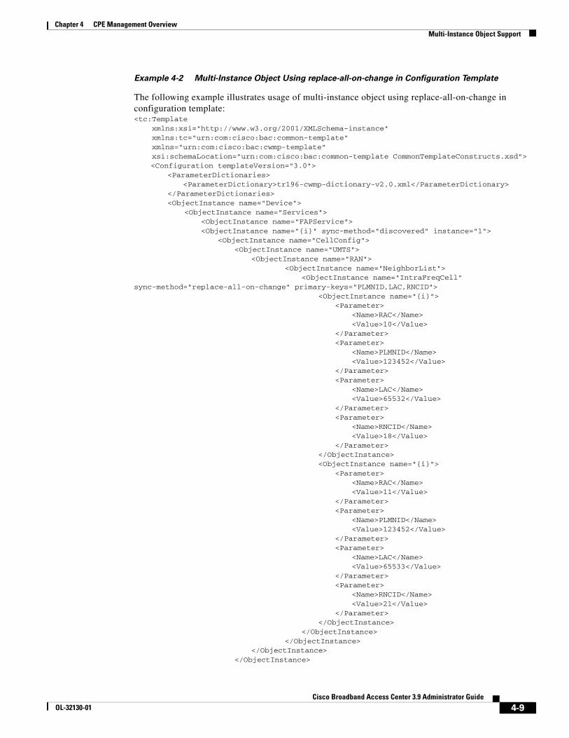
Chapter 4 CPE Management OverviewMulti-Instance Object Support
Example 4-2 Multi-Instance Object Using replace-all-on-change in Configuration Template
The following example illustrates usage of multi-instance object using replace-all-on-change in configuration template:<tc:Template xmlns:xsi="http://www.w3.org/2001/XMLSchema-instance" xmlns:tc="urn:com:cisco:bac:common-template" xmlns="urn:com:cisco:bac:cwmp-template" xsi:schemaLocation="urn:com:cisco:bac:common-template CommonTemplateConstructs.xsd">
<Configuration templateVersion="3.0"> <ParameterDictionaries> <ParameterDictionary>tr196-cwmp-dictionary-v2.0.xml</ParameterDictionary> </ParameterDictionaries>
<ObjectInstance name="Device"><ObjectInstance name="Services">
<ObjectInstance name="FAPService"> <ObjectInstance name="{i}" sync-method="discovered" instance="1"> <ObjectInstance name="CellConfig"> <ObjectInstance name="UMTS"> <ObjectInstance name="RAN">
<ObjectInstance name="NeighborList"><ObjectInstance name="IntraFreqCell"
sync-method="replace-all-on-change" primary-keys="PLMNID,LAC,RNCID"><ObjectInstance name="{i}">
<Parameter><Name>RAC</Name><Value>10</Value>
</Parameter> <Parameter>
<Name>PLMNID</Name><Value>123452</Value>
</Parameter><Parameter>
<Name>LAC</Name><Value>65532</Value>
</Parameter><Parameter>
<Name>RNCID</Name><Value>18</Value>
</Parameter></ObjectInstance><ObjectInstance name="{i}">
<Parameter><Name>RAC</Name><Value>11</Value>
</Parameter> <Parameter>
<Name>PLMNID</Name><Value>123452</Value>
</Parameter><Parameter>
<Name>LAC</Name><Value>65533</Value>
</Parameter><Parameter>
<Name>RNCID</Name><Value>21</Value>
</Parameter></ObjectInstance>
</ObjectInstance></ObjectInstance>
</ObjectInstance> </ObjectInstance>
4-9Cisco Broadband Access Center 3.9 Administrator Guide
OL-32130-01
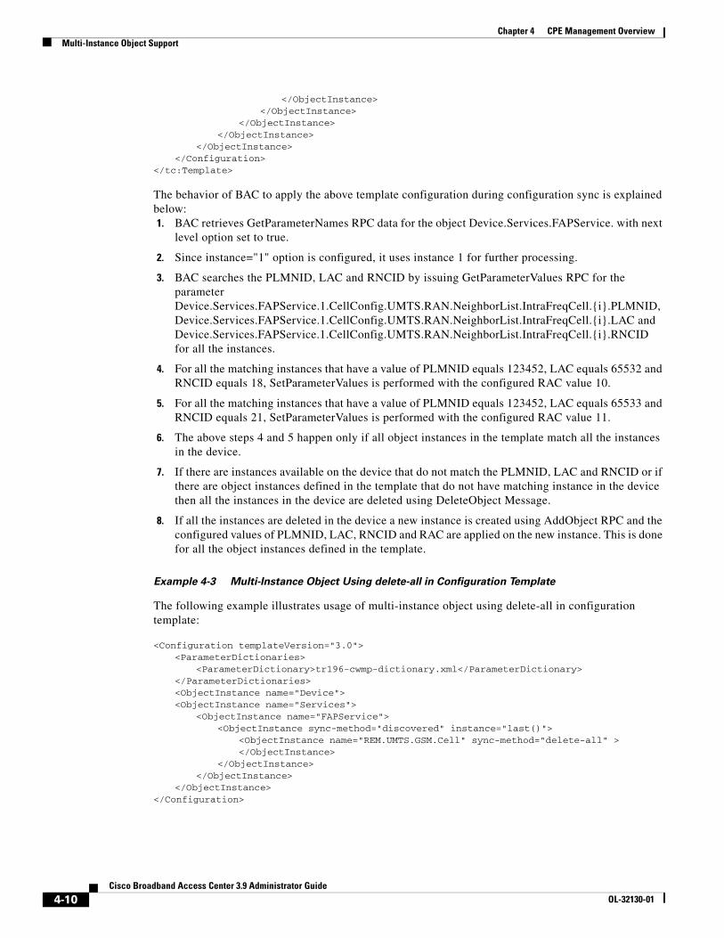
Chapter 4 CPE Management OverviewMulti-Instance Object Support
</ObjectInstance></ObjectInstance>
</ObjectInstance></ObjectInstance>
</ObjectInstance></Configuration>
</tc:Template>
The behavior of BAC to apply the above template configuration during configuration sync is explained below:1. BAC retrieves GetParameterNames RPC data for the object Device.Services.FAPService. with next
level option set to true.
2. Since instance="1" option is configured, it uses instance 1 for further processing.
3. BAC searches the PLMNID, LAC and RNCID by issuing GetParameterValues RPC for the parameter Device.Services.FAPService.1.CellConfig.UMTS.RAN.NeighborList.IntraFreqCell.{i}.PLMNID, Device.Services.FAPService.1.CellConfig.UMTS.RAN.NeighborList.IntraFreqCell.{i}.LAC and Device.Services.FAPService.1.CellConfig.UMTS.RAN.NeighborList.IntraFreqCell.{i}.RNCID for all the instances.
4. For all the matching instances that have a value of PLMNID equals 123452, LAC equals 65532 and RNCID equals 18, SetParameterValues is performed with the configured RAC value 10.
5. For all the matching instances that have a value of PLMNID equals 123452, LAC equals 65533 and RNCID equals 21, SetParameterValues is performed with the configured RAC value 11.
6. The above steps 4 and 5 happen only if all object instances in the template match all the instances in the device.
7. If there are instances available on the device that do not match the PLMNID, LAC and RNCID or if there are object instances defined in the template that do not have matching instance in the device then all the instances in the device are deleted using DeleteObject Message.
8. If all the instances are deleted in the device a new instance is created using AddObject RPC and the configured values of PLMNID, LAC, RNCID and RAC are applied on the new instance. This is done for all the object instances defined in the template.
Example 4-3 Multi-Instance Object Using delete-all in Configuration Template
The following example illustrates usage of multi-instance object using delete-all in configuration template:
<Configuration templateVersion="3.0"><ParameterDictionaries>
<ParameterDictionary>tr196-cwmp-dictionary.xml</ParameterDictionary></ParameterDictionaries><ObjectInstance name="Device"><ObjectInstance name="Services">
<ObjectInstance name="FAPService"><ObjectInstance sync-method="discovered" instance="last()">
<ObjectInstance name="REM.UMTS.GSM.Cell" sync-method="delete-all" ></ObjectInstance>
</ObjectInstance></ObjectInstance>
</ObjectInstance></Configuration>
4-10Cisco Broadband Access Center 3.9 Administrator Guide
OL-32130-01
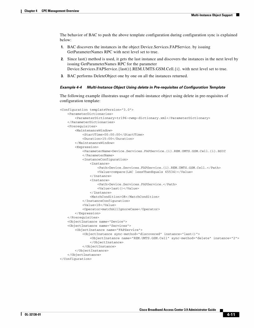
Chapter 4 CPE Management OverviewMulti-Instance Object Support
The behavior of BAC to push the above template configuration during configuration sync is explained below:
1. BAC discovers the instances in the object Device.Services.FAPService. by issuing GetParameterNames RPC with next level set to true.
2. Since last() method is used, it gets the last instance and discovers the instances in the next level by issuing GetParameterNames RPC for the parameter Device.Services.FAPService.{last()}.REM.UMTS.GSM.Cell.{i}. with next level set to true.
3. BAC performs DeleteObject one by one on all the instances returned.
Example 4-4 Multi-Instance Object Using delete in Pre-requisites of Configuration Template
The following example illustrates usage of multi-instance object using delete in pre-requisites of configuration template:
<Configuration templateVersion="3.0"><ParameterDictionaries>
<ParameterDictionary>tr196-cwmp-dictionary.xml</ParameterDictionary></ParameterDictionaries><Prerequisites>
<MaintenanceWindow><StartTime>00:00:00</StartTime><Duration>15:00</Duration>
</MaintenanceWindow><Expression>
<ParameterName>Device.Services.FAPService.{i}.REM.UMTS.GSM.Cell.{i}.BSIC</ParameterName><InstanceConfiguration>
<Instance><Path>Device.Services.FAPService.{i}.REM.UMTS.GSM.Cell.</Path><Value>compare(LAC lessThanEquals 65534)</Value>
</Instance><Instance>
<Path>Device.Services.FAPService.</Path><Value>last()</Value>
</Instance><MatchCondition>OR</MatchCondition>
</InstanceConfiguration><Value>18</Value><Operator>matchAllIgnoreCase</Operator>
</Expression></Prerequisites><ObjectInstance name="Device"><ObjectInstance name="Services">
<ObjectInstance name="FAPService"><ObjectInstance sync-method="discovered" instance="last()">
<ObjectInstance name="REM.UMTS.GSM.Cell" sync-method="delete" instance="2"></ObjectInstance>
</ObjectInstance></ObjectInstance>
</ObjectInstance></Configuration>
4-11Cisco Broadband Access Center 3.9 Administrator Guide
OL-32130-01
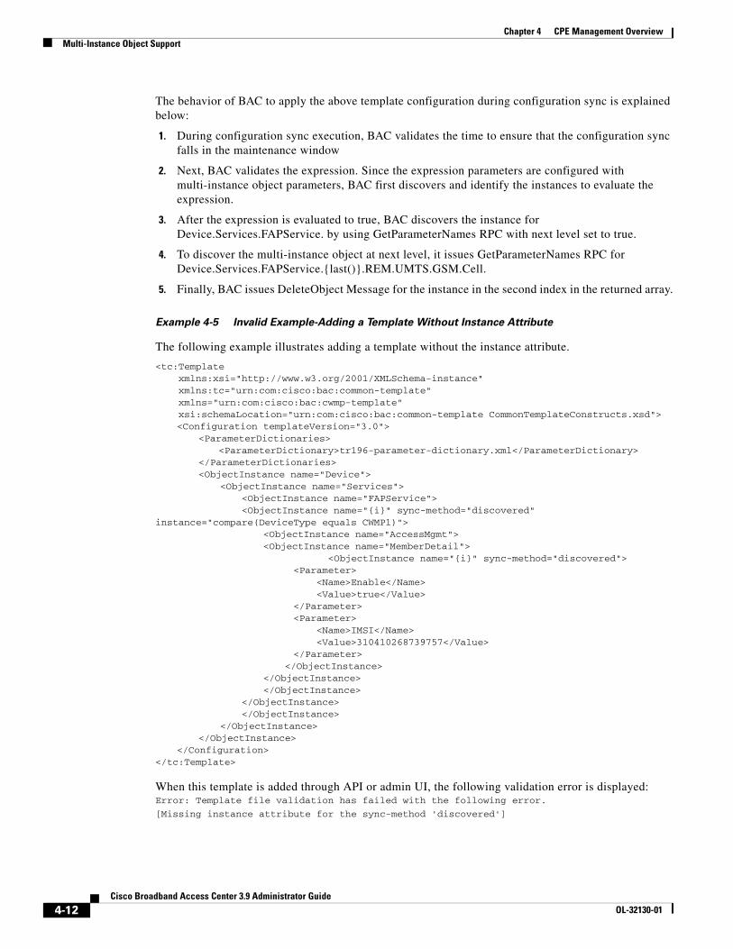
Chapter 4 CPE Management OverviewMulti-Instance Object Support
The behavior of BAC to apply the above template configuration during configuration sync is explained below:
1. During configuration sync execution, BAC validates the time to ensure that the configuration sync falls in the maintenance window
2. Next, BAC validates the expression. Since the expression parameters are configured with multi-instance object parameters, BAC first discovers and identify the instances to evaluate the expression.
3. After the expression is evaluated to true, BAC discovers the instance for Device.Services.FAPService. by using GetParameterNames RPC with next level set to true.
4. To discover the multi-instance object at next level, it issues GetParameterNames RPC for Device.Services.FAPService.{last()}.REM.UMTS.GSM.Cell.
5. Finally, BAC issues DeleteObject Message for the instance in the second index in the returned array.
Example 4-5 Invalid Example-Adding a Template Without Instance Attribute
The following example illustrates adding a template without the instance attribute.
<tc:Template xmlns:xsi="http://www.w3.org/2001/XMLSchema-instance" xmlns:tc="urn:com:cisco:bac:common-template" xmlns="urn:com:cisco:bac:cwmp-template" xsi:schemaLocation="urn:com:cisco:bac:common-template CommonTemplateConstructs.xsd">
<Configuration templateVersion="3.0"> <ParameterDictionaries> <ParameterDictionary>tr196-parameter-dictionary.xml</ParameterDictionary> </ParameterDictionaries>
<ObjectInstance name="Device"><ObjectInstance name="Services">
<ObjectInstance name="FAPService"> <ObjectInstance name="{i}" sync-method="discovered" instance="compare(DeviceType equals CWMP1)"> <ObjectInstance name="AccessMgmt"> <ObjectInstance name="MemberDetail">
<ObjectInstance name="{i}" sync-method="discovered"> <Parameter> <Name>Enable</Name> <Value>true</Value> </Parameter> <Parameter> <Name>IMSI</Name> <Value>310410268739757</Value> </Parameter> </ObjectInstance> </ObjectInstance> </ObjectInstance> </ObjectInstance> </ObjectInstance>
</ObjectInstance></ObjectInstance>
</Configuration></tc:Template>
When this template is added through API or admin UI, the following validation error is displayed:Error: Template file validation has failed with the following error.
[Missing instance attribute for the sync-method 'discovered']
4-12Cisco Broadband Access Center 3.9 Administrator Guide
OL-32130-01
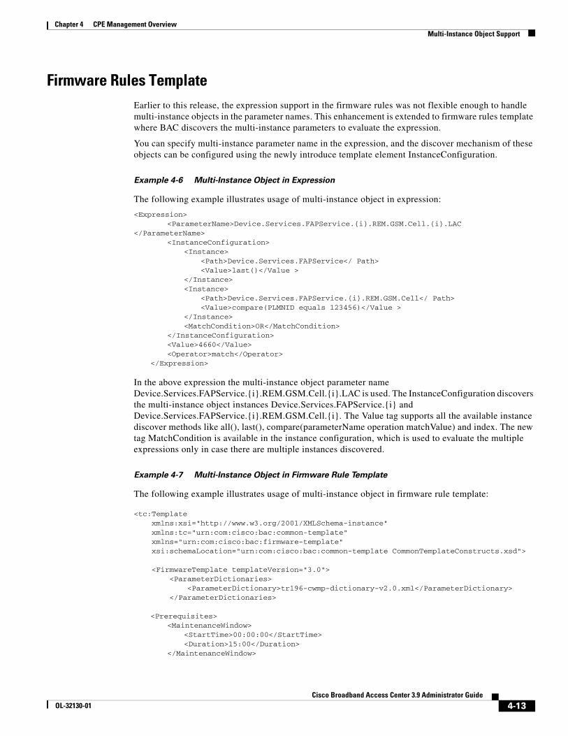
Chapter 4 CPE Management OverviewMulti-Instance Object Support
Firmware Rules TemplateEarlier to this release, the expression support in the firmware rules was not flexible enough to handle multi-instance objects in the parameter names. This enhancement is extended to firmware rules template where BAC discovers the multi-instance parameters to evaluate the expression.
You can specify multi-instance parameter name in the expression, and the discover mechanism of these objects can be configured using the newly introduce template element InstanceConfiguration.
Example 4-6 Multi-Instance Object in Expression
The following example illustrates usage of multi-instance object in expression:
<Expression><ParameterName>Device.Services.FAPService.{i}.REM.GSM.Cell.{i}.LAC
</ParameterName><InstanceConfiguration>
<Instance><Path>Device.Services.FAPService</ Path><Value>last()</Value >
</Instance><Instance>
<Path>Device.Services.FAPService.{i}.REM.GSM.Cell</ Path><Value>compare(PLMNID equals 123456)</Value >
</Instance><MatchCondition>OR</MatchCondition>
</InstanceConfiguration><Value>4660</Value><Operator>match</Operator>
</Expression>
In the above expression the multi-instance object parameter name Device.Services.FAPService.{i}.REM.GSM.Cell.{i}.LAC is used. The InstanceConfiguration discovers the multi-instance object instances Device.Services.FAPService.{i} and Device.Services.FAPService.{i}.REM.GSM.Cell.{i}. The Value tag supports all the available instance discover methods like all(), last(), compare(parameterName operation matchValue) and index. The new tag MatchCondition is available in the instance configuration, which is used to evaluate the multiple expressions only in case there are multiple instances discovered.
Example 4-7 Multi-Instance Object in Firmware Rule Template
The following example illustrates usage of multi-instance object in firmware rule template:
<tc:Template xmlns:xsi="http://www.w3.org/2001/XMLSchema-instance" xmlns:tc="urn:com:cisco:bac:common-template" xmlns="urn:com:cisco:bac:firmware-template" xsi:schemaLocation="urn:com:cisco:bac:common-template CommonTemplateConstructs.xsd">
<FirmwareTemplate templateVersion="3.0"> <ParameterDictionaries> <ParameterDictionary>tr196-cwmp-dictionary-v2.0.xml</ParameterDictionary> </ParameterDictionaries>
<Prerequisites><MaintenanceWindow>
<StartTime>00:00:00</StartTime><Duration>15:00</Duration>
</MaintenanceWindow>
4-13Cisco Broadband Access Center 3.9 Administrator Guide
OL-32130-01
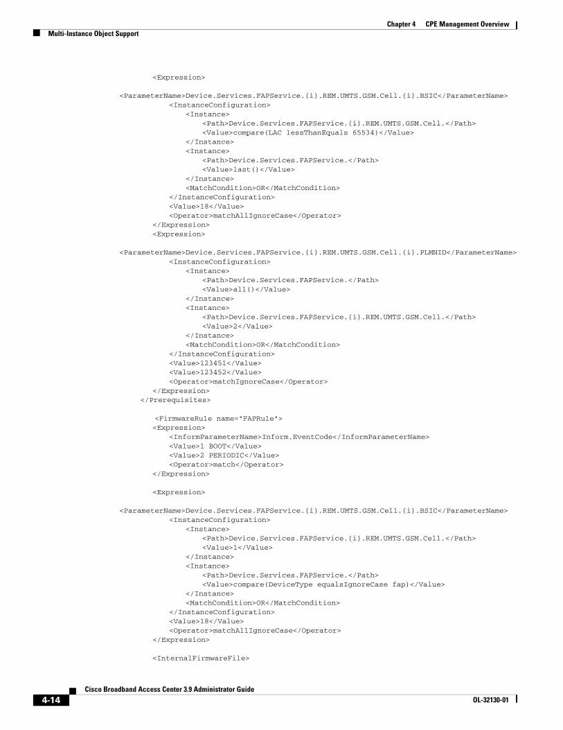
Chapter 4 CPE Management OverviewMulti-Instance Object Support
<Expression>
<ParameterName>Device.Services.FAPService.{i}.REM.UMTS.GSM.Cell.{i}.BSIC</ParameterName><InstanceConfiguration>
<Instance><Path>Device.Services.FAPService.{i}.REM.UMTS.GSM.Cell.</Path><Value>compare(LAC lessThanEquals 65534)</Value>
</Instance><Instance>
<Path>Device.Services.FAPService.</Path><Value>last()</Value>
</Instance><MatchCondition>OR</MatchCondition>
</InstanceConfiguration><Value>18</Value><Operator>matchAllIgnoreCase</Operator>
</Expression><Expression>
<ParameterName>Device.Services.FAPService.{i}.REM.UMTS.GSM.Cell.{i}.PLMNID</ParameterName><InstanceConfiguration>
<Instance><Path>Device.Services.FAPService.</Path><Value>all()</Value>
</Instance><Instance>
<Path>Device.Services.FAPService.{i}.REM.UMTS.GSM.Cell.</Path><Value>2</Value>
</Instance><MatchCondition>OR</MatchCondition>
</InstanceConfiguration><Value>123451</Value><Value>123452</Value><Operator>matchIgnoreCase</Operator>
</Expression> </Prerequisites>
<FirmwareRule name="FAPRule"><Expression>
<InformParameterName>Inform.EventCode</InformParameterName><Value>1 BOOT</Value><Value>2 PERIODIC</Value> <Operator>match</Operator>
</Expression>
<Expression>
<ParameterName>Device.Services.FAPService.{i}.REM.UMTS.GSM.Cell.{i}.BSIC</ParameterName><InstanceConfiguration>
<Instance><Path>Device.Services.FAPService.{i}.REM.UMTS.GSM.Cell.</Path><Value>1</Value>
</Instance><Instance>
<Path>Device.Services.FAPService.</Path><Value>compare(DeviceType equalsIgnoreCase fap)</Value>
</Instance><MatchCondition>OR</MatchCondition>
</InstanceConfiguration><Value>18</Value><Operator>matchAllIgnoreCase</Operator>
</Expression>
<InternalFirmwareFile>
4-14Cisco Broadband Access Center 3.9 Administrator Guide
OL-32130-01
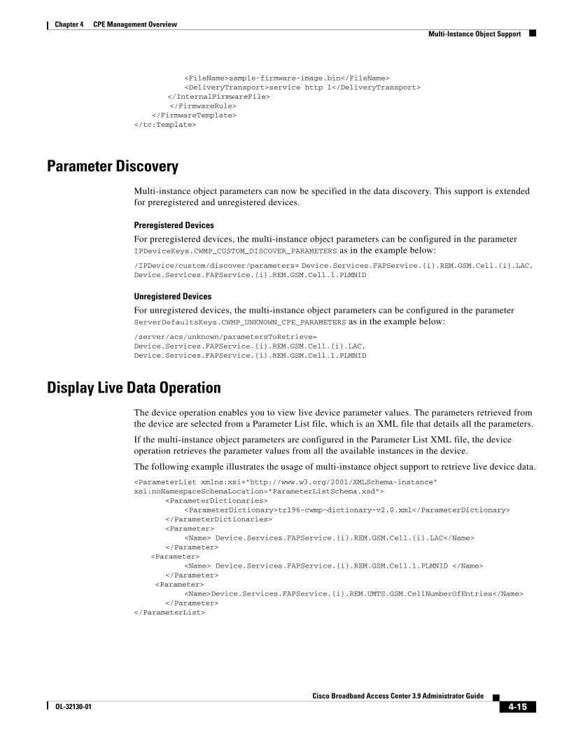
Chapter 4 CPE Management OverviewMulti-Instance Object Support
<FileName>sample-firmware-image.bin</FileName> <DeliveryTransport>service http 1</DeliveryTransport>
</InternalFirmwareFile> </FirmwareRule> </FirmwareTemplate></tc:Template>
Parameter DiscoveryMulti-instance object parameters can now be specified in the data discovery. This support is extended for preregistered and unregistered devices.
Preregistered Devices
For preregistered devices, the multi-instance object parameters can be configured in the parameter IPDeviceKeys.CWMP_CUSTOM_DISCOVER_PARAMETERS as in the example below:
/IPDevice/custom/discover/parameters= Device.Services.FAPService.{i}.REM.GSM.Cell.{i}.LAC, Device.Services.FAPService.{i}.REM.GSM.Cell.1.PLMNID
Unregistered Devices
For unregistered devices, the multi-instance object parameters can be configured in the parameter ServerDefaultsKeys.CWMP_UNKNOWN_CPE_PARAMETERS as in the example below:
/server/acs/unknown/parametersToRetrieve= Device.Services.FAPService.{i}.REM.GSM.Cell.{i}.LAC, Device.Services.FAPService.{i}.REM.GSM.Cell.1.PLMNID
Display Live Data OperationThe device operation enables you to view live device parameter values. The parameters retrieved from the device are selected from a Parameter List file, which is an XML file that details all the parameters.
If the multi-instance object parameters are configured in the Parameter List XML file, the device operation retrieves the parameter values from all the available instances in the device.
The following example illustrates the usage of multi-instance object support to retrieve live device data.
<ParameterList xmlns:xsi="http://www.w3.org/2001/XMLSchema-instance" xsi:noNamespaceSchemaLocation="ParameterListSchema.xsd"> <ParameterDictionaries>
<ParameterDictionary>tr196-cwmp-dictionary-v2.0.xml</ParameterDictionary> </ParameterDictionaries> <Parameter>
<Name> Device.Services.FAPService.{i}.REM.GSM.Cell.{i}.LAC</Name> </Parameter>
<Parameter><Name> Device.Services.FAPService.{i}.REM.GSM.Cell.1.PLMNID </Name>
</Parameter> <Parameter>
<Name>Device.Services.FAPService.{i}.REM.UMTS.GSM.CellNumberOfEntries</Name> </Parameter></ParameterList>
4-15Cisco Broadband Access Center 3.9 Administrator Guide
OL-32130-01
Chapter 4 CPE Management OverviewInstruction Generation and Processing
Instance SortingIn all the operations, when selecting the instances based on the instance configuration, you sort the list of instances returned in GetParameterNames RPC call. The discovered object instances can be sorted when the property ProvGroupKeys.ENABLE_INSTANCE_SORTING (/provGroup/enable/instanceSorting) is enabled.
This property can be configured at the Provisioning Group level in the object hierarchy. For details, see Provisioning Group Configuration Workflow, page 3-8.
Instruction Generation and ProcessingInstruction generation is the process of generating specific instruction sets for CWMP devices. By using technology extensions, through which device technologies are incorporated into Cisco BAC, device details are combined with provisioning rules to produce instruction sets appropriate to the CPE. These instructions are then forwarded to the DPEs in the device’s provisioning group and cached there.
The scriptable extensions are also supported in Cisco BAC. The extension points are defined in DPE for running the java based extension scripts. These scripts are executed in DPE, whenever the device establishes connection with the DPE. The extension scripts are added in the RDU database and forwarded to the DPE cache. For more information on scriptable extension service, see Scripting Framework, page 18-1.
When a device is activated in a Cisco BAC deployment, it initiates contact with the Cisco BAC server. After contact is established, the device’s preconfigured policy, based on configuration templates or firmware rules templates associated with the device, determine the management actions undertaken by the DPE.
This preconfigured policy determines the device’s level of service, also known as Class of Service. Device configurations can include customer-required provisioning information, such as authentication information, periodic inform rate, and Class of Service. This authoritative provisioning information for the device is forwarded to DPEs from the RDU as device configuration instructions.
Instructions are logical operations which the DPE autoconfiguration server (ACS) performs for a specific device. The instructions may map directly into a CWMP remote procedure call (RPC), for example, GetParameterValues; or, they may combine additional logic with multiple CWMP RPCs, such as firmware rules.
IGS could be controlled using the new API property, ApiCommandKeys.IGS_ENABLE. This property determines whether IGS should be triggered or not. The API command uses this property to control the regeneration of device configuration being affected by other API commands.
When this property is set to False in the map of associated properties of an API command, the command skips the regeneration of the configuration process and it returns immediately with a warning message. The API commands affected by this property are:
• replaceFile
• changeClassOfServiceProperties
• changeProvGroupProperties
• changeNodeProperties
• changeDefaults
For the list of other API commands see Non-concurrent Commands, page 19-2.
4-16Cisco Broadband Access Center 3.9 Administrator Guide
OL-32130-01
Chapter 4 CPE Management OverviewInstruction Generation and Processing
The RDU requests that instructions be processed, by passing “InstructionRecords” to the DPE. The DPE server then converts these “InstructionRecords” to “Instructions”, and returns the results to the RDUas “InstructionResponseRecords”.
Cisco BAC generates instructions through:
• The Instruction Generation Extension—Generates “InstructionRecords” for a single device.
• The Instruction Generation Service—Generates “InstructionRecords” for more than one device.
You can access statistics from the Instruction Generation Service from the administrator user interface at Servers > RDU > View Regional Distribution Unit Details.
Among the various instructions that the RDU generates are:
• Data Synchronization Instruction (DataSyncRecord)—Keeps the RDU up-to-date on various CPE parameters, such as the software version and the model name. These parameters may, in turn, be used in generating other instructions, such as configuration instructions that are specific to a given device type.
Some parameters are checked on every connection, while others are checked only when a change in the firmware version occurs. For details, see Discovering Data from Devices, page 12-12.
• Routable IP Address Instruction (RoutableIPAddressRecord)—Discovers if a particular device is reachable, enabling the DPE to create a TCP connection with a device in order to service a connection request. The instruction retrieves the WAN IP address for the device, PPP or DHCP, and compares it with the source IP address. If the IP addresses are different, the instruction updates the RDU.
• Firmware Rules Instruction (FirmwareRulesRecord)—Determines the firmware image to be downloaded to a device. The firmware image files are associated to groups of devices by a firmware rules template.
Cisco BAC uses the rules in the associated template to evaluate the firmware to be downloaded to the CPE. This instruction takes effect only if the device has been associated with a firmware rules template.
• Configuration Synchronization Instruction (ConfigSyncRecord)—Triggers a synchronization of the CPE configuration that is stored in the DPE cache. This instruction comes into effect only if the device has been associated with a configuration template. The process of configuration synchronization is explained in the subsequent section.
When the Signed Configuration feature is enabled, the RDU parses the ToBeSigned tag specified in the configuration template and sets the corresponding value on the CWMP parameter object.
By default, the ToBeSigned flag on the CWMP parameter object is set to False. For more information on Signed Configuration, see Signed Configuration for Devices, page 13-20.
Device Configuration SynchronizationDuring the process of CPE configuration synchronization, a device’s configuration is automatically synchronized based on the configuration template associated with the device’s Class of Service object. The process of synchronizing the CPE configuration according to the ConfigSync instruction stored in the DPE for this device is called Configuration Synchronization.
As part of this process, the DPE configures all parameters values and attributes found in the configuration template associated with a device through its Class of Service, so that:
• Notifications reflect those configured in the configuration template. For more information on Notifications, see Notification, page 5-8.
4-17Cisco Broadband Access Center 3.9 Administrator Guide
OL-32130-01
Chapter 4 CPE Management OverviewInstruction Generation and Processing
• Access control for all parameters reflects that configured in the configuration template. For more information on access control, see Access Control, page 5-9.
CPE configuration is associated with a unique configuration key. This configuration key is saved in the DPE database, and is used as the ParameterKey parameter in RPCs that are forwarded to the CPE.
Every time the CPE establishes a connection with the DPE, the device reports the value for the ParameterKey—in the form of a configuration revision number—by using the Inform message that the device forwards to the DPE. The DPE compares this value with the one in its cache for the particular device. A mismatch of the values, triggers the DPE and the device synchronization process.
During the process of configuration synchronization:
1. The DPE receives a ParameterKey from the device. If the value of this ParameterKey matches the one stored in the DPE, no synchronization is initiated. If the ParameterKey values differs, the synchronization process continues.
2. If access control is set in its configuration, the DPE sets the AccessList parameter to ACS-only. The access control feature is, by default, enabled. For more information on access control, see Access Control, page 5-9.
3. If you enable the notification feature, the DPE sets notification attributes as specified in the device configuration. Notifications are, by default, enabled. For more information on notifications, see Notification, page 5-8.
4. After the DPE configures the parameter values on the device according to the template, it sets a new configuration revision number in the ParameterKey argument. This revision number is used to determine if the device configuration is synchronized the next time the device and the DPE establish a connection.
If the device connection with the DPE times out during the synchronization process, the CPE attempts to reconnect to the DPE.
In this scenario, the value of the ParameterKey in the Inform message remains the same, because only a successful synchronization process changes the ParameterKey value. When the CPE reconnects to the DPE, the DPE initiates another round of synchronization with the original ParameterKey value.
5. The synchronization process ends with the DPE forwarding the new value for the ParameterKey attribute in its last update to the CPE.
In some situations, you must update the device even if the ParameterKey on the DPE matches the one on the device.
To force a configuration synchronization:
Step 1 From the Devices page, locate the device whose configuration you want to synchronize.
Step 2 Click the Operations icon ( ) corresponding to the device.
The Device Operations page appears.
Step 3 From the drop-down list under Perform Device Operation, select Force Configuration Synchronization.
Step 4 Click Submit.
The device configuration is synchronized with the DPE.
4-18Cisco Broadband Access Center 3.9 Administrator Guide
OL-32130-01
Chapter 4 CPE Management OverviewDevice Deployment in Cisco BAC
Device Deployment in Cisco BACA Cisco BAC deployment is divided into provisioning groups, with each provisioning group responsible only for a subset of the devices. All services provided by the provisioning group are implemented to provide fault tolerance.
Note A key principle of device management is that the RDU does not directly communicate with devices. All device interactions are delegated to DPEs in the provisioning group to which the device belongs.
Cisco BAC provides two device deployment options, which can also be used in combination:
• Preregistered—The device record is added to the RDU before the device makes initial contact with the DPE, also known as the ACS.
• Unregistered—The device makes contact with the DPE, before the device record is added to the RDU.
Preregistered DevicesIn this scenario, device data is preprovisioned into Cisco BAC, and the device is associated with a specific Class of Service. The Class of Service can correspond to a service that the subscriber registered for or a default configuration.
A preregistered device is preconfigured with certain parameters specific to the service provider. These parameters are typically “burnt-in” as factory defaults.
Note If you reset the device to factory defaults, the settings on the device revert to the preburnt configuration, and the device may go through the reconfiguration process.
Device data is preregistered in Cisco BAC. This is typically done through the API; alternatively, it can be done using the administrator user interface.
Preconfiguration involves three important issues:
• The device must be able to establish network connectivity. For DSL devices, this typically involves using auto-detection of ATM PVC and using PPP for authentication. The IP address is obtained using PPP or using DHCP. Other devices typically use an existing internet connection and local DHCP for address assignment.
• CPE must contact the configuration servers of the appropriate service provider; in other words, the CPE must know the ACS URL. The ACS URL can be preburnt into the device (assigned) or discovered using DHCP from the WAN side.
• The service provider must be able to associate the CPE with a specific subscriber. This process is typically accomplished by the Operations Support Systems (OSS) application responsible for subscriber registration. Cisco BAC is updated with appropriate data to provision device configuration.
4-19Cisco Broadband Access Center 3.9 Administrator Guide
OL-32130-01
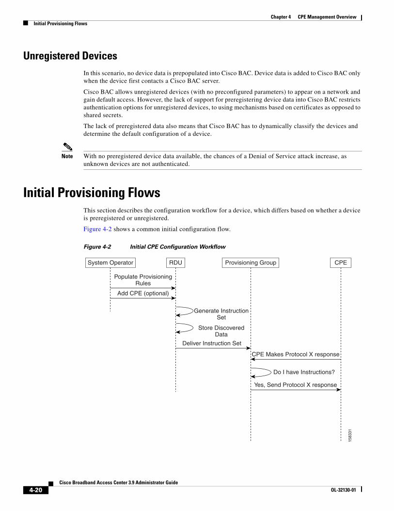
Chapter 4 CPE Management OverviewInitial Provisioning Flows
Unregistered DevicesIn this scenario, no device data is prepopulated into Cisco BAC. Device data is added to Cisco BAC only when the device first contacts a Cisco BAC server.
Cisco BAC allows unregistered devices (with no preconfigured parameters) to appear on a network and gain default access. However, the lack of support for preregistering device data into Cisco BAC restricts authentication options for unregistered devices, to using mechanisms based on certificates as opposed to shared secrets.
The lack of preregistered data also means that Cisco BAC has to dynamically classify the devices and determine the default configuration of a device.
Note With no preregistered device data available, the chances of a Denial of Service attack increase, as unknown devices are not authenticated.
Initial Provisioning FlowsThis section describes the configuration workflow for a device, which differs based on whether a device is preregistered or unregistered.
Figure 4-2 shows a common initial configuration flow.
Figure 4-2 Initial CPE Configuration Workflow
System Operator
Populate ProvisioningRules
RDU Provisioning Group CPE
Add CPE (optional)
Deliver Instruction Set
CPE Makes Protocol X response
Yes, Send Protocol X response
Do I have Instructions?
1583
31
Generate InstructionSet
Store DiscoveredData
4-20Cisco Broadband Access Center 3.9 Administrator Guide
OL-32130-01
Chapter 4 CPE Management OverviewInitial Provisioning Flows
For Preregistered Devicesa. From the Cisco BAC API, the RDU is populated with specifically defined configurations and rules
for various types of devices. The device is preconfigured and associated with a Class of Service.
b. The preregistered device finds its provisioning group by contacting the Cisco BAC server at a preconfigured URL, and initiates autoprovisioning with provisioning group servers (DPEs).
c. The RDU generates instructions appropriate for the device. The resulting device instructions direct DPE responses to various CPE protocol events, such as a TR-069 Inform and an HTTP file request.
d. The device instruction set is forwarded to the DPE and cached there. Now, the DPE is programmed to handle subsequent CPE protocol interactions for this device autonomously from the RDU. After the device is added to the network and a configuration is generated for the device, the device boots to allow the DPE to begin its interactions with the preregistered device.
e. During interactions with the device, additional information can be discovered and forwarded to the RDU. In this case, the RDU may decide to generate new instructions and forward them to all DPEs.
For Unregistered Devicesa. From the Cisco BAC API, the RDU is populated with specifically defined configurations and rules
for various device types.
b. During bootup, when the DPE receives a device request, it performs a local search for instructions cached for the specific CPE. Because the CPE has never previously contacted the DPE and because device data was not preregistered into Cisco BAC, no instructions are found.
The DPE then packs all relevant CPE information into an “instruction set” generation request, and forwards the request to the RDU. At the same time, the device request is rejected, forcing the device to retry. Also, the device receives the configured SOAP request/response extensions from DPE cache and the extensions are executed for the device. Unknown device extensions are configured in CWMP defaults and are sent to DPE cache. For more information on configuring extensions for unknown devices, see Configuring Extensions for Unknown Devices, page 18-4.
c. The RDU generates instructions appropriate for the CPE and distributes it to all DPEs within the device’s provisioning group. The resulting CPE instructions direct DPE responses to various CPE protocol events, such as a TR-069 Inform, and an HTTP file request.
d. The CPE is now registered and the details are stored in the RDU. The RDU captures the CPE registration time. The property to retrieve the registered time is /IPDevice/registeredTime. This property value can be obtained through the API IPDevice.getDetails() call.
e. The device instruction set is delivered to the DPE and cached there. Now, the DPE is programmed to handle all subsequent CPE protocol interactions for this device autonomously from the RDU.
The following parameters are discovered by Cisco BAC for unknown devices:
• Whether the device IP address is routable or NAT’ed.
• Inform.DeviceId.Manufacturer.
• Inform.DeviceId.ManufacturerOUI.
• Inform.DeviceId.ProductClass.
• InternetGatewayDevice.DeviceInfo.HardwareVersion.
• InternetGatewayDevice.DeviceInfo.SoftwareVersion.
• InternetGatewayDevice.DeviceInfo.ModelName.
4-21Cisco Broadband Access Center 3.9 Administrator Guide
OL-32130-01
Chapter 4 CPE Management OverviewAssigning Devices to Provisioning Groups
• InternetGatewayDevice.ManagementServer.ParameterKey.
Note You can change the default list of discovered parameters. See Discovering Data from Devices, page 12-12.
f. The device then reconnects, and receives the configuration instructions generated for it from the RDU and cached at the DPE.
Assigning Devices to Provisioning GroupsDevices can be assigned to a provisioning group in three ways: explicitly, automatically, or using a combination of both.
Explicit AssignmentYou can explicitly assign a device to a provisioning group. After devices appear in the default provisioning group, the provisioning system may, using the API, assign the device to a new provisioning group. On next contact with the device, Cisco BAC redirects the device.
To set the device to contact the assigned provisioning group, change the URL of the Cisco BAC server to the URL of the provisioning group URL. The Cisco BAC server URL is stored, and from then on, the device contacts Cisco BAC at the new address.
To move the device from one provisioning group to another, change the home provisioning group of the device using the API or the administrator user interface. Each provisioning group has a URL associated with it. To facilitate the move, on next contact, the ACS URL on the device is changed to the new provisioning group URL.
Automatic MembershipIf a device has not been explicitly assigned to a provisioning group, the device stays in the provisioning group in which it is brought up. This allows a network-directed assignment of CPE to the provisioning groups. You can use the automatic membership feature for roaming devices, enabling the local provisioning group to service these devices when they are moved.
When a device appears in a new provisioning group, it is automatically assigned to the new provisioning group, and the device data is purged from the old provisioning group. This process involves communicating with the RDU, which, in turn, updates the DPEs in the old and new provisioning groups. This is an expensive process; therefore, take care to prevent a large number of device migrations.
Automatic assignment of a device to a provisioning group works only if the DPEs are configured to allow unknown (unregistered) devices that do not show up in any provisioning group.
If the devices do show up in another provisioning group and the provisioning group is configured to allow access for unknown devices, Cisco BAC automatically assigns the device to the provisioning group.
For details on how to configure access for unknown devices, see the Cisco Broadband Access Center 3.8 DPE CLI Reference.
4-22Cisco Broadband Access Center 3.9 Administrator Guide
OL-32130-01
Chapter 4 CPE Management OverviewDevice Diagnostics
Combined ApproachYou can explicitly assign devices and allow automatic membership of devices to a provisioning group. For example, a generic unregistered device that appears on the network in a provisioning group is automatically assigned to it. Subsequently, the OSS explicitly assigns the device to another provisioning group by using the API.
Device DiagnosticsCWMP supports device troubleshooting and diagnostics features that you use to focus on a single device and collect diagnostics information for further analysis. This feature enables you to query devices for any data, including:
• Configuration
• Live statistics
• Fault indications
• Log file
• Diagnostics results
Device diagnostics is made possible in Cisco BAC through a set of operations that can be run on the device. These include:
• Reboot—Reboots the device. This reboot is primarily intended for diagnostic purposes.
• Request Connection—Initiates a connection request with Cisco BAC.
• Factory Reset—Resets a preregistered device settings to its original factory settings, to before a subscriber-specific configuration was burnt in.
• Display Live Data—Views device parameters directly from a device. You can define the parameters you want to appear.
• Ping Diagnostic—Enables you to perform an IP ping diagnostics test from the device to any host.
• Force Firmware Upgrade—Forces a CPE to update its firmware.
• Force Configuration Synchronization—Enables you to force an individual CPE to synchronize its configuration.
For details on performing these device operations, see Performing Operations on Devices, page 16-14.
Cisco BAC also provides the following features to help troubleshooting:
• Device History—Provides a detailed history of significant events that occur in a device provisioning lifecycle. See Device History, page 8-1.
• Device Faults—Detects devices with recurring faults, which can cause bottlenecks and affect network performance. See Device Faults, page 8-6.
• Device Troubleshooting—Provides detailed records of device interactions with Cisco BAC servers for a set of devices that are designated for such troubleshooting. See Device Troubleshooting, page 8-9.
• Performance Statistics—Provides detailed performance statistics that are related to system performance across major components. It also provides an analysis of the statistical data to aid troubleshooting. See Monitoring Performance Statistics, page 11-14.
4-23Cisco Broadband Access Center 3.9 Administrator Guide
OL-32130-01
Chapter 4 CPE Management OverviewConfiguring SNMP Trap for CPEs
Configuring SNMP Trap for CPEsThe fault management module of Cisco BAC facilitates CPEs to raise alarms and send events when any fault occurs. The fault management module can be enhanced to support the SNMP trap facility. With the SNMP trap facility, DPE receives the events from the CPEs and converts them into SNMP traps. DPE further sends these SNMP traps to the trap receiver.
Cisco BAC also supports integration with Cisco Prime Central application to receive EPM MIB OIDs traps in the Prime Central alarm browser. Each RDU and DPE component is registered as individual domain manager with Prime Central.
The following components are configured in Cisco BAC for SNMP Trap facility:
• RDU, see Configuration at RDU Level, page 4-24
• DPE and Trap Receiver, see Configuration at DPE Level, page 4-25
• Device, see Configuration at Device Level, page 4-26
Configuration at RDU Level
To configure RDU for SNMP trap facility:
Step 1 Create or update the BAC configuration template to support expedited and queued alarms.
The following parameters must be set in the configuration template:
• For expedited alarms:
– FAPService.{i}.FaultMgmt.SupportedAlarm.{i}.ReportingMechanism=0 {Expedited}
– FAPService.{i}.FaultMgmt.ExpeditedEvent=Active
• For Queued alarms
– FAPService.{i}.FaultMgmt.SupportedAlarm.{i}.ReportingMechanism=1 {Queued}
– FAPService.{i}.FaultMgmt.QueuedEvent=Active
For information on how to author configuration template, see Authoring Configuration Templates, page 5-14.
Step 2 Add this configuration template to the RDU database:
a. Log into the Cisco BAC admin UI.
b. Choose Configuration on the primary navigation bar.
c. Choose Files on the secondary navigation bar. The View Files page appears.
d. Click Add.
The Add Files page appears.
e. Choose Configuration Template from the File Type drop-down list.
f. Browse for the Source File Name.
g. Add the configuration template name in the File Name field.
h. Click Submit.
Step 3 Associate this configuration template with the required Class of Service. For details, see Configuring the Class of Service, page 17-1.
4-24Cisco Broadband Access Center 3.9 Administrator Guide
OL-32130-01
Chapter 4 CPE Management OverviewConfiguring SNMP Trap for CPEs
Configuration at DPE Level
To configure DPE for SNMP trap facility:
Step 1 Configure the SNMP alarm property values in the DPE. The following alarm property values must be configured in the DPE to support SNMP trap:
• AlarmIdentifier
• AlarmRaisedTime
• AlarmChangedTime
• ManagedObjectInstance
• EventType
• ProbableCause
• SpecificProblem
• PerceivedSeverity
• AdditionalText
• AdditionalInformation
These SNMP alarm property values can be configured in dpe.properties file through DPE CLI. For details on DPE CLI, see Cisco Broadband Access Center 3.8 DPE CLI Reference.
Step 2 Customize the /cpeAlarm/alarmParams property in dpe.properties file to include SNMP alarm property values. The SNMP alarm property values configured for this property are seen in the SNMP traps.
The default setting for /cpeAlarm/alarmParams property is:
/cpeAlarm/alarmParams=EventTime,AlarmIdentifier,EventType,ProbableCause,PerceivedSeverity
To integrate BAC with Prime Central (to receive the traps in Prime Central Alarm Browser), the setting should be:
/cpeAlarm/alarmParams=EventTime,AlarmIdentifier,NotificationType,ManagedObjectInstance,EventType,ProbableCause,SpecificProblem,PerceivedSeverity,AdditionalText,AdditionalInformation
To add parameters that will be part of SNMP trap for 'value change' and 'boot notification' of FAP, the setting should be:
/cpeAlarm/alarmParams=AlarmIdentifier,EventTime,ManagedObjectInstance,ManagedObjectAddress,ManagedObjectAddressType,EventType,ProbableCause,SpecificProblem,PerceivedSeverity,PerceivedSeverityIndex,AdditionalText,AdditionalInformation,NotificationType,AlarmType
Step 3 Configure the trap receiver to receive the SNMP traps from the DPE. The trap receiver is added as SNMP host with the required community and listening port. For information on how to add SNMP host and community, see Using the snmpAgentCfgUtil.sh Tool, page 11-6.
Note You can configure multiple trap receivers to receive SNMP traps from the CPEs.
Prime Central also needs to be configured as one of the trap receiver for Cisco BAC. This is done by running the Prime Integrator script with the DPE component installed, or by manually adding Prime Central as a trap listener in DPE. For more details, see the Cisco Broadband Access Center Installation Guide 3.9.
4-25Cisco Broadband Access Center 3.9 Administrator Guide
OL-32130-01
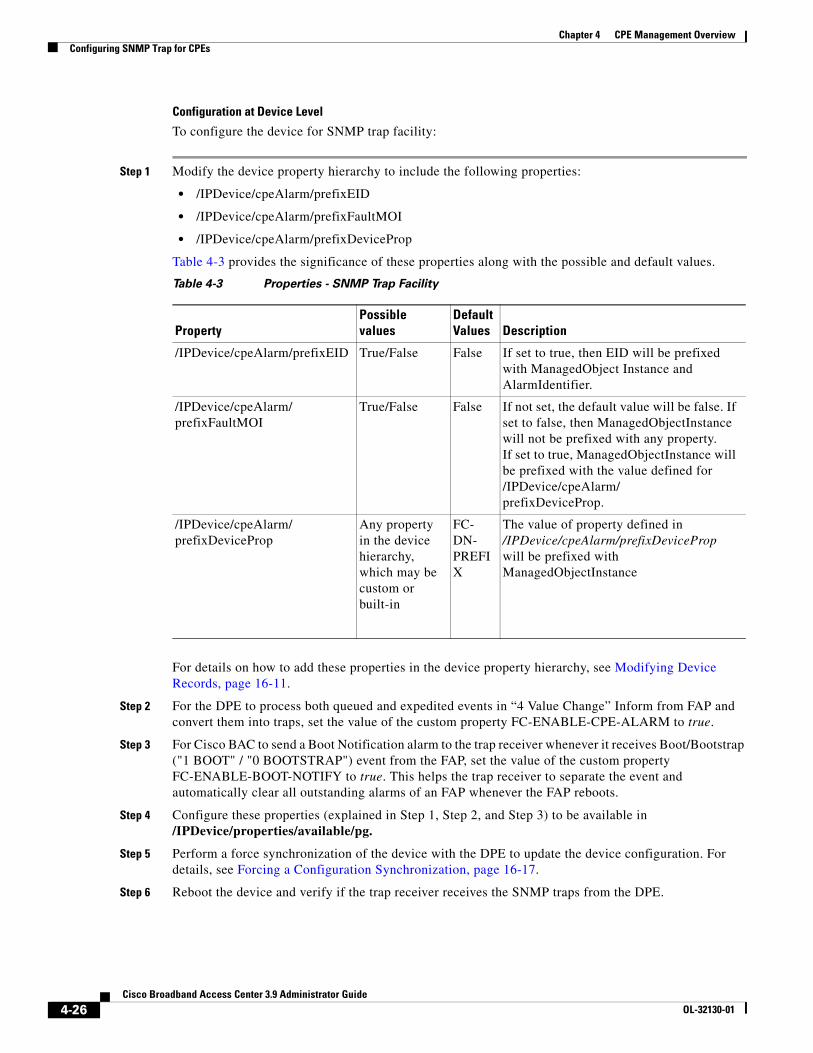
Chapter 4 CPE Management OverviewConfiguring SNMP Trap for CPEs
Configuration at Device Level
To configure the device for SNMP trap facility:
Step 1 Modify the device property hierarchy to include the following properties:
• /IPDevice/cpeAlarm/prefixEID
• /IPDevice/cpeAlarm/prefixFaultMOI
• /IPDevice/cpeAlarm/prefixDeviceProp
Table 4-3 provides the significance of these properties along with the possible and default values.
For details on how to add these properties in the device property hierarchy, see Modifying Device Records, page 16-11.
Step 2 For the DPE to process both queued and expedited events in “4 Value Change” Inform from FAP and convert them into traps, set the value of the custom property FC-ENABLE-CPE-ALARM to true.
Step 3 For Cisco BAC to send a Boot Notification alarm to the trap receiver whenever it receives Boot/Bootstrap ("1 BOOT" / "0 BOOTSTRAP") event from the FAP, set the value of the custom property FC-ENABLE-BOOT-NOTIFY to true. This helps the trap receiver to separate the event and automatically clear all outstanding alarms of an FAP whenever the FAP reboots.
Step 4 Configure these properties (explained in Step 1, Step 2, and Step 3) to be available in /IPDevice/properties/available/pg.
Step 5 Perform a force synchronization of the device with the DPE to update the device configuration. For details, see Forcing a Configuration Synchronization, page 16-17.
Step 6 Reboot the device and verify if the trap receiver receives the SNMP traps from the DPE.
Table 4-3 Properties - SNMP Trap Facility
PropertyPossible values
Default Values Description
/IPDevice/cpeAlarm/prefixEID True/False False If set to true, then EID will be prefixed with ManagedObject Instance and AlarmIdentifier.
/IPDevice/cpeAlarm/prefixFaultMOI
True/False False If not set, the default value will be false. If set to false, then ManagedObjectInstance will not be prefixed with any property.If set to true, ManagedObjectInstance will be prefixed with the value defined for /IPDevice/cpeAlarm/prefixDeviceProp.
/IPDevice/cpeAlarm/prefixDeviceProp
Any property in the device hierarchy, which may be custom or built-in
FC-DN-PREFIX
The value of property defined in /IPDevice/cpeAlarm/prefixDeviceProp will be prefixed with ManagedObjectInstance
4-26Cisco Broadband Access Center 3.9 Administrator Guide
OL-32130-01
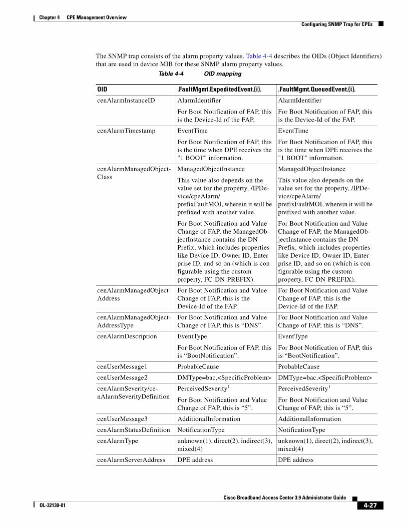
Chapter 4 CPE Management OverviewConfiguring SNMP Trap for CPEs
The SNMP trap consists of the alarm property values. Table 4-4 describes the OIDs (Object Identifiers) that are used in device MIB for these SNMP alarm property values.
Table 4-4 OID mapping
OID .FaultMgmt.ExpeditedEvent.{i}. .FaultMgmt.QueuedEvent.{i}.
cenAlarmInstanceID AlarmIdentifier
For Boot Notification of FAP, this is the Device-Id of the FAP.
AlarmIdentifier
For Boot Notification of FAP, this is the Device-Id of the FAP.
cenAlarmTimestamp EventTime
For Boot Notification of FAP, this is the time when DPE receives the "1 BOOT" information.
EventTime
For Boot Notification of FAP, this is the time when DPE receives the "1 BOOT" information.
cenAlarmManagedObject-Class
ManagedObjectInstance
This value also depends on the value set for the property, /IPDe-vice/cpeAlarm/prefixFaultMOI, wherein it will be prefixed with another value.
For Boot Notification and Value Change of FAP, the ManagedOb-jectInstance contains the DN Prefix, which includes properties like Device ID, Owner ID, Enter-prise ID, and so on (which is con-figurable using the custom property, FC-DN-PREFIX).
cenAlarmManagedObject-Address
For Boot Notification and Value Change of FAP, this is the Device-Id of the FAP.
For Boot Notification and Value Change of FAP, this is the Device-Id of the FAP.
cenAlarmManagedObject-AddressType
For Boot Notification and Value Change of FAP, this is “DNS”.
For Boot Notification and Value Change of FAP, this is “DNS”.
cenAlarmDescription EventType
For Boot Notification of FAP, this is “BootNotification”.
EventType
For Boot Notification of FAP, this is “BootNotification”.
cenUserMessage1 ProbableCause ProbableCause
cenUserMessage2 DMType=bac,<SpecificProblem> DMType=bac,<SpecificProblem>
cenAlarmSeverity/ce-nAlarmSeverityDefinition
PerceivedSeverity1
For Boot Notification and Value Change of FAP, this is “5”.
PerceivedSeverity1
For Boot Notification and Value Change of FAP, this is “5”.
cenUserMessage3 AdditionalInformation AdditionalInformation
cenAlarmStatusDefinition NotificationType NotificationType
cenAlarmType unknown(1), direct(2), indirect(3), mixed(4)
unknown(1), direct(2), indirect(3), mixed(4)
cenAlarmServerAddress DPE address DPE address
4-27Cisco Broadband Access Center 3.9 Administrator Guide
OL-32130-01

Chapter 4 CPE Management OverviewConfiguring SNMP Trap for CPEs
1. The value for PerceivedSeverity is the index between 0-5, and the mapping for severity definition is "Critical", "Major", "Minor","Warning", "Indeterminate",or "Cleared" as per the index value 0-5.
4-28Cisco Broadband Access Center 3.9 Administrator Guide
OL-32130-01
CiscoOL-32130-01
C H A P T E R 5
Configuration Templates ManagementThis chapter details the templates that Cisco Broadband Access Center (BAC) supports for device configuration and device management.
This chapter includes the following sections:
• Overview, page 5-1
• Features of Cisco BAC Templates, page 5-3
• Authoring Configuration Templates, page 5-14
• Using the Configuration Utility, page 5-23
OverviewCisco BAC provides an extensible template-based mechanism to assign configurations for devices that are compliant with the CPE WAN Management Protocol (CWMP). This template-processing mechanism simplifies configuration management, enabling customized configurations for millions of customer premises equipment (CPE) by using a small number of templates.
The result of processing a template is an instruction, which is forwarded to the DPEs in a device's provisioning group. This instruction contains all the necessary information for the DPE to configure the device.
Before attempting to create your own template file, familiarize yourself with information on:
• Parameter dictionaries (see Parameter Dictionaries, page 7-1)
• Firmware templates (see Firmware Management, page 6-1)
By using Cisco BAC templates, you can create a template file in an easily readable format, and edit it quickly and simply. You must add template files to the RDU by using the administrator user interface or the API, before any Class of Service can reference it.
Cisco BAC templates are XML documents written according to a published schema. When instructions are generated for a given device at the RDU for distribution to DPEs, a common template processor retrieves a template by using the device’s Class of Service object.
It then evaluates the template values, such as Includes and Conditionals, and substitutes template variables with their values. The resulting output is an XML object which represents a processed template.
5-1 Broadband Access Center 3.9 Administrator Guide
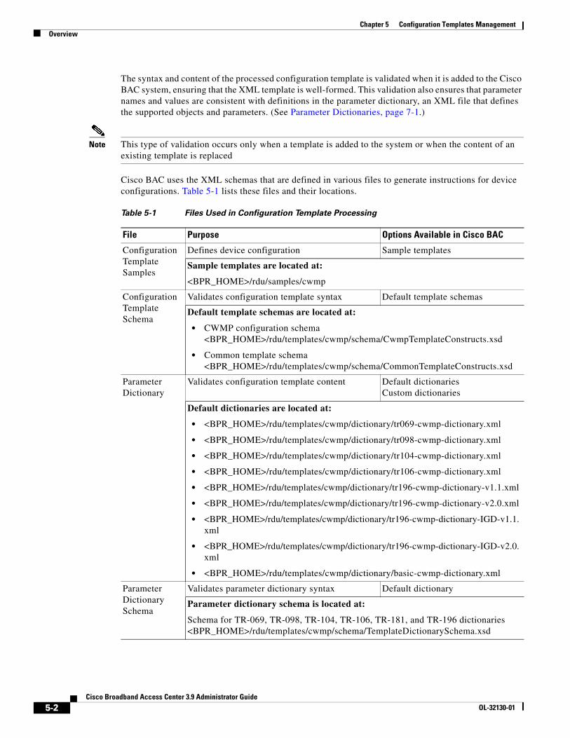
Chapter 5 Configuration Templates ManagementOverview
The syntax and content of the processed configuration template is validated when it is added to the Cisco BAC system, ensuring that the XML template is well-formed. This validation also ensures that parameter names and values are consistent with definitions in the parameter dictionary, an XML file that defines the supported objects and parameters. (See Parameter Dictionaries, page 7-1.)
Note This type of validation occurs only when a template is added to the system or when the content of an existing template is replaced
Cisco BAC uses the XML schemas that are defined in various files to generate instructions for device configurations. Table 5-1 lists these files and their locations.
Table 5-1 Files Used in Configuration Template Processing
File Purpose Options Available in Cisco BAC
Configuration Template Samples
Defines device configuration Sample templates
Sample templates are located at:
<BPR_HOME>/rdu/samples/cwmp
Configuration Template Schema
Validates configuration template syntax Default template schemas
Default template schemas are located at:
• CWMP configuration schema <BPR_HOME>/rdu/templates/cwmp/schema/CwmpTemplateConstructs.xsd
• Common template schema <BPR_HOME>/rdu/templates/cwmp/schema/CommonTemplateConstructs.xsd
Parameter Dictionary
Validates configuration template content Default dictionaries Custom dictionaries
Default dictionaries are located at:
• <BPR_HOME>/rdu/templates/cwmp/dictionary/tr069-cwmp-dictionary.xml
• <BPR_HOME>/rdu/templates/cwmp/dictionary/tr098-cwmp-dictionary.xml
• <BPR_HOME>/rdu/templates/cwmp/dictionary/tr104-cwmp-dictionary.xml
• <BPR_HOME>/rdu/templates/cwmp/dictionary/tr106-cwmp-dictionary.xml
• <BPR_HOME>/rdu/templates/cwmp/dictionary/tr196-cwmp-dictionary-v1.1.xml
• <BPR_HOME>/rdu/templates/cwmp/dictionary/tr196-cwmp-dictionary-v2.0.xml
• <BPR_HOME>/rdu/templates/cwmp/dictionary/tr196-cwmp-dictionary-IGD-v1.1.xml
• <BPR_HOME>/rdu/templates/cwmp/dictionary/tr196-cwmp-dictionary-IGD-v2.0.xml
• <BPR_HOME>/rdu/templates/cwmp/dictionary/basic-cwmp-dictionary.xml
Parameter Dictionary Schema
Validates parameter dictionary syntax Default dictionary
Parameter dictionary schema is located at:
Schema for TR-069, TR-098, TR-104, TR-106, TR-181, and TR-196 dictionaries<BPR_HOME>/rdu/templates/cwmp/schema/TemplateDictionarySchema.xsd
5-2Cisco Broadband Access Center 3.9 Administrator Guide
OL-32130-01
Chapter 5 Configuration Templates ManagementFeatures of Cisco BAC Templates
Cisco BAC supports multiple instance object which is available in the configuration template. This facilitates discovering and updating parameters for the selective object instances without specifying the object instance number. For more information on multi-instance object support see, Multi-Instance Object Support, page 4-5.
You can manage template files, configuration and firmware rules, by using the administrator user interface.
Features of Cisco BAC TemplatesA configuration template is a collection of Objects and Parameters. In a TR-069 device, InternetGatewayDevice is the root object, while in TR-106 device, Device is the root object. In a TR-196 device, InternetGatewayDevice, Device or FAPService are the root objects.
5-3Cisco Broadband Access Center 3.9 Administrator Guide
OL-32130-01
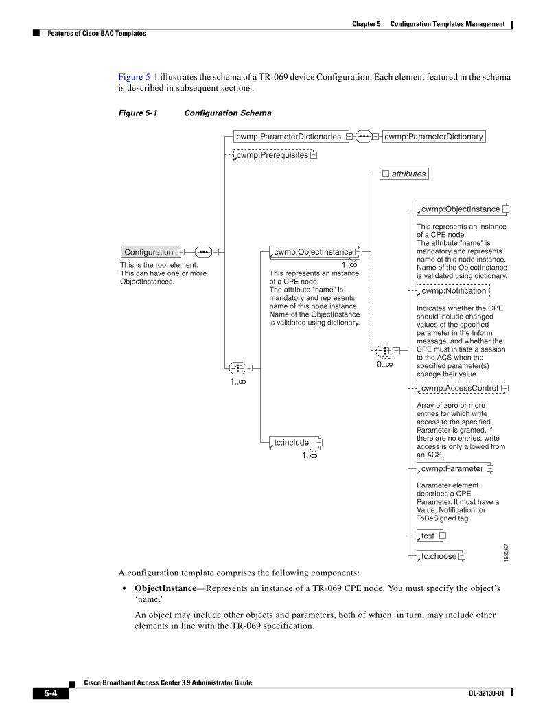
Chapter 5 Configuration Templates ManagementFeatures of Cisco BAC Templates
Figure 5-1 illustrates the schema of a TR-069 device Configuration. Each element featured in the schema is described in subsequent sections.
Figure 5-1 Configuration Schema
A configuration template comprises the following components:
• ObjectInstance—Represents an instance of a TR-069 CPE node. You must specify the object’s ‘name.’
An object may include other objects and parameters, both of which, in turn, may include other elements in line with the TR-069 specification.
1582
67
cwmp:ParameterDictionaries cwmp:ParameterDictionary
attributes
cwmp:Prerequisites
Configuration
This is the root element.This can have one or moreObjectInstances.
1..
1..
cwmp:Notification
1..tc:include
cwmp:ObjectInstance
cwmp:AccessControl
This represents an instance of a CPE node.The attribute "name" is mandatory and represents name of this node instance.Name of the ObjectInstance is validated using dictionary.
This represents an instance of a CPE node.The attribute "name" is mandatory and represents name of this node instance.Name of the ObjectInstance is validated using dictionary.
Indicates whether the CPE should include changed values of the specified parameter in the Inform message, and whether the CPE must initiate a session to the ACS when the specified parameter(s) change their value.
Array of zero or more entries for which write access to the specified Parameter is granted. If there are no entries, write access is only allowed from an ACS.
Parameter element describes a CPE Parameter. It must have a Value, Notification, or ToBeSigned tag.
cwmp:Parameter
tc:if
tc:choose
0..
cwmp:ObjectInstance
5-4Cisco Broadband Access Center 3.9 Administrator Guide
OL-32130-01
Chapter 5 Configuration Templates ManagementFeatures of Cisco BAC Templates
A CPE object may contain:
– Object—Describes an instance of a CPE node.
– Parameters—Describes a CPE parameter and must have a value, and Notification, Access Control, or both. (See Parameters, page 5-6.)
– Notification—Enables notification of changes in the value on all child parameters of this parameter at all levels. (See Notification, page 5-8.)
– Access Control—Controls whether or not entities other than the autoconfiguration server (user, SNMP, UPnP, and so on) can change values of any configuration parameters under this object. (See Access Control, page 5-9.)
• Parameter Dictionary—Contains definitions used to validate the objects and parameters in configuration templates. Cisco BAC supports only one dictionary per template. (See Parameter Dictionaries, page 7-1.)
• Prerequisites—Optionally, indicates the conditions that must be met before a device can be configured. These conditions may include:
– MaintenanceWindow—Enables you to specify the time that a configuration is to be applied to a device.
– Expressions—Enable you to specify any parameters that need to match on the device as a prerequisite to applying the configuration; for example, a particular software or hardware version of a device.
See Figure 5-3 for a graphical representation of the prerequisite schema. For detailed information on using the prerequisite option, see Prerequisites, page 5-9.
Adding a configuration template to Cisco BAC would fail if there are errors in the template. To avoid configuration errors, ensure that all:
• Object names and parameter names exist in the parameter dictionary.
• Parameter values are of the type specified in the parameter dictionary.
• Parameters that are not writable do not have a value. However, they may have the Notification, Access Control attributes, or both set.
• Substitutable variables are defined in the system through Cisco BAC custom property or device property.
5-5Cisco Broadband Access Center 3.9 Administrator Guide
OL-32130-01
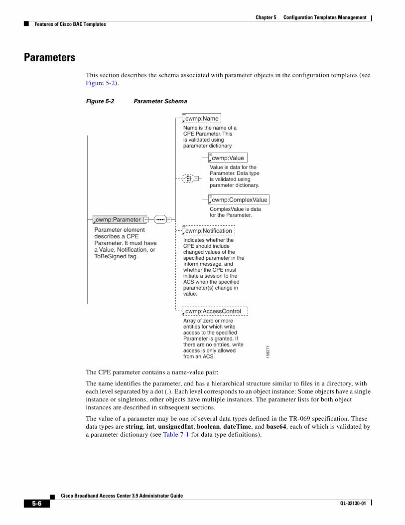
Chapter 5 Configuration Templates ManagementFeatures of Cisco BAC Templates
ParametersThis section describes the schema associated with parameter objects in the configuration templates (see Figure 5-2).
Figure 5-2 Parameter Schema
The CPE parameter contains a name-value pair:
The name identifies the parameter, and has a hierarchical structure similar to files in a directory, with each level separated by a dot (.). Each level corresponds to an object instance: Some objects have a single instance or singletons, other objects have multiple instances. The parameter lists for both object instances are described in subsequent sections.
The value of a parameter may be one of several data types defined in the TR-069 specification. These data types are string, int, unsignedInt, boolean, dateTime, and base64, each of which is validated by a parameter dictionary (see Table 7-1 for data type definitions).
1582
71
cwmp:Parameter
Parameter element describes a CPE Parameter. It must have a Value, Notification, or ToBeSigned tag.
Name is the name of a CPE Parameter. This is validated using parameter dictionary.
Value is data for the Parameter. Data type is validated using parameter dictionary.
cwmp:Name
ComplexValue is data for the Parameter.
cwmp:Value
cwmp:ComplexValue
Indicates whether the CPE should include changed values of the specified parameter in the Inform message, and whether the CPE must initiate a session to the ACS when the specified parameter(s) change in value.
cwmp:Notification
Array of zero or more entities for which write access to the specified Parameter is granted. If there are no entries, write access is only allowed from an ACS.
cwmp:AccessControl
5-6Cisco Broadband Access Center 3.9 Administrator Guide
OL-32130-01
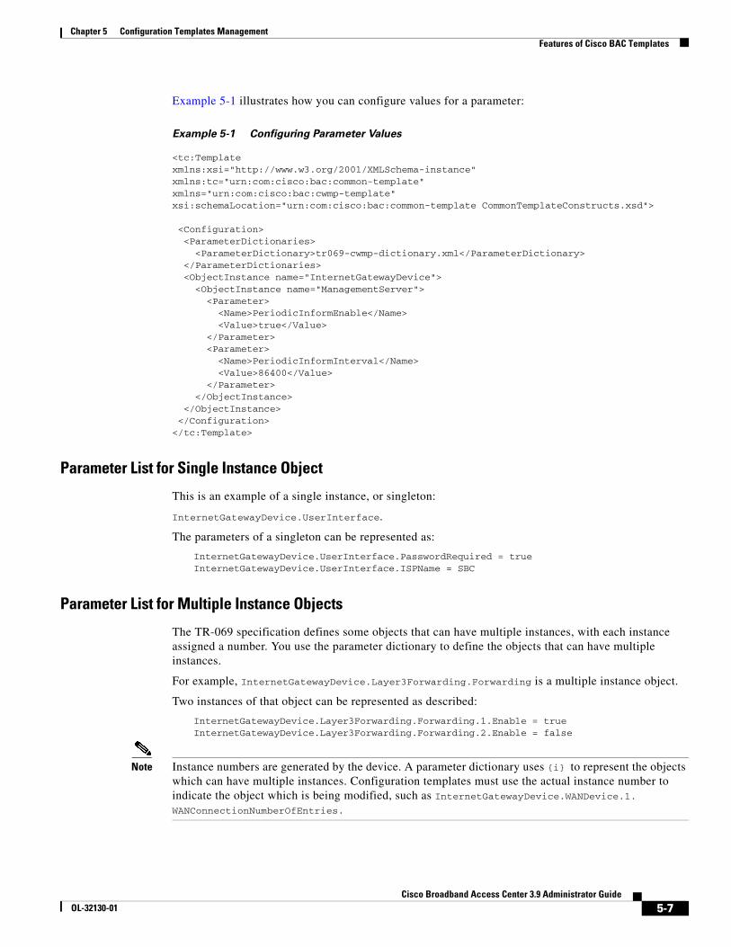
Chapter 5 Configuration Templates ManagementFeatures of Cisco BAC Templates
Example 5-1 illustrates how you can configure values for a parameter:
Example 5-1 Configuring Parameter Values
<tc:Template xmlns:xsi="http://www.w3.org/2001/XMLSchema-instance" xmlns:tc="urn:com:cisco:bac:common-template" xmlns="urn:com:cisco:bac:cwmp-template" xsi:schemaLocation="urn:com:cisco:bac:common-template CommonTemplateConstructs.xsd">
<Configuration> <ParameterDictionaries> <ParameterDictionary>tr069-cwmp-dictionary.xml</ParameterDictionary> </ParameterDictionaries> <ObjectInstance name="InternetGatewayDevice"> <ObjectInstance name="ManagementServer"> <Parameter> <Name>PeriodicInformEnable</Name> <Value>true</Value> </Parameter> <Parameter> <Name>PeriodicInformInterval</Name> <Value>86400</Value> </Parameter> </ObjectInstance> </ObjectInstance> </Configuration></tc:Template>
Parameter List for Single Instance Object
This is an example of a single instance, or singleton:
InternetGatewayDevice.UserInterface.
The parameters of a singleton can be represented as:
InternetGatewayDevice.UserInterface.PasswordRequired = trueInternetGatewayDevice.UserInterface.ISPName = SBC
Parameter List for Multiple Instance Objects
The TR-069 specification defines some objects that can have multiple instances, with each instance assigned a number. You use the parameter dictionary to define the objects that can have multiple instances.
For example, InternetGatewayDevice.Layer3Forwarding.Forwarding is a multiple instance object.
Two instances of that object can be represented as described:
InternetGatewayDevice.Layer3Forwarding.Forwarding.1.Enable = trueInternetGatewayDevice.Layer3Forwarding.Forwarding.2.Enable = false
Note Instance numbers are generated by the device. A parameter dictionary uses {i} to represent the objects which can have multiple instances. Configuration templates must use the actual instance number to indicate the object which is being modified, such as InternetGatewayDevice.WANDevice.1. WANConnectionNumberOfEntries.
5-7Cisco Broadband Access Center 3.9 Administrator Guide
OL-32130-01
Chapter 5 Configuration Templates ManagementFeatures of Cisco BAC Templates
NotificationBy using the Cisco BAC Notification attribute, a device can notify the DPE of parameter value changes. Notifications, by default, are turned off.
If Notification is enabled, it specifies that a device should include the changed values of a particular parameter in the device Inform message to the DPE, and that the device must initiate a session to the DPE whenever the value of that particular parameter is changed.
Cisco BAC supports the following values for the Notification attribute as defined in the TR-069 specification:
• Off—Notification set to off.
The device need not inform Cisco BAC of a change to the specified parameter(s).
• Passive—Notification set to Passive.
Whenever the specified parameter value changes, the device must include the new value in the ParameterList in the Inform message that is sent the next time that Cisco BAC establishes a session.
• Active—Notification set to Active.
Whenever the specified parameter value changes, the device must initiate a session with Cisco BAC, and include the new value in the ParameterList in the associated Inform message. Whenever a parameter change is sent in the Inform message due to a nonzero Notification setting, the Event code 4 VALUE CHANGE must be included in the list of Events.
Note The device returns a notification request rejected error if an attempt is made to set Notification on a parameter deemed inappropriate; for example, a continuously varying statistic.
Configuring Notification
The following example illustrates how you can configure the Notification attribute.
In this example, a configuration file is defined and generated for a UserInterface object, with Notification set to Active for all parameters. The ISPName parameter overrides this Notification and sets it to Passive.
<!--Set Notification of object InternetGatewayDevice.UserInterface.-->
<ObjectInstance name="InternetGatewayDevice"><ObjectInstance name="UserInterface">
<Notification>Active</Notification> <!-- applies to all parameters under thisobject -->
<Parameter><Name>PasswordRequired</Name><Value>true</Value>
</Parameter><Parameter>
<Name>WarrantyDate</Name><Value>2001-02-23T09:45:30+04:30</Value>
</Parameter><Parameter>
<Name>ISPName</Name><Value>SBC</Value><Notification>Passive</Notification> <!--applies to only this parameter-->
</Parameter><Parameter>
<Name>ISPHomePage</Name>
5-8Cisco Broadband Access Center 3.9 Administrator Guide
OL-32130-01
Chapter 5 Configuration Templates ManagementFeatures of Cisco BAC Templates
<Value>www.sbc.com</Value></Parameter>
</ObjectInstance></ObjectInstance>
Access ControlAccess control in Cisco BAC is enabled through the AccessControl attribute of the CPE that you can control by using configuration templates. CPE parameters can be changed using LAN autoconfiguration protocol if access control is set to allow such access. For instance, if the AccessControl attribute is set to Subscriber, then the subscriber on the LAN can change the parameter value.
The value of the AccessControl attribute is an array of zero or more entities for which write access to a specific parameter is granted. If no entries are present, only updates to the parameter value are allowed from Cisco BAC.
Cisco BAC defines only one entity in this list, in line with the TR-069 specification: Subscriber. This enables write access by the subscriber on the LAN, such as through the LAN-side DSL CPE Configuration protocol or through the UPnP protocol.
Configuring Access Control
The following example illustrates how to set access control in Cisco BAC by using configuration templates:
<ObjectInstance name="InternetGatewayDevice"><ObjectInstance name="ManagementServer">
<AccessControl> <!--Allow LAN-side updates of this object and parameters under it -->
<Entity>Subscriber</Entity></AccessControl><Parameter>
<Name>PeriodicInformEnable</Name><Value>true</Value>
</Parameter>
<Parameter><Name>PeriodicInformEnable</Name><AccessControl/> <!-- Allow updates only from ACS (BAC) -->
</Parameter></ObjectInstance>
</ObjectInstance>
PrerequisitesCisco BAC templates include a prerequisites option, which indicates what conditions must be met before configuring the device. For example, a prerequisite may specify that the device to which you apply a configuration must meet the requirement of a specific hardware or software version.
Prerequisite rules are embedded into an instruction, which is sent to the DPE. The DPE then interrogates the device as necessary to determine if the prerequisites match.
5-9Cisco Broadband Access Center 3.9 Administrator Guide
OL-32130-01
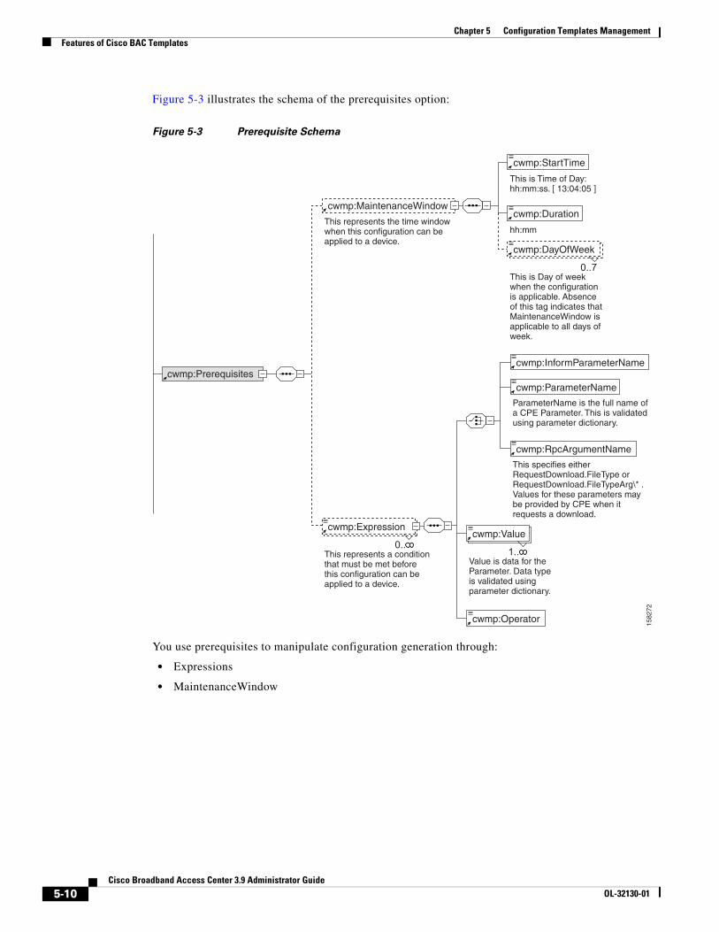
Chapter 5 Configuration Templates ManagementFeatures of Cisco BAC Templates
Figure 5-3 illustrates the schema of the prerequisites option:
Figure 5-3 Prerequisite Schema
You use prerequisites to manipulate configuration generation through:
• Expressions
• MaintenanceWindow
1582
72
cwmp:Prerequisites
ParameterName is the full name of a CPE Parameter. This is validated using parameter dictionary.
This represents the time window when this configuration can be applied to a device.
This is Time of Day: hh:mm:ss. [ 13:04:05 ]
cwmp:MaintenanceWindow
0..7
cwmp:DayOfWeek
cwmp:Duration
hh:mm
This is Day of week when the configuration is applicable. Absence of this tag indicates that MaintenanceWindow is applicable to all days of week.
cwmp:Expression
This represents a condition that must be met before this configuration can be applied to a device.
cwmp:StartTime
cwmp:Value
Value is data for the Parameter. Data type is validated using parameter dictionary.
cwmp:InformParameterName
cwmp:ParameterName
This specifies either RequestDownload.FileType or RequestDownload.FileTypeArg\* . Values for these parameters may be provided by CPE when it requests a download.
cwmp:RpcArgumentName
0..1..
cwmp:Operator
5-10Cisco Broadband Access Center 3.9 Administrator Guide
OL-32130-01
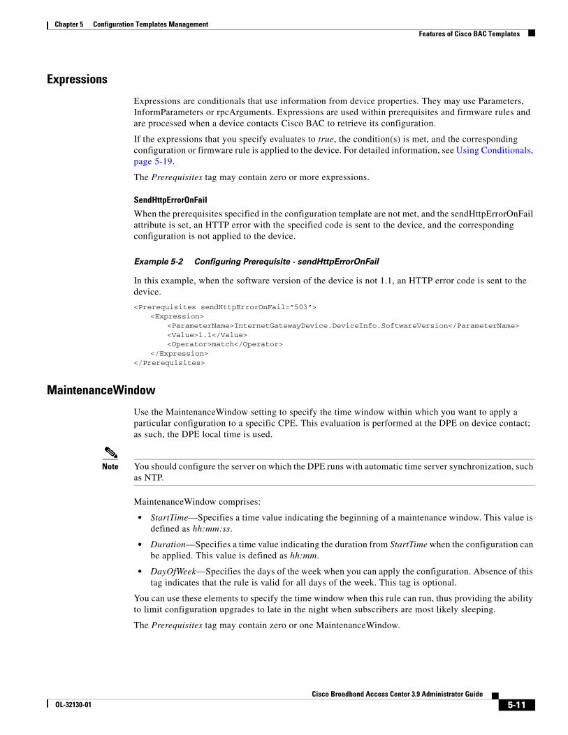
Chapter 5 Configuration Templates ManagementFeatures of Cisco BAC Templates
Expressions
Expressions are conditionals that use information from device properties. They may use Parameters, InformParameters or rpcArguments. Expressions are used within prerequisites and firmware rules and are processed when a device contacts Cisco BAC to retrieve its configuration.
If the expressions that you specify evaluates to true, the condition(s) is met, and the corresponding configuration or firmware rule is applied to the device. For detailed information, see Using Conditionals, page 5-19.
The Prerequisites tag may contain zero or more expressions.
SendHttpErrorOnFail
When the prerequisites specified in the configuration template are not met, and the sendHttpErrorOnFail attribute is set, an HTTP error with the specified code is sent to the device, and the corresponding configuration is not applied to the device.
Example 5-2 Configuring Prerequisite - sendHttpErrorOnFail
In this example, when the software version of the device is not 1.1, an HTTP error code is sent to the device.
<Prerequisites sendHttpErrorOnFail=”503”><Expression>
<ParameterName>InternetGatewayDevice.DeviceInfo.SoftwareVersion</ParameterName><Value>1.1</Value><Operator>match</Operator>
</Expression></Prerequisites>
MaintenanceWindow
Use the MaintenanceWindow setting to specify the time window within which you want to apply a particular configuration to a specific CPE. This evaluation is performed at the DPE on device contact; as such, the DPE local time is used.
Note You should configure the server on which the DPE runs with automatic time server synchronization, such as NTP.
MaintenanceWindow comprises:
• StartTime—Specifies a time value indicating the beginning of a maintenance window. This value is defined as hh:mm:ss.
• Duration—Specifies a time value indicating the duration from StartTime when the configuration can be applied. This value is defined as hh:mm.
• DayOfWeek—Specifies the days of the week when you can apply the configuration. Absence of this tag indicates that the rule is valid for all days of the week. This tag is optional.
You can use these elements to specify the time window when this rule can run, thus providing the ability to limit configuration upgrades to late in the night when subscribers are most likely sleeping.
The Prerequisites tag may contain zero or one MaintenanceWindow.
5-11Cisco Broadband Access Center 3.9 Administrator Guide
OL-32130-01
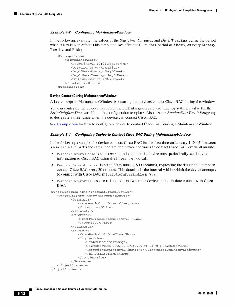
Chapter 5 Configuration Templates ManagementFeatures of Cisco BAC Templates
Example 5-3 Configuring MaintenanceWindow
In the following example, the values of the StartTime, Duration, and DayOfWeek tags define the period when this rule is in effect. This template takes effect at 1 a.m. for a period of 5 hours, on every Monday, Tuesday, and Friday.
<Prerequisites><MaintenanceWindow>
<StartTime>01:00:00</StartTime><Duration>05:00</Duration><DayOfWeek>Monday</DayOfWeek><DayOfWeek>Tuesday</DayOfWeek><DayOfWeek>Friday</DayOfWeek>
</MaintenanceWindow><Prerequisites>
Device Contact During MaintenanceWindow
A key concept in MaintenanceWindow is ensuring that devices contact Cisco BAC during the window.
You can configure the devices to contact the DPE at a given date and time, by setting a value for the PeriodicInformTime variable in the configuration template. Also, set the RandomDateTimeInRange tag to designate a time range when the device can contact Cisco BAC.
See Example 5-4 for how to configure a device to contact Cisco BAC during a MaintenanceWindow.
Example 5-4 Configuring Device to Contact Cisco BAC During MaintenanceWindow
In the following example, the device contacts Cisco BAC for the first time on January 1, 2007, between 3 a.m. and 4 a.m. After the initial contact, the device continues to contact Cisco BAC every 30 minutes.
• PeriodicInformEnable is set to true to indicate that the device must periodically send device information to Cisco BAC using the Inform method call.
• PeriodicInformInterval is set to 30 minutes (1800 seconds), requesting the device to attempt to contact Cisco BAC every 30 minutes. This duration is the interval within which the device attempts to connect with Cisco BAC if PeriodicInformEnable is true.
• PeriodicInformTime is set to a date and time when the device should initiate contact with Cisco BAC.
<ObjectInstance name="InternetGatewayDevice"><ObjectInstance name="ManagementServer">
<Parameter><Name>PeriodicInformEnable</Name><Value>true</Value>
</Parameter><Parameter>
<Name>PeriodicInformInterval</Name><Value>1800</Value>
</Parameter><Parameter>
<Name>PeriodicInformTime</Name><ComplexValue>
<RandomDateTimeInRange><StartDateTime>2006-01-27T01:00:00+03:00</StartDateTime><RandomizationIntervalMinutes>60</RandomizationIntervalMinutes></RandomDateTimeInRange>
</ComplexValue></Parameter>
</ObjectInstance></ObjectInstance>
5-12Cisco Broadband Access Center 3.9 Administrator Guide
OL-32130-01
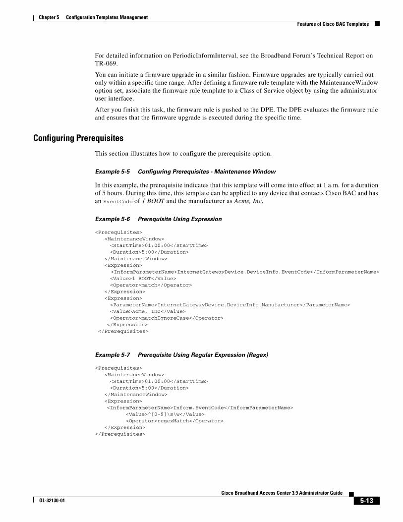
Chapter 5 Configuration Templates ManagementFeatures of Cisco BAC Templates
For detailed information on PeriodicInformInterval, see the Broadband Forum’s Technical Report on TR-069.
You can initiate a firmware upgrade in a similar fashion. Firmware upgrades are typically carried out only within a specific time range. After defining a firmware rule template with the MaintenanceWindow option set, associate the firmware rule template to a Class of Service object by using the administrator user interface.
After you finish this task, the firmware rule is pushed to the DPE. The DPE evaluates the firmware rule and ensures that the firmware upgrade is executed during the specific time.
Configuring Prerequisites
This section illustrates how to configure the prerequisite option.
Example 5-5 Configuring Prerequisites - Maintenance Window
In this example, the prerequisite indicates that this template will come into effect at 1 a.m. for a duration of 5 hours. During this time, this template can be applied to any device that contacts Cisco BAC and has an EventCode of 1 BOOT and the manufacturer as Acme, Inc.
Example 5-6 Prerequisite Using Expression
<Prerequisites><MaintenanceWindow><StartTime>01:00:00</StartTime><Duration>5:00</Duration>
</MaintenanceWindow><Expression>
<InformParameterName>InternetGatewayDevice.DeviceInfo.EventCode</InformParameterName><Value>1 BOOT</Value><Operator>match</Operator>
</Expression><Expression><ParameterName>InternetGatewayDevice.DeviceInfo.Manufacturer</ParameterName>
<Value>Acme, Inc</Value><Operator>matchIgnoreCase</Operator>
</Expression> </Prerequisites>
Example 5-7 Prerequisite Using Regular Expression (Regex)
<Prerequisites><MaintenanceWindow><StartTime>01:00:00</StartTime><Duration>5:00</Duration>
</MaintenanceWindow><Expression><InformParameterName>Inform.EventCode</InformParameterName> <Value>^[0-9]\s\w</Value> <Operator>regexMatch</Operator></Expression>
</Prerequisites>
5-13Cisco Broadband Access Center 3.9 Administrator Guide
OL-32130-01
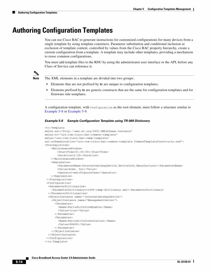
Chapter 5 Configuration Templates ManagementAuthoring Configuration Templates
Authoring Configuration TemplatesYou can use Cisco BAC to generate instructions for customized configurations for many devices from a single template by using template constructs. Parameter substitution and conditional inclusion or exclusion of template content, controlled by values from the Cisco BAC property hierarchy, create a custom configuration from a template. A template may include other templates, providing a mechanism to reuse common configurations.
You must add template files to the RDU by using the administrator user interface or the API, before any Class of Service can reference it.
Note The XML elements in a template are divided into two groups:
• Elements that are not prefixed by tc are unique to configuration templates.
• Elements prefixed by tc are generic constructs that are the same for configuration templates and for firmware rule templates.
A configuration template, with Configuration as the root element, must follow a structure similar to Example 5-8 or Example 5-9.
Example 5-8 Sample Configuration Template using TR-069 Dictionary
<tc:Template xmlns:xsi="http://www.w3.org/2001/XMLSchema-instance" xmlns:tc="urn:com:cisco:bac:common-template" xmlns="urn:com:cisco:bac:cwmp-template" xsi:schemaLocation="urn:com:cisco:bac:common-template CommonTemplateConstructs.xsd"><Prerequisites>
<MaintenanceWindow><StartTime>01:00:00</StartTime><Duration>2:30</Duration>
</MaintenanceWindow><Expression>
<ParameterName>InternetGatewayDevice.DeviceInfo.Manufacturer</ParameterName><Value>Acme, Inc</Value><Operator>matchIgnoreCase</Operator>
</Expression> </Prerequisites> <Configuration> <ParameterDictionaries> <ParameterDictionary>tr069-cwmp-dictionary.xml</ParameterDictionary> </ParameterDictionaries> <ObjectInstance name="InternetGatewayDevice"> <ObjectInstance name="ManagementServer"> <Parameter> <Name>PeriodicInformEnable</Name> <Value>true</Value> </Parameter> <Parameter> <Name>PeriodicInformInterval</Name> <Value>86400</Value> </Parameter> </ObjectInstance> </ObjectInstance> </Configuration></tc:Template>
5-14Cisco Broadband Access Center 3.9 Administrator Guide
OL-32130-01
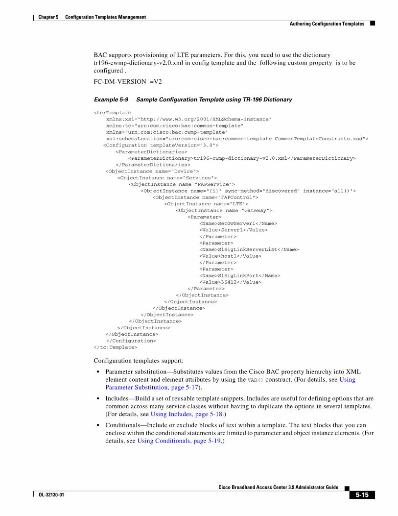
Chapter 5 Configuration Templates ManagementAuthoring Configuration Templates
BAC supports provisioning of LTE parameters. For this, you need to use the dictionary tr196-cwmp-dictionary-v2.0.xml in config template and the following custom property is to be configured .
FC-DM-VERSION =V2
Example 5-9 Sample Configuration Template using TR-196 Dictionary
<tc:Template xmlns:xsi="http://www.w3.org/2001/XMLSchema-instance" xmlns:tc="urn:com:cisco:bac:common-template" xmlns="urn:com:cisco:bac:cwmp-template" xsi:schemaLocation="urn:com:cisco:bac:common-template CommonTemplateConstructs.xsd"> <Configuration templateVersion="3.0"> <ParameterDictionaries> <ParameterDictionary>tr196-cwmp-dictionary-v2.0.xml</ParameterDictionary> </ParameterDictionaries>
<ObjectInstance name="Device"><ObjectInstance name="Services">
<ObjectInstance name="FAPService"><ObjectInstance name="{i}" sync-method="discovered" instance="all()">
<ObjectInstance name="FAPControl"><ObjectInstance name="LTE">
<ObjectInstance name="Gateway"> <Parameter>
<Name>SecGWServer1</Name><Value>Server1</Value></Parameter><Parameter><Name>S1SigLinkServerList</Name><Value>host1</Value></Parameter><Parameter><Name>S1SigLinkPort</Name><Value>36412</Value>
</Parameter></ObjectInstance>
</ObjectInstance></ObjectInstance>
</ObjectInstance></ObjectInstance>
</ObjectInstance></ObjectInstance>
</Configuration></tc:Template>
Configuration templates support:
• Parameter substitution—Substitutes values from the Cisco BAC property hierarchy into XML element content and element attributes by using the VAR() construct. (For details, see Using Parameter Substitution, page 5-17).
• Includes—Build a set of reusable template snippets. Includes are useful for defining options that are common across many service classes without having to duplicate the options in several templates. (For details, see Using Includes, page 5-18.)
• Conditionals—Include or exclude blocks of text within a template. The text blocks that you can enclose within the conditional statements are limited to parameter and object instance elements. (For details, see Using Conditionals, page 5-19.)
5-15Cisco Broadband Access Center 3.9 Administrator Guide
OL-32130-01
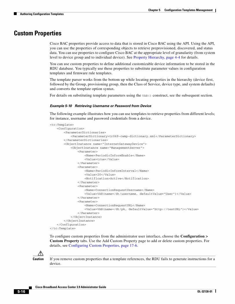
Chapter 5 Configuration Templates ManagementAuthoring Configuration Templates
Custom PropertiesCisco BAC properties provide access to data that is stored in Cisco BAC using the API. Using the API, you can use the properties of corresponding objects to retrieve preprovisioned, discovered, and status data. You can use properties to configure Cisco BAC at the appropriate level of granularity (from system level to device group and to individual device). See Property Hierarchy, page 4-4 for details.
You can use custom properties to define additional customizable device information to be stored in the RDU database. You typically use these properties to substitute parameter values in configuration templates and firmware rule templates.
The template parser works from the bottom up while locating properties in the hierarchy (device first, followed by the Group, provisioning group, then the Class of Service, device type, and system defaults) and converts the template option syntax.
For details on substituting template parameters using the VAR() construct, see the subsequent section.
Example 5-10 Retrieving Username or Password from Device
The following example illustrates how you can use templates to retrieve properties from different levels; for instance, username and password credentials from a device.
<tc:Template><Configuration>
<ParameterDictionaries><ParameterDictionary>tr069-cwmp-dictionary.xml</ParameterDictionary>
</ParameterDictionaries><ObjectInstance name="InternetGatewayDevice">
<ObjectInstance name="ManagementServer"><Parameter>
<Name>PeriodicInformEnable</Name><Value>true</Value>
</Parameter><Parameter>
<Name>PeriodicInformInterval</Name><Value>20</Value><Notification>Active</Notification>
</Parameter><Parameter>
<Name>ConnectionRequestUsername</Name><Value>VAR(name=/dt/username, defaultValue="User")</Value>
</Parameter><Parameter>
<Name>ConnectionRequestURL</Name><Value>VAR(name=/dt/pk, defaultValue="http://testURL")</Value>
</Parameter></ObjectInstance>
</ObjectInstance></Configuration>
</tc:Template>
To configure custom properties from the administrator user interface, choose the Configuration > Custom Property tabs. Use the Add Custom Property page to add or delete custom properties. For details, see Configuring Custom Properties, page 17-6.
Caution If you remove custom properties that a template references, the RDU fails to generate instructions for a device.
5-16Cisco Broadband Access Center 3.9 Administrator Guide
OL-32130-01
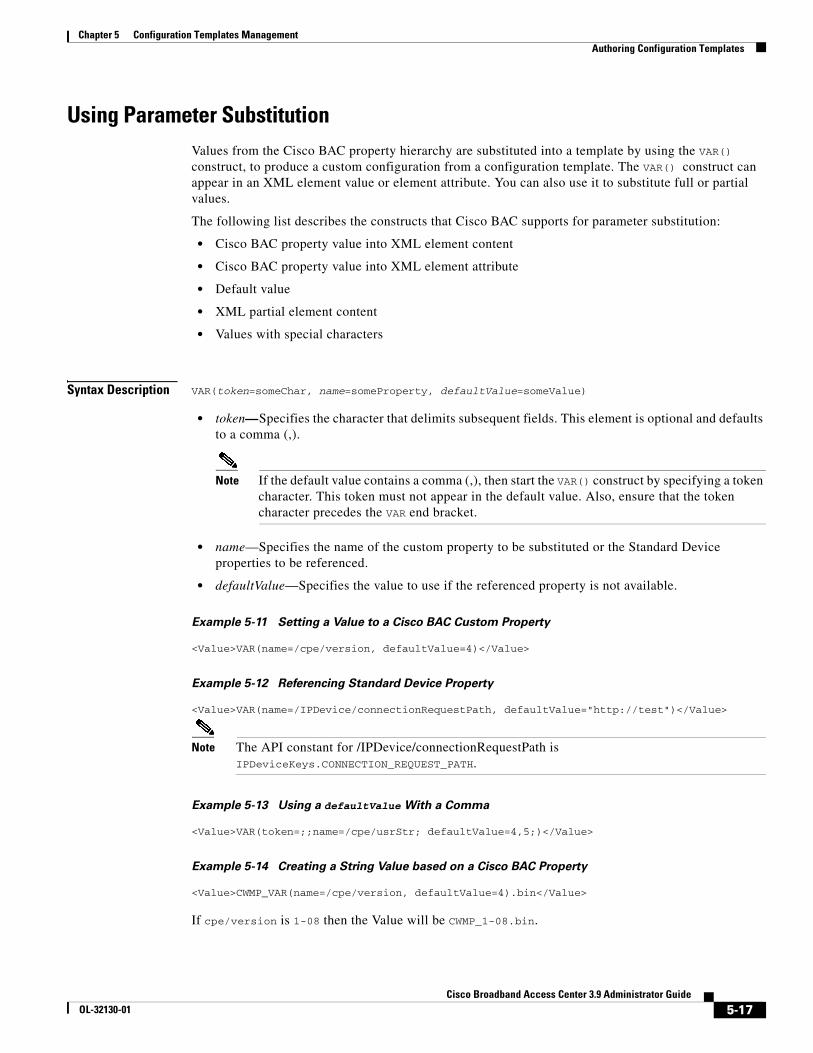
Chapter 5 Configuration Templates ManagementAuthoring Configuration Templates
Using Parameter SubstitutionValues from the Cisco BAC property hierarchy are substituted into a template by using the VAR() construct, to produce a custom configuration from a configuration template. The VAR() construct can appear in an XML element value or element attribute. You can also use it to substitute full or partial values.
The following list describes the constructs that Cisco BAC supports for parameter substitution:
• Cisco BAC property value into XML element content
• Cisco BAC property value into XML element attribute
• Default value
• XML partial element content
• Values with special characters
Syntax Description VAR(token=someChar, name=someProperty, defaultValue=someValue)
• token—Specifies the character that delimits subsequent fields. This element is optional and defaults to a comma (,).
Note If the default value contains a comma (,), then start the VAR() construct by specifying a token character. This token must not appear in the default value. Also, ensure that the token character precedes the VAR end bracket.
• name—Specifies the name of the custom property to be substituted or the Standard Device properties to be referenced.
• defaultValue—Specifies the value to use if the referenced property is not available.
Example 5-11 Setting a Value to a Cisco BAC Custom Property
<Value>VAR(name=/cpe/version, defaultValue=4)</Value>
Example 5-12 Referencing Standard Device Property
<Value>VAR(name=/IPDevice/connectionRequestPath, defaultValue="http://test")</Value>
Note The API constant for /IPDevice/connectionRequestPath is IPDeviceKeys.CONNECTION_REQUEST_PATH.
Example 5-13 Using a defaultValue With a Comma
<Value>VAR(token=;;name=/cpe/usrStr; defaultValue=4,5;)</Value>
Example 5-14 Creating a String Value based on a Cisco BAC Property
<Value>CWMP_VAR(name=/cpe/version, defaultValue=4).bin</Value>
If cpe/version is 1-08 then the Value will be CWMP_1-08.bin.
5-17Cisco Broadband Access Center 3.9 Administrator Guide
OL-32130-01
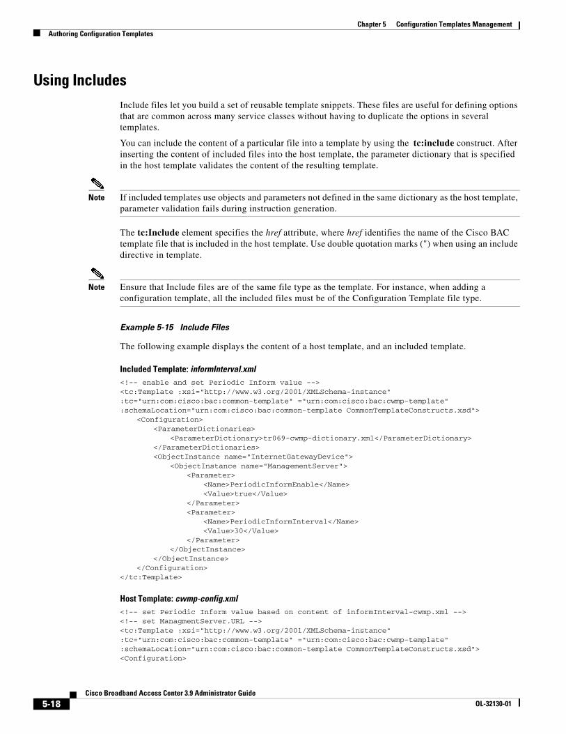
Chapter 5 Configuration Templates ManagementAuthoring Configuration Templates
Using IncludesInclude files let you build a set of reusable template snippets. These files are useful for defining options that are common across many service classes without having to duplicate the options in several templates.
You can include the content of a particular file into a template by using the tc:include construct. After inserting the content of included files into the host template, the parameter dictionary that is specified in the host template validates the content of the resulting template.
Note If included templates use objects and parameters not defined in the same dictionary as the host template, parameter validation fails during instruction generation.
The tc:Include element specifies the href attribute, where href identifies the name of the Cisco BAC template file that is included in the host template. Use double quotation marks (") when using an include directive in template.
Note Ensure that Include files are of the same file type as the template. For instance, when adding a configuration template, all the included files must be of the Configuration Template file type.
Example 5-15 Include Files
The following example displays the content of a host template, and an included template.
Included Template: informInterval.xml<!-- enable and set Periodic Inform value --><tc:Template :xsi="http://www.w3.org/2001/XMLSchema-instance" :tc="urn:com:cisco:bac:common-template" ="urn:com:cisco:bac:cwmp-template" :schemaLocation="urn:com:cisco:bac:common-template CommonTemplateConstructs.xsd">
<Configuration><ParameterDictionaries>
<ParameterDictionary>tr069-cwmp-dictionary.xml</ParameterDictionary></ParameterDictionaries><ObjectInstance name="InternetGatewayDevice">
<ObjectInstance name="ManagementServer"><Parameter>
<Name>PeriodicInformEnable</Name><Value>true</Value>
</Parameter><Parameter>
<Name>PeriodicInformInterval</Name><Value>30</Value>
</Parameter></ObjectInstance>
</ObjectInstance></Configuration>
</tc:Template>
Host Template: cwmp-config.xml<!-- set Periodic Inform value based on content of informInterval-cwmp.xml --><!-- set ManagmentServer.URL --><tc:Template :xsi="http://www.w3.org/2001/XMLSchema-instance" :tc="urn:com:cisco:bac:common-template" ="urn:com:cisco:bac:cwmp-template" :schemaLocation="urn:com:cisco:bac:common-template CommonTemplateConstructs.xsd"><Configuration>
5-18Cisco Broadband Access Center 3.9 Administrator Guide
OL-32130-01
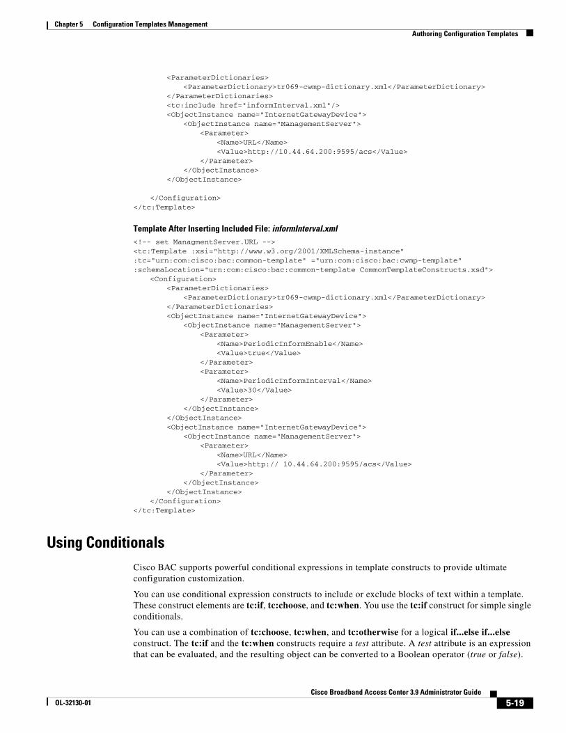
Chapter 5 Configuration Templates ManagementAuthoring Configuration Templates
<ParameterDictionaries><ParameterDictionary>tr069-cwmp-dictionary.xml</ParameterDictionary>
</ParameterDictionaries><tc:include href="informInterval.xml"/><ObjectInstance name="InternetGatewayDevice">
<ObjectInstance name="ManagementServer"><Parameter>
<Name>URL</Name><Value>http://10.44.64.200:9595/acs</Value>
</Parameter></ObjectInstance>
</ObjectInstance>
</Configuration></tc:Template>
Template After Inserting Included File: informInterval.xml<!-- set ManagmentServer.URL --><tc:Template :xsi="http://www.w3.org/2001/XMLSchema-instance" :tc="urn:com:cisco:bac:common-template" ="urn:com:cisco:bac:cwmp-template" :schemaLocation="urn:com:cisco:bac:common-template CommonTemplateConstructs.xsd">
<Configuration><ParameterDictionaries>
<ParameterDictionary>tr069-cwmp-dictionary.xml</ParameterDictionary></ParameterDictionaries><ObjectInstance name="InternetGatewayDevice">
<ObjectInstance name="ManagementServer"><Parameter>
<Name>PeriodicInformEnable</Name><Value>true</Value>
</Parameter><Parameter>
<Name>PeriodicInformInterval</Name><Value>30</Value>
</Parameter></ObjectInstance>
</ObjectInstance><ObjectInstance name="InternetGatewayDevice">
<ObjectInstance name="ManagementServer"><Parameter>
<Name>URL</Name><Value>http:// 10.44.64.200:9595/acs</Value>
</Parameter></ObjectInstance>
</ObjectInstance></Configuration>
</tc:Template>
Using ConditionalsCisco BAC supports powerful conditional expressions in template constructs to provide ultimate configuration customization.
You can use conditional expression constructs to include or exclude blocks of text within a template. These construct elements are tc:if, tc:choose, and tc:when. You use the tc:if construct for simple single conditionals.
You can use a combination of tc:choose, tc:when, and tc:otherwise for a logical if...else if...else construct. The tc:if and the tc:when constructs require a test attribute. A test attribute is an expression that can be evaluated, and the resulting object can be converted to a Boolean operator (true or false).
5-19Cisco Broadband Access Center 3.9 Administrator Guide
OL-32130-01
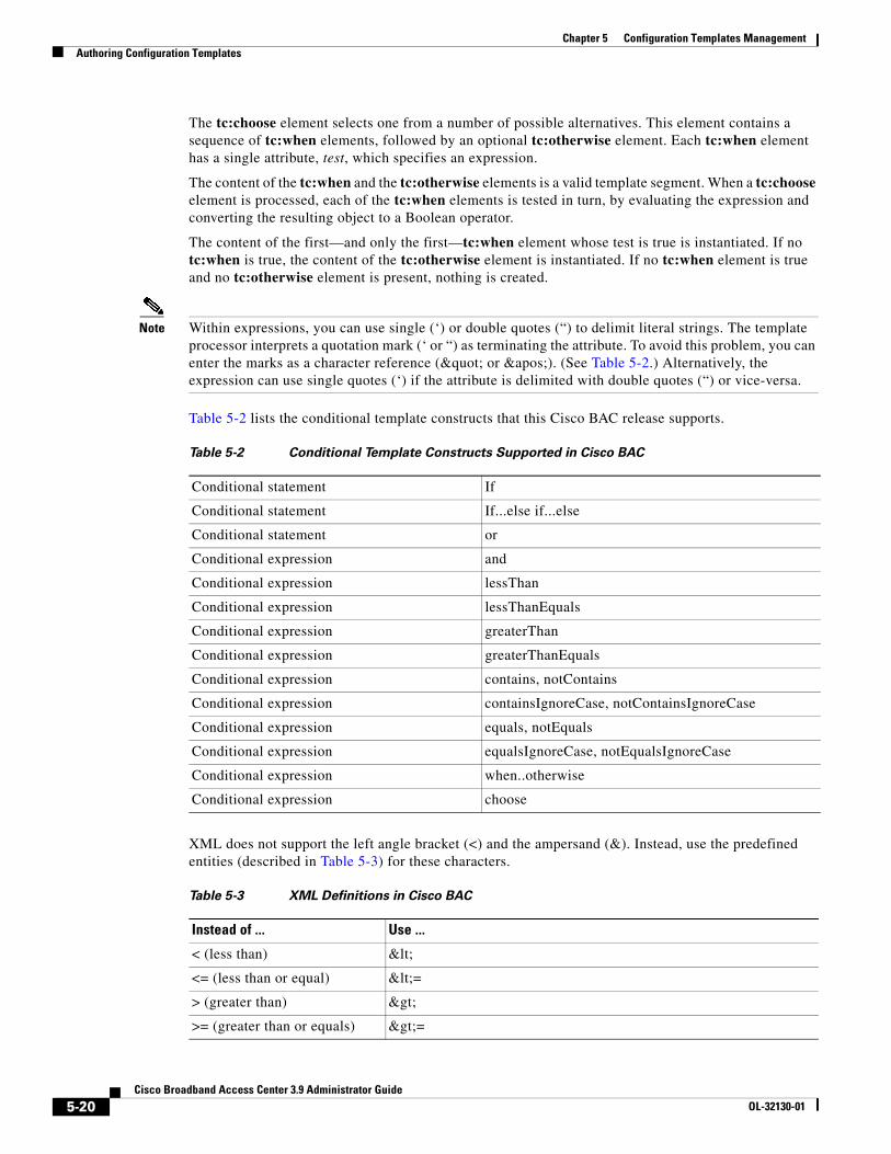
Chapter 5 Configuration Templates ManagementAuthoring Configuration Templates
The tc:choose element selects one from a number of possible alternatives. This element contains a sequence of tc:when elements, followed by an optional tc:otherwise element. Each tc:when element has a single attribute, test, which specifies an expression.
The content of the tc:when and the tc:otherwise elements is a valid template segment. When a tc:choose element is processed, each of the tc:when elements is tested in turn, by evaluating the expression and converting the resulting object to a Boolean operator.
The content of the first—and only the first—tc:when element whose test is true is instantiated. If no tc:when is true, the content of the tc:otherwise element is instantiated. If no tc:when element is true and no tc:otherwise element is present, nothing is created.
Note Within expressions, you can use single (‘) or double quotes (“) to delimit literal strings. The template processor interprets a quotation mark (‘ or “) as terminating the attribute. To avoid this problem, you can enter the marks as a character reference (" or '). (See Table 5-2.) Alternatively, the expression can use single quotes (‘) if the attribute is delimited with double quotes (“) or vice-versa.
Table 5-2 lists the conditional template constructs that this Cisco BAC release supports.
XML does not support the left angle bracket (<) and the ampersand (&). Instead, use the predefined entities (described in Table 5-3) for these characters.
Table 5-2 Conditional Template Constructs Supported in Cisco BAC
Conditional statement If
Conditional statement If...else if...else
Conditional statement or
Conditional expression and
Conditional expression lessThan
Conditional expression lessThanEquals
Conditional expression greaterThan
Conditional expression greaterThanEquals
Conditional expression contains, notContains
Conditional expression containsIgnoreCase, notContainsIgnoreCase
Conditional expression equals, notEquals
Conditional expression equalsIgnoreCase, notEqualsIgnoreCase
Conditional expression when..otherwise
Conditional expression choose
Table 5-3 XML Definitions in Cisco BAC
Instead of ... Use ...
< (less than) <
<= (less than or equal) <=
> (greater than) >
>= (greater than or equals) >=
5-20Cisco Broadband Access Center 3.9 Administrator Guide
OL-32130-01
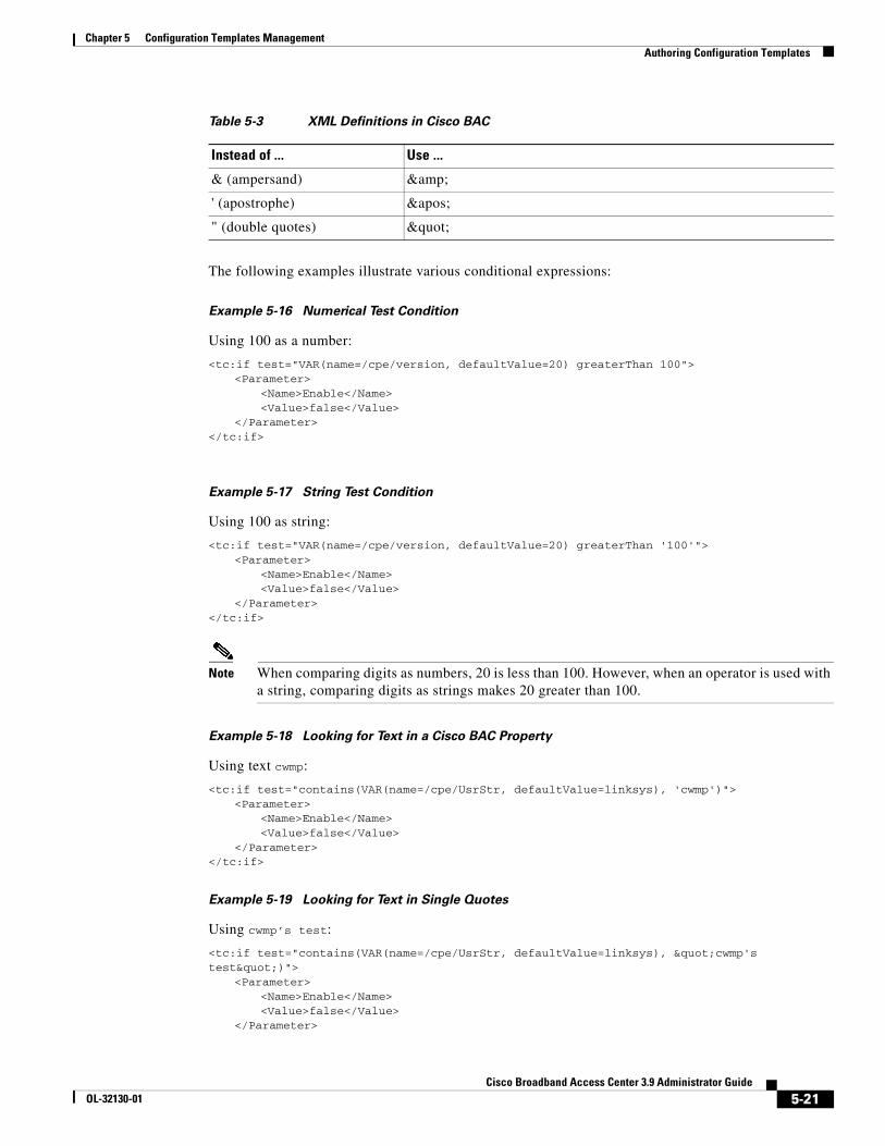
Chapter 5 Configuration Templates ManagementAuthoring Configuration Templates
The following examples illustrate various conditional expressions:
Example 5-16 Numerical Test Condition
Using 100 as a number:
<tc:if test="VAR(name=/cpe/version, defaultValue=20) greaterThan 100"><Parameter>
<Name>Enable</Name><Value>false</Value>
</Parameter></tc:if>
Example 5-17 String Test Condition
Using 100 as string:
<tc:if test="VAR(name=/cpe/version, defaultValue=20) greaterThan '100'"><Parameter>
<Name>Enable</Name><Value>false</Value>
</Parameter></tc:if>
Note When comparing digits as numbers, 20 is less than 100. However, when an operator is used with a string, comparing digits as strings makes 20 greater than 100.
Example 5-18 Looking for Text in a Cisco BAC Property
Using text cwmp:
<tc:if test="contains(VAR(name=/cpe/UsrStr, defaultValue=linksys), 'cwmp')"><Parameter>
<Name>Enable</Name><Value>false</Value>
</Parameter></tc:if>
Example 5-19 Looking for Text in Single Quotes
Using cwmp’s test:
<tc:if test="contains(VAR(name=/cpe/UsrStr, defaultValue=linksys), "cwmp's test")">
<Parameter><Name>Enable</Name><Value>false</Value>
</Parameter>
& (ampersand) &
' (apostrophe) '
" (double quotes) "
Table 5-3 XML Definitions in Cisco BAC
Instead of ... Use ...
5-21Cisco Broadband Access Center 3.9 Administrator Guide
OL-32130-01
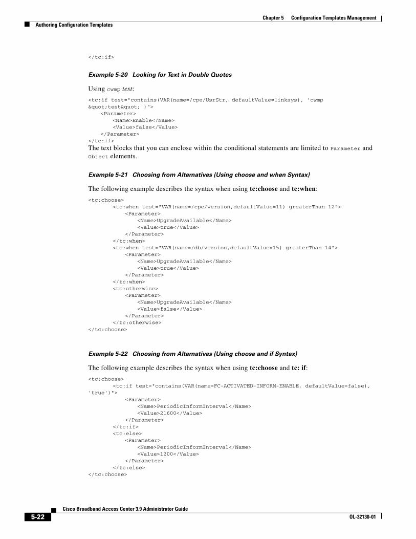
Chapter 5 Configuration Templates ManagementAuthoring Configuration Templates
</tc:if>
Example 5-20 Looking for Text in Double Quotes
Using cwmp test:
<tc:if test="contains(VAR(name=/cpe/UsrStr, defaultValue=linksys), 'cwmp "test"')">
<Parameter><Name>Enable</Name><Value>false</Value>
</Parameter></tc:if>
The text blocks that you can enclose within the conditional statements are limited to Parameter and Object elements.
Example 5-21 Choosing from Alternatives (Using choose and when Syntax)
The following example describes the syntax when using tc:choose and tc:when:
<tc:choose><tc:when test="VAR(name=/cpe/version,defaultValue=11) greaterThan 12">
<Parameter><Name>UpgradeAvailable</Name><Value>true</Value>
</Parameter></tc:when><tc:when test="VAR(name=/db/version,defaultValue=15) greaterThan 14">
<Parameter><Name>UpgradeAvailable</Name><Value>true</Value>
</Parameter></tc:when><tc:otherwise>
<Parameter><Name>UpgradeAvailable</Name><Value>false</Value>
</Parameter></tc:otherwise>
</tc:choose>
Example 5-22 Choosing from Alternatives (Using choose and if Syntax)
The following example describes the syntax when using tc:choose and tc: if:
<tc:choose><tc:if test="contains(VAR(name=FC-ACTIVATED-INFORM-ENABLE, defaultValue=false),
'true')"><Parameter>
<Name>PeriodicInformInterval</Name><Value>21600</Value>
</Parameter></tc:if><tc:else>
<Parameter><Name>PeriodicInformInterval</Name><Value>1200</Value>
</Parameter></tc:else>
</tc:choose>
5-22Cisco Broadband Access Center 3.9 Administrator Guide
OL-32130-01
Chapter 5 Configuration Templates ManagementUsing the Configuration Utility
Using the Configuration UtilityYou can use the configuration utility to test, validate, and view TR-069 template files: configuration and firmware rules. These activities are critical to successful deployment of instructions for individualized configuration files. (For more information on templates, see Authoring Configuration Templates, page 5-14.)
The configuration utility is available only when the RDU is installed, and it is installed in the <BPR_HOME>/rdu/bin directory.
All examples in this section assume that the RDU is operating and that these conditions apply:
• The BAC application is installed in the default home directory (/opt/CSCObac).
• The RDU login name is bacadmin.
• The RDU login password is changeme.
Note Some of the examples provided in this section were truncated whenever the omitted formation is of no consequence to the example of its outcome. Instances where this occurs are identified by an ellipsis (...) that precede the example summary.
This section discusses:
• Running the Configuration Utility, page 5-23
• Adding a Template to Cisco BAC, page 5-24
• Validating XML Syntax for a Local Template File, page 5-24
• Validating XML Syntax for a Template Stored in Cisco BAC, page 5-25
• Testing Template Processing for a Local Template File, page 5-26
• Testing Template Processing for a Template Stored in Cisco BAC, page 5-26
• Testing Template Processing for a Cisco BAC Template File and a Device, page 5-27
Running the Configuration UtilityIn subsequent procedures and examples, the phrase running the configuration utility means to enter the runCfgUtil.sh command from the directory specified. To run the configuration utility, run this command from the <BPR_HOME>/rdu/bin directory:
runCfgUtil.sh options
The available options include:
• -cwmp—Specifies the input file is to be processed as a CWMP technology configuration template file. Use -cwmp with the -a option.
• -a {sc | gc}—Specifies a required action, which could be either:
– sc—To specify a syntax check to test if the XML template and dictionary are well-formed. Use sc with the –l option.
– gc—To process a configuration template the same way as the Instruction Generation Service (IGS) would. Use gc with the (–l and –data), or the (-l and -i) options.
• -l filename—Identifies the input file to be on the local file system. For example, if the name of your input file is any_file, enter -l any_file.
5-23Cisco Broadband Access Center 3.9 Administrator Guide
OL-32130-01
Chapter 5 Configuration Templates ManagementUsing the Configuration Utility
Note Do not use -l with the -r option.
• -o filename—Saves the output of template processing in XML format into the specified file. For example, to save the output in a file called op_file, enter -o op_file This is an optional element.
• -i device id—Specifies the device to use for variable substitution when processing the template. Variable values are retrieved by using the device’s properties. Use with the -r option.
• -r filename—Specifies name of template stored in the RDU. Use this option instead of the -l option.
• -u username—Specifies the username to be used when connecting to the RDU.
• -p password—Specifies the password to be used when connecting to the RDU.
• -firmware—Specifies the input file to be a firmware rule template. Otherwise, assume configuration template.
Adding a Template to Cisco BACTo use the configuration utility to test BAC templates:
Step 1 Develop the template as described in Authoring Configuration Templates, page 5-14. If the template includes other templates, make sure all the referenced templates are in the same directory.
Step 2 Run the configuration utility on the local file system. You can check the syntax for the template, or have the configuration utility process template as IGS would, and return XML output.
If the processed template uses VAR() constructs to reference a device property, the resulting output will contain the defaultValues for those VAR() constructs.
Step 3 Add the template (and any included templates that are used) to the RDU.
If the template uses VAR() constructs to reference a device property, use the device option to generate a sample template.
Step 4 After all tests succeed, configure a Class of Service to use the template.
Validating XML Syntax for a Local Template FileUse the runCfgUtil.sh command to validate template files stored on the local file system.
Syntax Description runCfgUtil.sh -cwmp -a sc -l file
• -cwmp—Identifies the input file to be processed as a CWMP template file.
• -a sc—Specifies a syntax check.
• -l—Specifies that the input file is on the local file system.
• file—Identifies the input template file being validated.
5-24Cisco Broadband Access Center 3.9 Administrator Guide
OL-32130-01
Chapter 5 Configuration Templates ManagementUsing the Configuration Utility
To use a template file that is on the local file system:
Step 1 Change directory to /opt/CSCObac/rdu/samples/cwmp.
Step 2 Select a template file to use.
Note This example uses an existing template file called sample-cwmp-config.xml. The -cwmp option is used because this is a CWMP template.Run the configuration utility by using this command:
/opt/CSCObac/rdu/bin/runCfgUtil.sh -cwmp -a sc -l sample-cwmp-config.xml
• -cwmp—Identifies the input file as a CWMP template file.
• -l—Specifies that the input file is on the local file system.
• sample-cwmp-config.xml—Identifies the input template file being validated.
After running the utility, results similar to these should appear:
Broadband Access Center Configuration UtilityVersion: 3.0, Revision: 1.26validating configuration template sample-cwmp-config.xml...>sample-cwmp-config.xml is valid.
Validating XML Syntax for a Template Stored in Cisco BACUse the runCfgUtil.sh command to validate template files that are in the RDU database.
Syntax Description runCfgUtil.sh -cwmp -a sc -r file -u username -p password
• -cwmp—Identifies the input file to be processed as a CWMP template file.
• -a sc—Specifies a syntax check.
• -r file—Identifies the input file as a file that has been added to the RDU.
• -u username—Specifies the username to use when connecting to the RDU.
• -p password—Specifies the password to use when connecting to the RDU.
To validate a template file that has been added to the RDU:
Step 1 Change directory to /opt/CSCObac/rdu/samples/cwmp.
Step 2 Select a template file to use.
Note This example uses an existing template file called sample-cwmp-config.xml. The -cwmp option is used because a CWMP template is being used.
Step 3 Run the configuration utility by using this command:
./runCfgUtil.sh -cwmp -a sc -r sample-cwmp-config.xml -u admin -p changeme
• sample-cwmp-config.xml—Identifies the input file.
5-25Cisco Broadband Access Center 3.9 Administrator Guide
OL-32130-01
Chapter 5 Configuration Templates ManagementUsing the Configuration Utility
• admin—Identifies the username.
• changeme—Identifies the password.
• -cwmp—Identifies the file as a CWMP template.
After running the utility, results similar to these should appear:
Broadband Access Center Configuration UtilityVersion: 3.0, Revision: 1.26validating configuration template sample-cwmp-config.xml...>sample-cwmp-config.xml is valid.
Testing Template Processing for a Local Template FileUse the runCfgUtil.sh command to test template processing for a local template file.
Syntax Description runCfgUtil.sh -cwmp -a gc -l file -o file
• -cwmp—Identifies the input file to be processed as a CWMP template file.
• -a gc—Specifies instructions for configuration generation.
• -l file—Specifies that the input file is on the local file system.
• -o file—Specifies that the processed template be saved in XML format into the specified file.
To test template processing for a local template file:
Step 1 Change directory to /opt/CSCObac/rdu/samples/cwmp.
Step 2 Select a template file to use. This example uses the existing template file, sample-cwmp-config.xml.
Step 3 Run the configuration utility by using this command:
./opt/CSCObac/rdu/bin/runCfgUtil.sh -cwmp -a gc -l sample-cwmp-config.xml -o output.xml
• sample-cwmp-config.xml—Identifies the input file.
• output.xml—Identifies the file in which to save the processed template in XML format.
After running the utility, results similar to these should appear:
Broadband Access Center Configuration UtilityVersion: 3.0, Revision: 1.26generating configuration from sample-cwmp-config.xml...output.xml generated successfully.
You can view the configuration from the output.xml file.
Testing Template Processing for a Template Stored in Cisco BACUse the runCfgUtil.sh command to test the template processing for a template in the RDU database.
5-26Cisco Broadband Access Center 3.9 Administrator Guide
OL-32130-01
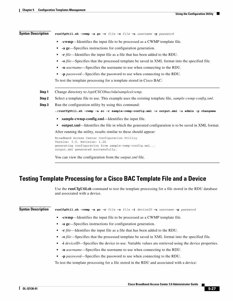
Chapter 5 Configuration Templates ManagementUsing the Configuration Utility
Syntax Description runCfgUtil.sh -cwmp -a gc -r file -o file -u username -p password
• -cwmp—Identifies the input file to be processed as a CWMP template file.
• -a gc—Specifies instructions for configuration generation.
• -r file—Identifies the input file as a file that has been added to the RDU.
• -o file—Specifies that the processed template be saved in XML format into the specified file.
• -u username—Specifies the username to use when connecting to the RDU.
• -p password—Specifies the password to use when connecting to the RDU.
To test the template processing for a template stored in Cisco BAC:
Step 1 Change directory to /opt/CSCObac/rdu/samples/cwmp.
Step 2 Select a template file to use. This example uses the existing template file, sample-cwmp-config.xml.
Step 3 Run the configuration utility by using this command:
./runCfgUtil.sh -cwmp -a sc -r sample-cwmp-config.xml -o output.xml -u admin -p changeme
• sample-cwmp-config.xml—Identifies the input file.
• output.xml—Identifies the file in which the generated configuration is to be saved in XML format.
After running the utility, results similar to these should appear:
Broadband Access Center Configuration UtilityVersion: 3.0, Revision: 1.26generating configuration from sample-cwmp-config.xml...output.xml generated successfully.
You can view the configuration from the output.xml file.
Testing Template Processing for a Cisco BAC Template File and a DeviceUse the runCfgUtil.sh command to test the template processing for a file stored in the RDU database and associated with a device.
Syntax Description runCfgUtil.sh -cwmp -a gc -r file -o file -i deviceID -u username -p password
• -cwmp—Identifies the input file to be processed as a CWMP template file.
• -a gc—Specifies instructions for configuration generation.
• -r file—Identifies the input file as a file that has been added to the RDU.
• -o file—Specifies that the processed template be saved in XML format into the specified file.
• -i deviceID—Specifies the device to use. Variable values are retrieved using the device properties.
• -u username—Specifies the username to use when connecting to the RDU.
• -p password—Specifies the password to use when connecting to the RDU.
To test the template processing for a file stored in the RDU and associated with a device:
5-27Cisco Broadband Access Center 3.9 Administrator Guide
OL-32130-01
Chapter 5 Configuration Templates ManagementUsing the Configuration Utility
Step 1 By using the administrator user interface, add the template file /opt/CSCObac/rdu/samples/cwmp/sample-cwmp-var-config.xml to Cisco BAC.
Note The sample-cwmp-var-config.xml template has a reference to the /IPDevice/connectionRequestUsername device property. The API constant for the property is IPDeviceKeys.CONNECTION_REQUEST_USERNAME.
Step 2 Select a template file to use. This example uses the existing template file, sample-cwmp-var-config.xml.
Step 3 Identify a device that is already in Cisco BAC and use that device’s ID. This example uses a device with the /IPDevice/connectionRequestUsername property set to testUser.
Step 4 Identify the device to use. This example assumes that the device exists in the RDU and has the variables set as properties.
Step 5 Run the configuration utility by using this command:
./runCfgUtil.sh -cwmp -a gc -r sample-cwmp-var-config.xml -i OUI-1234 -o output.xml -u admin -p changeme
• sample-cwmp-var-config.xml—Identifies the input file.
• OUI-1234—Identifies the ID of the device. The Device ID used here is for example purposes only.
• output.xml—Identifies the file in which to save the processed template in XML format.
• bacadmin—Identifies the default username being used in this example.
• changeme—Identifies the default password being used in this example
After running the utility, results similar to these should appear:
Broadband Access Center Configuration UtilityVersion: 3.0, Revision: 1.26generating configuration from sample-cwmp-var-config.xml...output.xml generated successfully.
Note You can open the output.xml file to view the configuration. The VAR(name=/IPDevice/connectionRequestUsername, defaultValue=test) statement will be replaced with testUser.
5-28Cisco Broadband Access Center 3.9 Administrator Guide
OL-32130-01
CiscoOL-32130-01
C H A P T E R 6
Firmware ManagementThis chapter describes firmware management for TR-069 compliant devices in Cisco Broadband Access Center (Cisco BAC).
This chapter includes the following sections:
• Overview, page 6-1
• Firmware Management Mechanisms, page 6-2
• Managing Firmware Files, page 6-5
• Authoring Firmware Rules Templates, page 6-6
• Using Template Constructs with Firmware Rule Templates, page 6-13
OverviewFirmware management consists of maintaining and distributing sets of firmware image files to corresponding customer premise equipment (CPE) through the Cisco BAC system. A firmware rules template associates the firmware image files to groups of devices. Cisco BAC uses the rules in the associated firmware rules template to evaluate which firmware to download to the device.
The firmware management functionality allows the administrator to view firmware information on devices, to add firmware images to the database, and to apply the image files to specific devices.
Cisco BAC supports two mechanisms for CPE firmware management:
• Policy-based firmware management through firmware rules templates.
• Direct firmware management through device operations API.
See Firmware Rule Templates, page 6-2, and Direct Firmware Management, page 6-4, for detailed information.
In the process of firmware management, regardless of the management method used, the device is instructed to obtain a new firmware image file from a file server. Cisco BAC provides a file service in its DPE. However, you can also direct CPE to other file servers.
Firmware rules can apply firmware to devices, based on a match of any preprovisioned or discovered device parameters, including device group membership, model, type, current state, type of connectivity, and so on.
The DPE triggers the firmware download by issuing a Download RPC with the location of the file on a file server and authentication credentials, if any. Cisco BAC supports HTTP and HTTP over SSL, called SSL/TLS in this chapter, for file downloads on DPE servers.
6-1 Broadband Access Center 3.9 Administrator Guide
Chapter 6 Firmware ManagementFirmware Management Mechanisms
This download can be initiated in various modes:
• Firmware-rule based, in which firmware rules may or may not allow the download of the file requested by a device, or may download a different file. Firmware rules are executed whenever a device connects to the DPE.
• The device may contact the DPE, based on periodic contact after a reboot or a specific action, such as an user-initiated upgrade by clicking in the local user interface of the device. Regardless of how the device contacts the DPE, the firmware rules, determine whether the upgrade is needed and is allowed at the time of the particular interaction.
• Proxy, in which an external application invokes the API download operation for a specific device and specifies the firmware image file location. The DPE then executes the Download RPC on the device, causing the device to download the file from the specified location.
The download can occur in three ways:
– Immediate, in which the DPE connects to the device and instructs the device to download the firmware.
– On-connect, in which the DPE instructs the device to download the firmware on next contact with the device.
– Asynchronous, in which the DPE instructs the device to download the firmware without reserving the PACE thread at RDU. The operation result is sent to the API client in an AyncOperationEvent.
The multiple instance object support is available in the firmware template, which facilitates discovering the device parameters for multiple object instances. The parameter value associated with the discovered object instances is matched with the parameter values specified in the template, and further firmware rule is applied based on the match condition. For more information on multi-instance object support, see Multi-Instance Object Support, page 4-5.
Firmware Management MechanismsThis section describes CPE firmware-management mechanisms provided by Cisco BAC. These comprise:
• Policy-based firmware management through firmware rules templates. See Firmware Rule Templates, page 6-2, for detailed information.
• External firmware management through proxy operations. See Direct Firmware Management, page 6-4, for detailed information.
Firmware Rule TemplatesYou use rule templates to set policy-based firmware management. The firmware rules templates are XML documents written according to a published schema document. Each template must be stored in a file and uploaded into Cisco BAC.
Each firmware rules template contains one or more rules which trigger firmware updates based on specific conditions. Any number of such templates can be added to Cisco BAC, through the administrator user interface or API. The template is associated with a Class of Service object using the COS_CWMP_FIRMWARE_RULES_FILE property. Each device, in turn, is assigned to a Class of Service. (For information on Cisco BAC object relationships, see Cisco BAC Device Object Model, page 4-2.)
6-2Cisco Broadband Access Center 3.9 Administrator Guide
OL-32130-01
Chapter 6 Firmware ManagementFirmware Management Mechanisms
In this model, you can make convenient updates to the definition of the rules, which apply to a large number of devices. When the rules template is updated, CPE that are indirectly associated with the template through the Class of Service are managed according to the new policy.
When the device establishes a connection with Cisco BAC, its firmware and configuration are automatically synchronized based on the configuration and firmware rules cached at the DPE. First, the firmware rules are executed, and if appropriate, the device firmware is updated. Then, the device configuration is synchronized.
Earlier to this release, the only file type supported by Cisco BAC was "1 Firmware Upgrade Image". With this release of Cisco BAC, firmware download is enhanced to allow upgrade of CPE devices with different vendor specific TR-069 download file types. Now vendor can define file type in both internal and external firmware rule tag.
Cisco BAC provides a two-stage firmware rule processing. First, the templates are processed at the RDU where template constructs such as conditionals and substitutable parameters are interpreted (See Using Template Constructs with Firmware Rule Templates, page 6-13).
This processing allows customization of rules for devices based on data available at the RDU (such as device properties and grouping). This data could be preprovisioned by using the API. Data previously discovered from the device and stored at the RDU can also be used in constructing the templates.
After the template has been processed, the resulting rules are sent to the DPEs in the device’s provisioning group. The rules, in turn, can have dynamic matching criteria, which enable further granularity in firmware rules policy.
To determine if a firmware update is needed, the rules engine at the DPE evaluates the firmware rules. Firmware rules allow a firmware update to be triggered on match of:
• Inform event types
• Device RequestDownloadRPC arguments
• Inform parameter values
• Any other device parameter values
• MaintenanceWindow time
Note You can use the MaintenanceWindow option to schedule firmware downloads to a device. For details, see Device Contact During MaintenanceWindow, page 5-12.
Together, these rules provide a powerful mechanism to create policy for managing firmware. For example, an administrator can write a rule that forces all devices of a certain model with a certain current firmware version to upgrade to a different firmware, during a specific service time window.
The DPE logs an entry for all cases of firmware selection by using rules. It also logs an entry if none of the rules match. This logging mechanism can be useful to track devices that have no firmware image file associated with them or if the device firmware is simply up to date.
Cisco BAC uses the XML schemas that are defined in various files to generate instructions for device configurations. Table 6-1 lists these files and their locations.
6-3Cisco Broadband Access Center 3.9 Administrator Guide
OL-32130-01
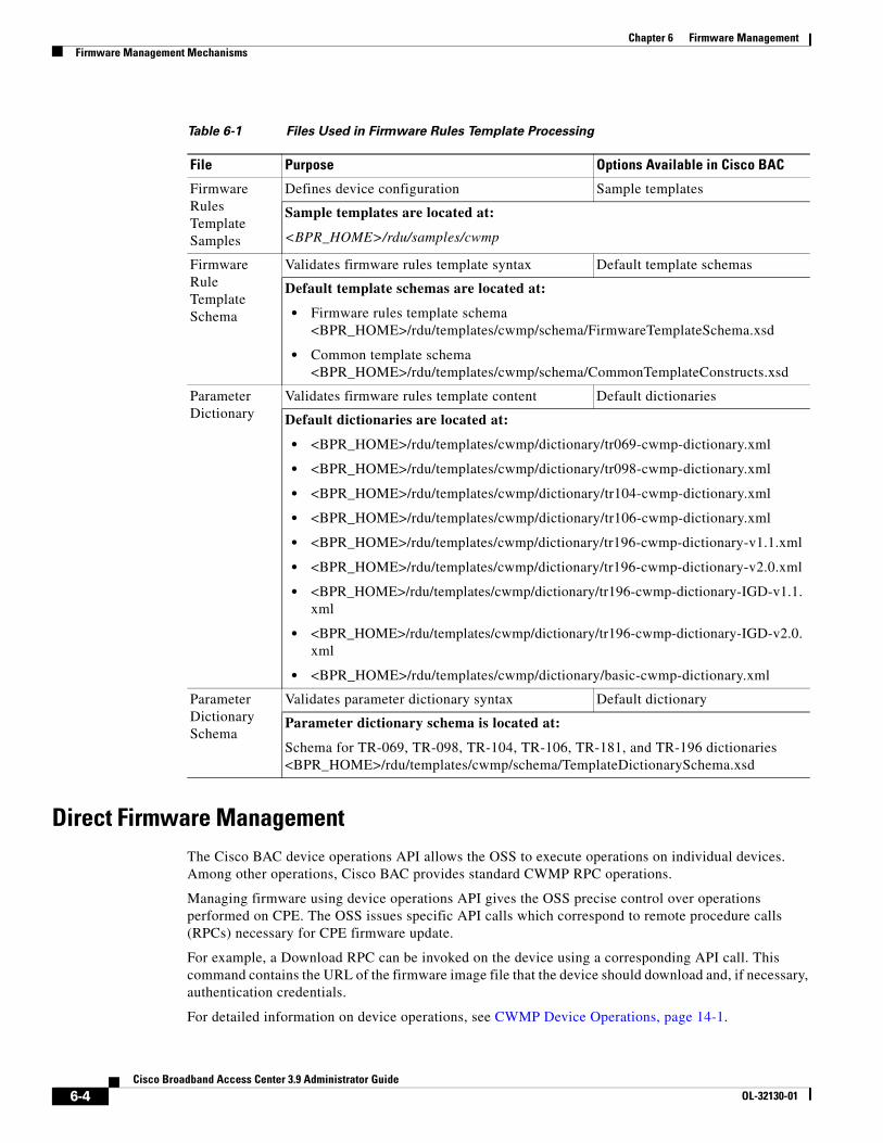
Chapter 6 Firmware ManagementFirmware Management Mechanisms
Direct Firmware ManagementThe Cisco BAC device operations API allows the OSS to execute operations on individual devices. Among other operations, Cisco BAC provides standard CWMP RPC operations.
Managing firmware using device operations API gives the OSS precise control over operations performed on CPE. The OSS issues specific API calls which correspond to remote procedure calls (RPCs) necessary for CPE firmware update.
For example, a Download RPC can be invoked on the device using a corresponding API call. This command contains the URL of the firmware image file that the device should download and, if necessary, authentication credentials.
For detailed information on device operations, see CWMP Device Operations, page 14-1.
Table 6-1 Files Used in Firmware Rules Template Processing
File Purpose Options Available in Cisco BAC
Firmware Rules Template Samples
Defines device configuration Sample templates
Sample templates are located at:
<BPR_HOME>/rdu/samples/cwmp
Firmware Rule Template Schema
Validates firmware rules template syntax Default template schemas
Default template schemas are located at:
• Firmware rules template schema<BPR_HOME>/rdu/templates/cwmp/schema/FirmwareTemplateSchema.xsd
• Common template schema <BPR_HOME>/rdu/templates/cwmp/schema/CommonTemplateConstructs.xsd
Parameter Dictionary
Validates firmware rules template content Default dictionaries
Default dictionaries are located at:
• <BPR_HOME>/rdu/templates/cwmp/dictionary/tr069-cwmp-dictionary.xml
• <BPR_HOME>/rdu/templates/cwmp/dictionary/tr098-cwmp-dictionary.xml
• <BPR_HOME>/rdu/templates/cwmp/dictionary/tr104-cwmp-dictionary.xml
• <BPR_HOME>/rdu/templates/cwmp/dictionary/tr106-cwmp-dictionary.xml
• <BPR_HOME>/rdu/templates/cwmp/dictionary/tr196-cwmp-dictionary-v1.1.xml
• <BPR_HOME>/rdu/templates/cwmp/dictionary/tr196-cwmp-dictionary-v2.0.xml
• <BPR_HOME>/rdu/templates/cwmp/dictionary/tr196-cwmp-dictionary-IGD-v1.1.xml
• <BPR_HOME>/rdu/templates/cwmp/dictionary/tr196-cwmp-dictionary-IGD-v2.0.xml
• <BPR_HOME>/rdu/templates/cwmp/dictionary/basic-cwmp-dictionary.xml
Parameter Dictionary Schema
Validates parameter dictionary syntax Default dictionary
Parameter dictionary schema is located at:
Schema for TR-069, TR-098, TR-104, TR-106, TR-181, and TR-196 dictionaries<BPR_HOME>/rdu/templates/cwmp/schema/TemplateDictionarySchema.xsd
6-4Cisco Broadband Access Center 3.9 Administrator Guide
OL-32130-01
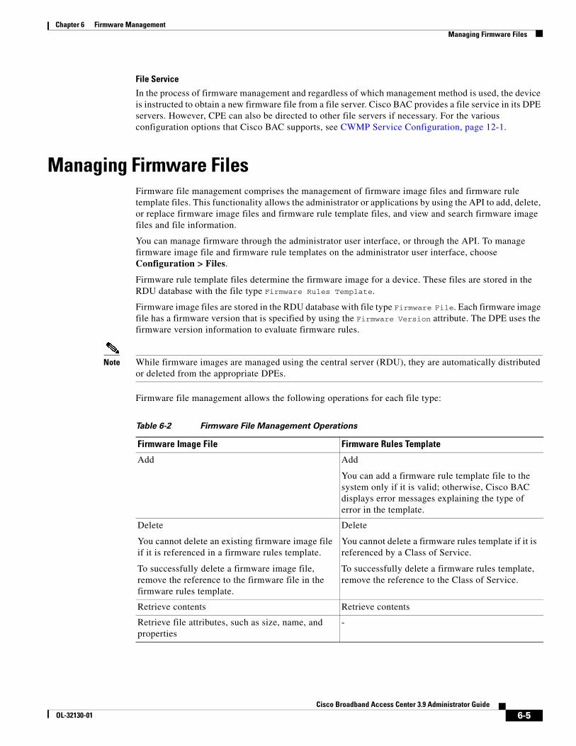
Chapter 6 Firmware ManagementManaging Firmware Files
File Service
In the process of firmware management and regardless of which management method is used, the device is instructed to obtain a new firmware file from a file server. Cisco BAC provides a file service in its DPE servers. However, CPE can also be directed to other file servers if necessary. For the various configuration options that Cisco BAC supports, see CWMP Service Configuration, page 12-1.
Managing Firmware FilesFirmware file management comprises the management of firmware image files and firmware rule template files. This functionality allows the administrator or applications by using the API to add, delete, or replace firmware image files and firmware rule template files, and view and search firmware image files and file information.
You can manage firmware through the administrator user interface, or through the API. To manage firmware image file and firmware rule templates on the administrator user interface, choose Configuration > Files.
Firmware rule template files determine the firmware image for a device. These files are stored in the RDU database with the file type Firmware Rules Template.
Firmware image files are stored in the RDU database with file type Firmware File. Each firmware image file has a firmware version that is specified by using the Firmware Version attribute. The DPE uses the firmware version information to evaluate firmware rules.
Note While firmware images are managed using the central server (RDU), they are automatically distributed or deleted from the appropriate DPEs.
Firmware file management allows the following operations for each file type:
Table 6-2 Firmware File Management Operations
Firmware Image File Firmware Rules Template
Add Add
You can add a firmware rule template file to the system only if it is valid; otherwise, Cisco BAC displays error messages explaining the type of error in the template.
Delete
You cannot delete an existing firmware image file if it is referenced in a firmware rules template.
To successfully delete a firmware image file, remove the reference to the firmware file in the firmware rules template.
Delete
You cannot delete a firmware rules template if it is referenced by a Class of Service.
To successfully delete a firmware rules template, remove the reference to the Class of Service.
Retrieve contents Retrieve contents
Retrieve file attributes, such as size, name, and properties
-
6-5Cisco Broadband Access Center 3.9 Administrator Guide
OL-32130-01
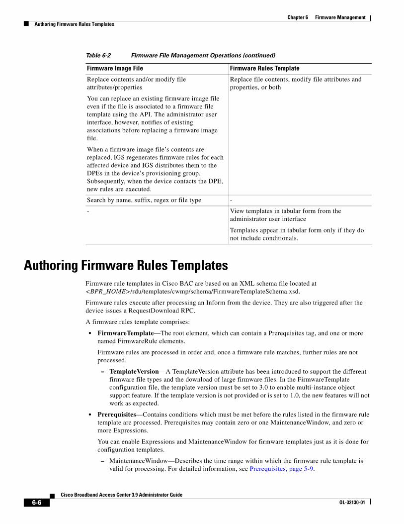
Chapter 6 Firmware ManagementAuthoring Firmware Rules Templates
Authoring Firmware Rules TemplatesFirmware rule templates in Cisco BAC are based on an XML schema file located at <BPR_HOME>/rdu/templates/cwmp/schema/FirmwareTemplateSchema.xsd.
Firmware rules execute after processing an Inform from the device. They are also triggered after the device issues a RequestDownload RPC.
A firmware rules template comprises:
• FirmwareTemplate—The root element, which can contain a Prerequisites tag, and one or more named FirmwareRule elements.
Firmware rules are processed in order and, once a firmware rule matches, further rules are not processed.
– TemplateVersion—A TemplateVersion attribute has been introduced to support the different firmware file types and the download of large firmware files. In the FirmwareTemplate configuration file, the template version must be set to 3.0 to enable multi-instance object support feature. If the template version is not provided or is set to 1.0, the new features will not work as expected.
• Prerequisites—Contains conditions which must be met before the rules listed in the firmware rule template are processed. Prerequisites may contain zero or one MaintenanceWindow, and zero or more Expressions.
You can enable Expressions and MaintenanceWindow for firmware templates just as it is done for configuration templates.
– MaintenanceWindow—Describes the time range within which the firmware rule template is valid for processing. For detailed information, see Prerequisites, page 5-9.
Replace contents and/or modify file attributes/properties
You can replace an existing firmware image file even if the file is associated to a firmware file template using the API. The administrator user interface, however, notifies of existing associations before replacing a firmware image file.
When a firmware image file’s contents are replaced, IGS regenerates firmware rules for each affected device and IGS distributes them to the DPEs in the device’s provisioning group. Subsequently, when the device contacts the DPE, new rules are executed.
Replace file contents, modify file attributes and properties, or both
Search by name, suffix, regex or file type -
- View templates in tabular form from the administrator user interface
Templates appear in tabular form only if they do not include conditionals.
Table 6-2 Firmware File Management Operations (continued)
Firmware Image File Firmware Rules Template
6-6Cisco Broadband Access Center 3.9 Administrator Guide
OL-32130-01
Chapter 6 Firmware ManagementAuthoring Firmware Rules Templates
– Expression—Zero or more expression for evaluating this rule; has the same syntax and definition as the Expression defined for the FirmwareRule element. For detailed information, see Expression and Regular Expression, page 6-7.
• FirmwareRule—Each FirmwareRule element provides:
– Expression—Zero or more expressions for evaluating this rule. The rules triggers a firmware update if all expressions in a given rule match. For detailed information, see Expression and Regular Expression, page 6-7.
– InternalFirmwareFile or ExternalFirmwareFile—One of the two must be specified.
– InternalFirmwareFile is used if the Cisco BAC file service is utilized, and the firmware image file has been added to the system using the API or the administrator user interface.
– ExternalFirmwareFile provides information for firmware image files located on external file servers.
For detailed information, see Internal Firmware File vs. External Firmware File, page 6-10.
Expression and Regular ExpressionExpressions provide a conditional way to apply the firmware rules based on value match. If the value is a range, Regular Expression (Regex) is used for defining the firware rule in firmware rule template. Regular expression provides a conditional way to apply the firmware rules based on Regex pattern match. Each expression or Regex must provide a ParameterName, InformParameterName or RpcArgumentName tag, one or more Value tags and an Operator tag.
The value of the event returned from the CPE, and the condition specified for the event determines whether the firmware rule is applied to the CPE. The firmware rules are defined in the firmware template with the appropriate event, Regex pattern associated with the event, and the condition for applying the firmware rule.
Regex support is also available in the configuration templates prerequisites. For more information on configuring prerequisites, see Configuring Prerequisites, page 5-13.
Cisco BAC processes these tags in sequence to match and assign a firmware image file to the CPE.
ParameterName
Specifies the name of a TR-069 parameter. The ParameterName is validated by using the relevant parameter dictionary.
The DPE may have this parameter available from Inform or from prior GetParameterValues RPCs calls within the same session. If the parameter value is not available in the session when processing the rule, the DPE queries the device for the missing parameter values before proceeding with evaluation of the rules.
For additional information, see Parameters, page 5-6.
InformParameterName
Specifies the name of an Inform parameter that is not described in the parameter dictionary. This entry is not validated.
For example, the expression in the following example evaluates to true if the device Inform.EventCode includes either of the specified values:
<Expression><InformParameter>Inform.EventCode</InformParameter><Value>1 BOOT</Value>
6-7Cisco Broadband Access Center 3.9 Administrator Guide
OL-32130-01
Chapter 6 Firmware ManagementAuthoring Firmware Rules Templates
<Value>3 SCHEDULED</Value><Operator>match</Operator>
</Expression>
Cisco BAC supports the following parameter names in the InformParameter tag:
• Inform.DeviceId.Manufacturer
• Inform.DeviceId.ManufacturerOUI
• Inform.DeviceId.ProductClass
• Inform.DeviceId.SerialNumber
• Inform.EventCode
For information on the values for Inform.EventCode, refer to the DSL Forum’s Technical Report on TR-069.
Value
Specifies data for the Parameter. One or more possible values might be listed for a given parameter. The data type for a value is validated by using a dictionary when possible.
In the expression, if you need to set a value that contains comma, then specify each item of the value separated by a comma in separate value tag. For example, the comma-separated value 12.4(22)T, RELEASE SOFTWARE (fc1) can be set as in the following expression:
<Expression><ParameterName>InternetGatewayDevice.DeviceInfo.SoftwareVersion</ParameterName><Value>12.4(22)T</Value><Value>RELEASE SOFTWARE (fc1)</Value><Operator>match</Operator></Expression>
You can also set the value as empty.
RpcArgumentName
Specifies the name for a parameter that the device reports. The possible values are RequestDownload.FileType and RequestDownload.FileTypeArg\*
• RequestDownload.FileType indicates the type of file that the device is requesting to download.
• RequestDownload.FileTypeArg\* indicates any argument that the device might have provided in a download request message. The asterisk (*) denotes the actual argument name.
See Example 6-3.
Operator
Evaluates the Parameter and the Value. In evaluating the expression, the Operator may be one of the following:
• match—Specifies that the device parameter value must match at least one of the values in a case-sensitive comparison.
• matchIgnoreCase—Specifies that the device parameter value must match at least one of the values in a case-insensitive comparison.
• matchAll—Specifies that the device parameter value must match all of the values in a case-sensitive comparison.
• matchAllIgnoreCase—Specifies that the device parameter value must match all of the values in a case-insensitive comparison.
6-8Cisco Broadband Access Center 3.9 Administrator Guide
OL-32130-01
Chapter 6 Firmware ManagementAuthoring Firmware Rules Templates
• noMatch—Specifies that the device parameter value must not match any of the values in a case-sensitive comparison.
• noMatchIgnoreCase—Specifies that the device parameter value must not match any of the values in a case-insensitive comparison.
Example 6-1 Expression - match InformParameterName
In the following sample expression, the match condition indicates that the subsequent rules are valid when the InformParameter Inform.EventCode has exactly the value 1 BOOT. The device reports this value in the Inform message when it contacts the autoconfiguration server (ACS).
<Expression><InformParameterName>Inform.EventCode</InformParameterName>
<Value>1 BOOT</Value> <Operator>match</Operator>
</Expression>
Example 6-2 Expression - match RpcArgumentName (RequestDownload.FileType)
In the following sample expression, the match condition indicates that the subsequent rules should be in effect when the RPCArgumentName RequestDownload.FileType matches exactly the value 1 Firmware Upgrade Image.
<Expression><RpcArgumentName>RequestDownload.FileType</RpcArgumentName><Value>1 Firmware Upgrade Image</Value><Operator>match</Operator>
</Expression>
Example 6-3 Expression - match RpcArgumentName (RequestDownload.FileTypeArg)
In the following sample expression, the match condition indicates that the subsequent rules should be in effect when the RPCArgumentName RequestDownload.FileTypeArg.Version matches the value 1.1.
Note The CWMP specification defines Version to be a FileTypeArg that you can use if File Type is Web Content.
<Expression><RpcArgumentName>RequestDownload.FileType</RpcArgumentName><Value>2 Web Content</Value><Operator>match</Operator>
</Expression> <Expression>
<RpcArgumentName>RequestDownload.FileTypeArg.Version</RpcArgumentName><Value>1.1</Value><Operator>match</Operator>
</Expression>
Example 6-4 Expression - noMatch ParameterName
In the following sample expression, the match condition indicates that the subsequent rules should be in effect when the Parameter InternetGatewayDevice.DeviceInfo.SoftwareVersion does not match the software version 1.02.
<Expression> <ParameterName>InternetGatewayDevice.DeviceInfo.SoftwareVersion</ParameterName>
6-9Cisco Broadband Access Center 3.9 Administrator Guide
OL-32130-01
Chapter 6 Firmware ManagementAuthoring Firmware Rules Templates
<Value>1.02</Value> <Operator>noMatch</Operator></Expression>
While specifying the Regex pattern, the operator tag may be one of the following:
• regexMatch—Indicates a condition that is set to ensure that the firmware rule is applied only when the device parameter value matches the Regex pattern.
• regexNoMatch—Indicates a condition that is set to ensure that the firmware rule is applied only when the device parameter value does not match the Regex pattern.
Example 6-5 Expression - regexMatch
In the following sample expression, the regexMatch condition indicates that the firmware rule comes into effect when the Parameter Inform.EventCode matches Regex pattern ^[0-9]\s\w.
<Expression><InformParameterName>Inform.EventCode</InformParameterName> <Value>^[0-9]\s\w</Value> <Operator>regexMatch</Operator>
</Expression>
If the condition is specified as regexNoMatch, the firmware rule is applied only when the Inform.EventCode does not match the Regex pattern ^[0-9]\s\w specified in the value tag.
Note Under expression, if the operator is regexMatch or regexNoMatch, ensure that only one value tag is used.
Internal Firmware File vs. External Firmware FileThe Internal and External firmware image file elements define whether the firmware image files are located within the Cisco BAC file server or at remote file server.
InternalFirmwareFile
The InternalFirmwareFile element describes the filename of the firmware image that was added to the RDU and automatically distributed to DPEs and the delivery transport method employed to download the firmware image to a device. It comprises:
• FileName—Specifies the name of the file in the RDU database.
• DeliveryTransport—Specifies service HTTP 1 or service HTTP 2 transfer.
You should configure the corresponding file service (HTTP 1 or HTTP 2) on the DPE. For configuration details, see the Cisco Broadband Access Center 3.8 DPE CLI Reference.
If you define multiple services on the DPE with the same transport, for example, two HTTP, the DPE chooses the first one to service the device.
• FileType—Specifies the vendor specific download FileType element. This element is optional. The default value is 1 Firmware Upgrade Image. The template version must be set to 2.0 to enable this feature.
• Location—Specifies the location where the files are stored. Possible values are Cache and File System. The default value is Cache. Specifying the location is optional and to enable this, you must set the template version to 2.0.
6-10Cisco Broadband Access Center 3.9 Administrator Guide
OL-32130-01
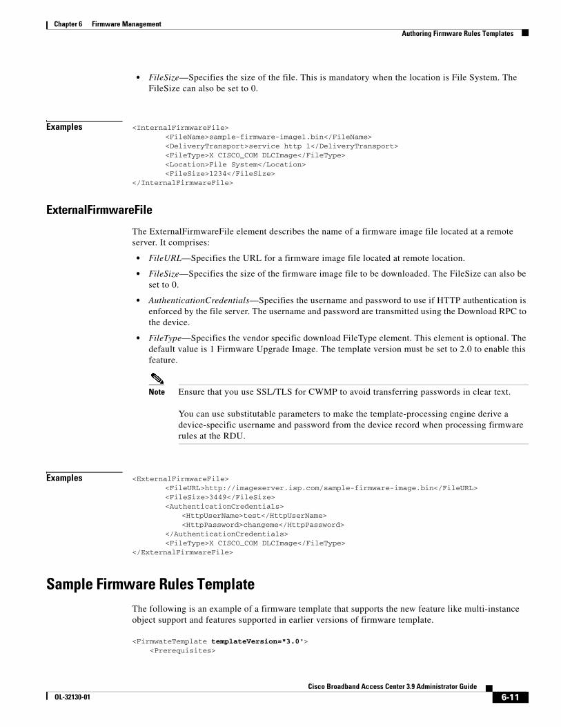
Chapter 6 Firmware ManagementAuthoring Firmware Rules Templates
• FileSize—Specifies the size of the file. This is mandatory when the location is File System. The FileSize can also be set to 0.
Examples <InternalFirmwareFile> <FileName>sample-firmware-image1.bin</FileName> <DeliveryTransport>service http 1</DeliveryTransport>
<FileType>X CISCO_COM DLCImage</FileType><Location>File System</Location><FileSize>1234</FileSize>
</InternalFirmwareFile>
ExternalFirmwareFile
The ExternalFirmwareFile element describes the name of a firmware image file located at a remote server. It comprises:
• FileURL—Specifies the URL for a firmware image file located at remote location.
• FileSize—Specifies the size of the firmware image file to be downloaded. The FileSize can also be set to 0.
• AuthenticationCredentials—Specifies the username and password to use if HTTP authentication is enforced by the file server. The username and password are transmitted using the Download RPC to the device.
• FileType—Specifies the vendor specific download FileType element. This element is optional. The default value is 1 Firmware Upgrade Image. The template version must be set to 2.0 to enable this feature.
Note Ensure that you use SSL/TLS for CWMP to avoid transferring passwords in clear text.
You can use substitutable parameters to make the template-processing engine derive a device-specific username and password from the device record when processing firmware rules at the RDU.
Examples <ExternalFirmwareFile><FileURL>http://imageserver.isp.com/sample-firmware-image.bin</FileURL><FileSize>3449</FileSize><AuthenticationCredentials>
<HttpUserName>test</HttpUserName><HttpPassword>changeme</HttpPassword>
</AuthenticationCredentials><FileType>X CISCO_COM DLCImage</FileType>
</ExternalFirmwareFile>
Sample Firmware Rules TemplateThe following is an example of a firmware template that supports the new feature like multi-instance object support and features supported in earlier versions of firmware template.
<FirmwateTemplate templateVersion="3.0"> <Prerequisites>
6-11Cisco Broadband Access Center 3.9 Administrator Guide
OL-32130-01

Chapter 6 Firmware ManagementAuthoring Firmware Rules Templates
<MaintenanceWindow> <StartTime>01:00:00</StartTime> <Duration>5:00</Duration> </MaintenanceWindow> <Expression> <InformParameterName>Device.DeviceInfo.EventCode</InformParameterName> <Value>1 BOOT</Value> <Operator>match</Operator> </Expression> <Expression> <ParameterName>Device.DeviceInfo.HardwareVersion</ParameterName> <Value>W3GFP-100-Rev 6.0</Value> <Operator>matchIgnoreCase</Operator> </Expression> <Expression> <ParameterName>Device.Services.FAPService.{i}.REM.UMTS.GSM.Cell.{i}.BSIC</ParameterName> <InstanceConfiguration> <Instance> <Path>Device.Services.FAPService.</Path> <Value>last()</Value> </Instance> <Instance> <Path>Device.Services.FAPService.{i}.REM.UMTS.GSM.Cell.</Path> <Value>compare(LAC lessThanEquals 65534)</Value> </Instance> <MatchCondition>OR</MatchCondition> </InstanceConfiguration> <Value>18</Value> <Operator>matchAllIgnoreCase</Operator> </Expression> </Prerequisites> <FirmwareRule name="InternalFileRule"> <Expression> <InformParameterName>Device.DeviceInfo.SoftwareVersion</InformPaameterNam> <Value>5.4.0</Value> <Operator>match</Operator> </Expression> <Expression> <ParameterName>Device.Services.FAPService.{i}.REM.UMTS.GSM.Cell.{i}.BSIC</ParameterName> <InstanceConfiguration> <Instance> <Path>Device.Services.FAPService.</Path> <Value>compare(DeviceType equalsIgnoreCase fap)</Value> </Instance> <Instance> <Path>Device.Services.FAPService.{i}.REM.UMTS.GSM.Cell.</Path> <Value>1</Value> </Instance> <MatchCondition>OR</MatchCondition> </InstanceConfiguration> <Value>18</Value> <Operator>matchAllIgnoreCase</Operator> </Expression> <InternalFirmwareFile> <FileName>sample-firmware-image.bin</FileName> <DeliveryTransport>HTTP</DeliveryTransport> <Location>File System</Location> <FileSize>1234</FileSize> <FileType>X CISCO_COM DLCImage</FileType> </InternalFirmwareFile> </FirmwareRule> <FirmwareRule name="ExternalFirmwareRule">
6-12Cisco Broadband Access Center 3.9 Administrator Guide
OL-32130-01
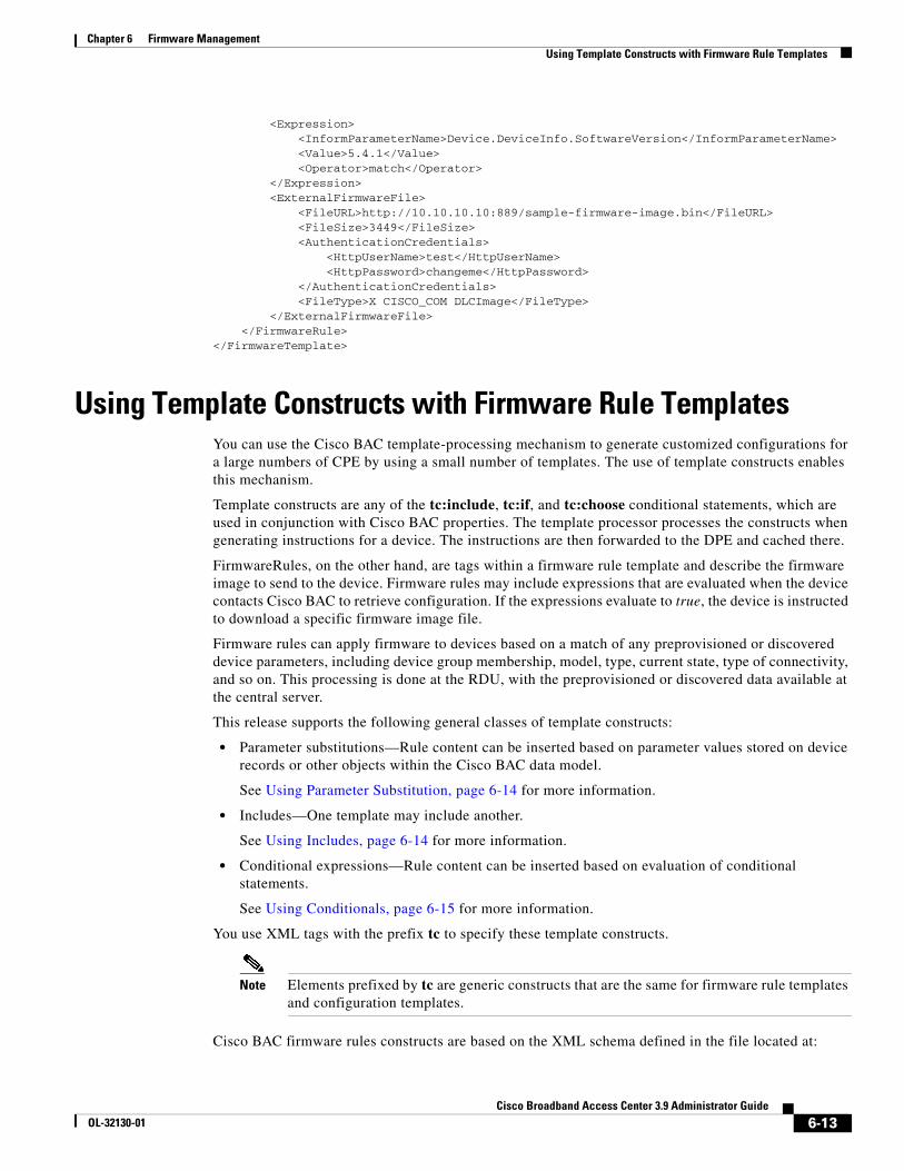
Chapter 6 Firmware ManagementUsing Template Constructs with Firmware Rule Templates
<Expression> <InformParameterName>Device.DeviceInfo.SoftwareVersion</InformParameterName> <Value>5.4.1</Value> <Operator>match</Operator> </Expression> <ExternalFirmwareFile> <FileURL>http://10.10.10.10:889/sample-firmware-image.bin</FileURL> <FileSize>3449</FileSize> <AuthenticationCredentials> <HttpUserName>test</HttpUserName> <HttpPassword>changeme</HttpPassword> </AuthenticationCredentials> <FileType>X CISCO_COM DLCImage</FileType> </ExternalFirmwareFile> </FirmwareRule></FirmwareTemplate>
Using Template Constructs with Firmware Rule TemplatesYou can use the Cisco BAC template-processing mechanism to generate customized configurations for a large numbers of CPE by using a small number of templates. The use of template constructs enables this mechanism.
Template constructs are any of the tc:include, tc:if, and tc:choose conditional statements, which are used in conjunction with Cisco BAC properties. The template processor processes the constructs when generating instructions for a device. The instructions are then forwarded to the DPE and cached there.
FirmwareRules, on the other hand, are tags within a firmware rule template and describe the firmware image to send to the device. Firmware rules may include expressions that are evaluated when the device contacts Cisco BAC to retrieve configuration. If the expressions evaluate to true, the device is instructed to download a specific firmware image file.
Firmware rules can apply firmware to devices based on a match of any preprovisioned or discovered device parameters, including device group membership, model, type, current state, type of connectivity, and so on. This processing is done at the RDU, with the preprovisioned or discovered data available at the central server.
This release supports the following general classes of template constructs:
• Parameter substitutions—Rule content can be inserted based on parameter values stored on device records or other objects within the Cisco BAC data model.
See Using Parameter Substitution, page 6-14 for more information.
• Includes—One template may include another.
See Using Includes, page 6-14 for more information.
• Conditional expressions—Rule content can be inserted based on evaluation of conditional statements.
See Using Conditionals, page 6-15 for more information.
You use XML tags with the prefix tc to specify these template constructs.
Note Elements prefixed by tc are generic constructs that are the same for firmware rule templates and configuration templates.
Cisco BAC firmware rules constructs are based on the XML schema defined in the file located at:
6-13Cisco Broadband Access Center 3.9 Administrator Guide
OL-32130-01
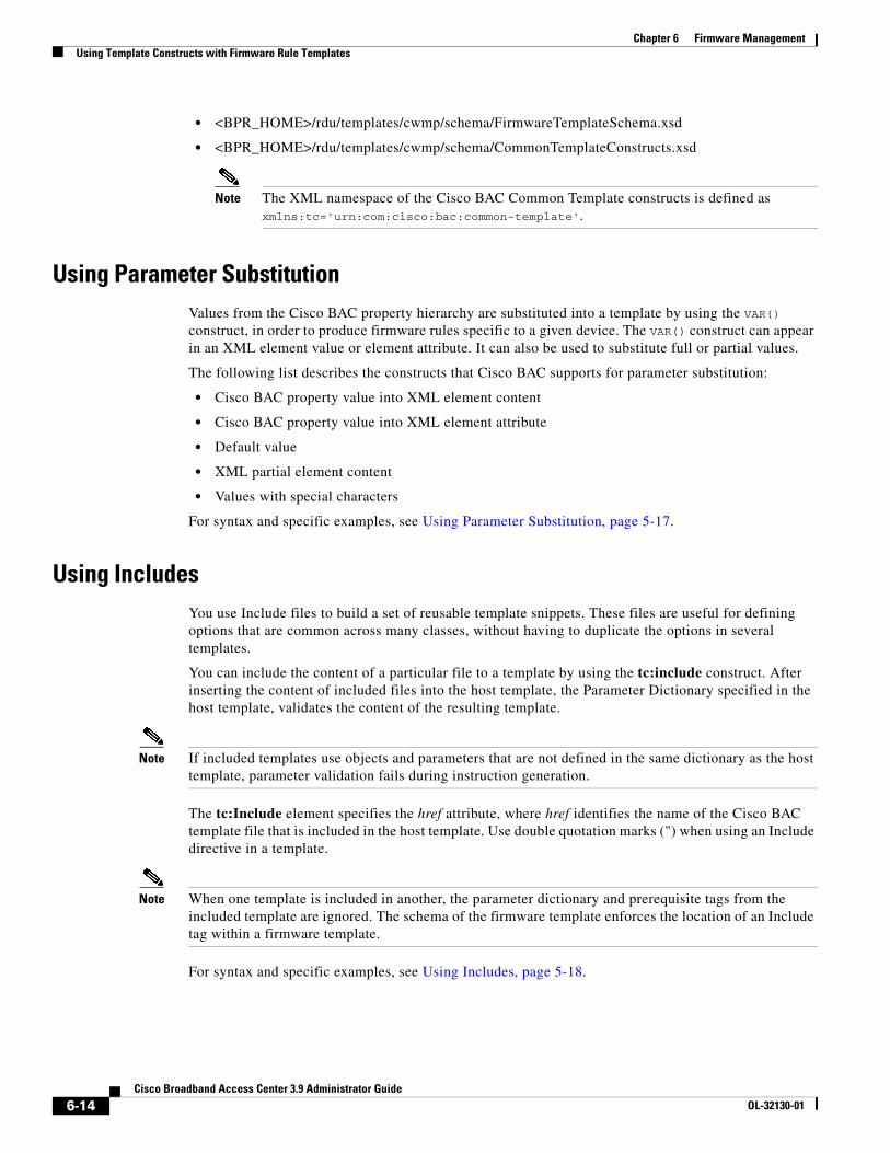
Chapter 6 Firmware ManagementUsing Template Constructs with Firmware Rule Templates
• <BPR_HOME>/rdu/templates/cwmp/schema/FirmwareTemplateSchema.xsd
• <BPR_HOME>/rdu/templates/cwmp/schema/CommonTemplateConstructs.xsd
Note The XML namespace of the Cisco BAC Common Template constructs is defined as xmlns:tc='urn:com:cisco:bac:common-template'.
Using Parameter SubstitutionValues from the Cisco BAC property hierarchy are substituted into a template by using the VAR() construct, in order to produce firmware rules specific to a given device. The VAR() construct can appear in an XML element value or element attribute. It can also be used to substitute full or partial values.
The following list describes the constructs that Cisco BAC supports for parameter substitution:
• Cisco BAC property value into XML element content
• Cisco BAC property value into XML element attribute
• Default value
• XML partial element content
• Values with special characters
For syntax and specific examples, see Using Parameter Substitution, page 5-17.
Using IncludesYou use Include files to build a set of reusable template snippets. These files are useful for defining options that are common across many classes, without having to duplicate the options in several templates.
You can include the content of a particular file to a template by using the tc:include construct. After inserting the content of included files into the host template, the Parameter Dictionary specified in the host template, validates the content of the resulting template.
Note If included templates use objects and parameters that are not defined in the same dictionary as the host template, parameter validation fails during instruction generation.
The tc:Include element specifies the href attribute, where href identifies the name of the Cisco BAC template file that is included in the host template. Use double quotation marks (") when using an Include directive in a template.
Note When one template is included in another, the parameter dictionary and prerequisite tags from the included template are ignored. The schema of the firmware template enforces the location of an Include tag within a firmware template.
For syntax and specific examples, see Using Includes, page 5-18.
6-14Cisco Broadband Access Center 3.9 Administrator Guide
OL-32130-01
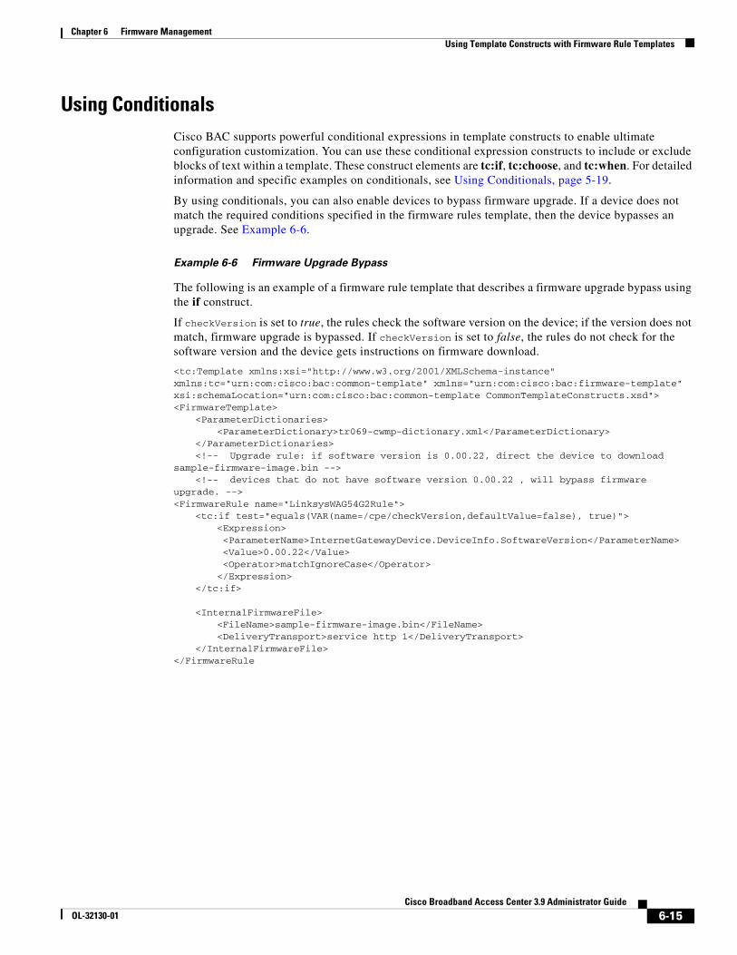
Chapter 6 Firmware ManagementUsing Template Constructs with Firmware Rule Templates
Using ConditionalsCisco BAC supports powerful conditional expressions in template constructs to enable ultimate configuration customization. You can use these conditional expression constructs to include or exclude blocks of text within a template. These construct elements are tc:if, tc:choose, and tc:when. For detailed information and specific examples on conditionals, see Using Conditionals, page 5-19.
By using conditionals, you can also enable devices to bypass firmware upgrade. If a device does not match the required conditions specified in the firmware rules template, then the device bypasses an upgrade. See Example 6-6.
Example 6-6 Firmware Upgrade Bypass
The following is an example of a firmware rule template that describes a firmware upgrade bypass using the if construct.
If checkVersion is set to true, the rules check the software version on the device; if the version does not match, firmware upgrade is bypassed. If checkVersion is set to false, the rules do not check for the software version and the device gets instructions on firmware download.
<tc:Template xmlns:xsi="http://www.w3.org/2001/XMLSchema-instance" xmlns:tc="urn:com:cisco:bac:common-template" xmlns="urn:com:cisco:bac:firmware-template" xsi:schemaLocation="urn:com:cisco:bac:common-template CommonTemplateConstructs.xsd"><FirmwareTemplate>
<ParameterDictionaries><ParameterDictionary>tr069-cwmp-dictionary.xml</ParameterDictionary>
</ParameterDictionaries><!-- Upgrade rule: if software version is 0.00.22, direct the device to download
sample-firmware-image.bin --> <!-- devices that do not have software version 0.00.22 , will bypass firmware
upgrade. --> <FirmwareRule name="LinksysWAG54G2Rule">
<tc:if test="equals(VAR(name=/cpe/checkVersion,defaultValue=false), true)"><Expression> <ParameterName>InternetGatewayDevice.DeviceInfo.SoftwareVersion</ParameterName> <Value>0.00.22</Value> <Operator>matchIgnoreCase</Operator></Expression>
</tc:if>
<InternalFirmwareFile><FileName>sample-firmware-image.bin</FileName><DeliveryTransport>service http 1</DeliveryTransport>
</InternalFirmwareFile> </FirmwareRule
6-15Cisco Broadband Access Center 3.9 Administrator Guide
OL-32130-01

Chapter 6 Firmware ManagementUsing Template Constructs with Firmware Rule Templates
6-16Cisco Broadband Access Center 3.9 Administrator Guide
OL-32130-01
CiscoOL-32130-01
C H A P T E R 7
Parameter DictionariesThis chapter describes Parameter Dictionaries which are used in the process of configuring and managing customer premises equipment (CPE) for CWMP.
This chapter includes the following sections:
• Overview, page 7-1
• Using Default Dictionaries, page 7-2
• Custom Dictionaries, page 7-3
• Parameter Dictionary Syntax, page 7-3
• Managing Parameter Dictionaries through User Interface, page 7-6
OverviewParameter dictionaries are XML files that list valid objects and parameters that Cisco BAC uses to configure a CWMP device. The dictionaries validate the objects and parameters used in the configuration and firmware rule templates.
Parameter dictionaries provide metadata about the supported objects and parameters, such as name, type, writeability and readability. Each dictionary is stored in a file and added to the RDU through the management API or the administrator user interface.
Configuration and firmware rule templates include a ParameterDictionary tag, an indicator of which dictionary defines the parameters in a given template. Cisco BAC validates configuration and firmware rule templates by using the dictionary to which the templates refer. All parameter names and values in the configuration and firmware rule template must be compatible with the parameters referenced in the parameter dictionary.
7-1 Broadband Access Center 3.9 Administrator Guide
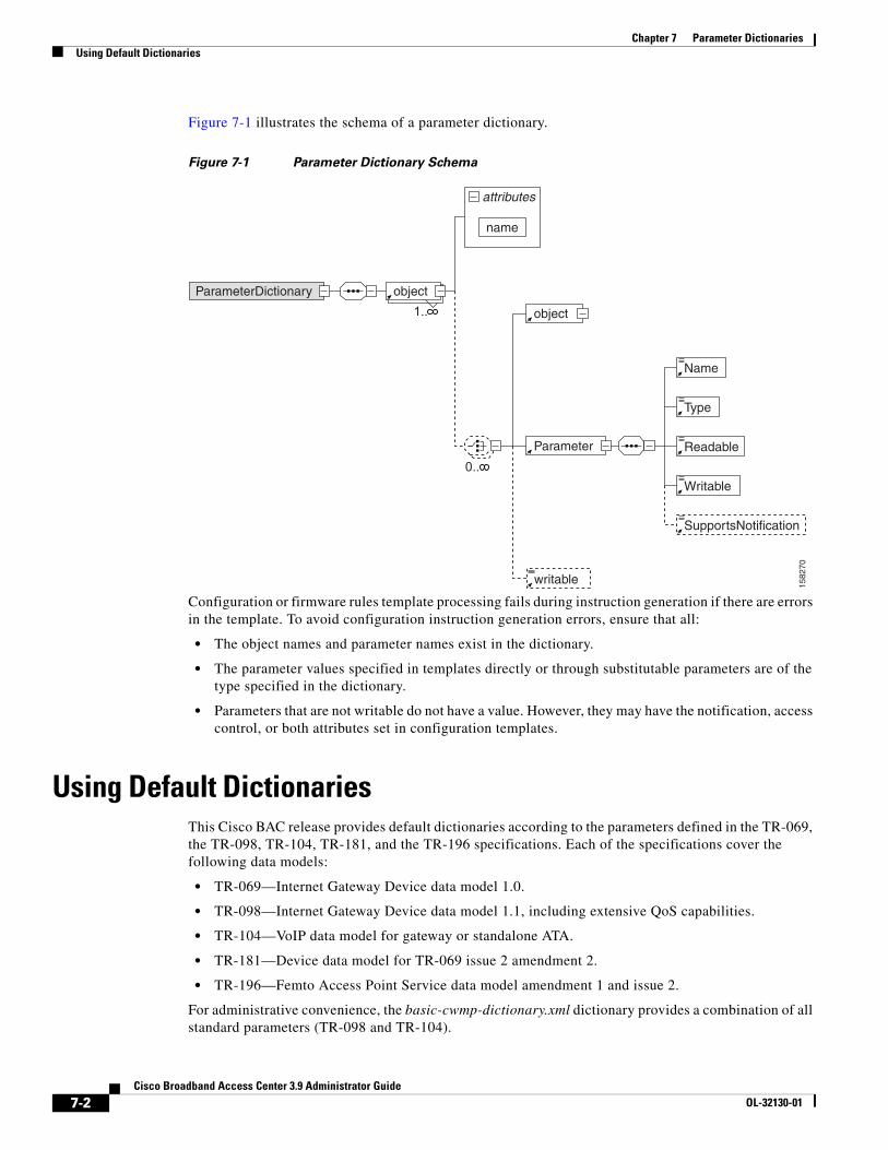
Chapter 7 Parameter DictionariesUsing Default Dictionaries
Figure 7-1 illustrates the schema of a parameter dictionary.
Figure 7-1 Parameter Dictionary Schema
Configuration or firmware rules template processing fails during instruction generation if there are errors in the template. To avoid configuration instruction generation errors, ensure that all:
• The object names and parameter names exist in the dictionary.
• The parameter values specified in templates directly or through substitutable parameters are of the type specified in the dictionary.
• Parameters that are not writable do not have a value. However, they may have the notification, access control, or both attributes set in configuration templates.
Using Default DictionariesThis Cisco BAC release provides default dictionaries according to the parameters defined in the TR-069, the TR-098, TR-104, TR-181, and the TR-196 specifications. Each of the specifications cover the following data models:
• TR-069—Internet Gateway Device data model 1.0.
• TR-098—Internet Gateway Device data model 1.1, including extensive QoS capabilities.
• TR-104—VoIP data model for gateway or standalone ATA.
• TR-181—Device data model for TR-069 issue 2 amendment 2.
• TR-196—Femto Access Point Service data model amendment 1 and issue 2.
For administrative convenience, the basic-cwmp-dictionary.xml dictionary provides a combination of all standard parameters (TR-098 and TR-104).
1582
70
attributes
name
ParameterDictionary
1..
writable
Parameter
0..
SupportsNotification
Writable
Readable
Type
Name
object
object
7-2Cisco Broadband Access Center 3.9 Administrator Guide
OL-32130-01
Chapter 7 Parameter DictionariesCustom Dictionaries
These default dictionaries are located at:
• <BPR_HOME>/rdu/templates/cwmp/dictionary/tr069-cwmp-dictionary.xml
• <BPR_HOME>/rdu/templates/cwmp/dictionary/tr104-cwmp-dictionary.xml
• <BPR_HOME>/rdu/templates/cwmp/dictionary/tr098-cwmp-dictionary.xml
• <BPR_HOME>/rdu/templates/cwmp/dictionary/tr196-cwmp-dictionary-v1.1.xml
• <BPR_HOME>/rdu/templates/cwmp/dictionary/tr196-cwmp-dictionary-v2.0.xml
• <BPR_HOME>/rdu/templates/cwmp/dictionary/tr196-cwmp-dictionary-IGD-v1.1.xml
• <BPR_HOME>/rdu/templates/cwmp/dictionary/tr196-cwmp-dictionary-IGD-v2.0.xml
• <BPR_HOME>/rdu/templates/cwmp/dictionary/basic-cwmp-dictionary.xml
Note You cannot modify or delete the default dictionaries in Cisco BAC.
You can add new user-defined dictionaries that templates reference. This feature enables Cisco BAC support for CPE parameter models, including vendor-specific parameters. For additional information, see the subsequent section on Custom Dictionaries. Cisco BAC support for vendor-specific dictionaries enables its use with any emerging data models such as WT-135 (IPTV STB) or WT-140 (NAS).
Custom DictionariesCWMP includes an extensibility mechanism that allows the use of vendor-specific parameters in addition to the standard parameters. Thus, you can add custom dictionaries to the Cisco BAC system to support any CPE. You can use this feature to support devices with practically any data model, including emerging standard data models such as WT-135 (IPTV STB) or WT-140 (NAS).
You can add, view, replace, or delete custom dictionaries to or from Cisco BAC through the administrator user interface or the management API.
Note You cannot use custom dictionaries for configuration templates. Cisco BAC configuration templates can only use the parameter dictionaries in the Cisco BAC database.
While adding custom dictionaries, ensure that they are based on the parameter dictionary schema, described in earlier sections.
Parameter Dictionary SyntaxCisco BAC validates the syntax of a parameter dictionary according to the Parameter Dictionary Schema, located at <BPR_HOME>/rdu/templates/cwmp/TemplateDictionarySchema.xsd.
If you want to add a vendor-specific parameter to a standard object, remember to define all higher-level standard objects and their parameters in the custom dictionary.
7-3Cisco Broadband Access Center 3.9 Administrator Guide
OL-32130-01
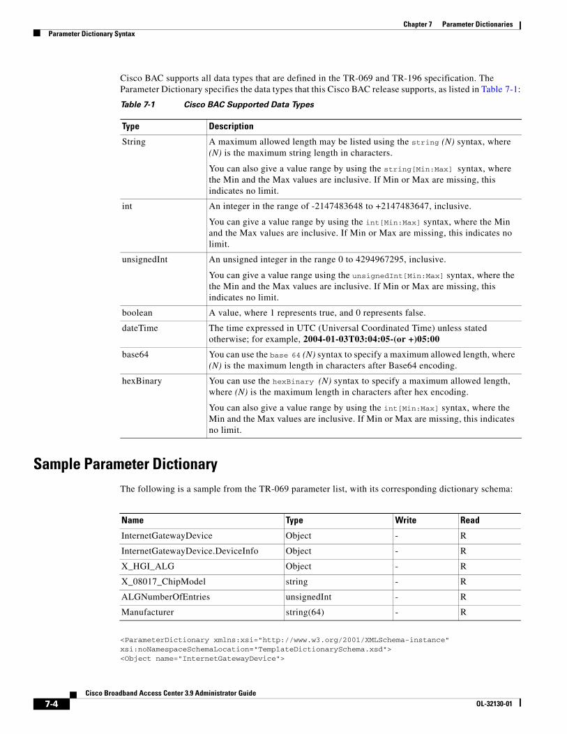
Chapter 7 Parameter DictionariesParameter Dictionary Syntax
Cisco BAC supports all data types that are defined in the TR-069 and TR-196 specification. The Parameter Dictionary specifies the data types that this Cisco BAC release supports, as listed in Table 7-1:
Sample Parameter DictionaryThe following is a sample from the TR-069 parameter list, with its corresponding dictionary schema:
<ParameterDictionary xmlns:xsi="http://www.w3.org/2001/XMLSchema-instance"xsi:noNamespaceSchemaLocation="TemplateDictionarySchema.xsd"><Object name="InternetGatewayDevice">
Table 7-1 Cisco BAC Supported Data Types
Type Description
String A maximum allowed length may be listed using the string (N) syntax, where (N) is the maximum string length in characters.
You can also give a value range by using the string[Min:Max] syntax, where the Min and the Max values are inclusive. If Min or Max are missing, this indicates no limit.
int An integer in the range of -2147483648 to +2147483647, inclusive.
You can give a value range by using the int[Min:Max] syntax, where the Min and the Max values are inclusive. If Min or Max are missing, this indicates no limit.
unsignedInt An unsigned integer in the range 0 to 4294967295, inclusive.
You can give a value range using the unsignedInt[Min:Max] syntax, where the the Min and the Max values are inclusive. If Min or Max are missing, this indicates no limit.
boolean A value, where 1 represents true, and 0 represents false.
dateTime The time expressed in UTC (Universal Coordinated Time) unless stated otherwise; for example, 2004-01-03T03:04:05-(or +)05:00
base64 You can use the base 64 (N) syntax to specify a maximum allowed length, where (N) is the maximum length in characters after Base64 encoding.
hexBinary You can use the hexBinary (N) syntax to specify a maximum allowed length, where (N) is the maximum length in characters after hex encoding.
You can also give a value range by using the int[Min:Max] syntax, where the Min and the Max values are inclusive. If Min or Max are missing, this indicates no limit.
Name Type Write Read
InternetGatewayDevice Object - R
InternetGatewayDevice.DeviceInfo Object - R
X_HGI_ALG Object - R
X_08017_ChipModel string - R
ALGNumberOfEntries unsignedInt - R
Manufacturer string(64) - R
7-4Cisco Broadband Access Center 3.9 Administrator Guide
OL-32130-01
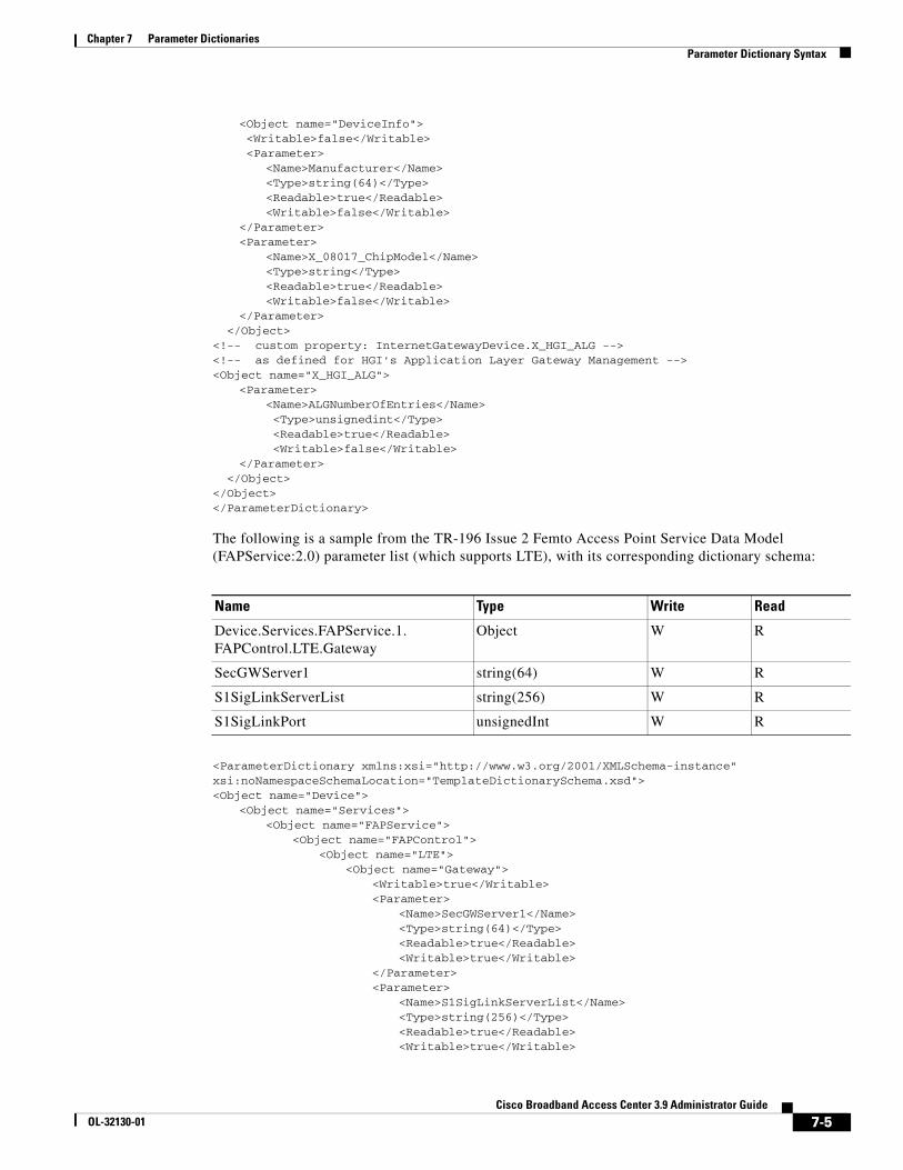
Chapter 7 Parameter DictionariesParameter Dictionary Syntax
<Object name="DeviceInfo"> <Writable>false</Writable> <Parameter>
<Name>Manufacturer</Name> <Type>string(64)</Type> <Readable>true</Readable> <Writable>false</Writable>
</Parameter><Parameter>
<Name>X_08017_ChipModel</Name> <Type>string</Type> <Readable>true</Readable> <Writable>false</Writable>
</Parameter> </Object><!-- custom property: InternetGatewayDevice.X_HGI_ALG --> <!-- as defined for HGI's Application Layer Gateway Management --> <Object name="X_HGI_ALG">
<Parameter><Name>ALGNumberOfEntries</Name> <Type>unsignedint</Type> <Readable>true</Readable> <Writable>false</Writable>
</Parameter> </Object></Object></ParameterDictionary>
The following is a sample from the TR-196 Issue 2 Femto Access Point Service Data Model (FAPService:2.0) parameter list (which supports LTE), with its corresponding dictionary schema:
<ParameterDictionary xmlns:xsi="http://www.w3.org/2001/XMLSchema-instance"xsi:noNamespaceSchemaLocation="TemplateDictionarySchema.xsd"><Object name="Device">
<Object name="Services"><Object name="FAPService">
<Object name="FAPControl"><Object name="LTE">
<Object name="Gateway"> <Writable>true</Writable> <Parameter>
<Name>SecGWServer1</Name> <Type>string(64)</Type> <Readable>true</Readable> <Writable>true</Writable>
</Parameter><Parameter>
<Name>S1SigLinkServerList</Name> <Type>string(256)</Type> <Readable>true</Readable> <Writable>true</Writable>
Name Type Write Read
Device.Services.FAPService.1.FAPControl.LTE.Gateway
Object W R
SecGWServer1 string(64) W R
S1SigLinkServerList string(256) W R
S1SigLinkPort unsignedInt W R
7-5Cisco Broadband Access Center 3.9 Administrator Guide
OL-32130-01

Chapter 7 Parameter DictionariesManaging Parameter Dictionaries through User Interface
</Parameter><Parameter>
<Name>S1SigLinkPort</Name> <Type>unsignedInt</Type> <Readable>true</Readable> <Writable>true</Writable>
</Parameter></Object>
</Object></Object>
</Object></Object>
</Object></ParameterDictionary>
Managing Parameter Dictionaries through User InterfaceYou can use the administrator user interface to manage parameter dictionary files, and view, add, delete, or replace parameter dictionaries. To export files, see Exporting Files, page 17-22.
Note You cannot modify or delete the default dictionaries.
Adding Parameter DictionariesTo add a new parameter dictionary to the Cisco BAC RDU database:
Step 1 Choose Configuration on the Primary Navigation bar.
Step 2 Choose Files on the Secondary Navigation bar. The View Files page appears.
Step 3 Click Add.
The Add Files page appears.
Step 4 Choose Parameter Dictionary from the File Type drop-down list.
Step 5 Browse for the Source File Name.
Step 6 Enter the File Name.
Step 7 Click Submit.
The View Files page appears with the new file.
7-6Cisco Broadband Access Center 3.9 Administrator Guide
OL-32130-01
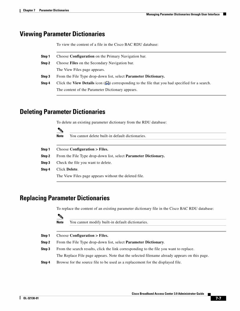
Chapter 7 Parameter DictionariesManaging Parameter Dictionaries through User Interface
Viewing Parameter DictionariesTo view the content of a file in the Cisco BAC RDU database:
Step 1 Choose Configuration on the Primary Navigation bar.
Step 2 Choose Files on the Secondary Navigation bar.
The View Files page appears.
Step 3 From the File Type drop-down list, select Parameter Dictionary.
Step 4 Click the View Details icon ( ) corresponding to the file that you had specified for a search.
The content of the Parameter Dictionary appears.
Deleting Parameter DictionariesTo delete an existing parameter dictionary from the RDU database:
Note You cannot delete built-in default dictionaries.
Step 1 Choose Configuration > Files.
Step 2 From the File Type drop-down list, select Parameter Dictionary.
Step 3 Check the file you want to delete.
Step 4 Click Delete.
The View Files page appears without the deleted file.
Replacing Parameter DictionariesTo replace the content of an existing parameter dictionary file in the Cisco BAC RDU database:
Note You cannot modify built-in default dictionaries.
Step 1 Choose Configuration > Files.
Step 2 From the File Type drop-down list, select Parameter Dictionary.
Step 3 From the search results, click the link corresponding to the file you want to replace.
The Replace File page appears. Note that the selected filename already appears on this page.
Step 4 Browse for the source file to be used as a replacement for the displayed file.
7-7Cisco Broadband Access Center 3.9 Administrator Guide
OL-32130-01

Chapter 7 Parameter DictionariesManaging Parameter Dictionaries through User Interface
Step 5 Click Submit.
After submitting the replacement file, a confirmation page appears to indicate that, after replacement, Cisco BAC will regenerate instructions for the affected devices.
Step 6 Click OK.
The View Files page appears.
7-8Cisco Broadband Access Center 3.9 Administrator Guide
OL-32130-01
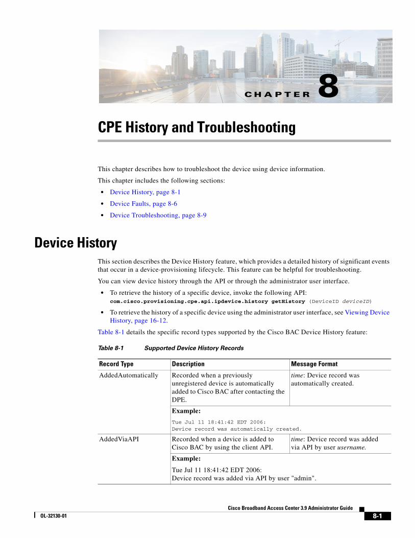
CiscoOL-32130-01
C H A P T E R 8
CPE History and TroubleshootingThis chapter describes how to troubleshoot the device using device information.
This chapter includes the following sections:
• Device History, page 8-1
• Device Faults, page 8-6
• Device Troubleshooting, page 8-9
Device HistoryThis section describes the Device History feature, which provides a detailed history of significant events that occur in a device-provisioning lifecycle. This feature can be helpful for troubleshooting.
You can view device history through the API or through the administrator user interface.
• To retrieve the history of a specific device, invoke the following API:com.cisco.provisioning.cpe.api.ipdevice.history getHistory (DeviceID deviceID)
• To retrieve the history of a specific device using the administrator user interface, see Viewing Device History, page 16-12.
Table 8-1 details the specific record types supported by the Cisco BAC Device History feature:
Table 8-1 Supported Device History Records
Record Type Description Message Format
AddedAutomatically Recorded when a previously unregistered device is automatically added to Cisco BAC after contacting the DPE.
time: Device record was automatically created.
Example:
Tue Jul 11 18:41:42 EDT 2006:Device record was automatically created.
AddedViaAPI Recorded when a device is added to Cisco BAC by using the client API.
time: Device record was addedvia API by user username.
Example:
Tue Jul 11 18:41:42 EDT 2006:Device record was added via API by user "admin".
8-1 Broadband Access Center 3.9 Administrator Guide
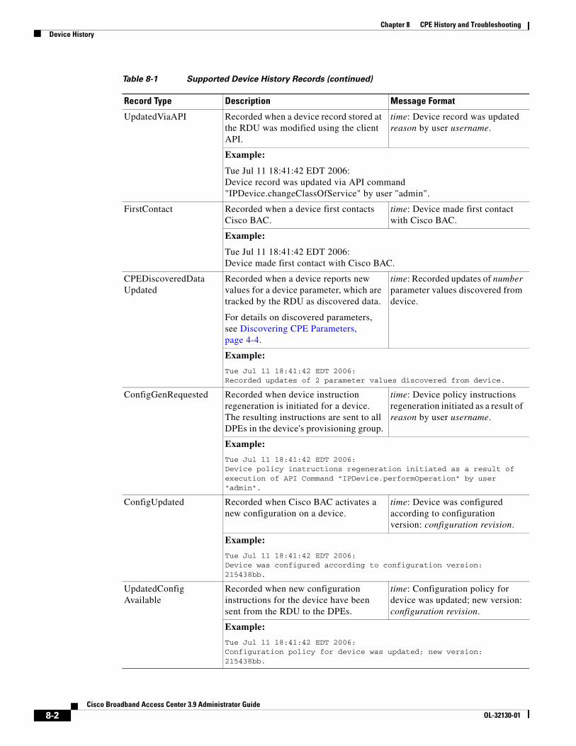
Chapter 8 CPE History and TroubleshootingDevice History
UpdatedViaAPI Recorded when a device record stored at the RDU was modified using the client API.
time: Device record was updated reason by user username.
Example:
Tue Jul 11 18:41:42 EDT 2006:Device record was updated via API command "IPDevice.changeClassOfService" by user "admin".
FirstContact Recorded when a device first contacts Cisco BAC.
time: Device made first contact with Cisco BAC.
Example:
Tue Jul 11 18:41:42 EDT 2006:Device made first contact with Cisco BAC.
CPEDiscoveredDataUpdated
Recorded when a device reports new values for a device parameter, which are tracked by the RDU as discovered data.
For details on discovered parameters, see Discovering CPE Parameters, page 4-4.
time: Recorded updates of number parameter values discovered from device.
Example:
Tue Jul 11 18:41:42 EDT 2006:Recorded updates of 2 parameter values discovered from device.
ConfigGenRequested Recorded when device instruction regeneration is initiated for a device. The resulting instructions are sent to all DPEs in the device's provisioning group.
time: Device policy instructions regeneration initiated as a result of reason by user username.
Example:
Tue Jul 11 18:41:42 EDT 2006:Device policy instructions regeneration initiated as a result of execution of API Command "IPDevice.performOperation" by user "admin".
ConfigUpdated Recorded when Cisco BAC activates a new configuration on a device.
time: Device was configured according to configuration version: configuration revision.
Example:
Tue Jul 11 18:41:42 EDT 2006:Device was configured according to configuration version: 215438bb.
UpdatedConfigAvailable
Recorded when new configuration instructions for the device have been sent from the RDU to the DPEs.
time: Configuration policy for device was updated; new version: configuration revision.
Example:
Tue Jul 11 18:41:42 EDT 2006: Configuration policy for device was updated; new version: 215438bb.
Table 8-1 Supported Device History Records (continued)
Record Type Description Message Format
8-2Cisco Broadband Access Center 3.9 Administrator Guide
OL-32130-01
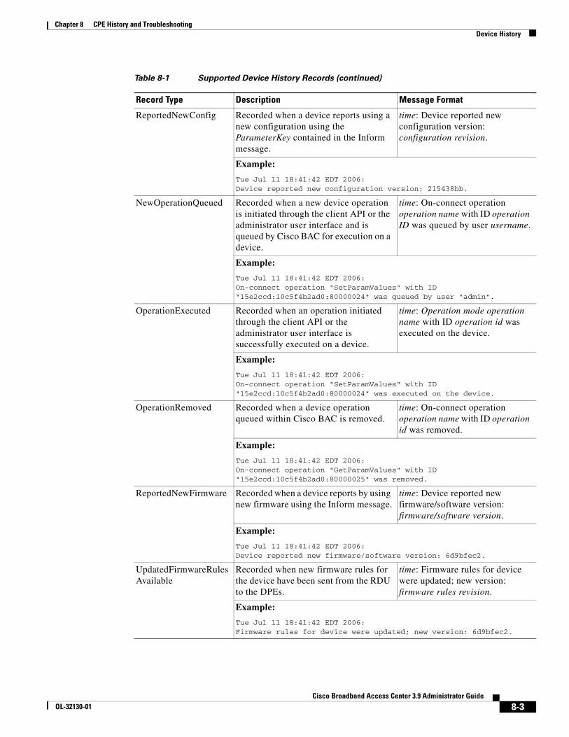
Chapter 8 CPE History and TroubleshootingDevice History
ReportedNewConfig Recorded when a device reports using a new configuration using the ParameterKey contained in the Inform message.
time: Device reported new configuration version: configuration revision.
Example:
Tue Jul 11 18:41:42 EDT 2006:Device reported new configuration version: 215438bb.
NewOperationQueued Recorded when a new device operation is initiated through the client API or the administrator user interface and is queued by Cisco BAC for execution on a device.
time: On-connect operation operation name with ID operation ID was queued by user username.
Example:
Tue Jul 11 18:41:42 EDT 2006:On-connect operation "SetParamValues" with ID "15e2ccd:10c5f4b2ad0:80000024" was queued by user "admin".
OperationExecuted Recorded when an operation initiated through the client API or the administrator user interface is successfully executed on a device.
time: Operation mode operation name with ID operation id was executed on the device.
Example:
Tue Jul 11 18:41:42 EDT 2006:On-connect operation "SetParamValues" with ID "15e2ccd:10c5f4b2ad0:80000024" was executed on the device.
OperationRemoved Recorded when a device operation queued within Cisco BAC is removed.
time: On-connect operation operation name with ID operation id was removed.
Example:
Tue Jul 11 18:41:42 EDT 2006:On-connect operation "GetParamValues" with ID "15e2ccd:10c5f4b2ad0:80000025" was removed.
ReportedNewFirmware Recorded when a device reports by using new firmware using the Inform message.
time: Device reported new firmware/software version: firmware/software version.
Example:
Tue Jul 11 18:41:42 EDT 2006:Device reported new firmware/software version: 6d9bfec2.
UpdatedFirmwareRulesAvailable
Recorded when new firmware rules for the device have been sent from the RDU to the DPEs.
time: Firmware rules for device were updated; new version: firmware rules revision.
Example:
Tue Jul 11 18:41:42 EDT 2006: Firmware rules for device were updated; new version: 6d9bfec2.
Table 8-1 Supported Device History Records (continued)
Record Type Description Message Format
8-3Cisco Broadband Access Center 3.9 Administrator Guide
OL-32130-01
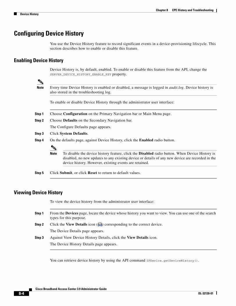
Chapter 8 CPE History and TroubleshootingDevice History
Configuring Device HistoryYou use the Device History feature to record significant events in a device-provisioning lifecycle. This section describes how to enable or disable this feature.
Enabling Device History
Device History is, by default, enabled. To enable or disable this feature from the API, change the SERVER_DEVICE_HISTORY_ENABLE_KEY property.
Note Every time Device History is enabled or disabled, a message is logged in audit.log. Device history is also stored in the troubleshooting log.
To enable or disable Device History through the administrator user interface:
Step 1 Choose Configuration on the Primary Navigation bar or Main Menu page.
Step 2 Choose Defaults on the Secondary Navigation bar.
The Configure Defaults page appears.
Step 3 Click System Defaults.
Step 4 On the defaults page, against Device History, click the Enabled radio button.
Note To disable the device history feature, click the Disabled radio button. When Device History is disabled, no new updates to any existing device or details of any new device are recorded in the device history. However, existing events are retained.
Step 5 Click Submit, or click Reset to return to default values.
Viewing Device History
To view the device history from the administrator user interface:
Step 1 From the Devices page, locate the device whose history you want to view. You can use one of the search types for this purpose.
Step 2 Click the View Details icon ( ) corresponding to the correct device.
The Device Details page appears.
Step 3 Against View Device History Details, click the View Details icon.
The Device History Details page appears.
You can retrieve device history by using the API command IPDevice.getDeviceHistory().
8-4Cisco Broadband Access Center 3.9 Administrator Guide
OL-32130-01
Chapter 8 CPE History and TroubleshootingDevice History
Configuring Device History Size
To configure the maximum number of device history entries from the administrator user interface, choose Configuration > Defaults > System Defaults. Enter a value in the field corresponding to Maximum Device History Entries. The default number of entries is 40.
To configure this number from the API, set the SERVER_MAX_DEVICE_HISTORY_SIZE property.
If you reduce the value of the Maximum Device History Entries, the existing records which exceed the limit do not get purged until a new device history is recorded. At that point, the device's history is updated according to the limit on maximum device history entries that the administrator sets.
If the maximum number has been increased, the older entries are retained. If the maximum number has been decreased, the oldest entries are deleted.
Device History RecordsThe device history records are logged in a rolling list. When the list reaches the limit that the administrator specifies, the oldest entry is removed. However, the following records are never deleted:
• AddedViaAPI (in the case of preregistered devices)
• AddedAutomatically (in the case of unregistered devices)
• FirstContact
To optimize Cisco BAC performance that extensive recording of device activity might impact, you can enable or disable specific event types with the following system properties from the API:
Note These properties are, by default, disabled. These options impact device history only if you have enabled the Device History feature.
• SERVER_DEVICE_HISTORY_IMMEDIATE_OP_ENABLE_KEY
Records OperationExecuted history for immediate operations.
• SERVER_DEVICE_HISTORY_PROXY_OP_ENABLE_KEY
Records the NewOperationQueued, OperationRemoved, and OperationExecuted history for on-connect device operations.
Note If you disable the SERVER_DEVICE_HISTORY_IMMEDIATE_OP_ENABLE_KEY property and enable the SERVER_DEVICE_HISTORY_PROXY_OP_ENABLE_KEY property, the immediate operation is disabled and the on-connect operation is enabled.
• SERVER_DEVICE_HISTORY_GEN_CONFIG_ENABLE_KEY
Records ConfigGenRequested history.
To enable or disable these properties from the administrator user interface:
Step 1 Choose the Configuration > Defaults page.
Step 2 Click the System Defaults link on the left corner of the screen.
8-5Cisco Broadband Access Center 3.9 Administrator Guide
OL-32130-01
Chapter 8 CPE History and TroubleshootingDevice Faults
Step 3 Click the radio buttons corresponding to the operation you want to enable or disable:
• To enable recording the history of immediate operations, click the Enabled radio button corresponding to Immediate Operation History.
• To enable recording the history of on-connect operations, click the Enabled radio button corresponding to On-Connect Operation History.
• To enable recording the history of configuration generation, click the Enabled radio button corresponding to Instruction Generation History.
To disable these operations, click the corresponding Disabled radio button.
Step 4 Click Submit.
Device FaultsIn large installations, devices with recurring faults can cause bottlenecks and affect performance. Recurring faults can result from a device malfunction or misconfiguration of Cisco BAC. You can use Cisco BAC to detect recurring faults occurring at the RDU and the DPE servers through the Recurring Device Faults feature.
You can also configure Cisco BAC to ignore and not store the CWMP faults reported by the CPE. The fault values must be specified in the dpe.properties file with comma separation, for example, /dpe/cwmp/fault/ignore=9003, 9801.
The DPE will filter the CPE faults with fault codes 9003 and 9801 while reporting the faults. This feature is helpful when faults from Customer Premises Equipment (CPE) to Cisco BAC are expected for certain standard operations such as a reboot or recurrent faults.
A recurrent fault is one that occurs many times over a short period of time, or one with high chances of occurring repeatedly. For instance, a fault may occur when an attempt is made to configure a device and if the device is missing a parameter.
Such a fault qualifies as recurring even if it happens only once, because this operation is executed on every device contact. However, if a one-time device operation is initiated from the API and results in a fault, this fault is returned to the API client in the operation response and is not considered to be recurring.
Also, consider the following scenarios:
• A configuration template at the RDU may refer to a property that was deleted from the system. Every time the RDU tries to generate instructions for devices by using this template, an error occurs. This error qualifies the device as the one causing a recurring fault and is reported to the user.
• A device sends an invalid or incomplete Inform message because of a bug in the device firmware. The same Inform is generated on every device contact. This problem also qualifies as a recurring fault.
This feature provides details about the last fault for given devices as well as aggregated fault statistics for the system as a whole, the RDU server, and each DPE server.
8-6Cisco Broadband Access Center 3.9 Administrator Guide
OL-32130-01
Chapter 8 CPE History and TroubleshootingDevice Faults
The following operations monitor device faults on the RDU and the DPE:
The RDU and the DPE maintain a list of recurring faults. Each fault contains the date and time of occurrence, the ID of the device, and a fault description.
Faults automatically expire and are purged from the system as soon as their lifetime expires. After a fault is purged from the system, the statistics are adjusted accordingly.
Note Cisco BAC limits the number of devices returned in the device fault list on the administrator user interface to 1,000. If the number of devices with faults exceeds 1,000, the operator will see a message stating that more devices have faults that just those on the screen.
To avoid impacting performance, Cisco BAC does not store fault information on the disk. If you restart the server, you will lose fault data that was maintained by that server in its memory. However, if faults repeat again, they are reported.
Retrieving Device FaultsDevice fault information is available using the API and the administrator user interface.
From the API, you can call the following properties:
• Configuration.getRDUDetails—Returns the list of devices with faults at the RDU.
• Configuration.getDPEDetails—Returns the list of devices with faults at the DPE.
• IPDevice.getDetails—Returns information about faults related to the device.
From the administrator user interface, choose:
• Servers > RDU—Displays device fault statistics at the RDU level and aggregated for all DPEs. Statistics appear for the following periods of time by default: 1, 3, 12, and 72 hours.
• Servers > Provisioning Groups > Manage Provisioning Groups > View Provisioning Group Details—Displays device fault statistics for each DPE in a provisioning group.
At the RDU:
Failures during instruction generation.
Failures during extension execution.
At the DPE:
Violations of the CPE WAN Management Protocol.
Failures during DataSync instruction processing, which is responsible for discovering data from a device and updating the RDU.
Failures during FirmwareRules instruction processing, which is responsible for executing firmware rules configured in the RDU firmware rules templates.
Failures during ConfigSync instruction processing, which is responsible for updating device configuration according to RDU configuration templates.
Failures during UnknownDevice instruction processing, which is responsible for processing unknown or unregistered devices.
8-7Cisco Broadband Access Center 3.9 Administrator Guide
OL-32130-01
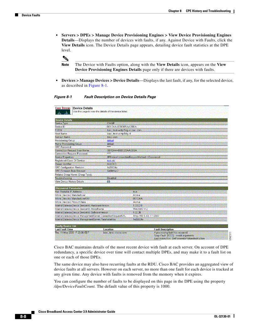
Chapter 8 CPE History and TroubleshootingDevice Faults
• Servers > DPEs > Manage Device Provisioning Engines > View Device Provisioning Engines Details—Displays the number of devices with faults, if any. Against Device with Faults, click the View Details icon. The Device Details page appears, detailing device fault statistics at the DPE level.
Note The Device with Faults option, along with the View Details icon, appears on the View Device Provisioning Engines Details page only if there are devices with faults.
• Devices > Manage Devices > Device Details—Displays the last fault, if any, for the selected device, as described in Figure 8-1.
Figure 8-1 Fault Description on Device Details Page
Cisco BAC maintains details of the most recent device with fault at each server. On account of DPE redundancy, a specific device over time will contact multiple DPEs, and may make it to a fault list on one or each of those DPEs.
The same device may also have recurring faults at the RDU. Cisco BAC provides an aggregated view of device faults at all servers. However on each server, no more than one fault for each device is tracked at any given time. Any device with faults is removed from the memory when it expires.
You can configure the number of faults to be displayed on this page in the DPE using the property /dpe/DeviceFaultCount. The default value of this property is 1000.
8-8Cisco Broadband Access Center 3.9 Administrator Guide
OL-32130-01
Chapter 8 CPE History and TroubleshootingDevice Troubleshooting
Managing Chatty ClientsIn this release of Cisco BAC, you can use the Chatty client feature to detect devices that make an excessive number of TR-069 or HTTP file server calls. You can use this feature to reduce the adverse impact of Chatty devices on services that are provided to other devices.
Using this feature, you can detect the Chatty devices and throttle their access to the DPE. This feature is enabled by default on the DPE. You can disable this feature from the DPE CLI, using the chatty-client filter enabled {true | false} command. (For more information, see the Cisco Broadband Access Center 3.8 DPE CLI Reference.)
The following properties are used to configure this feature on the DPE:
• SampleTimeInterval—Indicates the duration, in seconds, for which the DPE monitors the activity of a device. The default is 30 seconds.
• SampleHitsToThrottle—Indicates the number of events received from the device during the sample time interval. The default is 15.
• QuietTimeInterval—Indicates the duration, in seconds, for which the DPE monitors the activity of a throttled device. The default is 10 seconds.
• QuietHitsToLeaveThrottled—Indicates the number of events received from the device during the quiet time interval. The default is 5.
You can configure these properties using the DPE CLI. For more information, see the Cisco Broadband Access Center 3.8 DPE CLI Reference.
Cisco BAC uses the Chatty client filter to monitor the CPE events based on the device identifier. If the number of events received from the device during the sample time interval is greater than the value configured for the Sample-hits-to-throttle property, the DPE throttles the device. When a device is in a throttled state, all events that the device generates, are discarded.
Cisco BAC continues to monitor the activity on the throttled device to determine whether the device can be restored to the Normal state. If the device generates fewer events than the value configured for the Sample-hits-to-throttle property, the DPE moves the device to the Quiet state.
While in the Quiet state,
• If the number of events received from the device during the Quiet time interval is greater than the value configured for the Quiet-hits-to-leave-throttled property, the DPE moves the device to throttled state.
• If the number of events received from the device during the quiet time interval is less than the value configured for the Quiet-hits-to-leave-throttled property, the DPE restores the device to the Normal state.
Device TroubleshootingYou can use this feature to collect highly detailed troubleshooting information about one or multiple specific devices. Troubleshooting information includes all server interactions related to a given device or a group of devices. This information includes administrator user interface operations, RDU API operations, DPE interactions with the CPE, and inter-server DPE-to-RDU interactions.
You can enable or disable troubleshooting for one or a number of specific devices without turning logging on, and without searching through log files for specific device information.
Cisco BAC maintains a list of devices, based on the device identifier, for which detailed troubleshooting information is collected.
8-9Cisco Broadband Access Center 3.9 Administrator Guide
OL-32130-01
Chapter 8 CPE History and TroubleshootingDevice Troubleshooting
Troubleshooting information is stored centrally at the RDU and is maintained for each device. The DPEs do not store this data. Instead, the DPE forwards this information to the RDU which writes it to the device log file, troubleshooting.log, in the <BPR_DATA>/rdu/logs directory when it receives this information.
If the connection from the DPE to the RDU is lost, any new troubleshooting events occurring on the DPE are discarded. The logging of troubleshooting information resumes only after the RDU-DPE connection is restored.
The troubleshooting.log file is different from other log files such as rdu.log, dpe.log, and audit.log. The troubleshooting.log file only logs detailed troubleshooting information relating to a specific set of devices in the troubleshooting mode.
Note The tracking feature is turned off until one or more devices are added to the troubleshooting group.
When you enable or disable troubleshooting on a specific device, the change takes place immediately at all servers (RDU and DPEs); you do not have to reboot the RDU or the DPEs. The log files on the respective servers lists the current list of devices in the troubleshooting mode.
Caution Additional memory and disk space is required whenever the device troubleshooting feature is used. As the number of tracked devices increases, so does the amount of memory and disk space that is required to support the number of logs that are created.
Configuring Device TroubleshootingThe Device Troubleshooting feature is disabled until one or more devices are put into troubleshooting mode. This section describes how you can enable or disable troubleshooting for a device from the administrator user interface. It also describes how to view a list of devices in troubleshooting mode and how to view troubleshooting log for a given device.
You can configure the maximum number of devices in troubleshooting mode to prevent inadvertently putting too many devices in this mode, and thus, diminishing server performance. By default, this number is set at 100.
To configure the maximum number of the devices allowed in troubleshooting mode from the administrator user interface, click the Systems Defaults page using the Configuration > Defaults tabs. Enter a value in the Maximum Troubleshooting Device Count field.
Enabling Troubleshooting for a Device
To enable troubleshooting for a device, the device must be preregistered in the Cisco BAC RDU. If the device is not yet preregistered, add the device from the Manage Devices page by clicking the Add button. For information on adding devices, see Adding Device Records, page 16-11.
To enable troubleshooting for a device that already resides in the RDU database:
Step 1 From the Manage Devices page, click the Search Type drop-down list, and select the Device Identifier Option Search option. You can use the wildcard function for this search. (See Table 16-1.)
Step 2 Click Search.
A list of devices appears.
8-10Cisco Broadband Access Center 3.9 Administrator Guide
OL-32130-01
Chapter 8 CPE History and TroubleshootingDevice Troubleshooting
Step 3 Click the Identifier link corresponding to the device that you want to track.
The Modify Device page appears, listing various device parameters.
Step 4 Click the Enabled radio button corresponding to the Troubleshooting parameter.
Step 5 Click Submit. Troubleshooting is now enabled for the device.
To verify if a given device is enabled for troubleshooting, you can access the Device Details page, and view status against Troubleshooting.
Disabling Troubleshooting for a Device
To disable troubleshooting for a device:
Step 1 From the Devices tab, locate the device that you want to delete. You can use one of the search types for this purpose.
Step 2 Click the Identifier link corresponding to the device that you want to delete from the troubleshooting list.
The Modify Device page appears.
Step 3 Against the Troubleshooting parameter, click the Disabled radio button.
Step 4 Click Submit.
Viewing List of Devices in Troubleshooting Mode
When you enable troubleshooting for a device, the device is automatically added to a special device group which contains a list of devices in troubleshooting mode. The group type is system and the group name is troubleshooting. You can access the list of devices in this group from the API or the administrator user interface.
To view a list of devices currently enabled for troubleshooting:
Step 1 From the Manage Devices page, click the Search Type drop-down list, and select Group Search.
Step 2 From the Group (Group Type) drop-down list, select the troubleshooting (system) option to view all the devices in troubleshooting mode.
Step 3 Click Search.
You can also see the list of devices in troubleshooting mode is by viewing the RDU log (rdu.log) and the DPE log (dpe.log). The list of devices is logged whenever the server is started and whenever there is a change in the list of devices that are enabled for troubleshooting.
The devices enabled for troubleshooting appear in the log files with the log level of 5-notification. For more information on log files, see Logging, page 21-2.
8-11Cisco Broadband Access Center 3.9 Administrator Guide
OL-32130-01
Chapter 8 CPE History and TroubleshootingDevice Troubleshooting
Viewing Device Troubleshooting Log
You can view the troubleshooting log file of a specific device in one of two ways.
• Complete the procedure described in Viewing List of Devices in Troubleshooting Mode, page 8-11. Then, follow these steps:
Step 1 When a list of the devices in troubleshooting mode appears, click the View Details icon corresponding to a specific device.
The Device Details page appears.
Step 2 Against View Troubleshooting Log, click the View Details icon.
The View Log File Contents page appears.
• Complete the following procedure:
Step 1 From the Manage Details page under the Devices tab, click the Search Type drop-down list, and select the Device Identifier Option Search option. You can use the wildcard character (*) for this search.
Step 2 Click Search.
A list of devices appears.
Step 3 Click the View Details icon corresponding to the device whose log file you want to check.
The Device Details page appears.
Step 4 Against View Troubleshooting Log, click the View Details icon.
The View Log File Contents page appears.
The color coding for the device troubleshooting log entries is:
• BAC-TROUBLESHOOTINGINFO—Informational messages are marked in white.
• BAC-TROUBLESHOOTINGINPUT—Details of messages received by Cisco BAC servers are marked in grey.
• BAC-TROUBLESHOOTINGOUTPUT—Details of messages sent by Cisco BAC servers are marked in green.
• BAC-TROUBLESHOOTINGERROR—Error messages are marked in red.
8-12Cisco Broadband Access Center 3.9 Administrator Guide
OL-32130-01
CiscoOL-32130-01
C H A P T E R 9
Managing Cisco Broadband Access CenterThis chapter describes the various subcomponents within Cisco Broadband Access Center (BAC) that you can use to manage the system.
This chapter includes the following sections:
• Cisco BAC Process Watchdog, page 9-1
• Administrator User Interface, page 9-4
• Command Line Interface, page 9-5
• SNMP Agent, page 9-5
• Cisco BAC Tools, page 9-6
Cisco BAC Process WatchdogThe Cisco BAC process watchdog is an administrative process that monitors the runtime health of all Cisco BAC processes. This watchdog process ensures that, if a process stops unexpectedly, it is automatically restarted. One instance of the Cisco BAC process watchdog runs on every system which runs Cisco BAC components.
You can use the Cisco BAC watchdog as a command-line tool to start, stop, restart, and determine the status of any monitored processes.
You can enable the SNMP trap facility for Cisco BAC process watchdog. The SNMP traps are sent only when:
• there is a change in component’s state.
• the component is gracefully shut down.
If a monitored application fails to start or stops unexpectedly, the Cisco BAC process watchdog reports the criticial condition associated with the monitored application to the trap receiver through SNMP trap. The Cisco BAC process watchdog will wait for a prescribed amount of time before attempting to restart the monitored application. When the monitored application restarts, the Cisco BAC process watchdog sends another SNMP trap to the SNMP trap receiver informing the change in application’s state.
At the beginning, restart attempt is made at an interval of 1 second, and is increased exponentially with every subsequent attempt until the interval becomes 5 minutes. After that, the process restart is attempted at 5-minute intervals until successful. Five minutes after a successful restart, the period is automatically reset to 1 second again.
9-1 Broadband Access Center 3.9 Administrator Guide
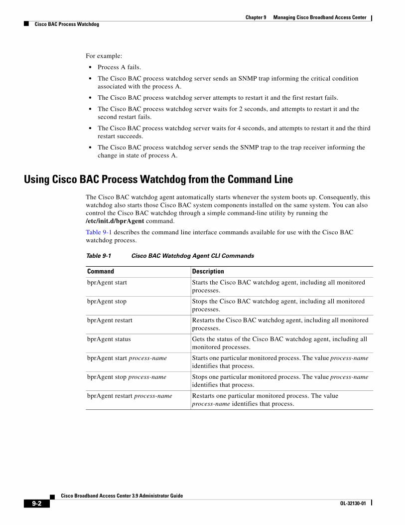
Chapter 9 Managing Cisco Broadband Access CenterCisco BAC Process Watchdog
For example:
• Process A fails.
• The Cisco BAC process watchdog server sends an SNMP trap informing the critical condition associated with the process A.
• The Cisco BAC process watchdog server attempts to restart it and the first restart fails.
• The Cisco BAC process watchdog server waits for 2 seconds, and attempts to restart it and the second restart fails.
• The Cisco BAC process watchdog server waits for 4 seconds, and attempts to restart it and the third restart succeeds.
• The Cisco BAC process watchdog server sends the SNMP trap to the trap receiver informing the change in state of process A.
Using Cisco BAC Process Watchdog from the Command LineThe Cisco BAC watchdog agent automatically starts whenever the system boots up. Consequently, this watchdog also starts those Cisco BAC system components installed on the same system. You can also control the Cisco BAC watchdog through a simple command-line utility by running the /etc/init.d/bprAgent command.
Table 9-1 describes the command line interface commands available for use with the Cisco BAC watchdog process.
Table 9-1 Cisco BAC Watchdog Agent CLI Commands
Command Description
bprAgent start Starts the Cisco BAC watchdog agent, including all monitored processes.
bprAgent stop Stops the Cisco BAC watchdog agent, including all monitored processes.
bprAgent restart Restarts the Cisco BAC watchdog agent, including all monitored processes.
bprAgent status Gets the status of the Cisco BAC watchdog agent, including all monitored processes.
bprAgent start process-name Starts one particular monitored process. The value process-name identifies that process.
bprAgent stop process-name Stops one particular monitored process. The value process-name identifies that process.
bprAgent restart process-name Restarts one particular monitored process. The value process-name identifies that process.
9-2Cisco Broadband Access Center 3.9 Administrator Guide
OL-32130-01
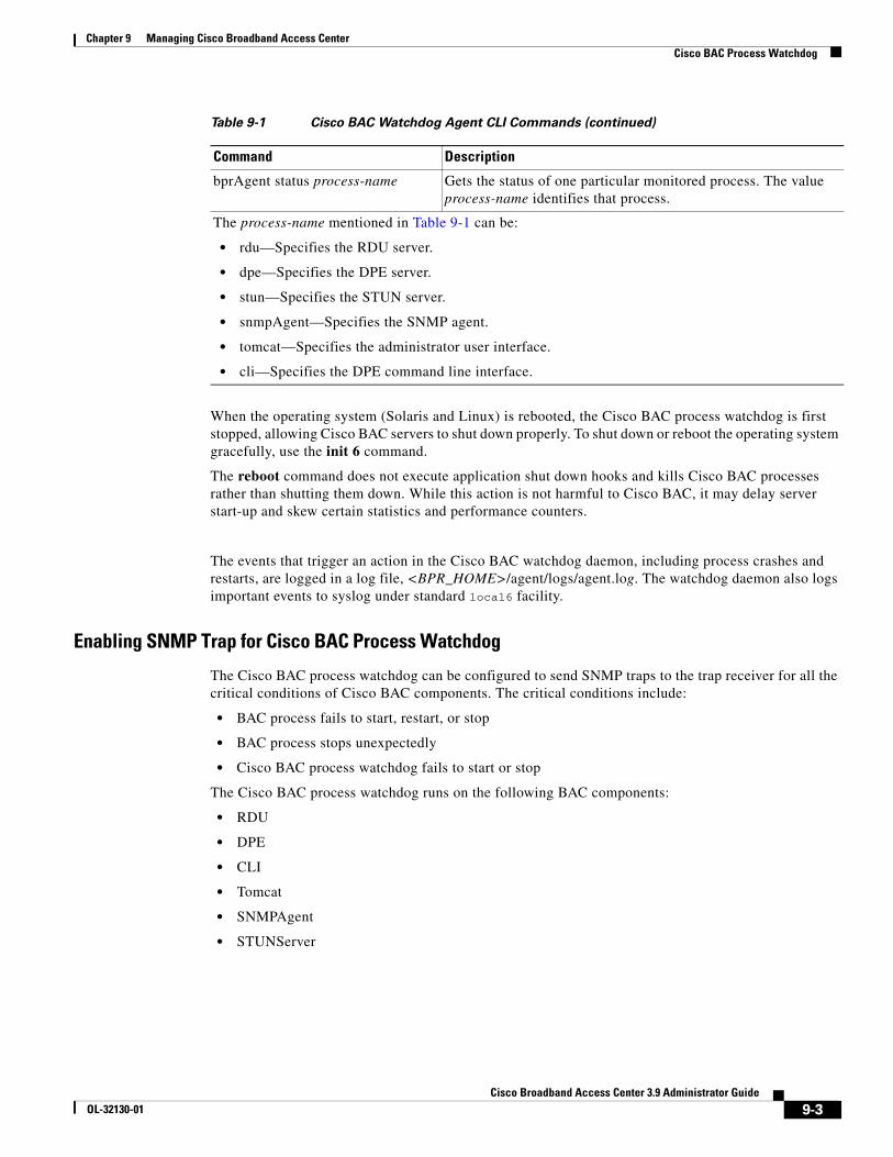
Chapter 9 Managing Cisco Broadband Access CenterCisco BAC Process Watchdog
When the operating system (Solaris and Linux) is rebooted, the Cisco BAC process watchdog is first stopped, allowing Cisco BAC servers to shut down properly. To shut down or reboot the operating system gracefully, use the init 6 command.
The reboot command does not execute application shut down hooks and kills Cisco BAC processes rather than shutting them down. While this action is not harmful to Cisco BAC, it may delay server start-up and skew certain statistics and performance counters.
The events that trigger an action in the Cisco BAC watchdog daemon, including process crashes and restarts, are logged in a log file, <BPR_HOME>/agent/logs/agent.log. The watchdog daemon also logs important events to syslog under standard local6 facility.
Enabling SNMP Trap for Cisco BAC Process Watchdog
The Cisco BAC process watchdog can be configured to send SNMP traps to the trap receiver for all the critical conditions of Cisco BAC components. The critical conditions include:
• BAC process fails to start, restart, or stop
• BAC process stops unexpectedly
• Cisco BAC process watchdog fails to start or stop
The Cisco BAC process watchdog runs on the following BAC components:
• RDU
• DPE
• CLI
• Tomcat
• SNMPAgent
• STUNServer
bprAgent status process-name Gets the status of one particular monitored process. The value process-name identifies that process.
The process-name mentioned in Table 9-1 can be:
• rdu—Specifies the RDU server.
• dpe—Specifies the DPE server.
• stun—Specifies the STUN server.
• snmpAgent—Specifies the SNMP agent.
• tomcat—Specifies the administrator user interface.
• cli—Specifies the DPE command line interface.
Table 9-1 Cisco BAC Watchdog Agent CLI Commands (continued)
Command Description
9-3Cisco Broadband Access Center 3.9 Administrator Guide
OL-32130-01
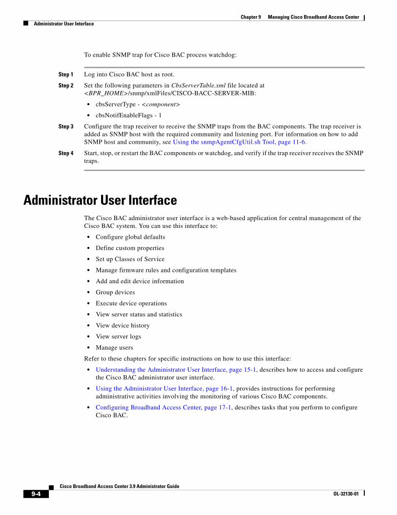
Chapter 9 Managing Cisco Broadband Access CenterAdministrator User Interface
To enable SNMP trap for Cisco BAC process watchdog:
Step 1 Log into Cisco BAC host as root.
Step 2 Set the following parameters in CbsServerTable.xml file located at <BPR_HOME>/snmp/xmlFiles/CISCO-BACC-SERVER-MIB:
• cbsServerType - <component>
• cbsNotifEnableFlags - 1
Step 3 Configure the trap receiver to receive the SNMP traps from the BAC components. The trap receiver is added as SNMP host with the required community and listening port. For information on how to add SNMP host and community, see Using the snmpAgentCfgUtil.sh Tool, page 11-6.
Step 4 Start, stop, or restart the BAC components or watchdog, and verify if the trap receiver receives the SNMP traps.
Administrator User InterfaceThe Cisco BAC administrator user interface is a web-based application for central management of the Cisco BAC system. You can use this interface to:
• Configure global defaults
• Define custom properties
• Set up Classes of Service
• Manage firmware rules and configuration templates
• Add and edit device information
• Group devices
• Execute device operations
• View server status and statistics
• View device history
• View server logs
• Manage users
Refer to these chapters for specific instructions on how to use this interface:
• Understanding the Administrator User Interface, page 15-1, describes how to access and configure the Cisco BAC administrator user interface.
• Using the Administrator User Interface, page 16-1, provides instructions for performing administrative activities involving the monitoring of various Cisco BAC components.
• Configuring Broadband Access Center, page 17-1, describes tasks that you perform to configure Cisco BAC.
9-4Cisco Broadband Access Center 3.9 Administrator Guide
OL-32130-01
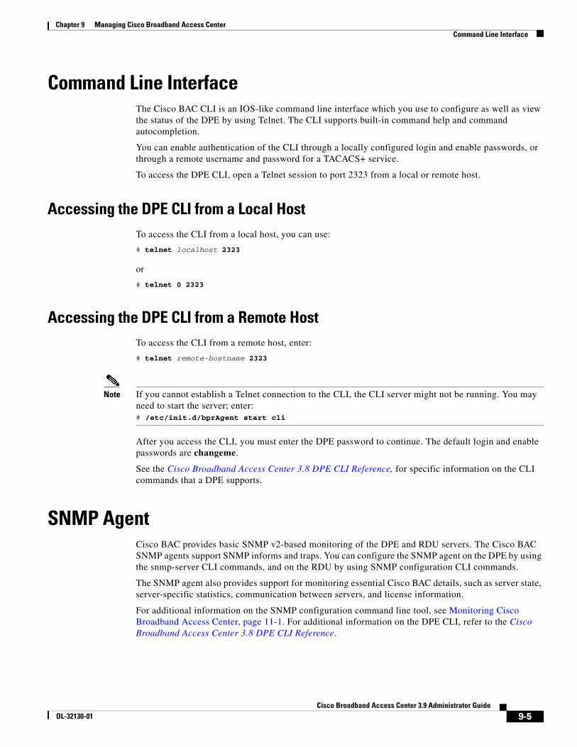
Chapter 9 Managing Cisco Broadband Access CenterCommand Line Interface
Command Line InterfaceThe Cisco BAC CLI is an IOS-like command line interface which you use to configure as well as view the status of the DPE by using Telnet. The CLI supports built-in command help and command autocompletion.
You can enable authentication of the CLI through a locally configured login and enable passwords, or through a remote username and password for a TACACS+ service.
To access the DPE CLI, open a Telnet session to port 2323 from a local or remote host.
Accessing the DPE CLI from a Local HostTo access the CLI from a local host, you can use:
# telnet localhost 2323
or
# telnet 0 2323
Accessing the DPE CLI from a Remote HostTo access the CLI from a remote host, enter:
# telnet remote-hostname 2323
Note If you cannot establish a Telnet connection to the CLI, the CLI server might not be running. You may need to start the server; enter:# /etc/init.d/bprAgent start cli
After you access the CLI, you must enter the DPE password to continue. The default login and enable passwords are changeme.
See the Cisco Broadband Access Center 3.8 DPE CLI Reference, for specific information on the CLI commands that a DPE supports.
SNMP AgentCisco BAC provides basic SNMP v2-based monitoring of the DPE and RDU servers. The Cisco BAC SNMP agents support SNMP informs and traps. You can configure the SNMP agent on the DPE by using the snmp-server CLI commands, and on the RDU by using SNMP configuration CLI commands.
The SNMP agent also provides support for monitoring essential Cisco BAC details, such as server state, server-specific statistics, communication between servers, and license information.
For additional information on the SNMP configuration command line tool, see Monitoring Cisco Broadband Access Center, page 11-1. For additional information on the DPE CLI, refer to the Cisco Broadband Access Center 3.8 DPE CLI Reference.
9-5Cisco Broadband Access Center 3.9 Administrator Guide
OL-32130-01
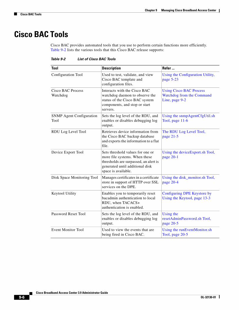
Chapter 9 Managing Cisco Broadband Access CenterCisco BAC Tools
Cisco BAC ToolsCisco BAC provides automated tools that you use to perform certain functions more efficiently. Table 9-2 lists the various tools that this Cisco BAC release supports:
Table 9-2 List of Cisco BAC Tools
Tool Description Refer ...
Configuration Tool Used to test, validate, and view Cisco BAC template and configuration files.
Using the Configuration Utility, page 5-23
Cisco BAC Process Watchdog
Interacts with the Cisco BAC watchdog daemon to observe the status of the Cisco BAC system components, and stop or start servers.
Using Cisco BAC Process Watchdog from the Command Line, page 9-2
SNMP Agent Configuration Tool
Sets the log level of the RDU, and enables or disables debugging log output.
Using the snmpAgentCfgUtil.sh Tool, page 11-6
RDU Log Level Tool Retrieves device information from the Cisco BAC backup database and exports the information to a flat file.
The RDU Log Level Tool, page 21-5
Device Export Tool Sets threshold values for one or more file systems. When these thresholds are surpassed, an alert is generated until additional disk space is available.
Using the deviceExport.sh Tool, page 20-1
Disk Space Monitoring Tool Manages certificates in a certificate store in support of HTTP over SSL services on the DPE.
Using the disk_monitor.sh Tool, page 20-4
Keytool Utility Enables you to temporarily reset bacadmin authentication to local RDU, when TACACS+ authentication is enabled.
Configuring DPE Keystore by Using the Keytool, page 13-3
Password Reset Tool Sets the log level of the RDU, and enables or disables debugging log output.
Using the resetAdminPassword.sh Tool, page 20-5
Event Monitor Tool Used to view the events that are being fired in Cisco BAC.
Using the runEventMonitor.sh Tool, page 20-5
9-6Cisco Broadband Access Center 3.9 Administrator Guide
OL-32130-01
CiscoOL-32130-01
C H A P T E R 10
Database ManagementThis chapter contains information on RDU database management and maintenance. The RDU database is the Broadband Access Center (BAC) central database. The Cisco BAC RDU requires virtually no maintenance other than to ensure availability of sufficient disk space. As the administrator, you must understand and be familiar with database backup and recovery procedures.
This chapter includes the following sections:
• Understanding Failure Resiliency, page 10-1
• Database Files, page 10-2
• Disk Space Requirements, page 10-3
• Backup and Recovery, page 10-4
• Changing Database Location, page 10-7
Understanding Failure ResiliencyThe RDU database uses a technique known as Write-ahead logging to protect against database corruption that could result from unforeseen problems, such as an application crash, system failure, or power outage.
Write-ahead logging involves writing a description of any database change to a database log file before writing the change into the database files. This mechanism allows the repair of any incomplete database writes that can result from system failures.
The RDU server performs an automatic recovery each time it is started. During this recovery process, the database log files are used to synchronize the data with the database files. Database changes that were written into the database log, but not into the database, are written into the database during this automatic recovery.
In this way, write-ahead logging virtually guarantees that the database does not become corrupted when the RDU server crashes because the database is automatically repaired when the RDU server is restarted.
10-1 Broadband Access Center 3.9 Administrator Guide
Chapter 10 Database ManagementDatabase Files
Write-ahead logging requires these conditions to work properly:
• You must set up the file system and physical storage so that they guarantee that the data is flushed to physical storage when requested. For example, a storage system with SDRAM-only write cache, which loses data during system failure, is not appropriate.
However, a disk array with battery-backup write cache that guarantees that the data gets persisted, even in the event of a system failure, is acceptable. A system without battery-backed write cache should flush data disk when requested instead of performing in-memory data caching.
• You must set up the file system with a 8192-byte block size to match the RDU database block size. This setting is usually the default unless explicitly adjusted.
Database FilesThe RDU database stores data in binary files using the file system you have mounted on the partition containing the files. It is essential to choose and configure a file system in a way that it is not susceptible to long recovery times after system failures.
Database files are vital to the operation of the RDU. Therefore, take extra precautions to safeguard them against accidental removal or other manual manipulation. Follow standard system administration practices to safeguard these important files.
For example, these files should always have permissions that allow only root user access. Additionally, it is a good practice to never log into your production system as a root user, but rather log in as a less privileged user and use the sudo command to perform tasks requiring root privileges.
Database Storage FileThe RDU server stores its database in a file called bpr.db, which resides in the database directory. This directory is located in the <BPR_DATA>/rdu/db directory and is configured by specifying the <BPR_DATA> parameter during a component installation. See Changing Database Location, page 10-7, for additional information on moving the database.
Note The database file is normally accessed in a random fashion. You should therefore, select a disk with the fastest seek time and rotational access latency to obtain the best database performance.
Database Transaction Log FilesThe RDU server stores database transaction logs in 10-MB files that are stored in the database log directory. You configure this directory during installation by specifying the <BPR_DBLOG> parameter. The log directory is located in the <BPR_DBLOG>/rdu/dblog directory. See Changing Database Location, page 10-7, for additional information on moving the transaction logs to a new directory.
Database log files are named in numeric sequence, starting at log.00000001, log.00000002, and so on.
Note The disk on which transaction logs are stored is usually accessed in a sequential manner, with data being appended to the log files. Select a disk that can efficiently handle this access pattern to achieve the best database performance. We recommend that you locate the database transaction logs directory on the fastest disk on the system. Also, ensure that 1 GB disk space is available.
10-2Cisco Broadband Access Center 3.9 Administrator Guide
OL-32130-01
Chapter 10 Database ManagementDisk Space Requirements
Automatic Log ManagementDatabase transaction logs files are used to store transaction data until that data is completely written into the database. After that, the transaction log data becomes redundant and the files are then automatically removed from the system. Under normal circumstances there should be only a few log files in the database transaction log directory. Over time, you will notice that older transaction logs disappear and newer ones are created.
Caution Database transaction logs are an integral part of the database. Manual deletion of transaction log files will result in database corruption.
Miscellaneous Database FilesThe database directory contains additional files that are essential to database operation. These files, in addition to the rdu.db file, are found in the <BPR_DATA>/rdu/db directory and are copied as part of the database backup:
• DB_VERSION—Identifies the physical and logical version of the database and is used internally by the RDU.
• history.log—Used to log activity about essential database management tasks, such as automatic log file deletion, backup, recovery, and restore operations. In addition to providing useful historical information for the administrator, this log file is essential to RDU database operation.
Disk Space RequirementsThe size of a fully populated database depends on a number of factors:
• Device objects that the RDU manages.
• Custom properties stored on each object.
• Device history records tracked for each device.
The approximate estimates for disk space required on each partition are:
• <BPR_DATA>, approximately 3 to 5 KB per device object
• <BPR_DBLOG>, at least 500 MB
Caution These numbers are provided as a guideline only and do not eliminate the need for normal system monitoring.
You can use the disk_monitor.sh tool to monitor available disk space and alert the administrator. See Using the disk_monitor.sh Tool, page 20-4, for additional information.
10-3Cisco Broadband Access Center 3.9 Administrator Guide
OL-32130-01
Chapter 10 Database ManagementBackup and Recovery
Handling Out of Disk Space ConditionsWhen the RDU server runs out of disk space, it generates an alert through the syslog facility and the RDU log. The RDU server then tries to restart automatically. When attempting to restart, the RDU server may again encounter the out of disk space error and attempt to restart again.
The RDU server continues trying to restart until free disk space becomes available. Once you free up some disk space on the disk that is operating near a limit, the next time the RDU restarts it will succeed.
If the size of your database grows beyond the capacity of the current disk partition, then you should move the database to a new disk or partition. For information on how to do this, see Changing Database Location, page 10-7.
Note It is a good practice to monitor disk space utilization to prevent failure. See Using the disk_monitor.sh Tool, page 20-4, for additional information.
Backup and RecoveryThe RDU server supports a highly efficient backup process that can be performed without stopping the server or suspending any of its activities. Database backup and recovery involves these stages:
• Backup—Takes a snapshot of the RDU database from a live server.
• Recovery—Prepares the database snapshot for re-use.
• Restore—Copies the recovered database snapshot to the RDU server.
Automated tools are provided for each of these steps. You can use these tools in either interactive mode or silent mode, but you must have root privileges to use the tools.
Note A non root user is provided with privilege to create directory only under the directories with non root access.
Database BackupBackup is the process of copying the database files into a backup directory. The files can then be compressed and placed on tape or other archive.
RDU database backup is highly efficient because it involves just copying files without interrupting server activity. However, because it involves accessing the RDU database disk, backup may adversely affect RDU performance. The opposite is also true; RDU activity happening during backup will adversely affect backup performance. Therefore, you should perform backups during off-peak hours.
Other than concurrent system activity, backup performance also depends on the underlying disk and file system performance. Essentially, backup will perform as fast as database files can be copied from source to target.
Use the backupDb.sh tool, in the <BPR_HOME>/rdu/bin directory, to perform database backups:
• To use this tool, you must provide the target directory where the backup files will be placed. This directory should be on a disk or partition that has available disk space equivalent to 120% of the current database file size.
10-4Cisco Broadband Access Center 3.9 Administrator Guide
OL-32130-01
Chapter 10 Database ManagementBackup and Recovery
• As illustrated in the following example, this tool automatically creates a time stamped subdirectory, under the directory you specify and places the backups there.
Examples Here is an example of using the backupDb.sh tool:
# backupDb.sh /var/backup
where /var/backup identifies the database backup directory.
In this example, all backup database files are stored in a directory called /var/backup/rdu-backup- 09252002-130345. The last subdirectory (rdu-backup-20020925-130345) is automatically created with a current timestamp.
Note The timestamped subdirectory format is rdu-backup-yyyyMMdd-HHmmss. In this example, the subdirectory would be rdu-backup-04272006-175430, meaning that the directory contains a backup that was started at 5:54:30 pm on April 27, 2006.
The backupDb.sh tool also reports progress to the screen and logs its activity into history.log.
Note When using the backupDb.sh tool, you can use a –help option to obtain usage information. You can also use the optional –nosubdir flag to disable, if necessary, the automatic creation of the subdirectory.
Database RecoveryDatabase recovery is the process of restoring the database to a consistent state. Since backup is performed on a live RDU, the database can be changing while it is being copied. The database log files, however, ensure that the database can be recovered to a consistent state.
Recovery is performed on a snapshot of a database. In other words, this task does not involve touching the database on the live RDU server. The recovery task can be performed either immediately following a backup or prior to restoring the database to the RDU server.
Note We recommend that you perform database recovery immediately after each backup. This way, the backed up database can be more quickly restored in case of emergency.
The duration of database recovery depends on the number of database log files that were copied as part of the backup, which in turn depends on the level of RDU activity at the time of the backup. The more concurrent activity RDU experiences during the backup, the more transaction log files have to be copied as part of the backup and the longer is the recovery. Generally, recovering a database takes from 10 to 60 seconds per transaction log file.
Use the recoverDb.sh tool, located in the <BPR_HOME>/rdu/bin directory, to perform recovery of the snapshot of a database. When you use this tool, you must provide the location of the backup. This is also the directory in which the recovery will be performed.
10-5Cisco Broadband Access Center 3.9 Administrator Guide
OL-32130-01
Chapter 10 Database ManagementBackup and Recovery
Examples Here is an example of using the recoverDb.sh tool:
# recoverDb.sh /var/backup/rdu-backup-20060427-130345
In this example, the snapshot located in the /var/backup/rdu-backup-20060427-130345 directory will be recovered to a consistent state. The progress of the recovery operation will appear on screen and the activity will be recorded in the history.log file in the snapshot directory.
Note When using the recoverDb.sh tool, you can use the –help option to obtain usage information on the tool.
Database RestoreRestoring the database is the process of copying the previously recovered database snapshot to the database location used by the RDU server. Only a database that has been previously recovered can be restored.
Since restoring the database means replacing the current RDU database, it is very important that you first properly remove and archive the old database.
Note Never delete the database you are replacing. You might need a copy of an old database to simplify future system diagnostics.
Use the restoreDb.sh tool, located in the <BPR_HOME>/rdu/bin directory, to replace the current RDU database with another database. When using this tool, you must specify an input directory. This directory must contain the recovered backup snapshot of the database to be restored to the RDU server.
Note Before running the restoreDb.sh tool, you must stop the RDU server. Also, remember to back up the database, then remove the database files from the rdu/db and the rdu/dblog directories.
Examples Here is an example of running the restoreDb.sh tool:
# restoreDb.sh /var/backup/rdu-backup-20060427-130345
In this example, the database found in the /var/backup/rdu-backup-200604275-130345 directory is restored to the RDU server.
Note When using the restoreDb.sh tool, you can use the –help option to obtain usage information on the tool.
You must restart the RDU after the restore operation is completed. The RDU log file will contain successful startup messages.
This tool displays progress on the monitor and logs its activity in the history.log file.
10-6Cisco Broadband Access Center 3.9 Administrator Guide
OL-32130-01
Chapter 10 Database ManagementChanging Database Location
Changing Database LocationYou can move the database from one partition or disk to another on the same system. You might sometimes want to do this for administrative reasons. This process requires stopping the RDU server and the Cisco BAC process watchdog.
The process of changing the database location involves changing system parameters and copying the appropriate files to the new location. You can adjust one or both of the following parameters:
• <BPR_DATA>—This parameter is initially set during installation and points to a directory that is used to store the database, and many other important files, such as logs, configuration files, and so on.
This directory also stores log data for the Cisco BAC process watchdog, the DPE (if installed on the same system), RDU, and SNMP agent, among others.
• <BPR_DBLOG>—This parameter is initially set during installation and points to the directory that stores database transaction log files.
The values for the above parameters are recorded in a file called <BPR_DATA>/bpr_definitions.sh. Any change to this file requires that you restart all BAC components running on the system.
To change the location of the database and transaction logs:
Step 1 Run the /etc/init.d/bprAgent stop command to stop the BAC process watchdog and all Cisco BAC components.
Step 2 Make a backup copy of <BPR_HOME>/bpr_definitions.sh file.
Step 3 Edit the file and change either or both the <BPR_DATA> and <BPR_DBLOG> parameters to new directories.
Step 4 Save the file.
Step 5 Copy or move the directory structure and contents of the original <BPR_DATA> and/or <BPR_DBLOG> directories to new location(s). If you make a copy, ensure that all file and directory permissions are preserved.
Step 6 Run the /etc/init.d/bprAgent start command to start the BAC process watchdog and all BAC components.
Step 7 Monitor the appropriate log files to ensure that all components have successfully started.
10-7Cisco Broadband Access Center 3.9 Administrator Guide
OL-32130-01

Chapter 10 Database ManagementChanging Database Location
10-8Cisco Broadband Access Center 3.9 Administrator Guide
OL-32130-01
CiscoOL-32130-01
C H A P T E R 11
Monitoring Cisco Broadband Access CenterThis chapter describes how you can monitor the central RDU servers and the DPE servers in a Cisco Broadband Access Center (BAC) deployment.
This chapter includes the following sections:
• Syslog Alert Messages, page 11-1
• Monitoring Servers by Using SNMP, page 11-5
• Monitoring Server Status, page 11-12
• Monitoring Performance Statistics, page 11-14
• Traffic Profiling, page 11-18
Syslog Alert MessagesCisco BAC generates alerts through the syslog service. Syslog is a client-server protocol that manages the logging of information. Cisco BAC syslog alerts are not a logging service; they provide a notification that a problem exists, but do not necessarily define the specific cause of the problem. You might find this information in the appropriate Cisco BAC log files.
Message FormatWhen Cisco BAC generates an alert message, the format is:
XXX-#-####: Message
• XXX—Identifies the facility code, which can include:
– RDU (regional distribution unit).
– DPE (device provisioning engine).
– AGENT (Cisco BAC process watchdog).
• #—Identifies the severity level in use. The three levels of alerts are:
– 1, which is alert.
– 3, which is error.
– 6, which identifies informational messages.
• ###—Identifies the numeric error code as described in the following sections.
11-1 Broadband Access Center 3.9 Administrator Guide
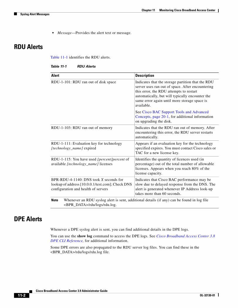
Chapter 11 Monitoring Cisco Broadband Access CenterSyslog Alert Messages
• Message—Provides the alert text or message.
RDU AlertsTable 11-1 identifies the RDU alerts.
DPE AlertsWhenever a DPE syslog alert is sent, you can find additional details in the DPE logs.
You can use the show log command to access the DPE logs. See Cisco Broadband Access Center 3.8 DPE CLI Reference, for additional information.
Some DPE errors are also propagated to the RDU server log files. You can find these in the <BPR_DATA>/rdu/logs/rdu.log file.
Table 11-1 RDU Alerts
Alert Description
RDU-1-101: RDU ran out of disk space Indicates that the storage partition that the RDU server uses ran out of space. After encountering this error, the RDU attempts to restart automatically, but will typically encounter the same error again until more storage space is available.
See Cisco BAC Support Tools and Advanced Concepts, page 20-1, for additional information on upgrading the disk.
RDU-1-103: RDU ran out of memory Indicates that the RDU ran out of memory. After encountering this error, the RDU server restarts automatically.
RDU-1-111: Evaluation key for technology [technology_name] expired
Appears if an evaluation key for the technology specified expires. You must contact Cisco sales or TAC for a new license key.
RDU-1-115: You have used [percent]percent of available [technology_name] licenses
Identifies the quantity of licences used (in percentage) out of the total number of allowable licenses. Appears when you reach 80% of the license capacity.
BPR-RDU-4-1140: DNS took X seconds for lookup of address [10.0.0.1/test.com]; Check DNS configuration and health of servers
Indicates that Cisco BAC performance may be slow due to delayed response from the DNS. The alert is generated whenever IP Address look-up takes more than 60 seconds.
Note Whenever an RDU syslog alert is sent, additional details (if any) can be found in log file <BPR_DATA>/rdu/logs/rdu.log.
11-2Cisco Broadband Access Center 3.9 Administrator Guide
OL-32130-01
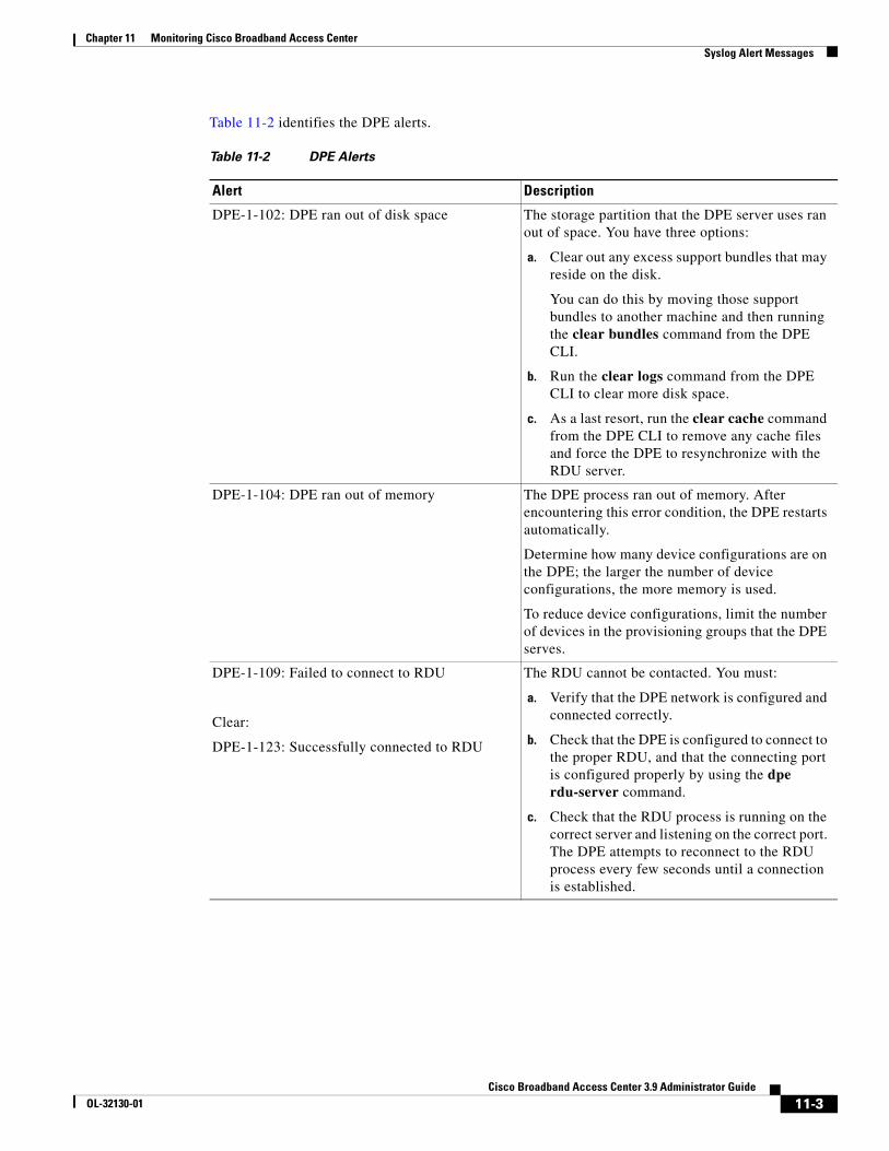
Chapter 11 Monitoring Cisco Broadband Access CenterSyslog Alert Messages
Table 11-2 identifies the DPE alerts.
Table 11-2 DPE Alerts
Alert Description
DPE-1-102: DPE ran out of disk space The storage partition that the DPE server uses ran out of space. You have three options:
a. Clear out any excess support bundles that may reside on the disk.
You can do this by moving those support bundles to another machine and then running the clear bundles command from the DPE CLI.
b. Run the clear logs command from the DPE CLI to clear more disk space.
c. As a last resort, run the clear cache command from the DPE CLI to remove any cache files and force the DPE to resynchronize with the RDU server.
DPE-1-104: DPE ran out of memory The DPE process ran out of memory. After encountering this error condition, the DPE restarts automatically.
Determine how many device configurations are on the DPE; the larger the number of device configurations, the more memory is used.
To reduce device configurations, limit the number of devices in the provisioning groups that the DPE serves.
DPE-1-109: Failed to connect to RDU
Clear:
DPE-1-123: Successfully connected to RDU
The RDU cannot be contacted. You must:
a. Verify that the DPE network is configured and connected correctly.
b. Check that the DPE is configured to connect to the proper RDU, and that the connecting port is configured properly by using the dpe rdu-server command.
c. Check that the RDU process is running on the correct server and listening on the correct port. The DPE attempts to reconnect to the RDU process every few seconds until a connection is established.
11-3Cisco Broadband Access Center 3.9 Administrator Guide
OL-32130-01
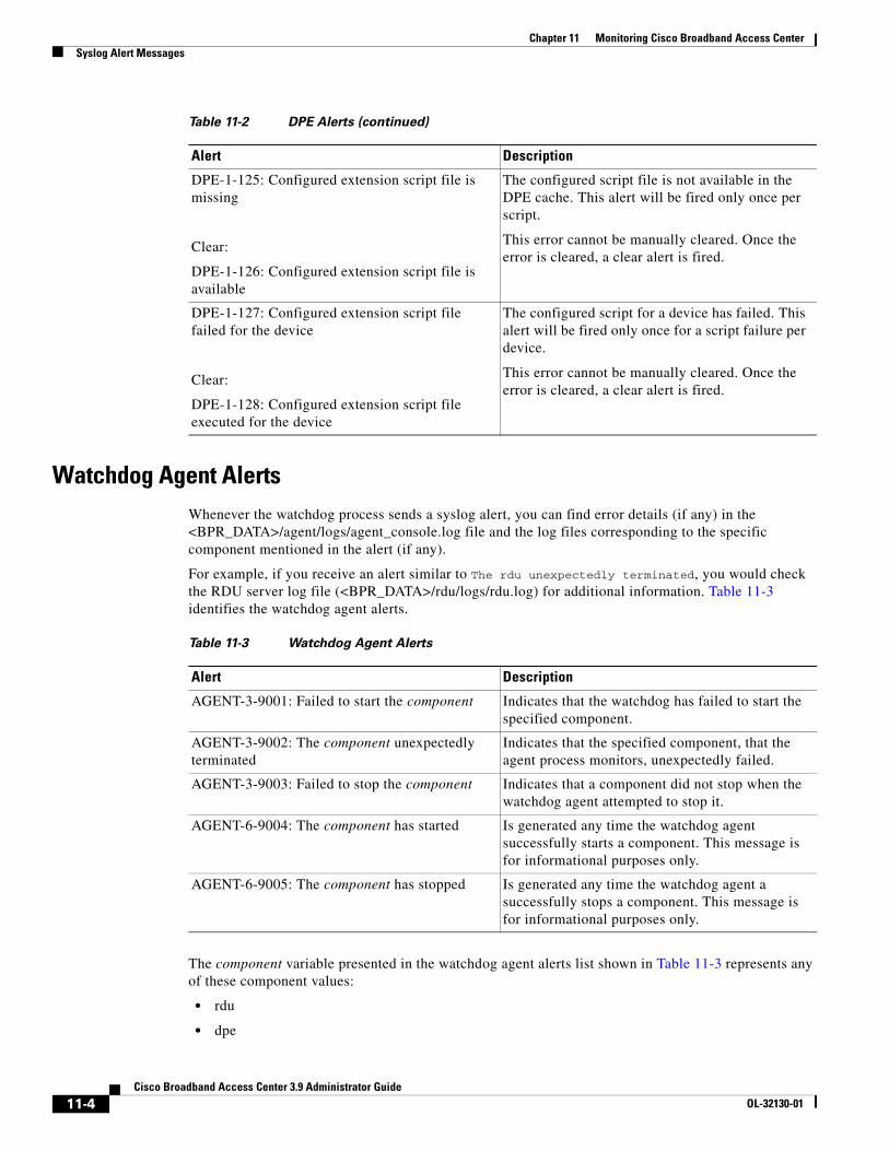
Chapter 11 Monitoring Cisco Broadband Access CenterSyslog Alert Messages
Watchdog Agent AlertsWhenever the watchdog process sends a syslog alert, you can find error details (if any) in the <BPR_DATA>/agent/logs/agent_console.log file and the log files corresponding to the specific component mentioned in the alert (if any).
For example, if you receive an alert similar to The rdu unexpectedly terminated, you would check the RDU server log file (<BPR_DATA>/rdu/logs/rdu.log) for additional information. Table 11-3 identifies the watchdog agent alerts.
The component variable presented in the watchdog agent alerts list shown in Table 11-3 represents any of these component values:
• rdu
• dpe
DPE-1-125: Configured extension script file is missing
Clear:
DPE-1-126: Configured extension script file is available
The configured script file is not available in the DPE cache. This alert will be fired only once per script.
This error cannot be manually cleared. Once the error is cleared, a clear alert is fired.
DPE-1-127: Configured extension script file failed for the device
Clear:
DPE-1-128: Configured extension script file executed for the device
The configured script for a device has failed. This alert will be fired only once for a script failure per device.
This error cannot be manually cleared. Once the error is cleared, a clear alert is fired.
Table 11-2 DPE Alerts (continued)
Alert Description
Table 11-3 Watchdog Agent Alerts
Alert Description
AGENT-3-9001: Failed to start the component Indicates that the watchdog has failed to start the specified component.
AGENT-3-9002: The component unexpectedly terminated
Indicates that the specified component, that the agent process monitors, unexpectedly failed.
AGENT-3-9003: Failed to stop the component Indicates that a component did not stop when the watchdog agent attempted to stop it.
AGENT-6-9004: The component has started Is generated any time the watchdog agent successfully starts a component. This message is for informational purposes only.
AGENT-6-9005: The component has stopped Is generated any time the watchdog agent a successfully stops a component. This message is for informational purposes only.
11-4Cisco Broadband Access Center 3.9 Administrator Guide
OL-32130-01

Chapter 11 Monitoring Cisco Broadband Access CenterMonitoring Servers by Using SNMP
• stun
• tomcat
• cli
• snmpAgent
Access Registrar Extension Point AlertsWhenever a Cisco BAC Access Registrar extension point syslog alert is sent, you can find additional details in the Access Registrar log file in <AR_HOME>/logs/name_radius_1_log.
Monitoring Servers by Using SNMPCisco BAC supports management of servers using SNMP. Specifically, an SNMP-based management system can be used to monitor Cisco BAC server state, license utilization information, server connections, and server-specific statistics.
Table 11-4 Access Registrar Extension Point Alerts
Alert Description
Error:
Auth HTTP Adapter: Failed to initialize Background thread pool and Request queue, due to Exception_message
Clear:
Auth HTTP Adapter: Background thread pool and Request queue initialized successfully.
The Access Registrar failed to initialize the background threads and queue in the extension point service.
Error:
Auth HTTP Adapter: Failed to initialize Http connections, due to Exception_message
Clear:
Auth HTTP Adapter: Http connections initialized successfully.
The Access Registrar failed to initialize the HTTP connection manager in the extension point service.
Error:
Auth HTTP Adapter: Extension point unable to find a usable Auth Service.
Clear:
Auth HTTP Adapter: HTTP message POST successful.
The alert message will be sent if the Extension point could not find a usable DPE Auth service.
11-5Cisco Broadband Access Center 3.9 Administrator Guide
OL-32130-01
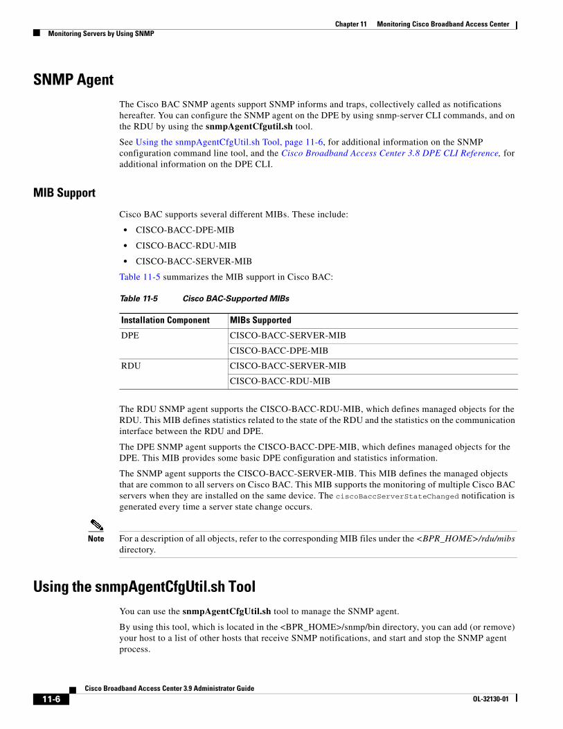
Chapter 11 Monitoring Cisco Broadband Access CenterMonitoring Servers by Using SNMP
SNMP AgentThe Cisco BAC SNMP agents support SNMP informs and traps, collectively called as notifications hereafter. You can configure the SNMP agent on the DPE by using snmp-server CLI commands, and on the RDU by using the snmpAgentCfgutil.sh tool.
See Using the snmpAgentCfgUtil.sh Tool, page 11-6, for additional information on the SNMP configuration command line tool, and the Cisco Broadband Access Center 3.8 DPE CLI Reference, for additional information on the DPE CLI.
MIB Support
Cisco BAC supports several different MIBs. These include:
• CISCO-BACC-DPE-MIB
• CISCO-BACC-RDU-MIB
• CISCO-BACC-SERVER-MIB
Table 11-5 summarizes the MIB support in Cisco BAC:
The RDU SNMP agent supports the CISCO-BACC-RDU-MIB, which defines managed objects for the RDU. This MIB defines statistics related to the state of the RDU and the statistics on the communication interface between the RDU and DPE.
The DPE SNMP agent supports the CISCO-BACC-DPE-MIB, which defines managed objects for the DPE. This MIB provides some basic DPE configuration and statistics information.
The SNMP agent supports the CISCO-BACC-SERVER-MIB. This MIB defines the managed objects that are common to all servers on Cisco BAC. This MIB supports the monitoring of multiple Cisco BAC servers when they are installed on the same device. The ciscoBaccServerStateChanged notification is generated every time a server state change occurs.
Note For a description of all objects, refer to the corresponding MIB files under the <BPR_HOME>/rdu/mibs directory.
Using the snmpAgentCfgUtil.sh ToolYou can use the snmpAgentCfgUtil.sh tool to manage the SNMP agent.
By using this tool, which is located in the <BPR_HOME>/snmp/bin directory, you can add (or remove) your host to a list of other hosts that receive SNMP notifications, and start and stop the SNMP agent process.
Table 11-5 Cisco BAC-Supported MIBs
Installation Component MIBs Supported
DPE CISCO-BACC-SERVER-MIB
CISCO-BACC-DPE-MIB
RDU CISCO-BACC-SERVER-MIB
CISCO-BACC-RDU-MIB
11-6Cisco Broadband Access Center 3.9 Administrator Guide
OL-32130-01
Chapter 11 Monitoring Cisco Broadband Access CenterMonitoring Servers by Using SNMP
Note The default port number of an SNMP agent is 8001.
You can use the snmpAgentCfgUtil.sh tool for:
• Adding a Host, page 11-7
• Deleting a Host, page 11-7
• Adding an SNMP Agent Community, page 11-8
• Deleting an SNMP Agent Community, page 11-9
• Starting the SNMP Agent, page 11-9
• Stopping the SNMP Agent, page 11-9
• Changing the SNMP Agent Location, page 11-10
• Setting Up SNMP Contacts, page 11-10
• Displaying SNMP Agent Settings, page 11-11
Adding a Host
You use this command to add the host address to the list of hosts that receive SNMP notifications from the SNMP agent.
Syntax Description snmpAgentCfgUtil.sh add host host-addr community community [udp-port port]
• host-addr—Specifies the IP address of the host that you want to add to the list of hosts.
• community—Specifies the community (read or write) to use while sending SNMP notifications.
• port—Identifies the UDP port used for sending the SNMP notifications.
Examples # ./snmpAgentCfgUtil.sh add host test.cisco.com community trapCommunity udp-port 162OKPlease restart [stop and start] SNMP agent.
Note The changes that you introduce through this command do not take effect until you restart the SNMP agent by using the /etc/init.d/bprAgent restart snmpAgent command. For detailed information, see Cisco BAC Process Watchdog, page 9-1.
Deleting a Host
You use this command to remove a host from the list of those receiving SNMP notifications from the SNMP agent.
Syntax Description snmpAgentCfgUtil.sh delete host host-addr
host-addr—Specifies the IP address of the host that you want to delete from the list of hosts.
11-7Cisco Broadband Access Center 3.9 Administrator Guide
OL-32130-01
Chapter 11 Monitoring Cisco Broadband Access CenterMonitoring Servers by Using SNMP
Examples # ./snmpAgentCfgUtil.sh delete host test.cisco.comOKPlease restart [stop and start] SNMP agent.
Note The changes that you introduce through this command do not take effect until you restart the SNMP agent by using the /etc/init.d/bprAgent restart snmpAgent command. For detailed information, see Cisco BAC Process Watchdog, page 9-1.
Adding an SNMP Agent Community
You use this command to add an SNMP community string to restrict access to the SNMP agent. The SNMP community name is used as a shared secret, with SNMP managers accessing the Cisco BAC SNMP agent.
Syntax Description snmpAgentCfgUtil.sh add community string [ro | rw]
• string—Identifies the SNMP community.
• ro—Assigns a read-only (ro) community string. Only get requests (queries) can be performed. The ro community string allows get requests, but no set operations. The network management system and the managed device must reference the same community string.
• rw—Assigns a read-write (rw) community string. SNMP applications require read-write access for set operations. The rw community string enables write access to object identifier (OID) values.
Note The default ro and rw community strings are bacread and bacwrite, respectively. Cisco recommends that you change these values before deploying Cisco BAC. To change them, add new community names and delete the default ones.
Examples # ./snmpAgentCfgUtil.sh add community fsda54 roOKPlease restart [stop and start] SNMP agent.
Note The changes that you introduce through this command do not take effect until you restart the SNMP agent by using the /etc/init.d/bprAgent restart snmpAgent command. For detailed information, see Cisco BAC Process Watchdog, page 9-1.
11-8Cisco Broadband Access Center 3.9 Administrator Guide
OL-32130-01
Chapter 11 Monitoring Cisco Broadband Access CenterMonitoring Servers by Using SNMP
Deleting an SNMP Agent Community
You use this command to delete an SNMP community string to prevent access to the SNMP agent.
Syntax Description snmpAgentCfgUtil.sh delete community string [ro | rw]
• string—Identifies the SNMP community
• ro—Assigns a read-only (ro) community string
• rw—Assigns a read-write (rw) community string
Note For additional information on the ro and rw community strings, see Adding an SNMP Agent Community, page 11-8.
Examples # ./snmpAgentCfgUtil.sh delete community fsda54 roOKPlease restart [stop and start] SNMP agent.
Note The changes that you introduce through this command do not take effect until you restart the SNMP agent by using the /etc/init.d/bprAgent restart snmpAgent command. For detailed information, see Cisco BAC Process Watchdog, page 9-1.
Starting the SNMP Agent
You use this command to start the SNMP agent process on which Cisco BAC is already installed.
Note You can also start the SNMP agent by invoking the Cisco BAC watchdog process agent by using the /etc/init.d/bprAgent start snmpAgent command. For more information, see Using Cisco BAC Process Watchdog from the Command Line, page 9-2.
Examples # ./snmpAgentCfgUtil.sh startProcess snmpAgent has been started
Stopping the SNMP Agent
You use this command to stop the SNMP agent process on any Solaris computer on which Cisco BAC is already installed.
Note You can also stop the SNMP agent by invoking the Cisco BAC watchdog process agent by using the /etc/init.d/bprAgent stop snmpAgent command. For more information, see Using Cisco BAC Process Watchdog from the Command Line, page 9-2.
11-9Cisco Broadband Access Center 3.9 Administrator Guide
OL-32130-01
Chapter 11 Monitoring Cisco Broadband Access CenterMonitoring Servers by Using SNMP
Examples # ./snmpAgentCfgUtil.sh stopProcess snmpAgent has stopped
Configuring an SNMP Agent Listening Port
You use this command to specify the port number to which the SNMP agent will listen. The default port number that the RDU SNMP agent uses is 8001.
Syntax Description snmpAgentCfgUtil.sh udp-port port
port— Identifies the port number to which the SNMP agent will listen.
Examples # ./snmpAgentCfgUtil.sh udp-port 8001OKPlease restart [stop and start] SNMP agent.
Changing the SNMP Agent Location
You use this command to enter a string of text that you use to indicate the location of the device running the SNMP agent. For example, you could use this string to identify the physical location of the device. You can enter any string up to 255 characters long.
Syntax Description snmpAgentCfgUtil.sh location location
location—Specifies the character string identifying the agents location.
Examples In this example, the physical location of the SNMP agent is in an equipment rack identified as equipment rack 5D:
# snmpAgentCfgUtil.sh location “equipment rack 5D”
Setting Up SNMP Contacts
You use this command to enter a string of text that you use to identify the contact person for the SNMP agent, together with information on how to contact this person. For example, you could use this string to identify a specific person including that person’s telephone number. You can enter any string up to 255 characters long.
Syntax Description snmpAgentCfgUtil.sh contact contact-info
contact-info— Specifies the character string identifying the individual to contact concerning the SNMP agent.
11-10Cisco Broadband Access Center 3.9 Administrator Guide
OL-32130-01
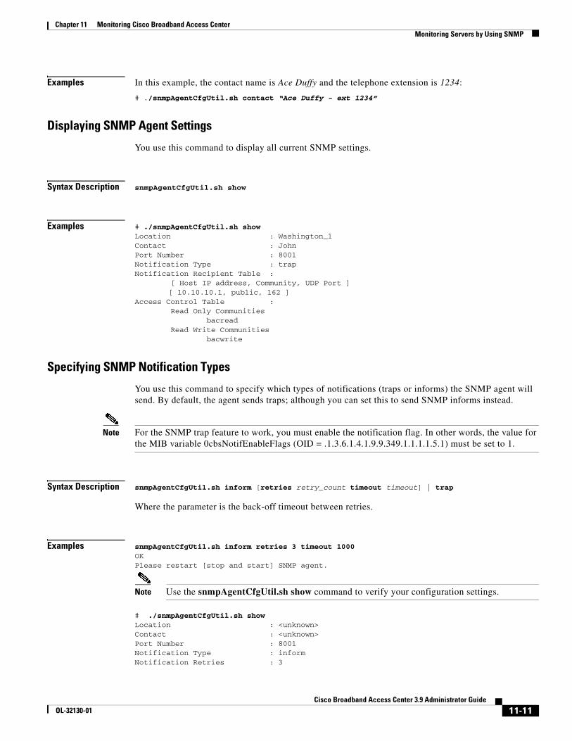
Chapter 11 Monitoring Cisco Broadband Access CenterMonitoring Servers by Using SNMP
Examples In this example, the contact name is Ace Duffy and the telephone extension is 1234:
# ./snmpAgentCfgUtil.sh contact “Ace Duffy - ext 1234”
Displaying SNMP Agent Settings
You use this command to display all current SNMP settings.
Syntax Description snmpAgentCfgUtil.sh show
Examples # ./snmpAgentCfgUtil.sh showLocation : Washington_1Contact : JohnPort Number : 8001Notification Type : trapNotification Recipient Table : [ Host IP address, Community, UDP Port ]
[ 10.10.10.1, public, 162 ]Access Control Table : Read Only Communities bacread Read Write Communities bacwrite
Specifying SNMP Notification Types
You use this command to specify which types of notifications (traps or informs) the SNMP agent will send. By default, the agent sends traps; although you can set this to send SNMP informs instead.
Note For the SNMP trap feature to work, you must enable the notification flag. In other words, the value for the MIB variable 0cbsNotifEnableFlags (OID = .1.3.6.1.4.1.9.9.349.1.1.1.1.5.1) must be set to 1.
Syntax Description snmpAgentCfgUtil.sh inform [retries retry_count timeout timeout] | trap
Where the parameter is the back-off timeout between retries.
Examples snmpAgentCfgUtil.sh inform retries 3 timeout 1000OKPlease restart [stop and start] SNMP agent.
Note Use the snmpAgentCfgUtil.sh show command to verify your configuration settings.
# ./snmpAgentCfgUtil.sh showLocation : <unknown>Contact : <unknown>Port Number : 8001Notification Type : informNotification Retries : 3
11-11Cisco Broadband Access Center 3.9 Administrator Guide
OL-32130-01
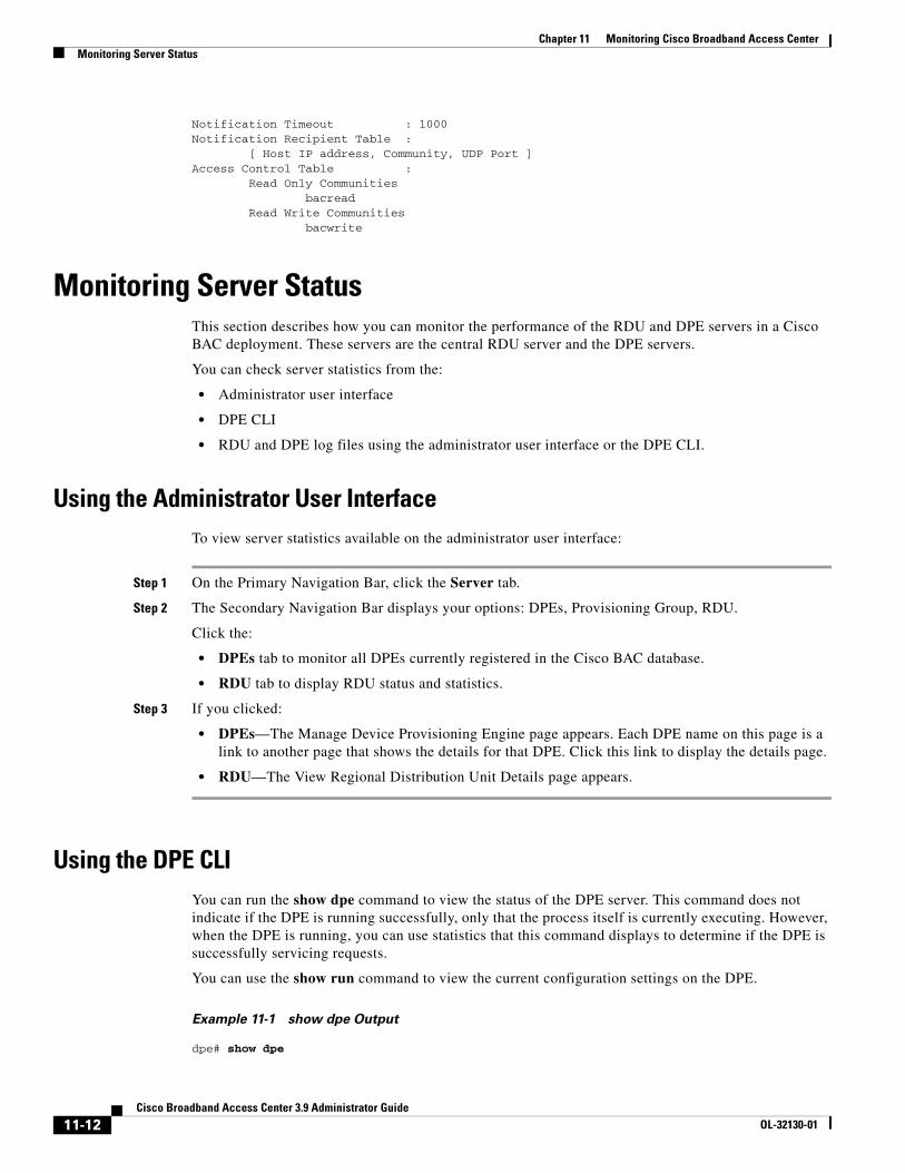
Chapter 11 Monitoring Cisco Broadband Access CenterMonitoring Server Status
Notification Timeout : 1000Notification Recipient Table : [ Host IP address, Community, UDP Port ]Access Control Table : Read Only Communities bacread Read Write Communities bacwrite
Monitoring Server StatusThis section describes how you can monitor the performance of the RDU and DPE servers in a Cisco BAC deployment. These servers are the central RDU server and the DPE servers.
You can check server statistics from the:
• Administrator user interface
• DPE CLI
• RDU and DPE log files using the administrator user interface or the DPE CLI.
Using the Administrator User InterfaceTo view server statistics available on the administrator user interface:
Step 1 On the Primary Navigation Bar, click the Server tab.
Step 2 The Secondary Navigation Bar displays your options: DPEs, Provisioning Group, RDU.
Click the:
• DPEs tab to monitor all DPEs currently registered in the Cisco BAC database.
• RDU tab to display RDU status and statistics.
Step 3 If you clicked:
• DPEs—The Manage Device Provisioning Engine page appears. Each DPE name on this page is a link to another page that shows the details for that DPE. Click this link to display the details page.
• RDU—The View Regional Distribution Unit Details page appears.
Using the DPE CLIYou can run the show dpe command to view the status of the DPE server. This command does not indicate if the DPE is running successfully, only that the process itself is currently executing. However, when the DPE is running, you can use statistics that this command displays to determine if the DPE is successfully servicing requests.
You can use the show run command to view the current configuration settings on the DPE.
Example 11-1 show dpe Output
dpe# show dpe
11-12Cisco Broadband Access Center 3.9 Administrator Guide
OL-32130-01
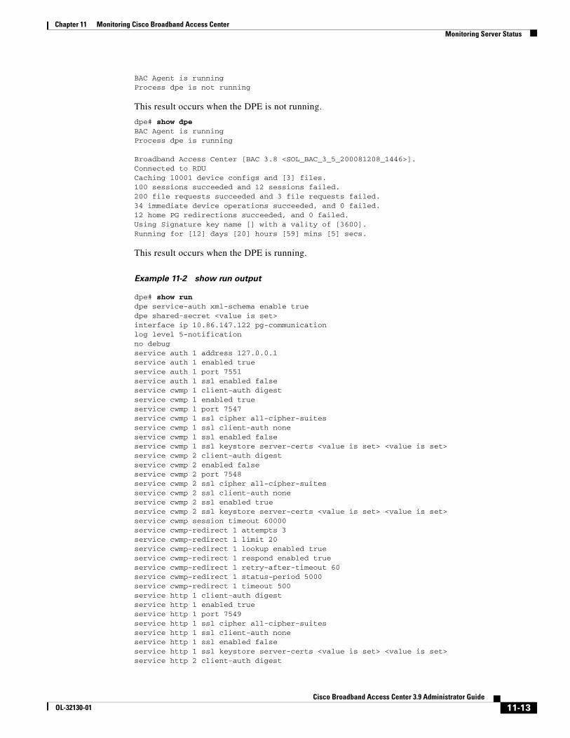
Chapter 11 Monitoring Cisco Broadband Access CenterMonitoring Server Status
BAC Agent is runningProcess dpe is not running
This result occurs when the DPE is not running.
dpe# show dpeBAC Agent is runningProcess dpe is running
Broadband Access Center [BAC 3.8 <SOL_BAC_3_5_200081208_1446>].Connected to RDUCaching 10001 device configs and [3] files.100 sessions succeeded and 12 sessions failed.200 file requests succeeded and 3 file requests failed.34 immediate device operations succeeded, and 0 failed.12 home PG redirections succeeded, and 0 failed.Using Signature key name [] with a vality of [3600].Running for [12] days [20] hours [59] mins [5] secs.
This result occurs when the DPE is running.
Example 11-2 show run output
dpe# show rundpe service-auth xml-schema enable truedpe shared-secret <value is set>interface ip 10.86.147.122 pg-communicationlog level 5-notificationno debugservice auth 1 address 127.0.0.1service auth 1 enabled trueservice auth 1 port 7551service auth 1 ssl enabled falseservice cwmp 1 client-auth digestservice cwmp 1 enabled trueservice cwmp 1 port 7547service cwmp 1 ssl cipher all-cipher-suitesservice cwmp 1 ssl client-auth noneservice cwmp 1 ssl enabled falseservice cwmp 1 ssl keystore server-certs <value is set> <value is set>service cwmp 2 client-auth digestservice cwmp 2 enabled falseservice cwmp 2 port 7548service cwmp 2 ssl cipher all-cipher-suitesservice cwmp 2 ssl client-auth noneservice cwmp 2 ssl enabled trueservice cwmp 2 ssl keystore server-certs <value is set> <value is set>service cwmp session timeout 60000service cwmp-redirect 1 attempts 3service cwmp-redirect 1 limit 20service cwmp-redirect 1 lookup enabled trueservice cwmp-redirect 1 respond enabled trueservice cwmp-redirect 1 retry-after-timeout 60service cwmp-redirect 1 status-period 5000service cwmp-redirect 1 timeout 500service http 1 client-auth digestservice http 1 enabled trueservice http 1 port 7549service http 1 ssl cipher all-cipher-suitesservice http 1 ssl client-auth noneservice http 1 ssl enabled falseservice http 1 ssl keystore server-certs <value is set> <value is set>service http 2 client-auth digest
11-13Cisco Broadband Access Center 3.9 Administrator Guide
OL-32130-01
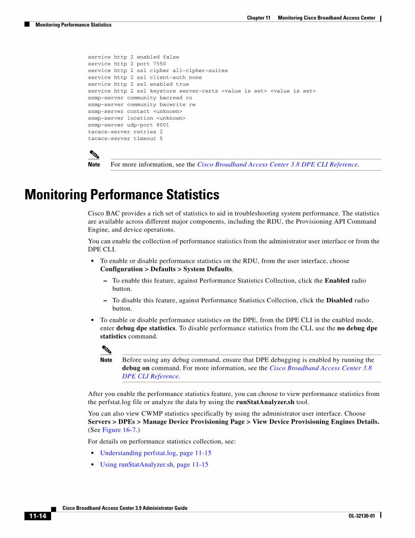
Chapter 11 Monitoring Cisco Broadband Access CenterMonitoring Performance Statistics
service http 2 enabled falseservice http 2 port 7550service http 2 ssl cipher all-cipher-suitesservice http 2 ssl client-auth noneservice http 2 ssl enabled trueservice http 2 ssl keystore server-certs <value is set> <value is set>snmp-server community bacread rosnmp-server community bacwrite rwsnmp-server contact <unknown>snmp-server location <unknown>snmp-server udp-port 8001tacacs-server retries 2tacacs-server timeout 5
Note For more information, see the Cisco Broadband Access Center 3.8 DPE CLI Reference.
Monitoring Performance StatisticsCisco BAC provides a rich set of statistics to aid in troubleshooting system performance. The statistics are available across different major components, including the RDU, the Provisioning API Command Engine, and device operations.
You can enable the collection of performance statistics from the administrator user interface or from the DPE CLI.
• To enable or disable performance statistics on the RDU, from the user interface, choose Configuration > Defaults > System Defaults.
– To enable this feature, against Performance Statistics Collection, click the Enabled radio button.
– To disable this feature, against Performance Statistics Collection, click the Disabled radio button.
• To enable or disable performance statistics on the DPE, from the DPE CLI in the enabled mode, enter debug dpe statistics. To disable performance statistics from the CLI, use the no debug dpe statistics command.
Note Before using any debug command, ensure that DPE debugging is enabled by running the debug on command. For more information, see the Cisco Broadband Access Center 3.8 DPE CLI Reference.
After you enable the performance statistics feature, you can choose to view performance statistics from the perfstat.log file or analyze the data by using the runStatAnalyzer.sh tool.
You can also view CWMP statistics specifically by using the administrator user interface. Choose Servers > DPEs > Manage Device Provisioning Page > View Device Provisioning Engines Details. (See Figure 16-7.)
For details on performance statistics collection, see:
• Understanding perfstat.log, page 11-15
• Using runStatAnalyzer.sh, page 11-15
11-14Cisco Broadband Access Center 3.9 Administrator Guide
OL-32130-01
Chapter 11 Monitoring Cisco Broadband Access CenterMonitoring Performance Statistics
Understanding perfstat.logYou can monitor performance statistics by using the data recorded in the perfstat.log file, in which statistics data is logged at specific intervals; this time interval is 5 minutes. The perfstat.log file resides in separate directories for the RDU (<BPR_DATA>/rdu/logs/statistics) and the DPE (<BPR_DATA>/dpe/logs/statistics).
Each perfstat.log file stores data for a minimum of one day and a maximum of 30 days. Since you can turn on and turn off the performance statistics feature, the logs may not represent data for consecutive days.
The perfstat.log file is renamed every day by using the perfstat.N.log format, where N is any value between 1 and 100. For example, perfstat.100.log will be the oldest log while perfstat.1.log will be the most recent renamed perfstat.log file.
Note The data is stored in comma-separated vector format. The format of each statistic is yyyymmdd:hh:mm, component, interval-in-milliseconds, stat1-tag, stat1-value, stat2-tag, stat2-value, … Stat1-tag and stat1-value specify the tag ID and the value of each statistic, respectively.
Using runStatAnalyzer.shYou can use Cisco BAC to analyze and provide a summary of performance statistics by using the runStatAnalyzer.sh tool. To analyze collected performance statistics, run the runStatAnalyzer.sh tool from the:
• <BPR_HOME>/rdu/bin directory for the RDU.
• <BPR_HOME>/dpe/bin directory for the DPE.
Syntax Description # runStatAnalyzer.sh [-d perfdata-dir] [-s start-time] [-e end-time] [-c component] [-f output-format] [-help] [-help components] [-help statistics [component]]
• perfdata-dir—Specifies the directory from which performance statistics are analyzed. This is the perfstatN.dat file located in the following default directories:
– <BPR_HOME>/rdu/logs/statistics for the RDU
– <BPR_HOME>/dpe/logs/statistics for the DPE
• start-time—Specifies the time from which collected data is to be analyzed. By default, all collected statistics are reported. Use this time format to specify start-time: yyyy-mm-dd:hh:mm.
• end-time—Specifies the time until which data collected data is to be analyzed. By default, all collected statistics are reported. Use this time format to specify end-time: yyyy-mm-dd:hh:mm.
11-15Cisco Broadband Access Center 3.9 Administrator Guide
OL-32130-01
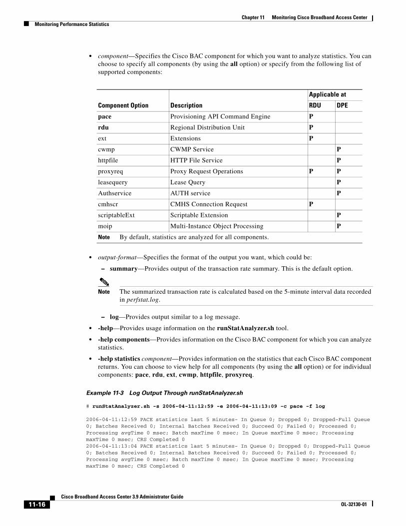
Chapter 11 Monitoring Cisco Broadband Access CenterMonitoring Performance Statistics
• component—Specifies the Cisco BAC component for which you want to analyze statistics. You can choose to specify all components (by using the all option) or specify from the following list of supported components:
• output-format—Specifies the format of the output you want, which could be:
– summary—Provides output of the transaction rate summary. This is the default option.
Note The summarized transaction rate is calculated based on the 5-minute interval data recorded in perfstat.log.
– log—Provides output similar to a log message.
• -help—Provides usage information on the runStatAnalyzer.sh tool.
• -help components—Provides information on the Cisco BAC component for which you can analyze statistics.
• -help statistics component—Provides information on the statistics that each Cisco BAC component returns. You can choose to view help for all components (by using the all option) or for individual components: pace, rdu, ext, cwmp, httpfile, proxyreq.
Example 11-3 Log Output Through runStatAnalyzer.sh
# runStatAnalyzer.sh -s 2006-04-11:12:59 -e 2006-04-11:13:09 -c pace -f log
2006-04-11:12:59 PACE statistics last 5 minutes- In Queue 0; Dropped 0; Dropped-Full Queue 0; Batches Received 0; Internal Batches Received 0; Succeed 0; Failed 0; Processed 0; Processing avgTime 0 msec; Batch maxTime 0 msec; In Queue maxTime 0 msec; Processing maxTime 0 msec; CRS Completed 02006-04-11:13:04 PACE statistics last 5 minutes- In Queue 0; Dropped 0; Dropped-Full Queue 0; Batches Received 0; Internal Batches Received 0; Succeed 0; Failed 0; Processed 0; Processing avgTime 0 msec; Batch maxTime 0 msec; In Queue maxTime 0 msec; Processing maxTime 0 msec; CRS Completed 0
Component Option Description
Applicable at
RDU DPE
pace Provisioning API Command Engine P
rdu Regional Distribution Unit P
ext Extensions P
cwmp CWMP Service P
httpfile HTTP File Service P
proxyreq Proxy Request Operations P P
leasequery Lease Query P
Authservice AUTH service P
cmhscr CMHS Connection Request P
scriptableExt Scriptable Extension P
moip Multi-Instance Object Processing P
Note By default, statistics are analyzed for all components.
11-16Cisco Broadband Access Center 3.9 Administrator Guide
OL-32130-01
Chapter 11 Monitoring Cisco Broadband Access CenterMonitoring STUN Statistics
2006-04-11:13:09 PACE statistics last 5 minutes- In Queue 0; Dropped 0; Dropped-Full Queue 0; Batches Received 0; Internal Batches Received 0; Succeed 0; Failed 0; Processed 0; Processing avgTime 0 msec; Batch maxTime 0 msec; In Queue maxTime 0 msec; Processing maxTime 0 msec; CRS Completed 0
Note The number of statistics available varies on the component specified.
Example 11-4 Summary Output Through runStatAnalyzer.sh
# runStatAnalyzer.sh -s 2006-04-11:12:59 -e 2006-04-11:13:29 -c pace -f summary
2006-04-11:13:04 PACE statistics last 5 minutes- In Queue 0; Dropped 0; Dropped-Full Queue 0; Batches Received 0; Internal Batches Received 0; Succeed 0; Failed 0; Processed 0; Processing avgTime 0 msec; Batch maxTime 0 msec; In Queue maxTime 0 msec; Processing maxTime 0 msec; CRS Completed 02006-04-11:13:29 PACE statistics last 30 minutes- In Queue 0; Dropped 0; Dropped-Full Queue 0; Batches Received 0; Internal Batches Received 0; Succeed 0; Failed 0; Processed 0; Processing avgTime 0 msec; Batch maxTime 0 msec; In Queue maxTime 0 msec; Processing maxTime 0 msec; CRS Completed 0
Note Summarized data is visible only if a complete set of data is available for the given interval. For example, the summary output of a 30-minute summarized interval appears only if there is 30 minutes worth of data. Based on the data available, the summarized time intervals are 5 minutes, 30 minutes, 60 minutes, 3 hours, 6 hours, 12 hours, 24 hours, 7 days, 14 days, 21 days, and 30 days.
Monitoring STUN StatisticsCisco BAC STUN server provides a rich set of statistics to aid in troubleshooting system performance and error conditions while communicating with the device. It also performs troubleshooting when connection requests are received from RDU and forwarded to the device.
For details on STUN statistics collection see, Understanding stunstatistics.log, page 11-17.
Understanding stunstatistics.logYou can monitor performance statistics by using the data recorded in the stunstatistics.log file, in which statistics data is logged at specific intervals. By default, the time interval is set to 15 minutes.
You can configure the interval in stun.properties available under STUN_HOME/stun/conf directory. The stunstatistics.log file resides in STUN_DATA/stun/logs/.
Example 11-5 Sample Logs Collected Through stunstatistics.log File
Number of Binding Request Received=40,Number of Binding Response Sent=40,Number of Binding Timeout Discovery Response Sent=0,Number of Binding Update Received=60,Number of Binding Update Authentication Succcess=25,Number of Binding Update Authentication Failure (401-Unauthorized)=35,Number of Binding Update Authentication Failure (420-Unknown Attribute)=0,Number of Binding Update Authentication Failure (431-Integrity Check Failure)=0,Number of Binding Update Authentication Failure (432-Missing Username)=0,Number of Binding Update Authentication Failure (500-Server Error)=0,Number of Dropped Requests (Network Failures)=0,
11-17Cisco Broadband Access Center 3.9 Administrator Guide
OL-32130-01
Chapter 11 Monitoring Cisco Broadband Access CenterTraffic Profiling
Number of UDP Connection Request Failure (Binding Mapping Not Found)=9,Number of UDP Connection Request Failure (Shared Secret Not Configured)=0,Number of UDP Connection Request Failure (Network Failures)=0,Number of UDP Connection Request Sent=54,Number of CXF Connection Request Received=27,Number of CXF Connection Response Success=18,Number of CXF Service Authentication Failure (Unauthorized)=0,Number of CXF Service Authentication Failure (Protocol Header Not Found)=0
STUN Binding Information
The STUN server stores the binding information from the device in its cache. You can view the binding information at any point of time by running the utility dumpStunBindingInfo.sh available under STUN_HOME/stun/internal/bin directory.
Using dumpStunBindingInfo.sh
To display the collected STUN binding information, run the dumpStunBindingInfo.sh tool from the STUN_HOME/stun/internal/bin directory.
Syntax Description dumpStunBindingInfo.sh [-?] [-file]
where:
• -?—Prints this usage message
• -file—Bindinginfo file to be parsed
Here binding info file is available under the STUN_DATA/stun/ directory.
Traffic ProfilingCisco BAC provides details about the traffic between the CPE and the DPE to provide visibility into flows that may be causing issues. This traffic profiling provides statistics on the following:
• Number of CWMP sessions handled
• Number of devices rejected
• Number of HTTP file requests handled
• Home Provisioning Group redirection status
• Traffic caused by chatty clients
The periodic statistics provides details, including the name of each Remote Procedure Call (RPC) and the specific types of Inform messages. The following RPC methods are monitored and reported:
• GetRPCMethods
• SetParameterValues
• GetParameterValues
• SetParameterAttributes
• GetParameterAttributes
11-18Cisco Broadband Access Center 3.9 Administrator Guide
OL-32130-01
Chapter 11 Monitoring Cisco Broadband Access CenterTraffic Profiling
• AddObject
• DeleteObject
• Download
• Reboot
• Inform
• TransferComplete
• AutonomousTransferComplete
• GetQueuedTransfers
• ScheduleInform
• SetVouchers
• GetOptions
• Upload
• FactoryReset
• GetAllQueuedTransfers
• Kicked
• RequestDownload
To enable or disable traffic statistics on the RDU, from the user interface, choose Configuration > Defaults > System Defaults.
• To enable this feature, against Performance Statistics Collection, click the Enabled radio button.
• To disable this feature, against Performance Statistics Collection, click the Disabled radio button.
To enable or disable traffic statistics on the DPE, from the DPE CLI in the enabled mode, enter debug dpe statistics. To disable traffic profiling from the CLI, use the no debug dpe statistics command.
After you enable the traffic statistics feature, you can view the traffic statistics from the perfstat.log file or analyze the data by using the runStatAnalyzer.sh tool.
You can view the traffic statistics by using the administrator user interface. Choose Servers > DPEs > Manage Device Provisioning Page > View Device Provisioning Engines Details.
11-19Cisco Broadband Access Center 3.9 Administrator Guide
OL-32130-01

Chapter 11 Monitoring Cisco Broadband Access CenterTraffic Profiling
11-20Cisco Broadband Access Center 3.9 Administrator Guide
OL-32130-01
CiscoOL-32130-01
C H A P T E R 12
Configuring CWMP ServiceThis chapter describes how to configure the CWMP service in Cisco Broadband Access Center (BAC).
This chapter includes the following sections:
• CWMP Service Configuration, page 12-1
• Connection Request Service, page 12-2
• Provisioning Group Scalability and Failover, page 12-16
CWMP Service ConfigurationCWMP is a specification of a set of remote procedure calls (RPCs), for example, GetParameterValues, SetParameterValues, and so on. These RPCs define the generic mechanism by which Cisco BAC reads or writes parameters to customer premises equipment (CPE) in order to manage it. These parameters include:
• Device configuration information
• Status information
• Performance statistics
You can enable or disable CWMP features on the DPE by using the DPE CLI.
Among the features that you can configure on the DPE are:
• HTTP-based Basic or Digest authentication
• Certificate-based authentication
• HTTP over SSL/TLS service settings
• Handling of unknown devices
• Debugging settings
• Session management settings
• CWMP service settings
• HTTP file service settings
For information on how to configure these properties, see the Cisco Broadband Access Center 3.8 DPE CLI Reference.
12-1 Broadband Access Center 3.9 Administrator Guide
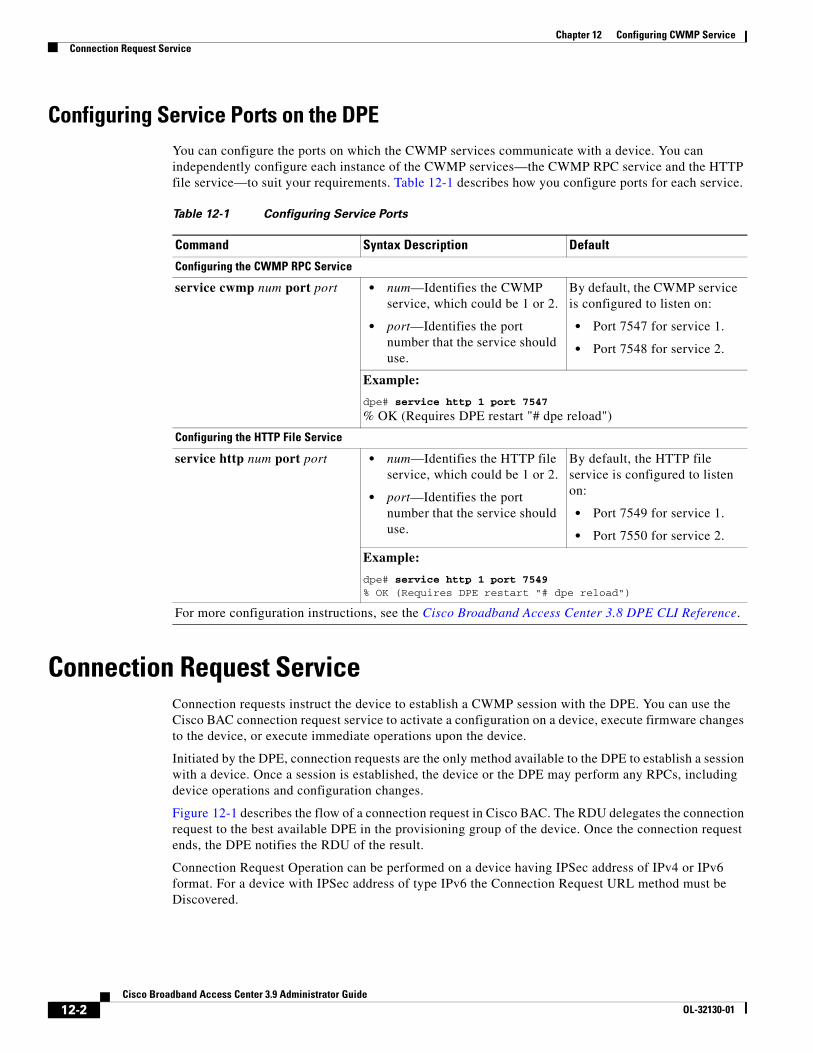
Chapter 12 Configuring CWMP ServiceConnection Request Service
Configuring Service Ports on the DPEYou can configure the ports on which the CWMP services communicate with a device. You can independently configure each instance of the CWMP services—the CWMP RPC service and the HTTP file service—to suit your requirements. Table 12-1 describes how you configure ports for each service.
Connection Request ServiceConnection requests instruct the device to establish a CWMP session with the DPE. You can use the Cisco BAC connection request service to activate a configuration on a device, execute firmware changes to the device, or execute immediate operations upon the device.
Initiated by the DPE, connection requests are the only method available to the DPE to establish a session with a device. Once a session is established, the device or the DPE may perform any RPCs, including device operations and configuration changes.
Figure 12-1 describes the flow of a connection request in Cisco BAC. The RDU delegates the connection request to the best available DPE in the provisioning group of the device. Once the connection request ends, the DPE notifies the RDU of the result.
Connection Request Operation can be performed on a device having IPSec address of IPv4 or IPv6 format. For a device with IPSec address of type IPv6 the Connection Request URL method must be Discovered.
Table 12-1 Configuring Service Ports
Command Syntax Description Default
Configuring the CWMP RPC Service
service cwmp num port port • num—Identifies the CWMP service, which could be 1 or 2.
• port—Identifies the port number that the service should use.
By default, the CWMP service is configured to listen on:
• Port 7547 for service 1.
• Port 7548 for service 2.
Example:
dpe# service http 1 port 7547
% OK (Requires DPE restart "# dpe reload")
Configuring the HTTP File Service
service http num port port • num—Identifies the HTTP file service, which could be 1 or 2.
• port—Identifies the port number that the service should use.
By default, the HTTP file service is configured to listen on:
• Port 7549 for service 1.
• Port 7550 for service 2.
Example:
dpe# service http 1 port 7549% OK (Requires DPE restart "# dpe reload")
For more configuration instructions, see the Cisco Broadband Access Center 3.8 DPE CLI Reference.
12-2Cisco Broadband Access Center 3.9 Administrator Guide
OL-32130-01
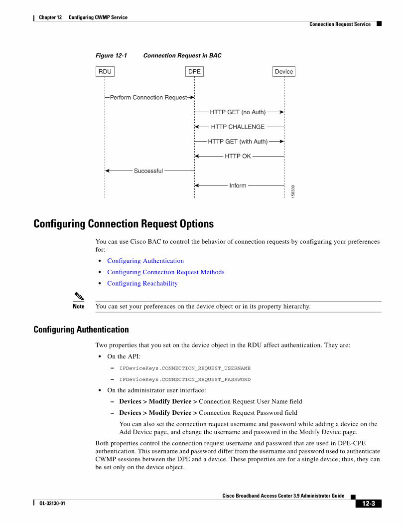
Chapter 12 Configuring CWMP ServiceConnection Request Service
Figure 12-1 Connection Request in BAC
Configuring Connection Request OptionsYou can use Cisco BAC to control the behavior of connection requests by configuring your preferences for:
• Configuring Authentication
• Configuring Connection Request Methods
• Configuring Reachability
Note You can set your preferences on the device object or in its property hierarchy.
Configuring Authentication
Two properties that you set on the device object in the RDU affect authentication. They are:
• On the API:
– IPDeviceKeys.CONNECTION_REQUEST_USERNAME
– IPDeviceKeys.CONNECTION_REQUEST_PASSWORD
• On the administrator user interface:
– Devices > Modify Device > Connection Request User Name field
– Devices > Modify Device > Connection Request Password field
You can also set the connection request username and password while adding a device on the Add Device page, and change the username and password in the Modify Device page.
Both properties control the connection request username and password that are used in DPE-CPE authentication. This username and password differ from the username and password used to authenticate CWMP sessions between the DPE and a device. These properties are for a single device; thus, they can be set only on the device object.
RDU DPE Device
1583
39
HTTP GET (no Auth)
Perform Connection Request
HTTP CHALLENGE
HTTP GET (with Auth)
HTTP OK
Inform
Successful
12-3Cisco Broadband Access Center 3.9 Administrator Guide
OL-32130-01
Chapter 12 Configuring CWMP ServiceConnection Request Service
If you do not specify a Connection Request password, a Connection Request password is automatically generated for the device using the connection request master secret. If you do not specify the Connection Request username, the device ID is used.
It is up to the device to issue an authentication challenge during connection request authentication, as illustrated in Figure 12-1. The DPE expects to be challenged with HTTP Digest authentication. There is no DPE configuration for connection request handling.
The API properties do not automatically update device parameters. You must preconfigure the corresponding values on the device or configure the values using a configuration template which can reference these properties.
Autogenerating Connection Request Passwords
In this release of Cisco BAC, Connection Request passwords can be autogenerated or specified by the Operational Support System (OSS).
Cisco BAC Generated Passwords:
In this approach, Cisco BAC generates a unique Connection Request password for each CWMP device. The password is encrypted using the connection request master secret and forwarded to the DPEs. You specify the connection request master secret in the CWMP Defaults page in the administrator user interface (see CWMP Defaults, page 17-10).
The DPEs derive the device passwords by using the hash message authentication code. If the DPE fails to authenticate using the current password, Cisco BAC attempts to authenticate by using the old password derived from the earlier master secret. Cisco BAC stores the last 15 passwords, by default, and attempts authentication by using each of these passwords in reverse order, until authentication succeeds.
To use autogenerated passwords, you have to specify the value, __AUTO_GENERATED__ for Connection Request password in the configuration template.
When the RDU attempts a connection request to a device:
• If /IPDevice/connectionRequestPassword property is not specified in the device record, the RDU assumes that an autogenerated password is used for that device.
• If /IPDevice/connectionRequestUsername property is not specified in the device record, the RDU uses the device ID as the user name for that device.
OSS Provided Passwords:
In this approach, you can provide passwords that may or may not be unique to each device. The Connection Request password is set on the /IPDevice/connectionRequestPassword property in the device record. When the password is set on the property, the following changes are triggered in the system:
• This RDU-provided password is used as the Connection Request password, instead of the autogenerated password at the DPE. As a rule, the password set on the device takes precedence over the autogenerated password.
• The hash key for the device reverts to the legacy format (DeviceConfHash).
You can also set the Connection Request username and password in the device configuration templates.
• If the username and password are set on both the device record and the configuration template, the username and password set in the device record are used.
12-4Cisco Broadband Access Center 3.9 Administrator Guide
OL-32130-01
Chapter 12 Configuring CWMP ServiceConnection Request Service
• If the username and password are present only on the configuration template (and not in the device record), this password is used instead of the auto-generated password.
Configuring Connection Request Methods
You can specify the method in which Cisco BAC attempts to perform a connection request by using the provisioning API or the administrator user interface. The selected method dictates how Cisco BAC determines the connection request URL to be used to contact the device.
The API property IPDeviceKeys.CONNECTION_REQUEST_METHOD specifies the connection request method (subsequent descriptions provide the details of each method).
Note You can specify this property anywhere in the device hierarchy.
To configure the default connection request method by using the administrator user interface, choose Configuration > Default > CWMP Defaults, and select an option from the drop-down list.
Cisco BAC supports the following methods to configure a connection request:
• Discovered
• Using FQDN
• Using IP
• LeaseQuery
• Annex G
• Use CMHS
When selecting a connection request method, it is important to consider performance and manageability, as each method provides different levels of both.
Discovered Connection Request
The Discovered method, during CPE interactions with the DPE, modifies the data synchronization instruction to discover the device's connection request URL, which corresponds to the parameter InternetGatewayDevice.ManagementServer.ConnectionRequestURL, whenever the DPE interacts with the device. The RDU records any updates to this parameter value and uses it when making connection requests.
Note This value must be discovered before connection requests are attempted.
Because this parameter value changes each time the device’s WAN IP address changes and every update has to be stored at the RDU, it is not the optimal method for connection requests.
With Connection Request method as Discovered, Connection request operation can be performed on a device having IPSec address of IPv4 or IPv6 format. In case of IPv6, DPE associated with the device should be running on a system that supports dual Stack.
Following is an example of Connection Request URL using IPv6 address:
http://[2001:420:27c1:469:250:56ff:febd:3e5d]:9899/dir/ConnReq.html?sn=001B67-BUBU00000000003
12-5Cisco Broadband Access Center 3.9 Administrator Guide
OL-32130-01
Chapter 12 Configuring CWMP ServiceConnection Request Service
Use FQDN Connection Request
The Use FQDN method uses the fully qualified domain name (FQDN) specified for the device at the RDU to construct a connection request URL for the device. It uses the FQDN along with the values specified in the following properties on the API:
• IPDeviceKeys.CONNECTION_REQUEST_PORT
• IPDeviceKeys.CONNECTION_REQUEST_PATH
You can also specify these properties on the administrator user interface:
Step 1 Choose Devices > Manage Devices.
Step 2 Use one of these methods:
• Add a device record. To do this, click the Add button. The Add Device page appears.
• Search for a device record. To do this,
a. Specify a Search Type and enter values for the screen components that are unique to the search type that you select.
A list of devices appears.
b. Click the Identifier link corresponding to the desired device.
The Modify Device page appears.
Step 3 From the Property Name drop-down list, select the /IPDevice/connectionRequestPort and /IPDevice/connectionRequestPath properties, and enter appropriate values in the Property Value field.
Note The API constants for /IPDevice/connectionRequestPort and /IPDevice/connectionRequestPath are IPDeviceKeys.CONNECTION_REQUEST_PORT and IPDeviceKeys.CONNECTION_REQUEST_PATH, respectively.
Step 4 Click Add.
You can specify the port and path properties anywhere in the property hierarchy.
Note Because the Use FQDN method relies on the DNS being updated with the device's correct IP address, you do not need to update Cisco BAC whenever the device IP address changes. Subsequently, this option is the most scalable one for connection requests.
Use IP Connection Request
The Use IP method discovers the device's WAN IP address by using the same mechanism as the Discovered method. Then, it constructs a connection request URL for the device by using the values in the following API properties:
• IPDeviceKeys.CONNECTION_REQUEST_PORT
• IPDeviceKeys.CONNECTION_REQUEST_PATH
You can also specify these properties on the administrator user interface:
Step 1 Choose Devices > Manage Devices.
12-6Cisco Broadband Access Center 3.9 Administrator Guide
OL-32130-01
Chapter 12 Configuring CWMP ServiceConnection Request Service
Step 2 Use one of these methods:
• Add a device record. To do this, click the Add button. The Add Device page appears.
• Search for a device record. To do this,
a. Specify a Search Type and enter values for the screen components that are unique to the search type that you select.
A list of devices appears.
b. Click the Identifier link corresponding to the desired device.
The Modify Device page appears.
Step 3 From the Property Name drop-down list, select the /IPDevice/connectionRequestPort and /IPDevice/connectionRequestPath properties, and enter appropriate values in the Property Value field.
Note The API constants for /IPDevice/connectionRequestPort and /IPDevice/connectionRequestPath are IPDeviceKeys.CONNECTION_REQUEST_PORT and IPDeviceKeys.CONNECTION_REQUEST_PATH, respectively.
Step 4 Click Add.
Because the Use IP method relies on the RDU having the device's WAN IP address, it requires the WAN IP address to be discovered before connection requests are attempted. Also, because the device's WAN IP address changes, the RDU must be updated with the new IP address. Subsequently, this option is not the optimal method for connection requests.
Using LeaseQuery
The LeaseQuery method discovers the latest IPSec address of the HNB from Cisco Network Registrar DHCP server. It first forms the Connection request URL by using the following API properties and then sends it to HNB through SeGW (Security Gateway).
• IPDeviceKeys.CONNECTION_REQUEST_PORT
• IPDeviceKeys.CONNECTION_REQUEST_PATH
You can also specify these properties on the administrator user interface:
Step 1 Choose Devices > Manage Devices.
Step 2 Use one of these methods:
• Add a device record. To do this, click Add. The Add Device page appears.
• Search for a device record. To do this,
a. Specify a Search Type and enter values for the screen components that are unique to the search type that you select. A list of devices appears.
b. Click the Identifier link corresponding to the desired device. The Modify Device page appears.
Step 3 From the Property Name drop-down list, select the /IPDevice/connectionRequestMethod, /IPDevice/connectionRequestPort and /IPDevice/connectionRequestPath properties, and enter the appropriate values in the Property Value field.
12-7Cisco Broadband Access Center 3.9 Administrator Guide
OL-32130-01
Chapter 12 Configuring CWMP ServiceConnection Request Service
Note The API constants for /IPDevice/connectionRequestMethod, /IPDevice/connectionRequestPort and /IPDevice/connectionRequestPath are IPDeviceKeys.CONNECTION_REQUEST_METHOD, IPDeviceKeys, CONNECTION_REQUEST_PORT, and IPDeviceKeys.CONNECTION_REQUEST_PATH, respectively.
Step 4 Click Add.
Configuring STUN Parameters (Annex G)
Cisco BAC now includes the TR-069 Annex G support for remotely managing CPE devices which are connected through a NAT gateway. Annex G uses a STUN server to identify a CPEs public IP address and port details.
The STUN server also tracks all the changes being made to the CPEs. Annex G uses a UDP based connection request mechanism defined in TR069 Annex G to allow Cisco BAC to initiate a session with the CPEs.
Step 1 Choose Devices > Manage Devices.
Step 2 Use one of these methods:
• Add a device record. To do this:
Click the Add button. The Add Device page appears.
• Search for a device record. To do this,
a. Specify a Search Type and enter values for the screen components that are unique to the search type that you select.
A list of devices appears.
b. Click the Identifier link corresponding to the desired device.
The Modify Device page appears.
Step 3 From the Property Name drop-down list, select the /IPDevice/connectionRequestPort and /IPDevice/connectionRequestPath properties, and enter appropriate values in the Property Value field.
Configure the following properties at the property hierarchy level:
• /IPDevice/cr/stunEnable
• /IPDevice/cr/stunServerAddress
• /IPDevice/cr/stunServerPort
• /IPDevice/cr/stunServerHttpPort
• /IPDevice/cr/stunServerHttpUsername
• /IPDevice/cr/stunServerHttpPassword
The API constants for /IPDevice/cr/stunEnable, /IPDevice/cr/stunServerAddress, /IPDevice/cr/stunServerHttpPort, /IPDevice/cr/stunServerPort, /IPDevice/cr/stunServerHttpUsername, and /IPDevice/cr/stunServerHttpPassword are:
IPDeviceKeys.STUN_ENABLED, IPDeviceKeys.STUN_SERVER_ADDRESS,
IPDeviceKeys.STUN_SERVER_PORT, IPDeviceKeys.STUN_SERVER_HTTP_PORT,
IPDeviceKeys.STUN_HTTP_USER_NAME, and IPDeviceKeys.STUN_HTTP_PASSWORD, respectively.
12-8Cisco Broadband Access Center 3.9 Administrator Guide
OL-32130-01
Chapter 12 Configuring CWMP ServiceConnection Request Service
Step 4 Click Add.
You can specify the port and path properties anywhere in the property hierarchy.
Configuring CMHS Connection Request (Use CMHS)
This method allows Cisco BAC to send connection request to CPE devices using the CMHS server, using BAC NB API Interfaces or BAC Admin UI.
When RDU receives the connection request message, it sends the message to the CMHS server that is configured in the BAC properties hierarchy. The CMHS NB API client contacts the CMHS server that the DLC is most likely be connected to.
Step 1 Choose Devices > Manage Devices.
Step 2 Use one of these methods:
• Add a device record. To do this:
Click Add. The Add Device page appears.
• Search for a device record. To do this:
a. Specify a Search Type and enter values for the screen components that are unique to the search type that you select.
A list of devices appears.
b. Click the Identifier link corresponding to the desired device.
The Modify Device page appears.
Step 3 From the Property Name drop-down list, select the /IPDevice/connectionRequestMethod property, and select Use CMHS from the Property Value drop-down list.
Step 4 Click Add.
Step 5 Create a group type called CMHS. See Adding a Group Type, page 16-19 for details on how to add a new group type.
Step 6 Add a group with type CMHS for each CMHS server which needs to be considered to send CMHS connection request. See Adding a New Group or Subgroup, page 16-20 for details on how to add a new group.
Step 7 Configure the following properties with CMHS server details, host, http port, user name and password, in the BAC properties hierarchy at group level.
• /IPDevice/cr/cmhsNbApiAddress
• /IPDevice/cr/cmhsNbApiPort
• /IPDevice/cr/cmhsNbApiUsername
• /IPDevice/cr/cmhsNbApiPassword
Note CMHS groups must not be used for any other purpose other than configuring CMHS server details for CMHS connection requests.
12-9Cisco Broadband Access Center 3.9 Administrator Guide
OL-32130-01
Chapter 12 Configuring CWMP ServiceConnection Request Service
If you do not specify any values for the properties /IPDevice/cr/cmhsNbApiUsername and /IPDevice/cr/cmhsNbApiPassword, the default values are taken from cmhs.properties file available in the BAC_HOME/rdu/conf/ folder. For the property/IPDevice/cr/cmhsNbApiPort, the default value is 80.
Note You can use the API IPDevice.changeNodeProperties(), if want to change any of the BAC properties for the CMHS group.
Step 8 Configure CMHS Server List Property, /IPDevice/cr/cmhsServerListPropertyName with a deployment specific Custom Property name. It needs to be set on BAC property hierarchy using BAC NB API or UI.
This Custom Property is not pre-defined by BAC. It needs to be created and populated with comma separated values of CMHS groups names. These values need to be considered while sending CMHS connection request.
Note The API constants for /IPDevice/connectionRequestMethod, is IPDeviceKeys.CONNECTION_REQUEST_METHOD.
Configuring External URLs on DPE
The ACS URL is the configured URL of the Cisco BAC server associated with each provisioning group. The devices use this URL to contact the DPEs in a given provisioning group. The RDU uses this URL to perform various operations, such as redirecting the devices to the home provisioning group.
The ACS URL that the DPE issues, depends on the URL that is configured for each of the CWMP services. You can use the following commands to configure the external URL for each service running on the DPE:
For CWMP services, the URL of the CWMP service that is first enabled on the DPE is sent to the RDU as the discovered ACS URL.
Command Description
service cwmp 1 external-url url Configures the DPE to represent externally the specified external URL as the URL of the CWMP service 1.
service cwmp 2 external-url url Configures the DPE to represent externally the specified external URL as the URL of the CWMP service 2.
service http 1 external-url url Configures the DPE to represent externally the specified external URL as the URL of the HTTP service 1.
service http 2 external-url url Configures the DPE to represent externally the specified external URL as the URL of the HTTP service 2.
For specific information about using these commands, see the Cisco Broadband Access Center 3.8 DPE CLI Reference.
12-10Cisco Broadband Access Center 3.9 Administrator Guide
OL-32130-01
Chapter 12 Configuring CWMP ServiceConnection Request Service
Disabling Connection Requests
You can choose to disable the connection request service. This option is useful if there is no STUN server and a device is behind NAT setup. Connection requests are not possible in such scenarios.
Note You can use ConnectionRequest via API device operations even if you disable connection requests.
Configuring Reachability
Reachability plays an important role in configuring connection requests. In earlier versions of Cisco BAC, connection requests were refused if a device's reported IP address and its source IP address did not match. This was because this implies that the device used the NAT standard, and therefore, configuration requests did not normally succeed. You could change this behavior from the administrator user interface or the API.
Cisco BAC supports a new standalone STUN server to handle the UDP connection requests feature. A UDP based connection request mechanism defined in TR069 Annex G, allows Cisco BAC to initiate a session with a CPE that is operating behind a NAT gateway. STUN Service can be run on Solaris or Linux.
By using the API, set the property IPDeviceKeys.FORCE_ROUTABLE_IP_ADDRESS to true to allow TCP based connection requests regardless of a mismatch in the device source IP address.
From the administrator user interface:
Step 1 Choose Devices > Manage Devices.
Step 2 Use one of these methods:
• Add a device record. To do this:
Click the Add button. The Add Device page appears.
• Search for a device record. To do this,
a. Specify a Search Type and enter values for the screen components that are unique to the search type that you select.
A list of devices appears.
b. Click the Identifier link corresponding to the desired device.
The Modify Device page appears.
Step 3 From the Property Value drop-down list, select /IPDevice/forceRouteIPAddress, and set a property value.
The API constant for /IPDevice/forceRouteIPAddress is IPDeviceKeys.FORCE_ROUTABLE_IP_ADDRESS.
Step 4 Click Add.
Note You can specify this property anywhere on the device's hierarchy.
12-11Cisco Broadband Access Center 3.9 Administrator Guide
OL-32130-01
Chapter 12 Configuring CWMP ServiceConnection Request Service
Discovering Data from DevicesThis section describes the Discovery of Data feature, which you use to retrieve a predefined set of parameters from the device, and store these parameters in the RDU for future use.
You can use this discovered data to manage device firmware and device configurations by providing some key attributes of the device and its current configuration. Discovered parameters are updated at the RDU any time their values change on the device.
You can configure data discovery at the RDU. The RDU forwards discovery policy instructions and the values of parameters, discovered for each device during the previous discovery process, to the appropriate DPEs. During interactions with the device, the DPE consults the discovery policy instructions specific to the device to determine what parameters need to be discovered.
After parameter values are discovered, existing device parameters are compared with those already stored for the device. If the values have changed or are being obtained for the first time, this data is updated at the RDU. If the RDU is not available to receive the update, the newly discovered data is dropped, and the entire process of data discovery is initiated the next time the device connects with the DPE.
Discovered parameters are stored on device records and you can view them by using the administrator user interface or obtain them through the API IPDevice.getDetails() call. IPDevice-getDetails() API also retrieves the device data along with the device property hierarchy. To view discovered parameters using the user interface, access the Manage Devices page under the Devices tab on the primary navigation bar.
Locate the device by using the search options, and click the View Details icon ( ) corresponding to the device. The Device Details page appears, displaying details of the discovered parameters for the device.
Multi-instance object support is available in data discovery for preregistered and unknown devices. For more information on multi-instance object support, see Multi-Instance Object Support, page 4-5.
The following sections describe:
• Configuring Data Discovery, page 12-12
• Troubleshooting Data Discovery, page 12-13
• Automatic IMEI Update, page 12-15
Configuring Data Discovery
Data discovery policy is configured using the RDU and includes parameters checked:
• On every device contact.
• Only upon a firmware upgrade.
While the discovery of data process executes every time a device establishes contact with the DPE, you can configure validation of certain parameters to occur only if the device has reported a new firmware version. This check eliminates the need to validate parameters whose values change only with a firmware upgrade.
For example, the device model name does not change without a firmware upgrade; thus, you do not need to check this parameter on the device unless the firmware has been upgraded.
Cisco BAC ships with a default configuration for data discovery. You can augment this default configuration in two ways:
• Add parameters to a custom list.
• Change the default list. This option, however, is not recommended.
12-12Cisco Broadband Access Center 3.9 Administrator Guide
OL-32130-01
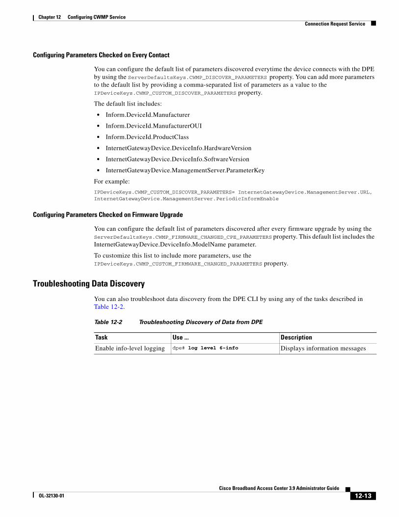
Chapter 12 Configuring CWMP ServiceConnection Request Service
Configuring Parameters Checked on Every Contact
You can configure the default list of parameters discovered everytime the device connects with the DPE by using the ServerDefaultsKeys.CWMP_DISCOVER_PARAMETERS property. You can add more parameters to the default list by providing a comma-separated list of parameters as a value to the IPDeviceKeys.CWMP_CUSTOM_DISCOVER_PARAMETERS property.
The default list includes:
• Inform.DeviceId.Manufacturer
• Inform.DeviceId.ManufacturerOUI
• Inform.DeviceId.ProductClass
• InternetGatewayDevice.DeviceInfo.HardwareVersion
• InternetGatewayDevice.DeviceInfo.SoftwareVersion
• InternetGatewayDevice.ManagementServer.ParameterKey
For example:
IPDeviceKeys.CWMP_CUSTOM_DISCOVER_PARAMETERS= InternetGatewayDevice.ManagementServer.URL, InternetGatewayDevice.ManagementServer.PeriodicInformEnable
Configuring Parameters Checked on Firmware Upgrade
You can configure the default list of parameters discovered after every firmware upgrade by using the ServerDefaultsKeys.CWMP_FIRMWARE_CHANGED_CPE_PARAMETERS property. This default list includes the InternetGatewayDevice.DeviceInfo.ModelName parameter.
To customize this list to include more parameters, use the IPDeviceKeys.CWMP_CUSTOM_FIRMWARE_CHANGED_PARAMETERS property.
Troubleshooting Data Discovery
You can also troubleshoot data discovery from the DPE CLI by using any of the tasks described in Table 12-2.
Table 12-2 Troubleshooting Discovery of Data from DPE
Task Use ... Description
Enable info-level logging dpe# log level 6-info Displays information messages
12-13Cisco Broadband Access Center 3.9 Administrator Guide
OL-32130-01
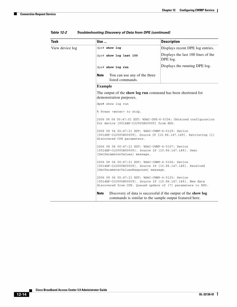
Chapter 12 Configuring CWMP ServiceConnection Request Service
View device log dpe# show log
dpe# show log last 100
dpe# show log run
Note You can use any of the three listed commands.
Displays recent DPE log entries.
Displays the last 100 lines of the DPE log.
Displays the running DPE log.
Example
The output of the show log run command has been shortened for demonstration purposes.
dpe# show log run
% Press <enter> to stop.
2006 08 04 00:47:01 EDT: %BAC-DPE-6-0104: Obtained configuration for device [0014BF-CJJ005B00009] from RDU.
2006 08 04 00:47:21 EDT: %BAC-CWMP-6-5129: Device [0014BF-CJJ005B00009]. Source IP [10.86.147.149]. Retrieving [1] discovered CPE parameters.
2006 08 04 00:47:21 EDT: %BAC-CWMP-6-5107: Device [0014BF-CJJ005B00009]. Source IP [10.86.147.149]. Sent [GetParameterValues] message.
2006 08 04 00:47:21 EDT: %BAC-CWMP-6-5106: Device [0014BF-CJJ005B00009]. Source IP [10.86.147.149]. Received [GetParameterValuesResponse] message.
2006 08 04 00:47:21 EDT: %BAC-CWMP-6-5120: Device [0014BF-CJJ005B00009]. Source IP [10.86.147.149]. New data discovered from CPE. Queued update of [7] parameters to RDU.
Note Discovery of data is successful if the output of the show log commands is similar to the sample output featured here.
Table 12-2 Troubleshooting Discovery of Data from DPE (continued)
Task Use ... Description
12-14Cisco Broadband Access Center 3.9 Administrator Guide
OL-32130-01
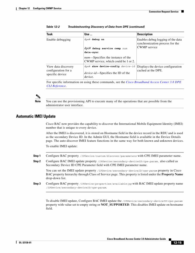
Chapter 12 Configuring CWMP ServiceConnection Request Service
Note You can use the provisioning API to execute many of the operations that are possible from the administrator user interface.
Automatic IMEI Update
Cisco BAC now provides the capability to discover the International Mobile Equipment Identity (IMEI) number that is unique to every device.
After the IMEI is discovered, it is stored on Hostname field in the device record in the RDU and is used as the secondary Device ID. In the Admin GUI, the Hostname field is available in the Device Details page. The auto-discover IMEI feature functions in the same way for both known and unknown devices.
To enable IMEI update:
Step 1 Configure BAC property /IPDevice/custom/discover/parameters with CPE IMEI parameter name.
Step 2 Configure BAC IMEI update property /IPDevice/secondary-deviceID/cpe-param, also called as Secondary Device ID CPE Parameter field with CPE IMEI parameter name.
You can set the IMEI update property /IPDevice/secondary-deviceID/cpe-param property in Cisco BAC property hierarchy through Class of Service page. This property is listed under the Property Name drop-down list.
Step 3 Configure BAC property /IPDevice/properties/available/pg with BAC IMEI update property name /IPDevice/secondary-deviceID/cpe-param.
To disable IMEI update, Configure BAC IMEI update the /IPDevice/secondary-deviceID/cpe-param property with value set to empty string or NOT_SUPPORTED. This disables IMEI update on hostname field.
Enable debugging dpe# debug on
dpe# debug service cwmp num data-sync
num—Specifies the instance of the CWMP service, which could be 1 or 2.
Enables debug logging of the data synchronization process for the CWMP service
View data discovery configuration for a specific device
dpe# show device-config device-id
device-id—Specifies the ID of the device.
Displays the device configuration cached at the DPE.
For specific information on using these commands, see the Cisco Broadband Access Center 3.8 DPE CLI Reference.
Table 12-2 Troubleshooting Discovery of Data from DPE (continued)
Task Use ... Description
12-15Cisco Broadband Access Center 3.9 Administrator Guide
OL-32130-01
Chapter 12 Configuring CWMP ServiceProvisioning Group Scalability and Failover
Provisioning Group Scalability and FailoverThis section describes the scalability and failover features provided in this release of Cisco BAC.
Cisco BAC’s scalability and failover provide a high degree of availability to suit networks of virtually any size, even those with millions of devices deployed. The product also provides such critical features as DPE redundancy and failover protection.
Scalability in a Cisco BAC deployment is accomplished through provisioning groups, each of which is a cluster of redundant DPE servers that communicate with a set of CPE. Provisioning groups enhance the scalability of the Cisco BAC network by making each provisioning group responsible only for a subset of devices.
This partitioning of devices can be along regional groupings or any other policy defined by the service provider.
To scale a deployment, the administrator can:
• Upgrade existing DPE server hardware.
• Add DPE servers to a provisioning group.
• Add provisioning groups and redistribute devices among them.
Cisco BAC supports explicit assignment and automatic membership of devices to provisioning groups. For more information, see CPE Management Overview, page 4-1.
Redundancy in Cisco BACRedundancy helps to ensure:
• High availability for your network applications.
• Users do not experience long network delays or black holes due to a single point of failure.
Cisco BAC supports local as well as regional server redundancy.
Local Redundancy
The Cisco BAC provisioning group is a cluster of redundant DPE servers that communicate with a set of devices. A single URL identifies each provisioning group.
You can configure local redundancy by using any software or hardware that provides load-balancing features, such as the Cisco Application Control Engine (ACE) 4710.
Regional Redundancy
Regional redundancy ensures that DPEs in a different location temporarily process CPE requests in case of regional failure. The simplest way of facilitating this deployment is to set up DPEs within a provisioning group in different geographic locations. In such a setup, CPE requests are serviced by DPEs located in different regions, providing regional failover within the confines of the provisioning group.
In some deployments, however, you may require that CPE requests be processed by servers in one location and fail over to DPEs in another location only in case of failure. In such a scenario, you can also locate DPEs for a provisioning group in different regions yet configure the network such that, under normal conditions, CPE requests are directed only to a subset of the DPEs in a particular region.
12-16Cisco Broadband Access Center 3.9 Administrator Guide
OL-32130-01
Chapter 12 Configuring CWMP ServiceProvisioning Group Scalability and Failover
Typically, you can configure regional redundancy by using DNS techniques. To configure the network for regional redundancy, ensure that the Cisco BAC hostname of a given provisioning name normally resolves to IP address(es) representing one set of DPEs.
However, when none of the DPE servers in that set responds to keepalives, such as ICMP, HTTP GET, or a TCP handshake, the DNS server should resolve the Cisco BAC hostname to the IP address(es) of the DPEs from a second set. CPE requests are then directed to a different set of DPEs.
Since DPEs in both sets belong to the same provisioning group, the new DPEs are ready to respond to requests. Subsequent DNS lookup requests fall back to the primary set of DPEs as soon as they become available.
DPE Load-BalancingCisco BAC supports the following mechanisms for DPE redundancy and load-balancing:
• Using DNS Round Robin, page 12-17
• Using a Hardware Load Balancer, page 12-17
Using DNS Round Robin
In using the DNS round-robin mechanism, the DNS server shuffles the list of DPE IPs when resolving the autoconfiguration server (ACS) hostname for the device. The device then takes the first IP address in the list as the ACS hostname.
This option is not recommended if the service provider does not control DNS caching servers. Also, DNS round-robinning performs less than ideally in a power outage scenario, when a large number of devices may receive the same order IP address cached by the DNS server, thus impacting performance. To work around this issue, Cisco recommends configuring a very short TTL of 1 second on the DNS server.
Using a Hardware Load Balancer
When a hardware load balancer is used, the ACS URL contains the IP address or is resolved by the DNS server to a single IP address. All DPEs for a provisioning group are hidden behind a single virtual IP address of the hardware load balancer, such as Cisco ACE 4710.
The ACE provides load balancing and SSL/TLS acceleration for TR-069 traffic between the CWMP devices and the DPEs. You can configure the ACE to translate its virtual IP address to a specific DPE IP address, based on a load-balancing algorithm. ACE performs a series of checks and calculations to determine the DPE that can best service each device request according to the load-balancing algorithm.
ACE also provides stickiness that allows the same device to maintain multiple simultaneous or subsequent connections with the same DPE for the duration of a session.
A redundant pair of load balancers can improve redundancy and may service more than one provisioning group.
12-17Cisco Broadband Access Center 3.9 Administrator Guide
OL-32130-01
Chapter 12 Configuring CWMP ServiceProvisioning Group Scalability and Failover
Adding DPE to a Provisioning GroupThis section describes how to add a DPE to a new provisioning group. In adding a DPE to a provisioning group, there are three possible options:
• Adding a DPE to a provisioning group
• Add a DPE to a provisioning group in a deployment that uses a hardware load balancer, such as Cisco ACE 4710, between the device and the DPE. In this case, you must update the load balancer.
• Adding a DPE to a provisioning group in a deployment in which a DNS server, using round robin, resolves to multiple DPEs for a provisioning group.
To add a DPE to a provisioning group:
Step 1 Configure the DPE from the DPE CLI. Among the configurations you must perform are:
• Specifying the provisioning group to which the DPE must belong. Enter:
dpe# dpe provisioning-group primary name
– name—Identifies the assigned primary provisioning group.
• Specifying the RDU to which the DPE connects. Enter:
dpe# dpe rdu-server {host | ip} port
– host—Identifies the FQDN of the host on which the RDU is running.
– ip—Identifies the IP address of the RDU.
– port—Identifies the port number on which RDU is listening for DPE connections. By default, this port number is 49187.
• Configuring the FQDN for a specific interface. The provisioning FQDN is the FQDN that is given to a device to contact the specific DPE interface. Enter:
dpe# interface ethernet {intf0 | intf1} provisioning fqdn fqdn
– intf0 | intf1—Identifies the Ethernet interface.
– fqdn—Identifies the FQDN that is set on the specified interface.
You must use the same FQDN for all DPEs in a given provisioning group. If DPEs are located behind the load balancer, use the FQDN of the load balancer as the interface FQDN, and ensure that it is the same for all DPEs which are part of the same load-balancing group.
You must also configure the CWMP service and the HTTP file service on one DPE to match the configurations on other DPEs.
For more information on configuration options, see the Cisco Broadband Access Center 3.8 DPE CLI Reference. Also, see Configuration Workflows and Checklists, page 3-1.
Step 2 Start the DPE by using the dpe start command, and allow the DPE to synchronize and populate device configuration instructions from the RDU.
Step 3 Optionally, if you are using a load balancer, add the DPE address to the load balancer.
Step 4 Optionally, if you are using the DNS round robin technique, add the DPE address to the DNS server.
12-18Cisco Broadband Access Center 3.9 Administrator Guide
OL-32130-01
CiscoOL-32130-01
C H A P T E R 13
Configuring CWMP Service SecurityThis chapter describes security options for Cisco Broadband Access Center’s (BAC) CWMP services, including authentication and encryption. It describes how to enable HTTP over SSL transport, called SSL in this chapter, for the CWMP services and the HTTP file services on the DPE, and use the certificate-management tool to create a certificate store on the DPE.
This chapter includes the following sections:
• Overview, page 13-1
• Key and Certificate Management in Cisco BAC, page 13-2
• Configuring SSL Service, page 13-3
• Configuring Security for DPE Services, page 13-11
• Configuring Security for RDU Services, page 13-18
• Signed Configuration for Devices, page 13-20
OverviewCisco BAC supports secure provisioning of CWMP devices by using SSL, specifically SSL 3.0 and TLS 1.0, as defined in RFC 2246. It supports device authentication based on shared secrets with the DPE by using Basic and Digest authentication as defined in RFC 2617.
Cisco BAC provides multiple services at the DPE: two instances of the CWMP service and two instances of the HTTP file service. You enable and configure each service independently, with different security options providing the flexibility of handling various devices differently on the same DPE.
Cisco BAC also provides secure device authentication by using unique or generic client certificates.
• Generic—Enables device certificate authentication through SSL by using a generic certificate that is common to all customer premises equipment (CPE) or a large subset of CPE. For example, all VoIP devices in a given deployment may have the same generic certificate that the service provider issues.
The client certificate is validated against a signing authority key, but does not establish identity of a given device. The device identifier is formed by using the data provided using HTTP Basic or Digest authentication; or by using the data in the CWMP Inform message.
• Unique—Enables client certificate authentication through SSL by using the unique certificate that each device provides. After the client certificate is validated by using the signing certificate authority's public key, the device's unique identifier is formed by using the CN field of the client certificate.
13-1 Broadband Access Center 3.9 Administrator Guide
Chapter 13 Configuring CWMP Service SecurityKey and Certificate Management in Cisco BAC
Cisco BAC supports a unique option of performing client-certificate authentication at a hardware load balancer and SSL accelerator such as Cisco ACE 4710.
In this scenario, the ACE performs certificate validation, extracts information about the SSL session, specifically client certificate fields, from the device certificate, and inserts that data into special HTTP headers. Cisco BAC then retrieves the CN field from the ACE header ClientCert-Subject-CN to form the unique device identifier.
Cisco BAC allows a mix of authentication options. For example, you can validate that the device has a generic certificate by using SSL and then perform additional HTTP Basic or Digest authentication once SSL connection is established.
Cisco BAC also provides an option of no-device authentication. This option is useful if the device is authenticated downstream from the DPE and the identity that the device presents can be trusted. If the Cisco BAC DPE is configured to perform no-authentication, it extracts the device identity from the Inform message and trusts it.
You can encrypt traffic between the device and a DPE by using SSL. Cisco BAC supports a variety of cipher suites, which determine the encryption algorithms to be used with the device and the encryption key length. You can configure acceptable cipher suites on the DPE by using the CLI. Another option is to terminate SSL at a hardware load balancer and accelerator for higher scalability.
Note Use the DPE CLI to configure security options for the CWMP service and the HTTP file service. For configuration instructions, see the Cisco Broadband Access Center 3.8 DPE CLI Reference.
Key and Certificate Management in Cisco BACThe DPE stores the certificates that the SSL protocol requires for authentication in the keystore. This keystore is a database in the form of a file that contains private keys and their associated public key X.509 certificates.
There are two keystores on the DPE server. The keystores are the cacerts keystore and the server certificates keystore.
• The cacerts keystore contains public key certificates that the DPE trusts for authenticating devices’ client certificates.
• The server certificates keystore contains the private key and the associated certificate chain for the server-side certificate, which is used to authenticate the DPE to the devices.
All DPE SSL services share a single cacerts keystore. This keystore can contain any number of signing authority certificates. The name of the cacerts keystore is fixed, and it must always reside in BPR_HOME/jre/lib/security directory. Cisco BAC ships with a default cacerts keystore, which can be manipulated by adding and removing signing authority certificates.
In contrast to the cacerts keystore, there can be multiple server certificate keystores and you can configure each SSL service in the DPE to use a different server certificate keystore. Each server certificate keystore should contain only one certificate chain. The server certificate keystores must reside in the BPR_HOME/dpe/conf directory.
If SSL is being terminated on the DPEs, and the provisioning group contains multiple DPEs, then all the DPEs must be configured with an identical keystore. An identical keystore is required since the same fully qualified domain name (FQDN) URL of the autoconfiguration server (ACS) is used to resolve to all DPEs in the provisioning group.
13-2Cisco Broadband Access Center 3.9 Administrator Guide
OL-32130-01
Chapter 13 Configuring CWMP Service SecurityConfiguring SSL Service
As defined in the TR-069 specification, the ACS URL must be identical to the Common Name (CN) value of the server certificate, which is imported into the keystore.
The DPE ships with a default sample server certificates keystore, called servercerts, which contains a self-signed server certificate.
However, because a CWMP device does not normally trust self-signed certificates, you cannot use the sample keystore to enable SSL for device provisioning. Instead, you must obtain a signed ACS certificate with private key and use it to create a new server certificate keystore (see Configuring DPE Keystore by Using the Keytool, page 13-3). You can use the default keystore to test the SSL service link before acquiring and configuring an ACS certificate.
Configuring SSL ServiceTo enable SSL on Cisco BAC:
Step 1 Create a server certificate keystore, which contains the private key and the associated ACS public key certificate. This process also requires updating the cacerts keystore to load the public certificate of the signing authority for the server certificate.
Step 2 Optionally, if you would like to configure CPE authentication to use client certificates, update the cacerts keystore with the public key of the CPE certificate authority root certificate, which can validate CPE certificates. For details, see Configuring DPE Keystore by Using the Keytool, page 13-3.
Step 3 Configure the DPE to use the new server certificate keystore from the DPE CLI. For details, see Configuring Security for DPE Services, page 13-11.
Step 4 Enable SSL transport for the CWMP service or the HTTP file service by using the DPE CLI. For more details, see Configuring Security for DPE Services, page 13-11.
Note To ensure that the changes you make to the keystore take effect, you must restart the DPE by using the dpe reload command from the CLI, or the /etc/init.d/bprAgent restart dpe command from the watchdog agent command line (see Using Cisco BAC Process Watchdog from the Command Line, page 9-2).
Configuring DPE Keystore by Using the KeytoolYou use Cisco BAC to configure the server certificate keystore and the cacerts keystore by using the keytool utility. The keytool is a key and certificate-management utility, which you use to administer the certificates on the DPE server.
The keytool utility resides in the Cisco BAC default installation directory, at /opt/CSCObac/jre/bin/keytool. Run the keytool utility by using a secure connection to the DPE server.
Note You must execute the keytool utility bundled with this Cisco BAC version, because the keystore file format varies between keytool releases.
13-3Cisco Broadband Access Center 3.9 Administrator Guide
OL-32130-01
Chapter 13 Configuring CWMP Service SecurityConfiguring SSL Service
To configure a server certificate:
Step 1 Create a new server keystore with a new private key by using keytool. See Generating Server Certificate Keystore and Private Key for a New Certificate, page 13-6, for details.
Step 2 Generate a certificate-signing request (CSR). See Generating a Certificate-Signing Request, page 13-7, for details.
Step 3 Request a public certificate from the signing authority by using CSR. See Generating a Certificate-Signing Request, page 13-7, for details.
Step 4 Load the public key of the signing authority into the cacerts keystore. See Importing Signing Authority Certificate into Cacerts Keystore, page 13-8, for details.
Step 5 Load the signed server certificate into the server keystore. See Importing the Signed Certificate into Server Certificate Keystore, page 13-9, for details.
Step 6 Put the new keystore file in the DPE BPR_HOME/dpe/conf directory.
Step 7 At the CLI, configure one of the DPE services to use the new keystore. See Configuring SSL Service, page 13-3, for details
Step 8 Restart the DPE by using the dpe reload command from the CLI, or the /etc/init.d/bprAgent restart dpe command from the watchdog agent command line (see Using Cisco BAC Process Watchdog from the Command Line, page 9-2).
Note To enable the use of client certificates for device authentication, ensure that the public certificate of the signing authority for device certificates is loaded into the cacerts keystore. Follow the procedure described in Importing Signing Authority Certificate into Cacerts Keystore, page 13-8, for details.
Importing an Existing Signed Server Certificate
If you already have the signed server certificate and you want to load it into the keystore, you must know the private key that is associated with the certificate. In this case, instead of following the procedure described above, follow the steps outlined in this section. Use the PCKS#12 file format, which combines both the private key and the signed certificate. You can load this file into a keystore by using the keystore import-pkcs12 command.
To configure a server certificate with an existing signed server certificate:
Step 1 Load the existing private key and certificates into a DPE-compatible file, used in authenticating the DPE to SSL clients, by using the keystore import-pkcs12 command.
When using this command, the syntax is:
keystore import-pkcs12 keystore-filename pkcs12-filename keystore-password key-passwordexport-password export-key-password
• keystore-filename—Identifies the keystore file to create. If it already exists, it will be overwritten.
Note Remember to specify the full path of the keystore file.
• pkcs12-filename—Identifies the PKCS#12 file from which you intend to import the keyand certificate.
13-4Cisco Broadband Access Center 3.9 Administrator Guide
OL-32130-01
Chapter 13 Configuring CWMP Service SecurityConfiguring SSL Service
• keystore-password—Identifies the private key password and the keystore password that you used when you created your keystore file. This password must be between 6 and 30 characters.
• key-password—Identifies the password used to access keys within DPE keystore. This password must be between 6 and 30 characters.
• export-password—Identifies the password used to decrypt the key in the PKCS#12 file. The export password must be between 6 and 30 characters.
• export-key-password—Identifies the password used to access keys within the PKCS#12 keystore. This password must be between 6 and 30 characters.
For example:
dpe# keystore import-pkcs12 example.keystore example.pkcs12 changeme changeme changeme changeme% Reading alias [1]
% Reading alias [1]: key with format [PKCS8] algorithm [RSA]
% Reading alias [1]: cert type [X.509]
% Created JKS keystore: example.keystore
% OK
Step 2 Copy the new keystore file into the DPE BPR_HOME/dpe/conf directory.
Step 3 At the CLI, configure one of the DPE services to use the new keystore. See Configuring SSL Service, page 13-3, for details.
Step 4 Restart the DPE by using the dpe reload command from the CLI, or the /etc/init.d/bprAgent restart dpe command from the watchdog agent command line (see Using Cisco BAC Process Watchdog from the Command Line, page 9-2).
Using the Keytool Commands
The keytool utility uses command arguments to configure a DPE keystore. Table 13-1 lists the keytool commands and their descriptions.
Table 13-1 Keytool Commands
-alias alias Identifies the identity assigned to a keystore entry, which stores the certificate chain and the private key. Subsequent keytool commands must use the same alias to refer to the entity.
-dname dname Identifies the X.500 Distinguished Names used to identify entities, such as those that the subject and the issuer named.
-file csr_file Identifies the CSR file to be exported.
-file cert_file Identifies the file from which the certificate is to be read.
-keyalg keyalg Identifies the algorithm to be used for key-pair creation. The values are DSA (default) and RSA.
-keysize keysize Specifies a keysize, whose values must be in multiples of 64 bits.
-keypass keypass Identifies the password assigned to a key pair.
-keystore keystore Customizes the name and location of a keystore.
13-5Cisco Broadband Access Center 3.9 Administrator Guide
OL-32130-01
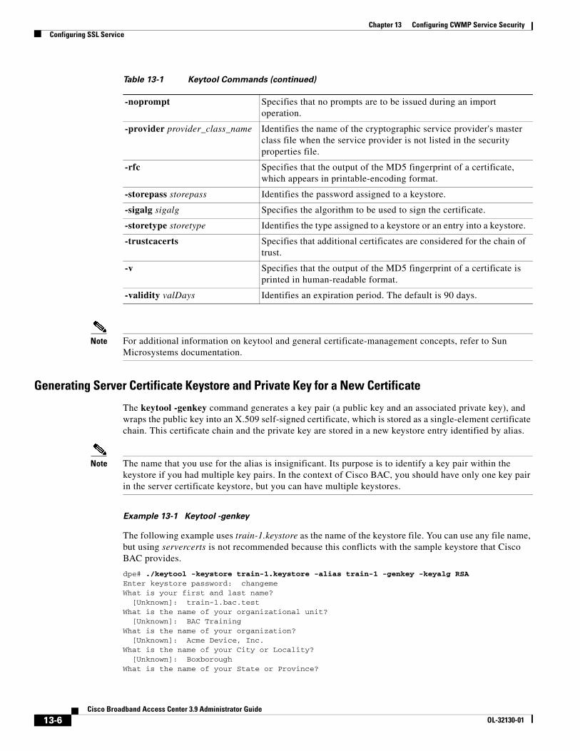
Chapter 13 Configuring CWMP Service SecurityConfiguring SSL Service
Note For additional information on keytool and general certificate-management concepts, refer to Sun Microsystems documentation.
Generating Server Certificate Keystore and Private Key for a New Certificate
The keytool -genkey command generates a key pair (a public key and an associated private key), and wraps the public key into an X.509 self-signed certificate, which is stored as a single-element certificate chain. This certificate chain and the private key are stored in a new keystore entry identified by alias.
Note The name that you use for the alias is insignificant. Its purpose is to identify a key pair within the keystore if you had multiple key pairs. In the context of Cisco BAC, you should have only one key pair in the server certificate keystore, but you can have multiple keystores.
Example 13-1 Keytool -genkey
The following example uses train-1.keystore as the name of the keystore file. You can use any file name, but using servercerts is not recommended because this conflicts with the sample keystore that Cisco BAC provides.
dpe# ./keytool -keystore train-1.keystore -alias train-1 -genkey -keyalg RSAEnter keystore password: changemeWhat is your first and last name? [Unknown]: train-1.bac.testWhat is the name of your organizational unit? [Unknown]: BAC Training What is the name of your organization? [Unknown]: Acme Device, Inc.What is the name of your City or Locality? [Unknown]: Boxborough What is the name of your State or Province?
-noprompt Specifies that no prompts are to be issued during an import operation.
-provider provider_class_name Identifies the name of the cryptographic service provider's master class file when the service provider is not listed in the security properties file.
-rfc Specifies that the output of the MD5 fingerprint of a certificate, which appears in printable-encoding format.
-storepass storepass Identifies the password assigned to a keystore.
-sigalg sigalg Specifies the algorithm to be used to sign the certificate.
-storetype storetype Identifies the type assigned to a keystore or an entry into a keystore.
-trustcacerts Specifies that additional certificates are considered for the chain of trust.
-v Specifies that the output of the MD5 fingerprint of a certificate is printed in human-readable format.
-validity valDays Identifies an expiration period. The default is 90 days.
Table 13-1 Keytool Commands (continued)
13-6Cisco Broadband Access Center 3.9 Administrator Guide
OL-32130-01
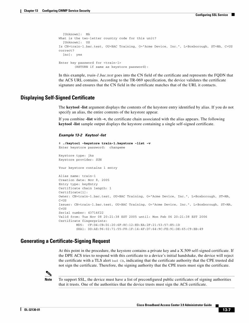
Chapter 13 Configuring CWMP Service SecurityConfiguring SSL Service
[Unknown]: MAWhat is the two-letter country code for this unit? [Unknown]: USIs CN=train-1.bac.test, OU=BAC Training, O="Acme Device, Inc.", L=Boxborough, ST=MA, C=US correct? [no]: yes
Enter key password for <train-1> (RETURN if same as keystore password):
In this example, train-1.bac.test goes into the CN field of the certificate and represents the FQDN that the ACS URL contains. According to the TR-069 specification, the device validates the certificate signature and ensures that the CN field in the certificate matches that of the URL it contacts.
Displaying Self-Signed Certificate
The keytool -list argument displays the contents of the keystore entry identified by alias. If you do not specify an alias, the entire contents of the keystore appear.
If you combine -list with -v, the certificate chain associated with the alias appears. The following keytool -list sample output displays the keystore containing a single self-signed certificate.
Example 13-2 Keytool -list
# ./keytool -keystore train-1.keystore -list -vEnter keystore password: changeme
Keystore type: jksKeystore provider: SUN
Your keystore contains 1 entry
Alias name: train-1Creation date: Nov 8, 2005Entry type: keyEntryCertificate chain length: 1Certificate[1]:Owner: CN=train-1.bac.test, OU=BAC Training, O="Acme Device, Inc.", L=Boxborough, ST=MA, C=USIssuer: CN=train-1.bac.test, OU=BAC Training, O="Acme Device, Inc.", L=Boxborough, ST=MA, C=USSerial number: 43714f22Valid from: Tue Nov 08 20:21:38 EST 2005 until: Mon Feb 06 20:21:38 EST 2006Certificate fingerprints: MD5: CF:D4:CB:D1:20:6F:8C:12:ED:EA:2F:21:53:57:E5:1D SHA1: DD:AE:96:02:71:55:F8:1F:14:4F:D7:64:9C:FE:91:DE:65:C9:BB:49
Generating a Certificate-Signing Request
At this point in the procedure, the keystore contains a private key and a X.509 self-signed certificate. If the DPE ACS tries to respond with this certificate to a device’s initial handshake, the device will reject the certificate with a TLS alert bad CA, indicating that the certificate authority that the CPE trusted did not sign the certificate. Therefore, the signing authority that the CPE trusts must sign the certificate.
Note To support SSL, the device must have a list of preconfigured public certificates of signing authorities that it trusts. One of the authorities that the device trusts must sign the ACS certificate.
13-7Cisco Broadband Access Center 3.9 Administrator Guide
OL-32130-01
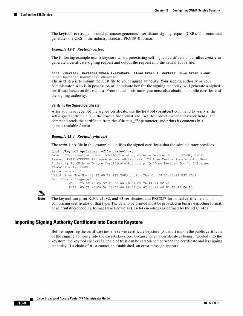
Chapter 13 Configuring CWMP Service SecurityConfiguring SSL Service
The keytool -certreq command parameter generates a certificate-signing request (CSR). This command generates the CRS in the industry standard PKCS#10 format.
Example 13-3 Keytool -certreq
The following example uses a keystore with a preexisting self-signed certificate under alias train-1 to generate a certificate-signing request and output the request into the train-1.csr file.
dpe# ./keytool -keystore train-1.keystore -alias train-1 -certreq -file train-1.csrEnter keystore password: changeme
The next step is to submit the CSR file to your signing authority. Your signing authority or your administrator, who is in possession of the private key for the signing authority, will generate a signed certificate based on this request. From the administrator, you must also obtain the public certificate of the signing authority.
Verifying the Signed Certificate
After you have received the signed certificate, use the keytool -printcert command to verify if the self-signed certificate is in the correct file format and uses the correct owner and issuer fields. The command reads the certificate from the -file cert_file parameter, and prints its contents in a human-readable format.
Example 13-4 Keytool -printcert
The train-1.crt file in this example identifies the signed certificate that the administrator provides.
dpe# ./keytool -printcert -file train-1.crtOwner: CN=train-1.bac.test, OU=BAC Training, O="Acme Device, Inc.", ST=MA, C=USIssuer: [email protected], CN=Acme Device Provisioning Root Authority 1, OU=Acme Device Certificate Authority, O="Acme Device, Inc.", L=Irvine, ST=California, C=USSerial number: 1Valid from: Tue Nov 08 12:40:28 EST 2005 until: Thu Nov 08 12:40:28 EST 2007Certificate fingerprints: MD5: 25:8E:98:C5:5C:23:5C:A0:4D:51:CF:2A:AA:2A:FC:42 SHA1: 05:C1:2D:C6:94:78:D1:40:88:6A:55:67:43:27:68:D3:AC:43:C6:A5
Note The keytool can print X.509 v1, v2, and v3 certificates, and PKCS#7-formatted certificate chains comprising certificates of that type. The data to be printed must be provided in binary-encoding format, or in printable-encoding format (also known as Base64 encoding) as defined by the RFC 1421.
Importing Signing Authority Certificate into Cacerts Keystore
Before importing the certificate into the server certificate keystore, you must import the public certificate of the signing authority into the cacerts keystore; because when a certificate is being imported into the keystore, the keytool checks if a chain of trust can be established between the certificate and its signing authority. If a chain of trust cannot be established, an error message appears.
13-8Cisco Broadband Access Center 3.9 Administrator Guide
OL-32130-01
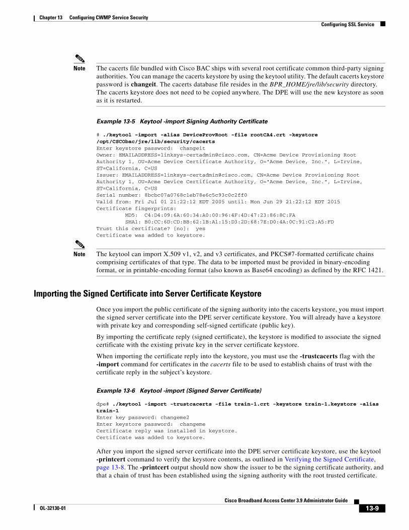
Chapter 13 Configuring CWMP Service SecurityConfiguring SSL Service
Note The cacerts file bundled with Cisco BAC ships with several root certificate common third-party signing authorities. You can manage the cacerts keystore by using the keytool utility. The default cacerts keystore password is changeit. The cacerts database file resides in the BPR_HOME/jre/lib/security directory. The cacerts keystore does not need to be copied anywhere. The DPE will use the new keystore as soon as it is restarted.
Example 13-5 Keytool -import Signing Authority Certificate
# ./keytool -import -alias DeviceProvRoot -file rootCA4.crt -keystore /opt/CSCObac/jre/lib/security/cacertsEnter keystore password: changeitOwner: [email protected], CN=Acme Device Provisioning Root Authority 1, OU=Acme Device Certificate Authority, O="Acme Device, Inc.", L=Irvine, ST=California, C=USIssuer: [email protected], CN=Acme Device Provisioning Root Authority 1, OU=Acme Device Certificate Authority, O="Acme Device, Inc.", L=Irvine, ST=California, C=USSerial number: 8bcbc07a0768c1eb78e6c5c93c0c2ff0Valid from: Fri Jul 01 21:22:12 EDT 2005 until: Mon Jun 29 21:22:12 EDT 2015Certificate fingerprints: MD5: C4:D4:09:6A:60:34:A0:00:96:4F:4D:47:23:86:8C:FA SHA1: B0:CC:6D:CD:BB:62:1B:A1:15:D3:2D:68:7E:D0:4A:0C:91:C2:A5:FDTrust this certificate? [no]: yesCertificate was added to keystore.
Note The keytool can import X.509 v1, v2, and v3 certificates, and PKCS#7-formatted certificate chains comprising certificates of that type. The data to be imported must be provided in binary-encoding format, or in printable-encoding format (also known as Base64 encoding) as defined by the RFC 1421.
Importing the Signed Certificate into Server Certificate Keystore
Once you import the public certificate of the signing authority into the cacerts keystore, you must import the signed server certificate into the DPE server certificate keystore. You will already have a keystore with private key and corresponding self-signed certificate (public key).
By importing the certificate reply (signed certificate), the keystore is modified to associate the signed certificate with the existing private key in the server certificate keystore.
When importing the certificate reply into the keystore, you must use the -trustcacerts flag with the -import command for certificates in the cacerts file to be used to establish chains of trust with the certificate reply in the subject’s keystore.
Example 13-6 Keytool -import (Signed Server Certificate)
dpe# ./keytool -import -trustcacerts -file train-1.crt -keystore train-1.keystore -alias train-1Enter key password: changeme2Enter keystore password: changeme Certificate reply was installed in keystore.Certificate was added to keystore.
After you import the signed server certificate into the DPE server certificate keystore, use the keytool -printcert command to verify the keystore contents, as outlined in Verifying the Signed Certificate, page 13-8. The -printcert output should now show the issuer to be the signing certificate authority, and that a chain of trust has been established using the signing authority with the root trusted certificate.
13-9Cisco Broadband Access Center 3.9 Administrator Guide
OL-32130-01
Chapter 13 Configuring CWMP Service SecurityConfiguring SSL Service
Importing Certificates for Client Authentication
This step is required only if you have configured client authentication by using client certificates on the DPE. If you have enabled client authentication by using client certificates, the cacerts keystore must contain the public certificate of the signing authority that signed the CPE client certificates. This certificate must be present to enable the DPE to validate certificates presented to it.
Example 13-7 Keytool -import (Signing Authority Certificate)
# ./keytool -import -alias DeviceClientRoot -file rootCA3.crt -keystore /opt/CSCObac/jre/lib/security/cacertsEnter keystore password: changeitOwner: [email protected], CN=Acme Device Client Root Authority 1, OU=Acme Device Certificate Authority, O=Acme Device LLC., L=Irvine, ST=California, C=USIssuer: [email protected], CN=Acme Device Client Root Authority 1, OU=Acme Device Certificate Authority, O=Acme Device LLC., L=Irvine, ST=California, C=USSerial number: d07d8a7badba7cb6446998b1ea89879fValid from: Fri Jul 01 21:19:50 EDT 2005 until: Mon Jun 29 21:19:50 EDT 2015Certificate fingerprints: MD5: 40:B0:40:49:37:3A:51:1F:0D:78:B6:B3:E2:2C:1A:E8 SHA1: 96:F5:84:71:84:CC:0A:A2:1E:7B:44:A2:B6:F5:B7:3D:C4:9F:81:3BTrust this certificate? [no]: yesCertificate was added to keystore
Note This procedure is exactly the same as the one described in Importing Signing Authority Certificate into Cacerts Keystore, page 13-8. In both cases, you are loading the public certificate of the signing authority. If the signing authority of the server certificates is the same as the signing authority for the device certificates, you must add the certificate only once.
Providing the DPE with the service-provider keystore
Once you have a new service certificate keystore, which contains the signed public key certificate, you must move the keystore file to the DPE. The file must be moved to the BPR_HOME/dpe/conf directory.
Example 13-8 Move Keystore to DPE Configuration Directory
# mv train-1.keystore /opt/CSCObac/dpe/conf
Once you complete this step, you can configure the DPE services to use the new keystore by using the DPE CLI.
Note You do not need to copy the cacerts keystore anywhere. The DPE will use the new keystore as soon as it is restarted.
For more information, see Configuring Security for DPE Services, page 13-11. For additional information on DPE configuration commands, see the Cisco Broadband Access Center 3.8 DPE CLI Reference.
13-10Cisco Broadband Access Center 3.9 Administrator Guide
OL-32130-01
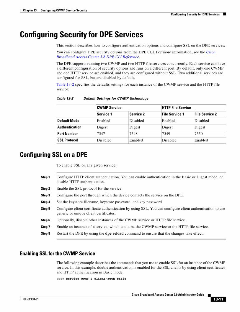
Chapter 13 Configuring CWMP Service SecurityConfiguring Security for DPE Services
Configuring Security for DPE ServicesThis section describes how to configure authentication options and configure SSL on the DPE services.
You can configure DPE security options from the DPE CLI. For more information, see the Cisco Broadband Access Center 3.8 DPE CLI Reference.
The DPE supports running two CWMP and two HTTP file services concurrently. Each service can have a different configuration of security options and runs on a different port. By default, only one CWMP and one HTTP service are enabled, and they are configured without SSL. Two additional services are configured for SSL, but are disabled by default.
Table 13-2 specifies the defaults settings for each instance of the CWMP service and the HTTP file service:
Configuring SSL on a DPETo enable SSL on any given service:
Step 1 Configure HTTP client authentication. You can enable authentication in the Basic or Digest mode, or disable HTTP authentication.
Step 2 Enable the SSL protocol for the service.
Step 3 Configure the port through which the device contacts the service on the DPE.
Step 4 Set the keystore filename, keystore password, and key password.
Step 5 Configure client certificate authentication by using SSL. You can configure client authentication to use generic or unique client certificates.
Step 6 Optionally, disable other instances of the CWMP service or HTTP file service.
Step 7 Enable an instance of a service, which could be the CWMP service or the HTTP file service.
Step 8 Restart the DPE by using the dpe reload command to ensure that the changes take effect.
Enabling SSL for the CWMP Service
The following example describes the commands that you use to enable SSL for an instance of the CWMP service. In this example, double authentication is enabled for the SSL clients by using client certificates and HTTP authentication in Basic mode.
dpe# service cwmp 2 client-auth basic
Table 13-2 Default Settings for CWMP Technology
CWMP Service HTTP File Service
Service 1 Service 2 File Service 1 File Service 2
Default Mode Enabled Disabled Enabled Disabled
Authentication Digest Digest Digest Digest
Port Number 7547 7548 7549 7550
SSL Protocol Disabled Enabled Disabled Enabled
13-11Cisco Broadband Access Center 3.9 Administrator Guide
OL-32130-01
Chapter 13 Configuring CWMP Service SecurityConfiguring Security for DPE Services
% OK (Basic authentication was enabled. Digest authentication was disabled. Requires DPE restart "> dpe reload")
dpe# service cwmp 2 port 7548% OK (Requires DPE restart "> dpe reload")
dpe# service cwmp 2 ssl enable true% OK (Requires DPE restart "> dpe reload")
dpe# service cwmp 2 ssl keystore train-1.keystore changeme changeme2% OK (Requires DPE restart "> dpe reload")
dpe# service cwmp 2 ssl client-auth client-cert-unique% OK (Requires DPE restart "> dpe reload")
dpe# service cwmp 1 enabled false % OK (Requires DPE restart "> dpe reload")
dpe# service cwmp 2 enable true% OK (Requires DPE restart "> dpe reload")
dpe# dpe reloadProcess dpe has been restarted.
% OK
Note This example configures SSL transport on CWMP instance 2. The example assumes that the train-1.keystore is preloaded with the signed public key certificate for the server and that the keystore file was moved to the BPR_HOME/dpe/conf directory on the DPE.
Enabling SSL for the HTTP File Service
The following example describes the commands that you use to enable the SSL protocol for an instance of the HTTP file service. In this example, client authentication is disabled; thus allowing access without an authentication challenge.
dpe# service http 2 client-auth none% OK (Requires DPE restart "> dpe reload")
dpe# service http 2 port 7550% OK (Requires DPE restart "> dpe reload")
dpe# service http 2 ssl enable true% OK (Requires DPE restart "> dpe reload")
dpe# service http 2 ssl keystore train-1.keystore changeme changeme2% OK (Requires DPE restart "> dpe reload")
dpe# service http 2 ssl client-auth none% OK (Requires DPE restart "> dpe reload")
dpe# service http 1 enable false% OK (Requires DPE restart "> dpe reload")
dpe# service http 2 enable true% OK (Requires DPE restart "> dpe reload")
13-12Cisco Broadband Access Center 3.9 Administrator Guide
OL-32130-01
Chapter 13 Configuring CWMP Service SecurityConfiguring Security for DPE Services
dpe# dpe reloadProcess dpe has been restarted.
% OK
Note For detailed information, see the Cisco Broadband Access Center 3.8 DPE CLI Reference.
Configuring CPE AuthenticationCPE authentication is supported through:
• Shared secret by using HTTP Basic or Digest authentication.
• Client certificates by using SSL. You can use certificate-based client authentication in lieu of or in addition to shared secret HTTP-based authentication.
• External client certificate authentication. In this scenario, the SSL connection is terminated at the hardware load balancer, which also authenticates the client.
The objective of authentication is to establish a trusted device ID, which is used to look up device instructions in the DPE cache. This device ID correlates to the device identifier preprovisioned for the device record at the Cisco BAC RDU database. In case of shared secret HTTP-based authentication, the username serves to establish the identity of the device and is treated as a device ID.
In case of authentication using unique client certificates, the device ID is obtained from the device certificate's CN field. With client certificate authentication by an external entity (such as a Cisco ACE 4710 load balancer), the certificate data, including the CN field, is passed to the DPE in the HTTP headers.
You can also choose the option of having no client authentication if clients are trusted. For example, the clients can already be authenticated for network access based on the subscriber physical line. In this case, you can configure Cisco BAC with no-authentication and it will derive the trusted device ID from the Inform message.
You can configure CPE authentication options from the DPE CLI.
Shared Secret Authentication
Cisco BAC supports HTTP authentication based on a shared password between the CPE and the DPE. This authentication is available in two modes: Basic and Digest.
Note To limit security risks during client authentication, Cisco recommends using the Digest mode (the default configuration). You should not allow client authentication in the Basic mode.
13-13Cisco Broadband Access Center 3.9 Administrator Guide
OL-32130-01
Chapter 13 Configuring CWMP Service SecurityConfiguring Security for DPE Services
To configure authentication in the Basic or Digest mode from the DPE CLI, use:
# service {cwmp | http} num client-auth mode
• num—Identifies an instance the service, which could be 1 or 2.
• mode—Identifies the client authentication mode for the service. The client authentication mode could be:
– basic—Enables Basic HTTP authentication.
– digest—Enables Digest HTTP authentication. This is the default configuration.
– none—Disables Basic and Digest authentication.
For detailed information, see the Cisco Broadband Access Center 3.8 DPE CLI Reference.
Changing a Device Password
You can configure the shared secret for the device in Cisco BAC. The shared secret is stored on the device record by using the IPDeviceKeys.CPE_PASSWORD property. The CPE must prove knowledge of this password during HTTP-based authentication.
In the Basic mode, the password is transmitted as encoded clear text, while in the Digest mode, the device is allowed to prove knowledge of the password (shared secret) without transmitting it.
You can configure the password:
• On the API, using the property IPDeviceKeys.CPE_PASSWORD.
• On the administrator user interface, using the CPE Password field in the Devices > Add Device or Modify Device pages.
Note You cannot change the CPE password if the DPE connection to the RDU is not available.
The CPE password is optional if you have enabled client authentication by using SSL and with client certificates.
A distinction should be drawn between changing the password used by Cisco BAC and the password used by the device. When you configure a password on the device record in Cisco BAC, the outcome differs depending on the previous value of the password.
If the password was already set on the device record, Cisco BAC changes it and initiates the process of changing the password on the actual device. However, if the prior password value on the device record did not exist (or was an empty string), Cisco BAC sets the new password on the device record, but does not initiate the change of password on the actual device.
Hence, if you wish to change the password from the existing value to another value only in Cisco BAC, you must first reset the value in Cisco BAC (set it to an empty string) and then set it to a new value.
Figure 13-1 describes the process that Cisco BAC uses to change the password on the actual device. This process is complicated by the fact that Cisco BAC needs to use the old password to authenticate the device first, and then set the new password. Only after the password change is acknowledged can Cisco BAC forget the previous password and remove it from its database.
13-14Cisco Broadband Access Center 3.9 Administrator Guide
OL-32130-01
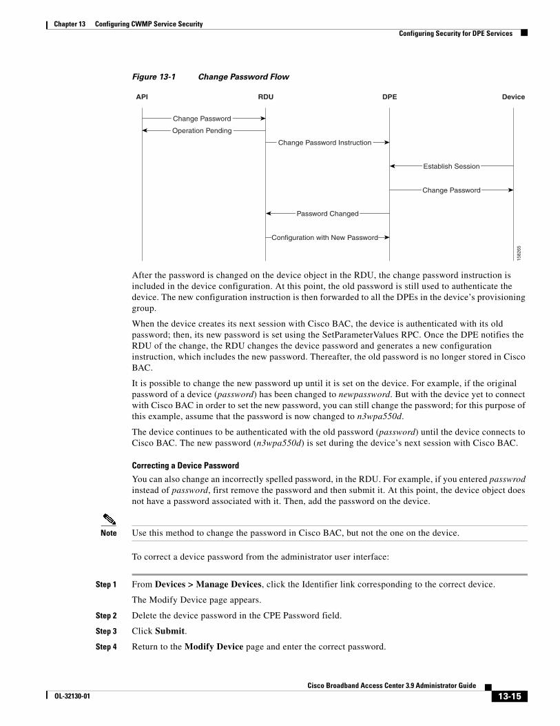
Chapter 13 Configuring CWMP Service SecurityConfiguring Security for DPE Services
Figure 13-1 Change Password Flow
After the password is changed on the device object in the RDU, the change password instruction is included in the device configuration. At this point, the old password is still used to authenticate the device. The new configuration instruction is then forwarded to all the DPEs in the device’s provisioning group.
When the device creates its next session with Cisco BAC, the device is authenticated with its old password; then, its new password is set using the SetParameterValues RPC. Once the DPE notifies the RDU of the change, the RDU changes the device password and generates a new configuration instruction, which includes the new password. Thereafter, the old password is no longer stored in Cisco BAC.
It is possible to change the new password up until it is set on the device. For example, if the original password of a device (password) has been changed to newpassword. But with the device yet to connect with Cisco BAC in order to set the new password, you can still change the password; for this purpose of this example, assume that the password is now changed to n3wpa550d.
The device continues to be authenticated with the old password (password) until the device connects to Cisco BAC. The new password (n3wpa550d) is set during the device’s next session with Cisco BAC.
Correcting a Device Password
You can also change an incorrectly spelled password, in the RDU. For example, if you entered passwrod instead of password, first remove the password and then submit it. At this point, the device object does not have a password associated with it. Then, add the password on the device.
Note Use this method to change the password in Cisco BAC, but not the one on the device.
To correct a device password from the administrator user interface:
Step 1 From Devices > Manage Devices, click the Identifier link corresponding to the correct device.
The Modify Device page appears.
Step 2 Delete the device password in the CPE Password field.
Step 3 Click Submit.
Step 4 Return to the Modify Device page and enter the correct password.
API RDU DPE Device
Change Password
Operation Pending
Configuration with New Password
Password Changed
Change Password
Establish Session
Change Password Instruction
1582
65
13-15Cisco Broadband Access Center 3.9 Administrator Guide
OL-32130-01
Chapter 13 Configuring CWMP Service SecurityConfiguring Security for DPE Services
Step 5 Click Submit.
The password is now changed on the device record in the RDU; no change of password on the actual device is initiated after this procedure.
Client Certificate Authentication
You can configure the DPE to require a validated device-provided certificate for authentication. These certificates could be:
• Generic—Enables device certificate authentication through SSL by using a generic certificate common to all CPE or a large subset of CPE.
• Unique—Enables client certificate authentication through SSL by using the unique certificate that each CPE provides.
If the device certificates are unique, it is not necessary to use HTTP authentication. But if the same certificate is used for all devices (that is, a single device certificate that a service provider uses), you should configure an additional HTTP authentication.
To configure client certification authentication from the DPE CLI, use:
# service {cwmp | http} num ssl client-auth mode
• num—Identifies the instance of the service, which could be 1 or 2. By default, client certificate authentication with SSL is:
– Disabled for service 1.
– Disabled for service 2.
• mode—Identifies the mode of client certificate authentication. Cisco BAC supports:
– client-cert-generic—Uses a certificate common to a set of devices.
– client-cert-unique—Uses a certificate unique to a device.
– client-cert-ext—Uses a load balancer, such as ACE, to validate the client certificate.
– none—Disables client certificate authentication.
External Client Certificate Authentication
An SSL connection can be terminated outside of the DPE, such as at a load balancer. In this case, the DPE may be configured without SSL service.
If a load balancer such as ACE, is used to terminate the SSL connections, the DPE does not receive the unique certificate, making it impossible to identify the device without HTTP authentication (Basic or Digest). To overcome this, the load balancer inserts additional HTTP headers that include the certificate information.
If a single session includes multiple TCP connections, each of the connections will be authenticated (if enabled). The session cookie binds the device to the existing session state.
13-16Cisco Broadband Access Center 3.9 Administrator Guide
OL-32130-01
Chapter 13 Configuring CWMP Service SecurityConfiguring Security for DPE Services
Authentication Options in Cisco BACThis section provides a summary of possible combinations of client-authentication options available in Cisco BAC for the CWMP and the HTTP file services. You can configure each instance of these services separately from the DPE CLI to suit your requirements.
Cisco BAC supports HTTP authentication in the Basic and Digest modes based on a shared password between the CPE and the DPE. If HTTP-based authentication is used, Cisco recommends use of the Digest mode.
You can also configure CPE authentication by using certificates unique to each CPE. In this case, HTTP authentication is not necessary. However, if you configure CPE authentication using generic certificates that are common to all CPE or a large subset of CPE, it is recommended that you configure the DPE to require an additional HTTP authentication.
Table 13-3 lists the various options that Cisco BAC supports and the commands you use to configure authentication from the DPE CLI. For details on each command, see the Cisco Broadband Access Center 3.8 DPE CLI Reference.
Table 13-3 Authentication Options in Cisco BAC
Option Refer to ...
Using HTTP
Enable device authentication by using HTTP in the Basic or Digest mode
service {cwmp | http} num client-auth {basic | digest}
Disable device authentication using HTTP
service {cwmp | http} num client-auth none
Note If device authentication using HTTP is disabled, trusted device identity is formed using the values in the Inform message from the device.
Using SSL
Enable device authentication in HTTP Basic or Digest mode over SSL connection but without client certificate authentication
service {cwmp | http} num client-auth {basic | digest}
service {cwmp | http} num ssl client-auth none
Enable device authentication in HTTP Basic or Digest mode over SSL connection based on unique client certificates
service {cwmp | http} num client-auth {basic | digest}
service {cwmp | http} num ssl client-auth client-cert-unique
Note When you configure the DPE to require HTTP-based (Basic or Digest) and authentication by using unique certificates, the device is authenticated by using both mechanisms. In this double authentication scenario, the device’s unique identifier is formed by using the CN field of the client certificate; thus establishing trusted device ID.
Enable device authentication in HTTP Basic or Digest mode over SSL connection based on generic client certificates
service {cwmp | http} num client-auth {basic | digest}
service {cwmp | http} num ssl client-auth client-cert-generic
13-17Cisco Broadband Access Center 3.9 Administrator Guide
OL-32130-01
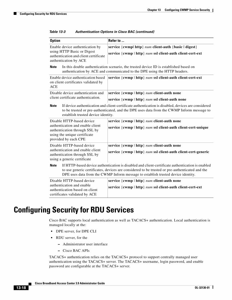
Chapter 13 Configuring CWMP Service SecurityConfiguring Security for RDU Services
Configuring Security for RDU ServicesCisco BAC supports local authentication as well as TACACS+ authentication. Local authentication is managed locally at the:
• DPE server, for DPE CLI
• RDU server, for the
– Administrator user interface
– Cisco BAC APIs
TACACS+ authentication relies on the TACACS+ protocol to support centrally managed user authentication using the TACACS+ server. The TACACS+ username, login password, and enable password are configurable at the TACACS+ server.
Enable device authentication by using HTTP Basic or Digest authentication and client certificate authentication by ACE
service {cwmp| http} num client-auth {basic | digest}
service {cwmp | http} num ssl client-auth client-cert-ext
Note In this double authentication scenario, the trusted device ID is established based on authentication by ACE and communicated to the DPE using the HTTP headers.
Enable device authentication based on client certificates validated by ACE
service {cwmp | http} num ssl client-auth client-cert-ext
Disable device authentication and client certificate authentication.
service {cwmp | http} num client-auth none
service {cwmp | http} num ssl client-auth none
Note If device authentication and client-certificate authentication is disabled, devices are considered to be trusted or pre-authenticated, and the DPE uses data from the CWMP Inform message to establish trusted device identity.
Disable HTTP-based device authentication and enable client authentication through SSL by using the unique certificate provided by each CPE
service {cwmp | http} num client-auth none
service {cwmp | http} num ssl client-auth client-cert-unique
Disable HTTP-based device authentication and enable client authentication through SSL by using a generic certificate
service {cwmp | http} num client-auth none
service {cwmp | http} num ssl client-auth client-cert-generic
Note If HTTP-based device authentication is disabled and client-certificate authentication is enabled to use generic certificates, devices are considered to be trusted or pre-authenticated and the DPE uses data from the CWMP Inform message to establish trusted device identity.
Disable HTTP-based device authentication and enable authentication based on client certificates validated by ACE
service {cwmp | http} num client-auth none
service {cwmp | http} num ssl client-auth client-cert-ext
Table 13-3 Authentication Options in Cisco BAC (continued)
Option Refer to ...
13-18Cisco Broadband Access Center 3.9 Administrator Guide
OL-32130-01
Chapter 13 Configuring CWMP Service SecurityConfiguring Security for RDU Services
You can select one of the authentication modes by using the administrator user interface. Local authentication option is the default.
RDU Authentication Mode SettingsYou can select either local or TACACS+ authentication by using the administrator user interface. To enable TACACS+ authentication:
Step 1 Choose Configuration on either the Primary Navigation bar or Main Menu page.
Step 2 Choose Defaults from the Secondary Navigation bar.
The Configure Defaults page appears.
Step 3 Click TACACS+ Defaults link on the left pane.
The TACACS+ Defaults page appears.
Step 4 Check the TACACS+ Authentication check box.
Step 5 Set the TACACS+ server and encryption key.
You can specify up to maximum of 5 TACACS+ servers. The order of the entries determines the order in which the TACACS+ servers are tried.
Step 6 Set the TACACS+ Client Read/Write timeout.
This is the time that the TACACS+ client waits for a TACACS+ server to reply to TACACS+ protocol requests. The range is from 1 to 300 seconds. The default is 5 seconds and applies to all TACACS+ servers.
Step 7 Set the TACACS+ Client Maximum retries.
This is the number of times that the TACACS+ client attempts a valid TACACS+ protocol exchange with a TACACS+ server if it fails to respond to initial request. The range is from 0 to 10. The default is 1 and applies to all TACACS+ server defined.
Step 8 Click Submit.
TACACS+ Authentication and Authorization in RDU
When TACACS+ authentication is enabled, the client attempts user login authentication to each server sequentially in the list until a successful authentication exchange is executed, or the list is exhausted. If the list is exhausted, the client automatically falls back into the local authentication mode (using the local system password).
After the TACACS+ authentication is done, the user authorization (i.e, user role as Admin, read-write user or read-only user) is retrieved from the RDU database. You can specify the user role (read-write or a read-only) in the Add Users page in the administrator user interface.
13-19Cisco Broadband Access Center 3.9 Administrator Guide
OL-32130-01
Chapter 13 Configuring CWMP Service SecuritySigned Configuration for Devices
Signed Configuration for DevicesCisco BAC uses the Signed Configuration feature to sign a portion of the CPE configuration that is targeted to be passed by the CPE to a third-party, such as an aggregation device. For example, a CPE with Femtocell functionality passes the access control entries to the Femtocell Gateway.
The configuration is signed using a secret key that is shared between Cisco BAC and the Gateway. This Signed Configuration eliminates the need to separately configure the Gateway for each individual CPE. The signature provides proof to the Gateway that the configuration:
• Was generated by Cisco BAC.
• Was not falsified during transmit.
• Is targeted for a specific CPE.
• Is targeted for a specific Gateway.
• Is current.
To prevent replay attacks, the time of the signature generation and its validity period are also incorporated in the signature.
Signature ExpirationCisco BAC is configured with a signature validity period that determines the window during which the device communicates the signed data and signature to the Gateway. If the device communicates the data to the gateway beyond that validity period, the gateway rejects the signature.
The gateway can also be configured to cache configurations beyond their signature validity period, provided the device reconnects to the gateway within a certain interval. This behavior reduces the load of signature regenerations for active devices and allows the device to not persist a security-sensitive signature across reboots.
Signature RegenerationThe DPE generates a new signature and sets it on a device only if:
• The Signed Configuration parameters at the RDU are changed in the data model or in the configuration template.
• The device reports to the DPE that the Gateway rejected the signature for reasons such as invalidity or expiration.
• Device reports to the DPE that it does not have a signature.
Configuration InterfacesYou can enable the Signed Configuration feature in Cisco BAC by configuring the following properties:
• Signature Validity—Specifies the number of seconds for which the signature is considered valid
• Signature Key Name— Indicates the name of the key that is used by the gateway to look up the shared secret key. You must change the signature key name when the secret key is changed.
• Secret Key—Specifies the secret that is used to compute the signature.
13-20Cisco Broadband Access Center 3.9 Administrator Guide
OL-32130-01
Chapter 13 Configuring CWMP Service SecuritySigned Configuration for Devices
These properties can be configured using the CWMP Defaults page in the administrator user interface or by using the IPDevice.changeDefaults API.
You must also create a configuration template for the device. To generate the Signed Configuration, at least one parameter in the template must be flagged to be signed. You can flag any TR069 parameter to be signed.
For example:
<Parameter><Name>MyParameter</Name><Value>Sample Value</Value><ToBeSigned>true</ToBeSigned></Parameter>
Depending on the target Gateway, there can be a minimum set of required parameters that must be specified as signed. Here is a sample CWMP configuration template:
<tc:Template...<configuration><ParameterDictionaries>
<ParameterDictionary>femto-cwmp-dictionary.xml</ParameterDictionary></ParameterDictionaries><ObjectInstance name=”Device”>
<ObjectInstance name=”Services”><ObjectInstance name=”X_00000C_FAPService”>
<ObjectInstance name=”AccessControl”><Parameter>
<Name>ACL</Name><Value>VAR(name=FC-ACL, defaultValue=””)</Value><ToBeSigned>true</ToBeSigned>
</Parameter></ObjectInstance>
<ObjectInstance name=”FGW”><Parameter>
<Name>Fqdn</Name><Value>VAR(name=FC-FGW-FQDN, defaultValue=””)</Value><ToBeSigned>true</ToBeSigned>
</Parameter></ObjectInstance>
</ObjectInstance></ObjectInstance>
Monitoring the Signed Configuration Feature You can monitor the Signed Configuration feature in Cisco BAC from the administrator user interface or DPE CLI. You have the following options:
• Choose Configuration > Files. Click the View icon ( ) corresponding to the Configuration Template to view the configuration parameters that are designated to be signed.
• From the Devices > Manage Devices page, click the View Details icon ( ) corresponding to the device. The following device faults are reported in the Device Details page:
– Signature rejected by the gateway because the validity period has expired.
– Signature rejected by the gateway because of an unknown secret key name
– Signed data rejected by the gateway because it is missing required parameters
13-21Cisco Broadband Access Center 3.9 Administrator Guide
OL-32130-01
Chapter 13 Configuring CWMP Service SecurityCustom Vendor Specific Attribute (VSA) in RADIUS Response
– Incompatible device. Template contains parameters designated for signing, but the device does not report any expected support for the Signed Configuration feature
• To get basic information about the Signed Configuration process, enable the INFO logging level on the RDU and the DPEs. At this level of logging, the following are logged:
– Changes in the Signed Configuration (in rdu.log)
– Details on the generation and setting of a new signature on a device (in dpe.log)
– Indications of signature rejection by the device (in dpe.log)
• You can use the debug on and debug service cwmp num cpe-signed-config-sync commands to obtain the low-level tracing information in addition to the INFO level logging.
Troubleshooting Signed Configuration Feature
When a device is placed in troubleshooting mode, all logging and debugging level details associated with Signature Generation are incorporated into the device troubleshooting log file. To view the device troubleshooting log file, see Viewing Device Troubleshooting Log, page 8-12.
You can use the perfstat.log to view statistics on the number of times that the DPE:
• Generates and sets the signature on a device.
• Receives signature faults from a device.
Custom Vendor Specific Attribute (VSA) in RADIUS ResponseIf custom vendor specific attribute (VSA) - in the form of VSA Index and VSA Name - is present in the Cisco Prime Access Registrar (PAR) server, this can be included in the RADIUS response. This is included in the authenticate requests by BAC DPE, which is also pushed to the Home-Node B (HNB) gateway as a response.
Adding Custom VSA
Note The process of adding custom VSA in PAR server should be done as part of maintenance activity and this should not be part of BAC running system. This is because adding custom VSA requires restart of the PAR server.
To add custom VSA, run the script addCustomVSA.sh in the server where PAR and PAR_EP is installed:
1. In the PAR (and PAR_EP) server, go to /opt/CSCObac/car_ep/bin
2. Run the script <BPR_HOME>/car_ep/bin/addCustomVSA.sh, and enter the corresponding values at the following prompts:
– Enter VSA Name – Unique name for the VSA, and only letters [A-Z] and dashes [-] are allowed
– Enter VSA Index – Unique index for the VSA
– Enter Property Format – Depends on the VSA type also (STRING, INTEGER, or BYTE_ARRAY). See Property Format Based on Type, page 13-23.
– Enter VSA Type – STRING, INTEGER, or BYTE_ARRAY
13-22Cisco Broadband Access Center 3.9 Administrator Guide
OL-32130-01
Chapter 13 Configuring CWMP Service SecurityCustom Vendor Specific Attribute (VSA) in RADIUS Response
3. Restart the PAR server:
/etc/init.d/arserver restart
Property Format Based on Type
Any device property can be included to construct the property of the VSA. But, the format to construct the property of the VSA depends on the data type of the VSA.
STRING
For STRING type, the device property format should contain the property name within '${' and '}' and can have any other string literals outside '${' and '}'. The value of this data type ranges between 0 and 253.
For example, if the property format is specified as ${FC-MNC}-${FC-MCC}, and if FC-MNC = sid09869 and FC-MCC = etr123, then the value of corresponding VSA will be:
VSA Name = sid09869-etr123
INTEGER
For INTEGER type, the device property format should contain only one property. The value of this data type ranges between 0 and 4294967295.
For example, if the property format is specified as FC-MNC, and if FC-MNC = 253, then the value of corresponding VSA will be:
VSA Name = 253
BYTE_ARRAY
For BYTE_ARRAY type, the device property format should contain only one property. The value of this data type ranges between 0 and 253.
For example, if the property format is specified as FC-MNC, and if FC-MNC = f8:08:13:40:01:23:04:08:01:f6:08:13:40:01:22:04:18:21:f7:08:13:40, then the value of corresponding VSA will be:
VSA Name = f8:08:13:40:01:23:04:08:01:f6:08:13:40:01:22:04:18:21:f7:08:13:40
Note If the VSA Name is defined with an invalid data type or if the data type is empty, then the data type is defaulted to STRING.
Note If invalid values are configured for the Property Format, or if an empty string is configured for the Property Format, the Custom VSA value will be 0 (zero) for INTEGER type, and empty for STRING and BYTE_ARRAY types.
13-23Cisco Broadband Access Center 3.9 Administrator Guide
OL-32130-01

Chapter 13 Configuring CWMP Service SecurityCustom Vendor Specific Attribute (VSA) in RADIUS Response
13-24Cisco Broadband Access Center 3.9 Administrator Guide
OL-32130-01
CiscoOL-32130-01
C H A P T E R 14
CWMP Device OperationsThis chapter describes the device operations mechanism in Cisco Broadband Access Center (BAC). By using this mechanism, you can run CPE WAN Management Protocol (CWMP) remote procedure calls for a device and perform maintenance tasks, such as changing a device’s provisioning group.
This chapter includes the following sections:
• Overview, page 14-1
• Connection Modes for Device Operations, page 14-2
• Managing a Device’s Provisioning Group, page 14-6
OverviewYou use device operations to run individual CWMP remote procedure calls (RPCs) against a device immediately, or the next time the device connects to Cisco BAC. By using this feature from the provisioning API, you can troubleshoot, collect data, or customize the interaction between a device and Cisco BAC.
Device operations are submitted in a batch by using the IPDevice.performOperation() API call. For details, refer to the API Javadoc which is available at BPR_HOME/docs/nb-api/javadoc.
You can perform some operations from the administrator user interface. This section is focused on describing the concepts behind device operations, regardless of whether they are initiated using the API or the administrator user interface.
During a Cisco BAC installation, several sample files are copied to the BPR_HOME/rdu/samples directory, which contains:
• The cwmp directory, which features *parameter-list.xml files that describe parameter lists used to retrieve live device data by using the administrator user interface.
• The nb-api directory, which features CwmpDiagnosticImmediateExample.java and CwmpDiagnosticOnConnectExample.java files that describe how you can perform device operations by using the API.
The device operations supported in this Cisco BAC release are listed in Table 14-1.
Table 14-1 Device Operations Supported in Cisco BAC
Operation Name Description
CreateObjectInstance Creates object instances within a device’s data model
DeleteObjectInstance Deletes objects from a device’s data model
14-1 Broadband Access Center 3.9 Administrator Guide
Chapter 14 CWMP Device OperationsConnection Modes for Device Operations
All device operations are executed before other configuration services, such as data synchronization, configuration synchronization, and firmware rules download.
Caution You should not perform device configuration updates using device operations. The configuration process can overwrite any settings that you configured by using device operations.
Connection Modes for Device OperationsCisco BAC enables the performing of device operations in three modes:
• Immediate
• On-connect
• Asynchronous
Immediate ModeAn immediate execution assumes that the device is reachable and is performed by the DPE first issuing a connection request to the device. If the device is not reachable, the operations automatically fail. You can run multiple operations in the same batch to improve performance, creating a single connection request and, thus, a single management session with the CWMP device.
A client uses a timeout period to post the API batch in immediate mode. If no timeout is set, the duration for immediate operations to time out is, by default, 60 seconds. If a device operation times out or its batch times out, an error is returned.
Download Instructs the device to perform a file download
FactoryReset Resets a device’s settings to its factory default state
Reboot Instructs the device to reboot
GetParamAttributes Retrieves attributes for a device’s parameters
GetParamNames Retrieves names of parameters exposed by a device
GetParamValues Retrieves parameter values from a device’s parameter space
GetRPCMethods Retrieves a device’s list of supported RPC methods
SetParamAttributes Sets the value of device parameter attributes, such as Notification and Access List
SetParamValues Sets the value of device parameters
ChangeProvGroup Redirects a device to a new provisioning group
GenerateConfig Regenerates the instruction set for a device
PassThrough Sends a generic SOAP message to the device
RemoveOperation Removes a pending on-connect device operation
RequestConnection Initiates a connection request to a device
Table 14-1 Device Operations Supported in Cisco BAC (continued)
Operation Name Description
14-2Cisco Broadband Access Center 3.9 Administrator Guide
OL-32130-01
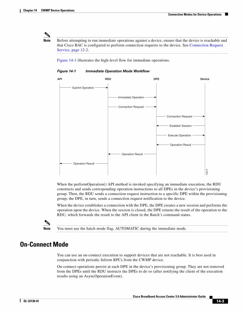
Chapter 14 CWMP Device OperationsConnection Modes for Device Operations
Note Before attempting to run immediate operations against a device, ensure that the device is reachable and that Cisco BAC is configured to perform connection requests to the device. See Connection Request Service, page 12-2.
Figure 14-1 illustrates the high-level flow for immediate operations.
Figure 14-1 Immediate Operation Mode Workflow
When the performOperation() API method is invoked specifying an immediate execution, the RDU constructs and sends corresponding operation instructions to all DPEs in the device’s provisioning group. Then, the RDU sends a connection request instruction to a specific DPE within the provisioning group; the DPE, in turn, sends a connection request notification to the device.
When the device establishes a connection with the DPE, the DPE creates a new session and performs the operation upon the device. When the session is closed, the DPE returns the result of the operation to the RDU, which forwards the result to the API client in the Batch’s command status.
Note You must use the batch mode flag, AUTOMATIC during the immediate mode.
On-Connect ModeYou can use an on-connect execution to support devices that are not reachable. It is best used in conjunction with periodic Inform RPCs from the CWMP device.
On-connect operations persist at each DPE in the device’s provisioning group. They are not removed from the DPEs until the RDU instructs the DPEs to do so (after notifying the client of the execution results using an AsyncOperationEvent).
API RDU DPE Device
Submit Operation
Establish Session
Immediate Operation
Connection Request
Connection Request
Operation Result
Execute Operation
Operation Result
Operation Result
1582
73
14-3Cisco Broadband Access Center 3.9 Administrator Guide
OL-32130-01
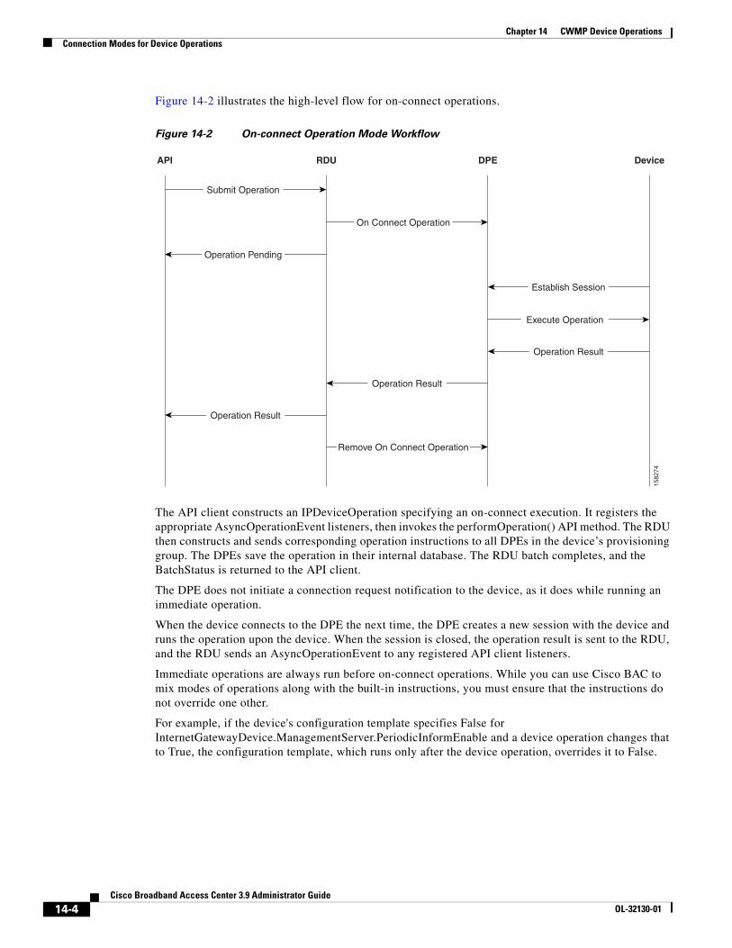
Chapter 14 CWMP Device OperationsConnection Modes for Device Operations
Figure 14-2 illustrates the high-level flow for on-connect operations.
Figure 14-2 On-connect Operation Mode Workflow
The API client constructs an IPDeviceOperation specifying an on-connect execution. It registers the appropriate AsyncOperationEvent listeners, then invokes the performOperation() API method. The RDU then constructs and sends corresponding operation instructions to all DPEs in the device’s provisioning group. The DPEs save the operation in their internal database. The RDU batch completes, and the BatchStatus is returned to the API client.
The DPE does not initiate a connection request notification to the device, as it does while running an immediate operation.
When the device connects to the DPE the next time, the DPE creates a new session with the device and runs the operation upon the device. When the session is closed, the operation result is sent to the RDU, and the RDU sends an AsyncOperationEvent to any registered API client listeners.
Immediate operations are always run before on-connect operations. While you can use Cisco BAC to mix modes of operations along with the built-in instructions, you must ensure that the instructions do not override one other.
For example, if the device's configuration template specifies False for InternetGatewayDevice.ManagementServer.PeriodicInformEnable and a device operation changes that to True, the configuration template, which runs only after the device operation, overrides it to False.
API RDU DPE Device
Submit Operation
Operation Pending
Establish Session
On Connect Operation
Operation Result
Execute Operation
Remove On Connect Operation
Operation Result
Operation Result
1582
74
14-4Cisco Broadband Access Center 3.9 Administrator Guide
OL-32130-01
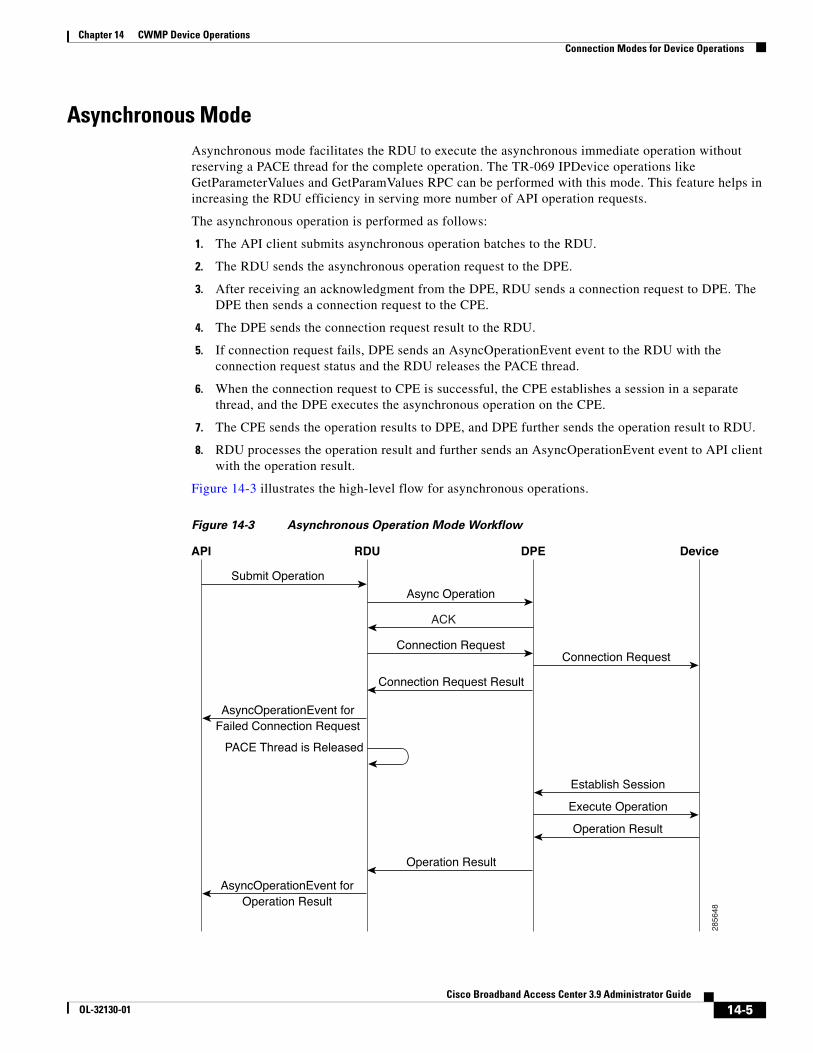
Chapter 14 CWMP Device OperationsConnection Modes for Device Operations
Asynchronous ModeAsynchronous mode facilitates the RDU to execute the asynchronous immediate operation without reserving a PACE thread for the complete operation. The TR-069 IPDevice operations like GetParameterValues and GetParamValues RPC can be performed with this mode. This feature helps in increasing the RDU efficiency in serving more number of API operation requests.
The asynchronous operation is performed as follows:
1. The API client submits asynchronous operation batches to the RDU.
2. The RDU sends the asynchronous operation request to the DPE.
3. After receiving an acknowledgment from the DPE, RDU sends a connection request to DPE. The DPE then sends a connection request to the CPE.
4. The DPE sends the connection request result to the RDU.
5. If connection request fails, DPE sends an AsyncOperationEvent event to the RDU with the connection request status and the RDU releases the PACE thread.
6. When the connection request to CPE is successful, the CPE establishes a session in a separate thread, and the DPE executes the asynchronous operation on the CPE.
7. The CPE sends the operation results to DPE, and DPE further sends the operation result to RDU.
8. RDU processes the operation result and further sends an AsyncOperationEvent event to API client with the operation result.
Figure 14-3 illustrates the high-level flow for asynchronous operations.
Figure 14-3 Asynchronous Operation Mode Workflow
Submit Operation
Async Operation
Connection RequestConnection Request
Connection Request Result
Operation Result
Establish Session
Execute Operation
ACK
AsyncOperationEvent forFailed Connection Request
AsyncOperationEvent forOperation Result
PACE Thread is Released
Operation Result
2856
48
API RDU DPE Device
14-5Cisco Broadband Access Center 3.9 Administrator Guide
OL-32130-01
Chapter 14 CWMP Device OperationsManaging a Device’s Provisioning Group
Note You must use the batch mode flag, ASYNC_AUTOMATIC during the asynchronous operation mode.
The API command Configuration.getRDUDetails() is enhanced to report statistics of the following asynchronous operations:
• Total number of asynchronous operation requests received by the RDU.
• Total number of asynchronous operation succeeded.
• Total number of asynchronous operation failed.
• Minimum time taken for asynchronous operation.
• Maximum time taken for asynchronous operation.
• Average time taken for asynchronous operation.
• Total time taken for all asynchronous operations.
• Total number of asynchronous immediate operations failed due to acknowledgment failed from DPE.
• Total number of asynchronous operations failed due to DPE server not found in Provisioning Group.
• Total number of asynchronous operations failed due to connection request error.
• Total number of asynchronous operations failed due to connection request failed.
• Total number of connection request succeeded for asynchronous operations requests.
Conditional ExecutionAdditionally, immediate and on-connect operations are conditionally executed based on the TR-069 Event Codes in the Inform message from the device. If no intersection occurs between the reported Event Codes in the device’s Inform and the list of Event Codes specified in the operation, the operation is not executed.
For example, an operation might be conditional upon the Inform Event Code list including 6 CONNECTION REQUEST. Therefore, the operation only executes if the device reports it is connecting because of an autoconfiguration server (ACS) connection request. If the device reports it is connecting for any other reason, for instance a periodic Inform, the operation does not execute.
Managing a Device’s Provisioning GroupThe provisioning group for a CWMP device is specified on the device object in the RDU. On the:
• Provisioning API, through the IPDeviceKeys.HOME_PROV_GROUP property.
• Administrator user interface, through the Home Provisioning Group drop-down list in the Devices pages.
In managing a device’s provisioning group, occasionally, you might need to redirect or correct the provisioning group of a device:
• Redirecting CPE to Home Provisioning Group, page 14-7.
In this scenario, the device communicates with a specific provisioning group, for example PG1, and you want to redirect it to communicate with its home provisioning group, PG2.
14-6Cisco Broadband Access Center 3.9 Administrator Guide
OL-32130-01
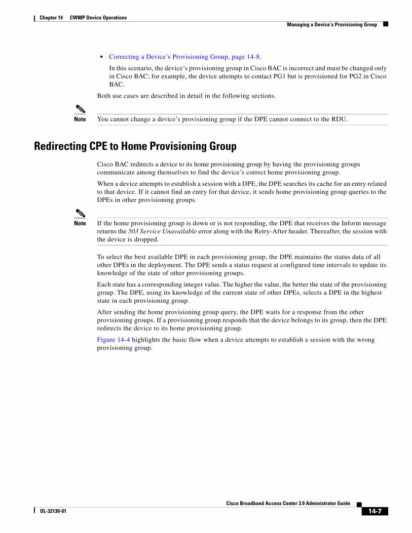
Chapter 14 CWMP Device OperationsManaging a Device’s Provisioning Group
• Correcting a Device’s Provisioning Group, page 14-8.
In this scenario, the device’s provisioning group in Cisco BAC is incorrect and must be changed only in Cisco BAC; for example, the device attempts to contact PG1 but is provisioned for PG2 in Cisco BAC.
Both use cases are described in detail in the following sections.
Note You cannot change a device’s provisioning group if the DPE cannot connect to the RDU.
Redirecting CPE to Home Provisioning GroupCisco BAC redirects a device to its home provisioning group by having the provisioning groups communicate among themselves to find the device’s correct home provisioning group.
When a device attempts to establish a session with a DPE, the DPE searches its cache for an entry related to that device. If it cannot find an entry for that device, it sends home provisioning group queries to the DPEs in other provisioning groups.
Note If the home provisioning group is down or is not responding, the DPE that receives the Inform message returns the 503 Service Unavailable error along with the Retry-After header. Thereafter, the session with the device is dropped.
To select the best available DPE in each provisioning group, the DPE maintains the status data of all other DPEs in the deployment. The DPE sends a status request at configured time intervals to update its knowledge of the state of other provisioning groups.
Each state has a corresponding integer value. The higher the value, the better the state of the provisioning group. The DPE, using its knowledge of the current state of other DPEs, selects a DPE in the highest state in each provisioning group.
After sending the home provisioning group query, the DPE waits for a response from the other provisioning groups. If a provisioning group responds that the device belongs to its group, then the DPE redirects the device to its home provisioning group.
Figure 14-4 highlights the basic flow when a device attempts to establish a session with the wrong provisioning group.
14-7Cisco Broadband Access Center 3.9 Administrator Guide
OL-32130-01
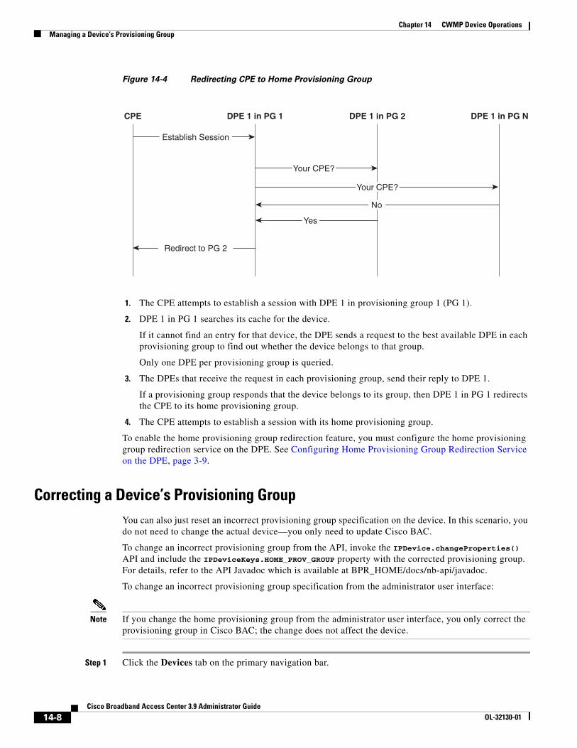
Chapter 14 CWMP Device OperationsManaging a Device’s Provisioning Group
Figure 14-4 Redirecting CPE to Home Provisioning Group
1. The CPE attempts to establish a session with DPE 1 in provisioning group 1 (PG 1).
2. DPE 1 in PG 1 searches its cache for the device.
If it cannot find an entry for that device, the DPE sends a request to the best available DPE in each provisioning group to find out whether the device belongs to that group.
Only one DPE per provisioning group is queried.
3. The DPEs that receive the request in each provisioning group, send their reply to DPE 1.
If a provisioning group responds that the device belongs to its group, then DPE 1 in PG 1 redirects the CPE to its home provisioning group.
4. The CPE attempts to establish a session with its home provisioning group.
To enable the home provisioning group redirection feature, you must configure the home provisioning group redirection service on the DPE. See Configuring Home Provisioning Group Redirection Service on the DPE, page 3-9.
Correcting a Device’s Provisioning GroupYou can also just reset an incorrect provisioning group specification on the device. In this scenario, you do not need to change the actual device—you only need to update Cisco BAC.
To change an incorrect provisioning group from the API, invoke the IPDevice.changeProperties() API and include the IPDeviceKeys.HOME_PROV_GROUP property with the corrected provisioning group. For details, refer to the API Javadoc which is available at BPR_HOME/docs/nb-api/javadoc.
To change an incorrect provisioning group specification from the administrator user interface:
Note If you change the home provisioning group from the administrator user interface, you only correct the provisioning group in Cisco BAC; the change does not affect the device.
Step 1 Click the Devices tab on the primary navigation bar.
CPE DPE 1 in PG 1 DPE 1 in PG 2 DPE 1 in PG N
Establish Session
Redirect to PG 2
No
Yes
Your CPE?
Your CPE?
14-8Cisco Broadband Access Center 3.9 Administrator Guide
OL-32130-01

Chapter 14 CWMP Device OperationsManaging a Device’s Provisioning Group
The Manage Devices page appears.
Step 2 Click the Identifier link corresponding to the correct device.
Step 3 Select your options from the Home Provisioning Group drop-down list.
Step 4 Click Submit to save the changes to the device.
The device is now assigned to a specific provisioning group.
14-9Cisco Broadband Access Center 3.9 Administrator Guide
OL-32130-01

Chapter 14 CWMP Device OperationsManaging a Device’s Provisioning Group
14-10Cisco Broadband Access Center 3.9 Administrator Guide
OL-32130-01
CiscoOL-32130-01
C H A P T E R 15
Understanding the Administrator User InterfaceThis chapter describes how to access the Cisco Broadband Access Center (BAC) administrator user interface and explains the interface.
This chapter includes the following sections:
• Configuring the Administrator User Interface, page 15-1
• Accessing the Administrator User Interface, page 15-2
• Understanding the Administrator User Interface Icons, page 15-4
Using the Administrator User Interface, page 16-1, explains how to use the user interface to perform administrative activities. In addition, the Cisco Broadband Access Center 3.8 DPE CLI Reference, contains descriptions of the CLI commands used to access, monitor, and control the Device Provisioning Engines (DPEs).
Configuring the Administrator User InterfaceWhen you install the RDU, the installation program also installs the administrator user interface. The administrator user interface starts by default, when the RDU is installed.
Before you use the administrator user interface, examine the adminui.properties file. This file contains a variety of controls that specify the behavior of the interface.
You can open this file by using any text editor, and change its content to perform the functions that you want. After your changes are complete and saved, restart the user interface so that all the changes to take effect.
To start the administrator user interface, enter:
# etc/init.d/bprAgent tomcat start
To stop the administrator user interface, enter:
# etc/init.d/bprAgent tomcat stop
You can configure the user interface by using the options available in the adminui.properties file. These options are controlled by Cisco BAC settings or defined in the adminui.properties file in the BPR_HOME/rdu/conf directory.
The configuration parameters are:
• /adminui/port—Specifies the listening port of the RDU. This port number is, by default, 49187.
• /adminui/fqdn—Specifies the fully qualified domain name of the host on which the RDU is running. This value is, by default, the FQDN of the host; for example, bac_test.ACME.COM.
15-1 Broadband Access Center 3.9 Administrator Guide
Chapter 15 Understanding the Administrator User InterfaceAccessing the Administrator User Interface
• /adminui/maxReturned—Specifies the maximum number of search results. This number is, by default, 1000.
• /adminui/pageSize—Specifies the number of search results displayed per page. You can set this number at 25, 50, or 75. The default value is 25.
• /adminui/refresh—Specifies if the refresh function is enabled or disabled. This option is, by default, disabled.
• /adminui/extensions—Specifies if the use of extensions in Cisco BAC is enabled or disabled. You use extensions to augment Cisco BAC behavior or add support for new device technologies. The use of extensions is, by default, enabled.
• /adminui/maxFileSize—Specifies the maximum size of a file uploaded to Cisco BAC. This file size is, by default, 10 MB.
• /adminui/refreshRate—Specifies the duration (in seconds) after which a screen is refreshed. This value is, by default, 90 seconds. Before setting a value for this option, ensure that the /adminu/refresh option is enabled.
• /adminui/timeout—Specifies the duration (in minutes) after which an idle session is timed out. This period is, by default, set as 300 minutes.
• /adminui/noOfLines—Specifies the last number of lines from the rdu.log or the dpe.log that will be displayed on the user interface. The number of lines that appear, by default, is 250.
• /adminui/noOfFiles—Specifies the number of troubleshooting log files that you can view. The number of files you can view is, by default, 1. The maximum number of files that you can view at a given time is 5.
Example 15-1 Sample adminui.properties File
/adminui/port=49187/adminui/fqdn=doc.cisco.com/adminui/maxReturned=1000/adminui/pageSize=25/adminui/refresh=disabled/adminui/extensions=enabled/adminui/maxFileSize=10000000/adminui/refreshRate=90/adminui/timeout=300/adminui/noOfLines=250/adminui/noOfFiles=1
Accessing the Administrator User InterfaceYou can access the administrator user interface from any computer that can access the URL corresponding to the Cisco BAC application.
Logging InYou can log into the user interface as an Administrative user, a Read/Write user, or a Read-Only user. Although each user type has different capabilities, as described in User Management, page 16-1, you access the user interface in the same way.
15-2Cisco Broadband Access Center 3.9 Administrator Guide
OL-32130-01
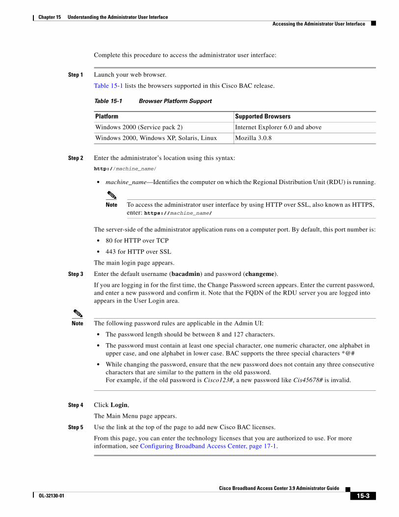
Chapter 15 Understanding the Administrator User InterfaceAccessing the Administrator User Interface
Complete this procedure to access the administrator user interface:
Step 1 Launch your web browser.
Table 15-1 lists the browsers supported in this Cisco BAC release.
Step 2 Enter the administrator’s location using this syntax:
http://machine_name/
• machine_name—Identifies the computer on which the Regional Distribution Unit (RDU) is running.
Note To access the administrator user interface by using HTTP over SSL, also known as HTTPS, enter: https://machine_name/
The server-side of the administrator application runs on a computer port. By default, this port number is:
• 80 for HTTP over TCP
• 443 for HTTP over SSL
The main login page appears.
Step 3 Enter the default username (bacadmin) and password (changeme).
If you are logging in for the first time, the Change Password screen appears. Enter the current password, and enter a new password and confirm it. Note that the FQDN of the RDU server you are logged into appears in the User Login area.
Note The following password rules are applicable in the Admin UI:
• The password length should be between 8 and 127 characters.
• The password must contain at least one special character, one numeric character, one alphabet in upper case, and one alphabet in lower case. BAC supports the three special characters *@#
• While changing the password, ensure that the new password does not contain any three consecutive characters that are similar to the pattern in the old password.For example, if the old password is Cisco123#, a new password like Cis45678# is invalid.
Step 4 Click Login,
The Main Menu page appears.
Step 5 Use the link at the top of the page to add new Cisco BAC licenses.
From this page, you can enter the technology licenses that you are authorized to use. For more information, see Configuring Broadband Access Center, page 17-1.
Table 15-1 Browser Platform Support
Platform Supported Browsers
Windows 2000 (Service pack 2) Internet Explorer 6.0 and above
Windows 2000, Windows XP, Solaris, Linux Mozilla 3.0.8
15-3Cisco Broadband Access Center 3.9 Administrator Guide
OL-32130-01
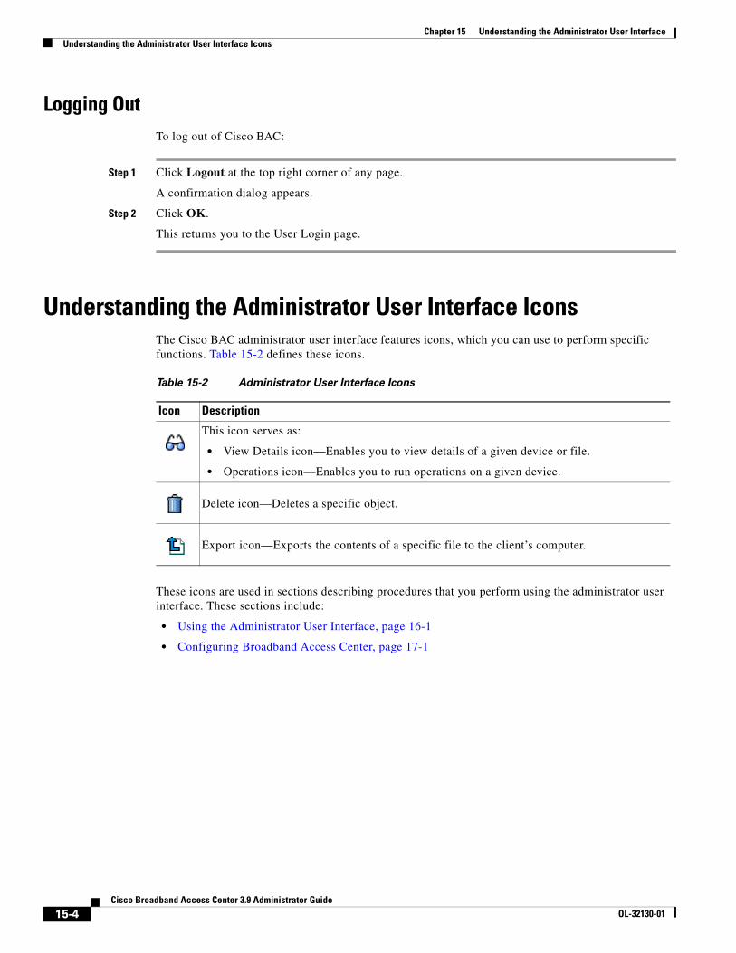
Chapter 15 Understanding the Administrator User InterfaceUnderstanding the Administrator User Interface Icons
Logging OutTo log out of Cisco BAC:
Step 1 Click Logout at the top right corner of any page.
A confirmation dialog appears.
Step 2 Click OK.
This returns you to the User Login page.
Understanding the Administrator User Interface IconsThe Cisco BAC administrator user interface features icons, which you can use to perform specific functions. Table 15-2 defines these icons.
These icons are used in sections describing procedures that you perform using the administrator user interface. These sections include:
• Using the Administrator User Interface, page 16-1
• Configuring Broadband Access Center, page 17-1
Table 15-2 Administrator User Interface Icons
Icon Description
This icon serves as:
• View Details icon—Enables you to view details of a given device or file.
• Operations icon—Enables you to run operations on a given device.
Delete icon—Deletes a specific object.
Export icon—Exports the contents of a specific file to the client’s computer.
15-4Cisco Broadband Access Center 3.9 Administrator Guide
OL-32130-01
CiscoOL-32130-01
C H A P T E R 16
Using the Administrator User InterfaceThis chapter describes the administration tasks performed from the Cisco Broadband Access Center (BAC) administrator user interface. These tasks mainly involve monitoring the actions of various Cisco BAC components.
This chapter includes the following sections:
• User Management, page 16-1
• Device Management, page 16-4
• Group Management, page 16-18
• Viewing Servers, page 16-22
Note The procedures described in this chapter are presented in a tutorial manner. Wherever possible, examples are included to illustrate the possible results of each procedure.For details on server configurations, see Configuring Broadband Access Center, page 17-1.
User ManagementManaging users involves adding, modifying, and deleting users who administer Cisco BAC. Depending on your user type, you can use this menu to add, modify, and delete users. This menu displays all users configured to use Cisco BAC and identifies their user types.
There are three types of Cisco BAC users: an Administrator, a Read/Write user, and a Read-Only user. Each has different levels of access, with unique permissions to ensure access control and the integrity of provisioning data.
The assigned user type appears near the top right corner of every screen on the administrator user interface.
AdministratorCisco BAC recognizes only one administrator and allows this user to view, add, modify, delete device data, and create other users. As an Administrator, you can also change other users’ permissions from Read/Write to Read Only, and vice-versa. In addition, you have the ability to change the passwords of any other user type.
You cannot delete the “Administrator” user.
16-1 Broadband Access Center 3.9 Administrator Guide
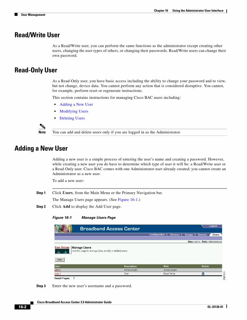
Chapter 16 Using the Administrator User InterfaceUser Management
Read/Write UserAs a Read/Write user, you can perform the same functions as the administrator except creating other users, changing the user types of others, or changing their passwords. Read/Write users can change their own password.
Read-Only UserAs a Read-Only user, you have basic access including the ability to change your password and to view, but not change, device data. You cannot perform any action that is considered disruptive. You cannot, for example, perform reset or regenerate instructions.
This section contains instructions for managing Cisco BAC users including:
• Adding a New User
• Modifying Users
• Deleting Users
Note You can add and delete users only if you are logged in as the Administrator.
Adding a New UserAdding a new user is a simple process of entering the user’s name and creating a password. However, while creating a new user you do have to determine which type of user it will be: a Read/Write user or a Read-Only user. Cisco BAC comes with one Administrator user already created; you cannot create an Administrator as a new user.
To add a new user:
Step 1 Click Users, from the Main Menu or the Primary Navigation bar.
The Manage Users page appears. (See Figure 16-1.)
Step 2 Click Add to display the Add User page.
Figure 16-1 Manage Users Page
Step 3 Enter the new user’s username and a password.
16-2Cisco Broadband Access Center 3.9 Administrator Guide
OL-32130-01
Chapter 16 Using the Administrator User InterfaceUser Management
Note The following password rules are applicable for user management:
• The password length should be between 8 and 127 characters.
• The password must contain at least one special character, one numeric character, one alphabet in upper case, and one alphabet in lower case. BAC supports the five special characters (*,@#
• While changing the password, ensure that the new password does not contain any three consecutive characters that are similar to the pattern in the old password.For example, if the old password is Cisco123#, a new password like Cis45678# is invalid.
Step 4 Confirm the new user’s password, and select whether the new user’s role is to be read only or read/write. See User Management, page 16-1, for complete descriptions of each user type.
Step 5 Enter a short description of the new user.
Tip Use the description field to identify the user’s job or position, something that identifies the unique aspects of the new user.
Step 6 Click Submit.
The Manage Users page appears with the new user added.
Note The new user’s password must be recorded and stored in a safe place. This helps prevent loss or theft of the password and possible unauthorized entry.
The users can later change their passwords, wherein they need to enter the current password, and enter a new password and confirm it.
Modifying UsersAlthough any user type can modify their password and user description, only the administrator can modify any other user’s information.
To modify user properties:
Step 1 From the Main Menu or the Primary Navigation bar, click Users.
The Manage User page appears.
Step 2 Click the correct user name to display the Modify User page for that user.
Step 3 Make the necessary changes to the password, user type (provided that you are logged in as the Administrator), and the user’s description.
Step 4 Click Submit.
The Manage Users page appears with the modified user information.
16-3Cisco Broadband Access Center 3.9 Administrator Guide
OL-32130-01
Chapter 16 Using the Administrator User InterfaceDevice Management
Deleting UsersOnly the administrator can delete any other user that appears in the Manage Users page. You cannot delete the default user, called bacadmin.
To delete a user:
Step 1 From the Main menu or the Primary Navigation bar, click Users.
The Manage User page appears.
Step 2 Click the Delete icon ( ) corresponding to the user you want to delete.
Step 3 The Delete User dialog box appears. Click OK.
The Manage Users page appears without the deleted user.
Device ManagementUse the Devices menu to provision and manage TR-069 and TR-196 enabled devices. You can:
• Search for a specific device or for a group of devices that share criteria that you specify. See Searching for Devices, page 16-5.
• Add, modify, or delete devices in the RDU database. See:
– Adding Device Records, page 16-11
– Deleting Device Records, page 16-11
• View device data, such as configuration, properties, discovered data, and faults. See Viewing Device Details, page 16-7.
• Regenerate device instructions. See Regenerating Device Instructions, page 16-12.
• Relate and unrelate any device to a specific group. See Relating and Unrelating Devices, page 16-13.
• Enable device troubleshooting. See Configuring Device Troubleshooting, page 8-10.
• Perform various operations, such as an IP Ping, and live data retrieval, on the device to gain more insight. See Performing Operations on Devices, page 16-14.
Manage Devices PageThe Manage Devices page appears when you click Devices on the Main menu or the Primary Navigation bar. This page, shown in Figure 16-2, contains the fields and controls necessary to perform all device management functions.
16-4Cisco Broadband Access Center 3.9 Administrator Guide
OL-32130-01
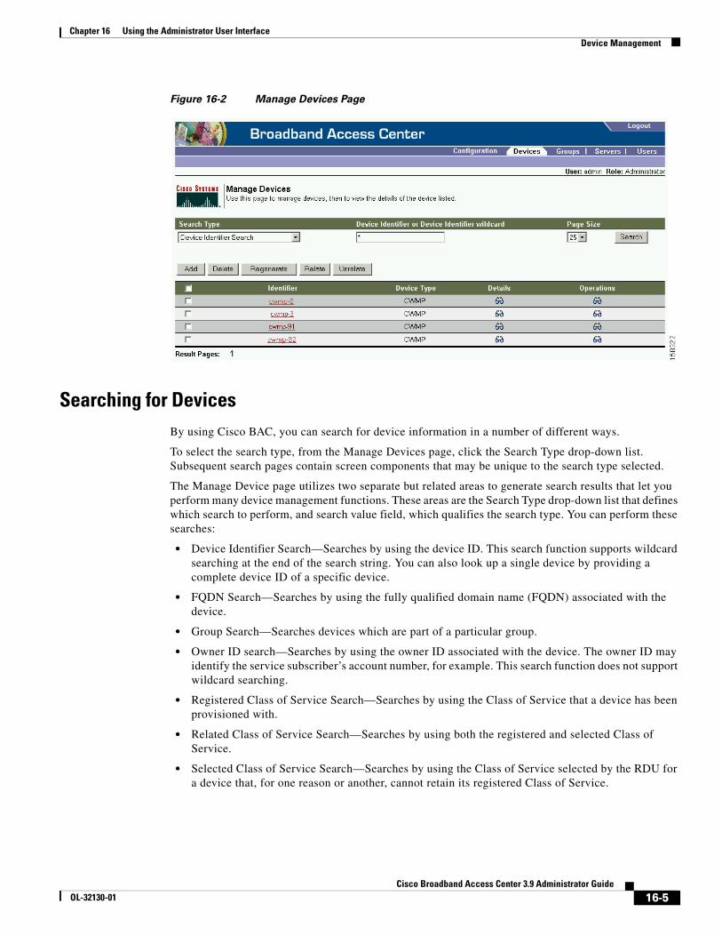
Chapter 16 Using the Administrator User InterfaceDevice Management
Figure 16-2 Manage Devices Page
Searching for DevicesBy using Cisco BAC, you can search for device information in a number of different ways.
To select the search type, from the Manage Devices page, click the Search Type drop-down list. Subsequent search pages contain screen components that may be unique to the search type selected.
The Manage Device page utilizes two separate but related areas to generate search results that let you perform many device management functions. These areas are the Search Type drop-down list that defines which search to perform, and search value field, which qualifies the search type. You can perform these searches:
• Device Identifier Search—Searches by using the device ID. This search function supports wildcard searching at the end of the search string. You can also look up a single device by providing a complete device ID of a specific device.
• FQDN Search—Searches by using the fully qualified domain name (FQDN) associated with the device.
• Group Search—Searches devices which are part of a particular group.
• Owner ID search—Searches by using the owner ID associated with the device. The owner ID may identify the service subscriber’s account number, for example. This search function does not support wildcard searching.
• Registered Class of Service Search—Searches by using the Class of Service that a device has been provisioned with.
• Related Class of Service Search—Searches by using both the registered and selected Class of Service.
• Selected Class of Service Search—Searches by using the Class of Service selected by the RDU for a device that, for one reason or another, cannot retain its registered Class of Service.
16-5Cisco Broadband Access Center 3.9 Administrator Guide
OL-32130-01
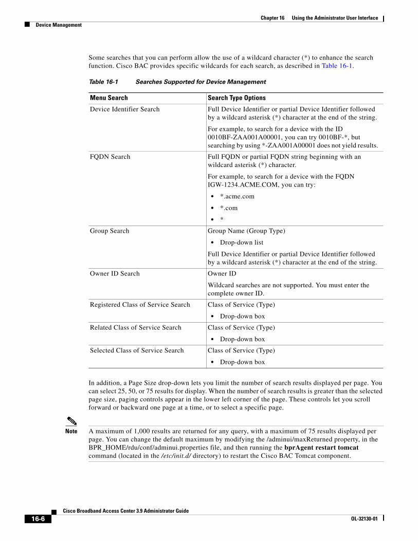
Chapter 16 Using the Administrator User InterfaceDevice Management
Some searches that you can perform allow the use of a wildcard character (*) to enhance the search function. Cisco BAC provides specific wildcards for each search, as described in Table 16-1.
In addition, a Page Size drop-down lets you limit the number of search results displayed per page. You can select 25, 50, or 75 results for display. When the number of search results is greater than the selected page size, paging controls appear in the lower left corner of the page. These controls let you scroll forward or backward one page at a time, or to select a specific page.
Note A maximum of 1,000 results are returned for any query, with a maximum of 75 results displayed per page. You can change the default maximum by modifying the /adminui/maxReturned property, in the BPR_HOME/rdu/conf/adminui.properties file, and then running the bprAgent restart tomcat command (located in the /etc/init.d/ directory) to restart the Cisco BAC Tomcat component.
Table 16-1 Searches Supported for Device Management
Menu Search Search Type Options
Device Identifier Search Full Device Identifier or partial Device Identifier followed by a wildcard asterisk (*) character at the end of the string.
For example, to search for a device with the ID 0010BF-ZAA001A00001, you can try 0010BF-*, but searching by using *-ZAA001A00001 does not yield results.
FQDN Search Full FQDN or partial FQDN string beginning with an wildcard asterisk (*) character.
For example, to search for a device with the FQDN IGW-1234.ACME.COM, you can try:
• *.acme.com
• *.com
• *
Group Search Group Name (Group Type)
• Drop-down list
Full Device Identifier or partial Device Identifier followed by a wildcard asterisk (*) character at the end of the string.
Owner ID Search Owner ID
Wildcard searches are not supported. You must enter the complete owner ID.
Registered Class of Service Search Class of Service (Type)
• Drop-down box
Related Class of Service Search Class of Service (Type)
• Drop-down box
Selected Class of Service Search Class of Service (Type)
• Drop-down box
16-6Cisco Broadband Access Center 3.9 Administrator Guide
OL-32130-01
Chapter 16 Using the Administrator User InterfaceDevice Management
Device Management ControlsThese buttons are located directly below the search function fields and are generally used in conjunction with the search function. For example, you might search for devices belonging to a specific group of devices in order to perform some sort of management function. The following buttons are available, although each management function may not be available depending on the search type used.
Add
The Add button lets you add a new device to the RDU database. See Adding Device Records, page 16-11, for the appropriate instructions.
Delete
The Delete button lets you delete any selected device(s) from the RDU database. See Deleting Device Records, page 16-11, for the appropriate instructions.
Regenerate
Use the Regenerate button to force immediate regeneration of instructions for selected device(s).
Relate
The Relate button lets you associate a device (by using its Device ID) with a specific group (referred to as Node in the API).
Unrelate
The Unrelate button cancels the relationship between a selected device and the group that the device is currently related to.
Searching for devices returns results under the following headings or links that appear on the page:
Identifier
Identifies all devices matching the search criteria. Each of the identifiers displayed has a link to another page from which you can modify the device.
Device Type
Displays the available device type; in this case, CWMP.
Details
Displays all available details for the selected device. See Viewing Device Details, page 16-7, for additional information.
Operations
Displays a drop-down list of available device operations. See Performing Operations on Devices, page 16-14, for additional information.
Viewing Device Details
You can view the details of any device identified in the search results.
To view any device details, click the View Details icon ( ) corresponding to the device you want to view, and the Device Details page appears.
16-7Cisco Broadband Access Center 3.9 Administrator Guide
OL-32130-01
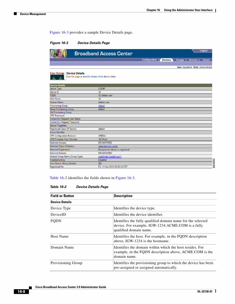
Chapter 16 Using the Administrator User InterfaceDevice Management
Figure 16-3 provides a sample Device Details page.
Figure 16-3 Device Details Page
Table 16-2 identifies the fields shown in Figure 16-3.
Table 16-2 Device Details Page
Field or Button Description
Device Details
Device Type Identifies the device type.
DeviceID Identifies the device identifier.
FQDN Identifies the fully qualified domain name for the selected device. For example, IGW-1234.ACME.COM is a fully qualified domain name.
Host Name Identifies the host. For example, in the FQDN description above, IGW-1234 is the hostname.
Domain Name Identifies the domain within which the host resides. For example, in the FQDN description above, ACME.COM is the domain name.
Provisioning Group Identifies the provisioning group to which the device has been pre-assigned or assigned automatically.
16-8Cisco Broadband Access Center 3.9 Administrator Guide
OL-32130-01
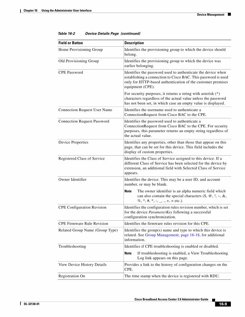
Chapter 16 Using the Administrator User InterfaceDevice Management
Home Provisioning Group Identifies the provisioning group to which the device should belong.
Old Provisioning Group Identifies the provisioning group to which the device was earlier belonging.
CPE Password Identifies the password used to authenticate the device when establishing a connection to Cisco BAC. This password is used only for HTTP-based authentication of the customer premises equipment (CPE).
For security purposes, it returns a string with asterisk (*) characters regardless of the actual value unless the password has not been set, in which case an empty value is displayed.
Connection Request User Name Identifies the username used to authenticate a ConnectionRequest from Cisco BAC to the CPE.
Connection Request Password Identifies the password used to authenticate a ConnectionRequest from Cisco BAC to the CPE. For security purposes, this parameter returns an empty string regardless of the actual value.
Device Properties Identifies any properties, other than those that appear on this page, that can be set for this device. This field includes the display of custom properties.
Registered Class of Service Identifies the Class of Service assigned to this device. If a different Class of Service has been selected for the device by extension, an additional field with Selected Class of Service appears.
Owner Identifier Identifies the device. This may be a user ID, and account number, or may be blank.
Note The owner identifier is an alpha numeric field which can also contain the special characters ($, @, !, ~, &, %, ^, #, *, -, _, ., +, = etc.).
CPE Configuration Revision Identifies the configuration rules revision number, which is set for the device ParameterKey following a successful configuration synchronization.
CPE Firmware Rule Revision Identifies the firmware rules revision for this CPE.
Related Group Name (Group Type) Identifies the group(s) name and type to which this device is related. See Group Management, page 16-18, for additional information.
Troubleshooting Identifies if CPE troubleshooting is enabled or disabled.
Note If troubleshooting is enabled, a View Troubleshooting Log link appears on this page.
View Device History Details Provides a link to the history of configuration changes on the CPE.
Registration On The time stamp when the device is registered with RDU.
Table 16-2 Device Details Page (continued)
Field or Button Description
16-9Cisco Broadband Access Center 3.9 Administrator Guide
OL-32130-01
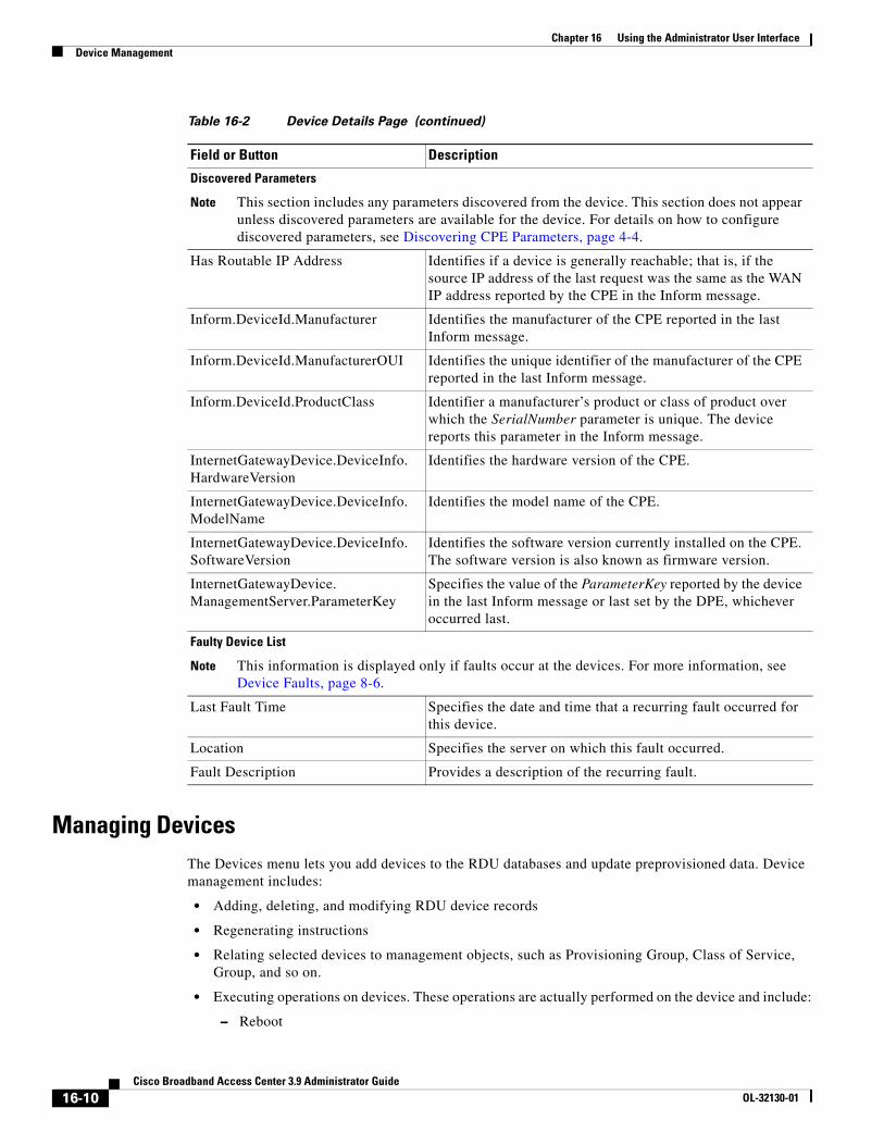
Chapter 16 Using the Administrator User InterfaceDevice Management
Managing DevicesThe Devices menu lets you add devices to the RDU databases and update preprovisioned data. Device management includes:
• Adding, deleting, and modifying RDU device records
• Regenerating instructions
• Relating selected devices to management objects, such as Provisioning Group, Class of Service, Group, and so on.
• Executing operations on devices. These operations are actually performed on the device and include:
– Reboot
Discovered Parameters
Note This section includes any parameters discovered from the device. This section does not appear unless discovered parameters are available for the device. For details on how to configure discovered parameters, see Discovering CPE Parameters, page 4-4.
Has Routable IP Address Identifies if a device is generally reachable; that is, if the source IP address of the last request was the same as the WAN IP address reported by the CPE in the Inform message.
Inform.DeviceId.Manufacturer Identifies the manufacturer of the CPE reported in the last Inform message.
Inform.DeviceId.ManufacturerOUI Identifies the unique identifier of the manufacturer of the CPE reported in the last Inform message.
Inform.DeviceId.ProductClass Identifier a manufacturer’s product or class of product over which the SerialNumber parameter is unique. The device reports this parameter in the Inform message.
InternetGatewayDevice.DeviceInfo.HardwareVersion
Identifies the hardware version of the CPE.
InternetGatewayDevice.DeviceInfo.ModelName
Identifies the model name of the CPE.
InternetGatewayDevice.DeviceInfo.SoftwareVersion
Identifies the software version currently installed on the CPE. The software version is also known as firmware version.
InternetGatewayDevice.ManagementServer.ParameterKey
Specifies the value of the ParameterKey reported by the device in the last Inform message or last set by the DPE, whichever occurred last.
Faulty Device List
Note This information is displayed only if faults occur at the devices. For more information, see Device Faults, page 8-6.
Last Fault Time Specifies the date and time that a recurring fault occurred for this device.
Location Specifies the server on which this fault occurred.
Fault Description Provides a description of the recurring fault.
Table 16-2 Device Details Page (continued)
Field or Button Description
16-10Cisco Broadband Access Center 3.9 Administrator Guide
OL-32130-01
Chapter 16 Using the Administrator User InterfaceDevice Management
– Request Connection
– Factory Reset
– Display Live Data
– Ping Diagnostic
– Force Firmware Upgrade
– Force Configuration Synchronization
For detailed information on these operations, see Performing Operations on Devices, page 16-14.
This section describes how to perform the various device management functions on new or existing devices.
Adding Device Records
To add a device record:
Step 1 From the Manage Devices page, click Add.
The Add Device page appears.
Step 2 Choose the device type and Class of Service, and complete the other fields on the page.
Step 3 In addition to the fields described earlier in this section, you can optionally add new values for existing property name/value pairs.
• Property Name—Identifies the name of the custom or built-in device property.
• Property Value—Identifies the value of the property.
To add the property, click Add.
Step 4 Click Submit to add the device, or Reset to clear all fields.
Modifying Device Records
To modify a device record:
Step 1 From the Manage Devices page, click the Identifier link corresponding to the correct device.
The Modify Device page appears.
Step 2 Enter the data in the correct field. You can modify any existing property name/value pairs by clicking Add, or delete any of them by clicking the Delete button.
Step 3 Click Submit to save the changes made to this device, or Reset to clear all fields.
Deleting Device Records
Deleting device records is a simple process, but one that you should use carefully. To undo the delete, you must restore a previously backed up database or re-add the device.
16-11Cisco Broadband Access Center 3.9 Administrator Guide
OL-32130-01
Chapter 16 Using the Administrator User InterfaceDevice Management
Note See Database Restore, page 10-6, for additional information if restoration of a backed-up database becomes necessary.
To delete a device record:
Step 1 From the Manage Devices page, locate the device that you want to delete. You can use one of the search types for this purpose.
Step 2 Select the check box associated with the correct device.
Step 3 Click Delete.
The device record stored in the RDU database is removed.
Viewing Device History
To view the history of a device configuration:
Step 1 From the Manage Devices page, locate the device whose history you want to view. You can use one of the search types for this purpose.
Step 2 Click the View Details icon corresponding to the device.
The Device Details page appears.
Step 3 Against View Device History Details, click the View Details icon.
The Device History Details page appears.
Regenerating Device Instructions
The Regenerate button or API operation force immediate regeneration of instructions for the device. These instructions are sent to the DPEs in the device's provisioning group. Normally, the process of regenerating the instruction is automatically triggered following changes to device, Class of Service, or other such impacting changes.
However, after a change to a Class of Service, the system takes time to regenerate instructions for all devices. This button can be used to expedite regeneration of instructions for a given device. This may be desirable during proactive troubleshooting.
Device instructions are automatically regenerated whenever:
• A file related to a Class of Service, that is, a template, is updated.
• The default Class of Service for a device type is changed.
• The provisioning group object is changed using the administrator user interface or the API.
• The Class of Service object properties are changed.
• The DPE sends a configuration regeneration request to the RDU.
• The device properties or relationship is updated.
16-12Cisco Broadband Access Center 3.9 Administrator Guide
OL-32130-01
Chapter 16 Using the Administrator User InterfaceDevice Management
Some instructions cannot be automatically regenerated because the Cisco BAC system cannot determine if the change impacts device instructions. In such cases, you must manually regenerate instructions by using the generationConfiguration() method or the administrator user interface. Instructions that must be manually regenerated are those that become necessary whenever:
• A technology default is changed.
• The system defaults are changed.
Note Regardless of how instructions are regenerated, they are not propagated to the devices until the device configuration is activated, that is, the device contacts the DPE either on schedule or as a result of a connection request initiated from the DPE.
Relating and Unrelating Devices
You can define any number of arbitrary groups. The Relate function lets you associate a device to a specific group, which is in turn associated with a specific group type.
Relating a Device to a Group
Note You can relate devices to groups only one by one using the administrator user interface.
To relate a device to a group:
Step 1 From the Manage Devices page, locate the device which you want to relate to a group. You can use one of the search types for this purpose.
Step 2 Check the check box corresponding to the device Identifier, and click the Relate button.
The Relate Device to Group(s) page appears.
Step 3 Select the Group Type from the drop-down list and the Group(s) from the list of defined groups.
Note To select multiple groups from the Group list, press Control or Shift.
Step 4 Click Submit.
The Manage Devices page appears.
To verify whether the device has been added to the group, click the View Details icon corresponding to the device. On the Device Details page that appears, check the status against Related Group Name (Group Type).
Unrelating a Device from a Group
Note You can relate devices to groups only one by one, using the administrator user interface.
To unrelate a device to a group:
16-13Cisco Broadband Access Center 3.9 Administrator Guide
OL-32130-01
Chapter 16 Using the Administrator User InterfaceDevice Management
Step 1 From the Manage Devices page, locate the device which you want to unrelate from a group.
Step 2 Check the check box corresponding to the device Identifier, and click the Unrelate button.
The Unrelate Device from Group page appears.
Step 3 From the list of defined Group(s), select the group(s) from which you want to unrelate the device.
Note To select multiple groups from the Group list, press Control or Shift.
Step 4 Click Submit.
The Manage Devices page appears.
Searching Devices in a Group
To search for devices belonging to a particular group:
Step 1 From the Manage Devices page, select the Group Search option from the drop-down list under Search Type.
The Group Name (Group Type) and the Device Identifier options appear.
Step 2 From the Group Name (Group Type) drop-down list, select the Group Name of the devices that you want to search.
Step 3 Enter a device ID in the Device Identifier field, or use a wildcard (*).
Step 4 Click Search.
The devices related to the group appears.
Performing Operations on Devices
You can perform the following functions from the Device Operations page:
• Reboot—Enables you to reboot the device. This operation is primarily intended for diagnostic purposes.
• Request Connection—Instructs the device to establish a CWMP session with Cisco BAC.
• Factory Reset—Enables you to reset a preregistered device settings to its original factory settings.
• Display Live Data—Enables you to view live device parameter values.
You can choose the parameters that you want to view for this device operation by selecting from the options under the Parameter List File drop-down box. Each parameter list is an XML file that details the parameters each file will return; click the View Details icon to view the parameters.
You can also define the parameters that you want to be retrieved in parameter lists. Cisco BAC provides a sample list of live data templates which specify various parameters to be read during a view live data query.
• Ping Diagnostic—Enables you to perform an IP ping diagnostics test from the device to any host.
16-14Cisco Broadband Access Center 3.9 Administrator Guide
OL-32130-01
Chapter 16 Using the Administrator User InterfaceDevice Management
Note For all of the above operations, if the device is not reachable, an error message appears.
• Force Firmware Upgrade—Enables you to force a device to update its firmware on next contact regardless of the MaintenanceWindow restrictions set in the firmware rules.
• Force Configuration Synchronization—Enables you to force an individual device to synchronize its configuration regardless of the current configuration version on the device.
Note The operations forcing a firmware upgrade or a configuration synchronization take effect on the next device contact with the autoconfiguration server (ACS).
Performing a Reboot
To reboot the device:
Step 1 From the Devices > Manage Devices page, locate the correct device.
Step 2 Click the Operations icon ( ) corresponding to the device.
The Device Operations page appears.
Step 3 From the drop-down list under Device Operation, select Reboot.
Step 4 Click Submit.
Performing a Request Connection
To force the device to initiate a connection request:
Step 1 From the Devices > Manage Devices page, locate the correct device.
Step 2 Click the Operations icon corresponding to the device.
The Device Operations page appears.
Step 3 From the drop-down list under Device Operation, select Request Connection.
Step 4 Click Submit.
16-15Cisco Broadband Access Center 3.9 Administrator Guide
OL-32130-01
Chapter 16 Using the Administrator User InterfaceDevice Management
Performing a Factory Reset
To reset device settings to its original factory settings:
Step 1 From the Devices > Manage Devices page, locate the correct device.
Step 2 Click the Operations icon corresponding to the device.
The Device Operations page appears.
Step 3 From the drop-down list under Device Operation, select Factory Reset.
Step 4 Click Submit.
Displaying Live Data
To display parameters from a device:
Step 1 From the Devices > Manage Devices page, locate the correct device.
Step 2 Click the Operations icon corresponding to the device.
The Device Operations page appears.
Step 3 From the drop-down list under Device Operation, select Display Live Data.
Step 4 Enter a duration in seconds for the operation to time out. The default timeout is 90 seconds.
Step 5 From the Parameter List File drop-down list, select the file, each of which is an XML file that details the parameters that are returned.
Step 6 Click on the View Details icon to view the parameters.
Note You can also view these sample templates under the Configuration > Files tabs. From the View Files page, select the Parameter List option under the File Type drop-down list. Click Search. A list of sample parameter list files appears.
Step 7 Click Submit.
Note If the device is not reachable, an error message appears.
Performing a Ping Diagnostic
To perform a ping operation to a device by using its IP address:
Step 1 From the Devices > Manage Devices page, locate the correct device.
Step 2 Click the Operations icon corresponding to the device.
The Device Operations page appears.
Step 3 From the drop-down list under Device Operation, select Ping Diagnostic.
Step 4 Enter values in the following fields:
16-16Cisco Broadband Access Center 3.9 Administrator Guide
OL-32130-01
Chapter 16 Using the Administrator User InterfaceDevice Management
• Device operation timeout (in seconds)—Specifies the duration after which the Ping operation times out.
• Name of the hostname to be pinged—Identifies the hostname of the CPE to be pinged.
• Interface—Identifies the WAN interface from which the Ping should originate on the CPE.
• Number of repetitions—Specifies the number of times the Ping operation should run.
• Time out—Specifies the timeout for the Ping packet.
• Data block size—Specifies the size of each Ping packet.
• DSCP—Specifies the DSCP value in each Ping packet.
Step 5 Click Submit.
Forcing a Firmware Upgrade
To force a firmware upgrade on a device on next contact and bypassing the MaintenanceWindow restrictions set in the firmware rules:
Step 1 From the Devices > Manage Devices page, locate the device whose configuration you want to synchronize.
Step 2 Click the Operations icon corresponding to the device.
The Device Operations page appears.
Step 3 From the drop-down list under Perform Device Operation, select Force Firmware Upgrade.
Step 4 Click Submit.
Forcing a Configuration Synchronization
To force a device to synchronize its configuration on next contact with the DPE regardless of the current configuration version on the device:
Step 1 From the Devices > Manage Devices page, locate the device whose configuration you want to synchronize.
Step 2 Click the Operations icon corresponding to the device.
The Device Operations page appears.
Step 3 From the drop-down list under Perform Device Operation, select Force Configuration Synchronization.
Step 4 Click Submit.
The device configuration is synchronized with the DPE.
16-17Cisco Broadband Access Center 3.9 Administrator Guide
OL-32130-01
Chapter 16 Using the Administrator User InterfaceGroup Management
Setting Device Operations Timeout
You can set the duration within which an operation is to be executed on device. After that period, the operation times out.
Note In addition to the procedure described in this section, you can set the default timeout duration in the Device Operation Timeout field using Configuration > Defaults > CWMP Defaults.
To set the timeout value for a device operation:
Step 1 From the Devices > Manage Devices page, locate the correct device.
Step 2 Click the Operations icon corresponding to the device.
The Device Operations page appears.
Step 3 From the drop-down list under Device Operation, select the operation you want to perform.
Step 4 Enter a value (in seconds) in the Device Operation Timeout field. The default value for a device operation to time out is 90 seconds.
Step 5 Click Submit.
Group ManagementGroup management allows the creation, modification, and deletion of groups and group types.
Note Group priorities in the property hierarchy (see Property Hierarchy, page 4-4) are handled through group types.
Managing Group TypesAccess the Manage Groups page (shown in Figure 16-4) by selecting Groups from either the main menu or the primary menu bar. Group Type is the default setting when this page appears.
16-18Cisco Broadband Access Center 3.9 Administrator Guide
OL-32130-01
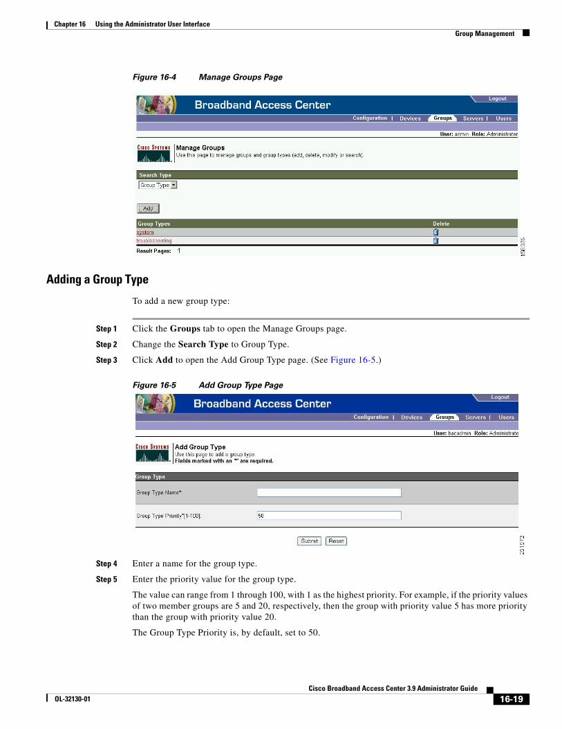
Chapter 16 Using the Administrator User InterfaceGroup Management
Figure 16-4 Manage Groups Page
Adding a Group Type
To add a new group type:
Step 1 Click the Groups tab to open the Manage Groups page.
Step 2 Change the Search Type to Group Type.
Step 3 Click Add to open the Add Group Type page. (See Figure 16-5.)
Figure 16-5 Add Group Type Page
Step 4 Enter a name for the group type.
Step 5 Enter the priority value for the group type.
The value can range from 1 through 100, with 1 as the highest priority. For example, if the priority values of two member groups are 5 and 20, respectively, then the group with priority value 5 has more priority than the group with priority value 20.
The Group Type Priority is, by default, set to 50.
16-19Cisco Broadband Access Center 3.9 Administrator Guide
OL-32130-01
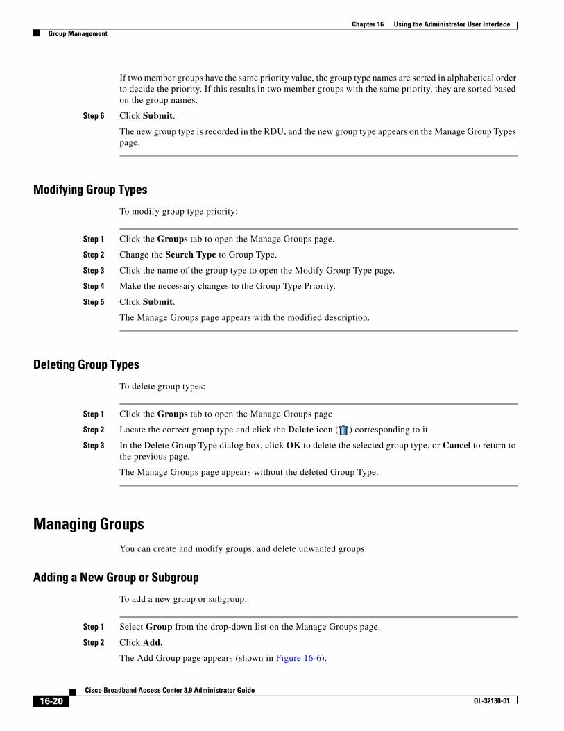
Chapter 16 Using the Administrator User InterfaceGroup Management
If two member groups have the same priority value, the group type names are sorted in alphabetical order to decide the priority. If this results in two member groups with the same priority, they are sorted based on the group names.
Step 6 Click Submit.
The new group type is recorded in the RDU, and the new group type appears on the Manage Group Types page.
Modifying Group Types
To modify group type priority:
Step 1 Click the Groups tab to open the Manage Groups page.
Step 2 Change the Search Type to Group Type.
Step 3 Click the name of the group type to open the Modify Group Type page.
Step 4 Make the necessary changes to the Group Type Priority.
Step 5 Click Submit.
The Manage Groups page appears with the modified description.
Deleting Group Types
To delete group types:
Step 1 Click the Groups tab to open the Manage Groups page
Step 2 Locate the correct group type and click the Delete icon ( ) corresponding to it.
Step 3 In the Delete Group Type dialog box, click OK to delete the selected group type, or Cancel to return to the previous page.
The Manage Groups page appears without the deleted Group Type.
Managing GroupsYou can create and modify groups, and delete unwanted groups.
Adding a New Group or Subgroup
To add a new group or subgroup:
Step 1 Select Group from the drop-down list on the Manage Groups page.
Step 2 Click Add.
The Add Group page appears (shown in Figure 16-6).
16-20Cisco Broadband Access Center 3.9 Administrator Guide
OL-32130-01
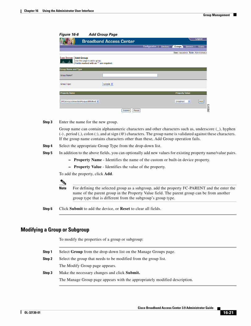
Chapter 16 Using the Administrator User InterfaceGroup Management
Figure 16-6 Add Group Page
Step 3 Enter the name for the new group.
Group name can contain alphanumeric characters and other characters such as, underscore (_), hyphen (-) , period (.), colon (:), and at sign (@) characters. The group name is validated against these characters. If the group name contains characters other than these, Add Group operation fails.
Step 4 Select the appropriate Group Type from the drop-down list.
Step 5 In addition to the above fields, you can optionally add new values for existing property name/value pairs.
– Property Name - Identifies the name of the custom or built-in device property.
– Property Value - Identifies the value of the property.
To add the property, click Add.
Note For defining the selected group as a subgroup, add the property FC-PARENT and the enter the name of the parent group in the Property Value field. The parent group can be from another group type that is different from the subgroup’s group type.
Step 6 Click Submit to add the device, or Reset to clear all fields.
Modifying a Group or Subgroup
To modify the properties of a group or subgroup:
Step 1 Select Group from the drop-down list on the Manage Groups page.
Step 2 Select the group that needs to be modified from the group list.
The Modify Group page appears.
Step 3 Make the necessary changes and click Submit.
The Manage Group page appears with the appropriately modified description.
16-21Cisco Broadband Access Center 3.9 Administrator Guide
OL-32130-01
Chapter 16 Using the Administrator User InterfaceViewing Servers
Deleting Groups or Subgroups
You can delete any group that appears in the Manage Groups page by checking the box corresponding to the correct group and clicking the Delete button.
Relating/Unrelating Groups to Groups
The relate and unrelate functions are used to establish a relationship between group objects. To either relate or unrelate this relationship:
Step 1 Click Relate or Unrelate, as desired, for the selected group.
The Relate Group or the Unrelate Group page appears.
Step 2 Select the appropriate Group Type from the drop-down list and select the group to which the node will be related/unrelated.
Step 3 Click Submit.
The Manage Groups page appears.
Viewing Group Details
To view details of a group:
Step 1 From the Manage Groups page, select the Group option from the Search Type drop-down list.
Step 2 Select the correct Group Type and enter the Group or Group wildcard in the appropriate field.
Step 3 Click Search.
Step 4 Click the link corresponding to the Group whose details you want to view.
The Modify Group page appears, with details of the Group Name and Group Type.
Viewing ServersThis section describes the Cisco BAC server pages:
• Viewing Device Provisioning Engines, page 16-22
• Viewing Provisioning Groups, page 16-26
• Viewing Regional Distribution Unit Details, page 16-27
Viewing Device Provisioning EnginesThe Manage Device Provisioning Engines page lets you monitor the list of all DPEs currently registered with the Cisco BAC database. Each DPE name displayed on this page is a link to another page that shows the details for that DPE. Click this link to display the details page, which is similar to Figure 16-7.
16-22Cisco Broadband Access Center 3.9 Administrator Guide
OL-32130-01
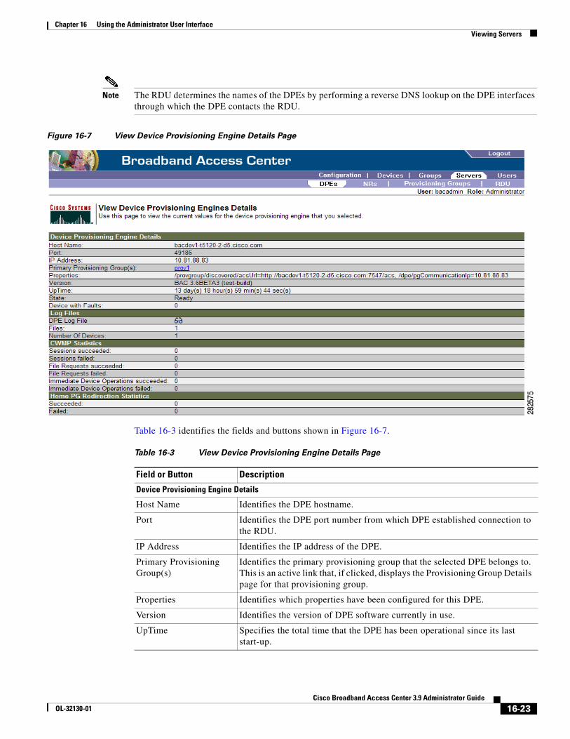
Chapter 16 Using the Administrator User InterfaceViewing Servers
Note The RDU determines the names of the DPEs by performing a reverse DNS lookup on the DPE interfaces through which the DPE contacts the RDU.
Figure 16-7 View Device Provisioning Engine Details Page
Table 16-3 identifies the fields and buttons shown in Figure 16-7.
Table 16-3 View Device Provisioning Engine Details Page
Field or Button Description
Device Provisioning Engine Details
Host Name Identifies the DPE hostname.
Port Identifies the DPE port number from which DPE established connection to the RDU.
IP Address Identifies the IP address of the DPE.
Primary Provisioning Group(s)
Identifies the primary provisioning group that the selected DPE belongs to. This is an active link that, if clicked, displays the Provisioning Group Details page for that provisioning group.
Properties Identifies which properties have been configured for this DPE.
Version Identifies the version of DPE software currently in use.
UpTime Specifies the total time that the DPE has been operational since its last start-up.
16-23Cisco Broadband Access Center 3.9 Administrator Guide
OL-32130-01
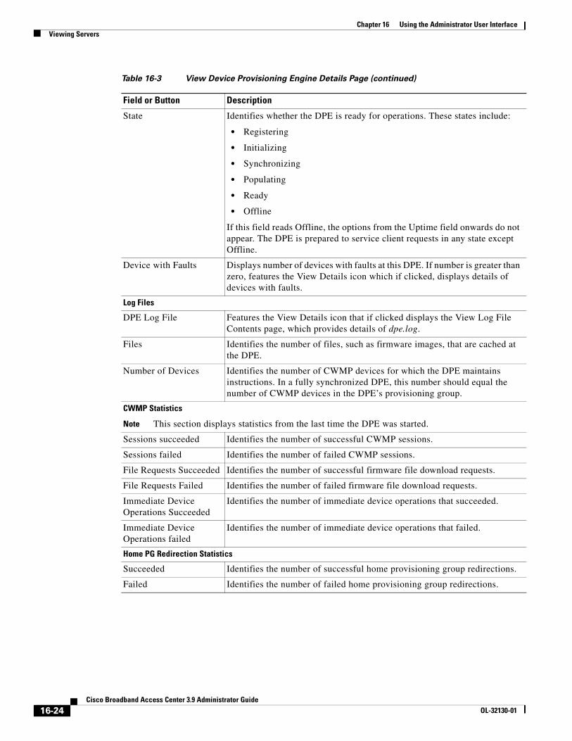
Chapter 16 Using the Administrator User InterfaceViewing Servers
State Identifies whether the DPE is ready for operations. These states include:
• Registering
• Initializing
• Synchronizing
• Populating
• Ready
• Offline
If this field reads Offline, the options from the Uptime field onwards do not appear. The DPE is prepared to service client requests in any state except Offline.
Device with Faults Displays number of devices with faults at this DPE. If number is greater than zero, features the View Details icon which if clicked, displays details of devices with faults.
Log Files
DPE Log File Features the View Details icon that if clicked displays the View Log File Contents page, which provides details of dpe.log.
Files Identifies the number of files, such as firmware images, that are cached at the DPE.
Number of Devices Identifies the number of CWMP devices for which the DPE maintains instructions. In a fully synchronized DPE, this number should equal the number of CWMP devices in the DPE’s provisioning group.
CWMP Statistics
Note This section displays statistics from the last time the DPE was started.
Sessions succeeded Identifies the number of successful CWMP sessions.
Sessions failed Identifies the number of failed CWMP sessions.
File Requests Succeeded Identifies the number of successful firmware file download requests.
File Requests Failed Identifies the number of failed firmware file download requests.
Immediate Device Operations Succeeded
Identifies the number of immediate device operations that succeeded.
Immediate Device Operations failed
Identifies the number of immediate device operations that failed.
Home PG Redirection Statistics
Succeeded Identifies the number of successful home provisioning group redirections.
Failed Identifies the number of failed home provisioning group redirections.
Table 16-3 View Device Provisioning Engine Details Page (continued)
Field or Button Description
16-24Cisco Broadband Access Center 3.9 Administrator Guide
OL-32130-01
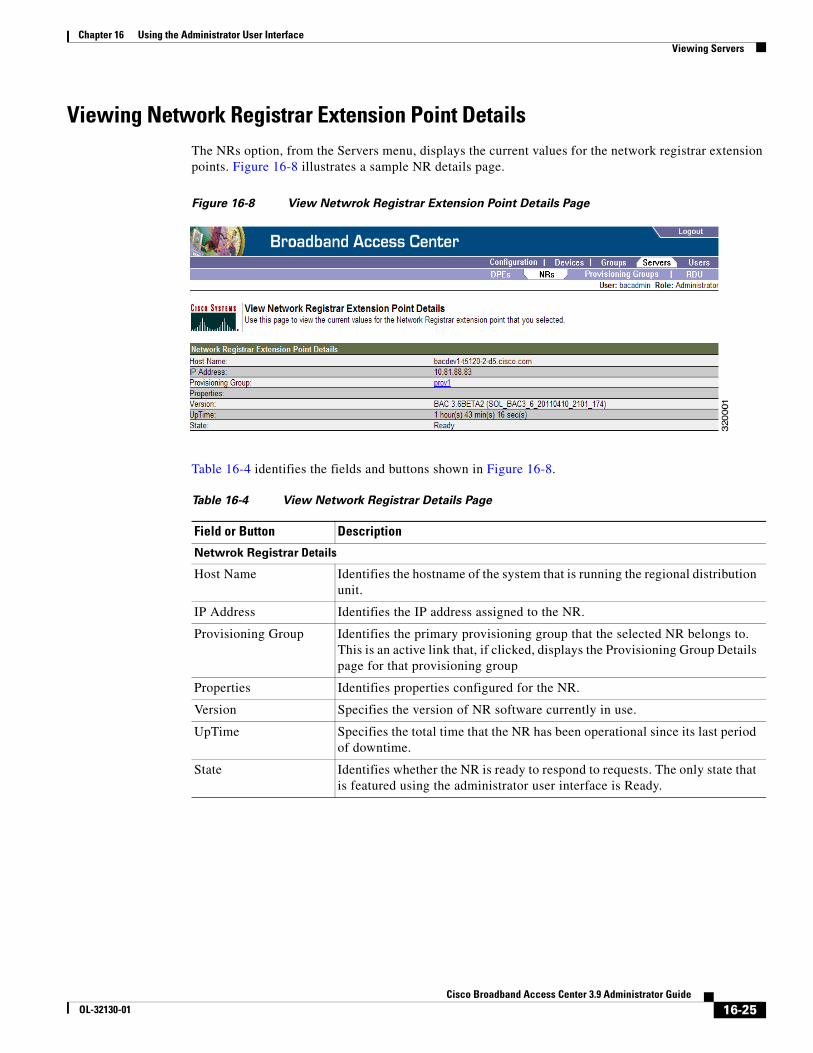
Chapter 16 Using the Administrator User InterfaceViewing Servers
Viewing Network Registrar Extension Point Details The NRs option, from the Servers menu, displays the current values for the network registrar extension points. Figure 16-8 illustrates a sample NR details page.
Figure 16-8 View Netwrok Registrar Extension Point Details Page
Table 16-4 identifies the fields and buttons shown in Figure 16-8.
Table 16-4 View Network Registrar Details Page
Field or Button Description
Netwrok Registrar Details
Host Name Identifies the hostname of the system that is running the regional distribution unit.
IP Address Identifies the IP address assigned to the NR.
Provisioning Group Identifies the primary provisioning group that the selected NR belongs to. This is an active link that, if clicked, displays the Provisioning Group Details page for that provisioning group
Properties Identifies properties configured for the NR.
Version Specifies the version of NR software currently in use.
UpTime Specifies the total time that the NR has been operational since its last period of downtime.
State Identifies whether the NR is ready to respond to requests. The only state that is featured using the administrator user interface is Ready.
16-25Cisco Broadband Access Center 3.9 Administrator Guide
OL-32130-01
Chapter 16 Using the Administrator User InterfaceViewing Servers
Viewing Provisioning GroupsThe Manage Provisioning Groups page lets you monitor all current provisioning groups. Each provisioning group appearing in this list is a link to its own details page. Click this link to display the details page, which is similar to Figure 16-9.
Figure 16-9 View Provisioning Group Details Page
Table 16-5 identifies the fields and buttons shown in Figure 16-9. The fields described in Table 16-5 may include active links that, if clicked, display the appropriate details page.
Table 16-5 View Provisioning Groups Details Page
Field or Button Description
Provisioning Group Details
Name Identifies the provisioning group name selected from the List Provisioning Groups page.
Primary Device Provisioning Engine(s)
Identifies the hostnames of the DPEs that are primary for this provisioning group.
Provisioning Group Properties
Discovered ACS URL Identifies the DPE URL through which the provisioning group connects to the DPE. Discovered URL is based on DPE interface configured for provisioning operations using the DPE CLI.
The parameters is based on registration information from the DPE which registered last with the RDU. This URL is used for operations such as redirection of CPE to a different provisioning group.
LeaseQuery Servers V4 The list of Cisco Network Registrar servers that are registered for this provisioning group.
16-26Cisco Broadband Access Center 3.9 Administrator Guide
OL-32130-01
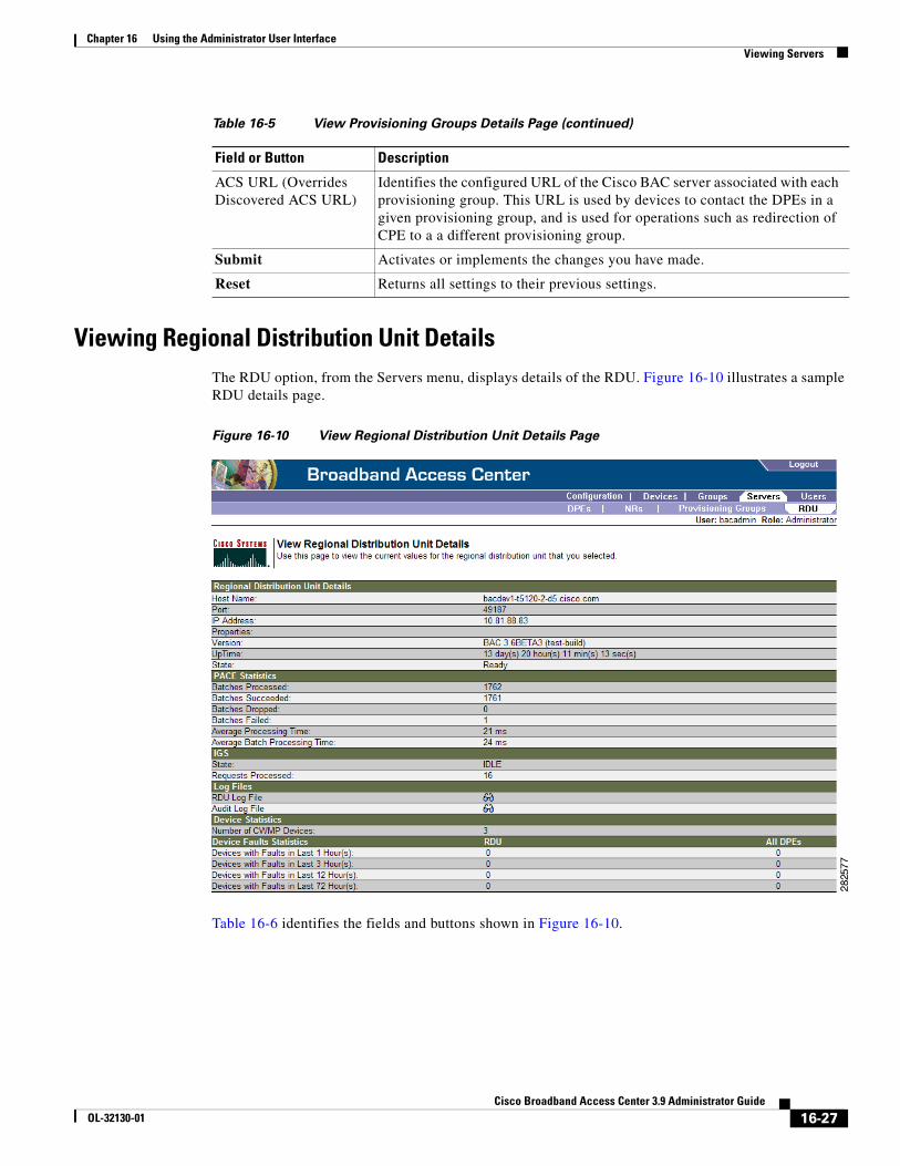
Chapter 16 Using the Administrator User InterfaceViewing Servers
Viewing Regional Distribution Unit DetailsThe RDU option, from the Servers menu, displays details of the RDU. Figure 16-10 illustrates a sample RDU details page.
Figure 16-10 View Regional Distribution Unit Details Page
Table 16-6 identifies the fields and buttons shown in Figure 16-10.
ACS URL (Overrides Discovered ACS URL)
Identifies the configured URL of the Cisco BAC server associated with each provisioning group. This URL is used by devices to contact the DPEs in a given provisioning group, and is used for operations such as redirection of CPE to a a different provisioning group.
Submit Activates or implements the changes you have made.
Reset Returns all settings to their previous settings.
Table 16-5 View Provisioning Groups Details Page (continued)
Field or Button Description
16-27Cisco Broadband Access Center 3.9 Administrator Guide
OL-32130-01
Chapter 16 Using the Administrator User InterfaceViewing Servers
Table 16-6 View RDU Details Page
Field or Button Description
Regional Distribution Unit Details
Host Name Identifies the host name of the system that is running the regional distribution unit.
Port Identifies the RDU listening port number for connections from the DPEs. The default port number is 49187, but a different port can be selected during installation of the RDU.
IP Address Identifies the IP address assigned to the RDU.
Properties Identifies properties configured for the RDU.
Version Specifies the version of RDU software currently in use.
UpTime Specifies the total time that the RDU has been operational since its last period of downtime.
State Identifies whether the RDU is ready to respond to requests. The only state that is featured using the administrator user interface is Ready.
PACE Statistics
Batches Processed Identifies how many individual batches have been processed since the last RDU start-up.
Batches Succeeded Identifies how many individual batches have been successfully processed since the last RDU start-up.
Batches Dropped Identifies how many batches have been dropped since the last RDU start-up.
Batches Failed Identifies how many batches have failed processing since the last RDU start-up.
Average Processing Time
Identifies the average time, in milliseconds, that it takes to process the batch excluding the time it spends in the queue if RDU is too busy.
Average Batch Processing Time
Identifies the average time, in milliseconds, that it takes to process the batch including the time it spends in the queue if RDU is too busy.
IGS
This is the Instruction Generation Service.
State Identifies the operational state of the instruction generation service. This could be:
• Idle—Specifies that the IGS is not processing regeneration requests.
• Regeneration—Specifies that the IGS is processing regeneration requests.
• Waiting Regeneration—Specifies that the IGS is unable to regenerate instructions for a device. When the IGS is stuck in this state, consult the rdu.log for details.
Requests Processed Identifies the number of instruction generation requests processed since last RDU start-up.
Elapsed Time Identifies, in seconds, the time elapsed since the start of regeneration.
Devices Regenerated Identifies the number of device instructions regenerated since the regeneration process started.
16-28Cisco Broadband Access Center 3.9 Administrator Guide
OL-32130-01
Chapter 16 Using the Administrator User InterfaceViewing Servers
Regeneration rate Identifies the cumulative rate of device instructions regenerated since the regeneration process started.
Requests pending Identifies the number of regeneration requests in queue.
Log Files
RDU Log File Features the View Details icon, that, if clicked, displays the View Log File Contents page, which provides details of the rdu.log file.
Audit Log File Features the View Details icon, that, if clicked, displays the View Log File Contents page, which provides details of the audit.log file.
Device Statistics
Number of CWMP Devices
Identifies the number of devices in the RDU database.
Device Faults Statistics
Devices with Faults in Last 1 Hour(s)
Identifies the number of devices with faults over the last one hour, at both the RDU and the DPEs.
Devices with Faults in Last 3 Hour(s)
Identifies the number of devices with faults over the last three hours, at both the RDU and the DPEs.
Devices with Faults in Last 12 Hour(s)
Identifies the number of devices with faults over the last 12 hours, at both the RDU and the DPEs.
Devices with Faults in Last 72 Hour(s)
Identifies the number of devices with faults over the last 72 hours, at both the RDU and the DPEs.
Table 16-6 View RDU Details Page (continued)
Field or Button Description
16-29Cisco Broadband Access Center 3.9 Administrator Guide
OL-32130-01

Chapter 16 Using the Administrator User InterfaceViewing Servers
16-30Cisco Broadband Access Center 3.9 Administrator Guide
OL-32130-01
CiscoOL-32130-01
C H A P T E R 17
Configuring Broadband Access CenterThis chapter describes the Cisco Broadband Access Center (BAC) configuration tasks that you perform by selecting the options in the Configuration menu.
This chapter includes the following sections:
• Configuring the Class of Service, page 17-1
• Configuring Custom Properties, page 17-6
• Configuring Defaults, page 17-9
• Managing Files, page 17-18
• Managing License Keys, page 17-23
• Managing DPE Feature Pack Extensions, page 17-24
• Managing RDU Extensions, page 17-26
• Publishing Provisioning Data, page 17-29
• Configuring Lease Query, page 17-30
• Updating the Location of FAP at Group Level in the Grid, page 17-31
• Updating the Location of FAP at Chassis Level, page 17-33
• Configuring Location Verification for UMTS, page 17-35
• Configuring 2G Scan and 3G Scan Capability of LTE, page 17-35
• Configuring Static Neighbor List of LTE, page 17-35
• Configuring Remote Reset for Tampered LTE FAP, page 17-37
Configuring the Class of ServiceBy using the Cisco BAC administrator user interface, you can configure the Classes of Service offered to your customers. You can use the administrator user interface to add, modify, view, or delete any selected Class of Service. Start with the Manage Class of Service page, as shown in Figure 17-1.
17-1 Broadband Access Center 3.9 Administrator Guide
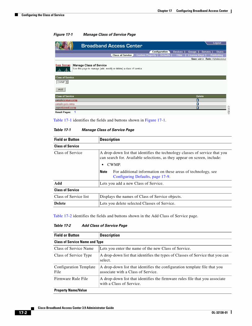
Chapter 17 Configuring Broadband Access CenterConfiguring the Class of Service
Figure 17-1 Manage Class of Service Page
Table 17-1 identifies the fields and buttons shown in Figure 17-1.
Table 17-2 identifies the fields and buttons shown in the Add Class of Service page.
Table 17-1 Manage Class of Service Page
Field or Button Description
Class of Service
Class of Service A drop-down list that identifies the technology classes of service that you can search for. Available selections, as they appear on screen, include:
• CWMP.
Note For additional information on these areas of technology, see Configuring Defaults, page 17-9.
Add Lets you add a new Class of Service.
Class of Service
Class of Service list Displays the names of Class of Service objects.
Delete Lets you delete selected Classes of Service.
Table 17-2 Add Class of Service Page
Field or Button Description
Class of Service Name and Type
Class of Service Name Lets you enter the name of the new Class of Service.
Class of Service Type A drop-down list that identifies the types of Classes of Service that you can select.
Configuration Template File
A drop-down list that identifies the configuration template file that you associate with a Class of Service.
Firmware Rule File A drop-down list that identifies the firmware rules file that you associate with a Class of Service.
Property Name/Value
17-2Cisco Broadband Access Center 3.9 Administrator Guide
OL-32130-01
Chapter 17 Configuring Broadband Access CenterConfiguring the Class of Service
Property Name Specifies the appropriate property. You can select the correct property from the drop-down list.
Property Value Specifies the value for the property name. You can select the correct value from the drop-down list.
Add Adds the new Property Name:Property Value pair to create the new Class of Service.
Submit Activates or implements the changes you have made.
Reset Returns all settings to their previous settings.
Table 17-2 Add Class of Service Page (continued)
Field or Button Description
17-3Cisco Broadband Access Center 3.9 Administrator Guide
OL-32130-01
Chapter 17 Configuring Broadband Access CenterConfiguring the Class of Service
Adding a Class of ServiceTo add a specific Class of Service:
Step 1 Choose Configuration on the Primary Navigation bar.
Step 2 Choose Class of Service from the Secondary Navigation bar.
Step 3 Click Add.
The Add Class of Service page appears. This page identifies the various settings for the selected Class of Service.
Step 4 Enter the name of your new class of service.
For example, assume that you want to create a new Class of Service called Gold-Classic for CWMP. You might enter provisioned-cwmp as the Class of Service Name, and choose CWMP from the service type drop-down list.
Step 5 Choose a Configuration Template File. For example, choose sample-cwmp-config.xml from the configuration file template drop-down list.
Step 6 Choose also a Firmware Rule File. For example, choose sample-cwmp-firmware-rules.xml from the firmware rule file drop-down list.
Step 7 Enter a Property Name and Property Value in the appropriate fields. This lets you configure standard or custom properties for this class of service object.
For example, choose as property name /IPDevice/connectionRequestMethod. Choose Discovered from the Property Value drop-down list and then continue with the rest of this procedure.
Note The API constant for /IPDevice/connectionRequestMethod is IPDeviceKeys.CONNECTION_REQUEST_METHOD.
Multiple Property Name:Property Value pairs could appear on this page. You use the Delete button to remove any unwanted pairs from the class of service.
Step 8 Click Add to add the property to the defining Class of Service.
Step 9 Click Submit to finalize the process or Reset to return all fields to their previous setting.
After submitting the Class of Service, the Manage Class of Service page appears to show the newly added Class of Service.
Modifying a Class of ServiceYou can modify the Classes of Service by selecting the various properties and assigning appropriate property values. When creating a Class of Service for the first time you select all of the appropriate properties and assign values to them.
If you make a mistake, or your business requirements for a certain Class of Service change, you can either change the property value before submitting your previous changes or delete the Property Name:Property Value pair altogether.
17-4Cisco Broadband Access Center 3.9 Administrator Guide
OL-32130-01
Chapter 17 Configuring Broadband Access CenterConfiguring the Class of Service
Note Changes to the Class of Service object trigger the Instruction Generation Service (IGS) to regenerate instructions for all affected devices and send instructions to the DPEs. IGS does this task as a background job. The status of the IGS can be observed using the View RDU Details page.
To add, delete, or modify Class of Service properties:
Step 1 Choose Configuration on the Primary Navigation bar.
Step 2 Choose Class of Service from the Secondary Navigation bar.
Step 3 Choose the Class of Service to be modified.
Step 4 Click the link corresponding to the correct Class of Service.
The Modify Class of Service page appears; note that the selected Class of Service name and type appear below the page description.
• To add a new property to the selected Class of Service:
– Select the first property that you want assigned to the selected Class of Service, from the Property Name drop-down and then, after choosing the appropriate value for that property, click Add.
– Repeat for any other properties you want to assign to the selected Class of Service.
• To delete a property for the selected Class of Service:
– Locate the unwanted property in the list immediately above the Property Name drop-down.
– Click the Delete button.
• To modify the value currently assigned to a property:
– Delete the appropriate property as described above.
– Add the same property back to the Class of Service while entering the new Property Value.
Note If you delete a property that is required for your business process, you must add it back, and select the appropriate value, before you submit the change.
Step 5 Click Submit to make the modifications to the class of service.
Each property added to a Class of Service, appears when you click Submit. After doing so, a confirmation page appears to regenerate the instructions for the devices with the selected Class of Service.
Step 6 Click OK.
The modified Class of Service will be available in the Manage Class of Service page.
Deleting a Class of ServiceYou can delete any existing Class of Service but, before you attempt to do so, you must ensure that there are no devices associated with that Class of Service.
17-5Cisco Broadband Access Center 3.9 Administrator Guide
OL-32130-01
Chapter 17 Configuring Broadband Access CenterConfiguring Custom Properties
Tip Where there are large numbers of devices associated with a Class of Service to be deleted, use the Cisco BAC application programmers interface (API) to write a program to iterate through these devices to reassign another Class of Service to the devices.
To delete a Class of Service:
Step 1 Choose Configuration on the Primary Navigation bar.
Step 2 Choose Class of Service from the Secondary Navigation bar.
Step 3 Click the Delete icon ( ) for the correct Class of Service, and a confirmation dialog box appears.
Note A Class of Service cannot be deleted if devices are associated with it or, if it is designated as the default Class of Service. Therefore, you cannot delete the unprovisioned-cwmp Class of Service object.
Step 4 Click OK to delete the file, or Cancel to return to the Manage Class of Service page. (See Figure 17-1.)
If you try to delete a Class of Service with devices associated with it, this error message is displayed:
The following error(s) occurred while processing your request.Error: Class Of Service [sample-COS] has devices associated with it, unable to delete
Please correct the error(s) and resubmit your request.
The specific Class of Service is specified within the error message. In this example this is represented by sample-COS.
Configuring Custom PropertiesCustom properties let you specify additional customizable device information to be stored in the RDU database. The Custom Property configuration page is found under the Configuration menu, and you use this page to add or delete custom properties.
Caution Although you can delete custom properties if they are currently in use, doing so could cause extreme difficulty to other areas where the properties are in use.
After the custom property is defined, you can use it in this property hierarchy. See Authoring Configuration Templates, page 5-14, for how to use the property hierarchy. Properties can be configured on the following objects for use in the property hierarchy:
• Device
• Group
• Provisioning Group
• Class of Service
17-6Cisco Broadband Access Center 3.9 Administrator Guide
OL-32130-01
Chapter 17 Configuring Broadband Access CenterConfiguring Custom Properties
• Device Type
• System defaults
Group priorities in the property hierarchy (see Property Hierarchy, page 4-4) are handled through group types.
Step 1 Choose Configuration on the Primary Navigation bar.
Step 2 Choose Custom Property on the Secondary Navigation bar,
The Manage Cisco BAC Custom Properties page appears.
• To add a custom property:
a. Click Add on the Manage Cisco BAC Custom Properties page,
The Add Custom Property page appears.
b. Enter the name of the new custom property.
c. Choose a custom property value type from the drop-down list.
d. Click Submit when complete.
After the property has been added to the administrative database, the Manage Cisco BAC Custom Properties page appears.
• To delete a custom property:
a. Identify the custom property to be deleted from the Manage Cisco BAC Custom Properties page.
b. Click the Delete icon corresponding to the correct custom property,
The custom properties deletion dialog box appears.
c. Click OK to delete the custom property.
Custom Property for Creating GRID ID for Additional Authentication
A new custom property, FC-GRID-ID-FORMAT, of string type, is available in Cisco BAC to support construction of FC-GRID-ID of the device . The FC-GRID-ID can be used as an additional authentication at the HNB-gateway.
You can edit the value of FC-GRID-ID-FORMAT to support any property, using the below pattern:
Key1=${Property1},Key2=${Property2},Key3=${Property3}...
You can also include discovered data as property. For example:
FC-GRID-ID-FORMAT = Manufacturer=${/ cwmp/discovered/Inform.DeviceId.Manfacturer},SiteId=${FC-SITE-ID},Version=${FC-MNC},RatIid=${FC-RAT-ID}
If you have configured empty string for FC-GRID-ID-FORMAT, the default value will be:
FC-GRID-ID-FORMAT = ${FC-ENTERPRISE-ID}-${FC-SITE-ID}-${FC-GROUP-ID}
In this case, the GRID ID of the device will be returned (as FC-GRID-ID property) as part of authentication, by taking the values for only the three properties – FC-ENTERPRISE-ID, FC-SITE-ID, and FC-GROUP-ID.
If you have configured invalid values for FC-GRID-ID-FORMAT, then the FC-GRID-ID value will be empty.
17-7Cisco Broadband Access Center 3.9 Administrator Guide
OL-32130-01
Chapter 17 Configuring Broadband Access CenterConfiguring Custom Properties
The creation of FC-GRID-ID also requires installation of the corresponding RDU extension, and configuration of the Service Level Extension Point in CWMP Defaults (see New Class for DNPrefix Extension, page 17-28 and CWMP Defaults, page 17-10)
Custom Property for Creating DNPrefix
A new custom property, FC-DN-PREFIX-FORMAT, of string type, is available in Cisco BAC to support the construction of FC-DN-PREFIX. The FC-DN-PREFIX can especially be applied to the fault systems so that all applicable identification information such as the enterprise, site, or chassis IDs are included.
You can edit the value for FC-DN-PREFIX-FORMAT to support any property, using the below pattern:
Key1=${Property1},Key2=${Property2},Key3=${Property3}...
You can also include discovered data as property. For example:
FC-DN-PREFIX-FORMAT = EnterPriseID=${FC-ENTERPRISE-ID},Manufacturer=${/ cwmp/discovered/Inform.DeviceId.Manfacturer},GridId=${FC-GRID-ID},RatIid=${FC-RAT-ID}
If you have configured empty string for FC-DN-PREFIX-FORMAT, the default value is applied as follows:
FC-DN-PREFIX-FORMAT = DeviceID=${/network/deviceID},OwnerID=${/ownerID},FQDN=${/device/fqdn}, EnterPriseID=${FC-ENTERPRISE-ID},SiteId=${FC-SITE-ID},GridID=${FC-GRID-ID},RatId=${FC-RAT-ID}
If you have configured invalid values for FC-DN-PREFIX-FORMAT, then the FC-DN-PREFIX value will be empty.
The creation of FC-DN-PREFIX also requires installation of the corresponding RDU extension, and configuration of the Service Level Extension Point in CWMP Defaults (see New Class for DNPrefix Extension, page 17-28 and CWMP Defaults, page 17-10).
Setting the Custom Properties for LTE Provisioning
For setting the LTE parameter values on the LTE device, the following custom properties need to be set in the Modify Device page:
• FC-ACTIVATED = true
• FC-CIG-ENABLED = false
• FC-GPS-ENABLED = true
This ensures that, if the GPS location is valid, all the LTE parameters with values specified in the configuration template are set to the LTE device, and the FC-SERVICE-STATUS of the LTE device is Operational.
Setting the Custom Properties for NWL
Cisco BAC helps you to configure the network listen function (NWL) of FAP using the following custom properties:
• FC-DNB-CONFIG-NWL-LIST-COUNT - Use this property (integer) to configure the value of number of neighbors received from FAP based on max power (the top 'n' number of neighbors is sorted based on power). If this property is not configured, the default value of 12 is used.
17-8Cisco Broadband Access Center 3.9 Administrator Guide
OL-32130-01
Chapter 17 Configuring Broadband Access CenterConfiguring Defaults
• FC-DNB-FREQ-MATCH - Set this property to true if you want to compare the neighbor identities using frequency. The default values is false, which compares the neighbor identities using GUID (instead of frequency).
Note The periodic NWL based location check of FAP is performed based on the success or failure of the check. If the location check fails, the custom property FC-NWL-SCAN-INTERVAL is automatically set to 20 minutes, till the location check is successful. Once the location check is successful, this property is automatically set to 1440 minutes (24 hours).
Configuring DefaultsThe Defaults page, found under the Configuration option, lets you access the default settings for the overall system, including the Regional Distribution Unit (RDU), and the CWMP technology.
Selecting Configuration OptionsThe procedure for configuring specific default types is identical. Complete this procedure to access the desired defaults page and then refer to the appropriate section within this chapter for a description of the various page components.
Step 1 Choose Configuration on either the Primary Navigation bar or Main Menu page.
Step 2 Choose Defaults from the Secondary Navigation bar.
The Configure Defaults page appears.
17-9Cisco Broadband Access Center 3.9 Administrator Guide
OL-32130-01
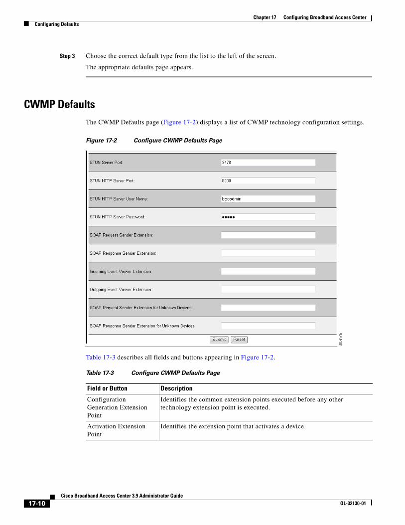
Chapter 17 Configuring Broadband Access CenterConfiguring Defaults
Step 3 Choose the correct default type from the list to the left of the screen.
The appropriate defaults page appears.
CWMP DefaultsThe CWMP Defaults page (Figure 17-2) displays a list of CWMP technology configuration settings.
Figure 17-2 Configure CWMP Defaults Page
Table 17-3 describes all fields and buttons appearing in Figure 17-2.
Table 17-3 Configure CWMP Defaults Page
Field or Button Description
Configuration Generation Extension Point
Identifies the common extension points executed before any other technology extension point is executed.
Activation Extension Point
Identifies the extension point that activates a device.
17-10Cisco Broadband Access Center 3.9 Administrator Guide
OL-32130-01
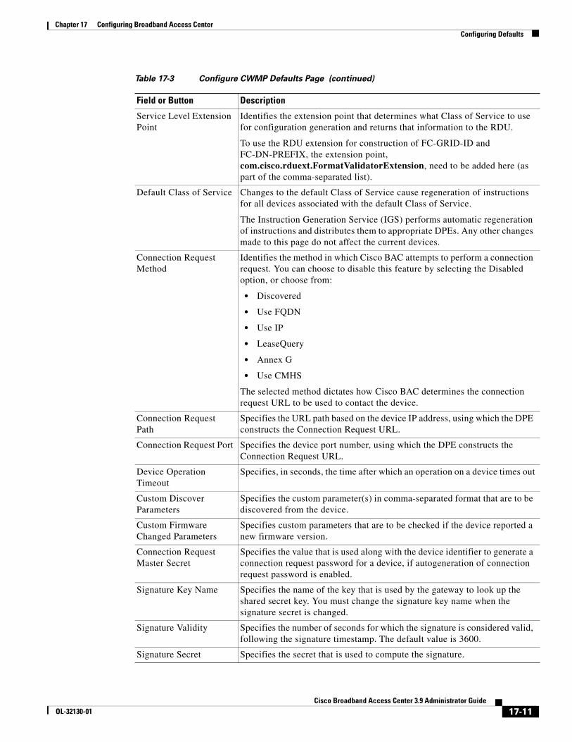
Chapter 17 Configuring Broadband Access CenterConfiguring Defaults
Service Level Extension Point
Identifies the extension point that determines what Class of Service to use for configuration generation and returns that information to the RDU.
To use the RDU extension for construction of FC-GRID-ID and FC-DN-PREFIX, the extension point, com.cisco.rduext.FormatValidatorExtension, need to be added here (as part of the comma-separated list).
Default Class of Service Changes to the default Class of Service cause regeneration of instructions for all devices associated with the default Class of Service.
The Instruction Generation Service (IGS) performs automatic regeneration of instructions and distributes them to appropriate DPEs. Any other changes made to this page do not affect the current devices.
Connection Request Method
Identifies the method in which Cisco BAC attempts to perform a connection request. You can choose to disable this feature by selecting the Disabled option, or choose from:
• Discovered
• Use FQDN
• Use IP
• LeaseQuery
• Annex G
• Use CMHS
The selected method dictates how Cisco BAC determines the connection request URL to be used to contact the device.
Connection Request Path
Specifies the URL path based on the device IP address, using which the DPE constructs the Connection Request URL.
Connection Request Port Specifies the device port number, using which the DPE constructs the Connection Request URL.
Device Operation Timeout
Specifies, in seconds, the time after which an operation on a device times out
Custom Discover Parameters
Specifies the custom parameter(s) in comma-separated format that are to be discovered from the device.
Custom Firmware Changed Parameters
Specifies custom parameters that are to be checked if the device reported a new firmware version.
Connection Request Master Secret
Specifies the value that is used along with the device identifier to generate a connection request password for a device, if autogeneration of connection request password is enabled.
Signature Key Name Specifies the name of the key that is used by the gateway to look up the shared secret key. You must change the signature key name when the signature secret is changed.
Signature Validity Specifies the number of seconds for which the signature is considered valid, following the signature timestamp. The default value is 3600.
Signature Secret Specifies the secret that is used to compute the signature.
Table 17-3 Configure CWMP Defaults Page (continued)
Field or Button Description
17-11Cisco Broadband Access Center 3.9 Administrator Guide
OL-32130-01
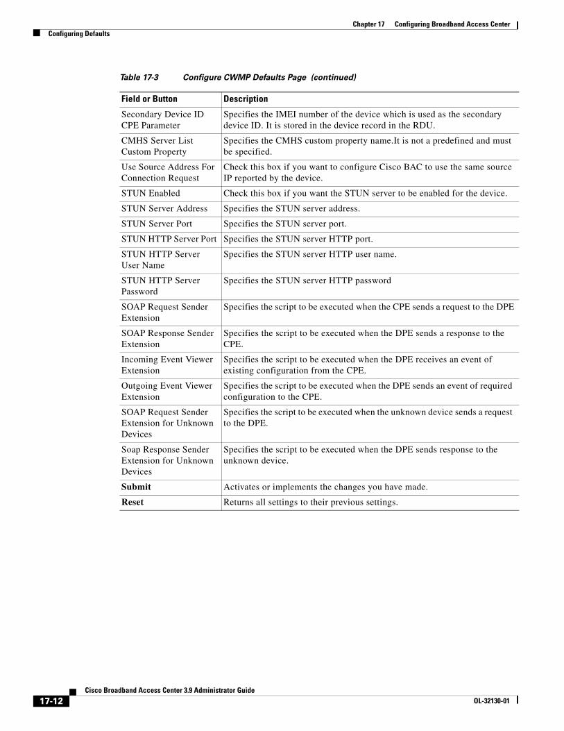
Chapter 17 Configuring Broadband Access CenterConfiguring Defaults
Secondary Device ID CPE Parameter
Specifies the IMEI number of the device which is used as the secondary device ID. It is stored in the device record in the RDU.
CMHS Server List Custom Property
Specifies the CMHS custom property name.It is not a predefined and must be specified.
Use Source Address For Connection Request
Check this box if you want to configure Cisco BAC to use the same source IP reported by the device.
STUN Enabled Check this box if you want the STUN server to be enabled for the device.
STUN Server Address Specifies the STUN server address.
STUN Server Port Specifies the STUN server port.
STUN HTTP Server Port Specifies the STUN server HTTP port.
STUN HTTP Server User Name
Specifies the STUN server HTTP user name.
STUN HTTP Server Password
Specifies the STUN server HTTP password
SOAP Request Sender Extension
Specifies the script to be executed when the CPE sends a request to the DPE
SOAP Response Sender Extension
Specifies the script to be executed when the DPE sends a response to the CPE.
Incoming Event Viewer Extension
Specifies the script to be executed when the DPE receives an event of existing configuration from the CPE.
Outgoing Event Viewer Extension
Specifies the script to be executed when the DPE sends an event of required configuration to the CPE.
SOAP Request Sender Extension for Unknown Devices
Specifies the script to be executed when the unknown device sends a request to the DPE.
Soap Response Sender Extension for Unknown Devices
Specifies the script to be executed when the DPE sends response to the unknown device.
Submit Activates or implements the changes you have made.
Reset Returns all settings to their previous settings.
Table 17-3 Configure CWMP Defaults Page (continued)
Field or Button Description
17-12Cisco Broadband Access Center 3.9 Administrator Guide
OL-32130-01
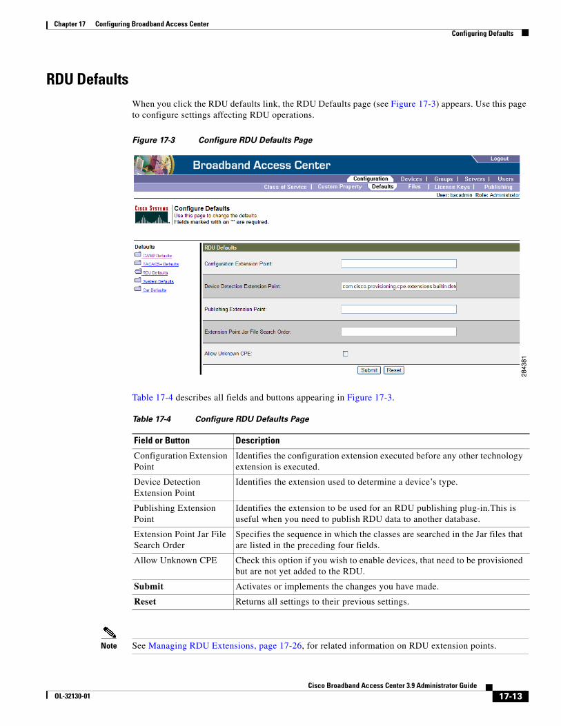
Chapter 17 Configuring Broadband Access CenterConfiguring Defaults
RDU DefaultsWhen you click the RDU defaults link, the RDU Defaults page (see Figure 17-3) appears. Use this page to configure settings affecting RDU operations.
Figure 17-3 Configure RDU Defaults Page
Table 17-4 describes all fields and buttons appearing in Figure 17-3.
Note See Managing RDU Extensions, page 17-26, for related information on RDU extension points.
Table 17-4 Configure RDU Defaults Page
Field or Button Description
Configuration Extension Point
Identifies the configuration extension executed before any other technology extension is executed.
Device Detection Extension Point
Identifies the extension used to determine a device’s type.
Publishing Extension Point
Identifies the extension to be used for an RDU publishing plug-in.This is useful when you need to publish RDU data to another database.
Extension Point Jar File Search Order
Specifies the sequence in which the classes are searched in the Jar files that are listed in the preceding four fields.
Allow Unknown CPE Check this option if you wish to enable devices, that need to be provisioned but are not yet added to the RDU.
Submit Activates or implements the changes you have made.
Reset Returns all settings to their previous settings.
17-13Cisco Broadband Access Center 3.9 Administrator Guide
OL-32130-01
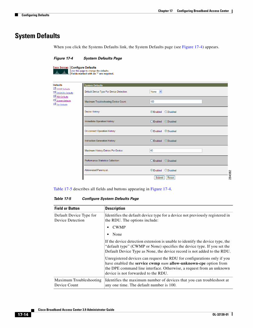
Chapter 17 Configuring Broadband Access CenterConfiguring Defaults
System DefaultsWhen you click the Systems Defaults link, the System Defaults page (see Figure 17-4) appears.
Figure 17-4 System Defaults Page
Table 17-5 describes all fields and buttons appearing in Figure 17-4.
Table 17-5 Configure System Defaults Page
Field or Button Description
Default Device Type for Device Detection
Identifies the default device type for a device not previously registered in the RDU. The options include:
• CWMP
• None
If the device detection extension is unable to identify the device type, the “default type” (CWMP or None) specifies the device type. If you set the Default Device Type as None, the device record is not added to the RDU.
Unregistered devices can request the RDU for configurations only if you have enabled the service cwmp num allow-unknown-cpe option from the DPE command line interface. Otherwise, a request from an unknown device is not forwarded to the RDU.
Maximum Troubleshooting Device Count
Identifies the maximum number of devices that you can troubleshoot at any one time. The default number is 100.
17-14Cisco Broadband Access Center 3.9 Administrator Guide
OL-32130-01
Chapter 17 Configuring Broadband Access CenterConfiguring Defaults
Device History Identifies if logging device record and device configurations is enabled or disabled.
Immediate Operation History
Identifies if logging of history of device operation initiated from the API using immediate mode is enabled or disabled.
On-Connect Operation History
Identifies if logging of history of device operation initiated from the API using on-connect mode is enabled or disabled.
Instruction Generation History
Identifies if logging the history of device instruction generation is enabled or disabled.
Maximum History Entries Per Device
Defines the maximum number of entries of device history that will be stored for each device. The default number of entries is 40.
Performance Statistics Collection
Determines if statistics collection is enabled. See Monitoring Performance Statistics, page 11-14, on performance statistics.
Abbreviated ParamList Enable this if you want to abbreviate the parameter names available in the configuration template. If enabled, parameter names are replaced with a dot (.).
Submit Activates or implements the changes you have made.
Reset Returns all settings to their previous settings.
Table 17-5 Configure System Defaults Page (continued)
Field or Button Description
17-15Cisco Broadband Access Center 3.9 Administrator Guide
OL-32130-01
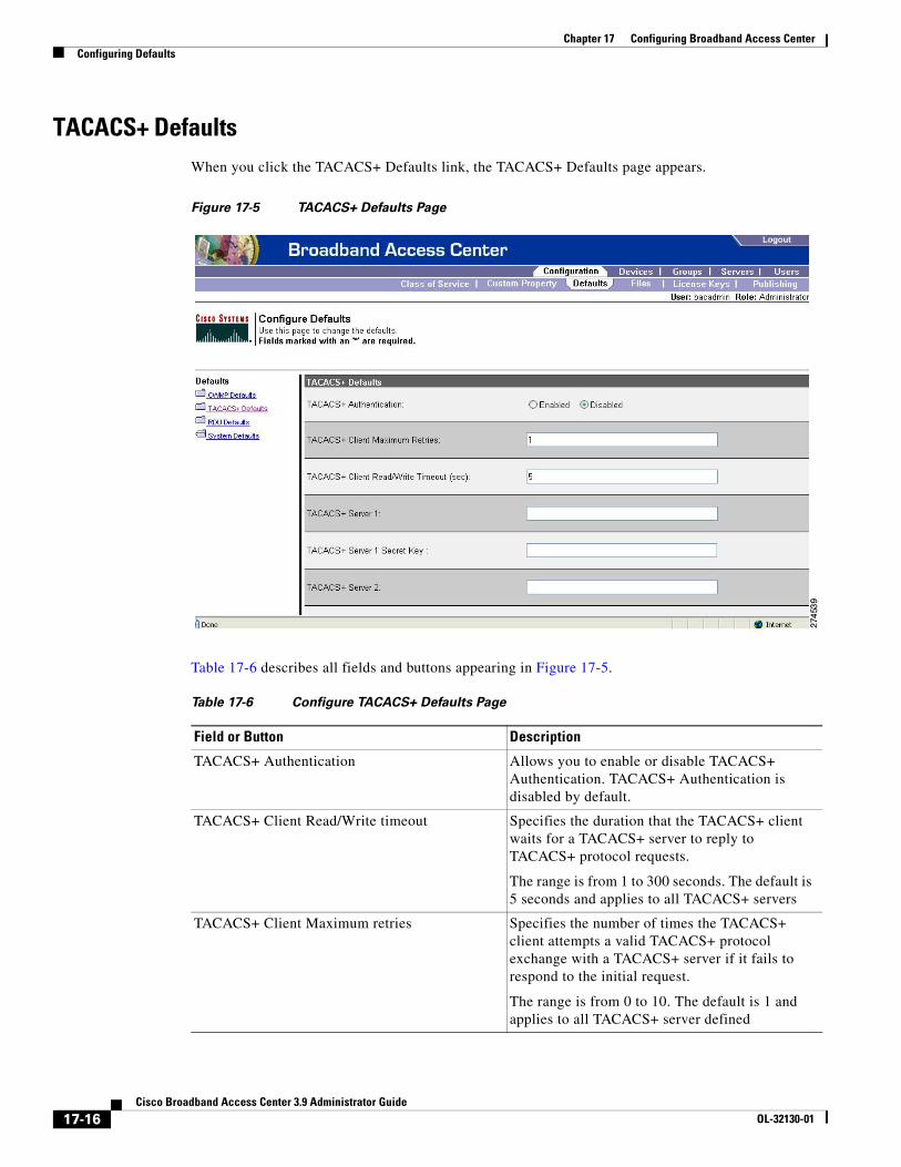
Chapter 17 Configuring Broadband Access CenterConfiguring Defaults
TACACS+ DefaultsWhen you click the TACACS+ Defaults link, the TACACS+ Defaults page appears.
Figure 17-5 TACACS+ Defaults Page
Table 17-6 describes all fields and buttons appearing in Figure 17-5.
Table 17-6 Configure TACACS+ Defaults Page
Field or Button Description
TACACS+ Authentication Allows you to enable or disable TACACS+ Authentication. TACACS+ Authentication is disabled by default.
TACACS+ Client Read/Write timeout Specifies the duration that the TACACS+ client waits for a TACACS+ server to reply to TACACS+ protocol requests.
The range is from 1 to 300 seconds. The default is 5 seconds and applies to all TACACS+ servers
TACACS+ Client Maximum retries Specifies the number of times the TACACS+ client attempts a valid TACACS+ protocol exchange with a TACACS+ server if it fails to respond to the initial request.
The range is from 0 to 10. The default is 1 and applies to all TACACS+ server defined
17-16Cisco Broadband Access Center 3.9 Administrator Guide
OL-32130-01
Chapter 17 Configuring Broadband Access CenterConfiguring Defaults
TACACS Server 1 Specifies the IP address or the hostname of the TACACS+ server that has the highest priority and serves as the first choice for the TACACS+ clients.
When TACACS+ authentication is enabled, the client attempts user login authentication to each server sequentially in the list until a successful authentication exchange is achieved, or the list is exhausted.
If the list is exhausted, the client automatically falls back to the local authentication mode.
TACACS Server 1 Secret Key Specifies the secret key used for encryption between the RDU and the TACACS+ server 1. The secret key is stored in the RDU database.
TACACS Server 2 Specifies the IP address or the hostname of the TACACS+ server that is queried by the TACACS+ client when the TACACS+ server 1 is unreachable.
TACACS Server 2 Secret Key Specifies the secret key used for encryption between the RDU and the TACACS+ server 2.
TACACS Server 3 Specifies the IP address or the hostname of the TACACS+ server that is queried by the TACACS+ client when the TACACS+ server 1 and TACACS+ server 2 are unreachable.
TACACS Server 3 Secret Key Specifies the secret key used for encryption between the RDU and the TACACS+ server 3.
TACACS Server 4 Specifies the IP address or the hostname of the TACACS+ server that is queried by the TACACS+ client when the TACACS+ server 1, TACACS+ server 2 and TACACS+ server 3 are unreachable.
TACACS Server 4 Secret Key Specifies the secret key used for encryption between the RDU and the TACACS+ server 4.
TACACS Server 5 Specifies the IP address or the hostname of the TACACS+ server that is queried by the TACACS+ client when the TACACS+ server 1, TACACS+ server 2, TACACS+ server 3 and TACACS+ server 4 are unreachable.
TACACS Server 5 Secret Key Specifies the secret key used for encryption between the RDU and the TACACS+ server 5.
Submit Activates or implements the changes you have made.
Reset Returns all settings to their previous settings.
Table 17-6 Configure TACACS+ Defaults Page (continued)
Field or Button Description
17-17Cisco Broadband Access Center 3.9 Administrator Guide
OL-32130-01
Chapter 17 Configuring Broadband Access CenterManaging Files
If you remove one TACACS+ server and replace it with another server, the newly added server will have the same priority as the removed server.
To change the order of the TACACS+ servers in the priority list, remove all server addresses and re-enter them in the desired order.
Managing FilesBy using the Cisco BAC administrator user interface, you can manage the template files and the parameter dictionaries for dynamic generation for CWMP files, or software images for devices (see Figure 17-6). You can add, delete, replace, or export any file type, including:
• Configuration Template—These are XML files that contain CWMP configuration policy, including parameter value settings, Notification attributes and Access Control attributes. See Authoring Configuration Templates, page 5-14, for additional information.
• Firmware File—These are images of device firmware, which can be downloaded to devices to upgrade their functionality. Cisco BAC treats this file type like any other binary file. See Firmware Management, page 6-1, for additional information.
• Firmware Rules Template—These are XML files written according to a published schema document. Each firmware rules template contains one or more rules that trigger firmware updates based on specific conditions. See Firmware Management, page 6-1, for additional information.
• JAR File—This file type is used to load Cisco BAC extensions.
• Parameter Dictionary—These are XML files that list valid objects and parameters used by Cisco BAC to configure a device. The dictionaries validate the objects and parameters used in the configuration and firmware rule templates. See Parameter Dictionaries, page 7-1, for additional information.
• Parameter List—These XML files list a predefined set of parameters from the device that are retrieved every time the device contacts Cisco BAC.
• DPE Extension Script—These script files are main extension scripts having the main provisioning logic. For more information on extension scripts, see Scripting Framework, page 18-1.
• Helper Script—These script files are utilities which can be used by multiple main extension scripts. The helper scripts are called from both the main extension scripts and other helper scripts.
Note Figure 17-6 is displayed after clicking the Search button on the Manage Files page.
17-18Cisco Broadband Access Center 3.9 Administrator Guide
OL-32130-01
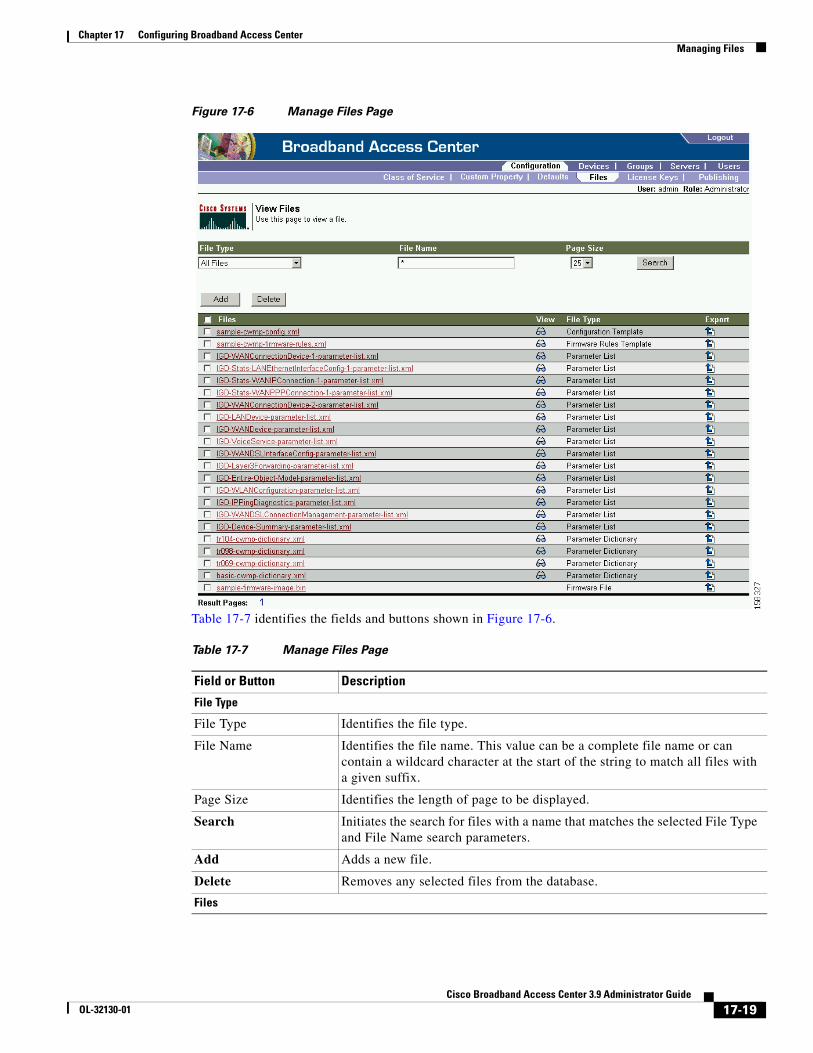
Chapter 17 Configuring Broadband Access CenterManaging Files
Figure 17-6 Manage Files Page
Table 17-7 identifies the fields and buttons shown in Figure 17-6.
Table 17-7 Manage Files Page
Field or Button Description
File Type
File Type Identifies the file type.
File Name Identifies the file name. This value can be a complete file name or can contain a wildcard character at the start of the string to match all files with a given suffix.
Page Size Identifies the length of page to be displayed.
Search Initiates the search for files with a name that matches the selected File Type and File Name search parameters.
Add Adds a new file.
Delete Removes any selected files from the database.
Files
17-19Cisco Broadband Access Center 3.9 Administrator Guide
OL-32130-01
Chapter 17 Configuring Broadband Access CenterManaging Files
Adding FilesTo add an existing file to the RDU database:
Step 1 Choose Configuration on the Primary Navigation bar.
Step 2 Choose Files on the Secondary Navigation bar.
The View Files page appears.
Step 3 Click Add.
Step 4 Choose the File Type.
Note For Firmware file type, two additional fields are provided: Firmware Version and Description, both of which are purely informational. You can enter any string in these fields.
Step 5 Browse for the Source File Name.
By default, file sizes up to 20 MB are supported.
Step 6 Enter the File Name.
Step 7 Click Submit.
The View Files page appears to indicate that the file has been added.
Cisco BAC now extends the http file service so that it can read the firmware file from the DPE file system or DPE cache.
When the firmware image size is very large (say 100 MB), adding the file through RDU may not be efficient. These files can be manually transferred to all the DPEs using tools such as scp, ftp and later when device requests for these files, they can be transferred to the device from the DPE.
Files list Displays a list of files that match the search criteria.
Note The check boxes immediately to the left of any selected item in this list must be checked before it can be deleted.
View Displays the details of the selected file.
File Type Identifies the type of file; for example, Configuration Template, Firmware Rules Template, Parameter List.
Export Exports any selected file to the client’s computer.
Table 17-7 Manage Files Page (continued)
Field or Button Description
File Type
17-20Cisco Broadband Access Center 3.9 Administrator Guide
OL-32130-01
Chapter 17 Configuring Broadband Access CenterManaging Files
Viewing FilesTo view the contents of a file:
Step 1 Choose Configuration on the Primary Navigation bar.
Step 2 Choose Files on the Secondary Navigation bar.
The View Files page appears.
Step 3 Search for the required file by using File Type.
Step 4 Click the View Details icon ( ) corresponding to the File Type you had specified for a search.
The View File page appears.
Replacing FilesTo replace an existing file:
Step 1 Choose Configuration on the Primary Navigation bar.
Step 2 Choose Files on the Secondary Navigation bar.
Step 3 Select the link that corresponds to the file you want to replace from the search output list.
The Replace File page appears. Note that the selected filename already appears on this page.
Step 4 Browse for the source file to be used as a replacement for the displayed filename.
Step 5 Click Submit.
If you are updating a configuration or firmware template which is associated with a Class of Service, after submitting the replacement file, a confirmation page appears to indicate that Cisco BAC will regenerate instructions for the affected devices.
The Instruction Generation Service automatically regenerates instructions for all devices associated with this template using the Class of Service association and sends new instructions to the appropriate DPEs.
Step 6 Click OK
The View Files page appears.
17-21Cisco Broadband Access Center 3.9 Administrator Guide
OL-32130-01
Chapter 17 Configuring Broadband Access CenterManaging Files
Exporting FilesYou can copy files to your local hard drive by using the export function.
Note The procedure described below assumes that you are using Internet Explorer. This procedure is different if you are using Netscape Navigator.
To export a file:
Step 1 Choose Configuration on the Primary Navigation bar.
Step 2 Choose Files from the Secondary Navigation bar.
Step 3 Identify the file that you want to export.
Step 4 To export
• Binary files, click the Export icon ( ) and you are prompted to either open the file or save it.
• XML files, such as templates, clicking the Export icon displays the file content. Therefore, you must right-click the Export icon and select Save Target As.
Step 5 Return to the Cisco BAC administrator user interface.
Deleting FilesComplete this procedure to delete an existing file:
Step 1 Choose Configuration on the Primary Navigation bar.
Step 2 Choose Files on the Secondary Navigation bar.
Step 3 In the Files area, enter the filename of the file that you want to modify.
Step 4 Click Search.
The appropriate file appears in the Files list.
Step 5 Choose the appropriate file or files.
Step 6 Click Delete.
Caution Deleting a template file that is not directly linked to a Class of Service, but is referenced by another template file that is linked to a Class of Service, causes the instruction regeneration service to fail.
Note You cannot delete a file associated with a Class of Service. You must remove the Class of Service association before proceeding. See Configuring the Class of Service, page 17-1, for additional information.
17-22Cisco Broadband Access Center 3.9 Administrator Guide
OL-32130-01
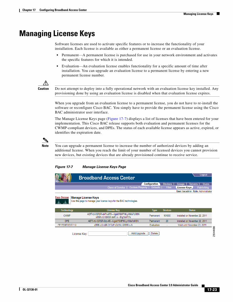
Chapter 17 Configuring Broadband Access CenterManaging License Keys
Managing License KeysSoftware licenses are used to activate specific features or to increase the functionality of your installation. Each license is available as either a permanent license or an evaluation license.
• Permanent—A permanent license is purchased for use in your network environment and activates the specific features for which it is intended.
• Evaluation—An evaluation license enables functionality for a specific amount of time after installation. You can upgrade an evaluation license to a permanent license by entering a new permanent license number.
Caution Do not attempt to deploy into a fully operational network with an evaluation license key installed. Any provisioning done by using an evaluation license is disabled when that evaluation license expires.
When you upgrade from an evaluation license to a permanent license, you do not have to re-install the software or reconfigure Cisco BAC. You simply have to provide the permanent license using the Cisco BAC administrator user interface.
The Manage License Keys page (Figure 17-7) displays a list of licenses that have been entered for your implementation. This Cisco BAC release supports both evaluation and permanent licenses for the CWMP-compliant devices, and DPEs. The status of each available license appears as active, expired, or identifies the expiration date.
Note You can upgrade a permanent license to increase the number of authorized devices by adding an additional license. When you reach the limit of your number of licensed devices you cannot provision new devices, but existing devices that are already provisioned continue to receive service.
Figure 17-7 Manage License Keys Page
17-23Cisco Broadband Access Center 3.9 Administrator Guide
OL-32130-01
Chapter 17 Configuring Broadband Access CenterManaging DPE Feature Pack Extensions
Adding and Modifying a LicenseTo add, modify, or upgrade a license:
Step 1 Choose Configuration on the Primary Navigation bar.
Step 2 Choose License Keys on the Secondary Navigation bar.
Step 3 Obtain your new license key from either your Cisco Systems representative or the Cisco Technical Assistance Center (TAC) website. See the Preface in this guide for TAC contact information.
Step 4 Enter the new license key in the License Key field.
Step 5 Click Add/Upgrade to install the new license key.
• If you enter a permanent license key, it overwrites the corresponding evaluation key (if that key was installed).
• If you enter a license key (permanent or evaluation) for a new technology, it will appear in the technology list.
.
Managing DPE Feature Pack ExtensionsCisco BAC provides a mechanism to license DPE feature packs extension. The feature pack licenses indicate the count of the devices that can be processed by the feature pack extension. The feature pack licenses can be added to the RDU through BAC admin UI (Configuration -> License Key) or API independently with or without CWMP or DPE licenses.
You must buy enough CWMP licenses to cover the number of devices that would use the feature pack extensions. For instance, if you buy a Femto feature pack license for X number of devices and DLC feature pack license for Y number of devices, then you must buy CWMP License for at least X+Y number of devices.
The feature pack licensing leverages BAC's existing licensing mechanism. Adding feature pack licenses to the RDU is similar to adding other licenses such as DPE and CWMP.
The DPE feature pack license is similar to RDU, DPE and CWMP license. However, in the case of DPE feature pack license, the MANIFEST of the DPE feature pack extension JAR should have the attribute Extension-Name defined and its value should be in the format FP- Technology Name - versionnumber.
Where:
FP—Denotes it is a feature pack license.
ExtensionName— DPE extension technology name. For example, Femto, DLC, CPEaaS.
VersionNumber— DPE extension technology version. This version number must be the same or lower than the version of the feature pack license added in DPE. If not, the DPE registration fails.
A few examples for FP- Technology Name - versionnumber would be FP-CPEaas-1.0, FP-CPEaas2.0, FP-Femto-10, FP-DLC-1.0 and so on.
17-24Cisco Broadband Access Center 3.9 Administrator Guide
OL-32130-01
Chapter 17 Configuring Broadband Access CenterManaging DPE Feature Pack Extensions
Writing a New Class for DPE Feature Pack ExtensionsThis procedure illustrates how to write a new class for DPE feature pack extension. This section also provides details about how to add a new class and integrate it with the DPE.
To write the new class:
Step 1 Create a Java source file for the custom publishing extension, and compile it.
Step 2 Create a manifest file for the JAR file that will contain the extension class.
For detailed information on creating a manifest file and using the command-line JAR tool, see Java documentation.
For example:
Manifest-Version: 1.0Ant-Version: Apache Ant 1.6.2Created-By: 17.0-b16 (Sun Microsystems Inc.)Implementation-Title: Cisco Broadband Access Center Femtocell ExtensionImplementation-Version: FEMTOEXT 3.7 (test-build)Implementation-Vendor: Cisco Systems, Inc.Extension-Name: FP-femtoext-3.7
Java JAR file manifests contain attributes that are formatted as name-value pairs and support a group of attributes that provide package versioning information.
Note Cisco BAC accepts only those extension JAR files that include a manifest with the Extension-Name attribute in the files.
Step 3 For each new class being subclassed, create a mapping file in the directory META-INF/services.
The name of the mapping file is the same as the new class being subclassed. This mapping file contains the names of the new subclasses of that class.
For example create the mapping file:
META-INF/services/com.cisco.provisioning.cpe.extensions.dpe.spi.cwmp.SoapRequestSenderService
This file consists of the following:
# This example configures the class SoapRequestSenderProvider as a DPE service# provider extension class attached to the DPE service SoapRequestSenderService.# Service providers for:# com.cisco.provisioning.cpe.extensions.dpe.spi.cwmp.SoapRequestSenderServicecom.cisco.bac.femto.dpe.extensions.FemtoServiceEnablementExtension
Step 4 Create the JAR file for the custom extension point in the directory <BAC_HOME>/dpe/conf/.
For example:
C:\>jar cm0vf manifest.txt femto.jar comadded manifestadding: com/(in = 0) (out= 0)(stored 0%)adding: com/cisco/(in = 0) (out= 0)(stored 0%)adding: com/cisco/bac/(in = 0) (out= 0)(stored 0%)adding: com/cisco/bac/femto/(in = 0) (out= 0)(stored 0%)adding: com/cisco/bac/femto/dpe/(in = 0) (out= 0)(stored 0%)adding: com/cisco/bac/femto/dpe/extensions/(in = 0) (out= 0)(stored 0%)adding: com/cisco/bac/femto/dpe/extensions/FemtoServiceEnablementExtension.class(in = 4038) (out= 4038)(stored 0%)
17-25Cisco Broadband Access Center 3.9 Administrator Guide
OL-32130-01
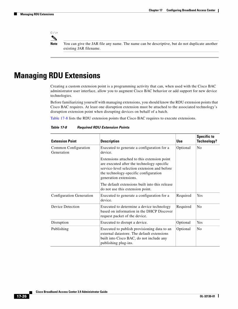
Chapter 17 Configuring Broadband Access CenterManaging RDU Extensions
C:\>
Note You can give the JAR file any name. The name can be descriptive, but do not duplicate another existing JAR filename.
Managing RDU ExtensionsCreating a custom extension point is a programming activity that can, when used with the Cisco BAC administrator user interface, allow you to augment Cisco BAC behavior or add support for new device technologies.
Before familiarizing yourself with managing extensions, you should know the RDU extension points that Cisco BAC requires. At least one disruption extension must be attached to the associated technology’s disruption extension point when disrupting devices on behalf of a batch.
Table 17-8 lists the RDU extension points that Cisco BAC requires to execute extensions.
Table 17-8 Required RDU Extension Points
Extension Point Description UseSpecific to Technology?
Common Configuration Generation
Executed to generate a configuration for a device.
Extensions attached to this extension point are executed after the technology-specific service-level selection extension and before the technology-specific configuration generation extensions.
The default extensions built into this release do not use this extension point.
Optional No
Configuration Generation Executed to generate a configuration for a device.
Required Yes
Device Detection Executed to determine a device technology based on information in the DHCP Discover request packet of the device.
Required No
Disruption Executed to disrupt a device. Optional Yes
Publishing Executed to publish provisioning data to an external datastore. The default extensions built into Cisco BAC, do not include any publishing plug-ins.
Optional No
17-26Cisco Broadband Access Center 3.9 Administrator Guide
OL-32130-01
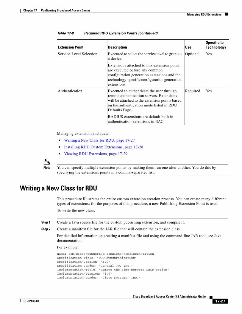
Chapter 17 Configuring Broadband Access CenterManaging RDU Extensions
Managing extensions includes:
• Writing a New Class for RDU, page 17-27
• Installing RDU Custom Extensions, page 17-28
• Viewing RDU Extensions, page 17-29
Note You can specify multiple extension points by making them run one after another. You do this by specifying the extensions points in a comma-separated list.
Writing a New Class for RDUThis procedure illustrates the entire custom extension creation process. You can create many different types of extensions; for the purposes of this procedure, a new Publishing Extension Point is used.
To write the new class:
Step 1 Create a Java source file for the custom publishing extension, and compile it.
Step 2 Create a manifest file for the JAR file that will contain the extension class.
For detailed information on creating a manifest file and using the command-line JAR tool, see Java documentation.
For example:
Name: com/cisco/support/extensions/configgenerationSpecification-Title: "TOD synchronization"Specification-Version: "1.0"Specification-Vendor: "General TW, Inc."Implementation-Title: "Remove the time-servers DHCP option"Implementation-Version: "1.0"Implementation-Vendor: "Cisco Systems, Inc."
Service-Level Selection Executed to select the service level to grant to a device.
Extensions attached to this extension point are executed before any common configuration generation extensions and the technology-specific configuration generation extensions.
Optional Yes
Authentication Executed to authenticate the user through remote authentication servers. Extensions will be attached to the extension points based on the authentication mode listed in RDU Defaults Page.
RADIUS extensions are default built in authentication extensions in BAC.
Required Yes
Table 17-8 Required RDU Extension Points (continued)
Extension Point Description UseSpecific to Technology?
17-27Cisco Broadband Access Center 3.9 Administrator Guide
OL-32130-01
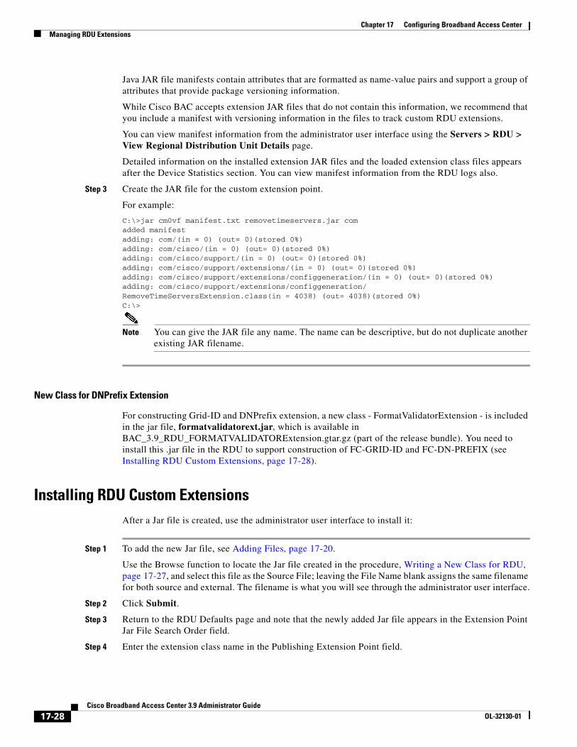
Chapter 17 Configuring Broadband Access CenterManaging RDU Extensions
Java JAR file manifests contain attributes that are formatted as name-value pairs and support a group of attributes that provide package versioning information.
While Cisco BAC accepts extension JAR files that do not contain this information, we recommend that you include a manifest with versioning information in the files to track custom RDU extensions.
You can view manifest information from the administrator user interface using the Servers > RDU > View Regional Distribution Unit Details page.
Detailed information on the installed extension JAR files and the loaded extension class files appears after the Device Statistics section. You can view manifest information from the RDU logs also.
Step 3 Create the JAR file for the custom extension point.
For example:
C:\>jar cm0vf manifest.txt removetimeservers.jar comadded manifestadding: com/(in = 0) (out= 0)(stored 0%)adding: com/cisco/(in = 0) (out= 0)(stored 0%)adding: com/cisco/support/(in = 0) (out= 0)(stored 0%)adding: com/cisco/support/extensions/(in = 0) (out= 0)(stored 0%)adding: com/cisco/support/extensions/configgeneration/(in = 0) (out= 0)(stored 0%)adding: com/cisco/support/extensions/configgeneration/RemoveTimeServersExtension.class(in = 4038) (out= 4038)(stored 0%)C:\>
Note You can give the JAR file any name. The name can be descriptive, but do not duplicate another existing JAR filename.
New Class for DNPrefix Extension
For constructing Grid-ID and DNPrefix extension, a new class - FormatValidatorExtension - is included in the jar file, formatvalidatorext.jar, which is available in BAC_3.9_RDU_FORMATVALIDATORExtension.gtar.gz (part of the release bundle). You need to install this .jar file in the RDU to support construction of FC-GRID-ID and FC-DN-PREFIX (see Installing RDU Custom Extensions, page 17-28).
Installing RDU Custom Extensions After a Jar file is created, use the administrator user interface to install it:
Step 1 To add the new Jar file, see Adding Files, page 17-20.
Use the Browse function to locate the Jar file created in the procedure, Writing a New Class for RDU, page 17-27, and select this file as the Source File; leaving the File Name blank assigns the same filename for both source and external. The filename is what you will see through the administrator user interface.
Step 2 Click Submit.
Step 3 Return to the RDU Defaults page and note that the newly added Jar file appears in the Extension Point Jar File Search Order field.
Step 4 Enter the extension class name in the Publishing Extension Point field.
17-28Cisco Broadband Access Center 3.9 Administrator Guide
OL-32130-01
Chapter 17 Configuring Broadband Access CenterPublishing Provisioning Data
The RDU returns an error if the class name does not exist within the jar file or if Cisco BAC detects any other errors. This error occurs mostly when replacing a Jar file, if, for example, the class you set up is not found in the replacement Jar file.
Step 5 Click Submit to commit the changes to the RDU database.
Step 6 View the RDU extensions to ensure that the correct extensions are loaded.
Viewing RDU ExtensionsYou can view the attributes of all RDU extensions directly from the View Regional Distribution Unit Details page. This page displays details on the installed extension Jar files and the loaded extension class files.
Publishing Provisioning DataCisco BAC has the capability to publish the provisioning data it tracks to an external datastore in real time. To do this, a publishing plug-in must be developed to write the data to the desired datastore. The Manage Publishing page identifies information such as the plug-in name, its current status (whether it is enabled or disabled), and switch to enable or disable it.
You can enable as many plug-ins as required by your implementation but care must be exercised because the use of publishing plug-ins can decrease system performance.
Note Cisco BAC does not ship with any publishing plug-ins. You must create your own plug-ins and load them into Cisco BAC in the same way as JAR files are (see Adding Files, page 17-20). Then, manage the plug-ins from the Manage Publishing page.
Publishing Datastore ChangesTo enable or disable a publishing plug-in:
Step 1 Choose Configuration on the Primary Navigation bar.
Step 2 Choose Publishing on the Secondary Navigation bar.
The Manage Publishing page appears. This page displays a list of all available database plug-ins and identifies the current status of each. C
Step 3 Click on the appropriate status indicator to enable or disable the required plug-in. Note that as you click the status, it toggles from enabled to disabled.
Modifying Publishing Plug-In SettingsThese settings are a convenient way for plug-in writers to store plug-in settings in the RDU for their respective datastore. To modify the publishing plug-in settings:
17-29Cisco Broadband Access Center 3.9 Administrator Guide
OL-32130-01
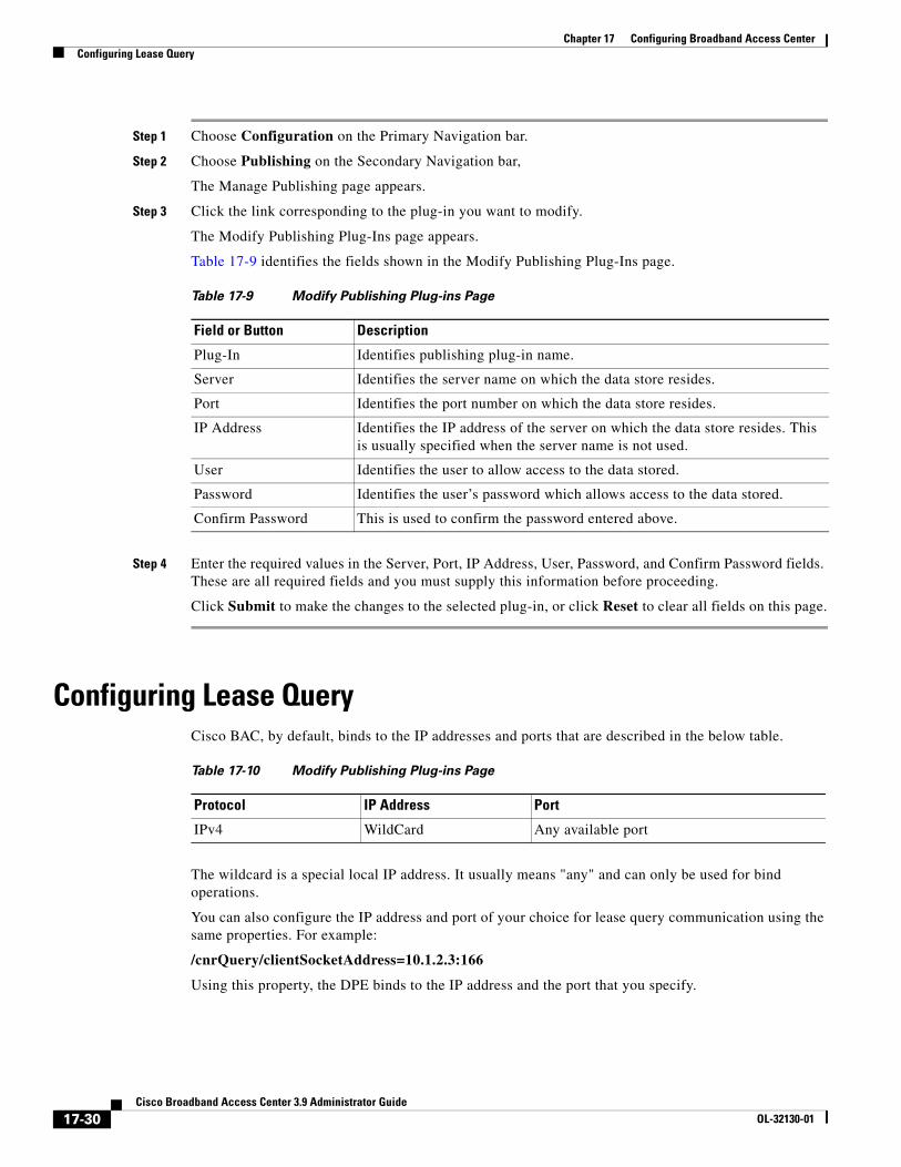
Chapter 17 Configuring Broadband Access CenterConfiguring Lease Query
Step 1 Choose Configuration on the Primary Navigation bar.
Step 2 Choose Publishing on the Secondary Navigation bar,
The Manage Publishing page appears.
Step 3 Click the link corresponding to the plug-in you want to modify.
The Modify Publishing Plug-Ins page appears.
Table 17-9 identifies the fields shown in the Modify Publishing Plug-Ins page.
Step 4 Enter the required values in the Server, Port, IP Address, User, Password, and Confirm Password fields. These are all required fields and you must supply this information before proceeding.
Click Submit to make the changes to the selected plug-in, or click Reset to clear all fields on this page.
Configuring Lease QueryCisco BAC, by default, binds to the IP addresses and ports that are described in the below table.
The wildcard is a special local IP address. It usually means "any" and can only be used for bind operations.
You can also configure the IP address and port of your choice for lease query communication using the same properties. For example:
/cnrQuery/clientSocketAddress=10.1.2.3:166
Using this property, the DPE binds to the IP address and the port that you specify.
Table 17-9 Modify Publishing Plug-ins Page
Field or Button Description
Plug-In Identifies publishing plug-in name.
Server Identifies the server name on which the data store resides.
Port Identifies the port number on which the data store resides.
IP Address Identifies the IP address of the server on which the data store resides. This is usually specified when the server name is not used.
User Identifies the user to allow access to the data stored.
Password Identifies the user’s password which allows access to the data stored.
Confirm Password This is used to confirm the password entered above.
Table 17-10 Modify Publishing Plug-ins Page
Protocol IP Address Port
IPv4 WildCard Any available port
17-30Cisco Broadband Access Center 3.9 Administrator Guide
OL-32130-01
Chapter 17 Configuring Broadband Access CenterUpdating the Location of FAP at Group Level in the Grid
Updating the Location of FAP at Group Level in the GridCisco BAC identifies the location of an anchor Femtocell Access Point (FAP) (or anchor FAP) within a grid. This location is updated at group or subgroup level so that other devices in the grid are also updated with the location details of the same anchor FAP.
For details about the creation of group or subgroup, see Group Management, page 16-18.
To achieve this location verification (LV) at group or subgroup level, Cisco BAC uses three custom properties that are associated with chained intra grid (CIG), and need to be defined at device level:
• FC-CIG-ENABLED
• FC-ANCHOR-AP-LV-LIST
• FC-CIG-GROUP-TYPE
Cisco BAC also skips location verification of other devices in the same grid if one of the connected devices has successfully verified the location of the anchor FAP.
The properties of the anchor FAP, which are updated at group level are:
• FC-CIG-GPS-LAT — GPS latitude value
• FC-CIG-GPS-LONG — GPS longitude value
• FC-CIG-GPS-LOCK-TS — GPS lock timestamp
• FC-CIG-ANCHOR-AP-EID — DeviceID of the anchor FAP
• FC-CIG-GPS-DISTANCE — GPS distance value
• FC-ANCHOR-GPS-LOCK — Status (boolean) of anchor FAP GPS lock
The properties of the anchor FAP, which are updated at subgroup level are:
• FC-CIG-GPS-LAT — GPS latitude value
• FC-CIG-GPS-LONG — GPS longitude value
• FC-CIG-GPS-LOCK-TS — GPS lock timestamp
• FC-CIG-ANCHOR-AP-EID — DeviceID of the anchor FAP
• FC-CIG-GPS-DISTANCE — GPS distance value
• FC-SUBSITE-ANCHOR-GPS-LOCK — Status (boolean) of subgroup anchor FAP GPS lock
The property of the anchor FAP, which is updated at device level, is FC-CURRENT-GPS-LOCK — Status (boolean) of current GPS lock
Configuring BAC and the Device for CIGTo configure Cisco BAC and the device for chained intra grid (CIG) in the Admin UI:
Step 1 In the BAC RDU Admin UI, configure the Chained Grid Group Generation configuration extension. Go to Configuration > Defaults > Configuration Generation Extension Point, and enter the following extension name – com.cisco.provisioning.cpe.extensions.builtin.generation.ChainedGridGroupGeneration
Step 2 For all the devices in the grid, configure the following custom properties to be available in /IPDevice/properties/available/pg:
• FC-CIG-ENABLED
17-31Cisco Broadband Access Center 3.9 Administrator Guide
OL-32130-01
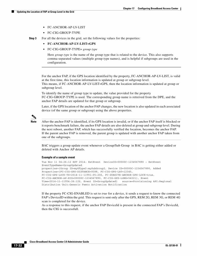
Chapter 17 Configuring Broadband Access CenterUpdating the Location of FAP at Group Level in the Grid
• FC-ANCHOR-AP-LV-LIST
• FC-CIG-GROUP-TYPE
Step 3 For all the devices in the grid, set the following values for the properties:
• FC-ANCHOR-AP-LV-LIST=GPS
• FC-CIG-GROUP-TYPE= group type
Here group type is the name of the group type that is related to the device. This also supports comma-separated values (multiple group type names), and is helpful if subgroups are used in the configuration.
For the anchor FAP, if the GPS location identified by the property, FC-ANCHOR-AP-LV-LIST, is valid at the first time, this location information is updated at group or subgroup level.This means, if FC-ANCHOR-AP-LV-LIST=GPS, then the location information is updated at group or subgroup level.
To identify the name of group type to update, the value provided for the property FC-CIG-GROUP-TYPE is used. The corresponding group name is retreived from the DPE, and the anchor FAP details are updated for that group or subgroup.
Later, if the GPS location of the anchor FAP changes, the new location is also updated in each associated device (of the same group or subgroup) using the above properties.
Note After the anchor FAP is identified, if its GPS location is invalid, or if the anchor FAP itself is blocked or it reports benchmark failure, the anchor FAP details are also deleted at group and subgroup level. During the next reboot, another FAP, which has successfully verified the location, becomes the anchor FAP.If the parent anchor FAP is removed, the parent group is updated with another anchor FAP taken from one of the subgroups.
BAC triggers a group update event whenever a Group/Sub Group in BAC is getting either added or deleted with Anchor AP details.
Example of a sample eventTue Nov 11 04:26:12 EST 2014: ExtEvent DeviceID=00000C-1234567890 : ExtEvent EventTypeName=GroupUpdatedproperties={Group ID=myGType2:mySubGroup2, Device ID=00000C-1234567890, Added Properties={FC-CIG-GPS-DISTANCE=9398, FC-CIG-GPS-LAT=12345, FC-CIG-GPS-LOCK-TS=2014-11-11T01:05:20Z, FC-SUBSITE-ANCHOR-GPS-LOCK=true, FC-CIG-ANCHOR-AP-EID=00000C-1234567890, FC-CIG-GPS-LONG=54321}, Event Time=2014-11-11T04:26:12Z, Event ID=GroupUpdated} source=Provisioning API:Regional Distribution Unit:Generic Femto Activation Notification
If the property FC-CIG-ENABLED is set to true for a device, it sends a request to know the connected FAP’s DeviceID within the grid. This request is sent only after the GPS, REM 2G, REM 3G, or REM 4G scan is completed for the device.As a response to this request, if the anchor FAP DeviceId is present in the connected FAP’s DeviceId, then the CIG is successfull.
17-32Cisco Broadband Access Center 3.9 Administrator Guide
OL-32130-01
Chapter 17 Configuring Broadband Access CenterUpdating the Location of FAP at Chassis Level
Updating the Location of FAP at Chassis LevelIn Cisco BAC, you can use the Chained Intra Chassis (CIC) Location Verification to skip the location verification on one technology type (either 3G or 4G) from same chassis, if the other technology type has already completed the location verification. This method is applicable together with other location verification methods like GPS, CIG, REM scan and so on.
Cisco BAC identifies the location of an anchor Femtocell Access Point (FAP) (or anchor FAP) based on the configured location verification methods. If all the configured location verification methods are successful and there is no peer RAT or the neighbor device in the same chassis has no details of anchor FAP, then the current device becomes an anchor FAP within the chassis.
To achieve this location verification at chassis level, Cisco BAC uses the following custom properties that are associated with chained intra chassis (CIC):
• FC-CIC-ENABLED - Need to be always set as true to update the remaining custom properties (shown below) in the device record
• FC-CIC-STATUS
• FC-CIC-STATUS-TS
• FC-CIC-ANCHOR-AP-EID
• FC-CHASSIS-ID
• FC-PEER-RAT-ID
Cisco BAC also skips location verification of other devices or peer devices in the same chassis if one of the connected device has successfully passed the location verification and it is an anchor FAP. The anchor AP details will be updated on the current device.
Configuring BAC and the Device for CICTo configure Cisco BAC and the device for chained intra chassis (CIC) in Admin UI:
Step 1 Configure the following custom properties related to Chained Intra Chassis location verification in Configuration > Custom Property > Manage BAC Custom Properties, using Add:
• FC-CIC-ENABLED
• FC-CIC-STATUS
• FC-CIC-STATUS-TS
• FC-CIC-ANCHOR-AP-EID
• FC-CHASSIS-ID
• FC-PEER-RAT-ID
Step 2 For all the devices in the chassis, configure the following custom properties to be available in /IPDevice/properties/available/pg:
• FC-CIC-ENABLED
• FC-CIC-STATUS
• FC-CIC-STATUS-TS
• FC-CIC-ANCHOR-AP-EID
• FC-CHASSIS-ID
17-33Cisco Broadband Access Center 3.9 Administrator Guide
OL-32130-01
Chapter 17 Configuring Broadband Access CenterUpdating the Location of FAP at Chassis Level
• FC-PEER-RAT-ID
Note FC-CIC-ENABLED is applicable at Device, CoS, Group, and Provisioning Group levels.
Note After the anchor FAP is identified, if the anchor FAP itself is blocked or it reports benchmark failure or if a shutdown occurs, the anchor FAP details are deleted for all devices on the chassis. During the next reboot, another FAP, which has successfully verified the chassis location, becomes the anchor FAP.
If the property FC-CIC-ENABLED is set to false or removed for a device, then when the device reboot occurs, it checks if it was an anchor FAP previously, and removes the anchor FAP details. The neighbor device or peer device anchor FAP details are removed after reboot.
17-34Cisco Broadband Access Center 3.9 Administrator Guide
OL-32130-01
Chapter 17 Configuring Broadband Access CenterConfiguring Location Verification for UMTS
Configuring Location Verification for UMTSThe FAP location verification method for UMTS can be configured in Cisco BAC. You can:
• Delay the GPS verification for the FAP during initial boot up, before the NWL based location verification is initiated
• Ensure that the NWL benchmark is updated if the DNM location verification of FAP is successful, even though DNB location verification is not successful
To configure delayed GPS verification during the initial boot up, use the custom property FC-GPS-TIME-OUT, and set the required value (in seconds). This ensures that, if the initial GPS location verification is Unknown or Time out, the location verification method waits for sometime (as specified by FC-GPS-TIME-OUT), before proceeding to NWL based location verification.
To give priority for DNM location verification, use the custom property FC-DNM-BENCHMARK-UPDATE. The default value is true, which ensures that the NWL benchmark is updated if DNM location verification is successful and DNB is not successful (Failure).
You can also define the action to be taken for DNB location verification failure, using the custom property FC-DNB-FAIL-ACTION:
• Set FC-DNB-FAIL-ACTION as unknown to continue with other location verification methods even though DNB has failed. This is the default value.
• Set FC-DNB-FAIL-ACTION as error to make the location verification status itself as failure.
Configuring 2G Scan and 3G Scan Capability of LTECisco BAC provides the option to discover the 2G scan and 3G scan capability of LTE and use it for location verification, even though the custom parameters FC-2G-REM-SCAN and FC-3G-REM-SCAN are set to true for the device.
To discover these capabilities from the LTE, go to Configuration > Defaults > CWMP Defaults > Custom Discover Parameters, and enter the following:
• .FAPService.{i}.Capabilities.LTE.GSMRxSupported
• .FAPService.{i}.Capabilities.LTE.UMTSRxSupported
The technology type REM scan is completed for the LTE only if these discovered parameters are also true.
Configuring Static Neighbor List of LTECisco BAC helps you to define the entire neighbor list configuration of an LTE, without considering the detected neighbors by the LTE as a result of the REM scan process. This release supports inter-RAT configuration, and you can configure up to 32 instances for the inter-RAT table.
To achieve this, you need to first disable the REM scan process, by setting the following parameters (described in the TR-196 Issue 2 Femto Access Point Service Data Model (FAPService:2.0)) to false:
• .FAPService.{i}.REM.LTE.ScanOnBoot
• .FAPService.{i}.REM.LTE.ScanPeriodically
To set the neighbor list of LTE, you can create a configuration template and assign values to all the parameters under the following objects:
17-35Cisco Broadband Access Center 3.9 Administrator Guide
OL-32130-01
Chapter 17 Configuring Broadband Access CenterConfiguring Static Neighbor List of LTE
• .FAPService.{i}.CellConfig.LTE.RAN.NeighborList.LTECell.{i}
• .FAPService.{i}.CellConfig.LTE.RAN.NeighborList.InterRATCell.UMTS.{i}
• .FAPService.{i}.CellConfig.LTE.RAN.NeighborList.InterRATCell.GSM.{i}
• .FAPService.{i}.CellConfig.LTE.RAN.NeighborList.InterRATCell.CDMA2000.{i}
Cisco BAC also supports reading values from the neighbor list that is used by the LTE. You can create configuration template to read values for all the parameters under the following objects:
• .FAPService.{i}.CellConfig.LTE.RAN.NeighborListInUse.LTECell.{i}
• .FAPService.{i}.CellConfig.LTE.RAN.NeighborListInUse.InterRATCell.UMTS.{i}
• .FAPService.{i}.CellConfig.LTE.RAN.NeighborListInUse.InterRATCell.GSM.{i}
• .FAPService.{i}.CellConfig.LTE.RAN.NeighborListInUse.InterRATCell.CDMA2000.{i}
Example 17-1 Sample Configuration Template for Setting the Neighbor List
<Configuration templateVersion="3.0"><ParameterDictionaries>
<ParameterDictionary>tr196-cwmp-dictionary-v2.0.xml</ParameterDictionary></ParameterDictionaries>
<ObjectInstance name="Device"><ObjectInstance name="Services">
<ObjectInstance name="FAPService"><ObjectInstance name="{i}" sync-method="discovered" instance="1">
<Parameter><Name>DNPrefix</Name><Value>VAR(name=FC-DN-PREFIX,
defaultValue=myDN)</Value></Parameter><ObjectInstance name="CellConfig"><ObjectInstance name="LTE">
<ObjectInstance name="RAN"><ObjectInstance name="NeighborList"></ObjectInstance>
<ObjectInstance name="LTECell" sync-method="discovered" instance="all">
<ObjectInstance name="{i}"><Parameter>
<Name>Enable</Name><Value>false</Value>
</Parameter><Parameter>
<Name>Alias</Name><Value>none</Value>
</Parameter><Parameter>
<Name>MustInclude</Name><Value>false</Value>
</Parameter><Parameter>
<Name>PLMNID</Name><Value>4005</Value>
</Parameter><Parameter>
<Name>CID</Name><Value>1</Value>
</Parameter></ObjectInstance>
</ObjectInstance></ObjectInstance>
</ObjectInstnace>
17-36Cisco Broadband Access Center 3.9 Administrator Guide
OL-32130-01
Chapter 17 Configuring Broadband Access CenterConfiguring Remote Reset for Tampered LTE FAP
</ObjectInstnace></Configuration>
Configuring Remote Reset for Tampered LTE FAPCisco BAC identifies tampered LTE FAPs and provides the option to remotely reset those devices. This avoids the need to manually reset the tampered device at the location.
To achieve this:
Step 1 Configure the following custom properties to be available in /IPDevice/properties/available/pg, for the LTE FAP:
• FC-TAMPERED-ENABLED
• FC-TAMPER-CLEAR
• FC-TAMPERED
Step 2 Set the properties FC-TAMPERED-ENABLED=true and FC-TAMPER-CLEAR=true.
If the device gets tampered, the reset happens as the value of FC-TAMPER-CLEAR is true. This enables the device for initialization and further processing according to the flow.
Note After the reset, the FC-TAMPER-CLEAR property gets removed from /IPDevice/properties/available/pg. You need to add it again for subsequent reset.
If FC-TAMPER-CLEAR is set to false and the device gets tampered, then FC-TAMPERED is automatically set to true, and this stops the initialization and further processing of the device.
17-37Cisco Broadband Access Center 3.9 Administrator Guide
OL-32130-01

Chapter 17 Configuring Broadband Access CenterConfiguring Remote Reset for Tampered LTE FAP
17-38Cisco Broadband Access Center 3.9 Administrator Guide
OL-32130-01
CiscoOL-32130-01
C H A P T E R 18
Scripting FrameworkThis chapter describes the Scripting framework in Cisco BAC that involves configuring java script based DPE extensions.
This chapter includes the following sections:
• Overview, page 18-1
• Script’s Shared Scope, page 18-1
• Extension Script, page 18-2
• Integrating Extension Scripts in BAC, page 18-3
• Adding Extension Points to the Device Property, page 18-3
• Configuring Extensions for Unknown Devices, page 18-4
• Verifying Extension Scripts Availability in DPE Cache, page 18-5
• Verifying Status of the Extensions in DPE, page 18-5
OverviewScriptable extension service facilitates running the java scripts based DPE extensions. Once the extension scripts are added in the RDU database, the RDU applies the scripts to the DPE cache. When the CPE boots and attempts to establish connection with the DPE, the extension scripts are executed based on the extensions configured in the device property hierarchy.
Script’s Shared ScopeScript’s Shared Scope is a shared repository for extension scripts. Cisco BAC APIs like get properties from PG, fire extension specific events, debugging, logging, and so on, are put into the Script’s Shared Scope so that the extension scripts can call them whenever required.
The following objects are added in the Script’s Shared Scope for extension scripts:
Table 18-1 Java Objects
Object Name API
request CwmpHttpRequest
response CwmpHttpResponse
18-1 Broadband Access Center 3.9 Administrator Guide
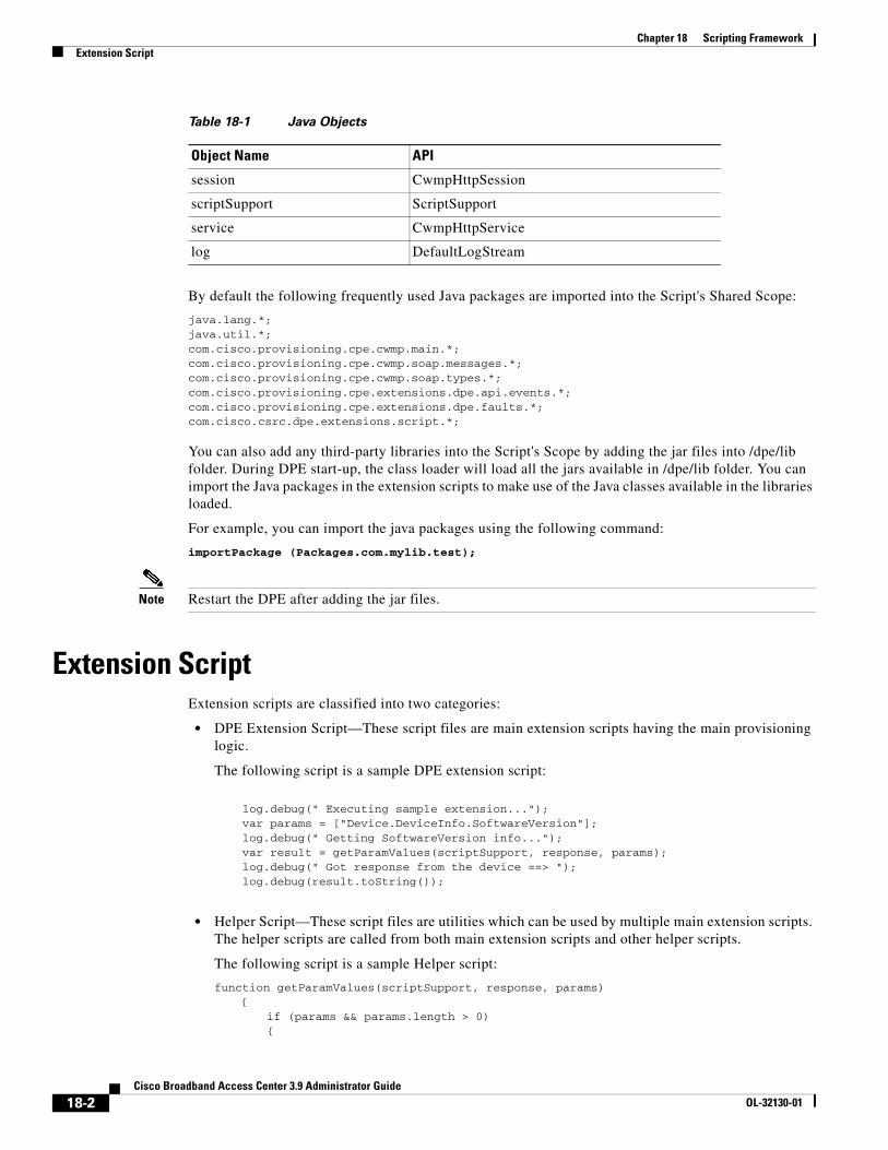
Chapter 18 Scripting FrameworkExtension Script
By default the following frequently used Java packages are imported into the Script's Shared Scope:
java.lang.*;java.util.*;com.cisco.provisioning.cpe.cwmp.main.*;com.cisco.provisioning.cpe.cwmp.soap.messages.*;com.cisco.provisioning.cpe.cwmp.soap.types.*;com.cisco.provisioning.cpe.extensions.dpe.api.events.*;com.cisco.provisioning.cpe.extensions.dpe.faults.*;com.cisco.csrc.dpe.extensions.script.*;
You can also add any third-party libraries into the Script's Scope by adding the jar files into /dpe/lib folder. During DPE start-up, the class loader will load all the jars available in /dpe/lib folder. You can import the Java packages in the extension scripts to make use of the Java classes available in the libraries loaded.
For example, you can import the java packages using the following command:
importPackage (Packages.com.mylib.test);
Note Restart the DPE after adding the jar files.
Extension ScriptExtension scripts are classified into two categories:
• DPE Extension Script—These script files are main extension scripts having the main provisioning logic.
The following script is a sample DPE extension script:
log.debug(" Executing sample extension..."); var params = ["Device.DeviceInfo.SoftwareVersion"]; log.debug(" Getting SoftwareVersion info..."); var result = getParamValues(scriptSupport, response, params); log.debug(" Got response from the device ==> "); log.debug(result.toString());
• Helper Script—These script files are utilities which can be used by multiple main extension scripts. The helper scripts are called from both main extension scripts and other helper scripts.
The following script is a sample Helper script:
function getParamValues(scriptSupport, response, params){
if (params && params.length > 0){
session CwmpHttpSession
scriptSupport ScriptSupport
service CwmpHttpService
log DefaultLogStream
Table 18-1 Java Objects
Object Name API
18-2Cisco Broadband Access Center 3.9 Administrator Guide
OL-32130-01
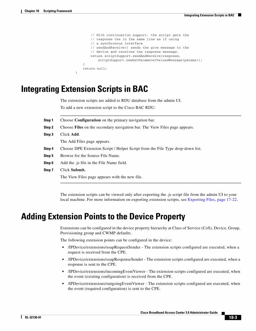
Chapter 18 Scripting FrameworkIntegrating Extension Scripts in BAC
// With continuation support, the script gets the// response the in the same line as if using// a synchronous interface// sendAndReceive() sends the give message to the// device and receives the response message.return scriptSupport.sendAndReceive(response,
scriptSupport.newGetParameterValuesMessage(params));}return null;
}
Integrating Extension Scripts in BACThe extension scripts are added to RDU database from the admin UI.
To add a new extension script to the Cisco BAC RDU:
Step 1 Choose Configuration on the primary navigation bar.
Step 2 Choose Files on the secondary navigation bar. The View Files page appears.
Step 3 Click Add.
The Add Files page appears.
Step 4 Choose DPE Extension Script / Helper Script from the File Type drop-down list.
Step 5 Browse for the Source File Name.
Step 6 Add the .js file in the File Name field.
Step 7 Click Submit.
The View Files page appears with the new file.
The extension scripts can be viewed only after exporting the .js script file from the admin UI to your local machine. For more information on exporting extension scripts, see Exporting Files, page 17-22.
Adding Extension Points to the Device PropertyExtensions can be configured in the device property hierarchy at Class of Service (CoS), Device, Group, Provisioning group and CWMP defaults.
The following extension points can be configured in the device:
• /IPDevice/extensions/soapRequestSender - The extension scripts configured are executed, when a request is received from the CPE.
• /IPDevice/extensions/soapResponseSender - The extension scripts configured are executed, when a response is sent to the CPE.
• /IPDevice/extensions/incomingEventViewer - The extension scripts configured are executed, when the event (existing configuration) is received from the CPE.
• /IPDevice/extensions/outgoingEventViewer - The extension scripts configured are executed, when the event (required configuration) is sent to the CPE.
18-3Cisco Broadband Access Center 3.9 Administrator Guide
OL-32130-01
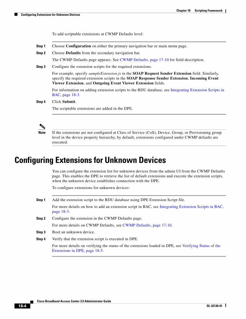
Chapter 18 Scripting FrameworkConfiguring Extensions for Unknown Devices
To add scriptable extensions at CWMP Defaults level:
Step 1 Choose Configuration on either the primary navigation bar or main menu page.
Step 2 Choose Defaults from the secondary navigation bar.
The CWMP Defaults page appears. See CWMP Defaults, page 17-10 for field description.
Step 3 Configure the extension scripts for the required extensions.
For example, specify sampleExtension.js in the SOAP Request Sender Extension field. Similarly, specify the required extension scripts in the SOAP Response Sender Extension, Incoming Event Viewer Extension, and Outgoing Event Viewer Extension fields.
For information on adding extension scripts to the RDU database, see Integrating Extension Scripts in BAC, page 18-3.
Step 4 Click Submit.
The scriptable extensions are added in the DPE.
Note If the extensions are not configured at Class of Service (CoS), Device, Group, or Provisioning group level in the device property hierarchy, by default, extensions configured under CWMP defaults are executed.
Configuring Extensions for Unknown DevicesYou can configure the extension list for unknown devices from the admin UI from the CWMP Defaults page. This enables the DPE to retrieve the list of default extensions and execute the extension scripts, when the unknown device establishes connection with the DPE.
To configure extensions for unknown devices:
Step 1 Add the extension script to the RDU database using DPE Extension Script file.
For more details on how to add an extension script in BAC, see Integrating Extension Scripts in BAC, page 18-3.
Step 2 Configure the extension in the CWMP Defaults page.
For more details on CWMP Defaults, see CWMP Defaults, page 17-10.
Step 3 Boot an unknown device.
Step 4 Verify that the extension script is executed in DPE.
For more details on verifying the status of the extensions loaded in DPE, see Verifying Status of the Extensions in DPE, page 18-5.
18-4Cisco Broadband Access Center 3.9 Administrator Guide
OL-32130-01
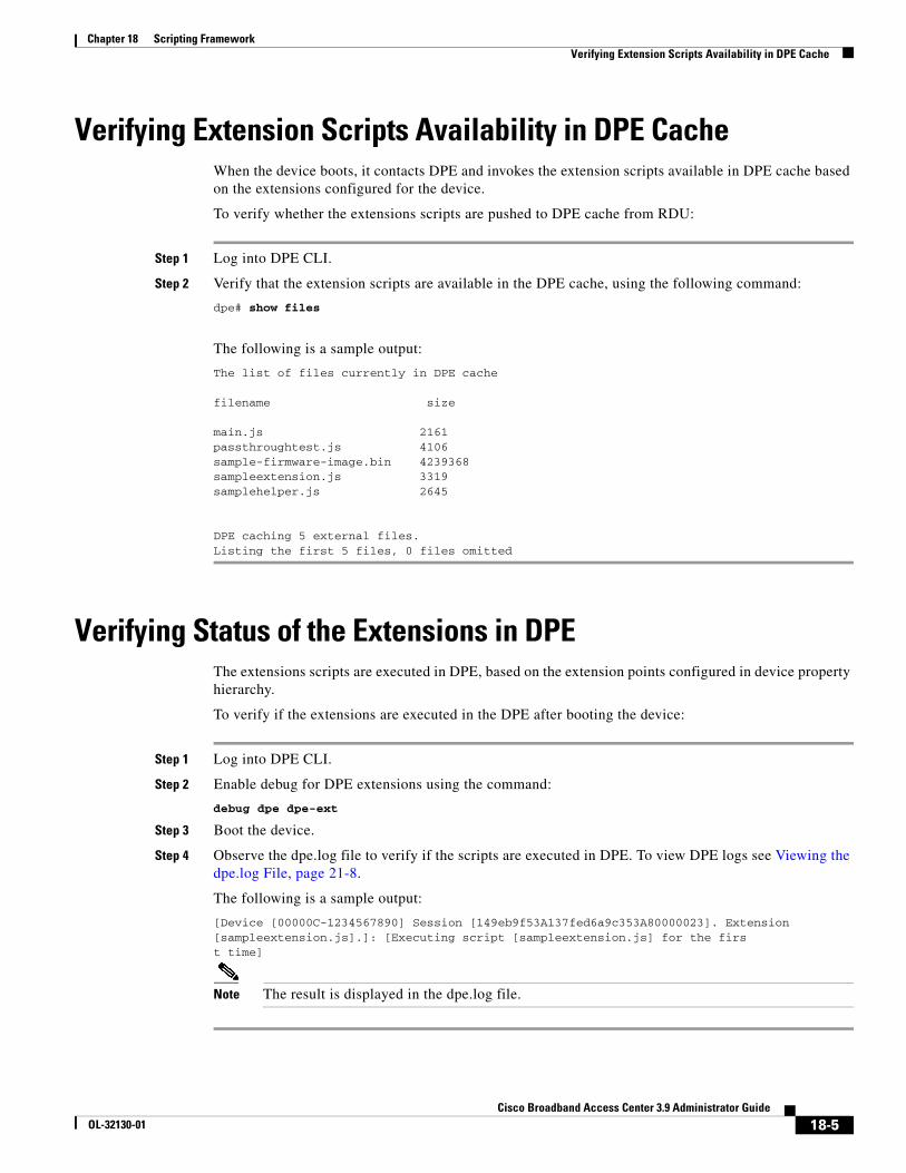
Chapter 18 Scripting FrameworkVerifying Extension Scripts Availability in DPE Cache
Verifying Extension Scripts Availability in DPE CacheWhen the device boots, it contacts DPE and invokes the extension scripts available in DPE cache based on the extensions configured for the device.
To verify whether the extensions scripts are pushed to DPE cache from RDU:
Step 1 Log into DPE CLI.
Step 2 Verify that the extension scripts are available in the DPE cache, using the following command:
dpe# show files
The following is a sample output:
The list of files currently in DPE cache
filename size
main.js 2161passthroughtest.js 4106sample-firmware-image.bin 4239368sampleextension.js 3319samplehelper.js 2645
DPE caching 5 external files.Listing the first 5 files, 0 files omitted
Verifying Status of the Extensions in DPEThe extensions scripts are executed in DPE, based on the extension points configured in device property hierarchy.
To verify if the extensions are executed in the DPE after booting the device:
Step 1 Log into DPE CLI.
Step 2 Enable debug for DPE extensions using the command:
debug dpe dpe-ext
Step 3 Boot the device.
Step 4 Observe the dpe.log file to verify if the scripts are executed in DPE. To view DPE logs see Viewing the dpe.log File, page 21-8.
The following is a sample output:
[Device [00000C-1234567890] Session [149eb9f53A137fed6a9c353A80000023]. Extension [sampleextension.js].]: [Executing script [sampleextension.js] for the first time]
Note The result is displayed in the dpe.log file.
18-5Cisco Broadband Access Center 3.9 Administrator Guide
OL-32130-01

Chapter 18 Scripting FrameworkVerifying Status of the Extensions in DPE
18-6Cisco Broadband Access Center 3.9 Administrator Guide
OL-32130-01
CiscoOL-32130-01
C H A P T E R 19
RDU and DPE Connection ManagementThis chapter deals with RDU TCP Connection Management, RDU Batch Concurrency and RDU DPE synchronization.
This chapter includes the following sections:
• TCP Connection Management, page 19-1
• RDU Batch Concurrency, page 19-2
• DPE-RDU Synchronization, page 19-3
TCP Connection ManagementCommunication between the RDU and its clients, such as DPEs, API, occurs over TCP. Each client creates a connection to the RDU that is maintained as long as the client desires.
Over this connection, clients submit batches to the RDU while the RDU replies with the batch results and additionally sends events. In order to maintain the connection, a heart beat is used when no other traffic is available. Timeouts are used to prevent the RDU and the clients from creating unwanted traffic.
Heart BeatHeart beat messages are initiated by the clients. The client sends a heart beat when a read timeout has occurred and it is in the process of receiving a message. On receiving this heart beat, the RDU echoes it. The client receives this echo and recognizes that the connection is alive. This cycle repeats itself until the connection is lost.
If the client fails to receive a reply after sending the heart beat (echo message), it closes its connection and attempts to open a new one.
The RDU will close the connection if no traffic is sent or received for two consecutive read timeouts. To change the number of read timeouts before closing the connection, you must set the following property in the RDU property file and restart the application. You can configure this property in the BPR_HOME/rdu/rdu.properties file.
/messaging/connection/numReadTimeouts=value
19-1 Broadband Access Center 3.9 Administrator Guide
Chapter 19 RDU and DPE Connection ManagementRDU Batch Concurrency
RDU Batch ConcurrencyIn the Cisco BAC system, a provisioning client submits API requests to the RDU in the form of batches containing single or multiple commands. A command represents an operation that can be performed on an object in the RDU's database, for example, changing a device's Class of Service. Depending on the commands contained in the batch, the RDU runs the batch in one of two modes: concurrent or non-concurrent.
The commands contained within a batch determine the mode it is to be run with. When a batch is received at the RDU, its commands are checked and the batch is marked with the mode with which it must be run with. During the execution of a concurrent-mode batch, other concurrent-mode batches are allowed to be run, in parallel. The majority of batches executed are run in the concurrent mode.
If the batch is marked as non-concurrent, it is executed only when all the currently executing batches are completed in the RDU. The non-concurrent batch is run alone. After the batch completes running, the RDU processes the queued batches in the mode that they have been marked.
The reason concurrent and non-concurrent modes exist is to provide higher throughput at the RDU without losing data integrity. There are only a few commands that cause a batch to run in non-concurrent mode. They are mainly concerned with system configuration operations that are not called very often.
Non-concurrent CommandsAlong with Server Registration, if any of the following commands are present in a batch, it is run in non-concurrent mode.
Configuration Interface
• addLicenseKey
• addUser
• addCustomPropertyDefinition
• addClassOfService
• addFile
• changeClassOfServiceProperties
• changeDPEDefaults
• changeExtensionPointSettings
• changeRDUDefaults
• changeSystemDefaults
• changeFileProperties
• changeProvGroupProperties
• changeUser
• deleteClassOfService
• deleteFile
• deleteLicenseKey
• removeCustomPropertyDefinition
• replaceFile
19-2Cisco Broadband Access Center 3.9 Administrator Guide
OL-32130-01
Chapter 19 RDU and DPE Connection ManagementDPE-RDU Synchronization
IPDevice Interface
• addDeviceType
• changeDefaults
• deleteDeviceType
• regenConfigs
• IPDevice.addNode
• IPDevice.changeNodeProperties
• IPDevice.deleteNode
• IPDevice.addNodeType
• IPDevice.changeNodeTypePriority
• IPDevice.changeNodeTypeProperties
• IPDevice.deleteNodeType
Long-Running Batch
A long-running batch is one that requires more than two seconds to run. The only batch that fits into this category is the synchronization batch submitted by the DPEs. Additional batches can become long running batches if custom extension points are used to interface with external systems (e.g. publishing to an external database).
Long-running batches, interleaved with non-concurrent batches, can create an impression that the RDU is not responding or is frozen. If a long-running batch is in progress and the next batch in the queue is a non-concurrent batch, the RDU waits for all current batches to finish before it starts to run the non-concurrent batch. It also will not start any other batches.
At those times, the RDU will seem to not respond. However, as soon as the long-running batch is completed, the RDU resumes running the queued batches. At this point, the RDU will respond again.
DPE-RDU SynchronizationCisco BAC supports multiple DPEs. The DPEs communicate with devices and the RDU. During installation, you must configure the following for each DPE:
• Name of the provisioning group to which this DPE belongs; this name determines the logical group of devices serviced by this DPE.
• The IP address and port number of the RDU.
The RDU generates the instructions for the device and sends the new instructions to all DPEs that service the provisioning group of the given device. The RDU will regenerate the instructions for a device when certain provisioning API calls are made at the RDU (such as changing the Class of Service of the device). The DPE stores the instructions and uses it to service subsequent requests.
The DPE persists all device instructions that it receives from the RDU to disk. Each instruction includes an identifier (device identifier or file name) and a revision number which is incremented every time the instruction is regenerated. In addition to events (dynamic notifications) fired by the RDU to all DPEs when a given configuration changes, there is also an automatic synchronization process which is used to bring DPE up-to-date with the RDU.
19-3Cisco Broadband Access Center 3.9 Administrator Guide
OL-32130-01
Chapter 19 RDU and DPE Connection ManagementDPE-RDU Synchronization
The DPE-RDU synchronization is a process of automatically updating the DPE cache to be consistent with the RDU. The DPE cache comprises the instruction cache, with instructions for devices, and the file cache, with files required for devices.
Under normal conditions, the RDU generates the events with instruction updates and sends them to all relevant DPEs to keep them up to date. Synchronization is needed if the DPE is missing some events because of connection loss. Such loss could be because of a network issue, the DPE server going down for administrative purposes, or a failure.
Synchronization also covers the special case when the RDU database is restored from backup. In this case, the DPE cache database must be returned to an older state to be consistent with the RDU.
Note The RDU and DPE synchronization process is automatic and requires no administrative intervention. Throughout the synchronization process, the DPE is still fully capable of performing provisioning and management operations on the CPE.
The DPE triggers the synchronization process every time it establishes a connection with the RDU.
When the DPE first starts up, it establishes the connection to the RDU and registers with the RDU to receive updates of instruction changes. The DPE and RDU then monitor the connection by using heartbeat message exchanges.
When the DPE determines that it had lost its connection to the RDU, it automatically attempts to re-establish it. It continues attempting to do this with a backoff-retry interval until it is successful. The RDU also detects the lost connection and stops sending events to this DPE. Since the DPE may miss the update events from the RDU when the connection is down, the DPE performs synchronization every time it establishes a connection with the RDU.
During the process of connection establishment and registration with the RDU, the DPE is in the Registering state.
Note To manually trigger the synchronization process for testing purpose, you can use the DPE CLI command dpe reload or break the connection by disconnecting and reconnecting the Ethernet cable.
The DPE requests a list of all the instructions it should have from the RDU. This list contains the identifiers for instructions and revision numbers, but not the actual instruction content. By using this list, the DPE determines which instructions in its store are inconsistent (wrong revision number), which ones are missing, and which ones to delete. Throughout the process of obtaining the synchronization list and comparing it with its store, the DPE is in the Synchronizing state.
As soon as the DPE finishes determining what to obtain from the RDU, it starts obtaining the instructions from the RDU. The DPE only obtains missing or out-of-date instructions. During this process, the DPE is in the Populating state.
The DPE populates at a fixed rate to ensure that the RDU is not overloaded with its requests. If multiple DPEs in the provisioning group are populating, the population time may be decreased as the requested instructions are sent to all DPEs in the provisioning group. After the DPE finishes populating, it is in the Ready state and fully synchronized with the RDU.
You can view the DPE state from the administrator user interface (see Viewing Device Provisioning Engines, page 16-22) or from the DPE CLI (by using the show dpe command).
19-4Cisco Broadband Access Center 3.9 Administrator Guide
OL-32130-01
CiscoOL-32130-01
C H A P T E R 20
Cisco BAC Support Tools and Advanced ConceptsThis chapter contains information on, and explains the use of, tools that help you maintain Cisco Broadband Access Center (BAC) as well as speed and improve the installation, deployment, and use of this product.
This chapter includes the following sections:
• Using the deviceExport.sh Tool, page 20-1
• Using the disk_monitor.sh Tool, page 20-4
• Using the resetAdminPassword.sh Tool, page 20-5
• Using the runEventMonitor.sh Tool, page 20-5
• Using the changeARProperties.sh Tool, page 20-8
• Using the changeNRProperties.sh Tool, page 20-9
• Obtaining the Key Performance Indicators (KPI) for BAC, page 20-10
For a list of other tools that are supported in this release, see Cisco BAC Tools, page 9-6.
Note This section contains examples of tool use. In many cases, the tool filenames include a path specified as BPR_HOME. This indicates the default installation directory location.
Using the deviceExport.sh ToolYou can obtain information about devices by using the device export tool, which retrieves device information from the Cisco BAC system and exports it to a flat file. This file can, in turn, be used to import data into an external application.
The deviceExport.sh tool, located at the BPR_HOME/rdu/bin directory, exports device information from the backup snapshot of the RDU database to a Comma Separated Value (CSV) format file.
Note You can use the device export tool only on the backup database; the tool does not export device information from the live RDU database.
20-1 Broadband Access Center 3.9 Administrator Guide
Chapter 20 Cisco BAC Support Tools and Advanced ConceptsUsing the deviceExport.sh Tool
You must provide a list of device properties that are to be exported in the control file. The control file is an XML file which defines the fields required for export. The tool provides an option to generate a sample control file, which you can edit to configure which properties to export.
You can generate the list of properties predefined in Cisco BAC and available for export by running the deviceExport.sh -samplectrl command. (For sample control output, see Example 20-2.)
The CSV format is used widely to exchange data between applications. Keep the following rules in mind about a CSV format file:
• Each device outputs to one line.
• Each line terminates with the UNIX format line separator (\n).
• Each field is separated by a comma (,).
• If a field contains white space, a comma, or a line separator, it is enclosed by double quotes ("). If a field contains double-quotes, repeat the character twice to escape it; for instance, "file name" becomes ""file name"".
• A boolean field outputs as true or false.
• A byte array outputs to a string with UTF-8 encoding.
• If a field is a list, it converts into a formatted string with each item separated by comma; for instance, a node list outputs as "node1, node2, node3".
• If a field is a map, it is converted into a long string. The key and data is separated by a comma; for instance, a map output looks like: "(key1, data1)(key2, data2)(key3, data3)".
• If the field value is null or does not exist, the output is an empty string followed by a comma.
• The first line is the field name separated by a comma.
• There is no comma at the end of each record.
Example 20-1 Sample CSV Format
74:7b:7b:f0:e7:80,admin,true,2,"node1,node2,node3","(prop1,value1)(prop2,value2)",,,
Syntax Description To use the deviceExport.sh command, use this syntax:
# ./deviceExport.sh [–help] [–samplectrl] controlfile backupdir outputdir
• controlfile—Identifies the path to the control file, which defines the fields required for export.
• backupdir—Identifies the path to the directory, which contains backed-up database files that are to be used as data source. (To back up your database, use the backupDb.sh tool; see Backup and Recovery, page 10-4.)
• outputdir—Identifies the target location for the output files. If the directory does not exist, a new directory is created.
• help—Generates tool usage information.
• samplectrl—Generates the sample control file, which contains the supported properties and device types, in the current directory. The control file is an XML file that contains the supported properties and device types. You can remove unwanted properties or choose to export only certain types of devices by editing the XML file. See Example 20-2 for output of a sample control file.
Example 20-2 Sample Control File
# ./deviceExport.sh –samplectrl
20-2Cisco Broadband Access Center 3.9 Administrator Guide
OL-32130-01
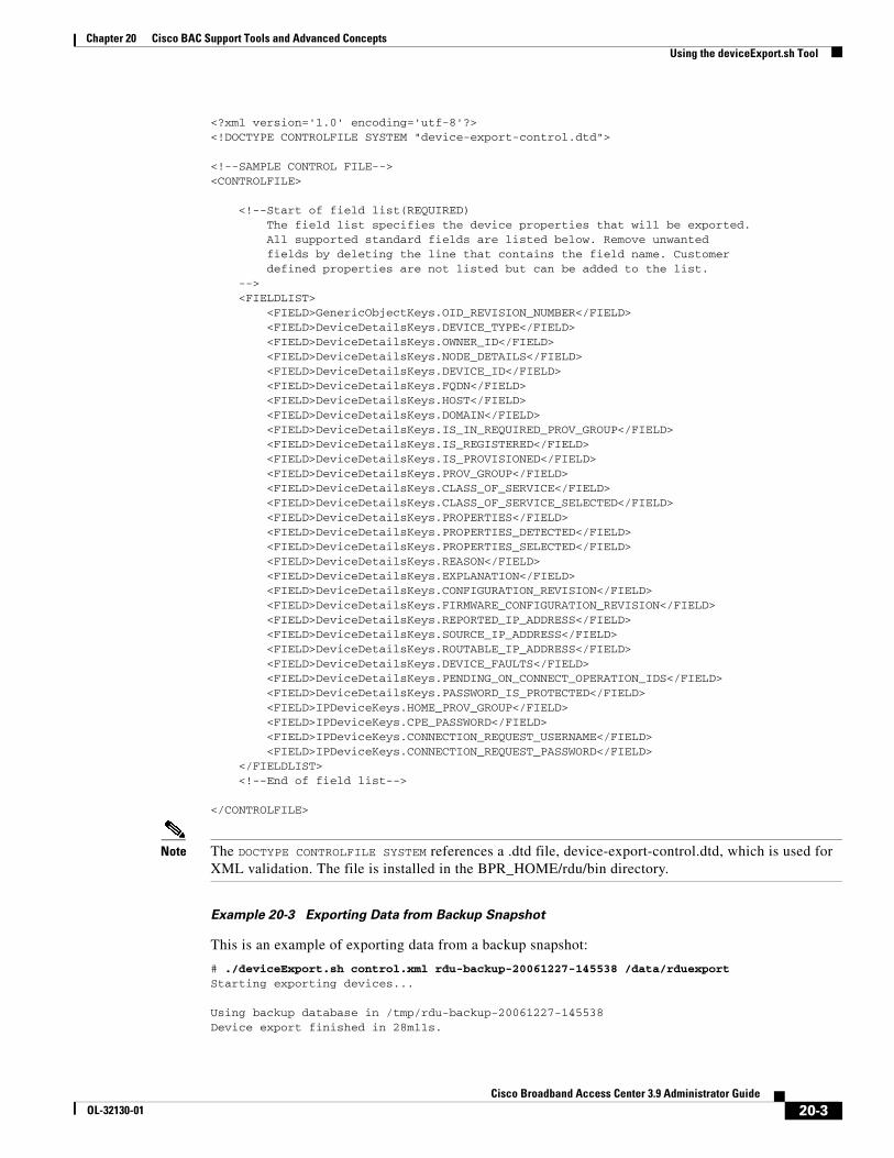
Chapter 20 Cisco BAC Support Tools and Advanced ConceptsUsing the deviceExport.sh Tool
<?xml version='1.0' encoding='utf-8'?><!DOCTYPE CONTROLFILE SYSTEM "device-export-control.dtd">
<!--SAMPLE CONTROL FILE--><CONTROLFILE>
<!--Start of field list(REQUIRED) The field list specifies the device properties that will be exported. All supported standard fields are listed below. Remove unwanted fields by deleting the line that contains the field name. Customer defined properties are not listed but can be added to the list. --> <FIELDLIST> <FIELD>GenericObjectKeys.OID_REVISION_NUMBER</FIELD> <FIELD>DeviceDetailsKeys.DEVICE_TYPE</FIELD> <FIELD>DeviceDetailsKeys.OWNER_ID</FIELD> <FIELD>DeviceDetailsKeys.NODE_DETAILS</FIELD> <FIELD>DeviceDetailsKeys.DEVICE_ID</FIELD> <FIELD>DeviceDetailsKeys.FQDN</FIELD> <FIELD>DeviceDetailsKeys.HOST</FIELD> <FIELD>DeviceDetailsKeys.DOMAIN</FIELD> <FIELD>DeviceDetailsKeys.IS_IN_REQUIRED_PROV_GROUP</FIELD> <FIELD>DeviceDetailsKeys.IS_REGISTERED</FIELD> <FIELD>DeviceDetailsKeys.IS_PROVISIONED</FIELD> <FIELD>DeviceDetailsKeys.PROV_GROUP</FIELD> <FIELD>DeviceDetailsKeys.CLASS_OF_SERVICE</FIELD> <FIELD>DeviceDetailsKeys.CLASS_OF_SERVICE_SELECTED</FIELD> <FIELD>DeviceDetailsKeys.PROPERTIES</FIELD> <FIELD>DeviceDetailsKeys.PROPERTIES_DETECTED</FIELD> <FIELD>DeviceDetailsKeys.PROPERTIES_SELECTED</FIELD> <FIELD>DeviceDetailsKeys.REASON</FIELD> <FIELD>DeviceDetailsKeys.EXPLANATION</FIELD> <FIELD>DeviceDetailsKeys.CONFIGURATION_REVISION</FIELD> <FIELD>DeviceDetailsKeys.FIRMWARE_CONFIGURATION_REVISION</FIELD> <FIELD>DeviceDetailsKeys.REPORTED_IP_ADDRESS</FIELD> <FIELD>DeviceDetailsKeys.SOURCE_IP_ADDRESS</FIELD> <FIELD>DeviceDetailsKeys.ROUTABLE_IP_ADDRESS</FIELD> <FIELD>DeviceDetailsKeys.DEVICE_FAULTS</FIELD> <FIELD>DeviceDetailsKeys.PENDING_ON_CONNECT_OPERATION_IDS</FIELD> <FIELD>DeviceDetailsKeys.PASSWORD_IS_PROTECTED</FIELD> <FIELD>IPDeviceKeys.HOME_PROV_GROUP</FIELD> <FIELD>IPDeviceKeys.CPE_PASSWORD</FIELD> <FIELD>IPDeviceKeys.CONNECTION_REQUEST_USERNAME</FIELD> <FIELD>IPDeviceKeys.CONNECTION_REQUEST_PASSWORD</FIELD> </FIELDLIST> <!--End of field list-->
</CONTROLFILE>
Note The DOCTYPE CONTROLFILE SYSTEM references a .dtd file, device-export-control.dtd, which is used for XML validation. The file is installed in the BPR_HOME/rdu/bin directory.
Example 20-3 Exporting Data from Backup Snapshot
This is an example of exporting data from a backup snapshot:
# ./deviceExport.sh control.xml rdu-backup-20061227-145538 /data/rduexportStarting exporting devices...
Using backup database in /tmp/rdu-backup-20061227-145538Device export finished in 28m11s.
20-3Cisco Broadband Access Center 3.9 Administrator Guide
OL-32130-01
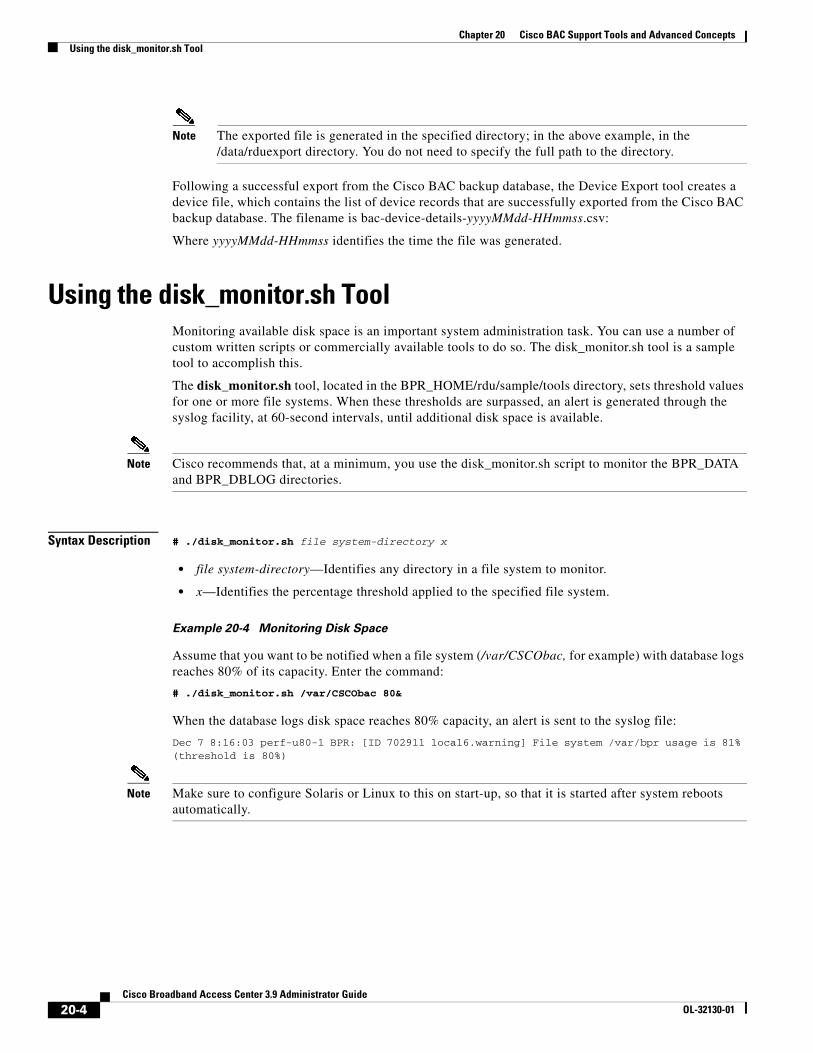
Chapter 20 Cisco BAC Support Tools and Advanced ConceptsUsing the disk_monitor.sh Tool
Note The exported file is generated in the specified directory; in the above example, in the /data/rduexport directory. You do not need to specify the full path to the directory.
Following a successful export from the Cisco BAC backup database, the Device Export tool creates a device file, which contains the list of device records that are successfully exported from the Cisco BAC backup database. The filename is bac-device-details-yyyyMMdd-HHmmss.csv:
Where yyyyMMdd-HHmmss identifies the time the file was generated.
Using the disk_monitor.sh ToolMonitoring available disk space is an important system administration task. You can use a number of custom written scripts or commercially available tools to do so. The disk_monitor.sh tool is a sample tool to accomplish this.
The disk_monitor.sh tool, located in the BPR_HOME/rdu/sample/tools directory, sets threshold values for one or more file systems. When these thresholds are surpassed, an alert is generated through the syslog facility, at 60-second intervals, until additional disk space is available.
Note Cisco recommends that, at a minimum, you use the disk_monitor.sh script to monitor the BPR_DATA and BPR_DBLOG directories.
Syntax Description # ./disk_monitor.sh file system-directory x
• file system-directory—Identifies any directory in a file system to monitor.
• x—Identifies the percentage threshold applied to the specified file system.
Example 20-4 Monitoring Disk Space
Assume that you want to be notified when a file system (/var/CSCObac, for example) with database logs reaches 80% of its capacity. Enter the command:
# ./disk_monitor.sh /var/CSCObac 80&
When the database logs disk space reaches 80% capacity, an alert is sent to the syslog file:
Dec 7 8:16:03 perf-u80-1 BPR: [ID 702911 local6.warning] File system /var/bpr usage is 81% (threshold is 80%)
Note Make sure to configure Solaris or Linux to this on start-up, so that it is started after system reboots automatically.
20-4Cisco Broadband Access Center 3.9 Administrator Guide
OL-32130-01
Chapter 20 Cisco BAC Support Tools and Advanced ConceptsUsing the resetAdminPassword.sh Tool
Using the resetAdminPassword.sh ToolCisco BAC supports both local authentication and TACACS+ authentication and you can use the resetAdminPassword.sh tool to reset the password for both local and TACACS+ authentication. Run the resetAdminPassword.sh tool from the BPR_HOME/rdu/internal/db/bin directory.
When the authentication is local if you use the resetAdminPassword.sh tool, it allows you to login with the default password changeme. After logging in, it will prompt you to change the password and you can change the password as you want.
When TACACS+ authentication is enabled, you can use the resetAdminPassword.sh tool to temporarily reset bacadmin authentication to local RDU. This tool allows you to login once with the password changeme to the RDU using the local reset admin password. After logging in, it will prompt you to change the password where you have to use the changeme password again. Then in the TACACS+ Defaults page you can change the password, as you want.
To enable local authentication, you have to manually change the authentication mode setting, after you login to the RDU. Otherwise, it will automatically fall back to TACACS+ authentication mode from next login.
To enable local authentication:
Step 1 Choose Configuration on either the Primary Navigation bar or Main Menu page.
Step 2 Choose Defaults from the Secondary Navigation bar.
The Configure Defaults page appears.
Step 3 Click TACACS+ Defaults link on the left pane.
The TACACS+ Defaults page appears
Step 4 Check the TACACS+ Authentication Disabled check box.
Step 5 Click Submit.
Note The authentication setting for other Cisco BAC users will not be affected by this tool. You must use the TACACS+ server administrative procedure to change the passwords.
Using the runEventMonitor.sh ToolYou can run the runEventMonitor.sh tool to view the events that are being fired in Cisco BAC. You can run this tool from the BPR_HOME/rdu/internal/bin directory.
20-5Cisco Broadband Access Center 3.9 Administrator Guide
OL-32130-01
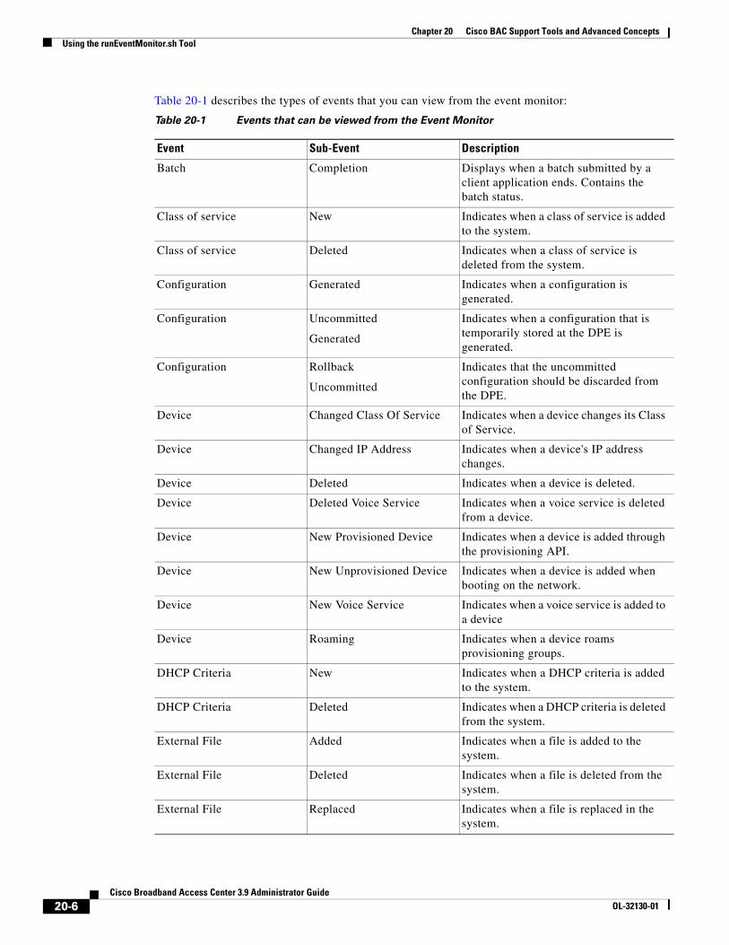
Chapter 20 Cisco BAC Support Tools and Advanced ConceptsUsing the runEventMonitor.sh Tool
Table 20-1 describes the types of events that you can view from the event monitor:
Table 20-1 Events that can be viewed from the Event Monitor
Event Sub-Event Description
Batch Completion Displays when a batch submitted by a client application ends. Contains the batch status.
Class of service New Indicates when a class of service is added to the system.
Class of service Deleted Indicates when a class of service is deleted from the system.
Configuration Generated Indicates when a configuration is generated.
Configuration Uncommitted
Generated
Indicates when a configuration that is temporarily stored at the DPE is generated.
Configuration Rollback
Uncommitted
Indicates that the uncommitted configuration should be discarded from the DPE.
Device Changed Class Of Service Indicates when a device changes its Class of Service.
Device Changed IP Address Indicates when a device's IP address changes.
Device Deleted Indicates when a device is deleted.
Device Deleted Voice Service Indicates when a voice service is deleted from a device.
Device New Provisioned Device Indicates when a device is added through the provisioning API.
Device New Unprovisioned Device Indicates when a device is added when booting on the network.
Device New Voice Service Indicates when a voice service is added to a device
Device Roaming Indicates when a device roams provisioning groups.
DHCP Criteria New Indicates when a DHCP criteria is added to the system.
DHCP Criteria Deleted Indicates when a DHCP criteria is deleted from the system.
External File Added Indicates when a file is added to the system.
External File Deleted Indicates when a file is deleted from the system.
External File Replaced Indicates when a file is replaced in the system.
20-6Cisco Broadband Access Center 3.9 Administrator Guide
OL-32130-01
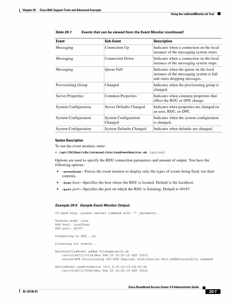
Chapter 20 Cisco BAC Support Tools and Advanced ConceptsUsing the runEventMonitor.sh Tool
Syntax Description
To run the event monitor, enter:
# /opt/CSCObac/rdu/internal/bin/runEventMonitor.sh [options]
Options are used to specify the RDU connection parameters and amount of output. You have the following options:
• -noverbose—Forces the event monitor to display only the types of events being fired, not their contents.
• -host host—Specifies the host where the RDU is located. Default is the localhost.
• -port port—Specifies the port on which the RDU is listening. Default is 49187.
Example 20-5 Sample Event Monitor Output.
If need help, please restart command with '?' parameter.
Verbose mode: true RDU host: localhost RDU port: 49187
Connecting to RDU...ok
Listening for events...
ExternalFileEvent added filename=gold.cm rev=1014671115124(Mon Feb 25 16:05:15 EST 2002)source=BPR Provisioning API:BPR Regional Distribution Unit:AddExternalFile command
DeviceEvent newProvDevice ID=1,6,01:02:03:04:05:06 rev=1014671179380(Mon Feb 25 16:06:19 EST 2002)
Messaging Connection Up Indicates when a connection on the local instance of the messaging system starts.
Messaging Connection Down Indicates when a connection on the local instance of the messaging system stops.
Messaging Queue Full Indicates when the queue on the local instance of the messaging system is full and starts dropping messages.
Provisioning Group Changed Indicates when the provisioning group is changed.
Server Properties Common Properties Indicates when common properties that effect the RDU or DPE change.
System Configuration Server Defaults Changed Indicates when properties are changed on an user, RDU, or DPE.
System Configuration System Configuration Changed
Indicates when the system configuration is changed.
System Configuration System Defaults Changed Indicates when defaults are changed.
Table 20-1 Events that can be viewed from the Event Monitor (continued)
Event Sub-Event Description
20-7Cisco Broadband Access Center 3.9 Administrator Guide
OL-32130-01
Chapter 20 Cisco BAC Support Tools and Advanced ConceptsUsing the changeARProperties.sh Tool
source=BPR Provisioning API:BPR Regional Distribution Unit:AddIPDevice command IP=null FQDN=null group=null
Using the changeARProperties.sh ToolThe Cisco BAC installation program establishes values for configuration properties used by Cisco BAC extensions that are incorporated into the Access Registrar RADIUS server. You use the changeARProperties.sh command, which is found in the BPR_HOME/car_ep/bin directory, to change key configuration properties.
Invoking the script without any parameters displays a help message listing the properties that can be set.
To run this command:
Step 1 Change directory to BPR_HOME/car_ep/bin.
Step 2 Run the changeARProperties.sh command using this syntax:
changeNRProperties.sh options
Where options are:
– -help—Displays this help message. The -help option must be used exclusively. Do not use this with any other option.
– -d—Displays the current properties. The -d option must be used exclusively. Do not use this with any other option.
– -s secret—Identifies the Cisco BAC shared secret. For example, if the shared secret is the word secret, enter -s secret.
– -q queue_size —Identifies the maximum number of the Access-Requests to be queued. For example, if you want to set the queue size to 1000, enter -q 1000.
– -t thread_count—Identifies the maximum number of threads to be used to process the requests. For example, if you want to set the thread count to 10, enter -t 10.
– -host addr—Identifies the DPE Auth HTTP interface you want to use. For example, if you want to use the interface localhost, enter -host localhost.
– -port port—Identifies the DPE Auth HTTP interface port you want to use. For example, if you want to use the port 7551, enter -port 7551.
– -url url—Identifies the DPE Auth HTTP service url you want to use. For example, if you want to use the url /auth, enter -url /auth.
– -ssl enabled|disabled—Enables or disables the SSL/TLS connection between PAR and DPE. Enter -ssl enabled to enable it and -ssl disabled to disable it.
– -x [true/false]—Enables or disables XML Schema validation e.g. -x true
20-8Cisco Broadband Access Center 3.9 Administrator Guide
OL-32130-01
Chapter 20 Cisco BAC Support Tools and Advanced ConceptsUsing the changeNRProperties.sh Tool
Using the changeNRProperties.sh ToolThe Cisco BAC installation program establishes values for configuration properties used by Cisco BAC extensions that are incorporated into the Network Registrar DHCP server. You use the changeNRProperties.sh command, which is found in the BPR_HOME/cnr_ep/bin directory, to change key configuration properties.
Invoking the script without any parameters displays a help message listing the properties that can be set.
To run this command:
Step 1 Change directory to BPR_HOME/cnr_ep/bin.
Step 2 Run the changeNRProperties.sh command using this syntax:
changeNRProperties.sh options
Where options are:
• -help—Displays this help message. The -help option must be used exclusively. Do not use this with any other option.
• -d—Displays the current properties. The-d option must be used exclusively. Do not use this with any other option.
• -s secret—Identifies the Cisco BAC shared secret. For example, if the shared secret is the word secret, enter -s secret.
• -f fqdn—Identifies the RDU FQDN. For example, if you use rdu.example.com as the fully qualified domain name, enter -f rdu.example.com.
• -p port—Identifies the RDU port you want to use. For example, if you want to use port number 49187, enter -p 49187.
• -g prov_group—Identifies the provisioning group. For example, if you are using provisioning group called group1, enter -g group1.
Examples This is an example of changing the Network Registrar extensions by using the NR Extensions Properties tool:
#sh changeNRProperties.sh -g primary1Current NR Properties:RDU Port: 49187RDU FQDN: rdu.example.comProvisioning Group: primary1Shared Secret: fggTaLg0XwKRs
Note You must restart your NR DHCP server for the changes to take effect.
This is an example of viewing the current properties:
#sh changeNRProperties.sh -dCurrent NR Properties:RDU Port: 49187RDU FQDN: rdu.example.comProvisioning Group: primary1Shared Secret: fggTaLg0XwKRs
20-9Cisco Broadband Access Center 3.9 Administrator Guide
OL-32130-01
Chapter 20 Cisco BAC Support Tools and Advanced ConceptsObtaining the Key Performance Indicators (KPI) for BAC
Obtaining the Key Performance Indicators (KPI) for BACCisco BAC collects the counter values of various Key Performance Indicators (KPI) periodically, for both DPE and RDU, and presents these values in .csv file format. This helps to upload these counters to performance management products like Cisco Prime Performance Manager.
The .csv file is located at <BPR_DATA>/metrics/logs, in both RDU and DPE.
Configuring the Properties for Generating the .csv FileYou can configure the different properties that are used for generating the .csv file for the KPIs.The configuration file is <BPR_HOME>/metrics/conf/metrics-configuration.xml
The properties that can be edited for generating the .csv file are described in the below table.
Note The first column of the .csv file contains the time stamp. If the time stamp contains ‘Z’, it indicates that the UTC time standard is used.
Property Default Value Description
refreshInterval 5 mins Minimum time to check the configuration file changes
includeCategories dpeDPERMSKPI, rduRDURMSKPI
Categories to generate output file
maxCsvFileRolloverSize 10 MB Retention size of the output file
maxCsvFileRolloverCount 2 Retention count of the output file
reportinterval MINUTES Output file generation interval: SECONDS, MINUTES, HOURS, DAYS
reportduration 5 Output file generation duration
filepath BPR_DATA Output file generation path
timeformat yyyy-MM-dd'T'HH:mm:ss.SSS Java 1.6 supported Timestamp format
timestandard UTC Time Standard: UTC/LOCAL
reportversion 3.9 Report version for output
20-10Cisco Broadband Access Center 3.9 Administrator Guide
OL-32130-01
CiscoOL-32130-01
C H A P T E R 21
Troubleshooting Broadband Access CenterThis chapter provides the information on how to observe the RDU and DPE logs, and troubleshoot Cisco BAC.
This chapter includes the following sections:
• Troubleshooting Checklist, page 21-1
• Logging, page 21-2
Troubleshooting Checklist While troubleshooting with Cisco BAC, use the checklist described in Table 21-1.
Table 21-1 Troubleshooting Checklist
Procedure Refer to ...
1. Check whether the Cisco BAC processes are up on all systems on which Cisco BAC components are installed.
Using Cisco BAC Process Watchdog from the Command Line, page 9-2
2. Check the Cisco BAC component logs for indications of high-severity errors. These include the information logged for:
– RDU
– DPE
RDU Logs, page 21-5
DPE Logs, page 21-8
3. View server uptime from the administrator user interface to confirm that the servers are not bouncing.
Viewing Servers, page 16-22
4. View the RDU and DPE service performance statistics from the administrator’s user interface. Observe any abnormal numbers, such as extended transaction times.
Viewing Servers, page 16-22
5. Check the syslog alerts log. Syslog Alert Messages, page 11-1
6. Check the operating system and hardware resources, such as:
– Disk space
– CPU time
– Memory
Solaris documentation for specific commands.
21-1 Broadband Access Center 3.9 Administrator Guide
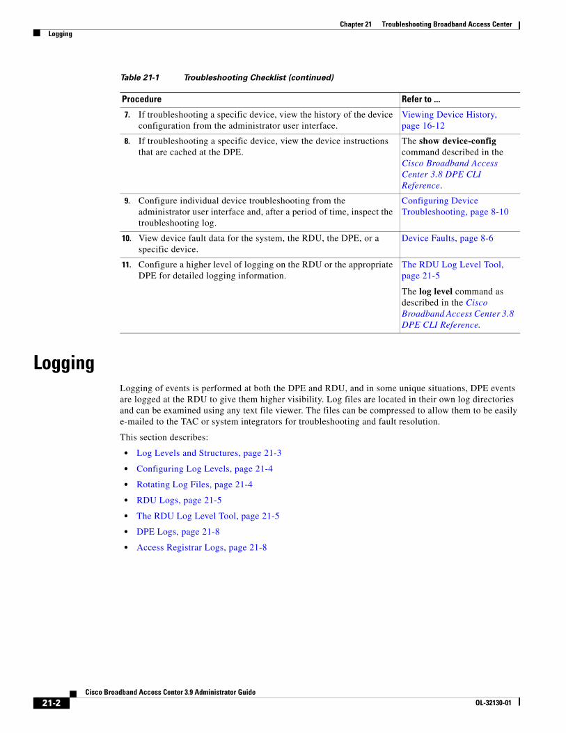
Chapter 21 Troubleshooting Broadband Access CenterLogging
LoggingLogging of events is performed at both the DPE and RDU, and in some unique situations, DPE events are logged at the RDU to give them higher visibility. Log files are located in their own log directories and can be examined using any text file viewer. The files can be compressed to allow them to be easily e-mailed to the TAC or system integrators for troubleshooting and fault resolution.
This section describes:
• Log Levels and Structures, page 21-3
• Configuring Log Levels, page 21-4
• Rotating Log Files, page 21-4
• RDU Logs, page 21-5
• The RDU Log Level Tool, page 21-5
• DPE Logs, page 21-8
• Access Registrar Logs, page 21-8
7. If troubleshooting a specific device, view the history of the device configuration from the administrator user interface.
Viewing Device History, page 16-12
8. If troubleshooting a specific device, view the device instructions that are cached at the DPE.
The show device-config command described in the Cisco Broadband Access Center 3.8 DPE CLI Reference.
9. Configure individual device troubleshooting from the administrator user interface and, after a period of time, inspect the troubleshooting log.
Configuring Device Troubleshooting, page 8-10
10. View device fault data for the system, the RDU, the DPE, or a specific device.
Device Faults, page 8-6
11. Configure a higher level of logging on the RDU or the appropriate DPE for detailed logging information.
The RDU Log Level Tool, page 21-5
The log level command as described in the Cisco Broadband Access Center 3.8 DPE CLI Reference.
Table 21-1 Troubleshooting Checklist (continued)
Procedure Refer to ...
21-2Cisco Broadband Access Center 3.9 Administrator Guide
OL-32130-01
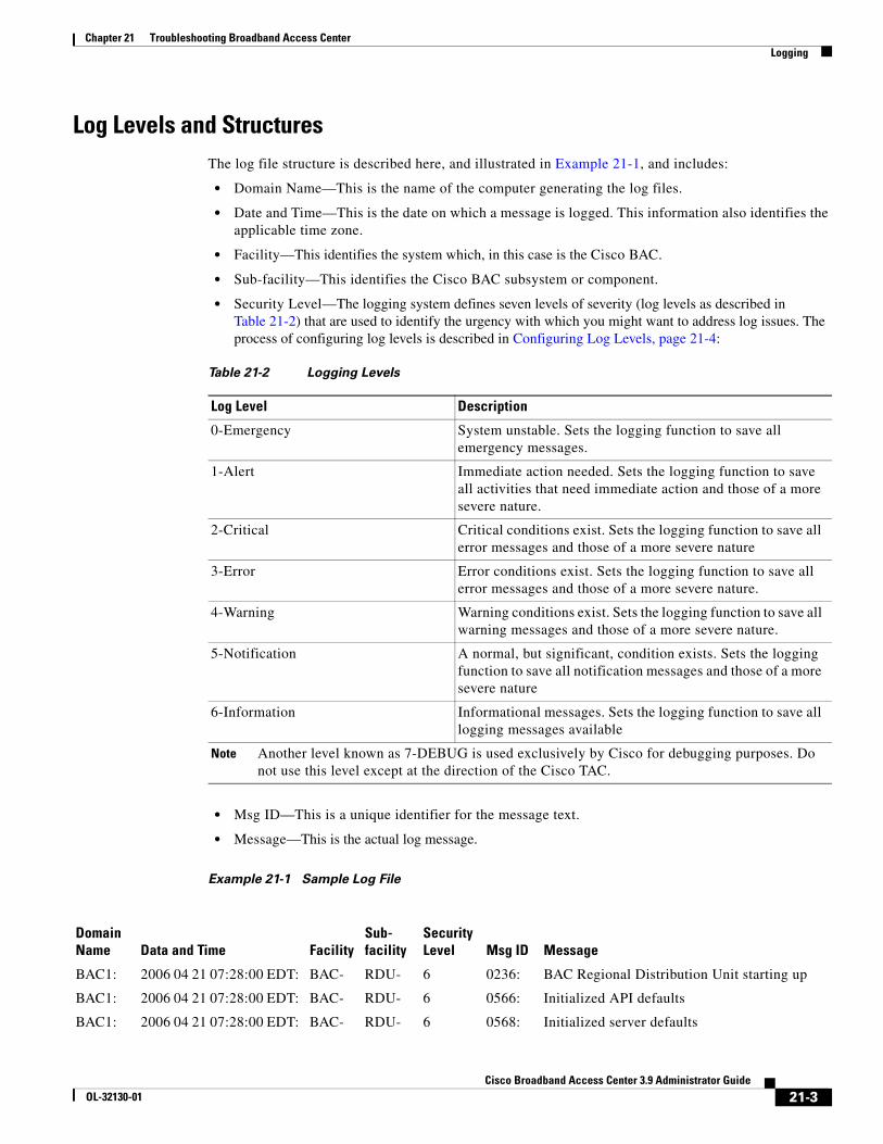
Chapter 21 Troubleshooting Broadband Access CenterLogging
Log Levels and StructuresThe log file structure is described here, and illustrated in Example 21-1, and includes:
• Domain Name—This is the name of the computer generating the log files.
• Date and Time—This is the date on which a message is logged. This information also identifies the applicable time zone.
• Facility—This identifies the system which, in this case is the Cisco BAC.
• Sub-facility—This identifies the Cisco BAC subsystem or component.
• Security Level—The logging system defines seven levels of severity (log levels as described in Table 21-2) that are used to identify the urgency with which you might want to address log issues. The process of configuring log levels is described in Configuring Log Levels, page 21-4:
• Msg ID—This is a unique identifier for the message text.
• Message—This is the actual log message.
Example 21-1 Sample Log File
Table 21-2 Logging Levels
Log Level Description
0-Emergency System unstable. Sets the logging function to save all emergency messages.
1-Alert Immediate action needed. Sets the logging function to save all activities that need immediate action and those of a more severe nature.
2-Critical Critical conditions exist. Sets the logging function to save all error messages and those of a more severe nature
3-Error Error conditions exist. Sets the logging function to save all error messages and those of a more severe nature.
4-Warning Warning conditions exist. Sets the logging function to save all warning messages and those of a more severe nature.
5-Notification A normal, but significant, condition exists. Sets the logging function to save all notification messages and those of a more severe nature
6-Information Informational messages. Sets the logging function to save all logging messages available
Note Another level known as 7-DEBUG is used exclusively by Cisco for debugging purposes. Do not use this level except at the direction of the Cisco TAC.
Domain Name Data and Time Facility
Sub-facility
Security Level Msg ID Message
BAC1: 2006 04 21 07:28:00 EDT: BAC- RDU- 6 0236: BAC Regional Distribution Unit starting up
BAC1: 2006 04 21 07:28:00 EDT: BAC- RDU- 6 0566: Initialized API defaults
BAC1: 2006 04 21 07:28:00 EDT: BAC- RDU- 6 0568: Initialized server defaults
21-3Cisco Broadband Access Center 3.9 Administrator Guide
OL-32130-01
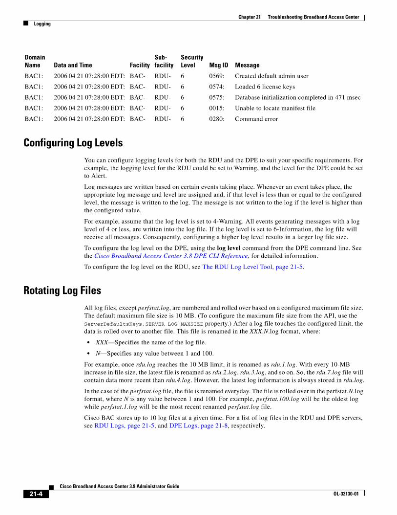
Chapter 21 Troubleshooting Broadband Access CenterLogging
Configuring Log LevelsYou can configure logging levels for both the RDU and the DPE to suit your specific requirements. For example, the logging level for the RDU could be set to Warning, and the level for the DPE could be set to Alert.
Log messages are written based on certain events taking place. Whenever an event takes place, the appropriate log message and level are assigned and, if that level is less than or equal to the configured level, the message is written to the log. The message is not written to the log if the level is higher than the configured value.
For example, assume that the log level is set to 4-Warning. All events generating messages with a log level of 4 or less, are written into the log file. If the log level is set to 6-Information, the log file will receive all messages. Consequently, configuring a higher log level results in a larger log file size.
To configure the log level on the DPE, using the log level command from the DPE command line. See the Cisco Broadband Access Center 3.8 DPE CLI Reference, for detailed information.
To configure the log level on the RDU, see The RDU Log Level Tool, page 21-5.
Rotating Log FilesAll log files, except perfstat.log, are numbered and rolled over based on a configured maximum file size. The default maximum file size is 10 MB. (To configure the maximum file size from the API, use the ServerDefaultsKeys.SERVER_LOG_MAXSIZE property.) After a log file touches the configured limit, the data is rolled over to another file. This file is renamed in the XXX.N.log format, where:
• XXX—Specifies the name of the log file.
• N—Specifies any value between 1 and 100.
For example, once rdu.log reaches the 10 MB limit, it is renamed as rdu.1.log. With every 10-MB increase in file size, the latest file is renamed as rdu.2.log, rdu.3.log, and so on. So, the rdu.7.log file will contain data more recent than rdu.4.log. However, the latest log information is always stored in rdu.log.
In the case of the perfstat.log file, the file is renamed everyday. The file is rolled over in the perfstat.N.log format, where N is any value between 1 and 100. For example, perfstat.100.log will be the oldest log while perfstat.1.log will be the most recent renamed perfstat.log file.
Cisco BAC stores up to 10 log files at a given time. For a list of log files in the RDU and DPE servers, see RDU Logs, page 21-5, and DPE Logs, page 21-8, respectively.
BAC1: 2006 04 21 07:28:00 EDT: BAC- RDU- 6 0569: Created default admin user
BAC1: 2006 04 21 07:28:00 EDT: BAC- RDU- 6 0574: Loaded 6 license keys
BAC1: 2006 04 21 07:28:00 EDT: BAC- RDU- 6 0575: Database initialization completed in 471 msec
BAC1: 2006 04 21 07:28:00 EDT: BAC- RDU- 6 0015: Unable to locate manifest file
BAC1: 2006 04 21 07:28:00 EDT: BAC- RDU- 6 0280: Command error
Domain Name Data and Time Facility
Sub-facility
Security Level Msg ID Message
21-4Cisco Broadband Access Center 3.9 Administrator Guide
OL-32130-01
Chapter 21 Troubleshooting Broadband Access CenterLogging
RDU LogsThe RDU has two logs that it maintains in the BPR_DATA/rdu/logs directory:
• rdu.log—Records all RDU events according to the configured logging severity level. (See Setting the RDU Log Level, page 21-6, for instructions on setting the default log levels.) To view rdu.log, see Viewing the rdu.log File, page 21-5.
• audit.log—Records all high-level changes to the Cisco BAC configuration or functionality including the user who made the change. To view audit.log, see Viewing the audit.log File, page 21-5.
• troubleshooting.log—Records detailed device information for troubleshooting a specific device, or a group of devices without turning logging on, and without searching through log files for device- or group-specific information. To view troubleshooting.log from the administrator user interface, see Viewing Device Troubleshooting Log, page 8-12.
• perfstats.log—Records device performance statistics to help troubleshoot issues related to system performance. For more information, see Monitoring Cisco Broadband Access Center, page 11-1.
Viewing the rdu.log File
You can use any text processor to view the rdu.log file. In addition, you can view the log file from the administrator user interface. To do this:
Step 1 Choose the RDU tab under Servers.
The View Regional Distribution Unit Details page appears.
Step 2 Click the View Details icon ( ) corresponding to RDU Log File.
The View Log File Contents page appears, displaying data from rdu.log.
Viewing the audit.log File
You can use any text processor to view the audit.log file. In addition, you can view the log file from the administrator user interface. To do this:
Step 1 Choose the RDU tab under Servers.
The View Regional Distribution Unit Details page appears.
Step 2 Click the View Details icon corresponding to Audit Log File.
The View Log File Contents page appears, displaying data from audit.log.
The RDU Log Level Tool
Use the RDU log level tool to change the current log level of the RDU from the command line, using the setLogLevel.sh command. This tool is located in the BPR_HOME/rdu/bin directory. Table 21-2 identifies the available log levels and the types of message written to the log file when enabled.
21-5Cisco Broadband Access Center 3.9 Administrator Guide
OL-32130-01
Chapter 21 Troubleshooting Broadband Access CenterLogging
We recommend that you keep the RDU logging level at the Warning level to help maintain a steady operations state. The Information level is recommended to be used with caution if you need to maintain steady state performance during debug operations.
You should exercise caution when running with the Information level set because this creates a great number of log entries, which in itself can adversely impact performance.
Note The RDU process has to be up to execute the log level tool. Also, you must be a privileged user to run this tool by using the setLogLevel.sh command.
Using the RDU Log Level Tool
All examples assume that the user name for the RDU is bacadmin, the password for the RDU is changeme, and the RDU server is up.
Enter this command to run the RDU log level tool:
setLogLevel.sh [0..6] [-help] [-show] [-default] [-debug]
where:
• -[0..6]—Identifies the logging level to be used. For a list of available levels, see Table 21-2.
• -help—Displays help for the tool.
• -show—Displays the current log level set for the RDU server.
• -default—Sets the RDU to the installation default level 5 (notification).
• -debug— Sets an interactive mode to enable or disable tracing categories for RDU server.
Note You should only enable the debug settings that the Cisco support staff recommends.
You can also use this tool to perform these functions:
• Setting the RDU Log Level, page 21-6
• Viewing the RDU’s Current Log Level, page 21-7
Setting the RDU Log Level
You can use this tool to change the logging level from one value to any other value.
The following example illustrates how to set the RDU logging level to the warning level, as indicated by the number 4 in the setLogLevel.sh command. The actual log level set is not important for the procedure, it can be interchanged as required.
To set the RDU logging level:
Step 1 Change directory to BPR_HOME/rdu/bin.
Step 2 Run the RDU log level tool using this command:
setLogLevel.sh 4
This prompt appears:
Please type RDU username:
21-6Cisco Broadband Access Center 3.9 Administrator Guide
OL-32130-01
Chapter 21 Troubleshooting Broadband Access CenterLogging
Step 3 Enter the RDU username at the prompt. In this example, the default username (bacadmin) is used.
Please type RDU username: bacadmin
This prompt appears:
Please type RDU password:
Step 4 Enter the RDU password for the RDU at the prompt. In this example, the default password (changeme) is used.
Please type RDU password: changeme
This message appears to notify you that the log level has been changed. In this example, the level was 5, for notification, and is now 4, for warning.
RDU Log level was changed from 5 (notification) to 4 (warning).
Viewing the RDU’s Current Log Level
You can use this tool to view the RDU log and determine which logging level is configured before attempting to change the value.
To view the RDU’s current logging level:
Step 1 Change directory to BPR_HOME/rdu/bin.
Step 2 Run this command:
setLogLevel.sh -show
This prompt appears:
Please type RDU username:
Step 3 Enter the RDU username (bacadmin) and press Enter.
Please type RDU username: bacadmin
This prompt appears:
Please type RDU password:
Step 4 Enter the RDU password (changeme) and press Enter.
Please type RDU password: changeme
This message appears:
The logging is currently set at level: 4 (warning)
All tracing is currently disabled.
21-7Cisco Broadband Access Center 3.9 Administrator Guide
OL-32130-01
Chapter 21 Troubleshooting Broadband Access CenterLogging
DPE LogsThe DPE maintains its logs at the BPR_DATA/dpe/logs directory.
• dpe.log—Records all events having the configured default level. In situations where the DPE undergoes catastrophic failure, such as engaging in a series of system crashes, the catastrophic errors are also logged into the rdu.log file.
• perfstats.log—Records device performance statistics to help troubleshoot issues related to system performance. For more information, see Monitoring Cisco Broadband Access Center, page 11-1.
Viewing the dpe.log File
You can use any text viewer to view the dpe.log file. In addition you can use the show log command, from the DPE CLI, to view the log file. See the Cisco Broadband Access Center 3.8 DPE CLI Reference, for additional information.
You can also view the DPE log file using the Cisco BAC administrator user interface. To do this:
Step 1 Choose Servers > DPEs.
Step 2 Click the link corresponding to the DPE whose log file you want to view.
The View Device Provisioning Engines Details page appears.
Step 3 To view the contents of the dpe.log file, click the View Details icon against DPE Log File in the Log Files area.
Access Registrar LogsCisco BAC generates trace messages from Cisco Access Registrar RADIUS server extensions. The RADIUS server trace resides in the PAR-install-path/name_radius_1_trace directory; PAR-install-path is a variable and is specific to the value that you enter. The default location for the RADIUS server log file is /opt/CSCOar/logs/name_radius_1_trace.
The trace messages emitted using the RADIUS server extensions are based on the extension trace level setting. You can set values (described in Table below) at the trace level; the number you set makes that number the current setting of the extension-trace-level attribute for all extensions.
Use the aregcmd command trace to set the trace level in the specified server to a new value. The trace level governs how much information is displayed about the contents of a packet. When the trace level is zero, no tracing is performed. The higher the trace level, the more information displayed. The highest trace level currently used by the PAR server is trace level 5.
Note Although the highest trace level supported by the PAR server is trace level 5, an extension point script might use a higher level. There is no harm in setting the trace to a level higher than 5.
The trace levels are inclusive, meaning that if you set trace to level 3, you will also get the information reported for trace levels 1 and 2. If you set trace level 4, you also get information reported for trace levels 1, 2, and 3. When you do not specify a server, PAR sets the trace level for all of the servers in the current cluster. When you do not specify a value for the trace level, PAR displays the current value of the trace level. The default is 0.
21-8Cisco Broadband Access Center 3.9 Administrator Guide
OL-32130-01
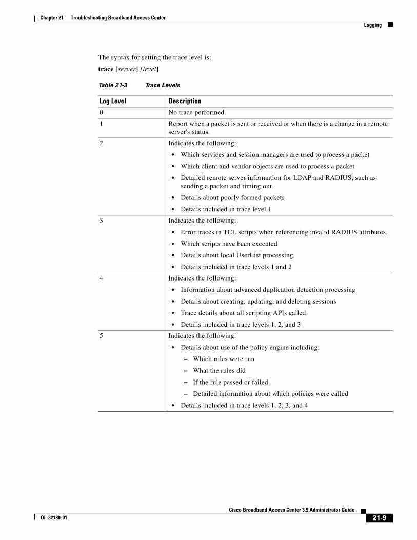
Chapter 21 Troubleshooting Broadband Access CenterLogging
The syntax for setting the trace level is:
trace [server] [level]
Table 21-3 Trace Levels
Log Level Description
0 No trace performed.
1 Report when a packet is sent or received or when there is a change in a remote server's status.
2 Indicates the following:
• Which services and session managers are used to process a packet
• Which client and vendor objects are used to process a packet
• Detailed remote server information for LDAP and RADIUS, such as sending a packet and timing out
• Details about poorly formed packets
• Details included in trace level 1
3 Indicates the following:
• Error traces in TCL scripts when referencing invalid RADIUS attributes.
• Which scripts have been executed
• Details about local UserList processing
• Details included in trace levels 1 and 2
4 Indicates the following:
• Information about advanced duplication detection processing
• Details about creating, updating, and deleting sessions
• Trace details about all scripting APIs called
• Details included in trace levels 1, 2, and 3
5 Indicates the following:
• Details about use of the policy engine including:
– Which rules were run
– What the rules did
– If the rule passed or failed
– Detailed information about which policies were called
• Details included in trace levels 1, 2, 3, and 4
21-9Cisco Broadband Access Center 3.9 Administrator Guide
OL-32130-01

Chapter 21 Troubleshooting Broadband Access CenterLogging
21-10Cisco Broadband Access Center 3.9 Administrator Guide
OL-32130-01
Cisco BroadOL-32130-01
A
P P E N D I X A FAQs on Provisioning Cisco Broadband Access CenterThis appendix lists answers to FAQs about Cisco BAC provisioning.
How do I enable or disable Network Registrar extensions?The procedures described in this section assume that:
• The Cisco BAC component is installed in /opt/CSCObac.
• Cisco Network Registrar is installed in /opt/nwreg2.
To manually install Network Registrar extension points:
Step 1 Log into the Network Registrar server, with root access.
Step 2 Copy the libbprextensions.so directory to the NR_HOME/local/extensions/dhcp/dex/ directory.
Step 3 Copy the cnr_ep.properties file to the BPR_HOME/cnr_ep/conf directory.
Step 4 Configure extensions from the Network Registrar command-line tool (nrcmd) using:
NR_HOME/local/usrbin/nrcmd -s -b < BPR_HOME/cnr_ep/bin/bpr_cnr_enable_extpts.nrcmd
To manually disable Network Registrar extension points:
Step 1 Log into the Network Registrar server, with root access.
Step 2 Enter:
NR_HOME/local/usrbin/nrcmd -s -b < BPR_HOME/cnr_ep/bin/bpr_cnr_disable_extpts.nrcmd
Step 3 Delete the libbprextensions.so file, which is located in the NR_HOME/local/extensions/dhcp/dex/ directory.
A-1band Access Center 3.9 Administrator Guide

Appendix A FAQs on Provisioning Cisco Broadband Access Center
A-2Cisco Broadband Access Center 3.9 Administrator Guide
OL-32130-01
OL-32130-01
G L O S S A R Y
A
alert A syslog or SNMP message notifying an operator or administrator of a problem.
API Application programming interface. Specification of function-call conventions that defines an interface to a service.
audit logs A log file containing a summary of major changes in the RDU database. This includes changes to system defaults, technology defaults, and classes of service.
autoconfiguration
server (ACS)
A server that provisions a device or a collection of devices. In Cisco BAC, the ACS refers to the Cisco BAC server and in some instances, the DPE.
B
broadband Transmission system that multiplexes multiple independent signals onto one cable. In Telecommunications terminology; any channel having a bandwidth greater than a voice-grade channel (4 kHz). In LAN terminology; a co-axial cable on which analog signaling is used.
Cisco Broadband
Access Center (BAC)
An integrated solution for managing and provisioning broadband home networks. BAC is a scalable product capable of supporting millions of devices.
C
caching Form of replication in which information learned during a previous transaction is used to process later transactions.
cipher suites Provide cryptographic algorithms that the SSL module requires to perform key exchange, authentication, and Message Authentication Code.
customer premises
equipment (CPE)
Terminating equipment, such as telephones, computers, and modems, supplied and installed at a customer location.
CPE WAN
Management
Protocol (CWMP)
A standard defined in the TR-069 specification by the Broadband Forum. CWMP integrates the capabilities defined in TR-069 to increase operator efficiency and reduce network management problems.
GL-1Cisco Broadband Access Center 3.9 Administrator Guide
Glossary
D
device provisioning
engine (DPE)
DPE servers cache device instructions and perform CWMP services. These distributed serves automatically synchronize with the RDU to obtain the latest instructions and provide Cisco BAC scalability.
F
fully qualified
domain name
(FQDN)
FQDN is the full name of a system, rather than just its hostname. For example, cisco is a hostname and www.cisco.com is an FQDN.
H
HTTPS See Secure Sockets Layer and Transport Layer Security.
I
instruction
generation
The process of generating policy instructions at the RDU for devices and distributing these instructions to the DPE. The instructions are cached by the DPE and informed about action needed to be performed on the CPE, which may include configuration, firmware upgrade or other operations.
IP address An IP address is a 32-bit number that identifies each sender or receiver of information that is sent in packets across the Internet.
N
network address
translation (NAT)
Mechanism for reducing the need for globally unique IP addresses. NAT allows an organization with addresses that are not globally unique to connect to the Internet by translating those addresses into globally routeable address space. This is also known as Network Address Translation.
network
administrator
Person responsible for operation, maintenance, and management of a network. See also network operator.
network operator Person who routinely monitors and controls a network, performing such tasks as reviewing and responding to alarms, monitoring throughput, configuring new circuits, and resolving problems. See also network administrator.
Network Time
Protocol (NTP)
NTP is a protocol designed to synchronize server clocks over a network.
GL-2Cisco Broadband Access Center 3.9 Administrator Guide
OL-32130-01
Glossary
P
provisioning API A series of Cisco BAC functions that programs can use to make the operating system perform various functions.
provisioning groups Groupings of devices with a defined set of associated DPE servers, based on either network topology or geography.
publishing Publishing provides provisioning information to an external datastore in real time. Publishing plug-ins must be developed to write data to a datastore.
R
redundancy In internetworking, the duplication of devices, services, or connections so that, in the event of a failure, the redundant devices, services, or connections can perform the work of those that failed.
regional distribution
unit (RDU)
The RDU is the primary server in the Cisco BAC provisioning system. It manages generation of device instructions, processes all API requests, and manages the Cisco BAC system.
S
Secure Sockets
Layer (SSL)
A protocol for transmitting private documents via the Internet. SSL uses a cryptographic system that uses two keys to encrypt data: a public key known to everyone and a private or secret key known only to the recipient of the message. By convention, URLs that require an SSL connection start with https: instead of http:. BAC 3.0 supports SSLv3.
See Transport Layer Security.
shared secret A character string used to provide secure communication between two servers or devices.
T
template files XML files that contain configuration or firmware rules for devices.
Transport Layer
Security (TLS)
A protocol that guarantees privacy and data integrity between client/server applications communicating over the Internet. BAC 3.0 supports TLSv1.
See Secure Sockets Layer.
TR-069 A standard which defines the CPE WAN Management Protocol (CWMP), which enables communication between CPE and an autoconfiguration server.
GL-3Cisco Broadband Access Center 3.9 Administrator Guide
OL-32130-01

Glossary
V
Voice over IP (VoIP) Mechanism to make telephone calls and send faxes over IP-based data networks with a suitable quality of service (QoS) and superior cost/benefit.
W
watchdog agent A watchdog agent is a daemon process that is used to monitor, stop, start and restart Cisco BAC component processes such as the RDU, JRun, and the SNMP agent.
GL-4Cisco Broadband Access Center 3.9 Administrator Guide
OL-32130-01

CiscoOL-32130-01
I N D E X
A
ACS
definition 1-1
URL, configuring 3-9
URL, discovery 2-6
administrator user interface
accessing 15-2
ACS URL, configuring 3-9
BAC architecture, and 9-4
configuring 15-1
connection request 12-5
device’s provisioning group, correcting 14-8
device faults, viewing 8-7
device history, configuring 8-4
icons (table) 15-4
logging in 15-2
HTTP transport 15-3
SSL transport 15-3
logging out 15-4
parameter dictionaries, managing 7-6
adding 7-6
deleting 7-7
replacing 7-7
viewing 7-7
performance statistics, collecting
enabling, disabling 11-14
RDU extensions, managing
required points (table) 17-26
server, monitoring 11-12
advanced concepts
See tools and advanced concepts
agent, SNMP
BAC architecture, and 9-5
MIB support 11-6
alert messages 11-1 to ??, 11-5
alerts, definition 1-1
message format 11-1
relating to
DPE 11-2
RDU 11-2
watchdog process 11-4
API, definition 1-1
architecture 2-1 to ??, 2-8
about DPEs 2-4
about provisioning groups 2-6
about RDU 2-4
administrator user interface 9-4
agents
SNMP 9-5
watchdog process agent 9-2
command line interface 9-5
deployment 2-1
logging 21-2, 21-3
overview 2-2, 2-4
watchdog process 2-7
audit logs, definition 1-1
authentication
about 13-13
available options 13-17
client certificate, configuring 13-16
external client certificate, configuring 13-16
autoconfiguration server
See ACS
IN-1 Broadband Access Center 3.9 Administrator Guide

Index
B
backup and recovery of database 10-4 to 10-6
C
caching, definition 1-1
cautions
regarding
custom properties, deleting 17-6
disk space requirement figures 10-3
network deployment with an evaluation license key 17-23
template files, deleting 17-22
troubleshooting devices 8-10
cipher suites
definition 1-1
classes of service
about 4-3
configuring
adding 17-4
deleting 17-5
modifying 17-4
client certificate authentication
configuring 13-16
command line interface
DPE, accessing 9-5
configuration history
See device history
configuration template
about 5-1
administrator user interface, using 17-18, 17-22
authoring 5-14
conditionals, using 5-19
includes, using 5-18
parameter substitution, using 5-17
configuration utility
about 5-23
template, adding 5-24
IN-2Cisco Broadband Access Center 3.9 Administrator Guide
template processing, testing 5-26, 5-27
template syntax, validating 5-24, 5-25
using 5-23
features 5-3
access control 5-9
notification 5-8
parameters 5-6, 5-7
parameters, schema (figure) 5-6
prerequisites 5-9, 5-13
prerequisites, schema (figure) 5-10
schema (figure) 5-4
template processing files (table) 5-2, 6-4
configuration workflows and checklists
component workflows
DPE checklist (table) 3-2
RDU checklist (table) 3-1
technology workflows
DPE configuration (tables) 3-5
provisioning group configuration 3-8, 3-9
RDU configuration, preregistering device data 3-4
RDU configuration (table) 3-3
configuring BAC
class of service
adding 17-4
deleting 17-5
modifying 17-4
connection requests 12-2
authentication 12-3
disabling 12-11
methods, discovered 12-5
methods, use FQDN 12-5, 12-6
methods, use IP 12-5, 12-6
reachability 12-11
custom properties 17-6, 17-7
CWMP service
DPE ports 12-2
defaults
configuration options, selecting 17-9
OL-32130-01

Index
CWMP 17-10
RDU 17-13
system 17-14
device history
enabling, disabling 8-4
number of entries 8-5
viewing 8-4
discovering device data
about 12-12
parameters 12-12, 12-13
files, managing
adding 17-20
deleting 17-22
exporting 17-22
replacing 17-21
viewing 17-21
license keys 17-23, 17-24
adding a license 17-24
modifying a license 17-24
provisioning data, publishing
Datastore changes 17-29
plug-in settings, modifying 17-29
RDU extensions, managing
custom extension points, installing 17-28
new class, writing 17-27
viewing 17-29
connection request service
about 12-2
authentication 12-3
disabling 12-11
methods 12-5, 12-7
discovered 12-5
use FQDN 12-6
use IP 12-6
reachability 12-11
workflow (figure) 12-3
CPE management
authentication 13-13
available options 13-17
OL-32130-01
client certificate, configuring 13-16
external load balancer, configuring 13-16
device assignment to provisioning groups 4-22
automatic 4-22
explicit 4-22
explicit and automatic approach 4-23
device configuration synchronization 4-17
device deployment options 4-19
preregistered 4-19
unregistered 4-19
discovering CPE parameters 4-4
default parameters (table) 4-5
instruction generation, and 4-16
overview 4-1
customer premises equipment, definition 1-1
custom properties
configuring 17-6
overview 5-16
CWMP
about 1-3
definition 1-1
CWMP service, configuring
connection request 12-2
authentication 12-3
disabling 12-11
method, discovered 12-5
method, use FQDN 12-5, 12-6
method, use IP 12-5, 12-6
reachability 12-11
discovering device data
about 12-12
parameters 12-12, 12-13
troubleshooting 12-13
DPE keystore, using keytool 13-3
certificates for client authentication, importing 13-10
certificate signing request, generating 13-7
existing signed server certificate, importing 13-4
keytool commands 13-5
IN-3Cisco Broadband Access Center 3.9 Administrator Guide
Index
self-signed certificate, displaying 13-7
server certificate and private key, generating 13-6
signed certificate, verifying 13-8
signed certificate into server certificate, importing 13-9
signing authority certificate into cacerts, importing 13-8
DPE ports 12-2
security
about 13-1
key and certificate management 13-2
SSL, configuring 13-3
D
database management
backup and recovery
backing up 10-4
recovering 10-5
restoring 10-6
disk space requirements 10-3, 10-4
caution regarding 10-3
handling out 10-4
failure resiliency, understanding 10-1, 10-2
files 10-2 to 10-3
automatic log management 10-3
DB_VERSION 10-3
history log 10-3
storage 10-2
transaction log 10-2
location, changing 10-7
defaults, configuring
CWMP 17-10
RDU 17-13
system 17-14
device diagnostics
configuration history, viewing 8-4
overview 4-23
IN-4Cisco Broadband Access Center 3.9 Administrator Guide
performance statistics, monitoring 11-14
runStatAnalyzer.sh tool, using 11-15
Device Export
deviceExport.sh tool, using 20-1
device faults
about 8-6
device history
about 8-1
enabling, disabling 8-4
number of entries, configuring 8-5
records, logging 8-5
supported records (table) 8-1
viewing 8-4
device management
about 16-10
administrator user interface, using
adding 16-11
deleting 16-11
devices menu 16-4
displaying live data 16-16
forcing configuration synchronization 16-17
forcing firmware upgrade 16-17
modifying 16-11
performing a Ping test 16-16
rebooting 16-15
regenerating instructions 16-12
relating, unrelating 16-13
requesting a connection 16-15
resetting to factory settings 16-16
searches supported (table) 16-6
setting operations timeout 16-18
controls 16-7
device details, viewing 16-7
Manage Devices page 16-4
searching for devices 16-7
See also CPE management
device object model
overview 4-2
relationships (figure) 4-2
OL-32130-01
Index
relationships (table) 4-3
device operations
about 14-1
conditional execution 14-6
connection modes
asynchronous 14-5
asynchronous workflow (figure) 14-5
immediate 14-2
immediate workflow (figure) 14-3
on-connect 14-3
on-connect workflow (figure) 14-4
device’s provisioning group, managing 14-6
correcting 14-8
sample files, accessing 14-1
supported operations (table) 14-1
device troubleshooting
about 8-9
configuring 8-10
disabling 8-11
enabling 8-10
troubleshooting log, viewing 8-12
viewing devices in troubleshooting mode 8-11
log entries 8-12
discovered connection request 12-5
disk space, monitoring
disk space monitoring
disk_monitor.sh tool, using 20-4
documentation
audience 1-xv
related to this product 1-xviii
DPE (Device Provisioning Engine)
about 2-4
alert messages 11-2
command line interface 9-5
component workflow checklist (table) 3-2
definition 1-2
dpe.log file, viewing 21-8
keystore configuring, using keytool 13-3
OL-32130-01
certificates for client authentication, importing 13-10
certificate signing request, generating 13-7
existing signed server certificate, importing 13-4
self-signed certificate, displaying 13-7
server certificate and private key, generating 13-6
signed authority certificate into cacerts, importing 13-8
signed certificate into server certificate, importing 13-9
license keys 2-5
load balancing
DNS round robin, using 12-17
hardware load balancer, using 12-17
performance statistics, collecting 11-14, 11-19
runStatAnalyzer.sh tool, using 11-15
ports, configuring 12-2
RDU synchronization 19-3
SSL
about 13-11
authentication options 13-17
configuring 13-11
configuring CWMP service, example 13-11
configuring HTTP file service, example 13-12
defaults (table) 13-11
device authentication, configuring 13-13
states 19-4
technology workflow checklist
CWMP service (table) 3-6
HTTP file service (table) 3-7
viewing
currently registered DPEs 16-22
F
FC-DN-PREFIX 17-8
FC-GRID-ID 17-7
firmware
about 6-1
IN-5Cisco Broadband Access Center 3.9 Administrator Guide

Index
files, managing
administrator user interface, using 17-18, 17-22
file service 6-5
firmware image 6-5
firmware rules template 6-5
firmware rules template
authoring 6-6
constructs 6-13
expressions 6-7
internal, external files 6-10
regular expressions 6-7
sample 6-11
management mechanisms 6-1, 6-4
direct firmware 6-4
policy based 6-2
upgrade
bypassing, example 6-15
forcing 16-17
FQDN
definition 1-2
use FQDN, connection request 12-6
G
group, managing
group types
deleting 16-20
groups, managing
about 16-20
adding 16-20
deleting 16-22
details, viewing 16-22
group types 16-18
adding 16-19
modifying 16-20
modifying 16-21
relating, unrelating groups 16-22
GUI (see administrator user interface)
IN-6Cisco Broadband Access Center 3.9 Administrator Guide
I
icons, administrator user interface (table) 15-4
instructions
generation, definition 1-2
generation and processing overview 4-16
IP address
definition 1-2
use IP, connection request 12-6
K
key, certificate management 13-2
keystore
about cacerts 13-2
about server certificates 13-2
configuring, using keytool 13-3
certificates for client authentication, importing 13-10
certificate signing request, generating 13-7
self-signed certificate, displaying 13-7
server certificate and private key, generating 13-6
signed certificate, verifying 13-8
signed certificate into server certificate, importing 13-9
signing authority certificate into cacerts, importing 13-8
keytool commands, using 13-5
sample server certificates 13-3
L
license keys, managing 17-23, 17-24
adding a license 17-24
DPE licensing 2-5
modifying a license 17-24
logging
about 2-7
BAC architecture, and 21-2, 21-3
OL-32130-01
Index
log file, sample 21-3
log files, rotating 21-4
log levels, configuring 21-4
log levels and structures 21-3
log level tool 21-5
current log level, viewing 21-7
setting 21-6
using 21-6
viewing log files
audit.log 21-5
dpe.log 21-8
perfstat.log 11-15
rdu.log 21-5
troubleshooting.log 8-12
logging into BAC 15-2
M
Multi-Instance Object Support 4-5
Configuration Template 4-6
Display Live Data Operation 4-15
Firmware Rules Template 4-13
Parameter Discovery 4-15
N
NAT, definition 1-2
network address translation
See NAT
Network Time Protocol, definition 1-2
O
overview
configuration management 1-2
device diagnostics and troubleshooting 4-23
features and benefits 1-1
firmware management 1-2
OL-32130-01
scalability 1-2
security 1-2
technology supported 1-3
P
parameter dictionary
administrator user interface, using 7-6
adding 7-6
deleting 7-7
replacing 7-7
viewing 7-7
custom 7-3
default 7-2
overview 7-1
schema (figure) 7-2
syntax 7-3
preregistered devices 4-19
preregistering device data 3-4
property hierarchy 4-4
provisioning API, definition 1-3
provisioning data, publishing
Datastore changes 17-29
plug-in settings, modifying 17-29
provisioning flows
initial configuration
preregistered devices 4-21
unregistered devices 4-21
initial configuration (figure) 4-20
provisioning groups
about 2-6
ACS URL, configuring 3-9
adding a DPE 12-18
definition 1-3
device faults, viewing 8-7
devices, assigning 4-22
automatic 4-22
explicit 4-22
explicit and automatic 4-23
IN-7Cisco Broadband Access Center 3.9 Administrator Guide
Index
redundancy 12-16
DNS round robin, using 12-17
hardware load balancer, using 12-17
local 12-16
regional 12-16
technology workflow 3-8, 3-9
publishing, definition 1-3
R
RDU (Regional Distribution Unit)
about 2-4
alerts 11-2
component workflow checklist (table) 3-1
definition 1-3
details, viewing 16-27
extensions, managing
custom extension points, installing 17-28
new class, writing 17-27
viewing 17-29
log level tool 21-5 to 21-7
current log level, viewing 21-7
setting 21-6
using 21-6
performance statistics, collecting 11-14, 11-19
runStatAnalyzer.sh tool, using 11-15
server, monitoring 11-12
technology workflow checklist (table) 3-3
redundancy
local 12-16
regional 12-16
redundancy, definition 1-3
S
schema (figures)
configuration 5-4
parameter 5-6
IN-8Cisco Broadband Access Center 3.9 Administrator Guide
parameter dictionary 7-2
prerequisite 5-10
Scripting Framework 18-1
Adding to the Device Property 18-3
Extensions for Unknown Devices 18-4
Integrating in BAC 18-3
Verifying in DPE Cache 18-5
Verifying Status in DPE 18-5
Secure Sockets Layer
See SSL
security
See CWMP service, configuring
server, monitoring
DPE
administrator user interface, using 11-12
CLI, using 11-12
performance statistics collection
monitoring 11-14
perfstat.log, understanding 11-14
runStatAnalyzer.sh tool, using 11-15
RDU
administrator user interface, using 11-12
SNMP agent 11-5
servers, viewing 16-22
DPEs 16-22
RDU details 16-27
service classes
See classes of service
shared secret
configuring
device password, changing 13-14
device password, correcting 13-15
definition 1-3
SNMP agent
about 2-7
MIB support 11-6
snmpAgentCfgUtil.sh tool
community, adding 11-8
community, deleting 11-9
OL-32130-01
Index
contacts, setting up 11-10
hosts, adding 11-7
hosts, deleting 11-7
listening port, identifying 11-10
location, changing 11-10
notification types, specifying 11-11
settings, displaying 11-11
starting 11-9
stopping 11-9
SSL
configuring 13-3, 13-11
CWMP service, example 13-11
DPE keystore, keytool commands (table) 13-5
DPE keystore, using keytool 13-3, 13-10
HTTP file service, example 13-12
definition 1-3
synchronization
configuration synchronization instruction 4-17
data synchronization instruction 4-17
device configuration 4-17
DPE-RDU 19-3
T
template files, developing
template file definition 1-3
templates
configuration 5-1, 5-13
configuration utility
running 5-23
template, adding 5-24
template processing, testing 5-26, 5-27
template syntax, validating 5-24, 5-25
constructs
conditionals 5-20
firmware rules 6-2, 6-4
authoring 6-6
constructs 6-13
TLS
OL-32130-01
definition 1-3
See SSL
tools and advanced concepts
configuration utility
adding template file 5-24
running 5-23
testing template processing 5-26, 5-27
validating template file 5-24, 5-25
deviceExport.sh tool 20-1
disk_monitor.sh tool 20-4
keytool utility 13-3
list of tools 9-6
RDU log level tool 21-5, 21-7
current log level, viewing 21-7
setting 21-6
using 21-6
snmpAgentCfgUtil.sh tool
SNMP agent, starting 11-9
SNMP agent, stopping 11-9
SNMP agent community, adding 11-8
SNMP agent community, deleting 11-9
SNMP agent hosts, adding 11-7
SNMP agent hosts, deleting 11-7
SNMP agent location, changing 11-10
SNMP agent settings, displaying 11-11
SNMP contacts, setting up 11-10
SNMP listening port, identifying 11-10
SNMP notification types, specifying 11-11
watchdog agent tool 9-2
TR-069, definition 1-3
Transport Layer Security
See TLS
troubleshooting
alert messages
DPE 11-2
message format 11-1
RDU alerts 11-2
syslog 11-1 to 11-5
watchdog process 11-4
IN-9Cisco Broadband Access Center 3.9 Administrator Guide
Index
devices
configuration history, viewing 8-4
data discovery 12-13
in troubleshooting mode 8-9
recurring faults, viewing 8-7
performance statistics collection
monitoring 11-14
perfstat.log 11-15
runStatAnalyzer.sh tool, using 11-15
U
unregistered devices 4-19
users
about 16-1
administrator 16-1
managing
adding 16-2
deleting 16-4
modifying 16-3
read-only user 16-2
read-write user 16-2
users, managing 16-1, 16-4
using BAC
devices, managing
about 16-10
adding 16-11
controls 16-7
deleting 16-11
details, viewing 16-7
modifying 16-11
regenerating instructions 16-12
relating, unrelating 16-13
groups, managing
adding 16-20
deleting 16-22
details, viewing 16-22
modifying 16-21
relating, unrelating 16-22
IN-10Cisco Broadband Access Center 3.9 Administrator Guide
servers, viewing
DPEs details 16-22
provisioning groups details 16-26
RDU details 16-27
user management
adding a new user 16-2
deleting users 16-4
modifying users 16-3
V
VoIP, definition 1-4
W
watchdog process
about 2-7, 9-1
agent, definition 1-4
alerts 11-4
command line, using 9-2
OL-32130-01