Formation of a Dynamic Kinetochore- Microtubule Interface through Assembly of the Dam1 Ring Complex
Upload
independentCategory
view
0download
0
The Rockefeller University Press, 0021-9525/97/01/229/12 $2.00The Journal of Cell Biology, Volume 136, Number 2, January 27, 1997 229–240 229
Chromosome Fragments Possessing Only One Kinetochore Can Congressto the Spindle Equator
Alexey Khodjakov,* Richard W. Cole,* Bruce F. McEwen,*
‡
Karolyn F. Buttle,* and Conly L. Rieder
‡
*
*Division of Molecular Medicine, Wadsworth Center, New York State Department of Health, Albany, New York 12201-0509;
and
‡
Department of Biomedical Sciences, State University of New York, Albany, New York 12201
Abstract.
We used laser microsurgery to cut between the two sister kinetochores on bioriented prometa-phase chromosomes to produce two chromosome frag-ments containing one kinetochore (CF1K). Each of these CF1Ks then always moved toward the spindle pole to which their kinetochores were attached before initiating the poleward and away-from-the-pole oscilla-tory motions characteristic of monooriented chromo-
somes. CF1Ks then either: (
a
) remained closely associ-ated with this pole until anaphase (50%), (
b
) moved (i.e., congressed) to the spindle equator (38%), where they usually (13/19 cells) remained stably positioned throughout the ensuing anaphase, or (
c
) reoriented and moved to the other pole (12%). Behavior of congress-
ing CF1Ks was indistinguishable from that of congress-ing chromosomes containing two sister kinetochores. Three-dimensional electron microscopic tomographic reconstructions of CF1Ks stably positioned on the spin-dle equator during anaphase revealed that the single ki-netochore was highly stretched and/or fragmented and that numerous microtubules derived from the opposing spindle poles terminated in its structure. These obser-vations reveal that a single kinetochore is capable of si-multaneously supporting the function of two sister ki-netochores during chromosome congression and imply that vertebrate kinetochores consist of multiple do-mains whose motility states can be regulated indepen-dently.
I
n
vertebrates, each replicated chromosome possessestwo small discrete structures, known as kinetochores,that are positioned on opposite sides of its primary
constriction. During mitosis, these “sister” kinetochores be-come attached to the forming spindle by capturing dynam-
ically unstable microtubules (Mts)
1
growing from the op-posing spindle poles (reviewed in Rieder and Salmon, 1994;Wordeman, 1995). Once captured, these Mts become morestable and form a kinetochore fiber (K-fiber) that tethersthe chromosome to the pole while also producing and/ortransmitting the forces for poleward chromosome motion.After both kinetochores have attached to the spindle, thenow “bioriented” chromosome undergoes a series of move-ments, termed congression (Darlington, 1937), that align ithalfway between the two poles on the spindle equator or“metaphase plate.”
The molecular mechanism(s) that underlie congressionremain largely unknown, but all models envision that it re-
quires two functional sister kinetochores and their associ-
ated K-fibers (for reviews see Mitchison, 1989
a
,
b
; Salmon,1989; McIntosh and Hering, 1991; Rieder and Salmon,1994). As a bioriented chromosome congresses towardsthe spindle equator, the “trailing” kinetochore moves awayfrom its associated pole (away-from-the-pole [AP] mo-tion) and its K-fiber elongates, while the “leading” kineto-chore moves towards its pole (poleward [P] motion) andits K-fiber shortens. We know from microinjection studiesthat the elongation and shortening of K-fiber Mts on mov-ing chromosomes take place primarily by the addition andremoval of Mt subunits at the kinetochore (e.g., Mitchisonet al., 1986; Wise et al., 1991). Recent video-enhanced lightmicroscopic studies have also shown that kinetochores at-tached to the plus end of spindle Mts periodically switchbetween two distinctly different functional states (Skib-bens et al., 1993; Khodjakov and Rieder, 1996). When inthe P state, the kinetochore produces (and/or experiences)a force that moves it poleward. By contrast, when in the“neutral” state, it does not produce a force, but it can bepushed or pulled away from its associated pole by externalforces (including a P-moving sister kinetochore; Khodja-kov and Rieder, 1996; Waters et al., 1996). Periodicswitches between these two functional states lead to theoscillatory motions characteristic of monooriented andbioriented chromosomes. For any one kinetochore, switch-ing appears to be mediated by tension produced from the
Address all correspondence to Dr. Conly L. Rieder, Division of MolecularMedicine, Wadsworth Center, PO. Box 509, Albany, NY 12201-0509. Tel.:(518) 474-6774. Fax: (518) 486-4901. E-mail: RIEDER@ WADSWORTH.ORG
1.
Abbreviations used in this paper
: AP, away-from-the-pole; CF1K, chro-mosome fragment containing one kinetochore; IVEM, intermediate volt-age electron microscope; K-fiber, kinetochore fiber; Mt, microtubule;MUG, mitosis with unreplicating genome; P, poleward.
on February 18, 2016
jcb.rupress.orgD
ownloaded from
Published January 27, 1997

The Journal of Cell Biology, Volume 136, 1997 230
activity of the proximal polar ejection force and, in thecase of bioriented chromosomes, also by the opposing ki-netochore (Skibbens et al., 1993, 1995; Rieder and Salmon,1994).
When Chinese hamster cells are induced to enter mitosisduring S-phase of the cell cycle (termed mitosis with un-replicated genome [MUG]), the unreplicated kinetochoresdetach from most of the underlying condensing chromatin(Brinkley et al., 1988) and fragment into smaller units that“curl” around the associated residual chromatin (Zinkowskiet al., 1991). Electron microscopic analyses of random cellpopulations undergoing a MUG reveal that
z
25% ofthese kinetochore fragments are positioned near the spin-dle equator (Christy et al., 1995). Of these, the great ma-jority consist of two joined and opposing fragments, likelyderived from the same (single) kinetochore, that are at-tached by Mts to the opposing spindle poles (Brinkley etal., 1988; Christy et al., 1995). Although a clear demonstra-tion is lacking, it has also been suggested that just one ki-netochore fragment can become similarly bioriented andpositioned on the spindle equator (Brinkley et al., 1988).These data, which were obtained from fixed cells, clearlyreveal that the kinetochores in vertebrates can be inducedto fragment and that these fragments maintain their abilityto attach to spindle Mts.
An important but yet-to-be-proven implication from theMUG studies is that when two joined and opposing piecesof the same kinetochore acquire an attachment to the op-posing poles, the complex moves (i.e. congresses) to thespindle equator (see Brinkley et al., 1988; Christy et al.,1995). If this is true, it has important ramifications for howvertebrate kinetochores function. It would mean, for ex-ample, that the elongation and shortening of kinetochoreMts, as well as the P and neutral activity states of a kineto-chore, are not bulk features of the kinetochore. Instead,individual kinetochores must consist of two or more inde-pendently regulated domains, each of which contains thecomplete molecular machinery for kinetochore function.However, since the behavior of kinetochore fragmentscannot be observed in living cells undergoing a MUG, itremains to be determined whether single kinetochores (ortheir fragments) possess the ability to move to the spindleequator when attached to Mts derived from the opposingspindle poles. It is possible instead that bioriented frag-ments positioned near the spindle equator in cells, fixedwhile undergoing a MUG, are nonmotile, and that theywere simply positioned roughly equal distances betweenthe two poles at the time of spindle formation.
The goal of our study was to test the hypothesis that asingle kinetochore possesses the capability of congressingto the spindle equator when it becomes attached to bothpoles. To do this, we used laser microsurgery to produce,from bioriented chromosomes in living prometaphasePtK
1
cells, two chromosome fragments each of which con-tained one kinetochore (CF1K). We have previously shownthat the only kinetochore on a CF1K produced in thismanner behaves normally, i.e., after the operation theCF1K moves towards the pole to which its kinetochore isattached and then initiates P and AP oscillatory motionsindistinguishable from those of neighboring, nonirradiatedmonooriented chromosomes (Khodjakov and Rieder, 1996).In this report, we detail the behavior of these CF1Ks dur-
ing the latter stages of mitosis and demonstrate that theyare capable of congressing and that the only kinetochoreon a congressed CF1K is attached by bundles of Mts toboth poles.
Materials and Methods
Cell Culture
PtK
1
cells (rat kangaroo kidney) were cultured as previously described(Rieder et al., 1994). In brief, stock cultures were maintained in 5% CO
2
in Ham’s F12 medium supplemented with 10% FCS. For experiments, thestock cells were subcultured onto 25-mm
2
coverslips lying in the bottom ofPetri dishes. Mitotically active coverslip cultures were then mounted inRose chambers (modified by milling for high resolution light microscopy)that contained L-15 media supplemented with 10% FCS and 10 mMHepes. These chambers were then placed on the stage of the laser–micro-scope system, where they were maintained throughout the experiments at35–37
8
C with a custom built incubator described by Rieder et al. (1994).
Laser Microsurgery and Video-Light Microscopy
Our laser microsurgery system has been described in detail by Cole et al.(1995) (see also Rieder et al., 1995; Khodjakov and Rieder, 1996). It isbased on an inverted light microscope (model Optiphot 200; Nikon, Inc.,Garden City, NY) equipped with de Sernamont differential-interference-contrast optics. This microscope is coupled to a motorized microscopestage (model MAC 2000; Ludl Electronics Ltd., Hawthorne, NY) and ananosecond-pulsed YAG laser (model Continuum; Santa Clara, CA). Forthe studies reported here, the cells were illuminated with shuttered 546-nm light obtained from a Hg lamp and viewed using a 60
3
objective lens(NA
5
1.4; Nikon, Inc). Time-lapse images were captured every 2–4 s witha CCD camera (model 100; Paultek Imaging, Princeton, NJ) and routedinto Image I (Universal Imaging Corp., West Chester, PA) for processingbefore storage on optical disks using a laser videodisk recorder (modelLVR-3300M; Sony Corp. of America, Montval, NJ).
The 1,064-nm output of the YAG laser was frequency doubled to 532 nm,filtered, attenuated, and routed into the Optiphot via its epi-port. Whenpassed through the 1.4 NA 60
3
objective, the waist of the laser beam is
z
0.5
m
m at focus (Cole et al., 1995). During microsurgery, that region ofthe chromosome to be irradiated was passed through the stationary laserbeam with the motorized stage.
Immunofluorescence Microscopy
Selected mitotic cells were subjected to laser microsurgery in Rose cham-bers as described above. These were then followed on the stage of the la-ser microscope until fixation by perfusion with 3% paraformaldehyde inPBS. After 10 min, the chamber was disassembled and the culture-con-taining coverslip was treated with 1% Triton X-100 in PBS for an addi-tional 10 min. The cultures were then processed for immunofluorescencelight microscopy using CREST-serum (a kind gift from Dr. W.R. Brink-ley, Baylor College of Medicine, Houston, TX) diluted 1:400 and a goatanti–human TRITC-conjugated secondary antibody (Sigma ChemicalCo., St. Louis, MO). Cells followed in vivo were then relocated and im-aged with a cooled CCD (model KAF-1400; Photometrics Ltd.; Tucson,AZ) camera run by ISEE (Inovision Corp., Durham, NC) software on aSGI workstation (Silicon Graphics, Inc., Mountain View, CA).
Data Analysis
Plots of distance versus time were generated using the semiautomatictracking program contained in ISEE software, which we also run on aSUN Sparc 10 workstation (Sun Microsystems, Inc., Mountain View, CA).This system is described in detail elsewhere (Khodjakov and Rieder,1996), and we use it to (semi) automatically plot the distance between agiven kinetochore region and its associated pole. Since kinetochoresthemselves were not visible in our video records, their positions were de-fined for tracking purposes as the leading edge of the primary constric-tion.
Electron Microscopy
Experimental cells were fixed at selected times within the Rose chambers
on February 18, 2016
jcb.rupress.orgD
ownloaded from
Published January 27, 1997
Khodjakov et al.
Single Kinetochore Congression
231
by perfusion with 2.5% glutaraldehyde in 0.1 M Millonig’s phosphatebuffer, pH 7.3. 30 min later, the coverslip culture was removed from thechamber, washed twice in phosphate buffer, and then postfixed in 2%aqueous OsO
4
for 60 min at 4
8
C. After three washes in buffer, the cellswere treated with 0.15% tannic acid (in buffer) for 1 min, washed once inbuffer, and then twice in distilled H
2
O. Next, they were stained en bloc in1% uranyl acetate (4
8
C; 60 min), washed in distilled H
2
O, dehydrated in agraded series of ethanols, and flat-embedded in Epon (for review see
Rieder, 1981). Cells previously followed in vivo were then relocated andserially thick-sectioned (0.25
m
m). Ribbons of sections were mounted inthe center of formvar-coated slot grids, on which 25-nm colloidal gold hadbeen lightly deposited to facilitate subsequent micrograph alignment. Af-ter staining in uranyl acetate and lead citrate, the sections were viewedand photographed in an intermediate voltage electron microscope (IVEM)(model JEM 4000 FX; JEOL U.S.A., Inc., Peabody, MA) equipped with acomputer-controlled tilt/rotation specimen holder. In some cases, three-
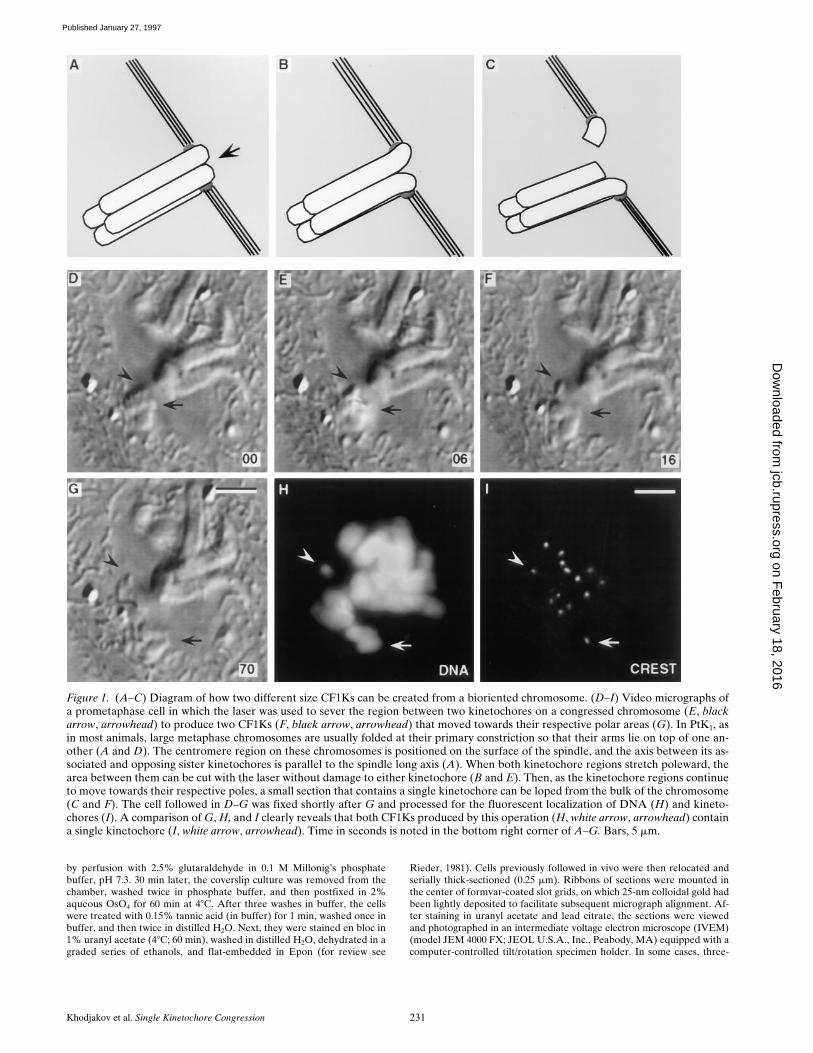
Figure 1. (A–C) Diagram of how two different size CF1Ks can be created from a bioriented chromosome. (D–I) Video micrographs ofa prometaphase cell in which the laser was used to sever the region between two kinetochores on a congressed chromosome (E, blackarrow, arrowhead) to produce two CF1Ks (F, black arrow, arrowhead) that moved towards their respective polar areas (G). In PtK1, asin most animals, large metaphase chromosomes are usually folded at their primary constriction so that their arms lie on top of one an-other (A and D). The centromere region on these chromosomes is positioned on the surface of the spindle, and the axis between its as-sociated and opposing sister kinetochores is parallel to the spindle long axis (A). When both kinetochore regions stretch poleward, thearea between them can be cut with the laser without damage to either kinetochore (B and E). Then, as the kinetochore regions continueto move towards their respective poles, a small section that contains a single kinetochore can be loped from the bulk of the chromosome(C and F). The cell followed in D–G was fixed shortly after G and processed for the fluorescent localization of DNA (H) and kineto-chores (I). A comparison of G, H, and I clearly reveals that both CF1Ks produced by this operation (H, white arrow, arrowhead) containa single kinetochore (I, white arrow, arrowhead). Time in seconds is noted in the bottom right corner of A–G. Bars, 5 mm.
on February 18, 2016
jcb.rupress.orgD
ownloaded from
Published January 27, 1997
The Journal of Cell Biology, Volume 136, 1997 232
dimensional reconstructions were generated from stereo pairs of serialsection images using Sterecon (for review see Marko and Leith, 1996). Inother cases, the biology within a selected thick section was reconstructedby IVEM tomography as detailed by McEwen et al. (1993).
Results
Generating CF1Ks by Laser Microsurgery
To produce a large CF1K that could be clearly followedthroughout the duration of mitosis, we used the schemesummarized in Fig. 1. For this approach, we first located abioriented chromosome positioned near the spindle equa-tor in which both sister kinetochores were in a P state(which stretched the primary constriction in a plane paral-lel to the interpolar spindle axis; Fig. 1,
A
and
D
). We thenstarted cutting the centromere between the stretched kineto-chore regions (Fig. 1,
B
and
E
). That our operation wasseparating the sister kinetochores could be easily assayedon a functional basis because, during a successful opera-
tion, the two kinetochore regions continued uninterruptedmotion towards their poles (Fig. 1,
B
,
E–G
). This opera-tion was then continued until we had lopped off a smallpiece of the chromosome that contained one of the kineto-chores (Fig. 1,
C
and
F
). Corresponding immunofluores-cent analyses revealed that each of the CF1Ks producedby this operation contained just a single kinetochore (Fig.1,
G–I
). Over time the smaller CF1K usually became pro-gressively stretched and unrecognizable, but the largerCF1K remained clearly visible throughout mitosis (unlessit moved back into the mass of chromosomes already posi-tioned on the forming metaphase plate—see below).
CF1Ks Can Become Bioriented and Stably Positioned on the Spindle Equator
Once generated from a bioriented chromosome, CF1Ksalways moved towards their respective poles. After near-ing the polar region, they then initiated P and AP oscilla-tory motions that were indistinguishable from those of
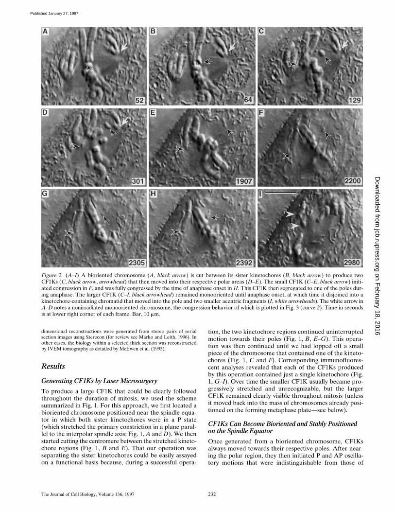
Figure 2. (A–I) A bioriented chromosome (A, black arrow) is cut between its sister kinetochores (B, black arrow) to produce twoCF1Ks (C, black arrow, arrowhead) that then moved into their respective polar areas (D–E). The small CF1K (C–E, black arrow) initi-ated congression in F, and was fully congressed by the time of anaphase onset in H. This CF1K then segregated to one of the poles dur-ing anaphase. The larger CF1K (C–I, black arrowhead) remained monooriented until anaphase onset, at which time it disjoined into akinetochore-containing chromatid that moved into the pole and two smaller acentric fragments (I, white arrowheads). The white arrow inA–D notes a nonirradiated monooriented chromosome, the congression behavior of which is plotted in Fig. 3 (curve 2). Time in secondsis at lower right corner of each frame. Bar, 10 mm.
on February 18, 2016
jcb.rupress.orgD
ownloaded from
Published January 27, 1997

Khodjakov et al.
Single Kinetochore Congression
233
neighboring, nonirradiated monooriented chromosomes(Khodjakov and Rieder, 1996; Figs. 2 and 3). As a rule,when a CF1K moved AP during an oscillation, the kineto-chore region remained nearest the pole, i.e., the wholeCF1K appeared to be pushed away from the pole with itskinetochore region trailing (Fig. 2,
C–G
,
black arrowhead
;Fig. 3, curve
3
; see also Rieder et al., 1986).In our study, half (25/50) of the CF1Ks that could be fol-
lowed until anaphase onset remained associated with thepole to which they were originally attached and behavedas a monooriented chromosome. The other half ultimatelymoved onto the metaphase plate. Importantly, during thismotion the CF1Ks exhibited behavioral changes that arecharacteristic of the biorientation and congression of non-irradiated chromosomes. First, as during congression ofuntreated chromosomes containing two kinetochores, whena CF1K congressed the kinetochore region led the motiontowards the spindle equator (Fig. 4,
arrow
). This contrastssharply with the behavior of the kinetochore region onCF1Ks and monooriented chromosomes moving AP dur-ing a normal oscillation, where the kinetochore regionusually trails the motion (see above). Second, the AP mo-tion of an oscillating monooriented chromosome is alwaysfollowed, some reasonable time thereafter, by a corre-sponding P motion of the chromosome (so that the aver-age kinetochore-to-pole distances remains about thesame—see Skibbens et al., 1993; Khodjakov and Rieder,1996). By contrast, more often than not (see below)CF1Ks that moved onto the metaphase plate remainedstably positioned on the spindle equator until or eventhroughout anaphase. Third, as in the newt (e.g., see Fig. 4
B
in Skibbens et al., 1993), the AP congression motion ofan untreated biorienting PtK
1
chromosome towards thespindle equator is always interrupted by at least one oscil-lation toward the proximal pole (Khodjakov and Rieder,1996; Fig. 3, curve
2
), and CF1Ks exhibited the same be-havior as they moved onto the spindle equator (Fig. 3,curve
1
). Finally, when initiating congression from a posi-tion near the pole, CF1Ks and normal chromosomes bothcovered the 6–10
m
m distance in about 5 min (Fig. 3,curves
1
and
2
), and during this motion the ratio of the APand P distances moved in relation to the proximal pole wasalways much higher (often approaching 5) than that exhib-ited when monooriented chromosomes or CF1Ks undergoa normal oscillatory cycle (where the ratio is usually about 1).
Of the 25 CF1Ks that moved to the spindle equator,six returned, after a variable period of time but beforeanaphase, to the same pole to which they were originallyoriented (data not shown). After reaching the spindleequator, six other CF1Ks ultimately moved through themetaphase plate and into the opposing half spindle untilthey reached the opposing spindle pole, where they beganto oscillate normally (Fig. 5). These CF1Ks, which had un-dergone “reorientation” (for review see Nicklas andWard, 1994), then remained associated with this pole untilanaphase.
The other 13 CF1Ks that congressed remained posi-tioned on the equator until anaphase (e.g., Figs. 2 and 6).Of these, four segregated to one of the poles during theensuing anaphase, but the other nine remained stably posi-tioned midway between the groups of separating anaphasechromosomes (e.g., Fig. 6). At anaphase onset, the larger
Figure 3. Time-versus-dis-tance plots depicting the be-havior of the two CF1Ksnoted by the black arrow andarrowhead in Fig. 2, as wellas the naturally monoori-ented chromosome noted bythe white arrow in this figure.Plot 1 (top, solid circles) rep-resents changes in distancebetween the right-hand poleand the kinetochore regionon the CF1K (Fig. 2, C–H,black arrow), while plot 2(top, open squares) depictschanges in distance betweenthe right-hand pole and thenonirradiated control chro-mosome (Fig. 2, A–D, whitearrow). Note that both theCF1K and the control chro-mosome exhibited low am-plitude oscillatory motionsuntil they initiated congres-sion (open arrows) and thateach underwent a single os-cillation at about the samepoint during the congressionperiod. The bottom part ofthis figure depicts the behav-
ior of the larger CF1K (Fig. 2, black arrowhead) relative to its (i.e., the left-hand) pole. This CF1K remained monooriented until ana-phase onset. The black bar at about 100 s represents time of laser surgery (corresponding to Fig. 2 B).
on February 18, 2016
jcb.rupress.orgD
ownloaded from
Published January 27, 1997

The Journal of Cell Biology, Volume 136, 1997 234
CF1Ks always disjoined into a single chromatid and twonon–kinetochore-containing chromosome fragments (e.g.,Fig. 2 I, white arrowheads; see also Khodjakov and Rieder,1996). As subsequently determined by three-dimensionalIVEM analyses, the single chromatid contained one kineto-
chore that was connected via Mts to both of the poles (seebelow).
Once a CF1K moved onto the metaphase plate, its ensu-ing motions were difficult to determine with certainty. How-ever, in one cell (Fig. 6, black arrow) we were able to
Figure 4. (A–H) Highly magnified selected images of the small CF1K noted by the black arrow in Fig. 2 as it congresses. Note that oncecongression is initiated (between B and C), the kinetochore region (black arrow) leads in motion towards the spindle equator. Bar, 5 mm.
Figure 5. (A–P) Selected frames from a video series showing the formation of two CF1Ks and their reorientation. In this cell, the armswere first separated from the centromere region of a large chromosome (compare arrows in A and B). The resultant fragment was thensplit along its long axis (C) to create two CF1Ks similar in size (D–O, arrow, arrowhead). The CF1K noted by the arrowhead in C movedtowards its pole (D and E), and then towards the spindle equator (F and G). This fragment then ultimately crossed the equator (H) andbecame permanently associated with the other spindle pole (I–O). After moving into its pole (C–H, arrow) the other CF1K also reori-ented (H–J, arrow) and moved through the spindle equator (K–L, arrow) until it reached the other pole (M–O, arrow). Bar, 10 mm.
on February 18, 2016
jcb.rupress.orgD
ownloaded from
Published January 27, 1997
Khodjakov et al. Single Kinetochore Congression 235
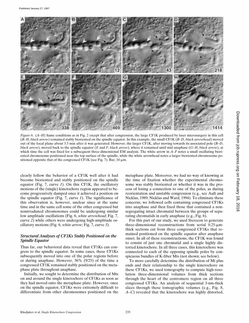
clearly follow the behavior of a CF1K well after it hadbecome bioriented and stably positioned on the spindleequator (Fig. 7, curve 1). On this CF1K, the oscillatorymotions of the (single) kinetochore region appeared to be-come progressively damped once it achieved a position onthe spindle equator (Fig. 7, curve 1). The significance ofthis observation is, however, unclear since at the sametime and in the same cell some of the other congressed butnonirradiated chromosomes could be undergoing similarlow amplitude oscillations (Fig. 6, white arrowhead; Fig. 7,curve 2) while others were undergoing high-amplitude os-cillatory motions (Fig. 6, white arrow; Fig. 7, curve 3).
Structural Analyses of CF1Ks Stably Positioned on the Spindle Equator
Thus far, our behavioral data reveal that CF1Ks can con-gress to the spindle equator. In some cases, these CF1Kssubsequently moved into one of the polar regions beforeor during anaphase. However, 36% (9/25) of the time acongressed CF1K remained stably positioned on the meta-phase plate throughout anaphase.
Initially, we sought to determine the distribution of Mtson and around the single kinetochore of CF1Ks as soon asthey had moved onto the metaphase plate. However, onceon the spindle equator, CF1Ks were extremely difficult todifferentiate from other chromosomes positioned on the
metaphase plate. Moreover, we had no way of knowing atthe time of fixation whether the experimental chromo-some was stably bioriented or whether it was in the pro-cess of losing a connection to one of the poles, as duringreorientation and unstable congression (e.g., see Ault andNicklas, 1989; Nicklas and Ward, 1994). To eliminate theseconcerns, we followed cells containing congressed CF1Ksinto anaphase and then fixed those that contained a non-segregating intact chromatid between the groups of sepa-rating chromatids in early anaphase (e.g., Fig. 6).
For this part of our study, we used Sterecon to generatethree-dimensional reconstructions from serial 0.25-mm-thick sections cut from three congressed CF1Ks that re-mained positioned on the spindle equator after anaphaseonset. In all of these reconstructions, the CF1K was foundto consist of just one chromatid and a single highly dis-torted kinetochore. In all three cases, this kinetochore wasconnected to each of the opposing spindle poles by con-spicuous bundles of K-fiber Mts (not shown; see below).
To more carefully determine the distribution of Mt plusends and their relationship to the single kinetochore onthese CF1Ks, we used tomography to compute high-reso-lution three-dimensional volumes from thick sectionsthrough the heart of the centromere region on all threecongressed CF1Ks. An analysis of sequential 3-nm-thickslices through these tomographic volumes (e.g., Fig. 8,A–C) revealed that the kinetochore was highly distorted,
Figure 6. (A–H) Same conditions as in Fig. 2 except that after congression, the large CF1K produced by laser microsurgery in this cell(B–H, black arrow) remained stably bioriented on the spindle equator. In this example, the small CF1K (B–D, black arrowhead) movedout of the focal plane about 3.5 min after it was generated. However, the larger CF1K, after moving towards its associated pole (B–D,black arrow), moved back to the spindle equator (E and F, black arrow), where it remained until mid anaphase (G–H, black arrow), atwhich time the cell was fixed for a subsequent three-dimensional EM analysis. The white arrow in A–F notes a small oscillating biori-ented chromosome positioned near the top surface of the spindle, while the white arrowhead notes a larger bioriented chromosome po-sitioned opposite that of the congressed CF1K (see Fig. 7). Bar, 10 mm.
on February 18, 2016
jcb.rupress.orgD
ownloaded from
Published January 27, 1997

The Journal of Cell Biology, Volume 136, 1997 236
appearing stretched and/or fragmented, and that it wasconnected to opposing spindle poles by numerous Mts.The distribution of these Mts, their plus ends, and their re-lationship to each other could be more clearly visualizedby Sterecon reconstructions made from stacking the perti-nent information contained within these 3-nm-thick slices.In all three reconstructions, two bundles of 6–12 parallelMts, running in a plane parallel to the spindle long axis,terminated on opposite sides of the kinetochore region(Fig. 8 D).
DiscussionOnce attached to the spindle, kinetochores in vertebratecells exhibit a directionally unstable behavior that is char-acterized by rapid, periodic switches between P and APstates of motion. Although these two states were originallyattributed to rapid switches between kinetochore-gener-ated P “pulling” and AP “pushing” forces (Skibbens et al.,1993), we now know that kinetochores moving AP do notexert a significant pushing force on the chromosome(Khodjakov and Rieder, 1996; Waters et al., 1996). In-stead, during AP motion the kinetochore is in a “neutral”
state in which it is coasting AP on the tips of kinetochoreMt plus ends elongating in response to external forces. Amajor implication of these recent findings is that thesource of the force for moving a chromosome AP differsbetween mono- and bioriented chromosomes. On mono-oriented chromosomes, the force responsible for AP mo-tion appears to be generated solely by the proximal polarejection force (for review see Rieder and Salmon, 1994),whereas on bioriented congressing chromosomes, it is gen-erated primarily by the P motion of the attaching “distal”sister kinetochore (Khodjakov and Rieder, 1996). That is,the chromosome must become attached via Mts to bothpoles before congression can be initiated, and this “biorien-tation” results in the production of a P force that acts onthe kinetochore attaching to the distal pole. As a result,the attaching kinetochore leads the motion of the chromo-some to the spindle equator during congression.
We have previously demonstrated that the damagecreated in chromosomes by our laser system is restrictedto the 0.5-mm diameter irradiated area. Indeed, when oneset of arms is severed from a large chromosome, 0.25–0.50mm from the centromere, the chromosome behaves like anormal chromosome throughout the duration of mitosis
Figure 7. Time versus dis-tance from the pole plots ofthe large CF1K shown in Fig.6 (black arrow), as well as thetwo bioriented metaphasechromosomes noted in thisfigure (Fig. 6, white arrow andarrowhead). The top curve(1, solid circles) depicts thebehavior of the kinetochoreregion on the large CF1K(Fig. 6, black arrow), whichwas tracked relative to thetop pole. Once created (solidbar at time 0), this CF1K ex-hibited oscillatory motionsthat favored a net displace-ment towards its associatedpole (0–220 s). It then initi-ated congression (near the220-s timepoint), and duringthis process, it exhibited oneoscillation before reachingthe spindle equator (near the550-s timepoint; comparewith Fig. 3). Once positionedon the spindle equator, theamplitude of its oscillationsbecame dampened (com-pare with plot 1). The middlecurve (2, open squares) de-picts the behavior of a largenonirradiated metaphasechromosome (Fig. 6, whitearrowhead), while the bot-tom curve (3, open squares)follows the small biorientednonirradiated metaphasechromosome (Fig. 6, white
arrow). The kinetochore region on both of these chromosomes was tracked relative to the bottom pole. Note that the amplitudes of theoscillations exhibited by these two “control” chromosomes varies widely.
on February 18, 2016
jcb.rupress.orgD
ownloaded from
Published January 27, 1997

Khodjakov et al. Single Kinetochore Congression 237
(Rieder et al., 1995; Khodjakov and Rieder, 1996). Further-more, when the region between the sister kinetochores is se-verely weakened or severed with the laser without com-pletely separating the kinetochore regions from thechromosome, the sister kinetochores behave normally
throughout the remainder of mitosis, with the exceptionthat their respective motilities are no longer coordinated(Skibbens et al., 1995). The single kinetochore on a CF1Kcreated by our operation also behaves the same when it ismonooriented as the only attached kinetochore on a natu-
Figure 8. Three-dimensional structure of the kinetochore region on the congressed CF1K noted by the black arrow in Fig. 6 H. (A–C)Selected 3-nm-thick slices from the tomographic volume generated from a thick (0.25-mm) section through this region. Note that a num-ber of microtubules impact and terminate on both sides of the kinetochore/chromatin complex. White arrows note structural differenti-ations that resemble pieces of the kinetochore outer plate, which is highly distorted. (D) Color-coded stereo volume generated fromstacking all of the pertinent information found in sequential slices of the tomogram shown in A–C. Recognizable portions of the kineto-chore outer plate are red and associated microtubules are blue. In this example, several Mts derived from the upper pole in Fig. 6 termi-nate in the upper part of the kinetochore plate, while those from the bottom pole terminate in the bottom half. Mts from both poles alsoappear to be connected to another region of the plate that is stretched between the poles. Bar, 0.25 mm.
on February 18, 2016
jcb.rupress.orgD
ownloaded from
Published January 27, 1997
The Journal of Cell Biology, Volume 136, 1997 238
rally monooriented chromosome (Khodjakov and Rieder,1996; also Fig. 3 of the present study). That is, it moves to-wards the pole to which it is attached and then begins tooscillate normally. Since the velocity and amplitude ofthese P and AP motions are about the same, the kineto-chore on a CF1K, as that on a monooriented chromosome,usually maintains a relatively constant average positionwith respect to its pole as long as it is monooriented (Fig. 3;see also Skibbens et al., 1993, 1995; Khodjakov and Rieder,1996). Together, these observations strongly support thecontention that our laser microsurgery protocol does notdamage either of the kinetochores during the productionof CF1Ks.
We found that a CF1K can move from a polar region tothe spindle equator and that once on the equator, it can re-main stably positioned throughout the ensuing anaphase.That this motion to the equator is true congression and notjust an exaggerated AP motion due to a normal oscillationis strongly supported by several different lines of evidence.First, during congression CF1Ks behave the same as nor-mal congressing chromosomes. In fact, without prior know-ledge, it is not possible to distinguish the congression mo-tions of a CF1K from that of a biorienting chromosomewith two kinetochores (see Results). Second, this behaviorculminates in a CF1K that, more often than not, is stablypositioned on the metaphase plate, which is the end prod-uct of congression. Finally, when we examined the struc-ture of the only kinetochore region on CF1Ks stably posi-tioned on the spindle equator during anaphase, it wasalways seen to be connected to both opposing spindlepoles by bundles of Mts, a feature which is a hallmark of abioriented chromosome and a requirement for congres-sion (see above). That its trilaminar structure was notclearly evident around the attenuated primary constrictionis not surprising considering the fact that the kinetochorewas experiencing P (anaphase) forces at the time of fixa-tion that were directed in two opposing directions. Asnoted by Roos (1973) (see also Rieder and Borisy, 1981),even the P forces acting on a monooriented PtK1 chromo-some can distort the attached kinetochore to the pointwhere its trilaminar structure is not recognizable. How-ever, although the kinetochore region on fully congressedCF1Ks lacked a clearly discernible trilaminar structure,the fact that it led the motion of the chromosome duringcongression and was the termination point for bundles ofMts derived from the opposing poles clearly signals that itcontained the kinetochore. The alternative explanation,that the congressed CF1Ks we followed contained onecomplete and one partial kinetochore that became at-tached to the opposing poles, is not defensible. Under thiscondition, CF1Ks would never be expected to remain sta-bly positioned at the spindle equator during anaphasebecause as for untreated chromosomes, chromatid disjunc-tion at anaphase onset would separate the opposing kineto-chore regions and allow them to move poleward.
Since kinetochores in PtK1 cells do not exert a signifi-cant pushing force against the chromosome (Khodjakovand Rieder, 1996; see also Waters et al., 1996) and since theproximal polar ejection force is not sufficient by itself tokeep a monooriented CF1K at the spindle equator (Khod-jakov and Rieder, 1996), how does a CF1K congress?Based on our data, we propose the following scheme for
this process. When created from a bioriented chromo-some, CF1Ks move towards the pole to which their kineto-chore is attached by P forces acting on (or generated by)the kinetochore (McNeil and Berns, 1981; Rieder et al.,1995). As the chromosome moves progressively towardsthe centrosome, poleward progress becomes impeded andthe kinetochore initiates the P and AP oscillatory motionscharacteristic of normal monooriented chromosomes thatare positioned within a dense array of Mts (e.g., seeCassimeris et al., 1994). During AP motions, the wholechromosome fragment is pushed AP by the proximal polarejection force so that the kinetochore region trails themovement (see above). If given enough time before ana-phase, the kinetochore encounters, and then binds, one ormore Mts growing from the distal pole. This induces it toinitiate motion towards the spindle equator and the chro-mosome arms begin to trail this motion as the kinetochoreapproaches the metaphase plate (see Fig. 4). Under condi-tions in which the kinetochore maintains a stable attach-ment to both poles, it moves to the spindle equator, whereit remains until anaphase onset or even through anaphase(Figs. 6–8). However, because Mts bound to and/or termi-nating in the kinetochore turnover relatively rapidly (forreview see Zhai et al., 1995) and because the stability ofthese Mts is deleteriously compromised by distortions inthe structure of the kinetochore (Nicklas and Ward, 1994)produced by the opposing P directed forces acting on it,some bioriented kinetochores ultimately lose their attach-ment to one of the poles. When this occurs, the kineto-chore either returns to the pole it was originally attachedto or it completes a successful reorientation to the otherpole (Fig. 5). This scheme, as outlined, is not only consis-tent with our data but also with the existing structural dataon how kinetochores on bivalents reorient during meiosis(see Ault and Nicklas, 1989; Nicklas and Ward, 1994) andmitosis (Ault and Rieder, 1992; McEwen, B.F., and C.L.Rieder, unpublished data).
To our knowledge, the attachment of a single kineto-chore to both spindle poles has not previously been docu-mented during the course of a normal bipolar mitosis, al-though it commonly occurs during the reorientation ofbivalents during meiosis (e.g., Ault and Nicklas, 1989; Nick-las and Ward, 1994). It must occur during mitosis, at leaston a transient basis, when spindle pole separation is de-layed until well after nuclear envelope breakdown. Underthis condition, kinetochores facing the single polar regionare exposed, and likely attach, to Mts growing from bothof the closely spaced centrosomes. As for these transientmonopolar spindles, it is not unusual for one kinetochoreto also be stably attached to two poles during a multipolardivision when both poles face the kinetochore (Heneen,1975). However, because of the steric considerations in-herent in the back-to-back positioning of sister kineto-chores on mitotic chromosomes, considerations which en-sure that when one faces one pole the other faces theopposite pole, the biorientation of a single kinetochore islikely to be a rare event when a bipolar spindle forms be-tween two well-separated centrosomes (see Nicklas, 1971),which is the prevalent route of spindle formation in animalcells (Aubin et al., 1980; Waters et al., 1993).
Why does removing one kinetochore by laser microsur-gery enhance biorientation of the remaining kinetochore?
on February 18, 2016
jcb.rupress.orgD
ownloaded from
Published January 27, 1997

Khodjakov et al. Single Kinetochore Congression 239
A logical explanation is that attenuating the primary con-striction with the laser allows the remaining kinetochoreto encircle more completely the remainder of the primaryconstriction, which makes it readily “visible” to Mts grow-ing from both poles. This explanation is consistent withobservations on the structure of kinetochore fragments incells undergoing a MUG (Zinkowski et al., 1991; Christyet al., 1995), which reveals that the outer Mt-binding plateof the vertebrate kinetochore is under an internal elasticforce that tends to curl it around the primary constrictionof the chromosome (see also McEwen et al., 1993; Throweret al., 1996).
From our data we conclude that the single kinetochoreson CF1Ks can become attached to Mts from both polesand that this biorientation then leads to congression. Thismeans that different parts of a kinetochore can exist, at thesame time, in different functional states, i.e., while onepart is generating or experiencing a P force and its associ-ated Mts are shortening, another part can be in neutraland be displaced AP while its Mts elongate. For this to oc-cur, a single kinetochore must be composed of multiple as-sociated domains, and the P and AP motility states ofthese domains can be regulated independently of one an-other. This conclusion strongly supports the Zinkowskiet al. (1991) hypothesis that vertebrate kinetochores areconstructed of multiple identical subunits, and it extendsthis hypothesis to the functional level.
Since different regions of a single kinetochore can switchindependently into different motility states, the motilitystate of a kinetochore is not regulated at the level of thewhole structure. Rather, at any point in time, the overallbehavior of a kinetochore is determined by the cumulativebehavior of multiple, independently regulated sites thatmay or may not all be working in concert. It is likely thatthe behavior of these sites is normally coordinated by tensionsince switches between bulk kinetochore P and AP (neu-tral) activity are correlated with this parameter, i.e., in-creasing tension on the kinetochore favors net switchingfrom P to neutral state, whereas diminishing tension favorsneutral to P switches (Skibbens et al., 1993, 1995). Thistension, which on a CF1K is generated across the kinetochorewhen those parts attached to the two opposing poles are ina P state, likely also stabilizes some of the Mts associatedwith the kinetochore (e.g., those that terminate perpendic-ular to the plate structure; see Nicklas and Ward, 1994).
We thank Ms. G. Osorio for her expert assistance with serial sectioning,Ms. A. Heagle for help with tomography, and Mrs. C. Hughes for main-taining and growing PtK1 cells. We also thank Drs. M. Koonce, R. Slo-boda (Dartmouth College), E.D. Salmon (University of North Carolina,Chapel Hill, NC), and K. Bloom (University of North Carolina, ChapelHill, NC), for stimulating discussions.
This work was supported by National Institutes of Health grant GMS40198 (to C. Rieder), National Science Foundation grant MCB 9420772(to B. McEwen), and National Institutes of Health grant NCRR/BTP P41-01219, which partly supports the Wadsworth Centers Biological Micros-copy and Image Reconstruction (BMIR) Facility as a National Biotechno-logical Resource. The video light microscopy component of the BMIR isalso supported by the Wadsworth Center as a Core facility.
Received for publication 9 August 1996 and in revised form 11 October 1996.
References
Aubin, J.E., M. Osborn, and K. Weber. 1980. Variations in the distribution and
migration of centriole duplexes in mitotic PtK2 cells studied by immunofluo-rescence microscopy. J. Cell Sci. 43:177–194.
Ault, J.G., and R.B. Nicklas. 1989. Tension, microtubule rearrangements, andthe proper distribution of chromosomes in mitosis. Chromosoma (Berl.). 98:33–39.
Ault, J.G., and C.L. Rieder. 1992. Chromosome mal-orientation and reorienta-tion during mitosis. Cell Motil. Cytoskel. 22:155–159.
Brinkley, B.R., R.P. Zinkowski, W.L. Mollon, F.M. Davis, M.A. Pisegna, M.Pershouse, and P.N. Rao. 1988. Movement and segregation of kinetochoresexperimentally detached from mammalian chromosomes. Nature (Lond.).336:251–254.
Cassimeris, L.C, C.L. Rieder, and E.D. Salmon. 1994. Microtubule assemblyand kinetochore directional instability in vertebrate monopolar spindles. Im-plications for the mechanism of chromosome congression. J. Cell Sci. 107:285–297.
Christy, C.S., M. Deden, and J.A. Snyder. 1995. Localization of kinetochorefragments isolated from single chromatids in mitotic CHO cells. Proto-plasma. 186:193–200.
Cole, R.W., A. Khodjakov, W.H. Wright, and C.L. Rieder. 1995. A differential-interference contrast-based light microscopic system for laser microsurgeryand optical trapping of selected chromosomes during mitosis in vivo. J. Mi-crosc. Soc. Am. 1:203–215.
Darlington, C.D. 1937. Recent Advances in Cytology. 2nd ed. Blakiston Co.,Philadelphia. 588 pp.
Heneen, W.K. 1975. Kinetochores and microtubules in multipolar mitosis andchromosome orientation. Exp. Cell Res. 91:57–62.
Khodjakov, A., and C.L. Rieder. 1996. Kinetochores moving away from theirassociated pole do not exert a significant pushing force on the chromosome.J. Cell Biol. 135:315–327.
Marko, M., and A.D. Leith. 1996. Sterecon—three dimensional reconstructionsfrom stereoscopic contouring. J. Struct. Biol. 116:93–98.
McEwen, B.F., J. Arena, Y.U. Liu, J. Frank, and C.L. Rieder. 1993. Three-dimensional ultrastructure of the colcemid-treated PtK1 kinetochore outerplate as determined by high voltage electron microscopic tomography. J.Cell Biol. 120:301–312.
McIntosh, J.R., and G.E. Hering. 1991. Spindle fiber action and chromosomemovement. Annu. Rev. Cell Biol. 7:403–426.
McNeil, P., and M.W. Berns. 1981. Chromosome behavior after laser microirra-diation of a single kinetochore in mitotic PtK2 cells. J. Cell Biol. 88:5443–5553.
Mitchison, T.J. 1989a. Mitosis: basic concepts. Curr. Opin. Cell Biol. 1:67–74.Mitchison, T.J. 1989b. Chromosome alignment at mitotic metaphase: balanced
forces or smart kinetochores? In Cell Movement. Vol. 2, Kinesin, Dyneinand Microtubule Dynamics. Alan R. Liss, Inc., New York. 421–430.
Mitchison, T.J., L. Evans, E. Schultze, and M. Kirschner. 1986. Sites of microtu-bule assembly and disassembly in the mitotic spindle. Cell. 45:515–527.
Nicklas, R.B. 1971. Mitosis. In Advances in Cell Biology, Vol. 2. D.M. Prescott,L. Goldstein, and E. McConkey, eds. Appleton Press, New York. 225–297.
Nicklas, R.B., and S.C. Ward. 1994. Elements of error correction in mitosis: mi-crotubule capture, release and tension. J. Cell Biol. 126:1241–1253.
Rieder, C.L. 1981. Thick and thin serial sectioning for the three-dimensional re-construction of biological ultrastructure. Meth. Cell Biol. 22:215–249.
Rieder, C.L., and G.G. Borisy. 1981. The attachment of kinetochores to theprometaphase spindle in PtK1 cells: recovery from low temperature treat-ment. Chromosoma (Berl). 82:693–716.
Rieder, C.L., and E.D. Salmon. 1994. Motile kinetochores and polar ejectionforces dictate chromosome position on the vertebrate mitotic spindle. J. CellBiol. 124:223–233.
Rieder, C.L., E.A. Davison, L.C.W. Jensen, L. Cassimeris, and E.D. Salmon.1986. Oscillatory movements of monooriented chromosomes, and their posi-tion relative to the spindle pole, result from the ejection properties of the as-ter and half spindle. J. Cell Biol. 103:581–591.
Rieder, C.L., A. Schultz, R.W. Cole, and G. Sluder. 1994. Anaphase onset invertebrate somatic cells is controlled by a checkpoint that monitors sister ki-netochore attachment to the spindle. J. Cell Biol. 127:1301–1310.
Rieder, C.L., R.W. Cole, A. Khodjakov, and G. Sluder. 1995. The checkpointdelaying anaphase in response to chromosome monoorientation is mediatedby an inhibitory signal produced by unattached kinetochores. J. Cell Biol.130:941–948.
Roos, U.P. 1973. Light and electron microscopy of rat kangaroo cells in mitosis.II. Kinetochore structure and function. Chromosoma (Berl.). 41:195–220.
Salmon, E.D. 1989. Microtubule dynamics and chromosome movement. In Mi-tosis: Molecules and Mechanisms. J.S. Hyams and B.R. Brinkley, eds. Aca-demic Press, New York. 119–181.
Skibbens, R.V., V.P. Skeen, and E.D. Salmon. 1993. Directional instability ofkinetochore motility during chromosome congression and segregation in mi-totic newt lung cells: a push–pull mechanism. J. Cell Biol. 122:859–875.
Skibbens, R.V., C.L. Rieder, and E.D. Salmon. 1995. The behavior of pro-metaphase kinetochores after separation from the centromere and chromo-some arms by laser microsurgery: evidence that kinetochore directional in-stability and position is regulated by tension. J. Cell Sci. 108:2537–2548.
Thrower, D.A., M.A. Jordan, and L. Wilson. 1996. Modulation of CENP-E or-ganization at kinetochores by spindle microtubule attachment. Cell Motil.Cytoskel. 35:121–133.
Waters, J.C., R.W. Cole, and C.L. Rieder. 1993. The force-producing mecha-
on February 18, 2016
jcb.rupress.orgD
ownloaded from
Published January 27, 1997
The Journal of Cell Biology, Volume 136, 1997 240
nism for centrosome separation during spindle formation in vertebrates is in-trinsic to each aster. J. Cell Biol. 122:361–372.
Waters, J.C., R.V. Skibbens, and E.D. Salmon. 1996. Oscillating mitotic newtlung cell kinetochores are, on average, under tension. J. Cell Sci. 109:2823–2831.
Wise, D., L. Cassimeris, C.L. Rieder, P. Wadsworth, and E.D. Salmon. 1991.Chromosome fiber dynamics and congression oscillations in metaphase PtK2cells at 238C. Cell Motil. Cytoskel. 18:131–142.
Wordeman, L. 1995. Mechanisms of chromosome segregation in metazoancells. In Progress in Cell Cycle Research. L. Meijer, S. Guidet, and H.Y.L.Tung, eds. Plenum Press, New York. 1:319–327.
Zhai, Y., P.J. Kronebusch, and G.G. Borisy. 1995. Kinetochore microtubule dy-namics and the metaphase–anaphase transition. J. Cell Biol. 131:721–734.
Zinkowski, R.P., J. Meyne, and B.R. Brinkley. 1991. The centromere-kineto-chore complex: a repeat subunit model. J. Cell Biol. 113:1091–1110.
on February 18, 2016
jcb.rupress.orgD
ownloaded from
Published January 27, 1997
Copyright © 2022 FDOKUMEN