experimental investigation on partial replacement of cement ...
Upload
khangminh22Category
view
0download
0
PROCEEDINGS OF THEV
THIRD INTERNATIONAL SYMPOSIUM
ON THE
Chemistry of Cement
RONDON -1952
(z/rÄ - ao.t'xHeld under the auspices of
THE BUILDING RESEARCH STATION OF THE
DEPARTMENT OF SCIENTIFIC AND INDUSTRIAL RESEARCH
and the
CEMENT AND CONCRETE ASSOCIATION
Published by the
Cement and Concrete Association, 52 Grosvenor Gardens, London SW1MCMLIV

Printed and published tn Bn^land tn 1954 Cement and Concrete Association
5 2 Grosi enor Gardens, London, S U ' 1

Contents
Historical Preface page xGeneral Summary xiiProgramme xivList of Participants xviiiTribute to Professor Tborvaldson xxxCement Research and the Future—A foreword to the papers by Dr. F. AL Lea xxxi
paper i. THE EARLY HISTORY OF CEMENT IN ENGLAND 1P. Gooding and P. E. Halstead
discussion: 27R. H. Bogue
paper 2. THE TRICALCIL'M SILICATE PHASE 30J. W. Jeffery
discussion: 49E. BurkeA. A. T. MetzgerH. O’DaniclF. OrdwayG. Trömelauthor's closure
paper 3. THE DICALCIUM SILICATE PHASE 56R. W. Nurse
discussion: 77M. A. BredigMrs. A. M. B. DouglasMrs. L. Heller\V. L. de KeyserA. A. T. MetzgerT. ThorvaldsenG. Trömel11. Zur Strassenautltor's closure
paper 4. TRICALCIUM ALUMINATE 91Fred Ordway
discussion: 109J. D. Bernal\X'. H. EitelN. Yannaquisauthor’s closure

PAP E R 5. TUE FERRITE PHASE 120G. Malquori and V. Cirilli
discussion: 137F. GilleH. G. MidglcyT. W. ParkerM. A. Swayzcauthors’ closure
PAP E R 6. THE ALKALI PHASES IN PORTLAND CEMENT CLINKER 151
Terry F. Newkirk
discussion: lh<)F. GillcR. W. Nurseauthor’s closure
PAP E R 7. INTERSTITIAL PHASES IN PORTLAND CEMENT CLINKER 172
Herbert Insley
discussion: ISO
E. BurkeVC". C. I LinsenA. A. T. MetzgerT. \X . Parkeraittljor's closure
PAPER 8. STUDIES ON THE CONSTHTT1ON OF PORTLAND CEMENT CLINKER ls4
R. H. Bogue
discussion: 212J. 11. WelchH. Zur Strassenauthor's closure
PAPER 9. THE STRUCTURES OF CEMENT HYDRATION COMPOUNDS 21b
J. D. Bernal
discussion: 237R. H. BogueP. M. de WoltFA. GrudemoMrs. L. HellerF. M. UaMiss H. D. MegawMiss A. E. Moore\X . H. TaylorE. Thiloautlor's closure

paper io. THE REACTIONS AND THERMOCHEMISTRY OF CEMENT HYDRATION AT ORDINARY TEMPERATURE 261
Harold H. Steinour
discussion: 289W. C. I lansen R. Hedin G. L. KalousekK. Koyanagi P. Longuet G. Malquori and V. Cirilli R. W. Nurse and H. F. W, Taylor author's closure
paper II. THE REACTIONS OF CEMENT HYDRATION AT ELEVATED TEMPERATURES 334
George L. Kalousek
discussion: 356G. E. Bcsscy\X'. L. de KeyserR. W. NurseH. F. W. TaylorT. Thorvaldsen 'author's closure
paper 12. THE PHYSICAL STRUCTURE OF CEMENT PRODUCTS AND ITS EFFECT ON DURABILITY 368
F. E. Jones
discussion: 419J. XC. Harding T. C. Powers J. H. P. Van Aardt H. E. Vivian author's closure
paper i?. CHEMICAL ASPECTS OF THE DURABILITY OF CEMENT PRODUCTS 436
T. Thorvaldson
discussion: 466G. Batta and J. BaiverlinL. Blondiau11. K. CookR. G. FranklinP. E. HalsteadJ. H. P. Van Aardtauthor’s closure

paper 14. TUE CONSTITUTION OF ALUMINOUS CEMENT 4S5 T. W. Parker
discussion: 515J. BrocardW. L. de KeyserC. Goria and A. BurdeseW. C. HansenMrs. L. HellerP. L’Hopitallier and Madame L. M. AssaudMrs. C. M. MidgleyH. G. MidgleyT. Vi’. Parker and J. F. RyderT. D. Robsonauthor's closure
paper 15. SLAG CEMENTS 53)F. Keil
discission: 571P. JanssensT. W. ParkerP. PirottcA. O. PurdonT. E. RuleN. Stuttcrhcimauthor's closure
paper 16. EXPANSIVE CEMENTS 5S111. Lafuma
discission: 5'<2H. Andrews11. J. CowanF. GilleC. Goria and M. Appi.moP. 1 likansonE. V. Meyerauthor's closure
paper 17. OIL WELL CEMENTS 593W. C. I lansen
discussion: (,27E. Burke H. H. Steinour author's closure
paper 18. MASONRY CEMENT (>33Charles E. Wucrpcl
discussion: 579J. Brocard \X . C. I lansen P. Mason author's closure

paper 19. SOME RECENT DEVELOPMENTS IN THE DESIGN AND CONSTRUCTION OF CONCRETE STRUCTURES 680
A. R. Collins
discussion: 700C. L. a’CourtW. C. AndrewsE. BurkeN. Daveyauthor's closure
paper zo. THE INFLUENCE OF THE FINENESS OFCEMENT RAW MIXES ON THEIR BURNABILITY 711
T. Heilmann
discussion: 745J. C. GullenP. HäkansonS. NagaiC. C. Skouauthor’s closure
paper zi. THERMODYNAMICS OF THE CEMENT KILN 75011. Gygi in collaboration with F. Guye
discussion: 779J. CallejaR. J. DaviesC. GoriaF. GuyeM. J. M. JaspersK. Meyer and H. Wendeborncutters' closure
paper 22. DEVELOPMENT OF CEMENTS FOR SPECIALUSES IN THE UNITED STATES 790
Myron A. Swayze
discussion: 798R. R. Hattiangadi author's closure
Resumes des documents 805Zusammenfassungen der Papiere 821zAutbors* index 838Subject index 847

Historical Preface
the first international Congress organized by the International Association for Testing Materials dealing with any of the subjects being discussed at the present Symposium was, so far as can be traced, held in Stockholm in 1897. Since that date a number of not dissimilar congresses have been organized by the International Association, and these have been held in various capitals. At Budapest in 1901, for instance, papers were contributed by such well-known men as Professor H. le Chatelier of Paris and Mr. B. Blount of London. Again at Brussels in 1906 Professor le Chatelier and Mr. Blount, as well as Monsieur R. Feret, were among those who submitted papers.
The first symposium to deal solely' with the chemistry of cement was held during the first World War, on 14th January 1918, when the Faraday Society arranged a meeting in London to discuss “ The setting of cements and plasters.” It was said at the time that such a meeting was necessary “ in view of the ditliculties experienced in inaugurating research into the question
cement and setting generally, were submitted :
TITLE of paperThe mechanism of the setting process in
plaster and cementCrystalloids against colloids in the
theory' of cementsThe agglomeration of granular massesThe constitution and hydration of
Portland cementThe setting and hardening of Portland
cementIs the setting of cement mainly a
physical or a chemical process ?Ancient and modern mortarThe effect of the addition of suitable slag
on the setting properties of Portland cement
The setting of cement in its relation to engineering structures
The effect of the addition of slag to Portland cement
meeting the following papers
AUTHOR
Cecil H. Desch
I lenry' le Chatelier
F. G. DonnanA. A. Klein
G. A. Rankin
John G. A. Rhodin
W. J. DibdenE. Deny & E. H. Lewis
Bertram Blount
Percy C. II. West

HISTORICAL PREFACE
These papers, with the discussions which followed, were published in Volume XIV of “ Transactions of the Faraday Society.”
In 1938, in view of the “ important developments ” which had since taken place and as fundamental work on several essential problems was then in progress in many countries, the Royal Swedish Institution for Engineering Research and the Swedish Cement Association invited a number of research cement chemists to an international meeting in Stockholm as it was felt that such a meeting would afford an opportunity for a valuable exchange of views and would contribute to the promotion of scientific and technical progress. This meeting was entitled “ Symposium on the Chemistry of Cements ” and the following papers were submitted :
TITLE OF PAPER
The study of giant molecules by means of ultracentrifugal sedimentation, diffusion and electrophoresis
Reactions between substances in solid state with special regard to systems containing silica
Constitution of Portland cement clinkerX-rays and cement chemistryThe calcium aluminate and silicate
hydratesThe calcium aluminate complex saltsPortland cement and hydrothermal
reactionsEffect of water on Portland cementThe chemistry of retarders and
acceleratorsThe mineral content of aluminous
cementReactions of aluminous cement with
waterThe chemistry of pozzolanasThe physical structure of hydrated
cements
AUTHOR
T. Svedberg
J. A. Hedvall
R. H. BogueW. BüssernG. E. Bessey
F. E. JonesT. Thorvaldson
P. SchläpferL. Forsen
N. Sundius
G. Assarsson
F. M. LeaS. Giertz-Hedström
It was originally arranged that the next symposium should be held in Washington in 1948 but economic conditions were not favourable for Europeans to travel to America. It was later decided to hold the symposium in England in 195 z and the Building Research Station of the Department of Scientific and Industrial Research and the Cement and Concrete Association agreed to act as sponsors.

General Summary
the third International Symposium on the Chemistry of Cement was held in London from 15th-20th September 1052 under the presidency of Sir Ben Lockspeiser f.r.s.. Secretary to the Department of Scientific and Industrial Research, with Sir Francis Meynell r.d.l, the Director of the Cement and Concrete Association, as vice-president. Mr. P. Gooding, the Development and Information Officer of the Cement and Concrete /Association, was the organizing secretary. The editing of the Proceedings has been carried out by P. E. Halstead B Sc. Ph.D. and R. W. Nurse M.Sc.F.Inst.P.
The opening session of the Symposium took place at the Royal Institution and other sessions at the Royal Society of Arts.
The Symposium was organized jointly by the Building Research Station of the Department of Scientific and Industrial Research and by the Cement and Concrete Association, and was attended by two hundred and sixty invited delegates, representing twenty-six countries.
The proceedings included seven half-day working sessions, at which twenty-two papers were presented and discussed and three half-day visits to research laboratories and cement works. There were one hundred and two contributions offered during the discussion which followed the main papers, making a total of one hundred and twenty-four items to be published as the proceedings of the Symposium. The average attendance at each session was one hundred and sixty.
A Government reception was held for the overseas delegates, and a banquet was offered to the delegates by the Cement and Concrete Association. In addition, a series of entertainments was provided to cover each day of the Symposium.
At the opening session of the Symposium the President welcomed the delegates with a speech, in which he pointed out that “ cement and concrete are major constructional materials which have revolutionized civil engineering construction and radically affect all branches of building. The world output of cement is now at least 120 million tons a year. If we convert this into concrete it means something approaching 5(X) million cubic yards, and we could do with a great deal more.” He stressed the great importance of a correspondingly large research effort and made plain that there was 11 still ample room for expansion in research."
The Vice-President also welcomed the delegates. He gave a short survey of the work of the Cement and Concrete Association and emphasized the

value of the co-operation in research which exists between industry and the Government in Great Britain : “ I know of no country in the world where you have quite this combination : private enterprise and" close government co-operation and support without interference. This cooperation is not merely financial, it does not exist only at the high and visible levels : it exists all the way down.”
An introductory address by Dr. A. A. Bates, read in his absence by Dr. R. H. Bogue, paid tribute to “ national aspects of genius which shine forth in the history of the development of Portland cement,” as exemplified in the great names of Smeaton, Aspdin, Vicat, Le Chatelier, Michaelis and Törnebohm. Professor H. Lafuma also gave an introductory address, in which he outlined the methods of work of his organization, the “ Centre d’Etudes et de Recherches de ITndustrie des Liants Hydrauliques ” and described its aims thus : “ what one should expect from such an institution is, not to lay down a doctrine, but to create a congenial environment, to promote a state of mind which can be acquired only through contact w’ith men who have long lived in an atmosphere of research work and of specialized research, as each branch has its own technique, its working rules, its way of reasoning and its own particular approach to problems. Those entrusted with the management of a Study Centre must, like the head of a research laboratory, strive to create a tradition from which the greatest possible number of scientific works can derive benefit.”
Professor G. G. Wästlund gave a report of the work of the Swedish Cement and Concrete Institute, which was founded after the Stockholm Symposium on the Chemistry of Cement “ mainly to do fundamental physical and chemical research on cement and allied materials and with an idea which at that time seemed to be quite new, namely to combine fundamental physical research with technical concrete research.”
At the close of the third session Dr. R. H. Bogue proposed a vote of appreciation to Professor Thorvaldsen for his lifelong service to the chemistry of cement. (This address is printed on page xxx).
The closing address to the Symposium, entitled “ Cement Research and the Future,” was given by Dr. F. M. Lea and is printed as a foreword to the papers.
The proceedings for the Symposium follow.

Programme
Session 1: Monday 15 September
Afternoon
ADDRESSES OF WELCOME
Sir Ben Lockspeiser f.r.s.Secretary, Department of Scientific and Industrial Research President of the Symposium
Sir Francis Meynell r.d.i.Director, Cement and Concrete Association V'ice-President of the Symposium
INTRODUCTORY addresses
Dr. A. Allen Bates (u.s.a.)}/ice-President, Portland Cement Association, U.S.A.The address n os read by Dr. R. H. Bopue
Prof. H. Lafuma (france)Director, Centre d'iitudes et de Recherchcs de ITndustrie des Liants llydrauliques, France
Prof. G. W astlund (swf.den)Srensha Forskningsinstitutet for Cement och Belong, vid Kungl. Tekniska Ildgskolan, Stockholm, Su edcn
PAPERS AND DISCUSSIONS
The early history of Portland cement in England {Paper 1)P. Gooding (u.k.)P. E. Halstead (u.k.)
Session 2: Tuesday 16 September
CONSTITUTION OF PORTLAND CEMENT
CHAIRMrX:
(Af/>rw>r^) Dr. F. AT. Lea (U.K.) Prof. VC. L. de Keyser (Belgium)

PROGRAMME
Morning
PAPERS AND DISCUSSIONS
The tricalcium silicate phase (Paper 2) -J. W. Jeffery (u.k.)The dicalcium silicate phase (Paper 3)R. W. Nurse (u.k.)Interstitial phases in Portland cement clinker (Paper 7) Herbert Insley (u.s.A.)The ferrite phase (Paper 5)G. Malquori (italy)V. Cirilli (italy)
Afternoon
PAPERS AND DISCUSSIONS
The alkali phases in Portland cement clinker (Paper 6)Terry F. Newkirk (u.s.A.)
The paper was read bj Dr. R. H. BogueTricalcium aluminate (Paper 4)Fred Ordway (u.s.A.)
The paper was read by Dr. R. IL Bog«eStudies on the constitution of Portland cement clinker
(Paper 8)R. H. Bogue (u.s.A.)
Session 3: Wednesday 17 SeptemberTHE SETTING AND HARDENING OF PORTLAND CEMENT
chairmen:(Morning) Prof. T. Thorvaldson (Canada) (AJternoon) Dr. T. Heilmann (Denmark)
Morning
PAPERS AND DISCUSSIONS
The structures of cement hydration compounds (Paper 9) J. D. Bernal (u.k.)The reactions and thermochemistry of cement hydration at
ordinary temperature (Paper 10)Harold H. Steinour (u.s.A.)
The paper was read by Mr. Ii-'z. Lerch (U.S.A.)

AfternoonPROGRAMME
PAPERS AND DISCUSSIONS
The reactions of cement hydration at elevated temperatures (Paper 11)
George L. Kalousek (u.s.a.)The physical structure of cement products and its effect on
durability (Paper 12)F. E. Jones (u.k.)Chemical aspects of the durability of cement products
(Paper 13)T. Thorvaldson (Canada)
Session 4: Thursday 18 September
SPECIAL CEMENTS
chairman: (wbole liiy) Dr. il. Gygi (Switzerland)
xMorning
PAPERS AND DISCUSSIONS
The constitution of aluminous cement (Paper 14)T. \X'. Parker (u.k.)Slag cements (Paper 15)F. Keil (germant)
Expansive cements (Paper 16)H. Lafuma (prance)Oil well cements (Paper 17)W. C. Hansen (u.s.a.)Masonry cement (Paper 18)Charles E. Wuerpel (u.s.a.)
«Afternoon
Visit to Building Research Station, Garston, Watford, Herts
Session 5: Friday 19 September
APPLICATIONS OF RESEARCH
chairman: (yZyZf <Zy) Dr. R. IL Bogue (U.S.A.)

PROGRAMME
Morning
papers and discussions (a) In manufacture
Thermodynamics of the cement kiln (Paper 21)H. Gygi in collaboration with F. Guye (Switzerland)The influence of the fineness of cement raw mixes on their
burnability (Paper 20)T. Heilmann (Denmark)
papers and discussions (b) In utilization
Some recent developments in the design and construction of concrete structures (Paper 19)
A. R. Collins (u.k.)Development of cements for special uses in the United
States (Paper 22)Myron A. Swayze (u.s.a.)
CLOSING ADDRESS
Cement research and the futureF. M. Lea (u.k.)
Ajternoon
Visit to the Research Station of the Cement and Concrete Association, Wexham Springs, Stoke Poges, Buckinghamshire
Saturday 20 September
Morning
visits to:
The laboratories at Birkbeck College, University of London, 21 Torrington Square, London, W.C.lThe research laboratories of the Associated Portland Cement Manufacturers Ltd, Stone, Greenhithe, KentThe cement works of the Tunnel Portland Cement Co.Ltd, Pitstone, Buckinghamshire.

List of Participants
Note: The asterisks denote authors and the daggers denote those who sent contributions but who were not present at the Symposium.
Abeies, P. \V."1 be Raila aj Lxeeutire—Lastern Region United Kingdoma’Court, C. L.Imperial Chemical Industries Ltd United KingdomAgrell, S. O.Lnirersify of Cambridge United KingdomAllen, T.Pilksngfan Brothers Ltd United KingdomAndersen, J.J tatspreveanstalten DenmarkAndrews, II.Building Research Station United KingdomAndrews, W. C. Civil Laigineer United KingdomAndrews, W. P.Cement and Concrete ^Association United KingdomAnselm, W.Ingenieurbüro fur die Steme-und Erdenindustrie Germany
[■Appiano, M.Inshtuto di Cbim'ha zXpplicata del Pohtecnico di Torino ItalyArmstrong, A. J.1 he Cement Makzrs' Federation United KingdomAru|.a, E.Building Research Station United KingdomAshpole, F. G.lamdon Brick Co. Ltd United KingdomAssarsson, G.Srenges Geologicka Lndershkaung Sw edenAssaud, Madame, L. M.Sociele ^Anonjme des Cbaux et Ctments de Lafarge et du Teil FranceAvenell, A.zVrdnted United Kingdom
Baiverhn, J.Unirtrsite de I-JtgeBaker, FI.The R/igby Porllarrd Cement Co. LidBannister, F. A.Rritesb Miueum oj Natural HutorjeBarnes, E.G. <l~ T. Urie Ltdxvni
Belgium
United Kingdom
United Kingdom
United Kingdom

fBates, A. AllenPortland Cement AssociationBennett, C.The Rugby Portland Cement Co. Ltd
U.S.A.
United Kingdom♦Bernal, J. D.Birkbeck College Research Laboratory, University of London Bessey, G. E.Research Council of the British Whiting FederationBlondiau, L.Societe Anonyme des Ciments de TbieuBlyth, R. C.Cement and Concrete Association
♦Bogue, R. H.Portland Cement Association Fellowship at National Bureau
of StandardsBonnell, D. G.Building Research Station
United Kingdom
United Kingdom
Belgium
United Kingdom
U.S.A.
United KingdomBowie, P. G.Cement and Concrete AssociationBrandenberger, E.Laboratoire Federal d’Essai des Materiaux et Institut de Recherctes—
Industrie, Genie cml, Arts et Metiers (Zurich)Brearley, R. J.Offie of the High Commissioner for Canada
fBredig, M. A.
United Kingdom
Switzerland
Canada
Oah Ridge National laboratoryBrocard, J.Laboratoires du Bailment et des Traraux Publics
fBurdcse, A.Institute di Chimica Appheata del Politecnico di TorinoBurke, E.7 be Associated Portland Cement Manufacturers Lid
U.S.A.
France
Italy
United KingdomBurn, D C.Cement and Concrete AssociationBuzzi, L.Socle fa Fratelh Birgpi
United Kingdom
Italy
Calle|a, J.Insiifufo 7 ecnico de la Construecion j del CementoCehs, R. T.Societe Anrrn^me Cimenteries ei Briquetenes RenniesChristie, G. II.“ 7 uisteel ** Reinforrement Lfd
tCinlli, V.Insiitulo di Cbmiua Apphcata del Politecnico di TorinoCleveland, A.Brixton School of Building
♦Collins, A. R.Cement and Concrete AssociationCook, H. K.Corps of Engineers, United States ArmyCoston, P. S.7 be Associated Portland Cement Manufacturers Ltd
Spain
Belgium
United Kingdom
Italy
United Kingdom
United Kingdom
U.S.A.
United Kingdom

Cowan, H. J.Univereity of Sheffield United KingdomCraddock, Q. L.The Associated Portland Cement Manufacturers Ltd United KingdomCrichton, D. C.The Associated Portland Cement Manufacturers Ltd United KingdomCzemin, W.Forschungsinstitut des 1 'eremes der Ösierr. Zementfabrikanten Austria
Dardanelli, P.Socieia Tratelh Bi<™i ItalyDavey, N.Bsuldmg Research Station United KingdomDavies, R. J.Pretoria Portland Cement Co. Ltd South AfricaDavis, Sir Gilbert Liberty Lime Co. Ltd United KingdomDawson, O.Ldmund Nuttall Sons d* Co. ^London') Ltd United KingdomDaxclhofer, J. P.Lcole Polytechnique de PUniiersite de Lausanne S» itzcrlandDean, E. G.Ministry of Works United Kingdomde Calcya, J. F.Mimsteno de Industna Direction General de Minas y Combustibles Spainde Junncmann, J.Ltabhssements Pohet et Cbausson Francede Keyser, W. L.Umversite I abre de Bruxelles Belgiumde Vi oltf, P. M.Technisch Physische Dienst T.N.O. I lollanddel Campo, M.Instituto l ecntco de la Construction y del Cemento SpainDouglas, Mrs. A. M. B.University of Cambridge United KingdomDutron, R.Groupement Professionriel des Fabruants de Ciment Portland
Arttfitiel de Belgique (Representing—Sonete Royale Beige des Ingenieurs et des Indus trie Is)
Belgium
Dzuhnski, Mlle M.Uniiemte de Liege Belgium
tEltcl, W. H.L'wenitjf of ToledoEngstrom, B. z\luiel>olaglet Gullogens BrutEve, Sir Malcolm Trustram The Cement Makert* I ederation
U.S.A.
S» eilen
United Kingdom
I'alco, A. R.Mints/erto de Industna Dtreieion General de Mtna/j Combuitiulet Spam

Falkiner, R. H.Edmund Nut fall Sons eS" Co. (London) LtdFisher, J. M.John Laing eS" Son LtdFors, B.Pargas Kalkbergs ÄkliebolagFrancon-Smith, J.Cbmnor Cement c" Lime Co. LtdFranklin, R. G.Imperial Chemical Industries LtdFuller, K. W.7 her mahle Lid
United Kingdom
United Kingdom
Finland
United Kingdom
United Kingdom
United Kingdom
Geiger, L.Societe de Ct went Portland Tourab-Le Catre EgyptGiertz-IIedstrom, S.Aktiebolaget I ’tbro-1 'erken SwedenGilfillan, J. H.Imperial Cbenneal Industries Ltd United Kingdom
tGdle, F.I orscbem^sinsti/ut der Zement Industrie GermanyGlanville, W. 11.Road Research Laboratory United Kingdom
•Gooding, P.Cement and Concrete ^Association United KingdomGoossens, J.Societe /Xnon^me des Ctments J. Vran den Heutel BelgiumGoossens, PaulSonete Anonyme des Ctments J. 1 *an den lleuvel BelgiumGoossens, PierreSociete Anonyme des Ciments J. I 'an den lleurel BelgiumCror\2t C.Lxiboraform Centrale Ricerc/oe Lnione Cementi Marchtno ItalyGrasso, M.Portland Cement Association I ellonsbip at National Bureau
of StandardsU.S.A.
Green, C, V, Colonial Geological Sumeys United KingdomGnfhth, C. F.Pilkington Brothers Ltd United KingdomGriffiths, E.National Physical Laboratory United Kingdom
Griffiths, L. H.Scmfex Ltd. United Kingdom
Grudemo, A.Cement-oth Betonymtifulet SwedenGrün, RRaustnj 1 orsebung Buchcnlx)/ GermanyGuillaume, L Prefecture de la Seine FranceGullcn, J C.Aber than c** Bristol Channel Portland Cement Co. Ltd United Kingdom

*Guye, F.Cementjabrik. HoMerbank-WHA’^^ A. G.
*Gygi, H.Cementjabrik llolderbank-W ildegg zt. G.
Switzerland
Switzerland
Haegermann, G.Portland-Zementjabrik I lemmoor GermanyHacnny, E.Sociiti zAnonyme ties V.ts .-VlexanJre Dapsens Belgium1 lacs, E. F.Seaiocrete Prodiu ts Ltd United KingdomHAkanson, P.Cement-ocb iVtofnJaboraforift Sweden
* Halstead, P. E,Gement and Concrete zXssociation United KingdomHanna, XX". S.L nirerx/ty oj Lowad t// F.gyptI lansen, XX'. C.Unifenal z\tlas Cement Co. U.S.A.Harding, J. XX’.Puibling Keieareb .S tation United KingdomHarmsen, G. J.Koninklijke .Shell- l^boratorin/n HollandHarper, F. C.Building I\esearih .Station United KingdomI Linley, Sir I LiroklBritish 1 dectricity .'h<fl’nrify Research Coiatcil United KingdomHast, N.Rnyal Institsete of Tecbnnlr.gy^bistitntion of Building Tcc^Hique Building Materials SwedenHattiangadi, R. R.^Associated Cement Companies Ltd IndiaHawkins, L. C.C.hinnor Cement c* Urne C o. Ltd United KingdomI ledin, R.C.ement-ocb Befonginsfitufet Sweden
tel Icilmann, T.F". L. Smidtb C* Co. -A 5 DenmarkI Idler, Mrs. L.Bzrki’eck College Research 1 ^dwrafor^ Unirersitj oj lj>ndon United KingdomHill, A. XX'.<.ement ami Concrete . Association United KingdomHmdlcy, C. XX". G. Mims try of U orks United KingdomHobbs, C.John losing C* .Son I .td United KingdomHolt, H. A.I be C ement Marketing Company Ltd United KingdomHowe, XX". T.G. C- T. Larle Ltd. United KingdomHumbert, C.Xociefe zlnonyme des Ciments Portland de Rom'r-as France

list of participants
Humm, W.Technische Forschungs-und Beratunystelie der E. G. PortlandHussey, A. V.l^afarge Aluminous Cement Co. Ltd
Switzerland
United Kingdom
Insley, H.National Bureau of Standards U.S.A.
Jackson, A. J.The Associated Portland Cement Manufacturers Etd United KingdomJaeger, T. M.F. L. Smidib c~ Co. Etd United KingdomJanssens, P.Societe Anonyme Cimenferies et Briqueteries Reunies (also repre
senting— Societe Anonyme Cannon Brand, Societe Anonyme la Cimenterie Belpe “ Cimbel ”)
Belgium
Jaspers, M. J. M.Deleeate of the Societe Anonyme Ciments et Carrieres Bataille
a Gaurain-RamecroixBelgium
‘Jeffery, J. W.Birkjieck College Research Laboratory, Unircrsity of lamdon United KingdomJensen, N. M.7 be 1 unnel Portland Cement Co. I.id United KingdomJensen, P. E.F. L. Smidtb cF Co. Lid United KingdomJohnson, A. D.Ulis Testing and Research Station United KingdomJohnson, F.7 be Rugby Portland Cement Co. l.td United KingdomJohnson, H. W.Johnson Im lei c~ Miar, Architects United KingdomJones, A.Associated Portland Cement Manufacturers Ltd United Kingdom
'Jones, F. E.Building Reiearib Station United KingdomJones, K.7 be Rugby Portland Cement Co. Ltd United Kingdom
Jorgensen, A. B.I". L. Smidtb d* Co. Ltd United Kingdom
*Kalousck, G. L.Unit ersit y of ToledoKArcby, E.Skantka CementallirhoiafetKaufmann, O.Terrohme EtdKearlcy, \\’.7/v II all Paper Manufacturers EtdKeen, R. A.Cement and Concrete .-Issociahon
U.S.A.
S» eden
United Kingdom
United Kingdom
United Kingdomxxiii

♦Keil, F.ForschungsinsHtut der Zement Industrie GermanyKerman, G. M.Abertbaw eF Bristol Channel Portland Cement Co. Ltd United KingdomKing, G.Albright cF Wilson Ltd United KingdomKing, J. W. H.Queen Mary College, Cniversitj of lumdon United KingdomKlavansky, A. L.Palestine Portland Cement Wonfes “ Nesber ” Ltd IsraelKoyanagi, K.Japan Cement Engineering Association JapanKuhl, II.Zement und Mörteltecbniscbes laiboratorium am Berlin Germany
♦Lafuma, II.Centre d'Etudes et de Bechert hes de PIndustrie des Liants
I IjdrauliqiasFrance
Larsen, S.zl '5 Dalen Portland-Cementfabrik NorwayLav, H. J. S.The Rugbji Portland Cement Co. Ltd United KingdomLax, D.Maunsell, Posford C* Parry United Kingdom
*Lca, F. M.Building Research Station United KingdomLee, A. R.Road Research luiboratory United KingdomLerch, W.Portland Cement .Association U.S.A.Lerner, R.C.R.M.C. 1 ailioratories Ltd United KingdomL'Hopitallicr, P.Societe zXnomme des Cbaux et Ciments de luifarge et du Teil FranceLindius, G.Shsmsiui CementakfieboLiget SwedenLiversedge, J. R.John Lirersedge c* zXssociates United KingdomLobry de Bruyn, C. A.Bow mater ialen-lnstitnui T.N.O. Hol LindLockspciscr, Sir BenDepartment of Scientif.c and Industrial Research United KingdomLoevenich, II. K.Baustoff-1 ‘orstbiaig Buebenlof GermanyIxifquist, B.Swedish State Power Board Sweden
fLonguct, P.Centre d'Ltiules et de Recherches de ITndustrie des IJantf
I hdrauliquesFrance
Lowe, N. M.lhe .Associated Portland Cement Manufacturers Ltd United KingdomI.und, A.Cement Ltd Eire

McGuire, R. E.The Cement Makers' Federation United KingdomMcIntosh, J. D.Cement and Concrete Association United KingdomMack, G. W.Building Research Station United KingdomMcNicoll, G. R.Cbmnor Cement eF Lime Co. Ltd United Kingdom'Malquori, G.Umversita di Napoli ItalyMarsden, E.New Zealand Scientific Office New ZealandMason, P.Building Research Station United KingdomMegaw, Miss H. D.Lnn ersity of Cambridge United KingdomMetzger, A. A. T. .Pargas Kalkbergs Akliebolag FinlandMeyer, E. V.Cementfabrikkernes Tekiuskz Oplysningskantor DenmarkMeyer, K.1 irma Ijergi Gesellschaft fur Chemie und Hüttenwesen m.b.H. GermanyMeyncll, Sir FrancisCement and Concrete Association United KingdomMidgley, Mrs. C. M.Building Research Station United KingdomMidgley, H. G.Building Research S tahon United KingdomMitchell, D.Tbe Associated Portland Cement Manufacturers Ltd United KingdomMitchell, J. C.Cement and Concrete Association United KingdomMitchell, K. M.Imperial Chemical Industries Ltd United Kingdom
Moore, Miss A. E.Cement and Concrete Association United Kingdom
Monee, P. B.Cement and Concrete Association United Kingdom
Muller, P. P.Imperial Chemical Industries Ltd United Kingdom
Muzaffar, S. D.Gffiie of the High Commissioner for Pakistan Pakistan
Nagai, S.Ceramic Association oj Japan
tNe»kirk, Terry F.Portland Cement Association I ellon <hip at National Bureau
of Standards‘Nurse, R. W.Building. Retearcb StationNAgaard, K.Dansk Andels Ccmentfabrik
Japan
U.S.A.
United Kingdom
Denmark

O’Daniel, H.Lniversitj of FrankfurtOrchard, D. F.Cement and Concrete zXssoaation
■fOrdway, FredPortland Cement zAssociaiton Fellonsbtp at National Bureau
of Standards
Germany
I'nited Kingdom
U.S.A.
»Parker, T. \V.BiuMing Research StationPeterson, O.Cement-orb BetongiaborafonetPfrunder, V. R.Portlaiuhemenljabrik. laufenPirottc, P.Societe Anonyme le FerroamentPreisler, J.Cement l.tdPugh, J.7 be Kef ton Portla?ui Cement Co. YjdPurdon, A. O.^ociete Vinanciere de Transport: et DTjitrepnses IndnstrieliesPurdy, J*I be Rugbjf Portland Cement C o. Ltd
United Kingdom
Su cden
Su it/crLind
Belgium
Lire
United Kingdom
Belgium
United Kingdom
Rea, VC. G.Ibe Associated Portland Cement Manufacturers L.td United KingdomRettig, G.Orthos Industrial Trading Co. United KingdomRio, A.Cak i e Cementi di Segni ItalyRoberts, M. H.Building Research Station United KingdomRobertson, A. A.Dirision of Industrial Dei elnpmentt Department of National
Dei eiopmentAustralia
Robin, P. I [.Semtex Ltd United KingdomRobson, T. D.Loifarge v \luminous Cement Co. Ltd United KingdomRoll, G. ILSealoirete Prodiuts Lid United KingdomRos, M.IaiboraImre Federal d'Lssais des Materiaux et Institut de
Reihenbes—Industrie, Genie aril. Arts ef Metiers (Zicria'-)Su itrcrland
Ross, H. C.I bi Hydro-Uectric Po» er Comnnsiion of Ontario CanadaRule, T. F.1 "itreous Concrete Co. Ltd United Kingdom

XXVll
Rutlc, J.Cement-og PxtonginstituttetRyan, D. J.Cement Ltd
Norway
Eire
St Pierre, P. D. S.Department of Alines and Technical SurveysSalter, Miss J. C.Cement and Concrete AssociationSchaffer, R. J.Budding R.esearch StationSchmit-Jensen, E.7 Le I unflel Tori land Cement Co. LtdSchmoelder, II. J.Dyckerhoff Tordand-Zementu erbe A. G.Seagar, E1 be Rugby Portland Cement Co. LtdShellard, E. S.I be Cement Marketing Company LtdSingleton Green, J.Stressed Concrete Design LtdSk|oldborg, P.AkJieselskabet Aalborg Portland-Cement-FabrikSkou, C. C.Imperial Chemical Industries IjdSkwarecki, J.I be Kelton Portland Cement Co. LidSlater, R. C.Surrey County Technical CollegeSiegten, J. A.Soacte Anonyme Tuiuspiement Industrie! SiegtenSmith, E. M. 'Cement LtdSparkes, F. N.Road Research LaboratorySpohn, E.Heidelberger Zement»erke A. G.Stagg, R. FI be ketton Pordand Cement Co. LtdStarnes, P. E.7 bermahte Ltd.
fStcinour, Harold H.Portland Cement AssociationStensrud, LA S Da/en Portland-CementjabnkStern’, L, R.I lammercmitb Sdxiol of BuildingStubbs, R. J.I^istuoods Cement Ltd
•fStutterhcim, N\Council for Scientific and Industrial Kesearch
*S\^a^7e, M. A.Lv>ne Star Cement Corporation
Canada
United Kingdom
United Kingdom
United Kingdom
Germany
United Kingdom
United Kingdom
United Kingdom
Denmark
United Kingdom
United Kingdom
United Kingdom
Belgium
Eire
United Kingdom
Germany
United Kingdom
United Kingdom
U.S A.
Norway
United Kingdom
United Kingdom
South Africa
U.S A.

Tate, N.Aurrej Technical College United KingdomTattersall, G. H.British Cast Concrete Federation United KingdomTaylor, ILF. \V.Birkbeck College Research I-aboratorj^ Untversiij of I^ondon United KingdomTaylor, W. ILUnirersitj? of Cambridge United Kingdom
tThilo, E.Humboldt—Unn-iversitat l^erhn GermanyThomas, A. J.lie British Portland Cement Mann/ai/nrers I.td United Kingdom7 homas, J/ Conard I airclough I .id United KingdomThorneloc, A. ILlie . Xsiociated Portland Cement Manujacturers Ltd United Kingdom
*7horxatdson, T.Unn-eriity oj SasAafJeuan CinadaTokio, J. M.Institiifo lemico de la Comtniuion y del Cemento SpamToplev, B.
\lbngbt c"' U iLon Ltd United KingdomTromcl, G.Atax-PlamA-Institut fur I isenfortjiing GermanyTsountas, C.\oii<te „Anonyme de (aments " I itan ” GreeceTurner, IL ILL.C.C. 1 citing Station jur Building Materials United KingdomTurner, \\ . G. z\.aiAI>erthan C* Bristol C banne I Portland C ement C o. Ltd United Kingdom
I Inch, A.1 be 1 wmel Pori land Cement Co. 1 .tdUttcnthal, P.1 he I unnei Portland Cement ( o. 1 .idL'\ ttcndaclc, J. E..Seahtlwr Derelopmcnt C o. I .id
L'mtcd Kingdom
United Kingdom
United Kingdom
Win Aardt, J. H. P.(Repreientint; \nutb . tfrnan Comutl for .\iientp.r and
Industrial Rriearib')van der Lccuw, K. L. A.Izrite Nederland'de C emeni IndustrieVigar, H. A.7be Ruej'v Portland ( ement Co. I.id\ man. H. IL.Commonwealth .'itienti'.r and Induttrial Researih Oryni^a.': ,n
South Africa
1 lolland
United Kingdom
Australia
Wakchcld. \X. A.I . !.. bm;d.-h u- ( n. LtdXXS ill
United Kingdom

Ward, R.Imperial Chemical Industries Ltd United KingdomWastlund, G.Cement-ocb Retonginstitutet SwedenWatkins, P E.The Pores tai Land, Timber Lailways Co. Ltd United KingdomWedgwood, G.CLmnor Cement cP Lime Co. Ltd United KingdomWeir, C. D.Mer^t, cP McLellan United KingdomWelch, J. H.Building Research Station United KingdomWendeborn, 11.Firma Lurgi Gesellschaft fur Chemie und Huttenn’esen m.b.H, GermariyWerner, D.Skanska Cementaktiebolaget SwedenWestmoreland-W'hite, Miss B.Brixton School of Building United KingdomWey, G.Stka G.M.B.H. Chem. Fabrik GermanyWhitaker, T.Building Research Station United KingdomWhite, T.The Porestal lusnd. Timber cP Railways Co. Ltd United KingdomV hiring, G. 11.London Brick Co. Ltd United KingdomW ilhams, A. L. Ministry of Works United KingdomWoodcock, W. H.Woodcock cP Mellersh United KingdomWorsdale, J. E.White's South African Portland Cement Co. Ltd South Africa
■'Xuerpel, C. E.Marquette Cement Manufacturing Co. U.S.A.
Zur Strassen, H.Pyefeerhofl Portlanzl-Zementuerke A. G. Germany

Tribute to Professor Thorvaldsonby Dr R. H. Bogue
Given at the close of the third session, Wednesday 17th September 1052
Mr. Chairman,May I have the privilege of the floor for a moment? Now that Professor
Thorvaldson has given his replies and cannot say ant thing more to me, I want the privilege of the floor to break the rules, if I may. 1 will not take two minutes.
There are occasionally, in all branches of endeavour, men who become great. They become the savants whom we look back to with respect and love. Such men were Le Chatclicr and Michaelis. Professor Thorvaldson has given his life to the study of cement and concrete; he is better known than anyone else in the world for his work on the durability of concrete, particularly in sulphate waters; and his personality is that which no one can come in contact with and fail to love him. I wish, therefore, as 1 said, to break the rules to this extent. Professor Thorvaldson has retired from his otlicial duties at the University of Saskatchewan. He tells me by no means is he stopping his active duties. W’e hope that he will continue his active duties and his contributions for a great many years, but I wish to propose, Mr. Chairman, a vote of appreciation for his lifelong service to us in the chemistry of cement.

Cement Research and the Futureby F. M. Lea
C.B.E., D.Sc., F.R.I.C., Hon.A.R.I.B.A.
Director of Building Research, Department of Scientific and Industrial Research
in this general address to the Symposium which it is my privilege to give, I should like both to look back and to look forward. The title I have given to it is perhaps rather bold, for while we can survey' the past we cannot chart the future. But by looking at some of the broad characteristics of cement research since 1938 we may perhaps find some of the seeds from which future advances may grow, or at least identify some of the more important problems that demand our attention. That must be the justification for my title, for prophecy is an act of faith, not of science, and it is with science I must deal.
The papers presented at the Stockholm Symposium were concerned with the constitution and hydration of cements. For our present meeting the net has been cast wider, and we have included not only these fundamental questions of cement chemistry, but also problems of manufacture and use.
The Stockholm Symposium came after a generation of very active and fruitful research. Much had been learnt of the broad principles of the constitution and hydration of cements, though a mass of detailed problems remained. Mow far we have gone in solving these problems is shown by the papers to the present meeting and these, in their turn, reveal many new matters requiring attention. I cannot in the time at my disposal attempt to touch on more than a few of these, but we should not, I think, misjudge the work of the last fifteen years if we characterized the earlier part of it as a period of consolidation from w'hich; in the last few years, new broad lines of advance have started to appear.
The increase in knowledge of the crystal structure of cement compounds, a deeper insight into the physical make-up of set cement and of the different ways in which water is held, and new developments in experimental techniques, all form signposts to our road.
Constitution of cementsSince 1938 there have been two main lines of study on the constitution
of Portland cement, one the investigation by phase equilibria methods ofxxxi

the role of the minor components, and, the other, the re-examination of the phases present in cement clinker. These two lines of research have tended to converge for the minor components enter into solid solution with the major components or transform them in some way. The complex polymorphism of tri- and di-calcium silicates appears at last to be resolved and we know much about the way in which minor components in solid solution stabilize the different forms of these compounds. This leads us to the interesting question of the relative rates of hydration of the different polymorphic forms and whether, for instance, the reactivity of dicalcium silicate in cement clinker can be increased. The technical value this would have is self-evident. More certainty has now been reached as to the nature of the iron compounds and the composition of the solid solutions in which they occur.
\X'e still have to settle the effect of the minor components on the compound content of Portland cement. Much progress has been made with phase equilibrium studies, but it seems clear that these are unlikely to lead to finality, and emphasis in research probably needs to be thrown back for a period on to the direct examination of clinker. The distribution of the alkalis and of alumina are important instances. Alumina, for example, can appear in cement as glass, C.NA„ CjA, C,AF solid solution, and in solid solution in C,S and possibly also in C;S. There is no method at present of calculating with any accuracy how much crystalline C,A may be present in a cement, despite the general tendency to use such calculated values as a measure of the sulphate resistance and long-term durability of cements. With the aid of new techniques now available it should be possible to establish the range of composition of the clinker components. Such information would enable us to improve the calculation of compound content and so predict better the properties of Portland cements.
The constitution of high alumina cement presents an even more involved problem than that of Portland cement, for not only may the iron compounds exist in different states of oxidation, but solid solution is also more widespread. One important advance, the identification of the so-called " unstable A t ” as a quaternary compound, was made possible by the use of MgO as a model, or analogous substitute, for FcO. This is a method which in appropriate circumstances, can be a useful tool, and we may also instance the way in which the crystal structure of tristrontium aluminate has been drawn on in elucidating that of tricalcium aluminate. The study of the analogous aluminate and silicate compounds of strontium and barium has attracted increasing attention in recent vears, and is worth pursuing. It will widen our knowledge of possible cements, even though of a verv special character, but, perhaps more important, it is likely to help clarify our understanding of the nature of cements and cementing action.
A rather different group of problems awaits our attention when we turn to the cements containing blastfurnace slag. At first sight the questions
xxxii

involved may appear simple, for in fully granulated slag only one substance, a glass, is involved. But some slag glasses are inert, others are hydraulic in an alkaline medium, and still others are self-hardening. Must we not expect that these differences are a reflection of changes in structure? Investigations of synthetic glasses would not only help to elucidate this problem but may well be the only way in which precise information can be obtained on the role of the various oxides. Even here X-ray methods may be of assistance. A determination of the distribution of interionic distances, as has been done for commercial glass compositions, would establish any structural differences between the various types of slag glasses and supplement the complementary chemical work described at this Symposium.
TechniquesLet us look for a moment at the developments in techniques which
have made possible many of the advances of the last decade. Those in microscopy have mostly been concerned with the metallographic technique where improved apparatus makes possible accurate measurement of the reflectivity and hardness of small grains. Tremendous strides have been made in the use of X-rays. A powder diagram of a simple substance can now be made in two or three minutes by the use of the fine focus tube; this instrument thus takes its place beside the microscope as an everyday tool for the quick examination of materials. Apparatus and methods used in structure analysis have been developed and smaller crystals can be examined. At the same time the intensive study of the process of crystal growth has yielded methods by which cement minerals have been grown to a size sufficient for crystal analysis.
More and more of the standard methods of chemistry can now be applied at high temperatures; the development of the high-temperature centrifuge, more refined methods of thermal analysis and for the observation of crystal formation, and improved automatic apparatus for controlling and recording temperatures, make it possible to gather a greater amount of information for a given expenditure of manpower.
1 lydratim oj cementsThough the main outlines of two of the ternary systems fundamental
to cement hydration (AO-SiO.-lLO and CaO-Al..O3-H2O were already clear at the time of the Stockholm Symposium, and much was known about the double salts of tricalcium aluminate, the precise application of this knowledge to the processes that actually occur in the hydration of cements is still only slowly being resolved. Knowledge of these systems has been refined and increased, but too little is as yet known of the analogous iron compounds, while the quaternary system CaO-Al2O3-SiO2-ILO, is still largely a closed book. Enough is known to indicate the existence of certain quaternary compounds of lime, alumina, silica and water, and to show’ that complex solid solutions of lime, alumina, ferric.oxide, silica and water can , xxxiii

be formed, either as hydrogarnets or as the tricalcium aluminate double salts. The relevance of this information to the chemical nature of set cement, particularly after long periods of hardening, is, however, still uncertain, and one of the most complex pages of inorganic chemistry has still to be written.
Once again it seems that advances in techniques are opening up new possibilities. Slowness of reaction of the anhydrous cement compounds with water, the formation of surface coatings which hinder the attaining of equilibria, and the existence of metastable states, are all sources of difficulty in experimental investigation. The discovery that by the application of supersonic vibrations the hydration of tricalcium silicate can be much speeded up seems to offer the hope that some at least of these difficulties may be overcome.
Advances in another direction, that of the structure of the basic hydrous silicates and aluminates, are fast increasing our knowledge of set cement. This was a field of silicate structure that had not been systematically studied. Refined methods of X-ray analysis have now made it possible to differentiate between (OH) ions and H.O molecules, even though uncertainties as to their bonding still remain, and to suggest a basic lime-silicate linkage system which is common to a whole group of natural and synthetic hydrated calcium silicates. This, when combined with the elucidation of the structure of most of the anhydrous compounds, promises also to give us a much clearer understanding of the hydration process.
There still remains much difficulty, especially when cement rather than one of the pure compounds is studied, in detecting the hydrates formed in pastes of low water content corresponding to those used in actual practice. It the reason for this is the low state of order in the extremely small crystals formed, then the extended use of electron diffraction should prove valuable; it may also assist in the identification of surface films. The results of electron microscopy have <>ften been difficult to interpret, but examination by simultaneous microscopy and diffraction is helping to remove this difficulty.
Ditlcrential thermal analysis is now being applied to the studv of cement hydration, but like other analogous methods, for example that of dchvdra- tion isobars, it may not alone give clear-cut answers because of the low state of order in the hydrates tn be studied.
While the hydrates in set cement form onlv very fine crystals, some of the difficulties experienced also arise from the presence, even in so-called completely hydrated cements, of enough of the original clinker to give a dominating X-ray pattern. \X"e can now sec how separation using the supercentrifuge may help to resolve this problem.
The use of radio-active tracer elements for the study of the mechanism of reactions has proved invaluable in many branches of chemistrv and we have presented at this meeting the first example of its use in the investigation of cement problems. This technique should have much wider

applications in the study of the setting and hardening of cements and help to resolve problems which might otherwise appear insoluble. Ability to label an atom can help not only in the study of dynamic processes, but also in the study of equilibria where there is uncertainty as to the way in which some particular element is distributed between different phases.
Structure and properties of set cementThe exploration of the structure—both physical and chemical—of set
cement is essential to a proper understanding of the basic properties, strength, durability, shrinkage, etc., of mortar and concrete. Investigations on these have made substantial progress.
It has become a commonplace remark that the old controversy of the “ gel ” versus the “ crystalline ” theory of cement setting has largely been resolved by the knowledge that the substance of set cement is crystalline, but of colloidal dimensions. It now seems, however, that the process of crystal growth may be an important factor in determining the properties of the set mass. Most of the hydrates can form fibrous or lath-like felted masses. If this is the key point in determining the strength, then an interesting field of research is opened up. It is well known that small quantities of impurity will often modify profoundly the habit of growing crystals, and it seems possible that substances might be found either to accentuate or destroy the fibrous character of set cement, with corresponding effects on the physical properties.
The observation that the crystal lattice spacings of the hydrated calcium silicates vary with water content in a similar way to that of swelling clay minerals, such as montmorillonite, is of much importance. Many theoretical calculations have been put forward relating shrinkage to capillary phenomena, and the Thomson equation has had to bear a burden heavier than that for which it is fitted, but this new evidence gives support to the view that one cause of shrinkage is to be found within the set cement crystals themselves. The extensive studies of the adsorption and desorption of water by cement pastes have given us a very valuable, even if arbitrary, division of the water in set cement between that contained in the pores, in the gel and that which is very firmly bound. The meaning of the distinction between the latter two should become apparent when the study of the structure of the hydrated compounds has reached a more advanced stage.
The mechanism of volume change in set cement products, whether arising from physical or chemical causes, still needs more investigation. \X’e have various theories of drying shrinkage and creep, of expansion arising from freezing, from chemical changes within the concrete such as the alkali-aggregate reaction, and from external attack as in the case of sulphate solutions. Crystal thrust, internal hydrostatic pressure, capillary phenomena, swelling of gels, osmotic pressure, etc., have all been called in to explain one or other of these phenomena. \\"e have, in fact, run

CEMENT RESEARCH AND THE FUTURE
through a gamut of physico-chemical principles, not all of them independent, without reaching finality.
Addition agentsThe improvement in frost resistance of concrete, and of the workability
of the mix, by air-entrainment, has been a dominant theme in recent years. The effect of small additions of substances loosely termed “ surface active ” on workability and frost resistance has been clearly shown to be directly related to the amount of air entrained. Some ot these agents, particularly in the drier mixes, can, however, influence workability without appreciable air-entrainment. Examples have been reported in which the compressive strength is maintained, while the tensile strength and extensibility are substantially increased. Here we find the rather unusual effect of a reduction in elastic modulus without any corresponding fall in strength. For some structural purposes this may be a disadvantage, but for others, such as road slabs, the benefit of increased resistance to shrinkage cracking may be of much practical interest.
The mode of action of these agents is not known. Available evidence indicates that they do not influence the rate ot hvdration ot the cement and hence it must be doubtful if they can act by increasing the surface of contact between cement and water. Perhaps some modification of crystal growth and form may be responsible.
The fundamental rheological properties of cement mixes are at last receiving more adequate attention after a long period in which reliance was placed on numerous and varied empirical tests. Some of these have proved valuable practical tools, but, as with all empirical tests, their limitations sometimes tend to be forgotten and their use pressed beyond their original purpose. For the further study of “ plasticizing " agents we undoubtedly need to get back to basic principles and then to adapt old empirical tests, or to devise new ones, as an aid to concrete practice. Particle size, shape, charge and interaction are basic properties governing the behaviour of plastic mixes to which attention has been directed, though it is perhaps studies on particle charge that have been most neglected.
Development of eementsI have spent most of my time in discussing the chemistry and physics
of cements, but I must not close without some mention of progress in the development of cements.
The technology of cement manufacture is an advanced one and improvements in its processes have progressed steadily in parallel with the growth of detailed knowledge of what happens at each stage in manufacture. Some of its basic problems, such as those involved in heat transfer, fuel economy, materials hantiling and fine grinding, are common to many other industries and progress is hkclv to run parallel with development and increase in knowledge of these subjects at large. But the cement industry has pioneered important developments in these fields, and it still has every

reason to push forward research and development designed to increase efficiency in its thermal processes and in fine grinding. We still lack an adequate theory of the mechanism of fine grinding or any definite measure of the efficiency of a tube mill for which, indeed, estimates vary from as low as 1 per cent up to 20 per cent or more.
Control of production has been much facilitated by new test methods, whether analytical for determining composition, or physical, as in the measurement of surface area, but we have still not reached general agreement as to the best and most reproducible method for specifying the most essential property of cement, its strength. There is often to be heard today a plea for increased uniformity in the quality of cement so that the constructional engineer may base design on average rather than minimum strength values of cement. Another suggestion is for a Portland cement of very high strength for such special uses as prestressed concrete. These are all matters which will continue to receive the attention of the cement technologist.
No radical change is to be seen over recent years in the types of cement available, though there have been interesting innovations. Amongst Portland cements we have the now well-established classes of normal, rapidhardening, low-heat and sulphate-resistant cements. The most important development here is the introduction of air-entraining agents with their valuable influence on frost resistance and workability. We have, as I have already mentioned, still much more to learn on workability aids.
Pozzolanic cements have long been known as giving improved sulphate resistance. The blending of pozzolana with a Portland cement which is itself sulphate resistant, rather than with an ordinary Portland cement, has also been recognized as a logical development. One example of this is to be found in the mixture of pozzolana and Ferrari, high iron, Portland cement used in Italy. Insufficient attention seems yet to have been paid towards exploiting the value of high glass content as a means of obtaining sulphate resistance in Portland cements, either for use alone or blended with pozzolanas.
Our programme at this meeting pays little attention to the chemistry of pozzolanas, and indeed our knowledge of their mode of action has not increased substantially since the time of the Stockholm Symposium. Progress here must, in part, depend on increases in out knowledge of what happens in the hydration and hardening of Portland cement. The testing of pozzolanas and pozzolanic cements has also still to be put on a really satisfactory basis.
It has often been held that slight unsoundness in hydraulic limes is of value in producing tight joints in brickwork, and the rationalization of this has come with expansive cements. Their general application seems at present rather remote, even though there is no development that would contribute more to concrete technology than the ability to reduce or eliminate shrinkage.
In oil wrell cements we have materials whose properties seem still to

require closer definition. They have to be so controlled, chemically and physically, that they can be pumped as slurries under unusual conditions and have an adequately long setting time at high temperatures and pressures. This has led to the development of appropriate test methods and investigation of the efliciency of different retarding agents. The suggestion that the action of these agents depends on adsorption at the surface of the cement minerals contrasts with the normal theory that gypsum retarders act by controlling the content of aluminates in solution and depositing them as films round the cement grains. It does, however, seem to accord with the observation that a cement can be made so hydrophobic by grinding oleic acid, and some other materials, with the clinker that it is almost impossible to wet it in the neat state.
Masonry cements, where it is the physical rather than the chemical properties which are improved in certain ways by blending other materials with Portland cement, now have their well-established uses and further study of them may be regarded as part of the general rheological investigation of mortars and concretes.
Amongst cements containing granulated blastfurnace slag the most recent innovation is the Trief process. The essential benefit of this process lies in the wet grinding of the granulated slag, for cements with a low Portland cement and high slag content, stimulated by the addition of activators, have been common in the past. Improved methods for the quick checking of the activity of slags are still needed. Supcrsulphated— or “ sursulphat6 ”—cements, based on granulated slags of fairly high alumina content and some form of calcium sulphate, form a class whose setting action depends on the formation of calcium sulpho-aluminate under such conditions that it is not accompanied by expansion. There is scope for more investigation of the mechanism of the reactions involved here, as indeed with all types of slag cement.
No important change has occurred in high alumina cement, but ability to control more closely its mineralogical composition would undoubtedly help both makers and users.
l:inaieI started this address by going back to the Stockholm Symposium and
in concluding I would like to return to it again. The idea that cement chemists needed an international forum for the periodic discussion of the progress of their science and technology, and the initiative that led to the holding of the Stockholm meeting, came from one who was a close friend of some of us—Lennart Forscn. His death during the vears of the war has taken him from us, but the spirit that imbued the Stockholm meeting has lived on in this. Were he still alive he would, 1 believe, have felt that research workers on cement still remain a close-knit international community, giving and gaining each from the efforts of the other. May that long continue.

[1]
The early history of cement in England
P. GOODING and P. E. HALSTEAD
INTRODUCTION
The meeting in London of the Third International Symposium on the Chemistry of Cement appears a suitable occasion for putting on record a summary of the facts regarding the early British investigators into cement, the early manufacturing companies and their works, and important structures in which Portland cement was first used. At the same time an attempt has been made to resolve certain points on which previous writers have differed.
Although in the course of investigations some new facts have come to light, much of the information here set down is already known; it is hoped, however, that even if this summary contains little that is new, a presentation of the facts will be of some interest.
EARLY INVESTIGATORS
Joseph TlspdinA bronze tablet in the City Hall of Leeds reads as follows :
“ In memory of Joseph Aspdin of Leeds, Stonemason 1779-1855. Whose invention of Portland cement patented 21st October 1824 followed by a century of improvement in its manufacture and use has made the whole world his debtor.”
The tablet, which was unveiled on 6th September 1924, was presented by the Portland Cement Association of America in co-operation with the Cement Makers’ Federation of Great Britain.
On 6th November 1824 the Leeds Mercury contained the following reference :
“ We hear that Joseph Aspdin, bricklayer of this town has obtained a patent for a superior cement resembling Portland stone."
This patent. No. 5022 of 1824, is now in the possession of Mr. J. \X'. Aspdin of Portland Lodge, Dawcross, Harrogate, Yorks, a great grandson of Joseph Aspdin. It veas exhibited in the Minerals of the Island pavilion at the South Bank Exhibition of the Festival of Britain from 4th May to 30th September 1951.
The following are extracts from the patent:“ I, the said Joseph Aspdin, my Exors. Admors. and Assigns, or such others
as 1 the said Joseph Aspdin, my Exors. Admors. and Assigns, should at any time

agree with and no others from time to time and at all times during the term of years therein expressed should and lawfully might make use exercise and vend within England, Wales and the Town of Berwick-upon-Tweed, my invention of “ An Improvement in the Modes of Producing an Artificial Stone ...”
“ My method of making a Cement or Artificial Stone for stuccoing Buildings, Waterworks, Cisterns, or any other purpose to which it may be applicable (and which I call Portland cement) is as follows . . . "
This is the first recorded reference to “ Portland Cement ” although Smeaton in his book on the Eddystone Lighthouse published in 17% had stated after a series of experiments that “ I did not doubt but to make a cement that would equal the best merchantable Portland stone in solidity and durability.”
In this patent specification Aspdin describes himself as a bricklayer, the description which also appears in the parish register on his marriage in 1811. By 1838, however, at the marriage of his son James, he is describing himself as a cement manufacturer.
Most writers have given Joseph Aspdin's date of birth as 1770 and his death certificate, which gives his age as 76 on 20th March 1855, appears to confirm this. However, in the Hunslct Parish Church register of baptisms (held in 1952 in Leeds Parish Church) the following entry appears :
“ Joseph, Son of Thomas Asdcn, 25th December 177S,”Aspdin’s family was known at various times as Aspden, Asden and Aspin.
There is a record of the name of Aspdin in Leeds in 1725 but between that date and 1776 “ Aspden ” is chiefly recorded, with occasional mentions of “ Asden ” and “ Aspin
The fact that the Aspdin and Aspden families arc the same would appear to be established by two entries in the Hunslct Parish register. On 3rd March 1725 the birth of Elizabeth vlipdin is entered, while an entry on 22nd February 1736 records the death at eleven years of Elizabeth
The record of Joseph Aspdin’s marriage (entry No. 208 in the Hunslct Parish register) reads as follows :
“ Joseph AspdinMary Fot herby
of this P.ifish of this Parish
Brick LiverSpinster 21 May 1^11 ”
The same register also contains the following entries concerning hisfamily :
.Ail.bfss Cb>id'i name IV.rnJoseph and Mary Ship Inn Son— J ames 23 Aug. 12 April
Ya rd 1S13 1S16(Bricklayer)
Joseph and Mary- Ship Inn Son—William 23 Sept. 12 AprilYard 1S15 ISI6(Bricklayer)
Joseph and Mary- Linds Lane Daughter— 1 May S Nov.Caroline 1S12 ISIS
Joseph and Mary Linds Line Daughter— 16 April 8 Nov.Charlotte ISIS IMS ”
(z\ family bible in the possession of Mr. J. \\". .Aspdin confirms the dates of birth of James and W illiam, but gives slightly dirferent dates for

the births of the daughters and records the birth of a further daughter, Louisa, on 6th February 1820.)
“ BurialsMar}7, daughter of Joseph and Mary Aspdin. Back of Shambles. 26th January 1817. 10 weeks.Charlotte, daughter of Joseph and Mary Aspdin. Back of Shambles. 27th November 1818. 7 months.
Joseph Aspdin died on 20th March 1855 and was buried in the churchyard of St. John’s Church, Wakefield. The following inscription was placed on his tombstone :
“ Sacred to the memory of the late JOSEPH ASPDIN
of this townInventor of the Patent Portland Cement
Who departed this life on the 20th day of March 1855Aged 7b years ”
On 24th November 1938, at a service at St. John’s Church, Wakefield, a plaque and a pair of gates were formally presented by the Rt. Hon. Viscount Wolmer, p.c., m.p., on behalf of the cement industry, to commemorate the life of rXspdin.
J awes AspdinJames Aspdin, Joseph’s elder son, is stated by Davis' to have carried
on the manufacture of cement at Wakefield after his father’s death, but there appears to be no evidence to support this. z\t his marriage on 14th August 1838 to Louise Walker he was described as a book-keeper.
A letter dated 25th October 1950 received by J. W. Aspdin from Charles E. Aspdin of Hasbrouck Heights, New Jersey, U.S.A., stated that the latter’s grandfather, William Aspdin, born 21st August 1852, was a son of James. Charles E. Aspdin states that his grandfather had four brothers, Thomas, James, Charles and Edward, and a sister Jennie. William and Thomas, who came from Richmond, Yorkshire, settled in Canada about 181)8, founding the town of Aspdin in Ontario. Thomas joined the NorthWest Mounted Police. It was known that William had children and that he and his wife were alive in 1878.
\V;illiaw AspdinThere may be doubt as to whether James Aspdin became a cement
manufacturer but there is none in the case of his brother William. Details of his activities are described later in this paper.
As shown above, William was born on 23rd September 1815. He is recorded as having married Jane Redman in December 1841. There were a number of children of the marriage. Among them was William Altona, born 27th February 1856 (died 11th March 1908) whose son J. W. Aspdin of Harrogate (born 3rd March 1907) the present possessor of the original Aspdin patent, also entered the cement industry for a time.
In 1843 W illiam left the paternal business and set up as a cement manu-

THE EARLY HISTORY OF CEMENT IN ENGLAND
facturer in London. In the course of some nine years in London he entered into and dissolved several partnerships, and the Great Exhibition ot 1851 found him operating as Robins, zXspdin and Company. The following year this association was dissolved and William moved to Gateshead. When his Gateshead business failed William left England and the remainder of his life was spent in Germany, where he carried on the manufacture of cement until his death. He died on 11th April 18(>4 at the age of 48, as a result of a fall in the streets of Itzehoe, in Holstein.1
Leaving the Aspdin family in first place as the reputed makers of the original Portland cement, other early investigators will now be dealt with as far as possible in chronological order.
John SmeatonThe details of the life of John Smcaton (1724-1792), one of England’s
most famous civil engineers, are, unlike Aspdin’s, fully recorded. It is not, therefore, proposed to deal with them in this paper.
Smcaton’s work in connexion with cement is fully described in his book “ Narrative of Eddystone lighthouse ”• and is referred to in page 10 of this paper.
Jdmes PdrfcrrJames Parker of Northtlcet, in the county of Kent, introduced Roman
cement (first known as Parker's cement) in 17<><» (Patent No. 2120). Previously, in 1791, a James Parker of Christ Church, Surrey (which is now a parish in the Borough of Southwark, County ot London) had taken out a patent (No. 180(>) for burning bricks and tiles and calcining chalk and limestone. The problem which has confronted all previous writers on this subject was whether these two men were the same. During the investigations for this paper certain facts were discovered which tend to prove that the two Parkers were the same. (See page 7—Parker and \\ vatt.)
fuzntX 1 rr»/James Erost, a builder, in 1822 patented what he called “ British cement ’’
which is referred to in other sections of this paper. Very little is known about Ernst’s life. One report suggests that he was working on cement in 1811.'1 He is reported to have retired from the cement business in 1832 to 1833 and gone to America. His association with the firm <>f W hite is referred to later in this paper.
Charks II", /’.o'/.yGeneral Pasley, author of “ Observations on limes, calcareous cements,
mortars, stucco and concrete ”, was born at Eskrlalcmuir, Dumfriesshire, on 8th September 178<\ He was educated bv Andrew Little of Langholme,1' joined the Royal Military Academy at W'i'olwich in 17,)o and was commissioned in 1797. In 17'48 he transferred to the Royal Engineers and was promoted first lieutenant in August 17,;i<). Between 1797 and 1S(R) he served

in Minorca, Malta, Naples and Sicily and took part in the sieges of Copenhagen and Flushing.
In November 1810 he published the first edition of his “ Essay on the military policy and institutions of the British Empire ”, further editions of which were published in 1811 and 1812.1O’H
Subsequently he took command of the Plymouth Company of Royal Engineers and endeavoured to improve the practice of military engineering. He became Director of the Military School, Chatham, in June 1812, with the rank of Brevet-Major and in the following year was promoted BrevetLieutenant-Colonel, reaching the rank of Regimental-Lieutenant-Colonel in 1814.1,1
In this year he married Harriet Spencer Cooper, who died a few months later.1 *" He married a second time in 1819.
1. C. JohnsonI. C. Johnson claimed to be the inventor of Portland cement and is
generally credited with the invention of the chamber kiln.The baptismal registers of St. Mary’s Church, Lambeth, show Johnson
to have been born at Vauxhall on 28th January 1811. He started work in a bookshop in the Strand and went to work for Francis and White, cement manufacturers of Nine Elms, in 1827.s'*-s He became apprenticed to a firm of builders, Seth Smith, on 26th June 1828.’ He was married on 28th May 1833.
After serving his apprenticeship Johnson joined J. B. White and Son of Swanscombe, cement manufacturers’ (a firm founded by his former employer after the dissolution of the Francis-White partnership), and became works
During the years 1814-1817 he published three volumes on “Military Instruction ” and in 1818 followed these with “ Standing Orders ”, a complete code of military rules. This was followed in 1829 by “ Practical operations of a siege", which was translated into French and published in Paris in 1847.10
In 1816 he was elected a Fellow of the Royal Society, and about 1826 he became interested in cements and started experimental work on their manufacture.12 Twelve years later, in 1838, he published his book “ Observations on limes, calcareous cements, mortars, stucco and concrete ”, a second edition of which appeared in 1847.111
Further military promotions occurred—he became Brevet-Colonel in 1830, Regimental-Colonel in 1831 and Major-General in 1841. In this year he took up the appointment of Inspector General of Railways, from which he resigned in 1846. In 1844 he received an honorary D.C.L. from Oxford University and in 1846 he received the K.C.B.10
In 1851 Pasley was promoted Lieutenant-General and two years later became Colonel-Commandant of the Royal Engineers. He became General in I860.10
He died on 19th April 1861.

manager at the age of 24.6 Whilst with J. B. White and Son, Johnson carried out investigations on Portland cement4 and in 1872 he took out a patent. No. 1583, for “ Improvements in the manufacture of Portland and other cements.” In 1850 he resigned from J. B. White and Son and commenced manufacture of Portland cement on his own account, forming a limited company in 1804.
In 1863 his first wife died and on 23rd June 1864 he married a second time. From this marriage he had seven children. He was elected Mayor of Gateshead for the term 1864-65,4’’ and in 1881, when living at Gravesend, was elected to the Town Council.7 He died 20th November 1011, the tear in which the company of I. C. Johnson Limited joined the British Portland Cement Manufacturers Limited.
The following address signed by British Portland cement manufacturers was presented to 1. C. Johnson on the occasion of his lOOth birthdav, on 28th January 1011:
“ W e, the undersigned tirms, desire to express to you our warm congratulations on the completion ot your hundreth year on this JSth day of January I'll 1.
“ f rom an early age you have been associated with the industry in which we arc all interested. Amongst us arc the successors of those with whom you were closely linked at the very outset of the manufacture you hate notably shared at the various stages ot its history. Many have been acepiaintcd with you personally since the middle of the last century, and many more in its later years. All of us have known vou as a manufacturer of sagacity and enterprise, and the firm with which your name is connected doubtless owes its acknowledged standing in no small degree to the <|uahties u Inch you brought to bear on the conduct of its ailairs so long as vou were actively cngagcsl in business.
“ But n<it only on the groumls of success in business do u c desire to express our appreciation of your career. The commercial qualities have elepctulcd largely on personal integrity, intelligence anil perseverance, and these as well as your exceptional health and strength arc cause for congratulation. It is for these reasons that the industiy of which you arc a member has ilcsircd to mark an event that happens to very few men, and we ask your acceptance of the gift which accompamcs this address in the hope that it may give you pleasure to possess a small mark of our esteem, and that those to whom you may hand it down will by it Ik- reminded that the atlcction in w hich they hold you found its counterpart in the appreciation of many with whom in a long life you have had relations.
" W e trust that the evening of your life may be to you a time of peace and happiness."’"
THE EARLY M A N C F A C T U R E R S AND WORKS
II orkj uiib wbiib ibe zlspilim litre iijjoeidicdIt was claimed by William Aspdin in a letter to The P>:i;Idtr in 1848
that his father commenced the manufacture of Portland cement in 1813. Davis, in his book “ A hundred years of Portland cement ”, gives the year as 1811.
It is known that in 1825 Joseph Aspdin established a factory at Wakefield near the bridge over the River Calder. These works were demolished when
b

the Lancashire and Yorkshire Railway was constructed but another factory was erected in Ings Road on a site not very far from the original one.1 The Wakefield works are said to have been in use up to 1853.
The Leeds Directory of 1830 gives Aspdin and Beverley as Patent Portland Cement Manufacturers of 68 Briggate, and Wakefield. The Wakefield entry reads :
“ Joseph Aspdin and Company, Cement Manufacturers, Wakefield.”William Aspdin appears to have come to London in 1843 and joined
J. M. Maude Son and Company of Upper Ordnance Wharf, Rotherhithe, with the object of making cement in that district.14
On 11th February 1848 William wrote from Northfleet regarding a failure of Roman cement at Euston Station.1* This letter provides the first record of his having left Rotherhithe and joined Robins, a Northfleet cement maker. The works of the new firm of Robins, Aspdin and Company were on the site of the present Bevans works of the Associated Portland Cement Manufacturers Limited, where a kiln reputed to be one of Aspdin’s remained until 1946. The firm of Robins and Company Limited joined the Associated Portland Cement Manufacturers Limited in 1900.
It is reported that William Aspdin’s partnership with Robins was dissolved on 7th November 1851. The Builder of 18th September 1852, contains a record of a partnership between William Aspdin and Ord, who set up works at Gateshead-on-Tyne in 1850-2.
The business failed in 185614 and after his failure at Gateshead William went to Hamburg. Until recently his subsequent life remained obscure, but some years ago F. Quietmeyer, after enquiries at Luneburg, ascertained that he was first associated with a Hamburg coal factor in the establishment of a cement works, previous negotiations with a Luneburg lime-burner having fallen through. Leaving Hamburg he shared in the establishment of another factory in Luneburg. As the promised output from this factory did not reach expectations he resigned from this association and returned to I lamburg where he raised capital for yet another venture, at Lagerdorf, near Itzehoe. Once again difficulties led to his retirement, but this last works was eventually to form the nucleus of a large plant now known as the Lägerdorfer Portland Zementfabrik, an important branch of the Alsen Company.Parker and Wjatt
It is reported that James Parker sold his patent to Samuel Wyatt but it is also reported that he formed a partnership with Wyatt.1’ An extract from Lziundes Directory of 1796-8 reads :
“ Parker and Company, Stone Lime Wharf, Kings Arms Stairs, Lambeth.”A search of the rate books at Southwark for Christ Church, county of
Surrey, shows that a James Parker rented premises at Carney Cap Alley in the years 1790-1. The records of Lambeth show that a James Parker resided at Pedlars Acre and Bridge Road between 1794 and early 1796 and it was at this latter address that Thomas Telford carried out his tests on

Parker’s cement in 1796. The rate books for the 1st Clink District of St. Saviour, Southwark, reveal that in 1803 Parker & Company paid rates amounting to £3. 15s. Od. on a rateable value of £50 in respect of premises in Skin Market Place and Pond Yard. In 1806 the rateable value had increased to £70 and the amount of rates paid to £7 and apparently Parker & Company had also by that time become liable for the rates (amounting to £5) on adjoining premises occupied by Charles Wyatt, of a rateable value of £50. The combined rateable value of £120 was quite substantial in those days, as will be seen from the fact that the brewery of Messrs. Barclay Perkins in the same district had a rateable value of £650. Skin Market Place and Pond Yard are still in existence; they lie to the west of Southwark Bridge Road between Bankside and Park Street. The firm of Parker & Company is not referred to in the rate book of 1799, so that it must have taken on the premises some time between 1799 and 1803.
The Land Tax Assessment books of Kent show James Parker to have rented property between 1796 and 1799 but between 1800 and 1823 this same property was rented by Charles Wyatt. In the years 1824-8 the property, which consisted of a water mill and cement works, was held by James Wyatt, son of Charles, in 1831 by Henry Wyatt and Company and in 1832 by Wyatt and Parker.
In the year 1823-4 the name of Wyatt and Parker appears in Pigoffs London und Prorinciu! Directories with works at Bankside, Borough, and in 1841 with works at the Isle of Dogs. The latter works were taken over by J. M. Blashtield in 1846.
G. c- T. ILr/e LtdGeorge and Thomas Earle founded the business in 1809 as merchant
traders, but it is not until 1821 that the first record of their manufacturing Roman cement appears. The works at this time were on the banks of the River Humber. Their raw material was obtained from Sandsend, near Whitby and Bowlby, near Staithes, and transported by boat to Hull. The first record of Earle’s entry into the Portland cement industry is in 1857, thirty-three years after the registration of Joseph Aspdin’s patent. The works on the Humber were extended in 1858, when an acre of land on the cast side of Neptune Street was purchased. These works were sold to the Hull Dock Company in lS(>(i and ten acres of land were purchased at Wilmington from H. Peck and Company who at that time were manufacturers of Roman cement. About 1885 John Hudson Earle, a grandson of George Earle, became a partner; and in 1894 managing director with Foster Earle, when a limited company was formed. At the latter’s death in 1897 John Hudson Earle took over personal control of the business.
At this time when improvements in the method of production were being introduced in rapid succession mainly designed to secure fuel economy and greater output, the works at \X ilmington consisted of eleven bottle kilns, eight Killick kilns and eight Batchelor kilns, the last two t\pes being

P. GOODING AND P. E. HALSTEAD
adaptations of the chamber kiln, in which slurry was partly dried before burning. The total production during that year reached 700 tons of cement per week. In the following year twelve Hilton kilns—an improved type of Batchelor kiln—were added. The combination of these different types reduced the fuel consumption to 35-40 per cent by weight of the clinker produced. Later, one of the bottle kilns was converted into a shaft, or continuous, kiln of the Schneider type 'which had a big reputation on the Continent, for fuel economy. This reputation was well-founded, but as the standard of the clinker produced was not always satisfactory the use of this kiln was later discontinued. The first rotary kilns were installed in 1906 and driven by Dowson gas supplied from Earle’s own generators. A point of interest here is that one of these ran non-stop for over a thousand hours, comparing more than favourably with the intermittent bottle kilns.
About 1889 Earle’s began testing the chemical and physical properties of their cement and in 1897 a chemical laboratory was built. Results obtained later led to the publication by the company of “ Earle’s specifications ” for standard strengths of cement.
The first trade mark for their “ Pelican ” Brand was dated 13th September 1897.
The company was granted a Royal Warrant by King Edward VII in 1904. In 1912 its name was changed from G. & T. Earle Limited to G. & T. Earle (1912) Limited, and in the same year the company joined the British Portland Cement Manufacturers Limited.
The present Chairman of G. & T. Earle Ltd. is Mr. Geo. Foster Earle (also Chairman of the A.P.C.M. Ltd. and B.P.C.M. Ltd) great grandson of the founder.
Fro st, Francis and WhiteJames Frost had premises at Finchley, Middlesex, from 13th April 1819
until 1828. He is shown as occupying premises at Swanscombe, Kent, on 25th March 1828 until March 1832, although Redgrave14 states that Frost went to Swanscombe in 1825.
In 1834 the Swanscombe premises are shown to be in the occupation of Francis and White (confirmed by Redgrave).14 In 1835, and again in 1837, the name is given as Francis and Company. According to Pasley the business of Francis and White was carried on under the name of Francis, White and Francis. According to Redgrave14 this business was dissolved on 1st February 1837, White continuing to hold the Swanscombe works and Francis founding the Nine Elms works. It is stated that White also had works at Millbank. In 1840 the name is changed to White and Company in the Swanscombe rate books.
The premises were apparently on the site of the present Swanscombe works of the Associated Portland Cement Manufacturers Limited. The White company and its chairman, Frederick A. White, were very active in the formation of the Associated Portland Cement Manufacturers in 190Q.22

I. C. JohnsonMtet working with J. B. White and Son, of Swanscombe, I. C. Johnson
set up his own works at Frindsbury near Rochester in 1850. Redgrave says this was the first works on the Medway. He then established a factory at Clitfe, Kent, in 1853 (the present site of the Alpha Clement Company’s Cliffe Works), and took over the Aspdin works at Gateshead-on-Tyne after William Aspdin’s failure in 1856. Finally he established a works at Greenhithe known today as Johnson’s works of the British Portland Cement Manufacturers Limited. He formed a limited company in 1804 under the name of 1. C. Johnson Limited and this was one of the constituent firms of the British Portland Cement Manufacturers Limited in 1911.
An interesting description of Johnson’s Tyneside works is given in 7pieside Industries, published in 188').
EARLY t. EM ENTs
Smeaton s cementJohn Smeaton’s work on the F.ddystonc lighthouse led him to make the
exhaustive stud\ of water cements which he describes in his book “ Narrative of F.ddystonc lighthouse
Having tested anti accepted the view that a cement of esjual parts of lime and Dutch trass was the most satisfactory, he made a wide and detailed study ot dulcrcnt txpes of lime, to ascertain the most suitable for underwater cement. He compared limes alter ditlerent degrees of burning and tested the current theory that the harder limestone produced the harder cement. Next he investigated the possibility of mixing his cement with seawater. Describing his experiments with seawater he notes that cement in which it is used may not fully dry out, but thinks nevertheless that it will be successful because, he sa}s, 11 It appeared to me . . . dning and hardening were distinct properties, not cvidcntlv dependent on each other.”
Exhaustive study of didercnt limestones convinced him of the superiority ot siliceous limestone anil in particular of the Aberthaw blue has. This, he stated, needeil burning " with a good deal of tire ” but on quenching fell to a fine powder. His investigations into the reason for this material's superiority included tests for silica content, and revealed a proportion of clay in the Aberthaw stone. From this he drew his conclusion that “ when a limestone is intimately mixed with a proportion of clat, which bv burning is converted into a brick, it is made to act more strongly as a cement."
Smeaton was, however, unable to ascertain whv clay in the composition of limestone should render it capable of setting in water in a wav that pure lime would not do, pointing out that exen the addition of cla\ to pure lime would not produce this effect.
His next experiments were concerned with the Dutch trass and similar earths. He ultimately concluded that Italian pozzolana from C.tvita Vccchia combined with Aberthaw has produced a cement of superior hardening properties when under water.
in

Aspdin’s cementThose who suggest that Joseph Aspdin may not have been the inventor
of Portland cement make the objection that his specification gives no proportions of limestones and argillaceous earth. A number of writers have also suggested that Aspdin’s cement was not a true Portland cement because of the low burning temperature.9'13'14'15'16
In regard to the first objection, Aspdin in his specification includes the words “ specific quantity ” before both the limestone and the clay. This would appear to suggest that the quantities were not haphazard, but in any case the absence of mention of proportions in the specification does not prove that Aspdin did not work to suitable and fixed proportions.
With regard to the suggestion of a low burning temperature, G. R. Redgrave11 states that Aspdin says in one of his letters that he made his cement from a mixture of “ tender and hard-burned clinker ”.
Further, Reid in 187717 made the following statement about Aspdin’s kiln :
“ In the progress which has been made in the manufacture of Portland cement during the last ten years but little effort has been exerted in the direction of the kiln. The original pattern first introduced by Aspdin still prevails in all its variety of form and modifications, yet it is curious that none of those imitations reach the excellence of the one at the parent cement manufactory at 'X'akcheld. The chimney or dome of that kiln is of unusual height, and much resembles a glass furnace in appearance. This extreme height, while affording excellent facilities for burning cement, meets also a difficulty in reference to the nuisance created by the discharged gases during the process of calcination."
It would appear that the fuel used in 1877 was the same as in 182+ and, as there is no doubt that a true Portland cement was being produced by 1877, it could well be argued that Aspdin had always had a better opportunity than his rivals to burn his cement to the required temperature.
On the other hand, however, an analysis of Aspdin’s cement made in 1849 by Professor Pettenkofer, a report of which appears in “ Praktisch Anleitung zur Anwendung der Gemente ” by W. A. Becker (1869) points in the opposite direction and appears to suggest that Aspdin’s cement was not a true Portland cement. The analysis is as follows :
^>er centChemically combined water..................... 1-00Carbon dioxide.......................................... 2-15Insoluble residue........................................ 2-20Silica........................................................... 22-23Iron oxide................................................... 5-30Manganese oxide :.................. TraceAlumina...................................................... 7-75Phosphoric anhydride............................... 0-75Lime............................................................ 54-11Magnesia..................................................... 0-76Sulphuric anhydride.................................. 1-00Alkalis......................................................... 2-75

Size of specimen
in.
Load
tons
Stress
Ib/sq. in.
Equivalent cube strength
Ib/sq. in.
Mixcement:
aggregate ratio
Age
months
4x4x2 110 15,400 9,100 1:0 14x31x2 70 12,0<N) 7,100 1:0 14x4x3 60 8,400 6,‘XX) 1:2
soft sand1
4x4x24 30 4,200 3, IXK) 1:2 sand
1
4x4x3j 40 5,600 5,100 1:4 sand
1
4x4x3j <>0 8,400 7,3(K) 1:6 shingle
1
18x9x9 141(or
41)?
3/XX)
(1,100)
4,(XX)
(1.300)
1:0 1
18x9x9 108 3,000 3,5(X) 1:1 sand
1
18x9x9 45 1,250 1,500 1:4 sand
1
18x9x9 41 125 150 1:9sand
1
Ijxlx ? 18-2 2 7,(XX) 5 1:0 6
While it is impossible from its analysis to judge with anything like certainty the degree of calcination of the cement the relatively high alkali content and the presence of P2O5 suggest that the firing temperature was not very high. The phosphorus pentoxide is an unusual constituent and was mentioned by I. C. Johnson as occurring in Aspdin’s cement. It may be that Aspdin used bone ash as a secret ingredient or a flux in his raw material.
z\ number of independent tests were made at the Great Exhibition of 1S51 on cements submitted by Robins, Aspdin and Company and J. B. White and Sons, both of whom submitted a product described as “ Portland cement ”. The results of these tests have been examined to ascertain whether it would be possible to base on them a comparison of the physical properties of mortars made with the two “ Portland ” cements. In most cases, however, the tests dithered widely, only one pair of beams being similarly tested. But as in the case of White's beam a neat cement was used while Aspdin’s beam was made with mortar, no conclusion could be arrived at.
All the compressive strength tests referred to Aspdin’s cement and they have been summarized in the Table above; approximate corrections were made to allow for the shape of the specimen in calculating the equivalent

cube strength. The results were far from consistent. There are two discrepancies in the text, one quite serious, where the load was given as 141 tons in one case and 41 tons in the other—it is presumed that 141 tons was correct; the other was a slight difference in the dimensions of the specimen.
Although the 1851 tests afford no adequate comparison between Aspdin’s and White’s “ Portland ” cements, an interesting light is thrown on the subject by a letter dated March 1852 and written by General Pasley.14 Pasley wrote :
“ Messrs Robins, Aspdin and Company manufacture Portland cement which appears to me to be just as good, if not superior to, that of Messrs White and Sons, although I never heard of it until I met Mr. Aspdin in the Great Exhibition last year.”
There remains, of course, the possibility that this superior cement was the result of improvements introduced by William Aspdin and it may well have differed from Joseph Aspdin’s original product, in which case we are at liberty to wonder whether the true Portland cement may not be the outcome of Wilbam’s research.
Parker's cementParker’s cement, afterwards known as “ Roman cement ” and used to
this day, was described in Parker’s specification of 1796 as follows :“ The principle and nature of the said Invention consists in reducing to powder
certain stones or argillaceous productions, called noddles of clay, and using that powder with water, so as to form a mortar or cement stronger and harder than any mortar or cement now prepared by artificial means. I do not know of any precise generical term for these noddles of clay; but I mean by them, certain stones of clay, or concretions of clay, containing veins of calcareous matter, having frequently, but not always, water in the centre, the cavity of which is covered with small crystals of the above calcareous matter, and the noddles agreeing very nearly in colour with the colour of the bed of clay in or near which they are found. These noddles, on being burnt with a heat stronger than that used for burning lime, generally assume a brown appearance, and are a little softened, and when so burnt and softened become warm (but do not slack) by having water thrown upon them, and being reduced to powder after burning, and being mixed with water just sufficient to make into a paste, become indurated in water in the space of an hour, or thereabouts. Any argillaceous stone, then, corresponding with this description, whether known by the name of noddles of clay, or any other name, is the sort and kind only that I mean to appropriate to my own use m the fermentation of my cement."
According to Redgrave14 Parker made his cement as follows:“ In preparing and composing this cement, Parker broke the noddles of clay
into small fragments. These were then burnt in a kiln or furnace with a heat nearly sufficient to vitrify them, then reduced to a powder by any mechanical or other operation, and the powder so obtained was the basis of the cement.
“To compose the cement in the most advantageous manner Parker took two measures of water and five measures of the powder. He then added the powder to the water, or vice versa, stirring and beating them during the whole time of intermixture. The cement was thus made, and would set or harden in 10-20 minutes after the mixing, either in or out of water.”

Redgrave and Spackman18 state : “ The ‘ pebbles ’ (or noddles) used for cement making were obtained at various places on the Kentish coast, those from Minster Manor and Whitstable being apparently in the best repute. It was not until very much later that Frost made use of the Harwich dredged stone, after which time it was customary to employ a mixture of J larwich and Sheppey stones in ecjual proportions to produce the best Roman cement, though Pasley tells us that about 183(> in the CJovernmcnt dockyard at Sheerness, they used one part of Sheppey t<i three parts of Harwich cement stone.”
The tollowing analysis of Parker's cement was given by Sir 1 lumphrey Davy i1"
3 \ar< b“ 1 then tCK>k up sonic of the mortar with a trowel, and spread it upon a tile
(which had been dipped in water), to the thickness of alx>ut three-quarters of an inch; upon this I pressed another tile, and cut otf the mortar which ha<l squeezed out, and snuxithed the edge, in the way of a joint in masonry; I then placed the tiles in a bucket which xias full of water, and I kept the water in agitation for some time with a trowel.
“ L pon anc»thcr tdc was spread a portion of the mortar to the thickness of one inch and a half, and this was likewise placed under water, but v. ithout putting any tile over it.
** I spread some of the mortar on the earthen border which surrounds the yard, and smoothed it with a troxicl; I pointed a joint of the brick wall; there was some put into an earthen basin which was full of water; and there was a lump alxiut two inches and a half in thickness left upon (he pavement.
“After the two tiles, with the mortar between, had remained under water for eighteen minutes, they were taken out, and I found the mortar round the edges perfect and smixith, and the Nxly of the mortar set; I put them under Maier for titreen minutes longer, and on again taking them out I found the mortar got so hard as to bear being pressed uith the finger without leaving anv impression; they Mere put a thir<l time under M ater, and remained in that situation for an hour and a quarter, and on taking them out at the end of that time the mortar Mas so hard as scarcely to soil the tmger when rubbed with Mater.
“ \X hen the mortar M'hich had been spreid upon the tile to the thickness ot one inch and a halt ^but Mitlumt having any tile put over it) had remained under Mater for sixteen minutes, 1 took hokl of the mortar, and lifted it out of the m atcr, m ith<mt the tde falling otf, and M ithouf anv lingers making anv impression on the Ixx’y of the mortar; I put it again under water, and let it remain for sewnteen minutes
pt-r an!Carbonate of lime........................................... 55(-lay.................................................................. 45
whereas Cresy gives the following :Lime................................................................. 55Alumina........................................................... 3SOxide of iron.................................................. 7
The following are extracts taken from a letter written by Thomas Telford to the Secretary of the British Society in 17r>6, describing tests made on Parker’s cement at Bridge Road, Lambeth : 3

longer, and on taking it out I found it harder and it was still smooth; I put it a third time in water, when it remained about an hour and on taking it out at the end of that time I found that it had got considerably harder, and on breaking it I found that it was equally hardened quite through the body of the mortar.
“ 1 he lump that was left upon the pavement of two inches and a half in thickness for about an hour and a half was set so hard that it was with some difficulty that I cut it down with a trowel and it was found to be hardened equally right through the whole of the body. The spattenngs which were separated from the heap of mortar in the working up were become very hard, and adhered firmly to the pavement. The pointing set very hard upon the brickwork in the course of fifteen minutes, and adhered firmly. The portion which I had spread upon the earthen border might, in the space of an hour and a half, have been trod upon without receiving the impression of the foot. The lump which was put into the earthen basin set in about eighteen minutes, and adhered to the basin ” March Ibfb
“ Vt ith a portion of the same composition w'as then mixed an equal portion of mortar of white chalk lime, and they were well worked together, adding as much water as to render them a pliable mortar. 1 put a lajer of this mortar to about the thickness of an inch upon a piece of Portland stone but without anything put over the mortar; it stood about two minutes in the open air, and was then placed m a bucket which was full of water, in this situation it was suffered to remain for forty minutes, when on examination 1 found it was firm set and smooth not the least washed by water, but not nearly so hard as the mortar made of composition only had become in fifteen minutes. I put it again in water, and left it on purpose that I might examine it some other day.
“ A ball of the same mortar, about tw o inches diameter, w hich had been left in the open air for forty minutes, became tery hard and smooth, as did also a portion which was left upon the board upon which it was worked up.
“ The lump, w hich had been put into the earthen basin on the 23rd had been left there, and still under water, on pouring off the water I found it had got so hard, that I could scarcely cut or scrape it off with a knife. What 1 had spread upon the earthen border was quite hard, and when 1 raised it with a trowel it took up some of the earth w ith it
“ I returned on the 4th April, and on taking out of the water the experiments made with equal portions of composition and mortar made of white chalk lime, I found it was become sufficiently hard and firm to resist the effects of the sea, but not so hard as the mortar which was formed of the composition only had become in the same time.
“From the foregoing experiments it seems evident that a cement made of Mr. Parker’s composition sets and hardens to a very considerable degree in water in the course of tw enty minutes, and that in an equal degree through the whole body of the mortar; that even when it is kept constantly under water it acquires this degree of hardness much sooner in the open air, and that without showing any disposition to contract or crack.”
Frost’s cementIn 1811 James Frost is said to have used two parts by weight of chalk
to one of clay to make a product which he called Frost’s cement. By 1822, however, he had discarded this procedure9 and in a new patent he specified the following :
“ I select such limestones or marls or magnesian limestones or marls as are entirely or nearly free from any admixture of alumina or argillaceous earth, and

contain from nine to forty per cent of siliceous earth, or silica, or combinations of silica and oxide of iron, the silica being in excess and in a finely-divided state, and break such selected materials into small pieces, which are then calcined in a kiln, in the manner calcareous substances usually are, until all carbonic acid be expelled, and until it be found on trial of a small portion of such calcined materials that it will not, when cool, slack or fall w hen wetted with water. The calcined material is to lie ground to a fine powder by any machinery fit for reducing dry substances to that state, and the powder is the material for making the cement or artificial stone, and must be kept in dry packages for use. When used it is to be mixed with water and tempered to the consistency of common mortar; it should be mixed in small quantities, and applied instantly to its intended purpose, as it will set in a few minutes to resist the impression of the finger, and gradually harden to a stony body. I'or many purposes a quantity of clean siliceous sand may be advantageously incorporated with it when it is tempered for use. The cement will be lighter or darker in colour as there is a lesser or greater quantity of oxide of iron in the selected materials; the lighter colour will be found best adapted to dry, and the darker colour to wet situations.”
Several writers have criticized the wording of the specification, stating that it showed Frost had a poor grip of his subject.
Pasley in 184714 referred to “ John B. White anil Sons in the Parish of Swanscombe,' Kent, the present proprietors of Mr. Frost’s works, who, after gradually relinquishing the objectionable parts of his process, have succeeded in making a good artificial cement, which they call their Portland cement."
Johnson's cementJohnson himself described to Redgrave the experiments he made in
his efforts to produce Portland cement.Extracts from Johnson’s account were reprinted in The Builtling Neus of December 1880. In view of its interest it is given in full below. The Aspdin referred to is William Aspdin who at the time in question was working with Maude and Son at Rother- hithe.
“ I was at this time (about 1K45) manager of the works of Messrs White at Swanscombe, making only the Roman cement, Keene's plaster, and Frost’s cement, the latter composed of 2 chalk to 1 of Medway clay, calcined lightly and weighing 70 to SO lb. per bushel.
“ My employers, attracted by the flourish of trumpets that was then Ixing made about the new cement, desired to be makers of it, and some steps were taken to join Aspdin in the enterprise, but no agreement could be come to. cspcciallv as I advised my employers to leave the matter to me, fully believing that I could wotk it out.
” As I before said, there were no sources of information to assist me, for although .Aspdin had works, there was no pcissibihtv of finding out what he was doing, because the place was closely built in, with walls some feet high and with no way into the works, excepting through the otbee.
“ I am free to confess that if 1 could have got a clue in that direction I should have taken advantage of such an opportunity, but as I have since learned, and that from one of his later partners, the process was so mystified that anyone might get on the wrong scent— for even the workmen knew nothing, considering that the virtue consisted in something Aspdin did with his own hands.
” Thus he had a kind of tray with several compartments, and in these he had powdered sulphate of copper, powdered limestone, and some other matters. \X hen a

layer of washed and dried slurry and the coke had been put into the kiln, he would go in and scatter some handfuls of these powders from time to time as the loading proceeded, so the whole thing was surrounded by mystery.
“ What then did I do ? I obtained some of the cement that was in common use and, although I had paid some attention to chemistry, I would not trust myself to analyze it, but I took it to the most celebrated analyst of that day in London, and spent some two days with him. What do you think was the principal element, according to him ? Sixty per cent of phosphate of lime! All right, thought I, I have it now. I laid all the neighbouring butchers under contribution of bones, calcined them in the open air, creating a terrible nuisance by the smell, and made no end of mixtures with clay and other matters contained in the analysis, in different proportions and burnt to different degrees, and all without any good result.
“The question was, what was the next thing to be done? I had an idea that the elements were those contained in Roman cement, and I had read somewhere that the older chemists had taught that the value of Roman cements was due to the iron and manganese contained in them. I knew that these matters gave rise to the peculiar colour of Roman cement, but they were absent in Portland.
“ I had a laboratory and appliances on the premises, so I worked night and day to find out the component parts of the stones from Harwich and Sheppey. Having found these and having tried many experiments, spreading over some months, in putting different matters together, I began to think that lime and alumina were the chief ingredients necessary. I therefore, tried quicklime powdered and mixed with clay and calcined, by which means I got something nearer. It was a cement very much like Frost’s. After this I used chalk and clay as used in Frost’s cement, but with more chalk in proportion. The result compound being highly burned, sxvelled and cracked.
“By mere accident, however, some of the burned stuff was clinkered, and, as I thought, useless, for I had heard Colonel Pasley say that he considered an artificial cement should feel quite warm after gauging, on putting your hand on it, and that in his experiments at Chatham he threw away all clinkers formed in the burning.
" Howeter 1 pulverised some of the clinker and gauged it. It did not seem as though it would harden at all, and no warmth was produced. I then made mixtures of the powdered clinker, and powdered lightly-burned stuff, this did set, and soon became hard. On examining some days later the clinker only, I found it much harder than the mixture; moreover, the colour was of a nice grey.
“ Supposing that I had nearly got hold of the right clue, I proceeded to operate on a larger scale, making my mixture of 5 of white chalk to 1 of Medway clay.This was well burned in considerable quantities, and was ground finely; but it was, of course, a failure from excess of lime, although I did not then know the reason of it. The whole of this material was tossed away as useless into a kind of tunnel near at hand, and laid there for some months, after which I had the curiosity to take a sample of it and gauged it as before, w hen, to my astonishment, it gauged smoothly and pleasantly, and did not crack and blow as before, but became solid, and increased in hardness w ith time.
“ Cogitating as to the cause of this difference, it occurred to me that there had been an excess of lime, and that this exposure in a rather damp place had caused the lime to slake.
“ 1 his was another step in advance, giving me, as it did, the idea of there being too much chalk, so I w ent on making different mixtures until I came to 5 of chalk and 2 of Medway clay, and this gave a result so satisfactory that hundreds of tons of cement so mixed were soon afterwards made. Some of this cement was sent to the French Government works at Cherbourg and was, as I believe, set up as a standard of quality to which all subsequent purveyors had to conform.”

THE EARLY HISTORY OF CEMENT IN ENGLAND
EARLY STRUCTURES USING PORTLAND CEMENT
Chirk AqueductOne of the earliest constructions in which Parker’s cement was used
was the Chirk Aqueduct which carries the Ellesmere Canal across the Ceriog River from Shropshire to Denbigh.21 The aqueduct is 710 ft long, 22 ft wide and has ten arches of 40 ft span.21' It was commenced in 170(1 and completed in ISOL21
Instead of using the normal construction of puddled earth, Telford, who was the engineer, decided to construct it with an iron bed which would form a continual tie preventing the side walls from collapsing through lateral pressure of the water. According to Telford’s own description, it was “ constructed with longitudinal walls instead of being filled with earth, and across these the canal bottom was formed bv cast-iron plates at each side infixed in square stone masonry." The sides of the canal were made waterproof by ashlar masonry backed with hard burnt bricks laid in Parker’s cement.21
Thames TunnelEarlier writers, including Redgrave1" have stated that Aspdin’s Portland
cement was used in the construction of the Thames Tunnel built by Isambard Brunel between XX'apping and Rothcrhithc. (Construction of the tunnel was started in 1S25, ceased temporarily in 1S2S after collapse of the walls and was resumed in 1835. The tunnel was completed in 1.842. Redgrave bases his statement on a pamphlet issued by Aspdin, Ord anil (Company about 1854. Study of this pamphlet, however, reveals that Aspdin nowhere claims that his cement was used in the actual construction, and analysis of samples of the original cement recently taken from the tunnel indicates that this was Rotpan cement. Furthermore Brunel’s diaries relating to the progress of the tunnel and now held by the Institution of (Civil Engineers make no reference to the use of Aspdin’s cement. It seems clear that the greater part, if not all, of the cement used was in fact Roman cement supplied by Francis and Parker and Wyatt.
The Aspdin pamphlet does, however, claim that the Aspdin Portland cement was made use of to hold back the water after the disaster of 1828. The full quotation is as follows :
“ Then it (Portland cement) parncularlv arrested the notice of Str Isambard Brunel, the eminent engineer, and constructor ot the Thames Tunnel, who tested it with ‘ Roman Cement', until he was thoroughly coni meed of the great superiority ot the roRtLiNti, by finding it three times stronger than any other cement then known to the public. Although, at that time, it cost from 20s. to 22s, per cask, bcsiiles the carriage to London, yet Sir Isambard Brunei determined (notwithstanding his ability to prix'ure ‘ Roman ’ at 12s. per cask, delivered on the spot) to adopt roRri AND chictly tor his purposes, as its merits required no other recommcnilatton than an impartial trial.
“ Xi hen the Thames broke through the tunnel, in 1S2S, and fil’.esl it u ith water, a large quantity ot this cement was thrown into the river, which etfcctuallv stopped up the cavity and enabled the contractors to pump out the water, and s-xm atter-

wards the work resumed its wonted appearance, subsequently obstructed for want of funds. And here it may be observed that this cement can be manufactured to set hard under water in one minute, or more quickly if required, while the result can be delayed for one or two hours, and, in either case, without detriment to the strength of the article.”
Victoria Docks, LondonA failure was experienced during the construction of a portion of the
Victoria Dock 1850-5 and repairs were partially effected with Portland cement concrete.24
London Main Drainage SchemePossibly the first work of real magnitude on which Portland cement
was used was the London Main Drainage Scheme, designed in 1859 by John Grant.
Reporting on the work to the Institution of Civil Engineers in 186525 John Grant said :
“ Previous to 1859, Roman cement was, with few exceptions, the only cement used for the inverts of the London sewers; the arches being set in blue lias lime; Portland cement was scarcely ever used.
“ Up to this time Portland cement had been confined to ordinary building operations such as external plastering and a few harbour works on the south coast where it was mostly used in the form of concrete blocks.
“ Samples were obtained from all the leading Portland cement manufacturers (the names of the manufacturers have been omitted as it might be invidious to compare one producer with another, especially as some forwarded were specially prepared) and these were subjected to tests, the results are shown in Tables I, II and III and IV of the appendix. Later, further samples were obtained without mentioning the purpose for which they were required, and although the results differed considerably, they were sufficiently satisfactory to warrant the insertion of the following clause in the specification for the Southern High Level Sewer (1859).
“ ' 83. The whole of the cement to be used in these works, and referred to in this specification, is to be Portland cement, of the very best quality, ground extremely fine, weighing not less than 110 lb. to the striked bushel, and capable of maintaining a breaking weight of400 lb. on an area 1J inch by 1J inch equal to 2| square inches, seven days after being made in an iron mould, of the form and dimensions shown on drawing No. 1 (Plate 2), and immersed six of these days in water.’
“ Testing was carried out on the site by machines constructed by Mr. C. Adie, ordinary workmen experiencing no difficulty in carrying out the tests; 70,000 tons of Portland cement was used during six years and 15,000 tests made, it can be confidently asserted that no cement of an inferior or dangerous character was used in any part of the works."
When a section of road near Greenwich wras being excavated in 1951 a portion of John Grant’s sewer was uncovered. It was constructed with bricks mortared together and the whole covered with a layer of concrete. Samples of the mortar and concrete were both analyzed and results showed them to have been made with what appeared to be a true Portland cement.
Cherbourg DocksMany and varied are the claims of manufacturers that they supplied the

cement for the erection of these docks, but' it has not been possible to ascertain exactly the actual manufacturers.
Quoted below is an extract of a letter from M. Pages, the Engineer of Roads and Bridges, Cherbourg, dated 24th March 1952 :
“ The specification for completing work on the east block of the outer harbour and the sinking of the west pier of the port of Cherbourg in 1S<>1 provided for the use of English Portland cement. The work, contracted for in August 1861, was earned out from 1861-1868, but there is no record of the cement which uas actually used.
“ Prior to 1889, some English cement named ‘ wouiDHtM ’ supplied by the firm of robertson, of London, uas used to construct the new lock gate for the Cherbourg wet dock, but French cement was also used at the same time.
“ An analysis of this cement made in 1883 by the I-aboratory of the National School of Roads and Bridges gave the following results :
Siliceous sand 0-25Compound silica 23 10Alumina 7-30Iron oxide 3 35Lime fuj-'K) Magnesium 0-75Sulphuric acid 0-75Loss through firing 3-20Products not measured and lost 0 40
100 ('N)
“ The quantity of sulphuric acid found agrees with that of 1-275 of sulphate of lime.
“ The tests for tensile strength made with this cement (briquettes of pure cement 16 sq. cm. in section immersed in seawater) gave the folio» ing results :
after 48 hours 6 to 10 kg. per sq. cm.after 5 days IS to 25 kg. per sq. cm.after 30 days 26 to 35 kg. per sq. cm.
“ Finally in 1883, 1884 and 1885 for work on the port of Cherbourg (not preciselyindicated) some slow-setting Portland cement of English origin uas used (1,050 tons). This cement is mentioned as having a tensile strength of 20 kg. per sq. cm. after being immersed for five days.
“ I did not find any confirmation that cement supplied by I. C. JOHNSON of Grcenhithc was used, but it is possible they may have supplied cement for work on the military port."
KILNS
Two main types of kiln have been used in the manufacture of cement in this country: the bottle or dome, and the rotary.
zbpdini kilnAccording to Reid,17 Aspdin’s kiln rather resembled a glass furnace,
having a very high chimney which afforded excellent facilities for burning cement and did not create a nuisance to the populace.
A bottle kiln in use in 1856 at G. & T. Earle’s works is described in an old memorandum book in the possession of one of the partners. Earle’s have supplied the following account of it:
“ A scale draw mg shous the height of the kiln to have been 3<> ft., the maximum

Figure 1: Early bottle kiln used in the manufacture of Portland cement.
diameter at the base 17 ft. and the minimum diameter at the top, 2 ft. 9 in. Its capacity was about 80 casks.
“ The kiln fuel consisted of a pile of wood faggots (called ‘ bavins ’ and obtained in the Sledmere district) with three cliff baskets of coal and six of coke. Above this were twelve courses of cement stone and coke ranging from three parts stone to one of coke in the first course to ten of stone to one of coke in the twelfth course. It would appear that Pozzolana was added after being dried. When the fire was through the top course more coke or ashes were added.
“ A great disadvantage of the bottle kiln was that, being intermittent, the brickwork cooled down between * drawing ’ and ‘ loading ’, and had to be heated again at each burning. The absorption of heat by this large mass of brickwork, and the coke consumption per ton of clinker produced, when taking into consideration the coke used to dry the slurry, or * slip ’ as it was called, was enormous. As the efficiency of the burning was largely dependent on the force and direction of the wind the total fuel expended was over 50 per cent of the clinker produced. Results were often disappointing as it was frequently necessary to reject tons of underburnt clinker (‘ Yaller ’) by hand picking.”
Chamber kilnThe chamber kiln was an adaptation of the “ bottle ”, invented and
patented by I. C. Johnson. He himself says the idea came to him while standing on the north bank of the Tyne at night looking at the kilns of

his Gateshead works which were giving off a lurid flame. “ If I could get my slurry into those cones”, he said, “ 1 believe there is waste heat enough to dry it without the use of drying stoves, but how is it to be done?” It then occurred to him that if a cone was laid in a horizontal position the problem might be solved. He removed the cone level at the top of the kiln proper, turned a semi-circular arch over the kiln and continued this back tor 70 to 80 feet, placing a chimney at the end. The front and back of this he bricked up, leaving a sufficient opening for fuel to be passed in at the front and for men to get out at the back.3
I. C. Johnson patented the chamber kiln in 1872 in his Patent No. 1583 “ Improvements in the manufacture of Portland and other cements In this he states :
“ My invention consists in constructing the drying chambers of a rectangular or other corresponding shape, and with the roof of semi-circular form springing from the floor or near thereto. One end of the chamber is open to the heat from the turnace, and the products of combustion pass over the mass to be dried, and finds an outlet into a chimney at the opposite end of the chamber through a door in which the material is preferably inserted. The chamber may be placed in connexion with coke ovens, kilns or other heating appliances, so that the waste heat can he utilized before passing into the chimney.
*' The floor of the chamber may be slightly inclined towards the front to induce the mass to flow down it, and so become more and more exposed to the top heat which is passing through the chamber in an opposite direction.
" I prefer to arrange the drying chamber about level with the top of the cement burning kiln, so that the mass when sudicicntly dry can be scraped or pushed over a ledge or bridge into the kiln direct to be burnt in the ordinary manner.”
S/.Kiff kilnsThe shaft kiln which was introduced in the 1880’s was a later adaptation
of the bottle kiln but differed from it in being continuous in operation. The dry process was used. The kiln was cylindrical in shape, usually about 40 tt high and some 7 to 0 ft in diameter. At the top it terminated in a tunnel-shaped shatt by which the raw materials and fuel were fed together into the kiln. Thus the upper part of the kiln contained the unburnt material, the centre was the tiring zone and the burnt clinker fell to the bottom. The application of mechanical draught to this type of kiln was later introduced on the Continent and gradually adopted in England. The methods of inducing the draught included the use of a fan operating in the chimney of the kiln, or alternatively, forced draught introduced about half-way down or at the bottom of the kiln. Improved types of shaft kiln were the Dietzsch, the Stein and the Schneider kilns. At least one battery of shaft kilns is known to have been still in operation in England in the 1920"s, but it would appear that the shaft kiln was not widely used in this country.
Ro/j.-ry kilnsAll previous kilns had been adaptations of the early “ bottle ” kiln.
With the invention of the rotary kiln a completely revolutionary design

is first introduced, and this alone made possible modern developments in the manufacture of cement.
First of the rotary kilns was Crampton’s, patented in 1877, followed by Ransome’s in 1885 and Stoke’s in 1888. The Americans, Edward Hurry and Harry Seaman, took out a British patent in 1895.
Apparently the early rotary kilns were not satisfactory owing to the difficulty of obtaining adequate lining for the burning cylinder. In the “ Chemistry of cement ” by C. H. Desch it is reported :
“ Ordinary siliceous firebrick is unsuited for the purpose, otx ing to its tendency to react xtith the basic clinker. Even if the acidity is reduced and a highly aluminous firebrick is used, the lining is still liable to fuse in contact with clinker. This was one of the principal difficulties at the time of the introduction of the rotary kiln into the cement industry. The difficulty has now been overcome by protecting the firebrick lining with a coating of cement clinker, w hich is rammed into place v. hlie at the full working temperature. The chemical interaction with the firebrick causes the inner and outer linings to become intimately united, and any defects which develop are readily repaired by means of clinker.”23
Knnso7»e’s kilnIn the j ear 1885 Frederick Ransome, of Lower Norwood, Surrey, took
out a patent, No. 5442, for “ Improvements in the manufacture of cement ”. In this he states :
“ According to my ini ent ion I reduce the cement material say as clay and chalk to the state of a fine dry pow der before passing it into a retort or furnace to be burnt and for burning the powder I prefer to employ a slowly revolving chamber or cylinder heated bi the combustion within it of gas obtained from coal, coke, petroleum, or other hidroc.trbon in a gas producer of any suitable construction.
11 To manufacture Portland cement tn the aboic described manner the materials ot w hieb the cement is to he composed such as clay and chalk are first intimately mixed together either tn the dry or wet state. If in the wet state the mixed materials or ‘ slurry ’ is dried, then pukenzed and afterwards sifted to bring it to the degree of fineness required m the sifted cement. Afterwards the finely powdered material so obtained is fed from the hopper into the rotating furnace and as the furnace rotates it is kept constantly turning oxer and oxer by the rotation of the furnace and is so exposed in a xery uniform manner to the action of the burning gases which arc passing through the furnace so that exery particle of the cement material is subjected to the same heat and is uniformly burnt instead of some parts being ox erburnt while others arc underburnt as is the case in the manufacture of cement m the usual manner.”
The Ransome kiln consisted of an inclined cylindrical furnace about 25 feet long which was carried on roller bearings and rotated by means of worm-gearing. The firebrick lining had a series of projecting courses arranged to form longitudinal ridges. The powdered raw material was fed into the kiln from a hopper at the upper end and travelled slowly down the furnace, being constantly turned over by the revolutions of the cj finder and thrown about by the internal projections. The kiln was fired by producer gas which entered the kiln at the opposite end, and as the materials passed forward they were gradually heated and ultimately fell into a pit at the lower end of the c) finder.

I jgur
c 2 : R
tiwim
e\ pa
tent
rota
ry ki
ln.

Redgrave and Spackman in “ Calcareous cements ”18 give the following reason for the failure of Ransome’s kiln :
“ He entirely failed to grasp the fact that, in order to produce a suitable clinker it was necessary to reach the stage of incipient fusion, and in its passage through the kiln the finely- ground cement materials caked together and adhered in a sticky mass to the linings. This caking of the clinker proved the ruin of the process, though Mr. Ransome had other difficulties to contend with. After prolonged trials and many costly failures the Ransome rotary kilns w ere abandoned as impracticable by English cement manufacturers.”
Stofee’s rotary kilnFollowing on Ransome’s failure, a civil engineer Frederick Stokes took
a patent No. 9986 “ Improvements in the continuous and economical manufacture of cement ”, in 1888, which states :
“ My said invention comprises an improved method of producing cement by first forming the previously prepared slurry into strips, sticks or sheets of regular transverse sectional area while in a semi-liquid state on heated surfaces either revolving or stationary, drying the same as herein after described subjecting them to the intense heat of combustion in a furnace so constructed and contrived as to ensure the constant exposure of the pieces or fragments of slurry to the action of the requisite heat and to keep them relatively in motion, and in regular progression, in such a furnace, for instance, as what is well known as a ‘ Revolver ’ or * Revolving furnace ’ which is mounted on rollers, and set on a slight incline, so that as it rotates the slurry passes gradually from the upper end, where it is continuously fed in direct from the drying apparatus, to the lower end of the said revolving furnace, whence it is discharged into a revolving cooling drum in the form of cement clinker in small fragments. The said cooling drum being also mounted on rollers and at an inclination so that the cement clinker travels along it, and is cooled by the passage of air to the furnace.”
Stoke’s method of achieving the required temperature in the furnace was known as the “ regenerative system ” in which the air is heated previous to combustion, either by contact with the hot clinker or through regenerative chambers or parallel flues, inside the cooling drum.
The Stokes kiln is described by Redgrave and Spackman in “ Calcareous cements ”:1S
“ In the Stokes process a burning cylinder 5 ft. in diameter and 35 ft. in length was employed : this was formed of steel plates resting on two sets of friction rollers, set in a cast-iron cradle. This cylinder which was lined with firebrick, was driven by means of spur gearing, about one revolution per minute, and the waste gas escaping from the burning ct linder, passed through a second cylinder 40 ft. in length by 12 ft. in diameter, set horizontally, and caused to rotate slowly on friction wheels, being driven by worm gearing. The outside of this drum was coated with wet slurry by a dipping arrangement, and the slurry was slowly dried by the hot walls of the drum to which it adhered. By the time the drum had nearly completed one revolution, the already dried material was scraped off in flakes by a series of chain scrapers, and delivered into the feed shoot of the burning cylinder. A third cylinder was placed at the lovier end of the burning cylinder and received the red hot clinker as it issued from the kiln. This cylinder vihich was of the same size as the burning cylinder, was provided internally with gills to assist in cooling the clinker as it passed through it and the current of air driven through the cy linder was used to mix w ith the producergas employed in the burning cylinder.”
Stokes, although he encountered and overcame many difficulties, ex-

perienced the same trouble as Ransome in respect of kiln linings. Even the introduction of magnesium and bauxite bricks did not solve the problem and this, together with mechanical defects, eventually caused the kiln to be discontinued.
I lurry s kilnThe kiln consisted of a rotary cylindrical furnace lined with firebrick set
up in a horizontally inclined position, rotating on ball bearings and driven by a worm shaft and worm. The cement material was fed in at the upper end of the cylinder and the flame from the lower end. In its passage through the furnace the material became hotter until at the flame end it became a clinker irregular in shape and size. From this point it passed into a conduit consisting of another rotary cylinder through which air passed. This process is the same as the others in so far as the burning is concerned, but in this case the hot clinker was laid or heaped on the concrete floor, sometimes for days, to cool before grinding.
In the Hurry and Seaman specification the process is described as follows: “ In the present improscinents the hot clinker from the rotary or other conduit is
allowed to pass through a breaker by which the hot clinker masses arc reduced or broken into small ami more or less uniform size (but not finely pulverized as in its finished condition) anel as an additiottal step in the process, is also wetted by a stream or streams of water which is applied to the hot material cither Ix-forc or after the reducing operation or simultaneously therewith whereupon the reduced and uetted material is conductcxl or passed through a conduit preferably a rotary one and while being so conducted is Subjected to a ciraft or strong current of air proiluccxl naturally or artificially which causes a rapid evaporation of the water or moisture from the reduced material and cools it ilown sufficiently so that at the time if reaches the point of exit of the conduit it is in condition for immediate handling. The speed at which the material is allowed to pass through the conduit will elepend largely upon the degree of fineness to which the hot clinker is reduced by the breaking o[wration, the quantity of w atcr supplied to and allowed to mix therewith and the volume of ait to which the material or wet material is subicctcd."
It will be seen from the above extract that the actual burning <>f the material is the same as that in Stoke's specification, the main diflercnce being in the cooling system used.
Possibly the first rotary kiln used in this countrv was a Ransome type kiln erected at Arlesey near Hitchin (a cement works now in the possession of the Associated Portland (iement Manufacturers Limited). This Kiln was erected in 1SS7; it was 25 ft long and 5 ft in diameter.1
RIJ'kRUXCL.V
1. davis, A. c. -A llurdrui Yiarj nf Tyr;;.;';,; London, Concrete Publication5I.imitcd. lr|J7. pp. 277.
2. Gravesend's grand old man reaches his century. l/cRr^ricr. 4th I ebruan'-p. 3.
3. jonxsoN", I. c. Rrirf llaZ-'-Y Kansas City, Cement Record,PP- -7.

DISCUSSION
4. Mr. Isaac Charles Johnson j.p. Abstainers Advocate. 1898. Vol. 9. No. 11.November, pp. 171-173.
5. “99 not out.” Tbe Golden Knle. 1910. Vol. 11. No. 124. April, pp. 72-73.6. Optimism at 99. Sunday School Chronicle and Christian Outlook. 1910. 24th February.
p. 155.7. Phillips, James. Men of Mark. 1885. pp. 7-10.8. smeaton, John Narrative of Eddystone Lighthouse. London, H. Hughes. 1791.
pp. 102-123.9. Bogue, r. h. The Chemistry of Portland Cement, New York, Reinhold Publishing
Corporation. 1947. pp. 6-11.10. Dictionary of National Biography. London, Smith Elder. 1909. pp. 439-442.11. Parker w. History of tbe Corps of Royal Engineers. London, Longmans Green.
1889. Vol. 11. pp. 433-436.12. butler, d. B. Portland Cement, its Manufacture, Testing and Use. London, E. & F.
N. Spon Limited. 1899. pp. 1-9.13. lea, F. M. and dESCh, c. h. The Chemistry of Cement and Concrete. London,
Edward Arnold and Company. 1935. pp. 5-8.14. Redgrave, G. R. Calcareous Cements. London, Charles Griffin and Company
Limited. 1895. pp. 238.15. Meade, r. K. Portland Cement. Easton, The Chemical Publishing Company.
1926. pp. 244-253.16. brown, w. a. The Portland Cement Industry. London, Crosby Lockwood and
Son. 1916. p. 3.17. Reid, henry. Science and Art of tbe Manufacture of Portland Cement. London,
E. & F. N. Spon Limited. 1877. p. 239.18. redgrave, G. R. and spackman, c. Cakareous Cements. London, Charles
Griffin and Company Limited. 1905. pp. 310,19. thlrston, A. p. Parker’s “ Roman ” cement. Transactions of tbe Newcomen
Society. 1938. \’oL 19. pp. 193-206.20. Atlas to the Life of Telford. London, Payne and Foss. 1838. Plate 13.21. Gibb, sir Alexander. 7be Story of Telford. London, Alexander Maclehouse
and Company. 1935. pp. 33-35.22. o'hagan, h. osborne. Leaves from my Life. London, John Lane, The Bodley
Head Limited. 1929. pp. 39-146.23. DESCh, c. h. Chemistry of Cement. London, Edward Arnold Limited. 1911.
pp. 29-30.24. Kingsbury, william Joseph. Description of the entrance, entrance lock and
jetty walls of the Victoria (London) Docks; with a detailed account of the wrought- iron gates and caisson, and remarks upon the form adopted in their construction. Proceedings of tbe Institution of Civil Engineers. 1858-1859. Vol. 18. Paper No. 1004. p. 463.
25. grant, john. Experiments on the strength of cement, chiefly in reference to thePortland cement used in the Southern Main Drainage Works. Proceedings of the Institution of Civil Engineers. 1864-1865. Vol. 25. Paper No. 1129. p. 67.
DISCUSSIONR. H. BOGUE
In connexion with my pleasure at listening to this excellent record of the history of Portland cement, I have pondered upon the profound changes that have taken place through the ages in the design of structures with which cement today is commonly employed. Most impressive of these structures.

which date the age, are the bridges. In the course of several tours through Europe I have had the opportunity to stand at the site of the Roman Pont du Gard and of bridges of the Goth, the Moor, the Frank and the Celt. I have observed the transition from the ancient to the modern, and have gazed with wonder upon the most recent contribution of the engineer’s art, the prestressed bridge, its slender bowlike span reaching across rivers without obstruction, in sharp contrast to the older and much heavier multiple arch that still remains where bombs have not turned it into rubble.
A question has often recurred to me; what is the significance of this change? In what manner or measure docs it represent progress? Is our modern construction more permanent than the old ? I lave our structures gained in durability over the Pont du Gard? I doubt it, and in anv case we shall have to wait a long time to find out. I lave we improved the beauty of our structures? The architectural form is different but I do not think we can say that the modern conception is more beautiful. Have we gained in usefulness ? The old bridges and aqueducts served their purpose very well. Wherein, therefore, do the changes represent progress in our civilization?
In olden times reliance for stability was placed on sheer mass. Immense blocks of natural stone were ingeniously keyed together, sometimes without the introduction of even a film of mortar. With consumate engineering skill, beauty of form was added to security of structure, and nor time nor labour was begrudged. Today we have learned to bring the special properties of materials to the aid of gravity. In place of natural stone we can now fabricate our own structural material through a chentical process, and we call it concrete. In place of mass to assure stability we substitute man-made bonding agents. To compensate for lack of tensile strength we long ago introduced rods of steel into our material and called it reinforced concrete. And to eliminate stress under load we are today introducing another type of steel, and call it prestressed concrete. The result of these changes is a conversion from edifices of great mass, hewn and carved in stone, to structures of delicate slenderness wrought in cement.
These changes have eliminated the extraordinary amount of man power needed to erect the old structures, and have vastly decreased the time required to build them. For in olden times works were performed by manpower. There were few tools, no steam or electricity, and labour was very cheap.
This leads me to the second point I would like to make. Man-power was cheap and the value of a unit of such power was inconsequential. An individual might be crushed or killed, but that would not matter—not very much. That is the situation wherever slave labour has been used and wherever man-power, even if not slave labour, is very cheap and despised. But today, in democratic countries, man counts for something. \X'e have made exhaustive studies of the factors governing safety and the elimination of industrial hazards. We accept a responsibility for the well-being, the physical happiness

DISCUSSION
and the spiritual satisfactions of our workmen and of their families. We take pride in their accomphshments and are concerned with their education and advancement.
Have these changes in attitudes anything to do with industrial progress ? My answer is emphatically in the affirmative. In a democratic society industrial progress is inseparably connected with human conservation and human happiness. We have learned that recognition of the brotherhood of man is not only good business but a powerful stimulant to the good life, both of individuals and of nations.
These are the significance of the changing horizons that I see from the Pont du Gard at Nimes to the Pont du Rhone at Vienne.

The tricalcium silicate phase
J. \X\ JEFFERY
SUMMARY
Evidence for the existence of an alite phase distinct from pure C,S is summarized under the headings: powder X-ray investigations; single crystal X-ray investigations; thermal analysis; optical investigations. It is concluded that there can be no longer any reasonable doubt that the alite phase of Portland cement clinker is tricalcium silicate modified by slight ‘ solid solution A critical discussion on the literature is followed by a summary of the polymorphism of tricalcium silicate at room temperatures. All the forms so far investigated are strongly pseudo-trigonal with the same cell dimensions: tf = 7-0, <" = 25-0 A, and space group R3m. Alite gives single lines on powder photographs at </—1-46, 1-48, and 1-76 A while pure C3S has corresponding doublets or triplets in each case.
The pseudo-structure of C,S as worked out by the author, and confirmed by O’Daniel and Uellner, is dcscrilxid and discussed. For alite the author finds the true cell has: </ = 33 08, Z' = 7-O7, c— 18-56 A, /‘? = 64c10' and the space group is Cm. The high temperature polymorphism of C,S is discussed.
It is shown that strength development in preparations of alite and pure CjS, in conditions similar to those of normal Portland cement, are not significantly di tic rent.
Finally, the effect of the ‘ solid solution ’ in alite on the calculated compound composition of clinker is discussed and related to the discrepancies between microscopically observed and calculated compositions.
INTRODVCTION
Tornebohm2" distinguished four components in Portland cement clinker, the most important of which he named ‘ alite,’ and Le Chatclier’* showed that this had the probable formula 3CaO.SiO,.. The controversy which subsequently arose over the question ‘what is alite?* has lasted until the present day. Bogue2 has summarized the main features of this controversy up to the point when Guttmann and Gille6 concluded from their investigations that ‘ alite is tricalcium silicate. Thus after fifty years the question “ what is alite? ” has been answered.’
By 1939, however, evidence (summarized in a later section) already existed showing that C,S could take up other constituents in solid solution, and

some of the evidence indicated that this was accompanied by a change in structure.
POSSIBLE COMPONENTS OF THE SOLID SOLUTION
Lea and Parker15 have shown that the compounds present in equilibrium with C3S in MgO-free mixtures will be (CaO or C2S), G,AF and C3A. McMurdie and Insley19 have studied the effect of MgO and shown that when this oxide is present in small amounts the phase assemblage is (CaO or C_,S), CjS, CjA, MgO and an iron compound which has been shown by Swayze’7 to have a composition very little different from CtAF. These therefore are the compounds which might be expected to form solid solutions* with C3S.
* The term ‘ solid solution ’ has been used to denote all cases in which one or more compounds enter the structure of the main component, although in almost every case this is strictly a process of substitution of atoms.
THE IMPORTANCE OF THE QUESTION OF THE CONSTITUTION AND
STRUCTURE OF ALITE
The practical importance of the question ‘ what is alite ? ’ is apparent from the fact that structural changes in C3S following solid solution may materially affect the rate of hydration and hardening when the material is ground and mixed with water; and the taking up of other compounds in solid solution will mean that the calculation of the compound composition from the formulae of Lea and Parker16 is in error.
Moreover, the elucidation of the atomic structure of C3S is of gre^t interest in the study of the theory of cementing action of compounds. It is also of general interest since silicates containing five oxygen atoms to one silicon atom are rare.
POLYMORPHISM AND STRUCTURE OF C3S
EVIDENCE FOR THE EXISTENCE OF AN ALITE PHASE DISTINCT
FROM PURE C3S
Powder X-ray inresligationsThe very considerable volume of research up to 1931 using X-ray powder
methods established that C3S existed as a definite compound, and that alite was at least closely related to, if not identical with it. However, it wras not possible to decide definitely from the X-ray evidence whether or not alite was identical with C3S.
But work done since 1931, particularly that of Jander and \Vuhrer10 and Koyanagi and Sudoh13 has definitely established that alite is not pure

CjS but contains small amounts of other substances. The latter authors established for the first time that the alite structure is ditTerent from, and slightly simpler than, that of pure C3S. The difference is so small that it had not been definitely detected by previous investigators. They also established that small amounts of MgO, as well as of (1,A, were necessary to form the alite structure but that the presence during sintering of the other equilibrium phases made no detectable difference to the alite lines. As a result of a special investigation of the question, these authors give l-O to 1-5 per cent as the limit of solid solubility of MgO in C,S. Unfortunately, their results on the exact amount of C,A taken up by C3S were never published, so the best results available on this point are those of Jander and XX'uhrer,“' who give 6-7 per cent as the limit of solid solubility of C3A in CjS. No study has yet been made of the problem of the minimum amounts of MgO and C,A necessary to produce the alite structure, and of the effect of increasing the amounts above this minimum, i.c. the limits of the phase field of alite.
The difference between alite and pure (1,S is shown by the powder photographs of figure 1. These were taken by Dr 11. Simons, using a 10 cm camera and CuKa radiation, ami provides! clear criteria for distinguishing between the two forms. Using the same technique. Midgley of the Building Research Station has examined a series of twenty Portland cement clinkers and found
Figure 1: Low to medium angle portions of in cm powder photographs taken with CuKi radiation, (al pure tricalcium silicate; (hl rccrvstallircd ahtc; (cx cement clinker, shnwinit fines due to tricalcium aluminate as well as alite.

(a) (b) (c) (d)
Figure 2 : Enlargements of photographs taken by Dr. M. von Euwe with a Guimer camera using a curved crystal monochromator, (a) pure C,S, (b) clinker, (c) alite powder, (d) powdered single crystals of alite. The strong lines are from aluminium used as an internal standard. Specimens supplied by the Building Resea'rch Station.

in every case that alite is present and not the pure C3S phase (private communication).
Even clearer criteria are provided by the photographs shown in Figure 2 (reproduced by courtesy of Dr. M. von Euwe who obtained them on a Guinier camera with curved crystal monochromator). The remarkable resolution achieved in these photographs shows a number of doublets and triplets for pure C3S in the low angle range which correspond to single lines for alite.
Discussion of results obtained from powder photographsSmall differences of measurement found in a single investigation are much
more significant than similar differences between the results of different investigators. This is particularly the case where different radiations have been used. It is probable that the results of Koyanagi and Sudohn are particularly accurate for the larger spacings because they used FeKx radiation. If we take spacings of less than 2 0 A the agreement between the results of Simons (Jeffery)11 and Koyanagi and SudohIJ is as good as the internal agreement of the latter’s results. For spacings greater than 2-0 A Koyanagi and Sudoh’s results are systematically greater for pure CjS than for alite by up to 0-01 z\, whereas Simons’ results, although showing the same tendency, are more irregular.
Jander and W'uhrer,1” unfortunately publish their results in the form of film measurements. If these arc converted into d-valucs using the camera diameter given in the paper, they are up to 0-1 A in the larger spacings and 0-02 A for smaller spacings, different from those of Simons and Koyanagi and Sudoh. It is thus difficult to assess the significance of differences of 0-(X)7 found by these investigators, especially as one at least of the lines for which they give measurements is, in the case of pure C,S, actually a doublet with a separation of 0 01 A. However, their main results on the extent of solid solution of CjA in C,S were based on intensity measurements, and are undoubtedly significant.
Single crystal X-ray investigationsThe early investigations of .\ndcrson and Lee1 and Guttmann and Gille’
were done on crystals from open hearth furnace slag which contained many impurities. As no single crystals of pure C,S were available at the time, this work provided no direct evidence on the polymorphism of C,S.
Recent work, (Jeffery)11'12 has clearly shown the distinction between alite and pure CjS. Figure 3 shows Laue photographs along the trigonal or pseudo-trigonal axes of crystals of pure C,S and recrystallized alite (both grown at the Building Research Station, Nurse)21 and of a slag crystal from the same source as that of both pairs of the early investigators. The lack of more than pseudo-trigonal symmetry is at once apparent in the case of pure CjS, and shows that it is different from the alite and slag crystals, which are so nearly trigonal that it is hard to detect the discrepancies in the photographs-
This difference is also shown by the high angle spots on rotation photo-

Figure 3 Laue photographs, with the beam along the c axis, from crystals of: (a) pure tricalcium silicate; (b) material isolated from slag; (c) alite.

QI
(a) (b) (c)
Figure 4. EnLirgcd portions of rotation photographs, about r, taken u ith CuKi radiation, showing 44SO. (a) slag; (b) alite; (c) pure tricalcium silicate.
graphs about the pseudo-trigonal axes for the same three crystals (Figure 4). Three pairs of reflections should fall on top of each other for trigonal symmetry (a necessary but not sufficient condition). In the case of the slag crystal this docs occur, producing a normal a., x2 doublet. For pure C,S all three pairs are separate. The recrystallized alite triplet is probably produced by two parallel lattices, slightly diflerent in size, but both similar to that of the slag crystal. However, the significance of this splitting into triplets is not yet definitely established (Jeffery),12 although it is known that it occurs for each reflection and is not simply due to differences between the three pairs. Clinker crystals of alite gave photographs which were very similar to those of the recrystallized alite. Because of the small size of such crystals it is not yet possible to be certain whether there are significant differences between the two, but any differences are small compared with those between alite and pure C,S.
Thermal an.ilysisThermal analysis curves of pure C,S and alite show significant differences;
Figure 0, (Nurse and Welch).21
Opiiral im-esM^aiionsNo significant differences between pure CtS and alite crystals could be

found by optical goniometry, but from the interference figures 2V-' 80° for pure C3S and 5—30° for alite. (Midgley).20 ‘ Zoning ’ of crystals of alite and alteration of the extinction directions from interior to exterior of a crystal have often been observed and are probably the result of ‘ solid solution’.
DISCUSSION ON THE ‘ALITE PROBLEM’
There can be no longer any reasonable doubt that the alite phase of Portland cement clinker is tricalcium silicate modified by slight ‘ solid solution’. More correctly, if is the substitution, familiar in silicate chemistry, of one magnesium and two aluminium atoms for two silicon atoms (Jeffery).11 The regions in which the substitution has occurred probably provide ‘ organizing centres ’ which change the complicated triclinic arrangement of pure C3S, which cannot quite take up a highly symmetrical trigonal arrangement, into a monoclinic one which still has a highly pseudo-trigonal character. In the alite crystals so far analyzed (Jeffery),11 this substitution occurs once in every 18 ‘ molecules ’ of C3S, giving a formula C54S16AM. It may be, however, that a greater degree of substitution can occur, giving rise to more than one form of alite. Indications of this are found in the complex character of the high angle reflections already mentioned (Figure 5). It is not possible to detect on powder photographs the difference between the form of alite found in slag and that of the recrystallized alite, so that it is at present impossible to say which form occurs in cement clinker. Only single crystal X-ray photographs, using improved techniques to deal with the very small crystals occurring in clinker, can resolve this problem.
1 1 ,♦ ■ * *
Figure 5: Rotation photograph of alite about c, taken with CuKa radiation. 62 hours exposure; 20 mA; 40 kV.
DISCREPANCIES IN THE LITERATURE
During the search of the literature on this subject a number of discrepan-

(h)
Figurc 6: I-auc photographs of ahtc u irh the beim perpendicular to the c axis. (a'i beam m the rctlcction plane; (b) beam m pscudo-rctlcction plane.

J. W. JEFFERY
cies of various kinds were discovered which are listed below, together with attempts to clear them up, where possible.
(1) Guttmann and Gille5- 6 deduced that alite was pure C3S, by carefully separating an alite fraction from cement clinker, analyzing it, and showing that the ALO3 present was almost completely accounted for in the small amounts of other components which remained after separation. The assumptions of this very indirect method of analysis were almost certainly incorrect, and in 19337 we find the same authors stating, on the basis of the X-ray investigations of Schwiete and Büssern.26 ‘ \X"e conclude, therefore, that it (4 per cent C3A) was taken up by the silicate as an isomorphous mixture. This 4 per cent is probably the maximum absorptive capacity of C3S for C3A.’ However, this later (1933) paper is apparently little known and only two references to it, by Lea and Desch11 and Büssern have been found. Jandcr and Wuhrer10 state that, ‘ these results are opposed to those of Guttmann and Gille6 who consider alite to be pure C3S,’ and Koyanagi and Sudoh13 say, ‘ Guttmann and Gille6 believe alite consists of C3S.’
4
(2) Hedin8 quotes Jander and Wuhrer10 as having found that C3S would take up ‘more than 4 per cent C3A’ whereas Koyanagi and Sudoh13 quote the same authors as finding 6-7 per cent C3A in solid solution. The first result was obtained in a paper early in 1938 (which appeared in two parts) and the second result was contained in a final paper late in 1938.
(3) Hedin8 quotes Koyanagi and Sudoh13 as finding up to 8 per cent C3A in solid solution; but at the end of the paper to which he refers the authors state ‘ Reports on the amount of C3A to be observed will be published later in the journal.’ The surviving author, Koyanagi, has recently stated (private communication) that the outbreak of war prevented publication of the second paper, and that all the records of the work were subsequently destroyed. Hedin (private communication) unfortunately cannot easily trace the source of his information.
(4) It remains to note that Koyanagi and Sudoh base their results on lattice changes with solid solution. Jander and Wuhrer, however, state that mixed crystal formation takes place without change of lattice constants, and base their results on intensity determinations. This discrepancy is not so damaging as at first appears since Jander and Wuhrer used CuKa radiation, and, with the small radius camera which they used, lattice changes are indiscernible, Koyanagi and Sudoh, however, used FeKz radiation and were able to resolve some of the line shifts due to lattice changes. The two methods, thus, in fact, confirm each other.
SUMMARY OF THE POLYMORPHISM OF TRICALCIUM SILICATE AT
ROOM TEMPERATURE
GeneralAt least three forms of tricalcium silicate have been shown to exist.
All three give, on X-ray rotation photographs with normal exposures,39

almost identical patterns, typified by the strong reflections of Figure 5, with row lines indicating rhombohedral symmetry. Laue photographs along the c axis (Figure 3) also show the pseudo-trigonal character of all three forms. The approximate pseudo-hexagonal cell dimensions are <z=7-0, c— 25-0 A. This cell contains 9 molecules of C,S. On rotation photographs with long exposures the lack of complete rhombohedral symmetry is shown by the complex character of high angle reflections and the occurrence of ‘ extra’ reflections. All three forms show these effects, but in different ways.
All the forms have been obtained in crystals showing rhombohedral and basal pinacoid faces. Goniometric measurements (Anderson and Lee,1 Guttmann and Gille,’ and Midglev-") give axial ratios of nearly 1-78, but in all cases diffuse reflections occurred and twinning, often of a cyclic character, was frequently present..
The cbardcferisfia of the three forms of triisiilcium sH.wi'e u hich have been investigated(a) Pure triüihium silieate. The rotation photograph (Figure 4) and the
Laue photograph along the pseudo-hexagonal c axis (Figure 3) show that this form is triclinic, with three unequal pseudo-hexagonal a axes. Powder photographs show many doublets where the other forms give single lines. The most clearly resolved doublet occurs at d—l^Cib and 1-454 A and is indicated by an arrow in Figure 1. However, because one of the strong lines of CaO (d—1-447) is very near to this doublet it may be better to rely for identification in mixtures with CaO on the stronger, but less well resolved doublets at d —1-407, 1-481 and 1-771, 1-752 A.
The single crystals of this form appear to be paramorphs of a high temperature form which probably has a true rhombohedral lattice (Jctlery).11
(Z») Tricaleium silicate cr\stalll~ed from basic slag^. This form contains small quantities of FeO, Fe.O„ MnO and P;Oo as well as MgO and ALO,. The Laue and rotation photographs (Figures 3 and 4) show that it is extremely similar to form (c), the only difference detectable in the rather small crystals so far available being the absence of splitting of the high angle reflections.
Guttmann and Gille7 investigated crystals from the same source and concluded that they were either trigonal or very strongly pseudo-trigonal in symmetry, with hexagonal cell dimensions in agreement with those given above.
(<•) zUite - tricalcium silicate containing, small amounts of MgO and zlhOs The rotation photographs (Figures 4 and 5) and the Laue photographs (Figures 3 and b)show that this form is monoclinic. ,\lite gives a number of single lines on powder photographs corresponding to doublets given by pure tricalcium silicate. The most characteristic line in this respect has d--1-457 and is shown by an arrow in Figure 1. The lines corresponding to the other doublets given for pure tricalcium silicate have d —1-485 and l-7fd A. In the d-valucs given in paragraphs (.;) and (<) the third place of decimals is only significant for difl'crcnccs, but not in absolute value. Even

the value for differences is not very significant since von Euwe’s more recent photographs show that the ‘ doublet ’ at 1-76 A for pure C3S is a actually a triplet.
THE STRUCTURE OF C3S
GeneralThe rhombohedral pseudo-structure has been worked out in detail by
Jeffery,11’12 who has also made some deductions about the true structure of alite from the cell contents and space group. A preliminary structure determination, subject to refinements, has also been made by O’Daniel and Hellner,24 who arrive at a different arrangement for the pseudo-structure.
There is no disagreement about the experimental evidence for the pseudostructure in the two cases; only the interpretation is different. However, O’Daniel and Hellner doubt the evidence for the lack of true trigonal symmetry in all cases, and therefore regard their structure as the true one, rather than as a good approximation to one with lower real symmetry.
It is hoped that the evidence required to decide between these two structures will be available shortly, but in the meantime the writer will describe the fully worked out structure, which he believes to be correct, and draw some conclusions from it, while giving a brief description of the alternative structure. O’Daniel and Hellner have now shown that their structure is incorrect and have confirmed that deduced by Jeffery (see discussion). The description of their structure is therefore omitted.
The psendo-structure oj CVS deduced bj jeJJerj1'- 12The structure is built from discrete SiO4 tetrahedra, together with separate
oxygen and calcium ions. The latter are each co-ordinated by six oxygens in
figure 7 : Stereographic projection of the calcium-oxygen bond directions round the calcium atoms (slight differences between different calciums have been neglected). The single oxygen has been placed at the south pole and the bonds to the other five all come in the top hemisphere. The arrows and figures show the direction and amount of movement required to give regular octahedral co-ordination.

Figure S : A stereoscopic p.iir of photographs of a model of the C,S structure. Only the Bottom third of the hexagonal cell is shown, the second and third layers being identical in arrangement, but translated to the left by a third and two thirds of the long diagonal ot the cell base, respectively. The black balls represent silicon, the grey (red on the mi Kief, oxygen and the silver, calcium. If the pair of photographs are ]<*>ked at with a stcroscopic viewer the relatnc positions of the atoms can be seen as distinctly as on the mrxicl itself.
an irregular arrangement, with the cen’rcs of live crowded into one hemisphere and only one closing the gap on the other side (Figure 7). Large holes, equal in size anil number to those occupied by the calcium atoms, occur adjacent to the loosely co-ordinated sides of the calcium atoms. The oxygen atoms attached to silicon are 3 co-ordinated on the other side by calcium atoms, and those not attached to silicon are octahedrally co-ordinated by calcium. The arrangements of the ions can best be described by regarding the structure as derived from that of (laO (NaCl-txpc) by replacement and re-arrangement. The hexagonal layers of calcium atoms are stacked ABAB(2B(1AC instead of ABf'.ABLABC as in CaO, and one calcium out ot tour in each layer is replaced bv silicon. The introduction of the silicon atom with its strongly bound, tetrahedrally co-ordinated, oxygens and the consequent introduction of an extra oxygen atom in each laver, together with the re-arrangement ot the calcium layers, forces large changes in the oxygen positions. Only the oxygen unattached to silicon is unchanged in position.
The Ca-O bonds are of length 2-31 - 2-54 A; Si-O all I fiO A; and the minimum 0-0 distance 2 (> A. (The Ca-O bonds in calcium oxide are 2-40 A.)
A photograph ot a model of the C,S structure is shown in Figure 8.
7hf slrt<itnre of aliie {Jfffcy)"' *-The monoclinic cell dimensions are:
—33-08, /; = 7-O7, 18-56 A, 3-04'10'The cell contents are 2C<,SleAM, and since the space group is Cm, the magnesium atom must he on the symmetry plane. It is almost certain that

J. W. JEFFERY
the aluminium atoms replacing silicons also lie on this plane adjacent to the magnesium atoms in order to balance the ionic charges.
DISCUSSION ON THE STRUCTURE OF C3S
The main features of the structure of C3S are the irregular co-ordination of the calcium ions and the ‘ holes ’ adjacent to these ions. Since irregular co-ordination gives rise to a distortion of the electrostatic field between the ions, C3S necessarily has a high lattice energy.
In considering the relation of the structure of C3S to its cementing properties, we are mainly concerned with the conditions in a set paste, with very little water present. In the initial setting process it is probable that the alkaline character of C3S (large portions of the structure are merely distorted CaO) is the main factor making for high solubility, thus giving rise to supersaturated solutions of the hydrated products. However, the high lattice energy associated with the irregular structure must also play a part, as suggested by Büssern.4 But the hardening process takes places under different conditions and in this the finer details of the structure may well be more significant. The fact that tristrontium silicate (which is not isomorphous with C3S) has no cementing properties (Nurse),22 although it readily forms hydrates, shows the influence of structure on cementing properties. In the absence of structural information on the hydrates it is not possible to say whether the structures of the anhydrous or the hydrated compounds play the main role, but the fact that strontium silicate hydrate is reported to be a crystalline powder as compared with the almost amorphous character of calcium silicate hydrate, is an indication that it is the structure of the hydrates which is the main key to the understanding of cementing action.
The cementing action of C3S is thus possibly associated with irregular co-ordination of the calcium ions by oxygen, together with the presence of ‘ holes ’ in the lattice. That it is not due to a low co-ordination number, as was postulated by Brandenburger,3 is shown by the fact that the co-ordination number in C3S is six, which is fairly common in stable calcium compounds. y-C2S which also has a six-fold calcium co-ordination (olivine type) is almost inert in the presence of water whereas 3-C.S, with a larger calcium co-ordination is comparatively active. This can be explained by the comparative regularity of the co-ordination in y-QS as well as the absence of large holes in the structure.
POLYMORPHISM OF C3S AT HIGH TEMPERATURES
A-rtf)' and optical evidenceJeffery11 suggested that the small rhombohedral crystals of pure C3S
were pseudo morphs of a high temperature form, because of the prevalence of crystals twinned at such a small angle that the twinning only shoxved up on X-ray photographs. Midgley20 has shown optically that cyclic twinning at 120° is also prevalent in both pure C3S and alite crystals (both in
43

clinker sections and in the large recrystallized specimens). This also supports the idea that at high temperatures the symmetry becomes trigonal.
Trömel29 has taken high temperature powder photographs of pure CjS, with comparison low temperature photographs on the same film. There are indications that the low temperature doublets become single lines at 1,500 "C and possibly also at 1,(X)QCC, but the resolution obtained is not sufficient to be definite about this. However, the high temperature photograph does show quite clearly a very considerable anisotropy in the coefficient of expansion. The indices of the first strong lines are 20-1, (X)-9, 20-4, 02-5. The middle two at room temperatures differ in spacing by 0-04 A and are scarcely resolved, even by a 19 cm camera, but at 1,(XH) 'C and still more at 1,5(X) ‘ C they are quite widely separated with a spacing difference ot about 0-16 A. The first, third and fourth lines show approximately the same expansion in spacing (increasing slightly with increase in the / index), which must be mainly determined by the expansion of the a axis, the expansion of the c axis increasing in effect with increase in /. The order of the lines must therefore be the same at high and low temperatures and the second line, which shows much greater expansion must be (X)-9. Thus the expansion along the c axis is much greater (roughly three times) than that along the a axis. No photographs have yet been taken in the neighbourhood of the transition temperature to see if this effect is structure sensitive.
Thermal analysisNurse and Welch,2’ have described the results of thermal analysis of pure
C,S, alite and a cement clinker rich in alite. Figure 0 shows the differential curve for pure C,S from 150' to 1,5(X) (L Six transformations can be seen. The first of these at 4f>4 "C is characteristic of preparations containing free CaO in a finely dispersed condition and probably arises from the loss of water of hydration from the surface of the CaO grains. The breaks at (i22 C and 750 "Xi are possibly due to the ß—T and y—T transformations of C.S, and this is confirmed by the presence of the x'—x break at 1,465 C, (since the C,S is formed by solid state reaction from CaO and SfO2, it will always contain a certain amount of free CaO and C.S). There remain two other breaks at 623 and OSO C, which it may be assumed arise from transformations in the C1S itself. The energy of these transformations is very small, probably less than 1 calorie per gramme.
Figure 0 .also shows the heating curve for synthetic alite (CmS^MA)- The break at S25 C is not ascribed to the y—x’ OS inversion for two reasons. Firstly because of its sharp character, and secondly because, even though C2S is present in the alite preparation as an intermediate product, as shown by the break at 1,427 C, it will be cither in the ß form or, as is more likely, since no low transformation appears, in the x' form. The 856 C transformation must, therefore, occur in the alite and probably corresponds t<i the upper transformation of pure C3S, lowered in temperature, as might be expected, by the effect of ‘ solid solution’.
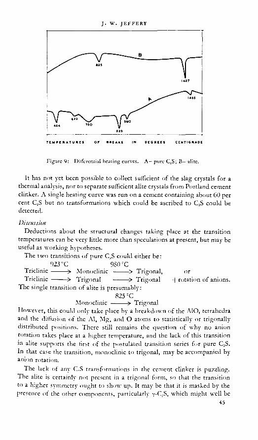
Figure 9: Dilfercntial heating curves. A—pure C^S; B—alite.
It has not yet been possible to collect sufficient of the slag crystals for a thermal analysis, nor to separate sufficient alite crystals from Portland cement clinker. A single heating curve was run on a cement containing about 60 per cent C,S but no transformations which could be ascribed to C5S could be detected.
DiscussionDeductions about the structural changes taking place at the transition
temperatures can be very little more than speculations at present, but may be useful as working hypotheses.
The two transitions of pure C3S could either be:923rC 980CC
Triclinic ------- > Monoclinic --------> Trigonal, orTriclinic ------- > Trigonal ------- > Trigonal 4-rotation of anions.
The single transition of alite is presumably:825 CC
Monoclinic ------- > TrigonalHowever, this could only take place by a breakdown of the A1O, tetrahedra and the diffusion of the Al, Mg, and O atoms to statistically or trigonally distributed positions. There still remains the question of why no anion rotation takes place at a higher temperature, and the lack of this transition in alite supports the first of the postulated transition series for pure C3S. In that case the transition, monoclinic to trigonal, may be accompanied by anion rotation.
The lack of any C,S transformations in the cement clinker is puzzling. The alite is certainly not present in a trigonal form, so that the transition to a higher symmetry ought to show up. It may be that it is masked by the presence of the other components, particularly v-C2S, which might well be
45

present,since the clinker used was fifteen years old. However,until these interpretations have been checked by the high temperature X-ray camera, they must be regarded as only tentative in all cases.
STRENGTH DEVELOPMENT AND CLINKER COMPOSITION
DEVELOPMENT OF STRENGTH IN HYDRATED PREPARATIONS OF
C,S AND ALITE
Experiments have previously been reported in which pure C,S was ground and treated as a cement. In general, strength was developed at a rate and to an extent which confirms the supposition that C,S is the main cementing component in Portland cement (Bogue).-
Nurse,2* has carried out experiments in which pure C,S an<l alite (C„S,eMA) were ground to the same specific surface (4,(XX) sq. cm. per g. as measured by the air permeability method. Lea and Nurse).17 The resulting powders of cement fineness Mere matle up as J in. cubes with sand in the proportion of 1:3 by weight (Parker).2' Compressive strengths were determined at 1, 3, 7 and 2S days. The rather surprising result was obtained, that the rate of hydration of the alite was appreciably lower than that of pure C,S.
figure 10: Strength curves of 1:3 mortars, determined on j in. cubes. Moist air storage up to 7 davs, water storage from 7—2s days. A. pure C,S + 4 per cent gypsum; B. alite- 4 per cent gvpsum; C. clinker A20*4 per cent gvpsum. Percentage composition of A2d : C,S—5*>; GS—IX C,AF—■ 7;C,A—13. ‘

It was then realized that, since Al^O, is present in the alite, gypsum should have been added, as is normal in the case of Portland cement, to control the setting time. Four per cent of ballmilled gypsum was added to each material and the strength development curves of Figure 10 were obtained. In the same figure a similar curve has been inserted for the clinker used in the thermal work, which was ground to the same fineness as the alite and pure C3S and contained the same amount of added gypsum.
DiscussionThe difference between pure C3S and alite at 28 days is not significant, and
the results at earlier ages may easily be due to some interaction between silicate and aluminate hydration phases. The same phenomenon may account for the fact that the ground clinker does not give a strength completely in accord with its content of C3S. The alternative explanation, that the phase in clinker is not so reactive as pure tricalcium silicate, cannot however be ruled out.
THE EFFECT OF THE INCLUSION OF AI,O3 AND MgO IN THE C3S
PHASE ON THE CALCULATED COMPOSITION OF CEMENT CLINKER
In calculating the compound content of Portland cement it has always been assumed that no solid solution takes place and that the compounds formed have their theoretical formulae. It would be easy to set up a new series of equations on the assumption that the C3S phase always had the composition C54S16AM. The result would be to decrease the calculated C3S, C3A and MgO content and to increase the calculated C.S. However, it seems highly probable that the other phases of cement may be found to differ appreciably from their theoretical compositions and for this reason it is not proposed to put forward a new set of equations which might give a false impression of the exactitude with which we can claim to know the composition of all the phases.
It is interesting to note, however, that in the thorough comparison between calculated and microscopically determined compound contents made by Insley,’ although the results for other compounds cannot be simply interpreted in terms of the above formula for alite,* for MgO the observed content was less than that calculated in twenty-five out of twenty-six clinkers investigated. The question of the content of crystalline MgO is öf great importance in connexion with long-term unsoundness. It has hitherto been agreed that the observed value for crystalline MgO tends to be low because of MgO dissolved in the glass. While this is certainly an explanation (quickly cooled clinkers being freer of periclase than slowly cooled ones), the
* The author is indebted to Dr. L. A. Dahl for pointing out the error in the effect of solid solution on calculated compound composition which occurred in the preprint of this paper. This error invalidated much of the discussion on Insley’s results, which has consequently been omitted here.

amount of MgO combined as alite, about 1 per cent, is significant. For instance, Insley’s measurements show cases where only 2-3 per cent of glass is present yet the calculated MgO is from 11 to 8 times as great as that found.
REFERENCES
1.
S.
9.
pp. 73, sn
London.
Building Research Technical Publication No. 16.16
17.
PrivateR.
:4.
27.
20.21.
3.4.
in.11.12.13.14.
RP1135. and 337.
p. 244.
IS.19. M r M L' R D I E
3 tambirjj-.SttDGLFV,
NURSE, R.
p. 102.
HED1N, R. Proceedings of tbe
1939. Vol. 5S. p. 2l13.. 1932. \"oL 56. p. I* 1-
244. pp. 1 and 65. p. 1148.
E. Nenes ]ahri"M<h p. 108.
ANDERSON, O. and LEE,
1933. Vol. 23. p. 338.BOGUE, R. H. 1 be Chemistry of Portbcnd Cement. New York. Reinhold Publishing
Corporation. 1947.BRANDENBERGER, E. Schneider Archif. 1936. X'ol. 2. p. 45.bussem, w. Proceedings of the Symposium on tbe Chemistry of Cements. 193S.
(Stockholm-Royal Swedish Institute for Engineering Research), p. 140.
and wfllRll, J.
w.
w.
K. and sc doh, r.LEA, F. M. and DFSCH, C. H.
Edward Arnold and Comp.inv. lea, f. m. and parser, t. w.
p. 1.LEA, F. St. and PARKER, T. W.
London, H.M.S.O. 1935.LEA, F. St. and N C R S F, R . W. ,
Institute of Chemical Engineers.Lt ER, H. Comptes RerJus.
H. F. and insley, h.. 19.k>. X’ol. 16. p. 4<>7.H. G. Building Research Station. l'*51. Private communication, w. Journiii of Scientific Instruments I'MU. X’ol. 2<'.
INSLEY, It., FLINT, P., NFWMAN, E. S.
Research of the National Rureau of Standirds.J A N D F. R , W.
JEFFERY, J. JEFFERY, J.
Vol. o.|. p. 13.if Research of tie Naiion.il Bureau
Mineral gie, Gt'l't."1
1()35. p. 48.PM. Trans. Royal Society. 1934. Vol. 234.
and Sw i nson, j. A. Journal of 1938. X'ol.
1938. X'ol. 27.Ph.I). Thesis, London University. I'i-SU.zlcta (.rystaihygraphica. 1952. X’ol. 5. p. 26.
Zement. 1939. X’ol. 28. p. 5(>3.
w. Journal of .Applied Cbemistri. xv. and wf i ch, ).
communication.O ‘ D A NI F I., H. and H F L t. N E R ,
Pa.'.iontnlngie. I95il. X’ol. 5.Parker, T. w. Jourml e>f t!’# So.Ktu o'Clemi.ai Inilustry. schwiftf, h. e. and bVssf.m, w. Tr.mndusfrie Zestu” SWAYZF, M. A. .American p.urnal of Science. 1946. 3 TÖRNFBOHM, A. E. Tomndsisirie Ze:tie’:;. 1897. X’ol. 21TRÖMEL, G. 1951. Private communication.
h. Building Research
C. Journal of tbe Washington z\cademy of Sciences.
Sat.iisb Cement and Com rete Kejeureb Inititutr. 1945.
5. G U T T M ANN, A . and GILL F., F. ZrwfnL 1929. Vol. 18. p. 912.6. G u r r M a n N, a . and C I L L F , F. Z.tmtnt, 1931. X’ol. 20. p. 144.7. GUTTMANN, A. and G I L L F , F. Zcwf«/. 1933. X’ol. 22. pp. 383 and 402

DISCUSSION
H. o’DANIEL
There are some improbabilities in our structure as well as in that of Dr. Jeffery’s. We are aware of the fact, that the ring of three tetrahedra in our proposal—we were surprised ourselves—is not the best solution with regard to thermodynamics, because it is astonishing that in the solid state such a ring is formed from isolated tetrahedra and that in a range of lower temperature again a decomposition into single tetrahedra takes place. On the other hand the arrangement of SiO4-tetrahedra one upon another, as proposed by Dr. Jeffery, also does not seem to be the ideal configuration. We like to confess, however, that the atomic distances in his structure seem to be the better ones.
To clear up these questions we have computed the Harker section H(xyo) in the last few weeks and transformed this into an implication diagram. These computations are based upon intensities, which are the same in Dr. Jeffery’s as in our X-ray photographs. It was performed with a Hollerith establishment of the International Bureau Machines Association, Frankfurt, in connexion with Mr. Schäfer of the Institute of Applied Mathematics of the Technical High School, Darmstadt. When I started for London the evaluation was not yet quite completed, but I must say that until now Dr. Jeffery’s horse seems to be one jump ahead of ours. In our diagram we find a high peak corresponding to those calciums which are common to both structures; but there are other small peaks which can be interpreted as the O-atoms of the tetrahedra which are the basis of Dr. Jeffery’s structure. We hope to complete the final interpretation of our calculations in a few weeks.
The synthesis mentioned above and a further one-dimensional Patterson synthesis P(00z) has enabled us to determine that Dr. Jeffery’s structure is obviously the right one. (The work will be published in Neues Jahrbuch für Mineralogie. 1953.)
F. ordway (read bjy Dr. R. H. Bogw)I think Dr. Jeffery’s paper indicates clearly what eventually will be
accepted by all cement chemists—that crystal structures are the fundamental factor determining the types and rates of reactions in burning and in hydration. We might compare our situation as inorganic chemists with that of the organic chemists before structural formulae were developed. Without the structural formulae it was possible to analyze reactants and products and to write equations for reactions in terms of empirical formulae, but the unifying principle was lacking. A knowledge of the actual formulae of the molecules themselves provided the sorely needed unifying principle.
In the inorganic reactions with which we have to deal, the ‘ molecules * are simply the contents of the unit cells in the structures of the various

solids involved. If the substance is colloidal there are comparatively few layers of these unit ceils in one or more directions, but if the substance is a perfect crystal it contains very many unit cells, all exactly alike and in perfect alinement. This perfection is what gives crystal structure analysis its tremendous power. If Dr. Jeffery can locate a single magnesium atom in the ‘ molecule ’ C5<Sle./\M, it is only through the combined effect of 10“ or 1015 such atoms all acting in unison. I think it is most desirable to make our structure studies according to the plan he is following—first, with great care, a study of comparatively large, perfect, pure crystals and then extrapolation from those well-established facts to determine the effects of colloidal size, structural imperfections or impurities. Dr. Jeffery has probably inspected his specimens carefully for optical homogeneity, and I should be interested to hear of any other methods he has found useful for detecting very fine twinning or other forms of structural randomness.
e. BURKE
Dr. Jeffery’s valuable paper touches a point that has been the subject of controversy for over half a century. One wonders if even yet we have arrived at a clear picture of what alite in Portland cement clinker really is. Dr. Jeffery shows that the idea that it is pure tricalcium silicate is disposed of and that there is at least some tricalcium aluminate in solid solution. Mr. Nurse has shown that this does not seem to be of any great advantage.
It may be of interest to recount some uncompleted work carried out by me about twenty years ago.
The investigations were chiefly microscopical and the refractive indices were measured by the Emmons single variation method1 where the refractive index of the immersion liquid was varied by changing the temperature. It was considered that the method was accurate to a few places in the fourth decimal place and all the measurements were made in sodium light.
Pure tricalcium silicate gave : a=l-713O and v= 1-7172.This agreed with the generally accepted figure of l-715d_0 W3 and also
with measurements on alite in melted Portland cement.However all measurements on normal Portland cement clinkers gave
higher results, the variation being, x=b7158 to 1-7107 and y=1-7220 to 1-7238. V
The refractive index of tricalcium aluminate was found to be 1-7080 so that, at first, it did not seem likely that alite could be a solid solution of CjA in CjS because alite should have had lower refractive indices than C,S.
It was found, however, that the alite in white cement clinker gave the following results : x —1-7120 and Y--1-7147.
This seemed to confirm the solid solution theory but did not explain why alite had such a high refractive index in normal Portland cement.
In the course of the investigation measurements of C,A in burns containing C,AF were made and it was found that the refractive index was

1-723 instead of 1-708. This agreed with the finding of Hansen, Brownmiller and Bogue2 that the presence of iron can raise the refractive index to as much as 1-735.
In a burn having the composition SCaOFe.Oj^SiCl, it was found that the refractive indices of C3S were a= 1-7138 and y=1-7172.
There was no alumina present in this burn and the refractive indices of CjS were the same as for the pure compound. In this section the C3S was quite colourless but the C,S was deeply stained by an iron compound probably 2CaO.Fe3O3.
It was, therefore, concluded that alite was actually a solid solution of C3A in C3S and that the C3A took iron oxide with it in solid solution probably as C,AF.
A series of mixes was made up containing varying ratios of C3S to C3A and the refractive indices of the alite plotted against the calculated C3A content. It was found from this that the C3S became saturated with C,A when its amount was about 20 per cent of that of the C3S.
When Lea and Parker’s method of recasting the constitution of Portland cement was published a somewhat interesting confirmation was obtained. If the calculated value for C,S was increased by 20 per cent or by the C3A content whichever was less the sum was in very many cases very close to the alite content obtained by microscopical measurement. There was a number of exceptions to this the reasons for which have not been elucidated, e.g. in clinkers containing small amounts of fluorine the C3S by calculation usually agreed with that by microscopical measurement.
It may be seen that these experiments tend to show that there may be much greater amounts of C3A in alite than are at present admitted. Owing to pressure of other work, however, the experiments could not be taken to a satisfactory conclusion.
There is still a good deal of work to be done on this subject particularly with regard to the application of the results of research to actual manufacture. It has often been remarked that, considering the large amount of excellent research that has been done on constitution, the benefit in actual practice has been disproportionately small. The result has been that often cement manufacture has been carried on more as if it were a craft or art rather than a science.
I sincerely hope that in the next few years we shall be able to take more of the knowledge gained in the research laboratories and apply it in actual manufacture.
REFERENCES
1. Emmons, w. j. American Miiuralogist. 1928. Vol. 13.2. Hansen, w. c., brownmiller, L. T. and bogue, R. H. Journal of the American
Cbcmical Socie/y. 1928. Vol."50. p. 396.

A. A. T. METZGERIt may be of interest to mention the results from a comparative investi
gation of the optic axial angle 2V of alite in two different types of clinker produced in Finland by Messrs. Pargas Kalkbergs Aktiebolag. The first type was an ordinary Portland clinker, with alumina in excess of ferric iron. The other one was what we call a brownmillerite clinker,1-1 where ferric iron was present in the same, or nearly the same, molecular amount as alumina. *
The optic axial angle was found to be quite normal in the Portland clinker, with an accumulation of values around 12°—15°. This is in accordance with the determinations made by Dr. Midgley and cited by Dr. Jeffery. However, in the brownmillerite clinker the values of 2V were higher, up to 48° and accumulating around 35°. All determinations were made by use of a Universal Stage with four circles. About sixty alite specimens were measured in both, kinds of clinker. The mean thickness of the thin sections was 11 microns.
The higher value of 2V for the alite in the brownmillerite clinker may depend on the lesser amount of C,A formed in this type. Assuming that alumina will at first combine with iron and lime to form C4AF, it is likely that in the brownmillerite clinker very little if any alumina is left to enter the alite structure. This is in contrast to the ordinary Portland clinker, where sufficient alumina is always present. Hence, the value of the optic axial angle may be an indication of the amount of C,A occurring as solid solution in the alite. The less the C>A present, the nearer will 2V approach the angle of pure CjS. The amounts of magnesia were about the same in both types of clinker.
Without over-estimating the importance of these observations it occurs to me that it would be helpful if similar comparative investigations of alite in clinker with different ratios of iron to alumina were carried out by methods other than the optical one used by me. These might possibly confirm the very interesting conceptions of the alite structure made by Dr. Jeffery.
REFERENCES
1. CEiTLtN, a. Om Brownmilieritccmcnt. Mcdd. fr. Pergas Kalkbcrgs A: B Kem.*Labor, o. Provningsanst. 1940. No. XXL
2. METZGER, A. A. T. Über die normative und modale Zusammensetzung einige*Portland- und Bmwnmillerit-Cemcnte. C.R. 5er. gro/. Fink No. XV, Bull Comm. Geol. Finl. 1940. 128. Helsingfora.
G. TRÖMELI would like to mention that the high-temperature X-ray photographs
used by Dr. Jeffery have been printed recently.* I agree with Dr- Jeffttf that these photographs up to ITOO^C show quite clearly a very considerable

anisotropy in the coefficient of expansion. On the other hand they do not definitely indicate any transformation. It will be necessary to check this question by more photographs with better resolution.
REFERENCE
t. TiöMEL, o. and Möller, H. High temperature X-ray powder photographs of calcium silicates and cement clinkers. ZemeHt-Kalk-Gipt. 1952. Vol. 5. No. 8.
J. w jeffery {author'i closure)I want to touch on one or two of the unsolved problems in connexion
with the tricalcium silicate phase. First of all I should like to say a few words about the solid solution occurring in alite, and I hope my voice indicates that solid solution is in inverted commas, because I do not believe that is the correct way of describing it. True solid solution occurs between substances of the same structural type and similar cell size, so that equivalent atomic sites in the crj'Stal are occupied at random by the corresponding atoms of the two constituents. That is not the case between tricalcium aluminate and tricalcium silicate. It seems to me the correct description must be a substitution of the silicon ion by aluminium. In the case of one substitution, a monovalent positive ion comes into a nearby hole in the lattice to balance the charges, or, with a double substitution, a divalent positive ion, which is the normal case in alite. In other words: 186,5+ AljOJ+MgO-^C,,SieAM+2SiOJ.
Of course SiO, cannot exist in equilibrium with so basic a substance as alite, and the equation is better expressed in terms of C,S, CaO and C,A as follows: ISCjS+QA+MgO+CaO-tC^S^AM+aC.-S. Now it should be possible for MgO to be substituted by CaO, the difference being at the calcium ion has a larger radius and it does not fit into the hole in the lattice as well as the magnesium ion. This is shown by the work of Koyanagi and Sudoh, who demonstrated that * solid solution or substitution occurring between tricaldum silicate and tricalcium aluminate did not produce e change in the X-ray pattern which we associate with alite until magnesium oxide was added to the mix. There certainly was some sort of change, some sort of substitution, and I suggest that it probably was calcium oxi e replacing magnesium oxide in the equation, but it did not allow e att‘“ to settle down into the simplest form we know—-the alite form—P^sx“na because the calcium was too large. VC+en magnesium oxide is a e en the alite powder pattern is produced. .
It is conceivable, of course, that this substitution could ca^ne until all the silicon was substituted by aluminium that is possi e rom e equation—but the evidence show’s that 2A1ZO, and 2MgO, i.e. tx^!C ® amount in the case we investigated, is about the most that can su
53

stituted in eighteen molecules of C,S. The evidence however is very slight and I would certainly agree with Mr. Burke that more work requires to be done on the problem, but although optical work can be verv valuable 1 think by itself it cannot provide the solution.
It two substitution stages do exist—cither two aluminiums substituting for two silicons, or four, — there may be a superlattice effect by the ordering of those two stages into regular alternate layers, in the case of a mix whose composition is halfway between the two stages. There are certain peculiar X-ray diflraction effects from alite which might possible be ascribed to this phenomenon, which is known to occur in the felspars, but, again, more work is required to settle this point.
Similarly, it is not yet certain whether the recrystallized alite, on which most of our X-ray work was done, is exactly the same as the alite in the original clinker. XX'c know already that any differences arc cxtremclv small, of the order of the superlattice effects I have just been discussing, but 1 had hopes! to have decided this question by now with the help,of our miniature single-crystal camera used on the ILhrenbcrg-Spcar tine focus tube. However, although 1 am satisfied that the technique is capable of solving the problem, the first halt dozen clinker crystals which I have used proved to be composite, with angles between the different individuals of onh a few minutes, anti as the ilitfraction pattern from a single crvstal is comphcatcil enough it woukl not be possible to sort out the pattern of such composite material. But in my small bottle of clinker there arc about a million crtstals of alite, so that 1 hope to find a single individual eventually, without dixcrting any more of the ten million tons of the industrv's output !
It is evident that much more work remains to be done to understand the high-tcmper.iture pohmorphism of (I,S, and it may also be worth while to investigate whether there is any didcrcncc between the interaction of pure ( ,S and alite with the other components of clinker during the setting ami harik-ning process.
On the v]vicstion of the composition of ahtc, the crystals which we have been using contained iron—enough to give them quite a green colour. That is present in the analysis. XX'c assume it replaced the alumina in the structure.
As tar as the amount ot 1 solid solution ’ is concerned, if one calculates on tb.e basis of a ‘ solid solution * ot (1,A in G-.S (whereas in fact it is 1 replacement of silicon by aluminium'!, in (?,A there is 3CaO which does not take anv part in tb.e process but adds verv consivlcrablv to the amount of (hA which is assumed to go into ‘ solid solution.’ In terms of Cb.A there mav be quite a considerable percentage of ’ solid solution." I think up to 7 per cent has certainlv been established but, as I sav, I do not think that is strict I v tb.e mechanism which docs take place. It is much smaller quantities (>f alumina w hich we arc reallv conccrneil with.
On the question raised by Dr. Ordwav I have come to the conclusion that I have not used optical mcthovls as well as I might, in connexion with

the investigation of C3S, but I have always tried to test optically whether my crystals were homogenous before setting them up as X-ray specimens, because it is a nuisance if the crystal is a twin and is found to be unusable. I have always found that X-rays are more sensitive than the microscope. That may be my handling of the microscope, but the twinning that is undoubtedly present is of individuals which are extremely close together in alinement, but just sufficiently misalined to make it impossible to use them. As I say, all the clinker crystals which I have been investigating recently showed this phenomenon, and I also found this when I was investigating large crystals made by Mr. Nurse. It took me a very long time before I found a single crystal of pure tricalcium silicate amongst those which he made. I lowever, this twinning was on a macroscopic scale and the sharpness of the X-ray reflections, even at high angles, shows that no twinning or random stacking on a molecular scale was present.
The work which Professor O’Daniel and his collaborators have done on the structure of C3S has been very well worth while. In a substance of such great practical importance it is as well to be doubly sure of the correctness of our deductions, particularly when the chain of evidence is as involved as it is in structure analysis. The fact that Professor O’Daniel started from an incorrect trial structure, and using a different method of attack from mine, arrived finally at the same conclusions, means that the structure is established with much greater certainty than it could have been by either of us separately. If my horse won the race, its success is only significant because Professor O'Daniel’s was such a strong challenger!

[3]
The dicalcium silicate phaseR. \V. NURSE
SUMMARY
The chemistry and crystal structure of the known forms of C2S are discussed. The theory of stabilization of high temperature forms is developed and is shown to account for the complicated phenomena associated with CLS in slags, cements and refractories. It is concluded that only ß-C,S is likely to occur in Portland cement, but that its rate of hydration will vary according to the type and amount of stabilizing agent it contains.
INTRODUCTION .
Although the main purpose of this paper is to discuss the nature and properties of the dicalcium silicate phase in Portland cement clinker, it will be necessary, because of the complications introduced by polymorphism and solid solution, to devote much of the space available to a consideration of the pure mineral. Interest in the compound extends beyond the scope of cement chemistry to include the fields of slag and refractory technology and the study of natural rocks. The literature has recently been reviewed by Brcdig* and a historical account will be found in Bogue.2 A useful bibliography has been compiled by Seil.1
THE POLYMORPHISM OF JC-iO.SlO,
The existence, over the range of temperature from 0—1WX)rC, of four polymorphic forms, designated y, x', x, and ß is now well-established, although some confusion still exists in the literature because the optical and X-ray properties quoted by earlier workers for the a form actually referred to ß material modified in appearance by twinning. Work in the high temperature powder X-ray camera by several authors, among whom Tromcl* should be specially mentioned, has cleared up the contusion which existed over the order of appearance of the modifications. This confusion arose because in quenching experiments from high temperature'' 6 the x‘ phase has been produced using almost pure material, whereas a true x modification has not yet been produced at room temperature except from quite impure material. Starting with y material, the order of inversion on heating is •)—x—x and on cooling x—x’—ß—y. These relations arc illustrated by the high temperature X-ray powder diagrams in Figure 1.

:■ Kormater Umwündiungsobiouf '
N8siMi^tiiem»-»n.4Ha^t*lA*Cee> ■
UmbilduRg ven y-CdiSO,
« wsd* «'ne»* o' «P* «^«0* p ss#
■.. VW#« I" flW*«'
«e#<#
■ «##
Mm« Röntgenaufnahmen von Caltiumorlftosilikat iäaitrotog il*3 • ■ CotSO» bei Temperaturen bis yoo^. tM* ■
Figure 1 : Powder X-rav diagrams taken at high temperature by 1 roMifl ätid .MoL’rr»
Figure 2 : Phase diagram for pure C2S (modified after J^rr^zg).

Figure 3 : Thermal analysis of C.S.
This behaviour suggests that the ß form is mctastable and led Bredig to draw up a hypothetical phase diagram similar to Figure 2. It has been possible to insert the inversion temperatures in this diagram as a result of careful thermal investigations by my colleague, J. H. Welch, working at the Building Research Station. A similar investigation covering only the upper inversion (wrongly identified at that time as ß—x) was carried out in 1946 by Newman and Wells,7 and Vasenin" has also covered the whole range. The method of interpretation of the differential thermal analysis curve employed by the latter author is however open to question, and the fact that his results varied with the source of silica employed in synthesis suggests that unknown amounts of impurity were present. The anaylses of the materials employed by Welch are given in Table 1.
TABLE 1.
CiO MgO SiO, Al.O, (Xa,K\.() Fc,O,
CaCO, StO.
5(vl7 >0-005
0-01>0-002
n.e.99-t>5
0-0J nil
o-o1»0-002
001 0-007
44 1 *> nil
n.e.—not estimated. Analyses by F. J. McConnell and L. J. Cirncr.
A typical scries of heating and cooling curves is shown in Figure 3; the inserted temperatures are average values. Curve .1 shows the typical scries of events on heating y material; curve B is a cooling curve and reads from right to left. The dotted portion of curve B shows the normal course of events if cooling is continued to room temperature; on re-heating curve . 1 is reproduced. If however cooling is interrupted before inversion to y then

curve C portraying the ß—ct,' inversion is produced on heating. A similar curve to C is obtained if temporarily stabilized ß is heated from room temperature.
Newman and Wells pointed out that the upper inversion temperature varied with the CaO:SiO, ratio of the preparation, and were unable to decide which inversion temperature referred to the pure material; either the inversion temperature is raised by CaO or lowered by SiO2. The course of the inversion temperature-composition curve close to the theoretical ratio should decide this point, but both Newman and W elch found that the change was abrupt and occurred over a range of composition smaller than that which can be detected by chemical analysis. Both workers however detected melting in increasing amount as the percentage excess SiO, was increased. The relevant invariant point is that at which C3S.. decomposes into C2S and liquid and is given as 1475 rC in Hall and Insley’s compilation of phase diagrams, but Muan and Osborn'1 give 1464 C which agrees well with both Newman and Welch.
Thus the evidence suggests that CaO enters into solid solution while SiO, does not and that the lower inversion (1438 'C Newman, 1447 °C Welch) is that of the pure mineral, the upper one (1456 rC Newman, 1465 °C Welch) being that of the solid solution with CaO. The fact that the inversion point is raised suggests a lower solubility of CaO in a than in x'-C2S. Dyckerhoff10 has shown that 8 per cent of CaO can enter into solid solution with ß-C2S. The significance of these facts, and their relation to the observation that preparations containing excess CaO become stabilized in the ß form after frequent heating, will be discussed later.
The general interpretation of the remainder of the thermal work is as follows. On heating pure C2S in the y form it undergoes a slow transition to x', the maximum heat ciTect being recorded at temperatures varying between 780* and 830 C, the lower temperatures being obtained with freshly prepared samples. At 1447‘C a large and sharply-defined thermal effect denotes the inversion from x' to x. On cooling, the x—x' inversion occurs at 1425 C, and the formation of ß at 670 CC is marked by a small but fairly well-dchned thermal arrest. Inversion to y is accompanied by a large volume expansion (“ dusting ”) uhich renders accurate measurement of the heat effect impossible. The onset of dusting usually occurs at 525 CC. The solid solution containing CaO behaves similarly on heating from the ß form, except that the x'—x inversion is raised to 1465 "C; on cooling, inversion to y is inhibited. If the CaO-stabilized ß is reheated, the inversion to a occurs at 765 C with a small and sharply-defined heat effect, and the same inversion temperature is obtained if a cooling mass of C2S is reheated from 600 C before inversion to y has taken place.
POWDER X-RAY DATA AND OPTICAL PROPERTIES
The x, x’ and ß forms of C2S cannot be obtained at room temperature except when impurity is present as a stabilizer. For this reason, there cannot

Powder X-ray spacings for QS polymorphs measured at the Building Research Station (kx units)
TABLE 2 :
a-QS (nagelschmidtite)
a'-CzS (bredigite)
ß-QS (larnite)
Y-CzS
8-60 w.7-04 w.4-79 w.3-882 m.s.3-800 w. 3-811 w. 3-768 w.
5-625 w.m.4-320 w.m.4-047 w.3-794 w.m.
3-496 w. 3-484 w. 3-354 w.3-456 m.s.3-329 m.
3-143 m.3-216 w.3-031 w.
3-180 w.3-015 w.
3-002 s.
2-963 m. 2-947 w. 2-881 w.2-888 m. 2-889 w. 2-840 w.2-829 s.2-684 s. 2-730 s. 2-756 s. 2-728 s.
2-570 w.2-663 s.2-595 w.
2-704 m.s.2-591 m.s. 2-525 w.
2-501 w. 2-522 w. 2-508 w.2-489 w. 2-419 w.m. 2-460 w.
3-297 w.2-413 w.2-341 w.
2-379 w.m.2-320 w.
2-209 m.s. 2-291 w. 2-259 w.m. 2-243 w.
2-121 w.2-259 m.s.2-170 w. 2-171 m.s. 2 186 w.
2-088 w.2 111 w.2-067 m.
2-147 w.2-108 w.2-073 w.
2 044 w. 2-008 w.m. 2-029 w.m. 2-024 w.
1-966 w.m.2-006 w.m.1-967 m.s. 1-963 w.
1-946 m.s. 1-923 m.s. 1-928 m.s.1-897 w. 1-895 w. 1-886 w.m. 1-878 w.1-850 m.1-831 m. 1-837 w.m. 1-800 m.1-799 w. 1-790 w. 1-780 w.m. 1-751 m.1-772 w.1-740 m.s.1-702 w.
1-751 w.1-725 w.1-686 w. 1-696 w.m. 1-685 m.s.
1-657 w. 1-665 w. 1-669 w.1 641 w. 1-646 w. 1-632 m.1-615 w. 1-621 w. 1-619 m.1-579 w. 1-574 m. 1-597 m.1-576 w. 1-554 m. 1-577 m.1-547 m. 1 563 m.
1-539 m. 1 539 w.1 525 m.s. 1-528 w. 1-517 m. 1-524 w.1 516 w. 1-488 m.s. 1-475 m. 1-498 w.1-467 w. 1-470 w. 1-441 w. 1-469 w.1-437 w. 1-424 w.m. 1-457 w.
1-398 w. 1-392 w.
1-407 w.
1-383 w.
1-443 w.1434 w.1-414 w.1401 w.1-374 w.
1-380 w.1-362 m. 1-361 w. 1-352 w.
1 343 w. 1-333 m. 1-336 w.1-286 w. 1-294 w.m. 1-312 w.
1-258 w. 1-292 w. 1-268 w.etc. . .... ...... etc,________ ________ £!£._________ etc. .

table 3 : Variations in spacing of the principal lines in the powder X-ray diagrams of QS at room temperature
* Broad, or doublet. Intensity variable.The lines are numbered in order <£ intensity, the strongest first.
a a ß Y
Intensity
orderd
Intensity
orderd
Intensity
orderd
Intensity
orderd
1. 2-80-2-86 2. 3001. 2-76-2-81
1. 2-72-2-77 1. 2-73-2-741, 2-65-2-70 5. 2-60-2-71 1. 2-61-2-73
3. 2-420-2-6104. 2-240-2-260
4. 2-209-22194. 2-171-2-2005. 1-966-1-993
3. 1-938-1-9602. 1-900-1-959
3. 1-905-1-928•3. 1 53-1-59
4. 1-8004. 1-751-1-7524. 1-630-1-632
6. 1-610-1-633
be given standard X-ray and optical data for these forms of the pure mineral. Patterns obtained in the high temperature X-ray camera are not very usefu for comparison with those of phases at room temperatures ot l“ceffects of thermal expansion and because the patterns are less we e e Most published data on ß refer to B.O3-subilized material, and it seems reasonable to regard this as standard. Spacings obtained on sue a samp with CuKx radiation using a 19 cm camera arc given in Tabk 2-^hough X-ray measurements on a* were first reported by Rait and Go sc mi t, the material described by Tilley and Vincent'» should perhaps be considered the “ type ” mineral and the measurements given in Table 2 were ma e at the Building Research Station on material kindly supplied by Prof. Tilley. Similarly the measurements given for nagelschmidtite (a) were o tame in the same way on material supplied by Nagelschmidt.1- The measurements for t are on material synthesized at the Building Research Station.
In Table 3 the variation in the strong lines of the diffraction diagrams is indicated, the measurements being taken from the literature or being ma e on material stabilized in different ways at the Building Research Station. It will be noted that the strongest lines show considerable overlapping among the various forms.

Opt
ical
prop
ertie
s of C
2S
Den
sity
3 035
3-40
3-28
2-97
Twin
ning
, etc
.
Cycl
ic an
d mul
tiple
tw
inni
ng, o
rthor
hom
bic
Poly
synt
hetic
twin
ning
Mon
oclin
icD
istin
ct 1(H
) cle
avag
eLa
mel
lar t
win
ning
on 1
00In
vers
ion t
win
ning
com
plex
Clea
vage
11 to
pris
m ax
isI-'
ibro
us, o
rthor
hom
bic
2V Smal
l 0
-20
J
Smal
l 0°
Smal
l
D 1 o or-, I C8| O ci Mod
erat
e I I
Urg
eSm
all to
I .ar
ge
g
OW
J00
100-
008—
0-01
40-
004
1 0-010 I 0-013
04)1
5 00
18
0-(X
)8
04X
)8
04)2
3
04)1
8
0 13
___ _ _
____
_Rcf
ract
tvei
ndic
es __ 14
,61
1-69
014
4,1-
1-69
3
l-(44
,
, 17
12
1-72
5
1-74
01-
732
1-70
11-
703
1-73
0
1735
1-65
4ox
! 1-
716
_ 1-
728
' 1-
717
!
1-71
5
1 645
K
1-65
21-
680
1-65
2—1-
682
1-66
2
1-70
2
1-71
2
1-72
51-
713
14,9
31 6
95
1-70
7
1-71
7
1 642
'
Refe
renc
e
nage
lschm
idtit
e 12 it 15
with
CaN
aPO
, 16 w
ith N
a,(J
and
Al/<
17
1 from Sc
awt H
ill 11
spie
gele
isen s
lag 11
with
CaN
aPO
, 16 i KC
,Sl2
“
from
Scaw
t 1 til
l n sy
nthe
tic, /
man
y au
thor
s)
from
blas
tfurn
ace s
lag,
(m
any a
utho
rs;
synt
hetic
, man
y aut
hors
I __
____
_-_
___
____
____
__
Mod
ifi
catio
n
i i! i

The difficulty mentioned in the last paragraph with regard to the X-ray data also applies to optical properties and density. Strictly speaking only results obtained on y refer to material of absolute purity. However, many of the properties are approximately constant for materials of differing origins, and may be considered representative. For reasons discussed later, however. X-ray examination is much more reliable than optical measurements in distinguishing the forms of C;S. This has been noted before with regard to the optic axial angle by Hansen.13 Optical properties and densities are listed in Table 4. Only measurements on material the nature of which has been confirmed by X-rays are included. It is seen that a clear distinction between a and x' or between x' and ß is impossible unless the crystals are perfect enough to permit the determination of the crystal system.
ATOMIC STRUCTURE
A direct determination of crystal structure has been carried out on the ß modification by Mrs. Midglcy at the Building Research Station.20 The structure of y has been postulated21 on the basis of an analogy with XaBcF4, and observations have been reported leading to unit cell measurements on x' 22 and on the mineral nagclschmidtite, assumed to be equivalent to x-Q.S.21 In addition, Brcdig1 has calculated the unit cell dimensions of x from the high temperature measurements made by Van Valkenburg and McMurdic2* and of x' from the high temperature photographs of TromcL* Bredig also believes that merwinite, C,MS;, is identical with x'-QS and has calculated a unit cell accordingly.23 Except in the latter case, no data are given which would show whether the indexing of the powder photographs was completely successful. Brcdig’s unit cell calculations and speculations regarding structural types arc summarized in Table 5. In Table 6 are given the results of single crystal measurements.
The measured unit cells in Table 6 are in each case simply related to the calculated ones in Table 5. Merwinite proves on detailed examination to be monoclinic and high temperature X-rav powder photographs which Trömel has kindly taken for the author show that merwinite does not invert to an a type, at least up to 1470 (i. It is probably therefore a distinct compound and not a solid solution of x'-C;S. Otherwise, it is open to question as to whether Table 5 or Table 6 correctly represents the structural relations of the polymorphic forms. The larger unit cells actually measured may result from super-lattice effects arising from the impuntv present. In this connexion it is interesting to note that Mrs. Midglcy20 states that very slight modifications to the ß structure suffice to produce an orthorhombic cell having the space group P men of K.SO. and that a somewhat larger distortion and rearrangement produces a trigonal cell having the space group Qm of glasier- ite. These observations would suggest that Brcdig’s suggested cells are Cssentiallv correct*
A reference is made in Table 6 to “ coniposite ” crystals. These were first observed by Mrs. Douglas.22 They are crystals which under the microscope

table 5 : Structural data according to Bredig
ModificationUnit cell dimensions
Space group Source of dataa b c
a 5-455-38
7-187-10
C3m (by analogy withglasiente)
2* at 1,500 rC;6 nagclschniidtitc
a' 5-305-20
9-559-20
6-786-78
P men (by analogy with K.SOJ
4 at 7iN) C26 merwinite
s unknown
Y 5-06 11-28 6-78 P bn m (by analogy with Na.Ikl-J
21
table 6: Structural data from single crystal measurements. Arbitrary choice of axes to show relation to Table 5
ModificationUnit cell dimensions
Space groups Source of dataa b c angle
X 5-4621-80
6-7621-54
— :: c>n cnstalson nagclschmidtitc
a'
merwinite109110-77
18 419-20
6-7b13 2b 91 ’
P mnn ?
12
27 slag cn stals and pure melt
3 5-48 9-28 6-76 94’33’ P21/n synthetic crystals stabilized with CaO and B;O,
Y m>nc
appear homogeneous single individuals, but which give multiple X-ray reflections showing them to be complexes of more than one form of C.-S usually x and x’. These individuals are oriented regularly so that a structural relationship between the forms can be obtained, c(x) being equal and parauel
to c(x’) and a(x) being and parallel to a(x). The third dimension of the
orthorhombic unit ceil is parallel to the y axis tn the hexagonal lattice, but \ 3a (x) = b (x'). The values obtained for the unit cell and the space group
are given in Table 6. Mrs. Douglas considers that the doubling <>f the urut64

Figure 4 : Structure of ß-C2S with an outline of the unit cell. Si black, Ca light grey, O dark grey.
Figure 5 : Structure of ß-C2S.Diagrammatic projection along b axis: twin planes are shown by heavy lines : pseudo-hexagonal cell is shown y dotted line.

cell in the a and b directions compared with Bredig’s values is not likely to be caused by ordering of the impurity ions and that it is more likely that weak lines are missing in Trömel’s photographs. Tilley and Vincent11 give the analysis of the crystals in question as corresponding to Cal.j,Ba0.0,Mg0.J1 Mno.^SiO,. One quarter of the Ca positions are thus occupied by impurity, and this could easily bring about the observed increase in the cell contents from 4 to 16 formula weights. However, Mrs. Douglas has also attempted to index Trömel’s high temperature photographs (taken on pure material) and, in disagreement with Bredig, finds it necessary to postulate an enlarged cell similar to that deduced from her single crystal work. The relationship between a and a' deduced by Mrs. Douglas is the same as that suggested independently by Mrs. Midgley except that the latter author does not find it necessary to double a and b. Presumably the phenomenon of composite crystals, which can only be detected by X-rays, combined with the effects of multiple twinning, accounts for the unreliability of optical measurements in distinguishing between the forms of C2S.
As will be shown later, the ß form is the one of greatest importance to cement chemistry, and the general features of the structure will therefore be discussed. A photograph of a model of the unit cell is shown in Figure 4. and a projection of the structure along the b axis in Figure 5. The structure is built up of SiO, tetrahedra linked to two tj"pes of Ca ion. Four of the eight Ca ions (Ca I) are positioned alternately above and below SiOt tetrahedra in the y direction and the remaining four (Ca II) are accommodated in the holes between the tetrahedra. Formally the co-ordination number of Ca I is six and of Ca II is eight, but the existence of holes fronting on the Ca ions means that the co-ordination is irregular and that O ions at distances greater than normal Ca—O bond lengths must also be considered as contributing to the co-ordination.
As already mentioned, slight re-arrangements will produce plausible a' and « structures; the pseudo-hexagonal cell is shown dotted in Figure 5, which also shows the twin planes. In the ß structure the SiO4 tetrahedra are slightly tilted and to bring about the change to a they must move into symmetrical array in line with the Ca I atoms; this would involve an increase in the axis b (monoclinic) or t (hexagonal) from 6-76 to approximately 7 A, in agreement with the enlargement of this axis shown by Bredig’s calculations.
THE STABILIZATION OF HIGH TEMPERATURE FORMSThe mechanism of stabilization has been most studied by workers on
refractory compositions or on slags. Here the problem is to prevent inversion to the t form with consequent expansion and disruption of the product; it is immaterial which of the higher forms remains. Consequently theories of stabilization hitherto postulated refer only to the conditions necessary to prevent the formation of y, and in fact there are very few recorded instincts of stabilization in the a or a' condition.

It is of interest to consider the possible mechanisms by which stabilization can be brought about. The pure material will be considered first of all.
The condition that two forms should exist together in equilibrium at a given temperature and pressure is that the Gibbs free energy should have a minimum value. This is expressed analytically by considering an infinitesimal variation in the Gibbs free energy G and equating to zero dG=0
whence : S dT—VdP+Sn; d|£i=0where S is the entropy, T the temperature, V the volume, P the pressure, Hj the number of moles of component (1,2..... .i) m the chemical potential of each component (1,2 .i). Such an expression can be written for each co-existing phase. In general the system is considered condensed (whence dP=O). Such a procedure is of such widespread application that it tends to be forgotten that the simplified condition :
—S dT=Snj dw=0 cannot apply to conditions where P is not constant or where appreciable areas of surface are formed or where the electric or magnetic field is variable or alternatively the dielectric or magnetic properties of the phases differ appreciably. Neglecting magnetic and electrical effects, such considerations will be of importance particularly :
(1) where the volume of the system changes appreciably, giving rise to the possibility of stress within a bulk phase.
(2) where the rate of diffusion is slow, as in reaction in the solid state, giving rise especially to nucleation effects involving surface forces.
The observed specific gravities of the forms of C2S are:— a 3-04;«’ 3-40; ß 3-28; T 2-97; corresponding values calculated from the structure are: a 3-071; a' 3-311; ß 3-311»; y 2-9711. It would appear therefore that increase of pressure would favour the a—a’ transformation and inhibit the ß—y transformation. Observed and calculated specific gravities do not agree very w’ell for the a' form. The observed value w'as obtained on barium- containing slag crystals, and since the refractive index of «' is slightly less than that of ß, it seems reasonable to assume that the densities are also in the same order, the a—ß phase change being favoured by increasing pressure. Stress induced by the thermal contraction of the specimen or of a surrounding film of glass has in fact been adduced as an explanation of stabilization in the ß form, although some of the evidence is doubtfid. The effect of pressure may also have some bearing on the fact that the forms of C2S most commonly found in nature are a or ß, y being comparatively rare.
Even after allowing for thermal expansion of a* (the a density being calculated at 1500 °Q the transformation a'—x involves a change in volume about half of that in the ß—y inversion; this fact does not seem to have been noted before and may account for some of the instability of orthosilicate refractories.
The effect of both pressure and temperature on the polymorphism would be explained if the ß form proved to be a high-pressure polymorph. That is, a definite field of stability for ß would exist in the P—T diagram as shown schematically in Figure 6. At pressures such as Po ß W’ould have no stable

Figure 6: Hypothetical pressure-temperature diagram if ß is a high-pressure polymorph.
existence, but on cooling from a' the effect of internal pressure in a bulk phase of a' would be such (because of the slope of the a'—-y boundary) as to cause the equilibrium to follow the metastable prolongation of the a* —ß boundary.
The effects of surface forces are more complicated. If A is the area of the interface and y is the interfacial tension, then the condition for equilibrium becomes : SdT—YdP-f-Ady+Sni dgj=O for each phase. The fact that the new phase is growing in the old phase and that consequently new surface must be created results in a lowering of the inversion point as compared with the inversion point for bulk phases; this is the explanation of undercooling in cooling curve experiments.
It is not possible here to go into the theory of nucleation in detail, but it may easily be shown (see for instance Bradley)1* that at each temperature below the bulk phase inversion point there is a critical size for the nuclei of the new phase. If a nucleus exceeds the critical size, it will grow and form a crystal, if it is less than the critical size it will revert to the old phase. As the degree of undercooling increases, the critical size becomes smaller. It is important to remember that nuclei of the new phase exist even above the inversion point but that they cannot form crystals of the new phase because the size of the critical nucleus is infinite. If now the specimen is rapidly cooled, the high temperature distribution of nuclei will be retained. Two extreme conditions may arise. In the first case none of the nuclei existing at the original temperature exceeded the critical size for the new temperature: an incubation period will follow in which the old phase is temporarily stabilized while a new distribution of nuclei corresponding to the new temperature is set up. In the second case the specimen is cooled sufficiently for nuclei, which at the higher temperature were not larger than the critical size, to be

promoted beyond critical size because the latter is decreased at lower temperatures. In this case nucleation takes place during the quench and complete inversion rapidly follows. In practice, stages intermediate between these extremes are met with, and there is an optimum temperature from which to quench in order to get the maximum stabilization of the high temperature phase.
So far, the question has been confined to a single phase change. When a series of changes is possible, then at any temperature the preparation will contain distributions of nuclei of varying sizes corresponding to all the various possible forms, and the question as to whether the nuclei grow or not will be determined by the degree of supercooling beyond the appropriate inversion point. The situation now becomes very complicated, as the condition of quenching may be such for instance as to inhibit the growth of the stable phase until the completion of an induction period, while ample nuclei of an intermediate phase are formed by the second of the two mechanisms discussed above. In this case the intermediate phase may form and grow metastably; this may happen even if the intermediate phase has no stable existence under ideal conditions,2’ as is indeed believed to be the case with ß-C£.»
A third mechanism of stabilization which at first sight appears to concern the pure phase will be discussed after considering the effect of impurities.
The possible effects of impurities have been discussed by Zerfoss and Davies31 under the headings of physical and crystal-chemical stabilization. Physical stabilization has already been discussed and the only effect of impurity will be to increase the possibility of strain due to glass formation or to affect the specific volume or surface energy by solid solution.
Discussion of ciystal-chemical stabilization is greatly hampered by the lack of complete information on atomic structure, and by the very scanty information on the extent of solid solutions and the lowering or raising of inversion temperatures. Lowering of the inversion temperature, indicates a greater solubility of the impurity in the high temperature form. Preservation of the high temperature form fa favoured in such a case, partly because the degree of supersaturation on cooling is less and partly because the impurity has to be precipitated before the lower temperature modification can form. As Bredig has pointed out, it is possible that the inversion point may be lowered below room temperature, when the “ high ** form will become truly stable.
In most cases a lattice substitution of the type which leads to a lowering of the inversion temperature will produce an atomic re-arrangement favouring the high temperature structure. It is possible from the known structure of the ß form, and knowing that the «' structure cannot differ greatly from that of ß, to suggest general rules for the stabilization of the a' or ß forms.
A sharp demarcation can be drawn between the regular olivine structure of the v form and the a' or ß type structures containing “ holes.” In general My substitution in the lattice tending to produce the irregular open type

structure will favour the retention of high temperature forms. If the substitution tends to expand the lattice in the pseudo-hexagonal direction, then the a form will be favoured. Since a considerable volume expansion occurs during the a'—a inversion and since the temperature is so high it is probable that the <x structure is capable of taking up much larger quantities of impurity than either a' or ß. Thus it has been suggested that in the systems Ca2SiO4—Ca3(PO4)232' 1 and Ca2SiO4—CaNaPO4“ the high, a, forms are completely miscible.
Recorded cases of stabilization in the a form are as follows: the slag mineral nagelschmidtite, 7CaO.P2O5.2SiO2 or 9CaO.P2O3.3SiO2 is generally conceded to be a-QS stabilized by 3CaO.P2O,. Lea and Nurse14 have shown that it decomposes below 650 °C, and the same authors find that CaNaPO, in large amounts will stabilize a-CjS. Beliankin and Lapin” separated a-C2S from ferrochrome slag and found that it contained 13-6 per cent of Mg2SiO4 and 5-6 per cent of Fe2SiO4. Greene17 found that alkalis with either AI2O2 or Fe2Oj would stabilize a-QS if the preparation was quenched from about 1150 °C. The most effective composition was 3-6 per cent CaO, 2-8 per cent Na2O, and 3-8 per cent A12O3 added to 89-8 per cent of QS. It has been explained that the two phosphate stabilizers are completely miscible with CjS in the a form; both Ca3(PO4)2 and CaNaPO, take on low temperature forms which are not isomorphous with any of the low forms of C2S. The effect of these stabilizers may therefore be explained by the much greater solubility in the a form of C2S and the slow rate of diffusion in the solid state at low temperatures which results in "the trapping of the impurity in the at, lattice. Stabilization by Mg2SiO4 and Fe2SiOi, is probably brought about by the same mechanism; MgO and FeO are said to be almost insoluble in the ß form. Neither of the corresponding orthosilicates takes on a hexagonal form in the pure state, the smaller size of Fe,+ and MgJ+ compared with Ca1* favouring stability of the olivine structure, and their solubility in a-C2S although extensive is therefore limited. Greene’s stabilizers are effective in smaller amounts and the probable explanation is that AlOt groups are formed, which being slightly larger than SiO4 groups, favour an extension in the hexagonal c direction, Na+ and Ca,+ in excess being necessary to neutralize the greater negative charge on A1O,.
Tilley11 believes the »' form (bredigite) in slags and natural rocks is stabilized by BaO, MnO and possibly MgO; Taylor14 obtained x' from mixtures of C2S and KCS, TrömeP2 from €,8 and 3CaO.P2Oj, and Lea and Nurse14 from C2S and CaNaPO4. It seems likely, from the composite nature of the slag crystals of bredigite that they were formed by inversion from a», and this would account for their high content of MgO; the latter is not likely to be able to substitute for CaO in either the *' or ß structures to any extent. The effect of the other stabilizers is discussed in the next paragraph.
The classical agent for stabilizing the ß form is B2O3. When such an acidic oxide is added to C2S the reaction must be more complex than appears at first sight. In the system CaO—B2O3—SiO2, for instance, the C,S solid solu

tions are all richer in CaO than compositions lying between C2S and B2O3. Some CaO must therefore be taken from the C2S and small quantities of C3S2 must be formed. In future studies on stabilization it would be advisable to use the subilizer in a combination capable of existing in equilibrium with the C2S. It is notable that in the experiments of Newman, the first effect of adding acidic stabilizers was to bring down the inversion temperature from its CaO-rich to its normal value.
Boric oxide is one of a group of effective stabilizers which must act by substituting groups such as BO«5*, PO* 3-, VO,1", SO«2-, for SiO«4-. Although the ions B’+, P’+, VJ+, S6+ are all smaller than Si*+, the size of the group RO, is almost entirely determined by the O—O distances and the substitution does not involve a significant change in lattice dimensions. Any larger ion substituting for Si’+ such as Al,+ or Fe3+ would increase the size of the tetrahedral group and such a substitution would favour the a or y forms. The oxides A12O3 or Fe2O, will therefore play a dual role according to the temperature and the conditions of oxidation or reduction. Thus the absorption of C2F by barium stabilized orthosilicate refractory brings about the inversion to the ? form, and it has been observed that in cement clinker of high P2O, content (where the C2S has been subilized as ß by phosphate) compositions of high R2O2 content tend to dust.14 On the other hand Fe2SiO4 stabilizes an as does a mixture of CaO, Fe2O, and alkali.”
Those ROt groups carrying a charge different to that on SiO4 must when brought into the C2S lattice bring about changes in the distribution of positive ions. Thus when BO«*- groups are inserted, extra Ca2+ ions must be introduced in the structural holes in C2S (the crystals on which Mrs. Midgley determined the structure of ^-C2S had B2O, 0-3 per cent and a CaO:SiO2 molar ratio of 2-1). At room temperature the holes are not large enough to accommodate these ions without distortion and only limited amounts of excess lime are taken up. If on the other hand a group of lower charge such as PO«1- is used, some CaJ+ ions must be omitted from the normal positions, increasing the number of holes. Chromium oxide is often quoted as being a stabilizer. On the above theory this is difficult to explain unless the Cr takes on its radius of 0-3 corresponding to Cr64". That this is the case is confirmed by Seil15 who states that Cr2O, is ineffective unless lime is added at the same time to form calcium chromate CaCrO,, the conditions being oxidizing.
Some stabilization apparently involves the substitution of a larger ion for Ca2+. Such a substitution in the Ca I positions of ß would be expected to favour a by extending the pseudo e axis according to the temperature conditions, but if the substitution were for Ca II then the bonds towards the Ca II positions would have a more normal length and the ß condition u'ould be favoured. Here again it is interesting to note that a small substitution of Ba2+ for Ca2+ stabilizes the ß form, but a larger addition brings about dusting. Possible substitutions of this kind involve replacing Ca2+ by Ba1*, St24-, Pb2+, K* or Na*. Na being almost the same size as Ca would not

be very effective; Newman7 states that neither Na2O nor KZO is a stabilizer, but the work of Taylor1* on the system QS—KCS shows that KZO is fairly effective.
Since CaO enters into solid solution with ß-C2S it must be possible for both Ca2+ and O2* ions to be held interstitially in the ß lattice. The filling of the structural holes will, of course, tend to perpetuate the structure.
The only stabilizing element which does not fit in with the above scheme for ß-CzS is manganese. Experiments by the author showed that MnzSiOt has no stabilizing effect, but Newman added manganese as MnzO, and obtained stabilization. It may be therefore that, as in the case of chromium, the manganese is able to form an RO, group of suiuble size, given the proper conditions.
It has been possible to give a general picture of the mechanism of stabilization which is no doubt incomplete and to which exceptions will probably be found. Before leaving the subject however, a special case should be mentioned of particular interest in cement chemistry.
It has been stated earlier that ß-CS is stabilized to some extent by an excess of CaO and that in this case the Ca2+ and O2* ions must be interstitially placed in the holes. On the other hand excess SiOz does not enter the lattice. Now a pure preparation of CjS is almost always made up by reaction in the solid state, and although the rate of reaction is quite high there will always therefore" be present small amounts of uncombined CaO and silicates more acidic than CZS. The latter do not enter the lattice of the forming CZS, but the CaO does, raising the a* —a inversion point, probably lowering the «'—ß inversion point, and tending to stabilize the CZS as ß. This and not the perfection of crystallization or the stresses in lumps is likely to be the reason for the apparently anomalous stabilization of pure preparations reported by many authors. Such a mechanism also accounts for the variation of inversion temperatures with thermal history, as noted by Welch and for the stabilization of CZS formed by dehydration of hydrated material as noted by Kecvil and Thorvaldson.17 Similarly C,S in process of formation takes up CZS, producing a lattice expansion16 which has been erroneously interpreted as indicating a special reactivity in the nascent state.
To sum up, the most important mechanisms of stabilization are :(1) A number of substances have high forms isomorphous with and
completely soluble in a-CzS. The low forms are not isomorphous with the low forms of CZS and consequently the a—x' inversion temperature is lowered to a point where it is virtually impossible for the impurity to be precipitated.
(2) Certain substitutions in the CZS lattice produce an extension of the hexagonal r axis and therefore tend to perpetuate the x form.
(3) The replacement of SiO,4- by smaller and more negative groups such as BO,1- is particularly effective in stabilizing ß because the excess charge requires the insertion of Caz+ or similar ions in interstitial positions.

(4) The replacement of SiO,- by groups of lesser charge such as PO,3 is less effective than (3) because in this case it is necessary to omit Ca2+ from the normal positions.
* *
(5) The effects of pressure and rate of nucleation must be considered in addition to any crystal chemical mechanism.
The clinkering temperature of Portland cement clinker ranges from 1400°- 1500 °C, and cooling down to 1400 °C will take place quite slowly. If the CZS in the clinker had its normal or CaO-raised inversion temperature, it would almost certainly be converted to the oc' form before entering the coolers. However, Greene17 has shown that in the presence of alkalis, Fe2O3 and AliOj, the a—inversion is lowered by several hundred degrees. Given rapid cooling it is possible therefore that the a form of C2S may be found in clinker. Clinker normally contains only traces of P2O3, or SO3 which might stabilize the a' or a forms; the only stabilizer present in large amounts is CaO. It might be expected therefore that the i' form would be rare and that ß when it forms will not be indefinitely stable. In fact most clinker “ dusts ” after a period ranging from a few weeks to several years.
THE SETTING PROPERTIES OF C2SIt has been shown that it is possible for C2S to be retained in the «, «'
ß or t forms under the conditions of formation of Portland cement. It will be shown later that only ß and y have actually been detected in clinker but that existing techniques are incapable of proving without doubt that small quantities of x or a' are absent. It would therefore be desirable to have some information on the hydraulic properties of the various forms.
Previous workers1 have shown that y is essentially inert and that ß hydrates slowly and steadily, the strength of cubes made from the " pure ” substance approaching that of the rapidly hydrating C,S at about twelve months. Presumably the “ pure ” material used was in each case stabilized by the addition of a small quantity of B2O3. It has been suggested that the special feature of the structures of cement minerals leading to hydration reactions is the existence of “ holes ” or irregular and one-sided co-ordination of Ca atoms. Since some types of solid solution will tend to increase this irregularity of structure, it might be expected that specimens of jB-C2S confining different stabilizers would have different setting properties. '
Table 7 gives the compressive strength of j in. cubes prepared from three specimens of ß-CtS. In each case the mixture was prepared from CaCO3, SiOj and the appropriate oxides for the stabilizers, decarbonated at 1200 °C, compressed into cylinders of approximately 1 cm diameter and 1 cm high, and fired at 1450°C. The pellets were ballmilled to a specific surface of 4000 sq.cm.per g (B.S. method) either with or without 3 per cent of gypsum and vere then treated as cements. The cubes were made up with a wateccement ratio of 0-31,1: 3 by weight of cement to sand, according to the methods described by Parker.3*
The preparation stabilized with phosphate gives appreciably higher streng-

table 7 : Strength of 1: 3 mortars made from QS
Stabilizer Gypsum additionCompressive strength
lb. per sq. in.
7 days 28 days 6 months
FeA+NazO 11 None 295 4363 per cent 212 350 1,544
i per cent B2O3 None 350 763 1,8693 per cent 401 726 2,417
5 per cent Ca)(PO1)2 None 485 1,837 4,3803 per cent 553 1,402 3,607
ths than that stabilized by B.O,, which preparation in turn gives strengths higher than those of the preparation with alkalis and Fe2Oj. Such a result might be explained by partial inversion to t during grinding, but optical and X-ray examination of the prepared powders showed that they were all three still essentially in the ß form.
In considering the hydraulicity of the a and a forms it is desirable in view of the resxdts on ß just discussed to use specimens containing a minimum of stabilizer and to choose a stabilizer which is found in normal Portland cement compositions. Attempts were made to prepare sufficient a using Greene’s17 formulation and a' using Taylor’s11 composition KC^Su- Not only did the attempt fail on the comparatively large scale using the compressed pellets, but neither preparation when examined after a few days yielded anything other than ß when quenched either in water or mercury and whatever the size of the quench packet or the temperature from which quenching took place. At the time of writing therefore, there has been no published data on this question. The failure to obtain stabilization of a and a' in the experiments just described, provides however additional grounds for doubting whether C2S can exist in clinker in any form other than ß or y.
THE CLINKER MINERALMany investigators have reported optical properties for the clinker mineral.
A determination of symmetry is usually not possible because of poor crystallization and the effects of inversion. The optic axial angle is often smaller than that reported for “ pure ”/3, but the refractive indices and birefringence agree more nearly with ß than with st' or a. In fact the possibility of a existing in any quantity in clinker can be ruled out on the grounds of the high refractive index and birefringence of the clinker phase. Insley2* has distinguished three types of C2S according to their appearance in polished and etched clinker specimens. It has been shown1-11 that such types would be expected to arise according to the conditions of formation and that the “ braided ’

appearance of C2S in clinker is parallelled in natural larnite. The optical evidence therefore points to the CjS in clinker being ß, but die possibility of a little a* occurring with it cannot be ruled out.
The X-ray diagrams of a and ß are very similar as regards the strongest lines, and these lines nearly coincide with lines arising from the CaO and C3S in the clinker. When it is remembered that only 20—30 per cent of CjS is normally present, it is obvious that an X-ray examination of the untreat- ted clinker will not reveal whether some of the C2S is present as
Midgley** has partially overcome this difficulty by concentrating the CzS fraction of clinker by a process of differential hydration of the clinker minerals, By this means he has shown that only lines corresponding to ß are found in X-ray patterns of concentrates from the clinker collection at the Building Research Station. ■
In one case Midgley was able to carry the concentration process further and to obtain an essentially homogeneous sample of CjS large enough for chemical and physical examination. The preparation gave a ß pattern and the analysis is given in Table 8.
table 8 : Analysis of QS separated from Bassett clinker. Analysis by L. J. Larntr
CaO MgO SiO, FeA TiOz MnA NazOK2O A1A
Loss on ignition
57-760-62
32-760-640-140-030-01 max.0-14 max.4623-45
Unfortunately the clinker was of an unusual type, being produced by the Bassett process. Also some surface coating was visible under the microscope and this taken with the high figure for AljO^ and combined water suggests that alumina gel is present, formed by complete hydrolysis of the calcium aluminates of the clinker. All the sample was expended in analysis, so further treatment to remove gel could not be attempted. It is hoped however that further development of the separation process will make it possible to obtain reliable analyses of the clinker phase. Leaving the question of combined A12O, open, then the content of possible stabilizers of the ß form in the present example is remarkably small. Since metallic iron was present m the clinker the iron quoted as Fe2O, was probably present in divalent condition; sulphide was definitely present and probably also SOj! the latter

will be included in the loss on ignition. It is possible therefore that the stabilizers in this special case were CaS and K2SO4.
DISCUSSION .Chemical, optical and X-ray evidence all tend to the conclusion that
only the ß form of C2S occurs in normal freshly-prepared Portland cement clinker. The known crystal structure of the ß form accounts for its reactivity towards water if the theory of Büssern is accepted. It has been shown that the type of stabilizer has a marked effect on the rate of hydration and more work on this subject is required. It seems probable that chemical separation of CjS from clinker can be developed to a stage where it will be possible to determine the content of minor constituents, and it may then be possible to make a more accurate calculation of the QS content of clinkers.
REFERENCES
1. BREDIG, M. A. Journal of th« Antriean Ceramic Sociey. 1950. Vol. 33. No. 6.p. 188.
2. BOGUE, h. h. The Chemistry of Portland Cement, New York. Reinhold PublishingCorporation. 1947.
3. seil, g. e. and staff. Bibliography on orthosilicates of the alkaline earths.Ceramic Abstracts. 1940. Vol. 19. No. 11. p. 273.
4. TRÖMEL, G. Nahcrwissenscbaften. 1949. Vol. 36. No. 3. p. 88.5. RAIT, j. R. and Goldschmidt, j. h. Journal of the Iron and Steel Institute. 1945.
Vol. 151. No. 1. p.391.6. nurse, r. w. 21st Congress of Industrial Chemistry, Brussels. 1948.7. NEWMAN, E. L. and wells, L. S. Journal of Research of the National Bureau of
Standards. 1946. Vol. 36. p. 137.8. Vasenin, p. I. Zburnal Prikladnoi Kbimii. 1948. ' Vol. 21. No. 1. p. 10.9. muan, a. and osborn, e. f. Preprint of paper to be read at the American
Iron and Steel Institute. New York. 1951. May 23-24.10. dtckerhoff, w. Zement. 1925. Vol. 14. p. 3.11. TILLET, C. E. and VINCENT, H. G. Mineralogical Magazine and Journal of the
Mineralogical Society. 1948. Vol. 28. p. 255.12. NAGELSCHMIDT, G. Journal of the Chemical Society. London. 1937. p. 865.13. Hansen, w. c. Journal of the American Ceramic Society. 1928. Vol. 11. p. 68.14. agrell, S. o. Journal of the Iron and Steel Institute. 1946. Vol. 152. No. 2. p. 19.15. segnit, e. r. Mineralogical Magazine and Journal of the Mineralogical Society. 1950.
Vol. 29. No. 210. p. 173.16. lea,f. m. and nurse, r. w. The production and agricultural value of silico-
phosphate fertilisers. Part IL Ministry of Supply. Permanent records of research and development. Monograph 11.108. London.
17. GREENE, K. t. Journal of Research of the National Bureau of Standards. 1944.Vol. 32. p. 1.
18. tatlor, w. C. Journal of Research of the National Bureau of Standards. 1941.Vol. 27. p. 317.
19. TILLEY, C. e. Mineralogical Magazine and Journal of the Mineralogical Society. 1929.Vol. 22. p. 77.
20. MtDGLEt, c. m. (mrs). Acta Crystallograpbica. 1952. Vol. 5. p. 307. 76

21. o'daniel, h. and tscheischwili, l. Ziitscbrift f#r Kristallographie. 1942.' Vol. 104. No. 2. p. 121.
22. DOUGLAS, A. M. B. (mrs). Mineralogical Magazine. 1952. Vol. 29. p. 875.23. MIDGLEY, c. m. (MRS). Journal of Applied plysia. 1952. Vol. 3. No. 9. p. 277.24. van valkenburg, a.(junr.) and mcmurdie, H. F. Journal oj ’Research of
the National Bureau of Standards. 1947. Vol. 38. No. 4, p. 415.25. bredig, m. a. Journal of Physical Chemistry. 1945. Vol. 49. p. 537.26. BREDtG, m. A. Journal of Physical Chemistry. 1942. Vol. 46. p. 747.27. ARUJA, e. Private communication. 1951.28. Bradley, R. s. Quarterly Rerieas. 1951. Vol. 5, No. 4. p. 315.29. sirota, N, ZbuntalTehnicbesieoiFryki. 1949. Vol. 18. No.9. p. 1136.30. lea, f. m. and nurse, r. w. Discussions of the Faraday Society. No. St.
Crystal growth. 1949. p. 363.31. ZEKFOSS, s. m. and Davies, h. m. Journal of the American Ceramic Society.
1943. Vol. 26. No. 9. p. 302.32. trOmel, G. and Körber, k. Archie für das Eisenbilltemvesen. 1933. Vol. 1.
p.7.33. beliankin, D. s. and lapin, v. V. DoUady AJfeademii Nawk SSSR. 1946.
Vol. 51. p. 705.34. nurse, r. w. Journal of Applied Chemistry. 1952. Vol. 2. No. 12. p. 708.35. seil, G. E. Journal of the American Ceramic Society. 1941. Vol. 24. p. 1.36. jander, w. Angewandte Chemie. 1938. Vol. 51. p. 696. .37. KEEVIL, n. B. and thorvaldson, t. Canadian Journal of Research. 1936.
Vol. 14. p.20.38. Parker, t. w. Journal of the Society of Chemical Industry. 1931. Vol. 58. p. 203.39. 1NSLET, H. Journal of Research of the National Bureau of Standards. 1936, VoL 17.
p. 353.40. MiDGLET, h. g. Journal of Applied Physics. 1952. VoL 3. No. 9. p. 277.
DISCUSSION
G. TRÖMELIn a paper recently published* details are given of the X-ray technique
at high temperatures by which Figure 1 shown by Mr. Nurse has been obtained. Other examples with mixtures, C2S-C,S, pure CsS and technical clinkers are also described.
I would like to emphasize the fundamental importance of these high temperature photographs. We have to acknowledge the fact that quenching experiments are not always reliable.
REFERENCE1. trömel, G, and Möller, G. High temperature X-ray powder photographs of
calcium silicates and cement clinkers. Zement-Kalk-Gips. 1952. VoL 5. No. 8.
MRS. L. HELLERI should like to mention that we have succeeded in preparing single
crystab of y-C2S. These were made by heating single crystals of afwillite77
at temperatures between 350°—730 °C, as described in more detail in my written contribution following Professor Bernal’s paper. The crystals so far obtained have been of imperfect mosaic. However, photographs have been taken about two crystallographic axes and one of the rotation photographs was completely indexed. The results so far are compatible with the cell dimension and space-group suggested by O’Daniel and Tscheischwili.
MRS. A. M. B. DOUGLASThe first part of this paper shows clearly the extent to which it has been
possible to remove the confusion concerning the various forms of dicalcium silicate and their inter-relationships, and at the same time is most valuable in that it directs attention to problems which still require examination by X-ray and other methods. The first section of this discussion is, in part, an amplification of reference 22 of the main paper.
X-RAT POWDER PHOTOGRAPHSMr. Nurse has provided a very valuable collection of standard data for
QS in Table 2. Table 3 emphasizes the regrettably wide range of variation to be anticipated in attempts to match a sample powder pattern against such complex standard patterns. My own data for bredigite are in reasonably close agreement with those given by Mr. Nurse, except for lines at </= 2-889 and d = 2-259 (Table 2), but I wish to direct attention to the much bigger differences, already reported,1 between the pow-der pattern of bredigite and that of pure a' at 750°—1,000 °C, obtained by Trömel. So far no explanation of the difference has been found and my recent attempts to obtain a satisfactory high-temperature photograph of bredigite for direct comparison with Trömel’s high temperature photographs of pure a'-C2S, have not been successful.
UNIT CELL DIMENSIONSIn considering Tables 5 and 6 and Mr. Nurse’s discussion of these data,
it is most important to remember the extreme difficulty of indexing correctly the powder pattern of a substance with a large unit cell and low symmetry unless data from single crystal photographs are available; without these, no great confidence can be placed in the indices, and consequently the cell dimensions, selected. The results for merwinite clearly illustrate this.
All the available evidence indicates that the true unit cell of the at' phase is approximately 11-0 A X 18-5 A X 6-8 A. Thus the powder patterns of bredigite, of quenched a'-QS2 and in particular of a.* at 750 °C (Trömel) all include lines (somewhat weaker than the average) which can only be interpreted on the basis of the a and b axes quoted, which are approximately double those deduced by Bredig. Much more decisive, however, is the fact that the single crystal reflections indicating the “ doubled ” a and b axes in bredigite are not, on the average, very much weaker, or less numerous, than the rest. It therefore seems to me most unlikely that these “ doubled ”

cell dimensions could arise directly or indirectly from replacement of less than one-quarter of the Ca ions in pure a’-C,S by Ba, Mg and Mn ions in bredigite.
The evidence concerning the true unit cell of the « phase is not so conclusive. The single crystal data for nagelschmidtite indicate that the true cell is a multiple of that proposed by Bredig, and it would not be surprising if weaker lines indicating the same enlarged unit cell for pure a were undetected against the heavy background scattering in a photograph taken at 1,500 °C In the case of the extra phase in the composite bredigite crystals the true unit cell dimensions also might well be multiples of those quoted, in spite of the fact that these are derived from single crystal date. The possibility arises since the trigonal pattern was extremely weak, the amount of the extra phase being very small (probably <5 per cent).
The values of the c dimension in the a and a' phases and of the b dimension in the ß phase are of particular interest It can be seen in Tables 5 and 6 that for the «' phase c = 6-76 A, and that this is identical with the b dimension of the ß phase, while for the a phase (neglecting the trigonal phase in the composite crystals) t = 7-18 A or a multiple of this. Mr. Nurse suggests that the increase from 6-76 to over 7 A occurring between the ß and a phases is due to a tilting of the SiO, tetrahedra. This differs from Bredig’s interpretation of the increase as possibly ‘due to the onset of rotation of the SiO, groups4 and I should be interested to know whether the author has considered the latter explanation. I should also like to know whether the re-arrangement postulated by Mrs. Midgley to bring about a transition from ß to a* with the small unit cell and the space-group Pmcn would not also be expected to increase the c dimension above 6-76 A. In
The interpretation of the high temperature photograph is not as satisfactory as that of bredigite, but it does seem that the c dimension has remained practically unchanged.
this connexion it may be of interest to compare the cell dimensions ofbredigite with those of pure a' at 750 °a
a b cBredigite 10-91 A 18-41 A 6-76 Aa' at 750 “C 11-08 A 18-55 A 6-76 A
COMPOSITE CRYSTALSIn considering the bearing of my observations’ on “ composite crystals ”
on the general problem of the inter-relationships of phases, a number of points should be kept in mind. First the quantity of trigonal phase could only have been detected by single crystal methods, since the quantity was far too small to be detected on powder photographs. Second, only one extra phase—shown to be in all probability a stabilized form of a—was ound in these slag crystals. Third, this trigonal phase Was found only in e bredigite crystals extract«! from vugs in the sbg and not in those

extracted from sections; it was suggested1 that this may be due to differences either in composition or rate of cooling or both.
In connexion with the inversion of these composite crystals Mr. Nurse suggests that the large quantity of Mg found in bredigite is principally contained in the trigonal phase. It is extremely probable that the compositions of the two co-existing phases differ (see above) but, owing to the small quantity of the trigonal phase, the analysis indicates that there would still be a considerable quantity of Mg in the orthorhombic phase even if the trigonal phase contained only Mg ions.
The relative orientations of the a and »' in these composite crystals, and also of a' and ß in composite crystals examined by Tilley1 (see Figure 2, Douglas 1952) are of interest in regard to the phase diagram given by Mr. Nurse for the QS system. It will be seen that, in at least one case, three different orientations of larnite were found within one bredigite crystal. This is somewhat surprising since three possible orientations would be expected only if the monoclinic phase has formed direcdy from a trigonal phase on cooling; if, in accordance with the phase diagram given by Mr. Nurse, it formed from the orthorhombic phase, then two slightly different mechanisms of atomic shift must be involved. Another interpretation might be that nuclei of both orthorhombic and monoclinic phases were present in the original trigonal phase, and that under the conditions of cooling both were able to grow, the orthorhombic crystal growing more rapidly and surrounding the monoclinic crystals.
In the second part of the paper, Mr. Nurse develops most interesting hypotheses of the nature of stabilization and succeeds in correlating many experimental observations. His work suggests several lines for discussion and I would like to raise a few points.
DENSITY OF THE «' PHASE
When considering the effect of pressure Mr. Nurse concludes, from the measured refractive indices, that the specific gravity of »' is probably less than that of ß. This deduction seems questionable since about half the reported values for the refractive indices of a' are greater, not less, than those for ß and also because most of the refractive index measurements have been made on materials containing differing amounts of impurity. The reason given for disregarding both measured and calculated densities is that the two do not agree very well for the x' phase, but this is hardly surprising since the quoted calculated value is obtained using Bredig’s unit cell, which has been shown to be only an approximate sub-multiple of the true cell. The calculated density for bredigite taking the analysis (Ca,.„ Bag.«, Mge.j| Mn0.m) SiO, and assuming 16 of these units per unit cell is 3-50 g/cc, which also is not in good agreement with the observed value of 3-40 g/cc. However, it will be observed that the total number of positive ions per formula unit is 2-07; if it is assumed that this should in fact be 2-00 then the calculated density becomes 3-44 g/cc Since the

observed densities are frequently less than the true densities owing to occlusion of air bubbles, it is probable that the latter figure is a dose approximation to the true density of bredigite. The density deduced for pure a'-CjS at 750 °C using my indexing of Trömd’s photograph is 3-29 g/cc, which is only slightly lower than the calculated value of 3-31 g/cc for the ß phase at room temperature. It thus appears probable, though not by any means certain, that the «' phase is slightly denser than the ß phase. In any case the difference in spedfic gravity and therefore the effect of pressure on the a'—ß transition is likdy to be small.
CRYSTAL-CHEMICAL STABILIZATIONIn connexion with this I would like to draw attention to the use of the
word “ holes ” when discussing atomic structures. Since, on the assumption of spherical atoms, all structures can be considered to contain “ holes ” of varying size, this term should be used with care. Dr. Jeffery (Paper 2) uses the term, when discussing the structure of C3S, only for the empty spaces adjacent to the Ca2+ ions which are “ equal in size ” to the latter. Midgley (1952) says that there are no such large empty spaces in ß'-C^ and Mr. Nurse states that the structural holes are not large enough at room temperature to accommodate Cal+ without distortion. Thus if the use of the term “ hole ” is restricted to spaces as large as, or larger than, any of the ions present, the ß-C^S structure, and probably «' and a, should not be described as containing “ holes.”
It is also perhaps misleading to describe the ß and a* structures as of open type when compared with y, since from density measurements t is obviously the most open type structure of all. However, when considering the possibility of inserting interstitial cations into a structure, the important thing is not the average size of the interstices but the maximum size. Hie latter is likely to increase while the former decreases with the greater irregularity in arrangement of the large anions which is found in the ß structure.
It seems unlikely that even the largest interstices in the ß structure, if they cannot accommodate a Cae+ ion could be distorted sufficiently to contain an O2— ion, as Mr. Nurse postulates in order to explain the apparent solid solubility of CaO in J3-C2S. It would seem more likely that instead some S?+ ions are omitted. Excess SiO2 is unlikely to enter the structure since there are no small, tetrahedrally co-ordinated interstices to accommodate excess Si ions, and also because two Ca ions would have to be omitted for every one excess Si ion.
The whole problem of the conditions of maximum stability of a complex structure is one on which it is extremely difficult to obtain direct expermental evidence, and I would like to ask the author whether he would care to elaborate the statement that the filling of structural “ holes ” will tend to increase stability.

. THE DICALCIUM SILICATE PHASE
REFERENCES
1. Douglas, A. M. B. Mineralogical Magazine. 1952. Vol. 29. p. 875.2. bait, j. r. and Goldschmidt, h, j. Journal of the Iron and Steel Inslitute. 1945.
" Vol. 151. p. 391.3. TILLEY, c. E. and Vincent, H. c. G. Mineraloycal Magazine. 1948. Vol. 28.
p. 255. -4. BREDIG, M. A. Journal of Physical Chemistry. 1943. Vol. 47. p. 587.
M. A. BREDIGThe writer would like to underline the author’s remarks in regard to
difficulties in the characterization of the polymorphic forms of calcium orthosilicate by X-ray patterns. Such patterns may be grouped into types as presented in the four columns of Table 2 of the paper, but the spacings listed do indeed not by their values or numbers accurately represent the crystal modifications of pure calcium orthosilicate in their respective temperature ranges of stability, at least not for a and a'. Unit cell contents derived from such patterns, which are very large, namely approximately 108 molecules of Gi,SiO4 per orthohexagonal unit cell in nagelschmidtite according to Mrs. Midgley’s data, and 16 molecules in the pseudo-ortho- hexagonal cell of merwinite, according to Aruja’s data, do not therefore represent the true unit cell contents at elevated temperatures of a and a* respectively. On general crystal-chemical grounds and from observations with other substances, these unit cell contents may be expected to become smaller rather than larger in the higher temperature phases of the pure compound Ca^SiO, or to remain constant, namely 4 Ca2SiO4 per orthohexagonal or pseudo-orthohexagonal cell, while their symmetry increases regularly from monoclinic (j3) to orthorhombic (x') and hexagonal (x). The writer tends to agree with Mr, Nurse’s suggestion that the large cells observed are produced by the presence of impurity atoms, such as magnesium in merwinite, and phosphate and other ions in the nagelschmidtite sample examined by Mrs. Midgley. Iler finding that a doubling of the a and b axes is not necessary in the a' phase of pure Ca,SiO4 fits this picture well. It will be necessary to study the contradictory evidence of Dr. Douglas, partially based, it seems, on Trömel’s high temperature data.
As pointed out previously* differences in the structures of merwinite (monoclinic pseudo-orthorhombic) and of pure high temperature x’-Ca2SiO4 (orthorhombic) are not in disagreement with the proposal* that at the high temperatures of its formation the substance 3CaO.MgO.2SiO2 is a true solid solution of Mg2SiO4 in orthorhombic x'-Ca2SiO4. The absence according to Trömel as quoted by Mr. Nurse, of the x phase in merwinite heated to 1,470 °C, was to be expected on the basis of the data of Parker and Nurse* and of Osborne3 which demonstrated that merwinite melts incongruently at 1,580 °G It is at, not below, 1,580 °C that 3 CaO.MgO.2 SiO2 is transformed into essentially pure hexagonal a phase, and a liquid phase.1 It remains to be determined whether Trömel observed at 1,470 °C the true

orthorhombic at' or the pseudo-orthorhombic monoclinic merwinite structure. Monoclinic merwinite may not be considered a compound but rather another, fifth, polymorphous form of calcium orthosilicate, related to and stabilized by large amounts of Mg2SiO„ if it is formed on cooling, as indicated by its multiple twinning, from the orthorhombic a' solid solution by solid phase inversion over a considerable range of composition and temperature, and if magnesium is substituting for calcium in a random fashion. In fact the situation in this solid solution may be similar to that in a pure compound such as NiO, which on cooling changes gradually from cubic to trigonal symmetry. Further experiments on this question would appear to be required.
In connexion with the author’s suggestion that the volume change in the a—x' transition may account for some of the instability of orthosilicate refractories, it is interesting to note that the c axis in phosphate-stabilized orthosilicate (nagelschmidtite) was found considerably larger (7-10 Ä, Bredig, and |x 21'54 = 7-18 A, Midgley) and much closer to the value at 1,500 °C (7-18 A, McMurdie and Van Valkenburg; Bredig) than in the so-called composite crystal of Dr. Douglas (c = 6-76 A). It is largely the contraction in the c direction, probably connected with the freezing of anion rotation* which is responsible for the volume change in the x—x' transition. It seems that the smaller size of the phosphate ion as compared with the silicate ion is responsible for the preservation of the large C:A ratio and thereby of the x phase. It is not clear at this time what the x stabilizing factor in Dr. Douglas’s composite crystals might have been that presumably preserved the x phase at room temperature but permitted the c axis to shrink to 6-76 A.
As far as the hydration reaction is concerned, it is not dear to the writer how the author’s results or the structure determination of the ß phase support Biissem’s theory that structures containing “ holes ” and low oxygen co-ordinations around calcium ate more active in hydration. The existence of such holes is not apparent in a structure of highest density, among CazSiO, phases, such as the ß phase. The writer’s suggestion1 that the tendency of the calcium ions to revert from the abnormally high and electrostatically weaker oxygen co-ordination in the high temperature and metastable phases (e.g., 8 and 6+| = 9, in ß) to the “ normal,” lower,
electrostatically stronger six-fold co-ordination of low temperature structures, as in Ca(OH)2, is a decisive factor does not seem to have been invalidated. In fact, one of Biissem’s suggestions,* i.e. that the activity of another constituent of cement, SCaO.Al.O, is due to active CaO,, with CaO, co-ordinations assumed to be inactive, bught to be reversed: the CaO, co-ordinations are the ones responsible for the hydraulic properties k ^reaS grouPs are inactive. Similarly, the writer has ascribed the
}draulic properties of ^-Ca2SiO, to the co-ordination which he predicted, ° CaO, or slightly higher; which is abnormally high for room temperature.

THE DICALCIUM SILICATE PHASE
but which was recently confirmed by Mrs. Midgley. He would also expect, except for possible disturbing effects of stabilizers, comparatively high hydration rates for the a' and a phases.
REFERENCES
1. BKEDIG, M. A. Journal oj Physical Chemistry. 1945. Vol. 49. p. 541.2. Parker, t. w. and nurse, r. w. journal oj the Iron and Steel Institute. 1943.
Vol. 148. pp. 475-88.3. Osborne. Journal of the American Ceramic Society. 1943. Vol. 26. pp. 321-32.4. BREDIG, M. A. journal of Physical Chemistry, 1943. Vol. 47. pp. 587-590.5. bUssem, w. Symposium on the Chemistry of Cement. 1938. Stockholm, p. 148.
H. ZUR STRASSENMr. Nurse states in his paper that there is a remarkable change in volume
between the high temperature modifications of C2S which is responsible for the instability of orthosilicate refractories. I should like to say that the same statement was made last year by Professor Spangemberg at a meeting of the Association of German Cement Plants (Verein “ Deutscher Zementwerke ”) at Bad Toenisstein.1
REFERENCE
I. spangemberg, K. Zement-Kalk-Cips. 1951. Vol. 4. No. 12. p. 317.
W. L. DE KEYSERI have been studying the reaction between CaO and SiO, from room
temperature to about 1,400 °C.This experiment was carried out using X-rays and thermal analysis in
a similar way to that used in my previous work on the synthesis of calcium aluminates.1
Analysis by X-rays was done after quenching and it seems definite that this method cannot be used to show the a* form of C2S.
RESULTS OBTAINED BY HEATING AT CONSTANT TEMPERATURE
Mixtures of Ca(OH)2 and colloidal silica — 1) wcrc heated
during 3 hours at 800°, 9006, 1,000°; 1,050°, 1,200°, 1,300° and 1,400 CC These samples were analyzed by X-rays after quenching. Results are:
800 °C Presence of CaO, y-C2S, ß-C2S900 °C CaO, ß-CjS; tC2S disappears1,000 °C CaO, jS-QS, reappearance of r-C2Sfrom 1,050° the CaO decreases and entirely disappears and the —1,400 °C r-C2S gradually increases.

From these results, it seems that the y-CjS formed is relatively stable up to 900 °C, where it disappears practically completely. It seems to reappear on heating to a higher temperature; this must be attributed to the quenching conditions which did not prevent the passing of a part of ß-C2S to the Y phase during the cooling, except in presence of a stabilizer.
At 900°C, the reaction of CaO on SiO2 being far from complete, it is the CaO which stabilizes the ^-C2S.
RAPID HEATING IN THE THERMAL ANALYZERThe mixture SiO24-2Ca(OH)j was put in the thermal analyzer and heated
linearly from room temperature to 1,000 °C in 1 hr 30 min. Figure 1 shows the results obtained.
In order to interpret this curve, we heated identical samples, under the same conditions, taking them quickly out of the apparatus at temperatures which seemed to show transformations. These samples were examined by X-rays.
The following are the results obtained :470 °C Ca(OH)t and a little Y-C2S .480 °C Quantity of r-C2S becomes considerable552 °C The quantity of y-C2S increases again and the product
seems better crystallized. ß-CzS appears.806 °C The quantity of Y-C2S is noticeably decreased and there
is a considerable formation of j3-C2S (from inversion T — a'» *' —ß)
837 °C The same tendencies are accentuated912 °C Complete disappearance of y and increase of ß960 °C No silicate other than ß-C2S

THERMAL ANALYSIS OF Y-C.,SThe relatively pure y-GS was obtained by a prolonged heating of ß-C2S
in a melted mixture of NaCl and LiCl (600 °C). This product was subjected to thermal analysis, heated to 1,040 °C in 1 hr 30 min. and cooled in the analyzer. Figure 2 shows results obtained.
In other experiments, we heated the y-C2S under the same conditions and w’e took out the product at 825° and at 925 °C We observed that the sample taken out at 825 °C showed, when cold, a product constituted essentially by ß-C.S, but containing still some y-C2S. The product taken out at 925 CC showed the presence of no silicate other than /?-QS.
If we admit that the passage from a' to ß could have taken place during the cooling, we can interpret our analysis in the same way as did Mr. Nurse in his work, by supposing that the first endothermic reaction which we find from SIX)0—825°C corresponds to that which Mr. Nurse reports at 780°—830 DQ This reaction would be due to the passage from y to a'.
Mr. Nurse reports a slight endothermic peak at a higher temperature
Figure 2.

mentioning that it does not always take place. We observed a peak at 905°—925 °C associated with the complete disappearance of r-C2S.
It is interesting to note that during the cooling an exothermic reaction takes place between 875°—850 °C which seems to correspond to the endothermic reaction from 900°—925 °C during the heating. The height of the endothermic and exothermic peaks being nearly identical suggests that we are dealing with a reversible transformation.
It should be noted that the maximum peaks are at 825° and 925 °C corresponding to those having maxima at 806° and 912 °C when starting from Ca(OH)2 and SiOz.
The product which had been heated and cooled in the thermal analyzer was reheated. -
We observed an endothermic peak (690°—715 °Q which we must, like Mr. Nurse, attribute to the passage from ß to a' and a new endothermic peak (895°—915 °C) which seems to be the same as that which we obtained previously from 905°—925 °C During a final cooling, we found an exothermic reaction from 905°—885 °C, corresponding probably to the endothermic reaction 915°—895 °C obtained during the heating. From 630 0 —615 °C there is an exothermic reaction which doubtless can be attributed to the passage from a* to ß.
These experiments seem to be in perfect agreement with the results given by Mr. Nurse.
I wish, however, to draw attention to this reaction, endothermic during heating and exothermic during tooling, which takes place at about 900 °G The fact that we have observed during the synthesis that r-C2S disappears only after this reaction is perhaps not decisive in the interpretation of the phenomenon. It could explain the endothermic reaction during the heating of y-CjS but does not explain the inverse reaction during the cooling. Eventually we have to point out that if we cool rapidly the sample heated at 925 °C, we observe an increase in the line (241) of CaO, while this is not the case if the cooling is done slowly in the thermal analyzer.
REFERENCE
I- DE ketsek, w. L. Bulleiin ie h Sociiti Mmique Belgiqw. 1951. No. 60.
T. THORVALDSONI would just like to ask Mr. Nurse a question in connexion with the
stabilization of the high temperature forms of C2S. He states that the a, a' and ß-forms of C2S cannot be obtained at room temperature except when 20 ,mPurity is present as a stabilizer. We have obtained what we consider to be ß-dicalcium silicate by three methods at Saskatchewan. I believe
t the method of dehydration of hydrated dicalcium silicate may be explained by Mr. Nurse’s mechanism, as due to the presence of free lime.

because such material will always contain very small amounts of this substance. We have also obtained what we consider to be stabilized j3-dicalcium silicate occasionally, not always, by a single ignition of a fluffy mass of silica gel and precipitated calcium carbonate. That, I believe, may also be explained by the mechanism outlined by Mr. Nurse, because with one ignition it is always possible that a little free lime remains, although the determination of free lime by the usual method does not indicate any appreciable quantity. However, for the last twenty years or more we have prepared in a routine manner what we have considered to be pure jfl-dicalcium silicate by heating finely divided calcium silicate for long periods at about 950 °C and then cooling rapidly—not quenching, but merely cooling rapidly—the process being repeated if necessary until no appreciable amount of Y-dicalcium silicate can be found by microscopic examination.
In view of the new transition diagram of GS I wonder if Mr. Nurse would venture a suggestion as to the nature of this product.
A. A. T. METZGERI wish to mention an observation made during the examination of a
Portland clinker from Portkunda, Estonia. A polished section is shown in Figure 1. The larnite crystals show well developed twinning. Every second twin lamella is longer than the lamellae between them. Some of the long lamellae are cut in such a way that they seem to form free prisms in the ground-mass of the clinker.
I have tried to explain this appearance by assuming that one of the twin individuals has grown faster than the other but I cannot find any plausible reason why this should have happened. One could possibly think of a
Figure 1 : Larnite in Portland clinker from Portkunda, Estonia. Polished section.

crystallization of larnite from the interstitial liquid attached to the one twin member as extension, as Dr. Insley has mentioned it in his paper on the interstitial phase to be read at this Symposium. But this, in my opinion, is not probable. I would be glad to hear from Mr. Nurse or any other participant of this Symposium if they have observed similar structures and what is their explanation.
As to the opinion of Mr. Nurse, that a clear distinction of the several CjS forms would be impossible by optical investigation, unless the crystals are perfect enough to permit the determination of the crystal system, I would recommend the use of a universal stage for these investigations. With this ingenious tool of modern optical petrology one can deal even with crystals lacking idiomorphy. By this means it will always be possible to recognize the crystal system. ■
R. w. nurse (author's closure)It is obvious from the discussion that much remains to be done before
the last word can be spoken on the subject of QS. It seems to be particularly necessary to obtain stabilized single crystals of the « and ot' forms which contain relatively small amounts of stabilizer or to devise methods for carrying out single crystal X-ray analysis at high temperature. This is shown by the differing interpretations made by Dr. Douglas and Mr. Bredig from the same high temperature powder X-ray diagrams. The question of the sign, of the volume change in the ß—a inversion can best be resolved by direct measurement of thermal expansion. Incidentally, Spangemberg’s remarks on this question, referred to by Dr. Zur Strassen, show him to agree with Dr. Doughs, that the at' form has the lowest specific volume of all the forms of C2S. .
At the time of writing my paper Dr. Doughs’ paper in the Mineralogical Magazine was not published and I have nothing to add to her specuhtions concerning anion rotation, ■which seem to be plausible. With regard to composite crystals, it should be remembered that a number of substances (e.g. CaNaPO,) have high temperature forms indistinguishable from a-CiS and it is possible therefore that the st and a phases in the composite crystal have quite different compositions. In such a case there might be changes in the c axis dimension, although one would expect the axial ratio to remain unaltered.
The crystals figured by Tilley were not composite crystals in the sense that they were optically homogenous but differentiated by X-rays. However, they do establish a structural relation between ß and x'. I do not see why the fact that the ß has three orientations relative to the x' material shows that the ß formed directly from a, since such an explanation would presuppose that the separate individuals have a common origin in one large a crystal which is now partly x' and partly ß. If the inversion proceeded
a then the x* should also have three orientations (or more) following

We are then forced to conclude that the orientation of theß arises from the strongly pseudo-trigonal structure of all the high temperature forms, the energy differences between the various orientations being small in comparison with the activation energy for inversion.
I should have made it clear that my reference to Büssem’s theory of hydratability was intended to refer to his own development of the idea of irregular co-ordination and not to his support for Brandenberger’s hypothesis of a lower co-ordination number for calcium at high temperatures. I do not think anyone now supports the latter suggestion.
It is perhaps incorrect to refer to “ holes ” in so dense a structure as ß-CtS, although the conventional crystal model in which the ion is represented as a solid ball can be equally misleading. The factor which seems to be common to the cement minerals which hydrate readily is that the coordination of the calcium ions is high (as Mr. Bredig says) and is irregular, so that a fractured surface of the crystal will contain areas of varying concentration of electrostatic charge, which may well be the points at which hydration begins.
It is most interesting to have Prof, de Keyser’s confirmation of Welch’s thermal work, including the unidentified reaction at 900 °C, which I had previously considered to be due to an unknown impurity.
In answer to Prof. Thorvaldson, free CaO in solid solution in CjS would not be detectable by chemical means, and it is possible, therefore, that this mechanism of stabilization is operative even in the material heated for long periods at 950 °C. Crystal growth is also quite rapid at such temperatures (evidenced by the development of “ spotty ” lines in the high temperature X-ray camera) and Urge crystals of ß-C^S will tend to be more stable than small ones. These are only suggestions and further research would be required in order to be certain.
The forms described by Prof. Metzger are very common, but I do not know how they arise.

(41
Tricalcium aluminateFRED ORDWAY
SUMMARY
Previous investigations of the structure of tricalcium aluminate are reviewed. An apparatus is described which has proved convenient for growing small single crystals of the compound. The status of the current structure determination by X-ray diffraction is indicated, and the approximate structure proposed by Büssern” in the Stockholm symposium is discussed in terms of the general principles governing the structure of minerals.
INTRODUCTIONTricalcium aluminate, CjA, is usually considered to be the third most
important crystalline phase occurring in Portland cement clinker. This distinction is an unmerited one if percentage composition is the only basis of comparison, since many cements may contain little or none of the phase identified as tricalcium aluminate.1* The distinction is well-deserved, however, if cementitious properties and structural relationships with the other phases found in cement clinker are also considered. Tricalcium aluminate reacts with water far more rapidly than the other main clinker constituents.1 Its structure is therefore of interest in the study of the hydration process.
The recungular and prismatic “ dark interstitial materials ” consist of tricalcium aluminate, perhaps with other substances in solid solution.16- 12 Furthermore the most important soda-bearing phase, which has been recognized11 as a separate compound NC,Aj, is very similar in structure to trical- dum aluminate. An iron compound that is formed in some clinkers is also similar in structure.10- 2e Thus a study of the crystal structure of tricalcium aluminate is also interesting because it throws tight on the structures of several other phases.
Numerous investigations of C,A have been made, but they have not resulted in a complete structure determination. The main reason for this lack of success is the fact that no single crystals of the compound were available, and therefore only powder diffraction data could be obtained. The purpose of this paper is to report the progress of our work on the preparation of single crystals of tricalcium aluminate and on the determination of the crystal structure. *

PREVIOUS INVESTIGATIONSThe powder pattern of tricalcium aluminate shows a strong pseudo
symmetry. Numerous lines corresponding to a cubic unit cell with d=7-6 A are very strong while the intervening lines, which can be indexed only with a larger unit cell, are comparatively weak. Consideration only of the strong lines led Steele and Davey31 to choose the incorrect unit cell as a basis for a postulated structure. Lagerqvist, Wallmark and Westgren1* found that C3A and tristrontium aluminate give very similar powder patterns. They determined the true lattice constants to be 15-22 A and 15-79 A, respectively. Brady and Davey6 confirmed their values for C3A.
Büssern and Eitel made a preliminary single-crystal study of tristrontium aluminate, which was described by Büssern13 in the Stockholm symposium. By means of Laue patterns, which indicated the X-ray symmetry to be Th, they established the cubic unit. Rotation patterns confirmed the lattice constant reported by Lagerqvist, Wallmark and Westgren.16 By means of a Schiebold-Sauter pattern for the zone [100] it was possible to exclude all but four of the space groups isomorphous with the point group Th or its non-centrosymmetric subgroup T. The possible space groups were found to be T‘-P23, T4-P2l3, T^-PmJ, and T6h-Pa3. From this information and the similarity in appearance between powder patterns of C3A and of perovskite, CaTiOj, Büssern and Eitel postulated a structure that was considered a probable approximation to the true structure of tristrontium and tricalcium aluminates.
The approximate structure specified only the atomic positions in a unit cube with half the true lattice constant and one-eighth the volume of the true cubic unit. The larger unit was expected to be built up of eight smaller ones, roughly similar but slightly distorted, so that the structure is not repeated in adjacent small units but in every second one.
The problem of the structure of CjA was discussed by McMurdie28 in terms of the known structures of other compounds whose powder patterns are similar to those of tricalcium and tristrontium aluminates, but no definite set of atomic positions was proposed.
In view of the indirectness of the experimental evidence already available and the tentative nature of the structure proposed by Büssern and Eitel, it was decided that our approach should be to attempt the synthesis of single crystals of tricalcium aluminate itself and the determination of the structure, by methods as direct as possible, from complete X-ray intensity data.
PREPARATION OF CRYSTALSThe need for single crystals of various substances in science and technology
has led to the development of scores of methods for growing them.11 Crystals of tricalcium aluminate might possibly be grown from solutions in water or other liquids near room temperature, from a solution or melt at high temperatures, or from the vapour phase at high temperatures. For each of these general processes many different types of apparatus have been

devised. The problem is not so much in finding a new method for preparing single crystals as in eliminating the large number of unsuitable methods among those already available. -
One process which would seem to have little potential value is that of crystallization from solutions near room temperature. The anhydrous compound is probably incapable of existing in equilibrium with a polar solvent such as water or of dissolving in non-polar solvents.
The process of crystallization from the vapour phase was not tested in our experiments. It may well be a method of potential value, however. The formation of well-developed ciystals of tricalcium silicate without a surrounding matrix indicates that deposition from vapour occurs in gas pockets in basic open-hearth slags- and on the surface of nodules of Portland cement clinker. In heating a laboratory preparation of pure C,A at 1,450-1,500 °C it was repeatedly observed that a porous mass of nearly uniform particles, approximately spherical but sometimes tending towards cubical shape, was formed without the presence of a significant quantity of any liquid phase. In this case the growth of the crystals by deposition from the vapour phase, tending to produce plane faces, is apparently in competition with dissolution of the crystals by evaporation, w'hich characteristically tends to produce rounded surfaces.
Growth of anhydrous C,A crystals by a hydrothermal method is worth consideration, in spite of the strong tendency of the compound to react with water. The hydrothermal quenching apparatus of Tuttle34 for instance, can be used at temperatures up to 900 °C. Only two experiments uTere made with hydrothermal treatment of anhydrous C3A (15,000 lb. per sq.in., 430° and 800 °Q, and in both of these the conditions of pressure and temperature were apparently outside the stability range of the anhydrous compound, the product consisting entirely of hydrates.
The geologist would term the volatile constituents trapped in the openhearth slag and also the water vapour in the hydrothermal recrysullization process as “ mineralizers,” that is, constituents which strongly assist the transport of new material to the surface of the growing crystals. Another substance that has been found to act as a mineralizer in the crystallization of tricalcium aluminate is K2O. Brownmiller’ has published a photomicrograph of a particularly W'ell-formed C3A crystal about 200 microns in outside dimension obtained “ by careful heat treatment and quenching from a suitable temperature” of a composition within the primary phase region of the system CaO-K2O-Al2O,.
In order to test the possibilities of KZO as a flux in the crystallization of QA, experiments were made with the composition 50 per cent CaO, 3 per cent K2O and 47 per cent A12Oj by »'eight, which falls near the centre of the primary-phase region found by Brownmiller* for CjA. Batches of the mixture were heat treated according to various time-temperature programmes ln i vertical-tube quenching furnace.4
In some tests the usual platinum envelopes were used as containers, and93

the charges were quenched in water; in others, a platinum-lined mullite crucible about 15 mm in diameter and in height was used as the container, and quenching was simply by rapid withdrawal of the thermocouple assembly, with the suspended crucible, from the furnace. The rapid quench produced a clear glass, while the slower cooling produced a matrix that was translucent because of fine quench growths.
It was found possible to grow from the CaO-K2O-AljO3 mix single crystals of tricalcium aluminate which were of a size suitable for X-ray diffraction studies, but no crystals larger than |-1 mm were found. All of those obtained were rounded, nearly spherical in shape, and somewhat cloudy and greyish in colour.
Attempts were made to increase the size of the crystals by repeated oscillations in temperature between 1,400° and 1,450 °C, but with little success. Probably a more suitable mix for the purpose would have a composition nearer to the high-lime limit of the primary-phase field for CjA, in order to permit oscillation through a larger temperature range. This would require a considerably lower K2O content.
Several attempts were made to use calcium chloride and various alkali halides as volatile mineralizers, as Nurse2’ had done in growing crystals of tricalcium silicate. None of the preliminary attempts gave particular promise of success, and it was not considered profitable to make the phase-equilibrium studies necessary for an intelligent choice of the proper conditions.
The use of fluxes such as K2O and calcium chloride as high-temperature solvents for recrystallizing tricalcium aluminate has one disadvantage. The possibility always exists that an added alkali cation or halide anion may be retained in solid solution in the final product. It is to be expected that small amounts of these ions will be retained as “ physical ” inclusions, and a question then must remain as to whether the impurity is sufficient in “ chemical ” effect to alter significantly the crystal structure and the X-ray diffraction properties. It is desirable if possible, therefore, to obtain crystals of the pure compound from melts whose composition approaches as nearly as possible that of the compound.
The foremost obstacle to successful crystallization of QA from a melt of the same composition is that the compound melts incongruently.2’- On cooling from high temperatures a liquid whose composition is C^, the precipitation of CaO — the primary phase — begins around 1,700 °C and continues down to 1,539 °C. The composition of the liquid changes from CjA to approximately Cj.^A. At the temperature of 1,539 °C the solid CaO reacts with the liquid to form solid C,A. The grains of CaO, being the reaction centres, serve also as crystallization nuclei. They determine the number of growing crystals, and therefore the average size at the end of growth. Furthermore, the CaO grains tend to be trapped in the growing crystals and then constitute inclusions of an impurity. The usual method of producing pure C,A in the laboratory, therefore, is to avoid melting and depend on solid-phase reactions.11

In spite of difficulties such as these, one silicate that melts incongruently has been grown in sizeable single crystals by Bauer, Gordon, and Moore.1 The crystallization of mullite, 3AliO3.2SiO2, was accomplished by use of the Verneuil” flame fusion method, in which the material to be recrystallized passes very rapidly through the critical temperature range between the liquid us and the solidus.
In the hope that the same method might be immediately applicable to tricalcium aluminate, a few experiments were made with a Verneuil furnace of the type used for growing crystals of sapphire and rutile. These preliminary tests made it obvious that considerable research would be needed to find the most suitable conditions of operation. The fact that the critical temperature range for mullite is only 115 °C, considerably smaller than the range of about 160 °C for tricalcium aluminate, suggests that crystallization of the latter compound presents a more difficult problem.
Another melt that would appear suitable for growing crystals of pure tricalcium aluminate is one whose composition lies in the binary system lime-alumina, but slightly removed from the exact formula ratio 3 :1. There is a primary-phase field for C3 A in the lime-alumina system between the weight compositions 59 per cent CaO-41 per cent A12O3 and 50 per cent CaO-50 per cent A12O,.2* The compound should begin to precipitate from a melt of the former composition cooled to 1,539 °C1® and continue until the liquid reaches the latter composition, the eutectic with the compound CI2A,,1* at 1,397 °Q Thus crystals of C3A can be expected to grow over a maximum temperature range of 142 °C. The crystals in the final product may reach a maximum of approximately 74 per cent by weight, and the content of glass produced on quenching the liquid phase must be at least 26 per cent.
Experiments were made with several lime-alumina mixes within the primary-phase field of C3A, using the same techniques as with the lime-potash- alumina mixture mentioned previously. The crystals produced were similar in shape and less cloudy, but smaller. The maximum size obtained was a few tenths of a millimetre, even when the sample temperature was oscillated between points just above the eutectic and just below the liquidus for as many as six cycles in a two-day run.
During all these preliminary experiments there u*ere felt to be two obstacles to success. One was the difficulty of making tests quickly to observe the effect of particular conditions, and the other was the difficulty of using crystals when they were obtained, embedded in a block of glass weighing several grammes. In attempting to devise a technique that eliminates these difficulties, one finds it desirable to employ an experimental method in which a small sample is used, in order to facilitate observation through a microscope and also to reduce the amount of material to be removed from the final desired crystal.
The apparatus finally evolved for the purpose has proved so convenient that it will be described briefly. A complete description has appeared elsewhere.11 The device consists basically of a loop of 0-25-mm wire heated by

Figure 1: Hot-wire assembly for growing crystols under the microscope. Sheets of mica are slipped into place above and below the metal frame F for protection from air currents.
electricity, on which a droplet of melt is held by capillarity. The wire is mounted, with a brass frame which holds sheets of mica for excluding air currents, on a four-prong plug as shown in Figure 1.
The advantages of microscopic study of minerals at high temperatures with such a device have been emphasized repeatedly in the literaturc.,’• ti An additional convenience has been added in our apparatus, a method for accurate, continuous measurement of the sample temperature. This is accomplished by using heater wires made of platinum and 90 per cent platinum-10 per cent rhodium, and placing the droplet of melt at the thermocouple junction. In order that the thermocouple e.m.f. may be separated by a low-pass filter from the voltage impressed on the heater by the power supply, a special source of high-frequency (5-kc.) alternating current is used. A schematic diagram of the arrangement is shown in Figure 2. The amplifier is required to supply about 35 watts in order to reach the melting point of the platinum wire.
The apparatus for growing crystals is used in the following manner. The desired mixture is ground and moistened with xylene. A little of the paste is attached to the thermocouple junction, which should be at the vertex of as sharp a V as possible. The temperature is gradually raised until

OSCILLATOR
Figure 2: Wiring of the power supply and filter circuits in the cnstal-growing apparatus. Numbers indicate rated impedances at the terminals the amplifier and of the 50-watt audio transformer.
the xylene evaporates and the solid finally melts. The behaviour of the sample with varying temperature is observed through a stereoscopic binocular microscope at any convenient magnification. Crystallization is produced by cooling to the liquidus, and if necessary by repeated heating and cooling over a temperature range below the liquidus. By repeated heating to dissolve most of the solid and cooling to reprecipitate it, all crysuls but one are dissolved. This single crystal is allowed to grow as large as possible by slow cooling. The temperature inhomogeneity in the droplet, which may be as great as 100 °C, is actually a help in controlling the crystal growth. At the end of the process, the entire sample is quenched by turning off the heater current.
The sample droplet conducts heat from the thermocouple junction more rapidly than does the surrounding air from other parts of the heater wire. The size of the droplet is therefore limited to about |—1 mm if a temperature of 1,500 °C must be attained. It is possible within this limitation, however, to grow crystals of tricafcium aluminate 0'3—0-5 mm in outside dimension without great difficulty. The rapid quench produces a single crystal embedded

in a small bead of glass, which is readily removed from the apparatus by bending back the heater wire with fine pliers. Since the glass produces no interfering diffraction pattern the specimen can often be used for X-ray work without further preparation.
Progress of the X-ray investigationWith the hot-wire method for growing crystals a specimen was obtained,
from a melt of pure lime and alumina, which gave patterns free from the asterism and extraneous spots produced by previous specimens. This crystal, about 0-3 mm in average diameter, has been used throughout this work. Thus the structure under investigation is that of “ pure” tricalcium aluminate as distinguished from the C3A phase found in commercial Portland cement clinker. No great differences in symmetry such as Jeffery16 found beween “ pure CjS ” and " alite ” have been noted for CjA, but the question has not yet been investigated with great care.
The X-ray symmetry of tricalcium aluminate was established by the Laue method, which provides the most sensitive test for deviations from an assumed symmetry.36 The quality of the diffraction patterns from the specimen used is shown by the Laue patterns in Figures 3—5.
The Laue pattern in Figure 3 shows the presence of a two-fold axis of rotational symmetry and two perpendicular mirror planes along the X-ray beam. The mirror planes are not horizontal and vertical, but at 45° angles to the vertical.
The Laue pattern in Figure 4, taken after the crystal had been routed about a vertical axis through an angle of 90 ° from the first orientation, shows a vertical mirror plane as its only element of symmetry. The pattem in Figure 5 was taken with the crystal routed instead through 54-7 o from the first orienution. It shows a three-fold axis of routional symmetry.
The three patterns together establish that the X-ray symmetry of the crystal is Tt,—2jm 3. The unit cell is therefore cubic. With the crysul oriented for the Laue pattern in Figure 3 one cubic axis is parallel to the X-ray beam and the other two are parallel to the film, inclined at 45 ° to the verticaL The space group of the structure must be isomorphous with the point group Th—2/m 3 or with its subgroup T—23.
Heavily-exposed rotation patterns were made with filtered Kx radiation from both copper and molybdenum Urgets. The axis of roution was the vertical axis of the series of Laue patterns. The layer-line spacings on the rotation patterns correspond to an identity period of 21-52 A along the am of rotation. The primitive translation in this direction is equal in length« V2 times the unit cell edge a. The corresponding value for a is 15-22 A, which agrees within experimental error with the values reported by Lagerqvist, Wallmark and Westgren* 6 and McMurdie.20
A full set of Weissenberg patterns has been made from this crystal with molybdenum Kx radiation. X-*ay reflections were recorded at Bragg 6 as high as 68°, corresponding to reciprocal lattice vectors 2 (sin 6) p-6

Figure 3: Laue patterns of tricalcium aluminate. Mo target, 52kVp, The highest diffraction angle 20, recorded at the comers, is about 61°. The X-ray beam is parallel to an edge of the unit cube.

Figure *: Laue patterns of tricalcium aluminate. Mo target, 52kVp. The highest diffraction angle 20, recorded at the comers, is about 61*. The X-oJ beam is parallel to a face diagonal.

Figute 5. Laue patterns of tricalcium aluminate. Mo target, 52kVp. The highest diffraction angle 26, recorded at the comers, is about 61®. The X-ray beam is parallel to a body diagonal

great as 2-6 A* 1. The number of reflections theoretically possible within this limit is about 260,000 but the number not related by symmetry operations of the point group Th is only 1 /24 as great, or about 11,000. Of this number, less than one-fourth are actually observable on the films. The observed X-ray reflections should, however, comprise ample experimental data for accurately determining the positions of atoms in the unit cell, which is large but has a rather high symmetry.
The Weissenberg patterns for layer lines 0 and 5 were indexed in order to establish the probable space group. The lattice was found to be neither face-centred nor body-centred. Therefore the possible space groups are limited to T‘-P23> T*-P2 13> T'h-Pmd, TJf,-Pn3, and T&i1-Pa3. Twenty-four of the 42 reflections Oti had &-\-I odd; T^-Pnd is thus excluded. z\Il of them, however, had k even. A strong presumption is thus established that the space group is the one for which this extinction rule is characteristic, T6h-Pa3. The choice has been accepted tentatively, subject to any change required by study of the other Weissenberg patterns. It agrees with Büssern and Eitel’s findings for tristrontium aluminate.
Attempts to establish the atomic positions have been concentrated first on the intensity data obtainable from the equatorial layer line. The corresponding zero-level Weissenberg pattern provided 183 symmetry-independent diffraction maxima of measurable intensity. The visual estimates of intensity were converted to values of the square of the structure factor modulus IFI by use of reciprocal Lorentz-polarization factors obtained from the chart of Lu.'»
The values of IFP were first used in a two-dimensional Patterson’* synthesis. The resulting contour map, which contains all the inter-atomic vectors in the crystal transferred to a common origin and projected on a common plane, was found too complex to give a definite indication of the structure. Although it was felt desirable to attack the problem, insofar as possible, independently of the work of Büssern and Eitel on tristrontium aluminate, the fact that all of our results so far were in agreement with theirs suggested that their postulated approximate structure might be a useful starting point Structure factors were calculated on the electronic computer SEAC (« described by Ordway1*) for Büssern and Eitel’s approximate structure and for a plausible distortion of it which reduces the symmetry to that of CjA These sets of calculated structure factors provided approximate sets of signs that could be applied to the observed values of the amplitude IFI.
Two-dimensional Fourier syntheses were computed from the observed amplitudes and calculated signs, in the hope that one or both of the syntheses would suggest further changes in the assumed structure for improving the fit between the observed and calculated amplitudes. No clear-cut indicacofl was found, however, because of the superposition in the diagrams of pö^s corresponding to atoms at many levels, all projected on a common pla”6 At this point the decision was made to concentrate on obtaining the comply three-dimensional intensity data from the Weissenberg patterns. This wor

is still in progress. When the complete data are available it will be possible to obtain a clearer map of the structure because a much larger number of experimental measurements will be included in the calculations and because plane sections through the three-dimensional structure can be obtained instead of two-dimensional projections.
Discussion of Büssern* s proposed structureThe approximate structure proposed by Biissem and Eitel for the small
unit cube is shown in Figure 6(a), as a stereoscopic pair of perspective drawings, based on calculations which were made by the method of Bond.* Since this proposal constitutes at present the best starting point in any attempt to predict probable structures for tricalcium aluminate, certain of its characteristics merit consideration.
The structure was derived after study of similarities between the powder patterns of C,A and of perovskite, CaTiO,. It provides a charge distribution that is in complete agreement with Pauling’s rules,27- 21 if each of the calcium ions surrounded by nine oxygens is considered to use of its charge for bonds with the surrounding ring of six and the remaining for bonds with the other three. It also corresponds well with the observed fact that the strongest reflections have Ä+^+/equal to 4 or 8. As Biissem” has mentioned, it leaves some of the positive calcium ions (those forming a small cube at the centre in Figure 6(a)) with a very asymmetrical environment of negative ions, and some of the aluminium ions (those shown at the centres of cube faces) with a rather unlikely four-fold planar co-ordination.
The crystal would not necessarily be expected to consist only of the co-ordination figures commonly found in minerals and other compounds very stable at room temperature. Some distortions would undoubtedly occur in the proposed structure, however, to produce a less symmetrical but more stable arrangement Büssern suggests that the square of oxygens about aluminium ions would be deformed to a flat tetrahedron. Judging from the ionic radii listed by Pauling21 it would be necessary for each Al-O vector to route out of the cube face in the proper direction by at least 17 ° to attain stability.
The cubic unit cell of tricalcium aluminate, with 4=15-22 A, corresponds to a length of 7-61 A for the edge of the cube shown in Figure 6(a). The atoms shown in the figure may be considered to lie in various chains, whose lengths are proportional to a. It is possible to calculate by simple geometry the value that a should assume in order that any one of these chains may contain the expected inter-atomic disunces.
There are zigzag chains -O-Ca-O-Ca-O- whose general direction is para lei to the edge of the cube, as shown in Figure 6(b). Normal inter-atomic ra u uould require «=8x2-39/\/2=13-5 A These chains therefore would presumably be considerably stretched by other more rigid parts of the 2.531^^* '^1C JSOfrcsP°ntbng value for tristrontium aluminate is 8x
t^iat an isomorphous barium compound would

Figure 6: Stereoscopic drawings of the approximate structure for one-eighth the B“* cc^ tricalcium aluminate, as proposed by Busscm and Eitel. The circles represent oxygen; the smallest, aluminium. (To view in three dinx®’ sions, hold the page about three inches from the eyes and rotate slowly the blurred images merge. Then move it away without rotation until the metgd images focus. A stereoscope can be used instead, if desized.)
(a) The atomic arrangement as a whole.(b) The-O Ca OCa-O-chains.(c) The oxygen chains.(d) The -O-A1-O-A1-O chains. » ag*(e) Packing << the atoms. The circles represent 80 per cent <
corresponding ionic radii.*


There are straight chains of oxygen atoms running in a diagonal direction across the faces of the cube as in Figure 6(c). A radius of 1-35 A for contact between the oxygen atoms8 would require a=8x2-70/V2==15'3 A. The aluminium atoms, alternating with oxygens, lie in horizontal and vertical rows crossing at the centres of the cube faces as shown in Figure 6(d). The corresponding calculated value of a from Pauling’s ionic radii28 is 8 X1-90= 15-2 A. Thus the calculated values for both the oxygen and the aluminiumoxygen chains agree well with the observed value.
In view of the small change in a, from 15-22 to 15-79 A, that is produced by substituting strontium for calcium, it is likely that the structure contains a comparatively rigid aluminium-oxygen network with considerable free space available for the divalent alkaline-earth ions. Büssern and Eitel’s structure fulfils these requirements except for the presence of the alkaline- earth ions at the corners of the cube in Figure 6(a). It is obvious that -O-Ca-O-Al-O- chains along the edges of the cube would require a considerably larger value of a than do the chains parallel to the edges as shown in Figure 4(d), which contain the much smaller aluminium ion in place of calcium. The difference for strontium is even more pronounced.
All of these considerations are unified by the principle, first pointed out by Bragg and West,8 that mineral structures tend to consist of close-packed aggregates of oxygen atoms. Bragg’ has listed a great many examples of the principle. In general, if the close-packing is hexagonal the c axis length is a multiple of the spacing between oxygen layers. In cubic close packing the a axis length is a multiple of the interlayer spacing times V3, since the layers lie perpendicular to the body diagonal of the unit cube. Bragg mentions the following series of compounds, in which the interlayer distance increases slowly with increasing size and number of cations: AGO,, 2-16 A; BeO, 2-19 A; BeAljO,, 2-21 A; MgAl2O4, 2-32 A. A typical value might be 2-2 A. The unit cells of cubic compounds of similar structure would then have a equal to 2-2^3, or 3-8 A. Thus it is the packing of oxygen atoms that produces the unit cell sizes closely related to the 3-8-A distance, which have been discussed by Büssern* ’ and McMurdie.”
The structure of perovskite has been considered by Pauling18 as an example of a close-packed arrangement differing from those mentioned above in that some of the cations are too large to assume interstitial positions between the Oxygen layers. The calcium ions in CaTiO, occupy certain positions in the oxygen layers, and both calcium and oxygen together form the dose-packed structure, with titanium in interstitial positions.
In Büssern and Eitel’s proposed structure the eight alkaline-earth ions shown in the interior of the cube in Figure 6(a) occupy positions corresponding to a cubic dose-packed arrangement. The ions at the comers of the cube, however, occupy interstitial positions between layers.
The proposed packing of the atoms is shown somewhat more dearly by Figure 6(e), in which each ion is indicated at 80 per cent of its normal radius. The calcium ions at the corners of the cube would obviously be

crowded. It seems more likely that the comparatively large calcium ion and the even larger strontium ion would find some other position in the unit cell. No more plausible arrangement has yet been found that conforms to the space-group symmetry. In view of the large number of atoms in the unit cell, however, it is possible that X-ray reflections due to only a few atoms in positions of lower symmetry would be comparatively so weak as to escape detection. A definite estimate of the sensitivity of the determination will be possible only when the complete intensity data are available. In addition the possibility of randomness in the structure or of a deviation from the accepted stoichiometric ratio 3 : 1 must also be remembered.
The unit cell dimensions of a number of members of the perovskite family have been carefully measured by Megaw,21 who found that certain of these compounds are required by the radii of the ions to deviate from cubic symmetry. W hen these distortions to lower symmetry occur the small ions of higher charge, occupying interstitial positions between the close- packed oxygen layers, form a comparatively rigid framework just as the aluminium ions apparently do in tricalcium and tristrontium aluminate. It is not difficult to imagine similar distortions of an ideal structure such as that proposed by Büssern and Eitel, which would result in doubling of the distance a between repetitions of equivalent structural units.
The ability of the C$A structure to accommodate ions of such widely differing sizes as calcium and strontium suggests that there should be considerable opportunity for solid solution, with other ions substituting for the alkaline earths. The resulting structures would probably be identified as solid solutions if the substitution took place randomly and as definite compounds if the positions of substitution were periodic. The compound NCeA,,11 has been interpreted by Büssern” as a result of the substitution, in each of the small cubes resembling Figure 6(a), of a sodium ion for the calcium at the corner and the addition of another sodium ion somewhere in the central cavity to preserve electrical neutrality. It is felt that the presence of sodium ions at the corners of the cube is improbable, for the same reasons as have been given for the calcium ions. The fact that the formula NC,A3 corresponds exactly to the substitution of two sodium ions for a calcium ion in each eighth of the unit cell does suggest strongly, however, that the small cube is the important structural element containing just one set of positions adapted for the substitution.
The stability of structures based on dose-packing of the ions, as in perovskite, has been discussed by Wells” in terms of a *’ tolerance ratio ” defined as
Rq+R*(Ro+Rb) V2
where the R’s are ionic radii and the subscript O refers to oxygen, while A and B indicate respectively the cations lying in and between the oxygen layers. The stable compounds known to have this structure fall in general within the range between t=0-8 and t=l-O. A value less than unity indicates that more s pace is available to the cations in the oxygen layers than they require.

If tricalcium aluminate is assumed to have a similar close-packed structure, then the corresponding value of t is 0-89. The analogous compounds of strontium and barium would have t equal to 0-94 and 1-02 respectively. The fact that the last of these exceeds unity would lead one to predict that the isostructural barium compound would not tend to form; and actually it has not been found, although a non-cubic tribarium aluminate is known.”
The values of t calculated for the series of analogous compounds with Al+J replaced by Fe+1 are 0-84, 0-89, and 0-97. On this basis it seems quite possible that such compounds may form, as McMurdie20 suggests.
ACKNOWLEDGEMENTSThe author wishes to thank S. Zerfoss and L. R. Johnson of the Naval
Research Laboratory for carrying out the tests of the Verneuil method, O. F. Tuttle of the Geophysical Laboratory and A. Van Valkenburg of the National Bureau of Standards for performing the experiments with the hydrothermal method, A. G Bonanno for assistance throughout the work reported in this paper, and Michael Grasso for making the stereoscopic drawings.
REFERENCES1. anderegg, F. o. and Hubbel, D. s. Procwdin^t oj th« Antritan Socity Jer
Teitintt Matrrialt. 1930. Vol. 30. p, 572.2. Andersen, o. and lee, h. C. Journal of the '6r<ubinyo<t oj Smnttt.
1933. Vol. 23. p. 338.3. bauer, w. h., Gordon, 1. and MOORE, c. H. JouHial of th rAuttrifaii Graiwic*
Sociey. 1950. Vol. 33. p. 140.4. BOGUE, r. H. Tb« Chtmistry of Portland Cement. New York. Reinhold Publishing
Corporation. 1947.5. bond, w. l. American Minerahffti. 1947. Vol. 32. p. 454.6. BRADY, L. j. and davey, w. f. Journal of Chemical Phytiti. 1941. Vol. 9.
p. 663.7. Bragg, w. l. Atomic Structure of Minerale. Ithaca. Cornell University Press.
1937.8. Bragg, w, l. and west, J. Proceeding! of Royal Society. 1927. A114. p. 450.9. brownmiller, l. t. American Journal of Science. 1935. Vol. 29. p. 260.
10. brownmiller, L. T. American Journal of Science. 1938. VoL 35. p. 241.11. brownmiller, L. T. and BOGUE R. H. /lerrrMOV Journal of Science. 1932
Vol. 23. p. 501.12. bucklet, H. E. CeytiolCravtb. New York. John Wiley and Sons, Inc. 1951.13. bUssem, w. X-rays and cement chemistry. Proceeding! of Sjmpoiium on the
Cbemittry of Cementi. 1938. pp. 141-68. Stockholm. Ingeniörsvetenskapsakade- mien.
14. BÜSSEM, w. and EITEL, a. Zeitrcbrift fier Krytlallngraphie und Mineraloge. 1936.Vol. 95. p. 175.
15. Hansen, w. C. Journal of th« American Ceramic Society. 1928. VoL 11. p.68.16. JEFFERY, J. W. ActaCrytlallograpbica. 1952. Vol. 5. p. 26.17. jolt, J. Proceeding! of the Royal Iritb Academy. 1891. Vol. 2. p. 38.18. LAGERQVIST, K., WALLMARK, S. and WESTGREN, A. Ztiticbrifl für «W'2d -*
hebe lymd allgemein«) Chemie. 1937. Vol. 234. p. 1.

19. LU, chia-si. Keviev of ScieHtifie Instruments. 1943. Vol. 14. p. 331.20. mcmurdie, H. F. Journal of Research of the National Bureau of Standards. 1941.
Vol. 27. p. 499.21. meg aw, h. D. Proceedings of the Pbjsiral Sosiety. 1946. Vol. 58. p. 133.22. Milton, c. and Smcer, h. c. American Mineralogist. 1946. Vol. 31. p. 401.23. nurse, R. w. Discussions of the Faraday Society, 1949. No. 5. p. 345.24. ORDWAY. F. Crystallographic calculations by high-speed digital computers.
Computing Metlxtds and the Phase Problem in X-ray Crystal Analysis. Ray Pepinsky, ed. 1952. pp. 148-65. State College, Pennsylvania. The X-ray Crystal Analysis Laboratory, Department of Physics, The Pennsylvania State College. -
25. Ordway, P. Journal of Research of the National Bureau of Standards. 1952. Vol. 48.p. 152.
26. Patterson, A. L. Zeitschrift für Kiyslallograpbie und Mineralogie. 1935. Vol. 90.p. 517.
27. Pauling, L. Journal of the American Chemical Society. 1929. Vol. 51. p. 1010.28. Pauling, L. The Nature of the Chemical Bond, 2nd Edition. Ithaca. Cornell Univer
sity Press. 1942.29. Rankin, G. a. and wright, F. e. American Journal of Science. 1915. Vol.
39. p. 1.30. sosman, R. a. and Andersen, o. Composition-temperature phase equilibrium
diagrams of the refractory oxides, reprinted with corrections, Plate 2. Keamt, N.J. Research Laboratory, U.S. Steel Corp. 1942.
31. Steele, F. a. and Davey, w. p. Journal of tbe American Chemical Society. 1929.Vol. 51. p. 2283.
32. Taylor, w. c. Journal of Research of tbe National Bureau of Standards. 1943.Vol. 30. p. 329.
33. Toropov, N. A. Comptes rendus de IAcademic des Sciences de rUJLS.S. 1935.*Vol. 1. pp. 147-51.
34. Tuttle, o. F. American Journal of Science. 1948. Vol. 246. pp. 628-635.35. verneuil, a. Anna let de cbimie ^et de pbysicpceY Paris 1904. Vol. 3. p. 20.36. ward, g. w. Journal of Research oftbe National Bureau ofStandards. 1941. Vol.26.
p. 49.37. wells, a. F. Structural Inorganic Clemistry. Oxford. University Press. 1945.38. Wyckoff, r. w. g. The Structure of Crystals. 2nd Edition. New York. The
Chemical Catalog Co., Inc. 1931.
DISCUSSION
J. D. BERNAL „ . .I should like to say first how much the crystallographers
appreciated this work on tricalcium aluminate, particular y cause ° technical methods which Dr. Ordway has evolved. It is a great tnump be able to grow a crystal under such conditions, and the excellence of t photographs shows how perfectly the crystal has been grown. e exciu possibilities that this method offers arc not, I think, limite to t e use o physical chemistry, for if you can use the method for growing a cr)s under the microscope and keeping it there, you can also use t e me for studying such a structure with X-rays, and this opens a w o c e o high temperature crystal work of an interesting character, ersona y, like it very much because it is akin to the hot-wire method whi vc

used myself in a region which will not appeal to people here, running around 100 °C for organic crystals, and I am delighted to find it can be used at such high temperatures without any serious heat loss.
Turning to the results, I shall be very interested to see the final structure, but it appears that in all these high temperature compounds we are going
■ to face a very great difficulty of structural determination depending upon the fact that we .are nearly always dealing with pseudo regular structures, structures which just vary from something which might be simple by a small amount, and it is clear that in a case as complicated as this it is going to be difficult to find the deviations. In that sense it is strictly analogous to the CjS compound which Dr. Jeffery has already discussed. VC'e may have to evolve new X-ray calculation techniques to deal with these small deviations.
If I may permit myself a few general remarks on this subject, the key to this high complexity of structure in compounds that are formed often quite roughly in commercial processes, which do not aim at growing beautiful crystals, and yet manage to grow crystals with these enormous cells, will I think be found in the new spiral dislocation theory of the growth of crystals. The theory is associated particularly with Frank and is beautifully illustrated by the spiral patterns on carborundum crystals; it suggests that crystals really grow by means of imperfections in the structure and they grow in spiral pyramids always maintaining a constant step height so that the atoms do not have, as it were, all to fall into place in these very complicated structures, but are fabricated on a self-repeating jig w'hich goes on all the time in a continuous process. A complex structure once started at a nucleus is automatically maintained. That is wffiy I think we are likely to meet more and more complicated structures among high temperature technical products. When, as in this case, and in the case of tricalcium silicate, and many others, the conditions under which the ctysul is formed are not maintained but a regular collapse occurs at a lower temperature, a still more complex structure is to be expected. The same process as Dr. Taylor has shown here accounts for the extreme complexities of natural rocks. What 1 hope is that we can use this method of Dr. Ordway’s to study the crystal structure in its high temperature symmetrical form, we can then go down to the lower temperatures and use the result to explain the greater complexities found there. 1 am sure this method will go very far to deal with petrological problems as well as technical ones.
w. EITELI am deeply impressed by the elegant method of growing single cqstals
of C3A being well acquainted with the tremendous difficulties of making well-crystallized synthetic minerals. In my experience C,A is one of the most interesting compounds which not only show incongruent fusion equilibria but also particular reactions with * mineralizing agents ’ in melts-
110 .

I remember demonstrating some years ago1 that CaF2 is a pronounced “ negative catalyst ” for the crystallization of C3A. The X-ray and microscopic studies which we have made in the system CaO-CuA7-CaF2 give evidence that C,A is a totally unstable phase which is decomposed in the presence of a negative mineralizer to form free CaO and CI2A7. I am not acquainted with publications which may confirm these observations and would be very thankful for a re-examination with improved modern methods of what we concluded from our results.
Is it not possible that the beautiful crystal with the forms (111) (110) (100) described by Brownmiller2 from a glass of the ternary system CaO-Al2O3-K2O “ in the region of primary crystallization of C3A ” may have been in reality Ci2A, which we observed as sharp crystals of the same habit in CaF2-con- taining melts? We .found that C3A always occurs in indistinctly rounded spherical forms with only indications of cubic growth; in agreement with Dr. Ordway’s findings.
I do not feel justified in discussing the structural details in Dr. Ordway’s paper but express my high appreciation of what he has done with such a difficult matter. I believe that here Patterson projections are not sufficient for making the atomic positions clear. Would it not be a great help in the explicit intensity discussions to use in the place of C3A an isostructural crystal phase, with increased F-value of ionic scattering factors? To use Sr2+ in the place of Ca2f is one way already suggested, but I find it would be more appropriate to make synthetic and X-ray studies either with the analogous compound 3CaO.Ga2O3, or if this material is not stable, to try to introduce Ga,+ in the place of Al’+ into the structure. The increase of scattering power of GaJ+ would help considerably to make the structural details clear.
REFERENCES
1. eitel, w. Zemrat. 1941. No. 30. pp. 17-21 and 29-32.2. brownmiller, l. t. <4mtrkan Journal ojScirntt. 1935. Vol. 29. p. 270.
N. YANNAQUIS
X-ray STUDIES OF SOME CALCIUM ALUMINATESIn the course of an investigation in conjunction with P. Longuet1 on
the preparation and stability of hydrated calcium aluminates 1 have determined the powder X-ray diagram of anhydrous tricalcium aluminate, anhydrous monocalcium aluminate and cubic hydrated calcium aluminate, an^JUve ^culated the dimensions of the unit cells of C3A and CyAH*.
e conclusions about the symmetry group of C>A are based entirely with Servat‘ons Dcbye-Scherter diagrams and must, therefore, be taken
a certain amount of reservation in view of the limitations of this
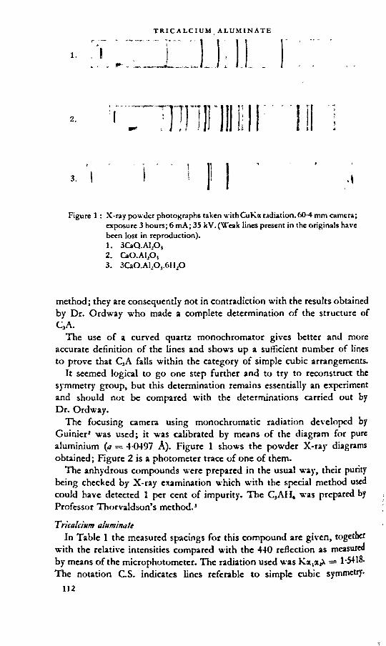
2.
Figure 1 : X-ray powder photographs taken withCuKa radiation.60-4 mm camera; exposure 3 hours; 6 mA; 35 kV. (Weak lines present in the originals have been lost in reproduction).1. 3CaQ.Al2O,2. CaO.AljO,3. 3CaO.AljOj.6HjO
method; they are consequently not in contradiction with the results obtained by Dr. Ordway who made a complete determination of the structure of CjA.
The use of a curved quartz monochromator gives better and more accurate definition of the lines and shows up a sufficient number of lines to prove that CjA falls within the category of simple cubic arrangements.
It seemed logical to go one step further and to try to reconstruct the symmetry group, but this determination remains essentially an experiment and should not be compared with the determinations carried out by Dr. Ordway.
The focusing camera using monochromatic radiation developed by Guinier2 was used; it was calibrated by means of the diagram for pure aluminium (<r = 4-0497 A). Figure 1 shows the powder X-ray diagrams obtained; Figure 2 is a photometer trace of one of them.
The anhydrous compounds were prepared in the usual way, their purity being checked by X-ray examination which with the special method used could have detected 1 per cent of impurity. The CjAH* was prepared by Professor Thorvaldson’s method.3
Tricalcium aluminateIn Table 1 the measured spacings for this compound are given, together
with the relative intensities compared with the 440 reflection as measured by means of the microphotometer. The radiation used was KstjxA = 1-5418. The notation GS. indicates lines referable to simple cubic symmetry.

Figure 2: Microphotometer trace of X-ray powder photograph of C3AHt (see Figure 1 photograph 3).
McMurdie’s* results are given for comparison. Since our t-r—ined in d is less than 5 X IO-* in relative value, the parameter a e to within 01 A; we find <r = 15-27 ± 0-01 A, which is 2x KF greater . that of McMurdie. The able shows lines with d-values as high as •

TRICALCIUM ALUMINATE
table 1: Spacings and intensities of lines measured for tricalcium aluminate
Yannaquis McMurdie (National Bureau of Standards)
hkl dA l/lo hkl dA I
210 6-831 0-04 C.S. 123 4-08 w211 6-241 0-03 124 3-34 VW as.220 5-401 0-03 440 2-70 vs
221,300 5-091 0-033 C.S. 620 2-39 w311 4-605 0-045 630-542 2-258 VW as.320 4-235 0-12 C.S. 444 2-200 m321 4-083 0-15 M2 2-039 VW400 3 822 0-03 731-553 1-984 VW
410,322 3-7C8 0-02 C.S. 650-M3 1-951 VW as.331 3-504 0-02 800 1-907 s421 3-333 0-06 C.S. 653 1-826 VW as.
5<W,43O 3-055 0-04 C.S. 844 1-556 s431,510 2-998 0-02 880 1-346 m
432 2-837 0-085 as. 1240 1-206 m521 2-789 0-14 888 1-106 w440 2-700 1-00 1284 1-023 m531 2-584 0-03
611,532 2-480 0-02620 2-415 0-07 vs very strong541 2-359 0-04 s strong444 2-205 0-16 m medium
700.632 2184 0-025 as. w weak720.M1 2-098 0-035 as. VW very weak
M2 2-041 0-085731,553 1-989 0-04565O.M3 1-955 0-045 as.
SIX) 1-909 0-37S10 1-895 0-055 as.733 l-8(>8 0-02
821,742 1-840 0-03653 1-825 0-05
822,660 1-802 0-02832,654 1-740 0-025
752 1-731 0-02910,833 1-688
842 1-668921,721,655 1-M8 0-03
(M 1-629 0-03762,922,850
84311 620 0-03 as.
844 1-559 0-37860,764 1-529 0-03
1010,942,861 7M
11-514 003 as.950,943 j 1-483 0-03951,773 1-476 0-03
1031,952,765 1-456 0-0021041/X>0,872 1-412 0-03 as.1121,1051,963 l-.W 0-03
880 1-350 Oil1210.884 1-272 0-03
1211,1150 1143,981,974
}1-2M 0-02

Lines with the d-values 6-831, 6-241, 5-401, 5-091, 4-605, 4-235, 2-098,1-895 and 1-840 are new lines, all satisfying the quadratic formula
, 15-27u = ------- ------------Vh2x k2xl2
* There are fourteen lines derived solely from the simple cubic arrangement, and it would be natural to conclude that the symmetry is that of the simple and not the body-centred cube.
A study of the characteristic extinctions leads to the following conclusions:1. Reflections occur when h = 4n for hOO reflections, which means
(400), (800), and possibly (1200) except with superposition of (884). On the other hand we have no (100) or (200) and probably no odd (hOO) reflections, nor even ones when h = 4n.
2. All hkl reflections may be considered to be present.These two conditions characterize the enantiomorphous space groups
P4j3 and P4,3. It should be pointed out, however, that these two groups are very rare in the mineral world, and that the enantiomorphy implies the existence of optical routory power, an unlikely property for CjA.
By taking into account the hkl reflections one might postulate a higher group. In fact reflections that are not affected by super-positions, i.e. (221), (331), (664), and (844) and for which 1 is random, suggest the possibility of a choice between Pm3m and Pn3m. Distinction is made by means of the (hkO) reflections for which (h4-k) is either even or odd; this decides in favour of Pm3m. It could be objected, however, that there is only a small number of hkl lines, and that (221), (331) and (664) are very weak, so that the determination rests on (844).
Consequently it is advisable to limit the conclusion to the following: the number and intensity of the lines characteristic of simple cubic symmetry is sufficiently pronounced to show that there is no longer any reason to place C3A in group Ia3d. In view of the obvious regularity of reflections hkl and hOO, and taking into account that the small number of lines on our Debye-Scherrer diagrams requires us to be cautious, it seems reasonable to place this substance in the Pm3m group.
Monocüldum aluminateA new series of interplanar spacings for CA is given in Table 2. A new
line d = 5-979 A is registered. It was not possible to resolve the close doublet 2-968, 2-976 A by means of the microphotometer, the intensity quoted is, therefore, only approximate.Hjdrated tricalcium aluminate
Flint, McMurdie and VCells give a value of a = 12-56 i 0-02 A for CjAIL,, symmetry group la3d. The new determination of the interplanar spacings is given in Table 3. From these values a has been calculated for the strongest lines, giving most weight to those falling within the region ^Aromatization. By this means a is found to be 12-59 ± 0-01 A. Although t is is higher than Flint’s value by a little more than the experimental

table 2: Spacings and intensities for CA
dA I/I,
5-979 45-571 7
■ 4-931 54-675 224-050 73-717 163-427 43-310 93-203 123-167 63-067 82-976 1002-968 422-915 10
' 2-879 72-857 112-705 82-686 22-541 222-520 28
. 2-445 62-423 152-407 242-388 62-299 52-271 62-198 122-177 32 138 92-086 41-965 41-945 4
' 1-927 161 916 101-836 61-752 51 717 41-683 61 659 61-606 41-581 61-559 61-528 101-509 21-461 91-451 8

table 3: Spacings and intensities for 3CaO.Al2Oj.6H2O
d A hkl VI,
5-140 211 864-453 220 423-M 321 563-149 400 462-816 420 812-571 422 192-469 431,510 302-300 521 1002-226" 440 132 043 611,632 941-991 620 121-817 444 121-746 640 391-714 633,552 291-683 642 511-599 651,732 171-574 800 151-484 822,660 131-408 840 851-366 760,920 131-342 664 17
error, it is not considered that there is any real difference between the specimens studied.
REFERENCES
1. Longuet, p. Congress of Industrial Chemistry. November, 1951. dtiMuteridMx&Conih-KctionetdeTniMMX Publics. Edition C. 1952, August/Septembcr. pp. 227-32.
2. cu ini er, a. Kadiocrisiallograjibie. Dunod Edition. Paris. 1945.3. thorvaldson, t., grace, n. s. and vigtvsson, V. a. Canadian journal of
Research. 1929. Vol. 1. p. 201.5. Ucmvrdie, H. F. Journal of Rtsearcb of the Nalional Bureau of StanJards. 1941.
Vol. 27. p. 499.
F. ordway (author'i elosscre) . . , fI agree fully with Professor Bernal about the great potentia v
single-crystal studies at high temperatures. VCe had postpone t e such techniques until a new audio-frequency power supply, incorpo an automatic temperature control, was built. Now that this new aPPa is in operation we hope to use it with the Buerger precession camera , design seems to minimize the inherent experimental difficu ties) i

near future. We have found that the growing crystals can be seen as clearly as in ordinary room-temperature microscopy if the wire is made in the shape of an inverted fl, with the loop forming as nearly a complete circle as possible. The volume of sample can be adjusted so that the upper and lower surfaces of the drop are flat and parallel, and an ordinary microscope lamp then provides such brilliant illumination that radiation from the hot wire at 1400 °C is negligible by comparison. Under these conditions it should be possible to use polarized light for characterizing and orienting the crystals at high temperatures almost as conveniently as at room temperature.
The tendency toward complex structures that are only pseudosymmetric is, I believe, going to become more and more obvious as inorganic structure analysis progresses further beyond the “ classical" tradition, in which structural imperfections are more or less ignored. Structure determinations carried out by increasingly powerful methods will eventually be used for the primary determination of the exact chemical formulae rather than being based on assumed chemical formulae as is now usually the case. The solution of the CjS problem is important, therefore, to a far wider field than cement chemistry alone.
1 have been intrigued, like Professor Bernal, by the high perfection and large unit cells found in the structures of many of these compounds. If the crystals are formed by deposition of successive layers of atoms, how does a layer in one unit cell “ notify ” the next corresponding layer, far away, of the proper position to form the next unit cell? Frank’s theory is an attempt to explain crystal growth in terms of spiral dislocations, which are continuously propagated as the growing surface of the crystal follows the spiral path. This mechanism does explain a recurring structural pattem of considerable size, but my feeling is that the repetition of the same pattern from one crystal to another must be explained by some process that is less of an accident than is suggested by the term ” dislocation.” 1 think the Frank theory would require only that the layer deposited in a single growth step be equal in thickness to one or more unit cells.
The idea of the production of complex structures by the collapse, on cooling, of simpler high-temperature structures is also an interesting one. Certainly there must be many compounds having a “ high ” and a “ low structure related in this way. If one makes a phase equilibrium study and finds the complex “ low ” form, however, (here is no a priori expectation that the more symmetrical “ high ” form will also be found. This form may actually be metastable or non-existent at atmospheric pressure.
One may think of each possible structural configuration as corresponding to a point in a multi-dimensional “ configuration space,” whose co-ordinates are the positions of atoms in the unit cell. The potential energy of the structure is a function of the position in this multi-dimensional space. The stable structure is that corresponding to the lowest minimum of the potential energy function. Its nature depends on pressure and temperature,

and on the sizes, charges, and bond-forming tendencies of the atoms involved. It seems to me that these factors must be the ones that fundamentally determine a stable structure if that structure is reproduced in all samples of the compound and has a definite range of thermodynamic subility.
The dependability with which new layers of atoms will deposit at specific positions on the surface of a growing crystal must vary with the depth and sharpness of the potential minimum in configuration space, i.e. with the strength of the forces tending to place an atom in a unique position as compared with those tending simply to attract nearest neighbours. Simple undirected electrostatic forces (between K+ and Cl", for instance, in molten KC1) can readily produce short-range order, but for perfect order over longer distances there must be much stronger directed forces. Givalent bonding (as between carbon atoms in an organic system) or the linking of aggregates of ions held rigidly by large electrostatic valences (such as SiO,"* groups in a silicate melt) can supply these directing tendencies. They should facilitate the building of a complex structure by forming a rigid skeleton throughout the crystal, which serves to aline the more flexible portions of the structure, and also by forming relatively stable complex groupings of atoms in the liquid phase, which serve as readily available building units in the process of crystal growth.
Dr. Eitel’s prediction that two-dimensional analyses will not be sufficient to give a solution to the structure problem is in agreement with our own feeling; they were computed as a relatively easy preliminary step, but with little hope that they would solve the problem. \X'e have good hope that the three-dimensional intensity measurements will lead to a solution, however. If not, we shall certainly try to use the isomorphous substitution of Sr for Ca and of Ga for Al in order to obtain additional data.

[5]
The ferrite phase
G. MALQUORI AND V. CIRILLI
SUMMARYIn the first part of the present work, the anhydrous ferrite phase has
been dealt with and special attention paid to the binary system CaO-Fe2Oj, because of its knowledge being fundamental to the tracing of the phase diagram of the ternary system CaO-Al2OrFe2O3. The latter system cannot, as yet, be considered as finally completed.
It has been ascertained that only two calcium ferrites exist: the mono- and the dicalcium ferrite. The phase diagram, however, as plotted by Sosman and Merwin, cannot be considered as completely satisfactory.
Dicalcium ferrite has indeed been shown to form a eutectic with calcium oxide; also, the eutectic between monocalcium ferrite and ferric oxide is likely to be nearer to the ferrite than has been admitted hitherto.
Direct experimental measurements have shown that the oxygen pressure of the system becomes very high in the region of compositions richer in ferric oxide than monocalcium ferrite, as soon as the melting process begins. X-ray, as well as microscopical observations, show that it is probable that formation of solid solutions takes place between the monocalcium ferrite and magnetite.
In the field of the ternary system CaO-ALOj-FcjO, which is of particular interest in the study of Portland cement, what Yamauchi and Swayze have observed regarding the possibility of formation of homogeneous solids richer in alumina than brownmillerite must be taken as confirmed.
Brownmillerite must, therefore, be considered as an intermediate term in the solid solution series of composition 2CaO.(Fe, A1)jO3.
Attention should be paid to the fact that it is impossible to obtain homogeneous solids containing less than 20-21 per cent by weight of Fe1OJ. Such a composition differs slightly from that indicated by Su-ayze.
Present knowledge regarding the zone of the sptem which is poor in lime must be considered insufficient even for an approximate delineation of that portion of the system.
As for hydrated calcium ferrites, the possibility of the formation of a tetracalcium ferrite, hexagonal in habit, as well as of a cubic tricalaum ferrite can be accepted as fully established.
The existence of less basic ferrites, although not to be safely excluded, has not, so far, been supported by sufficient experimental evidence. The

complex ferrites and solid solutions with the corresponding aluminates are discussed elsewhere in this symposium.
INTRODUCTION
When we refer to systems, the knowledge of which is of interest in the study of the constitution of calcareous cements, we mean by the term “ ferrite phase ” the phase or phases in which ferric oxide acting as an acid is present and is bound—alone or with alumina—to calcium oxide.
In the case of normal Portland cement, the ferrite phase is a solid solution of a composition between 4CaO.Al2O3.Fe2O3 and 6CaO.2Al2O,.Fe2O3 belonging to a more extensive series of solid solutions, to which the general formula 2CaO.(Fe,Al)2O3 is to be attributed. It is one of the interstitial phases which upon microscopical observation of a polished section appears distinctly more reflecting than other constituents.
The case of aluminous cement is far more complex and apart from the ternary phase, which is of an analogous nature, the existence of different ferrite phases is to be expected.
The presence of minor constituents should not cause—at least not for compositions which are of interest for the study of the constitution of the clinker of Portland cement—the appearance of more complex crystalline phases, i.e. of phases having more components than the three: CaO, A12O}, Fe2Oj.
In this paper we propose to report briefly on the contribution recently afforded by research work concerned with identification of these phases, their all-round characteristics and their behaviour upon hydration.
As will be realized, this field of research presents considerable difficulties and it is not surprising, therefore, that in spite of the modern means available for scientific examination, the results of the studies seem sometimes discordant and interpretation contradictory.
anhydrous ferrite phases
The system CaO—FejO,The first investigations u’ere made by Hilpert and Kohlmeyer1 who recog
nized the existence of five different ferrites, of a composition between 3CaO.Fe2O, and CaO.4Fe2Oj. Subsequently, Sosman and Merwin1 have drawn the well-known phase diagram, which differs considerably from that of earlier workers, as only two ferrites, mono- and dicalcium, appear in it, both melting incongruently.
The results of Sosman and Merwin have been confirmed by White, Graham and Hay1; their diagram, however, has been shown to be inadequate for describing satisfactorily all the properties of the system Fe2OrCaO, particularly in the region richer in Fe2O,.
Tavasci* was the first to ascertain that the melting points in that portion 0 the diagram which includes the compositions between monocalcium

Figure 1.
ferrite and ferric oxide, rise more rapidly than would be expected from the diagram itself. Discrepancies between the melting points stated by Sosman and Merwin and those derived from the deformation of cones prepared with mixtures of dicalcium ferrite and ferric oxide, have been pointed out also by Rees and Fisk.5
More recently, Swayze6 has shown that the ferrite 2CaO.Fe2O, melts without decomposition at 1435 "C, the eutectic between this compound and the calcium oxide being at 1425 °C.
According to Sosman and Merwin, a eutectic occurs between monocalcium ferrite and ferric oxide at a composition near to 80 mol. per cent of Fe^O,. Actually, however, observations by reflected light on polished sections of preparations containing more than 50 mol. per cent of FcjO, and taken to temperatures only a little higher than those of incipient melting and never allowed to exceed 1250 °C (in order to try and avoid decomposition with loss of oxygen) show .that free ferric oxide is distinctly identifiable above 60 per cent.
Figure 1 refers to the preparation containing 60 mol. per cent of FejO, obtained by previous sintering and successive melting at 1210 0 ± 5 °C of the mixture of the two pure oxides. It exhibits an apparently homogeneous structure consisting of an aggregate of elongated crystals with a reflective power var)'ing with orientation.
This structure, uniphasic in aspect, is not in agreement with the phase diagram. According to this, cry stals of monocalcium ferrite should be noticed immersed in a eutectic, in which it would be easy to identify ferric oxide owing to its noticeably high reflecting power.
The lines of both monocalcium ferrite and ferric oxide however, ire present in the Dcbyegram of the same preparation, but the latter have intensities considerably lower than those which can be observed for simple mixtures of oxide and ferrite in the same ratios. With the lines which belong

Figure 2.
to the ferrite and to the oxide, foreign lines can be detected which pertain to the spectrum of neither of the two above described substances, and the position and intensity of which vary with the time of thermal treatment of the melted material.
On prolonged annealing, at a temperature somewhat below that of the melting point, the spectral lines of ferric oxide show increased intensity and correspondingly the microscopic observation of preparations so treated indicates that along the edges of thick crystals (Figure 2), minute crystals begin to occur, having a high reflective power and being attributable to the ferric oxide.
Such features could be attributed to the very small dimensions of the crystallites of ferric oxide which become visible by microscopic observation only after the thermal treatment has enabled their coalescence to take place. Concerning the composition under examination, the ferric oxide should represent, how*ever, 27 per cent by weight and its specific gravity being higher than that of the ferrite—the percentage of the surface corresponding to it ought to be only a little lower. Even in the preparations annealed for long periods, microscopic measurement shows a much smaller content of ferric oxide.
This complex behaviour is probably due to the fact that in the preparation obtained by melting, the dissociation of ferric oxide is already fairly appreciable though the temperature has never exceeded 1250 °G This would account for the appearance of new lines which belong neither to the calcium ferrite nor to the ferric oxide spectra, and also, because of oxidation, for the presence of those crystallites of ferric oxide which become visible only after the annealing process.
The divergencies between observations of different experimenters are doubtless connected with the dissociability, at elevated temperatures, of the cnic oxide and its combinations with lime. We therefore think that for the
t

purpose of a more precise interpretation of experimental results which are to be the basis for tracing the phase diagram of the system Fe^Oj-CaO for the zone richer in Fe2O3 more complete knowledge of these phenomena cannot be dispensed with.
This dissociability, i.e. loss of oxygen, with consequent appearance of ferrous compounds, has been deplored by all workers who have applied themselves to these studies. Sosman and Merwin have observed that between CaO and CaO.Fe2O„ the loss of oxygen is slight if the temperature does not exceed 1400 °C—1500 °C. Decomposition, however, is rapidly enhanced for the second part of the phase diagram, i.e. between CaO.Fe2O3 and Fe2O3, when the percentage of Fe2O3, the temperature and the time of treatment are increased.
The different values available in the literature on the thermal behaviour of ferric oxide indicate that the oxygen pressure reaches the partial pressure of oxygen in the atmosphere between 1300 °C and 1400 °C.’
Kühl and Rasch8 have compared the thermal dissociation of free and combined ferric oxide, in the two ferrites mono- and dicalcium, measuring the rate with which these substances liberate oxygen on heating to the same elevated temperature, 1500 °C, and found that the dissociability of combined ferric oxide is clearly inferior to that of free oxide. The temperature reported by these authors is markedly above the melting point of both CaO.Fe2O3 at 1216 °C, and 2CaO.Fe2O3 at 1435 °G
At variance with these observations. White, Graham and Hay1 later on claimed, that the dissociation of the monocalcium ferrite remains low and below that of Fe2O3 alone, until the temperature at which the liquid appears, is reached, whilst above this temperature, the oxygen pressure increases markedly. "
We have directly confirmed this interesting statement and in Table 1 the oxygen pressure values for ferric oxide and monocalcium ferrite measured at different temperatures ate given.
Attention should be paid to the fact that up to around 1200 °C, the dissociability of the ferrite is approximately equal to that of ferric oxide, whilst at higher temperatures, coinciding with the beginning of melting (1216 °C), the dissociability slightly increases.
These dissociation phenomena, which obviously modify the conditions of equilibrium of the binary system Fe2O3-CaO, are still more pronounced for compositions less basic than CaO.Fe2O3 for which the liquid phase is obtained at a somewhat lower temperature.
The system Fe2O3-Fe-CaO Is not as yet very well known. Schenck and co-workers,’ Martin and Vogel,“’ Hay and White,11 Malquori and Cirilli,11 Grilli,11 have partially studied it using different experimental methods.
One more observation about the diagram of Sosman and Merwin is to be made. '
Preparations containing more than 60 mol. per cent of Fe2O3, obtained upon prolonged thermal treatment at the temperature of the eutectic
124

G. MALQUORI AND V. CIRILLI
TABLE 1.
Fe2O3 CaO.Fe203
°C O2 pressure mm Hg
°C O2 pressure mm Hg
1,080 3 1,060 11,130 7 1,130 41,250 27 1,200 181,340 145 1,250 ' 571,420 370 1,320 1781,460 710 1,350 3101,470 760 — —*
Figure 3.
CaO.FcjOj—FcjOj, show upon microscopical examination—as has been duly stated above—the presence of ferric oxide. Figure 3 refers to a composition with 80 mol. per cent of Fe.Oj and—as will be seen—the polished section looks not at all like what would be expected from the diagram of Sosman and Merwin, who locate the eutectic between CaO.Fe^O, and FezO3 approximately at that ratio between the tw o components. If the same preparation with 80 mol. per cent of Fe.Oj is kept at a temperature some ten degrees higher with the aim of obtaining complete melting, a distinctly ferro-magnetic solid results after cooling, with an X-ray spectrum analogous to that of magnetite, except for an appreciable displacement of the lines. ,
It seems probable that, because of the oxygen loss, a solid solution originates of the magnetite type with CaO taking the place of FeO. This hypothesis has now received a direct experimental proof. (Burdese and Brisi, private communication).

The crystal structure of the calcium ferrites was not well known hitherto. According to Sosman and Merwin2 the monocalcium ferrite CaO.Fe2O3 is nearly or quite uniaxial and White, Graham and Hay3 agree with this view.
One of our co-workers, Burdese, (private communication) working on a single crystal of monocalcium ferrite, recently established that this compound crystallizes in the orthorhombic system with the O-atoms so arranged as to form an almost hexagonal close-packed lattice. These results were based on rotating crystal and XX'eissenberg diagrams.
The dimensions of the unit cell, containing four molecules of CaFe2O„ have been determined as follows :
ao=9-16Ä bo=10-60Ä co=301ASosman and Merwin2 found that dicalcium ferrite is bi-axial, with a
moderate optic axial angle. As will be explained later, the unit cell is orthorhombic, like that of brownmillerite, and characterized by the following values:
ao=5-32Ä bo=14-63A Co=5-58A .
The system CaO——FejO,As for the binary system CaO-Al2Oj and Al2OJ-Fe2OJ> the first will be
dealt with more fully in another section. Here we only point out that we can now accept the formula 12CaO.7Al2O3 proposed by Eitel and Büssern14 for the aluminate formerly referred to as 5CaO.3Al.O3, while the composition of the less basic aluminate shown in the diagram of Rankin and Wright as 3CaO.5Al2O3 remains still to be settled.
Tavasci13 instead, has attributed to the less basic aluminate the formula GlO.2A12O3 and his assertion has been supported by Lagerqvist, Wallmark and Westgren.16 Some of our co-workers, too, have been able to confirm, by means of X-ray studies, the exactness of Tavasci’s claim.17
Referring to the system Fe2O3-Al2O3, we only report that it has been possible, by means of magnetic research work, to confirm the limits of solubility up to 1000 °C, of the two rhombohedral sesquioxides, previously discovered by Passerini.18-19 The existence of such solid solutions had formerly been pointed out by Forestier and Chaudron,10 by Hansen and Brownmiller21 and by Huttig and co-workers.22
The continuous improvement of knowledge on the binary systems is sure to have its repercussion upon further elaborations of the ternary system, but in view of the fact that the uncertainties which still exist are concerned with the acid zones, it is not likely that further improvements will displace the decidedly basic zone of the ternary system from its present position.
Hansen, Brownmiller and Bogue23 indicated that the compound 4CaO.Al2O3.Fe2O3 is capable of forming a continuous series of solid solutions with 2CaO.Fe2O3. This opinion was confirmed later on by X-ray examinations made by Solacolu.24
The possible formation of solid solutions between brownmillerite and the calcium aluminates has been recognized by McMurdie.23 According to

table 2 : Magnetic susceptibility (mass) per gramme of Fe2O3
Ratio Al2O3:Fe2O3 H= 1,500 H=l,870 H=2,460 Average
values0-5 31-8 x 10» 32-8 x 10» 32-9x10» 32-5X10'»0-75 40-4 39-2 39-9 39-81 41-9 42-5 42-8 42-21-25 51 0 51-9 51-7 51-51-5 56-1 55-3 56-8 56-11-75 600 60-9 60-5 60-52 66-8 67-8 66-3 67-02-25 669 66-6 66-0 66-52-5 670 68-1 67-3 67-53 68-5 68-9 68-0 68-535 67-5 68-6 • 67-7 67-8
Yamauchi,26 in the system Al-O3-Fe2O3-CaO the existence of a homogeneous solid of the composition b^CaO^^AljO^Fe^Oj, which is richer in alumina and lime than the brownmillerite, is possible. ■
More recently, Swayze* has shown that the continuous solid solutions between dicalcium ferrite and a hypothetical dicalcium aluminate, the ultimate term of which, according to Hansen, Brownmiller and Bogue was 4CaO.ALO3.Fe2O3, extend to ratios of Al2O3:Fe1O3>l, and he gives 6CaO.2Al,O3.Fe2O3 as the final term of this continuous series of solid solutions among which brownmillerite would represent an intermediate composition.
Well in accordance with this supposition are the results of the calorimetric experiences of Newman,22 who has established that the heats of solution of the solids with compositions comprised between the two extreme terms lie along a straight line.
We were able to produce further proof,21 measuring the magnetic susceptibility of solids, the composition of which is represented by the formula 6CaO.xAlJO3.yFeiO3 (x-j-y=3). The values of Table 2 illustrate that susceptibility increases linearly for molecular ratios of Al2O3:Fe2O3 between 0-5 and 2.
\Xhilst it is not possible by means of magnetic investigation to exclude that 4CaO.Al2O3.Fe2O3 exists as a definite compound, however unlikely this would seem, the existence of a phase the composition of which approaches that indicated by Swayze appears obvious. In fact, if this had not been formed for molecular ratios of Al2O3:Fe2O3 >1, (the magnetic effect due to the presence of calcium aluminate being negligible) the constancy of the magnetic susceptibility would have been observed to oscillate around the value *=42 x 10"6. The constancy of the susceptibility was obtained, how ever, for a higher value: x=67x KF* and for Al2O3:Fe2O3 ratios>2.
^"e therefore decided to complete these studies by X-ray examinations.2* It is well known that 2CaO.Fe2O3, 4CaO.Al2O3.Fe2O, and 6CaO.2Al2O3.

Fe2O3 show analogous Debyegrams with only a slight displacement in the positions of the lines, depending upon their compositions. A structural study, though partial, was made on brownmillerite by Büssern.30 He established that the unit cell is pseudotetragonal, contains 2 molecules of 4CaO.Al2O3.Fe2Oj and possesses the dimensions ao=5i34 A, bo=14-44 A, c0=5-52 A.
According to Büssern the cell should consist of a layer of FeO4 tetrahedra of orthorhombic symmetry, connected one-dimensionally in the a direction and linked above and below by means of oxygen bridges at a distance of |b to a layer of A1O6 octahedra of tetragonal symmetry.' The Ca ions are located between the octahedral and the tetrahedral layers
and should possess an incomplete co-ordination of oxygen atoms. The space group would be VhM (Imma). The unusual co-ordination of Ca and Fe ions would account for the reactivity of the compound towards water.
Brownmillerite forms a continuous series of solid solutions with 2CaO. FCjOi-, this is done by substituting Al ions for Fe ions in the layers where b=0 and b=J. According to Büssern, such a substitution would produce space strains because of the different ionic radius of the two elements—which manifest themselves in a relative instability of dicalcium ferrite as compared with brownmillerite.
This conclusion would appear to be rather improbable; in fact, dicalcium ferrite is less reactive than brownmillerite and it melts congruently at a higher temperature. According to Swayze, on the contrary, the melting of 4CaO.Al3Oj.FejO, should take place with decomposition.
Having succeeded in obtaining single crystals of 2CaO.FejOj, of 4CaO.Al2OJ.Fe2Oj and of 6CaO.2AljOj.FejO,, X-ray rotation and Wrissenberg photographs were taken and measured. In the three cases we found the lattice constants given in Table 3.
For dicalcium ferrite, the specific gravity of 401 allows us to calculate with good approximation that four molecules of CajFe2O, are contained in the elementary cell. The space group is the same as that found by Büssemfor browmmillerite (VhM). .
The non-equivalence of the Fe atoms alined along the b axis is dearly proved by an examination of the equatorial reflections obtained by routing the crystal around (001) (Figure 4). The relative intensity of the lines (040) very weak, and (080) very strong, is well in accordance with the opinion that grouping of FeOt, FeO„ FeOe, FeO„ held together by an oxygen atom, occurs in direction b.
table 3.
Composition a» be ce
2CaO.Fe2O, 532 14 63 5-58
4CaO.AljOj.FejO, 5 26 1442 5-51
6CaO.2ALOj.FCjO, 5 22 1435 548

Figure^
The elementary cell can be comprehensively expressed by the formula. Ca,Fet,vFe4'r'O20 «here Fe” and Fe* 1 represent Fe atoms, their co-ordination values being 4 and 6. The values which we calculated for the lattice constants of the brownmillcrite differ only insignificantly from the values given by Büssern. From the specific gravity value (dTG), two molecules of 4CaO.Fe2Oj.Al2Oj per cell must be reckoned or, in an equivalent manner, four molecules of CazAl.FeO,
For the solid GOO.aAl.Oj.FeP, (d=3-71) it is not possible to explain the arrangement of the atoms in an elementary cell of the type Ca,Me,” M e1'r,O2e- It must be assumed, therefore, that the formula advanced by Swayze represents only a composition ratio of the three oxides. A solid of this composition

tabl
e 4 : Pow
der p
hoto
grap
hs of
dic
alci
um fe
rrite
(Ca,
Fe2O
3) and
of te
rnar
y sol
id so
lutio
ns of
the s
yste
m Ca
O-F
e^O
j-Al^
Oj
(Bro
wnm
iller
itc an
d lim
it—co
mpo
sitio
n sol
utio
n)=F
e Ka r
adia
tion=
Solid
solu
tion
of li
mit
com
posit
ion
-a
THE FERRITE PHASE
't n * O i M m o go rj ^0*0s-i 04 O\ qx r* in «-I O' oo cnr*Otj-r* \O o oo r* \p m m tr v v m n hCM CM N A rH VH A vH Aw A A A A
sin20 co
mpu
ted
valu
es ■*<MOOxotncMaor*oC'*oor**oxOao-tt- ■vrr*»ov»-<Q'itoocccM<n«nr*̂-rwoor* CMrneMtO^rnoc^cxs-HiweMCMinCt^o ^<i-<cMMCMrnf,nfnm'f^***-**nr* 6Ö66Ö6Ö666Ö6ÖÖÖ6Ö
obse
rved
va
lues O O Q co o <*> O Q Q 00 O Ox m
sr r- 5o w q * r* S in m oo r*cm <*n cm o o* rn ao o cm m Ox -* oCM CM CM co CO M- M- M* M* lO F*6 ö öö ö oq 6 6 6 ö 6 ö ö
Brow
nmill
erite
-aw CO CM CM CM OC V) h» "Cm m <m Q 1 r*. m iCx * co —• tn
tx \o o Ox op | in *n 1 cn <n wcm cm cm A A A A A A A A A
d r* q C* cm cm O' w oo Ox o ox m m*n -* d o o x m cm q x ’T i> dr* *5 O 5c d d d. *r d d wcm cm cm A A A A A A A A A A A
o
l com
pute
d va
lues
CMdMdXdXXCx O — CM CM d Cx Os-e»-.CMCMfMdddd'r^-^*̂v*rdr* ööoooöööööoöoöoöö
obse
rved
va
lues Q Q Cx Q d OX o 'S O O h* O O* OXd -3 d 3 r* ax d o — O' ** o Jx
CM d CM d X CM 00 O O CM ■tC'dO.-e cm cm cm d d v v A *r m o6o6 6 q ö 6 ö 6 6 6 6 6 6
Dic
alci
um fe
rrite
■o_ d x d d Q1 O r* 'T I X d ci | r* | d 1**
I O 6 ofc I *n d d | **■ | d wcm cm A A A A A A A A
13O h* xg d d d ■* CM b- g w* C2» — Xr» -f d d cm O h* 'T cm 5 O O' d \Dr» 6 O Cx x r* d d d d d dcm cm cm A A A A A A A A *-* A A
sin20 co
mpu
ted
valu
es 832?. 8£8e?5sg5gs$2 C'fdCMdr*cMr*F»x?J ,G—• d x cm op i*<wCMfMCMdddddd^ ,wfrir,,frd<p 66666666666666666
obse
rved
va
lues m w s ^4 g o m o gm m e> g g-• m o m g c4 o m 3 — r* co » mm C4 m So c. r» o 5 —• 1 j~ — m m m m m m t ♦ TTf1'?
Ö Ö Ö Ö Ö Ö Q Ö Ö Ö Ö O O O
it w
v.st
st
. v,
st.
v.st
. m
w.
nut.
mst
.
mi mst. m
m
st.
st.
mst
.
hid
QCMOwCMO*Mdw^wfM(MQ2XS$OD'iDC;3Q*F- i*h*C ,eTX'OX.OQl,3r4HNCM--N6AcMt'lOO*M

is obtained by substituting a certain number of Al atoms for Fe atoms in dicalcium ferrite: it must, therefore, be considered as a term in the solid solution series originating from dicalcium ferrite and the hypothetical dicalcium aluminate. Brownmillerite, too, is a member of this series, and is thus to be considered as an intermediate term. '
Starting from this assumption, we wanted to examine whether 6CaO:2Al2O3.Fe2Oj really represents the final term of the series. By means of Debyegrams, we established that at ordinary temperature the limiting composition contains approximately 20-5 per cent by weight of Fe2O3, whilst for 6CaO.2Al2O3.Fe2Oj, the Fe2O, content is calculated to be 22-8 per cent (limit given by Yamauchi: 6-2CaO.2-2Al2Oj.Fe2O3).
In Table 4, we give data for sinz0 as obuined by Debyegrams for dicalcium ferrite, brownmillerite and the limiting solid solution, comparing them with values calculated for the various lines of which index numbers are reported Comparison between calculated and observed values can be considered satisfactory. The plot in Figure 5 shows the variation of the lattice constants as a function of the composition.
Büssern believes that in dicalcium ferrite only those Fe atoms with sixfold co-ordination can be replaced by Al atoms. This assumption is in contradiction to our experimental work.
The existence of homogeneous solids with an alumina content higher than that which is proper to brownmillerite, CaJ^AUOa» demonstrates that Al atoms are likely to occur with a co-ordination of 4 in the crystalline lattice of solid solutions of the type 2CaO.(Fe, A1)2O,. Furthermore, we have observed that in the whole field of solid solutions, the lattice constants are linear functions of the number of Fe atoms substituted; hence it is to be inferred that the substitution of Al to Fe does not occur selectively in the octahedral layer, but is merely statistical. Therefore, as stated above, brownmillerite represents only a term in the series of solid solutions, whereas 6Ca0.2Al2O3.Fe20j represents a composition ratio very near to the limit of saturation.
Since dicalcium aluminate does not exist, the substitution of aluminium for iron leads to a greater instability of the crystalline structure, so much so that it is impossible to obtain solid solutions of the type 2CaO.(Fe, A1)2O3 containing less than 20—21 per cent by weight of Fe2O3. This point of view of ours is well in accordance with the phase diagram modified by Swayze along the line 6CaO.2Al2O3.Fe2O3-2CaO.Fe2O3.
Findings on the nature of the ferrite phase have a considerable interest for the purpose of calculating the constitution of Portland cement clinker from the chemical analysis (Bogue’s method). Tricalcium aluminate indeed should no l°nger appear as a separate phase for ratios of Al2O3:Fe2O3>0-64, but only when the above ratio is higher than about 14 (1-28 for 6CaO.2Al2O3. FeA). 6 V, If in the diagram of the ternary system CaO-Al2O3-Fe2O3, the zone which 15 nch in lime can be considered today as being sufficiently known, we cannot

AIjO, substituted for Fc2O, mol per cent
Figure 5.
affirm the same for the zone poor in time.This zone, which is important for aluminous cements, is yet awaiting its
final delineation, which clearly depends upon a knowledge of the binary systems and particularly of the system Fc2OrCaO.
Observations on the solubility between monocalcium ferrite and aluminate have been described by McMurdie21 and some data can be found in papers of Yamauchi.1*
Tavasci21 points out that unknown compounds will probably exist such as CaO.Al.O3.2FeA; ISCaO.lOFe^O,. ALO,; IbCaO.llFcA-AliO, as weB as various solid solutions. I [is assumptions, derived only from microscopic observations by reflected tight, have qualitative value only and reveal the complexity and difficulty of investigations in those zones of the diagram for the ternary system which are less rich in time.
As is known, Swayze’s statements have only led to slight alterations of the diagram of the fundamenul system CaO-SiOrAl4Oi*FeA drawn by Lea and Parker.
As for the influence which minor constituents have upon equilibriuni relations in the above fundamenul quaternary system, Swayze has found that the action of magnesium oxide, if this is contained in percentages not higher than 5 per cent (the approximate limit of solubility of magnesium oxide in the liquid at the temperatures with which we are concerned), u

confined to altering the composition only slightly and to decreasing the temperature of the invariant points.
Recent researches by Eubank32 upon the system Na2O-CaO-Al2O3-Fe2O3- SiO2 establish that crystalline phases other than those already known, do not exist and that at 1310 °C ± 3 °C five distinct solids co-exist in equilibrium with the liquid, i.e. 3CaO.SiO2, 2CaO.SiOi, 3CaO.Al2O3, ferrite phase and Na2O.8CaO.3Al2O, (invariant).
Mn2Oj in the low quantities which are of interest in the composition of Portland cement, seems to be able to substitute integrally Fe2O3 in the ternary solid solution series.33
McMurdie, Sullivan, Mauer34 find that FcjO, and Mn3O4 are miscible in the solid state at all ratios.
HYDRATION OF THE ANHYDROUS FERRITE PHASESThe knowledge of the behaviour of the ferrite phase towards hydration
has great importance for the interpretation of constitution and properties of hydrated and hardened Portland cement, particularly for cements with a low ratio of Al2O3:Fe2O3 with or without free tricalcium aluminate. In the following paragraph we summarize briefly what has been done up to the present day.
Mention is made in the b'terature of a hydrated calcium ferrite 4CaO.Fe2O3.aq obtained by Pdlouze33 and more recently by Hoffmann.3*
According to this author, the salt is stable when in contact with lime solutions of a CaO content higher than 1-06 g per litre; below this concentration and down to 0-604 g per litre CaO, a new hydrate of an undefined composition appears to be stable.
The tetracalcium ferrite is easily prepared37 by co-precipitation with alkali from mixed solutions of ferric and of calcium salts at suitable dilution. It can also be obtained by treating ferric hydroxide with saturated limewater; with the latter procedure, however, the salification of the sesquioxide is not completely attained, even if highly dispersed preparations are used, because of the formation of protective films around the separate grains. Yet another method for preparing tetracakium ferrite is hydration of anhydrous dicalcium ferrite in presence of saturated limewater.
Hydrated tetracalcium ferrite consists of white thin hexagonal plates. For 4CaO.Fe203.14H20, we have determined3* a refractive index and Feitknecht” has determined the lattice consrants, finding a—3-42 and c==84). The salt after dehydration in vacuum over CaCl2 holds 14 water molecules, which are reduced to 12 over P2O3. The thermal dehydration curve does not exhibit any marked break; at 7 molecules of H2O a slackening
c process can be noted, and after this, the material loses water slowly.Uunng heating, the spectrogram of the more water-rich salt remains nearly
multered up to 7H2O; it disappears completely towards 4H2O. The spectro- of the anhydrous substance shows the lines of 2CaO.Fe2O3 as w'ell as
those of CaO.

Hoffmann36 claims to have succeeded in isolating another hydrate, viz. 4CaO.Fe2O3.7H2O working with the same solutions with which he had already obtained the more hydrated salt, but at a temperature of 50 0—60 °C. The new hydrate shows a different X-ray pattern.
This information is at variance with our own observations, i.e. that 4CaO.Fe2O3.14H2O and 4CaO.Fe2O3.7H2O show identical spectrograms and the explanation of this divergency is due to the fact that at temperatures between 50° and 60 °C, the transformation of tetracalcium ferrite to cubic tricalcium ferrite proceeds at a high rate. Octahedral crj’stals are actually formed upon heating, and they must be assumed to be cubic tricalcium ferrite. This ferrite affords a Debyegram similar to that which Hoffmann attributes to heptahydrated tetracalcium ferrite.37
Tetracalcium ferrite hydrate behaves therefore in the same way as the corresponding aluminate.
McIntire and Shaw,40 having followed up by microscopical examination the evolution of ferric hydroxide gel under the action of lime, have obtained evidence for the formation of thin hexagonal-shaped plates quite similar to the hexagonal crystals of the hydrated calcium aluminates. They propose the formula SCaO.FCjOj.aq for the crystalline ferrite.
Later on, Eiger41 observed that in the reaction between calcium hydroxide and iron hydroxide, the formation of a cubic ferrite 3CaO.Fe2O3.6H2O analogous to the corresponding aluminate is possible. According to Lea and Bessey,41 the refractive index of the crystalline material should be nD=l-71; the ferrite has a cubic lattice with a lattice constant of 12-71 A and this is little higher than that of the aluminate (12-56 A). The hexahydrate salt is stable up to about 250 CC, at higher temperature it rapidly yields water, reducing its extent of hydration to around 2H2O. Dehydration is complete only towards 1000 °C
Following up the removal of water by means of X-ray powder photographs, we have noticed that up to circa 1-5 HjO, the spectrum of the original product remains unaltered, though a wider spacing between the fundamental lines is to be noted and a gradual decrease in the intensity of some of them. At approximately 0-3HjO the spectrogram is distinctly different, though it exhibits a cubic symmetry which is always clearly visible, even by microscope. The total removal of water causes decomposition to 2CaO.FejOj and CaO. With dehydration, the ferrite behaves, therefore, in a similar way to that observed by Köberich41 for the corresponding aluminate.
According to Eiger,41 the cubic tricalcium ferrite is stable when in contact with a lime solution having a concentration of 250 mg per litre. Below this concentration, it would be converted into 2CaO.Fe2O3.5H2O, of orange colour, which in turn is stable in presence of water containing 15 mg lime per litre.
The possibility that an amorphous hydrated dicalcium ferrite may be formed, has been admitted by Bogue and Lerch,43 who claim to have obtained it by direct hydration of the anhydrous dicalcium ferrite. Also Yamauchi

maintains that by hydration of the dicalcium ferrite, 2CaO.Fe2O3.5H2O is formed, whose X-ray pattern would differ clearly from that of anhydrous ferrite.
The American scientists believe that the existence of a hydrated monocalcium ferrite is possible, which is also amorphous. It should be formed together with the hydrated tricalcium aluminate by the action of water on brownmillerite.
The tw’o hydrated ferrites, dicalcium and monocalcium, would originate according to Mather and Thorvaldson” also by water vapour action (100 °C —300 °Q on anhydrous dicalcium ferrite. Hydrated monocalcium ferrite w'ould also be formed in analogous experimental conditions from brownmillerite.
In the course of our experimental work we have had no opportunity to detect hydrated ferrites which were less basic than the tricalcium ferrite. Certainly these less basic ferrites do not exist in equilibrium with limewater of a concentration nearing that of saturation and this is just the case which more closely interests the cement chemist, since the ferrite phase becomes hydrated in the presence of saturated limewater or of solutions of concentrations close to that of saturation.
REFERENCES
1. Hilpert, s. and Kohlmeter, E. BcrUbt dtT Dtidirixn Cbemüebtn Cenlltcbaft.1909. Vol. 42. p. 4,581.
2. sosman, R. a. and merwin, H. E. Journal of lit U”atbintion Acadenn of Sciencet1916. Vol. 6. p.532.
3. white, j., graham, R. and hat, R. Journal of fbt Iron and Strel Indurhj. 1935.Vol. 131. p. 91.
tavasci. Bi ylnnati di Chimka /Applicata. 1936. Vol. 26. p. 291.5. Rees, k. and Fisk, H. c. Journal of ibt Ameruan Ceramic Sociriy. 1940. Vol. 23.
p. 185.6- swatze, m. A. American Journal of Science. 1946. Vol. 244. No. 1. p. 652- Schenck, H. Plyrikalifcbe Chemie det Eicenhttttenpro^eM. Springer. Berlin. 1932.
Schnall, n. g. Zeiiccbriflfür dektrocbemie. 1941. Vol. 47. p. 821.”• «Chi, H. and RASCH, R. Zement. 1931. Vol. 20. p. 812.
• schenck, R. and coworkers. Zeitcchrift fur Anorganiscbe und Allgemeine Chemie.1929. Vol. 184. p. 1. 1937. Vol. 235. p. 65.
• martin, e. and vogel, r. Archiv für dar EirenbiUtennvren (Stahl und Eiten.Ergäm-ung). 1934. VoL 8. p. 249.

11. hay. R. and wh ITE, j. Journal of th« B-"«/ of Scotland Iron and Steel Industiy. 1939-40.Vol. 47. p. 87.
12. MALQUORi, g. and ciRiLLi, v. Ga^etta Cbimica Italiana. 1945. Vol. 75.p. 137. .
13. ciRiLLi, v. Kicerca Scientifica. 1947. Vol. 17. p. 942.14. eitel, w. and bussem, w. Zeitschrift fur Kristallographie. 1936. Vol. 95. p.175.
Proceedings of Symposium on Chemistry of Cements, Stockholm. 1938. p. 149.15. TAVASCi, b. La Cbimica e I'Industria. 1935. Vol. 17. p. 461.16. LAGERQviST, K., wallmark, s. and westgren, a. Zeitschrift für .Anorgani
sche und Allgemeine Chemie. 1937. Vol. 234. p. 1.17. GORIA, c. and burdese, a. Päcerca Scientifica. 1950. Vol. 20. p. 1,613.18. ciRiLLi, v. Casetta Cbimica Italiana. 1947. Vol. 77. p. 255.19. PASSER1NI, L. Gagrgetta Cbimica Italiana. 1930. Vol. 60. p. 544.20. Forestier, H. and CHAUDRON, G. Comfites Rendus. 1925. Vol. 180. p. 1,264;
Forestier, H. Amtales de Chemie. 1928. 10. Vol. 9. p. 316.21. Hansen, w, c. and brownmiller, l. t. American Journal of Science. 1928.
Vol. 15. p. 225.22. HÜTTIG, G. F., meyer, T., Kittel, H. and cassirer, s. Zeitschrift für
Anorganische und Allgemeine Chemie. 1935. Vol. 224. p. 225.23. HANSEN, W. C., BROWNMILLER, L. T. and BOGUE, R. H. Journal of tht
American Chemical Society. 1928. Vol. 50. p. 396.24. SOLACOLU, s. Zement. 1932. Vol. 21. p. 301.25. mcmurdie, h. f. Journal of Research of the National Bureau of Standards. 1937.
Vol. 18. p.475.26. YAMAUCHI, T. Journal of the Japanese Ceramic Association. 1937. Vol. 45. 279,
361, 433,614, 880. 1938. Vol. 46. p. to. Ceramic Abstracts. 1938 VoL 17. p. 163. 1939. Vol. 18. p. 86. 1940. Vol. 19. p. 134.
27. Newman, e. s. Journal of Research of the National Bureau of Standards. 1947.Vol. 38. p.tol.
28. CiRiLLi, v. and brisi, c. Annali di Cbimica. 1951. Vol. 41. pp. 61.29. CIRILLI, v. and burdese, a. Ricrrca Scientifica. 1951. Vol. 21. p 1,185.30. bussem, w. Fortschritte der Mineralogie, Kristallographie tmd Petrographie Y)S1.
Vol. 22. p. 31. Proceedings of Symposium on Chemistry of Cements, Stockholm 1938. p. 153.
31. TAVASCI, b. Amali di Cbimica Applicata. 1937. Vol. 27. p. 505.32. EUBANK, w. R. Journal of Research of the National Bureau of Standards. 1950.
Vol. 44. p. 175. '33. lea, F. M. Quarterly Review of the Chemical Society. 1949. Vol. 3. p. 82.34. mcmurdie, h. f.. Sullivan, B. M. and mauer. F. A. Journal of Research of
the National Bureau of Standards. 1950. Vol. 45. p. 35.35. pIlouze, j. Annales de Cbimie et de Physique. 1851. 3. Vol. 33. p. 5.36. Hoffman, h. Zement. 1936. Vol. 25. p. 113.37. MALQUORI, G. and CIRILLI, v. Ricrrca Scientifica. 1940. Vol. 11. p. 316.38. MALQUORi, G. and ciRiLLi, v. Ricrrca Scientifica. 1943. Vol. 14. p. 7839. feitknecht, w. Helvetica Cbimica Acta. 1942. Vol. 25. p. 555.40. mcintire, w. h. and shaw, w. m. Soil Science. 1925. Vol. 19. p. 125.41. EIGER, a. Revue des Matlriaux de Construction et de Travaux Publics. 1937. Xol.33.
p. 141. Proceedings of Symposium on Chemistry of Cements, Stockholm. 1938. p-173.
42. köberich, f. University of Berlin. Dissertation. 1934.43. Bogue, r. h. and lerch, w. Industrial and Engineering Chemistry. 1934. <>•
261 p-837' . A 1937.44. mathex, d. t., and thoxvaldson, t. Canadiern Journal of Research. ■
Vol. 15. p. 331.

DISCUSSION
MYRON A. SWATZE
Perhaps some amplification of this writer’s work done partly in collaboration with L. S. Brown on the ternary system CaO-CjAj-CjF, and alone on the two quaternary systems as reported in the American Journal of Science, January and February, 1946, will be useful to the the authors in their work on this difficult and variable phase. These reports were necessarily very brief, with descriptions of individual burns of mixtures in the several Tables cut drastically in order to get the three reports down to acceptable length for publication. For this reason many significant tests were omitted.
At the time of publication of these reports, neither the writer nor his friendly critics, Dr. Bogue and Louis Dahl, were aware of the work done by T. Yamauchi. Fortunately, however, our ternary mixes contained several compositions which have a bearing on the question as to whether CtA2F. or Yamauchi’s 6-2 CaO-2-2 Al2Oj-Fe2O, is the final term in the solid solution series, so far as the constitution of Portland cement is concerned.. Incidentally, it is not clear whether Malquori and Cirilli’s limiting composition containing approximately 20-5 per cent Fe2O3, found by use of Debyegrams, is on the line of solid solutions beyond C»A2F or is below this line in lime content, as is the composition given by Yamauchi.
Our mixture G24, conuining 46-8 CaO, 33-2 A12O3 and 20-0 Fe2O, by weight, was designedly on the join between C,AF and QAj, and also by chance practically on the join between C»A2F and CA. This composition heated to 1345 "C yielded glass and rhombic crystals of the ferrite phase. This temperature is below the decomposition temperature (1365 °Q for QAjF. A second burn at 1375 DC yielded more glass and a massive ferrite phase of higher index. A third burn, heated first to 1350 °C and then slowly cooled to 1275 °C, contained a rhombic ferrite phase, CA, and a small amount of C,Aj. These petrographic notes would indicate that the ferrite phase was essentially C*A 2F, if the crystals seen were on the solid solution line in lime content. It could not have been of higher alumina content, or CjA, would have been absent.
A second mixture G79, containing 48-5 CaO, 30-5 A12O3, 21-0 Fe2O3, is practically on the extension of the line of solid solutions past the C«A2F point, with an excess of 0-25 per cent CaO. Our report shows one burn of this mix at 1360 °C yielded “ trace glass, rhombic iron compound ”. Recent reference to our original notes shows “ little glass ”, rather than the trace reported. A much later check bum of this mix at the same temperature, but with the thermo-couple freshly standardized, bears the notation
Practically no glass, nearly all rhombic iron compound, occasional small CiA” These later notes indicate that the temperature of the original burn vas higher than as reported, as no QA was first noted. The presence of t-iA ui the re-check on a composition so close to C»A2F denotes very little ^tension, if any, of the line of solid solutions beyond the 2:1 molecular

ratio between alumina and iron oxide. The magnetic susceptibility data in the paper seem to confirm this conclusion.
Concerning the possibility of the ferrite phase in Portland cement containing less lime than required to conform with compositions on the line CjF-QjA.F, I would like to point out the influence which solid CaO and C3S have on the crystallization of the ferrite phase from melts. In the ternary system, our composition G64 on cooling to 1380 °C yielded a eutectic mixture of C3A and an iron phase having an alpha index just above 2-00. A melt of the same mix at 1385 CC, contained only glass and a trace of CaO. The iron phase in the eutectic agreed petrographically with a later sintered mix not included in the report having an A : F ratio of 0-49, and a lime content to bring it on the C..F-C.AF line of solutions. Mix G88, with an A : F ratio of 0-550, and on the line of solid solutions, yielded an iron phase on sintering lower in alpha refractive index than that found in the ternary eutectic mixture, or in a similar phase appearing at the invariant point for CaO-CjS-CjA-QA^Fy in the unmodified quaternary system before crystallization had left the CaO boundary. A similar relation was found in the quaternary system as modified by magnesia in mix M43, except for the influence of magnesia on the pleochroism of the iron phase. From these data it should be concluded that when free CaO is present, the ferrite phase crystallizing from the liquid must be at least up to the requirements of the solid solution ferrite line in lime content.
One of the peculiarities of the ternary system is the much greater stability of the iron phase once we get away from the contact line between the iron phase and lime. As soon as the C3A phase area begins to intervene between lime and the iron phase, the stability of higher alumina members of the solid solution series becomes greater.
Less conclusive evidence is available on the lime saturation of the iron- bearing phase where CaO is absent. However, it should be pointed out that during the crystallization of the liquids in Portland cement clinker, there is always a goodly quantity of solid C,S present in contact with the cooling liquid phase. This compound readily gives up lime from its surface to unsaturated liquids, so that it is doubtful if the ferrite phase present in Portland cement has less lime in it than the CeAxFy formula would require, since lime available from C,S will tend to keep compounds crystallizing from the liquid saturated so far as lime content is concerned.
Regarding the statement by the authors that “ C,A should no longer appear as a separate phase for ratios of A12Oj : Fe.Oj greater than 0-64, but only when the above ratio is higher than about 1-4 (1-28 for QAiF),” this is not true for high-limed Portland cement mixes of moderately low A: F ratios where free CaO is present at the beginning of crystallization. Io these cases any mix between the A : F ratios of 0-56 and that of the invariant point for CaO-CJS-CJA-C.AxFy (A:F 1-44) for the modified quaternary system showed C>A to be present on cooling. W here crystallization of hig iron mixes followed the CJS-C2S-CtA,Fy phase boundary curve of the

modified quaternary system towards the CäS-C2S-C3zVC6AxFy invariant point, no C3A developed on cooling where the A: F ratio of the mix was 0-84 or less. However, a mix with an A : F ratio of 0-93 showed a small amount of CjA on complete cooling, with the final portion of the iron phase separating having the proper index for QAjF.
This rather high variability of the ferrite phase as to its A:F ratio in the low A:F range of mixes depending on whether or not the cooling liquid in Portland cement clinker is in contact with free CaO, is disturbing to those of us who like to calculate the compound composition of cement. For cements with A:F ratios of 1-6 and higher, and with sufficient magnesia or alkalis present to lower the invariant temperature to 1300 °C or less, we can be quite safe in assuming that the ferrite phase finally crystallizing will be CtAjF. For the A:F ratio range between 1-6 and 0-5 for commercial cements, all of which contain some free lime, there seems to be little chance of predicting the A:F ratio of the ferrite phase accurately. We do know that the influence of free lime is less if it is small in quantity and not well dispersed in the clinker, and for that reason I would suggest fine raw grinding and thorough burning for cements where for reason of exposure to sulphate solutions it is desired to keep the C,A. content to a minimum.
A final word about C,AF or brownmillcrite. In our tests of this compound as represented by Mix Gl, our heating and cooling curves were first run on a sintered mix of the raw components, in which liquid had never developed. With such a mix each portion was that of C4AF in composition. On initial heating, there was no evident break in the temperaturetime curve until the temperature later found to be the liquidus for the composition u’as reached (1412 CQ. Cooling curves for these initial melts had no significance, as the whole liquid undercooled, and then, with a sudden outpouring of heat, solidified with the temperature rising sharply towards that of the solidus (1395 °C). Subsequent re-heatings of the same mix displayed very slight breaks near these solidus and liquidus temperatures, but the temperatures at the breaks were not consistent, indicating to us that the composition was no longer homogeneous.
Later quench bums of sintered, re-ground and re-sintered mixtures, made to ensure complete absence of non-uniformity, disclosed no glass formation at 1395 CC, glass and an iron phase at 1400 °C, much more glass at 1410 °C, and complete melting at 1415CC., Solidus and liquidus curves through the C.AF composition and those immediately above and below it were not regular, indicating some greater tendency of this composition to remain solid on heating than its immediate neighbours in the solid solution series. This was reflected in the behaviour °f compositions along the CjA-CtA^Fy phase boundary line. Mix G99 composition was on this line, and practically on the C,A-C,AF join. It had 1 definite increase in final melting temperature over that of compositions ? ovc an<f below it in A: F ratio, and further required less than a 5 0 elevation 111 tcmPerature to change completely from solid to liquid. Similar com-

positions on the C3A-C^AxFy boundary, but higher in A:F ratio, displayed a widening gap between solidus and liquidus temperatures up to the crossing point of the join between CjA and QAjF, where again the liquidus displays a slight peak in the curve, and the widest gap between solidus and liquidus.
While these phenomena are still not understood by the writer on the basis of the general behaviour of solid solutions, the results of several repeat tests on separately prepared samples, with strict attention to temperature control and pyrometer accuracy and simultaneous burning of pairs of different compositions, left no doubt as to the accuracy of the observations. It was on the basis of these results that the following passage in the report on the ternary system was written :—
“ High temperature fusion points on the boundary curve between the CjA and iron phase fields occur where the CjA-QA2F and C,A-QAF joins cross this curve (Points II and IV). Points on the boundary curve between these intersections have slightly lower final melting temperatures. In this respect both QA^F and QAF resemble independent compounds, rather than merely members of a series of solid solutions.”I hope that these observations have some significance to the students of
crystal structure.
H. G. MIDGLEYIt has been shown by Swayze,1 Yamauchi1 and Malquori and Cirilli*
that a solid solution series exists between dicalcium ferrite and a composition near to 6CaO.2AJ2OJ.Fe2OJ. X-ray powder spacings of some compositions in this series have been given by Malquori and Grilli.* X-ray powder examination of compositions in this series have also been made by the author at the Building Research Station, the results are slightly different from those of Professor Malquori and Professor Grilli, but agree with the results of Hansen and BrownmiUer.4 As Professor Malquori and Professor Grilli have shown, the lattice dimensions change with composition and this then gives a method of estimating the composition of the ferrite phase in commercial clinkers. In X-ray powder photographs of untreated clinker specimens usually only one line of the ferrite phase can be determined (Midgley),5 i.e. the 200 reflection at approximately 2-63Ä, the strongest line of the ferrite pattern. This spacing varies very little with «imposition, so another reflection must be used, such as the 202, which varies from 1-944Ä in 2030^6,0, to 1-911A in 6CaO.2ALO,.1'6,0,. This reflection is then suitable as an indicator line to determine the composition of the fernte phase. A graph showing composition of phase plotted against the d vJue of the 202 spacing is given in Figure 1.
The 202 reflection cannot be detected in a powder photograph of A« untreated clinker but by taking a sized (52-100 B.S. sieve) sample of the clinker and passing it through an electromagnetic separator the ferrite phase was concentrated in the magnetic fraction sufficiently for the 202 reflection to be resolved.

Figure 1.
A number of cement clinkers in the Building Research Station collection were subjected to this treatment and the results of this examination are given in Table 1.
On examination of the photographs of the cement clinkers it was found, in some cases, that the 202 indicator line could be measured with accuracy (to ±0-004Ä), this being equivalent to ±4 per cent in determination of composition. In many other cases, however, the reflection was broad; this broadening could be ascribed to the small crysul size, but other reflections in the pattern such as 200 were of normal width, so another explanation must be sought. It seems very probable that this line broadening is due to crystal zoning, caused by non-equilibrium whilst cooling. The phenomenon of zoning in solid solutions is very common and has been discussed by Bowen.* The zones would represent compositions on either side of the bulk composition, so that the X-ray diffraction pattern w’ould show this by broad lines. A microphotometer trace of the broad lines shows a flat area, the limits of which can be estimated reproducibly by visual examination of the original photograph. This visual examination was used in compiling the date for Table 1.
In clinker samples No. A7, A8, A33, the broad line extended beyond a d value of 1-911A, this is probably due to interference by the 1-905Ä line of CjA. In compiling the table it has been assumed that in these cases the solid solution of maximum C2A content is present.
In one clinker, A141, the broad band is resolved into two distinct peaks— 1'911 and 1-927A, corresponding to two separate generations of ferrite
Phases of compositions C2A:C2F, 35:65 and QA.-^F, 62:28 respectively.

Of the samples examined, two have a composition of C4AF, two CeAF2, four between C6AF2 and C4AF, and four samples show zoning with a composition range.
table 1.
Cement No. 202 spacing AComposition by weight (per cent.)
CjA C.F
A9 1-922 44 56Ferrari 1-921 44 . 56A35 1-935 25 75A113 1-932 24 76A20 1-929 34 66A40 1-928 34 66A39 1-928 34 (6A37 1-929 34 66A141 1-927 <—> 1 911 35-62 65-38A10 1-928 4—> 1-911 35-62 65-38A36 1-935 <—> 1-911 26-62 74-38Al 43 1-927 <—>1-911 35-62 65-38A7 1.920----- > 46-62 54-38A5 1-919----- > 47-62 53-38A33 1-931----- > 29-62 71-38
table 2: Chemical analyses of cement clinkers (analyses by F. J. MtComtell, L. J. Lamer and U''. J. Grindle)
n.e.«— not estimated.
A9 A10 AM A35 A36 A37 A39 A40 A143
SiO, .. 20-10 21.00 21-65 20-43 20-26 22-63 20-22 20-72 23-78CaO .. 65 60 65-45 66-10 65-08 64-28 64 90 6691 66-94 64-90Al.O, .. 614 5-69 6-00 6-71 6-45 4-97 677 594 5-14FeA .. 4-19 425 2 55 234 2-95 2-48 3-07 307 2-88FeO .. 017 007 Nil Nil Nil Nil Nil Nil NilTiO, .. 0-28 0-28 0-25 0-35 0-30 023 0-25 0-27 0-35MgO .. 1-19 1-20 2-27 1-32 0-89 1-98 0-92 1-15 1-17Na2Ol 0-17 016 0-28 0-18 0-36 0-33 0-13K2O J “
0-6 0-85 0-16 0-78 0-60 0 60 0-47 0-76 0-76SO, .. 1 08 084 0-05 1-74 n.e. 1-38 0-21 025 n.e.Loss on Ign. 1 11 0-78 n.e. n.e. 2-02 n.e. n.e. n.e. n.e.
REFERENCES
1. swat ZE, m. A. Amtrkan Jowrnal ej Sriwt. 1946. Vol. 244. p. 65.2. TAM auch I, T. joNrnal e/ tin Japan« Oremk Seeitfy. 1937. Vol. 45. p. 279. 1*
Vol. 46. p. 66.

3. MALQUORi, G. and ciRilli, v. Third Iniernalional Symposium on the Chemistry ofCement. London. 1952.
4. Hansen, w. c. and brownmiller, l. t. American Journal of Science. 1928.Vol. 15. p. 225. ■ '
5. midgley, h. G. Journal of Applied Physics. 1952, Vol. 3, p. 279.6. BOWEN, N. L. American Journal of Science. 1913, Vol. 35. p. 583.
T. W. PARKERThe authors give a brief indication that Mn2Oj substitutes integrally for
Fe2O3 in the solid solution series of interest in Portland cement compositions. The point is not of any considerable practical importance since in most Portland cement compositions Mn.Oj occurs in only small amounts in comparison with the Fe2Oj constituent, but has some academic interest particularly because of the greater range of oxides of manganese and the shorter temperature ranges of stability. The following is a summary of some data obtained by the contributor at the Building Research Station.
The sample of MnzOj used had the following analysis : Mn (calculated as NnxOi) 94-4 per cent; SiO2, 0-04 per cent; Fe2O3, 0-14 per cent; CaO, 0-61 per cent; MgO, 0-13 per cent; SO3, 0-75 per cent; Na2O, 0-25 per cent; K2O, 005 per cent; loss on ignition at 700°C, 3-80 per cent. The graph. Figure 1, illustrates the change in ignition loss at increasing temperatures. From about 150° to 400°-450®C, the loss remains constant at about 1-4 per cent; between 4(X)°-600rC there is a marked increase to 3-80 per cent, this value remaining constant to 800°C Between 800° and 1000 °C there is again an increase in ignition loss which thereafter, up to 1500 °C remains constant at 7,3 per cent. The last stage corresponds to the conversion of the oxide to Mn3O4 while the increase in loss between 400 ° and 600 CC is probably caused by conversion of MnO2 in the original sample to Mn2O3.
Using this material as a starting point, a series of preparations was made having the molecular compositions 4GiO.Al2O3.Mn2O3, and mixtures of this composition with 4CaO.Al2O,.Fe2O3. Special attention was paid to the state of oxidation of the manganese in the final products.
The suggestion that Mn2O, could replace Fe2O3 in the celite of cement clinker was originally made by Guttman and Gille* and w as later confirmed hy Goffin and Mussgnug.2 The former authors attempted to prepare QAM, but concluded that the preparation was not homogeneous, containing black opaque parts and clear, crystalline but strongly pleochroic parts. Chemical investigation showed part of the manganese to be present as MnOz and from subsequent investigations they concluded that this part ’»as present as the compound CaO.MnO2. The composition 4CaO.Al2O3 (0-4 Fe2O3 0-6 Mn2O3) appeared to be the limit of solid solution. Both Guttmann and Gille and Goffin and Mussgnug used the Bunsen method °f determining available oxygen as a means of determining the state of oxidation of the manganese.. '^lc Bunsen method was also used in the experiments described m the present note, using a modification described by Parker and

Figure 1: Loss on ignition of Mn2Oj
Robinson.1 The difference in available oxygen content between a mix of 4CaO.Al2OJ.Mn2OJ and the same mix in which the Mn2O2 has been completely reduced to Mn2O, is, however, only of the order of 1 per cent. Since the accuracy of the available oxygen determination in this case is probably not more than 0-1 per cent, the limit of the determination of a change of oxidation in the direction of MnjO, is only of the order of 10 per cent of the manganese oxide content. For changes in the other direction, to MnO2, the accuracy is a little better because the difference in available oxygen content for a complete conversion to MnO, is of the order of 3-1 per cent. More accurate measurtmenti can be made by controlled weight experiments in which a charge of the composition to be investigated is carried in a platinum crucible, heated for known periods at different constant temperatures in the quench furnaces. This method, however, is subject to errors by volatilization of the platinum from the crucibles at the high temperatures employed. Table 1 gives the thermal history and weight changes of a sample of C,AM composition made up from CaCO2, A12O, and Mn2O2 after initial heating for 1 hour periods successively at 700 , 1000°, 1200° and 1300°C, the mixed starting materials weighing 1-3790 g, corresponding to an anhydrous oxide weight of 1-0056 g.
The trend of these results suggests that loss of platinum has not been a considerable factor. At about 1475 °C the composition of the manganese oxide is almost identically at Mn2O2; above this temperature some con* version to Mn2O4 has taken place; below it, some oxidation to MnOr Taking average values of results at the different temperature levels, the state of oxidation of the manganese is shown in Table 2.

table 1: Ignition of a 4CaO.Al2O3.Mn2O3 composition; thermal history of a 1-0056 g sample
Temperature Duration of heating
Weight after ignition
Increase -f- or decrease —
-c. hours g per cent.1500 1 10045 —Oil1450 1 10069 + 0-131550 1 1-0009 —0-471500 1 1-0034 —0-221475 1 1-0062 + 0 061450 1 1-0076 + 0-201450 2 1-0085 + 0-291450 6 1-0078 + 0-221400 1 1-0076 + 0-201400 4 1-0079 + 0-231550 1 1-0028 —0-281450 1 1-0075 + 0-19
Theoretical for complete conversion to | 0-9933 — 1-22MnjO,
Theoretical for complete conversion to |MnOj i 1-0393 + 3-35
table 2: Percentage of manganese oxides at different temperatures in a C^AM mix
Temperature
-c
Content in mix
Mn2Oj Mn,O4 MnO2
1550 22-5 10-11500 27-0 56 ■ Il ! <1475 320 — 061450 30-6 MM 201400 30-5 21
Theoretical 326 — —
Determination of available oxygen on another preparation made by heating to decarbonate the mix followed by fusion and crystallization at 1500° to 1450 °C to constant weight gave values in accordance with a distribution of oxides of 27-4 per cent Mn/D,, 5-2 per cent MnO2. In a number of other cases the available oxygen method has given results indicating rather higher MnO, values than those obtained by the weight method. The results, however, in either case show considerably less conversion to MnOz than that reported by Guttmann and Gille.
The appearance of the annealed specimen under the microscope was very
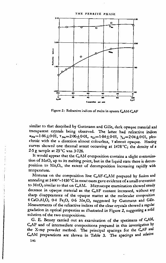
Figure 2: Refractive indices of mclrs in s>-stcm C,AM-C,AF
similar to that described by Guttmann and Gille, dark opaque material and transparent crystals being observed. The latter had refractive indices <XNa=l-86±0-01, Tn,=2-06±0 01, «Li=l-84±0-01, YU=2-O4±OO1, pleo- chroic with the x direction almost colourless, T almost opaque. Heating curves showed one thermal arrest occurring at 1478 °C; the density of a 2-5 g sample at 25 °C was 3-728.
It would appear that the C,AM composition contains a slight contamination of MnOj up to its melting point, but in the liquid state there is decomposition to MnjO,, the extent of decomposition increasing rapidly with temperature.
Mixtures on the composition line C,AF-C^AM prepared by fusion and annealing at 1400 ^-HSO CC in most cases gave evidence of a small conversion to MnOz similar to that on C,AM. Microscope examination showed steady decrease in opaque material as the C,AF content increased, without any sharp disappearance of the opaque matter at the molecular composition 4 CaO.AljOj 0-4 Fe^O, 0-6 Mn2O3 suggested by Guttmann and Gille. Measurements of the refractive indices of the clear crystals showed a regular gradation in optical properties as illustrated in Figure 2, suggesting a solid solution of the two compositions.
G. E. Bessey carried out an examination of the specimens of C,AM, C4AF and of intermediate compositions prepared in this investigation by the X-ray powder method. The principal spacings for the GAP and C,AM preparations are shown in Table 3. The spacings and relative

table 3: Interphnar spacings of the compositions 4CaO.Al2O3.Fe2O3 and 4CaO.Al2O3.Mn2O3
vs»« very strong; s = strong; m ■ moderate; w •» weak
4CaO.Al2O,.Fe2O, 4 CaO.Al2O3.Mn2O3
dhidA
Intensity Relative
dhkl A
Intensity Relative
3-64 w3-07 w
2-91 s 2-93 m2-77 5 2-72 m263 V S 2-63 vs215 m 213 m2045 s 2-070 m1923 s 1-883 s1-861 m 1-849 m1-805 s1-735 w
1-706 w1-663 w
1-569 s 1-555 m1-527 s 1-511 81-458 w 1-452 w1-420 w 1-421 w1-385 m 1-378 w1-338 w1-320 m 1-326 m1-209 w 1-195 w1-158 w 1-183 w1-131 w 1-124 w1 103 w 1-102 w1-075 w 1-069 w
1.026 w1-001 w 1007 w
0-991 w
intensities of the two are closely similar. A comparison with the spacings of C,A and CaO indicates the absence of any observable proportion o at e of these compounds. MnP, and MnjO, were also examined an spacings of their mote intense lines determined. Comparison wi pattern of QAM again indicated the absence of any observa e propo of these free oxides in the QAM preparation.
Table 4 shows the principal spacings of the two end members and t intermediate compositions in the QAM-QAF series. The wea er es

table 4: Interplanar spacings measured in melts of composition intermediate between those of the compositions 4CaO.AliO1.Fe2Oj 4CaO.Al2O3.Mn2O}
100%c4af
70%C.AF30%
C.AM
50%C,AF50%
C,AM
30%C,AF70%
C,AM
20% C.AF 80%
QAM
10% C,AF 90%
QAM
100%QAM
2-91 2-93 2-93 2-93 2-92 2-92 2-932-77 2-75 2-74 2-75 2-73 not
measured2-72
2-63 2-64 2-64 2-63 263 2-62 2-632-045 2-055 2-050 2-060 2-065 2-060 2-0701-9231-861
1-916 1-901 1-890 1-895 1-891 1-883
1-805 1-843 1-831 1-836 1-845 1-856 1-8491-569 1-567 1-562 1-555 1-554 1-554 1-5551-527 1-524 1-517 1 517 1-516 1-503 1-5111-385 1-375 1-373 1-383 1-383 1-376 1-3781-320 1-327 1-322 1-320 1-326 1-321 1-3261-158 1-172 1-171 1-173 1 171 1-178 1-1831-131 1-128 1-126 1-120 1-128 1-125 1-1241-001 0-999 0-998 not
measured1-000 not
measured1-007
not shown but all the lines obsen-ed in every case correspond with lines found for C,AF or were intermediate in position between those of C,AF and C,AM compositions. There were no lines unaccounted for as would be the case if only limited solid solution occurred. The evidence of the X-ray examination offers then strong confirmation of the conclusion from the work noted above that compositions from C,AF to C«AM lie within a zone of complete solid solution.
The experimental work described was carried out in the period 1934-36, i.e. before investigations had shown that C, AF was not the end member of the CjF—(CjA) solid solution series. Evidence of the possibility of forming C»A2Nf, similar to C*A 2F has not been available although some work on this point is at present in progress at the Building Research Station, h restarting this work an opportunity was taken to check the refractive index data given in Figure 2 by micro-reflectivity tests, as described in another paper in this symposium. Polished sections of the powders set in resin showed no evidence of a difference in phases such as might be suspectea from the appearance of opaque and clear material in transmitted g *• This confirms the view that the opaque appearance is caused by overbppmg crystals. Calculation of refractive indices from the reflectivity data s ow

good agreement with the results given in Figure 2, obtained by direct determination in transmitted light.
REFERENCES
1. guttmann, . and GILLE, F. Zemtnl. 1929. Vol. 18. pp. 500-506, 537-541,*570-574.
2. coffin, and mussgnug, g. Zement. 1933. Vol. 22. pp. 218-221, 231-234.3. PARKER, T. w. and ROBINSON, p. t. Journal oftie CfcemicaZ Society. 1929. p. 1106.
F. GILLE1 am very glad that Dr. Parker has now published new investigations on
the question of replacing of Fe2Oj by Mn2O3. He states that this question is merely of academic interest. However, for some of our plants, the question is also of importance in practice, because they are using as raw material blastfurnace slag which has a considerable manganese content. I believe that the difference between his findings and my own is due to the fact that I started with MnO2 containing K2O as impurity and I have shown that, starting with a 1:1 mixture of CaO and MnO2 only, completely opaque CaMnOj is easily obtained.
A later X-ray investigation showed that the X-ray spectrum of CaMnO, could be interpreted as arising from a structure of the perovskite (CaTiO,) lattice tj-pe. The X-ray photographs are no longer available, but I remember that the rest of the powdered samples is still available and I intend to check on the statements I made twenty-three years ago.
G. malquori and v. ciRiLLl (ftittborf chsurt)It appears from what Mr. Swayze has said that the reasons for our doubts
about the solid QA.F being a definite compound, are not completely evident. Our considerations are entirely of a crystallographic character. It is impossible conveniently to arrange the atoms of such an hypothetical compound in an elementary cell, which must be comprehensively indicated by the formula Ca,Me<ivMe,,Ö..o. \X'e must, therefore, suggest that the formula proposed by Mr. Swayze only represents the molecular ratio at which the three oxides are present in the solid solution in conditions very near to saturation. The X-ray powder photographs show indeed, that the substitution of iron atoms with aluminium atoms can exceed, if only very slightly, the ratio 2:3.
The material examined was obtained from the solutions of the corresponding aluminium, iron and calcium nitrates by drying, baking and sintering the oxides at temperatures slightly below and up to the melting point The material was re-ground between the different processes and wc have carefully tested the products obtained by means of chemical analysis
149

and microscopic investigations in order to ascertain that they confirm exactly to the formula : 2 CaO.(Fe.A1)2O3.
Concerning C4AF, we think that it is quite improbable that C,AF is to be considered as an independent compound.
If this were so, we should have to admit, that the iron atoms and aluminium atoms of the brownmillerite all possess well-defined co-ordination, without any possibility of changing octahedral positions with tetrahedral ones. On the contrary, such a possibility does exist for the solid solutions of intermediate compositions and it appears therefore more reasonable to postulate that the distribution of the positions of the iron and aluminium atoms occurs in a statistical way throughout the series.
Such a standpoint is well in accordance with the fact that the variation of the lattice constants follows linearly the number of the iron atoms substituted; similar considerations are to be inferred from observations of the data for the magnetic susceptibility and that for the heats of dissolution determined by Newman. If brownmillerite were a term with a particular structure, the plotted diagrams would not show a linear course. A further explanation of this problem might be obtained from a more precise estimate of the intensity of the reflections. This would require, however, the obtaining of more perfect crystals than those which were available for our experiments.
\X'e agree with Mr. Swayze that there are some particular cases in which it will not be true that C3A should no longer appear as a separate phase for ratios of ALOjiFe.-Oj greater than 0-64, but only' when the above ratio is higher than approximately l-4.
As to the observations of Dr. Midgley concerning the interplanar spacings which we have indicated for the dicalcium ferrite and those which have been published formerly by Hansen and Brownmiller, we can affirm that more recent investigations made with a spectrometer with a Geiger counter have given values slightly higher than those previously announced by us.
For die (002), (200) and (202) lines, we obtained the following results:
hU sin* fl d002 01198 2-791 (^-5-582)200 01314 2-664 (ae=5-328)202 0-2493 1-934
We must, however, point out that the experimental value of d for the (2>2) line is slightly higher than the theoretical value, calculated by means of the 0 angles for the preceding lines.

[61
The alkali phases in Portland cement clinker
TERRY F. NEWKIRK
SUMMARY
A review is given of previous work on the alkali-clinker systems and of the various forms in which Na2O and K2O may occur in Portland cement clinker. The importance of the formation of the alkali phases as they affect the burning of cement mixtures and the constitution of clinker is discussed. During burning the alkalis react preferentially with the available SO, to form alkali sulphates. Alkalis in excess of the molar equivalent of SO, react with the major clinker components to form NC,A, or KC2JSl2. The latter reactions alter considerably the potential compound composition of the clinker and may have a significant effect on the properties of the cement. For certain compositions, the reactions of the alkalis may cause the formation of free CaO as an equilibrium product. Equations which take into account the formation of the alkali phases are presented for use in computing the potential compound composition of clinker-type mixtures.
introductionIn the period following Rankin and Wright's11 classic study of the system
CaO-Al2O,-SiO2, data on other systems pertinent to Portland cement technology gradually evolved. Some of the studies included one or both of the alkalis, Na2O and K2O. The results of these investigations have shown that, although the percentages of K2O and Na2O in commercial clinker are small, diese oxides may have a very significant effect on the reactions which occur in die kiln and on the nature and proportions of the phases which appear in the clinker., Stant°nz? first reported the possibility of a deleterious reaction
cen a relatively large amount of alkalis in cement and certain siliceous ^gtegates, additional interest has developed, particularly in the United toes, in the role of the alkalis in Portland cement chemistry. In view of the
^IrCQt Gierest in the reactions of the alkalis in Portland cement, it is impor- 2t this time to discuss the alkali phases in clinker with regard to the

THE ALKALI PHASES IN PORTLAND CEMENT CLINKER
nature of these phases, their effect on the potential compound composition of the clinker, and their influence on the burning of cement mixtures.
THE NATURE OF THE ALKALI PHASES
Clinker phases containing NajO in absence of KjO. Postulations on the effects of the alkali phases in Portland cement clinker were often made in the early literature,11 and by 1930 it had been ascertained1* that small additions of Na2O to mixtures of CaO, A12O, and SiO, brought about a lowering in the temperature* of first liquid formation from 1455 ° to 1430 In the presence also of FCjOj and MgO, the temperature was further lowered to 1280
* All temperatures are in degrees C.
Systematic investigation of phase relations in systems involving the alkali oxides in regions related to Portland cement was initiated at the laboratories of the Portland Cement Association Fellowship in 1932. In that yew Brownmiller and Bogue* published the results of a study on a part of the system Na^O-CaO-AhO, through the secondary system CaO-NA-CA. This system proved to be one of outstanding importance because within it were found two ternary compounds one of which, NC, A„ has since been demonstrated to be one of the principal soda-bearing compounds of cement clinker.
In the system GtO-NA-CA, the primary-phase region of NC,A, adjoins that of C,A. The ternary compound dissociates at 1503° into CaO and liquid. Where NCeAj is the primary phase, it occurs as well-formed polyhedrons, often with hexagonal or octagonal outline. Twinning occurs on slowly cooled specimens. The optical properties of NC,A„ together with those of other alkali compounds to be discussed, are shown in Table 1. The X-ray diffraction pattern is very similar to that of C,A although it was demonstrated that NC,Aj is not an addition product of Na,O and C,A. It is convenient to picture the ternary compound as consisting of three molecules of CjA h which one molecule of CaO is repheed by one molecule of Na2O.
Although early work showed no indication of any solid solution between NC,A, and C,A at the liquidus, it was later found1* that at temperatures below liquid formation a solid solution formed having optical properties intermediate between those of the end members.
In the system NajO-CaO-SiO1, three ternary compounds were reported21 but were all far removed from the region of Portland cement. It was observed by Greene1* that at high temperatures Na2O in some form enters into solid solution with x-C2S thus preserving the high-temperature form. In his experiments it appeared necessary that either A12O, or Fe2O, be present in small amounts. On slow cooling of the solid solutions to about 1100®, the beta form of C2S appeared and within the crystals were noted occlusions of e soda phase, formed by exsolution. The temperature of the inversion «-QS to j3-C2S was lowered from 145601* to 1175o-1180°.
The above experiments suggest that a similar preservation of «-C2S may

table 1: Optical properties.of alkali compounds
Compound Indices ±0-003 Character Optic angle
NQA, ot= 1-702,t= 1-710 Biaxial negative
Medium
NajSO, (thenardite) a = 1-471, ß = 1-4777 = 1-484
Biaxial positive
2V= 84°
3K2SOf.Na,SO, <x = 1-490, 7 = 1-496 Uniaxialpositive
K2Sp4-NazSO4 solid solutions (high temperature forms)
Vary with composition Mean index = 1-480-1.500
Uniaxial negative
KjSO, (arcanite) e = 1-493, ß = 1-494, 7 = 1-497
Biaxial positive
2V = 67°
a = 1-695, 7 = 1-703 In presence of Fe2O,: s = 1-713, y = 1-722
Uniaxialpositive
accomplished in commercial clinker. It was pointed out,14 however, that under ordinary conditions of production, the CZS of cement clinker may mvett to the beta form to different degrees, and different amounts of alkali phase be occluded by exsolution. This may account for the various appearances otjS-C£ that have been observed in clinker,” and likewise may determine the behaviour of the resulting C2S phase, that is, the rate with which the CzS reacts with CaO to form CjS, and the rate of hydration of the C2S phase.
The stability of the compound NQA, in the system containing silica was established by Greene and Bogue” who studied that portion of the quaternary system NazO-GiO-AlzO>-SiO1 lootted ivithin the secondary system CzS-CaO-NA-Al2Oj. They delineated the boundaries of the NC,A, primaryphase region in this system and located the important invariant point at »hich C,S, QS, C,A and KC.A, can exist in equilibrium with liquid. The composition and temperature for this and other invariant points in some of the alkali systems important to Portland cement chemistry appear in Table 2.
A survey of the system NijO-CaO-ALOj-FejO, by Eubank and Bogue11 showed that the compound NC,A, also appears as a primary phase in the tron^ontaining system. On the other hand, in similar explorations of a portion of the system Na2OX^O-Fe2OrSiO2,* ! it was found that no ternary tonqiounds of NazO exist in the low-NazO region of this system. It was not 'totil Eubank11 completed an investigation of the high-lime portion of the system Na2O-CaO-AlzO,-Fe2O,-SiOz, however, that the possibility of the tiutena of a quaternary or quinary compound of soda containing both SiO, 1 , Fc2O, was eliminated. His work showed that NC,A„ C,A, C,S, C2S and
solid solution may exist in equilibrium with liquid at about• Mixtures that fall within the system NC,A)-CJA-C< AF-C3S-C2S, and
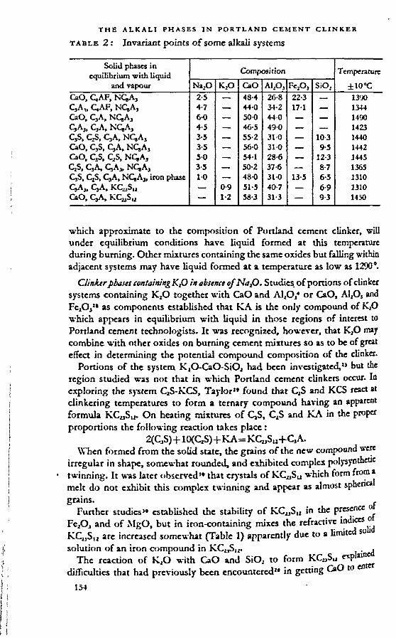
THE ALKALI PHASES IN PORTLAND CEMENT CLINKER
table 2: Invariant points of some alkali systems
Solid phases in equilibrium with liquid
and vapour
Composition Temperature
ilO’CNa2O K2O CaO ai2o3 f=2o, SiO2CaO, C.AF, NC,A3 2-5 — 48-4 26-8 22-3 — 1390
C.AF, NQA, 4-7 — 440 34-2 17-1 — 1344CaO, C,A, NC,A3 60 — 500 44-0 — — 1490c3a3, c3a, nc,a3 4-5 — 46-5 49-0 — — 1423C,S, QS, CjA, NQAj 3-5 — 55-2 31-0 — 10-3 1440CaO, CjS, C3A, NQAj 3-5 —- 56-0 31-0 — 9-5 1442CaO, C3S, C2S, NCgA, 50 — 54 1 28-6 — 12-3 1445QS, CjA, QA,. NC.Aj 3-5 — 50-2 37-6 — 8-7 1365CjS, CjS, C3A, NCgAj, iron phase 10 —. 48-0 31-0 13-5 6-5 1310
CjAt — 0-9 51-5 40-7 — 6-9 1310CaO, CjA, KCyS,, — 1-2 58-3 31-3 — 93 1450
which approximate to the composition of Portland cement clinker, will under equilibrium conditions have liquid formed at this temperature during burning. Other mixtures containing the same oxides but falling within adjacent systems may have liquid formed at a temperature as low as 1290'.
Clinkerpbases containing KtO in absence of NajO. Studies, of portions of clinker systems containing KäO together with CaO and AljO,4 or CaO, AI2O5 and Fc2O3n as components established that KA is the only compound of K2O which appears in equilibrium with liquid in those regions of interest to Portland cement technologists. It was recognized, however, that K,O may combine with other oxides on burning cement mixtures so as to be of great effect in determining the potential compound composition of the clinker.
Portions of the system K2O-CaO SiO2 had been investigated,25 but the region studied was not that in which Portland cement clinkers occur. In exploring the system C2S-KCS, Taylor2* found that C2S and KCS react at clinkering temperatures to form a ternary compound having an apparent formula KCUSU. On heating mixtures of 0,5, CZS and KA in the proper proportions the following reaction takes place :
2(C3S)+10(C1S)+KA=KCuSu+CjA.When formed from the solid state, the grains of the new compound were
irregular in shape, somewhat rounded, and exhibited complex polysynthetic twinning. It was later observed1* that crystals of KCySu which form from a melt do not exhibit this complex twinning and appear as almost sphen grains. ,
Further studies1* established the stability of KC2)SU in the presence o FejOJ and of MgO, but in iron-containing mixes the refractive indices o KCWSU are increased somewhat (Table 1) apparently due to a limited so solution of an iron compound in KC^Sj,. . .
The reaction of KaO with CaO and SiO2 to form KC2)S12 exp difficulties that had previously been encountered2* in getting CaO to en

into combination with other components in certain mixtures in which K2O was substituted for part of the CaO. The presence of K2O causes extensive changes in the potential compound composition resulting in greatly increased CjS:C2S ratios. Wlien the potential C2S becomes zero, CaO becomes an equilibrium product.
Because of its simihrity in optical properties with those of the calcium silicates, KCuSs2 would not ordinarily be distinguished from C2S or C3S during the microscopic examination of commercial clinkers. Brown3 reported in 1948, however, that he had observed a phase in high-alkali commercial clinker which he stated “ appears to be C23KSU."
The studies by Brownmiller4 and Taylor2’- 30 have established KC23S12 as the stable compound of potash in K2O-CaO-MgO-Al2Oj-Fe2O2-SiO2 mixtures approximating the composition of Portland cement clinker. Since Greene14 found from preliminary experiments that K2O and Fe2O3, and probably KZO and A12O, in certain proportions may enter into solid solution with’k-C2Sr it is likely that this solid solution or a potash-bearing phase precipitated as inclusions in the C2S grains may also appear in commercial clinkers.
Ciinfctrj confining, NaP and K2O. Both Na2O and K2O are present in most commercial clinkers so that the possibility exists that these alkalis may react with other components during burning to form new compounds containing both soda and potash. Comparatively little information is at present available on clinker-systems containing the two alkalis, but limited studies have been made of selected mixtures.
As a part of their investigation of the “ prismatic dark interstitial material ” in Portland cement clinker, Insley and McMurdie11 studied K20-Na20-Ca0- AljOj-FejOj-SiO! mixtures. They associated the presence of the alkalis in these mixtures with the formation of the prismatic phase which they concluded was probably a compound of lime, alumina and the alkalis with a small amount of C4AF in solid solution. A comprehensive treatment of this subject is given by Insley in another paper in this symposium.
In a recent investigation24 we noted that the compounds NC,A, and KCySu may occur together as products of equilibrium crystallization in certain clinker-tj-pe mixtures. It was realized, however, that a certain amount of solidsolution may occur between these compounds and other clinker phases.
Clinkers containing alkalis n itb S0v Since most commercial clinkers contain small amounts of SO, and other acidic oxides, it was recognized by Taylor2’»33 that the compounds KC21Su and NC,A, may react with these minor components during burning to form new compounds. This hypothesis was confirmed in subsequent investigations.1»* 24» 39
Before the identification of alkali sulphates in clinker, SO, was customarily considered as combined with part of the CaO as CaSO,. Brown2 observed in
ust taken between a kiln coating and underlying brick, and subsequently ln c^cr» a low-index phase that was tentatively identified as an alkali »

THE ALKALI PHASES IN PORTLAND CEMENT CLINKER
sulphate. Later Taylor3® found a phase identified as K2SO, in a number of commercial clinkers. It was noted from a study of the chemical compositions of a number of commercial clinkers that, in general, there is an increase in the K2O content of the clinker as the amount of SO3 increases. Usually the amount of K2O in the clinker is in excess of that required to form K2SO4 from the available SO3.
Taylor explained the presence of K2SO4 in clinker by his discovery that KC^Su reacts with CaSO4 at clinkering temperatures according to the equation:
KC23Sl2+CaSO4-*12(C 2S)+ K2SO,.The K2SO4 which forms is stable in the presence of (2,5, C2S, C,A and C4AF, and immiscible with the clinker melt.30
In a few subsequent experiments,3* he observed that a solid solution of Na2SO4 and K2SO4 appeared upon heating certain mixtures of Na2SO4, KCS and C2S. On the other hand, a phase identified as K2SO4 occurred in several Na2O-K2O-CaO-SiO2-SO3 mixtures of high K2O:Na2O and K2O:CaO ratios. The manner in which soda was combined in the mixtures was not determined. These experiments indicated that under certain conditions either Na2SO4 or a mixed alkali sulphate might be formed in clinker. It remained for future workers to define these conditions.
More recently, we established that the compound NC,A3 also is unstable when heated in the presence of SO,.,0>24 The reaction of the soda compound with CaSO4 may be expressed by the equation :
NC,A3+CaSO4=Na2SO4+3C3A.The sodium sulphate produced in the reaction is stable in the presence of the major clinker components and immiscible with the clinker melt.10* ”*31
In a recent study,24 we investigated the composition of the alkali-sulphate phase that forms on heating mixtures of KCySu, NC,A, and CaSO, in various ratios. It was determined that, if both alkalis are present, together with SO„ an alkali sulphate is formed that contains both K2O and Na2O. The proportions of the tvro alkalis in this sulphate phase vary with the composition of the mixture. For mixtures in which the number of moles of SO, available is less than the total number of moles of alkalis, there is » tendency for the alkalis to combine with the entire quantity of SO, in the approximate molecular ratio K2O:Na2O=3 subject to the availability of the three reactants in the mixture. Any excess of Na2O and K2O may react with other components to form the compounds NC,A, and KCaSy respectively.
Figure 1 shows the relationship between the composition of the alkah (R2O) and that of the alkali sulphate ,(R2SO4) for clinker-type mixtures having molecular ratios R2O:SO3 of 1, 2 and 3. The curves which appear as solid lines were based on compositions determined experimentally. The experimental data provided the basis for deriving empirical equations for calculating the approximate compositions of the alkali sulphate in commercial clinkers from their oxide compositions. These equations appear in Table 3. The curves which appear as dashed lines in Figure 1 were plotted from values

table 3 : Procedure for calculating the approximate composition of the alkali sulphate in Portland cement clinker
(1) Calculate r (the R2O:SOs molecular ratio in the cement mixture)(0-8500 K2O+1-2915 Na2O) r------------------- -----
(2) Calculate Kg (the mole fraction of K2O in the total alkali of the cement mixture) (0-8500 K2O)
r(SO3)The formulae for the oxides in these two equations represent the weight percentages of these oxides io the clinker. ‘
(3) Calculate K, (the mole fraction of K,SO4 in the sulphate) using the appropriate equation below as determined by the values for r and Kc:
If r is greater than 1-0
If r is equal to or less than 1-0, use the equation
and Kc lies betweenÄ . 0’75 0 8c------
r, use the equation
and Kc is equal to or lies between 0-75 (r-0-25)
r r,use the equation
and Kc lies between(r-O-25)—----- &1-0
use the equation
K, = rKc K, = 0-75 K, = 1-r (UKc)
Figure 1; Relationship between the composition of the alkali and that of the alkali sulphate in cement clinker for mixtures with molecular ratios R2O: SO, equal to 1, 2, and 3.
c^culated from the empirical equations. For the majority of commercial dmkets, the calculated mole fraction (KJ of K2SO4 in the alkali sulphate is 0-75. This is indicated by the fact that the slopes of the composition curves or mixtures with RZO:SO, ratios much greater than unity are nearly zero over
157

THE ALKALI PHASES IN PORTLAND CEMENT CLINKER
table 4 : Equations for the calculation of the potential phase composition of clinker-type mixtures, assuming complete equilibrium crystallization to yield only the compounds indicated
A. Mixtures baring KjOxSO) molecular ratios equal to or less than 1 -0(1) Systems including C3S, CjS, C3A( and C,AF as components
C3S = 4 0710 CaO - 6-7187 A1_,O, -1-4296 Fe2O3 - 7-6024 SiO2 - 2-8516 SO3 +3-6826 NaiO+2-4238" K2O
CjS = 5-0683 Al2O3+l-0784 Fc2O3+8-6024 SiOj+2-1511 50,-2-7780 NaX) -1-8284 K2O-3-0710 CaO
C3A = 2-6504 A!2Oj -1-6918 Fe2O3C,AF = 3 0430 Fe,O3CaSO, = 1-7005 S03 - 2-1960 Na2O -1-4453 K2ONa2SO4 = 2-2914 Na2OK2SO4 = 1-8500 K.O
(2) Systems including CaO, C,S, C3A and C4AF as componentsFree CaO = CaO-1-6504 A12O3-0-3512 Fe2O,-2-8012 Si02-0-7005 SO,
+0-9046 Na2O+0-5954 K,OC3S = 3-8012 SiO2C,A = 2-6504 A12O, -1-6918 Fe2O3C4AF = 3-0430 Fe.O,CaSO4 = 1-7005 SO, - 2-1960 Na2O -1 -4453 K2ONa2SO4 = 2-2914 Na2OK,SO4 = 1-8500 K2O
B. Mixtures baring RjOiSO, molecular ratios greater tbatt 1-0(1) Systems including C3S, C2S, C,A and C,AF as components
C,S = 4-0710 CaO - 6-7187 A12O,-1+296 Fe2O,- 7-6024 SiO2- 2 8516 SO, +3-6826 Na,O+2-4238 K2O
C2S =. 5-0683 Al2O,+l-0784 Fe,O,+8 6024 SiO2+2 1511 (12 K,+l) SO,- 2-7780 Na2O - 23-769 K2O - 3-0710 CaO
C3A = 2-6504 A1..O, -1-6918 Fe2O,+10-124 (1 - KJ SO, -13-074 Na,OC,AF - 3-0430 Fc2O,NQ,A3 = 13-170 Na2O -10 198 (1 - KJ SO,KQ3S„ = 22-345 K,O - 26-290 K, (SOJNa2SO4 = 1 -7743 (1 - KJ SO,K2SO4 = 2-1765 K, (SOJ
(2) Systems including CaO, C3S, C,A and C,AF as componentsFree CaO - CaO -1 -6504 A12O, - 0-3512 Fe2O, - 2 8012 SiO2 - 0-7005 (12 K.+1)
SO,+0 9046 Na2O+7-7399 K,OC,S = 3-8012 SiO2+34-219 K, (SOJ - 29-085 K ,OC,A ■ 2 6504 AI2O, -1 -6918 Fe2O,+10 124 (1 - KJ SO, -13074 Na2OG.AF = 3 0430 Fe,O3NC,A, - 13-170 Na2O - 10-198 (1 - KJ SO,KC„SI2 = 22-345 K,O - 26-290 K, (SOJNa2SO4 = 1-7743 (1 - KJ SO,K,SO4 • 2-1765 K, (SOJ
The formulae represent weight percentages of the corresponding compounds in die mixtures. In using the equations in part B (those for mixtures having R2O:SO, molecular ratios greater than 1-0) the value of K, should be calculated by the method outlined m
Table 3.

a wide range of total alkali compositions at a mole fraction of K2SO4:R2SOt of about 0-75. '
It was observed24 that KCjjSu and NCgAj appear together as products of complete equilibrium crystallization, along with the alkali sulphate, in certain mixtures having molecular ratios R2O:SO3 greater than unity. This observation, with the data on the composition of the alkali sulphates in clinker-type mixtures and the results of the previous work by other investigators of the alkali-clinker systems, provided the basis for the derivation of equations for calculating the potential compound composition of K20-Na2O-CaO-Al.OrFe2OrSiO2-S03 mixtures approaching the composition of Portland cement clinker. Only two sets of equations appear in the reference, namely the equations for the alkali systems which include C3S, C2S, C3A and C,AF as components. However, the compositions of some commercial clinkers fall within adjacent secondary systems in which free CaO may exist in equilibrium with €,5, C3A, an iron phase, and liquid together with the alkali and SO, phases. Two additional sets of equations have therefore been derived by the method of Dahl6 for the latter group of systems because of their importance. The compositions of a few commercial clinkers may also fall within other secondary systems; hou-ever, there does not appear tobe sufficient information available on these systems to justify their inclusion at this time. The four sets of equations, which appear in Table 4, are made use of in the calculation of potential compound compositions which are involved in the discussion to follow.
EFFECT OF THE ALKALI PHASES ON THE COMPUTED COMPOSITION OF CLINKER
The oxides K2O and Na2O although ordinarily present in only small amounts in commercial clinkers, may have a very significant effect on the potential compound composition of the clinker. This is due to the fact that each of the alkalis may enter into combination with major components of clinker to form new compounds in which the percentages of the alkali oxides are low.
Figures 2A and 2B illustrate the effect of additions of K2O and Na,O on the potential quantities of the major clinker compounds which will be formed in the event of complete equilibrium crystallization of a CaO-Al2O3- FeA-SiO, mixture having the approximate composition of Portland cement clinker. The potential compositions indicated by solid lines in the figures have been calculated from the equations given in Tables 3 and 4 which take into account the reactions of the alkalis with the major clinker components. Those represented by dotted lines were calculated by the method1 outlined b ASTM Standard Specification C150-49 in which the state of combination of the alkalis is not considered in obtaining the potential compound composi- tton. Figure 2A (solid lines) shows that the addition of only 1 per cent by bright of K2O to the CaO-AlArFcAj-SiO, mixture causes the formation °f 22-3 per cent of KC2JSt2, decreases the potential C2S by 23-8 per cent

Perc
ent of
com
poun
d Ind
icat
ed
Figure 2: Effect of additions of Na2O and KjO on the potential compound composition of a dinker-type mixture having an oxide composition: CaO 66-0 per cent, ALO, 7-0 per cent, Fe2Oj 3-0 per cent, SiO2 24-0 per cent. Solid lines represent the results of computations which indude the effects of the alkalis (Table 4). Dotted lines are for compositions computed by the method prescribed in A.S.T.M. Standard Specification C 150-49.
Figure 3: Diagrams illustrating a change in system that may result from variations in KjO, Na2O and SO, in the dinker. In A, the R2O increases from 0 to IO per cent in the absence of SOj. In B, the R2O remains at 1-0 per cent while the SO, increases from 0 to 1-0 per cent. Solid lines indicate (2,5; dashed lines indicate free CaO. Each curve is designated to indicate the composition of the R2O fraction in the dinker. The original composition of the dinker calculated to the four components was: CaO 69*4 per cent, A12O, 6’5 per cent, Fe2O, 2-5 per cent, SiO, 21-6 per cent.

and increases the potential C3S by 2-4 per cent. The computed percentages of CjA and C4AF remain unchanged by this addition. Similarly, in Figure 2B, the addition of 1 per cent of Na2O to the CaO-Al2Oj-Fe2O3-SiO2 mixture results in the formation at complete equilibrium crystallization of 13-2 per cent of NCgA3, decreases the potential C3A by 13-1 per cent and the potential CjS by 2-8 per cent and increases the potential C3S by 3-7 per cent. The computed percentage of QAF again remains constant during the addition of alkali to the mixture. Since the ASTM method of computing potential composition does not take into account the formation of the alkali phases, the percentages of the clinker compounds computed by this method (dotted lines) are relatively unchanged by additions of KZO or Na2O.
For certain compositions, relatively small increases in the alkali content of the mixture, particularly of K2O, may cause the composition of the clinker to shift to one of the systems in which CaO is a product of equilibrium crystallization. This change is illustrated in Figure 3A. The addition of only slightly more than 0-3 per cent of K2O to the mixture reduces the potential percentage of QS to zero. With further addition of K2O, free lime appears in the clinker. The percentage of this constituent increases with increasing KjO content until at 1 per cent K2O, the clinker may conuin about 5 per cent of free lime. Sodium oxide is not as effective as K2O in reducing the potential QS. Figure 3A shows that for the given clinker composition, no free lime is produced by the addition of 1 per cent Na2O alone. The difference in the action of the two oxides results from the composition of the alkali phases which are formed. Sodium oxide additions reduce the potential C2S only indirectly by releasing CaO in the reaction of Na2O with C3A so that more C3S and less C2S are formed. Potassium oxide additions reduce the potential QS directly by the combination of K2O with C2S to form KCI3Sit as well as indirectly by releasing CaO to combine with part of the C2S. Since both alkalis are usually present in clinker, the curve in Figure 3A for additions of equal percentages of Na2O and K2O is probably more nearly representative of the influence of the alkali phases on the constitution of the average clinker.
In the presence of SO3, the alkalis react preferentially with this component to form alkali sulphates. This reaction reduces the amounts of K2O and Na2O available to form KC2,SI2 or NQA, so that the effect on the potential compound composition of the dinker, as shown in Figure 3B, is similar to that produced by lowering the alkali content of the mixture.
Figure 4 illustrates the effect of additions of SO3 on the computed compound compositions of clinker-t}-pe mixtures containing, in the three diagrams, different amounts of total alkali; With no SO, present, the potential quantities of C2S and C,A are at a minimum, and those of C,S, KC2,S12 and NQA, are at a maximum, at the highest alkali content (Figure 4Q. pie addition of increments of SO, to the mixtures causes a gradual increase M the computed percentages of C2S and C,A and a decrease in the percentages °f QS, KCOSU and NC,A, until, with a total addition of 1 per cent SO„ die potential compound compositions of the three mixtures are nearly

Figure 4 : Effect of additions of SO3 on the potential compound composition of clinkertype mixtures containing Na_,O and K2O. All mixtures have a base composition of CaO 66-0 pct cent, Al.Oj 7-0 per cent, Fe3O3 3-0 per cent, and SiOj 24-0 pet cent to which have been added :
A. Na3O 0-2 per cent and K2O 0-2 per centB. Na2O 0-3 per cent and K2O 0-3 per centC. NajO 0-4 per cent and K2O 0-4 per cent
(COSO4)
Figure 5 : Diagram showing the final alkali and SO, products of equilibrium crystallization of clinkers containing Na2O, KjO and SO, (Dahl).The formulae in parentheses represent the compounds which are form«! by the reaction of the Na2O, K,O or SO, with other components of clinker.

identical and very close to that of the alkali-free mixture (see values for 0 per cent alkali in Figures 2A or 2B).
The shift of system which causes the release of free CaO as an equilibrium product in certain clinkers due to the formation of NC8A3 and KC23Si2 may likewise be prevented by increasing the amount of SO3 in the mixture so as to form alkali sulphates rather than the alkali-aluminate or alkali-silicate phases. Figure 3B shows that the free lime produced by the addition of 1 per cent total alkali is reduced by further additions of SO3 until C2S again becomes an equilibrium constituent of the clinker.
Dahl7 has pointed out that the four classes of compositions given at the bottom of Table 3 for determining the mole fraction of K2SO4 in the sulphate phase actually represent four different types of system in which the composition of Portland cement clinkers may fall with regard to their Na2O, K2O and SO, contents. These four types, numbered from left to right in the order in which they appear in Table 3, are represented in Figure 5. By expressing the percentages of Na2O, KZO and SO, in clinkers in terms of a constant total for these three components (for example, a total weight percentage of 100 per cent), the final alkali and SO, products of equilibrium crystallization may be obtained directly from the diagram. Thus for compositions in system type 3, the final alkali and SO, products are NCaA„ 3K2SO4.Na2SO4 and KCzjSlz.
The clinker systems which represent the different types in Figure 5 are not ternary. These tj'pes are illustrated by the following four systems for clinkers composed of C,S, C2S, C,A and C4AF (together with the alkali and SO, compounds):
1. C,S-C2S-C,A-C4AF-CaSO4-Na2SO4-K2SO42. CjS-CjS-C^-C,AF-NC,A,-Na2SO4-3K2SO. Na2SO43. C,S-C2S-C,A-C4AF-NC,A,-KC2,Sl2-3K2SO4.Na2SO44. C,S-C2S-C,A-C4AF-KC2,Su-3K2SO4.Na2SO4-K2SO4.
The above four systems differ only in the alkali and SO, compounds which will be formed as three of the final products of equilibrium crystallization.
During the process of manufacture of Portland cement clinker, the alkalis and SO, may vary from kiln to kiln and even from time to time within the same kiln. These variations may occur as a result of the irregular return of flue dust, of changes in the draught, temperature of the kiln, composition of the fuel, etc as well as of changes in the composition of the raw mix. As a result of the variations the composition of the clinker may shift from one system to another. The potential compound composition of the clinker will be considerably altered by each change of system.
Dahl7 had previously concluded on the basis of mathematical considerations that “ calculations of potential composition from average or composite analyses are sound only when the individual parts of the material are all in the same system.” He therefore stressed the importance of using the chemical analyses of “ grab samples ” rather than of composite samples of clinkers as the basis for calculating the potential composition of clinkers when consider-

ing the effects of the alkalis and SO3. A composite sample may contain clinkers in two or more systems, in which case the potential compound composition calculated from its chemical analysis will not be a true representation of the actual composition of the clinker. In Figure 5, for example, composite samples made up of equal amounts of compositions a and b will be judged from the chemical analysis to be at point xin system 2 so that the formation of CaSO4 will not be considered in computing the potential compound composition. Similarly, composite samples containing equal amounts of clinkers a and c will be judged to be in system 2 at jr even though neither of the two clinker compositions falls within this system.
The use of the equations in Table 4 for the rontint plant control of clinker compositions is not practicable at the present time for two reasons. In the first place, it has been shown that very small changes in the K2O, Na2O or SOj content of the clinker may produce very large changes in the amounts of C2S or CjA. Hence to hold to a fairly uniform C2S or QA content would require a constancy of K.O, Na2O and SO, in the clinker that is, at present, quite unattainable. In the second place, the purpose of controlled composition is controlled quality of the cement. But at the present state of our knowledge it is not possible to define the overall effects on the properties of a cement that would result from a conversion of C2S to KC2iSl2 or of CjA to NGA,.
EFFECT OF FORMATION OF ALKALI PHASES ON THE BURNING OF
CEMENT MIXTURES
The clinkering, prortss. There are three principal means by which the formation of alkali phases may affect the process of burning Portland cement clinker. First, the addition of Na2O or K2O to the system lowers the temperature at which liquid is first formed in the kiln and tends to increase the quantity of liquid present at a given temperature. Second, the alkalis react with the other components to form new compounds which do not occur in the alkalifree system. Third, the addition of the one or two alkali components to the alkali-free system causes shifting of the primary-phase boundaries so that the new mixture may even be located within a different primary-phase region from that of the alkali-free mixture.
Several investigators of the alkali systems’• ••• “• 1* have observed that the temperature of first liquid formation in mixtures having the approximate composition of Portland cement clinker is usually lowered by the addition of either Na.O or K.O to the alkali-free systems.
Other things being equal, a lowering of the temperature of liquid formation or an increase in the amount of liquid formed at any temperature accelerates the reactions between the clinker components. On the other hand, an increase in free CaO has often been observed2* upon the introduction o N’a.O or K.O to the mixture undergoing a burning operation. ,
An explanation-'* of the action of K.O in releasing free CaO during f°f mation of KC^S,, is indicated by the equation :
12 C2S - K2O= KC23Sl2+CaO.

The CaO released in this reaction may combine with the excess C2S, if any, to form CjS. The latter reaction, however, is sluggish, especially when the concentration of C2S is low. And since K2O lowers the concentration of C2S in the mixture as well as releasing free CaO, the difficulty of attaining complete combination increases with increasing percentages of K2O in the mixture.
Similarly, Na2O may cause the release of free lime during burning as illustrated by the equation :
3C3A4- Na2O=NC8A34- CaO.If sufficient C2S is available, the free CaO released by this reaction also combines with C2S to form C3S, but equilibrium may be difficult to attain.
As illustrated in Figure 2, an effect of the above reactions of the alkalis with the major components of clinker is to reduce considerably the potential quantity of C2S that would otherwise be formed. If the quantity of the alkalis is sufficiently great, there may not be enough C2S available to combine with all of the free CaO released in the formation of the alkali compounds. In that case free CaO will remain in the clinker as an equilibrium product of ciystallization.
As already pointed out, the addition of K2O or Na2O to an alkali-free system may have the effect of enlarging the CaO primary-phase region which also tends to make the complete combination of lime during the burning of mixtures containing one or both of the alkalis more difficult to achieve. The courses of crystallization of two mixtures having the same ratio of common components, but one of which also contains Na2O or K2O, will not be the same. Not only are the potential compound compositions of the two mixtures dissimilar, but also, in the event of arrested crystallization, the relative proportions of the major clinker phases and the amount and composition of the glass will be different for the two clinkers.
The volatilisation of alkalis in the kiln. During the burning of Portland cement clinker, a considerable proportion of the alkalis present in the raw mixture, particularly of K2O, is volatilized. Some of this is recondensed on the raw material in the cool end of the kiln, and some passes out with the products of combustion. In many instances the flue dust, which is high in alkalis and in sulphates, is collected and returned to the kiln as part of the kiln feed. In any case, an equilibrium is established between the concentration of the alkalis in the raw mixture and that in the clinker.
The tendency of K.O and Na2O to form certain compounds and solid solutions during the burning of cement mixtures raises the question as to whether it is better, from the standpoint of increasing volatilization during burning, for the alkalis tobe in combination with SO,or in compounds of the major clinker system. A finding of \X"oodsu that the addition of CaSO, to a cement mixture increased both the K2O and the Na2O contents of the clinker suggests that, during the burning of cement mixtures, both K2O and Na2O are more readily volatilized from the silicate and aluminate phases, than from the sulphates. Woods’ results show furthermore that additions

of CaSO4 to a cement mixture are more effective in causing the retention of KZO in the clinker than of NazO. This finding is in agreement with our conclusion24 that a KzO-rich alkali-sulphate phase is formed where composition limits permit during the burning of Portland cement mixtures.
RELATIVE WATER SOLUBILITY OF THE ALKALI PHASES ,The water solubility of the alkali phases in Portland cement clinker has
been the subject of a number of investigations’1 ”• 11 because of the possible effect of these constituents on the properties of cement products.
From the results obtained it may be concluded that the alkali phases hydrate rapidly, the sulphates going into solution almost immediately upon mixing the cement with water. Since on burning cement mixtures there is a tendency for the alkalis and SO, to form a sulphate phase in clinker having the composition 3K2SO4.Na2SO4, the initial amount of K2O which goes into solution will usually be greater than that of Na2O except for cements having very high ratios of total Na,O: total K2O. With the exception of the alkali sulphates the Na2O-bearing phases are apparently more soluble than those of K2O so that, as these Na2O-bcaring phases dissolve, the relative proportion of the two alkalis in solution changes in the direction of higher Na2O:K2O ratios. It also has been observed by Davis’ that the rate of release of Na,O in hydrating cement is slightly more rapid from crystalline clinkers than from glassy clinkers.
The rapid hydration of the alkali phases suggests the possibility that one or more of these may contribute to the development of early strength in cement specimens^ Experimental findings that dissolved alkali sulphates and hydroxides tend to accelerate both the initial and final set,20 and that dissolved Na2SO4 in the mixing water may contribute to the tensile strength of specimens at early ages1 are in agreement with this hypothesis.
SUMMARYA review of the available information on the alkali phases in Portland
cement clinker shows that the alkalis may appear in many different forms depending upon the composition of the mixture, conditions of burning, and rate of cooling. In K2O-Na2O-CaO-Al2O,-Fe2OJ-SiO2-SOJ mixtures approximating the composition of Portland cement clinker, the alkalis combine with the available SO, during burning to form an alkali-sulphate phase that contains both K2O and Na2O. \X"hcre the composition of the mixture permits, the alkalis appear in the sulphate in the approximate molecular ratio K20: Na,O=3.
Sodium oxide in excess of the amount in the sulphate may be present in the clinker as the compound NQA„ as a solid solution of NQA, in C,A, in solid solution with C,S or one or more of the other clinker compounds, as a soda-bearing phase in the form of inclusions in C2S, or as a component of the glass.
Potassium oxide in excess of the amount in combination with SO, may

appear in the clinker as the compound KC23S12, in solid solution with C2S or other clinker compounds, as a potash-bearing phase in the form of inclusions in CjS, or as a constituent of the glass.
In most commercial clinkers the amounts of K2O and Na2O present are in excess of the molecular equivalent of SO3 so that in addition to the sulphates both of the alkalis are likely to be present in other forms. A few commercial clinkers have molecular ratios R2O:SO3 equal to or less than unity. In these, the entire quantity of both alkalis will be combined as the sulphate.
The presence of the alkalis in the kiln lowers the temperature at which liquid is formed and by this action tends to accelerate reactions among the components of the cement mixture. The alkalis may, however, make it more difficult, or at times even impossible, to achieve complete combination of the CaO during burning due to their reaction with the major clinker components. For certain compositions, changes in system may result from fluctuations in the alkalis and in SO3 during burning so that free CaO becomes an equilibrium product in the clinker. Additional burning at higher temperatures will not remove this free CaO so long as the composition of the mixture remains unchanged. Other changes of system may be produced by fluctuations in the Na2O, K2O and SO3 contents which, although not causing free CaO to appear as an equilibrium product, may produce major changes in the potential compound composition of the clinker leading to non-uniformity in the product.
Changes of system caused by variations in Na2O, K2O or SO, can be detected by employing equations which take into account reactions among these oxides and of the alkalis with the major clinker components. The compositions ofclinkers having molecular ratios R2O:SO, equal to or less than unity may be considered for practical pürposes as coming within the system CaO- Al203-Fe2O3-SiO2. The equations for the four-component system may then be employed in the usual manner to obtain the potential compound composition.
The alkali phases in Portland cement clinker hydrate rapidly. The alkali sulphates dissolve immediately so that for most clinkers, the concentration of K,0 in the solution is greater than Na2O at very early ages. The other Na,0 phases apparently dissolve more rapidly than the other K2O phases so that for most cements all of the Na2O is in solution before all of the K2O. There is evidence that, because of their rapid hydration, one or more of the alkah phases may contribute to the development of early strength in cement products.
REFERENCES1. anon. Standard specifications for Portland Cement. American Society for Testing
Materials. Philadelphia. 1949. Designation: 050-49.2- shown, t. s. Private communication. 1936. Cited by Taylor, W. C. in Journal
oJRutarrb of the National Burra* oj Standard!. 1942. Vol. 29. p. 437.

3. brown, l. s. Journal of tbe American Concrete Institute. 1948. Vol. 19. p. 877,4. Brownmillek, L. T. American Journal of Science. 1935. Vol. 29. p. 260.5. brownmiller, L. T. and bogue, R. h. Journal of 'Research of the National
Bureau of Standards. 1932. Vol. 8. p. 289. RP414. American Journal of Science. Vol. 23. p. 501.
6. Dahl, l. A. Journal of Physical and Colloidal Chemistry. 1948. Vol. 52, p. 698.7. Dahl, l. a. Private communication, 1951. March 6.8. DAVIS, C. E, s. Australian Journal of Applied Science. 1951. Vol. 2. p. 123.9. DELANO, p. H. and WEBER, p. J. Industrial and Engineering Chemistry. 1941.
Vol. 33. p. 692.10. Eubank, w. r. Unpublished Portland Cement Association Fellowship report.
1948. May 3.11. Eubank, w..r. Journal of Research of the National Bureau of Standards. 1950.
Vol. 44. p. 175. RP206912. EUBANK, w. r. and BOGUE, R. H. Journal of Research of the National Bureau of
Standards. 1948. Vol. 40. p. 225. RP1867.13. Gilliland, j. L. and Bartley, T. r. Journal of the American Concrete Institute.
1950. Vol. 22. p. 153.14. GREENE, K. T. Journal of Research of the National Bureau of Standards. 1944.
Vol. 32. p. 1. RP1570.15. Greene, k. t. and bogue, R, H. Journal of Research of the National Bureau of
Standards. 1946. Vol. 36. p. 185. RP1699.16. hansen, w. c. Journal of Research of the National Bureau of Standards. 1930.
Vol. 4. p. 55. RP132.17. INSLET, H. Journal of Research of the National Bureau of Standards. 1936. Vol. 17.
p.353. RP917.18. INSLET, H. and McMURDIE, h. p. Journal of Research of the National Bureau of
Standards. 1938. Vol. 20. p. 173. RP1074.19. KALOUSEK, G. L., JUMPER, C. H. and TREGONING, J. J. Journal of Research
of the National Bureau of Standards. 1943. V*ol. 30. p. 215. RP153O.20. Lerch, w. Research reports, Portland Cement Association. 1944. April.21. MEADE, R. K, Portland Cement, 3rd edition. The Chemical PMishing Company.
Easton Pa. 1926. p. 41.22 moret, G. w. and bowen, n. l. Transactions of the Society of Glass Technolog.
1925. Vol. 9. p. 226.23. Morey, g. w., kracek, f. c. and bowen, n. l. Journal of the Society of Glass
Technolog. 1930. Vol. 14. p. 149.24. Newkirk, t. f. Journal of Research of the National Bureau of Standards. 1951.
Vol. 47, p. 349. RP2261.25. NEWMAN, e. s. and wells, l. S. Journal of Research of the National Bureau of
Standards. 1946. Vol. 36. p. 137. RP1696.26. Rankin, G. A. and wright, f. E. American Journal ofScience. 1915. VoL39.
p. 1.27. Stanton, t. E. Proceedings of the American Society of Ciril Engineers. 1940. Vol.
66. p. 1781.28. TAYLOR, w. c. Journal of Research of the National Bureau of Standards. 1938.
Vol. 21. p. 315. RP1131.29. TAYLOR, w. C. Journal of Research of the National Bureau of Standards. 1941.
Vol. 27. p. 311. RP1421.30. Taylor, w. c. Journal of Research of the National Bureau of Standards. 1942.
Vol. 29. p. 437. RP1512.31. taylor, w, c. Unpublished Portland Cement Association Fellowship report.
1944. January 20.32. woods, h. Rock Products. 1942. February. Vol. 45. p. 6$.

DISCUSSION
F. GILLEMr. Newkirk has pointed out in his excellent paper that it is at present
inconvenient to use the equations in Table 4 for the routine plant control ofclinker. I have tried to determine directly the alkalis bound as sulphates in clinker by extracting the latter with ethylene glycol. The chemical determination of the material which is soluble in this liquid in relation to that in the insoluble residue or in relation to the unaltered clinker will give an insight into the relationships between alkalis and SO, in any clinker sample. The paper will appear in the journal Zement, Kalk, Gips. 1952. November. Vol. 5. No. 11, as “ Untersuchungen zu Ermittlung der Bindung des SO, in Portland Zement Klinker ”.
R. w. NURSEDr. Bogue said in introducing Mr. Newkirk’s paper that they had not yet
reached the level of studying this matter by means of crystal structure, but I think it has been most interesting to see during the course of the discussion how the two methods of tackling the problem of cement constitution are leading to one common solution; here in England we have tended to study the two main phases in Portland cement, and have discovered that they can be modified in a most imporunt way by the addition of minor components, whereas in the United States Dr. Bogue and his school have studied the effects of the minor components very intensively by phase equilibrium studies, and are coming to exactly the same conclusions, that they do affect the major compounds. I should like to ask the author if he could clarify a point for me on the question of the potassium compound KCUSU. There is no doubt that the X-ray pattern of that compound is to all intents and purposes identical -with that of Dr. Newkirk in his paper isalways careful to refer to it as a compound. I wonder whether in fact it is really a compound or whether it is a limiting solid solution which happens to fall on or near an exact molecular ratio. We found at the Building Research Station that it is extremely difficult to prepare this material and that it inverts extremely rapidly, and wre have been unable to make enough of it to test its hydraulic properties; but I undersund from Dr. Bogue’s remarks that it has been possible to estimate the rate of hydration. I should Like to know whether it is faster or slower than ß-QS under similar conditions. In Figure 2 of the paper KCuSu is shown as existing in equilibrium with C2S (presumably ß) and increasing in relative amount « the KjO increases. If KC23SU is not a compound but a stabilized solid solution, then for any given conditions of cooling one would expect the CzS to remain as ß up to a limiting K2O content, when it u'ould quite suddenly change to with a very small region where both forms are found. Is the diagram entirely calculated from the phase equilibrium data or is there any evidence that you get the gradual change in clinker ?

T. f. newkirk {author's closure)I shall be anxiously awaiting the publication of Dr. Gille’s paper on the
state of combination of SO3 in Portland cement clinker. It should be most interesting to compare the actual compositions of the alkali sulphates formed on burning commercial clinkers with the corresponding compositions computed from clinker analyses by means of the equations which we have derived for equilibrium conditions.
Mr. Nurse has pointed out how two different approaches to the study of cement constitution are leading to a common solution. In the structural approach to the study of the calcium silicates, he and his associates have tended to consider K2O, Na2O, Fe2O3, B2O3, etc., as impurities which may stabilize one or more of the allotropic forms of QS. The term a'-C2S is, therefore, used to denote the orthorhombic crystal form regardless of the identity or quantity of the “ impurity ” present. The emphasis is thus placed on the structure of the phase rather than on its composition.
In the phase-equilibrium approach to the study of cement constitution, we are equally concerned with the chemical composition of a crystalline phase. There is need to distinguish between a phase having the a’-QS structure but containing, for example, potassium atoms and another phase with the same structure but containing boron atoms.
We have used the formula KCqS« throughout the paper to represent a crystalline material closely approaching QS in composition but containing approximately 4-5 per cent by weight of K2O. A homogeneous phase of this composition has been prepared in our laboratory by repeated burning of the mixture at about 1500 °C with intermediate fine grinding, mixing, flame-photometric analysis and adjustment of the K2O content as required.
Taylor concluded on the basis of his study of the system C2S-KCS that KQ,S12 was a compound, and we have accordingly referred to it as such m our dicussion. The final answer to this question, however, will not be obtained until a detailed structural analysis has been made of single crystab of the material. This will show whether or not the potassium atoms occupy definite positions in the structure and give a unit-cell formula which is repeated exactly throughout the crystal.
Our statements on the rate of hydration of the alkali phases are basal primarily on data obtained by Kalousek, Jumper and Tregoning and by Gilliland and Bartley. The latter authors concluded from a study of the compositions of water extracts taken at various intervals from a number of hydrating cements that the alkali phases hydrate rapidly. To our knowledge no direct measurements of the comparative rates of hydration of KC^Sy and ß-QS have yet been made.
The solid lines in Figure 2 show the changes in the potential compound composition that result from additions of Na2O or KZO to a hypothetical clinker mixture. The potential compound compositions were computed from the oxide compositions by employing the equations given in Table 4. We have not attempted to show in either the figure or the table which

DISCUSSION
particular form of a polymorphic compound will occur in the clinker nor the composition of any solid solutions that may be formed. As indicated in the paper, we recognize that solid solution may occur among certain of the- compounds listed. However, information on the extent and composition of these solid solutions is as yet incomplete. We believe, therefore, that the inclusion at this time of solid-solution factors in the equations for calculating the approximate constitution of clinkers would serve only to complicate these calculations without adding significantly to their precision.

Pl
Interstitial phases in Portland cement clinker
HERBERT INSLEY
ABSTRACTThe interstitial phases inducting glass, crystalline “ dark ” and “ light ”
material, free MgO and free CaO, are briefly reviewed. The variable properties of the interstitial liquid at dinkering temperatures, especially composition and viscosity, partly determine the degree of crystallinity and the nature of the crystals in the resulting product after cooling. The diffraction pattern which has been attributed to glass in clinker is more probably that of a metastable ferrite similar to tricaldum aluminate. Although the nature of the prismatic dark interstitial material has not been established it may be assumed to be a form of tricaldum aluminate, unknown in the pure state, stabilized by compounds of alkalis in solid solution. The deepened pleochroism of the crystalline interstitial ferrite phase in the presence of MgO may be caused by the displacement of the composition towards the high iron end of the solid solution series, 2CaO.Fe2O4- 6G1O.2AliO3.FejO,. The crystallization of interstitial magnesia is strongly influenced by the rate of cooling of the clinker through the crystallization range. The crystallinity and texture of the clinker are probably greatly affected by the properties of the interstitial material during the cooling period. Little is known quantitatively of these characteristics. Especially needed are data on viscosities of interstitial liquid, equilibrium relations of the calcium aluminates and a fresh study of the system CaO-MgO-AIjOj-FcjO,.
INTRODUCTIONThe purpose of this paper is to review briefly the generally accepted facts
as to the composition of glass and other interstitial phases in Portland cement clinker, to point out how topics still in dispute may be cleared up by further research and to show the possible applications of such work in elucidating the constitution and improving the quality of clinker.
Unfortunately, since the publication in 1947 of Bogue’s book,1 Th® Chemistry of Portland Cement”, there has been very little new information produced on the chemistry of the interstitial phases in clinker. Much 0
172

the discussion here, therefore, will deal with extended and probably unjustified extrapolations from these published data. Since others are dealing with the pure phases as they occur in the simplified systems of the oxides of Portland cement, I shall confine myself to the characteristics of the interstitial phases as they occur in industrial Portland cement clinker. These are glass, other “ dark interstitial ” material, “ light interstitial ” material, free lime, and free magnesia.
In a re-examination by Insley and McMurdie’ of Portland cement clinker by metallographic methods, the interstitial material was divided into two kinds, based on their reflectivities in the microscope—light interstitial and dark interstitial. More detailed study indicated that the light interstitial material was largely what is now known as the ferrite constituent but that the dark interstitial could be divided into three phases distinguished by a combination of morphology, optical properties and etching behaviour. These were called amorphous, rectangular and prismatic dark interstitial materials. The amorphous phase was identified as glass.
THE GLASSY PHASEIf intimately mixed raw material of a composition within the range used
in modern practice is heated to temperatures attained in commercial kilns (say 1450 °Q until equilibrium at that temperature is reached and then cooled very slowly, the resulting substance will contain little or no glass. In industrial practice equilibrium at the maximum kiln temperature is usually attained since reactions in such a composition are very rapid at these temperatures. The cooling, however, is seldom so slow that chemical equilibrium is maintained at all stages of the process and therefore some glass is always found. The amount of glass, of course, will never exceed the amount of liquid present at the maximum temperature reached in the kiln. The actual amount formed depends on a number of factors, including the viscosity of the liquid present during cooling and the “ crystallization potential ” of the phase or phases crystallizing. The well known work of Lea and Parker11 and the calculations of Dahl* based on this work have enabled us to determine the amounts of glass and the compositions of glass in four-component systems of cement oxides under equilibrium conditions at a very few temperatures. This information is of tremendous assisunce but it is inadequate to describe the very complex conditions in practice. In commercial kilns the ratio of crystals to glass is affected unpredictably by the non-uniform rate of cooling throughout the whole crystallization range and by the presence of additional oxides which, even in small amounts, may change profoundly the viscosities °f the liquids present and may lower very considerably the temperature at which the last liquid freezes.
Even without the complication of additional oxides cement clinker containing the most important four oxides, burned and cooled under customary rotiry kiln conditions, will contain some glass. This glass as liquid will have reacted during cooling only to a very slight extent with the previously

INTERSTITIAL PHASES IN PORTLAND CEMENT CLINKER
crystallized dicalcium and tricalcium silicates. A part of the remaining liquid will have crystallized partially during cooling and the residue with a favourable combination of high viscosity and high cooling rate will have frozen to a glass over a small cooling interval.
No published measurements of the viscosities of liquids in this system within the range of cement compositions are known to the writer. The calculations of glass content given by Lea and Parker for clinker with 68 CaO, 23 SiO2, 7 A12O3, and 2 Fe2O3 give glass contents of 25-5, 254 and 12-2 per cent when crystallized at 1450 °C, 1400 °C and the eutectic temperatures, ‘respectively. In the glasses, silica content does not exceed 7-8 per cent, the lime content ranges between 57 and 55 per cent and the alumina between 23 and 29 per cent. If it is assumed that Si is the only network former the tendency of the liquid to crystallize during cooling would be very great indeed. If, however, the aluminum is in four-fold co-ordination in the liquid, as it is in C3A, it also would be a network former and the presence of glass as observed microscopically in pure four- component melts as well as in commercial cement clinker would be plausible. The Lea and Parker calculated glass content in the compound with the low A12O3: Fe2O3 ratio (CaO 67, SiO2 23, A12O3 4-0, Fe2O3 6-0) shows a calculated glass content of 25-5 per cent with an Fe2O3 content in the glass of 23-5 per cent. Microscopic observation shows that such glasses have a much greater tendency to devitrify than the higher alumina glasses. Here Fe probably has a higher co-ordination than Al and does not act as a network former.
The direct determination of the viscosity of liquids in actual cement clinker at dinkering temperatures as well as of the liquids in synthetic clinkers of the four-component systems would give information of value in understanding the properties of cement. The high temperature centrifuge devised by Newkirk11 makes it possible to extract liquids from the clinker sample at various temperatures within the range at which liquid is in equilibrium with solids. A method of measuring the viscosity of such small amounts of liquid is not now available but it does not appear impossible to design an instrument which would give approximate values based on a relationship to other liquids, the viscosities of which can be measured on a more accurate instrument.
Even the small amounts of MgO, Na2O, K2O, and TiO2 that are normally present in commercial clinker will undoubtedly affect the viscosity of the liquid present since the major portions of these oxides will be concentrated in the residual liquid. In what direction the viscosity will be changed it is difficult to say. Arguing from the behaviour of much more siliceous liquids, it may be assumed that additions of MgO will lower the viscosity whereas Na2O, K,O, and TiOj will raise it.
In the four-component system the temperature of disappearance of the last liquid is 1338°Q Hansen* has shown that with Na2O and MgO adds in amounts similar to those normally occurring in cement this temperature

may be reduced to 1280 °C. Other alkalis and commonly occurring additional oxides such as TiO2 may reduce the temperature still further. Although determinations of the temperature of last liquid disappearance might be difficult, it is possible that sensitive etching techniques, modifications of those already used for identifying glass in Portland cement clinker, might enable one to detect the disappearance of glass in commercial clinkers which have been reheated in the laboratory and quenched at successively lower temperatures. Coloured tracer elements which do not significantly affect the temperature of liquid formation but which show colour differences depending on whether they are present in the crystalline or glassy state, might give a dependable indication. For use with other systems, cobalt oxide* ’ has been suggested.
At clinkering temperatures, the liquid obviously contains all the oxides that are not included in the crystalline materials. The crystalline materials are largely dicalcium and tricalcium silicates. These constituents as well as their near relatives containing alkalis have been discussed by others in this symposium. Theoretical considerations and direct determinations of glass in commercial clinker indicate that alkalis and other minor components, such as TiO2, do not increase significantly the amount of the glass in commercial clinker as compared with that in the simpler four-component system.
With respect to the physical properties and structure of the glass in clinker it must be admitted that little progress has been made in the last decade. Lerch and Brownmiller* 1 found that in quenched laboratory-prepared samples, the index of refraction of the glass varied from place to place in the same preparation. In preparations of different weight ratios of ALO, to Fe2O, the index of refraction increased with decreasing ratio, from about l-73 with a ratio of 3-24 to about 1-85 with a ratio of 0-64.
Microscopic examination of commercial clinker also shows considerable variation in refractive index of glass fragments from the same specimen of clinker. This is quite understandable in view of the microscopic heterogeneity of texture and the failure of the liquid to reach equilibrium during cooling with the larger crystals of already solidified phases.
Bro-wnmiller* made a study of the “ glass ” in preparations of CaO, SiOj, FCjOj, and A12O3 with compositions approaching those of the liquids to Portland cement clinker during burning. By varying the degree of quenching he was able to suppress or to obtain from these preparations X-ray powder diffraction patterns which were almost identical with those of ^CaO.AljOj. McMurdie11 pointed out that these patterns were too sharp and definite to support the conclusion of Brow'nmiller that they were the result of diffraction from structures having a random network and suggested that they were quench growths of crystalline metastable compounds such as 3CaO.Fe2O, which might have a structure similar to that of 3CaO.Al2O3. This suggestion has found some support in the experiments of Keyes.10
Since such phases have been found in compositions similar to those

INTERSTITIAL PHASES IN PORTLAND CEMENT CLINKER
of Portland cement glass it is not improbable that they occur in commercial clinkers which have been rapidly cooled and are in fact the source of the diffraction lines in X-ray patterns which are like those of cubic tricalcium aluminate. It is known that it is difficult to suppress the formation of quench growths of the calcium ferrites in laboratory experiments on the liquids of Portland cement clinker. A systematic study of the conditions of existence of such metastable phases and their structural relationship to tricalcium aluminate is greatly needed.
The accuracy of quantitative determinations of glass by metallographic methods depends to a large degree on the efficiency of the etching procedures used. As has been shown, only a highly alkaline reagent such as a fairly concentrated solution of potassium hydroxide is able to etch effectively and discriminatively the high iron glass in clinkers. Under such conditions the quantitative metallographic method gives results which agree fairly well with the heat of solution method developed by Lerch and Brownmiller.12 The discrepancies may be due to inadequacies and errors in both of the methods. It must be observed, however, that neither method makes any allowance for the so-called “ metastable *’ phase discussed above. If this phase is actually a calcium ferrite it probably does not differ greatly in optical and chemical properties from the calcium aluminoferrite known to be present and therefore both methods may include it with the latter substance.
The microscopic texture of the clinker and the habit and size of the crystak forming from the interstitial liquid as the clinker cools are strongly affected by the rate of cooling and the variation in composition within the clinker grains. As dicalcium silicate crystallizes it may attach itself to the already crystallized ß-dicalcium silicate as extension of members of the twinned grains, it may be present as rounded particles fringing the larger tricaldum silicate particles with which the liquid has partially reacted, or it may crystallize as isolated individuals in the interstices.
THE CRYSTALLINE INTERSTITIAL PHASESWhen cooling is fairly slow tricalcium aluminate crystallizes as the
“ rectangular ” dark interstitial. This has all the properties of cubic tricalcium aluminate, the structure of which is discussed in another paper of this symposium. It need only be said here that in metallographic preparations of clinker it is distinguished readily from other possible constituents by etching the polished section in water. Sometimes the cooling conditions are such that the cubic tricalcium aluminate may grow to a fairly large size.
When K2O or Na2O or both are present in the cement mix and the cooling in the kiln takes place at an intermediate rate, prismatic crystals are frequently formed in the interstices. Because of their ready etchability in water and their relatively low reflectivity (as compared with the light interstitial material) they were called prismatic dark interstitial material. There seems to be no doubt that the composition of these crystals is near to that of tricalcium aluminate because isometric tricalcium aluminate appears in place of these

anisotropic prismatic crystals if cooling is slower.There has been some discussion as to whether the prismatic crystals
are a form of pure tricalcium aluminate, the existence of which depends upon the presence of alkalis in the crystallization matrix, or whether their existence depends upon the presence of alkalis in the structure either in stoichiometric ratio or as a solid solution. The solution of this problem probably has little or no bearing on cement technology but it does seem to be of some importance to crystal chemistry.
There are, of course, many cases known where the presence of a “ flux ” faciliutes the crystallization of the stable form of a compound within its stability range without the flux itself entering into the substance of the compound. A notable example is the attainment of the stable form of silica by heating it in the presence of molten sodium tungstate. In the case under discussion, however, the form of tricalcium aluminate obtained by heating under equilibrium conditions is the isometric form whether or not alkalis are present. It is not apparent how the presence of alkali in the crystallization matrix could faciliute the formation of a metastable form unless it actually entered the structure.
On the other hand, several instances are known where the existence of a polymorphic form in a metastable state or in a very limited range of stability has been brought about by the presence of a small amount of alkali in the structure. The best known example is probably that of ß-alumina. In the presence of liquids as in the system NajO-AljOj-SiO^,1’ ß-alumina will lose its alkali content at constant temperature and convert to a-alumina. Under some conditions even of high temperature ß-alumina will apparently exist indefinitely.
This compound has been given a formula, NaiAl^O«* and a structure has been assigned1 which has not had complete acceptance, in part because of the very unusual molecular ratio.
Other compounds which show similar very low contents of alkalis were for the most part discovered in investigations of cement chemistry. Greene has shown that the hexagonal form of dicalcium silicate postulated by Bredig can be stabilized by the presence of soda and alumina. The compound to which the formula K2Gi2jSi12OM has been given is considered by Bredig4 to be still another form of dicalcium silicate stabilized by potash. Although its precise composition is not completely established, the compound ordinarily «signed the formula NaCa.AljO, has similar optical and morphological properties to the prismatic dark interstitial material formed writh soda. Its composition is only slightly different from that of Ca,Al1Oe.
Because of the volatility of the alkalis and the heat treatments necessary for these metastable compounds, the experimental conditions suitable to obtahi a single homogeneous phase for structure analysis are almost impossible to achieve. Possibly a more effective line of approach would be 10 consider in detail the structure of the more stable, alkali-free form of the compounds and what deformation of the structure might reasonably result

INTERSTITIAL PHASES IN PORTLAND CEMENT CLINKER
from addition of small amounts of alkali. The metastable alkali-containing forms would presumably have a higher energy content and therefore a narrower stability range than the alkali-free forms. The structure of cubic tricalcium aluminate is discussed at this Symposium.16 The structure of beta Ca2SiO4 has been described by Mrs. Midgley.1*
Until these problems have been resolved by unequivocal structure analysis it appears logical to assume that the prismatic dark interstitial material is a form of tricalcium aluminate, so far unknown in the pure state, which has been stabilized by small amounts of alkalis or compounds of alkalis in solid solution, rather than a formation within the stability range of cubic tricalcium aluminate of another form by the purely catalytic action of the alkalis in the liquid solution from which the crystals form.
The light interstitial material occurs intimately associated with the dark in commercial clinker. When cooling conditions have been favourable the light interstitial material occurs in crystals sufficiently large that the prismatic shape may easily be observed. Such large crystals have optical properties like those of compounds in the solid solution series 2CaO.Fe2Oj-6CaO.2Al2OJ.Fe,O3.1’ It has been frequently observed that such crystals in the presence of MgO show a much deepened pleochroism over those of pure 4CaO.ALOJ.Fe2OJ although phase studies fail to show the presence of detectable amounts of MgO in the crystals. It might be wise to give consideration to the possibility that in the complex clinker system the presence of MgO throws the composition of the crystals towards the high iron end of the solid solution series where the pleochroism is deeper. Work is needed on the system CaO-MgO-Al2OrFe2Oj.
In microscopic preparations of clinker viewed by transmitted light the light interstitial material has deeper colour and higher refractive indices than any other constituent of clinker. It is usually easily detected in polished specimens because of its high reflectivity and low reactivity to etching. It is affected very little by any of the alkaline or acid etching reagents commonly used.
\X hen cooling is fairly rapid or the composition is such that the ferrite phase crystallizes later than the aluminate phase, the crystals of the ferrite phase are small and poorly developed. Their boundaries are difficult to determine and quantitative microscopic analyses are liable to large errors. Under such conditions it is not improbable that a phase like the hj’pothedcal unstable 3CaO.Fe.Oj would be present. It is presumed that such a phase would have etching reactions and reflectivity not unlike the light interstitial material and therefore would be included with it in microscopic analyses.
It is questionable whether crystalline CaO should be considered as an interstitial phase at all. Crystalline CaO may occur in clinker as the result of over-liming, of inadequate batch mixing, or of insufficient heat treatment in the kiln. In any case it probably exists unchanged as a crystalline material from the time it is formed by the decarbonation of the limestone. Whether it occurs as inclusions in the “phenocrysts" of the calcium silicates or with the solidified interstitial liquid is largely a matter of chance.

Crystalline MgO when present is almost invariably in the interstitial material. It has the properties of periclase with no indication of solid solution of other oxides. It has long been known that its crystallization can be prevented by rapid cooling so that it remains dissolved in the glass.
From the cement manufacturer’s viewpoint, it is possible that further study of interstitial phases in clinker is uneconomical. If, however, it is found at some future time tnat it is important to suppress the crystallization of MgO or of the interstitial aluminates, it may be worth-while to investigate the value for this purpose of small additions of such materials as the borates. The microscopic study of the interstitial material provides a ready means for assessing the value of such additions.
On the other hand, from the point of view of cement chemistry, we have practically no unequivocal answers to the problems of the constitution of the interstitial materials. We do not know what the material is which gives the pattern of cubic tricalcium aluminate. We do not know what the composition of the prismatic dark material is. We do not know what gives the deepened pleochroism to the interstitial ferrite phase in the presence of magnesia. For one’s scientific peace of mind it would seem that better answers to these questions would be valuable and not too difficult to attain.
REFERENCES1. beevers, c. A. and brohult, s. Ztiltcbrift für Ktystalloff-apbu und Mineraloge.
1938. (A). No. 95. p. 472.2. Bogue, r. h. The Cbemiitij of Portland Cement. New York, Reinhold. 1947.3. Bragg, w. l., Gottfried, c. and west, j. Zeitschrift für Krjstailoyapbie
und Mineralogie. 1931. No. 77. p. 255.4. BREDIG, M. A. The Journal of Physical Chemistry. 1945. No. 49. p. 537.5. BROWNUttLER, L. t. The American Journal of Science. 1938. No. 35. p. 241.6. Dahl, L. a. Rock Products. 1942. June to December.7. Hansen, w. C. Journal of Research of the National Bureau of Standards. 1930.
No. 4. p. 55. RP132.8. INSLET, h. journal of Research of the National Bureau of Standards. 1940. No. 25.
p.295. RP1324.9. INSLET, h. and mcMurdie, h. F. Journal of Research of iite National Bureau of
Standards. 1938. No. 20. p. 173. RP1074.10. xetes, f. w. Dissertation, University of Illinois.11. lea, p, m. and Parker, t. w. Building Research Technical Paper 16.12. Lerch, w., and BRowNMtLLER, L. T. Journal of Research of the National Bureau
of Standards. 1937. No. 18. p. 617. RP997.13. McMurdie, h. p. Journal of Research of the National Bureau of Standards. 1941.
No. 27. p. 499. RP1437.’4- midglet, c. m. (Mrs.). Acta Ctystaltograpbica. 1952. Vol. 5. p. 307.
• Newkirk, t. and ordwat, F. Journal of the American Ceramic Society (in press).10- ORDWAT, F. 1952. "12- SCHAIRER, J. p. and BOWEN, n. L. The American . Journal of Science. 1947.
No. 245. p. 198.18. Swatze, m. a. The American Journal of Science. 1946. No. 244. p. 1.
• wetl, w. 1949. Personal communication

INTERSTITIAL PHASES IN PORTLAND CEMENT CLINKER
DISCUSSION
A. A. T. METZGERThe most valuable optical investigations of Insley and others concerning
the interstitial minerals of clinker have been carried out by reflexion methods. I wish to mention some results from investigations on thin sections, made at the Department of Geology and Mineralogy of Messrs. Pargas Kalkbergs Aktiebolag of Pargas, Finland. It is usually difficult to get clear thin sections because of the small sizes of .the grains. With the technique used in my department, we have a standard thickness of 10-12 microns for the thin section. It is not advisable to go down beyond 10 microns, as the alite will then show a retardation less than 0-0008 and will remain dark, independent of its orientation. At this thickness one gets a clear picture of the interstitial minerals as shown in Figures 1 and 2. The dark lamellae belong to the ferrite phase, that is the light interstitial phase. The light lamellae represent the dark interstitial phase. As Figure 2 shows between crossed nicols these lamellae have a pronounced birefringence. It usually varies between 0-009 and 0-012, as measured with an Ehringhaus compensator. Most crystals seem to be uni-axial, but weak biaxiality has been observed. No cubic forms have been found, but several prisms show the optical character of alite. Alite crystals have even been observed continuing into the prismatic phase. The prismatic form, it seems to me, may not be idiomorphic, but merely forced by the bordering prismatic ferrite phase. As these investigations are still in their early stages, I cannot tell you more at present.
Figure 1: Interstitial minerals. Ordinary light.
180

DISCUSSION
Figure 2: The same between crossed nicok.
T. W. PARKERI should like to make one comment particularly on the subject of glass,
rather than the interstitial phases.The results of work on the compound composition of Portland cement
have made it possible to alter the composition in directions designed to produce desired properties in the set cement. Obviously this may require alterations in raw materials, or in burning conditions, or in after-grinding.
It is worth noting that one way in which a marked change in mineral composition can be made without altering chemical composition, i.e. without adjusting the raw materials with such attendant changes in subsequent manufacturing conditions as may automatically become necessary, is by choice of the kind of cooling to which the clinker is subjected after attaining its highest temperature in the kiln. At the extreme ends of the possible choices, some 20 per cent of the composition of the clinker may be made into a glass, by rapid quenching, or may be made fully crystalline and in equilibrium with the remainder of the composition, by a sufficiently slow rate of annealing. The proportion involved is so large that its possible significance should not be ignored especially as the industrial processes involved even to produce the extremes do not seem to suggest undue practical difficulties.
The question which emerges then is whether it is desirable to convert all the material which is liquid at the clinkering temperature to glass, by quenching, or whether it is better to allow partial or complete crystallization. It will be recalled that experiments carried out some years ago by the Building Resorch Station in collaboration with Imperial Chemical Industries Ltd.
181

INTERSTITIAL PHASES IN PORTLAND CEMENT CLINKER
on clinker from one source, quenched from the kiln, did show advantages in at least one property, that of chemical resistance. This evidence suggests that there is a case for investigating a wider range of clinkers.
An item of perhaps longer range interest is that of the possible variation of properties of glasses of fully quenched clinker with change in glass composition.
Dr. Keil’s paper, later in the Symposium, shows we are yet some distance from any accurate answer to the question of the relation of glass composition to hydraulic properties. However, the position of Portland cement glasses may well be very interesting. At alumina-rich compositions, such as are characterized by alumina cement, glasses have inferior hydraulic properties to similar, but crystalline, compositions. VC’ith compositions characteristic of blastfurnace slags the reverse is the case; the glass has more favourable hydraulic properties than the crystalline material. There is, in addition, a range of less basic compositions in which neither the glassy nor fully crystalline forms have hydraulic properties. The Portland cement glasses are in an intermediate zone of compositions, between the alumina cement zone with inferior glass properties, and the slag zone with superior glass properties, and from this point of view, investigation might be useful. A great deal of data on some of the properties of Portland cement glasses is already known, especially from the work of United States investigators, but not directly on the particular problem outlined.
W. C. HANSENOn the line that Dr. Parker brought out, we do quench in a number
of cements to do away somewhat with flash setting where we have tricalcium aluminate and also high magnesia. Where the magnesia gets up to 4 or 5 per cent we quench effectively to prevent expansion from the magnesia.
e. burke •The light interstitial phase, which is often accepted as C, AF or a compound
of similar composition, shows up light in a polished section. This shows that it is not affected particularly by the etching fluid, e.g. water or dilute acid. C,AF, however, when ground to cement fineness reacts strongly with water and develops quite a high strength at twenty-four hours with no further increase. When magnesia is present, e.g. the hypothetical C,MAF, a flash set is obtained with generation of much heat. These observations seem to indicate that the light interstitial phase does not have the properties of C,z\F.
A few years ago I carried out some experiments on very slowly cooled clinker and clinker taken direct from the burning zone and quenched m water. It was found that the quickly cooled clinker was slightly easier to grind and slightly more rapid hardening than the slowly cooled clinker. The advantages obtained were not sufficient to warrant any change m manufacture. Tlie clinker had a low magnesia content so that the question of late unsoundness did not arise.

DISCUSSION
H. iNSLEY (author’s closure) „Prof. Metzger’s observations concerning the necessity of using sections
for cement clinker much thinner than the 30 micron standard for rocks are confirmed by the experience of Dr. L. S. Brown at the Portland Cement Association laboratories in Chicago and by our own experience at the National Bureau of Standards. In addition, we have found that by polishing the upper surface of the thin section and leaving it uncovered, observations may be made by both transmitted and reflected light1 on the same area of the section.
With regard to the possible prismatic habit of alite crystals, it has been demonstrated2 that thin platy crystals of alite, giving the appearance of prismatic habit may be developed in clinker specimens under the proper conditions of composition and heat treatment The “ dark interstitial ” prismatic phase found frequently in Portland cement made under usual manufacturing conditions can be shown to have etching properties and compositions more closely related to tricalcium aluminate than to tricalcium silicate. That the prismatic character of the crystalline “ dark interstitial ” phase is idiomorphic rather than induced by the crystallization of the ferrite phase is indicated by the fact that the prismatic character is more pronounced in clinkef where the AljO,: Fe2Oj ratio is sufficiently high to permit the crystallization of the “ dark interstitial ” phase before the ferrite phase.
Dr. Parker’s and Dr. Mansen’s comments on the relation of glass in Portland cement clinker to the hydraulic properties and durability of the cements produced emphasize the possibility that knowledge of the viscosities of liquids in clinker during burning may be of more than academic interest Obviously, the degree of crystallization of clinker is influenced by the viscosity of the liquid present at temperatures at which crystallization takes place. If values were available for viscosities of liquids in normal clinker and clinker of modified compositions, intelligent action could be taken to change the amount of glass in the finished cement in the desired way.
With regard to Mr. Burke’s comments on the differences in behaviour between the “ light interstitial ” material in clinker and C,AF, it should be noted that, in view of the work of Swayze,1 the ferrite phase in cement clinker may vary considerably from the composition C,AI7 previously accepted for it. If this composition is nearer the CZF end of the solid solution series than C*AF, then the phase should be more resistant to the action of water than C,AF.
KEPEKENCES
1. INSLEY, H. and McMi'SDlE, h. F. Journal of Vasearch of the National Bscrecur of Standards. 1938. No. 20. pp. 173-184. RP.1074.
HANSEN, W. C., DTCKEKHOFP, W,, ASHTON, F. W. and BOGUE, R. H. Joernal »fthwalCbtinütry. 1927. No. 31. p. 607.
• Iwatze, M. a. Asnericasi Journal of Sriena. 1946. No. 244. p. 1.

[8]
Studies on the constitution ofPortland cement clinker
R. H. BOGUE
In this paper the principles for the representation of multi-component systems on plane surfaces or solid models are discussed. A nuniber of devices are described by which geometric limitations are by-passed and useful data obtained. These include the following of boundary curves by various means. A method for separating the liquid from the solid phases in the charge in the furnace is described. Mathematical means for establishing the relationships between the primary and subordinate systems are pointed out as a method for removing the limitations due to geometrical dimensions. The above developments together with improved equipment and techniques enable multi-component systems to be explored with assurance of useful results.
INTRODUCTIONAt the time of the first symposium on cements sponsored by the Faraday
Society in 1018, Portland cement clinker was considered chiefly from the point of view c>f oxide composition and ratios of certain oxides. The principal tool of research had been the microscope, and the studies of Le Chatelier and Törncbohm had detined some of the major phases of clinker. At this meeting ten papers were presented by English, French, Belgian and American investigators, but the subject matter was limited to a discussion of the process of setting.
By the time of the second symposium, sponsored in 1038 by the Royal Swedish Engineering Institution for Engineering Research and the Cement Association of Sweden, the research and the industrial picture had changed. The hypothetical oxides and indices of oxide ratios had largely given place, in the thinking of the industry, to the actual chemical combinations that had been found to be present in the clinker. Ute methods of phase equilibrium had ciariticd the compositional problem with respect to the major constituents, and the role of glass had been detined. Regulated cooling of clinker had been introduced as a means for controlling the glass content, and hence the several properties of cement which are affected by the presence

of the undercooled liquid. X-ray techniques had supplemented the microscope for phase-identification purposes, and some beginnings had been made at a better understanding of internal structure by the use of X-ray methods. Thermal studies had solved many anomalies of setting, hardening and retardation, and some light was being thrown upon the action of pozzolanas, accelerators and admixtures.
At that gathering thirteen papers were presented by investigators from six countries.
As we come to the present period, fourteen years later, we observe additional startling changes. We find that theory has encroached upon the precincts of commercialism; new products have proclaimed the productivity of research; new ideas are finding expression every day, both in the manufacture of cement and in the fabrication of concrete. The laboratory of yesterday has all but become obsolete, and in its place are electronic and photometric and spectroscopic devices that perform, in a few minutes, operations that formerly required weeks of painstaking effort, crystalstructure investigations are revealing the atomic configuration of materials, and new techniques and applied mathematics are providing paths to the solution of problems that yesterday were insoluble. New laboratories are being put into productive operation and we seem to be entering an era where the scientist is not hampered with the barrier that his research must be directed to the solution of an immediate commercial problem.
Perhaps this idea cannot be stated better than in an unpublished report by Allan Bates:
“ Research and development, especially the former, are in essence sorties into the unknown. A crew of scientists sent out into unexplored scientific areas cannot foretell exactly what they will bring back, however carefully their voyage ntay have been planned. But it can be said almost with certainty that on their return they will bring, in addition to hoped-for riches, something unforeseen . .It is that unforeseen in research that leads the scientist to those discoveries
which, in the last two decades, have completely revolutionized the picture of world industry.
In my remarks at this time I propose to discuss briefly some of the new developments in the field of heterogeneous equilibrium by which the study of cement systems may be extended and accelerated. The importance of these developments in leading to an understanding of the role of each constituent in the formation and properties of clinker demand their presentation at this meeting. I shall discuss first some theoretical aspects of the applications of the phase rule to the study of multi-component systems, and conclude with a few words concerning recent developments in techniques that have quite tevolutionized the modern research laboratory.
the phase study of multi-component systemsThe mathematical statement by Gibbs’* expressing the laws of heterogene-

ous equilibrium has long been employed for establishing the phase-temperature relations in the systems of Portland cement clinker. I do not propose at this place to discuss the derivation of the phase rule nor to refer to the many applications that have been made of this rule in the simpler systems. Those applications have been treated elsewhere1- 7 and are well understood by investigators in this field.
Less well understood are the means by which the rule may be applied to systems of more than three components. The study of these means is in the forefront of research thought for, unless adequate solutions are evolved, multi-component systems will remain outside of our ability to explore systematically.
The conventional diagramThere are rigidly imposed limitations of the graphic method for the
representation of a series of relationships in the two-dimensional space of a plane surface. \X here a number of independent variables arc to be expressed, it is necessary to reserve one dimension for each variable. A solid model can have only three dimensions, which limits the number of independent variables that can be completely expressed thereby to three. A printed sheet can have but two real dimensions, which reduces the variables that can be completely represented to two. However, a variable that is dependent on the two independent variables can be represented by contour lines, such as isotherms, showing regions uniform with respect to the dependent variable. Where three or more independent variables arc expressed in a two-dimensional diagram, there may result a useful plot, but ambiguity is unavoidable. For example, if a three-dimensional space model is represented in perspective, then all points on a line with the projection are represented by a single point. Tlie art of avoiding confusion in such a diagram is often found in the introduction of a restricting condition, such as the retaining of a constant value for one of the independent variables.
A concentration-temperature phase diagram, when completely dclined, shows precisely the phase or phases that exist when a mixture of any composition in the system is at equilibrium at any temperature and at a fixed pressure. W ith a system of n components, the number of composition variables is n—1 because the irth component is known when «—1 components are defined. The variation of temperature makes the numbered independent variables equal to the number of comp* >ncnts, and so necessitates n dimensions for complete expression. Thus a binary system can be completely represented on a plane surface but a ternary system requires some restricting limitation.
The conventional method for representing a ternary system is to alioa the areas ot the triangular diagram to represent the proiectmn <'-t the liquidus surfaces from the solid model. Temperature thus becomes a dependent variable. Each area will show the compositional limitations of the primary phases of crystallization. By use of the curves which separate these i.elds, it becomes possible to trace the entire course of crystallization of a liquid of

any composition within the system. When isothermal lines also are projected onto the diagram, it becomes further possible to calculate the proportional amounts of each phase that will be present at equilibrium at any temperature. At an invariant point, however, these relative amounts change with heat content while the temperature remains constant, but the maximum and minimum values can be computed.
Systems of four componentsThe problem involved in extending these ideas to four-component systems
is that of expanding the triangular ternary area into a tetrahedral quaternary space. A solid model can be designed which will be divided into threedimensional volumes of primary-phase crystallization. As with the ternary systems, temperature then remains as a dependent variable. In a transparent solid model, the boundaries between primary-phase volumes may be seen as bivariant surfaces, and univariant curves common to three primary-phase volumes will be observed to converge to an invariant point where four such primary phases may exist simultaneously with liquid at some fixed temperature and pressure. Unless otherwise stated, pressures are understood to be one atmosphere.
Such a solid model may be pictured in perspective on a two-dimensional surface, but the diiTiculty of locating points precisely within the tetrahedron is greatly increased, due to the ambiguity, already mentioned, of utilizing a two-dimensional surface to represent a three-dimensional volume.
The usual method for exploring a quaternary system, and for representing it diagrammatically, is to take a scries of planes through the tetrahedron and then to treat each plane as a ternary (or pseudoternary) system. By the device of superimposing these planes, the area of an apparent two-dimensional bivariant primary-phase surface attains depth and becomes part of a threedimensional trivariant primary-phase volume. The apparent univariant curves of the two-dimensional diagram arc extended into divariant surfaces in the three-dimensional volume, and the apparent invariant points become univariant lines. It is with these ternary diagrams that the investigator is primarily concerned, and only when these have been established is a composite diagram of the complete tetrahedron producible.
The classical discussion of the geometrical relations within the tetrahedron of a quaternary system was presented by Bowen’ in 1915. Special attention was given to the paths of crystallization in typical cases with and without solid solution. Jancckc17 has discussed the relations of primary-phase v< dumes within the tetrahedral diagram showing the relations of the quaternary invariant points. Schairer-’* has indicated the modifications in technique necessary when one component (as FeO) may change in concentration (as by oxidation, reduction, reaction, volatilization, etc.) during the course of a heating operation.
It will be of value briefly to illustrate from the literature some of the devices that have been used for exploring the tetrahedron of a quaternary’ system.
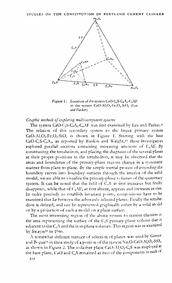
Figure 1: Location of the system C.iO-C.,S-C,Aj-C4AF in the system CaO-A!X)3-Fc,,O,-SiO2 (Iza and Parier'),
Graphic meihoils ojexploring multi-component systemsThe system CaO-('.,S-CsArC,AIT was first examined by Lea and Parker.21
The relation of this secondary system to the larger primary system CaO-ALOj-Fe^Oj-SiO. is shown in Figure 1. Starting with the base CaO-QS-CjA,, as reported by Rankin and \X right,” these investigators explored parallel sections containing increasing amounts of C,AF. By constructing the tetrahedron, and placing the diagrams of the several planes at their proper positions in the tetrahedron, it may be observed that the areas and boundaries of the primary-phase regions change in a systematic manner from plane tn plane. By the simple mental process of extending the boundary curves into boundary surfaces through the interior of the solid model, we arc able to visualize the primary-phase volumes of the quaternary system. It can be noted that the itcld of C(A at first increases but finally disappears, while that of C,AF, at first absent, appears and increases in size. In order precisely to establish invariant points, compositions have to be examined that lie between the arbitrarily selected planes. Finally the tetrahedron is defined, and can be represented graphically cither by a solid model or by a projection of such a model on a plane surface.
The most interesting region of the above system to cement chemists is the area representing the surface of the (1,S primary-phase volume that is adjacent to the C3A and the iron-phase volumes. This region was re-examined by Swayze*" in lO-lm
z\ somewhat different manner of selection of planes was used by Greene and Bogue” in their study of a portion of the system X.t20-Ca0-.M;0,-Si0;, as shown in Figure 2. The soda-free plane CaO-.XLOj-QS was employed as the base plane, CaO and C;S remained as two of the components in each of
1SS

Figure 2: The tetrahedron CaO-CiS-Al^Oj-NA in relation to the system Na.O-CaO-Al,O,-SiO, (Grrrw and lVig,i«Y
lik.’urc3: The tetrahedron Na.O-CaO-ALOj-Fe^, Mithin which is shown the pseudo-ternary s;,stcm CaO-C.AI -(NA,1 as a part of the pi-utc cutting the tetrahedron at Ca()-(AI")- NA, ( Z jihank and Iv ~a/ .

C4AF
I’igurc 4: The held <>f intersection ofthc GiO-C^Ai-'-lNA,) plane with the NC,Aj primary-phase volume (? jJ ank üisd
three succeeding planes in the tetraheilron, while the third component contained increasing ratios <>t NaX) to A1X),.
In a study of a portion ot the system XaX)-(L.iC)-.\!X)1-I;cX)i, liubank and Bogue"' selected a plane such as t<> include within it the two compounds NC,Af and as shown in Figure 3. It is sometimes helpful to draw a plane of three components in the form of an equilateral triangle, which can be done with anv triangular area. 'Fhus the plane (LiO-(NA,)-(l,AF is shown as an equilateral triangle in Figure 4.
Quite intkpcndently of the above study it was desired to learn the ctlect of successive aiklitions ot Na X) to the system (laO-fkAt-C-.F. This was accomplished1 by the exploration of successive parallel planes in the tetrahedron having the above three compounds as one face, and \a;O as the fourth component, as illustrated in Figure 5. A similar means was employed* in the studv of the ctlect of NaX) on the system CaO-(.;S-Cl, as shown in Figure (>.
Thus systems of four components have been explored satistactonly by examining a scries of tw<>-<limcnsional planes passing through the tetrahedra. In such procedures, the precise location of invariant points will usually require the examination of limited regions between the arbitrarily located planes.
Many illuminating tvpes of join (plane) through a tetrahedron have been used bv scientists at the Gcophvsical I.alx>ratorv. In a studv "t the quaternary svstem (la() FcO-AlX'l-.-SiO , Schairer'* investigated nve ternan joins, as shown in Figure 7. These arc designate!.! as follows; S:().-(.AS; (anorthite)-Fe(’), CAS -ALO, ! c(4, CS (wo'lastomte, pscudowollastonuc) -CAS.-FcO, C.-AS (gchlenitc)-CAS.-FcO, and CS-C.AS-FcO. It will be seen that the joins cut through the tetrahedron at various angles to include,

Figure 5: The tetrahedron Na,O-CaO-AI2O3-r:e,O3 on one face of which is shown the ternary system CaO-C5As-C2F and within which appears the quaternary system N'a,O-CaO- CjA j-CaF (I M'ank anj
Figure 6: The tetrahedron Na2O-CaO-Fc,O3-SiO2 on one face of which is show n the ternary system CaO-C2S-CF, and within which appears the quaternary system Na;O-CaO- -C-S CF anti B'-cui).

Figure 7: Diagram showing positions of the five joins (planes) studied within the regular (equilateral) tetrahedron CaO-FcO-ALOj-SiO, (\"</u/rrr).
at the apices of the resulting triangles, either binary or ternary compounds or oxide components.
In a later paper, Schairer” reports his procedure in a study <>f the quaternary system CaO-MgO-FeO-SiO.. Here, as shown in Figure 8, two joins are indicated parallel to the base (LaO-MgO-FeO. One of these includes the orthosilicates, and the other the mctasilicatcs. Another join is located cutting through MgO, FcO and CS (wollastonite).
Binary joins within the latter plane connect CMS (monticellite) with FeO, and C^MS. (akermanite) with FeO. All of these joins were investigated.
The same general method may be employed with five-component systems, but here the scries would have to consist of tetrahedra instead of triangles. And, to bring the systems within the range of experimental attack, each of these tetrahedra would have to be explored separately by such methods as already have been described. In this procedure, each tetrahedron represents a “ section ” of the four-dimensional region necessitated by the five- component system. Within each tetrahedron, one of the five components may be maintained constant, and within each triangle through a tetrahedron, a second of the five components may be held constant.
One may picture compositional changes in about the same manner as with the quaternary system. Suppose we have a scries of the tetrahedral diagrams completed and lined up in a row. We will see the position of the primary-phase volumes changing as we pass from one to another, that is, as we change the fifth component. Fach three-dimensional volume in the tetrahedron becomes part of a four-dimensional primary-phase region in the live component system. The bivariant surfaces become trivanant volumes, the univariant curves become bivariant surfaces, and invariant
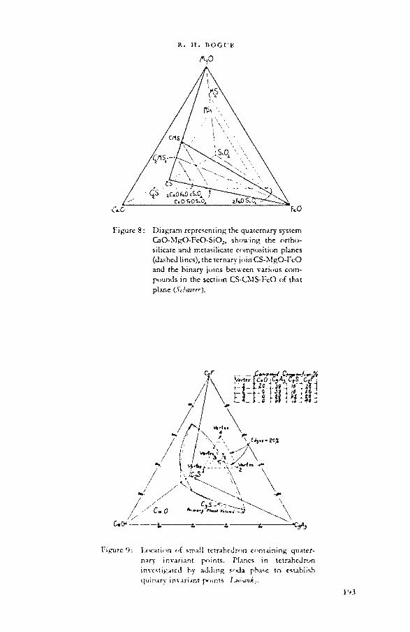
Figure 8: Diagram representing the quaternary system CaO-MgO-FcO-SiO2, showing the ortho- silicatc and metasilicate composition planes (dashed lines), the ternary join CS-MgO-FeO and the binary joins between various compounds in the section CS-CMS-FcO of that plane (,bZ>a;rrr).
Figure 9: laxtation of small tetrahedron containing quaternary invariant points. Planes in tetrahedron investigated by adding soda phase to establish quinary invariant points Ijji-äni.,.

Figure 10: Composition points studied in planes within the quinary system NC,A1-CaO-C1A3-C2F-CiS
points become univariant curves. At the invariant point of the five component system, five solid phases separate simultaneously from the liquid with which they are in equilibrium.
This is substantially the procedure adopted at our laboratory12 in the preliminary exploration of a part of the quinary system Na2O-CaO-ALOJ-Fc2OJ-SiO2. Starting with the published data for the quaternary system CaO-C,A3-C;F-C;S, a small tetrahedron was selected within that system, as shown in Figure 9. This tetrahedron contains the invariant points designated F, and T2 by Lea and Parker21 for CaO, 0,5, CjA, C,AF and 0,5, C2S, 03A, C.AF respectively. It was hoped that it would include also the corresponding invariant points in the quinary system following the introduction of Xa2O. Triangular sections were then explored through that tetrahedron, including the base Vi-V.-Vj and sections parallel to that base. In each series of five planes (see Figure 10) the soda content (as NO,A,) was held constant, and in each plane the iron oxide (as C-F) also was constant. Five of these scries (or tetrahedra) were included in the study, each of a different soda content, allowing a variation of 5 to 30 per cent NCjAj as a component. Tire component C-F varied in each scries from 2b to 46 per cent. By this procedure a preliminary survey was concluded and the invariant point for NC,A„ C,A, C.-S, C,S and the Fe.-O^-containmg solid solution was L'cated.
Other methods for representing systems of various components »ere

developed in detail by Roozeboom.37 Some of these have been discussed by Morey.-0 Thus it is shown that an equilateral triangular diagram can be opened up to a right-angled triangle in which the percentages of two components are indicated along the sides of the right triangle and that of the third component is obtained by subtracting from 100 the sum of the other two. Dahl* has pointed out that any form of triangle may be used for the above purpose.
Jones18 has plotted results obtained in studies of quaternary systems in the form of a projection onto the base of a pyramidal space figure consisting of a square base ami four triangular faces. This work was followed by studies on quinary systems1'’ in which the space figure employed was a prism consisting of three equal rectangular side faces and two equal triangular end faces.
Novel methods for representing compositions in multi-component svstems have been proposed. Among these may be mentioned the diagrams of Bochvar,’ and of Pcrcrman and Zvorykin.35 By the method of Bochvar, a composition (X.) of four components (.-1BCD) is defined as follows. Three of the components (as .-IBC) arc calculated to 100 per cent and the resulting value (</) is located in the triangular diagram of vIBC. Against one side of the triangle (as .-IB) is drawn another triangle having the vertex D. The latter triangle has no ternary significance, but only indicates, by lines parallel to ,1B, the percentage of 1). Thus a line drawn from q to D will pass through the loci of all compositions containing D in amounts from 0 to 100 per cent. The I) content of composition k is located on that line (at point /;). Then the composition of four-component k. is established by the two points q and b. In a modification of this method, the author makes use of concentric circles, surrounding the triangle .-1BC, within which the fourth component is located.
By such methods the phase boundary surfaces cannot be represented, and it would be impossible to determine whether a given composition is on one side or the other of such a surface. No means appear by which the course of crystallization can be traced in these diagrams. It docs not seem that such methods can replace co-ordinate systems in which the number of dimensions is equal to the number of independent variables.
StcontL-.r)' krl;.:ry ^hisaA notable departure in the diagrammatic representation of equilibrium
conditions in a multi-component system was introduced by Swayze“* in his study of the spiinary system CaO-MgO-C,A,-CJ7-C2S. It had been observed previously1'* that magnesia crystallizes as MgO in Portland cement compositions, and also25 that 4 to 6 per cent of MgO dissolves in the liquid r,f the GtO-Al.-Oj-Fc^Oj-SiO- system having Al.O-d c O, ratios between 0-68 and 3-0. Swayze therefore postulated that a 5 per cent addition of MgO
all mixes would result in all cases in a liquid saturated with MgO and from which MgO would crystallize as primary phase. In his diagram

Ligurctl: The CtS phase volatile in the system CaO-C5ArC.F-C;S modaied by 5 per cent NfgO (
(Figure 11) he indicated the continuous presence of 5 per cent MgO bv enclosing his 95 per cent tour-component tetraheiiron within an outer 100 per cent triangle representing the five-component system. And since MgO is always the primary phase, the phases shown are in all cases the secondary phases.
Ihe device utilized by Swayzc is practicable because magnesia does not combine with any nt the other components in the range slushed, but separates as MgO, and therefore the relative proportions of the other four components in the liquid are not arlectcd bv the crystallization of MgO. This factor, and the fact that MgO is the primary phase over the ent ire range, makes the use of Swayzc’s device unique in that a quinary system coukl be explored by the study of a single three-dimensional tetrahedron.
Since this treatment is rather involved, a simpkr analogy suggested by Ordway"1 will clarity the discussit m. In the upper part of Iigurc 12 is shown a phase diagram for a hypothetical system of three components, . I, B and C. If we assume that our interest is connncil to the primarv-ph.isc rcgi<>n ofB, we may then treat the system as binary by determining the secondary phases along any line, as .d'C, that is wholly within the H t-.chl. Tb.e primary phase of all mixes is B, so we determine the temperature at which the secondary phase separates, and identify that phase. 1'hc .-l.C" ratio of invariant point P can be established by noting the point P' where . 1 anil - IC crystallize simultaneously, and that of invariant point can be established by noting the point <z' where ,-IC and C crystalh/c together. The corresponding temperatures may be readily obtained, and the pseiulo-binary system vl C then plotted, as in the lower part of the figure.
It should be pointed out that the lower diagram is not a section through l'*n

Tipjrc 12: A hypothctic.il diagram shotting method for pnfjcctmg a primary phase boundary (Vj h) <>n a section (zl'C) therein those phases separate as secondary phases ((>r^u<7)).
the triangular phase diagram along the line z\ C , but a projection of another region on that line. Also it may be mentioned that the position of the line yl’C, or the percentage scale used in the figure is a matter of indifference. The only requirement is that the line taken be wholly within the primaryphase area of B. Thus a line representing (ill or 90 per cent of B would serve equally well. Practically, it is most expedient to use specimens containing the minimum of primary solid phase at the temperature where the secondary phase is separating.
It will be observed that the amounts of phase B in the liquids along the boundaries <7,/ and h arc indicated in the ternary diagram. These same data should be transposed to the .-1C binary diagram in order that it may be noted if any given composition is in the primary-phase region of B or in that of ^1, zlC or C. This step is important lest the diagram for the binary system be applied to compositions for which it is not applicable. In practical operation, the researcher will, of course, have determined the applicability of the method before subjecting his results to this mode of interpretation.
From this discussion it will be obvious that Swayze’s tetrahedron (Figure

11) does not represent a section through the quinary phase diagram, but rather a projection of a particular region on a section within the primaryphase region of MgO. The temperatures given are not those of the liquidus temperature with 5 per cent MgO, but those at which a secondary phase appears, the identity of which is indicated. The percentage of MgO in the liquid when this secondary phase appears was not determined, but was estimated to be below 5 per cent. The same results would be obtained if any other percentage of MgO were taken higher than 5 per cent. Some confusion might therefore be avoided if reference to the 5 per cent MgO were omitted and the outer triangle deleted, tor the representation is only of the relative percentages of the other four components in liquiils saturated with MnO.
It will be clear that the specializing conditions nude use of by Swayze would not generally apply. Thus, if the senary system NajO-CaO-MgO-ALOj-Ie.Oj-SiO., were to be considered, it is probable that the MgO could be treated as in the above quinary system, but it would be quite unjustified to assume that Na.O (as NfhA,) could be similarly treated. That would be possible only if enough XC,A, were present to saturate all liquids, and it MgO and NC,A3 were the first two phases to separate under all conditions. In such case, we could proceed to treat the remaining four components as a three-dimensional system, an<l determine the tertiary phase, rather than the primary or secondary phases, that separates from liquids saturated with MgO anil NWAi.
It is obvious that sotla could not so be treated. Swavze has noted, however,” that it is probable that all the crystallization which occurs on cooling commercial Portland cement clinker takes place in contact with the C.jS phase volume. If this is true, then all liquids of interest in the cement field are saturated with both MgO and C.S. The system Na^O-OaO-MgO-ALOj-IAqOrSiO.. in the region of Portlaml cement might then be explores! by maintaining a concentration of MgO ansi (1,5 suiii- cient to cause those two compounds to separate in all cases as primary and secondary phases. The experimentation wuulsl then be directed to the sictermination of the boundaries ami temperatures of the tertiary phases separating from the remaining four components in the three-dimensional tetrahedron. The operational problem in this case woulsl be to establish at all times a state of equilibrium between the MgO, the C,S and the liquid. This woulsl seem to be possible if the excess of these sohsl phases were kept relatively small. A very serious dirliculty that woukl have to be overcome, however, woukl be slue to the fact that the crystallization <>f CiS from the liquid woukl change the relative proportions of the other components in the liquid.
analytical treatment of multi-component systemsIt is sometimes of advantage to be able to treat competition relations b)
an analytical method, even though the problem may be capable of expression by graphical means. But geometric treatment becomes increasingly difficult

as the number of components is increased, and recourse must be had to analytical methods in the treatment of multi-component systems. Such a method was developed in general theorems by Morey and W illiamson28 and for practical phase study7 by Morey.25 The weight fraction of two components along any join jn the ternary system can be computed by the methods of analytical geometry. For any selected values of one component, the corresponding values of the other component become precisely known.
Such values in a ternary system can be computed readily bv various means, but more difficulty attends the computation of the three components of a join in the form of a plane in the quaternary system. It already has been shown that it is frequently desirable to study such planes as the means of exploration of four-component systems. In this case it is convenient to have an analytical expression for a plane passing through three points in the tetrahedron representing the whole system. Facility in the computation of mixtures is also gained by being able to express compositions in the plane selected for study, not alone in terms of the three apex compositions, but in terms of three of the four primary components. The fourth component is known, of course, from the difference between 1 (K) per cent and the sum of the other three. A simple extension of the principles developed for the join in the ternary system supplies the desired values for the quaternary system.
An analytical method developed by Dahl6' • involves the use of two types of equation, ir.trir.sk and parametric, each having its particular fields of application. The method has the advantage that it may be applied to systems of any number of components. This method will be illustrated below* bv comparing it with the geometric treatment of the phase diagram of a ternary system.
In the analytical treatment of a system the system as a whole is termed the primarj system, and systems of the same number of components within it are termed s<co?;<iary systems. Systems of a smaller number of components are termed subs,ratrate systems. For example, the ternary system CaO-Al^Oj-SiOj is a primary svstem. The ternary system (hS-QS-CjA within it is a secondary system, and the binary system'C3S-C3A is a subordinate system.
Any system of one less component than the primary system may be represented by an equation, just as a line is represented by an equation in analytic geometry. By making use of the fact that the sum of the components is constant, the equation may he expressed without a constant term. An equation ot this type has no reference to distances from co-ordinate axes, and is therefore termed an intrinsic equation. As an example, the equation for the system C;S-C,A, in molar form, is
C—3A—25^0where C, A and S represent moles of CaO, ALO3 and SiO, respectively.
This part of tl.c dacuwnn >s bv L. A. Dahl.

STUDIES ON THE CONSTITUTION OF PORTLAND CEMENT CLINKER
This equation is satisfied by the molar composition C.S, as indicated in its chemical formula, by the molar composition of CjA, and by the molar composition of any mixture of C2S and C3A. It applies to the number of moles of CaO, ALOj and SiO, in any quantity of a mixture of C2S and C3A, which would not be the case in an equation which has a constant term.
If CaO is added to any quantity of a mixture of C.S and CjA, and the number of moles of the components is substituted in the equation, a positive value is obtained, not zero. In the triangular diagram of a ternary system this indicates that the composition is on the side of the line (LS-C,A towards the CaO vertex. If either ALO, or SiO2 is added, a negative value is obtained, indicating that the composition is on the other side of the line. In view of the fact that all of the secondary systems within a given primary system arc bounded by systems of one less component, this characteristic of the intrinsic equations for subordinate systems may be used to determine the secondary system in which any given composition lies. This is analogous to locating the position of a composition in a triangular diagram to determine the secondary system in which it lies, thus determining its final products of crystallization. The analytic method, however, may be applied to systems of any number of components. The intrinsic equations for systems bounding secondary systems may be arranged in systematic order, in groups anti subgroups, forming a “ classification key " for determining easily the secondary system to which any given composition belongs.
Intrinsic equations may be expressed in terms of ordinary weight units, and arc then applicable to weight in grammes, pounds or any other units. If applied to a total of 100 weight units they may be said to be in percentage form. For example, the e<|uation f< >r the system l?;S-(l,A, previously expressed in molar form, may be transferred to weight or percentage form, as follows:
________ AV. _ _A. _ o5t)-O8 '
or C—l b5<HA—l-Sf>75S — 0where C, A and S now refer to the number of weight units of lime, alumina and silica.
Equations for converting primary compositions to secondary compositions may be obtained by multiplying the intrinsic equations of the boundary systems by suitable constants. \X ith these equations any composition expressed in terms of primary components may be converted into terms of the components of the secondary system in which it lies. This is equivalent tor a ternary system to locating the point representing a given composition in the triangular diagram and then determining graphically the percentages of the final products t'f crystallization.
Applications of the intrinsic equations arc not connncd to secondan or subordinate systems in which the components arc pure compounds. In the analytic treatment, any compositions within a primary system mat be taken as components of a secondary or subordinate system. For example, the liquid at an invariant point may be considered as a component of a
Joo

system in which the remaining components are the crystalline phases capable of existing in equilibrium with the liquid, as a means of calculating proportions of crystalline phases and liquid at the invariant-point temperature. This is equivalent to the graphic method of estimating proportions of two crystalline phases and an invariant liquid in the diagram of a ternary system.
A triangular diagram of a ternary system may be divided into regions differing with reference to the order of appearance and disappearance of crystalline phases during cooling or heating. By treating such regions as systems, multi-component systems can be similarly divided into secondary systems, or “ regions,” differing as to order of crystallization, with a classification key to enable one to determine the order of crystallization for any given composition.
The number of intrinsic equations required to define a subordinate system is the ditlcrcnce between the number of components in the primary and subordinate systems. In a quaternary system, for example, a ternary system is defined by a single equation and a binary system by two equations. The application of intrinsic equations is difficult in the case of a system of few components within a primary system of many components. For such applications of analytical method parametric equations are more useful. In addition they permit introduction of temperature as a parameter, corresponding to the introduction of isotherms in the diagram of a ternary system.
With reference to the analytical treatment of multi-component systems, a parameter may be defined as an independent variable introduced to permit defining the percentage of each primary component in terms of that variable in any subordinate or secondary system. For example, in terms of p, the the weight fraction of (1,A in any composition in the binary system C2S-C3A, the equations for the system mav be expressed as follows:
Weight percentage Ca() — 73-69—ll-42y>Weight percentage ALO, —37-73y>W eight percentage Si()2 — 26-31—2()-31/>
In these equations, /> is a separate parameter, introduced solely for direct computation of percentages of the primary components lime, alumina and silica in any composition within the subordinate binary system C.S-C,A. These same equations can be used regardless of the identity or number of additional components in the primary system. This computation illustrates the point that the number of equations required to define the subordinate system is the number of primary components represented in the subordinate ststem. 'I lie number of parametric equations may sometimes exceed the number of intrinsic equations required, but thev may be applied more simply in many problems to which thev arc adaptable.
The number of parameters required to detme a subordinate system is one less than the number of components in that system, regardless of the number of components in the primary system. Thus, two parameters are required in equations defining a ternarv system, in any system of four or rr^irc comp« »nents.

Parametric equations may be used in a preliminary systematic choice of compositions to be investigated in a multi-component system, corresponding to drawing parallel lines at regular intervals in a triangular diagram, in two directions, choosing for study compositions at intersections.
The parametric equations have particular value in the interpretation of data obtained in the investigation of multi-component systems. An invariant curve may be represented by parametric equations, in which T is a parameter representing temperature. The composition at a point on the curve at any given temperature may be found from the equations, and used in estimating proportions of liquid and crystalline phases at that temperature. Unless the curve is practically a straight line, the parametric expressions in the equations are non-linear. It is simpler to treat the curve as a series of straight lines, in order to use linear equations. The use of the equations to determine the proportions of liquid and crystalline phases w hen the liquid is on a uni variant curve is analogous to the corresponding graphic estimation from the phase diagram of a ternary system, although the number of crystalline phases involved is greater than in a ternary system.
Equations of isotherms on a divariant surface may be derived to permit estimation of proportions of liquid and crj'stalline phases at the temperature of a given isotherm when the liquid is on the divariant surface.
XXlien a study is confined to a particular secondary system, the system may be regarded as a primary system, and systems within it as secondary systems. This method was used by Dahl* in deriving equations for estimating phase composition of Portland cement clinker at clinkering temperatures, based upon the investigation of the quaternary system QS-CjS-CjA-C^AF by Lea and Parker.“ Parametric equations were used in the derivation of equations for estimating proportions of phases above the invariant point temperature and for estimating the proportions of crystalline phases in the cooled clinker from its composition and estimated glass content. A classification key for division of composition into regions diflering in their order of crystallization was developed by the use of intrinsic equations, as a means of determining the groups of equations applicable to any given composition.
Intrinsic and parametric equations have not been applied to systems involving solid solution. However, when the range of solid solutions is known, and tie-lines established to determine compositions on univariant curves capable of existing in equilibrium with them, it should be possible to derive and apply equations for analytical interpretation of the data.
RECENT DEVELOPMENTS IN TECHNIQUES
Nit»» ntttbeds for following the HqindusThe classic method for exploring a ternary system is to prepare a large
number of samples representing compositions regularly distributed over the entire field, and to subject each composition to such heat treatments as will indicate the primary phase. Additional samples are then required for the .

more precise location of boundary curves and invariant points, and for the establishment of equilibrium temperatures within the fields, along the bi variant curves and at each quintuple point. In the study by Rankin and Wright35 of the system CaO-Al2O3-SiO2, charges were prepared having composition intervals of 5 per cent over the entire range of the system. Some 1000 compositions were employed with fully 7000 heat treatments and microscopic examinations.
Since four such ternary areas constitute only the starting data for a quaternary tetrahedron, and five tetrahedra are only the starting data for a quinary system, it becomes obvious that the exploration of multi-component systems by this systematic process cannot be pursued if we hope to obtain solutions within a lifetime. An expedient has been to confine the study to a small portion of the whole system, as already indicated. It is fortunate that, in most cases, our interest is limited to a relatively very narrow region.
But even such restrictions become unwieldy when systems of five or six components are considered. Our needs in such systems would be mostly satisfied with a knowledge of the invariant compositions and temperatures, and the phases coexistent along univariant curves and divariant surfaces. If a short cut could be found which »'Quid give this information more directly than by following the classic method above referred to, it would make possible the exploration of systems too complex to be given consideration otherwise. A number of suggestions has been made to accomplish this end.
Dahl has pointed out5 that the boundary between two primary-phase regions may be followed rather conveniently by what he calls the “ zig-zag ” procedure. The method is based on the principle that, if we systematically reduce the amount of the component which is the primary phase, leaving the relative proportions of the other components unchanged, we are bound to leave that primary-phase region and enter another. When this change-over has occurred, a repetition of the process will swing the liquid over to the first or to some other primary-phase region. Eventually the invariant point will be reached. If the zig-zag path passes a eutectic point, the next composition will lead back to it. Thus we start with a selected mixture and determine the primary phase. The next mixture is made of a composition directly away from the vertex representing the primary phase. By continuing this process a boundary will be passed and another primary phase appear. The next composition will be made of a composition directly away from the vertex representing the second primary phase. Continuing in this manner we eventually arrive at an invariant point. In the last portion of the procedure the path of the mixture composition will follow approximately a univariant curve toward the invariant point, thus locating the curve. There are peculiar problems in locating peritectic points by this method, but these problems have been resolved.
Again, the composition of the liquid at an invariant point may be determined by making quantitative microscope analyses of the solid phases in a polished thin section of a charge quenched from a temperature just above

STUDIES ON THE CONSTITUTION OF PORTLAND CEMENT CLINKER
the invariant temperature. The microscopical analysis could be made by the use of an integrating stage.2 If LA represents the amount of phase v4 in the liquid. Ma the potential amount of phase X in the original mix, and JA the amount of phase A in the thin section, thenLA=^VA—J"A. The other observed phases are treated similarly and the composition of the liquid thus approximated in terms of the crystalline phases in the solids in equilibrium with it. The conversion between primary (oxide) and secondary (compound) systems may be made by the method of Dahl.6- • The invariant temperature may be established by a thermal analysis. Objections to this procedure are the diminished accuracy of the approximation w-ith increasing complexity of the system, and the limitations of the optical means by which the solid phases are distinguished and measured.
Newkirk2’ has pointed out that the invariant-point composition of any mixture could readily be ascertained if the liquid could be separated from the solid phases at certain temperatures, and one or the other analyzed. This idea is based on the well-grounded principle that the composition of the liquid during cooling follows the boundary cuncs to an invariant point or to some point on a solid-solution liquidus. The problem is to effect that separation. One means that might be used under favourable conditions would be to subject the cooled finely pulverized charge, following quenching from a temperature just above the invariant temperature, to centrifugation in a medium of such density that the undercooled liquid (glass) would be separated from the crystalline phases. The glass could then be analyzed to give the desired composition. .
Another solution suggested and developed by Newkirk is to centrifuge the charge while in the furnace at the required temperature. For this purpose he has devised a platinum capsule containing a filter element which is supported in a mullite rotor (Figure 13) and spun at about 4000 r.p.m. in the tube
Figure 13: Mullite rotor for supporting two platinum capsules for centrifuging a charge
in a furnace

Figure 14: Complete assembly of centrifuge furnace(A'« kirk).
of a specially constructed furnace (Figures 14 and 15). The liquid, which is forced through the filter, is then subjected to chemical analysis by micro methods and the use of the flame-photometer.
The accuracy of this method will depend on the amount of liquid separated for analysis. The amount of liquid present at the invariant-point temperature (at maximum heat content) is a function of the composition of the charge, the amount becoming greater as the invariant-point composition is approached. The first charge may be far removed from the invariant-point composition and little liquid recovered. The analysis will probably lack precision. A new charge made up of that composition will, in general, be closer to the correct composition than was the first charge. A separation from the second charge will yield a larger quantity of liquid, from which an analysis will give more precise results. By further repetitions, the correct composition wall result. And by repeating the operation at different temperatures the boundary curves can be located.
If the invariant point is not a eutectic, crysullization will not be complete205
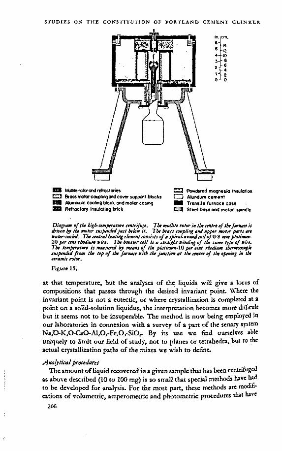
^3 Mulirte rotor and refractoriest-=J Brass motor couptingand cover support blocks iM Aluminum coding block and motor casing HU Refractory insulating brick
Kj Powdered magnesia insulation I J Alundum cement H8 Transite furnace cose -
Steel base and motor spindle
Diagram o/ tlx biglf-ttmprratHrt ttntrijut«. The mwlli!* rotor m tlx ctnirt of ibe jumatt h drhxn by tb« motor tmptHdtd just brio* it. The brass toubling anj upper motor parts art water-tooled. Tbt «niral beating element tonsists of a spiral-ioimd toil of 0'8 mm platinum- 20 jer «nt rhodium wire. The booster coil is a straight winding of the same type of wire, Tbt temperatort is measured by means of ibe piatinum-XO per cent rhodium tbermototeple suspended from the top of tbt furnace with tbt junction at the ctnirt of ibe opening in tbt ceramic rotor.
Figure 15.
at that temperature, but the analyses of the liquids will give a locus of compositions that passes through the desired invariant point. Where the invariant point is not a eutectic, or where crystallization is completed at a point on a solid-solution liquidus, the interpretation becomes more difficult but it seems not to be insuperable. The method is now being employed in our laboratories in connexion with a survey of a part of the senary system Na2O-K20~Ca0-/\L0j-Fe,0J-Si02. By its use we find ourselves able uniquely to limit our field of study, not to planes or tetrahedra, but to die actual crystallization paths of the mixes we wish to define.
Analytical froccdstretThe amount of liquid recovered in a given sample that has been centrifuged
as above described (10 to 100 mg) is so small that special methods have had to be developed for analysis. For the most part, these methods are modifications of volumetric, amperometric and photometric procedures that have

been described in the literature. Their importance to this treatment, and the general unfamiliarity of their use by cement investigators, require that they be given a brief description.
A microburette similar to that described by Lazarow20 is employed for micro-titrations. In this apparatus, a knurled knob is provided by which the shaft of a precision dial indicator is moved. This shaft in turn advances the plunger of a glass Luer syringe displacing the reagent and forcing it through a capillary tip immersed in the solution being titrated. The volume of the solution displaced is read directly from the dial.
Iron, after separation and passing through a silver reductor, can be determined either amperometrically with potassium dichromate as the reagent32 or by the more conventional procedure of titrating with ceric sulphate, using the ferrous complex of orthophenanthroline as the indicator.24
The amperometric titration of aluminum ion with sodium fluoride in the presence of ferric iron, ethyl alcohol and excess of sodium chloride has been described by Ringborn and Wilkman.36 This method was adapted for micro-analysis by keeping the volume of solution small so as to make it approximately 0 01 Af with respect to aluminum.
Calcium has been determined both amperometrically36 and by titration of the oxalate with potassium permanganate.24 With the latter method the titration is carried out with 04 N KMnO,, rather than the 0-01 N solution specified in the reference, so that a syringe of 1-0 ml capacity can be used.
Silica is determined by a colorimetric method involving the formation of a silico-molybdate complex followed by the reduction of this complex with sodium sulphite and hydroquinone to form molybdenum blue.24 The samples are diluted to a known volume and the per cent transmission at 720 millimicrons observed with a spectrophotometer. The amount of silica in the sample is then read from a calibration curve prepared from data on standard silica solutions which have been given an identical colour development and treatment.
Sodium and potassium are determined by means of the flame photometer. The method used is in substance that developed by Eubank and Bogue,10 adapted for micro work by employing standard solutions of lower K2O, Na2O and CaO concentrations than those prescribed in the reference.
The various methods which have been briefly mentioned have been employed to obtain complete analysis of fractions composed of KZO, NazO, CaO, A12Oj, Fe2O, and SiO2 and consisting of as little as 10 mg of total sample.
Thermal analjsisThe procedure of differential thermal analysis is becoming increasingly
prominent in studies on high-temperature phase equilibrium. The knowledge of the principles of thermal analysis is not new but the techniques and equipment for automatically measuring and recording small energy changes have been vastly improved.
In our laboratories Prodan34 has developed a method by which the charge,
STUDIES ON THE CONSTITUTION OF PORTLAND CEMENT CLINKER
instead of being placed in a crucible, is attached directly to the junction of a platinum: platinum 10 per cent rhodium thermocouple. After three or four cycles of fusion and cooling, the original sample of raw materials becomes a droplet consisting of the reacted phases normally existing at room temperatures. The sample, of 04 to 0-5 g in weight and still attached to the thermocouple junction, is then ready for use in the thermal analysis.
The couple with attached charge is first calibrated in the furnace and in the position where it is to be given thermal analysis. Following this, the analysis can proceed in the usual manner. It has been found possible in this way to analyze six samples simultaneously and without further attention, allowing the temperature control and recording to be handled automatically.
The principal advantages of the method lie in its sensitivity, as samples are at all times in direct contact with the measuring thermal element, and in the convenience and speed of operation. Very small heat effects are almost instantaneously detectable, and differential peaks have been found to be sharp and reproducible.
Temptrature tonirolImproved methods for temperature control are frequently being proposed.
A precision thermostat has been developed by Eubank,11 previously of our staff, for the control of temperatures between 1000° and 1550 °G By this method a thyratron is used in conjunction with an alternating current bridge and high-gain amplifier. The phase angle of the unbalanced bridge regulates the firing of the thyratron, and the control has been found to be highly sensitive and independent of normal fluctuations in line voltage. The thermostat has been found convenient to operate, easy to adjust for any temperature, and reliable for periods of continuous operation from a few minutes to several days. Temperatures have been readily maintained constant within±04 ° for several hours and withinj^l-O0 for several days.
Phase ebservationsA “ hot-wire ” apparatus has been devised by Ordway11 wherein a thermo
couple is heated by an audio-frequency current. The thermocouple e.m.f. is separated by a filter circuit from the audio-frequency voltage, making it possible to measure the sample temperature accurately and continuously. Although designed for the purpose of growing single crystals for structure studies (as indicated in another paper at this meeting, the “hot-wire should be very useful in making rapid preliminary surveys of the melting characteristics and phase relationships of multi-component systems. In this way much of a system may be roughly blocked out and much exploratory study curtailed. The final precise evaluations would probably require treatment by the conventional methods.
Hjdroibermal UsbniquesThis outline would not be complete without mention of the special ■
apparatus and techniques that have been developed for the study of systems

containing water as a component. Since this is a special field of investigation, and space does not permit its elaboration in this place, I shall give only some of the principal references to the rather extensive literature on this subject.
A bibliography to the early techniques will be found in a paper by Morey and Berlew27 in 1938. Newer techniques were described by Tuttle42 in 1948 and 1949. The technique used at the National Bureau of Standards for the study of the hydrogarnet solid-solution series was described by Flint and McMurdie13 in 1941.
SUMMARY AND POSTWORDIt has long been apparent to investigators on the constitution of clinker
that the study of complex systems by the very informative methods of heterogeneous equilibrium is severely restricted when carried out by the classical procedures. The importance of extending the scope of usefulness of the laws underlying those methods has given rise to the development of new techniques, aimed at removal of some of the more serious restrictions.
One great obstacle to the use of the methods of studying heterogeneous equilibria with complex systems has been the difficulty of geometrical representation of the composition-temperature relations of a system composed of more than four components. Even a four-component system can be depicted on a plane surface only in perspective, with temperatures indicated by contour lines, and is far from giving a clear and unconfused picture of the solid model that it is intended to represent.
The first problem, therefore, is to devise procedures by which representation of multi-component systems can be expressed within the two dimensions of a plane surface, or the three dimensions of a solid model. Although considerable progress in this direction has been reported, these procedures become unmanageable with increasing complexity of the system. Here mathematics has entered the picture to eliminate the necessity for geometrical representation of relationships, and to provide formulae to take the place of diagrams.
The second problem is concerned with the vast amount of time that is required to explore a system with such thoroughness as will permit the establishment of invariant points and phase boundaries. Shorts cuts in procedure are necessary if the study of complex systems is to yield useful data in a reasonable time. Many time-saving techniques have been developed.
Equipment has been made with which the solid and liquid phases of a charge may be separated while in the furnace at high temperature. This device has made possible a direct method for following the phase volumes, surfaces and curves of a multi-component system to the invariant points. A vast number of operations may thus be avoided so that, contrary to present practice, only data important to the immediate problem are accumulated.
In order that this method may be useful, it is necessary to adapt analytical procedures to provide accurate analyses of minute quantities of a sample. Such adaptations have been successfully made.

Our ability to detect and measure small temperature differentials has been greatly'extended by new electronic instruments capable of rapid and automatic recording of minute changes in energy levels. With these instruments, differential thermal-analytical methods are replacing the older quenching techniques for following phase relations, with the assurance that energy changes too small or too rapid otherwise to be observed will be identified. And a method is being used in thermal analysis wherein the thermo-element junction serves as the container, up to six of these elements being simultaneously in service in the same furnace.
By the use of the thyratron tube, temperature control is made more precise and more dependable. And by the use of a “ hot-wire ” apparatus, preliminary surveys of the melting temperatures and phase relations can be obtained with a minimum of effort and much saving of time.
We feel that, as a result of these developments, the scope of profitable investigation of cement systems by the laws and principles of heterogeneous equilibrium has been greatly extended. With the new power of this tool for exploring the nature of the chemical formations in the production of clinker, and the profundity of X-rays in revealing the course of the transformations, I feel that we are entering a new era in cement research. I venture to predict that the cement industry, aided by studies on reactions in the solid state, and supported by electronic and spectroscopic tools in the hands of investigators in an increasing number of laboratories, will reach in the next decade a new level in the character, quality and usefulness of its product.
REFERENCES
1. bochvar, A. A. Bulktin Academi det Seientet de FUSSR. 1944. Vol. 12.*p. 851.
2. BOGUE, a. H. Tbe Cbemiftrj of Portland CtmtHt. New York, Reinhold. 1937.3. Bowen, n. l. Tbt Ameriean JournalojScienre. 1915. Vol. 40. p. 161.4. Dahl, l. a. Raelk Prodwti. 1938. September to December.
PCA Research Bulletin. 1939. No. 1.5. Dahl, l. a. Staff Report of the PCA of America. 1946. 9th October.6. DAHL, L. A. Journal oj Pbjiiial and Colloidal Cbemiitrjt. 1948. Vol. 52. p. 698.
PCAF paper 51.7. Dahl, L. A. Journal of Chemual Edueation. 1949. Vol. 26. p.411. PCAF
paper 52.8. Dahl, L. a. Journal of Plytieal and Colloidal Cbemutry. 1950. Vol. 54. p. 547.
PCAF paper 57.9. Eubank, w. r. and BOGUE, R. H. Journal of Rteearcfc of tfce National Bweau of
Standardt. 1948. Vol. 40. p. 225. PCAF paper 50. RP1867.10. Eubank, w. R. and BOGUE, K. H. journal of Reteartl of the National Bureau
Standardt. 1949. Vol. 43. p. 173. PCAF paper 54. RP3019.11. eubank.w. r. KflVflr of Stwntiju hutnementi. 1950. Vol. 21. p. 845. PCAF
paper 59.12. EUBANK, w, r. Journal of Reteartb of the National Befftau of Stieedardt. 1950
Vol. 44. PCAF paper 56. p. 175. RPĻ9.

13. flint, E. p. and mcmukdie, h. f. Journal ojKeiearch oj the National Bureau ofStandards. 1941. Vol. 26. p. 13.
14. GIBBS, j. w. Transactions of tbe Connecticut Acadeng. 1906. “ Scientific Papers ”Longman’s Green, New York.
15. Greene, k. T. and BOGUE, R. H. Journal of Research of the National Bureau ofStandards. 1946. Vol. 36. p. 187. PCAF paper 47. RP1699.
16. Hansen, w. c. Journal of the American Chemical Society. 1928. Vol. 50. p. 3081.PCAF paper 18.
17. JÄNECKE, e. Fortschritte der Mineralogie. Kristallographie u,Petrograpbie. 1933. Vol.17. Part 2. p. 73.
18. Jones, F. E. Transacttons of the Faradaj Society. 1939. Vol. 35. p. 1484.Journal of Physical Chemistry. 1944. Vol. 48. p. 311.
19. jones, F. e. Journal of Physical Chemistry. 1944. Vol. 48. No. 356. p. 379.20. lazarow, A. Journal of Laboratory and Clinical Medicine. 1950. Vol. 35. p. 810.21. lea, F. m. and Parker, t. w. Philosophical Transactions of the Royal Society.
1934. Vol. 234. No. 731A. p. 1.22. lea, f. m. and Parker, t. w. Building Research technical paper 16. 1935.23. lerch, w. and brownmiller, l. t. Journal of Research of the National Bureau
of Standards. 1937. Vol. 18. p. 609. PCAF paper 32. RP.997.24. Milton, R. p. and waters, w. a,. Methods of Quantitative Microanalysis. London.
Edward Arnold, 1949.25. MOREY, G. w. Journal of Physical Chemistry. 1930. Vol. 34. p. 1745.26. morey, G. w. Glass Industry. 1931. Vol. 12. April, p. 69.27. morey, G. w. and berlew, j. S. American Journal of Science. 1938. Vol. 35A.
p. 185.28. morey, g. w. and Williamson, e. d. Journal of the American Chemical Society.
1918. Vol. 40. p. 59.29. Newkirk, t. P. In paper by Fred Ordway. Ceramic Age. 1951. Nov.30. Ordway, P. Staff report of the P.GA. of America. 1950. 24th February.31. ordway, F. Journal of Research of the National Bureau of Standards. 1951. Vol.
48 p. 152. PCAF paper 61. RP229932. parks, t. D. and lykken, l. Analytical Chemistry. 1950. Vol. 22. p. 1444.33. perel’man, f. m. and zvorykin, a. Igyes. Sektora Fi^-Kbim. Anal. LU'JR.
1949. VoL 191 p. 144.34. Prodan, l. a. Staff report of the P.C.A. of America. 1950. 11th August.35. Rankin, G. A. and wright, f. e. American Journal of Science. 1915. Vol.39.
p.l.36. Ringborn, A. and wilkman, b. Acta Cbemica Scandinavica. 1949. VoL 31.
p.22.37.. ROOZeboom, h. w. b. “Die heterogenen Gleicbgeaicbte" Braunschweig. F. Vieweg
und Sohn, 1911.38. Schairer, j. p. Journal of the American Ceramic Society. 1942. Vol.25. p.241.39. Schairer, j. p. Journal of the American Ceramic Society. 1950. VoL33. p. 160.40. swayze, m. a. American Journal of Science. 1946. Vol. 244. No. 1. p. 65.41. swayze, M. a. Personal communication. 1950. 16th January.42. tuttle, o. p. American Journal of Science. 1948. VoL 246. p. 628. Geological
Society of America. 1949. VoL 60. p. 1727.

STUDIES ON THE CONSTITUTION OF PORTLAND CEMENT CLINKER
DISCUSSION
H. ZUR STRASSENI would like to explain in a few words how quaternary systems may
be represented on a plane quantitatively. Such a representation, however, implies the condition that the four tetrahedral co-ordinates may be projected in their absolute length. There are two possibilities to fulfil this condition.
Let us consider a system of the four components B, C, D, each point being represented by the tetrahedral co-ordinates a, b, r, d. Instead of a tetrahedron we can use two triangles, in which two compounds are given absolutely and the other by a total, for instance, the two triangles ^4, B, C4-D and C, D, A-^-B (Figure 1). In the one triangle the composition is determined by the co-ordinates a and b, and the point Px*, in the other by the co-ordinates c and d and the point The line between Px and Ps has the length b-^d and runs parallel to the side A, B. The principle of this representation is known as Spindel’s parallelogram.* In each of the two triangles the geometric rules for quantity relations of the phases among each other apply, so that in general these triangles can be handled graphically like simple plane triangular diagrams.
The second method was developed by H. von Philipsborn.2 He projects the tetrahedron as shown in Figure 2. The point P in the tetrahedron is represented by the co-ordinates b, r, d, which are measured parallel to the three axes AB, AC and AD. In order to fix in an unambiguous way the co-ordinates of the point P, we need not only the co-ordinates d but also co-ordinates b and c of the point P'. For the representation of the point P of the quaternary system in the von Philipsborn diagram two triangles are required, as in the case of the Spindel parallelogram. They are not, however, of the same size. There is a principal diagram including all points such as P, Le. the triangle BCD, whilst an additional diagram comprises the triangle ABC, including the points P'. The line P—P' must always be parallel to AD and the location of P is determined by the co-ordinate d. In this case also the usual geometric rules are valid for each of the two triangles.
The representation according to the von Philipsborn method has the
Figure 1: Spindel’s parallelogram.

Figure 2 : von Philipsbom’s diagram.
1 Iwarumt point CeO-Cs5'-C321-C2(-4,F)2 „ „3 „ „ CeO-CjS-Cjz»4 „ „ C^C^-Cjzl5 „ „ GO-C^F6 „ „ C^f-C^F8 Mixrd cryitol C^z^.F) in tquiliMum nitb point 1
•» •» M M M 2
Figure 3: Quaternary system CaO-SiOj-AI^Oj-f’e.Oj according to Swayzc and represented in the Spindel parallelogram. The denominations of the respective points are identical to those used in Figure 6 contained in Swayze’s paper.
advanuge that the principal diagram may be considered as a rectangular tetrahedron, when seen in perspective and resting on the y4BC plane, the comer A being directed to the rear, thus giving an excellent picture ot the spatial conditions in the graphs represented.

If the method is applied to the melting diagram CaO-SiOj-AljOj-FcjOj it becomes evident that Swayze’s representation3 corresponds to the principal diagram of von Philipsbom. If Swayze’s diagram is complemented by the corresponding additional diagram for points P', the result is the complete quantitative representation of the quaternary system according to von Philipsborn.
The Spindel diagram does not offer the possibility of seeing the tetrahedron in perspective. This method provides, however, a clearer picture, because the two triangles do not overlap. Figure 3 shows Swayze’s results of the quaternary system CaO-SiOj-AljOj-FeiOi represented according to the Spindel parallelogram.
REFERENCES
1. Spindel, m. Zement. 1930. Vol. 19. p. 1200.2. von philipsborn, h. PortscMtte der Mineralogie. 1927. VoL 12, p. 151.3. swayze, m. A. American Journal of Sdenee. 1946. VoL 244. p. 165.
J. H. WELCHA few years ago at the Building Research Station I suggested that a
hot-wire technique for thermal analysis, and possibly for microscopic examination of melting points, would offer great speed and simplicity in certain thermal investigations. I made a few rather crude experiments, with disheartening results and subsequently abandoned the project. It is very encouraging, therefore, to hear that Dr. Ordway has been able to achieve success with this particular technique.
Since the pre-print of Dr. Bogue’s paper was available, he has been good enough to supply me with further details of the method of thermal analysis there described, and I have obtained several heating curves by this method. The only modification I have made is to incorporate a simple device in the recording circuit whereby the absolute and differential temperatures can be recorded simultaneously without mutual interference. Die results from these heating curves are surprisingly good when considering the small amount of material involved, and I think that this method will attain great importance in the future for melting determinations.
At the moment it appears that a normal crucible assembly will still be required for detecting polymorphic transitions of low energy in solids such as C2S and C,S which cannot be fused to the thermocouple.
Dr. Bogue comments on the usefulness of the method in detecting energy changes too small or too rapid to be otherwise identified, but I would like to draw attention to the danger of using differential thermal analysis to detect slowly occurring energy changes wherein the rate of heating of the. sample may outstrip its rate of attaining equilibrium. Thus,

early experimenters often discovered two thermal breaks in their differential heating curves on a binary system, the first of which was correctly interpreted as eutectic melting and the second of which was supposed to represent final melting.
It can be shown theoretically that the occurrence of a second break is spurious, and representative of non-equilibrium conditions in the sample, and although many workers have shown that in particular systems it occurs essentially at the melting point as determined by independent methods, it cannot be relied upon if not checked in this way. Differential thermal analysis is a useful technique when used with discrimination, but the results must be interpreted with caution.
One final point— Dr. Bogue mentions that the upper limit of operation of the temperature controller developed by Eubank is 1550 °C, and I imagine that this is the upper limit of operation of the quench furnace rather than of the controller. The platinum-rhodium wire-wound furnace, which can be used in oxidizing atmospheres at high temperatures, is far more convenient to use than, for example, molybdenum furnaces, which require special protection, and any increase in their usual working range is well worth striving for. In an attempt to secure this increase, all the platinumrhodium furnaces at the Building Research Station were converted to internal winding of their resistance elements. Although no originality is claimed for this innovation, it may not be widely known that the working range of quench furnaces may be safely extended to 1750 °C by this means. Furthermore, if the internal winding is protected from volatilization by a thin layer of refractory cement, the life of the furnace may be very greatly prolonged.
R. H. BOGUE (author's closure)Dr. Zur Strassen has called attention to two other methods for representing
the diagrams of a quaternary system. 1 am glad to have him call our attention to those methods. We had already looked into some of the other methods that have been reported, or noted in our paper, and although some of them may have merit, yet those methods did not appeal to us very much, and seemed to lack flexibility and usefulness. That is, those we did look into seemed to lack the flexibility and usefulness that are possessed by the methods we have described.
Mr. Welch has been kind enough to say some words about our process that are very encouraging. We are glad to know that he has duplicated some of our results. I agree with him that it is the limitations of the furnace rather than of the methods which have held our upper temperatures with the temperature controller down to 1550 CC, and I have no doubt that the method will lend itself to higher temperatures as soon as the equipment is built to take care of such temperatures. It is probable that the use of the inside winding suggested by Mr. Welch will accomplish this end very satisfactorily.

[9]
The structures of cement hydration compounds
J. D. BERNAL
SUMMARY *A study has been made of hydrated calcium silicate compounds produced
by hydration or precipitation methods under ordinary and hydrothermal conditions. Phases have been identified by X-ray methods making use of comparisons between synthetic products and natural minerals.
The cell dimensions have been partially or completely determined for ten of these phases. The forms of hydrated calcium silicate stable at low temperatures have been shown to be two related types of structures of composition Cj-i.jSHj.M.j and CjSILi- These occur in the form of extremely thin fibrous crysuls, similar to those found in gels, and this fact may be related to the setting properties of cement. Evidence for the presence of these compounds has been found in pastes of hydrated tricalcium silicate and in a sand-lime brick. The first compound has been identified with a group of somewhat ill-defined minerals from Crestmore, California, from Tobermory in Mull, and most recently from Ballycraighy in Northern Ireland which will be referred to, pending final agreement as to nomenclature, as tobermorite.
The structures of these compounds show the presence of a fibre repeat unit of about 7-3 A with marked pseudo-halving. This is common to a number of other hydrated silicates and is thought to imply the existence of silicate tetrahedra joined by hydrogen bonds. They also show a layer structure, the spacing of which varies on loss of water between 14 and 9 A in a way similar to the clay minerals and which may be connected with the shrinking properties of concretes.
INTRODUCTIONThe chemical composition and physical state of the compounds produced
in the hydration of Portland cement have been an object of study for many years. Nevertheless, despite the numerous and careful researches devoted to it, the complexities of die system have so far largely baffled investigation. We still know little or nothing of the essential structural and physicochemical relations that determine the basic events in the setting and hardening

of cements. As a result practice in this field is dependent on a purely empirical variation of conditions and recording of results.
The essential knowledge required is one which will provide a complete description of the distinct phases found in cement hydration and of the physico-chemical conditions under which they are produced and transformed. Earlier work in the lime-silica-water system, especially at ordinary temperatures,1 has shown that it is usually impossible to assign a simple chemical formula to any phase and that within some of the phases wide differences of composition occur not only in water content but also in CaO:SiO2 ratio. On the other hand, products with the same composition are often represented by several phases. Consequently chemical analysis alone cannot hope to unravel the system. Further, not only do the products of hydration occur in very fine crystalline state, often called gels, but attempts by normal methods to prepare large crystals of most of the hydrates have failed. Consequently microscopic and petrographic methods, so useful in other fields of cement chemistry, have yielded little and that often of an indefinite and controversial character.
*1T* important exception is the determination of the structure of afwillite* which was 7^™ J?7 Dr fielen Megaw in 1946 in connexion with the project but was completed by “W at Cambridge.
The most obvious method to overcome these difficulties was the use of X-ray methods1 but here again the results have been rather meagre, partly because of the fine-grained character of the material but mainly, as we have shown, because most of the compounds have large unit cells of low symmetry so that the X-ray powder patterns even of the pure phases overlap and have defied analysis. Further, owing to the difficulty of avoiding the presence of more than one phase there has been considerable divergence in the description of the patterns characteristic of many of them.
This situation consequendy offered a challenge to the X-ray crystallographer both on account of its intrinsic technical difficulty and because the whole field of basic hydrous silicates and aluminates was a major gap in our knowledge of silicate structures and had never been systematically studied. It was of special interest because it is precisely in the arrangements of the oxygen atoms or hydroxyl radicals attached to the amphoteric elements Si and Al, that the most interesting examples of hydrogen bond formation might be expected.1
It was partly in the hope of solving these scientific problems and partly in that of contributing to the undersunding of the practical problems of cement hydration, setting, hardening and shrinking that a research programme in this field was initiated by the Scientific Advisory Committee of the Ministry of Works in 1946.
This programme was carried out by the Building Research Station and the Physics Department of Birkbeck College starting effectively in 1949.* This paper gives an account of the more academic part of the work on cement hydration for the most part carried out by Taylor and Heller.

TECHNIQUESIt was clear at the outset that the difficulties that had held up earlier
investigators could only be overcome by improving the precision of X-ray technique, preferably by the preparation of single crystals, or at least of oriented aggregates of them in the form of fibres. This problem could be tackled from both ends at once by growing such crystals as large as possible and by improving technique so as to be able to examine smaller and smaller crystals.
In this latter field we were able to achieve a considerable improvement through the development by Ehrenberg and Spear of a fine focus X-ray tube5 permitting the diminution of scale of cameras which not only allowed smaller crystals to be examined but much shortened the times of exposure for powder as well as single crystal photographs.
So far it has been possible to grow single crystals, suitable for X-ray examination, of two compounds (C2Sa-hydrate and afwillite) in the CaO- SiO2-H2O system, by hydrothermal reactions carried out in small, high- pressure bombs.6 Attempts are being continued to obtain single crystals of other compounds in the system by this means with considerable hope of success in at any rate the cases of xonotlite and QSß-hydrate. The X-ray study of the products served not only as a means of characterizing distinct phases of the system but also as a means of assessing the physical condition of the crystals formed. Rough estimates could be made of the size and shapes of the elementar}* crystallites, that is, whether they were short or elongated, thick or thin.
A further line of attack was found in the study of the natural hydrated calcium silicate minerals. These are in many cases better crystallized than any samples of the corresponding artificially prepared compounds. The more complete X-ray data thus obtainable enable the powder photographs of the synthetic compounds to be accurately indexed, so providing a set of unequivocal powder data for each phase. On the other hand, the chemical compositions can in many cases be deduced with greater certainty from laboratory preparations than from the natural minerals which frequently contain two or more phases difficult or impossible to separate, rendering overall chemical analysis misleading. •
RESULTSThe major results of the work have already been published in a series of
papers.6"12- The phases established are set out with the dimensions of their unit cells, when known, in Table 1. Their approximate conditions of formation are indicated in Figure 1 and their principal powder lines in Figure 2.
Owing to the presence of polymorphism, and the existence of metastable stites, as well as pseudo and super structures among the crystalline forms studied, the establishment of any reliable phase diagram will involve much laborious work. The methods used in this investigation, except for some

2:3 r-i 3:2 auMolar Ratio O1 th« Starting Material
SlOe
Figure 1: Typical conditions of formation of compounds in the CaO-SiO2-H2O system.
Nate: Tbu Jigert sbowi tbe conditions of temperature under which each compound is formed as the apparently stable phase from starting materials of various lime: silica ratios, in the presence of both liquid water and water vapour. In many cases not shown in tbe figure, reaction proceeds through the formation of one or more intermediate products, which are thereby produced at temperatures con-. sidcrably above those at which they are stable. Calcium silicate hydrate (I) is very frequently formed in this way.
work on pastes, limited the study to systems with a large excess of water, a control of the vapour pressure would be necessary to extend it to water contents. As equilibrium may take days or months to obtain this wo require very much apparatus to do in a reasonable time. Some information on the stability of the phases has however been obtained by the study of eir isobaric dehydration curves11 especially where this dehydration occurs in a reversible way. , . .
At temperatures up to about 100 °C, only the monocalcium-sesquica cium

table 1: Compounds in the system CaO-SiO2-H2O, with crystallographic data
Substance Probable formula
Habit (where
unknown -)
Dimensions, where known of the cell or pseudo-cell (A).
Where unknown, —Reference
a b c p
e4. Fibrous group Okenite CS2H2 Fibrous 7-3 __ __ 31Xonotlite CSHg-33 »> 8-55 7-34 7-03 *90° 32Tobermorite* CSH,., approx. »> 11-24 7-30 28 90° 34
» CSH approx. » 11-24 7-30 22 90° 34
CSHos approx. 11-24 7-30approx.
18-6 90° 34CSH(I)t C).I.3SHO.5.2.5 »» 11-24 7-30 18—28 90° 34
C2SH(II)tapprox.
CjSHj.4 approx. *ll-2(?) 7-3 19-6(?) — 31Foshagite QS.H, » —‘ 7-3 — — 31Hillebrandite CjSH 16-60 7-26 11-85 90* 30CjS ß-hydrate C,SH Needles Very similar to Hillebrandite 11
B. Non-fibrous Gyrolite Lamellar 9-72 132-8 Trigon- 28
Afwillite QSA Prismatic 16-27 563 1323al
134°48# 4QS a-hydrate C2SH Plates 9-34 9-22 10-61 90e 20
C. Type not known Hint’s CSH* CSH Needles? __ ___ __ — —CjS y-hydrate* OSH«./?) —— — — —• —Tricalcium silicate hydrate CjSHj Needles — — —- ----- —
Note: Tbit Utt tntindet only tompounds »-bote existente as distiml si&stantes seems natonably certain. Others, both natural minerals and artificially pre tuned substances, bare been less certainly cbaraeteri^ed, and are not included. The compounds marked* are possibly members of tbe fibrous group, but tbit carowt be regarded at certain.
silicate hydrate C1.o.l.3SH2.j.l.0(I)(tobermorite)and its closely related dicalcium silicate hydrate CjSHj^I)* are formed. At somewhat higher temperatures, up to about 170 °C, not only CSH(I) but also gyrolite, Flint’s CSII,” afwillite, and C2Sx- and j8-hydrates may be formed. It is possible that okenite may also be formed at relatively low temperatures but this compound has never yet been obtained In the laboratory so that the evidence is not available. The remaining hydrated compounds—xonotlite, foshagite, C2Sr-H, and
•The name tobermorite will be used for the natural mineral, identical with CSH(I)> in any state of hydration. Three such states have been detirutely established12 and tie listed here.tPcnding agreed names for these phases, the synthetic compounds will be referred to throughout as CSH(I) and CjSH(Il).

Spacings In A.
15 3 235 2 8 2 6 2-4 2-2
FIBROUS GROUP
Okenite
Xonotltte
Fothagite
II TYPE UNKNOWN
Tricaklum silicate hydrate
Calcium siHcate hydrate (fl)
Artificial dicakium silicate
y9- hydrate
Calcium silicate hydrate (I) (room temperature)
Natural htHebrandice
Dicalcium silicate Y* hydrate
CaO.SIOi.HiO.(Flint et ol)
Natural tobermorlte*
Artificial calcium silicate fiydrate (I) (hydrothermal)
10 9 61'5
19 1-8 1-7 16 ,
1 1 1 .J 1 .. 1 II Illi
1 i 1 Hi 1. L I il
A . 1 1 1 1 ! 1
Illi 1 .
1 1 II Il 1 1 1 , III .
1 ill 1 1 1 II 1 1 1 . 1 1
1 1 II ill, Ill 1 1 1 in < ,il
. Ji III J II , 1 1 1 II 1 1 li i > 1
I ■ li 11 1 llul il.ll Lil lll.lL .lil-i—
III NON-FIBROUS
Gyrobte
Afwillite
Dicalcium silicate c* hydrate
15 3 2 IS
* From rtvonidehe. lines due to wilkwe are exduded.
Figure 2 : X-ray powder data for hydrated calcium silicates—line diagrams.
C3SH2 are only formed at higher temperatures, between about 170°C and 350-400 °C. At higher temperatures still, anhydrous compounds such as a- and ^-wollastonite have been obtained.
THE IDENTIFICATION OF THE CEMENT HYDRATION PRODUCTSIn the case of hydrothermal compounds where products could be obtained
giving good X-ray powder photographs, or better still, single crystals, the identification of the synthetic and natural compounds could be carried out with certainty. However, in the case of compounds produced by low temperature hydration or by mutual precipitation of lime and silica the difficulties were much greater and it was not until 1951 that reliable identification with a natural mineral was achieved.
In the earlier stages the problem was to characterize the products which were in true equilibrium with solutions of Ca(OH)z of concentrations ranging up to saturation. Much careful work had been done, in this field in the past1 but in the absence of controlled X-ray photographs of the products it was never possible to be certain either that true equilibrium had been attained or that the solid products contained only one phase. Indeed as long as it wras believed that the hydration and precipitation products were structureless gels no answ’er could be given to the latter question.
Taylor can fairly claim to have overcome both these difficulties as is shown in his paper.* In the first place by using pure materials, and avoiding possibilities of contamination by atmospheric CO^, the X-ray photographs were found to show unequivocally the presence of a crj’Stalline phase throughout. The same definite indexable lines were found over the whole range of CaOiSiOj ratios 1:1 to 3:2. The lines were broad, indicating very small crystallites of the order of dimension of50-200A but they were far too definite to correspond to an amorphous or structureless gel phase. This does not in itself preclude the possible additional presence of such a gel but it is clearly not the principal component for there is no evidence of diffuse scattering other than that attributable to water.
Another point of importance not previously recorded is the presence of a strong, though broad, reflection* corresponding to spacings which differed from specimen to specimen but which all lay in the range of from 9 to 14 Ä. No other hydrated calcium silicate then known gave a variable spacing in this range but its general character and variation with water content showed strong analogies w-ith the swelling clay minerals such as montmorillonite and halloysite. Another notable feature at this stage was that on indexing the reflections all, with the exception of the 9-14 A band and possibly one in the neighbourhood of 5-5 A, could be assigned to a twodimensional network In other words only (hkO) planes appeared. This character together with the marked broadening pointed strongly to the existence of thin regular layers only a few cells thick in the c direction of the (002)* reflection or
This reflection was originally described as 00112 but is now known to be 002 54
222

what comes to the same thing a random interleaving of forms with different (002) spacings.
It was clear that further progress would be dependent on obtaining larger crystals of this phase. An attempt to achieve this was made by hydrothermal processing at a temperature of 110 °C for six months.6 It was just possible, in the highest microscopic powers, to make out in these preparations minute crystals, possibly needles, usually about 3(i in size. These proved too small for single crystal X-ray investigation but the powder photographs revealed all the lines previously recorded much sharpened corresponding to larger crystals and in addition a new series of lines corresponding to pyramidal planes (hkl) indicating that the crystals had grown appreciably in thickness or regularity. .
At this point it seemed worthwhile to compare the powder diagrams of the synthetic CSH(I) with those of natural minerals. A marked resemblance was first noted with those of two rare calcium silicate minerals riversideite and crestmoreite first described by Eakle“ in 1917 as occurring near Crestmore, California, in an igneously metamorphosed limestone and which have not hitherto been found elsewhere. As earlier X-ray investigators15-16 only obtained powder data it was necessary to re-examine the original material. Through the kindness of Dr. Campbell Smith and Dr. Bannister we first obtained some specimens from the British Museum (Natural History) and later, through the kindness of Professor Pabst, some of Eakle’s original material. Powder photographs showed that the specimens described as riversideite gave all the lines previously found for CSH(I).* In addition they gave a number of others since identified with those of the calcium silico-sulpho-phosphate mineral wilkeite
Ca, (S, Six Pi.xO4)3 OH belonging to the apatite [Ca5(PO4)3F] group.
*The British Museum sample of riversideite contained a small proportion of a fibrous constituent which could not be identified. It had a mean refractive index near to 1-51 and gave a well marked fibre rotation photograph with a repeat distance of approximately 6-86A along the fibre axis; it may possibly be a hitherto unknown hydrated calcium silicate. Owing to the small amount available chemical analysis was not possible and the compound may alternatively have been produced from the riversideite under the conditions of storage.
x 2 1 *
This was confirmed and a surprising relation between the two minerals was revealed when small pieces of what appeared to be riversideite single crystals were photographed. The photograph (Figure 3) shows the existence of hexagonal single crystals of wilkeite which cannot be seen microscopically in the specimens. In parallel orientation with these are crystals of a hydrated calcium silicate, which is very similar to, if not identical with, the synthetic CSH(I) and the natural mineral tobermorite. The fibre axis (b) of the tobermorite is extremely well oriented parallel to the hexagonal (c) axis of wilkeite, being only slightly longer (7-30 compared with 6-90 A). What is more surprising is that, although the orientation is not so good, the

Figure 3: Natural riversideite. X-ray rotation photograph about the fibre axis.
c-axis of the tobermorite is oriented approximately perpendicular to one of the (a) axes of wilkeite. Symmetry would demand that all three (a) axes should be equally favoured. The fact that they are not points against the hypothesis that tobermorite is an altered wilkeite and in favour of the idea that both are derived as pseudomorphs from some orthorhombic crystal whose original orientation they retain.
The aggregate, quasi-single, crystals of riversideite show all the reflections given by the powder photographs of CSH(I) and also a number of weaker reflections. Their unequivocal indexing confirmed the assignment already made for the powder lines and established a unit cell of 11 *24 x 7-30x 22 and 28 A. The two values of the c-axis cited correspond to the double reflection at 11 and 14 A observed in most specimens of riversideite. Both reflections are sharp but their relative intensities vary. On heating, the 14 A reflection disappears and the 11 becomes more intense. At a higher temperature further shrinkage to 9-3 A occurs.11 There are thus three forms with differing c-axes, as in the shrinking clays. These observations strikingly confirm the conclusions drawn (see page 230) from the study of the synthetic material where the reversible shrinking also occurs though owing to the small number of co-operating layers the phenomenon is less definite.
The composition of riversideite is difficult to determine owing to its intimate mixture with wilkeite, which appears to constitute between 15 and 25 per cent of the material. The results of an analysis of carefully selected material are shown in Table 2.
CSH(I) has been identified with another mineral, tobermorite, by Claringbull and Hey.11 In this case the CSH(I) is present in pure condition and analysis showed that the composition was approximately CaSiOj.HjO.

table 2: Chemical analysis and composition of riversideite (Pabst's sample)
Oxide Overall analysis*
Deduction for wilkeite Residue^ Molecular
ratios
SiO2 27-4 3-0 35-6 1-00Al2O3 0-9 — 1-3 0-02Fe2O3t 0-3 — 0-4 0-005TiO2 <0-1 — <0-1 <0-002MnO nil -— nil nilMgO 1-0 — 1-4 0-06CaO 48-8 11-3 48-5 1-46PA 4-9 4-9 nil nilSO, 4-0 4-0 nil nilco2 3-3 — nil nilh2o 9-2 0-5 12-7 1-19
Total 99-9 23-7 100-0 —
* By F. J. McConnell, Building Research Station, Watford, Herts.t Total iron as Fe2O3.I After deduction of wilkeite, and of CO2 as calcite, and normalization to a total of 100 per cent.
Only a single 002 reflection, of spacing 11-3 ± 0-1 A, was observed; this is similar to that shown by the Crestmore material after dehydration to the monohydrate at 11O°G1Z Very recently, a new natural occurrence of pure tobermorite has been found in Northern Ireland by McConnell?5 Some of this material also has an 002 spacing of 11-3 A, and unlike the specimens studied by Claringbull and Hey, the individual crystals are sufficiently large for detailed optical studies to be made, and for single-crystal X-ray methods to be employed. The unit cell was found to be closely similar to that of the Crestmore tobermorite and, in addition, the space group was shown to be C222t. It appears likely .that this new source of material will enable the crystal structure of the CSH(I) (tobermorite) group to be determined.
THE SIGNIFICANCE OF CSH(i) AND C2SH(ii) IN CEMENT HYDRATION
AT ORDINARY TEMPERATUREIt would appear from the above results that the only two phases likely
to be formed at room temperature are CSH(I) and C2SH(II). The second of these forms is very similar to the first and has so far only been obtained by action of water on C3S at room temperature. It is unstable in contact with aqueous Ca(OIl)2 less concentrated than 0-02 M, being transformed to CSH(I) and Ca(OH)2. Since it is formed in contact with saturated Ca(OH)2

1. Sand-lime block, showing lines of quartz and calcium silicate hydrate (I).
Calcium silicate hydrate (I).
Calcium silicate hydrate (II).
Set paste of tricalcium silicate, after removal of calcium hydroxide with glycol.
As 4, but prior to glycol treatment.
Calcium hydroxide.
Figure 4 : X-ray powder photographs, taken on the Ehrenberg-Spear fine focus tube with the Jeffery semi-focusing camera. In each case the left-hand side of the photograph was taken with the camera adjusted for optimum focusing on the low angle lines, and the right-hand side with optimum focusing on the medium angle lines.
it would appear to be the normal form occurring in cement cured at ordinary temperature. However as Bessey7 pointed out, the presence of alkali in commercial cements may easily lower the solubility of Ca(OH)2 sufficiently to make it unstable, so causing CSH(I) to be formed.
Early X-ray examinations of set pastes of C3S or QS showed only calcium hydroxide, calcium carbonate and unchanged starting materials.11 It is likely to be extremely difficult to detect the hydrated calcium silicates in pastes, especially of Portland cement, since the reflections are very weak and diffuse compared with those of the other and more highly crystalline substances present. Optical methods are likely to be even more difficult to apply. However, Taylor has succeeded in identifying the two strongest lines (3-07 and 1-83 Ä), common to CSH(I) and CjSHCII) in pastes of C,S (water: solid ratio 1:2) set for six months at room temperature.n The lines were intensified by removal of the Ca(OH)z with ethylene glycol. He has also shown the presence of well crystallized CSH(I) as a major component of a commercial lightweight sand lime block autoclaved at 183 °G* This observation proves that the formation of CSH(I) is possible in the conditions occurring in a paste. (See Figure 4).
There seems no reasonable doubt that the major part of the silica in the hydration products of a set cement is to be found in the form of the hydrated silicates CjSHßl) and CSH(I). What is not, however, yet proved is that the formation of these compounds is responsible for the setting and hardening of cement. This however seems most probable in view of the fact that the

J. D. BERNAL
hydrated calcium silicates are precipitated from a supersaturated solution of CaO and SiO2 in the form of submicroscopic needle crystals, most suitable for forming what has previously been known as a gel. The whole mechanism would thus fall into line with that already elucidated for gypsum plasters where the fine needle-shaped crystals of CaSO4 2H2O are formed rapidly from the supersaturated solution provided by the dissolving of the far more soluble hemihydrate CaSO4.|H2O, the familiar plaster of Paris. The major difference between the two cases seems to be in the relatively much greater coarseness and softness of the sulphate as against the silicate.
Any attempt to explain hardening and shrinkage of cement on this model can only be speculative. Some recrystallization may occur in time giving larger and thicker crystallites but this in itself need not give rise to hardening, indeed, on analogy with metals, coarse grain should be more associated with greater plastic yield. There is more plausibility in associating the shrinking and possibly the hardening with loss of intra-crystalline water and reduction of the e spacing. The new observations however go far to reconcile the older rival views of Le Chatelier based on the idea of interlocking crystals and of Michaelis on the formation and shrinking of a gel. The X-ray and electron microscope evidence (see page 232) points to the presence of crystals of dimensions of the order of 500x100 x 50 A well within the range of the size of particles that make up the classical gels of gelatine, silica, bentonite and vanadium pentoxide. There is, therefore, no difference in reality between a mass of such fine interlocking crystals and a gel. Of the two descriptions however, the first is preferable on account of the available evidence of the existence of regular atomic order in the crystallites such as is absent from truly amorphous gels such as that of silica.
These speculations can only be checked by a careful and controlled comparison of the sequence of setting phenomena of cement—development of hardness, water loss etc.—with an X-ray study of the state of crystallization of the hydrated calcium silicates taken on the same specimens. Such a research programme is at the moment beyond our resources. ■
THE HYDROTHERMAL PRODUCTSNo attempt will be made here to discuss the modes of preparation and
stability ranges of the phases arrived at hydrothermally. The details are to be found in the cited papers.6’7’,0’1,131 In general, while no new phases have been found it has been shown that the known phases must be inter-related in an extremely complex way.
Equilibrium is particularly hard to obtain, particularly at temperatures below 200 °C, i.e. in the range of temperature significant in relation to the steam curing of cement. At 140 °C, for example, it appeared probable that equilibrium was not attained in some experiments after as long as four mohth’s hydrothermal treatment. Metastable forms are common and the apparent stibility range both in temperature and composition is extremely wide so that overlaps of two or three phases are common. It is for this reason that

it would be altogether premature to attempt to construct a phase diagram. The chart shown in Figure 1 must be construed rather as an indication of the conditions under which each phase appears to be normally formed as the stable product.
For the same reason we feel it is misleading to give strict formulae to all of the phases. As already stated it is very difficult, in most cases impossible, to get a chemical analysis that correctly represents a phase either with the minerals or with the synthetic products. Consequently the formula commonly accepted (and given in Table 1) must be held as open to question in many cases. It is possible, though no positive evidence exists, that CSH(I) may not be the only compound with a variable CaO:SiO2 ratio. As for water content, at the present stage it is almost meaningless to cite it, especially without specifying the temperature and pressure at which it is measured. Although there is certainly, in the high temperature forms, some water bound definitely as hydroxyl—in the other forms much water may be zeolitic, reversibly entering or leaving the structure; also, especially in the fine crystalline forms, much water may be simply adsorbed. The only reliable characteristic of the phase is the basic crystal pattern expressed in the first place by a description of the unit cell dimensions and where necessary their variation with composition and water content. More complete specification must wait for the full structure analysis—to the extent at present reached only in afwillite where OH groups and H2O molecules can be distinguished.
METASTABLE PRODUCTSThere is one aspect of the hydrothermal work that may be of considerable
practical importance: the frequent occurrence of products which though metastable persist for considerable periods. Thus, at 140 °C, ß-C^S yields C2Sa-hydrate as the main product of hydrothermal treatment lasting for four to eight days. After prolonged treatment of several weeks or months, however, it is only found as a minor constituent of the product, of which the main constituent is in some cases C2S ^-hydrate and in others a mixture of afwillite and calcium hydroxide. A second illustration is provided by the case of afwillite. Attempts by earlier workers to synthesize this compound had, with one exception (Bessey)’ been unsuccessful. This was found to be due to the fact that the lime-sitica mixtures, or ß- or r-C2S, from which it can be obtained, give CSH(I), and sometimes also C2Sx-hydrate, as an intermediate product which is only slowly converted to afwillite. Afwillite does not seem to be formed at temperatures above about 160 CC, and hydrothermal reactions lasting for several months were found necessary in order to obtain it in good yield. In fact, at temperatures much above that at which it is a stable phase CSH(I) (and not C2SH(1I)) is the first product formed from the hydration ofß- and r-C2S, from C3S, and from lime-silica mixes. It is effectively stable for hours if not days and consequently it is most likely to occur in normal industrial practice. In particular, in concrete steam cured at or below

100°C, although CSH(I) is not the stable phase formed either from C2S or C3S, it is very unlikely that the reaction will go beyond this stage. At 180 °C in normal autoclave working this is probably still the case for lime-silica mixes, sand lime bricks (see page 225) and even C,S, but C3S is probably directly converted to C2Sa-hydrate and in fact Thorvaldson and Shelton did actually find this compound in steam cured mortar.19
STRUCTURE INVESTIGATIONSIn the course of this research fairly reliable measurements have been made
of the true or pseudo' cells of four compounds—gyrolite, tobermorite (CSH(I)), hillebrandite (C2Sj8-H), and C2Sa-H (the cells of xonotlite and afwillite were already known) (see Table 1). There is information on the fibre repeat unit of three more, QSHjlI), okenite and foshagite, while the powder diagrams of Flint’s CSH, C2Sy-H and C3SH2 have not been interpreted. More detailed but still incomplete analysis has been possible for hillebrandite10 and C2Sa-hydrate.20 The only complete analysis has been that carried out by Megaw on afwillite4 which though initiated in relation to this research was carried out entirely at Cambridge. Scanty though these results are, they have already revealed interesting relationships between the different structures and taken in conjunction with structural information about other silicates and hydrates permit a certain degree of preliminary interpretation.
It is apparent from the table that all the structures studied except afwillite, gyrolite and C2Sx-hydrate occur in needle-shaped crystals in which the needle axis has the repeat unit distance of 7-3 A. In all cases, strong pseudohalving of this axis is observed, and the same repeat distance and pseudohalving occurs also in wollastonite (CaSiO3). This seems to indicate in all cases the presence of some well-linked chain of silicate ions stretched in this direction. There does not appear to be any simple relation of the other cell dimensions, which seem to depend mainly on the different arrangement of calcium ions and water (or hydroxyl) groups holding the chains together. In the case of the mineral tobermorite and with the associated CSH(I) and C2SH(II), one of these side dimensions is variable 14-9 A and depends on the water content showing a marked similarity in behaviour to a fibrous swelling clay such as halloysite. These compounds which seem to represent the main products formed in cements hydrated at ordinary temperatures, or under mild hydrothermal conditions below perhaps 140°C, seem therefore to show at the same time the properties of needle crystals with the property of rapid formation of networks simulating gels as in the gypsum plasters and those of a platy mineral with its capacity for swelling and shrinking.
Another respect in which the CSH crystals resemble the swelling clays is the evidence, from the breadth of the (002) plane reflections and the absence of (hkl) reflections, that the lath-shaped needles when first formed are extremely thin, probably less than five molecule widths or 50 A. This would account for their colloidal properties, their tendency to parallel aggregation,

Fi'gure 5 : Dehydration isobar of natural riversideite.
and their capacity for holding water far in excess of their bulk. There is also the possibility that long range forces of the type also found in other fibrous hydrophilic colloids such as vanadium pentoxide21 or tobacco mosaic virus22 assist in giving a certain initial rigidity which promotes setting.
Under hydrothermal conditions the crystals certainly grow in thickness and this growth probably occurs, though more slowly, at ordinary temperatures. It is shown by the sharpening of the (001) reflections, particularly of (002), and by the appearance of (hkl) planes.
The full understanding of these phenomena can only be reached after the structural analysis of the CSH(I) tobermorite compounds has been pushed to the point already reached for afwillite, in which it is possible not only to determine the positions of the metal ions but also to discriminate on the basis of the lengths of H-bonds between (OH) ions and H,O molecules. Though there is no reason to doubt that this will be possible it may yet take several years' work.
CRYSTAL CHEMICAL CONSIDERATIONSMeanwhile it is worth considering how far crystal chemical considerations
derived from the structure analysis of afwillite and other analogous silicates may throw light on the phenomena of hydration of the calcium silicates. The first problem to settle is that of the role of water. The dehydration curve of riversideite. Figure 5, shows definite changes in the neighbourhood of 60°, 170° and 270 °C. The first of these probably marks the evaporation of interstitially adsorbed water molecules. The second and third, however, point to the presence of about one molecule of water essential to the structure
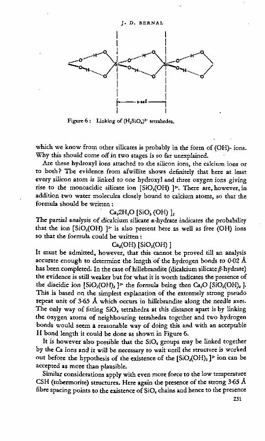
which we know from other silicates is probably in the form of (OH)- ions. Why this should come off in two stages is so far unexplained. '
Are these hydroxyl ions attached to the silicon ions, the calcium ions or to both? The evidence from afwillite shows definitely that here at least every silicon atom is linked to one hydroxyl and three oxygen ions giving rise to the monoacidic silicate ion [SiO3(OH) ]3‘. There are, however, in addition two water molecules closely bound to calcium atoms, so that the formula should be written :
' Ca32H2O [SiO3 (OH) ]2The partial analysis of dicalcium silicate a-hydrate indicates the probability that the ion [SiO3(OH) ]3' is also present here as well as free (OH) ions so that the formula could be written:
Ca2(OH) [SiO3(OH) ]It must be admitted, however, that this cannot be proved till an analysis accurate enough to determine the length of the hydrogen bonds to 0-02 A has been completed. In the case of hillebrandite (dicalcium silicate ^-hydrate) the evidence is still weaker but for what it is worth indicates the presence of the diacidic ion [SiO2(OH)2 ]2- the formula being then Ca2O [SiO2(OH)2 ]. This is based on the simplest explanation of the extremely strong pseudo repeat unit of 3-65 A which occurs in hillebrandite along the needle axes. The only way of fitting SiO4 tetrahedra at this distance apart is by linking the oxygen atoms of neighbouring tetrahedra together and two hydrogen bonds would seem a reasonable way of doing this and with an acceptable H bond length it could be done as shown in Figure 6.
It is however also possible that the SiO4 groups may be linked together by the Ca ions and it will be necessary to wait until the structure is worked out before the hypothesis of the existence of the [SiO2(OH)2 J2" ion can be accepted as more than plausible.
Similar considerations apply with even more force to the low temperature CSH (tobermorite) structures. Here again the presence of the strong 3-65 A fibre spacing points to the existence of SiO4 chains and hence to the presence

Figu
re 7
: Prepa
ratio
n and
reac
tions
of ca
lciu
m an
d cal
cium
sodi
um hy
drat
ed
silic
ates
. (TA
/Zo,
Berl
in, 1
950)
.
of the [SiO2(OH)2]z" ion. In this case the formula would be simply Ca [SiO2(OH)2] (H2O)y where y=0 to about 1-0 and the calcium enriched compounds would represent an addition of epi-axially arranged Ca(OH)2 layers, possibly on'both sides of the thin calcium silicate layers. The spacings of the two are sufficiently alike to permit this. The general formula might be thus written:
Ca [SiO2(OH)2] [Ca(OH)2], [H2O]y
where x varies from 0—0-5 for CSH(I) and is 1 for 0,511(11).
These views are however still speculative and must await confirmation from the determination of the structure of the tobermorite complex of structures.
What is known of the structure of xonotlite may throw more light on the relations of the hydrated and anhydrous calcium silicates. Here again the needle axis has a strong pseudo-periodicity of about 3-65 Ä but the low water content precludes the presence of hydrated silicate ions as a main constituent. In this case the analogy is more with the structure of wollastonite which also has a fibre pseudo period of 3-64 A. That this is a genuine relationship is rendered most probable by the conversion of fibres of xonotlite on heating to about 900 °C into parallel fibre aggregates of wollastonite. The mechanism of this is not easy to understand in terms of the generally accepted structure of wollastonite23 which contains [Si3O9]6' meusilicate rings piled along the fibre axis. The common possession of a 3-65 A pseudo period along the fibre axis for wollastonite, xonotlite, hillebrandite and CSH (I) seems unlikely to be accidental, yet, if it is based on an underlying structural identity we seem to be driven either to dispute the SijO, rings in wollastonite or to accept them in the heavily hydrated CSH (I). This central problem of the silicate chain arrangement can only be finally settled by complete structural analysis. Meanwhile some indications of the possible silicate ions can be derived from purely chemical considerations.
EVIDENCE FROM CHEMICAL REACTIONS
Thilo has carried out a series of parallel investigations on alkali and alkali- earth silicates and phosphates.24 His reaction scheme for silicates is shown in Figure 7. .
In interpreting these results he postulates a series of more or less hydroxyl replaced pyrosilicate chains of the general formula [SinO2n+2](2n+2,‘ where any of the O-ions not involved in the chain can be repheed by hydroxyL Most of these formulae are based on a general theory of polysilicate ion formation and not on any crystal structure analysis. Their exphnation of the chemical data might just as well be met by other formuhe for the ions involved. Indeed in the one case where X-ray analysis is forthcoming, afwillite, only separate SiO, tetrahedra have been found instead of the Si2O7 ions proposed by Thilo,
This criticism however does not apply to the hydroxymonosilicate ions of which he has studied the calcium and sodium salts. In particular the
- 233

THE STRUCTURES OF CEMENT HYDRATION COMPOUNDS
compound CaNaHSiO4, Thilo finds by X-ray analysis to be isomorphous with sodium sulphate Na2SO4 and consequently it should be written CaNa [SiO3(OH) ]. This provides independent evidence for the existence of the [SiO$(OH) ]3" ion. Further he derives a compound CaH2SiO4 in three different ways: from precipitation of sodium silicate by calcium chloride, by hydrolysis of CaNa2SiO4 at 180 °C and by hydrolysis of CaNaHSiO, at
TOO °C. This compound is identical with the CSH(I) (tobermorite) group.* The compound that he himself identifies with riversideite is certainly different. Thilo considers that the chemical properties of CaH2SiO4 show that it contains the [SiO2(OH)2]2" ion. This is also the conclusion from our own work though detailed structure analysis will be required to establish it. Thilo has also carried out some interesting and suggestive experiments on the base exchange character of this compound. He has shown that in the presence of nickel salts it can be converted to garnierite while with magnesium salts it gives something resembling antigorite. This would seem to show that some if not all of the calcium ions are readily accessible for exchange and reinforces the analogy with the clay minerals found through their crystal structure. The analogy is, however, not a close one for both garnierite and antigorite have fully developed mica-like silicate layers which are certainly not present in CSH(I). It is, however, very similar to the mechanism of formation of nickel clay minerals from silica gel in the activated catalysts studied by De Lange and Visser." At this stage the chemical evidence for the existence of hydrated silicate ions can hardly be taken as more than suggestive but as far as it goes it supports the picture derived from X-ray studies.
ELECTRON MICROSCOPIC AND DIFFRACTION STUDIESThe carefully executed studies of Grudemo2* using electron diffraction to
study individual crystals of calcium silicate hydrate preparations whose appearance is registered in the electron microscope goes far to confirm the general picture of their shape and size and ciystalline nature. Grudemo repeated as nearly as was possible Taylor’s preparations and in addition made use of supersonic vibration to disperse the reacting materials C,S, or Ca(OH)2 and silica gel. Some differences could be observed between die various preparations. Those rapidly precipitated showed the smallest, thinnest and most irregular forms. All, however, gave the same general picture; that of ragged ended cigar shaped rolls composed of extremely fine plates—which occasionally appeared in an unrolled state. He shows how this corresponds to the appearance presented by the swelling clay mineral halloysite, the structure of which has already been compared with that of CSH(I) and CjSH^I) on the evidence of the X-ray data. The curling up of the plates may be a secondary phenomenon in both cases due to loss of water in the vacuum chamber of the electron microscope but this would naturally be very difficult to check.
The electron diffraction data are more difficult to interpret. Most of the sharp lines they contain are shown to be due to calcite, which in spite of all

precautions seems to have been produced by atmospheric CO2. Nevertheless from the fact that the forms seen in the electron microscope are totally different from those of calcite and that some of the preparations show a mottled appearance suggestive of numerous calcite crystals, it may be reasonably argued that the primary formation was that of a calcium silicate hydrate in extremely thin sheets. These unstable crystals with their enormous surface have been more or less decomposed by CO2 but without serious change of form. They are at worst pseudomorphs and should give reliable indication of the original form of the hydrate crystals.
The scale of the crystals formed is of the order of 500 Ä in length and 100 A in width. The thickness is not easy to measure but must be less than 100 A indicating layers containing less than ten repeat units, thus accounting for the very blurred reflection from the (002) plane.
CONCLUSIONSThe main conclusion from the X-ray and physical chemical study of
cement hydration compounds is that there is only one or possibly two very similar crystalline forms, CSH(I) and C2SH(II), produced mainly at temperatures below 140°C and closely related to the mineral tobermorite. Even at the present stage of the research it is possible to show that the structure of this hydrate is that of a layer lattice with a variable thickness indicating the presence of interstitial sheets of water molecules. There may also be a certain amount of regularly adsorbed Ca(OH)2 which would account for the great range in the CaO:SiO2 ratio. The short pseudo-repeat unit of 3-65 A corresponding to the needle axis is common to a number of relatively better crystallized hydrothermal products and natural hydrated calcium silicate minerals such as hillebrandite, foshagite, xonotlite, okenite, and even the anhydrous wollastonite. This may indicate a common basic lime silicate linkage system, the nature of which can only be revealed by further research.
The work done so far can only be considered to be of a pioneer nature. What it has shown is that the problems of the calcium silicate hydrates, though difficult, can be successfully attacked by modern crystallographic methods. The next steps are also apparent. They lead in two directions. One is a fundamental and complete structural analysis of the silicate hydrates and an establishment of their stability ranges or phase diagram. The other is an extension to the more complicated system represented in the setting of Portland cement of various compositions and under different conditions. Only when these have been well explored will it be possible to find a truly scientific explanation of the phenomena and consequently gain real control of the industrially important processes of the setting, hardening, creep and shrinkage of concrete. i ,
REFERENCES
1. Steinour, h. h. ChemicalKmiewt. 1947. Vol. 40. p. 391.2. BÜSSEM, w. Symposium on the Chemistry of Cements, Stockholm. 1938. p. 141.

3. Bernal, j, D. and megaw, h. D. Proceedings of fix Royal Society. A. 1935.Vol. 151. p. 384.
4. megaw, h. d. Ata Crystalfograpbica, 1949. Vol. 2. p. 419; 1952. Vol. 5.p. 477.
5. Ehrenberg, w. and spear, w. E. Proceedinis of the Physical Society. B. 1951.Vol. 64. p. 67.
6. heller, L. and TAYLOR, h. F. w. Journal of the Chemical Society. 1951. p. 2,397.7. TAYLOR, h. f. w, and bessey, G. E. Magazine ofConcrete Rjesearch. 1950. Vol.2.
No. 4. p. 15.8. Taylor, h. F. w. Journal of the Chemical Society. 1950. p. 3,682.9. Taylor, h. f. w. Journal of Applied Chemistry. 1952. Vol.2. p. 3.
10. heller, L. and TAYLOR, H. F. w. Journal of the Chemical Society. 1952. p. 1018.11. heller, l. and taylor, h. f. w. Journal of the Chemical Society. 1952. p.2535.12. taylor, h. F. w. Journal of the Chemical Society. 1953. p. 163.13. flint, e. p., mcmürdie, H. f. and wells, l. s. Journal of Research of th*
National Bureau of Standards. 1938. Vol. 21. p. 617.14. eakle, A. s. Bulletin of the Department of Geology. 1917. Vol. 10. p. 327. (Uni
versity of California Publications).15. mcmurdie, h. F. and flint, e. p. Journal of Research of the National Bureau of
Standards. 1943. Vol. 31. p. 225.16. Clark, L. M. and Bunn, C. w. Journal of the Society of Chemical Industry. 1940.
Vol. 59. p. 155. (see also American Society for Testing Materials index).17. bessey, G. E. Symposium on the Chemistry of Cements. Stockholm. ,1938. p. 178
and p. 377.18. bogus, R. h. and Lerch, w. Industrial and Engineering Chemistry. 1934. Vol. 26.
p. 837. .19. thorvaldson, T. and shelton, G. R. Canadian Journal of Research. 1929-
Vol. 1. p. 148.20. heller, l. Acta Crystallograghica. 1952. Vol. 5. p. 724.21. zocher, H. Zeitschrift für anorganische {und allgemeine') Chemie. 1925. Vol. 147.
p. 91. '22. Bernal, J. D. and Fankuchen, I. Journal of General Physiology. 1941. Vol.
25. p. 111.23. barnick, m. a. w. Mitteilung aus dem Kaiser Wilhelm Institut für Silikatforschung.
Nr. 172. 1936.
24. Thilo, E. Abhandlungen der Deutschen Akademie der Wissenscbaften. Berlin. 1950.No. 4. p. 1.
25. de lange, j. and visser, x. De Ingenieur. 1946. Vol. 58. p. 24.26. GRUDEMO, 1. (private communication).27. Bernal, J. D., JEFFERY, j. w. and taylor. H. F, w. Magryne of Concrete
Research. 1952. Vol. 3, No. 11. p. 49.28. Mackay, h. L. and taylor, H. F. w. Mineralogical Magyryne. 1953. Vol. 30.
p. 80. '29. taylor, h. f. w. Mineralogical Magazine, in the press.30. heller, l. Mineralogical Magazine. 1953. VoL 30. No. 221. p. 150.31. taylor, H. f. w. Proceedings of the International Symposium on the Reactivity of
Solids. Gothenburg. 1952.32. berman, h. American Mineralogist. 1937. Vol. 22. p. 342.33. CLARtNGBULL, G. F. and het, M. H. Mineralogical Magazine. 1952. VoL 29.
p.960.34. heller, l. and taylor, h. f. w. Unpublished work.35. McConnell, J. d. c. Mineralogiccd Marine, in the press.

DISCUSSION
P. M. DE WOLFF ,I would like to put forward some results which I have recently obtained
with magnesium oxychloride cement, in view of the importance they may have with regard to the correlation between structure and cementitious properties.
These magnesium oxychloride cements are completely fibrous. The fibre spacing is about 345 A, and persists up to temperatures of about 300°C, though the material undergoes several phase changes in this process.
The structure investigation1 has given the result that this fibre spacing is related to the distance between Mg-neighbours in brucite, but the hydroxide layers are not present as such in the structure; they are, as it were, folded so as to give rise to infinite bands consisting of two or three rows of octahedra. The elongation of the Mg-Mg distance in the fibre direction as compared with that in brucite is explained by the partial replacement of OH by H2O. .
It struck me that in the case of calcium silicate hydrates occurring in Portland cement, the persistent spacing of 3-65 A is also slightly greater than the disunce between calcium neighbours in calcium hydroxide (3-59) and I would like to suggest the possibility that in this case too the hydroxide layers may be broken up in bands of the above-mentioned kind, also because the period of 5-62 A in the other direction is difficult to reconcile with complete layers.
REFERENCE
1. Wolff, p. m. de and walter-l6vy, l. The crystal structure of Mg2(OH)3 a.4H2O. Acta Cryttallograpbica. In the press.
MRS. L. HELLER
The thermal decomposition of the hydrated calcium SILICATES
Since Professor Bernal’s paper was written, an extensive investigation has been in progress at Birkbeck College, and is not yet completed, covering the changes occurring on thermal decomposition of the hydrated calcium silicates, with the object of studying the mechanism of the dehydration processes and the structural relationships of the compounds.
The investigation was carried out on oriented fibres of okenite, xonotlite, riversideite,’ foshagite, and hillebrandite, and on single crystals of gyrolite,2 afwillite and dicalcium silicate «-hydrate. In some cases powder specimens were used to supplement the data derived from fibres and crystals. The starting materials were identified by X-ray oscillation and rotation photographs and their axial directions and degree of order established. They were

THE STRUCTURES OF CEMENT HYDRATION COMPOUNDS
heated on platinum foil in a thermostatically controlled electric furnace for periods mostly of several hours. The products were then investigated by X-rays as before. The results obtained for each compound are summarized below.Okenite
Different fibres derived from the same mineral specimen gave X-ray photographs differing in detail but showing the same salient characteristics. On heating at between 330-630°C the X-ray pattern remained essentially that of okenite, but was found to be identical for the different fibres. The initial variations may possibly be ascribed to different states of hydration, but may also be due to complex twinning, to the presence of intimately inter-grown impurities or to slight variations in lime:silica ratio. At 730°C and above, all fibres of okenite gave a mixture of ^-wollastonite and cristobalite. The X-ray pattern of the ^-wollastonite was sharp and showed almost the same degree of orientation in the b direction as the original fibres. The presence of cristobalite was indicated only by its characteristic very strong spacing at 44 A. Figure 1 shows a comparison of rotation photographs of an okenite fibre before and after heating at 850°G The arrow indicates the 44 A line of cristobalite which evidently occurs as a fine powder; the similarity in the degree of orientation of the okenite and the ^-wollastonite is obvious. The X-ray patterns of the j8-wollastonite remained unchanged in every respect between 730°C and the highest temperatures investigated (about 1000°C). The 44 A spacing on the other hand appeared weak and diffuse at 730°C but increased in intensity and sharpness with increasing temperatures of heating. Thus it may be concluded that the jS-wollastonite was immediately produced in a well- crystallized state but that silica was expelled from the structure first in a very finely divided form, cry stallizing better on further heating.
CS2H2 —* J3-CS + SiO2 (cristobalite)(fibrous) (fibrous) (powder)
Figure 1: Rotation photographs of an okenite fibre. Above: before heating. Below: after heating to 850°C.

Xonotlite The thermal decomposition of xonotlite has already been mentioned
by Professor Bernal. The formation of ^-wollastonite was first observed on heating at 710°C. Below that temperature the xonotlite remained completely unchanged. As with okenite, the ß-wollastonite formed was only slightly less well-oriented than the original material. However, in this case the X-ray pattern of the ß-wollastonite at the lowest temperature of its formation was somewhat modified in intensity distribution compared with that of the normal mineral. In particular the strong line at 8 Ä was found to be weak. It was still weak after heating the specimen at 75O°C and only at still higher temperatures was the normal pattern of ^-wollastonite obuined. This suggests that the transformation of xonotlite into ^-wollastonite is only complete above 750°C.
CSH0.a ß-CS (fibrous) (fibrous)
Cakium silicate hydrate (I) and riversideite ,The behaviour of these compounds on heating was studied J>y Taylor,1
who investigated fibres of riversideite and powder specimens of calcium silicate hydrate (I). He found that heating at temperatures up to 550°C decreased the c axis, probably because of the expulsion of water layers. At 700°C a new phase appeared which could not be identified; this was preferentially oriented in the b direction of the original fibres and showed the same repeat distance. On treatment at temperatures above 800°C, ^-wollastonite, again oriented in the b direction, was obtained as the sole product. A series of experiments, using as starting material calcium silicate hydrate samples of lime:silica ratio graded from 1 to 1-5 is envisaged, to study the reactions of the excess lime on heating.
CSH^.j —> Intermediate —» ß-CS (fibrous) fibrous phase (fibrous)
Foshagite 'Fibres of foshagite mostly remained unchanged up to a temperature of
750°G In one case, however, the X-ray photograph of a fibre after heating at 550°C showed, in addition to unchanged foshagite, a set of sharp powder-rings characteristic of a sodium chloride type of structure, with d = 4-94 A. The only cubic substance likely to be present in appreciable quantity is calcium oxide, but its unit cell dimension is 4-80 A compared with 4-94 A for the compound actually obtained. Moreover, the intensity distribution is different in the two cases. It is, therefore, probable that the compound formed consists of mixed crystals of calcium oxide and small quantities of a cubic structure of larger unit cell, perhaps strontium oxide. On the other hand subsequent experiments have failed to reproduce these powder lines. Further experiments are still in progress. The powder lines disappeared on heating at 650°G If they were genuine and the expanded
239

THE STRUCTURES OF CEMENT HYDRATION COMPOUNDS
calcium oxide was actually derived from foshagite, this would indicate that calcium oxide (or hydroxide) can be expelled and re-absorbed from foshagite without any fundamental change in the structure. Clearly this would be a very interesting phenomenon but at present it lacks confirmation.
After heating at 750°C and subsequently at temperatures up to about 1000°C all samples of foshagite gave rise to a mixture of ^-wollastonite and ß-C2S, both alined with their b axes parallel to that of the starting material.
CjSjH, -> ß-CS + ß-C5> (fibrous) (fibrous) (fibrous)
HillebranditeAll attempts at obtaining an oriented dehydration product from
hillebrandite have so far been unsuccessful. Hillebrandite remains unchanged on heating at temperatures below 520°C. At 550°C and above, even very short periods of heating cause a complete transformation to jS-CzS, which is produced in powder form with completely random orientation. This does not, of course, preclude the formation of an intermediate, oriented product which, under the prevalent conditions, immediately reacts to give ß-C^S. However, there is no evidence for postulating such an intermediate phase.
CzSH -> j3-C2S (fibrous) (powder)
Gyrolite " 'Single crystals of this compound were studied by Mackay and Taylor.2
It is hexagonal and gives rise to a very complex X-ray pattern; this is somewhat simplified on heating at temperatures between 450-700°C. After heating at 70Q-750°C gyrolite was still present but additional reflections also appeared. The more prominent of these were attributed to the presence of «-wollastonite but the occurrence of an additional intermediate stage could not be excluded, «-wollastonite, and a little of the ß-form, probably derived by inversion of the «, were the only detectable products on heating above 750°G «-wollastonite is triclinic, pseudo-hexagonal. It was formed with its pseudo-hexagonal c axis, of length 19-65 A, alined parallel to that of the original gyrolite, of length 22-13 A. The (2130) direction in gyrolite, of spacing 3-18 A, became the pseudo-(1120) direction in «-wollastonite, with a spacing of 3-42 A. It is remarkable that «-wollastonite should be formed at all at 700°C, as the ß—>«-wollastonite inversion usually takes place between 1125-1178°G It indicates that a close structural resemblance must exist between gyrolite and «-wollastonite, facilitating a direct transformation. No other product besides «-wollastonite (and a little of the ß-form) could be detected by X-rays.
GSjHi —» «-CS + excess silica ?(single (single (amorphous) crystal) crystal) ‘

AfwilliteThe thermal decomposition of powder specimens of afwillite was
previously studied by Mrs. Moody.4 The present results, although not yet completely interpreted, can only partially be reconciled with hers. She found that after heating at 550°C a mixture of dicalcium silicate, quartz and calcite was formed and on heating above 1000°C rankinite was the sole product.
In the present investigation crystals of afwillite, heated at 350°C, gave rise to single crystals of y-C2S and of an additional phase X which could not be identified. Between 350°C and 730°C y-C2S was the sole product detected by X-rays; between 730-870°C y-C2S still occurred, but was mixed with another phase, Y, which, like X, gave rise to an X-ray pattern unlike that of any other known hydrated or anhydrous calcium silicate. The crystals of y-C2S produced were oriented with their b axis (= 5-06 A) parallel to that of the original afwillite (= 5-63 A). (The crystals obtained in these experiments were not perfect, but with careful choice of material and conditions, heating of afwillite may prove a good method of preparing single crystals of y-QS.) Both phases, X and Y, were single crystals alined parallel to the b direction of the y-QS. The main repeat distance of both compounds in that direction is approximately 5-06 A as for y-C2S, but phase X shows a pseudo-halving. It is possible that either X or Y corresponds to a structural modification of y-C2S and that the other phase may be metarankinite, described by McMurdie and Flint,3 for which no X-ray data were available. Neither could be identified with any of the forms of silica, calcite or calcium oxide, as suggested by Mrs. Moody. Some excess silica must be present together with the y-QS, but is probably amorphous. Figure 2 shows a rotation photograph of a crystal of y-QS, obtained from an afwillite crystal on heating at 650°C, mounted about the b direction of the original afwillite. It is evident that the crystal of y-C2S is slightly disoriented, but a more careful choice of starting material and conditions may lead to improved crystallization.
In agreement with Mrs. Moody’s results, afwillite crystals on heating above 870°C were found to give rankinite as the only product. This was produced in the form of a few small well-ordered and intricately twinned crystallites.
!• * A
Figure 2 : Rotation photograph of crystal of y-C2S obtained by heating an afa'illite crystal at 650°G

It thus appears that the re-arrangement of afwillite to X, Y and y-CaS can proceed with relative ease by a re-arrangement of the structural units, but that the formation of rankinite is associated with the partial disintegration of the structure. '
CjS.Uj X + Y-CjS —♦ y-C2S + excess silica?»------ ,------ •
(single crystal) (single crystals) (single (amorphous) crystal)
IC3s2 r-CS + Y
(several single •* — '----- <----- 'crystals) (single crystal)
DicalciHm silicate ct-lydrateInvestigations of the changes produced on heating C2SxH were made
difficult by the very small size of the crystals and the impurity of the available powder samples. However, several experiments indicated that crystals of C2SaH were stable up to 600°C, when they changed to a powder of ß-C2S. This sometimes inverted to the y form.
C2SH /3-C2S (single crystal) powder
Discussion With the exception of hillebrandite and C2SxH all the hydrated calcium
silicates under investigation, on thermal decomposition, gave rise to at least one product which was only slightly less ordered than the starting material. Moreover, this product had at least one axial direction in common with the unique axis of the initial compound and the repeat disunce in that direction remained nearly unchanged. The X-ray photographs of all the compounds (including hillebrandite and C2SxH) were sharp and clear, both immediately below and above the transition temperature. This indicates the absence of an intermediate amorphous state, which, in view of the orientation of the products, is in any case highly improbable. It therefore follows that the changes on dehydration proceed by a re-arrangement such as to cause the smallest possible disturbance of the existing structure, at least in the direction of the unique axis. Transformations to oriented thermal decomposition products were also observed by Brindley1 in the case of chlorites.
The present results (cf. Table 1) show that in the fibrous hydrated calcium silicates okenite, xonotlite, riversideite and foshagite, ^-wollastonite is either the sole product, or one of the products of thermal decomposition. Hillebrandite has a higher lime:silica ratio than the rest and probably therefore does not yield wollastonite, although it also belongs to the fibrous group. The difficulties raised by the structural relationship between the fibrous group of hydrated calcium silicates and ^-wollastonite have already

been discussed by.Professor Bernal. A complete re-investigation of the structure of ^-wollastonite is, therefore, urgently required.
The non-fibrous compounds, unlike the fibrous ones, do not resemble each other and consequently give rise to differing thermal decomposition products. In the case of gyrolite and afwillite these bear an obvious resemblance to the respective starting materials but C2SaH, which. Eke hillebrandite, has a high Emeisihca ratio, forms an unoriented product.
TABLE 1.
SubstanceTemperature of heating Product
Form in which
product 11* l2t±20°C occurs -
* li = length of unique axis of starting tnateriaL , ,t lj = length of that axis of die produces) which is oriented parallel to the unique axis
of the starting tnateriaL
Group A—fibrous
Okenite cs,h2 730-approx.
-1000ß-QS-b
cristobalitefibre powder
2 x 3-63 2 X 3-64
Xonotlite CSHo-y
710-850 ß-CS fibre 2 X 3-63 2 X 3-64
Riversideite CSH,.,., (approx.)
700 Intermediate phase
fibre j-2 x 3-63 2 X 3-63
800 ß-CS fibre 2 x 3-64Foshagite. c,s3h2 750-approx.
-1000ß-cs + ß-QS
fibre fibre
2 x 3-63 2 X 3-64 6-76
Hillebrandite QSH
550-approx.-1000
ß-CzS powder 2 X 3-63 —
Group B—non fibrous {sin^h crystals')
Gyrolite C^H,
750-1200 a-CS single crystal
22-13 19-65
Afwillite CÄH,
350 T-QS 4- phase X
single crystal single crystal
► 5-63
5-06
2 X 5-06
450-650 Y-CrS single crystal
506
730-870 Y-CzS-b phase Y
single crystal single crystal
5-06
5-06
1000 c,s2several twinned crystals
Dicalcium silicate «-hydrate CjSH
600-approx.-1000
ß-CzS powder —

REFERENCES
1. Brindley, G. w. International Sympotium oft th« Keattipiij of Satids. Gothenburg.1952.
2. Mackay, a. l. and taylor, H. F. w. Paper in preparation.3. Mcmuhdie, H. F. and flint, E. F. Journal of Reteareh of the National Bureau of
Standards. 1939. Vol. 21. p. 629.4. moody, k. m. Mineralogieal Magazine and Journal of the Mineratogkal Satiety. London.
1952. Vol 29, p. 838.5. taylor, h. f. w. Paper in preparation.
W. H. TAYLORI wish to mention a few points arising from my reading both of Professor
Bernal’s paper and of Mrs. Heller’s contribution to the discussion. I shall leave it for Dr. Megaw to discuss some important aspects of the interpretation of the afwillite structure.
I want first to speak about the thermal decomposition effects reported "by Mrs. Heller. Here I am speaking on behalf of Mrs. Moody, who carried out in our laboratory some rather similar dehydration work on afwillite itself.1 It is most exciting that Mrs. Heller has been able to obtain really beautifully oriented fibre specimens of y-dicalcium silicate. In particular it is important that she will now be able to check completely, if she has not already done so, the correctness of the structure proposed for r-C2S, which has always been assumed to be of the olivine type though the evidence has been less complete than is usually regarded as desirable by X-ray crystallographers.
In the higher temperature range of Mrs. Heller’s experiments, she finds rankinite as the only product of dehydration, and Mrs. Moody’s work is entirely in agreement with this. At the lower temperatures of dehydration, Mrs. Moody found, in addition to the y-C2S observed by Mrs. Heller, very definite evidence of the existence within the dehydrated material of something which transforms quickly and easily into calcite. This is checked by means which are reported in Mrs. Moody’s paper, and it is perhaps interesting to notice that in Professor Bernal’s paper there is a reference to the difficulty of avoiding the production of calcite in various C-S-H preparations. In his reference to electron microscope and electron diffraction work, this point is brought out very clearly.
Also, in connexion with these dehydration experiments in general, I should like to refer to work done long ago (by Aruja in the first place) on the dehydration of fibrous chrysotile asbestos,1 where strikingly similar effects are seen, in that beautifully crystalline, and very highly oriented olivine (or forsterite) is produced as the fibre loses its water. A good many of the effects observed in the dehydration of these calcium silicates are strictly paralleled in the dehydration of fibrous chrysotile asbestos. 1 agree with Professor Bernal that when we have a full understanding of one of

these dehydration experiments we shall be able to explain many other transition effects in solids.
May I say how welcome will be the promised full structure analysis of ß-wollastonite which is being undertaken in Professor Bernal’s laboratory. Since the work done in 1936, which was referred to in Professor Bernal’s paper, there has been more X-ray work on ß-wollastonite by Ito,1 but I think that no new light has been thrown on the difficulties which have been so troublesome, not only to X-ray crystallographers, but also to geologists and mineralogists.
One point I should like to stress in connexion with techniques. Professor Bernal this morning pointed out to you the extreme importance, for all the work he has been discussing, of the development of the practical side of X-ray techniques, for example in the use of micro cameras and fine-beam X-ray generators. The other thing which we X-ray crystallographers desire most earnestly is a corresponding advance in the technique of interpretation for this kind of structure, which would be comparable with the great advances in recent years in methods for the analysis of extremely complex organic structures.
REFERENCES
1. MOODY, K. M. Mineralogical Magryne. 1952. Vol. 29. p. 838.2. Hargreaves, a. and taylor, w. h. Mineralogical Magazine. 1946. Vol. 27.
p. 204.hey, M. H. and bannister, F. A. Mineralogical Magayne. 1948. Vol. 28.
p. 333. '3. ITO, t. X-raj Studier on Polymorpbitm. 1950. Tokyo, p. 93.
H. D. MEGAWThe work of Professor Bernal and his colleagues is of very great interest
in bringing some order into the confused crystallography of the hydrated calcium silicates.
I should like to comment on the 3-6 A spacing in the fibrous hydrates. Though the existence of (SiOjOH)1- or (SiO2(OH)2)2" ions is very probable, the evidence from afwillite* does not suggest that their linkage together by hydrogen bonds would account for the fibre structure; it would point rather to Professor Bernal’s alternative suggestion that the linkage is by Ca ions. In afwillite, the direction of short spacing and strong bonds (corresponding to the elongation of the crystal) is marked by a continuous line of shared edges between Si tetrahedra and Ca polyhedra; on the other hand the direction in which hydrogen bonds predominate is cut across by the cleavage plane. Thus the hydrogen bonds are not the strongest links in this kind of structure.
The length of 3-6 A would be quite appropriate for linkage by Ca, particularly in view of evidence that Si tetrahedra need not be strictly regular. A column of Si and Ca polyhedra strongly linked by shared edges,

THE STRUCTURES OF CEMENT HYDRATION COMPOUNDS
might persist in a variety of hydrate structures and in the anhydrous wollastonite.
Some recent observations I have made on the mineral bultfonteinite illustrate this. Its empirical formula is Ca4Si2O1(OH)tF2, and it is believed to be an alteration product of afwillite (Parry, Wright and Williams).1 The short spacing is almost exactly that of afwillite, and it seems likely that the structure consists of columns of Ca-Si-O polyhedra identical with those in afwillite but differently arranged in their side linkages. A second type of strongly-linked Ca-Si-O column might in the same way be the building unit common to fibrous silicates of 3-6 Ä spacing.
There is often a danger of neglecting the importance of the Ca ion in this kind of structure. This comes about because in determining a structure it is often easiest to begin with the oxygen packing or the placing of silicate groups, leaving Ca to be filled into the vacant cites. Once the structure is known, however, it is misleading to continue thinking in such terms, because the detail of the Ca-O bonding is clearly an important feature, which needs to be given adequate attention.
REFERENCES
1. MECAW, H. D. Aeta Ci^siallograpbira. 1952. Vol. 5. p. 477.2. parry, J., Wright, p. E. and williams, a. f. MinerobyealMagcyne, 1932.
Vol. 23. p. 145.
E. THILOThe X-ray analyses of Professor Bernal and his colleagues have given
new knowledge of the constitution of calcium silicate hydrate, and this allows the first real assertions of value about this important class of compounds, both from the theoretical and practical aspects. The results of Professor Bernal and his colleagues are in agreement with our researches on the chemical nature of these materials at a Urge number of points. Like Professor Bernal, we have come to the conclusion that the water in these compounds is present, at least in part, as very weakly acid, hydroxyl groups, bound to silica.
The greater number of the compounds investigated by Professor Bernal have been called by him monosilicate. From new experiments, which we have recently performed in Berlin, we have found that on the dehydration of these substances, and also in equilibrium with solutions of varying pH, there is far-reaching condensation between the monosilicate radicles, whereby they form, under the influence of water, salts of polymeric silicic acids.
Thus my colleagues and I have come to the conclusion that xonotlite must be an acid tetrasilicate. The reaction of the compound named CSH(I) with a solution of nickel chloride leads in out opinion not only to an exchange of calcium with nickel ions, but also involves a balanced condensation of

(H2SiO,)2" anions into silica networks or silica chains. This condensation is controlled by the low pH of the nickel solution. The CSH(I) also reacts with other salt solutions, the reaction being accompanied by condensation.
By reason of our researches on polymeric phosphates we have come to the view that in the structure of wollastonite the anionic groups are not built up of (Si3O9) rings but are spirally wound (SiO3) anion chains.
A. GRUDEMOAt the Swedish Cement and Concrete Research Institute the calcium
silicate hydrates are at present studied by means of electron microscopy and electron and X-ray diffraction. Professor Bernal has made an excellent review of our preliminary investigation in his paper, but quite recently some further results have been forthcoming. Figures 1-8 show some micrographs of characteristic specimens of calcium silicate hydrates obtained in various ways.
The electron microscope used in these studies is of the Philips design, which enables the operator to record almost instantaneously the electron diffraction pattern given by the specimen visible on the image screen without moving the specimen, only by changing apertures and lens currents. This is of course a great advantage and makes this type of electron microscope specially suitable for studies of such gel-forming substances as clays and calcium silicate hydrates with very thin layer lattice crystals.
Figure 1 is a micrograph of a calcium silicate hydrate prepared by H. F. W. Taylor in his investigation of compound formation at ordinary temperatures,* by shaking silica gel for forty-five days in an initially saturated lime solution. The product has the approximate composition CSH2.j in the air-dry state. It has been dispersed in water by ultrasonic treatment prior to the preparation of the electron optical specimen.
Figure 1: Magnification X 12,500

Figure 2: Electron diffraction diagram of the crystals shown in Figure 1.
The particles consist of very thin flakes, which are obviously flexible and sometimes rolled at the edges, as may be seen at some points in the micrograph. The similarity to days, e.g. montmorillonite, is evident.
It is a question open to discussion if the distortion and rolling of the crystal sheets of this and other specimens of calcium silicate hydrates are caused by lattice strains set up in the lattice as a consequence of a misfit between the separate units which are supposed to make up the single crysul layers, or if it is a secondary effect caused by dehydration processes in the vacuum within the microscope tube. Figure 2 is an electron diffraction diagram of the crystals shown in Figure 1. The pattern is the same as has been found by Dr. Taylor and by ourselves in X-ray diagrams, and is characteristic of the compound CSH(I). However, measurements of the ring diameters of this and other electron diffraction diagrams of the same substance show that an overall shrinkage of the lattice of about 2-4 per cent has taken place, inferring that the latter explanation of the distortions might be the most probable. The lattice spacings of other CSH(I) preparations, measured by electron diffraction, do not, however, exhibit any appreciable shrinkage, as compared with spacings obtained from X-ray diagrams, and since the accuracy of measurements on individual electron diffraction patterns is still somewhat doubtful, the question must be regarded as unsettled.
The spotty appearance of this and especially a few other diffraction

Figure 3: Magnification x 25,000
Figure 4 ; Magnification X 6,000
diagrams of the same substance indicates that the crystals are sufficiently large and well-built, to make it possible to obtain single crystal crossgrating (hk) diagrams from an isolated crystal, which might be used to confirm the dimensions and symmetry of the basal unit cell obtained for natural river- sideite by Professor Bernal and Dr. Taylor.
Figures 3 and 4 are micrographs of another material prepared by Dr. Taylor by shaking C,S with water for several weeks, until equilibrium was reached in a saturated lime solution, the final composition of the calcium

Figure 5: Magnification x 12,500
silicate hydrate precipitate being approximately CjSH,, and its X-ray diagram indicating the formation of a new compound C2SH(II). Before making electron optical specimens the powder was dispersed in a saturated lime solution by ultrasonic treatment. The morphologic appearance of these particles is substantially different from that of CSH(l). The aggregates may be described as bundles of fibrous particles, often with broom-shaped structures at the ends, probably due to the effect of ultrasonic treatment. The crystalline units of these aggregates are obviously in a highly distorted state. This is also indicated by the electron diffraction diagrams which only show a diffuse line at about 3-2-2-8 A and a line at 1-82 A.
Figure 4 shows at small magnification a phenomenon, which is sometimes seen, when C,S is dispersed in saturated lime solutions. From the surface of the flocculated particles thin fibres are protruding into the space between them, forming a fine network. Possibly this effect is caused by a secondary dissolution and recrystallization. It might be expected to appear under similar conditions also in setting cement pastes, but it is of course difficult to state whether this has anything to do with gel formation and hardening. •
Figure 5 shows a precipitate, obtained by prolonged ultrasonic treatment of CjS in water, until the lime solution formed was nearly saturated. This state was reached within a few hours, during which the ultrasonic vibrations had been applied for only a few periods of five minutes each. The proportions of the mixture were such, that the precipitate ought to have the approximate composition CjSHy, but X-ray diagrams show CSH(1) lines. The precipitate is a flocculated entanglement of very thin and distorted foils. "

Figure 6: Magnification x 12,500
Other preparations of a similar kind, made by ordinary shaking tests of C3S in water, have failed to reach equilibrium even after two months of continuous shaking, the result being only clusters of very finely divided, obviously colloidal particles together with unreacted C3S.
A series of calcium silicate hydrates has been prepared by adding ethyl silicate (C2H5O)4Si, in small portions and during continuous stirring, to a lime solution, whose concentration is kept constant at a chosen value in each separate batch by continuously distilling off water. This method was originally developed by R. Hedin, at our Institute, with the purpose of maintaining the same conditions during the synthesis of a batch, in order to obtain a homogeneous precipitate. One of these preparations is shown in Figure 6. It has been produced at a lime concentration of about 5 millimoles per litre, the resulting C:S ratio being 1-03. The habit of the units making up this aggregate is obviously that of thin, flexible foils. Electron as well as X-ray diffraction diagrams show the CSH(I) pattern.
Other preparations of the same kind with increasing lime concentration in solution have been shown to consist of CSH(I), with the C:S ratio increasing to 1-4-1-45 in saturated solutions. The increasing lime concentration is accompanied by a decrease in the dimensions and probably also the rigidity of the crystal sheets, causing a more and more pronounced aggregation and denser packing of the foils. This effect may partly be due to increasing rate of crystallization, but on the other hand it may also be caused by adsorption of continuously increasing amounts of calcium ions on the sheets of approximately monocalcium silicate hydrate composition, resulting in lattice deformations.
Figure 7 shows a specimen, which has been prepared in the following way. Ethyl silicate is cautiously poured on the surface of a saturated lime io 251

Figure 7: Magnification X 12,500
Figure 8: Magnification x 12,500
solution, so that the liquids do not mix. If the vessel is allowed to stand for some time, silica radicals penetrate the boundary surface and react with calcium ions, forming a gel-like precipitate of calcium silicate hydrate. Owing to the slow and undisturbed crystallization the foils are very well developed. A very large foil is seen, which has been torn along approximate straight lines. These might possibly have some connexion with the crystallographic axes within the sheet. Electron and X-ray diffraction diagrams show that the specimen is CSH(I). For this substance the spacings obtained by the two methods coincide closely.
The specimen in Figure 8 has been prepared by mixing calcium hydroxide

crystals and silica gel in water during ultrasonic treatment. A large amount of the silica gel has not reacted and appears as clusters of small colloidal particles. The branched and tapering calcium silicate hydrate structures have evidently grown rapidly from the silica out into the lime solution, probably following lines of maximum concentration gradient. These crystals have subsequently been attacked by carbon dioxide, which has transformed the calcium silicate hydrate to calcite and silica, the electron diffraction diagram from these particles being a calcite pattern. The initial habit of the particles has probably not been destroyed by the carbonation, the very small calcite crystals giving the interior of the lath-like formations a mottled appearance.
REFERENCE
1. TAYLOR, H. F. w. Journal oj tbe Chemical Society. 1950. December, p. 36S2.
MISS A. E. MOOREWe have been particularly interested in the advances in the knowledge
of the structure of cement hydrates revealed in Professor Bernal’s paper because of the immense practical importance of the dimensional change associated with change in water content of hydrated cement pastes.
The variable c spacing of 9-14 A noted by Dr. Taylor, with its implication of a layer structure which expands and contracts at right angles to the plane of the layers on taking up or losing water seems to be the key to moisture movement on the macroscale. In studying the hydration products of commercial cements rather than pure compounds the electron microscope seems peculiarly suitable for examining the heterogeneous reaction products in which individual particles are exceptionally fine. Individual crystals can be located and either identified or their structure elucidated by their electron diffraction patterns. Dr. Grudemo’s work in this field is of exceptional interest and he has apparently had more success than other investigators in avoiding contamination of his hydrates by COZ. The curling plate-hke crystals reported in his work have not been reported by other workers and, if due to loss of water to the microscope vacuum, will be difficult to avoid. Direct observation of wet material in the electron microscope has been attempted with biological specimens but the techniques are limited in scope and replica studies may be more helpful. Cosslett’s X-ray shadow microscope may provide an alternative solution.
In the location of water in hydrate structures neutron diffraction seems to offer special advantages. There is not the necessity for a high vacuum and furthermore the hydrogen nuclei have a larger capture cross-section for neutrons than any other atoms present so producing the most scattering and the strongest diffracted beams in contrast to the results obtained with X-ray or electron diffraction. There is also the further interesting possibility
253

THE STRUCTURES OF CEMENT HYDRATION COMPOUNDS
of introducing deuterium, with its even greater capture cross-section, as a tracer for part of the hydrate water.
R. H. BOGUEProfessor Bernal and his collaborators at Birkbeck College Research
Laboratory and at the Swedish Cement and Concrete Research Institute have made a fundamental contribution towards a solution of the complex problems concerned with the hydration of Portland cement and its constituents; their careful studies provide an inspiration to those of us engaged in similar pursuits.
With regard to the fine crystalline state and size of the calcium silicate hydrates, it is pertinent to recall that in 1946 Powers and Brownyard of the Portland Cement Association (PCA Bulletin No. 22), determined the specific surface area of hydrated Portland cement pastes by the B.E.T. method, using water as the adsorbate. For a given paste, they obtained a value of 180 square metres per gramme, which demonstrated that the ultimate particles were in the colloidal size range. Using a value of 10-6 square A for the area of a water molecule, and assuming a spherical shape, they calculated the average particle size from the surface area and concluded that, if the solid phase were an assemblage of equal spheres, each sphere would have a diameter of about 140 A. Considering the uncertainty of the packing of the adsorbed water molecules on the surface, and of the number of water molecules required to cover the surface with a uni- molecular adsorbed layer of water, the true diameter of these spheres would lie between 100 and 150 A. More recent determinations on hydrated C3S pastes indicate an ultimate particle size almost identical with that obtained above on Portland cement pastes.
A few months ago Copeland and Brunauer of the Portland Cement Association in collaboration with Swerdlow and Heckman of the National Bureau of Standards began an investigation of the hydration of C,S and Portland cement. In the course of preliminary observations with the electron microscope (PCA Memoranda, April-August, 1952) they found, among other material present, round, probably spherical particles ranging from 50 to 200 A in diameter. The electron micrographs* of the fully hydrated CjS, vacuum-dried and ultrasonically dispersed in butanol, show essentially two solid phases: large thin plates, presumably of calcium hydroxide, and small, round particles which may be a calcium silicate hydrate (Figure 1). These typical round particles also can be seen in the micrographs of similarly hydrated Portland cement and in the sawdust and scrapings
* Specimens for electron microscopy were prepared by ultrasonically dispersing the hydrated material in butyl alcohol using a 1500 kc quartz crystal oscillator for fifteen minutes. pKTien water was used as the suspending vehicle, small round particles were also observed but the dispersion was considerably poorer and a marked increase in the formation of calcite due to carbonation was noted.) A drop of the suspension was placed on a collodion-covered specimen screen and allowed to dry in room air for about an hour prior to examination in the RCA Type EMU instrument.

Figure 1: Electron micrograph of hydrated CjS, obtained by grinding C3S with water, in the ratio of 1 to 4, in a small steel ball mill for eight days (15 min. grinding followed by 45 min. rest in each hour). The non-evaporable water content then indicated 100 per cent hydration and the hydrate contained three molecules of water per molecule of C3S. (The cvaporable water was removed by drying the sample at the vapour pressure of ice at —78 °C to constant weight.) The specimen was obtained by dispersing the vacuum-dried sample ultrasonically in butanol. Attention is directed to the round particles (probably spheres) ranging from 50 to 200 A in diameter in the background and overhying the thin plates. "
freshly cut from a neat paste of C3S (Figure 2) and of Portland cement. Low-angle X-ray scattering data* obuined from the same fully hydrated,
vacuum-dried, but undispersed sample of C3S confirm the presence o discrete particles ranging from 50 to 200 A in diameter, assuming a spherica shape. .
* Obtained through the courtesy of A. S. Posner, American Dental Associat o Fellowship, National Bureau of Standards.
X-ray powder diffraction analysis of the fully hydrated, vacuum rie , undispersed C3S that was used for the above low-angle X-ray scattering

Figure 2: Electron micrograph of hydrated CjS, obtained as a neat paste by allowing (2,5 to stand at room temperature for eighteen months with water in the ratio of 1 to 0-7. The non-evaporable water content indicated approximately 85 per cent hydration. The specimen was obtained by cutting through the hardened paste with a diamond saw and dispersing the sawdust ultrasonically in butanol. Attention is directed to the small round particles surrounding the aggregated hydrated masses.
and electron microscopical studies indicates the presence of two or more crystalline phases: a dominant, stable pattern attribuuble to calcium hydroxide and a weak, variable pattern attributable to one or more calcium silicate hydrates, with interplanar spacings similar to those of the natural mineral afwillite (CjS2Hj) and Dr. Taylor’s synthetic calcium silicate hydrates (I) and (II).
From these preliminary studies it would appear that particles ranging from 50 to 200 A in diameter result from the hydration of (2,5. These findings confirm the deductions of Powers and Brownyard and provide additional information on the crj’stalline state of these colloidal particles. The full significance of these observations on the mechanism of the hydration

process and the nature of the cementing action of Portland cement will, of course, require further study.
F. M. LEAA major outstanding problem in the use of cement is how to limit
shrinkage. If the mechanism of shrinkage were really understood, and the part played by water bound in different ways in set cement in contributing to it, we should at least be on the way to finding possible means of controlling shrinkage. The work of Professor Bernal and his group is giving us, for the first time, some real knowledge of the various ways in which water is bound in set cement. The distinction between water essential to the crystal structure, probably in the form of hydroxyl ions, and intracrystalline water held in the form of interstitial sheets of water molecules, is of much importance.
Professor Bernal referred in introducing his paper to the long range ionic forces between fibrous crystals which operated over remarkable distances in solutions which were very dilute. Has a real distinction to be drawn between such forces, and their influence on the water, and those operating on water in gels of much lower water content ?
I have long thought that too much attention has been concentrated on simple capillary theory for explaining shrinkage. The work of Professor Bernal’s group has shown how the c spacing of the lattice of the hydrated calcium silicate decreases with a reduction in the amount of water held in the inter-lattice space. If the change in the content of water held in these various ways could be linked up with shrinkage, a fundamental explanation of that most important technical property of set cement would be found.
J. d. Bernal (author's closure)One of the things we hope to participate in doing is to establish the real
cells of all the substances likely to occur in the hydrated products, not only, of course, of the silicate cements, but the aluminate cements as well. It should then be possible to use powder photography with reasonable certainty as to what is being examined.
That links up with a further stage of the work, which is tying in the mineralogy with the technical products. One of the most useful collaborations has been with the British Museum and other mineralogical museums in this country and in the United States, to provide us with the rare minerals which have turned out to be identical with so many of the technical products. The two are very conveniently complementary. In the case of the synthetic product you know pretty well by chemical analysis what it is you are dealing with, but you are not very certain about its crystallographic form; in the case of the mineral you have a very good crystallographic form, but it is extremely difficult to know chemically what you are dealing with because most specimens contain several phases, or to control it, because you must take what nature offers. By putting both sets of evidence together, we

THE STRUCTURES OF CEMENT HYDRATION COMPOUNDS
should begin to approach a proper phase diagram for these hydrated compounds. ' .
Of course, the first problem was that of finding out what the constituents were, and what the phases were, and as you have heard from Dr. Taylor and Dr. Heller the essential phases have been approximately identified. One particular phase—what Dr. Taylor called the calcium silicate hydrate (I) —has turned out to be identical with the mineral tobermorite. That fixes what would appear to be the most common product of hydration of any calcium silicate system. It remains to be shown—Dr. Taylor and Mr. Nurse have been able to give some further evidence in the course of this Symposium (page 311)—that this mineral is, in fact, produced in quantity as the operative agent in actual set cement paste. I think now the evidence is fairly conclusive on that point, but it had to be done because it had previously been open to argument that what you produce synthetically in a medium containing a large amount of water may not be the same as what occurs in an actual concrete; but I think we now have direct evidence that it is identical. This mineral tobermorite turns out to be one of a group of hydrated silicate minerals of which we shall hear more in relation to the hydrothermal work later on today. They are of great interest to us, as scientists, because they furnish a group in which the basic structure remains the same while the water relations vary very much indeed. In fact, as shown in the paper, there is a continual range of composition from calcium silicate hydrates with two molecules or more of water right down to the anhydrous high temperature mineral wollastonite, in which a single crystal of one can be transformed with sufficient care into a single crystal of the other. When we consider the structures, I think we will have thrown much light on the nature of transformations in the solid phase which will be of petrological as well as of technical interest.
If we have succeeded in showing that calcium silicate hydrate (I) is formed in set pastes and concretes, it still remains to show whether it is the agent which actually holds the particles of aggregate together, and what the mechanism is by which it does hold them together. Those are the problems which still face us.
As to the first, it may be perhaps an unnecessary question to put to an audience like this, because, if nothing else, history shows it is only when you get anhydrous systems like tricalcium silicate, which can give these calcium silicate compounds, that you get the extra strength characteristic of a modern concrete as against a hydraulic lime. Therefore, I would suggest that the silicate must have something to do with it; if the calcium silicate hydrate (I) is the only silicate formed, it must be the calcium silicate hydrate (I) that does the job. That is still an indirect argument, and one would hope to be able to produce evidence later on which ties up the actual binding properties of the pure calcium silicate hydrate (I) with the properties of set concrete.
One very important point arises here. What are the characteristics that

lead to setting, not only of the silicates but, of course, of the analogous aluminates and of the older kind of plasters like the gypsum plasters ? We must find a modern interpretation of what Le Chatelier and others have maintained was the function of a gel. We have long known from electron microscope results and the polymer systems that most of the things called gels were, in fact, very fine fibrous crystals; the characteristic gel of collagen (gelatin jelly) is simply a network of fine fibres holding water in between them. There are forces between the fibres which are not capillary forces, but are some form of long-range ionic forces.
One of the most important things to establish was that calcium silicate hydrate did form such a network. We have evidence of this from the X-rays, evidence of the fact that the cold set products have only a two-dimensional structure. Therefore, we must be dealing with very thin plates. We can further infer, on account of the extremely small lattice dimension in one direction, and the evidence of the fibrous nature of products like riversideite, that one direction in these thin sheets goes very much faster than the others; so one would expect to get a ribbon-like structure.
Evidence for the first point, the thinness of the structure, has been furnished by Dr. Grudemo. Evidence for the second is more difficult to find, because he has not yet found pictures of isolated fibres of these thin materials, but they must be in some sense matted felts of material. All the evidence seems to suggest that the set silicate is something much more like a felt than anything else. It is a fine meshwork of fibres, and that is really what a gel is. A gel is something which crystillizes very fast. Fast crystallization promotes needle-like growth with ionic interactions, produces a firm and gripping mass, which provides the functional properties of the cement.
I hope I may be excused from answering most of the points of a purely crystallographic nature, which I can take up separately with the experts. One, however, I think, is of general interest—that arising out of Dr. de Wolff’s contribution on the structural analogies between Portland cement and the magnesium oxychloride cements. The close resemblance between the main fibre (pseudo) repeat unit of 3-65 A and that of 3-59 A occurring in calcium hydroxide had already been noted by Dr. Taylor {Journal1 of the Chemical Society, 1950). Dr. de Wolff’s demonstration of chains of magnesium-oxygen octahedra strongly supports the idea that a similar arrangement occurs in the calcium silicate hydrates with the difference that here hydroxyl groups are bound together in places by Si‘+ ions instead of Ca2+.
That all hydrated calcium silicate fibrous crystals are based on the same plan is also supported by the single crystal dehydration experiments reported by Mrs. Heller, and Dr. Megaw’s work on bultfonteinite shows that the linking may well be largely through the Ca2+ ions. I am inclined to agree with her in accepting this link rather than the far weaker hydrogen bonds as determining the strength of the fibres. The rather puzzling parallelism of structures with various Si:Ca ratios seems to point to a

THE STRUCTURES OF CEMENT HYDRATION COMPOUNDS
substitution of 4H+ for Si4 + similar to that which occurs in the hydrogarnet and which plays an important role in the setting of aluminous cement. On the other hand, Dr. Taylor’s dehydration isobars are not influenced by the Si:Ca ratio, a fact which is difficult to reconcile with this hypothesis. ■
As to the chemical nature of the substitution, I think Professor Thilo’s communication is of great importance. We have here in calcium silicate hydrate a substance that should be exhaustively studied as a chemical entity. Its reactions with other substances—sulphates, carbonates, alkalis,— should be studied chemically and crystallographically as a basis for further exploration of the phases of mixed hydroxides.
In another direction electron microscope observations have thrown much light on the physical state of formation of the silicate hydrates. Dr. Grudemo’s work seems to substantiate the existence of thin plate-like crystals formed under the conditions of precipitation we have studied and in some cases the fibrous habit, apparently due to rolled sheets, is well marked. The value of electron diffraction in checking the chemical identity of products which are extremely unstable in the presence of atmospheric carbon dioxide has been well brought out. It is difficult to comment without further information about the observations of Copeland and Brunauer reported by Dr. Bogue. The “ small round particles ” do not correspond to anything observed by us and it would be most useful if materials and methods of preparation and observation could be exchanged between the various workers in this field.
Finally, the remarks of Dr. Lea on shrinkage are, I think, extremely. important. I did not stress the point, but it is an absolutely essential one arising from the unforeseen discovery which Dr. Taylor has made of the sheet-like character of the calcium-silicate-hydrate. This structure does allow for a certain degree of intracrjsulline shrinkage. Now the evidence which we have just heard is that even after six months, set cement blocks are far from being fully hydrated. Consequently it seems likely that most, if not all, of the water they contain is to be found between the layers of the crystalline structure and that therefore the observed shrinkage is intracrystalline. As to the relative importance of the long range forces 1 had postulated for gel formation and those operating in an intracrystalline manner, I think that the first come into play only in the weak but coherent gels formed in the initial setting, and the latter in the later, hardening stages. The question as to whether a substance is a gel or a crystal is rather metaphysical, and I do not think it matters as long as it is something we can study by quantitative methods by means of X-rays or the electron microscope.

[1011
Theiiea.citi.oiis,andlti: TIII Hiwi ii H liKOlOi fl Hfl
HAROLD) H«. STEINOUR<
SUMMARY
The evidence available for establishing the. products of:Pörtland cement: hydration is mainly indirect. It consists largely of studies madeon thesimpler- systems CaO-SiO2-H2O, CaO-zM2O3-H2O, and! CaO-Al2O^CaSO4-H2O.1 Alkalis and Fe2Oji have been included in other; limited studies.-
Determinations of heat of hydration of Portland cement paste have beeni made mainly for immediate, practical purposes, but comparison ofthe data- with values for the clinker compounds hydrating separately has afforded 1 some indication of the. chemistry of the. matter. Recent-studies-ha vet- provided data on heat evolution over a 6J year period. Other studies havee provided extensive new data on effect of waterxement ratio. Continuous- records of the heat evolution of cement paste.during thesettingperiod,! and I over the first few days, have furnished interesting, indications of 'the- early- course of the cement reactions.
Independent reaction of the major clinker compounds is capable-in larger measure of accounting for the rates and ultimate, values of the-hydration,. strength development; and heat evolution of cement paste* but’this fact t does not rule out the possibility of some interaction. Free calcium hydroxide- is produced, and the liquid phase is saturated with this compound.’ The other ’ products formed in cement paste are gel-like and very difficult to identify- by microscopy or X-ray analysis. A promising new method of’approach1’ is that of differential thermal analysis.
It appears probable that the high-sulphate calcium sulpho-aluminate-is- formed, but then reacts with more of the calcium aluminate to form a solid 1 solution of' lower * sulphate content; Some tetracalcium aluminate-hydtate- may form, as a non-equilibrium product; after the- gypsum has all reacted. The calcium silicates evidently form hydrated calcium silicate that ’is -perhaps - lime absorptive-and has an overall lime:silica-ratio in the- neighbourhood of 2 br less, the precise value being uncertain. lion oxide may perhaps partially' substitute for alumina in the reaction products.

INTRODUCTIONA large volume of work has been done on the chemistry of Portland
cement hydration, but much uncertainty remains. The experimenter who seeks to learn what happens under the practical conditions of cement use has a difficult task. He has to contend with the complexity of Portland cement, the colloidal nature of the hydration products, the high concentration of the initial suspension, and the rapidity and finality with which cement paste solidifies to a dense, opaque mass litde responsive to the methods of microscopy and X-ray analysis. As a result, most of the scientific work pn cement hydration has been done not on cement paste itself, but on systems of fewer components, or in any case by use of excess water. Such an oblique approach, often useful in research work, has been less rewarding than it commonly is, because of the unusual difficulties in verifying the indications relative to cement paste. Until satisfactory methods are found for verification through direct observations on cement paste itself, contrary theories on what happens in the paste, or in concrete, will continue to exist side by side.
In the absence of such final verification, the situation is rather like that which Einstein and Infeld25 pictured regarding physical reality: “ In our endeavour to understand reality we are somewhat like a man trying to understand the mechanism of a closed watch. He sees the face and the moving hands, even hears its ticking, but he has no way of opening the case. If he is ingenious he may form some picture of a mechanism which could be responsible for all the things he observes, but he may never be quite sure his picture is the only one which could explain his observations.” Fortunately, the problems that confront the cement chemist are not on so metaphysical a plane, and he has reason to hope for developments that will open the watch case sufficiently for a good glimpse inside. Already, promising leads are developing, as will be discussed.
In recent reviewsM’ 241 have examined, at length, most of the background material bearing on the reaction products of cement hydration. In the present survey, the general picture revealed by the previous reviews is presented, amplified by later material which is treated in more detaiL The survey is essentially in two parts, the first of which is concerned primarily with reaction products. The second section treats of the thermochemistry, or heat of hydration, and presents evidence on rates of reaction.
REACTION PRODUCTS
INTRODUCTION
The modern era of cement research may be said to begin with the classic work of Henri Le Chatelier.54 When Le Chatelier reported his investigations in 1887, he pictured Portland cement as hydrating by indtptndtnt reaction of the calcium aluminate and the calcium silicates. This conception has remained the dominant one. Until recently at least, little basis has existed
262

for asserting interaction between any of the clinker compounds. Thus, independence of reaction has generally been assumed, except for such effects as might result from the saturation of the liquid phase with lime from the silicates. Though some recent evidence has improved the case for a degree of interaction (as by solid solution), it remains to be shown how extensive or fundamentally significant effects of this kind may be.
Independent reaction of the clinker compounds was suggested by the material presented in Bogue’s 1928 digest of the literature.9 Work on the hydration of Portland cement compounds reported by Bogue and Lerch in 1934,10 which included tests on mixtures, showed that the properties of the mixtures were in reasonable agreement with the assumption of independent reaction. Gypsum, of course, was considered to produce calcium sulpho-aluminate, but clinker compounds appeared to react with water, or calcium hydroxide solution, independently of each other. In 1935, Lea and Desch53 reported that “ the reaction of Portland cement with water is essentially the sum of the reactions of the individual constituents, modified perhaps by the formation of some hydrated tetracalcium aluminate.” With so little reason to expect interaction of the clinker compounds, it is not surprising that investigators should have been content for a long time to confine their phase equilibrium studies to the systems CaO-SiO2-H2O and CaO-Al2O3-H2O. Study of these ternary systems was, in any case, the rational approach to eventual study of more complex systems.
In extending the studies, a logical first step was addition of calcium sulphate to the system CaO-Al2O3-H2O. Though calcium sulpho-aluminates were discovered and studied much earlier, really thoroughgoing work on the system CaO-Al2OrCaSO4-H2O is of relatively recent origin. Now, however, very extensive studies are available. Other oxides of cement clinker besides lime, alumina, and silica have been studied also, with the object of determining their roles in cement hydration, but these studies will need to be carried much farther. Though they represent considerable work, they can scarcely be regarded as more than a good beginning. Jones38 has recently outlined the very extensive work that needs to be done in order fully to establish the role of gypsum. As yet, no comprehensive study of the system CaO-SiO2-Al2O3-H2O has been reported.
CALCIUM SILICATE HYDRATE
GeneralIf the calcium silicates of cement, C3S and jSQS, do react in cement paste
independently of the other constituents, what products are to be expected? To answer this question, one may study the reactions of the calcium silicates themselves, or may study the system CaO-SiO2-H2O using any initial materials that provide only these oxides. If equilibrium is reached, the composition of the final solution determines the final products. Since both CjS and jSQS are known to react with water to produce a saturated calcium
263

hydroxide solution, the interest of the cement chemist centres in the calcium silicate hydrate that exists in equilibrium with such a solution. Unfortunately, the studies that have been made do not provide uniform and unequivocal indications. There is uncertainty, also, because the state reached in cement paste may not represent equilibrium (even the colloidal equilibrium such as appears to be attained in the phase studies).
Le Chatelier54 concluded from experiments with limewater and silica sol that C3S and QS react with water to give Ca(OH)2 and CaO.SiO2.2|HzO. Since that time, other investigators have held that the siliceous product is 3CaO.2SiO2.aq, while still others have held that it is 2CaO.SiO2.aq. However, as in other cases, Le Chatelier may not have been far wrong. He, too, obtained products that analyzed higher in CaO than CaO.SiO2.2|H2O, but he considered the extra lime to be adsorbed. Some of the later investigators have supported this view.
Sixteen detailed investigations of the system CaO-SiO2-H2O have been reported.61 1> 14* 23* 3t>’ ,3> **• 301 6*' 6** 72* ,6, 771 •* Some were made bystudying the hydration and hydrolysis of the anhydrous calcium silicates, but more were made by starting with other initial reactants, such as calcium hydroxide solution and hydrous silica gel. Results of 15 of these studies, reviewed in 1947,73 were plotted together for comparison. Some of the results are rather diverse but, eliminating individual eccentricities, the general nature of the results is quahtatively as shown in Figure 1. This figure is actually a close representation of one set of data14 and was so drawn to give it concreteness, and not to emphasize any one investigation.
Figure 1: System GiO-SiO2-H,O. General nature of phase relations at ordinary temperature.

In Figure 1 the molar CaO:SiO2 ratio for the solids in apparent equilibrium with the liquid phase is shown in relation to the CaO concentration of the latter—a method of plotting that is commonly used for this system. This method is especially appropriate because the concentration of SiO2 in solution is small, and also because SiO2 in true solution is not easily distinguished from silica sol when that is present (as it may be at the lower lime concentrations). Above about 2 millimoles CaO per litre the solute is mainly calcium hydroxide.
The solids are gelatinous and devoid of microscopic crystallinity. At the lowest lime concentrations the solid is silica gel with a little adsorbed lime. The practically vertical rise of the curve at a concentration of less than 2 millimoles CaO per litre apparently represents an invariant point where silica gel is in equilibrium with calcium silicate hydrate. With increase of the CaO in the system the silica gel should all convert to this silicate. The fact that the vertical rise generally terminates about where CaO:SiO2 equals 1 has led to the rather general assumption that CaO.SiO2.aq is formed. Some investigators have thought that more than one calcium silicate hydrate is formed in this region of low CaO concentration, but the evidence is inconclusive and most of it weak. As the CaO concentration of the solution is further increased, the CaO:SiO2 ratio for the solids increases gradually (but to different degrees in different investigations). At a concentration of CaO in solution that approximates that at which saturation with Ca(OH)2 is to be expected, the curve rises nearly vertically again, except when evident supersaturation occurs (as it has in some investigations).
This final, abrupt rise evidently represents another invariant point. If it actually begins at the lime saturation point (a disputed matter which will be discussed later), then it simply represents equilibrium between solid Ca(OH)2 and calcium silicate hydrate of the over-all composition attained at the foot of the rise. The magnitude of the ratio at this point has commonly been about 3: 2 as in Figure 1. However, it has varied in different investigations and has sometimes amounted to about 2: 1. Whatever the value found, the inference has generally been that a product of similar composition may be formed in cement paste, which is also saturated with calcium hydroxide.
The question now arises as to what this product is chemically. The uncertainty is caused by the gradual rise of the curve in approaching lime saturation of the solution. The sloping curve apparently represents colloidal equilibrium between the solution and a single solid phase, for two solids could be in equilibrium with the liquid only at an invariant point. Moreover, since the curve rises and thus shows a gradual change in the composition of the solid, it represents either a phase on which marked adsorption occurs, or a solid solution of some kind. Adsorbed material has sometimes been called a second phase when it amounts to as much as would need to be assumed here, but it does not count as such in phase theory. On the basis of the adsorption theory, the chemical compound involved is generally assumed to be CaO.SiO2.aq. On the other hand, since a solid solution is commonly

CEMENT HYDRATION AT ORDINARY TEMPERATURE
regarded as a chemical combination, those who have assumed solid solution have variously assumed 3CaO.2SiO2.aq or 2CaO.SiO2.aq as the formula of the calcium silicate hydrate in equilibrium with solid Ca(OH)2. -
In view of the Urge change in CaO:SiO2 ratio (from 1:1 to 3 : 2 or 2 :1) and the shortness of the time periods in which apparent equilibrium is sometimes reached (only a few days), it would seem that the individual elements of the solid conveniently accessible to the solute must approach molecular thickness. It thus seems almost necessary that the solid should have an open structure similar to that of the zeolites (as has been suggested by Lafuma51 and others) or an expansible or easily cleavable layer structure like that of some clays.73 Under such circumstances the concepts of solid solution and adsorption may easily merge.
Kalousek10 has shown that a part of the lime in the calcium silicate hydrate is replaced by a lesser amount of alkali oxide when alkali hydroxide is added to the system. This observation has direct significance for cement pastes since cements contain significant amounts of soluble alkali.
Indications from free lime testA rather direct means of arriving at the composition of the calcium
silicate hydrate that is formed by the calcium silicates, or by Portland cement, when made up as paste, is based on free Ca(OH)2 determination. That is, after reaction, the hardened pastes are analyzed for uncombined lime, and the combined lime is obtained by difference. The methods used in the past are perhaps not highly accurate as applied to hydrated products, but are still of considerable interest. Tests made on hydrated calcium silicate pastes have generally indicated combined lime corresponding to a CaO:SiO2 ratio of 2:1 or more,”’ ,2’ J*> ’• though in one investigation’1 it was 1-6-T7.Tests made on hydrated Portland cement paste have naturally involved correction for CaO assignable to other reaction products, an uncertain process. The molar ratio of CaO:SiO2 for the calcium silicate hydrate determined in this way has been reported as 1-5,1-5, and 1-9 in different investigations. *’ •• 70
Tests for free Ca(OH)2 have also been applied in some investigations in which a relatively large proportion of water was used. Koyanagi,** using the glycerol-alcohol solution method, determined free lime in Portland cement hydrated in a large volume of saturated limewater. Allowance for lime combined by AlzOj and Fe2Oj gave a CaO:SiO2 ratio of 1:1 for the calcium silicate hydrate. Hedin,36 using ethylene glycol as solvent for Ca(OH), in a product obtained by reacting sodium silicate with a suspension of Ca(OH)ti found 3CaO:2SiO2 for the combining ratio.
More extensive studies involving free Ca(OI I)2 determination were made by Forbrich26 in 1936-7 in the laboratories of the Portland Cement Association (U.S.A.). This work, which was done as a part of a larger project, never reached publication, and the brief report on it remained buried in letter files and escaped consideration in my 1947 review.73

In his investigation. Forbrich made a succession of products by treating precipiuted silica with calcium hydroxide solutions of varied concentration. Each lime solution was passed through the silica suspension for 5 or 6 weeks, or until little or no change in concentration could be observed. The products, separated from the limewater, were analyzed for free Ca(OH)2, CO2, and SiO2 and CaO soluble in 10 per cent hydrochloric acid. Free lime was determined by the modified Emley method58 which employs glycerol-alcohol solution as solvent. The results in terms of lime combined with silica are shown in Table 1.
table 1: Composition of lime-silica products in apparent equilibrium with calcium hydroxide solutions of varied concentration at 26°C (Forbricby
Solution Solidmillimoles CaO
per litreMolar CaO:SiO2
(Corrected for free Ca^H)^
5-2 14-3 21-2
110 1-41 1-63
As Table 1 shows, the molar CaO:SiO2 ratio increased until, in saturated limewater (21-2 millimoles CaO per litre), the combined lime exceeded that for 3CaO.2SiO2.aq. Because of the changing, non-stoichiometric CaO:SiO2 ratio. Forbrich was inclined to interpret these results in terms of adsorption of lime on CaO.SiO2.aq. Others might infer, from the fact that free lime had been corrected for, that solid solution is indicated. Much depends on the effectiveness of the organic solvent used to dissolve the Ca(OH)2. It would seem that a highly effective solvent might even be capable of taking lime from a solid solution of open structure such as might be represented here. Bessey7 and Hedin” have both raised the question whether the organic solvents used to extract free lime may not be able to extract weakly combined lime. Forbrich’s results suggest a more moderate solvent action.
Mikhal’chenko,61 also, has reported that the glycerol-alcohol solvent does not extract lime from the products of varied CaO:SiO2 ratio obtained by treating silica gel with calcium hydroxide.
Ktcent workSince publication m 1947 of the review73 on which the preceding discussion
is mainly based, an important investigation of the system Ca0-Si02-H20 has been reported by Taylor.77 Taylor prepared hydrated calcium silicate specimens by three different methods, then shook individual products with water, or calcium hydroxide solution, at 17-20°C, until equilibrium was thought to be established. Irrespective of the iiiitial reactants used, the final
267

results conformed to one single curve when the molar CaO:SiO2 ratio for the solids was plotted against CaO in solution. The curve is reproduced in Figure 2. The different preparations used in the shaking experiments are identified at the right. The letters yl, B, C indicate the methods by which the calcium silicate hydrates were initially prepared, namely:
(v4) Decomposition of QS with water.(B) Reaction of calcium hydroxide solution with silica gel.(C) Double decomposition of calcium nitrate and sodium silicate.
Silica gel is indicated by S.
Cwcertratiofl ot CoO In eoMion - millimoto/tHr«
Figure 2: System CaO-SiO2-H2O at 17-20eC (Ttfi&r).
It is evident that Figure 2 is very similar to Figure 1. Thus, Taylor’s work constitutes further evidence in favour of the simple type of equilibrium curve already discussed. The central sloping part of Taylor’s curve ends where the molar CaO:SiO2 ratio reaches 1-5. The liquid phase at this point contains 20 millimoles of CaO per litre. In comparison, Taylor quotes Bassett’s1 value of 21'3 millimoles per litre for the solubility of coarse particles of Ca(OH)2 at 18°Q As will be discussed, he considered the difference between the two values to be significant.
Taylor made numerous X-ray analyses of the hydrous solids and obtained most interesting results. All products with CaO:SiO2 ratios between about 0-5 and 1-65 gave closely similar diffraction patterns. The greatest differences were a variation in the longest spacing over the range 10-12-5Ä, and variation in intensity of a spacing of 5-3Ä. The pattern was distinct from those of calcium hydroxide, calcium carbonate, and silica, and was considered to be that of a calcium silicate hydrate (which, for convenience was represented by

the numeral I). The pattern showed good agreement with ones reported for calcium silicate hydrate by Brandenberger11 and Strätling.” The near constancy of the pattern over the wide range in CaO:SiO2 ratio was considered to be attributable either to a zeolitic type of solid solution or to adsorption.
For CaO:SiO2 values below 0-4-0-5, the diffraction pattern became indistinct and the only new development was a single diffuse band. Thus, a mixture of gelatinous silica and silicate hydrate I was inferred.
At the other end of the curve, if the break at 3CaO:2SiO2 represents an invariant point caused by saturation of the solution with Ca(OH)2, one would expect both calcium silicate hydrate I and Ca(OH)2 to be present in the solids of higher ratio than 1-5. As already stated, only the hydrate I pattern was obtained up to ratio 1-65. Absence of the pattern for Ca(OH)2 in this range is not disturbing, however, for the proportion of Ca(OH)2 would be small. At ratios above 1-65 Taylor analyzed C products, obtained by double decomposition, and A products, obtained by reaction of C3S with water. The results for these two types of products differed! The C products gave the hydrate I pattern plus lines for Ca(OH)2—evidence indicative of an invariant point involving these two solids. In contrast, the A products, A4 and AS with CaO:SiO2 ratios of 1-9 and 1*94, gave patterns differing slightly from that for silicate hydrate I, and did not give the pattern for Ca(OH)2! Auxiliary tests indicated that Ca(OH)2 sufficient to have contributed 0-1 to the CaO:SiO2 ratio might have been detected, and that an amount sufficient to have contributed 0-3 to the ratio should easily have been detected. Hence, it appeared that the A4 and AS preparations had produced a calcium silicate hydrate with a CaO:SiO2 ratio of nearly 2:1—a hydrate differing only slightly in structure from I. This new hydrate was designated by the numeral II. Efforts to prepare more of it failed.
These various observations leave uncertain the phase equilibria at the highest lime concentrations. To assume a stable invariant point involving hydrate I and Ca(OH)2, one must conclude that hydrate II is a metastable product, and that the commonly accepted solubility of Ca(OH)2 was lowered, perhaps by impurity. Taylor mentioned these possibilities and, in fact, suggested that the solutions might have contained traces of alkali. However, he thought it probable that hydrate II is the stable one above 20 millimoles CaO per litre, and that those preparations in which both hydrate I and Ca(OH)2 were found were unstable. As he reports, Bessey7 also obtained a curve that showed an invariant point close to but below the accepted solubility for Ca(OH)2, and Bessey believed that a hydrated dicalcium silicate was formed.
Whether hydrate II can vary in lime content, after the manner of hydrate I, was not established, but Taylor cited the free lime tests that have been made on silicate pastes as suggestive of a maximum CaO:SiO2 ratio not greatly exceeding 2.
Whether to expect hydrate I (with a CaO:SiO2 ratio of l-5) or hydrate II in a calcium silicate or cement paste is debatable, and might remain so even
‘ 269

if it were known which hydrate is the equilibrium product". Aside from the slight difference in X-ray pattern, hydrate II with its CaO:SiO2 ratio of about 2 is distinguished from I mainly by its ability to hold more lime. Thus the question of the amount of lime held in one way or another by the calcium silicate hydrate in cement paste remains unsettled, though probably nearer solution.
Taylor made interesting observations regarding the probable crystal structure of hydrate I, a structure which may closely resemble that for hydrate II in view of the strong similarity of the X-ray patterns. All the sharply defined spacings of I could be accounted for as the hkO spacings of a unit cell having a and b axes of 5-6 and 3-6Ä, with a 90° angle between. This discovery coupled with the paucity and diffuseness of the remaining spacings, and the variability (10-12i5Ä) of the longest one, led to the following important conclusion: “ It seems possible that calcium silicate hydrate I has a layer structure in which the individual layers, in the plane of the a and b axes, are relatively well crystallized, while the distances between them represented by the 10-12-5Ä spacing are less rigidly defined. Such a structure might also account for the ability of the lattice to accommodate varying amounts of lime without fundamental change.” More recently Heller and Taylor,’1 have reported hydrothermal studies on the system CaO-SiO2-H2O in which they obuined calcium silicate hydrate I in better crystals and were able to establish crystal spacings with greater accuracy. In this more recent paper the largest spacing is given as 11 A, without indication of variation.
If the calcium silicate hydrate in Portland cement paste is closely similar either to hydrate I or II, it would seem that procedures might be developed whereby this product, as produced in the paste, might be detected by X-ray analysis. Striding and zur Strassen” did obtain an X-ray pattern for calcium silicate hydrate in a product obtained by shaking a small amount of Portland cement clinker with a Urge quantity of water. Brandenberger’1 obuined essentially the same pattern (reported by Taylor as closely the same as that for hydrate I) in tests on " delimed setting products of 3CaO.SiOz.”
CALCIUM ALUMINATE HYDRATE •Turning to the reaction of the tricalcium aluminate of Portland cement
with water, one may first inquire what product would form in the absence of g}-psum, but in saturated calcium hydroxide solution such as is ordinarily rapidly produced by Portland cement clinker.
In the report by Bcssey’ made at Stockholm in 1938,67 doubt was expressed as to whether the cubic tricalcium aluminate hexahydrate, CjAH«, or the hydrated tetracalcium aluminate of hexagonal or pseudohexagonal form, QAHu (also represented, by others, with 12 or 14 H3O), is the stable product in saturated calcium hydroxide solution. Later studies by Wells, Clarke, and McMurdie“ indicate that the cubic hexahydrate is the stable aluminate at lime saturation of the solution, and this conclusion is supported by certain other evidence,” including the reported transformation of C,AHu to
270

CjAH6 upon long standing in saturated limewater at ordinary temperature.52 However, though the balance of evidence now suggests that cubic
C3AH6 is the equilibrium product, it may still not be the product actually formed in a clinker and water paste. Investigations made at ordinary temperature on the system CaO-Al2O3-H2O indicate that cubic hexahydrate is seldom, if ever, the first calcium aluminate hydrate to crystallize out. Hexagonal plate crystals (such as are formed by CtA.aq and CjA.aq) are either observed first, or the circumstances generally admit of their prior formation. Even at lime concentrations such that the hexagonal plate crystals are clearly metastable, and much the more soluble, these plate crystals form first and convert but slowly to the cubic hexahydrate.
Bogue and Lerch10 obtained X-ray evidence of C3AH6 in C3A-water pastes, and in pastes prepared with mixtures of cement compounds, but Kalousek, Davis, and Schmertz44 using differential thermal analysis found no evidence of this aluminate in hydrated cements, and reported only infrequent occurrence in hydrated clinkers. Jones34 has stated that C3AH6 is not a normal product of cement hydration.
Initial formation of C4AH,3 in clinker and water paste seems much more probable than initial formation of cubic C3AH6. Even when alkali hydroxides have severely depressed the calcium ion concentration, C4AH13 should apparently still form.71 It is not impossible, however, that the cubic hexahydrate might form later. The meagreness of evidence for either compound in clinker or cement paste is not sufficient argument against its occurrence. Apparently, the hydrate, whatever it is, that is formed in pastes is gel-like in texture*̂- 74 and in this respect quite unlike the microscopically crystalline products obtained in the presence of more water. Cubic C3AH6 has sometimes been observed in gel-like formations.24* 78* 85 For gels of very fine texture the X-ray method of identification becomes unsatisfactory. Of some pertinence to this discussion is the fact that, for very small particles, particle size affects the solubility. Thus, the relative stabilities of different compounds do not necessarily remain the same as when the particles are large, especially when the differences in normal solubility are small.
Various investigators have asserted that a tricalcium aluminate hydrate forms during cement hydration, and it is not always evident that they mean to restrict the statement to the cubic hexahydrate. Some have definitely meant a product crystallizing as hexagonal plates46* 47 and others may have been intentionally obscure. Hourever, several investigators have doubted the existence of a tricalcium aluminate hydrate crystallizing like the di- and tetracalcium aluminate hydrates in the hexagonal or pseudohexagonal form. Wells, Clarke, and McMurdie86 demonstrated the non-appearance of such a product in the very extensive experimental study that they made on the system CaO-Al2O3-H2O. Hexagonal plate crystals which analyzed approximately 3CaO to 1A12O3 were shown by X-ray analysis to be mixtures or intergrowths of the di- and tetracalcium aluminate hydrates.
Phase relations found by Wells, Clarke, and McMurdie are shown in . 271

Figure 3: System CaO-Al^Oj-HjO at 21 °C (JFelk, Clark* andMcMurdieY
Compositions of “ hexagonal ” phases along curve ABD
SolutionA1A
(grammes per litre)
SolidsCaO:AlA
(molar)
SolutionCaO
(grammes per litre)
SolidsCaO.AEOj
(molar)
0-5 205 0-6 3-40-35 21 0-8 390-22 2-2 11 4-0015 2-5012 2-9
Figure 3. The heavy lines near the base of the figure give the solubilities of the stable compounds AIjOy3H2O and C,AH6; the broken continuations of these lines represent metastable rebtions. The heavy dashed line ABD shows the solubilities of the hexagonal pbte phases obtained in the investigation. These phases have been designated “ hexagonal ” in the legend since, crystallographically, they may be only pseudohexagonal.cr ” As is shown in the table below the figure the gross composition of these “ hexagonal ” phases varied, the CaO:Al2Oj ratio being about 2 at the lower lime concentrations but increasing to about 4 at the highest lime concentrations. It is these “ hexagonal ” phases which were shown by X-ray analysis to be mixtures of CgA.aq and C,A.aq. Curves QS and TV were drawn by the investigators to illustrate how the true metastable equilibria might appear if the “ hexagonal ” phases could be made to crystallize in the pure state.

These phases are of course only metastable since the curve for C3AH6 represents lower concentrations.
A tricalcium aluminate hydrate, C3AH18_2I which crystallizes as rhombic needles has been known for some years, but reported occurrences are fow^^7* It did not form in the investigation that produced Figure 3.
SULPHO-ALUMINATES AND REACTIONS OF GYPSUM-RETARDED CEMENT
When gj-psum is present, as is general in commercial Portland cement, the principal aluminous product that forms while any gypsum yet remains to react is evidently a calcium sulpho-aluminate. The comprehensive equilibrium studies made by Jones34-35 on the quaternary system CaO-Al2O3-CaSO,-H2O indicate that the sulpho-aluminate produced during this early stage is the high-sulphate form, 3CaO.Al2O3.3CaSO4.32H2O, if the equilibrium product is obtained. This evidence, moreover, is confirmed by work of Kalousek3’ on the same system (except that K2O was also present as a fifth component, in very low concentration).
After the gypsum is all used up, Jones’s work on the quaternary system indicates that under equilibrium conditions the continued solution of tricalcium aluminate from the cement should cause precipitation of cubic C3AH6, with establishment of an invariant point involving co-existence of the three solids: calcium hydroxide, high-sulphate sulpho-aluminate, and cubic tricalcium aluminate hexahydrate. Jones believes, however, that the hexahydrate will fail to precipitate, since it does not form readily. In that event the evidence from the quaternary system is that a metastable solid solution forms instead. As first formed, this phase is apparently approximately of the composition of the low-sulphate sulpho-aluminate, 3CaO.Al2O3.CaSO4.12H2O. Since sulphate is involved in its composition, it forms at the expense of the high-sulphate sulpho-aluminate formed previously. Thus, with continued solution of the aluminate in the cement the high-sulphate sulpho-aluminate may eventually be used up. This would indeed be the rule for cements of normal present-day composition. Afterwards, further solution of aluminate should cause more of the solid solution to form. But since no more sulphate is available, the composition of the solid solution changes. Under equilibrium conditions all previously formed solid solution must thus readjust its composition, maintaining a homogeneous solid phase which continually lowers in its percentage content of sulphate as the incorporation of more and more calcium aluminate occurs. Jones’s studies indicate that the readjustment under the circumsunces here discussed is probably towards the composition 5CaO:lAl2O3:14H2O, though this end product would never be reached, since none of the SO3 is lost.
It seems doubtfid, however, that anything approaching complete readjustment could keep pace with the rate at which the aluminate in the cement could react. Indeed it would seem that there might be opportunity at this stage for some independent formation of calcium aluminate hydrate. If
273

so, then the discussion presented earlier regarding the system CaO-Al2Oj-H2O has some pertinence here.
Jones investigated the effects of alkalis as additions to the system CaO-Al2O3-CaSO4-H2O, using K2O and Na2O in independent studies16' 17 and restricting the amounts to 1 per cent, as hydroxide. These studies covered only the case in which C3AH6 forms, and gave results qualitatively the same as for the quaternary system. Jones considered that solid solution formation would need to be investigated to predict what would happen in cements in the presence of these alkalis. Kalousek3’ studied the effects of Na2O up to 0-5 equivalents per litre and established apparent equilibria between the three solids: calcium hydroxide, high-sulphate sulpho-aluminate, and solid solution, over the experimental range from 046 to 0'51 equivalent of OH" per litre. The solid solution phase appeared to be derived from low- sulphate sulpho-aluminate and calcium aluminate hydrates; in other experiments Kalousek showed that solid solution forms between 3CaO.Al2O3.CaSO4.12H2O and 3CaO.Al2O3.Ca(OH)2.12H2O (the latter being simply a special formulation of tetracalcium aluminate hydrate). Thus, according to Kalousek’s work, the presence of alkalis in cement should not alter the expectation that a sulphate-bearing solid solution will form, at the expense of high-sulphate sulpho-aluminate, after the gypsum is used up. Kalousek has done later work which throws new light on these matters, revealing a rather complex situation, as will be discussed.
Some observations, made on cement itself, provide indications of the sulpho-aluminate that may be formed. In this connexion it is to be noted, however, that the high-sulphate sulpho-aluminate that has been observed microscopically in cracks and cavities, by Bates* and others, is regarded as a secondary formation resulting from exposure of the hardened paste or concrete, and is apparently not significant in the present connexion.
Forsin, at Stockholm in 1938,and Hedin, more recently',38 described experiments in which they collaborated, seeking to determine the maximum amount of SO3 that Portland cements can react with, when they hydrate as pastes. Excess gypsum was used, and free gypsum was determined by dissolving it out, in saturated lime solution. The corrected SO3:A12O3 ratios indicated formation of the low-sulphate sulpho-aluminate, 3CaO.Al2O3.CaSO4.12H2O. However, earlier experiments by Deval21 which were of rather similar nature are in contradiction and suggest formation of the high-sulphate sulpho-aluminate. .
More recently, Grilli,e found by shaking cements with varied amounts of gypsum (in relatively large amounts of solution, using an attrition agent) that SO3 combined until the molar ratio of SiO2 to the sum of A12O3 and Fe2O3 was about 3. Evidently, therefore, the possibility of sulphoferrite formation must also be considered. The role of iron oxide in the reactions of cement hydration is still an obscure matter on which much more work must be done. In experiments on simpler systems, evidence has been obtained of reactions analogous to those of alumina, and of solid solutions in which

ferric oxide substitutes for alumina.cf-74 Formation of hydrated monocalcium ferrite has also been suggested, on rather indirect evidence.10 The great difference in the properties of C3A and C4AF is testimony to the importance of the iron oxide in any complete picture of cement hydration. As Jones38 has stated, the role played by iron oxide in cement hydration appears to have received less than its proper share of attention. Malquori, Cirilli, and others have, however, done interesting work in this field.cf-74 -
Relatively recently, Kalousek has applied differential thermal analysis to the problem of direct determination of the hydration products in cement paste. He and his associates43- 44 have obtained very interesting results which seem to indicate that the first sulpho-aluminate that forms is the high sulphate one. It is considered that analogous sulphoferrite may also form. Soon, however, the high sulphate products are indicated to convert to sulphate solid solution described as “ the solid solution of the sulpho-aluminates (3CaO.Al2O,.CaSO4.12HjO—3CaO.Al2O3.Ca(OH)2.12HzO) and of the analogous Fe2O3-bearing products.” Eventually, however, this product also alters. The resultant phase, called phase X, is thought to be a gel consisting possibly of all the oxide constituents of cement. Lime, silica, and ferric oxide are apparently required constituents for the formation of this phase. Kalousek42 believes that the layer structure for calcium silicate hydrate that is indicated by Taylor’s work77 might, by reason of its large spacings, provide the framework for such a composite product.
No doubt much further work will need to be done to establish firmly the facts to be learned by application of differential thermal analysis. However, it is a promising approach, one that provides valuable clues regarding what goes on within cement paste, or inside the “ watch-case,” if I may revert to the picture presented at the beginning. The indication that the products of cement hydration are intimately mingled agrees with the observations of microscopists who report very little differentiation of the cement gel. Brownmiller13 observed, however, that the gel is not formless but has an intricate structure. •
The diversity of the evidence that has been presented regarding cement hydration, and the fact that it is still not possible to define fully and with assurance the products of the hydration reactions, makes it difficult to close this part of the present survey in any very tidy manner. Finality of solution is, after all, dependent on finality of evidence, whether one is experimenter or reviewer. A brief summing up will be attempted, however, after discussion of the thermochemistry of cement hydration.
THERMOCHEMISTRY
INTRODUCTIONFrom the uncertainties regarding the compound composition of hydrated
Portland cement it follows that the thermochemistry of the hydration does275
not at present lend itself to formulation in the usual precise thermochemical equations, except in minor part. However, the liberation of heat when cement reacts is a property of direct practical significance. Thus, the rate at which the heat is evolved is of as much interest as the total amount, and the amount evolved in a given period has significance independent of a knowledge of the reactions that produce it. To establish a basis for prediction requires, however, some study of the heat evolution in relation to the chemical composition of the cement, and thus we do learn something about the chemistry of the matter.
HEAT OF HYDRATION OF CEMENTThat Portland cement evolves heat during its reaction with water is a
commonplace laboratory observation. I shall not attempt to say who first reported on this property. Actual determinations of the quantity of heat evolved during the setting period and up to 100 hours were reported by Beals in 19135 on the basis of direct thermal experiments with correction for heat loss. These were the earliest heat evolution data cited by Davis and Troxell21 in a 1931 survey on the properties of mass concrete. Beals used a watencement ratio of 1-2 by weight, thus one considerably higher than is employed in concrete practice.
In comment on the Davis and Troxell paper. Woods and Steinour" reported on the advantages of using a heat of solution method to determine the heat evolution of cement over any desired period. As was pointed out, the heat evolution is given by the difference between the heats of solution, in acid, of the original unreacted cement and cement that has been hydrating during the period of interest. In 1932, Woods, Steinour, and Starke” published the first results obtained by this physical-chemical method on the heat evolution of hydrating cement. The cements tested varied in composition beyond the usual limits. They were made up at a water-cement ratio of 04 by weight and cured in closed containers at 35°Q The heat evolved up to 7 days ranged from 36 to 97 calories per gramme of the original «ment. Analyses of the data, made by the statistical method of least squares, related the heat evolutions to the chemical compositions of the cements.
Least squares analyses need to be interpreted with care. When made in terms of cement compounds, they may seem to provide more information than they actually do. Woods, Steinour, and Starke showed that the results of an analysis can be expressed with equal validity either in terms of the oxide composition of the cement or in terms of an assumed compound composition. That is, since the percentage of each cement compound is mathematically a linear function of the percentages of the oxides, it is a simple matter to convert a least squares analysis expressed in terms of coefficients to be applied to the percentages of the oxides to coefficients to be applied to the percentages of the compounds, or rite rersa. Thus, even if the least squares analysis yields results with low probable error, that in itself is no guarantee that the assumed compounds are correct. If they are correct, both in kind and amount, an

analysis will have significance relative to the compounds as they react in cement paste, but will not necessarily show how they would react independently.
Suppose, however, that it is actually found that the results of the least squares analysis in terms of compounds do show a considerable degree of correspondence with the heat evolutions of the separate compounds, as hydrated independently with appropriate amounts of water. Tliis then is some support for the assumption that the compounds have been correctly formulated and are reacting independently in the cement. It is not proof but it is pertinent evidence. Woods, Steinour, and Starke, having made their least squares analyses in terms of C3S, C2S, C3A, and CtAF, looked for and found a degree of correspondence with expectations based on the assumption of independent reactions, though a direct comparison was not possible at that time except in the case of C3A.
Results of the least squares analyses are reported in Table 2 together with one-year results published in 1933.90 The table includes total heat evolution data reported soon after by Lerch and Bogue,59 as will be discussed.
In 1933 and 1934, Davis, Carlson, Troxell, and Kelly19- 20 reported heats of hydration obtained in extensive experimentation made in connexion with the construction of Boulder Dam. Least squares analyses made on heats determined by the solution method for cements of widely varied composition gave results similar to those obtained by Woods, Steinour, and Starke, though curing conditions were somewhat different.
In 1934, Lerch and Bogue59 reported heats of complete hydration for the compounds C3S, CjS, C3A, and C^AF when hydrated independently. Through repeated steps of hydration, with regrinding in between, the compounds were so thoroughly hydrated that microscopic and X-ray analysis showed no unreacted material, except in the case of C2S, for which a residue of 2 or 3 per cent remained. Initially, and after each grinding, enough water was used to make a plastic paste. The heats of hydration obtained by the heat of solution method for these completely or practically completely hydrated specimens are included in Table 2.
These data for clinker compounds hydrated separately show a remarkable degree of agreement with the least squares analyses reported previously by Woods, Steinour, and Starke for cements tested at six months and one year. It is to be noted, however, that because a constant amount of gypsum (L5 per cent SO3) had been used in the cements this was not included in the least squares analyses. Lerch and Bogue calculated that if the aluminate forms cubic CjAHj, and if the gypsum reacts with that compound to form the high-sulphate sulpho-aluminate, 1-49 calories per 0-01 gramme SO3 are liberated during this last reaction. Calculated on this basis, the reaction of the gypsum would account for 2 or 3 per cent of the one-year heat evolutions. This heat effect would be distributed by the statistical analysis, and being rather small would not greatly influence the comparison made on the basis of Table 2. The one-year heat evolutions for the cements were all somewhat

table 2: (a) Results of statistical analysis of heat of hydration of cement at 35°C (IP'ieeJj, Steinour, and Starke) ■
Period of
hydration
Calculated heat evolution (in cement paste) expressed as calories per 0-01 gramme of * •
compound listed
CjS cy> CjA C,AF
3 days 0-98 019 1-70 . . 0-297 days 110 018 1-88 0-43
28 days 114 0-44 202 0-483 months 1-22 0-55 1-88 0-476 months 1-21 0-53 218 0-731 year 1-36 0-62 200 0-30
(b) Heats of complete hydration of compounds as listed above (Lerch and Bogue)
calories per 0'01 gramme • 1-20 0-62 2-07 1 00
less than the computed total heats, except in one instance in which the difference was insignificant. It may be reiterated that the data for the independent compounds need not have shown much correspondence with the least squares analyses for the cements, but the degree of agreement found is support for the assumption that the clinker compounds react essentially independently. Perhaps they form solid solutions, intergrowths, or mixed gels, but they appear to act, energetically, much as they would if hydrating independently.
As early as 1930, Thorvaldson, Brown, and Peaker”- •• had used the heat of solution method to determine the heat evolved when CaO hydrates to form Ca(OH)2, and when C3A combines with various definite amounts of water. The results are shown in Table 3. Lerch and Bogue” observed that their own value for hydration of CjA (Table 2) is in very fair agreement with the value reported by Thorvaldson, Brown, and Peaker for formation of the cubic hexahydrate.
REACTIONS AND RELATIVE REACTIVITIES OF THE TWO SILICATESJohannson and Thorvaldson32 found that decomposition of C3S to
^C2S and CaO at room temperature liberates 470 cal. per mole. This small figure added to the heat of hydration of a mole of lime, as computed from Table 3, gives 16,110 cal. This, then, is the amount by which the heat of reaction of 0,5 with water should exceed that of ßCjS if, as commonly assumed, both compounds form the same calcium silicate hydrate. In comparison, the total heat evolutions found by Lerch and Bogue for C,S and ^CjS show, when converted to the molar basis, a difference of 16,700cal.

From the close agreement between the two figures, it appears that C3S and ßCzS probably do produce the same silicate hydrate.
In recent work45 a heat evolution larger than 470 cal. per mole was found for the reaction: C3S=^3C2S-]-CaO, namely, 3,210 cal. per mole. On this basis, a comparison like that just made does not lead to close agreement, but still does not indicate any large difference in final silicate products.
table 3: Heats of hydration of calcium oxide and tricalcium aluminate (Tbomaldson, Brown and Peaker')
Anhydrous compound
Hydration product Heat of hydration,
cal. per gramme of
initial material
Formula Crystal system
CaO Ca(OH)2 278-93CaOAl2O3 3CaO.Al203.6H2O cubic 214
3CaO.Al203.8H20 ' hexagonal 235or
3CaO.Al2O3.10-2H2O • pseudo- . hexagonal
251
3CaO.AlA-H*6H 2O 261
The energy changes that attend the decomposition of C3S to ßC^S and CaO are all small.* 1 Though the activation energy is not known, other facts also suggest that C3S is a loose combination of QS and CaO. Thus it appears that the difference in the rates of reaction of the two silicates with water may be explained in terms of the high reactivity of CaO. Though the crystal structures of C,S and ßCzS have not been published at the time of writing it seems almost certain from what is known of other silicate structures that in the crystals of both of these compounds of high O:Si ratio the Si atom is surrounded by four O atoms unshared with other Si atoms. The QS has no oxygen excess, but C,S has an extra O atom per molecule. This extra O atom is evidently not bonded to Si but exists in the crystal as a separate ion.cf-75 Theory indicates that such a structure would not be stable,* 5’ “ a conclusion quite in accord with the fact that C3S is thermodynamically stable only between temperatures of 1250°C and IDOO^11 It is also significant that both above and below this range the decomposition products are CjS and CaO.
Thus, CjS is apparently a basic salt which can be formulated as Ca2(CaO)SiO,. It seems probable, in view of the looseness of the combination, that the CaO part of the structure has, to a significant degree, the high facility for reaction with water that is possessed by free CaO. A strong reaction tendency on the part of the CaO component, or more strictly of the
279

O2' ion, could evidently give the compound as a whole the high reactivity which it displays relative to QS.
HEAT EVOLUTION OVER LONG PERIODSData on the heat of hydration of cement are now available over periods
up to 6j years. Verbeck and FosterM have reported such data for 27 plant- produced Portland cements that are being employed in a comprehensive long-time study of cement performance in concrete.61 The data up to one year (obtained by Verbeck) had been reported previously60 together with other test data. The cements are essentially of the 5 numbered types defined by the specifications of the American Society for Testing Materials. The types may be described briefly as follows:
I Normal, or general purpose’Portland cementII Modified Portland cement, having moderate sulphate resistance and
moderate heat of hydrationIII High early strength Portland cement ■IV Low-heat Portland cementV Sulphate-resistant Portland cement.
A few air-entraining cements (which have the additional designation A) were also included. The heat of hydration data were obtained by the heat of solution method. The cement pastes had a waterxement ratio of 0-4 by weight and were cured, in separate experiments, both at 21 °C and according to a special schedule. Only the data for 21 °C will be considered here. Averaged values are reported in Table 4 for the 1-year and 6|-year periods. It is apparent that significant amounts of heat were evolved after the 1-year period, and also that Urge differences between the heat evolutions of different types of cements persisted over the 6|-year period. High early strength cements (type HI) evolved nearly as much heat after the initial year as did the normal cements (type I).
table 4: Heats of hydration of cements, for periods of 1 and 6| years at 21°C ^Verbeck and Foifer)
Cement type
Number of
cements averaged
Heat of hydration at age . indicated, cal. per gramme
1-year 6j-yearIncrement
(1 yr. to 6j yr.)
I and IA ■ 12 108-7 117-1 8-4Hand HA 6 95-2 M-2 31inandlliA 4 1138 121-2 7-4IV 4 80-6 85-3 4-7V 1 90-9 94-2 3-3
It is of interest to compare the 6 j-year heat evolutions with heats of complete hydration calculated from the Lerch and Bogue dato (Table 2).

Inclusive of the heat evolutions computed for SO3, free CaO, and MgO (203 cal. per gramme)69 the calculated heats of complete hydration are in fairly good agreement with the 6|-year experimental results reported for the normal and high early strength cements (types I and III). On the average, the experimental values for these cements exceed the calculated ones, but only by 2-5 per cent. The 6^-year experimental values for the other cements are consistently a little less than the computed total heats. They average 5 per cent less.
table 5: Results of statistical analysis of heat of hydration of cement at 21° C (yerbeck and Foster)
Table 5 gives results of least squares analyses made on the data of 14 of the cements, using just the 4 major compounds as variables (as in Table 2). The heat evolutions indicated" for C3A are higher than in previous work. At the 1-year and 6|-year periods the values for C3S, C2S, and QAF are comparable with the heats of complete hydration reported by Lerch and Bogue (Table 2). Inclusion of SO3 in other least squares analyses increased the CjA and C4AF coefficients at the later ages. By reason of the magnitudes of the coefficients for C,A and C4AF, and the relative values obtained at 1 year and 6| years. Verbeck and Foster suggested possible occurrence of slow secondary changes involving these constituents.
Period of
hydration
Calculated heat evolution (in cement paste) expressed as calories per 0-01
gramme of compound
c,s CtS CjA C4AF
3 days 0-58 012 212 0-697 days 0-53 010 372 118
28 days 0-90 0-25 3-29 1183 months 1-04 0-42 311 0-981 year 117 0-54 2-79 0-906} years 117 0-53 3-28 1-11
effects of various factorsNot only chemical composition as indicated by oxide analysis, but also
rate of cooling of clinker has an influence on the heat of hydration. It is this rate that determines the extent to which the melt formed at kiln temperature may solidify as glass instead of crystallizing. Lerch,” who investigated this matter, found that cements with high glass contents averaged about 8 cat per gramme higher in 28-day heat evolution than cements ground from very slow-cooled clinker. Effects of this kind, and others not ordinarily brought into statistical analysis of heat data, can account for some of the discrepancies between different investigations.

Effects of such variables as curing temperature, cement fineness, and water-cement ratio have been reported by various investigators.16- 1’-20- 5*> 60 These effects, as reported for early ages, are for the most part in the direction one might expect, namely, increase in heat evolution with increase in magnitude of each of these variables. Also, as might be expected, the effects of differences in curing temperatures and in cement fineness tend to diminish as the curing period becomes long and the hydration more nearly complete.
A very extensive investigation of the effect of waterxement ratio has recently been made by Verbeck and Hass.84 The cements are those of the long-time study61 mentioned earlier. These cements, originally tested at the water-cement ratio of 0-4 were retested at ratios of 0-6 and 0-8. To prevent separation of water at these higher ratios the vials containing the pastes were rotated during the first 24 hours. The curing temperature was 23°C, slightly higher than the original curing temperature, but retests on some of the cements at the 0*4 ratio gave nearly the same results as previously.
The heat evolutions obtained at the waterxement ratios of 0*6 and 0*8 are in some instances much greater than at 0*4. Up to at least 3 months, the effect of the increased waterxement ratio in increasing the heat evolution is, in general, greater for normal and high early strength cements (types I and III, A.S.T.M.) than for cements of the other types. For these cements of types I and HI, the heat evolutions at 28 days are about 15 to 20 per cent higher for the 0*8 than for the 0*4 waterxement ratio. At later ages, however, the difference tends to become less. The cements of the other types (H, IV and V) are, in general, slow in showing a large effect of waterxement ratio, but at 1 year some of them show as great a percentage effect as the other types at 28 days.
Comparison of averaged values shows that already at 3 months the heat evolutions of the normal and high early strength cements tested at the 0*8 waterxement ratio exceed the 6|-year values for the same cements tested at the 0*4 ratio. At 1 year the heat evolutions are about 5 and 8 per cent higher, for type I and type III cements, respectively, than the 6J-year values obtained at the lower waterxement ratio. As the latter values were fully as large as was to be expected on the basis of the data for heats of complete hydration obtained by Lerch and Bogue, it appears that heats of complete hydration (so-called) may be materially increased by increase in waterxement ratio.
RATE OF HEAT EVOLUTION AS GUIDE TO EARLY REACTIONSVarious investigators have obtained continuous records of the heat
evolution of cement paste during the setting period and over the first few days. The plotted curves showing the changes in the rate at which the heat is evolved have been used as guides to the early course of reaction, and as means of comparing different cements. Since the heat of solution method is not well adapted to the determination of heat evolution before the cement has set, use has been made of other, more direct methods. Carlson15- 16

developed a conduction calorimeter which is well suited to continuous measurement of the heat evolution after the first hour. To obtain the heat evolution during the initial period, the method is supplemented by direct measurement of the temperature rise of the paste under conditions of negligible heat loss.
Carlson,15- 16 Forbrich,16» 27 and Whittaker and Wessels87 have employed the conduction calorimeter for study of the early heat liberation of cement paste, but the most extensive study of this kind has been made by Lerch.56
Figure 4 presents a continuous record of the rate of heat evolution as determined by Lerch, for a cement of fairly normal composition, though somewhat high in C3A. In general, rate of heat liberation curves show an immediate rapid rise that lasts only briefly. In Figure 4 this initial rapid |jeat evolution is shown to have proceeded during the first five minutes at an average rate of 42 cal. per gramme per hour. Soon, however, the initial reaction practically ceases, and then a gradual evolution of heat begins which attains its maximum rate, for a cement of normal characteristics, after about 4 to 8 hours. This second heat evolution, which in Figure 4 reaches its peak at 6| hours, attains a maximum rate that is only a small fraction of that developed during the initial rapid reaction. Thereafter the rate may decline without further reversal, as would be the case in Figure 4 if the curve took the course indicated by the dashed line. However, Lerch found that many cements develop a “ delayed rapid reaction ” which, in Figure 4, is respon-
Figure 4: Rate of heat liberation of a Portland cement (LercA, clinker 15367, 2-4 per cent SO,).

sible for the third peak of the curve. This peak occurs at different times in tests on different cements.
Within a test period of 30 hours, Lerch was able in all cases to prevent the delayed rapid reaction (and thus the development of the extra peak) by using more gypsum in the cement. As more and more gypsum was added, the peak occurred progressively later and dwindled in height.
The initial rapid heat evolution, that" reaches its peak within the first five minutes, evidently occurs because the conditions for retardation of set require a brief period in which to become established. Lerch assumed that during this period some calcium aluminate hydrate is formed. Kalousek,* 1 however, attributes this early heat evolution to formation of calcium sulphoaluminate sufficient to coat the cement particles.
The heat evolution that occurs afterwards and gradually increases to maximum rate at 4 to 8 hours, Lerch attributed to the normal reactions in the retarded state, slow formation of calcium sulpho-aluminate and calcium silicate hydrate.
Lerch concluded that the delayed rapid reaction that sometimes occurs, and produces the extra peak, takes place soon after the gj-psum is all used up. This conclusion was based on his observations regarding the effect of extra gj’psum, and was supported by determinations of the SO, contents of successive liquid extracts. Yamane,* 2 also has reported sudden increased reactivity of hydrating cement at the time the sulphate in solution drops to a low value. Lerch inferred that the delayed rapid reaction represents hydration of calcium aluminate that was unable to form sulpho-aluminate because of insufficient gypsum. The fact that sufficient gypsum can apparently prevent the reaction suggests that one might calculate whether a high- or low- sulphate sulpho-aluminate is formed. There are, however, various uncertainties, such for instance as the rate of reaction of C4AF. -
CONCLUSIONIn conclusion, it can be said that much has been learned about the chemistry
of cement hydration. But it can also be said that little is definitely known. Much has been learned as to probable products of cement hydration, but we can speak with finality on very few points. That calcium hydroxide is formed by the reaction of tricalcium silicate is, of course, definite. The other products, gel-like and evidently intimately intermingled, are not known with such certainty.
The separate reactions of the individual clinker compounds are capable of accounting in large measure for the rates and ultimate values of the strength development and heat liberation of cement paste, but this does not rule out the possibility of some interaction. Indeed, one common gel may finally be formed. Even so, the nature of the combination may be more physical than chemical. We do not know.
From what has been learned about the reactions of the individual clinker

compounds, and from such observations as have been made with cement pastes, it is possible, however, to present a probable, if still somewhat vague, picture of cement hydration.
It is definite that the solution soon becomes saturated with calcium hydroxide and calcium sulphate; and it can be confidently asserted that the sulphate enters into combination with calcium aluminate. Most of the evidence indicates that the product is the high-sulphate sulpho-aluminate. What happens after the gypsum is all used up is somewhat debatable. Tricalcium aluminate hexahydrate might form as an equilibrium product, but immediate formation of this cubic hexahydrate is unlikely. More probably (and there is some direct evidence for this) the high-sulphate sulpho-aluminate and the calcium aluminate still coming into solution react to form a solid solution of the approximate composition of the low-sulphate sulpho-aluminate. Later, when the high-sulphate sulpho-aluminate has all disappeared, further calcium aluminate coming into aqueous solution should apparently enter this same solid solution, thus modifying its composition. However, it is probable (and is indicated by data on rate of heat liberation) that the reaction of the high-sulphate sulpho-aluminate is too slow to prevent independent formation of some calcium aluminate hydrate. Probably some tetracalcium aluminate hydrate is formed in this way. It is probable, too, that this reaction continues to some extent during the readjustment of the solid solution, which would evidently also proceed slowly.
As the tetracalcium aluminoferrite or other iron-containing phase of the cement reacts, at a rate apparently comparable with that of the tricalcium aluminate, it presumably forms products the same as or analogous to those formed by the latter. Solid solutions are perhaps formed in which the iron oxide substitutes for a part of the alumina; but the iron oxide may perhaps also form independent compounds analogous to those formed by the tricalcium aluminate. These are speculative matters.
The tricalcium silicate reacts with sufficient rapidity to saturate the solution quickly with calcium hydroxide. It continues to react, if not as rapidly as the aluminate yet at a comparable rate, evidently forming besides calcium hydroxide, a colloidal calcium silicate hydrate. The limersilica ratio of this product may be 3:2, 2:1, or perhaps something less definite, for the product may be a solid solution, or it may hold considerable adsorbed lime. The dicalcium silicate reacts much less rapidly but apparently forms the same calcium silicate hydrate. Alkalis present in the cement may modify the calcium silicate hydrate by replacing a part of the lime with a lesser amount of alkali oxide. The silicate gel may not remain very distinct or independent (physically at least) from the other products, which, also, are apparently largely colloidal.

CEMENT HYDRATION AT ORDINARY TEMPERATURE
REFERENCES
1. assarsson, G, and sundius, n. Sverigss GeoL Undersekning. 1929. Series C,No. 357. pp.9. Chemisches Zentralblatt. 1929. Part II. p. 2490.
2. Bassett, h. Journal of the Chemical Society. 1934. pp. 1270-1275.3. bates, p. h. National Bureau of Standards (U.S.). 1918. Technologic paper
_ No. 102. pp.42. ‘ .4. Baylis, j. K. journal of Physical Chemistry. 1928. Vol. 32. pp. 1236-1262.5. beals, L. N. JR. Proceedings of the American Society for Testing Materials. 1913.
Vol. 13. pp. 720-736. Discussion : pp. 737-739.6. seitlich, a. E. JoHrnol of the American Chemical Society. 1938. Vol. 60.
pp. 1832-1836.7. BESSEY, G. e. Reference67. pp. 178-215. Discussion: pp.'216-230.8. BESSEY, G. E. Reference 67. pp. 285-288.9. bogus, r. h. Rock Products. 1928. Vol. 31. No. 10. pp. 69-71. No. 12.
pp. 62-63. No. 14. pp. 61-62. No. 16. pp. 67-70. No. 13. pp. 65-68. No. 20. pp. 65-68.
10. bogus, r. h. and lerch, w. Industrial and Engineering Chemishy. 1934.Vol. 26. pp. 837-847.
11. brandenberger, E. Schneider Archiv fih angewandte Wissenschaft said Technik.1937. Vol. 3. pp. 239-244.
12. brown, l. s. and carlson, r. w. Proceedings of the American Society forTesting Materials. 1936. Vol. 36. Part II. pp. 332-350.
13. brownmiller, l. t. Journal of the American Concrete Institute. 1943. Vol. 14.pp. 193-210. Proceedings. Vol. 39.
14. burgh, A. J. P. van der. Chemisch Weekblad. 1932. Vol. 29. pp. 616-618.15. carlson, r. w. Proceedings of the Highway Research Board. 1937. Vol. 17.
pp. 360-367. .16. carlson, r. w. and forbrich, l. r. Industrial and Engineering Chemistry.
Anal. Ed. 1938. Vol. 10. pp. 382-386.17. CIRILLI, v. Ricerca Scientifua. 1939. VoL 10. pp. 459-461.18. CIRILLI, v. Ricerca Scientifica. 1940. Vol. 11. pp. 973-977.19. DAVIS, R. E., CARLSON, R. W., TROXELL, G. E. and KELLY, J. W.
Journal of the American Concrete Institute. 1933. Vol. 4. pp. 413-431. Procee^ngt. Vol. 29.
20. DAVIS, R. E., CARLSON, R. W., TROXELL, G. E. and KELLY, J. W.Journal of the American Concrete Institute. 1934. VoL 5. pp. 485-497. Proceedings. Vol. 30.
21. Davis, R. E. and troxell, G. e. Journal of the American Concrete Institute.1931. VoL 2. pp. 385-418. Proceedings. NoX.Zl.
22. deval, L. Bulletin de la Sociitl d Encouragement pour FIndustrie Nationale. 1901*(2nd half) pp. 96-105 and pp. 784-787. Tonindustrie-Zeihmg. 1902. VoL 26. pp. 913-915.
23. einstein, A. and infeld, l. The Evolution of Piysics. New York.Simon and Schuster. 1938.
24. eitel, w. Zement. 1930. VoL 19. pp. 394-399.25. flint, e. p. and wells, l. S. Journal of Research of the National Bureau of
Standards. 1934. VoL 12. pp. 751-783.26. FORBRtCH, L. r. Research Laboratories, Portland Cement Association. 1937.
Research Report.27. forbrich, L. r. Journal of the American Concrete Institute. 1940. VoL 12.
pp. 161-184. Proceedings. Vol. 37.28. forsen, l. Reference67. pp. 298-363. Discussion: pp. 364-394.29. haegermann, g. Reference 67. p. 289.
30. HEDIN, R. Svenska Forskningsinst. Cement Belong tid Kgl. Tek. Hogtfcol.Stockholm Handl. 1945. No. 3. pp. 5-150. (In English).
31. heller, L. and TAYLOR H. F. w. Journal of the Chemical Society. 1951.pp. 2397-2401.
32. JOHANNSON, o. K. and THORVALDSON, T. Journal of the American ChemicalSociety. 1934. Vol. 56. pp. 2327-2330.
33. jOLiBOis, p. and chassevent, l. Complex Rendüs. 1929. Vol. 188.pp. 452-454, reported in greater detail by Chassevent, L. Zement. 1934. Vol. 23. pp. 237-240. ‘
34. Jones, F. e. Tranxactionx of the Faraday Society. 1939. Vol. 35. pp. 1484-1510.and plate opposite p. 1349.
35. jones, F. E. Journal of Physical Chemistry. 1944. Vol. 48. pp. 311-356.36. JONES, F. E. Journal of Physical Chemistry. 1944. Vol. 48. pp. 356-378.37. jones, f. e. Journal of Physical Chemistry. 1944. Vol. 48. pp. 379-394.38. jones, F. E. Journal of Physical Chemishy. 1945. Vol. 49. pp. 344-357.39. kalousek, g. l. University of Maryland (U.S.). 1941. Thesis, pp. 36.40. kalousek, g. l. Journal of Research of the National Bureau of Standards. 1944.
Vol. 32. pp. 285-302.41. kalousek, G. l. Proceedings of the American Society for Testing Materials. 1946.
Vol. 46. pp. 1293-1297.42. kalousek, g. l. Personal communication. 1951.43. kalousek, g. l. and adams, m. Journal of the American Concrfte Institute.
1951. Vol. 23. pp. 77-90. Proceedings. Vol. 48.44. kalousek, g. l., Davis, c. w. and SCHMERTZ, w. e. Journal of the
American Concrete Institute. 1949. Vol. 20. pp. 693-712. Proceedings. Vol. 45.45. king, e. g. Journal of the American Chemical Society. 1951. Vol. 73. pp. 656
658.46. klein, A. A. and Phillips, a. j. National Bureau of Standards, (UJ.). 1914;.
Technologic Paper No. 43. pp. 71.47. KOYANAGi, K. Zement. 1931. Vol. 20. pp. 968-973.48. KOYANAGi, k. Zement. 1933. Vol. 22. pp. 705-708.49. Krasil’nikov, k. g. and kiselev, a. v. Journal of Physical Chemistry.
(U_Lr.R.). 1944. Vol. 18. pp. 527-536.50. kühl, h. and mann, a. Tonindustrie-Zeitung. 1934. Vol. 58. pp. 862-865,
896-897, 918-919, 930-932, 944-945, 955-957, 990-991, 1003, 1014-1016.51. lafuma, h. Revue des Maleriaux de Construction et de Travanx Publics. 1931.
pp. 1-5, 45-49.52. lafuma, h. Comptes Rendus. 1933. VoL 196. pp. 1671-1672.53. lea, F. M. and DESCH, C. H. The Chemistry of Cement and Concrete. London.
Edward Arnold & Co. New York. Longmans, Green and Company. 1935.54. le chatelier, h. Aimales des Mines. 1887. Vol. 11. Series 8. pp. 345-465.
English translation by J. L. Mack: Experimental Researches on the Constitution of Hydraulic Mortars. New York. McGraw Publishing Company. 1905.
55. LERCH, w. Journal of Research of the National Bureau of Standards. 1938. VoL 21.pp. 235-240. '
56. LERCH, w. Proceedings of the American Society JorTestingMateriais. 1946. VoL46.pp. 1252-1292.
57. Lerch, w. and rogue, R. h. Journal of Physical CAemishy. 1927. Vol. 31.pp. 1627-1646.
58. Lerch, w. and rogue, r. h. Industrial and Engineering Chemistry. Anal. Ed.1930. VoL 2. pp. 296-298.
59. lerch, w. and rogue, R. h. journal of Research of the National Bureau ofStandards. 1934. VoL 12. pp. 645-664.
60. lerch, w. and ford, c. l. Journal of the Aneriean Concrete Incfilute, 1948,Vol. 19. pp. 745-795. Proceedings. Vol. 44.
61. mcmillan, f. R. and tyler, I. l. Journal of the .American Concrete Institute.1948. Vol. 19. pp. 441-453. Proceedings. Vol. 44.
62. meters, s. l. Pit and Quarry. 1942. Vol. 35. No. 1. pp. 97, 101,103.63. mikhal’chenko, v. a. Journal of AppliedCbemishy(JJ.S.S.Bd). 1946. Vol.19
pp. 1364-1370. (In Russian.) Chemical Abstracts. 1947. Vol. 41. p. 5781F.64. Nacken, r. Zement. 1935. Vol. 24. pp. 183-191, 214-217. Same work
reported also by Nacken, R. and Mosebach, R. Zeitschrift für anorganische und allgemeine Chemie. 1935. Vol. 223. pp. 161-173.
65. Pauling, L. Journal of the American Chemical Society. 1929. Vol. 51. pp. 10101026.
66. Pauling, L. California Institute of Technology. Personal communication. 1931.67. Proceedings of the Symposium on the Chemistry of Cements, Stockholm. 1938.
Ingeniörsvetenskapsakademien. Stockholm. 1939.68. roller, p. s. and ervin, g. jr. Journal of the American Chemical Society.
1940. Vol. 62. pp. 461-471.69. Roth, w. a. and ch all, p. Zeitschrift für Elektrochemie und angewandte physi
kalische Chemie. 1928. Vol. 34. pp. 185-199.70. schläpfer, p. Reference 67, pp. 270-284. Discussion: pp. 285-297.71. seailles. " Comptes Kendus. 1932. Vol. 195. pp. 662-664. Ind. chim. 1932.
Vol.19. p.911.72. Shaw, w. M. and MaciNTiRE, w. h. Soil Science. 1930. Vol. 29. pp.429
456.73. STEINOUR, H. H. ChemicalRöiews. 1947. Vol. 40. pp. 391-460.74. STEINOUR, H. H. Research and Development Laboratories, Portland Cement
Association. 1951. No. 34. Bulletin, pp. 100.75. STRÄTLiNG, w. Zement. 1940. Vol. 29. pp. 427-432, 441-445, 455-460,
475-477. Same work reported also by zur Strassen, H. and Stratling, W. Zeitschrift für anorganische send allgemeine Chemie. 1940. Vol. 245. pp. 267-278.
76. TAVASCi, B. Annales de Chimie Applicata. 1933. Vol, 23. pp. 413-427.77. Taylor, H. F. w. Journal of the Chemical Society. 1950. pp, 3682-3690.
78. t'horvaldson, T. Canadian Chemistry and Process Industries. 1942. Vol. 26.pp. 172-174.
79. THORVALDSON, T., brown, w. G. and peaker, C. R. Journal of the 'American Chemical Society. 1930. Vol. 52. pp. 910-915.
80. THORVALDSON, T., brown, w. G. and peaker, C. r. Journal of theAmerican Chemical Society, 1930. Vol. 52. pp. 3927-3936.
81. THORVALDSON, T. and V1GFUSSON, v. A. Transactions of the Royal Society ofCanada. 1928. Vol. 22. Series 3. Part HL pp. 423-431.
82. TODD, s. s. Journal of the American Chemical Society. 1951. Vol. 73. pp. 32773278.
83. VESBECK, g. J. and foster, c. w. Proceedings of the American Society forTesting Materials. 1950. Vol. 50. pp. 1235-1262.
84. v E R b e C K, G. J, and hass, w. e . Research and Development Laboratories,Portland Cement Association. 1951. Research Report,
85. ward, G. w. Portland Cement Association Fellowship. National Bureau ofStandards, Washington D.C. 1944. April. Research Report.
86. wells, L. s., clarke w. f. and mcmukdie, h. f. Journal of Research ofthe National Bureau of Standards. 1943. Vol. 30. pp. 367-409.
87. Whittaker, a. G. and Wessels, v. E. Rock Products. 1945. Vol. 48.No. 8. pp. 95-101. ■
88. woods, h. and steinour, h. h. Journal of the American Concrete Institute.1931. Vol. 3. pp. 195-198. Proceedings. Vol. 28.
89. woods, H., steinour, H. H. and starke, H. R. Engineering Nevs-Kecord. 1932. Vol. 109. pp. 404-407. Same work reported also in Industrial and Engineering Cbemistrj. 1932. Vol. 24. pp. 1207-1214.
90. woods, h., steinour, h. h. and starke, h. r. Engineering Ne»>s-Rerord. 1933. Vol. 110. pp. 431-433. .
91. work, l. t. and lasseter, f. f. Concrete (Mill Section). 1931. Vol. 38.No. 3. pp. 81-86. No. 4. pp. 89-92. No. 5. pp. 79-84.
92. tamane, s. Journal of the Society of Chemical Industry, Japan. 1941. Vol. 44.pp. 779-787. Chemical .Abstracts. 1948. Vol. 42. p. 2075c. bulletin of the Institute of Physical and Chemical Research (Tofeyo). 1943. Vol. 22. pp. 504-544. Chemical Abstracts. 1948. Vol. 42. p. 9107h. Bulletin of the Institute of Physical and Chemical Research fTokyo). 1943. Vol. 22. pp. 605-630. Chemical Abstracts.1949. Vol. 43. p. 8634g.
DISCUSSION
K. KOYANAGI
SOME OBSERVATIONS ON THE COMPOSITION OF CALCIUM SULPHOALUMINATE PRODUCED BY HYDRATION OF PORTLAND CEMENT
In his paper “ The reaction and thermochemistry of cement hydration at ordinary temperature/* Dr. Steinour observes “it appears probable that the high-sulphate calcium sulpho-aluminate is formed, but then reacts with more of the calcium aluminate to form a solid solution of lower sulphate content. Some tetracalcium aluminate hydrate may form, as a non-equilibrium product, after the gypsum has all reacted.”
I wish to make some observations on this problem.Calcium sulpho-aluminate has been investigated by many cement chemists,
and a variety of chemical compositions adduced to the substance. Almost all these investigations were made with pure tricalcium aluminate and gypsum, and few have tried to separate the subsunce formed on the hydration of commercial Portland cement.
In observing the hydration of a great number of cement clinkers under the microscope, I have found that with some clinkers, crystals of calcium aluminate were formed abundantly in the early stages of hydration, and in other kinds of clinker throughout the hydration processes no calcium aluminate hydrate is formed at all.
After studying some hundreds of clinkers of varied chemical composition, it was found that clinkers high in alumina and very low in free lime showed always the highest solubility and, accordingly, the most vigorous formation of calcium aluminate in the early stages of hydration. On the basis of these tests, a clinker of the following composition was burned in a test kiln:
per cent per centSiO2 20-98 MgO 1-71A1A 8-28 so, . 0-05FeA 3-01 Loss on ignition 0-87CaO 65-48 Free CaO 0-30
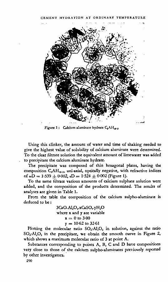
Figure 1 : Calcium aluminate hydrate
Using this clinker, the amount of water and time of shaking" needed to give the highest value of solubility of calcium aluminate were determined. To the clear filtrate solution the equivalent amount of limewater was added to precipitate the calcium aluminate hydrate.
The precipitate was composed of thin hexagonal plates, having the composition CjAHl0.s, uni-axial, optically negative, with refractive indices of tiD = 1-539 ± 0-002, cD = 1-524 ± 0-002 (Figure 1).
To the same filtrate various amounts of calcium sulphate solution were added, and the composition of the products determined. The results of analyses are given in Table 1.
From the table the composition of the calcium sulpho-aluminate is deduced to be:
3CaO.AlA.xGlSO..yH1O where x and y are variable
x = 0 to 3 00y = 10-62 to 32-61
Plotting the molecular ratio SO^Al^O, in solution, against the ratio SOjtAljO, in the precipitate, we obtain the smooth curve in Figure 2, which shows a maximum molecular ratio of 3 at point A.
Substances corresponding to points A, B, C and D have compositions very close to those of the calcium sulpho-aluminates previously reported by other investigators.
290

A. 3CaO.Al2O3.3CaSO4.30H2OB. 3CaO.Al20,-2-5CaS04.nH20Q 3CaO.Al.O,.2CaSO1.nH,OD. 3CaO.Al2O3.CaSO4.12H2O
obtained by Michaelis1 obtained by Candlot1 obtained by Mecfee1 obtained by Lerch, Ashton
and
Figure 2.
These were examined under the microscope and their refractive indices compared. Substance A is entirely needle crystals of calcium sulphoaluminate, whereas B, C and D contain varying proportions of tricalcium aluminate hydrates, the refractive index of which is the same as that of CiAHu,., (Figure 3).
From this I consider that 3CaO.Al2OJ.3CaSO4.32H2O is the only compound formed on hydration of Portland cement and substances with lower sulphate contents may be mixtures of calcium sulpho-aluminate and calcium aluminate hydrate.
On decomposing calcium sulpho-aluminate, results similar to those obtained by Dr. Kalousek were obtained: needle crystals of calcium sulpho-aluminate in microscopic specimens decomposed in time (two-three months) without exception into small partides (Figure 4). Chemical and microscopic tests indicated that the calcium sulpho-aluminate formed in the cement mixture becomes converted in time to 4CaO.Al2O3.nH2O and gypsum.

Substance A. Composition:3CaO.Al2O,.3CaSO4.32-61H2O
Substance B. Composition: 3CaOjMA2 43CaSO,.25 2H2O
Figure 3.

discussion
Substance Q ^imposition: 3CaO.Al203.l-88CaS04.25-2HzO
Substance D. Composition: 3aO.Al2O,0-95CaSO4.15H2O
Figures, tcntirutj

M ►J n ■< H
O
IT)
1 77-8
4 't-omrowo* V *7* T* 'T T xp Q do xb CO ©
04 rl
m m m * w <n w do xp TO
O 00 00 xp © CO 00 © W A M M
cn
*
68-1
1 r> oo in co 04rn o ox © y-6 cc ö « 6 8-
15
26-4
5 18
-60
45-9
5 Q W M M © Ox © © w A M w cn
58-3
7 ox \D i-f \D r* * h o co oo n \p o ob xb co © Th Mr-4 8-
01
26-3
4 18
-86
46-1
2 S S 8 xp w xb A M cn
csr
48-6
4 r- * m m h- xp»7* O 00 tp\p ö co \b ob ö'M V-I
£5 tn op w ob ob 1 0
0 5-
96
2-96
32
-16
y*, 38
-92 r* to px o o m M <H H Q r- n
ip o ob r* do ©M 1-1
ci px © »n w tn * do xp do xp M w
2 ö s*© © © wW A M M <n
O
19-4
9 o M cn m m r* tp m m s-t <n *n xp o ob A ob ö* Mr4
m m m #n m y cn w ob xb do xb M w 1-
005-
842- 8
4 31
-73
CX
12-9
7 SSS58S! ip ö ob h- do Ö Mr-» 8-
30
26-0
0 18
-06
45-9
8 8 2 K 8A A M w cn
00 9-73 3 8 $ S K 8
A 6 do rU A ©* Mw 8-49
26-4
0 17
-75
47-0
8 838$ w A M W cn
6-49 Ct © O M h* w 00 O w O M Xp
in O O db A ©* MW 9-10
27
-24
17-2
4 45
-28 o tn m oo O * * w
A A m A M
to 4-30 m © ox xp * wp o co op r-
© dx ob xp Ö 9-89
27
-96
16-7
4 43
-94 3 2 2 8
w A m A M
in 3-24 m o r- m o t*»w o © <n »n
A O W xp © 11-0
729
-31
16-3
042
-86 © M oo «n© op op OX
M
*04 xp m m m m o opo w m © »n ©
A M Mm m © m m »n enw A A Aw M ** '**•
© © CO © © <n cn m s
00 m Ö
8 2 P S 8 3 Ö Ö j A rt 14
-75
32-0
1 11
-02
38-9
8 © tn m m© qx Qs ox w A o 4*
04
1 0-19 1 ....
838^3:8 4* © A A A tn 4* w cn 17
-06
30-3
9 3-
94
37-8
4 © O © xp © <n m A w A © M
r-l oko v) tn tn Is* Sxvxcpp-'t w © ob ob ö »n -* w tn 18
-85
31-1
8 0
35-3
2
1-00
3-
02 0 10
-62
Solu
tion
No.
Mol
. rat
io S
OjiA
l^O
, in
solu
tion
Iq’S^o-o"
v> < U en U ♦
o2o o" |q, ■< <3 </> u *
0 O x'O.<i O a* < O V) w
Che
mic
al an
alys
is of
pre
cipi
tate
(p
er ce
nt)
Com
posit
ion
(per
cent
) afte
r co
rrec
tion o
f C
aCO
j as i
mpu
rity
Com
posit
ion
(mol
ecul
ar)

Figure 4 : Decomposition of calcium sulpho-aluminate in cement hydration. (Two months after preparation.)
REFERENCES
1. MICHAELIS, w. Toniniiutrie-Zeitxng. 1892. p. 105.2. Candlot, E. Bulktin Sociiti d'Entouraymtnl Industrie txationaie. 1890. p. 682.3. Mecke, P. Tonindustrie-Zeitun^. 1929. No. 38. p, 681.4. Lerch, w., ashton, F. w. and BOGUE, R. H. Journal of Research of the National
Bureau of Standards. 1929. Vol. 2. No. 4. p. 715.
R. HEDIN
At our laboratory we have lately devoted ourselves essentially to the study of the crystallization of supersaturated calcium hydroxide solutions.
We have found that, not only in the absence of adequate nucleus materials, could a solution with a calcium hydroxide concentration of about 30 millimoles per litre be obtained at 20°C without any crystallization, but even in the presence of the very best crystallization nuclei, crystallization will take place so slowly that, after having been stored for several days, the solution still has a very high degree of supersaturation.
The presence of small amounts of alkalis lowers the saturation concentration, but has a very small influence on the rate of crystallization and thus upon the stability of the supersaturated solutions.
In concrete we have a rather rapid crystallization of calcium hydroxide,

which must be due to a very high concentration. Even when the alkalis present are accounted for, this concentration must be estimated at around 25 millimoles per litre.
On account of this it seems to be important to make a separate investigation on the stability of calcium silicate hydrate at these high lime concentrations.
The work carried out by Dr. Taylor and others and discussed by Dr. Steinour seems to indicate that under such conditions we have to expect the solid phase to be composed of a calcium silicate hydrate with C:S ratio near 2 to 1. This, however, does not say anything about what crystallizes from the supersaturated solutions. We might as well expect a crystallization of a metastable phase. A factor of great importance in this connexion is the presence of different nucleus-forming materials and their effect on the structure of the crystallization products. As crystallization nuclei we have to consider not only the more or less crystalline solid phase, but also the poly-molecularly solved substances, as for instance silicic acid.
This interpretation might possibly give an explanation to the differing results which are obtained by the X-ray analysis of calcium silicate hydrate with a C:S ratio of about 2, if they are synthesized from different reaction systems.
Calcium silicate hydrate is formed by the reaction between sodium silicate and calcium nitrate, but because of hydrolysis also some undissociated silicic acid can be found in the solution, at least as an intermediate product, in a more or less colloidal or poly-molecular form, probably as meu-silicic acid.
These poly-molecular particles might act as crystallization nuclei, and their structure might somewhat influence the crystal structure of the crystallizing calcium silicate hydrate.
Even when synthesis is made by direct hydration of CjS, an intermediate formation can be assumed, probably of ortho-silicic acid. One wrould expect, however, such a silicic acid to have a different structure from the one formed from sodium silicate and it might therefore be supposed to give a calcium silicate of another type.
Further, a question which seems to me to be of great importance is the rate at which an earlier formed metastable phase under various conditions could later be changed into a stable phase under the same conditions.
GEORGE L. KALOUSEK
APPLICATION OF DIFFERENTIAL THERMAL ANALYSIS IN A STUDYOF THE SYSTEM LIME-SILICA-WATER
About eight years ago, the General Research Laboratories of the Owens-Illinois Glass Company undertook a comprehensive investigation of the chemistry and properties of hydrous calcium silicates. Although the research was directed primarily towards the development of integrated

lightweight heat insulating products for commercial purposes, much of the basic chemistry that was considered applies also to the hydration products of Portland cement. This contribution presents that portion of the results and describes the experimental techniques applied.
The present investigation, initiated in 1947, was undertaken to ascertain if the method of differential thermal analysis (DTA) in conjunction with X-ray studies would resolve some of the contradictions and help identify the solid phases of the system lime-silica-water. Detailed analyses including extensive studies on free lime tests were also carried out.
MATERIALS AND METHODS
Most of the preparations were made at room temperature from aqueous solutions of lime (0-05 g CaO per litre) and silica (0-40-0-45 g SiO2 per litre) by the method of Flint and Wells.4 These were added to solutions of Ca(OH)2 or, for preparation of the lime-rich phases, solutions with suspended crystalline Ca(OH)2. The mixtures were stored in Pyrex glass flasks previously etched with Ca(OH)2 solution or in ceresin-lined flasks.
The filtrates obtained from the mixtures were titrated with standard acid using methyl red indicator. The solids were analyzed directly for CaO and SiO2 and some as required for unreacted silica and free lime. The compositions were also computed from the known compositions of the raw mixtures and filtrates. The method of Steopoe6 was followed in analysis for unreacted silica. This method specifies 1N/HC1 with 5 per cent NaQ for solution, and a 10 per cent NazCO3-10 per cent NaCl solution for dissolving the silica gel resulting from the hydrolysis during the acid treatment. The glycerol-alcohol method of Lerch and Bogue* and the aceto-acetic esterether method of Franke2 were used for extracting lime from the solids and the results of the two methods are compared.
The combination of the solids with Ca(OH)2 in solution was done as follows : the samples in 0-3 g lots were dried at 105 °C for 16 hours and then placed in 100 ml of a solution containing 0-7 g of CaO per litre. The mixtures were filtered at selected periods of time and the filtrates analyzed for CaO. The loss of CaO from the solution was computed as percentage by weight of anhydrous sample. The samples after treatment were analyzed thermally and tested for extractable lime.
The DTA method followed has been described.’ The X-ray patterns were obtained using CuK alpha radiation and nickel filter with a camera of 14-32 cm diameter.
Results
Cbar<uIrrigation of rolid phasesThe results on compositions of the mixtures and phases are presented
in Table 1. For purposes of discussion the solid phases are divided into two groups. The first, representing compositions of 1-4 C:S and lower is further divided into four sub-groups of compositions of 0-8, 1-0, 1-25 and

table 1: Data on solid and aqueous phases in the system at 25°C
Composition of mixComposition
of filtrate Composition of solid
No. CaO g/1
SiO2 8/1
Agedays
CaO gil
SiOj g-l
GS (comp.)
GS (anal.)
•Tree"SiO.
%
"Free" CaO
%
GS (core.)
1 0-220 0-388 28 0121 0-186 0-53 0-56 18-6 — 0-782 0-225 0-388 28 0-112 0-170 0 56 0-60 14-4 —- 0-773 0-247 0-381 33 0-113 0-160 0-65 0-66 10-5 — 0-794 0-258 0-374 40 0-120 0161 070 0-77 7-2 08 0-875 0-300 0-356 100 0-067 0-080 0-90 083 21 0-70 0-856 0-234 0-208 28 0-093 0 082 1-20 0-85 —7 0 463 0-295 14 0-201 — — 100 1-4 1-3 —8 0-506 0-262 28 0 234 0-003 1-12 1-02 — — —9 0-587 0-230 28 0-327 0-002 1-22 1-09 0-3 —
10 0 687 0-210 28 0-457 0-005 1-17 149 0-3 1-2 —11 0-703 0-193 45 0-489 0-006 1-22 1-20 —12 0 703 0-193 106 0-451 0-005 1-44 1-22 — —13 0-724 0-195 28 0-487 0-005 1 27 1-24 08 14 —
14 0-837 0-153 28 0654 0-003 1-32 1-28 —- «— —15 0-818 0-151 28 0 637 0-003 1-28 1 29 0-7 1-316 0-774 0-124 28 0-608 0004 1-48 1-28 0-7 1-4 —17 0-923 0100 23 0-752 0-004 — 1-31 1-5 1-3 —18 1-060 0-051 18 0904 0 003 — 1-46 1-0 5-3 1-36*19 1-084 0-041 18 1-016 0-002 1 so 1-42 1-0 4-8 1-3320 1-259 0-214 28 0-976 0-003 1-41 133 — — —21 1-309 0-224 14 0953 0-008 1-74 1-39 — — •—22 1-309 0-224 23 0-997 —. 1-51 1-38 w— — —23 1 357 0-225 14 1-048 0-006 1-51 1-39 — — —24 1-357 0-225 28 1-040 — 155 1-38 — — —
25 1-426 0-225 15 1-109 0-003 1-53 1-53 0-7 4-5 1-46
26 1-426 0-225 28 1-103 0004 1-57 1 55 05 3-4 147
27 1-448 0-225 28 1-096 0-002 1 69 1-62 0-7 45 1-50
28 1-468 0225 28 1-084 0-002 1 84 160 — 2-2 1-5429 1-478 0-216 28 1-110 0-002 1-80 1-70 — —* •**30 1-590 0-225 28 1-146 0-002 213 212 0-4 17-2 1-5831 1-511 0-208 28 1-121 —— 2-04 1-83 — ——32 1-602 0-212 28 1-121 0-002 2-58 2-10 —— —•
33 1657 0232 5 1-118 0-002 2-49 2-26 0-2 19-5 Iti
* In correcting the composition, the small amounts of free SiO2 of 0-2 to 1-0 ptf aDt were disregarded because these small amount* approach those of experimental enort.
1*33 C:S. The second group consists of the remaining products o GS molar ratios.
The mixtures were processed generally for 28 days or longer. attainment of a condition simulating equilibrium, or true equih n determined by reacting some of the compositions for 7, »
*29%
t

100 days. In nearly all these tests the results at 21, 28 and 100 days were the same and a 28-day period was considered sufficiently prolonged for the purpose except at the high silica concentration. The presence of much unreacted silica, as will be shown, probably retards the attainment of equilibrium.
The computed and chemically determined C:S ratios of the solids are given in Table 1. Some of the chemically determined ratios are corrected for unreacted silica if analysis showed 1 per cent or more. Corrections for “ free ” lime were made for representative solids in the second group and two samples in the first group. The C:S ratios obtained by computation were generally higher than those determined directly due to reaction of the mixture with the glass. As a general rule the attack on the previously etched flasks caused no discernible effect as indicated by comparisons with results on samples prepared in the ceresin-lined flasks.
The DTA curves characterizing representative members of the first group of solid phases are given by the solid lines in Figure 1. (The dashline curves deal with another part of this study and will be discussed). The essential characteristic of the DTA curves is the exothermic peak which occurred at 830°±56C for the 0-8 C:S and 1-0 C:S products and at 865O±5°C and 900°±5°C for 1-25 and 1-33 C:S sohds, respectively. The extent of the exothermic peak was generally lower for the 0-8 C:S product compared to that of the 1-0 C:S solid. '
The first six solids tested in Table 1 were mixtures of silica gel and a solid phase having a composition close to 0-8 C:S as indicated by complete chemical analysis. Sample 5 processed for 100 days contained a relatively low free silica content. The 0-8 C:S solid was also prepared hydrothermally from silica acid and CaO mixtures at temperatures of 125° to 150°C using a processing time of 3 days. The presence of free silica in amounts of 5 per cent and higher was detectable by an increase in temperature and a “ flattening ” of the exothermic peak and by a general diffusion of the X-ray lines which obliterated all except the 3-03 line at a free silica content of 30 per cent. Taylor7 observed the same effect on X-ray patterns as the C:S ratio of the overall mixture was decreased.
In Figure 2 are plotted the C:S ratios of the solids (direct analysis except for two mixtures to be mentioned) against CaO concentrations. The vertical segment of the curve is based largely on previous results1 and those of Taylor.7 It will be noted that the lime concentration of the 100-day 0-8 C:S product mixture, 0-7 g CaO per litre, is on that line. It is assumed, therefore, that the liquid phase composition of 0-07 g CaO and about 0-08 g SiO2 or somewhat lower, represents the invariant point in the system for silica gel, 0-8 C:S solid and liquid phase.
As the lime concentration increased up to about 0T g CaO per litre the SiO2 concentration dropped to about 0'003 g per litre, and the composition of the solid phase attained a C:S ratio of close to unity. This relatively short segment of the curve in Figure 2 represents a continuous series of

Figure 1: DTA curves of 1-0 and 1-33 C;S solids before and after extraction of lime with accto-acctic ester.
Figure 2 : Rektion between the C:S ratios of the solids and the Un* concentration of the aqueous phase in the system.

solid phases, all of which were characterized by a single X-ray pattern. Increasing the lime concentration from 04 to 0-5 g CaO per litre resulted in a continuous and gradual increase in the C:S ratio from 1-0 to about 1-25. The increases in C:S ratio, unlike that of the 0-8-1-0 C:S series, were accompanied by progressive increases in the temperature of the exothermic peak from 830o±5°C to 865O±5°G
The solids that formed at lime concentrations from about 0-6 to 1-05 g CaO per litre were all characterized by an exothermic peak of 900o±5°C and a surprisingly constant C:S ratio of 1-28 to 1-38 for all samples manifesting only this exothermic peak. A detailed study was made of the formation of this solid particularly at lime concentrations of about 0-9 to 1-05 g CaO per litre because it is over this range that all previous reports show a continuous increase of lime in the solids with increase in lime concentration. This increase was also observed in the present study but such samples manifested DTA curves differing definitely from that shown in Figure 1 for the L33 C:S product. Decrease in the extent of the exothermic peak with no other change in the DTA curve was correlated with a small increase in C:S ratio from an average value of 1"33 to about 1-38. Increases in C:S ratio up to 1-46 were observed but the product manifested a small and prolonged endothermic valley at 800 to 830°C. Samples No. 18 and 19 in Table 1 of C:S ratios of 1-46 and 1-42 relinquished 5-3 and 4-8 per cent CaO in the aceto-acetic ester test compared to the 1-3 per cent for the other samples. Corrections for this lime allowing for the 1-3 per cent gave C:S ratios of 1-36 and 1-33 for these two samples. The value of 1-33 C:S was selected as the best representative composition on the basis of these results and because a value of l-33±0-02 was invariably obtained for the solids manifesting an extensive exothermic peak at 900°i5°C. The 1-33 C:S product differs from the others in being unstable at temperatures higher than approximately 60°C, and was therefore not prepared hydrothermally.
The X-ray data for the 0-8 to 1-33 C:S sohds agreed well with those reported by Taylor7 for the 1-0 to 1-5 C:S solids allowing for differences in intensities of the lines and the line at a spacing of 7-3 A. Taylor7 does not report this line, and many samples in this study also failed to show it while others manifested it at intensities varying from very weak to strong. The appearance of this line was independent of all known variables as composition, time and temperatures of processing required for the formation
- of these solids. ,The solids forming at lime concentrations of about 1-05 g CaO per litre
and slightly higher perhaps up to 140, but still somewhat less than saturation, gave a variety of DTA results and a spread in composition from about 1-4 to 1-6 C:S. Some manifested only a small peak at 890° to 910°C, a small endothermic valley at 500° to 530°C, a relatively small and prolonged valley at 750° to 820°C and also a relatively prolonged exothermic bulge in the temperature range of about 350° to 500°C Reproduction of results in the C:S range of 1-4 to 1-6 was poor and the amounts of free lime extracted

with the accto-acetic ester, ranging from 2 to 6 per cent, gave no clue to the nature of the solid. These observations suggest that such products are probably mixtures of the 1*33 C:S phase and the high-lime solid of the system. Because the tests on lime extraction gave results that help in differentiating between the 1-33 C:S phase and the high-lime phase, these will be discussed now.
Ume extraction tests "The samples having C:S ratios of 0-8 to 2 0 used in the lime extraction
tests were prepared hydrothermally at 150°C in large amounts, except the 1-33 C:S phase. Portions of these were tested by the glycerol and acetoacetic ester methods for extractable lime and the results are presented in Table 2 for samples dried at 150°C for 16 hours prior to test. These results show that the glycerol failed to extract any lime from products having C:S ratios of 0-8 to 1-0 and the aceto-acetic ester extracted small amounts only. Solids of C:S ratio of 1-0 to 1*5 gave about the same results for both methods, but at the remaining higher C:S ratios the glycerol extracted about twice the amount of Ca(OH), compared to the results for the aceto-acetic ester.
Further tests (see Table 3) on mixtures of some of these samples and added crystalline Ca(OH)2 showed that the glycerol did not extract all the added Ca(OH)i but the aceto-acetic ester gave nearly quantitative extraction of the lime after correction was made for the amounts extracted from the sample alone. This suggests that the glycerol is a carrier of the reaction between the Ca^HJj and the hydrous calcium silicate of the lower CS ratios. To test this hypothesis a mixture of Ca(OH)2 and silica acid was processed for 2 hours in the glyccrol-alcohol solution. A highly gelatinous product very nearly impossible to filter was obtained and a DTA curve is presented of it elsewhere in this report (Figure 5, curve 4).
Stability of the 0.8 to l-33 C:S y>base in tests for free limeDTA results on the residues of the samples of b0 and b33 C:S solids
after extraction with the aceto-acetic ester are given in Figure 1 by the dash-line curves. Although the samples prepared at room temperature relinquished slightly more Ca(OH)j to the extracting solution than those prepared at the higher temperatures, the DTA curves for each composition before and after extraction were substantially the same regardless of the method by which the samples were prepared. The temperature of the exothermic peak of the 1-33 C:S solid was occasionally decreased slightly by this treatment, but the same effect was obtained by heating the samp ® at the same temperature (about 69° to 71 °C) used in this test. The small amounts of lime are probably removed from the surfaces of these very finely sub-divided solids. In similar tests, the glycerol failed to extract any Ca(OH)2 from the 0-8 and 1-0 GS solids. Accordingly, it is assumed the solids of 0-8 to 1-33 GS are not altered significantly if at all by ei the aceto-acetic ester or the glyceroL

table 2: Amounts of lime extracted by the glycerol and aceto-acetic ester solvents from samples of 0-8 to 2'0 C:S ratios and dried at 150°C prior to test
C.S ratio
• Process Extracted lime as CaO*
Temperature "C
Time days
Glycerol per cent
Aceto-acetic ester per cent
0-8 150 3 00 0190-8 25 28 0-0 0-700-9 150 3 0-0 0-351-0 140 7 00 0-531-2 25 28 — 1-21-2 137 3 1-2 111-2 150 3 1-8 1-41-33 25 28 — 1-31-4 150 3 31 2-61-5 150 7 8-4 611-6 150 3 12-3 5-81-6 150 7 10-4 4-718 150 3 15-8 7-620 150 3 22-8 11-2
* Anhydrous basis.
table 3: Percentage of CaO extracted by the aceto-acetic ester and glycerol from 0-4 g lots of samples treated with known amounts ofCa(OH)2
* Silica gel previously autoclaved at 150°C.
Sample C:S*
Aceto-acetic ester Glycerol
Amount CaO added
g
Amount CaO extracted per cent
Amount CaO addedg____ _
Amount CaO extracted per cent
0-0 0-0231 96 0-0505 97
0-5 0-0205 97 0-0108 33
0-5 — • 0-0505 82
0-8 0-0061 98 0-0641 90
0-8 0-0308 96 —1-0 0-0426 99 0-0515 91
12 0-0741 97 0-0455 90

Adsorption of Ca^OH^from solutionIn Figure 3 are given DTA curves for samples of C:S ratios of 0-8, IO
and 1-2 before and after treatment with a solution of Gi(OH)2 at room temperature for 18 hours. It is seen that the exothermic peak of the 0-8 C:S increased markedly in extent, that of the 1-0 C:S increased in temperature and that of the 1-2 C:S solid remained unchanged by the treatment. However, the 1-2 C:S solid after treatment manifested a relatively large endothermic valley at 780° to 820°Q In Table 4 are given the amounts of lime taken up by the samples and the amounts of lime extracted from these treated samples by the aceto-acetic ester after drying at 150°G The composi-
table 4: Data showing the effects of lime adsorption on samples
processed at 150cC for 3 days
OMnposition of mix
CaO . adsorbed
Composition after adsorption
CaO desorbed at 150°C_
GS ratio per cent GS ratio percent _
08 97 0-98 04)
IO12
5-1 4 1
1111 29
04)37---- -----

tion of the 0-8 C:S solid was increased to 0-98 C:S but none of the adsorbedlime was extracted. The 1-0 C:S composition increased to I'll C:S and the added lime also was not extracted. The 1*2 C:S product adsorbed 41 per cent CaO and the essential features of the DTA curve were left unalteredby the treatment. However, nearly the total amount of adsorbed lime was extracted from this sample which manifested the endothermic valley at 780 to 820°G This sample after the lime extraction gave a DTA curve essentially the same as the original sample, except that there still remained a very small endothermic valley at the stated temperatures. These tests suggest that lime may be added by two different linkages to this solid, inone case entering the structure and not being subject to extraction an in the other being adsorbed on the surface and subject to extraction.
The preceding tests particularly with the 1-2 C:S product were pro a y not sufficiently prolonged to affect formation of the 1"33 C.S, an a so a higher lime concentration would have been required. Further study using the general approach mentioned here should prove helpful in dis osing more of the nature of these hydrous lime-silica solids. For ex^mPle- th® reason for the relatively high C:S ratios of samples No. 18 an 1 ste in Table 1 was explained on the basis of surface adsorbed lime, cause these solids manifested a prolonged endothermic valley at about to 800°C in the DTA curves.
The 0-8 to 1-33 C:S series of solitiphases , As indicated by the preceding considerations, a continuous series o
compounds having end compositions of QS}Hn and C4S3Hn are orme in the system. These are stable against significant attack by aceto-acetic ester or glycerol as used in tests for free lime. All show a pronounce exothermic peak in DTA curves as already mentioned. X-ray data show no significant difference among these samples, an observation ea y disclosed by Taylor ̂for a series of l-0 to 1‘5 C:S solids. The X-ray atao this study did not reveal any difference between the l-5 C.S P^o<?uC^.^n those of lower lime contents but results of other tests show de nite er ences. The exact water content of these solids, of course, is not e to precise determination as they possess the properties of ges. e oss on ignition amounted to about 14 to 17 per cent by weight or samp es dried at 105°C.
Lime-rkb solids in the system , . , . ,The preparation of the products of about 1‘5 C:S an o g er me
contents was complicated by the persistence of Ca(OH)2 as a separate p ase In these preparations the presence of Ca(OH)z could fortunate y etec e in amounts as low as 2 per cent by both X-ray and DTA res ts. e r data are given in Table 5 and representative DTA curves in igure .
Results of DTA and X-ray are presented for samples No. 25 an (Table 1) processed 14 and 28 days, respectively, in or er to us . variations of the DTA curves of the 1-4 to 1-6 C:S sohds compared to those
■ 305

CEMENT HYDRATION AT ORDINARY TEMPERATURE
table 5: X-ray data on some lime-rich solids listed in Table 1
Intensities : d = diffuse, v = very, s = strong, m = medium, w = weak.(a) Residue after test for free lime with the aceto-acetic ester.(b) Line characteristic of the members of the C4S5Hn—C4S3Hn series.(c) Line characteristic of Ca(OH)2.
No. 25 No. 26 No. 29 No.31 No. 32 No. 33 (ext.)la>
I/Io dA I/Io dA I/Io dA I/Io dA I/Io dA I/Io dA
wd 10-2 <«” wd 9-8 wd 9-8mw 4-8lc) m 4-85 m 4-85vwd 4-5(b' vwd 4-5 wd 4-5 wd 4-5 wd 4-5 vwd 4-5
VW 3-32vs 3-01lbl vs 3-01 VS 304 VS 3 05 vs 3-05 vs 3-04mw 2-80,b- m 2'80 mw 2-80 mw 2-80 w 2-78 m 2-80VW 2-60<C1 VW 2-60 mw 2-62 ms 2-61VW 2-26VW 2-08 VW 2-08VW 1-91<CI w 1-92 m 1-92w 1.83 cb>. wm 1-83 w 1-83 VW 1-82 vvw 1-82 wm 1-83VW 1-785<C> VW 1-785 w 1-780VW l-680<c’ ww 1-680 VW 1-675w l-66,bl VW 1-66 vvw 1-66 VW 1-66 VVW 1-66 w 1-66VW 1-52lb) VW 1-52 vvw 1-52
vvw l-475lc VW l-480,c1-52
VW l-438,cVW l-308,c
of the pure 1-33 C:S (Figure 1), and to show the detection of free Ca(OH)2 by both methods of test in sample 25 and not in sample 26. Comparison of the results of these two samples shows something of the progress of the reaction between 14 and 28 days. x
Sample 29 is of interest as it contained no Ca(OH)2 or at most only a trace of it, and had a C:S ratio of 1-70, the highest observed for these limerich gel-like solids uncontaminated with a detectable amount of Ca(OH)2. The DTA curve of this solid manifested a fairly large exothermic bulge between about 350 ° and 450°C and a relatively small exothermic peak at 900°C, indicating possible presence of some C4S3Hn. Because this sample was representative of the gel-like solids of the system and manifested no endothermic valley, it was mixed with 2 and 5 per cent of freshly slaked and dried crystalline Ca(OH)2, and the mixtures examined by DTA and X-ray. The endothermic valley caused by these amounts of the addition are indicated on the curve of sample 29 by broken lines. The X-ray patterns of the Ca(OH)2 in these samples agreed well with those of samples 25 and 32 for the 2 and 5 per cent additions, respectively, except that generally the intensities of the line in question for sample 32 were slightly stronger than those of the 5 per cent Ca(OH)2 admixture. The endothermic valley of sample 32 was somewhat larger and therefore the DTA results indicate

Figure 4 : DTA curves of representative lime-rich solids in the system.
the same general result as the X-ray data, that is sample 32 contained more than 5 per cent Ca(OH)2.
Samples 31 and 32 illustrate further the types of DTA curves obtained, particularly the presence of the exothermic bulge, small though it is, in the temperature range of about 350° to 450°C. The estimated compositions of these two solids allowing for the Ca(OH)2 in amounts suggested by the X-ray and DTA results are about 1-75 and 1-80 C:S. Samples of higher C:S ratios up to 2-26 (No. 33 in Table 1) showing a relatively very small and extended valley suggestive of Ca(OH)2 and a pattern of highly diffuse lines of Ca(OH)2 were prepared in a few of the short time tests. These relinquished large amounts of Ca(OH)2 to the aceto-acetic ester, 19-5 per cent for the present sample. The X-ray pattern of the residue is given in Table 5, and is nearly the same as that of the Ca(OH)2-free sample.
This study suggests that the relatively well stabilized lime-rich solids prepared in this study may have a composition of about 1-7 to 1-8 C:S. X-ray data of the lime-rich solids, given in Table 5, were generally the same as those of the C4S3Hn—C4S2Hn‘ series except for a relatively broad band at spacing of 4 to 5 A appearing in the patterns of the lime-rich solids. Because this band appeared in generally weak intensities, and was also infrequently observed for some of the lower-lime solids, it may not be sufficiently characteristic for purposes of identification. The lime-rich solids also infrequently showed a highly diffuse line at a spacing of about 10 A,

Figure 5 : DTA curves of various lime-rich solids before and after extraction with the aceto-acetic ester.
which may correspond to that of the C4S5Hn—C4S3Hn series at a spacing of 10 to 11-5 A. A better resolution of these various lines, which probably will be realized with the recent improved X-ray equipment may give the desired differentiation between the high and low-lime solid phases in the system at normal temperatures.
If the aceto-acetic ester extracted only the lime present as Ca(OH)2, it could be expected that the DTA curves of the lime-rich samples would be nearly the same as those of the residues exclusive of the thermal change due to Ca(OH)2, as was the case for the C4S5Hn—C4S3Hn series. The limerich solids, however, yielded relatively large and varied amounts of lime to the aceto-acetic ester (and also the glycerol) when none or only little free Ca(OH)2 was suggested by X-ray and DTA. An example is sample 26 already mentioned. The DTA curves of the residues were distinctly different from those of the untreated samples. Representative DTA results are presented in Figure 5. The general trend of results for all the residues, except that dried at 550dC before extraction, was the same: an irregular exothermic bulge somewhere between 300° and 550°C and an exothermic

peak at temperatures between 870° and 900°C. The residue from the sample dried at 550°C gave an endothermic valley instead of exothermic peak at 900°C. The recrystallization of the highly dried sample during thermal analysis apparently is different from that of the companion specimen dried at 150°C. ' ■
The curve at the bottom of Figure 5 represents the sample synthesized in glycerol for two hours using CaO and silica acid as the raw mix in a C:S ratio of 2-0. The sample was not available in sufficient amount to permit composition determination.
The preceding results suggest that the lime extracted from these hydrous lime-rich solids is not free lime and the solid phases are transformed during the tests. The resulting residue as suggested by DTA results may consist of a mixture of the gel-like product characterized by the exothermic bulge at 350° to 550°C and the 1-25 to 1-33 C:S solids. This is merely an indication, the results are too inconclusive to allow any definite answer. Further research to elucidate this matter should prove highly fruitful as this approach holds fine promise of being developed into a diagnostic tool for differentiating between the cementitious phase of concretes.
APPLICATION OF DTA IN STUDY OF HYDRATING CEMENTSIf hydrating cements formed hydrous lime-silica solids free of all the
constituents present in cements exclusive of lime and silica, it could be assumed that the lime-rich gel-like solids of the ternary system would be the same as those actually forming in hydrating cements. Recent studies by Kalousek and students3-4 using DTA for characterizing the solid phases suggest that the lime-silica-bearing products probably contain the other constituents integrally combined. A brief resume of the more pertinent results of those studies including a few DTA curves are presented here to illustrate the usefulness of this method for characterizing the hydration products of cements. .
In Figure 6 are given the DTA curves of the preparations described in the title of this figure. All the raw materials were introduced as solids. Curve 1 is that of a lime silica gel product but also would be representative of a completely hydrated cement if it manifested a larger break at about 130° to 140°C. Curve 2 is for the same type of preparation as represented by curve 1, but the silica gel contained 8-1 per cent A12O3 and is designated as alumina-silica gel. The reaction product would, therefore, contain approximately 3 per cent A12O3. Because DTA failed to reveal any of the known ALO3-bearing hydrates in this sample and because the result obtained differed so markedly from that of the Al2O3-free product, it was assumed that A12O3 could be precipitated as the highly insoluble calcium sulphoaluminate during the reaction. In a repeat test with gypsum added, the resulting DTA curve should be similar to No. 1 but manifest an endothermic valley at about 150°C characteristic of the tri-sulphate form of the calcium sulpho-aluminate. Curve 3 gives the result on the gypsum-treated product

1. CaO and silica gel2. CaO and alumina-silica gel3. Mix as for No. 2 with added gypsum4. CaO, silica gel and C4AF, 7 days4G. Mix same as for No. 4 with added gypsum, 7 days5. CaO, silica gel and C,AF, 90 days5G. Mix same as for No. 5 with added gypsum, 90 days.
and it is seen that substantially the expected result was obtained. On the basis of this observation one could say that a lime-alumina-silica-water gel will form, but if gypsum is added as in cement then the lime-silica-water gel is formed along with the sulpho-aluminate as suggested by previous theories on the phase constitution of hydrated cements.
Experiments were also carried out introducing Fe2O3 and -A12O3 as C4AF to ascertain the effect Fe2O3 might have on the complex hydration product. The expected formation of either the hydrogarnets or sulphoaluminates, except the latter as metastable phases, was not realized. The introduction of Fe2O3 to the quaternary system lime-alumina-silica-water. or the quinary system lime-alumina-sulphur trioxide-silica-water appears to result in formation of a single phase. This solid was designated phase X

in the previous studies and its mode of formation is illustrated by curves 4 and 5 in Figure 6. Curve 4 shows the initial state (7 days) of the reaction of CaO-silica gel-C+AF and water and 4G of the same mixture treated with gypsum. The sulpho-aluminate and presumably also the related Fe2O3 compound are formed when gypsum is present at 7 days. Curve 5 and 5G represent the respective products after 90 days. The two curves are highly similar and the solids appeared as single homogeneous phases in microscopic examination.
ACKNOWLEDGMENTSAcknowledgments are made to W. C. Taylor for advice and encourage
ment, Doris A. Hall for conducting the chemical tests, and B. L. Steierman and L. M. Muttart for the X-ray data.
REFERENCES1. flint, E. p. and wells, L. s. Journal of Research of the National Bureau of
Standards. 1934. Vol. 12. pp. 751-783.2. franke, Bruno. Zeitschrift für ^Anorganischen und allgemeine Chemie, 1941. Vol.
247. pp. 180-190. -3. KALOUSEK, G. L., davis, c. w. JR. and SCHMBRTZ, w. E. Journal of the
American Concrete Institute. 1949. Vol. 20. pp. 693-712.4. kalousek, G. L. and adams, M. Journal of the American Concrete Institute. 1951.
Vol. 23. pp. 77-90.5. Lerch, w. and bogue, r. h. Industrial and Engineering Chemistry. Anal. Ed.
1940. Vol. 2. pp. 296-298.6. STEOPOE, A. Zement, 1940. Vol. 29. pp. 193-194. 7. Taylor, ^H. F. w. Journal of the Chemical Society. 1950. Vol. 726. pp. 3682-3690.
R. W. NURSE AND H. F. W. TAYLORThe difficulties inherent in the detection of hydrated compounds in set
cement have already been emphasized at this Symposium. We have carried out some preliminary experiments to determine whether particle size separation will help to overcome these difficulties using a technique which has proved of assistance in overcoming a similar difficulty in the field of clay mineralogy.
By this means we have detected certain of the hydrated silicates and aluminates in a normal set paste of cement, and using the results to analyze the dehydration isobar of the set paste have made a tentative estimate of the phase composition in one example.
Briefly, the set cement is broken up to pass the 52 mesh B.S. sieve and dried. The resultant powder is rubbed down under a suitable liquid in a rubber or soft plastic pestle and mortar. The suspension obtained is diluted and elutriated, coarse material being returned to the mortar, until some 2-3 litres containing only a few grammes of solid are obtained which are then passed through the super-centrifuge, fractions being collected in any desired range of particle size, usually below 2 p.
The solid is deposited in the super-centrifuge as a thin layer on a plastic 311

table 1: Results of fractionation experiments
No. 1 2 3 4 5 6 7
Material Neat cement briquette 22 years water storage
Cement paste'1 2’
1:3 mortar cement: fused silica : 28 days water storage
Foamed cement paste121 60 days water storage
Elutriation liquid
Water WaterCO2-free
Kerosene Alcohol Water Water Alcohol
Conditions of drying
50°C 50°C 105 °C Washing with alcohol
50°C Over satd.(NH4)2SO4
Washing with alcohol
Constituents detected by X-rays in order of quantity estimated to be present.Fraction 1-3-0-5
Etr.<3'CalciteC3AH6
Etr.C3AH6Calcite
Ca(OH)2 C3AH6
Ca(OH)2 trace Hex.
Calcite Etr.QAH,
CSH(I) ' Etr. trace Calcite
Ca(OH)z, Etr-
Hex.CSH(I)
Fraction 0-5-0 06 (z
Calcite Etr. c3ah6
Calcite Etr.CjAH6
Pattern with high scatter.Calcite Ca(OH)2
Ca(OH)2 QS c3ah6
Calcite Etr. c,ah6
No yield
Remarks Unidentified spacings 17-3,12-1, 8-4 Ä (finest fraction)
A coarser (5-1-3 p) fraction also gave Ca(OH)2+ c3ah6. Unidentified line 17 Ä
The fine fraction also gave lines at 10 and 3-9 A— possibly Etr. or Hex.
Proportioi ofC3AH6 increased with particle size
1 All material < l-3p. was combined
(1) w:c ratio 0-5, prevented from setting by constant remixing.(2) Hydrolyzed protein foaming agent.(3) Etr. = Ettringite (high sulphate calcium sulpho-aluminate).
Hex. = Hexagonal calcium aluminate hydrate.QAHs = Cubic hydrated calcium aluminate.

sheet and is so coherent that thin strips can be cut from it and be mounted in the X-ray camera. Alternatively the powder may be broken off and ground up for a normal powder examination.
The main difficulty in applying the technique to set cement is to find a liquid in which the material will disperse which is also chemically inert. Much of our work has been carried out using water, with the object of seeing if the considerable effort required to develop the method would be justified. One run was done with kerosene and was not very successful, the solid flocculating. Two runs with anhydrous methylated alcohol were more promising.
X-ray photographs of the coarse fractions (> about 2 p.) showed them to consist chiefly of unhydrated material, together with calcium hydroxide. The conclusions regarding the finer fractions are summarized in Table 1.
The fractionation method has not yet been developed to the stage of separating the hydrated compounds from each other, or from calcium hydroxide, but it does at least remove some of the calcium hydroxide and virtually all of the unhydrated material. This degree of concentration is of considerable value as a preliminary to X-ray examination.
The use of water as an elutriation liquid is, of course, open to severe objections. It is possible that the hydrates obtained in experiments 1, 2, 5 and 6 were formed by reaction between freshly exposed cement grains and water used in elutriation during the several hours required for manipulation. From the known rate of attack of water on cement grains this is, however, unlikely, and we believe that these preliminary experiments show the possibility of extracting sulpho-aluminate, CSH(I), and hydrated aluminates from the set mass. The fact that all of the constituents obtained using water were also isolated in one or another experiment using kerosene or alcohol also tends to suggest that the results obtained using water were not grossly incorrect. "
Kerosene is not a suitable liquid, because of flocculation, and anhydrous alcohol appears the most promising medium yet tried. A difficulty which arises when liquids other than water are used is that calcium hydroxide,
•instead of being dissolved, is present in the finer fractions and tends to swamp the X-ray patterns. This might possibly be overcome by subsequent extraction with a suitable solvent.
No significance attaches to the fact that the aluminate was present in the cubic form in experiments 1, 2, 3 and 5, as in each instance the cement had been dried by heating. The fact that cubic C3AH6 was also present in the products of experiment 4 whereas CtAH13 was present in those of experiment 7 may, however, be significant and suggests that the expected conversion of hexagonal into cubic aluminate does in fact occur within a period of 22 years. The presence of sulpho-aluminate in the products of experiments 1, 2 and possibly 4, but not in those of experiment 3, is also readily explained, as this substance is decomposed at about 80 °C.
As a partial confirmation that the interpretation of the X-ray patterns

was correct a portion of the fine fraction from experiment 7 was heated to 115 °C for 24 hours and a new powder photograph taken. A separate experiment showed that this treatment decomposes sulpho-aluminate giving a badly crystalline product which would probably not be detectable in a mixture, while the hexagonal aluminates are converted into C3AH6. The results showed that the lines which had been attributed, in the case of the unheated material, either to sulpho-aluminate or to C4AH13 were almost wholly destroyed by this treatment. A few weak fines appeared in their place, some of which could be attributed to C3AH6. The lines interpreted as arising from Ca(OH)2 or CSH(I) were unchanged, in accordance with the behaviour of these substances on heating.
The success obtained in these experiments encouraged us to renew the attempt to detect the hydrates directly in a set paste. In order to eliminate as far as possible interference by unhydrated material, a lime-accelerated slag cement was selected, containing 5 per cent of Ca(OH)2. A cube of the neat paste, water:cement ratio 0-6, was cured under water for six months, and was then crushed and dried over sulphuric acid. The X-ray pattern indicated a mixture consisting chiefly of C4AH13, CSH(I) and Ca(OH)2. In this case, also, the lines attributed to C4AHl3 were practically destroyed by heating the sample to 115°C. The results obtained with this material are of some interest, not only because no preliminary fractionation had been carried out, and therefore no possibility of further hydration during fractionation existed, but also because the unhydrated cement was a glass, in which the aluminate and silicate constituents were chemically combined. Even with this starting material, separate hydrated silicate and aluminate phases were produced. It is therefore unlikely that, in the hydration of Portland cement, where the anhydrous phases are initially separate, this would not also be the case, as indicated by the experiments already described.
Figure 1 is a line diagram of the spacings of the most important hydrates plotted with the experimental results on one of the separated fractions and on the hydrated slag cement. Figures 2 and 3 are reproductions of the original powder X-ray patterns with the principal lines labelled.
The main conclusions to be drawn from this part of the works are:—1. The method oE particle size fractionation shows promise, at least as
a method for separating the hydration products from unreacted material. X-ray investigation of the fractions before and after heating to various temperatures enables their qualitative composition to be determined with fair certainty.
2. The results so far obtained support the view that hydration of the aluminates and silicates in Portland cement occurs in the main independently, the principal products being probably Ca(OH)2, CSH(I), C4AH13 and C3A.3CaSO4.32H2O. After long periods, conversion of hexagonal into cubic aluminate may occur, but no other change has been detected.
The uses of dehydration isobars in the study of the pure hydrated cement compounds have been mentioned elsewhere in this Symposium.1 Prelim-

* hkO and basal spacings only. Differential weakening of the X-ray lines given by this substance appears to occur, due to imperfect crystallization (page 314), and the absence of the basal spacing in the hydrated cement samples is probably not significant.
Figure 1: Comparison of X-ray data for hydrated cement samples with those for the pure hydrated compounds.
inary experiments suggest that the method may also be of value in investigating the phase composition of set cement.' The dehydration isobar, obtained at py q =6 mm, for a set cement, is shown in Figure 4, curve 1. The sample was the normally cured, 22-year old specimen, which had also been used for the fractionation and X-ray work. The chemical analysis and calculated phase composition of the initial material are given in Table 2.
If it can be assumed that the solid phases in the set cement do not interact significantly below 500o-600°C, the observed dehydration curve can be regarded as the sum of contributions from each of the hydrated compounds present. Although direct analysis of such a curve is likely to be possible only to a limited extent, it should at least be possible to check, both qualitatively and quantitatively, any conclusions regarding the phase

Scale in A
A = line attributed to CsA.3CaSO<.32H2OB = „ „ „ C4AHuC = „ „ „ Ca(OH)2D = „ „ „ Calcium silicate hydrate (I)
Where a line is attributed to two compounds, the compound making the greatercontribution is given first.
Figure 2: X-ray powder photograph of the fine fraction of a hydrated Portland cement (experiment 7), taken on a 6 cm diameter camera with copper Ka radiation.
Scale In A
Figure 3: X-ray powder photograph of the hydrated slag cement, taken on a 6 cm diameter camera with copper Kot radiation. Labelling of lines as in Figure 2.
table 2: Analysis of the cement (Blue Grcle, 1930)
Oxide per cent Moles/kg Whence, phase composition in moles/kg
SiOj 21 19 3-53Fe2O3 3-27 0-20 CsS 2-31TiO2 0-34 0-04AlA 5-36 0-53 QS 1-22CaO 64-37 11-48MgO 0-89 0-22 C3A 0-33SO, 2-53 0-32Na2O 0-36 0-06 c4af 0-20K,O 0-58 0-06Loss 1-33 0-74* CaSO42H2O 0-32

TEMPERATURE (°C)
Figure 4.
composition that may have been reached from other methods.A rough trial of this procedure has been made. The X-ray results
for the sample suggested that ß-CzS, Ca(OH)2, CaCO3, C3AH6, and C3A.3CaSO4.32H2O were among the main constituents, while the height of the step in the dehydration curve at about 380°C further suggests that about 2 moles per kg of Ca(OH)2 is present. To this must be added 0-8 moles of CaCO3, probably formed from Ca(OH)2 during storage. It was then assumed, as a very tentative hypothesis, that all of the SO3 was present as C3A.3CaSO4.32H2O, and the remaining A12O3 as C3AH6, and that 75 per cent of the C3S and 25 per cent of the QS had reacted to form calcium silicate hydrate (I) of composition 3CaO, 2SiO2, xH2O.-The dehydration isobars of the hydrated phases were then plotted, on appropriate scales, in Figure 4, and their sum is represented by curve 2. Agreement with the observed curve is only moderate, though sufficient to suggest that the method, if not the results so far obtained by its use, may be of some value. Better agreement could easily have been obtained by suitable adjustment of the amounts of the various hydrates assumed to be present, but it appears hardly worth while to do this until a wider range of data has been obtained.
The dehydration isobar method, by itself, is probably not capable of providing very much information. It is, however, probable that, if used in conjunction with other methods which can supply qualitative or rough quantitative data, more accurate quantitative estimates of the phase compo-
317

CEMENT HYDRATION AT ORDINARY TEMPERATURE
sition can be obtained by its application. Among such methods, particle-size fractionation. X-ray powder photography of both unheated and heated material, and differential thermal analysis,2 have already shown some promise. It is not too much to hope that a combination of these methods may allow the difficult problem of the phase composition of hydrated cements to be solved.
REFERENCES1. Bernal, j. D. This Symposium, paper 9.2. kalousek, G. L. This Symposium, contribution to discussion on this paper;
and Paper 11.
W. C. HANSENMost technologists, in visualizing the reactions of cement with water,
have followed the postulate, which was probably first expressed by Le Chatelier,54* that the cement minerals go into solution, produce supersaturated solutions and precipitate as hydrated crystalline or amorphous products. Recent studies in our laboratories indicate that tricalcium aluminate reacts with calcium sulphate and other salts without going into solution and that tricalcium silicate releases calcium hydroxide to the solution with the simultaneous formation of a solid hydrated calcium silicate. This discussion will present the evidence upon which this statement is based.
* See the paper by Dr. Steinour for the references to the literature.318
We have been interested in determining the mechanism whereby various types of compounds retard the rate of setting and hardening of cement pastes. As a first step in this programme, it was decided to attempt to develop methods of measuring the rates at which cements react with salts. This is difficult to do with gypsum because of its low solubility. Most commercial cement clinkers contain sulphate which interferes in attempts to use clinker with other salts. In our work, a clinker with a relatively low sulphur content was crushed to pass a No. 50 sieve and was then reheated to clinkering temperature in a gas-fired kiln. This reburned clinker had the following composition in per cent by weight:
CaO 65-2A12O3 6-5
3-0SiO2 21-5MnO 0-51MgO 2-6SO3 0-06K2O 0-03Na2O 0-09
In the studies to be discussed, this clinker, reduced to cement fineness, was made in pastes of 200 g of clinker with 150 ml of either water or salt

solution. In such pastes, the SO3, K2O and Na2O contents of the clinker are equivalent to 0-0100, 0-0043 and 0-0192 moles per litre, respectively, if they are dissolved in the 150 ml of liquid. The procedure followed was to shake this paste for 1 min. at room temperature and then filter on a suction funnel for a period of 1 min. The filtrates were then analyzed.
Most of the liquid was removed within a few seconds after the paste was placed on the filter. Hence, the time of contact between cement and liquid was essentially not much more than 1 min.
Table 1 gives the results for a series of tests in which five solutions of calcium chloride were used as mixing water.
If the sums of the negative components, SO3, (OH)2 and Cl2, in Table 1 are compared with those of the positive components, CaO, K2O and Na2O, they will be found to be very nearly equal. This demonstrates that significant quantities of SiO2 and A12O3 do not exist as negative components in these filtrates.
table 1: Composition of filtrates from pastes of 200 g clinker 150 ml CaCl2 solution
CaCl2
mol/1 SO3
Composition of filtrate—moles/litre
Na2O
Cl2 combined
mol/1
CaO released
mol/1(OH)2 Cl2 CaO k2o0-0075 None 0-0254 0-0017 0-0232 0-0013 0-0011 0-0058 0-02150-0150 None 0-0257 0-0039 0-0272 0-0013 0-0011 0-0112 0-023400300 None 0-0267 0-0143 0-0383 0-0013 0-0011 0-0157 0-02400-0600 None 0-0255 0-0442 0-0672 0-0013 0-0011 0-0158 0-02300-1200 None 0-0250 0-1014 0-1249 0-0013 0-0011 0-0186 0-0235
The value in the next to the last column of this table is the difference between the Cl2 content of mixing water and Cl2 content of the filtrate. This represents the quantity of CaCl2 that has been removed from the solution. This, it is believed, combined with tricalcium aluminate to form calcium chloro-aluminate having the formula 3CaO.Al2O3.CaCl2.10H2O.
The values in the last column are the amounts of CaO released by the cement,- probably mainly from the 3CaO.SiO2. These are calculated by subtracting the values for Cl2 in the filtrate from the values for CaO because the CaO required by this Cl2 was added in the calcium chloride.
On the assumption that the CaCl2 combines with 3CaO.Al2O3 to form 3CaO.Al2O3.CaCI2.10H2O, one mole (270 g) of 3CaO.Al2O3 combines with one mole of CaCl2. In the solution initially containing 0-06 moles of CaCl2, 0-0158 moles had combined. Hence, 270x0-0158 or 4-3 g 3CaO.Al2O3 per litre reacted with CaCl2 in a period of slightly more than 1 min.
It is very likely that a part of the SO3 in the clinker was released as alkali sulphates during this reaction period and reacted with 3CaO.Al2O3 to

CEMENT HYDRATION AT ORDINARY TEMPERATURE
form calcium sulpho-aluminate. Hence, somewhat more than 4-3 g of 3CaO.Al2O3 probably reacted during this period.
On the assumption that all of the CaO released to the solution was released by the reaction 3CaO.SiO2-|-aq = 2CaO.SiO2.aq+Ca(OH)2, one mole (228 g) 3CaO.SiO2 releases one mole of CaO. Hence, 228 x 0-230 = 5-2 g 3CaO.SiO2 per litre hydrolyzed in about 1 min.
Any SO3 released to the solution as alkali sulphate and then combined as CaSO, with 3CaO.Al2O3 had to obtain the CaO from the solution. Accordingly, the amount of 3CaO.SiO2 which hydrolyzed during this period was probably somewhat in excess of 5-2 g.
At present, there appears to be no experimental procedure by which it may be shown that 3CaO.Al2O3 does not go into solution and immediately precipitate as the chloro-aluminate or that 3CaO.SiO2 does not go into solution and immediately precipitate a hydrated calcium silicate. However, it seems impossible for the quantities of 3CaO.A12O3 and 3CaO.SiO2 indicated by the above figures to go into solution and precipitate as the reaction products in approximately 1 min. Also, one would expect to find significant quantities of A12O3 and SiO2 in the filtrate if supersaturation of the solution, with respect to chloro-aluminate and hydrated calcium silicate, were involved. It seems, therefore, that 3CaO.Al2O3, in reacting with water and salts to form the double salts such as sulpho- and chloro-aluminates, does so by direct reaction of the solid with dissolved salt and water. Also, that the hydrolysis of 3CaO.SiO2 to a hydrated silicate and Ca(OH)2 is a direct reaction of the solid with water which liberates CaO to the solution with the direct formation of a solid hydrated calcium silicate. Fors6n and Roller67 have postulated that hydrated tetracalcium aluminate is formed by the direct reaction of solid 3CaO.Al2O3 with dissolved hydroxide and water.
If this is the mechanism whereby 3CaO.Al2O3 reacts with CaSO,, it may be visualized that the high-sulphate form of sulpho-aluminate is formed on the crystals of 3CaO.Al2O3 to a certain depth until the CaSO, content of the liquid phase of the cement paste is in equilibrium with the high- sulphate product. If this concentration of CaSO, is greater than that required to form the low-sulphate form of sulpho-aluminate, the high-sulphate form would gradually be converted to the low-sulphate form as the solution diffused through it to contact the unreacted 3CaO.Al2O3 at the interior of the crystals. If the sulphate content of the cement was insufficient to convert all of the 3CaO.Al2O3 to the low-sulphate form, the interior portions of the larger grains of 3CaO.A12O3 might be converted to hydrated tetracalcium aluminate. Another possibility is that, when the concentration of CaSO, is reduced below that required to form the high-sulphate sulpho-aluminate, a solid solution of the low-sulphate form and tetracalcium aluminate forms. Either of these mechanisms appears to be in keeping with the findings of Kalousek and co-workers43- 44 by thermal analyses. .
In the case of the 3CaO.SiO2, it would react with water to form solid hydrated calcium silicate and Ca(OH)2. The latter would go into solution

and, as the solution became supersaturated, it would crystallize. Generally, crystals of Ca(OH)2 are the only identifiable crystals in hydrated cement pastes. The fact that crystals of calcium sulpho-aluminate are not found is an argument in favour of the solid reaction theory because identifiable crystals should be formed by crystallization from a supersaturated solution as is the case with Ca(OH)2.
This mechanism of the direct conversion of 3CaO.Al2O3 and 3CaO.SiO2 to solid products explains why cement products expand during reaction with water. It is well known that cement pastes shrink until they become rigid, after which they expand. The shrinkage is to be expected because the sums of the volumes of an anhydrous compound plus the water of hydration are greater than the volume of the hydrated product. One might expect, therefore, that a cement paste would continue to shrink as it hardens. The fact that it expands seems never to have been explained, except on the basis that the paste contained prismatic crystals which tended to grow and create space for themselves instead of forming new crystals in available space.
On the basis of the cement minerals going directly from one solid to another, one can visualize a simple system of four grains of cement touching each other and leaving a space at their centre filled with liquid. As these draw water and calcium sulphate from this space, the new hydrated products formed at the interfaces between them would force the unreacted portions of the grain to move to make room for the hydrated products. If they go into solution and re-precipitate, the re-precipitation should occur largely in the space formed by the particles going into solution and in the space occupied by the liquid phase. This expansion of specimens during hydration strongly supports the theory of the direct change of the solid anhydrous products to hydrated products.
If the reactions of the grains of cement are, for the most part, direct transformations of one solid to another, there is not much likelihood of the formation of hydrated products containing both A12O3 and SiO2. This would be much more likely if the reactions took place through solution. The work of Kalousek and co-workers points to the formation of one phase containing all oxides of cement. However, Dr. Steinour apparently visualizes that.the physical intermingling of the finely divided reaction products might, in a sense, behave as “ one common gel ” for he states “ The nature of the combination may be more physical than chemical.”
G. MÄLQUORI AND V. CIRILLI
the calcium ferrite complex saltsThe existence of a crystalline sulphoferrite 3CaO.Fe2O3.3CaSO4.aq,
analogous to ettringite, was first announced by Maclntire and Shaw,1 who obtained it by the combined action of lime and calcium sulphate on ferric

CEMENT HYDRATION AT ORDINARY TEMPERATURE
hydroxide. Bogue and Lerch2 identified the same substance among the hydration products of dicalcium ferrite in the presence of excess calcium sulphate. In these experiments the composition of the crystals could not be determined, but Jones3 obtained pure 3CaO.Fe2O3.3CaSO4.32H2O by treating a ferric ammonium alum solution with lime at 25 °C.
Malquori and Caruso,4 treating a ferric sulphate solution with a large excess of saturated limewater containing calcium sulphate, obtained a white precipitate which when dried in vacuum over CaClz and KOH, gave the formula 3CaO.Fe2O3.CaSO4.aq analogous to that of sulpho-aluminate of low sulphate form identified by Lerch, Ashton and Bogue5 and by Mylius.6 The composition of the triple salt is not modified even on very prolonged contact with a solution simultaneously saturated with lime and calcium sulphate, i.e. the change into the high-sulphate form does not take place.
The hydrolysis reaction runs as follows :3CaO.Fe2O3.CaSOt.aq Fe2O3.aq. + 3Ca(OH)2 + CaSO4.2H2OThe decomposition decreases with increase of both lime and calcium
sulphate content of the contact solution; in the presence of saturated limewater, stability is practically complete and the salt keeps its white colour unaltered.
The Debyegrams of the most hydrated products remain nearly unaltered upon thermal dehydration7 until a content of 4-5 water molecules is reached. The thermal dehydration curve shows breaks corresponding to 10, 8 and 6 molecules of water. By total dehydration, dicalcium ferrite, lime and calcium sulphate are obtained.
The existence of a sulphoferrite of low sulphate form was later confirmed by Hedin.8
Treating ferric chloride and ferric nitrate solutions with limewater containing in addition calcium chloride or calcium nitrate respectively, Malquori and Caruso4 have obtained the two salts 3CaO.Fe2O3.CaCl2.aq and 3CaO.Fe2O3.Ca(NOj)2.aq.
By means of thermal dehydration it is found that the chloro- and the nitroferrite spectra remain nearly unaltered up to a water content of 6H2O. Below that value, they gradually weaken. The thermal dehydration curves of both the chloro- and the nitroferrite clearly show a break corresponding to 6 water molecules. When heated over 500°C, the nitroferrite is decomposed into 2CaO.Fe2O3 and CaO, but chloroferrite, when heated up to about 650°C, only loses its water.
The results of our investigations provide evidence for the close analogy which, on the whole, exists between hydrated calcium ferrites and aluminates and also among the salts derived from them by association with different calcium salts.
It has been ascertained that:(a) The hexahydrated cubic ferrite as well as the corresponding aluminate
undergo thermal decomposition in a different way from that observed for the hydrated ferrites and aluminates hexagonal in habit.

(b) For the tetracalcium ferrite as well as for the corresponding aluminate, the water retained in excess of that which would correspond to the heptahydrate, is able to enter or leave the crystalline lattice without producing any modification of the lattice. It has been found, indeed, that the spectrograms of the more hydrated salts do not alter appreciably until a water content of 7 molecules. Between 7 and 4 moles, however, the patterns weaken without the appearance of new lines, and they disappear completely at lower hydration states.
(c) For the sulphoferrite 3CaO.Fe2O3.CaSO4.aq, the chloroferrite and the nitroferrite, the water retained in excess over the amount due to the hexahydrate, is of a zeolitic character, analogous to that observed for the corresponding aluminates. The salts containing more water than the hexahydrate, show in fact similar X-ray patterns which, beginning with the hexahydrate, weaken progressively with dehydration. The thermal dehydration curves accordingly show a break corresponding to the hexahydrate composition.
Brandenberger18 thinks the aluminates hexagonal in habit are constituted of Ca(OH)2 and A1(OH)3 layers, and this hypothesis is well in accordance with data obtained from studies of hydrocalumite. The hydrated aluminates would therefore correspond to the formula mCa(OH)2.nAl(OH)3.pH2O, where p is the number of water molecules removable by heating to 105°C. According to Bessey,’ a similar structure can be accepted for complex salts where acid radicals have substituted the OH-groups.
The analogies observed between hydrated aluminates and ferrites make it probable that a similar structure could be attributed to the latter, though nothing is yet known regarding their actual constitution.
SOLID SOLUTIONS BETWEEN HYDRATED CALCIUM FERRITES AND ALUMINATES
Composition, general behaviour and X-ray examination data all lead to the deduction that there exists a very close relationship between the structures of the hydrated calcium ferrites and aluminates and hence it is reasonable to consider these salts as being isomorphous, that is, capable of giving rise to solid solutions.
The structural analogy existing between tetracalcium aluminate and ferrite, has been pointed out by Feitknecht10 who gave very similar values for the lattice constants of the aluminate a = 3-36; c = 7-9; and of the ferrite : a = 3-42; c = 8-0.
We have demonstrated the existence of a series of solid solutions between tetracalcium ferrite and aluminate11 prepared by precipitation with alkali from mixed solutions of ferric, aluminium and calcium chlorides under conditions of such a dilution as to prevent the precipitation of chlorosalts.
The solids obtained were perfectly homogeneous and the Debyegrams illustrate that the lattice spacings of tetracalcium ferrite are gradually decreased, when part of the ferric oxide is substituted by alumina. At the

CEMENT HYDRATION AT ORDINARY TEMPERATURE
same time, the' refractive index changes continuously. The solid with a ratio AljOjiFcjOj = 1 (dried over CaCl2) has a refractive index of « = 1-57, which is clearly higher than the value determined by Mylius6 for tetracalcium aluminate (dried over CaCl2) with o> = 1-549 and is lower than the value we obtained for tetracalcium ferrite (dried over CaCl2) o> = 1-59.
These findings point to the existence of solid solutions between hydrated tetracalcium aluminate and ferrite.
Besides having a similar chemical constitution, the cubic ferrite and aluminate have also an analogous crystalline structure and, according to Lea and Bessey12 they have almost the same lattice constant. The existence of solid solutions between the two salts is therefore to be expected. Experimental proof for this possibility has been given independently by Flint, McMurdie and Wells13 and by the authors.11
We have observed11 that it is possible to obtain solid solutions between cubic ferrite and aluminate, by heating mixed crystals of tetracalcium ferrite and aluminate for some days in limewater at 70°C. Isotropic octahedral crystallizations were obtained, which contained less than 1 per cent of silica and for which we have determined the refractive indices as a function of the ratio Al2O3:Fe2O3 (Table 1).
table 1
Molecules Fe2O3 per 100 molecules R2O3 np
0 25 33 50 66
100
1-605 1-64 1-65 1-67 1-68 1-72
Our observations are thus in accordance with those of Flint and coworkers, observations which we Were able to consult in their original texts only after the end of this war.
Complex ferrites also show a similar behaviour and probably a similar structure to the corresponding aluminates; hence it is reasonable to suppose the existence of solid solutions to be possible. This possibility has been demonstrated for the sulphoferrite and the sulpho-aluminate of a high sulphate form.14
The latter can be prepared rather simply by adding a solution of aluminium sulphate to a great excess of saturated limewater and calcium sulphate solution; if, on the contrary, ferric sulphate is added, then a sulphoferrite of low sulphate form is obtained 3CaO.Fe2O}.CaSO4.aq. If, however, within certain limits of composition, mixed solutions of ferric and of aluminium sulphate are added to the limewater, precipitates are obtained with the SO3:R2Oj ratio very close to 3, as is shown in Table 2.

TABLE 2
Mol. A12O3 per100 mol. R2O3 SO3:R2O3 Solid phases in
equilibrium
100 3-01 3CaO.Al2O3.3CaSO4.aq50 3-03 3CaO.R2O3.3CaSO4.aq33 3-0125 3-0320 2-77 3CaO.R2O3.3CaSO4.aq
+3CaO.Fe2O3.CaSO4.aq15 2-60
. 10 1-92‘ 0 1-03 3CaO.Fe2O3.CaSOt.aq
On microscopical inspection, the solids with a ratio of SO3:R2O3 = 3 and various Al2O3:Fe2Oj ratios appear to be homogeneously constituted of prismatic crystals similar to the sulpho-aluminate of high sulphate form, though slightly squatter when the ratio Al2O3:Fe2O3 is decreased. The refractive index increases slightly but linearly with the increase of iron content. For the solid of 25 molecules of A12O3 per 100 molecules of R2O3, we have determined an average refractive index of 1-48, while e = 1-458 and di = 1-464 correspond to the sulpho-aluminate and a mean value of 1-49 to the sulphoferrite. The powder photographs are closely related to one. another and are also similar to the spectrogram of the sulpho-aluminate of high sulphate form. -
Upon precipitation of the mixed solution of the three chlorides, of calcium, iron and aluminium, with alkali under such conditions of concentration that the separation of the chlorosalts is possible, the resulting solids appear to be homogeneous under the microscope and show a refractive index which increases continuously and gradually with the increase of iron content. The examination of their X-ray patterns when compared with both extreme terms of the series, also confirms the existence of solid solutions.
We did not extend our studies to nitrosalts, but it is reasonable to infer an analogous behaviour.11
Let us now examine the consequences which these research data have on the interpretation of the hydration process of Portland cement clinker as well as on the constitution and behaviour of hardened cement.
Bogue and Lerch5 have observed that among the hydration products of 4CaO.Al2O3.Fe2O3 with water, a crystalline isotropic phase is present with a refractive index of 1-64, higher therefore than the value of 1-605 of cubic tricalcium aluminate. Since they did not note any remarkable variation in the X-ray pattern, comparing it with that of 3CaO.Al2O3.6H2O, they think that the observed increase of the refractive index should be attributed to the disturbance caused by a film of amorphous calcium ferrite originated during the hydration of 4CaO.Al2O3.Fe2O3 and firmly attached to the aluminate crystals. .

Assuming that 4CaO.Al2O3.Fe2O3 on hydration with water gives rise to hydrated tri calcium aluminate and to a hypothetical hydrated monocalcium ferrite, such a hydration process does not reproduce the conditions which prevail in the mixture of clinker with water, because here the hydration of the ferrite phase occurs in the presence of a solution practically saturated with lime.
Hydrating 4CaO.Al2O3.Fe2O3 with constantly saturated limewater and at a temperature of about 0°C, we have obtained11 a perfectly white product constituted of plates of hexagonal outline with a refractive index of <u = 1-57, a value which corresponds to that of the solid solution between tetracalcium ferrite and aluminate with the ratio Al2O3:Fe2O3 = 1. The Debyegram is also analogous to that observed for the solids obtained by precipitation of the mixed solutions with the ratio Al2O3:Fe2O3 = 1.
Submitting 4CaO.Fe2O3.Al2O3 to hydration under similar conditions, but at room temperatures (20o-25°C), minute isotropic crystals—together with the phase described in the preceding case which tends gradually to disappear upon standing—will be seen under the microscope. These crystals have a refractive index of 1-66-1-67 and must therefore be considered as solid solutions between cubic ferrite and aluminate.
We have not yet tested the behaviour of solid solutions at Al2O3:Fe2O3 ratios > 1, i.e. towards 6CaO.2Al2O3.Fe2O3, but owing to the observed solubility in the solid state between hydrated ferrites and aluminates, it is reasonable to expect a behaviour similar to that observed for 4CaO.Al2O3.Fe2O3.
A similar hydration process is likely to occur with the ferrite phase of cement. The ferrite phase upon hydration, i.e. in the presence of saturated limewater, would originate a solid solution between hydrated calcium ferrite and aluminate. The greater resistance to sulphates exhibited by cements with a low Al2O3.Fe2O3 ratio and devoid of or containing little free aluminate, can be ascribed to the existence of such solid solutions in which the alumina is associated with ferric oxide.
We have been able14 to observe that 4CaO.Al2O3.Fe2O3 reacts with calcium sulphate solutions in different ways according to the kind of hydration process. 5 g of brownmillerite were taken and added to 400 ml of water (CO2 free) and continuously shaken with the assistance of small glass balls for nearly a month in order to get complete hydration. The reddish solid obtained is formed of minute colourless fragments of hexagonal plates included in a rather transparent irresolvable coloured substance.
Having inferred from this that hydration was complete, we added calcium hydroxide in a quantity slightly higher than that which was necessary in order to take the alumina to 4CaO.Al2O3.aq and the ferric oxide to 4CaO.Fe2O3.aq and then added CaSO, in consecutive portions. We kept on adding the CaSO4 until the solid material was no more capable of fixing it and after 150 days of contact it was seen that the quantity retained is that stoichiometrically necessary to combine all the alumina and all the ferric oxide in sulpho salts of high sulphate form 3CaO.Fe2O3.3CaSO4.aq and 3CaO.Al2O3.3CaSO4.aq.

A second experiment was carried out, hydrating 5 g of ^aO.AlzOj.FcaOj with a procedure identical to that described above, but using saturated limewater instead of distilled water. Hydration, in this case, was remarkably quicker and a few days were sufficient for the solid to assume a pure white colour, no unhydrated material being visible under the microscope. It was also noted that on adding calcium sulphate, the reaction was much slower than before. Such a difference in behaviour can be attributed, in the case of hydration with saturated limewater, to the presence of solid solutions between ferrite and aluminate.
Flint and Wells15 have observed that the members of the series of solid solutions of the hydrated garnets are little reactive towards sulphate solutions. The presence of silica or ferric oxide in solid solution would slow down chemical attack by sulphate-containing solutions.
A term in the hydrogarnet solid solution series should be plazolite: 3CaO.Al2O3.2SiO2.2H2O which according to Flint and co-workers13- 15 can be identified with the product of reaction between metakaolin and lime of which Strätling and zur Strassen16 have given evidence. Actually they believed that the reaction product should correspond roughly to a composition of 3-5 molecules of CaO per 1 molecule of 2SiO2.Al2O3 and it should be composed of a mixture of hydrated gehlenite 2CaO.Al2O3.SiO2. nH2O and of silicate 3CaO.2SiO2.nH2O. Subsequent experiments conducted in our laboratories17 confirm the work of Strätling and zur Strassen.
The compound 2CaO.Al2O3.SiO2.nH2O is not resistant to sulphates. If, however, dehydrated kaolin is saturated with lime and the reaction product is brought in contact with a constantly saturated solution of lime and of calcium sulphate, it is found that the fixation of the sulphate in the solid is much slower than it would be if the same quantity of kaolin not pre-treated with lime were used.17
In Table 3, below, we give the results obtained by submitting tetracalcium and tricalcium aluminates, tetracalcium ferrite and two solid solutions of 4CaO.R2O3.aq with different Al2O3:Fe2O3 ratios to the action of solutions simultaneously saturated with lime and calcium sulphate.
table 3
Ratio SO3:R2O3 in the solidrime of reaction (days)
4CaO.A12O3.
aq
3CaO. A12O3.
aq
3CaO.A12O3.
aq
Solid solution
AI2O3 _ 3 Fe2O3
Solid solution
A12O3 _ . FeiO,
4CaO. Fe2O3.
aq
2 1-6 1-8 1-2 0-3 —- —6 2-4 2-3 20 0-7 0-2 0-2
10 2-8 2-7 2-6 1-0 — —15 30 30 30 1-3 0-5 0-430 1-8 0-8 0-660 2-4 1-3 0-9

The results obtained clearly confirm the efficacy of keeping the alumina in solid solutions in reducing the rate of attack by sulphate.
REFERENCES
1. MaciNTiRB, w. H. and SHAW, w. M. Soil Science.' 1925. Vol. 19. p. 125.2. BOGUE, R. H. and lerch, w. Inductrial and Engineering, Cbemictrj. 1934. Vol.
26. p. 837.3. Jones, F. E. Journal of Physical Cbemictry. 1945. Vol. 49. p. 344.4. mAlquori, g. and caruso, e. Atti X Congr. int. Cbim. 1938. Vol. II.
p. 713.5. lerch, w., ashton, F. w. and bogue, R. H. Journal of Research of the National
Bureau of Standards. 1929. Vol. 2. p. 715.6. mylius, c. Acta Academy Aboensis. 1933. Vol. 7. p. 3.7. MAlquori, G. L. and CIRILLI, v. Rlcerca Scientifica. 1940. Vol. 11. p. 434.8. HEDIN, R. Proceedings of the Swedish Cement hnd Concrete Research Institute. 1945.
p. 89.9. bessey, G. e. Proceedings of Symposium on Chemistry ofCements. Stockholm. 1938.
p. 172.10. feitknecht, w. Helvetica Chimica Acta. 1942. Vol. 25. p. 555.11. mAlquori, G. and ciRiLLi, v. Ricerca Scientifica. 1943. Vol. 14. p. 78.12. EIGER, A. Revue des Materiaux de Construction et de Travaux Publics. 1937. Vol. 33.
p. 141. Proceedings of Symposium on Chemistry of Cements. Stockholm. 1938. p. 173.13. flint, e. p., mcmurdie, h. f. and wells, L. s. Journal of Research of the
National Bureau of Standards. 1941. Vol. 26. p. 13.14. ciRiLLi, v. Ricerca Scientifica. 1943. Vol. 14. p. 27.15. flint, e. p. and wells, l. S. Journal of Research of the National Bureau of
Standards. 1941. Vol. 27. p. 171.16. zur strassen, H. and strätling, w. Zeitschrift für Anorganische (und Allge
' meine) Chemie. 1940. Vol. 245. p. 267.17. cirilli, v. Atti Acca. Sei. Fis. Mat. 1947. Vol. 14. p. 211.18. BRANDENBERGER, E. Schwer^, mineral, petrogr. Mitt. 1933. Vol. 13. p. 569.
P. LONGUET
NOTE ON A HYDRATED MONOCALCIUM • ALUMINATEAssarsson mentions a monocalcium aluminium hydrate, isolated from
the gel obtained in the course of hydration of high alumina cement at low temperatures.
The compound which I have isolated is obtained during the rapid freezing of a metastable solution of anhydrous monocalcium aluminate, according to the following method :
The metastable solution is prepared by filtration of anhydrous aluminate in suspension, after continuous shaking for about one hour at a temperature between 15° and 20 °C.
Freezing takes place in a spherical glass container immersed in a freezing bath kept at a temperature of about —50 °C. The container is then kept in melting ice for twenty-four hours, after which it is left to thaw out at room temperature. The resulting suspension is filtered as soon as the last ice crystals have melted, so that the precipitate is never in contact with mother

liquor with a temperature of more than 10°C. The isolated precipitate is vacuum dried in the presence of a drying agent.
A slight variation of this method gives a more completely crystallized product. It consists in partially freezing the solution and removing the remaining liquid. The liquid is then kept for twenty-four hours in melting ice and the suspension is subjected to the same treatment as previously.
The following results were obtained with four preparations made in the laboratory.
Preparation No. ■ 1 2 3 4
Original anhydrous aluminate
high alumina cement
CaO.Al2O3 obtained by synthesis
pure CaO.Al2O3 obtained by synthesis
high alumina cement
Freezing complete complete complete partial
Vacuum drying in the presence of
NaOH P2O5 P2O5 NaOH
Composition per cent
H2O 43-4 38-9 38-6 45-3
ai2o3 35-8 38-9 38-6 35-1
CaO 20-8 23-0 22-6 19-5 .
Mean formula CaO.Al2O3. 6-6H2O
CaO.Al2O3.5-6H2O
CaO.Al2O3.5-5H2O
CaO.Al2O3. 7-3H2O
Water of hydrationThe compounds obtained by the author are less fully hydrated than the
Figure 1: Monocalcium aluminate hydrate. Thermogravimetric analysis of precipitate No. 4. Thermal cycle 30°C per hour.

CaO.Al2O3.10H2O. The difference seems to be due to the method of drying, since all the compounds in this series show a tendency to fix a certain amount of water in what is called .a zeolitic form. When the relative humidity of the atmosphere was about 45 per cent, the compounds corresponded approximately to the following formula : CaO.Al2O3.7H2O.
Moreover, thermal analysis (thermogravimetry) has not revealed any significant point of inflexion, whatever the thermal cycle used (Figures 1 and 2).
Compound No. 1, maintained at a temperature of 100° to 105°C for forty-eight hours approaches an average composition: CaO.Al2O3.2-5H2O,
Figure 2; Monocalcium aluminate hydrate.Thermal cycle 300°C per hour.
but its structure is destroyed and the resulting dehydrated compound no longer shows any X-ray spectrum.
X-raj) spectrum*All four compounds produce the same spectrum, as described below.
On the right-hand side we have reproduced the values given by Assarsson. for CaO.Al2O3.10H2O.
* Investigation carried out in the laboratory of Professor Guinier, at the “ Conservatoire National des Arts et Metiers,” by M. Yannaquis of the “ Laboratories du Centre d’Etudes et de Recherches de ITndustrie des Liants Hydrauliques.”
330

CaO.Al2O3.(5-5 to 7-3)H2O (four different preparations)
CaO.Al2O3.10H2O (Assarsson)
Interplanar spacing A
Relative intensity
Interplanar spacing A
Interplanar spacing A
I Interplanar spacing Ä
I
14-6 VS 2-61 7-68 VS 2-90 s7-3 vs 2-50 6-50 2-705-45 2-40 5-33 2-564-93 2-31 4-76 2-483-58 vs 219 4-60 2-363-33 213 4-16 2-27313 3-94 2-182-90 3-58 s 2-102-74 3-27 2-06
3-11 1-965 s1-945 se
Consequendy, the compound isolated by the author is different from that obtained by Assarsson but it appears very similar to that obtained by Brocard2 in the course of hydration of pure monacalcium aluminate at 15°C; this compound has a similar X-ray spectrum.
REFERENCES
1. assarsson, g. Sver. Geol. Vndersekn Arbosk. 1933. Ser. C.27(4). No. 379.Ibid Arbosk. 1936. Ser. C.30(6). No. 399.
2. brocard, j. Thesis. Paris, 1948. Centre d’Etudes et de Recherches de ITndustriedes Liants Hydrauliques. Publication Technique No. 3.
harold H. steinour (author’s closure)Dr. Koyanagi’s discussion serves to emphasize one of the difficulties
that I encountered in condensing, for the present purpose, the large amount of material covered in my previous reviews.73-74 In one of those reviews,74* a full paragraph was devoted to the experiments that Dr. Koyanagi describes, and which were previously reported in Zement (1931). They constitute one of a considerable number of valuable studies which, regretfully, I was unable even to mention in the present paper.
* This review, entitled “ Aqueous cementitious systems containing lime and alumina,” has been published only as Bulletin 34 of the Research and Development Division, Portland Cement Association, 33 West Grand Avenue, Chicago 10, Illinois, U.S.A. A copy can be obtained free, upon request.
Dr. Koyanagi’s experiments were presented in my previous review under the heading “ Use of a high proportion of water.” Valuable as such studies are, I feel that their implications relative to cement paste must needs be confirmed in some way through observations made directly on the paste itself. This is much easier said than done, but recent developments seem promising.

Dr. Hedin emphasizes, among other things, our need to know more about the possible consequences 6f supersaturation of the liquid phase with calcium hydroxide. Jones34 has made the same point in discussing the application of his phase studies to Portland cement. In the studies made by Thorvaldson and Vigfusson87 on the hydration and hydrolysis of the di- and tricalcium silicates, moderate degrees of supersaturation with lime were attained without indication of qualitative change in the nature of the results. However, Dr. Hedin30 has obtained more marked effects, and the matter is certainly one which warrants more attention than it has yet received.
I have emphasized previously73’ 74 the importance that I attach to Dr. Kalousek’s introduction of the method of differential thermal analysis into the field of cement hydration. Here is one promising yet relatively simple means of making direct determinations on the hardened cement paste itself. With the further refinements in experimental and interpretive techniques that are bound to come, it would seem that this method will provide much highly evidential material.
The work reported by Mr. Nurse and Dr. Taylor, although admittedly only in the exploratory stage, provides additional promise that eventually a considerable body of evidence can be built up showing what is actually present in hardened cement paste.
Mr. Hansen has presented interesting data showing that cement clinker reacts rapidly during the first minute of exposure to a calcium chloride solution. His conclusion from this, that reactions may be occurring without solution of the clinker compounds, is for me a rather long leap. I calculate from the data presented that perhaps 10, 20, or possibly 50 layers of molecules (or equivalent ions) are involved in this first minute of reaction with the calcium chloride. I would like to know more regarding Dr. Hansen’s reasons for believing that such depths of reaction are likely to occur more rapidly without dissolution of the original solid than by solution and precipitation. Of pertinence to this discussion are the observations reported by Forsen28 at the Stockholm Symposium -in 1938, under the subheading “ The behavior of the components in water.” The same data have also been reported by Hedin.30
The research results presented by Professors Malquori and Cirilli constitute an appropriate supplement to the content of my paper. The role of iron oxide in cement hydration is an important subject, and these investigators have contributed greatly towards our eventual understanding of this matter. I was able to make somewhat more adequate mention of their work in a previous review74 than was possible in this one. Of special practical interest are their experiments showing that solid solutions of 4CaO.Al2O3.aq and 4CaO.Fe2O3.aq have relatively high resistance to sulphate attack.
Mr. Longuet reports that the X-ray diffraction pattern of his hydrated monocalcium aluminate is similar to that which Brocard obtained in the hydration of monocalcium aluminate at 15°C. Indeed, it appears to be

identical with that reported by Brocard, who also obtained the same product upon hydrating a commercial aluminous cement at 15°C. In both cases, X-ray tests made after hydration for one year at 15-18 °C still showed “ the aluminate that gives a strong line at 14-6 A.” This aluminate may, therefore, be of considerable practical significance.

[11]
The reactions of cement hydration at elevated temperatures
" GEORGE L. KALOUSEK
SUMMARYThe hardening of concrete products at elevated temperatures may be
attributed in part to reactions involving the cement and aggregate fines or deliberately added silica. These products of reaction may differ widely from those of cement pastes alone.
Menzel’s unique relation between strength and raw mix compositions for autoclaved cement-silica solids was studied by differential thermal analysis (DTA) in terms of reaction solids. The low strengths of the cement pastes without or with additions of silica up to 8 to 12 per cent, were indicated to be due in part to- the presence of Ca(OH)2 and the “ C2SH ” alpha-hydrate which may function merely as aggregates. As the amounts of added silica were increased, the Ca(OH)2 first, and then the alpha-hydrate, reacted to form another reaction product characterized by an exothermic reaction at about 840o-850°C. This solid may have a composition of about 1-25 C:S.* As the amount of this phase increased the alpha-hydrate diminished in amount. When the latter phase was exhausted the 1-25 C:S product in turn reacted with the added silica to give products in composition downwards to about 0-9 C:S. The highest strengths among all compositions were observed for these 0-9 to 1-25 C:S compositions.
* C:S is the abbreviated form for, mol of CaO per mol of SiO2
334
Autoclaved cement pastes without any silica addition consisted of an amorphous-appearing solid, “ C2SH ” alpha-hydrate and Ca(OH)z. Hydro- thermally synthesized lime-rich gel-like phase in the ternary system differed from the analogous phase prepared at room temperature, and appeared to be the precursor of the alpha-hydrate. The amorphous-appearing solid in autoclaved cement may contain the other cement constituents integrally bound and probably differs from that prepared in the ternary system. The only lime-rich crystalline phase that may be expected to form in autoclaved cement products at the usual processing conditions is the so-called “ C2SH ” alpha-hydrate. This phase has a composition of 1-8 to 2-4 CaO:l-00 SiO2:l-00 tol-25H2O.

Previous and new data indicate that the C3AH6 solid solution or the related hydrogarnets do not appear as hydration products in concrete products processed at elevated or ordinary temperatures. The sulphoaluminates and sulphoferrites of calcium may form for only relatively short periods of time in hydrating cements at temperatures up to about 100°C. At 100°C these phases could not be stabilized even with large amounts of gypsum although at temperatures of 90 °C and lower, such stabilization was effected.
Autoclaved Ca(OH)2-free products of lime or cement and pumice and shale, depending on amount of available silica, may show compositions ranging from about 2-4 to 0-9 C:S. The alpha-hydrate may appear only in samples of the highest C:S ratios but is less likely to form than in cement- silica products. The course of reaction of the products with added silica was similar to that of the cement-silica mixes. The DTA curves of reaction solids showed that the exothermic peak was rounded and occurred at higher temperatures, 850o-880°C for the pumice products, and at 900°—l,000°C for the shale products. The higher temperatures of this peak were observed for the lime-rich solids.
Several considerations, such as apparent homogeneity of phase, and DTA curves, suggest that the reaction product consists of all the oxide constituents of the ingredients integrally bound. The open structure of the hydrous calcium silicate may possibly accommodate the constituents extraneous to the ternary system lime-silica-water. It is considered that these are the types of solids, of variable compositions, that form in sand-lime brick and autoclaved concrete products.
INTRODUCTION
At ordinary temperatures the reactions of hydration of cement in concrete are those of the cement paste alone unless a pozzolan or reactive aggregate is present. Under hydrothermal conditions the reactions are more complicated because the cement reacts with siliceous materials present as aggregate dust, or those deliberately added. The resulting reaction products, depending on the impurities in the aggregates, may have compositions widely different from those of the normally hydrated cement. It is known that many properties of concrete products are enhanced by high-pressure steam curing and this is generally attributed to the formation of crystalline solids. The less favourable performance of the normally cured products is attributed to the presence of a gel-like phase.
Aside from the general gels v crystals hypothesis no satisfactory theory has yet been advanced to explain unequivocally why autoclaved products perform as they do, or the manner in which cement or lime reacts with various siliceous materials at elevated steam pressures. The numerous reports on hydrothermal synthesis of lime-silica-water solids, reviewed in 1950 by Taylor and Bessey,1 do not disclose the chemical nature of these solids. The experimental difficulties of identifying the ternary phase, or

CEMENT HYDRATION AT ELEVATED TEMPERATURES
phases, that form under conditions of commercial processes are too well known to need mention. The solids generally appear amorphous under the microscope, or if crystalline the particles are still too small to be definitely identified. Isolation of these phases as homogeneous products for detailed studies by X-ray and other means has been another serious difficulty not easy to surmount. The problem of identifying the gel-like or microcrystalline solids is common to both the moist-cured and autoclaved cement products. The explanation of the differences in performance obviously has to be found through the elucidation of the chemical and physical properties of these gel-like or microcrystalline solids.
The formation of these submicroscopic solids in common practice at temperatures of about 130° to 180°C was probably a major reason why most of the studies performed in the laboratories were made at generally higher temperatures than these with the hope of developing the size of the crystals. The more rigorous processing conditions, however, apparently did not result in the growth of crystals of these solids but rather in the formation of phases different from those obtained at the lower temperatures. Studies of products forming at temperatures of 150°C and lower have been undertaken only in recent years by Taylor,2 Heller and Taylor3-4>5 and Kalousek.4 It seems now that the solids obtained at room and moderate temperatures are intermediate reaction products and may comprise or be closely related to the cementitious phases of sand-lime brick and autoclaved concrete products.
For purposes of elucidating the relations between the gel-like and macrocrystalline phases forming in the lime-rich regions of the system lime-silica- water, a study was undertaken to ascertain the manner in which the 1-7 to 1-8 C:S gel-like product described6 before this symposium might transform to a definitely crystalline phase. This-investigation, a portion of a more general project, was sponsored by the Office of Naval Research at the University of Toledo. The methods and results of this study are presented in this paper.
Studies on hydrothermal reactions of lime and cement with ground silica, pumice and expanded shale were also carried out at the University of Toledo under the sponsorship of the National Lime Association. The complete report including relations between physical and chemical properties will be published elsewhere. Some of the more salient observations of that study, however, are integrated into this paper.
STUDIES ON THE MANNER OF CRYSTALLIZATION OF THE HIGH-LIME GEL-LIKE SOLID IN THE SYSTEM LIME-SILICA-WATER
Although the present study was designed to investigate the manner of transformation of a gel-like solid to a crystalline phase it also offered the opportunity of expanding the data on the gel-like solid in the system. The primary requirement for both purposes was that the product obtained be free or nearly free of the reactants (silica-gel and Ca(OH)2) and of the

expected crystalline transformation product. This called for a control of the reactions not easily reaUzed at room temperatures owing to the prolonged processing required, and the method of hydrothermal synthesis was adopted for this purpose as follows.
Silica in the form of “ silicic acid,” containing about 20 per cent water, having a HF residue of 0-1 per cent and passing a No. 200 sieve was used in the tests. Lime was obtained by igniting CaCO3 of low alkali content at 1,000°C for 2 hours. The CaO was first slaked completely in 6 parts of water (60o-70°C) per part of lime by weight and the silicic acid added to this slurry and mixed for 4 to 5 minutes. Usually the mix was divided into 4 to 6 small stainless steel autoclaves which were placed in an oven at a desired temperature. At fixed intervals of time an autoclave was withdrawn, quenched in water and the contents filtered. The solids were washed three times with acetone and three times with ether, and finally dried at 110°C for 2 to 3 hours.
All solids were studied by DTA (differential thermal analysis previously described)7 and many were also studied by X-rays. "
The first objective of each series of tests was to ascertain the time at which the Ca(OH)2 was completely or nearly completely combined as indicated by the absence of the endothermic valley at about 500°—520°C in the DTA curves. This method in conjunction with X-rays has been described before this symposium.6 Many exploratory tests including compositions up to 2-25 C:S revealed that all mixes higher in lime than in a 1-75 C:S ratio invariably manifested the DTA change indicating presence of Ca(OH)z. The products free or nearly free of Ca(OII)2 were analyzed for free silica using the method of Steopoe.8 These solids showed corrected C:S ratios of 1-75 to 1-85, the higher values obtaining for the phases manifesting a small amount of Ca(OH)2.
Some of these initial experiments were carried out at 175 °C, but the reactions progressed too rapidly to allow isolation of the desired phase, the crystalline phase appearing in 3 to 4 hours. A temperature of 120°C proved too low to effect complete combination of the Ca(OH)z in a 1-75 C:S mix in practical periods of time; about 1 to 2 weeks appeared to be required. The final experiments were carried out at temperatures of 130°, 140° and 150°C using mixes of 1-6, 1*7 and L75 C:S ratios, the lower lime mixes being studied in order to permit better differentiation between the two transformation products, to be described, of the gel-like phase at these temperatures. The free silica of these mixes ranged from about 1 to 5 per cent depending on the composition of the initial mix, and the corrected composition was 1-80 ± 0-04 C:S in relatively close agreement with that observed for the solids prepared at ordinary temperature.6
The fulfilment of the conditions described above did not resolve the manner in which Ca(OH)2 reacted. DTA curves showed, in all series of mixtures having C:S ratios of 1-75 and lower, that the valley characteristic of Ca(OH)2 decreased very largely or disappeared completely at some stage
337

Figure 1: DTA curves of 1'6 C:S products autoclaved at 130°C.
of the reaction. However, on continued processing a valley reappeared at 520°-540°C in the curves, increased in size for a time, but subsequently decreased in extent, and finally disappeared completely. This pattern of DTA curves was repeated, without exception, for all series of mixtures studied. These changes in the curves could be caused either by the formation of a new intermediate phase which persisted for only relatively short periods of time or by the splitting of Ca(OH)z out of the structure and subsequent recombination of this constituent.
X-ray patterns of the products indicated an anomalous behaviour. The products, free or nearly free of Ca(OH)2 as indicated by thermal analysis showed full X-ray patterns of Ca(OH)2 and some of the lines appeared in stronger intensities than observed for a well crystallized pure sample of Ca(OH)2. Over 200 samples in series of 4 to 10 were studied for the formation and transformation of the gel-like products in attempts to resolve the manner in which these reactions occurred.
Representative series- of DTA curves depicting the combination of Ca(OH)2 and the subsequent formation of a phase giving the same characteristic thermal change as Ca(OH)2 are presented in Figures 1, 2 and 3. The thermal changes, other than that at 520o-540°C, seen in these figures will also be discussed subsequently in this paper. Figure 1 gives the curves for a 1-6 C:S series processed at 130 °C. In this series the 16-hour sample showed a minimum of free Ca(OH)2, the next sample processed for 24 hours showed a marked increase in the size of the valley at 520°-540°C. Increasing the temperature of processing from 130° to 150°C caused a marked accelerating effect on the rate of reaction as shown by a comparison of Figures 1 and 2. At 150°C the Ca(OH)2 was largely depleted at 4 hours. The subsequent reappearance of the thermal change at 520o-540°C is shown to occur at an earlier time than at the lower temperature.

Figure 2: DTA curves of 1-6 C:S products acutolaved at 150°C.
Figure 3: DTA curves of 1-75 C:S products autoclaved at 175°C.

Figure 4: DTA curves showing characteristic exothermic peak of C5S4Hn with and without adsorbed lime.
The effect of change in composition on the course of the reaction at a fixed temperature (150°C) is indicated by a comparison of Figures 2 and 3, the C:S ratio being 1-75 for the latter compared to 1-6 for the former. The time required for combining nearly completely the Ca(OH)2 was increased to 24 hours by this increase in lime content.
The DTA curves in Figures 2 and 3 are also of some help in showing the presence of the gel-like product characterized in thermal analysis by an irregular exothermic reaction between temperatures of about 350° and 550°C. The endothermic reaction at 800°-890°C was also generally associated with that solid, but is not necessarily characteristic as it may also be due in part to other phases than a gel.
Another thermal change of interest in the curves shown in Figures 1, 2 and 3 is the exothermic peak or bulge at about 860°-870°C. The similarity between this thermal change and that observed for the samples prepared at room temperature6 was further investigated as follows. Lime-silicic acid mixtures having 1-2 to 1-4 C:S ratios were processed at 150°C for 3 and 7 days and the products analyzed thermally. The thermal analysis curves of two of the 3-day products may be compared in Figure 4 to that of a sample prepared at room temperature from Ca(NO3)2 and sodium silicate by the method of Klasse and Kühl.9 These three curves are nearly identical

except that the 1-4 C:S product processed at 150°C showed a valley at 820 °C. Analysis for free silica (0-8 to 1-5 per cent) indicated that the reaction had gone to substantial completion and the corrected compositions for the two products (excluding the 1-4 C:S product as a possible mixture of phases) were close to a value of 1-25 C:S. It is assumed that the solid characterized by the 860°-870°C exothermic peak is probably a microcrystalline gel-like compound having a composition represented by the formula C5S4Hn. The 1-4 C:S mixture when processed for 7 days showed a valley in the thermal curve at 470o-480°C* and that observed for the 3-day product at 820°C was no longer present. Although the latter thermal change was associated with adsorbed Ca(OH)2,6 it was found very rarely in samples processed at the present high temperature, the alpha-hydrate being the phase generally formed. The extent of the exothermic peak of the 7-day product was nearly the same as that of the 3-day sample. Since the thermal change at 470°-480°C characterizes the alpha-hydrate it is assumed that the 7-day product consisted of two phases, the C5S4Hn being present as a second solid in small amount.
Since CsStHn may be related to the lime-rich gel-like products of Figures 1, 2 and 3 as suggested by the presence of the exothermic peak, several samples of this hydrate were studied by X-rays. The X-ray patterns of the samples prepared at 150°C and at room temperature from silicic acid and CaO or by the method of Klasse and Kühl9 were nearly identical except for minor variations in intensities and two additional very weak lines for the product made from sodium silicate and Na2CO3. This pattern in turn agreed well with those reported by Taylor3 for the products prepared at room temperature. Heller and Taylor,3 however, reported a somewhat different X-ray pattern for the samples of CSHn prepared at moderately elevated temperature (110-200°C).
It is interesting that compositions richer in lime than represented by a C:S ratio of about 1-25 did not persist as a single phase at temperatures of 130 °C and higher, the alpha-hydrate always appearing sooner or later as a second solid phase. This is one reason why the 1-25 C:S product was assigned a definite formula, CsS4Hn.
The samples consisting of the C5S4Hn and the alpha-hydrate such as the 9-day sample in Figure 2 (1-6 C:S) and the 5-day sample in Figure 3 (1-75 C:S) show a progressive decrease in the extent of the exothermic peak with increasing C:S ratio. Qualitatively this indicates that the amount of C5S4Hn decreased as the C:S ratio was increased from 1-6 to 1-75. X-ray patterns of samples other than those referred to showed decreasing intensities of the 3-03 and 1-82 A lines as the C:S was increased from 1'25 to 1-75. In fact, the 1-75 C:S product, although showing a small exothermic bulge rather than a peak, failed to show these two lines suggesting that C5S4Hn was absent or the amount of it very small.* This thermal change is characteristic of the C2SH discovered by Thorvaldson and Shelton10 and designated as alpha-hydrate by Taylor and Bessey.1

The X-ray data for products (1-75 C:S processed at 150°C) represented in Figure 3 are given in Table 1 for the 24 hour, 2-, 3- and 5-day samples, and the X-ray data for Ca(OH)2 are also included. The 24-hour sample which contained the least extensive valley at 520°-540°C gave an X-ray pattern showing a complete and strong pattern for Ca(OH)2, the 3-03 and 1-82 A lines characteristic of the gel-like product, and the 4-2, 3'90, 3-26 and 2-42 A lines corresponding to those of the alpha-hydrate. The 2-day sample gave a similar X-ray pattern with only minor and irregular shifts in the intensities of some of the lines. The thermal analysis curve, however, manifested a
table 1: X-ray data of 1-75 C:S intermediate gel-like solids and alphahydrate prepared at 150°C from silicic acid and Ca(OH)2
24 hr 2 days 3 days 5 days Ca(OH)2 *I/Io d,A I/lo d,A I/Io d,A I/Io d,A I/Io d, A
VW 5-31 M 5-34VS 4-89 VS 4-85 VS 4-89 VW 4-91 0-9) 4-89VW 4'24 W 4-18 M 4-18 M 4-21VW 3-89 VW 3-86 W 3-90 M 3-90
M 3-48 M 3-51 S 3-51M 3-26 M 3-24 S 3-26 VS 3-26s 3-09 M 3-09 M 3-10 0-6) 3-10vs 3-03 M 3-01 S 3-02
W 2-87 M 2-87W 2-80 M 2-80W 2-68
vs 2-64 VS 2-60 VS 2-62 1-0) 2-62M 2-42 M 2-40 S 2-41 VS 2-41
VW 2-31 M 2-31W 2-23 M 2-23
W 2-07 W 2-15VS 1-917 VS 1-911 VS 1-914 M 1-917 0-9) 1-921M 1-827 M 1-819 M 1-824S 1-789 VS 1-782 S 1-784 S 1-779 0-9) 1-791
MS 1-734MS 1-705
M 1-679 s 1-675 M 1-677 0-6) 1-685M 1-653M 1-623
VW 1-564 0-2) 1-551M 1-475 MS 1-474 MS 1-474 M 1-474 0-6) 1-478M 1-440 MS 1-438 MS 1-439 0-6) 1-444
W 1-352M 1-309 MS 1-304 M 1-308 0-6) 1-310
S 1-271 f
* A.S.T.M. compilation.f Lincs of lower d values not reproduced.

marked increase in the valley at 520°-540°C and the appearance of the valley at 470°-480oC which is characteristic of the alpha-hydrate. The 3-day product had a more fully developed pattern of the alpha-hydrate, otherwise it was similar to the 2-day sample except that DTA curve showed the characteristic recession in size of the valley at 520°-540°C and an increase in the size of that at 470°-480°C. A marked change occurred in the solids in the interval between 3 and 5 days. The 5-day sample no longer showed the lines at 3'03 and 1-82 A spacings, and also failed to show several important lines of Ca(OH)2, while others persisted. Furthermore, this sample manifested a fully developed X-ray pattern of the alpha-hydrate and did not show in DTA curves the valley at 800°-840°C that was observed for the other samples in the series.
Recent studies by Heller and Taylor4 in which C3S was used as the starting material showed the formation of a phase at 110°C after 2, 3 and 7 days that manifested only two lines (3-07 and 1-83 A) and those of Ca(OH)2 in the X-ray pattern. At 120°C and higher temperatures the alpha-hydrate was formed. Unfortunately complete X-ray data on these samples were not given and direct comparisons cannot be made with the present results. However, the absence of some of the other lines of the lime-rich solid (1-7-1-8 C:S) isolated at ordinary temperatures notably those at 10-11-5 A, 5-4 A, 2-80 A and 1-66 A in this study would appear to make doubtful the formation of the same type of gel-like solid as was obtained at ordinary temperatures, particularly the 24-hour sample in which the presence of a small amount only of crystalline Ca(OH)2 was indicated by DTA results. This sample and the 2- and 3-day products showing only the 3-02 and 1-82 A lines and a few lines of the alpha-hydrate may be the precursor of that hydrate.
In any discussion of these results the manner in which Ca(OH)2 may be present in the sample has to be mentioned. It appears improbable in view of the present DTA results compared to those of the product prepared at room temperature and of nearly the same composition, that Ca(OH)2 is present in the 130°—150°C solids as a separate phase. The “ sandwich ” structure of alternate layers of SiO2 and Ca(OH)2 suggested by Bunn11 and developed further by Taylor1 is an appealing one. However, the solids considered by Taylor did not manifest a single line of Ca(OH)2 in X-ray patterns. This was considered to be due to the distortion of the Ca(OH)2 layer. The fact that the samples prepared at the higher temperatures showed not only the two lines of the 1-7-1-8 C:S gel-like product but all the lines of Ca(OH)2 suggests a different type of structure for these higher temperature products than that proposed by Taylor1 for the solids prepared at lower temperatures.
The results of these tests did not fulfil the original objective of the studies, that is, the isolation of the same type of gel-like solid (1-7-1-8 C:S) obtained at room temperature. However, they did indicate the manner of transformation to a definitely crystalline solid, which invariably in these

CEMENT HYDRATION AT ELEVATED TEMPERATURES
and other tests using different raw materials and process conditions was the alpha-hydrate. The beta- or gamma-hydrates were observed to be transition products of the alpha-hydrate. It is, therefore, not surprising that the alpha-hydrate has been observed in autoclaved cement pastes.
SYSTEM LIME-SILICA-WATER
There are no published data of a systematic study of the system lime- silica-water at elevated temperatures to indicate the relations between the composition of the aqueous phase and the various solid phases. The investigations were principally concerned with the isolation of crystalline phases by hydration of the anhydrous compounds or mixtures of lime and silica in desired proportions. For details the recent review by Taylor and Bessey1 may be consulted.
The hydrothermal synthesis of the phases in fields of the system applicable to hydrating cements may be said to have started with the microscopic discovery of the alpha-hydrate in autoclaved cement paste by Thorvaldson and Shelton10 in 1929. There followed in the following order a series of reports by Vigfusson,12 Vigfusson, Bates and Thorvaldson,13 and Keevil and Thorvaldson14 dealing with synthesis and examination of the crystalline lime-rich phases and related minerals. Four new phases were synthesized, three of which had compositions approaching that of a dicalcium silicate hydrate, but some uncertainty was expressed regarding the exact formulae for these phases. Taylor and Bessey1 designated these three solids as dicalcium silicate alpha-, beta- and gamma-hydrates. Adoption of this terminology does not mean to carry with it the implication that these three solids are polymorphic; certain variations in composition to be mentioned preclude polymorphism except in a limited sense. A tricalcium silicate hydrate was also prepared by direct hydration of C3S at relatively elevated temperatures.
All four of these hydrates mentioned were of interest as potential hydration solids of cements, and the possibility of course existed that any one of them might represent a well-crystallized form of the cement gel. The formation of the alpha-hydrate in autoclaved cement paste has been definitely established. Although the other phases have not been reported to occur in hydrated cements it is not unlikely that if more rigorous conditions of processing were used they would also form.
The synthesis of the phases described by Thorvaldson and bis associates has been duplicated in a number of laboratories but some doubt regarding the exact compositions and purity of these phases still prevails. Also, some of the variations in the X-ray patterns, particularly in marked differences in the intensities of some of the lines, posed questions not readily answered. On the other hand, the fine agreement of X-ray data reported by Vigfusson for the minerals foshagite and hillebrandite shown by direct chemical analysis to have the compositions of 1-6 and 1-9 C:S, respectively, suggested that these minerals may be members of a series of compounds manifesting one X-ray

pattern for different compositions. Although Vigfusson’s choice of specimens of the two minerals was criticized,1 the observation pertinent to the chemistry of the present topic is that two specimens of widely different composition (C:S ratio) gave nearly identical properties.
The isolation of the C4S5Hn-C4S3Hn series, described elsewhere in this symposium6 which was characterized by a single X-ray pattern for all compositions, and the observations of Vigfusson suggested the possibility that other hydrous calcium silicates might also show a wide spread in composition. Unpublished data15 indicated that the composition of the alpha-hydrate was somewhat lower in some samples and higher in others than 2-0 C:S, but none of the products was considered to be sufficiently pure to permit any conclusions on the spread in composition of that phase. The project on the manner of crystallization of gel-like phases was extended in order to investigate the compositions of the beta- and gamma-hydrates. The effects of form of raw materials, methods of mixing and processing conditions were partially established in that study so that the desired products were obtained free of contaminants. The methods and results are pending publication elsewhere. That report shows that phases of the alpha-, beta- and gamma-hydrates were obtained in compositions as follows:
Alpha 1-75 to 240 CaO : 1-00 SiO2: 1-00 to 1-25 H2OBeta 1-80 to 240 CaO : 1-00 SiO2: 1-00 to 1-30 H2OGamma 1-50 to 2-30 CaO : 1-00 SiO2: 0-30 to 040 H2O
Other lime-rich phases have been synthesized previously1 but the highlyrigorous conditions required for their formation probably preclude their occurrence in hydrated cements.
Bessey16 reported that the composition of the acid soluble cementitious phase of sand-lime brick ranged from 0-97 to 1'77 C:S with a substantial number of samples manifesting a value close to unity. Kalousek and Adams17 reported that the compositions of autoclaved mixtures of cement and ground quartz, allowance being made for the unreacted quartz, also approached a value of about 1-0 C:S or slightly lower, from a high value in the series of 2-35 C:S. More recently Taylor18 reported analysis and X-ray data on a lightweight sand-lime product in which the cementitious phase had.a C:S ratio of 1-25. It follows from the foregoing observations that low-lime products are formed in reactions between cement or lime and siliceous materials when cured with high-pressure steam.
Products of 1-5 C:S have been prepared but at temperatures so far above those used for production of sand-lime brick or concrete products that it is unlikely that such phases form in commercial products. Heller and Taylor4 synthesized afwillite (C3S2H2) at 110°C after a 200-day processing period. This phase apparently forms very slowly at temperatures below those used in commercial plants and is not considered to form in autoclaved cement products.
The C4S3Hn-C1S3Hn series which was prepared at room and moderately345

CEMENT HYDRATION AT ELEVATED TEMPERATURES
elevated temperatures appears to represent the solids forming in sand-lime brick and cement-silica products. Taylor18 has already made such an observation for a 1-25 C:S solid phase using X-ray data, and Kalousek and Adams17 also indicated the formation of that series in autoclaved cement- silica products by means of DTA results.
Xonotlite (C5S5H) is one of the minerals most easily synthesized of all the hydrous calcium silicates. It was found to integrate from relatively highly watered slurries into a lightweight solid manifesting a low thermal conduction and high-temperature stability. A patent (U.S. Patent Offiice No. 2,547,127) was granted to George L. Kalousek on methods for production of lightweight xonotlite products.
alumina and ferric oxide-bearing phases
Calcium sulpho-aluminates and, sulphoferritesLafuma and Brocard19 studied the temperature stability of the calcium
sulpho-aluminates and reported that the monosulphate form (3CaO.Al2O3.CaSO+.13H2O) decomposed to 3CaO.Al2O3.6H2O and gypsum at 140°C in an autoclave and the trisulphate form to the monosulphate form at temperatures well below 100°C. Similar results were also obtained by Kalousek and Adams.17 Addition of lime and silicic acid in parallel experiments lowered the temperatures of the transformations and also resulted in formation of unidentified solids. The instability of the sulphoaluminates in hydrating Portland cement at ordinary temperatures has already been indicated by DTA results in a previous publication.7
The formation and transformation of the sulpho-aluminates and presumably the sulphoferrites was followed by means of DTA at temperatures of 25°, 50° and 100°C. In Figure 5 two curves are presented for each temperature; the first of each pair shows the extent of the dehydration bulge at about 150°C for the maximum amount of trisulphate forming and the second shows the curve obtained shortly after the sulpho-aluminates were transformed to phase X. The monosulphate form or the solid solution characterized by a valley at about 220°C formed in greater abundance relative to the trisulphate as the temperature was increased. At 100"C the trisulphate was barely detected after only about one-half hour of processing and at 2 hours the monosulphate was present in maximum amount.
Previous tests7 showed that the sulpho-aluminates could be stabilized by addition of relatively large amounts of gypsum. Such tests were repeated at 70i° to 100'°C and the results showed that up to 90°C the trisulphate would persist as a stable phase if excess gypsum was present but at 100 °C regardless of the amount of gypsum added neither form of these could be detected in the hydrated cement.
The Fe2O3-beating double salts, analogues of the sulpho-aluminates, were prepared by methods similar to those of Malquori and Caruso,20 and Cirilli.21 The pure trisulphate form of the sulphoferrite, however, was not
346

Figure 5: DTA curves illustrating formation of calcium sulphoaluminates at 25°, 50° and 100°C,
obtained in many attempts, some iron-bearing gel, perhaps Fe(OH)3 was found even in the best samples. The solid solutions including the 3CaO.Fe2O3.CaSOt.13H2O in good crystalline form were prepared without difficulty. The DTA curves of the Fe2O3-bearing products were closely related to those of the Al2O3-bearing analogues. Only a few fests were made regarding the temperature stability of these Fe2O3-bearing salts and the results obtained were nearly the same as those reported for the sulpho-aluminates.
The role of Fe2O3 appears to be uniquely important in the hydration of Portland cement. Laboratory tests showed that mixtures free of Fe2O3 did not form phase X, regarded as a transformation product of the sulphoaluminates and ferrites. The results on a white cement (No, 12 in a previous publication)7 indicated that the solid solution of the sulpho-aluminates persisted up to 9 months (the final date of test), a result not manifested by any other cement.
Because phase X does not show a distinct and sharp thermal change effects of elevated temperatures were not too readily followed. However, 13 .347

the endothermic valley at about 130°C in the DTA curves was noted to have decreased markedly at curing temperatures of 80° and 100 °C compared with curing temperatures of 25°C. What effect, if any, this indicated change may have on the performance of concrete products is not known definitely.
HydrogarnetsA general solid solution of markedly different end members including the
garnet-hydrogarnet solid solution, and having a general formula of 3C (A,F) 3 (2H,S) was synthesized by Flint, McMurdie and Wells.22 The C3AH6, member of this solid solution had been believed to be a hydration product in cement pastes. With the discovery of the general solid solution it was thought that the hydrogarnets might form in hydrating cements and some tentative interpretations of concrete performance as related to these phases, such as better resistance to sulphate attack23 were proposed. These interpretations were based on the behaviour of the pure phases. No data on the direct detection of these solids in cement pastes manifesting different properties appear to have been published. Recently, Wells24 stated that hydrogarnets seem to be produced from lime, silica and alumina in the autoclave, but the experimental basis for this statement was not disclosed.
Kalousek, Davis and Schmertz7 in an application of DTA for identification of hydration products in set cements found that the C3AH6 underwent a marked endothermic reaction during dehydration which made possible the detection of very small amounts (about 1 per cent) of this hydrate in set cements. Twelve commercial cements moist-cured for 1 day to 9 months were examined for this phase, but in not a single case did the test reveal presence of C3AH6. Its presence or that of a related member of the solid solution was detected in the 28- and 90-day samples, but not in a 9-month sample, made from a clinker containing 0-05 per cent SO3. This particular clinker of low SO3 was selected for test because it was observed previously in studies25’26 of the formation of the sulpho-aluminates that the sulphate ion completely inhibited the formation of the C3AH6.
Thorvaldson and Grace27 prepared the C3AH6 by direct hydration of C3A at 150°C. This observation and unpublished results of similar tests by the writer indicated that the C3AH6 was probably a stable phase at 150° to 175 °C in presence of water. The possibihty that the hydrogarnets were stabilized at elevated temperatures in a closed system was suggested by these results and other general considerations. Tests to prove such a hypothesis included the autoclaving of five cements of different AI2O3 and Fe)O3 contents at temperatures of 125° to 175°C for various periods of time, and the preparation of several samples of the hydrogarnets. AU products were examined for the solid solution phases by comparison of DTA curves for the cement products and the hydrogarnets but none was detected, at least in amounts of 1 pet cent or higher, in the cement products. The details of the approach, and some of the data of these studies have been

published previously.17 Also in that report results are given showing that the stable reaction products of C4AF and water at room temperature are not the isometric phases of a solid solution as previously believed but the hexagonal phases. The isometric crystals, however, convert very slowly to the stable hexagonal products and this may be the reason why the earlier reports indicated that the isometric form was the stable product at room temperature.
The occurrence of the hydrogarnets in high-pressure steam-cured products was studied to some extent, and a few general observations of those studies are reviewed later in this report. In the present consideration of the subject of hydrogarnets it can-be stated that these phases were not detected in autoclaved concrete products made from pumice or expanded shale, both aggregates containing high amounts of A12O3. These phases, however, were detected in small amounts both microscopically and by DTA in mixes made with large additions of kaolin relative to the amounts of lime and silica.
The results reviewed here on the hydrogarnets and possible related phases indicate that they are not formed either in moist-cured or autoclaved concrete products as made commercially today.
HYDRATION PRODUCTS OF CEMENTITIOUS MATERIALS
'R-elations of physical properties and phase compositions of cement-silica solidsThe results by Menzel28 on autoclaved products of cement and various
powdered materials such as silica (quartz), expanded shale, etc., invariably manifested a definite type of relation between strengths or drying shrinkages and composition of mixes. A typical curve is reproduced in Figure 6 and also that observed for the 28-day specimens moist-cured at 70 °F. Changes in brands of cements, kinds of aggregates, gradations of aggregate fines and other variables within wide bounds caused some variations in the locations of the minimum and maximum points of these curves for the autoclaved products, but the general form remained much the same as presented. The cause of these unique fluctuations was not explained.
In an attempt to explain these variations in properties with mix compositions a study17 was undertaken to identify or characterize the reaction products by means of DTA. Menzel’s conditions of test were closely duplicated. Finely ground silica (quartz) sand passing a No. 200 sieve was used and the mixes indurated at 177°C for 24 hours. The results of these tests have been discussed in detail in the previous publication. The present summarization will facilitate comparisons with products made from expanded shale and pumice.
The DTA curves and pertinent analytical data are given in Figure 7. The first curve is that of the autoclaved cement paste containing no added silica. The extensive valley at 560°-570°C shows the presence of a relatively large amount of Ca(OH)2 and that at 470°-480°C characterizes the alphahydrate which also was present in abundance. The alpha-hydrate may at
349

SILICAfO-ZOOS/evE), PERCENT OF souos
^20
Figure 6: Strength-mix composition relation reproduced from Menzel’s repdrt.28
Figure 7 : DTA curves and composition data of cement-silica reaction products.
least, in part, account for the low strength of the autoclaved specimens compared to those cured at 70°F (Figure 6, 0-0 per cent added silica). Introduction of progressively larger amounts of silica caused reductions in the amount of Ca(OH)2 and increases in the alpha-hydrate. An 8 per cent addition of silica for the cement of these tests resulted in complete elimination of the Ca(OH),, and the formation of the largest amount of the alpha-hydrate observed in these tests, roughly 30 to 50 per cent of the mass of the products. During this particular transformation, the strengths decreased and were the lowest when the alpha-hydrate was present in maximum amount. This minimum in strength is, therefore, attributed to the presence of this crystalline phase.
Further additions of silica increased the strength and reduced the amount of the alpha-phase. All improvement in strength, however, could not be ascribed solely to the decrease in quantity of the alpha-hydrate because the DTA curves showed presence of an exothermic peak at 840°A5'C which increased in extent as the alpha-hydrate receded in amount. This exothermic peak suggests that these cement-silica products being formed in the reactions between the alpha-hydrate and the residual silica are probably similar to the lime-silicic acid products.6 A definite difference, however, is indicated; the temperature of the peak remained at one value for all compositions in the cement-silica series, but the lime-silicic acid products manifested a shift from 835°ff:5°C to 865°dz5oC as the composition changed from 1-0 to 1-25 C:S.
The maximum strengths and maximum drying shrinkages were observed28 for silica addition of about 30 to 50 per cent and it is over this same range that the exothermic peak tended to be the most extensive. Also, the products showed compositions ranging from 1-25 to 0-92 C:S. The maximum strengths and shrinkages, therefore, appear to be associated with a reaction product manifesting definite thermal effects and having a composition roughly in the range of 0-9 to 1-3 C:S.
The decline in strength and decrease in shrinkage with addition of silica in excess of that required for the maximum point in the curve may be regarded as being caused, at least in large measure, by the dilution of the cementitious phase with unreacted quartz particles. It is to be noted that in the range of corrected compositions downwards from about 2-35 to about 1-4 C:S the amounts of silica were very small. However, for compositions of about 1-3 to 0-9 C:S the amounts of free silica increased markedly. This difference in reactivity of the reaction products with the excess silica may be attributed to the lesser availability of the lime in those products compared to that of the lime-rich phase for the reactions. It may be recalled that the C4S5Hn—C4S3Hn series of products was not attacked by the acetoacetic ester. The same general factors governing the availability of the lime for reaction may also obtain in the reactions between the low-lime solids and the free silica in the present tests.
Another interesting feature revealed by the complete data is that the351
CEMENT HYDRATION AT ELEVATED TEMPERATURES
lowest composition manifesting a detectable amount of the alpha-hydrate was 1-28 C:S. The next preparation in the series, 1-25 C:S, did not contain that phase. The same observation was made for the lime-silicic acid products.
The agreement between the DTA curves for the cement-silica and the lime-silicic acid products was not without exception. The cement products showed small irregularities in the temperature range of about 200° to 700°C not manifested by the silicic acid products. It is not known if these have a real significance.
Microscopic examination of the preparations free of the alpha phase or excess quartz particles revealed agglomerates that were homogeneous but appeared amorphous. Examination with the electron microscope revealed a definite crystal structure. The X-ray data of the solids were about the same as those reported by Taylor.18 None of these tests revealed the presence of more than one phase which ranged in composition from 1-25 C:S downwardly to about 0-9 C:S. The magnitude of the errors in the corrected compositions increases as the amount of free silica increases and, therefore, the compositions with the high free silica content cannot be interpreted rigidly.
Reaction oj lime and cement with pumice or shaleIt is well known that many aggregates used in concrete products react
readily with lime at elevated steam pressures. The popular aggregates made of shale and clay contain relatively large amounts of impurities, the most abundant of these being A1,O3. Pumice which is chemically and physically different from the shale and clay aggregates also contains a high percentage of A12O3. It seemed desirable to examine the reaction products of these two aggregates as they may form under commercial conditions. The pumice contained 12-6 per cent A12O3 and 2-3 per cent Fe2O3 and the shale 16-1 per cent A12O3 and 8-5 per cent Fe2O3.
The aggregates were ground to pass a No. 200 sieve and prepared into mixtures with lime and cement in different proportions. The proportions of the raw mixes were computed in terms of C:S ratios counting the lime and silica in all ingredients, some were higher and others lower than that of a 1-0 C:S. Slurries of 0-7 part water to 1 part solids of raw mix were autoclaved at 177°C for 7 hours and then dried in the containers at 105°-110°C for 16 to 18 hours. After grinding to pass a No. 100 sieve, the solids were analyzed thermally and analyzed chemically for insoluble residue following a standard method. The C:S ratio was computed from this result and the original composition. Representative DTA curves are given in Figure 8 for the pumice solids of corrected C:S ratios of 1-36 and 1-08 and of shale products of 2-1, 1-40 and 1-12 C:S. It will be noted that these curves compared to those of the cement-silica preparations manifest a markedly “ flattened ” exothermic bulge, which also appeared at temperatures of about 850°-880°C for the pumice and 900°-l,000oC for the shale. The products of the highest C:S ratio especially those of shale show this

departure in shape of the exothermic peak from that of the cement-silica most markedly.
It is interesting that DTA curves ot the pumice and shale products of the higher (1-5—2-0) C:S ratios did not indicate the presence of the alphahydrate after a 7-hour processing period. Prolonged processing of comparable pumice products resulted in the formation of that hydrate However, it appeared that the alpha-hydrate was much less likely to form than in mixes of cement-quartz at comparable conditions. Also as already mentioned the product manifesting the extensive exothermic peak does not form.
The siliceous aggregates when used in relatively smaller amounts generally tended to form the lime-rich solid characterized by the prolonged exothermic bulge at about 300° to 550°C as that of the 2-1 C:S shale product in Figure 8. Increasing the amounts of the siliceous fines resulted in formation of lower lime products, the final compositions depending on the amounts and the reactivity of the fines for a given processing condition. When excess siliceous fines were present the final composition tended to approach a value of 1-0 C:S. The general course of the reactions in terms of compositions of products and availability of silica appeared, therefore, to be the same as that of the cement-silica solids already discussed.
No perceptible difference was found between the products of comparable corrected compositions made of lime or cement and the two aggregates mentioned. Aggregates as highly contaminated as those used in these tests and contributing in amount to about a half or more of the total constituents of the final reaction products appear to establish the indicated properties in greater measure than does the lime or cement.
If these reaction solids consisted of a hydrous calcium silicate as one phase and an A12O3 (or Fe2O3) bearing phase as another, one might expect to find agreement at least in part with some of the DTA results for pure lime-silica-water results. The Al2O3-(or Fe2O3) bearing phase if present as a hydrogarnet or some other hydrous phase would be detected by DTA. Such results were not obtained. Examination with a microscope revealed an apparent homogeneous but amorphous-like product. The electron microscope revealed clumps of particles that consisted of minute crystals (see Figure 9). Those of the cement-quartz and lime-pumice mixes were compared and found to be the same.
These results may be interpreted tentatively on the basis of an open structure of a single phase which can accommodate the various constituents present in the aggregate and lime-bearing phases.
ACK.NOWLEDGMENTThe author is deeply indebted to W. C. Taylor of the Owens-Illinois
Glass Company for making available most of the equipment used in this study at the University of Toledo and for general co-operation and advice. Acknowledgments are also made to David Sivertsen for conducting the tests on the lime-rich gel-like solids in the ternary system and to Vance Dodson, Jr. for X-ray studies.

Figure 8: DTA curves of reaction products of pumice and shale fines made with either lime or cement.
Figure 9 : Electron photomicrograph of a 1-1 C:S solid made of cement and silica at 177 °C (X 9,000).

' REFERENCES
1. TAYLOR, H. F. w. and BESSEY, G. E. Magazine of Concrete Research. 1950.Vol. 2. No. 4. July. p. 15.
2. TAYLOR, h. f. w. Journal of the Chemical Society. 1950. p. 3682.3. heller, l. and taylor, h. f. w. Journal of the Chemical Society. 1951. (531.)
p. 2397.4. HELLER, l. and taylor, h. f. w. Journal of the Chemical Society. 1952. p. 1018.5. heller, l. and TAYLOR, H. F. w. Journal of the Chemical Society. 1952. (480.)
p. 2535. '6. KALOUSEK, G. l. Proceedings of the Third International Symposium on the Chemistry
of Cement. London. 1952. Discussion of Paper No. 10 by Harold H. Steinour.7. kalousek, g. L., Davis, c. w. JR. and schmertz, w. e. Journal of the
American Concrete Institute. 1949. June. Proceedings. Vol. 45. p. 693.8. steopoe, a. Zement. 1940. Vol. 29. p. 193.9. klasse, f. and kühl, h. Zement. 1928. Vol. 17. No. 2-9. pp. 48-56.
10. thorvaldson, t. and Shelton, g. r. Canadian Journal of Science. 1929. Vol. 1.p. 148.
11. BUNN, c.w., CLARK, l.m. and CLi FFO rd, I. L. Proceedings of the Royal Society.1935. A. Vol. 151. p. 141. "
12. viGFUSSON, v. A. American Journal of Science. 1931. Vol. 21. p. 67.13. viGFUSSON, v. A., bates, G. N. and thorvaldson, T. Canadian Journal of
Research. 1934. Vol. 11. p. 520.14. keevil, N. b. and thorvaldson, t. Canadian Journal of Research. 1936. Vol.
14. p. 20.15. Unpublished data in files of General Research Laboratories, Owens-Illinois Glass Co.
Toledo, Ohio.16. bessey, g. E. Sand-lime bricks. National Building Studies. Special Report
No. 3. 1948. London, H.M.S.O.17. kalousek, g. l. and adams, m. Journal of the American Concrete Institute. 1951.
September. Proceedings. Vol. 48. p. 77.18. taylor, h. f. w. Journal of Applied Chemistry. 1952. Vol. 2. p. 3.19. lafuma, h. and brocard, j. “ Recherches sur la stabilite du sei de Candlot.”
Centre d'Ctudes et de Recherches de ^Industrie des Tianis Hydrauliques. 1950. Technical Publication No. 15.
20. malquori, g. and caruso, e. Atti X Congr. intern. Chim. 1938. Vol. 2.p. 713.
21. ciRiLLi, v. Ricerca Scientifica. 1943. Vol. 14. p. 27.22. flint, e. p., mcmurdie, h. f. and wells, l. s. Journal of Research of the
National Bureau of Standards. 1941. Vol. 26. p. 13. RP 1355.23. flint, e. p. and wells, l. s. Journal of Research of the National Bureau of
Standards. 1941. Vol. 27. p. 171.24. wells, l. s. Rs>ck Products. 1952 April, p. 209.25. kalousek, g. l. University of Maryland (U.S.). 1941. Dissertation.26. kalousek, g. l. Journal of Physical Chemistry. 1945. Vol. 49. p. 405.27. thorvaldson, t. and grace, n. s. Canadian Journal of Research. 1929. Vol. 1.
p. 36.28. menzel, c. A. Journal of the American Concrete Institute. 1934. Nov. Dec.
p. 1. Proceedings. Vol. 31. p. 125.

DISCUSSION
R. W. NURSEAlthough I realize that differential thermal analysis is a very powerful
method and that Dr. Kalousek has been able to use it with great success, I want to sound a note of caution with regard to the interpretation of such curves. In general a DTA curve shows endothermic reactions taking place in the lower temperature range and exothermic reactions at higher temperatures. It is the low temperature endothermic breaks which are of great significance because they are characteristic of the starting material which we wish to study. The later exothermic reactions, being due to recrystallization or to reaction in the solid state between the anhydrous products of the low-temperature reactions, are more characteristic of the final products than of the starting material. Thus it is possible to obtain exothermic breaks at the temperatures which Dr. Kalousek quotes as characteristic of hydrated products of known composition from completely anhydrous mixtures of CaO and SiO, of the same CaO:SiO2 ratios. In general the breaks are not so sharp as Dr. Kalousek’s, but this can be attributed to differences in the intimacy of mixing and the particle size in the two cases. Similarly the low temperature endothermic breaks degenerate into ill-defined troughs when the product examined is poorly crystallized. The absence of the break characteristic of well-crystallized Ca(OH)2 cannot, therefore, be taken as evidence that that phase is entirely absent. A well-known example of this effect is given by flint, which although composed of 99 per cent quartz does not give the characteristic quartz break on a DTA curve.
W. L. DE KEYSERI have followed Dr. Kalousek’s paper with great interest and I was glad
to see he used DTA. Since I, myself, have used this method in my researches on clay materials over the last 17 years, I would also like to say I agree with Mr. Nurse. We must not lose sight of the fact that DTA depends mainly on the rate at which the reaction takes place. In my opinion DTA is essentially a method suitable for preliminary investigations, particularly—as Dr. Bogue has pointed out yesterday—in view of the fact that nowadays it has become more or less automatic.
Many authors check their results by means of X-ray examination. I do so myself—but I think there is a tendency to neglect other very useful methods. I have in mind the thermobalance which, for the decomposition of hydrates, gives results comparable to those obtained with the DTA method although, on the whole, they have a more quantitative character. At one time, I used this method extensively for investigations on clay materials and I succeeded, for instance, in establishing the rational quantitative composition of some laterites of Belgian Congo.
In order to facilitate the graphical representation of the results I have

Figure 1 : Sand-lime brick with amorphous hydrated calcium silicate bond.
made a graphical differentiation between curvesp = f(t) p = weight of the sample
t = corresponding temperature
$=f'®When there is loss of weight, we obtain curves comparable to those
obtained with the DTA method. The loss of weight is then represented by the area between the differential curve and the axis of the abscissa. As regards the reactions occurring at high temperatures, I think it would be interesting to make a more extensive use of the thermal expansion method.
G. E. BESSEYI should like to mention some work done some years ago at the Building
Research Station on sand-lime bricks. This is obviously outside the immediate field of the symposium, but it deals essentially with the same system; that is, with the lime-silica-water system. We found in this work1 that micro-sections of sand-lime bricks sometimes showed definite crystalline cementing material, and sometimes apparently amorphous material.

Figure 2 : . Sand-lime brick with crystalline hydrated calcium silicate bond.
Figure 1 shows a section, at a magnification of about 700, of a brick in which the bonding material was apparently amorphous. Figure 2 is an example of a brick with a well-crystallized bonding material. The prismatic needles are somewhat similar to those that have been shown in electron micrographs in other contributions. In these bricks the crystals are very much bigger than in the electron micrographs and can be very clearly seen. The formation of the crystals seems to depend largely upon the rate of reaction between the lime and the sand. If there is a very rapidly reactive system, the product is apparently amorphous, and if it is slowly reactive, the crystals are of visible size. The rate of reaction is a function of the surface activity of the sand that is used. It was shown that some sands are much more active in reaction with lime, but the reason for this has not yet been made clear. The practical importance of the degree of crystallization and the rate of reaction is reflected directly in the drying shrinkage of the bricks. A non-crystalline or not visibly crystalline bond gives high, and clearly crystalline material low, drying shrinkage.
Figures 3 and 4 illustrate another item from the same investigation, the effect of structure on drying shrinkage and on changes in length on

BATCH No 1 COLLOIDAL
1
Figure 3 : Length changes of sand-lime bricks exposed to carbon dioxide in the dry condition.
carbonation. Figure 3 shows the effect of storage of bricks in carbon dioxide in the dry condition. The colloidal (or apparently amorphous) structure brick has a large original drying shrinkage, whilst the obviously crystalline one has a very much smaller shrinkage. During carbonation there is a shrinkage which is very large in the amorphous, and smaller in the crystalline brick, showing that, although there is essentially the same amount of cementing material present, the structure of it, the crystalline structure, restrains the shrinkage due to the change in the volume on carbonation, (the products of carbonation occupying a smaller volume). The reversible moisture movement after carbonation, as shown in Figure 3, is also very much larger with the one brick than the other and larger than in the original material; the original structure is still exercizing a restraining effect, apparently, upon the movements of the hydrated silica formed on carbonation.
Figure 4 shows similar relations with bricks carbonated in a wet condition359

BATCH No.1. COLLOIDAL
5
DRYING SHRINKAGE AFT CARBONATION
ORIGINAL MOISTURE MOVEMENT 0-046%
MOVEMENT DURING CARBONATION tO-OOSZ
MOVEMENT DURING FURTHER •WETTING, AFTER CARBONATION. «NOT SIGNIFICANT.
MOISTURE
MOVEMENT
BATCH No.2, CRYSTALLINE
ADRYING SHRINKAGE AFTER CARBONATION I 0-029%
.ORIGINAL MOISTURE MOVEMENT 0-008_t
MOVEMENT DURING (CARBONATION tO-OOSZ
L MOISTURE 1 MOVEMENT-1 0-019Z
MOVEMENT DURING FURTHER £" WETTING, AFTER CARBONATION,
Figure 4 : Length changes of sand-lime bricks exposed to carbon dioxide in the wet condition.
where there is no shrinkage during carbonation, but increased subsequent drying shrinkage and moisture movement.
I would like to turn to another subject involving some conjecture. Nobody has yet had the temerity to try to give a phase diagram for the system lime-silica-water despite all that has been done on the subject. Whilst it is obvious that nothing approaching a proper diagram can yet be given, the more recent work which Professor Bernal and others have described gives some basis for constructing a phase diagram and I do feel it is worth while putting forward something in a generalized form to indicate at least the relative fields of stability of the various compounds in the system; the attempt at a diagram may give a clearer idea of how little we know and of what is needed to work out the system completely.
Figure 5 shows a hypothetical outline of the system constructed on the basis of such evidence as is available. The Figure shows the projection on the CaO-SiO2-temperature face of the ternary polythermal prism for the system under saturated water-vapour pressure, the projection being made from the H,O edge. This form of diagram shows the invariant points and boundary curves in terms of the ratio of the two components and of temperature, and it seems to be a convenient one for a system of this type. Only areas of stable equilibria can, of course, be shown.
The diagram is not intended to show quantitatively the position of 360

Figure 5 : Hypothetical phase diagram of system Ca0-Si02-H20.
boundary curves or invariant points, for the data is not available. It gives much the same information as Dr. Taylor and Professor Bernal have shown as a series of squares, but in this form the diagram gives a better idea of the phase relationships as they appear at the present time. At the ends are the very small fields of calcium hydroxide and hydrated silica. At ordinary temperatures calcium silicate hydrate (I) occupies most of the field, with dicalcium silicate hydrate (II) having a very small area and probably disappearing a little way above ordinary temperatures because of the lower solubility of calcium hydroxide. At higher temperatures the various hydro- thermally formed compounds appear.
The difficulties which have been found of obtaining reproducible results in hydrothermal experiments may be well understood, apart from the persistence of metastable phases under any particular set of conditions, for with the very low solubilities and consequently slow transitions, the absence of precise temperature control in most work of this nature may well have led to failure to obtain true equilibria. Determination of the solubility curves at a series of controlled temperatures is likely to be the only way of clearly elucidating this system. This involves problems of separating the solution whilst under pressure in the autoclave, but this should not prove unduly difficult.
REFERENCE
1. bessey, G. e. Sand-lime bricks. National Building Studies. Special Report No. 3. 1948.. London, H.M.S.O.

H. F. W. TAYLOR 'There appears to be a large measure of agreement between Dr. Kalousek’s
very interesting results and the observations made in this laboratory. It now seems fairly well established from both sets of results, that of the many hydrated calcium silicates known, only two, broadly speaking, are likely to be formed in steam-cured cement or concrete. These are the gel-like substance, which we believe to be at least closely related to the compound that we have called ‘ calcium silicate hydrate (I) ’, and C2S a-hydrate. It also seems established that the first of these is often produced as an intermediate product, which may be partially transformed into the second during the course of the steam-curing process. Dr. Kalousek has, in addition, drawn attention to the very great significance, under hydrothermal conditions, of reactions involving siliceous aggregates. The establishing of these three facts should help to clarify existing knowledge, and to suggest profitable lines of future investigation.
Two specific points call for discussion :(i) Dr. Kalousek raises the question, as to whether the gel-like hydrated
calcium silicate, sometimes formed hydrothermally, which gives only two X-ray powder lines at about 3-05 and T83 A, is the same compound as that formed at ordinary temperatures. While it would be unwise to attempt any certain conclusions on the basis of two powder lines, I think that there is some reason to believe that this is, at least approximately, true. Several of our hydrothermal experiments have yielded products giving only these two lines whereas others, carried out under fairly similar conditions, have yielded products showing the full X-ray pattern of calcium silicate hydrate (I).1 Moreover, reaction at room temperature sometimes yields material showing only these two lines, as with the C3S pastes mentioned by Professor Bernal.2 These results suggest that occurrence of the 3-05 and 1-83 A lines, without any others of the calcium silicate hydrate (I) pattern, indicates formation, either of this compound, or of some other compound of closely related structure, in a very imperfect state of crystallization.
This might well cause a differential weakening of the X-ray reflections. Gross irregularity in the distances between successive layers of the structure would cause all non-hkO reflections, including the strong 001* (10-14 A) to disappear. If the fibres were also reduced in width, to a few unit cells in the a direction, 020 (1-83 A) would be little affected, but 200 (2-80 A) and the weaker hkO’s would probably vanish, while the very strong 110 (3-05 A) would be reduced in intensity. One vould thus expect to obtain a pattern in which the 1-83 and 3-05 A lines were alone visible, and in which the disparity between the intensities of 110 and 020 was not as great as in better crystallized material. This is very near to what is actually observed, and it may prove possible to check the hypothesis by making careful
* For simplicity, the indexing originally proposed in reference 3 is retained, although recent work by Dr. Heller and the author suggests that all three axes may have to be doubled.

measurements of the relative intensities of the 110 and 200 reflections in different samples.
Whether the substance giving the 3-05 and 1-83 Ä line is, in any particular case, more closely related to the hydrate (I), or to the hydrate (II),3 or, perhaps to some still different modification of one of these structures, is another question. It is by no means certain that such fine distinctions, between closely related structures, retain their full meaning when crystallization is as imperfect as in the present case.
(ii) Dr. Kalousek’s observation that a maximum in the yield of C2S a-hydrate may coincide with a minimum in strength development, accords well with the views on cementing action expressed by Professor Bernal.3 Unlike calcium silicate hydrate (1) and closely related compounds, C,S a-hydrate is a highly crystalline substance which forms rectangular plates. It is probable that these would not possess cementing properties, especially when, as in the present case, their formation involves the disruption of a previously existing structure of interlaced fibres.
REFERENCES
1. heller, l. and taylor, H. F. w. Journal of the Chemical Society. 1952. p. 2535.2. Bernal, j. d. Proceedings of the Third International Symposium on -the Chemistry of
Cement. 1952. London, p. 225.3. taylor, h. f. w. Journal of the Chemical Society. 1950. p. 3682.
T. THORVALDSON
Mr. Chairman, the application of the method of differential thermal analysis to cement systems is very much in its infancy. As an amateur, I sometimes find such curves puzzling, and feel much better if there is confirmatory evidence such as X-ray diffraction patterns. Now, Dr. Kalousek has combined these two methods and has sought other physical evidence wherever possible. I might say that in some studies at the University of Saskatchewan, on somewhat different materials the two methods have been found to give good qualitative and semi-quantitative agreement as to the minerals (hydrates) present, using pure substances for standardization.
If I might mention something that was brought out this morning by Dr. Kalousek, I should like to say that in the early 1930’s Mr. J. H. Fraser presented a thesis at the University of Saskatchewan on the reaction between aqueous silica sols and calcium hydroxide. He came to the conclusion that a product of approximately the composition C4S3. x H2O was formed and found that the alcohol-glycerol method did not indicate any free lime in the product. His results are thus in agreement with those of Dr. Kalousek. I might say that Mr. Fraser did an exceedingly careful piece of work. He worked in closed systems with no possibility of carbonation in gold-lined steel tubes, and was able to shake these tubes for an indefinite period without any danger of contamination. Unfortunately this work was never published
except as a M.Sc. Thesis, because of Professor Fraser’s death before he wrote a paper for publication.
I should like to see Dr. Kalousek apply the DTA method to the study of the hydration products of pure tricalcium silicate and dicalcium silicate at room temperatures for comparison with the products obtained by the reaction of Ca(OH)2 with silica. This might give strong evidence as to whether the products obtained by hydrolysis of the silicates and by direct reaction between the lime and silica are identical or not.
The promise of the DTA method lies in the fact that it is a tool for studying the behaviour of hydrated cement itself as used in practice, which is, after all, the material in which we are primarily interested, and I think it has great possibilities in that direction.
George l. kalousek (author’s closure)The question raised by Mr. Nurse, Professor de Keyser and others
regarding the interpretation of DTA results perhaps may be best answered by the presentation of additional experimental results which were applied in appraising the limitations of the DTA method. The studies on the hydrous calcium silicates conducted in the laboratory of the Owens-Illinois Glass Company, Kaylo Division, included the application of X-ray, DTA, electron microscopy, chemical analysis with emphasis on “ free ” lime and unreacted silica, surface area measurements by nitrogen adsorption (BET method), dehydration determinations and investigation of the solubility relations in the system at temperatures of 100° to 200°C. The objective of So comprehensive an investigation was to ascertain with a considerable degree of certainty that the various solid phases of the system were isolated free of contaminants before each was studied in detail.
The consideration of the limitations of DTA was concerned with two general aspects of the method. The first dealt with the physical properties of the samples, and mechanical and electrical features of the equipment. The effects of the fineness of the sample, the bulk density of the sample in the cell, the size of the thermocouple bead relative to the size of the sample, deviation of the “ blank ” DTA curve from a straight line of an ideal apparatus, rate of heating, etc., were established quantitatively or fixed as constants of the apparatus. Evaluation of these effects, following methods described in related technical literature, was readily done except that of fineness. The effect of fineness was either ascertained quantitatively from results of surface area measurements by nitrogen adsorption in case of homogeneous samples or estimated from comparison of the degree of diffusion of X-ray lines in patterns of heterogeneous products.
The second aspect of DTA was concerned with the determination of the cause of the thermal changes using homogeneous samples. The studies and results on the 0-8-1-33 C:S hydrates were as follows. Portions of each sample were heated at different temperatures and the loss in weight observed. The X-ray pattern of each heated sample was obtained. The products were

found to dehydrate over a broad temperature range and this is the reason why the thermal changes due to dehydration were not sufficiently distinct in DTA to serve for characterizing the samples. The X-ray patterns remained essentially unaltered for all partially dehydrated samples. However, as the last trace of water was driven off the sample underwent a recrystallization or decomposition and recrystallization. The dehydrated 1-0 C:S transformed to pure wollastonite at a temperature of 760°+5 °C for static heating and 830°ffi5cC in the DTA test. The products of C:S ratios lower than 1-0 also recrystallized to wollastonite at the same temperature but another phase, not definitely identified and assumed to be amorphous silica, was found present. The samples of C:S ratios above 1-0 recrystallized to wollastonite and one or two other unidentified phases. The very weak and diffuse X-ray lines suggested that CaO and beta-C2S were present, but the results were inconclusive.
The exothermic reaction of the recrystallization or decomposition and recrystallization occurred at highly reproducible and definite temperatures for each given composition. The exothermic peak is therefore considered to be highly characteristic. Samples prepared at room temperature underwent the exothermic reaction at temperatures 6°-10°C lower than those synthesized at 125O-175°C. Nitrogen gas adsorption results revealed that the samples prepared at room temperature had surface areas about 30 to 40 per cent higher than the high-temperature preparations. Electron microscope examinations confirmed this qualitatively and gave the added information that the products had the same crystal habit. It appeared that the small decrease in the temperature of the exothermic peak was due to the greater fineness.
Thermal changes accompanying reactions between phases in heterogeneous samples were not found suitable for purpose of characterization of the phases involved. The changes, depending on fineness of the solids and intimacy of mixing, are not readily reproduced. However, one such reaction involving Ca(OH)2, either free or adsorbed, appears to be characterized by an endothermic break at 760°-820°C. The effect of adsorbed Ca(OH)2 is illustrated by the 1-2 C:S product in Figure 3.* Reaction products containing free Ca(OH)2 also manifested this change as illustrated by curve 1 in Figure 5.* Mechanical mixtures of Ca(OH)2 and the solid phases of the system at room temperature also underwent this endothermic reaction. This thermal break was not too readily reproduced but may be of interest in further studies concerned with adsorbed Ca(OH)2.
* See discussion by writer of paper by Harold H. Steinour entitled The reactions and thermochemistry of cement hydration at ordinary temperature.”
Mr. Nurse’s statement that poorly crystallized Ca(OH)2 will not necessarily be detected by DTA appears to apply only under special conditions. The dehydration of Ca(OH)2 is accompanied by a very large adsorption of heat so that, as shown earlier,* small additions of this phase in crystals sub

microscopic in size adsorbed sufficient heat to permit detection of the phase. On the other hand, if the same type of Ca(OH)2 crystals had been subject to partial solution in the earlier stages of a reaction, the DTA results manifested a flattening of the break for Ca(OH)2. An example is given by curve 2 in Figure 5* for a sample processed five days at ordinary temperature. The diffuse lines in an X-ray pattern of this sample suggested that the crystals were probably etched remnants of the original minute Ca(OH)2 crystals. A portion of the same sample processed for thirty days showed the characteristic thermal break for Ca(OH)2, and the X-ray pattern was sharp. The Ca(OH)2 probably had recrystallized.
* See discussion by writer of paper by Harold H. Steinour entitled “ The reactions and thermochemistry of cement hydration at ordinary temperature.”
The samples prepared at elevated temperature showed only slight flattening, or none, of the thermal break characteristic of Ca(OH)2. The samples obtained in the short time periods and probably containing etched crystals of Ca(OH)2 manifested only a slight extension of the temperature range of dehydration but the depression in the curve still appeared characteristic of Ca(OH)2. It follows that a quantitative interpretation of the result is not possible; however it seems that the results may be used qualitatively regarding the presence of small amounts of Ca(OH)2.
The exothermic thermal change observed by Mr. Nurse for mechanical mixture of lime and silica is probably caused by a sintering reaction. The liquidus temperature of the system CaO-SiO2 lies at a temperature nearly 600°C higher than that of the exothermic reaction. (The endothermic changes at the lower temperatures observed by Mr. Nurse were not reproduced in these studies for completely anhydrous phases mixed in a closed system to prevent partial hydration of the CaO by moisture in the air.) The occurrence of the exothermic reaction of the 0-8-T33 C:S hydrates and the CaO-SiO2 mixtures at roughly the same temperature is coincidental; the former is sharp, occurs at a fixed temperature and is easily reproduced, the latter is sluggish, of very small extent and is not reproducible.
In a summary statement on application of DTA, it may be said that the method has marked limitations if the results are to be interpreted without any additional knowledge of the nature or chemistry of the sample under test. DTA applied in conjunction with other research methods has been found to be a highly valuable tool. The most striking application being in delineating the compositional limits of the 0-8-1-33 C:S hydrates which was not possible by any other means. From a strictly fundamental viewpoint based on X-ray data, a differentiation between the members of the 0-8-1-33 C:S hydrates or between these and the lime-rich hydrate (l-7-l'8 C:S) is not justified. From the standpoint of technology, such differentiation becomes very important because physical properties (strengths, volume stability, etc.) are related to composition.
Application of the DTA method to a study of the hydration of the

anhydrous lime silicates of cement clinker, as suggested by Professor Thorvaldson, should prove useful. In earlier studies on cement hydration by the writer and students, the results of DTA suggested that possibly two lime-rich, gel-like solids formed in hydrating cements, one being relatively unstable. The transformation product showed only minor thermal changes similar to those of the 1-7-1-8 C:S hydrate. The calcium silicate hydrate (II) prepared by Dr. Taylor by hydration of C3S could possibly be involved in the reactions suggested by DTA.
Mr. Bessey, in showing a correlation between amounts of cryptocrystalline reaction products and shrinkage, has made a significant contribution to the chemistry and technology of sand-lime brick specifically, and concrete products in general. The very low shrinkage of the sand-lime brick containing the well-crystallized solid carries with it the implication that drying shrinkage may be amenable to control through the formation of crystalline products. Mr. Bessey did not identify the crystalline phase which probably was not the easily recognized platy-crystals of the alphatype hydrate. Crystals having appearance similar to those under consideration were identified in present studies to be xonotlite. The formation of this phase could account for the observed low shrinkage.
Solubility relations such as those suggested by Mr. Bessey have been studied at temperatures of 100°—200 °C. Although not complete, the results and description of design of equipment for filtration at elevated temperatures and pressures will be prepared for publication. It may be stated here in view of Mr. Bessey’s results that certain solid phases of the system are stabilized at different silica concentrations, and the concentration of silica is established by the type of silica used. The formation of different phases from amorphous and crystalline silica under otherwise identical conditions may therefore be explained through the foregoing observations.
The generally good agreement between the results reported by Dr. Taylor and Dr. Heller and those of the present investigation are encouraging in suggesting that the highly complicated chemistry of the hydrous calcium silicates can be resolved successfully. It seems that much has been accomplished especially through the structure studies of Professor Bernal and his associates. However, much further effort may be required before the purely fundamental results on the hydrous calcium silicates can be extended through the more complex related system and these in turn applied to explain the behaviour of concrete and concrete products in service.

[12]
The physical structure of cement products and its effect
on durabilityF. E. JONES
SUMMARYThe paper comprises mainly a critical review of some of the literature.
It does not lay any claim to completeness in a very wide field, and is to be regarded rather as a preliminary sketch. Study of structure in its effect on durability involves much study of the properties of cement and aggregates. The properties and structure, first of the cement paste and then of aggregates, are considered. This is followed by a discussion of the various factors leading to failure of concrete, arising from causes inherent in the structure and composition, excluding external chemical attack other than atmospheric corrosion.
A critical summary is given of the work of Powers and Brownyard on the physical properties of hardened Portland cement paste at about 70 °F.
The properties of aggregates are considered with special reference to the work done to determine thermal coefficients of expansion, but other properties of thermal diffusivity, strength, porosity, surface texture and shape are also treated. Consideration is given to methods of measurement for several of the properties mentioned, since the effect of individual properties on structure behaviour can only be assessed if they can be measured with sufficient accuracy.
Much of the paper is devoted to a discussion of the effect on durability of mortars and concretes of improper design and preparation, moisture movements on wetting and drying, thermal movements on heating and cooling, atmospheric corrosion and frost action. The mechanism of frost action is discussed in the light of Collins’ application of Taber’s theory of frost heaving of soils and of Powers’ hydraulic pressure hypothesis. In final discussion a tentative assessment is indicated of the value of different aggregates for concrete, based on individual properties.

The term “ cement products ” in the above title may cover not only a variety of mortars and of cast in situ and precast concretes made with sand, gravel and crushed rock aggregates, but may also include products made with other types of aggregate such as asbestos fibres, wood-wool or sawdust. It is not proposed to deal with all these, and wood as aggregate will be excluded from consideration. Attention will be limited to normal mortars and concretes, excluding lightweight and no-fines concretes.
The physical structure of cement mortar and concrete involves the distribution of particles of various aggregates in a binding medium of hardened hydrated cement paste. Typical photographs of sawn cross-sections of concrete, in this case precast concrete kerbs, are shown, for example, in Figure 13. A study of the effect of physical structure on durability involves consideration of the structure and incidentally the properties of cement paste and of the aggregates, the design of the mix, the mutual effects of paste and aggregate on one another when the mortar or concrete is subjected to changing conditions, and finally the effect of frost action in relation to structure.
This paper is a review mainly of some of the more recent literature. The time available for its preparation has been short and its length limited, so that the treatment is necessarily incomplete and uneven. One approach to an outhne of the problem is to consider the structure and properties first of the cement paste, then of aggregates, and finally of the concrete or mortar as a whole. Another is to consider in turn the influence of various factors which lead or may lead from various causes inherent in the structure and composition of concrete to its eventual disintegration. In this paper both methods of approach are used.
THE STRUCTURE AND PROPERTIES OF CEMENT PASTESThis review must pay special attention to the recent remarkable series of
papers by Powers and Brownyard1 and a subsequent paper by Powers2 dealing with the physical properties of hardened Portland cement paste cured at about 70 °F. These papers throw additional light on previous ideas of structure and behaviour, and are striking also for the ingenuity with which an imposing edifice has been built, backed by a great amount of thorough and complicated experimental work, on the basis of relatively simple experimental principles; and for the attempt to give quantitative expression to previous ideas. Powers and Brownyard referred to the results of their studies as a “ series of hypotheses, rather than a rigorous presentation of established facts,” and pointed to the possibility of corrections and change of emphasis. The writer’s study of this work has perforce been limited, but for the present purpose it may suffice to pick out some of the matters which appear to bear most on the present problem.
A cement paste starts as a mixture of water and unhydrated (or only surface hydrated) cement particles. If no air is present the spaces between the
369

particles are filled by water only. As hydration proceeds, the amount of solid matter increases since the hydration products occupy a larger volume than the anhydrous cement compounds they replace, and the voids tend gradually to be filled. Powers and Brownyard point to characteristics of the paste in the following words:3 “ Some of the water associated with hardened cement paste is obviously a constituent of the new solids produced by chemical reactions. If all such water is driven from the paste, the cohesion of the paste is destroyed. Another part of the water, amounting in a saturated paste to as much as 50 per cent of the volume of the paste, or even more, is free to leave the hardened paste without destroying the cementing value of the material. It does, however, have important effects on the hardened paste: the paste shrinks as water is lost and swells as it is gained; the strength and hardness of the hardened paste vary with its degree of saturation; some of this water is freezable and is thus a source of disruptive pressures that tend to disintegrate concrete exposed to weather. Furthermore, the amount of water that is free to come and go in response to changes in ambient conditions is an index to the degree of porosity of the hardened paste. The porosity is obviously an important property of the material related directly to its quality.” This, of course, is largely a restatement of what is already known.
The authors classified the total water in a hardened cement paste as : (1) water of constitution (i.e. part of the solid matter, as water of crystallization, or otherwise chemically combined); (2) adsorbed water, bound by surface forces; and (3) capillary water (i.e. water in pores, but not bound by surface forces). They considered that (1) was roughly equivalent to the water—described as non-evaporable water wn—arbitrarily defined as that retained on drying to constant weight at 23 °C in vacuo over the system Mg(ClO,)2.2H2O-Mg(ClO4)2.4H2O. The difference between this water and that held in the saturated surface dry condition is defined as evaporable water we. Adsorption isotherms of the evaporable water in various samples of paste were determined and it was found, inter alia, that the evaporable water held at any pressure up to about 0-4ps (ps=vapour pressure over saturated paste) is directly proportional to wn.
The adsorption curves found for Portland cement are similar to those for many other substances. The authors have, therefore, felt justified in applying to Portland cement a recent “ multimolecular adsorption ” theory advanced by Brunauer, Deming, Deming, Emmett and Teller.5 This was evolved to explain the taking up of gases and vapours by exterior surfaces of solid materials, and can be expressed as :
C.E--51 -_______ , Ps k H)Vm (l-P) (l-E+C.P)................................
x Ps/ X ps ‘ ps?where w = amount of vapour adsorbed at vapour pressure p
Vm =amount of adsorbate required for a complete condensed layer on the solid, one molecule deep
C = constant

Although not expected to hold for the interior of a porous solid, Powers and Brownyard stated that the equation can be used to represent the low- pressure part of the curve (i.e. the adsorption curve for Portland cement pastes). The authors have in fact applied the equation to the range p=0-05ps to p=0-40 ps.
Condensation of vapour in a porous cement paste is then explained by combining this relation (based on energy available at solid surfaces) with Kelvin’s equation on the relation between surface curvature (in capillaries) and vapour pressure (based on energy available at liquid surfaces). The latter relation is
In P =-^,(1 + 1) ps dfRT \ r, ' r2 / (2)
where a = surface tension of liquiddf = density of liquidM=molecular weight of liquidR =gas constantT = absolute temperaturer, and r2=principal radii of curvatures at liquid surface.
By comparing an observed “ adsorption ” curve (combined effect of surface adsorption, capillary condensation, and dissolved alkali) with the calculated vapour pressure curve for the alkali present, the effect of alkali was shown to be generally small, and no correction was applied. It appears questionable, however, whether this is altogether justified and it seems desirable that further work should take this factor into account.
Equation 1 was applied to cement pastes by rewriting as, x 1 (C—l)x . p
—m/ where x=-£- w (1—x) VmC r VmC psc_ iso that plotting—---- ragainst x should give a straight line of slopes rw (1 xj
and intercept on the y axis of^^y.-, and enable C and Vm to be calculated for
individual pastes from adsorption curves up to E-=0-4.
A further step was made by assuming that Vm is proportional to the internal surface of the paste. It will of course vary with the degree of hydration, but it was assumed that the ratioXsis a constant for any given cement
under fixing curing conditions, and plots of Vm against wn indicated that this was reasonably so. For different cements it varied from about 0-24 to 0'30. Assuming that the effect of different composition in different cements is governed by a relational=A (per cent C3S)-|-B(per cent C2S)+C(per cent
C3A)-]-D(per cent CtAF) the coefficients were calculated from data on a number of cements.
The specific surface of the paste (i.e. the adsorbent) is calculated from the fact that it must be equal to the product of the area covered by a single
371

molecule (aj and the number of adsorbed molecules in the first layer
(i.e. where N=Avogadro’s number and M=molecular wt. of the
adsorbed water vapour). A value of a, taken from the literature gave the specific surface S=35-7 X 10⁶Vm sq. cm.per g.—wn.107. Thus since wn may lie between zero and about 0-25g. per g. cement, it follows that S may vary up to about 2-5 X 10⁶ sq. cm. per g. cement, an exceedingly high value.
For the densest possible pastes, the authors found that the maximum amount of water taken up approximated to 4 Vm (using values for Vm calculated by applying equation 1 within the range of -^-up to 0-4). It ap-
Pspears to be arbitrarily assumed that this represents gel water only. Any excess is considered to be capillary water, which can vary according to the porosity of the paste as a whole. The size of the pores in the gel was estimated from this value of 4 Vm. The area of the pore walls in the gel is S,
-, where vg=specific volume of
gel water=0-9 (see later). Thus m=10xl0-8cm (10Ä). Assuming the pores to be rectangular prisms, it can be shown that the average breadth is 20—40 A. Assuming the colloidal particles making up the gel to be spherical, their average diameter was estimated to be about 140 A, using an appropriate value for S. On this basis the authors suggest that cement gel is made up of solid units roughly 140A diameter, with interstices averaging 20—40Ä. The solid units and interstices may be of any shape.
In the further discussions, which include, for example, consideration of heat of adsorption etc., the free energy and entropy changes of adsorption, and the energy of binding of water in hardened paste, a discussion of “ swelling pressure ” and the mechanism of shrinkage and swelling is of special interest. The authors deduce the force required to prevent swelling in the cement gel (i.e. the “ swelling pressure ”) from a consideration of the free energy changes that occur when water is taken up at a constant temperature. The gel is assumed to behave as a highly concentrated colloidal solution, and the swelling pressure to be related to vapour pressure like osmotic pressure. The following equation is derived :
Swelling pressure^?—Ps=—. 2-303 log102_ . .(3)
1 1 1 J V J- 4Vm.vghence the hydraulic radius m—— 35-7xlO6V
where P = external pressure on gel when in equilibrium with free water at PsPs=existing external pressurevf = specific volume of adsorbed water
Taking Vf=0-87 (from later work) the equation may be written as:
P—Ps=—52,810 log10 lb. per sqPs
. in. and gives values which, as— decreases, Ps
increase steeply to about 28,000 lb. per sq. in. at £-=0-3.Ps
The force resulting in the potential swelling pressure discussed above is

Relative humidity within prism - per cent
Figure 1 : Influence of degree of drying (in terms of relative humidity) on the apparent thermal coefficient of neat prisms stored in air having different relative humidities at 70 °F for 4 months.
considered to arise from attraction between the liquid and the solid surface. Volume change is related to the change in spacing of particles in the paste as water is adsorbed or withdrawn. Since the first layer of water molecules is much more strongly adsorbed than the higher layers, the bulk of the volume change should be accounted for by a movement of twice the diameter of a water molecule (about 2x2-7 A), which on the basis of spherical particles of solid matter 140Ä in diameter corresponds to a volume change of 16 per cent. This seems amply sufficient to account for the much smaller changes actually observed in reversible shrinkage and swelling.
Mvf ps
The variable swelling pressure must be balanced at any value of£-by Ps
some opposing force. The picture presented by the authors appears to be that in early stages of adsorption by a dry gel, where no capillary condensed water is present, this opposing force is the tendency of water to evaporate. Later, when capillary condensed water is present, the force arising from surface tension balances the swelling pressure. Writing the former as F=ö(pL+ p)and applying Kelvin’s equation 2, we have F=—ln£-
which is the same as the potential swelling force.In an actual cement paste, mortar or concrete, the swelling (or shrinkage)
will be partially opposed by elastic forces, changes in which will be measured by the product of the overall change in volume and the coefficient of compressibility.
An interesting point arises in the effect of an increase in temperature on373

the force of capillary tension. This force must decrease owing both to reduction in the surface tension of water and reduction in curvature of water surfaces resulting from thermal expansion of capillaries. Accordingly, an increase in volume must occur until the swelling pressure is reduced to a value where it is again in equilibrium with the force of capillary tension. At saturation the force of capillary tension and the swelling pressure are zero, and no change in volume other than purely thermal changes can occur. It is also concluded that if the specimen contains no evaporable water, there can, ipso facto, be no effect. This has an obvious important bearing on the determination of the thermal coefficient of expansion of neat cement pastes, mortars and concretes. Meyers6 has recently described work which supports Powers and Brownyard’s theoretical conclusions on the effect of moisture in pastes on the apparent thermal expansion. Figure 1 (taken from Meyer’s paper) shows the influence of the degree of drying. The coefficient reaches a maximum at 60—70 per cent relative humidity.
In a further paper, the authors deduce the bulk volume of the solid phase to be VB=cvc+vd(l+4k)wn.where VB=sum of unhydrated and hydrated cement (including gel, the
characteristic gel pores, and other hydrates).cvc=volume of cement (c=g. cement per cc. saturated paste,
vc=specific volume of cement).vd=mean specific volume of the non-evaporable water and the
physically adsorbed part of the evaporable water.The value of vd, originally deduced to be 0-86 for the densest possible
pastes was later2 corrected to 0-75. The equation appears to apply only to dense saturated samples containing no capillary water outside the gel, but is actually applied by the authors to give the bulk volume of the solid phase, or of capillary water per unit volume of paste at any stage of hydration for any paste. The validity of this is not clear.
An attempt was also made to obtain an equation for the absolute volume of the solid phase (Vs). This is defined as the sum of the volumes of all the hydrated solids and the volume of the unreacted cement. For a saturated paste it differs from the overall volume by the volume of the evaporable water, and from the bulk volume of the solid phase by the volume of gel water. The absolute volume of the solid phase per volume of cement is given by —- = 1 fl--- 2^ where vn = hypothetical specific volume of wn. DirectCVc CVcmeasurements of Vs on four cements, using helium as the displacement medium enabled a value of 0-82 to be assigned to vn. The equation indicates direct proportionality between Vs and cvc for constant ^2. The authors
have presented some limited data (their Figure 5—8, reproduced as Figure 2) from which they conclude, on what seems to be rather scant evidence, that one straight line relationship exists up to cvc=0-45, and another for higher cement contents. The data in fact suggest a continuous curve.

Original cement - Fraction of over-all paste volume (CVc)
F- E. JONES
Figure 2 : Relationship between volume of solid phase and original cement content at virtually ultimate hydration.
The relation of paste structure to compressive strength has been considered, and a straight line relationship found between the strength of mortars and the ratio of the volume of gel to the original space available. This ratio is
represented by X = where ß = constant and w0 = original water
content after bleeding. Somewhat similar relations between strength and values dependent on the extent of hydration have been obtained by other workers.7- 8
Powers and Brownyard have also deduced a theoretical equation, based on a theoretical relation by Kozeny9 (see also Carman10) for the permeability of well-cured neat cement pastes of low watericement ratio (i.e. without capillaries).
This isK^soxio« vm^_kiy
where K,=coefficient of permeability of water in ft. per sec.kj=a constant which is stated to be probably near 1.
In practice, as^6 increases above 4, permeability is very much higher than
that calculated by this equation, presumably through capilbries outside the gel, or through channels formed during bleeding. Additionally, in concrete, fissures formed under the aggregate particles increase permeability.
Absorptivity is defined as the characteristic rate at which dry or partially dry paste absorbs water without the aid of external hydraulic pressure. Water entering capillaries is governed by capillary forces, that entering the gel by
375

Figure 3 : Relationship between ice content and temperature.
adsorption forces. No theoretical relation for absorptivity was attempted.The freezing of water in hardened Portland cement was also discussed.
The authors point out that the alkalis present in solution will lower the freezing point and that this effect becomes more marked as ice separates and the concentration increases. Thus from this cause alone, freezing will be progressive. A far more important factor in progressive depression of freezing point, however, is the reduction in vapour pressure caused by capillary tension and adsorption as ice separates and in effect dries out the paste. Powers and Brownyard have determined changes in volume of Portland cement pastes in dilatometers over ranges of +2 °C to—25 °C and have estimated the amount of ice that exists at different temperatures. Some typical curves are given in Figure 3. Although actual values are subject to some doubt because of uncertainties in the calculations, the curves are of interest in showing the progressive nature of the freezing. The authors consider that the freezing in place of adsorbed water is very unlikely and that before any gel water freezes it first moves out of the gel (by surface migration or distillation) and joins the ice already in the capillaries. Since freezing and melting are equivalent to drying and wetting the paste in their effect on water movement, the amounts of freezable and unfreezable water at any temperature should be determinable in terms of the vapour isotherms at 25 °C after suitable correction for the value of E- at the temperature of the
isotherm and at the freezing point. Comparison of the unfreezable water calculated from “ adsorption ” curves (vapour isotherms) with that determined in the melting curves gave a degree of agreement which the authors

F. E. JONES
consider warrants estimating the amount of water freezable at a given temperature from the 25 °C vapour isotherm. Further, relations were deduced at various temperatures for the freezable water in terms of the total water and non-evaporable water, and also of the original waterxement ratio and non- evaporable water.
In a subsequent paper by Powers,2 the author emphasizes that wn is essentially that part of the water in cement paste which others have called chemically combined or fixed water, and is an arbitrary quantity the value of which depends on the conditions of its determination. The bulk volume of the solid phase, the volume of hydrated cement, the volume of gel pores and capillary pores, the surface area of hydrated cement and the amount of water freezable at certain temperatures are all given quantitative expression in terms of wn and constants which are known or can be calculated for individual cements. The author gives a new value of 0-75 for the mean specific volume of the total water in a saturated sample that contains no capillary water outside the gel. This replaces the previously deduced value of 0-86,11 and seems to throw some doubt on some of the data in Powers and Brownyard’s Part V.12
The work described has thus attempted a quantitative evaluation of the various phases in a hardened cement paste and at the same time has suggested a rather clearer picture than that hitherto available of the structure, and of the effects of wetting and drying, heating and cooling, freezing and thawing. It should, therefore, prove of value in considering the problem of durability of mortars and concretes. Powers and Brownyard appear to be concerned only with plastic mortar or concrete mixes in which the aggregate is sound and non-absorbent, and in which the interstices between aggregate particles are completely filled by the cement paste, porosity arising only by virtue of the porosity of the paste itself. This will hardly be true in some actual mortars and concretes because of imperfect packing of aggregate particles combined with lack of sufficient cement to fill all interstices, because of porosity arising by imperfect adhesion between aggregate and paste surfaces, and because of porosity of the aggregate itself.
Insofar as the paste itself is concerned, Powers and Brownyard have presented some diagrams (their Figures 5—11 reproduced in Figure 4) to illustrate the relationship between the volumes of the various phases in hardened paste and the original water content. The writer has previously expressed some doubt about the reality of the abrupt changes in slope shown. Further, mixes outside the range of say 0-3—0-6 original cement fraction of overall paste volume (-^2=0-7—0-2^ appear remote from any
practical ratios. The graphs given by Powers in the 1949 paper2 appear preferable, though even here it would seem better to confine attention to mixes within the range — = 0-19—0-76. The diagram restricted to a
maximum value of = 0-76 is shown in Figure 5. Note that the central

IOO per cent of Ultimate hydration75 per cent of Ultimate hydration
Figure 4 : Relationship between volumes of various phases in saturated hardened paste and original cement content.
hatched area of each column showing reacted cement includes the non- evaporable and gel water.
In connexion with some of the ideas put forward by Powers and Brownyard a recent paper by Lea and Lee” on shrinkage and creep in concrete is of interest, particularly that section dealing with theories of shrinkage.
The previous discussion has been concerned wholly with cement cured at about 70 °F. Although it is not proposed to discuss the structure and behaviour of cement and concrete cured at higher temperatures, it seems desirable in this place to make a brief reference. Powers and Brownyard1
378

Water - Cement Ratio
Figure 5 : Physical composition of cement pastes at various stages of hydration.
found that curing in an autoclave at 420 °F (215 °C) for six hours affected the adsorption characteristics greatly. About 90 per cent of all the evaporable water was now taken up above 0-8 ps. Reduction of specific surface was from l-15xl06sq. cm. per g.to about 0-06 X 106 sq. cm. per g, indicating a very high conversion of colloidal to microcrystalline material, and consequently a considerable modification in structure. In a recent paper. Nurse14 has discussed the chemical and physical effects of high temperature curing, including effect on strength, dimensional stability, sulphate resistance and general durability. Kalousek and Adams15 have also recently discussed the hydration products formed in cement paste up to 175 °C.
the structure and properties of aggregatesIn considering the physical structure and properties of aggregates in
relation to durability it is necessary to study chiefly porosity, absorption and permeability; thermal movements; surface texture; and shape. Aggregates of low porosity, absorption and permeability should tend, other things being equal, to give concrete of high strength and frost resistance, andn 379

vice versa. Thermal movements may result in differential stresses which may weaken mortars and concretes; surface texture is related to strength of bond between paste and aggregate; while shape has an important bearing on workability and hence, indirectly, on durability. It is important to be able to get an adequate measure of the various properties of aggregates which are bound up with the structure of concrete and its behaviour in relation to durability. Only if full data are. available can a proper assessment be made of relative importance of various factors as regards durability. The present short treatment discusses especially methods and data relating to thermal coefficients of expansion.
Some typical publications of recent years which consider various properties of aggregates affecting durability of concrete are those by Mielenz,16 Rhoades and Mielenz,17 and Blanks.18 The first author lists the most significant physical properties as (1) abundance and nature of pores and internal fractures(2) surface texture (3) particle shape (4) volume change on wetting and drying (5) coefficient of thermal expansion. It is pointed out that none of these are directly determinable by standard tests and the paper is designed to show the usefulness of petrographic examination in supplementing these. Petrographic examination does not of course give any quantitative measure of the properties mentioned, but it can lead, in skilled hands, to a useful qualitative additional assessment of the quality of aggregates. The paper by Rhoades and Mielenz is somewhat similar in scope, while Blanks deals generally with physical properties in relation to durability of concrete.
More recently, an American Symposium on Mineral Aggregates has included papers by Rhoades and Mielenz19 and Allen.20 The former again discuss the petrographic and mineralogic characteristics of aggregates, their physical properties and relation to concrete quality, while the latter deals rather more generally with various characteristics and discusses also grading and size, fire resistance, air entrainment and blending of aggregates in relation to strength and durability of concrete. Sweet21 in the same symposium discusses physical and chemical tests of mineral aggregates and their significance.
Porosity and permeabilityThe importance of porosity of aggregates in affecting the durability of
concrete is illustrated in a number of papers dealing with the behaviour of chert. Kriege22 states that one of the first field observations of the unsoundness of some chert was made in 1923, and describes the case. Reagel23 found the chert to be of low frost resistance. Another case of trouble in 1927 was also mentioned. Sodium sulphate tests on various cherts showed varying resistance to disintegration. Microscopic examination at that time suggested that the poor quality cherts were associated with an irregular texture and the presence of pyrite crystals.
Sweet24 and Sweet and Woods25 have described a study of chert as a concrete aggregate and have included a discussion of previous literature on

Figure 6 : Expansion of marble.
Figure 7 : Expansion and growth of marble.
this topic. Their conclusions agree with those of previous workers and relate durability to porosity, rate of absorption and the proportion of the void space which is filled with water when the aggregate is used in the concrete.
Thermal movements
(a) Coefficients oj thermal expansion. Several interesting papers have been published on the coefficients of thermal expansion of aggregates. Wheeler26 determined the linear expansion of granite, marble and dolerite over a wide range of temperature, and found that the coefficient of thermal expansion is not constant, and that the aggregate does not contract to its original length on cooling. The marble in this instance showed a greater expansion over the same temperature range (up to 450 °C) than granite. The dolerite had a lower expansion than either. Souder and Hidnert27 described tests on marble

and limestone. Ten grades of marble were tested. They were heated and cooled both in oil and in air between 20 °C and 300 °C, and also cooled from 25 °C to —95 °C. Specimens were cut either perpendicular or parallel to the bed. One typical heating and cooling curve is given in Figure 6. It was found that after heating, each specimen showed an increase in length roughly proportional to the maximum temperature to which it was heated. This “ growth ” of the marble or limestone is shown in Figure 7, where the same specimen has been heated to increasing temperatures after repeated cooling to 20 °C. It is not clear, however, how far the specimen would continue to expand if repeatedly heated and cooled within the same limiting temperature, and it seems more probable than not, that the growth would become negligible for the range of temperatures to which a concrete would be subjected in normal usage. On cooling below room temperature, several marbles, one in particular, showed expansion. There was also a slight permanent lengthening of the specimens when passed through the cooling cycle.
Koenitzer28 measured the expansion of four limestones and a sandstone. Cylinders 2 in. x 5 in. were cut from blocks parallel and perpendicular to the bedding plane. Higher thermal coefficients were found for sandstone than for the limestones.
Griffith29 has given much data on the thermal expansion of typical American rock types between 0 ° and 260 °C. This author gives a table for the average coefficients between room temperatures (say 15 °C) and 100 °C, but if the curves are extrapolated to —18 °C and the average coefficient between —18 °C and 24 °C taken, appreciable differences—usually in the direction of lower coefficients—are often found. Thus taking Griffith’s Rhyolite— Granite series, of the 20 rock specimens examined, 7 show no significant change between the two temperature intervals, another 10 show a significant fall in the lower range, and 3 show a rise. It appears that the value of the thermal coefficient of expansion for a particular rock applicable to its use in concrete will vary with the range of temperature to which the concrete is subjected. The table also indicates that the coefficient may vary quite widely within a particular rock type and temperature range. Thus in the five examples of “ biotite granite ” listed, the average coefficient for 24 °C —100 °C varies from 1-9 to 5-2 and for—18 °C to 24 °C, from 2-0 to 6-8 Before the degree of importance of the thermal coefficient of expansion can be properly assessed, therefore, in the case of any aggregate, it appears necessary to carry out a determination of the thermal expansion coefficient on the specific material, for it seems that the average value for a particular rock type affords only a general guide. Values obtained by Griffith for the temperature ranges 0°—15 °C and 15 °C—100 °C are given in Table 1. For limestones they show a considerable fall in some cases in the lower temperature range, while with sandstones and quartzite there is relatively little change. Table 2, taken from Griffith’s paper, shows the relation between silica content and thermal expansion of aggregates. In general the coefficient decreases as the silica content decreases. A general relation between the
382

table 1: Thermal coefficients of expansionx IO6 below and above room temperature {Griffith')
RockTemperature range
0—15 °CTemperature range
15—100 °Cper °F per °C per °F per °C
Limestone 2-6 4-7 5-5 9-95-3 9-5 5-7 10-31-2 2-2 61 11-0
Travertine 2-4 4-3 3-8 6-8Limestone 1-2 2-2 1-8 3-2Sandstone 5-2 9-3 5'9 10-6
6-7 12'0 5'5 9-9Quartzite 6-4 11-5 5-5 9-9Marble 2-6 4-7 4-0 7-2
table 2: Relation between silica content and thermal coefficients of expansion {Griffith)
Rock Coefficient per °F x 106Average SiO2
per centper °F per °C
Cherts, quartzites 6-4, 6-7, 64, 6-0, 5-5 64 11-0 94Sandstones 4- 7, 5-7, 3-7, 5-6, 6-3, 5-5
5- 5, 6-5, 54, 5-9 5-4 9-7 84
Granitoid rocks 44, 4-5, 3-4, 4-9, 3-6, 1-9, 4-7, 5-2, 3-9, 3-8, 6-6, 44, 4-5, 2-9, 5-8, 5-0, 5-6, 3-7, 3-7, 6-0, 3-7, 4-2, 2-8
4-3 7-7 66
Slates 4-9, 4-5, 4-9, 3-5 4-4 7-9 61Andesites 2-2, 2-5, 3-9, 5-7 3-6 6-5 58Gabbros, basalts, diabase (dolerite)
2-6, 2-2, 3-3, 2-6, 3-5, 3-5, 34, 3-0, 2-0, 5-0 34 5-6 51
coefficient of expansion of various rock types is also shown, expansion decreasing in the order : cherts, quartzites and sandstones, granitoid rocks, slates, andesites, gabbros, basalts and dolerites.
The “ Handbook of Physical Constants ”30 gives some data on thermal expansions of different rock types between 20 °C and 100 °C, and these are given in Table 3. The sources from which the table is derived have already been discussed, but the table is of interest as showing in a general way the relative coefficients of expansion for various rock types. The basalt, gabbro and dolerite group is shown as having the lowest coefficient. It is stated

table 3 : Coefficients of thermal expansionX 106 for different rock types (Handbook of Physical Constants'}
Rock type No. of determinations
CoefficientX105
per °C
Granites and rhyolites 21 8±3Andesites and diorites 4 7±2Basalts, gabbros and diabases (i.e. dolerites)
10 5-4±l
Sandstones 10 10±2Quartzites 2 11Limestones 20 8ffi4Marbles 9 7±2Slates 3 9±1
“ When a rock specimen is measured in the laboratory, it is found that the coefficients of expansion are very different on heating and cooling, with a still different result on each subsequent run. This is due to the unlike expansions of adjacent grains because of differences both of composition and of orientation. As a result, when a rock is heated, the grains with the largest thermal dilation tend to determine the apparent change of length of the whole specimen, creating internal fractures and pores. Thus what is actually measured is rather the increase in porosity than the true thermal expansion.” The same publication lists thermal expansion of single crystals, and some
384
table 4: Thermal expansions for single crystals (Handbook of Physical Constants}
Crystal OrientationExpansion 20—100 °C
per cent
SiO2 (quartz) Parallel to c axis 0-08Perpendicular to c axis 0-14
CaCO3 (aragonite) Parallel to dr axis 0-05Parallel to b axis 0-11Parallel to c .axis 0-20
CaCO3 (calcite) Parallel to c axis 0-17Perpendicular to c axis —0-05
CaCO3 (pure) Parallel to c axis 0-207Perpendicular to c axis —0-038
Orthoclase Parallel to a axis 0-12Parallel to b axis 0-00

table 5 : Comparative data on thermal coefficients of expansionx 106 for various rock types
Rock typeNo. of
specimensTemperature
range °C
Mean coefficients per °CxlO6 Investigator
average range
Quartzite 9 —20 to +60 9-9 7-0—12-2 J. and P.*3 20 to 100 10-6 G.5 0 to 60 11-7 W, and de R.2 0 to 40 10-6 B.and H.
Sandstone 11 —20 to +60 7-4 4-4—10-4 J. and P.10 20 to 100 9-8 G.
» 2 0 to 40 10’0 B. and H.Chert 24 —20 to +60 11-1 7-3—11-9 J. and P.
1 20 to 100 11-5 G.22 0 to 60 12-2 W. and de R.
Granite 4 —20 to +60 6-1 1-8—9-2 J. and P.17 20 to 100 7-9 G.
j. 2 0 to 60 5-5 W. and de R.2 0 to 40 5-9 B. and H.
Other granitic rocks (Syenite, diorite
monzonite)
8 —20 to +60 6-1 3-6—7-0 J. and P.
Basalt 7 —20 to +60 6-2 4-4—7-4 J. and P.,, 4 20 to 100 4-8 G.
2 0 to 60 9-4 W. and de R.DoleriteOther felsitic rocks
1 0 to 40 7-5 B. and H.
(Andesite, dacite, trachyte)
10 —20 to +60 6-0 3-8—7-4 J. and P.
Limestone 13 —20 to +60 4-4 0-9—9-1 J. and P.,, 22 20 to 100 7-9 G.
5 0 to 20 4-6 G.,, 16 0 to 60 4-6 W, and de R.,, 5 —7 to +88 7-6 K.
2 0 to 40 4-3 B. and H.Marble 2 —32 to +24 1-2 P.
>, 2 24 to 100 7-8 P.9 24 to 100 11-3 S. and H.
Siliceous limestone 6 —20 to +60 8-3 3-6—9-8 J. and P.Dolomite 6 —20 to +60 7-6 6-6—8-7 J. and P.Dolomitic marble 1 —17 to +49 3-6 P.
* J. and P. = Johnson and ParsonsG. = GriffithW. and de R.= W'illis and de KensB. and H. = Bonnell and Harper
K. = Koenil^erP. = PearsonS. and H.=Souder and Hidnert

table 6: Thermal coefficients of expansionX106 for various rock types 25—29 °C (^Verbecfe and Hass)
Type No. of Mean coefficient Rangespecimens X106 per C
Gravel 4 12-4 121—12-9Sand 6 11-5 10-3—121Sand—Gravel 2 10-0 9-4—10-3Slag 3 10-7 9-2—11-7Limestone 4 10-4 9-5—11-5Granite 2 8-2 8-0—8-4Trap rock 2 8-1 7-8—8'5Marble 2 5-4 5-4—5-4
values are quoted in Table 4 as of interest in showing the different expansions in different directions in crystals. Calcite shows an expansion parallel to the c axis and a contraction at right angles to it.
Johnson and Parsons31 have pubhshcd a paper of considerable interest, dealing with the thermal expansions of concrete aggregate materials. Length changes were followed from —25 °C to 4- 65 °C, and from4~65 °C to —5 °C. Commercial aggregates from 26 different sources and divided into various rock and mineral fractions were examined. The coefficients of linear expansion determined in comparison with values obtained by Griffith,29 Willis and de Reus,32 Bonnell and Harper33 and other authors are given in Table 5. Again it may be noted that even with a particular rock type there can be a wide range of expansions. Variations for similar rocks or minerals were attributed to three main factors, crystal orientation, composition difference, and grain size. The point was also made that some materials did not expand uniformly on heating, but it was suggested that irregularities might have been caused by capillary water in the specimens.
Measurements of the thermal expansion of some aggregates have also been described by Bonnell and Harper33 between 32 °F and 104 °F (0 °C—40 °C). The coefficients varied between 2-1—6-5 X 10"6 per °F, limestones having the lowest values. The data are included in Table 5.
An interesting dilatometer method for determining the coefficient of expansion of fine and coarse aggregate has recently been described by Verbeck and Hass.34 A determination of the rise in temperature necessary to expand by a known volume a mixture of about one litre of aggregate in water contained in a suitable glass flask enables the coefficient of thermal expansion to be calculated. The determination is made on a sample of about 1500 grammes of aggregate and the rise in temperature is normally from 25 °C to 29 °C. The method should prove of considerable value, especially for sands, in helping to assess the significance of thermal expansion as a

table 7: Effect of surface texture on adhesion between mortar and aggregate (Goldbec^)
Surface condition of aggregate
Tensile strength lb. per sq. in.
28 days in water
28 days in water then28 days in
air
28 days in water then 25 cycles
wetting and drying
Porous, rough face 350 260 235Rough 240 275 230Conchoidal fracture.
smooth 285 170 45Smooth 120 45 —Very smooth 195 40 25Fairly rough 250 185 160Rough 215 300 245
factor in durability, especially if measurements over a range of temperatures are reasonably practicable. Results of measurements (taken from Verbeck and Hass’s paper) are given in Table 6.
(^) Thermal diffusivity. The possible significance of this property will be discussed later. A bulletin35 of the U.S. Bureau of Reclamation reports diffusivity values calculated from separately determined values of conductivity, specific heat and density, using the relation
• K.Diffusivity;=—, where K=conductivityc=specific heat p=density
Thomson36 describes a method of measuring thermal diffusivity.
Surface textureNffcy little work seems to have been done on this property of aggregates
as a factor affecting durability of mortar or concrete. It appears evident however that the relative roughness or smoothness of the surfaces of aggregates must play a part in determining the degree of adhesion to the cement paste. It seems likely too that, as Blanks18 suggests, this is linked also with pore characteristics near the surface. The writer is not familar with any methods which might be used for determining surface roughness and hence for evaluating this factor as influencing concrete durability. It seems possible however that a device such as the replica surface analyzer described by Herschmann37 might find some application in this study.
Some interesting tests were described by Goldbeck38 to determine the relative degree of bond by “ embedding in cement briquettes pieces of
387

aggregate shaped to a square cross section 1 in. on a side, with the natural face of the aggregate placed at the minimum cross-section of the briquettes. The remaining portion of the briquette was filled with mortar.”- Results given in Table 7 show a wide difference in bond strength, rough surfaces retaining bond, whereas with smooth surfaces the bond was greatly reduced.
"Particle shapeParticle shape has an important bearing on workability, and hence,
indirectly, on durability, since harsh aggregates are likely to lead to the use of increased water:cement ratios to give ease of working. The importance of shape is recognized for example by the inclusion in B.S.812:194339 of a specific test for flakiness and elongation.
Heywood40 has discussed a measure of particle shape for large particles. This depends upon a method developed by Hogan40 for measuring surface area by immersing a stone for a prescribed time in molten paraffin wax at a prescribed temperature and determining the weight of the wax coating. Under suitable conditions of test this is related to the surface area. An appropriate calibration curve enables the surface area to be calculated in relation to the weight. Davies and Rees41 have used a method suggested by Robertson and Emodi42 for comparing the shapes of sand grains. The specific surface was determined by an air permeability method based on the work of Carman43 and Lea and Nurse44 and the ratio of this to the calculated specific surface of spheres of the same sieve fraction given as the “ coefficient of angularity.” Loudon45 determines a similar angularity factor. Goldbeck46 has described a method based on the fact that the more elongated and flat the particles of sand in a particular sieve fraction, the higher will be the percentage of voids. Each fraction is filled loosely into a cylinder in a standard manner, and the percentage of voids calculated from the known volume of the cylinder and the weight and bulk specific gravity of the sand. Schiel47 has described a sieve test for particle shape.
THE STRUCTURE AND PROPERTIES OF MORTARS AND CONCRETESIN RELATION TO DURABILITY
Table 8 lists the most obvious factors, or possible factors, leading to failure of concrete, arising from causes inherent in the structure and composition, excluding external chemical attack other than atmospheric corrosion. It is proposed to restrict the discussion in this sense.
1: Structure. General considerationsNormal mortar and concrete consists essentially of aggregate particles
embedded in a hydrated cement paste. The mass is more or less porous, partly because the paste itself is generally porous and partly because it may not fill all the voids between aggregate particles. This latter condition may occur because of incomplete packing of the aggregate. Air may be present, whether as a result of incomplete consolidation etc. or by deliberate air
388

entrainment. Many failures are due primarily to improper design or preparation. Even in placing concrete in small amounts, as for example in cast concrete work, the quality can vary markedly from point to point unless scrupulous care is taken. There has to be considered the aggregate and cement, the proper proportioning and water content (air content if air entrainment is being used) and the proper placing of the concrete in position. It is not proposed to deal at length with all these, but rather to review those aspects which appear to be particularly relevant.
Agyeg.ate. In the case of aggregate, apart from general soundness (including porosity) the particle shape, grading, and surface texture all have an important bearing on the quality of the concrete which it is possible to make, and it is well recognized that this is so. What is not clear is the relative importance of these factors, and the degree to which extra care taken in preparation may offset the lack of a desirable quality or qualities in an aggregate. To take two examples of the latter, work on porous chert aggregates suggests that a relatively dry porous aggregate might be used quite safely where a saturated aggregate would prove fatal to durability; and as another example, aggregates with flaky and elongated particles might be used successfully or unsuccessfully depending on the degree of care exercized in control of water content and consolidation.
Cement. The properties of the cement, too, are of importance with regard to the properties of the paste which is formed in a concrete, and the interaction, whether physical or chemical, between the paste and the aggregate embedded
' in it. A variety of cements is available and it is not clear how far the properties of the resultant paste and consequently durability of the concrete may be affected thereby, though presumably it is generally slight. (The quality and properties of a cement of any one type may also vary). Rapid-hardening Portland cements differ from normal Portland cements only in finer grinding and a slight change in composition. Low-heat cements have a modified compound composition and contain less C3S and C3A and more C2S. Waterrepellent cements are essentially normal Portland cements to which waterrepellent materials are added. Some special cements have additions of about 2 per cent calcium chloride to accelerate hardening. The Portland-slag cements are various mixtures of Portland cements with granulated blastfurnace slag. Masonry cements have additions to improve workability; pozzolana cements are mixtures of Portland cement and natural pozzolanic materials. High alumina cement differs greatly from Portland cement in composition, with a high content of calcium aluminates and a low proportion of calcium silicates. Super-sulphate cement consists of a mixture of granulated slag and anhydrite with a very small addition of Portland cement. Apart from these various types, the user may wish to increase workability by adding a surface-active or dispersing agent. The possible effect of such agents on the properties of the paste is unknown. Presumably insofar as workability is improved, the overall result can only be favourable assuming advantage is taken to improve
389

Som
e fac
tors
affe
ctin
g dur
abili
ty of
conc
rete
, inhe
rent
in st
ruct
ure a
nd co
mpo
sitio
n

tabl
e 8 : con
tinue
d
Fros
t act
ion
.
Free
zing
of w
ater
in w
et co
ncre
te res
ults in
a de
stru
ctiv
e expa
nsiv
e stre
ss wh
ich is
repea
ted
with
each
cycl
e of f
reez
ing
and
thaw
ing.
Fr
ost ac
tion al
one m
ay cau
se fail
ure of
a co
ncre
te im
prop
erly
mad
e with
hars
h agg
rega
te
and
too
muc
h w
ater
, esp
ecia
lly w
hen
the c
oncr
ete
has n
ot b
een d
ried b
efor
e exp
osur
e.- Often
, how
ever
, fros
t act
ion m
ay be
the f
inal
di
sinte
grat
ing f
acto
r afte
r the
prim
ary d
amag
e of
wea
keni
ng an
d cra
ckin
g the
neat
cem
ent m
atrix
an
d break
ing dow
n the adhe
sion bet
wee
n ag
greg
ate an
d neat
cemen
t has alre
ady be
en
caus
ed by
one or
more
of th
e othe
r fact
ors
desc
ribed
.
Atm
osph
eric
corro
sion
Carb
on dio
xide
and to
some ex
tent
sulph
ur
diox
ide i
n the
atm
osph
ere a
ct on
the h
ydra
ted
cem
ent p
aste
from
the s
urfa
ce.
Carb
onat
ion res
ults in
shrink
age of
the
cem
ent pas
te nea
r the surf
ace,
and affe
cts
stren
gth,
modu
lus o
f ela
stici
ty, an
d moi
sture
m
ovem
ent.
Sinc
e su
lphu
r dio
xide
is p
rese
nt in
the a
tmos
ph
ere o
nly to
a ve
ry sm
all ex
tent
com
pare
d w
ith ca
rbon
dio
xide
its e
ffect
may
be n
eglig
ible
.
Cem
ent-a
ggre
gate
inte
ract
ion
Certa
in k
inds
of a
ggre
gate
s are
cap
able
of r
eact
ing
with
Portl
and c
emen
t in su
ch a
way
as to
caus
e ex
pans
ion i
n gre
ater
or l
ess d
egre
e, or
to w
eake
n th
e bon
d bet
wee
n agg
rega
te an
d cem
ent.
Two
mai
n typ
es of
reac
tion m
ay oc
cur :
I. Re
actio
n betw
een si
liceo
us agg
rega
tes
and alka
li (sodi
um and
pota
ssiu
m
hydr
oxid
es) in
hydr
ated
cem
ent, g
ivin
g al
kali sili
cate
gel an
d resul
ting in
expa
nsio
n.II.
Re
actio
n be
twee
n fe
rrugi
nous
aggr
egat
es
and cal
cium
hydrox
ide or
hydr
ated
ce
men
t.M
uch w
ork h
as be
en do
ne on
I. Li
ttle w
ork
has b
een d
one o
n the s
ugge
sted I
I, but
it m
ay
play
a pa
rt in
conc
rete
s mad
e with
certa
in al
tere
d do
lerit
es an
d bas
alts.
.

the design of the mix. There are various types of integral waterproofing agents which may be used, either water-repellent or capable of blocking pores. The use of air-entraining agents, whether incorporated in the cement, or added during mixing, is now well-known and resulting improvement in resistance to frost action seems to be well established.48-49 What is of immediate interest is the effect on structure which results in this increased durability.
The cement should be sound if the concrete is to be durable. Thus Portland cement should not contain uncombined lime, while magnesia is limited to a maximum of 5 per cent. The soundness of pastes has been discussed by Bogue,50 who has referred to other views on causes of unsoundness.
It has recently been suggested by Jackson51 that trouble with modern cements is connected with the greatly increased fineness as compared with the older cements. This author states that in the survey of concrete structures described in his paper, it was found that bridges built before 1930 show less disintegration than those built after 1930. Since construction procedures have presumably improved, the cement becomes suspect. Jackson writes : “ In 1917 the A.S.T.M. specification required that no more than 22 per cent of cement should be retained on a No. 200 sieve. Now, for Type I Portland cement the specific surface should be not less than 1600 sq. cm per g. This corresponds approximately to not more than 3 or 4 per cent on a No. 200 sieve. The increase in fineness has come about gradually, and largely as the result of demands on the part of users for high early strength. This demand culminated in 1930 in the adoption of specifications for high early strength cement, with still greater fineness.” It is only to be expected that increase in fineness will have a bearing on the properties of the paste, particularly perhaps as a result of the expected greater extent of hydration. It does not however follow that a greater degree of hydration is the cause of lower durability. Jackson does not suggest a return to less finely ground cements.
There is some evidence52 that gypsum content has an influence on the strength and drying shrinkage of cements, especially those high in C3A, and it has been suggested that durability might be improved by adding more gypsum. .
The content of sodium and potassium in cements is important where reactive aggregates are present. As is now well known, certain kinds of siliceous aggregates react with sodium and potassium hydroxides released in the hydration of cement. An alkali silicate gel is thereby produced, the swelling of which sets up an expansion stress which may be sufficient to crack mortar or concrete. A considerable volume of literature has now been produced on this topic. The writer has been concerned with investigating this factor in relation to British Portland cements and British aggregates and some papers dealing with this work are in the press or in course of preparation.
Design. Apart from the provision of the best available aggregate and cement, the designer of concrete is faced with the problem of combining these with
392 '

F. E. JONES
water (and air if air entrainment is used) in a manner which will be suitable for the materials at his disposal and will give a concrete of adequate strength and durability. To illustrate the kind of approach which is made to design for the guidance of the user, reference will be made specifically to publications of Collins53 and A.C.I. Committee 613.54
Collins distinguishes between rounded, river and crushed aggregates, in considering the aggregate: cement ratios which give various degrees of workability for various watencement ratios and various gradings covering what is described as “ a normal range of practical aggregates.” The river gravel will have a fair proportion of sharp edges and will be intermediate between the rounded gravel and the angular and often flaky grains of crushed rock. For a given aggregatercement ratio, the latter type of aggregate requires a considerably higher water:cement ratio than rounded gravel to give the same degree of workability. The two factors of grading and shape of particles have an important bearing on the ability of concrete to resist disintegration. This will be mainly because of their effect on workability, since wherever workability is reduced and additional water is added to correct for this, the properties of the cement paste will be harmfully affected.
It is of interest to compare the mixes, which for comparable concrete can be deduced from the A.C.I. Committee’s recommended practice and Collins’ paper, with those employed in practice, specifically in cast concrete products such as flags and kerbs..
Table I of the A.C.I. recommendations indicates for a wearing slab laid directly on the ground, a maximum water: cement ratio of 0-58, a slump of 2—3 inches without vibration (1J—2 inches with vibration), and a maximum particle size f—1J inches. (It may be noted that for a cast concrete flag made in accordance with B.S.368 and 2 or 2| inches thick, the maximum particle size is limited to | inch). It is stated that “ the best percentage of sand is that which will result in the lowest unit water content (water per cubic yard), and also provide the required degree of workability . . .. Proportions (of aggregate) should be determined on the basis of unit water requirements.” Table 5 (of the recommendations) gives recommended amounts of sand and water for various maximum sizes of coarse aggregate and for rounded or angular aggregates. Applying this to the case of a concrete flag made with rounded aggregate of | inch maximum size, with waterxement ratio=0-57 (310 lb. per cu. yd.), dsand=2-65, dcoarse aggregate=2-55, the calculated proportions by weight for the mix are l:2-7:3-04. Similarly, for angular | inch aggregate, proportions are 1:2-7:2-5 with waterxement ratio=335 lb. per cu. yd; and for angular | inch aggregate, proportions are l:2-6:2-5 with waterxement ratio=360 lb. per cu. yd.
The method of calculation is based on the principle of selecting a suitable waterxement ratio, having regard to the type of construction and exposure conditions involved, and to the strength desired in the concrete, to use the largest practicable aggregate, and then, having regard to particle shape and grading of the coarse aggregate, to choose that percentage of sand which
393

will require the lowest amount of water for an appropriate workable mix. Having decided on the appropriate sand and water content, the relative volumes of water, cement, sand and aggregate are calculated on the assumption that there will be no voids in the concrete.
It is, of course, recognized that the amount of water and the waterxement ratio needed to give an appropriate degree of workability will vary quite considerably. This in turn must affect the properties of the cement paste. In the above calculations, the density of the aggregate is important. The density values used are those for a flint sand and flint coarse aggregate. It is worth noting that for a dolerite aggregate the density may vary from 2-8 to 3-1, with an average density of 3-0. Thus if the angular aggregate of I inch maximum size is dolerite, the proportions become l:2-95:2-95 (wt) for d=3-0, in place of l:2-6:2-5. "
It should be emphasized that in the A.C.I. recommendations the preferred procedure is that the waterxement ratio for the specified strength should be determined by laboratory tests, that the best percentage of sand be determined on the job, and the unit water requirements by test, rather than that reliance should be placed on a table of recommended values.
In contrast with the A.C.I. recommendations, Collins53 gives sets of tables for aggregatexement ratio (wt). The density of the aggregate is not mentioned. This seems unfortunate in view of the variability in density as between flint and dolerite aggregates. Allowance can, however, be made very simply.
Using the data of Collins’ Table I, for cements of average quality, a normal Portland cement with a waterxement ratio of 0-57 will give a crushing strength at 28 days of 4400 lb. per sq. in. (This compares with 3700 lb. per sq. in. according to the A.C.I. Committee data). For medium workability (slump 2—4 inches) and aggregate of f inch maximum size. Table 4 indicates that for a waterxement ratio of 0-57 and using a rounded aggregate, an aggregatexement ratio (wt) of 6-7—7-6 could be used, depending on the aggregate grading. (This compares with 5-7 in the A.C.I. tables). The amount of sand to be used is determined by the sieve analysis of the sand and gravel available. Collins’ Figure 2 shows sieve analyses covering “ a normal range of practical aggregates.” Thus if the sieve analysis of the sand and gravel is such that a mixture with 35—40 per cent of sand gives a medium grading, this would be considered suitable. For 35 per cent sand and an aggregatexement ratio of 7-1:1, proportions would be l:2-5:4-6 (wt). The waterxement ratio is selected by reference to a table showing the relation with crushing strength of the concrete. If a crushed aggregate is used, the indicated aggregatexement ratio is 4-5 to 4-9, depending on the aggregate grading; and for a ratio of 4-7 the proportions would be 1:1-65:3-05. It is not stated to what density of aggregate this may be referred. The A.C.I. Committee recommendations for crushed flint gravel aggregate would give mix proportions of l:2-7:2-5 (wt) or for dolerite aggregate 1:3-05:2-95 (wt).
Such methods of mix design represent a considerable advance over earlier 394

table 9 : Design of cast concrete products, showing degree of guidance given in British Standards .
Product B.S. Max. size aggregate
Cement vol
Aggregate vol
Waterrcement
Flags 368:1936 j in. <tl- (as
>3 sumed)
Not ' specified
Kerbs 340:1936
340:1950
f in.
Not specified
<tl■ (as
Nosumed) guidance
Not specified
-40-55 (suggested)
Pipes 556:1945 J in. (to 36 in.dia.)
J in. (over 36 in.dia.)
<11 ^4 - Not specified
Railway sleepers
986:1944 J in. 1 j>l j (fine) j> 3 (coarse)
Not specified
practice, but even so it will be seen from the illustrations given that they can lead to marked differences in mix proportions and maximum sizes of aggregate.
It is of interest, also, to compare mixes calculated by applying such procedures, with mixes used in precast concrete work in this country (cf. Figure 13). Various mixes are recommended. Brady55 has discussed cast concrete in general and gives a description of mixes and methods of making. Table 9 shows the degree of guidance given in British Standards for flags, kerbs, pipes and railway sleepers. It suffices to show that control over design is only slight and is left very largely to the manufacturer. The mixes, so loosely specified, are in effect practicable mixes which initially give adequate mechanical strength and conform to certain simple water absorption requirements. There appears to be room for improvement with reference to choice of aggregate and cement, grading, water contents, avoidance of segregation and absorption. The use of air entrainment to increase frost resistance of certain products merits careful consideration.
The above emphasizes the need for classification and co-ordination of the principles of design, and application to the whole field of concrete work.
Placing. In placing the wet mix it is important to avoid segregation. This will tend to lead to a layer of concrete consisting largely of coarse aggregate and cement, and another consisting of fine aggregate and cement. Neither layer can be correctly proportioned, both may be unduly porous and the composite structure may give rise to differential thermal or moisture movement stresses. The use of vibration methods in placing is of importance. Vibration is especially useful in enabling drier mixes to be used than can be

PHYSICS OF CEMENT DURABILITY
placed by hand ramming, but care is needed to avoid segregation. It appears that this is chiefly a matter of proper grading or avoiding too wet a mix.
2 : Volume change in alternate wetting and dryingAnother factor in the deterioration of concrete must be the stresses set up
by differential moisture movement, either between different parts of the concrete as a whole, or between aggregate particles and the mortar or cement paste. The extent to which wetting and drying cycles can occur under specific conditions must of course vary. Furthermore, there seems as yet, little on which to base an assessment of the relative importance of this and other factors.
Moisture movement in a concrete product is dominantly a property of the cement paste. The consequent expansion on wetting and shrinkage on drying will depend both on the amount of cement and on the water: cement ratio. A theoretical consideration of the mechanism of shrinkage and swelling by Powers and Brownyard1 has already been given.
As regards the extent of the possible movement in concrete in practice, the available data known to the writer are not very satisfactory. Davis and Troxell56 measured the length change undergone by 3 in. x3 in. x45 in. specimens of what was termed “ dense granite concrete ” (1 cement:5 crushed granite) when (a) kept under water for 2 years (increase 0-02 per cent) (b) dried in air for 2 years (decrease 0-06 per cent in 200 days, with no further appreciable decrease). Davis57 also found that the shrinkage of a cement paste following immersion in water for 7 days and drying at 50 °C, was 0-1 per cent. If one pictures, therefore, the case of an aggregate particle set in cement paste, and assuming it has little or no moisture movement it follows that in the dry state there must be a compressive stress in the aggregate particle and a tensile stress in the paste proportional to the shrinkage, tending to disruption of the whole. Davis58 has the following to say on both moisture and thermal movements; “ Only recently has it come to be generally appreciated that permanency is affected not so much upon merely strength and rigidity as upon volume changes which are continually in progress within the mass. Many of the examples of slow progressive failure of mortars and concrete can only be ascribed to this cause, and it seems safe to say that the property of expanding as water is absorbed or as the temperature increases, and of shrinkage as moisture is given off or the temperature is lowered, is the greatest single factor at work in the disintegration of our concrete structures.”
Davis58 quotes Bates59 for the statement that a neat cement paste expanded by 0-08 per cent during 13 weeks storage in water, while a 1:3 mortar expanded only 0-01 per cent. A number of other results are also quoted. Thus Hatt and Mills60 using 2 in. X 2 in. x 24 in. bars of neat cement paste stored 10 days in water and then in air for 4 days, found a shrinkage of 0-12— 0-23 per cent., nearly all within the first year. White61 found for neat cement paste in air, a shrinkage of 0-18—0-34 per cent after one year. He also found, similarly, shrinkages in 1:3 mortar of 0-06—0-09 per cent after one

F. E. JONES
table 10 :' Effect of type of fine aggregate on shrinkage [Chapman)
Fine aggregate
Contraction (pet cent)
1:2 mortar 1:2:4 concrete
Conglomerate 0-21 0-075Trap-rock 0-21 0-093Slag 0-14 0-068Granite 0-13 0-068Limestone 0-13 0-062
year. In water, neat cement pastes expanded by 0-07—0-15 per cent, mortars by 0-01—0-05 per cent. Davis58 states that average shrinkages based on several groups of tests on specimens of various mixes kept in dry air for one year were: neat cement paste 0-25 per cent; 1:3 mortar 0-09 per cent; 1:6 concrete 0-07 per cent; 1:9 concrete 0-05 per cent.
The effect of different types of fine aggregate on shrinkage may be of some significance. Thus, Chapman62 found that shrinkage is affected by the type of fine aggregate, as shown in the results of Table 10. McMillan63 also found with 4 in. X 5 in. X 24 in. bats of 1:2:4 concrete, measured after two days under wet sacking and then stored 420 days in air, that shrinkages varied with the nature of the aggregate. Thus for sandstone it was 0-066 per cent, for trap-rock 0-063 per cent, and for granite 0-035 per cent. Again Davis for 3 in. X 3 in. x 40 in. bars of 1:2:3 concrete found that gravel and sandstone concretes contracted by 0-08 per cent, while under the same conditions granite and limestone concretes contracted by only 0-04 per cent. These data indicate that, other things being equal, a significantly higher shrinkage occurs in concretes made with sandstone or trap rock (which includes dolerite and basaltic types) than with granite or limestone. This is an apparent fact which needs to be fitted into the general picture of the stresses induced in concrete which contribute to eventual failure.
As regards the effect of fineness of aggregate on shrinkage. Chapman62 also found that a 1:2 mortar in which the fine aggregate was all of sieve size greater than 20 mesh, contracted less than when it included particles less than 20 mesh (0-12 per cent as compared with 0-18 per cent). Davis58 makes the comment, “ The fact that mortar mixes of given cement ratio are subjected to larger volume changes than concrete mixes of the same cement ratio, leaves the impression that contractions and expansions are dependent in a measure upon the fineness of the aggregate.” However, Davis and Troxell56 found for granite dust in granite concrete specimens 3 in. X 3 in. x 40 in. with aggregate of f in. maximum size, that there was no appreciable difference in moisture movement for (a) no granite passing a 100 mesh sieve (b) 6 per cent and (c) 25 per cent less than 100 mesh. Thus there seems to be

Figiire.8 : Showing crazing of precast concrete kerbs.

no definite evidence on the point. It may, however, be of some importance in' view of the fact that crushed rock aggregates may contain a large proportion of very fine material. -
Some recent work by Bonnell, Harper and Solomons64 is of interest. These authors have concluded that “ the main factor causing crazing of cast stone is the differential moisture shrinkage between the surface layer and the adjacent layer underneath.” The cast stones investigated had a normal concrete backing, with a one inch thickness of facing mix consisting of one part Portland cement and four parts of fine aggregate (all less than No. 7 B.S. sieve). The work was, therefore, concerned primarily with the crazing of mortars, but the results should also be partly applicable to normal concrete. The authors point out that control of initial drying shrinkage does not eliminate the trouble, nor does early carbonation, so that the latter cannot be a controlling factor as was assumed by Brady73 (see later). It was found that wetting and drying under standard conditions could reproduce in a short time results somewhat similar to those obtained in outdoor exposure for 18 months. The effect of various factors was investigated and it was concluded for the mixes examined that there was no relation between water: cement ratio, total porosity or saturation coefficient and crazing. It was shown that pore-size distribution is important, finer-pored cast stone crazing more readily than that with a coarser-pored structure. Cast stone with the porous aggregates tested tended to give a dominantly fine-pored texture, irrespective of the structure of the interstitial cement paste, and to show less resistance to crazing. The conclusion seems to be that to avoid crazing the cement paste should have a coarse pore structure (obtained by suitable water content and degree of compaction), while the aggregate should be non-porous or at least not fine-pored. This work is of importance in relation to the mechanism of surface crazing, as shown for example in concrete kerbs in the course of normal weathering (Figure 8). The authors have indicated the desirability of modifying the shrinkage characteristics of the hardened cement paste to reduce moisture movement. Reduction may be effected by carbonation or by autoclaving at high temperatures, though not by steam curing up to 100 °C.65 For a discussion on shrinkage see also a recent paper by Lea and Lee.13
3 : Thermal movements in alternate heating.and coolingThe main source of possible trouble so far as this factor is concerned
with durability is that the thermal coefficient of expansion of aggregates is lower than that of cement paste in varying degree, depending on the moisture content of the paste and on the aggregate involved. Stresses may thus be set up," varying with the aggregate, the state of dryness and the extent of temperature change, and these will tend to disruption of the bond between the aggregate and the cement.
The coefficient of expansion of the neat cement paste is itself variable, depending partly on the gel and water content. The limits appear to lie
399

PHYSICS OF CEMENT DURABILITY
between 6—10 X10"6 per °F for pastes up to about six months old with a maximum at 60—70 per cent relative humidity (Meyers).6 According to Davis,57 the values depend on such factors as the kind and composition of the cement, the waterxement ratio, and the age. The recent work of Meyers6 is of special interest, and has already been referred to in connexion with the effect of moisture in pastes on the apparent thermal expansion. Older pastes show the same characteristics but to a lesser degree. The range is less and the maximum appears to occur at a lesser relative humidity. Meyers writes: “When neat cement paste is autoclaved, practically no cement gel is present. The internal surface area of the microcrystalline structure is low and moisture and thermal volume changes are low . . . .It would appear that such changes of coefficient in ordinary neat hardened cement paste are dependent on its gel content.” As would be expected the apparent thermal expansion of concrete also varies with the relative humidity, the range between maximum and minimum values being much reduced.
Besides the stresses which may arise from differences in thermal coefficients of expansion, it is possible that during. heating or cooling of concrete, differences in the rate of temperature change of aggregate and cement paste may result in temperature differences sufficient to set up harmful stresses. The rate of temperature change will be greater the higher the thermal conductivity and the lower the heat capacity and density, i.e. the higher the thermal diffusivity (-----conductivity \ s£em tQ
\specinc heatx density/ available.
Stresses may also arise because of temperature differences throughout a concrete during heating or cooling.
Pearson66 has described a specific case of concrete failure in cast stone steps, attributed primarily to the difference in thermal coefficient of expansion between the cement paste and a crystalline dolomitic marble aggregate of low coefficient. It was also concluded that failure was aggravated by a steady temperature fall between the time the concrete was made in summer and the freezing and thawing cycles of winter, thus setting up a gradually increasing internal stress. Additionally the exposed situation—conditions of rain, and melting ice and snow keeping the concrete in a water-saturated condition readily susceptible to frost action—was also suggested as a further factor. This was further discussed by Pearson and others.67 Pearson endeavoured to show the importance of the factor of setting the steps in mortar in such a way that they were maintained in a wet condition for long periods. Concrete specimens made with the original marble aggregate and exposed out-of-doors for three years expanded from 0-04 per cent—0-09 per cent and showed a few fine cracks. One bar (expansion 0-06 per cent) was transferred to a tray of water and in two months during which time “ there were 18 cycles of temperature through the freezing point. . . the bar expanded from 0-06 per cent to 0’23 per cent, after which it was easily broken in the hands.” Reagel and Willis66 suggested that in Pearson’s results, any effects of both the

differential thermal expansion and the mechanical action of frost are exerted simultaneously towards disintegration of the concrete. To avoid the latter effect, specimens could be dried and cooled in air. Pearson69 adopted this suggestion. Bars 2 in. x 2 in. x 10 in. were made up with Vycor glass (0-5 X IO"6 per °F in range —20 °F to 180 °F), Maryland marble (—1-2X10"6 per °F in range —25 °F to 75 °F,+4-4x 10"6 per °F in range 75° to 212 °F), and Ohio silica pebbles (about 6—7xl0"6 per °F as coarse aggregate (No. 4 to | in. sieves). The fine aggregate was Ottawa silica sand. They were cured 28 days in moist air. One marble and one' pebble bar were immediately placed in water so that no water was lost from the bars, and freezing and thawing cycles started. The other eight bars were dried slowly at 70 °F and 50 per cent relative humidity to minimize differential shrinkage stresses. They were weighed after eight weeks and the sonic moduli of elasticity measured. They were then alternately placed dry in refrigerator air at —20 °F and in room air at 70 °F to 80 °F, two cycles in 24 hours. The modulus of elasticity was measured at intervals. Weight and length were also determined at intervals for 100 cycles, then the bars were immersed in water and given 40 freezing and thawing cycles or until failure. Figure 9 shows the behaviour of the marble and silica pebble bars frozen wet from the start. Pearson writes: “ It has been demonstrated numerous times in the writer’s experience that when concrete is subjected to severe freezing and thawing with all its original water, its life is much shorter than when the same concrete has an opportunity to dry out before exposure to freezing. In this case the effect of thermal coefficient was largely overshadowed by the extreme severity of the test and there was not a very marked difference between the two bars in resistance to disintegration.” Figure 10 shows the behaviour of the dry bars when heated and cooled for 100 cycles, followed by freezing and thawing in a wet state. During heating and cooling there was a moderate expansion of all bars, with the marble concrete (M) and the Vycor glass concrete (V) above the silica concrete (S). Further, the modulus of elasticity of M and V fell rapidly in the early cycles, while S showed very little fall. Pearson writes : “ When exposed to the low temperature, the matrix tended to contract, was restrained and highly stressed by the low coefficient aggregates. This restraint may or may not have immediately produced cracks in the matrix, but with each additional cycle the chances of either cracking the matrix or of breaking the bond between matrix and aggregate were increased. Either of these developments would presumably account for the drop in elasticity, and that seems to be what happened to the marble and Vycor concretes, while the silica concrete remained unaffected because the aggregate has very nearly the same thermal movement as the matrix.” During freezing and thawing, the marble and Vycor concretes showed large expansions, but the expansion of the silica concrete was small. As regards the modulus of elasticity, there was temporarily a marked increase on soaking “ considerably greater than can be accounted for by taking into consideration the change in density,” On starting freezing and thawing, there were considerable falls
401

Figures 9 and 10: Changes in length and elasticity of concrete bars subjected to (Figure 9) cycles of freezing and thawing, or (Figure 10) heating and cooling followed by freezing and thawing.
for M and V and only a small fall for S. This work of Pearson has been considered in some detail because it is very suggestive in its picture of the mechanism of failure induced by aggregate of low thermal expansion.
Hornibrook6’ also described a case where low thermal coefficient of the aggregate may have played a part in causing disintegration. The aggregate was a crushed fine-grained crystalline limestone. It was suggested that heavy working necessitated by the harsh aggregate produced a rich mortar mix at the surface and that the consequent relatively high coefficient of expansion near the surface as compared with the leaner interior set up an excessive stress.
Meissner67 has described freezing and thawing tests. Concrete specimens comprising several aggregates, using one cement at the same waterxement ratio, varied widely in durability, and this was ascribed to differences in the aggregates. Those concretes whose aggregates consisted nearly or entirely of one rock type were most durable and those containing mixed rock types least so. It was thought that differential expansion and contraction of mixed rocks in the concrete contributed to failure. Meissner gave some other data (Table 11) which at first sight indicate that the least durable concretes are

table 11: Some data on concretes subjected to freezing and thawing cycles (Meissner)
Aggregate
Thermal coefficient of expansion X106
No. of freezing and . thawing cycles -
per °F per °C to 25 pet cent wt. loss
to 0*3 per cent expansion
Diorite 1 4-7 8-5 13 6Quartz diorite 4-4 7-9 25 19Limestone Ä ' 2-3 44 44 41Diorite 2 3-8 6-8 59 45Limestone B 1-8 3-2 84 88
those with aggregates having the highest coefficient of expansion. Since, however, the specimens were apparently tested immediately after curing, it may be that differential expansion between aggregates and cement paste has had no opportunity of playing its part in developing those internal stresses which may be expected to lead to weakening of the concrete, as exemplified in Pearson’s tests. If this is so, the differences in durability shown by the data must arise from some other cause. Similar data on concrete made with three limestone aggregates of only slightly different thermal expansions and showing varying resistance to freezing and thawing, were also quoted. Meissner has suggested that differences in surface texture of the aggregates are responsible for the variations shown.
Swayze67 described a third case of trouble with cast stone due to differential thermal expansion, in Central New York. The coarse aggregate was stated to be almost pure calcite, practically all single crystals |—| in. There was an expansion of 14xl0"6 per °F along one axis and a shrinkage of 3 x 10"6 per °F perpendicular to this. Every calcite grain was torn completely loose from the cement. Swayze writes: “ While the differential volume changes between these aggregates and paste are sufficient to break the bond between them in any range of temperature, the severe disintegration shows up only when water freezes in the cracks so formed. The performance record of a particular calcite aggregate in cast stone may be excellent for exterior work or in vertical outdoor exposure, and yet it may be absolutely unfit for use when the stone is laid where it will become saturated with water and then freeze.... Any mineral which shows a large difference in refractive index from one axis to another must be under suspicion.” Here failure is ascribed not only to differential expansion between the aggregate and cement, but there is also brought in differential movements in single crystals along different crystal axes.
Johnson and Parsons31 have concluded that four types of aggregate material might be unfavourable in concrete from the point of view of thermal

expansion: (a) aggregate with expansion markedly different from the normal value; (b) aggregate composed of single crystal fragments with different expansivity in various crystallographic directions; (c) aggregate (gravel or crushed coarse-grained rock) composed of two or more fractions which are present in considerable amounts and have widely different expansivities; and (d) aggregate with irregular expansion. These authors suggest that gravel from Kimball, Nebraska may provide an example of (c) in that 90 per cent is composed of granite, about half of which is broken into fragments of quartz and orthoclase felspar, the coefficients for which vary with crystallographic directions between limits of 8-0 and 14-4x10"6 per °C and of 0-0 and 15-0 x 10'6 per °C respectively.
Callan70 has reported on determinations of the thermal expansions of coarse aggregates and of the mortars used in various concrete specimens and correlation of the differences between the coefficients and the durability of the concrete as determined by freezing and thawing tests. The durability factor is here given as the modulus of elasticity expressed as a percentage of the original value after 300 cycles of freezing and thawing between the limits of 0 ° and 40 °F. Analysis of 78 concretes with about 4-5 per cent entrained air and containing basalt, limestone and quartzite coarse aggregates with sands of these materials, or natural siliceous and glacial sands, indicated that the durability factor (DFE) was related to the difference between the coefficient of thermal expansion of the coarse aggregate and that of the mortar (Ac) (determined between 35 °F and 135 °F), and to the percentage absorption of the aggregate by the equation :
DFE=109-65—8-76 x Ac—15-22 X per cent absorption.The variable affecting DFE to the greatest extent was Ac, though the effect of absorption of the coarse aggregate was stated to be far from negligible. It was considered that over half of the actual variation in durability may be explained on the basis of the variable Ac and absorption of aggregate alone.
The maximum tangential stress due to differential thermal movement at the interface between a spherical particle and a matrix in which it is embedded was taken from unpublished work by Pickett to be where E =
modulus of elasticity of concrete, T=temperature range, and q=Poisson’s ratio. Taking E=3-0xl06 lb. per sq. in., T=say 50 °F, Ac=say 4-0 X10"6 per °F and p,=25 (for normally saturated concrete) the maximum stress is thus 800 lb. per sq. in. The authors point out that this degree of stress is sufficient to exceed the tensile strength of many concretes and to cause cracks to develop. Actual stresses should normally be greater than those calculated because of high stress concentrations occurring at the angular edges of many particles. It was recommended that caution should be exercized whenever the differences between the thermal coefficients of coarse aggregate and mortar exceed 3-0xl0"6 per °F and it was concluded that “the tendency toward lowered durability is found particularly in limestone coarse aggregate concretes in which natural siliceous fine aggregates are used.”
404

F. B. JONES
The evidence of these accounts seems to point fairly conclusively to the significance of different thermal coefficients of expansion in concrete and concrete materials in relation to structure and durability. Wherever possible, it would seem desirable to minimize these movements in the structure by due regard for the thermal expansion of the constituents, whether of the cement paste, aggregate, mortar, or concrete as a whole. Preferably, the coefficient of expansion of the aggregate should be as near as possible to that of the cement paste.
Mention was made at the beginning of this section to the possible importance of diffusivity. The significance of differences in thermal diffusivities for concretes, aggregates and cement pastes lies in the different rates of gain or loss of heat during heating or cooling, with the consequent temperature differences and effect on volume changes which must ensue. Thus an aggregate particle with a thermal diffusivity value higher than that of cement paste may be expected during cooling to lose heat and to fall in temperature more quickly than the cement paste. For equal coefficients of thermal expansion it would shrink relatively more than the cement paste and tend to disrupt bond. It would, therefore, be theoretically desirable that the thermal diffusivity as well as thermal expansion of an aggregate particle should be as near as possible to that of the cement paste. There may, however, be some advantage with say an aggregate of relatively low thermal coefficient if it has a higher thermal diffusivity, though this can only apply during periods of heating or cooling. In discussing the type of aggregate for mass concrete, Rawhouser71 suggests that it is desirable to choose aggregate capable of producing a concrete which would heat or cool most readily to the temperature of its surroundings, i.e. the thermal diffusivity should be as high as possible.
Finally, a study by "Weiner72 of the influence of thermal properties on durability is of interest. Of two apparently similar concretes except for different coarse aggregates, one siliceous gravel, the other trap-rock, it was found that the former was much less durable when exposed to natural freezing and thawing. In rapid laboratory freezing and thawing tests it is stated that the “ gravel concrete is almost invariably subject to greater surface deterioration than the trap-rock concrete”. The author considers that both differences in coefficient of thermal expansion and thermal diffusivity, are factors in producing stress. Distinction is made between surface stress, interior stress and aggregate—mortar stress. The first is calculated from the equation: 75
Stress= where E=modulus of elasticity of con
crete, To=initial temperature difference between concrete and surroundings, a=coefficient of thermal expansion of concrete and u=Pöisson’s ratio. Weiner does not give the value for E used in his calculation (cf. Callan’s E=3 X10⁶ lb. per sq. in.) while the value for Poisson’s ratio is given as 0-16 for saturated concrete (cf. Callan’s 0-25). The actual calculated values for surface stress
■ 405

seem therefore open to doubt. However, from the equation, they should be proportional to the coefficient of thermal expansion of the concrete and hence will be proportionally higher for the coarse siliceous aggregate concrete. This is apparently linked with the behaviour in rapid laboratory frost tests. To calculate interior stress an equation is applied which includes the effect of thermal diffusivity, thermal expansion of the concrete and the time after the concrete is placed in surroundings at a much lower temperature. The results lead the author to conclude that under such conditions gravel concrete is again subjected to somewhat greater stress, though its significance is questioned. Both the foregoing relate to the effect of thermal shock on the concretes. In discussing the aggregate-mortar stress (rather than the aggregate-cement paste stress) the author surprisingly states a value for the siliceous mortar expansion which must be less than that of the siliceous aggregate or cement paste alone. A further possibility in producing aggregate-mortar stress was considered to arise from differences in thermal diffusivities of the quartz aggregate and the siliceous mortar, which did not exist in the case of the trap-rock. It was accordingly concluded that quartz in the siliceous aggregate changes more rapidly in temperature than the surrounding mortar when the concrete is subjected to fluctuating temperature conditions. No evidence is given of the temperature differences which might exist between aggregate and cement or mortar matrix and it seems questionable whether in practice the differences in rates of change of temperature with time are sufficient to give any significant temperature differences between aggregate and mortar. These differences can in any case only occur while flow of heat is taking place and it does not seem likely that the effect is as significant as differences in thermal coefficients of expansion of aggregates as compared with neat cement paste.
4 : Cement—aggregate interactionIt is not proposed to discuss this in any detail. Alkali-aggregate reaction
has however a bearing on the topic of this paper, since the mechanism of the expansive pressure is finked with the structure of the concrete. Thus74 “ expansion and disruption of a mortar or concrete should only be caused where there is a sufficient concentration of reactive material at any point to give an amount of alkali-silicate gel whose swelling cannot be accommodated in any surrounding pore space. For a given percentage of reactive mineral, and a sufficient amount of alkali, the maximum expansion will only be obtained if the particles are of sufficient size. Very finely divided or highly porous material may cause no expansion.”
Various authors have argued for and against osmosis as the cause of the expansive pressure. While it seems likely that osmosis does play a part, it would appear that it could only function in exerting pressure when the reacting particle is completely enclosed and there is no escape for the alkali silicate gel into the surrounding open pores of the mortar or concrete.
The mechanism of the expansive pressure, as related to physical structure 406

has a bearing on the use of corrective measures. Thus apart from the desirability of avoiding reactive aggregate, or, if present, avoiding the use of cement containing too much alkali, it is desirable to be able to apply correctives where both reactive aggregates and excess alkali are necessarily present together. The use of finely ground pozzolanic materials has been advocated by several authors, though the need for caution in their use has been stressed. Basically, perhaps, the effectiveness of such pozzolanic materials may be linked with the general distribution of alkali silicate gel throughout the mass of concrete which their use entails, and a consequent reduction in the availability of alkali at any major reactive particle.
5: Atmospheric corrosionBy atmospheric corrosion is meant any unfavourable action of carbon
dioxide, and perhaps to some extent sulphur dioxide, in the atmosphere on concrete. This effect will be confined essentially to the surface and near surface, by reaction with the cement paste, bringing about changes in the physical 'properties^ Such changes may significantly affect durability by leading, for example, to surface cracking which in turn may lead to increased frost action and cracking within the interior.
table 12 : Effect of carbonation on tensile strength of mortars (Besseji)
Per cent relative
humidity
Tensile strength lb. per sq. in. Free lime (as per cent CaO)No CO2 CO2 No CO2 CO2
7 days 28 days 7 days 28 days 7 days 28 days 7 days 28 days
100 512 576 510 579 2-4 2-5 1-7 1-480 448 544 523 679 ■ 2-2 — 1-4 0-850 486 522 594 740 2-0 2-6 0-3 0-5
Carbonation of the cement paste from the surface produces several important effects, including a permanent shrinkage, changes in strength, and an increase in the modulus of elasticity of the surface layers.
Brady75 found that carbonation of 1:3 cement-.sand prisms resulted first in a slight expansion and a slight rise in temperature, followed by contraction. The initial slight expansion was stated to be mainly due to water released on carbonation. Bessey76- determined the effect of carbonation on the tensile strength of small mortar specimens, made up in the form of standard briquettes (Table 12). Carbonation, especially at 50 per cent relative humidity, increases the tensile strength considerably. The reaction rate is much slower in a saturated atmosphere. Carbonation of concrete in practice will occur under conditions of the normal concentration of carbon dioxide in the atmosphere and relative humidity roughly about 70 per cent. The rate of carbonation is then presumably controlled by temperature, the
407

PHYSICS OF CEMENT DURABILITY
physical structure of the concrete, and. in particular of the cement paste, and also the chemical composition of the cement paste.
Besides increase in tensile strength, there is a marked, increase in the modulus of elasticity, which involves a correspondingly greater induced tensile stress for a given strain however caused.
Since asbestos-cement consists very largely of hydrated Portland cement with a relatively small amount of asbestos fibres, the changes brought about on carbonation of such sheeting may be applied to the cement paste in concrete. Tests carried out by the writer77 show (1) a permanent shrinkage; (2) a reduction in moisture movement; (3) an increase in the modulus of rupture; (4) a decrease in impact strength; (5) an increase in the modulus of elasticity. All these effects must be taken into account in considering the effects of atmospheric carbonation on durability.
Twenty years ago, Brady78 commented on crazing of cast concrete products as follows : “ The outstanding problem of the cast concrete industry appears to be the crazing of cast stone and concrete products in general.... Crazing may become apparent a few days after the material is exposed to the atmosphere, or it may take one or two years to develop . .. . Cracks up to 7 mm. deep are not uncommon, but crazing is primarily a defect of the surface. So far as is known, all previous investigators of the crazing of concrete have concluded that it results from the drying and consequent shrinking of the material. The view has been held that as the surface of a block of concrete dries, the skin shrinks in relation to the moist interior and the tensile stress set up on the dry skin is sufficient to cause cracking .... However, in many cases, crazing does not develop during the first drying of the material, when the concrete is relatively weak. Frequently the trouble starts a year or more later.... If a block of concrete is exposed for some time to the atmosphere, carbonation occurs from the surface inwards. In several blocks of crazed concrete it was found that the depth of the crazing crack coincided with the depth of the carbonated layer.”
Length and weight changes were determined by Brady on thin specimens of 1:3 cement/sand mortars in air and carbon dioxide. The results (Figure 11) suggested that carbonation might exert an important influence on crazing. The shrinkage due to carbonation was about two-thirds of the initial wet— dry shrinkage. Later, Brady79 measured length changes of mortars with variations in vapour pressure at 20 °C (cf. Powers and Brownyard’s curves), and concluded that these were too small to be significant. Using the data, and assuming the same relation to hold for other temperatures, change in length for variations of 95—55 per cent relative humidity is approximately as shown in Figure 12. It appears to be a maximum of about 0-03 per cent for uncarbonated and 0-015 per cent for carbonated mortars. For richer mortars or for neat cement pastes the movement would be greater. These changes cannot be dismissed as too small to matter, particularly since they can be repeated indefinitely, and possibly function in the same way as cyclic or fatigue stresses which bring about corrosion fatigue and failure of metals.

Figure 11 : Change in weight and length of cement mortar 1:3 made with normal Portland and high alumina cements stored in air and in carbon dioxide
Figure 12 : Changes in length with. changes in humidity.
Brady79 has made the further point that the age of carbonation is important. He writes : “ The crushing strength of concrete and its modulus of elasticity are related to the age of the concrete, and according to Feret80 the relation between tensile strength and crushing strength is very definite. Giertz- Hedström81 has proceeded from such assumptions to develop a formula for the risk of cracking in a concrete due to the development or application of tensile forces. The risk of cracking increases with the strength of the material owing to the fact that the modulus of elasticity increases more rapidly than the tensile strength. Thus it is safer for shrinkage to take place in the early life of the concrete when the risk of cracking is less. Glanville82 has studied the stresses developed in restrained concrete members, i.e. under conditions somewhat similar to those in the thin surface layer in which surface cracks occur, and has found that the magnitude of the stress developed by shrinkage movements does in fact increase with the age at which shrinkage first occurs.

' PHYSICS OF CEMENT DURABILITY
This he attributes entirely to the fact that the rate of creep is less for greater ages.”
The main points which seemed to emerge were that the shrinkage caused by carbonation is an important factor in causing1 crazing, and that this shrinkage is more dangerous at later ages when the consequent stress is greater. Carbonation shrinkage, however, may act alone or in conjunction with an unrelieved drying shrinkage. Further, it does not seem safe to ignore the reversible moisture movement which occurs with variations in the relative humidity of the atmosphere, and Bonnell, Harper, and Solomons64 have in fact concluded that in the case of cast stone the main cause of crazing is the differential moisture shrinkage between the surface layer and the adjacent layer underneath, when the material is alternately wetted and dried (see previously).
There seems to be no experimental evidence of the effect of variations in structure of the cement paste on carbonation. Presumably carbonation will be greater as the watericement ratio increases, with consequent increase in capillary pore space. The effect of sodium and potassium hydroxides in the cement paste in promoting carbonation also merits consideration, and may be of significance. The initial carbonation reaction may not be with free lime but rather with the alkali hydroxides, the sodium carbonate formed then reacting with free lime with formation of calcium carbonate and regeneration of alkali. The alkali may thus function as a catalytic agent. This suggests that the rate of carbonation may be related to the content of alkali in the aqueous phase under otherwise similar conditions.
Mention has been made of moisture movement changes functioning as fatigue stresses. Corrosion fatigue in metals implies damage caused by exposure to cyclic stresses while at the same time there is exposure to a corrosive atmosphere or solution. This combination may intensify damage very considerably. In cyclic stresses of the nature of a simple repeated bend and of a rotating beam, it is the surface layers of the metal that are most highly stressed. Corrosion likewise involves the surface layers first. It lowers fatigue resistance while fatigue stresses accelerate corrosion. The cyclic stresses involved need not necessarily be rapid. In the case of concrete it seems possible that the slow reversible contraction and expansion of the surface layers of paste brought about by variations in moisture content, or temperature, or possibly the rapid vibrations caused by traffic, may play a part. In metals, attack on the intercrystalline cementing material in combination with alternating stresses leads eventually to breakdown of the bond between crystals. Analogously in concrete, attack on the cement paste in conjunction with alternating stresses may lead to a breakdown of paste and of bond. An extraneous physical cause of failure may also be impact stresses caused, e.g. by traffic, partly owing to fatigue failure in the concrete, partly to reduced impact strength of the cement paste.
6 : Frost action .Frost action as a factor in durability of concrete and its relation to structure
410

is recognized to be of considerable importance. Once even a limited number of voids in a concrete become filled or nearly filled with water, destructive
‘ expansive forces are exerted and repeated with each cycle of freezing and thawing. When concrete is first made, especially with a wet mix, many voids will be filled with water and if the concrete is exposed to frost action without drying out, trouble may be anticipated. It has been noted that if a concrete is dried out first before exposure it is relatively difficult to refill the pores with water and the concrete is consequently more resistant to damage by freezing. Further, a concrete made with a harsh aggregate such as a crushed rock with flaky and elongated particles, as compared with a rounded gravel, needs more water for the same degree of workability and is more porous. It is to be expected that such concrete will usually be more susceptible to frost damage.
It is clearly possible for freezing and thawing alone to be responsible for the failure of an improperly made concrete^ with harsh aggregate and too much water, and which has not been given a chance to dry out before being subjected to frost action. But it seems likely that damage from freezing may also enter as a secondary factor after the primary damage of weakening and cracking the hydrated cement paste and breaking down the adhesion between aggregate and cement has already been caused by one or more of the several other factors already discussed. It is possible that these other factors, by themselves, or in combination, may suffice to cause failure, but it is thought that they often serve the purpose of weakening the concrete and also allowing it to be more easily penetrated by water, so that if frost action follows, disintegration is accelerated. ■
There is space to consider only two recent papers dealing with the mechanism of freezing and thawing in concrete. Collins83 has drawn attention to failures of poor concrete, made with high waterxement ratios, which showed laminations of approximately equal thickness parallel to the cold surface. These were similar to those formed in soils by frost heaving. Accordingly, Collins has applied to concrete the theory of Taber84 on the mechanism of frost heaving in soils. It is stated that this explanation of frost action has also been suggested by Gill and Thomas85 for the failure of porous bricks. Taber states that ice crystals in contact with water grow parallel to the direction in -which heat is flowing and not necessarily in the direction of least resistance. The crystals will continue to grow so long as a supply of water is available or until the pressure attains a value at which freezing is inhibited. This pressure increases to 30,000 lb. per sq. in. at —22.°C and is exerted in a direction parallel to the axis of the ice crystals. Collins describes the mechanism of failure as follows. Cooling begins at the exposed surfaces and extends slowdy inwards. When any layer below the surface reaches a sufficiently low temperature the water in the largest pores begins to freeze. The ice crystals formed are in contact with unfrozen water in the surrounding smaller pores, and by drawing water from them, the crystals continue to grow. A plane of weakness will tend to form. As the surrounding pores are emptied, ice will cease to be formed and the cold front will penetrate further

until more freezable water is encountered and a new plane of ice formation arises, and so on. In subsequent freezings, ice will tend to form at the same level as before. Damage to the concrete is considered to be caused primarily by the gradual growth of the ice crystals and the consequent segregation and concentration of the ice into layers.
Powers66 has put forward a hypothesis that failure is due to hydraulic pressure caused by resistance to water movement due to expansion accompanying the gradual freezing of water, rather than by direct crystal pressure, though he does not exclude entirely effects due to the latter. He considers the effect of freezing on the hardened cement paste, basing his hypothesis on the conclusions on paste structure already discussed. It is supposed that in a specimen of concrete which has been in contact with water for some time there is a region near the surface which is nearly or totally saturated. On cooling, ice first forms on the outside, thus sealing the specimen. Freezing next occurs near the surface, and residual unfrozen water is displaced through submicroscopic pores in the paste. A hydraulic pressure resisting this is set up and may be sufficiently high to disrupt the specimen, depending on the permeability of the concrete, the rate of freezing, and the amount of water present. The saturated region must be sufficiently thick before a damaging hydraulic stress can be set up. Theoretical data are calculated which indicate that a rich concrete mix of low permeability should disintegrate more easily than a lean one. The fact that experience contradicts this is explained by the
. low rate of absorption, and the difficulty of saturating a rich concrete. The development of hydraulic pressure in the above may be relieved whenever water moving along submicroscopic pores enters air-filled cavities such as entrained air bubbles, accessible pores in aggregate particles, and thin fissures under aggregate particles. Generally, only about 0-7—1 -0 per cent (vol) of the concrete present as air spaces of this type is necessary to accommodate the water-ice expansion. Provided this is available, it is the distance between air spaces which is most important in affording relief of stress. The author concludes that “ given a total air space greater than the possible amount of expansion, the protection of the concrete will be greater the smaller the average size of the individual air spaces ” and that “ for a given degree of protection, the smaller the air-filled cavities, the smaller the total volume of air required.” These conclusions are of considerable interest in connexion with the protection afforded by air entrainment.
The writer has no space in which to attempt any discussion of the two theories briefly indicated above. Powers’ paper has already been discussed87 by Terzaghi, McHenry and Brewer, and by Collins. Powers in his paper recognized the necessity for much more quantitative information to test the validity of his or other theories.
DISCUSSIONAs has been indicated, this paper is necessarily very incomplete. The
writer offers his apologies to the authors of many contributions, in particular

F. B. JONES
those from European countries, which from language or other difficulties have escaped notice. Nevertheless it is hoped that the paper as presented will provide a useful basis for discussion.
A paper of this kind involves the consideration of various physical properties of cement paste and of aggregates which affect the behaviour of the mortar or concrete structure in which they are used. One section has been devoted to a condensed survey of the recent work of Powers and Brownyard on Portland cement paste.
The properties of aggregates have been considered with special reference to the work done to determine thermal coefficients of expansion of aggregates, since most recent work appears to bear on this property. Properties which may affect the behaviour of the structure appear, however, to include strength; porosity, absorption and permeability; thermal movements; surface texture; and shape. To these should probably be added the modulus of elasticity. Before the effect of individual properties on behaviour can be properly evaluated, it is necessary to be able to measure all these properties with sufficient accuracy.
British Standard 882:1944 covers coarse and fine aggregates from natural sources for concrete, and may be used as a convenient measure of progress in determining aggregate suitability. A strength test is provided (aggregate crushing value), but there is no provision for evaluating the significance of porosity, absorption and permeability so far as these are related to frost resistance, though tests for absorption and specific gravity of coarse aggregate and specific gravity of fine aggregate are provided for use if required. It is stated that there is no simple test for frost resistance and that experience is the only reliable guide. No mention of properties related to thermal movements is made. The standard provides for information on surface texture and particle shape to be furnished on request. Provision is made for six classes of surface texture based on visual examination of hand specimens, and four classifications of particle shape. No mention is made of moisture movement or modulus of elasticity. Tests for aggregate reactivity, the possible importance of which has only been recognized since the standard was published, are also not included.
Those sections of this paper which deal individually with various factors inherent in the structure'and composition affecting the durability of mortars or concrete, throw into relief the complexity of the problem. It would seem necessary in the long run to examine carefully the several factors concerned, singly (so far as this is practicable) or in combination, in much greater detail than has been done in the past.
Some of the factors involved appear to serve essentially to break down the neat cement matrix and the bond between this and aggregates, and to open up fine cracks which will eventually admit water, which in turn, under suitable conditions of freezing and thawing, causes the visible disintegration of the concrete. No clearly visible evidence of deterioration may be shown in a concrete in which bond has been partly destroyed until contact with water is made under conditions of freezing and thawing.

Air entrainment will undoubtedly modify the influence of the various factors, and by the inclusion of air bubbles confer a modification in structure which increases frost resistance markedly.
It seems possible to attempt some assessment of the value of different aggregates for concrete, based on individual properties. A general picture of the suitability of any particular aggregate may thus be obtained.
Strength. Strength should be adequate for the purpose, not necessarily very high.Porosiy. Generally speaking, aggregates of high open-pore porosity are likely to be of low frost resistance, because of the ease with which they take up water.Particle shape. The importance of particle shape in determining the quality of the concrete seems to be high. For equal work done in consolidation, a rounded aggregate gives a concrete of much lower open-pore porosity than a crushed rock aggregate consisting of angular and flaky particles. It seems doubtful whether greater care in making can compensate for an aggregate which is poor in this respect. It is well known that the main difficulty with angular and flaky particles arises from the lower “ workability ” which necessitates a higher water:cement ratio to increase workability, and the necessity for a greater amount of work in compaction. The higher water: cement ratio gives concrete of lower strength, while in practice insufficient extra work is done to compact the mix properly, giving a concrete of higher porosity and lower frost resistance. Further, with angular and flaky particles there is greater tendency to interlock in positions from which no extra amount of work in consohdation may dislodge them, giving voids which are difficult to fill.Surface texture. It seems desirable to consider this property from two points of view, (a) adhesion to the cement paste, (b) workability. Thus a polished glassy type of aggregate would be expected to give poor adhesion, and a very rough surface poor workability. While this suggests contradictory requirements for the best kind of surface texture, it may be that a dull surface, as opposed to a polished one is evidence of a sufficiently rough texture to give a good mechanical key to the cement paste and that otherwise the particle should be preferably rounded.
Moisture movement. The avoidance of stress in a mortar or concrete caused by differential moisture movement of the hydrated cement paste and aggregate theoretically requires equality in moisture movement. From this point of view, therefore, the nearer the moisture movement of the aggregate approaches that of hydrated cement, the better. However, the moisture movement of most igneous rocks and of limestones is very small. That of sandstone is appreciably high but is still only about one-third that of hydrated cement. Table 13 (Schaffer)86 gives a comparison of moisture movements for specimens 6 in. x 3 in. x 3 in., dried to constant weight at 50 °C and immersed in

water. No data for igneous rocks appear to be available, presumably because the movement is negligible.
table 13 : Moisture movements of building stones (Schaffer)
Material Per cent expansion
LimestonesBath 0-006Hopton Wood 0-004Portland 0-008Ham Hill 0-013
Magnesian limestonesAnston 0-009Huddleston 0-012
SandstonesDarley Dale 0-032Longridge 0-026Robin Hood 0-037
Thermal movements. As for moisture movement the avoidance of thermal stress between aggregate and paste requires equality in movement. So far as thermal coefficient of expansion is concerned we can, therefore, estimate the degree of danger involved in this respect with different aggregates from the relative extent to which the coefficient for a particular aggregate is lower than that of the cement paste. From the data given in the appropriate section it would appear that the approximate order of decreasing thermal coefficient is: cherts, quartzites and sandstones; granitoid rocks, slates, andesites; gabbros, basalts, dolerites, limestones. '
-Ag^regite reactivity. It seems desirable to distinguish (1) the now well- established reactivity between siliceous types of aggregate and free sodium and potassium hydroxides in the hydrated cement which may lead to harmful expansion (2) the possible reactivity of altered ferruginous types of aggregate with free lime in the cement. There is no evidence that this is harmful.
The significance of the properties of the aggregate, both in themselves and in relation to those of the cement paste is apparent from the foregoing, particularly where concrete products are used in positions where they are subjected to frost action. It may be possible eventually to base a scheme for classification of aggregates regarding suitability for concrete on an assessment of their merits under the above headings, having regard to the relative importance of the various properties. Much remains to be done. On the latter point, moisture movement may often be virtually absent as a factor and dominant properties may be particle shape, thermal movement and reactivity. Doleritic or basaltic aggregates may rate poorly as regards the first two of these, but be innocuous as regards alkali-aggregate reactivity. A rounded flint gravel may be good so far as particle shape and thermal

PHYSICS OF CEMENT DURABILITY
movement are concerned, but may have poor adhesion and possibly be reactive.
A final point in closing. The photographs of Figure 13 illustrate a striking obvious variation in the macroscopic structure of concrete kerbs made by various manufacturers. The question of the significance of these different structures in relation to durability still remains unanswered.
diversity of structure.Figure 13.' Typical sawn cross-section of precast concrete kerbs showing

F. E. JONES
REFERENCES
1. powers, T. c. and brownyard, t. l. Journal of the American Concrete Ins iitute.1946/7. Vol. 18. Proceedings 43.
2. powers, T. c. American Society for Testing Materials. 1949. Bulletin No. 158May. (P.C.A. Bulletin. 1949. No. 29. June.)
3. powers, T. c. and brownyard, t. l. Journal of the .American Concrete Institute.1946. Vol. 18. Proceedings 43. p. 250.
4. Brunauer, s., emmett, p. H. and teller, E. Journal of the American Chemical Society. 1938. Vol. 60. p. 309.
5. Brunauer, s., deming, L. s. deming, w. E.. and teller, E. Journal ofthe American Chemical Society. 1940, Vol. 62. p. 1723.
6. Meyers, s. l. Highway Research Board Proceedings. 1950. . Vol. 30. p. 193.7. lea, f. m. and jones, f. e. Journal of the Society of Chemical Industry. 1935.
Vol. 54. p. 637.8. giertz-hedström, s. Symposium on the Chemistry of Cements. 1938. Stockholm.
p. 505.9. kozeny, j. Sit^un^terichte der Akademie der Wissenschaften in Wien. YI2.1. Vol.
136. (Part Ila). p. 271.10. carman, p. c. Soil Science. 1941. Vol. 52. p. 1. '11. powers, t. c.. and brownyard, t. l. Journal of the American Concrete Institute.
1947. p. 688.12. powers, t. c. and brownyard, t. l. loco citato, pp. 669,13. lea, F. M. and lee, c. r. Symposium on the Shrinkage and Cradtingof Cementive
Materials, Society of Chemical Industry. 1947. pp. 7-17.14. nurse, r. w. BuildingResearcb Congress. London 1951. Division 2. p, 86,15. kalousek, G. L. and adams, M. Journal of the American Concrete Institute. 1951.
Vol. 23. p. 77.16. mielenz, r. c. Bulletin of the Geological Society of America. 1946. Vol. 57.
pp. 309-18.17. Rhoades, r. and mielenz, R. c. Journal of the American Concrete Institute.
1946. Vol. 17. No. 6. p. 581.18. blanks, R. F. Proceedings of the American Society of Civil Engineers. 1949. Vol.
75. No. 4. pp. 441-68.19. rhoades, r. and mielenz, r. c. Symposium on Mineral Aggregates, American
Society for Testing Materials. 1948. Special Technical Publication No. 83. pp. 20-48.
20. allen, c. w, loco citato, pp. 152-159.21. sweet, h. s. loco citato, pp. 49-113.22. Kriege, h. f. Rock Products. 1929. Vol. 32. No. 9. pp. 50-53.23. reagel, F. v. Engineering News-Record. 1924. Vol. 93. pp. 332-34.24. sweet, h. s. Proceedings of the Highway Research Board. 1940, Vol. 20. pp, 599
620.25. sweet h. s. and woods k, b. Purdue University Engineering Experimental
Station, Lafayette, Indiana. Engineering Bulletin No. 5. 1942. pp. 106.26. wheeler, n. E. Transactions of the Royal Society of Canada. 1910. Ser. III. iv.
p. 19.27. Souder, w. h. and hidnert, p. Journal of Research of the National Bureau of
Standards. 1919. Science Paper No. 352.28. koenitzer, l. h. Proceedings of the American Society for Testing Materials. 1936.
Vol. 36. Part II. pp. 393-406".29. Griffith, j. h.. Bulletin of the Iowa Engineering Experimental Station. 1936.
No. 128.

30. Handbook of Physical Constants. The Geological Society of America. 1942. SpecialPaper No. 36.
31. Johnson, w. H. and parsons, w. h. Journal of Research of the National Bureauof Standards. 1944. Vol. 32. No. 3. p. 101.
32. Willis, T. f. and de reus, m. e. Proceedings of the American Society for TestingMaterials. 1939. Vol. 39.
33. Bonnell, D. G. R. and harper, p. c. National Building Studies. TechnicalPaper No. 7. London, H.M.S.O. 1951.
34. verbeck, g. s. and hass, w. e. Proceedings of the Highway Research Board. 1950.Vol. 30. p. 187.
35. U.S. Bureau of Reclamation. Boulder Canyon Projects Final Report Part VII. 1940.Bulletin No. 1.
36. Thomson, w. T. Bulletin of the Kansas State College. 1941. No. 40.37. herschmann, h. k. National Bureau of Standards. 1947. Technical News
Bulletin. Vol. 31. No. 3. 29th March.38. goldbeck, A. T. Crushed Stone Journal. 1939. Vol. 14. No. 5. p. 8.39. British Standards Institution. B.S. 812:1943. „ . .40. Heywood, h. Proceedings of the Institute of Mechanical Engineers. 1933. ' Vol. 125.
p. 383. . ' \ '41. dAvies, w. and rees, w. j. Journal of the Iron and Steel Institute. 1944. Vol.40. .
No. 2. pp. 19-47.42. Robertson, R. h. s. and emodi, b. Nature. 1943. Vol. 152. p. 539.43. carman, p. c. Transactions of the Institution of Chemical Engineers. 1937. Vol. 15.
p. 150. Journal of the Society of Chemical Industry. 1938. Vol. 57. p. 225. 1939. Vol. 58. p. 1.
44. lea, f. m. and nurse, r. w. Journal of the Society of Chemical Industry. 1939."Vol. 58. p. 277.
45. Loudon, a. g. Giotechnique 1953. Vol. 3. No. 4. December, p. 165.46. goldbeck., a. t. Concrete. 1951. Vol. 59. No. 10. p. 28.47. schiel, f. F.I.A.T. Report 1112.48. Symposium on Concrete Containing Air-entraining Agents. Journal of the American
Concrete Institute. 1944. Vol. 15. No. 6. pp. 509-69.49. gonnerman, h. f. Journal of the American Concrete Institute. 1944. Vol. 15.
(Proceedings 40). p. 477.50. bogue, R. h. The Chemistry of PortlandCement. Reinhold Publishing Corporation,
New York. 1947. pp. 494-8.51. Jackson, f. h. Public Roads. 1945. Vol. 24. No. 4, p. 98.52. lerch, w. Bulletin of the American Society for Testing Materials, 1946. January.53. collins, A. R. Concrete and Constructional Engineering. 1939. Vol. 34. p. 557.54. American Concrete Institute Committee 613. Journal of the American Concrete Institute.
1943. Vol. 15. pp. 93-114. 1944. Vol. 15. pp. 116-1. 1945. Vol. 16.p. 651.
55. brady, F. l. Modern Concrete Construction. 1939. Vol. 1.56. davis, R. e. and troxell, g. e. Proceedings of the American Concrete Institute.
1929. Vol. 25. p. 210.57. davis, R. e. Journal of the American Concrete Institute. 1930. Vol. 1. Proceedings
26. p. 407.58. davis, r. e. Proceedings of the American Society for Testing Materials. 1930. Vol.
30. Part I. p. 668.59. bates, f. h. Proceedings of the American Society for Testing Materials. 1915. Vol.
15. Part II. p. 126.60. Hatt, w. k. and mills, r. e. Purdue University. 1928. Bulletin No. 34.

61.
62.
63.64.65.66.
67.
68.69.
70.
71.
72.
73.
74.
75.76.77.78.79.80.
81.
82.
83.84.85.
86.87.
88.
white, A. h. Proceedings of the -American Society for Testing Materials. 1911. Vol.11. p. 531. 1914. Vol. 14. Part II. p. 203.
chapman, c. m. Proceedings of the American Society for Testing Materials. 1924.Vol. 24. PartH. p. 267. '
Mcmillan. Engineering Nen>s-Record. 1915. 11th Match.Bonnell, D, G. R., harper, F, c. and Solomons, s. E. B, Unpublished. nurse, R. w. Magazine of Concrete Research. 1949. Vol. 1. No. 2. p. 79. Pearson, j. h. Journal of the American Concrete Institute. 1941. Vol, 13. No. 1.
p. 29.Pearson, J. H. and others. Journal of the American Concrete Institute, 1942. Vol. ■
13. No, 6. pp. 36-1. ,reagel, F. V. and WILLIS, T. F, loco citato.Pearson, j. h. Journal of the American Concrete Institute. 1944. Vol. 15.
(Proceedings 40). p. 33.callan, E. j. Waterways Experiment Station. Corps of Engineers U.S. Army,
Vicksburg, Mississippi. 1950. Bulletin No. 34. February.rawhouser, c. Journal of the American Concrete Institute. 1945. Vol. 16.
Proceedings 41. pp. 305146.Weiner, A. Journal ofthe American Concrete Institute. 1947. Vol. 18. Proceedings 43.
p. 997.Pickett, G. Proceedings of the American Concrete Institute. 1939. Vol. 39. p.
917. 'Jones, f. e. National Building Studies. No. 14. Research Paper. London,
H.M.S.O. 1952.brady, F. L. Cement and Cement Manufacture. 1931. Vol. 4. p. 1105.bessey, g. E. Journal of the Society of Chemical Industry. 1933. Vol.52. p.287T.Jones, F. B. Building Research Station. England. 1947. Technical Paper 29.brady, F. l. Building Research Station. England. Annual Report 1931.brady, F. L. Building Research Station. England. Annual Report 1933.feret, r. Revue des Materiaux de Construction et de Travasex Publics. 1929. No.241.
p. 372.GIERTZ-HEDSTRÖM, s. Engineer. 1934. Vol. 151. p. 235. Cement. 1934.
Vol. 7. p. 211.GLANViLLE, w. H. Structural Engineer. 1933. Vol. 11. No. 54. p. 143.
Discussion 145.Collins, A. r. Concrete and Constructional Engineering. 1939. Vol. 34. p. 557.Taber, s. Public Roads. 1930. Vol. 11. p. 113.gill, A. F. and Thomas, J. F. J. Proceedings of the Highway Research Board.
1939. Vol. 19. p. 251.powers, t. c. Journal of the American Concrete Institute. 1945, Vol. 16. p.245.powers, T. c. and others. Journal of the American Concrete Institute. 1945.
Vol. 16. pp. 272-1.Schaffer R. j. Building Research Station. England. 1932. Special Report 18.
J. W. HARDING
DISCUSSION
INTRODUCTION .
Dr, Jones has reviewed the work of Powers and Brownyard, and, in view of the significance of the contribution of these authors in a territory where it is difficult enough for a theoretician to establish a bridgehead at all, it seems important to try to remove a limitation which they suppose
419

applies to their application of the B.E.T. equation when dealing with the interior of a porous solid. The difficulty is referred to in the words of Powers and Brownyard :* “Owing to the assumptions made in the derivation, eq. (A) would be expected to hold only for adsorption on exterior surfaces. It could hardly be expected to hold for surfaces on the interior of a porous solid where unlimited adsorption would obviously be impossible.” The authors had in mind, of course, the original derivation of the equation based on a kinetic picture of condensation and evaporation with respect to an exterior surface.
However, Cassie,2 employing the methods of statistical mechanics, has derived an equation which is formally identical with the B.E.T. equation, but which does not restrict the sites upon which molecules may be adsorbed to an exterior surface. The nature of the assumptions involved in a statistical-mechanical treatment may perhaps be most readily appreciated if I sketch out a derivation of an equation of the B.E.T. type following the methods employed by Cassie, but with the introduction of some modifications and a slight change of dress which will, I hope, serve to adapt the resultant equation to the particular problem we are considering.
THE MODELLet us suppose that in the porous solid under investigation there exist
two kinds of sites which may accommodate water molecules: (a) those in gross pores in which water can exist to all intents and purposes in its normal bulk state and (b) those in micro-pores or in interlamellar channels of the dimensions of the micro-crystalline lattice spacing, into which water molecules may penetrate and be adsorbed on to sites in a more tightly bound state than in the bulk liquid. In this second process we may, in addition, suppose that the invading water molecule must expand the lattice locally so as to make a hole (or penny-shaped crack) large enough to accommodate itself.
Let Mg. be the number of sites (per gramme, say, of solid) available in (b) and let N^Nj^Mg) be the number of water molecules accommodated on these sites. Let N be the number of molecules accommodated on sites (a) and (b) together. Then (N—NJ molecules are accommodated in the bulk water phase. To complete the picture let us suppose that the portion of solid under consideration is enclosed in a vessel containing N2 molecules of water vapour and that the volume available to the vapour is Vv.
Following Cassie we treat the water on sites of type (a) and (b) as a single composite phase, the free energy, F, of this composite phase being made up of the sum of three contributions : F| from molecules on sites of type (a), Fs from molecules on sites of type (b) and a contribution, Fm, from the entropy of mixing of molecules on the two kinds of sites.
When we have obtained the appropriate expressions for the free energy contributions, we next calculate the value of N2 for which the total free energy, F, of the composite phase is a minimum for a fixed value of N. This fixes Nt in terms of N and Ms.

It remains to distribute the total number of water molecules, (N+N2), between the composite condensed phase and the vapour phase. This is, of course, done by equating the chemical potential deduced from the free energy of the composite phase to the chemical potential of the molecules in the vapour phase. It will be shown that this procedure leads to an equation of the B.E.T. type.
THE FREE ENERGIES
For simplicity the contribution to the free energy arising from the internal motions of the water molecule has been neglected in the following treatment, that is, we have treated the water molecule as a structureless particle of mass m.
The free energy, Fv, of the water vapourThe free energy of the water vapour, assumed to behave as a perfect
gas, is given by the expression (see, for example, reference)3
(1)
where Vv is the volume of the vapour and N2 is the number of molecules in the gas.
The free energy, Fi, of molecules on sites of type (a) ■For water in the gross pores we employ a crude model of a liquid* in
which each molecule is regarded as moving under the influence of a field due to a smoothed potential of magnitude—xu so that we have for F]
where v is the volume available to a molecule of liquid moving within the cell formed by its nearest neighbours. .
The free energy, Fs, of molecules on sites of type (f)We now consider the contribution to the free energy from molecules
on localized sites of type (b). If there are Ms of these sites, the number of distinguishable ways of distributing N2 molecules on these sites is given by
(3)NJCM, — N,) ISuppose that the binding energy per molecule in excess of that of a
molecule in the bulk phase (a-sites) is w and that, on becoming attached to a localized site, a molecule expands the lattice in its neighbourhood so as to increase its potential energy by an amount ws. .
Then the free energy for molecules on sites of type (b) may be written :
where Q is given by (3).

The free energy of mixing, Fm, in the composite phaseFollowing Cassie, we treat the molecules on a-sites and b-sites together
as constituting a composite phase in which molecules may exchange places as between sites (a) and (b). The statistical problem consists in determiningthe number of ways of distributing Nx sites of one kind and (N — NJ of the other among N molecules. The number of ways is given by
N !g(Ni,N-N1) = Ni...!(N_N;n.......................................... (5)
and the free energy of mixing is consequently given by the expression:
F-^ = lng........................................... T................................(6)
The total free energy, F, of the composite condensed phaseThe resultant free energy of the composite condensed phase is the sum
of the three partial contributions : .
F = Fs + Fi + Fm.................................................................... (7)
where Fs, Fi and Fm are given by the expressions (4), (2) and (6) respectively.
THE DETERMINATION OF Nx FOR A FIXED VALUE OF NAs stated above, we now minimize the free energy as a function of N,
for a fixed value of N : ,
This leads to the condition (compare Cassie, loc. cit.,2 p. 453) :
2(1 — ^Nx = Ms + N — V(N —Ms)2 + 4j8NMs..............(9)
where. /2?rmkT\| z, ws — w\ 've’p(1 + Ar).................. <10)
THE CONDITION FOR EQUILIBRIUM AND THE ADSORPTION ISOTHERM
The chemical potential, \J.,for the condensed phaseThe chemical potential, p, of molecules in the condensed phase is given by
(11)
We obtain
— I aNi __ aF - äN+ sH "sN ~ »N....................................................
since the Nx - distribution has been so chosen as to give (^j-=- ) = 0.X^MiZ jq
- ET - '“(Ä)+iff+v}+1 • ■(12)

The chemical potential, the vapour phaseFor the vapour phase we have
................................OT
where we have used the gas equation :
kT P=N2V-.................................. (14)
p being the “ vapour ” pressure.
The condition for equilibriumFor equilibrium between the condensed phase and the vapour phase
we must haveP pv............................ *................(15)
whenceln(N^N;) + Ef+ Inv = ln(y)--‘-..............-.......(16)
Now as N, —> 0, p —> ps, the saturation vapour pressure at temperature T.Proceeding to this limit we find
h + 1"t-1-(k)..................................... (17)and on subtracting (16) from (17) we deduce the relation;
The adsorption isotherm -If we now substitute in (18) the value for Nt given by (9) we find, after
some algebraic manipulation:
N =-------------------------- r.................................................. (19)(i-xj^+a-^x} - ,
whereß is given by (10) and x =—.Ps
The equation (19) is identical in form with the B.E.T. isotherm, but differs from it, as it also does from the equivalent expression derived by Cassie (loc dt.,2 p. 453, eq. 18), in the interpretation of the constants involved.
In order to facilitate comparison with the work of Powers and Brownyard, we write
mN = w (P. & B.’s w)........................................................... (20)mMs = Vm............................ (21)
where m is the mass of a water molecule.

Since N is the total number of water molecules adsorbed per gramme of cement paste (to specialize the porous solid), and Ms is the number of localized low energy sites, the quantities w and Vm represent the total mass of adsorbed water per gramme of cement paste and the maximum mass of water which can be adsorbed on localized sites per gramme of cement paste respectively.
We now rewrite (19) in the form :
<22>
If, further, we write
ß = £ (23)
We have1 x 1 C — 1
= v^c+v^c (24)
which is convenient because it is the form used by Powers and Brownyard (loc. cit.,1 p. 479) to compare with their experimental data, since it shows
that when is plotted against x the result should be a straight line.
The slope of the line is 2^ and the intercept on the y-axis is
As may be seen by reference to (10), equation (23) relates the experimentally determinable quantity C to the “ free volume ” of the liquid, to the energy requited to expand the lattice to accommodate a molecule on a site of type (b) and to the binding energy of a molecule on a b-site.
This formal treatment is of interest in that it indicates the sort of assumptions about the distribution of the water molecules in a porous and partly layered (or fibrous) structure which will lead to an adsorption isotherm of the B.E.T. type which is suggested by experimental observations. In detail, however, the treatment is far from satisfactory.
The immediate obstacles in the way of a more physical treatment are twofold :
(i) the limitations of X-ray analysis in elucidating surface, as distinct from bulk, structure, and in fixing the location of hydrogen atoms, and
(ii) the intractable nature of the calculations to which existing theories of chemical valency lead in all but the simplest types of molecules or crystal lattices.
Any adequate treatment of water adsorption equilibrium based on molecular theory will automatically entail a consideration of the physical mechanism of swelling in solids containing micro-pores.
As Dr. Lea has remarked elsewhere in these proceedings, the capillary condensation theory based on the Kelvin equation has been very much

overworked. Even if any meaning can be attached to the use of the formula at all when dealing with micro-pores of molecular dimensions, it is clearly illegitimate in this case to identify the surface tension (or energy) appearing in the Kelvin formula with the surface tension of water in the bulk phase.
REFERENCES
1. powers, t. c, and brownyard, t. l. Studies of the physical properties ofhardened Portland cement paste. Research Laboratories of the Portland Cement Association. Bulletin 22. 1948. p. 472.
2. Cassie, a. b. d. Transactions of the Faraday Society. 1945. Vol. 41. p. 4503. rushbrooke, G. s. Statistical Mechanics. 1949. Clarendon Press, Oxford, p. 47.4. FOWLER, R. H. and GUGGENHEIM, E. A. Statistical Thermodynamics. 1939.
Cambridge University Press, p. 324.
T. C. POWERS
To discuss this paper provides an opportunity to acquaint the readers of the Symposium with the results Of studies carried out by us since the works referred to by Dr. Jones were published. (A collected volume of these papers was issued as P.C.A. Bulletin 22.1 shall hereafter refer to them as Bulletin 22.) At the time that Bulletin 22 was published the work was far from complete and we knew that corrections and changes of emphasis would be very likely to develop with further research. This has proved to be true, although corrections and changes do not yet appear to involve fundamental matters.
The surface area of hydrated cement. We now have additional evidence that the surface area as computed from the parameter Vm of the B.E.T. equation is close to the actual surface area with which water makes contact when it enters dry, hardened paste. We conducted a series of permeability measurements (see later) and computed the surface area from the coefficient of permeability using eq. 12, Part 7, of Bulletin 22 (see later). The empirical constant k^ representing the “ immobile ” part of the water in the sample, turned out to be approximately 3. The value of Vm obtained from eq. 12 was almost the same as that determined by water vapour adsorption. Although this does not constitute proof of the correctness of Vm, it gives reason for added confidence in the B.E.T. method of evaluating surface (see also size of gel particles, below).
Specific volume of gel water. Originally we calculated the specific volume of the gel water on the basis of the mean value for non-evaporable and gel waters, 0-86, and the specific volume of the solid phase as determined by its displacement in helium. W'e stated that we did not know whether or
425

not the displacement in helium gave the correct value. It has now been established that the specific volume of the solid phase was not correctly given by the measurements made with helium. When the correct value is used, the mean specific volume of the gel water when the gel is saturated turns out to be 0-988 at 23 °C, which is practically the same as that of bulk water at the same temperature. In fact, there is no difference between the specific volumes of the capillary water and the gel water, when the gel is saturated.
Since the specific volume of all the evaporable water in cement paste is practically unity, the total porosity of any given saturated paste can easily be measured simply by determining its capacity for evaporable water. /./■
Formula for the Wk volume of the solid phase. With reference to the formula Vb = cvc + va(l -b 4k)wn, we have found the original value of vd, 0-86, to be correct but the coefficient, 4, too high. At the time Bulletin 22 was written it appeared that the weight of the gel water in a saturated paste was equal to 4Vm. Data obtained from many additional specimens (including a group that was water-cured for eleven years, water: cement ratio approximately 0-25) show that the porosity of the cement gel is smaller than that indicated by the data presented in Bulletin 22. The correct value has not yet been established, but it is known that the capacity of the gel for evaporable water does not exceed 3Vm. ’
Si^e ofgel particles. As mentioned by Dr. Jones, we estimated the equivalent sphere diameter of the gel particles from the specific surface of the solid phase, arriving at a value a little under 140 A. Recently, through co-operation with the National Bureau of Standards, we obtained electron photomicrographs showing the gel actually to be made up of spherical or nearly spherical particles having diameters of approximately 100 A.
The samples photographed were prepared in two different ways: One way was to hydrate the cement or cement compound in a miniature ball mill using a waterxement ratio of about 4-0 by weight. The physical form of the reaction product was a slurry of colloidal particles. After removing the water the fine powder was sent to the National Bureau of Standards where it was dispersed in n-butyl alcohol by means of an ultrasonic generator. A sample of the suspension was caught on a collodion film, dried, and photographed. The product of ball milling—though a powder rather than a hard body—showed the normal amount of non- evaporable water and the normal relationship of non-evaporable water to adsorbed water. We think, therefore, that the colloidal material obtained by the ball-mill method was probably the same as that which forms the hardened paste.
The other method consisted in shaving off material from a hardened neat cement specimen or obtaining “ sawdust ” by means of a diamond saw. These preparations were dried and treated in the same way as the product obtained by ball mill.
The pictures of the ball mill’s product showed discrete spheres clearly
and showed larger masses that were easily seen to be aggregations of spheres.
The samples prepared from hardened paste cured in the normal manner showed a fewer number of discrete spheres and the sphericity of the particles in the larger masses was not quite so vivid. Nevertheless, it was evident that the ultimate particles revealed by the electron microscope were either spherical or nearly spherical and that the gel was composed of aggregations of these spheres.
Computations were made of what the capacity for gel water would be if the spheres were of equal size and packed in hexagonal array. It turned out that the weight of gel water should be equal to about 2-7Vm. This value is compatible with empirical indications referred to above that the gel water does not exceed 3Vm.
'Permeability of hardened Portland cement paste. As mentioned before, data on the permeability coefficients of hardened Portland cement pastes are now available. They show that the coefficients for mature pastes generally lie between 0-5xl0"17cm2 and 200xl0-17cm2 for pastes having water: cement ratios ranging from 0-25 to 0-7 by weight. The equation
K2 = 15-7 X 10"17Vm(N — k!)3 (eq. 12 of Bulletin 22)
has been found to hold remarkably well for pastes made with Portland cements of different types having water: cement ratios within the range mentioned. As already stated, the empirical constant k, turns out to be about 3-0.
Stated more specifically, the range over which the equation holds includes pastes having capacities for evaporable water between 3Vm and 7Vm. If the porosity of the paste is slightly greater than that corresponding to 7Vin, the measured permeability exceeds the calculated value slightly, and as the porosity increases the divergence becomes greater. When the evaporable water capacity exceeds 9Vm, an increase in porosity produces an increase in permeability far greater than that calculated from the equation.
It thus appears that for pastes having capacities for evaporable water between 3Vm and 7Vm the impedance to flow is produced by all the surface area of the paste—that is the flowing water encounters all gel particles. When the capacity for evaporable water exceeds 9Vm, impedance to flow is much less than that which would be presented by all the internal surface. The intermediate range is apparently one of transition from one predominant condition to another predominant condition.
From these facts we deduce that when the capacity for evaporable water exceeds 9Vm, the capillary pores constitute a continuous, interconnected network that permits percolating water to by-pass masses of gel particles. When the evaporable water capacities lie between 3Vm and 7Vnl, the capillary pores are not continuous but are pockets isolated by cement gel. In the intermediate range, some of both conditions exist, that is, a few by-passes
427 "
PHYSICS OF CEMENT DURABILITY
occur but not enough to account for all or nearly all the flow, as seems to be the case when the capacity for evaporable water exceeds 9Vm.
Equation 12 indicates that when the total evaporable water equals 3Vm> the permeability coefficient is zero. To this extent the equation is incorrect. It could be written so as to indicate that the permeability approaches not zero but the permeability of the gel itself. Experimentally, the permeability of the gel has been found to be 2 to 5 X 10"18cm2.
At the time Bulletin 22 was written we thought that the capillary channels were generally interconnected in pastes having compositions within the practical range. The permeability data just reviewed required us to change this conclusion since they indicate that throughout the practical range of waterxement ratios the capillary pores are discrete pockets after not over three weeks of curing under standard conditions.
The indications just reviewed about permeability are somewhat more tentative than some of the others given above, because the analysis of the permeability data is not now very far advanced.
Paste composition diagrams. Dr. Jones expressed some misgivings over the type of diagram shown in his Figures 2 and 4. He felt that the point B in Figure 2, for example, could hardly be real—that the relationship actually indicated by the plotted points was a continuous curve. Others have had the same difficulty and for that reason in the 1949 publication I expressed the same relationships in the form shown in Dr. Jones’s Figure 5.
In studying diagrams like Figure 2 it is easy to lose sight of the fact that time is not represented—only compositions. The line OB, for example, simply represents a constant amount of non-evaporable water per c.c. of cement and therefore represents a given stage of hydration. The four open circles, on the other hand, represent samples of equal age but not equal stages of hydration. If they did represent equal stages of hydration, they would of necessity fall exactly on the same line, OB or BC.
When the position of OB, that is its slope, corresponds to complete hydration, it represents an upper limit determined by the amount of available cement, water being in excess. The segment BC is then also an upper limit determined by the amount of available water-filled space, cement being in excess.
The revised data on the evaporable water capacity of the gel show that the slope of line BC is too steep and therefore that the intersection point B should appear farther to the right. Points D and E should, of course, move to the right the same distance as point B. In Dr. Jones’s Figure 5 the top of the cross-hatched area representing hydrated cement should appear a little lower.
I cannot agree that the diagrams of Figure 5 should have shown no waterxement ratios below 0-19. We have prepared samples free from air voids with waterxement ratios as low as 0-08 by weight, by moulding under high pressure. It seems that an initial porosity approaching zero
428 '

could be produced by using a high enough moulding pressure. The diagrams of Figure 5 or Figure 4 should illustrate accurately what the compositions of such samples would be at a given stage of hydration, with different amounts of water and cement available.
"Frost resistance. In his discussion of frost resistance. Dr. Jones refers only to my 1945 paper. A later paper “ The air requirement of frost-resistant concrete ” {Proceedings of the Highways Kesearch Board. 1949. Vol. 29. P.C.A. Bulletin 33) apparently did not come to his notice. This second paper included a restatement of the hydraulic-pressure hypothesis on a more satisfactory basis than that given in 1945. It includes a mathematical analysis that identifies the major factors controlling the intensity of hydraulic pressures generated during the process of freezing. These factors include the permeabifity of the paste, the bursting strength of the paste, and the maximum rate of ice formation.
When the only experimental values obtainable at the time were substituted into the equation, the results indicated that a layer of saturated paste cannot be frozen without damage if its half thickness exceeds about 0-025 cm, or 0-01 in.
Methods of estimating the interbubble distances in air-entrained paste were presented and data for the interbubble distances in specimens of air-entrained concrete were given. It turned out that in air-entrained concrete that withstood the laboratory freezing and thawing test, the calculated void spacing factors did not exceed 0-025 cm; the same was true of concrete that withstood frost action in the field. .
This agreement between the theoretical and observed limits was considered strong support for the hypothesis. However, the data used in calculating the pressure intensities from the theoretical equation were scanty and open to question as to accuracy. Consequently, as soon as it was possible to do so, additional experiments were undertaken. These new experiments have been under way for about two years and are now nearing completion.
The results of the new experiments have only recently seemed to point to final conclusions. We hope that satisfactory proof of the present indications will be obtained from work now under way. With the understanding that further substantiation at some points is required,-1 will indicate below the general nature of our findings aS they now appear.
In most pastes hydraulic pressure is generated during the initial stages of freezing. The sample begins to dilate as soon as freezing begins. Pressure is transient, depending on resistance to hydraulic flow. Such pressure is never due to lack of space for the excess volume of water produced by freezing if the porosity of the paste and lowest temperature are within the practical range.
Hydraulic flow occurs to an appreciable extent only during the initial stage of freezing. It probably ceases before the temperature falls to —6 °C.
429

Nevertheless, as the temperature continues to fall, expansion of the paste may also continue. (It does unless the paste contains entrained air or unless the capacity for freezable water is exceedingly small.) At this stage expansion cannot be accounted for in terms of the hydraulic pressure hypothesis.
When the capacity of the paste for freezable water is very small the paste may expand slightly at the start of freezing, apparently from transient hydraulic pressure, but as the temperature continues to fall it contracts more than can be accounted for from the temperature change. Moreover, when a paste contains entrained air, an initial expansion (also apparently due to transient hydraulic pressure) is followed by an abnormal contraction. Abnormal contraction during freezing cannot be accounted for by the hydraulic pressure hypothesis.
The indication of these observations is that the abnormal volume change that occurs during freezing is due not only to the generation of hydraulic pressure but also to the surface-diffusion of water from the gel to cavities containing ice. These cavities are the capillary cavities previously described and, when present, entrained-air voids.
Thus, during the process of freezing a period of hydraulic flow is apparently followed by a period of water diffusion, though of course the two processes probably overlap to some extent.
During the diffusion stage at temperatures below 0°C the ice bodies in the cavities grow by drawing water from the contiguous films of adsorbed water. The water thus lost from the film is replenished by diffusion from the surrounding gel. (Gel water does not freeze in place.) The gel consequently shrinks and exerts pressure on the ice in the capillary cavities. But the swelling pressure in the adsorbed film surrounding the body of ice is sufficient to cause an overall expansion. .
When the paste contains air voids, the air voids receive water during the hydraulic-flow stage. This water freezes in the air voids. The quantity of ice is small relative to the capacity of the void. During the diffusion stage, water diffuses to the air voids containing ice as well as to the ice-containing capillary cavities. However, since the air voids are not full of ice or liquid, shrinkage of the gel does not exert pressure on the ice in the air voids. Therefore, at any given time during the diffusion stage the rate of diffusion to the air void will be higher than the rate to the capillary cavities.
As the process continues, the time comes when the potential causing diffusion to the ice-filled capillary cavities disappears because of pressure on the ice and desiccation of the gel. Thereafter, as the temperature continues to fall, gel water diffuses toward the air voids only, and an overall shrinkage results.
The closer the air voids in the paste are to each other, the shorter the time during which gel water is able to diffuse to the ice bodies under pressure in the capillary cavities. Hence, during the diffusion stage, the smaller the air-void spacing, the smaller the expansion produced by freezing.
The foregoing explanation, based on a combination of the hydraulic- 430

pressure hypothesis and what might be called the diffusion hypothesis, seems to account very well for the phenomena observed in our experiments. However, as remarked before, some aspects of the conclusions given above were indicated only recently, and confirming experimental work is not yet complete. For that reason we regard the present statement to be somewhat tentative, particularly as to details of the diffusion stage of the process.
All our work indicates that the protection of hardened paste afforded by entrained air depends on the distance between the air voids. It does not depend directly on the total amount of air present nor on the overall degree of saturation of the concrete. We now know that to protect hardened paste adequately the calculated spacing factor of the air voids in the paste must not exceed 0-025 cm. Part of the object of current experiments is to determine whether this limit is fixed during the hydraulic flow stage or during the diffusion stage.'Present indications are that the spacing requirement is established by conditions prevailing during the diffusion stage, except possibly for pastes having extremely high capacity for freezable water.
Under average conditions, an air content of 12-20 per cent of the volume of the paste (3-5 per cent of the volume of the concrete) provides a spacing factor under 0-025 cm and therefore affords a high degree of protection against frost damage. But variations from the average are common; therefore, differences in the degree of protection are found when the air content is maintained at a fixed value without taking into account the average sizes or specific surface of the air voids. -
H. E. VIVIAN ,
The subject of concrete durability is one of great importance and one of the most interesting aspects of this problem concerns the development and propagation of cracks. Environmental conditions can affect the development and propagation of cracks in cement paste mortar and concrete specimens. Recent work has indicated that cracks in mortar can be widened and propagated by filling them with solutions containing divalent positive ions (e.g. calcium nitrate solution). Filling cracks with solutions containing monovalent positive ions (e.g. sodium nitrate) causes no significant increments in crack width or propagation.
When the crack surfaces are first treated with a solution containing a surface-active agent that is adsorbed on the crack surfaces, subsequent treatment with calcium nitrate solution does not affect the crack width or propagation significantly. These observations indicate the importance of studying the behaviour of surfaces and the development of cracks.
When cracks are. filled with water and the specimens are stored in a moist atmosphere for some time a process of “ autogenous healing ” occurs. It is thought that calcium hydroxide crystallizes in the cracks, reducing the permeability of the specimen to penetration by water or solution and thereby increasing the durability of the specimen. Work is continuing on the properties of surfaces, and the development of cracks.

In addition to the above comments on crack propagation there are some further aspects of concrete durability which can be mentioned briefly. These are concerned largely with future experimental work. While it is of great importance to study the properties of hardened cement paste and aggregates, it is also essential to study the properties of mortar and concrete and particularly those properties that are affected by the various mixing, placing and curing techniques used. It is necessary to determine whether differences in the structure of mortar and concrete affect their durability and if so, to specify the type of structure that is most durable.
Besides overall considerations of structure the development of cracks can affect the permeability and durability of mortar and concrete. The cement paste phase of mortar and concrete tends to shrink both before and after setting occurs even under conditions that prevent water loss. Such shrinkage could initiate crack formation. As water is lost from the mass drying shrinkage occurs and causes either more cracks to develop or the propagation of existing cracks. Work is proceeding on the initiation and propagation of cracks in cement paste, mortar and concrete. The influence of solutions on the propagation and widening of these cracks has already been mentioned.
These brief comments have stressed the importance of crack development and propagation and the properties of surfaces in relation to the durability of mortar and concrete. Many of the problems associated with lack of durability of concrete appear to be due to surface effects. Dr. Jones has discussed some of these, notably adhesion between cement and aggregate and the shrinking and swelling of cement paste as water is lost and gained. In order to understand the mechanisms of the different types of failure further data are needed on the mechanical properties of cement paste and how the rates of variation of different exposure conditions affect these properties (e.g. rates of freezing on disintegration of concrete).
J. H. P. VAN AARDTThe curing conditions (high-temperature curing is not considered here),
amongst other things, influence the quality of the paste, e.g. there are reasons to believe that complete immersion, or ponding, is not always the best method of curing, especially if the concrete is thereafter subjected to aggressive solutions. In any case the time lapse between concreting and ponding seems to be of considerable importance. If ponding is done too soon after casting it seems to lower the quality of the concrete—at least the upper layers or exposed surfaces are affected adversely.
If the paste and the aggregate are of good quality, the next important factor is the bond between the aggregate and the cement paste. Some factors effecting bond strength have been discussed by the author. All the writer would like to point out is that more work is required in connexion with possible interactions between aggregate and cement paste. At present the only well-known reaction between aggregate and cement paste is the

alkaline interaction. Its harmful effect on cement products is common knowledge, but it may be that other types of interactions are advantageous. The good bond strength between a calcareous aggregate and cement paste may not be due, purely, to the surface texture of the aggregate. A possible interaction should not be entirely excluded.
f. e. Jones (author’s closure)The contribution by Dr. Harding to the discussion is very helpful in that
it attempts to remove a limitation which Powers and Brownyard thought applied to their application of the B.E.T. equation.
Mr. Powers has taken the opportunity of outlining some corrections and changes of emphasis in the hypotheses advanced by Powers and Brownyard. Fuller consideration of these must await the promised publications.
The empirical constant kj in the permeability equation is now assigned a value of about 3. The specific volume of gel water, originally assigned a value of 0-90 is now determined as 1, the same as that of the capillary water. The weight of gel water is now corrected to 3Vm or less (e.g. 2-7Vm as calculated later). This implies further corrections! Thus the equation for the bulk volume of the solid phase becomes at least VB = cvc+vd(l+3k)wn, while the equation for calculating hydraulic radius of pores in the gel becomes
m = 3Vm 35-7xl(?Vm = 8-4 x 10"8 cm.
It is of considerable interest to learn that electron photo-micrographs show the gel actually to be made up of spherical or nearly spherical particles having diameters of about 100 A. The assumption previously made by the authors that the gel may be composed of spherical particles with an average diameter of about 140 A is thus substantially confirmed.
It is interesting to note that permeability data have now been obtained on hardened Portland cement pastes which indicate that for kt = 3 the permeability equations developed hold for water: cement ratios from 0-25 to 0-7 by weight (evaporable water between 3Vm and 7Vm). With higher water contents, permeability rapidly increases at a far greater rate than that, calculated from the equation. The picture presented by Mr. Powers is that of a structure consisting of spherical gel particles which may vary from being closely linked together so that flowing water encounters all particles (when the equations hold) to being only loosely linked so that the capillary pores constitute a continuous inter-connected network through which water passes easily. In some intermediate range both conditions exist. The tentative deduction made that for watencement ratios between 2-5 and 7 by weight, capillary pores are not continuous, but form pockets isolated by cement gel is not however as convincing as the general picture.
Regarding Mr. Powers reference to Figure 2, it was realized that the line OB merely gives the relation between Vs and cve for a particular value of wn/c. The plotted values of Figure 2, taken from Powers’ Tables 5-17
' 433

appear, however, to cover samples of varying age as well as varying values of wn/c. Appropriate data extracted from the table and plotted in Figure 2 appear to be as follows :
Mix vs Age (days)
Mean wn?te
— 0'78 - 0-56 180 0-155A 0-73 0-485 180447 0-193B 0-64 0-406 180-362 0-218C 0-55 0-343 180-365 0-235
The data are for specimens at ages when it is expected that the maximum values of wn/c for varying initial wo/c values have been reached. These maximum values of wn/c are, as found by experiment, not the same, but gradually decrease as the initial wo/c values decrease. There appears no reason for any abrupt transition and it seems therefore still doubtful whether Mr. Power’s clear cut division into two straight-line relationships intersecting in the point B has any real significance.
In suggesting that in Figure 5 it would seem preferable to confine attention to mixes within the range wo/c = 0-19—0-76, what was in mind was the thought that mixes outside this range were remote from normal practical usage, not that it was not possible to produce a paste with wo/c less than 0-19.
With regard to frost resistance, the paper “ The air requirement of frostresistant concrete ” had not previously been seen. Mr. Powers’ discussion of this and of findings based on experiments now nearing completion are appreciated. Publication of the new work will be awaited with considerable interest.
Mr. Vivian has mentioned some interesting work on cracking in mortar and concrete, and on the widening and propagation of cracks by treatment with solutions containing divalent ions. The latter is new and developments will be awaited with interest. There can be full agreement with Mr. Vivian’s comments on the importance of studying the properties of mortar and concrete, including the properties of the surface.
Mr. van Aardt has drawn attention to the importance of curing conditions in the subsequent behaviour of concrete, specifically to the practice of “ ponding.” This may well have a very important effect on the quality of the surface, presumably because if done too soon, it tends to build up a high waterrcement ratio at and near the surface. I am in agreement with Mr. van Aardt as* regards the desirability of more work on interactions between aggregate and cement paste. Besides alkali-aggregate reaction, the paper has made reference, for example, to the possible reactivity of altered ferruginous types of aggregate with free lime in the cement. As Mr. van Aardt indicates, it has to be borne in mind that some chemical interactions

may be possible which will increase bond strength and hence be beneficial.Before concluding, there are one or two comments which may be of
interest. A useful summary on methods of measurement of surface texture appeared in The Instrument Manual published in London in 1949.1 Critical reviews of methods of measuring, specifying and inspecting surface roughness are given in papers by Reason and others2 in a conference on Surface Finish held in London in 1945, and by Broadston3 and by Mikelston4 at a Pittsburgh conference in 1946. *
The main factors involved in concrete disintegration in this country and others with a similar climate will be improper design and preparation on the one hand, and frost action on the other. Very much could be done to minimize the effect of the latter by paying proper attention to control of quality. Cement-aggregate interaction in this country does not seem likely to be troublesome. Apart from these, there still remain the other factors of thermal and moisture movements and of atmospheric corrosion. It is desirable to investigate these more fully and assess them more accurately as regards their potentialities for concrete breakdown.
REF5RENCET
1. The Instrument Manual. 1949. • United Trade Press. London.2. reason, r. e. and others. Conference on Surface Finish, Institution of Mechanical
Engineers, London, 1945. March. Proceedings of the Institution of Mechanical Engineers. 1945. Vol. 15. No. 10.
3. broadston, j. a. Surface finish measurement instrumentation. Conference ofInstrument Society of America, Pittsburgh, 1946. Instruments. 1949. April and June.
4. mikelston, w. Surface roughness measurements of inspection. Conference ofInstrument Society of America. Pittsburgh. 1946.

[13]
Chemical aspects of the durability of cement products
T. THORVALDSON
ABSTRACTAfter a brief account of the search for a cement of the Portland cement
type resistant to the chemical action of natural waters, especially those containing sulphates, experimental data is presented for the expansion and changes in tensile strength of lean mortars, made of ASTM type I and V cements, exposed to sulphate solutions. The available evidence on the effect of the chemical compounds, which may be present in Portland cement, on the sulphate resistance of mortars and concrete is summarized as well as the influence of additions of pozzolanic materials. Some theories of the nature of sulphate resistance are considered.
INTRODUCTION "The search for a masonry cement resistant to the action of weather, wind
and water is no doubt older than recorded history. The burning of lime and the use of slaked lime and sand as a mortar was probably practised before the time of ancient Greece. The Greeks and Romans were aware of, or discovered, the method of increasing the resistance of such mortars to the action of water by adding volcanic tuff, powdered tile, pottery or brick to the slaked lime. This method was also used by the Romans to increase the durability of their concrete structures. However, it seems to have been accepted that the best lime was produced from the hardest (i.e. purest) limestone.
EARLY IDEAS ON THE RELATION OF COMPOSITION TO DURABILITYThe discovery by John Smeaton, through his studies in connexion with
the rebuilding of Eddystone Rock Lighthouse (1756-1759), that a limestone must contain a considerable proportion of clayey matter to produce the best hydraulic lime, represented a new milestone on the road to the production of durable cement. It was the first step towards the production of natural cement and later Portland cement. Smeaton combined his discovery and the common knowledge of the use of pozzolanic materials to make a durable mortar. . .

Modern scientific practice in the manufacture and utilization of Portland cement may appear far removed from these early beginnings, but the chief, methods of approach by which progress has been made have been the same: the choice and control of the raw materials, the selection of suitable aggregates and additives, with insistence on good workmanship and control at all stages of manufacture and utilization, all applied in the light of the accepted basic scientific knowledge of the day.
Early in the last century Collet-Descotils suggested and Vicat established the essentiality of silica in the raw materials for production of hydraulic lime. The latter demonstrated how the amount of silica could be regulated to obtain the best product and' may therefore be considered to be the founder of the technique of artificial control of the raw mix for the manufacture of Portland cement. Vicat also explained the disintegrating action of sea-water on concrete as due to the reaction of magnesium sulphate with the lime of the cement. Michaelis concluded that while the precipitation of magnesium hydroxide is a visible sign of the reaction it is the combination of the sulphate with the lime of the cement which causes the damage to the concrete. For prevention he recommended the addition of pozzolanas to bind the free lime of the hydrated cement. Michaelis used Candlot’s discovery of calcium sulpho-aluminate to explain further the destruction of concrete by sulphates. These views of Michaelis later led to the commercial production of a hydraulic cement of radically modified composition.
THE DURABILITY OF PORTLAND CEMENT STRUCTURES IN SEA-WATERSmeaton’s problem of producing a building material highly resistant to
the action of sea-water became progressively more important among maritime nations. By the beginning of this century many national committees had been appointed to investigate and report on the problems involved, is. 2, 7», 47 Many of the failures reported were peculiar to reinforced concrete but deterioration of plain concrete was not uncommon. The damage occurred rarely at levels where the concrete was continually submerged and most frequently between high-water neap tides and spring tides or just above the high-water level.
There was general agreement that if sea-water penetrated mass concrete, disintegration might follow, and that such action was more pronounced in warmer seas than in northern latitudes where the effect of alternate freezing and thawing and attrition by ice were major factors. It was, however, very difficult to estimate the relative roles of physical and chemical action as each accentuates the effect of the other. A surface layer weakened by chemical action is easily removed by abrasion or may spall due to frost action, presenting a new surface for chemical attack. Physical attrition may thus mask, yet promote, chemical action.
The reports therefore placed great emphasis on the necessity for a dense concrete of low porosity. The hope that a concrete completely impermeable to sulphates could be produced by using a very rich mix, probably led the
Committee of the Institution of Civil Engineers to state “ that properly constituted Portland cement concrete, employed as it should be, may be relied on to produce sound and permanent work ” 15 p. 273.
Considering a concrete structure in contact with sea-water one would expect the rate at which sulphate permeates the structure to depend on the following mechanisms:
1. Transportation of sea-water by hydrostatic pressure through intercommunicating capillaries across walls.
2. Capillary movement of liquid as evaporation occurs above the water level or on the opposite side of a wall.
3. (a) Diffusion of sulphate through the liquid in capillaries;(b) diffusion through the gel formed by the hydration of the cement;(c) diffusion along interphase boundaries and through the crystal
line material present. 'As the concrete becomes denser, mechanisms 1 and 2 may become in
operative and finally in the ideal case only 3(b) and 3(c) remain.Some experimental data on the relative magnitudes involved are available.
The diffusion coefficient for the sulphate ion in aqueous solution at 25 °C is of the order of 10"5cm2.sec"1 and does not change rapidly with concentration.59 Spinks. Baldwin and Thorvaldson62 reported measurements of diffusion coefficients for the sulphate ion of Na2SO4 in standard sand mortars and neat cement, using 35S as a tracer. Values of the following order of magnitude were obtained at 25 °C : DSq4 = for 1:3 mortar, 30X 10"10cm2. sec'1; for 1:2 mortar, 12xlO"locm2. sec-1; for neat cement, 2xlO"locm2. sec"1. The concentration of sulphate between 0-15 and 0-015 molar was found to have very little effect on D. No convection of liquid or movement due to capillary action was possible as the specimens were completely immersed at constant temperature. If the limiting factor of sulphate action in these cases is the diffusion of the sulphate into the test piece one might expect a 15-fold difference in the rate of action on the 1:3 mortar and the neat cement. When comparing neat cement with an extremely lean mortar where the controlling mechanism is diffusion through the liquid in the capillaries, one might expect a factor of the order of 10s divided by the fraction of the mortar composed of capillaries and voids.
The investigations on marine structures do not supply much evidence on the effect of the chemical composition of the cement within the Portland cement range. Gary31 reported that concrete blocks made from a Portland cement containing 7-6 per cent alumina and ferric oxide showed practically no effect after 15 years immersion in tanks of sea-water, while similar blocks made from a cement containing 9-6 per cent of the combined oxides disintegrated in 10 years. Substitution of trass for a portion of the latter cement is reported to have increased its resistance.
Many claims are made for improvement through the use of pozzolanic materials and slag cements. The results obtained with pozzolanas ate far from consistent, which is not surprising when one considers the great
438

differences in composition, physical properties and chemical activity of such materials,45 and possible variations with richness of mix, amount of additive, conditions of exposure and composition of the cement.
THE SEARCH FOR SULP HATE - REST STANT PORTLAND CEMENTS
(<?) Iron-ore and Ferrari cementsMany attempts have been made to produce a commercial cement which
combines the desirable properties of the Portland type with resistance to the action of sulphate waters. In the German iron-ore or Erz cement, associated with the name of Michaelis, ferric oxide and silica sand were substituted for the clay in the raw mix. Originally this cement contained very little alumina so that a calcium ferrite phase took the place of both the ternary iron-bearing phase and the calcium aluminate of Portland cement. The resulting cement was more resistant to sulphates, set and hardened more slowly, had a higher density, and its production required more power and fuel than normal Portland cement. By 1925 the composition had been altered, the raw materials containing alumina, so that the A:F* ratio was slightly above 0-7.34 Assuming the absence of free lime all the ferric oxide and alumina were probably present in the iron-bearing phase of the clinker, the excess of alumina above A:F=0-64 forming the compound C6A2F, discovered by Swayze,67 and going into solid solution with C4AF.
* A:F = AljOäiFejOj by weight unless otherwise specified.t U.S. sieve series 20-30 mesh. Sieve opening 0-84 to 0-59 mm.
About 1920, after many years of experimentation, Ferrari,25 of Italy, produced a calcareous cement in which the proportion between the oxides Fe2O3 and A12O3 was between 1 and 1-563 ”, the object being to obtain a cement “ free from the binary calcium compounds of aluminium and iron usually present ” in Portland cement.25 Ferrari reported that the cement which he called “ ferroportland ” possessed a high degree of resistance to the action of sulphate waters when used with pozzolanas.24 In 1937 Grün34 gave an analysis for Ferrari cement with an A:F ratio of 0-44 by weight (molar ratio 0-69) but in 1938 Ferrari26 stated that this cement contained chemically equivalent amounts of A12O3 and Fe2O3. An analysis reported in 1947 by Bogue,9 p.25 showed an A:F molar ratio of unity.
(6) Mortars made with pure CZS, and C3AIn an attempt to elucidate the mechanism of the deterioration of concrete
in sulphate waters and to determine the effect of changes in the composition of the cement on sulphate resistance Thorvaldson, Vigfusson and Larmour73 began in 1925 a study of mortars made with the pure substances considered at the time to be the major components of Portland cement. The standard sandf mortars at first studied were :. I. 1 part C3S+5 parts sand. '
II. 1 part ß-C2S-|-5 parts sand. '

III. 1 part C3S+0-25 part C3A+5 parts sand.IV. 1 part ß-C2S-|- 0-25 part C3A+5 parts sand.V. 0-53 part C3S+0-26 part ß-C2S+0-21 part C3A+7-5 parts sand.
These were stored in the form of mortar bars (1-6 cm X1-6 cmx!9 cm) in solutions of NaaSOt, MgSO, and (mortar V) also in a saturated solution of CaSO4 with blanks in pure water. Exact measurements of changes in length were made from time to time.
Very striking differences were observed when these mortars were stored in sulphate solutions. In 2 per cent and 8 per cent Na2SO4, for 2 years, mortars I and II gave no greater expansion than those stored in water, but in solutions of MgSO4 of about the same concentrations both mortars expanded gradually. The expansion of the C3S mortar (I) in 2 per cent MgSO4 was 0'75 per cent at the end of 2 years (1 per cent in 46 months), a degree of expansion reached by 1: 5 mortar bars of normal Portland cement, similarly treated, in about one-fiftieth of that time. The expansion of the ß-C2S mortar (II) was more rapid than that of the C3S mortar (I) (0-75 per cent in 10 months; 1 per cent in 13 months) possibly due to the very much lower strength.
The incorporation of C3A with the silicates (mortars III, IV and V) destroyed the high resistance to sulphate action observed for the mortars made with the pure silicates. The increased rate of expansion, especially in the dilute solutions, was more marked for the mortars containing C3S (III and V) than for the mortar containing ß-C2S (IV). The behaviour of mortar (V) in a saturated solution of CaSO4 was similar to that of bars made with Portland cement except that the expansion was somewhat more rapid. Steam curing of mortar (V) for 10 days at 98 °C caused very great decrease in the rate of expansion of the mortar both in 0T5M Na2SO4 and 045M MgSO4, especially the former thus indicating that the mechanism involved in steam curing at 98 °C, which increases the volume stability in sulphate solutions, operates at least in part with only C3S, ß-C2S, C3A and silica sand present.
(<■) The ejfect oj substituting C4AF and C2F for C2AIn 1928 when Hansen, Brownmiller and Bogue36 announced the discovery
of the compound C4AF as a probable component of Portland cement clinker, a much more extended series of experiments was initiated with mortars made with pure compounds and mixtures of these compounds. Mortar bars (1-6 cm X1-6 cmx 10 cm) composed of 1 part of the “ cement ” and 10 parts standard sand were made with C3S, ß-C2S and a 1:1 mixture of the two. For determining the effect of other compounds (C3A, C,A3, C4AF, C2F, etc.) 80 per cent of C3S or C2S or the 1: 1 mixture of these was used as a base with 20 per cent of the compound under study.
The results of the first 3-year period of exposures to sulphate solutions76 confirmed the previous observations73 of the apparent complete stability of the mortars made with C3S or C2S or mixtures of these in 0-15M and 0-50M Na2SO4; the fairly high resistance, compared with Portland cement, to the action of dilute solutions of MgSO4, and the extreme instability

produced by the addition of C3A to the mortars. In addition it was found that storage in a saturated solution of CaSO4 produced effects similar to storage in 0-15M Na2SO4; with a somewhat longer period of exposure required for the same degree of expansion. Furthermore, it was evident within the first few months that the substitution of either C4AF or QF for the C3A in the mortar, produced a great increase in volume stability especially of the bars stored in solutions of Na2SO4 and CaSO4, those containing the C3A with the silicate base having completely disintegrated while those with CtAF or C2F showed no visible effects and very low expansion.
At the time of the above experiments, and still more so today, it was realized that results obtained with synthetic mortars made with “ cement ” compounds can be applied to commercial cements only with the greatest caution. In plant production of a cement the properties of these compounds may be modified by a number of factors such as solid solution, the presence of minor components, partial crystallization on cooling with variability in the glass phase of the clinker, and the absence of conditions of complete equilibrium due to time and temperature factors in burning or the formation of occluded or “ protected ” solid phases on cooling. Results obtained with such mortars can therefore at best be considered as probable limiting values for a cement of a given composition.
(</) 'Flemings cements produced at Port ColborneIn 1930 Fleming27 made experimental plant runs at Port Colborne,
Ontario, in which he modified the raw plant mix so as to reduce the calculated potential C3A with a corresponding increase in the calculated C4AF content of the clinker. Table 1 gives the calculated compound composition, by the method of Bogue, for two modified cements, B and C, and for a normal cement. A, produced at the same plant, and by the method of Swayze,67 assuming equilibrium crystallization, for cements A and B (A:F ratios, 2-4 and 1-8 respectively). The composition of the ferric oxide phase for cement C (A:F=1T2) is unknown but it seems probable that while cements A and B both contained a C3A phase as well as a phase of the composition C6A2F all the alumina of cement C may have been present in the“ iron ” phase.+8>16-67 Neither B nor C contained any free CaO, and A only a very small amount ( >0-3 per cent).
Figure 1 and Table 2 give linear expansion data obtained in my laboratory for 1:5 standard sand mortar bars, made from the three cements of Table 1, stored in sulphate solutions. The data illustrate the striking effect on volume stabihty brought about by relatively small changes in the oxide composition of the cement. The expansions are average values for bars cured for 14 and 28 days. Water curing for a further 2-month period lowered materially the rate of expansion of the bars made from cements B and C in sulphate solutions especially during the early periods of exposure. It might be mentioned that the sulphate resistance of the normal cement. A, was well above the average for Canadian cements of that period.

M ►J
Com
poun
d com
posit
ion c
alcu
late
d by m
etho
d of:
Sway
ze
U 10-1
10-5
3- <71 CO<0 ch
C/D(J 39 35
c/i(J 35 42
Bogu
e
C.A
F
r* ’M
CaA r-j r* m
(/>
46 38 31
ko o m CM m rf
Oxi
de co
mpo
sitio
n per
cent
1 MgO 4-4
3-2
3-0
SO,
1- 9
2- 2
1-8
____
___
1
SiO
2
22-
7
23-
3
21-6
2-3
2-4
4-0
VlV 5-
54-
34-
5
CaO
61-
3
62-
5
63-
6
Cem
ent
<; m u

tabl
e 2: Line
ar ex
pans
ion (
per c
ent) 1
:5 sta
ndar
d san
d mor
tar b
ars (
i-6 cm
X f6
cmX
10 cm
) in s
ulph
ate s
olut
ions
at 21
♦ at 1
0 mon
ths 1
-00 p
er ce
nt,
j- at
8 m
onth
s 0’9
5 per
cent
.
14 y
ears
0-84 00 op
10 ye
ars
0-56
0-56
6 ye
ars
0-29
i14
5 C4<D
4 ye
ars
0-20
0-60
Z.T-0
2 yea
rs 60-0 0-25
0-03
1 yea
r
0-04
Ö 0
6 mon
ths
140
003
0-05
0-80
* 0 6
2 mon
ths
, 0-35 002
0-96
00-3
>1-0 0-30
0-95
0-58
0-
10
0-01
j 4 w
eeks
047
0-01
6 6 0-91
0-60
047
0-50 M OOOO
6ÖO
3 wee
ks
0'56
04
2 0-
005
0-74
0-27
0-01 m m
• 0 6 ö
>1-3
30-
900-
35
0-01
0-01
0-00
5
2 wee
ks
0-07
0-06
0-00
5
043
I 043 0-00
5
• 0-19
0-
24
0-10
0-56
0-48
0-21
0-01
0-01
0-00
5
1 wee
k
<0-0
10-
010-
00
! <0-0
1I 0-02 0-
00
0-07
0-09
0-07
0-06
041
0-07
00-000-0oo-o
LCe
men
t
< « u C m u emu emu
Solu
tion 0
Z s :§Ö 0-
50M
Na2
S04
sS’ = =3
0 tn tiOS = -06
1
Sat. C
aSO
4
” i

MONTHS
Figure 1 : Expansion of 1 :5 standard sand mortar of cements A, B and C in 015 M Na2SO4.
The effect of the change in composition of the cements on the tensile strength curves for briquettes stored in sulphate solutions was also very striking. Table 3 indicates the more significant differences for 1:5 standard sand briquettes placed in sulphate solutions after curing for 14 days in water.
The applicability of experimental results obtained with lean mortars to the problem of sulphate resistance has often been questioned on the
table 3: Storage of 1:5 briquettes (cements of Table 1) in sulphate solutions
Cement SolutionPeriod of gain in tensile strength after immersion
in the solution
Time required for loss of one-half of 14 day
tensile strength
A O15NfNa2SO4 7 days 21 daysB » 7 months 3 yearsC 9 months At 6 years still 40 per cent
above 14 day strength
A OlSMMgSO, 4 days 30 daysB » 2 to 4 weeks 12 monthsC 4 to 8 weeks At 6 years still 20 per cent
above 14 day strength

basis that the most important factor is the production of impervious concrete. The investigations on the deterioration of concrete exposed to sea-water have indicated the great importance of this factor. However, no concrete made with ASTM Type I Portland cement is entirely immune to sulphate action under severe conditions of exposure, even specimens of neat cement disintegrating or fracturing under such conditions.70 One might then ask to what extent the higher resistance of mortars made with a Portland cement such as C above is due to changes in chemical composition per se and to what extent it is due to changes in the permeability of the test pieces to sulphate ? The availability of radio-active sulphur as a tracer has supplied means of investigating this question. Spinks, Baldwin and Thorvaldson62 have repotted that they found no significant difference between the diffusion coefficients of the sulphate ion in 1: 2 standard sand mortars, made with an ASTM Type I and a Portland cement similar to cement C above stored in 045M Na2SO4 or saturated CaSO4. The same was found to apply to specimens of neat cement and to 1 : 3 standard sand mortars. Furthermore, while the measured diffusion coefficient decreased with the time of exposure no significant difference in the magnitude of the change was found for the two types of cement up to 3 months exposure. These results which must be considered tentative and subject to confirmation, indicate that permeability to sulphates may not play an important part in the difference in sulphate resistance of similar mortars made from these two types of Portland cement.
We are thus brought back to the importance of the chemical stability of the cement in relation to concrete performance. • Lean sieve-like mortars enable one to expose the cementing material throughout the specimen, instead of a very thin layer on the surface, to chemical action. In measuring expansion we are dealing with an important property in relation to stability of concrete. The method therefore appears useful for determining rapidly and significantly the relative stability of cements. The great variability to which such lean mortars are subject especially as between experimenters in different laboratories is a drawback unless fairly large differences in resistivity are involved.
THE EFFECT OF THE MAJOR COMPONENTS OF CEMENT ON SULPHATE
RESISTANCE
(») Tricalcium aluminate 'An account has already been given of the instability in sulphate solutions
of lean mortars (1: 5 and 1:10) containing C3A, C3S and ß-C2S as compared with mortars of the silicates.73- 76 Bogue10 working with rich mortar bars (1: 2), also found greatly accelerated expansion in 2 per cent solutions of Na2SO4 and MgSO4 when C3A was incorporated in the silicate mortar. '
Merriman56 working with 32 commercial cements observed a general relationship between the alumina content and the chemical instability of the cement. Carlson and Bates13 found a general correlation between the
445

CHEMISTRY OF CEMENT DURABILITY
deterioration of 1: 3 mortar briquettes in 10 per cent Na2SO4 and the calculated C3A in 138 samples of commercial cement. Those containing 4 to 7 per cent C3A were found to have excellent sulphate resistance.
The most extensive long-time study on the relation of the composition of commercial cements to their sulphate resistance was initiated by Miller in 1919 and reported on from time to time by Miller and Manson.57 Both laboratory and field experiments were made with 122 cements from 85 mills, using mainly 1: 3 concrete cylinders (2x4 in.) exposed up to 25 years to the action of both Na2SO4 and MgSO4 and mixtures of these, changes in length and compressive strength being determined. The authors state that “ it was shown that there was definite correlation between the sulphate resistance of a Portland cement and the percentage of tricalcium aluminate, as calculated. With but a few exceptions, this relationship held without giving any consideration whatever to variables of manufacturing practices at the different mills”.
Among the 122 cements studied there were 19 pairs, the composition of one of each pair having been modified so as to decrease the A:F ratio. The average change in the ratio for the group was from 2-22 to 1-04, corresponding to a reduction of calculated QA from 10-0 to 4-7 per cent. Without exception the resistance of each of the 19 modified cements was found to be greater than that of the original cement. Miller and Manson set “ the extreme upper limit of tricalcium aluminate permissible for a cement of high sulphate resistance ” as 5-5 per cent.
On the basis of work with 18 Portland and 10 special cements Hughes37 concluded that high resistance to 10 per cent Na2SO4 is probable if the percentage of C3A is low and the ratio SiO2:R2O3 is high, and that low resistance is probable if the percentage of C3A is high and the ratio A12O3: Fe2O3 is high.
From the study of a series of 27 laboratory cements (the calculated C3A content of which varied from 0-0 to 20 per cent), exposed to 2 and 10 per cent solutions of Na2SO4 in the form of 28-day 1 : 3 standard briquettes, Davis and co-workers19 came to the conclusion that the chief cause of rapid disintegration was C3A. Cements containing less than 6 per cent calculated C3A exhibited strong resistance but the greatest resistance was shown by cements of 2 to 4 per cent C3A and medium to low C3S content.20 . The most comprehensive series of studies on the relation of chemical composition to durability under varied but carefully controlled conditions was initiated by Bogue in 1926.10 Altogether more than 400 clinkers were used, most of them produced or modified in a laboratory rotary kiln but many commercial cements were also used. Many references will be made to these studies.
In 1934, Bogue, Lerch and Taylor11 reported that susceptibility to attack by solutions of Na2SO4 and MgSO4 was determined primarily by the C3A content of the cement or by the A:F ratio within the range of clinker com-

position studied by them. The conclusion was based on measurements of the expansion of 1: 2 mortar bars and compressive strengths on 1: 2 and 1: 4 mortar cubes as well as on visual examination. The final report by Bogue10 describing long-time experiments with a larger series of laboratory and commercial cements did not alter this conclusion, although the influence of other factors than the calculated C3A was sometimes apparent.
On the basis of experimental work connected with the construction of the Colorado River aqueduct, Tuthill78 concluded that a cement to be resistant to sulphate corrosion should not contain more than 4 per cent C3A and not more than 50 per cent or less than 30 per cent C3S.
McMillan, Stanton, Tyler, and Hansen,54 and Dahl17 reported on a longtime study of the performance, as to sulphate resistance, of 27 cements in the form of concretes containing up to 7 sacks of cement per cu. yd. of concrete. In the leaner mixes they report that the calculated C3A provides a fairly good criterion of the sulphate resistance of the concrete, although there were some striking exceptions due to some unrecognized factor. The results obtained up to 6 years indicated that with a rich mix of concrete high resistance was attainable, even with cements of unfavourable composition. Considering the typical “ delayed ” expansion of mortars one would feel safer if the test period were much longer. A limit of 7 per cent C3A was suggested as a practical criterion, as a lower limit, such as 5 per cent which is the maximum allowable for ASTM type V cements, rejected some of the cements of best performance.
From the data obtained with lean and intermediate concretes Dahl17 concludes that “ the C3A content of the cement and the expansion of 1: 6 mortar bars in Na2SO4 solution were of equal significance in evaluating the performance of the cements in concrete exposed to sulphate soils”. Taylor and Bogue69 developed a “ sulphate susceptibility test ” for Portland cements involving “ the measurement of the amount of dissolved SO3 rendered insoluble when the cement is shaken with lime-water for a stated period”. Using the cements of Miller and Manson57 they found that the rating by this test was in general agreement with the results obtained by these authors in performance tests of concretes.
Among the factors known to affect both the sulphate resistance and the amount of C3A and C4AF in the clinker is the glass content. Parker60 found that, for a series of pairs of clinkers of very nearly the same calculated compound composition one high and the other low in glass, the cements high in glass were consistently more resistant to sulphate action. He observed a relation, between the calculated C3A content and the sulphate resistance only for the cements low in glass. On the basis of a comparison of a large number of quickly and slowly cooled clinkers Bogue10 concluded that “ crystaUine C3A is less resistant to sulphate attack than a glass rich in QA, but crystalline C4AF is more resistant than a glass rich in C4AF ” and that “ glasses of low A:F ratio are more resistant to sulphate action than are those of higher A:F ratio”.

Figure 2: Expansion of 1:10 mortar Type 1 Portland cement with crystalline C3A added in 0-15M Na2SO4.
Figure 3 : Expansion of 1 :10 mortars of cement C with crystalline C3Aadded in 0-15M Na2SO4.

Recent phase composition studies suggest other possible factors. Independent crystallization of the liquid phase in the clinker with the formation of C5A3 and consequent reduction of the actual C3A as suggested by Lea and Parker48 might be expected-to increase sulphate resistance as it has been found76 that replacement of C3A by C3A3 in a lean silicate mortar increased materially the volume stability especially in solutions of MgSO4. Reaction of alumina and lime with C4AF to form C6A2F, with the formation of a solid solution, QAF-l-CcAjF, would reduce the C3A content. The possible formation of a ferric oxide phase with an A:F ratio below 0-64, in a clinker with an overall A:F ratio of 0-64 or higher,67 would increase the potential C3A in the clinker. The presence of the compound Na2O.8CaO.3Al2O3 which Eubank and Bogue23 and Eubank22 have found to be stable in the presence of the principal compounds of clinker may modify the chemical behaviour of the alumina-bearing phase and affect the sulphate-resistance of the cement. All these questions need further study.
The effect of the addition of C3A (-200 mesh) to Fleming’s cement C on the stability of 1 : 10 mortar bars, seems to be of interest in this connexion. (Unpublished results by David Wolochow and the writer.) Figure 2 shows the effect of adding C3A to a normal Portland cement (Type I) on the expansion of 1 : 10 mortar bars in 2 per cent Na2SO4. It should be noted that if the time scale were in months instead of days all the curves would fall within the first division close to the j axis. Addition of 1 pet cent C3A to cement C reduced the time required for an expansion of 0-20 per cent in 2-1 per cent Na2SO4 to almost one-tenth of that required by the bars made from the original cement, and the addition of 2-5 per cent C3A reduced the time below that required for the corresponding bars of cement A (see Figure 3). It would therefor appear that a very small amount of actual crystalline C3A (less than 2-5 per cent) accessible to the sulphate solution, rendered the very stable cement C (which may contain a solid solution, C6A2F-|-C4AF, and no C3A) less stable in 2-1 per cent Na2SO4 than cement A which by calculation contained 7 per cent C3A, after allowing for the formation of C6A2F. Furthermore, the 1 : 10 mortars of cements A and C, with 2-5 per cent C3A added to each, stored in 2-1 per cent Na2SO4 gave expansion curves which were practically identical.
(6) Tetracalcium aluminoferriteThe capacity of C4AF to form solid solutions either with C2F or C6A2F36' 67
and the finding that crystalline C4AF is more resistant to sulphates than a glass rich in C4AF6 * * * 10 should be kept in mind. Bogue10 also reports that anincrease in the calculated C4AF to between 20 and 27 per cent may result inmarked acceleration in the rate of expansion of 1: 2 mortar bars stored in2 per cent Na2SO4 and MgSO4. The work with lean mortars76 indicates that crystalline C4AF is vulnerable to sulphate action although much more resistant than crystalline C3A.

, (<■) Tricaltium silicate and ß-dicalcium silicate ,'' The early work76 on the expansion of 1: 10 mortar bars made with pureI cement compounds in sulphate solutions indicated that in the presencei of 2Ö per cent C3A or C,AF in the cement the resistance to volume change
1 was reduced with increasing ratio of CsSiQS. Bogue, Lerch and Taylor11\ working with 1: 2 and 1: 4 mixes of laboratory cements found the reverse‘ to be the case. Bogue,9 p.514 suggested that the apparent contradictionI between the results obtained with the lean and rich mortars may be due toI physical factors, the durability of the lean mortar depending mainly on the1 resistance of the cement to chemical action while in the case of the rich‘ ' mortars strength and water-tightness of the paste were predominating fac- tors. The time of curing may also have been a factor: 8 weeks for the lean
' mortars, favouring hydration of the C2S, and one week for the rich mortars.1, In the 1949 report10 Bogue states that changes in the ratio of C3S:C2S result
i in little observable effect on expansion in sulphate solutions.■ I ■ Unpublished data obtained by the writer in 1932 add some information
as. to the difference of behaviour of lean and rich mortars. Two commercial cements were used with calculated C3S:C2S ratios of 2-5 and 0-5, respectively, (calculated C3A, 14 per cent). The mortars used were 1: 10,1: 5, 1: 3, and
’ 1:2, cured 28 days. The more rapid expansion of high-C3S 1: 10 mortar,'. ■ especially in solutions of Na2SO4 and CaSO4, was confirmed. All the high; C3S mortars expanded at first more rapidly than the low-C3S counterparts,
ii but later the low-C3S 1: 3 and 1:2 mortars caught up (the 1: 2 mortar in; 2 per cent MgSO4 at 8 months) and exceeded the expansion of the high
i C3S mortars.1; Thus, at least for cements high in C3A, a high C3S:G2S ratio appeared to’! accentuate the expansion of very lean mortars, and of richer mortars during! . the early periods of storage in sulphate solutions. For longer periods of
storage the richer mortars made with the cement of high C3S:C2S ratio j expanded more slowly. These statements may hold only for mortars cured
1 for at least 28 days before exposure to sulphate.i Davis, Hanna and Brown20 reported that the greatest resistance to sulphate
;: action was exhibited by cements of low (2 to 4 per cent) C3A content andi; medium or low C3S content and later21 that for “ Portland cements having
I the same C3A content, the lower the C3S content, the greater the resistance' i1 of the cement to the action of Na2SO4 solutions ”. Their conclusions were
based on observation of 28-day standard mortar briquettes stored in 2 per , cent and 10 per cent solutions of Na2SO4.;. Some recent phase-equilibrium studies have a bearing on the significancei ; of the usual calculated values for the C2S content and the C3S:C2S ratio of
;> ’I cement clinkers. The possible presence of C5A3 either as a separate phase orj in the glass of the clinker48 would increase the C3S and lower the C2S content.
I j The formation of the compound C6A2F would have a similar effect. The work, of Taylor68 on K2O in cement clinker has indicated that the compound- j K2O.23CaO.12SiO2 may be present. This would also increase the potential' 450 -
; II i i i H

C3S in the clinker and in addition might alter the chemical properties of the dicalcium silicate tied up in the product both as to rate of hydration and behaviour in sulphate solutions. The studies of Greene33 on solid solutions of C2S with Na2O and Fe2O on the one hand and IS^O and ALO3 on the other and the possible effect on the final crystalline form of the C2S may also be significant. ■
(<7) I^ong-time exposure of silicate mortars to sulphate solutionsThe results reported above73- 76 on the storage of mortars made with
pure C3S and ß-C2S in sulphate solution up to 3 years indicated complete immunity to the action of solutions of Na2SOt and CaSO4. Results from long-time exposure to these solutions however, make it necessary to modify these conclusions. The 1:5 ß-C2S mortar (II) described above73 gave an expansion of less than 0-01 per cent when stored in a 2 per cent Na2SO4 solution for 22 years, but in 8 per cent Na2SO4 it began to expand slowly after 3 years and reached an expansion of 0-9 per cent at the end of 22 years. The 1: 5 C3S mortar (I) stored in 8 per cent Na2SO4 gave negligible expansion at the end of four years but shortly thereafter slow expansion began which approached 0-5 per cent at the end of 22 years. No corresponding tests are available for this mortar in 2 per cent Na2SO4.
The 1:10 C3S mortar mentioned above76 expanded only 0-02 per cent in 6 years of storage in 0-15M Na2SO4 (2-1 per cent) but after that expanded more rapidly reaching 0-5 per cent expansion in 12 years with distinct signs of deterioration. In 0-50M Na2SO4 (6-7 per cent) the expansion was 0-02 per cent in 3 years and 0-2 per cent in 9 years. The 50:50 C3S+C2S mortar in 0-15M Na2SO4 expanded 0-02 per cent in 10 years, 0-04 per cent in 12 years, after that more rapidly. At the end of 18 years the ß-C2S mortar had expanded only 0.02 per cent in this solution showing its extreme stability. At that time it had, however, expanded to 0-10 per cent in 0-50M Na2SO4. Stored in a saturated solution of CaSO4 the C3S mortar expanded 0-22 per cent in 9 years; the C3S-|-C2S mortar 0-19 per cent in 18 years, but the C2S mortar showed no expansion in 18 years.
These long-time tests indicate that both 1:5 and 1:10 ß-C2S mortars are completely resistant to volume change up to 18 years under the conditions of exposure to a solution of 0-15M Na2SO4 and to a saturated solution of CaSO4, but are attacked slowly by concentrated solutions of Na2SO4 and that similar mortars containing C3S are vulnerable to the action of 0-15M Na2SO4 and saturated CaSO4, although this becomes evident only after very long exposures. The action of the two salts appeared to be essentially similar.
Autoclaving of the silicate mortars for 24 hours at 150 °C slowed down very materially the long-time expansion of the two mortars containing C3S both in 0-15M Na2SO4 and saturated CaSO4 but did not stop the expansion entirely. On the other hand the autoclaved C2S mortar showed very slightly greater expansion in these solutions than did the untreated mortar. Similarly the autoclaving reduced the rate of expansion of the C3S mortar
451

to about one-seventh of that of the untreated specimen in 0-15M MgSO+ (1-8 per cent) but there was no significant change in the rate of expansion of the C2S mortar by this treatment. One might therefore expect a greater increase in sulphate resistance on autoclaving mortars made from cements high in C3S than from those high in C2S especially in solutions of MgSOt. Bogue’s data,10 p.60 and 61 for expansion of steam-cured 1 : 2 mortars in 2 per cent Na2SO4 and MgSO4 for pairs of low and high-C3S cements with nearly the same content of C3A and C4AF (Tables 9a, 9c and 9d, cements No. 221 and 226; 223 and 228; 225 and 230; 233 and 238 ; 235 and 240) appear to support this view although no rigid comparison is possible.
THE EFFECT OF THE MAJOR COMPONENTS OF CEMENT ON DURA
BILITY OF MORTARS AND CONCRETE IN FRESH WATER
The deterioration of concrete in sulphate waters has received much attention in the past because of the serious effects often produced in a short space of time. The construction of huge concrete dams in connexion with irrigation works and the generation of electric power, and the importance of the permanence of such structures, has lately led to more studies on the durability of concrete exposed to fresh water, especially with reference to gradual long-time volume changes. Two such studies will be considered here, one by Davis and his co-workers19- 20 in California, begun in 1931 in connexion with the building of Boulder Dam, the other by Bogue and his colleagues11- 10 at the Portland Cement Association Fellowship (PCAF) U. S. National Bureau of Standards, initiated in 1926. „
- The Cahfornia group used some 27 cements burned in a rotary laboratory kiln. All passed the ASTM specifications for soundness and time of setting and were within the normal range of fineness. The specimens used for expansion measurements were “ plastic mortar ” bars (1-5 in X1-5 inx 12 in.) with a cement:aggregate ratio of 1: 3-25 and waterxement ratio of 0-58 by weight. The aggregate was Boulder Dam sand (63 per cent quartz, 9 per cent chalcedony, 9 per cent limestone) all passing No. 4 sieve (opening 4-76 mm) with a fineness modulus of 2-68. The mortars were “ mass-cured ” for 28 days and then stored in water or air. The limits of calculated percentage compound composition of the cements were C3S, 8 to 70; C2S, 9 to 73; C3A, 0 to 20; C4AF, 3 to 18; MgO, 1-5 to 4-7; CaO (free), 0 to 0-6 (with one exception, 1-7 per cent).
The PCAF studies as already mentioned, used over 400 cements of varied and carefully controlled composition mostly produced or modified by heat treatment in a rotary laboratory kiln, but some commercial products also were used. Neat cement bars (mostly 1 in. X1 in. X 6 in.) made from a paste of normal consistency were usually employed for storage in water; neat cement, or 1: 2 standard sand mortars, and occasionally leaner mixes, for storage in air. The bars were removed from the moulds in 24 hours, cured in water for 6 days, and then stored under the desired conditions.
In comparing conclusions one should keep in mind the difference in 452 '

conditions of the two investigations, such as the cement and water content of the specimens, the type of aggregate and time of curing.
Using mortar bars made from 9 cements of widely varying calculated compound composition Davis and his co-workers made a comparison of the contraction during a 2-month exposure to air at 70 °F (relative humidity 50 per cent) of specimens mass-cured for one month and similar specimens cured an additional 11 months in water. It was found19 that “ the difference as between types of cement was appreciably less for the long than for the short curing period ” but that “ the length of curing period appears to have little effect upon the contraction of cements of normal or high C3S content”.
The authors concluded that C2S was the greatest contributor to shrinkage in air and that at the age of 10 years its contribution was approximately double that of any of the other three major components. They state that “ for cements of both low and high C3A content, regardless of age, the higher the C3S the lower the shrinkage, though within the normal range of composition (25 to 55 per cent C3S) the effect of the C3S content is small.”20 The authors report that “ C3S contributed slightly more to shrinkage than did either C3A or C4AF”. Their data indicates that as long as the sum of C3A and C4AF is nearly constant, the ratio C3A:C4AF has little effect on the shrinkage in air.
Excluding cements high in MgO and those containing more than 65 per cent C2S the authors found that C3A was the greatest contributor to expansion under wet conditions, its contribution at the end of 10 years being 6 times as great as that of any other major component. They report that the lowest contribution to wet expansion was made by C4AF, and that the contribution by C3S was slightly greater than that by C2S up to one year and slightly smaller at 10 years.
The results reported by Bogue10 as to the effect of the four main components of cement are based on a much larger number of cements of controlled composition. He found that changes in the ratio C3S:C2S resulted in little observed effect on contraction in air or expansion in water, and that “ changes in the ratio of C3A to C4AF affect but slightly the length changes of specimens stored in water or air. Increases in that ratio tend to result in slightly greater expansion in water and contractions in air ”. The writer found that 1: 5 mortars of C3S and ß-C2S, during 22 years storage in water, expanded only 0-01 per cent while addition of 25 per cent C3A to the silicates increased the 22 year expansion to 0-04 per cent.
It is evident that within the usual limits of clinker composition variations in the four main components of Portland cement have only a small effect on the expansion in water or shrinkage in air of neat cement, mortars and concrete.
In discussing durability of concrete the tacit assumption is generally made that compressive strength is a major factor. It is well known that C3S is the main contributor to early strength as C2S is to strength at later ages. Both
453
may contribute in the end about equally. C3A when mixed with the silicates contributes to strength, although alone it develops very little strength. C4AF lowers strength at early ages but has little effect at later ages.10 Hughes37 stated that “ resistance to freezing and thawing indicates that C3S is most desirable and C4AF the least desirable of the four major constituents”. Davis and co-workers19 subjected 2 in. x4 in. mortar cylinders, cured for 16 months, to 60 cycles of alternate high and low.temperatures and alternate wetting and drying, followed by compression tests. They concluded that weight for weight the contribution to high “ durability ratio ” was in the order C3S > C2S > C3A > C4AF. •
However, when considering the effect of exposure of concrete to corrosive chemical agents, strength becomes a very secondary factor, although of value, other things being equal. '
THE EFFECT OF THE MINOR COMPONENTS OF PORTLAND CEMENT
ON DURABILITY
(0) Free calcium oxide ■Since the time of Le Chatelier the unsoundness of Portland cement,
as shown by the boiling or steam test using pats of neat cement, has been attributed to the presence of uncombined calcium oxide. In his thesis for the doctorate in 1887 Le Chatelier49 stated that “ the presence of traces of (free) Erne in a cement suffices to cause a very evident swelling and cracking ” in the steam test, and that “ the absence of free lime in Portland cements of good quahty is very certain”. Later experimenters were not always in agreement with these conclusions, due mainly to the fact that addition of calcium oxide to a cement does not always produce unsoundness and because free lime is Eberated in concrete during hydration of the cement. If Eme added to a cement has been burnt at a moderately low temperature it will hydrate rapidly during the preparation of the neat content pat and wiE not cause failure on application of the steam test, while if it has been ignited to a high temperature, hydration may be delayed until the pat is steamed. Lafuma’s theory42 that a sofid which separates out of solution does not cause expansion has been used to explain the innocuousness of the crystaUization of Ca(OH)2 Eberated by hydrolysis in the set cement.
The work of Bogue and his co-workers50» 11> 10 on the effects of free CaO in cEnker appears to be conclusive. A large number of groups of laboratory cements, with Eme content as the only variable within each group, and 34 commercial high-early-strength cements containing up to 6 per cent free CaO were used. The expansion of neat cement bars in water storage at room temperature increased regularly with the free Eme content of the chnkers; bars from a laboratory cEnker containing 4-4 per cent free CaO expanding 1 per cent with disintegration in six weeks. The commercial cements gave somewhat lower expansions for equal free CaO contents. Expansions continued slowly up to 10 years in water storage. The expansion
454

on steam curing both at 100 °C and in the autoclave at 177 °C increased with increasing free CaO; 2 per cent or more usually giving excessive expansion and causing failure in the soundness test. Long storage of the cements in air with partial hydration and carbonation of the free CaO markedly reduced the expansion of the bars in water storage.
When the 7-day neat bars made from laboratory cements were stored at 21 °C in air (relative humidity 50 per cent) the presence of free CaO in the original clinker appeared to be even more deleterious. At first there was some contraction which was not greatly affected by the amount of free CaO, then, for all clinkers with 2-3 per cent free CaO or more, expansion with ultimate disintegration occurred. The group containing 0-6 to 1-8 per cent free CaO showed a tendency towards increased expansion at later ages.
The experimental evidence indicates clearly the hazard of using clinkers containing free CaO where volume constancy is of primary importance, and confirms the view that Portland cement clinker of good quality should not contain appreciable amounts of free CaO.
(^) Magnesium oxide .Bogue reported on the effect of MgO on the volume stability at the 1938
Stockholm symposium8 and again more fully in 1949.10 Carefully controlled experiments with quickly and slowly cooled laboratory clinkers showed conclusively that MgO, present in the clinker as crystals of periclase, may cause serious expansion of neat cement bars stored in water or subjected to accelerated hydration in steam and may increase the rate of expansion of 1: 2 mortars stored in sulphate solutions especially at later ages and in high- CjA cements. In quickly cooled clinkers the MgO may be present in solution in the glass phase and in this form does not produce abnormal expansion. In water storage, expansion of neat cement bars made from slowly cooled clinkers was found to increase with increasing MgO content, and to continue up to 10 years but 50 to 80 per cent of the expansion usually occurred during the first 3 years. The boiling test for soundness did not disclose the potential expansion due to periclase, making the autoclave test at 177 °C necessary (ASTM C151-43). When the MgO content of slowly cooled clinkers exceeded 2-4 per cent, autoclaving at 215 °C for 5 hours gave rapid increase of expansion, up to 12 per cent for a clinker containing 4-8 per cent MgO. The same clinkers cooled quickly gave only low expansion. When the cement contained more than about 5 per cent MgO, autoclaving the neat cement specimens at 177 °C gave excessive expansion usually with disintegration, even after 5 years water storage, and some commercial cements with above 2-8 per cent MgO gave excessive expansion. A finding of interest was that for storage of bars in water, the rate of increase in length with increase in free CaO was markedly greater for cements of high MgO than for cements of low MgO content. For high values of free CaO the accelerated expansion continued up to 10 years. No evidence of a significant effect of the MgO content on the contraction of neat bars in air was found.

(<■) The oxides of sodium and potassium and the alkali-aggregate reactionVery little attention was paid to the effect on durability of small amounts
of alkali elements usually present in commercial cement until Stanton63-64 reported in 1940, that reactions between high-alkali cements and certain California aggregates containing “ opaline cherty shales ” and “ siliceous magnesian limestone ” may lead to expansion and subsequent failure of concrete. Stanton found that concretes made from these aggregates and cements containing less than 0-5 per cent alkali, expressed as Na2O, behave normally while concretes made with cements of 1 per cent alkali content gave abnormal expansion and cracking when kept moist without conditions for leaching being present. In between these Emits he found the expansion to be roughly proportional to the alkali content of the cement. Used with certain other aggregates these high-alkali cements caused no serious expansion. The formation of a sodium silicate gel was found to be associated with the reaction.64
Many occurrences of “ random pattern cracking ” and deterioration of concrete structures where high-alkali cements had been used were soon discovered. Meissner55 reported on the Parker Dam, in Arizona, where deterioration appeared within three years of construction, especially where a cement containing 1-42 per cent total alkalis had been used. He found that a clear transparent, to opaque white, gel composed essentially of silica, alkalis and water, filled void spaces in the affected concrete and exuded from it. The condition was apparently generally associated with a hard andesitic rock* which often showed alteration at the contact between rock and cement paste. The opaline silica of a rock showing veins of chalcedony, opal and quartz had become soft with the formation of a viscous liquid. Kammer and Carlson40 reported on the delayed expansion of concrete at the Buck hydro-electric plant in Virginia, where phyllite had been used as aggregate. The excessive expansion of the concrete structure was first noticed 10 years after construction, had reached 0-5 per cent 20 years later and was still continuing. Tremper77 reported general deterioration of concretes made with volcanic aggregate from the Mt. Rainier district in the State of Washington. Many other occurrences of alkali-aggregate reaction were noted.14- 4- 1
Stanton, Porter, Meder and Nicol66 concluded that excessive expansion of concrete made with the cherts of California was due to the opaline type and never to the pure chalcedonic type of silica. The maximum expansion occurred with less than 5 per cent, possibly 2| per cent of opal in the aggregate. It was suggested that when there was no evidence of opal in the aggregate small quantities of cryptocrystalline silica in such minerals as granite, andesite and rhyolite might be responsible. No evidence had been found that feldspars caused expansion. In some cases the “ caliche ’* coatings
* Apparently expansion of concrete containing andesite had been observed in 1928 and attributed to the aggregate although the report was not published (see Journal of the American Concrete Institute, 1948, Volume 20, p. 84).
456 .

on gravels in arid regions might contribute to the expansion. Selenite in the aggregate was also suggested as a possible causative factor due to the formation of tricalcium sulpho-aluminate.
Addition of small amounts of aluminium powder was found to reduce the alkali-aggregate expansion,66 possibly due to the formation of innumerable small voids although addition of small amounts of vinsol resin had practically no effect. McCoy and Caldwell53 found certain protein airentraining agents as well as the fluoride and carbonate of lithium to be effective in reducing expansion. H. E. Vivian81 of Melbourne, Australia, reported that when the amount of void space in a mortar exceeded 7 to 8 per cent the alkali-aggregate reaction did not result in abnormal expansion while with a lower proportion of voids present, expansion occurred under the conditions of his experiments. Gaskin32 found that expansion could be prevented by prolonged exposure of the mortar to an atmosphere of carbon dioxide. The best remedial results were obtained by pozzolanic admixtures65 although some pozzolanas were ineffective. The use of pozzolanas for counteracting alkali-aggregate reaction was discussed by Lerch53 and Stanton65 at the Symposium on the Use of Pozzolanic Materials in Mortars and Concretes held at San Francisco in 1949.
Bean and Tregoning,3 using an accelerated method (solubility of the active mineral in alkali solution at 122 °C), found that alkali carbonate and sulphate solutions were quite unreactive as compared with the caustic alkalis. This suggests that the total alkali content of the cement may not give a measure of the potential alkali-aggregate reaction as Taylor68 reports that potassium may occur as K2SO4 in cement clinker. A co-operative study of the expansion caused by high alkali cements and reactive aggregates7 found no material expansion with a cement containing 0'40 Na2O equivalent (Na2O-f-0-658 K2O) but with cements containing 0-58 per cent Na2O or more there was a general trend to greater expansion with increased alkali content.
Hansen35 proposed a hypothesis for the mechanism of the expansion namely, that the soluble alkali silicates, formed in the concrete, give rise to osmotic pressure, the hardened cement paste acting as a semi-permeable membrane. Reaction of lime with active silica gives an insoluble calcium silicate and hence does not have a similar effect. Hansen’s hypothesis has been further supported by the experimental work of McConnell, Mielenz, Holland and Greene52 who attribute the destruction to the osmotic imbibition of water by the gels, also by the work of Parsons and Insley.61 Vivian’s81 observation that porous mortars showed no material decline in tensile strength while the strength of tight mortars dropped rapidly is in agreement with the hypothesis.
From the available literature one would conclude that the most frequent cause of alkali-aggregate reaction is the presence of opal, an amorphous hydrated silica, in the aggregate. Two other varieties of silica, chalcedony, a cryptocrystalline variety of quartz, and tridymite have also been considered
457

CHEMISTRY OF CEMENT DURABILITY
suspect. Acidic and intermediate volcanic glasses and weathered siliceous rocks in general also may cause expansion. The reactive material in phyllite, a metamorphic sediment, has not been identified. ' ■
The most obvious remedies are to avoid using reactive aggregate, or to use only low-alkali cements. However, when Na2SO4 acts on Portland cement mortar caustic soda is produced. The experimental evidence for rapid diffusion of NaOH through mortar35-61 supports the view that the conditions for alkali-aggregate reaction may occur, as suggested by Porter66 in a concrete made with active aggregate and low-alkali cement when exposed to natural waters containing Na2SO4. If the combination of a high-alkali cement and a reactive aggregate is unavoidable the expansion may be decreased or prevented by the use of suitable pozzolanas. The addition of finely ground active aggregate such as opaline rocks is usually an effective remedy.
PORTLAND-POZZOLAN CEMENTSSpace does not allow more than a mention of pozzolanas in concrete.
At the Stockholm symposium in 1938 Lea45 gave an account of their nature and the practice and theory of their use. Lately their use in America has materially increased.18- 5- 21
Pozzolanic materials are so variable that one can not expect any general statement to be applicable to them all. The beneficial action is supposed to be due mainly to combination with the lime liberated during hydration of the cement with the formation of stable cementing products. Among the benefits claimed for their use in concrete are: improved workability and less segregation and bleeding; increased durability in sulphate waters and under condition of low pH; increased water-tightness and reduced tendency for lime to leach out; somewhat higher tensile strength; lower heat of hydration and less cracking in mass concrete; prevention of damage by alkali-aggregate reaction; saving in the cost of cement. There are also some acknowledged disadvantages: some loss of early compressive strength although this may be regained at later ages; less resistance to erosion, weathering and to alternate freezing and thawing, although it is claimed this can be counteracted by air-entraining; slightly greater expansion on wetting and contraction on drying. Lately a new artificial pozzolan, fly ash, has come into use and claims have been made for elimination of some of the disadvantages of natural pozzolanas.6
Parker60 reported preliminary results indicating that cements high in glass showed the greatest response to pozzolanas in increased sulphate resistance.
Miller and Manson57 tested 7 commercial Portland-pozzolan cements and found that they displayed differences in sulphate resistance almost as great as their group of 122 straight Portland cements. Some of the 2 in. X 4 in. concrete cylinders stored in 1 per cent MgSO4 and in mixtures of Na2SO4 and MgSO4 lost as much as 30 per cent in weight and 50 per cent in strength
458

without any increase in length. The specimens stored in 1 per cent Na2SOt gave the most favourable results.
Experiments with additions of reactive silica (dried pulverized silica gel) are of interest in connexion with pozzolanic action. Thorvaldson, Vigfusson and Wolochow74 found that substitution of from 7 to 20 per cent of the cement with active silica increased very materially the volume stability of 1: 5 and 1: 10 mortar bars in solutions of N'a2SO4 and CaSOt and in dilute solutions (0-6 per cent or less) of MgSO4. Bogue10 reported that incorporation of 5 to 10 per cent precipitated silica in laboratory cements resulted in slightly diminished expansion of neat bars in water especially in the case of high-C3A cements but in slightly increased contraction of 1: 2 mortar bars in air, the latter effect being parallel to the increased water requirement of the pastes. The same amounts improved the resistivity of specimens stored in 2 per cent Na2SO4 and MgSO4, especially in the case of cements of intermediate (about 11 per cent) C3A content. Addition of 15 per cent silica to the cements occasionally increased expansion in water and in most cases gave higher expansions in the sulphate solutions. No consistent effect due to variation in C3S content was observed.
Unpublished data are now available for storage in sulphate solutions for more than 20 years of 1 : 10,1: 5 and 1: 3 mortars with up to 17-7 per cent of the commercial cement substituted by reactive silica.74 The 1: 10 bars (17-7 per cent SiO2) made from a cement with a C3S:C2S ratio of 1, by weight, (15 per cent calculated C3A) stored in 2-1 per cent Na2SO4 have in 20 years expanded no more than similar bars stored in water (0-03 per cent). Similar bars made from cements with high and with low C3S:C2S ratio showed lower stability. Thus bars from a cement with a C3S:C2S ratio of 2-7 (13-5 per cent calculated C3A) expanded 0-31 per cent in 20 years and those made from a cement with a QS^S ratio of 0-6 (13-5 per cent calculated C3A) expanded 0-55 per cent in 19 years in the same solution. It also appeared that the optimum amount of reactive silica varied with the richness of mix and that for high replacements of the cement by SiO2 the leaner mixes may show greater volume stability than richer mixes. For exposure to solutions of MgSOt the optimum effect was produced by 10 per cent SiO2 and large increases in volume stability were observed only in moderately dilute solutions."
ACID ACTION ON CONCRETE
Concrete foundations and drain tile exposed to peaty, low pH soils are subject to deterioration. Miller and Manson56 have studied such action in the peaty soils of Minnesota and Wisconsin and found deterioration to be general and to increase with the acidity of the peat. None of the 17 Portland cements tested differed in resistance to the action of the soil acids. The resistance to the action increased with the cement content and with the reduction in permeability of the concrete.
In some food industries deterioration of concrete through action of acidic organic substances is met with. Such action can usually be delayed by

surface treatment and protection of the concrete. Other special cases met with are the action of SO2 and H2S on concrete which results in combined acid and sulphate action. -
THEORIES OF SULPHATE RESISTANCEApart from increasing the cement:aggregate ratio, the chief methods of
increasing the sulphate resistance of a mortar or concrete are the incorporation of pozzolanas, the substitution of ferric oxide for a part of the alumina in the cement and the autoclaving of precast products. These three methods all affect the performance of the product when stored in solutions of Na2SO4 and CaSO4 in a similar manner, namely, the period of negligible or slow expansion is prolonged even in the case of lean mortars, as if the vulnerable alumina compounds of the cement had disappeared. However, once expansion begins it may proceed fairly rapidly. The resistance of lean mortars to the action of concentrated MgSO+ is not greatly increased by these means but the benefits appear in richer mortars.
A certain amount of information available on the hydrothermal reactions of the cement compounds might be used as a basis for an explanation of the increased sulphate resistance on autoclaving of silica sand mortars. The C3S and C2S are known to hydrate to crystalline compounds41-28 and the lime liberated is removed by reaction with the silica aggregate to form relatively stable hydrated silicates.72- 80- 39 The C3A hydrates to the stable cubic C3AH671 instead of to the metastable, more soluble and reactive C4AH13 and C2AH8 formed on hydration at room temperature,82-•’ pp. 406-415. The C3AH6 may partly hydrolyze to the still more unreactive C4A3H3.3S Any calcium sulpho-aluminate already formed in the mortar is decomposed in the autoclave at 150 °C to C3AH6 and CaSO4.43 All these reactions, especially the prevention of the formation of C4AH13, may contribute their share to the increased sulphate resistance. The objection that C3AH6 is attacked by solutions of CaSO4 with the formation of sulpho-aluminate may not be valid as the conditions in vitro are not the same as those in a cement mortar. It has been found that by replacing the anhydrous C3A of a composite lean silicate mortar by an equivalent amount of C3AH6 (prepared separately in an autoclave at 150 °Q the resistance of the mortar to volume change in sulphate solutions is materially increased,75 although not as much as when the mortar made with a mixture of C3S, C2S and C3A is autoclaved at 150 °C. It is therefore possible that under the conditions present in an autoclaved cement mortar C3AH6 does not cause rapid disintegration in sulphate solutions.
It has also been suggested74 that the prevention of the formation of reactive C4AH13 may be responsible for the protection against sulphate action afforded by reactive silica and by active pozzolanas in general. A material lowering of the concentration of Ca(OH)2 in mortars containing reactive silica is indicated by the lower pH values attained by water in which such mortars are stored as compared with ordinary cement mortars.
460 ‘

From hydrothermal and X-ray studies of the garnet-hydrogarnet series Flint, McMurdie and Wells29 found that the isometric compounds C3AH6, CjFH6, C3AS3 (grossularite) and C3FS5 (andradite) form complete solid solutions with each other. They presented experimental evidence to show that the principal product of the hydrothermal treatment of various glasses representative of compositions of the liquid phase of cement clinker at 1400 °C belongs to this series, as well as the principal hydration product of CtAF and the mineral plazolite, C3AS,H,. They report confirmation of the work of Strätling, reported by Büssern12 that a product of the composition QASjHjt had been obtained by the action at room temperature of a lime solution on dehydrated kaolin. Büssern considered that this product was probably a mixture of hydrated gehlenite, C2ASf Ix and C3S2HX but the authors suggest that it may be a single phase related to the mineral plazolite.
Flint and Wells30 consider that such hydrogarnets may be formed slowly in cement pastes at ordinary temperatures especially from the glass phase, and report the production of silica-containing hydrogarnets by hydrothermal treatment of mixtures of hydrated and anhydrous aluminates and silicates and silica gel. They found alumina-bearing preparations of the hydrogarnet series very resistant to the action of sulphates, and cite the work of Parker60 who found an improvement in the sulphate resistance with increase in the glass content of cements. As a result of this experimental evidence they propose the theory that the increase in sulphate resistance of Portland cement on steam curing of mortars, on addition of pozzolanic materials, on substituting CtAF for C3A in the cement, and on increasing the glass phase at the expense of crystalline C3A is due to the formation of hydrogarnets, containing lime, silica, alumina and ferric oxide, which are resistant to the action of sulphates. The theory is based on a large amount of careful experimental work and appeals by its general application to all the main methods of increasing sulphate resistance including increased time of curing.
Lea46 pointed out that when Na2SO4 acts on Portland cement mortar the reaction with Ca(OH)2 would cause a portion of the sulphate to separate out as gypsum before equilibrium was attained. He suggested that the increased resistance of autoclaved mortars to sulphate attack was primarily due to the suppression of the reaction, Ca(OH)2—>CaSO4.2H2O, through the removal of free lime, and to the reduction in permeability of the mass as a result of the formation of protective films of the calcium hydroxide— silica reaction product. In support of this thesis he presented experimental evidence showing that by the removal of free lime from lime-silica gel mortars, either by autoclaving at 183-5 °C or by prolonged curing in water, the volume stability of the mortar in 5 per cent Na2SO4 was greatly increased, and that a similar result was achieved for Portland cement-silica sand mortars on removing the free lime either by curing in carbon dioxide gas or by autoclaving. On the other hand the resistance of a mortar made with calcium carbonate-sand was only slightly increased on autoclaving at 183-5 °C. Furthermore, these methods did not give the same protection against the
461

action of MgSO4, since in this case the formation of gypsum did not depend on a high concentration of Ca(OH)2 in the mortar.
Using the method of differential thermal analysis, Kalousek and Adams39 studied the hydration products of cements between 25° and 175 °C. They found that the first R2O3-bearing hydrates formed on curing between 25 ° and 100 °C were the high - sulphate sulpho-aluminate and probably the analogous sulpho-ferrate but that these then formed a solid solution which was converted into an unidentified phase X. At the higher temperatures (70o-100°C) the solid solution was formed in greater abundance than at lower temperatures. At 100°C the consecutive reactions appeared to be complete in 3 to 4 hours. The authors suggest that the solid phase X may be a gel consisting of all the oxide constituents of cement and state that lime, silica, and ferric oxide are required for its formation. They found no evidence of hydrogarnets in cements hydrated between 25 ° and 175 °C and state that hydrogarnets prepared from C+AF were not stable, and on periodic regrinding of the solids were transformed completely into C4AH13 and a gel in 3 to 6 months.
While the formation of crystals of sulpho-aluminate and gypsum in Portland cement mortars during disintegration in sulphate solutions is well established, many experimental observations throw doubt on the assumption that physical forces of crystallization are the primary cause of expansion and loss in strength. A few examples might be mentioned. Lean mortars made with C3S and C2S stored in a solution of Na2SO+ showed the presence of masses of gypsum crystals long before there was any abnormal expansion and while the strength of the specimen was rapidly increasing. Mortar bars (1:5) made with a laboratory clinker (C3S, 25 per cent; C2S, 50 per cent; C3A, 24 per cent) disintegrated in a 2 per cent solution of Na2SO4 with very little expansion (0-06 per cent) although microscopic examination showed very large quantities of tricalcium sulpho-aluminate present. In 2 per cent MgSO4 the bars disintegrated at 0-2 per cent expansion although gypsum prisms appeared as abundant as in mortar with an expansion of 1-5 per cent made from a commercial clinker. Working with 1: 7-5 mortar bars made from a type I commercial cement Larmour44 found that storage in 8 per cent Na2SO4 caused an expansion of 1-5 per cent in 16 days with disintegration, while in the same concentration of Na2SO4 with 4 per cent NaOH present, the bars showed no abnormal expansion in 75 days (0-03 per cent) but had disintegrated at 85 days, the last measurement of expansion being 0-2 per cent at 83 days. Large masses of sulpho-aluminate were present. Blanks stored in 4 per cent NaOH expanded only 0-03 per cent in 12 years and 0-07 per cent in 22 years. When similar bars Were stored in a solution containing 8 per cent Na2SO4, 4 per cent NaOH and 3-5 per cent NaCl they expanded 0-05 per cent in 10 years and 0-16 per cent in 22 years with no signs of disintegration although abundant sulpho-aluminate as well as gypsum was observed after an exposure for 50 days. Blanks stored in a solution containing 4 per cent NaOH and 3-5 per cent NaCl expanded only

0-024 per cent and Blanks stored in 3-5 per cent NaCl 0-04 per cent in 22 years. Many observations such as these suggest that volume changes in the mortars are controlled by osmotic forces concerned with the swelling and shrinkage of gels, that the chemical reactions condition the gel system and destroy cementing substances while the formation of crystalline material is incidental to these chemical reactions, and that the increased resistance to volume change with increased richness of mix may not be primarily due to decreased permeability but rather to the more prolonged maintenance of conditions within the mortar unfavourable to the swelling of the gels.
REFERENCES '
1. alderman, a. R., gaskin, A. j,, jones, R. H. and vivian, H. E. Journalof ibe American Concrete Institute. 1950. Vol. 21. p. 613.
2. Atwood, w. G. and Johnson, a. a. Proceedings of the .American Society ofCivil Engineers. 1923. Vol. 49. p. 1038.
3. bean, l. and tregoning, j. j. Journal of the American Concrete Institute. 1944.Vol. 16. p.37.
4. blanks, r. F. Proceedings of the American Society for Testing Materials. 1943.Vol. 43. p. 199.
5. blanks, a. f. Journal of the American Concrete Institute. 1949. -Vol. 21, p. 89.6. blanks, R. F. Journal of the American Concrete Institute. 1950. Vol. 21. p.701,7. blanks, r. f. et al. Bulletin of the American Society for Testing Materials. 1946.
Vol. 142. p. 28.8. BOGUE, R. H. Proceedings ofSymposium on theChemistry ofCements. Stockholm. 1938.
p. 59.9. BOGUE R. H. The Chemistry ofPort land Cement. New York, Reinhold Publishing
Co. 1947. '10. bogus, R. H. Portland Cement Association Fellowship, 1949. Paper No. 55.11. bogus, r. h., lerch, w. and TAILOR, w. c. Industrial and Engineering
Chemistry. 1934. Vol. 26. p. 1049.12. bussem, w. Proceedings of Symposium on the Chemistry of Cements. Stockholm. 1938.
p. 163 and pp. 497-498.13. Carlson, e. T. and bates, p. h. Engineering Neus-Record. 1931. Vol. 107.
p. 130.14. coombes, h. A. American Journal of Science. 1942. Vol. 240. p. 288.15. crosthwaitb, p. M. and redgrove, G. R. First Report of the Institution of
Civil Engineers. 1920. H.M.S.O. London; also later interim reports.16. Dahl, L. A. Research Laboratory of the Portland Cement Association. 1939.
Bulletin No. 1.17. DAHL, l. A. Journal of the American Concrete Institute. 1949. Vol. 21. p. 257.18. DAVIS, R. E., CARLSON, R. W., KELLY, J. W, and TROXELL, G. E.
Journal of the American Concrete Institute. 1934. Vol. 5. p, 369.19. DAVIS, R. E., CARLSON, R. W., TROXELL, G, E. and KELLY, J. W.
Journal of the American Concrete Institute. 1933. Vol. 4. p. 413. 1934. Vol. 5. p. 485.
20. DAvrs, R, B., hanna, w. c, and brown, E. H. journal of the AmericanConcrete Institute. 1946. Vol. 18. p. 21.

21. davis, R. e., hanna, w. c. and brown, E. H. American Society forTesting Materials. Special technical publication No. 99. p. 131.
22. Eubank, w. r. Journal of Research of the National Bureau of Standards. 1950.Vol. 44. p. 175. '
23. Eubank, w. R. and bogue, r. h. Journal of Research of the National Bureau ofStandards. 1948. Vol. 40. p. 225. "
24. Ferrari, f. Giortiale di Chimica Industriale led Applicatd). 1920. Vol. 2. p. 549.25. Ferrari, f. Chemical Abstracts. 1921. Vol. 15. p. 1951.26. Ferrari, F. Zement. 1938. Vol.' 27. p. 1.27. Fleming, a. G. The Engineering Journal (Canada). 1933. Vol. 16. p. 260.28. flint, E. p., mcmurdie, H. F. and wells, L. s. Journal of Research of the
. National Bureau of Standards. 1938. Vol. 21. p. 617.29. flint, E. p., mcmurdie, H. F. and wells, L. s. Journal of Research of the
National Bureau of Standards. 1941. Vol. 26. p. 13.30. flint, e. p. and wells, l. s. Journal of Research of the National Bureau of
Standards. 1941. Vol. 27. p. 171.31. Gary, M. Mitteilungen aus dem Kgl. Materialprüfungsamt x» Gross-Lichterfelde. 1919.
Vol. 37. p. 132. Cited by lea, f. m. and desch, c. h. in The Chemistry of Cement and Concrete, p. 368.
32. gaskin, A. j. Journal of the American Concrete Institute. 1950. Vol. 21. p. 625.33. greene, k. T. Journal of Research of the National Bureau of Standards. 1944. Vol.
32. p.l. ■ ,34. grün, R. Angewandte Chemie. 1938. Vol. 51. p. 879.35. Hansen, w. c. Journalof the American Concrete Institute. 1944. Vol.15. p. 213.36. hansen, w. c., brownmiller, l. t. and bogus, r. h. Journal of the
American Chemical Society. 1928. Vol. 50. p. 396.37. hughes, c. a. Proceedings of the American Society for Testing Materials. 1933.
Vol. 33. Part 2. p. 511.38. Johnson, h. and thorvaldson, t. Canadian Journal of Research. 1943. Vol.
B.21. p. 236.39. kalousek, G. L. and adams, m. Journal of the American Concrete Institute. 1951.
Vol. 23. p. 77. "40. Kammer, h. A. and carlson, r. w. Journal of the American Concrete Institute.
1941. Vol. 12. p. 665. '41. keevil, n. b. and thorvaldson, t. Canadian Journal of Research. 1936.
Vol. B.14. p. 20.42. lafuma, h. Revue des Materiaux de Construction et de Travaux Publics. 1929-30.
Vol. 243. p. 441. Vol. 244. p. 4. '43. lafuma, h. and brocard, j. Centre d’Etudes et deRecherches de 1’Industrie
des Liants Hydrauliques. 1940. Technical publication No. 15.44. larmour, r. K. Master’s Thesis, University of Saskatchewan. 1925.
45. lea, F. M. Proceedings of Symposium on the Chemistry of Cements. Stockholm. 1938.p. 460.
46. lea, F. M. Canadian journal of Besearcb. 1949. Vol. B27. p. 297.47. lea, f. M. and desch, c. h. The Chemistry of Cement and Concrete. London.
Arnold, 1935. pp. 364-370.48. lea, f . M. and Parker, t . w. Building Research Publications. Technical paper
No. 16. London. H.M.S.O. 1935.49. l e chatelier, h . Experimental Researches on the Constitution of Hydraulic Mortars.
(Translated by J. L. Mack). 1905. pp. 80-81. McGraw Publishing Co., New York. '
50. lerch, w. Concrete, Cement Mill Edition. 1929. Vol. 35. pp. 109. and 115.

51. Lerch, w. Research Laboratories of the Portland Cement Association. 1950.Bulletin 31. American Society for Testing Materials. Special technical publication No. 99. p. 153. ' ,
52. McCONNEL, D., MIEIENZ, R. C., HOLLAND, W. T. and GREENE, K. T.Journal oj the American Concrete Institute. 1947. Vol. 19. p. 93.
53. mccot, w. j. and caldwell, a. g. Journal of the American Concrete Institute.1951. Vol. 22. p. 693.
54. MCMILLAN, F. R., STANTON, T. E., TYLER, I, L. and HANSEN, W. C.Research Laboratories of the Portland Cement Association. 1949. Bulletin No.
• 30. pp. 1-64.55. meissner, h. s. Journal of tbe American Concrete Institute. 1941. Vol. 12,
p. 549.56. Merriman, T. Engineering News-Record. 1930. Vol. 104. p. 62.57. miller, D. G. and Manson, p. w. The U.S. Department of Agriculture.
1933. Technical bulletin No. 358. pp. 1-80; Proceedings of tbe American Society for Testing Materials. 1940. Vol. 40. p. 988. University of Minnesota Agricultural Experimental Station 1951. Bulletin No. 194, pp. 1-111.
58. miller, d. g; and manson, p. w. University of Minnesota Agricultural*Experimental Station. 1948. Technical bulletin No. 180. pp. 1-80.
59. Nielsen, j. m., ADAMSON, A. w. and cobble, j. w. Journal of the AmericanChemical Society. 1952, Vol. 74. p. 446.
60. Parker, t. w. Journal of the Society of Chemical Industry. 1939. VoL 58T.p. 203. -
61. parsons, w. H. and insley, h. Journal of the American Concrete Institute. 1948.Vol. 19. p.625.
62. Spinks, J. w. T., Baldwin, H. w. and thorvaldson, T. Xllth Internatio-national Congress of Pure and Applied Chemistry. 1951. Abstract of papers, p. 220. Canadian journal of Technology. 1952. Vol. 30. p. 20.
63. Stanton, T. b. Engineering News-Record. 1940. Vol. 124. p. 171.64. Stanton, T. B. Proceedings ofthe American Society ofCivilEngineers. 1940. Vol. 66.
p. 1781.65. stanton, t. E. American Society for Testing Materials. 1950. Special
technical publication No. 99. p. 178.66. stanton, t. e., porter, o. J., Meder, L. c. and nicol, a. Journal of the
American Concrete Institute. 1942. Vol. 13. p. 209.67. swayzb, m. a. American Journal of Science. 1946. Vol. 244. pp. 1 and 65.68. taylor, w. c. Journal of Research of the National Bureau of Standards. 1942.
VoL 29. p. 437.69. taylor, w. c., and bogue, r. h. Journal of Research of the National Bureau of
Standards. 1950. Vol. 45. p. 223. '70. thorvaldson, t. Engineering Journal (Canadr). 1928. Vol. 11. p. 180.71. thorvaldson, T,, grace, N. s. and viGFUSSON, v. A. Canadian journal of
Research. 1929. Vol. 1. p. 201.72. thorvaldson, t. and shelton, g. r. Canadian journal of Research. 1929.
Vol. 1. p. 148.73. thorvaldson, T., viGFirssoN, v. a. and larmour, R. k. Transactions of
the Royal Society of Canada. 1927. Vol. 21. (Section III), p. 295,74. thorvaldson, t., viGFUSSON, v. A. and wolochow, D. Canadian Journal of Research. 1929. Vol. 1. p. 385.
75. thorvaldson, T. and wolochow, d. Journal of tbe American Concrete Institute.1938. Vol. 9. p. 241.
76. thorvaldson, t., wolochow, d. and vigfusson, v. a. Canadian Journalof Research. 1932. Vol. 6. p. 485.

77. tremper, B. Journal oj the American Concrete Institute. 1941. Vol. 12. p. 6731944. Vol. 16. p. 89. '
78. TUTHiLL, l. H. journal of the American Concrete Institute. 1937. Vol. 8. p. 83.79. U.S. Department of Agriculture. 1925. Bulletin No. 1343.80. viGFVssoN, v. a., bates, G. N. and thorvaldson, T. Canadian journal of
Research. 1934. Vol. 11. p. 520.81. Vivian, H. E. journal of the American Concrete Institute. 1950. Vol. 21. p. 617.82. wells, L. s., clarke, w. F. and mcmurdie, H. F. journal of Research of the
National Bureau of Standards. 1943. Vol. 30. p. 367.
■ DISCUSSION
R. G. FRANKLIN "
One point on which further comment would be welcome is the method of test for resistance to chemical attack. Some form of accelerated test is usually employed and although such tests do seem to be reasonably consistent in the general trend of the conclusions to be drawn, they are open to criticism, because they are dependent on the judgment of the observer as well as on the particular form of measurement made. For example, in our early work we used lean mortar bars and measured their expansion. This gave a good comparison between different cements in the same test solution but was less sure in comparing the severity of attack of different solutions. Thus, in magnesium sulphate solutions appreciable expansion would occur but the bars still held together, whereas in other solutions there would be much less expansion but the bars would fall to pieces even while being measured.
Efforts were therefore made to reduce the dependence on the observer’s judgment. We tried tensile test pieces to measure strength rather than expansion but found that the low tensile strength of lean mortars was not very responsive to differences in chemical attack. We are now following the compressive strength of small cubes made with 3 : 1 mortar using a water : cement ratio of about 0-6; the grading of the sand has been adjusted to make the cubes sufficiently porous to give accelerated results while retaining a normal mix composition and water : cement ratio. This procedure is giving better results but there is still a degree of uncertainty caused by distortion of the cube faces in a manner varying with different test solutions and so making errors in crushing strength measurements. In sodium sulphate solution the cube faces curl up and expand whereas in magnesium sulphate solution they expand uniformly and crack later on; no distortion is observed in ammonium sulphate solution. Dilute nitric and hydrochloric acids cause gradual erosion of cube surface without cracking but in dilute sulphuric acid the cubes crack and the surfaces go soft and mushy.
A further point I would like to mention, is regarding cement composition and resistance to chemical attack. Professor Thorvaldson leaves no doubt that tricalcium aluminate is the major factor involved, if we exclude unfavourable proportioning and placing of mortars or concrete. According to results

we are now obtaining, even dilute acids can have much less effect on a Portland cement in which C3A has been wholly replaced by C,AF. Although the limits for C3A given by different workers vary somewhat—we have heard that they are between 3 per cent and 8 per cent—no doubt Professor Thorvaldson would agree that this variation relates to variations in the amount of C3A taken up into solid solution under different conditions of preparation.
Excluding the case of steam-cured precast products, it appears that both the incorporation of pozzolana and the substitution of iron for part of the alumina can be very effective in enhancing the chemical resistance of Portland cement and we have had strikingly good results by both methods. The unreactive hydrogarnet formation theory seenls to account for the latter case, that is, the partial substitution of the alumina by iron. It is, perhaps, less easily acceptable as an explanation of the effect of pozzolana addition because in this case there is simply an addition to the substantial quantity of calcium silicates already present. Perhaps Professor Thorvaldson would give further comment on this point.
P. E. HALSTEAD ■
I should like to comment briefly on a matter which Professor Thorvaldson touched on towards the end of his paper; the action of acids on concrete. We have been particularly interested in the effect of soft, natural waters of low pH on concrete and sufficient tests have been made to enable us to assess physical factors not usually given much attention but which have a marked influence on the rate of attack. -
The work was originally intended to provide information for the design on concrete installations to be used in waterworks, but the scope of the investigation has been made wide enough for the results to be of more general interest. Comparisons have been made of the strength of concrete exposed to the action of a soft slightly acid (pH 3-5 to 5) natural moorland reservoir water and controls immersed in a hard slightly alkaline (pH ca.8) tap water. ■ -
Experiments were made with all the varieties of cement available commercially in Great Britain and in the case of ordinary Portland cement, concrete of the entire range of practicable mix proportions was made.
Experiments have been made exclusively on test pieces, in the form of concrete cubes of 4 in. side length immersed in flowing water. It is recognized that this does not simulate practical conditions in at least two important respects, namely:
(a) that the ratio of surface to volume is higher;(b) that there is no tendency for water to flow through the concrete
either by permeability or through cracks.Nevertheless, the results are valuable in that they give an indication of the relative rates of attack of corrosive water on concrete of a wide range of types. , '

It was found that after six months’ immersion the loss in weight of cubes averaged 1| per cent and after one year 2| per cent. After six months the losses varied considerably from type to type of concrete, but after one year the variation was much less. •
The compressive strength of all types of concrete followed a similar course. After three months the loss of strength was 15 per cent i 10 per cent and after one year 20 pet cent d: 7 per cent.
In general, loss of strength tended to increase with increasing water: cement ratio and the loss of strength at early ages for any type of concrete was roughly inversely proportional to its compressive strength, becoming more uniform after one year.
In the results obtained for loss of strength and weight of the cubes we have attempted to assess the depth of penetration of the attacking water making the following assumptions : .
1. The loss in strength corresponds to a loss of effective surface area or volume of the cube due to removal of cementitious material from the outer layer.
2. The loss of weight corresponds to a removal of CaO from the outer layer of the cube.
On this basis we find that there is deterioration of the concrete to a limiting depth of about | in. The assumptions on which this result has been obtained are somewhat speculative and the result should be regarded as no more than an indication of the order of depth of penetration. It would be of interest to check this rough estimate by tests on cubes of different volumes and an attempt will be made to do this.
We have mentioned these results which summarize very briefly tests on a very wide variety of concretes because they appear to us to give substantial support to the idea that the uncomplicated attack of corrosive solutions on concrete is limited to a comparatively thin surface layer. It seems probable that the more soluble constituents of the hydrated cement are leached out of the surface layer, rapidly at first but later much more slowly, and that the rate-determining factor after a comparatively short period becomes the rate of diffusion of ions of solvent and solute through the siliceous skeleton which remains. This process seems very slow and probably not widely different for different types of concrete.
It is not confined only to Portland cements, the results obtained with aluminous and super-sulphated cements are similar, and purely inorganic chemical effects soon appear to become subordinate to physical chemical ones.
In practice the erosion is rarely so simple and is complicated by expansive chemical or physical reactions which break down the internal structure of the concrete, by mechanical erosion of the surface and by the effects of hydrostatic pressure which drive the attacking agent through the concrete. It is often suggested that the way to combat the action of soft water is to make very rich mixes, but it does not seem that this course is justifiable on chemical grounds. '

J. H. P. VAN AARDT
It is my impression that not much systematic work has yet been done on the resistance of cement products to chemical agents other than sulphates. This seems to be borne out also by the author’s paper, which is largely limited to a discussion of the effects of this group of chemicals.
Because of some serious sulphuric acid corrosion of concrete sewers, encountered in South Africa, the writer is particularly interested in acid attack on concrete. This type of corrosion also occurs in other parts of the world and various investigators have devoted time to the problem, e.g. Pomeroy and Bowlus1 in the U.S.A, and Parker2 in Australia have carried out extensive research on the generation and oxidation of hydrogen sulphide in sewers. The hydrogen sulphide is produced by sulphate and organic- sulphur, reducing bacteria in the sewage and submerged slimes, and under favourable conditions of concentration, flow velocity, turbulence, etc., the gas is released into the sewer atmosphere. The hydrogen sulphide, together with water vapour, condenses on the inner surface of the pipes above the waterline and, if conditions ate suitable, it is next oxidized by sulphur oxidizing bacteria to sulphuric acid. The acid and sulphate then attack the concrete, as shown in Figure 1. We are at present studying concrete sewer corrosion problems and I would like to say something about the results we have obtained so far with accelerated tests on cement mortar specimens immersed in 1 per cent w/w sulphuric acid and 5 per cent magnesium sulphate. The behaviour of specimens immersed in aggressive solutions is observed by determining changes in weight, length, and dynamic modulus of elasticity. The latter is calculated from the natural frequency of vibration, which is measured by means of the apparatus shown in Figure 2. It has been proved by various workers that expansion measurements are very useful for determining the resistance of cement products to chemical agents, but this can obviously only be true if deterioration is accompanied by length changes. Deterioration can, however, occur without dimensional changes taking place, i.e. if a cement mortar specimen is immersed in acetic acid, destruction will occur without any appreciable expansion. In effect expansion may only take place after the specimen has deteriorated to some extent. This may explain the “ delayed ” expansion
Figure 1.

Figure 2.
mentioned by the author in his paper. The dynamic modulus of elasticity on the other hand, appears to be a more dependable measure of quality and quality changes. -■ It is generally agreed that accelerated tests can be misleading in that erroneous conclusions can be drawn from such tests. The question arises whether to keep the quality of the specimen equal to the material to be used in practice, or whether to use an inferior quality specimen and use an aggressive solution somewhere near what is encountered in actual practice. The decision will depend on many factors including the object of the experiment and the demands for the test. In our experiments good quality mortars were used, but in some instances rapid expansion took place in acid solutions, while in magnesium sulphate solutions the expansions were considerably slower. One would imagine that in the sulphuric acid solutions the precipitated calcium sulphate would tend to make the specimens more impervious and due to neutralizing effects no acid attack can occur in the interior of the specimen, yet some of the specimens expanded rapidly and broke down long before any of the dissolution characteristic of acid attack

had occurred. The material, in the cores of water-cured specimens immersed in sulphuric acid, remained strangely alkaline (pH 12-5) up to the time when the specimens broke down completely. The outside acid-attacked skin could easily be recognized—it was only -jg in- thick. This appears to indicate that permeability as such does not play the more important part in this case, but that the composition as well as the mobility of the aggressive agent (in this case the sulphate ion) and the vulnerability of the hardened cement paste are more important. We have no definite proof as yet, but we believe that mixtures of sulphates and chlorides are less aggressive to concrete than sulphates alone. This observation was made when we examined concrete which had been in contact with natural brine solutions having a fairly large sulphate content. .
Similar specimens (1 :3 cement-quartz sand, water: cement ratio 0-45) were prepared, using fifteen different cements and the specimens were cured by four different methods. The ones which received high-temperature curing were treated for four hours and were then stored in the laboratory atmosphere for 2f months. Those cured in water and in the humidity room (72 °C and 90 per cent relative humidity), received this treatment for the entire 2| months. All specimens were thoroughly soaked in water before commencement of corrosion tests. The vulnerability of the cements varied appreciably, but in every instance the water-cured specimens deteriorated much more rapidly than the ones cured in a humidity room. The former, although stronger at the start, expanded rapidly and broke within a short period, while the latter slowly lost material from the outside (the square bars became circular) and showed relatively slow expansion and deterioration (see Figure 3). As expected, the steam-cured specimens were more resistant to sulphuric acid and magnesium sulphate attack. The reason why the water-cured specimens deteriorated so much quicker is not at all clear. It has been shown that carbonation improves the resistance to sulphate corrosion, but it is doubtful whether the specimens cured in the humidity room were completely carbonated. It is, therefore, believed that the physical structure of the paste affects the resistance, and that factors such as rate of hydration, availability of water and supersaturation, will determine the structure of the paste. The amount of gel formed is probably the major factor because it will determine the magnitude of the osmotic pressures set up in the paste.
Our experiments have shown that if a calcareous aggregate (limestone or dolomite) is used in place of quartz sand, the cement mortar specimens are far less vulnerable to sulphuric acid and sulphate corrosion (Figure 4).
It will be noted from the author’s paper that investigators differ widely on the point of maximum permissible C3A content for sulphate resistance. Some of the discrepancies are probably due to different formulae of compound composition calculation, various concentrations of sulphate solutions and, in addition, we ate of the opinion that curing conditions and the type of aggregate used have a major bearing on the subject. It is suggested that

DETERIORATION OF 1:3 CEMENT:AGGREGATE
SPECIMENS IN 1% SULPHURIC ACID
Figure 3..
DETERIORATION OF 1:3 CEMENT: AGGREGATE
SPECIMENS IN 1% SULPHURIC ACID
Figure 4,

an attempt should be made to standardize a method of testing specimens for sulphate resistance so that the results of various workers can be compared direcdy. Only after the method has been standardized will it be possible to obtain general agreement concerning the limits for C3A content and the effect of other cement compounds on this.
REFERENCES .
1, Pomeroy, R. and bowlus, f. d. Sewage VorJfet Joarna!. 1946. July.2. Parker, c.D. Australian Journal of Experimental Bioisgy. 1945. No. 23. p. 81.
L. BLONDIAÜ
In his paper Professor Thorvaldson examines in particular the resistance of Portland-type cements to the destructive action of SO42" ions, and their improvement by the addition of pozzolanic materials. It seems to be of value to draw attention to the behaviour of cements based on granulated blastfurnace slag subjected to the action of sulphates.
Independently of the effects of the mechanical phenomena which might affect the life of concrete structures, the latter are subject to physical phenomena (diffusion, internal crystallization as the result of alternate immersion and evaporation). Their effect is offset by the compaction of concrete. Apparently it is the variations in compaction between rich and lean mortars which explain the differences in behaviour between various mortars in laboratory experience. They are independent of the nature of the cement. -
The destructive effects of aggressive solutions, in particular sulphate solutions, are equally of a chemical nature, and they are reduced or annihilated by changes in the chemical composition of the cement. Therefore, the cement specialist searches for a satisfactory composition. In order to succeed, he must penetrate into the theories of hydration and of the disintegration of cements under the action of calcium sulphate, a compound formed through the action of lime released in the hydration of cement and the sulphates present in aggressive solutions. Eventually, we have the transformation of calcium sulphate into calcium sulpho-aluminate, which most commonly gives rise to expansion and to the destruction of structures.
Professor Lafuma, in his paper “ Research on calcium aluminates and their combination with calcium chloride and calcium sulphate,” establishes that calcium sulpho-aluminate occurs in the powdered state, and, in this state, is not identifiable under the microscope, or in long, perfectly crystallized prisms,' which are easily observable and identifiable under the microscope, depending on whether it is formed from insoluble alumina or alumina in solution. ■
The formation of calcium sulpho-aluminate from insoluble alumina, as a consequence of the phenomenon of pulverization which accompanies it,
473

causes a considerable increase in the apparent volume, which, even with relatively low contents, develops important forces of expansion, which are sufficient to destroy all cohesion of the hydrated system and to provoke swelling and cracking.
In contrast, not only does the formation of calcium sulpho-aluminate from alumina in solution not give rise to any destructive effects but, through the enrichment of the crystals in the hydrated system, increases hardening. The weak expansive tensions engendered by this crystallization are limited to those developed during crystallization of any substance from elements in solution. ,
Consequently, the way in which calcium sulpho-aluminate is formed determines, according to Lafuma’s theory, the content of calcium sulphate which the cement can sustain without giving way to chemical decomposition. It depends directly on the presence or absence of dissolved alumina, which is, in itself, a function of the concentration of lime in the liquid phase of the cement-water system.
But when ground granulated blastfurnace slag is agitated in distilled water and the liquid phase extracted after from 20 minutes to 24 hours, it is found that the filtrate contains lime and alumina in solution. If there is an adequate lime silica index (about 1-4) and an adequate hydraulic potential (70-80 calories per gramme), the granulated slag is suitable not only for the manufacture of cement, but also for a sulphate-resisting cement. -
It is necessary to start and accelerate the phenomenon of the hydration of slag by multiplying the germs of crystallization in such a way as to compensate by their heat of crystallization, for the absorption of heat due to the endothermic phenomena and to permit, by this increase of heat, the solution of new amounts of slag. There are two methods of stimulating the germs of crystallization:
1. In the manufacture of blastfurnace slag cements, permetallurgical cements or slag cements with clinker, by the addition of greater or lesser amounts of Portland cement clinker (5 to 30 per cent according to the type of cement). This method has the advantage of greatly increasing the rate of setting, but at the cost of reducing the intrinsic chemical strength of the principal component—slag. Cements of this class, those with 5 to 15 per cent clinker, have a certain chemical resistance, which improves with age, but, on the other hand, they have relatively weak initial strengths. As for cements with clinker contents normally permitted in blastfurnace slag cements, these have high mechanical strengths and a chemical strength which is reduced as the clinker content increases. However, the latter has a tendency to improve with the passage of time, as a result of the progressive combination of the lime with the acid constituents of the slag, i.e. silica and alumina.
2. In the manufacture of super-sulphated metallurgical cements, by large additions of calcium sulphate (from 12 to 15 per cent). In such

cases, only the smallest additions of clinker are made with the aim of completely regulating the basicity of solutions to a level which permits the alumina to stay in solution. In this medium, which has weak concentrations of lime and alumina (basicity close to pH 11-8), the addition of calcium sulphate creates an abundance of germs for a particularly rapid crystallization as a result of the weak solubility of calcium sulpho-aluminate. The elimination of the lime and the combination of alumina with the calcium sulphate to form the sulphoaluminate determines, moreover, the solution of new quantities of these elements. The release of heat—149 cal. per g SO,—which accompanies the crystallization of sulpho-aluminate contributes towards the acceleration of the whole phenomenon.Also in this process, the calcium sulphate has in itself a uniquely accelerating function, whereas in Portland cement and blastfurnace slag cement, it has a retarding function. The duration and speed of the accelerating action of calcium sulphate depend, on the one hand, on the quantity present, which is regulated so that the whole of the alumina can combine itself into sulpho-aluminate and, on the other hand, by its solubility, which is maintained at an adequate level in order to permit the solution in proportion to the content of lime and
. soluble alumina. .It thus results that the chemical resistance of granulated slag is safeguarded. The calcium sulphate resistance of this type of cement is such that, when tested by the Le Chatelier-Anstett method of which the severity is well known, it gives rise to no expansion, even if the tests are extended to 10 and 15 years.These cements, of which the fineness is necessarily extreme (4,000-5,000 sq.cm, per g. Blaine) in order to obtain the maximum activity from the slag, are characterized by initial strengths comparable to those of high-strength cements, by final strengths higher than those of the latter, by particularly high tensile strength, by a low heat of hydration (25-30 cal. per g.), by an expansion which is practically zero when tested m the autoclave, and by very low permeability. They give increased workability to concrete and, other factors being equal, reduce segregation.These cements have been used for many years in France, Belgium, Morocco, Portugal, Iran, Australia, England, the Netherlands, in structures which have been more frequently exposed to the action of calcium sulphate than to other more diverse aggressive solutions. Their use does not demand greater care than that called for by normal requirements; but they do not like clay sands.
This quick review will show all the interest which can be found in the use of granulated slag in the manufacture of cements for use in structures in contact with sea-water, sulphate waters and others; slags are capable of giving cements which are very sulphate-resistant. Moreover, the manu-

facture of such cements allows very appreciable economies in the use of coal.
From the point of view of the science of cements, the manufacture of these cements, particularly super-sulphated metallurgical cements, fully confirms the theses of Le Chatelier and of Lafuma.
REFERENCES
blondiau, l. Les ciments destines & la mer doivent-ils satisfaire i 1’essai de resistance chimique aux eaux sulfatdes suivant le processus Le Chatelier-Anstett ? Rerae des Materiaux. 1935.Le ciment metallurgique sursulfate. Principes de fabrication, proprietes chimiques, physiques et mecaniques. Repue des Materiaux. 1939.L’expansion des ciments mesuree par 1’essai A 1’autoclave. Centre d’Etudes et de Recherches de 1’Industrie des Liants Hydrauliques. 1949. Publication No. 10. Novembre.Influence de 1’allure de la granulation suf la qualite des laitiers utilises en cimenterie.Silicates industriels. Bruxelles, 1951. No. 4.De la perte de resistance du ciment sursulfate ä haute resistance au cours de sa conservation dans les conditions de chantier. Proems-verbal de la 102dme seance de l’A.B.E.M. (Bruxelles) 28.5.1942. .Du contröle des laitiers granules utilises en cimenterie. Rewe des Materiaux. 1951.No. 424, 425.
G. BATTA and J. BAIVERLIN
In a study of the behaviour of cement minerals in the presence of aggresive solutions two of the principal constituents of cement, C3S and C3A, were prepared and their behaviour in salt solutions was examined.
C3S was prepared from a mixture of CaSO4 and SiO2 and C3A as described by Dr. Bogue except that CaSO4 was used instead of CaCO3. The products were examined by X-rays by courtesy of Professor Brasseur and Mme. Destenay, and were also analyzed chemically for sulphate and free lime.
Previous investigations having shown the complexity of the action of sea-water, the simpler reactions with solutions of CaSO4 and of MgSO4 (20 g. per litre) were first studied. The concentration of MgSOt chosen was that encountered in the study of a case of corrosion of a concrete tunnel in the region of Liege.
This investigation is in two parts. The first section is a study with the microscope of the effect of aggressive solutions on the kind of crystals formed. Since set concrete is never completely hydrated, experiments were made both with anhydrous and partly hydrated compounds. We cannot, however, hope to explain all cases of concrete disintegration by such experiments since so many other factors have to be considered, such as degree of compaction, presence of impurities, etc. A second part is devoted to the measurement of the expansion of the compounds and various types of cement in similar media by means of Le Chatelier needles.

A MICROSCOPIC STUDY
A few centigrammes of the anhydrous substance and one or two drops of solution were placed on a slide and the cover glass was sealed on with wax, the slide being kept in moist air. If the material was to be hydrated first, water was used in the first instance. The crystals formed might be gypsum, sulpho-aluminate or hydration products and they were distinguished as follows : gypsum alone is soluble in sodium thiosulphate, whereas a 5 per cent solution of acetic acid dissolves the hydrates and sulpho-aluminate.
In addition we have measured the pH of suspensions of different concentrations and at different times.
Tricalrium silicate
(a) Distilled water •No crystallization was observed, not even the Ca(OH)2 which should form theoretically. pH 12-2.
(b) Saturated ^psum solution(i) anhydrous compound. No crystallization. pH 12-0.
(ii) hydrated compound. No crystallization.
(c) 20 per litre (Figure 1)(i) anhydrous. Gypsum formed. pH 11-4.(ii) hydrated. The same.
(d) Sea-water(i) anhydrous. Particles formed having an edging of tiny brilliant
grains. pH 11-2.(ii) hydrated. The same.
Tri calcium aluminate
(a) Distilled water (Figure 2) ' . ,. Needles and hexagonal crystals insoluble in sodium thiosulphate and
soluble in acetic acid. Similar to Travers’ photographs of hydrated aluminate, pH 12-05. ■
(b) Saturated ypsum solution ■' (i) anhydrous. Needles and hexagonal crystals as above. pH 12-1.
(ii) hydrated. Small crystals as above. The spheroliths are giving way to a kind of gel round some grains.
(c) AfgJO, 20 g. per litre ■(i) anhydrous. The grains become covered with spheroliths, which
grow with time. Soluble in acid, insoluble in thiosulphate. pH 9-35.
(ii) hydrated. The same. The spheroliths are bigger and in places a border of grains or brown gel surrounds certain particles. (Figure 3.)

Figure 1 : Tricalcium silicate (C3S) in a solution of MgSO4 (20 g per litre). Observationafter two days; magnification X 150.
Figure 2 : Hydrated tricalcium aluminate. Observation after three days; magnification X 102.

(d) Sea-water (Figure 4)(i) anhydrous. Tiny elongated needles which transform the aluminate
grains to spheroliths. Insoluble in sodium thiosulphate, soluble in acid. pH 11-2.
' (ii) hydrated. The same except for borders which may indicate gel formation.
In making up the suspensions for pH measurement, we noticed that when C3A was shaken with the gypsum solution, MgSO, or sea-water, the apparent volume of solids increased, whereas there was no volume increase with C3S. Also a solution having initially 1-24 g. per litre of SOt after shaking with C3S was always the same, whereas after shaking with C3A the concentration fell to a trace only of SO4.
STUDY OF EXPANSIONWe have studied the expansion of mortars using Le Chatelier needles and
have shown that sulphate solutions free from chlorides produce an expansion of lean mortars of Portland cement beginning at one month in water rich in sulphate (20 g. per litre), the expansion eventually producing a measurement of 40-50 mm. between the needles. The expansion is less for richer mortars and is larger for cements rich in alumina. If chlorides are present the expansion is less, beginning only after a year. We have shown that chlorides inhibit the action of sulphates.
Tests made on C3S as normal mortar placed in the Le Chatelier mould and immersed in sea-water or magnesium sulphate, have shown that this constituent does not give rise to expansion even after a year. If a small amount (2-3 per cent) of C3A is added, however, expansion generally begins in a month and the specimens eventually crack. The alumina in slag also produces expansion.
CONCLUSIONSThe microscopic tests show that C3A is much more reactive than C3S,
producing crystalline formations and showing an increase in volume which is confirmed by observations during the pH tests.
1. With a material made with cement or hydraulic lime its destruction may be caused lack of adhesion due to the poor mechanical properties of gypsum formed at places in contact with aggressive waters rather than by an expansive reaction.
2. Sodium chloride counteracts the action of magnesium sulphate for no gypsum occurs by the action of sea-water on C3S as in the case of magnesium sulphate solution.
3. No gypsum occurs in the case of the action of magnesium sulphate and sea-water on C3A, the crystals observed being hydrated aluminate or sulpho-aluminate. If, as is probable, these crystals are only hydrated aluminate the salt in solution would promote hydration. Consequently,

Figure 3 : Tncalcium aluminate, hydrated for three days in a solution of MgSO4 (20 g, per litre). Observation after one day; magnification X 102.
Figure 4: Anhydrous tricalcium aluminate in artificial sea-water. Observation after one day; magnification X 102.

Maynard’s theory explaining the disintegration of concrete by a subsequent hydration, would be correct.
HERBERT K. COOK
First, I should like strongly-to second and emphasize the statement that Professor Thorvaldson has made in his paper, that the selection of suitable aggregates and additives, and insistence on good workmanship and control are among the major methods of approach by which progress has been made. Certainly, this is true from the standpoint of making durable concrete structures, which is one of the end-points with which we are all concerned. I believe that it was Dr. Bogue who, about fifteen years ago, said that no conceivable improvement in the composition of cement would remove the necessity for strict adherence to good practice in concrete placement, high quality in the other materials in the concrete and good workmanship.
My second comment refers to the durability of concrete exposed to seawater. Since 1940, we have maintained an exposure station at St. Augustine, Florida, where concrete specimens are installed horizontally on a rack at the half-tide elevation. Since freezing weather is almost unknown at this station, the exposure consists only of wetting the specimens in sea-water when the tide rises and exposing them to air when it falls. The mean temperature of the sea-water is 70 °F.
In 1940 we obtained samples of fifty-one different commercially produced Portland cements manufactured at various mills in the United States. These cements were predominantly manufactured to comply with the requirements of Specification SS-C-206 of the United States Government, similar to ASTM Type II, but some of other characteristics were included. These cements were used in a standard concrete mixture, with aggregates of good quality, from which 6 in. by 6 in. by 48 in. column specimens were moulded. Three columns representing each cement were made for installation at St. Augustine; one was broken in transit, but the remaining 152 were installed on 30th November, 1940. The specimens have been carefully inspected each year and every other year they are tested for fundamental flexural frequency of vibration. At the end of six years all groups except one showed values for dynamic modulus of elasticity higher than" at installation; the exception was concrete made with a cement containing approximately 17 per cent tricalcium aluminate as calculated from chemical analysis. After nine years a total of only nine of the specimens had failed, eight of these specimens contained one or the other of the only three cements among the fifty-one used that had a calculated tricalcium aluminate content greater than 12 per cent. The cause of deterioration of the ninth specimen is not known. A few other specimens have been broken in handling.
I feel that these results confirm the conclusions of Professor Thorvaldson and others that an excessively high tricalcium aluminate content in the cement is one of the major factors contributing to non-durability of concrete
481

CHEMISTRY OF CEMENT DURABILITY
exposed to sea-water or other situations in which sulphates are present.
t. thorvaldson {author's closure)The difficulties which Mr. Franklin enumerates, when discussing the use
of the expansion measurements of lean mortars to determine the relative resistance of cements to sulphate action, are real ones. The chemical reactions involved in the action of MgSO4 and Na2SOt differ materially, the former attacking all the cement compounds while the latter, at least in short-time exposures, does not affect the silicates seriously. Furthermore, in the case of lean mortars, with the intimate exposure of the cement of the specimen to the solution, the intensity of the chemical attack by MgSO4 prevents small changes in the resistance of the cement from becoming evident within the reproducibility of the measurements. With richer mortars the effect of the resistance of the cement may become more evident.
However, as long as there is no qualitative change in the compound composition, we have found that cements showing increased resistance to sulphate action, as indicated by the expansion of lean mortars in solutions of Na2SO4, usually show corresponding increases in the resistance of rich mortars to the action of MgSO4. This may not hold if one is comparing cements containing different chemical compounds, with the possibility of a reversal in the relative effect of the two sulphates. Thus, lean mortars of aluminous cements are more resistant to the action of MgSO4 than Na2SO4, while with most Portland cements the reverse is the case.
Mr. Franklin’s observations on the hydrogarnet theory of sulphate resistance are of interest. We have noticed that after the early period of curing, during which sulphate resistance of a mortar may temporarily decrease, the resistance appears to increase slowly with age, and that this change is perhaps especially marked with cements in which there is enough iron to absorb most of the C3A into the iron phase. There may be many reasons for this, such as an increase in strength, due to progressive hydration of cementing substances, irreversible changes in gels, etc., but it may also be due to the slow formation of chemically resistant substances such as hydrogarnets, and one can imagine that this might be favoured by the presence of pozzolanic materials and by steam curing. The theory therefore may be applicable to all the known methods of increasing sulphate resistance.
The contribution of Mr. Franklin to the subject of the action of acids on concrete and the very interesting reports by Dr. Halstead and Mr. van Aardt on their researches are especially welcome, as they compensate for the inadequate discussion of the subject in my paper.
Mr. van Aardt has drawn attention to differences in the behaviour of mortars cured by immersion in water and those cured in a humidity room. In using expansion measurements of lean mortars to study sulphate action, we have found similar differences and also that the air-cured mortars gave less reproducible results. Attempts at reproducing the effect by exposure of the specimens to an atmosphere of carbon dioxide for short periods of time

were not successful. We have surmised that lean mortars might be very- sensitive to small variations in humidity under conditions just below saturation, possibly because of irreversible changes in the colloids present. Mr. van Aardt suggests that the amount of gel formed, the structure of the cement paste and hence osmotic forces in the mortar may be affected by the difference in the curing conditions.
I am indebted to Mr. Blondiau for extending the discussion to cements based on blastfurnace slag and for developing in greater detail Professor Lafuma’s theory of the mechanism of crystal deposition in cement pastes with and without expansion, which I only referred to in my paper.
The experiments of Professor Batta and Mr. Baiverlin confirm the difference in the behaviour of C3A and C3S in mortars exposed to sulphate waters. We have also found that the presence of large amounts of sodium chloride in sulphate solutions reduced somewhat the rate of expansion of lean Portland cement mortars. When the chloride was introduced into the mortar in the mixing water, the rate of expansion was not affected for concentrations up to 1 per cent and only very slightly up to 3 per cent NaCl, but with concentrations above this the rate of expansion in solutions of Na2SO„ MgSO4 and CaSO4 was very materially and progressively decreased. Concentrations in the mixing water of up to 1 per cent NaCl were found to increase the 7 and 28 day tensile strength, but concentrations above this progressively reduced the strength. Interpretation of such observations must be sought in studies on the stability of the compounds concerned, especially the sulpho-aluminates and chloro-aluminates, to which Lafuma, Wells, Lerch, Ashton and Bogue and others have contributed.
Carefully controlled field experiments such as those at St. Augustine, Florida, described by Mr. Cook, where the action of sea-water on concrete may be observed in the absence of complicating factors such as frost action or attrition except by waves, are very valuable. As it seems unlikely that sodium chloride is a principal factor we are probably dealing with the action of sulphate at a low but constant concentration (about 0-25 per cent SO4). The indicated relation between the calculated potential C3 A and deterioration is interesting.
In general, there seems to be overwhelming evidence that the alumina compounds are the vulnerable part of set Portland cement exposed to sulphate waters. The only argument stems from the variability, in practice, of concretes made from cements of equal alumina content. Experimental evidence indicates that only a very small amount of C3A as a separate crystalline phase is necessary to destroy the volume stability of mortars in sulphate solutions. It seems probable that Portland cements in the higher ranges of alumina content contain some C^A as a separate phase, but that as the A12O3 content decreases and the Fe2O3 content increases this probability is greatly reduced due to the solution of the C3A in the super-cooled glass phase and the formation of ternary compounds of iron and alumina. Considering exposure to Na2SO4 and CaSO4, it would seem that the vulnerability of the

C3A as a separate crystalline phase is o£ the first order of magnitude, that of the C3A dissolved in the glass of the second order and that of the alumina containing iron phase of the third order. The distribution of alumina between the three forms is determined by the physical conditions during manufacture and possibly by the incidental presence of minor oxides, i.e. oxides other than those of calcium, silicon, aluminium and iron. The effect of the compounds in which these minor oxides may occur in the clinker on the sulphate resistance of the cement is still unknown. .

114]
The constitution of aluminous cement
T. W. PARKER
SUMMARY
The present state of knowledge of the constitution of aluminous cement is reviewed very briefly and a summary given of the results of a recent investigation at the Building Research Station on this subject. This investigation was concerned mainly with the problem of the composition of the mineral known as “ unstable 5CaO.3Al2O3 ” and with the composition of the ferrites occurring in aluminous cement.
Investigations on the system CaO-Al2O3-SiO2-MgO show that a compound 6Ca0.4Al2O3.MgO.SiO2 occurs as a primary phase. The pure compound, which melts incongruently, is isomorphous with the “ unstable 5CaO. 3A12O3 ” mineral of aluminous cement and it is inferred that the composition of the latter is 6CaO.4Al2O3.FeO.SiO2.
Investigations of the ferrites in polished sections under the microscope, by reflected light, made use of a new microreflectivity technique. The ferrites present correspond to compositions on the line 6CaO.2Al2O3.Fe2O3— 2CaO.Fe2O3. The ferrites in cements containing mainly “ unstable 5CaO.3Al2O3 ” are at the 6CaO.2Al2O3.Fe2O3 end of the solid solution series; those in cements containing mainly CaOAl2O3 fell in the range of compositions of molecular proportions between 4CaO.Al2O3.Fe2O3 and 6CaO.Al2O3.2Fe2O3. No new evidence was obtained which would indicate whether any of these three ferrite compositions are true compounds.
It is confirmed that FeO can appear as a final crystallization phase and possible assemblages of compounds which can occur are indicated.
The above data have been used to devise a method of calculation of compound contents, based on the analysis of the cement and an additional analysis of the residue insoluble in acid under a prescribed procedure. The results have been compared with qualitative observations under the microscope and also with some limited quantitative microscope measurements. Except in one case the agreement is reasonably good, bearing in mind the approximations and assumptions which had to be made.
The data available are even less adequate to enable a method of formulation of raw mixes to be indicated than to calculate the compound composition once the cement is made. However, a possible direction of formulation is
485

THE CONSTITUTION OF ALUMINOUS CEMENT
developed which shows fair agreement with practice in cements made in the laboratory.
Some relevant observations on the relation of constitution to setting time are reported based on an investigation made during the war. It is shown that the presence of 12CaO.7Al2O3 leads to fast setting. Data are also given on the effect on hydration of the presence of alkalis which are well known to accelerate the set. The effect of a number of other additions is also reported. Borax, boric acid and tartaric acid delay the set to an extent likely to be deleterious. Increased fineness of grinding of the cement tends to shorten the setting time; aeration and limited prehydration in the grinding mills tend in the reverse direction.
Some observations are given on the possibilities of further investigation. A study of the equilibrium of the iron oxides and oxygen under the furnace conditions of aluminous cement manufacture is amongst the most important of the outstanding items. A series of phase equilibrium studies is also indicated, Finally it is suggested that preliminary study of the relation between, say, strength and compound composition would be worth while as a guide to the practical value of further studies. .
INTRODUCTIONAluminous cement production was in its infancy when the Faraday
Society held the first symposium on the chemistry of cements and plasters in 1918. The rapid increase in knowledge of the material from that time until 1938 is well shown in the paper presented by Sundius at the second symposium, held in that year in Sweden. Much of this increase arose from general studies of the systems containing CaO, A12O3, SiO2, Fe2O3, and FeO but some could be attributed to detailed investigations directly in the field of aluminous cement compositions.
Sundius reviewed the results of previous investigations in his paper, but also added new results and conclusions from his own investigations. In particular he drew attention to the presence of an acid-insoluble residue, classified as a wiistite-bearing glass; to the probability that the mineral previously identified as “ unstable 5CaO.3Al2O3 ” contained FeO, SiO2 and perhaps TiO2 as well as CaO and A12O3; and to the probable presence of FeO and Fe2O3 in any gehlenite mineral which occurred.
From the examination of cements from various sources he noted that the assemblage of minerals differed in different samples. The total number of minerals observed included CaO. A12O3, “ unstable 5CaO.3Al2O3,” gehlenite, ferrite, perovskite, 2CaO.SiO2, and the wiistite-bearing glass.
Tavasci added further new data in contributing to the discussion of Sundius’s paper. In particular he gave details of methods and results of investigating an aluminous cement clinker sample by means of microscopic examination of polished surfaces by reflected light, using selective etches for the different minerals. This new method of approach gave substantial agreement with the findings of Sundius except in the identification of the ferrites

where Tavasci suspected the presence of more acid alumino-ferrites than those in the 4CaOlAl,O3.Fe2O3-2CaO.Fe2O3 series.
By 1938 then, it may be said that the form in which the oxide constituents could appear was known at least approximately. It was not possible to predict from the oxide compositions alone the final composition of the cement and there were still some problems of mineral compositions which were not wholly resolved, in particular, the composition of “ unstable 5CaO.3Al2O3 ” and of the ferrites. Since 1938, there have been a number of investigations of hydration mechanisms but few further studies have been made of the constitution of the unhydrated cement. Yamauchi, and Malquori and Cirilli have separately studied systems containing calcium ferrites and the latter authors in particular have investigated the state of oxidation of the ferric oxides in the more acid calcium ferrites. This work is summarized elsewhere in the present symposium. Very recently, two papers have been prepared for publication by the present author with Ryder on two of the problems mentioned above, that of “ unstable 5CaO.3Al2O3 ” and of the ferrites. The findings in these two papers are summarized in the following two sections.
CALCIUM ALUMINATE CONSTITUENTS
Crf3.Alj3y It is accepted that CA is the most commonly occurring aluminate. In some samples it may be the only aluminate present. Hansen, Brownmiller and Bogue and also McMurdie have shown that the mineral takes up Fe2O3 in solid solution. McMurdie noted that the solid solution was that of CF in CA so that there was not, for example, a direct conjugation line - between CA and C4AF but the line lay between the point of maximum solid solution of CF in CA and C4AF. Evidence from the recent work suggests that the aluminate does not contain the maximum amount of Fe2O3 possible in the solid solution. For example, the maximum quantity leads to an increase in refractive indices from aNa = 1-643 and YNa = 1'663 to about 1-70 for a and 1-72 for y. In a typical aluminous cement, however, the refractive index of the aluminate was aLi = 1-68 YLi = 1'70. In his 1938 paper Sundius quoted values for ny of 1-662 and 1-67 for two different cements.
12CaO.7v4/203. The presence of this aluminate has previously been reported and was found to occur in the recent investigation. McMurdie showed that it also could take up Fe2O3 in solid solution but no experimental investigation of the state of the mineral in aluminous cement has yet been made.
3C<zO.5^4Z2O3 (or C<?O.2H4O3). No new data were obtained. -“ Unstable 5CaO.3Al2O3 ”. The recent investigation by Parker and Ryder
has carried the work of Sundius a stage further. It is shown that the mineral identified in aluminous cement as “ unstable C3A3 ” is not in fact the same as the metastable phase first described by Rankin and Wright. It is probably a compound containing CaO, A12O3, FeO and SiO2. An analogous compound exists in which MgO replaces FeO. The MgO analogue occurs as a primary phase of crystallization in the quaternary system CaO-Al2O3-MgO-SiO2
487

and its probable composition is C6A4MS (or 4CA.C2S.MgO).The pure compound melts incongruently at 1380 °C to form CA, MA and
liquid. On further heating to 1400 °C, MA and liquid are formed, and final melting is at 1420°C.
It is assumed that the FeO analogue has the same formula i.e. CsA^F'S, this assumption being consistent with the X-ray and crystallographic data obtained by Mrs C. M. Midgley. The mineral, as it occurs in aluminous cement, may be a solid solution of the two, since some small amounts of MgO occur in the cements.
In the quaternary system CaO-Al2O3-SiO2-MgO, there are eight combinations of minerals, which can result from final crystallization which are of interest in aluminous cement. The list is as follows :
(a) CA-C6A4MS-C12A7-C2S(b) CA-C6A4MS-C2S-C2AS(c) CA-C6A4MS-C12A7-MgO(d) C6A4MS-C12A7-C2S-MgO
(e) CA-CAMS-QAS-MA(f) CA-C6A4MS-MA-MgO(g) C6A4MS-C2S-C2AS-MA(h) C6A4MS-C2S-MA-MgO
The portion of the quaternary diagram containing the C6A4MS field is shown in Figure 1, while Figure 4 reproduces a plane section through the
488

Figure 2: ‘ Unstable C5A3 * etched with 1 per cent borax solution (100°C 30 sec.). FeO compound in aluminous cement. (Magnification X 200.)
quaternary tetrahedron at a constant 5 per cent MgO content. Figures 2 and 3 show the similarity in appearance under the microscope of the FeO compound in an aluminous cement and the MgO compound prepared synthetically.
It is hardly to be expected that the primary phase volumes of the same part of the tetrahedron of CaO-AhOj-SiOj-FeO would be exactly similar to those for the MgO system. In particular, the possibility of similar final crystallization zones containing the corresponding ferrous spinel is doubtful, although a spinel of estimated composition (|FeO, JMgO) A12O3 has been isolated from one rather unusual aluminous cement sample at the Building Research Station. It cannot then be said with certainty that the same eight assemblages would occur. There seems, however, a reasonable probability that corresponding assemblages might occur for the first four listed above. If so, it will be noted that two of them ((c) and (d) above) would contain FeO as a separate phase, which would give a theoretical background for Sundius’s observations on the presence of wiistite-bearing glasses. Since

Figure 3: ‘ Unstable C5A3 ’ etched with 1 per cent borax solution (100°C 30 sec.). MgO compound in a
. synthetic melt. (Magnification x 200.)
Sundius has reported on one sample the presence of C2AS with the wüstite glass and similar observations have also been made by Parker and Ryder it seems probable that the assemblage (e) above is modified by the replacement of MgO by FeO. A list of assemblages with FeO would then include the following: ■
(a') CA-C6A4F"S-C12A7-C2S (b') CA-C6A4F"S-C2S-C2AS (c') CA-C6A4F"S-C12A7-FeO (d') CeA^'S-QA-Q-S-FeO (e') CA-C6A4F"S-C2AS-FeO
FERRITESData on the phase equilibria of the ferrites with the other compounds
which may occur in aluminous cement are still very incomplete. When the data of Swayze1 and McMurdie2 are combined with the original data of

Figure 4: Part of the 5 per cent MgO plane in the system CaO-Al2O3-SiO2-MgO, including data of McMurdie Insly.
Hansen, Brownmiller and Bogue3 together with some additional evidence from the Building Research Station on the system CäO-ALOj-FeiO,, the conclusions are that mixes in the aluminous cement region may crystallize in one of the following assemblages (see Figure 5).
(a) C12A7(ss) and CA(ss)(b) CA(ss), C12A7(ss) and QAjF(c) CA(ss) and a solid solution on the line C6A2F-C2F(d) CA(ss), CF(ss) and a solid solution on the line C6A2F-C2F.
In Figure 6, the separation between the solid solutions C6A2F-C2F in types (c) and (d) is shown as occurring at the composition point C4AF. The evidence is however too slender to be definite in fixing this point. Evidence from the examination of microscope sections shows that the composition of the ferrite can proceed down this line at least as far as a point corresponding to CsAFz, although the equilibrium in this case is not on the system CaO-Al2O3-Fe2O3 but on aluminous cement compositions, having, therefore, additional oxides.
A new adaptation of a known microscope technique has been added to the means of investigating mineral compositions of the type under review and has proved useful in the present case, particularly for investigating minerals of high refractive index or those which tend to be nearly opaque in normal thin sections. It is the use of micro-reflectivity measurements on polished surfaces examined by reflected light. By simple calculation the reflectivity measurements can be converted to refractive index data. Applying this technique to the examination of polished sections of aluminous cement, as

Figure 5: Probable primary phase relations in the system CaO-Al2O3-Fe2O3.
Figure 6: Probable solidus relations in the system CaO-Al2O3-Fe2O3,

made in this country, the indications are that cements whose aluminate constituents are solely “ unstable C5A3 ” or the latter with Cl2A7 are in equilibrium with the ferrite C6A2F; cements containing “ unstable C5A3 ” with a little CA are in equilibrium with a solid solution lying between C6A,F and C4AF; those containing mainly CA with a ferrite solid solution between C4AF and about C6AF2.
The compositions C6A,F, C4AF and C6AF2 are used for identification because they have become familiar. The new work has produced no fresh evidence which would lead to confirming the identity of any of them and the results would equally well be described in terms of a solid solution of C2F with the hypothetical QA having an end composition corresponding to CtAjF.
Further development in this field still requires detailed study within the system CaO-Al2O3-Fe2O3 and a series of studies of the equilibrium of the four component system CaO-Al2O3-Fe2O3-FeO.
THE COMPOUND COMPOSITION OF ALUMINOUS CEMENTSIn the section which follows, an attempt is made to devise methods for
calculating the compound composition of aluminous cement from the oxide analysis, making use of the information derived from the phase and mineralogical studies described in the previous section. It will, of course, be immediately obvious that solutions as complete' as those obtained by Bogue and subsequent writers for Portland cement are not yet possible. Thus, from the previous section, there are limitations in having to deduce the phase equilibria of the FeO system from that of the MgO system and in this connexion it has already been noted that the assumption that ferrous spinel does not occur in the FeO system even though magnesia spinel does in the MgO system is only a guess. The absence of systematic data on the equilibrium of the ferrites with “ unstable C5A3 ” or more generally, with the FeO system has also been noted.
In addition, the system with FeO cannot be treated strictly as a condensed system and the ratio of FeO to Fe2O3 cannot be accurately forecast.Aluminous cements always contain some residual FeO and Fe2O3 in an insoluble residue. When FeO is one of the final crystallization products this residue is larger; the FeO carries Fe2O3 with it but no systematic relation between the FeO and Fe2O3 in the insoluble residue has been determined. Finally aluminous cement made by fusion produces a cooled product in various stages of completeness of crystallization and the deductions which can be made at present only relate to the completely crystalline part. It will be shown later that it is in fact, necessary to use further approximations in addition to those which may result from the above.
Nevertheless, even approximate solutions would enable further investigation to proceed on the relation between composition and properties and might help in more accurate formulations of raw mixes in manufacture.
The attempt at an approximate solution is greatly aided by determining493 "

THE CONSTITUTION OF ALUMINOUS CEMENT
the “ insoluble residue ” and analyzing it. In this case, the insoluble residue is the residue after dissolution of a 2 g. sample of the cement (ground to pass a B.S. No. 300 sieve) in 200 ml of 0-5 HC1 solution for 24 hours. It is necessary to define it in this way since the result varies to some extent with varying conditions of time, strength of acid etc. The composition on which the subsequent calculations of compounds are made is that passing into solution i.e. the difference between the original oxide composition and that in the residue. FeO as a crystalline phase will appear in the residue, but it has already been noted that a little insoluble iron oxide is invariably found. It is not possible to give a precise guide but from samples on which the present notes are based, it would be reasonable to say that residues greater than 1— 2 per cent would usually indicate an FeO final equilibrium phase.
As with Portland cement, it is necessary to ignore any unique compounds formed by the minor components, although a partial allowance can be made as described later. The content of TiO2 however presents a problem. It may be present in amounts up to 2 per cent and although it is established that it can, at least in part, occur as CT, there is some doubt about whether it may not appear also in “unstable C5A3.” In the data presented by Sundius at the Stockholm symposium its presence was inferred. The Building Research Station data show a general indication that the TiO2 is partitioned between soluble and insoluble residue, the proportion in the soluble fraction tending to be higher in those cements known to contain considerable “ unstable C5A3.” For purpose of calculation therefore, the assumption is made that TiO2 in the insoluble residue appears as CT, while the soluble TiO2 can be added to the soluble SiO2. Although the absolute amounts are small, this assumption can unfortunately make considerable differences to the results of the subsequent calculation since it may lead to an increase in the assumed SiO2 value of as much as 20—25 per cent.
With these adjustments, the soluble portion can contain five major oxides, CaO, A12O3, SiO2, Fe2O3 and FeO. One of the possible final phases has been removed in the insoluble residue, i.e. FeO. The remaining possible compounds ate CA, C12A7, C6A4F"S, C2S, C2AS and a ferrite of composition along the C6A2F-C2F line. It has previously been noted that solid solution of Fe2O3 in CA and C12A7 may occur while both Fe2O3 and FeO might appear in solid solution in C2AS. For the present calculation, these solid solutions are ignored; similarly the present discussion does not deal with cements in which CA2 might appear.
From the previous section the six compounds above may be grouped as follows :
CA-C6A4F"S-C12A7-C2S—ferrite CA-QA^’S-CjS-QAS—ferrite
- CA-CAF'S-QS—ferriteC6A4F"S-C12A7-C2S—ferrite CA-C6A4F"S-C2AS—ferrite.
This is the same list as given previously with FeO removed from three 494

of the assemblages but ferrite added. It will be noticed that only FeO is uniquely tied to one compound. Fe2O3 appears only in the ferrite but as the latter has a variable composition it cannot be used as a starting point without some simplifying assumptions. Further the FeO is not a safe starting point since the amount dissolved in acid is to some degree dependent on solution conditions.
Subsequent calculations are simplified if the analytical data are converted into g. mol. instead of weight per cent. The following routine of calculation has been devised and, although having obvious imperfections, seems to be in reasonable accord with microscope and other determinations made on clinker samples used in the main investigation.
(i) A partial correction for some of the minor components is made by combining the g. mol. of SiO2+TiO2, treated subsequently as “ SiO2 ”; FeO+MgO, treated subsequently as “ FeO and Fe2O3+Mn2O3, treated subsequently as “ Fe2O3.”
(ii) The g. mol. of Fe2O3 are calculated as C4AF and that of SiO2 as C2S. The remainder includes FeO and residual CaO and A12O3.(a) If the ratio of CaO:Al2O3 is greater than 1, the two oxides are
first calculated to C2A and CA.The C2A is assumed to combine with C4AF to give the ferrite
solid solution in the direction of C6A2F. If more OA is available . than that required to form C6A2F, then it is assumed that C12A7 is
■ present. The calculation is then recast, first by taking from the CaO and A12O3, sufficient C2A to form C6A2F, then calculating the remainder to C12A7 and CA.
There remain CA, C,S and FeO. These are in part used for combination to 4CA. C2S. FeO (i.e. CeAtF'S) using for this purpose
CAthe lowest of the values for QS, FeO or —. Residual compounds
from the CA, C2S or FeO are assumed to remain present.i.e. this calculation produces :
Ferrite (lying between C4AF and C6A2F)’ C12Aj (if excess lime beyond C6A2F is present)
C6A4F"S■ CA
C2S. FeO "
Not more than four of
(b) If the ratio of CaO:Al2O3 is less than 1, there are alternative methods of calculation which give rather widely differing results Results of trial calculations have been tested against microscope determinations on a few clinkers in the Building Research Station collection and against the observations of Sundius on the samples and analyses reported by him to the Stockholm symposium. The best agreement between calculated and observed in this limited
495
series is obtained by the following method : Calculate Fe2O3 as C6AF2 (instead of C4AF) Calculate SiO2 as C2S .Calculate CA from the CaO and A12O3 and determine the residue.
(i) If there is surplus CaO, combine the surplus with CA to C2A and adjust the ferrite composition. Calculate C6A4F"S
CAfrom the least value of 2 C2S or FeO.
(ii) If there is surplus A12O3 it is to be assumed to form C2AS or to combine to form a more ferruginous ferrite (i.e. C6AF2+A12O3—>2CzF+2CA). It is to be noted that if the size of the insoluble residue indicates that FeO is a final phase, then only C2S or C2AS can appear, but not both together. In a case in which the C2S is
, much greater than residual A12O3 (after correcting the C2S for formation of C6A4F"S) the A12O3 is assumed to combine with the ferrite. On the other hand, when the A12O3 is about equivalent to the C2S, it is assumed that C2AS is formed. A slight excess of C2S in this case requires correction to C2AS at the expense of the ferrite.
Trial calculations on specific examples show that the procedure is less complicated than might appear from the description given above. The following are given as illustrations.
Example 1. Cement sample No. (5.R.J) d111*Composition (g. mol. ratios), CaO 0-690, A12O3 0-355, SiO2 0-101,
FeO 0-093, Fe2O3 0-033. ■Fe2O3 as C4AF, 0-033 g. mol.SiO2 as C2S, 0-101 g. mol.Residual CaO 0-356 g. mol.; A12O3 0-322 g. mol. corresponds to 0-034 g.mol. C2A and 0-288 g. mol. CA.The C2A combines with C4AF to give ä ferrite composition 0-033 mol.C6A2F. . '
- CAFor the calculation of C6A4F"S, inspection shows the value of -r-O»2RR^2=0-072 to be less than that of FeO (0-093) or C2S (0-101). It is
therefore used as the basis for calculation.The final result is:
Ferrite C6A2F 0-033 g. mol.=23-l per cent ■C6A4F"S 0-072 g. mol.=63-l per centC2S 0-029 g. mol.= 5-0 per cent
unaccounted FeO 0-021 g. mol. = 1-5 per cent ) „ „t , ,, -1 - - r 9-0 per centInsoluble residue 7-5 per cent ) .
*The composition is that of the material passing into solution in acid i.e. the difference between the original analysis of the cement and that of the insoluble residue.

In this calculation there is 0-001 g. mol. C2A unaccounted. If fully corrected, this would represent 0-2 per cent C12A7.
It will be noted that all the FeO in solution was not used: it is assumed that there is some solution of wiistite and that probably the amount in solution may be greater for greater values of the residue.
Example 2. Sample of clinker from the U.S. in B.R.J. collection♦Composition (g. mol.) CaO 0-530, A12O3 0-382, SiO2 0-098, FeO 0-054, Fe2O3 0-013. . 'If C4AF is used as the base, there is a surplus of A12O3. The ferrite is therefore calculated as C6AF2 —0-006 g. mol.
CjS —0-098 g. mol.Residual CaO 0-295, A12O3 0-376, equivalent to 0-295" CA with 0-081 surplus A12O3.The insoluble residue is 20-7 per cent: the soluble part can therefore contain C2S or CjAS but not both.Using the surplus 0-081 A12O3 with QS-^O-OSl C2AS, with residual 0-017 C2S. This combines with 0-017 FeO and 0-068 CA to give 0-017 C6A4F"S.Summary: C6AF2 " 0-006 g. mol. or 4-9 per cent
CA 0-227 g. mol. or 35-9 per centCeAtF'S 0-017 g. mol. or 14-9 per centCjAS 0-081 g. mot or 22-2 per cent
unaccounted FeO 0-037 g. mol. or 2-7 per cent i „ ,■j nr. 1 23-4 per centresidue 20-7 per cent) r
Again it is assumed that some wiistite has dissolved into the .acid solution but when C2AS is present some FeO is likely to be carried as a solid solution of C2F"S2 in C2AS. There is no evidence to aid in assessing values to this however. . ■
"Example 3. Analjses and data given by Sundius for a French cement ♦Composition CaO 0-650, A12O3 0-377, SiO2 0-087, FeO 0-055, Fe2O3 0-041. Preliminary calculation again shows surplus A12O3 if C4AF is used as a basis. Calculate therefore on C6AF2.
C6AF2 ■—0-021 g. mol.C2S —0-087 g. mol.
Residual CaO 0-353, residual A12O30-356—>0-353 CA+0-003 A12O3.CA C6A4F"S is calculated on FeO as the least of FeO, C2S or
CeAJF'S —0-055 g. mol., 0-032 g. moL residual C2S:0-003 surplus A12O3
The insoluble residue is 9-1 per cent; C2S and C2AS cannot therefore both be present. The A12O3 has therefore to be combined with the ferrite as
♦The composition is that of the material passing into solution in acid i.e. the difference between the original analysis of the cement and that of the insoluble residue.

tabl
e 1: . A
naly
ses o
f alu
min
ous c
emen
ts an
d of r
esid
ues a
fter 2
4 hou
rs ex
tract
ion
with
0-5
N H
C1
Ana
lyse
s quo
ted b
y Sun
dius
4 Finn
ish 4
resid
ue'
1-----
----
0-2
1-0 30
0-4
0-1
0-1 op
cem
ent
39-3
4 39
-17
6- 33
7- 79
5-
19
0-55
1-
71
Fren
ch 3 resid
ue -sb b» . cn ’S O -$■H N LT) Q IH <N rHÖ O CO 1 ** o o Ö 8-
84
cem
ent o in a in o okp r* th i o i> I
vo ob ö 1 ob 1 H<n co thSw
edish
1re
sidue or'-r-.oetc^enin
9-97
cem
ent
MMiNHCOHiniN'd-'i-NÖvbdiOci co
Build
ing
Res
earc
h Sta
tion s
ampl
es
U.S
. resid
ue ’N cn , \o o in o00 <N r-l 1 !> 1-1 O
4- 4 © 6 o Ö ’N
cem
ent
34-5
2 43
-16
6- 13
7- 49
4-
85
0-70
1-
65
S 22 re
sidue
I 1 1 ? 1 1 1• 1 O 1 <N 1 1 1 2-8
cem
ent
40-4
9 38
-22
7-65
6-00
3-
42
1-36
1-
25
S 19
I resid
ue t I i SO i i i1 1 g 1 § 1 1 I
8-1
cem
ent
ptfiHHCdOiripClb'h'Öob'tÖtN en cn
S 15 re
sidue \o vo . cn Qv<n r* <n | co o cn v\
<N <5 cn vo Ö Ö o 14-5
cem
ent
34-9
5 36
-55
10-5
5 0-
21
8-14
6-
21
0-35
2-
00
Sil re
sidue
0-28
0-15
3-17
1-46
0-
24
0-21
5-7
cem
ent
' 38-92
36
-33
8-40
0-
17
7-62
5-
01
0-33
1-
96
Sam
ple
No. o oq% o"^o
,ed —-1 ü m U .^5 ie-i Tota
l re
sidue

follows:C6AF2+ALO^2C2F+2CA.0-003 g. mol. AI2O3 react to 0-006 CA and 0-006 C,F. -Residual C6AF2 0-021—0-003=0-018. . •
Summary: .Ferrite t C6AF2 0-018 g. mol. or 13-6 )
l CjF 0-006 g. mol. or 1-6 ) rC6A4F"S 0-Q55 g. mol. or 48-2CA 0-139 g. mol. or 22-0 C2S 0-032 g. mol. or 5-5 Residue 9-1
tabue 2 : Analyses of acid soluble fractions, expressed as gramme molecules per 100 grammes of cement ,
Table 1 gives analytical data on some clinker samples available at the Building Research Station together with those reported by Sundius. Table 2 is a conversion of the -weight per cent ratios to g. mol. The three examples quoted above are included in the table.
Building Research Station samples Sundius
Sil S 15 S 19 S22 U.S. Swedish1
French3
Finnish4
CaO 0-690 0-585 0-710 0-723 0-530 0-592 0-650 0-530Al^Og 0-355 0-351 0-367 0-375 0-382 0-409 0-377 0-384Fe2O3+Mn2O3 0-033 0-046 0-041 0-046 0-013 0-009 0-041 0-033FeO+MgO 0-093 0-020 0-116 0-089 0-054 0-056 0-055 0-076SiO2+TiO2 0-101 0-116 0-093 0-081 0-098 0-158 0-087 0-100
The samples S 11, S 15, S 19 and S 22 are not necessarily representative of the normal production of the works from which they were drawn. They were initially selected in a search for clinkers likely to contain much “ unstable C5A3.” ■
Table 3 shows the values for compound content according to the methods described above. This table also shows the qualitative indications of compounds present as determined under the microscope at the Building Research Station or as reported by Sundius. Calculations, and the microscope determinations on Building Research Station samples are due to J. F. Ryder of the Building Research Station.
It will be seen that the calculated assessments agree well with the qualitative microscope observations, except in one case, that of Sundius’s French sample in which calculations show considerable “ unstable QA3 ” whereas the direct observations reported are only of CA.
The microscope observations on the ferrites can give an estimate of ferrite composition by means of a measurement of microreflectivity, and a
. 499

table 3 : Compound contents
Sample No.
CA QA^S C12A7 qs CjAS Ferrite FeO+ residues
calc. mic. calc. mic. calc. mic. calc. mic. calc. mic. calc. mic. calc.
S 11 Nil trace 63-1 t 0-2 trace 5-0 * Nil + 231 t 90S 15 32-1 t 2-6 trace Nil t Nil trace 31-0 t 17-5 t 15-7S 22 Nil t 61-3 t 0-4 i 1-9 * Nil t 32-3 t 4-2S 19 Nil i 64-0 t Nil t 3-4 * Nil t 27-2 t 4-9
Sample from U.S. 35-9 t 14-9 * Nil t Nil t 22-2 * 4-9 * 23-4
SundiusFinnish 4-7 * 66-7 t Nil i 41 * Nil t 19-8 * 4-8Sundius
Swedish 1 37-5 t 2-6 : Nil t Nil + + 42-5 t 3-4 t 13-8Sundius French 22-0 * 48-2 t Nil 5-5 * Nil t 15-2 * 91
Microscope indications: ♦present fpresent in quantity {not detected.
table 4 : Comparison of ferrite compositions
♦Sample kindly provided by Prof. N. Sundius.
♦Sundius Finnish S15 ‘ S22 S 19 U.S. sample
calc. mic. calc. mic. calc. mic. calc. mic. calc. mic.
CeAjF 60 50 0 0 100 100 87 100 0 0c4af 40 50 0 20 0 0 13 0 0 0CsAF, 0 0 100 80 0 0 0 0 100 80c2f 0 0 0 0 0 0 0 0 0 20
table. 5 : Comparison of calculated and experimental values
Compound Sil S 19 S22 Sundius Finnishcalc. meas. calc. meas. calc. meas. calc. meas.
Aluminates 631 60 64 65 61-3 56 71-4 67QS 5-2 6-2 3-4 2-7 2-3 6-5 4-1 3-7Ferrite 32-1 33 32-1 33 36-5 38 24-6 29

comparison of this with calculated composition is a check on the method of calculation. Table 4 gives a comparison.
Measurements on the ferrite in sample S 11 indicated that the composition varied between the limits C6A2F and C4AF. The calculated composition is C6A2F.
A further experimental check on the calculations has been devised by Ryder and applied to those samples of which polished specimens were available. The light reflected from the whole field of view of the objective on the pofished specimen is directed on to a selenium photo-electric cell, the current produced being recorded as a deflexion of a mirror galvanometer. A second reading is taken of a standard specimen of known reflectivity, thus enabling the overall reflectivity of the sample to be calculated. By etching the specimen with a | per cent solution of nitric acid in alcohol the contribution to the reflectivity of C2S and C12A7 is removed without affecting the reflectivity of the other components. A determination 'of the overall reflectivity after this etching treatment therefore permits the estimation of these compounds by difference. The remaining minerals are in three groups, i.e. those of refractive index around 1-66—1-70 (C2AS, CA and C6A4F"S) the ferrites of mean refractive index 1-95—2-07 and those of refractive index around 2-4 (CT and wiistite glasses). If the proportions by volume of these three groups are A, B and C then :
R=Ara+Br>>+Crcand (i_Q)=:A+B+Cwhere R= overall reflectivity after etching
Q=volume proportion of C2S-|-C12A7If a determination of the overall reflectivity of the etched specimen is made using an oil immersion objective with an oil of known refractive index then a third equation can be written and A, B and C determined.
Unfortunately the apparatus was not sufficiently sensitive to be used with oil immersion objectives. For those cements giving only a small residue after extraction with acid, however, the error involved in assuming this residue to be equal to C cannot be very great, and it is then possible to calculate A and B from the reflectivity in air alone. Table 5 gives a comparison of these measured values with the calculated values. In the table “ Aluminates ” means the sum of CA and C6A4F"S; “ C2S ” is the sum of C2S and C12A, and “ Ferrites ” is the sum of ferrite and wiistite.
The comparison, taken with the data of Tables 3 and 4, suggests that the method of calculation gives results of the right order.
FORMULATION OF MIXESThe methods adopted for calculation of compound contents in the previous
section show clearly that present data are quite inadequate to enable raw materials to be formulated so as to produce a given compound composition. There is also little information to give any guide on what might be expected to be the “ best ” compound composition to aim at. Finally, there is the
501
THE CONSTITUTION OF ALUMINOUS CEMENT
difficulty of absence of information on the equilibrium between FeO and Fe2O3 in aluminous cement mixtures in the molten condition. In practice it is understood that manufacturers are able to use empirical rules for maximum desirable SiO2 content or ratio of A12O3 to Fe2O3 and with reasonably constant furnace conditions and raw material sources, constancy of product is possible. 1 -
It is however at least of academic interest to speculate on the possibilities of formulation on the data at present available and some suggestions in this direction are given below. It is emphasized that they are purely theoretical and have not had practical confirmation on the full scale.
It is to be assumed that if it were easily practicable, a cement containing only CA would be the most suitable. Since fluxes have to be present, such phase data as exist may be used to indicate a direction of most suitable composition. Thus it can be assumed that a composition leading to much C2AS is probably undesirable because C2AS is in effect only a diluent in the final cement. Further a crystallization path which produces C2AS as a redissolving phase is undesirable because, under the conditions of cooling, equilibrium is not likely to be maintained and C2AS will remain in the final product. The same argument holds for FeO. On the other hand the same objection does not apply to CA if the latter is a disappearing phase, since in this case lack of equilibrium will be an advantage. This point is mentioned because study of crystallization paths in the relevant part of the system CaO-Al2O3-SiO2-MgO shows that crystallization paths are nearly all complicated and the appearance and redissolving of phases is common. Even without difficulties about melting temperatures, this effect would militate against compositions, say, on the line CA-C6A4F"S being regarded as next best to CA alone.
It will be shown in the next section that it is also undesirable to use compositions which result in more than a small quantity of C12A7 being present. The presence of more than a small quantity leads to fast setting which can become uncontrollably rapid in the presence of traces of alkali.
Solacolu5 has suggested that aluminous cement compositions containing only CaO, A12O3 and SiO2 are best sited along the line CA—(invariant point of C2AS, CA and C2S). The latter is point 13 of Rankin and Wright’s diagram.
In the system CaO-Al2O3-SiO2-MgO, compositions containing more than 1—2 per cent MgO are probably best sited within the volume enclosed by the planes from CA to the boundary line CA-C6A4MS-Cl2A7 and CA to the boundary line CA-C6AtMS-C2AS. The upper limits to these planes are the lines from CA to the quaternary invariant points CA-C6A4MS-C2AS-MA and CA-C6A4MS-C12A7-MA or MgO. The exact compositions of these invariant points are not known but they probably occur at about 6 per cent MgO. In Figure 4, the points D and E are at 5 per cent MgO. If we assume that the invariant points D' and E' are at 6 per cent MgO and that the relative proportions of CaO, A12O3 and SiO2 are the same in D' as D and E' as E, then the compositions are:—D': CaO 41-3, A12O3 44-1, SiO2 8-7, MgO 6-0 and

E': CaO 43-1, ALjO, 47-0 SiO2 4-0, MgO 6-0. The plane through CA, D' and E' then becomes the upper limit, so far as MgO is concerned, for the best siting. "
It is necessary next to assume that the melting relations in the FeO system will be identical with those in the MgO system. The weakness of this is obvious but no positive alternative data are available. In any event the guess - does not affect the principles of the development under discussion.
Compositions in the volume enclosed by the planes mentioned will all crystallize CA as primary phase and CeA+F’S as second phase. The third phase will be either C12A7, C2S or C2AS, the latter being a disappearing phase. Outside this volume, on the low SiO2 side of the plane of CA with the triple line CA-C6A4F"S-C12A7, C12A7 will be the second phase to crystallize or may even be the primary phase. The final compositions will contain more C12A7 and may therefore be troublesome in setting properties. On the high SiO2 side of the plane CA-triple line CA-C6A4F"S-C2AS,C2AS will become second or even first phase and may be assumed to be diluting the cement unnecessarily. These deductions give some indication of the role of silica, particularly in controlling setting properties. A more quantitative guide is developed below.
The significance of the plane CA-D'-E' is not so marked. On the high FeO side of this plane, FeO can be the second or even the primary phase and as a diluent has the same disadvantages as diluent C2AS, but over a fair proportion of the “ best ” volume of compositions, FeO is in any event a final product of crystallization. Until more is known about the influence of composition on properties including, for example, the hydration behaviour of glassy residues or the exact hydration characteristics of C6A4F"S it is difficult to be more definite, but for the present discussion it is assumed that the aim should be to have CA and C6A4F"S as the first two phases to crystallize.
The planes outlined can be defined as equations in the normal way but it is simpler to consider relations along the lines CA-D' and CA-E' in terms of the relations of the ratio CaO:Al2O3 to SiO2:Al2O3 and FeO:Al2O3 respectively. These relations are plotted graphically in Figure 7. The lines for D'
and E' are nearly identical for the graph of against and the mean line is plotted in Figure 7.
The equations for these lines are as follows:(1) —CaO:Al2O3=2-75FeO:Al2O3+0-55(2) —CaO:Al2O3=l-8 SiO2:Al2O3+0-55—(point D')(3) —CaO:Al2O3=4-24 SiO2:Al2O3+0-55 (point E')
In an actual cement, Fe2O3 is present as well, and is combined as a ferrite. For simplification, the mean ferrite composition, say C4AF can be taken. In equations (1)—(3) above, the CaO:Al2O3 ratio relates to the residual CaO and A12O3 after deducting the quantities necessary for C4AF i.e. it is the ratio
of (CaO-|^ Fe2O3) to (A12O3-^ Fe2O3).

Figure 7: Formulation curves for aluminous cement mixes.
For manufacture, the information required is the ratio of bauxite to chalk which should be used, provided that analyses of both starting products are available. The equations above can be used to develop suitable mixtures either in terms of SiO2 or FeO but in practice it is probably better to calculate for the latter, for the reason that the SiO2 content may be adjusted Separately if too low. The line of development is as shown below.
Assume that the ratio of FeO to Fe2O3 in the finished cement is known from previous experience with the furnaces to be used. From this ratio and
, the known value of Fe,O3 in the bauxite calculate the hypothetical FeO and Fe2O3 contents of the bauxite.
Correct the ALO3 value by subtracting the alumina required for combination with the ferrite. A mean ferrite composition of C4AF is assumed for this purpose: the corrected alumina is therefore (Al2O3-0-64 Fe2O3). Calculate the ratios FeO:corrected A12O3 and SiO2:corrected A12O3 and determine from the graph in Figure 7 the appropriate ratio of CaO:Al2O3 to fit the FeO:Al2O3 ratio. Inspect whether this value will also fall between the two SiO2:Al2O3 curves. ■ ■
For the calculations of chalk:bauxite ratio, the CaO value determined from the above has to be corrected by an addition appropriate to the CaO
504

required for C,AF (=l-4xFe2O3 value). It can be determined directly from the equation for the graph as follows:
CaO-1-4 Fe2O3 ■ 2-75 FeOAl2O3-0-64 Fe2O3 ~ Al2O3-0-64 Fe2O3 +°'55
Whence CaO=2-75 FeO+O-55 Al2O3+l-05 Fe2O3.
The chalk required is calculated from the CaO content of the chalk and the value given above.
If the FeOxorrected A12O3 ratio is beyond the limit of the graph, the use of an extension of the curve produces mixes in which no CA, but only C6A4F"S is formed of the aluminates. Here it is necessary to pose the question whether the cementing value of C6A4F"S is a good enough substitute for CA. If not, then a cement less favourable than the most suitable composition must be accepted, containing much free FeO.
'Example .Although no direct works applications are available, some experimental
work carried out at the Building Research Station during the war as part of a different programme has been re-examined in terms of the development just described. Other items of the wartime programme are described in the next section.
The experiments relevant to the present problem involved making small quantities of aluminous cement from chalk and a Gold Coast bauxite in the laboratory and examining the resulting clinker microscopically. Small quantities were then ground for small-scale setting time tests. Four different ratios of chalk to bauxite were tried and because the bauxite was low in SiO2 repeat tests were made with compositions containing added SiO2.
The clinkers were made by fusion in carbon crucibles in a gas-fired furnace. It was found difficult to prevent complete reduction of the Fe2O3 to iron. By trial and error a procedure for cooling was found which produced an FeO:Fe2O3 ratio of approximate unity. This was the best which could be achieved—it was not found possible on the small scale and with the furnaces and crucibles available to retain a higher proportion of Fe2O3. If the present knowledge had been available, mote useful data could have been obtained on the samples, which unfortunately were all used in the tests and which therefore cannot be re-examined.
The bauxite and chalk had the following analyses (figures are percentages):
Bauxite: ■ SiO2 1-7: A12O3 52-7:' Fe2O3 14-8: TiO2 1-9: CaO 0-4: MgO 0-2: Na2O 0-05.
Chalk: SiO2 0-64: A12O3 0-62: Fe2O3 0-38: CaO 54-2: MgO 0-3.
For the trials without added silica, the hypothetical bauxite composition, taking account of the reduction of Fe2O3 to give equal precentages of FeO and Fe2O3 is SiO2 1-7, A12O3 53-2, FeO 7-0, Fe2O3 7-0 etc.

'TL r FeO . 0-07The ratio of corrected is 0.532—0-64(07) -0‘14
. r ' SiO2 • 0-017 AA2Sratio of corrected a12q3 is 0.532—0-64(07) -0-035
The iron ratio is beyond the limit of the graph and therefore no composition can strictly fulfil the conditions postulated for “ best ” compositions. The ratio of CaO:Al2O3 on an extension of the curve corresponding to the iron ratio is 0-95. The silica ratio required for this value from the curves of Figure 6 is 0-95 (curve CA-E') which is well above the actual ratio. The latter may therefore be expected to lead to much C12A7. The CaO: A12O3 ratio appropriate to an SiO2:Al2O3 ratio of 0-035 in curve (CA-E') is 0-7. After correcting for the formation of C4AF it can be calculated that this would lead to a chalk:bauxite ratio of 0-62:1 or a bauxite: chalk ratio of 1-63:1.
The wartime laboratory tests were made on mixes ranging in bauxite:chalk ratio from 1-05 to l-67~. Microscope and small-scale setting time tests were made on the products. The latter do not compare exactly with normal standard tests, tending both to be shorter and to decrease the gap between initial and final set. The data are, however, comparative and are given below.
TABLE 6.
Ratio bauxite: chalkSetting time (in minutes) Microscope observations
initial final
1-05 6 22 Much C12A7, some dendritic CA1-22 6 • 24 CA and1-43 28 56 CA : small amount C12A7 ’1-67 28 56 Mainly CA.
For the second series SiO2 was added to the chalk-bauxite mix. The amount varied slightly but corresponded to about 3-8 per cent of the bauxite The amended bauxite composition (including the corrections for FeO) is SiO2 5-4, A12O3 50-7, FeO 6-7, Fe2O3 6-7 etc.
This does not alter the ratio of FeOxorrected A12O3 which remains at 0-14 as before. The SiO2:corrected A12O3 is however altered to 0-12, which is beyond the scope of curve CA-E' but corresponds to a CaO:Al2O3 ratio of 0-77 on curve CA-D'. An extension of curve CA-E' to an S:A value of 0-12 corresponds with a C:A value of 1-05. In effect this means that the presence of much C12A7 is unlikely for any ratio of C:A less than 1-07. When the ratio falls below 0-77 some diluting C2AS is likely to occur.
These two ratios are calculated to correspond to bauxitexhalk ratios of 1-09 and 1-20.

The experimental figures are as follows:
table 7.
♦This mix had an addition of 5-4 per cent SiO2, not 3-8 per cent as for the calculations. fThis cement was ground to 3,400 sq. cm. per g. surface against 2,900 sq. cm. per g. for the remainder. This may account for some shortening of the set.
. Bauxite: chalkSetting time (in minutes) Microscope observations
initial final
l-05f 3 11 not determined1-07* 75 145 Much CA1-22 28 56 Much CA
On the whole these practical examples, although mainly directed to control of set show that the hypothesis for formulation may have some validity.
SOME NOTES ON THE INFLUENCE OF COMPOSITION AND OF VARIOUS
ADDITIONS ON THE SETTING TIME OF ALUMINOUS CEMENT
Preliminary noteThe data in the section which follows were obtained during the war at
the Building Research Station by the present author with G. E. Bessey,J. F. Ryder and H. Andrews.
Lack of supplies of bauxite caused the British manufacturers to use a substitute derived from two waste products, dross from aluminium furnaces, and “ red mud ” from aluminium manufacture. The process has been described by Hussey.6 In practice it did not prove possible to convert completely to the use of this alternative material although mixtures of it with natural bauxite were used. Cements containing only the synthetic material without natural bauxite were very fast, or even flash setting, this being the defect which prevented complete use of the material. The Building Research Station investigation was aimed at a determination of the cause of the rapid setting. As has already been indicated, work since then has shown various points at which the wartime work might have been used to greater effect if the later knowledge had been available at the time, but some of the data are of interest in spite of these shortcomings and are described below.
Cements made from the synthetic bauxite had a much higher ratio of FeO: Fe2O3 than the normal production from natural bauxite. Alkalis, sulphate and magnesia contents were also higher. In comparison with pre-war clinkers, the microscope appearance showed much more C12A7. Laboratory preparations at the Building Research Station showed that it was difficult to avoid this, even when the bauxiteichalk ratio was markedly increased probably because the increased ratio produced more reduction of

Fe2O3 which must have partly compensated for the reduced basicity of the mix by releasing CaO and A12O3 which would otherwise have combined as ferrite. The reducing action of the synthetic bauxite was probably caused by the presence in it of free aluminium, which at high temperatures oxidized at the expense of the ferric oxide. For comparison, analytical data on a clinker made by the manufacturers from synthetic bauxite, and one made at about the same time from natural bauxite consisting of 85 per cent French bauxite and 18 per cent Greek bauxite were as follows. The same chalk supply was used in both.
SiO2 A12O, Fe2O3 FeO TiO2 CaOSample D synthetic 6-34 39-55 2-46 10-65 1-65 35-41Sample C natural 5-64 37-02 9-37 6-90 2-00 38-10
MgO MnO Na2O K2O SO3Sample D synthetic 197 0-22 0-50 0-10 0-20Sample C natural 0-36 0-08 0-16. 0-06 0-09
Compound composition. In the previous section it was noted that cements containing C12A7 exhibited short setting times. Several previous investigators have shown that Ci2A7 itself has a rapid set while CA has a slow set. The following data from the Building Research Station confirm these previous observations. A series of mixes of lime and alumina adjusted to vary from pure CA to pure C12A7 were fused in a laboratory furnace and ground in a small ball mill. Small-scale setting time tests were made on the resulting products. The method of preparation and testing have been found from experience to give shorter setting time values than normal; this is shown in the Table below by the values found for CA.
table 8 : Setting times of CA, C12A7, and mixtures of the two
*A repeat test with a new preparation. 'jThis mix contained unreacted alumina. Its composition was 47 per cent CA, 36 per cent C12A7, 17 per cent A12O3. "
Composition Setting time (in minutes)CA CI2A7 initial final
100 0 20 60100* 0 18 4090 10 13 2980 20 5 1270 30 5 1557f 43 3 50 100 2 4

The striking feature of the results is the relatively small amount of C12A7 required to make the mix quick-setting, 20 per cent being sufficient. Recent qualitative tests on C6AtMS suggest that “ unstable C3A3 ” has a slow set similar to that of CA.
Influence ofl alkalis. It is well known that the presence of alkalis in an aluminous cement-water paste leads to a shortening of the setting time. The indications of the wartime work were however that the effect of alkalis varied with different cements. The differences are shown clearly in Figures 8 and 9 in which the penetration of the Vicat needle is shown plotted against time for mixes gauged with water and with increasing strengths of NaOH solution. Figure 8 gives data on a normal pre-war cement, while Figure 9 relates to the natural bauxite cement made during the war having the analysis given in the preliminary note. This figure also shows the setting behaviour of the synthetic bauxite cement gauged with water.
Figure 8: Effect of NaOH on setting of pre-war cement.
Figure 9: Effect of NaOH on setting of cement E.

The presence of alkalis affects the composition of the solution formed in the first few minutes when the cement is gauged with water. It was found possible to secure extracts by filtering pastes made with watericement ratios as low as 0-60. Tests were then made with a number of cements to obtain extracts after 5, 10 and 15 minutes contact, the extracts being analyzed. Data for 5-minute contact are given in Table 9 below.
table 9 : Composition of solution extracted from gauged cements
Data
Pre-war cements
Natural bauxite cement
Synthetic bauxite cement
Natural bauxite cement E
A B c D water only
+0-24 per cent CaSO4
4-0-2 per cent Na2SO4
4-0-43 per cent NaOH
4-0-31 per cent NaOH
4-0-2 percentNa^O.,
SiO2 Nil 0-0002 Nil 0-0009 0-0003 Nil 0-0005 0-0002 0-0001A12O3 0-1182 0-0948 0-1795 0-1925 0-1638 0-1357 0-2528 0-8563 0-7032CaO 0-0682 0-0473 0-0498 0-0285 0-0650 0-0750 0-0268 0-0028 0-0095Na2O 0-0054 0-0043 0-0951 0-0965 0-0038 0-0060 0-1414 0-6739 0-4412K2O 0-0043 0-0136 0-0081 0-0268 0-0038 0-0086 0-0132 0-0142 0-0081SO3MgO
0-0003 0-0007 0-0007 0-01050-0003
0-00020-0002
0-0013 0-0123 0-0002 0-0142
A12O, CaO 1-77 2-00 3-60 6-75 2-52 1-81 9-53 3-06 74.0
No/es: ^4 and B were from samples chosen because of high alkali content. C and D are the samples whose analyses are given in the preliminary note. E—a sample purchased in 1941, known to be made from natural bauxite. The change in composition is shown by the XljO3:CaO ratio of the extract.
Other tests were also made on samples C and D. When sample C (natural bauxite) was hydrated on a microscope slide, the first stages of hydration produced crystallites of hydrated calcium aluminates, forming as spherulites in the solution surrounding the original cement grains. Sample D (synthetic bauxite) did not produce spherulites but the first hydration appeared to be of a gel-like character, forming on the surface of the original grains.
The extent of hydration at very early ages was determined on cements gauged with 40 per cent of water. After allowing to stand for periods of |, 1, 2, 4 and 6 hours respectively, specimens were crushed and the free water removed by washing with alcohol and ether, followed by drying in a vacuum over fused calcium chloride. The quantity of fixed water was determined from the loss in weight on ignition at 1000 °C. A correction for gain

in weight caused by oxidation of FeO was obtained by heating the unhydrated samples. The accuracy of this correction is uncertain but the error is not likely to exceed 0-3 per cent. Data on samples D (synthetic) and E (natural) were:
Loss on ignition at 1000 °C (corrected) afterI hr 1 hr 2 hr 4 hr 6 hr
D 04 0^8 (H) L5 L7~E 04 0-5 0-7 1-3 8-8
"When cement E was gauged with alkaline solutions instead of water little change was observed up to NaOH solution, but with y NaOH solution, the gain at 6 hours was prevented, extent of hydration remaining at 0-8 per cent. ,
Tests of heat of hydration in the first few hours after mixing gave data in the same general direction as that of the extent of hydration tests.
These data suggest that in the fast-setting cements, a film of hydrated material forms rapidly on the cement grains, probably binds them together sufficiently to cause rapid stiffening of the mix, but then tends to inhibit further hydration. The data obtained were however insufficient to disentangle completely effects caused by the presence of alkalis and those caused by C12A7.
Influence oj miscellaneous additions. Table 10 shows the effect of a number of additions in the gauging water on cements D and E.
The effect of alkalis has been discussed above. In so far as this effect is due to an increase in pH resulting from the alkali hydroxide, it should be reduced or eliminated by the addition of buffers or acids such as would restore the pH to the normal value for aluminous cement. The data in Table 10 below show that in fact such agents did retard the set. The amino acids are appropriate buffering agents at alkaline pH values and one of the simplest of these, glycine, has a neutralization point at about pH 11. It was found to give marked retardation when used in the proportion of 0-5 per cent of the weight of the cement with the synthetic bauxite cement D but to have little effect on the natural bauxite cement E.
The precipitation pH of Mg(OH)2 is close to pH 11 and magnesium salts might therefore have similar effects to glycine provided that the anion of the salt has no specific effect. However, the data are inconclusive since retardation was observed on both cements D and E.
Amongst the other agents tried, the very powerful retarding effect of borax and of traces of tartaric acid are noteworthy. In normal cements they clearly have a deleterious effect on set.
Fineness of grinding. The influence of fineness on setting time was examined in the wartime work because the clinker from synthetic bauxite was softer than that from natural bauxite and there was, therefore, a tendency for the former to be finer. A test by the air-permeability method showed a value of
511

table 10 : Effect of additions on setting time
Gauging liquid (22 per cent water unless
otherwise stated)
Cement E (natural bauxite)
Cement D synthetic bauxite
Additions 0-5 per cent by wt. of cement, unless otherwise stated, used in solution.
Initial set Final set Initial set Final set
hr. min. hr. min. hr. min. hr. min.WaterNaOH (0-43 per cent ground in)
34 3 32 8 29
(31f per cent W:C)NaOH (0-43 per cent ground in)
10 50
(311 per cent W:C) 17 1 34Ca(OH)2 (satd. soln.) 9 2 40Ba(OH)2 (30 per cent W:C) 2 45 5 48 0 9Ba(NO3)2 50 7 30 0 56
BaCl2 2 42 10 0 20 2 33Mgriä-öHzO 2 40 n.d. 17 2 40MgCl2.6H2O (1 per cent)BaCl2+MgCl2.6H2O
17 1 27
(0-5 per cent of each) 55 5 12NaCl 1 16 7 30 8 40KOI 4 35 6 50 0 35CaCl2 3 15 n.d. 22 3 0CaCl2 (0-25 per cent) 4 0 5 57 22 3 5Magnesium silicofluoride 33 >6
<20
MgSO+.7H2O 3 45 5 11 0 29Na2SO4 " 17 2 45 9 35K2SO4 24 3 24 <7 21CaSO4 (satd. gypsum solution) CaSO4.2H2O (0-24 per cent
45 3 40
ground in) 2 0 3 30
Calcium aluminate 20 2 56 0 37Calcium sulpho-aluminate Calgon
9 2 37 9 42
(sodium hexametaphosphate) 25 3 50 8 3 25Calgon (0-25 per cent) 1 18 4 15 ' 10 1 2Borax 5 30 20 0 1 36 4 0Boric acid >7 30 >24 0Boric acid (0-2 per cent) 1 40 4 30Boric acid (0-1 per cent) <30 1 12
Tartaric acid (0-1 pet cent) No set after 24 hr. >6 0 n d.Tartaric acid (0'05 per cent) 7 0 8 20 1 9 >4 0Tartaric acid (0'0125 per cent) 15 1 17Sugar 1 15 >12 0Sugar (0'12 per cent) 1 30 >12 0Sugar (0-05 per cent) 40 5 27

TABLE 10 continued
Gauging liquid (22 per cent water unless
otherwise stated)Cement E
natural bauxiteCement D
synthetic bauxite
Additions 0-5 per cent by wt. of cement, unless otherwise stated, used in solution
Initial set Final set Initial set Final set
hr. min. hr. min. hr. min. hr. min.Keratin (0-25 per cent)
(added solid) <15 1 3Keratin (0-1 per cent)
(added solid) 12 1 8Keratin (0-05 per cent)
(added solid) 7 50Glycine 43 1 50 59 3 0
n.d. Not determined.
3.800 sq. cm. per g. for the synthetic bauxite -cement (Sample D) against2.800 sq. cm. per g. for the natural bauxite cement (Sample C).
Further tests were therefore made by grinding two different clinkers in the laboratory ball mill to three different finenesses, 2,000, 3,000 and 4,000 sq. cm. per g. and carrying out normal setting time tests on the products. The first was a clinker from natural bauxite cement. Sample C. The setting time of the synthetic bauxite cement was too short to be useful in this test; a clinker was therefore used for a second test which had been made from a 50/50 mixture of synthetic and natural bauxite (Sample F) The results are tabulated below.
Even with the natural bauxite cement, the effect is considerable, especially on the initial set between 2,000 and 3,000 sq. cm. per g. Cement F has in any event too short a set for practical purposes but the increase of fineness converts it into a flash set.
table 11: Influence of fineness on the setting time of two cements
SampleSetting time
at 2,000 sq. cm. per g.
Setting time at 3,000
sq. cm. per g.
Setting time at 4,000
sq. cm. per g.Initial Final Initial Final Initial Final
min min. min. min. min. min.
Natural bauxite, C 185 250 48 200 55 17550/50 synthetic/natural, F 6 55 0 20 0 0

Aeration. Some limited data were obtained on the setting time of the two cements C and F, after allowing to aerate in trays in the laboratory for periods up to 8 days. In both cases the setting time was lengthened considerably. Similar results were obtained by the manufacturers by introducing small quantities of water (of the order 0-25 to 0-75 percent) into the grinding mills. Tests for extent of hydration of the latter samples up to the first 6 hours after mixing showed that they retained the characteristic behaviour of the fast-setting cements in this respect i.e. they did not show a marked increase on extent of hydration at 6 hours. The most obvious explanation of the aeration or pre-hydration effect is that the hydrated skins are formed round the grains without the opportunity existing for these grains to bind together to give the initial stiffness. The slowness of subsequent hydration on mixing with water suggests that the cements would be slow-hardening.
GENERAL CONCLUSIONSRebuffat has pointed out in a recent paper7 that since aluminous cement is
an expensive product having specialized uses there is a very strong case for research into the relation of constitution and properties. Undoubtedly there is still a great deal to be done in a field which is intrinsically more complicated than that of Portland cement.
The work on constitution in the present paper has been greatly aided by the fortunate finding that MgO forms a compound isomorphous with the FeO compound “ unstable C5A3,” and most of the deductions about aluminous cement have been based on the phase relations of the MgO compound. This useful relation requires more positive confirmation because it enables any future programme of research to be undertaken more easily. “ Unstable C3A3 ” is an important compound from the scientific point of view in aluminous cement because all final crystallization paths of aluminous cement composition, other than those involving CA2, contain it. As a matter of interest, although only small quantities of laboratory cements containing MgO instead of FeO have been available, qualitative tests show that such mixes set and harden like normal aluminous cement. They make a white product which might have possibilities if suitable commercial raw materials can be found.
> Further phase equilibrium work is needed before the calculation of compound content can be really satisfactory. In particular additional work on the system CaO-Al2O3-Fe2O3 to determine tie-lines along the C6A2F-C2F solid solution line and work on quaternary systems of the ferrite solid solution with CA, C6A4MS, C2S, C2AS and MgO are required. The microreflectivity technique has proved a useful tool and may help in future work of this kind. It may be that developments to determine the relation, say, of strength to compound composition should await this further work. On the other hand the attempt to develop a method of calculation such as has been given in the preceding pages agrees fairly well with microscope observations and gives some guide which could be used now. A preliminary survey, using this

method, would in any event, be worth while to show whether more intensive studies would be worth pursuing.
Formulation of taw mixes from existing theoretical data is obviously more difficult although tests on the full scale along the lines demonstrated for laboratory cements would be valuable in showing whether the methods are along the right lines. Works tests are also needed on one point which stands clearly in importance, that of the equilibrium relations under furnace conditions of FeO, Fe2O3 and oxygen. The collection of data on furnace atmospheres, temperatures, and changes in oxidation states of the products with varying compositions are a necessity for future progress.
The work on which this report is based began during the war in collaboration with the Ministry of Works and the Lafarge Aluminous Cement Company. Subsequently the company has continued to supply samples of interest to the course of the work and has taken a lively interest in it. The author wishes to record his thanks to the company and to several of his colleagues who have undertaken some parts of it. Mr. J. F. Ryder in particular has taken a large share of the experimental programme throughout.
REFERENCES
1. swayze, m. A. American Journal of Science. 1946. Vol. 244. No. 1. p. 1.No. 2. p. 65.
2. mcmurdie, h. F. Journal of Kesearch of the National Bureau of Standards. 1937.Vol. 18. p. 475.
3. HANSEN, w. c., brownmiller, L. T. and bogue, R. H. journal of theAmerican Chemical Society. 1928. Vol. 50. p. 396.
4. sundius, n. Proceedings of the Symposium on theChemistry of Cements, Stockholm. 1938.p. 395.
5. solacolu, s. Zement. 1933. Vol. 22. No. 3. p. 33. ’ No. 9. p. 114No. 15. p. 191. No. 19. p. 250. No. 23. p. 311.
6. Hussey, A- v. Chemistry and Industry. 1947. p. 635.7. rebuffat, a. Revue des Materiaux de Construction et de Travaux Publics. 1951
No. 424. p. 1. No. 425. p. 47. No. 429. p. 186. No. 430. p. 216.
DISCUSSION ■ ■
H. G. MIDGLEY ,
MELILITE FROM HIGH-ALUMINA CEMENTOne of the minor constituents of high-alumina cement is a melilite,
usually referred to as gehlenite. In one sample of cement clinker, that described in the paper by Dr. Parker as U.S. and Example No. 2, the melilite occurred in sufficient quantity to attempt a mineral separation. The clinker contained about 25 per cent of melilite, but the crystals were not of very good shape and on crushing many of the grains consisted of more than one phase, so that to obtain a pure separation a very large quantity of material was needed to give a reasonable yield.

■ The method of separation was as follows: the raw clinker was crushed, retaining the fraction of 52-100 B.S. sieve size; this sample was hydrated in a very large excess of water, the whole being shaken for seven days. The hydration affected the calcium aluminates and some of the iron-bearing phases, the hydrates were removed by washing with dilute sodium hydroxide, the residue being washed with alcohol and dried. Control of the separation was maintained by frequent microscopic examination of the material at all stages. The residue after hydration and washing consisted of the melilite and part of the ferrites. The melilite is non-magnetic so a further concentration was made using a Hallimond electro-magnetic separator. To obtain the final complete separation the non-magnetic concentrate was centrifuged with heavy liquids of suitable density. Using nearly all the available material, about 50 g, only 0-2 g of pure melilite was obtained. This sample was analyzed and the result is given in Table 1.
table 1: Analysis of melihte from high-alumina cement (analysis by Larner)
SiO2 17-1 A12O3* 38-5FeO 1-7 CaO 39-5Fe2O3 0-6 MgO 0-5TiO, 1-7 loss on ign. nil
The atomic ratios, referred to seven oxygen atoms, give as the formula :
Ca2.rill(Mg().Oo3Fe 0.002Fe o-ogAlo.ogsji.ozsC-Aii'ijSio.osajzO? •
This formula is in agreement with the general formula proposed by Warren1 for melilites ■
(CaNaK)2(MgFe"Fe"'Al) (SiAl)2O7
However, in the case of the melihte from high-alumina cement there is an unusual feature in that the (SiAl)2O7 radical contains more Al than Si, which means that some mineral containing more Al than gehlenite must be present in solid solution. It can be calculated that this compound is CA2.
REF EKE NCE
1. warren, b. E. Zeitschrift fur Krisiallographie. 1930. Vol. 74. p. 131.
MRS. L. HELLERSome time ago we undertook an investigation of the crystal structure of
CA. This proved complex owing to the very small size of the crystals and their intricate twinning. The investigation was carried out by twodimensional Fourier projections. No high degree of accuracy is claimed

for the atomic co-ordinates, but the agreement between observed and calculated structure factors, together with a consideration of the crystal chemistry, show that the basic features are undoubtedly correct.
The compound is monoclinic with cell dimensions a = 8-837, b = 8-055, c = 15-250 A, ß = 90° 36', space group = P2i/n; 12 formula units per unit cell. The Al and O atoms form a distorted type of ^-tridymite structure, with Al atoms instead of Si. Thus the structure consists of A1O4 tetrahedra which share corners to build up a three-dimensional framework, and of calcium atoms which occupy the holes. The calcium atoms are irregularly co-ordinated by six or seven oxygen atoms.
The relatively high exothermic heat of hydration of CA indicates that it has a high lattice energy. This is probably related to that feature of the structure which accounts for the hydrating properties of the, compound. It has been suggested, purely as a hypothesis, that the tendency to hydrate may be associated with the irregular co-ordination of the Ca atoms, which is a feature common to the structures of C3S, ß-C2S, C5A3 and CA.,
MRS. C. M. MIDGLEYThe structural similarity between C6A4MS and the blue pleochroic
mineral of high-alumina cement clinker, known as “ unstable C,A3 ” was established by means of single crystal oscillation and Weissenberg X-ray photographs. A single crystal of the cement mineral, free from impurities, was obtained from a thin section of a clinker. The single crystal photographs of the two minerals show similar symmetry and cell dimensions with differences in intensities which are thought to be due to the different reflecting powers of the iron and magnesium ions. The cell dimensions of these minerals are so large aS to make the interpretation of powder photographs impossible. The powder photographs of C6A4MS and of a separation of “ unstable C5A3 ” from clinker show differences which are partly due to the different reflecting powers of the ions and pardy to the presence of impurities in the clinker-separated specimens.
A weakly birefringent form of C12A7 prepared by annealing C12A7 glass below 1000 °C (the unstable C5A3 of Dyckerhoff) gave an X-ray powder photograph identical with that of cubic C12A, and totally unlike that of the blue pleochroic mineral of high-alumina cement.
W. L. DE KEYSERI was very interested by the work of Dr. Parker, and I wish first of all
to congratulate him very sincerely. ■During an investigation which I published a few months ago,1 I noticed
the presence in the samples of Ca(OH)2+Al2O3 heated at 1250 °C the appearance of what I thought to be unstable C5A3. When examined by X-rays the appearance of this phase is characterized by the elevation of the intensity of the d = 3-76 line. It is, I think, of interest to note that this
517

line appeared only in samples prepared from calcium hydrates and aluminium hydrates, that the cooling must take place very rapidly and that a temperature of 1250 °C is necessary. The phenomenon is perfectly reproducible, but I could only produce it in the above conditions. A heating at 1200 °C or at 1300 °C gives stable C5A3. The Ca(OH)2 cannot be replaced by CaCO3.
Dr. Parker was kind enough, some months ago, to send me a sample of C6AtMS which he had prepared, together with the radiocrystallographic data obtained by Mrs. Midgley on this product, on stable C12A7 and on unstable C5A3 obtained by the method of Sundius. It is possible that the line 3-76 noted above corresponds to the line 3-752 obtained by Mrs. Midgley for the Sundius sample.
The data given to me do not mention the corresponding line for the C6AtMS. However, I made a determination by X-rays with a Philips spectrometer on the sample which Dr. Parker kindly sent me and while in a general way my results agree with those of Mrs. Midgley, I think that I can affirm the existence of a line at 3-76 for this sample, close to the line 3-71 (3-69 obtained by Mrs. Midgley). -
REFERENCE
1. de Keyser, w. L. 'Bulletin Societe chintique de Belgique. 1951. Vol. 60. pp. 516 and 541.
C. GORIA AND A. BURDESE
In his interesting paper Dr. Parker has pointed out the constitution of aluminous cement in the field of the compounds CA, C12A„ C6A4MS, C2S, emphasizing the importance of the solid 6CaO.4Al2O3.FeO.SiO2, which is isomorphous with C6A4MS.
He has not given much consideration to the less basic compositions involving the presence of the CA2 compound, about which he asserts that no new data were obtained.
Experiments made on some samples of clinker, produced in several manufactures, demonstrate that the composition involving CA2 is not unusual.1'4
In particular, our X-ray researches4 on this compound have been made on monocrystals of CA2 segregated from aluminous cement of the type produced in 1945-46 in the factory of Pola.
From our experiments we conclude that the monoclinic lattice of CA2 is of space-group Cj'h. -
The unit cell is characterized by the following values : ao = 12-85 A, bo = 8-83 A, co = 5-42 A, ^3 = 107° 50'; these data agree with the previous results of Westgren and collaborators.5
In our researches we find that CA2 melts at 1770 °C, congruently:

Filonenko and Lavrov* too have reached the analogous conclusion by examining the field of stability of CA2 in the binary system CaO—A12O3. According to these researchers there is a eutectic between CaO.2Al2O3 and CaO.6Al2O3, containing 80-5 per cent of alumina.
In our opinion the researches pointed out by Dr. Parker about the constitution of aluminous cement and the influence of composition on the setting time and the mechanical resistance, ought to be extended to cements containing CA2.
REFERENCES
1. solacolu, s. Zement. 1933. Vol. 22. pp. 33, 114, 191, 250, 311.2. sundius, N. Proceedings of the Symposium on the Chemistry of Cements, Stockholm.
1938. p. 403.3. tavasci, B. Chimica e Industrie!. 1935. Vol. 17. p. 461.4. goria, c. and burdese, a. La Ricerca Scientifica. 1951. Vol. 21. p. 1613.5. lagerqvist, k., wallmark, and westgren, a. Z. anorg. Chem. 1937.
Vol. 234. p. 1.6. filonenko, F. l. and lavrov, J. V. 'Doklady Aka. Nauk. U.S.S.R. 1949.
Vol. 64. No. 4. p. 529, 673. Journal of Applied Chemistry. U.S.S.R. 1950. Vol. 23. No. 10. p. 1040. See : Journal of the American Ceramic Society (Abstracts'). 1950. Vol. 33. p. 2 and 1951. Vol. 34. p. 94.
J. BROCARDThe contributions on aluminous cement which have been brought to
our notice cannot fail to interest French research workers; ci merit fondu holds a place of affection, not only because it originated in France, but also because it is the type of cement that lends itself most readily to experimental control or verification of the basic theories of Vicat and Le Cha teller.
The paper presented by Dr. Parker is not only very important as regards our knowledge of anhydrous aluminous cement but it will also be of great use to scientists involved in the problem of the practical application of aluminous cement.
This aspect of the question is of particular importance since any improvements in the practical application of aluminous cements resulting from extensive research on this subject would undoubtedly make it possible to do away with some of the restrictions, which are still attached to the use of this type of cement.
We would simply point out that the composition of anhydrous cement, and more particularly the nature of the secondary constituents, plays a large part in the anomalies observed during the setting of aluminous cements at temperatures of about 30 °C, since these anomalies are not present in the case of pure aluminate Al2O3.CaO or only to a very small extent.
The formation of the various types of hydrated aluminates, ranging from aluminate c = 14 Ä of which the Al2O3:CaO ratio has not been clearly

THE CONSTITUTION OF ALUMINOUS CEMENT
established to the classical dicalcium aluminate; Al2O3.2CaO.7H2O, are also, linked up with the composition of the anhydrous phase.
When it is possible to forecast the nature of hydrated aluminates as a function of the anhydrous phase, which itself is well known, the problems arising from the transformation of the hexagonal form into the cubic form will be much nearer solution.
W.. C. HANSEN 1We did not receive a copy of the paper by Dr. Parker in time to study
his method of calculating the potential compound composition of aluminous cements in the light of microscopic examination of the clinker of our cement. In general, we believe that the crystalline phases of our clinker—I am talking now of the clinker in United States cement—by the procedure followed by Dr. Parker would be a solid solution of CfiAF2 and C2F, CA, this new compound C6A4F"S, C2AS and insoluble residue. In calculating our mix compositions for our kiln feed, we have assumed that the silica formed C2AS, that the Fe2O3 formed a solid solution of C4AF and C2F and also that it replaced a certain amount of alumina in the monocalcium aluminate. To this extent, our assumptions follow those by Dr. Parker. If we take the C6A4F"S compound of his and subtract the C2AS, we end up with C4A3F'', ferrous iron, and, if we assume that the ferrous iron combines as a base, this composition is equivalent to C5A3, with ferrous iron replacing part of the lime. We have always considered FeO as a base, so that the new compound suggested by Dr. Parker will not make much difference in the calculations of our mixes but it does indicate where the major proportion of the ferrous iron is to be found. We are especially happy to have this paper by Dr. Parker because it is going to prove very useful in guiding future research on the phase composition of aluminous cements.
p. l’hopitalliek and Mme. l. M. assaud and read byT. D. ROBSON)
We have never considered the fibrous constituent to be an unstable form, but our means of investigation have not enabled us to assign a formula to it. It would seem that this has now been done satisfactorily and we shall adopt the formula C6A4F"S given by Dr. Parker.
On the other hand we are not in complete agreement with him when defining the crystallization systems that can appear.
Taking into account only the essential crystalline constituents (including the fibrous material) but otherwise neglecting the ferrites or aluminoferrites we have, up to now, identified nine types of crystallization.
Of these nine types (and we realize that there may be others) only three contain the fibrous C6A4F"S. A fourth contains needles which are similar to the fibres but which seem to have a different constitution.

The nine assemblages identified with the microscope in clinkers are:I CA-QASII CA-QS ParkerIII CA-C2AS-C2SIV C3As-C2AS . (a') CA-C6A4F"S-C12A7-C2SV c12a7-c4af (b') CA-C6A4F"S-C2S-C2ASVI CA-C2AS-needles (o') CA-C6A4F"S-C12A7-FeOVII C6A4F"S-C2AS-CA-C2S (d') C6A4F’S-C12A7-C2S-FeOVIII C6A4F"S-C2S (e') CA-C6A4F',S-qAS-FeOIX C6A4F"S-C12A7-C2S
It will be noticed that IX and (d') are the same (neglecting FeO)that VII and (b') are the same.
As there are still some apparent divergencies between our observations and those put forward by Dr. Parker, we are fully in agreement with him in thinking that the study of the various systems is still incomplete and notably that the system C-A-F"'-F’ would present the greatest interest. In particular, we note the uncertainty which still exists over the alumino- ferrites CsAjF and C6AF2. Our means of investigation do not permit us to explore this domain.
As far as gehlenite is concerned, the differing modes of attack by the same chemical reagent lead us to think that solid solutions do indeed exist.
Returning to the chemical composition of C6A4F”S we would like to know the degree of probability which Dr. Parker accords to this formula derived from C6A4MS. Has it been possible to establish with certainty the formula for the latter compound? We can report that the final melting point we found for this compound was the one indicated—1420 °C. We also mention that fusion in * reducing atmosphere can bring about the appearance of the fibrous constituent in a clinker from which it was originally absent, whilst heating below the fusion point (in an oxidizing atmosphere) can cause the disappearance of fibres and the production of other constituents, CA in particular. This latter effect occurs without apparent modification of the cohesion of the clinker.
T. D. ROBSONThe compound which formerly was often referred to as “ unstable
C5A3 ” has been the subject of great speculation, and ignorance of its nature represents a very obvious gap in our knowledge of aluminous cement constitution, particularly since we are here dealing, not with an unimportant minor constituent, but with one which can sometimes be present in major proportions. The formula now suggested (C6A4F"S) must therefore be regarded as a notable forward step. It is to be hoped that complete confirmation of the structure of this compound—and also of the position of its phase boundaries—will follow in the near future.
A study of clinkers which contain a high proportion of C6A4F"S indicates quite clearly that this compound is almost certainly very slow-setting and

that its contribution to concrete or mortar strength (at least at early ages) is fairly negligible. One cannot, therefore, overestimate the practical importance of knowing its conditions of formation, since, in cements containing a considerable amount of iron oxides, the proportion of C6A4F"S which theoretically may appear, is obviously very large indeed. If suitable measures are not taken it can replace CA almost completely and we already know that its formation utilizes lime, alumina, and silica in a way which is uneconomical and which does not usefully add to the desired properties of aluminous cement. The aims of aluminous cement mix formulation should be to obtain the maximum amount of CA from the alumina, to combine the silica as far aS possible to C2S rather than to C2AS, and to reduce C6A4F”S to a minimum. The most obvious method of achieving the last objective is to keep the ferrous oxide constituent as low as possible unless (for example) one can ensure that it will appear mainly as a wüstite phase. The work of Dr. Parker is of great help in deducing the extent to which these principles can be realized.
It has been rightly said that, at present, FeO is not a safe starting point for calculation of constituent compositions but the hope of being able to calculate C6A4F"S simply and directly would obviously justify much further investigation of the Sundius acid-solution technique. It is not impossible that some modified, but still simple, procedure could effect a reliably sharp separation of wüstite, calcium titanate, etc., from the other components. At present the determination of acid-insoluble residue is probably not sufficiently refined and standardized to prevent discrepancies arising from calculations based on the soluble portion of the cement. For example, we have the impression that the proposed calculation methods tend to exaggerate the proportion of C6A4F"S in cements, with low or medium C6AtF"S content. This, of course, may be due to some solution of wüstite in the acid.
In view of the complexity of the full-phase system of aluminous cement, several attempts have been made in the past to plot the compositions on the simple lime-alumina-silica diagram and thus to define the area or areas of desirable compositions. Everything then depends on how one “ gets rid of ” the iron oxides (if these are present to any appreciable extent) but it is remarkable how much valuable information can still be obtained by the application of phase diagram principles after certain empirical assumptions have been made. Such methods have the great advantage of simplicity but can be regarded only as a very superficial approach to the problem of mix formulation which has been attempted in the paper.
Figure 1 shows about 300 aluminous cement clinker samples plotted in this way, and a visible distinction is made between those which gave high and low concrete strengths at one day. The cement strengths were determined on 6-inch cubes of 1:2:4 concrete (w:c = 0-50) and the original clinker samples were obtained from commercial furnaces, under very varied operating conditions, over a period of about ten years. In order to plot

D ABOVE 8000 Lts/Mw AT 24 HRS. e BELOW 5500 " ■
Figure 1.
the compositions on a three-way system, the ferric oxide was converted to its molecular equivalent of alumina, and the ferrous oxide in a similar way was converted to lime.* The total “ alumina,” “ lime ” and silica was then recalculated to 100 per cent giving the three definitive constituents which have been terrhed M2O3, NO and SiO^. We must emphasize that the clinkers thus plotted had an iron oxide content (all expressed as Fe2O3) of 13—19 per cent, and the ratio of ferric to ferrous oxide was very variable. Titania was ignored.
* This method was, we believe, first suggested in 1928 by M. Fargier of Soc. Anon, des Chaux et Ciments de Lafarge et du Teil.
It will be seen that there is a remarkably sharp separation between the zones of high and low strength. Line I joins CA to point P—the invariant point CA-C2AS-C2S (Solacolu placed his high-strength clinkers on this line). Compositions on the high-silica side of this line were found to have lower one-day strengths (and generally slower setting times) because of increasing C2AS proportions. Line II joins CA to point Q—the junction of the phases CA-C12A7-C2S and, by this method of plotting, the high- strength zone is roughly centred about this line. There is a reasonably sharp cut-off line corresponding to M2O3 = 47 per cent and line III has been drawn from CA to the point Y where the 47 per cent M2O3 fine cuts the CA-C12A7 phase boundary. No low-strength compositions are shown below fine III but this is simply because no commercial clinkers of suitable analyses were available for examination. This line is therefore rather arbitrary but it is reasonable to suppose that there must be a lower limit to the high-strength zone because of increasing C12A7 formation. In support of this, it was found that some of the high-strength clinkers which are

THE CONSTITUTION OF ALUMINOUS CEMENT
plotted near this line (and in the vicinity of Y) had setting times which were becoming too fast. The significance of the line X-Y may be due to the necessity for providing a sufficiently long crystallization path in the CA field when dealing with clinkers containing relatively high proportions of ferrites (which may mask the-active CA). It is possible that with clinkers of low iron content this cut7off line may be moved further to the left, and also, in this case, the boundaries of the high-strength zone may be broader.
More probably, this line may be connected with the position of the C4AF"S phase-volume, e.g. point Y has almost the same lime-silica-alumina co-ordinates as point E on Figure 4 (Parker). The lines I and III which define the “ pencil ” of high-strength compositions correspond quite closely in position to the two planes suggested by Dr. Parker for enclosing favourable compositions in the system CaO-Al2O3-SiO2-MgO.
It is, therefore, rather remarkable that by employing these particular arbitrary assumptions in order to reduce the complex system to a simple three-oxide system we arrive at a representation which agrees reasonably well with theoretical considerations and which gives results of practical value for control or formulation purposes. For example, in its own empirical fashion, the diagram illustrates the possible deleterious effect of an increase in the FeO constituent of a cement, since the resultant increase in NO may move the point representing the cement composition from the right of the cut-off line (M2O3 = 47 per cent) to the left of that line.
Many anomalies may, of course, be expected but their relative infrequence is surprising.
T. W. PARKER and J. F. RYDER
The following additional data have been obtained on the hydration properties of mixtures of CA and C6A4MS, since the date of preparation of the original paper. .
Sufficient CA and C6A4MS has been prepared from the pure oxides to enable a programme of small-scale strength tests (on | in. cubes) to be undertaken. The C6A4MS material was first prepared as a glass, which was subsequently annealed below the decomposition temperature of C6A4MS to crystallize this compound. Both compounds were ground to cement fineness before testing. Preliminary tests on the C6A4MS showed it to be very slow in setting, initial and final sets occuring between seven and sixteen hours after mixing. The neat material developed about 1,500 lb per sq.in. crushing strength at one day but was abnormally sensitive to mixing with sand, there being a very pronounced reduction to virtually negligible strength even in a 1:1 mix. The CA had a setting time of 1 hr 35 min. (initial) and 5 hr 35 min. (final). At one day, neat cubes gave a strength of 7,400 lb per sq.in.
From experience of this method of testing, no great significance should be attached to the exact setting times recorded; they do, however, give an indication of the order of times.

100 PERCENT CA CEMENTS
Figure 1: Compressive strengths of | in. cubes of 1:3 mortars, watertcement ratio 0-46.
Mixtures of CA and C6A4MS were then prepared and the crushing strength of 1:3 cement:sand mixes determined. The water:cement ratio adopted (046) was that giving a plastic mix. An identical series was prepared and tested of mixtures of CA with quartz ground to cement fineness. The results of tests at one and seven days are shown in Figure 1. It will be observed first that with the quartz addition the reduction in strength is not in direct proportion with the quantity of diluent. Indeed, for the first 40 per cent inert admixture, there is only a relatively small reduction in strength. The explanation seems to be that the water: cement ratio adopted (046) is too low to give the maximum strength in the 100 per cent CA cement; figures obtained at w:c = 0-55 and 0-60 are noted on the figure and show a marked increase. In the sand admixtures, therefore, the strengths are a resultant of some increase due to an effective higher water content in the CA and a decrease due to dilution.
The admixtures with C6A4MS show an increased strength at one day for the first 60 per cent admixture and thereafter a diminution similar to that with sand. At seven days, there is little change in strength over the first 60 per cent addition, and thereafter a decrease, although strengths remain higher than with the sand diluent, probably because the hydraulic effect of the C6A4MS is becoming a noticeable contribution at this age. Although not shown on the figure, tests have been continued to twenty-eight days, and the cements containing high proportions of C6A4MS then exhibit crushing strengths comparable with those having high proportions of CA.

x------x Mlx.ES with Ct A< MS
o—o Mixes with ground quartz
-------Initjal Set
Figure 2: Effect on setting times of CA of additions of C6A4MS or of ground quartz.
Figure 3: Hydration of CA and C6At MS (neat cement pastes, 40 per cent water).
The unusual effect of small additions of C6A4MS in increasing the strength at one day is, no doubt, in part caused by the w:c effect noted for sand. In addition, however, it has been noted that the setting times of the mixtures are shortened when small additions are made, further addition causing a lengthening of set. The effect of C6A4MS in this respect is different from that of quartz, as is shown in Figure 2. The shorter final set is likely to lead to higher strengths at the early ages.
Figure 3 shows data obtained on the extent of hydration of the two compounds with time, the values being consistent with the strength data observed.
Rather different behaviour was observed in limited tests on a sample of a composition crystallizing C6A4MS as a primary phase and having a final composition of about 90 per cent C6A4MS with 10 per cent C2S, i.e. the sample was obtained by direct crystallization from the liquid, not by annealing. In this case there was a rapid development of strength at one day,

though the seven-day values were similar to those obtained on the annealed mix. It has been determined that the difference is not due to the presence of C2S but apart from this, the reason for the differences observed has not been found.
It can at least be concluded from the data that the C6A4MS compound has hydraulic properties and in at least up to 40 per cent admixture with CA does not have adverse effects. It does not produce the undesirable fastsetting characteristics of C12A7, but in general does seem to be a less favourable hydraulic constituent than CA. On the whole the evidence seems to show that the basis of the attempt at a formulation method in the third section is correct.
T. w. Parker {author’s closure)It is very gratifying to the author to find that his contribution has attracted
so informative contributions to the discussion. The new data by Dr. Heller and Dr. Midgley are on important constituents in the cement; it has been noted in the paper that there are as yet insufficient data to be able to correct the estimated mineral composition for solid solutions of other oxides in CA and C2AS but, clearly, corrections of this type will eventually have to be devised to improve the accuracy of estimation. Mrs. Midgley’s X-ray data on the compounds C6A4F"S and C6A4MS were carried out for the author and are regarded as valuable confirmatory evidence. Professor de Keyser’s experimental observations on the same compounds show apparent differences; the explanation may become more obvious as further data are obtained on the crystal structure of these compounds. Messrs. Goria and Burdese point to a shortcoming of the paper in its absence of discussion of CA2. The author agrees with this comment and is grateful to the contributors for the addition of the data given. CA2 is not a common constituent of British aluminous cements and there was therefore less opportunity to obtain practical data.
M. Brocard draws attention to the possible relation of constitution to the behaviour on hydration at elevated temperatures and notes that pure CA is only affected to a small extent. This is contrary to the observations of Lea1 who reported losses in strength of small-scale cubes of CA-sand mortars on maturing at 45 °C in water similar to those of high-alumina cement. The author and J. F. Ryder have made some preliminary small-scale tests on the effect of curing CeAtMS mortars at elevated temperature and find that the temperature effect is observed in this case also.
Mr. Hansen’s notes are a useful confirmation that the method of approach in the paper gives conclusions agreeing with practice. Presumably the particular U.S. raw materials and method of manufacture are such as to lead to a C2AS-, rather than C2S-bearing cement. One difficulty in considering the more general case is that of the combination of the SiO^ and this accounts for some, of the complications which have had to be introduced into the suggested methods.

M. L’Hopitallier and Mme Assaud compare the theoretical assemblages given in the paper with those observed by them in microscope studies on clinker and note that only two coincide. However, the agreement is better than this. The assemblages given in the paper are the equilibrium compositions which should exist within a series of tetrahedra. These tetrahedra are bounded by triangles and compositions falling in the triangles would crystallize to form three of the four compounds; similarly, compositions on the lines forming the triangles crystallize to two compounds, while the apices form at equilibrium only one compound.
Thus if we were dealing with true equilibria conditions, the cases quoted by M. L’Hopitallier and Mme. Assaud in which there were less than four in the assemblage would represent boundary planes or boundary lines of particular tetrahedra. In detail, their example I can be taken as a boundary condition of the author’s assemblage “ e' II of a' or b'; III of b'; V of a' or d'; and VIII of a', b' or d'. IX and VII are noted as identical with d' and b' respectively which leaves IV and VI unaccounted. The former (IV) deals with a part of the system not discussed in the present paper, leaving the single discrepancy as VI. -
This argument assumes equilibrium conditions. In practice lack of final equilibrium may lead to some of the phases being left in a vitreous residue. The detection of only two of four phases might result from any composition close to the tetrahedral boundaries, either because the remaining phase or phases were present in too small a quantity for accurate determination, or because they were present in glassy residues.. .
The composition CcAtMS is the most probable one from the experimental evidence. Without repeating detail which it is hoped to submit for publication elsewhere, there is a slight discrepancy at one point in the experimental data. Deductions from the latter lead to the view that the composition C6A4M1.5S was more probable. Evidence from extraction tests gives results varying over an M:S range from 1:1 to 2:1. However individual preparations show that only the C6AtMS composition produces a single phase on annealing glasses. The optical properties suggest that the MgO and FeO compounds are isomorphous and this conclusion is supported by the X-ray data. The presence of FeO in the clinker mineral was first shown by Sundius’s analysis and confirmed by similar analyses in the present work. The observations of M. L’Hopitallier and Mme. Assaud on the effect of reheating clinker in oxidizing and reducing atmospheres are in conformity with this conclusion; similar observations have been made by the author and J. F. Ryder.
At first sight, Mr. Robson’s interesting diagram seems to be generally in confirmation of the authors hypotheses in developing formulation methods, since the most suitable mixes are those in a zone which would tend to produce primarily CA and C6A4F"S. However, when examined in more detail, the agreement is no more than that of a general trend. For example, a critical comparison is that of the projection of the plane CA'-D'-E'

(see pages 502-3) on Mr. Robson’s diagram with his CA-X-Y. The position of CA-D'-E' varies depending on whether the MgO or the FeO analogue of “ unstable CSA3 ” is considered but in neither case does it coincide with CA-X-Y. •
REFERENCE -
1. lea, f. M. Journal of the Society of Chemical Industry. 1940. Vol. 59. pp. 18-21.

[15]
Slag cementsF. KEIL ■
SUMMARY
Distinction can be made between three different types of slag cements— Portland-slag cement, slag-Portland cement," and slag-sulphate cement, the first named component being in each case the principal one. The hydraulic properties of the granulated blastfurnace slag can be established by means of a technical testing procedure. These properties are closely related to the chemical composition of the slags, the relationship being approximately defined by formulae. Blastfurnace slags with an alumina content of at least 12 per cent are suitable for the production of slag-sulphate cement. A high addition of calcium sulphate is required and a simultaneous, but not too vigorous activation by lime or clinker is also necessary. In the decomposition of slags with amine and ammonium salts, distinct differences are shown between the behaviour of slags poor and rich in alumina.
Slag cements are produced in the same way as Portland cements. The litre weight of the dried slag can be used to evaluate grindability and, seen in a wide range, it has certain relationships with the water content of water- granulated slags.
In conclusion, it is shown that the content of granulated blastfurnace slag in a slag cement can be determined, even if the distribution in the fraction 0-06 to 0-09 mm suitable for the required determination is not the same as in the cement.
DEFINITION OF SLAG CEMENT
The present paper deals only with those cements which contain, as an essential component, granulated blastfurnace slag in a chemically unchanged form. That is to say, it will not include those Portland cements whose production is based on blastfurnace slag and limestone as raw materials instead of the usual lime marl or limestone and clay.
Slag must always be understood to mean granulated blastfurnace slag, that is to say, the slag that occurs in molten form in the ordinary production of pig iron in the blast furnace with the use of coke and subsequently, after rapid quenching, remains largely or completely glassy. Slowly cooled crystallized slag is unhydraulic. High-alumina cement with 40 per cent to 50 per cent A12O3 and about the same percentage of CaO, derived from blastfurnace slag, is not dealt with here, nor will coal slags be considered. As a rule, they
530

contain still unburnt parts and they lack homogeneity and uniformity of chemical composition. They have frequently an excessive amount of injurious constituents, for instance sulphate (SO3), so that they solidify like gypsum or cause excessive expansion in the cement. The procedure of reducing the iron ore in the blast furnace and desulphurizing the pig iron places such narrow limits on the slag composition that components injurious to concrete do not occur in granulated blastfurnace slag.
By slag cements is meant also only such mixtures of finely ground blastfurnace slag and Portland cement clinker and alkali or sulphate activators which attain the same strength as ordinary Portland cements and behave together in the same manner as cements. The German designation for such hydraulic binding agents with technical properties similar to those of the standardized hydraulic binding agents generally permissible for the production of concrete is “ Hfitten^ement." The word “ Hütten ” is prefixed to all products from blastfurnace slag in order to avoid confusion with the untehable coal slags which in everyday German are also just called “ Schlacken.” In Germany, the term “ Zement ” may only be applied to binding agents containing blastfurnace slag if they attain the strengths of the lowest grade of Portland cements Z225. The others are called “ Mischbinder ” and “ Schlackenbinder.” It must be remembered that the British Standard B.S.12: 1947 for ordinary Portland cement and the U.S. Standard A.S.T.M. C.150-47 for Type I demand rather higher requirements than DIN 1164 for Z225. In England, there is only the Portland-blastfurnace cement with a maximum content of 65 per cent slag; and in the U.S.A, there is a similarly designated test standard A.S.T.M. C.205-47 T; while in the French-speaking areas the designation “ ciment ” is also customary for hydraulic binding agents whose strength lies below the lowest grade of “ ciment Portland 160-250”. The lower grade of “ ciment de haut Journeau ” and of “ ciment de laitier au clinker ” is equivalent to the lower grade of “ ciment d maqonner.”
Thus, some slag cements conform in respect to their strengths to the usual Portland cement of the country concerned, while a number of types rich in slag do not wholly conform to it.
HISTORICAL DEVELOPMENT AND PRESENT POSITION21' ls’ 311 40- 42' 55Portland cement was developed from hydraulic lime in the first half of
the past century and its development was greatly promoted in the course of the following hundred years by scientific research and technical improvements. The discovery of the hydraufic properties of blastfurnace slag produced in the operation of modern coke blast furnaces dates back to the year 1862 (Langen).
It was not until 1882 that the addition of blastfurnace slag to Portland cement was introduced. In 1901, this mixture, which for some time met with considerable opposition, was given the name “ E,isenportland^ement” when it was recognized that only the glassy granulated slags could be used.
' 531
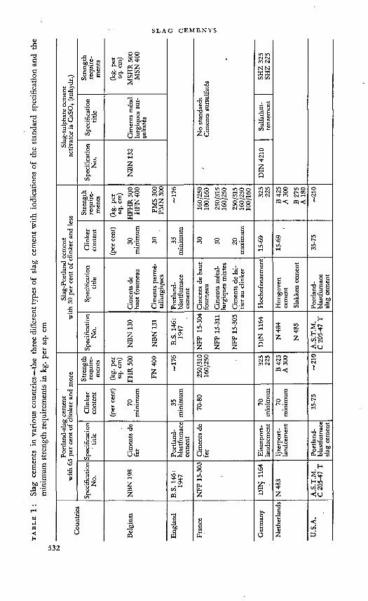
tabl
e 1: Slag
cem
ents i
n var
ious
coun
tries
—th
e thre
e diff
eren
t typ
es o
f slag
cem
ent w
ith in
dica
tions
of th
e sta
ndar
d spe
cific
atio
n and
the
min
imum
stre
ngth
requ
irem
ents
in kg
. per
sq. cm
Slag
-sul
phat
e cem
ent
activ
ator
is C
aSO
4 (an
hydr
.) Stre
ngth
re
quire
m
ents
(kg.
pet
sq. c
m)
MSH
R 50
0 M
SN 4
00
z N
o sta
ndar
dsCi
men
ts su
rsul
fatd
s SHZ
325
SHZ
225
Spec
ifica
tion
title
Cim
ents
met
al-
lurg
ique
s sur
- su
lfate
s
Sulfa
thüt
te
nzem
ent
Spec
ifica
tion
No.
NBN
132
DIN
4210
Slag
-Por
tland
cem
ent
with
50 pe
r cen
t of c
linke
r and
less
£ *
O O o o w o co m
8.8 B4Z ÖZ mo-
<oT
o o o in o o tn ko i-t m i-i in<n_<N <n <n rM o o o o o o o" kQ O kQ KQ LQ kO o
325
1
225
«<: cq<;
Clin
ker
cont
ent
■ (per
cent
)
30
min
imum
30 35
min
imum
30 50 20
max
imum
15-6
9
15-6
9
35-7
5
Spec
ifica
tion
title
Cim
ents
de
haut
foum
eau
Cim
ents
perm
e-ta
llurg
ique
s
Portl
and
blas
tfurn
ace
cem
ent
Cim
ents
de h
aut
foum
eau
Cim
ents
m6t
al-
lurg
ique
s mix
tes
Cim
ents
de la
itie
r au c
linke
r
Hoc
hofe
nzem
ent
Hoo
gove
n ce
men
tSl
akke
n cem
ent
Portl
and
blas
tfurn
ace
slag c
emen
t
Spec
ifica
tion
No.
NBN
130
NBN
131
B.S.
146:
. 19
471__
____
__'
NFP
15-3
04
NFP
15-3
11
NFP
15-3
05
DIN
1164
N48
4
N48
5
A.S
.T.M
.C
205-
47 T
Portl
and-
slag
cem
ent
with
65 pe
r cen
t of c
linke
r and
mor
e
Stre
ngth
re
quire
m
ents
2 ou e o oo.g -o VS Z
kDT
250/
310
160/
250
325
225
B425
A 30
0 oI
Clin
ker
cont
ent
(per
cent
)
. 70
min
imum 8 a
” aS
70-8
0 8 B o 8
"c "E
8 a o §
c8
35-7
5
Spec
ifica
tion
' title
Cim
ents
de
fer
Portl
and
bias
tfum
ace
' cem
ent
Cim
ents
de
fer Eise
npor
tla
ndze
men
tIjz
erpo
rt-la
ndce
men
t
Portl
and
bias
tfum
ace
slag c
emen
t
Spec
ifica
tion
No.
NBN
198
B.S.
146:
1947
NFP
15-3
03
DIN
1164
N48
3
A.S
.T.M
.C
205^
7 T
Coun
tries
Belg
ium
Engl
and
Fran
ce
Ger
man
y
Net
herla
nds! i
U.S
.A.

Credit is due to Passow for promoting the introduction of slag cements, especially blastfurnace cement, which was first made in 1907.
Following the discovery of sulphate activation by Kühl in 1908, the production of binding agents from blastfurnace slag activated by calciumsulphate gained a firm footing first of all in those countries whose slags contained a high percentage of alumina. This was particularly true in the case of Belgium and France where cement still bears the name of “ ciment metal- lurgique sursulfate.” In Germany it is called “ Gipsschlacken^ement ” or, more recently, “ Suljat-HüttetK<ement.''’ A survey of the standard slag cements in various countries is shown in Table 1. There has been a general rise in the production of slag cements in the past few years for the following reasons. The addition of slag provides the possibifity of economizing in coal; and the use of these cements has proved advantageous for mass structures or constructions which are exposed to sulphate-bearing waters, such as seawater. Slag cements compared with Portland cements, have lower early strengths and correspondingly a slower development of hydration heat which makes them suitable for mass structures but more sensitive to low temperatures.
Our knowledge of slag cements is not so far advanced as that of Portland cement which is not surprising. Research work has been going on since the beginning of the century on the connexion between the constitution of a clinker and its technical properties; the various kinds of crystals in Portland cement clinker are visible and their influence on the hardening process is largely known. The properties of slag cements that have been known for 50 years are caused by the activation of blastfurnace slag by Portland cement or by the effect on the blastfurnace slag of other alkali materials like lime in slaked or unslaked form; or the effect of sulphate materials like gypsum or anhydrite. Other basic materials, such as NaOH, KOH or Na2CO3, also CaCl2 and other sulphates such as Na2SO4 are effective in the same or a similar way. They are occasionally used in small amounts as additions, but as sole activators they are only used for testing purposes in the laboratory. There is no question of using them in commercial slag cements as, owing to their high solubility, they can cause efflorescence, promote the rusting of reinforcement, and also lower the resistance of the cement to air-setting.
The added materials are usually designated activators and the blastfurnace slag a latent hydraufic binding agent. This is justified by the fact that good hydraulic granulated blastfurnace slag hardens even in unground form; it attains considerable strengths by mixing with solutions or by the addition of slight quantities of unhydraulic materials; and it does not require the co-operation of a self-hardening partner like Portland cement. It cannot, therefore, be counted among the pozzolanas, as by pozzolanas we mean the big group of natural or synthetic materials of the most varied description and with the most widely varying characteristics from brick dust through fly-ash to the volcanic ashes. The usual definition of pozzolanas is that they form permanent insoluble compounds with lime in the presence of water,
'■ 533

that is to say, they give cement-like properties to unhydraulic. binding agents like lime. According to the experiments of Rodt,56 the best known poz- zolana, trass, when mixed with calcium hydroxide, binds ample quantities of calcium in the first stage of hardening, although there is no correlation between lime-binding and hardenability, while only comparatively small amounts of lime are absorbed from lime-saturated water by blastfurnace slag whether it is glassy or crystallized. Thus the lime-binding capacity of pozzolanas does not greatly affect the hardening of blastfurnace slag. Only the swelling capacity of the slag is related to its hardenability. In fact, blastfurnace slag always gives off lime to pure water, giving pH values from 7 to 11. According to Naumann,51 the lime solubility of granulated slag amounts to as much as 6 per cent of the total lime content, and that of disintegrated crystallized slag 16 per cent. All these peculiarities, but especially the fact that the blastfurnace slag participates in the hardening and is hydrated with great speed, justify its description as a latent hydraulic binding agent.
Of the many possible cements, only three types are of practical importance, namely slag cement with (a) 65 per cent clinker and more, which we shall call Portland-slag cement; (b) 50 per cent clinker and less which we shall call slag-Portland cement; and (c) lime sulphate as activator which we shall call slag-sulphate cement (cf. Table 1). -
The slag-lime cement produced with unslaked or slaked lime as activator (in Germany, “Mischbinder” or “Schlackenbinder”-, in France, “ ciment de laitier h. la chaux ”) appears now only in periods of a shortage of binding agents, or has only local importance. These mixes usually contain additions of 10—20 per cent slaked lime or 20—30 per cent hydraulic lime. The maximum strength lies with the lower additions of lime. The surplus of lime takes into account, the carbonation of the lime during storage. That is also the reason why -slag-lime cements are regarded today as inferior hydraulic binding agents and are no longer important. The addition of small amounts of gypsum or Na2SO4 can appreciably increase the strength and permit a substantial decrease in the lime addition.
TESTING THE HYDRAULIC VALUE OF A SLAG
The hydraulic effect of blastfurnace slag can be most easily understood and numerically evaluated in a mixture with Portland cement clinker. These mixes have generally superseded the slag-lime cements as standardized cements, as, owing to the self-hardening property of the Portland cement, they guarantee adequate hardening also at low temperatures and suffer no loss of strength as a result of prolonged storage.
Preparation op test specimensIn order to test cements with finely ground additions, a testing process
must be applied in which the substitution of an inert material for the Portland cement immediately results in a perceptible decrease in strength. This is not the case with every testing mortar, and especially not when a single-
534

Figure 1: Strengths of cement mortar according to DIN 1164 with various contents of sand or slag.
grain, not very fine sand is used for the making of the mortar. Then, because of the better constancy of volume, even fine sand can cause an increase in strength. As is shown in Figure 1, the condition is fulfilled by the German testing mortar with standard sand of mixed grading. The substitution of finely ground standard sand for increasing quantities of Portland cement results in an almost linear drop of compressive strength. If, instead of sand, blastfurnace slag of the same grade of fineness and with a gypsum content related to the amount of clinker is used, the strengths are higher. As quartz sand, in the case of long-term strengths, also reveals14 itself as an active factor in the hardening, the use of corundum (A12O3) may be considered for future tests. For observation up to 90 days, the use of quartz sand is evidently sufficient. The strengths of the test mortar according to DIN 1164 are in good relationship to the concrete strengths, as was shown by Haegermann (Figure 2). The strengths of the test specimens according to DIN 1164 decrease in a similar manner to those of concrete with 300 kg. cement per

Hydraulic binding agents
The figures 1-12 on the abscissa refer to hydraulic binding agents consisting of 75 j>er cent Portland cement and of 25 fer cent various admixtures which are the following )
1. No admixture {pure Portland cemenf) to 100 per cent.
2. Blastfurnace slag A to 25 per cent.3. Blastfurnace slag B to 25 per cent.4. Trass R to 25 per cent.5. Trass B to 25 per cent,6. Clay to 25 per cent {heated at 800°Q.7. Boiler slag to 25 per cent.8. Brich dust to 25 per cent.9. Fly ash {pit coal} to 25 per cent.
10. Limestone to 25 per cent.11. Si-material {waste product of aluminium production)
to 25 per cent.12. No admixture (75 per cent Portland cement only).
Figure 2: Strengths of mortar (DIN 1164) and of rich and lean concrete at 28 days’ storage in water (according to Haegermann).

cu. m. concrete and 200 kg. cement per cu. m. concrete, if 25 per cent of the Portland cement is replaced by blastfurnace slag, trass, burnt clay, boiler slag, fly-ash, or siliceous material (Si-Stoff).33
The following method is recommended for the testing of hydraulicity.2' 37Portland cement clinker, the addition material to be tested, and quartz
sand are ground separately to a fineness of 15 per cent residue on the 0-06 sieve (10,000 meshes per sq. cm.). This is' equivalent to a specific surface, according to Blaine, of approximately 4,000 sq. cm. per g.
The ground clinker is intimately mixed with 5 per cent finely ground gypsum, CaSOt.2H2O (0 per cent residue 4,900-mesh sieve), equivalent to 2-33 per cent SO3.
With the Portland cement thus obtained, the following series of mixes is prepared :
per cent by per cent byweight Portland weight addition
cement material85 4- 1570 + 3050 + 5030 4- 7010 4- 90
and a similar series of mixes with ground quartz sand instead of the addition material. Ground quartz sand, being non-hydraulic serves as a criterion for the evaluation of the hydraulic addition material.
This series and the Portland cement without any addition are tested according to DIN. 1164 with prisms 4 X 4 X16 cm. The tests cover ages of 7, 28 and 90 days, the test specimens being stored in water. Figure 3 shows the results of such a test from 0 per cent to an addition of 50 per cent.
Procedure for testing of small specimensAs there is no difficulty in forming and compressing the plastic mortar
without the aid of mechanical means, the possibility of producing and testing much smaller specimens was investigated. The size of the specimens was reduced to 1x1x6 cm and no essential difference was observed in the results obtained. The necessary testing apparatus- is shown in Figure 4. These prisms, 6 cm long, still permit measurements of length to a distance of 5 cm with a comparator. A length of 1 to 1-5 cm is adequate to determine the strength.
The determination of bending strength is carried out by a simple apparatus with a leverage of 1:1-5 (Figure 5) and for the determination of the compressive strength of the prisms we use a bending apparatus with two measuring ranges of 1000 and 2500 kg. The knife edge of this apparatus is replaced by a distance piece which transmits the compression to the broken piece of the prism, as in the case of the standard prisms (Figure 6). Of course, a small compression apparatus with a suitable measuring range is also practi-
537

IOO 90 80 70 60 5Oe/o of Portland cement.O IO 20 30 40 50% of admixture.
Figure 3: Effect of hydraulic admixtures on the strengths of Portland cement mortar according to DIN 1164 (by Hae^ermanny
Figure 4: Apparatus for the small specimen testing method. "
cable. As shown in Table 2, the deviations of the test results are still within the usual limits of error. In comparison with the 4 X 4 X16 cm prism, the small prism gave on the average nearly the same bending strength and a
538

Figure 5 : Small specimen bending test.
Figure 6 : Small specimen compressive test.
table 2 : Strengths of standard prisms and small prisms. Z 225, after 7 days’ storage in water
Measurements Compressive strength Bending strengthWeight per
unit of volume
cm. kg. per sq. cm. kg. per sq. cm. kg. per cu. dm.standard prisms 1644-158+160 41-3+43-6 2-25
4 x 4 X 16 166+156+165 average 42-4+35-5 , average- 148+140+142 155 38-2+ 36-6 39-6
small prisms1X1X6
155+161+158170+161+152147+146 •
• 15847-0+38-237-5+32-0 ■ 38-7
2-26

compressive strength about 7 per cent higher. Practically the same strength was obtained on still larger prisms of 10 X10 x 30 cm made from the same mortar and under comparable conditions. With the aid of the small-scale testing method it has been possible to examine the change of length with water storage and also to obtain one value for the bending strength and two values for the compressive strength from 4 to 5 g of a melt of hydraulic binding agent.
Calculation of hydraulic indicesIn order to determine the hydraulic hardening numerically, the compressive
strength of the mixture (at 28 days’ storage in water) of:70 per cent Portland cement-)-30 per cent addition material =a
is related to that of the .Portland cement..................................................................................... =b
and .to the mixture of 70 per cent Portland cement-)-30 per cent groundquartz sand ............................................................................... =c
according to the formula ^~C x 100
The figure thus obtained is thePrincipal Hydraulic Index 70/30” for the hydraulic hardenability of the addition material.
In addition to the principal index for the mixing ratio 70/30, a further index can be calculated, especially in the case of blastfurnace slag, for the mixing ratio 30/70.
Examples:Principal hydraulic index 70/30 for an addition material:Compressive strength at 28 days’ storage in water:*mix 70 Portland cement+30 addition material 326 kg. per sq. cm. (=a) mix 70 Portland cement-)-30 quartz sand 216 kg. per sq. cm. (=c) pure Portland cement 386 kg. per sq. cm. (=b)
326—216386—216
X 100=112 xioo
Principal Index 70/30=65
Hydraulic Index 30/70 for the hydraulic hardenability.Compressive strength at 28 days’ storage in water:mix 30 Portland cement+70 addition material 212 kg. per sq. cm. (=a) mix 30 Portland cement+70 quartz sand 56 kg. per sq. cm. (=c) pure Portland cement 386 kg. per sq. cm. (=b)
212—56386—56
xioo=l|2 xlOO
Index 30/70=47

In the mix ratio 70/30, the addition material shows 65 per cent, and in the mix ratio 30/70, 47 per cent of the hardenability of the clinker. The hydraulic index thus alters with the mix ratio; but it also alters with the age of the test and is different for compressive strength and bending strength.
Method of Parker and NurseOn the basis of thorough tests conducted at the Building Research
Station with 37 English blastfurnace slags in a mix ratio of 65 clinker : 35 slag (ground to a fineness of approx. 3000 sq. cm. per g.), in which specimens were produced for the determination of compressive strength according to B.S.S. and also concrete specimens (1:2:4) with approximately 10 cm edge length, with a waterxement ratio of 0.60, Parker and Nurse54 have indicated a different evaluation method for the hydraulic value of slags. The concrete strength at the age of 90 days which was achieved with Portland-slag cement was related to the compressive strength of the concrete with pure Portland cement; and the later date was chosen because the earlier strength values are appreciably influenced by smaller additions, for instance, by the gypsum content. They calculate the percentage strength as equal to 0-38 G (M-0'72)+75-0. Here G signifies the glass content microscopically established in the fraction 0-06—0.09 mm. If G=0, that is to say, if the slag is totally crystallized, the percentage strength=75, that is the percentage compressive strength which is attained by concrete at 90 days, if 35 per cent of the Portland cement is replaced by an inert material. M is the modulus formerly contained in the German cement standards for the evaluation of the slag
CaO+MgO+j A12O3’ — SiO2+j A12O3
which is shown on page 20 as F I, and which varies in the investigated slags between 0-85 and 1-35. With a glass content of 50 per cent and a modulus of 0-85, the constant value 75 increases by only 2, i.e. to 77, and with a glass content of 100 per cent and a modulus of 1-35 it increases by 24, i.e. to 99. Thus, an immediate connexion is established between the chemical composition and the glass content of the slag and the technical properties of a certain concrete, when 35 per cent of the Portland cement proportion is replaced by the given slag.
We have not yet followed this path and attach greater importance to the evaluation of the slags by the hydraulic index 30/70, that is to say, the figure corresponding to slag-Portland cement, since this allows the hydraulic properties of the slag to emerge more clearly. Our evaluation figures cover the range from 0 to 100, as the strength of the mortar or the concrete with the inert addition is put equal to 0, while the English evaluation figures can only range between 75 and 100 and over; 22 of the 26 investigated slags, for instance, had a percentage strength between 81 per cent and 103 per cent.

Criticism of the hydraulic indices. If these methods, especially the German method, are examined critically it is undoubtedly an advantage to have a clear conception of the hydraulic effect of the slag in a slag cement. A principal index 70/30 with the value 65 per cent according to the German method (see example on page 11) means that the slag behaves in a Portland-slag cement at the age of 28 days as if it consisted of 65 per cent of clinker and 35 per cent of inert quartz sand. The index 30/70 with the value 47 means that the slag behaves in a slag-Portland cement at the age of 28 days (90 days would be better) as if it contained 47 per cent of clinker and 53 per cent of quartz sand. These indices are, however, only valid under certain conditions. They depend on the strength of the clinker and on the amount of gypsum addition, but especially on the testing age of the specimens and the mix ratio of clinker to slag. Parker and Nurse5* have found only slight divergences in their evaluation figures for various clinkers. It cannot be expected that it will be possible to apply them to slag-sulphate cement, but it has been shown that a slag which reacts well to alkali activation also gives a good slag-sulphate cement.
The order of magnitude of the principal hydraulic index 70/30 and its dependence on the test age is shown in Table 3. It emerges from these figures that the slags in clinker-rich mixes of the Portland-slag cement type possess principal hydraulic indices between approximately 50 and 90 per cent. By an increase of the fineness of grinding it will usually be possible to attain the strength level of the comparable Portland cement, especially when it is primarily a question of the strength at 90 days.
table 3 : Principal hydraulic index 70/30
at 28 days at 90 days
per cent. per cent(1) from investigations of Parker
and Nurse(a) for hematite slags 52 to 97 65 to 89(b) for basic and furnace slags 38 to 69 48 to 89
(2) from investigations of Haegermann basic blastfurnace slag 63 , 79( trass R, trass B ) ( 45 , 18 )
Table 4 shows the index 25/75, which is better suited for the evaluation of the hydraulic quafities of slags. These results were obtained before the test mixture was fixed at 30/70, which was in 1944. Moreover, they are average values from compressive and bending strengths. The values of the hydraulic index 30/70 should, however, differ only slightly from those in Table 4. These figures clearly show the differences in the hydraulic behaviour of the various slags whose chemical composition is shown in Table 5, and

tabl
e 5 : Che
mic
al an
alys
is of b
asic
and a
cid b
lastf
urna
ce sl
ag, o
f “ re
nn ”
slag a
nd o
f tra
ss
F. KEIL
Tras
s
n
56-0
16
-1
1-1
0-3
2-5
1-5
trace
s 5-
1
1 40 00
0-0
0-2 04 (0
-34)
“Ren
n"
slag - o o i-i o o in
o ö ö o th 0-45
'S *5 eo y « o -s< 8 ”C CflHcriOOiO'iOOurr) M O in i-H o |8 A o o *h o 1 10
Aci
d gra
nula
ted
blas
tfurn
ace s
lag
y m o m m o Iti ^J^CMCOrHvdinS^ w o o <D ö • rH
is iHfnöeno^enöo ö o ö Ö o • 1-2
' Ba
sic g
ranu
late
d bla
stfur
nace
slag ric
h in a
lum
ina
- intT-'d-vo^kocsitMcn oo © i-r m I .2 th\ö©©ö^)4-öö ö 6 h ö I I
© CM
Ti-b*q'rO't\ONMoo cnot^Mi i™ 6it)Öh4^4ö6 o © o a 1 1 1-
7
ti i-<inoo©'0<n©nj "o © © ns i iw ö4öc>H^föa d ö t4 (j 1 1
© CM
in-^cncMi.oocnrncM in o o m i iCM^ÖQÖ^^-OO © © © * I 1-
9cn©\0oC'H<NT7in3<'y ©KpKpi | rHrnööö^*nc C © © Ö 1 •
' 20
' po
or in
alum
ina
Mi-HincninmcM© ’N vh en cm i icntM©C>©d\THH rH © CM © 1 1 1-
7
v^i7<*n<p^-C7»op^- co th © q\ i |ina\©©©©iHO © © h © • •co en r-< ,
1-6
t. ^Ofn^*min©CM© co T7* -d- | |ino\©o©cbcM©© ©©cm©* * CQ
1-6
inh-cpM-tncM©CM <n w © tn i 1wobo©CM'OA© TH ©cm©* *co V
1-7
M ©©inoor**h»mcM© co h co o i |^A©<d<d«cm©h ö Ö h h 1 1
91
F II
I—va
lue

slag cements
a steep rise of individual slags with increasing age and increased fineness. They also show that the very acid slags, which occur very rarely, when finely ground, are capable of a considerable hydraulic effect at 90 days. Table 6 indicates the approximate hydraulic indices 30/70 of the basic slags tested in Table 4.
table 4 : Hydraulic indices 25/75. (Average from hydraulic indices forbending and compressive strength)
Granulated slag of normal1 and higher2 fineness
Fill37 days 28 days 90 days
normal higher normal higher normal higher
basic hh 2-0 46 57 94e 1-9 57 72 66 86 92 97g 1-7 24 30 - 82k 1-6 42 44 71t 1-6 23 32 68 49 88
acid te 1-2 — 14 11 36 30 52mx 1-0 — 13 5 23 22 33
crystallized slag —• 2 •' 1 2 — 7“ renn ” slag — 5 — 15 16 52trass 54 25 194 25 244 24
(1) 25 per cent residue on sieve 0-06 DIN 1171; approx. 2000—3000 sq. cm. per g. according to Blaine
(2) 2 per cent residue on sieve 0-06 DIN .1171;
(3) mi CaO+CaS+iMgO+AlzO3' 1 SiO2+MnO(4) ground after mixing for 15 minutes.
approx. 5000 sq. cm. per g. according to Blaine
table 6: Hydraulic indices 30/70 for basic slags (calculated on basis of findings from Table 4)
Specific surface according to Blaine
at 7 days at 28 days at 90 days
coarse ground 2000—3000 20—50 25—70 30—90
fine ground 5000 30—60 45—65 50—70

Other methods of evaluating the hydraulic propertiesIn order to permit a rapid evaluation of the hydraulic properties without
knowledge of the chemical composition, a number of methods has been suggested which, however, have not yet found general application though they render good service in special cases.
According to de Langavant43 and Feron26 in the metallurgical plant Cockerill, Ougree-Marihaye, observation of slags in ultra-violet light has proved useful. Good slag gives a pinkish fluorescence, not-so-good slag has a bluish shade or contains substantial amounts of blue fluorescent grains. Other works have been less successful with this test. In the heating experiment (see below), the pink shining and the bluish shining slags revealed no difference in the amount of heat developed, but the pink grains showed a blue fluorescence after devitrification. In the X-ray pattern, the pink shining slag proved to be completely glassy, while the blue shining slag showed a spectrum with very faint lines, which, however, could not be more closely identified. The fluorescence thus apparently indicates the degree of devitrification and is perhaps a sign of the temperature at which the cooling of the slag has started. As is known, the phenomenon of luminescence is based on the fact that ultra-violet fight invisible to the human eye is transformed into visible light, that is to say, that short-wave rays of light are absorbed and long-wave rays are given off. The cause of the luminescence is thought to lie in irregularities in the lattice structure of the materials involved. These luminescences usually come from embedded foreign matter, in the present case, possibly from embedded sulphur.
Mussgnug48 has carried out a quick test of mixes of finely ground slags with various activators by heating them with steam. He compressed the mixes with 10 per cent water into cylinders 5 cm high and 5 cm diameter, and heated these test specimens for four hours in a flow of steam. In this test, low hydraulic slags attained less than 100 kg. per sq. cm. compressive strength, high hydraulic slags more than 200 kg. per sq. cm. As a rule, the strength runs parallel in steam hardening and in normal hardening. The steam heating, however, favours the more highly devitrified slags, so that the values established in steam heating are higher than those attainable in normal hardening. This method thus provides useful values, particularly if it is desired to use the slag sands for the production of steam-hardened metallurgical bricks.
An indication of the hydraulic value of a slag sand is obtained with the microscope if the refractive indices are determined by the embedding method. In lime-rich slags they usually fie above 1-65. According to Guttmann and Weise,30 treatment with potassium hydroxide, and subsequent colouring with methylene blue, is also a useful way of evaluating the hydraulic properties. According to the improved process of Gille,27 it is recommended to heat 0-5 g slag of 0-06 to 0-09 mm grain size in a test glass, after addition of 12 ml of 5 per cent potassium hydroxide in a container of water up to the boiling point of the water; to shake the filtered slag sand with 5 ml of a
545

0-5 per cent methylene blue solution, then to filter it off and dry it. The colouring thus occurring is slighter in low hydraulic slags than in higher hydraulic slags, but does not run parallel with the strengths.
A further microscopic method has been applied by Michelsen.46 He mixes finely powdered slag with a drop of 2 per cent aluminium sulphate solution, and observes when the first needle formation occurs and when the crystals are completely developed. In high hydraulic slags, needle formation occurs within one minute, in low hydraulic slags only after four to five minutes. In the first case, crystal formation is completed after 5 minutes, in the second case, it takes up to 35 minutes. This test, in itself a sensitive one, reacts to devitrified slags, however, just as quickly as to glassy slags, and thus gives no reliable indication of the hydraulic value of a slag The method has recently been checked on five slags by Tanaka and Takemoto.60 They substantially confirm the results of Michelsen. The good hydraulic slags required 1 to 2 minutes for the formation of the first crystals, the less hydraulic slags 4 to 5 minutes. In the first case, the crystals grow quickly— within 20 minutes—in the second case, slowly, for more than 20 minutes. In the first case the crystals are less than 30p., in the second, they are from 40 to 60p. long. This method proves to be impracticable for quantitative purposes and cannot be applied to crystallized slags. Chemical and optical investigations of the authors revealed that the crystals were gypsum.
The determination of the devitrification or crystallization heat released during slow heating of the slag also requires only a short time. It must not be believed, however, that there is a causal connexion between the hardenability and the devitrification heat, for the acid glasses also give off heat when devitrified, without being essentially hydraulic. It may be assumed that the heat of devitrification of the technical glasses and slag glasses lies between 40 and 80 cal. per g.
The method first indicated by Grün,26 continued by Dumesnil,17 and recently elaborated by Lecldre43 is carried out by heating 25 g of slag under 0-09 mm grain size in a porcelain crucible in an electric furnace, whose temperature is increased by 20 °C per minute. In the beginning, the temperature of the slag lags behind the furnace temperature, and then above 750°—800 °C, hurries on ahead of it. The heating curves have differing characters (see Figure 7). Leclöre43 considers that the temperature at which the heat development begins and the question whether a second release of heat follows it are characteristic of individual slags.
Blondiau7 proposes to determine the hydraulic potential as the difference in the heat of solution of an untreated powdered slag and one heated for four hours at 1000 °C, with a specific surface of approximately 2700 sq. cm. per g., according to Wagner, that is about 4860 sq. cm. per g. according to Blaine. He found that the release of devitrification heat is greatest at 1000°C and reaches its maximum value as quickly as 1| hours. On the basis of these findings, he postulates that slags are assuredly suitable for the production of cement when the ratio of CaO to SiO2 lies between 1*45 and 1-54, the ratio

Figure 7 :'The curves of heating of two granulated and of one crystallized slag (according to Gr««). The thin lines alongside the heating curves represent the heating curves of the oven.
of SiO2 to A12O3 between 1-8 and 1-9, and the hydraulic potential between 70 and 80 cal. per g., according to his method of determination. Comparable findings were made both with slag-sulphate cement (addition of 17 per cent CaSO4) and with slag-Portland cement (addition of 30 per cent clinker and 6 per cent CaSO4).
Our heating experiments with slag sand38 have shown that after one hour’s heating at 800 °C the X-ray pattern (Figure 8) already shows visible alterations in the structure, which was not the case up to 600 °C. After three hours’ heating of slag “ e ” up to 1100 °C, fines were clearly recognizable which also occur in a synthetic mix of gehlenite and dicalcium silicate. In accordance with these alterations, the hydraulic properties of the slags can decrease by approximately one-third by heating to 850 °C (light red heat), but on the other hand, the grindability of some slags is so greatly improved that in this case, better strengths are obtained for the same expenditure of power for grinding. With prolonged heating, up to 50 per cent of the 8 present in the slag can be transformed by oxidation into SO3. The improvement in grindability is greater in slags in which more sulphide is transformed. A loosening of the structure evidently occurs during heating.
As Passow55 has already indicated, testing with sodium or potassium hydroxide leads very soon to measurable and comparable strengths. Relying on thorough experimentation, Feret25 recommends the making of cubes of-5 cm edge length, or small prisms, from one part slag sand and two parts
547

1. g original condition
2. e original condition
3. e 800°C 1 hour
4. e 1100°C 3 hours
5. ß QS+CjAS mixture (compare with e).
Figure 8 : X-ray patterns of heated granulated slags.
standard sand, which are mixed with 11 per cent o£ a caustic soda solution (200 g sodium hydroxide per litre) and hardened for 24 hours at a constant temperature in an atmosphere free from carbonic acid. The strength values thus obtained tally well with those after normal heating. Feret considers this method to be particularly .useful as it supplies usable values quickly, and because the properties of the slag are not concealed by the addition of other binding agents. This method is based on a suggestion of Chassevent,13 who has also shown that the solubility of the slag sands in dilute sodium hydroxide solution (0-5 g caustic soda per litre) and the temperature rise of slag sand pastes made with a sodium hydroxide solution in the adiabatic calorimeter depends on the hydraulic value of the slags. According to Feret, the determination of solubility, however, furnishes values that vary too little. The results of the calorimetric determinations are difficult to evaluate in their relationship to strength. All these tests conducted in France refer only to slag sands with more than 13 per cent alumina. ■ .
chemical composition, granulation temperature and HYDRAULIC PROPERTIES
Blastfurnace slag is the molten flux in the blast furnace which, in the production of pig iron, contains the unreduced oxides. It is produced from the silicate, argillaceous and calcareous constituents of the iron ores, the additions, and the ashes of the coke. An ore rich in alumina like minette, for instance, gives a slag rich in alumina; a dolomite addition a slag rich in magnesia; sulphur-bearing coke and sulphur-bearing ore a slag rich in sulphur.
The type of pig iron also influences the composition and hence the technical properties of slags from this process to the extent that slag from cold- blown pig iron, e.g. Thomas pig iron, is poorer, under comparable conditions, in CaO and CaS and richer in SiO2, MnO and FeO than slag from foundry pig iron smelted from the same ore. With rising temperatures, the slag melt can absorb more CaO and S, and more FeO and MnO can be reduced to Fe and Mn. .

According to the findings of Mussgnug,47 the slag of hot-blown openhearth steelmaking iron gives better strengths, despite the comparatively high manganese content, than slag of" the same chemical composition arising in the production of Thomas pig iron. It would appear from this observation that a higher temperature of production promotes hydraulic properties. A necessary condition is that the slag is water-cooled from this temperature and solidifies like glass. Any delay in granulation can cause a decrease in hydraulicity. The microscope then frequently reveals an increase in not completely glassy particles. Foamed slag, therefore, generally has lower hydraulic properties than immediately granulated slag. This is confirmed by recent experiments by Blondiau,6 in which the reduction of the granulation temperature by a comparatively small amount from 1537° to 1479 °C caused a loss of strength of approximately 10 to 40 per cent in the slag-sulphate cement produced with the slag. The slag with delayed granulation had a hydraulic potential reduced by only 5 to 7 cal. per g.
Experiments on the influence of the chemical composition on the hydraulic properties confirm unanimously that the hydraulic value of a slag rises with an increasing content of CaO and CaS and with a decreasing content of SiO2 and MnO, probably, too, of TiO2 and FeO. The question as to how far MgO can replace CaO as a hydraulically effective proportion is not yet clarified. We have observed that slags rich in magnesia, i.e. with more than 8 per cent MgO, have not the same hydraulic value as slags poor in magnesia of comparable composition. According to established findings by Stutterheim and Nurse59 in slags with 15 per cent to 18 per cent MgO, it would appear that the MgO possesses no hydraulic value in such high contents. Spinel was identified in two of the slags.
In the course of the decades, alumina has proved itself to be a constituent that promotes hydraulic properties, to which attention is drawn in the following.
Attempts have been made to reproduce the complicated relationships between chemical composition and hydraulic properties in formulae. Departing from the “ basicity ratios ” of the blastfurnace worker for the judging of melting conditions in the blast furnace, which are designated pi, p2, and p3 and are calculated as follows:
CaO CaOq-MgO CaOfi-MgOpl-siö; p2- siöT“ p3 Sio2+Ai2o3
the following proposals were made:CaO+MgO+j A12O3
r : SiO2+iAl2O3 -
p ii. CaO+MgO+Al2O3 I" SiO2 —
FTTT CaO+CaS+j MgO+Al2O3 >1C.' SiO2+MnO _

tabl
e 7 : Com
pres
sive s
treng
th in
kg. p
er sq
. cm
. of g
lass
es qu
ench
ed in
wat
er (a
dmix
ture
of ac
tivat
or in
perc
enta
ge)
Com
pres
sive s
treng
th in
kg. p
er sq
. cm
.
18 pe
r cen
t of c
linke
r5 p
er c
ent o
f gyp
sum
00 ®<N
26 25
CO o-i 20
2
-Ö
*O1 o 04 m
oo
3 day
s
i 12
per c
ent o
fhy
drau
lic gy
psum
5 per
cent
of c
linke
r
0004VO m n.
d. n.d.
n.d.
7 day
s
46 n.d. 73
d73d n.
d.
3 day
s
41 42 OI in 00 kD
00 04
12 pe
r cen
t of
hydr
aulic
gyps
um2 p
er ce
nt o
f Ca(
OH
)2
r§ 00
co 1-404
•p-u 156
108 kD Ci
7 day
s
138
n.d. 04 / 00 Ch s
3 day
s
107 to 101 67 26
10 p
er ce
nt of
Ca
(OH
)2 m 'S00 G04
543
. 589 i
455
103
3 day
s
n.d.
i 350 296
140 00
04
1 per
ce
nt o
f cl
inke
r
28 da
ys
0 o o o 125
No
acti
vato
r
28 da
ys
0 o o o 122
Fine
ness
by
Blai
ne
(sq.
cm. p
er g
.)
4550
4820 o 1—1
4650
4980
Gla
ss
Geh
leni
te
90 pe
r cen
t of
gehl
enite
+10
per c
ent o
f di
calc
ium
sil
icat
e90
per c
ent o
f ge
hlen
ite+1
0 pe
r cen
t of
12/7
calc
ium
al
umin
ate
Ake
rman
ite

Hydraulic Properties (according to F III)
medium ■ good very good <1-5 1-5—1-9 >1-9
Formula I was contained in the old German standards, Formula II was introduced into the revised version of DIN 1164 in the year 1942, when so-called acid blastfurnace slag was also produced in Germany, a slag which proved itself useful for the production of cements poor in clinker. In drder to enable a more accurate distinction to be made between very good, good, and usable slags. Formula III was proposed. The essential difference in these three formulae is the transfer of A12O3 in its full amount to the numerator and the consideration of S and MnO. To date we have achieved excellent results in the judging of slags on the basis of Formula III.
The F III value only refers to the glassy constituents soluble in HC1. According to Stutterheim and Nurse, spinels (MgO.Al2O3) can occur in granulated slags rich in MgO, which are insoluble in HC1 and HF. They also remain practically undissolved in evaporation with HF and H2SO4. For instance, we found 9-3 per cent spinel in a South African slag with a content of 15 per cent MgO.
There are, of course, many shortcomings in formulae of this kind, but they enable a quick evaluation to be made when the chemical composition of the slag is known, which is the case at every blastfurnace works. It is known within what limits it varies and how far the composition can be altered by altering the burden. For a day-to-day acceptance of the slag from the same blastfurnace works it often suffices to have only the analysis of one constituent, for instance of Mn or of SiO2, if the colour of the slag is not already enough, (see page 545).
de Langavant43 considers the following formula as being particularly suitable as an “ index of quality,” which is somewhat simpler than the German Formula III:
Hydraulic Propertiesmedium good very good
i=20+C+A+0-5 M-2 S= <12 12—16 >16
in which C is the content of CaO, A that of A12O3, M that of MgO, and S that of SiO2. The formulae are very similar to each other. Their justification will have to be checked by as many determinations on synthetic melts as possible (see page 552). Compared with the previous system of indices, they would appear to represent a certain step forward. Blondiau finds, in suitable slags, in addition to a certain hydraulic potential, a ratio CaO:SiO2 of 1-45 to 1-54 and a ratio SiO2:Al2O3 of between 1-8 and 1-9.
Attempts have also been made, relying on the phase relationships in equilibrium crystallizations, to convert the analyses of the basic blastfurnaceslag glasses, after grouping them in a quaternary system (Ca, Na2)O—MgO,
551

Wollastonite Monticellite 5CaO.3Al2O3
QMSj C2AS c2s
cs CMS c5A3
(Fe, Mn)O—A12O3—SiO2 into compounds. The following were selected: AkermaniteGehleniteDicalcium silicateAn attempt was made by comparing the hydraulic behaviour of slag
glasses in which the one or the other constituent was numerically predominant, to determine the hydraulic efficiency of these assumed compounds.
The selected compounds are not all the crystal typei occurring at equilibrium in the system C-M-A-S. In particular, A12O3 still present after calculation of gehlenite was calculated as calcium aluminate, in order to take into account the peculiar hydraulic behaviour of high alumina-bearing basic slag glasses, whilst spinel should be formed at equilibrium with basic blastfurnace slags of the usual MgO content. It will be shown from tests, described later, that the hydraulic behaviour of the glasses concerned cannot be properly evaluated by converting the analysis into minerals present at equilibrium.
In this way it was found in connexion with a comparison of the strengths of slag-sulphate cements that in the slag a considerable proportion of calculated gehlenite indicates a good hardening, but that there is no immediate relationship between gehlenite content and strength. Dicalcium silicate, as a calculated constituent of the glass also has a favourable hydraulic effect. According to such calculations, it appears that akermanite is more or less inert in hardening, especially when it is burdened with substantial quantities of iron and manganese. The same holds good for monticellite and wollastonite. The strengths decrease, on the whole, with a decreasing alumina content and a rising content of the sum SiO2+MnO+FeO. Here the F value according to Formula III has proved to be most useful.
A more simple calculation of the “ mineral constitution ” is made by Elsner von Gronow22 by regarding the whole of the A12O3 as being bound in the gehlenite. If there is then less than 1 mole CaO for each mole SiO2 in the remainder, the slag is unsuitable for the production of cement. Usable slags contain in the remainder 1 to 1-3 mole CaO for every mole SiO2, good slags 1’3 to 1-6 mole CaO. After deduction of the components of the gehlenite, the calculation can be continued by regarding MgO as being bound in akermanite and by crediting the remainder of CaO and SiO2 to the two compounds 2CaO.SiO2 and CaO.SiO2. Thus, the connexions reproduced by the formulae are confirmed by these calculation methods.
INVESTIGATIONS WITH SYNTHETIC MELTSAs described previously, one is readily inclined to deduce the hydraulic
properties from those of the known crystalline constituents, especially as the hydraulic properties of C2S are known from investigations on Portland cement. Investigations on synthetic melts are, therefore, particularly informative. Up to the present, they are only available on a very small scale.
Nurse and Stutterheim52 have investigated the gehlenite-spinel system

and found that the greater part of the system lies within the spinel primary phase field and that the eutectic has a composition of 85-5 per cent gehlenite and 16-5 per cent spinel (CaO 34-15 per cent, MgO 4-70 per cent, A12O3 42-85 per cent, SiO2 18-30 per cent) and is at 1527 °C. As regards the hydraulic properties of these glasses, it has already been said (page 552) that, beyond a certain content, MgO must not be regarded as a hydraulically effective component, apparently because it crystallizes out as a spinel.
Pure glasses39 with the chemical composition of gehlenite (C2AS) and of akermanite (C2MS2) were produced by us according to the method of Dyckerhoff,19 the former being further supplemented by melts which were altered, first in the direction of dicalcium silicate (C2S), and then in the direction of the 12/7 calcium aluminate (C12A7). As emerges from Table 7, it was revealed that gehlenite glass and the two similar mixes possess no hardenability of their own and react either very little or not at all after sulphate activation or with activation as slag-Pprtland cement, but attain very considerable strengths with Ca(OH)2 as activator. Akermanite glass is self-hardening in a remarkable way (122 kg. per sq. cm. compressive strength at 28 days stored in water) and develops higher strengths as slagPortland cement than the gehlenite glass, but with lime hydrate it has considerably lower strengths than gehlenite glass and the gehlenite-like glasses.
It would appear, therefore, that here is a sphere of work offering highly satisfactory prospects. However, it may be stated today that no support has been found for the belief that the hydraulic properties of blastfurnace slag are the result of certain chemically defined groupings such as gehlenite and akermanite, or are determined by the minerals in equilibrium crystallizations.
SLAG-SULPHATE CEMENT1' 4- 23' 32' 34' 50The combined action of sulphate and slag is not so easily understood and
investigated as that of Portland cement and slag. When slags with a minimum content of approximately 12 per cent A12O3 are involved, sulphates or their SO42" ions evidently cause the same or similar reactions as the OH" ion of the alkali activators. We may assume on the basis of decomposition tests that A12O3, presumably as A1O4 group, is more tightly connected with the SiO4 lattice in the rich-alumina slags than in the low-alumina slags, from which A12O3 can be separated (see page 555), without an externally recognizable alteration of the grains. According to the fundamental work of Blondiau,4 the hardening processes do not occur in the presence of a saturated calcium hydroxide solution of 1-2 g. CaO per litre, but in the presence of a considerably lower CaO concentration of about 0-2 g. CaO per litre. Köberich41 has shown that the most favourable hardening conditions lie between concentrations of 0-15 and 0-40 g.CaO per litre, that only low strengths occur with 8 per cent clinker; and that the clinker addition is also a means of controlling the relationship of compressive strength to

bending strength. In this connexion it should be recalled that Rodt57 found a substantial increase in the volume of the slag on reaction with saturated lime water and that the swelling capacity of the slag was proportional to its hardenability. According to Ottemann,53 the limiting value indicated by Köbetich for pure calcium hydroxide solution at room temperature is about equivalent to a pH interval of 10-8 to 12-5, and agrees with the equilibrium value for ettringite. The optimum hardening of the slag-sulphate cement thus depends on conditions that permit the formation and existence of ettringite. According to Feitknecht and Buser,24 the latter may be formed by precipitation from a Na aluminate solution which contains an excess of NaOH. They give the following formula: 6Ca(OH)2.Al2(SO4)3. 26 H2O.
Slag-sulphate cements with high initial strengths contain 6 to 8 per cent SO3—corresponding to 10 to 13 per cent anhydrite or hydraulic gypsum (Estrichgips)—a high-alumina slag with 15—20 per cent A12O3, and 5 per cent Portland cement. Portland cement has the advantage over lime of having good durability on storage. A slag-sulphate cement that has become slow in hardening by long storage can be freshened up by the addition of 1 per cent Ca(OH)2.
The hydraulic gypsum used is frequently burnt in such a way that it contains slight quantities of free lime, which is comparatively simple where there is CaCO3 impurity, but is more difficult if the gypsum contains clay.
According to Budnikov,9- 10 not only 5, to 10 per cent anhydrite burnt at 500—700 °C, but also a mixture of natural anhydrite and 3—5 per cent dolomite burnt at 800 °—900 °C is suitable.
When CaO-f MgOSiO2+A12O3 = 1-2 and MnO does not exceed 1 per cent, a higher
grade of slag-sulphate cement results.Slag-sulphate cements are ground very finely, i.e. to approximately 1—
2 per cent residue on the 4,900-mesh sieve. The hardened cements sometimes easily “■ sand off,” i.e. the air-side surface does not harden sufficiently and is easily rubbed off. An increase in the clinker addition diminishes the danger of sanding-off. As a rule, slag-sulphate cements develop less heat of hydration than clinker-bearing slag cements.
Hummel35 has shown that the strength of slag-sulphate cement decreases particularly slowly with a rising water:cement ratio and that, contrary to Portland cement, it expands more on being thoroughly moistened and shrinks less when dried out. Mussgnug50 has drawn special attention to the fact that slag-sulphate cement only develops its peak hydraulic efficiency at higher water:cement ratios, i.e. at 0-6—0-7. Its use for earth-moist concrete mixtures rich in cement is, therefore, not to be recommended. On the other hand, because of its low heat development and its excess of sulphate, it is suitable for the production of mass constructions in hydraulic engineering, especially if they are exposed to sulphate-bearing waters.12
As regards the suitability of slag for the production of slag-sulphate

cements, our tests have revealed that, while greater differences can occur in the strengths if 1 per cent calcium hydroxide or 5 per cent high-calcareous or 5 per cent low-calcareous clinker is used as basic activator together with hydraulic gypsum, on the whole, the strengths decrease, just as with basic activation, with falling A12O3 or the calculated content of gehlenite and with an increasing content of the sum SiO2+MnO-|-FeO. Here, too, the Formula III value has proved itself most satisfactory for evaluation.
CHEMICAL DECOMPOSABILITY OF GRANULATED SLAGS
Method oj investigation 'Water in pure form or with an addition of activating material is not very
suitable for establishing variations in the structure of granulated slags, as contact with water causes very complicated reactions. Solid materials are hydrolyzed and partially dissolved, and dissolved constituents are precipitated. It would appear that solutions are more suitable which permit certain constituents of the slag sand to separate from the grain either by exchange or by displacement, without being able to crystallize out again. Valuable work has been done on this question by Theusner.61
We have used for our investigation salts with the following cations and anions: ■
. Cations AnionsAcetate
Citrate
These solutions have various advantages for the intended investigations:
(Ammonium) (Methylamine) (Ethylamine) (Dimethylamine)
NH4 + ch3.nh3+ c2h3.nh3+ (CH3)2.NH2+
ch3.coo-ch2.coo "C(OH).COOch2.coo
(a) The lime salts occurring during the reaction are readily dissolved in the cold. In addition, calcium acetate is readily soluble at highertemperatures.
(b) By addition of the acid or alkali contained in the salts, solutions of varying pH value can be obtained. With the exception of a small pH range, these solutions have a high buffer capacity, that is to say, an addition of acid or alkali causes only a slight change in the pH value, in comparison with the non-buffered solution. Consequently, it is possible to carry out the attack with a practically constant pH value.
(c) Citric acid, like lactic acid, has the advantage of forming soluble complex salts with Al, Fe, and Ti.
(d) The amine salts were included because they permitted the pH range to be extended to approximately 12, and because special effects were to be expected with them.
The sieved grain fraction, 60 to 90p, was elutriated with neat methylalcohol until the grains were freed from the adhering finest particles. The samples were then dried at 100 °C until the alcohol was removed. In this way, samples were obtained of almost uniform surface, so that the influence
555

of the surface, which plays a decisive role in dissolution processes, was practically eliminated. One gramme of the sample was then weighed into a 100 c.c. flask, 75 c.c. of a 10 per cent solution of the salt involved was poured on to it, and it was then shaken for a certain time. The pH value was tested with the Wulf foil calorimeter. When larger amounts of the slags dissolved, a noticeable change in pH value took place within the badly buffered pH range (e.g. for ammonium citrate from pH 6—8) using 1 g of slag. In order to secure solution at constant pH in this case, the ratio of weighed-in material: solvent must be reduced.
On completion of the shaking, the solution was separated from the undissolved residue by filtering and it was established how much of the total CaO,SiO2 or A12O3 had gone into solution. This was usually done by analyzing the solution after previous fuming with sulphuric acid and nitric acid (to destroy the organic acids and the ammonium salts), -but frequently also by investigating the residue.
Kemlts of investigationsThe investigations have shown that two different groups of slag glasses
can be distinguished according to their behaviour towards ammonium and amine salts, if we disregard the glassy high-alumina cement that was also investigated. ' ,
The two groups are characterized by the alumina content as follow: Group 1 lower than or equal to 12 per cent A12O3 Group 2 higher than 12 per cent A12O3
Group 1 includes the slag glasses “ k,” “ h,” “ s,” and “ t,” Group 2 the slag glasses “ hh,” “ g,” “ f,” “ e,” and “ se ” (see Table 5).
The two normal blastfurnace slags are either slightly or not at all soluble (pH 7—12) in alkaline solutions of ammonium acetate, ammonium citrate and methylamine citrate, but show an appreciable increase in solubility with increased concentration of hydrogen ions (falling pH value),. There is a distinct difference in the manner of increase in the two groups. In Group 2 (slag “ hh ”), the rise within a small pH range is very sudden; with pH=7, the slag glass is still nearly insoluble, with pH=5, it is almost completely soluble. In Group 1 (slag “ k ”), on the other hand, there is a gradual rise in solubility. In the alkaline range (pH more than 7), there is a somewhat higher solubility than in Group 2, and at pH=5, the slag glass is still not completely soluble.
In further tests, shaking with ammonium citrate solution from pH= approx. 6-2 and with ammonium acetate solution at a higher temperature (60—70 °C) was continued until the slag “ k ” poor in alumina had given off practically all its lime. This occurred after 55| hours. With this treatment, the three blastfurnace slags, of which slags “ k ” and “ s ” must be counted in Group 1 and slag “ hh ” in Group 2, clearly show quite different behaviour.
It emerges from the analyses of the residues shown in Table 8 that almost the whole of the lime can be dissolved out of slag “ k ” of Group 1 with both
556

Figure 9: Granulated slag “ k ” (8 per cent A12O3). Having been shaken 55 J hours in 10 per cent ammonium citrate. Ordinary light. Magnification x 67.
table 8 : Chemical composition of the residue of granulated slag (after shaking with ammonium acetate or ammonium citrate)
Solution 10 per cent of ammonium acetate pH about 5 at 18 °C
' 10 per cent of ammonium citrate pH about 6-2 at 18 °C
Shaking time (hours) 90—100 51 90—100 55i
Temperature (°C) 70 70
Slag k r hh k s r hh
Loss on ignition 11-6 ' 25-2 2-9 23-7 " n.d. n.d. 0-4
SiO2 78 75 37 74 51 48 34R2O3 21 22 17 20 17 12 17CaO 0 1 42 5 31 31 43MgO 1 0-5 3 ' 1 1 10 4

ChM hI fl
b
Setti
ng ti
me
in h
ours
and
min
utes final o mrh cn v-i
sb IO vo
initi
al oom<M O Ofcn *
Com
pres
sive s
treng
th
in kg
. per
sq. c
m.
(sto
rage
in w
ater
)at
28 da
ys1
401
(100
)
405
(100
)
362
(100
)
at 7
days
to S' t g o S' oq iS cm iS cm iS
Bend
ing
stren
gth
in kg
. per
sq. c
m.
(sto
rage
in w
ater
)at
28 da
ys1
68 (100
)
67 (100
)
67 (100
)
at 7
days
1
52 (77) 48 (72) 43 (64)
Type
of c
emen
t
1
Portl
andz
emen
tPZ
225
Eise
npor
tland
zem
ent
EPZ
225
Hoc
hofe
nzem
ent
HO
Z 22
5
Num
ber
of
teste
d ce
men
ts
O CM 00CM 00 . MD

ammonium acetate and also ammonium citrate, while slag “ hh,” similarly treated, gives off CaO,Al2O3, and SiO2 in about the same proportions as they are present in the slag glass. Slag “ r ” with a content of 94 per cent A12O3 behaves in one of the two tests reproduced in Table 8 like the slag “ k ” with 7-9 per cent, and in the other test like slag <c s ” with 124 per cent. The cause of this behaviour may presumably be found in the high MgO content.
If the residues of the three slags shaken with ammonium citrate at 60— 70 °C are examined under the microscope, it is recognized that in the case of slag “ k ” (8 per cent A12O3, Figure 9), the grains have not been changed in their external form by the lixiviation. They are still hard and feel sandy to the touch. Only CaO and MgO are dissolved out in major quantities (Table 8). Yet by the low refractive indices and by the fact that many grains still have a core with a higher refractive index it can be recognized that it is not unchanged slag. In slag “ s ” (12 per cent A12O3), all the grains show this distinct zonal formation with the grain form preserved. Due to the different compositions of the loosened outside zone and the solid core, tensions are evidently caused in the grains when drying which result in the many cracks visible in the grains.
The grains of slag “ hh ” (Group 2 with 17 per cent A12O3) appear outwardly unchanged, their refractive index and their structure are almost the same as in the untreated slag. The chemical analysis of the residue is also substantially unchanged. The investigation of the soluble part and of the residue shows that CaO,SiO2, and R2O3 have gone into solution to almost the same degree as they are present in the slag.
Even the glasses in high-alumina cement, after a suitable period of shaking in strongly alkaline solutions of ammonium salts, formed similar pseudomorphs after the original grains, as occurred with Group 1 slags in weak acid solutions, except that, contrary to the slags, they were soft, and were later dissolved or finely dispersed. This behaviour of high-alumina cement glass is particularly remarkable in view of the fact that such cement contains only 7—8 per cent SiO2.
It is not intended to discuss at length the application of this process to Portland cements and alumina cements. The varying hydraulic behaviour of the poor-alumina and the rich-alumina slags, especially towards sulphate activation, finds an explanation in these results. Apparently, the slight quantity of A12O3 in the glasses of Group 1 is in a structural combination with the SiO4 tetrahedrons so that CaO can be separated out without externally visible changes, while with the slags of Group 2 there is such a close connexion between CaO,Al2O3 and SiO2 that the separation of the lime would mean a complete collapse of the structure. ,
technical properties of slag cementsCriteria for the selection of the slag which is to be added to the clinker are
given in previous chapters. It is essential that they have a suitable chemical 559

hot blown light colour foamy low litre weight high water content easy to grind more hydraulic*
1.2.3.4.5.6.
*with similar chemical composition.On the relationship between water content and litre weight of water-
granulated blastfurnace slag, data have been given by Weise (Figure 10), indicating that in granular heavy slag the water content averages 8 per cent and can increase in very foamy slag to more than 50 per cent. According to tests by Mussgnug,49 the grindability of the slag also depends on the litre weight, which is a readily acceptable suggestion, and it was established in operational grinding that the grinding of light slags requires 32 kWh per ton, the grinding of heavy slags 64 kWh per ton, i.e. double the power.
composition and are, of course, completely glassy. If they are to be used at the same time for the production of clinker, which has been the practice since the year 1883, their MgO content must not be so high that the permissible content in the clinker is exceeded, i.e. 5 per cent in Germany, U.S.A., and Great Britain. Manganese oxide, like iron oxide promotes sintering. Generally speaking, the following connexions are valid:
Pig iron gives wet granulated cement slag with following properties : cold blown
dark colour granular higher litre weight low water content hard to grind less hydraulic*
Litre weight filled in loose Grindability
200 to 600 easy to grindin grammes
Weight - kg/l (filled in dry loose condition)
Figure 10 : Average relationship between water content and litre weight of wet granulated cement slag from a metallurgical plant (according to IFe/re). .

The properties of slag cements differ from those of Portland cements primarily in the increase in hardening. This is clearly illustrated by the average values of the German standard tests, in 1950, of720 Portland cements, 182 cements of the Portland-slag cement type, and 168 cements of the slagPortland cement type (Table 9). With a somewhat higher compressive strength at 28 days, the Portland cements attained 66 per cent of the 28-day compressive strength at 7 days, while the blastfurnace cement (slag-Portland cement) only attained 54 per cent. Cements of the Portland-slag cement type lie between these two at about 60 per cent. These findings agree very well with those obtained by Walz63 in tests on concrete specimens of Portland cement and blastfurnace cement (Table 10). He established an increase of 35 per cent between the ages of one month and one year in Portland cements and of 56 per cent in slag-Portland cement. If we start with the compressive strength at 28 days, we must deduct about one-third in the case of Portland cement, and about one-half in the case of slag-Portland cement, in order to arrive at the 7-day strength, and in order to obtain the strength at one year, we must add these two respective amounts to the 28-day strength. That means, at the same time, that a concrete or a mortar in accordance with DIN 1164 made of Portland cement increases in strength twofold from 7 days to one year, and a cement made of blastfurnace slag threefold. It must be emphasized, however, that individual cements differ more or less from the average values.
table 10 : Increase in strength of concretes as a percentage of 28-day values according to
Type of cementConcrete strengths in percentage of 28-day values
at 28 days at 90 days at 360 days
Portland cement 100 119 135
Slag-Portland cement 100 127 156
In line with the slower hardening, the heat of hydration also develops more slowly than in the case of Portland cements (Tables 11 and 12), especially in the first days of hardening. For this reason, the use of cements rich in slag is advantageous in those cases in which the development of much heat is not so desirable, leading for instance, in mass structures, to heat tensions.
Owing to the slower rate of hardening and the low hydration heat, concrete and mortar made of slag cements require careful curing, especially protection against too rapid drying and the effects of cold weather. Slag-sulphate cement even demands a certain minimum content of water to enable it fully to develop its hydraulic properties.

table 11: Heat of hydration* in cal. per g. of Portland cements and Portland-slag cements according to Leu161 45
* Heat of hydration based on the determination of heats of solution.16
Type of cementHeat of hydration in cal. per g.
at 7 days at 28 days at 90 days
Portland cement 81 93 103
Portland-slag cementI 68 83 86
Portland-slag cementII 59 73 78
Portland-slag cementIII 62 — 79
table 12 : Comparison of hydration heats up to three days of various cements according to Payy'15- 16
Type of cementHeat of hydration in cal. per g.
at 1 day at 2 days at 3 days
Portland cement 23 to 46 42 to 65 47 to 75
Slag-Portland cement 18 to 28 30 to 51 ’ 33 to 67
The initial and final setting times are later than with Portland cements. On the other hand, slag cements generally fulfil the test for constancy of volume, both the Le Chatelier test and the autoclave test, as the expansive effect of free lime and of magnesia present as periclase is reduced by the increasing content of slag. According to Blondiau,5 5 to 10 per cent blastfurnace slag is sufficient to reduce the expansion of a clinker to 0-4 per cent. An addition of slag may even eliminate alkali-aggregate reaction.3
As far as resistance to aggressive solutions is concerned, reports on the favourable behaviour of slag cements have been available for decades. Two reports have appeared in recent years on this important question, one by Campus12 on Belgian tests, the other by Eckhardt and Kronsbein20 on German tests on storage of concrete specimens in sea-water. According to these reports, specimens made from normal Portland cement, even if trass was mixed with it, offered less resistance to the attack of seawater than Portland cements rich in iron oxide, and especially slag cements

Figure 11 Portland cement clinker. Magnification X140.
Figure 12: Granulated basic blastfurnace slag. Magnification■ X 140. . ‘

of the slag-Portland cement type. The differences in the behaviour of the various kinds of cement were most conspicuous in lean mixes and became less evident in the transition to denser mixes richer in cement, in which, however, they were still recognizable. These differences may, therefore, be accepted as generally valid; the question arises, however, whether their importance has not been diminished by the modern compacting processes of concrete technology.
Trief produces the slag cement that bears his name by wet grinding the undried granulated slag with an addition of Portland cement with slight amounts of catalysts, and works up this wet mix, together with the addition, direct into concrete. This concrete can be used for the manufacture of concrete products and has been used already in the construction of a dam in the Alps. The wet mass of finely ground slag, without Portland cement and catalysts, can be preserved for some length of time and can even be carefully dried, without losing any of its hardenability.62 According to the description of the process given by de Langavant,44 78 per cent slag is used with 22 per cent Portland cement. An addition of 1-5 per cent NaCl is useful as a catalyst, an addition of NajSCX and Na2CO3 is also mentioned. The Trief process is the development of the “ Weckverfahren ”—awakening process—according to Schönhöfer,58 who by vigorous pan-grinding of wet slag as binding agent, it being thus “ awakened,” produced a sticky concrete with air-cooled slag as concrete aggregate, that was afterwards formed into building bricks. In the eastern parts of Germany, a “ Schlackennas sbinder”8 has been developed as a substitute for the scarce standard cement. It consists of wet pan-ground blastfurnace slag which is afterwards mixed with lignite fly ash.
DETERMINATION OF SLAG IN SLAG CEMENT
Basis of procedureAs a rule, the slag cements contain only clinker, granulated slag and a
calcium sulphate. The presence of slag in cement is established either by an addition of HC1,_ when H2S, recognizable by its smell, is evolved, or by microscopic examination, in which the glassy transparent or translucent, optically isotropic slag can be clearly distinguished from the crystallized clinker. (See Figures 11 and 12). If necessary, it can be made recognizable by the addition of lead acetate, as a black lead sulphide is formed.
The chemical composition of clinker and slag is nearly always unknown. In many cases, it may be assumed that the clinker contains no S, and that clinker and slag contain no SO3. Then all the SO3 present in the cement comes from the added calcium sulphate, all the S from the slag. It can be established under the microscope whether gypsum, hemi-hydrate or anhydrite is present; a certain indication of this is often provided by'the ignition loss. Then there only remains the ratio of slag to clinker. This determination is a comparatively simple matter if pure samples of the clinker and of the

slag are available. It becomes rather more difficult if it is only possible to win the pure clinker and the pure slag by separation with heavy solutions. One then determines the quantity of a suitable reference component in clinker (k), in the slag (s) and in the cement (c), and obtains from a simple proportion the ratio of slag to clinker, and, taking into account the" proportion of gypsum, the slag content. Sulphide sulphur is particularly suitable as reference component, as S is generally contained only in the slag and k is then=O. CaO and soluble silica can also be used as reference component.
Example: Reference component CaOChemical analysis of the cement shows:Cement: SO3=l-4per cent; ignition loss=2-0 per cent; CaO=58-0 per
cent.clinker k=65-8 per centslag s =44-5 per centCalculation of c: 1-4 per cent SO3 is equivalent to 2-4 per cent CaSOt100 per cent-2-4 per cent-2-0 per cent=95-6 per centReference component: c=58q-95-6=60-6 per cent.The following relationship is then valid for the slag content x of the
mix clinkerffi slag:slag k—c
slag+clinker k—s
i.e. 0-244 or approx. 24 per cent.65-8—60-6 _ 5-2 65-8-44-5 -21-3
If there are no samples of the clinker and of the slag available, the determination can be made under the microscope with the help of a planimeter eyepiece by counting the particles of slag and clinker in a certain fraction (g), usually 0-06 to 0-09 mm. Care must be taken to ensure that the distribution of clinker and slag is the same in this fraction as in the cement (g=c), which can be determined by establishing a reference component. Another method uses separation with heavy solutions. In the most favourable case, pure clinker, pure slag, and calcium sulphate can be separated from the fraction 0-06 to 0-09 mm. If this fraction has the same composition as the slag cement (see above), one obtains the proportions of clinker and slag direct by weighing the separated parts.
If this important condition is not fulfilled, it is necessary to determine a further reference component in the separated clinker and the separated slag and the cement, and to calculate from this the ratio of both. The determination becomes most difficult when it is impossible to separate pure clinker and pure slag by the suspension analysis. It is then necessary to determine chemically the content of reference component gj in the heavy grits enriched with clinker and the content of the reference component g2 in the light grits enriched with slag sand and at the same time to determine planimetrically

tabl
e 13 :
Worki
ng sc
hem
e for
dete
rmin
atio
n of c
onte
nt of
gran
ulat
ed sla
g

the proportion of slag sand as dx and d2. The most frequently occurring cases are shown in Table 13.
Suspension analysisPreparation of the cement. Not the whole cement, but only a certain size
range is used for the suspension analysis. This is necessary because, in the heavy solutions available, the finest particles under 10—20p. do not separate sufficiently, due to coagulation effects. The dust-fine particles are therefore removed by sieving on the 10,000-mesh sieve or by washing in neat alcohol, the coarse particles by sieving on the 4,900-mesh sieve. Washing with alcohol should be definitely preferred in the case of finely ground cements. The grits are dried or, in the case of cements with higher ignition losses, are heated in a covered crucible for 5 minutes at 700—800 °C. Hydrated clinker and hydrated slag sand can be more easily separated after heating. The separation of the fine components under 15p. can also be carried out by airseparation.11- 18
Separation procedureThe following mixtures are suitable as separation liquids:
• " ■ - Density1. Methylene iodide plus benzene 3-3—0-92. Methylene iodide plus acetylene tetrabromide 3-3—3-03. Acetylene tetrabromide plus benzene 3-0—0-9
The benzene-free mixtures (2) have the advantage that they do not alter their density by evaporation, the methylene-iodide-free mixtures (3) have the advantage over the former (1 and 2) of being cheap. Their specific gravity is usually not high enough, however, to separate pure clinker. The grits obtained according to the preparation procedure above are covered in a centrifuge tube by a suitable heavy solution and well moistened with it. It is then whirled in the centrifuge until the grits separate in to a lighter and a heavier part and, possibly, still contain particles which may by chance have the same specific gravity as the liquid, and are therefore suspended. The separation lasts only a few minutes.
The liquid above the sediment, with both and heavy and lighter particles suspended in it and floating on it, is poured off. The two parts of the cement grits thus separated are investigated under the microscope as to whether and how far a separation of clinker and slag has occurred. The density of the liquid mixture is then altered by the addition of a lighter or heavier solution according to the microscopic finding, until the liquid has been determined by which the purest possible clinker and purest possible slag is obtained. It may be necessary, in certain circumstances, to repeat the separation of these parts. .
In favourable circumstances there may be two liquids involved. As a rule, there will be three, i-e. one of high specific gravity for the separation of pure clinker, a second with medium specific gravity for the separation of pure
567

slag from the heavy parts, and a third of low specific gravity for the separation of pure slag from the lighter parts.
PLANIMETRIC ANALYSISPreparation of samples. The same grits must be used for the planimetric
analysis as for the supension analysis, as it is impossible to measure with sufficient accuracy under the microscope the dust-fine particles under 10 to 20p when present with considerably bigger ones. In this case, however, the grits need not be heated. These grits are mixed on the object-slide with Canada balsam. By heating over a small flame, the mixture is freed from the volatile constituents of the Canada balsam to such a degree that, on applying the cover slip and cooling, it hardens. Care should be taken to choose the amount of grits so that as many grains as possible are evenly distributed on the object-slide and that, as far as possible, the single grains are not covered. Prior to measuring, the appearance of the slag and of the clinker should be studied (see Figures 11 and 12).
MeasurementThree samples are prepared for measurement. The measuring itself is
done with an integration table or planimeter ocular. One counts the measured lengths which fall to slag, clinker or other components, e.g. CaSO4, separately, and calculates the proportions by weight from the volume proportions thus found, by multiplication by the specific gravity of the grains concerned. As a rule, the specific gravity of clinker can be assumed to be 3-2, that of slag 2-9. ’
According to the suggestion of Janssens,36 the content of slag in a mixture of clinker and slag can be determined within a short time (halfhour) if a sample of the clinker and a sample of the slag are available and one determines separately their reduction effect by titration with potassium permanganate. (According to our tests, cautious oxidation at intervals of several hours by the action of KMnO, only results in the oxidation of S2— and Fe2+ but not Mn2+.) This method is essentially of value only for controlling the production of Slag cements. -
The methods described require a considerable length of time, especially if no complete separation of clinker and slag is achieved. In few cases, however, will it be necessary to determine the content of slag to within less than 5 per cent, as we know today that the properties of a slag cement change with an increasing slag content, not suddenly but almost continuously. In most cases, it will only be important to determine whether a slag cement of the Portland-slag, the slag-Portland, or the slag-sulphate cement type is involved, and this is possible with the help of a microscope or by the determination of S or CaO.

REFERENCES '
1. Anselm, w. Die Herstellung von Portlandzement, Eisenportlandzement undHochofenzement,—Technisch-wirtschaftliche Errechnungen über Material-, Kraft- und Wärmeaufwand und über Selbstkosten und Schlackenpreise. Zement. 1943 Vol. 32. pp. 205-209. .
2. Arbeitsring Zement. Verfahren zur Bewertung der Erhärtungsfähigkeit hydraulischer Zusatzstoffe. Zement. 1944. Vol. 33. p. 89.
3. baronA de la, o. F. Alkali-aggregate expansion corrected with Portland-slagcement. Journal of the American Concrete Institute. 1951. Vol. 22. pp. 545-552.
4. blondiau, L. Les ciments mdtallurgiques sursulfates et applications dans lestravaux exposes aux agents aggressifs. Chimie et Industrie, Paris. 1934.Quelques essais comparatifs sur la sensibilite au froid des ciments et tout particu- torement des ciments metallurgiques sursulfates. Chimie et Industrie, Paris. 1935 Le ciment metallurgique sursulfate. Kevue des Materiaux de Construction etdeTravaux Publics. Paris 1939. .De la resistance des mortiers normaux battus et plastiques ä resistance du beton. 1943. - '
5. blondiau, l. L’expansion des ciments mesuree par l’essai ä 1’autoclave. Centred’Etudes et de Recherches de ITndustrie des Liants hydrauliques. Publication technique No. 10. 1948.
6. blondiau, l. Influence de Failure de la granulation sur la qualite des laitiersutilises en cimenterie. Silicates Industriels XVI. 1951. pp. 105-109.
7. blondiau, L. Du controle des laitiers granules utilises en cimenterie. Kevue desMateriaux de Construction et deTravaux Publics. 1951. No. 424. pp. 6-9. No. 425. pp. 42-46.
8. buck, p. Von der Braunkohlenfilterasche zum Schlackennassbinder. Strassen-und Tiefbau. 1949. Vol. 3. pp. 293-298.
9. Budnikov, p. p. Einfluss verschiedener Gipsmodifikätionen auf Schlackenportlandzement. Zement (Russian). 1936. pp. 34-40.
10. Budnikov, p. p. and gusew, w. k. Einige Eigenschaften der klinkerfreienSchlackenzemente. Silikat-Technik. 1950. Vol. 1. pp. 64-65.
11. brocard, j. Le dosage du laitier de haut fourneau dans les ciments. Revue desMateriaux de Construction ei de Travaux Publics. 1951. No. 424. pp. 10-17.
12. campus, p. Essais sur la resistance des mortiers et betons ä l’eau de mer. Extraitdes Annales des Travaux Publics de Belgique, 1947. August. ,
131 chassevent, L. Zusammensetzung und hydraulische Eigenschaften von Schlacken. 17. Kongress der chemischen Industrie, Paris, Veröffentlichung 147.
14. chassevent, l. Nouveaux essais de resistance des ciments en mortier de sablebroye finement. Revue des Materiaux de Construction et de Travaux Publics. 1951. No. 427 April to No. 429 June.
15. Davey. Commission Internationale des Grands Barrages. New York. 1936. 2ndCongress. Vol. 2. p. 71.
16. Dreyfus, j. La Chimie des Ciments. Paris. 1950. p. 526.17. dumesnil. Conference a la Maison de la Chimie. 1942.18. duriez, m. and houlnick, m.cl. Contröle des proportions de laitier pour
cimenteries et de Portland entrant dans la composition d’un ciment. Revue des* Materiaux de Construction et de Travaux Publics. 1950. No. 422. to No. 423.
19. dyckerhoff, w. Neue Untersuchungen über die Konstitution der PortlandZement-Klinker. Zement. 1924. Vol. 13. pp. 455-457. pp. 467-470.
20. Eckhardt, A. and kronsbein, w. Versuche über das Verhalten von Betonund Zement im Seewasser. Deutscher Ausschuss für Stahlbeton. 1950. No. 102.
21. Ejsenportland^ement, Taschenbuch Uber die Erzeugung und Verwendung des Eisenportland-tyments. 6, Auflage, Düsseldorf. 1931.

22. Elsner V. gronow, H. Glas^ustand und Eigenschaften der Zemente. Göttingen1948.
23. Elsner v. gronow, H. Die Strasse. 1942. Vol. 8. p. 199.24. Reitknecht, w. and BUSER, H. Zur Kenntnis der nadeligen Calcium
Aluminiumhydroxydsalze; 9. Mitteilung übet Doppelhydroxyde und basische Doppelsalze, (a) Helvetica Cbemica Acta. Vol. 32. pp. 2298-2305. (b) Rsf. Chemisches Zentralblatt. 1950. Vol. 1. p. 2330.
25. FERET, R. (a)Kevue des Maferiaux de Construction et de Travaux Publics. 1939. p. 1.(b) Additions de matteres pulverulentes aux Hants hydrauliques. Paris. 1926.
26. RERON, R. Quelques aspects de la question du laitier. Silicates Industriels XVI.1951. pp. 61-68.
27. GILLE, F. Verfahren ^ur Prüfung der 'Rjeaktionsfähigkeit von Schlackensand. Hochofenschlacke von F. Keil, Verlag Stahleisen, Düsseldorf. 1949.
28. grün, R. Thermische Untersuchungen an Hochofenschlacken. Mitteilung aus dem - Forschungsinstitut der Hüttenzement-Industrie, Düsseldorf. Zementverlag Berlin.
1925.29. grün, r. Der Hochofenzement und seine Verwendung. Berlin. 1928.30. guttmann, a. and weise, c. Die Bewertung der hydraulischen Eigenschaften
eines Schlackensandes. Zement. 1926. Vol. 15. pp. 527-531. pp. 547-549.31. guttmann, a. Die Verwendung der Hochofenschlacke. 2. Auflage, Düsseldorf.
1934. '32. guttmann, A. Verein DeutscherEisenportlandzement-IVerke. Bericht vom. 2.12.1935.33. haegermann, g. Uber die Bewertung der Erhärtungsfähigkeit hydraulischer
Zusatzstoffe in Mischung mit Portlandzement. Zement. 1944. Vol. 33. pp. 93-97.34. hummel, A. Gipsschlackenzement, ein kohlesparendes Bindemittel. Beton- und
" Stahlbetonbau. 1944. Vol. 43. pp. 85-90.35. hummel, A. and charisius, k. Schwindarmer Zement und Quellzement.
Zement-Kalk-Gips. 1949. Vol. 2. pp. 127-132.36. Janssens, P. Etude du dosage du laitier dans les ciments mctallurgiques. Silicates
. Industriels XVI. 1951. pp. 129-134. Keport: Cement and Eime Manufacture.1951. Vol. 24. No. 4. July. pp. 61-64.
37. keil, f. Zur Bewertung der Zementschlacken. Zement. 1944. Vol. 33.pp. 90-93.
38. keil, f. Veränderungen von Schlackensanden (Zementschlacken) durch Glühenbei 850°. (ff Archiv für das Eisenhüttenwesen. Gr. A., Nr. 327. 1948. Vol. 19. (b) Keferat: Stahl und Eisen. 1947. p. 231. 1948. p. 360.
39. keil, f. and gille, f. Hydraulische Eigenschaften basischer Gläser mit derchemischen Zusammensetzung des Gehlenits und Äkermanits. Zement-Kalk-Gips.1949. Vol. 2. pp. 229-232. ~
40. keil, f. Hochofenschlacke. Verlag Stahleisen, Düsseldorf. 1949.41. köberich, F. Uber die Verfahren zur Herstellung von Gipsschlackenzement und
neue Entwicklungsmöglichkeiten. Zement-Kalk-Gips. 1949. Vol. 2. pp. 109113.
42. kühl, H. and knothe, w. Die Chemie der hydraulischen Bindemittel. Leipzig.1915.
43. CLERET de LANGAvANT, j. Considerations theoriques sur la nature du laitierde cimenterie. Revue des Maferiaux de Construction et de Travaux Publics. 1949. No. 409. p. 381.
44. CLERET de langavant, j. Emploi des ciments speciaux pour barrages enFrance. Publication technique No. 6. Centre d’Etudes et de Recherches de l’Industrie des Liants hydrauliques. 1948.
45. lea, F. M. Commission Internationale des Grands Barrages. Stockholm. 1948.3rd Congress. Question No. 11. RSponse No, 11.

46. MicHELSEN, s. Schnellbestimmung der hydraulischen Eigenschaften granulierterHochofenschlacken. Zement. 1931. Vol. 20. pp. 588-589.
47. MUSSGNUG, G. Die hydraulischen Eigenschaften der Hochofenschlacke.(a) Mitteilungen 'Forsch.—Aist. GHH-Ksn^ern. 1938. Vol. 6. pp. 153-180.(b) Zement. 1939. Vol. 28. pp. 248-253, pp. 261-268, pp. 279-283, pp. 293-298.
48. MUSSGNUG, G. Eigenschaften hydraulischer Hochofenschlacken. Archiv Eisen-hüttenvesen. 1939-1940. Vol. 13. pp. 193-200.
49. MUSSGNUG, G. Beitrag zur Frage der Mahlbarkeit von Hochofenschlacken(Zementschlacken) und Klinkern. Zement. 1942. Vol. 31. pp. 183-193.
50. MUSSGNUG, G. Einige charakteristische Eigenschaften des Gipschlackenzementes.Zement-Kalk-Gips. 1951. Vol. 4. pp. 208-213.
51. Naumann, G. Uber die Zersetzung von Eisenhochofenschlacken. Bodenkundeund Pflan^enernährung. 1939. Vol. 15. No. 60. pp. 74-126.
52. nurse, R. w. and stutterheim, n. The system gehlenite-spinel. Relationto the quaternary system CaO-MgO-Al2O3-SiO2. Journal oj the Iron and Steel Institute. 1950. June. pp. 137-138.
53. ottemann, j. Die Bedeutung der Wasserstoffionenkonzentration für die hydraulische Erhärtung von Braunkohlenaschen und Gipsschlackenzement. SilikatTechnik. - 1951. Vol. 5. pp. 143-148.
54. Parker, T. w. and nurse, r. w. Investigations on granulated blastfurnaceslag for the manufacture of Portland blastfurnace cement. National Building Studies. London. 1949.' Technical Paper No. 3.
55. passow, h. Die Hochofenschlacke in der Zementindustrie. Würzburg. 1908.56. root, v. Zur Bestimmung des freien Kalkhydrats in erhärteten Zementen und
Zement-Trass-Mischungen, sowie des gebundenen Kalkhydrats in erhärteten Kalk- Trass-Mischungen. Zement. 1935. Vol. 24. pp. 94-97.
57. Rodt, v. Das Verhalten von Hochofenschlacken gegenüber gesättigter Kalkhydratlösung. Zement. 1941. Vol. 30. pp. 247-250. pp. 259-263.
58. schönhöfer, r. Die Herstellung von Kunststeinen aus Hochofenschlackenach dem Weckverfahren. Archiv Eisenhüttemvesen. 1927-1928. Vol. 1. No. 4. pp. 267-271. •
59. stutterheim, n. and nurse, r. w. Experimental blastfurnace cement incorporating high magnesia slags. Magazine of Concrete Kesearch. 1951. No. 8.
60. Tanaka, t. and takemoto, k. Research on hydraulic properties of granulatedblastfurnace slag. Bock Products. 1951. July. pp. 82-84.
61. theusner, m. Beiträge zur Erweiterung der bisherigen Kenntnisse von der Konstitution natürlicher und künstlicher Schlacken. Dissertation Technische Hochschule Berlin. 1908.
62. trief, v. Herstellung eines pulverförmigen latenthydraulischen Stoffes. Patentanmeldung 80b, 5/03. p. 4019. B. vom 31.8.1949, ferner Belgien vom 3.9.1948. Verfahren zur Herstellung eines latenthydraulischen Stoffes aus Hochofenschlacke. Patentanmeldung 80b, 5/01. T1886 vom 18.7.1950, ferner Belgien vom 20.7.1949.
63. walz, K. Die Beurteilung der Bohrkernfestigkeit im Hinblick auf die Biegezugfestigkeit und das Alter des Betons. Bauingenieur. 1940. Vol. 21. pp. 58-60.
DISCUSSION
P. JANSSENS
THE DETERMINATION OF SLAG IN SLAG CEMENTS(a) The method based on the determination of the reduction effect by
titration with potassium permanganate is reported as a suggestion

of the contributor. This is not quite exact, the method has been described by Coy and extended by us.My original work consisted of the presentation of a microscopic method in which a granulometric fraction (grains from 88[x to 60p) of the slag cement is measured by planimetry and the result corrected for gypsum content, and also for the ratio between the slag content of the cement and the slag content of this analyzed granulometric fraction.
This ratio is determined experimentally by the reduction effect (with KMnO4) of the fraction 88-60p and of the cement.
(b) The determination of slag in slag cement by polarography is also possible in slag-cement manufacture. The principle is as follows:
By continuous sampling of the slag fed to the millsand of the cement produced, it is possible to obtain two representative samples, one of the slag and one of the cement. By dissolving them and submitting them to polarographic analysis, it is possible to obtain, after an appropriate choice of an impurity present in the slag, diffusion curves corresponding to the decomposition potential of this impurity. The half-wave potential value corresponds to the nature of the element, and the length of 'the wave is characteristic of the amount of that element present. ,
Analyzing the slag and the cement in this way, we obtain two similar diffusion curves. The length of the waves, however, is different in the two cases. The ratio of the lengths—for example, of the wave of Zn—gives the amount of slag in the slag cement.
NOTE ON THE RAPID DETERMINATION OF Fe, Ti,- Mn, Al, Mg, Ca AND Si IN THE SLAGS BY POLAROGRAPHY AND OF Na AND K
BY FLAME PHOTOMETRYIt is possible to determine quickly the Fe, Ti, Mn, Al, Ca, Mg and Si
content of the slags by polarography.Mr. Van den Bosch, who is in charge of the development of this technique
in the research laboratories of C.B.R. (Brussels) found it was possible to determine:
(a) The iron and the titanium content by reducing Fe3+ to Fe2+ and Ti4+ to Ti2+ with citric acid as complexing agent.
The precision is ±0-5 per cent of the amount of Fe present and ±3 per cent for Ti and the analysis takes five minutes.
(b) Manganese with HCN as complexing reagent by reduction from Mn2+ to Mn, with a precision of ±3 per cent of the amount present. The time is about fifteen minutes.
(c) Aluminium in the absence of phosphoric acid at pH 3 by reduction . from Al3+ to AL The precision is about 2 per cent and the time required is ten minutes.

(d) Calcium with a precision of +5 per cent of the amount present by reducing the Ca2+ to Ca in the presence of tetramethylammonium hydroxide. This precision can probably be increased by adding some complexing agent for ■ example: versenate (complexon: ethylenediaminotetraacetic acid). We are experimenting with this possible method.
(e) Magnesium with a similar complexing agent. The direct determination of the Mg ion is impossible because Mg (OH)2 is insoluble in the alkaline medium which is necessary because in acid the H+ discharges at the dropping electrode before the Mg2+.
(f) Silicon semi-quantitatively by the reduction of the silicomolybdate complex. The improvement of this determination has to be investigated.
The sodium and potassium determinations by flame photometry are described in several papers. We are using this technique successfully.
N. STUTTERHEIM -
Dr. Keil points out that our knowledge of slag cement is not as far advanced as that of Portland cement. This is perhaps due in part to the fact that the latter has been known much longer and has moreover found much wider use than slag cements. However, a more important reason is to be found in the relative complexities of the respective problems. Without belittling the difficulties of studying the constitution of Portland cement clinker for a moment, and recognizing the present incomplete picture, it can nevertheless be said that the difficulties encountered for a material which is largely amorphous, whose chemical composition varies infinitely over a wide range, and whose practical usefulness is dependent on obscure activation reactions, are even more formidable.
. In modern Portland cement plants the chemical composition of the product is kept to within narrow limits and the manufacturing processes are closely controlled. Speaking generally, this is not so for the slag-cement industry, and one feature, symptomatic of this, is the wide use of hydraulicity indices for assessing the value of slags as ingredients for cement. Practically all of these indices are based on the premise that the quality of a slag cement, in particular its strength, is related in some simple way to chemical or physical properties of the slag used. Although such indices have undoubted value for a particular slag, say from a blastfurnace using raw materials from the same source and producing one type of iron, it is not surprising that the indices prove unsatisfactory for general interpretation. The hydraulicity index put forward by the author is not based on any assumptions concerning the mechanism of the setting reaction, the part played by the constituent oxides or the physical state of the slag, but measures slag quality directly in terms of strength. It has merit also in that it allows the effects of such variables as type of activator or fineness of grinding to be assessed. The method is, of course, not quick to perform since full ageing of test specimens

to 28 days, or as the author seems to prefer, even to 90 days, must be allowed.This index is particularly valuable in investigations of the effects of
variations in slag composition, rate of chilling from the molten state. Systematic work of this nature was started in Dr. Keil’s laboratory, some of which is reported in his paper. It is to be hoped that the studies will be extended to embrace all the variables of economic importance. The smallscale testing technique described is an interesting and necessary feature of laboratory scale work on experimental cements melts.
The author makes no more than passing mention of the effects of rapid cooling of slag during granulation. The opinion is held by many investigators as well as plant operators that the temperature of the slag at time of granulation and the rate of cooling affects more than glass content, i.e. that for a particular composition, the rate of chilling of the glass, and not merely its amount, has a bearing on the quality of the cement made from it. It would be interesting to know if the author has any information on this point.
Due to the almost complete absence of organized structure in glasses, petrological and roentgenological methods of study are not of much use with slags, but there are other deductive processes by means of which information can be obtained on the structure and behaviour of these materials. Safford and Silvermann’s refractivity studies and the earlier speculations of Zachariasen provide some clues; the work on exchange or displacement of specific oxide constituents, using various salt solutions as reported by the author gives useful complementary data. .
With respect to high magnesia slags, the author quotes Nurse and the writer as concluding that beyond a certain content, MgO is not hydraulically effective because it crystallizes as spinel (MgO.Al2O3). In this connexion it may be said that the effect is indirect, viz. it is the removal of the hydrauh- cally active A12O3 to from insoluble spinel that would bring about a reduction in cementing action. However, even if such spinel formation is inhibited by sufficiently rapid chilling it is found that MgO cannot be regarded as equivalent to CaO, probably because it does not form cementitious hydrates to anything like the same extent as the latter.
Further work done by the writer at the South African Building Research Institute in connexion with the possibility of making cement from high magnesia slags has shown that for this type of material the magnesia content would have to be in excess of 24 per cent before there would be any risk of periclase formation. Spinel (MgO.Al2O3) is the primary phase for these slags if they are basic: for slags with higher SiO2 contents the primary phase is forsterite. The actual blastfurnace slags concerned have MgO contents of the order of 19-22 per cent and give negligible autoclave expansions and show no signs of unsoundness.
Dr. Keil makes very little mention of the present state of knowledge of the mechanism of the hydration reactions for slag cements or, what is closely related to it, the action of the various activators on slags. This is no criticism

of his paper, but is taken as an indication that there is not much progress to report in this regard.
REFERENCE
1. stuttekheim, N. Some studies in the quaternary system CaO-Al2O3-SiO2-MgO with particular reference to the possibilities of making cement from high-magnesia blastfurnace slags. South Africa Industrial Chemist. 1952. Vol. 6. No. 6. July.
P. PIROTTE
In his paper Dr. Keil states that the 25/75 index is better suited than the 70/30 index for the evaluation of the hydraulic qualities of slags. Performance tests of this type are useful in a comparative study of slags, but it should be noted that the results vary with the quality of the clinker, which cannot be kept constant from one series of tests to another.
We still lack a satisfactory method for the evaluation of a slag, as such.Several years’ experience with the fluorescence test1 has shown that there
is no definite relation between the fluorescence and the quality of the slag. Nevertheless, the test may give useful comparative results, when applied to slags of the same origin; it is then possible to establish, by comparison with performance tests, an empirical “ fluorescence scale ”. Even then, the test is not wholly reliable; the best slag I have encountered gave a vivid blue fluorescence which, according to the promoter of the method, indicates a “ bad ” quality.
In the evaluation of a slag, both the chemical composition anti physical state must be taken into account. The best approaches, to date, are the methods proposed by Parker and Nurse,2 and Blondiau,3 but much remains to be done.
In considering the chemical aspect of the question, attention should be drawn to the work of Dubuisson.4 This, to my knowledge, is the first attempt to place the whole problem of the clinker—slag—calcium sulphate mixtures mixtures on a logical chemical basis.
With regard to the properties of slag cements, it should be emphasized that the strength is not a simple linear function of the clinker content. With mixtures prepared under identical conditions, the curves “ strength y proportion of clinker ” at successive ages, show a maximum. With time, the position of the maximum gradually shifts to decreasing proportions of clinker, and eventually stabilises at about 25-30 j>er cent clitiktT- Absolutestrength values vary with the individual clinker and slag, and with the fineness, but the important point is, that totally independent observations lead to the same deduction. Indeed, the hardening curves show, as regards ultimate strength, an optimum clinker content of about 30 per cent. This is of the same order of magnitude as the result of a calculation, based on chemical composition, which, according to Dubuisson, ensures not only optimum

ultimate strength, but also resistance to water containing dissolved calcium sulphate. Furthermore, Campus5 concludes that the best resistance to seawater is ensured when the clinker content is less than 35 per cent.
With regard to the determination of slag in slag cement, I should like to recall my previous remarks.6 Any method depending on the isolation of slag from a selected grain size fraction of the cement, is unreliable, because the composition of the isolated slag may be (and in most cases £r) quite different from the composition of the average slag present in the cement. This is due to the fact, that industrial slags, even when carefully selected, are mixtures of particles differing in hardness and composition. The harder grains are more or less concentrated in the coarser fraction of the cement. The error may be considerable, and since its magnitude is always unknown, the most painstaking efforts end in a meaningless result.
A fair appreciation on the type of the cement may be obtained by the determination of CaO and SO3, and calculation of CaO present in the “ slag + clinker ” fraction. The S (or Mn) content of individual slags is too variable to permit even a rough approximation.
REFERENCES
1. This Symposium, Paper 15, page 545 and reference 26.2. This Symposium, Paper 15, page 541 and reference 54.3. This Symposium, Paper 15, page 546 and reference 7.4. dubuisson, a. Appreciation de la valeur hydraulique d’un laitier d’addition dans
la fabrication des ciments metallurgiques. Revue des Materiaux de Construction et de Travaux Publics. 1949. No. 403-405. April—June. ’
5. This Symposium, paper 15, reference 12 and also : campus etal. Annales des TrauauxPublics de Belgique. 1945. June.
6. Discussion. Journees Internationales du Laitier. Brussels. 1950. cf. Silicates Indus-iriels. 1952. - No. 4. April, p. 134.
A. O. PURDONDr. Keil referred to the activation of slags by small quantities of certain
substances. In this connexion I may mention that some years ago I studied the use of small quantities of lime and sodium salts for the activation of slags at the Sofina laboratories in Brussels. The results were published in the Journal of the Society of Chemical Industry in September, 1940. During the war I had the opportunity of repeating some of these tests with British slags, which, by the way, seemed to be rather inferior to Belgian slags. At the same time I found it possible to make satisfactory cements using small quantities of calcium salts with lime or Portland cement clinker. The work was taken up again later in Brussels and although still largely of an empirical nature, led to some interesting results. Sodium sulphate and sodium chloride were found to be especially suitable. As was to be expected, the sulphate cements gave higher strengths at early ages than did the chloride cements.

The strength-time curves of the two cements almost coincided, however, after about one year.
Again, as was to be expected, mixtures of the two salts gave intermediary values at early ages, but caught up with the pure sulphate cement at later ages. A cement of this kind was observed to give higher strengths, bending strengths in particular, than did the same slag activated by a chemically equivalent quantity of caustic soda. This seems to point to the possible formation of calcium sulpho-aluminate and, perhaps, also of the chloroaluminate. I also notice that when lime was replaced by clinker, the results were about the same, or slightly better. As Dr. Keil has pointed out, the advantage of clinker is to prevent deterioration on storage. On the other hand, the use of clinker, even in such a small quantity, appeared to tender the cement vulnerable to attack by sulphate waters. The Anstett test piece showed signs of disintegration after one day only, whereas the test piece made with the clinker-free cement remained unchanged up to 28 days. I had hoped that Dr. Keil would have something to say about possible formation of sulpho- or chloro-aluminates in slag cements. Perhaps some other member may be able to throw light on this subject.
T. W. PARKERDr. Keil notes that his laboratory attaches greater importance to the
evaluation of slags by means of a.hydraulic index, based on the direct evaluation of performance in a Portland cement-slag admixture, than on a method such as that proposed by Mr. Nurse and myself, based on the chemical composition and physical state of the slag. I agree entirely that in the present state of knowledge, a direct performance test is by far the most satisfactory way of evaluating a slag. Indeed the formula which Mr. Nurse and I have proposed is not based on any greater fundamental issue than that of assuming the probability that the activity of a slag will be influenced by its degree of, glassiness and its chemical composition. The formula confirms these two suppositions. In all the statistical tests made, the significance of the degree of glassiness is shown while the particular choice of modulus in terms of oxide composition was that giving the best correlation of those tried with the performance tests, subject to rejection of others for reasons of restricted sampling ranges etc. It is interesting in this respect that the statistical analyses gave more favourable results for formula I of Dr. Keil’s paper than of his formula III. But apart from this practical confirmation of the dependence of slag hydraulicity on glassiness and on chemical composition, the actual formula is no more than a derivation from performance tests. The difficulty about the latter is that they are too elaborate and require too long a time to complete to be useful either for works control purposes or for rapid exploration of slag resources, while the derived method calls for only an extension of existing analytical data from the ironworks, together with a simple test under the microscope.
The use of direct performance tests is not altogether free from complexities.577

According to Dr. Keil’s procedure the cement clinker and additions are ground separately and then mixed. In practice, the materials are likely to be ground together and there is evidence that preferential grinding of the softer material will take place, the conditions varying with the individual clinker and the kind of addition. With slags as additions, preferential grinding will usually be of clinker. For similar grinding times in the mills, the cement-slag mixture was found in one works test to be coarser than that of cement clinker without slag admixture. These fineness effects can influence the strength of the product, particularly at early ages. They emphasize the need to relate slag hydraulicity to the later ages (e.g. 90 days) of the performance test data and show that supplementary tests may be needed in considering direct application to particular full-scale applications.
With regard to the actual granulation process, the author lists the technical properties of slags from hot-blown and cold-blown furnaces. I assume that these properties relate to slags all granulated in approximately the same way, that is, probably by flushing with water either at the slag runner or from the ladle into a pond of water. The low litre weight and high water contents of the otherwise more suitable hot-blown slags is perhaps of less importance in Germany than it would be here because of the close proximity of slag works and cement works in the former case. It does not hold here and the problem of transport of bulky wet material would probably be important. It was for this reason that Mr. Nurse and I investigated alternative methods of granulation. It was clear that higher litre weight products with lower water contents could be obtained from hot-blown slags e.g. by high-pressure- water methods of granulation and the point seemed to us to have practical importance, at least in this country. Apart from the question of water content, we found that high litre weight slags if produced by high-pressure granulation were easier to grind than those of low litre weight. This is the reverse of German experience. Technical properties of this kind of practical granulated slags would seem to repay more extensive study. For example the water content of the slag after allowing to drain is clearly of practical importance because it has subsequently to be dried off artificially. Data on European slags available to us have almost always shown lower water contents than we were able to obtain by normal granulation methods on British slags. In an allied field, that of production of foamed slag, the behaviour of, say, Thomas slags, from European sources, to the water treatment differs from slags in this country which, if not precisely similar to Thomas slags, have some resemblance in temperature. These observations are only qualitative and unsystematic but they suggest that some detailed exploration of the physical properties of the molten slag before granulation, for example viscosity and surface tension, and a more detailed study of what takes place at the instant of granulation, might have practical benefit. It is not at present possible to assume that a works procedure of granulation and subsequent treatment will apply without modification in transferring from one country to another. . .

T. EDGAR RULE
A’/izg cements .In Dr. Keil’s paper there is a paragraph on wet grinding of slags.I would be interested to know if he considers the ground material derived
from- z/ry grinding is the same as the product obtained by wet grinding with regard to their respective setting values for equal fineness. "
It appears to me that dry grinding results in a product similar to Portland cement, and wet grinding, a hydrated material which resembles a lime-sand mortar in a colloidal state, and therefore inclined to be more active than dry ground material.
F. keil (author’s closure') -Mr. Janssens shows in his contribution, that his proposal only concerns
the use of the well-known potassium permanganate reduction method for determining the ratio of slag content of the cement to slag content of the microscopically analyzed granulometric fraction. His remarks regarding the determination of the constituents of the slag by polarography are very useful.
Mr. Stutterheim asks for information on the granulation procedure. In my report, I mentioned the results of Mussgnug and Blondiau. Dr. Parker has reminded us of his own investigations on this point. In December, 1952 W. Kramer in a paper to be published shortly in Stahl und Eisen, Germany, reported that the grains of the slag have different shape, if liquid slag is disintegrated by laterally impinging jets of water. Instead of a close structure the grains have a foamy one, containing more water, but having a lower litre weight when dry with a better grindability and hydraulicity. Mr. Stutterheim’s findings that the magnesia content has to be in excess of 24 per cent before there would be any risk of periclase formation will be of importance for all slags of high MgO content.
Mr. Pirotte has shown that the fluorescence method of evaluating the hydraulic power is applicable only with slags of the same origin. His opinion of the limited value of this method can be supported by the investigations of our Institute. In 1926, when it was first applied for the investigation of slag by Guttmann, it could only be recommended for testing deterioration of crystallized slag and not for evaluating the hydraulic power of slag. .
Mr. Pirotte’s view is quite correct, as there is not always a straight line when Portland cement and slag are mixed and this is even more true at higher storage ages, but for the evaluation the initial strengths are more decisive than the latter ones, because the hydraulic properties are always compared and must always be compared with those of pure Portland cement.
Mr. Purdon asks for the causes of the resistance of slag cements to sulphate cements. In my report I intentionally did not touch this problem, as none of the explanations offered up to now have been generally acceptable. As to the remarks of Dr. Parker regarding the influence of granulation I refer
■ 579

to my answer to Mr. Stutterheim. I think, his suggestion is of special importance.
I have already said myself, that this testing method, has some deficiences. Dr. Parker points out the differences between large scale production of slag cement by grinding Portland cement and slag simultaneously, compared with our testing method of separate grinding and subsequent mixing. I think the separate grinding method is more suitable for two reasons. One is because by simultaneous grinding, new unknown influences may be active and the other is that the separate grinding method is not only recommended but has already been given a trial in some cement plants.
In reply to the question of Mr. Rule investigations with a blastfurnace slag of the Ruhr district (see Zement-¥ialk-Gips. 1949. Vol. 2. pp. 73-74) show, that a significant difference with wet grinding compared with dry grinding only occurs when the’slag is very finely ground. There are economic advantages in producing slag cement in this way when Portland cement—at least 10 per cent—and an activator—1-5 per cent Na2SO4 or similar—are immediately added to slurry and mixed with aggregate to give a concrete.
I did not wish to touch in my paper such a difficult problem as the hydration of slag. / '
Let us hope, that the ^tudy of slags may reveal the similar process of hardening in a shorter time than the study of Portland cement clinker has done up to now. '

[16]
Expansive cements
H. LAFUMA
SUMMARY
The disadvantages of the shrinkage of cement are well known and attempts have been made to counteract this shrinkage by bringing opposing factors into play. Prominence has been given to the advantages that could be derived from a slight expansion of the cement with regard to the characteristic properties of concrete.
The first satisfactory solution for industrial purposes was found by Hendrickx, activities in this sphere having been stimulated by Lossier to whom we owe the chief applications.
The necessity of obtaining a controllable expansion that will remain constant with time practically enforces the use of Candlot’s salt as the expansion agent; it is made from a sulpho-aluminate clinker obtained by burning a mixture of gypsum, bauxite and carbonate of lime.
Expansive cement, properly so called, is prepared from a ternary mixture comprising:
Portland cement, which imparts its particular properties to the final product;sulpho-aluminate clinker, which is the expansion agent; . blastfurnace slag, the stabilizing agent, the slow action of which enables the expansion to take place besides absorbing the excess of sulphate of lime.The composition of the three constituents, their relative proportions, and
their fineness are the principal factors whose influence should be considered with regard to obtaining the required expansion.
It will hardly be necessary to stress the disadvantages caused by the shrinkage of concrete in buildings; one of the more obvious results is the formation of cracks that will enable aggressive agents in the atmosphere or water to reach the interior of the concrete and the reinforcing steel. Shrinkage will also cause internal stresses inside the concrete and make it more brittle. And finally, it is an important disturbing element in the design of reinforced concrete structures.
Shrinkage is the property possessed by concrete of contracting on drying; it is closely related to the moisture content; the contraction increases when
' 581

the concrete dries but will change to swelling when the concrete re-absorbs water. In other words, the apparent volume changes are reversible, at least approximately.
The study of shrinkage in concrete is extremely complex on account of the many factors that influence the phenomenon. It varies with the type of cement used, its fineness, the preparation of the mix, the amount of mixing water, the admixtures of soluble salts, the curing conditions etc. Only vague, or even contradictory data are available on the influence of the quality of the cement itself and, so far, it seems that the systematic investigations carried out in America have not been able to establish the influence of the various constituents, the results of various authors who have attempted to do so being in complete disagreement.
Therefore, the main effort has been directed towards reducing the amount of shrinkage by improving the manufacture and curing of the concrete. During the last few years, a great deal of attention has been paid to the possibility of counteracting shrinkage by the compensating action of certain factors—hence the idea of cements with compensated shrinkage—or even to transform the shrinkage into swelling, as suggested by Mesnager and later by Caquot and Dossier who pointed out the advantages that might ensue iii improving the characteristics of the concrete.
To eliminate shrinkage entirely it would be desirable to produce a swelling equal to the shrinkage at any given moment, and this would, mean that the swelling should take place during the drying period, which seems impossible. Consequently, it was necessary to adopt the following approximate method: swelling, exceeding the amount of .shrinkage, is produced for a period of time lasting as long as possible, so that subsequent contraction on drying offsets the original swelling. The method applies to cement a phenomenon first taken advantage of in connexion with building plasters in which one of the constituents—anhydrous plaster—produces a certain amount of expansion that compensates the shrinkage of the hemi-hydrate.
Figure 1 gives a schematic representation of the principle.In practice, the compensation of shrinkage will require a cement producing
a swelling of the order of 2 to 3 mm per metre; expansive cements have an' initial swelling exceeding 7 mm per metre.
The materials that may be used as expansion agents are: lime, magnesia and calcium sulpho-aluminate. As Le Chatelier pointed out, the expansion is closely linked up with the hydration in the solid state without any previous solution : it is the result of the powdered condition of the hydrates formed, producing an apparent increase in volume that would prove detrimental to the mechanical strength of the concrete if it were left entirely free and unrestrained. Excessive expansion could result in complete disintegration of the concrete mass.
The necessity of obtaining a controllable expansion that will remain constant with time practically enforces the use of sulpho-aluminate as an expansion agent, but there is still the possibility of using it under various

Figure 1.
forms since there is a certain latitude in the choice of the source and the amounts of alumina, calcium sulphate and lime required for its production. The idea and industrial adaptation have been effected by Hendrickx and his assistants.
The first expansion agent to give satisfactory practical results was a sulpho-aluminate clinker.
Starting from the idea that high temperatures might produce a combination of sulphate with lime and alumina, the technical experts of the firm “ Poliet et Chausson ” have tried simultaneous burning of gypsum, bauxite and calcium carbonate. The existence of a chloro-silicate 2CaO.SiO2.CaCl2, described by Le Chatelier, seemed to support the initial hypothesis of an anhydrous sulpho-aluminate.
After several laboratory tests, industrial production of the sulpho- aluminous cement was commenced, using a wet-feed rotary kiln. M. Perre, director of the Beaumont works describes the process as follows :
The mix is prepared by wet grinding of a mixture containing about 50 per cent gypsum, 25 per cent red bauxite and 25 per cent chalk, to a fineness of less than 3 per cent residue on the 900 sieve. The mix containing 42 to 45 per cent water is then burnt in a “ Polysius Solo ” kiln, with a length of 70 m and a diameter of 3-20 m, burning pulverized fuel. Burning takes place readily, clinker forms at an appreciably lower temperature than Portland cement. The material forms into conglomerates with a diameter of about 50 cm. These conglomerates break up automatically on entering the cooling chamber. Burning is carried out with a large quantity of excess air in order to reduce the amount of free SO2.

When the clinker has cooled, it is crushed and ground and this produces the sulpho-aluminous cement that will be mixed with Portland cement for the manufacture of non-shrinking and expansive cements.
The chemical composition of the sulpho-aluminous clinker may be as follows, for instance:
£er centInsoluble matter 2-8Soluble SiO2 7-0Fe2O3 5-7A12O3 19-9CaO 41-3MgO 0-1TiO2 0-8Loss on ignition 0-9so3 22-1
It must be pointed out, however, that subsequent investigations on the clinker did not confirm in any way the original hypothesis regarding its composition.
X-ray analysis revealed the presence of important amounts of: free anhydrous calcium sulphate; calcium aluminate, particularly CSA3; calcium silicate Y-C2S. '
Consequently, the clinker is probably composed of a mixture of the following substances : calcium sulphate 38 per cent; y-dicalcium silicate 20 per cent; aluminates, ferrites and aluminoferrites 38 per cent; impurities 4 per cent.
X-ray examination does not reveal either ferrites or aluminoferrites, neither does it show up small amounts of impurities, and there is no “ dusting ” due to the presence of dicalcium silicate because the proportion of calcium sulphate will prevent it, according to the well-known observations of Candlot. .
At this point, it might be useful to give a few brief considerations on sulpho-aluminous cements of this type. There is no reason why they should not be used. They are the only ones to produce remarkable strengths at early ages, comparable to those of aluminous cements. They have been studied and investigated on several occasions but have never been produced on an industrial scale. It would be possible to use either a mixture of high- alumina cement and calcium sulphate, or to burn a mixture of gypsum and bauxite, since the final product is a mixture of calcium sulphate and calcium aluminate. However, from this point of view, the clinker described above contains rather too much lime. The difficulty that prevented industrial application, is the more or less unavoidable irregularity of the manufactured product, which is prohibitive in cement manufacture.
But, quite apart from these theoretical considerations, the clinker described above is being used for the manufacture of expansive cements, in a mixture

with Portland cement of normal composition and of the best possible quality.
The fact that sulpho-aluminous clinker is a mixture of calcium sulphate, calcium aluminate and dicalcium silicate, and not a new sulpho-aluminate compound is sufficient proof that it is not absolutely necessary to use it but that there are other possibilities, such as a mixture of high-alumina cement and calcium sulphate, or of bauxite or pozzolana and calcium sulphate. But since the main factor is the rate of dissolution of these various substances, it may well be important whether the expansion agent is prepared by thermal treatment or by simple mechanical mixing.
But, to get back to expansive cements to be found on the market they are composed, in principle, of two cements; each cement is stable on its own: artificial Portland cement, which forms the basis and gives its own properties to the mixture; sulpho-aluminous cement, which constitutes the expansive agent.
A third, stabilizing, substance is added, i.e. blastfurnace slag, whose slow action enables the expansion to take place over a given period of time and which subsequently absorbs the excess calcium sulphate. An adequate choice of the grading and proportions of these three constituents will make it possible to control both the extent and the duration of the swelling. Figure 2 shows the action of slag in a cement causing a large amount of expansion.
Figure 2.
Mixing should be carried out with the utmost care, since any irregularity will have a considerable influence on the results. The composition of nonshrinking cements is very similar to that of expansive cements, the only difference being that expansive cements contain larger amounts of sulpho- aluminous cement in order to produce the required expansion.
To avoid any subsequent damage, it is necessary that the expansion is585

Rciiduc on 4,900 sieve
Figure 3.
completely under control as regards its extent and its xluration. Premature expansion would lower the initial strengths. The expansion can be delayed by using rather a coarse grading for the sulpho-aluminous cement. It is useless to try to prolong the expansion beyond a period of about ten days on account of the difficulty involved in keeping the concrete sufficiently wet to enable the reactions to take place.
Figure 3 represents the duration of the swelling as a function of the fineness of the sulpho-aluminous cement.. It is quite easy to understand how the duration of the expansion is a function of the particle size of the sulpho-aluminous cement: finer particles will hydrate more rapidly. Moreover, finely ground cements will show less expansion, since the expansion represents the difference between the apparent initial and final volumes, and the finer the cement, the greater its apparent initial volume.
The amount of expansion can be controlled by the proportion of sulpho- aluminous cement added to the mix.
Expansion will start only when more than 8 per cent sulpho-aluminous cement is present.
The curve representing the swelling of expansive cement as a function of its SO3 content is, of course, entirely similar.
Elongation starts only beyond 4 per cent of SO3. The Portland cement, has also a certain amount of influence. For similar SO3 contents, the differences in elongation will be small but there may be an appreciable time lag on account of the strength of the Portland cement. The higher the strength, the slower the swelling because the two forces involved act in opposite directions; the expansion will be delayed in proportion to the strength of the Portland cement. The following table gives the mechanical characteristics

Sulpho-Qluminate cement a» percentage of the mixture with Portland cement
Figure 4.

Day«
Figure 6.

Figure 8.
of a few expansive cements in relation with Portland cement (Figure 6):A Portland cementB Expansive cement SO3 4-4 per cent total swelling 2,75 mm per m.C „ „ 5-35 „ „ „ „ 5-90 „D „ „ 5-90 „ 9-65 „E „ „ 6-30 „ „ „ „ 13-00 „
The test specimens used in this investigation were cured in water after demoulding. If the specimen is kept restrained in a mould during the curing process, a certain amount of self-stressing takes place and this increases the strengths to a considerable extent, as shown in Figure 7.
One of the advantages of expansive and non-shrinking cements is the improvement in water-tightness resulting from the absence of incipient cracking during the period of expansion. The cracks, started during the time when the concrete is still plastic, are the main cause of any subsequent permeability. '
One disadvantage should also be mentioned; cements of this type aerate- very easily. Figure 8 shows the strength and expansion values of an expansive cement kept for a certain amount of time in ordinary sacks or in sacks impregnated with tar.
To study the applications of expansive and non-shrinking cements would exceed the scope of the present paper. Lossier, who advocated their
589

use in the first place, has described in the technical press a number of remarkable and spectacular applications—full references to these applications have been included in the bibliography. It will be sufficient to mention the following three points.
The first concerns the difficulties involved in the use of cements of this type. Since the expansion is, in fact, the difference between the initial and the final apparent volume of the concrete, the expansion will be adequately defined only in so far as the compacting of the fresh concrete is itself adequately defined.
The second is relative to an important difference between expansive and non-shrinking cements. Contrary to what might be expected at first, it is easier to ensure a given amount of expansion than to compensate for the normal amount of shrinkage. This is due to the conditions of placing. When expansive cement is being used, the expansion is produced by systematic wetting of the concrete. Consequently, it will be sufficient to use a cement with a small excess swelling. Wetting of the concrete is stopped when the. desired amount of expansion has almost been reached and, after a few hours, the swelling stops at the required limit. But the same technique could not be applied to non-shrinking cement and it is more difficult to control the wetting conditions and, consequendy, to control the expansion.
The last point refers to the problems of large-scale industrial manufacture of specialized products of this type, although there is no doubt about their interest from the technical point of view. Cements of this type will necessarily find a very limited market and their manufacture will not have a very great commercial appeal. Commercial firms producing these cements do so without any great financial incentive and technicians should appreciate the fact that cement manufacturers have interested themselves in the solution of these problems.
REFERENCES
1. lafuma, h. Theorie de l’expansion des Hants hydrauliques. (Theory of the ' expansion of cements.) Revue des Materiaux de Construction et de Travaux Publics.
1929. December. 1930. January.2. lossier, H. Les ciments san retrait et i expansion. (Non-shrinking and expansive
cements.) Genie Civil. 1936. Vol. 109. No. 14. pp. 285-287. ^4nnales des Ponts et Chaussees. 1937. Vol. 1. No. 1. pp. 15-36. Zement. 1937. Vol. 26. No. 32. p. 507.
3. lossier, h. L’evolution des constructions en beton et en B.A. en fonction dePavenir des ciments. Ciments froids—ciments maniables—ciments ductiles— ciments sans retrait et ciments expansifs stabilises. (Developments in the design of concrete and reinforced concrete structures, as a function of the behaviour of cements. Cold cements—workable cements—ductile cements—non-shrinking cements and cements with controlled expansion.) Extrait des Memoires de U Societe des Ingenieurs Civils de France—Fast. "1937. July-August, p. 32.

4. LossiER, H. Etat actuel de la question des ciments expansifs. (Survey of thepresent-day position as regards the problem of expansive cements.) Institut Technique du' Bätiment et des Ttavaux Publics. 1941. Circular K.I. 10th February, p. 9.
5. LossiER, h. Ciments sans retrait et expansifs. Expose preliminaire. (Nonshrinking and expansive cements. Preliminary survey.) Travatex. 1943. Vol 120. No. 6. p. 203.
6. perre, r. Ciments sans retrait, ciments expansifs. (Non-shrinking cements,expansive cements.) Cours Conference du Centre de Perfectionnement Technique. 1944 Vol. 2. April, pp. 26-34. 9 Figures. Travaux. 1943. Vol. 120. No. 6. p. 205. Cement and Lime Manufacture. 1947." Vol. 24. pp. 75-77.
7. LossiER, h. Les ciments expansifs et leurs applications. Autocontrainte du beton(Introduction by M. Caquot). (Expansive cements and their applications. Natural stresses in concrete.) Genie Civil. 1944. Vol. 121. No. 8. pp. 61-65. Vol. 121. No. 9. pp. 69-71. "Bulletin Technique de la Suisse Komande. 1947 Vol. 73. pp. 221-230. Travaux. 1947. Vol. 156. p. 15. '
8. LossiER, H. L’utilisation des cements expansifs pour la reparation et la reconstruction d’ouvrages d’art sinistres. (The use of expansive cement? for repairs and reconstruction of damaged works of art.) Gerne Civil. 1945. Vol. 122. pp 153-155. Vol. 122. No. 21. pp. 164-166.
9. LossiER, h. Emplois du beton expansif. (The uses of expansive cement.)Journal of the American Concrete Institute. 1947. Vol. 18. No. 9. pp. 1074-1075. Concrete and Constructional Engineering. 1947. Vol. 42. No. 1.
10. LossiER, h. Ciments expansifs—nouvelles applications. (Expansive cements—new applications.) Techniques et Architectures. 1948. No. 1-2. pp. 78-79.
11. LossiER, h. L’autocontrainte des betons par les ciments expansifs. (Self stressingof concrete made with expansive cements.) Memoires de la Societe des Ingenieurs Civils de France. 1948. March-April, fasc. No. 3-4. pp. 189-225. 25 Figures.
12. sollassol, j. L’autocontrainte des betons par les ciments expansifs. (Selfstressing of concrete by the use of expansive cements.) Monitore Travaux Publics Bdtiment France. 1948. No. 48. 27th November, pp. 9. 3 Figures. Summary. Annales Institut Technique du Bätiment et des Travaux Publics: 1949 February. No. 64. (Doc. Technique. 1948. September/October. fasc. No. 22.) p. 57.
13. LossiER, h. Les ciments expansifs. (Expansive cements—extracts from theProceedings of the Third Congress on Large Dams—Stockholm, June 1948.) R.25. Vol. 3.
14. Revue des Materiaux de Construction—Ciments Expansifs. (Expansive cements.)Comments on papers published in Hoch und Tiefbau. L’Entreprise, Zurich. 1947. No. 35. August. No. 39. September. Revue des Materiaux de Construction et de Travaux Publics. 1948. No. 390. March, p. 104.
15. grün, r. and grün, w. Quellzement, Herstellung, Eigenschaften und Verarbeitung. (Expansive cement—manufactures, properties and practical use.) Beton, ses matieres et sa mise en oeuvre. Circulaire dTnformation de ITnstitut Technique Buchenhof, Hostel. Revised edition. 1948. Circular of Information. No. 11 B5. pp. 8.
16. Budnikov, k. Le sulfo-alummate comme facteur positif pour le preparation duciment expansif. (In Russian.) (Sulpho-aluminate as a positive factor in the manufacture of expansive cement.) Photograph from: Dokladni Vsesoyuoyioi Akademii Sei’Skokhosgsaistvennuikh Nauk Imeni V.I. Lenina S.S.S.R. 1948. No. 6. pp. 681-6.
17. goria, c. and afpiano, m. Un nouveau ciment mixte: le ciment sulfo-alumineux a la pouzzolane (un nuove cemento di miscela: il sulfo-allumino- pozzolanica). (A new mixed cement: sulpho-alumina pozzolanic cement.)

• Industria Cement»^ Italy. 1949. No. 3. pp. 34-37. March. No. 4. pp. 54-57. April. 2 Figures. 8 Tables. 16 Bibliography references. .
18. hummel, A. and charisius, k. Schwindarmer Zement und Quellzement.(Non-shrinking cement and expansive cement.) Zement-K.alk-Gij>s. 1949. No
. 7. July. pp. 127-132. 7 tables. 4 Figures. Bibliography. .19. Ferrari, F. Sui cementi misuratamente espansivi. (Cements with controlled
expansion.) Industria Cemento, Italy. 1949. No. 5-6. May/June. pp. 68-71. 10 Bibliography references.
20. keil, f. and gille, f. Gipsdehnung und Gipstreiben von Zementen mitHochofenschlacke. (Damage and swelling caused by the gypsum in cements containing blastfurnace slag.) 7.ement-Kalk-Gips. 1949. No. 8. August, pp. 148-152. 4 Tables. 4 Figures. 13 Bibliography references. '
21. goria, c. and appiano, m. Un nuovo cemento di miscela: il sulfo-allumino-pozzolanico 11. (A new mixed cement: sulpho-alumina pozzolanic cement 11.) Industria Cemento, 1950, Italy. No. 7. July. pp. 112-116. 7 Tables. 1 Figure. 5 Bibliography references.
22. ' goria, c. and appiano, m. Prospettive d’impiego dei cementi espansivi nelleconstruzione di strade e di piste di volo. (Possibilities for the use of expansive cements for roads and runways.) Industria Cemento, 1951. Italy. No. 1-2. January/February. pp. 37-42. 6 Tables. 20 Bibliography references.
23. The uses of expanding cement. Cement andLime Manujacture. 1951. No.24. May.pp. 45-6. 1 Figure.
' DISCUSSION
P. HÄKANSON .
I have followed the development of ciment expansif in France with a great deal of interest and I have read a good deal of the literature on it. In spite of this, there is one point that is not clear to me. I should like to ask what stresses are set up in the concrete and to what extent are they relieved ?
We have made some simple experiments on beams 10x10x70 cm and 20x20x70 cm. We immersed them in water and fixed them into an apparatus, having demoulded them after two days. We controlled the length of the specimen and kept it constant by means of a screw. The stress was measured by means of a rather exact device underneath the beam and it was always found that at first the stress increased; later it decreased, sometimes practically to zero. Sometimes it remained at about 5 to 8 kg. per sq. cm. The maximum varied between 15 and 27 kg. per sq. cm., and was reached within a week, the stress decreasing soon after. It appears to me that in concrete which is fairly well restrained, this cement acts in the following way. At first it expands and sets up a stress but owing to the plastic flow that stress is more or less relieved and after the first two weeks when there is no appreciable stress to counteract the shrinkage it appears to me that this concrete will shrink and crack just like ordinary concrete.
E. V. MEYERI should like to have Professor Lafuma’s view on the possibility of using
expansive cements for concrete roads, keeping them constantly under compression and thus avoiding joints. A British engineer has proved that the

weight of the concrete slab is sufficient to ensure that there will be no blowup. According to the very interesting experiments mentioned by Mr. Häkanson, I think the possibility is not very great. Professor Lafuma mentioned in his paper that if the expanding concrete is restrained in its form an increase in strength takes place on account of the extra compression. I should like to know how the concrete acts when it is released; in other words, how much of the unrestricted expansion is regained and how much is converted into creep? I know that some investigations have been made but I should like to have this point elucidated. '
H. J. COWAN
I should like to take advantage of Professor Lafuma’s presence, if I may, to ask for his views on the results of tests on expansive cement concrete recently carried out in the civil engineering department of the University of Sheffield.
It seemed reasonable to assume, and indeed it had been suggested by various writers, that the expansion of the cement, if resisted by suitable steel reinforcement, could be utilized to produce initial compressive stresses in the concrete similar to those which would be induced by mechanical prestressing. Two barrels of expansive cement manufactured by Poliet et Chausson, Paris, were procured and two- beams were cast together with the appropriate subsidiary test specimens. A 1:2:2 concrete mix was used with a water:cement ratio of 0-5. The dimensions of the beams were 6 in. by 9 in. by 8 ft 6 in. long. Each beam was reinforced with four half-inch diameter high tensile steel bars with an ultimate strength of 150,000 lb. per sq. in., one bar in each corner of the rectangular cross-section. The beams were fitted with thick steel end-plates. The bars passed through these endplates and were threaded at the ends and fitted with nuts bearing against the end-plates. These nuts were made finger tight only. It was assumed that the expansion of the cement, duly observed in our subsidiary tests, would induce tensile stresses in the steel and corresponding compressive stresses in the concrete.
One of the beams was tested in pure bending, and the other in pure torsion. The results were compared with experiments on four Portland cement concrete beams, of which two were normally reinforced and the other two mechanically prestressed, I may add that the torsion test is extremely sensitive to small increments in initial compressive prestresses.1 We found that the strength of the expansive cement beams was only slightly higher than that of the normally reinforced Portland cement beams, and well below that of the mechanically prestressed beam.
We thought that this negative result might be explained by the apparently very low cohesive strengths of the expansive cement at the time when most of the expansion takes place. If the expansion is resisted in one direction, the volume flow of the concrete would then produce expansion mainly in some other direction. In the case under discussion the expansion parallel
593

to the axis was resisted by the steel reinforcement while the expansion across the beam was opposed by the steel mould. The concrete, could however, expand without obstruction in an upward direction.
If this is the correct explanation of our test results it would limit severely the possible applications of expansive cement for the purpose of prestressing, since it could only be used in confined positions. All the successful applications of expansive cement of which I am aware are, in fact, of this type.2 I should be very glad to have Professor Lafuma’s views on this point and I would also be grateful for any further information on the mechanics of the expansion process.
. REFERENCES
1. cowan, h. j. and Armstrong, s. Final report. Fourth International Congress forBridge and Structural Engineering, 1952. Cambridge.
2. Expanding Cements. Library Record No. 15. Cement and Concrete Association.-1950. London. September, pp. 4.
F. GILLEIn his excellent paper on expansive cements Professor Lafuma has shown
the difficulties that their use on a large-scale basis involves. In our investigations we found that besides other influences temperature also affects the expansion, expansion going up with the decreasing temperature. There was a remarkable difference even between the behaviour at temperatures about 19°C and 32°C, as shown at the right of Figure 1, that is, in the temperature range in which concrete is usually laid. It is presumed that these differences depend upon altered conditions for the formation of ettringite. "
Figure 1: Change in length of mortar and concrete specimens with time, when made with expansive cement.

H. ANDREWS
Professor Lafuma has mentioned in his paper the expansion of gypsum plasters and I should like to make one or two comments on this aspect even though it is somewhat outside the main theme of this symposium. It is well known that mixes of plaster of Paris and water expand on setting to gypsum, though consideration of the density of the phases involved shows that there is a reduction in true volume. The expansion is caused by the arrangement of the gypsum crystals which, in growing, create pores in the set material. The set product, still containing a considerable proportion of water, shrinks on drying, a characteristic of most porous materials. The unrestrained expansion is normally many times greater than the shrinkage. It becomes less as the proportion of mixing water increases and can be significantly affected by other materials present or added. Its magnitude may vary between zero and 0-5 per cent linear or even higher. Tests at the Building Research Station have shown that the shrinkage on drying from saturation to equilibrium in air of 65 per cent relative humidity is also dependent on the proportion of water used for mixing, becoming less as the proportion is increased. It may vary between 0-01 and 0-02 per cent and increases if the humidity of the air is reduced.
The setting expansion of plaster of Paris, even if it is fairly high, is normally no disadvantage. Indeed, for producing plaster casts it constitutes one of the most useful characteristics of the material as it enables the finest details of the moulding to be accurately reproduced. In some instances, however, its expansion may give rise to difficulties and defects. In building the use of plaster with a high setting expansion may cause distortion of building boards to which it is applied or may affect adhesion to smooth surfaces such as some types of concrete. In dentistry and in some engineering work it can lead to undesirable dimensional inaccuracies. Methods are known and used for controlling the setting expansion of materials based on plaster of Paris. In dentistry and other work, plasters with a very low expansion and a convenient setting time are obtained by the use of potassium sulphate and borax. In building plasters a mixture of a keratintype retarder and a small proportion of lime gives a satisfactorily low expansion. Such additions are considered to effect a reduction in expansion chiefly by modifying the crystal habit of the gypsum formed on setting, but a disadvantage of the use of lime is that it carbonates during storage and eventually becomes ineffective. Portland cement has the same effect as lime in reducing the magnitude of the setting expansion and has the advantage of a slower rate of deterioration through carbonation during storage. '
c. goria and m. appianoIn his paper Professor Lafuma concludes his description of the chemical,
physical and mechanical performances of Lossier’s cement by mentioning three particular points.

The first concerns the difficulty when using these cements, of defining the amount of expansion (that is the difference between the initial and the final apparent volume of the concrete).
The second essentially points out the difficulty of controlling the wetting conditions and consequently the expansion.
The third refers to the problems of production on an industrial scale.For the third point we remark that in agreement with the experiences
of other authors1'2-3 the simplest way to manufacture these expansive cements is by merely grinding a mixture, thus avoiding the unnecessary heating of the sulpho-aluminous expansive component.
KEFERENCES
1. Budnikov, K. Reference 16 of main paper.2. hummel, a. and charisius, k. Reference 18 of main paper.3. keil, f. and gille, f. Reference 20 of main paper.
h. lafuma (authors closure) .In reply to Mr. Häkanson, the expansive force has been measured in
numerous experiments in France and is found to be about 30 to 40 kg. per sq. cm., becoming stabilized by creep at about three-quarters of its maximum value. Concrete made from expansive cement if dried out undergoes a shrinkage of the same order as normal concrete, measured with reference to the dimensions attained at the moment of beginning the drying cycle. -
It is not possible to give a definite answer to Dr. Meyer’s query. Limited trials on road sections in expansive concrete suggest that it is possible to increase the spacing of the joints. If the concrete is restrained during the period of rapid expansion, the expansion produced on releasing the restraint is only that to be expected having regard to the restraining force and the elasticity of the concrete. But restriction of the expansion will affect the mechanical properties of the concrete. .
Notable authors, such as Lossier, have subscribed to the view that expansive cement can be used to bring about self-stressing, but I do not personally believe this, for the following reasons.
The expansion of the cement is due to the formation of calcium sulphoaluminate under particular conditions, the mechanism resembling that involved in the slaking of quicklime. I shall discuss the latter reaction, which is the simpler. The absolute volumes involved in the reaction CaOfi- H2O=Ca(OH)2are lc.c.-|-lc.c. = l-8c.c. As is general in hydration reactions, there is an overall diminution in absolute volume. An apparent expansion results because the calcium oxide becomes hydrated without first dissolving in the water. The reaction takes place in the solid state, and since l'5c.c.of hydrate is formed from every Ic.c.of oxide, there is necessarily an expansion accompanied by pulverization and disruption of the solid mass. .

In the case of expansive cement, the expansion is due to the formation of sulpho-aluminate, but because of the cohesion produced by the other constituents, there is no disruption; the cohesion naturally diminishes if the cement is not restrained.
The stress developed by the hydration of lime is restricted, as Le Chatelier has shown, for the following reason. The solubility of hydrated lime is increased by pressure. It follows that in a moist mass of hydroxide subjected to pressure, recrystallization takes place relieving the stresses; there is always space for this because of the absolute decrease in total volume accompanying hydration.
The same limitation applies in the case of calcium sulpho-aluminate, and that is the reason why in my opinion it is not possible to achieve such high tensions in the steel as are obtained mechanically in prestressed concrete.
In the particular experiment quoted by Dr. Cowan it may be that expansion took place vertically, but even if this were not so, the results would be explained by what I have already said.
The formation of ettringite (sulpho-aluminate) is also controlled by the temperature, anomalies appearing at 30 to 40°C as shown by Kühl and confirmed by Brocard and myself. The experiments of Dr. Gille are as far as I know the only ones of their kind.

[17]
Oil well cementsW. C. HANSEN
SUMMARYPortland cements are used by the petroleum industry for cementing of
gas and oil wells at temperatures ranging from atmospheric to about 350 °F and at pressures ranging from atmospheric to about 18,000 lb. per sq. in. Slurries of such cements must remain pumpable at these elevated temperatures and pressures for periods up to about 4 hr. and then should harden fairly rapidly. This paper outhnes the operations of drilling and cementing wells and reviews the work of technologists in producing cements for this purpose and in developing methods of testing such cements under high temperatures and pressures. It also describes certain special cements and presents data showing the influence of pressure upon the strengths and heats of hydration of cement pastes cured at elevated temperatures.
INTRODUCTIONDuring approximately the past twenty years, Portland cements with and
without additives have been produced which were designed for use in deep oil and gas wells. Before discussing such cements, it seems desirable to review briefly the process of drilling wells with rotary drills and the operations of cementing these wells. A rotary drill consists of a cutting bit or drill suspended on a column of pipe known as the drill stem. In the early stages of the drilling operation, water is pumped as a circulating medium down the drill stem where it escapes through holes in the bit and flows back to the surface. The slurry, consisting of the drill cuttings and water, is collected in ponds or tanks, to form what is known as the drilling mud. This mud, as the hole becomes deeper, replaces water as the circulating medium.
The functions of the drilling mud are to prevent collapse of the hole, to lubricate the drill, to carry the cuttings away from the drill to the surface and to provide sufficient pressure to prevent fluids, such as oil, water and gas, from flowing from the formations into the hole. These requirements make it necessary that the mud be controlled very carefully with respect to such properties as water-loss characteristics, density and viscosity. The mud in contact with the porous formations in the well should form a very thin filter cake on the formation to act as a seal against further loss of water from the mud but it should not lose enough water to build a relatively dry thick filter cake. '
These properties are controlled by additions of bentonitic clays and various 598

other materials to the natural mud produced in the drilling operation. Some of these materials are quebracho extract, calcium and sodium salts of lignin sulphonic acid, sodium hexametaphosphate, sodium pyrophosphate, carboxymethylcellulose,- pre-gelatinized starch, sodium and calcium hydroxides. These are of interest to the cement technologist because there is a possibility that these additives will contaminate any cement used and either accelerate or retard the rate at which cement reacts with water.
For simplicity, this discussion will be limited to wells producing oil but it applies also to gas wells. Cement is used in oil wells for a number of purposes. However, the two principal uses are to cement the steel casing to the walls of the hole and to seal porous formations which contain either gas or water that is flowing into the oil-bearing formation. The first of these is known as casing cementing and the second as squeeze cementing.
In the early days of drilling, the well was drilled to the formation carrying the oil and a casing was then cemented into the hole. The present practice is to drill through the oil-bearing formation, cement the casing in place and then shoot holes, known as perforating, through the casing and the column of hardened cement which binds the casing to the formation. For details of the operations of cementing and perforating, the reader is referred to articles by Grossman,1 Owsley,2 Howard and Fast,3 Walker,4 Forsyth,5 Teplitz6 and McLemore.7 .
THE CEMENTING OPERATIONWhen the well is ready for cementing, it is a hole which may extend through
water-bearing, gas-bearing and oil-bearing formations. It is important that, when the casing is cemented to the formation, the bond between the column of cement and the formation be such that water and gas cannot flow from their formations between the walls of the well and the casing into the oilbearing formation. When such flow occurs, it is believed to result from channelling in the cement and it is only in recent years that channelling has not been a major problem in the cementing operation. Channelling is attributed to interference by the mud cake on the walls of the formation with the cement in forming a perfect bond to the walls. This difficulty has been reduced very materially by equipping certain lengths of the casing with scrapers or wires protruding from the surfaces. These are known as scratchers and, when the casing has been lowered into the hole, it is either rotated or reciprocated so that the scratchers remove the mud from the formation at the locations where good bond between the cement and formation is required.
When an unsatisfactory cementing job is obtained, it is necessary to do a squeeze cementing job. In this operation, a cement slurry is forced through perforations in the casing and column of hardened cement into the channels or into the formation from which the water or gas is flowing into the oilbearing formation. .
The actual operation of cementing a casing into a well comprises several steps. As pointed out in the introduction, the hole, as it is drilled, is kept
599

fiHed with a mud which is constantly circulated. The casing is lowered into this mud to within a short distance of the bottom of the hole and the mud is re-circulated down through the casing and up along the walls of the hole for a period of time to remove the scrapings. Then usually a few barrels of water or of a solution of some salt, such as sodium pyrophosphate, is pumped in on top of the column of mud. A plug is then placed on top of the water or salt solution and then the required amount of cement slurry to fill the space to a predetermined height between the casing and the walls of the hole is pumped in on top of the plug. This plug, known as the bottom plug, is designed so that the application of pressure will shear out a centre portion and allow the cement slurry to pass through. Another plug is placed on the column of cement slurry and then mud is pumped on top of it until the cement slurry has been forced into the space to be cemented. The cement slurry is then permitted to stand quietly until it has hardened sufficiently to permit drilling to be resumed or to permit perforating.
The water or salt solution referred to above is used for two reasons. One is to minimize contamination of the cement slurry with mud and the other is to wash the remains of the mud cake from the walls of the wells. Solutions of the phosphates appear to be fairly effective in dispersing clay muds.
PRESSURES AND TEMPERATURES IN OIL WELLSTwo wells8» 9 have been drilled to depths in excess of 20,000 feet. The
temperatures of the earth at such depths vary with the elevation of the surface above sea level and other factors but, at 20,000 feet, the temperature is in the range of 300 ° to 400 °F.
The pressure exerted on a column of cement after it is placed and is standing quietly depends upon the length and density of the column" of material above. Typical pressures are shown in Table 1, from which it may be seen that pressures up to 18,000 lb. per sq. in. may be encountered.
table 1: Hydrostatic pressure of fluids at various depths
Depth
Pressure for fluid indicated—(Ib./sq.in.)Water Drill mud or cement slurry
8-33Ib./gal.
11-0 Ib./gal.
13-0 Ib./gal.
15-0 Ib./gal.
17-0 Ib./gal.
ft.1,000 433 572 676 780 8845,000 2,165 2,860 3,380 3,900 4,420 "
10,000 4,330 5,720 6,760 7,800 8,84015,000 6,495 8,580 10,140 11,700 13,26020,000 8,660 11,440 13,520 15,600 17,680
The actual temperature to which the cement is exposed during the time in which it is being placed is somewhat less than the temperature of the earth because, as the mud is re-circulated after setting the casing, heat is carried away. Farris10 made a study on five wells in the Gulf Coast of Texas and
600

Louisiana, immediately after the drilling operations were completed before cementing of the casing, to determine the extent to which the temperatures at the bottom of the well are reduced by the circulating mud. His data, given in Table 2, show that the loss in temperature due to the circulating mud may approach 100 °F.
table 2 : Data by Farris on temperatures in oil wells*
*R. Floyd Farris, “ A practical evaluation of cements for oil wells,” American Petroleum Institute, Division of Production, November, 1941. ,
Well. Circulation rate
Depth of well
Mud-circulating temperature
Bottom hole temperature
Suction Discharge Circulating Static
gal./min. ft. °F °F °F °F1 426 5,310 96 105 109-5 1362 175 8,150 110 115 ■ 122-0 ' 1952 365 8,150 114 116 121-5 1953 507 8,300 117 121 127-5 215
. 4 405 9,923 117 121 137-0 1925 408 10,924 '128 133 156-0 244
After determining the temperatures in these wells, Farris continued his work and calculated the time required for a cementing job. The total cementing time is the sum of the time required to mix the cement slurry to be placed plus the time required to pump the slurry to its final location. The latter depends on such factors as the characteristics of the pump, the rate and pressure at which the pump operates and the density of the circulating mud. Farris, from his study, arrived at the data given in Table 3, which he used in designing methods of testing to be discussed later. In practice, it is necessary to allow for breakdown of equipment and other difficulties. Hence, the
*API Code No. 32.
table 3 : Basis for casing-cement well-simulation test schedules*
Schedule Depth Mud weight
Surface pressure
Bottom hole circulating
temp.
Bottom hole pressure
Total cementing
time
. ft. Ib./gal. Ib./sq.in. °F Ib./sq.in. min.0 — — 80-0 — —
1 1,000 10 500 80-0 1,020 232 2,000 10 500 91-0 1,539 273 4,000 10 500 103-0 2,580 374 6,000 10 750 113-0 3,867 ’ 465 8,000 10 1,000 125-0 5,156 556 10,000 12 1,250 144-0 7,484 657 12,000 14 1,500 172-0 10,227 748 14,000 16 1,750 206-0 13,386 849 16,000 17 2,000 248-0 16,144 91
10 18,000 18 2,000 300-0 18,800 100

actual cementing time may be appreciably longer than the calculated time.In the drilling of deep wells, several strings of casing are ordinarily cement
ed in place before the well is completed. As each string is cemented, the driller wants to proceed with the drilling or perforating as quickly as possible. Hence, a cement which hardens rapidly after it is placed is desired.
From this brief review of the operations of drilling and cementing oil wells and from the data in Tables 1, 2 and 3, it is seen that the cement technologist was faced with the problem of producing cements which would yield slurries having the following properties :
1. Remain in a pumpable condition for a period of time between about 1 to 3 hr. when subjected to pressures between about 1,000 to 20,000 lb. per sq. in. and temperatures between about 80 ° and 300 °F.
2. Set and harden rapidly after the desired period of fluidity is passed.
METHODS OF TESTINGAs these oil wells became deeper, technologists in the oil and cement
industries were faced with the problem of developing methods of testing the suitability of cements for use in these deep wells. This need led to the development of equipment for determining the thickening times of neat cement slurries at elevated temperatures alone and in conjunction with high pressures. Early in 1930, technologists of the Standard Oil Co. of California11 designed and built an apparatus which is known as the Standard of California Thickening-Time Tester. This tester consists essentially of a movable mixing cell containing both a stationary and a movable paddle and a spring scale for measuring in ounces the torque required to mix the slurry. In the original operation of this apparatus, the slurry was mixed at about 60 r.p.m. for 20 min. and at 14-5 r.p.m. for the remainder of the test. The 20 min. period was used to simulate the field conditions of mixing and pumping the slurry into the casing and the latter period was used to simulate the flow of the slurry down the casing. The temperature of the slurry was raised by means of a water bath from 80 °F at the start of the test at the rate of 1 ° per min. until a temperature of 140 °F was attained. The slurry was then held at this temperature until a reading of 40 oz. was obtained on the scale. The time from the moment mixing was started until this reading was obtained was known as the thickening time. The procedures for the operation of this tester as now followed are given in A.P.I. Code No. 32 for Testing Cements used in Oil Wells, American Petroleum Institute, New York, N.Y.12
Another of the early pieces of equipment for use in testing these cements was designed by Weiler.13- 14 This became known as the Halfiburton Consis- tometer and more recently as the Halliburton Thickening-Time Tester.12 In this instrument, a metal cell filled with cement slurry and housed in a water bath is rotated at a constant speed while a paddle within the cell is held by a movable weight attached to a pendulum. As the resistance of the cement slurry to shear by the paddle increases, the movable weight is raised and the amount it is raised is indicated by a pointer on the scale. The instru-

ment is calibrated in poises against an oil of known viscosity. The thickening time of a cement slurry as measured in the Halliburton Thickening-Time Tester is defined as the time required for the slurry to develop an indicated viscosity of 100 poises. The thickening time may be determined in this instrument at atmospheric pressure only at any temperature up to 200 °F.
Robinson,15 reporting for the Special Committee on Oil Well Cements of the American Petroleum Institute in 1939, compared results obtained with the Standard of California and Halliburton Thickening-Time Testers and described the instruments. This report, which gave detailed procedures for making various tests on cements, was the first effort of the American Petroleum Institute to prepare a code for testing cements used in oil wells but it was not until November, 1947 that a code of testing was adopted. The latest edition of this code is known as A.P.I. Code No. 32, Second Edition, June, 1950.12
The Halliburton and Standard of California instruments were very useful in the testing of cement for use at elevated temperatures but they were not capable of determining the effects of both temperature and pressure on the characteristics of cement slurries. The Petroleum Engineering Department of Louisiana State University was among the first to become interested in testing cements simultaneously at elevated temperatures and pressures. Craft, Johnson and Kirkpatrick16 from that department reported the results of a study in which setting times and strengths were determined at elevated temperatures and pressures. Table 4 gives results from their work.
table 4: Effect of temperature and pressure on time of initial set and compressive strength with a 50 per cent slurry of Portland cement*
*Data by Craft, Johnson and Kirkpatrick, A.I.M.E. 114,68 (1935).
Temperature
Atmospheric results Hydraulic results
Time for initial set
Compressive strength at
72 hr.
Autoclave pressure gauge
Time for initial set
Compressive strength at
72 hr.
°F min. Ib./sq.in. Ib./sq.in. min. Ib./sq.in.130 98 — 500 87 —180 63 2,240 2,000 54 3,950180 63 — 4,000 53 3,900205 56 405 2,000 43 3,780250 _ _ — 2,000 29 3,815
. 275 _ — 2,000 2,680300 _ _ 2,000 — 765325 — — 2,000 —* 760
It may be seen from Table 4 that elevated pressure decreased the setting times and increased the strengths, except at the higher temperatures. The
low strengths obtained at 205 °F and atmospheric pressure were attributed to the expansion of gas bubbles in the slurry which produced a porous specimen. The specimens cured in the autoclave were dense so the decreases in the strengths at 275° to 325°F and 2,000 lb. per sq. in. could not be attributed to the expansion of gas. This reduction in strength at elevated temperatures is recognized in the manufacture of products cured with steam under high pressure. For example, Menzel,17 in reporting on studies of steam-cured products, states “When steamed at 350°F, the strengths varied from 40 to 60 per cent of that of moist cured concrete.”
Jessen and Webber18 and Byrd and Jessen19 developed equipment and procedures for measuring the temperatures reached by cements hydrated at elevated temperatures. -
Two instruments were developed to study the combined effects of temperature and pressure on the thickening time of cement slurries. One was developed by Neighbors and Cromer20 at Louisiana State University. They found that increasing pressure decreased the thickening times of slurries but only to a minor degree, when compared to decreases produced by increasing temperatures. In offering an explanation for this effect of pressure, they state “ Although the physical and chemical effect of pressure on the slurry is not clearly understood, it may be accounted for by the Le Chatelier principle, which states that an increase in pressure causes a decrease in fluid volume. Decrease in volume affords a closer contact between the water and cement and this, in turn, tends to accelerate hydration.”
Farris21 developed the first practical instrument in 1939 for use at pressures up to 5,000 lb. per sq. in. and temperatures up to 300 0 F and continued his work to develop a form of this consistometer to operate at pressures up to 20,000 lb. per sq. in. and temperatures up to about 400°F. Several laboratories of the cement and oil companies are now equipped with this instrument, which is known as the Stanolind Pressure Thickening-Time Tester.12 This instrument is similar to the Halliburton Thickening-Time Tester in that the cell containing the slurry is rotated about a paddle. The cell is housed in a bath of oil in a heavy steel cylinder. Pressure is applied by means of a pump and is transmitted to the cement slurry through a neoprene diaphragm acting as the cover of the cell. The paddle is held in place by a calibrated spring and connected to this spring is an electrical contact arm which rides over a potentiometer element to which a known e.m.f. is applied. The voltage between the contact arm and one terminal of the potentiometer is a measure of the deflexion of the spring. This is recorded on a recording voltmeter.
Regarding the development of this equipment, Farris states “ Since the physical properties of cement slurries vary with the shear, it is necessary that the rate of shear be fixed at some practical value before an attempt is made to evaluate slurry consistencies. To arrive at this, the energy consumption due to fluid flow of a unit volume of cement was calculated for different common casing sizes, different rates of slurry injection and various slurry

consistencies. Calculations were next made to determine the relation of energy consumed per unit volume of slurry in the high-pressure consisto- meter to rotational speed of the stirring mechanism for slurries of various consistencies. The data gave families of curves from which it was possible to make direct comparisons of slurry input in a given size casing to consisto- meter speed at equal rates of shear.” 1 '
From these calculations, Farris arrived at a speed of 47 r.p.m. as an average speed for the consistometer to simulate the flow in the usual sizes of casing. He selected this speed and calibrated the instrument with true viscous liquids. However, he states “ Although the consistometer is calibrated with true viscous liquids, using accepted units of viscosity (poises), the term
• “ viscosity ” will not be applied to cement slurries in this investigation, in recognition of the fact that cement slurries do not behave as true fluids. The thickness or body of the cement slurries will be indicated by the term “ consistency ” henceforth in this report. However, the term “ poises ” will be retained simply for convenience to express the units of consistency and to reflect the implications of the calibration.”
Farris and others at first used these instruments at constant pressures and temperatures but Farris continued his work in both the laboratory and the field and developed what are known as well-simulation test schedules. Table 3 gives the data used in developing these testing schedules. In these schedules, the slurry mixed at room temperature is placed in the cell of the tester and the temperature and pressure are raised at prescribed rates, depending upon the depth of the well in which the cement is to be used. For example, in the test schedule (No. 8) for wells of 14,000 ft depth, the slurry is mixed at 80 °F and placed in the cell and the pressure is raised immediately to 1750 lb. per sq. in. and then at the rate of 278 lb. per sq. in. every 2 min. while the temperature is raised at the rate of 3 °F every 2 min. This requires 124 min. to reach a pressure of 13,385 lb. per sq. in. and a temperature of 206 °F. The slurry is then maintained at this pressure and temperature until a consistency of 100 poises is obtained.
The methods of testing the other properties of cement are, in most cases, those of the American Society for Testing Materials except that setting times are determined at various temperatures up to 200 °F and briquettes and cubes are cured at those temperatures. Uren22 summarized the knowledge of the properties and behaviours of oil well cements in 1942 and urged that a code of testing be developed. The American Petroleum Institute recognized the need for uniform methods of test and, accordingly, assigned the task of preparing a testing code to a committee of technologists from the cement and oil industries. Such a code, as stated earlier, was developed under the title “A.P.I. Code for Testing Cements used in Oil Wells,”12 A.P.I. Code 32, June, 1950. This code outlines standard procedures for tests of such properties as setting times, compressive strengths and thickening times as measured in the Standard of Cafifornia, Halliburton and Stanolind Pressure Thickening-Time Testers.

Cement technologists have followed two lines in developing cements for use in deep wells where the slurries must remain fluid for periods of one or more hours at high temperatures and pressures. One is to use cements in which the ratio of A12O3 to Fe2O3 is such that, theoretically, the 3CaO. A12O3 content of the cement would be zero and the Fe2O3 content would be somewhat in excess of that required to convert all of the A12O3 to 4CaO. Al2O3.Fe2O3.23 In the usual methods24 of calculating the potential compound composition of cements, the Fe2O3 would be expressed as a certain percentage of 4CaO.Al2O3.Fe2O3 plus a certain percentage of 2CaO.Fe2O3 with the tacit understanding that the Fe2O3 and A12O3 are present as members of the solid solution series 2CaO.Fe2O3-4CaO.Al2O3.Fe2O3. Cements of this type - are generally referred to in the oil industry as slow-set cements.
The other method of obtaining cements for use in deep wells is to add materials to the cement which will retard the rate of reaction of the cement minerals with water. These cements are known as retarded oil well cements. Generally, both types of cement are not ground as fine as the cements that are used for normal construction purposes. Also, these cements usually have compositions similar to A.S.T.M. Type II cements. There are at least two reasons for using the Type II composition. One is that cements having the relatively low 3CaO.Al2O3 contents of Type II cements respond more readily to the retarders than do those with relatively high 3CaO.Al2O3 contents; the other is that the waters in the deep oil wells generally carry large amounts of sodium and magnesium sulphates and it is believed that the resistance afforded by the Type II cements to attack by sulphates is a desirable feature.
Ferrari25 patented a slow-setting cement before it was recognized that CaO, A12O3 and Fe2O3 formed ternary compounds and solid solutions. He specified that the ratio by weight of Fe2O3 to A12O3 in his cement should be between 1 and 1-563 and believed that the AJ2O3 and Fe2O3 in such a cement existed as 2CaO.Al2O3.SiO2 and 2CaO.Fe2O3.2SiO2.
Steinour26 proposed the use of cements of low 3CaO.Al2O3 content for cementing deep wells. He gives the data of Table 5 to show the influence of the potential 3CaO.Al2O3 content of the cement upon the setting times at normal and elevated temperatures. It may be seen from this table that the reduction of the 3CaO.Al2O3 from 10-3 to 0-0 per cent increased the setting times at 200 °F from approximately 51 to 230 min.
Swayze27 gives data showing the effect of water-soluble dextrins and starches on the setting rates of a cement having a calculated 3CaO.Al2O3 content of 5-5 per cent and of a cement having a Fe2O3 content in excess of that required to convert all of the A12O3 to 4CaO.Al2O3.Fe2O3, equivalent to 2-5 pet cent 2CaO.Fe2O3. Data from his patent, given in Table 6, show that it was possible to increase the pumpability time approximately 100 min. with the same amount of additive by decreasing the potential 3CaO.Al2O3 from 5-5 to 0-0 per cent.

table 5 : Data from U.S. Patent No. 1,.839,612 to Steinour
3CaO.Al2O3 4CaO.Al203.Fe203Initial setting time* at temperatures
indicated200°-208oF 70 OF
per cent per cent min. min.10-3 7-6 51—54 1908-2 9-1 54—57 1107-2 61 48—51 1606-5 12-2 ' 69—79 1655-5 9-1 85—88 - 1904-2 9-1 102—111 1752-6 16T 160—166 1802-2 15-2 186—195 1250-0 15-0 230—235 350
* Setting time at elevated temperatures determined with Gillmore Needle on slurry of 52 g cement+25 ml water.
table 6 : Data from U.S. Patent No. 2,374,628 to Swayne
Additive—per cent by weight of cement
Pumpability time*Cement A Cement B
min. min.None 127 1000-10 Arrowroot starch 336 2360-05 Dextrin 276 1710-05 Dextrin-(- 0-05 wheat flour 303 174
*Data for slurries of 40 parts water4-100 parts cement in Halliburton Thickening-Time Tester;Cement A : C3A=0-0 per cent; C2F=2-6 per cent.Cement B : C3A=5-5 per cent. "
Others had used dextrins, starches and flours to retard the rate of setting of cements. For example, Gresly28 in 1908 disclosed the use of dextrins and starches and Tronc2’ disclosed the use of rye flour in cement in 1882.
Gruenwald, Durbin and Tillie30 give data for retardation effected by casein in a cement containing Fe2O3 equivalent to 2-04 per cent 2CaO.Fe2O3 in excess of that required to convert the A12O3 to 4CaO.Al2O3.Fe2O3. Their data, given in Table 7, show that the addition of 0-4 per cent casein increased the pumpability times approximately two to three times over those of the untreated cement.

table 7 : Data from U.S. Patent No. 2,290,956 to Gruemvald, Durbin andTillie .
*Data for slurries of 40 parts water+100 parts cement in Halliburton Thickening-Time Tester.fTBP= Tributyl phosphate added to suppress foam.
Casein—per cent by weight of cement Temperature Pumpability time*
°F min.0-0 140 3420-4 140 5330-4+TBPf 140 6100-0 170 1950-4 170 4700-4+TBP 170 6000-0 200 1850'4 200 5350-4+TBP 200 460
RETARDED OIL WELL CEMENTSThe first U.S. Patent granted on a cement which was specifically claimed
to be suitable for cementing deep oil wells was granted to Steinour31 in 1932. This patent disclosed the use of calcium borates and oxychlorides as retarders.
The second U.S. Patent for an oil well cement appears to be that granted to Weiler32 in 1935. His retarder was a mixture of natural gums and boron compounds. His preferred composition was boric acid 60 per cent, borax 30 per cent and gum arabic 10 per cent. From 0-50 to 3-50 per cent of the mixture by weight of the cement was used in his cement. Others had used boron compounds and gums as retarders. For example, Rockwood33 had disclosed the use of borax for retarding the rate of setting of plaster of Paris. Likewise, Lewis34 had disclosed the use of gum arabic in plaster of Paris. Also, Johnson35 used gums and many other materials in retarding the rate of hardening of Portland cement.
Dickens36 claimed that additions of tartaric acid and calcium tartrate to the Weiler retarder improved it. Table 8 gives data from Dickens’ patent. At that time, one of the characteristics desired in these cements was that of having approximately the same thickening time at temperatures of about 140° to 200 °F. It may be seen from Table 8 that the thickening times of the cements prepared with the Dickens’ retarder did not differ by more than 35 min. at temperatures of 140 0 and 180 °F.
Pontoppidan37 used oxyacids such as tartaric acid to prevent the setting of kiln feed slurries to which kiln dust had been added. He also disclosed the use of sugars, oxyaldehydes and oxyketones for this purpose. Also, Winkler38 used organic acids and salts with a plurality of hydroxyl groups as additives

table 8 : Data from U.S. Patent No. 2,211,368 to Dickens
Temperatute
Thickening time* for percentage of retarder indicated
0'30 0-35 0-40 0-45
°F hr. min. hr. min. hr. min. hr. min.140 4 55 6 00 5 53 6 10180 4 20 5 40 5 50 6 40
*Cements A and B: Specific surface 1,830 sq.cm/g. and C3A contents of 5-8 and 5-5 per cent respectively.tCement C : Specific surface 2,460 sq.cm/g and C3A content of 3-8 per cent.
*Time required for slurry of 40 parts water and 100 parts cement to obtain consistency of 100 poises in Halliburton Thickening-Time Tester
table 9 : Data from U.S. Patent No. 2,233,973 to Dunn
Additive—0-10 per cent of weight of cement
Vicat setting time
Initial Final
hr. min. hr. min.Sodium hexametaphosphate 12 25 13 20Sodium acid pyrophosphate 0 45. 0 40Tetra sodium pyrophosphate 1 00 1 00Trisodium phosphate 3 10 2 55Disodium phosphate 2 45 2 15
table 10 : Data from U.S. Patent No. 2,374,581 to Brown
Additive—per cent by weight of cement
Time of pumpability for cement indicated
A* B* Cf
min. ’ min. min.None 100 90 580-14 Sodium bicarbonate 133 144 850-15 Tartaric acid — 295 —0-25 Tartaric acid 202 4-300 397015 Cream of tartar ’ .1 405 —0-25 Cream of tartar 425 — 4-4800-10 Tartaric acid-J-0 05 sodium bicarbonate — 285 —0-10 Tartaric acid+0-10 sodium bicarbonate — 388 —0’20 Tartaric acid-|-010 sodium bicarbonate 184 — 3480-10 Calcium tartrate —- 364 —

in cement to act as dispersing agents and to reduce the water content of the concrete.
Dunn39 studied various sodium phosphates as retarders at normal temperatures. Results from his patent, given in Table 9, show that sodium hexametaphosphate was very effective in retarding the rate of setting.
Brown40 gives data for sodium bicarbonate, tartaric acid and tartrates as retarders. Data from his patent, given in Table 10, show that tartaric acid and tartrates markedly increased the pumpability times for the three cements tested. ■
Cannon and Foster41 disclosed the additions of tannic, gallic, humic, quercitannic, lignic and carbocylic sulphonic acids in sodium hydroxide solutions as retarders for cements. Another to work with humic acid was Olze42 who studied the effects of caramel, humic acid and liquorice extract on the properties of cements. .
Andes and Ludwig43 used oxidized and hydrolyzed starches to retard the setting of Type II cement. Data from their patent, given in Table 11, show that, at temperatures of 100 ° to 180 °F, the thickening time increased as the solubility of the starch in cold water increased. On the other hand, at temperatures of 200° and 220 °F, the starch with lowest solubility gave the greatest increase in the thickening time.
Ludwig44 found that salts of carboxymethyl cellulose were effective retarders for Types I and II cements at elevated temperatures and that the effectiveness at the temperature of 140 °F was increased by blending the sodium salt with hydroxyethyl cellulose. Data from his patent, given in Table 12, show that, with 0-08 per cent of the sodium salt of carboxymethyl cellulose plus 0-125 per cent hydroxyethyl cellulose, the thickening times at temperatures of 1400 to 220 °F varied between 5 hr. 12 min. and 6 hr. 33 min.
Ludwig45 found maleic acid to be a more effective retarder at 200 °F than it was at temperatures of 140° and 180 °F and that, by the use of a mixture of modified starch and maleic acid, it was possible to obtain nearly the same thickening times with a Type II cement at temperatures of 140 °, 180 ° and 200 °F. Data from this patent are given in Table 13.
Ludwig46 also studied oxidized cellulose as a retarder for Type II cement. Results of this study are given in Table 14. By comparing the data in Table 12 with those in Table 14, it may be seen that the retarding power of the sodium salt of carboxymethyl cellulose increased with temperature whereas that of the oxidized cellulose decreased with temperature.
Generally, if not always, the cementing of oil wells is done by a company which specializes in this type of work and which maintains plants where cement can be handled in bulk. Within the past one or two years, there has been some activity on the part of certain oil firms to use, in place of the usual oil well cements, Type I or Type II cements to which small amounts of either a calcium or sodium salt of lignin sulphonic acid is added at the bulk plant by the cementing company. These salts have been used extensively as additives in drilling muds and it has been known for some years that they

table 11: Data from U.S. Patent No. 2,429,211 to Andes and Ludwig
*Time to reach 100 poises in Halliburton Thickening-Time Tester.
Starch
Solubility of starch in cold water
Thickening time* at temperature indicated
100 °F 140 °F 180 °F 200 °F 220 °F
per cent per cent hr. min. hr. min. hr. mtn. hr. min. hr. min.0 — 6 20 3 00 2 15 2 " 00 1 45045—0-20 Up to 10 6 45 3 15 6 30 6 00 3 30042—045 10 to 25 8 00 7 00 7 30 5 45 2 50040—042 25 to 40 9 45 10 15 8 30 5 30 2 200-08—040 40 to 65 16 00 10 27 7 00 5 15 2 00
*Thickening time for slurry of 40 parts water+100 parts cement to reach 100 poises in Halliburton Thickening-Time Tester.
table 12 : Data from U.S. Patent No. 2,427,683 to ~Ludwig
Cement Type
additive—per cent by weight of cement
Thickening time* at temperature indicated
140 °F 180 °F 200 °F 220 °F
hr. min. hr. min. hr. min. hr. min.I None 2 09 1 12 0 42 0 32I 0-24 Na CMCf 2 53 3 36 5 21 6 58
II None 3 46 1 47 1 29 1 11II Ö46 Na CMC 3 33 2 58 5 37 10 39II 0-06 Na CMC+0425 HECf 6 28 5 16 5 11 3 46II 0-08 Na CMC+0425 HEC 6 20 5 40 6 33 5 12
*Time to reach 100 poises in the Halliburton Thickening-Time Tester, f Sodium salt of carboxymethyl cellulose. •'IHydroxyethyl cellulose.
table 13 : Data from U.S. Patent No. 2,470,505 to Ludwig
Thickening time* for modifier, per cent by weight of cement indicated
TemperatureNeat cement
Modified starch
0-12 per cent
Maleic acid 0-10 per cent
Maleic acid 0-30 per cent
Mod. starch 0-06 per cent
Maleic acid 0-10 per cent
°F hr. min. hr. min. hr. min. hr. min. hr. min.100 6 42 8 45 8 46 11 . 55 7 40140 3 00 9 02 3 18 4 47 5 10180 2 01 10 05 2 38 4 10 5 40200 1 47 6 43 3 30 10 08 5 52220 1 32 2 48 2 07 4 52 3 15

table 14 : Data from U.S. Patent No. 2,471,632 to l^udwig
Oxidized cellulose
Thickening time* at temperature indicated
140 °F 180 °F 200 °F 220 °F
per cent hr. min. hr. min. hr. min. hr. min.0 3 24 ' - 1 50 1 33 1 12003 3 58 d _ — —006 7 54 — — —009 13 06 13 30 6 47 2 01 .015 — — — 2 360-21 — — —- 3 070-27 — — — 3 41
♦Thickening time for slurry of 40 parts water+100 parts type II cement to reach 100 poises in Halliburton Thickening-Time Tester. 1
retard the rate of setting of cements. For example, Mark47 found that these materials, when added to concrete, dispersed the particles of the cement and increased the workability of the concrete and Forbrich48 showed that calcium ligno-sulphonate retarded the rates at which cements released heat.
The manner in which these various materials react with cement to retard the rate of the reaction of the cement with water has not received much attention. However, Ernsberger and France4’ showed that calcium lignosulphonate was adsorbed by the cement and suggested that the anion of the salt was adsorbed.
From the review of the literature of the retarders used in oil well cements, it is seen that most of them fall into one of the following groups :
1. Starches or cellulose products2. Sugars -3. Acids or salts of acids containing one or more hydroxy groups.
The compounds of the first group are made up of anhydroglucose units of the formula (C6H10O5) which may be written

The formula for glucose isCHO
H—C—OH
HO—C—HI
H—C—OH
H—C—OHI
CH2OH
and the formula for tartaric acid isCOOH
I HO—C—H
H—C—OH
COOH
From these structural formulae, it is seen that the three classes of compounds have the group HO-C-H in common. There are, of course, compounds, such as alcohols, which contain this group that show no particular ability to retard the reaction of cement with water. Hence, the mere presence of such a group in a compound is not evidence that the compound will function as a retarder for this reaction but the fact that a large majority of the organic compounds that do function as retarders contain this group indicates that this is the effective group in those compounds. The manner in which the compounds containing this group produce retardation is not known but, since such small quantities are effective, it seems that they must function by adsorption or chemisorption. That is, there may be certain atoms on the surfaces of the grains of 3CaO.Al2O3 and 3CaO.SiO2 that can adsorb or react with the HO-C-H group to form a layer on the grain which protects it from attack by water. This might be visualized to be similar to formation of 3CaO.Al2O3.Ca(OH)2 advanced by Roller50 as the mechanism whereby calcium hydroxide and calcium sulphate prevent 3CaO.Al2O3 from causing “ flash set.” It appears that these compounds must react with both 3CaO.Al2O3 and 3CaO.SiO2 because cements with no potential 3CaO.Al2O3 respond to these additives. This is seen from the data reported by Swayze27 for starch and dextrin.

LOW-WATER-LOSS CEMENTSIt was pointed out in the introduction that great care was taken in the
preparation of the drilling mud to develop one that would build a thin filter cake on the porous formations and then would resist further loss of water. Such muds are said to have low-water-loss properties. As the technologists increased their knowledge of cements and cementing operations, they began to consider the possibility of improving cements by changing their water-loss properties. The test51 used for determining the water-loss of a mud is to subject the mud to a pressure of 100 lb. per sq. in. in a pressure filter for 30 min. The amount of water filtered from the mud through a No. 52 Whatman filter paper in this test is known as the water-loss. Good low-water-loss muds will lose less than 5 ml of water in this test. On the other hand, slurries of the usual Portland cements normally used in oil wells will generally lose all of their filterable water in less than 2 min.
In cementing the casing into the hole, the casing is sometimes rotated or reciprocated as the cement is forced into the space between the casing and the walls of the formation in order to assist in the uniform placement of the slurry to prevent channelling. Howard and Clark52 obtained evidence that slurries of the usual cements would, in some cases, lose sufficient water to the formation during placing to cause the casing to stick and to prevent a satisfactory cementing job. On the other hand, they found that a specially prepared low-water-loss cement gave slurries which permitted the casing to be rotated readily all during the cementing operation.
Low-water-loss cements are prepared by the addition of suitable materials to Portland cement. For example, Proctor53 used a variety of gels and clays to impart low-water-loss properties to cements. However, most of Proctor’s products developed very little strength in 24 hr.
Alcorn54 prepared a low-water-loss cement by adding soya bean, protein and sodium hydroxide to cement. Data from Alcorn’s patent, given in Table 15, show that he was able to produce cement slurries which lost less than 10 ml of water in 30 min.
table 15 : Data from U.S. Patent No. 2,469,353 to Alcorn
MortarNo.
CementSoya bean
proteinH2O
NaOH . 10 Per cent soln
Water-loss in time indicated in baroid mud tester at 100 lb. per sq. in.
5 min. 10 min. 15 min. 30 min.
g g g g cc CC CC CC12 250 5-0 85 10-0 4-5 4-5 60 7-813 250 3-0 91 6-0 50 5-8 6-5 8-514 250 1-5 97 1-5 5-0 6-5 7’5 9.415 250 00 100 0-0 Dry in 0-5 min.

Ludwig55 obtained a cement with low-water-loss properties for use at high temperatures by additions of pregelatinized starch to a Type II cement. Data from his patent are given in Table 16. The explanation for the failure of pregelatinized starch to be effective at low temperatures is that the starch grains do not swell in cold water. '
Morgan56 prepared a low-water-loss cement by using methyl cellulose alone and in mixtures with clay and ferric oxides as additives to Portland cement. Data from his patent, given in Table 17, show that this additive was very effective in producing low-water-loss slurries even at very high water: cement ratios.
table 16 : Data from U.S. Patent No. 2,489,793 to 'Ludwig
Water-loss for slurries of 100 g cement 4-70 g water in baroid mud tester at 100 lb. per sq. in. at times and
temperatures indicated70»—80 °F 190°—200 °F
Additiveper cent ml. min. sec. ml. min. sec. -
None 0-00 184 2 10 153 0 52Amijel No. 40 2-00 166 2 10 30 30 —Amijel No. 30 2-00' 160 2 12' 14 30 —Impermex 3-00 158 2 12 16 30 —Claro 2-00 210 2 27 29-5 30 —Claro 300 208 2 45 . 14-5 30 —
table 17 : Data from U.S. Patent No. 2,549,507 to Morgan
Methyl cellulose weight—per cent of final
mixWaterxement ratio
Volume of filtrate at 30 min. and 50 lb.
per sq. in.
0-0gal./sack*
5cc
1130-2 6 340-2 7 410-5 7 80-2 8 740'5 ■ 8 70-5 10 1610 10 21-0 12 1
_ ' i-o 14 ________ 2__________
U.S. sack= 94 lb.

In deep wells, where high formation pressures are encountered, it is necessary to add weighting materials to the drilling fluid to overbalance these pressures. Muds with densities as high as about 20 lb. per gal. have been used. A cement slurry containing about 40 per cent water by weight of cement will have a density of approximately 16-5 lb. per gal. It has been proposed that, in cases where very heavy muds are required, a weighted cement slurry should be used to minimize diffusion of the heavier mud into the slurry and to maintain sufficient hydrostatic pressure on the formation during the cementing process. Data by Edwards,57 given in Table 18, show the densities obtained with iron filings and barytes as additives to cement slurries. Larsen58 overcame the tendency for the weighting materials to settle out of such slurries by adding bentonite or natural gums to the slurries. Data from Larsen’s patent are given in Table 19.
table 18 : Data from U.S. Patent No. 2,279,262 to "Edwards
Water Cement Iron filings Density of slurry
per cent per cent per cent Ib./gal.40-0 60-0 00 14-228-6 71-4 0-0 16-324-6 62-3 131 18-2
. 22-0 41-2 36-8 19-722-5 40-0 37-5 20-219-4 32-2 . 48-4' 22-216-0 26-6 57-4 23-8
Barytes400 60-0 00 14-228-6 71-4 0-0 16-3
. 25-9 55-6 18-5 17-526-0 37-0 37-0 18-020-6 . 51-4 28-0 19-217-3 40-5 43-2 21-5
table 19 : Data from U.S. Patent No. 2,526,674 to Larse«
Data for cement slurries weighted to 20 lb. per gal. with crushed barytes (—104-20 mesh), waterxement ratio 9 gal. per sack and for slurries weighted to 19-1 lb. per gal. With sintered hematite (—204-40 mesh) water cement:iatio 10 gal. pet sack.
Per cent bentonite 0'0 01 0-2 0-3 0-5 0-75Pet cent settling 11-5 ' 8-8 4-5 3-5 20 2-0Per cent bentonite 00 1-5 30 4-0 5-0 —-Pet cent settling 150 30 1-0 1-5 1-0 —

EFFECTS OF CONTAMINANTS '
The Mid-Continent A.P.L District Study Committee on Cementing Practices and Testing of Oil Well Cements59 during 1950 made a comprehensive study of the effects of drilling mud additives on oil well cements. The additives studied were sodium hydroxide,, sodium carbonate, sodium silicate, sodium hexametaphosphate, sodium acid pyrophosphate, sodium chloride, pregelatinized starch, sodium carboxymethylcellulose, salts of lignin sulphonic acid, quebracho, sodium pakonate, tall oil soap and Carbonox. These were studied with a Type I, a slow-set and a retarded oil well cement. The effects of these materials in several concentrations on setting times, thickening times and strengths were determined. In general, it was found that the inorganic salts decreased the pumpable time whereas the organic materials, with the exception of tall oil soap, increased the pumpability time.
Many oil wells are drilled through salt (NaCl) formations and the waters encountered in many wells carry relatively high concentrations. Ludwig60 made a study of the effect of sodium chloride on the setting properties of a retarded oil well cement and a Type I cement. In this study, the concentrations of CaO and SO3 in solutions of KOH at 200 °F saturated with respect to both Ca(OH)2 and CaSO4 were also determined. Figure 1 of this paper is Figure 1 of Ludwig’s paper and compares the concentrations of CaO and SO3 in solutions of KOH at 200 °F with those of Hansen and Pressler61 at 86°F (30°C). Tables 20 to 22 give data from the paper by Ludwig.
Figure 1: Concentrations of CaO and SO3 in solutions of KOH ät 200°F and 30°C (86°F). Data for 30°C from paper by Hansex and Pressler.

table 20 f Data showing effect of sodium chloride on the thickening times of cements
TemperatureThickening Time in Halliburton Thickening-Time
concentration of NaCl indicated—p.p.m.Tester for
None 5,000 20 000 10(0,000 300,000
°F hr. min. hr. min. hr. min. hr. min. hr. min.Type I cement
100 4 38 4 10 3 15 2 33 >7 00120 2 50 2 37 1 55 1 45 5 03140 1 42 1 33 1 15 0 56 3 12
Retarded slow-set cement140 5 15 4 08 2 45 1 50 5 15160 5 40 4 30 3 10 . 2 10 4 06180 - - 5 10 4 15 3 25 2 48 3 16200 . 5 05 4 30 3 30 2 30 2 56
table 21: Data showing effect of sodium chloride on thickening time of retarded oil well cement
Well depthThickening time in Stanolind Pressure Thickening-Time Tester
for concentration of NaCl indicated—p.p.m.
None 5,000 20,000 100,000 300,000
ft. hr min. hr. min. hr. min. hr. min. hr. min.8,000 3 19 2 42 2 08 1 58 5 36
10,000 2 56 2 04 1 27 1 24 3 5712,000 2 18 1 53 1 12 1 09 2 3714,000 2 04 1 49 1 10 1 01 2 10
table 22: Data showing effect of sodium chloride on compressive strengths of cements
Retarded oil well cement
Temperature °F
Compressive strength at 24 hr. for concentrations of NaCl1 indicated—p.p.m. •
None 5,000 20,000 100,000 300,000
lb./sq. in. lb./sq. in. lb./sq. in. lb./sq. in. lb./sq. in._ Type I cement
100 2,108 2,763 3,320 3,067 1,484120 2,917 4,030 4,417 3,288 2,003 '140 4,023 4,127 4,693 3,513 2,220
140 2,349 2,910 4,090 4,430 - 1,992160 2,715 4,092 4,510 5,253 2,208180 . 5,023 6,183 6,978 6,797 2,379

It may be seen from these data that concentrations of NaCl below 300,000 p.p.m. tend to decrease the thickening times as measured in the Halliburton and Stanolind Pressure Thickening-Time Testers, except for the retarded slow-set cement in which 300,000 p.p.m. of NaCl increased the thickening times as measured in the Halliburton Thickening-Time Tester. It may also be seen that the compressive strengths of the Type I cement increased to a maximum as the concentration of salt increased to 20,000 p.p.m. and decreased markedly as the concentration increased to 300,000 p.p.m. The compressive strengths for the retarded slow-set cement generally increased to a maximum as the concentration of salt was increased to 100,000 p.p.m. and decreased very markedly when the concentration of salt reached 300,000 p.p.m.
OTHER SPECIAL CEMENTS
As pointed out under the cementing operation, the oil-bearing formation must be completely sealed off from water and gas-bearing formations. It is believed that, in some cases, communication between these formations and the oil-bearing formation is caused by cracks produced in the cement column by the perforating bullets. Forsyth5 studied the nature of the holes and the amount of cracking produced when the hardened slurry was perforated at ages of 26 to 335 hr. and with tensile strengths of 20 to 373 lb. per sq. in. He found no cracking at strengths up to 245 lb. per sq. in. However, he cautions against perforating green cement, with tensile strengths of 20 to 36 lb. per sq. in. because the pressure of the formation tends to force the green cement back into the perforations and to clog them. He found that 6 lb. of bentonite per bag of cement produced cements which were more resistant to cracking at strengths above 300 lb. per sq. in. than were those produced without additions of bentonite. '. Bentonitic clays are added to cements, not. only to produce a hardened slurry which will not shatter as much during perforating as does the hardened slurry without additions of these clays, but also to minimize settling of solids from the slurry, to lower the water-loss, and to lower the densities of the slurries.62 The use of these clays also markedly increases the yield of slurry from a given quantity of cement because of the larger amounts of water which may be used when bentonite is present. In many wells, there is the problem of “ lost returns,” meaning that the drilling fluid or the cement is forced by the hydrostatic pressure into an underground formation. In such cases, a lightweight cement slurry has a definite advantage over a normal weight slurry.
Bechtold63 proposes to use an air-entraining cement in cementing wells for the purpose of decreasing the brittleness of the hardened slurry. He also claims that the densities of the slurries may be reduced by the use of such a cement. Other features claimed for this cement are improved fluidity and better bond of the hardened cement to the formation. Bechtold visualizes that, during the setting of the cement, when the temperature of the slurry
619

is rising, the increased temperature expands the entrained air, which causes the slurry to be forced into the pores of the formation.
EFFECT OF PRESSURE UPON STRENGTH
Farris21 and Neighbors and Cromer20 showed that the thickening times of cement slurries decreased as the pressure increased. Bell and Grimm64 found higher strength for briquettes submerged under water and mud in a 1650 ft. well, about 800 lb. per sq. in. than obtained for briquettes submerged in water at atmospheric pressure. Studies were made in our Research Laboratories by Mr. N. C. Ludwig to determine the effect of pressure at constant temperatures upon the compressive strengths of cement pastes.
The equipment used in this study is shown in Figures 2, 3 and 4. This consisted of a pressure cylinder fitted with heating coils, a pump similar to the pump used in the Stanolind Pressure Thickening-Time Tester, a container fitted with a neoprene diaphragm and 2 in. cube moulds. The cube moulds were fitted with metal covers through which a number of holes were drilled. The top sides of the covers were fitted with spacer bars so that the filled moulds could be piled on top of each other and permit pressure to be exerted on the slurry through the holes.
Figure 2 : Pressure curing cell and pump.

Figure 3: Closed specimen container, open cube mould and assembly of cube moulds.
The procedure followed was to mix a slurry of 100 parts of cement with 40 parts of distilled water at room temperature and fill the moulds with the slurry. A piece of waxed paper was placed over the slurry in the mould, the perforated cover was then placed on the mould, the filled moulds were then assembled as shown in Figure 3 and then placed in the container filled with water. The neoprene cover was placed on the container which was then placed in the pressure cylinder filled with oil. The temperature and pressure were then raised to the desired values and held at those values for prescribed periods of time. The pressure from the oil was transmitted through the neoprene diaphragm to the water in the container holding the cubes. Hence, the cubes were exposed only to water during the curing period.
Heat of hydration tests by the solution method65 were made on certain of the cement pastes cured at elevated temperatures and pressures. The specimens for these tests were cast in glass" vials, which were covered with waxed
. 621

Figure 4: Open specimen container and assembly of glass vials.
paper and cured in the pressure curing cylinder. The assembly of the vials is shown in Figure 4. ■
These studies were made with one slow-set cement and two retarded oil well cements. The compositions of these are given in Table 23. The compressive strengths for cerhent A cured 24 and 48 hr. at atmospheric and 5,000 lb. per sq. in. pressures and at six temperatures are given in Table 24. This table also contains data for the specific gravities of the cubes which were determined before the cubes were broken by weighing them under water and in air.
Table 25 gives the compressive strengths obtained with pastes of cement A cured for 24 hr. at 200 °F and five different pressures. Table 26 gives the heats of hydration for pastes of cements A, B and C cured at temperatures of 160 ° and 200 °F and at three different pressures. .
The data in Table 24 show that a pressure of 5,000 lb. per sq. in. markedly

table 23 : Compositions of cements A, B and C
Cement. Oxide analysis—per cent by weight
SiO, AI2O3 Fc2O3 CaO MgO MnO SO3 Loss K2O Na2O
A 21-3 5-6 4-7 64-4 0-95 0-14 1-6 0-58 0-51 0-21B 17-9 5-8 60 63-3 0-98 0-13 1-8 1-10 0-19 0-56C 24-8 3-0 6-6 621 0-72 0-11 1-5 0-64 013 0-48
A : Retarded cement—SCaO.A^Oä 6'9 pet cent; Wagner specific surface 1,325 sq.cm/g, B : Retarded cement—SCaO.AljOa 5-2 per cent; Wagner specific surface 1,440 sq.cm/g. C : Slow-set cement—SCaO.A^C^ 0-0 per cent; Wagner specific surface 1,250 sq.cm/g.
table 24 : Compressive strengths of cement A at elevated temperatures and pressures
Compressive strengths and specific gravities of 2 in. cubes at age and ’ pressure indicated
Temperature Strength at 24 hr. Strength at 48 hr. Specific gravity at 48 hr.Atmospheric
5,000 lb./sq. in.
Atmospheric
5,000 lb./sq. in.
Atmospheric
5,000 lb./sq. in.
°F100
lb./sq. in.1,445
lb./sq. in.1,859
lb./sq. in.2,890
lb./sq. in. 4,085 2-10 2-10
120 2-607 3,190 3,903 5,150 2-10 2-09140 ■ 3,428 3,818 5,283 6,810 2-09 209160 3,803 4,395 5,490 7,330 2-06 2-06180 4,923 6,373 6,482 8,845 204 2-08200 4,779 7,315 5,890 9,530 1-98 2-06
table 25: Compressive strengths of cement A at 200°F and different pressures
Temperature PressureCompressive strength at
24 hr.
°F Ib./sq.in. Ib./sq.in.200 Atmospheric 5,023200 500 6,697200 1,000 7,417200 2,000 7,470200 5,000 7,315

table 26 : Heats of hydration of neat pastes cured for 24 hr. at elevated temperatures and pressures
Temperature PressureHeats of hydration for cements indicated
calories per gramme
A B C
°F160
Ib./sq.in.Atmospheric 61-6 74-8 37-4
160 5,000 65-2 77-6 40-7160 7,500 66-1 77-7 430200 Atmospheric 69-7 75-2 44-9200 7,500 71-1 78-5 48-9
increases the compressive strengths of the specimens and that the increase is greater at 48 hr. than at 24 hr. Also, there is a tendency for the increase in strength caused by pressure to increase with increasing temperature of curing. The data in Table 25 show that increasing pressures up to 1,000 lb. per sq. in. produced marked increases in strength but that pressures above 1,000 lb. per sq. in. did not increase the strengths above those obtained at 1,000 lb. per sq. in.
One explanation for the effect of pressure upon strengths is that the pressure increases the density of the specimen by increasing the amount of sedimentation during setting. Except for the specimens cured at 200 °F, there was no significant difference between the specific gravities of the cubes cured at atmospheric and 5,000 lb. per sq. in. pressures. Hence, changes in density do not appear to be the cause of the increased strengths produced by pressure.
It may be seen from Table 24 that the strengths at atmospheric pressure and 200 °F are less than those at 180 °F whereas, at the pressure of 5,000 lb. per sq. in. the strengths at 200 °F are greater than- at 180 °F. It will be recalled that Craft, Johnson and Kirkpatrick16 explained the low strengths obtained by them at 205 °F and atmospheric pressure as being caused by the expansion of the gas in the slurry producing a porous specimen. Also, it may be seen from Table 24 that the specific gravity of the cubes cured at 200 °F and atmospheric pressure was 1-98, as compared to 2-06 when cured at a pressure of 5,000 lb. per sq. in. It appears, therefore, that the low strengths at 200 °F are the result of the expansion of gases in the slurry. The committee responsible for the Code for Testing of Oil Well Cements12 recognized this and recommended that tests for strengths at atmospheric pressures be limited to temperatures of 140 ° to 180 °F.
Farris21 points out that the system cement-water undergoes a decrease in volume as setting occurs and that, according to the principle of Le Chatelier, increased pressure should, therefore, accelerate the rate at which cement and water react. It may be seen from Table 26 that the heats of hydration,

as measured by the heat of solution method, were increased small amounts by increasing the pressures either to 5,000 or 7,500 lb. per sq. in.
ACKNOWLEDGEMENT
The writer wishes to express his appreciation to the management of the United States Steel Corporation and the Universal Atlas Cement Company for permission to publish this paper and to his colleagues in the Department of Tests and Research for their assistance in its preparation.
REFERENCES ■
1. Grossman, waldo, L. Primary cementing of casing in rotary-drilled wells.WorMOU. 1951. Vol. 132. No. 5. p. 153.
2. Owsley, william, D. Improved casing cementing. Oil <& Gas Journal. 1950.Vol. 48. No. 32. p. 76,
3. Howard, G. c. and fast, c. r. Squeeze cementing. Oil <6 Gas Journal.*' 1949. Vol. 48. No. 30. p. 75.
4 walker, a. w. Squeeze cementing. World Oil. 1949. Vol. 129. No. 6. p. 87.
5. Forsyth, val, L. Study of gun perforating. World Oil. 1948. Vol. 128.No. 5. p. 142.
6. TEPLiTz, A. j. A review of casing cementing and perforating practices. Oil drGas Journal. 1948. Vol. 47. No. 19. p. 69.
7. mclemore, Robert, h. Application of the shaped-charge process to petroleumproduction. American Petroleum Institute, Drilling and Production Practice. 1947.
8. armond, polly de. 20,000 ft, goal reached. Oil Gas Journal. 1950.Vol. 48. No. 38. p. 183. '
9. mcasling, leigh, s. JR. Mystery well. Oil&Gas Journal. 1951. Vol. 49.No. 49. p. 68.
10. Farris, r. floyd. A practical evaluation of cements for oil wells. AmericanPetroleum Institute, Division of Production. 1941. November.
11. Silcox, d. e. and rule, r. b. Cement for oil wells. Oil Weefely. 1935.29th July, p, 21.
12. A.p. i. Code 32. Code for testing cements used in oil wells. 1950. June.13. Weiler, j. e. Determining the suitability of cement for oil-well cementing.
Petroleum Engineering Magazine, 1938. September14. Weiler, j. e. Apparatus for testing cements. U.S. Patent No. 2, 122,765.
1938.15. robinson, w. w. Cement for oil wells: status of testing methods and sum
mary of properties. American Petroleum Institute, Drilling and Production Practice. 1939. ,
16. craft, b. c., Johnson, T. J. and Kirkpatrick, H. L. Effects of temperature, pressure and water : cement ratio on setting time and strength of cement. Transactions of The American Institute of MiningEngineers. 1935. Vol. 114. pp. 62-68.
17. Menzel, carl, A. Strength and volume change of steam-cured Portlandcement mortar and concrete. Journal of the American Concrete Institute. 1934. Vol.31. p. 125.
18. jessen, f. w. and Webber, c. e. Setting of Portland cement. Industrial andEngineering Chemistry. 1939. Vol. 31. p. 745.

19. Byrd, e. e. and jessen, p. w. Thermal characteristics of high-temperatureoil-well cements. Industrial and Engineering Chemistry. 1942. Vol. 34. pp. 1 and 144.
20. neighbors, glen, n. and Cromer, sylvan. Some factors controlling thepumping time of oil-well cements. American Institute of Mining and Metallurgical Engineers. Technical publication No. 1,400. 1941. November. Petroleum Technology.
21. Farris, R. floyd. Effects of temperatures and pressures on rheologicalproperties of cement slurries. American Institute of Mining and Metallurgical Engineers. Technical publication No. 1,207. 1940. Petroleum Technology.
22. uren, Lester, c. Cements for oil and gas wells. Petroleum Engineering. 1942.August and September.
23. Hansen, w. c., brownmiller, L. T. and bogue, R. H. Studies on thesystem calcium oxide-alumina-ferric oxide. Journal of the vAmerican Chemical Society. 1928. Vol. 50. p. 396. .
24. bogus, r. h. Calculation of compounds in Portland cement. Industrial andEngineering Chemistry. (Analytical Edition). 1929. Vol. 1. p. 192.
25. Ferrari, fabio. Manufacture of slow-setting cement. U.S. Patent No.1,372,015. 1921.
26. steinour, h. h. Method of forming cementitious bodies at elevated temperatures. U.S. Patent No. 1,839,612. 1932.
27. swayze, myron, A. Portland cement and method of retarding the setting ratethereof. U.S. Patent No. 2,374,317. 1945.
28. gresly, julius. Method of commencement of hardening of hydraulic cements.French Patent No. 391,711. 1908.
29. tronc, Stephen. Manufacture of artifical stone. U.S. Patent No. 254,247.1882.
30. GRUENWALD, ERNST., DURBIN, HARVEY, R. and TILLIE, WILLIAM. H.Retarding setting rate of Portland cement. U.S. Patent No. 2,290,956. 1942.
31. steinour, h. h. Portland cement composition and method and material formaking same. U.S. Patent No. 1,852,595. 1932.
32. Weiler, John, E. Method of and composition for retarding the setting timeof Portland cement. U.S. Patent No. 2,006,426. 1935.
33. Rockwood, Charles, B. Composition of matter for covering walls, etc.U.S. Patent No. 542,173. 1895.
34. lewis, John, w. Artificial stone. U.S. Patent No. 771,479. 1904.35. Johnson, nathan, c. Method and composition for treating concrete. U.S.
Patent No. 1,637,321. 1927.36. dickens, c. h. Retarder composition for cement. U.S. Patent No. 2,211,368.
1940.37. PONTOPPiDAN, carl. Manufacture of Portland cement. U.S. Patent No.
1,320,172. 1919.38. winkler, kaspar. Hydraulic cement. U.S. Patent No. 2,174,051. 1939.39. dünn, Thomas, H. Slow setting cement. U.S. Patent No. 2,233,9’73. 1941.40. brown, Levi, s. Slow setting cement. U.S. Patent No. 2,374,581. 1945.41. cannon, george, e. and foster, james, l. Cement and cementing opera
tion. U.S. Patent No. 2,188,767. 1940.42. olze, Frederick, wilhelm, Alex. Plasticizer. U.S. Patent No. 2,234,191.
1941.43. Andes, Ralph, verne, and ludwig, norman, c. High temperature
cement modifier. U.S. Patent No. 2,429,211. 1949.44. ludwig, norman, c. Retarded cement and method of making. U.S. Patent
No. 2,427,683. 1947.45. ludwig, norman, c. Slow setting cement and process of making the same.
U.S. Patent No. 2,470,505. 1949.

46. LUDWIG, NORMAN, c. Retarded cement. . U.S. "Patent No. 2,471,632. 1949.47. mark, Jacob, G. Concrete and hydraulic cement. U.S. Patent No. 2,141,570.
1938. ’ ' ’48. forbrich, L. R. The effects of various reagents on the heat liberation charac
teristics of Portland cement. Proceedings of the American Concrete Institute. 1940. Vol. 37. p. 161.
49. ernsberger, Fred, M. and France, wesley, c. Portland cement dispersion by adsorption of calcium lignosulfonate. Industrial and Engineering Chemistry. 1945. Vol. 37. p. 598.
50. roller, paul, s. The setting of Portland cement. Industrial and EngineeringChemistry. 1934. Vol. 26. p. 669.
51. A. p. i. Code 29. Standard field procedure for testing drilling fluids.52. Howard, George, c. and Clark, j. B. Factors to be considered in obtaining
proper cementing of casing. Proceedings of the 28th Annual Meeting of the American Petroleum Institute. 1948. Bulletin No. 234. Production.
53. proctor, Ralph, R. Means and method for solidifying underground structures.U.S. Patent No. 2,233,872. 1941.
54. Alcorn, irwin, w. Cementing earth bores. U.S. Patent No. 2,469,353. 1949..55. ludwig, Norman, c. Low-water-loss cement containing pregelatinized
starch. U.S. Patent No. 2,489,793. 1949.56. Morgan, bryan, E. Oil well cementing. U.S. Patent No. 2,549,507. 1951.57. Edwards, Donald, B. Weighted cement. U.S. Patent No. 2,279,262. 1942.58. larsen, delmar, H. Well cementing composition. U.S. Patent No. 2,526,6’H.
1950.59. The effects of drilling mud additives on oil-well cements. American Petroleum
Institute.60. ludwig, Norman, c. Effects of sodium chloride on setting properties of oil
well cements. Oil <4? Gas Journal. 1951. 24th May. p. 125.61. Hansen, w. c. and pressler, e. e. Solubility of Ca(OH)2 and CaSO4.2H2O in
dilute alkali solutions. Industrial and Engineering Chemistry. 1947. Vol. 39. p. 1,280.
62. Anon. Use of gel cement in. cementing of casing. California Oil World andPetroleum Industry. 1944. March, p. 27. . . ’
63. bechtold, Ira, c. Method of cementing wells. U.S. Patent No. 2,236,987.1941.
64. bell, h. w. and grimm, m. w. Some tests on cement and cement accelerators. Pulletin of the American Association of Petroleum Geologists. 1928. • Vol. 12. p. 279.
65. Standard method of test for heat of hydration of Portland cement. AmericanSociety for Testing Materials. Designation C. 186-49.
DISCUSSION
HAROLD H. STEINOURI am greatly interested in Dr. Hansen’s conclusion that the HO-C-H
group is the effective factor in the retarding action of many of the organic retarding agents. Of equal interest is his conclusion that these compounds react both with C3A and C3S, and his further assumption that the action may be such as to form a layer on the grain which protects the latter from reaction with water. '

In work for the Riverside Cement Company* in 1935, I tested a large number of chemical additives for their effects on the hydration and hardening of ß-C2S (which had been stabilized with a little boric oxide). I came to the conclusion that an OH group that did not ionize off and that did not dissociate other than very weakly to release H-ion, was an effective factor in the action of a number of these additives in retarding hydration and strength development of ß-C2S. As Dr. Hansen has done, I, also, thought in terms of an adsorption.
* Permission for this publication has kindly been granted by Mr. Gamer A. Beckett, President of the Riverside Cement Company. ■
Dr. Hansen has been rather more cautious than I in that he has drawn his conclusion in terms of the HO-C-H group rather than simply OH. since I included phenols in the classes of retarders from which I drew my conclusions, I thought only in terms of the OH group. This, of course, did not distinguish between organic and inorganic compounds. Accordingly, I came to consider some of the acid salts of weak polyvalent oxygen acids, such as phosphates and borates, as perhaps also producing retardation for the same reason, since they also have OH groups, a proportion of which they retain unless or until precipitation of normal calcium salts completes their neutralization. Indeed, experiments showed that both boric acid and calcium borate, Ca(H2BO3)2, are very strong retarders for ß-C2S. Orthophosphoric add and NaH2PO4 are also strong retarders, whereas Na3POt (which hydrolyzes to produce some Na2H PO4) was found to retard relatively briefly. ,
I was interested also in the OH of the carboxyl group, COOH, of weak organic adds, reasoning that it also might participate through adsorption as well as through acid reaction. Simple carboxylic acids were not found, however, to be very effective retarders for ß-C2S except in some cases where the molecule contained two or more of the carboxyl groups. It is probable that in many cases neutralization is completed within a short time, and thus the OH groups are soon dissociated. Of course the acid action, j>er se, may constitute a retarding influence while it lasts. To judge whether an OH adsorption effect is operative when retardation is produced by a carboxylic acid, one may test the calcium salt if it is sufficiently soluble and if the acid is sufficiently weak to cause significant hydrolysis. It was found that calcium citrate is a very strong retarder, much stronger than its one independent (or non-carboxylic) OH group would suggest.
Other agents that produce an acid reaction, but one that is probably short lived in the presence of the C2S, are the salts of weak or relatively insoluble bases. The bases that are formed by the reactions of these salts might conceivably retard through OH adsorption. Indeed, cupric, ferric, plumbous, stannous, and aluminum salts were found to be strong retarders for ß-C2S, as were also strong solutions of ammonium salts. The gelatinous

hydroxide that is precipitated in most of these cases may perhaps retard simply because of mechanical protective action; however, any such action may be aided by adsorption on the silicate through exposed OH groups.
Dr. Hansen reports that some compounds, such as alcohols, contain the HO-C-H group and yet show no distinct retarding action. He concludes, therefore, that although the HO-C-H group is the effective factor in some retardants the mere presence of such a group does not guarantee that the substance will be a retarder. I agree with this statement, but suggest that the greater the number of OH groups per molecule the greater is the probability of strong retarding action. Monohydric alcohols showed some retarding action when used with ß-C2S, but the trihydric alcohol, glycerol, was so strongly retarding as to stop practically all hydration.
Some of the possibilities discussed above are speculative. Hence, I want to re-emphasize that OH when in the HO-C-H grouping cited by Dr. Hansen, and also when attached to the benzene ring, appears definitely to be a significant factor in some chemicals that are retarders for ß-C2S. That being the case, OH may also be a factor in other retarders. The evidence now available on the hydrogen bond appears to provide considerable basis for adsorption such as has been suggested. Hydrogen bonds are found in condensed states of alcohols, phenols, carboxylic acids, water, and, interestingly enough, of boric acid also.
experimentsThe experimental tests that I made were rather simple. Pastes consisting
of 5 grammes of finely ground j8-C2S, 2 ml of water, and the added chemical were made up in small glass vials which were stoppered and stored at 27 °C. After definite periods of curing, the glass vials were broken away, and the specimens were compared for strength development by breaking or abrading them between the fingers. As an alternative procedure, indentation tests were sometimes made. Strengths were rated relative to the strength of a specimen made up without the added chemicals.
Tests for “ fixed ” water were made on many of the crushed specimens. Samples were dried for 4 hours at 105 °C, weighed, ignited in a muffle furnace for 3 hours, and weighed again. Corrections for the additives were made in computing fixed water from these weights.
Some of the data obtained with organic additives are shown in Table 1. Tartaric acid is shown to be a much better retarder for ß-C2S than is succinic acid which lacks the two OH groups of the former. Tartaric acid is a stronger acid, but this greater acid 'strength is evidently not the effective factor, for calcium tartrate is also a strong retarder. Citric acid with only one independent OH group but three COOH groups is a strong retarder. So also is calcium citrate, as previously mentioned. ,
Salicylic acid with its one carbon-ring OH is a better retarder than benzoic acid which lacks this OH, but it is much surpassed by gallic acid which has three OH groups. Pyrogallol which has three OH groups but lacks the

table 1: Effectsofaddedchemicalsonthehydrationandhardeningofß-C2S, , 5 grammes of ß-C2S in 2 ml water, 6 days of curing at 27 °C
Chemical
Amt. on anhyd. basis,
% of QS wtFormula .
Tests at 6 days
Fixed water, %
Strength rating
NoneAcids :*'
— — 3-23 standard
acetic 1-2* CHyCOOH 3-03 - a little softeriso-valeric 2-0 Cffij-COOH 2-93 a little softersuccinic 1-2 (CH2-COOH)2 2-40 much softertartaric 1-5 (CHOH-COOH)2
ch2-cooh 0-80 mud f
citric 1-3 CHOH-COOHCHjCOOH
0-64 mud
benzoic 2-4 C6H5COOH 3-31 softersalicylic 2-8 C6IItOHCOOH 2-31 softergallic 3-4 C6H2(OH)3COOH 1-11 mud
pyrogallol 2-5 cyyoHh 1-31 mudglycerol 3-0 C3H5(OH)3 0-00 thin mudsucrose 3-0 C12H14O3(OH)3 0-05 thin mudcalcium tartrate 3-8 (CHOH-COO)2Ca not det. mudjcalcium citrate 3-4 Ca3(C6H5O7)2 not det. mudttannic acid . 3-0 — not det. thin rnudf
* The amounts of acids used in these experiments were 1 milli-equivalent per 5 g of ß-QS. . ,■f “ Mud ” and “ thin mud ” were the lowest strength ratings. The “ standard ” or control specimens had solidity and significant strength though they could easily be broken manually.I These three experiments were made at 32 °C, instead of 27 °C. '
carboxyl group is nearly as effective a retarder as gallic acid. Glycerol, a simple chain hydrocarbon except for its three OH groups is a powerful retarder, as is also sucrose with its eight OH groups. Tannic acid, less well-defined chemically, but a ring structure well supplied with OH groups is also a very strong retarder. " ■
The reader may wonder why we wanted to retard the hydration of ß-C2S. We didn’t want to, we simply found that the agents mentioned performed as reported. Some of the effects will be recognized as being similar to known effects on cement. It is rather interesting that this degree of correspondence should be as great as it is.
It is quite possible that in some instances more than retardation is

involved. That is, strength development may be permanently affected. That aspect is outside the scope of this discussion.
E. BURKE ■
I should like to ask Dr. Hansen if there has been any satisfactory explanation of the large reduction in strength that occurs in some cement grouts after three days when cured at a high temperature, e.g. 150 °C. Quite a number of them show a curious and sudden drop after three days. The other point is that we get some very puzzling effects on aeration of oil well cements, especially when tested in grouts at high temperatures. Some of the cements on aeration become slower setting other quicker setting and in the case of retarded cements there seems to be a reversion on aeration to the original setting time without the retarder, i.e. the retarder steadily becomes less effective with aeration.
w. c. hansen (author's closure)Dr. Steinour has presented a very interesting contribution on retarders.
In my discussion of retarders, I limited it to organic compounds which have been used commercially for oil well cements. With this limitation, it appears that the OH groups of COOH groups, for example, do not retard sufficiently for use in cements exposed to elevated temperatures. However, theoretically, such a limitation should not be placed on this action and, therefore. Dr. Steinour appears justified in his conclusion regarding the OH group as an effective factor in the retarding power of various organic and inorganic compounds. ■
Mr. Burke asks if there is a satisfactory explanation to the loss in strengths of grouts exposed to temperature of 150 °C. We believe that the explanation is that the particles of the so-called cement gel grow when exposed to elevated temperatures and, accordingly, have lower surface energies. We are making tests of adsorption of water vapour, similar to those of Powers and Brownyard,1 on hardened cement pastes cured at elevated temperature and pressure.
We find that the surface area of the hardened cement paste decreases■ markedly with increasing temperature above about 100 °C.
The second question by Mr. Burke calls for an explanation of the effects of aeration on the setting time of cements. We have found, as he has, that aeration at times increases the setting time and, at other times, decreases it. We have not arrived at an explanation for both of these behaviours. In the case of the retardation by aeration, it seems that adsorption of moisture on the 3CaO.SiO2 and 3CaO.Al2O3 grains might coat them in much the same way as Dr. Steinour and I have discussed for retarding agents. Roller2 claims that “ excess absorbed water vapour ” activates both
- 3CaO.Al.Oj and 3CaO.SiO2 and makes the cement fast-setting. We have never been able to obtain definite experimental evidence for a complete answer to this question.

REFERENCES
1. powers, T. c. and brownyard, t. l. Studies of the physical properties ofhardened Portland cement pastes. Journal of the American Concrete Institute. Proceedings. 1947. Vol. 43.
2. roller, Paul s. The setting of Portland cement. Industrial and Engineering, Chemistry. 1934. Vol. 26. p. 1077.

118]
Masonry cement
CHARLES E. WUERPEL
SUMMARY
Modern masonry cement in the United States is passing through a period of development which appears to be proceeding towards increased uniformity in constitution and, of greater importance, in uniformity and predictability of performance.
The preponderant constitution today is a very finely interground homogeneous mixture of Portland cement and limestone given a very high degree of plasticity and water retention by the interground addition of an airentraining agent, and regulated in setting time by gypsum.
Existing purchase (acceptance) specifications are very loose in performance criteria. This has not been inspiring to the development of a high degree of uniformity in the numerous products sold under this “ type.” However, important moves towards improvement of the national specifications are in progress. In order that “ masonry cement ” as a type may acquire prestige similar to that of Portland cement, it is the writer’s belief that the following minimum additions to and improvements in the existing specifications must be made:
(a) Autoclave test for soundness with a maximum permissible expansion of the order specified for Portland cement.
(b) Workability retention test to assure adequate retention of plasticity.(c) Plasticity index to assure high order of plasticity.(d) Air content minimum limit, as a transitory step during development of
adequate criteria for (c) above, since “ plasticity ” seems to be very largely a direct function of air content (see Figure 7).
(e) Compressive strength criteria should be maintained, but de-emphasized somewhat in importance.
(f) Bond tests do not appear feasible for inclusion in a basic purchase specification, at least at present.
(g) Requirement for uniform unit weight; preferably 70 lb per bag, andwith each bag understood to contain one cubic foot (loose volume) of cement. ■
With greatly increased awareness of the importance of improvements in this type of cement, there is greatly intensified research. Major progress towards uniform high quality and increased usefulness of masonry cement seems assured.

INTRODUCTION ,The classic medium used to “ cement ” the units of masonry construction
through the ages has been some form of “ burned lime.” The cementing action was a result of the slow re-carbonation of the lime by infiltration of CO2 from the air or the result of slow reaction with a pozzolana to form calcium silicate or a combination of both. This mode of integrating masonry construction was eminently acceptable until the present century when general technological acceleration caught masonry work in the general speed-up of operations, and demand was created for increased efficiency of structural design in masonry structures.
Tremendous growth in production of Portland cement at the turn of the century provided means by which the classic lime mortar might be improved in terms of early and positive strength development. The tendency to add Portland cement to lime mortars has grown to the point in the United States where the requirements of the proportion specification of A.S.T.M. Specification for Masonry Mortar C 270 has reversed the trend so far that now as little as one-fourth part (by volume) of hydrated lime or lime putty is added to one part of Portland cement for Type A-l mortar for thin cavitywall construction.
This reversal of trend from a „very small “ sweetening ” of lime mortar with Portland cement toward “ sweetening ” of Portland cement mortar with lime is characteristic of the current great demand for speed in strength development. Lime is used today in the United States principally for its contribution of plasticity to mortars.
The unctuous smoothness and adhesiveness that well-aged “ lime putty ” gives to mortar is uncontested, but proper ageing is conspicuously absent today. With the growth of the lime industry there has been a considerable increase in the types of lime commercially available and their physical properties vary markedly, especially in regard to contribution to mixture plasticity and to volume stability in the finished structure. Also, the demand for appreciable strength at the early age makes increasingly important the careful regulation of the quantity of lime added to each batch of mortar ing this material as well as cement.
Masonry cements, patent mortar cements, and various other combinations of Portland or natural cements or hydraulic hydrated limes with variously hydrated limes, ground shales, or other form of finely divided argillaceous material have appeared on the market during the past 20 years to provide single packaged substitutes for job mixtures of Portland cement and lime. The rather chaotic condition which developed is characterized best by the following excerpt from Briefe. Engineering.1
206. MASONRY CEMENTSMasonry cements are largely proprietary mixtures, and as such, their formulae
are seldom disclosed by the manufacturers. A.S.T.M. Specifications C 91-40 contain requirements for time of setting, soundness, compressive strength, staining and water retention of masonry cement mortars. The specifications place no limits on the chemical composition of masonry cements and consequently there is a

wide Variation in the constituents of various brands. Research Paper RP 746, Journal of Research of the National Bureau of Standards, Volume 13, December, 1934, ‘ Investigation of Commercial Masonry Cements by Jesse S. Rogers and Raymond L. Blaine, reports an investigation of the properties of 41 commercial masonry cements in use at that time. Regarding these cements the authors state, 1 It was found that the cements could be classified as hydraulic limes, hydrated limes, natural cements, blastfurnace-slag cements containing various additions, several cements whose composition could not be positively determined, or Portland cements with and without admixtures, the quantities of which varied from small amounts to amounts larger than the quantity of Portland cement. About half of those studied contained water-repellent additions.’
‘ The physical properties of the mortars made from the cements also varied over a wide ranges For example, the weight per cu. ft. of cements varied from 39-7 to 89-9 lb. The compressive strength of the mortars when tested at 28 days ranged from 50 to 3,650 lb. per sq.in. The addition of water-repellent material strikingly affected the properties of mortars made from cements to which such additions had been made. The workability particularly seemed to be increased, due to the incorporation of air in the mortar during mixing, brought about by the water-repellent additions acting as emulsifying agents ’.
The majority of masonry cements included in the investigation had been on the market a relatively short time when this work was started. During the past six years many manufacturers have changed the formulae for their cements, resulting in products of different composition and with properties materially different from those reported in Research Paper 746.
The appendix to the 1942 Annual Report of A.S.T.M. Committee G-12 on Mortars for Unit Masonry contains a report of the results of tests on masonry mortars by 14 co-operating laboratories. Mortars composed of 22 different masonry cements and local sands in the proportion of 1:3 by volume were included in the investigation. The compressive strength at 28 days of 2 in. cubes made from these masonry cement mortars at initial flows of 105 per cent tanged from 360 lb. per sq.in. to 2,375 lb. per sq.in. with an average for the 22 of 955 lb. per sq.in. Flow after suction is not reported on all of the mortars on which compression tests were made, however, for 12 of the 22 masonry cements on which the data are available, the flows after suction for 1 minute (initial flow 105 per cent) ranged from 62 per cent to 95 per cent of initial flow with an average of 76 pet cent.
The Portland cement industry entered the picture rather slowly and with divergent formulae for its version of prepared masonry (or mortar) cement. Gradually, however, it has become evident through experience that a superior product of generally uniform character could be produced by intergrinding Portland cement or Portland cement clinker, limestone “ chips,” gypsum, and an air-entraining plasticizer to a considerably greater fineness than is normal for even high early-strength Portland cement. With the exception of the continued addition of very small quantities of hydrated lime in a few instances as an additional plasticizer, this Portland cementlimestone mixture has become in the last decade by far the predominant “ masonry cement ” commercially available in the United States. It is with this type of material that this paper is particularly concerned.
SPECIFICATIONSThe specifications of the U.S. Federal Government (SS-C-181b) and of the
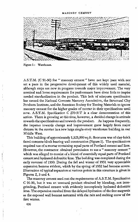
Figure 1: Warehouse.
A.S.T.M. (C 91-50) for “ masonry cement ” have not kept pace with nor set a pace in the progressive development of this widely used materia], although steps are now in progress towards major improvement. The very nominal and loose requirements for performance have done little to inspire needed standardization in the product. This lack of adequate specification has caused the National Concrete Masonry Association, the Structural Clay Products Institute, and the American Society for Testing Materials to ignore masonry cement for the higher grades of mortar in their specifications until now. A.S.T.M. Specification C 270-51T is a clear demonstration of this action. There is growing at this time, however, a decided change in attitude towards the specifications and towards the product. As happens frequently, the impetus towards change and improvement grew largely from major distress in the mortar in a new large single-story warehouse building in our Middle West. , '
This building of approximately 1,525,000 sq.ft, floor area was of clay-brick faced concrete-block bearing wall construction (Figure 1). The specifications required use of a mortar containing equal parts of Portland cement and lime. However, the contractor obtained permission to use a “ masonry cement ” which was alleged to consist of a blend of essentially equal parts of Portland cement and hydrated dolomitic lime. The building was completed during the early summer of 1950. During the fall and winter of 1951 very appreciable expansion became evident, which by the spring of 1952 had become severe. Illustration of typical expansion at various points in this structure is given in Figures 2, 3 and 4.
The masonry cement used met the requirements of A.S.T.M. Specification C 91-50, but it was an unsound product obtained by blending, not intergrinding, Portland cement with evidently incompletely hydrated dolomitic lime. The expansion resulted from the delayed hydration of the free magnesia as the exposed wall became saturated with the rain and melting snow of the first winter. •

Figute 2 : Seriously disintegrated parapet.
Figures.: Expansion of walls with resultant rupture of concrete foundation.
‘ . 637

Figure 4 : Cracking of interior plaster near comer due to expansion in walls.
Figure 5: Complete disintegration of unsound mortar from warehouse parapet.

- Figute 6: Autoclaved mortars. '■ (a) Neat paste of Portland cement
(b) Portland cement plus unsound■ masonry cement mortar. ■ ■
(c) Neat paste of Portland cementand unsound masonry cement.
(d) Neat paste of unsoundmasonry cement. "
Tests made by the writer on specimens of mortar extracted from the interior (unaffected) walls and from the seriously disintegrated parapet shown in Figure 2 indicated that very appreciable potential expansion remains in the mortar. The specimens of mortar were cut into suitable sized bars and autoclaved. The results of the tests are given in Tables 1, 2 and 3. Figure 5 shows graphically the complete disintegration of the bars by the autoclave test. Figure 6 shows expansion of moulded bars, containing this unsound cement in combination with a sound Portland cement and with a local mason’s sand.2 ■
There has been a number of other instances of destructive expansion in masonry construction in the area all of which arose from saturation of the mortar containing this particular brand of lime-cement. The spreading of the news regarding these serious failures of a “ masonry cement ” in mortar has resulted in proposals for significant improvement in the A.S.T.M. and Federal specifications for masonry cement which appear to have a very good chance of being adopted in the near future. The most significant and most seriously needed modification will be the insertion of a requirement for soundness as determined by the autoclave.

table 1: Expansion of mortar specimens upon autoclaving 3 hours, as prescribed in A.S.T.M. C 151-49
Specimen* Initial length Final length Length change Expansion
Ein.
10-96in.
Disintegratedin.
Disintegratedper cent
F 9-94 —G 9-96H 6-74 7-50 +0-76 11-3M-l 10-1390 10-1482 +0-0092 0-09
table 2: Expansion of mortar specimens upon autoclaving 1| hours, otherwise as prescribed in A.S.T.M. C 151-49
Specimen* Initial length Final length Length change Expansionin. in. in. pet cent
A 6-98 8-92 + 1-94 27-8B 10-98 11-10 +0-12 1-1M-2 10-1393 10-1465 +0-0072 0-07M-3 10-1385 10-1452 +0-0067 0-07
table 3 ; Expansion of mortar specimens upon autoclaving 45 minutes, otherwise as prescribed in A.S.T.M. C 151-49
* Specimens A to H are from “ warehouse ” mortar.Specimens M-l to M-5 are 1:3 mortar specimens prepared in the laboratory from sound Portland cement-limestone-base masonry cement.
Specimen* Initial length Final length Length change Expansion
in. in. in. per centC 10-98 11-62 +0-64 5-8D 6-98 7-12 +0-14 2-0M-4 10-1365 10-1418 +0-0053 0-05M-5 10-1389 10-1444 - +0-0055 0-06
It is significant that the cause of the serious expansion in mortars referred to above was the lime component. This points out one of the principal reasons for the wide substitution of limestone ground to an impalpable PQwder for lime in the present-day masonry cement produced by a majority of the manufacturers of Portland cement. It has been demonstrated that limestone interground with Portland cement produces a very fine powder of sub-rounded particles which contributes extremely tenacious unctuousness to mortars together with a very high degree of volumetric stability from a
640

chemical as well as a physical viewpoint. Since the pulverized limestone has not been elevated in temperature, there is no unstable MgO or CaO, and contribution to expansive unsoundness is nil. It has been demonstrated that Portland-limestone masonry cements develop essentially one-half the autoclave expansion of the Portland constituent, thus making them more stable volumetrically than Portland cement mortar, .
The extremely fine size of the pulverized limestone provides rapid, practically immediate, stability in volume in the presence of water and a density of matrix which minimizes volume instability with changes in the moisture content of hardened mortar.
Introduction of an air-entraining agent in the grinding process adds to the grindability of the solids and contributes greatly enhanced properties of plasticity, extendability, and water retentiveness to the mortar. It is to the myriad of very fine, widely disseminated air bubbles which strongly resist coalescence that major credit is due for the excellent working, spreading, and binding qualities of Portland masonry cement.
In an endeavour to ascertain the propriety of including masonry cement in the higher type mortars specified in A.S.T.M. C 270-51T, a co-operative series of tests was developed between four laboratories involving sixteen masonry cements. The conditions of the test are given below.
Materials usedPortland cement. Each participating laboratory used Type 1 cement from its own supply. The physical characteristics of each of these Portland cements were reported with the remainder of the test data.Masonry cement. Each participating laboratory furnished to each of the other three participating laboratories a representative sample of masonry cement. This provided four Type II masonry cements which were tested by the four participating laboratories. .•
In addition, each participating laboratory obtained from the open market a supply of three additional brands of Type II masonry cement for testing.
This provides a total of seven masonry cements to be tested by each laboratory; four of them in common and three separate; a total of sixteen masonry cements. .
Sand and testsEach participating laboratory tested each masonry cement with the
standard mortars required in A.S.T.M. C-91. The test data are given in Table 4.
Each participating laboratory used a locally obtained “ mason s sand which met the requirements of A.S.T.M. Specification C 144-44 in connexion . with the tests performed under A.S.T.M. C270-51T, the results of which are given in Tables 5, 6 and 7.
In considering the data in Tables 5, 6 and 7, it must be remembered that different Portland cements and different mason’s sands were used in each
641

tabl
e 4: Co-
oper
ativ
e tests
A.S.T
.M. C
12. M
ason
ry ce
men
t tests
C 91
Wat
er re
tent
ion
per c
ent
Rete
ntio
n
74-
0
71-3
77-8
75-
2
74-6
00 00 S 00O00 84
-089
-088
-081
-0
85-5
Firs
t flo
w
111-
0
108-
010
6-0
112-
5
109-
4
102-
011
0-0
107-
011
0-9
107-
5 o o O OK o O OK o O ^4 o TH 10
9-0
Wat
er
' 47
-444
-
848
-045
-
0
46-3 OJ O M o
¥ ?i 45-1
44-0
42-4
46-7
42-0
43-8
Com
pres
sive s
treng
th
in lb
. per
sq. i
n.
28 da
y
1,77
02,
174
1,92
72,
074
1,98
6
1,60
01,
867
1,54
21,
790 o o
1—t 1,44
01,
613
1,52
11,
852
1,60
7
7 day
1,34
01,
708
1,44
41,
592
1,52
1
1,15
51,
321
1,20
41,
289
1,24
2 o oo m ok OK OK in TH ok cnw
1,11
5
Setti
ng ti
me G
ilmor
e in
hr. m
in. Fina
l m m in o H N OJ Mvo io r* 6 21 4 45 4
405
006
00
5 06 5 00
4 30 7 45 6 20
5 54
Initi
al o vi q <n <n t-h o Tt-en co m <n 3 52 in Q in o o in 04
eq <n m cn 3 15 o in o in co in cn r-i04 04 m cn 3 32
Aut
ocla
ve
expa
nsio
n pe
r cen
t
0-07
90-
081
0-09
10-
100 00 00
o6 0-
034
0-01
60-
033
0-04
0
0-03
1
0-04
00-
038
0-05
30-
050
0-04
5
Soun
dnes
s pa
t W M0 0 0 O O
K id W idO 0 o o O
K id id id id O O 0 0 O
K
Nor
mal
co
nsist
ency
o o o o o ob h 6 co <N CO CO 29
-5 o o m o ob ko A r* 04 04 04 04 27
-1 to in inco co co 04 04 04 <M 23
-8
Mas
onry
ce
men
t
< < < < s a ö a u u u o
Labo
rato
ry
i-4 CJ CO Tf
Ave
rage
i-< 04 CO
Ave
rage
i-4 04 CO 'M-
Ave
rage

tabl
e 4 : con
tinue
d
Wat
er re
tent
ion
per c
ent
Rete
ntio
n
O N coxb b* O H b* b* 00 00 89
-1 OOOHlDlNOMObiOXO iOxovOTf-wj-bioboboobobA b'b.b.Q0 00b*00 00Oxb»b»b-
o r-4 00
Firs
t flo
w
112-
011
0-0
108-
011
2-5
110-
6 OOOoOOOOQblbJb*cO'ti-eooiHOx'OxbinoQ’^-OoOt^i-IOOOOTHrHO 10
4-4
Wat
er
44-4
41-8
46-0
43-2
43-9 bl<O'eb^,'* ,*O\0rHOX0O
45-2
Com
pres
sive s
treng
th
in lb
, per
sq. i
n.
28 da
y 0*1 Cl IO m w ch o r-iw1,
219 Ooinogooxxocooobiino Qxinin<o*noJOb*<Db-cnoi xc^ b»^ en^ oo, 1-4, o, b* o, ko xb Q
1-4* rd* r-T bf bf bf 1-T 1-T i-T r-T 1-T bf
inCX SO
7 day
' __
__._
___i
O O O\ o b* xO M 00 b* OX CO 00 862 tnQoen^-OTt-OxxOoob*<n QOtinwfncobib»b4ob»in ■v,b*blOxcn,b-b»bJO>b*00\D
1-T 1-T r-T bf 1-f 1-T r-f
' 1,
234
Setti
ng ti
me G
ilmor
e in
hr.
min
. Fina
l in in o o iH U-> i-H 1-1m m x£) 5 23 6
307
455
305
005
155
304
559
25i
7 00
1 11
55
8 25
1 6
50
6 14
Initi
al in o o mH If) Qm 't m 3 23 ooomoooocoomm ocnoinobqOr-«'*cn'*u*)
rf-^cncqcofn'itxt-Tj-in’t-ca 3 42
1
Aut
ocla
ve
expa
nsio
n pe
r cen
t
! 0-093 0-08
50-
102
0-11
0 00 ox oo
■d-kD00OxblXOrHblinOb*b*inÖmO' sDb*xDOxooHOOOOOiHOOOblOOOOOOOOOOQOO 0-
060
Soun
dnes
s pa
t W M M W 0 0 O O O
K oooooooooooo
Nor
mal
co
nsist
ency
o o co in A so xb xb eq <m bJ bj 26
-5 •nininoipoipocooinoxböxxöxbxbdxrnob-,*inbiö bibibib^bjcqbibibicncncn 26
-6
Mas
onry
ce
men
t
Q Q Q q tifcOSH >->W u 2 Z 0 Pm
Labo
rato
ry
H <N «) -t
Ave
rage
Ave
rage
of
all t
ests

tabl
e 5 : Co-
oper
ativ
e tes
ts A.S
.T.M
. C 12
. Mas
onry
mor
tar t
ests C
270.
Mix
pro
porti
ons 0
:
Wat
er re
tent
ion
per c
ent
Rete
ntio
n
’ O <N xf \p Ö CO kO tO 00 fr- F* 74
-6
90-0
82-7
88-2
81-4
85-6 o m en
ih in 00 co 00 00 83
-6
Firs
t flo
w
1 11
0-0
107-
011
0-
011
1-
2
1 10
9-6
i
O O O 00 o o o A
109-
5
108-
0 |10
8-0
106-
0 ,10
8-8
o
Wat
er
64-2
56-6
51-3
54-4
56-6 r* oo ft o
6 4- o ft ko m in in 54-4
62-2
54-8
49-2
52-0
54-6
Com
pres
sive s
treng
th
in lb
. per
sq. i
n.1 28 da
y Q Q 00 FT «5 r-4 00Oi co 03o00 83
01,
650
1,70
11,
945
1,53
2
1,02
01,
400
1,61
11,
711
1,43
5
7 day
(1) 930
1,30
5 ' 1,
324
1,18
6
(1)
1,21
01,
234
1,34
0
1,26
1 O Th Fl ft Fi mCh Oä
1,03
2 1
Mix
pro
porti
ons b
y vol
ume
I Parts en m cn en en on en co co en tn
Sand rH M Tf-V) V) VD V) w FJ co V) V) V) V) i-i FJ <n Th c/) cn cn vd
Parts i-l r-i T-t i-l i-l r-4 w w i-l i-l iH i-l
Mas
onry
ce
men
t
<-<■<< « pq Ö pq u u u u
Parts o o o o o o o o o o o o
Portl
and
cem
ent
rH Fl ** i-i FJ en iH Fl CO
Labo
rato
ry
vh FT er) Th
Ave
rage
M N ff; if
Ave
rage
i-i Fl en Th
Ave
rage

tabl
e 5 : con
tinue
d
(1) N
ot m
ade.
Wat
er re
tent
ion
per c
ent
Rete
ntio
n
84-0
72-7
81-0
78-5
79-1 ooov,)C^i-<ior*<n'*vo^
CCCCCObOkOCOb.QOb.COb' 80-3
Firs
t flo
w
109-
0
110-
0
105-
010
9-1
108-
3
114-
011
2-
011
3-
011
1-
0 10
8-0
112-
0
108-
0. 10
6-0
108-
011
1-
511
2-
810
7-3
109-
4
Wat
er
59-4
54-0
48-0
52-0 xb
cn inl9C^tno^Ji-iocrc*-^-ocq^pQtnQvDiAArHÖcbindib»•O'OtSinininin^-^-xoinu-) 55
-7
Com
pres
sive s
treng
th
in lb
. per
sq. i
n.28
day
625
960
1,32
31,
053 066 tOOoomoMNOoo 1̂^
vocoooio^iMmo^tMOi—1-T of r-T r-T (xf I-T t-T r-T i-T 1,
364
7 day
(1) 570
871
772 |
____
____
____
_1
CO cn
(1)
(1)
(1) 750
1,30
0 1,
030
1,70
0 . 1,894
79
3 50
072
5 1,
510
1,04
1
1____
____
____
____
___M
ix p
ropo
rtion
s by
volu
me
Parts on co vn en
Sand i-( co •*
C/D </)(/) V) T-iiHwc>Jcjc<i<nenfnTh-^-Th
Parts 1—< 1-1 1-1 H 1—li—<i—ii-4-Hi—liHi—li—li—1i—<i—1
Mas
onry
ce
men
t
Q Q Q Q M fc O K H- j g Z O fc
Parts o o o o oooooeoooooo
Portl
and
' cement
1-1 fQ Tf
Labo
rato
ry
HMM*
Ave
rage
Ave
rage
of
all t
ests

tabl
e 6 : Co-
oper
ativ
e tes
ts A.S
.T.M
. C 12
. Mas
onry
mor
tar t
ests C
270.
Mix p
ropo
rtion
s |: 1:4
-5
Wat
er re
tent
ion
per c
ent
Rete
ntio
n
74-
0
64-5
75-
5
72-5
71-6 o in * co
kb d ko d\ co r* co r* 82
-9 O xt- O\ Ov h co th r^. 00 t* CO t* 78
-6
Firs
t flo
w
112-
011
0-0
106-
011
2-5
110-
1
108-
011
2-0
110-
010
6-8
109-
2
112-
010
9-0
108-
0
109-
6
d o
Wat
er \p o CM O Öi cö <O rH in in -m- m 52
-5
" 56-9 51-2
42-5
49-0
49-9
59-8
52-3
47-3
49-7
52-3
Com
pres
sive s
treng
th
in lb
. per
sq. i
n.28
day
2,22
03,
140
3,41
53,
392
3,04
2
1,91
52,
960
2,63
13,
150
2,66
4
2,21
03,
010
2,94
33,
219
2,84
6
7 day
(1)
2,27
52,
402
2,50
9
2,39
5.
(1)
2,22
01,
931
2,33
4
2,16
2
(1)
2,29
02,
128
2,31
7
2,24
5
Mix
pro
porti
ons b
y vo
lum
e
Parts
4-5
4-5
4-5
4-5
4-5
4-5
4-5
4-5
4-5
4-5
4-5
4-5
Sand r-t CM CO -d" V) V) V) V) H CM CO 'd' (/)«)(/)(/) «H CM CO M-
</l V) W) (/)
Parts r-4 v-4 r-i i-t ■H -H T-l -H 1—1 1—1 I—1 1—1
Mas
onry
ce
men
t
c < < < ffl fl ffl ffl u u u u
Parts
, __
____
__1
Hm Hn H* H« HM Hoe Hm *
Portl
and
cem
ent
vH CM CO r-i CM CO M- W CM CO
Labo
rato
ry
rd CM CO
Ave
rage
iH CM CO
Ave
rage
i-i cm on
Ave
rage

tabl
e 6 : con
tinue
d
(1) N
ot m
ade.
Wat
er re
tent
ion
per c
ent
Rete
ntio
n
o \p o tn et o \o co r* oo r* 77
-5 OOöHifiiricoNiO^OnCOCOQOfsSlDGOCOCObh-t'» 77
-2
Firs
t flo
wO O O O\ k6 d> tn co o o o o o 10
7’0 '
110-
011
0-
011
1-
0 11
0-0
109-
0
I 108-0 108-
011
0-
010
7-
3 11
0-7
108-
1
109-
1
3 co \p W 4 ö 4 ö\ tn m 4- -4- 49
-7 ■^■«NNcnc^c^C'ienQpcipcsroi in^icN4Hvo444N4i inu-iirjininiosf^-Tfininir) 51
-3
Com
pres
sive s
treng
th
in lb
. per
sq. i
n.28
day
1,86
02,
630
2,85
32,
742
2,52
1 inoooinomb*i s*.iHi-*in me^or^hsooo-srcnmKOin tOA o_ 'o tj- ooe oo r*t-T tsf tn co tn ci tn m* nf csf tn 2,
714
7 day o tn © m oo oo 02 Ow
i-T rq i-T
' 1,971 (1)
(1)
(1)
1,94
0 2,
200
2,35
0 2,
103
2,53
6 1,
866
1,57
7 1,
881
2,89
1
2,17
5
Mix
pro
porti
ons b
y vo
lum
e
Parts
4-5
4-5
4-5
| 4-
5
. 4-
54-
5 4-
5 4-
5 4-
5'
4-5
4-5
4-5
4-5
4-5
1 4-
51
4-5
1
Sand
|
«-t <n Tt*vd tn tn t/)V>VD1/)VDV>C/)</DC/Dcn(Z)Cn
Parts iH i—l W W
Mas
onry
ce
men
t j
q q q q M 0 5C « -'M J S Z 0 cu
Parts ,4» -* n hm v*» Hs **< H* ,-* s He* «***
Portl
and
cem
ent
i-t <m tn
Labo
rato
ry
w <m tn
Ave
rage
HHriMNNfionrn't't^
Ave
rage
of
all t
ests

tabl
e 7: Co-
oper
ativ
e tes
ts A
.S.T
.M. C
12. M
ason
ry m
orta
r tests
C 27
0. M
ix p
ropo
rtion
s 1:
Wat
er re
tent
ion
per c
ent . Re
tent
ion
74-
0
62-4
75-
5
70-5 VO
Oo o r>
in 4- A oo r* oo b- Cx
oo
o m Th eqiS K R S 74
-3
Firs
t flo
w
O O O Kp 4- d\ o H 2 H 2 11
0-7
1100
111-
010
6-0
110-
5
109-
4
111-
0
109-
010
5-0
112-
4
109-
4
Wat
er
■ 58
-150
’444
-549
-31
50-6
54-9
49-3
42-8
'' 48-
3
48-8 OK Th 00 M
J> <D "t ok in in Th Th
9-09
Com
pres
sive s
treng
th
in lb
. per
sq. i
n.28
day
s R § oM* 'T rn 3,
730
2,72
53,
680
3,24
33,
836
3,37
1
2,80
04,
010
3,71
33,
833
3,58
9
7 day
(1)
3,17
52,
910
3,06
1
3,04
9
(1)
2,75
02,
665
2,82
5
2,74
6
(1)
3,03
02,
767
2,82
4
2,87
4
Mix
pro
porti
ons b
y vo
lum
e
Parts VO C VO kO KO VO KO VO KO KO KO
! Sand H M M 't co v) co i-i m on 't C/D </) C/D <Z) i-i <M co Th <Z> CO </) (Z)
Parts i—l 1—1 -H i-i 1 1—4 r-t «—1-
1-4 1-4 i-4 i-l
Mas
onry
! cement
c < < < a a b n Q U U U
Parts 1—t i-4 i-l i—l i-l r-l i-l i-i 1-4 1-4 i-4 i-4
Portl
and
cem
ent
1-1 M m Th 1-4 CM m Th i-i cm en tj-
Labo
rato
ry
H M co Th
■ Average
i-i <N <n Th
Ave
rage
i-4 eq en *
Ave
rage

tabl
e 7 : con
tinue
d
(1) N
ot m
ade.
Wat
er re
tent
ion
____
____
____
per c
ent
1 Rete
ntio
n
80-0
67-9
761
74'7
74-7 OOOiHOpHtOcnOtOKOb*
oboAkDcnobcMr^otDTHcno
74-1
1 First
flow
, 112-0 ' 112-0 109-
011
3-6
111-
7
110-
0
112-
0
108-
0
109-
0
111-
0
110-
0
106-
011
0-0
109-
0
110-
4
113-
8
108-
6
O1 Water 00 ’«t CM
rö di cn 6i ** "M- 48-9
54-0
58-1
53-5
49-
8
50-
4
49-
6
44-5
43-2
43-6
51-
7
. 50
-050
-
0 op5
Com
pres
sive s
treng
th
in lb
. per
sq. i
n.28
day \
2,58
03,
590
3,59
93,
436
3,30
1
2,32
52,
975
2,82
04,
030
4,24
64,
280
3,46
73,
736
2,99
73,
361
3,38
14,
642
3,50
6
7 day
(1)
2,62
02,
472
2,54
2 J2,
545
(1)
(1)
(1)
2,86
0!
2,81
03,
030
2,80
43,
063
2,32
22,
150
2,39
73,
562
2,79
2
Mix
pro
porti
ons b
y vo
lum
e
Parts io O O VO kOCD'OvOvOCOcO'OtC'-OvOtO
1 C/3
■ SI S2 S3 S4 C/DC/DC/)(/)C/)C/D(/D<y)</DC/DIZ)CÄ
Parts
|
H H ri H i-lTHi-li-li-fi-i-HrHi-li-iT-li-H
Mas
onry
ce
men
t
q Q Q Q q z 0 fu
Parts i-H iH 1—< iH Ht-lT-lr-lTHi-li-lfHWi-IH»-«
Portl
and
cem
ent
ih eq cn
Labo
rato
ry
i-< M co
Ave
rage
Ave
rage
of
all t
ests

00
M J ffl<
Wat
er re
tent
ion
per c
ent
Av.
81-0
74-1
77-2
80-3
Min
. ’N vH in iH s $ 8 8
Max
.
88-2
80
4 84
-0
87-0
Com
pres
sive s
treng
th —
lb. p
er sq
. in.
28 da
y
Av.
1,69
5
3,50
8
2,71
4
1,36
4
Min
.
1,00
6
2,32
5
1,63
5
645
Max
. o <n oitn 't in oo» vo r*of M-*' erf e<r
7 day
Av.
1,23
4
2,79
2
2,17
5
1,04
1
Min
.
708
2,54
5
1,57
7
500
Max
. id- OJ TH *<n ko ck cheo in oo ooof erf of t-T
Soun
dnes
s aut
ocla
ve
per c
ent
Av.
0-06
0
Min
.
0-00
2
Max
. |lll o
Prop
ortio
ns by
vol
ume
Sand 3 6 4-5 3
M.C
.
tH i-l rH t-4
P.C. 1 0-5
Mix
ture
sp
ec. &
type
C9i,
nC
270,
A-l
C 27
0, A
-2
C 27
0, B

table 9 : Recommended modification of Table 11 of A.S.T.M. C 27051T
Mortar type
Parts by volume of
cement
Parts by volume of A.S.T.M. C91
type II masonry cement
Parts by volume of hydrated lime
or lime putty
Aggregate, measured ' in a damp, loose
condition
A-l 11
11
not less than 2f and not mote than 3 times the sum of the volumes of the cements and lime used.
A-2 11
1over f to J
B1
1 ■over f to 11
C1
1over If to
D 1 — over 2| to 4
laboratory. It is worthy of especial note that the water demand was greater and the strength was lower for each of the cements as tested by laboratory 1 as compared to the data of the other three laboratories. This was due in large part to the coarser and less well-graded sand used by that laboratory.
It will be noted, also, that laboratory 2 obtained lower values for water retention than did the other three laboratories.
The data presented on the 16 masonry cements may be considered typical, and demonstrate in the summary given in Table 8 that this type of masonry cement will produce the results required by the property specifications of C 270-51T, which are in essence as follows :
Type Strength—28 days lb. per sq. in.
Water retention per cent
A-l 2,500 70A-2 2,000 70B 800 70
These data have been submitted to the American Society for Testing Materials and consideration is being given at this time to modification of Table II of A.S.T.M. Specification C 270 to permit use of masonry cement as shown in Table 9.
PHYSICAL PROPERTIES AND PERFORMANCEVery much remains to be learned about means of evaluating the perfor
mance in structures before a really adequate specification may be written for masonry cement or for masonry mortar. Let us consider that the functions of a mortar for masonry are threefold: (1) to bind the units together in a
- 651

stable structure; (2) to present an effective barrier to the infiltration, absorption, or passage of moisture into or through the wall; and (3) to present a neat, uniform appearance. In order that these functions may develop, the mortar must have the following properties.
The unhardened mortar must be very plastic, smooth and workable so that it will spread with a minimum of effort to cover with intimate contact all surfaces to be coated and bonded. A means for measuring the elusive quality of plasticity is needed so that a quantitative requirement may be specified. Many varieties of equipment and procedures have been studied3-4 in attempts to solve this important problem. In our current work, the “ deformed cube ” for determining a “ plasticity index ” seems to give promise (see Appendix A,) but a great deal of work remains before results obtained will be fully evaluated.
Next, the mortar must possess body, cohesiveness, and adhesiveness so as to stick to itself and to all surfaces with which it comes in contact and resist being squeezed out of joints by superimposed courses. Portland cement mortars possess body to an excessive degree, but coherence and adhesion (“ stickiness ”) are inferior. The three related properties are well balanced in masonry cement, but there is as yet no means for quantitative expression of the resultant quality.
The mortar must possess a high water retentiveness; the ability to resist rapid loss of water to dry absorptive masonry units being bonded, and to resist escape of water by “ bleeding ” when the mortar is in contact with non-absorptive units. Loss of moisture due to poor water retention results in rapid loss of plasticity, coherence, and adhesiveness in the mortar. It is such losses which contribute to a preponderant degree to incompleteness and ineffectiveness of bond by the mortar to the underside of superimposed brick. A further vital factor affected by water retention is that of hydration and strength development. The application of water to masonry assemblages for the purpose of “ curing ” is almost unheard of. The water retentiveness of the mortar must play a large part in the prevention of premature- drying of the mortar. How much we do not yet know. The A.S.T.M. and Federal methods of measuring “ water retention ” give results which seem to compare very well with the performance of mortars in construction.
The very essence of masonry construction is that the hardened mortar bind the units together and not just hold them apart. A mortar which is highly plastic and which retains that plasticity for adequate periods of time, and yet which will resist being squeezed from joints under load of superimposed courses, is essential for the development of intimate, complete, enduring bond. Methods of measuring “ workability retention ” and developing an “ index of stiffening ” which offer promise are described in appendices to this paper. Test data using these criteria are presented in later paragraphs.
Study of the actual bond effected between two typical masonry units under controlled conditions may be a desirable quantitative measure of the inherent capacity of a mortar to develop a tenacious cementation. Studies of

this type have been made by many, including Anderegg, Palmer, Pearson, Withey and others.5- 6< 7> 8> ’> 10
“ Shrinkage ” is one of the phenomena of mortars which is believed by many to have an effect on the watertightness and strength of bond. The most direct way to determine the degree of the effect of this phenomenon seems to the writer to be to test the bond between two units whose position with regard to each other is maintained rigorously constant during the period of hardening of the mortar. Such investigations are currently being made in our research laboratory, and the methods used are given in Appendix C. Preliminary results are presented later in this paper.
Compressive strength is a property of mortar which is greatly overemphasized. The really important strength in masonry work is that produced by the complex combination of water-retentiveness, adhesiveness, and plasticity with adequate (but not necessarily high) structural strength which develops a strong adhesive bond. In most instances in which rupture of any sort occurs in a masonry assemblage, the unit and the mortar remain essentially intact; the rupture is at the interface of mortar and unit. Mortars made with Portland cement develop high compressive strength but are prone to develop poor bond in actual construction due to low plasticity and low water retention. There are adequate means for testing the compressive strength of mortar, but the importance given it in A.S.T.M. and in “ project ” specifications is questionable.
The ability of the mortar and of the interfacial bond to develop an effective barrier to the passage of water while permitting the “ breathing ” of moisturevapour is important, but not independently critical because the properties and factors which make for good structural bond favour optimum watertightness. The basic capacity of the. hardened mortar to “ repel ” water is questionable in importance, because almost all mortars are adequately impervious to the free migration of water or vapour, whereas, almost all actual passage of water through masonry assemblages occurs at the mortarunit interface of poorly bonded or unbonded units. However, data on the “ absorption ” characteristics of mortars are presented in this paper.
DISCUSSION OF TEST DATA
The nature and degree of adhesive bond and other physical properties developed by a group of 20 currently manufactured masonry cements, which are considered to be representative of this class of material, are under study currently by the research laboratory of this company. The cements used include : (a) 13 of the Portland cement-limestone-air-entraining agent type (the CS group); (b) 3 which are very similar to those in (a) except that they contain a small quantity of hydrated lime (the “ CSL,” and “ CSDL ” groups); (c) one which contains Portland cement, pulverized slag, hydrated lime, and an air-entraining agent (the “ CLG ” cement); (d) one which contains Portland cement, natural cement (predominant) and an air-entraining agent (the “ CN ” cement); (e) one Portland cement-hydraulic hydrated

lime cement (“ CL ”); and (f) one Portland cement-hydrated dolomitic lime-air-entraining agent cement (CDL-13). It is CDL-13 which represents the unsound “ masonry cement ” mentioned in earlier paragraphs.
The work in this programme has not progressed to a conclusive stage, but the data available are presented as general information on modern masonry cements and on our methods and endeavours to assay their qualities of performance. '
The basic chemical and physical properties of the masonry cements are given in Table 10. The extreme range in properties shown in Table 11 continues to be rather large, even after elimination of the definitely unsound cements as determined under carefully controlled laboratory procedures. The similar “ properties ” of the Portland cement used in the later phase of this programme are shown also in Table 11 to provide a basis for comparison. Selected physical test data from Table 10 are plotted in Figures 7 and 8 to show graphically the ranged in the values obtained.
It is worthy of especial note that the three cements with autoclave expansions in excess of 0-50 per cent are those which contain appreciable quantities of “ lime ” and that the degree of expansion bears a relationship to the MgO content. That the MgO content, per se, is not critical is attested by the soundness of CN 11 and CS 29, which have MgO contents higher than that of CL 23. That the mere presence of lime is not necessarily detrimental is attested by the normal performance of CSL 9, CLG12, CSL 29. In each case, the presence of “ free ” or unhydrated lime or magnesia is believed to be the cause of unsoundness. The three definitely unsound cements were not included in Table 10 because they are considered abnormal.
Cement CS 6 was not included in the group composite because it contains an abnormal ratio of Portland cement to limestone, as is attested by the very low (for this composition of masonry cement) ignition loss, and the abnormally high strengths. Despite the abnormality in composition, cement CS 6 developed very desirable mortar-making characteristics.
Table 12 presents range and average physical test data resulting from a study designed particularly to determine the bonding qualities of the masonry cements and a typical Portland cement as used in the type mixtures common to masonry construction.
The considerable improvement in water retention and plasticity index of all mixtures containing masonry cements, either alone or in combination with the Portland cement, over that produced by the Portland cement mixtures is marked. The compressive strength and the early bond strength diminish with increase in the content of masonry cement. These data were not unexpected in view of the extreme care used throughout the programme to ensure completeness and non-disturbance of bond. The Portland cement mixtures, and to a somewhat lesser extent, the very rich masonry-Portland mixtures, required exertion of considerable effort to force the upper brick of the “ sandwiches ” down to the f inch thickness of joint, whereas this was accomplished with much greater ease as the plasticity index of the mix-

T-O
W COM
PRES
SIVE
STREN
GTH
PSI 28
-DAY
COM
PRES
SIVE
STREN
GTH
PSI
BLAI
NE FI
NEN
ESS
MASONRY CEMENTS
Figure 7 : Comparison of basic physical data on 20 masonry cements.

MASONRY CEMENTS
Figure 8 : Comparison of basic physical data on 20 masonry cements.
masonry ceaents

tures increased with the masonry cement content. Also, the fixation of the joint by ball-bearing separators and C-clamps obviated any possibility of disturbance of bond. Neither the required energy of placement nor fixation in place would be obtained in field masonry mortars. However, these factors are hard to integrate into a test method. It appears permissible to state, though, that with optimum worker-effort as expended in the “field,” bond strength with the relatively non-plastic, low water-retentive Portland cement mixtures would be very much less certain or strong.
Additional data on shrinkage, elasticity, and strength of the mixture containing masonry cement are given in Table 13. Within the limits of the data presented, it is evident that shrinkage does not vary to an appreciable extent in any of the mixtures and that the reduction in volume after 28 days of continuous drying is small. Since all the mixtures possess elasticity in proportion to the masonry cement content, with essentially equal shrinkage characteristics, it appears reasonable to conclude that rupture of bond due to shrinkage would be much less likely to occur as the masonry cement content increases in relationship to the total cement content. This is important since masonry cement is used most generally as the sole cementing agent in a masonry mortar.
REFERENCES
1. Plummer, h. c. and reardon, L. s. Structural Clay Products Institute. BrickEngineering. 1943.
2. Mcburney, j. w. Expansion of mortar as a cause of cracking in masonry.Proceeding! of the American Society for Testing materials. (In process of publication). 1952. Vol. 52.
3. voss, w. c. Extrusion machine. "Rock Products. (Staff description.) 1940.January, p. 48. '
4. berthier, r. m. A new method for measuring plasticity. Revue des Materiauxde Construction et de Travaux Publics. 1950. June. No. 417.
5. anderegg, f. o. Some properties of mortar in masonry. Proceedings of theAmerican Society for Testing Materials. 1940. Vol. 40. pp. 1130-1140.
6. anderegg, f. o. The effect of brick absorption characteristics upon mortarproperties. Proceedings of the American Society for Testing Materials. 1942. Vol. 42.
821-830.7. hall, j. v. and palmer, l. a. Durability and strength of bond between
mortar and brick, journal of Research of the National Bureau of Standards. 1931. March. Vol. 6.
8. palmer, l. a. and parsons, D. A. A study of the properties of mortars andbrick and their relation to bond. Journal of Research of the National Bureau ‘of Standards. 1934. May. Vol. 12. pp. 609-644. RP683.
Pearson, j, c. Measurement of bond between brick and mortar. Proceedings of the American Society for Testing Materials. 1943. Vol. 43. p. 857.
10. withey, m. o. Recent experiments on masonry building materials made in the materials testing laboratory at the University of Wisconsin. University of Wisconsin. 1935. Reprint No. 53.

tabl
e 10 :
Masonr
y te
st pr
ogra
mm
e. C
hem
ical
and p
hysic
al p
rope
rties
of c
emen
ting
mat
eria
ls (m
orta
rs co
ntai
n O
ttaw
a sili
ca sa
nd)
Cem
entin
g mat
eria
ls
cs
-30
54-7
72-
811-
94
17-9
1 CO CMVO
CO 00CM 5,
755
89-6
9
op
24-3
4 20 o
m OK
CSL
-29
57-7
2 | 5 on
I lf-T
22-0
2
2-43 COop
CM 7,67
2 |
94-0
4 o Z-LZ 4 00 0£ £
|OK
CS
-28
58-8
2 | 8 oq 1-
19 |
16-9
0
2-33
2-94
]5,
007 1
cn ob 00 n-
4 I24
-5
5 30 o
^OK
J
i CL 1 -23 00 GOs
k2-£ |
1-75
|
110-
431
1-65
\ZL-Z |
6,82
5 |
96-6
9
CM 00
1
36-2
5 25 1 0T 6
I pOK
1
CSD
L' -22 55
-751
11-4
01 IT6-0
18-9
3
1-70 uoco
CM
981*9
1
92-8
4 oCO 28
-0
6 00
1 7 35 xo
I
CS
-19
91-89
IO in 919
-10
1-87
1 2-90]
6,67
7
98-5
3 fr-41 28-0
4 10 1 in
CMd
^o|
CS
-18
54-5
2 1 in
I T6-0
17-7
0
7-35
'■ 2-9
4]: 7,
9121
1 99-
23 00 d 27
-5
3 55
| 5 00
1 3(0 1
CDL
| -13 47-1
6 1
I XL-ZZ
; 1-94 i
1 | 9-37 00 vo
d 2-84
1 186T*Z,
82-6
7^8
l31
-5
o00 [O
K |
CLG
-1
250
-78 |
I ZZ-Z j
o
i
7-74 00 00
d CM 7,69
8
93-6
900 d 34
-0
5 40 ' 99 £
1
OK
|
| CN 1 -11
| Z£-Et 1
8 d*
1 tx-z
i
13-5
1
9-62 00
CM 5,96
7
96-8
6 md 33
-5
6 30
St 6 1 |O
K |
, cs 1 -10 j 46-
42 |
m 00Csj
1 8Z.-T
20-6
9 o
1 2-88
7,23
7
91-7
4 002 24
-2
4 48 o
OK
'
CSL
1 -9 157-
65 1
CM 0O oCM [1
7^0
2-93 ä
CM
i 5,3
34
96-3
3
o co 28
-0
3 40
os s 1
OK
I
CS -855
-57 | in ci
21-2
1
7-56 in00
CM 7,58
3
97-6
5
d 31-0
4 45 in
[OK
|
CS
-7 oo 2-09
J2-
22
24-5
11
0-78 co
CM
16,7
891
1
93-2
1 o cn 25
-8
4 15
| 6 35
O
i CS 1 -6 s00 in
' 1'94 in
CM
12-5
2 00 co00 c*>CM
| 681*4]
1
95-5
910
-oJ
26-0
4 00
01 9 I
OK
|
CS
-552
-44 | in
voCM
VOCt
19-0
7
2-61 $
CM
| ZSV5 75-6
0 o
23-5
4 00
OK
'
CS
-442
-98J
2-90
I2-
60 1
17-6
4 o oCM
inO\CM 6,
967 I
84-1
2 rj-
24-4
4 30
715
OK
1
CS
-352
-74 I
1 2-20 | co
CM 19-4
7
6-04 cv oo
CM
o00* 91
-50
15-3
26-0
5 15 o CM
OK
!
CS' -2 43
-32 | m
cncow 22
-46 o o
dco 00CM
m in
95-7
5 o tn
;27-
l
4 15 o o
OK
1
CS
-1
t7-I9 2-17
2-27
20-7
2
9-15 00
CM
00£
99-4
7 ip
30-3
5 15
LSt£l OK
Chem
ical
an
d ph
ysic
al
prop
ertie
sC
aO (p
er ce
nt) 1
MgO
(per
cent
) 1SO
3 (pe
r cen
t) 1Ig
nitio
n los
s(p
er ce
nt)
Inso
lubl
e res
idue
(p
er ce
nt)
Spec
ific g
ravi
ty 1
Bla
ine f
inen
ess 1
325 m
esh
(per
cent
age
pass
ing)
Plas
ticity
inde
x111
Nor
mal
co
nsist
ency
Setti
ng ti
me
Gilm
ore:
'
Initi
al se
t(h
r.min
.)Fi
nal s
et (h
r.min
.)Pa
t sou
ndne
ss

tabl
e 10:
continu
ed
(1)
The l
arge
r the
inde
x nu
mbe
r the
grea
ter t
he w
orka
bilit
y.(2
) Th
e lar
ger t
he in
dex n
umbe
r the
grea
ter t
he st
iffen
ing
tend
ency
.(3
) C-
185.
-
! Ce
men
ting
mat
eria
ls
CS
-30
0-07
3
CT) 21-0
8
85-2
0
73-0
5
2-85
7-44
0-38
3
1,27
31,
513
o
CSL
-29
0-05
7
53-6
21-4
0
89-3
0
78-8
8
1-61
5-35
0-30
1
1,15
31,
537
8CS
-2
8
0-10
6
30-9
21-5
8
70-2
2
70-0
0
2-02
5-22
0-38
7
1,65
32,
038
o
o
54-2
14-5
6
82-3
0
83-7
5
3-53
6-83
0-51
7 | OX CMCM VO1™1
o
CSD
L -2
2
6-50
0
23-6
19-4
6;
87-2
2
77-2
61
3-22
8-43
CMCO on6
927
1,21
1
o
CS
-19
0-06
2
15-5
23-9
2
0000 66
-93
1-11
3-71
0-29
9
1,27
91,
778 o
CS
-18
0-13
3
38-2
25-2
5
90-6
5
58-9
6 co ox r* co
0-23
0!
1,20
41,
542
o
CD
L -1
3
Disi
nt.
38-2
17-5
5
79-4
3
85-8
2
2-60
7-07
00 VD COÖ
684
1,07
6 o
CLG
-1
2
0-02
3
40-0
12-0
8
84-1
1
73-8
5
2-25
6-24
0-36
1
986
1,75
162
-5
CN
-11
0-20
4
34-5 o
co
U")COCO
coCM 1-
093-
270-
333
1,05
71,
839
o
CS
-10
0-07
5
43-3
30-0
1 00-06 61-1
1
1-75
4-94
0-35
4
926
1,00
8o
CSL -9
0-09
6
38-2
15-9
1
87-6
1
69-8
4 CO 0004 *£>tH co 0-
334
1,58
11,
878
o
CS -8
00OÖ 16
-7
16-4
01
.
82-5
9 69-08 2-50
8-76
10-2
86 |
1,22
51,
584-
o
CS
-7
0-06
5
vb o
89-7
11
78-2
6 o o r>. coCO s
Ö 1,03
21,
444
o
CS
-6
0-02
2
34-5
18-2
6
91-3
5
81-8
9
2-23
6-20
098-0 2,01
33,
090
o
CS
-5
6 51-8
23-7
2
85-7
8
77-4
2
3-79
9-46
0-40
1
724
1,00
6 o
CS
-4
co
6 60-7
24-7
4 00-06 76-5
9
Ox ro CM 00 0-
336
646
1,05
5 o
CS
-3
0-02
9
20-4
24-0
2
95-1
0
73-4
1
3-20
9-45
0-33
9 CM VOO Th o
CS
-2
008o 24
-1
23-1
6
89-2
2
72-0
8 O ox VO oCM 00
CM
O
833
1,30
7
o
CS
-1
0-06
2
15-3
27-3
0
92-2
3
67-7
3
1-50
5-86
0-25
6
1,02
51,
300
o
Chem
ical
an
d ph
ysic
al
prop
ertie
sA
utoc
lave
ex
pans
ion
(per
cent
)St
iffen
ing
inde
x121
Air
cont
ent^
(per
cent
)W
ater
rete
ntio
n (p
er ce
nt)
Wor
kabi
lity
rete
ntio
n (p
er ce
nt)
Abs
orpt
ion
(181
b. F3
) 1 h
r (pe
r cen
t) 24
hr (
per c
ent)
.2#2 C
ompr
essiv
estr
engt
h :7
day
(lb/sq
.in.)
28 d
ay (l
b/sq
.in.)
Bag w
eigh
t (lb
)

table 11: Properties of masonry cements111 and Portland cement
PropertyMasonry cements Portland
cement* 1 2 3 4)Maximum Minimum Average
CaOl3> (per cent) 58-82 42-98 52-41 63-67MgO (per cent) 9-09 1-25 2-90 3-69SO3 (per cent) 2-60 0-91 1-82 1-90Ignition loss (per cent) 24-51 7-74 18-63 1-07Insoluble residue (per cent) 9-62 0-78 4-49 0-18Specific gravity 2-95 2-71 2-88 3-16Fineness (Blaine) (sq.cm./g.) 8,770 5,007 6,276 3,126325 mesh (percentage passing) 99-47 75-60 92-86 93-02Plasticity index141 19-80 9-40 13-70 4-50Normal consistency 34-0 23-5 27-5 23-5Setting time in hr.min.: Initial 6 30 3 40 4 29 3 45
- Final 9 45 5 00 6 38 6 20Soundness : Pat O.K O.K O.K O.K
Autoclave* 5 6 7-1 0-204 0-023 0-087 0-098Air content (per cent) 30-01 12-08 22-25 8-38Water retention (per cent) 95-10 70-22 86-79 59-10Workability retention
(per cent)161 80-69 58-96 71-97 70-20Index of stiffening* 8) 60-7 15-3 33-9 71-0^>Absorption : 1 hr (per cent)* 9* 3-79 0-780 2-05 404
24 hr (per cent) 9-46 3-27 6-16 8-14Ratio 1 hr:24 hr 0-40 0-23 0-329 0-496Compressive strength in lb/sq.in.:
7 day 1,653 646 1,099 2,97528 day 2,038 1,006 1,504 4,526
Approx, wt/cu.ft. (lb) 70 70 70 94
(1) Cements CS 6, CDL 13, CSDL 22, and CL 23, not included because of marked abnormality of constitution.
(2) Values obtained by methods used with masonry cements.(3) A.S.T.M. gravimetric determination; does not indicate form in which CaO exists.(4) See Appendix A for method. Improvements seriously needed and now under study.(5) Follows A.S.T.M. method except stored for 48 hours prior to testing.(6) See Appendix B.(7) Value probably not significant as test was devized for masonry cement. A Urge
amount of bleeding occurred during second flow determination causing a low flow, which resulted in high apparent early stiffening.
(8) See Appendix D for method.(9) Procedure given in Federal Specification SS-C-181b.

tabl
e 12
: Physic
al p
rope
rties
of “f
ield
” m
orta
rs
§ (1) Spe
cim
ens s
tore
d in
air a
t 73
°F an
d 50 p
er ce
nt re
lativ
e hum
idity
.(2
) Value
s for
stra
ight
Por
tland
cem
ent m
ixes
are f
or on
ly on
e bat
ch, th
eref
ore;
max
imum
and
min
imum
valu
es at
e not
indi
cate
d.

n5 d cä
co
c6
cd
-S
bD a5
d ti <5 H No
te : Ini
tial 2
4 ho
urs i
n m
ould
in m
oist
cabi
net;
rem
aini
ng, ti
me i
n lab
orat
ory a
ir.
Mod
ulus
of r
uptu
re
Ib./s
q.in
.
Av.
784
478
412
199
214
251
603
370
Min
. 'f'OOCTiNOd-QO
Max
.
IT) o -d- O'. O r-( oj
Com
pres
sive s
treng
th
Mod
ified
cube
Ib./sq
.in.
Av.
s-T w of r-lM
in.
1
2,54
5 87
7 79
6 28
8 39
4 55
81,
848
659
Max
. mkOOOcnd'iO'i'C \Or-i-iinu")mcniD cn^ co o conin of of of v-i
, Modul
us of
elas
ticity
Ib
./sq.
in. x
106
soni
c m
etho
d
Av.
3-17
1-
93
1-78
1-
04
1-12
1- 19
2- 27
1-
63
1 | Mm. 2-21
| 1-17 1-26
0-
51
0-65
i 0-85 1'92
1-
21
Max
.l
3-56
2-32
2-37
1-61
1-58
1- 48
2- 55
1-86
Cont
ract
ion
per c
ent
Av.
i
0070
0-07
00-
076
0-08
30-
086
0-09
90-
085
0-06
8
Min
. o»cno’<ttnvDcnas intn’ ’̂vor,*o*r*» |n ooooooooÖQOOOÖOO
1 c^mcninOtOCiO ocoo-i-fomocoöööooööö
Mix
pro
porti
ons b
y vol
ume
Sand
Mas
onry
ce
men
t 10-
25 1 2 1 1 1 0-5 1
Portl
and
cem
ent
ui m

CHARLES E. WUERPEL
APPENDIX A
METHOD OF TEST FOR DETERMINING PLASTICITY INDEX (“DEFORMED
CUBE”)
ObjectiveTo endeavour to measure the “ plasticity ” of masonry mortars by
deformation in a semi-restrained state.
ApparatusThe apparatus consists of a bottomless rectangular hinged mould (4 in.
X 4 in. base and 2 in. height) placed on top of a flat, smooth steel plate. The hinged corners permit deformation of the mould from a square to an elongated diamond shape when pulled by weights attached to flexible cords. Friction on the oiled steel plate is negligible. A metal rule divided in 64ths of an inch is used to measure deformation.
ProcedureThe mould, temporarily restrained in its original square shape by a tem
plate, is filled with the mortar to be studied. Excess mortar from the filling operation is conveniently screeded onto the template, which is then removed by raising vertically. Figure 1 shows the undeformed cube filled with mortar. After removal of the template, weights in increments of 1 lb are attached to one of the flexible cords, causing the cube to deform. The other cord is firmly attached to an anchor post on the smooth bottom plate. The deformation caused by each increment of load is determined by measuring either diagonal of the cube. The deformation can be obtained also by measuring the change in the angle formed by the sides of the cube. A total load of 7 lb was found to be sufficient to provide an appropriately varying deformation of the masonry mortars tested to date. Figure 2 shows the cube after deformation by a 7 lb load.
CalculationsA graph of the load versus deformation data is plotted. The slope of the
resulting curve is calculated and is designated as the “plasticity index.”
DiscussionThe mortars tested to date have been machine-mixed in a Hobart K-4B
mixer and fall into two flow ranges : (a) the basic masonry cement data using Ottawa 20-30 silica sand having a flow of 100-115; (b) the masonry mortars used for construction of the tensile bond brick sandwiches (containing mason’s sand) having a flow of 125-135. The plasticity index tends to be higher for the 125-135 range.
Further investigation has indicated that the use of only a single load of 5 lb (single deformation measurement) results in a more simple test procedure and less chance for disturbance due to impact loading which occurs when the load is added in increments. Using this simplified procedure, the plasticity
663

Figure 1 : Undeformed cube.
Figure 2 : - Cube deformed.
index is calculated using the following equation :Plasticity index=length of diagonal of undeformed cube in inches—length
of diagonal of deformed cube in inches X100.In the above equation the diagonal measured to determine the deformation
is perpendicular to the direction of application of load. All plasticity index results shown in the basic paper have been calculated by the original method using the slope of the load versus deformation relationship.

APPENDIX B
METHOD OF TEST FOR WORKABILITY RETENTION
ObjectiveThis method of test is intended to measure the retention of “ workability ”
of masonry cement mortars when exposed to an atmosphere simulating outdoor summer conditions. It is based on the method developed in the research laboratory of the Universal Atlas Cement Company.
AppartusThe apparatus consists essentially of:(a) a 16| in. x 12 in. x 24 in. exposure box containing a source of radiant
heat of variable intensity and an air-circulating fan(b) a 22 in. x 10 in. X 4 in. metal “ mortar box ” with sloping ends(c) a small mortar hoe(d) a thermometer having a range of 10 0 to 220 ° F(e) a 1,000 ml metal measure(f) standard flow table(g) a laboratory timer(h) spatula(i) straightedge.
Materials 'The sand is of the type listed as coarse mason’s sand and conforms as
nearly as possible to the following requirements taken from A.S.T.M. C 144-44. • ■
Sieve size Percentage passing4 1008 95—100
16 60—10030 35—7050 15—35
100 0—15
ProcedureThree pounds of masonry cement are throughly dry-mixed with 11 lb of
mason’s sand in the “ mortar box,” using the small mortar hoe. This should not require more than 60 seconds. Immediately upon completion of the dry mixing, approximately | of the estimated water requirement is poured into a formed depression in the dry material and mixed with the ingredients (see Figure 2). The mixing is done with the hoe. Additional water is added in increments, with mixing, until a flow (method described in A.S.T.M. C 109) within the range of 125-135 per cent is obtained. The mixing time is four minutes, timed from the first addition of water. When a flow is obtained within the 125-135 range, a unit weight determination is made using
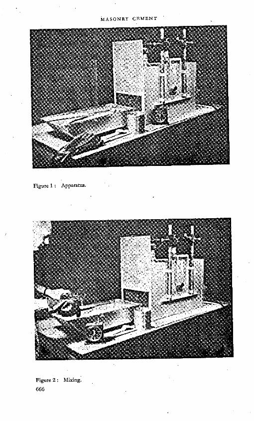
Figure 1 : Apparatus.
Figure 2 : Mixing.

Figure 3 : Inserting mortar into exposure box.
Figure 4 : Completion of test.

the C 185, 500 ml cup. A 1,000 ml cup may be substituted for the 500 ml cup if desired. While the flow test is in progress, the temperature of the mass of mortar is obtained. This temperature should be 74 °F±2 °. Upon completion of flow and unit weight determinations, the mortar used in these determinations is returned to the mortar box and remixed with the mass, using the small mortar hoe. The mortar box is tapped until the surface of the mortar is essentially level and then immediately placed in the exposure box. (see Figure 3). '
After 15 minutes of exposure the mortar is removed from the exposure box, quickly remixed with the mortar hoe to incorporate the heated surface with the cooler bottom material and then replaced in the exposure box for the remainder of the exposure period. This remixing should not require more than 1 minute. (During the remixing period the timer is stopped and started when the mortar has been returned to the exposure box). Throughout the entire exposure test the temperature within the box is held between 118° and 120 °F. This can easily be controlled by occasional adjustments of the rheostat controlling the heater. After a total of 30 minutes of exposure, the mortar is removed, thoroughly remixed in order fully to incorporate the drier and heated surface mortar into the mass, and a flow test determined. While this flow test is in progress, the temperature of the mass of mortar is determined. This change in temperature during the exposure test is an indication of the amount of heat absorbed from the source of heat and also generated by the chemical reaction within the mortar. A second unit weight determination (see Figure 4) is made after the second flow determination in an attempt to check air and water loss from the mortar.
Calculations 'The flow, workability retention, unit weight of mortar, and yield is
calculated as follows :
Flow per cent=Increase in diameter (in.) X100Original diameter (in.) .
Workability = Flow after exposure X100retention Flow before exposure
Unit weight = Litre wt (g)x28-3,(litres/cu.ft.)(lb/cu.ft.) 453-6 '
Yield = Total wt. of batch (Ib)Xwt of cement/bag (lb)(cu. ft./bag) wt/cu. ft. of mortar (lb) X wt of cement in batch (lb)

. APPENDIX C
METHOD USED FOR THE PREPARATION AND TESTING OF BRICK
SANDWICH TENSILE BOND SPECIMENS
ObjectiveTo construct, store, and test sandwich assemblages consisting of two
2| in. x3| in. x8 in. fired clay “ face ” bricks bonded by a f in. layer of mortar on the 31 in. X 8 in. surface, (see Figures 1-8).
MaterialsFace brick. The 2| in. x 3| in. x 8 in. brick used were obtained from Des
Moines, Iowa, and were designated as “ facebrick ” complying with A.S.T.M. C 216-50, grade SW, type FBX. The average suction was 9'4 grammes per brick face per minute of immersion of the face in water.
Mason’s sand. The sand used was designated as coarse mason’s sand complying with A. S.T.M. Specification C144-44 .It had the following characteristics:
Mesh Percentage passing
Fineness modulus
- Specific gravity Absorption
4 1000 2-17 2-67 0-748 980
16 90-430 70050 21-8
100 2-7
ApparatusThe apparatus consisted essentially of:(a) A Hobart K-4B mechanical mixer (see Figure 1)(b) Wooden jigs designed to fit around the bottom brick as shown in
Figure 2. The jigs were boiled in linseed oil to prevent absorption of water from mortar
(c) 8 in. C-clamps(d) I in. steel ball bearings(e) Special clamps for gripping specimens for testing as shown in Figure 5(f) A universal testing machine capable of testing the assemblages in
tension(g) Standard flow table(h) Laboratory timer(i) Spatula(j) Mason’s tool for tooling mortar joints(k) 2 in. x 2 in. cube moulds.
ProcedureMixing mortar. Using the mix proportions desired, a dry batch of approxi
mately 3,500 grammes of sand and cement was mixed dry in the Hobart 669

Figure 1 : Hobart K4-B mixer.
Figure 2 : Jigs assembled; mortar applied; ball-bearing separatorsinstalled.

Figure 3 : Jigs removed; top brick in place.
K-4B mixer until the batch appeared homogeneous. This usually required less than 30 seconds. Water was then added while mixing continued until a flow judged to be within the range of 125-135 was developed. The mortar was mixed for three minutes, timed from the first addition of water, followed by a period of 10 minutes rest, followed in turn by a final two-minute mixing period. During the rest period a preliminary flow test was made and additional water added if necessary to assure proper flow at the end of the mixing period. ' ■
If the flow was within the specified 125-135 flow, the mortar was used in the construction of four duplicate brick sandwich assemblages. If the desired flow was not obtained, the batch was discarded and a new one made. -
Sandwich construction. A wooden base, consisting of two 2 in. x 4 in. blocks was used to hold the lower brick above the working surface and this enabled the completed assemblage to be clamped together with a C-clamp without unduly disturbing the assemblages. Wooden jigs were assembled around the lower brick on top of the base and were held in place by dowel pins inserted in holes drilled in the base (see Figure 2). This method of holding the jigs also permitted easy dismantling of the jigs. Mortar was applied to the lower brick and levelled off even with the top of the jig by a rapid motion of the trowel or large spatula. After a two-minute waiting period, during which three f in. ball bearings were installed in the mortar as separators (see Figure 2) and the jigs were dismantled, the upper brick was lowered onto the mortar and pressed down into contact with the j in. ball bearing separators, (see Figure 3). The excess mortar was struck off from the sides of the assemblages
671

Figure 4 : Completed sandwich showing “ C ” clamp andtooled mortar joint.
Figure 5 : Sandwich in grips preliminary to testing.

Figure 6 : Ruptured specimen showing placement of ball-bearingseparators.
and 8 in. C-clamps were applied (one per assemblage) to hold the assemblages rigidly against any possible disturbance (see Figure 4) The joints were tooled after the mortar had hardened sufficiently to prevent thumb prints from being formed in the mortar. This degree of hardness was usually obtained approximately 30 to 90 minutes after the assemblages were clamped with C-clamps. Excess mortar from the batch was utilized to prepare 2 in. X 2 in. compressive strength cubes. '
CuringAfter tooling, the assemblages were cured for 24 hours under damp burlap
at 73 °F and then in air at 73 °F and 50 per cent relative humidity until they were tested in tension. Clamps were removed from the assemblages after the first 24 hours at the same time the damp curing was stopped. The 2 in. x 2 in. compressive strength cubes were removed from their moulds at 24 hours and cured in air at 73 °F and 50 per cent relative humidity with the sandwiches.
TestingThe sandwiches were tested in tension at 7 and 28 days* in a universal
testing machine. Special grips, shown in Figure 5, were used to grip the specimens for testing. The loading rate was 600 lb per minute. Immediately after rupture the exposed surface of the mortar was painted with phenolphthalein indicator. Areas in which the mortar had not been carbonated by
* Data not available at time of preparing this report. -

Figure 7 : Ruptured specimen showing large area of poor bond along periphery.
Figure 8 : Ruptured specimen showing excellent bond with nearly equal rupture on top and bottom of mortar.

infiltrating air turned a bright red. The appearance of the ruptured area after painting with phenolphthalein was examined for any irregularities that may have been caused by poor or incomplete bond. Figures 6, 7 and 8 show typical bond failures. (Note: No phenolphthalein was applied to upper surface of lower brick in Figure 8). The 2 in. x 2 in. compressive strength cubes were tested at the same age as the corresponding tensile bond specimens.
, APPENDIX D
TEST METHOD USED FOR DETERMINATION OF STIFFENING INDEX
Objective -This method of test is used for the detection of rapid loss of workability
in masonry mortars.
ApparatusSame as required for A.S.T.M. C 185 except that the two Burmeister
mortar flow troughs are required for simultaneous use.
Procedure 'Patch. The proportions of the mortar were 300 g of cement to 1200 g of
standard 20-30 Ottawa silica sand and sufficient water, in multiples of 3 ml to give a flow of between 2-75 and 3-00 in. on the mortar flow trough. The flow was determined in accordance with the procedure given in C 185.
Mixing of mortar. The mixing procedure was the same as C 185 except that the total mixing time was reduced to only one minute. No waiting period was used.
Flow determination.. The two flow troughs were filled simultaneously using the procedure given in C 185. Immediately after filling, the first flow trough was dropped 10 times in 10 seconds, and the flow recorded. The second flow trough was allowed to stand for 10 minutes (covered with a damp cloth)- After the 10 minute waiting period, the second flow trough was dropped 10 times in 10 seconds and the flow recorded.
CalculationsThe stiffening index, which is a measure of the reduction of flow caused
by the 10 minute waiting period, was calculated from the following equation :
Stiffening index=lst flow - 2nd flowx 100. 1st flow
Discussion 1 .Available data suggest that a value of 40 per cent in this test provides an
acceptable criterion; that is, when masonry cement has noticeably rapid stiffening, the results produce a 40 per cent or larger reduction in flow.
675

MASONRY CEMENT
DISCUSSION
W. C. HANSENOne of the tasks facing the cement technologist is that of developing
methods of measuring and expressing in suitable units those properties of mortars which make up what is known as the workability of the mortar. Mr. Wuerpel has described the workability retention test and the plasticity test. The American Society for Testing Materials has a sub-committee of Committee C-l working on this problem.
We are trying out a method in the laboratories of our ten plants which we hope will provide a numerical rating for the workability of the product from each plant and will serve to maintain uniformity of workability in the products from the ten plants.
The equipment used in this method consists of the standard flow table and a so-called plasticimeter, similar to instruments described by Reed-Lewis1 and Wilsnack.2 It consists of a cup with a removal extension and a plunger. In use, the cup is filled with mortar which is struck off flush with the top and the extension is then clamped in place. The plunger is set on top of the mortar and allowed to penetrate it for 60 sec. when the depth of penetration is recorded. The flow of the same mortar is also measured on the flow table. Two batches of mortar are used in each test. One batch is made to have a flow slightly below 100 per cent and the other is made to have a flow slightly above 100 per cent. The penetrations are then plotted against flow and the penetration at 100 per cent flow is reported as the workability rating for that mortar cement.
In the flow test, a cone of mortar is deformed by dropping the table. The resistance of that cone to a given extent of deformation appears to be related to a property which might be called the cohesiveness of the mortar and to the resistance of the mortar to flow on the brass top of the table. In the penetration test, the mortar is forced up through the annular space formed by the surface of the plunger, which has a diameter of 1-75 in., and the walls of the extension to the cup, which has a diameter of 3 in. We visualized that different characteristics of the cement might be manifested in the two tests so that an attempt to correlate these characteristics might give a better evaluation of the workability properties than would any single test.
As an example of the type of data obtained, a sample of the masonry cement from one of our plants required approximately 43 per cent water for a flow of 100 per cent and the penetration was 74 mm in a 1: 3 mortar. A 1:1:6 mortar prepared from Portland cement and a hydrated lime required approximately 57 per cent water for a flow of 100 per cent and the penetration was 17 mm. One observable difference between the two mortars was that a trowel drawn with considerable pressure across a pile of the latter mortar would leave a surface in which the sand grains were bare; whereas the same procedure with the masonry cement mortar left a
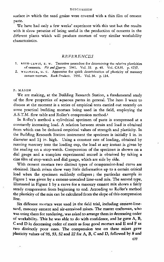
surface in which the sand grains were covered with a thin film of cement paste.
We have had only a few weeks’ experience with this test but the results with it show promise of being useful in the production of cements in the different plants which will produce mortars of very similar workability characteristics.
REFERENCES
1. reed-lewis, E. w. Tentative procedure for determining the relative plasticitiesof cements. Pit and Quarry, 1941. Vol. 33. p. 48. Vol. CA35. p. 6757.
2. wiLSNACK, G. c. Apparatus for quick determination of plasticity of masonrycement mortars. Rock Produrts. 1951. Vol. 54. p. 114.
P. MASON
We are making, at the Building Research Station, a fundamental study of the flow properties of aqueous pastes in general. The item I want to discuss at the moment is a series of empirical tests carried out recently on some practical building mortars being used in the field, employing the A.S.T.M. flow table and Roller’s compression method.1
In Roller’s method a cylindrical specimen of paste is compressed at a constantly increasing load. A relation between strain and load is obtained from which can be deduced empirical values of strength and plasticity. In the Building Research Station instrument the specimen is initially 1 in. in diameter and 1| in. high. Using a constant rate of loading, obtained by running mercury into the loading cup, the load at any instant is given by the reading on a stop-watch. Compression of the specimen is shown on a dial gauge and a complete experimental record is obtained by taking a cine film of stop-watch and dial gauge, which are side by side.
With cement mortars two distinct types of compression-load curve are obtained. Harsh mixes show very little deformation up to a certain critical load when the specimen suddenly collapses; the particular example in Figure 1 was given by a cement-unsoaked lime-sand mix. The second type, illustrated in Figure 1 by a curve for a masonry cement mix shows a fairly steady compression from beginning to end. According to Roller’s method the plasticity of the mix can be calculated from the slope of this compression line.
Six different mortars were used in the field trial, including cement-lime- sand, masonry cement and air-entrained mixes. The master craftsman, who was using them for rendering, was asked to arrange them in decreasing order of workability. This he was able to do with confidence, and he gave A, B, C and D in decreasing order of merit as four good mortars and E and F as two distinctly poor ones. The compression test on these mixes gave plasticity values of 95, 53, 52 and 22 for A, B, C and D, followed by 8 and

Figure 1
6 for E and F respectively. It appears that Roller’s method gives useful empirical estimates of the workability of mortars.
There is one more point I should like to make, following Mr. Hansen’s remarks about the flow table. In this field trial, the craftsman adjusted the water content of the mix to his own satisfaction. The flow was immediately measured, and was found to range from 70 to 140 per cent for the six different mortars. Furthermore, the range of flow values on samples taken from the board near the end of each job was from 30 to 120 per cent.
I raised that point to show the need for great care in selecting the level or levels at which plasticity is to be measured (e.g. for specification purposes) no matter what method be used for the measurement.
REFERENCE1. roller, p. s. Journal of Physical Chemistry, 1939. Vol. 43. pp, 457-489. Pro-
x ceedings of the American Society for Testing Materials. 1942. Vol. 42. pp. 750-760.
J. BROCARDThe theory of masonry cements, so important both from the technical
and economical point of view is undoubtedly not yet finally established.Formerly, cements used for masonry work were mixtures whose compo
sition was left to the practical technician, and whose nature varied considerably according to the locality. Later on, well-intentioned architects and engineers included in their specifications a requirement for the use of artificial Portland cement.
Later still, it was recognized, both in France and other countries, that this was the wrong approach, and that the qualities required of cements to be used for masonry work were not the same as those required of cements for use in reinforced concrete. In this case, mechanical strength, particularly compressive strength, will be less important than some other properties.
Consequently, in order to avoid using obsolete empirical methods, it 678'

became necessary to define the properties of “ masonry cement Today there are in France two standard specifications for masonry cement. NFP 15-307 and 15-309.
These cements are composed of a mixture of Portland clinker with fairly low mechanical strength—which is of no importance in this case— and of various other constituents; inert powders, pozzolanas, slags, “ grappiers ”, etc. The lowest groups of the cements thus obtained have a higher mechanical strength than the highest group of the corresponding American cements. Unfortunately, most of the important properties required for masonry cements have not been defined.
These properties are; volume stability, water retention and workabifity and also bonding properties, which are closely linked with the former.
Mr. Wuerpel’s paper develops all these points in detail, which is why it may be considered a basic document for technicians working with masonry cements, as regards manufacture, practical application, as well as standard- izatioh. .

[19]
Some recent developments in the design and construction of
concrete structuresA. R. COLLINS
SUMMARYNo account of recent developments in concrete technology can be complete
and this paper attempts to give no more than a personal view of some of the changes that have occurred since the last symposium.
In the field of concrete-making the most important development is thought to be the greatly increasing use of mix design methods and quality control which has resulted in considerable gains in the effective strength of concrete in structures.
There have been many improvements in the structural field of which the use of shell roof construction and prestressed concrete are typical. Both of these have been responsible for greatly increasing the capabilities of concrete structures and for making much better use of the properties of concrete and steel.
In construction technique, air-entrainment, precasting structural concrete (both reinforced and prestressed) and textured surface finishes are thought to be important.
The effect of these developments has been to make engineers more aware of the quality of the concrete they produce and of the cement they use. It has also made them appreciate the problems involved in testing both cement and concrete. In Britain, engineers have been asking for cement of more uniform quality and for cement to be supplied in two or more separate grades of differing quality (as distinct from the different types of cement now made).
Another effect of the increasing use of concrete for a wider range of structures has been to focus attention on the problem of improving the appearance of exposed surfaces and in particular on crazing, efflorescence and other forms of surface blemishes. Whether the cement technologist can contribute to the improvement of the performance of concrete in these respects is not known, but further research, especially into the physical structure of hardened concrete, is clearly required.

INTRODUCTION
This paper is unlike most of those submitted to this symposium in that it has been prepared by an engineer whose understanding of the chemistry of cement is comparatively slight. Its purpose is not, however, to add to knowledge of the chemistry of cement but to survey new developments in the use of concrete and to promote discussion of their effects on cement technology.
It is, of course, impossible to describe or even catalogue all the new developments that have taken place in the last few years nor to decide which of the developments are in fact new or worthwhile. A personal selection has, therefore, to be made of items that illustrate general trends and much of importance must be omitted. It is unlikely that others, even of the same nationality, would make the same choice but it is hoped that the views of one engineer will prove of sufficient interest to provoke discussion.
The developments will be described under three headings : concretemaking technique (including testing), new structural applications and new constructional methods.
DEVELOPMENTS IN CONCRETE-MAKING TECHNIQUEThe most important development in concrete manufacture in Britain in
recent years has been the rapid increase in the use of methods of mix design based on scientific data and a wider application of quality control.
These techniques have been used for many years on large and important works but since 1945 there has been a rapid growth in their application to small works. This growth has been in response to an increasing demand for concrete of high strength and durability and has been assisted by developments in the manufacture of small weighbatchers of low cost suitable for portable mixers.
A measure of the increase in the use of quality control is given by the production of these small weighbatchers which in the last five years has increased to some 10 or 15 times the pre-war output.
The knowledge that is being applied in this way has been acquired over a very long period by research workers in many countries. In Britain, the Building Research Station and the Road Research Laboratory have been engaged on research on the subject for over twenty-five years and in more recent years have been joined by other organizations including the Universities and the Cement and Concrete Association. All these bodies have consistently advocated the use of logical methods of mix design and quality control.
The method of mix design now commonly used in Britain is based on that developed at the Building Research Station and Road Research Laboratory and described in publications of the Department of Scientific and Industrial Research.1-2 It is based on the assumption, not strictly true but sufficient for practical purposes, that the quality of concrete can be measured in general by the crushing strength of test cubes; that the strength depends within certain limits on the watericement ratio alone and that with a given water:

cement ratio the mix proportions can be varied to obtain any desired degree of workability without greatly affecting the strength. The Road Research Laboratory publication2 already referred to gives curves and tables from which the waterxement ratio can be chosen and tables from which can be obtained the mix proportions for any of four standard degrees of workability with aggregates of various size, particle shape and grading. This method of mix design, though not taking all relevant factors into account, provides a good basis for trial mixes in the field and its simplicity has not only encouraged general application but has helped in giving a wide understanding among engineers of the principles underlying the making of good concrete. Other contributing factors have been the general raising of standards of training and design and the demands of designers for higher working stresses.
Most of the large civil engineering contracting firms and many smaller ones now have central testing laboratories which control the technical aspects of concrete production in the field and sometimes undertake research. These organizations are providing contractors with first-hand basic information which places them in a position to advise the designing engineer on concrete-making materials and mix design. '
The practical effect of the increased “ know-how ” in the concrete construction industry can be seen in the success with which standards of concrete quality set in specifications are met. Before the war the minimum specified cube crushing strength of high-grade concrete of about 1:6 proportions was often no more than 3000 lb. per sq.in. at 28 days. At the end of the war when a minimum strength of 4000 lb. per sq.in. was set for airfield runways there was some doubt whether it could be consistently met with mixes leaner than 1:6, but the specification was in fact satisfied with a mix of 1:6-25 by weight (530 lb. per cu.yd.; 305 kg. per cu.m.) which gave an average strength of about 5750 lb. per sq. in. at 28 days. In 1952 runway construction similar strengths are being obtained with mixes of 1:7-25 proportions (475 lb. per cu.yd.; 270 kg. per cu.m.). .
DEVELOPMENTS IN CONCRETE STRUCTURAL ENGINEERINGAlthough the centenary of the invention of reinforced concrete has already
been celebrated it is only in recent years that the possibilities of the material have been well exploited. For the first three-quarters of the century of reinforced concrete the structures for which it was used were in general little different from those employing older materials. Even so, the achievements of reinforced concrete were considerable especially in the fields of heavy civil engineering and bridge building. ■
During the period between the wars a number of new forms of structure and new methods of using reinforced concrete were developed in which the inherent properties of the material were more fully used which have made concrete designers less reliant on older forms. None of these developments (except perhaps prestressing) could be called revolutionary; they are often no more than variations in size, scale or shape but variations of such a kind

that the resulting structures have completely changed in appearance and new methods of design have had to be evolved. One of the most important of the new structural forms is the thin shell used as barrel vaulting, domes and other roofing shapes.
Thin shell roofsVaults and domes of brick or masonry and even of materials like concrete
have been used for many centuries and some of the domes have been of outstanding size. In these structures, however, the vault or dome itself always exerted a thrust on its supports which required heavy resisting buttresses. In the modern concrete dome or vault there need be no external thrust and the structure may be supported on thin columns or walls.
The origin of shell concrete construction is generally attributed to the engineers who designed the hemi-spherical domes needed by Zeiss for his planetaria and for a number of years both the methods of calculation and construction were most highly developed in Germany. The advantages of shell construction in giving a clean interior and architecturally exciting exterior shapes were, however, so obvious that the method of construction rapidly spread to many other countries and thousands of shell roofs must by now be in existence. In Britain alone well over five hundred have been built since the war.
A shell roof may have one of many shapes including simple cylindrical shells with" edge beams, multiple cylinders joined edge to edge and circular or square domes. Multiple shells may be tilted to give north-light roofing or two or more shell shapes may be combined. The membrane need not even be curved but can consist of flat sections set at various angles. Shell roofs may be supported along their edges or at their corners or may be cantilevered from single supports. Examples of roofs of some of these types are shown in Figures 1 to 5. Clear spans of 100 to 150 feet are comparatively common and even greater spans have been constructed though they are economically less justified.
A further shape that has not yet been widely used but which has certain advantages is the anticlastic shell. In this the roof membrane is curved in two directions at right angles to each other with the centres of curvature on opposite sides of the membrane. The resulting shape is similar to but not quite the same as that obtained by twisting opposite edges of a flat slab. It has the advantage that all lines parallel to the edges are straight so that the main supports of the shuttering may be made straight. A photograph of a model of a proposed design for Coventry Cathedral incorporating an anticlastic shell roof 200 feet square is shown in Figure 6.
Similar to the shell roof in outside appearance, though structurally different in that it is a space frame and not a membrane, is the “ lamella ” roof as used by Nervi in Italy. This is constructed of small precast concrete elements set in a diagonal pattern and supported at a small number of points by sloping buttresses. An example of this construction, is shown in Figure 7.

Photograph Twisteel Ltd.
Figute 1 : Barrel vault roof drill shed at the Royal Marine Depot at Deal, Kent.
Figure 2 : South-light shell roof in South Africa for the Premier Gate, Fence and Wire ' Company Limited.
Prestressed concreteThe development of prestressed concrete occurred almost contempor
aneously with that of shell construction. Its origins go back almost to the beginning of the century when various attempts at applying pre-tension in the steel of reinforced concrete were made without success. It was the work of Freyssinet in the period from about 1925 to 1940 that made prestressing

Figure 3 : Aerial view of the two-way shells and the barrel vault roofs of the factory for Enfield Cables Limited at Brynmawr, South Wales.
Figure 4 : Interior of the main production hall of the factory at Brynmawr, South Wales.
- 685Figure 5 : Cantilever shell roof at the Madrid racecourse.

Figute 6 : Model of an “ anticlastic ” shell roof submitted for competition for a design for the new Coventry Cathedral.
a practical structural process. The importance of Freyssinet’s contribution lies in the fact that he realized the fundamental difference between reinforced and prestressed concrete. The earlier workers had merely tried to increase the stress in the steel but Freyssinet thought of the stress as being applied to the concrete and of the steel merely as a convenient but not the only way of doing this. He also appreciated the importance of the creep and shrinkage
686 '
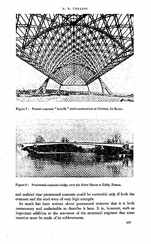
Figure 7 : Precast concrete “ lamella ” roof construction at Orvieto, Nr Rome.
Figure 8 : Prestressed concrete bridge over the River Marne at Esbly, France.
and realized that prestressed concrete could be successful only if both the concrete and the steel were of very high strength.
So much has been written about prestressed concrete that it is both unnecessary and undesirable to describe it here. It is, however, such an important addition to the resources of the structural engineer that some mention must be made of its achievements.

The earliest and some of the most notable structures in prestressed concrete were naturally built in France to the designs of Freyssinet himself. Some of the most outstanding of these are the now famous bridges over the Marne in which the main members were precast in sections in a factory nearby, assembled and prestressed together and floated into position. The use of standardized sections was a notable development In bridge construction. A photograph of one of these bridges (Esbly) is shown in Figure 8.
There are important prestressed structures in many other countries including hangars and bridges in Belgium, bridges in Germany and South America, precast buildings in Sweden and circular tanks in the U.S.A.
In Britain the output of prestressed concrete is already about 10 or 15 per cent of that of reinforced concrete and prestressing steel is used at the rate of about 12,000 tons per year. Several notable large structures have been erected as well as a number of excellent small ones.
The new hangars at London Airport represent one of the most efficient uses of concrete in spanning large distances that has so far been obtained. The roof beams have a span of 110 ft with a T section 4 ft wide, 6 ft deep and only 4 in. thick. They were made in sections at a products works and assembled and prestressed on the site before being lifted into place (see Figure 9).
At the other end of the structural scale there are a number of small bridges in the New Forest, Hampshire, which have achieved structural and architectural elegance with unassuming simplicity and the utmost ease of erection, being assembled on the site by three men. An example of one of these bridges is shown in Figure 10.
Prestressed concrete is now an established structural system but its apparent simplicity and its everyday use should not obscure the fact that its resources are by no means exhausted and that in combination with precasting and with other structural forms such as shell construction it shows promise of even more spectacular uses in the future.
DEVELOPMENTS IN CONSTRUCTIONAL TECHNIQUESDuring the last fifteen years there have been many notable developments
in construction technique most of which have by now established their place in building and civil engineering. Some are already so widely used that they cease to be remarkable while others ate as yet only beginning to come into practice.
It is impossible to describe more than one or two techniques within the scope of this paper and difficult to make a fair selection of the most important. However, a selection has been made of three of those that seem to illustrate best the new trends in concrete technology. The three chosen are air-entrainment, the precasting of structural concrete and the use -of special surface treatments to give concrete structures of satisfactory appearance. Many other interesting and promising developments such as lightweight concrete both plain and reinforced, vacuum concrete, high-temperature curing and vibration, have had to be omitted.

Figure 9 : Precast prestressed secondary beams in the new hangars for British European Airways at London Airport., '
Figure 10 : Precast prestressed road bridge in the New Forest, nr Lyndhurst, Hampshire.689

Air-entrainment 'So much has been written on the subject of air-entrainment that little need
be said here except that its very widespread use in the United States has not been paralleled in Europe in spite of the obvious advantages that the technique has in improving the frost resistance of concrete. This difference in use is perhaps in part due to differences in climate but it may also be due to the use in Europe of concrete of lower workability than that commonly employed in America. This concrete not only has an inherently higher frost resistance but the low workability also makes it more difficult to entrain the optimum proportion of air.
Although the value of air-entrainment was apparently discovered more or less by accident, fundamental research on the structure of hardened cement paste, notably by Powers, has reached a stage where the value of entrained air could have been forecast if it were not already known. This research has provided a reasonably convincing case for the theory that the air acts rather like a safety valve in relieving the pressures generated in concrete by the freezing water.
Even though not universally applicable it is clear that air-entrainment is a valuable technique and a powerful addition to the resources of the engineer using concrete.
Precast structural concreteIt might perhaps be thought with some justification that one of the chief
advantages of reinforced concrete as a structural material is its ability to be cast in the position it is finally to occupy. This was in fact the chief characteristic of reinforced concrete for many years and is still one of the most important properties of concrete when used in many kinds of structure. It is, therefore, something of a paradox that the development of precasting should become a worthwhile improvement in technique, but the precasting of structural members has important advantages in simplifying and speeding up construction in certain fields and developments in general construction methods have overcome most of its disadvantages. .
There are many reasons why the technique has made such progress in recent years. Among the most important are the shortage of materials for formwork, the complexity of shape of many structural members, the general reduction in weight of concrete structures resulting from the use of high stresses and the availability of efficient cranes and other lifting apparatus.
By using precast concrete, work can begin on many parts of the structure at the same time and one mould can be used in place of the many that would be required for normal in situ casting without any diminution in speed of construction. As a consequence, elaborate formwork does not become uneconomic when the requirements of the structural design call for it, resulting in greater freedom for the designer.
During the war structural precast concrete was used on a large scale in standardized buildings for army camps. These buildings were usually single-

story huts consisting of a series of portal frames covered with light sheeting. Since the war many buildings of a similar type but often much larger have been erected in Britain for use as factories (see Figure 11) but precasting has also been used in multi-story framed buildings of many kinds. Notable examples are the hangars in France erected by a British company (Figure 12), office buildings in London (Figure 13) and the power station at Acton in London where columns and beams with weights of up to 30 tons each were precast (Figure 14). The shell roof of the hangar at Marignane with a span of 300 ft which was cast on the ground and lifted into place by means of jacks is an example of specialized precasting (Figure 15). The “ lamella ” roof (Figure 7) is another.
The American “ tilt-up ” method of construction and the process in which floors are cast at ground level and then raised by jacking them up the columns, also developed in the U.S.A., are other examples. -
In combination with prestressing which allows structural continuity to be easily obtained with separate units, precasting has become almost the accepted construction method and has allowed complicated structures to be erected with ease and economy. Notable examples are the bridges over the Marne and the hangars at London Airport already mentioned (Figures 8 and 9).
The surface of concrete’ The name of Portland cement was chosen by Aspdin because of the similarity in appearance between concrete made with it and the famous stone used for St Paul’s Cathedral and so many other important buildings in London. Concrete has suffered from this similarity almost ever since because architects and others have used it as if it were a limestone but without taking those precautions normally employed in a stone building to deflect rain. There has naturally been some disappointment because concrete has not weathered in the same way as natural stone. The differences in physical structure between concrete and limestone are, however, so great that no similarity in performance during weathering can be expected and it is unlikely that the treatment of concrete surfaces as though they were stone would lead to successful results.
All this has, of course, been known for many years and a considerable number of concrete buildings has been erected in which the surface has been treated to take advantage of the inherent properties of concrete but these buildings have remained a small proportion of the total and architects have been inclined to use stone and brick to face concrete buildings.
If concrete is treated correctly, however, its appearance can be quite satisfactory aesthetically and it can be used to give a whole range of colours and textures not obtainable in other building materials. Many different treatments can be used with success but those generally employed are variations of three processes; exposing the aggregate, tooling the surface (which also exposes the aggregate but in a different way) and. casting the concrete in shaped moulds to produce fine or coarse textured or boldly patterned

Figure 11 : Precast concrete kiln house and store for a pottery factory.
Figure 12 : Precast structural concrete hangar in France having a span of 98 ft.

Figure 13 : Combined precast and cast in situ ten-story reinforced concrete office building in London.
Photograph Sir Robert McAlpine 6* Sons Ltd.
Figure 14 : Precast concrete turbine house at Acton Lane ‘ B ’ Power Station, London.

Photograph Ray-Delvert.
Figure 15 : Shell roof at Marignane in France. Precast on the ground and lifted intoposition.
surfaces. Examples of surfaces of these kinds are shown in Figures 16 to 19.With these kinds of treatment many of the difficulties met with ordinary
concrete surfaces are overcome, but certain problems still remain. In zzr sit« concrete the treatment often has to be carried out after the concrete has hardened with resulting high costs. Difficulties arise from variations in colour of the aggregates and cement paste and, efflorescence may also affect the surface. These may be largely overcome by the use of precast surfacing slabs but not all structures are suitable for this kind of finish. Sometimes the use of textured renderings provides a solution but efflorescence may again cause uneven changes in colour and apparent fading.
THE EFFECTS OF THE NEW DEVELOPMENTS ON CEMENT TECHNOLOGYBuilding construction is one of the oldest activities of civilized man and
by its nature conservative and resistant to rapid change. Developments containing the promise of revolution often remain with their promise unfulfilled. It is therefore dangerous to write of revolutions in building but it does appear that concrete is at last bringing changes in the shape and appearance of buildings of a magnitude to warrant the term “ revolutionary.” The chief factor in this change is the proper appreciation of the fundamental properties of concrete and of the methods of design and construction required to make use of these properties. This has resulted in new demands

Figure 16: Precast concrete facing slabs with exposed brick aggregate surface on flats in London for Holborn Metropolitan Borough Council.
on the knowledge of structural designers, new shapes, space relationships and surfaces for architects and new methods of construction.
Every new development creates new problems, every problem solved exposes other problems and the problems in one field often have to await the solution of others in other fields. The new structural uses of concrete have brought with them new problems in design and construction and are

Figure 17 : Tooled concrete columns at the Cement and Concrete Association’s Research Station, Buckinghamshire.
bound to have important effects on the technique of making concrete. In some respects structural developments are in advance of the materials of construction and provide a challenge to the cement and concrete technologists to solve the problems that they pose. Incidentally, they are also providing a challenge to the structural designer to devise methods of design that can be used in the ordinary engineering office.

Figure 18 : Moulded concrete facing slabs on a school building at Ipswich, Suffolk.
The effect of these developments on the work of the cement technologist is more difficult to foresee and in any event is unlikely to be immediate.
One effect that has already become clear is an increasing interest among engineers in the quality and uniformity of the materials they use. Normally, the effect of variations in the proportions of the concrete mix is so much greater than that of the constituent materials that the variations in the latter are often ignored. With a high degree of field control, however, variations

Figure 19 : Precast moulded and tooled facing slabs, each 2 ft square at Institute of Zoology, Nancy, France.
in aggregate grading and in the strength or rate of hardening of the cement are significantly reflected in the routine test results on the concrete. In Britain this has led to a rising demand for closely graded aggregates (“ singlesized ” aggregates) which can be recombined to produce the overall grading required and some comment has also been made on variations in cement quality.
Cement in general (and British cement is no exception) is usually of an average quality comfortably in excess of the standard specifications. There are several reasons for this margin of quality, the chief of which being that tests for the quality of cement are not yet so reliable that the same result can be obtained from the same sample when tested at different times by different laboratories. In addition, the failure of a batch of cement to comply with the specification is a serious matter not only because of the large sums of money involved but also because sub-standard cement is so rare that engineers do

not as a rule await the results of tests before using the cement. Any failure may, therefore, result in large costs in cutting out and replacing concrete.
The use of quality control and the growth of field testing have allowed engineers to appreciate the margin in quality between average cement and the minimum requirements of specifications. Most engineers realize that a reasonable margin is required and that a general raising of specification requirements would add to the cost of cement. There is some demand, however, for the grading of cement into perhaps two qualities, not by using different methods of manufacture but merely by selecting batches of known above-average quality to be marketed as the higher grade. It is argued that grading in this way would not add appreciably to the cost of cement and would give engineers the choice of a cement of higher-than-average quality for works of special importance. There are many sound reasons why this grading cannot be carried out but the interest of the designing and constructing engineers has been aroused as a direct consequence of the greater use of testing by the user and demands for special or more uniform ordinary cements are likely to grow.
The development of quality control has also focused attention on methods of testing both .cement and concrete. It has been recognized for some considerable time that the old tensile test for cement quality is unsatisfactory in that it is a measure more of the operator’s skill than of the quality of cement. The commonly used alternatives of flexure or compression testing of standard mortars are better than the tension test but are still not ideal in that results are not reliably consistent. -
In Britain the standard test is at the moment made on a 1:3 mortar cube compacted by vibration on a small standardized vibrating table. With this test.it is possible to obtain consistent results at any one laboratory. For example, six cubes made individually from one sample of cement may well have compressive strengths with a coefficient of variation as low as 2 per cent and coefficients much over 4 or 5 per cent ate rare. There is, however, a greater variation in the results of tests made at different laboratories the causes of which are by no means clear. It is known that among the more important of these causes are the effects of temperature and differences in the behaviour of compression testing machines. The effects of temperature variations on the strength of concrete are well known but not always appreciated by commercial testing laboratories. The differences due to different compression testing machines are, however, much less well known and their causes are obscure. Thus, two apparently rigid testing machines both accurately calibrated by proving ring may give significantly different compression strengths for cubes made from the same batch of cement or concrete. An investigation into the causes of these differences is now in progress in Britain together with research on alternative methods of testing the quality of cement. It is hoped that these investigations will allow more closely reproducible tests of the quality of both cement and concrete to be made.
Of the effects of the other developments on the demands likely to be made 24 699
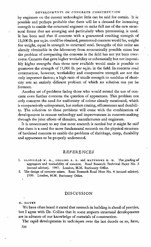
by engineers on the cement technologist little can be said for certain. It is possible and perhaps probable that there will be a demand for increasing strength to enable the structural engineer to make full use of the new structural forms that are emerging and particularly when prestressing is used. It has been said that if concrete with a guaranteed crushing strength of 11,000 lb. per sq.in. could be obtained, prestressed concrete would be, weight for weight, equal in strength to structural steel. Strengths of this order are already obtainable in the laboratory from economically possible mixes but the problem of compacting the concrete in the field has not yet been overcome. Cements that gave higher workability or substantially but not impossibly higher strengths than those now available would make it possible to guarantee the strength of 11,000 lb. per sq.in. in the field. In concrete road construction, however, workability and compressive strength are not the only important factors; a high ratio of tensile strength to modulus of elasticity sets an entirely different problem of which no solution can yet be foreseen.
Another set of problems facing those who would extend the use of concrete even further concerns the question of appearance. This problem not only concerns the need for uniformity of colour already mentioned, which is comparatively unimportant, but surface crazing, efflorescence and durability. The solutions to these problems will come with the combination of developments in cement technology and improvements in concrete-making through the joint efforts of chemists, manufacturers and engineers.
It is unnecessary to say that more research is needed but it might be said that there is a need for more fundamental research on the physical structure of hardened concrete to enable the problems of shrinkage, creep, durability and appearance to be properly understood.
REFERENCES
1. GLANviLLE. w. H., collins A. R. and matthews D. D. The grading ofaggregates and workability of concrete. Road Research Technical Paper No. 5 (second edition). 1947. London, H.M. Stationery Office.
2. The design of concrete mixes. Road Research Road Note No. 4 (second edition).1950. London, H.M. Stationery Office.
DISCUSSION
N. DAVEY
We have often heard it stated that research in building is ahead of practice, but I agree with Dr. Collins that in some respects structural developments are in advance of our knowledge of materials of construction.
The rapid developments in techniques over the last decade or so, have, 700

as Dr. Collins has pointed out, presented us with many problems for research and a brief mention of several items receiving particular attention at the Building Research Station may not be inopportune.
Owing to the shortage of steel the use of concrete tanks for the storage of petrol and light oils is being actively considered in some quarters. Since untreated concrete is permeable to petrol, the successful use of such tanks must depend on the development of durable petrol-proof linings which are at the same time resistant to water and to the alkalis present in the cement. The storage of heavier fuel oils in concrete reservoirs is also being studied. Complications arise, however, from the fact that the very viscous grades of heavy oil now available have to be heated before they can be pumped into, or removed from, the tanks. The effects of this heating of the concrete tanks are being investigated.
A study is being made of the efficiency of various types of movement joints in concrete structures, in limiting cracking due to displacements arising from temperature effects, shrinkage, settlement, etc. Liquid-retaining structures, where the effects of cracking are most serious, are receiving particular attention.
Investigations are proceeding of the measures required for the better protection of concrete sewers. It is clear from preliminary surveys that the structural strength of concrete sewer pipes is neither the only, nor the most pressing problem in current sewer practice; others of possibly more urgent interest are sulphate action, biological corrosion, mechanical construction techniques, joint design and penetration of tree roots and various special requirements related to peculiar local conditions such as mining subsidence. The whole problem of the durability of concrete products buried in corrosive soils needs further and urgent study. But for the intervention of the last war an extensive research to be made in collaboration with the Institution of Civil Engineers, would have been far advanced. Unfortunately the programme is still in abeyance.
In the field of prestressing there is much more we ought to know. This ■seems to be one of those cases where application is driving ahead of research. The risk of damage or collapse due to fire may be greater for prestressed concrete than for ordinary reinforced concrete construction, and the repair of a prestressed concrete structure so damaged is probably quite impracticable. Adequate fire resistance may, however, be obtained by slight modifications in construction or by the additions of a small amount of protective material. The whole subject is being very actively studied at the Building Research Station.
Under pulsating load conditions, prestressed concrete behaves satisfactorily since it does not crack so readily as normally reinforced concrete; but under extreme shock loading prestressed concrete appears, at present, to be inferior.
The steel shortage has encouraged the use of shell concrete roofs, but the design calculations are complex and tedious. The theoretical basis of

DEVELOPMENTS IN CONCRETE CONSTRUCTION
shell roof design is, therefore, being studied with special emphasis on the practical means by which solutions can be made more readily available to engineers. Measurements are also being made of the strains and displacements in reinforced concrete models for comparison with those computed by theoretical means, and as a result of this research it is hoped that in due course simplified methods of design will be developed for particular forms of shell.
E. BURKE .The very interesting paper presented by Dr. Collins raises points of
great concern to the cement manufacturer and it may be of interest to hear the' views of one who is both an engineer and is engaged in cement manufacture.
A point that exercizes the minds of most users of concrete is the compressive strength. On the other hand the cement manufacturer realizes that his product is judged by the strength it gives in concrete. For many years, therefore, he has controlled the manufacture of cement by means of a concrete test. Unfortunately, until recently, a concrete test has not been suitable for insertion in a specification for cement on account of the lack of agreement among testing establishments. There are many causes for the lack of agreement and they have been closely investigated for many years. As a result of work carried out in the laboratories of my company a concrete test has been developed which we believe overcomes all these difficulties. The test is based on ensuring that in the test cube a given weight of cement and water is always present. The nature of the aggregates, the range of allowable slump of the concrete and the maximum absorption of the aggregates, are specified but not the grading. The importance of close temperature control and accuracy of the compression testing machine is emphasized.
In collaborative tests carried out so far the results have been very promising and the investigations are proceeding. The point kept in view is that the cement should be tested in the way it is usually used in practice. This is likely to lead to a much more convincing and useful result.
■ In the test referred to the grading of the aggregates is not specified directly. It is, however, specified indirectly through the slump and the requirement that the concrete should have reasonable workability. On the site not only does one obtain the most workable concrete by using the right grading, but also for that workability one uses the minimum water: cement ratio.
It does not need much consideration to realize that unless weigh-batching and control of aggregate grading are used first-class concrete or even concrete of consistent strength cannot be obtained. It can also be seen that if this type of control is used the tables for design of mixes and the laboratory tests available can be of practical use whereas with haphazard methods their value is not very high. .
A matter that is not always appreciated by the cement user is that the

manufacturer must always make the cement with an adequate margin above specification. The amount of this margin is bound up with the variation in the results obtained by different testing establishments. At the present time the range in strengths for a given cement amounts to 25 to 30 per cent of the mean. In addition some allowance must be made for a degree of aeration between the time when the cement is tested at the cement works and when it is used on the site. In actual practice it has been found that the margin cannot be reduced below 30 per cent, i.e. the manufacturer must make his cement to give at least 1-3 times the specification strength for the works test. It is not surprising, therefore, that quite often a user obtains strengths for a cement much in excess of the specification. It usually means that his conditions of test are very close to those of the manufacturer.
When methods of testing cement are improved the margin could then be reduced. It is, however, unlikely that it could be reduced below about 20 per cent. Another point that needs to be appreciated is that the margin must be made to operate at all dates required by the specification. Therefore, at some dates the margin will necessarily be greater.
We have heard in recent years a good deal about the variation in the strength of cement but this question is very much obscured by the variation due to the testing procedure. This point is brought home somewhat forcibly when one examines the strength results for concrete obtained by various experienced testing establishments using the same cement and aggregates. Any discussion of the variation in the cement is likely to be unproductive until the matter of variability of the test results is cleared up.
Many users link the idea of good quality of cement with a high strength at 1, 3, 7, or 28 days. What is not always realized is that most cements, for a given mix, reach about the same ultimate strength. The chief difference is the rate at which they reach this strength. A good example of this is low-heat cement which, if judged according to its rate of hardening, would be classed as a very low-grade cement. In actual fact it is a cement manufactured under very strictly controlled conditions and in about a year attains the strength of the best rapid-hardening cements.
Another misunderstanding that is fairly common is that the slower hardening ordinary cements, the so-called low-grade cements, are cheaper to manufacture than the more rapid-hardening cements.
Actually there is no direct relation. The matter is very complex but the chief factor lies in the nature of the raw materials. It can quite easily happen that a slow-hardening cement is more expensive to make than a more rapidhardening cement from different raw materials. A price difference based on rate of hardening is not, therefore, sound. These remarks, of course, refer to ordinary Portland cements of different rates of hardening and not to “ rapid-hardening cements.”
The question of dividing ordinary Portland cements into two grades of different rates of hardening really implies that there would be an additional specification. This would give rise to two alternatives.

1. An intermediate specification between ordinary Portland cement and. rapid-hardening would be inserted in British Standard No. 12. Considering the available gap in the strength requirements o£ the specification and the variation in results between testing establish
- ments it is very doubtful if there is room for another grade.2. The gap between ordinary Portland and rapid-hardening cements
could be widened by reducing the requirements for ordinary Portland cement in order that another grade could be inserted.
It would be interesting to hear the comments of the author on this.
c. l. a’court "I should like to preface my remarks by saying that I find, inevitably, that
a little of what I have to say overlaps into Mr. Swayze’s paper, and I hope he will forgive this anticipation and perhaps deal with it, if he thinks it appropriate.
In his paper Dr. Collins has touched upon a wide variety of subjects, as indeed he was bound to do with the very broad field implied in the title. He has also ventured to consider not only the developments in these but certain implications which Seem to arise from them.
In the very brief time one has for comment, one can only seize upon one or two of the salient features and still do little more than mention thoughts which they suggest, without, so to speak, substantiating them. As I pass to this I should, however, like to emphasize how much I concur in the points which Dr. Collins has made in his various references to quality control and the persistent advances and refinements in designing techniques, notably as represented by shell construction and prestressing. t
He also refers to the somewhat paradoxical development of precast concrete work. It is impossible to be anything like exact in this matter, but it seems highly probable that something of the order of 20 per cent of the cement made in this country goes into this kind of work. Furthermore, I think that this percentage is still increasing.
I feel also that one should pay tribute to certain developments to which he refers; for example, to the work of the Road Research Laboratory in producing those documents which have had such a tremendous effect upon practical concreting in this country in recent years—incidentally, this was work with which Dr. Collins himself was very intimately connected—and also to the very important development in methods of attack by the contracting firms. When many of us here started our working lives contractors were inclined to have the reputation of being the type of people who made their fortunes by some kind of conjuring trick such as taking, one ton of cement on to the site and apparently putting 10 tons into the job. Whatever basis there was for that, it is certainly true that at that time the qualified engineer on the contractor’s staff was only emerging from the position of being barely tolerated. It is a far cry from those conditions to a state of affairs in which we have leading contractors with central laboratories of

their own—and in a position to advise on a wide range of technical questions on the basis of laboratory work, coupled with the unique opportunity they have for large-scale observation. For myself, taking a backward look over the years, I find that to be one of the most fascinating developments which has taken place.
Dr. Collins refers to the fact that the centenary of reinforced concrete has already been celebrated. Despite that fact, and despite the fact that it can be said that Portland-cement-like materials have been used since quite early historical times, it still remains approximately true to say that concrete construction as we know it today is a matter of this century.
At this point I am rather tempted to follow Dr. Collins’ example and peer into the crystal. In true oracular manner, I think one could say that the fact that the 20th century is the century of this kind of concrete does not mean that the 21st century will be likewise. In fact, I am inclined to think that it will not be, and that there will be other developments. We might say that what will happen in 100 years time is not of very much concern to us here or even to those who are putting up plants today, but I think it will throw a forward shadow over cement research and concrete work in the relatively near future.
In particular. Dr. Collins has made reference—as have others—to the need for various kinds of cement. In the U.S.A, they have their official types 1 to 5, with variations, and Mr. Swayze comments in his paper, and as I read it with some pride, that they are furthermore prepared to supply other cements to meet special requirements. This may be very feasible in a country which makes about 40 million tons of cement a year. I take it that it is not quite so easy in a country which makes 10 million and it becomes virtually economically impossible in a country making one to two million. In this connexion one has to remember that if you are going consistently to use substantial quantities of cement, then in the long run that infers local production.
I am tempted in this connexion also to wonder whether so far our developments have been in quite the right direction. I hold strongly, for example, that the use of rapid-hardening Portland cement, as we know it today, is very rarely justified and frequently dangerous. That is a personal view.
One can turn the pages of Dr. Collins’ paper and see some excellent photographs of very elegant structures, which require a very high-quality cement We know—as indeed we have heard today—that cement manufacturers have been under some pressure for a few years to bring up their bulk manufacture to the standards which are employed by that type of construction. It has to be borne in mind that the type of construction which requires that standard of material consumes only a relatively small proportion of the cement which is made. It may be 10 per cent, it may be 30 per cent; the pattern varies considerably in different countries. The greater quantity of cement, I venture to say, is certainly used under conditions which make nonsense of any great refinement. One cannot imagine that any small

DEVELOPMENTS IN CONCRETE CONSTRUCTION
adjustments in the C3S or C4AF content or in the normal strength figures will have any significance when cement is used in a 1:2:9 mortar or in lean concrete spread over a site, or as packing for a drain. Presumably the same sort of thing is true of soil-cement construction and I think that that type of construction may show that it is only yet in its infancy. Mr. Wuerpel yesterday presented an eloquent case for masonry cement, and that is an illustration of what I am saying.
We therefore arrive at a very interesting position—we have on the one hand this development of high-grade, exciting construction which certainly attracts our attention in a remarkable degree and which is requiring of the cement manufacturers a correspondingly high-grade cement; but this development in itself only throws into relief the parallel importance of the economics of the great bulk of the work in which cement is used.
It would seem that if we are to avoid a multiplicity of cement types, modern trends suggest that we should re-assess some of the requirements. I think most manufacturers would like to aim at avoiding such multiplicity, and most people would be forced in some degree to concur, because this all comes back to economics—you have to pay for difficulties of storage and general manufacture. It might well be, for example, that we should re-assess these factors of strength, low heat, rate of hardening, sulphate resistance and so on, and the characteristics of the cement which go to meet these requirements. We might be able to re-combine these characteristics in a relatively small number of cement types, perhaps along lines somewhat different from those which we have so far been disposed to follow.
W. C. ANDREWS '
Like the author of the paper, I am an engineer with but a slight knowledge of the chemistry of cement. It is therefore with some trepidation that I join in these discussions.
There is much in Dr. Collins’ excellent summary that I should like to comment on, but which would be outside the scope of this Symposium. I have therefore endeavoured to limit my remarks to matters which have a reasonable connexion with these discussions on the assumption that the cement chemist is not concerned with the use made of the material he produces.
The first comment I want to make is to emphasize the importance of Dr. Collins’ reference to the need for special high-strength cements, or, perhaps more important, more uniform ordinary cement. These are particularly required in precast or prestressed construction where the sizes of members have to be reduced to the absolute minimum and thereby leave little or no margin for irregularity in strength across the section.
This naturally leads to the question of methods of testing, a matter which I would recommend for your most urgent attention. Testing is still, I fear, too much affected by the human element.
I am doubtful how far the problem of surface finish can be solved by

anything you can do with cement. The author states that if concrete is treated correctly its appearance can be quite satisfactory aesthetically. That is a bold statement and depends entirely upon what you mean by “ correctly ” and what by “ satisfactory.” Incidentally, I would give more importance to uniformity of colour than does Dr. Collins. I believe that large unbroken surfaces should be avoided and, except in the case of purely industrial structures, covered up. I believe many of the difficulties engineers experience in the use of concrete occur because they expect too many quahties from the same piece of material. For example, a strong mix, generally implying a high proportion of cement, is the most subject to shrinkage, crazing, etc., whereas, by reducing the cement content and varying the aggregate so as to avoid these defects, the resultant strength is not equal to structural requirements.
By providing structural members with a separate weathering or beautifying skin—both can be of concrete—better results would be achieved.
A. r. Collins {author’s closure}The application of research to buildings and structures is always very
difficult to assess. My paper necessarily gives a personal and perhaps rather biased view of recent developments in concrete construction. '
The developments I have described have been included as examples of a general theme and no attempt has been made to give an exhaustive list of what I think is important. Simplification is always rather difficult but if I were required to simplify what I have said to its utmost I think I should say that we may well be seeing the revolution in construction that has always been inherent in the use of concrete from the beginning. The ways in which this revolution is materializing are, however, very different from those that were in the minds of the pioneers in reinforced concrete.
During the opening session. Dr. Bogue spoke about progress in structural engineering. It is always difficult to decide what does in fact constitute progress but, for my purpose, I have taken it to mean that it makes something either easier to do or allows us to do something that was previously impossible. An example was given in the paper by Mr. Gooding and Dr. Halstead on the first day of this Symposium when Mr. Gooding mentioned that 2,000 men were employed at a cement works some 75 years ago compared with the 50 or so who are employed today.
In the same way, I think shell roof construction and prestressed concrete allow us to cover space in an easier and simpler way than was previously possible. The result is that in the structural sense concrete is becoming lighter and stronger and structures are becoming more efficient. Figure 9 in my paper illustrates this trend; it shows the prestressed concrete beams at the hangars at London Airport; the ease with which these beams span their 110 feet is a notable measure of the changes which have occurred in the past few years.
All the new structural developments depend on the engineer being able

to rely on the high quality of the concrete used. A small weighbatcher is a simple but valuable tool and one that when used with intelligence can do much towards producing concrete of uniform quality. Large weighbatchers have been employed for many years on large works but the rapidly increasing rate at which the small weighbatchers are coming into use indicates that the construction industry appreciates the need for concrete of good quality on small works as well as large with the result that advanced design can become the rule rather than the exception.
It is interesting to note that the structural conceptions I have mentioned— precast concrete, concrete shell construction, prestressed concrete—were all developed by engineers in the field, not as a direct result of research: the research has in fact come afterwards. On the other hand, the methods of designing mixes and making concrete are the direct results of research on the properties of concrete. The contribution by Dr. Davey gives a valuable record of what is being done at the Building Research Station and as I agree almost completely with what he has said I can add nothing further.
Mr. Burke’s remarks were also valuable in giving the cement manufacturer’s views on the problem of the uniformity of cement. Again, I agree with almost all he has to say but would add that engineers cannot expect a close standard of uniformity in what is after all a very cheap material produced wholly from common natural ingredients. Nor can a closer standard be set until the method of testing quality can be improved so as to produce uniform results repeatable by different operators in different laboratories. The standardization of a raw material such as cement is not nearly so simple as that for a finished product which can be tested and passed or rejected at once. For example, the failure to pass a specification of, say, one in a thousand of electric lamps would not be a serious matter, but the failure of one batch in a thousand tons of cement would cause endless trouble because nearly all cement is used before the results of tests on site are available. Cement makers, therefore, have to be absolutely certain that their product will pass the specification when it is made and they have to aim at a standard of quality sufficiently above the minimum requirements to allow for even a remote chance of it being found to be sub-standard after delivery. .
Mr. a’Court has mentioned the change that has occurred in recent years in the methods of making concrete and how it is now becoming common practice for contractors to have their own specialized staff with testing and even research laboratories. This is a most important development and one which will result in a great improvement in the standards of construction. It is this development which has incidentally been the instrument focusing attention on the quality of cement.
I think that Mr. a’Court has to some extent answered the question, put by Mr. Burke at the end of his contribution, when he says that the greatest part of cement manufactured is used in places where high strength is of

little importance. This would mean, in the terms that Mr. Burke has used, that there might well be a purpose for a low-strength cement though naturally this would not be of low quality. It is quite possible, however, that the best way in which cement of this kind could be produced economically would be by using a pozzolana or similar addition.
I should, however, like to ask what is meant by the “quality” of cement and how should it be measured ? I am not at all sure that our present tests for strength are true indications of quality but they have become firmly established and in the minds of engineers, high early strength is often synonymous with high quality. It would be very useful if some fundamental research could be done on methods of assessing the true quality of concrete. •
Mr. Andrews in his discussion gave emphasis to the other extreme and referred to the need for very high strength. The problem here is much more difficult to solve particularly as a high early strength is not necessarily accompanied by a high ultimate strength. In this connexion I think the engineer should ask himself what strength he really requires, when he requires it and why he requires it before he asks for a cement to give a very high strength.
In his comments on surface finish, Mr. Andrews asks what is meant by the correct treatment required to give a satisfactory appearance to concrete and he also questions the meaning of the word “ satisfactory ” in this connexion. My view is that concrete can be given a satisfactory appearance, that is, it can be given a surface of smooth or rough texture, uniform if desired, but varying if necessary, and with a range of colours greater than that which can be obtained with other low-cost building materials. The textured surface obtained by exposing the aggregate is particularly valuable and it certainly appears to be satisfactory enough to merit the praise of many architects. It is a surface that is inherently a property of concrete, it imitates no other material and in fact can be imitated only with great difficulty with other materials.
The correct treatment required to produce a surface of this kind varies considerably but it is known and has been found to be well within the capabilities of the skilled and semi-skilled labour that normally deals with construction in concrete.
I think that Mr. Andrews has misunderstood my point about the uniformity of colour of cement. In the finishes I had in mind the colour of the surface is determined almost entirely by the aggregate and the cement itself plays little part. Variations in the colour of cement, unless they are outside the range normally met in practice, have little effect. I agree that uniformity of colour in general is an important matter but with exposed aggregate surfaces this is obtained by careful mix control.
In his final remarks, Mr. Andrews touches on a matter of important principle when he says that we expect a given piece of concrete to have a wide range of properties. Variation in concrete composition to meet

different structural functions is generally common practice but it is clear that it is also often an advantage to employ specialization among the different parts of a structure, for example, by allowing the structural frame to act only as a frame, to employ thermal insulating materials to perform only this function and to use the outer surface of the building only to give the appearance required.

[20]
The influence of the fineness of cement raw-mixes on
their burnabilityT. HEILMANN
SUMMARY
The object of the tests was to elucidate what demand it is necessary and economically justifiable to make on the fineness of a raw mix in order to ensure a satisfactory burnability.
The tests were made with burning of nodules of 12 mm diameter. The burnings were carried out in such a way that the dried nodules were first calcined for half an hour at 950 °C and then transferred direct to the kiln for the final burning, where they were burnt, generally for 20 minutes, at varying temperatures. It was then investigated what burning temperature is necessary to obtain clinker with a suitably low content of free CaO.
By way of introduction, a description is given of various tests on two standard raw mixes, which tests illustrate among other things the effect of the burning time on the burning temperature required.
Further, tests were run on nodules of different sizes. These tests have shown that variation of the nodule size up to 25 mm diameter has no appreciable influence on the burning results, whereas larger nodules called .for a longer burning time or a higher burning temperature.
Next, a number of test series were run to determine the influence of the content in the raw mix of coarse silica and calcite particles, i.e. particles above 0-09 mm size. The tests showed that a raw mix with a comparatively high lime saturation factor (LSF 95 per cent) should not contain more than 0-5 per cent coarse silica above 0-2 mm. With a lower lime saturation factor somewhat larger amounts of coarse silica will be permissible; but then the burnability will suffer to some degree. During the burning, the coarse silica is converted into soluble silicates, mainly dicalcium silicate, but without any content of tricalcium silicate.
If the coarse limestone particles are pure calcite, up to 5 per cent limestone particles above 0-15 mm will be permissible. If the limestone particles contain
711

BURNABILITY OF CEMENT RAW MIXES
impurities consisting of siliceous minerals, a considerably larger amount of coarse limestone particles will be permissible.
Furthermore, research has been made as to the importance of the distribution in the raw mix of the fine particles, i.e. particles below 0-09 mm size. These tests proved that minor changes in the distribution of the fine particles have no notable influence on the burnability of the raw mix. A certain amount of very fine particles, about 35 per cent below 15 microns, seems to be necessary in the raw mix in order that a reasonable burnability may be obtained. This amount will, however, always be present in straight-ground as well as in closed-circuit-ground raw mixes prepared from hard raw materials. The considerable increase in the amount of fine particles which occurs when washable materials are used causes an improvement in the burnability.
As a supplement to the above investigations, mention is finally made of some burning tests on raw mixes from a number of different cement works.
The tests were carried out with the valuable assistance of Messrs O. Sönderhausen, P. Uttenthal, A. Schönnemann and K. A. Simonsen.
INTRODUCTION .
In the course of time the question of the burnability of different raw mixes has interested many research workers in the cement industry—which is not surprising. For one thing, careful burning is essential to obtain a good quality of cement, and, furthermore, the burning itself is the most exacting process in the manufacture of cement, both as regards prime cost and operating expenses.
In order to obtain economical burning it is, of course, necessary to provide the best conditions for a sound fuel economy, in the first place through a correct design of kiln and then in the firing of it. The composition of the raw mix, chemically as well as granulometrically, is, however, also an essential factor to the burning economy generally. Anybody engaged in the manufacture of cement will be aware of this fact, and the large amount of research work which has been carried out on the investigation of this question is proof of the importance attached to this stage of the manufacture.
The merely qualitative influence of the fineness of a raw mix on its burnability is well known; we know that the more fine-grained the raw mix, the easier it will, as a rule, be to burn it, i.e. the lower will be the burning temperature required for the production of clinker of satisfactory quality. In a few places in the world such fine-grained and intimately mixed raw materials—natural cement-rock—are found that further fine grinding has practically no influence on their burnability. In most cases, however, one will have to decide whether it will be preferable to acquiesce in the increased expenses incurred by grinding the raw materials to greater fineness, or to choose the higher cost involved when burning a coarser raw mix. Next, there is the question of special requirements in respect of the fineness of
712

individual components of the mix, such as limestone or silica, affecting the burnability of the aggregate raw mix.
To give an idea of what a rise in the burning temperature will mean, it may be mentioned that a change of, say, from 1400 to 1500 °C will generally cause an increase in the heat consumption of the kiln of 60 calories per kilo of clinker, which corresponds to about 4-5 per cent of the total fuel expenses. Moreover, a higher burning temperature will as a rule involve increased lining expenses. ‘
In the laboratories of F. L. Smidth & Co. the problem has been investigated, in recent years, by means of a large number of burning tests on raw mixes received from various cement works as well as on raw mixes prepared in the laboratory from different raw materials occurring in practice. In this way a considerable amount of test material has gradually been gathered, which, as a supplement to the research work previously done, throws an interesting light on many of the problems which have a bearing on the demands which are made on the fineness of the raw mix from technically and economically justifiable points of view in each individual case.
The tests have been carried out partially as mere routine tests and, in this connexion, investigations of a more pronounced research nature have been made. The test work presented here cannot, however, be considered as a systematic and exhaustive investigation of these problems, but it may be instrumental in throwing light on the subject and perhaps act as an incentive for further research. '
When talking of the influence of the fineness on the burnability of a raw mix, it should be realized that “ fineness ” is a very comprehensive term. As will be known, the fineness is generally expressed by the residue on a sieve with a 0-1 mm (100 microns) width of mesh, which is equivalent to 170-200 meshes per inch or 4900 meshes per square centimetre. It is obvious that, for the same sieve residue, great variations may occur in the amounts of quite fine and quite coarse particles. Furthermore, the fineness of the individual components making up the raw mix may fluctuate very much for a specific sieve residue of the aggregate raw mix.
If, for instance, we compare a raw mix produced by straight grinding and a raw mix produced by closed-circuit grinding, the particle size distribution will be different for the same sieve residue. The raw mix produced by closed- circuit grinding will not only contain smaller amounts of the very coarse particles, but also smaller amounts of the very fine particles, say, of a size below 2 microns. The former circumstance will tend to facilitate the burning, whereas the latter may have the opposite effect. Here, it is important to know which circumstances are of the greatest consequence, and, in the tests, attempts have also been made at answering this question.
Judgment of the burning tests has been made primarily by determining the content of free lime in the clinker after burning, a low content of free lime being taken as an expression of a satisfactory combination of minerals ensuring a sound clinker.

In some cases microscopic examination of the burnt products has also been made; but generally, no deeper research has been made on the formation of minerals in the clinker. .
TESTING TECHNIQUE ■In the arrangement of the tests, attempts have been made at reproducing
as accurately as possible the treatment to which the materials are subjected in a rotary kiln.
When the raw mix to be tested consisted of a slurry, this was first dried to plastic consistency, i.e. about 15-20 per cent moisture, and thereafter small nodules of a certain size were made (in the majority of the tests 12 mm diameter, corresponding to a dry matter of 1-5 g weight). In the cases where the raw mix was prepared dry, water was added until plastic consistency was attained. ' ■ -
Next, the nodules were dried and then subjected to calcination at 950 °C in order to expel the carbon dioxide. The nodules were then introduced hot into the furnace where the final burning process was to take place, this furnace having been adjusted beforehand for the required burning temperature. In the tests it was soon found that the time factor, i.e. the time the material stays at the burning temperature, plays a very great part in the formation of minerals. In order to prevent the calcining process, and the heat consumed therein, from effacing and obscuring the processes which take place during the burning proper, it was found expedient to proceed in the
Kiln for burning tests with appertaining instruments.Figure 1:714 -

manner already described, i.e. the nodules were first calcined and then introduced hot into the furnace in which the burning proper took place.
During calcination and burning, the nodules were placed in platinum crucibles containing 4-6 nodules each. After the nodules had been burnt for the required time, the crucibles containing the nodules were taken out of the furnace and cooled in a desiccator in order to prevent the absorption of moisture and carbon dioxide.
The calcining was effected in an electric furnace, whereas the burning took place in a gas-fired furnace which could accommodate four crucibles. The burning was done with 10 per cent excess air. Of the four crucibles, generally one held a standard raw mix which was included in the test, to ensure that the test conditions were maintained uniform.
The furtiace, with ancillary instruments for control of gas and air as well as automatic temperature control, is depicted in Figure-1.
In general, each raw mix was burnt at three different temperatures at intervals of 50 °C. After cooling, the nodules were pulverized, and immediately thereafter they were subjected to an analysis to determine the content of free lime by the ethylene-glycol method. Then a curve was plotted with the content of free lime as ordinate and the burning temperature as abscissa. Hence the proper burning temperature was thus found as the temperature which was required for obtaining a suitably low content of free lime, i.e. 1-5 to 2 per cent. It is, of course, also possible to examine the results by comparing the contents of free lime of different raw mixes burnt at the same temperature.
It was a condition for obtaining reproducible results that the raw meal used in the tests was very carefully homogenized before the burning. As a rule, the homogeneity was checked by crushing a certain number of nodules from a given raw mix after drying and determining the CaCO, content by. titration of each nodule separately, and thereafter estimating the deviation on the titrations found thereby in relation to the deviation on the titration proper.
BURNING OF STANDARD RAW MIXESIt has already been mentioned that standard raw mixes were included as a
basis for checking the various burnings and ascertaining that the test conditions were maintained uniform. Two standard raw mixes were used, and they had the chemical and granulometric compositions stated in Table 1. Besides the chemical analyses, the silica moduli (Ms) and the lime saturation factors (LSF) and the mineral compositions calculated on the assumption that'all the lime is combined in the clinker, are given.
Both standard mixes were made from Danish chalk and clay. They were ground to rather great fineness, viz. about 1 per cent residue on the 0-09 mm sieve, partially in order to facilitate homogenization of the raw mixes.
The mean value of multiple burnings of these two raw mixes is represented graphically in Figure 2. A statistical evaluation of the test results has shown that there is a standard deviation of 0-2 per cent lime on a single burning
715

table 1: Chemical and granulometric compositions of standard raw mixes I and II •
Standard raw mix No. I n
Particle size distribution
I II
AnalysesSiO2 161 15-3 + 0-09 mm
(per1
cent)1
A12O3 2-6 2-5 + 50 microns 3 3Fe2O3 1-2 1-1 + 20 „ 8 8CaO ■ 43-3 43-7 + io „ 13 14MgO 0-7 0-7 + 5 „ 20 - 21Loss 35-7 36-2 4-2 „ 43 " 41K2ONa2OTotal
0.-601
100-3
0-50-1
100-1
Mineral composition in clinker without free CaO
Standard raw mix No. I IILSF 89 94C3A 7-7 7-4CoAF 5-8 5-2Q.S 31-2 17-5C3S 53-7 68-0Ms 4-2 4-2
table 2 : Results of burning tests with nodules of varying sizes (4—17 mm dia.)
Size of nodules, diameter in mm 17 12 8 4
Burning Burningtemp. time Percentage of free CaO in clinker(°C) (min)
1350 10 6-3 6-6 5-7 5-9' 20 3-3 3-6 3-3 3-5
30 3-0 2-5 2-4 2-6
1450 10 3-1 3-6 3-420 1-6 1-6 1-630 0-9 1-0 0-9
1500 10 1-6 1-4 1-1 1-220 0-6 0-6 0-6 0-530 0-4 0-4 0-4

Figure 2: Burning of standard raw mixes, burning time 20 minutes.
result. Considering that this deviation includes not only deviation in the determination of free lime (which amounts to 0-1 per cent CaO), but also errors on the great number of individual processes making up the aggregate burning tests, it may be said to be quite a satisfactory result. The errors seem to be the same for the various burning temperatures applied, that is to say, for high and low contents of free lime.
IMPORTANCE OF NODULE SIZE AND BURNING TIMEBy way of introduction to the actual tests, I shall mention first some
preliminary tests which were made in order to investigate the influence of the nodule size and the burning time.
The raw materials used were identical with those specified in Table 1. Only, the raw mix for these tests was of a composition corresponding to a lime saturation factor of 97 and a silica modulus of 3-7.
These tests were in fact carried out at a time when we were not yet aware of the necessity of including standard raw mixes in all the tests.
Nodules of sizes from 4 to 17 mm were made, and they were burnt at the temperatures 1350, 1450, and 1500 °C for periods ranging from 10 to 30 minutes.

Figure 3: Variations in burning time.
Figure 4: Variations in burning time, standard raw mix II. LSF 94-0, Ms 4-2.718 "

The results of the burning tests, i.e. the contents of free lime after burning, are summarized in Table 2.
The tests show that only with the low burning temperature, over a period of 10 minutes, is it possible to trace any sign of influence of the nodule size within the limits chosen here. After these tests, the nodule size of 12 mm was standardized, as this size was found most suitable for further research work. Unless otherwise stated, the burning time applied here is 20 minutes.
In addition to indicating the importance of the nodule size, the tests also show the influence of the variations in the burning time on the burning temperature required. In order to illustrate this factor, the average figures of the free lime content, after the burning of 8,12, and 17 mm nodules^ have been plotted in Figure 3. A corresponding series of tests, with longer burning times, was made on the aforementioned standard raw mix. The results of this series of burning tests are given in Figure 4.
From Figures 3 and 4, it appears, as might be expected, that by prolonging the burning time it is possible to obtain a reduction in the burning temperature. It will, therefore, be realized that in fixing the dimensions of the burning zone of a kiln, efforts should be made to provide for the material to be adequately subjected to the high temperature.
Further to the series of tests outlined in the foregoing (Figure 3 and Table 2), we later made another series of tests with burning of nodules of up to 40 mm diameter. The raw mix was prepared from the same materials as were used in the aforementioned series of tests, only the chemical composition of the raw mix became slightly different, corresponding to LSF=95, Ms=3-5, and Ma (the alumina-iron modulus)=2-2.. The samples were burnt only at the temperatures 1350 and 1400 °C and with 20 minutes burning time. As it appeared that the calcination was not complete after half an hour’s calcining at 950 °C, the series was duplicated, partly with half an hour’s calcination prior to the burning, as in the previous tests, and partly with as long a time of calcining as was necessary to ensure complete calcination.
The test results which are summarized in Table 3 show that it is only when the diameter of the nodules exceeds 25 mm that the nodules are not burnt through completely. It will be seen that the content of free lime is essentially
table 3 : Results of burning tests with nodules of varying sizes (17— 40 mm dia.)
Size of nodules, diameter in mm 40 25 ' 17Time of calcination before the burning fh Ifh jh ih ih Ih
Percentage loss during calcination 20 33 30 36 34 36
Percentage of free CaO in clinkerBurning temperature in °C : 1350' 1450
3-8 2-6 1-5 • 1-2 1-6 1-021 1-3 0-7 0-9 0-8 0-9

larger if the calcining prior to the burning proper has not been complete. Incidentally, the results of these tests are in good agreement with what may be observed in the case of wet-process kilns with defective heat-transferring installations, where balls of raw materials with partially underburnt cores may sometimes pass through the burning zone.
TESTS ON LABORATORY-PREPARED RAW MIXES OF VARYING FINENESSIn order to study the influence of the fineness of the various components
of a raw mix, several series of raw mixes of greatly varying granulometric composition, but otherwise of approximately the same chemical composition were prepared in the laboratory.
The tests comprised the following sizes:Series 1, the primary object of which was to investigate the effect of
coarse particles in the raw mix, i.e. particles above 0-09 mm. This series was divided into two groups:
' Series 1A Raw mixes containing particles of coarse silica, andSeries IB Raw mixes containing coarse particles of calcite.
Series 2, the special object of which was to investigate the effect of a larger or smaller content of fine particles, i.e. particles below 0-09 mm. The tests in this series were run in the way that the fineness of one or more of the components making up the raw mix, viz. limestone-, quartz-, and clayminerals, was varied while the fineness of the other components was left unchanged.
Series 1A. The effect of particles of coarse silicaFrom chalk, clay and sand of the chemical analyses enumerated in Table 4
raw mixes having the compositions likewise specified in Table 4 were prepared. The raw mixes were made so that clay and chalk were ground separately to below 1-0 per cent residue on the 0-09 mm sieve, the sand contained in the raw mixes consisting partly of sand ground to below 1-0 per cent residue on the 0-09 mm sieve and partly of coarser sand of varying particle size. The raw mixes contained 0-5, 1 and 2 per cent respectively of coarse sand of the following particle series:
- 0-09—0-15 mm0-15—0-2 mm0-2 —0-3 mm
‘ 0-3 —0-46 mm.The raw mixes prepared in this manner were burnt at 1450,1500 or 1550 °C
with burning times of 20 and 30 minutes. The results are summarized in Table 5. There is some uncertainty in the results, probably in consequence of the difficulty of introducing the coarse particles homogeneously into the raw mixes. ■
The results are represented graphically in Figures 5 and 6 which for the burning temperatures 1550 and 1500 °C, respectively, show the content of free lime as a function of the particle size of the coarse sand added.
720

table 4 : Chemical and granulometric compositions of raw materials and raw mix for testing effect of coarse silica and calcite in the raw mix
Analyses Chalk Clay Sand Raw mix 81-14-5
SiO2 2-33 55-6 99-5 14-4A12O3 0-41 17-5 0-33 3-1Fe2O3 0-26 9-1 0-17 1-4CaO 53-8 2-0 — 43-9MgO 0-2 3-4 — 0-7Loss 42-9 9-7 — 1 36-5K^O 005 2-9 0-06 0-5Na2O 0-05 . 0-1 0-02 0-1
Total 100-00 100-3 100-08 100-6
LSF 97-5Ms 3-2Ma 2-2
Particle size distribution of ground materials' (per cent)
+ 90 microns 1 0 0 1+ 50 „ 2 8 30 4+ 20 „ 10 25 75 15+ io „ 20 60 90 29+ 5 „ 30 78 95 40+ 2 „ 60 . 90 98 66
table 5 : Results of burning tests with raw mixes containing varying amounts of coarse silica
Size of coarse silica mm
Burning time 20 min Burning time 30 min
0-09—0-15
0-15—0-20
0-20—0-30
0-30—0-46
0-20—0-30
0-30—0-46
Coarse Burningsilica in temp. Percentage of free CaO in clinkerraw mix
(per cent) (°Q1450 1-2 12 1-4 1-4 1-2 1-2
0-5 1500 1-0 1-0 1-2 1-3 0-7 0-71550 0-5 0-6 0-5 0-8
1450 1-1 1-7 2-3 2-6 1-8 2-21-0 1500 1-5 1-6 2-2 2-7 1-6 2-0
1550 1-4 1-7 2-1 2-5
14502-0 1500 2-2 3-0 3-3 4-0 3-1 3-7
1550 1-6 1-9 2-8 3-0 2-4 3-0

Figure 5: Effect of coarse silica in raw mix, burning temperature l,550°C
Figure 6: Effect of coarse silica in raw mix, burning temperature 1,500°C
It appears from the results that small amounts of coarse silica, i.e. amounts of up to 0-5 per cent, may be allowed in the raw mixes without impairing the burnability. Amounts of coarse silica particles larger than 0-5 per cent make it difficult to burn the raw mix. As might be expected, the difficulty increases with increasing particle size of the silica. It will be observed that a rise in burning temperature as well as prolonged burning time tend to reduce but slightly the amount of free lime, i.e. to increase the formation of minerals. These facts are commented upon later on (see p. 726).
As a general conclusion, the tests seem to show that cate should be taken to see that not more than about 0-5 per cent coarse silica particles above 0-2 mm and not more than 1 per cent coarse silica particles of sizes between 0-09 mm and 0-2 mm are contained in a raw mix if it is desired to get a good
722

formation of minerals by burning. If the lime content of the raw mix is reduced, it will be found that the permissible amount of coarse silica increases somewhat. Thus, recent tests have indicated that in a raw mix with a lime saturation factor of about 90 it would be possible to allow up to 1 per cent coarse silica particles above 0-2 mm and still obtain a low content of free lime.
Generally, however, it will hardly pay in practice to work with such a large content of coarse silica particles even with a comparatively low lime saturation factor. It will always be possible to improve the burnability of the raw mix, i.e. reduce the burning temperature, by grinding the silica to greater fineness, and in most cases the expense of such fine grinding will be much lower than the extra cost of the burning involved by the increased amounts of coarse silica.
A corresponding series of tests was run with the use of coarse flint particles instead of the coarse quartz particles in the raw mix. Otherwise these tests were made in exactly the same way and with the same raw materials as applied in the tests with coarse quartz. The results tended to indicate that the flint particles reacted slightly more slowly than the quartz particles, but the difference was very small, which bears out previous research results.
Series IB. Rzzb' mixes with coarse particles of calciteThe raw mixes for this series of tests were prepared from the same raw
materials as were used for series 1A, with the exception that for all tests in this series fine ground silica of particle size minus 0-09 mm was used, whereas varying amounts of chalk were replaced with coarse particles of a pure, crystalline calcite.
The added amounts of coarse calcite correspond to a content in the raw mix of 4, 8, and 12 per cent of coarse calcite, respectively. The size of the added particles of calcite was varied in the same way as for series 1A. The results of the burning tests are summarized in Table 6. In this case also tests have been run with 30 minutes burning time.
As in the tests of series 1A with the coarse silica, the results of this series are somewhat obscured by difficulties in homogenizing the raw mixes containing coarse calcite. Further, the number of tests is not so large as might be desirable.
It may be observed that even fairly large amounts of coarse calcite have practically no effect on the burnability of the raw mix, as long as the size of these particles does not exceed 0-15 mm. The amount of particles larger than 0-15 mm which may be permitted in the raw mix, without risk of any essential change of the burnability, seems to lie around 5 per cent.
Furthermore, it will be noticed that there is an indication that rising temperature and longer burning time have a certain effect on the content of free lime, in contrast with what was the case with the coarse silica particles, where a rise in the burning temperature and an extension of the burning time had practically no influence on the content of free lime.

table 6 : Results of burning tests with raw mixes containing varying amounts of coarse calcite • .
Burning time 20 min Burning time 30 min
Size of coarse calcite nun
0-09—0-15
0-15—0-20
0-20— 0-30
0-30—0-46
0-09—0-15
045—0-20
0-20— 0-30
0-30—0-46
Coarse calcite in raw mix
Burning temp.
Percentage of free CaO in clinker
(pet cent)
4
(°C)1500 1550 1600
2-2 3-2 " 1-3 2-7
14
8150015501600
0-9 1-4 2-3 0-3
0-3
0-4 1-914 0-7
12150015501600
0-9 2-8 30 0-8
0-5
2-20-8
2-81-60-7
Thus an essential difference is found in the effect of coarse silica and coarse calcite in a given raw mix. This agrees very well with what has been found in previous test work, and it is also in accord with the practical experience of several cement works.
The reason why a certain percentage of coarse calcite is less detrimental than coarse silica is, of course, in the first place, because the weight of the calcite is halved by the calcining. •
Moreover, 1 part of SiO2 by weight will normally combine 1-87 or 2-80 times as much CaO, corresponding to the formation of the minerals C2S and C3S, respectively, perhaps on an average about 2-5 times as much. It might therefore be expected that 1 per cent silica, which is too coarse to react in the raw mix, might do as much harm during the burning as an amount of coarse calcite about twice 2-5=five times as large. This actually concurs fairly well with the results obtained. However, it appears that raw mixes which, owing to a larger content of coarse silica, contain a larger amount of free lime after the burning, on account of an incomplete formation of minerals, do not show any substantial increase in the content of insoluble matter in the clinker as compared with corresponding raw mixes without coarse silica and consequently with minor amounts of free lime.
This is due to the fact that during the burning the coarse silica reacts with the calcite in the surrounding mass to form soluble silicates. It has been confirmed by microscopical examination of clinker (Figures 7 and 8) that the coarse silica is converted into mixes of dicalcium silicates and calcium silicates with a lower lime content. Perhaps it may be reckoned that, on an
724

Figure 7: Grain of coarse silica partially converted into C2S, Temperature l,400°C. Etching 1 per cent HNO3. Enlargement x 150.
Figure 8: Grain of coarse silica partially converted into C2S. Temperature l,400°C. Etching 1 per cent HNO3. Enlargement X 300. -

BURNABILITY OF CEMENT RAW MIXES
average, an amount of lime equivalent to about 1-5 times the amount of silica is combined in these particles. An increase of the temperature or an extension of the burning time does not seem to bring about any essential change on this point. This is in accordance with what has been found in the tests in respect of the influence on the content of free lime.
If we reckon that the coarse silica during the burning combines only about 1-5 times as much lime, this will mean that for each per cent of silica which is too coarse to react normally i.e. to form a mix of C2S and C3S, there will arise an excess of lime corresponding to 2-5 minus l-5=l-0 times the amount of coarse silica in the raw mix.
Thus a taw mix containing 1 per cent silica which is too coarse to react normally during the burning would show an increase in the content of free lime in the clinker of about 1-5 per cent, as compared with a raw mix where the silica is sufficiently fine.
This is also in agreement with what has been found in test series 1A, see Table 5, the addition of, say, 1 per cent coarse silica increasing the amount of free lime by 1-0 to 1-5 per cent, while the addition of 2 per cent coarse silica increases the content of free lime by 2-3 per cent.
The above will apply to raw mixes with a high lime saturation factor. With a lower lime saturation factor in the raw mix it will be possible for the mass surrounding the coarse silica particles to absorb part of the excessive lime originating from the reduced lime combination in the coarse silica.
If we imagine a raw mix with a certain amount of coarse silica and an average lime saturation factor of, for instance 90, the burnt product—the clinker—will consist of a ground-mass with a somewhat higher lime saturation factor, say, 92-94, but without any substantial content of free lime. In this ground-mass are embedded the reaction products of the coarse silica, consisting chiefly of mixes of di-silicates and silicates with lower lime contents than the ground-mass. *
It is therefore possible to compensate to a certain extent for the content of coarse silica by maintaining an adequately low lime saturation factor of the clinker. -
The strengths of a cement produced by the grinding of clinker of this nature, i.e. with low-lime reaction products from coarse silica, will generally correspond to the average lime saturation factor of the clinker.
As, however, the ground-mass has in reahty a higher lime saturation factor than what corresponds to the average composition, the burning conditions will have to be adapted to the higher lime saturation factor rather than to the average lime saturation factor. Now, as an increasing lime saturation factor will call for a higher burning temperature, we arrive at the following conclusion. If it is desired to obtain clinker of a certain quality, an increasing content of coarse silica will have to be compensated for by an increase in the burning temperature in order to ensure an appropriate formation of minerals in the ground-mass in spite of its increasing lime saturation factor.
If, however, it is desired to produce clinker with a high content of C3S so 726

as to get a high-quality cement, it will be necessary to eliminate the coarse silica particles by suitable fine grinding of the raw mix. But this will be well known to the cement chemist.
From the foregoing it would be natural to conclude that under equal conditions it would be permissible to have about twice as large an amount, by weight, of coarse calcite as silica in a raw mix. When nevertheless it has been found that essentially larger amounts of calcite can be allowed, this is probably in part due to the fact that the burnt lime is more porous and therefore has a great capability of reaction.
Whereas, as mentioned in the foregoing, it is possible to compensate to some extent for too high a content of coarse silica by reducing the lime saturation factor of the raw mix, no similar remedy exists when the content of coarse calcite is too high.
Another thing which must be taken into consideration when estimating the detrimental effect of the coarse particles of calcite is the purity of such particles, i.e. their content of CaCO3.
Any impurities contained in the particles of limestone, generally consisting of siliceous minerals, will react during the burning with part of the lime in the particles of limestone, thereby reducing the amount of free lime. Furthermore, the siliceous minerals will promote a certain internal decomposition of the particles of limestone, thus making way for further reaction with the surrounding mass.
If we go to the limit, assuming that the coarse particles of limestone contain only 75 per cent CaCO3, with the balance consisting of various siliceous minerals, it will, of course.be realized that such particles will be fairly harmless even though rather coarse.
Provided that the particles of limestone consist of, say, 90 per cent CaCO3 and 10 per cent siliceous minerals, it may be assumed that during the burning the siliceous minerals will combine about one-third of the free lime formed by the calcination. It may therefore be expected that such particles of limestone containing 90 per cent CaCO3 will be permissible in an amount which is about 1-5 times the amount allowed with particles of 100 per cent pure CaCO3. This has also been fairly well confirmed by subsequent series of tests. Further tests with the special object of investigating the way particles of coarse silica and coarse lime react during the burning are described in the appendix.
Test series 2The object of this series was, as already mentioned, to investigate the in
fluence of variations in the size distribution of the fine particles, i.e. sizes below 0-09 mm (90 microns).
The raw mixes for this series of tests were prepared from marble, siliceous sand, and clay of the same type as the clay used in test series 1. The chemical compositions of the three materials used in the tests are given in Table 7. ■

table 7 : Analyses of raw materials for test series 2
Marble Calcined clay Silica sand
(per cent) (per cent) (per cent)
SiO2 0-4 59-5 93-8A12O3 0-1 210 0-3Pe2O3 0-2 8-5 0-7CaO 54-6 2-7 1-9
table 8 : Partide size distribution of raw materials for test series 2
Per cent by weight of particles larger than. Material Fraction
2n 5 y- 10 [Z. 20 iz 50 fx 90 [z
MarbleM-O 0—90 82 70 55 35 8 0M-a . 2—90 94 87 76 58 15 0M-b 10—90 97 . 93 90 80 35 0M-c 50—90 100 100 100 100 65 0M-d min. 2 0 0
Calc. ClayC-O 0—90 95 78 60 35 . 7 0C-a 2—90 99 89 73 45 8 0C-b 10—90 100 98 97 78 18 0C-c 50—90 100 100 100 100 65 0C-d min. 2 0 0
SandSj-O 0—90 87 75 50 17 1 0S2O 0—90 94 91 80 60 10 0Sj-a 2—90 98 84 56 21 1 0S2-a 2—90 99 96 91 ' 68 15 0S2-b 10—90 100 99 97 78 . 22 0Sg-c 50—90 100 100 100 100 65 0Sj-d min. 2 0 0
In order to separate the day into fractions according to particle sizes without running the risk that the various fractions would become of altered chemiCai compositions, the clay was first calcined at a temperature of 1100 °C, to obtain a partial sintering effect.
The three materials were thereafter ground separately to a particle size of minus 0-09 mm. Particle size analyses of the products made in this way are spedfied in Table 8. As the ground sand contained fine particles in smaller amounts than the marble and the calcined clay, part of it was subjected to further grinding, resulting in two ground sand products, both with a particle

size of below 0-09 mm. These two fractions, the coarser one and the finer one, are denoted in Tables 8 and 10 by and S2, respectively.
From each of the materials ground in this manner, particles smaller than 2, 10 and 50 microns were then separated by elutriation. The particle size analyses of remaining coarse fractions are likewise given in Table 8, under the designations a, b and c.
As appears from the particle size analyses, the separation was not entirely clean; this applies particularly to the separation at 2 and 10 microns. For safety’s sake, the chemical compositions of the individual fractions were checked separately, but they proved to differ only slightly from the initial materials.
The fraction of minus 2 microns was used for the preparation of raw mixes with increasing contents of very fine particles.
For the burning tests various raw mixes, of the following compositions, were prepared:
table 9: Composition of raw mixes for test series 2
Raw mix . A B C DLSF 96 96 93 93Ms 31 4-1 3-0 3-7Marble (per cent) 79-5 80-0 78-7 79-3Calcined clay (per cent) 14-7 11-5 16-0 12-7Siliceous sand (per cent) 5-8 8-5 5-3 8-0
Raw mixes for the burning tests were then made with a number of different granulometric compositions, which could be divided into the following test groups :
Testff-oup 2v4. This test group comprised burning tests on raw mixes from which increasing amounts of fine particles had been removed, corresponding to the use of the fractions stated in Table 8, viz. :
Fraction 0: 0—90 microns„ a: 2—90 „„ b: 10-90 „„ c: 50—90 „
In the tests with the fractions of particles of 0—90 and 2—90 microns was used sand of both of the two finenesses stated, i.e. with 60 per cent particles of minus 20 microns as well as with 17 per cent particles of minus 20 microns.
The results of the burning tests are summarized in Table 10.The tests show that raw mixes consisting exclusively of the particle
fractions 50-90 and 10-90 microns are very difficult to burn. The burning is, however, facilitated when the lime saturation factor is reduced from 96 to 93.
The difference in the burnability of raw mixes consisting of the fractions ' 729

table 10 : Results of burning tests in group 2A
Raw mix type A B C D
LSF-Ms 96—3-1 96-4-1 93-3-0 93—3-7Sand (per cent) 5-8 8-5 5-3 8-0
Burning temp, in °C 1400 1450 1500 1550 1450 1450
Fractions Burning(miri) Percentage of free CaO in clinker
M-O, C-O, Sj-O 0—90 microns 20 1-8 0-8 0-8M-O, C-O, S2-O 20 1-7 1-5 3-0 11 210—90 microns 30 1-8 1-0M-a, C-a, Sj-a 2—90 microns 20 1-7 0-7M-a, C-a, S2-a 20 21 3-9 1-42—90 microns 30 2-7 .1-4M-b, C-b, S2-b 20 6-0 8-3 3-610—90 microns 30 6-1 4-3M-c, C-c, S2-c 20 6-5 8-0 2-950—90 microns 30 7-3 4-8
2-90 and 0-90 microns proved to be fairly small; both mixes are, however, considerably easier to burn than the raw mixes previously mentioned consisting of fractions of particles of 10-90 and 50-90 microns.
Thus, the burning is greatly facilitated when the amount of particles below 10 microns contained in the mix increases from 7 to 25 per cent. On the other hand, it is only of secondary importance whether the amount of particles below 10 microns increases further from about 25 to, say, 45 per cent, which corresponds to an increase in the amount of particles below 2 microns of from 5 to 15 per cent.
The increase in the amount of particles below 10 microns from 25 to 45 per cent and of particles below 2 microns from 5 to 15 per cent is in close agreement with the difference which is found with a closed-circuit-ground and a straight-ground raw slurry of hard materials respectively. It may thus be expected that the difference in the amount of fine particles arising therefrom will have only comparatively small influence on the burnability of a raw mix, although there will be a tendency for the straight-ground slurry to give a slightly better burnability under otherwise equal conditions.
It will also be seen that application of the fine ground sand facilitates the burning to some extent, particularly of raw mix D, which contains 8 per cent, while the importance of the fine ground sand seems to be less pronounced for the raw mixes which contain only 5 per cent sand.
Testg'ouj) 2B. In continuation of the above tests, it was now investigated what influence there is on the burnability of a raw mix if a single component

contains no fine particles below 50 microns. Three raw mixes were prepared, in which, successively, one of the components, limestone, clay and sand, was added in the particle size 50-90 microns, while the other components occurred in the particle sizes 2-90 microns, corresponding to the particle size distribution curves “ a ” in Table 8. Only raw mixes of type A, i.e. with an LSF of 96 and an Ms of 34,were prepared, and these were burnt for 20 minutes at a temperature of 1450 °C, with the following results :
Free lime after20 minutes., burning
' at 1450 °C(per cent)
Raw mix with sand 50-90 microns 34„ „ „ clay 50-90 „ 2-5,, ,, ,, marble 50-90 ,, 4-5
The results, which are comparable with raw mix D in Table 10, which gave clinker with 24 per cent free lime under similar conditions of burning, indicate that application of the coarse fractions makes the raw mixes more difficult to burn. As far as the clay component is concerned, the difference is, however, comparatively small. For the lime component the difference is greatest, but then it must be borne in mind that the raw mix contains about 80 per cent limestone.
Test group 2C. Finally, a series of tests was run to find out to what degree an increasing content of the very fine particles below 2 microns improves the burnability of a raw mix.
The raw mixes for this series of tests were prepared in the way that minus-2-micron-material, fraction d, was added to each of the ground components in such quantities that the amount of particles below 2 microns was 30, 50, and 60 per cent, respectively. Thereafter the raw mix was made up like raw mix A in Table 9, that is, corresponding to an LSF of 96 and an Ms of 34. It is observed that in each of these raw mixes all of the three components separately have the same content of particles below 2 microns.
The results of the burning tests are summarized in Table 11, which also enumerates, for comparison, the results obtained by burning the raw mix with a particle composition corresponding to fraction 0, cf Table 8, i.e. with about 15 per cent particles below 2 microns.
'The test results show that an increase in the amount of particles below 2 microns, from 15 to 30 per cent, will bring about a certain.improvement in the burnability of the raw mix, and when the amount of particles below 2 microns increases up to 50-60 per cent a further improvement of the burnability takes place.
Such large amounts of fine particles as 30 per cent below 2 microns are generally only found in raw mixes prepared from washable materials (chalk, clay or marl). Thus, there is an appreciable difference in the burnability of raw mixes produced from washable materials and of raw mixes produced by

table 11: Results of burning tests in group 2C, burning time 20 min
Raw mix type A
LSF—MsPer cent sandBurning temperature °C
96—3-1 5-8
1400 1450
Particles minus 2 microns Free CaO in clinker(per cent) (per cent)
60 0-4 0-550 0-5 0-430 1-5 0-915 1-7 1-5
the grinding of hard materials. This difference will appear particularly distinctly when attempts are made at manufacturing special cement with a particularly high content of C3S.
The grinding work which will be required in order to increase the amount of minus-2-micron particles in a raw mix ground of hard materials up to 50-60 per cent will presumably, in most cases, involve so heavy extra grinding costs that these will greatly exceed the savings in kiln expenses which might be expected owing to such an increase in the amount of fine particles.
An attempt has been made at representing graphically the results from this series of tests in Figure 9, which shows the content of free lime in the clinker as a function of the amount of particles below 15 microns in the raw mixes used. It will be noticed that if the amount of particles below 15 microns becomes less than about 35 per cent an essential reduction in the burnability of the raw mix takes place, i.e. the necessary burning temperature increases. The more difficult the raw mix is to burn, by reason of its basic composition, the more pronounced this increase in the burning temperature will be.
As a general conclusion from the tests mentioned here, it may be said that minor changes in the distribution of particles below 90 microns will have no appreciable influence on the burnability of the raw mix. A certain amount of fine particles is necessary in order that reasonably good burnability may be obtained; but the amount of fine particles required for this purpose will always be present in straight-ground raw mixes as well as in closed-circuitground raw mixes which are made from hard materials. The considerable increase in the amount of fine particles which occurs when washable materials are used gives a considerable improvement in the burnability.
What is said here applies, of course, only to relatively pure raw materials, that is to say when the limestone component of the raw mix contains no appreciable amount of siliceous mineral impurities and the siliceous components contain no appreciable amounts of limestone impurities, or that the mineral particles making up the raw materials are in the main laid free in the raw mix.

Figure 9: Results from test series 2.
If these conditions are not satisfied, it is necessary to estimate the fineness of the raw mix not only by the size of the individual particles but also by their composition, i.e. by the particle size of the minerals making up the raw materials, cf. the comments on test series IB.
Moreover, many siliceous minerals, particularly the so-called clay minerals, - have become decomposed during the calcination as a result of which a certain increase will take place in the content of very fine particles in the raw mix. This fact will, of course, also have to be taken into account when estimating the fineness of a raw mix with a view to its burnability.
TESTS ON RAW MIXES FROM VARIOUS CEMENT WORKSTo supplement the examination of different laboratory-prepared raw mixes,
an account will now be given of some burning tests on raw mixes from different cement works. These examples comprise mainly raw mixes containing coarse calcite, whereas the content of coarse silica is comparatively low. The tests show how the fineness of the raw mixes affects the required burning temperature, and they also give an impression of the fluctuations of the burning temperatures on account of the different types of raw materials used in the preparation of the raw mixes. Incidentally, the demand in respect of the fineness of the raw mixes varies with the different types of raw materials.
The following is a review giving a brief description of the types of raw materials and raw mixes comprised by the tests which are mentioned here:Works A
a. High-grade, hard limestone containing 90-95 per cent CaCO3.b. Plastic, washable clay.
Ms in raw mix: about 3-0.

Works B 'a. Hard, somewhat impure limestone containing 85-90 per cent CaCO3.b. Shale, which is ground together with the limestone.
Ms in raw mix: about 3-0.Works C
a. Hard, coarse-crystalline limestone containing coarse-grained impurities of various siliceous minerals; containing 80-85 per cent CaCO3.
b. Washable clay.Ms in raw mix: 3-0.
Works D .A mix of different types of limestone, mainly fine-crystalline; the content
of CaCO3 varied between 60 and 85 per cent.Mg in raw mix: 2-2.
Works EAs for Works D, a mix of different types of fine-crystalline limestone
and marls, with a content of CaCO3 varying between 50 and 90 per cent.Ms in raw mix: 2-85.
Analyses of the raw mixes are given in Table 12, and the results of the burnings are illustrated in Figures 10-14.
Raw mixes A, B and C were all made from hard limestone of different purity. The silica moduli of these raw mixes are fairly high, viz. 2-7—3T. It will be seen that all these raw mixes require grinding to rather great fineness in order that they may be burnt at a reasonable temperature.
Raw mix C is evidently the most difficult to burn, in spite of the fact that it contains only a small amount of coarse particles above 0-2 mm. As the limestone contains only 80-85 per cent CaCO3, it might be supposed that
table 12 : Composition of raw'mixes from various cement plants
Plant A B C D E
SiO2 ■ 14-8 14-3 15-3 14-0 15-0A12O3 3-3 3-5 3-2 4-4 3-8Fe2°3 1-5 1-8 1-9 2-0 1-5CaO 42-2 43-4 43-5 42-3 43-0MgO 1-5 0-8 1-5 1-4 1-5Loss 36-4 - . 35-4 34-6 361 . 35-0
Total 99-7 99-4 100-1 100-2 99-8
LSF 91 95-5 91 92-5 91-0Ms 31 2-7 3-0 2-2 . 2-85
■ Mineral composition without free CaO
c4ap 7-3 8-5 8-0 9-4 7-0CjA 9-8 9-5 8-2 12-7 11-4C3S 541 65-5 56-4 51-7 51-70,5 260 14-3 25-5 23-2 27-2

4-0-2 4-0-09 percentage CaCO3in 4-0-09
mix 1 4-6 9-9 96» 2 1-5 4-1 95»• 3 0-6 2-3 94
Figure 10: Burning of raw mix from plant A, LSF 91-0, Ms 3-1.
4-0-2 4-0-09 percentage CaCO3 in 4-0-09
mix 1 1-9 9-3 91„ 2 1-0 7-3 85- 3 0-5 4-5 80
Figure 11: Burning of raw mix from plant B, LSF 95-5, Ms 2 -7.

+0-2 4-0'09 percentage CaCO3in 4-0-09
mixl 0-5 11-5 72» 2 0-2 5-5 80
Figure 12: Burning of raw mix from plant C, LSF 91-0, Ms 3-0.
4-0-2 4-0-09 mix 1 4-8 19-0
•• 2 1-7 10-0» 3 0-6 5-5
Figure 13: Burning of raw mix from plant D, LSF 92'5, Ms 2'2. 736

+ 0-09 mix 1 11-5
" 2 8-5» 3 5-9
Figure 14: Burning of raw mix from plant E, LSF 91 -0, Ms 2-85.
this raw mix would be comparatively easy to burn. The limestone is, however, coarse-crystalline, that is, the residue on the 0-09 mm sieve consists of a mix of particles of pure calcite crystals and particles of siliceous minerals. With regard to burnability, such a limestone will then react in the same way as a high-grade, pure limestone.
When judging the results from the burning of raw mix B, it must be taken into consideration that the lime saturation factor of this raw mix is somewhat higher than that of raw mixes A and C. Whilst, nevertheless, raw mix B does not call for a higher burning temperature, this is due to the fact that the limestone is lower in lime and that, unlike the limestone in raw mix C, it is very fine-grained; thus each particle in raw mix B is a mix of minute crystals of calcite and siliceous minerals.
Raw mixes D and E were both made from mixes of fine-crystalline limestone with a content of CaCO, in the neighbourhood of the CaCO3 content of the raw mix. It is observed that even fairly great changes in the sieve residue have comparatively little influence on the burnability of the raw mix, i.e. the content of free lime, and, on the whole, essentially larger sieve residues are permissible than in raw mixes A, B and C. Furthermore, it is seen that, in spite of its high silica modulus, raw mix E is very easy to burn.
For further appreciation of the results, particularly with regard to the question of the fineness to which it will pay to grind a raw mix, the following comments may be made, using raw mix B as example.
The power required for grinding this raw mix from 9-3 to 7-3 per cent residue on the 0-09 mm sieve (corresponding to curve 1 and curve 2, respectively, in Figure 11) was found by grinding tests to be 2 kWh per ton clinker, and when grinding from 7-3 to 4-5 per cent residue on the same
737

sieve (curve 2' and curve 3, respectively) the power consumption was found to be 4 kWh per ton clinker.
If the total grinding expenses, i.e. power consumption plus wear and tear, are reckoned to be Id. per kWh, the improved fineness will thus involve an increase in the grinding expenses of 2d. and 4d. per ton clinker, respectively.
It will be seen that when counting on 2 per cent free lime in the clinker the improvement in fineness from 9-3 to 7-3 per cent residue on the 0-09 mm sieve has reduced the burning temperature by about 25 °C, and this temperature has further been reduced by about 45 °C by increasing the fineness from 7-3 to 4-5 per cent residue on the 0-09 mm sieve.
The corresponding savings in the fuel economy of the kiln will be about 15 and 25 calories per kilo clinker, corresponding to a saving of about 2-5 and 4 kilos coal per ton clinker. At a coal price of £3 per ton these savings represent 2d. and 3d. per ton clinker, respectively.
Thus it would appear that under these conditions a fineness of the raw mix corresponding to 7-9 per cent residue on the 0-09 mm sieve would be appropriate, while grinding to greater fineness would not be economically justifiable. An increase in the price of fuel would, however, involve a change in this state of affairs in favour of grinding of the raw mix to greater fineness.
The foregoing should, of course, only be taken as an example of how it is possible, on the basis of burning tests of this nature, to form an idea of the most expedient fineness of the raw mix in each individual case. In order that a more exact appreciation of the conditions may be arrived at, there may be several other factors to consider, particularly if it is a question of a works in operation, such as the cost of lining in the kiln, the kiln capacity in relation to the marketing possibilities, the raw mill capacity, etc.
APPENDIX
In addition to the tests already described, some tests were made with the special object of further investigating the way in which the particles of coarse silica and coarse lime reacted during the burning. It was observed that coarse grains of silica even up to 1-2 mm size are rather quickly converted into soluble calcium silicates during the burning. Microscopic examinations have indicated that silicates seem to be formed by lime penetrating into the silica grains from the surrounding substance. The silica grains will, of course, grow in size during the absorption of lime, but it is characteristic that in the main they keep their original shape.
In burning a raw mix of a satisfactory fineness normally, large quantities of tricalcium silicate are easily formed. However, no formation of tricalcium silicate has been observed in the coarse grains of silica. Microscopic examinations as well as analyses of the coarse grains isolated from clinker after the burning indicate that lime is not absorbed in the coarse silica grains in greater amounts than corresponding to a CaO:SiO2 ratio of about 1-5.

In a raw mix consisting of coarse grains of silica and pure lime only, without any A12O3 or Fe2O3, no reaction between the lime and the silica was observed below a temperature of 1400 °C. However, in raw mixes of a normal composition the grains of coarse silica react already at temperatures below 1300 °C.
It seems likely that the penetration of lime into the silica grains takes place through a liquid phase containing calcium, silica and alumina, and formed on the surface of the silica grains. As a matter of fact, grains of coarse silica isolated from Portland cement clinker after the burning have shown a content of a few per cent of alumina. -
The coarse grains of calcite seem to react in a different way during the burning. What happens is that the lime moves out into the surrounding substance forming, for instance, dicalcium silicate and tricalcium silicate. Also in this case the lime is the moving element.
On the whole the gradual decomposition of the grains of calcite seems to occur quite regularly from the surface of the grains so that the original crystal shape of the calcite grains may be found in the remaining unchanged part of the grain which will consist of burnt lime or free lime.
The above observations are illustrated by the following micro-photographs:Figure 15 shows the outer part of a silica grain in a clinker burnt of a
raw mix containing 2 per cent of coarse silica sand of 0-2—1-0 mm size. The burning temperature was 1400 °C and the burning time 5 minutes only. The border line between the original silica grain and the surrounding mass is seen in the lower right corner of the picture. It is characteristic that there is no actual indication of a reaction slowly proceeding from the surface of the silica grains to their centre. Very quickly a radial reaction right into the centre takes place. Thereafter the grains are gradually and continuously converted, probably still absorbing some lime, but in such a way that the centre of the grains in the main show the same characteristics as the outer part.
It will be noted that already after 5 minutes burning the silica grain having an original size of about 0-8 mm is completely penetrated by crystals of calcium silicate. The crystals in the centre are too small for exact identification but in the outer part of the grain is seen the beginning of the characteristically shaped dicalcium silicate crystals.
Figure 16 shows the same raw mix after 10 minutes burning at 1400 °C. It shows further development of dicalcium silicate crystals in the centre of the grain.
A continuation of this development is seen on Figure 17, which shows the same clinker after 15 minutes burning at 1400 °C.
Figure 7 shows the same raw mix after 20 minutes burning at 1400 °C. It shows a further development of the dicalcium silicate grains. Further, it shows towards the surrounding substance, a layer of closely joined crystals of dicalcium silicate. It seems as if this layer to some extent prevents further penetration of lime into the grain.
Another series of burning tests was made with the same raw mix with

burnability of cement raw mixes
Figure 15 : Raw mix containing 2 per cent coarse silica sand 0-2—1-0 mm. Burning temperature 1400°C, burning time 5 min. Enlargement X 150.
Figure 16: Raw mix containing 2 per cent coarse silica sand 0-2—1-0 mm. Burning temperature 1400°C, burning time 10 min. Enlargement X 150.

Figure 17 : Raw mix containing 2 per cent coarse silica sand 0-2—1-0 mm. Burning temperature 1400°C, burning time 15 min. Enlargement X 150.
Figure 18 : Raw mix containing 2 per cent coarse silica sand 0-2—1-0 mm. Burning temperature 1300°C, burning time 20 min. Enlargement X 300. .

Figure 19 : Raw mix containing 2 per cent coarse silica sand 0-2—1-0 mm. Burning temperature 1350°C, burning time 20 min. Enlargement X 300.
Figure 20 : Raw mix containing 10 per cent of coarse calcite particles 0-2—1 -0 nun. Burning time 20 min., burning temperature 1500 °C, etched in water. Enlargement X 300. -

Figures 21 and 22 : Raw mix containing 10 per cent of coarse calcite particles 0-2—1-0 mm. Burning time 20 min., burning temperature 1500°C, etched in nitric acid. Enlargement X 300.

20 minutes burning time, but with variation of the burning temperature from 1300-1400 °C. -
Figure 18 shows the outer part of a coarse silica grain in clinker after burning at 1300 °C. It is noticed that the grain is completely penetrated by silicate crystals.
Figure 19 shows the clinker after burning at 1350 °C. The characteristic dicalcium silicate crystals are already developed in the centre of the grain at this temperature and at the edge of the grain are seen the above-mentioned closely joined crystals of dicalcium silicate.
Burning at 1400 °C has already been illustrated in Figure. 7. .The preceding three illustrations show a clinker burnt of a raw mix
containing 10 per cent of coarse calcite particles of a size varying from 0-2-1-0 mm. The burning temperature in all three cases is 1500 °C and the burning time 20 minutes.
Figure 20 shows a polished cut surface of dinker etched in water. In the centre of the picture is seen the remains of a calcite grain composed of a conglomerate of small particles of globular grains of CaO. It is interesting to note that the original rhombohedral shape of the calcite grain is still seen and further that apparently no foreign substance has penetrated into the calcite grain.
Figures 21 and 22 show the same part of the clinker with the grain of lime, but after etching with nitric add. In these illustrations appear well- developed crystals of tricalcium silicate in the near surroundings of the caldte grains, whereas crystals of dicalcium silicate have formed further away from the calcite grain.
REFERENCES1. Bogue, R. H. TheChemistryofPortlandCement. Reinhold, New York. 1947. p. 149.2. Campbell, E. D. and ball, s. Journal of the American Chemical Society. 1903.
Vol. 25. November, p. 1103.3. dormann, o. Zeitschrift fur angen>andte Chemie. 1911. Vol. 24. p. 157.4. Hansen, w. c. and bogus, r. h. Portland Cement Association Fellowship.
National Bureau of Standards, Washington, D.C. 1927. Paper No. 10. November.
5. hedvall, j. a. Reactions between substances in solid state with special regardto systems containing silica. Proceedings of the Symposium on the Chemistry of Cements, Stockholm. 1938. Ingeniöfsvetenskapakademiens Handlingar. Stockholm. 1939. p. 42.
6. kühl, H. and Berkowitz, b. Tonindustrie^eitung. 1933. Vol. 57. No. 25and 27.
7. kühl, H. Zement-Chemie. 1951. Vol. II. p. 329.8. hendrickx, j. Rev«e des Materiaux de Construction et de Travaux Publics. 1947.
June, July, November, pp. 254, 273, 384.9. plank, f. h. Zement-Kalk-Gips. 1950. No. 3. December, p. 287.
10. rankin, g. a. Concrete. 1922. Vol. 21. p. 72.11. Rockwood, N. c. Kock Products. 1939. Vol. 42. January, p. 42.12. Shipman, j. Pit and Quarry. 1937. Vol. 29. February, p. 73.

DISCUSSION
р. hXkansonDr. Heilmann has judged the result of his burning tests by determining
the free lime in the clinker. That is a very important test because the soundness of the clinker is due to the amount of free lime, but would it not be worth while also to test the physical properties of the clinker—especially the strength? -
The reason why I raise the question is because of observations which we made during the later years of the war and the early years after the war. We had a low grade of fuel and of lining and we had to burn at a comparatively low temperature. At that time we had difficulties in meeting our specifications. Later, when conditions improved, enabling us to burn at a higher temperature, our strength results increased. We examined everything; we found there was no difference in chemical composition, and no difference with respect to free lime or uncombined silica in the clinker. The appearance under the microscope was also practically unchanged. '
That led us to believe, although there is no proof of it, that there are reactions taking place afterwards—what we call, perhaps wrongly, the formation of solid solutions causing disturbances in the lattice of the alite. It would be interesting to investigate the quality of the clinker to find out whether the determination of the free lime is a good enough measure of the burnability. In order to ensure these latter reactions, it is necessarj’ to take the burning to a further stage than that required merely to combine all the free lime.
We have started some work along these lines and the idea is to use the technique developed by Dr. Keil and Professor Kühl.
Finally, I will just mention one rather strange observation we have made with regard to burnability. In one of our works although we have there a coarse crystalline limestone we are able to burn a considerably coarser raw mix than in our other works.
с. C. SKOU
With reference to the cost figures mentioned in the author’s paper, I should like to add a little more on the credit side of extra fine grinding, namely, the savings which accrue from a much longer life of the kiln linings. Daily, I deal with a slurry made up from finely divided chalk, a fat clay low in silica, with sea sand added to compensate for the low silica in the clay. This mixture is normally ground to a fineness of about 6 per cent residue on the 0-09 mm sieve. The slurry is blended to produce a L.S.F. of 0-95 and burnt in such manner that the free lime in the clinker does not exceed 1 per cent.
In order to save power in the grinding of the raw materials, it is tempting to grind coarser, i.e. to a residue of 9-10 per cent on the 0-09 mm mesh and still be below 04 per cent residue on the 0-210 mm sieve. This we have
• 745

BURNABILITY OF CEMENT RAW MIXES ,
also tried, with the result that our fuel consumption has increased, apart from the sand not being fully converted during the burning process. However, at 6 per cent residue on the 0-09 mm sieve, our power consumption on extra raw-mixture grinding is very well balanced by the savings in fuel, but what is equally important to me is that the life of the kiln linings is doubled and the output from the kilns is increased by about 8 per cent.
By the use of a high-alumina brick with 68 per cent alumina in the firing zone, the doubling of the life of the firing zone corresponds to a saving of at least l|d. per ton in the cost of the clinker. The decrease in the production cost of clinker arising from an increase of 8 per cent on the kiln output, I shall leave to my technical colleagues to calculate. "
J. C. GULLENDr. Heilmann’s paper deals with a subject concerning which little has
been published.Mix C is stated to be difficult to burn and has to be finer ground from
11-5 to 5-5 per cent retained on B.S.170 sieve. At Aberthaw the plant is operating with siliceous blue lias limestone shale and clay, the limestone portion being very siliceous and the silica portion extremely fine-grained; the former ranging in CaCO3 70-90 per cent and the shales and clays up to 50 per cent CaCO3. The power consumption for processing these materials is high and it has been found that the difference in power consumption between grinding to 14 per cent and 10 per cent residue on the B.S.170 sieve is approximately 5 kW per ton and that saving in fuel by finer grinding is adversely affected by changed viscosity conditions in the slurry.
Cement manufacturers maintain slurry moisture content at a critical value and this is governed by the pumpability of the slurry. A reduction in the B.S.170 fineness from 14 per cent to 10 per cent corresponds to an increase in slurry moisture of approximately 2 per cent and according to Dr. Geoffrey Martin, each extra per cent of moisture in the slurry is equivalent to 10 cwt of fuel wasted per 100 tons clinker produced.
Further, modern rotary kiln practice demands maximum production relative to kiln capacity and any increase in slurry viscosity tends to restrict air supply through the chain system with resulting production loss, assuming that the fan, as is usual, is operating at full capacity.
It is interesting that laboratory experiments carried out at Aberthaw showed that clinker burnt from fine-grained siliceous materials and containing very low insoluble residue still contained appreciable amounts of free CaO and that the free CaO can be lowered by increasing the temperature or time of burning. A reduced L.S.F., however, although increasing the burnability has to bear an increase in the cost of grinding the resulting clinker in order to maintain early strength requirements, a factor which is of vital importance, e.g. in the cost öf production of low-heat cement.
The alternative to the correction of burnability by finer grinding of the raw materials is the addition of an appropriate amount of FczC^, which

DISCUSSION "
besides having the effect of lowering the burning temperature, substantially increases the life of the kiln lining. .
This was strikingly demonstrated at one of the Australian cement plants processing coarse-grained siliceous limestone, resulting in heavy brick Hning expenditure due to short life, dusty clinker, poor visibility in kilns and low cement strength. These objectionable factors entirely disappeared with the addition of Fe2O3 to the raw mix, no further changes being made. Possibly the power consumption of clinker grinding showed an increase, but this would be entirely offset by the advantages. •
With regard to the quoted figures for compound composition in the author’s paper, experience at Aberthaw seems to indicate that the accuracy of these calculations is very much dependent upon the fineness characteristics of the silica portion of the minerals composing the raw materials. For example, the American cement specification A.S.T.M. 1944 quotes C3A 7 per cent for low-heat cement and yet Aberthaw low-heat cement, which calculates to 9 per cent C3A, gives heats of hydration values of 45 cal. per g. at 7 days and 55 cal. per g. at 28 days. According to A.S.T.M. this cement does not comply with the specification.
The prediction of the heat values from the calculated compound composition is therefore uncertain and as previously stated, dependent on the fineness of the silica.
S. NAGAII would like to mention that the study will be more interesting if the
effects of (1) steam, which is produced and contained in the actual burning by powdered coal, gas, or oil, and (2) calcium fluoride or fluorspar powder, which is sometimes added in small amounts to raw mixes, are discussed.
When the raw mixes, after calcining at 800-850 °C, are heated (a) in a dry atmosphere, or (b) in a wet atmosphere, containing about 10-25 per cent steam, as under actual burning conditions, the speed of combination of CaO with SiO2 or A12O3 in case (b) is much increased and equivalent to about 50-70°C higher temperature in case (a). Especially in the presence of about 0-5 per cent fluorspar powder, the presence of steam facilitates the complete combination of CaO with SiO2 or A12O3.
Although I have made a study of the above, I regret that circumstances do not permit me to give more definite results here..
t. Heilmann {author’s closure)I agree fully with Mr. Häkanson that the content of free CaO is not "
sufficient completely to characterize the degree of burning of clinker. On the other hand, a low content of free CaO in the clinker is essential and must first of all be achieved through the burning process. '
As a supplement to the determination of free CaO I think it would be of great interest also to investigate the strength properties of the clinker under various conditions as regards fineness of the raw mix, and the results of

tests Mr. Häkanson has undertaken will certainly be awaited with general interest.
The difficulties experienced by Mr. Häkanson in obtaining clinker with good strength properties during periods when low-grade fuel has been used may probably be explained by the fact that the coal ash absorbed by the raw materials in the kiln may not be homogeneously mixed with the taw meal. ■
The absorption of the coal ash will take place during the entire length of the rotary kiln. In case of a wet-process kiln the amount of ash absorbed in the slurry will generally be homogeneously intermixed with the raw material. After the slurry is dried and the nodules formed, the ash will precipitate on the surface of the nodules wherefrom, during the burning, it will gradually penetrate into the centre of the clinker. This will result in clinker consisting of an outer part containing a surplus of coal ash with a rather low lime saturation and a centre part with a comparatively high lime content. In order that the centre part of the clinker should not contain a surplus of uncombined free lime, the lime saturation of the centre part should not be too high and probably not exceed, say, 93-95, but under these conditions the lime saturation of the outer part may be rather low, and the poor strength properties of this low-grade outer part may not be counterbalanced by the good strength properties of the centre part of the clinker. I think these conditions are often met with where low-grade fuel of high ash content is used for the burning and actually put a limit to the general quality which it is possible to obtain of the clinker.
I am aware that this explanation may not be quite in agreement with Mr. Häkanson’s observations according to which the structure of the clinker burnt with the low-grade fuel appeared to be the same as that of clinker burnt with fuel of good quality, but perhaps the difference in composition may not necessarily be very pronounced in the mineral structure of the clinker.
Mr. Skou drew attention to the fact that the proper fineness of a given raw mix should not be chosen only with regard to the coal consumption, but also with regard to the kiln economy in general, and in particular the cost of the lining; these considerations could be generally agreed upon.
If it is assumed that the characteristics of the raw mix referred to by Mr. Skou are similar to those of raw mix B, pages 734-5, Figure 11, the reduction of the 0-09 mm residue from 9 per cent to 6 per cent may have caused a reduction of the burning temperature by perhaps 40 °. This reduction may have been sufficient to bring the burning temperature from being above or near the critical temperature for the alumina bricks down to a level where these bricks have good chemical resistance towards the attack from the clinker. .
Mr. Gullen also called attention to the fact that other aspects should be considered when judging the effect of fine grinding than just the burning temperature and the change in fuel consumption, which is a direct conse-
DISCUSSION
quence of the change of the burning temperature. In many cases a finer grinding of the raw mix will affect the viscosity of the slurry and consequently the water content of the slurry, thereby also affecting the fuel economy. The effect of the finer grinding on the water content of the slurry will probably vary rather much from plant to plant.
Dr. Nagai’s observation, according to which the presence of steam will facilitate the burning, is interesting as it confirms and enlarges upon observations made previously by J. A. Hedvall. The burning tests which I have reported on have, as mentioned in the paper, been carried out in a gas-fired furnace and thus under conditions which, as far as the atmosphere is concerned, should be similar to those prevailing in a proper kiln.
As pointed out by Mr. Gullen and also by Dr. Nagai, there are other means of reducing the burning temperature than reducing the fineness, such as, for instance, adding fluxing agent in the form of iron oxide or fluorspar. In general a reduction of the silica ratio, an increased content of alkali or even an increased content of MgO, may also tend to decrease the burning temperature.
In order to limit the scope of the present investigation, the test work reported was confined to the direct influence of the fineness of the raw mix on the bumability. One must realize, of course, that many factors must be taken into consideration when judging the burning economy in general other than the fineness of the raw mix. We must further realize that no two cement plants are quite alike as regards raw materials and manufacturing conditions. For this reason it is often very difficult to compare the conditions at various plants. As has already been mentioned, the test work which is presented here should not be considered an exhaustive investigation of the various problems concerning the burnability of a raw mix, but perhaps it may act as an incentive for further research on this subject.

[211
Thermodynamics of the cement kiln
H. GYGI
in collaboration with f. guye
SUMMARYBy setting up a correct heat balance we have attempted to show how much
of the supplied heat is used as effective heat and how much is lost.The process in the kiln has been analyzed with regard to the structural
changes in the raw material, the respective temperatures and also the flow of the gases. A new type of heat exchanger, equally suitable for the kiln and cooler, has been described.
Furthermore, the axial velocity for the transport of material through the kiln has been determined as well as the relations between speed, inchnation and diameter as a function of the ratio of material in a kiln section, for which an optimum was found.
Finally, a method has been described permitting the calculation of the dimensions of a rotary kiln.
INTRODUCTIONIn Switzerland we find abundant quantities of first-class raw material for
the manufacture of cement. The raw material is to be found especially in the Jura mountains, where most of the Swiss factories are placed. On the other hand our country has no coal that can be mined. Therefore, our industry depends on coal imported from abroad which because of high transport costs is very expensive in Switzerland. For this reason fuel economy plays an important part in the Swiss cement industry.
' HEAT BALANCE OF A CEMENT KILN
To know the working conditions of a rotary kiln and to be able to test its economy it is absolutely necessary to set up an accurate heat balance. Before dealing with a practical example, two points will be mentioned which are of special importance for setting up a heat balance. They are, the investigation of the heat of formation of clinker in a theoretical heat balance and the calculation of the loss of heat by radiation and convection.
750

HEAT OF FORMATION OF CLINKER
The heat of formation of clinker includes the amount of heat which is required (without any loss) to form 1 kg clinker at 0 °C using the necessary amount of raw material at 0 °C. ' "
In 19371 we had the opportunity of studying this subject using the latest data published at that time. To-day the knowledge of the mineral components of cement is considerably enlarged and it is possible now to make more accurate calculations. ,
The following practical example of calculation refers to the same clinker used in 1937 with the only difference that this time the presence of brownmillerite is taken into consideration.
Analysis of clinker:per cent -
Insoluble SiO2 A12O3
, Fe2O3CaO total
- MgO ■so3Na2O-|-K2O Total
0-1720-886-023-58
66-332-080-300-63 ,
99-99The analysis of this clinker may be simplified as follows:
per centSiO2 A12O3 Fe2O3 CaO Total
21-626-223-71
68-45 ■ 100-00
By the use of Bogue’s method of calculation the following mineralogicalcomposition is obtained :
per cent .3CaO.SiO22CaO.SiO23CaO.Al2O34CaO.Al2O3.Fe2O3
67-30 11-2010- 3011- 30
For the production of 1 kg of this clinker the following raw materialsare required :
KgCaCO3 x2SiO2.Al2O3.2H2O SiO2
■ Fe2O3Total .
1-2210-1600-1420-037 ■1-560 -

THERMODYNAMICS OF THE CEMENT KILN
It is now possible to study the chemical processes taking place in the kiln.
1. Amount oj heat required(a) Heating of raw materials from 0 °C to 450 °C 1
kcal/kg 136-3 20-215-33-2
CaCO3 1-221 x 0-248 X 450Kaolin 0-160 x 0-280 X 450SiO2 0142 x 0-239 x 450Fe2O3 0-037 x 0-190 x 450
==
175-0 175(b) Dehydration of kaolin
. 0-160 x 223 = 35-6 36 .(c) Heating from 450 °C to 900 °C
CaCO3 1-221 X (0-266 x 900 — 0-248 x 450) =s= 156-5Meta-kaolin 0-138 X (0-258 X 900 — 0-238 X 450) = 17-3SiO2 0-142 x (0-263 x 900 — 0-239 x 450) = 18-4Fe2O3 0-037 X (0-218 x 900 — 0-190 x 450) = 4-1
196-3 196(d) Dissociation of CaCO3 (into CaO + CO2)
1-221 x 396 = 483-0 483
(e) Heating of the oxides from 900 °C to 1,400 °CCaO 0-685 x (0-218 x 1,400 — 0-213 X 900) = 77-7Meta-kaolin 0-138 X (0-270 x 1,400 — 0-258 X 900) = 20-2SiO2 0-142 x (0-270 x 1,400 — 0-263 x 900) s= 20-0Fe2O3 0-037 x (0-238 x 1,400 — 0-218 x 900) = 5-1
123-0 123
(0 The endothermic effect of the clinker formation2 iscalculated from the difference between the specific heatsat 1,450 °C of clinker and C3S :Clinker 1 x 1,450 X 0-265 = 384C3S 1 X 1,450 x 0-247 s= 358
26 26Total amount of heat required .. .. .. • • 1,039 kcal/kg
2. Amount of beat recup erated(a) Exothermic effects at the formation of clinker minerals
kcal/kgC3S 0-673 X 111;2 74-7C2S 0-112 x 148; 2 16-6C3A 0-103 X 83; 2 = 8-6C4AF . 0-113 x 26;2 = 2-9
102-8 103The exothermic effect was determined in 1942 by Eiteland Richter4 from the difference between the heats ofsolution of clinker and the oxides in the raw material.The results are of the same order as our calculation. .
(b) Cooling of clinker from 1,400 °C to Q °C1 X 1,400 x 0-261 = 366 366
(C) Cooling of CO2 from 900 °C to 0 °C0-537 x 900 x 0-257 =-= 124 124

(d) Cooling of the steam from 450 °C to 0 °CSteam from 450 °C to 100 °C :
0-022 x (450 x 0-382 —100 x 0-376) = 3Condensation at 100 °C :
0-022 x 539 = 11-8Cooling of water from 100 °C to 0 °C:
0-022 x 100 =17-0 17
Total amount of heat recuperated .. 610 kcal/kgHeat of formation of clinker : 1,039 — 610 429 „
CALCULATION OF THE HEAT LOSS BY RADIATION AND CONVECTIONThe calculation of the loss of heat of the kiln and of the cooler by radiation
is of great importance to the heat balance.A few years ago the total losses of heat, by radiation and convection, were
calculated according to Heilman’s formula5 by empirical means. The formula may be used for horizontal tubes in unmoved air. Heilman’s calculation is based on tubes up to a diameter of 457 mm. The curves corresponding to this diameter were used for cement kilns. They showed the coefficient of heat transmission as a function of the kiln shell temperature (Figure 1).
The temperature of the surrounding air was taken as 35 °C. The heat loss from the kiln shell may be determined according to the following formula (for one section of the kiln) :
Qta=Fa (ta-k,) Otta kcal/h whereQta = amount of heat emitted from section a of kiln (kcal/h)Fa = surface of the element a (m2)ta = average kiln shell temperature of the section of kiln in question ( °Q to = temperature of the surrounding air ( °Q
ot|ta = coefficient of heat transmission for temperature ta
Recently new methods have been developed for a more accurate calculation of the heat transmission for different diameters of tube, especially with regard to the calculation of losses by convection.
It is very interesting to be able to calculate the loss of heat from an openair cement kiln exposed to the influence of winds, as new plants are not always protected by special buildings.
We wish to thank R. Gregorig, D.Sc., who helped us to calculate the heat losses by radiation and convection by the latest methods.
1. Lojäj b) radiationThe radiant heat is given by the formula of Stefan-Boltzmann :
Q=CF[(S‘-(®']kcil/h whmC = coefficient of radiation kcal/m2.h (°Q4F = radiating surface (mz)Tt = absolute temperature of the radiating surface (°K)

Figure 1: Heat transmission coefficients of horizontal tubes of a diameter of457 mm in stationary air. From Heilmann.
K[ln
ihcll tempe
ratu
re
Figure 2: Losses'by radiation from a horizontal tube surface in air at different wall and air temperatures.
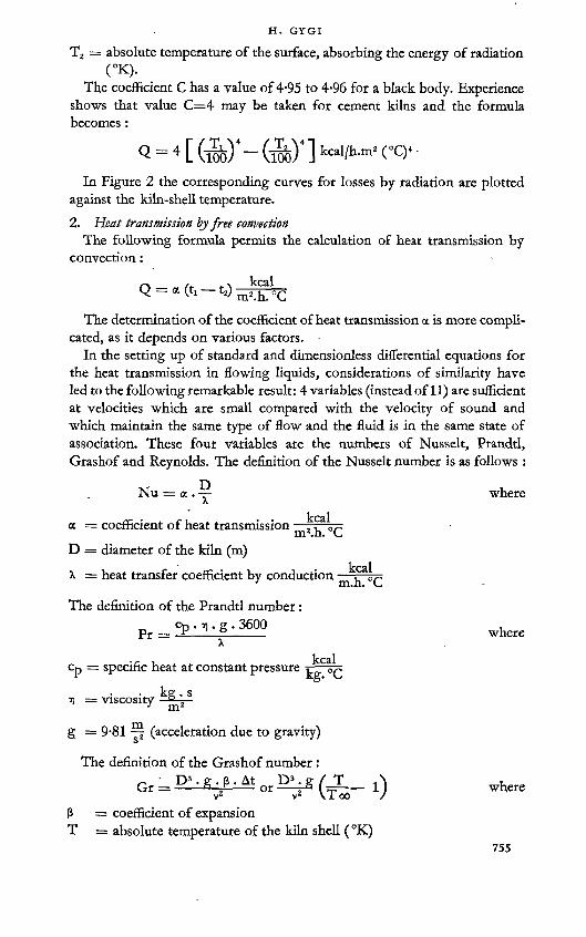
T2 = absolute temperature of the surface, absorbing the energy of radiation (°K).
The coefficient C has a value of 4-95 to 4-96 for a black body. Experience shows that value C=4 may be taken for cement kilns and the formula becomes :
<1=4 [ (rob)' - ® ‘ 1 <oc>‘ ■
In Figure 2 the corresponding curves for losses by radiation are plotted against the kiln-shell temperature.2. Heat transmission free convection
The following formula permits the calculation of heat transmission by convection: -
— a (t, —12) m2 h oC
The determination of the coefficient of heat transmission a is more complicated, as it depends on various factors. ■
In the setting up of standard and dimensionless differential equations for the heat transmission in flowing liquids, considerations of similarity have led to the following remarkable result: 4 variables (instead of 11) are sufficient at velocities which are small compared with the velocity of sound and which maintain the same type of flow and the fluid is in the same state of association. These four variables are the numbers of Nusselt, Prandtl, Grashof and Reynolds. The definition of the Nusselt number is as follows :
where
where
where
X
The definition of the Prandtl number : pr ■ v). g . 3600
= a-"x
a = coefficient of heat transmission —m2.h. °CD = diameter of the kiln (m)
X = heat transfer coefficient by conduction —4 m.n. G
. r , kcalcp = specific heat at constant pressure
• kg . sH = viscosity —gp—
g = 9-81 (acceleration due to gravity)
The definition of the Grashof number :Gr = D3 .g ß.At or DGg / T _ .
vz v2 \T ooß = coefficient of expansionT = absolute temperature of the kiln shell (°K)

THERMODYNAMICS OF THE CEMENT KILN
T oo = absolute temperature of the surrounding air ( °K) -
v = kinematic viscosity j
According to Kraussold’s relation6 heat transmission is calculated as follows :
Nu = 0-13 . Vpr • GrHaving put the corresponding expressions in this formula we may deter
mine the coefficient of heat transmission directly.
a = 0^V^.D^g(^1) „
From Figure 3 the total loss of heat by radiation and convection per m2 radiating surface can be found if the kiln is installed in a closed building.
The losses by radiation and convection were calculated after Heilman’s formula and also according to our diagram (Figure 2). We found that our results were the same as Heilman’s.
3. Coefficient of heat transmission by convection and influence of windsAs many cement kilns are set up in the open air and only the head of the
kiln and the burner’s panel are protected by buildings, it is desirable to know the losses by convection taking account of the velocity of air with regard to the kiln axis.
In the presence of atmospheric currents, the laws of heat exchange by convection are entirely different and it is very difficult to find an approximate equation for the exchange of heat in transition from quiet to streaming atmospheres.
For currents perpendicular to the kiln axis the relations found by Hilpert7 for Reynolds numbers between 2 and 250,000 were used. For bigger Reynolds numbers one can extrapolate according to the equation :
Nu = 0-00672 . Re0-905 or
~ K I P’ W 10-905 TI-0-095“ ~ K2 Kt+2737 • u
TV 0-00672. x2 — (R. 7). g)»-903
Value of K2 for various average temperatures
t(°C) 25 50 100 150 200
_____ kcal______(oC.h)0-°95.mkgl>-903 0-133 0-1362 0-1398 0-1415 0-1443

Re = Reynolds number — W ‘ (for temperature t)
temperature of air+temperature of kiln shell
w = velocity of wind (m/sec)p = air pressure (kg/m2)D = diameter of the tube (m)
The nomogram (Figure 4) shows the loss of heat by convection per 1 m length of kiln in kcal/h.
To get the total heat loss, the corresponding loss by radiation must be added using our diagram 2. If the direction of the wind is at an angle to the kiln axis the following equation may be applied :
— =1----K . COS2e“so
putting for K : ,K = 0-6 if Re = 3000 -4- 20,000
Having no experience with bigger Reynolds numbers than those in the present example the same value for K has to be taken.
If the direction of the wind lies parallel to the kiln axis we obtain :
— = 0-4“so
Although there exists a special formula for the exchange of heat in this case (i.e. direction of wind parallel to the kiln axis) it is easier to use the same relation as above, especially as the various obstacles around the kiln might cause vortices and put in question the correctness of the formula.
Figure 3 : Total heat losses as the sum of the losses by radiation and convection.

iFjgure 4 : Meat losses iby ^owsation from a stationaty 'horizontal ttiibe in moving -dry air. Air stream vertical to the tube axis. From measurements 'of iR. Hilpert ((ten Bosch, M. Die Wärmeübertragung. Zürich. 1936).
(CAiLCiUiLATLON (OF A HEAT BALANCEAs ttxwo main factors in the heat balance, the heat of formation of tjlinker
.and tthe losses Iby radiation, have been defined, it is possible to set up the
.complete balance of the kiln without any difficulty.The following data were used for the calculation of the heat balance of a
(Holderbank kiln (wet process). '
Kiln capacity:8500 kg/h
A»no«t?t of tool required:1.8'4 per cent
Low calorific value of coal:. ,7645 kcal/kg.
Amount of water contained in slurry:34'0 per cent .
Dust:Various measurements of the waste gases of the kiln have shown that the loss of dust is nearly compensated by the amount of coal ash. Taking this difference into consideration we use 1-57 instead of 1'56 kg dry raw material for 1 kg clinker.

Combustion air: . ■ 'Calculated from the elementary analysis of coal = 1-51 Nm3/kg,of clinker ' '
Excess of air:According to analysis of gas = 8- per cent. From this we obtain:Combustion air required: 1-51 X 1-08 = 1-63 Nm3/kg of clinker
Combustion gases: ■With an excess of air according to the amount of coal required and according to the analysis of coal: l*68'Nm 3/kg of clinker '
Water: •-. From slurry 0-810 X = l-008v Nm3/kg of clinker
From kaolin 0-022- X = 0-027 Nm3/kg of clinker
Carbon dioxide:
Derived from limestone.: 0-537 X = 0-273 Nm3/kg of clinker
Average temperature of waste gases:226 °C .
Losses by radiation and convection from the tiln shell and from the cooler:■ Withthehelpofthirty testing points^ at the surface of the kilmandl
the cooler and i using. the diagram (Figure 3)' it : was found I that i the total loss by radiation and!convection amounted Ito:
1J908j700 Ideal lorr^^P^^®’= 22412 ’kcal/kg of dinkert
Witbithe-help ofi these data itiis easy to establish;a heat: balance fori 1; hg oft clinkerratt ai temperature' of 0pG.. Table 11 gives, a: dean and] distinct: survey, of > this-b'alänce. •
THE: IL IT- DHA'GR<AM1 OF THE. CEMENT' KILN. .The heat' balance illustrated! above shows , ati first: sight: how the ■ required I
heatis expended In a; kiln.. "But the calculation does not1 show the most'efficient: temperature at,which:
the heat* should be suppbed; norr the conditions of: heat: transfer, to,the raw mix through the intermediary of the combustion gases.
As these connexions are not too easily found!for a, cement: kiln, the best1 thing-would be to study the possibilities with the helpofa, diagram.whichis generally valid. This can be done by using the Lt-diagram of the cement kiln, where the enthalpy I of the kiln feed is shown with regard to the endothermic and exothermic heat effects and the enthalpy I of the combustion gases as well as the corresponding temperatures t of the material and the combustion gases. '

thermodynamics of the cement kiln
table 1: Heat balance
Amount of heat introduced
Amount consumed per kg of clinker
kg
Lower calorific value of fuel
kcal/kg
Calories per kg of clinker
kcal/kgSupplied by fuel 0-184 7,645 1,407
Amount per kg of clinker
Specific heat Temperature
°CNm3, kg kcal/kg °CPrimary air 0-295 Nm3 0-313 38 3Secondary air 1-335 Nm3 0-313 25 11Raw slurry 2-380 kg 0-496 25 30Total 1,451
Amount of heat spent
Amount per kg of clinker
Specific heat Temperature Calories per
kg of clinkerNm3, kg kcal/kg °C kcal/kg
Heat of formation of clinkerCO2 + SO2, combus-
429
tion gases 0-278 Nm3 0-430 226 27N2 for the theoreticalamount of air required 1-190 Nm3 0-316 226 85Excess air 0-120 Nm3 0-316 226 9H2O gases of combus-tion 0-089 Nm3 0-375 226 8CO2 raw material 0-273 Nm3 0-430 226 27H2O raw slurry:
(a) latent heat 1-009 Nm3 482(b) sensible heat 1-009 Nm3 0-375 226 86
H2O kaolin 0-027 Nm3 0-375 226 2Heat of clinker 1-000 kg 0-193 175 34Losses by radiation 224Unaccounted for 36Total 1,451
THE I-T-DIAGRAM OF BURNING CLINKER
To familiarize the reader with the I-t-diagram for clinker burning the proceedings in an ideal kiln are recapitulated, where clinker at 0°C is manufactured from an entirely dry mixture consisting of lime, kaolin and silicic acid at 0 °C. For the manufacture of 1 kg of clinker consisting of:
per cent3CaO.SiO2 67-32CaO.SiO2 11-23CaO.AI2O3 10-3 and4CaO.Al2O3.Fe2O3 11-3
we need 1-221 kg CaCO30-160 kg Al2O3.2SiO2.2H2O0-037 kg Fe2O30-142 kg SiO2Total 1-56 kg dry raw material.

Figure 5 : I-t-diagram of clinker burningI Clinker burning without losses H Wet kilnIII Dry kiln.
The theoretical process of burning clinker without loss represented in Figure 5, curve I, will be studied first. To heat up the raw material to 450 °C, 175 kcal/kg of clinker are required (A'B'). At this temperature the dehydration of kaolin takes place with an endothermic effect of 36 kcal, during which 0T60 kg meta-kaolin and 0-022 kg steam of 450 °C are formed (B'C'). Then follows the heating of the materials with the dehydrated clay to 900 °C requiring a further 196 kcal (C'D). At this temperature the decomposition of the calcium carbonate begins requiring 483 kcal (DE); 0-685 kg CaO and 0-537 kg CO2 are formed.
While cooling the free CO2 to 450 °C 67 kcal/kg of clinker (C'C) are regained. Similarly 17 kcal are produced by the cooling of steam from 450 °C to 0 °C, so that not 407 kcal as from the drawing, but 407 less 141 = 266 kcal are required for heating up to the decomposition temperature of carbonate according to the real course of curve I.
Now the oxides are heated to the sintering temperature of 1400 °C, consuming 123 kcal (EF). At 1400 °C the endothermic effect of 26 kcal (FG) for the formation of liquid has to be considered; 898 kcal are required. As there is an exothermic effect of 103 kcal (GH) for the formation of clinker minerals, this amount of heat is equivalent to the heat regained. Also, the heat recuperated by cooling of the burned clinker to 0 °C amounts to 366 kcal (HK) so that the ideal kiln requires 429 kcal for 1 kg of clinker.
Curve I clearly shows the very large amount (483 kcal), which is used for the decomposition of carbonate. A change in the CaO content of clinker for instance from 67 to 68 per cent raises the heat of formation of clinker by 7 kcal. The heat regained by cooling the clinker is very considerable too; it amounts to 366 kcal, showing the great importance of efficient cooling of clinker in practical kiln handling.

Curves II and III illustrate the real course of heating (differing only in the dry zone), formation of clinker, and cooling of the kiln feed. Curve III relates to a dry kiln which requires raw material containing 12-5 per cent water and curve II relates to the Holderbank wet kiln where raw slurry containing 34 per cent water is used.
A comparison of the experimental and theoretical heating curves of the kiln feed shows that most of the water evaporates at temperatures of 75 °C and the essential dissociation of limestone takes place at a temperature near 800 °C. -
Another interesting factor is the similarity between curves II and III found experimentally and the theoretical curve I.
The theoretical heat of formation of clinker can easily be obtained from Figure 5. For this purpose we take curve I; U stands for the amount of heat regained by cooling the clinker to 0 °C, V is the amount of heat regained by cooling the gases to 0 °C and from the condensation of steam, so that 429 kcal are left over for heat T.
THE I-T-DIAGRAM OF THE CEMENT KILNNow the entire I-t-diagram of the cement kiln shown in Figure 6 can be
drawn. Again the real course of the cooling and heating curves for wet and dry kilns is represented by curves I and II. Also, the corresponding gas temperatures are represented by curves III and IV. Curve III was calculated from the heat balance of the Holderbank wet kiln as shown in Table 1. On the other hand curve IV was calculated for a dry kiln similar to the wet kiln except for the amount of water in the raw feed which was 12-5 per cent instead of 34 per cent. The heat required for a dry kiln amounts to 1001 kcal as compared with 1451 kcal for the wet kiln.
The heat of the kiln feed can be taken directly from the abscissa of the I-t-diagram; for gases it is different as the relation between the heat of the gases and the heat of the material depends on the losses by radiation. In Figure 6 the losses by radiation for both types of kiln are represented. Zero is removed to the cooler at the entrance of the air of combustion; the radiation losses for 1 kg of clinker are represented in such a way that the total radiation loss calculated from the cooler can be taken for every point of the cooler. In that way, the losses by radiation from the cooler to this part of the kiln, where the temperature of the gas reaches the temperature of the material, are calculated negatively; from this point to the end of the kiln the losses by radiation are again calculated positively. The heat of the gases can be found at every point of the cooler using the following formula :
Heat of the air of combustion at point x of the cooler :I* =■= Ij + i + Sx
Similarly we take for the kiln :ly = Ig + i + Sy
i.e. heat of the kiln gases at point y of the kiln.In view of the great importance of the temperature of gas for both types
762

Figure 6: I-t-diagram of the cement kilnI Material; wet kilnII Material; dry kilnIII Gases; wet kilnIV Gases;dry kiln.
table 2.
Section of
kiln
Material temperature
°CHeat balance of a kiln section .
1 175 to 1,185 Ii + i2 = I2 + ij + Si2 1,185 to 1,400 I2 + >3 + X = I3 + i2 + S23 ■ 1,400 to 1,237 L + i» + AHU = I4 + ij + Rg.i + S34 1,237 to 915 I4 + 15 + AHU = I5 + i4 + ARcQz + S45 915 to 825 I5 + ie + AHU = I6 + is + ARco2 + S36 825 to 700 Is + ij = I? + *6 + ARco2 + S67 . 700 to 197 I7 + i9 = I8 + i7 + RKa + S78 197 to 25 Is + i» = I9 + is + rHzO + Sg
• In which: Ij, I2,1, =*1» *Z> l3 =
RK1 =Rcq2 =RKa =Ryfco =X =$t» S2, S3 =
■ ahu =
Enthalpy of gases .Enthalpy of materialEndothermic effect on the formation of liquidEndothermic effect in the decarbonation zoneEndothermic effect on the dehydration of kaolinLatent heat of H2O from raw materialExothermic effect on the formation of clinker minerals Exothermic losses by radiation from thecorrespondingsections Heat given up to the sections by combustion of coal.
26 763

THERMODYNAMICS OF THE CEMENT KILN
of kiln it might be useful to show how those temperatures may be determined.
The heat balance set up in Table 1 for the wet kiln and calculated for the corresponding temperatures for the dry kiln serves as a basis for the determination of the course of temperature of the kiln gases. Further, the determination of the gas temperatures makes use of the studies published by the author of the procedure for heating up and burning in the kiln and of calculations of losses by radiation.1 With the help of this information it is possible to set up a heat balance for every section of the kiln and to calculate the temperatures of gases at the end of a section.
The equations to be used are given in Table 2.By a summation of the eight equations contained in Table 2 we obtain :
Ii + i<> + Hu + X = it + I, + Rki + Rco^ + Rh2o + 8
where:X = 103 kcal/kg of clinker Rk1 = 26 kcal/kg of clinker R<X)2 = 483 kcal/kg of clinker
" B-Ka — 36 kcal/kg of clinker and substituting for the equation above
Ii + is + Hu = i[ + I9 + RjiaO + 8 429We obtain an expression which represents the whole heat balance of
Table 1 by means of an equation. -
DISCUSSION OF THE GAS TEMPERATURESThe I-t-diagram of a cement kiln represented in Figure 6 is very interesting,
and it is worth while examining it thoroughly.Considering the gas temperatures in a wet kiln we obtain for an initial
combustion air temperature of 25 °C a temperature of 410 °C on leaving the cooler. The temperature difference between air and clinker, considering the present temperature of the clinker, amounts to 150 °C at the entrance to the cooler and increases to 775 °C on leaving the cooler. Afterwards the combustion air temperature rises to the temperature of ignition of the mixture of coal dust and air, and a maximum temperature of combustion of 1890 °C is attained. Then, the kiln gases begin to cool and they leave the kiln at a temperature of 226 °C. In the burning zone the difference of temperature between gases and material is about 800 °C and at the end of the kiln the difference is reduced to 200 °C.
The temperature distribution in a dry kiln is not very different. The temperature of the combustion air at the end of the cooler, however, is higher and amounts to 573 °C. Because of the higher temperature of the combustion air the maximum temperature of combustion amounts to 2050 °C. Thus the temperature difference between gas and material in the burning zone is higher in the dry kiln than in the wet kiln. In the calcinating zone the
764

relations will change and in the dry zone they are in favour of the wet kiln. At the end of the kiln the difference amounts again to 200 °C.
The maximum temperature of combustion, which is 160 °C higher for a dry kiln, is the result of its better fuel economy. Therefore, a kiln with a better fuel economy requires a more refractory kiln lining in the sintering zone.
Certain variables affecting gas temperatures must be studied more thoroughly as they are not evident from Figure 6.
Excess of air affects the gas temperature perceptibly. If the excess air in a Holderbank wet kiln were zero instead of 8 per cent the maximum gas temperature in the sintering zone would be 2040 °C. An excess air value of 20 per cent would lower the maximum gas temperature to 1660 °C.
It has been proposed that kilns should be operated with air containing more oxygen to improve the heat economy. This type of air containing 35 per cent O2 would raise the flame temperature even as far as 3100 °C.
These considerations are based on results obtained from practical experiments. But combustion depends to a high degree on fuel quality and especially on its content of volatile matter. It is well known that the ignition of coal containing little volatile matter takes place only at high temperatures but proceeds at a very fast rate. On the other hand the ignition temperature of coal containing much volatile matter is low and the combustion flame is long. If combustion were 25 per cent slower the maximum flame temperature in the sintering zone would amount to 1720 °C.
At Holderbank, experiments were made with different qualities of coal and it was found that the Saar coal containing 38 per cent volatile matter could not be used under normal conditions, whereas non-bituminous coal with a low content of volatile matter burned with such a short flame that the refractory linings were damaged.
FEATURES OF AN ECONOMICAL KILNStudies of the gas temperature for any industrial kiln lead to the problem:
how is the heat of the fuel transmitted to the material ? It is obvious that a transfer medium is necessary (the flame gases). As the burning process in a cement kiln takes place at high temperatures the burned material and the combustion gases leave the burning zone also at high temperatures. So one has to use the heat in the clinker for preheating the combustion air and vice vena employ the sensible heat of the gases for preheating the kiln charge. Also it is important that losses by radiation should be low.
The results of the calculation of gas temperatures can be summarized as follows : The temperature difference between gas and material in the burning zone increases with the improvement of heat economy whilst it decreases on entering the cooler and leaving the kiln.
Therefore, an effective cooler must be fitted with ample and effective heating surfaces. On the other hand one has to avoid higher losses by radiation which might occur with a bigger cooler.

As mentioned above a smaller fuel consumption will heighten the flame temperatures. It is well known that the heat transfer in the sintering zone takes place largely by radiation, thus nothing need be done to increase heat transfer in this section of the kiln.
In the calcinating and drying zone there is almost the same problem as in the cooler i.e. to install ample effective heating surfaces for keeping the heat exchange at a high level, even at low temperatures of waste gases. There is, therefore, a large calcinating and drying zone which must be insulated against losses by radiation. ■
To keep losses of waste gases at a minimum not only as to temperature but also as to quantity, it is important to keep the excess air as low as possible during burning. But on the other hand losses of unburned fuel in the waste gases have to be carefully avoided. A recording system controlling the kiln continuously has to indicate the O2 and the CO2 contents of the waste gases, as well as their temperature.
HEAT EXCHANGERS
The heat consumption of the wet kiln we studied is equal to 1451 kcal/kg of clinker as mentioned above. A comparable dry kiln, however, (similar temperatures of waste gases, temperatures of the clinker’s discharge and radiation losses etc.) will use 1001 kcal/kg of clinker. Therefore the dry process has a great advantage and we concentrated on studying the problem of the thermal efficiency of the dry kiln.
In practice there are some difficulties in keeping the waste-gas temperature in a dry kiln at the same level as in a wet kiln, whose temperature is easily controlled because of the large amount of evaporating water.
To increase the thermal efficiency of a dry kiln it is necessary to obtain an optimum heat exchange between gas flow and raw material.
After studying the problem of heat exchange in the clinker cooler we developed a new type of heat exchanger which will shortly be described. Its purpose is to increase heat transmission by convection between the clinker and the combustion air as well as between the material and the gases in the kiln. The installation of lifters brings about this effect by raising the material and showering it back through the gas stream. By means of a row of guide vanes a vortex is produced that increases the rate of flow of the gases. The heat transmission between a flowing gas and material is proportional to the 0-75 power of the rate of flow and because of this one gets an excellent heat transmission. All these parts are employed in contact with high-temperature gases and are manufactured from heat-resistant cast steel.
The measured heat values obtained from a dry kiln with a daily production of 220 t before and after the installation of heat exchangers in the kiln and cooler, are illustrated by the following table.

TABLE 3.
Before installation After installationkcal/kg of clinker
Heat supplyFuel 1,324 1,042Primary and secondary air . 11 15Ground raw material 18 11
Total 1,353 1,068
Heat consumptionTheoretical heat of formation of clinker 448 448Combustion gasesExcess air ■ 263 142H2O in kaolinCO2 in raw material 61 34H,O in raw material:
(a) Latent heat of evaporation 126 110(b) Sensible heat 48 27
Heat in clinker 73 35Radiation losses 191 181Other losses 143 91
Total 1,353 1,068
Lifting paddlesGuide wheel
Figure 7 : The vortex through which the material raised by the lifting paddles falls.

Figure 8 : First guide vanes. The manhole cover in the centre of the vane is removed. ■

Figure 9 : Middle guide vanes. The lifters can be seen at the circumference of the vanes.

Thus the installation of heat exchangers saves 21 per cent of the normal coal consumption.
A heat exchanger is illustrated in Figure 7 and the first row of guide vanes shown from the burner’s panel is shown in Figure 8. Figure 9, shows the second row of guide vanes and some lifters between two rows of guide vanes.
Special attention must be paid to the problem of dust in the dry kiln. Most of the dust in wet kilns is kept back by the slurry on the chains. In dry kilns however the dust passes on more easily with the kiln gases particularly as the material is well distributed by the lifters of the heat exchangers. Therefore, it is absolutely necessary to nodulize the raw material carefully and to use nodules which are as durable as possible. The mechanical resistance of the nodules depends on the physical structure of the raw material. The Holderbank laboratory has developed a simple method for the determination of the relative mechanical resistance.
RATIO OF MATERIAL IN A KILN SECTION AND TRANSPORT OF MATERIAL
RATIO OF MATERIAL IN A KILN SECTIONAn important factor influencing the economy of a rotary kiln is its ratio
of material. This problem was studied at Holderbank in collaboration with Mr. G. Eichelberg, Professor at the Swiss Federal Institute of Technology in Zürich, who has made the following calculations.
It is obvious that the heat transmission between the gases and the solid materials is not favourable for a small kiln charge, the contact surface for both media being very small. On the other hand heat transmission is also unfavourable if the kiln is half filled with solid materials. For this reason an optimum ratio of material has to be found at which the heat exchange between the gases and the solid material at a given gas temperature attains a maximum.
For the resolution of this problem investigations were made in the calcinating zone of a Holderbank kiln, where the gases have a temperature of 1500° to 800 °C.
Heat transmission between gas and solid material takes place by radiation, but may also occur by transmission of heat by conduction and convection directly and indirectly through the intermediary of the surface of the lining of the kiln. Without showing the whole method of calculation, the relations of heat transmission will be represented by the following general terms:
1. General equation for heat transmission( Qgm'I • d = — Ga. cp . dTG = — Gm . cM . dTM\ total/x

This equation can be divided as follows :
2. Heat transmission bj radiation
QcWstr = FwG • eG •£wCs[(wo) - (So)4]
QGMstr = FmG • £G • eM CsrfTG-Y-riMYiLkioo/ uoo7 J
where:QwMstr = Fmg ■ EwG = gasW = wallM = materialstr = radiationF = inner surface of the lining of the kiln e = coefficient of absorptionCs = radiation constant for black bodiesD = diameter
3. Heat transmission by conduction and convection
QgwLk = Fwg • «G (Tg — Tw) QgMlk = Fmg * aG (Tg — Tm) QwHlk = ^WM • «WM (Tw----Tm)
Figure 10 : Drum section with the inner diameter D.
For obtaining the relations necessary for the calculation oF the most favourable conditions the geometry of Figure 10' showing $ kiln section can be used.

There are other terms to be considered:c 71 na /8 sin 28'i ” r>2f« =T- D- = TD^m
Corresponding to a kiln of 1 m length :
Fmw = ". D .
.Fwg = „,d.^zlS
p ty sin 8Fmg — ” • L>. ——then:
Fmg __ ,l _ sin 8Fow G it — 8
The equations and data mentioned above lead to the practical calculation of the problem putting for the ratio of material <pM about 20 per cent and for 8 = 60 Thus heat is transmitted from the gases | directly to the material and I through the intermediary of the kiln lining.
The heat directly transmitted by radiation at a gas temperature of 1500 °C amounts to 92 per cent and at 800 °C to 65 per cent. The rest is transmitted by conduction and convection. Of the heat indirectly transferred to the material, 94 and 70 per cent respectively are radiated from the gas to the kiln lining and 52 and 12 per cent are transferred to the material by radiation from the lining. The rest is transferred from the lining to the material during the period of contact.
From the calculation of heat transmission we arrive at the diameter D and the ratio -g for the calcinating zone. We intend now to determine the conditions
of heat transmission at temperatures from 1500 °C to 800 °C for a given rate of production and at a gas velocity of Wo = 1-6 msec-1 for the combustion gases in the kiln measured at 0 °C, 760 mm Hg.
An increase of the ratio of material <?M for a certain gas velocity causes an increase of the ratio /^=.On the other hand an increase of the diameter will
V ^kl
cause a decrease of the ratio The relation between the ratio of material
and the valuesD , L j L.P v ■ c 11• TÄ and "Tt— are shown in Figure 11.V U 'tiki
The diagram makes it evident that the minimum of the quotient
corresponds to a ratio of material of 22 per cent or to a 8 of 63 °. As theminimum of the curve is very flat the ratio of material may differ between 15 and 30 per cent without influencing the product L.D. appreciably.

Figure 11: D, and D.L. depending on the ratio of
material in a kiln section.
TRANSPORT OF MATERIALIn order to calculate the inclination of a kiln for a given production,
diameter, speed and ratio of material, we are now going to determine the axial velocity of the material.
A more accurate investigation of the geometry of material flow in an inclined rotating drum leads to the following equation: "
siflY. = siS^sin ß
tg r = ?in *° sm ß*
sin ß* = sin ß . cos t; ß ~ ß* v = angle of inclination of the drum ß = angle of slopeß* = apparent angle of slopeY = gliding angle ,

Figure 12 : Geometry of an inclined rotating drum.
wr _Wmo - At
1. Transport of material if the ratio of material is ^ero AL = rr. D . tg Y At = - 60
n
WMo = b.n^I
Figure 13 : Drum section with
' filling limit zero.
2. Transport of material depending on the ratio of material <pMAt a partly filled drum section the transport of material is caused by gliding
of the highest layer, shown in Figure 14.Turning through the angle d? we get for the hatched volume of material
dV = R . sin 8 . Rdp . sin 8 . bA displacement of the centre of gravity from S to S' gives
L =-j. D . sin 8 . tg Y
and the whole volume is then -V=PD2^M-b ‘

Figure 14 : Partially filled drum section.
Therefore, its centre of gravity is displaced by .at dV 'AL — y
during the time dt = —co
The axial velocity of material, may be then expressed as follows :w, AL. dV J-. sin38 „ „wM = ^^r = D-n-9ör^-tsY
or •Ta sin38. sin vWM = D . n .------------- -TT...........
sin^* .90(™ SULZ» )
For 8 = 0 Wmo goes to and leads to the following term after differen
tiating the numerator and denominator with respect to 3WMo = D.n.^2
A division gives the following quotient:WM 2 sin38Wmo 3^8 — 2'. sin 2s)
The material transported per hour is represented as follows :
Gm = "^ D2. <pM . WM • 3600 Ym
reduced to the amount of clinker :
GKt = -2-D2. <?M . Wmo • 3600. rM .
D . n . . tg Y Y Msch
(y Msch = ym apparent)
Gk.,.. - 15 • K- D-.n. sin.

Figure 15 : Velocity of material transport.
In the calcinating zone of the Holdetbank kiln the corresponding values are as follows : -
If Gki = 8500 kg/h, = 22 per cent (8 = 63 °) is 0-0226and D = 2-08 (Da = 2500, D; = 2100 mm). From the equation
above is 0-68. ■ .WmoThe inclination of the drum axis becomes tg v= sin v — 5/100 and the
speed n == 60/78 = 0-77 t/min.Therefore we obtain the expression
Y. Msch — lion mF ~ .
i.e. the relation between the apparent density of material and the apparent angle of slope.
This quotient is valid for all types of kilns containing the same material. So we may write : •
Gm/h = 166,000. <?M. . D3. n . sin vWith the help of this formula we may determine the inclination of the
kiln at a given speed and vice versa. Figure 15 permits the graphical solution of this equation. ,
776

CALCULATION OF THE DIMENSIONS OF A ROTARY KILN
We have studied in the preceding paragraphs how the heat is transferred in the kiln and we have shown that certain rules must be observed in order to run the kiln under the most favourable conditions. But so far nothing has been said concerning the layout or the dimensions of the whole kiln for a given production and heat economy.
In order to establish the dimensions of a kiln we base our calculations upon a kiln which works under favourable conditions, knowing exactly its production, heat consumption, temperature of waste gases etc. Based upon these data, we shall establish the rules of similarity, giving us the dimensions of a kiln of let us say higher production, but the same heat economy. These rules of similarity are only applicable for the same type of kilns.
We are now considering Figure 16 where two kiln sections of a standard kiln and a kiln to be calculated are represented.
The production of the standard kiln is Po and that of the bigger kiln to be calculated is P. Therefore we get:
P = Po . Xwhereby x stands for a factor bigger than 1.
To obtain similar thermal conditions in both kilns, such as comparable gas velocities etc., the cross-section of the calculated kiln will have to be x times bigger too.
S = So . xIt is obvious, that the specific heating surface of the two kilns having
the same heat economy, must be constant.Thus the following result is obtained for the heating surface :
H = Ho. xThis leads to a diameter
D - Do. ^/x xand to a length .
L# - — L*y * X
provided that geometrical similarity of both kilns may be maintained.
Therefore, the two kilns have the same ratio y8 = = S. We call the
ratio of the whole length to the inner diameter of the calcinating zone slenderness. The slenderness of a wet kiln is about 30, but may vary between 25 and 40.
As mentioned above an important factor for heat transmission is the heating surface of the kiln. Therefore, similar kilns have the same production in kg/h and m2 of inner surface of the kiln, and we call it p. The specific production of a wet kiln amounts to 400-600 kg/h and mz of inner surface of the kiln. On the other hand the specific production per volume of similar kilns is not constant. If r stands for the specific production, per inner volume, we come to the following relation :

Kiln to be tested
Figure 16 : The standard kiln and the kiln to be designed.
_ Production__ P _ Po . x______ 1r — Volume ~ V — Vo . x . a/x — °' a/x
From this formula it becomes evident that the specific production (per p 1inner volume) r = y be reduced by a factor when we have to deal
with a bigger kiln. A practical example will illustrate this theory.A kiln on which we are basing our calculations has the following
dimensions :
Calcinating zoneLengthInner diameter of lining
Length of the whole kilnSlendernessProduction per daySpecific production per inner surface Specific production per inner volume Ratio of material in a kiln section InclinationSpeed
Lo = • 63 m Do = 3-05 m LWo = 145 m So = 47-5 Po = 750 t po = 515 kg/m2 ro = 615 kg/m3 ?Mo= 31-7 vo = 5 per centtio = 0-7 t/min
To obtain the dimensions of the kiln producing 1000 t daily and which is- now under construction, we have to calculate factor x. Thus :
1VUU -f oo Jx — = 1'33 andL = 72-6 m D = 3-52 m Lw = 167-2 mS = 47-5 p = 515 kg/m2 r = 532 kg/m3

Inclination and speed are the same. Thus we get a ratio of material of Tm = 25-3.
The method of calculation of <pM has already been shown.The most important diameter of the kiln is the diameter of the calcinating
zone as calculated above. It may be advisable to vary slightly this diameter in the dry zone and in the burning zone for different reasons.
The doughy state of the material makes it necessary to enlarge the dry zone of a wet kiln since heat transfer is more easily accomplished through chains, besides which the chains leave only a reduced free cross-section for the gas.
These chains are excellent heat exhangers as they put the slurry into intimate contact with the waste gases. However, they have a disadvantage because they destroy the nodules in formation. Therefore, it is advisable to reduce the number of chains and to stop them where the water content of the raw material still amounts to 7-10 per cent, and to put in heat exchangers preceding the chains as mentioned above.
The dimensions of the burning zone (length and diameter) are determined by the quality of fuel as the refractory linings must resist as well as possible the radiating heat of the flame. Experience shows that the burning zone has to be enlarged compared with the calcinating zone for coal containing less than 20-25 per cent volatile matter.
REFERENCES1. GYGi, H. Wärmetechnische Untersuchungen des Drehofens syr Herstellung von Portland
cementWinker. Zürich, E, Rüegg. 1937.2. Anselm, w. Kadex Rundschau. 1950. p. 50.3. AZBE, v. j. Ruck Products. 1951. Vol. 54. p. 161.4. eitel, w. and Richter, h. Zement. 1942. Vol. 31. p. 505.5. Heilman, R. H. Industrial and Engineering Chemistry. 1929. Vol. 21. p. 192.6. kraussold, H. DieTechnik. 1948. Vol. 5. pp. 208-210.7. ten bösch, M. Die iFärmeühertragung. 1936. Zürich.
DISCUSSION
F. GUTE ■
1 only have a few remarks to add to the paper of Dr. Gygi, whom I had the privilege to assist in this work.
My aim is now to inform you of our projected investigations to follow up the first chapter about heat balance and especially the calculation of the heat of formation of clinker at temperatures below 1,000 °C.
Up to this day these calculations have been based upon a raw material formed by lime and a clay substance such as kaolinite with a slight excess of silica and small amounts of iron oxide. In reality' the physical and
779

THERMODYNAMICS OF THE CEMENT KILN
mineralogical composition of argillaceous substances in the raw material varies considerably and this leads to correspondingly changed conditions during the burning of clinker, especially in the presence of measureable quantities of quartz.
These observations have made Hendrickx1 search for a method of determining the so-called “ burnability ” of the raw materials.
We have been convinced for a long time that the physical and mineralogical state of the argillaceous substances in the raw mixture will influence the velocity of the reaction between lime-silica and lime-alumina. Investigations about clinker burnings in a laboratory furnace starting with anhydrite and clay for the manufacture of Portland cement and sulphuric acid have confirmed our conviction. In several cases we found that the burning of a clinker with a given quality of clay required half the time of another quality of clay at equal temperatures in the furnace.
These facts have been confirmed by the investigations of Professor Briner2 in Geneva about the dissociation of calcium sulphate in the presence of additions, such as meta-kaohnite. He gives the following interpretation :
At the dissociation of calcium sulphate in the presence of kaolinite the enthalpy change is the difference between the enthalpy of the products (silicates and aluminates) and reactants (calcium sulphate and kaolinite). Due to the fact that the enthalpy of kaolinite may vary, the enthalpy change of the reaction will vary correspondingly and may influence the reaction, according to variable surface energies of kaolinite. These latent energies in the clays give them a so-called “ active ” state.
We have established a programme as follows :1. Studies on clays of different composition in a pure state, especially
of kaolinite and montmorillonite, qualitative and quantitative mineralogical analysis of the mixtures existing in our raw materials to show the different kinds of clays. We have previously made analyses after the method of Daubner.
2. Studies on the surface of clay and its energy states, determination of its specific surface by means of adsorption.
3. Theoretical and practical thermodynamic studies about the reaction between argillaceous substances and calcium carbonate.
Our first calculations of the equilibria in the reactions between silica and calcium carbonate have shown that the formation of dicalcium and tricalcium silicate may start at temperatures of 500 °C and 550 °C respectively; that means below the dissociation temperature of calcium carbonate. With the help of kinetical studies and practical investigations it seems possible to determine the most favourable conditions under which the reactions take place. -
After this, the thermodynamic conditions of the first reactions, taking place in the cement kiln may be clearer and also the reasons for the different types of clinker which may be produced depending on the raw material, as for instance clinkers of different ease of grinding.

DISCUSSION
REFERENCES
1. HENDRiCKX, j. Notes speciales sut la fabrication du ciment Portland artificiel.1922.
2. BRiNER, e. Helvetica Chimica Acta. Volumen XXXI. Fase. Septimus.
MICHEL J. M. JASPERS
Dr. Gygi deals with many problems concerning theoretical study, practical operating and the layout of cement rotary kilns. As time is limited, I think it better to limit my contribution to the discussion to two points— a theoretical one, concerning internal radiation; and a practical one. Concerning dust production.
First, the author in his paper established the rules of similarity for rotary cement kilns, and obviously two kilns working under the same conditions have the same gas velocity at the same place. As we all know, there are certain materials where the dust losses of the kiln run very high. On the other hand, it is desirable to keep these losses within a reasonable rate. Has the author any suggestions to make as to how the dust losses in a kiln can be kept below a certain figure ?
Secondly, Geoffrey Martin, in his book, “ Chemical Engineering and Thermodynamics applied to the Cement Rotary Kiln”, develops the idea of internal radiation of high-grade heat from the clinker zone to the colder zones. He mentions it as the principal cause of the low thermal efficiency of most rotary kilns. It would be interesting to hear the comments of the author on this. '
R. J. DAVIESTo those of us who are concerned with the cement-making processes,
the inclusion in this Symposium of papers on the application of research in-cement manufacture is particularly welcome. This is especially so as progress in the two main manufacturing processes—burning and grinding —during the last twenty or thirty years has lagged far behind the advances which have been made in knowledge of the product.
Dealing specifically with the cement kiln, it may be said that, with one notable exception, thermal efficiency remains in the region of 25 to 30 per cent. Kiln developments have been largely confined to the design of heat exchange devices applied to the low-temperature section of the process, without producing any very significant improvement in thermal efficiency.
The reason for this is not far to find. To put the thermodynamics of the system in the simplest language, there is already an excess of low- temperature heat energy available at the back end of the kiln for the low- temperature processes of drying and preheating. If this were not so, then it is unlikely that we should have the wet process of cement manufacture.
The failure of kiln designers to produce any real improvement in the thermal efficiency of the system is due mainly to their having concentrated
781

THERMODYNAMICS OF THE CEMENT KILN
on utilizing this excess of low-temperature heat energy instead of taking steps to limit the amount of such low-temperature energy present in the system. Its presence in excess is due, first, to poor heat exchange in the high-temperature zones of the kiln, i.e. the calcining and clinkering zones; and, secondly, to the very serious loss of high-temperature heat energy by radiation from these zones, within the kiln, to the low-temperature zone. The remedy, which may prove difficult though not impossible of attainment, is to improve heat exchange, particularly in the calcining zone, and to prevent radiation of heat energy up the kiln. I should like to ask Dr. Gygi’s opinion of the prospects of advances being made on these lines.
I said a moment ago that there is one exception to the failure of heat exchange devices to produce a significant improvement in thermal efficiency. I refer to the Lepol kiln. In South Africa and Southern Rhodesia we have a considerable number of these kilns, which are capable of thermal efficiency in the region of 45 per cent. The essential feature of these kilns is that the low-temperature processes are carried out on a moving grate, and the high- temperature processes in a short rotary kiln. The kiln and grate sections are so disposed that direct radiation of heat from the former to the latter is substantially prevented. Whether this baffling effect was intended by the inventor or whether it is fortuitous, I do not know. However, the fact remains that in general the fuel consumption is lower and the burning temperature higher than is the case with the conventional rotary kiln. I would suggest that this system may point the way to the attainment of greater thermal efficiency in the future. '
K. MEYER and H. WENDEBORN
In addition to considering what can be done to improve the efficiency of the rotary kiln, it is of interest to study completely different systems of burning. Table 1 shows the comparison of the heat requirement in kcal/kg of clinker for various kiln systems and for dry and wet processes.
The Lepol and shaft kilns and the sinter process achieve the most favourable values. It should be noted that the specific outputs in tons of clinker per cubic metre of kiln content are different for wet and dry processes. Rotary kilns work with lower capacity on the wet process if one excepts rotary kilns with slurry injection.
The sinter process using dry feed has been described.1-2 It is not equally well known that cement raw slurry of normal consistency can also be processed to a good clinker in one operation. Information on the latter process has been given in two publications3 but in these, unfortunately, developments up to 1935 only are described. The following observations are necessary because of advances in our knowledge of slurry sintering and because of the interest aroused by this process.
At the present time cement raw slurry is burnt to clinker only in rotary kilns. Such a thermally favourable burning system as the shaft or Lepol kiln cannot be applied because the viscosity of the raw slurry does not permit

table 1: Comparison of heat requirements in kcal/kg of clinker for various kiln systems
Process Systemk cal/kg of cli ker 1 (including possible
recuperated amounts)
Dry Lepol 985Dry Shaft 1,100Dry Lurgi sinter 1,100—1,250Dry Rotary with preheater 1,250Dry Rotary, normal 1,550Wet Rotary with preheater 1,350Wet Rotary with chains, long 1,450Wet Rotary with chains, short 1,500Wet Rotary, normal 2,100Dry Rotary with utilization of waste heat 1,750—550 = 1,200Wet Rotary with utilization of waste heat 2,100—430 = 1,670
of the formation of large lumps nor of granulation. Despite a series of process modifications the higher heat requirement for slurry burning considerably reduces the advantages.4
Some characteristic features of the sinter process are : '1. Intensive combustion of solid fuel in direct contact with the raw
material.2. Strong preheating of the active components by direct heat transfer
by means of the hot exhaust gases.3. Achievement of highest reaction temperatures in the shortest period
and sharp quenching after completion of clinkering.4. Utilization of return material for control of the thermodynamic
operation. ■* Whilst the sinter process has in common with the shaft kiln the mixing of raw meal with the solid fuel and with the Lepol and shaft kilns the preheating of the active products by extracted exhaust gases, features 3 and 4 are especially characteristic of the cement sinter process as is apparent from the following.
In Figure 1 heating and cooling curves of cement burning by means of different systems are compared. That of the sinter process corresponds to a characteristic proceeding wholly different to all others. In the shortest time the highest temperature (combined with highest diffusion rates) will be reached, and in the same period the formed clinker is quenched to such a temperature region that harmful crystallization is no longer possible.
As can be seen from Figure 2, the amount of returned material has very little influence on the heat consumption. This fact makes it possible to dry out raw cement slurry with the addition of sufficient return material so that the mixture contains the requisite water content for sintering, the
783

TIME * MINUTES
Ol---------------- ----------------- ----------------- ---------------------------------- ----------------- ----------------- L---------- =»J40 30 20 IO O IO 20 30 40
/ ■
S*'. 0
c
• 1 :
X***,e*1*-.
i\\
/ i \d • \
1 \\ \\ \
d
Figure 1: Temperature of materials in °C and burning rate v cm/tnin -
Maximum sintering temperature " v(a) Lepol kiln l,450°C —(b) Shaft kiln l,470°C • 2-66(c) A-shaft kiln l,470°C 2-66(d) Sinter process l,550°C 2-74
Burning rate from 1,200° tol,550°C in the sintering zone = 51 sec.l,450°C in the Lepol kiln = 28’5 min.l,470°C in the shaft kiln = 3-5 min.l,470°C in the A-shaft kiln = 1-0 min.
Sinteringzone
min.
Lepol kiln
min.
Shaft kiln min.
A-shaft kiln min.
Warming up 20°— 500°C 60 20°— 500°C 18 25 , 15Warming up 500°— 850°C 0-5 500°— 900°C 17 3 5Heating 850°—l,550°C 1-0 900°—l,450°C 82 10 5Cooling off 1,550°—l,000°C 0-8 1,450°—l,000°C 28 56 30Cooling off 1,000°— 500°C 5-0 1,000°— 500°C 13 92 92

O 20 40 60 ao 100 - 200 300
RETURN MATERIAL AS PERCENTAGE OF RAW MEAL
HEAT
REQUI
REM
ENT - K
cal/K
e clrn
ker
Figure 2 : Relation of fuel consumption to return material in the sinter mixture.
Figure 3 : Diagram of the double layer sintering with fuel-free lower layer.
1. Clinker charge2. Fuel-free under layer3. Normal sinter charge4. Ignition hood5. Exhaust box ,6. Crusher7. Grader

THERMODYNAMICS OF THE CEMENT KILN
optimum water content of particles ready for sintering being 12 to 14 per cent of total dry material (raw meal, return material, fuel).
The return material is extracted from the well-sintered cake and consists of part-burned material together with the fines (less than 6 mm.).
The exhaust gases from the last third of the sinter grate reach temperatures up to 350 °C and can be extracted separately from the other cooler exhaust gases for further use. When it is possible to utilize fully their heat content a gain of approximately 150 kcal/kg clinker is secured. This heat serves to vaporize part of the water contained in the raw slurry, the complete removal of which is mainly responsible for the higher heat requirement compared with the working of raw meal.
For instance, the hot gases may be exhausted separately and be mixed with slurry in a separate drying plant. It is also possible to utilize the exhaust gas heat direct on the grate, by leading it through a layer of fuel-free nodules composed of slurry and return material lying immediately on and in contact with the grate. The water vapour and a part of the CO2 will be driven off. Sintering will not penetrate into this layer, which is screened off into the return material which in the further operation of the process is mixed with additional slurry.
The operation of this process can be followed in Figure 3. Usually the grate receives first a layer, 3 cm thick, of finished clinker 8 to 25 mm mean particle diameter (1). Over this lies in proportions as required, the fuel-free under-layer composed of cement raw slurry and return material nodules (2). Next above this is the normal sinter charge (3) which contains the required solid fuel for the completion of the process. Under the ignition hood (4) the fuel will be ignited and a vacuum is created in the exhaust box (5) by an exhaust fan for intensification of the combustion. At the discharge end the whole grate charge passes to a crusher (6) and is then graded on a vibrating screen into particles of under 8 mm, 8 to 25 mm and over 25 mm. The particles under 8 mm include the finest clinker grains, partly burnt clinker and also the dried raw slurry in the form of raw meal. This mixture travels back in a circuit. The particles 8 to 25 mm in diameter provide as far as necessary the grate layer, and go otherwise with the particles of over 25 mm as production to the clinker storage bins.
The most favourable working conditions for individual slurries were ascertained by various tests, and it was shown that the simple sintering of slurry with return material addition and without recovery of exhaust gas heat is already of practical advantage.
With a heat consumption of about 1,630 kcal/kg clinker a slurry with approximately 38 per cent H2O content and with return material in the proportion of about 1 : 1-35, also addition of coke slack to nodulize and burn, give an output of 8 tons on each square metre of suction surface. The exhaust gas temperature reaches a maximum of about 350 °C.
For a further series of tests the quantity of raw slurry corresponding to the conservable exhaust gas quantity was converted into dry raw meal

and this was then nodulized with raw slurry, return material and fuel. The return material part decreased to 1-25 : 1 but it was possible to reduce the fuel from 1,630 to 1,420 kcal, that is, about 20 per cent of the total raw slurry. In this the heat consumption amounted again to only 1,420 kcal but the exhaust gas reached a maximum temperature of only 145 °C.
At the present time a small plant on this principle is being completed in France.
REFERENCES
1. Borner, k. and kirste, r. Betriebserfahrungen über das Zementbrennen aufdem Sinterrost. Zement-Kalk-Gips. 1948, Vol. 1. p. 7.
2. Wendeborn, H. Das Lurgi-Zementbrennverfahren. Zement-Kalk-Gips. 1949.Vol. 2. p. 1.
3. Wendeborn, H. Saugzug-Sintern und -Rösten. VDI- Verlag. 1934. Das Saugzug-Sinterverfahren und seine Verwendung beim Zementbrennen. Zeitscbr. VD119. 1935. 541. DRP. 609 839,700 791,721 117.
4. anselm, w. Die Zementherstellung, Berlin 1941. S.47, auszugsweise.5. anselm, w. Die Schnellkülhung des Klinkers bei Zementbrennöfen. Zement-Kalk
Gips .' 1949. Vol. 2. p. 84.
J. CALLEJA •
I have read the interesting paper very carefully and I can see that the author has studied in detail many of the problems which I and my associates have met with in connexion with the burning of clinker.
It would be interesting to apply Dr. Gygi’s calculations and considerations to burning in vertical kilns.
C. GORIA
Dr. Gygi examined at his works the state of temperature in the burning zone in a cement rotary kiln. I have carried out some research in this zone on the chemical behaviour of aluminous refractories the results of which are in course of publication and are summarized below.
A sufficiently wide statistical examination has shown that, usually, chamotte bricks that only contain 45 per cent A12O3 have greater durability than homogeneous bricks that contain 62 per cent A12O3 (kyanite, sillimanite, etc.). This is attributed to the greater adherence and duration of crusting of clinker on the same chamotte-refractory.1
Macroscopical examination of sections revealed that in such bricks, the isothermal lines did not correspond with the chemical isocomposition lines; the clinker lining adheres firmly to the grain. In the case of a homogeneous composition, corrosion may proceed more" quickly through the successive breaking down of thin adhering layers.
X-ray investigations showed in this last case the formation of gehlenite

C,AS-Akermanite C2MS2 solid solutions (and sometimes glass of the same compositions) showing the influence of MgO and CaO in lowering the refractoriness of this thin layer.2
REFERENCED
1. neumuller, H. Zement-Kalk-Gips. 1952. Vol. 5. pp. 1-6.2. KONOPiCKY, k. Zement-Kalk-Gips. 1951. Vol. 4. pp. 240-5.
H. GYGi {author’s closure)Dr. Jaspers asked two questions; the first was how to reduce the dust
losses in a kiln where the nodules are of not too good a quality. I think there is only one possible way of reducing these dust losses, and that is to reduce the velocities of the gas in the kiln. If we have a kiln of main dimensions, diameter as D and length L, we can write the slenderness as S equals L over D. This means, let us say, that in a certain section x we have a gas velocity of W; and the dust losses of this kiln are too high. What can you do? The only thing is to make D1 bigger than D and Ll smaller than L. Then the gas velocity, W1, will be smaller than W. The product of D times L must equal that of D1 times L1—or, rather, that is not quite correct, for in the second kiln you have higher exhaust gas temperature and therefore the product D1 times L1 must be slightly bigger. That is the only possibility of reducing the dust losses of the kiln.
Dr. Jaspers put a second question. He asked how we can reduce the internal radiation. He mentioned Geoffrey Martin’s book, and I think Geoffrey Martin is correct when he says that this internal radiation reduces thermal efficiency. I can tell you that during the war we prepared a small rotary kiln for electrical burning and we tried to reduce the heat consumption as much as possible by using a staggered kiln as in Figure 1. We separated the kiln so that internal radiation was impossible. The kiln ran all right, but there were difficulties, and after the war we changed the kiln again and made it into one piece.
In his contribution, Mr. Davies mentioned that the thermal efficiency of the cement kiln is low. I do not quite agree with him. After all, if we
788

have a kiln running under certain conditions, all we can seek to do is to reduce the radiation, the losses by the clinker, and try to get a low temperature of the exhaust gases. With a wet kiln nowadays these temperatures vary between 150 °C and 200 °C. That is not high. If you go lower you get condensation in your chimney, so that there are limitations. On the other hand, you can get clinker coolers where the clinker comes out of the cooler with a reasonably low temperature.
As far as radiation is concerned, in the colder zones of the kiln we can use insulating bricks. I agree that this cannot be done in the burning zone, but if the dimensions of the burning zone are appropriate you should not get a coating on your bricks.
Mr. Davies mentioned the Lepol kiln as having better heat economy. That is true, but it is not because the efficiency is high.- It can be explained by the fact that you have a certain humidity in the nodules when entering the kiln; they vary between 12 per cent and 15 per cent instead of 30 per cent to 40 per cent with a wet kiln. The question of the dry or the wet process is not a matter of the kiln but a matter of the raw material, and not every raw material can be treated in a dry kiln.

[22]
Development of cements for special uses in the
United States
MYRON A. SWAYZE .
SUMMARY .The paper presents an account of the methods by which special cements
are evolved by co-operation between cement users and manufacturers in the United States.
The history of the development of the five A.S.T.M. cement specifications is outlined.
Cements meeting the A.S.T.M. specifications have been found unsatisfactory in certain special applications and. the reasons for the autoclave expansion test and the recently introduced alkali-content fimitation are explained.
The future of masonry, pozzolanic, and air-entraining cements is considered and brief mention is made of the development of such specialized products as oil well cements.
INTRODUCTIONThe growth in the number of varieties of cement made by the cement
industry in the United States over the past twenty-five years is good proof that our manufacturers are making what the customer wants. If his needs are special, the user often expresses them by means of a specification, mutually agreeable to him and the producer of his special product, which will establish the minimum in cement qualities which are acceptable by him. If demand for such a speciality becomes widespread, a national specification eventually develops.
In 1925 there were but two kinds of cement covered by specifications in the United States—Portland cement and natural cement. Both specifications dated back to 1904. At present, counting air-entraining varieties as separate types, we have at least sixteen different cements in which Portland cement clinker is the principal ingredient. Of these, all but one are now covered by some sort of specification.
Since there is a very definite connexion between special provisions in790 ■

specifications and the properties of cements made in accordance with them, any discussion of cements might well be prefaced by a description of our methods in arriving at specifications. -
MODE OF DEVELOPMENT OF U.S. CEMENT SPECIFICATIONSThe writing of our national specifications for cements is now in the hands
of three agencies: the Federal Specifications Board, the American Society for Testing Materials and the American Association of State Highway Officials. All three agencies act independently in originating or adopting new methods of test and in the setting of new specification requirements. However, new methods or requirements are usually quickly adopted by the other agencies, once the changes have been shown to be desirable.
In the Federal ■ Specifications Board, the Technical Committee on Cements, Limes and Plasters is in charge of cement specifications. The membership of this committee consists solely of Federal employees representing various governmental agencies which use cement. Their decisions on changes in old requirements or the institution of new ones are reached independently. They do, however, request comment on individual items from technical representatives of producer companies, but need not be governed by this comment.
A.S.T.M. regulations governing standing committees require that a committee chairman be a non-producer, and that either an equal balance of producers and non-producers be maintained, or that non-producers be allowed to predominate. In Committee C-l on Cement, the producers are in the minority. These regulations are quite effective in keeping control of cement specifications in the hands of the consumer interests which is where that control belongs.
A.A.S.H.O. specifications for cement usually follow Federal and A.S.T.M. standards rather closely, although they display originality of opinion on details. Producers’ representatives have no part in decisions made by A.A.S.H.O.
In all three of these organizations the final decision as to requirements lies with the consumer.
PURPOSE OF CEMENT SPECIFICATIONSThe ultimate aim in the minds of consumers in writing cement speci
fication requirements is not only to establish minimum quality values, but also to ensure uniformity in the quality of products obtained under them, not only as regards different lots of the same brand of cement, but as to all brands offered for the same construction purpose. This desire has been voiced by so many technical representatives of Federal agencies and other large consumers as to leave no doubt as to that intention.
Such an attitude on the part of the purchaser is not only understandable, but logical, since prior to his selection and purchase of a cement for a given job, he has estimated carefully his material costs, in which cement enters as
. 791

CEMENTS FOR SPECIAL USES IN THE UNITED STATES
a major ingredient, and has based his estimate of cement quantities on assumed performance. If that performance is not as expected, he may be faced with the rejection of his end product—concrete—or be forced to use more cement than he calculated, thereby increasing his costs.
DEVELOPMENT OF NEW TYPES OF CEMENTDuring the period 1904—1926, all Portland cements made in the United
States were covered by a single national specification: A.S.T.M. Specification C9, or its Federal counterpart. The products made under it were quite varied in composition, strength-gaining properties and other characteristics such as resistance to unusual exposures. Consumers quite generally were aware of these differences but could not discriminate between the various cements offered to them without either writing their own specifications or making an arbitrary selections of brands. Both courses were resorted to.
During the first World War, the need developed for cement with rapid hardening properties, for emergency use in gun emplacements, etc. The French met this need with aluminous cement. Manufacture of this product was started in the United States after the war by one company. Believing that there was a permanent need in the construction field for a Portland cement with high early-strength characteristics, another U.S. company developed and produced such a product in 1926. This cement was characterized by a high C3S content obtained by double burning of a high- limed raw mix, with intermediate grinding of the first clinker to redistribute uncombined free lime. Some years later this process was abandoned in favour of a single hard-burning of a high-limed and very finely ground raw mix. Since there was no special specification to distinguish this cement from ordinary Portland, the new cement was sold under the manufacturer’s guarantee of early strength performance for several years.
Other Portland producers rapidly entered this new high early-strength field. In 1929, Committee C-l recognized the need for a specification to govern the minimum quality for this type of Portland cement, and adopted a tentative standard (C74-30T) for it in the following year. In essence, this specification is practically the same as that for our present Type III. These new products were of relatively high fineness, developed considerably higher heats of hydration at 24 hours and at later ages, and in consequence were usually limited in use to concrete of moderate mass and section size. Owing to failure to raise early strength limits since the first requirements were set, 24-hour compressive strengths of various brands range from just above the specification requirement of 1250 lb. per sq. in. to practically double that amount for the better products. These cements develop as much as 60 calories per gramme heat of hydration at 24 hours, with later heats depending on their C3A content. Where C3A is reduced by iron additions to the mix, the 28-day heat may be less than that of a Type I cement. One special high early- strength product, with a 70 per cent C3S content, no C3A (an A:F ratio of 0-50) and very low free lime, has a 24-hour strength of 2400-2500 lb. per

sq.in. and heats of hydration at 1 and 28 days of 60 and 90 calories respectively. This product has shown no attack whatever by sulphate solutions after exposure for several years.
For large masses of concrete, such as gravity dams, it was discovered in the 1920’s that serious internal cracking of the concrete was produced by the high heats of hydration in normal Portland cement, especially when this heat was not removed by artificial means. An enterprising group of research men at a west coast cement plant, headed by Hubert Woods, attacked this problem from the basis of lowering the rate of heat evolution by control of composition. The result of their work was the low C3S, low C3A cement now known as Type IV low-heat cement, first used in the Rodriguez and Pine Canyon Dams in 1931. Studies of heat of hydration of cement compounds by other laboratories quickly followed knowledge of their work, with the result that the Bureau of Reclamation wrote a low-heat cement specification in 1932 for use in Hoover Dam. This specification contained maximum limits on C3S and C3A and, as double insurance, limits of 60 and 70 calories per gramme of heat of hydration at 7 and 28 days. This cement due to its composition, is of low early strength, but has good ultimate strength if it receives prolonged water curing. Drying shrinkage with inadequate curing can result in most unsightly, although non-dangerous shrinkage cracking of thin sections, as inspection of parapet walls of Hoover Dam reveals. The popularity of low-heat Type IV cement has decreased considerably in recent years. In 1949 only 130,000 barrels were sold for mass concrete purposes.
Type II cement, as we know it today, followed quickly on low-heat cement. The newly established Tennessee Valley Authority felt that less reduction in heat evolution was needed for their smaller dam structures, and they set up a- specification for Type “ B ” cement, which was very similar to the present Type II. Composition limits of 50 per cent and 8 per cent were set on C3S and C3A respectively, supplemented by limits of 70 and 80 calories per gramme on heat evolution at 7 and 28 days. The limits on heat of hy- ’ dration survive only in the Federal specification.
The original Federal specification for sulphate-resistant cement (Type V) came as an outgrowth of laboratory investigations at the Bureau of Standards and elsewhere on the properties of the low-heat cements used in Hoover Dam. The Technical Committee on Cements, Limes and Plasters found that one of these cements had exceptional sulphate-resisting properties, and, so far as this writer can determine, wrote their restrictive chemical limits for this whole class of cements around the composition which this one cement possessed. These limits were such as to limit this type of cement, to the low early-strength low heat of hydration classification. It has been only recently that these chemical limitations have been relaxed to allow the production or a more normal product. Actually, sulphate resistance is a property which can be possessed by any class of Portland cement. Since most of our sulphate exposures occur in the arid regions of our western states,

the construction industry might well be served better by a high early strength cement sulphate-resistant product than by even our present Type V. A strict performance test for resistance would serve better than our present arbitrary 5 per cent limit on C3A. The sulphate susceptibility test of Bogue and Lerch appears to have much promise as an accelerated test for this property. Recent studies by the C-l Working Committee on Sulphate Resistance indicate that exposure tests of lean mortar bars in sulphate solution require far too long to reveal differences for this method to be used for acceptance purposes.
The great advantages of air entrainment in producing high resistance to frost action in concrete were becoming more and more widely recognized in the late 1930’s. A.S.T.M. Committee C-l collected information on this subject, instituted comparative tests on effects of interground Vinsol resin on concrete properties, and finally in 1942 set up tentative specification C175 to cover air-entraining Portland cements of Types IA and ILA. Later, high early-strength cement Type IIIA was added to this list. The Federal Specifications Board delayed action until 1945, when they consolidated all five types of both plain and air-entraining cements into a single specification.
At first, the resin was interground with the cement without neutralization, and it was soon found that the arbitrary amounts specified gave varying amounts of air in concrete, depending on the amounts of alkali which the particular cements in use might contain. This deficiency was overcome by neutralization of the resin with caustic soda (NaOH) before addition, and by control of the amount added through an air-entraining test. Other agents with similar action have been approved by the committee in recent years. Most of these belong to the neutralized resin class, or are neutralized tall oils.
All of the precautions with which we surround air-entraining additions to cement, and similar admixtures for use at the concrete mixer, were set up when the principle of air-entrainment was quite new, and the specification committees were very cautious as to what materials should be permitted to be used. With requirements for these materials now well established, there need be less care taken, so long as the compounds belong to the same general classes.
The best of these are probably the pine resins. All of these should be neutralized with caustic soda, in order that their action with high- and low- alkali cements will be the same. Any pine resin should be equally suitable, the selection being mainly that of price. The same observations hold true for tall oil derivatives.
The principle of air entrainment applies equally to all types of Portland cement and otherwise so far as increased resistance to frost action is concerned. There are other advantages, however, to air entrainment in very moderate amounts which have not yet been generally appreciated. For years the cement industry in the United States has had a large number of admixtures accompanying its product into the concrete market, all designed to improve concrete workability or some other allied property. It is note-
794

worthy that our present air-entraining cements do not require such aids.Very small quantities of air-entraining agents are required to promote
workability, freedom from segregation and freedom from bleeding in concrete. The amounts for such purposes are but a third to a fifth of that needed to produce air required for the highest frost resistance. Concrete strengths are improved rather than lowered by these small additions, except in the' very rich range of mixes. It is the writer’s personal opinion that eventually all our cements will contain trace quantities of these materials. At present our manufacturers are restrained from using them by either restrictive limits on air-entraining power of“ plain ” cements or by definition of additives permitted to be present.
Since the 1938 symposium in Stockholm, two causes of expansion in concrete have been recognized and the trouble solved by changes in specifications or test methods. The first of these was from presence of crystalline magnesia (periclase) in Portland cement, which was not detected by our old soundness test on neat pats over boiling water. Our present soundness test in the autoclave at 295 lb pressure and 420 °F temperature for 3 hours, with a 0-50 per cent expansion limit on neat bars, has been more than adequate in eliminating this cause of trouble. Our cement industry recognized this need for a change in test method in 1937, recommended its adoption by our national specification bodies in 1938, and Voluntarily imposed the new test on its products in the interim between then and 1940, when the autoclave test was placed in the specifications.
Troubles with expansion due to reaction between alkalis in cement and certain California aggregates were first reported by T. E.' Stanton of the California Highway Department in Engineering News-Record, February 1, 1940. New evidence of the same trouble was soon found in Washington highways, reported by Bailey Tremper, and in Parker Dam constructed in 1938 on the Colorado River, and reported by H. S. Meissner, (yl.C.I. Journal, April, 1941). Other instances were later found in other areas, one being in an area of Alabama and Georgia where sand and gravel from the vicinity of Montgomery, Alabama had a rather wide distribution. The reactive materials in these various areas are either opaline silica, certain feldspars or cherts.
In many instances it was found that where cements contained less than 0-60 per cent alkalis calculated as Na2O, no expansion took place in concretes. In other locations, such as Parker Dam, where the aggregates contained zeolites as well as reactive silica, there still is a question as to whether reduction of alkali in the cement will suffice, since the hydrated lime liberated by the hydrating cement can generate alkali from the zeolites if they are originally in the alkaline phase. In such cases, recourse to the use of poz- zolanic additions seems necessary. .
The present trend in highway construction where reactive aggregates exist is definitely towards low alkali Portland cement, with no observable troubles developing since this change was made. Use of Portland-pozzolana cements was tried in California roads many years ago, but was discontinued due to 27 795

the need for prolonged curing and an observed greater shrinkage in this type of concrete.
On the other hand, use of pozzolanic materials, either as a Portland- pozzolana cement or as a blend of the two materials at the concrete mixer, is definitely gaining ground in the field of mass concrete. In 1949, shipments of Portland-pozzolana cement exceeded 1,100,000 barrels. The pozzolana in these products consists mainly of calcined shale. A relatively new development along this line is the use of fly ash by the Bureau of Reclamation in the construction of Hungry Horse Dam. This use of fly ash, a by-product from power plants, has given impetus to the promotion of this material by the power companies as a partial replacement of Portland cement, as they see a chance to convert this normally wasted material from a liability into an asset.
Two difficulties may be expected with such use. While most of this material is pozzolanic in character, the inevitable presence of varying amounts of carbon from incompletely burned powdered coal makes the task of ensuring a definite amount of air in air-entrained concrete almost impossible. A second difficulty can be expected with the ash from coals which contain limestone as part of the ash. These grains of lime are hard-burned, and can, therefore, be expected to cause trouble in the concrete when they hydrate.
Oil well cements have already been thoroughly and ably discussed at a previous session of this symposium by W. C. Hansen. The development of these special products by cement producers’ research laboratories has become a race with the oil producers’ ability to drill deeper and therefore hotter holes. Up to about seven or eight years ago the theoretical maximum depth that wells could be drilled was approximately 16,000 feet. Below this depth, drill stems could be expected to pull in two from the sheer weight of the amount of steel in the hole. Recent development of special steels and joints has now extended this depth to 20,000 feet, as Hansen has stated. Unofficial reports on one of these two record holes indicate a circulating pressure at the bottom of the hole of 21,000 lb per sq.in. and a circulating temperature at bottom of 380 °F, with an estimated cementing time of 110 minutes. Theoretically, no commercial cement exists which can be used to cement such a well. Practically, it can be done by cooling circulating mud and by the use of special retarders with a basic cement of prolonged thickening time by virtue of composition, and then placing this cement at the bottom of the hole with the utmost possible speed. While such wells are so rare that production of cements suitable for them is commercially impractical, nevertheless they represent a challenge to the cement chemist that will not be denied. Our belief is that if oil or gas is found at greater depths, there will be cements available to cement the casing for them.
As to specifications for these oil well cements, the oil industry is still far from a complete agreement on what properties it desires, and hence there is yet no standard specification. They are, however, rapidly developing improved methods of testing, most of which are intended to indicate directly how cements will perform in actual use. In this work, as in the out-

lining of an eventual specification, they are working closely with interested cement producers. In the code for testing, recently adopted by the American Petroleum Institute, practically all of the tests are of the performance variety, which is gratifying to cement manufacturers, since it leaves them free to make improvements based on individual research. It now appears that both the thickening rates of cement slurries and also rates of strength development will eventually be determined on samples which have been subjected to curing pressures and temperatures similar to those encountered in actual cementing operations.
The technical details on manufacture of masonry cement as now produced by Portland cement manufacturers in the United States have been so thoroughly described by Charles E. Wuerpel that little additional comment is needed here. The use of a mixture of Portland cement and pulverized limestone as it exists in the masonry cements Wuerpel has described, has two advantages over Portland-hydrated lime blends which might be emphasized. First, the water requirement of the Portland-limestone product is considerably less for a given consistency in mortars than is found for the old cementlime mixes. The cause of this reduction in water requirement is partially due to the lesser amount of water required to “ wet ” limestone grains, and partially to the presence of considerable amounts of entrained air which increases the workability of any mix. This decrease in water requirement decreases the amount available for absorption by the brick, and therefore decreases the early plastic shrinkage in the mortar while this absorption is in progress. The result should be a definite improvement in the watertightness of masonry walls laid with the new Portland base masonry cement. Like Wuerpel, I regret that time has been too short for development of adequate data on this point for report at this session.
The second advantage is likewise connected with lower water requirements, but takes effect after the mortar has hardened. Drying shrinkage for straight Portland mortars is always moderately high, and is increased by additions of hydrated lime to such mixes. Our present data on this point are still meagre, but indicate that the more plastic and workable the lime, the greater is the drying shrinkage of the hardened mortar. The Portlandlimestone masonry cements, on the other hand, show less shrinkage than do straight Portland mortars. '
A third advantage stems from the use of liberal quantities of air-entraining agents in these Portland-limestone masonry cements. Hardened masonry mortars made with these cements absorb considerably less water on exposure to driving rains than do Portland-hydrated lime mortars, and in consequence yield walls that are more impervious to water in wet weather. A new Federal specification for masonry cements now under consideration will very probably limit the amount of water absorbed by a dry 2 in. cube of masonry mortar after immersion in the J in. of water for 1 hour.
The purpose of the foregoing has not been to present the symposium with a lot of factual data which are already available from many sources, but
797

rather to give a picture of the close and understanding relations which exist between producer and consumer of Portland cement in the United States. The constant endeavour of the industry is to furnish the user with the product best suited for his purpose. Research by both groups has contributed much to an understanding of the needs of the user, and of the ability of the manufacturer to supply those wants. In consequence, our industry in the past fifty years has grown from a consumption of ten million barrels in 1900 to over 244 million barrels last year.
DISCUSSION
R. R. HATTIANGADIA development of special cements on a commercial scale could not, I
believe, have been possible in any other country than the United States. May I be permitted to observe that it is the combined result of the American spirit of restlessness and inquiry, as well as a variation of the principle that the customer is always right—as reflected in the latitude given to the consumer to write his own specifications for an engineering commodity like Portland cement; a latitude which, in turn, connotes a high degree of competence and understanding on the part of the consumers of what the various shades of difference in the specifications denote.
But, while so much care is being taken in obtaining small variations in the specification, one might question whether the fullest advantage of the intrinsic properties of cement is being similarly taken. It is generally recognized that the durability of concrete depends on a dozen or more important factors including the fundamental aspects of the methods and rates of construction and, therefore, however exact may be our knowledge of the properties of a given cement tested under ideal conditions, we cannot predict what may take place in a concrete structure, by way of temperature movements, volume changes, development of cracks, etc. Even in the United States, which is in the forefront of cement manufacture, and has in recent years, brought out a large variety of special cements to satisfy the most fastidious customer, adequate consideration does not seem to be given to extracting the fullest advantage from the special cement employed. When I was in that country about four years ago, I watched several road and other constructions, where the quality of workmanship appeared to be sacrificed to speed of construction.
Also, when one reviews the types of cements which have been used in the construction of large dams in the United States during the last 20 years or so, one is confronted with such a variety of cementing materials that it becomes difficult to understand why a new type of cement was being evolved before complete information was obtained on the performance of

the earlier type of cement. I am sure there must be excellent reasons for this, but such reasons are not always fully known.
I have no doubt, too, that where the distinctive role played by different cements in relation to extraneous factors is clearly understood and established, there would be a case for manufacturing special cements with only small variations in their respective properties. In a country such as my own, however, which looks up to the United States as leaders in the field of cement technology, the result has been a tendency on the part of a few engineers to lay an over-emphasis on the different types of cement such as have been evolved in the United States. The undesirable characteristics of even bad concrete constructions are prone to be attributed to the fact that the parent cement has not been manufactured according to the specifications of this or that type of cement as available on the American market.
Dr. Jones and other speakers have observed that most concrete failures arise merely from the fact that the concrete is badly made. In this connexion I might mention a very interesting observation which was made in one of the B.I.O.S. Reports which came out in 1947 or so. I remember to have read how in war-time Germany, excellent concrete constructions seem to have been made from cement which was admittedly below par !
There can, of course, be no doubt that, with other things being equal, a correct application of the knowledge regarding special cements can secure the desired ends—as, for example, the restriction of C3A in cement, for counteracting the influence of sulphatic waters. Professor Thorvaldson produced evidence to show that C,A—beyond certain proportions at any rate—is a very undesirable constituent in concrete constructions exposed to sulphatic waters. At the same time he explained that there was considerable divergence of opinion as to the limits prescribed by various workers to make the cement safe against aggressive waters. On the other hand, in the discussion which followed on this paper, it was mentioned by one of the speakers that experimental test ramps made out of 52 commercial Portland cements and exposed to the tide movements in the open sea resulted in only three being attacked. These were made from cements containing more than 11 per cent C3A. I am mentioning this merely to raise the doubt whether it is necessary to write a special variation in the specification for Portland cement, such as is done in the case of Type V cement in the U.S.A., considering that the majority of ordinary Portland cements have a QA content ranging from 4 to 8 per cent; and since, in any case, blended cements are coming into vogue; whether a blended cement would not better serve the purpose; and also whether, generally speaking, well-made dense concrete is not an answer to many ills alleged to be arising from a particular constituent of Portland cement.
I am aware that the emphasis on good dense concrete can be construed to mean that I suggest that research on new cements is not necessary. Far from it. Research must, of course, go on. As Professor Bernal pointed out, a couple of days ago, one of the objectives of research on cement should,

CEMENTS FOR SPECIAL USES IN THE UNITED STATES
be to prevent wasteful use of cement in concrete, even if the mathematical end of such a pursuit should result in a concrete in which there would be no cement at all !
Myron a. swayze {author's closure)The purpose of my paper was not to present to the Symposium a lot of
factual data on various types but rather to picture the relationship which we have between the producers and the consumers and the people who have a general interest in the matter of cement and specifications in the United States of America.
As the paper points out, we have three specification bodies. First, there is the American Society for Testing Materials Committee C-l on Cement; by the rules of the Society this is composed of a majority of consumers and general interests—general interests being people like college professors and testing laboratory representatives, who neither produce nor consume but act as a leaven to the other groups. By no means all producers of cement in the United States are on this Committee, but those who are members are generally research-minded and furnish perhaps the majority of research which is required to go into specifications and methods of test. The large Federal agencies, who have representation, and also to some extent the colleges, contribute to co-operative research which either helps to form new specifications or modify present specifications.
Second, we have the Federal Specifications Board, in which the Technical Committee on Cements, Limes and Plasters handles specifications for all cements used by Federal agencies. This committee consists entirely of men from the different departments of the U.S. Government. Theoretically, they are under no obligation whatever to consult cement manufacturers as to what requirements they set in their specifications. Actually, the closest harmony exists between them and the cement industry. Revisions of old Federal specifications and drafts of new ones are always submitted to the technical people in the cement industry for comment before being issued as standards, and they are quite sympathetic in adopting worthwhile suggestions for improvement in either standards or test methods.
The third specification body is the American Association of State Highway Officials, who usually follow A.S.T.M. and Federal specifications closely.
It seems that there may be some misunderstanding of my reference to the present sixteen different kinds of cement which we have in the United States and on which we have specifications for all but one. It should not be assumed from that statement that these sixteen cements being produced are available in all areas. We have the main types, which are A.S.T.M. types I, II and III, available over the country. As I pointed out in the paper, use of Type IV is rapidly dying out. It was rarely used for anything except the very largest of dams, and it appears that the specification will eventually be discarded.
Type V is a very special product used only for sulphate soils and waters

and is made only in a few localities in the United States. This accounts for five out of the sixteen. -
Then there are other cements, such as slag-Portland, which are produced in only one or two plants. There is a specification, somewhat loosely drawn, for this product, but it does not make the distinction between eisenportlandzement and hochofenzement, with different limits on slag content, as is done in Germany. Again, this specification was written purely to cover production by one or two plants in the United States to define the quality of cement which would come from them. .
In a similar category is the specification for Portland-pozzolan cements, which are made in very few places, mainly confined to the Pacific coast. I know of none in the central part of the country, or the East. Masonry cement was dealt with by Mr. Wuerpel, and there are the oil-well cements, which Mr. Hansen discussed yesterday.
A specification for oil-well cement is being developed by the American Petroleum Institute, in which the oil producers have the major voice. Representatives of several cement companies are sitting in on the problem, and it promises to be a very good specification when the oil producers finally agree as to how they wish a cement for oil wells to behave. This specification will be almost completely a performance specification. They leave to the manufacturer the details of how he will arrive at a cement which will behave as they wish. There have been too many occasions in the past—and as producers we are thankful that the idea is changing—when the consumer has told the producer not only the behaviour that he wants in a cement, but how to make a cement to behave that way. We still have many points in our specifications which limit producers to definite details of manufacture, but this idea is dying out, and our specification bodies ate rapidly coming to the belief that the sooner we come to good performance tests on cement the better it will be for all concerned.
The mode of development of specifications varies. As I have said, the high early-strength specification was originally written not as a specification, but purely as a guarantee by the first producer of high-early cement in the United States. There were no specifications to cover it, and the company believed that the consumer should have some idea of what the quality would be.
Type IV cement specification was written by the consumer—the Bureau of Reclamation—who took the data developed by the Riverside Cement Company’s research staff under Hubert Woods and wrote a specification around heat of hydration, with many limits on composition. Finally it became both a Federal and A.S.T.M. specification.
Perhaps it may be interesting to see how some specifications have a brief life and then never reach general acceptance. We had such an illustration in 1949, with the Kansas Highway Department. There has been a rather poorly founded belief in a number of areas in the United States for some time that our modern cements are poorer in quality and yield

CEMENTS FOR SPECIAL USES IN THE UNITED STATES '
less durable concrete than the cements made 25 to 30 years ago. An idea of that sort is disconcerting, and it was felt that a trial should be made. The Kansas Highway Department approached the Lone Star Cement Corporation in late 1948 to see whether we would make them some “ old- fashioned ” cement. We accepted the challenge, provided that they would also compare, their old-fashioned methods of finishing and curing concrete in contrast with modern methods. That was agreed. We had a conference at the State capital with the highway department officials, with representatives of the Bureau of Public Roads and the Portland Cement Association present. We laid our laboratory record books before the highway officials and showed them exactly what means we used to produce cement in 1925. That was not to recommend a specification, but simply to give them an idea of what we proposed to do. Later we wrote saying we would grind the raw material to the old fineness—between 88 and 90 per cent through 200 mesh, as against 93 per cent now. We would duplicate our old composition so that-it would have between 38 and 42 per cent tricalcium silicate, as contrasted with 50 per cent or more at1 present. We would grind the cement in open circuit to a fineness between 80 and 82 per cent passing a 200 mesh sieve. In other words, we would do our best to make cement as we made it at that plant in 1925. It was so produced.
We eventually made three cements—old-fashioned clinker, coarse grind, open circuit;- modern clinker, coarse grind, open circuit; and modern cement as we make and grind it today. They used the three cements to lay 36 alternations of 1,000 feet each, with all three cements and the two finishing and curing conditions. The Kansas Highway Department has not yet published their data on the thorough investigation they made on resistance to freezing and thawing, water ratio, strength and various other tests made in the field or on laboratory specimens, but an inspection of the road, which has now passed three somewhat rigorous winters, discloses that there is as yet absolutely no difference in durability between concretes finished and cured in the same way, regardless of which cement was used. On the other hand, there was a definite improvement in surface quality by finishing at a somewhat later age than concrete is finished now, then covering with damp but not overwet burlap for 24 hours and afterwards covering with wet earth for 21 days. I' think twenty-one days is probably unnecessary; modern cements do not need so long a curing period. But the Kansas Highway Department have since then given up their modern method of membrane curing and have gone back to moist curing.
They were not satisfied with this one trial and immediately went to other manufacturers for similar cements and planned other test roads. They laid five in the following year with other cements. Their mistake arose when they used our old performance records on raw material fineness, clinker composition and cement fineness and method of grinding at a single plant as a basis for rather strict specification limits for the other competitive plants, where our special practices might not have fitted at all. They
802

therefore had to make many revisions in their limits to allow these other companies to manufacture the old-fashioned product. As far as we could find, no differences in concrete quality were found between any cement as made 25 years ago and the corresponding modern cements. The Highway officials have now given up the idea and are satisfied - with modem specifications.
One of the commentators on Dr. Collins’ paper said there was no necessity for the Type III high early-strength cement and spoke even of danger in its use. We do not feel that way at all in the United States. Millions of barrels of high early-strength cement are used annually. Its use is surrounded by tests to determine the durability, so that there is no hesitation in its use. For example, practically all of our large housing developments around New York City, where we are putting up multiplestory concrete frame apartment houses, ate made with high early-strength cement, at a decided saving to the contractor and, therefore, to the organizations furnishing the money for the jobs.
I very much appreciate Dr. Hattiangadi’s discussion of my paper, particularly with respect to the manner in which much of our cement is used in the United States. His criticism, based on actual observation of concreting practices in my country, that the quality of workmanship in laying concrete roads appeared to be sacrificed for speed of construction, is highly valid. We are too frequently in too much of a hurry in our modern concrete construction to obtain the most lasting results with the materials, tools and methods with which we work.
We are prone to confuse concrete strength with durability; these are not synonymous terms. The potential strengths of our modern cements are higher at seven days today than our old cements were at twenty-eight days, some twenty years ago. Since our strength requirements for concrete have not advanced correspondingly, we now use less cement per cubic yard of concrete, to. the detriment of durability where severe exposures are encountered.
Further, we are too apt to adopt new methods or materials that promise either less labour or faster procedure with the work before adequate research has demonstrated the effect of these changes on concrete stability and other properties. Use of liquid membrane curing compounds, referred to earlier, is a case in point. There can be little doubt but that the erroneous belief that our modern cements are less durable than the old ones has its origin in changes such äs these.
All too frequently, the mixing, placing, finishing and curing of concrete is in the hands of essentially unskilled labour, with little appreciation of the effect of what they do on the life of the material they handle. No other building materials are so treated—they are made by experts. In the light of this, it is amazing, not that we have failures, but that there are so few of them.-
Beyond any doubt, part of this quest for new and better cements has

been due to lack of information on how to use the old ones properly. On the other hand, increased severity of winter exposures, scarcity of stable aggregates in wide areas and unusual conditions of exposure or use have confronted the cement industry with a very real need for change if the market for its product were not to be lost to competitive materials. The development of air-entraining cements, low-alkali products and other special types has been its answer to this challenge.

Resumes des documents
LES DEBUTS DU CIMENT PORTLAND
EN ANGLETERRE
P. Gooding et P. E. Halstead
Le 3e Symposium sur la Chimie des Ciments semble une occasion appropriee pour presenter un aper^u des faits concernant les premiers auteurs de recherches sur le ciment en Angleterre, sur les premiers fabricants et leurs manufactures, et sur les constructions importantes dans lesquelles le ciment Portland füt pour la premiere fois employe. En meme temps nous avons tente de resoudre certains points sur lesquelles nos predecesseurs n’etaient pas d’accord.
Quoique quelques nouveaux faits se soient reveles au cours de nos recherches, une grande partie de ce qui suit est dejä connu. Nous esperons toutefois que meme si ce resume ne contient que peu de neuf, une presentation complete de nos connaissances actuelles ä ce sujet aura un certain interet.
LA PHASE DU SILICATE TRICALCIQUE
J. W.Jefferj
Nous resumons comme suit F evidence pour 1’existence d’une phase alite qui differe du C3S pur : les recherches sur des poudres a 1’aide des rayons X; les recherches sur des cristaux individuels a 1’aide des rayons X; 1’analyse thermique; les recherches optiques. Nous concluons qu’il est maintenant certain que la phase alite du clinker de ciment Portland est le silicate tricalci- que modifie par une petite quantite de “ solution solide.” Nous faisons la critique de la litterature et ensuite nous resumons le polymorphisme du silicate tricalcique a la temperature des locaux. Toutes les formes que nous avons examinees jusqu’ici sont fortement pseudo-trigonales avec les" memes dimensions des cellules : a=7-0, <■=25-0 A, et le groupe d’espace est R3m. L’alite donne des lignes simples sur les photographies obtenues au moyen de la methode de la poudre a </=l-46, 1-48 et 1-76 A, tandis que le C3S pur a des lignes doubles ou triples correspondantes dans chaque cas.
Nous discutons la pseudo-structure du C3S decrite par 1’auteur et con-805

firmee par O’Daniel et Hellner. Pour 1’alite 1’auteur trouve que la cellule reelle a: <z=33-08, ^=7-07, c= 18-56 Ä, ß=94°10', et le groupe d’espace est Cm. Nous discutons le polymorphisme du C3S a haute temperature.
Nous montrons que le developpement de la resistance dans des preparations d’alite et de C3S, dans les conditions pareilles a celles du ciment Portland normal, ne differe pas d’une maniere significative.
Enfin nous discutons 1’influence de la “ solution solide ” dans 1’alite sur la composition (en composes) calculee du clinker, et nous la rapportons aux differences entre les compositions observees ä 1’aide du microscope et les compositions calculees.
LA PHASE DU SILICATE BICALCIQUE
R. IT. Nurse
Nous discutons la chimie et la structure cristalline des formes connues de C2S. Nous developpons la theorie de la stabilisation des formes de hautes temperatures et nous demontrons que cette theorie explique les phenomenes complexes se rapportant au C2S dans des laitiers, des ciments et des materiaux refractaires. Nous concluons qu’il est probable que le/?-C2S est la seule forme qui se rencontre dans le ciment Portland, mais que sa vitesse d’hydratation variera d’une fajon repondant au type et ä la quantite d’agent stabilisateur qu’il contient.
L’ALUMINATE TRICALCIQUE
Fred Ordway
Cette etude fait la revue des recherches anterieures sur la structure de 1’aluminate tricalcique. Nous decrivons un appareil qui s’est montre propre a produire de petits cristaux individuels du compose. Nous indiquons la position de la methode courante pour la determination de la structure a 1’aide de la diffraction des rayons X, et nous discutons la structure approximative, proposee par Büssern13 au Congres de Stockholm, sous le rapport des principes generaux gouvernant la structure des mineraux.
LA PHASE FERRITE
G. Malquori et V. Cirilli
La premiere partie de cet expos d discute la phase ferrite anhydre en faisant attention specialement au Systeme binaire CaO-Fe2O3; il faut que 1’on
806

connaisse ce Systeme, qui est d’une importance fondamentale, pour tracer le diagramme de phase du Systeme ternaire CaO-Al2O3-Fe2O3. Les Etudes sur ce dernier Systeme ne peuvent pas encore etre considerees comme achevees.
On a verifie qu’il n’existe que deux ferrites de calcium: le ferrite mono- calcique et le ferrite bicalcique. Cependant, le diagramme de phase, comme 1’ont trace Sosman et Merwin, ne peut pas tee considere comme complete- ment satisfaisant.
En effet, on a demontre que le ferrite bicalcique forme un eutectique avec I’oxyde de calcium; il est aussi probable que 1’eutectique du ferrite monocalcique avec I’oxyde ferrique est plus prds du ferrite qu’on ne Favait admis jusqu’a present. ■
Des mesures experimentales directes ont indique que la pression d’oxygene du Systeme s’eleve considerablement au voisinage des compositions qui sont plus riches en oxyde ferrique que le ferrite monocalcique des que la fusion commence. Des observations a Paide des rayons X et de la microscopic indiquent qu’il est probable que la formation de solutions solides du ferrite monocalcique avec la magnetite s’effectue.
Dans le domaine du Systeme ternaire CaO-Al2O3-Fe2O3, qui est particu- lierement interessant pour 1’etude du ciment Portland, on doit considerer comme confirmees les etudes de Yamauchi et Swayze relatives ä la possibilite de la formation de solides homogenes plus riches en alumine que la brownmillerite.
La brownmillerite doit done tee regardee comme stade intermediaire dans la serie des solutions solides de la composition 2CaO.(Fe,Al)2O3.
- Il faut toutefois remarquer qu’il n’est pas possible d’obtenir des solides homogenes ayant une teneur en Fe2O3 inferieure a 20—21% en poids. Une telle composition differe legerement de celle que Swayze a indiquee.
Les connaissances actuelles relatives a la zone du Systeme qui est pauvre en chaux doivent tee considerees comme insuffisantes meme pour une description approximative de cette partie du Systeme.
Quant aux ferrites hydrates de calcium, la possibilite de la formation d’un ferrite tetracalcique hexagonal ainsi que d’un ferrite tricalcique cubique a ete tout a fait confirmee.
L’existence de ferrites moins basiques, bien qu’elle ne puisse etre exclue, n’a pas ete confirmee jusqu’a present par evidence experimentale süffisante. Les ferrites complexes et les solutions solides, avec les aluminates corres- pondants, seront discutes dans un autre expose a ce Congres.
LES PHASES ALCALINES DANS LE CLINKER
DU CIMENT PORTLAND
Terry F. Newkirk
Cette etude fait la revue des recherches anterieures sur les systemes d’alcali-clinker et de diverses formes sous lesquelles le Na2O et le K2O
807

peuvent se tencontrer dans le clinker du ciment Portland. Nous indiquons I’importance de la formation des phases alcalines comme elles influencent la cuisson de melanges de ciments et la constitution du clinker. Pendant la cuisson les alcalis se combinent de preference au SO3 disponible et donnent des sulfates alcalins. Les alcalis excedant Pequivalent moleculaire de SO3 entrent en reaction avec les principaux constituants du clinker et forment du NCsA3 ou du KC23Si2. Ces dernieres reactions modifient considerablement la composition potentielle du clinker et peuvent influencer d’une maniere significative les proprietes du ciment. Dans le cas de certaines compositions les reactions des alcalis peuvent causer la formation de CaO libre comme produit d’equilibre. Nous presentons des equations qui tiennent compte de la formation des phases alcalines et qui servent a calculer la composition potentielle des melanges du type clinker.
LES PHASES INTERSTITIELLES DANS LE CLINKER
' DU CIMENT PORTLAND
Herbert Ins ley
Nous faisons en peu de mots la revue des phases interstitielles, y compris le verre, la matiere cristalline ” sombre ” et “ pale ”, le MgO libre et le CaO libre. Les proprietes variables du liquide interstitiel aux temperatures de clinkerisation, surtout la composition et la viscosite, fixent partiellement le degre de cristallinite et la nature des cristaux dans le produit resultant apres le refroidissement. Le patron de diffraction que Pon a attribue au verre dans le clinker est probablement celui d’un ferrite metastable pareil a Paluminate tricalcique. Quoiqu’on n’ait pas encore etabli la nature de la matiere interstitielle prismatique de couleur fonc^e, on peut supposer qu’elle est une forme de Paluminate tricalcique, inconnue a Petat pur, stabilisee par composes d’alcalis en solution solide. Le pleochroisme plus profond de la phase cristalline de ferrite interstitiel en presence de MgO peut 6tre cause par le deplacement de la composition vers Pextremite a haute'teneur de fer de la s^rie de la solution solide, 2CaO.Fe2O3— 6CaO.2Al2O3.Fe2O3. La cristallisation de la magnesie interstitielle est fortement influencee par la vitesse de refroidissement du clinker ä travers le domaine de cristallisation. Il est probable que la cristallinite et la texture du clinker sont fortement influencees par les proprietes de la matiäre interstitielle pendant la periode de refroidissement. Ces caracteristiques sont encore presque inconnues a Pegard des donnees quantitatives. On a surtout besoin de donnees sur la viscosite du liquide interstitiel, de relations d’equilibre des aluminates de calcium et d’une nouvelle etude du Systeme CaO-MgO-Al2O3-Fe2O3. .

RESUMES
ETUDES SUR LA CONSTITUTION DU CLINKER
' DU CIMENTPORTLAND
R. H. Hog«
Cette communication discute les principes de la representation de systemes ä constituants multiples sur des surfaces planes ou sur des modules massifs. Nous decrivons plusieurs appareils a 1’aide desquels nous pouvons surmonter les limitations geometriques et obtenir des donnees utiles. Ceux-ci com- prennent plusieurs methodes pour suivre des courbes limites. Nous decrivons une methode pour separer les phases liquides d’avec les phases solides dans la charge du four. Nous indiquons des moyens mathematiques etablir pour entre le Systeme primaire et les systemes subordonnes, les rapports constituant une methode pour obirer aux restrictions dues aux dimensions geometriques. Les developpements que nous venons d’indiquer, avec des appareils et des techniques ameliores, permettent d’etudier des systemes ä constituants multiples avec 1’assurance d’obtenir des resultats utiles. "
LES STRUCTURES DES COMPOSES D’HYDRATATION
• DES CIMENTS
J. D. Bernal •
Nous avons etudie les composes du silicate de calcium hydrate produits au moyen de methodes d’hydratation ou de precipitation dans les conditions ordinaires et dans les conditions hydrothermales. Nous avons identifie des phases a 1’aide des rayons X en employant des comparisons entre des produits synthetiques et des mineraux naturels.
Nous avons determine, en partie ou completement, les dimensions des cellules pour une dizaine de ces phases. Nous indiquons que les formes du silicate de calcium hydrate stables a basse temperature sont deux types allies de structures ayant la composition et CjSH^j. Celles-cise presentent sous la forme de cristaux fibreux extremement minces, semblables a ceux que Pon trouve dans les gels, et nous pouvons rapporter ce feit aux proprietes de la prise du ciment. Nous avons demontre la presence de ces composes dans des pates de silicate tricalcique hydrate et dans une brique composee de sable et de chaux. Le premier compose a etc identifie avec un groupe assez mal defini de mineraux de Crestmore, en Californie, de Tobermory, dans File de Mull, et de Ballycraighy, en Irlande du Nord, que nous appellerons Tobermorite jusqu’a ce que le nom ait etc defimtive- ment decide.
Les structures de ces composes indiquent la presence d’une courte unite809

de fibre repetiteuse de 7-3 A environ avec- pseudo-division prononcee commune ä plusieurs autres silicates hydrates, et laquelle signifie probable- ment 1’existence de tetraedres de silicate unis par des liens d’hydrogene. Elies montrent aussi une Structure stratifiee dont 1’ecartement, en perdant de Feau, varie entre 14 et 9 A d’une fagon semblable ä celle des mineraux des argiles et qui peut se rapporter au retrait des betons.
LES REACTIONS ET LA THERMOCHIMIE
DE L’HYDRATATION DU CIMENT A LA
TEMPERATURE ORDINAIRE
" Harold H. Steinour
Les preuves disponibles pour determiner les produits de 1’hydratation du ciment Portland sont principalement indirectes. Elies consistent surtout a des etudes sur des systemes plus simples CaO-SiO2-H2O, CaO-Al2O3-H2O, et CaO-Al2O3-CaSO4-H2O. On a efFectue d’autres etudes plus limitees sur les alcalis et le Fe2O3.
On a fait des determinations de la chaleur d’hydratation des pates de Portland principalement pour des buts immediats et pratiques, mais une comparaison des donnees avec les valeurs pour les composes du clinker qui s’hydratent separement a donne quelques indications relatives ä la chimie de ce processus. Des etudes recentes ont fourni quelques donnees sur 1’evolution de chaleur pendant une periode de 6-5 ans. D’autres etudes ont fourni beacoup de nouvelles donnees relatives a 1’influence du rapport H2O:ciment (“ waterxement ratio.”) Des enregistrements continus de Involution de chaleur d’une pate de ciment pendant le temps de prise et pendant les premiers jours ont donne des indications interessantes relatives ä la premiere partie du cours des reactions du ciment.
La reaction independante des principaux composes du clinker peut expliquer en grande partie les vitesses et les valeurs finales de 1’hydration, le developpement de la resistance, et 1’evolution de chaleur d’une pate de ciment, mais ce fait n’exclut pas la possibilite d’une action reciproque en quelque sorte. De 1’hydrate de calcium fibre se forme, et la phase liquide, est saturee en ce compose. Les autres produits qui se forment dans la pate de ciment ressemblent aux gels et sont tres difficiles ä identifier a 1’aide de la microscopic ou des rayons X. Une nouvelle methode qui donnes des espdrances est l’analyse thermale differentielle. .
Il paralt 6tre probable que le sulfoaluminate de calcium sursulfate se forme, mais ensuite il entre en reaction avec plus d’aluminate de calcium pour donner une solution solide ayant un moindre contenu de sulfate. De I’aluminate tetracalcique peut se former comme produit non-equifibre apres que le gypse est entierement entre en reaction. Les silicates de calcium forment evidemment du silicate de calcium hydrate qui est, peut-dtre, absorp-
810 -

tif en chaux et qui a un rapport chauxzsilice total d’environ 2 on moins, la valeur exacte ^tant incertaine. Il est possible que Poxyde de fer se substitue partiellement a Palumine dans les produits de la reaction.
LES REACTIONS D’HYDRATATION DU CIMENT
AUX TEMPERATURES ELEVEES
George L. Kzi/o«ee&
Le durcissement d’articles en beton aux temperatures elevees pent etre attribue en partie a des reactions auxquelles prennent part le ciment d’une part et les aggregats fins ou de la silice ajoutee dans ce but de Pautre. Les produits de ces reactions peuvent etre tres differents de ceux que Pon obtient avec des pates de ciment pures. '
La relation unique de Menzel entre la resistance mecanique et la composition du melange cru des sofides ciment-silice chauffes ä Pautoclave fot etudiee par analyse thermique differentielle (DTA) en fonction des produits de reaction solides. La faible resistance mecanique des pates de ciment sans silice, ou avec une proportion de silice jusqu’ä 8 a 12%, est due ä la presence de Ca(OH)2 et de Palpha-hydrate “ C2SH,” qui n’agissent probablement que comme grains d’aggregat. En augmentant la quantite de silice ajoutee il fut trouve que le Ca(OH)2 d’abord et Palpha-hydrate ensuite reagissaient avec celle-ci pour former un autre produit de reaction caracterise par une reaction exothermique aux environs de 840° ä 850 °C. Ce produit solide a probablement une composition s’approchant de 1,25 C:S. A mesute que la proportion de cette phase dans le melange augmente, celle d’alpha-hydrate se trouve diminuee. Lorsque Palpha-hydrate disponible est epuise le produit 1,25 C:S commence lui-meme ä reagir avec la silice additionelle pour donner des produits dont les compositions s’echelonnent en diminuant jusqu’- environ 0,9 C:S. La resistance mecanique a etc maximum pour les produits de composition entre 0,9 C:S et 1,25 C:S.
Les pates de ciment sans addition de silice chauffees ä Pautoclave forment un solide d’apparence amorphe de Palpha-hydrate “ C2SH ” et de Ca(OH)2. Il fut trouve que la phase riche en chaux et d’une apparence de gel du Systeme ternaire obtenue par Synthese ä Pautoclave est differente de la phase analogue obtenue a temperature ordinaire. Il semble que la premiere de ces deux phases est precurseur de Palpha-hydrate. Le solide d’apparence amorphe dans le ciment chauffe a Pautoclave peut contenir les autres constituants du ciment integralement combines, et differe probablement de celui prepare dans le Systeme ternaire. La seule phase crystalline riche en chaux qui puisse se former dans des produits de ciment chauffes ä Pautoclave sous les conditions usuelles est Palpha-hydrate “ C2SH.” Cette phase a une composition de 1,8 ä 2,4 CaO : 1,00 SiO2: 1,00 a 1,25 H2O.
Les donnees experimentales anterieures et nouvelles indiquent que la .811

solution solide C3AH6, ainsi que les hydro-grenats qui lui sont apparentes, n’apparaissent pas comme produits d’hydratation dans des articles de beton fabriques soit a temperature elevee soit a temperature ordinaire. Des sulpho-aluminates et des sulpho-ferrites de calcium ne peuvent se produire que comme phases ä vie relativement courte lorsque des ciments sont hydrates ä des temperatures de Fordre de 100°C. A des temperatures de 100°C et au dela ces phases n’ont pu etre stabilisees meme par des quanti- tes importantes de gypse, tandis qu’ä des temperatures de 90°C et moins une telle stabilisation a pu etre effectuee.
Des produits sans Ca(OH)2 de chaux ou de ciment et de pierre ponce et de schiste (selon la quantite de silice disponible) chauffes ä Pautoclave peuvent avoir des compositions variant entre 2,4 a 0.9 C:S. L’alpha-hydrate peut n’apparaitre que pour les valeurs les plus elevees du rapport C:S et sa formation est moins probable qu’avec les melanges ciment-silice. Les reactions se produisant par 1’addition de silice sont semblables ä cedes obtenues avec les melanges ciment-silice. Les graphiques DTA pour les produits de reaction solides montrent que le sommet exothermique est plus arrondi et correspond a des temperatures plus elevees, vers 850° a 880°C, pour les produits de pierre ponce et vers 900° a l,000°C pour ceux de schiste. Les temperatures de sommet les plus elevees de ce graphique ont ete observees avec les solides les plus riches en chaux.
De nombreuses considerations, telles que 1’apparente homogeneite de phase et les graphiques DTA, semblent indiquer que le produit de reaction est compose de tous les elements oxydes du Systeme combines integralement. Il est possible que la structure ouverte du silicate de calcium hydrate permette d’accomoder les elements etrangers au Systeme ternaire chaux-silice-eaü. L’auteur croit que ce sont des solides de ce type et de composition variable qui sont formes dans les briques au sable et a la chaux et dans les articles en beton fabriques a Pautoclave.
LA STRUCTURE PHYSIQUE DES PRODUITS DE CIMENT
ET SON INFLUENCE SUR LA DURABILITE
F. E. Jones
Cette communication s’occupe principalement de la litteräture sur ce sujet et en fait la revue. Elie n’eleve pas des pretensions a perfection dans un tres grand domaine et eile doit 6tre regard ee comme une revue prehmin- aire. LYtude de la structure et son influence sur la durabilite entraine une etude etendue des proprietes du ciment et des agregats. Nous considerons d’abord les proprietes et la structure de la pate de ciment et ensuite celles des agregats. Puis, nous discutons les divers facteurs qui am^nent la rupture du beton et qui sont dus a des causes inherentes a la structure et ä la composition, sans compter 1’agression chimique exterieure (a 1’exception de la

corrosion atmospherique).Nous presentons un resume critique des recherches de Powers et Brown
yard relatives aux proprietes physiques d’une pate de ciment Portland qui s’est endurcie ä 70 °F environ.
Nous considerons les proprietes des agregats en particulier par rapport aux determinations des coefficients thermiques de dilatation, mais nous discutons aussi d’autres proprietes: diffusivite thermique, resistance, poro- site, texture superficielle, et forme. Nous considerons des methodes pour mesurer plusieurs d’entre les proprietes susmentionnees, cat on peut determiner l’influence des proprietes individuelles sur la fa^on dont se comporte la structure seulement si 1’on peut les mesurer avec une precision süffisante.
Cette etude est consacree en grande partie ä une discussion de l’influence d’une composition et d’une preparation incorrecte sur la durabilite des mortiers et des betons, les mouvements accompagnant le mouillement et 1’assechement, les mouvements thermiques accompagnant 1’echauffement et le refroidissement, la corrosion atmospherique et Faction du gel. Nous discutons le mecanisme de Faction du gel par rapport ä Fapplication par Collins de la theorie du gonflement des sols de Taber et a Fhypothese de la pression hydraulique de Powers. Dans la discussion finale nous indiquons la determination tentative de la valeur de divers agregats pour le beton, basee sur les proprietes individuelles.
LES ASPECTS CHIMIQUES DE LA DURABILITE
DE PRODUITS DE CIMENT
T. ThoruaUson
■ Apres une description concise de la recherche d’un ciment du type Portland resistant ä Faction d’eaux naturelies, surtout celles qui contiennent des sulfates, nous presentons des donnees experimentales sur Fexpansion et sur les changements de la resistance a la traction de mortiers pauvres en ciment, prepares avec des ciments du type I et du type V ASTM, exposes a des solutions de sulfates. Nous resumons Fevidence disponible relative ä l’influence des composes chimiques qui pen vent se rencontrer dans le ciment Portland sur la resistance aux sulfetes de mortiers et de beton ainsi que l’influence d’additions de substances pouzzolaniques. Nous examinons quelques theories de la nature de la resistance aux sulfates.
LA CONSTITUTION DU CIMENT ALUMINEUX
T. IT. Parker
Nous faisons en peu de mots la revue de 1’etat actuel de nos connaissances de la constitution du ciment alumineux et nous resumons les resultats d une
813

investigation recente ä la Building Research Station sur ce sujet. Cette investigation s’occupa principalement du probleme de la composition du mineral denomme “ 5 CaO.3Al2O3 instable ” et de la composition des ferrites qui se rencontrent dans le ciment alumineux.
Les recherches sur le Systeme CaO-Al2O3-SiO2-MgO montrent que le compose 6CaO.4Al2O3.MgO.SiO2 se produit comme phase primaire. Le compose pur, qui fond de maniere incongruente, est isomorphe avec le mineral “ 5CaO.3Al2O3 instable ” du ciment alumineux, et nous concluons que la composition de cette derniere substance est 6CaO.4Al2O3.FeQ.SiO2.
Les investigations des ferrites dans des plaques minces polies sous le microscope ä lumiere reflechie employaient une nouvelle technique de microreflectivite. Les ferrites qui se rencontrent dans la substance examinee correspondent aux compositions surlaligne 6CaO.2Al2O3.Fe2O3-2CaO.Fe2O3. Les ferrites dans les ciments qui contiennent principalement le “ 5CaO. 3A12O3 instable ” sont ä 1’extremite correspondant au 6CaO.2Al2O3 Fe2O3 de la serie de la solution solide; celles qui se rencontrent dans des ciments contenant principalement le CaO.Al2O3 sont dans la serie des compositions des proportions moleculaires entre 4CaO. Al2O3.Fe2O3 et 6CaO. Al2O3.2Fe2O3. Nous n’avons pas obtenu de la nouvelle evidence qui pourrait indiquer lesquelles de ces trois compositions de ferrite sont de vrais composes.
Nous confirmons que le FeO peut se presenter en forme d’une derniere phase cristalline et nous indiquons les assemblages des composes qui peuvent se presenter. ■
Nous avons employe les donnees susmentionnees pour imaginer une methode de calculer la teneur en composes basee sur 1’analyse du ciment et sur une analyse supplementaire du residu insoluble dans des acides suivant une methode prescrite. Nous avons compare les resultats avec des observations qualitatives sous le microscope et aussi avec quelques mesures quantitatives limitees que 1’on a effectuees ä Faide du microscope. Sauf dans un seul cas, la concordance est assez bonne eu egard aux approximations et aux suppositions que 1’on a du faire.
Les donnees disponibles sont encore moins satisfaisantes. pour indiquer une methode pour la formulation des melanges des matieres premieres que pour calculer la composition en composes quand le ciment est fait. Nous developpons toutefois une possible direction de formulation qui montre une concordance assez satisfaisante avec la pratique dans les ciments faits au laboratoire.
Nous mentionnons quelques observations sur la relation entre la constitution et le temps de prise basees sur une etude que 1’on a effectuee pendant la guerre. Nous montrons que la presence de 12CaO.7Al2O3 cause une prise rapide. Nous presentons ainsi des donnees sur 1’influence sur 1’hydratation de la presence d’alcalis qui accelerent, comme on le salt, la prise. Nous indiquons aussi 1’influence de plusieurs autres additions. Le borax, 1’acide borique et 1’acide tartarique retardent la prise jusqu’a un degrd qui est probablement nuisible. L’augmentation de la finesse de mouture du ciment

' RESUMES
tende a diminuer le temps de prise; I’aeration et la prehydratation dans les broyeurs agissent en sens oppose.
Nous mentionnons quelques observations sur les possibilites de nouvelles recherches. L’etude de 1’equilibre des oxydes de fer et de 1’oxygene dans les conditions des fours de la fabrication du ciment alumineux represente une des etudes des plus importantes qui sont encore a effectuer. Nous indiquons aussi une serie d’etudes de 1’equilibre des phases. Nous suggerons enfin qu’une etude preliminaire de la relation entre, par exemple, la resistance et la composition en composes serait fructueuse comme indication de la valeur pratique de nouvelles etudes.
LES CIMENTS DE LAITIER
F. Keil
Nous pouvons etablir une distinction entre trois differents types de ciments de laitier—le ciment Portland de laitier, le ciment de laitier Portland, et le ciment de laitier sulfate (ciment metallurgique sursulfate) ; dans chaque cas le principal composant est mentionne le premier. Les proprietes hydrauliques du laitier de hauls fourneaux granule peuvent etre determinees au moyen d’une methode d’essai technique. Ces proprietes se rapportent intimement ä la composition chimique des laitiers, la relation etant approximativement definie par formules. Les laitiers de hauts fourneaux ayant au moins une teneur en aluminium de 12% sont propres ä la production du ciment de laitier sulfate (ciment metallurgique sursulfate). Une haute addition de sulfate de calcium est necessaire et aussi une activation simultanee (mais pas trop vigoureuse) par chaux ou clinker. Dans la decomposition de laitiers avec des seis d’amines et d’ammonium nous montrons de distinctes differences entre la fa^on dont se comportent les laitiers pauvres en alumine et les laitiers riches en cette substance.
La methode de la production des ciments de laitier est pareille ä celle de la production des ciments Portland. Le poids du litre est relatif a la teneur en eau de laitiers granules a 1’eau et il peut servir pour estimer la susceptibilite par rapport ä la mouture.
Nous montrons enfin que la teneur en laitier de hauts fourneaux d’un ciment de laitier peut etre determinee meme si la distribution dans la fraction 0-06-0-09 mm propre ä la determination necessaire n’est pas la meme que celle du ciment.
LES CIMENTS EXPANSIFS
H. l^afuma
Les inconvenients bien connus du retrait des ciments ont conduit ä815

RESUMES
rechercher sa compensation par la mise en jeu de facteurs antagonistes et 1’on a fait ressortir les avantages que pourrait presenter, pour les carac- teristiques du beton, une legere expansion du ciment.
La premiere solution industrielle satisfaisante a ete rcallsee par Hendricks sous l’impulsion de. Lossier ä qui 1’on doit les principales applications.
La necessite d’avoir une expansion reglable et stable dans le temps impose pratiquement le sei de Candlot comme agent d’expansion; il se forme au depart d’un clinker sulfo-alumineux obtenu par cuisson d’un melange de gypse, bauxite et carbonate de chaux.
Le ciment expansif proprement dit est prepare avec un melange ternaire comprenant: '
Du ciment Portland, qui communique au produit final les proprietes qui lui sont propres;du clinker sulfo-alumineux qui est 1’agent d’expansion;du laitier de haut-fourneau, agent stabilisateur, dont Paction lente permet ä 1’expansion de se produire puis d’absorber le sulfate de chaux en exces. La composition des trois constituants, leurs proportions relatives, la
finesse sont les principaux facteurs dont il convient d’envisager 1’influence pour obtenir 1’expansion recherchee.
LES CIMENTS A CIMENTER DES PUTTS A PETROLE
IF. C. Hansen .
L’industrie petrolifere fait usage du ciment Portland pour cimenter des puits a gaz ou ä petrole a des temperatures qui varient de la temperature atmospherique ä 350°F environ, et ä des pressions qui varient de la pression atmospherique a 1200 kg/cm2 environ. Les Schlamms de tels ciments doivent rester pompables ä ces hautes temperatures et pressions pendant des periodes jusqu’a 4 heures et ensuite ils doivent s’endurcir assez rapide- ment. Cette communication decrit en grandes lignes les operations du per^age et de la cimentation des puits et eile fait la revue des travaux des technologues relatives ä la production des ciments pour ce but et au developpement des methodes pour essayer ces ciments ä haute temperature et pression. Elie decrit aussi certains ciments speciaux et eile presente des donnees qui indiquent 1’influence de la pression sur les resistances et les chaleurs d’hydratation de pates de ciment dont le durcissement s’efiectue a haute temperature.
CIMENT A MA^ONNER (“MASONRY CEMENT”)
Charles E. Wnerpel
Le ciment a ma^onner (“ masonry cement ”) moderne aux Etats-Unis '816

eprouve une periode de developpement qui parait tendre a une uniformite de constitution de plus en plus complete, et, ce qui est plus important, a plus d’uniformite et de predictabilite d’action.
Aujourd’hui la constitution preponderante est un melange homogene de grande finesse de ciment Portland et de calcaire, auquel on donne un tres haut degre de plasticite et de conservation d’eau en ajoutant un agent d’entrainement d’air (“ air-entraining agent ”) et dont le temps de prise est regie en ajoutant du gypse.
Les specifications actuelles d’achat (acceptation) sont tres laches au sujet des criteres de Faction effective. Cette circonstance n’a point contribue au developpement d’un haut degre d’uniformite des produits nombreux qui se vendent sous ce “ type.” On prend cependant des mesures importantes pour perfectionner les normes nationales. Pour que le “ masonry cement,” comme type, acquiere un prestige pared a celui du ciment Portland, il est necessaire, selon 1’opinion de 1’auteur, d’ajouter les supplements et les perfectionnements minima suivants aux normes actuelles :
(a) Essai de deformation a I’autoclave, avec 1’expansion maximum qui peut etre permise, de Pordre de celle qui est specifiee pour le ciment Portland.
(b) Essai pour assurer la conservation d’une consistance süffisante.(c) Indice de plasticite pour assurer un haut degre de plasticite.(d) Limite minimum de Pair contenu comme mesure de transition pendant
le developpement de criteres suffisants pour (c), ci-dessus, car il parait que la “plasticite” est en grande partie une fonction directe du contenu d’air (fig. 7).
(e) Les criteres de la resistance a la compression doivent etre conserves, mais il faut quelque peu diminuer leur importance.
(£) Essais d’adhesion: ceux-ci ne paraissent pas etre praticables pour une specification fondamentale d’achat, du moins ä present.
(g) Uniformite du poids d’unite comme condition requise : preferablement 70 livres par sac, chaque sac contenant un pied cube (volume lache) de ciment bien entendu.
On a maintenant bien compris 1’importance de perfectionner ce type de ciment et on a fortement intensifie les recherches. Il parait etre assure qu’on fera de grands progres et qu’on parviendra ä une bonne qualite uniforme et ä une plus grande utilite du “ masonry cement.”
QUELQUES DEVELOPPEMENTS REGENTS DANS
L’ETUDE ET LA CONSTRUCTION D’OUVRAGES
EN BETON
A. R. Collins
Aucune description des developpements recents dans le domaine de la technologic du beton ne peut etre complete, et cet expose ne täche que de
817

RESUMES
presenter des opinions personnelles sur quelques changements qui se sont produits depuis le Congres dernier.
Selon 1’opinion de 1’auteur le developpement le plus important dans le domaine de la confection du beton consiste a employer de plus en plus des methodes pour 1’etude du dosage et pour contröler la qualite, ce qui a amend une augmentation considerable de la resistance effective du beton dans les oiivrages.
Beaucoup de perfectionnements se sont realises dans le domaine de la construction; les voutcs minces et le beton precontraint en sont des exemples typiques. Ces deux developpements ont contribue a une grande augmentation des possibilites des ouvrages en beton et a un meilleur emploi des proprietes du beton et de 1’acier.
Dans la technique de construction, 1’entrainement d’air (“ air entrainment ”), le beton prefabrique (armd et precontraint) et le fini de texture Speciale des surfaces exterieures doivent etre consideres comme importants.
Ces developpements ont appele 1’attention des ingenieurs sur la qualitd du beton qu’ils produisent et du ciment qu’ils emploient. Grace a cela, ils comprennent aussi les problemes que pose 1’essai du ciment et du beton. En Angleterre les ingenieurs demandent un ciment d’une quahte plus uniforme et ils desirent que le ciment soit procurable en deux ou plus de deux classes distinctes de qualite differente (par contraste avec les divers genres de ciment fabriques a present).
L’emploi du beton pour la construction d’ouvrages de divers genres s’accrolt et il a attire 1’attention sur le probleme de 1’amelioration de 1’aspect des surfaces exterieures et particulierement sur la formation de fissures, 1’efflorescence et d’autres defauts de la surface. On ne sait pas si le technologue peut contribuer au perfectionnement du beton sous ces rapports, mais il est dair que 1’on doit effectuer d’autres recherches, specialement sur la structure physique du beton durci.
L’INFLUENCE DE LA FINESSE DES MELANGES DES
MATTERES PREMIERES SUR LA CUISSON DI CIMENTS
T. Heilmann
Les essais avaient pout but d’eludder les exigences necessaires et economi- quement justifiables auxqudles doit satisfaire la finesse d’un melange des matieres premieres pour obtenir une cuisson satisfaisante.
Nous avons effectue les essais avec des nodules de 12 mm de diametre que nous avons soumis a la cuisson. Les essais de cuisson ont ^t6 effectues de telle maniere que les nodules seches etaient d’abord calcines pendant une demi-heure ä 950 °C et ensuite ils etaient mis directement au four pour la cuisson definitive; le temps de cette cuisson etait de 20 minutes et eile avait
818

llieu a 'differentes temperatures. EPuis, nous wans letudie Ha teiBpdtatute -de (cuisson -qui test rnecessaire pour <olbtenir un <clinker <coritenaflt tune iqiiantite <de (CeO Ubre suffisemment petite.
(Dans (1’iintmduction moaas donnons une description de diverses ‘experiences .avec deux melanges normaux des unatieres premieres. <Ges -essais dlucitient, entre autoes, (Finfluence du temps de cuisson sur Ila temperature de tcuisson tnecessaire.
De pilus, uaous avons effectue des essais sur des meddles de differentes dimensions et jls ont imontre qu’une variation de la dimension des modtiles ijmsqu’a .25 mm de diametre n’a pas «Finfluence appreciable sur les ijdsdltaits de la -cuisson, rtandis quo ide plus grands modules -cxigeaient tun plus longue temps <de tcuisson <m tine phis lhaute temperature de «cuisson.
Puis, nous avens <effectue plus-ieuts essais ayamt pour but «de -determiner Finfluence du poumcentage de grosses particules «de si'lice et «de calcite dans He melange ides matieres premieres, dest-a-dire des particules ayamt un diametre superieur a O-09 mm. (Les essais ontmo.ntreq'u’tm melange des «matibres premieres ayant tun degre de saturation «en chaux «qui <est tela'tivemen’t Ihawt (degre «de saturation <en chaux '95 pour «cent) ne doit pas corrtenir (pilus «de «0-5 pour «cent «de silice ayant tun diametre superieur ä '(0-2 mm. Avec wn moindre «degre de saturation en «chaux «on pourra permettre, jusq'u’ä urn certaht point, de plus grandes quantites de grosse silice, mais «dans <ce <cas la cuisson sera tun peu plus diifficile. Pendant la «cuisson la grosse sil ice se mms-- forme en des silicates solubles, principalement le silicate ibicalciqtie,tiiiaiis sans aucun silicate tricalcique. •
Si les grosses particules de calcaire consistent en «calcite pure, oft pent permettre jusqu’ä 5 pour «cent de particules -de calcaire ayant urn diametre superieur a 0-15 mm. Si les particules de calcaire contiennent des impuretes consistent en mineraux siliceux, beaucoup plus de grosses particules «de ■calcaire peuvent &tre permises.
Nous avons en outre «etudie Fimportance de la distribution des particules fines dans le melange des matieres premieres, e’est-a-dire les particules ayant un diametre inferieur ä 009 mm. Ces essais ont montre <que de petites variations de la distribution des particules fines n’ont pas d’inffuence notable sur la «cuisson du melange des matieres premieres. Une certaine quantity de particules ties fines, environ 35 pour cent inferieures 115 microns, pataft etre necessaire dans le melange des matieres premieres pour obtenir une cuisson assez satisfaisante. Cette quantit«e sera toutefois toujours pr&ente dans des melanges des matieres premieres moulues dans un moulin a simple action et aussi dans des melanges faits de matieres dures a Paide d’un moulin a circuit ferme. L’augmentation considerable du nombre de particules fines en employant des matieres lavables ameliore la cuisson. '
Comme supplement aux recherches que nous venons de discuter, nous mentionnons enfin quelques essais sur la cuisson de melanges des matieres premieres de plusieurs differentes usines a ciment.
Les essais ont ete effectues avec la collaboration ties appr&iee des messieurs819

RESUMES
suivants: O. Sönderhausen, P. Uttenthal, A. Schönemann et K. A. Simonsen.
LA THERMODYNAMIQUE DU FOUR A CIMENT
H. Gygi
En dressant un bilan thermique correct nous avons essaye ä demontrer quelle proportion de la chaleur fournie est utilisee comme chaleur effective et quelle proportion constitue les pertes.
Nous avons analyse le processus dans le four par rapport aux changements structuraux de la matiere premiere, aux temperatures respectives et aussi ä 1’ecoulement des gaz. Nous decrivons un nouveau type d’echangeur de chaleur qui convient pour le four et egalement pour le refroidisseur.
Nous avons en outre determine la vitesse axiale du transport des materiaux dans le four ainsi que les relations entre la vitesse, 1’inclinaison et le diametre comme fonction du degre de remplissage dans une section du four, pour lequel nous avons trouve une valeur optimum.
Nous decrivons enfin une methode qui permet le calcul des dimensions du four rotatif.
LE DEVELOPPEMENT DES CIMENTS SPECIAUX
AUX ETATS-UNIS
Myron A. Stvaj/^e
Get expos 6 decrit les methodes ä Faide desquelles on developpe des ciments speciaux par cooperation entre les personnes qui emploient le ciment et les fabricants aux Etats-Unis.
Nous donnons une description concise de 1’histoire des cinq specifications A.S.T.M. pour les ciments.
On a trouve que les ciments qui se conferment aux specifications A.S.T.M. sont peu satisfaisants dans certaines applications Speciales et nous expliquons Pobject de 1’essai de dilatation ä Pautoclave et de la limitation, recemment introduite, de la teneur en alcalis.
Nous portons notre attention sur 1’avenir des ciments ä ma^onner (“ masonry cements ”), des ciments pouzzolaniques et des ciments entraineurs d’air (“ air-entraining cements ”), et nous mentionnons brievement le developpement de produits speciaux comme les ciments ä cimenter des puits ä petrole. "

Zusammenfassungen der Papiere
DIE FRÜHE GESCHICHTE DES ZEMENTES
IN ENGLAND
P. Gooding und P. E. Halstead ■
Die Dritte Internationale Tagung über Zementchemie in London erscheint eine passende Gelegenheit, eine Übersicht der historischen Tatsachen zu geben bezüglich der ersten britischen Forscher auf dem Gebiet des Zementes, der ersten zementherstellenden Firmen und ihrer Werke, und der wichtigen Bauten, in denen der Portlandzement seine erstmalige Anwendung fand. Zugleich wird versucht, einige Punkte zu klären, über welche es bei vorigen Verfassern noch Meinungsverschiedenheit gab.
Obwohl bei den Forschungen einige neue Tatsachen ans Licht kamen, sind die hier mitgeteilten Einzelheiten grösstenteils schon bekannt; dennoch hoffen wir, dass wenn sie auch nicht viel Neues enthält, diese Übersicht der historischen Tatsachen nicht verfehlen wird, Interesse zu erregen. ■
DIE TRIKALZIUMSILIKATPHASE
. 7. IT. Jeffery
Beweise für das Vorhandensein einer Alitphase# die vom reinen C3S unterschieden ist, werden kurz zusammengefasst unter den Abschnitten: Pulveruntersuchungen mittels Röntgenstrahlen; Untersuchung einzelner Kristalle mittels Röntgenstrahlen; thermische Analyse; optische Untersuchungen. Man zieht die Folgerung, dass es jetzt kaum bezweifelt werden kann, dass die Alitphase des Portlandzementklinkers Trikalziumsilikat ist, modifiziert durch eine kleine Menge von “ fester Lösung.” Eine kritische Besprechung der Literatur wird gefolgt von einer Zusammenfassung der Polymorphie des Trikalziumsilikates bei Zimmertemperaturen. Alle bisher untersuchte Formen sind stark pseudo-trigonal mit denselben Zellabmessungen : a=7-0, r=25-0 Ä, und Raumgruppe R3m. Der Alite gibt einzelne Linien auf Pulveraufnahmen bei <Z=l-46, 1-48 und l-Tö Ä, während das reine C3S in jedem Fall entsprechende Doppel-oder Tripellinien hat.
Die Pseudostruktur von C3S, vom Verfasser ausgearbeitet und durch821 '

O’Daniel und Kellner bewährt, wird beschrieben und besprochen. Für die wirkliche Zelle des Alits findet der Verfasser : a= 33-08, b='7-Ql, <'=18-56 A, j8=94°10', Raumgruppe Cm. Die Polymorphie von C3S bei hohen Temperaturen wird besprochen.
Es wird gezeigt, dass die Festigkeitsentwicklung in Präparaten von Alit und in reinem C3S, in Verhältnissen, die denen des normalen Portlandzements gleich sind, nicht in bedeutendem Masse verschieden ist.
Schliesslich wird der Einfluss der “ festen Lösung ” in Alit auf die berechnete Zusammensetzung (hinsichtlich der Verbindungen) des Klinkers besprochen und in Beziehung gebracht zu den Unterschieden zwischen den mikroskopisch beobachteten und den berechneten Zusammensetzungen.
DIE DIKALZIUMSILIKATPHASE .
' ■- R. IT. Nurse
Die Chemie und Kristallstruktur der bekannten Formen von C2S werden besprochen. Die Theorie der Stabilisierung der Hochtemperaturformen wird entwickelt und es wird nachgewiesen, dass sie die komplizierten Erscheinungen, welche verbunden sein mit C2S in Schlacken, Zementen und feuerfesten Materialien erklären kann. Man zieht die Folgerung, dass wahrscheinlich nur ß-C2S im Portlandzement vorkommt, aber dass seine Hydratationsgeschwindigkeit schwankt je nach dem Typus und der Menge des Stabilisierungsagenses, das er enthält.
DAS TRIKALZIUMALUMINAT
Fred Ordwaj! .
, Man wirft zuerst einen Rückblick auf vorhergehende Untersuchungen über die Struktur des Trikalziumaluminates. Man beschreibt einen Apparat, der sich als geeignet ausgewiesen hat zur Erzeugung kleiner Einzelkristalle der Verbindung. Der Status der gangbaren Bestimmung der Struktur mittels der Röntgendiffraktion wird angedeutet, und die etwaige, von Büssern13 in der Stockholmer Tagung vorgeschlagene Struktur wird besprochen in Hinsicht auf die allgemeinen Prinzipe, welche die Struktur der Mineralien beherrschen.

ZUSAMMENFASSUNGEN
DIE FERRITPHASE
' G. Malquori und V. Cirilli
Im ersten Teil dieser Abhandlung wird die anhydrische Ferritphase besprochen, wobei dem binären System CaO-Fe2O3 besondere Aufmerksamkeit gewidmet wird; man muss dieses System, das von grundlegender Bedeutung ist, kennen um das Phasediagramm des ternären Systems CaO-Al2O3-Fe2O3 aufzeichnen zu können. Die Untersuchungen über letzteres System sind noch nicht als vollendet zu betrachten.
Es ist festgestellt worden, dass es nur zwei Kalziumferrite gibt: das Mono- und das Dikalziumferrit. Das von Sosman und Merwin aufgezeichnete Phasediagramm kann jedoch nicht als völlig befriedigend angesehen werden.
Es wurde in der Tat bewiesen, dass das Dikalziumferrit ein Eutektikum mit dem Kalziumoxyd bildet; es ist auch wahrscheinlich, dass das Eutektikum zwischen dem Monokalziumferrit und dem Ferrioxyd näher beim Ferrit liegt als bisher angenommen wurde.
Direkte Messungsversuche haben gezeigt, dass die Sauerstoffspannung des Systems in der Umgebung von Zusammensetzungen, die reicher an Ferrioxyd als das Monokalziumferrit sind, sehr hoch wird sobald der Schmelzvorgang beginnt. Beobachtungen mit Röntgenstrahlen sowie mikroskopische Beobachtungen zeigen, dass es wahrscheinlich ist, dass die Bildung fester Lösungen zwischen dem Monokalziumferrit und dem Magnetit stattfindet.
Auf dem Gebiet des ternären Systems CaO-Al2O3-Fe2O3, das besonders interessant ist hinsichtlich der Untersuchung des Portlandzementes, müssen die Untersuchungen von Yamauchi und Swayze bezüglich der Möglichkeit der Bildung homogener fester Stoffe, die reicher an Tonerde als das Brownmillerit sind, als bestätigt betrachtet werden.
Das Brownmillerit muss daher als ein Zwischenstadium in der Reihe der festen Lösungen der Zusammensetzung 2CaO.(Fe,Al)2O3 angesehen werden.
Es ist jedoch zu bemerken, dass es nicht möglich ist, homogene feste Stoffe zu erhalten, die weniger als 20—21% Fe2O3 nach Gewichtsteilen enthalten. Eine solche Zusammensetzung weicht ein wenig ab von der, die Swayze angegeben hat.
Die heutige Kenntnisse betreffs der kalkarmen Zone des Systems sind als ungenügend zu betrachten sogar für eine annähernde Beschreibung dieses Teils des Systems.
Bezüglich der hydratischen Kalziumferrite ist die Möglichkeit der Bildung eines sechseckigen Tetrakalziumferrites sowie eines kubischen Trikalziumferrites für endgültig bewiesen zu halten.
Die Anwesenheit weniger basischer Ferrite, obwohl sie nicht ausgeschlossen ist, ist bisher nicht durch eine genügende Anzahl experimenteller Beweise bestätigt worden. Die komplexen Ferrite und festen Lösungen mit
823

den entsprechenden Aluminaten werden in einem anderen Vortrag auf dieser Tagung besprochen.
DIE ALKALIPHASEN IM
PORTLANDZEMENTKLINKER
Terrj F. Newkirk
Man wirft einen Rückblick auf vorhergehende Untersuchungen über die Alkali-Klinker Systeme und die verschiedenen Formen worin Na2O und K2O im Portlandzementklinker vorkommen können. Die Bedeutung der Bildung der Alkaliphasen wie sie das Brennen von Zementmischungen und die Konstitution des Klinkers beeinflussen wird besprochen. Während des Brennens reagieren die Basen vorzugsweise mit dem vorhandenen SO3 und bilden Alkalisulfate. Das Übermass an Basen, das hinausgeht über das Molekularäquivalent von SO3, reagiert mit den Hauptbestandteilen des Klinkers und bildet NCSA oder KC23S12. Die letztere Reaktionen bewirken eine beträchthche Änderung der potentiellen Zusammensetzung des Klinkers und können die Eigenschaften des Zementes in bedeutender Weise beeinflussen. Für gewisse Zusammensetzungen können die Reaktionen der Basen die Bildung von CaO in freiem Zustand als Gleichgewichtsprodukt zur Folge haben. Gleichungen, welche die Bildung der Alkaliphasen berücksichtigen, werden dargestellt zur Anwendung bei der Berechnung der potentiellen Zusammensetzung von Mischungen des Klinkertypus.
INTERSTITIELLE PHASEN IM
PORTLANDZEMENTKLINKER
Herbert Insley
Man wirft einen kurzen Rückblick auf die interstitiellen Phasen, einschliesslich des Glases, des kristallinischen “ dunklen ” und “ hellen ” Materials, des freien MgO und des freien CaO. Die veränderlichen Eigenschaften der interstitiellen Flüssigkeit bei Klinkerungstemperaturen, insbesondere die Zusammensetzung und Viskosität, bestimmen zum Teil den Kristallinitätsgrad und das Wesen der Kristalle im resultierenden Erzeugnis nach Abkühlung. Das Beugungsbild, das man dem Glase im Klinker zugeschrieben hat, gehört wahrscheinlicher zu einem metastabilen Ferrit, das dem Trikalziumaluminat gleicht. Obwohl das Wesen des prismatischen dunklen interstitiellen Materials noch nicht festgestellt

worden ist, ist es anzunehmen, dass es eine Form des Trikalziumaluminates ist, im reinen Zustand unbekannt, stabilisiert durch Verbindungen von Basen in fester Lösung. Der tiefere Pleochroismus der kristallinischen interstitiellen Ferritphase in Anwesenheit von MgO ist vielleicht der Verschiebung der Zusammensetzung nach dem Ende mit hohem Eisengehalt der Reihe der festen Lösung, 2CaO.Fe2O3-6CaO.2A12O3.Fe2O3, zuzuschreiben. Die Kristallisation der interstitiellen Magnesia wird stark beeinflusst von der Abkühlungsgeschwindigkeit des Klinkers durch den Kristallisationsbereich hin. Die Kristallinität und die Struktur des Klinkers werden wahrscheinlich von den Eigenschaften des interstitiellen Materials während der Abkühlungszeit stark beeinflusst. Bezüglich dieser charakteristischen Eigenschaften ist in quantitativer Hinsicht wenig bekannt. Insbesondere braucht man Angaben über die Viskosität der interstitiellen Flüssigkeit, Gleichgewichtsbeziehungen der Kalziumaluminate, und eine neue Untersuchung des Systems CaO-MgO-Al2O3-Fe2O3.
UNTERSUCHUNGEN UBER DIE KONSTITUTION
DES PORTLANDZEMENTKLINKERS
R. H. Bogue
In dieser Abhandlung werden die Prinzipe für die Darstellung der Mehrkomponentensysteme auf ebenen Flächen oder körperlichen Modellen besprochen. Mehrere Vorrichtungen werden beschrieben, womit die geometrischen Beschränkungen überwunden und brauchbare Angaben erreicht werden. Diese umfassen das Folgen von Grenzkurven durch verschiedene Mittel. Ein Verfahren zur Trennung der flüssigen Phasen von den festen Phasen im Aufgabegut des Ofens wird beschrieben. Mathematische Mittel zur Feststellung der Berziehungen zwischen den primären Systemen und den Nebensystemen werden angezeigt als Methode zur Entfernung der Beschränkungen infolge der geometrischen Dimensionen. Die obigen Entwicklungen und die verbesserten Apparate und Verfahren erlauben die Untersuchung von Mehrkomponentensystemen in der Gewissheit brauchbare Ergebnisse zu erreichen.
DIE STRUKTUR DER
ZEMENTHYDRATATIONSVERBINDUNGEN
J. D. Bernal
Man hat die hydratisierten Verbindungen des Kalziumsilikates, durch Hydratation oder Präzipitation erzeugt in normalen und in hydrothermischen
825

Verhältnissen, untersucht.'Phasen sind festgestellt worden mittels Röntgenstrahlen, wobei man künstliche Erzeugnisse mit natürlichen Mineralien verglichen hat. '
Die Zellengrössen sind gänzlich oder teilweise festgestellt worden für zehn von diesen Phasen. Man hat nachgewiesen, dass die Formen des hydratisierten Kalziumsilikates, welche bei niedrigen Temperaturen stabil sind, zwei miteinander verwandte Typen von Strukturen mit der Zusammensetzung C1.1.5SH2.5.0.5 und C2SH4.2 sind. Diese kommen vor in der Form äusserst dünner, faseriger Kristalle, die den Kristallen ähnlich sind, welche man in Gelen antrifft, und diese Tatsache hängt vielleicht zusammen mit den Abbindungseigenschaften von Zement. Man hat die Anwesenheit dieser Verbindungen in Teigen von hydratisiertem Trikalziumsilikat und in einem Kalksandziegel nachgewiesen. Man hat festgestellt, dass die erste Verbindung einer nicht gut definierter Gruppe von Mineralien aus Crestmore in Kalifornien, Tobermory in Mull und Ballycraighy in Nord-Irland gehört, welche wir jetzt Tobermorite nennen bis der Name richtig festgesetzt worden ist.
Die Strukturen dieser Verbindungen zeigen die Anwesenheit einer kurzer, sich wiederholender Fasereinheit von 7-3 Ä mit weitgehende pseudo-halbierung die von mehreren anderen hydratisierten Silikaten gemeinschaftlich besessen wird und wahrscheinlich hindeutet auf die Anwesenheit von Silikattetraedern verbunden von Wasserstoff bindungen. Sie zeigen auch einen Schichtenaufbau, dessen Zwischenräume bei Wasserverlust variiert zwischen 14 und 9 A, wie bei den Tonmineralien, und der vielleicht zusammenhängt mit dem Schwinden des Betons.
DIE REAKTIONEN UND THERMOCHEMIE DER
ZEMENTHYDRATATION BEI GEWÖHNLICHER
* TEMPERATUR
Harold H. Steinour
Die vorhandenen Beweise zur Feststellung der Hydratationserzeugnisse des Portlandzementes sind hauptsächlich indirekt. Sie bestehen grösstenteils aus Untersuchungen über die einfacheren Systeme CaO-SiO2-H2O, CaO-Al2O3-H2O und CaO-Al2O3-CaSO4-H2O. Bezüglich der Basen und des Fe2O3 sind andere, beschränkte Untersuchungen durchgeführt worden.
Bestimmungen der Hydratationswärme von Portlandzementbrei sind hauptsächlich behufs unmittelbarer, praktischer Zwecke durchgeführt worden, aber Vergleichung der Angaben mit Werten für die abgesondert hydratisierenden Klinkerverbindungen hat einige Andeutungen über die Chemie dieses Prozesses gegeben. Neulich durchgeführte Untersuchungen haben Angaben über die Wärmeentwicklung während eines Zeitraumes von
826

6-5 Jahren geliefert. Andere Untersuchungen lieferten viele neue Angaben über den Einfluss des Wasserzementverhältnisses. Ununterbrochene Aufzeichnungen der Wärmeentwicklung des Zementbreies während der Abbindezeit und während der ersten Tage haben interessante Angaben über den frühen Verlauf der Zementreaktionen geliefert.
Selbständige Reaktionen der Hauptverbindungen des Klinkers können grossenteils die Geschwindigkeit und die Endwerte der Hydratation, die Festigkeitsentwicklung und die Wärmeentwicklung des Zementbreies erklären; diese Tatsache schliesst jedoch die Möglichkeit von Wechselwirkungen nicht aus. Freies Kalziumhydroxyd entsteht, und die flüssige Phase wird mit dieser Verbindung gesättigt. Die anderen im Zementbrei gebildeten Erzeugnisse sind gelartig und sehr schwer durch Mikroskopie oder Röntgenanalyse festzustellen. Ein vielversprechendes neues Verfahren ist die differentiale thermische Analyse.
Es scheint wahrscheinlich zu sein, dass hochsulfatiges Kalziumsulfo- 1 aluminat gebildet wird, aber dass dieser Stoff dann mit weiterem Kalzium- aluminat reagiert und eine feste Lösung mit geringerem Sulfatgehalt bildet. Etwas Tetrakalziumaluminathydrat kann entstehen als Erzeugnis, das nicht am Gleichgewicht teilnimmt, nachdem aller Gips reagiert hat. Die Kalziumsilikate bilden augenscheinlich hydratisches Kalziumsilikat, das möglicherweise Kalkabsorbierend ist und ein Gesamtverhältnis von Kalk zu Silika von ungefähr 2 oder weniger hat; der genaue Wert ist ungewiss. Es ist möglich, dass Eisenoxyd teilweise das Alumina in den Reaktionserzeugnissen ersetzt.
DIE HYDRATATIONS-ERSCHEINUNGEN DES
ZEMENTS BEI HÖHEREN TEMPERATUREN
George L. Kalonsek
Die Erhärtung von Beton Erzeugnissen bei hohen Temperaturen kann zum Teil durch Reaktions Vorgänge erklärt werden in welchen das Zement einerseits und die feinen Zuschlagstoffe oder auch bewusst eingefuhrte SiO2 andererseits teilnehmen. Die Produkte solcher Reaktionen können unter Umständen sehr verschieden von denjenigen sein die man mit rein Zementpasten vorfindet. ’
Die von Menzel stammende einheitliche Korrelation zwischen der Festigkeit und der Rohmischungszusammensetzung von unter Dampfdruck erhitzten Zement-Silika Festkörpern wurde mittels der differential-thermischen Analyse (DTA) der festen Reaktionskörper studiert. Es wurde gefunden dass die niedrige Festigkeit von Zementpasten ohne oder mit nur 8 bis 12% SiO2 zum Teil durch die Anwesenheit von Ca(OH)2 und des “ Q.SH ’ —Alpha-Hydrates die bloss als Zuschlagstoffe wirken erklärt sein kann. 28 827

Erhöht man die Menge der SiO2 in der Rohmischung so reagiert zunächst das Ca(OH)2 und später das Alpha-Hydrat mit der SiO2 um eine Verbindung zu ergeben die durch eine exothermische Reaktion um 840° bis 850 °C gekennzeichnet ist. Diese feste Verbindung soll eine Zusammensetzung von etwa 1,25 C:S haben. Als sich die Menge dieser Phase erhöht wird die Menge des Alpha-Hydrates geringer. Wird die ganze vorhandene Menge des Alpha-Hydrates erschöpft so fängt nunmehr die Verbindung 1,25 C:S selbst an mit der zugegebenen SiO2 zu reagiren um Verbindungen zu ergeben deren Zusammensetzung sich allmählich erniedrigend bis etwa 0,9 C:S abstuft. Die höchsten Festigkeitswerte für sämtliche Verbindungen waren für diejenigen mit einer Zusammensetzung von 0,9 bis 1,25 C:S festgestellt.
Unter Dampfdruck erhitzte Zementpasten ohne SiO2-Zugabe bestanden aus einer scheinbar amorphen festen Phase. Sowie aus “ C2SH ” AlphaHydrates und Ca(OH)2. Die hydrothermisch synthetisierte kalkreiche Gel-ähnliche Phase im ternären System erwies sich von der ähnlichen bei Zimmertemperatur präparierten Phase verschieden und schien Vorgängerin des Alpha-Hydrates zu sein. Die amorph erscheinende feste Phase im unter Dampfdruck erhitzten Zement mag die übrigen Zementkomponenten im miteinander fest verbundenen Zustand enthalten und ist wahrscheinlich von der im ternären system präparierten verschieden. Die einzige kalkreiche krystallische Phase die in unter Dampfdruck im den üblichen Umständen erhitzten Zement Erzeugnissen vorkommen kann in das sogenannte “ C2SH ” Alpha-Hydrat. Diese Phase hat eine Zusammensetzung von 1,8 bis 2,4 CaO : 1,00 SiO2:1,00 bis 1,25 H2O.
Frühere wie auch neuere Versuchsergebnisse zeigen dass die feste Lösung C3AH6 sowie die mit ihr verwandten Hydrogranaten kommen nicht als Hydratationsprodukte in Betonerzeugnissen die unter Dampfdruck oder bei normalen Temperatur hergestellt sind vor. Die Kalzium-Sulphoaluminate und-Sulphoferrite können nur in der Weise von verhältnismässig kurzlebigen Zwischenphasen vorkommen wenn die Hydrierung des Zements um etwa 100°C stattfindet. Beträgt die Hydrierungstemperatur 100°C so können diese Zwischenphasen auch mit grösseren Gypsmengen nicht stabilisiert werden. Bei einer Hydrierungstemperatur von 90°C gelang es dagegen diese Zwischenphasen stabil festzuhalten. .
Unter Dampfdruck erhitzte Ca(OH)2—freie Erzeugnisse von Kalk oder Zement und Bims oder Schieffer können ein Zusammensetzung von 2,4 bis 0,9 C:S aufweisen in Abhängigkeit von der Menge der zur Verfügung stehenden SiO2. Das Alpha-Hydrate kann nur in Körpern mit dem höchsten C:S Verhältnis vorkommen und wird seltener als bei den Zement—SiO2 Mischungen gebildet. Die Reaktionsvorgänge unter Zugabe von SiO2 sind den in Zement—SiO2 Mischungen ähnlich. Die DTA Kurven der reagiren- den Festkörpern zeigten dass die exothermische Spitze abgerundet ist "und etwas höheren Temperaturen entspricht, etwa 850° bis 880°C für Bims Erzeugnisse und etwa 900° bis 1000°C für Schieffer Erzeugnisse. Die

höchsten Spitzentemperaturen wurden für die kalkreichsten Mischungen beobachtet.
Mehrere Feststellungen, darunter die scheinbare Phasenhomogenie und der Verlauf der DTA Kurven, geben der Vermutung Anlass dass der Reaktionsprodukt aus sämtlichen Oxydanteile der Mischungskomponenten besteht die sich in fester Verbindung miteinander befindet. Die aufgeschlossene Struktur des hydrierten Kalzium Silikates mag wohl sämtliche Bestandteile in sich aufnehmen die dem ternären System Kalk—SiO2— Wasser fremd sind. Es wird vermutet dass Sand-Kalk Ziegel sowie verschiedene unter Dampfdruck erhitzte Betonerzeugnisse aus festen Körpern dieser Art bestehen.
DIE PHYSIKALISCHE STRUKTUR VON
ZEMENTPRODUKTEN UND IHR
EINFLUSS AUF DIE DAUERHAFTIGKEIT
F. E. Jones
Diese Abhandlung besteht hauptsächlich aus einer kritischen Besprechung der Literatur. Sie macht keinen Anspruch auf Vollkommenheit auf einem sehr weiten Gebiet und sie muss vielmehr als eine vorläufige Übersicht betrachtet werden. Die Untersuchung des Einflusses der Struktur auf die Dauerhaftigkeit verlangt eine umfassende Untersuchung der Eigenschaften von Zement und Zuschlagstoffen. Die Eigenschaften und die Struktur des Zementbreies werden zuerst betrachtet und danach die der Zuschlagstoffe. Dann werden die verschiedenen Faktoren besprochen, die zur Zerstörung des Betons führen und die aus in der Struktur und der Zusammensetzung innewohnenden Ursachen entstehen, äussere chemische Angriffe (äusser der atmosphärischen Korrosion) nicht mitgerchnet.
Die Untersuchungen von Powers and Brownyard über die physikalischen Eigenschaften von erhärtetem Portlandzementbrei bei ungefähr 70 °F werden kritisch zusammengefasst.
Die Eigenschaften von Zuschlagstoffen werden betrachtet, insbesondere mit Rücksicht auf die Untersuchungen hinsichtlich der Feststellung der thermischen Ausdehnungszahl, aber auch andere Eigenschaften werden behandelt: thermische Diffusität, Festigkeit, Porosität, Oberflächenstruktur und Form. Man betrachtet auch das Messverfahren zur Feststellung mehrerer der obigen Eigenschaften, da der Einfluss einzelner Eigenschaften auf das Verhalten der Struktur nur festgestellt werden kann, wenn man sie mit genügender Genauigkeit messen kann.
Die Abhandlung besteht grossenteils aus einer Besprechung des Einflusses auf die Dauerhaftigkeit von Mörteln und Betonen von unrichtiger Zusammensetzung und Aufbereitung, Feuchtigkeitsbewegungen beim Nasswerden
829

und Trocknen, thermische Bewegungen beim Warmwerden und Ab kühlen, atmosphärische Korrosion und Frosteinwirkung. Der Mechanismus der Frosteinwirkung wird besprochen im Hinblick auf Collins’ Anwendung der Theorie von Taber bezüglich des Aufschwellens des Bodens und die hydraulische Druckhypothese von Powers. In der Schlussbesprechung werden versuchsweise die Werte der verschiedenen Zuschlagstoffe für Beton, gegründet auf individuelle Eigenschaften, angegeben.
CHEMISCHE ASPEKTE DER DAUERHAFTIGKEIT
VON ZEMENTERZEUGNISSEN
T. TborvaMson
Nach einer kurzen Beschreibung der Forschung nach einem Zement des Portlandzementtyps, der den chemischen Angriffen der natürlichen Wässer widerstehen kann, besonders derjenigen, die Sulfate enthalten, werden experimentale Angaben dargestellt für die Ausdehnung und die Änderungen der Zugfestigkeit magerer Mörtel bereitet aus Zementen des Typus I und V ASTM und der Einwirkung von Sulfatlösungen unterworfen. Die vorhandene Beweise hinsichtlich des Einflusses der etwaigen im Portlandzement befindlichen chemischen Verbindungen auf die Widerstandsfähigkeit von Mörteln und Betonen gegenüber Sulfaten wird kurz zusammengefasst, sowie der Einfluss von Zusätzen puzzolanischer Stoffe. Einige Theorien über das Wesen .der Widerstandsfähigkeit gegenüber Sulfaten werden betrachtet.
' DIE KONSTITUTION DES TONERDEZEMENTS
T. W. Parker
Der heutige Stand unserer Kenntnis bezüglich der Konstitution des Tonerdezements wird in Kürze besprochen und eine Zusammenfassung der Ergebnisse einer neulich durchgeführten Untersuchung in der Building Research Station über diesen Gegenstand wird gegeben. Die Untersuchung befasste sich hauptsächlich mit dem Problem der Zusammensetzung des Minerals, das als “ unbeständiges 5 CaO.3Al2O3 ” bezeichnet wird, und mit der Zusammensetzung der Ferrite, die im Tonerdezement vorkommen.
Untersuchungen über das System CaO-Al2O3-SiO2-MgO haben nachgewiesen, dass eine Verbindung 6CaO.4Al2O3.MgO.SiO2 als primäre Phase vorkommt. Die reine Verbindung, die inkongruent schmilzt, ist isomorph mit dem “ unbeständigen 5CaO.3Al2O3 ” Mineral des Tonerdezements und man zieht die Folgerung, dass die Zusammensetzung dieses letzteren Stoffes 6CaO.4Al2O3.FeO.SiO2 ist.
Untersuchungen über die Ferrite in polierten Schnitten unter dem 830

Mikroskop mit reflektiertem Licht bedienten sich einer neuen Mikrore- flektivitätstechnik. Die vorhandenen Ferrite entsprechen den Kompositionen auf der Linie 6CaO.2Al2O3.Fe2O3-2CaO.Fe2O3. Die Ferrite in Zementen, die hauptsächlich das “ unbeständige 5CaO.3Al2O3 ” enthalten, sind am 6CaO. 2A12O3. Fe2O3 Ende der Reihe der festen Lösung; die Ferrite in Zementen, die hauptsächlich CaO. A12O3 enthalten, gehören zur Reihe der Kompositionen mit Molekulargrössen zwischen 4CaO.AJ2O3.Fe2O3 und 6CaO.Al2O3.2Fe2O3. Neue Beweise, die nachweisen könnten ob eins oder mehrere dieser drei Ferritkompositionen wirkliche Verbindungen sein, wurden nicht gefunden.
Es wird bestätigt, dass das FeO als eine schliessliche kristallinische Phase erscheinen kann, und mögliche Sammlungen von Verbindungen, die vorkommen können, werden angedeutet.
Die obigen Angaben sind verwendet worden zur Erdenkung eines Verfahrens zur Berechnung des Gehalts an Verbindingen, auf Basis der Analyse des Zementes und einer zusätzlichen Analyse des in Säuren unlöslichen Restes nach einem vorgeschriebenen Verfahren. Man hat die Ergebnisse mit qualitativen Beobachtungen unter dem Mikroskop und auch mit einigen beschränkten quantitativen mikroskopischen Messungen verglichen. Mit Ausnahme von einem Fall ist die Übereinstimmung ziemlich gut wenn man sich erinnert an die Annäherungen und Annahmen, die man machen musste.
Die vorhandenen Angaben sind noch weniger genügend zur Andeutung eines Verfahrens zur Formulierung von Rohmischungen als zur Berechnung des Gehalts an Verbindungen wenn einmal der Zement gemacht ist. Eine mögliche Richtung der Formulierung wird jedoch entwickelt, die eine ziemlich gute Übereinstimmung mit der Praxis bei im Laboratorium hergestellten Zementen zeigt.
Einige passende Beobachtungen über die Beziehung zwischen der Konstitution und der Abbindezeit, auf Basis einer während des Krieges durchgeführten Untersuchung, werden angeführt. Man zeigt, dass die Anwesenheit von 12CaO.7Al2O3 ein schnelles Abbinden herbeiführt. Auch werden Angaben angeführt bezüglich des Einflusses der Anwesenheit von Basen, die bekanntlich das Abbinden beschleunigen, auf die Hydratation. Auch wird der Einfluss einer Reihe von anderen Zusatzstoffen erwähnt. Borax, Borsäure und Weinsteinsäure verzögern das Abbinden bis zu einem Grade, der wahrscheinlich schädlich ist. Erhöhte Mahlfeinheit des Zementes neigt zur Verkürzung der Abbindezeit; Lüftung und beschränkte Vorhydratation in den Mühlen hat die umgekehrte Auswirkung,
Einige Bemerkungen über die Möglichkeiten weiterer Untersuchungen werden gegeben. Eine Untersuchung über das Gleichgewicht des Eisenoxyds und des Sauerstoffes unter den Umständen des Ofens bei der Herstellung von Tonerdezement gehört zu den wichtigsten der noch durchzufuhrenden Untersuchungen. Eine Reihe von Untersuchungen über das Gleichgewicht der Phasen wird auch angezeigt. Schliesslich wird es angegeben, dass eine vorbereitende Untersuchung der Beziehung zwischen z.B. der Festigkeit und der Zusammensetzung (hinsichtlich der Verbindungen) der Mühe wett

sein wird als Anzeige des praktischen Wertes weiterer Untersuchungen.
SCHLACKENZEMENTE
F. Keil
Es lassen sich drei verschiedene Typen von Schlackenzementen unterscheiden ; Portland-Schlackenzement, Schlacken-Portlandzement und Sch- lacken-Sulfatzement, wobei jeweils die erstgenannte Komponente die vorherrschende ist. Mit Hilfe eines technischen Prüfverfahrens sind die hydraulischen Eigenschaften der granulierten Hochofenschlacke festzustellen. Diese Eigenschaften stehen in einer engen Beziehung zu der chemischen Zusammensetzung der Schlacken. Diese Beziehung kann durch Formeln in angenäherter Weise wiedergegeben 'werden. Zur Herstellung von Schlacken-Sulfatzement sind Hochofenschlacken mit einem Tonerdegehalt von mindestens 12% geeignet. Neben einem hohen Zusatz an Calciumsulfaten ist eine gleichzeitige, aber nicht zu starke Anregung durch Kalk oder Klinker erforderlich. Bei der Zersetzung von Schlacken mit amin- und ammonsauren Salzen zeigen sich ebenfalls deutliche Unterschiede in dem Verhalten der tonerdearmen und tonerdereichen Schlacken.
Die Herstellung der Schlackenzemente geschieht in derselben Weise wie die der Portlandzemente. Das Litergewicht der trockenen Schlacke steht innerhalb weiter Grenzen in Beziehung zum Wassergehalt der wassergranulierten Schlacke und kann zur Beurteilung der Mahlbarkeit dienen.
Zum Schluss wird gezeigt, wie man den Gehalt eines Schlackenzementes an granulierter Schlacke feststellen kann, auch wenn die Verteilung in der für die erforderliche Bestimmung geeigneten Kornfraktion 0,06 bis 0,09 mm anders ist als im Zement.
AUSDEHNENDE ZEMENTE
. H. Lafuma ■
der bekannten Nachteile des Schwindens der Zemente hat man gestrebt nach der Ausgleichung des. Schwindens durch entgegenwirkende Faktoren und man hat die Vorteile einer leichten Ausdehnung des Zementes hinsichtlich der charakteristischen Eigenschaften des Betons betont.
Die erste in industriellem Masstabe befriedigende Lösung ist von J. Hendricks gefunden, unter Anregung von H. Lossier, dem wir die Hauptanwendungen verdanken.
Die Notwendigkeit eine regelbare und in der Zeit stabile Ausdehnung zu haben führt praktisch zur Anwendung des Candlotschen Salzes als Ausdehnungsagens; dieses Salz wird bereitet aus einem sulfo-aluminösen Klinker, den man durch Brennen einer Mischung von Gyps, Bauxit und Kalziumkarbonat herstellt.
832

Z-U SA M M 5 N.F A &SI? N.G p K
Der eigentliche, ausdehnendc Zement- -qd»! berejtgtt w, ypto tgrpäf^h Mischung; folgender Zusammensetzung::
Portlandzement;, den- dem Endprodukte seine- eigenen! Eigenschaden erteilt;,Sulfoaluminöser Klinker,, der das, Ausdehnungsagens ist;,Hochofenschlacke,, das, Stabilisierungsagens,, dessen, langsame Wirkung, das- Entstehen der Ausdehnung^ zulässt undi ausserdem, das, überflüssige. Kalziumsulfat absorbiert.Die Zusammensetzung den drei Bestandteile,, ihre reEtieen. Menge11), eßd{
die Feinheit sind, die Hauptfaktoren deren Einfluss man betrachten muss, um, die gesuchte Ausdehnung zui erreichen,
ÖLBOHRLOCHZEMENTE
r-. C. Has«»»
Die Ptetroleumindustrie gebraucht Portlandzement zur Zementierung von, Gas- und Olbohrlöcher bei Temperaturen zwischen der atmosphärischen, Temperatur und! ungefähr 350i°F, und bei Drücken zwischen dem, atmos,- phärischen Druck und ungefähr 1200' kg/cm3^ Breie solcher Zemente müssen, bis zu 4 Stunden lang bei diesen hohen Temperaturen und Drücken pumpbar bleiben und sich dann ziemlich schnell erhärten. Diese Abhandlung beschreibt in grossen Umrissen das Bohrungs- und Zementierungsverfahren, und. bespricht die Arbeit von Technologen bezüglich der Herstellung hierzu, dienender Zemente und der Entwicklung von Methoden zur Prüfung solcher Zemente bei hohen Temperaturen und Drücken. Sie beschreibt auch gewisse Spezialzemente und bietet Angaben dar, die den Einfluss des Druckes auf die Festigkeit und Hydratationswärmen von Zementbreien,, deren Erhärtung bei hohen Temperaturen stattfindet, zeigen.
MAUERZEMENT (“MASONRY CEMENT”)
Charles E, Wuerpel
Der neuzeitliche Mauerzement (“ masonry cement ”) in den Vereinigten Staaten macht eine Entwicklungsperiode durch, welche fortzuschreiten scheint zu grösserer Einheitlichkeit der Konstitution und, was noch wichtiger ist, zu grösserer Einheitlichkeit und Zuverlässigkeit der Wirkung.
Die heutige vorwiegende Zusammensetzung ist eine seht fein vermahlt gleichmässige Mischung von Portlandzement und Kalkstein, der man einen sehr hohen Plastizitätsgrad und Wasserbehaltungsgrad gibt durch den Zusatz eines Lufteinschliessungsagentes (“ air-entraining agent ”) und deren Bindezeit geregelt wird durch den Zusatz von Gips.
Heutige Einkaufnormen (Annahme) sind sehr ungenau hinsiohtiieh det833

Wirkungskriterien. Dieser Umstand hat gar nicht beigetragen zur Entwicklung eines hohen Gleichmässigkeitsgrades der zahlreichen Erzeugnisse, die unter diesem “ Typ ” verkauft werden. Wichtige Schritte zur Verbesserung der nationalen Normen werden jedoch nun getan. Zur Erreichung eines Ansehens, das dem Ansehen des Portlandzements gleicht, wird es nach der Meinung des Verfassers notwendig sein die folgenden Minimalzusätze und Verbesserungen in den heutigen Normen vom “ masonry cement ” anzubringen: '
(a) Autoklavversuch für Raumbeständigkeit, mit maximal zulässiger Ausdehnung der Grössenordnung, die für den Portlandzement spezifiziert ist.
(b) Steifeprüfung zur Sicherung einer zureichenden Plastizitätsbehaltung.(c) Plastizitätsindex zur Sicherung eines hohen Plastizitätsgrades.(d) Mindestwert des Luftgehalts als Ubergangsmassnahme während der
Entwicklung entsprechender Kriterien für (c), oben, denn “ Plastizität ” scheint grossenteils eine direkte Funktion des Luftgehalts zu sein (Abb. 7).
(e) Druckfestigkeitskriterien sollen erhalten werden, aber ihre Wichtigkeit soll einigermassen verkleinert werden.
(f) Haftfestigkeitsversuche scheinen nicht brauchbar zu sein in einer grundlegenden Spezifizierung, wenigstens nicht im Augenblick.
(g) Die Anforderung einer gleichmässigen Einheitsgewichtes : am liebsten 70 Pfund je Sack; jeder Sack enthält wohlverstanden einen Kubikfuss (loses Volumen) von Zement.
Man ist sich des grossen Belangs der Verbesserungen in diesem Zementtype sehr bewusst und die Untersuchungen werden kräftiger durchgeführt. Grosse Fortschritte zur Erreichung einer hohen einheitlichen Qualität und erhöhten Brauchbarkeit von “ masonry cement ” scheinen sicher zu sein.
EINIGE NEUE ENTWICKLUNGEN IN DEM ENTWURF
UND DER AUSFÜHRUNG VON BETONBAUTEN
yl. R. Collins
Keine Beschreibung der neuen Entwicklungen in der Beton-technologie kann vollständig sein, und diese Abhandlung versucht nur eine persönliche Meinung über einige der Änderungen, die seit der vorigen Tagung stattgefunden haben, zu geben.
Auf dem Gebiet der Betonbereitung ist die stark zunehmende Anwendung von Gütekontrolle und von Verfahren zur Erreichung von Mischungen der richtigen Zusammensetzung, die bedeutende Zunahmen der wirksamen Festigkeit des Betons in Betonbauten zur Folge gehabt hat, als die wichtigste Entwicklung zu betrachten.
Im Betonhochbau haben sich viele Verbesserungen vollzogen; davon sind die Schalengewölbe und der vorgespannte Beton typische Beispiele.
834

ÄUSAMMENFASSONGEN
Diese bei den Bauarten haben vid beigetragen zur Vermehrumg <d«t kdten der Betonbauten und zur viel besseren Benutzung der Eigenschaften des Betons und des StaMs.
In der Bautechnik werden die Belüftung des Betons air entrainffiientdie Verwendung von Fertigbauteilen (aus gewöhnEchem Stahlbeton, und aus vorgespanntem Beton) und die Oberflächenbehandlung von besondeier Textur für wichtig gehalten.
Diese Entwicklungen haben zur Folge gehabt, dass die Ingenieure sich der Güte des hergestellten Betons und des verwendeten Zementes mehr bewusst sein und dass sie die Probleme der Zement—sowie der Betonprüfung begreifen. In England verlangen die Ingenieure einen Zement nut einer gleichmässigeren Qualität und sie wollen, dass der Zement in zwei oder mehreren abgesonderten Klassen von verschiedener Qualität geliefert wird (im Gegensatz zu den verschiedenen jetzt hergestellten Zementorten).
Eine andere Folge der zunehmenden Verwendung von Beton in einer grösseren Reihe von Bauten war die Aufmerksamkeit zu lenken auf das Problem der Verbesserung des Ansehens freier Oberflächen und besonders auf Haarrissbildung, Ausblühungen und oberflächliche Makel anderer Art. Wir wissen nicht, ob der Zementtechnolog zur Verbesserung des Betons in diesen Hinsichten beitragen kann, aber weitere Untersuchungen, insbesondere über die physikalische Struktur des erhärteten Betons, sind augenscheinlich notwendig.
DER EINFLUSS DER MAHLFEINHEIT DER
ROHMEHLE AUF IHRE BRENNBARKEIT
T. Heilmann
Der Zweck dieser Versuche war aufzuklären, welche notwendige und wirtschaftlich zu rechtfertigende Anforderungen man an die Feinkörnigkeit eines Rohmehls stellen darf um sich einer befriedigenden Brennbarkeit zu versicheren.
Die Versuche wurden durchgefuhrt mit dem Brennen von Granalien von 12 mm Durchmesser. Die Brennversuche wurden in solcher Weise durchgeführt, dass die getrockneten Granalien zuerst während einer halben Stunde kalziniert wurden bei 950 °C. und dann in den Ofen gebracht wurden für das endgültige Brennen, das gewöhnlich eine Dauer von 20 Minuten hatte und bei verschiedenen Temperaturen stattfand. Danach wurde untersucht, welche Brenntemperatur notwendig ist zur Herstellung eines Klinkers mit schicklich niedrigem Gehalt an freiem CaO.
Als Einleitung gibt man eine Beschreibung verschiedener Versuche mit zwei Standardrohmehlen, welche Versuche u.a. den Einfluss der Brennzeit auf die Brenntemperatur nachweisen.
Ausserdem wurden Versuche durchgefuhrt mit Granalien verschiedener835

Grössen. Diese Versuche haben nachgewiesen, dass Schwankungen in der Granaliengrösse bis einen Durchmesser von 25 mm keinen merklichen Einfluss auf die Brennresultate hat, während grössere Granalien eine längere Brennzeit oder eine höhere Brenntemperatur erforderten.
Danach wurden mehrere Versuchsreihen durchgeführt um den Einfluss des Gehalts an groben Teilchen des Siliziumdioxydes und des Kalzites im Rohmehl festzustellen, d.h. Teilchen grösser als 0-09 mm. Die Versuche zeigten, dass ein Rohmehl mit verhältnismässig hohem Kalksättigungsgrad (Kalksättigungsgrad 95%) nicht mehr als 0-5% grobes Siliziumdioxyd über 0-2 mm enthalten soll. Mit einem niedrigeren Kalksättigungsgrad werden etwas grössere Mengen von grobem Siliziumdioxyd zulässig sein; aber dann wird die Brennbarkeit einigermassen schlechter sein. Während des Brennens wird das grobe Siliziumdioxyd in lösliche Silikate umgeändert, hauptsächlich Dikalziumsilikat, jedoch ohne einigen Gehalt an Trikalziumsilikat.
Wenn die Teilchen des groben Kalksteins aus reinem Kalzit bestehen, werden bis zu 5% Kalksteinteilchen grösser als 045 mm zulässig sein. Wenn die Kalksteinteilchen Unreinigkeiten enthalten, welche bestehen aus kieselartigen Mineralien, wird ein bedeutend höherer Gehalt an groben Siliziumdioxydteilchen zulässig sein.
Ausserdem sind Versuche durchgeführt worden in Hinsicht auf die Bedeutsamkeit der Verteilung der feinen Teilchen im Rohmehl, d.h. Teilchen unter 0-09 mm Grösse. Diese Versuche haben nachgewiesen, dass kleine Änderungen in der Verteilung der feinen Teilchen keinen bemerkenswerten Einfluss hatten auf die Brennbarkeit des Rohmehls. Eine gewisse Menge von sehr feinen Teilchen, etwa 35% unter 15 Mikronen, scheint im Rohmehl notwendig zu sein um eine ziemlich gute Brennbarkeit zu geben. Diese Menge wird jedoch immer vorhanden sein in Rohmehlen, die in einer einfach wirkenden Mühle gemahlt worden sind, sowohl als in Rohmehlen, die in Mühlen mit geschlossenem Mahlkreis aus harten Rohstoffen bereitet wurden. Die bedeutende Zunahme des Gehalts an feinen Teilchen bei der Anwendung waschbarer Materialen hat eine Verbesserung der Brennbarkeit zur Folge.
Als Ergänzung der obigen Untersuchungen werden schliesslich einige Brennversuche mit Rohmehlen verschiedener Zementfabriken erwähnt.
Die Versuche wurden durchgeführt unter der wertvollen Mitwirkung der Herren: O. Sönderhausen, P. Uttenthal, A. Schönemann und K. A. Simonsen.
DIE THERMODYNAMIK DES-ZEMENTOFENS
H. Gygz
Mittels einer richtig aufgestellten Wärmebilanz haben wir zu zeigen ver-836

sucht, welcher Teil der zugeführten Wärme als nützliche Wärme gebraucht wird und welcher Teil verloren geht. .
Der Vorgang im Ofen wurde analysiert hinsichtlich der Strukturveränderungen im Rohstoff, den entsprechenden Temperaturen und auch der Strömung der Gase. Ein neuartiger Wärmeaustauscher, der sowohl für den Ofen als auch für den Kühler geeignet ist, wird beschrieben. '
Ausserdem wurde die axiale Geschwindigkeit des Materialtransportes durch den Ofen bestimmt, sowie die Beziehungen zwischen der Geschwindigkeit, der Neigung und dem Durchmesser als Funktion des Füllungsgrades in einem Ofenquerschnitt, wofür ein Optimum gefunden wurde.
Schliesslich wird ein Verfahren beschrieben, das zur Berechnung der Abmessungen des Drehofens geeignet ist.
' DIE ENTWICKLUNG VON SPEZIALZEMENTEN
IN DEN VEREINIGTEN STAATEN
Mjjron A. Swaj^e
Diese Abhandlung beschreibt die Verfahren, mittels welcher in den Vereinigten Staaten Spezialzemente durch Zusammenarbeit zwischen Zementgebräuchern und Fabrikanten entwickelt werden.
Die Entwicklungsgeschichte der fünf A.S.T.M.—Zementnormen wird kurz beschrieben.
Zemente, die den Anforderungen der A.S.T.M.—Normen genügen, haben sich in gewissen Spezialanwendungen als unbefriedigend erwiesen, und die Gründe der Ausdehnungsprobe im Autoklav und der neulich eingeführten Beschränkung des Basengehalts werden erklärt.
Die Zukunft der Mauerzemente (“ masonry cements ”), puzzolanischen Zemente und belüftenden Zemente (“ air-entraining cements ”) wird betrachtet und die Entwicklung solcher Spezialerzeugnisse wie z.B Ölbohrlochzemente wird kurz erwähnt.

* Author Index
A ‘a’Court, C. L., 704Adams, M., 287, 311, 345, 355, 379, 417,
462,464Adamson, A. W., 465Adie, G, 19Agrell, S. O., 76Alcorn, I. W„ 614, 627Aiderman, A. R., 463Allen, Q W., 380, 417Altona, W., 3 -Anderegg, F. O., 108, 653, 657Andersen, O., 34, 40, 48,108, 109Andes, R. V., 610, 626Andrews, H., 507, 595Andrews, W. C, 706Anselm, W., 569, 779, 787Appiano, M., 591, 592, 595de Armond, P., 625Armstrong, S., 594Aruja, E., 77, 82, 244Asden, T., 2Ashton, F. W.» 183, 291, 295, 322, 328 'Aspdin, Q E., 3Aspdin, E,, 2Aspdin, James, 3Aspdin, Joseph, 1, 6, 11, 691Aspdin, J. W., 1Aspdin, M., 3Aspdin, W., 3, 7,16Assarsson, G,, 286, 328, 331Assaud, Mme. L. M., 520Atwood, W. G., 463Azbe, V. J., 779 ,
BBaiverlin, J., 476Baldwin, H. W., 438, 445, 465Ball, S., 744Bannister, F. A., 223, 245Barnick, M. A. W., 236Bartley, T. R., 168, 170
Bassett, H., 268, 286Bates, A., 185Bates, G. N., 344, 355, 466Bates, P. H., 274, 286, 396, 418, 445, 463Batta, G., 476 ■Bauer, W. H., 95, 108Baylis, J. R., 286Beals, L. N. Jr., 276, 286Bean, L., 457, 463Bechtold, I. Q, 619, 627Becker, W. A., 11Beckett, G. A., 628Beevers, G A., 179Beitlich, A. E., 286Beliankin, D. S„ 70, 77Bell, H. W., 620, 627Berkowitz, B., 744Berlew, J. S., 209, 211Berman, H., 236Bernal, J. D., 109, 216, 257, 318, 361, 362
363Berthier, R. M., 657Bessey, G. E., 134,146,226,228,236,267,
269, 270, 286, 323, 324, 328, 335, 341, 344, 345, 355, 357, 361,407, 419,507
Blaine, R. L., 635Blanks, R. F., 380, 387, 417, 463Blondiau, L., 473, 476, 546, 549, 562, 569,
575Bochvar, A. A., 195, 210Bogue, R. H., xxx, 27, 30, 46, 48, 51, 56,
76, 108, 126, 134, 136, 137, 152, 153, 168, 169, 172, 179, 183, 184, 236, 254, 263, 271, 277, 278, 286, 287, 291, 295, 297, 311, 322, 325, 328, 392, 418, 429, 440, 445, 446, 455, 459, 463, 464, 465, 487,491, 515,626, 744
Bonanno, A. G, 108Bond, W. L., 103,108Bonnell, D. G. R.» 385,386,399,410,418,
419Borner, K., 787Bowen, N. L., 141,143,168,179,187,210

Bowlus, F. D», 46'9,473Bradley, R. S_, 68, 77Brady, R L, 395,399,407, 409,418,419Brady, L K 92,108Bragg, W. L., 106,108,179Brandenbetger, E., 43, 48, 90, 269, 270,
286, 323,328Brasseur, H-, 476Btedig, M. A,, 56, 57, 58,63,64, 66,69,
76,77,78,79,82,83,84,89,177,179Brewer, H. W., 412Brindley, G. W., 242, 244Briner, E., 780, 781Brisi, C, 125,136Broadston, J. A., 435Brocard, J., 331, 346, 355, 464, 519, 569,
597,678 ‘Brohult, S., 179Brown, E. H., 450, 463, 464Brown, L. S., 155,167,168,183,286,610,
626Brown, W. A., 27Brown, W. G., 278, 288Brownmiller, L, T., 51,93,108, 111, 126,
130, 136, 140, 143, 150, 152, 155, 168, 175, 176, 179, 211, 286, 440, 464, 487, 491, 515, 626
Brownyatd, T, L„ 254,368,369,396,417, 425, 631
Brunauer, S., 254, 370, 417Brunel, I., 18Buck, P., 569Buckley, H. E., 108Budnikov, P. P., 554, 569, 591, 596Bunn, C. W., 236, 343, 355Burdese, A., 125,126,136, 518, 519Burke, E., 50, 54, 182, 631, 702Buser, H., 554, 570Büssern, W.» 39,43,48, 76, 83, 84, 90, 91,
92, 102, 103, 104, 106, 107, 108, 126, 128,136, 235, 461, 463
Butler, D. B., 27Byrd, E. E., 604, 626
CCaldwell, A. G., 457,465Callan, E, J., 404, 419Calleja, J,, 787Campbell, E. D., 744Campus, P., 562, 569, 576Candlot, E„ 291, 295, 437Cannon; G. E., 610, 626Caquot, M., 582, 591
Cairison, E. T, 445,463Carlson, R. W,, 277, 282, 283, 286, 436,
463,464Catman, P, G, 375, 388, 417,418Caruso, E., 322, 328,346,355Cassie, A. B. D., 420,425 ‘Cassirer, 8,, 136ChaM, P,, 288Chapman, G M., 397,419Charisius, K-, 570, 592, 596Chassevent, L., 287, 548, 569Chaudron, G., 126, 136Cirilli, V., 120, 124, 136, 149, 274, 275,
1 286, 321, 328, 346, 355,487Claringbull, G. F., 224, 236Clark, J. B., 614, 627Clark, L, M., 236, 355Clarke, W, R, 270, 271, 288, 466Gieret de Langavant, J., 545,551,564,570Gifford, I. L., 355Cobble, J. W., 465Collet-Descotils, H. V., 437Collins, A. R., 368, 393, 394, 411, 418,
419, 680, 700, 707Cook, H. K., 481Coombes, H. A., 463Cooper, H. S., 5 _Copeland, L. E., 254~Cowan, H. J., 593, 594Coy, W., 572 'Craft, B. C., 603, 624, 625Gomer, S., 604,620,626Crosthwaite, P. M., 463
DDahl, L. A., 47, 137, 159, 162, 163, 168,
173,179,195,199, 202,210,447,463Davey, N., 562, 569, 700Davey, W. P., 92,108, 109Davies, H. M., 69, 77Davies, R. J., 781Davies, W., 388, 418Davis, A, C., 3, 6, 26 ,Davis, C. E. S., 166,168Davis, C. W., 271, 287, 311, 348, 355Davis, R. E., 276,277,286,396,400,418,
446, 450, 452, 463, 464Davy, H., 14Delano, P. H., 168Deming, L. S., 370, 417Deming, W. E., 370, 417 >Desch, C. H., 23,27,39,48,263,287,464Destenay, Mme. D., 476

Deval, L., 274, 286Dickens, C. H., 608, 626Dodson, V, Jr., 353Dormann, O., 744Douglas, Mrs. A. M. B., 63,64,66,77,78,
80, 82, 83, 89Dreyfus, J., 569Dubuisson, A., 575, 576Dumesnil, P., 546, 569Dunn, T. H„ 610, 626Durbin, H. R., 607, 626Duriez, M., 569Dyckerhoff, W., 59,76,183, 517, 553,569
EEakle, A. S., 223, 236Earle, F., 8Earle, G., 8Earle, G. F., 9Earle, J. H., 8Earle, T., 8 'Eckhardt, A., 562, 569Edwards, D. B., 616, 627Ehrenberg, W., 218, 236Eichelberg, G., 770Eiger, A., 134, 136, 328Einstein, A., 262, 286Eitel, W„ 92,102,103,104,106,108,110,
111, 126, 136, 286, 752, 779Elsner von Gronow, H., 552, 570Emmett, P. H., 370, 417Emmons, W. J., 51Emodi, Miss B., 388, 418Emsberger, F. M., 612, 627Ervin, G. Jr., 288Eubank, W. R., 133, 136, 153, 168, 189,
207, 208, 210, 215, 449, 464
FFankuchen, I., 236Fargier, M., 523Farris, R. F., 601, 620, 624,625, 626Fast, C. R.. 599, 625Feitknecht, W., 133, 136, 323, 328, 554,
570Fcret, R., 409, 419, 547, 570Feron, R., 545, 570Ferrari, F., 439, 464, 592, 606, 626Filonenko, F. L., 519Fisk, H. G., 122,135Fleming, A. G., 441, 464
Flint, E. P., 48, 115, 209, 211, 220, 229, 236, 241, 244, 286, 297, 311, 324, 327, 328, 348, 355,461,464
Forbrich, L. R., 266,283, 286,612,627Ford, C. L., 288Forestier, H., 126,136Forsen, L., xxxviii, 274, 286, 320, 332Forsyth, V. L., 599, 619, 625Foster, C. W., 280, 288Foster, J. L., 610, 626Fotherby, M., 2Fowler, R. H„ 425France, W. C., 612, 627Franke, B., 297, 311Franklin, R. G., 466Fraser, J. H., 363Freyssinet, E., 684 ’Frost, J., 4, 9, 15
GGary, M., 438, 464Gaskin, A. J., 457, 463, 464Geitlin, B., 52Gibb, A., 27Gibbs, J. W., 185, 211 •Giertz-Hedström, S., 417, 419Gill, A. F., 411, 419Gille, F., 30, 34, 39,40,48,143,145,149,
169, 545, 570, 592, 594, 596Gilliland, J. L., 168,170GlanviUe, W. H., 409, 419, 700Goffin, O., 143, 149Goldbeck, A. T., 387, 388, 418Goldschmidt, J. H., 61, 76, 82Gonnerman, H. F., 418Gooding, P., 1Gordon, I., 95,108Goria, C., 136, 518, 519, 591, 592, 595,
787 ,Gottfried, C., 179Grace, N. S., 117, 348, 355, 465Graham, R.» 121, 124,135Grant, J., 19, 27Grasso, M., 108Greene, K. T„ 70, 73, 74, 76, 152, 153,
155, 168, 177, 188, 211, 451, 457, 464, 465
Gregorig, R., 753 .Gresly, J., 607, 626Griffith, J. H., 382, 385, 386,417Grimm, M. W., 620, 627Grindle, W. J., 142Grossman, W. L., 599, 625

Grudemo, A., 234, 236, 247Gruenwald, E., 607, 626Grün, R., 439,464, 546, 570, 591Grün, W., 591Guggenheim, E. A., 425Guiniet, A., 112, 117, 330Güllen, J. C., 746Gusev, W. K., 569 •Guttmann, A., 30, 34, 39, 40, 48, 143,
145, 149, 545, 570Guye, F,, 750, 779Gygi, H., 750, 779, 788
HHaegermann, G., 286, 535, 536, 537, 570Häkanson, P., 592, 745Hall, D. A., 311Hall, F. P., 59Hall, J. V., 657Halstead, P. E., 1, 467Hanna, W. C., 450, 463, 464Hansen, W. C., 51,76,108,126,130,136,
140, 143, 150, 168, 174, 179, 182, 183, 211, 318, 440, 447, 457, 464, 465, 487, 491, 515, 520, 598, 617, 626, 627, 631, 676, 744, 796
Harding, J. W., 419Hargreaves, A., 245Harper, F. G, 385, 386,399,410,418,419Hass, W. E., 282, 288, 386, 418Hatt, W. K., 396,418Hattiangadi, R. R., 798Hay, R.» 121, 124, 135, 136 'Heckman, F. A., 254Hedin, R., 39,48,251,266, 267, 274,287,
295, 322, 328Hedvall, J. A., 744Heilman, R. H.» 753, 779Heilmann, T., 711, 747Heller, Mrs. L., 77, 217, 236, 237, 270,
287, 336, 341, 355, 362, 363, 516Hellner, E., 30, 41, 48Hendricks, G., 581Hendricks, J., 744, 780, 781Herschmann, H. K., 387, 418Hey, M. H., 224, 236, 245Heywood, H., 388, 418Hidnert, P., 381, 385, 417Hilpert, S., 121, 135, 756, 758Hoffmann, H., 133, 134, 136Hogan, M. A., 388Holland, W. Y., 457,465Homibrook, F. B., 402
Houlnick, M. CL, 569Howard, G. G, 599, 614, 625, 627Hubbel, D. S., 108Hughes, C. A^ 446, 454, 464Hummel, A., 554, 570, 592, 596Hurry, E., 23, 26Hussey, A. V., 507, 515 .Hüttig, G. F., 126,136
IInfeld, L., 262, 286Insley, H., 31, 47, 48, 59, 74, 77, 89,155,
168, 172, 173, 179, 180, 183, 457, 465, 491
Ito, T„ 245
J .Jackson, F. H., 392, 418Jander, W., 31, 32, 34, 39, 48, 77Jänecke, E., 187, 211 .Janssens, P., 568, 570, 571Jaspers, M. J. M., 781Jeffery, J. W., 30, 48, 53, 81, 98,108,236Jessen, F. W., 604, 625, 626Johannson, O. K., 278, 287Johnson, A. A., 463Johnson, H., 464Johnson, I. G, 5,10,12, 22, 26, 27Johnson, L. R., 108Johnson, N. G, 608, 626Johnson, T. J., 603, 624, 625Johnson, W. H., 385, 386,403,418Jolibois, P., 287joly, J., 108 ■Jones, F. E., 195,211,263, 271, 273, 275,
287, 322, 328, 368,417,419,433Jones, R. H., 463Jumper, G H., 168,170
KKalousek, G. L., 168,170, 266, 271, 273,
274, 284, 287, 291, 296, 311, 318, 320, 334, 336, 355, 364, 379,417, 462, 464
Kammer, H. A., 456, 464Keevil, N. B., 72, 77, 344, 355, 464Keil, F„ 530, 570, 579, 592, 596Kelly, J. W., 277, 286, 463Keyes, F. W., 175, 179de Keyser, W. L., 84,87,90,356,517,518King, E. G., 287Kingsbury, W. J., 27Kirkpatrick, H. L., 603,624,625Kirste, R., 787

Kiselev, A. V., 287Kittel, H., 136Klasse, F., 340, 341, 355Klein, A. A., 287Knothe, W., 570Köberich, F., 134, 136, 553, 570Koenitzer, L. H., 382, 385, 417Kohlmeyer, E., 121, 135Konopicky, K., 788Körber, K., 77Koyanagi, K., 31, 34, 39, 48, 53, 266, 287,
289Kozeny, J., 375, 417Kracek, F. C., 168Kramer, W., 579Krasil’nikov, K. G., 287Kraussold, H., 756, 779Kriege, H. F., 380, 417Kronsbein, W., 562, 569Kühl, H., 124, 135, 287, 340, 341, 355,
533, 570, 597, 744
Lde La Barona, O. F., 569Lafuma, H., 266, 287, 346, 355, 454, 464,
473, 581, 590, 596Lagerqvist, K., 92, 98, 108, 126, 136, 519 de Lange, J., 234, 236Langen, E., 531Lapin, V. V., 70, 77Larmour, R. K., 439, 462, 464, 465Lamer, L. J., 58, 75, 142Larsen, D. H., 616, 627Lasseter, F. P., 289Lavrov J. V., 519Lazarow, A., 207, 211Lea, F. M., xxi, 27, 31, 39, 46, 48, 51, 70,
76, 77,134,136,173,179,188,194, 202, 211, 257, 263, 287, 324, 378, 388, 399, 417, 418, 424, 458, 461, 464, 529, 562, 570
Le Chatelier, H., 30, 48, 184, 227, 259, 262, 264, 287, 318, 454, 464
Ledere, F., 546Lee, C. R., 378, 399, 417Lee, H. C., 34, 40, 48, 108Lerch, W., 134, 136, 168, 175, 176, 179,
211, 236, 263, 271, 277, 278, 281, 283, 286, 287, 288, 291, 295, 297, 311, 322, 325, 328, 418, 446, 463, 464, 465
Lewis, J. W., 608, 626L’Hopitallier, P., 520Longuet, P., Ill, 117, 328
Lossier, H., 581, 590Loudon, A. G., 388, 418Lu, Chia-Si, 102, 109Ludwig, N. Q, 610, 615, 617, 620, 626,
627Lykken, L., 211
MMcAsling, L. S. Jr., 625McBurney, J. W., 657McConnell, D., 457, 465McConnell, F. J., 58, 142, 225McConnell, J. D. C, 225, 236McCoy, W. J., 457, 465McHenry, D., 412McIntire, W. H„ 134, 136, 288, 321, 328Mackay, A. L., 236, 240, 244McLemore, R. H., 599, 625McMillan, F. R., 288, 397, 419, 447, 465 McMurdie, H. F., 31, 48, 63, 77, 83, 92,
98, 106, 108, 109, 113, 114, 115, 117, 126, 132, 133, 136, 155, 168, 173, 175, 179, 183, 209, 211, 236, 241, 244, 270, 271, 288, 324, 328, 348, 355, 461, 464, 466, 487, 490, 515
Malquori, G„ 120, 124, 136, 149, 275, 321, 328, 346, 355, 487
Mann, A., 287Manson, P. W., 446, 458, 465Mark, J. G., 612, 627Martin, E., 124, 135Martin, G., 781Mason, P., 677Mather, D. T., 135, 136Matthews, D. D., 700Mauer, F. A., 133, 136Meade, R. K., 27, 168Mecke, P., 291, 295Meder, L. C., 456, 465Megaw, Miss H. D., 107, 109, 217, 229,
236, 245, 246Meissner, H. S., 402, 456, 465, 795Menzel, C. A., 334,349,355,604,625Merriman, T., 445, 465Merwin, H. E., 120, 121, 122, 124, 135Mesnager, A., 582Metzger, A. A. T., 52, 88, 90, 180Meyer, E. V., 592Meyer, K., 782Meyer, T., 136Meyers, S. L., 288, 374, 400, 417Michaelis, W., 227, 291, 295, 437, 439Michelsen, S., 546, 571

Midgley, Mrs. C. M., 63,66,71,76, 77, 79, 81, 82, 83, 84, 178, 179, 488, 517
Midgley, H. G., 32, 37, 40, 43, 48, 52, 75, 77, 140, 143, 515
Mielenz, R. C, 380, 417, 457, 465Mikelston, W., 435Mikhal’chenko, V. A., 267, 288Miller, D. G., 446, 458, 465Mills, R. E., 396, 418Mil ton, C., 109Milton, R. F., 211Moller, H., 53, 57, 77Moody, Miss K. M., 241, 244, 245Moore, Miss A. E., 253Moore, C. H., 95, 108Morey, G. W., 168, 195, 199, 209, 211Morgan, B. E., 615, 627Mosebach, R., 288Muan, A., 59, 76Mussgnug, G., 143, 149, 545, 549, 554,
560, 571Muttart, L. M., 311Mylius, C., 322, 324, 328
NNacken, R., 288Nagai, S., 747Nagelschmidt, G., 61, 76Naumann, G., 534, 571Neighbors, G. N., 604, 620, 626Nervi, P. L., 683NeumuUer, H., 788Newkirk, T. F., 151, 168, 170, 174, 179,
204, 211Newman, E. S., 48, 58, 59, 71, 72, 76,127,
136, 150, 168Nicol, A., 456, 565Nielsen, J. M., 465Nurse, R. W., 34, 36,43,44,46,48, 50,55,
56, 70, 76, 77, 82, 84, 89, 94, 109, 169, 311, 356, 379, 388, 417, 419, 541, 549, 552, 571, 575
Nusselt, W., 755
OO’Daniel, H., 30, 41, 48, 49, 55, 76, 78O’Hagan, H. O., 27Olze, F. W. A., 610, 626Ordway, F., 49, 54, 91,102,109,117,179,
196, 208, 211Osborn, E. F., 59, 76, 82, 84Otteman, J., 554, 571Owsley, W. D., 599, 625
PPabst, A., 223, 225Pages, M., 20Palmer, L. A., 653, 657Parker, C. D., 469, 473Parker, J., 4, 7, 8Parker, T. W., 31, 46, 48, 51, 73, 77, 82,
84, 143, 149, 173, 179, 181, 188, 194, 202, 211, 447, 458, 461, 464, 465, 485, 524, 527, 541, 571, 575, 577
Parker, W., 27Parks, T. D., 211Parry, J., 246Parsons, D. A., 657Parsons, W. H., 385, 386, 403, 418, 457,
465Pasley, C. W., 4, 13Passerini, L., 126, 136Passow, H., 533, 547, 571Patterson, A. L., 102, 109Pauling, L., 103, 106, 109, 288Peaker, C. R., 278, 288Pearson, J. C., 653, 657Pearson, J. H., 385, 400, 419Pelouze, J., 133, 136Perel’man, F. M., 195, 211Perre, R., 583, 591Phillips, A. J., 287Phillips, J., 27Pickett, G., 419Pirotte, P., 575Plank, F. H., 744Plummer, H. C., 657Pomeroy, R., 469, 473Pontoppidan, C., 608, 626Porter, O. J., 456, 458, 465Posner, A. S., 255Powers, T. C., 254, 368, 369, 377. 396,
412,417,419,425, 631, 690Prandtl, L., 755Pressler, E. E., 617, 627Proctor, R. R., 614, 627Prodan, L. A., 207, 211Purdon, A. O., 576
QQuietmeyer, F., 7
R
Rait, J. R., 61, 76, 82Rankin, G. A., 109, 126, 151, 168, 188,
203, 211, 487, 744Ransome, F., 23

Rasch, R., 124, 135Rawhouser, C., 419Reagel, F. V., 380, 400, 417, 419Reardon, L. S., 657Reason, R. E., 435Rebuffat, A., 514, 515Redgrave, G. R., 9, 11, 13, 27Redgrove, G. R., 463Redman, J., 3Reed-Lewis, E. W., 676 ■Rees, K., 122,135Rees, W. J., 388, 418Reid, H., 11, 27de Reus, M. E., 385, 386, 418Rhoades, R., 380, 417Richter, H., 752, 779Ringborn, A., 207, 211Robertson, R. H. S., 388, 418Robinson, P. L., 144, 149Robinson, W. W., 603, 625Robson, T. D., 521Rockwood, C. B., 608, 626Rockwood, N. C., 744Rodt, V., 534, 554, 571Rogers, J. S., 635Roller, P. S„ 288, 320, 627, 631, 677Roozeboom, H. W. B., 195, 211Roth, W. A., 288Rule, R. B., 625Rule, T. E., 579Rushbrooke, G. S., 425Ryder, J. F., 487. 499, 507, 524
SSafford, H. W., 574Schaffer, R. J., 414, 419Schairer, J. F., 179, 187,190, 192, 211Schenck, H., 135Schenck, R., 124,135Schiel, F., 388, 418Schlüpfer, P., 288Schmall, N. G., 135Schmertz, W. E., 271, 287, 311, 348, 355Schönhöfer, R., 564, 571Schönnemann, A., 712Schwiete, H. E., 39, 48Seailles, L., 288Seaman, H., 23, 26Seguit, E. R., 76Seil, G. E., 56, 71, 76, 77Shaw, W. M., 134, 136, 288, 321, 328Shelton, G. R., 229, 236, 341, 344, 355,
465
Shipman, J., 744Silcox, D. E., 625Silverman, A., 574Simons, H., 32, 34Simonsen, K. A., 712Sirota, N., 77Sivertsen, D., 353Skou, C. C., 745Smeaton, J., 2, 4, 10, 27, 436Smith, C., 223Solacolu, S., 126, 136, 502, 515, 519, 523Solomons, S. E. B., 399, 410, 419Sönderhausen, O., 712Sosman, R. B., 109, 120, 121, 122, 124,
135Souder, W. H., 381, 385, 417Soulassol, J., 591Spackman, C., 14, 27Spangemberg, K., 84, 89Spear, W. E., 218, 236Spicer, H. G, 109Spindel, M., 212, 214Spinks, J. W. T„ 438, 445, 465Stanton, T. E., 151,168,447,456,465,795Starke, H. R., 276, 288Steele, F. A., 92, 109Steierman, B. L., 311Steinour, H. H., 235, 261, 276, 288, 289,
331, 355, 606, 608, 626, 627Steopoe, A., 297, 311, 337, 355Stokes, F., 25Strätling, W., 269,270, 288,327,328,461Stutterheim, N., 549, 552, 571, 573, 575Sudoh, T., 31, 34, 39, 48, 53Sullivan, B. M., 133, 136Sundius, N., 286, 486, 515, 519Swayze, M. A., 31, 48,120, 122,135,137,
140, 142, 179, 183, 188, 195, 211, 213, 214, 403, 439, 465, 490, 515, 606, 613, 626, 704, 790, 800
Sweet, H. S., 380, 417Swenson, J. A., 48Swerdlow, M., 254
T
Taber, S., 368, 411, 419Takemoto, K-, 546, 571Tanaka, T., 546, 571Tavasci, B., 121, 126, 132, 135, 136, 288,
486, 519Taylot, H. F. W„ 217, 222, 226, 236, 239,
240, 244, 247, 253, 259, 267, 287, 288, 299, 311, 335, 336, 341, 344, 352, 355, 361, 362, 363

Taylor, W. G, 70, 72, 74, 76, 109, 154, 155, 156, 167, 168, 311, 353, 446, 447, 457, 463, 465
Taylor, W. H., 244, 245Telford, T., 7, 14, 18, 27Teller, E., 370, 417Ten Bosch, M., 758, 779Teplitz, A. J., 599, 625Terzaghi, Miss R., 412Theusner, M., 555, 571Thilo, E., 232, 234, 236, 246Thomas, J. F. J., 411, 419Thomson, W. T., 387, 418Thorvaldson, T., xxx, 72, 77, 87, 90, 112,
117, 135, 136, 229, 236, 278, 287, 288, 332, 341, 344, 348, 355, 363, 436, 464, 465, 466, 482
Thurston, A. P., 27Tilley, C. E., 61, 66, 70, 76, 80, 82, 89Tillie, W. H-, 607, 626Todd, S. S-, 288Törnebohm, A. E., 30, 48, 184Toropov, N. A., 109Travers, A., 477Tregoning, J. J., 168, 170, 457, 463Tremper, B., 456, 466, 795Trief, V., 564, 571Trömel, G., 44, 48, 52, 56, 57, 63, 66, 70,
76, 77, 78, 81, 82Tronc, S., 607, 626Troxell, G. E., 276, 277, 286, 396, 397,
418, 463Tscheischwili, L., 77, 78Tuthill, L. H., 447, 466Tuttle, O. F„ 93, 108, 109, 209, 211Tyler, I. L., 288, 447, 465
U
Uren, L. C., 605, 626Uttenthal, P., 712
VVan Aardt, J. H. P., 432, 469, 482Van der Burgh, A. J. P., 286Van Valkenburg, A., 63, 77, 83, 108Vasenin, F. I., 58, 76Verbeck, G. J., 280, 282, 288, 386, 418Verneuil, A., 95, 109Vicat, L. J., 437Vigfusson, V. A., 117, 288, 332, 344, 355,
439, 459, 465, 466Vincent, H. C. G., 61, 66, 76, 82Visser, R., 234, 236
Vivian, H. E., 431, 457, 463, 466Vogel, R., 124, 135Von Euwe, M., 33, 34, 41Von Philipsbom, H., 212, 214Voss, W. G, 657
W
Walker, A. W., 599, 625Walker, L., 3Wallmark, S., 92, 98, 108, 126, 136, 519Walter-Levy, L., 237Walz, K., 561, 571Ward, G. W., 109, 288Warren, B. E., 516Waters, W. A., 211Webber, C. E., 604, 625Weber, P. J., 168Weiler, J. E., 602, 608, 625, 626Weiner, A., 405, 419Weise, C., 545, 570Welch, J. H., 36,44,48,58,59, 72,90,214Wells, A. F., 58, 59, 76, 107, 109, 115Wells, L. S., 168, 236, 270, 271, 286, 288,
297, 311, 324, 327, 328, 348, 355, 461, 464,466
Wendeborn, H., 782, 787Wessels, V. E., 283, 288West, J., 106, 108, 179Westgren, A., 92, 98, 108, 126, 136, 518,
519Weyl, W., 179Wheeler, N. E., 381, 417White, A. H., 396, 419White, F. A., 9White, J., 121, 124, 135, 136Whittaker, A. G., 283, 288Wilkman, B., 207, 211Williams, A. F., 246Williamson, E. D., 199, 211Willis, T. F., 385, 386, 400, 418, 419Wilsnack, G. G, 676Winkler, K., 608, 626Witney, M. O., 653, 657de Wolff, P. M., 237Wolochow, D., 449, 459, 465Woods, H., 165, 168, 276, 288, 289, 793Woods, K. B., 380, 417Work, L. T., 289Wright, F. E., 109,126,151,168,188,203,
211, 246, 487Wuerpel, G E., 633, 797Wuhrer, J., 31, 32, 34, 39, 48Wyatt, G, 8

Wyatt, J,, 8Wyatt, S., 7Wyckoff, R. G. W., 109
YYamane, S., 284, 289Yamauchi, T., 120, 127, 131, 132, 134,
136, 137, 140, 142, 487
Yannaquis, N., Ill, 114, 330
ZZachariasen, W. H., 574Zerfoss, S. M., 69, 77, 108Zocher, H., 236Zur Strassen, H., 84, 89, 212, 270, 288,
327, 328Zvorykin, A., 195, 211

Subject Index
Absorptivity, of dry cement paste, 375 Aceto-acetic ester-eiber, free lime
determinations, 297, 302, 304, 307, 308Activators, for slag cements, 533 Additions, to cements, xxxvi, 607-616 Adhesion, mortar and aggregate, 387Adhesiveness, of mortars, 652Adsorption, in cement pastes, free energy
and entropy changes, 372of Ca(OH)2 by calcium silicate hydrates,
304, 305of water by cement paste, xxxv of retarders, xxxviii
Adsorption isotherm, evaporable water in cement pastes, 370 porous solids, 422, 423
Aeration oj oil-well cement, 631Afwillite, see 3CaO.2SiO23H2OAggregate, absorption, 379
absorption, in concrete durability, 404 adhesion to cement paste, 377, 411 air-entrainment, 380altered ferruginous types, reactivity in
cement, 415bond strength in cement mortar, 388 British Standard 882:1944, 413 coefficient of thermal expansion, 386,
404differential expansion with cement
paste, 403fine, effect of type on shrinkage of
concrete, 307fineness, effect upon shrinkage, 397 fire resistance, 380grading, 380interaction with cement, 389, 390 mixed differential expansion and
contraction, 402permeability, 379, 380petrographic examination, 380 porosity, 379, 380properties and structure, 379 reaction with alkali of cement, 392, 415
Aggregate (continued) shape, 379, 388
effect on concrete durability, 388, 393, 411
flakiness and elongation test, 388 influence on workability, 388
siliceous, hydrothermal reactions, 362 strength test, 413surface area, determination, 388 surface texture, 379, 387, 414 thermal diffusivity, 387thermal expansion, 379, 381, 382 thermal properties, influence on
concrete durability, 405 volume change on wetting and drying,
380Aggregate-cement ratio, effect on durability,
393Aggressive solutions, resistance of slag
cements to, 562Air-entrained cements, heat of hydration,
long period, 280 use in oil-wells, 619
Air-entrainment, xxxvieffect on concrete durability, 392 pine resins, 794resistance to frost action, 690, 794 tall oil derivatives, 794Vinsol resin, 794
Akermanite, see 2CaO.MgP.2SiO2Alcohol-glycerol, free-lime determination,
297, 302, 308, 363Alite, see 54CaOA6SiO2.Al2O3,MgPAlkali, amount in Aspdin’s cement, 12
amount in clinker, variation and effect on constitution, 163
effects on system CaO-Al2O3-CaSO4- H2O, 274
in cement paste, effect on “ adsorption ” curves, 371effect on freezing of water, 376
in clinker, effect on free lime content,

Alkali (coniinaed') .effect upon glass content, 175 systems with SO3, 163 volatilization during burning, 165,
177in hydrating cement, 285 in stabilization of 2CaO.SiO2, 70 influence on saturation concentration
of Ca(OH)2, 295 Alkali-aggregate reaction, xxxv, 151, 392,
406, 415, 456, 457, 799 andesite rock, 456 caliche coatings, 456 chalcedony, 456, 457 chert, 456 crypto-crystalline silica, 456, 457 effect of voids, 457 felspars, 456 granite, 456 opal, 456 opaline cherty shales, 456 rhyllite, 456, 458 quartz, 456 rhyolite, 456 tridymite, 457 volcanic glasses, 458 weathered siliceous rocks, 458
Alkali halides, use as volatile mineralizers, 94 .
Alkali hydroxide, effect of addition to system Ca0-Si02-H20, 266 effect upon initial and final set, 166
Alkali phase, 151—171 contribution to development of early
strength, 166effect on burning of cement mixtures,
164effect on computed composition of
clinker, 159in clinker, 151 optical properties, 153 rate of hydration, 170 water solubility, 166
Alkali sulphate, effect upon initial and final set, 166 in clinker, 155
calculation of approximate composition, 157
extraction with ethylene glycol, 169 Alkali systems, of importance in cement
chemistry, invariant points, 153, 154 Alkalis, composition of extracted
solution from gauged high alumina cements, 510
Alkalis (continued)'iAl^)i.2SK)1, mullite, crystallization, 95 Alumina, state of combination in cement
xxxii .Alumina, [3-, conversion to x- alumina, 177 Aluminium, co-ordination, in ferrites, 131
determination by amperometric titration, 207
dross, 507influence on glass formation, 174 “ red mud ”, 507
Aluminium-oxygen network, 3CaO.Al2O3 106
Aluminous cement—see High alumina cement Amorphous phase, in interstitial material
of clinker, 173Amperometric methods, analysis of small
quantities, 206, 207Amphoteric elements, 217Analysis, Aspdin’s cement, 11
Parker’s cement, 14Roman cement. 14
Analytical treatment, multi-component systems, 198
Andesites, coefficient of thermal expansion, 383
Anion rotation, in 2CaO.SiO2, 79, 83, 89 in 3CaO.SiO2, 45
Asbestos-cement, carbonation, effects on physical properties, 408
Asterism, in X-ray pattern of 3CaO.Al2O3 crystals, 98
y4A.T.Af., method of computing potential composition of clinker, 161
Asymmetrical environment, of Ca ions in 3CaO.Al2O3, 103
Atmospheric corrosion, concrete, 407 Atomic Structure,—see Structure Autoclai>e expansion test, for masonry
cement, 639Autoclaved cement paste, Ca(OH)2 in, 349
2CaO.SiO2a-hydrate in, 344, 349 thermal expansion, 400
Autoclaved products, amorphous reaction production, 353 combination of Ca(OH)2, 338 examination by electron microscope,
352, 353free SiO2 in, 351hydrogarnets in, 348, 349microscopic examination, 352 physical properties, 349relation between drying shrinkage and
composition, 349

Autoclaved products (continued) relation between strength and
composition, 349, 351X-ray patterns, 338
“ Autogenous healing ”, of cracks in mortar, 431
3BaO.Al2O3, 103, 108Basalts, coefficient of thermal expansion,
383Basset process, clinker analysis of
2CaO.SiO2, 75Bauxite bricks, kiln lining, 26Bentonite, cement, addition, 619B.E.T. equation, 423, 425
application to interior of porous solid, 420
“ Biotite granite ”, coefficient of thermal expansion, 382
Blastfurnace slag, in expansive cements, 581
Blastfurnace slag cements, 483, xxxii Bleeding, cement paste, 375B2O3, stabilizer for ß 2CaO.SiO2, 70Bochvar’s method, representing
compositions, 195Bomb, high-pressure, in hydrothermal
reactions, 218Bond lengths, in 3CaO.SiO2 structure, 42 Bonding, masonry units, 652Bone ash, ingredient in Aspdin’s cement,
12Borate, additions, effects on clinker, 70,
179Bredigite, see a'- 2CaO. SiO2British cement, James Frost’s patent, 4 British Standard 882:1944, natural
aggregates for concrete, 413Bronmmiilerite, see ACaO.AlfD^.Fefdj and
corresponding solid solution seriesBulk volume, solid phase in cement paste
374, 377, 426Bultfonteinite, 246, 259Bunsen method, determining available
oxygen, 143Burnability, cement raw material 711-749,
780effect of burning time, 717
Fe2O3, addition 746 fineness, 720 fluxes, 747 lime saturation factor, 726 nodule size, 717 steam, 747
testing technique for, 780
CaCrOA, stabilizer for 2CaO.SiO2,71 Calcite, aggregate, cast stone failure, 403
coarse particles in raw mix, 723 crystals, formation from calcium
silicate hydrate, 234, 244, 253 single crystal, thermal expansion, 386
Calcium, co-ordination number at high temperatures, 90 determination of small amounts
amperometrically, 207Calcium aluminate hydrates, 270 see also CaO,Al2O3 aq., 2CaO.AllO3 aq.,
3CaO^4l2O3.6H2O, ACaO_Al2O5aq. analogies with calcium ferrite hydrates,
323conversion of hexagonal into cubic
form in set cement, 313hexagonal plate phases, 271, 272 hexagonal form, thermal decompo
sition, 322independent formation in cement paste,
285in pastes, gel-like texture, 271 structure, 323
Calcium ferrites, 120-143see also 4CaO.AZ2O3.FeP3,CaO.Fe2O3l
2CaO,Fe2O3 and corresponding solid solutions
co-ordination of Al and Fe, 129-131 hydration, 133, 183in high alumina cement, 121, 486, 490,
493, 494, 560in iron ore cement, 439in Portland cement, composition by
X-rays, 140concentration in magnetic fraction,
140light interstitial matter, 121, 173,
180formation, 139
heats of dissolution, 127, 150 limiting compositions, 131 magnetic susceptibility, 127, 138, 150 polished sections, 485 solid solutions, 137, 140, 178 unit cell dimensions, 128, 131, 132
Calcium ferrite hydrate, 135, 275, 323 see also 2CaO.Fe2O3 aq.
3CaO.Fe2O3 aq.4CaO.Fe2O3 aq.
Calcium fluoride “ negative catalyst ” in 3CaO.Al2O3 crystallization, 111
Calcium ions, hydration associated with, in CaO.AlA, 517

Calcium phosphate, ingredient in Aspdin’s cement, 17
Calcium silicate hydrates, absorbed Ca(OH)2, 235, 267, 304, 305
Ca(OH)2 layers in structure, 343 clay-like structure, 266 colloidal, 229, 253, 285 composition, 246, 264, 266 crystal sheets, distortion and rolling,
248crystal size, 235crystallization, imperfect, 362, 363 dehydration, 237, 364, 365 dehydration isobars, 260dispersion in water by ultrasonic
treatment, 247effect on differential thermal analysis,
365electron diffraction studies, 234, 247 electron microscopic studies, 234, 247,
260, 364, 365exchange reactions, 246 formation, related to second heat
evolution, in cement, 284free lime tests, 269fibrous, 3.6Ä spacing in, 245
products, of thermal decomposition, 242
[SiO2(OH)2]z" ion in, 245 [SiOjOH]3" ion in, 245
Flint’s, 220formation during ultrasonic treatment,
253gels, water content, 305 identification in pastes, 226in equilibrium with solid Ca(OH)2, 266 interstitial sheets of water molecules
in, 235lime extraction tests, 302lime-rich, gel-like solids, 306 metastable states, 218moisture expansion, 253natural minerals. X-ray study, 218 non-fibrous, products of thermal
decomposition, 243polymorphism in, 218 preparation, 234, 251, 297 round particles in, 260 similarity to clays, 247 solid solution in, 267state of combination of water in, 228 structural analogy with magnesium
oxychloride cement, 259 structural formulae, 233
Calcium silicate hydrates (continued) structural relations to anhydrous
compounds, 233structure, 229
Ca-O bonding, 246 chemical evidence, 234 pseudo-repeat unit of 3.65Ä, 235
superstructures in, 218 surface area, nitrogen adsorption
(BET method), 364, 365 thermal decomposition, 237 ultra-sonic treatment, 250 variable X-ray spacings, 222, 253 X-ray powder data, 221 zeolite-like structure, 266
Calcium silicate hydrate (Z), cementitous properties, 363 crystallographic data, 220 dehydration isobar, 317 detection in set cement, 313, 314 exchange reactions, 246 imperfect crystallization, 315 in set slag cement, 314 in steam-cured cement and concrete,
362in system CaO-SiO2-H2O, 361 parallel orientation of, 223 probable crystal structure, 224, 225,
270thermal decomposition, 239 variable c-axis, 224zeolitic type of solid solution in, 269
Calcium silicate hydrate (II), CaO :SiO2 ratio, 269
crystallographic data, 220 designation, 269differential thermal analysis, 367 in system CaO-SiO2-H2O, 261 structure, 229
Calcium sulphate—see CaSO4; gypsum Calcium sulpho-aluminates—see also
hCaO.Aljd^, CaSO4,12H2O (low form) or 3CaO.u4l2O3.3CaSO4.32H2O (high
form)composition, in hydrating Portland
cement, 289, 294decomposition, 291, 295, 346
Calcium sulpho-ferritesSee 3CaO.Fe2O3.Ca5O4.12H2O (low form) or 3Ca<3.Fe2O3.3CaSO4.32H2O (high form) Calculation, potential phase compositions
of clinker-type mixtures, 158,159Caliche coatings, alkali-aggregate reaction,
456

Candlot’s salt, (calcium sulpho-aluminate), 581
CaO—see also Limecombination in cement, 155crystalline, occurrence in clinker, 173
178interstitial phase in clinker, 173reaction with SiO2, 84stabilizer of ß2CaO.SiO2, 72, 85
CaO.^Z2O3, 487, 494, 502, 518, 519, 522crystal structure, 516, 517effect on setting times of 6CaO.4Al2O3.
MgO.SiO2, 526hydration, 526in expansive cements, 584powder X-ray data. 111, 115, 116solubility with CaO.Fe2O3, 132
CaO.^4/2O3 aq, preparation, 328thermogravimetric analysis, 329water of hydration, 329X-ray diagram, 330
CaO.Äipy1H20, 329CaO.ALOpOHp, 329CaO,2Aip3, melting-point, 518
solid solution in melilite, 516space-group, 518X-ray data, 126, 518
2CaO.Aip2 aq, 271, 290, 323, 520solid solution with ferrites, 323
3CaO.Aip;, 91-119cement content, 799crystallization, influence of K2O, 93chemical attack, 441content of cements, 606contribution to expansion, 453determination by X-rays, 176effect of 4CaO.Al2O3.Fe2O3 on refrac
tive index, 50effect on durability, 481heat of hydration, 277, 278in clinkers, 91in interstitial phase, 176incongruent melting of, 94isomorphous substitution in, 119mineralizing agents, reactions, 110, 111 microscopic examination of hydration,
477minimum content, 139reaction with calcium sulphate, 318, 320reaction with water, 270refractive index, 50replacement by 5CaO.3Al2O3, 449 single crystals, grown from CaO-K2O-
A12O3 mix, 94
3<SsO,v4/2O3 {continued) hot-wire method of preparation, 96,
97, 98preparation, 91, 92
solid solution in, 39, 91, 107, 152structure, 98, 102-107, 111X-ray powder pattern, 92, 111, 112
3CaO.^4Zpy6Hp, 115dehydration, 348detection in set cement, 313dehydration isobar, 307hydration of 3CaO.Al2O3, 270, 320in autoclaved products, 348in cement, 271, 273, 285, 313, 314preparation, 112solid solution with ferrite, 324X-ray data. 111, 115, 117
3CaO.5Xip3, 487see also CaO.2.Aip34CaO.Aip3.aq, 271, 290, 323
detection in set cement, 313solid solution with ferrites, 323
4CaO.vl/2O3.13H2O, 270-2715Ca03Al101, aluminate, later found to be
12CaO.7Al2O3, 126in artificial slag melts, 552replacing 3CaO.Al2O3, 449
5CaO3Aip3 unstable, 485, 486, 487, 494, 517, 521
I'ZCaO.IAiPi, 486, 487, 494, 518, 553 aluminate, previously referred to as
5CaO.3Al2O3, 1263CaO.Aip3.CaCZ2AOHp, 319, 4833CaO.Aip3.CaSOp2Hp, 273, 285, 320,
346, 483differential thermal analysis, 346, 347formation in set cement, 273solid solution of, 273, 275, 289, 291,
320, 3473CaO.Aip3.3CaSO432Hp, 263, 273,
275, 285, 320, 326, 346, 483detection in set cement, 289, 309, 313dehydration isobar, 317differential thermal analysis, 346, 347heat of formation, 475initial heat evolution in cement, 284secondary formation in cement, 274secondary heat evolution in cement,
284stabilization by gypsum, 346
4CaO.Aip3.Fe2O3action of water, 135, 182, 349contribution to expansion, 453co-ordination of Ca and Fe, 128

4CaO.24Z2O3.Fej33 (continued) chemical attack, 326, 446-441 density, 129evidence for existence, 127, 140heat of hydfation, 277, 278hydration products, 325in high alumina cement, 485 melting point, 128, 139 solid solutions, 50, 126, 128 structure, 128X-ray powder diagram, 146, 147
6CaO.2/lZ2O3.Fe2O3,—see also Ferritei decomposition temperature, 137 evidence for formula, 140 incompatability of formula with unit
cell, 149in high alumina cement, 485in sulphate resisting cement, 439magnetic susceptibility, 138 reaction with water, 183 solid solution series, 137, 485 structure, 128, 149X-ray powder diagram, 140
6'22 CoO.2-2vl/2O3.Fe2O3, solid solutionseries, final term, 127, 137
6Ca0.4v4/2O3.Fe0.SiO2, 494, 518, 520in high alumina cement, 522X-ray data, 527
6CaOAv4/2O3.M^p.SiO2, 485, 488, 517,518hydration, 526X-ray, 527
4CaO.AI2O3.Mn2O3> decomposition, 146 density, 146heating curves, 146pleochroism of, 143preparation, 143refractive indices, 146X-ray spacings, 146, 147
2CaO.FU203.SiO2,489, 494, 502, 521,522, 553
3CaO.Al2O3.2SiO2.2H2O, plazolite, 3272CaO.A/2O3.5iO2.nHjO, sulphate
resistance, 327CaO.Fe2O3) combined ferric oxide in,
dissociability, 124 melting point, 121-2Structure, 126solid solution with monocalcium
aluminate, 1322CaO.Fe2O3, combined ferric oxides in,
dissociability, 124chemical attack, 440, 441 co-ordination values of Fe atoms, 129
2CaO.Fe2O3 (continued)in 2CaO.SiO2, 51powder photograph. X-ray data, 130,
150reactivity to water, 183solid solutions with brownmillerite,
126, 128, 178, 449solid solution series with hypothetical
2CaO.Al2O3, 127, 131 heats of dissolution, 150 magnetic susceptibility, 150
specific gravity, 128 structure, 126, 128, 131
2CaO.Fe2O3 aq, 134, 135, 323amorphous form, 134
3CaO.R2O3, metastable, in glass, 175, 178tolerance ratio of hypothetical
compound, 108?>CaO.Fe203.aq, 134, 135, 323
dehydration, 134 lattice constant, 134 refractive indices, 134, 324 solid solution with aluminate, 324, 326 thermal decomposition, 322
4CaO.FejO3.nq, 133, 134, 135, 323 dehydration curve, 133 solid solution with aluminate, 324 transformation to cubic, 134 water content, 323 X-ray pattem, 134
3CaO.Fe2O3.CaC/2.aq, 322 water content, 323
3C<zO.Fe2O3.Cs(NO3)2.^, 322 water content, 323
3CaO.F62O3.Ca5Ot.12H2O, 322, 324 differential thermal analysis, 346
3CaO.Fe203.3CaS04.32H20, 321, 322, 326, 346differential thermal analysis, 346 formation in cement pastes, 274, 275 solid solution with sulpho-aluminate,
3253CaO.Ga2O3, 111Ca(pH)2, adsorption in hydrated calcium
silicates, 265, 304, 305 combination in autoclaved products,
338, 341, 352crystallization, 295 detection by differential thermal
analysis, 305detection by X-rays, 305 effect on differential thermal analysis,
365

Ca(OH')2 (continued')formation by hydration of 3GiO.SiO2,
-285, 315hydrothermally prepared, 340, 341 in set cement, 314layers in structure of hydrated calcium
silicates, 343reaction with alkali, 295pumice or shale, 352silica, 84sulphate, 461solubility of coarse particles, 268
2CaO.MgO.2SiO21552, 553glass, 553
3CaO.MgC)2SiO2, merwinite, identity with 2CaO.SiO2, 63 structure, 63,78,82, 83
CaO.MnO21143X-ray data, 149
2CaO.Na2O.P2O5(CaNcPO4')> stabilization of 2CaO.SiO2, 70
3CaO.P2O5, stabilizer for a'- or a-2CaO.SiO2, 70
CaO.SiO2, 552structure, 229, 233, 247
CaO.SiO2, a-, formation from gyrolite, 240 CaO.SK)2, ß-, 245
formation from calcium silicate hydrates, 365foshagite, 240 okenite, 238 riversideite, 239 xonolite, 239
C<0.2Si022H20, okenite, 220, 229, 237, 238
2CaO.SiO2> 56-90anion rotation in, 79, 89composite crystals in, 63, 79, 80, 89 density, 62,63, 67, 80heat of hydration, 277, 278 high temperature X-tay, 61 hydration, 263, 278, 285, 332 in cement clinker, 73, 74, 75, 76, 177 in high alumina cement, 486, 494, 518 in slags, 522optical properties, 56, 59, 62, 63, 89 phase diagram, 57powder X-ray data, 59, 60, 61, 82, 169 P-T diagram, 67, 68reaction with liquid during cooling of
clinker, 174relationship between a- and <x'-2CaO.SiO2, 64, 66relation to merwinite, 83
2CtfO.3,iO2 (continued)■setting properties, 73 "Shrinkage due to, 453 ■solid solution, with’CaÖ, "59,72,87,
90Stabilization of, 66,71, 72,87 structure, 63, 64, '65, 66, 78,89,-244,
279thermal analysis, 58,86 twinning in, 56 volume change in, '67, 84
2CdO.JzO2, a-, stability, 70, 74,152 Stabilization, 70
2CaO.5iO2,a\, 18-79 stabilization, 70 unit cell, 78 X-ray powder pattern, -78
2CnO.'SiO2, ß-, formation from dicalcium silicate a-hydrate, 242 formation from foshagite, -240 formation from hillebrandite, 240 “ holes ” in, '66, '69, 71 stabilization, 59, 70,72,81
2CaO.5'zO2,Y-, in expansive cefneiits, 584 pure, preparation, 86 single crystals, 'formation, 77, 241
2C«O.SiO2.a- hydrate, 237, 343, 344, 345 cementitious properties, 363 in autoclaved cement pastes, 228, 341,
344, 349, 350, 352in steam-cured cement and concrete,
362single crystals, 218 structure, 229 thermal decomposition, 242 X-tay data, 342
2CaO.Si02.^>- hydrate^ composition, 345 in hydrothermal treatment of cetnent,
228single crystals. 218 structure, 229 transition product of a-hydrate, 344
2O0.W2.Y-hydrate, 220, 344composition, 345 transition product of 8c-hydrate, 344
2CkO.5/O2.H2O, biHebtandite, 344 crystallographic data, 220 structure, 229 thermal decomposition, 237, 240
2Gd)3S»2.2H20)&)iToiife^ 229 crystallographic data, 220 thermal decomposition, 237, 240
3CaO.SK)2, 30-55anion rotation, 45

3CaO.SiO2 (continued)atomic structure, 31cementing properties, 43 chemical attack, 452coefficient of expansion, anisotropy,
44, 53content of clinker, 158co-ordination, 43crystal, twinning, 43, 55formation of Ca(OH)2 from, 318 formation of solid calcium silicate
hydrate from, 318formation in system CaO-B2O3-SiO2, 71 goniometric measurements, 40 heat of decomposition, 278, 279 heat of hydration, 277, 278, 281 high-temperature polymorphism, 54 high temperature X-ray photographs,
52hydration, 249, 250, 254, 255, 263, 284,
285, 296,320, 332, 477in clinker, 30, 32, 33, 34ionic substitution in, 31, 53lattice energy, 43optical properties, 36polymorphism, 31, 34, 39, 43pure, compared alite, X-ray powder
photographs, 32high temperature powder photo
graphs, 44identification in mixtures with CaO,
40paramorph of high temperature
form, 40refractive index, 50strength development, 46
reaction with liquid during cooling of clinker, 174
reaction with water, 263solid solution in, 30, 39structure, 31, 41, 42, 49, 53
relative to hydration, 279 withdrawal of alternative, 49
thermal analysis, 36, 44transition temperature, 45twinning of crystals, 40X-ray powder investigation, 31
3CaO.SiO,aq, 220preparation from 3CaO.SiO2, 344
3CaO.25zO2, 241, 244decomposition, 59
3CaO.2.f/O2.3H2O, aJwiUitedehydration, 244hydrothermal synthesis, 228
3C«O.2d/O2.3H2O, afwillite (continued) possible formation from 3CaO.SiO2,
256structure, 77, 217, 218, 245synthesis, 345thermal decomposition, 237, 241
3CaO3SiO2.H20, xonotlite crystallographic data, 220 in sand-lime brick, 367 lightweight products, 346 single crystals, 218 synthesis, 218 thermal decomposition, 237, 239
4Ca0.5Si02.nH20-4Ca0.3Si02.nH20, series, 345, 351
5CaO.4SiO2.nH2O, an autoclaved product in system CaO-SiO2-H2O, 340, 341
5CaO.3SiO2.3H2O, foshagite, 344 crystallographic data, 220 'structure, 229thermal decomposition, 237, 239
5CaO.5SiO2.H2O, 246 see also 3CaO.3Si02Hj0 54Ca0.16Si02.Al203.MgO, alite, 30-55
distinction from 3CaO.SiO2, 30, 32 in clinker, 30, 48, 50, 51 iron content, 54MgO in, 47, 48optical properties, 50, 52 organizing centres, 37 phase field, 32separation from clinker, 39 solid solution of 3CaO.Al2O3, 52 strength development, 46 structure, 42superlattice effects, 54 synthetic, 44, 45 thermal analysis, 36, 44, 45 twinning, 43X-ray powder data, 40 zoning of crystals, 37
CaO.TiO2, 92, 103, 106, 107, 486, 494Capillary channels, in cement pastes, 428Capillary forces, 259Capillary theory, shrinkage set cement, 257 Capillary water, in hardened cement paste,
specific volume, 433Carbon, in fly ash, 796Carbonation, asbestos-cement, effect on
physical properties, 408 cement paste, physical effects, 407 concrete, effect of alkali hydroxide in
cement paste, 410 factors affecting rate, 407

Carbonation (continued)relation to shrinkage, 399 ■
mortars, effect on tensile strength, 407 sand-lime bricks, length changes, 358
CaS, in stabilization of 2CaO.SiO2, 76 CaSOA, in expansive cements, 584
reaction with 3CaO.Al2O3, 318, 320 reaction with K2O.23CaO.12SiO2, 156 solution, reaction with 4CaO.
Al2O3Fe2O3, 326Cast stone, crazing due to differential
moisture shrinkage, 397 failure, due to thermal effect, 403
Cast concrete products, mix design, 393, 395 mix design, British Standards, 395
Cement, blastfurnace slag, xxxii, 530-580 chemical stability, 445 constitution, xxxi development of new types, 792 durability, effect of atmospheric
corrosion, 390 effect of frost, 389
erz, 439 expansive, xxxvii, 58, 581-597 Ferrari, 439, 606Fleming’s composition of, 442 grading by quality, 699, 703 high-alumina, 389, 485-529 high early-strength, 792 hydration of, xxxiii, 460, 462 hydrophobic, xxxviii low-heat, 389, 793 low-water-loss, 614-5 masonry, 389, 633, 797, xxxviii mixed with sea water, Smeaton’s
experiments, 10oil well, xxxvii, 589-632, 796 Portland-pozzolana, 458
-slag, 389, 474 pozzolana, 389 rapid-hardening, 389 reactions with water, 268-344
at elevated temperatures, 334-367 retarded oil well, 606 Smeaton’s, 10specifications—development of U.S.,
791sulphate-resistant, 793 sulphate susceptibility test, 794 super-sulphate, 389, 468, 475 testing, xxxvi types, 389variation in strength, 703 water-repellent, 389
Cement (continued) weighted, 616
Cement-ageregate bond, in concrete durability, 413
Cement-aggregate interaction, in concrete durability, 406
Cement manufacture, Aspdin’s kiln, 20Aspdin’s specification, 11 dry process, shaft kiln, 22, 783 early works, 6pozzolana, ingredient, 21Ransome’s patent, 23Roman cement, H. Peck & Co., 8
G. & T. Earle Ltd., 8Stokes “regenerative system ”, 25
Cement paste, absorptivity, 375 adsorption in, free energy and entropy
changes, 372capillary condensation in, 371capillary pores, volume, 377carbonation, physical effects, 407 differential expansion with aggregate,
403energy of binding of water in, 372 expansion during freezing, 430 freezing of water in, 376gel pores, volume, 377gel water in, 372
specific volume, 425heat of adsorption in, 372internal surface, 371made with CaCl2 solution, composition
of filtrates from, 319neat, expansion and shrinkage, 396 permeability, 375, 427, 433phases, quantitative evaluation, 377 porosity, 427shrinkage, mechanism of, 372size of gel particles, 426solid phase, absolute volume, 374
bulk volume, 374, 377soundness, 392specific surface, 371structure, 369
relation to compressive strength, 375 surface adsorption in, 371 “ swelling pressure ”, 372thermal coefficient of expansion, 374,
400water, adsorbed, 370, 424
capillary, 370, 372, 374chemically combined, 370, 377 evaporable, 370freezable, 377

Cement paste, (continued)gel, 377non-evaporable, 370, 377, 378
wetting and drying, effects, 377Cement products, physical structure, effect
on durability, 368Cement, quality, test for, 699
variations in, 697, 698Cement slurry, thickening time, 603
effect of pressure, 604Centrifuge, high temperature, xxxiii, 174,
205, 206Chalcedony, alkali-aggregate reaction, 456,
457Chamber kiln, invention of, 5Chemical analysis, application to liquid
from high temperature centrifuge, 205 determination small amounts Na, K,
Ca, Al, Fe, SiO2, 206, 207Chemical attack, effect of composition of
cement on resistance to, 466 quenched clinker, 182 resistance tests, 466use of Le Chatelier needle to measure,
476Chemical potential, condensed phase, in
porous solids, 422Chert, aggregate, concrete durability,
380, 389alkali-aggregate reaction, 456 coefficient of thermal expansion, 383
Chlorides, effect on sulphate expansion, 479
Ciment de haut fourneau, 531Ciment de laitier au clinker, 531Ciment d mafonner, 531Ciment metallurgique sursulfate, 533Clay nodules, in manufacture of Parker’s
or Roman cement, 13Clinker, alkali content effect on compound,
composition, 159, 163 alkali phases, 151-171 alkali sulphate in, 155
calculation of approximate composition, 157
alkali sulphates, extraction with ethylene glycol, 169
3CaO,Al2O3 in, 913CaO.Al2O3 in, determination by
X-rays, 176calculated composition, effect of A12O3
and MgO in 3CaO.SiO2, 47calculation of constitution, 3CaO.Al2O3
as separate phase, 131
Clinker (continued)relevance of nature of ferrite phase,
1312CaO.SiO2, y-, in, 1523CaO.SiO2 phase, 32, 33, 34 computed potential composition,
A.S.T.M. method, 161constitution, 184cooling drum, Stoke’s process, 25 differential hydrations of minerals in, 75 dusting of, 73ferrite phase, concentration in magnetic
fraction, 140ferrite phase, estimation of composition,
140free CaO in, effect of alkalis, 161effect of SO3, 163heat of formation of, 751high P2O3 content, dusting, 71 interstitial phases, 173 iron compound in, 91 K2O in, 151liquid formation in, 154, 198MgO content, calculated compared
observed, 47microscopic examination, 155, 175,
178, 180Na2O in, 151partially burnt, microscopical examina
tion, 739quenched, compared slowly cooled, 182
effect on chemical resistance, 182 effect on expansion due to MgO, 182 effect on flash set, 182 effect on glass content, 181, 184 effect on heat of hydration, 281
reheating in oxidizing and reducing atmospheres, 528
replacement of Fe2O3 by Mn2O3, 149 routine plant control of composition,
164, 169samples, “ composite ”, 163
“ grab ”, 163strength of, 745sulpho-aluminate, 581 viscosity of liquid, 174
Coefficient of thermal expansionaggregates, 381, 382, 384, 385, 386, 415 3CaO.SiO2, anisotropy, 44, 53neat cement paste, mortar and concrete,
374, 399Cohesiveness, of mortars, 652Colloidal products, in hydration of cement,
256, 285, 426

Colloidal properties, of calcium silicate hydrate
Composite crystals 2CaO.SiO2, 63, 64,66, 79, 83, 89
Concrete, acid action on 459, 467, 469 autoclaving, influence on shrinkage,
399carbonation rate, 407compressive strength, 702crack propagation, 431creep, 377deterioration in sea-water, 437, 438,
445durability, 377, 413, 431, 432
atmospheric corrosion, 407 cement—aggregate interaction, 391 crazing of cast products, 408 effect of aggregate shape, 393, 414 air-entraining agents, 392, 414
porosity, 414strength, 414thermal movements, 390, 405,415,
fatigue stresses, 408freezing and thawing test, 403, 404,
429influence of gypsum content, 392
placing of mix, 395properties of aggregates, 380
moisture movement effects, 390 relation of porosity, 381
proportion of void space, 380rate of absorption, 381refractive index of minerals, 403
elasticity changes, freezing and thawing cycles, 402
frost resistance, 377, 410, 429mix design, 392, 394
segregation in, 395modulus of elasticity-tensile strength
relation, 409moisture movement, 396placing, 395Poisson’s ratio, 405prestressed, 28reinforced, 28shrinkage, 378, 397
effect of aggregate, 397stresses, 396
stress due to shrinkage movements,409due to temperature differences, 400
sulphate, 471surface treatment, 7,09thermal coefficient of expansion, 374
Concrete (continued)diffusivity, 400, 405movements, alternate heating and
cooling, 399, 402ultimate strength, 703
Concrete reservoirs, 701Concrete seivers, 701Condensed phase, chemical potentials in
porous solids, 422Conduction calorimeter, in determination
heat evolved from cement paste, 283Consistometer for cement pastes, 604Constructional techniques, 688Co-ordination, Ca in 3CaO.Al2O3, 103
to ions related to hydratability, 90in ß- 2CaO.SiO2, 43, 66in 3CaO.SiO2 structure, 42, 43irregular, in Biissem’s hydratability
theory, 90in 2CaO.SiO2, relation to hydration
reactions, 73in 3CaO.SiO2, associated cementing
action, 43Co-ordination number, Ca at high tempera
ture, 90Corrosion fatigue, analogy in concrete
disintegration, 410Cost, extra fine grinding of raw mix, 745 Cracked surfaces, in mortar, treatment, 431 Cracks, propagation, in concrete and
mortar, 431Craving, cast concrete, 399, 408, 410Creep, in concrete, 378, xxxvCrestmoreite, 223Cristobalite, formation from okenite, 238Critical si^e, in nucleation, 68Cr2O3, as stabilizer for 2CaO.SiO2, 71Crypto-crystalline silica, alkali-aggregate
reaction, 456, 457Crystal growth, 90, xxxiii, xxxv
dislocation theory, 110hot-wire technique, 96factor in frost action, 411influence of mineralizers, 93, 94
Crystal, single, growing for structure studies, 208
Crystallites, elementary, hydration compounds, size and shape, 218
Crystallisation, 3CaO.Al2O3 from melts, 94Ca(OH)2, 295from supersaturated Ca(OH)z
solutions, 295from vapour phase

Crystallisation (continued') imperfect, of calcium silicate hydrates,
362, 363order of, in multi-component systems,
201paths, in quaternary systems, 187
Crystallograpbic data, compounds inCaO-SiO2-H2O systems, 220
Crystals, single, thermal expansion, 384Curing, autoclave, effect on specific
surface, 379cement paste, effect on quality, 432 high temperature, effect on dimensional
stability, 379effect on durability, 379effect on strength, 379effect on sulphate resistance, 379
steam, of concrete, 335Curing temperature, effect on heat of
hydration, 282Dark interstitial phase, 173, 180, 183Deformed cube, method of test, 663Dehydration isobar, xxxiv, 230, 311, 314,
315, 317afwillite, 2443CaO.Al2O36H2O, 307calcium chloro-ferrite, 322 calcium nitro-ferrite, 322 calcium sulpho-ferrite, 322riversideite, 230
Dehydration processes, of calcium silicate hydrates, 237
Delayed rapid reaction, in cement, 283, 284Devitrification, of glass, 174Dicalcium aluminate, hypothetical, solid
solution series with 2CaO.Fe2O3, 131Dicalcium ferrite, see 2CaO.Fe2O3Dicalcium silicate, see 2CuO.5z"O2Dicalcium silicate «.-hydrate, see 2CaO.SiO2
«.-hydrateDicalcium silicate ^-hydrate, see 2G?O.ffiO2
ß hydrateDicalcium silicate '{-hydrate, see 2CaO^iO2
■{-hydrateDicalcium silicate hydrate (II), see Calcium
silicate hydrate IIDifferential thermal analysis, 207, 209, 296,
337, 356application to study of CaO-SiO2-H2O,
296, 3372CaO.SiO2, 583CaO.SiO2, 45crucible method, 214 droplet method, 208, 214
Differential thermal analysis (continued) effect of heating rate, 214 hydrated cements, 271, 275 in detection of free lime, 305, 308 in study of cement hydration, 332, 462 method, application to cement systems,
363, 364, 366Diffusion, of water in cement paste, 431 Dislocation theory, of crystal growth, 110 Dispersing agents, influence on properties
of cement pastes, 389Dolerite, coefficient of thermal expansion,
381, 383concrete aggregate, 394
Double burning of cement, 792Drying shrinkage, autoclaved products,
relation to mix composition, 351 in sand-lime bricks, 358
Durability, cement products, influence of physical structure, 368 concrete, 380 effect of cement fineness on, 802
free lime, 454 minor components of Portland
cement, 454 in fresh water, 452 older cements, 392, 802Portland cement structures in sea
water, 437structures, 28
Durability factor (DFE), concrete, 494 Durability ratio, 454Durability tests, autoclave, 451, 452, 455
carbonation of free CaO, reduced expansion, 455
diffusion co-efficient of SO4 in cement, 445
effect of time of curing, 450 expansion, neat cement bars, 454, 455 fresh water, various cements, 452, 453 in flowing water, 467lean and rich mortars, 450storage of mortar in CaSO4, 440, 483
MgSO4, 440, 483 Na2SO4, 440, 483
Dust losses in rotary kilns, 781Dusting, cement clinker, 73
2CaO.SiOz, 59Dutch trass, use of, Smeaton’s cement, 10 “ Earles’ specifications ”, cement, standard
strength, 9Eddystone Rock Lighthouse, 2, 10, 436 Efflorescence on concrete, 694Ehrenberg-Spear fine focus tube, 54

Eisenportland-7.ement, 531Elasticity, dynamic modulus, 470, 481Electronic computer, SEv4C, use for
calculation of structure factors, 102Electron diffraction, xxxiv, study of
calcium silicate hydrates, 247, 234Electron microscopy, xxxiv, in examination
of cement hydration products, 253 in investigation of calcium silicate hydrates, 234, 247, 260
hydration of 3CaO.SiO2, 254 set cements, 227
Energ), of binding of water, cement pastes, 372
Equations, intrinsic, 199, 200, 201, 202 isotherms, 202number required to define subordinate
system, 201parametric, 199
in multi-component systems, 201, 202 '
in systems involving solid solution, 202
Equilibrium, in system CaO-SiO2-H2O, 298condensed and vapour phase in porous
solids, 423in hydration of cement, 264phases in hydrothermal treatment of
cement, 227Er^ cement, 439Etching techniques, in examination of
clinker, 175, 176, 178Ethyl silicate method, preparation of
calcium silicate hydrates, 251Ethylene-glycol method,—see Free limeEttringite, see 3CaO.j4l2O3.3CaSOt.32H2OExpansion, alkali-aggregate reaction, 456
3CaO.Al2O3 in Na2SO„ 444, 448 cement during setting, 321 cement paste during freezing, 430Lafuma’s theory, 454neat cement paste, 396
Expansion agents, in cement, 582Expansive cement, xxxvii, 581Fe, determination amperometrically, 207Felspar, superlattice effect in, 54FeO, crystallization, 485Fe2O3, 121-2
dissociation in ferrites. 123-4in melts, 123magnetic susceptibility, 127oxygen pressure, 124 replacement by Mn2O3 in clinker, 149
Fe3Ot, solid solutions with Mn3O4, 133 Ferrari cements, 439, 606Ferrite phase, 120-143
see also Calcium ferrites and under formulae
Ferrous spinel, 489Ferruginous aggregate, reactivity in cement,
4152FeO. SiO2, in a-2CaO.SiO2, 70 Fine-focus X-ray tube, xxxiii, 218 Fineness, cement, relation to concrete
durability, 392, 802 effect upon heat of hydration of
cement, 282Flame photometer, in determination of K
and Na, 207in examination of liquid from high
temperature centrifuge, 205 Flint, concrete aggregate, 394 Flint's calcium silicate hydrate, 220 Flow properties, aqueous pastes, 677 Fluorescence test for slag, 575 Fluorine in clinker, 51 Fly ash, as pozzolana, 796
the carbon in, 796lime in, 796
Foshagite, see 5CaO.3SiO2.3H2O Fractionation, set cement products, by
particle size method, 314Free entry, water vapour, 421
of mixing, in porous solids, 422total, of composite condensed phase,
in porous solids, 422water, in pores, 421
Free lime, aceto-acetic ester method, 297, 302, 304, 307, 308
effect in differential thermal analysis, 308, 365
ethylene glycol method, 266, 715 glycerol method, 297, 302, 308, 363 in 2CaO.SiO2, 72, 87in 3CaO.SiO2, 44in cement, 139, 173, 178
effect of alkali, 161, 164effect of SO3, 163
in concrete durability, 392in fly ash, 796in hydrated calcium silicates, 266X-ray examination, 308
Free MgO, interstitial phase in clinker, 173
Freezing, of cement paste, hydraulic pressures, 429 of water in cement paste, 376

Freezing and thawing, effect on concrete, 410effect on hardened cement paste, 377,
429Freezing and thawing test, 429Frost, action on concrete, 401, 406, 410 Frost’s cement, 15Furnace, quench, internal winding of
elements, 215 upper temperature limit of operation,
215Gabbros, coefficient of thermal expansion,
383Garnet - hydrogarnet, 461, 462 sulphate
resistance, 327Gas temperatures, in rotary kiln, 765Gehlenite,—see 2C7aO.^4/2O3.J'/O2Gehlenite, hydrated, 327, 461Gel, alkali silicate, in pozzolanas, 407
crystallization, 336 freezing of water in, 376 in CaO-Al2O3-SiO2-H2O, 310, 328 in hydration of cement, 217, 222, 250,
271, 284, 285, 335, 345, 362, 367 in system CaO-SiO2-H2O, 265, 306,
309, 340-345iron-bearing, in preparation of sulpho
ferrites, 347 ■long range ionic forces in, 259 nature of, 259permeability, 428single composite phase, 275 single phase of set cement, 321 water content, 305
Gel particles, diameter, 426Gel water, 430, 433
specific volume, 425Gipschlacken^fment, 533Glasierite, space group, 63Glass, composition, 172, 182, 441
content of clinker, effect of minor components, 175
devitrification, 174 from slag, xxxiii hydration, 461 in clinker, control of amount, 184
detection by coloured tracerelements, 175
effect of rapid quenching, 181 effect upon heat of hydration, 281 etching techniques, 175physical properties and structures,
175quantitative determination, 176
Glass {continued)refractive index, 175relation to durability of cement, 183 relation to hydraulic properties, 183 release of Na2O from, during
hydration, 166metastable, 3CaO.Fe2O3 in, 175 slag-cement, 314X-ray powder diffraction patterns,
system CaO-SiO3-Fe2O3-Al2O3, 175 Glycerol-alcohol method, free lime, 267,
297, 302, 308“ Grab samples ”, of clinker, importance
in calculating potential composition, 163
Granites, coefficient of thermal expansion, 381, 383
Granite - rhyolite series, coefficient of thermal expansion, 382
Grinding, cost of, 738fineness of raw mix, 746wet, xxxviii, 564
Guinier camera, X-rsiy powder photography, 33, 34
Gypsum,—see also CaSO,,, 318effect, in cement hydrationeffect on “ delayed rapid reaction ” in
cement, 284“ free ” determination in cement, 274 heat of reaction in cement, 277in cement, effect on drying shrinkage,
392effect on strength, 392
reaction, in cement hydration, 263 stabilizer for calcium sulpho-aluminate,
346Gypsum plasters, setting mechanism,
similarity to that of cement, 227Gypsum retarded cement, reactions, 273 Gyrolite,—see 2CsO.3SiO2.2H2O Habit modification, xxxvHardness, measurement of small grains,
xxxiiiHeat balance, of rotary kiln, 750, 758Heat exchangers, in rotary kilns, 766-770Heat insulating products, lightweight, 297Heat loss, kiln, 753Heat ofi adsorption, in cement pastes, 372 Heat of formation, cement clinker, 751 Heat of hydration, 281-284
air-entrained cement, 2803CaO.Al2O3, 277, 2784CaO.Al2O3, 277, 278 cement, 276, 277, 280

Heat of hydration [continued')2CaO.SiO2, 277, 2783CaO.SiO2, 277, 278effect of pressure, 621
temperature, 621Portland and slag cements, 562
Heat of solution method, 276determination glass content of clinker,
176High alumina cement, 485-529
additions, effect on setting time, 507,511, 512
aeration, effect on setting time, 514 alkalis, effect on setting time, 486 calculation of composition, 485, 520 chalk: bauxite ratio, 504composition, effect on setting time, 507 compound composition, 493, 495, 500 constitution, xxxiideterioration, 468extent of hydration, 510ferrite phase, in 121fineness, influence on setting time, 511,
513formulation of mixes, 501, 504hydration, 333phase asemblages, 521relation of composition to strength,
523setting, 260, 509, 511, 519
High temperaturecentrifuge, 174, 205, 206microscopic study of minerals, 96solvents, use in recrystallizing
processes, 94X-ray photographs, 56, 77, 78, 82
Hillebrandite,—see ZCcsO^iO^.H^OHoles, in atomic structures, 42, 43, 66, 69,
71, 73, 80, 81, 83, 90Hot-wire apparatus, 96, 98, 109, 208
action on concrete, 460in sewers, 469
Hüttenzement, 531Hydratability, related to high co-ordination
of Ca ions, 90related to irregular co-ordination, 90
Hydrated calcium silicates, xxxivsee also calcium silicate hydratesHydrated cement, size of crystallites in,
227, 254soluble constituents, 468surface area, 377
Hydrates, water in, location by neutron diffraction, 253
Hydrationalkali phases, 166, 170calcium silicates, crystal chemical
considerations, 2304CaO.Al2O3.Fe2O3, 324, 325 2CaO.Fe2O3, 332 2CaO,SiO2, 3323CaO.SiO2, xxxiv, 256, 278, 279 cement, xxxiii, 225, 309, 335, 318 cement, effect of gypsum, 309
hydrated compounds, detection, 311.314
independent reaction of compounds, 262, 278, 285
investigation by differential thermal analysis, 275, 332
product a single phase, 309, 310 role of iron oxide in, 274 second heat evolution, 283 solid solution during, 263 thermochemistry, 275 volume changes in, 370
cement paste, equilibrium in, 222, 264 differential, of clinker minerals, 75 heat of,—see Heat high alumina cement, 333 in presence of alkalis, 486 products of, identification, 222 rates, of K2O.23CaO.12SiO2 and
2CaO.SiO2, 169, 170 reactions, rate of heat evolution as
guide, 282Hydraulic flow, of water in cement paste,
431Hydraulic lime, xxxvii, 436, 437Hydraulic pressures, during freezing of
cement paste, 429Hydrocalumite, 323Hydrogarnets, xxxiv, 209, 260, 310, 327,
348, 349, 353, 462, 482see also 3CaO.Hl2O3.6H2OHydrogen bonds
formation, 217in structure of hydrated calcium
silicates, 231Hydrolysis, calcium silicates, 332
set cement, 454Hydrothermal experiments, 93, 135, 208,
335, 361Hydrothermal products, 223, 227
sulphate resistance, 460Igneous rocks, moisture movement, 414 Incubation period, in phase transformations,
68
Industrial bayards, elimination, 28Integrating, stage, in microscope analyses,
204Interstitial phases, 121, 172—183
prismatic dark, 155, 178, 180Interstitial water, in calcium silicate
hydrates, 235Intra-crystalline water, 2.2.1Intrinsic equations, 199, 200, 201, 202Invariant curve, representation by para
metric equations, 202Invariant points, some alkali systems, 153,
154tracing by zig-zag procedure, 202
Iron, determination of small amounts amperometrically, 207
Iron-containing phase, in cement paste, 274, 285
Iron-ore cements, 439Isotherms, equations of, 202Johnson's cement, 16Joins, binary and tertiary, in exploration
of systems, 190Kaolin, in autoclaved mixes, hydrogarnet
formation, 349K2O.23CaO.125-iO2, 177Kelvin equation, 371, 373, 424Kerbs, concrete, mix design, British
Standards, 395Kiln, Aspdin’s description, 11, 20
Batchelor, G. & T. Earle Ltd., 8 bottle, G. & T. Earle Ltd., 8, 20, 21 chamber, adaptations, G. & T. Earle
Ltd., 9I. C. Johnson’s invention, 21, 22 invention of, 5
continuous, G. & T. Earle Ltd., 9Crampton’s, 23Dietzch, 22heat transmission in, 755Hilton, G. & T. Earle Ltd., 9Hurry and Seaman’s, 23, 26 influence of wind on efficiency, 756 Killick, G. & T. Earle Ltd., 8Lepol, 782lining, bauxite bricks, 26
magnesium bricks, 26Ransome’s, 23rotary, dimensions, 777-779
dust losses in, 781first use in Great Britain, 26gas temperature in, 765heat balance, 758
Kiln (. continued^heat loss by radiation and convection,
753heat loss by convection, 755 introduction and development, 22 I-T diagram, 759-766 thermodynamics of, 750-789 transport of material in, 770-776 use of heat exchangers, 766-770
Schneider type, 9, 22shaft, G. & T. Earle Ltd., 9
introduction and development, 22Stein, 22Stoke’s, 23, 25various, heat requirements, 782
K2O—see also alkaliaddition to mix, increased free lime in
clinker, 164alkali-aggregate reaction, 456effect on system CaO-Al2O3-CaSO4-
H2O, 274in cement clinker, 450in commercial clinker, 151in crystallization of 3CaO.Al2O3, 93
K2O.^4/2O3, in clinker, 154 K2O.23C<zO.123zö2, 170, 450
in preparation of a'- 2CaO.SiOz, 74 rate of hydration, 169reaction with CaSO4, 156solid solution of iron compound in, 154 ternary compound, 154X-ray pattern identical with that of
a'- 2CaO.SiO2, 169KOH, in cement paste, effect on carbo
nation, 410K2SOa, in cement clinker, 156, 457
solid solution, with Na2SO4, 156“ Lamella roof ”, 683, 691Larnite,—see 2CaO.Si02,^>Lattice, micro-crystalline, in porous
solids, 420Lattice energy, CaO.Al2O3, 517
3CaO.SiO2, 43Layer structure, hydrated calcium silicates,
216Leaching, 468Le Chatelier—Anstett test, slag cement,
475Le Chatelier needles, measurement of
chemical attack, 476, 479.L/2CO3, 457Light interstitial phase, 173, 178, 180, 182 Lime,—see also CaO, Ca(pH)2, and Free
lime hydraulic, xxxvii

Limestone, blue lias, in manufacture of Smeaton’s cement, 10crystalline, in concrete failure, 402 growth, in heating and cooling cycles,
382in masonry cement, 640moisture movement, 414siliceous, in manufacture of Smeaton’s
cement, 10Line broadening, in powder photographs,
due to crystal zoning, 141laqidd phase, high temperature centrifuge,
205proportion, parametric equations, 202
London ,/lirpori, 688, 689, 707Long range forces, between fibrous crystals,
257in gels, 259in setting of calcium silicate hydrates,
229Magnesia,—see underMagnesium oxychloride cements, fibrous
nature, 237structural analogy with Portland
cement, 259Magnetic fraction, of clinker, ferrite phase,
140Magnetic susceptibility, calcium ferrites,
126, 127, 138Magnetite, in CaO-Fe2O3 system, 125Manganese, state of oxidation in melts,
144Marble, coefficient of thermal expansion,
381growth in heating and cooling cycles,
380dolomitic, aggregate in cast stone
failure, 400Masonry cement, 633-679, 797
autoclave expansive test, 639 co-operative tests, 641 failures, 636free MgO in, 636historical, 634limestone in, 640performance, 651physical properties, 651specification, 635 test data, 653
Mechanical draught, application to shaft kiln, 22
Melilite, from high alumina cement, 515, 516
Merwinite,—see 'jGdD.M^).2.SiO2
Melarankmite, 241Metastable phases, in glass, 175
in hydrated calcium silicates, 218, 361 in hydrothermal treatment of cement,
227, 228MgO, action in system CaO-SiO^-Al^Og-
Fe2O3, 132 combined as alite, 48, 53 crystalline, in clinker, 47, 173,178,455 effect on durability, 392, 455
pleochroism of iron phase, 138 viscosity of liquid of clinker, 174
in bredigite, 70, 80in clinker, expansion prevented by
quenching, 182in masonry cement, 636solid solutions with 3CaO.SiO2, 31 unsoundness in Portland cement, 795
Mg(0H)2, presence in sea-water attack, 437
storage of morur in, 440, 483 Af&W4, in a-2CaO.SiO2, 70 Microburette, in micro-titrations, 207 Micro-refectioity, 485, 491Microscopic examination, clinker, 47, 155,
175, 178, 180,183Mineralizers, in crystal growth, 93, 94,
110Minor components of clinker, effect upon
glass content, 175MisMinder, 531Mix design, of concrete, 394, 681, 698A4v2O3, ignition loss, 143, 144
replacing Fe2O3 in clinker, 133, 143, 149
Af»3O4, solid solutions with Fe3O4, 133Modulus of elasticity, sonic, in concrete
durability, 401tensile strength relation, concrete
durability, 409Moisture movement, building stones, 414,
415 calcium silicate hydrates, 253 differential, concrete, 396 reversible, in concrete, 410 sand-lime bricks, 359, 360
Monocalcium aluminate, see CaO.Alf03Monocalcium aluminate hydrate, see CaO.
Al203.aq.Monocalcium ferrite, see CaO.Fe2O3Monochromator, curved quartz, 112 Monticellite, 552Mortar, carbonation, effect on tensile
strength, 407

Mortar (continued') compressive strength, 653 durability, 377, 388, 413 shrinkage, 397, 653 thermal expansion, 374, 404 water tightness, 653
MulUte, crystallization, 95Multi-component systems, 185, 195, 198, 201Multi-molecular adsorption theory, 370Na, determination with flame photo
meter, 207NaBeF,, structural analogy with
Y-2CaO.SiO2, 63Nagelschmidtite, a-2CaO.SiO2—stabilized
by 3CaO.P2O5, 70 unit cell, 63, 79, 82X-ray powder data, 60, 61
Na2O,—see also alkali, alkali-aggregate reaction, 456 effect of viscosity of liquid of clinker,
174effects on system CaO-Al2O3-CaSO4-
H2O, 274in commercial clinker, 151in hydrating cement, 166solid solutions with a-2CaO.SiO2, 152
Na2O.8CaO3s4l2O3,107, 152, 153, 156, 177, 449
NaOH, effect on setting time of high alumina cement, 509in cement paste, effect on carbonation,
410NajSO^,—see also alkali sulphate .
diffusion coefficient for sulphate ion,438
expansion of mortar in, 444 in mixing water, 166solid solution, with K2SO4, 156storage of mortar in, 440, 441, 483
NazSO4 test, on concrete aggregates, 380Neutron diffraction, in location of water
in hydrate structures, 253NiO, change of symmetry on cooling, 83Nodule sisp, effect on burnability, 717Nomenclature, of hydrated calcium silicates,
216Nucleation, 67, 68, 69, 80, 110Oil well cements, xxxvii, 598-632, 796Okenite, see CsO.25'/O2.2H2OOpal, alkali-aggregate reaction, 456Organic acids, deterioration of concrete,
459Ortho-silicic acid, intermediate formation in
direct hydration, 3CaO,SiO2, 296
Osmotic pressure, 372, 406, 457, xxxvOuygen, available, determination by
Bunsen Method, 143Parametric equations, 199, 201, 202Parker’s cement, 4, 7, 13, 14, 18Pore-si’ce distribution, in cast stone, 399 Porous solids, thermodynamics, 420, 422,
425Pastes, flow properties, 677Peaty soils, deterioration of concrete, 459 Periclase,—see MgOPermeability, 375, 412, 425, 427, 433Permeability equation, application to
hardened cement paste, 433Perovskite,—see CaO.TiO2Phase diagram, pure 2CaO.SiO2, 57Phase equilibrium, effects of nucleation, 68,
69effect of surface forces on, 68 multi-component systems, 185
Phases, interstitial, in clinker, 172-183 Phase X, in hydration of Portland cement,
275, 310, 347Photometric methods, in analysis of small
quantities, 206, 207Phyllite, alkali-aggregate reaction, 456,458 Pine resins, for air-entrainment, 794 Plasticity, measurement of, 652, 676 Plasticity Index, method of test for, 663Pla^olite, 327, 461P2O3, in cement clinker, 70Poisson’s ratio, for saturated concrete, 405 Polished thin sections, clinker, 183, 203 “ Ponding ” of concrete, effect on quality,
432, 434Portland cement, early development of,
1-29,436Portland-po^tpplan cements, 458, 796, 801Portland-slag cement, 530Potassium, determination with flame
photometer, 207 .Pov;yolana, xxxvii, 335, 407, 436, 437,438,
457, 458, 459, 461, 473, 533, 796 in cement manufacture, 10, 21
Precast structural concrete, 690Pressure, effect on 2CaO.SiO2 trans
formations, 67, 68, 80, 81 effect on heat of hydration, 621 effect on strength, 620
Prestressed concrete, 684-8, 700, 701Primary systems, 199, 200Principal hydraulic index, 540Prismatic dark interstitial material, in
clinker. 155, 173, 176, 178

Projections, of quaternary systems, 195 212
Pseudosymmetry, in complex structures, 118
Pseudoternary systems, 187Pumice, in autoclaved concrete, 349
reaction products with cement and lime, 336, 352
Pyrite, in chert aggregate, 380Quality control, of concrete, 681, 699Quarts, alkali-aggregate reaction, 456Quartzites, coefficient of thermal
expansion, 383Quenching, experiments, reliability of, 77Quenching, nucleation during, 69
of clinker, effect on properties, 181, 182
Kadio-active tracer, xxxiv, 445Paiilii'ay sleepers, concrete, mix design,
British Standards, 395Kanfeinite,—see 3CaO,2SiO2Ka»> mixes, cost of fine grinding, 745
standard, 715 tests on, 733
Pcectangular dark interstitial, 173, 176Kejiectivity, interstitial phases in clinker,
173 measurement under microscope,
xxxiii, 485, 501Refractive index, alite, white cement
clinker, 50by micro-reflectivity tests, 148 3CaO.Al2O3, 504CaO.Al2O3.Mn2O3, 1463CaO.SiO2, pure, 50Emmon’s single variation method, 50 minerals, relation to concrete dura
bility, 403solid solutions between cubic hydrated
calcium aluminates and ferrites, 324solid solutions between hydrated tetra
calcium aluminate and ferrite, 324Regenerative system, cement manufacture,
25Resistance elements, internal winding, 215Retarder, in cements, xxxviii, 318
in oil well cement, 606-612 theory of, 613, 627
Rheolo^, mortars, xxxviii of cement mixes, xxxvi
Rhyolite, alkali-aggregate reaction, 456Riversideite, 223, 224, 230, 237, 239Rocks, coefficients of thermal expansion,
384, 385, 386
Roman cement, 7, 8, 13, 14, 17, 18,19, 417 Samples, clinker, 163Sand-lime, lightweight product, cemen
titious phase, 345Sand-lime Mock, X-ray powder photo
graph, 226Sand-lime brick, 216, 335, 357
carbonation, effect upon length, 359 cementitious phase, 345, 346 drying shrinkage, 358, 360 electron micrographs, 358 influence of colloidal structure upon
drying shrinkage, 359 moisture movement, 359, 360
Sandstone, moisture movement, 414 thermal expansion, 382, 383
Sea-water, action of, 437, 481 in cement mixes, Smeaton’s experiments, 10
Second heat evolution, in cement pastes, 283 Separation, liquid and solid phases at high
temperatures, 204Separator, electro-magnetic, Hallimond,
516Set, acceleration by alkali sulphates and
hydroxides, 166 high alumina cements, 260 retardation, 318
Set cement, constitution, solid reaction theory, 321 dehydration curve, 317 detection of hydrates, 314 extraction of hydrates from, 314 phase composition, 311 single phase gel, 275, 320 single phase of, 314 supersaturation of the liquid phase in,
332Setting, flash, effect of quenching clinker,
upon, 182of 2CaO.SiO2, 73 of gypsum plasters, 227
Setting time, CaO.Al2O3, 12CaO.7Al2O3 and mixtures, 508 cement, effect of chlorides, 617
effect of contamination by drilling mud, 617
effect of miscellaneous additions, 607-612, 628-630
Schlacken, 531Schlackenbinder, 531Sewers, concrete, 469, 701
H2S in, 469 'Shale, alkali-aggregate reaction, 456

Shale IconrinueiT)expanded, in autoclaved concrete, 349 reaction with cement, 352hydrothermal reactions with lime and
cement, 336Shell roofs, 683, 702
anticlastic shell, 683 'hangar at Marignane, 691, 694
Shrinkage, cement, 227, 321, 581, 582 cement paste, mechanism, 372 cement during setting, 321 clay minerals, xxxv concrete, 378, 396, 397, 399, 410 effect of 2CaO.SiO2, 453 long term tests, 453 mortars, 432, 653 set cement, 257, 373, 396
Silica, coarse, in cement raw mix, 720 determination of small amounts by
colorimetric method, 207 ground, studies of hydrothermal
reactions with lime and cement, 336 free, in autoclaved products, 351
method of Steopoe, 337minerals, alkali-aggregate reaction, 457 physical state, influence on phase
formation, 367unreacted, in systems CaO-SiO2-H2O,
298, 299Silicate mortars, 451, 452Siliceous rocks, weathered, alkali-aggregate
reaction, 458Silicic acid, nucleus-forming material in
cement hydration, 296Single crystals, growing, for structure
studies, 208preparation by Verneuil flame fusion
method, 95Sinter process of cement manufacture, 782
heat requirement, 786ion, 231
in calcium silicate hydrates, 245 (SiOjOH)3- ion, in calcium silicate
hydrates, 245Slag, activation, 576
analysis by polarography and flame photometry, 572
chemical composition, 548 granulated, 530
chemical decomposition, 555 hydraulic indices, 540, 549 hydraulic properties, 530 wet grinding, 564X-ray patterns, 548
Slag (continued)granulation temperature, 548 heat of devitrification test, 546 heat of solution test, 546hydraulic index, 577hydraulic properties, 534, 537, 541,
548, 575index of quality, 551microscope test, 546mineral constitution, 552quality, relation to physical properties,
560refractive index test, 545strengths of cement mortar containing
535X-ray pattern, 545
Slag cements, 530-580activators for, 533autoclave soundness test, 562CaSO4 as accelerator, 475 determination of slag content, 564, 566, 568, 571evaluation of hydraulic properties, 545 for marine structures, 438heat of hydration, 562in various countries, 532 lime-accelerated, 314preparation of test specimens, 534 resistance to aggressive solutions, 562 separation procedure for, 567steam test for, 545sulphate resistance, 473, 533 ultra-violet light examination of, 545
Slag, coal, 530Slag, foamed, hydraulic properties, 549Slag, high magnesia, 574Slag-lime cement, 534Slag-Portland cement, 530Slag-sulphate cement, 530, 553Slag, Thomas, 578Slate, coefficient of thermal expansion,
383Slurry, bumability, 711-749
closed-circuit ground, 730 raw, straight-ground, 730 sintering, 782
SO2, action on concrete, 460SOj, in clinker, effect on free lime
content, 163in clinker, reaction with alkalis, 155 in liquid extracts of cement, relation
to delayed rapid reaction, 284Sodium, small quantities, determination
with flame-photometer, 207

Sodium sulphate, see 7Vs25'O4Solid models, representation of four-
component systems, 187, 188Solid phase, transformations in, 258Solid phase reactions, in preparation of
3CaO.Al,O3, 94Solid reaction theory, in reaction of cement
with water, 321Solid solution, alite, “ Zoning ” of crystals,
372CaO.SiO2, studies of Greene, 451between 2CaO.Fe2O3 and 2CaO.Al2O3,
127between complex calcium aluminates
and ferrites, 325between hydrated calcium ferrites and
aluminates, 3233CaO.Al2O3 in alite, indicated by
optic axial angle, 524CaO.AI2O,.Fe2O3 with 4CaO.Al2O3.
Mn2O3, 146calcium sulpho-aluminate and hydrated
tetracalcium aluminate, 320CaO and ß-2CaO.SiO2, 72, 81CaO.Fe2O3 and CaO.Al2O3, 1323CaO.SiO2 with 3CaO.Al2O3, 39crystal zoning in, 141effect on calculated composition of
clinker, 47ferrite phase, 121in alite, 53in 3CaO.Al2O3, 91, 107in calcium silicate hydrates, 267in reaction of iron-containing phases
of cement pastes, 285in system CaO-SiO2-H2O, 265in system Fe2O3-Al2O3, 126Na2O with a-2CaO.SiO2, 152Na2SO4 with K2SO4, 156series 2CaO.Fe2O3-6CaO.2Al2O3.
Fe2O3,178substitution of Fe2O3 by Mn2O3, 143
Solid state, reaction, 44, 67, 320, 332, 356 Soundness, clinker, relation of MgO, 47 Specifications, development of U.S. cement,
791Earle’s standard strength cements, 9Parker’s Roman cement, 13Joseph Aspdin’s Portland cement
manufacture, 11Spectrophotometer, use in determination
of small quantities, of SiO2, 207Spindel diagram, 212, 214Spinels, occurrence in granulated slags, 551
Stability, structural, related to toleranceratio, 107
Stability, thermodynamic, of high temperature structures, 119
Stabilisers, effect on setting properties of 2CaO.SiO,, 73
Steam-cured concrete, calcium silicate hydrates in, 228, 229 2CaO.SiO2 «-hydrate in, 362
Steam and high-pressure, curing of concrete, 335
Steopoe’s method, for free silica, 297, 337 Stereoscopic pair, perspective drawings of
atomic structure, 103Stiffening index, determination of 675 Stoichiometric ratio, deviation from, 107 Strength, autoclaved products, relation
to mix composition, 349, 351 compressive, Aspdin’s cement, 12 compressive, cement pastes, relation
to structure, 375 development, alite, 46 development, in cement, 284 development, pure 3CaO.SiO2, 46 early, cement specimens, contribution
of alkali phase, 166 effect of pressure, 620 tensile, early development, contribution
of dissolved Na2SO4, 166Strength tests, small specimens, 539 Stress, in concrete, due to temperature
differences, 400 in restrained concrete members due to
shrinkage, 409within a bulk phase, 67
hSrO.Aip^, 103X-ray data, 92, 102, 107
3SrO.SiO2, 43Structure, atomic, see under formula of
compound of cement hydration compounds, 216
260Structure factors, calculation on electronic
computer, 102Subordinate systems, 199-201 Sulfat-Hüttensement, 533 Sulphate attack, xxxv, 327, 462, 473
3CaO.SiO3 and ßCaO.SiO2, 450 calcium sulpho-aluminate, 437, 473,
474crystal growth, 462 effect of chlorides, 479, 483 linear expansion, 443 mobility of sulphate ion, 471

Sulphate-reducing bacteria, 469Sulphate resistance, autoclaved mortars, 461
blastfurnace slag, 4733CaO.Al2O3, mortars, 439, 440, 4462CaO.SiO2, mortars, 439, 440, 4513CaO.SiO2, mortars, 439, 451 cements, relation to hydrogarnet
phases, 327, 348, 482cements with low A/F ratio, 326effect of 3CaO.Al2O3, 446, 447effect of composition of cements, 445,
446effect of curing conditions, 471effect of glass content, 447formation of calcium sulpho-aluminate,
462calcium sulpho-ferrite, 462improved by keeping A12O3 in solid
solution, 328oil well cement, 604pozzolanas, 458slag cements, 533standardized test methods, 473tests in CaSO4, 440, 441 theories, 460
Sulphate-resistant cement, 793Sulphates, long exposure of silicate
mortars to, 451penetration of structure in sea-water,
438susceptibility test, 447, 794
Sulpho-aluminate clinker, 581Sulpho-aluminates, see calcium sulpho
aluminatesSulpho-ferrite, formation, 274, 275Supercentrifuge, xxxiv
use in separating hydrates in set cements, 311
Supersaturation, in Ca(OH)2 solutions, 295 in setting cement, 332
Supersonic vibration, in preparation of calcium silicate hydrates, xxxiv, 234
Super-sulphated cements, 475deterioration of, 468
Surface active agents, xxxviinfluence on properties cement paste,
389hydrated cement, 377, 425, 631
Surface treatment, of concrete, 69Swelling pressure, cement paste, 372, 373System, Al2O3-CaO-2CaO.SiO2-Na2O.
A12O3, 153Al2O3-CaO-CaSOt-H2O, 263, 273
effect of alkali, 274
System (continued)Al2O3-CaO-FeO-SiO2, 190, 490 Al2O3-CaO-Fe2O3, 126,131, 132, 491 Al2O3-CaO-Fe2O3-K2O-MgO-SiO2,
155Al2O3-CaO-Fe2O3-K2O-Na2O-SiO2,
155, 207Al2O3-CaO-Fe2O3-MgO, 178Al2O3-CaO-Fe2O3-MgO-Na2O-SiO2,
198Al2O3-CaO-Fe2O3-Na2O, 153, 190Al2O3-CaO-Fe2O3-Na2O-SiO2, 133,
153, 194Al2O3-CaO-Fe2O3-SiO2, 132, 188, 213,
214effect of MgO, 132viscosity of liquid, 175
Al2O3-CaO-MgO-SiO2, 485, 488, 502 Al2O3-CaO-Na2O, 152 Al2O3-CaO-SiO2, 151, 522Al2O3-Fe2O3, 126B2O3-CaO-SiO2, 70CaO-CaF2-12CaO.7Al2O3, 111 CaO-CaO.Al2O3-Na2O.Al2O3, 152 CaO-5CaO.Al2O3-4CaO.Al2O3.Fe2O3-
SiO2, 188CaO-5CaO.3Al2O3-2CaO.Fe2O3, 137CaO-5CaO.3Al2O3-2CaO.Fe2O3-
2CaO.SiO2, 194CaO-5CaO.3Al2O3-2CaO.Fe2O3-
2CaO.SiO2-MgO, 195CaO-FeO-MgO-SiO2, 192 CaO-Fe2O3, 121, 126, 132
with free iron, 124CaO-Fe2O3-Na2O-SiO2, 153, 188 CaO-K2O-SiO2, 1543CaO.Al2O3-4CaO.Al2O3.Fe2O3-
2CaO. SiO2-3CaO.SiO2-CaSO4- K2SO4-Na2SO4, 163
3CaO.Al2O3-4CaO.Al2O3.Fe2O3- 2CaO.SiO2-3CaO.SiO2-K2O. 23CaO.12SiO2-K2SO4-3K2SO4. Na2SO4, 163
3CaO.Al2O3-4CaO.Al2O3Fe.2O3- 2CaO.SiO2-3CaO.SiO2-K2O. 23CaO.12SiO2-3K2SO4.Na2SO4- Na2O.8CaO.3Al2O3, 163
3CaO.Al2O3-4CaO.Al2O3.Fe2O3-2CaO.SiO2-3CaO.SiO2-3K2SO4.Na2SO4- Na2O.8CaO.3Al2O3-Na2SO4,163
2CaO.Al2O3.SiO2-MgO, 552 4CaO.Al2O3.Fe2O3-4CaO.Al2O3.
Mn2O3, 143, 146-82CaO.Na2O.P2O3-2CaO.SiO2, 70

System (continued) 3CaO.P2O5-2CaO.SiO2, 70 2CaO.SiO2-K2O.CaO.SiO2, 154 Al2O3-CaO-H2O, xxxiii, 263, 271, 272 Al2O3-CaO-SiO2-H2O, xxxiii, 263 CaO-Fe2O3-H2O, 133 CaO-SiO2-H2O, xxxiii, 217, 219, 263,
266, 298, 344, 360, 361 crystallographic data, 220 effect of alkali, 266 free lime, 298, 299, 305 lime rich solids, 305-309 unreacted silica, 288, 289
intrinsic equations, 200 multi-component, 185, 195, 198, 201 primary, 199 pseudo, 187 projections, 195 secondary, 199 subordinate, 199
Tali oil derivatives, for air-entrainment, 794
Techniques, hydrothermal, 208 Techniques, in cement chemistry, xxxiii
X-ray investigations, 218Temperature, parameter, in multi
component systems, 201 upper limit, quench furnaces, 215
Temperature control, 208Tensile bond, method for testing, 669 Testing,, G. & T. Earle’s cement, physical
and chemical properties, 9 Portland cement, London sewer
construction of 1859, 19Telford’s, of Parker’s cement, 14
Tetrahedral sections, of five-component systems, 192
Thermal analysis, 207 2CaO.SiO2, 58 3CaO. SiO2, 36, 44 in establishment of invariant tempera
ture, 204Thermal dehydration curve, calcium chloro
ferrite, 322 calcium nitro-ferrite, 322 calcium sulpho-ferrites, 322
Thermal diffusivity, concrete, 400, 405 Thermal expansion, 2CaO.SiO2, effects on
X-ray pattern, 61 single crystals, 384
Thermal expansion method, 357 Thermobalance, 356Thermochemistry, cement hydration, 261,
275
Thermodynamics, cement kilns, 750, 789Thickening time, cement slurry, 603 Thickening time testers, 603, 604 Thin sections, clinker, 180
polished, 203TiO2, effect on viscosity of liquid of
clinker, 174Tobermorite, 258,—see Calcium silicate
hydrate I“ Tolerance-ratio ”, for structural stability,
107Tracer elements, coloured, glass detection
in clinker, 175Tracer methods, 438, 445Tridymite, alkali-aggregate reaction, 457Trief process, xxxviii, 564Twinning, 2CaO.SiO2, 56, 88
in 3CaO.SiO2, 40, 43, 55in merwinite, 83in Na2O.8CaO.3Al2O3, 152
Ultrasonic treatment, for dispersion, 247, 253, 426
Unsoundness, clinker, MgO content, 47, 795
Verneuil, flame-fusion method of crystallization, 95
Vinsol resin, 457, 794Viscosity of liquid, in clinker, effect of
K2O, 174effect of MgO, 174
Na2O, 174TiO2, 174
influence on glass formation, 173, 174 Voids, effect on alkali-aggregate reaction,
457in cement paste from entrained air,
430von Pbilipsborn’s method, of system
representation, 212Water, evaporable, in cement paste, 427
in hydrates, location by neutron diffraction, 253
in pores, free energy, 421molecules, in porous solids, 420role in shrinkage of set cement, 257 state of combination in calcium silicate
hydrates, 228zeolitic, in CaO.Al2O3 hydrates, 329
Water-,cement ratio, effect on durability, 369effect on heat of hydration, 282
Water loss, cement slurry, effect of additions, 614-5
Water retention, measurement, 652

Waterworks, concrete for, 467Weighbatchers, 708Weighted cements, 616Well-simulation test schedules, 605White cement, solid solution of sulpho
aluminates, 347Wilkeite, 223JP7»</r, influence on heat loss from
rotary kilns, 756Workability, cement mixes, influence of
aggregate shape, 388 cement paste, 389 concrete, 394concrete, connection with durability,
414Wollastonite, see CaO.SiO2Wüsiiie-bearing glass, 486Xonotlite, see 3CaO.3SiO2.H2O
X.phase, single phase of set cement, 275, 310, unidentified phase on heating
afwillite, 241X-raj, data, see under substanceX-rajis, fine focus tube, xxxiii, 218,
in detection of Ca(OH)2, 305, 308X-ray technique, at high temperatures, 77 y, unidentified phase on heating
afwillite, 241Zeolitic structure, of calcium silicate
hydrates, 266Zeolitic water, in calcium aluminate
hydrates, 329procedure, for tracing invariant
points, 203Zoning, alite crystals, 37
of crystals, solid solutions, 141
Copyright © 2022 FDOKUMEN