SOP Cement Program
81
STANDARD OPERATIONAL PROCEDURE ONSHORE DRILLING IDENTIFICATION CODE : - REVISION : 0 CHAPTER 18 CEMENT PROGRAM 18. Cement Program 18.1. General 1. Cement is used in the drilling operation to: a. Protect and support the casing, b. Prevent the movement of fluid through the annular space outside the casing, c. Stop the movement of fluid into vugular or fractured formations, and d. Close an abandoned portion of the well. A cement slurry is placed in the well by mixing powdered cement and water at the surface and pumping it by hydraulic displacement to the desired location. Thus, the hardened, or reacted, cement slurry becomes "set" cement, a rigid solid that exhibits favorable strength characteristics. 2. This Standard Operational Procedure applies within Pertamina and may also be a reference to a subsidiary of Pertamina. Scope of this work is as follows: a. Preliminary information b. Slurry design c. Spacer design d. Hydraulic calculation e. Cement placement technique f. Downhole equipment g. Surface equipment h. Operating program 3. Definition: a. Consistometer is a device with rotating paddles, used to check the pumpability and set time of cement slurries. b. Chiksan Swivel Joints are metal are metal pipe fittings with integral ball-bearing swivels. These rugged fittings come in 3/8- to 12-inch sizes and can handle cold working pressures up to 20,000 psi. Page | 1
Transcript of SOP Cement Program
STANDARD OPERATIONAL PROCEDUREONSHORE DRILLING IDENTIFICATION CODE : -
REVISION : 0CHAPTER 18 CEMENT PROGRAM
18. Cement Program18.1. General
1. Cement is used in the drilling operation to:a. Protect and support the casing, b. Prevent the movement of fluid through the annular space
outside the casing, c. Stop the movement of fluid into vugular or fractured
formations, and d. Close an abandoned portion of the well. A cement slurry is placed in the well by mixing powderedcement and water at the surface and pumping it by hydraulicdisplacement to the desired location. Thus, the hardened, orreacted, cement slurry becomes "set" cement, a rigid solidthat exhibits favorable strength characteristics.
2. This Standard Operational Procedure applies within Pertaminaand may also be a reference to a subsidiary of Pertamina.Scope of this work is as follows:a. Preliminary information b. Slurry designc. Spacer designd. Hydraulic calculatione. Cement placement technique f. Downhole equipmentg. Surface equipmenth. Operating program
3. Definition:a. Consistometer is a device with rotating paddles, used to
check the pumpability and set time of cement slurries.b. Chiksan Swivel Joints are metal are metal pipe fittings
with integral ball-bearing swivels. These rugged fittingscome in 3/8- to 12-inch sizes and can handle cold workingpressures up to 20,000 psi.
Page | 1

STANDARD OPERATIONAL PROCEDUREONSHORE DRILLING IDENTIFICATION CODE : -
REVISION : 0CHAPTER 18 CEMENT PROGRAM
c. Klampons is tubing protectors that used by the Rigoperators while handling Tubulars between the rack andthe rig floor.
d. Slurry is a thin sloppy mud or cement or, in extendeduse, any fluid mixture of a pulverized solid with aliquid (usually water), often used as a convenient way ofhandling solids in bulk.
e. Additive is material added to a cement slurry to modifyor enhance some desired property
f. Spacer is Fluid containing insoluble weighting materialsthat is used to separate drilling fluids and cementingslurries.
4. Standard operating procedures have limitations and somepoints that must be obeyed. The following points are: a. Cementing program in this SOP used for conventional
drilling. For other case (i.e. HPHT drilling, Deep WaterDrilling) have own SOP.
b. Specification for Cements and Materials for WellCementing base on API SPEC 10A.
5. Reference:a. Saudi Aramco-Drilling Manualb. Dehadrun Drilling Operation Practice Manualc. Eni Drilling SOP
18.2. Cement Types, Specifications, & Additives18.2.1. Cement Types
Class G (HSR)* cement is used exclusively operations asthe basic oilwell cement. This cement can be blended withmany additives to cover a wide range of well conditions.The five normal slurry compositions are as follows:a. All the above figures refer to a 94 lb sack.
Page | 2

STANDARD OPERATIONAL PROCEDUREONSHORE DRILLING IDENTIFICATION CODE : -
REVISION : 0CHAPTER 18 CEMENT PROGRAM
b. Slurry weights listed above are absolute weights.Weight of cement measured from the cement tub in anon-pressurized mud balance may be as much as 15 pcflighter due to entrapped air.
c. Modifications of the basic slurries will be specifiedby Drilling Engineering.
Table 18. 1 High Sulfate Resistant Cement
Cement SlurryWeight(PCF)
SlurryYield
(FT3/SK)
WaterRequirement(GAL/SK)
Class G Neat 118 1.15 5.03Class G +35% SilicaFlour
118 1.52 6.28
Class G + 1.5% Bentonite(Prehydrated), 6.6 Lbs. Gel/bbl Of MixWater
101 1.69 8.96
Class G +35% SilicaSand
125 1.35 5.01
Class G +35% SilicaSand + 5% ExpandingAdditive
125 1.40 5.25
18.2.2. SpecificationsAPI Specification 10A “Specification for Cement andMaterials for Well Cementing” is used for the approval ofthe purchasing of class G (HSR) cement.API Recommended Practice 10B is used for the basic testprocedures for the physical testing of cement slurries.Many instruments in the cement lab are not listed in API
Page | 3

STANDARD OPERATIONAL PROCEDUREONSHORE DRILLING IDENTIFICATION CODE : -
REVISION : 0CHAPTER 18 CEMENT PROGRAM
RP 10B. Procedures for testing cements are located in thelabs procedures manual.
18.2.3. Performance of Cement SlurryData given for the effectiveness of any additives is onlyvalid for the cement, water and additives used for thetest. Different cement brands, and even differentproduction runs of the same brand of cement, reactdifferently to the various additives. When there is anydoubt, have the actual job cement, water and cementadditives tested. Most cement additives from the variousservice companies are completely compatible with eachother. Testing is always recommended if additives fromdifferent service companies are being used.Almost all of Schlumberger/Dowell's products arecompletely compatible with Halliburton’s and BJ’sproducts and vice versa. Before making any substitutions,consult with the Cement Lab, Drilling Engineering or theService Company. Many additives have more than onefunction. For example, a dispersant (friction reducer)can be added to a slurry design to help make the mixingeasier for a class G cement slurry that is mixed at adensity greater than 118 pcf. The physical effects ofadding the dispersant will be reduced the rheology, andlengthen the thickening times. Lists of the more commoncement functions and additives are included in thefollowing pages.
18.2.4. Additive Functions:a. Retarders
The function of retarders is to increase thethickening time (pumping time) of the cement slurrybeing pumped. Lignosulfonates and their derivativesmake up the majority of the cement retarders for use
Page | 4

STANDARD OPERATIONAL PROCEDUREONSHORE DRILLING IDENTIFICATION CODE : -
REVISION : 0CHAPTER 18 CEMENT PROGRAM
in low and medium temperatures. (80 0F – 220 0F)Higher temperature retarders are composed ofPolyhydroxy Organic Acids and sugar derivatives. Ithas been observed that combinations of low and hightemperature retarders are effective in extendingthickening times for high temperature applications.High temperature retarders should never be used incements with BHCT lower than 180 0F, unless confirmedby lab tests.
b. Fluid Loss AdditivesThe function of fluid loss additives is to reduce thewater loss from the cement slurry. This class ofcement chemicals and gas migration additives aregenerally the most expensive part of the cementinginvoice. If high fluid loss occurs the following canhappen: Premature dehydration of slurry, which can cause
annulus plugging and incomplete placement ofslurry.
Changes in slurry flow properties (rheology) andincreased slurry density.
Damage to production zones by cement filtrate Most fluid loss additives also retard the thickeningtime. On the 4 ½” and 7” liner jobs for vertical ArabD wells, no retarder is used. Adequate retardation isproduced from the synergetic effects combining thefluid loss additive with the dispersants.
c. Dispersants (Friction Reducers)The functions of dispersants are: A) to thin theslurry in order to reduce the turbulent flow rate orenable easy mixing of slurry B) to densify cementslurry (increase the solid-to-liquid ratio). C) to aidin fluid loss control.
Page | 5

STANDARD OPERATIONAL PROCEDUREONSHORE DRILLING IDENTIFICATION CODE : -
REVISION : 0CHAPTER 18 CEMENT PROGRAM
Over dispersing the cement slurry can cause high freefluid and density settling in the cement column. Thismust be avoided at all times and especially whencementing deviated or horizontal section of the well.Pumping slurry that is not up to the designed weight(density) can easily settle after placement.Pressurized mud balances must be used to confirmcorrect cement density. Pumping cements that areheavier than the planned density doesn’t causesettling problems.However, the thickening times are generally shorter.
d. AcceleratorsThe function of accelerators is to reduce thethickening time and decrease the (WOC) time. CalciumChloride is the most common accelerator used. CalciumChloride does not increase the final strength ofcement and may perhaps lower the final compressivestrength a little. Most fluid loss additives do notwork well with Calcium Chloride in the cement slurry.Sodium Silicate is recommended if low fluid loss isrequired with fluid loss control in most cases.Special mixing is required for sodium silicateslurries 1) if accelerator is used then theaccelerator must be added first. 2) if a retarder isto be used then the Sodium Silicate should be addedfirst and the retarder must be added last.
e. Non-FoamersThe function of non-foamer (defoamers) in cementslurry is to release trapped air in the slurry as itis being mixed. Entrapped air cause viscosityincreases, which make the cement slurry more difficultto mix. Entrapped air also makes the density of theslurry more difficult to measure. Special non-foamerare used for Latex cement slurries. The addition of
Page | 6

STANDARD OPERATIONAL PROCEDUREONSHORE DRILLING IDENTIFICATION CODE : -
REVISION : 0CHAPTER 18 CEMENT PROGRAM
excess non-foamer may stabilize foam. Bentonite cementslurries usually require twice as much non-foamer thanconventional cements. Latex cements may require asmuch as five times more non-foamer than conventionalcement slurries.
f. Strength Retrogression PreventersThe function of silica flour and silica sand in cementis to prevent strength retrogression of the setcement. Exposure temperatures of 250 0F to 300 0Frequire 25% silica flour or silica sand by weight ofcement. When cement is exposed to temperatures from300 0F to 450 0F, 35% silica flour or silica sand isrequired. At temperatures above 450 0F only silicaflour should used. Service companies recommend 35%silica at temperatures over 235 0F. Thisrecommendation is conservative with built in safetyfactors for improper blending ratios of cement-silicaflour and inaccurate temperature data.
g. Strength Retrogression PreventersThe function of silica flour and silica sand in cementis to prevent strength retrogression of the setcement. Exposure temperatures of 250 0F to 300 0Frequire 25% silica flour or silica sand by weight ofcement. When cement is exposed to temperatures from300 0F to 450 0F, 35% silica flour or silica sand isrequired. At temperatures above 450 0F only silicaflour should used. Service companies recommend 35%silica at temperatures over 235 0F. Thisrecommendation is conservative with built in safetyfactors for improper blending ratios of cement-silicaflour and inaccurate temperature data. be blended inthe mix water, and 2) it is spherical which makes thegel strengths much lower, thus reducing the viscosity.
h. Gas Migration Additives
Page | 7

STANDARD OPERATIONAL PROCEDUREONSHORE DRILLING IDENTIFICATION CODE : -
REVISION : 0CHAPTER 18 CEMENT PROGRAM
The function of Gas migration additives is to helpprevent fluids (gasses & Liquids) from migrating tothe surface during the loss of hydrostatic pressurethat occurs prior to the setting of cement. The mostpopular additive is Liquid Latex. Latex provides lowfluid loss to the slurry and lower initialpermeability to the set cement. Expanding additivesare often included in the slurry design to reverse anyshrinkage that occurs during the setting of cement.Special mixing instruction for latex systems: add thestabilizer to the water after the bactericide butprior to any other cement additives.
i. ExtendersThe function of the extenders is 1) to decrease theslurry density or 2) to increase the slurry yielddecreasing the total cost. Pre-hydrated Bentonite isthe best example of cost saving of a neat cementslurry. However, if low fluid loss is required, thecement can become more expensive as the increasedwater in the system requires more chemicals to preventit from escaping from the slurry. Sodium Silicateshave also been used to lower the density of cement butare more expensive than pre-hydrated Bentonite. Foamcement and Micro spheres have been utilized withlimited success.
j. Expanding AdditivesThe function of expanding additives is to increase thebonding strength of the set cement. After cement goesthrough hydration reaction, the cement shrinks.Expanding additives primarily MgO and CaO orcombinations of the two are dry blended in cement totake the set cement out of shrinkage and provide up to2.5% expansion. This expansion may take up to twoweeks to reach completion. Salt (NaCl) is not
Page | 8

STANDARD OPERATIONAL PROCEDUREONSHORE DRILLING IDENTIFICATION CODE : -
REVISION : 0CHAPTER 18 CEMENT PROGRAM
recommended as an expansion additive in cement due tothe higher permeability that high concentrations ofsalt in cement produce. On the other hand MgO and CaOare not as water soluble as NaCl and provide a lowerpermeability once the cement has set.
k. BactericideThe function of the Bactericide (biocide) is to killsignificant quantities of bacteria in the cementmixing fluid to prevent chemical degradation of cementadditives. Bacteria reproduce exponentially and if notcontrolled will reduce the cement additives to anineffective level.
18.3. Slurry Desain18.3.1. Factors That Influence Cement Slurry Design
Lab tests are run prior to pumping cement in a well.Collecting accurate data prior to designing the cementensures a good cement design. The following factors willeffect the cement slurry design: Well depth Well temperature Mud column pressure Viscosity and water content of cement slurry Strength of cement require to support the pipe Quality of available mixing water Type of mud & density Slurry density Cement shrinkage Permeability of set cement Fluid loss requirements Resistance to corrosive fluids
Page | 9

STANDARD OPERATIONAL PROCEDUREONSHORE DRILLING IDENTIFICATION CODE : -
REVISION : 0CHAPTER 18 CEMENT PROGRAM
18.3.2. Limitations of Thickening Time Test DataThe thickening time test is a dynamic test. While thecement slurry is being tested, measurements are beingmade of the consistency (viscosity) under downholecirculating conditions. The thickening time test does notgive information on how the cement slurry performs underdown hole static conditions. The thickening time testdoes not give useful information on the following: The setting profile of the cement after the plug is
bumped. The compressive strength of the cement. How the fluid loss to the formation affects the cement
slurry. How long the cement will be pumpable during a
shutdown. This is different for each cement slurry andthe particular well conditions.
To determine theses parameters, tests that simulate theslurry’s environment under static/dynamic conditions mustbe performed.
Figure 18. 1 Shown above is a typicalthickening time curve for Class G cement + 1%
Page | 10

STANDARD OPERATIONAL PROCEDUREONSHORE DRILLING IDENTIFICATION CODE : -
REVISION : 0CHAPTER 18 CEMENT PROGRAM
CaCl2 @ 118 pcf, a BHCT of 100 0F. When theconsistency reaches 100 Bc the thickening timeis terminated.
18.3.3. Fluid Loss TestsCement is like drilling mud in some aspects, as it is asuspension of solids. Chemical reactions occur on thesurface of the solid particles of cement after water hasbeen added. The rate that a cement slurry loses waterthrough a high permeability zone under pressure is calledfluid loss or filtration rate.The water that is lost from the slurry does not give thecementing properties that were originally designed.When water is lost from the cement slurry, the slurryproperty’s change: Viscosity increases which increases friction or pump
pressures. – High loss of water will result in ahighly viscous cement slurry which is unpumpable.
Thickening time decreases Higher solids to liquid ratio – cement bridges may
form in areas of narrow clearances The water that is lost from the cement slurry will havehigher compressive strengths. High fluid loss cementslurries can be used when squeezing high injection rateleaks or perforations.Two types of tests are preformed for cement slurries. 1)HT/HP Fluid loss test and 2) Stirred fluid loss test. Thepermeable medium for both tests is a 325 mesh screen.a. HT/HP Fluid Loss Tests (BHCT<190 0F)
The cement slurry is condition at bottom-holecirculating temperature (maximum 190 0F) underatmospheric pressures. The cement is then transferredto the fluid loss cell and tested at the bottom-hole
Page | 11

STANDARD OPERATIONAL PROCEDUREONSHORE DRILLING IDENTIFICATION CODE : -
REVISION : 0CHAPTER 18 CEMENT PROGRAM
circulating temperature and 1000 psi. The filtratecollected is used to calculate the fluid loss.
b. Stirred HT/HP Fluid Loss Tests (BHCT>190 0F)The cement slurry is condition in the test apparatusat bottom-hole circulating temperature and 1100 psi.The cell is then rotated 180 degrees and the testcement slurry falls on to the 325 mesh screen. Backpressure (100 psi) is maintained through out thetesting period. The filtrate collected is used tocalculate the fluid loss. Cements tested with theStirred fluid loss cell generally give higher fluidloss values as compared to the same cements tested onthe HT/HP fluid loss cell.
18.3.4. WOC TimeThe industry accepts a compressive strength of 500 psifor drilling out the casing shoe. This is also true fortesting and drilling out the top of the liner. Onconventional wells, where the top of the liner is shallowand the cement density is low the 500 psi compressivestrength may take up to 10 hours to develop. On deep gaswells with long liners, up to 30 hours may be requiredfor the cement to develop 500 psi compressive strength.a. Ultrasonic Cement Analyzer (UCA Test)
The UCA is a non-destructive test that gives sonic(compressive) strength data as a function of time.This test is usually run for 24 hours. The test is runfor longer periods of time depending on the settingprofile of the cement. The most important use of thedata from the UCA is WOC (waiting on cement) time. Itshould be noted that this test uses uncontaminatedcement slurry unless otherwise specified. Mudcontamination in cement slurries can either shorten orlengthen the initial set of the cement. Mud
Page | 12

STANDARD OPERATIONAL PROCEDUREONSHORE DRILLING IDENTIFICATION CODE : -
REVISION : 0CHAPTER 18 CEMENT PROGRAM
contamination also reduces the final compressivestrength.
Figure 18. 2 Shown above is thecompressive strength of a 7” liner jobsfor a Khuff gas well
b. Static Gel Strength Analyzer (SGSA Test)The SGSA/UCA is a non-destructive test that givesstatic gel strength & sonic (compressive) strengthdata as a function of time. The most important use ofthe data from the SGSA are 1) the time that the cementslurry begins to gel (zero gel) and the time that theslurry reaches a gel strength of 1200 lb/100 ft2(maximum gel) and 2) sonic strength which WOC (waitingon cement) time is determined. Hydrostatic pressurefrom the cement slurry is being lost at the Zero Gelpoint. At the maximum gel point the cement is so thickthat fluids (including gases) can not pass through thecement column. For gas and fluid migration control,the shorter the time between zero gel and maximum gelthe better the chance for preventing migration ofdownhole fluids through annulus to surface. Someliterature states that gel strength of 500 lb/100 ft2is the point that gas leakage can be contained. It
Page | 13

STANDARD OPERATIONAL PROCEDUREONSHORE DRILLING IDENTIFICATION CODE : -
REVISION : 0CHAPTER 18 CEMENT PROGRAM
should also be noted that this test usesuncontaminated cement slurry unless otherwisespecified.
Figure 18. 3 This Static gel strengthdata is for a 150 pcf cement used tocement across abnormal pressure
18.3.5. Pressurized Mud Balance & DensitometersA pressurized fluid density balance is used to monitorthe density of cement slurry that is mixed in the field.Non-pressurized fluid density balances (mud balance)should be avoided as errors of up to 15 pcf can occur dueto entrapped air in the cement slurry. The pressurizeddensity balance greatly reduces the volume of trapped inthe slurry. High density cement slurries that are mixedwith latex additives tend to trap more air thanconventional cements.A pressurized fluid density balance should be used tocalibrate any densitometers on the cementing units.Calibration should be made at two densities. It isrecommended to calibrate the densitometer at the cementdensity and either the spacer or mud density. Once thecalibration is complete, it should not be re-adjusted
Page | 14

STANDARD OPERATIONAL PROCEDUREONSHORE DRILLING IDENTIFICATION CODE : -
REVISION : 0CHAPTER 18 CEMENT PROGRAM
before or during the cement job unless confirmed by thepressurized density balance. The densitometers should beplaced on the pressure side of pumps to guaranty accuratedensity measurements.
18.3.6. Free Fluid Test (free water)If excess water is added to the cement beyond therequirement for fluidity or chemical reaction the solidparticles separate from the slurry leaving the lighterexcess water on top. This excess fluid is called freefluid. Neat class G cement mixed at 118 pcf should have amaximum free fluid of 1.4% according to API Spec 10A,Specification for Cements and Materials for WellCementing, 22nd Edition, January 1995.
18.3.7. Rheology TestMeasuring the rheological properties of a cement slurryprovide information of the cement slurry’s flowproperties and settling tendency. The Fann model 35rotational viscometer is the most widely used instrumentused for determination of rheological properties for wellcements. The rheological model is first determined fromthe Fann readings. Two models are considered for cementslurries (Power Law and Bingham Plastic). Turbulent flowis more easily achieved if n’ (power law) approaches 1and YP (Bingham Plastic) approaches 0 or negative.Density settling is possible if n’ >1.0 or if YP<1.
18.3.8. Mud-Spacer-Cement Compatibility TestRheology data of cement, spacer and mud are used asguidelines to determine if the fluids are compatible.Rheology of the mixtures of various concentrations of
Page | 15

STANDARD OPERATIONAL PROCEDUREONSHORE DRILLING IDENTIFICATION CODE : -
REVISION : 0CHAPTER 18 CEMENT PROGRAM
cement-spacer, spacer-mud and cement-spacer-mud are takento evaluate the effect of mixing of the three fluids.Sever gelling is noted when the rheology readings of themixtures is much higher than the three initial readingsof the cement, spacer and mud. Highly compatible fluidsare determined when the Fann readings of the mixtures ofthe fluids fall in between the readings of the basefluids. Example of mud compatibility test is shown below.
18.3.9. Gas Migration AdditivesEvery service company has cement additives that helpsreduce or eliminate gas migration during the setting ofcement. Service companies also have cement additives thatexpand after the cement has set. Most additives that aresupposed to prevent gas migration as the slurry setsproduce cement slurry that has low fluid loss. Commonadditives to prevent gas migration during the setting ofcement are D-600 (Dowell), Latex 2000 (Halliburton) andB-86L (BJ). All of these latex additives require theaddition of stabilizer D-135, Stabilizer 434B and LS-1respectively. Studies show that these polymers and latexadditives fill the porosity of the cement matrix givingthe cement very low permeability during the transitionfrom slurry to solid.Expanding additives (Microbond-HT, B-82 and EC-2) allexpand after the cement has set. This expansion isdependent on the exposure temperature of the cement. Themaximum linear expansion with 5% (by weight of cement) ofthese additives is around 2.5%. It is possible for gasleaking up the annulus, after the cement job, to stopsome time later (up to one month) due to late expansionof set cement, which contains these additives. Cementswithout expanding additives normally shrink after thehydration reaction is complete. Expanding additives and
Page | 16

STANDARD OPERATIONAL PROCEDUREONSHORE DRILLING IDENTIFICATION CODE : -
REVISION : 0CHAPTER 18 CEMENT PROGRAM
latex additives have been successfully used in cementingthe abnormally pressured Jilh formation. More recentlyexpanding additives have been used to cement the Arab-Dopen hole sections of deep gas wells. These wells haveabnormal pressure due to their location, which is usuallynear to water injectors.
18.3.10. Cementing: Pre-Job Considerations for Slurry DesignThe following will aid in planning a successful cementjob. What is the depth? MD, TVD? What is the BHST? What is the BHCT? Has correction been made for Horizontal section of the
well with respect to BHCT? What is the required density? (LOC or Abnormal
Pressure Zones) What is the estimated job time? What is the chemical composition of the mix water?
Ca+2,Mg+2,Clvalues? What is the chemical composition of the drilling
fluid’s filtrate? Ca+2,Mg+2,Cl- values? Has bactericide been added to the mix water? Is there a potential for annular flow of gas or liquid
as the cement sets? Are there any special or unusual well conditions that
must be considered?
18.3.11. Pre-Job MeetingBefore every cement job, the Foreman will hold a pre-cement meeting to assure that the objectives areunderstood, assignments made and possible problems andsolutions are discussed. Those involved in the meetingwill be the Drilling Engineer, Contract Toolpusher,
Page | 17

STANDARD OPERATIONAL PROCEDUREONSHORE DRILLING IDENTIFICATION CODE : -
REVISION : 0CHAPTER 18 CEMENT PROGRAM
Foreman, Cementer(s) and the Driller. The liner hangerrepresentative will be on location for liner jobs. TheEngineer is available for cement slurry design, volumecalculations and recommended pressures for bumping theplugs. He will also discuss the mixing, displacing, andthickening times. All three parties, Engineer, Foreman,and Cementer will individually calculate and compare theslurry and displacement volumes.Assignments will be made as to who will: Monitor the cement slurry weight. Pump water and mud to the pump trucks or cementing
unit. Insert plugs. (Foreman & Cementer) Check displacement volumes. Catch samples. It doesn't do much good to catch a dry
sample of cement unless a container of mixing water iscaught at the same time.
All signals for communications will be reviewed. Thepressure recorder on the cementing unit, the 5 or 6 pendrilling recorder and the radioactive Densiometer (ifused) should all be inspected prior to the job to insurethat they are working properly.The Foreman must not have any duties that will tie himdown to any one operation. He must be free to supervisethe overall operation and be able to go to any troublethat may occur.To avoid any potential problems in communicationsonshore, the pump truck should be located so thatvisibility is good between the driller's console and thepump truck. The best way to accomplish this is by placingthe pump truck at the end of the catwalk.
18.4. Lab Testing of Cement18.4.1. Types of Tests
Page | 18

STANDARD OPERATIONAL PROCEDUREONSHORE DRILLING IDENTIFICATION CODE : -
REVISION : 0CHAPTER 18 CEMENT PROGRAM
The cement lab routinely performs the following test onall field cement jobs. Thickening Time (pumping time) Fluid Loss (only if the slurry contains fluid loss
additives) Free fluid (free water, vertical or 45 degrees) Rheology (determine turbulent flow rate) Sonic Strength (compressive strength) Slurry Density (pressurized density balance) The cement lab can perform the following special test
at the request of Drilling Operations or Drilling Engineering: Static Gel Strength Settling (density settling) Expansion (both linear & radial) Cement-Spacer-Mud compatibility Gas Migration Potential Cement ROP (Kick-off/Sidetrack Plugs)
18.4.2. When To Send Samples For Testing Forman or Engineer suspects a problem with cement,
cement additives or mix water. Service company lab not functioning BHST > 2200F Khuff wells: K2 wells, 13 3/8” casing and deeper, K1 wells, 9 5/8” casings and deeper All CTU Cement Jobs Abnormal well conditions that may adversely affect the
cement job. Remote locations **For remote locations, cement and rig water should besent to Oil Company and Service Company labs at leastthree days before the cement job.
Page | 19

STANDARD OPERATIONAL PROCEDUREONSHORE DRILLING IDENTIFICATION CODE : -
REVISION : 0CHAPTER 18 CEMENT PROGRAM
18.4.3. Initial Pilot TestingThis test is performed on lab cement, raw water (rigwater if in stock) and lab additives. The most recentbatch of cement from the factory is used to perform thesetests. The standard tests are carried out. The mostimportant function of performing this test is to save laband rig time. Lab tests are performed to determine theretarder and fluid loss additive concentrations to meetthe thickening time and fluid loss requirements. Pilottests are not always performed prior to the writing ofthe program. Database searches are usually a goodstarting point in the design of the cement slurry.
18.4.4. Pilot Testing prior To MixingSamples of rig cement blend and rig water are collectedand tested for the critical physical properties. Thistest is used to compare test results from the Aramcooilwell cement lab with the Service company’s lab. Whencomparing the thickening time results of both labs thefollowing rule should apply: The thickening time resultsthat have the highest concentration of retarder for theshortest acceptable thickening time is the cementformulation that should be mixed in the field. Thisapplies only if all other tests like fluid loss,compressive strength development, etc. are within therequirements set by Drilling Engineering. Theserequirements are usually listed on the drilling program.
18.4.5. Field Sample Confirmation TestingSamples of cement blend and mixing fluid (water pluscement additives) are sent in by the Service Company toboth Saudi Aramco and service company oilwell cementlabs. The results are usually faxed to the rig as soon as
Page | 20

STANDARD OPERATIONAL PROCEDUREONSHORE DRILLING IDENTIFICATION CODE : -
REVISION : 0CHAPTER 18 CEMENT PROGRAM
the thickening time is finished. The compressive strengthdata is usually sent the next day.
18.5. Mixing CementThe most important cement slurry property that can be measure inthe field is slurry density. All lab tests are performed at thedesigned slurry density. Variation in slurry density in thefield will produce cement slurry that may be unpredictable withrespect to thickening time, fluid loss, rheology, free fluid,settling, static gel strength and compressive strength. Thepressurized density balance is the best device readily availableto field personnel to measure cement density. Batch mixing isthe most effective way to ensure accurate slurry density.18.5.1. Mix Water Quality
The water used as pre-blended cement mix water should bereasonably fresh. If the water is too hard (high Calcium &Magnesium concentration) then alternative sources of watershould be located. If the proposed water is high inChloride then alternative sources of water should belocated. If no acceptable water can be found send a sampleof the proposed water to the cement lab and a softeningtreatment can be recommended in most cases. Softeningtreatments usually include adding Soda Ash and or Causticcausing a heavy white precipitate to settle to the bottomof the tank. The clear water should be skimmed off the topafter the precipitate has settled to the bottom of thetank. Sometimes there are exceptions to this rule and theyshould be clearly defined in the drilling program. Biocideshould be added to all mix waters that contain retarders,friction reducers or fluid loss additives. If any mixwater is questionable then verify that such water isacceptable with the Drilling Superintendent / Engineer /Oil well cement lab prior to blending chemicals.
Page | 21

STANDARD OPERATIONAL PROCEDUREONSHORE DRILLING IDENTIFICATION CODE : -
REVISION : 0CHAPTER 18 CEMENT PROGRAM
18.5.2. Type of Chemicals and Quantity to Be BlendedThe type of chemicals and quantity to be blended in themix water will be specified in the drilling program orseparate cementing procedure (supplement to the program)based on lab data. Mix those chemicals in the water onlocation. This allows an "on site" check of the waterquality and type and quantity of chemicals blended. TheDrilling Foreman is personally responsible for confirmingthat the proper types and amounts of chemicals and waterare utilized in preparing the "mix water” blend.
18.5.3. Mix Water Blending and Storage SystemMix water must at all times be completely isolated fromany source of contamination. The fluid handling systemused to blend and pump the cement mix water should becompletely isolated from all other fluid systems. A commonmanifold for the pre-flush, mix water, wash water and mudsystems is not acceptable. It is acceptable to utilize amanifold for other fluids than cement mix water; i.e.,pre-flush, wash water and mud. An individual fluidhandling system of tanks and lines to the cementing unitis necessary for the mix water system. This will usuallyinvolve rigging up special lines and tanks. Rig up asnecessary to achieve the above.
18.5.4. Cement Job QualityThe preparation work prior to performing a complicatedcement job is crucial to the success of the cement job.Batch Mix cement when possible. This gives you a positivecheck of the total batch of cement slurry before it goesdownhole. On large jobs (where you can't batch mix), mixand pump a small amount to the desert before pumpingcement downhole. This short 'pump test' will exercise thepump system and prove that the system can blend cement
Page | 22

STANDARD OPERATIONAL PROCEDUREONSHORE DRILLING IDENTIFICATION CODE : -
REVISION : 0CHAPTER 18 CEMENT PROGRAM
slurry with the fluid properties and weight desired. Onlarge critical jobs, where one particular service companydoes not have the sufficient batch mixing capacity, employthe use of other service company batch mixers. It isrecommended that only one Service Company pump the cementjob. The Foreman should completely satisfy any question hemight have regarding the mechanical reliability of theequipment, cementing technique to be used, mix water blendand mix water system reliability, ell conditions, etc.before mixing cement. Don't hesitate to discuss anyquestion with the Drilling Superintendent and eliminate asmany problem areas as possible.
18.5.5. Pre-mixing additivesThe tanks that the mixing fluid will be stored should beclean. Lines filling the tank should be flushed if usedfor purposes other than transporting water. LiquidBactericide (biocide) should be poured on the bottom ofthe tank prior to filling the tank. Most resident bacteriacolonies will be on the tank bottom. Bacteria thrive oncement chemicals like retarders, fluid loss additives anddispersants. Fill the tank with water. Mixing water shouldbe cool. If Wasia water is used, it must be allowed tocool in open tanks for at least 24 hours. Past experiencehas indicated that many 'flash sets' were the directresult of using a Hot, saline water. The calcium &chloride content of the mixing water should be checkedprior to mixing. Temperature, calcium and chloride contentof the mix water should be recorded. Biocides generallyhave short half-lives. Additional biocide should be a dedevery eight hour during the hotter months (April throughOctober). During the cooler months (November throughMarch) add biocide every 12 hours. Check with the ServiceCompany or the Aramco cement lab for proper order of
Page | 23

STANDARD OPERATIONAL PROCEDUREONSHORE DRILLING IDENTIFICATION CODE : -
REVISION : 0CHAPTER 18 CEMENT PROGRAM
addition of cement chemicals prior to pre-mixing additivesto the water.
18.5.6. Sampling and Sample sizesa. Sample Containers
All sample containers should be clean and free ofmoisture. The sample containers for dry cement shouldbe air tight. The sample containers for water and themixing fluid should be leak proof. Saudi AramcoMaterial Stock number (25-008-865) One-gallon widemouth plastic bottles are good for both dry cement andmix fluid.
b. Dry Cement SamplingFor sampling dry cement either of two methods areacceptable. 1) First Aerate the cement for five to tenminutes, then open the hatch on the bulk storage unitand sample the cement blend approximately one foot(12”) below the top level. 2) Pressurize the bulkstorage unit, then blow out a volume of cement thatwould represent the volume left in the line, then catchthe required sample of dry cement.
c. Sampling of Mix FluidAfter all the cement additives have been mixed in thewater, continue to circulate the fluid for thirtyminutes. At this point sample the fluid from the top ofthe tank. Do not sample from a valve. If any fisheyes(dry additive that have gelled due to improperhydration) are floating on the top, do not include themin the sample.
d. Sample Size of Lab TestingFor pilot testing purposes, each lab should receive aminimum of two gallons of water from the same sourcethat will be used for cementing. The minimum dry cementsample size for lab testing is one gallon for each
Page | 24

STANDARD OPERATIONAL PROCEDUREONSHORE DRILLING IDENTIFICATION CODE : -
REVISION : 0CHAPTER 18 CEMENT PROGRAM
laboratory and each stage. For a three stage cementjob, where all three stages are requested to be tested,the samples should be distributed as follows: Three drycement samples would go to the Saudi Aramco Cement laband the other three would go to the Service Companylab.The minimum mix water sample size is one gallon. Thisis approximately twice the amount required to mix withone gallon of cement. Additional water is requiredbecause adjustments may be needed to lengthen thethickening time of the field mixed sample. Usually, thelabs will have some leftover cement blend from thepilot tests performed prior to mixing. The lab willonly resort to using that sample as a last resort.
e. Sample LabelingAll samples should be labeled as follows: Well Name & No. Rig Name & No. Date Job Description & Stage Description of Sample Include all the additives that are mixed in the water
or blended in the cement. Name of Lab (Saudi Aramco or Service Co.)
18.6. Check List for Cementation Job18.6.1. Before Casing running
a. Tally the casing and total depth such that the casingcan be landed within 1.5 m (5 ft.) of the bottom(floor).
b. Caliper log should be recorded to know the hole size atvarious depths and for the calculation of cement slurryvolume to be pumped to achieve desired cement rise.
Page | 25

STANDARD OPERATIONAL PROCEDUREONSHORE DRILLING IDENTIFICATION CODE : -
REVISION : 0CHAPTER 18 CEMENT PROGRAM
c. Well is properly conditioned so that it is free fromlost circulation, tight pull, caving and activity priorto pulling out for casing lowering.
18.6.2. During Casing Running Ina. Check the prepared casing running and fill up schedule.b. Control lowering speed to prevent fracturing/loss
circulation.c. Control torque make up on casing threads.d. Use differential type of floating equipment in
potential mud loss wells.e. To see that float shoe is checked and placed on first
joint of casing to guide casing into well andminimising derrick strain.
f. To check float collar and should be placed onone/two/three joints above casing shoe depending uponwell depth.
g. To ensure float shoe and float collars used are of sametype.
h. Type of floating equipment, conventional ordifferential. If differential type is used, thetripping ball is checked.
18.6.3. Mechnical Aidsa. To check the following for centralizers :
Total number of centralisers used. Ensure use of stop rings to place the centralizers. Ensure the stop rings are not welded on casings. Ensure centralizer spacing done with computer
programme. 60 Mts. below and above the zone and the interval of
the zone should be properly centralized. Total cement column is centralized.
Page | 26

STANDARD OPERATIONAL PROCEDUREONSHORE DRILLING IDENTIFICATION CODE : -
REVISION : 0CHAPTER 18 CEMENT PROGRAM
b. Ensure use of scratchers against permeable formation toremove filter cake
c. Ensure use of swirlers in washout sections.
18.6.4. Circulation Prior to Cementationa. Condition hole with good surface conditioned mud at a
maximum possible rate within the limitation of fracturegradient for 1.5 to 2 cycles (minimum).
b. Circulation rate and pressure.c. Mud was conditioned to lowest possible Pv & Yp as the
system permits without dropping solids.d. Mud parameters during final circulation:
Specific gravity. Pv Gel Viscosity water loss
e. Casing reciprocation during circulation was done.f. Cementation started only after the mud is free from any
gas bubbles /pockets/ cuttings and at least 90% of thehole mud is being circulated.
18.6.5. Cementing Heada. Whether single or double plug container cementing head
is used.b. Cementing head should be checked for any leakage during
cementing operation and proper function of plug releaseindicator.
c. Stopper pin is checked for its easy movement.d. Top and bottom plugs are placed in proper sequence viz.
Bottom hollow plug is loaded first and then top solidplug.
18.6.6. Cementing Equipment
Page | 27

STANDARD OPERATIONAL PROCEDUREONSHORE DRILLING IDENTIFICATION CODE : -
REVISION : 0CHAPTER 18 CEMENT PROGRAM
a. The cementing units, bunkers/silos are thoroughlychecked to avoid any break down during the operations.
b. The discharge of cementing unit is checked physicallyfor their capacity in accordance with the liner size.
c. Tanks of cementing units are thoroughly cleaned.d. Cementing head and all connection lines are pressure
tested to 1.5 times the maximum pressure to beencountered during cementing.
e. Check and calibrate the pressure gauges.
18.6.7. Blending of Cement Additivesa. A minimum of two transfers of cement and additives is a
must, when dry blending is recommended.b. Correct weights (dosage) of powdered additives are
mixed.c. Conduct test of each blended cement sample.d. If wet mixing is done, the correct percentage of
additive is thoroughly mixed with the mixing water.
18.6.8. Preflush / Spacera. Check whether sufficient volume of Spacer/Preflush to
be displaced ahead of cement slurry in turbulent flowwith minimum 10 minutes contact time or equal to 150-200 mts. of annulus height, is prepared.
b. Check compatibility of preflush/spacer, drilling mudand cement slurry at room temperature and BHCT.
18.6.9. Cement Slurry Designa. Determine maximum permissible down hole cement slurry
density to prevent fracturing or induced losses. Thedensity of cement slurry should be at least 1 ppg(preferable 2-3 ppg) heavier than the drilling mud.
b. Correct bottom hole circulating temperature andpressures should be used to design the slurry.
Page | 28

STANDARD OPERATIONAL PROCEDUREONSHORE DRILLING IDENTIFICATION CODE : -
REVISION : 0CHAPTER 18 CEMENT PROGRAM
c. Thickening time: Is there a safety factor for placement taken into
consideration? Has it been laboratory tested with drill site
technical water under simulated conditions?d. Viscosity (Consistency) of cement slurry is low enough
for the required displacement rate to achieveturbulence.
e. Fluid loss control is adequate as per well requirement.f. Free water is controlled as per well requirement.g. Comprehensive strength of cement is determined after 24
hrs and 48 hrs at BHST.h. Silica Flour 35% is used with ‘G’ class cement at
temperature above 110°C.
18.6.10. Slurry Mixing and Pumpinga. Sufficient mixing water is available for the volume of
cement to be mixed and enough liquid or solid additivesare present at site.
b. Mixing pump pressure should be tested for requireddischarge.
c. Batch mixer/ recirculating mixer/ precision slurrymixer is used for preparing homogenous slurry.
d. Mud balance or other density measuring device iscalibrated with fresh water before actual cement job.
e. The SG of cement slurry is continuously monitoredduring cementation job.
f. The SG of cement slurry is maintained as close as thelab design with variation of ± 0.2 ppg.
g. Quantity of cement used and slurry volume pumped is asper plan.
h. Continuous monitoring of mud returns during cementslurry pumping.
Page | 29

STANDARD OPERATIONAL PROCEDUREONSHORE DRILLING IDENTIFICATION CODE : -
REVISION : 0CHAPTER 18 CEMENT PROGRAM
18.6.11. During Displacementa. Displacement volume is calculated as per casing string
actually being run in the well.b. Displacement is to be done by :
Rig pumps Cementing units.
c. Number of strokes were calculated with 100%, 98% or 95%rig pump efficiency.
d. The discharge of the rig pump is checked physically aswell as theoretically.
e. The SPM of pump was calculated to achieve desired flowregime during displacement.
f. Casing was reciprocated/ rotated during cementingoperation.
g. Cycle of reciprocation ——————m/mins.h. If rotated, the speed of rotation—————RPM.i. Displace top plug out of cementing head with minimum
down time.j. Last 200 strokes are pumped at slower speed to bump the
plug.k. Check function of NRVs.l. Pressure applied to be calculated in case of NRV
failure.m. If well was kept under pressure, necessary directions
to be conveyed to shift in-charge for monitoring ofpressure during WOC.
n. Casing left open during WOC if NRV holds after plughitting.
o. Continuous monitoring of mud returns duringdisplacement.
18.6.12. Operational Considerationsa. Necessary instructions to be passed to the cementing
officials before starting the job.
Page | 30

STANDARD OPERATIONAL PROCEDUREONSHORE DRILLING IDENTIFICATION CODE : -
REVISION : 0CHAPTER 18 CEMENT PROGRAM
b. The cementing unit pumps are loaded prior to startingthe cementation job.
c. Extra bunker / silo loaded with cement is kept asstandby
d. Necessary arrangement for applying back pressure (if itis to be given) has been made.
e. Anchoring / rig up of cementing units has been properlymade.
f. Supply of water to the cementing unit has been checked.g. Safety precaution has been taken prior to commencing of
actual cementing operation.h. WOC time specified is sufficient.
18.6.13. Monitoringa. Data comparisons with calculated predictions and post
analysis of the job.b. Calculate material balance for mix water, cement and
cement additives and compare with volume of each slurrypumped.
c. Prepare a summary of the completed job.
18.6.14. Evaluationa. Quality of CBL/VDL: Excellent / Satisfactory / Poor.b. CBL/VDL was taken after 48 hrs. / 60 hrs.c. Whether CBL/VDL is recorded under pressurized
conditions.d. CBL/VDL taken before or after hermatical test.e. Interpretation of CBL/VDL in terms of Bond Index.
18.7. Primary Cementing18.7.1. Cement slurry mixing and pumping
a. Pressurize bulk units to 15-25psi just prior tostarting mixing slurry.
Page | 31

STANDARD OPERATIONAL PROCEDUREONSHORE DRILLING IDENTIFICATION CODE : -
REVISION : 0CHAPTER 18 CEMENT PROGRAM
b. Start the pumping operation to break circulation toensure that the casing shoe is open and check the mudreturn.
c. Do not premix the cement additives in the water morethan 5-6 hours before the cementing job. Beforepremixing additives in water, better to wait until thefinal circulation is started after casing lowering tothe target depth. Verify metering device if liquidadditives are pre mixed in water, continue to agitatechemical water thoroughly until the job is complete.
d. The mix water for cement should be measured throughdisplacement tank because it helps to calculate easilyhow much quantity of cement has been pumped in theevent of unplanned shutdown. When liquid cementadditives are mixed in displacement tanks, measurementof mixed water is absolutely necessary as tanks arealternately filled and emptied.
e. Control slurry density with pressurized mud cupbalance. Check calibration of densometer as well as mudcup balance with fresh water to ensure the reliabilityof density readings.
f. Use top and bottom cement rubber plugs. Inspect plugsbefore loading. Turn bottom plug upside down andinspect hollow core and rubber diaphragm. Do notpuncture diaphragm of bottom plug prior to loading.Bottom hollow plug is loaded first and then Top solidplug is loaded. Check order of plug loading.
g. A bottom plug is not recommended with large amounts oflost circulation material in the slurry or with badlyrusted or scaled casing, as such material may collecton the ruptured diaphragm and bridge the casing.
h. Displace top plug out of cementing head withoutshutting down operations. Do not open cementing head todrop top plug and better to use a two plug container,
Page | 32

STANDARD OPERATIONAL PROCEDUREONSHORE DRILLING IDENTIFICATION CODE : -
REVISION : 0CHAPTER 18 CEMENT PROGRAM
as it will allow the well to suck in air and causehoney combing of cement around the shoe joints.
i. Use pre-flush or spacer volume equal to 150-200 mannular height, Pump pre-flush or spacer ahead ofbottom plug. Better use two bottom plugs, one ahead ofpre-flush and one ahead of cement slurry. Be sure toconduct compatibility test with pre-flush, mud andcement slurry.
j. To ensure good control of slurry density and otherproperties, batch mix all cement slurries, if possible.Alternatively use continuous mixing devices likePrecision Slurry Mixer (PSM) or
k. Recirculating Cement Mixer (RCM).l. Do not try to get the last few quantity of cement out
of the cement bunker or surge tank. This will causereduction in slurry density and will result in poorslurry at shoe joint and outside bottom joints.Maintain constant density of the last 10-12bbls.(2cu.m) slurry pumped which is very critical.
18.7.2. Displacement Technique18.7.2.1. Single Or First Stage
1. Line up to the rig pumps. Break circulation slowly.When it has been determined that full returns havebeen established, gradually increase the pump rateand circulate total hole volume. Record thepressures at the various flow rates. At the end ofcirculation, record the pressure with estimateddisplacement rate.
2. During circulation monitor pit levels, bottoms-upmud properties and eventual shows.
Page | 33

STANDARD OPERATIONAL PROCEDUREONSHORE DRILLING IDENTIFICATION CODE : -
REVISION : 0CHAPTER 18 CEMENT PROGRAM
3. After bottom circulation, line up the cement headto the cementing manifold.
4. Check the cementing lines and connect the cementingmanifold to the rig mud pumps. All lines of thecementing manifold shall be flushed with water andpressure tested to 5,000psi prior to cementing.
5. The Mud Engineer shall record initial pit levels.He shall be present at the mud pits during thewhole cementing and displacement operationsreporting any loss on returns, pertinent facts anddata.
6. Pump the spacer. Unless the effective mud densityrequired to control formation pressure dictatesotherwise, all cement jobs shall be flushed with awater spacer. The spacer volume shall be equivalentto, circa three minutes of contact time. The use ofother particular spacers, related to mud weight andsystem in use, will be specified, in the drillingprogram (contact time, compatibility with cementslurry, etc.).
7. In all cementing operations, a top and bottom plugshall be utilized unless otherwise specified in theCementing Program, 30" and 20" casing will becemented through an inner string.
8. The use of non rotating PDC drillable plugs arerecommended to enable further drilling phases.
9. In advance to the cementing job, the water andcement shall be checked to ascertain that the
Page | 34

STANDARD OPERATIONAL PROCEDUREONSHORE DRILLING IDENTIFICATION CODE : -
REVISION : 0CHAPTER 18 CEMENT PROGRAM
chemical characteristics are the same as thesamples used in the pilot tests.
10. Mix the cement to the required slurry weight andhave the weight checked regularly. A pressurizedmud balance is recommended in order to reduce anyair entering the system to a negligible volume. Theuse of this tool provides advantages: A fluid density value that is virtually the same
as that under actual downhole conditions. The correct water/cement ratio. It must be noted
that changing the W/C ratio, means the amount ofadditives in the slurry also change.
11. When mixing cement, samples of slurry shall becollected in numbered containers, taken at thestart, middle and end of each type of slurry. Alsotake water, mixing water samples and one sample ofdry cement from each tank used.
12. For the slurry recipe follow the CementingProgram.
13. Leave the mixing tube full of the required weightslurry at the conclusion of mixing to avoid thepossibility of pumping diluted cement or possiblywater into the casing before the top plug isreleased.
14. Flush the cement from the lines prior toreleasing the top plug.
15. The Cementing Operator shall personally releasethe top plug and the Company Drilling and
Page | 35

STANDARD OPERATIONAL PROCEDUREONSHORE DRILLING IDENTIFICATION CODE : -
REVISION : 0CHAPTER 18 CEMENT PROGRAM
Completion Supervisor shall personally witness theprocess.
16. Switch over to the rig pumps. The cement pumpingunit shall be ready, waiting to take over in caseof any malfunction or in the event pressure becomesexcessive for the rig.
17. Displace the cement with mud at the maximumpermissible rate and surface pressure, unlessotherwise stated in the Cementing Program.
18. Slow the pumps, if there is a loss of returnsduring the displacement, to regain circulation.
19. If returns cannot be regained, continue todisplace the cement at the lowest permissible rate(unless otherwise advised) record the returns.
20. Stop displacement only in the event the pressureexceeds 70% of the casing burst pressure or5,000psi, whichever is least.
21. Reduce the flow rate at the end of operation toavoid any sudden pressure surge when bumping theplug.
22. Bump the plug, pressure up to conduct the casingpressure test. Release the pressure gradually assoon as possible to avoid the micro annulus effect.
23. The bumping pressure values are always given inthe Drilling Program.
Page | 36

STANDARD OPERATIONAL PROCEDUREONSHORE DRILLING IDENTIFICATION CODE : -
REVISION : 0CHAPTER 18 CEMENT PROGRAM
24. Should the plug not bump, never over displacemore than half the shoe truck volume (betweencollar and shoe).
25. Check for back flow to ascertain if the floatequipment is holding.
26. If the float equipment fails, shut-in the well byclosing standpipe manifold a period at least longenough for thickening. Monitor the pressure gaugeso that required pressure can be maintained bybleeding excessive pressure periodically.
27. In this case, the pressure remaining must notexceed the observed differential pressure betweenthe mud and cement.
28. The displacement procedure for 30" CP and 20"surface casing is as follows: The displacement volume should be approximately 1
bbl less than the theoretical volume. Check for returns. If the floating equipment is
holding back pressure, pick up the stinger,circulate and retrieve inner string. If floatingequipment is not holding the back pressure, pumpthe volume bleed back plus 1 bbl, fill up theannulus (required), hold the pressure on theinner string and wait on cement.
Keep the annulus under control to be sure thatseals are holding the pressure.
At the end of this surface casing cementing job,carefully wash the annulus between the CP and thesurface casing to at least 5m below the seabed,
Page | 37

STANDARD OPERATIONAL PROCEDUREONSHORE DRILLING IDENTIFICATION CODE : -
REVISION : 0CHAPTER 18 CEMENT PROGRAM
in order to allow well abandoning operationsmaking the seabed free from any obstructions.
29. Record all mixing, displacing and bumpingoperations on a pressure recorder.
30. Consider the option of reciprocating the casingduring and after the cementing job to maximize thebonding performance.
Page | 38

STANDARD OPERATIONAL PROCEDUREONSHORE DRILLING IDENTIFICATION CODE : -
REVISION : 0CHAPTER 18 CEMENT PROGRAM
Figure 18. 4 Typical One Step cement Job
Page | 39

STANDARD OPERATIONAL PROCEDUREONSHORE DRILLING IDENTIFICATION CODE : -
REVISION : 0CHAPTER 18 CEMENT PROGRAM
18.7.2.2. Dual/ Second Stage Cementing1. The appropriate position of the stage tool in the
casing string is always given in the DrillingProgramme.
2. Drop the bomb (opening plug) immediately after thefirst stage cement job according with floatingequipment. Record the opening time.
Note: In relation to the drift angle of a directionalwell, mud density and mud rheological properties,heavier bombs may be selected.
3. Open the stage collar. Follow the manufacturer'sprocedure for the stage tool opening pressure andapproximate bomb landing time. If difficulty isexperienced in opening the stage collar occurs, re-check the pumping circuit and relevant valvesbefore a final decision is made to reduce thetension on DV sleeves by slacking-off weight of thehook.
4. With the stage collar opened, start circulationwith a low pump rate, keeping the mud level undercontrol. Increase the pump rate only when it iscertain that no cuttings or cement contaminationwill cause bridges and compromise the circulationdue to fracturing below the stage collar. Circulatea volume equal to the total open hole capacity fromthe stage tool to surface, checking the eventualexcess cement slurry returns.
5. During circulation and after bottom's up, recordthe pressures at each different flow rates. Thebottoms up must be analyzed with a gas detector, if
Page | 40

STANDARD OPERATIONAL PROCEDUREONSHORE DRILLING IDENTIFICATION CODE : -
REVISION : 0CHAPTER 18 CEMENT PROGRAM
the are gas-cut keep circulating until normalagain. If necessary, wait on cement for the firststage cement slurry.
6. Prepare for the second stage cement job as per theCementing Programme.
7. Perform the second stage operation as soon as thecement setting time of the first stage is complete(at least twice the thickening time). A Lab onlytest is recommended.
8. Arrange the by-pass manifold at the rig floor withdouble lines (pumping and reversing-out).
9. Keep the casing in tension with the slip elevatoras required by casing hanging calculations (Referto the Drilling Programme).
10. Prepare the wellhead (with partially made upbolts) and BOP lifting system to quickly hang thecasing string after the second stage cement job.
11. With the mud well balanced, insert the closingplug into the cementing head. Check the stop pin,indicating flag and the circulation manifold.
12. Pump the first cushion and pump the cementslurry.
13. Launch the closing plug and verify its release.
14. Displace the slurry with a pump rate inaccordance with the Cementing Programme andprevious circulation tests. Make sure that the
Page | 41

STANDARD OPERATIONAL PROCEDUREONSHORE DRILLING IDENTIFICATION CODE : -
REVISION : 0CHAPTER 18 CEMENT PROGRAM
hydraulics of annulus are correctly considered toavoid fracturing (if a stage tool-packer is notprovided).
15. Configure the surface mud system to recover theexcess cement slurry, spacer, contaminated mud.
16. Close the stage collar with the pressure advisedby the manufacturer's instructions. After pressuretesting, gradually bleed off the pressure.
17. Wash through all the inlets in the wellhead andBOP stack with water.
Page | 42

STANDARD OPERATIONAL PROCEDUREONSHORE DRILLING IDENTIFICATION CODE : -
REVISION : 0CHAPTER 18 CEMENT PROGRAM
Figure 18. 5 Two Stage Cement Job
18.7.3. Waiting-On-Cement1. Sufficient WOC time must be observed for the cement to
develop adequate strength before operations areresumed. For a period of hours after the plug isbumped, the cement is rigid but has very littlestrength, and any damage sustained by the cement sheathduring this period does not “reheal”.
2. The required period of WOC time varies depending on thecement and down hole condition of temperature andpressure.
Page | 43

STANDARD OPERATIONAL PROCEDUREONSHORE DRILLING IDENTIFICATION CODE : -
REVISION : 0CHAPTER 18 CEMENT PROGRAM
3. Cement used to cement an intermediate casing stringshould have compressive strength of at least 500 psibefore drilling is resumed.
4. Completion interval cement should have compressivestrength of at least 2000 psi before the well isperforated.
18.7.4. Cement Job Monitoring1. Use a cementing monitoring van to collect data and to
enable job supervisor to observe entire operation.
2. Compare data with calculated predictions and carry outpost analysis of the job.
3. Calculate material balance for mix water, cement andcement additives and compare with volume of each slurrypumped.
4. Prepare a summary of the completed job.
18.7.5. Job Evaluation/ Post Job Analysis1. Evaluation of cement job is very crucial to determine
the success of a cement job for its objectives. Acomplete post job analysis comparing field jobparameters with actual results is the best way toreasonably understand what happened in down hole andaccordingly necessary corrective measures for futureoperation may be applied.
2. Caliper, CBL-VDL, CET or USIT logs can provide accurateand useful information to evaluate post job success or
Page | 44

STANDARD OPERATIONAL PROCEDUREONSHORE DRILLING IDENTIFICATION CODE : -
REVISION : 0CHAPTER 18 CEMENT PROGRAM
failure. However, production results are the actualproof of the acceptable quality of cementation.
3. The general rule is that the cement bond log should notbe run until 48 hrs. after the cementation in order toachieve the true cement bond reading. This again ishighly dependent on the cement type and additives usedin the slurry and bottom hole conditions.
4. Field results show that more than 90% of wells exhibita micro-annulus on a primary cement job. Always recordCBL-VDL under 700-1000psi pressure to eliminate micro-annulus effect.
5. The bond index method is most commonly used forinterpretation of amplitude curve in CBLVDL towardsachievement of zonal isolation. This method isessentially a graphical solution, which allowsdetermination of amplitude value corresponding to aparticular bond index.
6. One of the guidelines followed by internationaloperators for deciding on requirement of remedial jobsbased on the bond index method given below.
18.8. Specialized Primary Cementing Operation18.8.1. Stab in Cementing
Stab in cementing is done when large size of casingnecessitates high displacement volume in conventionalcementing or combined strings do not allow the use ofconventional plug. This cementing is carried out withdrill pipe with a stabbing unit attached to its bottomend. The drill pipe with stab in unit (stringer) isstabbed into the stab-in cementing collar or shoe and thencementation is carried out.
Page | 45

STANDARD OPERATIONAL PROCEDUREONSHORE DRILLING IDENTIFICATION CODE : -
REVISION : 0CHAPTER 18 CEMENT PROGRAM
1. Run in the casing in place with a stab-in floatshoe/collar and set in the casing slips suspending thestring off bottom.
2. With the casing set, fix the stringer equipped with acentralizer at the end of drill pipe string and run inthe assembly until it is approximately 3 ft (1 m) abovethe float shoe/collar. When running in, the pipes arefilled with the same fluid as the one placed in thewell.
3. Establish circulation with the drilling fluid and seethe returns coming from the annulus between the drillpipe and the casing.
4. Stop circulation and lower drill pipe so as to enablingthe stinger to stab into and seal in the stab-in floatshoe/collar in the casing. As much as possible, thestringer is engaged only once into the collar or shoe.Test the surface lines and hermeticity of the innerstring.
5. Again establish circulation and observed for returnsflowing between the conductor pipe and the casing.
6. Mixed cement and pumped through the drill pipe and upthe annulus until it reaches the surface. As soon asmud contamination is no longer evident in the cementreturns, mixing can be stopped and the drill pipevolume displaced. Continuously monitor the weight onstring during displacement to ensure proper engagementof stringer all the time
7. If lost circulation is noticed before the cementreaches the surface, mixing should be stopped and the
Page | 46

STANDARD OPERATIONAL PROCEDUREONSHORE DRILLING IDENTIFICATION CODE : -
REVISION : 0CHAPTER 18 CEMENT PROGRAM
cement displaced, avoiding the pumping of largequantities of cement into the fractured zone. Care mustbe taken to avoid collapsing the casing because ofexcessive differential pressure between the outerannulus and the drill pipe/casing annular space.
18.8.2. Liner CementationA liner is a standard casing string which does not extendall the way to the surface up to the well mouth, but it ishung from inside the previous casing, generally keeping anoverlap of 50 to 100 m.
18.8.2.1. Critical points for liner cementation1. Slurry Design: While designing the cement slurry
for liner cementation job, the following slurryparameters should be carefully considered. Thickening Time: It is usually designed to
include the time taken for reversing out theexcess slurry above the liner hanger top. Howeverthe wells where high pressure gas is beingisolated behind the liner, relatively shortthickening and setting time are required toreduce chances of gas penetrating the unsetcement.
Slurry Density: High density low water ratiocement is used to prevent water separation andentry of fluid into the well bore, but thecombined density and displacement pressure mustremain below the fracture pressure of the weakestzone.
Fluid Loss Control: Fluid loss of the slurryshould remain less than 100 ml/30mins so as toavoid building up of cement filter cake and toreduce chances of annulus bridging due to smallannular channels.
Page | 47

STANDARD OPERATIONAL PROCEDUREONSHORE DRILLING IDENTIFICATION CODE : -
REVISION : 0CHAPTER 18 CEMENT PROGRAM
2. A four arm caliper should be run prior to the lineroperation to ascertain the hole size forcalculation of cement slurry volume which is verycritical for liner cementation.
3. No lost circulation material should be used inliner cementation to avoid plugging of floatequipment or the narrow annulus. If loss controlmaterial is added in mud to combat loss, then afterlowering of liner the well should be circulatedwith fresh mud free from LCM (Lost CirculationMaterial).
4. Centralizing the liner in the hole is verycritical, because annular clearance are so smallthat the liner must be kept clear of borehole wallfor effective cement placement. This isparticularly true in case of deviated wells. Bowspring centralizers may be used in the open hole ifthere is sufficient annular clearance. Rigidcentralizers are used in the casing/liner lapregion, and also in the open hole in cases of verynarrow annular clearance. Centralizers or positivestandoff devices also reduce the likely hood ofdifferential pressure sticking of the liner in theopen hole.
5. The length of the liner overlap can be as little as50ft for a drilling liner or as much as 500 ft fora production liner.
Page | 48

STANDARD OPERATIONAL PROCEDUREONSHORE DRILLING IDENTIFICATION CODE : -
REVISION : 0CHAPTER 18 CEMENT PROGRAM
6. In deviated wells rotating type liner isrecommended to facilitate mud removal and placementof cement slurry at the lower side of the hole.
7. Use combination dart in case of combination stringis used for lowering liner.
8. Preferably use liner hanger with integral packer orwith top seal in case of loss prone areas to avoidhanger top squeeze job.
9. The small clearance also makes it difficult to runliners. Swab/ surge pressure can be extremelysevere and running speed should be slow to avoidpressure that could break down formations to causelost circulation. It is frequently necessary torestrict running speed to one stand of drill pipeevery 2 – 3 min.
10. Circulation should be carried out before settingthe liner to clean the mud system of any cutting ordebris. Cutting will come during circulation and atthe restricted area of liner hanger it mayaccumulates causing the rise in pressure.
11. The plug arrangement for liner cementingeliminates the opportunities to run a bottom plug ahead of the cement. Normally a spacer fluid whichis compatible with mud and cement is pump betweenmud and cement to provide a buffer to avoid seriouscontamination.
12. The amount of cement excess for liner cementingmust be carefully calculated by taking into
Page | 49

STANDARD OPERATIONAL PROCEDUREONSHORE DRILLING IDENTIFICATION CODE : -
REVISION : 0CHAPTER 18 CEMENT PROGRAM
accounts the well conditions and displacementefficiency. Displacement efficiency is a keyvariable in determining cement slurry volumes as itis not uncommon to have 60% to 80% displacementefficiency in liner cementing. Excess volumeincrease the likelihood for good cement placementbut it is also increases the possibility ofoperating problems.
13. The volume of cement used on most deep liners isusually rather small. Since slurry designparameters are critical for liner cementation batchmixing should be done to promote uniformity.
14. Slow down displacement when the pump down plug(dart) approaches the liner wiper plug in order toobserve the first pressure surge (about 300psi)corresponding to the shearing of the pins.
15. Release the liner setting tool after completionof displacement and if packer type liner hanger isused then set the packer.
16. Pull the setting tool free from the liner andreverse out any excess cement above the liner top.If no packer is incorporated into the liner hangerthen reverse out keeping excess cement over the topof the liner so that 8 to 10 joints of theintermediate casing will contain cement to bedrilled out after setting.
17. Reverse circulation places an extra pressure onthe annulus and this additional pressure should bepre-calculated and controlled where necessary to
Page | 50

STANDARD OPERATIONAL PROCEDUREONSHORE DRILLING IDENTIFICATION CODE : -
REVISION : 0CHAPTER 18 CEMENT PROGRAM
avoid formation break down. A liner packer keepsreverse circulation pressure off the formation.
18. In long liners, there may be a considerabletemperature differential between the bottom and topof the liner. The cement may take very long time toset at the top and as such drilling of cement mustbe done after the cement develop the minimumcompressive strength at the top of liner also.
18.8.2.2. Testing of liner topA leaking liner top can become a serious and expensiveproblem during future drilling operations, or duringthe production life of the well. Therefore, testingthe top of a liner after it has been cemented isabsolutely essential to the success of the wellcompletion. There are two methods that may be used totest the pressure integrity of a cemented liner top.1. Hydrostatic testing
Testing the liner top with applied pressure can bedone with or without a packer; however, in eithercase, burst limitation of the intermediate casingmust be considered. In case of a drilling liner,pressure applied to the liner top should be equalto or greater than the hydrostatic pressure at theliner top when the maximum anticipated mud weighthas been attained in subsequent drillingoperations. To complete the testing of the pressureintegrity of a liner top, the fracture gradient ofthe zone at the shoe of the intermediate casingmust also be considered. Until the testing pressureis high enough to be above the fracturing pressureof the zone, the cement job on the liner top hasnot been tested.
Page | 51

STANDARD OPERATIONAL PROCEDUREONSHORE DRILLING IDENTIFICATION CODE : -
REVISION : 0CHAPTER 18 CEMENT PROGRAM
2. Differential testingA Negative pressure test should be run on linertops because of the possibility of mud solidsplugging up a small channel or the existence of“honeycombed” cement or micro-annulus. These typeenvironment often cannot be pumped into and give afalse sense of security. A negative pressure testshould be equal to any differential pressure thatthe well may encounter later in drilling orcompletion. Differential testing of a liner toprequires the use of a packer normally set at 100 to300 ft above the top of the liner. This testing isaccomplished by lowering the pressure above theliner to a point lower thanThe highest pore pressure behind the liner. Thismay even require partial evacuation of the fluidfrom the drill pipe by adding nitrogen or somecombination of nitrogen and fluid to lighten thecolumn. Differential pressure testing requiresclose scrutiny of the collapse rating of the lineritself.
18.9. Secondary Cementation18.9.1. Plug Cementation
A cement plug of a specified length when placed across aselected interval in an open hole or a cased hole, iscalled “Plug cementing”. The most commonly used techniquefor plug placement is known as “Balanced Plug Method”.Plug failures can be prevented by following the standardbest practices as detailed below. Select gauge section of a hole. Consult a caliper log
for selecting a location to set a plug And determining
Page | 52

STANDARD OPERATIONAL PROCEDUREONSHORE DRILLING IDENTIFICATION CODE : -
REVISION : 0CHAPTER 18 CEMENT PROGRAM
the temperature of the formation where the plug is tobe set.
Circulate long enough to condition the well so as toensure that the entire mud system is uniformlyweighted.
Check the mud system carefully for loss of returns,fluid gain or gas entry. Any movement of the plug afterit is placed may cause the cement not to set.
A cement plug is best set in a competent hard rock.Shale should be avoided as they are
Often caved and out of gauge. However, if the kicking off is the objectives, the plug
should not be set in a excessively hard formation.Ideally, the plug should extend from a soft shale downto a hard formation. Logs and drilling rate recordshould be consulted when selecting a location to set aplug for kickoff.
Slurry design Viscous slurries with high gel strength and low
density are needed for lost circulation plugs, torestrict flow into voids or fractures.
High compressive strength is mandatory in whipstockplug to have a sharp contrast between the plug andthe formation hardness. Use densified cement slurrythat will tolerate considerable mud contamination.Addition of sand or weighting materials will notimprove the compressive strength of lower watercontent slurry.
Carefully calculate cement, water and displacementvolumes and always plan to use more than enough cement(1.5 to 2 times the calculated volume) to compensatefor contamination effect so as to get the desired pluglength.
Page | 53

STANDARD OPERATIONAL PROCEDUREONSHORE DRILLING IDENTIFICATION CODE : -
REVISION : 0CHAPTER 18 CEMENT PROGRAM
Batch mix the cement slurry to ensure uniform slurrydensity.
Pump preflush that is compatible with drilling fluid.Preflush volume should be sufficient to cover anannular height of 500 to 800ft and the after flushvolume should cover the same height in the tubingstring as that of the preflush.
For open hole cement plugs in gas wells, use a weightedspacer 1 to 2ppg heavier than the mud. Using water aspreflush can cause reduction of hydrostatic head,resulting in gas migration through the cement.
Whenever possible preflush/spacer should be pumped inturbulent flow conditions.
Try to rotate or reciprocate drill pipe slowly till thecompletion of displacement.
Under displace the plug by 200-300 liters to avoid anyback flow.
Pull out the drill pipe/tubing slowly (30-50 ft/min)out of the cement to minimize contamination.
Reverse wash twice the drill string volume to washexcess slurry out of the hole.
Ample WOC time to be allocated (12 to 24 hours) for aplug job. A common practice is to allow for longer WOCtime since well temperature for a cement plug job isdifficult to know accurately.
Always test the cement plug by tagging top of cementwith Bit and apply required weight for “Hardness” test.
While placing a cement plug for kick-off specialmeasures as depicted below are required to be followedfor success at first attempt Use either a mechanical or chemical method to provide
some static barrier below the intended bottom of theplug
Page | 54

STANDARD OPERATIONAL PROCEDUREONSHORE DRILLING IDENTIFICATION CODE : -
REVISION : 0CHAPTER 18 CEMENT PROGRAM
When a high viscous pill is used for achieving astatic barrier below the cement column, then thelength of the pill should be equal to the cement pluglength and funnel viscosity of the pill shouldexceeds 150 sec. Also the pill density should begreater than the mud weight and 10 sec gel strengthof the pill should be above 50 lbs/100 sq.ft.
Use a “Divertor tool” for placement of cement toachieve uniform placement of cement slurry all aroundthe wellbore and to prevent contamination due todownward movement.
Typically 2 7/8 tubing should be used as tail pipe tominimize contamination during pulling out as it willcreate less disturbances of the cement plug when thepipe is being pulled. The length of tail pipe shouldbe 1.5 - 2 times the plug length.
At least provide 48 hrs. W.O.C for attainingsufficient hardness/ strength for side- track plug.
18.9.2. Squeeze CementingSqueeze cementing is defined as the process of forcingcement slurry, under pressure, through holes or splits inthe casing/well bore annular space and then allowing it todehydrate by further application of pressure. Squeezecementing is necessary for many reasons but probably themore important use is to segregate hydrocarbon producingzones from those formations producing other fluids. Thekey element of a squeeze cementing job is that ofplacement of cement at the desired point or pointsnecessary to accomplish the purpose.
A basic fundamental of squeeze cementing is thatregardless of the technique used during a squeeze job, thecement slurry (a suspension of solids) is subject to a
Page | 55

STANDARD OPERATIONAL PROCEDUREONSHORE DRILLING IDENTIFICATION CODE : -
REVISION : 0CHAPTER 18 CEMENT PROGRAM
differential pressure against a filter of permeable rock.The resulting physical phenomena are filtration, filter-cake deposition and, in some cases, fracturing of theformation. The slurry, subject to a differential pressure,loses part of its water to the porous medium, and a cakeof partially dehydrated cement is formed. As the filtercake builds, the pump in pressure increase until a squeezepressure less than fracturing pressure is attained. A goodguide for a squeeze pressure is 500-1000 psi above thepump in pressure with no flow back in 3 to 5 minutes.
18.9.2.1. Injectivity Test Prior To SqueezingPrior to placement of cement slurry, conductinjectivity test against the squeeze interval todetermine if and at what rate below the fracturegradient fluid can be placed against the formation. Arate sufficient to allow adequate time for cementplacement must be reached before actually mixing thecement. When the fracture gradient must be exceeded toobtain sufficient rate for cement placement, it shouldbe done without excess.A minimum of ten barrels volumes should be used whenobtaining an injection rate. Deep perforations requiremore volume than shallow ones because of theadditional hole volumes. Consider spotting a clearfluid such as water across the perforations whenobtaining an injection rate.The injection test is performed for several reasons: To ensure that the perforations are open and ready
to accept fluids. To obtain an estimate of the proper cement slurry
injection rate. To estimate the pressure at which the squeeze job
will be performed, and
Page | 56

STANDARD OPERATIONAL PROCEDUREONSHORE DRILLING IDENTIFICATION CODE : -
REVISION : 0CHAPTER 18 CEMENT PROGRAM
To estimate the amount of slurry to be used.If suitable injection rate could not be established atthe desired injection pressure, it may be necessary touse acid to clean up the perforations, channel etc.Hydrochloric and hydrofluoric acids are commonly used.While taking injectivity test, raise the pressure veryslowly up to the point of injection without fracturingthe exposed formation.
18.9.2.2. Design of Cement Slurry for Squeeze JobThe properties of cement slurry must be tailoredaccording to the characteristics of the formation tobe squeezed, and the technique to be used. Squeezeslurry should be designed to have the followinggeneral attributes: Low viscosity: to allow the slurry to penetrate the
small voids Low gel strength: a gelling system restricts slurry
movement No free water Appropriate fluid loss control.Following factors may be considered in designing thecement slurry for any squeeze operation:1. Fluid Loss Control
Fluid loss and filter cake growth rate varydirectly i.e. higher the fluid loss, faster will bethe filter cake build up. As such, while designingthe slurry, fluid loss must be tailored to theformation type and the permeability so as toachieve a uniform cake build up against the squeezeinterval.The generally accepted API fluid loss rates arelisted below:
Page | 57

STANDARD OPERATIONAL PROCEDUREONSHORE DRILLING IDENTIFICATION CODE : -
REVISION : 0CHAPTER 18 CEMENT PROGRAM
Extremely low permeability formation - 200ml/30min
Low permeability formation - 100 to 200ml/30min High permeability formation (>100md) - 35 to 100
ml/30min
2. Thickening TimeThe temperatures encountered in squeezing can behigher than those of primary jobs, because fluidcirculation before the job is usually less. Forthis reason, special API testing schedules existfor squeeze cement slurry design and must befollowed to prevent premature setting. The addedstringency in the API testing schedules for squeezecementing simulates the actual temperature theslurry is subjected to when hold near bottom forextended periods.Thickening time must be sufficient to assure slurryplacement and reversing out of the excess. Forrunning squeeze method, requirement of thickeningtime should be less. Whereas for a hesitationsqueeze method, higher pumping time must bedesigned so that cement slurry remains in fluidstage till squeeze pressure is achieved.
3. Compressive StrengthHigh compressive strength although desirable but isnot a primary concern for squeeze slurry design asa partially dehydrated cement cake of any normalcement slurry will develop sufficient compressivestrength.
Page | 58
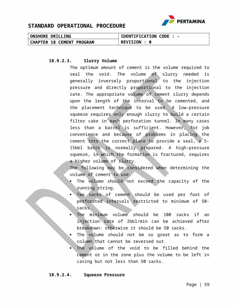
STANDARD OPERATIONAL PROCEDUREONSHORE DRILLING IDENTIFICATION CODE : -
REVISION : 0CHAPTER 18 CEMENT PROGRAM
18.9.2.3. Slurry VolumeThe optimum amount of cement is the volume required toseal the void. The volume of slurry needed isgenerally inversely proportional to the injectionpressure and directly proportional to the injectionrate. The appropriate volume of cement slurry dependsupon the length of the interval to be cemented, andthe placement technique to be used. A low-pressuresqueeze requires only enough slurry to build a certainfilter cake in each perforation tunnel. In many casesless than a barrel is sufficient. However, for jobconvenience and because of problems in placing thecement into the correct place to provide a seal, a 5-15bbl batch is normally prepared. A high-pressuresqueeze, in which the formation is fractured, requiresa higher volume of slurry.The following may be considered when determining thevolume of cement to use. The volume should not exceed the capacity of the
running string. Two sacks of cement should be used per foot of
perforated intervals restricted to minimum of 50-sacks.
The minimum volume should be 100 sacks if aninjection rate of 2bbl/min can be achieved afterbreakdown: otherwise it should be 50 sacks.
The volume should not be so great as to form acolumn that cannot be reversed out.
The volume of the void to be filled behind thecement or in the zone plus the volume to be left incasing but not less than 50 sacks.
18.9.2.4. Squeeze Pressure
Page | 59
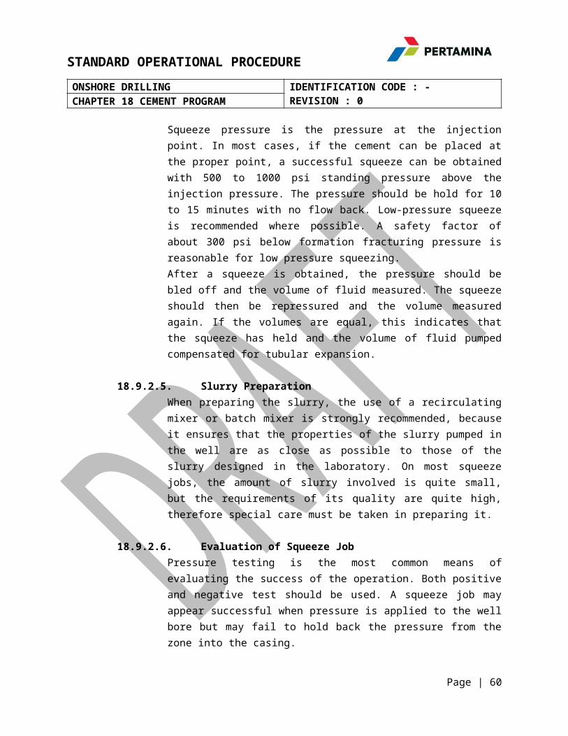
STANDARD OPERATIONAL PROCEDUREONSHORE DRILLING IDENTIFICATION CODE : -
REVISION : 0CHAPTER 18 CEMENT PROGRAM
Squeeze pressure is the pressure at the injectionpoint. In most cases, if the cement can be placed atthe proper point, a successful squeeze can be obtainedwith 500 to 1000 psi standing pressure above theinjection pressure. The pressure should be hold for 10to 15 minutes with no flow back. Low-pressure squeezeis recommended where possible. A safety factor ofabout 300 psi below formation fracturing pressure isreasonable for low pressure squeezing.After a squeeze is obtained, the pressure should bebled off and the volume of fluid measured. The squeezeshould then be repressured and the volume measuredagain. If the volumes are equal, this indicates thatthe squeeze has held and the volume of fluid pumpedcompensated for tubular expansion.
18.9.2.5. Slurry PreparationWhen preparing the slurry, the use of a recirculatingmixer or batch mixer is strongly recommended, becauseit ensures that the properties of the slurry pumped inthe well are as close as possible to those of theslurry designed in the laboratory. On most squeezejobs, the amount of slurry involved is quite small,but the requirements of its quality are quite high,therefore special care must be taken in preparing it.
18.9.2.6. Evaluation of Squeeze JobPressure testing is the most common means ofevaluating the success of the operation. Both positiveand negative test should be used. A squeeze job mayappear successful when pressure is applied to the wellbore but may fail to hold back the pressure from thezone into the casing.
Page | 60

STANDARD OPERATIONAL PROCEDUREONSHORE DRILLING IDENTIFICATION CODE : -
REVISION : 0CHAPTER 18 CEMENT PROGRAM
The universally recognized technique for confirmingwhether the cement in place will hold the formationfluids under producing conditions consist of applyinga negative differential pressure on the face of theplugged perforations.Positive pressure testAfter the W.O.C time, test the cement by applyingrequired surface pressure for checking integrity ofthe perforation squeezed. The pressure applied at theface of the perforation is predetermined at the jobdesign stage. It may be the reservoir pressure orpressure equal to future working pressure in the wellfrom fracturing or acidizing treatments but should notexceed the formation fracturing pressure.Negative pressure testA negative test or differential pressure testing ofthe well bore may be obtained either by swabbing andlowering the fluid level or by displacing work overfluid with some lighter fluid. Negative pressure testshould be conducted using pressure no greater than theexpected maximum drawdown in the well when it is putinto production.When the objective of the squeeze is to repair aprimary cement job, the normal cement log (CBL/VDL)should be run to evaluate the effectiveness of therepair by comparing pre-squeeze and post squeeze logs.
18.9.2.7. Misconception in Squeeze Cementing The cement slurry penetrates the pores of the rock
Only the mix-water and dissolved substancespenetrate the pores, while the solids accumulate atthe formation face and form the filter cake. Itwould require a permeability higher than 100 darcyfor the cement grains to penetrate a sandstone
Page | 61
STANDARD OPERATIONAL PROCEDUREONSHORE DRILLING IDENTIFICATION CODE : -
REVISION : 0CHAPTER 18 CEMENT PROGRAM
matrix. The only way for slurry to penetrate aformation is through fractures and large holes.
High pressure is needed to obtain a good squeezeIf the formation fracturing pressure is exceeded,control of the placement of the slurry is lost, andthe slurry enters unwanted areas. Pressure is of nohelp to place the slurry in all the desiredlocation. Once created, a fracture may extendacross various zones, and open unwanted channels ofcommunications between previously isolated zones.
Plugged perforationIt is rare to find all perforations open andproducing. Perforations will usually have somedegree of mud fill up, depending on the completion,fluid. Mud filter cake is capable of withstandinghigh pressure differentials especially in thedirection from the well bore to the formation andthe high pressures may create a fracture beforeaccepting cement filtrate. Many squeeze failure maybe attributed to subsequent clean up of apreviously plugged perforation which did not acceptthe cement slurry during the squeeze job.
18.9.2.8. Squeeze Cementing Procedure18.9.2.8.1. Low Pressure Squeeze Cementing
1. Consult a CBL / VDL log prior to squeeze job.2. Decide the point of perforation and perforate
against a permeable formation at least 6 to 8Shots (Gun Perforation) per foot for achievingbetter intake.
3. Carry out injectivity test in water. Ifinjectivity is found to be poor, acid job may berequired to improve injectivity.
Page | 62

STANDARD OPERATIONAL PROCEDUREONSHORE DRILLING IDENTIFICATION CODE : -
REVISION : 0CHAPTER 18 CEMENT PROGRAM
4. For low pressure squeeze cementing, follow allthe standards as given for a normal cement plugjob so as to spot the slurry against theperforated interval.
5. Then pull out drill string sufficiently above thecement top.
6. Close BOP and apply pressure through drill stringto squeeze cement.
7. Squeeze calculated volume of slurry and close thewell under pressure for 4 hrs.
18.9.2.8.2. Block Squeeze Cementing1. For block squeeze perforate 2 sets of perforation
i.e. above and below the cement retainer.2. If the poor bondage is continuous for a longer
section, decide to carry out block squeeze usinga cement retainer.
3. Establish circulation through cement retainerbehind casing with water or cleaned fluid toensure good clean up of the channels.
4. Maintain the down hole treating pressure belowthe formation fracture pressure when carrying outinjectivity test or establishing circulationbehind casing.
5. Calculate slurry volume keeping intoconsideration the annular volume and slurryrequired below cement retainer.
6. Use spacers ahead and behind cement slurry for aminimum length of 50 to 75m to avoidcontamination.
7. While displacement monitor free falling /U tubingof cement slurry by controlling through choke.Displace cement up to the tip of cement retainerso as to keep the cement inside the string and
Page | 63

STANDARD OPERATIONAL PROCEDUREONSHORE DRILLING IDENTIFICATION CODE : -
REVISION : 0CHAPTER 18 CEMENT PROGRAM
engage tubing string to retainer, and squeeze tocirculate out cement between the twoperforations.
8. Disengage the string from retainer and balancethe plug. Pull out the string above the top ofperforations, reverse wash and squeeze cement inthe upper perforation (optional) and keep thewell under final squeeze pressure.
18.9.2.8.3. Water /Gas Shut Off Squeeze1. For elimination of water intrusion or reduction
of gas oil ratio this squeeze cementing iscarried out to seal all the perforations and thenre-perforate a selected interval.
2. All procedures that of low pressure squeezecementing are to be followed for placement ofcement slurry against the perforated interval.
3. In case of good injectivity, squeeze calculatedvolume of slurry into the perforations leaving acement plug inside the casing. Squeezing to bedone by hesitation method, so that final squeezepressure is achieved.
4. In case of no injectivity, squeeze cement slurryat the maximum permissible squeezing pressure andclose the well under squeeze pressure for 4hours.
18.10. Cementing Safety GuidelinesThis cementing guideline is intended to standardize cementingprocedures and safety aspects with a view to improve planning,execution and evaluation areas related to cementing servicesand to reduce occurrences of accidents. The cementing of oil well is an important and highly criticaloperation which is accomplished in a relatively short period of
Page | 64

STANDARD OPERATIONAL PROCEDUREONSHORE DRILLING IDENTIFICATION CODE : -
REVISION : 0CHAPTER 18 CEMENT PROGRAM
time. Utmost care should be taken to follow established safetyregulations to avoid any untoward accident during cementation.Following are some distinctive features /areas of safetyconcern associated with cementing operations.a. Simultaneous presence of a large crew of different
disciplines makes coordination extremely essential.b. Several liquid chemicals and cementing additives used in
cementation can cause safety hazards which needs properprecautions while handling.
c. High pressure and air pressure involved in cementing jobexecution.
d. Simultaneous running of all equipment creating high level ofnoise pollution.
e. Special attention is required when cementation is beingcarried out in night time.
18.10.1. Pre-Departure Checks of Mobile Cementing Equipment1. Oil level, HSD level, Radiator water level, Steering
hydraulic oil level, battery connections, tyrepressure etc. are to be checked.
2. After initial warm up of engine, check engine oilpressure, water temperature, air pressure, brakeapplication, auto electrical light indications etc.
3. Fire extinguisher, spark arrestor in engine’s exhaustpipes and a first-aid kit should be there in allcementing vehicles.
4. Accessories like high pressure lines, valves, swivels,jet mixers, rubber hoses etc. should be clamped andfastened to avoid any loss and third party injurywhile plying the cementing vehicle on road.
Page | 65

STANDARD OPERATIONAL PROCEDUREONSHORE DRILLING IDENTIFICATION CODE : -
REVISION : 0CHAPTER 18 CEMENT PROGRAM
5. While lifting the cab of cementing vehicle for chassisengine check-up/ repair, no person should be allowedto stand underneath the charging pump till the cabinis locked and properly clamped in position.
18.10.2. Safety During on Land Cementation1. Onshore cementing operator should be well conversant
with traffic signals, road safety rules andregulations to minimize road accident.
2. One should never attempt to perform work or drive avehicle when he is impaired by alcohol or drugs.
3. While reversing a cementing vehicle, one should becertain that the sides and backing area is clear. Oneshould not reverse a vehicle at the facility or on thework location without a guide.
4. One should use the prescribed personal protectivesafety kits like overhaul, hardhats, safety glasses,hard-toed shoes, hand gloves etc. Wearing of rings,bracelets or neck chains should be avoided while onoil field duty and in repair/ maintenance garage.
5. A pre-job planning meeting should be held to ensureproper job layout and placement of cementing equipmentfollowing all safety procedures.
6. Mobile cementing equipment positioning should beplanned for quick removal from the work area in caseof an emergency. All vehicles should be placed withcabin facing away from the well and wooden wedgesupport should be placed behind wheels to minimize
Page | 66

STANDARD OPERATIONAL PROCEDUREONSHORE DRILLING IDENTIFICATION CODE : -
REVISION : 0CHAPTER 18 CEMENT PROGRAM
vibrations and movement of line while pumpingoperation.
7. Place cementing pump / bunkers / mobile silos at least1.5 - 2 m apart from other cementing vehicles and atleast 25 m distance from the well head.
8. Park all vehicles which are not required for the jobto safe areas from the well head so as not to blockthe well site exits.
9. In hooking of high pressure lines from cementingunits, avoid crossing of two discharge lines. Linesshould not be run under cementing trucks. Ensureproper anchoring of high pressure lines to preventaccident in case of line failure.
10. Use sufficient number of chicksans to providemore flexibility to discharge lines for reducingvibrations during cementing operations.
11. Do not suspend discharge lines from cementinghead without safety chains. Inclined or verticaldischarge lines should be tied off to prevent themfrom being dragged.
12. Use only high pressure fittings and approvedsteel pipes which are in good condition and thoroughlyinspected.
13. Cementing heads, manifolds, valves and plugsshould be inspected, cleaned and lubricated prior tohooking up. Always clean an oil line connection beforemaking up cementing lines.
Page | 67
STANDARD OPERATIONAL PROCEDUREONSHORE DRILLING IDENTIFICATION CODE : -
REVISION : 0CHAPTER 18 CEMENT PROGRAM
14. The cementing operational in-charge mustsupervise line hook up work and thoroughly inspectprior to testing lines.
15. Care should be taken to avoid damage to thethreaded pin end and stopper of cementing head duringhandling and tightening to the casing. Cementing headmust be secured to the links by safety chains.
16. Thread protectors must be used on all exposedmale threads of circulating subs or cementing heads toavoid thread damage.
17. Only steel lines should be used for releasingpressure and checking back flow from the wells.
18. In electrical rigs, all cementing equipmentshould be earthed to the derrick structure to avoidany electrical shock accident. Electrical poweredcementing skid unit should also be earthed properly.
19. Cementing head, safety valves and high pressurelines of cementing units should be checked foroperation at stipulated pressure to ensure operationalsafety and NDT should be carried out at an interval of3 years.
18.10.3. Pumping Job1. All valves in discharge lines shall be checked
properly to see that they are open before orders aregiven to start pumping.
2. No pumping should take place while any personnel isworking on, above or below floor level.
Page | 68

STANDARD OPERATIONAL PROCEDUREONSHORE DRILLING IDENTIFICATION CODE : -
REVISION : 0CHAPTER 18 CEMENT PROGRAM
3. Flammable or combustible fluids are not to be placedin open displacement tanks on cementing equipment.
4. Acid pumping with cementing units should be avoided,if possible. In case it cannot be avoided, make extrasure that all the valves, caps, lines etc. are fittedcorrectly and also the least number of people shouldbe present in the vicinity. After the job, thecementing unit and the lines should be washedthoroughly so as to remove any traces of acid.
5. When pumping into any system : Be sure that you have an accurate pressure gauge. Be alert for closed valves also. Start slowly with little throttle to confirm that
system is open.
6. A pressure-chart to record pumping pressurecontinuously should be made available for allcementing jobs. Pressure chart should be supplementedwith pumping sequence volume, time and rate.
7. Surface pumping pressure should not exceed the lowestpressure rating of the union and / or whateverconnections used such as chicksans, valves, cross-overetc.
8. When transferring or venting material through an openended hose, a “T” shall be affixed to the end of thehose to prevent the hose from whipping around. The endof the hose should be secured tightly to a stationaryobject.
Page | 69

STANDARD OPERATIONAL PROCEDUREONSHORE DRILLING IDENTIFICATION CODE : -
REVISION : 0CHAPTER 18 CEMENT PROGRAM
9. Cement bunker or mobile cement silo loaded with cementshould be kept on jacks at drill site when parked.
10. During slurry, mixing, chemical preparations,adequate precautions must be taken to avoid chemical /additive contact with skin, eyes and clothing. Fumesof defoamer should not be inhaled while using. Whenhandling cement additives, appropriate safety goggles,respirators, dust or vapor masks, face shield, rubbergloves, shoes and hearing protection should be worn.
11. Fluid loss, retarder and dispersant, additivesfor cement do not contain hazardous ingredients.
12. Primary routes of their entry in human body is byskin contact, eye contact, inhalation and ingestion.Material safety data sheet should be made available atwork-center while handling cement additives. Reviewmethod and hazard of handling, transferring andchemical mixing as well as proper mixing sequence.
13. Proper illumination with adequate flame prooflighting arrangements should be provided in theoperational area especially at slurry mixing point andadditive mixing system to ensure safe and effectivejob coordination during night time.
18.10.4. Rig Down1. Before dismantling the line, pressure must be released
to zero. Pressurized line should not be hammered.Tightening or loosening of connections under pressureis strictly prohibited.
Page | 70

STANDARD OPERATIONAL PROCEDUREONSHORE DRILLING IDENTIFICATION CODE : -
REVISION : 0CHAPTER 18 CEMENT PROGRAM
2. After pumping has been completed, all pumps, lines andhoses will be flushed before rigging down. All valvesand caps on all piping of each unit shall be opened orremoved to allow complete drainage of any fluid in theunits piping. Piping choked with cement slurry maydamage cementing equipment and lead to majorbreakdown.
3. The air pressure in pneumatic bulk silo / mobilecement silo should be relieved before the vehicles aremoved off to location.
4. Transportation of chicksans, high pressure lines,valves, swivels, hoses with end connections from rigfloor to ground should be done by winch line only.Throwing down these equipment from derrick floor mustbe prohibited.
18.10.5. Safety in Cement Bulk Handling Plant1. All cement silos and other pressurized vessels should
be emptied and pressure tested at the specific rating.Safety valves and pressure gauges attached to eachvessel should be checked for proper functioning.
2. If any leakage is observed during pressure testing ofsilos, it should be rectified immediately on toppriority.
3. Valves in pipe lines should also be checked for properisolation.
4. Proper functioning of air dryer should be ensured toget rid of moisture in the air line to silos with aview to prevent cement lump in the system and provideconsistent dry cement supply for slurry mixing.
Page | 71
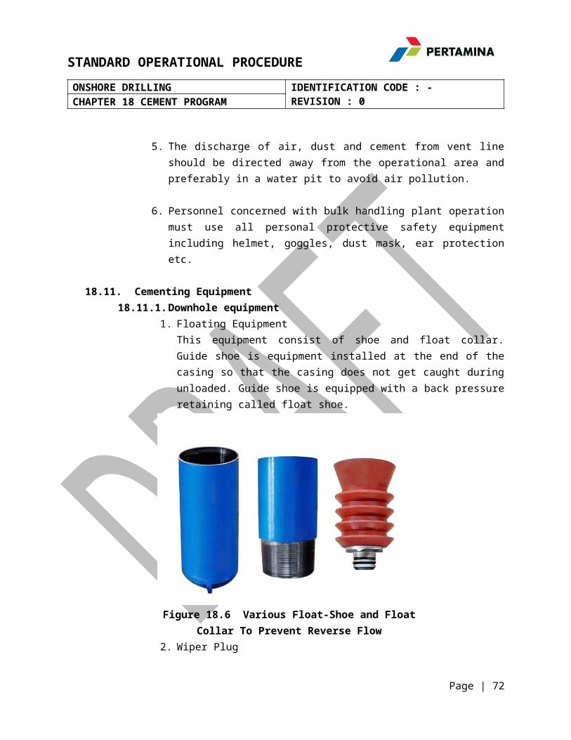
STANDARD OPERATIONAL PROCEDUREONSHORE DRILLING IDENTIFICATION CODE : -
REVISION : 0CHAPTER 18 CEMENT PROGRAM
5. The discharge of air, dust and cement from vent lineshould be directed away from the operational area andpreferably in a water pit to avoid air pollution.
6. Personnel concerned with bulk handling plant operationmust use all personal protective safety equipmentincluding helmet, goggles, dust mask, ear protectionetc.
18.11. Cementing Equipment18.11.1.Downhole equipment
1. Floating EquipmentThis equipment consist of shoe and float collar.Guide shoe is equipment installed at the end of thecasing so that the casing does not get caught duringunloaded. Guide shoe is equipped with a back pressureretaining called float shoe.
Figure 18.6 Various Float-Shoe and FloatCollar To Prevent Reverse Flow
2. Wiper Plug
Page | 72

STANDARD OPERATIONAL PROCEDUREONSHORE DRILLING IDENTIFICATION CODE : -
REVISION : 0CHAPTER 18 CEMENT PROGRAM
Wiper plug is a plug that is used to clean the wallsof the casing of the drilling mud. This plug isdivided into two, the top plug and bottom plug.Bottom plug serves to encourage the mud in the casingwhile the top plug is used to urge the cement columnin the casing so that the cement can be to spot thelocation of cementing.
Figure 18.7 Wiper Plug to insulatethe mixing of Cement and Mud
3. ScratchersScratchers is cleaning equipment wellbore wall of mudcake so that cement can be attached directly to the walland avoid channeling formation (hole between cement andformation channel). There are several kinds to use thistool, by twisting (rotating) or by pulling down(reciprocating).
Page | 73

STANDARD OPERATIONAL PROCEDUREONSHORE DRILLING IDENTIFICATION CODE : -
REVISION : 0CHAPTER 18 CEMENT PROGRAM
Figure 18..8 Scratcher for Cleaning Wall of hole Wells4. Centralizer
Centralizer is a tool to put the casing exactly in themiddle of the wellbore in order to obtain the samedistance between the wall with the wall of the wellborecasing. Installation of this tool on the casing isusually by means of welded (welding). The placement ofthe casing in the wellbore as much as possible is locatedin the middle to avoid channeling.
Figure 18.9 Centralizer to make casing in Middle
Page | 74

STANDARD OPERATIONAL PROCEDUREONSHORE DRILLING IDENTIFICATION CODE : -
REVISION : 0CHAPTER 18 CEMENT PROGRAM
5. Landing collarServes to insulate and capture the liner wiper plug,preventing it from rising back to the top of the hole, toinsulate the pressure from below and to prevent it fromspinning out while drilling (drill-out).
Figure 18.10 Landing Collar6. Packer Bore Receptacle
Commonly called Bore Receptacle polished which is athick-walled tube with an inner diameter of teeth and theinside is smooth which is usually coated with TFE toprevent the attachment of cement or other materials,thereby reducing friction and corrosion.
Page | 75
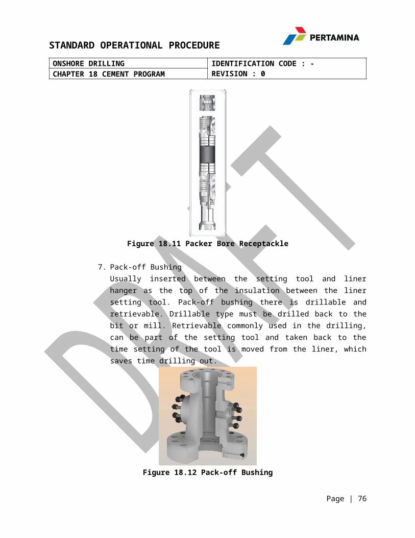
STANDARD OPERATIONAL PROCEDUREONSHORE DRILLING IDENTIFICATION CODE : -
REVISION : 0CHAPTER 18 CEMENT PROGRAM
Figure 18.11 Packer Bore Receptackle
7. Pack-off BushingUsually inserted between the setting tool and linerhanger as the top of the insulation between the linersetting tool. Pack-off bushing there is drillable andretrievable. Drillable type must be drilled back to thebit or mill. Retrievable commonly used in the drilling,can be part of the setting tool and taken back to thetime setting of the tool is moved from the liner, whichsaves time drilling out.
Figure 18.12 Pack-off Bushing
Page | 76

STANDARD OPERATIONAL PROCEDUREONSHORE DRILLING IDENTIFICATION CODE : -
REVISION : 0CHAPTER 18 CEMENT PROGRAM
8. Pump Down Plug Dropping Head Dan Cementing ManifoldAnchored at the top of the drill pipe. Manifold is usedto assist in the mud and cement pumping time into thedrill pipe and hold down pump to pump down plug behindthe cement plug is released. (Figure 18-8)
Figure 18.13 Pump Down Plug Dropping Head
Page | 77

STANDARD OPERATIONAL PROCEDUREONSHORE DRILLING IDENTIFICATION CODE : -
REVISION : 0CHAPTER 18 CEMENT PROGRAM
9. Liner SwivelIs a tool used for the liner stuck in the open hole or inthe hole where the hanger is not straight barrel spinningdifficult. By using this tool rotates liner will not,just the liner hanger and setting tool are rotating.(Figure 18-11)
Figure 18.14 Liner Swivel
18.11.2.Surface equipment
1. MixerThis tool, in principle, is to bring the slurry ofcement and water with very high speed (jet system)through a venturi flow causing turbulence which makesthe mixing process to be perfect.
Page | 78

STANDARD OPERATIONAL PROCEDUREONSHORE DRILLING IDENTIFICATION CODE : -
REVISION : 0CHAPTER 18 CEMENT PROGRAM
Figure 18.15 Jet-Mixer For Mixing Cement and CementWater Being Suspension
2. Cement PumpCement pump used for pumping a cement slurry down thewell. Commonly used pumps are double-acting pistonpumps duplex or triplex single acting plunger pump.Plunger pump is commonly used as the exit rate ismore uniform slurry with considerable pressure.Sometimes pumping the recirculating mixer puttogether in a single place that is easily moveable.This is referred to as a mobile cementing equipment.
Page | 79

STANDARD OPERATIONAL PROCEDUREONSHORE DRILLING IDENTIFICATION CODE : -
REVISION : 0CHAPTER 18 CEMENT PROGRAM
Figure 18.16 Plunger Pump Can It was found In Cementing
3. Plug ContainersPlug container as the top and bottom cementing plug placed above and below the cement slurry.
Figure 18.17 Cementing Head To Store Before CementWiper Plug Removable
4. Casing Cementing HeadThis tool serves as a media liaison between the pipecementing of casing and pump cement into a place toput the plug (top and bottom plug). With the casingcementing head is then mud can be circulated by the
Page | 80

STANDARD OPERATIONAL PROCEDUREONSHORE DRILLING IDENTIFICATION CODE : -
REVISION : 0CHAPTER 18 CEMENT PROGRAM
insistence of the bottom plug to the bottom of thecasing and the cement slurry loaded on it beforependesakan by top plug begins.
Figure 18.18 Cementing Head / Head Plug Conditioner For Saving Cement Wiper Plug Before Removable
18.7.
Page | 81