Chapter 2 - Incinerators and Oxidizers - US Environmental ...
70
Chapter 2 Incinerators and Oxidizers John L. Sorrels Air Economics Group, OAQPS U.S. Environmental Protection Agency Research Triangle Park, NC 27711 Amanda Baynham, David Randall, and Cindy Hancy Research Triangle Institute Research Triangle Park, NC 27709 November 2017
-
Upload
khangminh22 -
Category
Documents
-
view
0 -
download
0
Transcript of Chapter 2 - Incinerators and Oxidizers - US Environmental ...
Chapter 2
Incinerators and Oxidizers
John L. Sorrels
Air Economics Group, OAQPS
U.S. Environmental Protection Agency
Research Triangle Park, NC 27711
Amanda Baynham, David Randall, and Cindy Hancy
Research Triangle Institute
Research Triangle Park, NC 27709
November 2017

i
Contents
Chapter 2 ........................................................................................................................................... 2-1
Incinerators and Oxidizers ................................................................................................................ 2-1
2.1 Introduction ........................................................................................................................ 2-1
2.2 Process Description ............................................................................................................ 2-3
2.2.1 Solid Waste Incinerators ........................................................................................ 2-6
2.2.2 Thermal Oxidizers ............................................................................................... 2-10
2.2.3 Catalytic Oxidizers............................................................................................... 2-16
2.2.4 Other Considerations: Packaged versus Field-Erected Units, Auxiliary
Equipment
.............................................................................................................................. 2-22
2.2.5 Technology Comparison ...................................................................................... 2-24
2.3 General Treatment of Material and Energy Balances ...................................................... 2-25
2.4 Design Procedures ........................................................................................................... 2-26
2.4.1 Steps Common to Thermal and Catalytic Units .................................................. 2-27
2.4.2 Steps Specific to Thermal Units .......................................................................... 2-31
2.4.3 Steps Specific to Catalytic Units.......................................................................... 2-36
2.5 Cost Analysis for Thermal and Catalytic Oxidizers ........................................................ 2-40
2.5.1 Estimating Total Capital Investment ................................................................... 2-40
2.5.2 Estimating Total Annual Cost .............................................................................. 2-49
2.5.3 Cost Comparison for Example Case .................................................................... 2-53
2.6 Cost Analysis for Incinerators ......................................................................................... 2-54
Appendix A: Properties of Selected Compounds .......................................................................... 2-59
Appendix B: Design Procedure for Non-Recuperative Thermal oxidizers .................................. 2-63
List of Figures
Figure 2.1: Thermal Oxidizer - General Case ................................................................................. 2-10
Figure 2.2: Regenerable-Type/Thermal oxidizer .......................................................................... 2-14
Figure 2.3: Recuperative Catalytic Oxidizer .................................................................................. 2-19
Figure 2.4: Equipment Costs of Thermal Oxidizers, Recuperative ............................................... 2-42
Figure 2.5: Equipment Costs of Thermal Oxidizers, Regenerative .............................................. 2-44
Figure 2.6: Equipment Cost of Catalytic Oxidizers, Fixed-Bed ................................................... 2-44
Figure 2.7: Equipment Costs of Catalytic Oxidizers, Fluid-Bed ................................................... 2-45
Figure 2.8: Equipment Costs Comparison of Incinerator Types .................................................. 2-45
ii
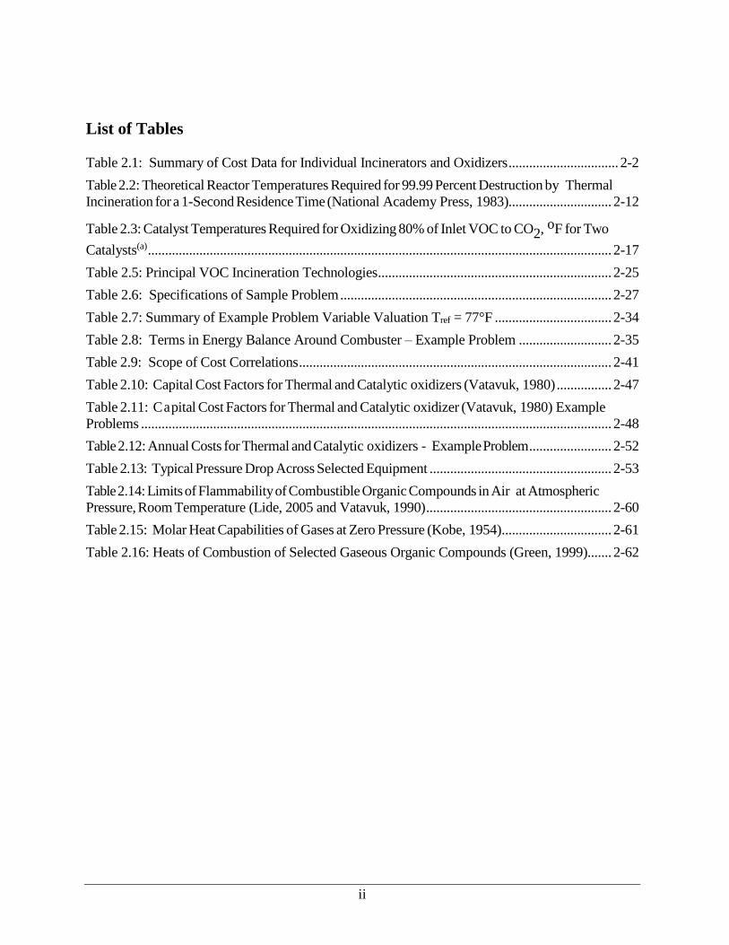
List of Tables
Table 2.1: Summary of Cost Data for Individual Incinerators and Oxidizers ................................ 2-2
Table 2.2: Theoretical Reactor Temperatures Required for 99.99 Percent Destruction by Thermal
Incineration for a 1-Second Residence Time (National Academy Press, 1983).............................. 2-12
Table 2.3: Catalyst Temperatures Required for Oxidizing 80% of Inlet VOC to CO2, oF for Two
Catalysts(a) ....................................................................................................................................... 2-17
Table 2.5: Principal VOC Incineration Technologies .................................................................... 2-25
Table 2.6: Specifications of Sample Problem ............................................................................... 2-27
Table 2.7: Summary of Example Problem Variable Valuation Tref = 77°F .................................. 2-34
Table 2.8: Terms in Energy Balance Around Combuster – Example Problem ........................... 2-35
Table 2.9: Scope of Cost Correlations ........................................................................................... 2-41
Table 2.10: Capital Cost Factors for Thermal and Catalytic oxidizers (Vatavuk, 1980) ................ 2-47
Table 2.11: Capital Cost Factors for Thermal and Catalytic oxidizer (Vatavuk, 1980) Example
Problems ......................................................................................................................................... 2-48
Table 2.12: Annual Costs for Thermal and Catalytic oxidizers - Example Problem ........................ 2-52
Table 2.13: Typical Pressure Drop Across Selected Equipment ..................................................... 2-53
Table 2.14: Limits of Flammability of Combustible Organic Compounds in Air at Atmospheric
Pressure, Room Temperature (Lide, 2005 and Vatavuk, 1990) ...................................................... 2-60
Table 2.15: Molar Heat Capabilities of Gases at Zero Pressure (Kobe, 1954) ................................ 2-61
Table 2.16: Heats of Combustion of Selected Gaseous Organic Compounds (Green, 1999)....... 2-62
2-1
2.1 Introduction
In this context, the terms “incineration” and “oxidation” refer to several different thermal
treatments of organic substances in waste materials. The term incineration is generally used to
describe a process for the combustion of solid and liquid wastes, such as hazardous, medical,
municipal, or sewage waste. With respect to gaseous waste streams containing volatile organic
compounds (VOCs) and/or organic hazardous air pollutants (HAP), the terms “incinerator” and
“oxidizer” are often used interchangeably and generally refer to the use of thermal or catalytic
oxidizers.1 The U.S. Environmental Protection Agency defines any organic compound to be a
VOC unless it is specifically determined to have negligible photochemical reactivity.2 Indeed, a
number of commonly used organics (e.g., acetone, methane, and methylene chloride) are
specified as not being VOCs and some non-VOC organic compounds (e.g., methylene chloride)
are listed as hazardous air pollutants pursuant to section 112(b)(2) of the Clean Air Act. This
distinction is important since emissions of VOCs and HAP are regulated, while both VOC and
non-VOC organic compounds are combustible and are therefore important in the design of the
incinerator or oxidizer. For convenience, we use the term “VOC” in the remainder of the chapter
to refer to both VOC and volatile organic HAP.
Incineration, like carbon adsorption, is one of the best-known waste treatment methods
for industrial gas. Carbon adsorption allows recovery of organic compounds that may have value
as commodity chemicals. In contrast, however, incineration is an ultimate disposal method in
that the combustible compounds in the waste gas are destroyed rather than collected. A major
advantage of incineration is that virtually any gaseous organic stream can be incinerated safely
and cleanly, provided proper engineering design and management are used. In some applications,
waste heat from the oxidizer can be recovered and used in other processes or converted to
electric power.
The main types of thermal oxidizers are direct fire, catalytic, recuperative, and
regenerative. Historically, the most commonly used is the regenerative thermal oxidizer (RTO),
although recuperative thermal oxidizers are becoming more common (ICAC, 2016). Table 2.1
provides capital cost estimates for thermal oxidizers in several industry source categories.
1 Incinerators should not be confused with flares. Flaring is a combustion control process for in which the gases are
piped to a remote, usually elevated, location and burned in an open flame in the open air using a specially designed
burner tip, auxiliary fuel, and steam or air to promote mixing for nearly complete destruction. For more information
on flares, please review the Flares chapter in the EPA Air Pollution Control Cost Manual. 2 Volatile organic compound (VOC) is defined in 40 CFR 51.100, which also provides a list of organic compounds
that are excluded because they have been determined to have negligible photochemical reactivity.

2-2
Table 2.1: Summary of Cost Data for Individual Incinerators and Oxidizers
Source Category Unit Type
Flow to
Incinerator Units
Capital
Cost ($)
Total Annualized
Cost ($) Year Comments Reference
Portland Cement RTO 502,312 dscfm 25,280,000 7,970,758 2010 Cost based on costs of an RTO installed on an existing kiln. Total
capital investment includes direct (DC) and indirect costs (IC) estimated based on Cost Manual.
EPA 2010
Plywood
Composite - MIN
RTO 7,587 dscfm NA 358,359 2002 Estimated cost based on RTO cost algorithm developed using: (1)
information provided by an RTO vendor with numerous RTO installations at PCWP plants, and (2) the Control Cost Manual.
The RTO cost algorithm was used to determine RTO total capital
investment (TCI) and total annualized cost (TAC) based on the exhaust flow to be controlled and annual operating hours of 8,000
hours per year.
EPA 2002
Plywood Composite -
MAX
RTO 79,483 dscfm NA 599,447 2002
Plywood
composite
RTO 50,000 dscfm 924,699 NA 1997 Purchased equipment cost based on data provided by vendor.
100,000 dscfm 1,350,204 NA
200,000 dscfm 2,201,214 NA
Aerospace RTO w/out Concentrator
60,000 acfm NA 347,282 2014 RTO quote from Epcon. Cost were in $/ton 3
Aerospace RTO w/ Zeolite
Concentrator
60,000 acfm NA 367,276 2014 Concentrator quote from Anguil. Cost were in $/ton
Spray Finishing RTO 200,000 scfm 3,300,000 1,050,000 ~2008 4
Spray Finishing RTO w/ concentrator
12,000 scfm 2,500,000 300,000 ~2008
Spray Finishing RTO w/ conc. & recirculator
3,000 scfm 820,000 42,000 ~2008
Semiconductor RCTO - CO
Catalyst
7600 scfm 121,440 69,208 2014 Based on manufacturer cost information 5
Ethanol Plant RTO 44,500 scfm 850,000 NA 2005 TO manufacturer
6 Ethanol Plant Recuperative
TO (50%)
57,200 scfm 1,000,000 NA 2005 TO manufacturer
Specialty Med
products
Recuperative
TO (65%)
1,500 scfm 145,000 NA ~2006 Capital cost is equipment cost only Nester
Tire cord coating RTO 25,000 scfm 450,000 NA ~2006
Sewage sludge
incineration
Fluid Bed
Incinerator
4 dry
tons/hour
$75 million NA 2010 Capital cost for 3 fluid bed incinerators, each with capacity 4 dry
tons/hour. Units burn undigested sludge and are autogenous. Costs
are total for permitting and construction.
7
3 See http://www.ecy.wa.gov/programs/air/psd/PSD_PDFS/Final_Boeing_777X_TSD_PSD_14-01_09092014.pdf. 4 Presentation prepared by Catalytic Combustion, “Air Emissions Control in Spray Finishing Applications. 5 See http://www.oregon.gov/deq/NWR/Documents/IntelType4permitAppl.pdf. 6 See http://www3.epa.gov/chp/documents/voc_destruction_white_paper.pdf. 7 See http://projectgroundwork.org/sustainability/op_enviro/incinerator.html.
2-3
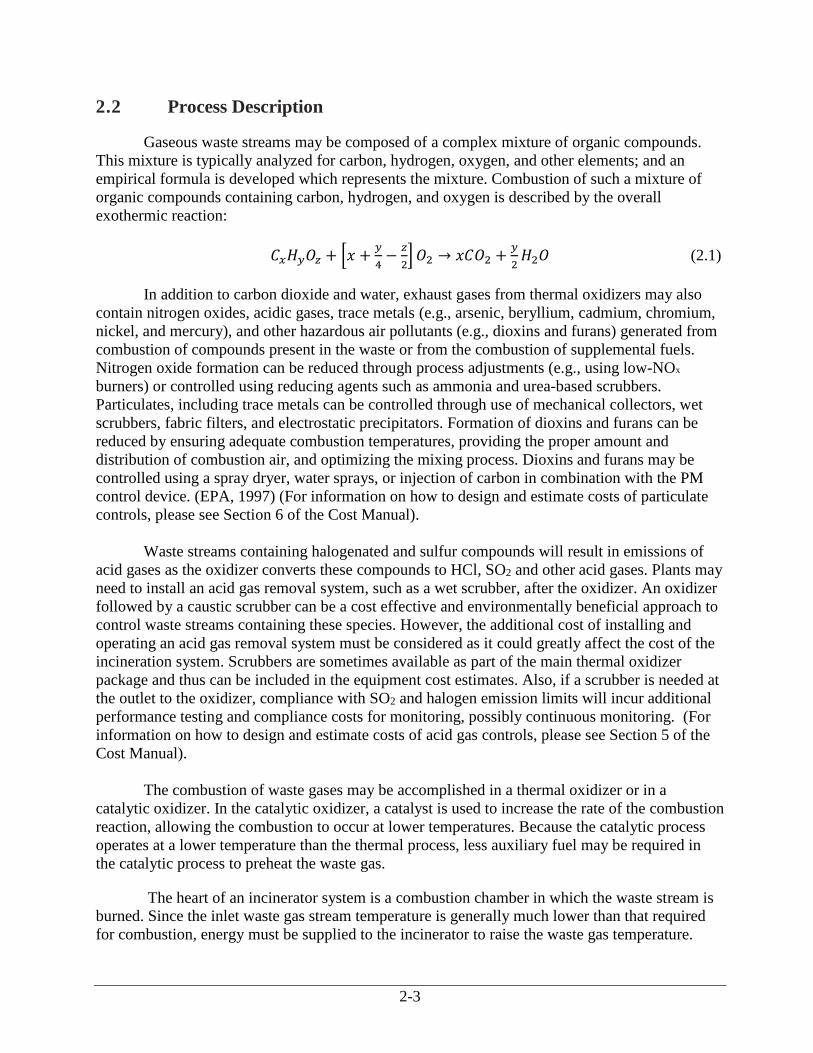
2.2 Process Description
Gaseous waste streams may be composed of a complex mixture of organic compounds.
This mixture is typically analyzed for carbon, hydrogen, oxygen, and other elements; and an
empirical formula is developed which represents the mixture. Combustion of such a mixture of
organic compounds containing carbon, hydrogen, and oxygen is described by the overall
exothermic reaction:
𝐶𝑥𝐻𝑦𝑂𝑧 + [𝑥 +𝑦
4−
𝑧
2] 𝑂2 → 𝑥𝐶𝑂2 +
𝑦
2𝐻2𝑂 (2.1)
In addition to carbon dioxide and water, exhaust gases from thermal oxidizers may also
contain nitrogen oxides, acidic gases, trace metals (e.g., arsenic, beryllium, cadmium, chromium,
nickel, and mercury), and other hazardous air pollutants (e.g., dioxins and furans) generated from
combustion of compounds present in the waste or from the combustion of supplemental fuels.
Nitrogen oxide formation can be reduced through process adjustments (e.g., using low-NOx
burners) or controlled using reducing agents such as ammonia and urea-based scrubbers.
Particulates, including trace metals can be controlled through use of mechanical collectors, wet
scrubbers, fabric filters, and electrostatic precipitators. Formation of dioxins and furans can be
reduced by ensuring adequate combustion temperatures, providing the proper amount and
distribution of combustion air, and optimizing the mixing process. Dioxins and furans may be
controlled using a spray dryer, water sprays, or injection of carbon in combination with the PM
control device. (EPA, 1997) (For information on how to design and estimate costs of particulate
controls, please see Section 6 of the Cost Manual).
Waste streams containing halogenated and sulfur compounds will result in emissions of
acid gases as the oxidizer converts these compounds to HCl, SO2 and other acid gases. Plants may
need to install an acid gas removal system, such as a wet scrubber, after the oxidizer. An oxidizer
followed by a caustic scrubber can be a cost effective and environmentally beneficial approach to
control waste streams containing these species. However, the additional cost of installing and
operating an acid gas removal system must be considered as it could greatly affect the cost of the
incineration system. Scrubbers are sometimes available as part of the main thermal oxidizer
package and thus can be included in the equipment cost estimates. Also, if a scrubber is needed at
the outlet to the oxidizer, compliance with SO2 and halogen emission limits will incur additional
performance testing and compliance costs for monitoring, possibly continuous monitoring. (For
information on how to design and estimate costs of acid gas controls, please see Section 5 of the
Cost Manual).
The combustion of waste gases may be accomplished in a thermal oxidizer or in a
catalytic oxidizer. In the catalytic oxidizer, a catalyst is used to increase the rate of the combustion
reaction, allowing the combustion to occur at lower temperatures. Because the catalytic process
operates at a lower temperature than the thermal process, less auxiliary fuel may be required in
the catalytic process to preheat the waste gas.
The heart of an incinerator system is a combustion chamber in which the waste stream is
burned. Since the inlet waste gas stream temperature is generally much lower than that required
for combustion, energy must be supplied to the incinerator to raise the waste gas temperature.
2-4
Often, the energy released by the combustion of the total organics (VOCs and others) in the waste
gas stream is not sufficient to raise its own temperature to the desired levels. In these cases,
auxiliary fuel (e.g., natural gas) must be added to raise the temperature.
Auxiliary fuel requirements may also be decreased, and energy efficiency improved, by
providing heat exchange between selected inlet streams and the effluent stream. The effluent
stream containing the products of combustion, along with any inert compounds that may have
been present in or added to the inlet streams, can be used to preheat the incoming waste stream,
auxiliary air, or both via a “primary”, or recuperative, heat exchanger. The fractional energy
recovery by the preheater or primary heat exchanger is defined as follows:
𝐹𝑟𝑎𝑐𝑡𝑖𝑜𝑛𝑎𝑙𝐸𝑛𝑒𝑟𝑔𝑦
𝑅𝑒𝑐𝑜𝑣𝑒𝑟𝑦=
𝐸𝑛𝑒𝑟𝑔𝑦 𝑎𝑐𝑡𝑢𝑎𝑙𝑙𝑦 𝑟𝑒𝑐𝑜𝑣𝑒𝑟𝑒𝑑 𝑓𝑙𝑢𝑒 𝑔𝑎𝑠
𝑀𝑎𝑥𝑖𝑚𝑢𝑚 𝑒𝑛𝑒𝑟𝑔𝑦 𝑟𝑒𝑐𝑜𝑣𝑒𝑟𝑎𝑏𝑙𝑒 𝑖𝑓 𝑓𝑙𝑢𝑒 𝑔𝑎𝑠 𝑎𝑝𝑝𝑟𝑜𝑎𝑐ℎ𝑒𝑠 𝑙𝑜𝑤𝑒𝑠𝑡 𝑡𝑒𝑚𝑝𝑒𝑟𝑎𝑡𝑢𝑟𝑒 𝑎𝑣𝑎𝑖𝑙𝑎𝑏𝑙𝑒 𝑡𝑜 ℎ𝑒𝑎𝑡 𝑒𝑥𝑐ℎ𝑎𝑛𝑔𝑒𝑟
(2.2)
The energy actually recovered, the numerator of Equation 2.2, is the increase in sensible
heat of the gas, e.g., waste gas or waste gas plus dilution air, being heated. The maximum energy
recoverable would be the decrease in sensible heat of the flue gas, if it were cooled to the
temperature of the incoming waste gas. While this maximum energy recovery would be attained
only with a very large heat exchanger, the concept of fractional energy recovery is useful in
expressing the extent of the improvement in energy efficiency using a “primary” heat exchanger.
Energy efficiency can be further improved by placing another (“secondary”) exchanger
downstream of the primary exchanger to recover additional energy from the effluent stream (e.g.,
to generate low pressure process steam or hot water). Secondary energy recovery can be
economically advantageous where there is a use for the steam or hot water. However, secondary
energy recovery is generally not used unless there is a specific on-site use for it.
The majority of industrial gases that contain VOCs are dilute mixtures of combustible
gases in air. In some applications, such as air oxidation processes, the waste gas stream is very
deficient in oxygen. Depending on the oxygen content of the waste stream, auxiliary air may be
required to combust the total organic content of the waste gas as well as any auxiliary fuel that
has been used.
The concentration of combustible gas in the waste gas stream plays an integral role in the
design and operation of an incinerator. From a cost standpoint, the amount of air in excess of the
stoichiometric amounts should be minimized. For safety reasons, however, any mixture within the
flammability limits, on either the fuel-rich or fuel-lean side of the stoichiometric mixture, presents
an unacceptable fire hazard as a feed stream to the incinerator. The lower, or fuel-lean, explosive
limit (LEL) of a given organic compound defines the minimum concentration of that compound
in air that can produce more energy than is needed to raise its own temperature to the ignition
point. Similarly, the upper, or fuel-rich, explosive limit (UEL) represents the highest
concentration of the organic in air that is ignitable. In the latter case, the amount of available
oxygen in the air limits the reaction. Both the LEL and the UEL are measured at standard
temperature and pressure. The LEL and heating values for some commonly used organic
compounds are shown in Table 2.13. Typically, the waste gas stream contains a mixture of
2-5
hydrocarbons in air. For a typical hydrocarbon mixture, the heating value would be approximately
50 Btu/scf at the LEL (Vatavuk, 1990).
Since the majority of industrial waste gases that contain VOCs are dilute mixtures of
combustible gases in air, their heating values are low and their oxygen content exceeds that
required to combust both the waste organics (VOCs and others) and the auxiliary fuel. If a waste
gas above 50 percent LEL (about 25 Btu/scf) is encountered, it must be diluted to satisfy fire
insurance regulations. Generally, the streams are diluted to below 25 percent LEL, although
concentrations from 25 percent to 50 percent are permitted provided the waste stream is
continuously monitored by LEL monitors. Because air is the usual diluent gas, care must be taken
with preheating the diluted stream so that it remains below about 1200oF. (See discussion below
on preheating.) Tables showing LEL, UEL, and heats of combustion for selected organic
compounds are provided in Appendix A.
Currently, some regenerative and catalytic oxidizers include “self-sustaining” features that
operate without auxiliary fuel while processing waste gas streams with organic content greater
than 3 to 10% of the LEL. These units use two sets of heat absorbing ceramic media beds with
excellent thermal energy recovery characteristics. The first set of ceramic media heats the inlet
gas, while the second set recovers thermal energy generated during combustion. The direction of
gas flow is periodically reversed so that the outlet ceramic bed becomes the inlet bed and vice
versa. This system enables high levels of thermal energy to be recovered. Some manufacturers
report thermal energy recovery rates as high as 97 percent. This high rate of recovery significantly
reduces fuel consumption and reportedly allows some units to operate without auxiliary fuel after
initial startup.8
The goal of any incineration system is to control by thermal destruction the amount of
VOCs released to the environment. Performance of a control device such as an oxidizer can be
described by a destruction and removal efficiency (DRE) in percent (%), defined according to the
following equation:
DRE = [𝐼𝑛𝑙𝑒𝑡 𝑚𝑎𝑠𝑠 𝑟𝑎𝑡𝑒 𝑉𝑂𝐶−𝑂𝑢𝑡𝑙𝑒𝑡 𝑚𝑎𝑠𝑠 𝑟𝑎𝑡𝑒 𝑉𝑂𝐶
𝐼𝑛𝑙𝑒𝑡 𝑚𝑎𝑠𝑠 𝑟𝑎𝑡𝑒 𝑉𝑂𝐶] × 100
It is important to note, however, that incomplete combustion of the inlet VOCs could
result in the formation of other VOCs not originally present. For example, the incomplete
oxidation of dichloroethane can yield vinyl chloride. Both of these compounds are VOCs. The
definition given in Equation 2.3 would still be meaningful, however, as long as the newly formed
VOC (e.g., vinyl chloride) is detected. This situation necessitates the complete chemical analysis
of the inlet and outlet gas streams to confirm compliance with state and Federal regulations.
The outlet VOC concentration, usually in parts per million by volume (ppmv), is
sometimes used to assess the performance of an oxidizer. The outlet VOC concentration is
typically used to assess performance for sources subject to regulatory limits on the outlet VOC
concentration, rather than a percent reduction limit.
8 See http://www.anguil.com/oxidizers/regenerative-thermal.aspx
2-6
Equipment life for an oxidizer is variable and depends on several factors, including the
system design and materials used in its construction, composition of the waste gas stream, and the
temperatures experienced by the oxidizer. In general, oxidizers that handle corrosive waste gases
or higher levels of particulates will have a shorter operational life. Systems that undergo frequent
fluctuations in temperature or more frequent startup-shutdown cycles will have a shorter
operational life than systems where a steady temperature is maintained.
There are several different oxidizer designs available. These designs can be broadly
classified as thermal systems and catalytic systems. Thermal systems may be direct flame
incinerators with no energy recovery, flame incinerators with a recuperative heat exchanger, or
regenerative systems that operate in a cyclic mode to achieve high energy recovery. Catalytic
systems include fixed-bed (packed-bed or monolith) systems and fluid-bed systems, both of
which provide for energy recovery.
Solid waste incinerators operate in a similar manner to oxidizers but receive solid and
liquid waste, instead of waste gas streams. There are six different designs of solid waste
incinerators, all of which use thermal energy to combust waste materials and destroy VOC and
HAP. These designs are grate incinerators (fixed or moving), rotary kilns, multiple hearth
incinerators, fluid bed incinerators, controlled-air, and excess air incinerators.
Oxidizers and incinerators vary in size. They may be small, prefabricated, modular
designs or large units that must be constructed onsite. Some of the larger units, particularly those
used to combust municipal waste, include heat recovery systems that can be used for steam and/or
electricity production. The following sections discuss design aspects of these systems.
2.2.1 Solid Waste Incinerators
Solid waste incinerators typically emit hazardous air pollutants, including dioxin, furan,
mercury, lead, cadmium, and other heavy metals. For this reason, solid waste incinerators are
generally fitted with air pollution controls, such as afterburners to reduce carbon monoxide
emissions, scrubbers to remove particulates and acid gases, filters (e.g., electrostatic precipitators,
cyclones, or baghouses) to remove particulates, and dry sorbent injection for acid gas control. The
types of pollution controls used depend on the composition of the wastes burned and on the
design of the solid waste incinerator. For example, fluidized bed incinerators can control NOx by
using lower temperatures at which NOx do not form, while sulfur dioxide emissions are
controlled by mixing sulfur absorbing materials (e.g., limestone or dolomite) into the fluid bed
medium.
There are several different designs of solid waste incinerators. A description of each type
is included below.
Fixed Grate Incinerators
Fixed grate incinerators consist of a fixed metal grate over an ash pit. Waste is loaded
either from the side or top, and ash removed from the bottom. Many small incinerators used to
combust municipal waste have the fixed grate design.
2-7
Moving Grate Incinerators
In a moving grate incinerator, waste is loaded onto a moving metal grate that moves
through the combustion chamber and deposits ash into a pit at the other end. Air is supplied
through the grate from below and through air nozzles located above the grate to provide mixing of
gases and surplus oxygen to ensure complete combustion. Operating temperatures are typically
maintained at 850 oC (1,560 oF) or higher to ensure complete destruction of toxic organic
materials. Moving grate incinerators are used to incinerate municipal waste.
Rotary Kilns
Rotary kilns are used to incinerate hazardous waste and hospital, medical, and infectious
waste. A rotary kiln consists of an inclined, cylindrical vessel that is rotated slowly about its
longitudinal axis. Waste material is fed into the upper end of the vessel and gradually moves to
the lower end and is gradually mixed and organic material combusted. Depending on the design,
gasses from the combustion process move either in the same direction as the waste or in the
opposite direction. The kiln is usually equipped with an auxiliary burner that is used to start
combustion and maintain the combustion temperature. Rotary kilns are generally also equipped
with a secondary chamber, where combustion of volatile organic compounds generated in the
rotary kiln are combusted in excess air. Because the waste is rotated in the primary combustion
chamber, rotary kilns typically have higher particulate emissions than other incinerator designs
and are usually equipped with scrubbers, fabric filtration systems, or electrostatic precipitators for
particulates.
Multiple Hearth Incinerators
Multiple hearth incinerators are used to incinerate sewage sludge from wastewater
treatment plants. They consist of a cylindrical vessel constructed of steel and lined with
refractory. Inside are a series of horizontally stacked refractory-lined hearths. The typical multiple
hearth incinerator has 5 to 12 hearths, with 9 hearths required for complete combustion. The
upper hearth tiers are the drying zone, the middle tiers the combustion zone, and the bottom tiers
the ash cooling zone. A hollow cast iron shaft passes through the center of the vessel through
which air is pumped from the bottom of the vessels to the hearths above before exiting the vessels
at the top. Some or all exiting air is recirculated to the bottom of the vessel, while additional
ambient air is sometimes pumped into the middle hearth tiers to ensure complete combustion.
Rotating arms equipped with teeth (called rabble arms) are located above the hearths. Dewatered
sludge is fed into the top of the vessels onto the outer edge of the first tier of hearths. The rabble
arms on the upper tier gradually move the sludge from the outside of the vessel to the inside,
where it drops through holes onto the hearth below. On the second tier hearth, the rabble arms
move the waste from the inside to the outside of the vessel, where the sludge drops through to the
next level. The process is repeated through the various hearth tiers until ash is discharged through
the bottom of the vessel. Auxiliary heat is provided by burners located on the sides of hearths.
Process gases are exhausted through the top of the unit at temperatures between 427 and 760oC
(800 and 1,400oF). Temperatures in the combustion zone maintained at about 482oC (900oF) and
75 to 100 percent excess air is used to ensure complete combustion of the sludge. The dewatered
sludge consists of between 15 to 35 percent solids. Detention times for solids varies from less
than 1 hour to 3 hours, while gas detention times are 1 to 3 seconds. If the sludge is dewatered to
about 30 percent, the combustion process can be self-sustaining provided the heat value of the
2-8
solids is sufficient. However, supplemental fuel is required for initial start-up and during periods
when the heating value of the solids is low (EPA 1995 and 2003). In recent years, most multiple
hearth incinerators are being replaced with more efficient fluidized bed incinerators.
Fluidized Bed Units
Fluidized bed units are generally used for sewage sludge incineration. They consist of a
vertical steel vessel, lined with refractory material and equipped with air nozzles located on the
floor of the vessel. A mixture of fuel, waste, sand, and other materials (e.g., limestone to control
sulfur dioxide) are fed into the lower part of the vessel, while the jets of air agitate and mix the
particles into a fluid-like suspension. The sand is typically between 0.8 to 1.0 meters (2.5 to 3
feet) thick. The result is a fluidized bed of mixed gases and solids that promotes heat transfer and
chemical reactions. The injected air may be at ambient temperatures or preheated by passing
through a heat exchanger where heat from exhausted gas is used to raise the temperature of the
ambient air (EPA 1995).
The fluidized bed is maintained at temperatures between 760 to 871oC (1,400 and 1,600 oF) (EPA 2003), which results in the evaporation of water and combustion of organic materials. In
the area above the fluidized bed, any remaining carbon and combustible gases are burned. The
gases are vented at temperatures between 760 and 870 oC (1,500 and 1,600oF). Fluidized bed
incinerators use less fuel and can operate with lower excess air than other incinerators. Fluidized
bed incinerators typically operate with 20 to 50 percent excess air (EPA 1995 Retention times for
solids vary from 1 to 5 minutes, while gas retention times are between 6 and 8 seconds (EPA
2003).
Due to the lower operating temperatures, NOx emissions are generally lower than for other
incinerators; however, carbon monoxide (CO) and other emissions (e.g., HAP) may be higher due
to less complete combustion resulting from the lower combustion temperatures. For this reason,
fluidized bed incinerators are sometimes fitted with afterburners to control CO emissions.
Because of the lower emissions, most new sewage sludge incinerators are fluidized bed
incinerators (EPA 1993). Sewage sludge incinerators are typically fitted with wet flue gas
desulfurization (FGD) scrubbers to reduce mercury emissions in compliance with new source
performance standard (NSPS), emissions guideline (EG), and federal implementation plan (FIP)
that became final in 2016.9
Controlled-Air Incinerators
Controlled-air incinerators (sometimes called starved-air incinerators) are used to
incinerate municipal solid waste and medical waste (e.g., hospital, medical, and infectious
wastes). These units consist of two chambers. The primary combustion chamber is operated at
temperatures of 760 to 980oC (1,400 to 1,800oF) with air supplied from beneath the waste bed.
The air is supplied at less than the stoichiometric amount of oxygen required for combustion. The
secondary combustion chamber is operated with excess air at temperatures of 980 to 1,095oC
(1,800 to 2,000oF) (EPA 1993). Waste is fed into the primary combustion chamber, where it is
9 These final rules were set for mercury and eight other pollutants under section 129 of the Clean Air Act. These rules
are contained in a Federal Register notice available at https://www.gpo.gov/fdsys/pkg/FR-2016-04-29/pdf/2016-
09292.pdf.

2-9
dried and most residual carbon is burned. Volatile organics generated in the primary chamber
enter the second chamber, where the higher temperatures and excess air ensure complete
combustion. The secondary chamber is sometimes equipped with auxiliary burners located at the
entrance to the chamber to help maintain the combustion temperature when wastes with low
heating values are combusted. Controlled-air incinerators are generally not equipped with
emissions controls because the flue gas tends to have low levels of particulates due to the
relatively low air flow rates and the secondary chamber reduces CO emissions.
Excess-Air Incinerators
Excess air incinerators are small, typically batch units that are used to incinerate municipal
solid waste and hospital, medical, and infectious wastes. They are generally operated at excess air
levels up to 300 percent. Although designs vary, they generally consist of two or more chambers
and baffles. Waste is fed into the primary combustion chamber, where the waste is dried and
combusted by the primary chamber burner. Combustion gases, volatile materials, and water
vapor exhaust to the secondary chamber. The secondary chamber is equipped with additional
burners and an air injection port. The secondary chamber is typically maintained at a temperature
between 870 and 980oC (1,600 and 1,800oF) (EPA 1993).
Mass Burn-Waterwall Units
Mass burn-waterwall combustion units are used to incinerate municipal solid waste
(MSW) and are the preferred design for large municipal waste combustors (MWC). They range in
size from 46 to 900 Mg/day (50 to 1,000 tons per day). The units are similar to the moving grate
incinerator discussed above. They consist of primary combustion chamber with grate and a
secondary chamber. The upper walls of the primary combustion chamber are equipped with metal
tubes that contain circulating pressurized water used to recover heat from the combustion
chamber. Heat is also recovered in secondary sections of the combustor. The recovered heat is
used to produce steam and/or electricity. Waste is fed into a feed hopper by overhead cranes and
then transferred to the combustion chamber either by gravity feeders or hydraulic rams.
Reciprocating grates or roller grates are then used to move the waste through the various stages of
the combustion chamber. In the first stage, the moisture content of the waste is reduced prior to
ignition. The second stage, referred to as the burning grate, is where the majority of active
burning takes place. The last stage, referred to as the burnout or finishing grate, is where
remaining combustibles in the waste are burned. Ash is discharged from the finishing grate into a
water-filled ash quench pit or ram discharger. Air is supplied both from beneath the grate and
through rows of high-pressure nozzles located in the side walls of the combustion chamber. The
combustion chambers are typically operated with 80 to 100 percent excess air (EPA 1996).
Mass Burn Rotary Waterwall Units
Mass burn-refractory kilns are used to incinerate MSW. They range in size between 180 to
2,400 Mg/day (200 to 2,700 tons per day) and use a rotary combustion chamber followed by a
waterwall furnace. The rotary combustion chamber operates in the same manner as the rotary kiln
described above. However, in mass burn rotary waterwall units, the rotary combustion chamber is
equipped with water-filled tubes for heat recovery. The waste is fed into the inclined rotary
combustion chamber using hydraulic rams. Air is injected both from beneath and above the waste
bed, with most of the combustion air supplied in the first half of the rotary combustion chamber.
2-10
The rest of the combustion air is supplied to the afterburner grate and above the rotary combustor
outlet in the furnace. They are typically operated at about 50 percent excess air. As with the mass
burn waterwall units, recovered heat is used for steam and/or electricity production (EPA 1996).
2.2.2 Thermal Oxidizers
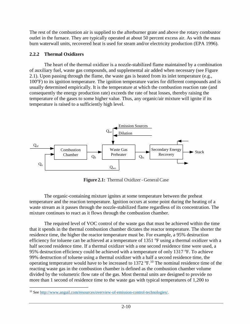
The heart of the thermal oxidizer is a nozzle-stabilized flame maintained by a combination
of auxiliary fuel, waste gas compounds, and supplemental air added when necessary (see Figure
2.1). Upon passing through the flame, the waste gas is heated from its inlet temperature (e.g.,
100oF) to its ignition temperature. The ignition temperature varies for different compounds and is
usually determined empirically. It is the temperature at which the combustion reaction rate (and
consequently the energy production rate) exceeds the rate of heat losses, thereby raising the
temperature of the gases to some higher value. Thus, any organic/air mixture will ignite if its
temperature is raised to a sufficiently high level.
Figure 2.1: Thermal Oxidizer - General Case
The organic-containing mixture ignites at some temperature between the preheat
temperature and the reaction temperature. Ignition occurs at some point during the heating of a
waste stream as it passes through the nozzle-stabilized flame regardless of its concentration. The
mixture continues to react as it flows through the combustion chamber.
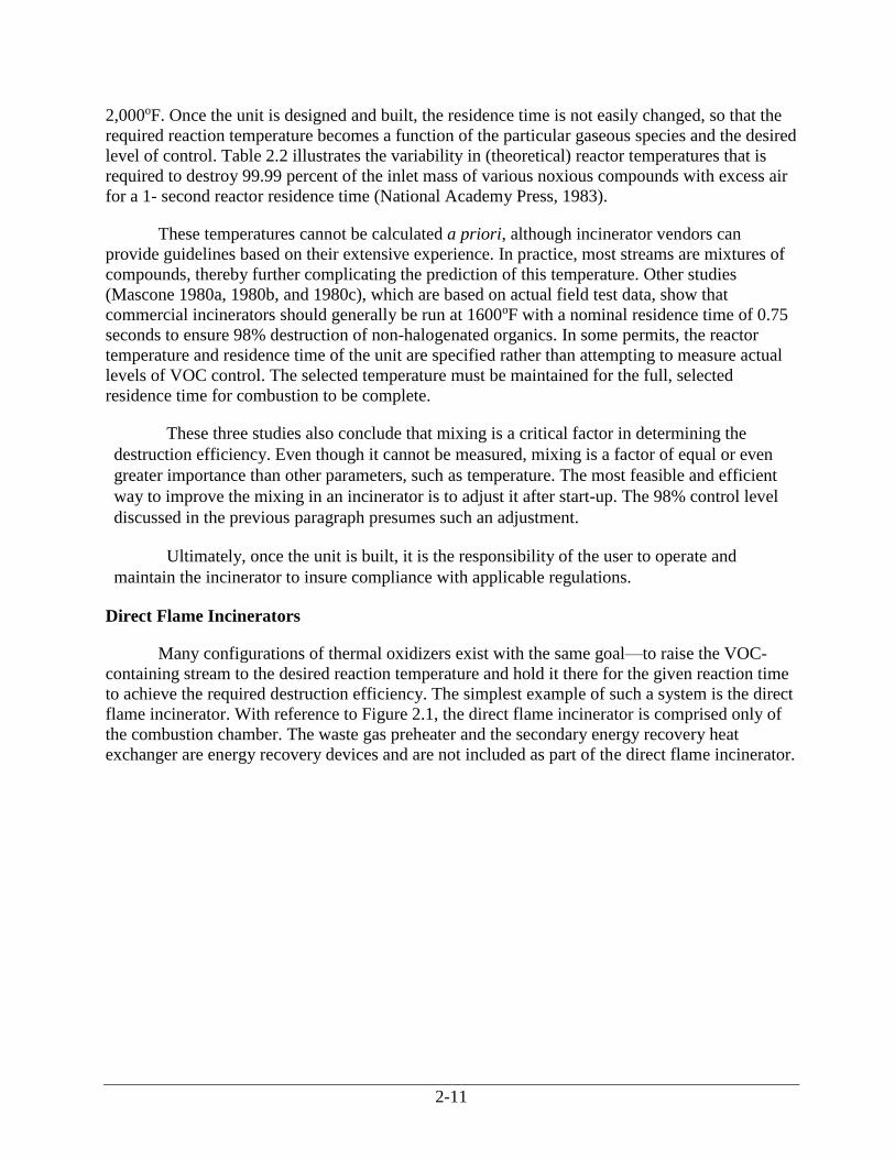
The required level of VOC control of the waste gas that must be achieved within the time
that it spends in the thermal combustion chamber dictates the reactor temperature. The shorter the
residence time, the higher the reactor temperature must be. For example, a 95% destruction
efficiency for toluene can be achieved at a temperature of 1351 oF using a thermal oxidizer with a
half second residence time. If a thermal oxidizer with a one second residence time were used, a
95% destruction efficiency could be achieved with a temperature of only 1317 oF. To achieve
99% destruction of toluene using a thermal oxidizer with a half a second residence time, the
operating temperature would have to be increased to 1372 oF.10 The nominal residence time of the
reacting waste gas in the combustion chamber is defined as the combustion chamber volume
divided by the volumetric flow rate of the gas. Most thermal units are designed to provide no
more than 1 second of residence time to the waste gas with typical temperatures of 1,200 to
10 See http://www.anguil.com/resources/overview-of-emission-control-technologies/.
Combustion
Chamber
Waste Gas
Preheater
Secondary Energy
Recovery
Emission Sources
Qa
Stack
Dilution
Qaf
Qfi Qfo
Qwo
Qwi
2-11
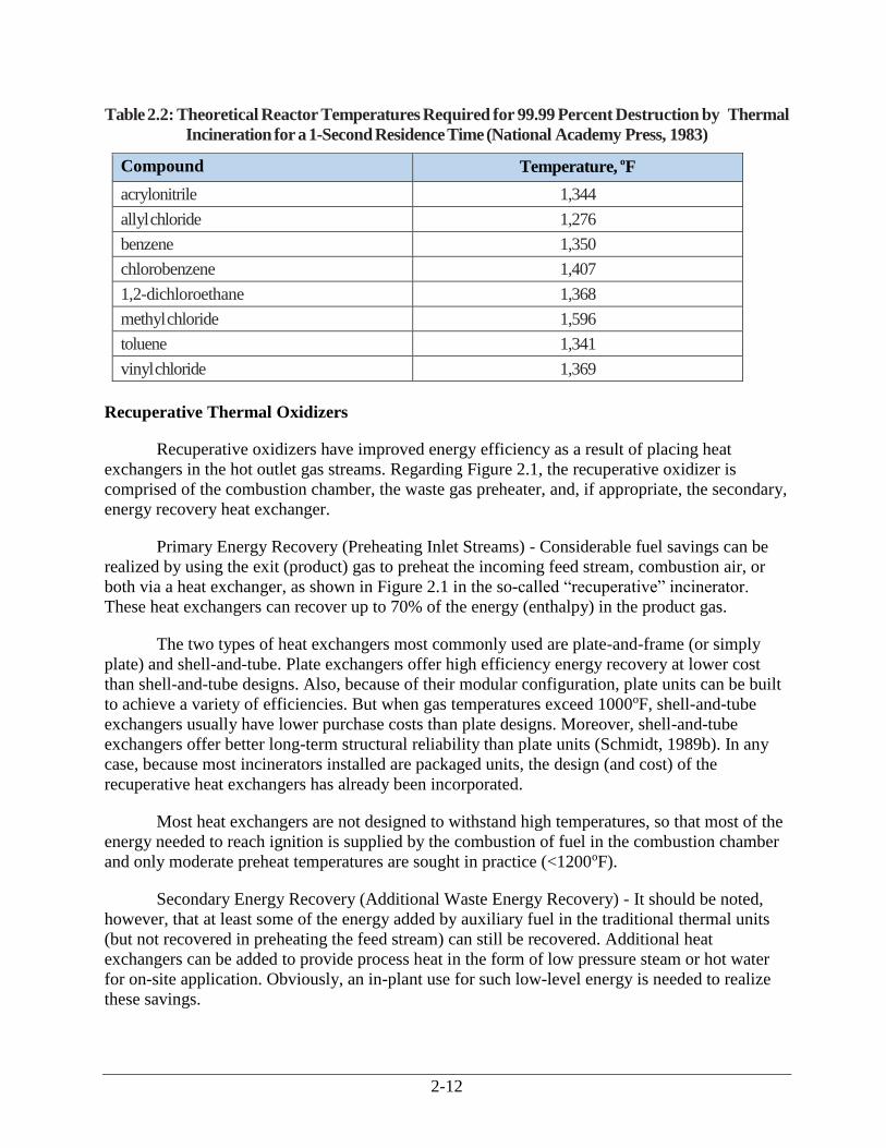
2,000oF. Once the unit is designed and built, the residence time is not easily changed, so that the
required reaction temperature becomes a function of the particular gaseous species and the desired
level of control. Table 2.2 illustrates the variability in (theoretical) reactor temperatures that is
required to destroy 99.99 percent of the inlet mass of various noxious compounds with excess air
for a 1- second reactor residence time (National Academy Press, 1983).
These temperatures cannot be calculated a priori, although incinerator vendors can
provide guidelines based on their extensive experience. In practice, most streams are mixtures of
compounds, thereby further complicating the prediction of this temperature. Other studies
(Mascone 1980a, 1980b, and 1980c), which are based on actual field test data, show that
commercial incinerators should generally be run at 1600oF with a nominal residence time of 0.75
seconds to ensure 98% destruction of non-halogenated organics. In some permits, the reactor
temperature and residence time of the unit are specified rather than attempting to measure actual
levels of VOC control. The selected temperature must be maintained for the full, selected
residence time for combustion to be complete.
These three studies also conclude that mixing is a critical factor in determining the
destruction efficiency. Even though it cannot be measured, mixing is a factor of equal or even
greater importance than other parameters, such as temperature. The most feasible and efficient
way to improve the mixing in an incinerator is to adjust it after start-up. The 98% control level
discussed in the previous paragraph presumes such an adjustment.
Ultimately, once the unit is built, it is the responsibility of the user to operate and
maintain the incinerator to insure compliance with applicable regulations.
Direct Flame Incinerators
Many configurations of thermal oxidizers exist with the same goal—to raise the VOC-
containing stream to the desired reaction temperature and hold it there for the given reaction time
to achieve the required destruction efficiency. The simplest example of such a system is the direct
flame incinerator. With reference to Figure 2.1, the direct flame incinerator is comprised only of
the combustion chamber. The waste gas preheater and the secondary energy recovery heat
exchanger are energy recovery devices and are not included as part of the direct flame incinerator.
2-12
Table 2.2: Theoretical Reactor Temperatures Required for 99.99 Percent Destruction by Thermal
Incineration for a 1-Second Residence Time (National Academy Press, 1983)
Compound Temperature, oF
acrylonitrile 1,344
allyl chloride 1,276
benzene 1,350
chlorobenzene 1,407
1,2-dichloroethane 1,368
methyl chloride 1,596
toluene 1,341
vinyl chloride 1,369
Recuperative Thermal Oxidizers
Recuperative oxidizers have improved energy efficiency as a result of placing heat
exchangers in the hot outlet gas streams. Regarding Figure 2.1, the recuperative oxidizer is
comprised of the combustion chamber, the waste gas preheater, and, if appropriate, the secondary,
energy recovery heat exchanger.
Primary Energy Recovery (Preheating Inlet Streams) - Considerable fuel savings can be
realized by using the exit (product) gas to preheat the incoming feed stream, combustion air, or
both via a heat exchanger, as shown in Figure 2.1 in the so-called “recuperative” incinerator.
These heat exchangers can recover up to 70% of the energy (enthalpy) in the product gas.
The two types of heat exchangers most commonly used are plate-and-frame (or simply
plate) and shell-and-tube. Plate exchangers offer high efficiency energy recovery at lower cost
than shell-and-tube designs. Also, because of their modular configuration, plate units can be built
to achieve a variety of efficiencies. But when gas temperatures exceed 1000oF, shell-and-tube
exchangers usually have lower purchase costs than plate designs. Moreover, shell-and-tube
exchangers offer better long-term structural reliability than plate units (Schmidt, 1989b). In any
case, because most incinerators installed are packaged units, the design (and cost) of the
recuperative heat exchangers has already been incorporated.
Most heat exchangers are not designed to withstand high temperatures, so that most of the
energy needed to reach ignition is supplied by the combustion of fuel in the combustion chamber
and only moderate preheat temperatures are sought in practice (<1200oF).
Secondary Energy Recovery (Additional Waste Energy Recovery) - It should be noted,
however, that at least some of the energy added by auxiliary fuel in the traditional thermal units
(but not recovered in preheating the feed stream) can still be recovered. Additional heat
exchangers can be added to provide process heat in the form of low pressure steam or hot water
for on-site application. Obviously, an in-plant use for such low-level energy is needed to realize
these savings.
2-13
The need for this higher level of energy recovery will be dependent upon the plant site.
The additional heat exchanger is often provided by the incineration unit vendor. The cost of this
additional heat exchanger may be estimated via standard heat exchanger correlations and should
be added to the costs estimated using the cost correlations in this section.
Regenerative Thermal Oxidizers
The traditional approach to energy recovery in the recuperative units (shown
schematically in Figure 2.1) still requires a significant amount of auxiliary fuel to be burned in the
combustion chamber when the waste gas heating values are too low to sustain the desired reaction
temperature at the moderate preheat temperature employed. Additional savings can, under these
conditions, be realized in units with more complete transfer of exit-stream energy. This is the
concept behind the so-called excess-enthalpy or regenerable burner systems (i.e., regenerative
thermal oxidizers (RTOs)). These systems use direct contact heat exchangers constructed of a
ceramic material that can tolerate the high temperatures needed to achieve ignition of the waste
stream. It has been reported that RTOs are the most widely used emission abatement technology
and that roughly 80 percent of all recent thermal oxidizer applications are RTOs.11,12
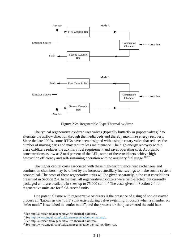
The operation of the regenerative system is illustrated in Figure 2.2. As shown in mode A
of Figure 2.2, the inlet gas first passes through the first hot ceramic bed thereby heating the stream
(and cooling the bed) to its ignition temperature. If the desired temperature is not attainable, a
small amount of auxiliary fuel is added in the combustion chamber. The hot gases then react
(releasing energy) in the combustion chamber and while passing through the second ceramic bed,
thereby heating it to the combustion chamber outlet temperature. When the temperature of the
outlet ceramic bed reaches a set temperature, the process flows are reversed so that the inlet gas is
now fed into the hot second ceramic bed and exits through the first ceramic bed, as shown in
mode B in Figure 2.2. This cyclic process affords very high energy recovery.13 While regenerative
oxidizers generally consist of two ceramic beds, three bed systems are available.14
11 Anguil. Regenerative Thermal Oxidizer (RTO). Available at “http://www.anguil.com/oxidizers/regenerative-
thermal-oxidizer-rto/. 12 Controlled Environment Equipment Corp. Regenerative Oxidizer Systems in Comprehensive Industrial Solutions.
Available at: “http://www.cee-corp.com/VentilationSystems/RegenerativeOxidizer”. 13 Some manufacturers claim thermal energy recoveries of 97 percent (See
http://www.anguil.com/oxidizers/regenerative-thermal.aspx). 14 See http://www.glenro.com/thermox-regenex.html.
2-14
Emission SourceAux Fuel
Emission SourceAux Fuel
First Ceramic Bed
Second Ceramic
Bed
Combustion
Chamber
Aux Air Mode A
Stack
First Ceramic Bed
Second Ceramic
Bed
Combustion
Chamber
Aux Air
Mode B
Stack
Figure 2.2: Regenerable-Type/Thermal oxidizer
The typical regenerative oxidizer uses valves (typically butterfly or poppet valves)15 to
alternate the airflow direction through the media beds and thereby maximize energy recovery.
Since the late 1990s, some RTOs have been designed with a single rotary valve that reduces the
number of moving parts and may require less maintenance. The high-energy recovery within
these oxidizers reduces the auxiliary fuel requirement and saves operating cost. At organic
concentrations as low as 3 to 4 percent of the LEL, some of these oxidizers achieve high
destruction efficiency and self-sustaining operation with no auxiliary fuel usage.16,17
The higher capital costs associated with these high-performance heat exchangers and
combustion chambers may be offset by the increased auxiliary fuel savings to make such a system
economical. The costs of these regenerative units will be given separately in the cost correlations
presented in Section 2.4. In the past, all regenerative oxidizers were field-erected, but currently
packaged units are available in sizes up to 75,000 scfm.18 The costs given in Section 2.4 for
regenerative units are for field-erected units.
One potential issue with regenerative oxidizers is the presence of a slug of non-destroyed
process air (known as the “puff”) that exists during valve switching. It occurs when a chamber on
“inlet mode” is switched to “outlet mode”, and the process air that just entered the cold face
15 See http://airclear.net/regenerative-rto-thermal-oxidizer/. 16 See http://www.anguil.com/oxidizers/regenerative-thermal.aspx. 17 See http://airclear.net/regenerative-rto-thermal-oxidizer/. 18 See http://www.anguil.com/oxidizers/regenerative-thermal-oxidizer-rto/.
2-15
plenum and the lower section of the heat recovery media reverses directions and is sent up the
stack. Such puffs limit the maximum DRE of the unit. Several techniques have been implemented
to minimize puffs. One technique is to minimize the volume and frequency of puffs with low
volume cold face plenum and highly efficient heat recovery media. Another technique is to use
three or more chambers. In these multi-chambered units the untreated gas is directed to the idle
third chamber and then bled through the combustion chamber instead of going directly to the
stack. Another way to control the “puff” is by purging chambers with clean air between inlet and
outlet modes with the purge gas sent to a third chamber.19
In recent years, a new system has been developed that uses a rotating distributor in place
of the valve and damper system. In this system, the packed ceramic honeycomb elements of the
heat exchanger are divided into sections and then rotated so that different sections of the heat
exchanger serve the cooling phase while another section serves the heating phase. The waste gas
flows through the RTO’s heat exchanger from the bottom to the top, thereby heating the waste gas
to the combustion temperature. The hot gases of combustion then flow down through the other
side of the rotating heat exchanger where the waste heat is absorbed. This design eliminates the
need for complicated valve and damper switching systems and is said to eliminate fluctuations in
flow caused by valve switching.20
Ceramic Media
Several different types of heat transfer media are used for RTOs; including random
packing, monolithic (honeycomb) structured block and corrugated structure packing.
Random packing uses a wide variety of packing materials, including gravel, ceramic balls
and shapes of all kinds which are randomly dumped into the RTO to form a media bed. Random
arrangement prevents nesting that would constrict flow and cause dead areas that collect
particulate. Ceramic “saddles” have proved to be the optimal shape for RTO random packing
because it minimizes pressure drop (for lower electricity consumption by the induction fan) and
maximizes surface area (for higher heat transfer efficiency). Recently, RTO media suppliers have
refined the design of ceramic saddles to provide a high open area and aerodynamic design that
limits nesting and reduces pressure drop by 20 percent compared to standard saddle media.
Monolith structure is a form of structured packing that is placed in a formal arrangement,
rather than randomly dumped. Cells extend through the block in a straight channel perpendicular
to the cold face. The advantage of this design is that it theoretically provides a straight,
aerodynamic channel for the air stream. The disadvantage is that if particulate plugs a channel at
the cold face, where the inflow enters the block, then this entire channel becomes a dead zone.
Vendors recommend adding particulate removal devices upstream of the RTO if the particulate
concentration is greater than 0.005 gr/dscf to 0.002 gr/dscf (Raemhild, 2001, and Nester, 2006).21
19 http://www.nestecinc.com/pdf/PuffReducationTech.pdf 20 http://www.eisenmann.com/en/products-and-services/environmental-technology/exhaust-air-purification.html. 21 gr/dscf = grains per dry standard cubic foot
2-16
Corrugated structured packing is constructed of corrugated sheets of ceramic. The angle of
inclination of the corrugations of adjacent sheets is reversed, ensuring excellent distribution of air
flow throughout the media bed. 22
Manufacturers of ceramic media are constantly developing or improving proprietary
products to optimize pressure drop, thermal efficiency, corrosion, plugging/fouling, and/or
surface area. Additionally, manufactures state that some of these new material compositions and
shapes in media can be substituted without modifying your existing unit or creating additional
installation hassles. 23
Developments to mitigate issues relating to varying VOC loads in gas streams are also
available and include air dilution and changing the switching cycle time. In some cases, a hot
bypass valve is used to direct the clean (hot) oxidizer exhaust around the heat recovery bed,
directly into the stack. Bypassing temporarily reduces the thermal efficiency, thereby allowing
higher solvent concentrations to be processed. 24
Another development in RTO operation yields an increase in the overall Btu value of the
process gas stream by injecting a controlled fuel or a premixed air and fuel mixture (controlled to
less than 25% of the LEL) directly into the process inlet of the RTO. This additional energy
reduces the energy demand on the burners, causing the burners to turn down and run at their low-
fire or pilot position, if included. Under this condition, significantly less combustion air and
natural gas is introduced directly into the combustion chamber than when the burners are
operating. Since the mass imbalance across the heat recovery chambers is virtually eliminated,
the measured overall effective thermal efficiency of the RTO unit is markedly improved, and the
fuel consumption reduced and the overall performance improved (Bunimovitch, 2010).25
2.2.3 Catalytic Oxidizers
Catalytic oxidizers operate very similar to thermal oxidizers, with the primary difference
that the gas, after passing through the flame area, passes through a catalyst bed. The catalyst
facilitates the overall combustion reaction given in Equation 2.1 by increasing the reaction rate,
enabling conversion at lower reaction temperatures than in thermal oxidizer units. Nevertheless,
the waste stream must be preheated to a temperature sufficiently high (usually from 300 to 900oF)
to initiate the oxidation reactions. The heated gas then passes through the catalyst bed. Oxygen
and VOC migrate to the catalyst surface by gas diffusion and are adsorbed onto the active sites on
the surface of the catalyst where oxidation then occurs. The oxidation reaction products are then
desorbed from the active sites by the gas and transferred by diffusion back into the gas stream.
The preheated gas stream is then passed over the catalyst bed. The chemical reaction
(combustion) between the oxygen in the gas stream and the gaseous pollutants takes place at the
catalyst surface.
22 http://www.reliableplant.com/Read/9117/thermal-oxidizers-particulate-buildup 23 http://www.norpro.saint-gobain.com/uploadedFiles/SGnorpro/Documents/RTO-HeatTransfer.pdf 24 http://www.epa.gov/cmop/docs/cmm_conference_sept09/07stone.pdf
http://airclear.net/regenerative-rto-thermal-oxidizer/ 25 http://www.nestecinc.com/november-2013-newsletter.html
http://www.anguil.com/case-studies/service-and-maintenance/rto-media-retrofit.aspx

2-17
Catalytic incineration can, in principle, be used to destroy essentially any oxidizable
compound in an air stream. However, there are practical limits to the types of compounds that can
be oxidized due to the poisoning effect some species have on the catalyst. These limits are
described below. In addition, most configurations require a low heating value of the inlet gas and
low particulate content. The particulate content threshold varies between catalysts and depends on
the pore size and volume of the catalyst.
The volumetric gas flow rate and the concentration of combustibles in the gas flowing to
the catalytic oxidizer should be constant for optimal operation. Large fluctuations in the flow rate
will cause the conversion of the VOCs to fluctuate also. Changes in the concentration or type of
organics in the gas stream can also affect the overall conversion of the VOC contaminants. These
changes in flow rate, organics concentration, and chemical composition are generally the result of
upsets in the manufacturing process generating the waste stream. In situations where the flow
rate, concentrations, and chemical composition frequently fluctuate, thermal oxidizers (discussed
earlier in this chapter) or carbon adsorption (discussed in Section 3.1 of this Manual) should be
evaluated as alternative control technologies.
As was the case for thermal units, it is impossible to predict a priori the temperature and
residence time (e.g., inverse space velocity) needed to obtain a given level of conversion of a
VOC mixture in a catalytic oxidation system. For example, Table 2.3 (Pope et al., 1976) shows
the temperature needed for 80% conversion of several VOCs over two oxidation catalysts in a
specific reactor design. This table shows that the temperature required for this level of conversion
of different VOCs on a given catalyst and of the same VOC on different catalysts can vary
significantly.
Table 2.3: Catalyst Temperatures Required for Oxidizing 80% of Inlet VOC to CO2, oF for Two
Catalysts(a)
Temperature, oF
Compound CO3O4 Pt-Honeycomb
acrolein 382 294
n-butanol 413 440
n-propylamine 460 489
Toluene 476 450(b)
n-butyric acid 517 451
1, 1, 1-trichloroethane 661 >661
dimethyl sulfide — 512
(a) Except as specified in (b), data is from Pope, 1976.
(b) ICAC, 2016.
The control efficiency and performance of a catalytic oxidizer system is in part dictated by
the permit requirements. More stringent performance requirements and catalyst life requirements
require the catalyst suppliers to design for longer life and performance. Suppliers often provide
catalysts capable of higher performance that are warranted to the lower level required by the
permit. Higher levels of control and performance requirements have a significant impact on the
2-18
cost. For example, changing from 95% to 99% DRE can cause the catalyst volume to increase by
over 50%.
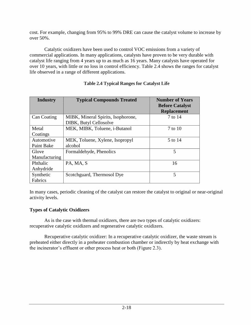
Catalytic oxidizers have been used to control VOC emissions from a variety of
commercial applications. In many applications, catalysts have proven to be very durable with
catalyst life ranging from 4 years up to as much as 16 years. Many catalysts have operated for
over 10 years, with little or no loss in control efficiency. Table 2.4 shows the ranges for catalyst
life observed in a range of different applications.
Table 2.4 Typical Ranges for Catalyst Life
Industry Typical Compounds Treated Number of Years
Before Catalyst
Replacement
Can Coating MIBK, Mineral Spirits, Isophorone,
DIBK, Butyl Cellosolve
7 to 14
Metal
Coatings
MEK, MIBK, Toluene, i-Butanol 7 to 10
Automotive
Paint Bake
MEK, Toluene, Xylene, Isopropyl
alcohol
5 to 14
Glove
Manufacturing
Formaldehyde, Phenolics 5
Phthalic
Anhydride
PA, MA, S 16
Synthetic
Fabrics
Scotchguard, Thermosol Dye 5
In many cases, periodic cleaning of the catalyst can restore the catalyst to original or near-original
activity levels.
Types of Catalytic Oxidizers
As is the case with thermal oxidizers, there are two types of catalytic oxidizers:
recuperative catalytic oxidizers and regenerative catalytic oxidizers.
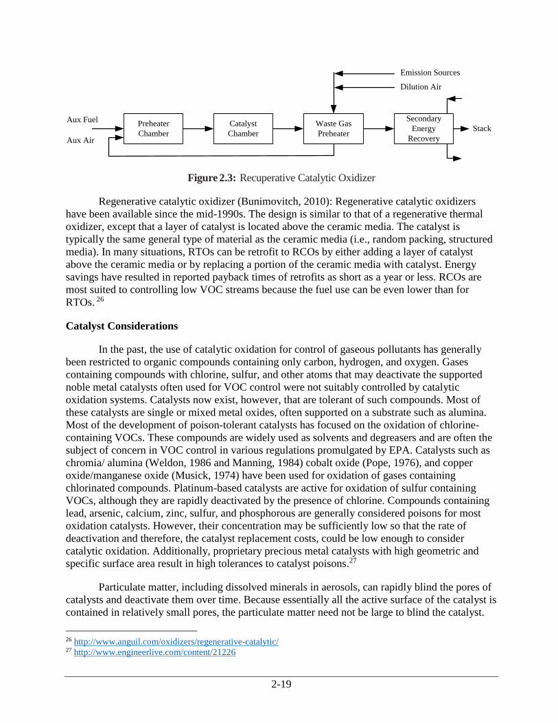
Recuperative catalytic oxidizer: In a recuperative catalytic oxidizer, the waste stream is
preheated either directly in a preheater combustion chamber or indirectly by heat exchange with
the incinerator’s effluent or other process heat or both (Figure 2.3).
2-19
Figure 2.3: Recuperative Catalytic Oxidizer
Regenerative catalytic oxidizer (Bunimovitch, 2010): Regenerative catalytic oxidizers
have been available since the mid-1990s. The design is similar to that of a regenerative thermal
oxidizer, except that a layer of catalyst is located above the ceramic media. The catalyst is
typically the same general type of material as the ceramic media (i.e., random packing, structured
media). In many situations, RTOs can be retrofit to RCOs by either adding a layer of catalyst
above the ceramic media or by replacing a portion of the ceramic media with catalyst. Energy
savings have resulted in reported payback times of retrofits as short as a year or less. RCOs are
most suited to controlling low VOC streams because the fuel use can be even lower than for
RTOs. 26
Catalyst Considerations
In the past, the use of catalytic oxidation for control of gaseous pollutants has generally
been restricted to organic compounds containing only carbon, hydrogen, and oxygen. Gases
containing compounds with chlorine, sulfur, and other atoms that may deactivate the supported
noble metal catalysts often used for VOC control were not suitably controlled by catalytic
oxidation systems. Catalysts now exist, however, that are tolerant of such compounds. Most of
these catalysts are single or mixed metal oxides, often supported on a substrate such as alumina.
Most of the development of poison-tolerant catalysts has focused on the oxidation of chlorine-
containing VOCs. These compounds are widely used as solvents and degreasers and are often the
subject of concern in VOC control in various regulations promulgated by EPA. Catalysts such as
chromia/ alumina (Weldon, 1986 and Manning, 1984) cobalt oxide (Pope, 1976), and copper
oxide/manganese oxide (Musick, 1974) have been used for oxidation of gases containing
chlorinated compounds. Platinum-based catalysts are active for oxidation of sulfur containing
VOCs, although they are rapidly deactivated by the presence of chlorine. Compounds containing
lead, arsenic, calcium, zinc, sulfur, and phosphorous are generally considered poisons for most
oxidation catalysts. However, their concentration may be sufficiently low so that the rate of
deactivation and therefore, the catalyst replacement costs, could be low enough to consider
catalytic oxidation. Additionally, proprietary precious metal catalysts with high geometric and
specific surface area result in high tolerances to catalyst poisons.27
Particulate matter, including dissolved minerals in aerosols, can rapidly blind the pores of
catalysts and deactivate them over time. Because essentially all the active surface of the catalyst is
contained in relatively small pores, the particulate matter need not be large to blind the catalyst.
26 http://www.anguil.com/oxidizers/regenerative-catalytic/ 27 http://www.engineerlive.com/content/21226
Preheater
Chamber
Catalyst
Chamber
Waste Gas
Preheater
Secondary
Energy
Recovery
Aux Fuel
Aux Air
Stack
Emission Sources
Dilution Air

2-20
No general guidelines exist as to particulate concentration and particulate size that can be
tolerated by catalysts because the pore size and volume of catalysts vary greatly.
Methods of Contacting Gas Stream and Catalyst
The method by which the VOC-containing stream contacts the catalyst serves to
distinguish catalytic incineration systems. Both fixed-bed and fluid-bed systems are available
routes for catalyst use in oxidation and incineration. Fixed-bed catalytic oxidizers may use a
monolith catalyst or a packed-bed catalyst. Each of these is discussed below.
Fixed Bed Monolith Catalyst Oxidizers - The most widespread method of contacting the
VOC- containing stream with the catalyst is the catalyst monolith. In this scheme the catalyst is a
porous solid block containing parallel, non-intersecting channels aligned in the direction of the
gas flow.
Monoliths offer the advantages of minimal attrition due to thermal expansion/ contraction
during startup/shutdown and low overall pressure drop.
Packed-Bed Catalytic Oxidizers - A second contacting scheme is a simple packed-bed in
which catalyst particles are supported either in a tube or in shallow trays through which the gases
pass. The first scheme is not in widespread use due to its inherently high pressure drop, compared
to a monolith, and the breaking of catalyst particles due to thermal expansion when the confined
catalyst bed is heated/cooled during startup/shutdown. However, the tray type arrangement, where
the catalyst is pelletized is used by several industries (e.g., heat-set web-offset printing).
Pelletized catalyst is advantageous where large amounts of such contaminants as phosphorous or
silicon compounds are present. (Yarrington, 1989b)
Fluid Bed Catalytic Oxidizers - A third contacting pattern between the gas and catalyst is a
fluid-bed. Fluid-beds have the advantage of very high mass transfer rates, although the overall
pressure drop is somewhat higher than for a monolith. An additional advantage of fluid-beds is a
high bed-side heat transfer as compared to a normal gas heat transfer coefficient. This higher heat
transfer rate to heat transfer tubes immersed in the bed allows higher heat release rates per unit
volume of gas processed and therefore may allow waste gas with higher heating values to be
processed without exceeding maximum permissible temperatures in the catalyst bed. In these
reactors, the gas phase temperature rise from gas inlet to gas outlet is low, depending on the
extent of heat transfer through imbedded heat transfer surfaces. The catalyst temperatures depend
on the rate of reaction occurring at the catalyst surface and the rate of heat exchange between the
catalyst and imbedded heat transfer surfaces.
Generally, fluid-bed systems are more tolerant of particulates in the gas stream than either
fixed-bed or monolithic catalysts. This is due to the constant abrasion of the fluidized catalyst
pellets, which helps remove these particulates from the exterior of the catalysts in a continuous
manner. A disadvantage of a fluid-bed is the gradual loss of catalyst by attrition. Attrition-
resistant catalysts have been developed to overcome this disadvantage (Sheffer, 1988).
2-21
Catalyst Regeneration
In some applications, catalyst activity can be restored by catalyst regeneration. There are currently
three methods for regenerating catalyst activity.
Thermal Treatment involves elevating the catalyst to high temperatures sufficient to vaporize or
oxidize the organic compounds or char that are masking the catalyst. The increased temperature is
achieved by supplying additional heat from the system burner at the inlet to the catalyst chamber.
Physical Treatment uses mechanical means to remove particulates that are deposited on the
catalyst. The most common approach is to blow compressed air and/or water across the surface of
the catalyst to dislodge particulates.
Chemical Treatment involves cleaning with acid and/or alkaline solutions to remove compounds
adhering to the catalyst surface. The catalyst modules are removed from the oxidizer and the
chemical treatment performed either at the plant site by the user or returned to the catalyst
supplier for treatment at their own cleaning facility. Chemical cleaning is the most frequently
used cleaning procedure for catalysts in VOC applications. The treatment does not affect the
catalyst composition, but merely removes masking compounds from the catalyst surface.
Depending upon the specific application, preventative chemical cleaning maintenance can be
scheduled from every six months in applications where catalyst masking is severe, to every three
or more years. Chemical cleaning has been used for over 40 years and has proved to be an
effective method for extending catalyst life in applications where masking occurs.
Flameless Thermal Oxidizers (FTO)
In this process, the exhaust stream is mixed with air before entering the flameless reactor vessel.
The air mixture is evenly distributed into a bed of inert ceramic material coated with a metal
catalyst. This bed provides complete mixing of the VOC with oxygen. The VOC oxidizes into
carbon dioxide and water vapor once the mixture reaches the combustion temperature. The
released combustion energy is absorbed by the ceramic bed and is transferred to the exhaust
stream leaving the catalytic oxidizer. The temperature control of the system is very important in
effective oxidation of VOCs. This process is a flameless incineration, as opposed to catalytic
incineration, which uses an external fuel source. The catalytic oxidizer uses the heat of the
exhaust to maintain combustion. To ensure the proper operation of the FTO, the exhaust gas
entering the reactor needs to be at least 600oF. Ideally, the hydrocarbon concentration of the waste
stream entering the system is high enough to generate the heat required to maintain the reaction.28
However, FTOs can be used in applications where the hydrocarbon content of the waste stream is
insufficient to maintain the optimal operating temperature. In such situations, electric heat or
supplemental fuels must be added to the waste stream to maintain the optimal operating
temperature.29
28 http://www.arb.ca.gov/pm/pmmeasures/ceffect/reports/sjvapcd_4692_report.pdf 29 http://www.lindeus-
engineering.com/internet.le.le.usa/en/images/FTO%20Technology%20Datasheet%200716%20Web136_279769.pdf?
v=1.0 .

2-22
FTO offers the benefit of high temperature thermal destruction combined with the
reliability of electric operation. Generally, the pre-heater of the FTO can be turned off as
hydrocarbon rates increase. FTOs can also result in reduced power consumption via heat recovery
systems that utilizes heat generated from hydrocarbon destruction to pre-heat the incoming
vapors.
2.2.4 Other Considerations: Packaged versus Field-Erected Units, Auxiliary Equipment
Packaged vs. Field-Erected Units
Except for regenerative oxidizers, the equipment cost correlations included in this chapter
are for packaged units only. They are not valid for field-erected units. For regenerative oxidizers,
the correlations are valid for field-erected units only. Packaged units are units that have been shop
fabricated and contain all elements necessary for operation, except for connection to facilities at
the site, e.g., utilities. The elements include the combustion chamber, preheater, instrumentation,
fan, and the necessary structural steel, piping, and electrical equipment. This equipment is
assembled and mounted on a “skid” to facilitate installation on a foundation at the plant site. Tie-
in to the local emission source is not part of the packaged unit. Units are usually sized to handle
flow rates of < 20,000 scfm, but can be built to accommodate flow rates up to 50,000 standard
cubic feet per minute (scfm). The cost correlations in this chapter are valid to 50,000 scfm for
packaged units, except for fluid-bed units which are valid to 25,000 scfm.
Conversely, field-erected units may be built to any desired size. The combustion chamber,
preheater, and other equipment items are designed and fabricated individually, and assembled at
the site. However, both the equipment and installation costs of field-erected units are typically
higher than those for equivalent-sized packaged units because the factors that improve efficiency
of shop-fabrication, such as uniform working environment, availability of tools and equipment,
and more efficient work scheduling, are generally not available in the field.
Acid Gas and Venturi Scrubbers
The final outlet stream of any incineration system may contain certain pollutants that must
be removed. The combustion of sulfur-containing compounds results in SO2, while chlorinated
compounds yield Cl2 and HCl in the outlet stream. These acid gases must be removed from the
gas stream if they are present at significant concentrations (regulations for limits on these gases
vary from state to state; Cl2 and HCl are also regulated as HAP under CAA section 112 for many
industries). These gases can be effectively removed using a packed-bed gas absorber (vertical
scrubber) in which the flue gas is contacted with a caustic scrubbing liquid. For fluid-bed catalytic
reactors, venturi scrubbers are often used because they also remove particulates from the flue gas.
In addition, venturi scrubbers are often used to reduce mercury from sewage sludge incinerators
as mentioned earlier in this chapter. In most cases adding a scrubber or absorber significantly
increases the cost of the incineration unit, sometimes by a factor of two. More information on acid
gas scrubbers is available in the “Acid Gas Scrubbers” chapter of this Manual (see Section 5,
Chapter 1). More information on venturi scrubbers and other particulate control devices can be
found in Section 6, chapters 1 through 3.
2-23
If chlorinated VOCs are present in the waste gas, heat exchangers may require special
materials of construction. This added expense is not included in the costing procedures outlined in
this section.
In most cases, acid gas scrubbers are located on the outlet of the thermal oxidizer.
However, scrubbers may also be used on the inlet to the thermal oxidizer. This arrangement is
sometimes used where the waste gas stream contains certain acidic sulfur or halogen compounds.
The principal advantages of this arrangement are in reducing corrosion of oxidizer components
and avoiding the additional costs associated with upgrading the materials used in oxidizer
construction.
Scrubbers are sometimes included by vendors as part of an integrated scrubber/thermal
oxidizer package. Although equipment costs quoted for the systems include the cost of the
scrubber and thermal oxidizer, the additional costs associated with the purchase, handling, and
disposal of the scrubbing medium and spent scrubbing solution and monitoring of scrubber flow
rate and pressure drop should be included in the operating costs for the integrated system. For
information on estimating the capital and operating costs of scrubbers, please refer to Sections 5
and 6 of the Cost Manual.
Heat Exchangers (Preheaters and Other Waste Energy Recovery Units)
For thermal and catalytic units that have some degree of energy recovery, the cost of the
primary heat exchanger is included in the cost, and its design is usually done by the incineration
unit vendor. The cost correlations presented in this chapter include units both with and without
energy recovery. Secondary energy recovery, if desired, requires an additional heat exchanger,
which is also often provided by the incineration unit vendor. Costing procedures for secondary
energy recovery are not included in this section.
Concentrators
For processes that generate large volumes of waste gas with lower concentrations of VOC,
plants may install concentrators before the oxidizer inlet. These systems use an adsorption system
to convert the stream to a smaller volume of highly concentrated gas that is optimized for
treatment by the oxidizer. Such optimization of treatment may lead to a smaller sized, and thus
less costly, oxidizer. Typical concentrators use carbon or zeolite as the adsorbent. The waste gas
entering the condenser passes through a cartridge where emissions are stripped from the air
stream and adsorbed on the substrate. A small volume of heated air is passed over the substrate to
release the VOC. The heated air with its high concentration of VOC can then be treated in the
oxidizer. Various different designs of concentrators are available and may be purchased as part of
an integrated oxidizer system.
Other Auxiliary Equipment
Additional auxiliary equipment such as hoods, ductwork, precoolers, cyclones, fans,
motors, and stacks are addressed separately in other sections of this Manual.
2-24
2.2.5 Technology Comparison
Both the thermal and catalytic incineration systems are designed to provide VOC control
through combustion at a level in compliance with applicable state and Federal requirements.
Given the wide range of options available, however, it is obvious that not every incinerator will
fulfill these requirements at the same cost. This section presents a first step toward deciding how
best to deal with VOC emission abatement using incinerators or oxidizers considering some
qualitative factors pertinent to the types of incinerators described in this chapter. It is the intent of
the remainder of this section to provide a method by which the cost of VOC control for a
particular application can be calculated.
A summary of the principal types of incinerators and oxidizers is presented in Table 2.5.
From the earlier discussions, the following factors relating to the presence of contaminants should
be considered by potential users (Stettenbenz, 1988):
The fouling of the catalyst in a catalytic system is a possibility. Poisons to the system
include heavy metals, phosphorous, sodium, sulfur and most halogens, although catalysts
have been developed that are chlorine resistant, such as siloxane.
The possibility of process upsets that could release any of the above poisons or cause
fluctuations in the heating value to the incinerator would favor a thermal system.
Except for low sulfur distillate fuels, fuel oil should not be used as auxiliary fuel to a
catalytic system due to the sulfur and vanadium it may contain (Yarrington, 1989b).
All the above factors would serve to increase the operating expense of a catalytic unit
through replacement costs of the catalyst. An additional factor relates to relative energy efficiency
of the various types of incinerators:
Thermal units generally require more auxiliary fuel than catalytic units and operate at
temperatures that are roughly 1000oF higher. This difference in fuel requirement increases
as the heating value of the waste stream decreases.
In general, a trade-off exists between the higher capital costs of catalytic oxidizers and the
higher operating costs of thermal oxidizers. This difference will be illustrated by a design
example presented in Section 2.4, which describes both technologies, and cost analysis presented
in Section 2.5, which compares the capital and operating costs of the two technologies.
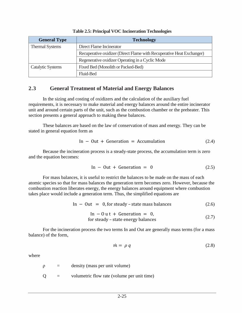
2-25
Table 2.5: Principal VOC Incineration Technologies
General Type Technology
Thermal Systems Direct Flame Incinerator
Recuperative oxidizer (Direct Flame with Recuperative Heat Exchanger)
Regenerative oxidizer Operating in a Cyclic Mode
Catalytic Systems Fixed Bed (Monolith or Packed-Bed)
Fluid-Bed
2.3 General Treatment of Material and Energy Balances
In the sizing and costing of oxidizers and the calculation of the auxiliary fuel
requirements, it is necessary to make material and energy balances around the entire incinerator
unit and around certain parts of the unit, such as the combustion chamber or the preheater. This
section presents a general approach to making these balances.
These balances are based on the law of conservation of mass and energy. They can be
stated in general equation form as
In − Out + Generation = Accumulation (2.4)
Because the incineration process is a steady-state process, the accumulation term is zero
and the equation becomes:
In − Out + Generation = 0 (2.5)
For mass balances, it is useful to restrict the balances to be made on the mass of each
atomic species so that for mass balances the generation term becomes zero. However, because the
combustion reaction liberates energy, the energy balances around equipment where combustion
takes place would include a generation term. Thus, the simplified equations are
In − Out = 0, for steady – state mass balances (2.6)
In − O u t + Generation = 0,
for steady – state energy balances (2.7)
For the incineration process the two terms In and Out are generally mass terms (for a mass
balance) of the form,
�̇� = 𝜌 𝑞 (2.8)
where
ρ = density (mass per unit volume)
Q = volumetric flow rate (volume per unit time)
2-26
L
or sensible heat terms (for an energy balance) of the form,
�̇� = �̇� ∆h = ρ q Cp (T − 𝑇𝑟𝑒𝑓) (2.9)
where
Cp = heat capacity
T = temperature
The reference temperature, Tref, is often taken to be zero or the temperature of a convenient stream,
e.g., the inlet gas stream, in whatever units T is in, so the Tref term may not appear in the equations.
When the reference temperature is taken as zero, the sensible heat terms become
�̇� = 𝜌 𝑄 𝐶𝑝 𝑇 (2.10)
Energy losses, HL, are also part of the Out term and, for the incinerator process, are taken here to be
10% of the total energy input to the incinerator.
For the incineration process, the generation term for energy balances accounts for the energy
released through the combustion reactions. This term is generally of the form
�̇� = 𝜌 𝑄 (−∆ℎ𝑐) (2.11)
Where
(-Δhc) = heat of combustion.
2.4 Design Procedures
The following procedure is designed to provide parameters for use in developing a study
cost estimate (range of accuracy ± 30%) for thermal and catalytic oxidizers. The principal
parameters of interest are
flue gas flow rate, upon which all the equipment cost correlations are based.
auxiliary fuel requirement, which is important in estimating annual operating costs.
For emissions sources that generate dilute mixtures of VOCs in air (i.e., waste streams that
contain a minimum of 20% oxygen), the flue gas flow rate exiting the oxidizer is greater than the
inlet waste gas flow rate by the amount of auxiliary fuel and the increase in the moles of gas as a
result of the combustion reaction. Because these two factors usually cause only small increases in
flow rate, a number of simplifying assumptions can be made in the design calculations. For
applications where diluent air must be used to adjust the combustible concentration in the waste
gas to 25% LEL and where auxiliary fuel and auxiliary combustion air are needed, more complete
mass and energy balances must be made.
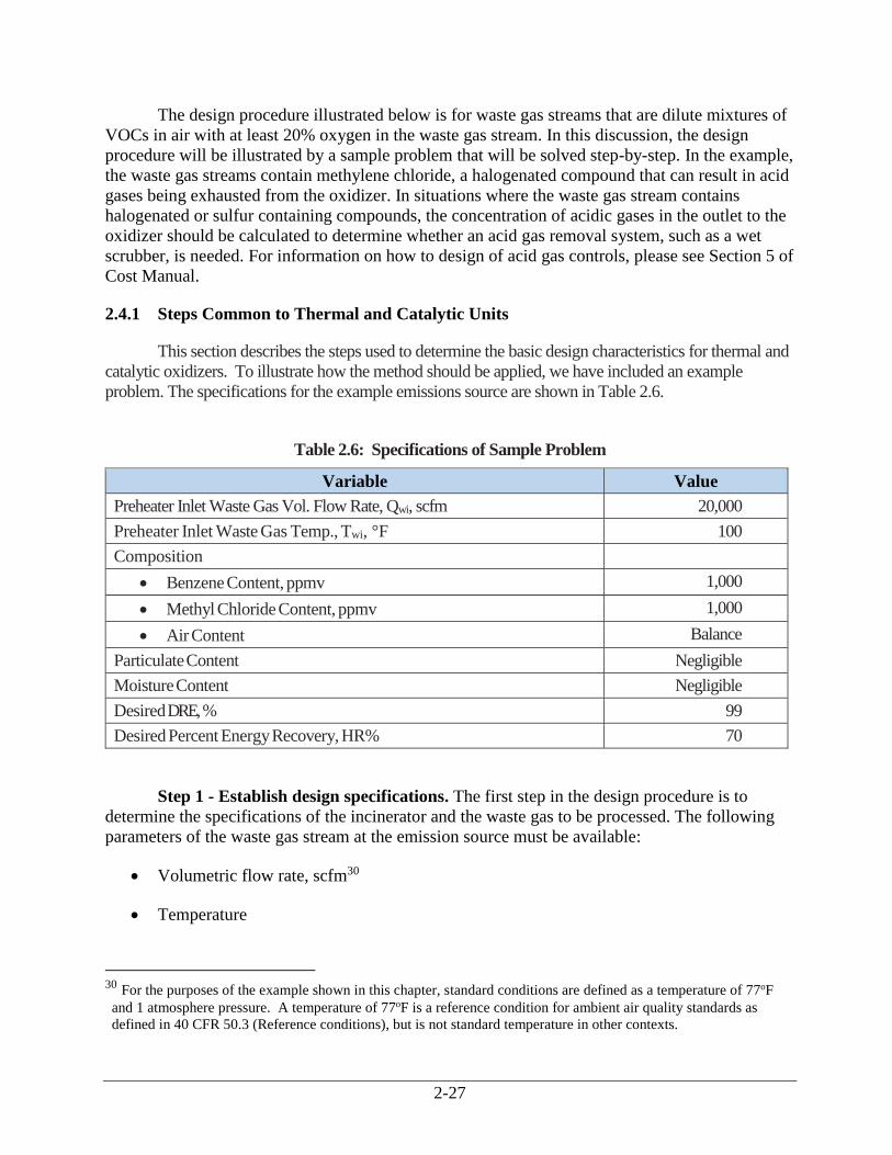
2-27
The design procedure illustrated below is for waste gas streams that are dilute mixtures of
VOCs in air with at least 20% oxygen in the waste gas stream. In this discussion, the design
procedure will be illustrated by a sample problem that will be solved step-by-step. In the example,
the waste gas streams contain methylene chloride, a halogenated compound that can result in acid
gases being exhausted from the oxidizer. In situations where the waste gas stream contains
halogenated or sulfur containing compounds, the concentration of acidic gases in the outlet to the
oxidizer should be calculated to determine whether an acid gas removal system, such as a wet
scrubber, is needed. For information on how to design of acid gas controls, please see Section 5 of
Cost Manual.
2.4.1 Steps Common to Thermal and Catalytic Units
This section describes the steps used to determine the basic design characteristics for thermal and
catalytic oxidizers. To illustrate how the method should be applied, we have included an example
problem. The specifications for the example emissions source are shown in Table 2.6.
Table 2.6: Specifications of Sample Problem
Variable Value
Preheater Inlet Waste Gas Vol. Flow Rate, Qwi, scfm 20,000
Preheater Inlet Waste Gas Temp., Twi, °F 100
Composition
Benzene Content, ppmv 1,000
Methyl Chloride Content, ppmv 1,000
Air Content Balance
Particulate Content Negligible
Moisture Content Negligible
Desired DRE, % 99
Desired Percent Energy Recovery, HR% 70
Step 1 - Establish design specifications. The first step in the design procedure is to
determine the specifications of the incinerator and the waste gas to be processed. The following
parameters of the waste gas stream at the emission source must be available:
Volumetric flow rate, scfm30
Temperature
30 For the purposes of the example shown in this chapter, standard conditions are defined as a temperature of 77oF
and 1 atmosphere pressure. A temperature of 77oF is a reference condition for ambient air quality standards as
defined in 40 CFR 50.3 (Reference conditions), but is not standard temperature in other contexts.
2-28
Oxygen content
Chemical composition of the combustibles
Inerts content
Heating value—In certain cases the heating value may act as a surrogate for the chemical
composition of the combustibles. This is particularly true for dilute mixtures of
combustibles in air.
Particulate content—The particulate content is important as particulates can coat the
catalyst. An upstream filter may suffice if particulate content is too high. Fluid-bed
catalytic oxidizers can tolerate higher particulate contents than fixed-bed catalytic
oxidizers.
The following parameters must be specified for the incinerator:
Desired DRE—This efficiency should be based on requirements dictated by relevant state
and Federal regulations.
Combustion chamber outlet temperature—This temperature may also be based on
requirements of a regulation or on recommendations developed during regulatory
development.
Desired percent energy recovery—The desired percent energy recovery should be the
result of a process optimization in which costs of incinerators with several different levels
of energy recovery are estimated and the minimum cost design selected. The tradeoff is
between the capital cost of the energy recovery equipment and the operating (fuel) cost.
Step 2 - Verify that the oxygen content of the waste gas is at least 20%. There must be
sufficient oxygen in the waste gas to support the combustion of the waste organics (including
VOCs) and the auxiliary fuel, if auxiliary fuel is needed. It may be necessary to add auxiliary air
if the oxygen content is less than about 20%. In this example, the waste stream contains greater
than 20% oxygen, as shown below for 1000 ppmv of benzene and methyl chloride:
𝐴𝑖𝑟 𝐶𝑜𝑛𝑡𝑒𝑛𝑡, 𝑉𝑜𝑙. % = 100 − 1,000 (𝑝𝑝𝑚)
106 × 100 −1,000 (𝑝𝑝𝑚)
106 × 100 = 99.8% (2.12)
This gives the oxygen content in percent as:
O𝑥𝑦𝑔𝑒𝑛 𝐶𝑜𝑛𝑡𝑒𝑛𝑡 = 99.8% × 0.209 = 20.86% (2.13)
Where 0.209 is the concentration of oxygen in air.
Step 3 - Calculate the LEL and the Percent of the LEL of the gas mixture. If the waste
stream contains a significant amount of inert constituents in addition to the nitrogen associated
with the oxygen in air, the calculation of LEL (and UEL) loses meaning since the LEL (and UEL)
2-29
is measured in mixtures of organic with air only. A full chemical analysis is necessary to
complete the design procedure in such a case.
The example chosen here is typical, in that there is more than one VOC component in the
gas stream. An approximate method to calculate the LEL of a mixture of compounds, LELmix, is
given by Grelecki (Grelecki, 1976) as
𝐿𝐸𝐿𝑚𝑖𝑥 = [∑𝑥𝑗
(∑ 𝑥𝑖𝑛𝑗=1 )𝐿𝐸𝐿𝑗
𝑛𝑗=1 ]
−1
(2.14)
Where
Xi = volume fraction of combustible component i
LELi = lower explosive limits of combustible component j (ppmv)
N = number of combustible components in mixture
For the example case,
∑ 𝑋𝑖
𝑛
𝑖=1
= (1,000 + 1,000) × 10−6 = 2,000 × 10−6
From standard references (Lide, 2005) or from Appendix A,
𝐿𝐸𝐿𝐵𝑧 = 14,000 𝑝𝑝𝑚𝑣 𝑓𝑜𝑟 𝑏𝑒𝑛𝑧𝑒𝑛𝑒𝐿𝐸𝐿𝑀𝐶 = 82,500 𝑝𝑝𝑚𝑣 𝑓𝑜𝑟 𝑚𝑒𝑡ℎ𝑦𝑙 𝑐ℎ𝑙𝑜𝑟𝑖𝑑𝑒
𝐿𝐸𝐿𝑚𝑖𝑥 = [1,000
2,000 × 14,000+
1,000
2,000 × 82,500]
−1
= 23,938 𝑝𝑝𝑚𝑣
% LELmix =total combustible conc.in mixture
LELmix × 100 (2.15)
% LELmix =2,000
23,938 × 100 = 8.4%
The percent LEL of the mixture is therefore 8.4%. Because this is well below 25%, no
dilution air is needed in this example. If the mixture had been above 25% LEL, sufficient dilution
air would have been needed to bring the concentration of the mixture to less than 25% to satisfy
fire insurance regulations.
Step 4 - Calculate the volumetric heat of combustion of the waste gas streams,
(- Δh cw), Btu/scf. The energy content of the gas stream, expressed in terms of the heat of
combustion, is calculated as follows:
2-30
(−∆ℎ𝑐𝑤) = ∑ (−∆ℎ𝑐𝑖
)𝑛𝑖=1 𝑥𝑖 (2.16)
where
(-∆hcw) = heat of combustion of the waste stream (Btu/scf)
(-∆hci) = volumetric heat of combustion of component i at 25°C (Btu/scf)
Xi = volume fraction of component i in the waste gas
n = number of combustible components in the waste gas
The heat of combustion that should be used in these calculations is the “lower” heat of
combustion, i.e., with gaseous water, rather than liquid water, as a reaction product since water
leaves the incinerator in the vapor state. From Appendix A or standard references (Lide, 2005 and
Green, 1999) with appropriate conversion of units, the volumetric heat of combustion at 25°C for
the two components is calculated to be as follows:
(−∆ℎ𝑐𝐵𝑧) = 3,475 Btu/scf for benzene
(−∆ℎ𝑐𝑀𝐶) = 705 Btu/scf for methyl chloride
The compositions specified earlier as ppmv are converted to volume fractions as
XBz = 1,000 ppmv × 10-6 = 10-3 for benzene
X,MC = 1,000 ppmv × 10-6 = 10-3 for methyl chloride
Using these values of heat of combustion and composition, the heat of combustion of the
waste gas stream per standard cubic foot (scf) of incoming gas is
(−∆𝑐𝑤) = (3,475)(10−3) + (705) (10−3) = 4.18
𝐵𝑡𝑢
𝑠𝑐𝑓
Assuming the waste gas is principally air, with a molecular weight of 28.97 g/mole and a
corresponding density of 0.0739 lb/scf, the heat of combustion per pound of incoming waste gas
is:
(−∆ℎ𝑐𝑤) = 56.6 𝐵𝑡𝑢/𝑙𝑏
The negative heat of combustion, by convention, denotes an exothermic reaction. Also by
convention, if one refers to heat of reaction rather than heat of combustion, then a positive value
denotes an exothermic reaction.
Empirically, it has been found that 50 Btu/scf roughly corresponds to the LEL of organic/air
mixtures. Insurance codes require a value below 25% LEL, which corresponds to about 13 Btu/scf.
However, if LEL sensors and monitors are installed, one can incinerate a waste gas with a combustible
organic content between 25 and 50% LEL, which corresponds to 13 to 25 Btu/scf.
2-31
For catalytic applications, the heat of combustion must normally be less than 10 Btu/scf (for
VOCs in air) to avoid excessively high temperatures in the catalyst bed. This is, of course, only an
approximate guideline and may vary from system to system.
After Step 4, determination of the (-Δhcw) design procedure for thermal and catalytic
oxidizers is discussed separately, beginning with Step 5 for each type of incinerator.
2.4.2 Steps Specific to Thermal Units
Figure 2.1 shows a generic thermal oxidizer with the appropriate streams labeled.
Step 5t - Establish the temperature at which the incinerator will operate. As
mentioned in Section 2.2.1, both the reactor temperature and residence time of the waste gas in
the reactor determine the level of VOC destruction. In general, state and local regulations specify
the required level of destruction that the customer must meet. In this example a destruction
efficiency of 99% is specified. Based on Table 2.2, this destruction efficiency can be met in a
thermal oxidizer operated at a temperature, Tfi of 1600°F and a residence time of 1 second. (Note:
This higher efficiency level is the minimum achievable by any new properly designed and
operated incinerator. Many incinerators can currently achieve destruction efficiencies of 99% or
higher. This is consistent with a statement made by Anguil Environmental, Inc. in November
2015 (Chemical Engineering Magazine, 2015))
Step 6t - Calculate the waste gas temperature at the exit of the preheater. The extent
of the heat exchange to be carried out in the preheater is the result of a technical and economic
optimization procedure that is not illustrated in this example. As the VOC stream temperature
leaving the heat exchanger, Two, increases, the auxiliary fuel requirement decreases, but at the
expense of a larger heat exchanger. However, there are several important limits on Two. First, Two
must not be close to the ignition temperature of the organic-containing gas to prevent damaging
temperature excursions inside the heat exchanger should the gas ignite. Second, for gases
containing halogens, sulfur, and phosphorous (or other acid-forming atoms), the flue gas
temperature after the heat exchanger, Tfo, must not drop below the acid dew point. Both
limitations minimize the amount of possible heat exchange and thus the maximum value of Two.
The calculation of the acid dew point is not simple. It is recommended that vendor guidance be
sought to ensure that the dew point is not reached. Condensation of acid gases will result in
corrosion of many of the metallic construction materials used in heat exchangers. As an example,
fuel sulfur contents of 1 to 2 percent can give acid dew points of about 200 to 270°F. Increasing
the sulfur content to 4 percent can raise the dew to about 290°F. Chlorine and phosphorous have a
much smaller effect on acid dew elevation.
With the following assumptions, one can estimate Two using Equation 2.2, the definition of
fractional energy recovery for a heat exchanger:
The fractional energy recovery is specified.
2-32
The amount of auxiliary fuel, Qaf and auxiliary combustion air, Qa, are small relative to the
waste gas, Qw, so that the mass flow rates of gases, piQf and pfQf, on both sides of the
preheater are approximately the same, or:
𝜌𝑤 𝑄𝑤 = 𝜌𝑓 𝑄𝑓 (2.17)
The heat capacities of the gases on both sides of the preheater are approximately the same,
regardless of composition. This is true for waste streams which are dilute mixtures of
organics in air, the properties of the streams changing only slightly on combustion.
The mean heat capacities above the reference temperature of the gases on both sides of the
preheater are approximately the same regardless of temperature.
With these assumptions, the equation for fractional energy recovery for a heat exchanger
becomes
𝐹𝑟𝑎𝑐𝑡𝑖𝑜𝑛𝑎𝑙 𝐸𝑛𝑒𝑟𝑔𝑦 𝑅𝑒𝑐𝑜𝑣𝑒𝑟𝑦 =𝑇𝑤𝑜 – 𝑇𝑤𝑖
𝑇𝑓𝑖 – 𝑇𝑤𝑖 (2.18)
For this example with a fractional energy recovery of 0.70, an incinerator operating
temperature, Tfi, of 1600°F, and a waste gas inlet temperature, Twi of 100oF, the waste gas
temperature at the end of the preheater becomes:
Two= 1,150°F
The temperature of the exhaust gas, Tfo, can be determined by an energy balance on the
preheater, which, with the same assumption as used in deriving Equation 2.18 regarding the mass
flow rates and average heat capacities of the gases involved, results in the following equation:
𝑇𝑓𝑖− 𝑇𝑓𝑜
= 𝑇𝑤𝑜−𝑇𝑤𝑖
(2.19)
e.g., the temperature rise in the waste gas is approximately equal to the temperature
decrease in the flue gas with which it is exchanged. For this example, this results in
𝑇𝑓𝑜= 550°F
This value of Tfo
should be well above the acid dew point of the flue gas stream.
It should be remembered that Two should be well below the ignition temperature of the
VOC stream to prevent unwanted temperature excursions in the preheater. This must be verified
even if the stream is well below the LEL because flammability limits can be expanded by raising
the reactant stream temperature. A sufficiently high preheat temperature, Two could initiate
reaction (with heat release) in the preheater. This would ordinarily be detrimental to the materials
of construction in the heat exchanger. The one exception is the thermal oxidizer of the regenerable
type described in Section 2.1. The 95-percent energy recovery, obtainable in regenerable systems
would result in this example in a Two of 1,525°F. The significant reaction rate that would occur at
this temperature in the ceramic packing of the heat exchanger/reactor is by design.
2-33
Step 7t - Calculate the auxiliary fuel requirement, Qaf. Auxiliary fuel will almost
invariably be needed for startup of the unit. However, at steady state, if the energy released by
combustion of the organics present in the waste stream is sufficient to maintain the reactor
temperature (1600°F in the example), only a small amount of auxiliary fuel (< 5% of the total
energy input) is needed to stabilize the flame. In most cases, however, more fuel than just this
stabilizing fuel will be required to maintain the reactor temperature.
With the following assumptions, one can estimate Qaf using a mass and energy balance
around the combustion chamber and following the principles discussed in Section 2.2, with
reference to Figure 2.1.
The reference temperature, Tref, is taken as the inlet temperature of the auxiliary fuel, Taf,
No auxiliary air, Qa, is required.
Energy losses, HL, are assumed to be 10% of the total energy input to the incinerator
above ambient conditions (Schmidt, 1989a, and Yarrington, 1989a). Thus, if the reference
temperature is near ambient condition
𝐻𝐿 = 0.1 𝜌𝑓𝑖 𝑄𝑓𝑖 𝐶𝑝𝑚𝑓𝑖 (𝑇𝑓𝑖 − 𝑇𝑟𝑒𝑓) (2.20)
The heat capacities of the waste gases entering and leaving the combustion chamber are
approximately the same, regardless of composition. This is true for waste streams which
are dilute mixtures of organics in air, the properties of the streams changing only slightly
on combustion.
The mean heat capacities above the reference temperature of the waste gases entering and
leaving the combustion chamber are approximately the same regardless of temperature.
Thus the mean heat capacity for the waste gas stream entering or leaving the combustion
chamber should be evaluated at the average of Two and Tfi. For air this assumption
introduces an error of, at most, 5% over the temperatures of interest.
With these assumptions, the mass and energy balance around the combustion chamber
reduces to the following equation:
𝜌𝑎𝑓𝑄𝑎𝑓 =𝜌𝑤𝑜𝑄𝑤𝑜[𝐶𝑝𝑚𝑎𝑖𝑟
(1.1𝑇𝑓𝑖−𝑇𝑤𝑜−0.1𝑇𝑟𝑒𝑓)−(−∆ℎ𝑐𝑤𝑜
)]
(−∆ℎ𝑐𝑎𝑓)−1.1𝐶𝑝𝑚𝑎𝑖𝑟
(𝑇𝑓𝑖−𝑇𝑟𝑒𝑓)
(2.21)
The waste stream is essentially air so that
ρwo= ρwi=0.0739 lb/scf, air at 77℉, 1 atm
Cpmair = 0.255 Btu/lb F, the mean heat capacity of air between 77°F and 1375°F (the
average pm air temperature of the waste gas entering the leaving the combustion chamber)
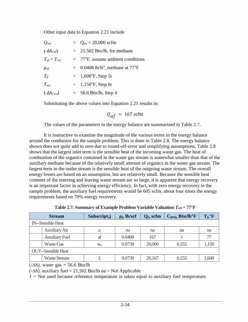
2-34
Other input data to Equation 2.21 include
Qwo = Qwi = 20,000 scfm
(-Δhcaf) = 21,502 Btu/lb, for methane
Taf = Tref = 77°F, assume ambient conditions
ρaf = 0.0408 lb/ft3, methane at 77°F
Tfi = 1,600°F, Step 5t
Two = 1,150°F, Step 6t
(-Δhcwo) = 56.6 Btu/lb, Step 4
Substituting the above values into Equation 2.21 results in:
𝑄𝑎𝑓 = 167 scfm
The values of the parameters in the energy balance are summarized in Table 2.7.
It is instructive to examine the magnitude of the various terms in the energy balance
around the combustor for the sample problem. This is done in Table 2.8. The energy balance
shown does not quite add to zero due to round-off-error and simplifying assumptions. Table 2.8
shows that the largest inlet term is the sensible heat of the incoming waste gas. The heat of
combustion of the organics contained in the waste gas stream is somewhat smaller than that of the
auxiliary methane because of the relatively small amount of organics in the waste gas stream. The
largest term in the outlet stream is the sensible heat of the outgoing waste stream. The overall
energy losses are based on an assumption, but are relatively small. Because the sensible heat
contents of the entering and leaving waste stream are so large, it is apparent that energy recovery
is an important factor in achieving energy efficiency. In fact, with zero energy recovery in the
sample problem, the auxiliary fuel requirements would be 605 scfm, about four times the energy
requirements based on 70% energy recovery.
Table 2.7: Summary of Example Problem Variable Valuation Tref = 77°F
Stream Subscript,j ρj, lb/scf Qj, scfm Cpmj, Btu/lb°F Tj,°F
IN--Sensible Heat
Auxiliary Air a na na na na
Auxiliary Fuel af 0.0408 167 1 77
Waste Gas wo 0.0739 20,000 0.255 1,150
OUT--Sensible Heat
Waste Stream fi 0.0739 20,167 0.255 1,600
(-h), waste gas = 56.6 Btu/lb
(-h), auxiliary fuel = 21,502 Btu/lb na = Not Applicable
1 = Not used because reference temperature is taken equal to auxiliary fuel temperature.
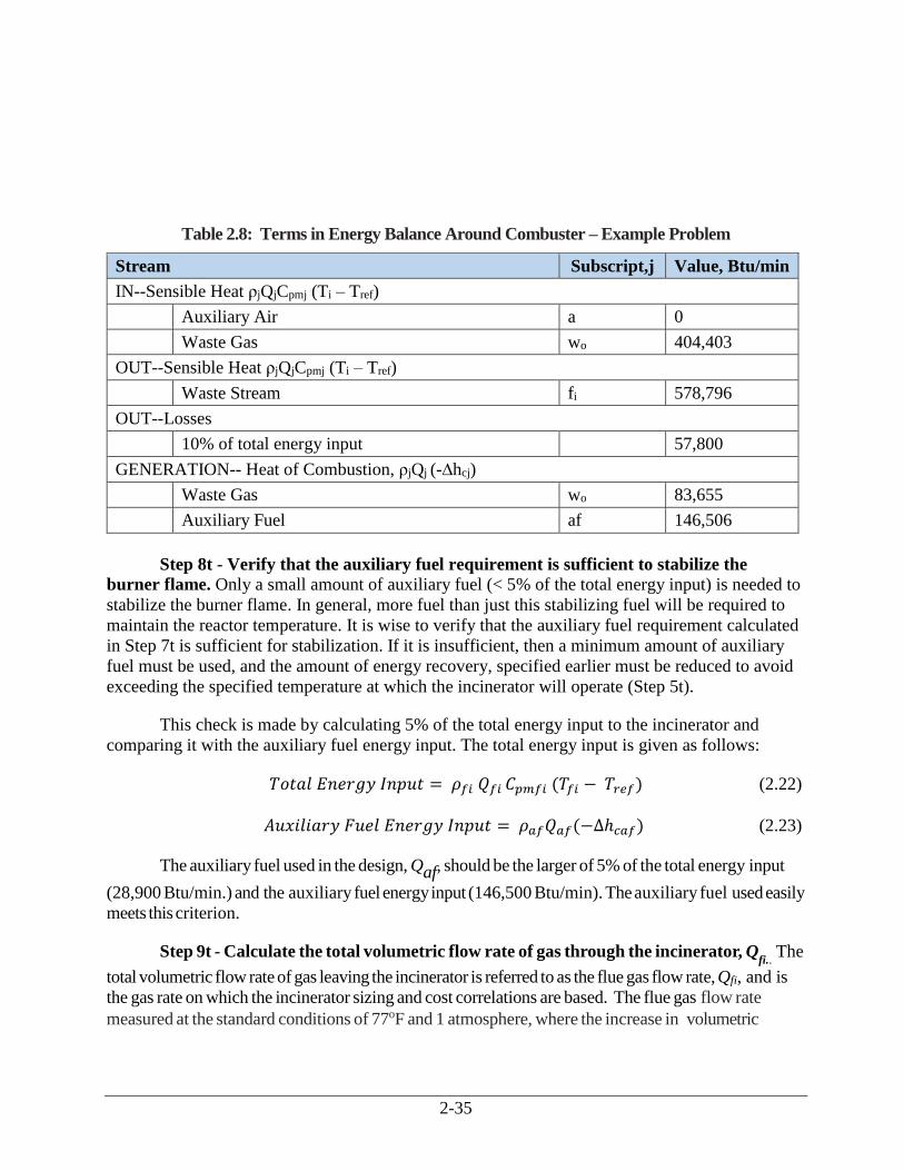
2-35
fi
Table 2.8: Terms in Energy Balance Around Combuster – Example Problem
Stream Subscript,j Value, Btu/min
IN--Sensible Heat ρjQjCpmj (Ti – Tref)
Auxiliary Air a 0
Waste Gas wo 404,403
OUT--Sensible Heat ρjQjCpmj (Ti – Tref)
Waste Stream fi 578,796
OUT--Losses
10% of total energy input 57,800
GENERATION-- Heat of Combustion, ρjQj (-∆hcj)
Waste Gas wo 83,655
Auxiliary Fuel af 146,506
Step 8t - Verify that the auxiliary fuel requirement is sufficient to stabilize the
burner flame. Only a small amount of auxiliary fuel (< 5% of the total energy input) is needed to
stabilize the burner flame. In general, more fuel than just this stabilizing fuel will be required to
maintain the reactor temperature. It is wise to verify that the auxiliary fuel requirement calculated
in Step 7t is sufficient for stabilization. If it is insufficient, then a minimum amount of auxiliary
fuel must be used, and the amount of energy recovery, specified earlier must be reduced to avoid
exceeding the specified temperature at which the incinerator will operate (Step 5t).
This check is made by calculating 5% of the total energy input to the incinerator and
comparing it with the auxiliary fuel energy input. The total energy input is given as follows:
𝑇𝑜𝑡𝑎𝑙 𝐸𝑛𝑒𝑟𝑔𝑦 𝐼𝑛𝑝𝑢𝑡 = 𝜌𝑓𝑖 𝑄𝑓𝑖 𝐶𝑝𝑚𝑓𝑖 (𝑇𝑓𝑖 − 𝑇𝑟𝑒𝑓) (2.22)
𝐴𝑢𝑥𝑖𝑙𝑖𝑎𝑟𝑦 𝐹𝑢𝑒𝑙 𝐸𝑛𝑒𝑟𝑔𝑦 𝐼𝑛𝑝𝑢𝑡 = 𝜌𝑎𝑓𝑄𝑎𝑓(−∆ℎ𝑐𝑎𝑓) (2.23)
The auxiliary fuel used in the design, Qaf, should be the larger of 5% of the total energy input
(28,900 Btu/min.) and the auxiliary fuel energy input (146,500 Btu/min). The auxiliary fuel used easily
meets this criterion.
Step 9t - Calculate the total volumetric flow rate of gas through the incinerator, Qfi..
The
total volumetric flow rate of gas leaving the incinerator is referred to as the flue gas flow rate, Qfi, and is
the gas rate on which the incinerator sizing and cost correlations are based. The flue gas flow rate
measured at the standard conditions of 77oF and 1 atmosphere, where the increase in volumetric

2-36
throughput due to an increase in the number of moles of gas as a result of combustion is neglected, is the sum
of the inlet streams to the incinerator.
𝑄𝑓𝑖 = 𝑄𝑤𝑜 + 𝑄𝑎 + 𝑄𝑎𝑓
= 20,000 + 0 + 167= 20,167 𝑠𝑐𝑓𝑚
(2.24)
This result conforms to the assumptions stated in Step 6t, e.g., the mass (and volume) flow
rates on both sides of the preheater are approximately equal. Finally, it must be emphasized that
steps 5t to 9t apply to thermal recuperative oxidizers only. To calculate the auxiliary fuel
requirements for other types of thermal oxidizers (e.g., regenerative), a different procedure must
be used. (See Appendix B.)
2.4.3 Steps Specific to Catalytic Units
Figure 2.3 shows a generic catalytic oxidizer with the appropriate streams labeled. The
approach used in the calculations on the catalytic oxidizer is somewhat different than that used in
the thermal oxidizer. This difference arises because of additional constraints which are placed on
the catalytic oxidizer. These constraints are as follows:
The desired catalyst bed outlet temperature is typically 700 to 900°F. The maximum
temperature to which the catalyst bed can be exposed continuously is limited to about
1200°F. Therefore, the combustible content of the waste gas is limited, and the amount of
heat exchange that occurs in the primary heat exchanger may be limited.
The inlet temperature to the catalyst bed itself must be above the catalytic ignition
temperature required to give the desired destruction efficiency in the incinerator.
Therefore, the combustible content of the waste gas is further limited to that which, when
combusted, will raise the temperature in the catalyst bed no more than the ΔT between the
required reactor bed inlet temperature, and the desired reactor bed outlet temperature.
Auxiliary fuel, in combination with the preheater from the primary heat exchanger, is used
to preheat the waste gas to the reactor inlet temperature. A minimum amount of auxiliary
fuel (< 5% of the total energy input) must be used to stabilize the flame in the preheat
combustion chamber. This has the effect of further limiting the combustible content of the
waste gas stream and the amount of heat exchange permissible in the primary heat
exchanger.
The steps outlined below represent one approach to recognizing these constraints and
incorporating them into the calculation procedures.
Step 5c - Establish the desired outlet temperature of the catalyst bed, Tfi. The energy
released by the oxidation of the VOCs in the catalyst bed will raise the temperature of the gases
by an amount, ΔT, as the gases pass through the catalyst bed. An outlet temperature from the
catalyst, and thus from the reactor, must be specified that will ensure the desired level of
destruction of the VOC stream. As in thermal oxidizers, this value varies from compound to
compound and also varies from catalyst to catalyst. Final design of the incinerator should be done
2-37
by firms with experience in incinerator design. Manufacturers indicate that values from 400 to
900°F result in destruction efficiencies above 95 percent (Nester). To prevent deactivation of the
catalyst a maximum bed temperature of 1200°F should not be exceeded. In the example problem,
the catalyst outlet temperature, Tfi, is selected to be 900°F.
Step 6c - Calculate the waste gas temperature at the exit of the preheater (primary)
heat exchanger. The waste gas temperature at the exit of the primary heat exchanger is estimated
in the same manner as for the thermal oxidizer. The equation for fractional energy recovery
Equation 2.18, is used, with the same assumptions as used for the thermal oxidizer. For the
example problem with a fractional energy recovery of 0.70, a catalyst bed outlet temperature, Tfi,
of 900°F, and a waste gas inlet temperature, Twi, of 100°F becomes
𝑇𝑤𝑜 = 660℉
The same considerations regarding the closeness of the temperature of the exhaust gas, Tfa,
to its dew point apply to the catalytic oxidizer as they did to the thermal oxidizer.
Step 7c - Calculate the auxiliary fuel requirement, Qaf. The auxiliary fuel requirement,
Qaf, is calculated by making mass and energy balances around the preheater combustion chamber
and the catalyst chamber. The auxiliary fuel requirement calculated in this manner must be
checked to insure that it falls within the constraints imposed by design considerations of the
catalytic oxidizer. These constraints are as follows:
The auxiliary fuel requirement must be positive. A negative fuel requirement indicates that
the heat of combustion of the waste gas, (-Δhc), is too high for the fractional energy
recovery in the primary heat exchanger that was selected.
The auxiliary fuel amount must be high enough to provide a stable flame in the preheater
combustion chamber (See Step 8c below).
An energy balance around the preheater combustion chamber and the catalyst chamber,
taken together, results in Equation 2.21, the same equation used in the thermal oxidizer
calculations. The input data for Equation 2.21 for the catalytic oxidizer example problem are
summarized below:
The waste stream is essentially air so that
ρwo = ρwi = 0.0739 lb/scf, air at 77°F, 1 atm
Cpmair = 0.248 Btu/lb F, the mean heat capacity of air between 77°F and 780°F (the
average of the preheater exit and catalyst bed outlet temperatures)
Other input data to Equation 2.21 include:
𝑄𝑤𝑜 = 𝑄𝑤𝑖 = 20,000 scfm
(-Δhcaf) = 21,502 Btu/lb, for methane
2-38
Taf = Tref = 77°F, assume ambient conditions
ρaf = 0.0408 lb/ft3, methane at 77°F
Tfi = 900°F, from Step 5c
Two = 660°F, from Step 6c
(-Δhcwo) = 56.6 Btu/lb, from Step 4
Substituting the above values into Equation 2.21 results in
𝑄𝑎𝑓 = 40 scfm
If the outlet temperature of the catalyst bed, Tfi, is 800°F, then Qaf, decreases to -6.7 scfm.
In other words, no auxiliary fuel would, theoretically, be required at this bed temperature.
However, as discussed above in Step 8t, a certain quantity of auxiliary fuel would be required to
maintain burner stability.
At 70% energy recovery and 900°F outlet catalyst bed temperature, a waste gas with a
heat combustion (-Δhcwo), of about 79.9 Btu/lb would cause the auxiliary fuel requirement, Qaf, to
become negative, indicating the catalyst bed would exceed 900°F. At 70% energy recovery and
800°F outlet catalyst bed temperature, the same result occurs with a (-Δhcwo) of 52.7 Btu/lb. Both
of these heats of combustion are relatively low for typical waste gases. These results are, of
course, dependent on the assumption of energy losses from the combustion chamber. The lower
the energy losses, the lower the allowable waste gas heat of combustion before overheating occurs
in the catalyst bed.
Step 8c - Verify that the auxiliary fuel requirement is sufficient to stabilize the
burner flame. Only a small amount of auxiliary fuel (< 5% of the total energy input) is needed to
stabilize the burner flame. In general, more fuel than just this stabilizing fuel will be required to
maintain the reactor temperature. It is wise to verify that the auxiliary fuel requirement calculated
in Step 7c is sufficient for stabilization. If it is insufficient, then a minimum amount of auxiliary
fuel must be used and the amount of energy recovery specified earlier must be reduced to avoid
exceeding the specified temperature at which the incinerator will operate (Step 5c).
This check is made in the same manner as that in Step 8t of the thermal oxidizer
calculation. The results of this check indicate that the auxiliary fuel requirement is more than
sufficient to stabilize the burner flame.
Step 9c - Estimate the inlet temperature to the catalyst bed, Tri. The inlet temperature
to the catalyst bed must be calculated to ensure that the inlet temperature is above that necessary
to ignite the combustible organic compounds in the catalyst that was selected for use.
The inlet temperature to the catalyst bed, Tri, should be such that, when the temperature
rise through the catalyst bed, T, is added to it, the resulting temperature is Tfi, 900°F. Thus,
𝛥𝑇 = 𝑇𝑓𝑖 − 𝑇𝑟𝑖 (2.25)
2-39
The value of ΔT is determined by an energy balance around the preheater portion of the
combustor. The preheater is required to heat the gases up to the catalyst bed inlet temperature
using auxiliary fuel.31 This energy balance is prepared with the assumptions made earlier in
deriving Equation 2.21 and further assuming that only auxiliary fuel is combusted in the preheater
portion. The resulting equation is very similar to Equation 2.21 except that (1) the terms with an fi
subscript become terms with ri subscripts to denote a catalytic reactor inlet stream rather than a
combustor outlet (flue gas inlet to the primary heat exchanger) and (2) the term for combustion of
the waste gas organics does not appear. The resulting equation is as follows:
𝜌𝑎𝑓𝑄𝑎𝑓 =𝜌𝑤𝑜𝑄𝑤𝑜[𝐶𝑝𝑚𝑎𝑖𝑟
(1.1𝑇𝑟𝑖−𝑇𝑤𝑜−0.1𝑇𝑟𝑒𝑓)]
(−∆ℎ𝑐𝑎𝑓)−1.1𝐶𝑝𝑚𝑎𝑖𝑟
(𝑇𝑟𝑖−𝑇𝑟𝑒𝑓)
(2.26)
This equation may be rearranged to solve for Tri explicitly. This produces an equation that
is somewhat complex and non-intuitive.
𝑇𝑟𝑖=
𝜌𝑎𝑓𝑄𝑎𝑓[(−∆ℎ𝑐𝑎𝑓)+1.1𝐶𝑝𝑚𝑎𝑖𝑟
𝑇𝑟𝑒𝑓]+𝜌𝑤𝑜𝑄𝑤𝑜𝐶𝑝𝑚𝑎𝑖𝑟(𝑇𝑤𝑜+0.1𝑇𝑟𝑒𝑓)
1.1𝐶𝑝𝑚𝑎𝑖𝑟(𝜌𝑎𝑓𝑄𝑎𝑓+𝜌𝑤𝑜𝑄𝑤𝑜)
(2.27)
After substituting the example problem parameters into Equation 2.28, we obtain a value
for Tri of 693°F. Based on ignition temperatures shown in Table 2.3, this reactor inlet temperature
should be satisfactory. Prior to a more definitive design, the ignition temperatures for the specific
chemicals should be verified.
The temperature rise across the catalyst bed is thus (900 - 693) or 207°F. These
temperatures are somewhat sensitive to the assumption for energy losses from the combustor. The
assumption for energy losses is perhaps somewhat conservative, i.e., it causes a larger Qaf to be
estimated than would a less conservative assumption, and becomes more conservative as the
combustor size and insulation are increased.
Step 10c - Calculate the total volumetric flow rate of gas through the incinerator, Qfi.
The total volumetric flow rate of gas leaving the incinerator is referred to as the flue gas flow rate,
Qfi, and is the gas rate on which the incinerator sizing and cost correlations are based. The flue gas
flow rate measured at the standard conditions for temperature and pressure of 77°F and 1
atmosphere, where the increase in volumetric throughput due to an increase in the number of
moles of gas as a result of combustion is neglected, is the sum of the inlet streams to the thermal
oxidizer, as defined in the following equation:
𝑄𝑓𝑖 = 𝑄𝑤𝑜+𝑄𝑎 + 𝑄𝑎𝑓
= 20,000 + 0 + 40 = 20,040 𝑠𝑐𝑓𝑚
Step 11c - Calculate the volume of catalyst in the catalyst bed. If the volumetric flow rate of
gas through the catalyst bed, Qfi and the nominal residence time (reciprocal space velocity) in the
31 At equilibrium, the temperature of the catalyst bed is maintained without requiring auxiliary fuel.
2-40
catalyst bed are known, then the volume of catalyst can be estimated. There exists a complex set
of relationships between the catalyst volume and geometry, overall pressure drop across the
catalyst, conversion of the oxidizable components in the gas, gas temperature, and the reaction
rate. These relationships are dependent on the catalyst and the type of compound being oxidized.
It is beyond the scope of this Manual to discuss these relationships, even in an approximate way.
For the purposes of cost estimation, the space velocity, in reciprocal time units, necessary to
achieve the required level of destruction can be used to approximate the catalyst volume
requirement. The space velocity is defined as
Φ =𝑄𝑓𝑡
𝑉𝑐𝑎𝑡 (2.28)
where
Vcat = Overall bulk volume of the catalyst bed, including interparticle voids (ft3)
By petro-chemical industry convention, the space velocity is computed at the conditions of
60°F (not 77°F) and 1 atm. The volumetric flow rate, Qfi, must be corrected to these conditions.
The proper space velocity to achieve a desired level of conversion is based on experimental data
for the system involved. For precious metal monolithic catalysts, the space velocity generally lies
between 10,000 h-1 and 60,000 h-1. Base metal catalysts operate at lower space velocities, ranging
from 5,000 to 15,000 h-1 (Yarrington, 1989b).
There are a number of catalyst bed parameters, such as catalyst configuration and bed
design that are not significant for study type cost estimates. Accordingly, design of these factors is
not discussed here.
2.5 Cost Analysis for Thermal and Catalytic Oxidizers
This section presents procedures and data for estimating capital and annual costs for four
types of incinerators:(1) thermal-recuperative, (2) thermal regenerative, (3) fixed-bed catalytic,
and (4) fluid-bed catalytic.
2.5.1 Estimating Total Capital Investment
Total capital investment, (TCI), includes the equipment cost, EC, for the incinerator itself,
the cost of auxiliary equipment (e.g., ductwork), all direct and indirect installation costs, and costs
for buildings, site preparation, offsite facilities, land, and working capital. However, the last five
capital cost items usually do not apply to incinerators. (See Section 1, Chapter 2 (Cost Estimation:
Concepts and Methodology) of this Manual for a detailed description of the elements comprising
the TCI.) In the previous edition of this chapter, although industry representatives were reluctant
to provide updated costs in 1999 dollars, they did indicate costs had not significantly changed
since 1988 (Masonick, 1999, Raemhild, 1999, and Wilke, 1999) and 11 quotes from vendors for a
specific configuration for three types of incinerator systems (recuperative, regenerative, fixed-bed
catalytic) compared favorably to those generated using the cost equations.
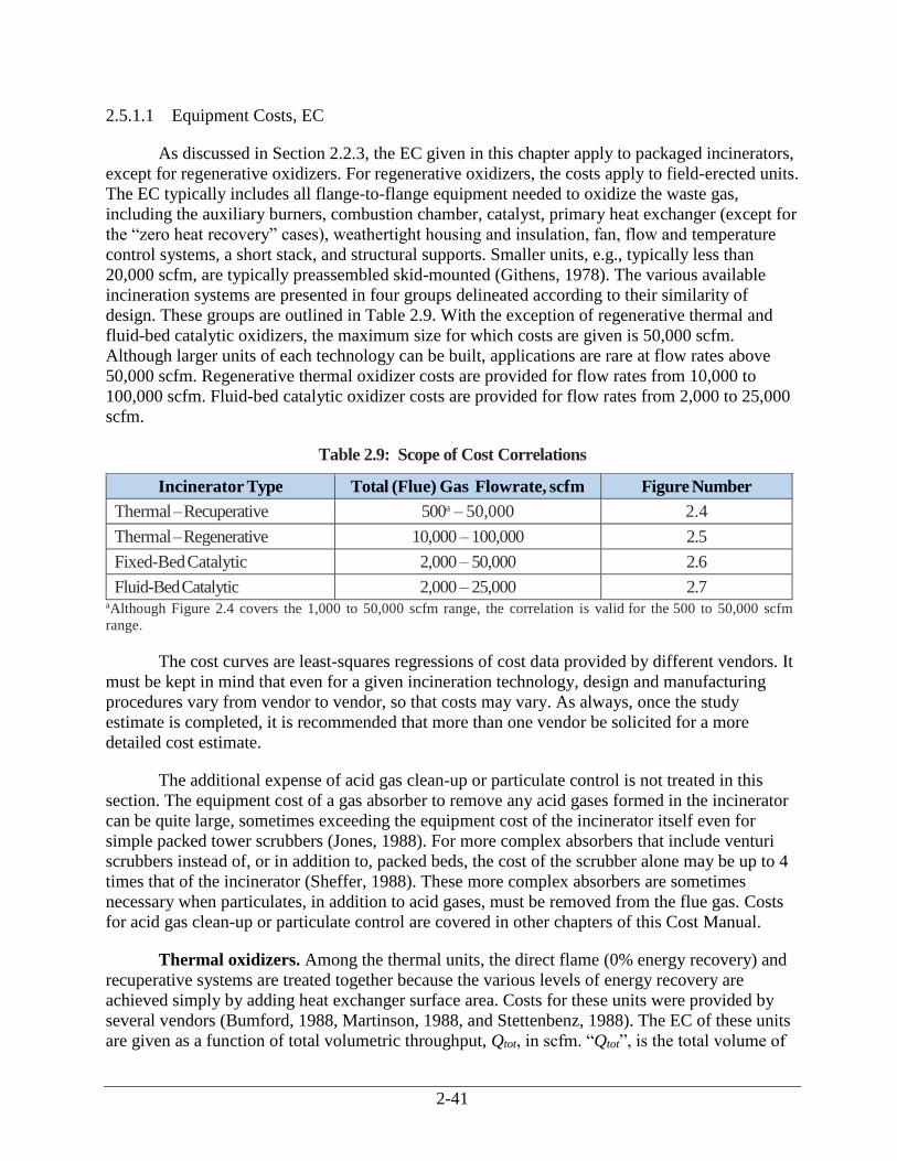
2-41
2.5.1.1 Equipment Costs, EC
As discussed in Section 2.2.3, the EC given in this chapter apply to packaged incinerators,
except for regenerative oxidizers. For regenerative oxidizers, the costs apply to field-erected units.
The EC typically includes all flange-to-flange equipment needed to oxidize the waste gas,
including the auxiliary burners, combustion chamber, catalyst, primary heat exchanger (except for
the “zero heat recovery” cases), weathertight housing and insulation, fan, flow and temperature
control systems, a short stack, and structural supports. Smaller units, e.g., typically less than
20,000 scfm, are typically preassembled skid-mounted (Githens, 1978). The various available
incineration systems are presented in four groups delineated according to their similarity of
design. These groups are outlined in Table 2.9. With the exception of regenerative thermal and
fluid-bed catalytic oxidizers, the maximum size for which costs are given is 50,000 scfm.
Although larger units of each technology can be built, applications are rare at flow rates above
50,000 scfm. Regenerative thermal oxidizer costs are provided for flow rates from 10,000 to
100,000 scfm. Fluid-bed catalytic oxidizer costs are provided for flow rates from 2,000 to 25,000
scfm.
Table 2.9: Scope of Cost Correlations
Incinerator Type Total (Flue) Gas Flowrate, scfm Figure Number
Thermal – Recuperative 500a – 50,000 2.4
Thermal – Regenerative 10,000 – 100,000 2.5
Fixed-Bed Catalytic 2,000 – 50,000 2.6
Fluid-Bed Catalytic 2,000 – 25,000 2.7 aAlthough Figure 2.4 covers the 1,000 to 50,000 scfm range, the correlation is valid for the 500 to 50,000 scfm
range.
The cost curves are least-squares regressions of cost data provided by different vendors. It
must be kept in mind that even for a given incineration technology, design and manufacturing
procedures vary from vendor to vendor, so that costs may vary. As always, once the study
estimate is completed, it is recommended that more than one vendor be solicited for a more
detailed cost estimate.
The additional expense of acid gas clean-up or particulate control is not treated in this
section. The equipment cost of a gas absorber to remove any acid gases formed in the incinerator
can be quite large, sometimes exceeding the equipment cost of the incinerator itself even for
simple packed tower scrubbers (Jones, 1988). For more complex absorbers that include venturi
scrubbers instead of, or in addition to, packed beds, the cost of the scrubber alone may be up to 4
times that of the incinerator (Sheffer, 1988). These more complex absorbers are sometimes
necessary when particulates, in addition to acid gases, must be removed from the flue gas. Costs
for acid gas clean-up or particulate control are covered in other chapters of this Cost Manual.
Thermal oxidizers. Among the thermal units, the direct flame (0% energy recovery) and
recuperative systems are treated together because the various levels of energy recovery are
achieved simply by adding heat exchanger surface area. Costs for these units were provided by
several vendors (Bumford, 1988, Martinson, 1988, and Stettenbenz, 1988). The EC of these units
are given as a function of total volumetric throughput, Qtot, in scfm. “Qtot”, is the total volume of
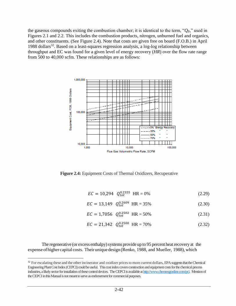
2-42
the gaseous compounds exiting the combustion chamber; it is identical to the term, “Qfi,” used in
Figures 2.1 and 2.2. This includes the combustion products, nitrogen, unburned fuel and organics,
and other constituents. (See Figure 2.4). Note that costs are given free on board (F.O.B.) in April
1988 dollars32. Based on a least-squares regression analysis, a log-log relationship between
throughput and EC was found for a given level of energy recovery (HR) over the flow rate range
from 500 to 40,000 scfm. These relationships are as follows:
Figure 2.4: Equipment Costs of Thermal Oxidizers, Recuperative
𝐸𝐶 = 10,294 𝑄𝑡𝑜𝑡0.2355 HR = 0% (2.29)
𝐸𝐶 = 13,149 𝑄𝑡𝑜𝑡0.2609 HR = 35% (2.30)
𝐸𝐶 = 1,7056 𝑄𝑡𝑜𝑡0.2502 HR = 50% (2.31)
𝐸𝐶 = 21,342 𝑄𝑡𝑜𝑡0.2500 HR = 70% (2.32)
The regenerative (or excess enthalpy) systems provide up to 95 percent heat recovery at the
expense of higher capital costs. Their unique design (Renko, 1988, and Mueller, 1988), which
32 For escalating these and the other incinerator and oxidizer prices to more current dollars, EPA suggests that the Chemical
Engineering Plant Cost Index (CEPCI) could be useful. This cost index covers construction and equipment costs for the chemical process
industries, a likely sector for installation of these control devices. The CEPCI is available at http://www.chemengonline.com/pci. Mention of
the CEPCI in this Manual is not meant to serve as endorsement for commercial purposes.
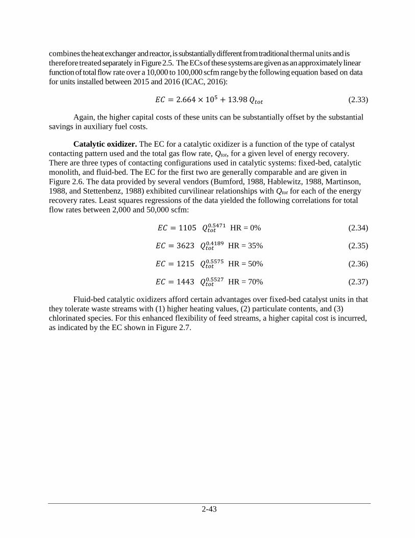
2-43
combines the heat exchanger and reactor, is substantially different from traditional thermal units and is
therefore treated separately in Figure 2.5. The ECs of these systems are given as an approximately linear
function of total flow rate over a 10,000 to 100,000 scfm range by the following equation based on data
for units installed between 2015 and 2016 (ICAC, 2016):
𝐸𝐶 = 2.664 × 10⁵ + 13.98 𝑄𝑡𝑜𝑡 (2.33)
Again, the higher capital costs of these units can be substantially offset by the substantial
savings in auxiliary fuel costs.
Catalytic oxidizer. The EC for a catalytic oxidizer is a function of the type of catalyst
contacting pattern used and the total gas flow rate, Qtot, for a given level of energy recovery.
There are three types of contacting configurations used in catalytic systems: fixed-bed, catalytic
monolith, and fluid-bed. The EC for the first two are generally comparable and are given in
Figure 2.6. The data provided by several vendors (Bumford, 1988, Hablewitz, 1988, Martinson,
1988, and Stettenbenz, 1988) exhibited curvilinear relationships with Qtot for each of the energy
recovery rates. Least squares regressions of the data yielded the following correlations for total
flow rates between 2,000 and 50,000 scfm:
𝐸𝐶 = 1105 𝑄𝑡𝑜𝑡0.5471 HR = 0% (2.34)
𝐸𝐶 = 3623 𝑄𝑡𝑜𝑡0.4189 HR = 35% (2.35)
𝐸𝐶 = 1215 𝑄𝑡𝑜𝑡0.5575 HR = 50% (2.36)
𝐸𝐶 = 1443 𝑄𝑡𝑜𝑡0.5527 HR = 70% (2.37)
Fluid-bed catalytic oxidizers afford certain advantages over fixed-bed catalyst units in that
they tolerate waste streams with (1) higher heating values, (2) particulate contents, and (3)
chlorinated species. For this enhanced flexibility of feed streams, a higher capital cost is incurred,
as indicated by the EC shown in Figure 2.7.
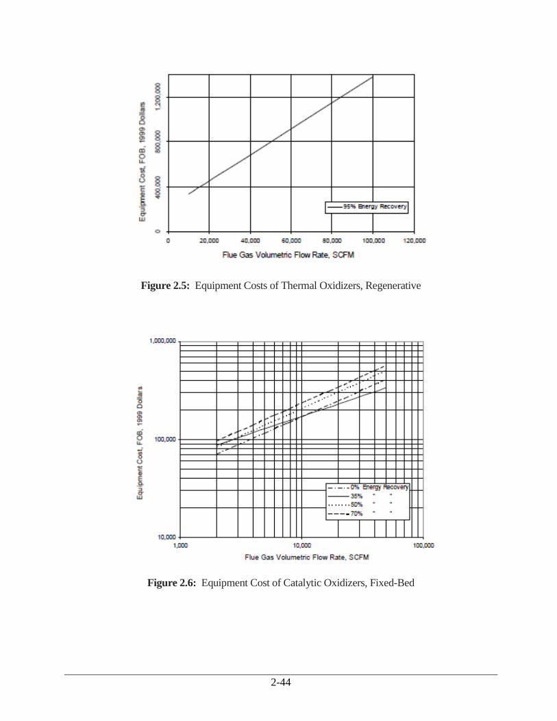
2-44
Figure 2.5: Equipment Costs of Thermal Oxidizers, Regenerative
Figure 2.6: Equipment Cost of Catalytic Oxidizers, Fixed-Bed
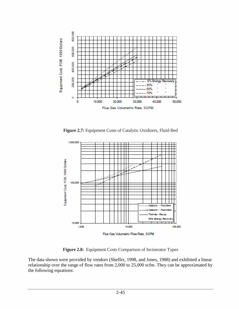
2-45
Figure 2.7: Equipment Costs of Catalytic Oxidizers, Fluid-Bed
Figure 2.8: Equipment Costs Comparison of Incinerator Types
The data shown were provided by vendors (Sheffer, 1998, and Jones, 1988) and exhibited a linear
relationship over the range of flow rates from 2,000 to 25,000 scfm. They can be approximated by
the following equations:
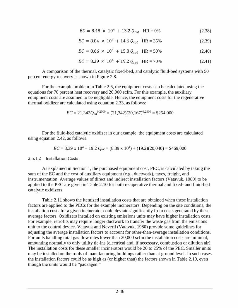
2-46
𝐸𝐶 = 8.48 × 10⁴ + 13.2 𝑄𝑡𝑜𝑡 HR = 0% (2.38)
𝐸𝐶 = 8.84 × 10⁴ + 14.6 𝑄𝑡𝑜𝑡 HR = 35% (2.39)
𝐸𝐶 = 8.66 × 10⁴ + 15.8 𝑄𝑡𝑜𝑡 HR = 50% (2.40)
𝐸𝐶 = 8.39 × 10⁴ + 19.2 𝑄𝑡𝑜𝑡 HR = 70% (2.41)
A comparison of the thermal, catalytic fixed-bed, and catalytic fluid-bed systems with 50
percent energy recovery is shown in Figure 2.8.
For the example problem in Table 2.6, the equipment costs can be calculated using the
equations for 70 percent heat recovery and 20,000 scfm. For this example, the auxiliary
equipment costs are assumed to be negligible. Hence, the equipment costs for the regenerative
thermal oxidizer are calculated using equation 2.33, as follows:
EC = 21,342Qtot0.2500 = (21,342)(20,167)0.2500 = $254,000
For the fluid-bed catalytic oxidizer in our example, the equipment costs are calculated
using equation 2.42, as follows:
EC = 8.39 x 10⁴ + 19.2 Qtot = (8.39 x 10⁴) + (19.2)(20,040) = $469,000
2.5.1.2 Installation Costs
As explained in Section 1, the purchased equipment cost, PEC, is calculated by taking the
sum of the EC and the cost of auxiliary equipment (e.g., ductwork), taxes, freight, and
instrumentation. Average values of direct and indirect installation factors (Vatavuk, 1980) to be
applied to the PEC are given in Table 2.10 for both recuperative thermal and fixed- and fluid-bed
catalytic oxidizers.
Table 2.11 shows the itemized installation costs that are obtained when these installation
factors are applied to the PECs for the example incinerators. Depending on the site conditions, the
installation costs for a given incinerator could deviate significantly from costs generated by these
average factors. Oxidizers installed on existing emissions units may have higher installation costs.
For example, retrofits may require longer ductwork to transfer the waste gas from the emissions
unit to the control device. Vatavuk and Neveril (Vatavuk, 1980) provide some guidelines for
adjusting the average installation factors to account for other-than-average installation conditions.
For units handling total gas flow rates lower than 20,000 scfm the installation costs are minimal,
amounting normally to only utility tie-ins (electrical and, if necessary, combustion or dilution air).
The installation costs for these smaller incinerators would be 20 to 25% of the PEC. Smaller units
may be installed on the roofs of manufacturing buildings rather than at ground level. In such cases
the installation factors could be as high as (or higher than) the factors shown in Table 2.10, even
though the units would be “packaged.”
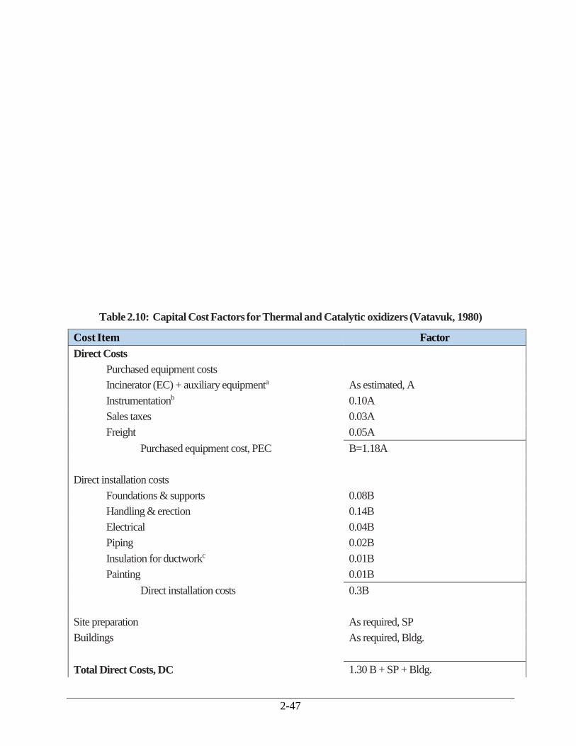
2-47
Table 2.10: Capital Cost Factors for Thermal and Catalytic oxidizers (Vatavuk, 1980)
Cost Item Factor
Direct Costs
Purchased equipment costs
Incinerator (EC) + auxiliary equipmenta As estimated, A
Instrumentationb 0.10A
Sales taxes 0.03A
Freight 0.05A
Purchased equipment cost, PEC B=1.18A
Direct installation costs
Foundations & supports 0.08B
Handling & erection 0.14B
Electrical 0.04B
Piping 0.02B
Insulation for ductworkc 0.01B
Painting 0.01B
Direct installation costs 0.3B
Site preparation As required, SP
Buildings As required, Bldg.
Total Direct Costs, DC 1.30 B + SP + Bldg.
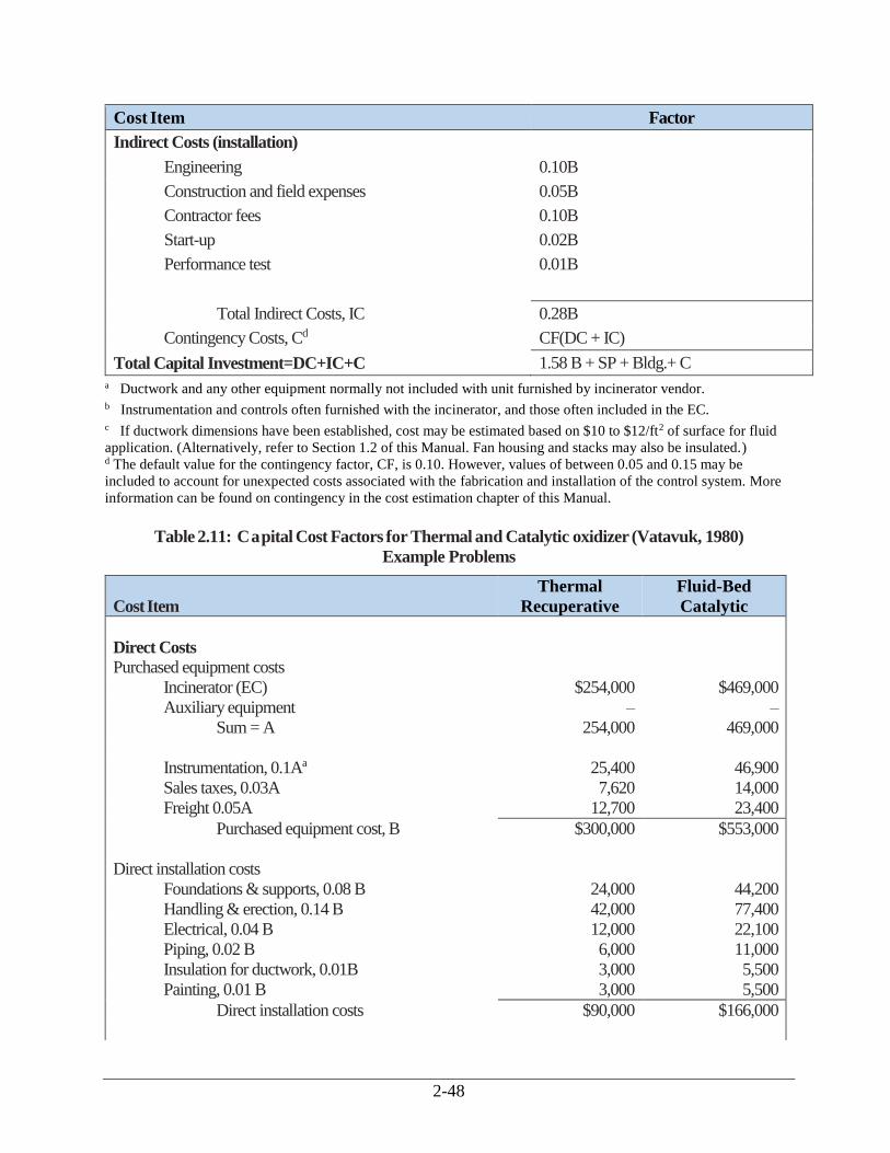
2-48
Cost Item Factor
Indirect Costs (installation)
Engineering 0.10B
Construction and field expenses 0.05B
Contractor fees 0.10B
Start-up 0.02B
Performance test 0.01B
Total Indirect Costs, IC 0.28B
Contingency Costs, Cd CF(DC + IC)
Total Capital Investment=DC+IC+C 1.58 B + SP + Bldg.+ C a Ductwork and any other equipment normally not included with unit furnished by incinerator vendor. b Instrumentation and controls often furnished with the incinerator, and those often included in the EC. c If ductwork dimensions have been established, cost may be estimated based on $10 to $12/ft2 of surface for fluid
application. (Alternatively, refer to Section 1.2 of this Manual. Fan housing and stacks may also be insulated.) d The default value for the contingency factor, CF, is 0.10. However, values of between 0.05 and 0.15 may be
included to account for unexpected costs associated with the fabrication and installation of the control system. More
information can be found on contingency in the cost estimation chapter of this Manual.
Table 2.11: Capital Cost Factors for Thermal and Catalytic oxidizer (Vatavuk, 1980)
Example Problems
Cost Item
Thermal
Recuperative
Fluid-Bed
Catalytic
Direct Costs
Purchased equipment costs
Incinerator (EC) $254,000 $469,000
Auxiliary equipment – –
Sum = A 254,000 469,000
Instrumentation, 0.1Aa 25,400 46,900
Sales taxes, 0.03A 7,620 14,000
Freight 0.05A 12,700 23,400
Purchased equipment cost, B $300,000 $553,000
Direct installation costs
Foundations & supports, 0.08 B 24,000 44,200
Handling & erection, 0.14 B 42,000 77,400
Electrical, 0.04 B 12,000 22,100
Piping, 0.02 B 6,000 11,000
Insulation for ductwork, 0.01B 3,000 5,500
Painting, 0.01 B 3,000 5,500
Direct installation costs $90,000 $166,000

2-49
Site preparationa – –
Buildingsa –
Total Direct $390,000 $719,000
Indirect Costs (installation)
Engineering, 0.10 B 30,000 55,300
Construction and field expenses, 0.05 B 15,000 27,600
Contractor fees, 0.10 B 30,000 55,300
Start-up, 0.02 B 6,000 11,000
Performance test, 0.01 B 3,000 5,500
Total Indirect Costs $84,000 $155,000
Total Direct and Indirect Costs
Contingency Cost, 0.10(DC + IC)
$474,000
$47,000
$874,000
$87,000
Total Capital Investment (rounded)
$521,000
$961,000
a These items are not required for this example problem.
2.5.2 Estimating Total Annual Cost
The total annual cost (TAC) is the sum of the direct and indirect annual costs. The TAC
for both example systems is given in Table 2.12, along with suggested factors for calculating
them.
2.5.2.1 Direct Annual Costs
Direct annual costs for incinerators include labor (operating and supervisory),
maintenance (labor and materials), fuel, electricity, and (in catalytic units) replacement catalyst.
For thermal and catalytic units, the fuel usage rate is calculated as shown in Sections 2.3.2 and
2.3.3, respectively where natural gas (methane) is assumed to be the fuel. (Other fuels could be
used for thermal units.)
The electricity costs are primarily associated with the fan needed to move the gas through
the incinerator. The power (in kilowatts) needed to move a given inlet volumetric flow rate of air
(Qwi per Sections 2.2.3 and 2.3.3) at a total flange-to-flange pressure drop of ΔP inches of water
and combined motor/fan efficiency, ℰ, is adapted from Equation 2.7, as follows:
𝑃𝑜𝑤𝑒𝑟𝑓𝑎𝑛 =1.17 × 10⁻⁴ 𝑄𝑤𝑖
∆𝑃
𝜀
Fan efficiencies vary from 40 to 80 percent (Green, 1999) while motor efficiencies are usually
90 percent. The total pressure drop across an incinerator system depends on the number and types of
equipment elements included in the system and on design considerations. The estimation of actual
pressure drop requirements involves complex calculations based on the specific system’s waste gas
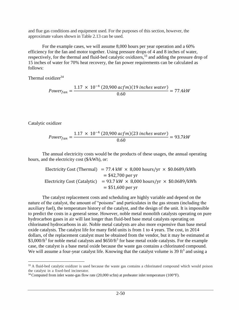
2-50
and flue gas conditions and equipment used. For the purposes of this section, however, the
approximate values shown in Table 2.13 can be used.
For the example cases, we will assume 8,000 hours per year operation and a 60%
efficiency for the fan and motor together. Using pressure drops of 4 and 8 inches of water,
respectively, for the thermal and fluid-bed catalytic oxidizers,33 and adding the pressure drop of
15 inches of water for 70% heat recovery, the fan power requirements can be calculated as
follows:
Thermal oxidizer34
𝑃𝑜𝑤𝑒𝑟𝑓𝑎𝑛 =1.17 × 10⁻⁴ (20,900 𝑎𝑐𝑓𝑚)(19 𝑖𝑛𝑐ℎ𝑒𝑠 𝑤𝑎𝑡𝑒𝑟)
0.60= 77.4𝑘𝑊
Catalytic oxidizer
𝑃𝑜𝑤𝑒𝑟𝑓𝑎𝑛 =1.17 × 10⁻⁴ (20,900 𝑎𝑐𝑓𝑚)(23 𝑖𝑛𝑐ℎ𝑒𝑠 𝑤𝑎𝑡𝑒𝑟)
0.60= 93.7𝑘𝑊
The annual electricity costs would be the products of these usages, the annual operating
hours, and the electricity cost ($/kWh), or:
Electricity Cost (Thermal) = 77.4 kW × 8,000 hours/yr × $0.0689/kWh
= $42,700 per yr
Electricity Cost (Catalytic) = 93.7 kW × 8,000 hours/yr × $0.0689/kWh
= $51,600 per yr
The catalyst replacement costs and scheduling are highly variable and depend on the
nature of the catalyst, the amount of “poisons” and particulates in the gas stream (including the
auxiliary fuel), the temperature history of the catalyst, and the design of the unit. It is impossible
to predict the costs in a general sense. However, noble metal monolith catalysts operating on pure
hydrocarbon gases in air will last longer than fluid-bed base metal catalysts operating on
chlorinated hydrocarbons in air. Noble metal catalysts are also more expensive than base metal
oxide catalysts. The catalyst life for many field units is from 1 to 4 years. The cost, in 2014
dollars, of the replacement catalyst must be obtained from the vendor, but it may be estimated at
$3,000/ft3 for noble metal catalysts and $650/ft3 for base metal oxide catalysts. For the example
case, the catalyst is a base metal oxide because the waste gas contains a chlorinated compound.
We will assume a four-year catalyst life. Knowing that the catalyst volume is 39 ft3 and using a
33 A fluid-bed catalytic oxidizer is used because the waste gas contains a chlorinated compound which would poison
the catalyst in a fixed-bed incinerator.
34 Computed from inlet waste-gas flow rate (20,000 scfm) at preheater inlet temperature (100°F).
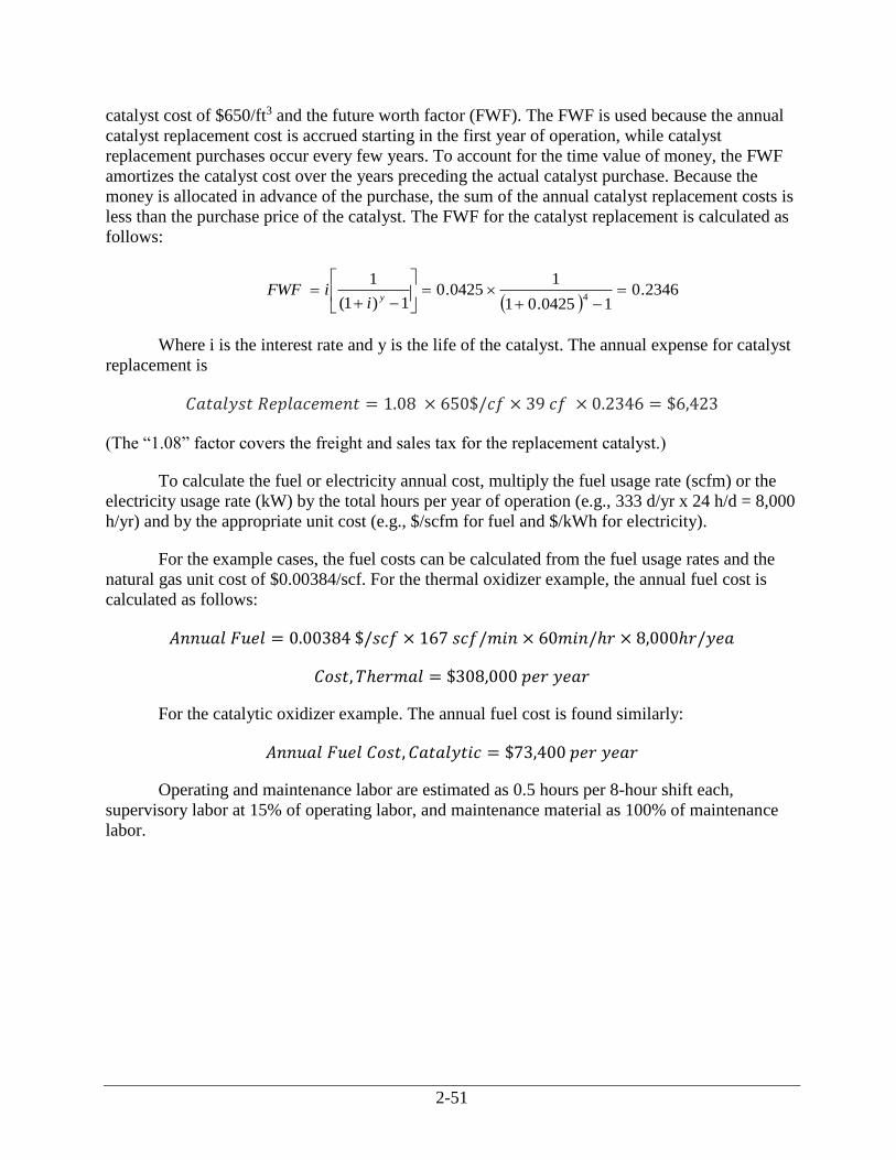
2-51
catalyst cost of $650/ft3 and the future worth factor (FWF). The FWF is used because the annual
catalyst replacement cost is accrued starting in the first year of operation, while catalyst
replacement purchases occur every few years. To account for the time value of money, the FWF
amortizes the catalyst cost over the years preceding the actual catalyst purchase. Because the
money is allocated in advance of the purchase, the sum of the annual catalyst replacement costs is
less than the purchase price of the catalyst. The FWF for the catalyst replacement is calculated as
follows:
2346.0
10425.01
10425.0
1)1(
14
yi
iFWF
Where i is the interest rate and y is the life of the catalyst. The annual expense for catalyst
replacement is
𝐶𝑎𝑡𝑎𝑙𝑦𝑠𝑡 𝑅𝑒𝑝𝑙𝑎𝑐𝑒𝑚𝑒𝑛𝑡 = 1.08 × 650$/𝑐𝑓 × 39 𝑐𝑓 × 0.2346 = $6,423
(The “1.08” factor covers the freight and sales tax for the replacement catalyst.)
To calculate the fuel or electricity annual cost, multiply the fuel usage rate (scfm) or the
electricity usage rate (kW) by the total hours per year of operation (e.g., 333 d/yr x 24 h/d = 8,000
h/yr) and by the appropriate unit cost (e.g., $/scfm for fuel and $/kWh for electricity).
For the example cases, the fuel costs can be calculated from the fuel usage rates and the
natural gas unit cost of $0.00384/scf. For the thermal oxidizer example, the annual fuel cost is
calculated as follows:
𝐴𝑛𝑛𝑢𝑎𝑙 𝐹𝑢𝑒𝑙 = 0.00384 $/𝑠𝑐𝑓 × 167 𝑠𝑐𝑓/𝑚𝑖𝑛 × 60𝑚𝑖𝑛/ℎ𝑟 × 8,000ℎ𝑟/𝑦𝑒𝑎
𝐶𝑜𝑠𝑡, 𝑇ℎ𝑒𝑟𝑚𝑎𝑙 = $308,000 𝑝𝑒𝑟 𝑦𝑒𝑎𝑟
For the catalytic oxidizer example. The annual fuel cost is found similarly:
𝐴𝑛𝑛𝑢𝑎𝑙 𝐹𝑢𝑒𝑙 𝐶𝑜𝑠𝑡, 𝐶𝑎𝑡𝑎𝑙𝑦𝑡𝑖𝑐 = $73,400 𝑝𝑒𝑟 𝑦𝑒𝑎𝑟
Operating and maintenance labor are estimated as 0.5 hours per 8-hour shift each,
supervisory labor at 15% of operating labor, and maintenance material as 100% of maintenance
labor.
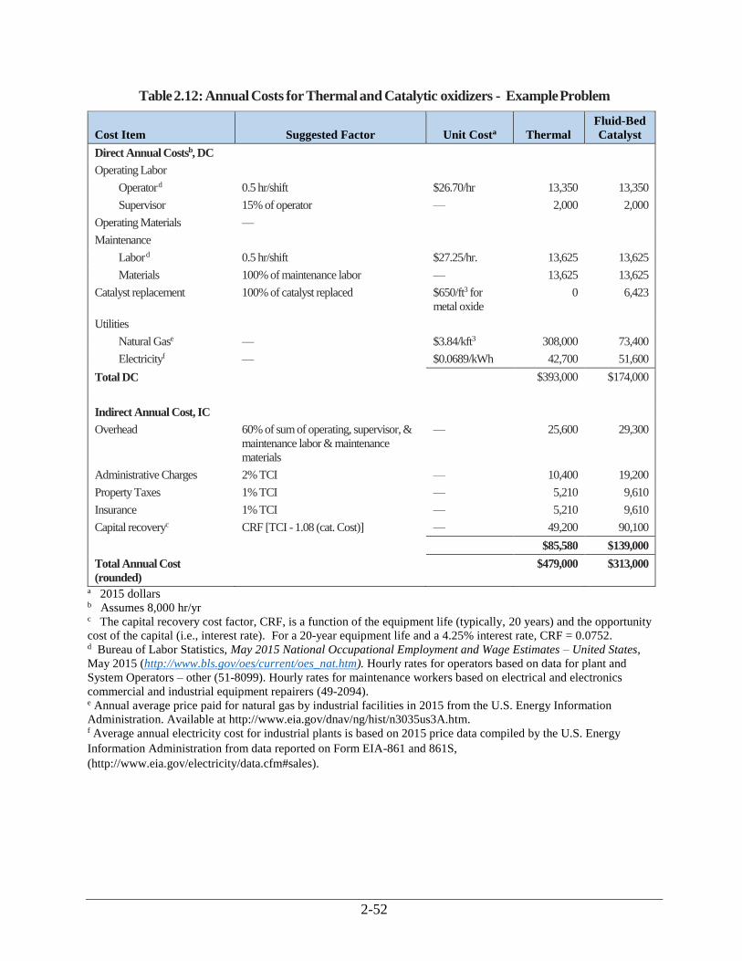
2-52
Table 2.12: Annual Costs for Thermal and Catalytic oxidizers - Example Problem
Cost Item Suggested Factor Unit Costa Thermal
Fluid-Bed
Catalyst
Direct Annual Costsb, DC
Operating Labor
Operator d 0.5 hr/shift $26.70/hr 13,350 13,350
Supervisor 15% of operator — 2,000 2,000
Operating Materials —
Maintenance
Labor d 0.5 hr/shift $27.25/hr. 13,625 13,625
Materials 100% of maintenance labor — 13,625 13,625
Catalyst replacement 100% of catalyst replaced $650/ft3 for
metal oxide
0 6,423
Utilities
Natural Gase — $3.84/kft3 308,000 73,400
Electricityf — $0.0689/kWh 42,700 51,600
Total DC $393,000 $174,000
Indirect Annual Cost, IC
Overhead 60% of sum of operating, supervisor, &
maintenance labor & maintenance
materials
— 25,600 29,300
Administrative Charges 2% TCI — 10,400 19,200
Property Taxes 1% TCI — 5,210 9,610
Insurance 1% TCI — 5,210 9,610
Capital recoveryc CRF [TCI - 1.08 (cat. Cost)] — 49,200 90,100
$85,580 $139,000
Total Annual Cost
(rounded)
$479,000 $313,000
a 2015 dollars b Assumes 8,000 hr/yr c The capital recovery cost factor, CRF, is a function of the equipment life (typically, 20 years) and the opportunity
cost of the capital (i.e., interest rate). For a 20-year equipment life and a 4.25% interest rate, CRF = 0.0752. d Bureau of Labor Statistics, May 2015 National Occupational Employment and Wage Estimates – United States, May 2015 (http://www.bls.gov/oes/current/oes_nat.htm). Hourly rates for operators based on data for plant and
System Operators – other (51-8099). Hourly rates for maintenance workers based on electrical and electronics
commercial and industrial equipment repairers (49-2094). e Annual average price paid for natural gas by industrial facilities in 2015 from the U.S. Energy Information
Administration. Available at http://www.eia.gov/dnav/ng/hist/n3035us3A.htm. f Average annual electricity cost for industrial plants is based on 2015 price data compiled by the U.S. Energy
Information Administration from data reported on Form EIA-861 and 861S,
(http://www.eia.gov/electricity/data.cfm#sales).
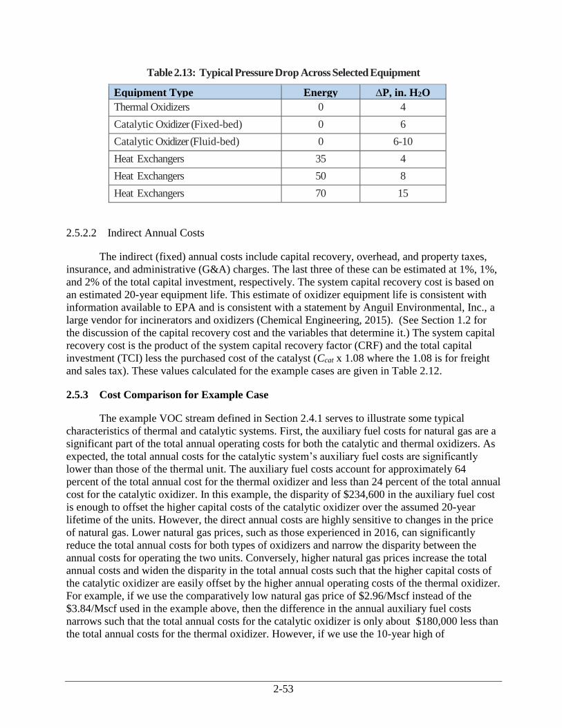
2-53
Table 2.13: Typical Pressure Drop Across Selected Equipment
Equipment Type Energy
Recovery, %
∆P, in. H2O
Thermal Oxidizers 0 4
Catalytic Oxidizer (Fixed-bed) 0 6
Catalytic Oxidizer (Fluid-bed) 0 6-10
Heat Exchangers 35 4
Heat Exchangers 50 8
Heat Exchangers 70 15
2.5.2.2 Indirect Annual Costs
The indirect (fixed) annual costs include capital recovery, overhead, and property taxes,
insurance, and administrative (G&A) charges. The last three of these can be estimated at 1%, 1%,
and 2% of the total capital investment, respectively. The system capital recovery cost is based on
an estimated 20-year equipment life. This estimate of oxidizer equipment life is consistent with
information available to EPA and is consistent with a statement by Anguil Environmental, Inc., a
large vendor for incinerators and oxidizers (Chemical Engineering, 2015). (See Section 1.2 for
the discussion of the capital recovery cost and the variables that determine it.) The system capital
recovery cost is the product of the system capital recovery factor (CRF) and the total capital
investment (TCI) less the purchased cost of the catalyst (Ccat x 1.08 where the 1.08 is for freight
and sales tax). These values calculated for the example cases are given in Table 2.12.
2.5.3 Cost Comparison for Example Case
The example VOC stream defined in Section 2.4.1 serves to illustrate some typical
characteristics of thermal and catalytic systems. First, the auxiliary fuel costs for natural gas are a
significant part of the total annual operating costs for both the catalytic and thermal oxidizers. As
expected, the total annual costs for the catalytic system’s auxiliary fuel costs are significantly
lower than those of the thermal unit. The auxiliary fuel costs account for approximately 64
percent of the total annual cost for the thermal oxidizer and less than 24 percent of the total annual
cost for the catalytic oxidizer. In this example, the disparity of $234,600 in the auxiliary fuel cost
is enough to offset the higher capital costs of the catalytic oxidizer over the assumed 20-year
lifetime of the units. However, the direct annual costs are highly sensitive to changes in the price
of natural gas. Lower natural gas prices, such as those experienced in 2016, can significantly
reduce the total annual costs for both types of oxidizers and narrow the disparity between the
annual costs for operating the two units. Conversely, higher natural gas prices increase the total
annual costs and widen the disparity in the total annual costs such that the higher capital costs of
the catalytic oxidizer are easily offset by the higher annual operating costs of the thermal oxidizer.
For example, if we use the comparatively low natural gas price of $2.96/Mscf instead of the
$3.84/Mscf used in the example above, then the difference in the annual auxiliary fuel costs
narrows such that the total annual costs for the catalytic oxidizer is only about $180,000 less than
the total annual costs for the thermal oxidizer. However, if we use the 10-year high of
2-54
$9.65/Mscf35 for the natural gas price at industrial facilities, the total annual costs for the catalytic
oxidizer would be $589,000 less than the total annual costs for the thermal oxidizer, which easily
offsets the $440,000 additional capital investment required for the catalytic oxidizer.
Two other factors that should be noted in the comparison of these two systems are (1) the
99 percent level of destruction met by the thermal oxidizer may be difficult to reach by the
catalytic system (this may be important in some cases), and (2) the example waste stream is of
particularly low heating value (4 Btu/scf) which favors the catalytic system due to the lower
auxiliary fuel requirements.
2.6 Cost Analysis for Incinerators
Solid waste incineration systems are designed to handle a specific volume and type of
waste. Information needed to select/design a solid waste incinerator include:
The total amount of solids to be processed, including the average and peak amounts.
Characteristics of the waste material, including moisture content, percent volatile solids,
heat value, and concentration of inorganics.
Capital costs of incinerators depend on the size and type of unit. In addition to the cost of
the incinerator, other components of an incinerator system include:
Solid waste storage and conveyance system to transfer waste to the incinerator;
Ash handling and storage system;
Air pollution controls; and
Auxiliary fuel system (e.g., natural gas pipelines, fuel oil storage tanks).
Some incinerators operate using ambient air, while others preheat the air before it enters
the incinerator. Heating the air reduces fuel costs by about 60 percent. However, the additional
equipment needed to preheat the air may increase the capital costs by as much as 15 percent (EPA
2003).
Sewage Sludge Incinerators
Annual operating costs depend on fuel costs. The amount of auxiliary fuel combusted
depends on the heat value of the waste. The heat of combustion for sewage sludge ranges from
18,624 to 30,364 kj/dry Kg of solids (8,000 to 13,000 Btu/dry lb) for primary wastewater solids
and 11,640 to 23,280 kJ/dry kg of solids (5,000 to 10,000 Btu/dry lb) for mixtures of primary
waste and activated solids. Incinerators handling anaerobically digested solids are generally more
expensive to operate because of the low heat value of the solids (12,804 kJ/dry kg of solids (5,500
Btu/dry lb). The amount of auxiliary fuel consumed is also dependent on the moisture content of
35 Average annual natural gas price for industrial consumers in 2008 based on U.S. Energy Information
Administration data available at https://www.eia.gov/dnav/ng/hist/n3035us3A.htm.
2-55
the sludge. In general, incineration of sewage sludge is most economical when the sludge is
dewatered to at least 25 percent solids. Typical annual O&M costs range from $83 to $269/dry
Mg ($76 to $245/dry ton (adjusted to 2002 ENR values). The adjusted 2002 O&M costs for a
multiple hearth facility retrofitted with additional air pollution control equipment to comply with
federal regulations (40 CFR Part 503, 40 CFR Part 62, Subpart LLL, 40 CFR Part 60, Subpart
LLLL, and 40 CFR Part 60, Subpart MMMM) (EPA 2003).
Capital costs for sludge waste incinerators is difficult to obtain because few new
incinerators have been constructed in recent years due to the relatively low cost of land
application (estimated at $15.40/dry Mg ($14/dry ton)) (EPA 2003).
Two new sewage sludge incinerators were installed at the R.L Sutton Wastewater
Reclamation facility in 2009. The system consists of 2 new fluidized bed incinerators and a
dewatering system consisting of four centrifuges, cake pumps and screw feeders, sludge silos,
polymer system, and controls. The total capital cost of the system was $56,890,000 (EPA 2003).
Three new fluidized bed incinerators were installed at the Mill Creek in 2010. They cost
$75 million to permit and construct, and are anticipated to save about $1 million in fuel costs a
year. The new incinerators burn undigested sludge, which means the incinerators can be self-fired
by the thermal energy contained in the waste being burned. The old incinerator building will be
demolished, and the Mill Creek digesters will be decommissioned.36
The rated capacity of the three new incinerators is 4 dry tons per hour each, for a total of
12 dry tons per hour. When operating continuously, they can be autogenous, or self-fueling. This
feature will dramatically reduce fuel consumption and air emissions, including greenhouse gas
(GHG) emissions. Due to the lower operating costs, greater operational flexibility, and lower
emissions, the EPA believes that only fluidized bed incinerators are likely to be constructed in the
future (ERG 2011).37
36 See http://projectgroundwork.org/sustainability/op_enviro/incinerator.html. 37 Memorandum from Eastern Research Group, Inc. to U.S. EPA, Revised Estimation of Impacts for New Units
Constructed Within Five Years After Promulgation of the SSI NSPS, January 2011.
2-56
References
Bumford, C. L. (Peabody Engineering, Stamford, CT), Personal Communication between C. L.
Bumford and Donald R. van der Vaart (RTI, Research Triangle Park, NC), March 28, 1988.
Bunimovich, G., and Y. Matros, Saving Energy in Regenerative Oxidizers. Chemical
Engineering. March 2010.
Chemical Engineering Magazine, EPA Bumps Up Enforcement Efforts, November 2015, pp. 27-
28.
Eastern Research Group, Inc., Memorandum to Amy Hambrick, U.S. EPA, January 2011,
Revised Estimation of Impacts for New Units Constructed Within Five Years After Promulgation
of the SSI NSPS.
Githens, R. E. and D. M. Sowards, Catalytic Oxidation of Hydrocarbon Fumes, PB- 299 132,
National Technical Information Service, Springfield, VA, 1978
Green, D.W. (eds.), Perry’s Chemical Engineers Handbook, 7th ed., McGraw- Hill, New York,
NY 1999.
Grelecki, C., Fundamentals of Fire and Explosion Hazards Evaluation, AIChE Today Series,
New York, 1976.
Hablewitz, Robert (Pillar Technologies, Hartland, WI), Personal Communication between Robert
Hablewitz and Donald R. van der Vaart (RTI, Research Triangle Park, NC), March 20, 1988.
Institute of Clean Air Companies (ICAC), Letter from Michael Stafford, Interim Executive
Director, to Larry Sorrels (EPA, OAQPS, Research Triangle Park, NC), December 21, 2016.
Jones, Andrew (Energy Development Associates, Itasca, IL), Personal communication between
Andrew Jones and Donald R. van der Vaart (RTI, Research Triangle Park, NC), March 4, 1988.
Kobe, K. A. and associates, Thermochemistry for the Petrochemical Industry, Petroleum Refiner,
Jan. 1949 through Nov. 1954.
Lide, David R. (ed.), CRC Handbook of Chemistry and Physics, 85th ed., CRC Press, Cleveland,
Ohio, 2005.
Manning, P., Hazard Waste, 1984, 1(1).
Martinson, C. M. (TEC Systems, DePere, WI), Personal Communication between C. M.
Martinson and Donald R. van der Vaart (RTI, Research Triangle Park, NC), March 28, 1988.
Mascone, D.C., EPA, OAQPS, Memorandum from Mascone to Farmer, J. R., OAQPS, EPA, June
11, 1980a, Thermal Incinerator Performance for NSPS.
2-57
Mascone, D.C., EPA, OAQPS, Memorandum from Mascone to Farmer, J. R., OAQPS, EPA, July
22, 1980b, Thermal Incinerator Performance for NSPS, Addendum.
Mascone, D.C., EPA, OAQPS, Memorandum from Mascone to Farmer, J. R., OAQPS, EPA,
August 22, 1980c, Thermal Incinerators and Flares.
Masonick, Gary (Goal Line Environmental Technolgies) Personal communication between Gary
Masonick and Janet D. Groeber (SAIC. Cincinnati, OH), September 29, 1999.
Matthews, Manuel; Robert Herbick, Ky Dantran, Replacement of the Multiple Hearth Furnaces
by the Fluid Bed Furnaces – The R.L. Sutton WRF Experience, Proceedings of the Water
Environment Federation, 2009, 55-64.
Mueller, James H. (Regenerative Environmental Equipment Co., Inc., Morris Plains, NJ),
Personal Communication between James H. Mueller and Donald R. van der Vaart (RTI, Research
Triangle Park, NC), January 13, 1988.
Musick, J. K., and F. W. Williams, Ind. Eng. Chem. Prod. Res. Dev., 1974, 13(3).
National Acadamy Press, Prudent Practices for Disposal of Chemicals from Laboratories,
Washington, D.C., 1983.
Nester, James.L., Technology Selection Criteria for VOC Control, NESTEC, Inc., 2006.
Pope, D., Walker, D. S., Moss, R. L., Atmos. Environ., 1976, 10.
Raemhild, Gary (Goenergy, Kent, WA) , Personal Communication between Gary Raemhild and
Janet D. Groeber (SAIC. Cincinnati, OH), September 28, 1999.
Raemhild, G., and S. Jaasund. Geoenergy International Corporation. Upstream Particulate
Removal for RTOs on Direct-Fired OSB Dryers—How Much Is Enough? TAPPI Environmental
Conference, April 2001.
Renko, Ronald J. (Huntington Energy Systems, Inc., Union, NJ), Personal Communication
between Ronald J. Renko and Donald R. van der Vaart (RTI, Research Triangle Park, NC),
March 16, 1988.
Schmidt, Thomas (ARI International, Palatine, IL), Personal Communication between Thomas
Schmidt and William M. Vatavuk (EPA, OAQPS, Research Triangle Park, NC), June 7, 1989a.
Schmidt, Thomas (ARI International, Palatine, IL) Letter from Thomas Schmidt to William M.
Vatavuk (EPA, OAQPS, Research Triangle Park, NC), August 16, 1989b.
Sheffer, Bill (ARI, Inc., Palatine, IL) Personal Communication between Bill Sheffer and
Donald R. van der Vaart (RTI, Research Triangle Park, NC), March 30, 1988.
2-58
Stettenbenz, Ralph (Combustion Engineering, Air Preheater, Inc., Wellsville, NY), Personal
Communication between Ralph Stettenbenz and Donald R. van der Vaart (RTI, Research Triangle
Park, NC), March 23, 1988.
U.S. EPA, AP 42, Chapter 2.3.1.1, Medical Waste Incineration, Volume 1, fifth edition, 1993
(http://www.epa.gov/ttn/chief/ap42/ch02/index.html).
U.S. EPA, AP 42, Chapter 2.2.1.1, Sewage Sludge Incineration, Volume 1, fifth edition, 1995
(http://www.epa.gov/ttn/chief/ap42/ch02/index.html).
U.S. EPA, AP 42, Chapter 2.1.2, Refuse Combustion, Volume 1, fifth edition, 1996
(http://www.epa.gov/ttn/chief/ap42/ch02/index.html).
U.S. EPA, Economic Impact Analysis of the Plywood and Composite Wood Products NEHSAP,
OAQPS, November 2002. (http://www3.epa.gov/ttnecas1/regdata/EIAs/eia11_22_02.pdf)
U.S. EPA, Locating and Estimating Air Emissions from Sources of Dioxins and Furans, EPA
454/R-97-003, May 1997.
U.S. EPA, Office of Water, Biosolids Technology Fact Sheet: Use of Incineration for Biosolids
Management, EPA 832-F-03-013, June 2003.
U.S. EPA, Summary of Environmental and Cost Impacts of Final Amendments to Portland
Cement NEHSAP (40 CFR Part 63, Subpart LLL), EPA-HQ-OAR-2002-0051, August 2010.
(http://www3.epa.gov/airtoxics/pcem/summary_impacts.pdf).
Vatavuk, W. M. and R. Neveril, Estimating Costs of Air Pollution Control Systems, Part II:
Factors for Estimating Capital and Operating Costs, Chemical Engineering, November 3, 1980,
pp. 157-162.
Vatavuk, William. M., Estimating Costs of Air Pollution Control, Lewis Publishers, 1990.
Vatavuk, William M. (EPA, OAQPS, Research Triangle Park, NC), Letter from William M.
Vatavuk to Rod Pennington (REECO/Research Cottrell, Somerville, NJ), September 22, 1992a.
Vatavuk, William M. (EPA, OAQPS, Research Triangle Park, NC) Letter from William M.
Vatavuk to Gerald Schrubba (Salem Engelhard, South Lyon, MI), September 22, 1992b.Weldon,
J. and S. M. Senkan, Combustion Sci. Technol., 1986, 47.
Wilke, John (CVM Corp., Wilmington, DE), Personal communication between John Wilke and
Janet D. Groeber (SAIC. Cincinnati, OH), September 29, 1999.
Yarrington, Robert (Englehard Corp., Edison, NJ), Personal Communication between Robert
Yarrington and William M. Vatavuk (EPA, OAQPS, Research Triangle Park, NC), June 6, 1989a.
Yarrington, Robert M. (Englehard Corporation, Edison, NJ), Letter from Robert M. Yarrington to
William M. Vatavuk (EPA, OAQPS, Research Triangle Park, NC), August 14, 1989b.
2-59
Appendix A
Properties of Selected Compounds
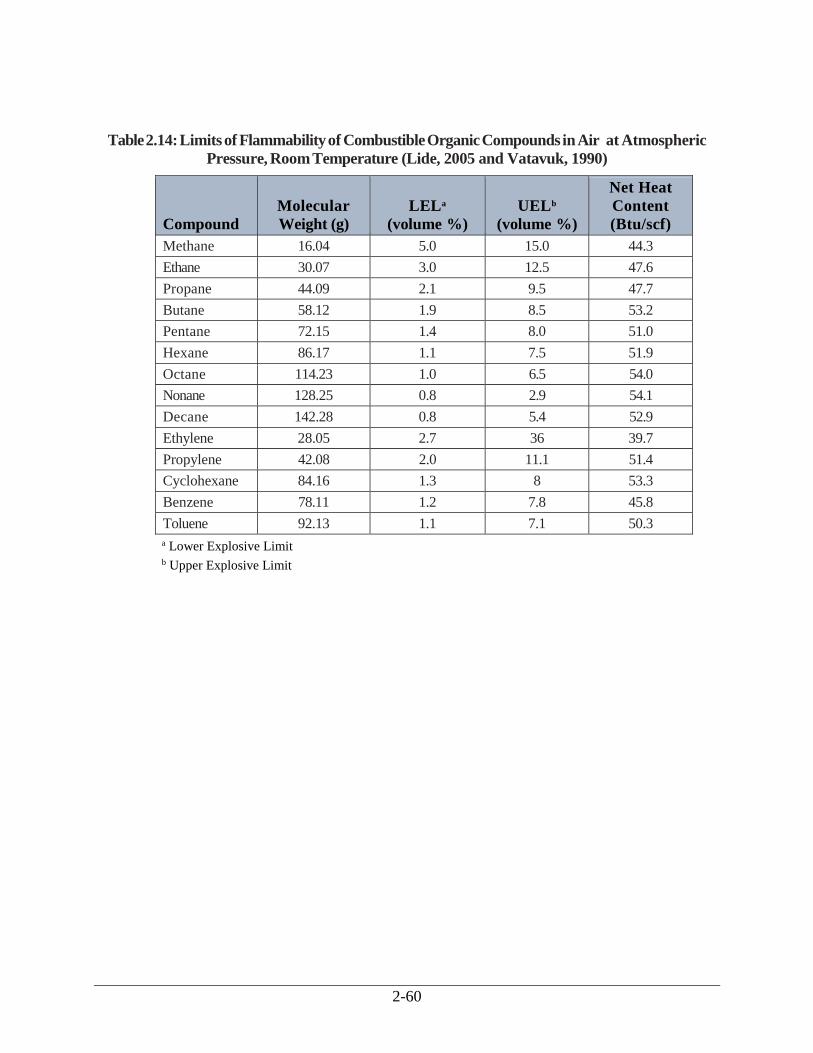
2-60
Table 2.14: Limits of Flammability of Combustible Organic Compounds in Air at Atmospheric
Pressure, Room Temperature (Lide, 2005 and Vatavuk, 1990)
Compound
Molecular
Weight (g)
LELa
(volume %)
UELb
(volume %)
Net Heat
Content
(Btu/scf)
Methane 16.04 5.0 15.0 44.3
Ethane 30.07 3.0 12.5 47.6
Propane 44.09 2.1 9.5 47.7
Butane 58.12 1.9 8.5 53.2
Pentane 72.15 1.4 8.0 51.0
Hexane 86.17 1.1 7.5 51.9
Octane 114.23 1.0 6.5 54.0
Nonane 128.25 0.8 2.9 54.1
Decane 142.28 0.8 5.4 52.9
Ethylene 28.05 2.7 36 39.7
Propylene 42.08 2.0 11.1 51.4
Cyclohexane 84.16 1.3 8 53.3
Benzene 78.11 1.2 7.8 45.8
Toluene 92.13 1.1 7.1 50.3
a Lower Explosive Limit b Upper Explosive Limit
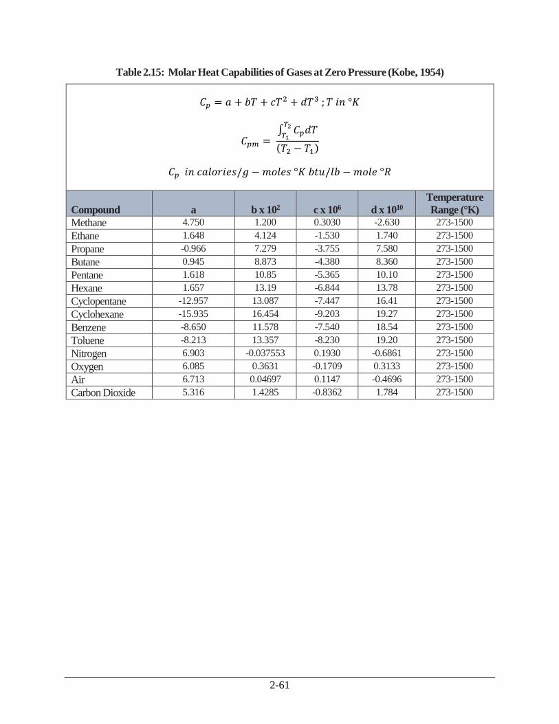
2-61
Table 2.15: Molar Heat Capabilities of Gases at Zero Pressure (Kobe, 1954)
𝐶𝑝 = 𝑎 + 𝑏𝑇 + 𝑐𝑇2 + 𝑑𝑇3 ; 𝑇 𝑖𝑛 °𝐾
𝐶𝑝𝑚 = ∫ 𝐶𝑝𝑑𝑇
𝑇2
𝑇1
(𝑇2 − 𝑇1)
𝐶𝑝 𝑖𝑛 𝑐𝑎𝑙𝑜𝑟𝑖𝑒𝑠/𝑔 − 𝑚𝑜𝑙𝑒𝑠 °𝐾 𝑏𝑡𝑢/𝑙𝑏 − 𝑚𝑜𝑙𝑒 °𝑅
Compound a b x 102 c x 106 d x 1010
Temperature
Range (°K)
Methane 4.750 1.200 0.3030 -2.630 273-1500
Ethane 1.648 4.124 -1.530 1.740 273-1500
Propane -0.966 7.279 -3.755 7.580 273-1500
Butane 0.945 8.873 -4.380 8.360 273-1500
Pentane 1.618 10.85 -5.365 10.10 273-1500
Hexane 1.657 13.19 -6.844 13.78 273-1500
Cyclopentane -12.957 13.087 -7.447 16.41 273-1500
Cyclohexane -15.935 16.454 -9.203 19.27 273-1500
Benzene -8.650 11.578 -7.540 18.54 273-1500
Toluene -8.213 13.357 -8.230 19.20 273-1500
Nitrogen 6.903 -0.037553 0.1930 -0.6861 273-1500
Oxygen 6.085 0.3631 -0.1709 0.3133 273-1500
Air 6.713 0.04697 0.1147 -0.4696 273-1500
Carbon Dioxide 5.316 1.4285 -0.8362 1.784 273-1500

2-62
Table 2.16: Heats of Combustion of Selected Gaseous Organic Compounds (Green, 1999)
Compound Molecular
Weight
Heat of Combustion
(cal/g) (Btu per lb)
Methane 16.043 11,957 21,523
Ethane 30.07 11,355 20,439
Propane 44.097 11,073 19,932
Butane 58.123 10,927 19,669
Pentane 72.15 10,749 19,348
Hexane 86.177 10,692 19,245
Octane 114.231 10,617 19,110
Nonane 128.258 10,593 19,068
Decane 142.285 10,573 19,031
Ethylene 28.054 11,273 20,291
Propylene 42.081 10,937 19,688
Acetylene 26.038 11,537 20,767
Cyclohexane 84.161 10,382 18,689
Benzene 78.114 9,595 17,271
Toluene 92.141 9,685 17,434

2-63
Appendix B
Design Procedure for Non-Recuperative
Thermal oxidizers
2-64
Not all thermal oxidizers are equipped with recuperative heat exchangers to transfer
energy from the flue gas stream to the incoming waste gas stream. These non-recuperative units
use other mechanisms to recovery flue gas energy. One of these types is the regenerative
oxidizer. As discussed in a subsection of Section 2.1 entitled Regenerative oxidizers, a
regenerative oxidizer accomplishes energy recovery by conveying the flue gas through a ceramic
bed which captures a portion of the stream’s enthalpy. After a switching mechanism is engaged,
the incoming waste gas passes through this hot bed and is warmed to its ignition temperature.
This process is illustrated in Figure 2.2.
While we can determine the stream inlet and outlet temperatures for a recuperative heat
exchanger fairly accurately, we cannot always do so for a regenerative oxidizer bed. For one
thing, these beds do not behave like typical heat exchangers. The bed temperature profiles are
often difficult to predict. More importantly, because regenerative oxidizers do not operate at
steady state conditions, the temperatures within the beds and many other parts of the unit vary
with time. For that reason, it is more convenient to view the entire regenerative oxidizer as a
“black box” into which waste gas and auxiliary fuel flow and from which flue gas emanates.
Around this black box we may make mass and energy balances. In this way, we need not make
any assumptions about what occurs inside the incinerator regarding temperatures, flow rates, or
other stream parameters.
However, to determine the auxiliary fuel requirement for regenerative oxidizers via the
procedure shown in this appendix we have to make two key assumptions, viz.: (1) the
temperatures and flow rates of all streams entering and leaving the incinerator are at steady state
and (2) the combustion temperature (and by inference, the heat loss fraction) are constant as
well. The other assumptions will be addressed in the following design steps:
Steps 1 to 4: These are the same as those for thermal recuperative and catalytic oxidizers. (See
Section 2.4.1.)
Step 5t - Establish the incinerator operating temperature: Because their designs are more
resistant to thermal stresses and because they can achieve very high heat recoveries, regenerative
oxidizers are usually operated at higher temperatures than recuperative units. Consequently,
higher VOC destruction efficiencies are achieved. Operating temperatures of 1800 to 2000°F are
typical.
Step 6t - Calculate the waste gas temperature at the exit of the preheater: As explained
above, regenerative oxidizers do not employ preheaters. The preheating is done by and within the
ceramic beds. Moreover, because the mass and energy balances are made around the entire unit,
we do not need to know the temperature of the preheated waste gas to calculate the auxiliary fuel
requirement.
Step 7t - Calculate the auxiliary fuel requirement, Qaf: Because a regenerative oxidizer
recovers nearly all of the energy from the combustion (flue) gas, its auxiliary fuel requirement is
usually lower than that for a recuperative oxidizer. However, as discussed above, this fuel
requirement is determined via mass and energy balances taken around the entire unit, not just the
combustion chamber. Consider the following diagram:
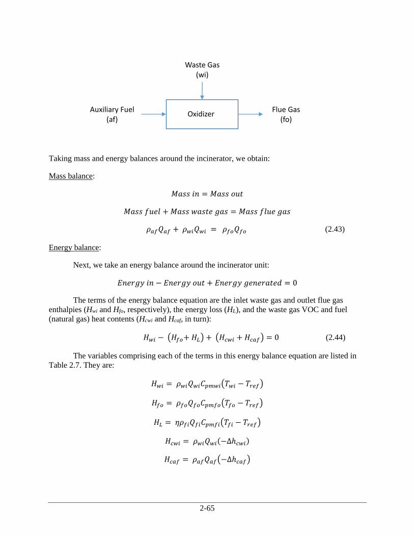
2-65
Taking mass and energy balances around the incinerator, we obtain:
Mass balance:
𝑀𝑎𝑠𝑠 𝑖𝑛 = 𝑀𝑎𝑠𝑠 𝑜𝑢𝑡
𝑀𝑎𝑠𝑠 𝑓𝑢𝑒𝑙 + 𝑀𝑎𝑠𝑠 𝑤𝑎𝑠𝑡𝑒 𝑔𝑎𝑠 = 𝑀𝑎𝑠𝑠 𝑓𝑙𝑢𝑒 𝑔𝑎𝑠
𝜌𝑎𝑓𝑄𝑎𝑓 + 𝜌𝑤𝑖𝑄𝑤𝑖 = 𝜌𝑓𝑜𝑄𝑓𝑜 (2.43)
Energy balance:
Next, we take an energy balance around the incinerator unit:
𝐸𝑛𝑒𝑟𝑔𝑦 𝑖𝑛 − 𝐸𝑛𝑒𝑟𝑔𝑦 𝑜𝑢𝑡 + 𝐸𝑛𝑒𝑟𝑔𝑦 𝑔𝑒𝑛𝑒𝑟𝑎𝑡𝑒𝑑 = 0
The terms of the energy balance equation are the inlet waste gas and outlet flue gas
enthalpies (Hwi and Hfo, respectively), the energy loss (HL), and the waste gas VOC and fuel
(natural gas) heat contents (Hcwi and Hcaf, in turn):
𝐻𝑤𝑖 − (𝐻𝑓𝑜+ 𝐻𝐿) + (𝐻𝑐𝑤𝑖 + 𝐻𝑐𝑎𝑓) = 0 (2.44)
The variables comprising each of the terms in this energy balance equation are listed in
Table 2.7. They are:
𝐻𝑤𝑖 = 𝜌𝑤𝑖𝑄𝑤𝑖𝐶𝑝𝑚𝑤𝑖(𝑇𝑤𝑖 − 𝑇𝑟𝑒𝑓)
𝐻𝑓𝑜 = 𝜌𝑓𝑜𝑄𝑓𝑜𝐶𝑝𝑚𝑓𝑜(𝑇𝑓𝑜 − 𝑇𝑟𝑒𝑓)
𝐻𝐿 = 𝜂𝜌𝑓𝑖𝑄𝑓𝑖𝐶𝑝𝑚𝑓𝑖(𝑇𝑓𝑖 − 𝑇𝑟𝑒𝑓)
𝐻𝑐𝑤𝑖 = 𝜌𝑤𝑖𝑄𝑤𝑖(−Δℎ𝑐𝑤𝑖)
𝐻𝑐𝑎𝑓 = 𝜌𝑎𝑓𝑄𝑎𝑓(−Δℎ𝑐𝑎𝑓)
Oxidizer
Waste Gas (wi)
Flue Gas (fo)
Auxiliary Fuel (af)
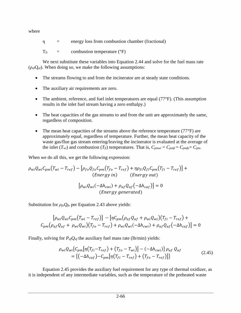
2-66
where
η = energy loss from combustion chamber (fractional)
Tfi = combustion temperature (°F)
We next substitute these variables into Equation 2.44 and solve for the fuel mass rate
(ρafQaf). When doing so, we make the following assumptions:
The streams flowing to and from the incinerator are at steady state conditions.
The auxiliary air requirements are zero.
The ambient, reference, and fuel inlet temperatures are equal (77°F). (This assumption
results in the inlet fuel stream having a zero enthalpy.)
The heat capacities of the gas streams to and from the unit are approximately the same,
regardless of composition.
The mean heat capacities of the streams above the reference temperature (77°F) are
approximately equal, regardless of temperature. Further, the mean heat capacity of the
waste gas/flue gas stream entering/leaving the incinerator is evaluated at the average of
the inlet (Twi) and combustion (Tfi) temperatures. That is, Cpmwi = Cpmfi = Cpmfo= Cpm.
When we do all this, we get the following expression:
𝜌𝑤𝑖𝑄𝑤𝑖𝐶𝑝𝑚(𝑇𝑤𝑖 − 𝑇𝑟𝑒𝑓) − [𝜌𝑓𝑜𝑄𝑓𝑜𝐶𝑝𝑚(𝑇𝑓𝑜 − 𝑇𝑟𝑒𝑓) + 𝜂𝜌𝑓𝑖𝑄𝑓𝑖𝐶𝑝𝑚(𝑇𝑓𝑖 − 𝑇𝑟𝑒𝑓)] +
(𝐸𝑛𝑒𝑟𝑔𝑦 𝑖𝑛) (𝐸𝑛𝑒𝑟𝑔𝑦 𝑜𝑢𝑡)
[𝜌𝑤𝑖𝑄𝑤𝑖(−Δℎ𝑐𝑤𝑖) + 𝜌𝑎𝑓𝑄𝑎𝑓(−Δℎ𝑐𝑎𝑓)] = 0
(𝐸𝑛𝑒𝑟𝑔𝑦 𝑔𝑒𝑛𝑒𝑟𝑎𝑡𝑒𝑑)
Substitution for ρfoQfo per Equation 2.43 above yields:
[𝜌𝑤𝑖𝑄𝑤𝑖𝐶𝑝𝑚(𝑇𝑤𝑖 − 𝑇𝑟𝑒𝑓)] − [𝜂𝐶𝑝𝑚(𝜌𝑎𝑓𝑄𝑎𝑓 + 𝜌𝑤𝑖𝑄𝑤𝑖)(𝑇𝑓𝑖 − 𝑇𝑟𝑒𝑓) +
𝐶𝑝𝑚(𝜌𝑎𝑓𝑄𝑎𝑓 + 𝜌𝑤𝑖𝑄𝑤𝑖)(𝑇𝑓𝑜 − 𝑇𝑟𝑒𝑓) + 𝜌𝑤𝑖𝑄𝑤𝑖(−Δℎ𝑐𝑤𝑖) + 𝜌𝑎𝑓𝑄𝑎𝑓(−Δℎ𝑐𝑎𝑓)] = 0
Finally, solving for PafQaf the auxiliary fuel mass rate (lb/min) yields:
𝜌𝑤𝑖𝑄𝑤𝑖{𝐶𝑝𝑚[𝜂(𝑇𝑓𝑖−𝑇𝑟𝑒𝑓) + (𝑇𝑓𝑜 − 𝑇𝑤𝑖)] − (−Δℎ𝑐𝑤𝑖)} 𝜌𝑎𝑓 𝑄𝑎𝑓
= {(−Δℎ𝑐𝑎𝑓)−𝐶𝑝𝑚[𝜂(𝑇𝑓𝑖 − 𝑇𝑟𝑒𝑓) + (𝑇𝑓𝑜 − 𝑇𝑟𝑒𝑓)]} (2.45)
Equation 2.45 provides the auxiliary fuel requirement for any type of thermal oxidizer, as
it is independent of any intermediate variables, such as the temperature of the preheated waste
2-67
gas. Clearly, this equation can be used with regenerative oxidizers, as long as the above-stated
assumptions hold.
The heat loss fraction (η) will vary according to the incinerator type, how the incinerator
components are configured in the unit, the construction materials, the type and amount of
insulation, and other factors. For instance, for recuperative oxidizers, η is approximately 0.10.
The heat loss fraction for regenerative oxidizers is considerably lower, however. There are two
reasons for this. First, the components of a regenerative oxidizer—combustion chamber, ceramic
beds, etc.—are housed in a single enclosure, while in a recuperative oxidizer the combustion
chamber, heat exchanger, and interconnecting ductwork are housed separately, thus offering
more heat transfer area. Second, because regenerative units are lined with ceramic, they are
better insulated than recuperative oxidizers.
To gain an estimate of this heat loss fraction, we contacted two regenerative oxidizer
vendors. [Vatavuk 1992a and 1992b] Based on the heat loss data that they supplied, we
calculated values ranging from 0.002 to 0.015 (0.2 to 1.5%). These values varied according to
the incinerator configuration (vertical or horizontal), the waste gas flow rate, the ambient
temperature, and the wind speed.
Step 8t - Verify that the auxiliary fuel requirement is sufficient to stabilize the burner
flame: As explained in Section 2.4.2, only a small amount (< 5% of the total energy input) is
needed to stabilize the burner flame. With recuperative oxidizers, the auxiliary fuel requirement
is usually much larger than the burner stabilization requirement, so that this constraint rarely
comes into play. With regenerative oxidizers, however, the auxiliary fuel requirement may be as
low as or lower than the fuel needed to stabilize the burner. Therefore, it is important to compare
these two requirements. This comparison is made via Equations 2.23 and 2.24. If the auxiliary
fuel is less, the minimum fuel requirement would be set at 5% of the total energy input.
Step 9t - Calculate the flue gas volumetric flow rate, Qfi: As with thermal recuperative
oxidizers, the regenerative oxidizer flue gas flow rate is the rate used to size and cost the unit.
Measured at standard conditions (1 atmosphere and 77°F), is the sum of the inlet waste gas (Qwi)
and fuel (Qaf) flow rates. But since Qaf for regenerative units is small compared to Qwi, the waste
gas and flows should be virtually identical.