AP42 Section 5.1 Related - US Environmental Protection ...
396
AP42 Section 5.1 Related: 2 Title: AB 2588 Pooled Source Emission Test Program Vol. 3 Compilation of Test Methods Series of tests conducted on 19 refinery sources July 1990 Almega Corporation
-
Upload
khangminh22 -
Category
Documents
-
view
1 -
download
0
Transcript of AP42 Section 5.1 Related - US Environmental Protection ...

AP42 Section 5.1
Related: 2
Title: AB 2588 Pooled Source Emission Test Program Vol. 3 Compilation of Test Methods Series of tests conducted on 19 refinery sources
July 1990
Almega Corporation
EPA
Text Box
Note: This material is related to a section in AP42, Compilation of Air Pollutant Emission Factors, Volume I Stationary Point and Area Sources. AP42 is located on the EPA web site at www.epa.gov/ttn/chief/ap42/ The file name refers to the file number, the AP42 chapter and then the section. The file name "rel01_c01s02.pdf" would mean the file relates to AP42 chapter 1 section 2. The document may be out of date and related to a previous version of the section. The document has been saved for archival and historical purposes. The primary source should always be checked. If current related information is available, it will be posted on the AP42 webpage with the current version of the section.

TkE ALMEGA CORPoRATiON
I AB2588 POOLED SOURCE EMISSION TEST PROGRAM
THE ALMEGA CORPORATION PROJECT I6551 THE ALMEGA CORPORATION REPORT 16551-4
VOLUME I11 Compilation of Test Methods
PREPARED €OR
Western States Petroleum Association 505 N. Brand Boulevard, Suite 1400
Glendale, California 91203

rThE A ~ M E ~ A CoRpORArioN PLEASE REPLY TO:
WEST COAST
July 26, 1990
Western States Petroleum Association 505 N. Brand Boulevard, Suite 1400 Glendale, CA 91203
Attention: Mr. Robert Stockdale, Chairman
Subject: AB 2588 Pooled Source Emission Test Program
AB2580 Working Group
The Almega Corporation Project I6551 The Almega Corporation Report 16551-4 Volume 111- Compilation of Test Methods
Gentlemen:
INTRODUCTION ICI
A series of tests were conducted on 19 refinery sources to develop preliminary emission factors to aid refiners in preparation of the 1989 emission estimate report mandated by AB2508, Air Toxics "Hot Spots" Information and Assessment Act of 1987. Testing was performed on a representative number of heaters, boilers and cogeration gas fired turbines, and one sulfur recovery unit, one gasoline loading rack and one asphalt recovery incinerator.
This volume contains reference copies of the CARB test methods and the USEPA multiple metal train test method used throughout this program. Details of modifications of these methods for compounds for which test methods do not exist have been included in Volume I of this report.
Respectfully submitted, THE ALMEGA CORPORATION
Meryl R. Jackson Vice President
EAST COAST MIDWEST WEST COAST 607C Country Club Drive
Pottstown, PA 19464 Bensenville, IL 60106 Signal Hill, CA 90806 Phone: (215) 469-9625 Phone: (708) 595-0175 Phone: (213) 4264221
Fax: (215) 469-6701 Fax: (708) 595-1203 Fax: (213) 426-1143
RD2 Mount Pleasant Road 2301 East 28th Street, Suite 309

Tkr ALMEGA CORPORAT~ON
,LIST OF APPENDICES
i,
APPENDIX I ,
DESCRIPTION
b/ A.. ........... .CARB Method 1 Sample and Velocity Traverse for
d i g . . ........... .CARB Method 2 Determination of Stack Gas Velocity
C..............CARB Method 3 Gas Analysis for Carbon Dioxide,
D..............CARB Method 4 Determination of Moisture Content
Stationary Sources
and Volumetric Flow Rate (Type S Pitot Tube)
Oxygen, Excess Air and Dry Molecular Weight
in Stack Gas
JJ JJ /f E. ............. CARB Method 15 Determination of Hydrogen Sulfide,
Carbonyl Sulfide and Carbon Disulfide Emissions from Stationary Sources
Gaseous Mercury Emissions from Sewage Sludge Incinerators
Stationary Sources (Low Concentration Gas Chromato- graphy Technique)
Determination of Hydrochloric Acid Emissions from Stationary Sourced
Organics Emissions from Stationary Sources
J..............CARBMethod 425 Determination of Total Chromium and Hexavalent Chromium Emissions from Stationary Sources
F . . . . . . . . . . . . . . W B Method lOlA Determination of Particulate and
G..............CARB M ethod 410A Determination of Benzene from
H..............CARB Method 421
I.... .......... GARB I4 ETHOD 422 Determination of Halogenated
.............. CARB nethod 426 Determination of Cyanide Emissions from Stationary Sources
I L..............CARB Meth od 429 Determination of Polycyclic
Aromatic Hydrocarbon Emissions from Stationary Sources
cont'd....

f , TkE A~MEC~A CORPORAT~ON
Page Two
APPENDIX cont I d DESCRIPTION
M..............CARB Method 4 3 0 Determination of Formaldehyde in Emissions from Stationary Sources
N..............USEPA Draft Multiple Metals Method

ThE ALME~A CORPORATiON
APPENDIX 9
CARB Method 1
Sample and Velocity Traverse for Stationary Sources

V
f- , ' O f Cdlt fOrnfd
Alr Resources Board
Method 1
Sample and Veloci ty Traverses for S t a t t o n a y Sources
Adopted: June 29, 1983 hended: March 28, 1986
METHOD 1 - SAMPLE AND VELOCITY TRAVERSES FOR STATX0)URY SOURCES
1. P r i n c i p l e and A p p l i c a b i l i t y
1.1 P r i n c f p l t : To a i d f n t h e representat ive measurement o f pO1lUtant
emissions and/or t o t a l volumetric f l o w r a t e from a
s t a t i o n a y source, a measurement s i t e where t h e
e f f l u e n t stream i s f lowing i n a known d i r e c t i o n 1 s
selected, and t h e cross-section o f the stack i s
d i v fded I n t o a number o f equal areas. A t rave rse
p o t n t i s then l o c a t e d within each o f these equal
areas.
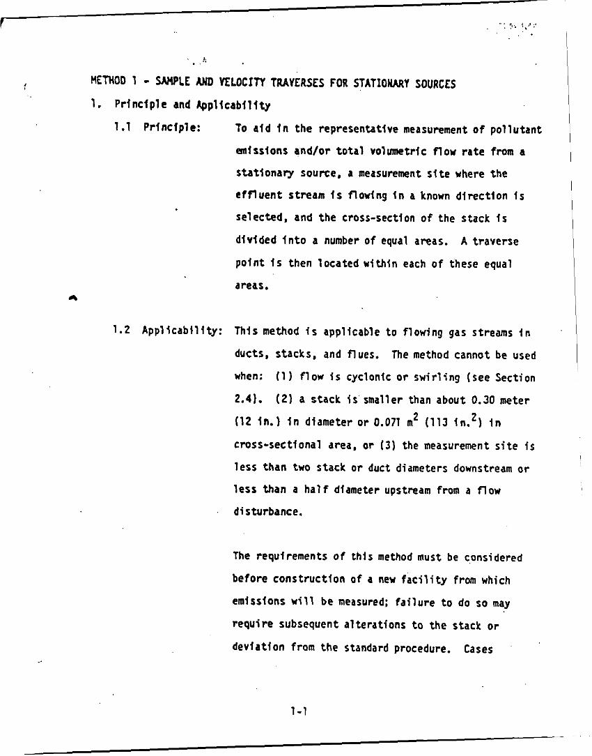
1.2 A p p l i c a b i l i t y : Th is method is appl icable t o f low ing gas streams I n
ducts, stacks, and flues. The method cannot be used
when: (1) f l o w t s cyclonic o r s w i r l i n g (see Section
2.41. ( 2 ) a s tack i s smaller than about 0.30 meter
(12 in.) i n dlameter o r 0.071 m2 (113 in.') i n
cross-sect tonal area, o r ( 3 ) the measurement s i t e is
l e s s than two stack o r duct diameters downstream o r
l e s s than a h a l f diameter upstream from a f l o w
disturbance.
The requirements o f t h i s method must be considered
be fore c o n s t r u c t i o n of a new f a c i l i t y from which
emissions w i l l be measured; f a i l u r e t o do so may
r e q u i r e subsequent a l t e r a t i o n s t o the s tack or
dev ia t i on from the standard procedure. Cases
1-1

‘ tnvolvtng v r r t a n t s are sub jec t t o approval by the
Control Agency’s au thor ized representatfvc.
2. Procedure
2.1 Se lec t i on o f Measurement S i te . Sampling o r v e l o c i t y measurement i s
performed a t a s f t e l oca ted a t l e a s t e i g h t stack o r duc t diameters
downstream and two diameters upstream from any f l w dlsturbance such
as a bend, expansion, o r c o n t r a c t i o n i n t h e stack, o r from a v i s f b l e
flame.
p o s i t i o n a t l e a s t two s tack o r duct diameters downstream and a h a l f
d iameter upstream from any f l o w disturbance.
sect ion, an equivalent diameter (0,) s h a l l be ca lcu la ted from the
f o l l o w i n g equation, t o determine the upstream and downstream
distances: De = 2Lu
2.2 Determining t h e Number o f Traverse Po in ts
I f necessay. an aJ te rna t i ve l o c a t f a n may be se lected. .a t -a- .
For a rectangular c ross
where L = l e n g t h and W 8 width. m
2.2.1 P a r t i c u l a t e Traverses. When t h e eight-and two-diameter
c r i t e r i o n can be met, t h e minlmum number o f t raverse po in ts
s h a l l be: (1) twelve, f o r c i r c u l a r o r rectangular s tacks w i t h
diameters ( o r equ iva len t diameters) greater than 0.61 meter
(24 in.); (2 ) e igh t , f o r c i r c u l a r stacks w i t h diameters
between 0.30 and 0.61 meter (12-24 in.] : (31 nine, f o r
rec tangu lar stacks w t t h e q u i v a l e n t diameters between 0.30 and
0.61 meter 112-24 i n . ) .
I
1-2 .
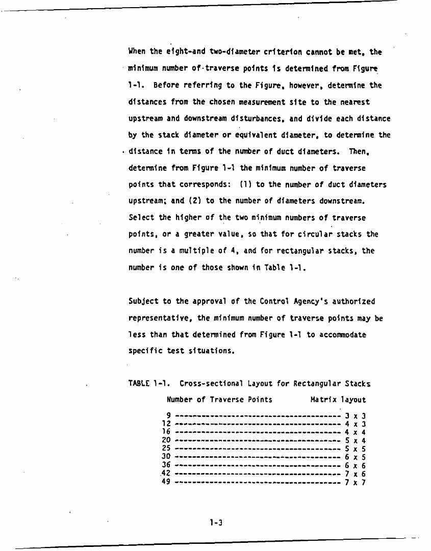
Yhen the eight-and two-diameter c r l t e r l o n cannot be net. t h e
mlnlmum number o f . t rave rse po ln ts I s determined from Figure
1-1. Before r e f e r r j n g t o the Ffgure, however, determine the
d is tances f r o m the chosen measurement s i t e t o the nearest
upstream and downstream disturbances. and d i v i d e each distance
by the s tack diameter o r equiva lent diameter, t o determine the
d is tance i n terms o f the rider o f duc t diameters. Then.
determine f r o m F igu re 1-1 the minimum number o f t raverse
po fn ts t h a t corresponds: (1) t o the number o f duct diameters
upstream; and (21 t o the number o f dfameters downstream.
Se lec t t he h ighe r o f the two minimum numbers o f t raverse
points , o r a g rea ter value, so t h a t f o r c i r c u l a r stacks the
number i s a m u l t i p l e o f 4, and for rec tangu lar stacks, t h e
number i s one o f those shown i n Table 1-1.
Subject t o t h e approval o f the Control Agency's au thor ized
representat ive, t h e minimum number o f t raverse p o l n t s may be
l e s s than t h a t detennined frm Figure 1-1 t o accomnodate
s p e c i f i c t e s t s i t ua t i ons .
TABLE 1-1. Cross-sect lonal Layout f o r Rectangular Stacks
Number o f Traverse Points M a t r i x l ayou t
3 x 3 4 x 3 4 x 4 5 x 4 5 x 5 6 x 5 6 x 6 7 x 6 7 x 7
1-3

I I 1.8 I.* 1.. 1.8 e.1 Y
I I I I I I
I T Y 8
1-4

2.2.2 Velocfty (Non-Particulate) Traverses. Uhen veloci ty or
volumetrlc f l o w r a t e i s t o be d e t e n i n e d ( b u t not particulate
mat ter) , the same procedure d s t h a t f o r PartfCUlate traverses
(Sectlon 2.2.1) i s followed, except t h a t f i gu re 1-2 may be
used instead of Figure 1-1.
. Subject t o the approval of the Control Agency's authorlred
representat ive, the mlnlmum number o f traverse points may be
l e s s than t h a t determined from Figure 1-2 t o accomnodate
spec i f i c t e s t s f tua t ions .
2.3 Cross-Sectional Layout and Location o f Traverse Points
2.3.1 Circular Stacks. Locate the t raverse poin ts on. two
perpendicular diameters accordfng t o Table 1-2 and the example
shown i n Figure 1-3. Any equation t h a t gives the same values
a s those i n Table 1-2 may be used I n l i e u o f Table 1-2.
For pa r t i cu la t e traverses, one of t h e diameters must be i n i
plane containing the g rea t e s t expected concentration
var ia t lon, e.g., a f t e r bends, one diameter sha l l be i n the
plane of the bend. This requirement becomes l e s s c r i t i c a l as the dis tance from the disturbance increases; therefore, other
diameter loca t ions may be used, subjec t t o approval of the
Control Agency's authorized representative.
1-5

I :

. . . * , . . . I n addi t ion. ;or stacks hav ing diameters g rea ter than 0.61 m
124 in.), no t raverse po fn ts s h a l l be l oca ted wi th in 2.5
cent imeters (1.00 In.) o f t he stack wa l ls ; and for stack
diameters equal t o or l e s s than 0.61 m (24 in.) no t raverse
p o f n t s s h a l l be loca ted within 1.3 cm (0.50 in . ) o f t he stack
walls. To meet these c r i t e r i a , observe the procedures g iven
, b e l ow.
2.3.1.1 Stacks uith Diameters Greater Than 0.61 m (24 in. I . When any of t he t rave rse p o i n t s as l oca ted i n Section
2.3.1 f a l l within 2.5 cm (1.00 in . ) o f the stack
walls, re loca te them away from the stack w a l l s to :
11 1 a distance o f 2.5 cm 11.00 in . 1; o r 12) a
distance equal t o the nozz le l n s i d e diameter,
whichever t s l a rger .
(on each end of a diameter) s h a l l be the 'arljusted'
t raverse points .
These re loca ted t raverse p o i n t s
Whenever two successive t ransverse po in ts are
combined t o fonn a s i n g l e ad justed t raverse point ,
t r e a t the adjusted p o i n t as two separate t raverse
points , bo th i n t h e sampling ( o r v e l o c i t y
measurement) procedure, and i n record ing the data.
1-7
\

,:. ..*.. : ' , . ' . .
2.3.1.2 Stacks w i t h Diameters Equal t o or Less Than 0.61 rn
(24 in.). Follow the procedure i n Sect ion 2.3.1,.
n o t i n g o n l y t h a t any 'adjusted' p o i n t s should be
re loca ted away f r o m the s tack w a l l s to :
d is tance o f 1.3 cm (0.50 in.); o r (21 a dis tance
equal t o the nozzle tns ide diameter, whichever f s
1 arger.
t
(1) a
2.3.2 Rectangular Stacks. Determine the number o f t r a v e r s e po in ts
.as expla ined i n Sect ions 2.1 and 2.2 o f t h i s method.
Table 1-1, detennine t h e g r i d conf igurat ion.
,cross-section i n t o as many equal rectangular elemental areas
as t raverse points, and then loca te a t raverse p o i n t a t the
c e n t r o i d o f each equal area according t o the example i n F igure
From
D i v i d e the stack
1-4.
F jgure 1-4 Example Showing Rectangular Stack Cross
Section D iv ided i n t o Twelve Equal Areas, wi th a Traverse Po in t a t Cent ro id o f Each Area
1 -8

I . . . .
I f t he t e s t e r des i res t o use more than t h e m l n i m u h ' n d e r o f '
t raverse points, expand the 'minimum number of t raverse
points ' m a t r l x (see Table 1-1) by addjng the e x t r a t raverse
po in ts a long one o r the o the r o r bo th l e g s of t h e matr ix ; the
f i n a l m a t r i x need n o t be balanced. F o r example. i f a 4 x 3
'minimum number of po in ts ' n a t r j x were expanded t o 36 points,
. the f i n a l m a t r i x cou ld be 9 x 4 or 1 2 x 3, and would n o t
necessar i ly have t o be 6 x 6. A f t e r cons t ruc t i ng the f i n a l
matr ix. d i v i d e the stack cross-sect ion i n t o as many equal
rectangular, elemental areas as t raverse po in ts , and loca te a
t raverse p o i n t a t t he c e n t r o i d o f each equal area.
Subject t o t h e approval of t h e Control Agency's author ized
representat ive, a1 te rna t f ves t o the m a t r i x l a y o u t p rescr ibed
i n Table 1-1 may be used t o accomnodate s p e c i f i c t e s t
s i tua t ions .
The s i t u a t i o n o f t raverse p o i n t s be ing too c l o s e t o the stack
w a l l s i s n o t expected t o a r i s e with rec tangu lar stacks.
t h i s problem should ever ar ise, t h e Control Agency's
au thor ized representa t ive must be contacted f o r reso lu t io 'n o f
t h e matter.
I f
2.4 Y e r i f i c a t i o n o f Absence o f Cyclonic Flow. I n most s ta t i ona ry
sources, t he d i r e c t i o n o f stack gas f l o w i s e s s e n t i a l l y p a r a l l e l t o
t h e s tack walls. However, cyc lon ic f low may e x i s t (11 a f t e r such
dev ices as cyclones and i n e r t l r l d e d s t e r s f o l l o w i n g v e n t u r i
1-9

scrubbers, or (2) In stacks having tangent ta l t n l e t s or other duct.
configurations whtch tend to induce swlr l tng; In these instances,. the
presence or absence o f cyclonfc n w a t the sampling locat ion must be
detenuined. The following techntques are acceptable f o r t h i s
detemi nati on.
Level.and zero the manometer. Connect a Type S p t t o t tube t o the
manometer. Position the Type S p i t o t tube a t 6;ch t raverse p o i n t , i n
successton, so t h a t the planes o f the face openings o f the p i t o t tube
are perpendicular t o the s tack cross-secttonal plane: when the Type
S p i t o t tube i s i n this posit ion i t i s a t '0 reference.' Note the
d i f fe ren t ia l pressure [Z p ) redding a t each traverse po in t . If a
n u l l (zero) p i t o t reading I s obtained a t 0' reference a t a given
traverse p o i n t , an acceptable ,flow.conditton extsts a t t h a t point.
I f the p i t o t reading i s not zero a t 0' reference, r o t a t e the p l t o t
tube (up t o + 90' yaw angle), u n t i l a n u l l readlng i s obtained.
Carefully determine and record the value of the ro ta t ion angle ( a ) t o
the nearest degree. After the n u l l technique has been applied a t
each traverse point, ca l cu la t e the average o f the absolute values of
a ; assign a value of 0' t o those points f o r which no rotat ion was
required. and include these i n the overall average.
value of a i s grea ter than 10' the overall flow condition i n the
stack i s unacceptable and a l t e rna t ive methodology, subjec't t o the
approval of the Control Agency's authorized representat ive must be
used to perform accurate sample and veloci ty traverses.
-
If the average
I
' , ! i
I
i l
1-10

. .
3. Bfblfography
1. D t t a r r i n l n g Dust Concentratfon I n a Gas Stream. MM. Performance Test Code No. 27. New York, 1957.
2. Devorkln, Howard, e t a l . A i r P o l l u t i o n Source Test ing Manual. A t r P o l l u t i o n Control Distr ict . Los Angeles, CA. W o v d e r 1963.
3. Methods for Determination o f Ve loc i tv . Volume- Dust and M l s t Content of Gases. Yestern P r e c l p l t a t i o n Dfvision-ii Joy-hnufactur ing -. - to. Los Angeles, CA. B u l l e t i n UP-50. 1968.
4. Standard Method for Sampling Stacks for Par t i cu la te Matter. In: 1971 Book of ASTH Standards. P a r t 23. ASW Designation 0-2928-71. Phf ladelphia, PA. 1971.
5. P lan ts Inc lud ing Wonunlfon Flow. Park, HC. EPA-600/2-76-170. June 1976.
Hanson. H.A.. e t a l . P a r t i c u l a t e Samplfng Strategies for Large Power USEPA, ORD, ESRL. Research Tr iangle
6. Entropy Environmentalists, Inc. Detenninat(on o f the Optimum Number o f Sampling Pofnts: An Analys is o f Method 1 Crf ter la . Environmental P ro tec t i on Agency. Research T r iang le Park, HC. EPA Contract No. 68-01-3172, Task 7.
1-11

APPENDIX B
CARB Method 2
Determination of Stack Gas Veloc i ty and Volumetric F l o w Rate
(Type S P i t o t Tube)

State o f Ca l i fo rn ia A i r Resources Board
Method 2
Detenninatlon of Stack Gas Velocity and Volumetric F l o w Rate (Type S P i t o t Tube)
Adopted: June 29. 1983

METHOD 2 - DETERMINATION OF STACK GAS VELOCITY AND VOLUMETRIC FLOW RATE (TYPE S PITOT TUBE)
1. P r inc ip le and A p p l l c a b i l i t y
1.1 Pr inc ip le : The average gas ve loc i t y t n a stack t s determined
from the gas dens i ty and from measurement o f the
average v e l o c i t y head w l t h a Type S (Stausscheibe o r
reverse type) p i t o t tube.
1.2 App l i cab i l i t y : f h l s method i s appl icable f o r measurement o f the
average v e l o c i t y o f a gas stream and f o r quant i fy ing
gas flow.
Thls procedure Is n o t appl icable a t measurement s i t e s
which f a l l t o meet the c r i t e r l a o f Method 1, Section
2.1. Also, t h e method cannot be used f o r d i r e c t
measurement i n cyc lon ic o r s w l r l l n g gas streams;
Section 2.4 o f Method 1 shows how t o determine
cyc lon ic o r s w l r l l n g f l o w condit ions. When
unacceptable cond i t ions ex is t , a1 te rna t i ve
procedures, sub jec t t o the approval o f the Control
Agency's Author ized Representative. must be employed
t o make accurate f l o w r a t e detennlnations; examples
o f such a l t e r n a t i v e procedures are: (11 t o i n s t a l l
s t ra igh ten ing vanes; (2 ) t o ca l cu la te the t o t a l
volumetric f low r a t e r to l ch lomet r i ca l l y . o r ( 3 ) t o
move t o another measurement s i t e a t which the f low i s
acceptable.
2- 1

2. Apparatus
Spec i f i ca t ions f o r the apparatus are g iven below. Any o ther apparatus
t h a t has been demonstrated (sub jec t t o approval o f the Control
Agency’s Authorized Representative) t o be capable o f meeting the
spec i f i ca t ions will be considered acceptable.
2.1 Type S P i t o t Tube.
made o f metal t ub ing (e.g., s t a i n l e s s s tee l ) .
t h a t the external tub ing diameter (dimensiorl Dt, Figure 2-2bl
be between 0.48 and 0.95 cent imeters (3/16 and 3/8 inch).
sha l l be an equal distance from the base o f each l e g o f the p i t o t
The Type S p i t o t tube (Figure 2-11 sha l l be
It i s recomnended
There
tube t o i t s face-opening plane (dimensions PA and PB, Figure
2-2b); i t i s recornended t h a t t h i s distance be between 1.05 and
1.50 times the external tub ing diameter. The face openings o f
the p i t o t tube sha l l , preferably , be a l igned a s shown i n
F igure 2-2; however, s l i g h t misalignments o f t h e openings are
penniss ib le (see f i g u r e 2-3).
The Type S p i t o t tube s h a l l have a known coe f f i c i en t , detennined
as ou t l i ned I n Section 4. A m i d e n t i f i c a t i o n number sha l l be
assigned t o the p i t o t tube; t h i s number sha l l be permanently
marked or engraved on the body o f the tube.
A standard p i t o t tube may be used ins tead o f a Type S, provided
t h a t i t meets the spec i f i ca t i ons o f Sections 2.7 and 4.2; note,
however, t h a t t he s t a t i c and impact pressure holes of standard
p i t o t tubes are susccpt ib le t o plugging i n par t i cu la te - laden gas
2-2

1.90-2.54 CM (0.75-1.0 I N . )
qpp TEMPERATURE SENSOR
FLEXIBLE TUB 6.25 HM ( 1 / 4
L
LEAK-FREE
TYPE S PITOT TUBE
GAS FLOU
MANOMETER
* L DISTANCE TO FURTHEST SAMPLING POINT PLUS 30 Cy (12 I N . )
+*PITOT TUBE - TEMPERATURE SENSOR SPACING
Figure 2.1 Type S p i t o t tube-manometer assembly.
. .
2-3 ES0 04,%7

A-SIDE PLANE
-. .-. .--- 0.48 CM l o t - 0.95 CM (3116 I N . ) ' (3/8 I N . )
t
NOTE :
I TRANSVERSE TUBE A X I S I --.
( C )
Figure 2 .2 . Properly constructed Type S p i t o t tube, shown i n : ( a ) end view; face opening planes perpendicular to transverse a x i s ; (b) top view; face opening planes p a r a l l e l t o longi tudinal a x i s ; ( c ) s i d e view: both legs o f equal length and centerlines co inc ident , when viewed from both s i d e s . Basel ine c o e f f i c i e n t values of 0 . 8 4 may be assigned t o p i t o t tubes constructed t h i s way.
2 -4 rrcv M.a-L

- -
I .
' I TRANSVERSE TUBE . - I A X I S &.-!&-.-- I
Figure 2.3. Types of face-opening misalignment that can result from field use or improper construct ion of Type S pitot tubes. These will not affect cp so long as and 9 <loo, o 2 < s o , z (0.32 c m ( l / E i n . ) and ~ ( 0 . 0 8 cm ( l / 32?n . ) .
2 - 5

streams. Therefore, whenever a standard p l t o t tube i s used t o
perform a 'traverse, adequate proof must be furn ished t h a t the
openlngs of the p i t o t tzbe have n o t plugged up dur ing the
traverse period; t h i s can be done by tak ing a v e l o c i t y head (op)
reading a t the f i na l traverse po ln t . c leanlng ou t the impact and
s t a t i c holes o f the standard p l t o t tube by "back-purging" w i t h
pressurlzed a i r , and then tak ing ano the rdp reading.
readfngs made before and a f t e r the a i r purgc are the same (+5
percent) the t raverse Is acceptable. Otherwise, r e j e c t the run.
Note t h a t i f o p a t the f i n a l t raverse p o i n t Is unsui tab ly low.
another p o i n t may be selected.
i n t e r v a l s Is p a r t o f the procedure, then comparative ap readings
sha l l be taken, as above, f o r t he l a s t two back purges a t which
su l tab ly h igh o p readjngs are observed.
I f the AP
-
I f "back-purging" a t regu la r
2.2 D i f f e r e n t i a l Pressure Gauge. An I n c l i n e d manometer o r equiva lent
device i s used. Most sampllng t r a i n s a re equipped with a 10-in.
(water column) i n c l i n e d - v e r t i c a l manometer, havlng 0.01-in. H 0
d lv ls ions on the 0- t o 1-in. I n c l i n e d scale, and 0.1-in. H20
d iv ls fons on the 1- t o 10-in. v e r t i c a l scale.
manometer ( o r o ther gauge o f equlva lent s e n s i t i v i t y ) i s
sat ls factory f o r the measurement o f o p values as low as 1.3 mn
(0.05 in . ) H20.
greater s e n s i t i v i t y sha l l be used (sub jec t t o the approval o f the
Control Agency's Authorized Representatlve), I f any o f the
fo l lowing i s found t o be true:
a l l b p readings a t the t raverse po in ts i n the stack i s l e s s than
2
This type o f
However, a d i f f e r e n t i a l pressure gauge o f
(1 ) the a r i t hmet i c average o f
2-6

I .
I' 1.3 mm (0.0.5 In . ) H20; ( 2 ) f o r traverses o f 12 o f more polnts , more than 10
percent o f the t n d t v l d u a l A p readings are below 1.3 mn (0.05 in.) H20; ( 3 )
f o r traverses o f fewer than 12 points, more than o n e b p readtng I s below 1.3
mn (0.05 in.) H20.
As an a l t e r n a t l v e t o c r i t e r i a (1 1 through (3 ) above, the
fo l low ing c a l c u l a t i o n may be perfonned t o d e t e n t n e the necessi t)
o f using a more sens t t i ve d t f f e r e n t i a l pressure gauge:
where: b p i = Ind iv tdua l v e l o c i t y head reading a t a traverse point , mn H20 ( i n . H20).
n
K
- Total number o f traverse points.
= 0.13 mn H20 when m e t r i c u n i t s a r e used and 0.005 in . H20 when Engl ish u n i t s a re used.
I f T I s greater than 1.05, the v e l o c i t y head data a re
unacceptable and a. more s e m i t i v e d i f f e r e n t t a l pressure gauge
must be used.
Note: I f d t f f e r e n t i a l pressure gauges o the r than i n c l i n e d
manometers are used (e.g., magnehelic gauges). t h e i r c a l i b r a t i o n
must be checked a f t e r each t e s t series.
o f a d f f f e r e n t i a l pressure gauge. c0mpareA.p readings o f the
gauge w i t h those o f a gauge-oil manometer a t a minlmum o f three
To check the c a l t b r a t l o n
2-7

points , approximately represent ing the range o f n p values i n the
stack.
d i f f e r e n t i a l pressure gauge and gauge-oil manometer agree t o
w i t h i n 5 percent, the d i f f e r e n t l a1 pressure gauge sha l l be
considered t o be i n proper ca l i b ra t i on . Othen ise . t h e t e s t
ser ies sha l l e i t h e r be voided, o r procedures t o ad jus t the
measuredop values and f i n a l r e s u l t s sha l l be used, subject t o
the approval o f the Control Agency's Authorized Representative.
I f , a t each polnt , the values o f a p as read by the
2.3 Temperature Gauge. A thermocouple. l i q u i d - f i l l e d bu lb
thermometer, b i m e t a l l i c thennometer, mercury-in-g1 ass
thermometer, o r o ther gauge capable o f measuring temperature t o
w i t h i n 1.5 percent o f the mfnlmum absolute stack temperature
sha l l be used. The temperature gauge sha l l be at tached t o the
p i t o t tube such t h a t the sensor t i p does no t touch any metal; the
gauge sha l l be i n an fnterference-free arrangement w i th respect
t o the p i t o t tube face openlngs (see Figure 2-1 and a l so Figure
2-7 i n Section 4) . Al te rna te pos i t i ons may be used i f the p i t o t
tube temperature gauge system i s ca l i b r a t e d according t o the
procedure o f Section 4. Provided t h a t a d f f fe rence of no t more
than 1 percent i n the average v e l o c i t y measurement i s introduced,
the temperature gauge need n o t be at tached t o the p i t o t tube;
t h i s a l t e r n a t i v e i s sub jec t t o the approval o f t he Control
Agency's Authorized Representative.
2-a

2.4 Pressure Probe and Gauge. A pferometer tube and mercury o r
w a t e r - f i l l e d U-tube manometer capable o f measuring stack pressure
t o within 2.5 mn (0.1 in . ) Hg i s used. The s t a t i c tap o f a
standard type p i t o t tube o r one l e g o f a Type S p i t o t tube w i t h
the face opening planes pos i t ioned p a r a l l e l t o the gas f low may
a lso be used as the pressure probe.
2.5 Barometer. A mercury, aneroid, o r o the r barometer capable of
measuring atmospheric pressure t o within 2.5 mm Hg 10.1 in . Hg)
may be used.
obtained from a nearby na t iona l weather serv ice s ta t ion , i n which
case the s t a t i o n value [which 1s the absolute barometric
pressure) sha l l be requested and an adjustment f o r e leva t ion
d i f ferences between the weather s t a t i o n and the sampling p o i n t
s h a l l be appl ied a t a r a t e o f minus 2.5 mn (0.1 in.) Hg per
30-meter (100 foo t ) e leva t i on Increase, o r vice-versa f o r
e leva t ion decrease.
I n many cases, the barometric reading may be
2.6 Gas Density Determination Equipment. Method 3 equipment. i f
needed (see Section 3.6). t o detennine the stack gas dry
molecular weight. and Method 4 o r Method 5 equipment f o r moisture
content detennination; o the r methods may be used subject t o
approval of the Control Agency's Author f red Representative.
2.7 Ca l ib ra t i on P i t o t Tube. When c a l i b r a t i o n of the Type S p i t o t
tube i s necessary (see Section 41, a standard p i t o t tube i s used
2 -9

a s a reference.
a known c o e f f i c i e n t , obtained e i t h e r (11 d i r e c t l y f r o m the
National Bureau o f Standards, Route 270. Quince Orchard Road,
Gaithersburg, Maryland, o r (2 ) by c a l i b r a t i o n against another
standard p i t o t tube w i t h an NBS-traceable coe f f i c i en t .
A l te rna t i ve l y , a standard p i t o t tube designed according t o the
c r i t e r i o n given f n 2.7.1 through 2.7.5 below and i l l u s t r a t e d i n
F igure 2.4 (see a l s o C i ta t i ons 7. 8, and 17 i n Sectlon 61 may be
used.
w i l l have baseltne c o e f f i c i e n t s o f about 0.99 M.01.
The standard p i t o t tube sha l l , preferably, have
P i t o t tubes designed according t o these spec i f i ca t ions
-
(-
2.7.1 Hemispherical [shown i n F igure 2-41. e l l i p s o i d a l , o r
conica l t i p .
2.7.2 A minlmum o f s i x diameters s t r a l g h t run (based upon 0, the
external diameter o f the tube) between'the t i p and the
s t a t i c pressure holes.
2.7.3 A minimum of e i g h t diameters s t r a i g h t run between the
s t a t i c pressure holes and the c e n t e r l i n e o f the external
tube, f o l l ow ing the 90 degree bend.
2.7.4 S t a t i c pressure holes o f equal s i r e (approximately 0.1 0) .
equal ly spaced i n a piezometer r i n g conf igurat ion.
I 2-10 I
1

Figure 2.4 Standard p i t o t tube design s p e c i f i c a t i o n s .
2-11 €03 04.83

2.7.5 Ninety degree bend, w i t h curved o r mi te red junct ion.
2.8 O i f f e ren t i a l Pressure Gauge f o r Type S P i t o t Tube Ca l i b ra t i on
An i n c l i n e d manometer o r equiva lent i s used.
s ing le -ve loc i ty C a l i b r a t i o n technique i s employed (see Section
4.1.2.31, t he c a l i b r a t i o n d i f f e r e n t i a l pressure gauge sha l l be
readable t o the nearest 0.13 mm H20 (0.005 in. H201.
m u l t i v e l o c i t y c a l i b r a t i o n s , the gauge s h a l l be readable t o the
nearest 0.13 nun H20 (0.005 in . H20) f o r p values between 1.3
and 25 mm H20 (0.05 and 1.0 in. H20). and t o the nearest 1.3
mm H20 (0.05 in. H20) f o r n p values above 25 mm H20 (1 .O
in. H20). A special, more sens i t i ve gauge w i l l be requ i red t o
readap values below 1.3 mn H20 (0.05 in . H20) (see C i t a t i o n
18 i n Section 61.
I f the
For
3. Procedure
3.1 Set up the apparatus a s shown i n F igure 2-1. C a p i l l a r y tubing o r
surge tanks i n s t a l l e d between the manometer and p i t o t tube may be
used t o dampen p f luc tua t ions . Conduct a p re tes t leak-check as
fol lows:
l e a s t 7.6 cm ( 3 in. H20) v e l o c i t y pressure r e g i s t e r s on the
manometer: then, c lose o f f the impact opening.
sha l l remain s tab le far a t l e a s t 15 seconds; (2 ) do the same f o r
t he s t a t i c pressure side, except us ing suct ion t o ob ta in the
minimum of 7.6 cm (3 in. H201. Other leak-check procedures,
subject t o the approval o f t he Control Agency's Authorized
Representative. may be used.
(11 blow through the p i t o t impact opening u n t i l a t
The pressure
2-1 2
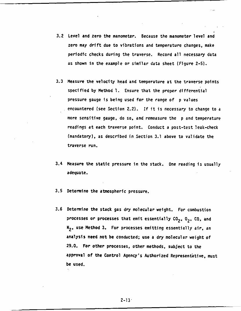
3.2 Level and zero the manometer. Because the manometer l e v e l and
zero may d r t f t due t o v ib ra t i ons and temperature changes, make
per iodtc checks dur ing the traverse. Record a l l necessary data
as shown i n the example o r s i m i l a r data sheet (F lgure 2-51.
3.3 Measure the v e l o c i t y head and temperature a t t he t raverse po in ts
spec i f i ed by Method 1.
pressure gauge i s being used f o r the range o f p values
encountered (see Section 2.2). I f i t i s necessary t o change t o a
more sens i t i ve gauge, do so. and remeasure the p and temperature
readings a t each traverse point .
(mandatory). as described i n Section 3.1 above t o va l i da te the
traverse run.
Ensure t h a t the proper d i f f e r e n t i a l
Conduct a pos t - tes t leak-check
3.4 Measure the s t a t i c pressure i n the stack.
adequate.
One reading i s usual ly
3.5 D e t e n i n e the atmospheric pressure.
3.6 Determine the stack gas dry molecular weight. For combustion
processes o r processes t h a t emi t e s s e n t i a l l y C02. 02, CO, and
N2, use Method 3. For processes emi t t i ng e s s e n t i a l l y a i r , an
analys is need n o t be conducted; use a dry molecular weight o f
29.0. For o ther processes, o ther methods, subject t o the
approval o f the Control Agency's Authorized Representbtive. must
be used.
2-13 '

FIGURE 2.5
. . ~~
inside wall . in . Without With Offset Offset
Traverse Point Number
F i l e No. State of Caltfornta A I R RESOURCES BOARD
Velocl ty Stack
in . H20 U s ) . OF Head Temperature JAP
Stationary Source D iv is ion Engfneering Evaluation Branch
VELOCITY TRAVERSE DATA
I I 01 stance From I I I 1
I
~~
Average
Plant P i t o t Tube Factor -------- Sampling S i t e Barometric Pressure. i n . Hg
Stat ic Pressure i n Stack (Pg) in . Hg Remarks

3.7 Obtain the moisture content from Reference Method 4 ( o r
equiva lent ) o r from Method 5.
3.8 Oetennine the cross-sectional area o f the stack o r duct a t t he
sampling locat ion. Uhenever possible. phys ica l l y measure the
stack dimensions ra the r than using b luepr in ts .
4. Ca l i b ra t i on
4.1 Type S P i t o t Tube.
Type S p i t o t tube I n top, side, and end views t o v e r i f y t h a t the
face openings o f the tube are a l igned w i t h i n the spec i f i ca t ions
i l l u s t r a t e d i n Figure 2-2 o r 2-3. The p i t o t tube sha l l n o t be
used i f i t f a i l s t o meet these. alignment specif icat ions.
Before i t s i n i t i a l use, c a r e f u l l y examine the
A f t e r v e r i f y i n g the face opening alignment, measure and record
the fo l low ing dlmensions o f t h e p i t o t tube: (a ) the external
tub ing diameter (dimension Dt Figure 2-2b); and (b) the base-to
opening plane distances (dimensions PA and PB Figure 2-Zb).
I f Dt i s between 0.48 and 0.95 cm (3/16 and 3/8 i n . ) and i f
PA and PB are equal and between 1.05 and 1 .SOl l t , there are
two poss ib le options: (1 ) t he p i t o t tube may be ca l i b ra ted
according t o t h e procedure out1 ined i n Sections 4.1.2 through
4.1.5 below, o r (2) a basel ine ( i s o l a t e d tube) c o e f f i c i e n t value
of 0.84 may be assigned t o t h e p i t o t tube. Note, however, that
if the p i t o t tube 1s p a r t o f an assembly. c a l i b r a t i o n may s t i l l
be requlred, despite knowledge o f t he basel ine c o e f f i c i e n t value
(see Section 4.1.1).
2-1 5

I f Ot, PA, and Pg are outs ide the spec i f i ed l l m i t s , t he
p i t o t tube must be c a l i b r a t e d as ou t l i ned i n 4.1.2 through 4.1.5
below.
4.1.1 Type S P i t o t Tube Assemblies. During sample and v e l o c i t y
traverses, the i s o l a t e d Type S p i t o t tube i s no t always
used; i n many instances. t he p i t o t tube i s used i n
combination w i th other source-sampliny Components
(thermocouple. sampling probe, nozzle) as p a r t o f an
"assembly." The presence o f o ther sampling components can
sometimes a f f e c t the basel ine value o f the Type S p i t o t
tube c o e f f i c i e n t ( C i t a t i o n 9 f n Section 6 ) ; therefore, an
assigned l o r otherwise known) basel ine c o e f f i c i e n t value
may or may n o t be v a l i d f o r a given assembly.
The basel ine and assembly c o e f f i c i e n t values w i l l be
i d e n t i c a l on ly when the r e l a t i v e placement o f the
components i n the assembly i s such t h a t aerodynamic
in te r fe rence e f f e c t s a re eliminated. Figures 2-6 through
2-8 i l l u s t r a t e in ter ference- f ree component arrangements
f o r Type S p i t o t tubes having external t ub ing diameters
between 0.48 and 0.95 cm (3/l6 and 3/8 in.). Type S p i t o t
tube assemblies t h a t f a i l t o meet any o r a l l o f the
spec i f i ca t i ons o f Figures 2-6 through 2-8 s h a l l be
ca l i b ra ted according t o the procedure out1 ined i n Sections
4.1.2 through 4.1.5 below. and p r i o r t o ca l i b ra t i on . the
2-1 6

TYPE S P I T O T TUBE t o t 3: x > 1.90 cm ( 3 / 4 in.) for 0; = 1 . 3 cm -
SAMPLING NOZZLE
112 i n . )
TYPE S P I T O T TUBE t o t 3: x - > 1.90 cm ( 3 / 4 in.) for 0; = 1 . 3 cm (1 /2 i n . )
SAMPLING NOZZLE
( a ) BOTTOM VIEW: SHOWING MINIMUM PITOT-NOZZLE SEPARATION. . .
SAMPLING PROBE - PRESSURE
I SAMPLING NOZZLE
OPENING
1 - 1 IMPACT PRESSURE
Y
TYPE 5 P I T O T TUBE,
OPENING
NOZZLE OPENING to ( b ) S I D E VIEW: TO PREVENT P I T O T TUBE FROM INTERFERING WITH
GAS FLOW STREAMLINES APPROACHING THE NOZZLE. THE IMPACT PRESSURE OPENING PLANE OF THE P I T O T TUBE SHALL BE EVEN WITH OR DOWNSTREAM FROM THE NOZZLE ENTRY PLANE
Figure 2.6. Required p i t o t tube-sampling nozzle configuration to prevent aerodynamic interference; buttonhook-type nozzle: centers of nozzle and p i t o t opening al igned; i n respect to flow direc t ion , Dt between 0.48 and 0 . 9 5 cm (3/16 and 3/8 i n . ) .
2-17
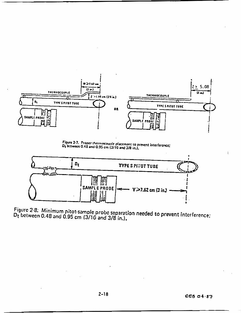
Figurc 2.8; Minimum pitot-sample probc separation needed to prevent interference; Dt bctwecn 0.18 and 0.95 cm (3/1G and 3/8 in.).
2-18 EE6 0 4 . 8 3

values o f the intercomponent spacings (p i to t -nozz le,
pitot-thermocouple, p i to t -probe sheath) sha l l be measured
and recorded.
Note: 00 no t use any Type S p i t o t tube assembly which i s
constructed such t h a t the impact pressure opening plane of
the p i t o t tube i s below the en t r y plane o f t he nozzle (see
Figure 2-6b).
4.1.2 Ca l i b ra t i on Setup. I f the Type S p i t o t tube i s t o be
ca l ibrated. one l e g o f the tube sha l l be permanently
marked A, and the other, 8.
a f low system having the fo l l ow ing essent ia l design
features:
Ca l i b ra t i on sha l l be done i n
4.1.2.1 The flowing gas stream must be confined t o a duct
c i r c u l a r o r rectangular. For c i r c u l a r
cross-sections, the minimum duct diameter sha l l
be 30.5 cm (12 in.); f o r rectangular
cross-sections, the width (shor te r s ide) sha l l be
a t l e a s t 25.4 cm (10 in.).
4.1.2.2 The cross-sectional area o f the c a l i b r a t i o n duct
must be constant over a distance o f 10 o r more
duct diameters. For a rectangular cross-section,
use an equiva lent diameter, ca lcu la ted from the
2-19

fo l low ing equation, t o determine the number o f
duct diameters:
Equation 2-1
where: De = Equivalent diameter
L - Length
W = Uidth
To ensure the presence o f stable, f u l l y developed
f l o w pat terns a t the c a l i b r a t i o n s i t e , o r " t e s t
sectlon." the s i t e must be loca ted e fgh t
diameters downstream and two diameters upstream
from the nearest d i s turbance s.
Note:
no t absolute; other t e s t sec t ion loca t ions may be
used (subject t o approval o f t he Control Agency's
Authorlzed Representative), provided t h a t the
f l o w a t the t e s t s i t e i s s tab le and demonstrably
p a r a l l e l t o the duct axis.
The e igh t - and two-diameter c r l t e r i a are
4.1.2.3 The f l o w system sha l l have the capaci ty t o
generate a test -sect ion v e l o c i t y around 915 m/min
(3,000 ft/rnin).
w i t h t ime t o guarantee steady f l o w dur ing
This v e l o c i t y must be constant
i
2-20

ca l i b ra t i on .
c o e f f i c i e n t s obtained by s ing le -ve loc i ty
c a l i b r a t i o n a t 915 m/min (3,000 f t /m in ) w f l l
genera l ly be v a l i d t o w i t h i n +3 percent f o r the
measurement o f v e l o c i t i e s above 305 m/min (1.000
f t /m in) and t o within +5 t o 6 percent f o r the
measurement o f v e l o c i t i e s between 180 and 305
m/min (600 and 1.000 f t h i n ) .
c o r r e l a t i o n between Cp and v e l o c i t y i s desired,
the f l ow system sha l l have the capacity t o
generate a t l e a s t four d i s t i n c t , t ime- fnvar iant
tes t -sec t ion v e l o c i t l e s covering the v e l o c i t y
range from 180 t o 1.525 m/min (600 t o 5,000
f t /min) , and c a l i b r a t i o n data sha l l be taken a t
regu la r v e l o c i t y i n t e r v a l s over t h i s range (see
C l ta t l ons 9 and 14 i n Section 6 f o r d e t a i l s ) .
Note t h a t Type S p i t o t tube
-
-
I f a more prec ise
4.1.2.4 Two en t ry por ts , one each f o r t he standard and
Type S p i t o t tubes, sha l l be Cut i n the t e s t
section; the standard p i t o t en t r y p o r t sha l l be
located s l i g h t l y downstream o f the Type S por t ,
SO t h a t t he standard and Type S impact openings
w f l l l i e I n the same cross-sectional plane dur ing
ca l i b ra t i on . To f a c i l i t a t e alignment o f the
p i t o t tubes dur ing ca l i b ra t i on , i t i s advisable
t h a t the t e s t sec t ion be constructed o f P lex ig las
o r some o the r transparent mater ia l .
2-21 ,

4.1.3 Ca l ib ra t ion Procedure. Note t h a t t h i s procedure i s a
general one and must no t be used w i thout f i r s t r e f e r r i n g
t o the special considerations presented i n Section 4.1.5.
Note also t h a t t h l s procedure appl ies on ly t o
s ing le -ve loc i ty ca l ib ra t ion . To ob ta in c a l i b r a t i o n data
for the A and B sides o f the Type S p i t o t tube, proceed as
f o l 1 ows :
4.1.3.1 Make sure t h a t t he manometer i s proper ly f i l l e d
and t h a t the o i l i s f ree from contamination and
i s o f t he proper density.
a l l p i t o t l ines ; repa i r o r replace i f necessary.
Inspect and leak-check
4.1.3.2 Level and zero the manometer. Turn on the fan
and a l l ow the f low t o s t a b i l i z e . Seal the Type S
entry port.
4.1.3.3 Ensure t h a t the manometer i s l e v e l and zeroed.
P o s i t i o n the standard p i t o t tube a t t he
c a l i b r a t i o n p o i n t (detennlned as o u t l i n e d I n
Section 4.1.5.1). and a l i g n the tube so t h a t i t s
t i p i s po inted d f r e c t l y I n t o the flow.
P a r t i c u l a r care should be taken I n a l l g n i n g the
tube t o avoid yaw and p i t c h angles. Make sure
t h a t the en t r y p o r t surrounding the tube i s
proper ly sealed.
(-
I
2-22 -

4.1.3.4 ReadApstd and record i t s value i n data t a b l e
s i m i l a r t o the one shown i n F igure 2-9.
the standard p i t o t tube from t h e duct and
disconnect i t from the manometer. Seal the
standard en t r y port.
Remove
4.1.3.5' Connect the Type 5 p i t o t tube t o the manometer.
Open the Type S en t ry por t . Check the manometer
l e v e l and zero i n s e r t and a l i g n the Type S p i t o t
tube so t h a t f t s A side impact opening i s a t the
same p o i n t as was the standard p i t o t tube and i s
po inted d i r e c t l y i n t o the flow. Make sure t h a t
the en t r y p o r t surrounding the tube {s proper ly
sealed.
4.1.3.6 Readbps and enter I t s value i n the data
table. Remove the Type S p i t o t tube from the
duct and disconnect i t from the manometer.
4.1.3.7 Repeat steps 4.1.3.3 through 4.1.3.6 above u n t i l
three p a i r s o f p readings have been obtained.
4.1.3.8 Repeat steps 4.1.3.2 through 4.1.3.7 above f o r
the B side o f the Type S p i t o t tube.
2-23

I'

%
. .. .4.1.3.9 Perform calcu lat ions. as described i n Section
4.1.4 below.
4.1.4 Calculat ions
4.1.4.1 For each of the s i x p a i r s o f p readings (i.e..
three from s ide A and three from side 8 ) obtained
i n Section 4.1.3 above, ca l cu la te the value o f
the Type S p i t o t tube c o e f f i c i e n t a s follows:
Equation 2-2
where: C P l s ) = Type S p i t o t tube c o e f f i c i e n t
c o e f f i c i e n t ; use 0.99 i f the c o e f f i c i e n t i s unknown and the tube i s designed according t o the c r i t e r i a of Sections 2.7.1 t o 2.7.5 of t h i s method.
the standard p i t o t tube. cm H20 ( i n . H20)
4% = v e l o c i t y head measured by the Type S p i t o t tube, cm H20 ( in. H20)
Cp(std) - Standard p i t o t tube
APstd = Ve lOd ty head measured by
4.1.4.2 Calculate rp (s ide A). the mean A side
coe f f f c ien t . and c p (s ide 6 ) . the mean 8-side
c o e f f Id en t ; ca lcu la te the d l f ference between
these two average values.
2-25

4.1.4.3 Ca lcu la te the d e v i a t i o n o f each o f t h e th ree A-
s i d e values o f Cpis) f rom TP ( s i d e A), and
t h e dev ia t ton o f each 8-s ide va lue o f CPls)
from rp (s ide B). Use t h e f o l l o w l n g equation:
Deviat ion = C p i s ) - ‘EpIA or E l
Equation 2-3
4.1.4.4 Calcu late ’ a, the average d e v i a t i o n from the mean,
f o r bo th the A and B s ides of t he p i t o t tube.
Use the fo l lowing equat ion:
a (s ide A o r B) ’ = ,v Equation 2-4
4.1.4.5 Use the Type S p i t o t t u t e o n l y i f the values o f
( s ide A ) and
0.01 and i f the absolute va lue o f t h e d i f f e rence
between rp ( A ) and rp (E) i s 0.01 o r less.
( s ide E) a r e l e s s than o r equal t o
4.1.5 Special Considerat ions
4.1.5.1 Se lec t ion o f C a l i b r a t i o n P o i n t
4.1.5.1.1 When an i s o l a t e d Type S p i t a t tube i s ca l i b ra ted ,
s e l e c t a c a l i b r a t i o n p o i n t a t o r n e w the center
o f t he duct. and f o l l o w the procedures o u t l i n e d
I n Sections 4.1.3 and 4.1.4 above. The Type S
p i t o t c o e f f i c i e n t s so obtained, i.e.. rp ( s ide
A ) and rp ( s ide R.1, w i l l be v a l i d , so long as
e i t h e r : (1 ) t he i so lated p i t o t tube I s used; o r
( 2 ) t he p i t o t tube i s used w i t h o the r components
2-26

[nozzle, thermocouple, sampl e probe) ! n an
arrangement t h a t i s f ree from aerodynamic
in te r fe rence e f fec ts (see Figures 2-6 through
2-81.
4.1.5.1.2 Fo r Type S p f t o t tube-thermocouple combinations (w i thout
sample probe). s e l e c t a c a l l b r a t i o n p o i n t a t or near the
center o f the duct;, and fo l low the procedures o u t l i n e d i n
Section 4.1.3 and 4.1.4 above. The c o e f f i c i e n t s so
obtained will be v a l i d so long as the p i t o t
tube-thermocouple combination i s used by i t s e l f o r w i t h
other components i n an interference-free arrangement
(Figures 2-6 and 2-81.
4.1.5.1.3 For assemblies w i t h sample probes, t he c a l i b r a t i o n p o i n t
should be loca ted a t or near the center o f the duct;
however, i n s e r t t o n o f t h e probe sheath i n t o a small duct
may cause s i g n i f i c a n t cross-sectional a r e a blockage and
y i e l d i nco r rec t c o e f f i c i e n t values ( C i t a t i o n 9 ) .
Therefore, t o minimize the blockage e f fec t , the
c a l i b r a t i o n p o i n t may be a f e w inches o f f center i f
necessary.
when the theo re t i ca l blockage, as determined by a
pro jected area model o f the probe sheath, i s two percent
o r l e s s of t he duct cross-sectional area for assemblies
wf thout external sheaths (Figure 2-10a1, and three percent
or l e s s fo r assemblies w i t h external sheaths (Figure
The actual blockage e f fec t w i l l be n e g l i g i b l e
2-lob).
2-27

Figure 2.10. Projected-area models for typical pitot tube assemblies.
2-28

4.1.5.2 For those probe assemblies i n which p i t o t tube nozzle
in te r fe rence i s a fac to r lf.e., those i n which the
p l to t -nozz le separation distance f a i l s t o meet the
spec i f i ca t i on i l l u s t r a t e d i n Figure 2-6a). the value o f
depends upon the amount o f free-space between t h e cPl SI tube and nozzle, and therefore i s a func t i on o f nozzle
size. I n these Instances, separate c a l i b r a t i o n s sha l l be
perfonned w i t h each o f the comnonly used nozzle sizes i n
place. Note t h a t t he s ing le-ve loc i ty c a l i b r a t i o n
technique Is acceptable f o r t h i s purpose, even though the
l a r g e r nozzle sizes U0.635 cm o r 1 /4 in . ) are n o t
o r d i n a r i l y used f o r i s o k i n e t i c sampling a t v e l o c i t i e s
around 91.5 m/mln. (3.000 f t h in .1 , which i s the
c a l t b r a t i o n ve loc i t y ; note also t h a t i t i s n o t necessary
t o draw an i s o k i n e t i c sample during ca l i b ra t i on .
( C i t a t i o n 9 i n Section 6.)
4.1.5.3 For a probe assembly constructed such t h a t i t s p i t o t tube
Is always used i n the same o r ien ta t i on , only one side of
the p i t o t tube need be ca l l b ra ted ( t h e s ide which w i l l
face the f low) .
alignment spec i f i ca t i ons o f Figure 2-2 o r 2-3, however.
and must have an average dev iat ion (a ) value o f 0.01 o r
l e s s (see Section 4.1.4.41.
The p i t o t tube must s t i l l meet the
2-29

4.1.6 F i e l d Use and Reca l lb ra t ion
4.1.6.1 F i e l d Use
4.1.6.1.1 When a Type S p i t o t tube ( i s o l a t e d tube o r
assembly) i s used i n the f i e ld , the approprfate
c o e f f i c i e n t value (whether assigned o r obtained
by c a l i b r a t i o n ) sha l l be used t o perfonn ve loc i t y
calculat ions. For c a l i b r a t e d Type 5 p i t o t tubes,
the A side c o e f f i c i e n t s h a l l be used when the A
side o f the tube faces the flow, and the B s ide
c o e f f i c i e n t sha l l be used when the B side faces
the flow; a1 te rna t ive ly , t h e ar i thmet ic average
o f the A and B stde c o e f f i c i e n t values may be
used, i r respec t i ve o f which s ide faces the flow.
4.1.6.1.2 When a probe assembly i s used t o sample a small
duct (12 t o 36 in. i n diameter). t h e probe sheath
sometimes blocks a s i g n i f i c a n t p a r t o f t he duct
cross-section, causing a reduct ion i n the
e f f e c t i v e value o f CPfs). Conventional ~
p i tot-sampl i n g probe assemblies are no t
recomnded f o r use i n ducts having ins ide
diameters smaller than 12 inches.
i n Section 6.)
( C i t a t i o n 16
,
2-30

4.1.6.2 Recal ibration
4.1.6.2.1 Isolated P i to t Tubes. After each f ie ld use. the
p i t o t tube shal l be careful ly reexamined I n t o p ,
side. and end views. I f the p i to t face openings
a re still aligned w i t h i n the specifications
i l l u s t r a t ed i n Figure 2-2 or 2-3, i t can be
assumed t h a t the baseline coeff ic ient of the
p i t o t tube has n o t changed.
tube has been damaged t o the extent t h a t i t no
longer meets the specifications of Figure 2-2 o r
2-3. the damage shall either be repaired t o
restore proper alignment of the face openings o r
the tube shal l be discarded.
If . however, the
4.1.6.2.2 P i to t Tube Assemblies. After each f i e l d use.
check the face opening alignment of the p i t o t
tube, a s i n Section 4.1.6.2.1; also, remeasure
the intercomponent spacings of the assembly. If
the intercomponent spacings have not changed and
the face opening alignment i s acceptable, i t can
be assumed t h a t the coef f ic ien t of the assembly
has n o t changed. If the face opening alignment
is no longer w i t h i n the specifications of Figures
2-2 or 2-3. e i t h e r repair the damage or replace
the p i t o t tube (cal ibrat ing the new assembly, i f
2 -31

4.2 S t ndard p i t
necessary).
changed. res to re the o r i g i n a l spacings o r
reca l i b r a t e the assembly.
I f the intercomponent spacings have .
t tube ( i f appl icable). If a standard p l t o t tube i s
used f o r the v e l o c i t y traverse, the tube s h a l l be constructed
according t o the c r i t e r i a o f Section 2.7 and sha l l be assigned a
basel ine c o e f f i c i e n t value o f 0.99.
i s used as p a r t o f an assembly, the tube sha l l be I n an
in ter ference- f ree arrangement (sub jec t t o the approval o f the
Control Agency's Authorized Representative).
I f the standard p i t o t tube
4.3 Temperature Gauges. A f t e r each f i e l d use. c a l i b r a t e d i a l
thermometers, 1 f q u i d - f i l l e d bu lb thennometers.
thermocouple-potentiometer systems, and other gauges a t a
temperature w i t h i n 10 percent o f the average absolute stack
temperature.
NBS-cal i brated reference thennocoupl e-potentiometer system o r an
a1 ternate reference, subject t o the approval o f t he Control
Agency's Authorized Representative.
For temperatures up t o 405OC (761OF). use an
If, dur ing ca l i b ra t i on , the absolute temperatures measured w i t h
the gauge being c a l i b r a t e d and the reference gauge agree w i t h i n
1.5 percent, the temperature data taken i n the f i e l d sha l l be
considered va l id . Otherwise, the p o l l u t a n t emission t e s t sha l l
e i t h e r be considered i n v a l i d o r adjustments ( i f appropriate) o f
2-32
the t e s t results sha l l be made, subject t o the approval o f the , '
Control Agency's Authorized Representative.
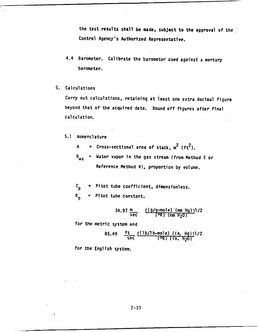
4.4 Barometer. Ca l ib ra te the barometer used against a mercury
barometer.
5. Calculat ions
C a r r y ou t calculat ions. r e t a i n i n g a t i e a s t one ex t ra decimal f i g u r e
beyond t h a t o f the acqulred data.
ca lcu lat ion.
Round o f f f igures a f t e r f i n a l
5.1 Nomenclature
A = Cross-sectional area o f stack, m2 ( f t 2 ).
%S = Uater vapor i n the gas stream (from Method 5 or
Reference Method 4) . propor t ion by volume.
- P i t o t tube coef f i c ien t , dimensionless. cP K = P i t o t tube constant. P
fo r the met r lc system and
85.49 - ft [( lb / lb-mole) ( in . Hg) 112 sec (OR) [ in . H20
f o r the English system.
2-33

Md = Molecular weight o f stack gas. d ry bas is (see Section 3.6) g/g-mole ( lb/ lb-mole).
MS = Molecular weight of stack gas, wet basis, g/g- mole ( l b / l b m o l e ) .
Md (1-BWS) + 18.0 BWS
Equation 2-5
Pbar = Barometric pressure a t measurement s i t e , mn Hg ( i n . Hg).
= Stack s t a t i c pressure, mm Hg ( i n . Hgl.
PS = Absolute stack gas pressure, mm Hg ( i n . Hg).
pg
Pbar + pg
Equation 2-6
PStd = Standard absolute pressure, 760 mm Hg
Qsd = Dry volumetric stack gas f low r a t e corrected
t S = Stack temperature OC ( O F ) .
TS = Absolute stack temperature, OK ( O R ) .
(29.92 in. Hg).
t o standard condit ions, dscm/hr (dscf /hr ) .
= 273 + tS f o r metr ic
Equation 2-7
= 460 + tS f o r English
Equation 2-8
Tstd = Standard absolute temperature, 293% (528.R)
"5 = Average stack gas ve loc i t y , m/sec ( f t / sec) .
P = Veloc i ty head o f stack gas, mm H20 (in. H20).
3,600 = Conversion fac to r , sec/hr.
18.0 = Molecular weight o f wa te r , g/g-mole (lb-lb-mole).
2-34

5.2 Average
~
stack gas veloctty
"s = CP )a vg
Equatfon 2-9
5.3 Average stack gas dry volumetric flow r a t e
Equation 2-10
2-35
6. Bib1 iography
c' 1. Mark, L.S. Mechanical Engineer's Handbook. New York,
2. P e r y . J.H. Chemical Engfneers' Handbook. New York.
3.
McCraw-Hi11 Book Co., Inc. 1951.
McGraw-Hi l l Book Co., Inc. 1960.
Signi f icance o f Errors i n Stack Sampling Measurments. U.S. Environmental Protection Agency, Research Tr iangle Park, NC. (Presented a t the Annual Meeting o f the A i r Po l l u t i on Control Assodat ion. S t . Louis, MO June 14-19, 1970.)
4.
Shigehara, R.T., U. F. Todd, and W.S. Smith.
Standard Method f o r Sampling Stacks f o r Par t i cu la te Matter. In: 1971 Book o f ASTM Standards, P a r t 23. Phi ladelphia, PA. 1971. ASTM Designation D-2928-71.
5. Vennard. J.K. Elementary F l u i d Mechanics. New York. John Wiley and Sons, Inc. 1947.
6. F l u i d Meters - Their Theory and Application. h e r c i a n Society of Mechanical Englneers, New York. NY. 1959.
7. ASH RAE Handbook o f Fundamentals. 1972. p. 208.
8. Annual Book o f ASTM Standards, P a r t 26. 1974. p. 648.
9. Vollaro, R.F. Guidelines f o r Type S P l t o t Tube Cal ibrat ion. U.S. Environmental Protect ion Agency. Research Tr iangle Park. NC. (Presented a t 1 s t Annual Meeting, Source Evaluation Society, Dayton, Ohio, September 18, 1975.)
10. Vollaro, R.F. A Type 5 P i t o t Tube Ca l ib ra t ion Study. U.S. Environmental Protect ion Agency, Emission Measurement Branch, Research Tr iangle Park, NC. Ju ly 1974.
Vollaro. R.F. The E f f e c t s o f Impact Opening Misalignment on the 4alue o f the Type S P i t o t Tube Coef f ic ient . U.S. Environmental Protect ion Agency, Emission Measurement Branch, Research Tr iangle Park, NC. November 1976.
Properly Constructed Type S P i t o t Tubes. Protect ion Agency, Gnisslon Measurement Branch, Research Tr iangle Park, NC. November 1976.
13. Vollaro. R.F. An Evaluation o f Single-Velocity Ca l ib ra t ion Technique as a Means o f Detenninlng Type S P i t o t Tube Coeff ic ients. U.S. Environmental Protect ion Agency, Emission Measurement Branch, Research Tr iangle Park, NC.
11.
12. Vol laro, R.F. Establishment o f a Baseline Coef f i c ien t Value f o r U.S. Environmental
August 1975.
2-36

14. Vollaro. R.F. The Use o f Type S P i t o t Tubes f o r the Measurement o f Lou Velocit ies. U.S. Environmental Protect ion Agency, Emission Measurement Branch, Research Tr iangle Park, NC.
Sampling Probe. Uni ted Technologies Corporation, P r a t t and Whitney A f r c r a f t Div is ion, East Har t ford, CT. 1975.
Ducts Smaller than 12 Inches i n Diameter. U.S. Environmental Protection, Agency, Emission Measurement Branch, Research Tr iangle Park, NC. November 1976.
Ed. London, Pergamon Press. 1966.
Instrumentation fo r t he Measurement o f Low-Range Gas Veloc i t ies. Environmental Pro tec t ion Agency, Emission Measurement Branch. Research Triangle Park, NC. Novmeber 1976. (Unpublished Paper)
November 1976.
15. Smith, Marvfn L. Ve loc i t y Ca l i b ra t i on o f €PA Type Source
16. Vollaro, R.F. Recomnended Procedure f o r Sample Traverses i n
17. h e r , E. and R.C. Pankhurst. The Measurement o f A i r Flow, 4 th
18. Vollaro, R.F. A Survey o f Comnercially Avai lab le U.S.
19. Gnyp, A.W., C.C. S t . Pfer re, D.S. Smith, 0. Morzon. and J . Steiner. An Experimental I nves t i ga t i on o f the E f f e c t o f P i t o t Tube-Sampl i ng Probe Conf igurat ions on the Magnl tude o f the S Type P i t o t Tube Coe f f i c i en t f o r Commercially Avai lable Source Sampling Probes. Environment. Toronto, Canada. February 1975,
Prepared by the Un ive rs i t y o f Windsor f o r the M i n i s t r y o f the
2-37

T k ALMEC~A C O R p O R A T i O N
APPENDIX
CARB Method 3
Excess Air and Dry Molecular Weight Gas Analysis for Carbon Dioxid, Oxygen,

State of California Air Resources Board
Method 3
Gas Analysis f o r Carbon Dioxide, Oxygen, Excess A i r , and Dy Molecular Weight
Adopted: June 29, 1983 Amended: March 28, 1986

METHOD 3 - GAS ANALYSIS FOR CARBON DIOXIDE, OXYGEN, EXCESS A I R , AND DRY MOLECULAR E I G H T
1. P r f n c l p l e and A p p l f c a b i l f t y
1.1 Pr inc ip le : A gas sample i s ext racted from a stack. by one o f the
f o l l o w i n g methods:
(21 s ing le -po in t . in tegra ted sampling; o r ( 3 )
mul t i -po in t , i n teg ra ted sampling. The gas sample i s
analyzed f o r percent carbon d iox ide (C02), percent
oxygen (02). and. i f necessary, percent carbon
monoxide (CO).
determinat ion i s t o be made, e i t h e r an Orsat o r a
(1 1 sfngle-point, grab sampling;
I f a dry molecular weight
F y r i t+ 1/ analyzer o r o ther analyzers s p e c i f i e d i n
Method 100 may be used f o r the analysis; f o r excess
a i r o r emission r a t e co r rec t i on f a c t o r detenninatton.
an Orsat ana lyzer o r analyzers spec i f i ed i n Method
100 must be used.
1.2 A p p l i c a b i l i t y : This method f s appl icable f o r determining C02 and
O2 concentrat ions. excess a i r , and dry molecular
weight o f a sample from a gas stream o f a f o s s i l - f u e l
combustion process. The method may a l so be
app l i cab le t o o t h e r processes where i t has been
determined t h a t compounds o ther than C02, 02, CO,
and n i t r o g e n (N2) a r e not present i n concent ra t ion
s u f f i c i e n t t o a f f e c t the results.
11 Mention of t rade names o r s p e c i f i c products does n o t c o n s t i t u t e endorsement by the A i r Resources Board.
3-1

Other methods, a s well as modifications t o the
procedure described herefn, are a l so applicable f o r
some o r a l l of the above determinations. Examples of
spec i f t c methods and modifications include: I1 ) a
multi-point sampling method using an Orsat analyzer
t o analyze individual g rab samples obtained a t each
p o i n t ; (2 ) a method u s i n g C02 o r O2 and
stoichiometric ca lcu la t ions to detennjne dry
molecular weight and excess a i r : (3) assigning a
value of 30.0 f o r dry molecular weight, i n l ieu o f
actual measurements, f o r processes b u r n i n g na tura l
gas, coa l , o r o t l . These methods and modifications
may be used, b u t are subject t o the approval o f the
Control Agency's Authorized Representative,
2. Apparatus
As a n a l t e rna t ive t o the sampling apparatus and systems described herein.
o ther sampling systems (e.9.. l i q u i d displacement) may be used provided
such systems are capable of obtaining a representat ive sample and
maintaining a constant sampling r a t e , and a r e otherwise capable of
yielding acceptable resul ts . Use of such systems i s subject t o the
approval o f the Control Agency's Authorized Representative.
2.1 Grab Sampling (Figure 3-1)
2.1.1 Probe. The probe shou ld be made of s t a in l e s s s tee l or
boros i l ica te glass t u b i n g and should be equipped w i t h an
in-stack or out-stack f l l t e r t o remove par t icu la te matter ( a
3-2

. ... z
p lug o f g lass wool I s sat is fac to ry f o r t h i s purpose). Aw other ma te r ia l i n e r t t o 02, Cot, CO. and N2 and
r e s i s t a n t t o temperature a t sampling condf t fons may be used
f o r the probe; examples of such ma te r ia l a r e aluminum, copper,
quar tz g lass and Teflon.
2.1.2 Pump. A one-way squeeze bulb, o r equivalent, i s used t o
t ranspor t t he gas sample t o the analyzer.
2.2 In tegrated Sampling (F igure 3.21
2.2.1 .Probe. A probe such as t h a t described i n Sec t ion 2.1.1 l s
su l tab1 e.
2.2.2 Condenser. An a l r - coo led o r water-cooled condenser, o r o ther
condenser t h a t w i l l n o t renove 02, C02,.C0. and N2 may
be used t o remove excess no ls tu re which would i n t e r f e r e w i t h
the opera t ion o f t h e pump and f low meter.
2.2.3 Valve. A needle va lve i s used t o ad jus t sample gas f l ow
rate.
2.2.4 Pump. A leak- f ree, diaphragm-type pump, o r equ iva len t , i s
used t o t ranspor t sample gas t o the f l e x i b l e bag.
m a l l surge tank between the pump and r a t e n e t e r t o e l im ina te
the p u l s a t i o n e f f e c t o f the diaphragm punp on the rotameter.
I n s t a l l a
3- 3

2.2.5 Rate meter. The rotameter, or equ iva len t r a t e meter, used
should be capable of mearurfng f l o w r a t e t o n l t h i n + 2 percent
o f the selected f l o w rate. A f low r a t e range o f 500 t o 1000
- cn 3 h l n i s suggested.
2.2.6 F l e x l b l e Bag. Any l eak - f ree p l a s t i c (e.g., Tedlar, Mylar,
. Teflon1 or p las t l c -coa ted aluminum le.9.. a lumlnized H y l a r )
bag, o r equlvalent. hav ing a capac l ty cons is ten t w l t h t h e
selected flow r a t e and t ime l e n g t h of tho t e s t run. may be
used. A capacl ty i n t h e range o f 55 t o 90 l i t e r s i s
suggested.
To leak-check the bag, connect l t t o a water manometer and
pressur ize the bag t o 5 t o 10 cm H20 ( 2 t o 4 i n H20) .and
a l l ow t o stand overnight. A d e f l a t e d bag ind ica tes a leak.
2.2.7 Pressure Gauge. A w a t e r - f i l l e d U-tube manometer, o r
equivalent. o f about 30 cm (12 i n 1 f s used f o r t he f l e x i b l e
bag leak-check.
2.2.8 Vacuum Gauge. A mercury manometer. o r equlvalent. o f a t l e a s t
760 nn Hg ( 3 0 l n Hg) i s used f o r the samplfng t r a i n
leak-check.
2.3 Analysis. For O r s a t and F y r i t e analyzer maintenance and opera t i on
procedures, fo l low the i n s t r u c t i o n s recornended by the manufacturer,
unless otherwise spec i f i ed herein.
3-4
A
L..!

2.3.1 Dry Molecular Welght Determination. An Orrat analyzer or
Fyrf te type combustlon gas analyzer may be used.
2.3.2 Emission Rate Correction Factor o r Excess Air Detennlnatlon.
An Orsat analyzer must be used. For low C02 ( l e s s t h a n 4.0
percent) o r h i g h O2 (g rea t e r than 15.0 percent)
. concentrations, the measuring buret te of the Orrat must have
a t least 0.1 percent subdfvislons.
3. Dry Molecular Weight Determination
Any of the three sampling and analyt ical procedures described below may be
used for determining the dry molecular weight.
3.1 Single-Point, Grab Sampling and Analytical Procedure
3.1.1 The sampling point i n the duct shall e i t h e r be a t the centroid
o f the c ross section o r a t a p o i n t no c l o s e r t o the walls than
1.00 m f3.3 f t ) . unless otherwise spec i f ied by the Control
Agency's Authorized Representative.
3.1.2 Set up the equipment as shown f n Figure 3.1, making sure a l l
connections ahead o f the analyzer a r e t i g h t and leak-free. I f
a n Orsat analyzer i s used, i t is recomnended t h a t the analyzer
be leak-checked by following the procedure i n Section 5.
3- 5

3.1.3 Place the probe i n t h e stack, w i t h t h e t f p o f t h e probe
pos i t ioned a t t he sampling po in t ; purge the sampllng l i n e .
Draw a sample i n t o t h e ana lyzer and i m d i a t e l y analyze i t f o r
percent C02 and percent 02.
the gas t h a t i s N2 and CO by subt rac t ing the sum o f the
percent C02 and percent O2 f r o m 100 percent. Calculate,
. the dry molecular weight as i nd i ca ted i n Sect ion 6.3.
I
Detennine t h e percentage o f
3.1.4 Repeat the sampling. ana lys is , and ca l cu la r ton procedures,
' u n t i l the dry molecular weights o f any three grab samples
d i f f e r f r o m t h e l r mean by no more than 0.3 g/g-mole (0.3
1 b/l bmole).
Average these th ree molecu la r weights, and r e p o r t t h e r e s u l t s
t o the nearest 0.1 g / g m o l e ( l b f l bmo le ) . 1
3.2 Single-Point, In tegra ted Sampl fng and Ana ly t i ca l Procedure
3.2.1 The sampling p o i n t i n t h e duc t s h a l l be loca ted 'as s p e c i f i e d
I n Section 3.1.1.
3.2.2 Leak-check (op t i ona l ) t h e f l e x i b l e bag as i n Sect ion 2.2.6.
Set up the equipment as shown i n F igure 3-2. J u s t p r i o r t o
sampling, leak-check ( o p t i o n a l 1 t h e t r a i n by p lac ing a vacuum
gauge a t the condenser i n l e t , p u l l i n g a vacuum o f a t l e a s t 250
mm Hg (10 i n Hg), p lugg ing t h e o u t l e t a t t he quick disconnect,
and then tu rn ing o f f t h e pump.
s tab le f o r a t l e a s t 0.5 minute.
The vacuum should remain
Evacuate the f l e x i b l e bag.
3-6

7- J FILTER (CLASS WOOLl
SOUEEZE BULB /
c R A T E M E T E R . -
A I R . C O O L F n S U R C f T A N K ,
RIGID C O N T A I N E R ’ Figure 3.2 Integrated g a s sampling t r a i n .
3-7

3.2.3
3.2.4
3.2.5
Connect the probe and place i t I n the stack, w i t h the t i p o f
the probe posltioned a t the sampling point ; purge the sampling
line.
connections are t i g h t and leak-free.
I ' (
Next, connect the bag and make sure t h a t a l l
Sample a t a constant ra te .
simultaneous w i t h , and f o r the same to t a l length of time as.
the pol lutant emission rate detemination. Collection of a t
The sampling run should be
l e a s t 30 l i t e r s (1.00 f t 3 of sample gas i s recomended;
however, smaller volumes may be collected. i f desired.
O b t a i n one integrated f l u e gas sample d u r i n g each p o l l u t a n t
emission r a t e d e t e n i n a t i o n . W i t h i n 8 hours a f t e r the sample
i s taken. analyze i t fo r percent C02 and percent O2 u s i n g
e i t h e r an Orsat analyzer o r a Fyrite-type combustion gas
analyzer.
t h a t the Orsat leak-check described i n Section 5 be performed
before this determination; however, t h e check i s optional.
Determine the percentage o f the gas t h a t < s N2 and CO by
subtracting the sum of the percent C02 and percent O2 from
100 percent.
in Section 6.3.
I f an Orsat analyzer i s used, i t i s reccmmended
Calculate the dry molecular weight a s indicated
Repeat the analysis and calculat ion procedures u n t i l the
i n d i v i d u a l dry molecular weights f o r any three analyses d i f f e r
from the i r mean by no more t h a n 0.3 g/g-mole (0.3
1 b/l b-mol e) .
!
3-8
Average these three mol ecu ld r weights, and r e p o r t the r e s u l t s ,
t o the nearest 0.1 g/gmole (0.1 l b f l b ino le ) .
3.3 Mu1 t l-Point. In tegra ted Sampling and Ana ly t i ca l Procedure
3.3.1 Unless otherwise spec i f i ed by the Control Agency's Authorized
Representative, a minfmum o f e i g h t t raverse po in ts sha l l be
, used for c i r c u l a r stacks having diameters l e s s than 0.61 rn (24
i n ) , a minimum o f n ine s h a l l be used f o r rectangular stacks
hav ing equ iva len t diameters l e s s than 0.61 m I 2 4 i n ) , and a
mfnfmum of twelve t raverse p o i n t s sha l l be used f o r a l l o the r
cases.
Method 1. The use o f fewer po in ts i s subject t o approval o f
the Control Agency's Author ized Representative.
The t raverse po in ts s h a l l be loca ted accordfng t o
3.3.2 Fo l low t h e procedures o u t l i n e d i n Sections 3.2.2 through
3.2.5, except f o r the fo l low ing ; t r a v e r s e a l l sampling po in ts
and sample a t each p o f n t f o r an equal leng th o f time. Record
sampling data as shown i n F igure 3-3.
4. Emission Rate Cor rec t ion Factor o r Excess A i r Determinat ion
Note: A Fy r i t e - t ype combustfon gas analyzer i s n o t acceptable fo r
excess a i r o r emission r a t e c o r r e c t i o n fac to r d e t e n i n a t i o n . unless
approved by the Control Agency's Author ized Representative.
percent C02 and percent O2 a r e measured, t he a n a l y t i c a l r e s u l t s
of any o f t he th ree procedures g iven below may a l so be used for
c a l c u l a t i n g t h e dry molecular weight.
I f both

Each of t he th ree procedures below shal l be used o n l y when spec i f i ed
i n an app l icab le subpart o f t he standards. The use o f these
procedures f o r other purposes must have spec i f f c p r i o r approval o f
the Control Agency's Author i t e d Representative.
4.1 S ing le Po in t , Grab Sampling and Analytical Procedure
4.1.1 The sampling p o i n t i n the duct s h a l l e i t h e r be a t the cen t ro id
o f t he cross-sect ion or a t a p o i n t no c lose r t o the w a l l s than
1.00 m (3.3 f t ) , unless otherwise spec i f ied by the
adn in i s t ra to r .
4 . 1 . 2 Set up the equipment as shown i n F igure 3-1, making sure a l l
connections ahead o f the analyzer are t i g h t and leak-free.
Leak-check the O r s a t analyzer according t o t h e procedure
described i n Section 3. T h i s leak-check i s mandatory.
4.1.3 Place the probe i n the stack, w i t h t h e t i p o f t h e probe
pos i t ioned a t t h e sampling po in t ; purge the sampling l i n e .
D r a w a sample i n t o the analyzer.
f ac to r determination, i m e d i a t e l y analyze the sample, as
o u t l i n e d i n Sections 4.1.4 and 4.1.5, f o r percent C02 o r
percent 02.
( 1 ) imnediately analyze the sample, as i n Sections 4.1.4 and
4.1.5, f o r percent C02, 02, and CO; (2) determine t h e
percentage o f t he gas t h a t i s N2 by subt rac t ing t h e sum o f
t h c percent C02. percent 02, and percent CO from 100
For emission r a t e co r rec t i on
I f excess a i r i s desired, proceed as fo l lows:
3-10

percent; and (31 ca lcu la te percent excess a i r as outlined f n
Sectton 6.2.
4.1.4 To ensure complete absorptfon o f the C02. 02, o r i f
appllcable. COS make repeated passes through each absorblng
solution u n t f l two consecutive readings a re the same. Several
. passes ( three or four1 should be made between readfngs. ( I f
constant readings cannot be obtained a f t e r three consecutive
readings, replace the absorbing solution.)
4.1.5 After the analysis i s ccnpleted, leak-check (mandatory) the
Orsat analyzer once again, a s described i n Section 5. For the
r e su l t s of the analysis t o be va l id , the Orsat analyzer must
pass t h i s leak tes t before and after the analysfs. Note:
Since this single-point, grab sampl ing and analyt ical
procedure i s normally conducted i n conjunction nlth a
single-point, g r a b sampling and analyt ical procedure f o r a
pol lutant , only one analysis i s ord inar i ly conducted.
Therefore, g rea t care must be taken t o obtain a valid sample
and analysis . Al though i n most cases only C02 or O2 i s
required, i t i s recomended t h a t both C02 and O2 be
measured, and tha t Ci ta t ion 5 i n the Bibliography be used t o
va l ida te the analytical data. -\ ..
4.2 Single-Point, Integrated Sampling and Analytical Procedure
4.2.1 ..
The sampling point i n t h e duct shal l be located as specified
i n Section 4.1.1.
3-1 1

4 .2 .2 Leak-check (mandatory) the f l e x f b l e bag as i n Section 2.2.6.
Set up the equlplnent as shown i n F i g u r e 3-2. Jus t p r i o r t o
samplfng, leak-check (mandatory) t h e t r a i n by p lac ing a vacuum
gauge a t t he condenser i n l e t . p u l l i n g a vacuum o f a t l e a s t 250
mm Hg (10 I n Hg), plugging the o u t l e t a t t h e quick disconnect,
and then tu rn fng o f f the pump. The vacuum s h a l l remain s tab le
. .
. f o r a t l e a s t 0.5 minute. Evacuate t h e f l e x i b l e bag. Connect
t he probe and p lace i t i n the stack, w i t h the t f p o f the probe
pos i t i oned a t t he samplfng po in t ; purge the sampling l i ne .
.Next, connect the bag and make sure t h a t a l l connections a r e
t i g h t and leak free.
4.2.3 Sample a t a constant ra te , or as s p e c i f i e d by the Control
Agency's Authorized Representative.
simultaneous wi th , and f o r t he same t o t a l l eng th o f time as,
the p o l l u t i o n emission r a t e determination. Co l lec t a t l e a s t
30 l i t e r s (1.00 f t3) o f sample gas.
c o l l e c t e d , sub jec t t o approval o f t h e Control Agency's
Author? zed Representative.
The sampllng run must be
Smal ler volumes may be
. 4 .2 .4 Obtain one in tegra tea f l u e gas sample during each p o l l u t a n t
emission r a t e determination.
f ac to r determination, analyze the sample w i t h i n 4 hours a f t e r
i t i s taken f o r percent C02 o r percent O2 (as o u t l i n e d i n
Sect ions 4.2.5 through 4.2.7).
leak-checked (see Section 5 ) before t h e analysis.
a i r i s desired. proceed as fo l l ows :
For emission r a t e cor rec t ion
The Orsat analyzer must be
I f excess
( 1 ) w i t h i n 4 hours a f t e r
3-12

the sample Is taken, analyze i t (as I n Sectfons 4.2.5 through
4.2.7) f o r percent C02. 02, and CO; (21 determine the
percentage o f the gas t h a t i s N2 by sub t rac t i ng the sum o f
the percent C02, percent O2 and percent CO f rom 100
percent; ( 3 ) ca lcu la te percent excess a i r . as o u t l i n e d i n
Sect ion 6.2.
4.2.5 To ensure complete absorpt ion o f the C02, 02, o r I f
appl icable, CO, make repeated passes through each absorbing
. s o l u t i o n u n t i l two consecutive readings a r e t h e same. Several
passes ( t h r e e o r f ou r ) should be made between readings. ( I f
constant readings cannot be obtained a f t e r t h ree consecutive
readtngs, rep lace the absorbing solut ion. 1
4.2.6 Repeat t h e analys is u n t i l the fo l l ow ing c r i t e r i a a r e met:
4.2.6.1 For percent C02, repeat the a n a l y t i c a l procedure
u n t i l the r e s u l t s o f any th ree analyses d i f f e r by no
more than ( a ) 0.3 percent by volume when C02 I s
g rea ter than 4.0 percent o r (b ) 0.2 percent by volume
when C02 i s l e s s than o r equal t o 4 .0 percent.
Average the three acceptable values o f percent C02
and repo r t the r e s u l t s t o the nearest 0.1 percent.
4.2.6.2 F o r percent 02, repeat t h e a n a l y t i c a l procedure
u n t i l the r e s u l t s o f any three analyses d i f f e r by no
more than ( a ) 0.3 percent by volume when O2 i s l e s s
3-13

than 15.0 percent or (b l 0.2 percent by volume when
O2 i s grea te r than o r equal t o 15.0 percent.
Average the three acceptable values o f percent O2
and repor t the resu l t s t o the nearest 0.1 percent.
4.2.6.3 For percent CO. repeat t h e analytical procedure u n t i l
the r e s u l t s of any three analyses d i f f e r by no more
t h a n 0.3 percent. Average the three acceptable
values o f percent CD and report the r e su l t s t o the
nearest 0.1 percent.
4.2.7 After the ana lys i s Is completed, leak-check (mandatory) the
Orsat analyzer once aga in , as described i n Section 5. For the
r e su l t s of the ana lys i s t o be v a l i d , the Orsat analyzer must
pass t h i s leak t e s t before and a f t e r the analysis.
Note: Although i n most instances only C02 or 02; Is
required, i t i s recomnended t h a t both C02 and O2 be
measured, and t h a t Ci ta t ton 5 i n the Bibllography be used t o
va l !date the ana ly t ica l data.
1
4..3 Mu1 t i - P o i n t , Integrated Sampling and Analytical Procedure
4.3.1 Both the minimum number of sampling points and the sampling
p o i n t locat jon sha l l be as specified I n Section 3.3.1 o f this
method. The use of fewer points t h a n specified Is subject t o
the approval of the Control Agency's Authorized
Representative.
3-14'

4.3.2 F o l l o w the procedures o u t l f n e d i n Sec t ion 4.2.2 through 4.2.7,
except f o r the following: Traverse e l l sampling po in ts and
sample a t each .po in t f o r an equal l e n g t h o f t ime .
samplfng data as shown i n F igure 3-3.
Record
- 4.4 O u a l i t y Cont ro l Procedures.
4.4 .1 D a t a V a l i d a t i o n When Both to2 and 0 are measured.
Al though i n most instances, only to2 or 0 measurement
i s requi red, i t i s recamended t h a t bo th C02 and 0 be -- measured t o p rov ide a check on t h e q u a l i t y o f t he data.
f o l l o w i n g q u a l i t y c o n t r o l prccedure i s sugoested.
Note: Since t h e nethod f o r v a l i d z t i n g t h e COz and 0
analyses i s based on ccmbustion o f organic and f o s s i l f u e l s
and d i l u t i o n of t h e gcs stream w i t h a i r , t h i s nethod does
no t apply t o sources that (1) renove CO? o r 0, through
processes o ther than c m b u s t i o n 12) add 0 (e.0. oxygen
enr ichment) and N, i n p r c p o r t i o n s d i f f e r e n t f rm t h a t o f
a i r , 13) add C02 (e.g. cenent on l i n e k i l n s ) , o r ( 4 ) have
no fue l f a c t o r , F- va lues ob ta inab le (e.g., ext remely
v a r i a b l e waste m ix tu res ) . Th is method va l i da tes the
measured p ropor t i ons o f COz and 0 f o r t h e foe1 type, 4 bu t t h e nethod does not detect sample d i l u t i o n r e s u l t i n g
frm leaks du r ing o r c f t e r sample c o l l e c t i o n .
i s a p p l i c a b l e f o r samples c o l l e c t e d downstream o f n o s t l i n e
o r l i n e s t o n e f lue-gas d e s u l f u r i z a t i c n u n i t s a s the CO,
added o r removed frm t h e gas s t r e a n i s n o t s i o n i f i c a n t i n
r e l a t i o n t o t h e t o t e 1 CO, concentrat ion. The C02
4 - __2
The
4
2
-
-
This method
-
3-15

. . ConcentrdtfOns frcn other types of scrubbers usfng only
Water or basic Slurry can be s i g n i f i c a n t l y a f fec ted and
would render the F- check minimally useful . c,
- I
4.4.1.1 Calculate a fuel f a c t o r , F- using t h e following equation: -
Fo 20.9 - 90 e k'here:
Eq. 3.3
'00 = Percent 0, by volume fd ry bes f s ) . -2 .
3 - 20.9
- = Percent CO, by volume ( D r y Basis) .
Percent 0, by volume i n ambient air . -
If CO i s present i n q u a n t i t i e s measurable by t h i s nethod, ad jus t the
0 a n d CO, values before performing t h e ca l cu la t ion f o r F e s
f o l i m s - -2 - -
. . - . .
Where: I CO = Percent CO by volme ( d r y b a s i s )
4.4.1.2 Cmpare tlie ca lcu la ted F, f ac to r w i t h the expected
F, values. The following t a b l e may be used i n e s t a b l i s h i n 2
acceptable ranges f o r the expected Fo i f the fuel being burned
i s known. When f u e l s are burned i n cmbina t ion . c a l c u l a t e t h e
cmbined fuel F, a n d F, f2c to r s ( a s defined i n tlethod 1 9 )
according t o t h e procedure f n Method 10 Section 5.2.3.
c a l c u l a t e t h e F f a c t o r as follcws:
- - "
- - Then
3-16

Fuel Type Fo range Coal :
A n t h r a c i t e and L i g n i t e 1 -01 8-1.130 1.083-1 .230 B i t umi nous
O i 1 1 a260-1.413 1.270-1.370
D i s t i 11 a t e Resi dua 1
Gas 1.600-1 -838
Propane 1.434-1.586 Natura l
Butane 1.405 1.553
1.000 1.120 llood
1.003-1.130 Wood B a r k
~~
Ca lcu lated Fa values beyond t h e xcep tab le - ranges shown i n t h i s t a b l e should
be i n v e s r i g a t e d be fo re accept ing the t e s t resu l ts .
of t h e s o l u t i o n s i n t h e gas analyzer and t h e ana lyz ing technique should be
checked by sanp l ing and analyz ing a known concentrat ion, such as a i r , t h e f u e l
f a c t o r should be reviewed and v e r i f i e d .
percent i s app rop r ia te f o r t h e FA f a c t o r o f mixed f u e l s w i t h v a r i a b l e f u e l
r a t i o s .
should be considered in d e t e m i n i n g i f a r e t e s t i s appropr ia te , i.e., i f t h e
measured emissions are much lower or nuch g rea te r than t h e ccnp l iance l i m i t
r e p e t i t i o n o f t h i s t e s t would not s i a n i f i c a n t l y change t h e ccnp l i ance s ta tus
of t he source and would be unnecessar i ly time-consuming and c o s t l y .
- FOP example. t h e s t reng th
. .
An a c c e p t a b i l i t y range of f. 12 - ..
The l e v e l o f t h e emission r a t e r e l a t i v e t o t h e canp l iance l e v e l
,.
3-17

. . 5. Leak-Check Prccedure, f o r Orsat Analyzers
c. ! Moving a n Orsat analyzer frequently causes i t t o leak. Therefcre, 'an
Orsat Analyzer should be thoroughly leak-checked on si te before the f lue
gas sample (s introduced 1nto I t . The p raedure for leak-checking an
Orsat analyzer f s :
5.1.1 Bring the l iquid level i n each pfpet te up t o the reference nark on
. the capi l lary t u b i n g and then close t h e pipet te stopcock.
5.1.2 Raise the leveling bulb suff ic ient ly t o br ing the confining l i q u i d
meniscus onto the graduated por t ion of the burette and t h e n close
t h e manifold stopcock. .
S1.3 Record the meniscus position. . I
5.1.4 Observe the nenfscus in t h e burette and the l i q u i d level i n the
p ipe t te f o r movement over :he next 4 minutes.
5 i 1 . 5 For t h e Orsat analyzer t o pass the leak-check, two conditions must
be met. . *
3-1 8

5.1.5.1 The l l q u i d level I n each pipette must not fa l l below-
the bottom o f the capillary tub lng d u r i n g this
4-minute interval.
5.1.5.2 The menlscus In the burette must n o t change by more
than 0.2 ml during this 4-minute interval.
5.1.6 If the analyzer f a l l s the leak-check procedure, a l l rubber
connections and stopcocks should be checked u n t i l the cause of
. the leak i s identified. Leaking stopcocks must be
disassembled, cleaned, and regreased.
connections must be replaced. After the analyzer I s
reassembled, the leak-check procedure must be repeated.
Leaking rubber
6. Calculations
6.1 Nomenclature.
'd Percent EA
Percent C02
Percent O2
Percent CO
Percent N2
0.264
0.280
0.320
0.440
Dry molecular weight. g/g-mole (lb/lb-mole)
Percent excess air.
Percent C02 by volume (dry basis).
Percent O2 by volume (dry basis).
Percent CO by volume (dry basis).
Percent N2 by volume (dry basis).
Ratio of O2 t o N2 i n a i r , v/v.
Molecular weight of N2 o r CO, divided by 100.
Molecular weight o f O2 divided by 100.
Molecular weight o f C02 divided by 100
3-19

6.2 Percent Excess A i r . Calcu late the percent excess a i r ( i f
appl icable] , by s u b s t i t u t f n g the appropr la te values o f percent 02, .r
CO, and N2 (obtained from Section 4.1.3 o r 4.2.4) I n t o Equation
3-1.
] 100 percent 'o? - 0.5 percent CO
Percent N2 - [percent 02 - 0.5 percent CO) percent EA -
Equation 3-1
Note: The equat ion above assumes t h a t ambient a i r i s used as the
source o f O2 and t h a t t h e f u e l does n o t con ta in appreciable amounts
o f N2 (as do coke o r b l a s t furnace gases). For those cases when
appreciable amounts o f N~ are present (coal, o f t , dnd na tura l gas
do n o t conta in appreciable amounts o f ' N 2 ) o r when oxygen enrichment
i s used, a l t e rna te methods, sub jec t t o approval o f the Control
Agency's Author ized Representative, a re required. i
6.3 Dry Molecular Weight. Use Equation 3-2 t o c a l c u l a t e the dry
molecular welght o f t he stack gas.
Md = 0.440 (percent COz) + 0.320 (percent 02) +
0.280 (percent N2 + percent C O )
Equation 3-2
Note: The above equat ion does n o t cons ider argon i n a i r (about 0.9
percent, mo lecu la r weight o f 37.71. A negat fve e r r o r o f about 0.4
percent i s introduced. The t e s t e r may o p t t o i nc lude argon i n the
ana lys is us ing procedures' subject t o approval o f t he Control Agency's
Author ized Representative. \
3-20
7. Bibltography
1. Internat ional Journal o f Alr and Water Pollutlon. 6:75-81. 1963.
2. Journal o f the American Industr ia l b g i e n e Association. 25:291-297. 1964.
3. Burrell Manual for Gas Analysis. Seventh edit ion. Burrell Corporation, 2223 F i f t h ' Avenue, Pit tsburgh. PA 15219. 1951.
4. Mitchell, W.J. and M . R . Hidgett. F ie ld Re l i ab i l i t y ,o f the Orsat Analyzer. Journal o f Air Pol lut ion Control Association 26:491-495. May 1976.
5. Shigehara, R.T., R.M. Neulicht, and W.S. Smith. Validating Orsat
Altshuller, A.P. Storage o f Gases and Vapors i n Plastic Bags.
Conner. Yilliam 0. and J.S. Nader. Air Sampling w i t h P l a s t t c Bags.
Analysis Data from Fossil Fuel-Fired Units. Stack Sampling News 4(21:24-26. .August 1976.
3-21

p TkE A~MEC~A CORPORATiON
APPENDIX Q
CARB Method 4
Determination of Moisture Content in Stack Gas

State of Ca l i fo rn ia A i r Resources Board
Method 4
Determination of Moisture Content i n Stack Gases
Adopted: June 29. 1983

METHOD 4 - DETERMINATION OF MOISTURE CONTENT I N STACK GASES
1. P r inc ip le and A p p l l c a b l l j t y
1.1 Pr inc ip le : A gas sample i s ext racted a t a constant r a t e f r o m the
source; mois ture i s removed from the sample s t r e a m
and determined e i t h e r vol umetrical l y o r
grav imet r ica l l y .
1.2 App l i cab i l i t y : This method i s appl icable f o r d e t e n i n i n g the
moisture content o f s t a c k gas.
Two procedures are given.
method, f o r accurate determinations o f moisture
content (such as are needed t o ca l cu la te emission
data). The second i s an approximation method, which
provides estfmates o f percent moisture t o a i d i n
s e t t i n g i s o k i n e t i c sampling ra tes p r i o r t o a
p o l l u t a n t emission measurement run. The
approximation method described here in i s on ly a
suggested approach; a1 te rna t i ve means f o r
approximating the moisture content, e.g., dry ing
tubes, wet bulb-dry bu lb techniques, condensation
techniques, s to ich iometr ic ca lcu la t ions , previous
experience, etc., a r e a1 so acceptable.
The f i r s t i s a reference
The reference method i s o f ten conducted
simultaneously w i t h a p o l l u t a n t emission measurement
run; when i t i s , ca l cu la t i on o f percent i sok ine t i c .
4-1

POllUtdnt emlsslon rate, etc., for the run sha l l be
based upon t h e r e s u l t s o f the reference method o r , i t s
equivalent; these ca lcu la t lons s h a l l no t be based
upon r e s u l t s o f the approxlmatlon method, unless the
approximation method i s shown, t o the s a t i s f a c t l o n o f
the Control Agency's Authorized Representative, t o be
capable o f y t e l d l n g r e s u l t s w i t h i n 1 percent H20 o f
the reference method.
Note - The reference method may y i e l d questionable
r e s u l t s when appl l e d t o saturated gas
streams o r t o streams t h a t conta in water
droplets. Therefore, when these condi t ions
e x i s t or are suspected, a second
determination o f the mois ture content sha l l
be made slmultaneously w i t h the reference
method, as fo l lows:
stream I s saturated. Attach a temperature
sensor [capable o f measurlng t o - + l 0 C
(2OF)I t o the reference method probe.
Measure the stack gas temperature a t each
t raverse p o l n t (see Section 2.2.1) dur lng
the reference method traverse; ca l cu la te the
average stack gas temperature. Next,
determine the molsture percentage, e i t h e r
by:
making appropriate
Assume t h a t the gas
(1 ) uslng a psychrometric cha r t and
c
4-2

correct ions i f stack pressure i s d i f fe ren t
from t h a t o f t h e chart , o r ( 2 ) using
sa tura t ion vapor pressure tables.
where the psychranetr ic c h a r t o r the
sa tu ra t i on vapor pressure tab les are n o t
appl icable (based on evaluat ion o f the
process), a1 ternate methods, subject t o the
approval o f the Control Agency's Authorized
Representative, s h a l l be used.
In cases
2. Reference Method
The procedure described i n Method 5 f o r determining moisture content i s
acceptable as a reference method.
2.1 Apparatus
A schematic o f the sampling t r a i n used i n t h i s reference method i s
shown i n Figure 4-1. A l l components sha l l be maintained and
ca l i b ra ted according t o the procedure ou t l i ned i n Method 5.
2.1.1 Probe.
tubing. s u f f l c f e n t l y heated t o prevent water condensation, and
Is equlpped w i th a f i l t e r e i t h e r in-stack (e.9.. a p lug o f
g lass wool i nser ted i n t o t h e end o f the probe) o r heated
out-stack (e.g., as descr ibed i n Method 5 ) t o remove
The probe i s constructed o f s ta in less s t e e l o r glass
p a r t j c u l a t e matter.
4 - 3

. .
CONDENSER-ICE BATH S m E M INIXUOING~ SILICA GEL TUBE
. ... . F i g u r e 4.1 Moisture sainplinq t r a i n (Reference Method).
c
i

When stack condi t ions permit, o ther metals o r p l a s t i c tub ing
may be used f o r the probe, subject t o the approval o f the
Control Agency's Authorized Representative.
2.1.2 Condenser. The condenser consts ts o f four lmpingers connected
t n series w i t h ground glass, leak- f ree f t t t i n g s o r any
s i m i l a r l y leak- f ree non-contaminating f i t t t n g s . The f i r s t .
t h i rd , and four th impingers sha l l be o f the Greenburg-Smith
design, modi f ied by rep lac ing the t i p w i t h a 1.3 centimeter
(1/2 inch) I D glass tube extending t o about 1.3 cm (1/2 i n . )
from the bottom o f the f lask.
the Greenburg-Smith design w i t h the standard t i p .
Modi f icat ions (e.9.. us ing f l e x i b l e connections between the
impingers, ustng mater ia ls other than glass, o r us ing f l e x i b l e
vacuum l l n e s t o connect the f i l t e r holder t o the condenser)
may be used, subject t o t h e approval o f the Control Agency's
Authorized Representative.
The second impinger s h a l l be o f
The f i r s t two impingers s h a l l conta in known volumes of water,
the t h t r d sha l l be empty, and the four th sha l l conta in a known
weight o f 6 t o 16 mesh i n d i c a t i n g type s i l i c a gel, o r
equivalent desiccant.
used, dry a t 175OC (35O0F) f o r 2 hours. New s t l i c a gel
may be used as received.
temperature t o w i t h i n l 0 C IZOF), sha l l be placed a t the
o u t l e t o f the f o u r t h impinger, f o r monitortng purposes.
I f the s i l i c a gel has been prev ious ly
A thermometer. capable o f measuring
4-5
A1 te rna t ive ly , any system may be used (sub jec t t o the approval
o f the Control. Agency's Authorized Representative) t h a t cools
the sample gas stream and al lows measurement o f both the water
t h a t has been condensed and the moisture leav ing the
condenser, each t o w i t h i n 1 m l o r 1 g. Acceptable means are
t o measure the condensed water. e i t h e r g rav ime t r j ca l l y o r
vo lumetr ica l ly , and t o measure the moisture leav ing the
condenser by: (1 1 monitoring the temperature and pressure a t
the e x i t o f the condenser and using Da l ton 's law o f p a r t i a l
pressures, o r (2 ) passing the sample gas stream through a
. ta red s i l i c a gel ( p r equtvalent desiccant) t rap, w i t h e x i t
gases kept below 2OoC (68'F). and determining the weight
gain.
I f means other than s i l l c a gel are used t o determine the
amount o f moisture leav ing the condenser, i t i s recomnended
t h a t s i l i c a gel ( o r equivalent) s t i l l be used between the
condenser system and pump, t o prevent moisture condensation i n
the pump and metering devices and t o avo id the need t o make
cor rec t ions f o r moisture i n the metered volume.
2.1.3 Cooling System. An i c e bath container and crushed i c e [ o r
equjva lent ) are used t o a i d I n condensing moisture.
c
I
2.1.4 Metering System. T h i s system inc ludes a vacuum gauge,
leak- f ree pump. thennometers capable o f measuring temperature
t o w i t h i n 3'C [5.4OF), dry gas meter capable o f measuring
4-6
c

volume t o w i t h i n 2 percent, and r e l a t e d equipment a s shown i n
F igure 4-1. Other metering systems, capable o f maintaining a
constant sampling r a t e and determining sample gas volume. may
be used, subject t o the approval o f the Control Agency's
Authorized Representative.
2.1.5 Barometer. Mercury, aneroid, o r o ther barometer capable o f
measuring atmospherfc pressure t o w i t h i n 2.5 mm Hg (0.1 in .
Hg) may be used.
obtained from a nearby nat ional weather serv ice s tat ion, i n
which case the s t a t i o n value (which i s the absolute barometric
pressure) sha l l be requested and an adjustment f o r e leva t ion
differences between the weather s t a t i o n and the sampling po in t
sha l l be appl ied a t a r a t e o f minus 2.5 mm Hg (0.1 in . Hg) per
30 m 1100 f t ) e leva t ion increase o r v i c e versa f o r e leva t ion
decrease.
I n many cases, t he barometric reading may be
2.1.6 Graduated Cy1 inder and/or Balance.
measure condensed water and moisture caught i n the s i l i c a gel
t o w i t h i n 1 m l o r 0.5 g.
subdivisions no greater than 2 m l . Most labora tory balances
are capable o f weighing t o the nearest 0 .5 g o r less. These
balances are su i tab le f o r use here.
These i tems are used t o
Graduated cy l i nde rs s h a l l have
2.2 Procedure. The fo l lowing procedure i s w r i t t e n f o r a condenser system
(such as the impinger system described I n Section 2.1.2)
incorpora t ing volumetric analys is t o measure the condensed moisture,
4 - 7

and s f l f c a gel and gravimetrtc analysls t o measure the moisture
leavf ng the condenser. c 2.2.1 Unless otherwise specified by the Control Agency's Authorized
Representative. a minimum o f e lght traverse p o i n t s shall be
used f o r c i r cu la r stacks having diameters l e s s t h a n 0.61 m
(24 i n ) . a minimum of nine points shal l be used for
rectangular stacks having equivalent diameters 1 ess t h a n
0.61 m (24 i n ) , and a minimum o f twelve traverse p o i n t s shall
be used i n a l l other cases. The t raverse p o i n t s shall be
located according t o Method 1. The use of fewer points i s
subject t o the approval of the Control Agency's Authorized
Representative.
t h a t a l l traverse p o i n t s can be sampled.
from opposite sides o f the stack (four to t a l sampling ports)
for large stacks, t o permit use of shorter probe lengths.
Mark the probe w i t h heat res i s tan t tape o r by some other
method t o denote the proper distance i n t o the stack o r d u c t
for each sampling point.
first two implngers.
s i l i c a gel t o the nearest 0.5 g , a n d t r ans fe r the s i l i c a gel
t o the fourth fmpinger; a l ternat ively, the s i l i c a gel may
f i r s t be t ransferred to the impinger, and the weight of the
s i l ica gel plus implnger recorded.
Select a sui table probe and probe length such
Consider sampling
Place known volumes o f water i n the
Weigh and record the weight of the
2.2.2 Select a t o t a l sampling time such t h a t a m l n i m u m to ta l gas
volume o f 0.60 scm (21 s c f ) will be col lected, a t a rate no
4-0

greater than 0.021 m3/min (0.75 cfm). Yhen both molsture
content and po1,lutant emission r a t e a re t o be detemined. the
molsture d e t e d n a t i o n s h a l l be simultaneous with, and f o r the
same t o t a l length o f t ime as, the p o l l u t a n t emission r a t e run,
unless otherwise spec i f i ed i n an appl icable subpart o f the
standards.
2.2.3 Set up the sampling t r a i n as shown i n F igure 4-1.
probe heater and ( I f app l icab le ) the f i l t e r heating sys tem t o
temperatures o f about 120°C (248OF1, t o prevent water
condensation ahead o f the condenser; a l low time f o r the
temperature t o s t a b i l i z e .
container.
before and a f t e r each t e s t , a s fol lows: Disconnect the probe
from the f i r s t impinger o r ( i f appl icable) f r o m the f i l t e r
holder.
ho lder) and p u l l a 380 mm (15 i n ) Hg vacuum; a lower vacuum
may be used. provided t h a t i t i s n o t exceeded during the
tes t .
sampling r a t e o r 0.00057 m /min (0.02 cfm). whichever i s
less, i s unacceptable.
the probe t o the sampling t ra in .
Turn on the
Place crushed i c e i n the i c e bath
It i s requ i red t h a t a leak check be performed
Plug the i n l e t t o the f i r s t impinger ( o r f i l t e r
A leakage r a t e i n excess o f 4 percent o f the average 3
Following the leak check, reconnect
2.2.4 During the sampling run, mainta in a sampling r a t e w i t h i n 10
percent o f constant ra te , o r as speci f ied by the Control
Agency's Authorized Representative. For each run, record the

FlGURP 4.2 Project No.
Date Time C! \ WATER VAPOR CALCULATIONS
Standard Condltlons 68°F and’29.92 in. Hg
in . Hg h b l e n t Condltions - O F and -
Time I I ~ ~ ~ ~ ~ ~ _ _
Gas Volume Impinger Meter
(Vm). Ft3 (TI’!; OF ( ImP: OF Through Meter Tem T M l
~
O r l f l c e Pressure (AH). In. Hz0
Flnal I n i t i a l
~~
Volume o f Water Collected i n Implnger (Vic). m l
A.
B.
C.
0.
e 6
130 140 150 155
Assume 1 gram H20 1 m l H20 Gas Volume Metered. (‘fmStd)
( 1 s in. Hg ) + l3-Z- Pma = Pbar t (AH/13.6) * (
15.1 19.7 25.3 20.7
( vm = (17.64) ( ) ( ’ ) = 5 OCF 528 OR
Vmstd = 29.92 in. Hg Tm
Volume o f Water Collected (VWstd)
‘,s’;d = (0.04707 ft3) ( V i c ) (0.04707) ( TI-
1 - SCF
Moisture Content i n Stack Gas (Bw) i n Percent
Bw = A+B x 100 = -t---+ x 100 =
If calculated moisture content (c) i s greater than a t saturat lon temperature (e.g. 212°F o r below) use the t a b l e for moisture content.
04.07 4-10
Temp. O F
50 60 70 80 90
100 110
I20 -
Z OF H20 AT SATURATION
1.2 1.7 2.5 3.5 4.8 6.5 a. 7
11.5 -
- Temp, OF
180 185 190 195 200 205 21 0 21 2 -
- # ..
H Z O - 51.1 57.0
63.6 70.8 78.6 87.0 96.2
100.0 -
c

data required on the example data sheet shown i n F igure 4-2.
Be sure t o record the dry gas m e t e r reading a t the beginning
and end o f each sampling time increment and whenever sampling
i s halted.
po int . a t l e a s t once dur ing each time increment.
Take o ther appropriate readings a t each sample
2.2.5 To begin samplfng, p o s i t i o n the probe t i p a t the f i r s t
traverse point.
flow t o the desired ra te .
sampling a t each t raverse p o i n t f o r an equal leng th o f time.
Add more i c e and, if necessary, s a l t t o mainta in a temperature
o f less than 2OoC I68OF) a t the s i l i c a gel ou t le t .
Immediately s t a r t the pump and ad jus t t he
Traverse the cross section,
2.2.6 A f t e r c o l l e c t i n g the sample, disconnect the probe f r o m the
f i l t e r holder ( o r from t h e f i r s t impinger) and conduct a leak
check (mandatory) as described i n Sectjon 2.2.3. Record the
leak r a t e .
the t e s t e r s h a l l e i t h e r r e j e c t the t e s t r e s u l t s o r sha l l
cor rec t the sample volume a s i n Section 6.3 o f Method 5.
Next, measure the volume o f the moisture condensed t o the
nearest m l . Determine the increase i n weight o f the s f l i c a
gel ( o r s f l i c a gel p lus impinger) t o the nearest 0.5 g.
Record t h f s in format ion and ca lcu la te the moisture percentage,
as descrfbed i n 2.3 below.
If the leakage r a t e exceeds the al lowable ra te ,
4-1 1
i

2.3 Calculations. Carry o u t the f o l l o d n g calculations. retaining a t
least one extra decimal figure beyond t h a t of the acquired data .
Round off figures a f t e r f i n a l calculation. c-
2.3.1 Nomenclature.
0,s
yc
= Proportion of water vapor, by volume, i n the gas stream.
Molecular weight o f water, 10.0 g/g mole (18.0 1 b/l b-mol e ) .
barometric pressure] a t the dry gas meter, mm Hg ( i n Hg).
Standard absolute pressure, 760 mm Hg (29.92 i n Hg I
=
Pm = Absolute pressure ( f o r t h i s method. same as
P s t d
R = Ideal gas constant, 0.06236 (mm Hg) (m3) / [g-mole4 (KO) f o r metric u n i t s and 21.85 ( i n Hg) ( f t )/(lb-mole) ( O R ) f o r E n g l l s h u n i t s .
Tm = Absolute temperature a t meter. OK ( O R ) .
Ts td - Standard absolute temperature, 2930 K ( 528OR 1.
Vm = D r y gas volume measured by the dry gas meter, dcm (dcf) .
A Vrn
Vm(Std)
Vwc [ s t d 1
= Incremental dry gas volume measured by dry gas meter a t each t raverse point, dcm (dcf ) .
Dry gas volume measured by the dry gas meter, corrected t o standard conditions, dscm (dscf 1.
Volume of water vapor condensed corrected t o standard conditions, scm ( sc f ) .
corrected t o standard conditlons, scm ( se t ) .
=
=
VwsglStd) - Volume of water vapor col lected i n s i l i c a gel
Vf = Final volume of condenser water, m l .
Vi = In i t f a l volume, i f any. of condenser water, ml.
"f = Final weight o f s i l i c a gel p l u s impinger, g.
4-1 2

= In i t i a l w e i g h t o f s i l i c a gel o r s l l l c a gel p l u s impinger, g.
M i
Y = D r y gas meter cal ibrat ion factor.
P W = Oensity of water, 0.9982 g/nl (0.002201 lb/ml).
2.3.2 Volume of water vapor condensed.
= K 1 ( Y f - Vi)
Equation 4-1
where: K 1 = 0.001333 m3/ml fo r metrfc uni ts
=
2.3.3 Volume of water vapor collected f n s i l i c a gel.
0.04707 f t 3 / d f o r E n g l i s h un i t s
= K 2 (Iff - M i )
Equation 4-2
where: K 2 = 0.001335 n3/9 f o r metric units
= 0.04715 ft3/9 fo r English units
2.3.4 Sample gas volume.
Equation 4-3
where: K3 = 0.3858 o K / m Hg f o r metric units
17.65 W i n . Hg for English u n i t s
NOTE: If the post-test leak r a t e (Section 2.2.6)
exceeds t h e allowable r a t e , correct the value
of Vm i n Equation 4-3 a s described i n
Section 6.3 o f Method 5.
4-1 3

2.3.5 Moisture Content
vwc ( s t d l + %sg( s t d l Bws =
vwc ( s t d ) + h s g ( s td ) + Vm(std1
Equation 4-4
NOTE: I n saturated o r moisture droplet-laden gas streams, two
ca l cu la t i ons o f the moisture content o f the stack gas
s h a l l be made, one us ing a value based upon the
saturated condi t jons (see Section 1 . Z ) ; and another
based upon the r e s u l t s o f the impinger analysis.
lower o f these two values o f Bws s h a l l be considered
correct.
The
2.3.6 V e r i f i c a t i o n o f constant sampling rate. For each time
increment, determine the A V ~ . Calculate the average. I f
the value f o r any t ime increment d i f f e r s from the average by
more than 10 percent, r e j e c t the r e s u l t s and repeat the run.
3. Approximation Method
The approximation method described below i s presented on ly as a suggested
method (see Section 1.2).
3.1 Apparatus
3.1.1 Probe; Sta in less s tee l o r glass tubing, s u f f i c i e n t l y heated
t o prevent water condensatlon and equipped w i t h a f i l t e r
[ e i t h e r in-stack o r heated out-stack) t o remove p a r t l c u l a t e
matter. A p lug o f g lass wool, i nse r ted i n t o the end o f the
probe, i s a sa t i s fac to ry f i l t e r .
4-14

3.1.2
3.1 -3
3.1.4
3.1.5
3.1.6
3.1.7
3.1.8
Impfngers. Two midget Impingers, each w i t h 30 m l . capaclty.
or equivalent.
Ice Bath.
implngers.
Drying Tube. Tube packed w i t h new or regenerated 6-to 16-mesh
Indicating-type s i l i c a gel (o r equivalent desiccant), t o dry
the sample gas and t o protect the meter and pump.
Valve.
Pump.
gas sample through the t ra in .
Volume meter. Dry gas meter, suf f ic ien t ly accurate t o measure
the sample volume within 2 percent and cal ibrated over the
range o f flow ra t e s and condi t l ons actual ly encountered dur ing
sampl i ng . Rate Meter. Rotameter t o measure the flow range from 0 t o 3
lpm (0 t o 0.11 cfm).
Container and ice , t o aid i n condensing moisture in
Needle valve, t o regulate the sample gas flow rate.
Leak-free, diaphragm type, or equivalent t o p u l l the
3.1.9 Graduated cylinder. 25 m l .
3.1.10 Barometer. Mercury, aneroid, o r other barometer, d s described
i n Section 2.1.5. above.
Vacuum Gauge. A t l e a s t 760 mn Hg (30 i n . Hgl gauge, t o be
used for t h e sampling leak check.
3.1.11
3.2 Procedure
3.2.1 Place exactly 5 m l d i s t i l l e d water i n each impinger.
Leak-check the sampling t r a i n as follows: Temporarily insert
a vacuum gauge a t or near the probe i n l e t ; then, plug the
probe i n l e t and pu l l a vacuum of a t l e a s t 250 mm Hg (10 i n

Hg). Note the time r a t e o f change o f the dry gas meter d i a l ;
a l t e rna t i ve l y , d rotameter (0-40 cc/min.) may be temporar i ly C' attached t o the dry gas ne te r o u t l e t t o determine the leakage
rate. A leak r a t e no t i n excess o f 2 percent o f the average
sampllng r a t e i s acceptable.
Note - Carefu l ly release the probe i n l e t p lug before tu rn ing
o f f the pump.
3.2.2 Connect the probe, i n s e r t It i n t o the stack, and sample a t a
constant r a t e o f 2 l p n (0.071 cfm). Continue sampling u n t i l
the dry gas meter reg i s te rs about 30 l i t e r s (1.1 f t 3 1 o r
u n t i l v i s i b l e l i q u i d droplets a r e c a r r i e d over from the f i r s t
impinger t o the second. Record temperature, pressure, and dry
gas meter reddlngs as requl red by Figure 4-4.
3.2.3 After c o l l e c t i n g the sample, combine the contents o f the two
impingers and measure the volume t o the nearest 0.5 m l .
3.3 Calculations. The ca lcu la t ion method presented i s designed t o
estimate the moisture i n the stack gas; therefore, o ther data, which
are only necessary f o r accurate moisture determinations, are no t
col lected.
content, f o r the purpose o f d e t e n l n i n g i s o k i n e t i c sampling r a t e
settings.
The fo l low ing equations adequately estimate the moisture
c 4-1 6

COMMENTS LOCATION TEST DATE
OPERATOR
BAROMETRIC PRESSURE
GAS VOLUME THROUGH MET R Vm ,
m 5 ( i t 3 1 CLOCKTIME RAJE METER SETTING METER TEMPERATURE m /min. ( f t 3 / m i n . ) OC ( O F )
3.3.1 Nomenclature.
B,
Bws
yc
Pm
P s t d
R
Tm
T s t d
Vf
V i
Vm
vm(std)
vwc ( std)
hc Y
= Approximate proportion, by volume, o f water vapor in the gas stream leaving the second impinger. 0.025.
= Water vapor f n the gas stream, proportion by vol ume .
= Molecular weight o f water, 18.0 g/g-mole (18.0 1 b/l b-mol e).
Absolute pressure ( f o r t h i s method, same as barometric pressure) a t the dry gas meter.
Standard absolute pressure, 760 mm Hg (29.92 i n Hg).
Ideal gas constant, 0.06236 [mn Hg) (m3)/(g-mole) [OK f o r metric uni ts and
Engl ish units
Absolute temperature a t meter, 0 (OR).
21.85 ( i n Hg) I f t J )/lb-mole [OR) f o r
Standard absolute temperature. 2930K ( 528% 1.
Final volume of impinger contents, ml.
In i t i a l volume of impinger contents, m l .
Dry gas volume measured by dry gas meter, dcm (dcf 1.
D r y gas volume measured by dry gas meter, corrected t o standard conditions, dscm (dscf).
Volume o f water vapor condensed, corrected t o s tandard conditions, scm (scf).
Density o f water, 0.9982 g/ml (0.002201 lb/nl) .
D r y gas meter ca l ibra t ion factor.
c .. .
(' ,
4-18

3.3.2 Volume o f water vapor co l lected.
( v f - v i ) P u RT(std) vwc ( s t d ) =
PStd b = K1 ( V f - V i 1
Equation 4-5
= 0.001333 m3/ml f o r metr ic u n i t s
= 0.04707 f t 3 / m 1 f o r English un i t s
where: K1
3.3.3 Gas Volume
Equation 4-6
where: K2 = 0.3858 O K / m Hg for met r i c u n i t s
= 17.65 oR/in. Hg f o r Engl ish u n i t s
3.3.4 Approximate moisture content.
+e, vwc( s t d ) bs =
i vwc [ s t d 1 + (0.025) vwc(std) + Vm(std)
Equation 4-7
4. Ca l ib ra t ion
4.1 For the reference method, c a l i b r a t e equipment as spec i f ied i n the
fo l low ing sect ions of Method 5; Section 5-3 (metering system);
Sectlon 5.5 (temperature gauges); and Section 5.7 (barometer).
recomnended leak check o f the metering system (Section 5.6 of
Method 5 ) a lso appl ies t o the reference method.
The
For the
4-19

. . ., . r
5. E1 b l iography
1. A i r Po l l u t i on Englneerlng Manual [Second Edi t ion) . Danlelson. J.A. U.S. Envlranmental Protect ion Agency, O f f i c e o f A i r Q u a l i t y led. 1.
Planning and Standards. Research Tr iangle Park, NC. Publ lcat ion No. AP-40. 1973.
2. Devorkin, Howard. e t a l . A i r P o l l u t i o n Source Test lng Manual. A i r
3. Methods for Deteminat lon of Veloci ty, Volume, Dust and M i s t Content
Po l lu t ion Control D i s t r i c t , Los Angeles, CA. November 1963.
o f Gases. Western Prec ip i ta t ion D iv i s ion o f Joy Manufacturing Co., Los Angeles. CA. B u l l e t i n UP-50. 1968.
4-21
APPENDIX G
CARE Method 4 1 0 A
Determination of Benzene from Stationary Sources (Low Concentration Gas Chromatography Technique)

State o f C a l i f o r n i a A i r Resources Board
Method 410A
Determination o f Benzene frcn Stat ionary Sources (Low Concentration
Gas Chrmatographic Technique)
Adopted: Yarch 28, 1986

METHOD 41 OA OETERMINATION OF BENZENE FROM STATIONARY SOURCES (LOW CONCENTRATION GAS CHROMATOGRAPHIC TECHNIQUE)
1.
2.
3.
APPLICABILITY AND PRINCIPLE
1.1 A p p l i c a b i l i t y : This method app l ies t o the measurement o f low
concentrat ion emissions o f benzene from s ta t i ona ry sources.
method does n o t account f o r benzene contained i n p a r t i c u l a t e matter.
1.2 P r i n c i p l e : An in teg ra ted bag s.ample o f stack gas conta in ing benzene
The
and o ther organics i s subjected t o gas chromatographic ( G C )
analysis. using a photo i o n i z a t i o n detector ( P I D ) .
RANGE AND SENSITIVITY
The range o f t h i s method i s 1.0 t o 1000 ppb. The upper l i m i t may be
ra ised by extending the c a l i b r a t i o n range o r by d i l u t i n g the sample.
lower l i m i t may be improved depending on t h e s k i l l o f the operator and
the q u a l i t y o f the equipment.
INTERFERENCES
The chromatogriphic columns and the corresponding operat ing parameters
herein described normal ly provide an adequate reso lu t i on o f benzene; b u t
in ter ferences may be encountered from some sources. Therefore, the
chromatograph operator s h a l l se lec t t h e column and operat ing parameters
best su i ted t o h i s p a r t i c u l a r ana lys is problem, subject t o the approval
o f the Executive Of f i cer .
produces conf inn ing data through an adequate supplemental a n a l y t i c a l
technique, such as ana lys is w i t h a d i f f e r e n t column o r GC/mass
spectroscopy, and has the data ava i l ab le f o r review by the Executive
Of f i cer .
The
Approval i s automatic provided t h a t the t e s t e r
Note: L' = l i t e r
m l = m i l l i l i t e r
ul = m i c r o l i t e r 41 OA- 1

3.1 In format ion regarding the s ta t i ona ry source being tested, such a s
t h e i n d u s t r i a l process, fue l , was te m a t e r i a l being t reated, and
other p e r t i n e n t in fo rmat ion should be t ransmi t ted w i t h t h e sample.
It must be emphasized t h a t any canpound which has the same r e t e n t i o n
t ime as benzene a t t h e operating cond i t i ons described i n t h i s method
i s a p o t e n t i a l in te r fe rence. Retent ion t i n e data on a s ing le column
3.2
cannot be consfdered p roo f o f chemical i d e n t i t y . I f there a r e
s i g n i f i c a n t p o t e n t i a l in ter ferences, separate cond i t ions [column
packing, temperature, detector,. e tc . 1 must be changed t o circumvent
the problem.
I f other gas chrcnatagraphic cond i t i ons or other techniques are
used, the t e s t e r i s requ i red t o subs tan t ia te t h e data through an
adequate q u a l i t y assurance program approved by the Executive O f f i ce r .
3 . 3
4. APPARATUS
The fo l l ow ing sampling apparatus has been success fu l l y f i e l d tes ted and
i s recmended. Any other sampling apparatus which. a f t e r review o f t he
Executive O f f i c e r . i s deemed equivalent f o r t he purposes o f t h i s t e s t
method, nay be used.
4.1 Sampling (see F igure 1 i n p a r t 6. PROCEDURE):
cons is ts of the fo l l ow ing ccmponents.
4.1.1 Probe: Stainless s tee l , Pyrex g lass o r Te f lon tub ing (as
The sampling t r a i n
stack temperature permi ts ) , equipped w i t h an opt ional
g lass wool p lug t o remove p a r t i c u l a t e matter.
,410A-2

4.2 Sample Recovery: Te f lon tub ing (o r o the r s u i t a b l y i n e r t mater ia l 1 ,
6.4 mn outs ide diameter, i s requ i red t o connect the sample bag t o
the chromatograph sample loop f o r sample recovery. Use a new unused
piece f o r each ser ies o f bag samples t h a t cons t i t u tes an emission
t e s t and d iscard upon conclusion o f ana lys i s o f those bags.
4.3 Analysis: The f o l l o w i n g equipment i s needed:
4.3.'1 Gas Chromatograph: With PID, potent fometr ic s t r i p cha r t
recorder and 1.0 t o 2.0 m l cryogenic sampling l oop w i t h
automatic sample valve. The chromatographic system sha l l
be capable o f producing a response t o 1.0 ppb benzene t h a t
i s a t l e a s t as g rea t as the average noise l e v e l .
Ths s ignal t o noise r a t i o sha l l be repor ted w i t h a l l l a b
r e s u l t s and the fo l l ow ing s ign i f i cance sha l l be i n fe r red :
1 :1 in fo rmat ion
2:l detec t ion
3:l q u a n t i f i c a t i o n
(Response i s measured from the average value o f the base
l i n e to' the maximum o f the waveform, wh i le standard
operating cond i t ions are i n use.)
4.3.2 Chromatographic Columns: Columns are as l i s t e d below.
The ana lys t may use o ther columns provided t h a t the
prec is ion and accuracy o f the ana lys is o f benzene
standards are n o t impaired and he has ava i l ab le f o r review
i n f o m a t i o n conf i rming t h a t there i s adequate reso lu t i on
o f the benzene peak. (For the l i s t e d o r a l t e r n a t i v e
41 OA-4

4.3.2.1
4.3.2.2
4.3.3 '
4.3.4
4.3.5
4.3.6
4.3.7
4.3.8
4.3.9
columns, the resolut ion goal shal l be an area overlap of
not more than 10 percent o f the benzene peak by an
in te r fe ren t peak. Any such area overlap sha l l be reported
w i t h a l l l ab r e su l t s . ) Calculation o f area overlap i s
explained i n Appendix A:
Chromatographic Peak Resolution.')
Column A:
10% N,N-bis (Z-cyanoethyl) formamide on 100/120 mesh
Chrmasorb PAW.
There a re other columns a t l e a s t as sens i t i ve t o benzene.
Cmumn B: Stainless s t e e l , 6 ft. by 1 / 8 i n . , 6C column,
packed with 10% 1.2.3 - t r i s (2-cyanoethoxy) propane.
Flow Meters ( 2 ) :
Gas Regulators:
Themmeter:
heated sample loop a t time of sample injection.
Barmeter: Accurate t o 5 mmHg, t o measure atmospheric
pressure around gas chromatograph during sample analysis.
Pump (opt ional) : Leak-free, w i t h m i n i m u m of 100 nl /nin
capacity.
Recorder: S t r i p char t type, optionally equipped w i t h
e i t h e r disc o r e lec t ronic integrator .
Planimeter: Optional, i n place of d i sc or e lectronic
in tegra tor , o r recorder, t o measure chrmatograph peak
areas.
"Determination o f Adequate
Stainless s t e e l , 6 f t . by 1/8 i n . , packed w i t h
The packing i s a suspect carcinogen.
Rotameter type, 100 ml/min capacity.
For required gas cylinders.
Accurate t o l'C, t o measure temperature o f
41 OA- 5

4.3.10 Syringe: Ground glass, 100 m l , o r o ther s u i t a b l e device
t o t rans fe r gas samples f r o m Tedlar bags t o the GC sample
i n l e t . Es tab l i sh background l e v e l o f benzene
concentrat ion i n syr inge as l ess than one percent o f l e v e l
measured f o r t e s t .
4.4 Ca l ib ra t ion : Sect ions 4.4.2 through 4.4.5 are f o r t he
opt ional procedure i n Section'7.1.
4.4.1 Syringe: As i n 4.3.10. Background l e v e l measured f o r
each t e s t .
4.4.2 Tedlar o r Aluminized Mylar Bags: 50 L capaci ty , w i t h
valve ; separate bag marked f o r each c a l i b r a t i o n
c oncent r a t i on.
4.4.3 Syringes: 1.0 uL, lOuL, and 100 uL, i n d i v i d u a l l y
c a l f b r a t e d t o dispense l f q u i d benzene.
D r y Gas Meter w i t h Temperature and Pressure Gauges:
Accurate t o - +2 percent. t o meter n i t rogen i n p repara t ion
o f standard gas mixtures. c a l i b r a t e d a t t he f low r a t e used
t o prepare standards.
4.4.4
4.4.5 Midget Impinger/Hot P l a t e Assembly: To vaporize benzene.
5. REAGENTS
. Use only reagents t h a t a r e o f chrmatograph ic grade.
5.1 Analysis: The f o l l o w i n g are needed f o r analysis.
5.1.1 Helium o r Nitrogen: Z e r o grade, f o r chrmatograph c a r r i e r
gas; also, hel ium i s f o r f l u s h i n g sample gases.
41 OA-6

5.2 Cal ib ra t ion : Use one o f t h e fo l l ow ing options: e i t h e r 5.2.1
and 5.2.2, o r 5.2.3.
5.2.1 Benzene, 99 Mol Percent Pure: C e r t i f i e d by t h e
manufacturer t o c o n t a i n a minimum o f 99 Mol percent
benzene; f o r use i n t h e preparat ion o f standard gas
mixtures as descr ibed i n Sect ion 7.1.
5.2.2 Nitrogen, Zero grade: For preparat ion o f standard gas
mixtures as descr ibed i n Section 7.1.
5.2.3 Cyl inder Standards ( 3 ) : Gas mix tu re standards (500. 50,
and 5 ppb benzene i n n i t rogen cy l i nde rs ) .
use c y l i n d e r standards t o d i r e c t l y prepare a chranatograph
c a l i b r a t i o n curve as described i n Section 7.2.2. i f the
fo l l ow ing cond i t ions are met:
c e r t f f i e s the gas canpos i t ion w i t h an accuracy o f +3
percent or b e t t e r (see Section 5.2.3.1). (b ) The
manufacturer r e c m e n d s a maximum she l f l i f e over which
t h e gas concentrat ion does not change by grea ter than +5
percent fra the c e r t i f i e d value. ( c ) The manufacturer
a f f i x e s the date of gas c y l i n d e r preparation, c e r t i f i e d
benzene concentrat ion, and recamended maximum s h e l f l i f e
t o the c y l i n d e r be fo re shipment t o t he buyer.
The t e s t e r may
( a ) The manufacturer
-
-
5.2.3.1 Cyl inder Standards C e r t i f i c a t i o n : The manufacturer
s h a l l c e r t i f y t h e concentrat ion o f benzene i n
n f t rogen i n each c y l i n d e r by ( a ) d i r e c t l y analyzing
41 OA- 7

each c y l i n d e r and (b) c a l i b r a t i n g t h e a n a l y t i c a l
procedure on t h e day o f c y l i n d e r analysis.
c a l i b r a t e h i s a n a l y t i c a l procedure, t he manufacturer
s h a l l use. as a minimum, a three-point c a l i b r a t i o n
curve. It i s reccmnended t h a t t he manufacturer
ma in ta in (1 ) a h igh-concentrat ion c a l i b r a t i o n
standard (between 5 and 10 ppn) t o prepare h i s
c a l i b r a t i o n curve by an appropr ia te d i l u t i o n
technique; and ( 2 ) a low-concentrat ion c a l i b r a t i o n
standard (between 5 and 10 ppb) t o v e r i f y the
d i l u t i o n technlque used.
To
I f the d i f f e rence between
t h e apparent concentrat ion read f r o m the c a l i b r a t i o n
curve and the t r u e concentrat ion assigned t o the
1 ou-concentrat ion standard exceeds 5 percent o f t h e
t r u e concentrat ion, t h e manufacturer s h a l l determine
the source o f e r r o r and co r rec t i t , then repeat the
three-point,calibration.
5.2.3.2 V e r i f i c a t i o n o f Manufacturer ’s C a l i b r a t i o n
Standards: Before using, the manufacturer s h a l l
v e r i f y each c a l i b r a t i o n standard by ( a ) canparing i t
t o gas mixtures prepared (cri th 99 Mol percent
benzene) i n accordance w i t h the procedure descr ibed
i n Sectlon 7.1 o r by ( b ) having i t analyzed by the
National Bureau of Standards. The agreement between
41 OA-8

the i n i t i a l l y determined concentrat ion value and the
v e r i f i c a t i o n concentrat ion value must be w i t h i n +5
percent. The manufacturer nus t r e v e r i f y a l l
c a l i b r a t i o n standards on a t i n e i n t e r v a l cons is ten t
w i th the s h e l f l i f e o f the c y l i n d e r standards sold.
-
5.2.4 Audi t Cy l inder Standards ( 2 ) : Gas mix tu re standards w i t h
concentrat ions known only t o t h e person supervis ing the
ana lys is o f samples.
be i d e n t i c a l l y prepared as those i n Section 5.2.3 (benzene
i n n i t rogen cy l inders ) .
c y l i n d e r should be:
range o f 5 t o 20 ppm benzene and one high-concentrat ion
c y l i n d e r i n the range o f 100 t o 3CO ppm benzene.
avai lab le, the t e s t e r may ob ta in a u d i t c y l i n d e r s by
contact ing: U.S. Environmental Pro tec t ion Agency,
Environmental Moni tor ing and Support Laboratory, Qua l i t y
Assurance Branch [MD-77), Research Tr iang le Park, North
Carol ina 27711. I f a u d i t cy l i nde rs are not ava i l ab le a t
t h e Environmental P ro tec t i on Agency, the t e s t e r must
secure an a l t e r n a t i v e source.
The a u d i t c y l i n d e r standards sha l l
The concentrat ions o f the a u d i t
one low-concentrat ion c y l i n d e r i n the
When
6. . PROCEDURE
The fo l low ing sampling procedure has been successful ly f i e l d tes ted and
i s recmended.
Executive Of f icer , i s deemed equiva lent f o r the purposes o f t h i s t e s t
nethod. may be used.
Any other sampling procedure which, a f t e r review o f the
41 On-9

6.1 Sampling: Assemble t h e sample t r a i n as shown i n F igure 1. Perform
a bag leak check according t o Sec t ion 7.3.2.
connects a s i l l u s t r a t e d , and determine t h a t a l l connections between
the bag and the probe a r e t i g h t . Place the end o f the probe a t t he
c e n t r o i d o f t he stack, and s t a r t t h e pump w i t h t h e needle valve
adjusted t o y i e l d a f l o w t h a t w i l l more than h a l f f i l l the bag i n
the spec i f i ed sample period. A f t e r a l low ing s u f f i c i e n t t ime t o
purge the l i n e several tjmes, connect t h e vacuum l i n e t o t h e bag and
evacuate the bag u n t i l t he rotameter i nd i ca tes no flow.
times, d i r e c t t he gas e x i t i n g the rotameter away f ra sampling
personnel.
begin sampling.
disconnect the sample l i n e f ra the bag, and disconnect the vacuum
l i n e f r a n the bag conta iner .
J o i n the quick
A t a l l
Again connect t h e sample t r a i n as shown i n F igure 1 and
A t t h e end o f t h e sample period. shut o f f the pump,
Keep t h e bag conta iner i n shade.
6.2 Sanple Storage: Keep t h e sample bags out o f d i r e c t sun1
Per fom the analys is w i t h i n 4 days of sample c o l l e c t i o n .
6.3 Sample Recovery/Freezeout/Injection: CAUTION, s e r i a l d i
be necessary f o r h igh l y concentrated samples t o p ro tec t
system fran overloading.
ght.
u t i ons may
he GC
6.3.1 Sample Recovery: Immerse the sample loops i n l i q u i d n i t rogen
(LIIz l and a l l ow t h e temperature t o s t a b i l i z e (approximately
5 minutes).
A f t e r f l u s h i n g the 100 nl syr inge w i t h about 40 nl o f t he
sample, withdraw 40 m l from the sample bag.
41OA-10
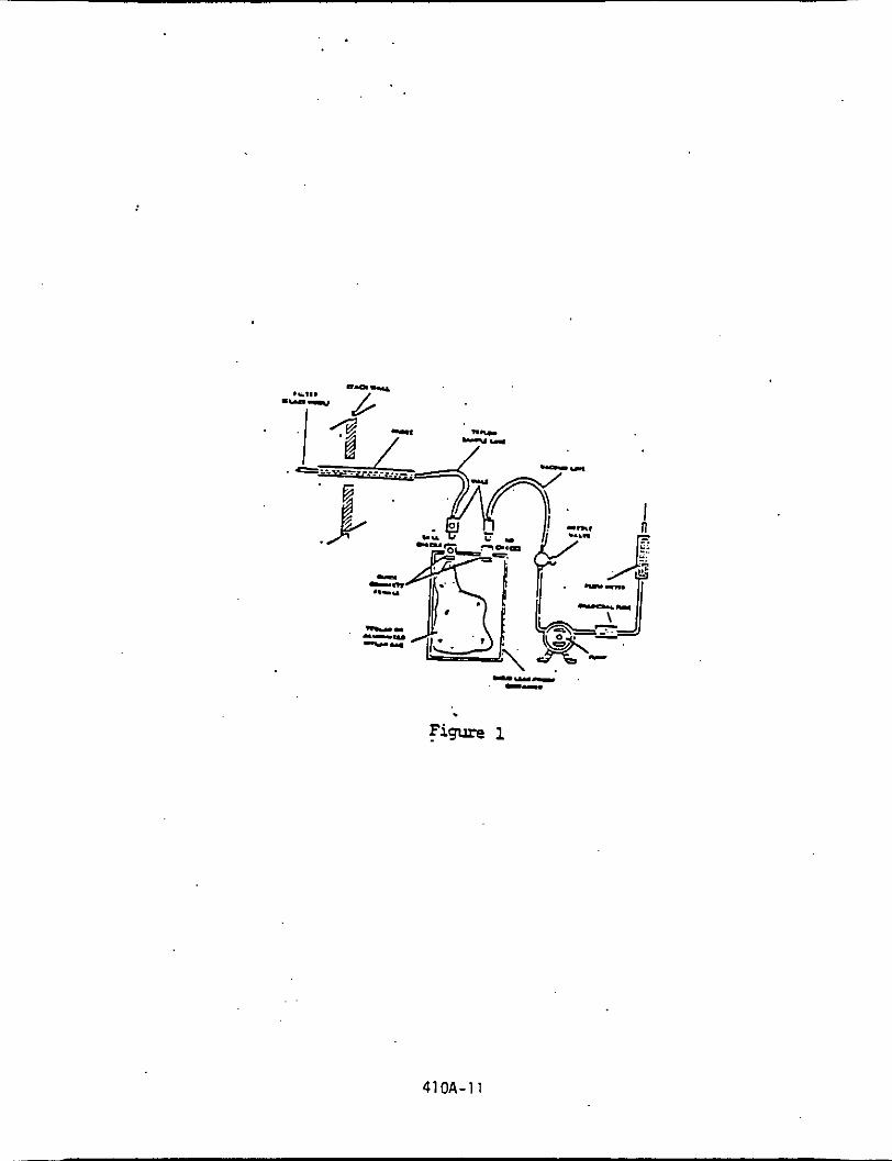
. --I- -
410A-11

6.3.2 Freeze-out: Transfer t h e sample i n t o the cryogenic sampling
loop ( t r a p ) .
Back f i l l the syringe w i t h 40 nl of helium and f lush the 40
m l th rwgh the t rap . t hen f l u s h he l ium through the t r a p f o r 2
minutes a t 20 ml/min.
Stop the h e l i u m flushing. Remove the 1/4 inch U-trap f rcn
I so la te t h e cryogenic t r a p by u s i n g an " isolat ion valve"
which allows the c a r r i e r g a s t o by-pass the trap.
the LN2 Dewar w i t h a Dewar containing 8O'C water and
immerse the t r a p .
Replace '
Allow a l l i c e t o melt from the trap.
6.3.3 Injection: Using t h e v a l v e , introduce the sample i n t o the
c a r r i e r gas stream.
6.4 Analysis: CAUTION, se r ia l d i lu t ion , nay be necessary f o r highly
concentrated samples t o prevent overloading.
temperature t o ambient fo r column A o r column E , and the detector
temperature t o 150'C. Using zero helium or n i t rogen as the c a r r i e r
gas, es tab l i sh a flow r a t e i n t he range consis tent w i t h the
manufacturer's requirements f o r sa t i s fac tory detector operation. If
necessary, a d j u s t flow rate f o r best detector response. Observe the
base line periodically and determine t h a t the noise level has
s tab i l ized and t h a t base-line d r i f t has ceased. Record the
inject ion t i n e ( t h e posit ion of t h e pen on the chart a t the t i n e of
sample i n j e c t i o n ) , t h e sample number, the sample loop temperature,
the column temperature, c a r r i e r gas flow r a t e , char t speed, and the
Set t h e column
41OA-12

at tenuator se t t i ng .
r e t e n t i o n t ime corresponding t o benzene, as determined i n Section
7.2.1.
i n t e g r a t o r , e lec t ron i c i n t e g r a t o r . or a planimeter.
t h e r e t e n t i o n time.
u n t i l two consecutive values for t he t o t a l area o f the benzene peak
do not vary more than 5 percent . . Use t h e average value o f these two
t o t a l areas . t o cmpu te the bag concentrat ion.
Frm t he char t , note the peak having the
Measure the benzene peak area, A,,,, by use o f a d isc
Record A,,, and
Repeat t h e i n j e c t i o n a t l e a s t two t i n e s or
6.5 Determinat ion o f Bag Water Vapor Content: Measure the ambient
temperature and b a r m e t r i c pressure near the bag. Frm a water
sa tu ra t i on vapor pressure tab le , determine and record the w a t e r
vapor content o f t he bag as a decimal f igure.
humidity t o be 100 percent unless a l esse r value i s known.)
(Assume the r e l a t i v e
7. PREPARATION OF STANDARD GAS MIXTURES, CALIBRATION, AND QUALITY ASSURANCE
7.1 'Preparation o f Benzene Standard Gas Mixtures: This procedure may
only be used i f no c y l i n d e r standard i s ava i lab le .
apparatus shown i n F igure 2.
passed a leak check (described i n Section 7.3.2) and meter i n about
50 L o f nitrogen.
pressure a t t h e dry gas meter, and t h e temperature a t the dry gas
meter.
1.0 uL o f 99+ percent l i q u i d benzene through t h e septum on top o f
t he inp inger .
benzene.
prepare d i l u t i o n s having approximately 50 ppm and 500 ppm benzene
Assemble the
Evacuate a 50 L Tedlar bag t h a t has
Measure the b a r m e t r i c pressure, t he r e l a t i v e
While the bag is f i l l i n g . use the 1.0 uL syringe t o i n j e c t
This gives a concentrat ion o f approximately 5 ppm o f
I n a l i k e manner, use t h e 10 uL and 100 uL syringes t o
410A-13

410A-14

concentrations.
appropriate d i lu t ion techniques, i n j e c t 50 nL of each di lut ion i n t o
3 d i f fe ren t empty Tedlar bags and f i l l each w i t h 50 L of nitrogen t o
obtain 3 standard gas mixtures of 5. 50, and 500 ppb.
t h e spec i f ic concentrations, r e f e r t o Section 8.1. These g a s
mixture standards may be used f o r 7 days from the d a t e o f
preparation, a f t e r w h i c h time preparation of new gas mixtures i s
required. (Caution: 3 If the new gas mixture s t anda rd i s a lower
concentration than the previous g a s mixture standard, Contamination
may be a problem when a bag i s reused.)
Using the same apparatus, the 100 uL syringe, and
To calculate
7.2 Calibration:
7.2.1 Determination of Benzene Retention Time: ( T h i s section can
be performed simultaneously w i t h Section 7.2.2.) CAUTION,
se r i a l d i lu t ions may b e necessary f o r highly concentrated
samples t o protect GC p lumbing .
conditions ident ical w i t h those i n Section 6.4, above.
Determine proper a t tenuator position. Flush the sampling
loop w i t h zero helium o r nitrogen and activate the sample
valve. Record the i n j e c t i o n t ime. the sample loop
temperature, the column temperature, the c a r r i e r gas flow
ra t e , the char t speed, and the a t tenuator setting. Record
peaks and detector responses t h a t occur in the absence o f
benzene.
30 sec a t the r a t e of 100 ml/min w i t h one o f the benzene
Establish chrmatograph
Maintain condi t ions, and f lush the sample loop f o r
410A-15
ca l ibra t ion mixtures.
Record the in jec t ion time.
t o benzene. Measure the distance on the char t f r a the
in jec t ion t i n e t o the time a t which t h e peak maximum occurs.
This dis tance divided by the char t speed i s defined as the
benzene peak retent ion time. Since i t i s qui te l ikely tha t
there will be other organics present i n t h e sample, i t i s
very important t h a t posi t ive iden t i f i ca t ion of the benzene
peak be made.
Then ac t iva t e the sample valve.
Select the peak t h a t corresponds
7.2.2 Preparatfon of Chromatograph Calibration Curve: Make a gas
chrmatographic measurement of each standard gas mixture
(described i n Section 5.2.3 or 7 . 1 . ) using conditions
ident ical w i t h those l i s t e d i n Sections 6.3 and 6.4. Record
C , the concentration of benzene in jec ted , the at tenuator
s e t t i n g , char t speed, peak areas , sample l o o p temperature,
column temperature, c a r r i e r gas flow r a t e , and retention
time. Record the laboratory pressure. Calculate A C , the
peak area multiplied by the at tenuator se t t ing .
two consecutive inject ion areas a re w i t h i n 5 percent, then
p l o t the average of those two values versus C c .
other standard gas mixtures have been similarly analyzed and
Repeat u n t i l
When the
ved by
or
s more
p lo t ted , d r a w a s t ra ight l i n e t h r o u g h the points der
the l e a s t squares method. Perform ca l ibra t ion d a i l y
before and a f t e r each se t of bag samples: whichever
f reouent .

7.3 Qual i ty Assurance:
7.3.1 Analysls A u d i t : Immediately a f t e r the preparation of the
ca l ibra t ion curve and before the sample analyses, perform a
check f o r d r i f t against a cylinder of known concentration
traceable t o the l as t analysis audi t .
perform t h e analysls aud i t described i n Appendix B:
"Procedure f o r F i e l d Audi t ing GC Analysis."
A t l e a s t twice a year ,
7.3.2 Leak Checks: Uhile performance of t h i s section is required
a f t e r bag use, i t i s a l so advised t h a t i t be performed before
' bag use. After each use, make sure a bag did n o t develop
leaks by connecting a water manometer and pressurizing the
bag t o 5 t o 10 cm H20 (2 t o 4 i n H20).
fo r 10 m i n .
indicates a leak. Also. check the r i g i d container fo r leaks
i n this manner. (Note: an a l te rna t ive leak check method i s
t o pressurize the bag t o 5 t o 10 cm H20 ( 2 t o 4 in H20)
and allow t o stand overnight . A deflated bag indicates a
leak.)
Allow t o stand
Any displacement i n the water manometer
For each sample bag i n i t s r i g i d container, place a
rotameter i n line between the bag and the pump in l e t .
Evacuate the bag.
flow when the bag appears t o be empty indicates a leak.
Failure of the rotameter t o r eg i s t e r zero
7.3.3 Bag Check. To insure no contamination o r interferences from
the Tedlar bag, a suf f ic ien t number of bags should be checked
before use. T h i s can be accomplished by f i l l i n g the bag w i t h
410A-17

N2 or zero a i r h making a n inject ion on the GC under normal
analysis conditions.
each time, b u t , i f th i s i s not possible, i t i s necessary t o
check every bag p r io r t o use.
I t i s r ecmended t h a t new bags be used
7.3.4 Syringe Check. Prior t o use, the GC in jec t ion syringe should
be checked f o r contaimination by inser t ing the needle through
t h e tnjector septum, drawing a volune of c a r r i e r gas i n t o the
barrel of the syringe & re-injecting i t back on to the .
column.
d u r i n g the analysis t o insure no contamination of the syringe.
T h i s procedure should a l s o be done per iodical ly
8. Calculations:
8.1 Optional Benzene Standards Concentrations:
Calculate each benzene standard concentration (Cc i n ppm)
prepared i n accordance w i t h Section 7.1 as follows:
I 8(0.2706)(10 3) Y 293 pn 'm
G 760 Tm
ET
Yn Y P m a 701.9 m CC
where:
B = Volume of benzene in jec ted , n i c r o l i t e r s .
'm Y = D r y gas meter ca l ibra t ion factor , dimensionless.
'm
Tm 0.2706.
= Gas volume measured by dry gas meter, l i t e r s .
=
=
Absolute pressure o f t h e dry gas meter, mHg.
Absolute temperature of the dry gas meter, OK.
Ideal g a s volune of benzene a t 293' K and 760 mHg
LJol . 103 = Conversion fac tor [ Ippm) ( m l ) / u l l .
41oA-18

8.2 Benzene Sample Concentrations: From t h e ' c a l i b r a t i o n curve
descr ibed i n Section 7.2.2 above, se lec t the value o f Cc t h a t
corresponds t o A,. Calcu late the concentrat ion o f benzene i n
the sample (C, i n ppm) as fol lows:
where: - Concentrat ion o f benzene
C, = Concentrat ion o f benzene
chromatrograph, ppm.
. cs. n the sample, ppm.
ndicated by the gas
Pr = Reference pressure, the barometric pressure recorded
dur ing ca l i b ra t i on , mmHg.
Ti = Sample loop temperature a t the t ime o f analysis, OK.
Pi - Barometric pressure a t t ime o f analysis, mmHg.
T r - Reference temperature, the sample loop temperature
recorded dur ing ca l i b ra t i on . OK.
= Water vapor content o f the bag sample, volume f r a c t i o n 'wb
41OA-19

Appendix . A
Determination of Adequate Chromatographic Peak Resolution
In t h i s method of dea l ing with resoultion. the extent t o which one
Chromatographic peak overlaps another i s determined.
For convenience, consider the range of t h e e lu t ion curve o f each
compound as r u n n i n g from -2 t o +2 . T h i s range i s used i n o the r
resolut ion c r i t e r i a , and i t contains 95.45 percent of t h e a rea of a
normal curve. I f two peaks a r e separated by a known d is tance , b, one can
determine the f rac t ion of the area of one curve t h a t l ies w i t h i n the range
of the other. The extent t o which the elut ion curve of a contaminant
compound overlaps the curve of a compound that, i s under ana lys i s i s found by
integrat ing the contaminant curve over l imi t s b-20’ t o b+2QS whereus i s the
standard deviation of the sample curve.
There a r e several ways this calculat ion can be simplified.. Overlap can be
determined fo r curves o f u n i t a rea ; then actual a reas can be introduced. The
desired integrat ion can be resolved i n t o two integrals o f t he normal d is -
t r ibu t ion function for which there are convenient ca lcu la t ion programs and
tab les .
571. 1975, Texas Instruments, Inc., Dallas, Texas ‘75222.
An example would be Program 15 T,exas Instruments Program Manual
G+26. 2
41 OA-20

The f o l l o w i n g c a l c u l a t i o n steps are requ i red :
1. 2as = ts/ 2 I n 2
= tc/ 2 i n 2
3. '1 - = (b-2eS)/uc 2 . c
4. X 2 = (b+2U,)/uc
8. A. = l o A c / A S
9. Percentage over lap = A, x 100
where
A, = The area o f t he sample peak o f i n t e r e s t determined by
e l e c t r o n i c i n teg ra t i on , o r by t h e formula A, = h s t s .
The area o f the contaminant peak, detennined i n the same
manner as A,.
The d is tance on the chromatographic cha r t t h a t separates the
maxima o f the two peaks.
The peak he igh t o f the sample compound o f i n t e r e s t . measured
f r o m the average value o f the base l ine t o the maximum o f t he
curve.
t, = The w id th of the sample peak o f i n t e r e s t a t 1/2 o f peak height.
A, =
b =
HS =
I 410A-21

tc = The w i d t h o f the contaminant peak a t 1/2 o f peak h e i g h t .
Gs = The standard deviation of the sample compound of in t e re s t
e lu t ion curvs.
The standard d e v i a t i o n of the contaminant e lu t ion curve.
The integral o f the noma1 d i s t r ibu t ion function from x1 t o
i n i i n i ty.
O(x,) = The integral of the normal d i s t r ibu t ion function from x2 t o
in f in i ty .
Uc = Q(x,) =
k
Io = The overlap in t eg ra l .
A. = The area overlap fract ion.
In judging the s u i t a b i l i t y of a l t e r n a t e gas chromatographic columns. o r
the e f f e c t s of a l t e r i n g chromatographic conditions. one can employ the area
overlap as the resolut ion parameter w i t h a spec i f i c maximum permissible value.
The use of Gaussian functions t o describe chromatographic e lut ion curves
In those i s widespread. However, some e lu t icn curves a r e highly asymnetric.
cases where the sample peak i s followed by a contaminant t ha t has a leading
edge t h a t r i s e s sharply b u t the curve then t a i l s o f f , I t may be possible to
define a n e f f ec t ive w i d t h f o r t, as "twice the distance from the leading edge
t o a perpendicular l i n e through the m a x i m of the contaminant curve, measured
along a perpendicular bisect ion o f t h a t l ine ."
I n most instances, Q(x2) i s very small and may be neglected. 410A-22

APPE!iDIX B Procedure for Field Auditing GC Analysis.
Responsibilities of audit supervisor and analyst at the source sampling
site include the following:
.A. Check that audit cylinders are stored in a safe location both before
and after the audit to prevent vandalism o f same.
6. At the beginning and conclusion o f the audit, record each cylinder
number and cylinder pressure.
pressure drops below 200 psi.
Never analyze an audit cylinder when the
.-
410A-23
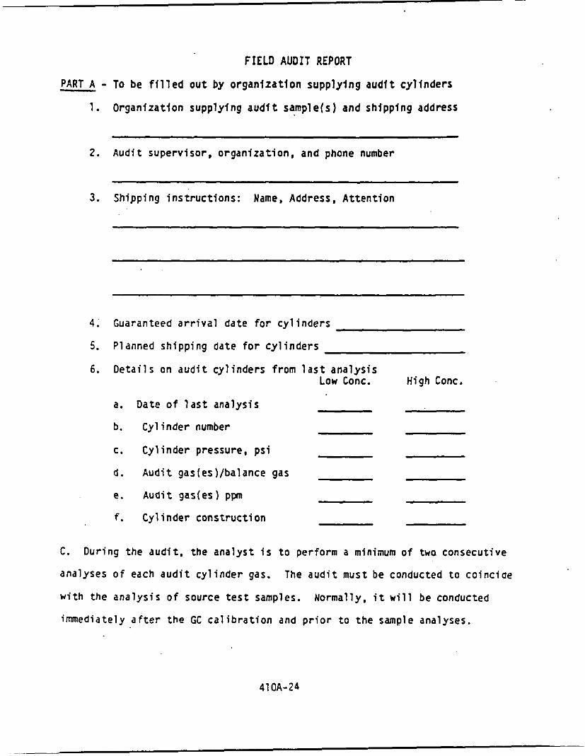
FIELD AUDIT REPORT
- PART A - To be f i l l e d o u t by organ iza t ion supply ing a u d l t cy l l nde rs
1. Organfzatfon supply ing audf t sample(s) and shipping address
2. Audi t supervisor, organizat ion, and phone number
3. Shipping i ns t ruc t i ons : Name, Address, A t ten t ion
4. Guaranteed a r r i v a l date f o r cy l i nde rs
5. Planned shipping date f o r c y l i n d e r s
6. Deta i l s on a u d i t cy l inders f r o m l a s t ana lys is Low Conc. High Conc.
a. Date o f l a s t analys is
b. Cy l inder number
c. Cy l inder pressure, p s i
d . Aud i t gas[es)/balance gas
e. Audi t gas(es) ppn
f. Cylinder cons t ruc t ion
C. Dur ing the aud i t , the analyst f s t o perform a minimum o f twa consecutive
analyses o f each a u d i t c y l i n d e r gas. The a u d i t must be conducted t o co inc ide
w i t h the ana lys is o f source t e s t samples. Normally. i t w i l l be conducted
immediately a f t e r the GC c a l i b r a t i o n and p r i o r t o t h e sample analyses.

D. A t the end of audIt analyses, the a u d i t supervtsor requests the calculated
concentrations from the analysis and then compares the r e s u l t s w i t h the actual
audl t concentrations.
respective actual concentration w i t h i n + 10 percent, he then dfrects the
ana lys t t o begin the analysis of source samples.
and/or supervisory policy determine course of action i f agreement i s not within
- 10 percent.
I f each measured concentration agrees w i t h the
- Audi t supervisor judgment
Uhere a cons is ten t b i a s i n excess o f 10 percent i s found, i t may be
possible t o proceed w i t h the sample analyses, w i t h a correct ive fac tor t o be
applied t o the r e su l t s a t a l a t e r time.
t o locate the cause o f the dlscrepancy, a s i t may be misleading.
supervisor i s t o record each cylinder number, cylinder pressure ( a t the end o f
the a u d i t ) , and a l l calculated concentrations. The individual being audited
must not under any circumstance be told the actual a u d i t concentrations u n t i l
the calculated concentrations have been submitted t o the audi t supervisor.
However, every attempt should be made
T h e audit
P a r t B: To be f i l l e d out by aud i t supervisor
1. Process Sampled
2. Location o f audi t
3. Name o f individual audited
' 4 . A u d i t d a t e
5. A u d i t r e su l t s
41 OA-25

Low Conc. Hfgh Conc.
a.
b.
C.
d.
e.
f.
9.
Cy1 inde r Number
Cy1 i nder Pressure before aud i t , p s i
Cy l inder pressure, a f t e r aud i t , p s i
Measured concentrations, ppm I n j e c t i o n #l*
I n j e c t i o n i2'
Average'
Actual Aud i t concentrat ion, ppm ( P a r t A, 6e)
A u d i t Accuracy*
Low Conc. Cyl inder
High Conc. Cy l inder
*Percent Accuracy = Measured Conc. - Actual Conc. x 100 Actual Conc.
Problems detected ( i f any)
'Results o f two consecutive i n j e c t i o n s t h a t meet the sample analys is c r i t e r i a o f the rest method.
41OA-26

TkE ALME~A CORpORATiON
APPENDIX
CARB Method 421
Determination of Hydrochloric Acid Emissions from Stationary Sources

S t a t e o f C a l i f o r n i a A i r R e s o u r c e s Board
Method 4 2 1
D e t e r m i n a t i o n Of H y d r o c h l o r i c Acid Emissions From S t a t i o n a r y S o u r c e s
I
Adopted: January 22, 1987

Method 4 2 1 - Dete rmina t ion of H y d r o c h l o r i c a c i d Emission8 From S t a t i o n a r y S o u r c e s -
.#
1. A P P L I C A B I L I T Y A N D PRINCIPLE
1.1 A p p l i c a b i l i t y T h i s method a p p l i e s t o t h e d e t e r m i n a t i , o n of ' h y d r o c h l o r i c a c i d e m i s s i o n s f r o m s t a t i o n a r y sources . I t does not measure l i q u i d o r s o l i d phase c h l o r i d e . Gaseous HC1 i s d e f i n e d a s t h a t v h i c h p a s s e s t h e f i l t e r a t i t s h e a t e d tempera t u r e .
1 . 2 P r i n c i p l e P a r t i c u l a t e a n d gaseous c h l o r i d e e m i s s i o n s a r e e x t r a c t e d i s o k i n e t i c a l l y from t h e s t a c k and passed - through an i m p i n g e r - f i l t e r t r a i n where t h e gaseous c h l o r i d e is c o l l e c t e d i n a s o l u t i o n o f Sodium B i c a r b o n a t e and Sodium Carbonate . T h i s i m p i n g e r s o l u t i o n is ana lyzed f o r c h l o r i d e b y i o n chromatography v i t h c o n d u c t i v i t y d e t e c t i o n . The c h l o r i d e peak is i d e n t i f i e d b y c h a r a c t e r i s t i c r e t e n t i o n t i m e , and q u a n t i f i e d b y r e f e r e n c e t o e x t e r n a l s t a n d a r d s .
2 . R A N G E , SENSITIVITY, A N D PRECISION
2 . 1 Range and S e n s i t i v i t y The a n a l y t i c a l method h a s been used t o measure c h l o r i d e c o n c e n t r a t i o n i n d r i n k i n g v a t e r , s u r f a c e v a t e r . and mixed d o m e s t i c and i n d u s t r i a l w a s t e w a t e r . (See Refe rence
A method d e t e c t i o n l i m i t (MDL) of 0.015 mg/L h a s been o b t a i n e d v i t h r e a g e n t v a t e r a t an a t t e n u a t o r s e t t i n g of 1 uMHO f u l l s c a l e ( R e f e r e n c e . l O . l ) . Any change i n t h i s s e t t i n g vould produce a p r o p o r t i o n a l change i n t h e WDL. The MDL vould a l s o vary v i t h t h e sample m a t r i x .
10.1).
2.3 P r e c i s i o n T h e f o l l o v i n g s i n g l e o p e r a t o r accu racy and p r e c i s i o n d a t a v e r e o b t a i n e d f o r reagent(RW), drinking(DW), and s u r f a c e (SW) v a t e r , and mixed d o m e s t i c and i n d u s t r i a l v a s t e v a t e r (WU) ( R e f e r e n c e 10.1).
Number Mean S t a n d a r d Sample S p i k e of Recovery D e v i a t i o n
T y p e (mg/L) R e p l i c a t e s x ( m a l t )
R W 0.050 7 9 7 . 7 0 . 0 4 7 DW 10.0 7 9 0 . 2 0.289 sw 1 .o 7 105.0 0.139 ww 7 . 5 7 0 2 . 7 0 . 4 4 5
421-1

3. INTERFERENCES
The c h r o m a t o g r a p h i c co lumns and t h e c o r r e s p o n d i n g o p e r a t i n g p a r a m e t e r s h e r e i n d e s c r i b e d n o r m a l l y p r o v i d e a h i g h deg ree of r e s o l u t i o n : b u t i n t e r f e r e n c e s may be e n c o u n t e r e d from some s o u r c e s . T h e r e f o r e , t h e ch romatograph o p e r a t o r s h a l l s e l e c t column and o p e r a t i n g p a r a m e t e r s b e s t s u i t e d t o t h e p a r t i c u l a r a n a l y t i c a l p roblem, s u b j e c t t o a p p r o v a l by t h e E x e c u t i v e O f f i c e r . T h i s a p p r o v a l is a u t o m a t i c provided t h a t t h e t e s t e r p roduces d a t a t o d e m o n s t r a t e t h a t t h e t e c h n i q u e i s c a p a b l e of a c c u r a t e and r e p r o d u c i b l e measu remen t s , and h a s t h e d a t a a v a i l a b l e f o r r e v i e w b y t h e E x e c u t i v e O f f i c e r .
3 . 1
3.2
3 . 3
3 . 4
3 .5
Any a n i o n w i t h a r e t e n t i o n t i m e s i m i l a r t o t h a t of c h l o r i d e can i n t e r f e r e . Large amounts of an a d j a c e n t a n i o n can i n t e r f e r e w i t h t h e peak r e s o l u t i o n f o r t h e c h l o r i d e an ion . Sample d i l u t i o n a n d / o r s p i k i n g can s o l v e most i n t e r f e r e n c e problems.
C o n t a m i n a n t s i n t h e r e a g e n t v a t e r , r e a g e n t s , g l a s s v a r e and o t h e r s ample p r o c e s s i n g a p p a r a t u s can c a u s e d i s c r e t e a r t i f a c t s o r e l e v a t e d b a s e l i n e i n i o n chromatograms.
Samples t h a t c o n t a i n p a r t i c l e s l a r g e r t h a n 0 .45 microns and r e a g e n t s o l u t i o n s t h a t c o n t a i n p a r t i c l e s l a r g e r t han 0.20 m i c r o n s m u s t be f i l t e r e d t o p r e v e n t damage t o i n s t r u m e n t co lumns and f l o w systems.
The " u a t e r d i p " or n e g a t i v e peak e l u t e s n e a r t o t h e c h l o r i d e peak and can i n t e r f e r e . When t h e s t a n d a r d e l u e n t ( S e c t i o n 5.4.2) does n o t g i v e a d e q u a t e s e p a r a t i o n of t h e c h l o r i d e peak from t h e w a t e r d i p , t h e recommended e l u e n t i s 2mM NaOH/2.4mM NaHC03 ( R e f e r e n c e 10.3).
I f o t h e r i o n c h r o m a t o g r a p h i c c o n d i t i o n s o r o t h e r t e c h n i q u e s a r e u s e d , t h e t e s t e r i s r e q u i r e d t o s u b s t a n t i a t e t h e d a t a th rough an a d e q u a t e q u a l i t y a s s u r a n c e program approved b y t h e E x e c u t i v e O f f i c e r .
4. APPARATUS
The f o l l o w i n g s a m p l i n g a p p a r a t u s is recommended. The t e s t e r may use an a l t e r n a t i v e s a m p l i n g a p p a r a t u s on ly i f , a f t e r r e v i r v b y t h e E x e c u t i v e O f f i c e r , i t i s deemed e q u i v a l e n t f o r t h e p u r p o s e s of t h i s t e s t method.
4 . 1 Sampl ing T r a i n A s c h e m a t i c d i a g r a m of t h e s a m p l i n g t r a i n i s s h o w n i n F i g u r e 1 . The equ ipmen t r e q u i r e d f o r t h i s t r a i n i s t h e same a s d e s c r i b e d i n S e c t i o n 2.1 of C I R B Method 5 e x c e p t a s f o l l o w s :
421-2

4 . 1 . 1 P r o b e L i n e r . Same a s d e s c r i b e d i n S e c t i o n 2.1.2 o f M e t h o d 5 e x c e p t u s e o n l y q u a r t z o r b o r o s i l i c a t e g l a s s l iners .
4 . 1 . 2 I m p i n g e i s . F o u r i m p i n g e r s a r e c o n n e c t e d i n s e r i e s v i t h g l a s s b a l l j o i n t f i t t i n g s . T h e f i r s t , t h i r d , a n d f o u r t h i m p i n g e r s a r e o f t h e G r e e n b u r g - S m i t h d e s i g n m o d i f i e d by r e p l a c i n g t h e t i p v i t h a 1-cm ( 0 . 5 i n . ) I . D . g l a s s t u b e e x t e n d i n g t o 1 cm f r o m t h e b o t t o m o f t h e f l a s k . T h e s e c o n d i m p i n g e r is of t h e G r e e n b u r g - S m i t h d e s i g n v i t h t h e s t a n d a r d t i p . T h e f i r s t a n d s e c o n d i m p i n g e r s s h a l l c o n t a i n k n o v n q u a n t i t i e s of 3 mH s o d i u m b i c a r b o n a t e (NaHC03). a n d 2.4 mM s o d i u m c a r b o n a t e (Na CO 1.
c o n t a i n a k n o v n w e i g h t o f s i l i c a g e l o r e q u i v a l e n t d e s s i c a n t . A thermometer u h i c h m e a s u r e s t e m p e r a t u r e s t o v i t h i n l0C (2OF). s h o u l d b e p l a c e d a t t h e o u t l e t o f t h e f o u r t h i m p i n g e r .
T h e t h i r d s h a l l b e e m p t y , a n d t h e f o u r t h s $ A a
4 . 2 S a m p l e R e c o v e r y . T h e f o l l o u i n g i tems a r e n e e d e d :
4 . 2 . 1 P r o b e L i n e r a n d P r o b e N o z z l e Brushes, P e t r i D i s h e s . P l a s t i c S t o r a g e C o n t a i n e r s , F u n n e l a n d R u b b e r P o l i c e m a n . Same a s M e t h o d 5 , S e c t i o n s 2.2.1. 2 . 2 . 4 , 2.2 .6 , a n d 2 . 2 . 7 , r e s p e c t i v e l y .
4 . 2 . 2 Wash B o t t l e s ( 2 ) . O n l y g l a s s may b e u s e d .
4 . 2 . 3 S a m p l e S t o r a g e Containers . C h e m i c a l l y r e s i s t a n t , b o r o s i l i c a t e g l a s s b o t t l e s , f o r i m p i n g e r a n d p r o b e s o l u t i o n s a n d u a s h e s , 1000 mL. Use s c r e v - c a p l i n e r s t h a t a r e e i t h e r r u b b e r - b a c k e d T e f l o n o r l e a k - f r e e a n d r e s i s t a n t t o chemica l a t t a c k by 1.0 N NaOH ( N a r r o v m o u t h g l a s s b o t t l e s h a v e b e e n f o u n d t o b e l e s s p r o n e t o l e a k a g e ) .
4 . 2 . 4 G r a d u a t e d C y l i n d e r a n d / o r B a l a n c e . To measure c o n d e n s e d u a t e r t o w i t h i n 2 m L o r 1 g. g r a d u a t e d c y l i n d e r t h a t h a s a m i n i m u m c a p a c i t y o f 500 mL, a n d s u b d i v i s i o n s n o g r e a t e r t h a n 5 mL. ( H o s t l a b o r a t o r y b a l a n c e s a r e c a p a b l e of w e i g h i n g t o t h e n e a r e s t 0 . 5 g o r l e s s ) .
may b e u s e d .
Use a
4 . 2 . 5 F u n n e l . To a i d i n s a m p l e recovery. Only g l a s s
421 -3

4.3 A n a l y s i s
r The f o l l o w i n g equipment is needed:
4.3.1 Balance - A n a l y t i c a l . Capab le o f a c c u r a t e l y
4.3.2 Sample b o t t l e s . Glass . O f s u f f i c i e n t v o l u m e t o
we igh ing t o t h e n e a r e s t 0.0001 8 .
a l l o u r e p l i c a t e a n a l r s e s of t h e a n i o n of i n t e r e s t .
4 . 3 . 3 P i p e t t e s . A n a s s o r t m e n t of s i z e s .
4.3.4 Vo lumet r i c F l a s k s . 100-mL, 250-mL and 1000-mL.
4.3.5 Ion chromatograph . A n a l y t i c a l s y s t e m comple t e w i t h i o n chromacograph and a l l r e q u i r e d a c c e s s o r i e s i n c l u d i n g s y r i n g e s , a n a l y t i c a l co lumna, compressed a i r , d r c e c t o r , and s c r i p c h a r t r e c o r d e r . A d a t a sys t em i s recommended f o r peak i n t e g r a t i o n . The i o n c h r o m a t o g r a p h s h o u l d have a t l e a s t t h e components l i s t e d below. The a n a l y s t may use a l t e r n a t i v e c o r p o n e n t s p rov ided t h a t t h e r e i s a d e q u a t e r e s o l u t i o n o f t h e c h l o r i d e peak, and t h e r e i s no i m p a i r m e n t of t h e p r e c i s i o n and a c c u r a c y of t h e a n a l y s i s of t h e c h l o r i d e s t a n d a r d s .
4.3.5.1 Anion g u a r d c o l u m n : 4 x 50 m m , Dionex P/N 03827, o r e q u i v a l e n t .
Anion s e p a r a t o r c o l u m n : 4 x 2 5 0 m m , Dionex P/N 35350, o r e q u i v a l e n t .
4.3.5.2
4.3.5.3 Anion s u p p r e s s o r column: f i b e r , Dionex P/N 35350, o r e q u i v a l e n t .
4.3,5.4 P u m p c a p a b l e of m a i n t a i n i n g a s t e a d y
4.3.5.5 Flow gauges. Capab le of measu r ing t h e s p e c i f i e d s y s t e m f l o w r a t e .
4.3.5.6 D e t e c t o r - C o n d u c t i v i t y c e l l .
f l o w a s r e q u i r e d b y t h e sys t em.
Approx ima te ly 6 u L volume, Dionex, or e q u i v a l e n t .
4.3.6 F i l t e r i n g System. 0.45 o i c r o n m i l l i p o r e f i l t e r and a i l l i p o r e vacuum f i l c r a t i o n u n x t o r e q u i v a l e n t .
421 -4

5 . REAGENTS
U n l e s s o t h e r v i s e s p e c i f i e d , use American Chemica l S o c i e t y r e a g e n t g r a d e ( o r e q u i v a l e n t ) c h e m i c a l s t h r o u g h o u t . Mention of t r a d e names o r s p e c i f i c p r o d u c t s does not c o n s t i t u t e endor semen t b y t h e C a l i f o r n i a A i r Resources Board.
5 .1 Sampling. The f o l l o v i n g r e a g e n t s a r e needed:
5.1.1 F i l t e r s , S i l i c a Gel, Crushed I c e and Stopcock G r e a s e . Same a s Method 5 , S e c t i o n s 3.1.1, 3.1.2, 3.1.4 and 3.1.5, r e s p e c t i v e l y .
5.1.2 Water. Deionized . d i s t i l l e d , t o conform t o ASTH S p e c i f i c a t i o n D1193-77, T y p e 3 ( R e f e r e n c e 10.1). I f h i g h c o n c e n t r a t i o n s of o r g a n i c m a t t e r a r e n o t e x p e c t e d t o be p r e s e n t , t h e a n a l y s t may o m i t t h e po ta s s ium permanganate t e s t f o r o x i d i z a b l e o r g a n i c m a t t e r .
5 .1 .3 I m p i n g e r S o l u t i o n . Sodium B i c a r b o n a t e 3 m H , and Sodium c a r b o n a t e 2.4 mM. D i s s o l v e 1.0081 g s o d i u m b i c a r b o n a t e (NaHC03) and 1.0176 g of sodium c a r b o n a t e (Na2C03) i n r e a g e n t w a t e r (5.1.2). and d i l u t e t o 4 l i t e r s .
5.3 Sample Recovery.
5 .3 .1 Recovery s o l v e n t . S o l u t i o n of Sodium b i c a r b o n a t e ( 3 mM) and Sodium c a r b o n a t e (2.4 m M ) . Same a s 5.1.3 above.
5.4 A n a l y s i s . T h e f o l l o v i n g r e a g e n t s a r e needed:
5.4.1 Reagent vater. Same a s 5.1.2 above. V e r i f y t h a t t h e c o n d u c t a n c e i s 1 US o r l e s s i f y o u r system i n c l u d e s a c o n d u c t i v i t y d e t e c t o r . For o t h e r d e t e c t o r o p t i o n s , you m u s t u s e o t h e r methods t o m o n i t o r your v a t e r q u a l i t y .
5.4.2 E l u e n t s o l u t i o n : Same a s 5.1.3 above.
5 . 4 . 3 S u l f u r i c a c i d . C o n c e n t r a t e d .
5.4.4 R e g e n e r a t i o n s o l u t i o n ( f i b e r s u p p r e s s o r ) . S u l f u r i c a c i d , 0.025 N. D i l u t e 2.8 m L c o n c e n t r a t e d s u l f u r i c a c i d (H2S04) t o 4 l i t e r s w i t h r e a g e n t w a t e r (same a s 5.4.1 above).
421-5

5 . 4 . 5 S t o c k S t a n d a r d S o l u t i o n , 1000 mg/L. T h l a m a y b e
.. p u r c h a s e d a s a c e r t i f i e d s o l u t i o n o r p r e p a r e d f r o m ACS r e a g e n t g r a d e ma te r i a l s ( d r i e d a t 105OC f o r 30 m i n . ) a s f o l l o w s : Dissolve 1 . 6 4 8 5 g s o d i u m c h l o r i d e ( N a C l ) i n r e a g e n t v a t e r (5.1.2) a n d d i l u t e t o 1 l i t e r . S t o c k s t a n d a r d s a r e s t a b l e f o r a t l e a s t one m o n t h when s t o r e d a t 4OC.
5 . 4 . 6 I n t e r m e d i a t e S t o c k S t a n d a r d . P i p e t 2 0 0 mL of t h e s t o c k s t a n d a r d (5.4.5 a b o v e ) i n t o a 1000-mL v o l u m e t r i c f l a s k , a n d d i l u t e t o v o l u m e w i t h r e a g e n t w a t e r (5.4.1). T h i s s t a n d a r d may b e s t o r e d f o r o n e m o n t h .
5 . 4 . 7 C a l i b r a t i o n S t a n d a r d s . Add a c c u r a t e l y m e a s u r e d v o l u m e s o f t h e i n t e r m e d i a t e s t a n d a r d t o a v o l u m e t r i c f l a s k a n d d i l u t e t o v o l u m e w i t h r e a g e n t v a t e r . D i l u t e v o r k i n g s t a n d a r d s s h o u l d b e p r e p a r e d w e e k l y .
6. PROCEDURE
6.1 S a m p l i n g . B e c a u s e o f t h e c o m p l e x i t y o f t h i s m e t h o d , t e s t e r s s h o u l d b e t r a i n e d a n d e x p e r i e n c e d w i t h t h e t e s t p r o c e d u r e s i n o r d e r t o ensure r e l i a b l e r e s u l t s .
6.1.1 P r e t e s t P r e p a r a t i o n . F o l l o w t h e same g e n e r a l p r o c e d u r e d e s c r i b e d i n N e t h o d 5, S e c t i o n 4.1.1. e x c e p t t h e f i l t e r need n o t b e v e i g h e d .
6 . 1 . 2 P r e l i m i n a r y D e t e r m i n a t i o n s . F o l l o v t h e seme g e n e r a l p r o c e d u r e d e s c r i b e d i n M e t h o d 5 , S e c t i o n 4 . 1 . 2 .
6.1.3 P r e p a r a t i o n o f C o l l e c t i o n T r a i n . F o l l o w t h e s a m e g e n e r a l p r o c e d u r e g i v e n i n ! l e t h o d 5 , S e c t i o n 4.1.3, e x c e p t p l a c e 100 mL o f i m p i n g e r s o l u t i o n ,(5.1.3) i n e a c h of t h e f i r s t t v o i m p i n g e r s , l e a v e t h e t h i r d i m p i n g e r e m p t y , a n d t r a n s f e r a p p r o x i m a t e l y 200 t o 300 g of p r e v e i g h e d s i l i c a g e l f r o m i t s c o n t a i n e r t o t h e f o u r t h i m p i n g e r . Assemble t h e t r a i n a s s h o w n i n F i g u r e 1.
6 . 1 . 4 L e a k - C h e c k P r o c e d u r e s . F o l l o v t h e g e n e r a l l e a k - c h e c k p r o c e d u r e s g i v e n i n M e t h o d 5 , S e c t i o n s 4.1.4.1 ( P r e t e s t L e a k C h e c k ) , 4.1.4.2 ( L e a k - C h e c k s D u r i n g t h e S a m p l e R u n ) , a n d 4.1.4.3 ( P o s t - T e s t L e a k - C h e c k ) .
6.1.5 S a m p l i n g T r a i n O p e r a t i o n . F o l l o v t h e same g e n e r a l p r o c e d u r e g i v e n i n V e t h o d 5 , S e c t i o n 4.1.5. F o r each r u n , r e c o r d t h e d a t a r e q u i r e d on a d a t a s h e e t s u c h a s t h e o n e s h o w n xn A R B M e t h o d 5 , F i g u r e 5-2.
421 -6
i

. . . . . . . .
6.1 .6 C a l c u l a t i o n of P e r c e n t I s o k i n e t i c . Same a s Method 5 . S e c t i o n 4 .1 .6 .
6 . 2 S a m p l e R e c o v e r y . A l l o w t h e p r o b e t o c o o l . I n s p e c t t h e t r a i n p r i o r t o a n d d u r i n g d i s a s s e m b l y a n d n o t e a n y a b n o r m a l c o n d i t i o n s , D i s c o n n e c t t h e i m p i n g e r s , a n d t r e a t t h e m i n t h e f o l l o w i n g manner:
6 . 2 . 1 C o n t a i n e r No. 1 ( I m p i n g e r s ) . I f t h e v o l u m e o f l i q u i d is l a r g e , t h e t e s t e r may p l a c e t h e i m p i n g e r s o l u t i o n s i n s e v e r a l c o n t a i n e r s . C l e a n e a c h of t h e f i r s t t h r e e i m p i n g e r s a n d c o n n e c t i n g g l a s s w a r e i n t h e f o l l o w i n g m a n n e r :
1. W i p e t h e l m p l n g e r b a l l j o i n t s f r e e o f s i l i c o n e
2. R o t a t e a n d a g i t a t e e a c h i m p i n g e r , s o t h a t t h e i m p i n g e r c o n t e n t s m i g h t s e r v e a s a r i n s e s o l u t i o n . '
g r e a s e a n d c a p t h e j o i n t s .
3. T r a n s f e r t h e c o n t e n t s o f t h e i m p i n g e r s t o a 500-mL g r a d u a t e d c y l i n d e r . Remove t h e o u t l e t b a l l j o i n t c a p a n d d r a i n t h e c o n t e n t s t h r o u g h t h i s o p e n i n g . Do n o t s e p a r a t e t h e i m p i n g e ' r p a r t s ( i n n e r a n d o u t e r t u b e s ) w h i l e t r a n s f e r r i n g t h e i r c o n t e n t s t o t h e c y l i n d e r . Measure t h e l i q u i d v o l u m e t o w i t h i n '2 mL. A l t e r n a t i v e l y , d e t e r m i n e t h e ' w e i g h t o f t h e l i q u i d t o w i t h i n 20.5 g. R e c o r d i n t h e l o g t h e v o l u m e o r w e i g h t of t h e l i q u i d p re sen t , a n d t h e o c c u r r e n c e o f a n y c o l o r o r f i l m i n t h e i m p i n g e r c a t c h . T h e l i q u i d v o l u m e o r w e i g h t i s n e e d e d , a l o n g w i t h t h e s i l i c a g e l d a t a , t o c a l c u l a t e t h e s t a c k gas m o i s t u r e c o n t e n t ( s e e M e t h o d 5 , F i g u r e 5-3).
4 . T r a n s f e r t h e c o n t e n t s t o C o n t a i n e r No. 1.
5 . N o t e : I n s t e p s 5 a n d 6 b e l o w , measure a n d r e c o r d t h e t o t a l a m o u n t o f r e c o v e r y s o l v e n t u s e d f o r r i n s i n g . P o u r a p p r o x i m a t e l y 30 m L o f r e c o v e r y s o l v e n t (5.3.1) i n t o e a c h of t h e f i r s t t h r e e i m p i n g e r s a n d a g i t a t e t h e i m p i n g e r s . D r a i n t h e r e c o v e r y s o l v e n t t h r o u g h t h e o u t l e t arm o f e a c h i m p i n g e r i n t o C o n t a i n e r No. 1. R e p e a t t h i s o p e r a t i o n a s e c o n d t ime ; i n s p e c t t h e i m p i n g e r s f o r a n y a b n o r m a l c o n d i t o n s .
421-7

6. W i p e t h e b a l l j o i n t s of t h e g l a s s w a r e (' c o n n e c t i n g t h e i m p i n g e r s f r e e of s i l i c o n e g r e a s e and r i n s e each p i e c e of g l a s s w a r e t w i c e w i t h r e c o v e r y s o l v e n t . T r a n s f e r t h i s r i n s e i n t o C o n t a i n e r No. 1. Mark t h e h e i g h t of t h e f l u i d l e v e l t o d e t e r m i n e whe the r l e a k a g e o c c u r s d u r i n g t r a n s p o r t . Label t h e c o n t a i n e r t o c l e a r l y i d e n t i f y i t s c o n t e n t s .
6 . 2 . 2 C o n t a i n e r No. 2 ( S i l i c a Gel). Check t h e c o l o r of t h e i n d i c a t i n g s i l i c a g e l t o d e t e r m i n e i f i t h a s been c o m p l e t e l y s p e n t , a n d n o t e i t s c o n d i t i o n . T r a n s f e r t h e s i l i c a g e l from t h e f o u r t h i m p i n g e r t o t h e o r i g i n a l c o n t a i n e r and sea:. The t e s t e r may use a f u n n e l t o pour t h e s i l i c a g e l , and rubbe r pol iceman t o remove t h e s i l i c a g e l from t h e
. i m p i n g e r . I t is n o t n e c e s s a r y t o remove t h e s m a l l amount of p a r t i c l e s t h a t may a d h e r e t o t h e imp lnge r w a l l s .and a r e d i f f i c u l t t o remove. S i n c e t h e g a i n i n w e i g h t i s t o b e u s e d f o r m o i s t u r e c a l c u l a t i o n s , do n o t u s e ' w a t e r o r a n y o t h e r l i q u i d s t o t r a n s f e r t h e s i l i c a ge l . I f a b a l a n c e i s a v a i l a b l e i n t h e f i e l d , t h e t e s t e r may f o l l o w t h e p rocedure f o r C o n t a i n e r No. 2 under S e c t i o n 6 . 4 ( A n a l y s i s ) .
6 . 2 . 3 Recovery S o l u t i o n Blank. Save a t o t a l volume of r e c o v e r y s o l u t i o n e q u a l t o c h a t used f o r s a m p l i n g ( i m p i n g e r s o l u t i o n ) and c l e a n u p ( 6 . 2 . 1 ) . P l a c e i n a g l a s s s a m p l e c o n t a i n e r , and s e a l t h e c o n t a i n e r .
6.3 Sample P r e p a r a t i o n .
6 . 3 . 1 C o n t a i n e r No. 1 ( I m p i n g e r s ) . Check t h e l i q u i d l e v e l t o d e t e r m i n e v h e t h e r any sample was l o s t d u r i n g s h i p m e n t . I f a n o t i c e a b l e amount of l e a k a g e h a s o c c u r r e d , e i t h e r v o i d t h e s a m p l e or d e t e r m i n e t h e volume l o s t f rom t h e d i f f e r e n c e between t h e i n i t i a l and f i n a l s o l u t i o n l e v e l s , a n d u s e t h i s v a l u e t o a d j u s t t h e f i n a l r e s u l t s , s u b j e c t t o a p p r o v a l b y t h e E x e c u t i v e O f f i c e r . F i l t e r t h e s ample t h r o u g h a M i l l i p o r e membrane f i l t e r ( 4 . 3 . 6 ) i n t o a v o l u m e t r i c f l a s k , and d i l u t e t o volume w i t h d e i o n i z e d d i s t i l l e d water .
6 . 3 . 2 Recovery S o l u t i o n Blank. F i l t e r t h r o u g h a M i l l i p o r e membrane f i l t e r ( 4 . 3 . 6 ) i n t o a v o l u m e t r i c f l a s k . D i l u t e t o t h e same volume a s t h e sample ( S e c t i o n 6.3.1 above).
i
421 -a

6 . 4 Analysis . The m e t h o d i s r e s t r i c t e d t o use b y o r u n d e r t h e s u p e r v i e i o n o f a n a l y s t s e x p e r i e n c e d i n t h e u se of I o n c h r o m a t o g r a p h y a n d i n t h e i n t e r p r e t a t i o n o f t h e r e s u l t i n g c h r o m a t o g r a m , E a c h a n a l y s t m u s t d e m o n s t r a t e t h e a b i l i t y t o g e n e r a t e a c c e p t a b l e r e s u l t s w i t h t h i s m e t h o d u s i n g t h e procedure d e s c r i b e d i n S e c t i o n 7.3.2.
6 . 4 . 1 The f o l l o w i n g o p e r a t i n g c o n d i t i o n s a r e r e c o m m e n d e d f o r t h e i o n c h r o m a t o g r a p h . O t h e r columns, c h r o m a t o g r a p h i c c o n d i t i o n s , o r d e t e c t o r s may b e u s e d if c h e c o n d i t i o n s o f S e c t i o n 7.3.2 a r e met.
6 . 4 . 1 . 1 C o l u m n s . As s p e c i f i e d i n 4 . 3 . 5 .
6 . 4 . 1 . 2 D e t e c t o r . As s p e c i f i e d i n 4.3.5. S e l e c t t h e s e n s i t i v i t y r e q u i r e d f o r t h e a n a l y s i s . F o l l o w t h e m a n u f a c t u r e r ' s i n s t r u c t i o n s f o r o b a t a i n i n g t h e o p t i m u m t e m p e r a t u r e c o m p e n s a t i n g f a c t o r f o r e a c h c o l u m n s e t a n d e l u e n t b a t c h . T h i s i s e s p e c i a l l y i m p o r t a n t w h e n o p e r a t i n g a t h i g h s e n s i t i v i t i e s .
6 . 4 . 1 . 3 E l u e n t . As s p e c i f i e d i n 5 . 4 . 2 .
6 . 4 . 1 . 4 S a m p l e L o o p - 1 0 0 u L .
6 . 4 . 1 . 5 Pump Volume - 2 . 3 0 mL/min.
C a l i b r a t e t h e i o n c h r o m a t o g r a p h , a n d p r e p a r e a c a l i b r a t i o n cu rve a s d e s c r i b e d i n S e c t i o n 7.2 .
6 . 4 . 2 Lood a n d i n j e c t a f i x e d a m o u n t o f w e l l m i x e d s a m p l e ( a t l e a s t 1 0 l o o p v o l u m e s ) . T h e f i r s t s a m p l e t o b e a n a l y z e d s h o u l d b e a q u a l i t y c o n t r o l s t a n d a r d s a m p l e . Use t h e s a m e s i z e l o o p f o r s t a n d a r d s a n d s a m p l e s . F l u s h t h e i n j e c t i o n l o o p t h o r o u g h l y , w i t h e a c h n e w s a m p l e . C.n a u t o m a t e d c o n s t a n t v o l u m e i n j e c t i o n s y s t e m m a y a l s o be u s e d ,
F o r e a c h s a m p l e , r e c o r d t h e i n j e c t i o n t ime, i n j e c t i o n v o l u m e , f l o w r a t e , d e t e c t o r s e n s i t i v i t y s e t t i n g , r e c o r d e r c h a r t s p e e d , p e a k h e i g h t o r a rea , a n d r e e e n c i o n time. R e p e a t t w o t imes, o r u n t i l t w o c o n s e c u t i v e v a l u e s f o r t h e c h l o r i d e p e a k d o n o t v a r y b y m o r e t h a n 5 p e r c e n t . F rom t h e a v e r a g e of t h e s e two v a l u e s , s u b t r a c t t h e p e a k h e i g h c o r a r e a o f t h e r e c o v e r y s o l u t i o n b l a n k . Use t h e c o r r e c t e d s a m p l e v a l u e t o c o m p u t e t h e c h l o r i d e c o n c e n c r a t i o n o f t h e s a m p l e . If t h e c h l o r i d e c o n c e n t r a t i o n o f t h e a b s o r b i n g s o l u t i o n b l a n k i s b e l o w t h e w o r k i n g r a n g e o f t h e a n a l y t i c a l m e t h o d , u s e z e r o f o r t h e b l a n k .
421-9

I f t h e p e a k r e s p o n s e e x c e e d s t h e w o r k i n g r a n g e of t h e syatem, d i l u t e t h e s a m p l e w i t h a n a p p r o p r i a t e a m o u n t of r e a g e n t w a t e r a n d r e a n a l y z e .
Run a r e a g e n t b l a n k a n d a s t a n d a r d a f t e r e v e r y 10 s a m p l e s t o c h e c k t h e c h r o m a t o g r a p h c a l i b r a t i o n . R e c a l i b r a t e a s necessary.
T h e w i d t h o f t h e r e t e n t i o n t ime w i n d o w u s e d t o m a k e i d e n t i f i c a t i o n s s h o u l d b e b a s e d upon measurements o f a c t u a l r e t e n t i o n time v a r i a t i o n s of s t a n d a r d s over t h e c o u r s e of a day. T h r e e times t h e s t a n d a r d d e v i a t i o n of a r e t e n t i o n t ime c a n b e u s e d t o c a l c u l a t e a s u q g e s t e d window s i z e f o r c h l o r i d e . However, t h e e x p e r i e n c e of t h e a n a l y s t s h o u l d w e i g h h e a v i l y i n t h e i n t e r p r e t a t i o n of c h r o m a t o g r a m s .
If t h e r e s u l t i n g c h r o m a t o g r a m f a i l s t o p r o d u c e a d e q u a t e r e s o l u t i o n , or i f i d e n t i f i c a t i o n o f c h l o r i d e i s q u e s t i o n a b l e . s p i k e t h e sample w i t h a n a p p r o p r i a t e a m o u n t o f s t a n d a r d , a n d r e a n a l y z e .
c o n d u c t t h i s s t e p i n t h e f i e l d . W e i g h t h e s p e n t s i l i c a g e l ( o r s i l i c a q e l p l u s i m p i n q e r ) t o t h e n e a r e s t 0.5 g: r e c o r d t h i s w e i q h t .
6 . 0 . 3 C o n t a i n e r No. 2 ( S i l i c a Gel). T h e t e s t e r m a y
(- .) .. . I
7 . CALIBRATION, STANDARDIZATIOK, A N D QUALITY COYTROL
7.1 S a m p l i n g T r a i n C a l i b r a t i o n . C a l i b r a t e t h e s a m p l i n g t r a i n c o m p o n e n t s a c c o r d i n g t o t h e i n d i c a t e d s e c t i o n s o f M e t h o d 5 : P r o b e N o z z l e ( S e c t i o n 5.1); P i t o t T u b e ( S e c t i o n 5.2): M e t e r i n g S y s t e m ( S e c t i o n 5.3): P r o b e H e a t e r ( S e c t i o n 5 . 4 ) : T e m p e r a t u r e Gauges ( S e c t i o n 5 . 5 ) : L e a k - C h e c k o f t h e M e t e r i n g S y s t e m ( S e c t i o n 5 . 6 ) : a n d B a r o m e t e r ( S e c t i o n 5.7).
7 . 2 S t a n d a r d C a l i b r a t i o n C u r v e . E s t a b l i s h t h e i o n c h r o m a c o g r a p h i c o p e r a t i n g p a r a m e t e r s i n d i c a t e d i n S e c t i o n 6.4.1 a b o v e . P r e p a r e a s u f f i c i e n t n u m b e r o f s t a n d a r d s t o a l l o w c a l c u l a t i o n of a n a c c u r a t e c a l i b r a t i o n curve . T h i s s h o u l d i n c l u d e a m i n i m u m of t h r e e c h l o r i d e c a l i b r a t i o n s t a n d a r d s a n d a b l a n k ( S e c t i o n 5 . 0 . 6 ) . T h e c o n c e n t r a t i o n of o n e of t h e s t a n d a r d s s h o u l d b e n e a r , b u t a b o v e , t h e m e t h o d d e t e c t i o n l i m i t i f t h e system i s b e i n g o p e r a t e d o n a n a t t e n u a t o r s e t t i n g t h a t a l l o v s t h i s m e a s u r e m e n t . T h e o t h e r s t a n d a r d s s h o u l d c o r r e s p o n d t o t h e r a n g e o f c o n c e n t r a t i o n s e x p e c t e d i n t h e s a m p l e , or s h o u l d d e f i n e t h e w o r k i n g r a n g e o f t h e d e t e c t o r . U n l e s s t h e a t t e n u a t o r r a n g e s e t t i n g s a re p r o v e n t o b e l i n e a r , e a c h s e t t i n g m u s t b e c a 1 i b r.a t e d i n d i v i d u a 11 y. (-.
,
421 -1 0

7 . 2 . 1 P u m p e l u e n t t h rough t h e column. After the system i s e q u i l i b r a t e d , a n d t h e d e t e c t o r b a s e l i n e i s s t a b l e , i n j e c t t h e h i g h e s t s t a n d a r d . I A d j u s t z e r o t o a p p r o x i m a t e l y 10 p e r c e n t of c h a r t . As t h e h i g h e s t s t a n d a r d f o r c h l o r i d e e l u t e s , a d j u s t t h e c a l i b r a t i o n t o a p p r o x i m a t e l y 90 p e r c e n t of c h a r t .
7 . 2 . 2 I n j e c t 0.1 t o 1.0 m t ( d e t e r m i n e d by i n j e c t i o n l o o p volume) of each c a l i b r a t i o n s t a n d a r d s t a r t i n g w i t h t h e h i g h e s t c o n c e n c r a t i o n . Record t h e c o n c e n t r a t i o n o f t h e s t a n d a r d , peak h e i g h t or a r e a , t h e i n j e c t i o n t i m e ( t h e p o s i t i o n of t h e pen on t h e c h a r t a t t h e t i m e o f sample i n j e c t i o n ) , i n j e c t i o n volume, f l o w r a c e , a t t e n u a t o r s e t t i n g , and r e c o r d e r c h a r t speed. Measure t h e d i s t a n c e on t h e c h a r t f rom t h e i n j e c t i o n t i m e t o t h e t i m e a t which t h e peak maximum occur s . T h i s d i s t a n c e d i v i d e d b y t h e c h a r t speed i s d e f i n e d a s t h e c h l o r i d e r e t e n t i o n t ime . Repeat t h e i n j e c t i o n a t l e a s t two t i m e s or u n t i l 2 c o n s e c u t i v e v a l u e s f o r t h e c h l o r i d e p e a k a r e a a r e w i t h i n 5 p e r c e n t of t h e i r a v e r a g e va lue . When a l l t h e s t a n d a r d s have been s i m i l a r l y a n a l y z e d , s u b t r a c t t h e ave rage peak h e i g h t o r peak a r e a o f t h e b l a n k f r o m t h e a v e r a g e d peak h e i g h t s of e a c h s t a n d a r d . C a l c u l a t e a l i n e a r r e g r e s s i o n p l o t of t h e c o r r e c t e d peak h e i g h t of’ each s t a n d a r d ( y - a x i s ) v e r s u s the co r re spond ing c o n c e n t r a t i o n ( x - a x i s ) .
7 .3 Q u a l i t y c o n t r o l 7.3.1 T h e m i n i m u m q u a l i t y c o n t r o l r e q u i r e m e n t s a r e an
i n i t i a l d e m o n s t r a t i o n o t l a b o r a t o r y c a p a b i l i t y ( a c c o r d i n g t o S e c t i o n 7.3.2). o n d t h e a n a l y s i s of s p i k e d s a m p l e s a s a c o n t i n u i n g check on pe r fo rmance . T h e l a b o r a t o r y shou ld m a i n t a i n pe r fo rmance r e c o r d s t o document t h e q u a l i t y of d a t a t h a t a r e g e n e r a t e d .
I n r e c o g n i t i o n of t h e r a p i d advances o c c u r i n g i n chromaeography, t h e a n a l y s t i s p e r m i t t e d c e r t a i n o p t i o n s t o improve s e p a r a t i o n s or lower t h e c o s t of measurements. Each t i m e s u c h m o d i f i c a t i o n s t o t h e method a r e made, t h e a n a l y s t i s r e q u i r e d t o r e p e a t t h e p rocedure d e s c r i b e d i n S e c t i o n 7.3.2 be lou .
The l a b o r a t o r y s h o u l d s p i k e and a n a l y z e a m i n i m u m of 10% of a l l samples t o m o n i t o r c o n t i n u i n g l a b o r a t o r y per formance . F i e l d and l a b o r a t o r y d u p l i c a t e s should a l s o be ana lyzed .
421-11

7 .3 .2 Be fo re p e r f o r m i n g any a n a l y s e s , t h e a n a l y s t shou ld '; I
d e m o n s t r a t e t h e a b i l i t r t o g e n e r a t e a c c e p t a b l e a c c u r a c y and p r e c i s i o n w i t h t h i s method, u s i n g a l a b o r a t o r y c o n t r o l s t a n d a r d .
7.3.2.1 S e l e c t a r e p r e s e n t a t i v e s p i k e c o n c e n t r a t i o n . Use t h e s t o c k s t a n d a r d t o p r e p a r e a q u a l i t y c o n t r o l check sample v i t h c o n c e n t r a t i o n i n r e a g e n t w a t e r t h a t i s 100 t i m e s g r e a t e r t h a n t h e v a l u e s e l e c t e d above.
7 .3 .2 .2 Use a p i p e t t o add 1.00 mL of t h e check s a m p l e (7.3.2.1) t o each of f o u r 100-mL a l i q u o t s of r e a g e n t wa te r . Analyze t h e a l i q u o t s a c c o r d i n g t o t h e p rocedure i n S e c t i o n 6.4.2.
7 .3 .2 .3 C a l c u l a t e t h e a v e r a g e p e r c e n t r e c o v e r y (R). and t h e s t a n d a r d d e v i a t i o n (s) of t h e p e r c e n t r e c o v e r y , f o r t h e r e s u l t s .
7.3.2.4 Compare t h e s e r e s u l t s (7.3.2.3) w i t h t h e r e c o v e r y and s i n g l e o p e r a t o r p r e c i s i o n e x p e c t e d f o r t h e method ( S e c t i o n 2.3). I f t h e d a t a a r e n o t comparable w i t h i n c o n t i o l l imi t s (7.3.3), r e v i e w t h e p o t e n t i a l problem a r e a s and r e p e a t t h e t e s i .
7.3.3 The a n a l y s t m u s t c a l c u l a t e method pe r fo rmance c r i t e r i a a n d d e f i n e t h e per formance of t h e l a b o r a t o r y f o r each s p i k e c o n c e n t r a t i o n of a n a l y t e be ing measured.
7 .3 .3 .1 C a l c u l a t e upper and lower c o n t r o l l imits f o r method pe r fo rmance a s follows: Upper C o n t r o l L i m i t ( U C L ) - R + 3 s Lower C o n t r o l L i m i t ( L C L ) - R - 3 s w h e r e R and s a r e c a l c u l a t e d a s i n S e c t i o n 7.3.2.3. The UCL and LCL c a n b e u sed t o c o n s t r u c t c o n t r o l c h a r t s t h a t can be used t o f o l l o w t r e n d s i n performance.
7.3.4 T h e a c c u r a c y s t a t e m e n t f o r t h e method may be w r i t t e n a s R 2 s w h e r e R a n d s a r e a s d e f i n e d i n S e c t i o n 7.3.2.3. T h i s s t a t e m e n t should be deve loped from a n a l y s e s of a t l e a s t four s a m p l e s p r e p a r e d a c c o r d i n g t o S e c t i o n 7.3.2.3.
421-12
7.3 .5 Before p r o c e s s i n g any samples , t h e a n a l y s t m u s t d e m o n s t r a t e t h r o u g h t h e a n a l y s i s of an a l i q u o t of r e a g e n t w a t e r t h a t a l l g l a s s w a r e a n d , r e a g e n t i n t e r f e r e n c e s w i l l n o t pose a problem. Whenever t h e r e i s a change i n r e a g e n t s , 8 l a b o r a t o r y r e a g e n t blank m u s t b e p rocessed a s a s a fegua rd a g a i n s t l a b o r a t o r y c o n t a m i n a t i o n .
8.
7 . 3 . 6 I t i s recommended t h a t t h e l a b o r a t o r y adopt a d d i t i o n a l q u a l i t y a s s u r a n c e p r a c t i c e s f o r use w i t h t h i s method. The s p e c i f i c p r a c t i c e s t h a t a r e most p r o d u c t i v e wou.ld depend t o some degree on t h e n a t u r e of t h e samples .
7 . 3 . 6 . 1 F i e l d d u p l i c a t e s may be ana lyzed t o mon i to r t h e p r e c i s i o n of t h e s ampl ing t echn ique .
7 . 3 . 6 . 2 When t h e r e i s d o u b t a b o u t t h e i d e n t i f i c a t i o n of a peak i n t h e chromatogram, c o n f i r m a t o r y t e c h n i q u e s such a s sample d i l u t i o n and s p i k i n g o u s t b e used .
7 . 3 . 6 . 3 Whenever p o s s i b l e , t h e l a b o r a t o r y shou ld perform a n a l y s i s of q t i a l i t y c o n t r o l che'ck s a m p l e s and p a r t i c i p a t e i n r e l e v a n t per formance e v a l u a t i o n sample s t u d i e s .
CALCULATIONS.
8 . 1 Nomencla ture .
cc - c o r r e c t e d c h l o r i d e c o n c e n t r a t i o n (ug/mL) from t h e
C, - c o n c e n t r a t i o n of H C 1 i n t h e s t a c k gas (0g /m3) , d r y
c a l i b r a t i o n curve .
b a s i s , c o r r e c t e d t o s t a n d a r d c o n d i t i o n s of 760 m m Hg ( 2 9 . 9 2 i n . Hg) and 293 OK (528'R).
was needed t o r educe t h e c o n c e n t r a c i o n i n t o t h e r a n g e of c a l i b r a t i o n )
S e c t i o n 6.3 .1) .
F = D i l u t i o n f a c t o r ( r e q u i r e d only i f s ample d i l u t i o n
V, - T o t a l vo lume o f s a m p l e (mL) a f t e r d i l u t i o n ( f r o m
a t - T o t a l H C 1 ( m a ) i n sample volume V,.
v'(std) See S e c t i o n 8 . 2 below. - D r y Gas Volume. dscm ( d s c f ) .
'421 - 1 3

. (' 8 .2 Dry Gas Volume .
U s i n g t h e d a t a from t h i s t e s t , c a l c u l a t e V,(s td) , t h e t o t a l volume o f d r y g a s m e t e r e d c o r r e c t e d t o s t a n d a r d c o n d i t o n s (2OoC a n d 760 m m Hg), by u s i n g E q u a t i o n 5-1 o f M e t h o d 5. I f n e c e s s a r y , a d j u s t v, s td for l e a k a g e s a s o u t l i n e d i n S e c t i o n 6.3 o f M e t h o d 4. dee t h e f i e l d d a t a s h e e t f o r t h e a v e r a g e d r y g a s meter t e m p e r a t u r e a n d a v e r a g e o r i f i c e p r e s s u r e . d r o p .
8.3 V o l u m e o f W a t e r - V a p o r a n d M o i s t u r e c o n t e n t . U s i n g d a t a o b t a i n e d I n t h i s t e s t a n d E q u a t i o n s 5-2 a n d 5-3 o f M e t h o d 5 , c a l c u l a t e t h e v o l u m e of u a t e r v a p o r
a n d t h e m o i s t u r e c o n t e n t Bus o f t h e s t a c k gas.
8.4 C o n c e n t r a t i o n s . 8.4.1 T o t a l H y d a o c h l o r i c A c i d in S a m p l e . Use t h e . :
f o ' l l o u i n g e q u a t i o n t o ' c a l c u l a t e t h e m a s s o f H C 1 i n t h e s a m p l e v o l u m e V s : . .
C, 10-3 V, 1.028 I Eq. 1
F m t
W h e r e : 1.028 - t h e c o n v e r s i o n f r o m c h l o r i d e a n i o n t o ; h y d r o c h l o r i c a c i d
8.4.2 H y d r o c h l o r i c A c i d C o n c e n t r a t i o n , i n S t a c k Gas. Use t h e f o l l o u i n g e q u a t i o n t o c a l c u l a t e H C 1 c o n c e n t r a t i o n i n t h e s t a c k g a s :
E q . 2
3 3 W h e r e :
K - 35.31 f t / m i f V, (s td) i s e x p r e s s e d i n E n g l i s h u n i t s
K - 1.00 q 3 3 I m i f Vm(s t ,d) i s e x p r e s s e d i n met r i c u n i t s
8 . 5 I s o k i n e t i c V a r i a t i o n a n d A c c e p t a b l e Resul ts . S a m e a s M e t h o d 5 , S e c t i o n s 6.11 a n d 6.12. r e s p e c t i v e l y . To c a l c u l a t e V s t h e a v e r a g e s t a c k g a s v e l o c i t y , use e q u a t i o n 2-9 o f M e t h o d 2 a n d t h e d a t a f r o m t h i s f i e l d t e s t .
421-14

9. ALTERNATIVE TEST METHODS FOR INORGANIC CHLORIDE
9.1 NIOSH M e t h o d 7903. I s s u e d 2 / 1 5 / 8 4 (Reference 10.6). T h i s m e t h o d h a s b e e n d e v e l o p e d f o r t h e d e t e r m i n a t i o n of t h e t o t a l c o n c e n t r a t i o n of a i r b o r n e i n o r g a n i c a n i o n s a f t e r c o l l e c t i o n a s t h e i r c o r r e s p o n d i n g a c i d s on a s i l i c a g e l s o r b e n t s a m p l e r t u b e w i t h g l a s s f i b e r p l u g . T h e a n a l y t i c a l t e c h n i q u e is i o n c h r o m a t o g r a p h y , a n d v i 1 1 t h e r e f o r e b e s u b j e c t t o t h e same i n t e r f e r e n c e s r e p o r t e d i n S e c t i o n 3 of t h i s m e t h o d . A n a l y t i c a l p r e c i s i o n e s t i m a t e s h a v e b e e n o b t a i n e d w i t h l a b o r a t o r y g e n e r a t e d m i x t u r e s of a c i d s . T h e m e a s u r e m e n t p r e c i s i o n was 0.025, a n d t h e o v e r a l l p r e c i s i o n v a s 0.054 f o r HC1 i n t h e
H o u e v e r , t h e e f f e c t i v e n e s s of t h e s a m p l i n g m e t h o d f o r HC1 h a s n o t b e e n d e m o n s t r a t e d .
.
c o n c e n t r a t i o n r a n g e 0.14 - 14 m g / m 3 .
9 . 2 NaOH I m p i n g e r s a m p l i n g t r a i n ( R e f e r e n c e 1 0 . 5 ) A m i d g e t i m p i n g e r s a m p l l n g t r a i n v i t h 1 . O N N a O H a s t h e i m p i n q e r s o l v e n t was u s e d t o s a m p l e c o a l - f i r e d b o i l e r s a n d m u n i c i p a l i n c i n e r a t o r s . C o l l e c t i o n e f f i c i e n c i e s were s a t i s f a c t o r y , b u t p r e t e a t m e n t of t h e s a m p l e v a s n e c e s s a r y t o a v o i d S035- a n d c a t i o n i n t e r f e r e n c e s w i t h t h e q u a n t i t a t i v e m e t h o d , w h i c h c o n s i s t e d o f a t i t r a t i o n o f c h l o r i d e w i t h a s t a n d a r d Hq(NOj)2 s o l u t i o n u s i n g a b r o m o p h e n o l b l u e - d i p h e n y l c a r b a z o n e m i x e d i n d i c a t o r .
10. BIBLIOGRAPHY.
1 0 . 1 American S o c i e t y f o r T e s t i n g a n d Mater ia ls . A n n u a l Book of ASTW S t a n d a r d s . P a r t 31; Water, A t m o s p h e r i c A n a l y s i s . P h i l a d e l p h i a , P a . 1 9 7 4 . pp. 40-42.
10.2 O ' D e l l , J.W., P f a f f , J.D., Gales , M.E., a n d McKee, G.D. " T e s t M e t h o d : T h e d e t e r m i n a t i o n o f I n o r g a n i c A n i o n s i n w a t e r b y Ion C h r o m a t o g r a p h y - M e t h o d 300.0. U.S. E n v i r o n m e n t a l P r o t e c t i o n A g e n c y / E n v i r o n m e n t a l M o n i t o r i n g a n d S u p p o r t L a b o r a t o r y , C i n c i n n a t i . Oh io . Jan., 1984.
Waste, W a s h i n g t o n , D.C., M e t h o d 9250. I n " T e s t M e t h o d s f o r E v a l u a t i n g S o l i d W a s t e - P h y s i c a l / C h e m i c a l M e t h o d s " SU- 8 4 6 ( 1 9 8 2 ) .
10 .4 NIOSH M a n u a l o f A n a l y t i c a l M e t h o d s , 3 r d ed.. M e t h o d 7903 ,
10.3 U.S. E n v i r o n m e n t a l P r o t e c t i o n A g e n C y / O f f i C e of S o l i d
A c i d s , I n o r g a n i c . U.S. D e p a r t m e n t o f H e a l t h a n d Human S e r v i c e s DHHS ( N I O S H ) P u b l . No. 86-100. F e b , 1 9 8 4 .
10 .5 C h e n e y , J.L., a n d F o r t u n e , C.R., 1 9 7 9 . E v a l u a t i o n of a m e t h o d f o r m e a s u r i n e h y d r o c h l o r i c s c i d i n c o m b u s t i o n s o u r c e e m i s s i o n s . T h e - S c i e n c e o f t h e T o t a l E n v i r o n m e n t . 1 3 : 9 - 1 6 .
421-15

10.6 Dionex, S y s t e m 2000 I/SP. I o n Chromatograph. O p e r a t i o n and M a i n t e n a n c e Hanual. Document So. 32584-01. March 1985. D i o n e x Corp. S u n n y v a l e , C a l i f o r n i a 96086.
10 .7 Same as Hethod S, C i t a t i o n s 2 f o 5 and 7 of S e c t i o n 7.
./.- '.
421-16

TkE ALME~A CORpORATbN
APPENDIX I
CARB Method 422
Determination of Halogenated Organics Emissions from Stationary Sources

. .
.
S t a t e of C a l i f o r n i a AIR RESOURCES BOARD
Hethod 422
D e t e r m i n a t i o n o f Halogenated O r g a n i c s E m i s s i o n s from S r e t i o n a r y S o u r c e s .
...
Adopted: January 22, 1987

YET1100 4 2 2 DETERMIWATIOS OF HALOGESITED OF.;ASICS FROM STATIONARY SOURCES
INTRODUCTIOK
T h i s method shou ld not be a t t e m p t e d by p e r s o n s u n f a m i l i a r w i t h t h e o p e r a t i o n o f a g a s c h r o m a t o q r a p h , o r b y : h o s e w h o a r e u n f a m i l i a r w i t h s o u r c e sampl ing . a s t h e r e a r e zany d e t a i l s c h a t are beyond t h e s cope of c h i s p r e s e n t a t i o n . Ca re Z U S L be e x e r c i s e d t o p r e v e n t exposure of s a m p l i n g p e r s o n n e l t o t a t a r d o u s emis s ions .
1. P R I N C I P L E A N D A P P L I C A B I L I T Y ..
1.1
1 . 2
P r i n c i p l e . An i n t e g r a t e d baq sample o f s -ack g a s c o n t a i n i n g one o r more h a l o q e n a t e d o r q a n i c s is s u b j e c t e d t o g a s c h r o m a t o g r a p h i c (CC) a n a l y s i s . u s i n g a s u i t a b l e d e t e c t o r .
A p p l i c a b i l i t y . The method is a p p l i c r t ! ? :c t h e . measurement of ha loqena ted o r g a n i c s such a s carbon t e r r a c h l o r i d e . e t h y l e n e d i c h l o r i d e , p c r c b i o r o e t h y l e n e . t r i c h l o r o e t h y l e n e . me thy lene c h l o r i d e . 1,l. 1- r r i c h l o r o e t h a n e , t r i c h l o r o t r i f l u o r o e t h a n c . and e t h y l e n e d i b r o m i d e i n s t a c k qases . I t i s n o c a?p l : cab le where t h e y a s e s a r e occ luded i n p a r t i c u l a t e t a t e e r ,
2 . RASCE Ah’D SEWSiTIVITY
The p r o c e d u r e d e s c r i b e d h e r e i n is a p p l i c a b l e t o t h e measurement of haloqenaced o r q a n i c s i n c h e c.1 t o 1-00 p ? ~ ran3e. The upper l i m i t may b e ex tended b y f u r t h e r c a ! l b r ~ c i o n o r b y d i l u t i o n of t h e sample. The l o w e r l i m i t nay be ex tended b y i n j e c t i o n of l a r g e r s ample volumes o r b r p r c c o n c e x t r a t i o n t e c h n i q u e s .
3. INTERFERENCES
The chromatoqraphy column w i t h t h e c o r r e s ? c n i i n q o p e r a t i n g p a r a m e t e r s herein d e s c r i b e d h n s been r e p r e s e n t e d a s b e i n g u s e f u l f o r produ,clnq a d e q u a t e r e s o l u c i o n of ha loqenaced o r q a n i c s . However. r e s o l u t i o n i n t e r f e r e n c e s may.be e n c o c a r e r e d on sone s o u r c e s . Also, t h e chromatograph o p e r a t o r a a y k n o w of a column t h a t w i l l produce a s u p e r i o r r e s o l u t i o n of che p a r t i c u l a r compound of i n t e r e s t w i t h o u t r e d u c i n g t h e r e sponse E O t h a t compound. a s s p e c i f i e d i n S e c t i o n 6.3.1
If o t h e r q a s c h r o m a t o g r a p h i c c o n d i t i o n s o r S c h e r t e c h n i q u e s a r e u s e d , t h e tester is r e q u i r e d t o s u b s t a n t l a z e r h e d a t a throuqh an a d e q u a t e q u a l i t y a s s u r a n c e proqram which i s s u j j e c t t o a p p r o v a l b y t h e Execu t ive O f f i c e r .
422-1

4. APPAZATUS '
4.1 Sampling ( s e e F i g u r e 1 )
The f o l l o w i n g s a m p l i n g a p p a r a t u s has been s u c c e s s f u l l y f i e l d t e s t e d a n d is recommended. A n y o t h e r s a m p l i n g a p p a r a t u s which. a f t e r r e v i e v b y t h e Execu t ive O f f i c e r , IS deemed e q u i v a l e n t f o r t h e p u r p o s e s of t h i s t e s t method, may be used. Appara tus r e q u i r e d f o r s ampl ing is d e s c r i b e d below. I t is recommended t h a t a l l equipment which comes i n c o n t a c t u i t h sampled g a s b e of s t c l n l e s s s t e e l . g l a s s , t e f l o n , o r t e d l a r u n l e s s t h e s e m a t e r i a l s a r e f o u n d u n s a t i s f a c t o r y and o t h e r m a t e r i a l s demons t r a t ed s u i t a b l e i n s p e c i f i c s i t u a t i o n s .
4 .1 .1 Probe. S t a i n l e s s ' s t e e l , .Py rex g l a s s or T e f l o n a s a p p r o p r i a t e f o r s t a c k t e m p e r a t u r e , equipped w i t h a g l a s s w o o l p l u g t o remove p a r t i c u l a t e m a t t e r . A permanen t ly plumbed, va lved conneccion L O a d u c t o r s t a c k may be used i n s t e a d of a probe.
4.1.1.1 A n i m p i n q e r w i t h an i c e b a t h n a y be r e q u i r e d t o t r a p condensa t ion i n ' c e r t a i n c a s e s : i f used i t s h a l l be l o c a t e d b e t v e e n t h e p r o b e and t h e s a m p l e l i n e s h o u n i n F i g u r e 2.
4.1 .2 Sample line. T e f l o n t u b i n g , 6.4 m m ( 1 / 4 i n c h ) o u t s i d e d i a m e t e r , of l e n g t h s u f f i c 1 , e n t t o connec t t h e probe t o bag and n o c l onge r than 100 f c .
4.1.2.1 To r e d u c e t h e r i s k of s a m p l e c o n t a m i n a t i o n , new unused t u b i n g s h a l l be used f o r e a c h s e r i e s of bag s a m p l e s cons . idered t o c o n s t i c u c e an e m i s s i o n s t e s t .
4.1.3 Threaded. ' s e a l e d c o u p l i n g s s h a l l be used t o c o n n e c t s ample t r a i n components. Qu ick -connec t c o u p l i n g s of s t a i n l e s s s c e e l , some w i t h b a l l checks which p r e v e n t Llov 'when d i s c o n n e c t e d a n d some w i t h o u t b a l l cheok.s, . a r e recommended a s shown i n F i g u r e I.
4.1.6 Sample bags. : -1
k. l .4 .1 Bags s h a l l be made of T e d l a r f i l m .
4.1.4.2 S t a i n l e s s s t e e l qu ick-connect c o u p l i n g s w i t h b a l l c h e c k s a s s h o u n i n F i q u r e 1 a r e recornmended b u t manual ly valved f i t t i n g s may be used.
4.1.4.3 A l l b a g s . u s e d i n a t e s t i n g p rogram o r p r o j e c t s h a l l be uniform and f r e e from d i f f e r e n c e s i n manufac tu re or c o n s t r u c t i o n
422-2

I With ball-chrck 6 E]I
vh ich could a f f e c t c o m p a t i b i l i t y w i t h ; o l l u t a n c s o f i n c e r e s c .
4.1.5 R i q i d c o n c a l n e r ( s ) f o r f i l l i n g s a m p l e baqs b y app1i :ac ion of vacuum.
1.1.5.1 The c o n t a i n e r s h a l l b e a i r c i q h t when s e a l e d b u t n e e d n o c b e s p e c i a l l y c o n s t r u c t e d f o r t h e purpose : c a r d b o a r d c a r t o n s and d u c t cape have b e o n used e f f e c c i v e l y .
1 .1 .5 .2 T h e c o n t a i n e r s h a l l be opaquc Dxcepc t h a t a s m a l l windou c o ' c h r c k Chc c o n d i t i o n o i t h e baq w i c h i n ,is . p e r m i s s i b l e .
c o u p l i n g s c o U I J C ~ wich sample bags, s ample l i n e and vacuum l i n e and w i t h p r o v i s i o n s t o s h u t o f f vacuum and sample : quick- connec t c o u p l i n q s a s shown i n F i g u r e 1 a r e recommended.
4 .1 .5 .3 T h e c o n t a i n e r . * s h a l l be f i t t e d w i t h
4.1.5.4 T h e c o n t a i n e r s h a l l have an i n t e r n a l c a p a c i t y no l a r g e r t han t h e sample b a g s csed .
4 . 1 . 5 . 5 Sample b a t s may be f a b r i c a t e d w i t h r i g i d c o n t a i n r r r a s a n i n t e g r a l u n l c .
422-1

6.1.6 Double-ended a .daptor t o ' a l l o w c o n n e c t i o n of vncuum l i n e t o e i t h e r s ample l i n e o r r i g i d c o n t a i n e r i n l e t .
4.1.7 Needle v a l v e t o a d j u s t s a m p l e flow r a t e ,
6.1.8 P u m p , l e a k f r e e , w i t h c a p a c i t y of a t l e a s t 2 l i t e r s per minute.
6.1.8.1 A bypass f r o m p u m p o u t l e t t o i n l e t w i t h an a p p r o p r i a t e vacuum r e l i e f va lve i s sugges t ed t o p r o t e c t baqs and , r i g i d c o n t a i n e r .
4.1.9 Charcoa l tube t o r r d u c e risk o f dischargYn'g t o x i c g a s m i x t u r e s i n v i c i n i t y of s a m p l i n g personnel .
6.1.10 Flow m e t e r , r o t a m e t e r t ype o r e q u i v a l e n t , w i t h measurement range of 0.1 t o 1.0 l i t e r s per minute f o r o b s e r v i n g sampl ing r a t e .
shown i n F i g u r e 2. 4.1.11 Tube and f i t t i n g s t o connec t sample t r a i n a s
6.1.12 S h i p p i n g c a r t o n s t o ' p r o t e c t bags i n t r a n s p o r t . .
6.1.13 C a r t o n s s h a l l be opaque t o p r o t e c t baqs from
6.1.16 C a r t o n s s h a l l have no s t a p l e s o r m e t a l c l o s u r e s
6.1.15 T h e r i g i d c o n t a i n e r i n which bags a r e f i l l e d may
u l c r a v i o l e t l i q h t .
which m i z h c damaqe baqs.
be u s e d f o r bag t r a n s p o r t : any window i n t h e c o n t a i n e r s h a l l be covered w i c h opaque m a t e r i a l d u r i n g such use.
6.2 Appara tus f o r P r e p a r a t i o n of Known :4 ix tures . The a p p a r a t u s shown i n F i g u r e 2 ? a y be u s e f u l f o r p r e p a r a t i o n of known c o n c e n t r a t i o n s of p o l l u t a n t s of i n t e r e s t r e q u i r e d i n 6 b e l o w ; .
A p u r a r a b l e a d a p t o r t o connec t a n a l y t i c a l a p p a r a t u s and sample b n q f i t t i n q s f o r t h e purpose of w i thd rawinq a l i q u o t s o f t h e sample w i l l be r e q u i r e d . Wi thdrawal of a l i q u o t s b y p e n e t r a t i o n o f t h e baq f i l m w i t h a sTrinQe n e e d l e i s nor pe rmis sab le . S p e c i f i c a t i o n of a n a l y t i c 3 1 a p p a r a t u s i s beyond t h e scope O E c h i s method..
. . .) 6 . 3 A l i q u o t T ransEcr Adaptor.
6.6 Expendable f l a r e r i a l a
6 . 4 . 1 Zero a i r o r 99.999z n i t r o g e n i n c y l i n d e r ( s ) .
422-4

1 . 4 . 2
4 . 4 . 3
1.4.4
4 . 1 . 5
4 . 4 . 6
4.5 A n a l y s i s .
4 . 5 . 1
4 . 5 . 2
6 . 5 . 3
4.5.4
4 . 5 . 5
Pure p o l l u t a n t m a t e r i a l s c c r t i f i e i by t h e m a n u f a c t u r e r t o be 9 9 + Z pure f o r ; r e p a r a t i o n of known m i x t u r e s , o r a p p r o p r i a c e c y i i n d e r q a s e s c o n t a i n i n g t h e p o l l u t a n c ( s ) o f i::e:est i n k n o w n c o n c e n t r a t i o n .
P u r e d i s t i l l e d wa te r .
S u l f u r i c a c i d s o l u t i o n . 0.1 Sorca: .
Sodium hydroxide solution. 0.1 !:oraal.
I c e f o r i c e ba th . ..
Cas Chromatograph; p o t e n t i o m e t r i c s t r i p r e c o r d e r 9r e q u i v a l e n t such a s a d a t a system and 1.0 t o 2.0 c l s ampl ing loop i n a u t o m a t i c sample v a l v e . Cis c i ; h z s y r i n 5 e s 3 a y be used when an a u t o c a c i c sa=pl:n; va lve and loop a r e not a v a i l a b l e . The c h r o c a z o 3 r a p k i c s y s t e m s h a l l b e c a p a b l e of p roduc ing a r e sponse where O . l p p m of t h e he1oqenate.d o r g a z i : conpound o f i n t e r e s t is a t l e a s t a s q r e a t 3s -he ave raqe noise l e v e l . (Response is n e a s u r e d fro:. che e v e r a q e v a l u e o f t h e b a s e l i n e t o t h e > a x l - u m o f t h e waveform, w h i l e s t a n c a r a operazir . ; c c n d i t i o n s a r e i n use.)
Chromatoqraphic Column. S t a i n l e s s S t e e l . 3.05r x 3 . 2 m m . c o n t a i n i n q 20 p e r c e n t S?-2:CO/G.i p e r c e n t Carbouex 1500 on 100/120 S u p e l c o p o r t . T h i s p a r t i c u l a r column w i l l no t a t e q c a z e l : r e s o l v e E t h y l e n e Dibromide. A n a l t e r n a t i v e column m u s t be used. C A R B Haagen-Sci: :<erhod 1.:: (9 .0 ) u s e s a q l a s s column, 6 f r x I / & in 0.2 p e r c e n t Carbowax 1500 on Supe lco 80/100 a e s h Carbo?ac C. in c o n j u n c t i o n w i t h a n e l e c t r o n c a s r - r e d e t e c t o r (ECD). Other columns c a n 'be u s e d , provided ehac t h e p r e c i s i o n and accurac) . of :he a n a l y s i s o f s t a n d a r d s a r e not i c p q i r e d . I a f o r e a c i o n c o n f i r m i n g c h a t adcquace r e s o l u t i a n o f t h e h a l o g e n a t e d o r g a n i c com pound peak is accompl ished s h o u l d b e a v a i l a b l e . Adequate r e s o l u t i o n is d e f i n e d a s a n a r e a o v e r l a p or' s o t a o r e chen 1 0 p e r c e n t of t h e h a l o g e n a t e d o r q a c i c compound peak b y an i n r e r f e r e n c peak.
Flow M e t e r s (2 ) . Rotamete r r y > e , , c) t o 100 a L / r i n c a p a c i t y .
Cas R e g u l a t o r s w i t h mcta.1 d i a p i r a j r s . For r e q u i r e d c y l i n d e r s .
Thermometer.
h ' i t h a s : r i t ab l e d e t k c t o r ,
Accura t e c o one de3:ee c e n t i q r a d e . 422-5

4 . 5 . 6
4 . 5 . 7
6 . 5 . 8
4 . 5 . 9
t o measure t e m p e r a t u r e o f h e a t e d sample loop a t t i m e o f s a m p l e i n j e c t i o n .
Barometer . Accura t e t o 5 m m Hg, t o measure a t m o s p h e r i c p r e s s u r e around g a s chromatograph d u r i n g s a m p l e a n a l y s i s .
Pump--Leak-free. Min imum c a p a c i t y 100mL/min.
Recorde r . S t r i p c h a r t t y p e , o p t i o n a l l y equipped w i t h d i s c i n t e g r a t o r o r e l e c t r o n i c i n t e g r a t o r .
P l a n i m e t e r . O p t i o n a l , i n p l a c e of d i s c o r e l e c t r o n i c i n t e g r a t o r , f o r 6.5.8 t o measure ch romatograph peak a r e a s .
..
4 . 6 C a l i b r a t i o n . S e c t i o n s 4.6.2 t h rough 4.6.5 a p p l y when c y l i n d e r s t a n d a r d s a r e n o t a v a i l a b l e , a n d t h e a n a l y s t m u s t p r e p a r e s t a n d a r d g a s m i x t u r e s a c c o r d i n g t o S e c t i o n 7 . 1 .
6 . 6 . 1 T u b i n g . T e f l o n , 6.6 m m o u t s i d e d i a m e t e r , s e p a r a t e
6 . 6 . 2 T e d l a r o r Aluminized ! f y l a r Bags. 5 0 - l i t e r
p i e c e s marked f o r each c a l i b r a t i o n c o n c e n t r , a t i o n .
c a p a c i t y , w i t h v a l v e : s e p a r a c e bag marked f o r each c a l i b r a c i o n .
4 . 6 . 3 S y r i n g e s . 25uL. S O U L g a s t i g h t , i n d i v i d u a l l y . c a l i b r a t e d , t o d i s p e n s e l i q u i d ha logena ted o r g a n i c s o l v e n t .
6 . 6 . 6 . Dry Gas Meter . w i t h Tempera tu re a n d P r e s s u r e . Gauges. Accura t e t o 2 2 p e r c e n t . t o mete r nitro:en f o r p r e p a r i n g s t a n d a r d qas mlxcures , c a l i b r a t e d a t t h e f l o w r a t e used t o p r e p a r e s t a n d a r d s .
6 . 6 . 5 . H i d g e t Impinger /Hot P l a t e Assembly. To v a p o r i z e s o l v e n t .
5 . REAGENTS * . I t i s n e c e s s a r y t h a t a l l r e a g e n t $ b e o f ch romatograph ic grade .
5.1 Gases f o r t h e Cas Chromatoqraph.
. .I
I 5.1.1. C a r r i e r Cas. Hydrocarbon f r e e ' , o r zero grade
he l ium o r 99.999: n i t r o q e n o r as recommended b p t h e m a n u f a c t u r e r f o r o p e r a t i o n of t h e d e t e c t o r and c o m p a t a b i l i t y u i t h t h e column.
5.1.2. Fue l . 11s recomaended b y . the m a n u f a c t u r e r f o r ' t he o p e r a t i o n of t h e CC.
5.1.3. Zero Cas. Hydrocarbon-f ree a i r o r 99 .999% n i t r o g e n , t o be used f o r d i l u t i o n s . blank
422-6
I

p r e p a r a t i o n . and s t a n d a r d p r e p a r a t i o n .
5.2 C a l i b r a t i o n , Usc one of t h e f o l l o v i n q o p t i o n s : c l t h c r 5.2.1 and 5.2.2, o r 5.2.3.
5.2.1
5.2.2
5 .2 .3
Haloqrna ted o r g a n i c compound, 99 m o l p c r c c n t of t h r p a r t i c u l a r h a l o q r n a t e d o r q a n i c compound: f o r u s c in t h c p r c p a r a t i o n o f s t a n d a r d gas mixtures a s desc r ibed I n S c c t i o n 7.1
Nitroqrn Cas. Zero %rad*, f o r p r e p a r a t i o n o f s t a n d a r d g a s m i x c u r e s .. a s d e s c r i b e d in Seccion 7.1
C y l i n d e r S t a n d a r d s (3). Cas e i x t u r e s t a n d a r d s ( Z O O . 100, and 50 p p m of t h e ha logena ted o r g a n i c compound o f I n t e r e s t , In n i t r o g e n ) f o r which t h e g a s c o m p o s i t i o n has been c c r t i f i e d w i t h an a c c u r a c y o f 2 3 ' p e r c c n t o r b e t t e r b y t h e manufac tu re r . Thc m a n u f a c t u r e r m u s c have recommended a maximum shelf l i f e f o r each c y l i n d e r ove r which t h c c o n c e n t r a t i o n iocs not chanqc b y q r c a t r r t h a n 2 5 p r r c e n c from the c c r c i f i e d va lue . 'The d a t e of g a s c y l i n d e r p r r p a r a t i o n . c c r t i f i e d c o n c e n t r a t i o n of t h e ha logcna ted o r g a n i c compound and rccommendrd maximum s h e l f l i f e m u s t have been a f f i x e d t o che c y l i n d e r b.eforc s h i p m r n t f rom t h e g a s m a n u f a c t u r e r t o c h e b u y e r . T h c r gas m i x t u r c s t a n d a r d s mar b e used d i r e c t l y t o p r r p a r e a chromacoqraph c a l i b r a t i o n c u r v c a s d r s c r i b c d i n S e c t i o n 7.2.2.
5.2.3.1 C y l i n d r r S t a n d a r d s C e r t i f i c a t i o n . Thr c o n c r n t r a t i o n of the halogenaced o r g a n i c conpound i n n i t r o g e n i n each c y l i n d e r m u s t have been c e r t i f l r d b y t h e m a n u l a c t u r r r b y a d i r e c t a n a l y s i s o f each c y l i n d e r u s i n q an a n a l y t i c a l p rocedure t h a c t h e manu iaccurc r had c a l i b r a t e d on t h e day o f c y l i n d e r a n a l y s i s . Thr C a l i b r a t i o n o f t h e a n a l y t i c a l p rocedure s h a l l , a s a n i n i m u m , h a v r u t i l l z e d a t h r e e - p o i n t c a l i b r a t i o n curvc. I C is kccommended c h a t t h e . m a n u f a c t u r e r ma inca in t w o c a l i b r a t i o n s t a n d a r d s and usc the re s t a n d a r d s in t h r f o l l o w i n g way: (1) a h i g h C o n c r n t r a t i o n scanda rd (bccwecn 200 and 100 p p m ) f o r p r e p a r a t i o n of a c a l i b r a t i o n c u r v e b y an a p p r o p r i a c e d l l u c i o n 'echnique: ( 2 ) a l o w c o n c c n c r a c i o n s t a n d a r d ( b e t u e e n 50 and 100 p p m ) f o r v e r i f i c a t i o n of t h e d i l u t i o n cechn ique uscd. I i t h e d l f f e r r n c r betwecn che a p p a r c n t c o n c c n t r a c i o n read from t h c c a l i b r a t i o n curve and t h e t r u e c o n c c n c r a c l o n a s s i g n e d t o t h r low c o n c e n t r a t i o n scandard r x c c r d s 5 p r r c e n t o f t h e t r u c c o n c e n t r a t i o n . d c t c r m i n e t h e
422- 7

s o u r c e of e r r o r . a n d c o r r e c t i t , t h e n r e p e a t t h e t h r e e - p o i n c c a l i b r a t i o n .
5 . 2 . 3 . 2 E s t a b l i s h m e n t and V e r i f i c a t f o n of C a l i b r a t i o n S t a n d a r d s . The c o n c e n t r a t i o n of each c a l i b r a t i o n s t a n d a r d m u s t have been e s t a b l i s h e d b y t h e m a n u f a c t u r e r u s i n q r e l i a b l e p rocedures . and v e r i f i e d b y ( 1 ) compar inq it t o gas m i x t u r e s prepared ( w i t h 9 9 mol p e r c e n t o f t h e ha loqcna tcd o r g a n i c compounds) i n a c c o r d a n c e w i t h t h e pr0cedur.r d e s c r i b e d i n S e c t i o n 7.1.1 o r
. ( 2 ) b y havlnq t h e c a l i b r a t i o n s t a n d a r d a n a l y z e d b y t h e N a t i o n a l Bureau o f S t a n d a r d s , i f such a n a l y s i s i s . a v a i l a b l e . The ag reemen t between t h e i n i t i a l 1 y " d e t e r m i n e d c o n c e n c r a c i o n v a l u e a n d t h e v e r i f i c a t i o n c o n c e n t r a t i o n v a l u e m u s t be w i t h i n 2 5 p e r c e n t . A l l c a l i b r a t i o n s t a n d a r d s m u s t be r e v e r i f i e d ' o n a t i m e i n t e r v a l c o n s i s t e n t v i t h che s h e l f l i f e o f t h e c y l i n d e r s t a n d a r d s sold.
I
5 . 2 . 4 A u d i t C y l i n d e r S t a n d a r d s (2). Cas m i x t u r e s r a n d a r d s p repared i d e n t i c a l l y t o t h o s r i n S e c t i o n 5.2.3 ( t h e ha loqena ted o r g a n i c compounds of i n t e r e s t , i n n i t r o g e n ) , excepc t h e c o n c e n t r a t i o n s a r e k n o w n on ly t o t h e person s u p e r v i s i n g t h e a n a l y s i s o f samples . The c o n c e n t r a t i o n s of che a u d i t . c y l i n d e r s h o u l d . be: one l o u - c o n c e n t r a t i o n c y l i n d e r i n t h e range o f 25 L O 50 p p m , and one h i g h - c o n c e n t r a t i o n c y l i n d e r i n t h e range of 200 L O 300 p p m . Other c o n c e n c r a c i o n r a n g e s shou ld be c o n s i d e r e d when t h e method r ange i s d i f f e r e n t from t h e r ange s t a t e d in S e c c i o n 2. W h e n a v a i l a b l e . a u d i t c y l i n d e r s may be obcainerl b y c o n t a c t i n g : €PA, Env i ronmen ta l b !oni tor inq and Suppor t Labora to ry . Q u a l i t y Assurance Branch ;:.ID- 77). Research T r i a n q l e Park , North C a r o l i n a 277il. I f a u d i t c y l i n d e r s a r e n o t a v a i l a b l e a t ;?A, d n a l t e r n a t i v e s o u r c e m u s t be secured .
6 . PROCEDURE .- . i 6.1 Requi rements f o r Dcmonscracion of llethod S u i t a b i l i t y .
6.1.1 A v a l l a b l l i t y of A n a l y t i c a l C a p a b i l i t y and S t a n d a r d s . A v a i l a b i l l c r o f a p p r o p r i a t e a n a l y t i c a l s e r v i c e s c a p a b l e o f d r c e r m i n i n q c o n c e n t r a c i o n ( s ) o i che s p e c i f i c p o l l u c a n c ( s ) of i n t e r e s t shou ld b e v e r i f i e d .
6.1.2 P r e l i m i n a r y P e r f o r r r n c r ' C h e c k s Required. T h e s u i t a b i l i t y o f t h i s s r m p l l n q method s h a l l be a s s e s s e d b r f o r e sampl in8 r n y source .
422-0

6.1.2.1
6.1.2.2
T h e P r e l i m i n a r y P o l i u t a n t / A p p a r a t u s Compa t ib i1 , i t y Check d e s c r i b e d below o r e q u i v a l e n t e x p e r i m e n t s s h a l l b e performed b e f o r e s a n p l i n q any s o u r c e . T h i s s a m p l i n g method s h a l l b e c o n s i d e r e d a p p r o p r i a t e only i f l e v e l s of c o n t a m i n a t i o n and change i n c o n c e n t r a t i o n of non-blank samples d e m o n s t r a t e d b y t h e s e c h e c k s a r e a c c e p t a b l e in t h e c o n t e x t of t e s t i n q r e q u i r e m e n t s .
The I m R i n g e r E f f e c t s C h e c k d e s c r i b e d below o r e q u i v a l e n t e x p e r i m e n t s s h a l l be performed b e f o r e sampl ing any s o u r c e where c o n d e n s a t i o n i n t h e s ample l i n e o r bag may occur . Use of a n i m p i n g e r i n t h e sampl1ng"c ra in w i l l be a p p r o p r i a t e on ly i f t h e p e r c e n t loss d e m o n s t r a t e d b y t h e check i s a c c e p t a b l e i n t h e c o n t e x t of t e s t i n g r e q u i r e m e n t s .
6.1.3 P r e - t e s t Performa.nce Checks Required.
6.1.3.1 A l l bags s h a l l b e s u b j e c t e d t o t h e Pre- t e s t Bag Leak Check d e s c r i b e d b e l o v b e f o r e use.
6.1.3.2 Sample a n a l y s e s s h a l l n o t be c o r r e c t e d f o r c o n t a r i n a t i o n l e v e l s found u n l e s s i t i s d e m o n s t r a t e d t h a t c o n t a m i n a t i o n is p r e d i c t a b l e and cha t c o n t a m i n a t i o n and sampled c o n c e n t r a t i o n s a r e i n P a c t c u m u l a t i v e .
6.1.4 I n c i d e n t a l Pe r fo rmance Checks Recommended. The I n c i d e n t a 1 Con tam i n a t i o n and Sample S c a b i l i t y C h e c k d e s c r i b e d i n 6.2.5 below is recommended a s r o u t i n e p r a c t i c e t o quard a q a i n s t c o n t a m i n a c i o n and c o n c e n t r a t i o n l o s s problems which may deve lop unexpec ted ly . O t h e r t y p e s of q u a l r t y ' c o n t r o l checks may a l s o be performed.
6.2 Per formance Checks. , . .i
6.2.1 P r e l i m i n a r y P o l l u t a n t / A p p a r a t u s C o m p a t i b i l i t y Checks. Draw pure a i r o r n i t r o g e n from one baq t o a n o t h e r t h r o u g h a 100 f t . l o n g t e f l o n l i n e u s i n g p r o c e d u r e s s i a i l a r t o Chose i n 6.2.5 below t o o b t a i n a blank sample. Repeat t o o b t a i n r e p l i c a t e s . Draw pure a i r o r n i t r o g e n c o n t a i n i n q knovn c o n c e n t r a c i o n ( s ) of t h e p o l l u c a n t ( s ) o f i n t e r e s t from one baq t o a n o t h e r t h rouqh t h e same 100 i t . 1 o n q . T r f l o n l i n e ' u s i n 3 p r o c e d u r e s s i m i l a r t o t h o s e i n 6 below. Repeac E O o b t a i n r e p l i c a t e s . R e t a i n t h e bag samples f o r a c l e a s t 10 d a y s i n a s h i p p l n q c a r t o n a t room t e m p e r a t u r r
422-9

I n a w e l l v e n t i l a t e d a r e a , t h e n a n a l y z e t o d e t e r m i n e f i n a l c o n c e n t r a t i o n . Repor t o r i g i n a l c o n c e n t r a t i o n ( s ) and c o n c e n t a t i o n ( s ) a f t e r t r a n s f e r and s t o r a g e f o r a l l s a m p l e s and p e r c e n t g a i n o r l o s s f o r non-blank samples .
6.2.1.1 P u r e a i r o r n i t r o g e n c o n t a i n i n g known c o n c e n t r a t i o n ( s ) of t h e p o l l u t a n t ( s ) of i n t e r e s t may be prepared u s i n g a p p a r a t u s s i m i l a r t o c h a t shown i n F i g u r e 2 t o i n t r o d u c e k n o w n volumes o f t h e d i l u t i o n g a s a n 6 of t h e pure p o l l u t a n t , vapor i zed b y h e a t i f n e c e s s a r y , i n t o a bag: s t a b i l i t y of such bagged m i x t u r e s may be i n v e s t i g a t e d b y comparing aged ' m i x t u r e s t o f r e s h l y prepared m i x t u r e s a n a l y t i c a l l y .
6.2.1.2 A l t e r n a t i v e l y , a p p r o p r i a t e gas m i x t u r e s i n c y l i n d e r s may be used i f a v a i l a b l e .
6.2.2 P r e l i m i n a r y I m p i n g e r E f f e c t s Checks. Draw pure sir o r n i t r o g e n c o n t a i n i n g known c o n c e n t r a t i o n ( s ) of t h e p o l l u t a n t ( s ) of i . n t c r e s t from one bag t o a n o t h e r th rough an impinge r f i t l e d v i t h ' pure d i s t i l l e d wacer and immersed i n an i c e ba th : a n a l y z e t o d e t e r m i n e a n y loss of c o n c e n t r a t i o n ( s ) . Eepeat v i t h i m p i n g e r s f i l l e d w i t h 0.1:; s o l u t i o n s of 1t2S04 and XaOH. .Repor t p e r c e n t g a i n or loss i n c o n c e n t r a t i o n d u e t o each lmplnge r s o l u t i o n .
6.2.2.1 I f p o l l u t a n t ( s ) o f i n t e r e s t a r e found t o be absorbed r e g a r d l e s s of pH and methods e x i s t t o q u a n t i f y che p o l l u t a n t ( s ) i n s o l u t i o n t h e s t a b i l i t y of t h e p o l l u t a n t ( s ) i n s o l u t i o n r a y be i n v e s t i g a t e d .
6.2.3 P r e - t e s t Bag Leak Check. Check a l l s ample bags . f o r l e a k r by i n f l a t i n g w i i h zero a i r o r 99.999%
n i t r o g e n t o 2 t o 4 inch.es .of water : good baqs should hold c o n s t a n t Dressure a s i n d i c a t e d b y a manometer f o r 10 m i n u t ' i s o r (alternative te sc ) should remain t a u c and i n f l a t e d o v e r n i q h t . Repor t baq a c c e p t a b i l i t y : d e s t r o y o r r e p a i r and r e t e s t d e f e c t i v e bags.
c o n t a m i n a t i o n b y f i l l i n g them w i t h z e r o a i r o r 99.999% n i t r o g e n and s u b j e c t i h g t o a n a l y s i s f o r ' t h e p o l l u t a n t ( s ) of i n t e r e s t : c o n t a m i n a t i o n i n a g r o u p of b a g s nay be checked b y f i l l i n g o n e baq a t l e a s t h a l f f u l l of z e r o a i r o r 99.999: n i t r o g e n a n d .pa d rawing t h e gas from t h a t bag i n t o o t h e r baqs s u c c e s s i v e l y one a f t e r a n o t h e r , u s i n g p rocedures s i m i l a r co t h o s e i n 6.2.5 below, then
6.2.6 P r e - t e s t Beg Contaminar ion Check. Check baqs f o r
422-1 0

a n a l y z i n g t h e l a s t bag f i l l e d . Repor t c on t a.m i na t ion as c o n c e n t r a t ion ( s ) found.
6.2.5 I n c i d e n t a l Con tamina t ion and Sample S t a b i l i t y Checks. C a r r y a t l e a s t one bag f i l l e d w i t h zero a i r o r 99.999% n i t r o g e n and a c l e a s t one barJ f i l l e d w i t h zero a i r o r 99.999% n i c r o g e n c o n t a i n i n g known c o n c e n t r a t l o n ( s ) o f t h e p o l l u t a n t ( s ) of Interest t o t h e s a m p l i n g s i t e v l t h o c h e r e q u i p m e n t and d e l i v e r them f o r a n a l y s i s w i t h bags c o n t a i n i n g sampled qas. ..
6.3 F i e l d Sampllnq Procedures .
6.3.1 De te rmine s t a c k m o i s t u r e c o n t e n t b y ARB.Method 4: i f m o i s t u r e content is abovr t h e 60°F s a t u r a t i o n l e v e l an i m p i n g e r ' i s r e q u i r e d co c o n c r o l c o n d e n s a t i o n .
6.3.1.1 Sampl ing s h a l l n o t be per lormed i f u s e of an i m p l n g e r is i n a p p r o p r i a t e and c o n d e n s a t i o n i s expec ted i n t h e sample .
6.3.2 Assemble t h e s ampl ing t r a i n a t t h e s a m p l i n g site a s s h o v n i n F i g u r e 1: i f a p p r o p r i a t e and n e c e s s a r y , p rov ide a n i m p i n q e r i n an i c e ba th t o p r e v e n t c o n d e n s a t i o n i n c h e s a n p l r .
p u m p and a d j u s t t h e n e e d l e v a l v e t o q i v e a f l o w r a t e t h a t w i l l a t l e a s t h a l f - f i l l t h e sample bag d u r i n q t h e desired sampl inq pe r iod .
6.3.h Leak che.ck t h e s a m p l e l i n e a n d t h e p r o b e o r permanent s t a c k c o n n e c t i o n b y c l o s i n 3 che i n t a k e w i t h a p l u q o r v a l v e and c o n n e c t i n q : h e vacuum line d i r e c t l y t o t h e sample l l n e : c a n s i d e r c o n t i n u i n q f l o v a f t e r l i n e e v a c u a r i o n i n d i c a t i v e of leakage .
r e p r e s e n t a t i v e s a m p l e . f r o n t h e s t a c k i f a permanent s t a c k c o n n e c t i o n is not u s e d .
6.3.5.1 Some risk o f e x p o s u r e t o t o r i c m a t e r i a l s
6.3.3 Leaving t h e vacuum line unconaec ted , s t a r t t h e
6.3.5 P l a c e t h e end o f t h e pr.o!,e i n a p o s i t i o n t o d r a v a
nay b e a s s o c i a t e d w i t h p robe man ipu lac ion : p r o t e c t p e r s o n n e l a s necessa ry .
6.3.6 P u r q e t h e sample l i n e . Connect t h e s a n p l r l i n e d i r e c t l y t o t h e vacuum l i n e and draw s u f f i c i e n t q a s f r o m t h e s t a c k throu.Sh t h e s a e p l e l i n e L O p u r 3 e I C .
422-1 1

6.3.7 P r e p a r e t o p u r g e t h e s a m p l e bag and i t s c o n n e c t i o n t o t h e r i g i d c o n t a i n e r b y one of t h e f o l l o w i n g two methods,
6.3.7.1 P a r t i a l l y f i l l t h e sample bag in advance w i t h pure a i r o r n i t r o g e n .
6.3.7.2 P a r t i a l l y f i l l t h e sample bag w i t h g a s d r a w n th rough t h e s a m p l r l i n e from che s o u r c e t o be sampled.
6.3.8 Reconnect t h e f l r s t s a m p l e l i n e and t h e n t h e vacuum l i n e a s s h o w n i n F i g u r e l c o b e g i n s a m p l i n g , noting t h e t i m e char t h e r i g i d c o n t a i n e r is f i r s t s u b j e c t e d t o vacuum.
6.3.9 A d j u s t t h e n e e d l e . v a l v e a s n e c e s s a r y d u r i n g s a m p l i n g t o m a i n t a i n c o n s t a n t s ample f l o w .
6 .3 .10 C o n t i n u e sampl ing f o r t h e planned i n t e r v a l and then d i s c o n n e c t t h e vacuum l i n e n o t i n g t h e t i m e vhen vacuum on t h e r i g i d c o n t a i n e r is broken.
6.3.11 P rompt ly d i s c o n n e c t t h e sample l i ne : e n s u r e t h a t f l o w c h r o u g h t h e bag i n l e t is blocked.
6.3.12 'Open t h e r i g i d c o n t a i n e r and remove t h e sample bag: e n s u r e t h a t t h e bag f i t t i n g is s e a l e d .
6.3.13 Prompt ly p l a c e t h e s e a l e d bag i n a s h i p p i n g c a r t o n : c l o s e t h e c a r t o n t o p reven t p o s s i b l e d e g r a d a t i o n of t h e sample b y u l t r a v i o l e t l i g h t . S e v e r a l b a g s may be p l aced in t h e same s h i p p i n g c a r t o n .
6 .3 .14 P o s t - t e s t Purge of Sampl iny Equipment. Draw ambien t a i r th rough t h e sample l i n e and p u m p b e i o r r d i s a s s e m b l i n g t h e sample t r a i n t o reduce t h e r i s k of expos ing p e r s o n n e l t o cox ic compounds.
6.4 Sample Bag T r a n s p o r t Procedure. * _
6.4.1 T r a n s p o r t sample bags.'6n s h i p p i n g cartons.
6.6.2 A v o i d exposure L O e x c e s s i v e e l c v a t i o n o r t e m p e r a t u r e .
6.4.3 Because a i r b o r n e t r a n s p o r t could c a u s e r u p t u r e o f baQs c o n t a i n i n g c o x i c s a m p l e s , only s u r t o c e s h i p m e n t is adv i sed .
422-1 2

6 . 4 . 4 D e l i v e r baqs t o l a b o r a t o r y f o r a n c l 7 s i s p r o m p t l y
6 . 5 Analys i s . S e t t h e c o l u m n c e m p e r a t u r e t o 10G°C, a n d t h e d e t e c t o r t e m p e r a t u r e t o 225OC. Vhen op t imuc h y d r o g r n and oxygen f l o v r a t e s have been d e t e r m i n c d , v e r i f y and m a i n t a i n t h e s e flow rates d u r i n q a l l chrcmatoqraph o p e r a t i o n s . Use zero-grade he l ium or 99.999% nitrogen a s t h e c a r r i e r gas. E s t a b l i s h a c a r r i e r gas f l o w r a t e i n t h e r a n g r c o n s i s t e n t v i t h t h e m a n u f a c t u r c r ' s r e q u i r e m e n t s f o r s a t i s f a c t o r y d e t e c t o r o p e r a t i o n . A f l o v r a t e of a p p r o x i m a t e l y 20 mL/mI4 shou ld produce a t e q u a t c s e p a r a t i o n s .
Observe t h e b a s e - l i n e p e r i o d i c a l l y and d e t e r m i n e t h a t t h c noise l e v e l has s t a b i l i z r d and t h a c b e s c l i n r d r i f t has ceased . Purge t h e sample l o o p f o r t h i r t y seconds a t t h e r a t e o f 100 m L / m i n , t h e n a c t i v a t e t h e s a z p l e valvc. Record t h e i n j e c t i o n t ime ( t h e p o s i t i D n o f t h e pen on t h e c h a r t a t t h e t ime of sample i n j e c t i c n ' , . :!I? s a c p l e number, t h e sample loop t e m p e r a t u r e , :he c o l a a r . t e m p e r a t u r e , c a r r i e r g a s f l o w r a t c , cher - . speed and the a t t e n u a t o r s e t t i n g . Record t h e l a b o r a t o r y p re s su re . F r o m t h e c h a r t , note t h e p e a k h a v i n s a r r : e n r f o n t i n e c o r r r s p o n d i n g L O t h a t o f t h e ha logeca-ed o r g a n i c compound a s d e c e r a i n e d i n S e c t i o n 7.2.1. blresxre t h e ha loqena ted o r g a n i c compound peak a r e a , A v i t h a d i s c i n r r q r a t o r .
' t h e r e t e n t i o n t imc. Repeat t h r i n j e c z i o r . e t l e a s t t u 0 t i m e s o r u n t i l t w o c o n s e c u t i v e v a l u e s f o r t h e t o t a l a r e a of t h e peak do not vary b y m o r e t h a x 3 p i r r c n t . The a v e r a g e v a l u r f o r t h e s e L W O c o r a l a r c i l s x i l i be used t o compute t h e baq c o n c e n t r a t i o n .
and i n no c a s e l a t e r tnan 21 hours a f t e r sampling.
e l e c t r o n i c i n t r g r a t o r , o r a p , a n i r e r e r . P I e c o r c A m and
6 . 6 Neasure t h e ambient t c m p e r a t u r e and bare-eceric p r e s s u r e nea r t h e bag. 'From a w a t e r s a t u r a c l o a v tpor p r e s s u r e t a b l e , d r t e r m i n e a n d r eco rd the w a t e r va;or c o n t e n t o f t h e bag a s a dec ima l f i g u r e . (Assucc t h r r e l a t i v e h u m i d i t y t o be I00 p e r c e n t u n l e s s a l ~ s s c r v a l u e is known.)
7 . STANDARDS, CALIBRATION, A N D QUALITY' ASSURAXCE
7 . 1 S t a n d a r d s . . .i
7.1.1 P r e p n r a t i o n o f S t anda rd Gas ' : i r tu reo . ( O p t i o n a l - . d e l e t r i f c y l i n d e r s t a n d a r d s a r e .:sed.) Assemble
t h e a p p a r a t u s shown in F i g u r e 2. Cheek cha t a l l f i t t i n q s a r e L i g h t . Evacuate c X - l i t c r T r d l a r o r a l u m i n i z e d Mylar bag t h a t has passed a l eak check ( d e s c r i b e d i n Sec l ion 7.3.2) and c ~ c e r i n about 5 0 ' l i t r r s of n i t r o e r n . . Yeasure t k e : 3 r o 2 c t r i c p r e s s u r e , t h e r r l a r i v r p ' resscrc a: t h e dry gas m e t r r , and t h e r r m p r r a t u r c a t :he d r y qas meter .
422- 1 I

.. L 0
we r o - -1
0 : b n r
E C Y 9 u c w o u u L - u
ez- .< w o
- L . 3 - 0.4
L - 0
5 - a&
Y 9
€ a 0 n
E 8 0
c
E P
0 0 N
(0
rn
n m c
W
al c)
3 0 P
c
N * 0 CI c
m r)
c V I V- u c m e Y u 0 L 0
c u L
c - t; c
0 c
c 0
( 3 0 G O c c
h... c
C Y N
. . + d
N
ai
t w . c
h
(u 0
.
OI Y) bn N
c
w a ai a
422-14

Figure 2 TRAIN FOR PREPARATION OF SAMPLES
NITROGEM C l L l Y O F l
. a
I
422-1 5

R e f e r t o T a b l e 1. W h i l e t h e bag is f i ? l i n g . u s e t h e 50uL s y r i n g e t o i n j s c t t h rough t h e septum on t o p of t h e i o p i n g e r . t h e quanc icy r e q u i r e d L O y i e l d a c o n c e n t r a t i o n of ZOOppm. I n a l i k e manner, u se t h e 23uL s y r i n g e eo p r e p a r e bags hav ing a p p r o x i m a t e l y 100 and 50 ppm c o n c e n t r a c i o n s . To c a l c u l a t e t h e s p e c i f i c c o n c e n t r a c i o n s . r e f e r t o S e c t i o n 8.1. T e d l a r bag g a s m i x t u r e s t a n d a r d s of me thy lene ch lor ’ ide , e t h y l e n e d i c h l o r i d e . and trichlorotrifluoroethane may be used f o r 1 day: t r i c h l o r o e t h y l e n e and 1 . 1 . 1 - c r i c h l o r o e t h e n e f o r 2 days : p e r c h l o r o e t h y l e n e and ca rbon t e t r a c h l o r i d e f o r 10 days from che d a t e of p repa rac ion . Dibromoechane Is s u b j e c t t o decay and a n a l y s i s would b e s t be c a r r i e d o u t v i t h i n a f e u h o u r s o f s ample c o l l e c t i o n . (Cau t ion : Con tamina t ion may be a p r o b l e m when a bag i s r e u s e d i f t h e n e w g a s m i x t u r e s t a n d a r d is a l o w e r c o n c e n t r a t i o n than t h e p r e v i o u s gas mixcure s t anda rd . ) I
7.2 C a l i b r a t i o n .
7 .2 .1 D e t e r m i n a t i o n of Halogenated O r g a n i c Compound R e t c n t i o n Time. T h i s s e c t i o n can be pcrformed s i m u l t a n e o u s l y w i t h S e c t i o n 7.2.2. E s t a b l i s h ch romatograph c o n d i t i o n s i d e n c i c a l v i c h t h o s e i n S e c t i o n 6.5. above. Determine p rope r a t t e n u a t o r p o s i t i o n . F l u s h t h e sampl ing loop w i t h z e r o hel ium or n i t r o g e n and a c t i v a t e t h e sample valve. Record t h e i n j e c t i o n t i m e , t h e s ample loop t e m p e r a t u r e . t h c column t e m p e r a t u r e , t h e c a r r i e r q a s f l o u r a t e , t h e c h a r t speed and t h e accenuacor s e t t i n q . Zecord peaks and d e t e c t o r r e s p o n s e s c h a t o c c u r i n t h e absence o f che ha logena ted o rgan ic . H a i n c a i n c o n d i t i o n s ( w i t h t h e equipment p l u m b i n q a r r a n g e d i d e n t i c a l l y t o S e c t i o n 6.5). f l u s h t h e s a m p l e l o o p f o r 30 s e c o n d s a t t h e r a t e of 100 m L / m i n v i c h one of t h i ha fogena ted o r g a n i c compound c a l i b r a t i o n m i x t u r e s . a n d . a c c ~ v a c e t h e sample valve. Record t h e i n j e c t i o n t ime. S e l e c t t h e peak t h a t c o r r c s p o n d s t o t h e ha log rna ted o r g a n i c compound. Measure t h e d i s t a n c e on t h e c h a r t from t h r i n j e c t i o n t i m e t o t h e t i m e a t which t h e peak maximum occur s . T h i s d i s t a n c e d iv ided b y t h c c h a r t specd is d e f i n e d a s t h e ha lopena t rd o r g a n i c compound peak r e t e n t i o n rime. S i n c e i t i s p o s s i b l e t h a t t h e r e w i l l b e o t h e r o r g a n i c s p r e s e n t i n t h e s ample , i t i s very i m p o r t a n t t h a t p o s i t i v e i d e n t i f i c a t i o n of t h e ha-loqenated o r g a n i c compound peak b e made.
422-1 6

7 . 2 . 2 P r e p a r a t i o n o f Chromatoqraph C a l i b r a t i o n Curve. Make a g a s c h r o n a t o q r a p h i c measurement of each s t a n d a r d q a s m i x t u r e ( d e s c r i b e d i n S e c t i o n 5.2.3 o r 7.1.1) u s i n g c o n d i t i o n s i d e n t i c a l w i t h chose l i s t e d i n S e c t i o n s 6.3 a n d 6.5. F l u s h t h e s a m p l i n g l o o p f o r 3 0 s e c o n d s a t t h e r a t e o f 100 m L / m l n w i t h one of t h e s t a n d a r d qao m i x t u r e s a n d a c t i v a t e t h e sample valve. Record C,, t h e c o n c e n t r a t i o n of ha loqena ted o r g a n i c i n j e c t e d . t h e a t t e n u a t o r s e t t i n g , c h a r t speed. peak a rea . sample l o o p t e m p e r a t u r e . column t e m p e r a t u r e . c a r r i e r gas f low r a t e . and r e t e n t i o n t i n e . Record t h e l a b o r a t o r y p r e s s u r e . C a l c u l a t e A < , t h e peak a r e a m u l c i p l i e d b y t h e a t t e n u a t o r s e t t i n g . Repeat u n t i l two c o n s e c u t i v e i n j e c t i o n a r e a s a r e w i t h i n 5 p e r c e n t , t hen p l o t t h e a v e r a g e of t h o s e 'two peak a r e a v a l u e s v e r s u s C,. When t h e o t h e r s t a n d a r d Sas m i x t u r e s have been s i m i l a r l y ana lyzed and p l o t t e d , draw a s t r a i q h t . l i n e tn rough t h e po in t s . Perform c a l i b r a t i o n d a i l y , o r b e f o r e and a f t e r each s e t of b a g s a m p l e s , whichever i s more f r e q u e n t .
I
7.3 Q u a l i t y Assurance .
7.3 .1 A n a l y s i s A u d i t . Immedia t e ly a f t e r t h e p r e p a r a t i o n of t h e c a l i b r a t i o n c u r v e a n d p r i o r t o t h e sample a n a l y s e s , perform t h e a n a l y s i s a u d i t .
8 . CALCULATIONS
8 . 1 O p t i o n a l S t a n d a r d s C o n c e n t r a t i o n s . C a l c u l a t e each ha loqena ted o r g a n i c s t a n d a r d c o n c e n t r a t i o n prepared I n accordance w i t h S e c t i o n 7.1.1 a s f o l l o w s :
x 'm x 760 x 2h.035 x l o 3 B I D
H x V , r Y 293 P m c c - Where: - Standa rd c o n c e n t r a t i o n i n ppm. - Volume of g a s injrctrd. .uL . V, Cas volume measured b y dy,y gas meter i n l i t e r s . Y I D r y g a s meter c a l i b r a t i o n f a c t o r P, - Abso lu te p r e s s u r e of t h e d r y gas m e t e r , mm Hg. - Abso lu te t e m p e r a t u r e of t h e d r r ?as m e t e r , OK. - Dens i ty o f compound a t 293 OK. n Eiolecular weight of compound. :::- - uq/mg
24.055 I Volume of 1 u g mole of i d c a l g a s a t 293OK and - Convers ion f a c t o r , p p m
760 mm Ilg. uL/ug-mole
2 4 . 0 5 5 x 10' x lo6 26.055 103 I 106 u L / L
422-1 7

6 . 2 Sample C o n c e n t r a t i o n s . From t h e c a l i b r a t i o n c u r v e d e s c r i b e d in S e c t i o n 7.2.2 above, s e l e c t t h e v a l u e of Cc c h a t c o r r e s p o n d s t o Ac. C a l c u l a t e C, a s f o l l o w s :
Cc x P r x T i P i X T r X ( 1 - Svb)
cs - Where:
svb - The v a t e r v a p o r c o n t e n r o f t h e bag s a m p l e , a s a n a l y z e d .
C, - The c o n c e n t r a t i o a of t h e ha logena ted o r g a n i c i n t h e s a m p l e i n ppm.
Cc - The c o n c e n t r a t i o n o f t h e ha logena ted o r g a n i c i n d i c a t e d b y t h e gas chromatograph . in p p m .
P r - The r e f e r e n c e p r e s s u r e , t h e l a b o r a t o r y p r e s s u r e r e c o r d e d d u r i n g c a l i b r a t i o n , m m H q .
Ti - The sample l o o p t e m p e r a t u r e on t h e a b s o l u t e s c a l e a t t h e r i m e of a n a l y s i s , OK.
Pi - The l a b o r a t o r y p r e s s u r e a t t i m e o f a n a l y s i s , m m Hg. T r - The r e f e r e n c e t e m p e r a t u r e , t h e sample loop
t e m p e r a t u r e r eco rded d u r i n g c a l i b r a t i o n , OK. I
9. REFERENCES
9 . 1 F e a i r h e l l e r . W. R.: Kemmer, A.M.: W a r n e r , B. J.: and Douglas , D.Q. 'Neasurement o f Caseous Organ ic Compound E m i s s i o n s b y Gas Chromatography," EPA C o n t r a c t No. 68-02- 1404. Task 33 and 68-02-2818, Work Assignment 3. J a n u a r y 1978. Revised A u g u s r , 1978 , b y EPA.
9 . 2 !lethod 23 . Proposed t o the Code of F e d e r a l R e g i s t e r 1980. p . 9 7 6 6
9 .3 B u l l e t i n 747. " S e p a r a t i o n of Hydrocarbons" 1974. S u p e l c o , Inc. B e l l e f o n t e . Pennsylvania 16823.
9 . 4 Communication from Joseph E. Knoll. P e r c h l o r o e t h y l e n e A n a l y s i s b y Car Chromatography. March 8. 1978.
9 .5 Communication from Joseph E..Knoll. Test Method f o r Halogenated Hydrocarbons. Dcc'ember 20, 1978.
9 . 6 C a l i f o r n i a Air Resources Board. Haagen-Smit L a b o r a t o r y - . ..L
. Div i s ion . P r o c e d u r e f o r t h e samDlinn and a n a l v s i s of -,--- - a t m o s p h e r i c C t o C3 ha logena ted ' hyd;ocarbons. CARB Method 103. 1485
9.7 Sredd. B y r o n 8. " F i e l d V a l i d a t i o n of EPA R e f e r e n c e Method 2 3 .
422-18

T k ALMEC~A CORpORATiON
APPENDIX J
CARB Method 425
Determination of Total Chromium and Hexavalent Chromium Emissions from Stationary Sources

State o f California AIR RESOURCES BOARD
Proposed Method 426
Emissions from Stationary Sources Determination o f Total Chromium and Hexavalent Chromium
Adopted (INSERT DATE OF ADOPTION)
.

7 / 1 o / a 9 D R A F T M E T H O D 4 2 5 C H R O M I U M - - - LOOP
P R O P O S E D M E T H O O 425 D E T E R M I N A T I O N OF TOTAL C H R O M I U M AN0 H E X A V A L E N T C H R O M I U M
E M I S S I O N S FROM S T A T I O N A R Y S O U R C E S
1 A P P L I C A B I L I T Y , PRINCIPLE, AN0 F I G U R E S
1. 1 A P P L I C A B I L I T Y This m e t h o d applies t o t h e d e t e r m i n a t i o n of h e x a v a l e n t c h r o m i u m (Cr(V1)) and total c h r o m i u m e m i s s i o n s from s t a t i o n a r y sources.
1. 2 P R I N C I P L E
P a r t i c u l a t e emissions a r e c o l l e c t e d from t h e source in an a l k a l i n e m e d i u m by use o f CARE M E T H O O 5. The c o m p o n e n t s o f the c o l l e c t e d sample are each d i v i d e d into t w o equal portions w i t h one portion of e a c h c o m p o n e n t used for total c h r o m i u m analysis and t h e o t h e r portion used for h e x a v a l e n t c h r o m i u m analysis.
1. 2. 1 H e x a v a l e n t C h r o n l u m A n a l y s i s
F o r t h e h e x a v a l e n t c h r o m i u m a n a l y s i s t h e c o l l e c t e d sample c o m p o n e n t pOrtiOnS a r e e x t r a c t e d in a n a l k a l i n e s o l u t i on and a n a l y z e d by t h e d i p h e n y l c a r b a z i d e c o l o r i m e t r i c method.
1. 2. 2 Total C h r o m i u m A n a l y s i s
F o r the total c h r o m i u m analysis t h e c o l l e c t e d samples must be p r e p a r e d in o r d e r to c o n v e r t o r g a n i c forms o f c h r o m i u m t o inorganic forms. t o m i n i m i z e o r g a n i c i n t e r f e r e n c e s , a n d t o c o n v e r t t h e sample t o a S u i t a b l e s o l u t i o n for analysis. S a m p l e s a r e then s u b j e c t e d t o an a c i d d i g e s t i o n procedure. F o l l o w i n g the a p p r o p r i a t e d i s s o l u t i o n and d i l u t i o n o f t h e sample. a r e p r e s e n t a t i v e a l i q u o t i s placed m a n u a l l y or b y m e a n s o f a n a u t o m a t i c s a m p l e r into a g r a p h i t e t u b e furnace. The s a m p l e a l i q u o t is t h e n s l o w l y e v a p o r a t e d to d r y n e s s , c h a r r e d (ashed), a n d atomized. T h e a b s o r p t i o n of h o l l o w c a t h o d e r a d i a t i o n d u r i n g a t o m i z a t i o n will be p r o p o r t i o n a l t o t h e c h r o m i u m c o n c e n t r a t i o n .
1. 3 F I G U R E S
The fol.low ng f i g u r e s summar
425 - 1
le f e a t u r e s o f this method.

7 / 1 0 / 8 9 D R A F T METHOD 4 2 5 CHROMIUM - - - LOOP
I
1. 3 . 1 Figure 1.
Sample Collection and Recovery f o r Hexavalent and Total Chromium
0.1 N NrOH rinse ~t bb
otal Chrommm 1 t,,,) exavalent C h r m m w AulvJri,
optionally, the p r o t w d maq 8.11 fw exiraotron of thr Wtw k .nlq m e of
the fmpinger Iiqufds, r b i a h rlll orrate t h r n sample r-rvrries for analqsts
4 2 5 - 2

7 / 1 0 1 8 9 D R A F T M E T H O D 4 2 5 C H R O M I U M - - - L O O P
1. 3 . 2 F i g u r e 2 .
Hexavalent Chromium Analysis
optionally, lhc preload may call f o r r r i r ic t ion ef the filter in only .ne of
the impinpcr liqulds. vhiah rill crcalm thrrc sample rremveries for arulgsis
propescd : t v o scparal. analyses
ia FOW)
pcrfermcd thus + +
A (te J 50mL velrrnetrio flask4
l e02 with 611 rr l fur io mi4 Jdd t .O mL ef diphrnylcarbazide selution
adjust the pH
I dilulr te velurnc vllh r a t e r - l r t oeler develep 1 0 minrtcs
1 I
4 2 5 - 3

7 / 1 0 / 8 9 D R A F T M E T H O D 4 2 8 C H R O M I U M - - - L O O P
2. 4. 2. 2 N i t r o g e n should not b e used as t h e purge gas because
2 . 4. 2. 3 Low c o n c e n t r a t i o n s o f c a l c i u m m a y c a u s e
of a p o s s i b l e C N band interference.
i n t e r f e r e n c e s ; at c o n c e n t r a t i o n s a b o v e 200 mglL c a l c i u m ’ s effect is constant. C a l c i u m n i t r a t e is t h e r e f o r e added t o e n s u r e a k n o w n c o n s t a n t effect. This s t e p m a y be o m i t t e d if t h e s a m p l e i s known to be f r e e o f calcium.
2 . 5 A L T E R N A T I V E M E T H O D S
Total C h r o m i u m D e t e r m i n a t i o n by Flame A t o n i c A b s o r p t i o n S p e c t r o s c o p y
F o r high total c h r o m i u m c o n c e n t r a t i o n s w h i c h a r e within t h e d e t e c t i o n range of f l a m e atomic a b s o r p t i o n s p e c t r o s c o p y , this analytical me t h o d m a y b e used instead of t h e f u r n a c e t y p e m e t h o d s p e c i f i e d in these pages.
Other M e t h o d s
If other t e c h n i q u e s or c o n d i t i o n s are used in the analysis of total c h r o m i u m andlor h e x a v a l e n t c h r o m i u m then the tester i s r e q u i r e d t o s u b s t a n t i a t e t h e data t h r o u g h an a d e q u a t e q u a l i t y a s a u r a n c e p r o g r a m a p p r o v e d by t h e E x e c u t i v e Officer.
3 A P P A R A T U S
All surfaces w h t c h m a y come in c o n t a c t with s a m p l e must be g l a s s , teflon. or o t h e r s i m l l a r l y n o n - m e t a l l i c inert m a t e r i a l a n d must b e prewashed with d e t e r g e n t s , 1+1 HN03. and T y p e I1 water.
A n y other s a m p l i n g a p p a r a t u s which, after r e v i e w by the E x e c u t i v e Officer, is d e e m e d e q u i v a l e n t f o r t h e p u r p o s e s of t h i s test m e t h o d , m a y be used.
3. 1 S A M P L I N G TRAIN
Same as CARE M e t h o d 6 . S e c t i o n 2.1. except use a g l a s s n o z z l e , a g l a s s lined s t a i n l e s s steel probe, a T e f l o n - coated glass f i b e r f i l t e r , and 0.1 N N a O H in t h e first t w o impingers.
3. 2 SAMPLE R E C O V E R Y
Same a s C A R E M e t h o d 5 . S e c t i o n 2.2.
3. 3 A N A L Y S I S - The f o l l o w i n g a p p a r a t u s and m a t e r i a l s a r e needed:
4 2 5 - 6
I

7 / 1 0 / 8 9 D R A F T M E T H O D 4 2 5 C H R O M I U M - - - LOOP
3. 3. 1 A n a l y s i s o f H e x a v a l e n t C h r o m i u m
3. 3. 1. I P h i l i p s Beakers
B o r o s i l i c a t e , 125mL. w i t h d i g e s t i o n covers.
3 . 3. 1. 2 F i l t r a t i o n A p p a r a t u s
Vacuum unit c o n s t r u c t e d of glass, t o d C C O m m O d d t e sintered glass funnels.
3 . 3. 1. 3 V o l u m e t r i c Flasks
100-mL and other a p p r o p r i a t e volumes.
3. 3. 1. 4 Hot P l a t 2
3 . 3. 1. 5 P i p e t t e s
A s s o r t e d sizes, a s needed.
3. 3. 1. 6 Sp e c t r o p h o t o m e t e r
To m e a s u r e a b s o r b a n c e at 540nm.
3. 3. 2 A n a l y s i s o f Total C h r o m i u m
3. 3. 2. 1 A t o m i c A b s o r p t i o n S p e c t r o p h o t o m e t e r
S i n g l e or dual channel, single- or double-beam i n s t r u m e n t h a v i n g a g r a t i n g m o n o c h r o m a t o r . p h o t o m u l t i p l i e r d e t e c t o r , a d j u s t a b l e s l i t s , a w a v e l e n g t h r a n g e of 190 t o 800 nm and p r o v i s i o n s for s i m u l t a n e o u s background c o r r e c t i o n and interfacing w i t h a s t r i p chart recorder.
D i s c h a r g e Lamp. 3 . 3 . 2. 2 C h r o m i u m H o l l o w C a t h o d e Lamp or E l e c t r o d e l e s s
3. 3 . 2. 3 G r a p h i t e F u r n a c e
A n y g r a p h i t e f u r n a c e d e v i c e w i t h t h e a p p r o p r i a t e t e m p e r a t u r e a n d t i m i n g c o n t r o l s .
3 . 3. 2 . 4 S t r i p Chart R e c o r d e r
A r e c o r d e r is s t r o n g l y r e c o m m e n d e d for furnace work so that t h e r e will be a p e r m a n e n t r ecord and so that a n y p r o b l e m s w i t h the a n a l y s i s such a s drift, i n c o m p l e t e a t o m i z a t t o n . losses during charring. c h a n g e s in S e n s i t i v l t y . etc.. can e a s i l y be recognized.
4 2 5 - 7

7 / 1 0 / 8 9 DRAFT M E T H O D 4 2 5 C H R O M I U M - - - LOOP
4 REAGENTS
Unless o t h e r w i s e indicated. a l l r e a g e n t s m u s t c o n f o r m t o t h e s p e c i f i c a t i o n s e s t a b l i s h e d by t h e C o m m i t t e e o n Analytical Reagents of t h e A m e r i c a n C h e m i c a l Society. W h e r e such s p e c i f i c a t i o n s are not a v a i l a b l e , use t h e best a v a i l a b l e grade.
4. 1 S A M P L I N G
S a m e a s C A R B m e t h o d 5, S e c t i o n 3.1. e x c e p t Teflon-coated glass fiber filters a r e used, and 0.1 N NaOH is used in the flrst t w o impingers. S e e section 4.3.2 below. A n y other sampling m e t h o d w h i c h , after r e v i e v o f the E x e c u t i v e Officer, i s deemed e q u i v a l e n t f o r t h e p u r p o s e s of t h i s test m e t h o d , m a y be used.
4. 2 S A M P L E R E C O V E R Y
Same a s C A R B M e t h o d 5, S e c t i o n 3.2.
4. 3 R E A G E N T S FOR HEXAVALENT C H R O M I U M
4. 3. 1 W a t e r
D e i o n i z e d distilled. m e e t i n g A m e r i c a n S o c i e t y for Testing a n d M a t e r i a l s (ASTW) s p e c i f i c a t i o n for type r e a g e n t - ASTW Test M e t h o d D 1193-77. T h e w a t e r should be m o n i t o r e d for impurities.
4. 3 . 2 Batch of 0.1% NaOH S o l u t i o n
The s a m e batch o f 0.1N N a O H solution should be used for impinger sampling. s a m p l e recovery, preparation. e x t r a c t i o n . and analysis. Therefore, s a m p l i n g and a n a l y t i c a l personnel should c o o r d i n a t e their plans so that all steps in s a m p l i n g and analysis use the same batch o f S o l u t i o n w h i c h will be p r e p a r e d fresh for each s o u r c e test. Typically. d i s s o l v e 4.0 g NaOH in w a t e r in a 1 liter v o l u m e t r i c f l a s k a n d d i l u t e t o t h e mark. Repeat. as n e c e s s a r y , so t h a t a single batch o f S u f f i c i e n t v o l u m e is p r e p a r e d t o s e r v e a l l o f t h e needs o f s a m p l i n g and analysis. S t o r e t h e s o l u t i o n i n a t i g h t l y c a p ped p o l y e t h y l e n e bottle.
4. 3 . 3 Potassium D i c h r o m a t e Stock Solution
Dissolve 2.829 g o f a n a l y t i c a l r e a g e n t g r a d e K2Cr207 in w a t e r , a n d d i l u t e to 1 liter (1 m L = 1000 ug Cr(V1)).
4. 3 . 4 Potassium Dichromate S t a n d a r d Solution
D i l u t e 10.00 m l p o t a s s i u m d i c h r o m a t e stock s o l u t i o h t o 100 mL ( 1 m L = 100 ug H e x a v a l e n t C h r o m i u m ) w i t h water.

7 / 1 0 / 8 9 D R A F T M E T H O D 4 2 5 C H R O M I U M - - - LOOP
4. 3. 5 S u l f u r i c Acid. 6H
O i l u t e . 1 6 6 m L s u l f u r i c acid t o 1 0 0 0 mL i n water.
4. 3 . 6 Di p h e n y l c a r b a z l d e S o l u t i o n
D i s s o l v e 0.5 g of 1.5-diphenylcarbazide i n 100 mL acetone. S t o r e in a brown bottle. Discard when the s o l u t i o n b e c o m e s d i s c o l o r e d .
4 . 3. 7 0.12 P o t a s s i u n P e r n a n g a n a t e Solutlon
4. 3. 8 0 . 0 1 s P o t a s s i u m P e r m a n g a n a t e S o l u t i o n
4. 3. 9 Removal of R e d u c i n g A g e n t s in the R e a g e n t s
The 0.1 N NaOH and t h e 6N sulfuric acid solutions m a y c o n t a i n small a m o u n t s of r e d u c i n g agents that can react vith t h e h e X d V d l e n t chromium. P o t a s s i u m p e r m a n g a n a t e i s a d d e d t o t h e s e r e a g e n t s in order t o n e u t r a l i z e t h e s e r e d u c i n g agents. P i p e t t e 3 mL of t h e e x t r a c t i o n solution into cuvettes A and B . U s e c u v e t t e A a s a s a m p l e cell and c u v e t t e E a s a r e f e r e n c e cell. Z e r o the instrument at 5 2 8 nm with both cuvettes. Wait 10 minutes. A d d an a d e q u a t e amount ( u L ) o f 0.012 p o t a s s i u m p e r m a n g a n a t e s o l u t i o n t o (4.3.9) cuvette A. Enough should b e added S O that after 10 m i n u t e s d slight c h a n g e in a b s o r b a n c e is observed. This step may h a v e t o be r e p e a t e d a number o f t i m e s i n order t o d e t e r m i n e t h e r e q u i r e d a m o u n t o f p o t a s s i u m permangante that is required. From t h e c h a n g e i n absorbance. c a l c u l a t e t h e amount o f p o t a s s i u m p e r m a n g a n a t e that is needed t o n u e t r a l i z e the r e d u c i n g agents found i n the reagents. Then p i p e t t e t h e proper volume o f higher c o n c e n t r a t i o n 0.12 p o t a s s i u m p e r m a n g a n a t e solution into the reagents. T h i s . i r d o n e by a s s u m i n g that the number of m i l l i e q u i v a l e n t s o f r e d u c i n g agents in t h e reagents are equal t o t h e n u m b e r o f m i l t t e q u i v a l e n t s o f 0 . 1 2 p o t a s s i u m p e r m a n g a n a t e plpetted. This p r o c e d u r e i s repeated with t h e 6N s u l f u r i c acid solution.
4. 4 R E A G E N T S F O R TOTAL C H R O M I U M
4. 4. 1 ASTW T y p a I1 Water (ASTN D1193)
Refer to section 4.3.1.
4. 4. 2 C o n c e n t r a t e d Nitric A c i d
4. 4. 2. 1 R e a g e n t p r e p a r a t l o n should use Ultrer or e q u i v a l e n t grade HN03. -
4 2 5 - 9

7 / 1 0 / 8 9 DRAFT M E T H O D 4 2 5 C H R O M I U M - - - LOOP
4 . 4. 2. 2 G l a s s w a r e c l e a n i n g should use A C S r e a g e n t grade HN03.
4. 4. 3 H y d r o g e n P e r o x i d e (302.) (Optional)
4. 4. 4 Ma t r i x M o d i f i e r
F o l l o v manufacturer's r e c o m m e n d a t i o n s .
4. 4 . 5 C h r o m i u m S t a n d a r d S t o c k S o l u t i o n (100OmgIL)
Either p r o c u r e a c e r t i f i e d aqueous s t a n d a r d from a s u p p l i e r (Spex I n d u s t r i e s , A l p h a Products, or Fisher S c i e n t i f l c ) a n d v e r i f y b y c o m p a r t r o n w i t h a second standard. d i s s o l v e 2.829 g o f P o t a s s i u m D i c h r o m a t e (K2Cr20,. analytical r e a g e n t grade) in T y p e 11 water a n d d i l u t e t o 1 liter.
4. 4. 6 C h r o m i u m W o r k i n g S t a n d a r d s
These c h r o m i u m standards and t h e z e r o s t a n d a r d should be prepared to c o n t a i n 1.0% ( v l v ) HNOJ.
5 S A M P L E COLLECTION. P R E S E R V A T I O N , AND H A N O L I N G
5. 1 SAMPLE C O L L E C T I O N
All samples a r e c o l l e c t e d f r o m t h e source by u s e of CARE M e t h o d 5.
5. 2 SAMPLE H A N D L I N G A N D P R E S E R V A T I O N
All s u r f a c e s w h i c h m a y c o m e in c o n t a c t w i t h s a m p l e must be glass. teflon. or other s i m i l a r l y n o n - m e t a l l i c inert m a t e r i a l and m u s t be p r e w a s h e d w i t h d e t e r g e n t s , 1 + 1 HN03. and T y p e I1 water.
c o n t a m i n a t i o n C h e c k s
B e f o r e u s e in sampling. t o e n s u r e that s a m p l i n g e q u i p m e n t i s c l e a n and f r e e o f c h r o m i u m c o n t a m i n a t i o n , a p p a r a t u s m u s t be c l e a n e d until a sample of final rinse for each probe, impinger. o r filter has been a n a l y z e d a s b e l o w t h e d e t e c t i o n limit.
6 P R O C E D U R E S
6. 1 S I L I C A G E L W E I G H I H G
For stack g a s m o i s t u r e d e t e r m i n a t i o n , w e i g h t h e spent silica gel o r silica gel plus impinger t o t h e n e a r e s t 0.5 9 using a balance. This step m a y be c o n d u c t e d in the. field.
4 2 5 - 10

7 / 1 0 / 8 9 DRAFT M E T H O D 425 C H R O M I U M - - - LOOP
s e p a r a t e analyses. Both sample r e c o v e r i e s are s p l i t and t h e h e x a v a l e n t c h r o m i u m split i s f i l t e r e d o p t i o n a l l y a s d e s c r i b e d above.
6. 3 R E A G E N T BLANK P R E P A R A T I O N
H e x a v a l e n t Chromium R e a g e n t B l a n k
For each preparation. t r a n s f e r 35 m L o f solution to a 50mL v o l u m e t r i c flask. a d j u s t t h e pH t o 1.0 2 0.2 with 6N sulfuric acid. add 1.0 m L of d i p h e n y l c a r b a z i d e solution, dilute t o volume with water, and l e t color d e v e l o p for 10 minutes.
Total C h r o m i u m R e a g e n t B l a n k
For total chromium, t h e r e a g e n t blank is simply 1 1 "19.
6. 4 S A M P L E P R E P A R A T I O N
6. 4. 1 H e x a v a l e n t C h r o m i u m S a m p l e P r e p a r a t i o n
For each preparation. t r a n s f e r 35 mL o f solution t o a 50mL v o l u m e t r i c flask. adjust the pH t o 1.0 2 0.2 with 6N s u l f u r i c acid. a d d 1.0 mL of d i p h e n y l c a r b a z i d e s o l u t i o n , d i l u t e t o v o l u m e vith water, and let color d e v e l o p f o r 10 minutes.
6. 4. 2 Total C h r o m i u m S a m p l e P r e p a r a t i o n
In a beaker. a d d lOml o f c o n c . nitric acid t o the s a m p l e aliquot taken f o r analysis. C o v e r t h e beaker w i t h a d i g e s t i o n cover. P l a c e t h e b e a k e r on a hot p l a t e and r eflux t h e s a m p l e d o w n t o 2-3mL. A d d another 5 m L n i tric acid to c o m p l e t e digestion. Reflux t h e s a m p l e volume down t o 1mL.
W a s h down t h e beaker walls and d i g e s t i o n cover with d i s t i l l e d w a t e r and filter t h e sample t o r e m o v e s i l i c a t e s and o t h e r insoluble m a t e r i a l t h a t could clog t h e nebulizer. F i l t r a t i o n should be d o n e o n l y if there is c o n c e r n that Insoluble m a t e r i a l s m a y clog the nebulizer. A d j u s t t h e v o l u m e t o 50 mL o r a p r e d e t e r m i n e d value based o n t h e e x p e c t e d metal c o n c e n t r a t i o n s . The final c o n c e n t r a t i o n of HN03 in the s o l u t i o n s h o u l d be 1 I . T h e sample is n o w r e a d y for analysis. The a p p l i c a b i l i t y of d s a m p l e p r e p a r a t i o n t e c h n i q u e must be d e m o n s t r a t e d b y a n a l y z i n g spiked s a m p l e s andlor r e l e v a n t s t a n d a r d r e f e r e n c e m a t e r i a l s
6. 5 A N A L Y S I S
4 2 5 - 1 2

7 / 1 0 / 8 9 D R A F T M E T H O D 4 2 5 C H R O M I U M - - - L O O P
6. 5. 1 H e x a v a l e n t C h r o m i u m A n a l y s i s
Optionally, t h e analyst m a y f i l t e r t h e p r e p a r a t i o n for c l a r i t y at t h i s point. I f so. m e d i u m r e t e n t i o n filter paper should b e used. T h e f i l t e r paper s h o u l d be pre- w e t t e d w i t h a few m L o f p r e p a r a t i o n b e f o r e f i l l i n g t h e a b s o r p t i o n cell.
T r a n s f e r a portion o f t h e p r e p a r a t i o n t o a 5 c m a b s o r p t i o n cell.
M e a s u r e t h e a b s o r b a n c e at t h e o p t i m u m w a v e l e n g t h o f 5 4 0 nm.
If a p p r o p r i a t e , subtract t h e s a m p l e b l a n k a b s o r b a n c e r e a d i n g t o o b t a i n a net reading.
I f t h e a b s o r b a n c e r e a d i n g of a s a m p l e p r e p a r a t i o n e x c e e d s t h e c a l i b r a t i o n r a n g e , d i l u t e w i t h r e a g e n t b l a n k o r re-measure u s i n g less o f t h e s a m p l e preparation. (There should b e a b o u t 1 5 m L r e m a i n i n g at t h i s point.)
6. 5 . 2 C h e c k f o r M a t r i x Effects on the C r ( V 1 ) Results
S i n c e t h e a n a l y s i s f o r Cr(V1) b y c o l o r i m e t r y is s e n s i t i v e t o t h e chemical c o m p o s i t i o n o f t h e s a m p l e ( m a t r i x effects), t h e a n a l y s t shall c h e c k at least o n e s a m p l e f r o m e a c h s o u r c e u s i n g t h e m e t h o d o f a d d t t i o n s a s follows: O b t a i n t w o e q u a l v o l u m e a l i q u o t s o f t h e s a m e s a m p l e solution. T h e a l l q u o t s s h o u l d e a c h c o n t a i n b e t w e e n 6 an d 10 ug o f Cr(V1) (less if n o t possible). S p i k e o n e o f t h e a l l q u o t s w i t h a n a l i q u o t o f s t a n d a r d s o l u t i o n t h a t c o n t a i n s b e t w e e n 6 and 10 ug o f Cr(V1). N o w t r e a t both t h e spiked a n d u n s p i k e d s a m p l e aliquotr a s d e s c r i b e d in S e c t i o n 6.4.1 above. Next. c a l c u l a t e t h e Cr(V1) m a s s Cs. in u p in t h e a l i q u o t o f t h e u n s p i k e d s a m p l e s o l u t i o n b y u s i n g t h e f o l l o w i n g equation:
c s = C a A Eq. 1 At-AS
where:
Ca = Cr(V1) in t h e s t a n d a r d solution, ug.
A s = A b s o r b a n c e o f t h e u n s p i k e d s a m p l e solution.
A t 8 A b s o r b a n c e o f t h e s p i k e d s a m p l e solution.
V o l u m e c o r r e c t i o n s will n o t b e r e q u i r e d since t h e s o l u t i o n s a s a n a l y z e d hrvm b e e n m a d e t o t h e s a m e f-inal volume. I f t h e r e s u l t s o f t h e m e t h o d o f s t a n d a r d I: a d d i t i o n s p r o c e d u r e used o n t h e s i n g l e s o u r c e s a m p l e d o
4 2 5 - 1 3

7 / 1 0 / 8 9 DRAFT M E T H O D 425 C H R O M I U M - - - LOOP
i
!
not agree t o within 10 percent of t h e v a l u e obtained by t h e routine s p e c t r o p h o t o m e t r i c analysis, t h e n reanalyze a l l samples from the source using t h i s m e t h o d of s t a n d a r d additions procedure.
6. 5. 3 Total C h r o m i u m A n a l y s i s
The 357.9-nm w a v e l e n g t h line shall be used.
F o l l o w t h e m a n u f a c t u r e r ' s o p e r a t i n g instructions for a l l o t h e r s p e c t r o p h o t o m e t e r parameters.
F u r n a c e p a r a m e t e r s s u g g e s t e d b y t h e m a n u f a c t u r e r should be e m p l o y e d as guidelines. S i n c e temperature-sensing m e c h a n i s m s and t e m p e r a t u r e c o n t r o l l e r s can vary between instruments or with time, t h e validity of the furnace p a r a m e t e r s must be p e r i o d i c a l l y confirmed by s y s t e m a t i c a l l y altering the furnace p a r a m e t e r s while a n a l y z i n g a standard. I n this manner. losses of a n a l y t e d u e t o higher than n e c e s s a r y t e m p e r a t u r e settings or losses in s-ensitivity d u e t o less than o p t i m u m settings can be minimized. S i m i l a r v e r i f i c a t i o n of f u r n a c e p a r a m e t e r s m a y b e required for complex sample matrices.
Inject a m e a s u r e d U L a l i q u o t of p r e p a r a t i o n into t h e f u r n a c e and atomize. I f t h e c o n c e n t r a t i o n found exceeds the C d l i b r d t i O n r a n g e , the s a m p l e should b e d i l u t e d in t h e s a m e acid m a t r i x and reanalyzed. The u s e o f m u l t i p l e injections c a n lmprove a c c u r a c y and help detect furnace p i p e t t i n g errors.
When appropriate. s u b t r a c t a s a m p l e blank r e a d i n g from a s a m p l e r e a d i n g t o o b t a i n a net reading.
7 CALIBRATION. QUALITY CONTROL. AHD DATA R E P O R T I N 6
7. 1 G E N E R A L
P e r f o r m all o f t h e C d l i b r d t i O n S d e s c r i b e d in CARE Method 5 . S e c t i o n 5.
7. 2 C A L I B R A T X O H A H D QUALITY C O N T R O L F O R H E X A V A L E N T C H R O M I U M 7 . 2. 1 C a l i b r a t e t h e w a v e l e n g t h s c a l e o f t h e s p e c t r o p h o t o m e t e r
e v e r y 6 months. The c a l i b r a t i o n m a y be a c c o m p l i s h e d by using a n e n e r g y s o urce with an intense line e m i s s i o n such a s a m e r c u r y lamp. o r by u s i n g a s e r i e s o f g l a s s f i l t e r s s p a n n i n g t h e m e a s u r i n g r a n g e o f t h e s p e c t r o p h o t o m e t e r . C a l i b r a t i o n m a t e r i a l s are available c o m m e r c i a l l y and from the N d t i O n d l B u r e a u of Standards. S p e c i f i c d e t a i l s on the u s e o f such m a t e r i a l s should be s u p p l i e d by t h e vendor; g e n e r a l i n f o r m a t i o n about ., c a l i b r a t i o n t e c h n i q u e s c d n be o b t a i n e d from general r e f e r e n c e books o n a n a l y t i c a l chemistry. The
4 2 5 - 1 4

7 / 1 0 / 8 9 D R A F T M E T H O O 425 C H R O M I U M - - - LOOP
w a v e l e n g t h s c a l e o f t h e s p e c t r o p h o t o m e t e r must read c o r r e c t l y w i t h i n 2 5 nm at all c a l i b r a t i o n p o i n t s ; o t h e r w i s e , t h e s p e c t r o p h o t o m e t e r shall b e r e p a i r e d and r e c a l i b r a t e d . O n c e t h e w a v e l e n g t h s c a l e o f t h e s p e c t r o p h o t o m e t e r is in p r o p e r Calibration. u s e 540 nm a s t h e o p t i m u m w a v e l e n g t h f o r t h e m e a s u r e m e n t o f t h e a b s o r b a n c e o f t h e s t a n d a r d s and samples.
d e t e r m i n e t h e . p r o p e r m e a s u r i n g wavelength. I f t h e instrument is a double-beam s p e c t r o p h o t o m e t e r , s c a n t h e s p e c t r u m b e t w e e n 530 and 550 n m u s i n g a 50 u g Cr(V1) s t a n d a r d s o l u t i o n in t h e s a m p l e cell a n d a r e a g e n t blank s o l u t i o n in t h e r e f e r e n c e cell. I f a p e a k d o e s not o c c u r , t h e s p e c t r o p h o t o m e t e r is m a l f u n c t i o n i n g and should be repaired. W h e n a p e a k is o b t a i n e d w i t h i n t h e 530 t o 550 n m r a n g e , t h e w a v e l e n g t h at w h i c h t h i s peak o c c u r s shall b e t h e o p t i m u m w a v e l e n g t h f o r t h e m e a s u r e m e n t o f a b s o r b a n c e o f b o t h t h e s t a n d a r d s and t h e samples. F o r a single-beam s p e c t r o p h o t o m e t e r , f o l l o w t h e s c a n n i n g p r o c e d u r e d e s c r i b e d above. e x c e p t t h a t t h e r e a g e n t b l a n k and s t a n d a r d s o l u t i o n s shall b e s c a n n e d separately. T h e o p t i m u m w a v e l e n g t h shall b e t h e w a v e l e n g t h at w h i c h t h e m a x i m u m d i f f e r e n c e s in a b s o r b a n c e b e t w e e n t h e s t a n d a r d and t h e r e a g e n t b l a n k occurs.
c o n s t r u c t a c a l i b r a t i o n curve b y p l o t t i n g t h e c o n c e n t r a t i o n s o f t h e s t a n d a r d s a g a i n s t t h e d b S O r b d n C e S o r (2) f o r t h e m e t h o d of S t a n d a r d a d d i t i o n s , p l o t added c o n c e n t r a t i o n v e r s u s a b s o r b a n c e . See s e c t i o n 6.5.2 f o r t h e u s e o f t h e m e t h o d o f s t a n d a r d additions.
7. 2. 4 E a c h s t a n d a r d f o r h e X d V d l e n t c h r o m i u m is m a d e u p f r e s h in a s e p a r a t e 5 0 m L v o l u m e t r i c f l a s k s t a r t i n g w i t h 35 m L of t h e s a m e b a t c h o f N a O H s o l u t i o n r e s e r v e d f o r its s a m p l e set. T h e n a n a p p r o p r i a t e amount of h e x a v a l e n t c h r o m i u m is a d d e d t o e a c h c a l i b r a t i o n Standard. s t a r t i n g w i t h n o n e f o r t h e z e r o standard. T h e n 6 N s u l f u r i c acid a n d di.phenylcarbazide s o l u t i o n a r e added in t h e s a m e m a n n e r a s in s a m p l e preparation.
7. 2. 2 A l t e r n a t i v e l y , a s c a n n i n g p r o c e d u r e m a y be employed t o
7. 2. 3 E i t h e r ( 1 ) r u n a s e r i e s o f c h r o m i u m s t a n d a r d s a n d
7. 3 C A L I B R A T I O N A N 0 Q U A L I T Y C O N T R O L FOR TOTAL C H R O M I U M
7. 3. 1 E i t h e r (1) r u n a s e r i e s o f c h r o m i u m s t a n d a r d s a n d r e a g e n t b l a n k s a n d c o n s t r u c t a c a l i b r a t i o n c u r v e b y p l o t t i n g t h e c o n c e n t r a t i o n s o f t h e S t a n d a r d s a g a i n s t t h e a b s o r b a n c e s o r ( 2 ) f o r t h e m e t h o d o f S t a n d a r d a d d i t i o n s . plot added c o n c e n t r a t i o n v e r s u s a b s o r b a n c e . F o r i n s t r u m e n t s that redd d i r e c t l y in c o n c e n t r a t i o n , set t h e c u r v e c o r r e c t o r t o r e a d o u t t h e p r o p e r c o n c e n t r a t i o n .
4 2 5 - 1 5

. -.- 7 / 1 0 / 8 9 D R A F T M E T H O D 425 C H R O M I U M - - - L O O P
C a l i b r a t i o n s t a n d a r d s f o r total c h r o m i u m should start w i t h 1% v l v H M O 3 w i t h n o c h r o m i u m f o r t h e z e r o standard with a p p r o p r i a t e increases in total c h r o m i u m concentration in t h e o t h e r calibration Standards. The calibration s t a n d a r d s should be prepared following the s t e p s o u t l i n e d In s a m p l e p r e paration.
s a m p l e injections. S t a n d a r d s a r e r u n in part t o m o n i t o r t h e life a n d p e r f o r m a n c e o f t h e g r a p h i t e tube. L a c k of r e p r o d u c i b i l i t y o r a significant change in the signal f o r t h e s t a n d a r d s indicates t h a t t h e tube should b e replaced.
7 . 3 . 2 Run a c h e c k s t a n d a r d a f t e r a p p r o x i m a t e l y e v e r y 10
7. 3. 3 D u p l i c a t e s , spiked samples. and check s t a n d a r d s should
7. 3. 4 C a l c u l a t e m e t a l c o n c e n t r a t i o n s ( 1 ) by t h e m e t h o d o f
b e r o u t i n e l y analyzed.
standard additions. o r (2) f r o m a Calibration curve, or (3) d i r e c t l y from. t h e instrument's concentration readout. All d i l u t i o n or c o n c e n t r a t i o n f a c t o r s m u s t b e t a k e n into account. c o n c e n t r a t i o n s r e p o r t e d f o r m u l t i p h a s e d o r wet samples must be a p p r o p r i a t e l y qualified (e.g.. 5 uglg d r y weight).
reagent b l a n k and t h r e e total c h r o m i u m Standards. A c a l i b r a t i o n c u r v e should b e m a d e f o r e v e r y batch o f samples, unless c h e c k S t a n d a r d s r e m a i n w i t h i n 1 0 1 o f t h e last c a l i b r a t i o n curve.
7. 3. 5 C a l i b r a t i o n c u r v e s m u s t be c o m p o s e d o f a m i n i m u m of a
7. 3. 6 D l l u t e s a m p l e s w i t h r e a g e n t b l a n k s o l u t i o n if t h e y are m o r e c o n c e n t r a t e d t h a n t h e highest Standard or if t h e y fall on t h e p l a t e a u of a c a l i b r a t i o n curve.
s a m p l e batch t o d e t e r m i n e if c o n t a m i n a t i o n or a'ny m e m o r y e f f e c t s a r e occurring.
7. 3. 8 T e s t t h e s y s t e m w i t h check s t a n d a r d s after a p p r o x i m a t e l y e v e r y 1 5 samples.
7 . 3. 9 Run o n e d u p l i c a t e s a m p l e f o r e v e r y 10 samples. p r o v i d i n g t h e r e is e n o u g h s a m p l e f o r d u p l i c a t e analysts. A d u p l i c a t e s a m p l e is a s a m p l e brought t h r o u g h t h e w h o l e s a m p l e preparation.
7. 3. 7 E m p l o y d m i n i m u m of o n e matrix-matched s a m p l e blank per
4 2 5 - 16

7 / 1 0 / 8 9 ORAFT M E T H O D 425 C H R O M I U M - - - LOOP
7 . 3.10 Spiked s a m p l e s or standard reference m a t e r i a l s shall be used d a i l y t o e n s u r e t h a t c o r r e c t p r o c e d u r e s are being f o l l o w e d and that a l l e q u i p m e n t i s o p e r a t i n g properly. This will serve a s a c h e c k on c a l i b r a t i o n standards, too.
7 . 3.11 W h e n e v e r sample matrix p r o b l e m s are suspected, the m e t h o d of S t a n d a r d a d d i t i o n s shall be used f o r t h e analysis of all extracts, o r w h e n e v e r a n e w s a m p l e m a t r i x is being analyzed.
7 . 3.12 The c o n c e n t r a t i o n of all c a l i b r a t i o n standards should be v e r i f i e d a g a i n s t d q u a l i t y control check sample o b t a i n e d from an o u t s i d e source.
a v a i l a b l e for easy r e f e r e n c e o r Inspection. 7 . 3.13 All q u a l i t y control data should be m a i n t a i n e d and
7. 4 OATA R E P O R T I N G
C a r r y out t h e c a l c u l a t i o n s , r e t a i n i n g at least o n e extra decimal f i g u r e beyond that o f the acquired data. Round o f f figures after final c a l c u l a t i o n s .
7 . 4 . 1 Total Cr(V1) i n S a m p l e
C a l c u l a t e a n d r e p o r t mc6. t h e total u g Cr(V1) in the sample. This can be o b t a i n e d from t h e c a l i b r a t i o n curve o r from t h e m e t h o d of s t a n d a r d additions. N o t e that mc6 is t h e sum o f t h e m a s s e s of hexavalent c h r o m i u m a n a l y s e s p e r f o r m e d on a l l s a m p l e splits. A l s o t a k e in a c c o u n t t h e d i l u t i o n s w h e n c a l c u l a t i n g mc6.
Report a l l s a m p l e b l a n k d a t a , too.
7. 4. 2 Total C h r o m i u m in t h e S a m p l e
C a l c u l a t e and r e p o r t met. t h e total ug o f c h r o m i u m in t h e sample. This can be o b t a i n e d from the c a l i b r a t i o n c u r v e or f r o m t h e m e t h o d o f standard additions. Note that m c t i s t h e s u m o f t h e m a s s e s of total c h r o m i u m a n a l y s e s p e r f o r m e d on a l l s a m p l e splits. A l s o t a k e into a c c o u n t t h e n e c e s s a r y d i l u t i o n s w h e n c a l c u l a t i n g out m
R e p o r t all sample blank d a t a , too.
A v e r a g e Dry G a s M e t e r T e m p e r a t u r e and A v e r a g e O r i f i c e P r e s s u r e D r o p
S a m e a s M e t h o d 5, S e c t i o n 6.2.
Ct'
7 . 4 . 3
4 2 5 - 1 1

7 / 1 0 / 8 9 DRAFT M E T H O D 4 2 5 C H R O M I U M - - - L O O P
7 . 4 . 4
7 . 4 . 5
7. 4. 6
7 . 4 . 7
Dry 6 a s Volume, Yolu0e o f Y a t e r Vapor, M o i s t u r e Content
S a m e a s M e t h o d 5, Sections 6.3. 6.4, and 6.5, r e s p e c t i v e l y .
Cr(V1) E m i s s i o n Concentration.
C a l c u l a t e and report c6, (g/dscm). t h e Cr(V1) c o n c e n t r a t i o n i n t h e stack gas. d r y b a s i s . corrected to s t a n d a r d c o n d i t i o n s , as follows:
c6, ( 10-6g1ug) (mc6/V,( std))
Total Chromium E m i s s i o n C o n c e n t r a t i o n
C a l c u l a t e and report ct, (gldscm). the total c h r o m i u m c o n c e n t r a t i o n in the stack gas, dry basis, corrected to s t a n d a r d c o n d i t i o n s as follows:
c t s ( 1°’6g.lug) (mctlvm(std))
I s o k i n e t i c Variation. A c c e p t a b l e R e s u l t s
S a m e a s M e t h o d 5. S e c t i o n s 6.11 and 6.12. r e s p e c t i v e l y .
e REFERENCES
e. 1
8. 2
8. 3
8 . 4
U S . E n v i r o n m e n t a l P r o t e c t i o n A g e n c y l O f f i c e of Solid W a s t e , W a s h i n g t o n , D.C., ‘Test M e t h o d s f o r E v a l u a t i n g Solid W a s t e , P h y s i c a l l C h e n i c a l M e t h o d s , ‘SW-846 ( 1 9 8 0 ) , SW-846 R e v i s i o n A (August 8 . 1980). and SW-846 R e v i s i o n B (July 1981).
Cor. X.B.. R.W.. R.W. Linton. and F.E. B u t l e r . D e t e r m i n a t i o n o f C h r o m i u m S p e c i a t i o n i n E n v i r o n m e n t a l P a r t i c l e s - A M u l t i t e c h n i q u e S t u d y of F e r r o c h r o m e S m e l t e r Dust. A c c e p t e d for p u b l i c a t i o n in E n v i r o n m e n t a l S c i e n c e a n d Technology.
S a me a s i n B i b l i o g r a p h y of M e t h o d 5 . C i t a t i o n a n d 7.
C a l i f o r n i a A i r R e s o u r c e s Board. I n o r g a n i c A n a Section. (1988)
2 t o 6
ys i s
4 2 5 - 18
TkE A ~ M E ~ A CORPORATiON
APPENDIX E
CARB Method 15
and Disulfide Emissions from Stationary Sources Determination of Hydrogen Sulfide, Carbonyl Sulfide

Tkr A ~ M E ~ A CORPORAT~ON
APPENDIX E
HYDROGEN SULFIDE
Determination of hydrogen sulfide emissions is based upon a modification of CARB Method 15.
In this modification a sample of the exhaust gas is collected in a tedlar bag following the test method detailed in CARB Method 4 1 0 A , included in Appendix G of this volume. Analysis of the hydrogen sulfide in the bag is conducted using the GC/FPD analytical method detailed in CARB Method 15.
A sample holding time of not more than three (3) days has been determined by the analytical laboratory.
ehs

State o f C a l i f o r n i a Atr Resources Board
Method 15
Determination o f Hydrogen Sulf ide, Carbonyl Sulf lde, and Carbon D isu l f lde
Emissions from Stat ionary Sources
Adopted: June 29, 1983
METHOD 15 -. DETERMINATION OF HYDROGEN SULFIDE, CARBONYL SULFIDE, AND CARBO14 DISULFIDE EMISSIONS FROM STATIONARY SOURCES
INTRODUCTIOf~
The method described below uses the p r i n c i p l e of gas chromatographic
separation and flame photometric detect ion (FPD).
sys tem o r s e t s of operating condft ions that represent usable methods of
d e t e n l n i n g su l fu r emissions. a l l systems which employ t h i s p r i nc ip le , bu t
d i f f e r only I n d e t a l l s o f equipment and operatton, may be used a s a l t e r n a t i v e
methods, provided t h a t the c r i t e r i a s e t below are met.
Since there are many
1. P r inc ip le and A p p l i c a b i l l t y
1.1 Pr inc ip le : A gas sample i s ext rac ted from the m i s s i o n source
and d i l u t e d w i t h c lean dry a i r . An a l i q u o t o f the
d i l u t e d sample i s then analyzed f o r hydrogen s u l f i d e
(H2S), carbonyl s u l f i d e (COS), and carbon d i s u l f i d e
ICs,) by gas chromatographic (GCI separation and
flame photometric de tec t i on (FPD).
1.2 A p p l i c a b i l i t y : Th is method i s app l i cab le f o r determination o f the
above s u l f u r compounds from t a i l gas con t ro l u n i t s o f
s u l f u r recovery plants.
15-1

d i l u e n t gas. The C02 l e v e l should be approximately. 10 percent f o r
the case w i th C02 present. The two chromatographs should show
agreement w i t h i n the p rec i s ion l i m i t s o f Section 4.1.
3.3 Elemental Sulfur. The condensation o f s u l f u r vapor i n the sampling
l f n e can lead t o eventual coa t i ng and even blockage o f the sample
l i ne .
problem by heating the sample l i n e .
This problem can be e l im ina ted along with the moisture
4. Precision
4.1 Ca l i b ra t i on Precision. A se r ies o f three consecutive i n j e c t i o n s o f
the same c a l i b r a t i o n gas. a t any d i l u t i o n , sha l l produce r e s u l t s
which do no t vary by more than +13 percent f r o m the mean o f t he
three in jec t ions .
-
4.2 Ca l i b ra t i on D r i f t . The c a l i b r a t i o n d r i f t determined from the mean
o f three i n j e c t i o n s made a t the beginning and end of any 8-hour
per iod sha l l no t exceed +5 percent. -
5. Apparatus
5.1.1 Probe. The probe must be made o f i n e r t mater ia l such as
s ta fn less s tee l o r glass. It should be designed t o
incorporate a f i l t e r and t o al lows c a l i b r a t i o n gas t o
enter t he probe a t o r near the sample en t ry po in t . Any
p o r t i o n of t he probe no t exposed t o the stack gas must be
heated t o prevent mois ture condensatfon.
15-3

5.1.2 The sample- l ine must be made o f Teflon,;' no greater
than 1.3 cm [1/2 fn.) i n s i d e diameter. A l l p a r t s f r o m the
probe t o the d i l u t i o n system must be thermosta t ica l l y
heated t o 120°C.
5.1.3 Sample Pump. The sample pump s h a l l be a leak less Tef lon
coated diaphragm type o r equivalent.
upstream o f the d i l u t i o n system, the pump head must be
heated t o 120°C.
I f the pump i s
5.2 D i l u t i o n System. The d i l u t i o n system must be constructed such. t h a t
a l l sample contacts are made o f i n e r t mater ia l (e.g., s ta in less
s tee l o r Teflon). It must be heated t o 120°C and be capable o f
approximately a 9:l d i l u t i o n o f the sample.
5.3 Gas Chromatograph. The gas chromatograph must have a t l e a s t the
fo l l ow ing components:
5.3.1 Oven. Capable o f maintainfng the separation column a t the
proper operating temperature +I OC. -
5.3.2 Temperature Gauge. To moni tor column oven, detector, and
exhaust temperature +1 'C. -
C'
11 Mention o f trade names o r s p e c f f i c products does n o t c o n s t i t u t e an endorsement by the A i r Resources Board.
15-4

5.3.3 Flow System. Gas metering system t o measure sample, fuel,
combustion gas, and carrier gas f lows.
5.3.4 Flame Photometric Detector.
5.3.4.1 Electrometer. Capable of fu l l scale
amp1 i f icat ion of 1 i near ranges o f 1 o - ~ t o
amperes fu l l scale.
5.3.4.2 Power Supply. Capable o f deliverfng up t o 750
volts.
5.3.4.3 Recorder. Compatible with the output voltage
range of the electrometer.
5.4 Gas Chromatograph Columns. The column system must be demonstrated
t o be capable of reso lv ing three major reduced sulfur compounds:
H2S, COS, and CS2.
To demonstrate t h a t adequate resolution has been achieved the t e s t e r
must submit d chromatograph o f a ca l ib ra t ion gas containing a l l
three reduced sulfur compounds in the concentration range o f the
applicable standard. Adequate resolution w i l l be defined as base
line separatlon of adjacent peaks when the amplifier attenuation i s
s e t so t ha t the smaller peak i s a t least 50 percent of fullscale.
Base line separation I s defined as a return t o zero +5 percent i n -
15-5

(-- the i n t e r v a l between peaks. Systems no t meeting th is c r i t e r i a nay
be considered a l te rna te methods sub jec t t o the approval o f the
Control Agency's Authorized Representative.
5.5.1 Ca l i b ra t i on System. The c a l i b r a t i o n system must contafn
the fo l low ing components.
5.5.2 Flow System. To measure a i r f low over penneation tubes a t
- +2 percent.
complete t e s t series w f t h a wet t e s t meter.
measuring device d f f f e r s from the wet t e s t meter by 5
percent, the completed t e s t ' sha l l be discarded.
A l te rna t ive ly , the t e s t e r m a y e l e c t t o use the f low data
t h a t would y i e l d the lowest f l o w measurement.
w i t h a wet t e s t meter before a t e s t i s optional.
Each flomneter s h a l l be ca l l b ra ted a f t e r a
I f the f l o w
Ca l i b ra t i on
5.5.3 Constant Temperature Bath. Devtce capable of mainta in ing
the penneation tubes a t t he c a l f b r a t i o n temperature w i t h i n
5.5.4 Temperature Gauge. Thennometer o f equivalent t o moni tor
bath temperature w i t h i n - +lot.
(L
c 15-6

6. Reagents
6.1 Fuel. Hydrogen (H2) p repur i f i ed grade o r better.
6.2 Combustion Gas. Oxygen (02) o r a i r , research p u r i t y o r ,be t te r .
6.3 Carr ie r Gas. P repur i f i ed grade o r bet ter .
6.4 Di luent. A i r conta in ing l e s s than 0.5 ppm t o t a l s u l f u r compounds
and less than 10 ppm each o f moisture and t o t a l hydrocarbons.
6.5 Ca l i b ra t i on Lases. Permeation tubes, one each o f H2S. COS, and
CS2, g rav imet r ica l l y c a l i b r a t e d and c e r t i f i e d a t some convenient
operating temperature. These tubes cons is t o f hermet ica l ly sealed
FEP Tef lon tubing i n which a l i q u i f i e d gaseous substance i s
enclosed. The enclosed gas permeates through the tubing w a l l a t a
constant rate.
covering a wide range o f known concentrat ions can be generated by
varying and accurately measuring 'the f low r a t e o f d i l u e n t gas
passing over the tubes.
c a l i b r a t e the GC/FPD system and the d i l u t i o n system.
When the temperature i s constant, c a l i b r a t i o n gases
These c a l i b r a t i o n gases are used t o
7. Pretes t Procedures
The fo l lowfng procedures are h e l p f u l i n preventing any problem which
might occur l a t e r and i n v a l i d a t e the e n t i r e test.
15-7

6.2
6.3
Percent Excess A i r . t r l c u l r t a the percent excess a i r ( i f
appl icable) , by s u b s t f t u t l n g the appropr ia te values o f percent 02, ' r
CO. and N2 (obtalned frw Section 4.1.3 o r 4.2.4) i n t o Equation
3-1.
-J 100 percent 07 - 0.5 percent Co
Percent W2 - (percent 02 - 0.5 percent C O J percent EA =
Equatlon 3-1
Note: The equat lon above assumes t h a t ambient a l r i s used as the
source o f O2 and t h a t the fue l does n o t con ta in appreciable amounts
of N2 (as do coke o r b l a s t furnace gases). For those cases when
appreciable amounts o f N2 are present l coa l , 011, and natura l gas
do no t con ta in appreciable amounts o f N2) o r when oxygen enrichment
i s used, a l t e r n a t e methods, sub jec t t o approval o f the Control
Agency's Author ized Representatfve, a re required.
Dry Molecular Weight.
molecular weight of the stack gas.
Use Equation 3-2 t o c a l c u l a t e the dry
- 0.440 (percent CO,) + 0.320 [percent 021 + 'd
0.280 (percent N2 + percent CO)
Equation 3-2
Note: The above equat ion does n o t cons ider argon i n a i r (about 0.9
percent, .molecular wefght o f 37.7). A negat ive e r r o r o f about 0.4
percent I s introduced. The t e s t e r may o p t t o Inc lude argon i n the
analys is us ing procedures' subject t o approval o f t he Control Agency's
Author ized ReDresentatlve. t
3-20

7.1 After the complete measurement system has been se t up a t the s i t e
the fo l lowing procedures are t o be completed before sampling i s
i n i t i a t e d .
7.1.1 Leak Test. Appropriate leak t e s t procedures should be
employed t o ve r i f y the i n t e g r i t y o f a l l components, sample
l ines , and connections. The fo l l ow ing l eak t e s t procedure
i s suggested: For Components upstream o f the sample pump,
at tach the probe end o f the sample l i n e t o a manometer o r
vacuum gauge, s t a r t the pump and p u l l greater than 50 mn
( 2 In.) Hg vacuum, c lose o f f the pump ou t le t , and then
stop the pump and ascertain t h a t there i s no leak f o r 1
minute. For components a f t e r t h e pump, apply a s l i g h t
pos i t i ve pressure and check f o r leaks by apply ing a l i q u i d
[aetergent i n water, f o r example) a t each j o i n t . Bubbling
ind icates the presence o f a leak.
7.1.2 System Performance. Since the complete system i s
ca l i b ra ted fo l low ing each test , the prec lse c a l j b r a t i o n o f
each component 1 s no t c r i t i c a l . . However, these components
should be v e r i f i e d t o be operat ing properly. T h i s
v e r i f i c a t i o n can be perfonned by observing the response o f
f l o m t e r s o r the o f GC output t o changes i n f low r a t e s o r
c a l i b r a t i o n gas concentrations and ascer ta in ing the
response t o be w i t h i n predicted l i m i t s . I f any component
i
15-8

o r the completed system fa i l s t o respond i n a normal and
predictable manner, &e source of the discrepancy should
be identi f ied and corrected before proceeding.
t4. Calibration
Prior t o any sampling run, ca l ib ra t e the system using the following
procedures.
period, a cal ibrat ion need not be perfonned prior t o the second and any
subsequent runs.
prescribed i n section 10, a f t e r the last run made withln the 24-hour
period. 1
( I f more than one run I s perfonned during any 24-hour
The cal ibrat ion must, however, be verified a s
8.1 General Considerations. This section outlines s teps t o be followed
f o r use of the GC/FPD and the d i l u t i o n system. The procedure does
not include detai led lnstruct ions because the operation of these
systems i s canplex. and i t requires an understandlng of the
individual system being used.
operating manual describing i n detai l the operating procedures
associated w i t h each component i n the measurement system.
addltion, the operator should be familiar with the operating
principles of the components; par t icular ly the GC/FPD. The
c i t a t ions i n the bibliography a t t he end of t h i s method a r e
recomnended f o r review f o r this purpose.
Each system should include a written
In
15-9

8.2 Cal lb ra t ion Procedure. I n s e r t the penneatlon tubes In to the tube
chamber. Check the bath temperature t o assure agreement w l t h the
c a l i b r a t i o n temperature o f the tubes w l t h i n +O.l°C. A l low 24
hours f o r the tubes t o equ l l l b ra te . A1 te rna t l ve l y e q u l l t b r a t i o n m a y
be v e r i f i e d by i n j e c t i n g samples o f c a l l b r a t l o n gas a t 1-hour
In terva ls . The permeation tubes can be assumed t o have reached
e q u l l i b r i w when consecutive hour l y samples agree w l t h i n the
prec is ion l i m i t s of sec t ion 4.1.
-
V a r y the amount o f a i r f lowlng over the tubes t o produce the desired
concentratlons f o r c a l i b r a t i n g the qna ly t i ca l and d i l u t l o n systems.
The a i r f low across the tubes must a t a l l times exceed the f low
requirement o f t i le a n a l y t l c a l systems. The concentrat ion i n p a r t s
per m f l l i o n generated by a tube conta in lng a spec i f i c penneant can
be ca lcu la ted as fol lows:
C = K x Pr/ML
Equatlon 15-1
where
C = Concentration o f penneant produced I n ppm.
P r = Penneation r a t e o f the tube l n ug/mln.
I4 = Molecular weight o f t he petmeant: g /gnole.
L
K
- =
Flow ra te, l/min, o f a i r over penean t @ ZOOC, 760 m Hg.
Gas constant a t 20°C and 760 nun Hg = 24.04 l / g mole.
15-10

8.3 Cal ib ra t ion o f Analysls System. Generate a ser ies o f three o r more
known concentrations spanning the l i n e a r range o f the FPD
(approxlnately 0.05 t o 1.0 ppm) f o r each o f the f o u r major s u l f u r
compounds. Bypassing the d l l u t i o n system. I n j e c t these standards
I n t o the GC/FPD analyzers and monitor t he responses.
fo r each concentrat lon must y l e l d the prec ls ion described i n
section 4.1.
problem i n the c a l i b r a t i o n o r ana ly t i ca l system. Any such problem
nust be I d e n t i f i e d and corrected before proceeding.
Three i n j e c t s
F a i l u r e t o a t t a t n t h i s p rec i s ion i s an fnd ica t ion o f a
8.4 Ca l ib ra t ion Curves. P l o t the GC/FPD response I n cur ren t (amperes)
versus t h e i r causative concentratlons I n ppn on log- log coordinate
graph paper f o r each s u l f u r compound. A l te rna t ive ly , a l e a s t
squares equat ion may be generated from the c a l i b r a t i o n data.
8.5 Ca l ib ra t lon o f D i l u t i o n System. Generate a known concentrat ion of
hydrogen s u l f i d e using the permeation tube system.
ra te o f d i l u e n t a t r f o r the f l r s t d l l u t i o n stage so t h a t the des l red
leve l o f d l l u t i o n i s approximated.
gas i n t o the GC/FPD system and moni tor i t s response. Three
in jec t i ons f o r each d i l u t l o n must y i e l d the prec is ion described i n
section 4.1. Fa f l u re t o a t t a i n t h i s p rec ls lon i n t h i s step i s an
fnd ica t lon of a problem i n the d t l u t i o n system. Any such problem
nus t be I d e n t i f i e d and corrected before proceeding. Uslng the
c a l i b r a t i o n data fo r H2S (developed under 8.3) determine the
Adjust the f l ow
I n j e c t t he d i l u t e d c a l i b r a t i o n
,15-11

d i l u t e d c a l i b r a t i o n gas concentrat ion i n ppn. Then ca l cu la te the
d i l u t i o n factor as the r a t l o o f the c a l i b r a t i o n gas concentrat ion
before d i l u t i o n t o the d i l u t e d c a l i b r a t i o n gas concentrat ion
detemined under t h i s paragraph. Repeat t h f s procedure f o r each
stage o f d i l u t i o n required. A1 t e rna t i ve l y , the GC/FPD system may be
ca l i b ra ted by generating a ser ies o f th ree more more concentrations
o f each s u l f u r compound and d i l u t f n g these samples before i n j e c t i n g
them i n t o the GC/FPD system.
c a l i b r a t i o n data f o r the unknown samples and a separate
determination o f the d l l u t i o n f a c t o r w i l l n o t be necessary.
However, the prec is ion requirements o f sec t i on 4.1 are s t i l l
appl icable.
This data w l l l wlen serve as the
9. Sampling and Analysis Procedure
9.1 Sampling. I nse r t the sampling probe i n t o the t e s t p o r t making
c e r t a i n t h a t no d i l u t i o n a i r enters the stack through the port.
Begin sampling and d i l u t e the sample approximately 9:l using the
d i l u t i o n system. Note t h a t the prec ise d i l u t i o n f a c t o r i s t ha t
which i s de ten ined i n paragraph 8.5. Condit ion the e n t i r e system
w i t h sample f o r a minimum o f I S minutes p r i o r t o commencing
analysis.
c
9.2 Analysls. A l iquots o f d i l u t e d sample are i n j e c t e d i n t o the GC/FPD
analyzer f o r analysis.
c 15-12

9.2.1 Sample Run. A sample run i s composed o f 16 i n d i v i d u a l
analyses ( I n j e c t s ) performed over a per iod o f no t l e s s
than 3 hours o r more than 6 hours.
9.2.2 Observation f o r Clogging o f Probe. I f reductions i n
sample concentrat ions are observed dur ing a sample run
t h a t cannot be expla ined by process conditions, the
sampling must be i n t e r r u p t e d t o determine if the sample
probe i s clogged w i t h p a r t i c u l a t e matter.
found t o be clogged, the t e s t must be stopped and the
r e s u l t s up t o t h a t p o l n t discarded. Testing may resume
a f t e r cleanlng the probe o r rep lac ing i t w i t h a clean
one. A f t e r each run, the sample probe must be inspected
and, I f necessary, dismantled and cleaned.
I f the probe i s
10. Post-Test Procedures
10.1 Sample L ine Loss. A known Concentration o f hydrogen s u l f i d e a t the
l eve l o f the appl lcable standard, +20 percent, must be introduced
i n t o the sampling system a t t h e opening o f the probe i n s u f f i c i e n t
quan t i t i es t o ensure t h a t there i s an excess o f sample whlch must be
vented t o the atmosphere. The sample must be transported through
the e n t i r e sampling system t o the measurement system i n the normal
manner.
the known value t o detennine the sampling system loss. A sampling
system l o s s of more than 20 percent Is unacceptable. Sampling
-
The r e s u l t i n g measured concentrat ion should be compared t o
15-13

losses of 0-20 percent must be corrected by d i v i d i n g the resu l t i ng
sample concentrat ion by the f r a c t i o n o f recovery. The known gas
sample may be generated us:ng permeation tubes. A1 te rna t ive ly ,
cy l inders of hydrogen s u l f i d e mixed i n a t r may be used provided they
are traceable t o penneation tubes. The opt ional p r e t e s t procedures
provide a good gu ide l ine f o r determining i f there are leaks i n the
sampl i ng system.
10.2 Recalibrat ion. A f t e r each run. o r a f t e r a ser jes o f runs made
w i t h i n a ~ 4 - h o u r period, perfonn a p a r t i a l r e c a l i b r a t i o n using the
procedures i n secton 8. Only H2S ( o r o the r permeant) need be used
t o reca l i b ra te the GC/FPD analysis system 18.3) and the d i l u t i o n
system (8.5).
(- 10.3 Determination of Ca l i b ra t i on D r i f t . Compare the c a l i b r a t i o n curves
obtained p r i o r t o the runs, t o the c a l i b r a t i o n curves obtained under
paragraph lU . l .
set f o r t h i n paragraph 4.2.
in tervening run o r runs should be considered not va l i d . The tes te r ,
however, may instead have the op t ion o f choosing the c a l i b r a t f o n
data se t which would g ive the h ighest sample values.
The c a l i b r a t i o n d r i f t should not exceed the l i m i t s
I f the d r i f t exceeds t h i s l i m i t , the
11. Calculat ions
11.1 Determine the concentrat ions o f each reduced sulfur compound
detected d i r e c t l y from the c a l i b r a t i o n curves. A1 t e rna t i ve l y , the
c.: 15-1 4

concentrations may be ca lcu la ted using the equat ion f o r the l e a s t
squares 1 i ne.
11.2 Calcu lat ion of SO2 Equivalent. SO2 ,equivalent will be
detennined f o r each analys is made by sumning the concentrations o f
each reduced tu1 f u r compound resolved dur ing the g iven analys is .
SO2 equivalent = T ( H 2 S , COS. 2 CS2)d
Equation 15-2
where:
SO2 equivalent The sum o f the concentrat ion f o r each o f the
measured compounds (COS, H2S, CS2) expressed
as s u l f u r d iox ide i n ppm.
= Hydrogen su l f ide , ppm.
cos = Carbonyl s u l f i d e , ppm.
= Carbon d i su l f i de , ppm.
d - D i l u t i o n factor , dimensionless.
H2S
cs2
11.3 Average SO2 equivalent w i l l be detennined as fo l lows:
N I: SO2 equiv.i
Average SO2 equivalent = i n 1
N ( 1 - EWO)
Equation 15-3
where:
Average SO2 equiva lent = Average SO2 equiva lent i n ppm, dry
basis.
15-15

SO2 equivalent i =
N = Number o f analyses p e r f o m d .
ow0 =
SO2 i n ppm as determined by Equation 15-2.
Frac t ion of volure o f water vapor i n t h e gas stream a s
determined by Method 4 - Determination o f Motsture i n
Stack Gases (36 FR 24887).
12 Example System
12.1 Apparatus
12.1.1 Sample System
12.1.1.1 Probe. S ta in less s tee l tubing, 6.35 mm (1/4 i n . )
outside diameter, packed w i t h glass wool.
12.1.1.2 Sample Line. 3/16 inch i n s i d e diameter Tef lon tubing
heated t o 12O0C.
a thennostatic heater.
Th is temperature i s con t ro l l ed by c
12.1.1.3 Sample Pump. Leakless Te f lon coated diaphragm type
o r equivalent. The pump head i s heated t o 120°C by
enclosing i t i n the sample d i l u t i o n box (12.2.4
bel ow).
12.1.2 D i l u t i o n System. A schematic diagram o f the dynamtc
d i l u t i o n system i s given i n Figure 15-2. The d i l u t i o n
system i s constructed such t h a t a l l sample contacts are
15-16

made of i n e r t materials.
120°C must be capable o f d minimum o f 9:l d i l u t i o n o f sample.
Equipment used f n the d i l u t i o n system I s l i s t e d below:
The d f l u t i o n system which i s heated t o
12.1.2.1 D i l u t i o n Pump. Model A-150 Kohmyhr Tef lon p o s i t i v e
displacement type, nonadjustable 150 c c h i n . +2.0
percent, o r equivalent. per d i l u t i o n stage. A 9:l
d i l u t i o n o f sample i s accomplished by combining 150
cc o f sample with 1350 cc of c lean dry a i r as shown
i n Ffgure 15-2.
-
12.1.2.2 Valves. Three-way Tef lon solenoid o r manual type.
12.1.2.3 Tubing. Tef lon tub ing and f i t t i n g s a r e used
throughout from the sample probe t o t h e GC/FPD t o
present an i n e r t surface fo r sample gas.
12.1.2.4 Box. Insu la ted box, heated and maintained a t
12OoC. of s u f f i c i e n t dimensions t o house d i l u t i o n
apparatus .
12.1.2.5 Flarmeters. Rotameters o r equiva lent t o measure f low
from 0 t o 1500 m l h i n . +1 percent per d i l u t i o n stage. -
12.1.3 Gas Chromatrograph.
15-17

12.1.3.1 Column - 1.83 m (6 f t .1 leng th o f Teflon tubing, 2.16
nm~ (0.085 in.) ins ide diameter, packed w i t h
deactivated s i l i c a gel, o r equivalent.
12.1.3.2 Sample Valve. Teflon s i x p o r t gas sampling valve,
equipped w i t h a 1 m l sample loop, actuated by
compressed a i r (Figure 15-1).
12.1.3.3 Oven. For contafning sample valve, s t r i 'pper column
and separation column. The oven should be capable o f
mafntaining an elevated temperature ranging from
ambient t o 100°C, constant w i t h i n + l 0 C . -
12.1.3.4 Temperature. Monitor. Themcoup l e pyrometer t o
measure column oven, detector, and exhaust
temperature +1 OC. -
12.1.3.5 f low System. Gas metering system t o measure sample
f l ow , hydrogen flow, oxygen f l o w and n i t rogen c a r r i e r
gas flow.
12.1.3.6 Detector. Flame photometric detector.
12.1.3.7 Electrometer. Capable o f f u l l sca le amp l i f i ca t i on o f
l i n e a r ranges o f t o amperes f u l l scale.
15-18
12.1.3.8 Power Supply. Capable o f de l i ve r ing up t o 750 vo l ts .
12.1.3.9 Recorder. Compatible w i t h the output voltage range
o f the electrometer.
12.1.4 Cal ib ra t ion . Permeation tube system (F igure 15-3).
12.1.4.1 Tube Chamber. Glass chamber o f s u f f i c i e n t dimensions
t o house penneation tubes.
12.1.4.2 Mass Flowmeters. Two mass flowmeters i n the range o f
0-3 l/min. and 0-10 l/min. t o measure a i r f l ow over
permeation tubes a t + 2 percent. These f l o m e t e r s
sha l l be c ross-ca l ib ra ted a t the beginning o f each
test.
range o f bo th flowmeters. se t and monitor the f low
r a t e o f gas over the permeation tubes.
c a l i b r a t i o n gas generated a t this f low r a t e as
measured by one f l o m e t e r followed by i n j e c t i o n o f
c a l i b r a t i o n gas a t the same flow r a t e as measured by
the o ther flowmeter should agree w i t h i n the spec i f i ed
prec fs ion l i m i t s .
problem with t h e mass f low measurement.
f l o m t e r s h a l l be c a l i b r a t e d p r i o r t o the f i r s t t e s t
w i t h a wet t e s t meter and thereaf ter a t l e a s t once
each year.
-
Uslng a convenient f low r a t e i n the measuring
I n j e c t i o n o f
I f they do not, then there i s d
Each mass
15-19

12.1.4.3 Constant Temperature Bath. Capable o f mainta in lng
permeation tubes a t c e r t i f i c a t i o n temperature of
3U°C w i t h i n + 0.1OC.
12.2 Weagents.
12.2.1 Fuel. Hydrogen (HZ) p r e p u r i f l e d grade or bet te r .
12.2.2 Combustion Gas. Oxygen (02) research' j u r i t y o r bet ter .
12.2.3 Car r i e r Gas. Ni t rogen (N2) p r e p u r i f i e d grade o r bet ter .
12.2.4 Diluent. A i r conta in ing l ess than 0.5 ppm t o t a l s u l f u r
compounds and l e s s than 10 ppm each o f moisture and t o t a l
hydrocarbons, and f i l t e r e d us ing MSA f i l t e r s 46727 and
79030. o r equivalent. Removal o f s u l f u r compounds can be
v e r i f l e d by I n j e c t i n g d i lu t ion a i r only, described i n
sect ion 8.3.
12.2.5 Compressed A i r . 60 p s i g f o r GC valve actuation.
12.2.6 Ca l l b ra t l on Gases. Penneation tubes g rav ime t r i ca l l y
c a l i b r a t e d and c e r t i f i e d a t 3O.O0C.
15-20

12.3 Operating Parameters. The operating parameters f o r the GC/FPD
system are as fol lows: n i t rogen c a r r i e r gas f low r a t e o f 100
cch in . , exhaust temperature o f l l O ° C . detector temperature
105OC, oven temperature o f 4OoC, hydrogen f low r a t e of 80
cc/minute, oxygen f low r a t e o f 20 cc/minute, and sample f l ow r a t e o f
80 cc/minute.
12.4 Analysis. The sample valve I s actuated f o r 1 minute I n which time
an a l i q u o t o f d l l u t e sample i s i n j e c t e d onto the Separation column.
The valve i s then dehctlvated f o r the rematnder o f analys is cyc le i n
which tlme the sample loop Is r e f i l l e d and the separation column
continues t o be foreflushed. The e l u t i o n time f o r each compound
w i l l be detemined dur ing ca l i b ra t i on .
15-21

. .
13. Bibl iography
1. Analysis." Anal. them. 38,760 (1966).
O'Keeffe, A.E. and G.C. Ortman. 'Prfmary Standards f o r Trace Gas
2. Stevens, R.K.. A.E. O'Keeffe. and G.C. Ortman. "Absolute Ca l i b ra t i on o f a Flame Photometrlc Detector t o V o l a t i l e Su l fu r Compounds a t Sub-Part-Per M i l l i o n Levels." 3:7 (Ju ly , 1969).
3. Mulick, J.D., R.K. Stevens, and R. Baumgardner. "An Ana ly t i ca l System Deslgned t o Measure M u l t i p l e Malodorous Compounds Related t o K r a f t M i l l A c t i v i t i e s . " Presented a t t he 12 th Conference on Methods f n A i r P o l l u t i o n and Indus t r i a l Hygiene Studies, Un ive rs i t y o f Southern Ca l i fo rn fa , Los Angeles. CA.
4. Devonald. R.H.. R.S. Serenfus, and A.O. McIntyre. "Evaluation of the F1 ame Photometric Detector f o r Analys is o f S u l f u r Compounds." and Paper Magazine o f 'Canada, 73.3 (March 1972).
5. Grimley. K.W., W.S. Smith. and R.M. Martfn. D i l u t i o n System i n the Condit ioning o f Stack Gases f o r Automated Analysis by a Mobile Sampling Van." S t . Louis, MO. June 14-19, 1970.
6. General Reference. Standard Methods o f Chemical Analysis Volume I11 A and B Instrumental Methods. S i x th Edit ion. Van Nostrand Reinhold to .
Env i romenta l Sclence and Technology
A p r i l 6-8. 1971.
Pulp
'The Use o f a Dynamic
Presented a t t h e 63rd Annual APCA Meeting i n
c
15-22

T k A I M E ~ A CORpORATiON
APPENDIX F
CARB Method lOlA
Determination of Particulate and Gaseous Mercury Emissions from Sewage Sludge Incinerators

State o f t a l i f o r n i a A i r Resources Board
Method l O l A
Determination o f P a r t i c u l a t e and Gaseous Mercury Emissions From Sewage Sludge Incinerators
Adopted: March 28, 1986
I

INTRODUCTION
T h i s method i s similar t o Method 101. except acidic potassium permanganate
solution i s used instead of acidic iodine monochloride f o r collection.
1. Applicabili ty a n d Pr inciple
1.1 Appli'cability This method appl ies t o the determination of
par t icu la te and gaseous mercury (Hg) emissions
from sewage sludge incinerators and other sources
as specif ied i n the regulations. '
1 . 2 Pri nci pl e':
2 . Range and Sens i t iv i ty
Par t icu la te and gaseous Hg emissions are
wi thd rawn i sokine t ica l ly from the source and
collected i n acidic potassium permanganate
(KMn04) solution.
mercuric form) i s reduced to elemental Hg which
is then aerated from the solution in to an opt ical
cell and measured by atomic absorption
spectrophotometry.
The Hg col lected ( i n the
2 . 1 Range. After i n i t l a l d i lu t ion , t h e range of this method i s 20 t o 800
The upper l i m i t can be extended by fur ther di.lution of the ng Hg/ml.
samDl e.
101A-1

2.2 S e n s i t i v i t y The s e n s i t i v i t y o f t h e method depends on the
recorder/spectrophotometer combination selected.
3. I n t e r f e r i n g Agents
3.1 Sampling. Excessive ox id i zab le organic mat ter i n the stack gas
prematurely depletes the KMnO,, . s o l u t i o n and thereby prevents
f u r t h e r c o l l e c t i o n o f Hg.
3.2 Analysis. Condensation o f water vapor on the o p t i c a l c e l l windows
causes a p o s i t i v e in ter ference.
4. Prec is ion
Based on e i g h t pa i red - t ra in tes ts , the w i th in - labora tory standard
dev ia t ion was estimated t o be 4.8 ug Hg/ml i n the concentrat ion range
o f 50 t o 130 ug Hg/mJ.
5. Apparatus
5.1 Sampling Tra in and Sample Recovery.
Same as Method 101. Sections 5.1 and 5.2 respec t ive ly , except f o r t he
f o l 1 owing var ia t ions :
101A-2

5.1.1 Probe Liner.
Same as Method 101, Section 5.1.2 except
t h a t i f a f i l t e r is used ahead of t h e
impingers, the t e s t e r must use the probe
heating system t o minimize t h e condensation
o f gaseous Hg.
5.1.2 F i l t e r Holder (Optional 1. Borosil icate
glass w i t h a r i g i d s ta inless-s teel
wire-screen f i l t e r support (do n o t use glass
f r i t supports) and a s i l icone rubber or
5 .2 Analysis. The app
Teflon gasket, designed to provide a
posi t ive seal against leakage from outside
o r around the f i l t e r . The f i l t e r holder
must be equipped w i t h a f i l t e r heating
system capable of maintaining a temperature
around t h e f i l t e r holder of 120 - + 15' C (248
- + 25' Fl during sampling to minimize both
water and gaseous Hg condensation.
t e s t e r may use a f i l t e r in cases where the
stream contains large quant i t ies of
The
par t icu la te matter.
ratus needed for analysis i s the same a
Method 101, Sections 5.3 and 5.4, except as follows:
101A-3

5.2.1 Vol ume t r i c P i petts.
Class A: 1-. 2-, 3-, 4-, 5-, lo-, and 2 0 4 .
5.2.2 Graduated Cy1 inder.
25-1111
5.2.3 Steam Bath.
6 . Reagents Use ACS reagent-grade chemicals or equivalent, unless o t h e n f s e
specified.
6.1 Sampling and Recovery
The reagents used i n sampling and recovery are as follows:
6.1.1 Water
Deionized d i s t i l l e d , meeting ASTM
Specifications fo r Type I Reagent Water - ASTM Test Method D1193-77 (incorporated by
reference - see (61.18). If high
concentrations of organic matter 'are n o t
expected t o be.present, the analyst may
eliminate the KMnOq t es t for oxidizables.
101A-4

6.1.2 Nitric Acid (HN03). 50 Percent ( V / V ) .
Mix equal volumes o f concentrated HNO and
deionized d i s t i l led water, be ing careful t o
slowly add the acid t o the water.
6.1.3 Si1 ica Gel,
I n d i c a t i n g type, 6- t o 16- mesh.
previously used, dry a t 175' C (350' F ) f o r
2 h r . The t e s t e r may use new s i l i c a gel a s
received .
I f
6.1.4 F i l t e r (Optional 1 .
Glass f ibe r f i l t e r , w i t h o u t organic binder.
exhibi t ing a t l e a s t 99.95 percent efficiency
on 0.3 um dioctyl phthalate smoke
par t ic les .
cases where the gas stream contains la rge
quant i t ies of par t icu la te matter, b u t he
should analyze blank f i l t e r s fo r Hg
content.
The t e s t e r may use the f i l t e r i n
6.1.5 Sulfur ic Acid (H2S04). 10 Percent
( V I V I . Add and mix 100 m l o f Concentrated
H2 SO, w i t h 900 ml of deionized
d i s t l l l e d water.
101A-5

6.1.6 Absorbing Solut ion. 4 Percent KMn04
(W/V). Prepare f resh da i l y . Dissolve 40 g
o f KMn04 i n s u f f l c i e n t 10 percent
H2S04 t o make 1 l i t e r .
s to re i n g lass b o t t l e s t o prevent
degradation.
Prepare and
6.2 Analysis., The reagents needed f o r analys is are l i s t e d below:
6.2.1 T in (11) Solut ion.
Prepare f resh d a i l y and keep sealed
when n o t being used. Completely
d isso lve 20 ug o f t i n (111 c h l o r i d e [o r
25 g i f t i n (11) s u l f a t e ] c r y s t a l s
(Baker Analyzed reagent grade or any
other brand t h a t will give a c l e a r
s o l u t i o n ) i n 25 m l o f concentrated
HC1. D i l u t e t o 250 m l w i t h deionized
d i s t i l l e d water. Do n o t s u b s t i t u t e
HN03. H2S04 or other s t rong a d d s
f o r t he H t l .
101A-6

6.2.2 Sodium Chloride - Hydroxylamine Solution.
Dissolve 1 2 g of sodium chloride and 12 g of
hydroxylamine su l f a t e (or 12 g of
hydroxylamine hydrochloride) i n deionized
d i s t i l l e d water and d i l u t e t o 100 ml.
6.2.3 Hydrochloric Acid (HC1). 8 N.
Dilute 67 m l o f concentrated HMO3 t o
100 m l w i t h deionized d i s t i l l e d water
(slowly add the HCl t o the water).
6.2.4
6.2.5
Nitric Acid. 15 Percent ( Y / Y l .
Dilute 15 m l of concentrated HMO3 t o
100 ml w i t h deionized d i s t i l l e d water.
Mercury Stock Solution. 1 mg Hg/ml.
Prepare and s to re a l l mercury standard
sol u t l o n s In borosi l icate glass
containers. Completely dissolve 0.1154
g mercury (11) chloride i n 75 m l o f
deionized d i s t i l l e d water.
o f concentrated HNO and a d j u s t the
volume t o exactly 100 m l w i t h deionized
d i s t i l l e d water. M i x thoroughly. This
solution i s s tab le f o r a t l e a s t 1
month.
Add 100 m l
101A-7

6.2.6 Internediate Mercury Standard So lu t ion . 10
ug Hg/ml.
Prepare fresh weekly. Pipet 5.0 ml of t h e
mercury stock solution (Section 6.2.5) in to
a 500-ml volumetric f l a sk and add 20 m l of
15 percent HN03 s o l u t i o n .
volume t o exactly 500 ml w i t h deionized
d i s t i l l e d water. Thoroughly mix the
sol u t i on.
Adjust the
6.2.7 Working Mercury Standard Solution. 200 ng
Hg/ml. Prepare f resh daily. Pipet 5.0 m l
from the "Intermediate Mercury Standard
Solution" (Section 6 . 2 . 6 ) in to a 250-1111
volumetric flask. Add 5 m l o f 4 percent
KMn04, absorbing solution and 5 ml o f 15
percent HNO.,. Adjust the volume t o
exactly 250 ml w i t h deionized d i s t i l l e d
water. Mix thoroughly.
6 . 2 . 8 Potasstum Permanganate. 5 Percent (W).
Dissolve 5 ug of KMn04 i n deionized
d i s t i l l e d water and d i lu t e t o 100 rnl.
lOlA-8

7. Procedure.
6.2.9 F i 1 t e r
Whatman No. 40 o r equiva lent .
7.1 Sampiing. The sampling procedure i s the same as Method 101,
except f o r changes due t o the use o f KMn04 instead
of IC1 absorbing s o l u t i o n and the poss ib le use o f a
f f l t e r . These changes are as fo l lows:
7.1.1 Prel iminary Determinations.
The pre l im inary detenninat ions are the same
as those given i n Method 101, Sect ion 7.1.2,
except f o r the absorbing s o l u t i o n deplet ion
sign.
organic content may make i t impossible t o
sample f o r t h e des i red minimum time.
problem i s i nd i ca ted by the complete
bleaching o f the purp le c o l o r o f the KMn04
so lut ion. I n these cases, the t e s t e r may
d i v ide t h e sample r u n in to two o r more
subruns t o i nsu re t h a t the absorbing
so lu t i on would n o t be depleted.
where an excess o f water condensation i s
encountered, c o l l e c t two runs t o make one
sampl e.
I n t h i s method, h i g h ox id izab le
This
I n cases
101A-9

7.1.2 Preparation o f Sampling Tra in .
The preparation of the sampling t r a i n i s the
same a s t h a t given i n Method 101.
7.1.3, except for the cleaning of the
glassware [probe, f i l t e r holder ( i f used)
impingers, and connectors] and the charging
of the f irst three impingers.
method, clean a l l the glass components by
r insing w i t h 50 percent HN03 t a p water, 8
N HC1 tap water, and f i n a l l y deionized
d i s t i l l e d water. Then place 50 m l o f 4
percent KMn04 i n the f i r s t impinger and
100 ml i n each of the second and t h i r d
impingers.
Section
In this
I f a f i l t e r i s used, use a pair o f tweezers
to place the f i l t e r i n the f i l t e r holder.
Be sure t o center the f i l t e r and place the
101A-10
gasket i n proper p o s i t i o n t o prevent the
sample gas stream from by-passing the
f i l t e r . Check the f i l t e r f o r tears a f t e r
assembly i s completed.
the f i l t e r heat ing system a t t h e des i red
opera t ing temperature a f t e r the sampling
t r a i n has been assembled.
Be sure a l so t o s e t
7.1.3 Sampling Tra in Operation. In a d d i t i o n t o
the procedure given i n Method 101, Section
7 . 1 . 5 , mainta in a temperature around the
f i l t e r ( i f app l i cab le ) o f 120 + 14(-GL-)' C
(248' - + 25' F). -
7 .2 Sample Recovery Begin proper cleanup procedure as soon as the
probe i s removed from the stack a t the end o f the
sampling period. A1 1 ow the probe t o 'cool. Uhen
i t can be sa fe l y handled, wipe o f f any external
p a r t i c u l a t e mat ter near the t i p o f the probe
nozzle and place a cap over it.
t h e probe t i p t i g h t l y wh i le the sampling t r a i n i s
coo l i ng because the r e s u l t a n t vacuum would draw
l i q u i d o u t from the impingers.
Do n o t cap o f f
101A-11

Before moving the sample t r a i n t o the cleanup
s i t e , remove the probe from the t r a i n , wipe o f f
the s i l i c o n e grease, and cap the open o u t l e t of
t he probe. Be c a r e f u l n o t t o l o s e any condensate
t h a t migh t be present. Wipe o f f the s i l i c o n e
grease from the impfnger.
ground-glass stoppers, p l a s t i c caps, o r serum
caps t o c lose these openings.
Use e i t h e r
Transfer the probe, impinger assembly, and ( i f
app l i cab le ) f i l t e r assembly t o a cleanup area
t h a t i s clean, p ro tec ted from the wind, and f r e e
o f Hg contamination.
l abo ra to r ies loca ted i n the inmediate v i c i n i t y o f
Hg-using f a c i l i t i e s i s no t normal ly f r e e o f Hg
contamination.
The ambient a i r i n
Inspect the t r a i n before and dur ing assembly, and
note any abnormal condit ions. T r e a t the :ample
as fo l lows:
101A-12

7.2.1 Container No. 1. (Impinger, Probe, and
F i l t e r Holder).
measure the l i q u i d i n the f i r s t th ree
impingers t o w i t h i n + 1 m l .
volume o f l i q u i d present (e.g., see Figure
5-3 o f Method 5 i n P a r t 60 o f 40 CFR). This
in fo rmat ion i s needed t o ca l cu la te the
molsture content o f the e f f l u e n t gas.
only graduated cy1 i nde r and glass storage
b o t t l e s t h a t have been precleaned as i n
Section 7.1:2)
f i r s t th ree impingers i n t o a 1000-ml glass
sample b o t t l e . (Note. - I f a f i l t e r i s
used, remove the . fo l t e r from i t s holder, a s
o u t l i n e d under “Container No. 3“ below.)
Taking care t h a t dust on the outs ide o f the
probe o r o ther e x t e r i o r sur faces does no t
ge t i n t o the sample, q u a n t i t a t i v e l y recover
the Hg (and any condensate) from the probe
nozzle, probe f i t t i n g , probe l i n e r and f r o n t
half o f the f i l t e r holder ( i f app l icab le ) as
f o l l ows:
t o t a l o f 250 t o 400 m l o f f resh 4 percent
KMn04. so lu t ion : add a l l washings t o the
1000-ml g lass sample b o t t l e ; remove any
Use a graduated cy l i nde r ,
Record the -
(Use
Place the contents o f the
Rinse these components w i t h a
101A-13

res idua l brown deposits on the glassware
us ing the minimum amount o f 8 N HC1
required; and add t h i s HC1 r i n s e t o t h i s
sample container.
A f t e r a l l washings have been c o l l e c t e d t n
the sample container, t i g h t e n the l i d on the
conta iner to prevent leakage dur ing shipment
t o the labora tory . Mark t h e he igh t o f the
f l u i d l e v e l t o determine whether leakage
occurs d u r l ng transport. Label the
conta iner t o c l e a r l y i d e n t i f y i t s contents.
7.2.2 Container No. 2. ( S i l i c a Gel) Note the
c o l o r o f t he i n d i c a t i n g s i l i c a gel t o
detennine whether i t has been completely
spent and make a no ta t i on o f i t s condit ion.
Transfer the s i l i c a gel from i t s impinger t o
i t s o r i g i n a l con ta iner and seal. The t e s t e r
may use as a ids a funnel t o pour the s i l i c a
gel and a rubber policeman t o remove the
s i l i c a ge l from the impinger. It i s no t
necessary t o remove the small amount o f
p a r t i c l e s t h a t may adhere t o the fmpinger
wa l l and are d i f f i c u l t t o remove. Since the
1 Ol A-1 4

gain i n weight i s t o be used for moisture
ca lcu la t ions , do not use any water or other
l i q u i d s t o t ransfer the s i l i ca gel.
balance i s a v a i l a b l e i n the f i e ld , weigh t h e
spent s i l i c a gel ( o r s i l i ca gel plus
impinge r ) t o the nearest 0.5 9: record t h i s
weight.
I f a
7.2.3 Container No. 3 ( F t l t e r ) . If a f i l t e r was
used, careful ly remove i t from the f i l t e r
holder, place i t in a 100 m l glass sample
bottle, and a d d 20 t o 40 m l o f 4 percent
KMn0.4.
f i l t e r , be sure t h a t the par t icu la te cake i s
inside the fold. Carefully t ransfer t o the
150-ml sample bo t t l e any par t icu la te matter
and f i l t e r f i be r s t h a t adhere t o the f i l t e r
holder gasket by u s i n g a dry Nylon b r i s t l e
b r u s h and a sharp-edged blade. Seal the
container. Label the container t o c lear ly
ident i fy i t s contents. Mark the h e i g h t of
the f l u i d level t o detennine whether leakage
occurs during transport.
If i t i s necessary t o fold t h e
101A-15

7.2.4 Container No. 4 ( F i l t e r Blank). If a
f i l t e r was used, t r e a t an unused f i l t e r from
the same f i l t e r l o t used for sampling in the
same manner as Container No. 3.
7.2.5 Contafner No. 5. (Absorbing Solution
Blank) For a blank place 500 ml of 4
percent KMn04, absorbing solut ion in a
1000-ml sample bottle. Seal the container.
7.3 Sample Preparation. Check l i qu id level i n each container t o see
i f l i qu id was l o s t d u r i n g transport.
noticeable amount of leakage occurred,
efther vo id the sample or use methods
subject t o the approval o f the Administrator
t o account f o r the losses. Then follow the
procedures beiow.
I f a
7.3.1 Containers No. 3 and No 4. ( F i l t e r and
F i l t e r Blank).
the contents, i n c l u d i n g the f i l t e r , of
Container: No. 3 and No. 4 i n separate
250-ml beakers and heat the beakers on a
steam b a t h u n t i l most of the l i q u i d has
If a f i l t e r was used, place
101 A- 16

evaporated. 00 n o t take t o dryness. Add 20
m l o f concentrated HIO3 t o the beakers,
cover them with a glass, and heat on a h o t
p l a t e a t 70' C f o r 2 hours.
h o t p l a t e and f i l t e r the s o l u t i o n through
Remove f r o m the
Whatman No. 40 f i l t e r paper. Save t h e
f i l t r a t e f o r Hg analysis. Discard the
f i l t e r .
7.3.2 Container No 1 (Impingers, Probe, and F i l t e r
Holder). F i l t e r t he contents o f Container
No. 1 through Whatman No. 40 f i l t e r paper t o
remove t h e brown Hn02 p rec ip i t a te . Wash
the f i l t e r w i t h 50 m l o f 4 percent KMnOq.
absorbing s o l u t i o n and add t h i s wash t o the
f i l t r a t e . Discard the f i l t e r . Combine the
f i l t r a t e s from Containers No. 1 and No. 3
( i f app l i cab le ) . and d i l u t e t o a known
volume w i t h deionized d i s t i l l e d water. M i x
thoroughly.
7.3.3 Container No. 5 (Absorbing So lu t ion
Blank).
i n Sect ion 7.3.2. Combine t h i s f i l t r a t e
w i t h the f i l t r a t e w i t h Container No. 4 and
Treat t h i s container as descr ibed
' d i l u t e t o a known volume w i t h deionized
d i s t i l l e d water. Mix thoroughly.
, 101A-17
I
~~

7.4 Analysis. Ca l ib ra te the spectrophotometer and
recorder and prepare the c a l i b r a t i o n
curve as described i n Sections 8.1 t o
8.4. Then repeat the procedure used t o
e s t a b l i s h the c a l f b r a t i o n curve w i t h
appropr ia te ly s ized a l i q u o t s (1 t o 10
ml) o f t h e samples (from Sections 7.3.2
and 7.3.3) u n t i l two consecutive peak
heights agree w i t h i n + 3 percent o f
t h e i r average value.
sample i s below the detectable l i m i t ,
use a l a r g e r a l i q u o t (up t o 20 m l ) , bu t
decrease t h e volume o f water added t o
the ae ra t i on c e l l accordingly t o
prevent t h e so lu t i on volume from
exceeding the capaci ty o f the aera t ion
b o t t l e .
- I f the 10-ml
If the peak maximum o f a
1 . 0 4 a l i q u o t i s o f f scale, f u r the r
d i l u t e the o r i g i n a l sample t o b r i n g the
Hg concentrat ion i n t o the c a l i b r a t i o n
range of t h e spectrophotometer.
Hg content o f the absorbing s o l u t i o n
and f i l t e r blank i s below the working
range o f t he a n a l y t i c a l method, use
zero f o r t h e blank.
I f the
101 A-18

Run a blank and standard a t l e a s t a f t e r
every f i v e samples t o check the
spectrophotometer c a l i b r a t i o n ;
r e c a l i b r a t e as necessary.
It i s a lso recomnended t h a t a t l e a s t
one sample f r o m each stack t e s t be
checked by t h e Elethod o f Standard
Addi t ions t o conf i rm t h a t m a t r i x
- e f f e c t s have n o t i n t e r f e r e d i n the
analysis.
8. Ca l i b ra t i on and Standards
The c a l i b r a t i o n and standards are the same as Method 101, Section 8,
except f o r the fo l l ow ing var ia t ions :
8.1 Opt ical C e l l Heating System Cal ibrat ion. Same as method 101,
Section 8.2 except use a 25 m l graduated c y l i n d e r t o add 25 m l o f
. deionized d i s t i l l e d water t o the b o t t l e sect ion o f t h e aera t ion c e l l
8.2 Spectrophotometer and Recorder Ca l i b ra t i on
The mercury response may be measured by e i t h e r peak he igh t or peak
area. The temperature o f the so lu t i on a f f e c t s the r a t e a t
whit-h. elemental Hg i s re leased f r o m a so lut ion, and consequently, i t
(Note:
101A-19
I

a f f e c t s the shape of the absorpt ion curve (area) and the p o i n t o f
maximum absorbance (peak height ) . To ob ta in reproducib le resu l ts ,
a l l so lu t ions must be brought t o room temperature before use.) Set
the spectrophotometer wave leng th a t 253.7 nm and make c e r t a i n the
o p t i c a l c e l l t s a t the minimum temperature t h a t w i l l prevent water
condenstation.
Then s e t the recorder scale as fol lows:
cy l inder , add 25 m l o f deionized d i s t i l l e d water t o the aera t ion c e l l
b o t t l e and p i p e t 5.0 ml of the working mercury standard s o l u t i o n i n t o
the aera t ion c e l l . (Note: Always add the Hg-containing s o l u t i o n t o
the aera t ion c e l l a f t e r the 25 m l o f deionized d i s t i l l e d water.)
Place a Teflon-coated s t i r r i n g bar i n t h e b o t t l e .
percent KMn04, absorbing so lu t i on fo l lowed by 5 m l of 15 percent t o t h e ae ra t i on b o t t l e and mix HN03, and 5 m l o f 5 percent KMn04’
wel l .
aerat ion c e l l and make c e r t a i n t h a t (1) the aerat ion c e l l e x i t ann
stopcock (F igure 101-3 of Method 101) i s c losed (so t h a t Hg w i l l n o t
prematurely enter the o p t i c a l c e l l when :he reducing agent i s being
added) and ( 2 ) there i s no f low through the bubbler.
sodium ch lo r i de hydroxylamine i n I - m l increments u n t i l the so lu t i on
i s co lor less. Now add 5 m l o f t i n (11) so lu t i on t o the aerat ion
b o t t l e through the s ide ann.
on the recorder, open the aera t ion c e l l e x i t ann stopcock, and
immediately i n i t i a t e aera t ion w i t h cont inued s t i r r i n g .
maximum absorbance of the standard and s e t t h i s value t o read 90
percent o f the recorder f u l l scale.
Using a 2 5 4 1 graduated
Add 5 m l o f t h e 4
Now, a t tach the b o t t l e sec t ion t o the bubbler sec t ion of the
Add 5 m l o f
S t i r the s o l u t i o n f o r 15 seconds, turn
Determine the
101A-20

9. Calcu lat ions
9.1 D r y Gas Volume, Volume o f Water Vapor and Moisture Content, Stack Gas
Veloc i ty , I s o k i n e t i c Va r ia t i on and Acceptable Results and
Determination of Compliance.
Same as Method 101. .Section 9.1, 9.2, 9.3, 9.8 and 9.7 respect ive ly ,
except use data obtained
9.2 To ta l Mercury
For each source sample, c o r r e c t t he average maximum absorbance o f t he
two consecutive samples whose peak heights agree w i t h i n + 3 percent
o f t h e i r average fo r the c o n t r i b u t i o n o f the f i e l d blank.
ca l cu la te the t o t a l Hg content i n ug i n each sample.
d i l u t i o n s made t o b r i n g the sample i n t o the working range o f the
spectrophotometer.
- Then
Correct f o r any
9.3 Mercury Emission R a t e
Calculate the Hg emission r a t e R i n g/day f o r continuous operations
using Equation 101A-1. For c y c l i c operations, use only the t ime per
day each stack i s i n operatlon. The t o t a l Hg emission r a t e from a
source w i l l be the sumnation o f r e s u l t s from a l l stacks.
.
R = K mHn V+ A+ (86.400 x 10⁻⁶) Equation 101A-1 [ V i (Std.ll'V, (Std. II(TS/P,)
1 Ol A-21

Where:
m = Total Hg conten t i n each sample ug.
= Average s tack gas v e l o c l t y m/sec ( fps) . Hg
vS
AS = Stack cross-sectional area m 2 ( f t 1.
86,400
1 o-6 Vm ( S t d l
Vw ( s t d 1
T
P
K
= Conversion fac to r , sec/day.
= Conversion fac to r , g/ ug.
= D r y gas sample volume a t standard
cond i t ions cor rec ted f o r leakage
( i f any), m ( f t 1. 3 3
= Volume o f water vapor a t standard
condi t lons, m3 (ft3).
= Absolute average stack gas
temperature 'K ( O R ) .
= Absolute stack gas pressure, nun Hg
( i n Hg).
= 0.3858 'K/m Hg f o r met r ic u n i t s
= 17.64 W i n Hg f o r Engl ish u n i t s
10. Bibliography
1. Same as Method 1101, Section 10
101A-22

2. M i t c h e l l , W.J., M.R. Midgett, J.C. Suggs, and 0.. Albrinck
Test Methods t o Oetennine the Mercury Emissions f r o m Sludge
Incinerat ion Plants U.S. Environmental Protect ion Agency, Research
Triangle Park, North Caroljna. Pub1 i c a t j o n No. EPA-600/4-79-058.
September 1979
101A-23

TkE ALMEGA CORPORATiON
APPENDIX K
CARB Method 426
Determination of Cyanide Emissions from Stationary Sources

TkE ALMEC~A CORPORATiON
HYDROGEN CYANIDE
Hydrogen Cyanide emissions from the source were determined using a modification of CAR0 Method 426.
In this modification, particulate cyanides were collected in the probe wash and pre-impinger filter, and were discarded. All gaseous cyanides collected in the impinger section of the sample train were analyzed using the analytical protocol detailed in Method 426, and were reported as hydrogen cyanide.

S t a t e of C a l i f o r n i a Air Resources Board
Method 426
D e t e r m i n a t i o n O f CTanide E m i s s i o n s From S t a t i o n a r y S o u r c e s
Adopted: January 22. 1967

Method 4 2 6 - D e t e r m i n a t i o n o f C y a n i d e E m i s s i o n s F r o m S t a t i o n a r y S o u r c e s
1.
2 .
3 .
A P P L I C A B I L I T Y A N D PRINCIPLE
1.1 A p p l i c a b i l i t y T h i s m e t h o d i s f o r d e t e r m i n a t i o n o f c y a n i d e s i n a e r o s o l a n d g a s e m i s s i o n s f r o m s t a t i o n a r y s o u r c e s . C y a n i d e i s d e f i n e d a s c y a n i d e i o n a n d c o m p l e x c y a n i d e c o n v e r t e d t o h y d r o c y a n i c a c i d (HCN) by r e a c t i o n i n a r e f l u x s y s t e m o f a m i n e r a l a c i d i n t h e p r e s e n c e of m a g n e s i u m i o n .
P a r t i c u l a t e a n d g a s e o u s e m i s s i o n s a r e e x t r a c t e d i s o k i n e c i c a l l y f r o m t h e s t a c k a n d p a s s e d t h r o u g h a n i m p i n g e r - f i l t e r t r a i n where t h e c y a n i d e i s c o l l e c t e d on a g l a s s - f i b e r f i l t e r a n d i n a s o l u t i o n o f s o d i u m h y d r o x i d e . T h e c o m b i n e d f i l t e r e x t r a c t a n d i m p i n g e r s o l u t i o n a r e a n a l y z e d f o r c y a n i d e b y e i t h e r t i t r a t i n g w i t h s t a n d a r d s i l v e r n i t r a t e i n t h e p r e s e n c e o f a s i l v e r s e n s i t i v e i n d i c a t o r o r b y a c o l o r i m e t r i c p r o c e d u r e u s i n g C h l o r a m i n e - T w i t h e i t h e r p y r i d i n e - b a r b i t u r i c a c i d or p y r i d i n e - p y r a r o l o n e c o l o r f o r m i n g r e a g e n t s .
1 . 2 P r i n c i p l e
R A N G E A N D SENSITIVITY
T h e t i t r a t i o n p rocedure u s i n g s i l v e r n i t r a t e w i t h p-dimethylamino-benral-rhodanine i n d i c a t o r i s u s e d f o r m e a s u r i n g c o n c e n t r a t i o n s o f c y a n i d e g r e a t e r t h a n 1 mg/L ( 0 . 2 5 m g / 2 5 0 mL of a b s o r b i n g l i q u i d ) . T h e d e t e c t i o n l i m i t f o r t h i s p r o c e d u r e i s 0.3 mg/L. T h e c o l o r i m e t r i c p r o c e d u r e h a s a n o p t i m u m w o r k i n g r a n g e o f 0 .02 - 1 mg/L. a n d a d e t e c t i o n l i m i t o f 0.01 mg/L.
INTERFERENCES
S u l f i d e s a d v e r s e l y a f f e c t t h e c o l o r i m e t r i c a n d t i t r a t i o n p r o c e d u r e s . S a m p l e s c h a r c o n t a i n h y d r o g e n s u l f i d e , m e t a l s u l f i d e s o r o t h e r c o m p o u n d s t h a t mag p r o d u c e h y d r o g e n s u l f i d e d u r i n g t h e d i s t i l l a t i o n s h o u l d b e d i s t i l l e d b y t h e p r o c e d u r e d e s c r i b e d i n S e c t i o n 6.3.3.2. T h e a p p a r a t u s f o r t h i s p r o c e d u r e i s s h o w n i n F i g u r e 3.
P o s i t i v e e r r o r s may o c c u r w i t h s a m p l e s t h a t c o n t a i n n i t r i t e a n d / o r n i t r a t e . D u r i n g t h e d i s t i l l a t i o n , n i t r i t e a n d n i t r a t e f o r m n i t r o u s a c ' i d w h i c h r e a c t s w i t h s o m e o r g a n i c c o m p o u n d s t o f o r m o x i m e s . u n d e r t e s t c o n d i t i o n s t o g e n e r a t e H C K . T h e i n t e r f e r e n c e o f n i t r i t e a n d n i t r a t e is e l i m i n a t e d b y p r e t r e a t m e n t w i t h s u l f a m i c a c i d .
T h e s e c o m p o u n d s w i l l d e c o m p o s e
S i n c e o x i d i z i n g a g e n t s may d e c o m p o s e m o s t o f t h e
426-1

c y a n i d e s , t h e y m u s t b e r e m o v e d d u r i n g s a m p l e r e c o v e r y ( S e c t i o n 6 . 2 . 1 . 1 ) . I f t h e a n a l y t i c a l m e t h o d h e r e i n r e c o m m e n d e d d o e s n o t g i v e t h e d e s i r e d s e n s i t i v i t y i n t h e p r e s e n c e o f i n t e r f e r i n g s u b s t a n c e s i n t h e s a m p l e . t h e t e s t e r may s e l e c t a n e q u i v a l e n t p r o c e d u r e . s u b j e c t t o t h e a p p r o v a l o f t h e E x e c u t i v e O f f i c e r . T h e r e s t e r a u s t t h e n p r o d u c e d a t a t o d e m o n s t r a t e t h a t t h e m e t h o d is e q u i v a l e n t , a n d s u b s t a n t i a t e t h i s d a t a t h r o u g h a n a d e q u a t e q u a l i t y a s s u r a n c e p r o g r a m a p p r o v e d by t h e E x e c u t i v e O f f i c e r .
4 . APPARATUS
T h e f o l l o w i n g s a m p l i n g a p p a r a t u s i s r e c o m m e n d e d . T h e t e s t e r may u s e a n a l t e r n a t i v e s a m p l i n g a p p a r a t u s o n l y i f , a f t e r r e v i e w by t h e E x e c u t i v e O f f i c e r , i t i s deeffied e q u i v a l e n t f o r t h e p u r p o s e s o f t h e m e t h o d .
4 . 1 S a m p l i n g T r a i n
' F i g u r e 1. A s c h e m a t i c d i a g r a m o f t h e s a m p l i n g t r a i n i s s h o w n i n
T h i s i s s i m i l a r t o t h e C A R B X e t h o d 5 s a m p l i n g t r a i n w i t h some m i n o r c h a n g e s w h i c h a r e d e s c r i b e d b e l o w .
4 . 1 . 1 P r o b e N o z z l e , P r o b e L i n e r , P i t o t T u b e , D i f f e r e n t i a l P r e s s u r e G a u g e , F i l t e r Holder , F i l t e r H e a t i n g Sys t em, M e t e r i n g S y s t e m . Barometer a n d Gas D e n s i t y D e t e r m i n a t i o n E q u i p m e n t . Same a s M e t h o d 5 S e c t i o n s 2.1.1 t o 2 .1 .6 . a n d 2.1.8 t o 2 .1 .10 , r e s p e c t i v e l y .
4 . 1 . 2 I m p i n g e r s . F o u r i m p i n g e r s a r e c o n n e c t e d i n s e r i e s w i t h g l a s s b a l l j o i n t f i t t i n g s . T h e f i r s t , t h i r d . a n d f o u r t h i m p i n g e r s a r e o f t h e G r e e n b u r g - S m i t h d e s i g n m o d i f i e d b y r e p l a c i n g the t i p w i t h a I-cm (0.5 in.) I.D. g l a s s t u b e e x t e n d i n g t o 1 cm f r o m t h e bottom o f t h e f l a s k . T h e s e c o n d i m p i n g e r i s o f t h e G r e e n b u r g - S n i t h d e s i g n s i t h t h e s t a n d a r d t i p . T h e f i r s t a n d s e c o n d i m p i n g e r s s h a l l c o n t a i n known q u a n t i t i e s o f 0.1 N NaOE ( S e c t i o n 6.1.3). T h e t h i r d s h a l l b e e m p t y , a n d the f o u r t h s h a l l c o n t a i n a k n o w n w e i g h t o f s i l i c a g e l o r e q u i v a l e n t d e s i c c a n t . I n t h e c a s e of s o u r c e s w h i c h p r o d u c e s i g n i f i c a n t l e v e l s o f c a r b o n d i o x i d e , t h e t e s t e r m a y s u b s t i t u t e s o d i u m b i c a r b o n a t e f o r s o d i u m h y d r o x i d e i n t h e f i r s t a n d s e c o n d i m p i n g e r s . A t h e r m o m e t e r ' w h i c h m e a s u r e s t - z p e r a t u r e s t o w i t h i n l 0 C ( Z O F ) , s h o u l d b e p l a c e d a t t h e o u t l e t of r h e f o u r t h i m p i n g e r .
4 . 2 S a m p l e R e c o v e r y . T h e f o l l o w i n g i t e m s a r e n e e d e d :
426-2

, -
I
4.2.1
4.2.2
4.2.3
I .
4.2.4
4.2.5
P r o b e L iner a n d P r o b e N o z z l e B r u s h e s , P e t r i D i s h e s , P l a s t i c S t o r a g e C o n t a i n e r s , R u b b e r P o l i c e m a n a n d F u n n e l . S a m e a s M e t h o d 5 , S e c t i o n s 2.2.1, 2.2.4, 2.2.6, a n d 2.2.7. r e s p e c t i v e l y .
Wash B o t t l e s . C l a s s ( 2 )
S a m p l e S t o r a g e C o n t a i n e r s . A l k a l i r e s i s t a n t p o l y e t h y l e n e b o t t l e s . I m p i n g e r a n d p r o b e s o l u t i o n s a n d w a s h e s , 1000 mL. Use s c r e w - c a p l i n e r s t h a t a r e e i t h e r r u b b e r - b a c k e d T e f l o n o r l e a k - f r e e a n d r e s i s t a n t t o a t t a c k b y a l k a l i .
G r a d u a t e d C y l i n d e r a n d / o r B a l a n c e . To m e a s u r e t h e v o l u m e o f c o n d e n s e d w a t e r t o w i t h i n 2 m L , or t h e w e i g h t t o w i t h i n 1 g. Use a g r a d u a t e d c y l i n d e r t h a t h a s a m i n i o u m c a p a c i t y o f 500 m L , a n d s u b d i v i s i o n s n o g r e a t e r t h a n 2 mL. ( M o s t l a b o r a t o r y b a l a n c e s a r e c a p a b l e o f w e i g h i n g t o t h e n e a r e s t 0.5 g or l e s s ) .
F u n n e l . C l a s s , t o a i d i n s a m p l e r e c o v e r y .
4.3 A n a l y s i s . T h e f o l l o w i n g e q u i p m e n t is n e e d e d :
4.3.1
4.3.2
4.3.3
4.3.4
4.3.5
L.3.6
4.3.7
4.3.8
R e f l u x d i s t i l l a t i o n a p p a r a t u s a s s e m b l e d a s s h o w n i n F i g u r e 1 or F i g u r e 2. T h e b o i l i n g f l a s k s h o u l d b e o f 1 l i t e r s i z e w i t h i n l e t t u b e a n d p r o v i s i o n f o r c o n d e n s e r . T h e g a s a b s o r b e r may b e a F i s h e r - M i l l i g a n s c r u b b e r .
M i c r o b u r e t . 5 .0 mL (for t i t r a t i o n ) .
S p e c t r o p h o t o m e t e r s u i t a b l e f o r m e a s u r e m e n t s a t 5 7 8 n m o r 620 n m w i t h a 1.0 cm c e l l or l a r g e r .
R e f l u x d i s t i l l a t i o n a p p a r a t u s f o r s u l f i d e r e m o v a l 3 s s h o w n i n F i g u r e 3. T h e b o i l i n g f l a s k s h o u l d b e o f 1 - l i t e r s i z e w i t h i n l e t t u b e a n d p r o v i s i o n f o r c o n d e n s e r a s i n 4.3.1. T h e s u l f i d e s c r u b b e r may be a W h e a t o n B u b b l e r 1709682 w i c h 29/42 j o i n t s , s i z e 100 mL. T h e a i r i n l e t t u b e s h o u l d n o t b e f r i t t e d . T h e c y a n i d e a b s o r p t i o n ves se l s h o u l d b e t h e s a m e a s t h e s u l f i d e s c r u b b e r . T h e a i r i n l e c t u b e o f t h l s a b s o r b e r s h o u l d be f r i t t e d .
Flow m e t e r , s u c h a s Lab C r e s t w i t h s t a i n l e s s s t e e l f l o a t ( F i s h e r 11-164-50).
E r l e n m e y e r F l a s k s . 1 2 5 mL. 24/-40 'E.
Whatman No. 42 f i l t e r p a p e r (or e q u i v a l e n t ) .
V o l u m e t r i c F l a s k s . l O O - m L , 250-mL, a n d 1000-mL.
426-3

( r . 3 . 9 B a l a n c e - A n a l y t i c a l . C a p a b l e o f a c c u r a t e l y v e i g h i n g . t o t h e n e a r e s t 0.0001 g .
5 . REAGENTS
Unless o t h e r v i s e s p e c i f i e d , u s e ACS r e a g e n t g r a d e c h e m i c a l s or e q u i v a l e n t . Mention of t r a d e names o r s p e c i f i c p r o d u c t s d o e s n o t c o n s t i t u t e e n d o r s e m e n t b y t h e C a l i f o r n i a A i r R e s o u r c e s Board.
5 . 1 Sampling. The f o l l o w i n g r e a g e n t s a r e n e e d e d :
5 . 1 . 1 G l a s s F i b e r F i l t e r s , S i l i c a G e l , C r u s h e d I c e and S t o p c o c k Grease . Came a s Method 5 , S e c t i o n s 3.1.1. 3 . 1 . 2 , 3 .1 .6 a n d 3 . 1 . 5 , r e s p e c t i v e l y .
5 . 1 . 2 Water . D e i o n i z e d , d i s t i l l e d , t o c o n f o r m t o ASTM S p e c i f i c a t i o n D1193-77, Type 3. If h i g h c o n c e n t r a t i o n s o f o r g a n i c m a t t e r a r e n o t expec ted t o b e p r e s e n t , t h e a n a l y s t may o m i t t h e p o t a s s i u m p e r m a n g a n a t e t e s t f o r o x i d i z a b l e o r g a n i c m a t t e r .
5 . 1 . 3 Sodium Hydroxide s o l u t i o n . 0.1 N. D i s s o l v e (r.0, g NaOH i n d e i o n i z e d d i s t i l l e d w a t e r , a n d d i l u t e t o 1 l i t e r w i t h w a t e r .
5 . 2 Sample Recovery .
5 . 2 . 1 Sodium Hydroxide s o l u t i o n , 0.1 N. Same a s 5.1.3 above .
5 . 2 . 2 Sodium Hydrox ide s o l u t i o n , 1 0 N. D i s s o l v e 40 g NaOH i n d e i o n i z e d d i s t i l l e d w a t e r , and d i l u t e t o 100 mL.
5 . 2 . 3 A s c o r b i c a c i d , c r y s t a l s .
5 . 2 . 4 P o t a s s i u m i o d i d e - s t a r c h t e s t pape r ( K I - s t a r c h p a p e r ) .
5 . 3 A n a l y s i s . The f o l l o w i n g r e a g e n t s a r e needed:
5 . 3 . 1
5 . 3 . 2
5.3.3
Water . Same a s 5 . 1 . 2 above.
Sodium Hydroxide S o l u t i o n , 1.25 N. D i s s o l v e 50 g of NaOH i n d e i o n i z e d d i s t i l l e d w a t e r , and d i l u t e t o 1 l i t e r .
D i l u t e Sodium Hydroxide ' S o l u t i o n , 0 . 2 5 " . D i l u t e 200 m L o f 1 .25 Y sodium h y d r o x i d e s o l u t i o n (5 .3 .2 ) t o 1000 mL w i t h d e i o n i z e d d i s t i l l e d w a t e r .
426-4

5.3.4 S u l f u r i c a c i d , 18 N. S l o w l y add 500 m L of c o n c e n t r a t e d H2S04 t o 500 m L of d e i o n i z e d d i s t i l l e d v a t e r .
5 .3 .5 Sodium d i h y d r o g e n p h o s p h a t e , 1 M. D i s s o l v e 138 g of NaH2POb.H20 i n 1 l i t e r of d e i o n i z e d d i s t i l l e d v a t e r . R e f r i g e r a t e t h i s s o l u t i o n .
5 . 3 . 6 S t a n d a r d s i l v e r n i t r a t e s o l u t i o n , 0.0192 N . P r e p a r e b y c r u s h i n g a p p r o x i m a t e l y 5 g AgNO c r y s t a l s and d r y i n g t o c o n s t a n t v e i g h t a t i O ° C . W e i g h o u t 3.2667 g o f d r i e d AgN03, d e i o n i z e d d i s t i l l e d w a t e r , and d i l u t e t o 1000 mL ( 1 m L I 1 mg CN').
d i s s o l v e i n
5 .3 .7 S t o c k Cyanide S o l u t i o n . D i s so lve 2.51 g of KCN and 2 g o f KOH i n 9 0 0 m L of d e i o n i z e d d i s t i l l e d v a t e r . S t a n d a r d i z e w i t h 0.0192 N A g N O j ( S e c t i o n 5.3.6). D i l u t e t o a p p r o p r i a t e c o n c e n t r a t i o n s o t h a t 1 m L - 1 mg CN-.
5 .3 .8 I n t e r m e d i a t e s t a n d a r d c y a n i d e s o l u t i o n . D i l u t e 100.0 mL of s t o c k c y a n i d e so lu . t i on ( 1 m L = 1 mg CN') t o 1 0 0 0 m l w i t h d e i o n i z e d d i s t i l l e d v a t e r . ( 1 m L = 100.0 ug CN').
5 .3 .9 Working s t a n d a r d c y a n i d e s o l u t i o n . P r e p a r e f r e s h d a i l y b y d i l u t i n g 100.0 m L of i n t e r m e d i a t e c y a n i d e s o l u t i o n t o 1000 mL w i t h d i s t i l l e d v a t e r and s t o r e i n a glass s t o p p e r e d b o t t l e (1 mL = 10.0 u g CN').
5 .3 .10 Cyanide C a l i b r a t i o n S t a n d a r d s . P i p e t 0.0, 1.0, 2.0, 5 .0 , 10.0, 15.0, a n d 20.0 m L o f t h e w o r k i n g c y a n i d e s t a n d a r d s o l u t i o n (5.3.9) i n t o 250-mL v o l u m e t r i c f l a s k s . To each f l a s k , add 50 .mL of 1.25 N sodium h y d r o x i d e , and d i l u t e t o 250-mL w i t h d e i o n i z e d d i s t i l l e d v a t e r . T h e s e working s t a n d a r d s c o n t a i n 0.0, O . O k , 0.08, 0.20, 0.40 , 0.60, and 0.80 mg C N - / L . r e s p e c t i v e l y . P r e p a r e a s needed, a d d i t i o n a l s t a n d a r d s a t o t h e r c o n c e n t r a t i o n s i n a s i m i l a r manner.
5 .3 .11 Rhodanine i n d i c a t o r . D i s s o l v e 2 0 mg of p -d ime thy l a m i n o - b e n z a l r h o d a n i n e i n 100 m L of a c e t o n e .
5 .3 .12 Chloramine-T s o l u t i o n . D i s s o l v e 1.0 g of w h i t e , w a t e r - s o l u b l e Chloramine-T i n 100 m L of d e i o n i z e d d i s t i l l e d v a t e r and r e f r i g e r a t e u n t i l r eady t o u s e . P r e p a r e f r e s h d a i l y .
5 .3 .13 Co lo r r e a g e n t - One o f t h e f o l l o w i n g may be used :
5 . 3 . 1 3 . 1 P y r i d i n e - B a r b i t u r i c Acid Reagent . P l a c e 1 5 g o f b a r b i t u r i c a c i d i n a 250 m L
426-5

v o l u m e t r i c f l a s k and a d d j u s t enough d i s t i l l e d w a t e r t o v a s h t h e s i d e s o f t h e f l a s k and w e t t h e b a r b i t u r i c aci.d. A d d 75 mL o f p y r i d i n e a n d m i x . A d d 1 5 m L o f conc. H C 1 , mix, and cool t o room t empera tu re . D i l u t e t o 250 mL w i t h d e i o n i z e d , d i s t i l l e d w a t e r a n d m i x . T . h i s r e a g e n t i s s t a b l e f o r a p p r o x i m a t e l y s i x months i f s t o r e d i n a c o o l , d a r k p l ace .
5.3.13.2 P y r i d i n e - p y r a z o l o n e s o l u t i o n . ( a ) 3 - M e t h y l - l - p h e n y l - ? - p y r a z o l i n - 5 - o n e
r e a g e n t , s a t u r a t e d s o l u t i o n . A d d . 0.25 g of 3 - ~ e t h y l - l - p h e n y l - 2 - p y r a z o l i n - 5 - o n e t o 50 mL o f d i s t i l l e d v a t e r . a n d h e a t t o 6 6 C w i t h s t i r r i n g . Coo l t o room t e m p e r a t u r e .
NOTE: I t i s i m p e r a t i v e t h a t t h i s s y n t h e s i s be per fo rmed a s d i r e c t e d .
( b ) 3.3'D i q e t h y 1 - I, 2 p y r a z o 1 i n e .I - 5.5 ' d i o n e ( b i s p y r a z o l o n e ) : D i s s o l v e 0.01 g of b i s p y r a z o l o n e i n 10 m L of p y r i d i n e .
1 I-d i . p hen y 1- [ 4 , 4 ' - b i-
( c ) P o u r s o l u t i o n (5.3.13.2a) t h r o u g h non-ac id -vashed f i l t e r paper. C o l l e c t t h e f i l t r a t e . Through t h e same f i l t e r p a p e r pour s o l u t i o n (5.3.1'3.2b) c o l l e c t i n g t h e f i l t r a t e i n t h e same c o n t a i n e r a s f i l t r a t e f r o m (5 .3 .13 .2a) . M i x u n t i l t h e f i l t r a t e s a r e homogeneous. The mixed r e a g e n t d e v e l o p s a pink c o l o r b u t t h i s d o e s n o t a f f e c t t h e c o l o r p r o d u c t i o n w i t h c y a n i d e i f used v i c h i n 26 h o u r s of p r e p a r a t i o n .
5 .3 .14 Magnesium c h l o r i d e s o l u t i o n . Weigh 510 g of MgC12.6H20 i n t o a 1000 mL f l a s k . D i s s o l v e and d i l u t e t o 1 l i t e r w i t h d e i o n i z e d d i s t i l l e d v a t e r .
950 mL of d e i o n i z e d d i s t i l l e d x a t e r . t o d . 5 v i t h a c e t i c a c i d . D i l u t e t o 1 l i t e r .
5 .3 .15 Lead a c e t a t e . D i s s o l v e 30 8 of Pb(C2H 02).3H20 i n d d j u s t che pH
5 .3 .16 S u l f a m i c a c i d .
6 . PROCEDURE
6.1 S a m p l i n g . Because of t h e c o m p l e x i t y of c h i s a e c h o d , t e s t e r s s h o u l d be t r a i n e d and e x p e r i e n c e d K i t h t h e t e s t 2 r o c e d u r e s i n
426-6

o r d e r t o e n s u r e r e l i a b l e r e s u l t s .
6.1.1 P r e t e s t P r e p a r a t i o n . F o l l o v t h e same g e n e r a l p r o c e d u r e d e s c r i b e d i n Method 5 , S e c t i o n 4.1.1, e x c e p t t h e f i l t e r n e e d n o t b e ve ighed .
6 .1 .2
6 .1 .3
6.1.4
6 . 1 . 5
6.1.6
P r e l i m i n a r y D e t e r m i n a t i o n s . F o l l o v t h e same g e n e r a l p rocedure d e s c r i b e d I n Method 5 , S e c t i o n 4 .1 .2 .
P r e p a r a t i o n of C o l l e c t i o n T r a i n . F o l l o v t h e same g e n e r a l p rocedure g i v e n i n Method 5 , S e c t i o n 4.1.3, e x c e p t p l a c e 100 m L of 0.1 N NaOH i n each of t h e f i r s t t v o i m p i n g e r s , l e a v e t h e t h i r d i m p i n g e r empty, and t r a n s f e r a p p r o x i m a t e l y 200 t o 300 g of p r e v e i g h e d s i l i c a g e l f rom i t s c o n t a i n e r t o t h e f o u r t h i m p i n g e r . Assemble t h e t r a i n a s shown i n C A R B t lethod 5 , F i g u r e 5-1.
Leak-Check P r o c e d u r e s , F o l l o v t h e g e n e r a l l e a k - check p r o c e d u r e s g i v e n i n Method 5 , S e c t i o n s 4.1.4.1 ( P r e t e s t L e a k C h e c k ) , 4.1.4.2 ( L e a k - Checks D u r i n g t h e Sample R u n ) , a n d 4.1.4.3 ( P o s t - T e s t Leak-Check).
Sampl ing T r a i n O p e r a t i o n . Follow t h e same g e n e r a l p r o c e d u r e g iven i n Method 5 . S e c t i o n 4.1.5. For e a c h run, r e c o r d t h e d a t a r e q u i r e d on a d a t a s h e e t such a s t h e one shown i n C A R B Method 5 , F i g u r e 5-2.
C a l c u l a t i o n of P e r c e n t I s o k i n e t i c . Same a s Method 5, S e c t i o n 4.1.6.
6 . 2 Sample Recovery.
B e g i n p r o p e r c l ean -up p r 0 c e d u r e . a ~ soon a s t h e probe i s r e m o v e d f r o m t h e s t a c k a t t h e e n d o f t h e s a m p l i n g p e r i o d .
A l l o v t h e p robe t o cool . When i t c a n be s a f e l y h a n d l e d , w i p e o f f all e x t e r n a l p a r t i c u l a t e m a t t e r - n e a r t h e t i p of t h e p robe n o z z l e and p l a c e a c a p o v e r i t . Do n o t cap o f f t h e probe t i p t i g h t l y w h i l e t h e s a m p l i n g t r a i n i s c o o l i n g , a s t h i s v o u l d c r e a t e a v a c u u m i n t h e f i l t e r h o l d e r , t h u s d r a v i n g l i q u i d f rom t h e i m p i n g e r s i n t o t h e f i l t e r .
B e f o r e m o v i n g t h e s a m p l i n g t r a i n t o t h e c l e a n u p s i t e , remove t h e probe from t h e s a m p l i n g e r s i n , wipe o f f t h e s i l i c o n e g r e a s e , and c a p t h e open o u t l e t o f t h e probe. Be c a r e f u l n o t tu l o s e a n y c o n d e n s a t s t h a t m i g h t be p r e s e n t . Wipe o f f t h e s i l i c o n e g r e a s e from t h e g l a s s w a r e i n l e t v h e r e t h e probe w a s f a s t e n e d and c a p t h e i n l e t . . Remove t h e u m b i l i c a l cord f rom t h e l a s t i m p i n g e r and c a p
426- 7

t h e i m p i n g e r . The t e s t e r may u s e g r o u n d - g l a s s s t o p p e r s , p l a s t i c c a p s , o r s e rum c a p s t o c l o s e t h e s e open ings .
T r a n s f e r t h e p robe and f i l t e r - i m p i n g e r a s s e m b l y ' t o a c l eanup a r e a , which i s c l e a n and p r o t e c t e d f rom t h e w i n d s o t h a t t h e c h a n c e s o f c o n t a m i n a t i n g or l o s i n g t h e sample a r e m i n i m i z e d .
I n s p e c t t h e t r a i n p r i o r t o and d u r i n g d i s a s s e m b l y and n o t e any a b n o r m a l c o n d i t i o n s . Check t h e p H of t h e i m p i n g e r s o l u t i o n s t o a s c e r t a i n t h a t t h e pH i s s t i l l b a s i c , and t h a t t h e t e s t was a v a l i d one .
T r e a t t h e s a m p l e s a s f o l l o w s :
6 .2 .1 C o n t a i n e r No. 1 ( F i l t e r ) . C a r e f u l l y remove t h e f i l t e r f r o m t h e f i l t e r h o l d e r a n d p l a c e i t i n a g l a s s s a m p l e c o n t a i n e r c o n t a i n i n g 50 m L of 0.1 N NaOH. C a r e f u l l y t r a n s f e r any v i s i b l e p a r t i c u l a t e m a t t e r a n d / o r f i l t e r f i b e r s t h a t a d h e r e eo t h e f i l t e r h o l d e r g a s k e t w - i t h a d r y Nylon b r i s t 1 . e b rush a n d / o r sharp-edged b l ade .
6 .2 .1 .1 O x i d i s i n g a g e n t s . I f o x i d i s i n g a g e n t s a r e k n o w n o r suspec ted t o b e p r e s e n t , t e s t and t r e a t t h e s a m p l e as f o l l o w s . Te.st a d r o p of t h e s ample w i t h p o t a s s i u m i o d i d e - s t a r c h t e s t pape r ( K I - s t a r c h pape r ) . A b l u e c o l o r i n d i c a t e s t h e need f o r t r e a t m e n t . Add a s c o r b i c a c i d , a few c r y s t a l s a t a t ime , u n t i l a d r o p of s a m p l e p r o d u c e s no color on t h e i n d i c a t o r paper . Then add an a d d i t i o n a l 0.6 g of a s c o r b i c a c i d f o r e a c h l i t e r o f s a m p l e volume.
6 . 2 . 1 . 2 P r e s e r v a t i o n . S a m p l e s m u s t be p r e s e r v e d w i t h 2 m L 10 N sodium h y d r o x i d e (5.3.2) per l i t e r o f s ample (pH 1 1 2 ) a t t h e t i m e o f c o l l e c t i o n .
6 .2 .2 C o n t a i n e r No. 2 (Probe) . Tak ing c a r e t h a t d u s t on t h e o u t s i d e o f t h e p robe or o t h e r e x t e r i o r s u r f a c e s d o e s n o t g e t into t h e s a m p l e , c l e a n a l l s u r f a c e s t h a t h a v e been exposed t o t h e s a m p l e ( i n c l u d i n g t h e p r o b e n o z z l e , p robe f i t t i n g . p robe l i n e r , and f r o n t h a l f o € t h e f i l t e r h o l d e r ) v i c h 0 . 1 N NaOH. P l a c e t h e v a s h i n a g l a s s s a m p l e s t o r a g e c o n t a i n e r . Measure and r e c o r d ( t o t h e neares ' t 2 - m L ) t h e t o t a l amount of 0.1 N NaOH used f o r e a c h r i n s e . Per form t h e r i n s e s w i t h 0.1 N NaOH a s f o l l o w s :
C a r e f u l l y remove the probe n o z z l e and r i n s e t h e
426-8
i n s i d e s u r f a c e w i t h 0.1 N NaOH f r o m a w a s h b o t t l e . B r u s h w i t h a N y l o n - b r i s t l e b r u s h , a n d r i n s e u n t i l t h e r i n s e s h o w s no v i s i b l e p a r t i c l e s , a € t e r w h i c h , m a k e a f i n a l r i n s e o f t h e i n s i d e s u r f a c e . B r u s h a n d r i n s e t h e i n s i d e p a r t s o f t h e S v a g e l o k f i t t i n g w i t ' h 0.1 N SaOH i n a l i k e manner u n t i l n o v i s i b l e p a r t i c l e s r e m a i n .
Rinse t h e p r o b e l i n e r w i t h 0.1 N NaOH. W h i l e s q u i r t i n g t h e s o d i u m h y d r o x i d e r i n s e i n t o t h e u p p e r e n d o f t h e p r o b e , t i l t a n d r o t a t e t h e p r o b e so t h a t a l l i n s i d e s u r f a c e s w i l l b e w e t t e d w i t h t h e 0.1 N NaOH. L e t t h e 0.1 N N a O H d r a i n f rom t h e l o w e r e n d i n t o t h e s a m p l e c o n t a i n e r . T h e t e s t e r m a y u s e a g l a s s f u n n e l t o a i d i n t r a n s f e r r i n g l i q u i d w a s h e s t o t h e c o n t a i x e r . Follow t h e r i n s e v i t h a p r o b e b r u s h . H o l d t h e p r o b e i n a n i n c l i n e d p o s i t i o n , a n d s q u i r t 0.1 N NaOH i n t o t h e u p p e r e n d a s t h e p r o b e b r u s h i s b e i n g p u s h e d w i t h a t w i s t i n g a c t i o n t h r o u g h t h e p r o b e . H o l d t h e s a m p l e c o n t a i n e r u n d e r n e a t h t h e l o w e r e n d o f t h e p r o b e , a n d c a t c h a n y l i q u i d a n d p a r t i c u l a t e m a t t e r b r u s h e d f r o m t h e p r o b e . R u n t h e b r u s h t h r o u g h t h e p r o b e t h r e e t i m e s o r m o r e u n t i l n o v i s i b l e s a m p l e ma t t e r i s c a r r i e d o u t w i t h t h e 0.1 N N a O H a n d n o n e r e m a i n s on t h e p r o b e l i n e r on v i s u a l i n s p e c t i o n . W i t h s t a i n l e s s s . t e e l o r o t h e r meta l p r o b e s , r u n t h e b r u s h t h r o u g h i n t h e a b o v e p r e s c r i b e d m a n n e r a t l e a s t s i x t i m e s , s i n c e me ta l p r o b e s h a v e s m a l l c r e v i c e s i n w h i c h p a r t i c u l a t e m a t t e r c a n b e e n t r a p p e d . R i n s e t h e b r u s h v i t h 0.1 N NaOH a n d q u a n t i t a t i v e l y c o l l e c t t h e s e w a s h i n g s i n t h e s a m p l e c o n t a i n e r . A f t e r t h e b r u s h i n g , m a k e a f i n a l r i n s e o f t h e p r o b e a s d e s c r i b e d a b o v e . I t is r e c o m m e n d e d t h a t t w o p e o p l e c l e a n t h e p r o b e t o m i n i m i z e loss o f s a m p l e : B e t w e e n s a m p l i n g r u n s , k e e p b r u s h e s c l e a n a n d p r o t e c t e d from c o n t a m i n a t i o n .
A f t e r e n s u r i n g t h a t a l l j o i n t s h a v e b e e n w i p e d c l e a n o f s i l i c o n e g r e a s e , b r u s h a n d r i n s e v i t h 0.1 N NaOH t h e i n s i d e o f t h e f r o n t h a l f o f t h e f i l t e r h o l d e r . B r u s h a n d r i n s e e a c h s u r f a c e t h r e e t imes o r more, i f n e e d e d , t o r e m o v e v i s i b l e p a r t i c u l a t e ma t t e r . Make a f i n a l r i n s e of t h e b r u s h a n d f i l t e r h o l d e r .
A f t e r a l l w a s h i n g s h a v e b e e n c o l l e c t e d i n t h e s a m p l e c o n t a i n e r , t e s t a d r o p o f t h e s a m p l e v i t h p o t a s s i u m i o d i d e - s c a r c h t e s t p a p e r ( K I - s t a r c h p a p e r ) . A b l u e c o l o r i n d i c a t e s t h e n e e d for t r e a t m e n t . Add a s c o r b i c a c i d , a f e w c r y s t a l s a t a t i m e , u n t i l a d r o p o f s a m p l e p r o d u c e s n o c o l o r o n
426-9

t h e i n d i c a t o r p a p e r . T h e n a d d an a d d i t i o n a l 0.6 g o f a s c o r b i c a c i d f o r e a c h l i t r e o f s a m p l e v o l u m e .
S a m p l e s m u s t b e p r e s e r v e d v i c h 2. m L 10 N s o d i u m h y d r o x i d e p e r l i t e r o f s ample (pH 2 1 2 ) a t t h e t ime of c o l l e c t i o n .
T i g h t e n t h e l i d o n t h e s a m p l e c o n t a i n e r s o t h a t t h e f l u i d w i l l n o t l e a k o u t v h e n i t is t r a n s p o r t e d t o t h e l a b o r a t o r y . M a r k t h e h e i g h t o f t h e f l u i d l e v e l t o d e t e r m i n e w h e t h e r l e a k a g e o c c u r s d u r i n g s h i p m e n t . L a b e l t h e c o n t a i n e r t o c l e a r l y i d e n t i f y i t s c o n t e n t s .
Rinse t h e g l a s s w a r e a f i n a l t i m e v i t h water t o r e m o v e r e s i d u a l NaOH b e f o r e r e a s s e m b l i n g . Do n o t s a v e t h e f i n a l r i n s e w a t e r . R e p e a t t h e t e s t f o r o x i d i s i n g a g e n t s (6.2.1.1) a n d t h e n p r e s e r v e t h e s a m p l e (6.2.1.2).
. .
6.2.3 C o n t a i n e r No. 3 ( S i l i c a Gel ) . C h e c k t h e c o l o r o f t h e i n d i c a t i n g s i l i c a g e l t o d e t e r m i n e i f i t h a s been c o m p l e t e l y s p e n t , a n d note ' i t s c o n d i t i o n . T r a n s f e r t h e s i l i c a g e l f rom t h e f o u , r t h i m p i n g e r t o t h e o r i g i n a l c o n t a i n e r a n d seal . T h e t e s t e r may u s e a f u n n e l t o p o u r t h e s i l i c a g e l a n d r u b b e r p o l i c e m a n t o remove t h e s i l i c a g e l f r o m t h e i m p i n g e r . I t i s n o t n e c e s s a r y t o r e m o v e t h e s m a l l a m o u n t o f p a r t i c l e s t h a t may a d h e r e t o t h e i m p i n g e r wal l s a n d a r e d i f f i c u l t t o r e m o v e . S i n c e t h e g a i n i n w e i g h t i s t o b e u s e d for m o i s t u r e c a l c u l a t i o n s , d o n o t use a n y v a t e r o r o t h e r l i q u i d s t o t r a n s f e r t h e s i l i c a g e l . I f a b a l a n c e i s a v a i l a b l e i n t h e f i e l d , t h e t e s t e r may f o l l o w t h e p r o c e d u r e f o r C o n t a i n e r No. 2 u n d e r S e c t i o n 6.4 ( A n a l y s i s ) .
6 . 2 . 4 C o n t a i n e r No. 4 ( I m p i n g e r s ) . I f t h e v o l u m e o f l i q u i d i s l a r g e , t h e t e s t e r may p l a c e t h e i m p i n g e r s o l u t i o n s i n s e v e r a l c o n c a i n e r s . C l e a n e a c h o f t h e f i r s t t h r e e i m p i n g e r s a n d c o n n e c t i n g g l a s s w a r e i n t h e f o l l o w i n g m a n n e r :
1. W i p e t h e i m p i n g e r b a l l j o i n t s f r e e o f s i l i c o n e '
2 . R o t a t e a n d a g i t a t e e a c h i m p i n g e r . so t h a t t h e i m p i n g e r c o n c e n t s m i g h t s e r v e a s a rinse s o l u t i o n .
g r e a s e a n d c a p t h e j o i n t s .
3. T r a n s f e r t h e c o n t e n t s o f t h e i m p i n g e r s t o a 500-mL g r a d u a t e d c y l i n d e r . ' R e m o v e t h e o u t l e t b a l l j o i n t c a p a n d d r a i n t h e c o n t e n t s t h r o u g h t h i s o p e n i n g . Do n o t s e p a r a t e t h e i m p i n g e r
426-1 0

p a r t s ( i n n e r a n d o u t e r t u b e s ) w h i l e t r a n s f e r r i n g t h e i r c o n t e n t s t o t h e c y l i n d e r . M e a s u r e t h e l i q u i d v o l u m e t o v i t h i n +2mL. A l t e r n a t i v e l y , d e t e r m i n e t h e w e i g h t o f t h e l i q u i d t o v i t h i n +0.5 g. R e c o r d i n t h e l o g t h e v o l u m e o r w e i g h t o f t h e l i q u i d p r e s e n t , a n d t h e o c c u r r e n c e o f a n y c o l o r or f i l m i n t h e i m p i n g e r c a t c h . T h e l i q u i d v o l u m e o r v e i g h t is n e e d e d , a l o n g v i t h t h e s i l i c a g e l d a t a , t o c a l c u l a t e t h e s t a c k g a s m o i s t u r e c o n t e n t ( s e e M e t h o d 5 , ' F i g u r e 5-3). Determine t h e pH o f t h e i m p i n g e r s o l u t i o n t o a s c e r t a i n w h e t h e r i t is s t i l l b a s i c a n d v h e t h e r t h e t e s t v a s a v a l i d o n e .
4.. T r a n s f e r t h e c o n t e n t s t o C o n t a i n e r No. 4.
5 . Note : In s t e p s 5 a n d 6 b e l o v . m e a s u r e a n d r e c o r d t h e t o t a l a m o u n t o f 0.1 N NaOH u s e d f o r r i n s i n g . Pour a p p r o x i m a t e l y 30 m L o f 0.1 N NaOH i n t o e a c h o f t h e f i r s t t h r e e i m p i n g e r s a n d a g i t a t e t h e i m p i n g e r s . , D r a i n t h e 0.1 N N a O H t h r o u g h t h e o u t l e t arm o f e a c h i m p i n g e r i n t o C o n t a i n e r No. 3. Repea t t h i s o p e r a t i o n a s e c o n d t i m e ; i n s p e c t t h e i m p i n g e r s f o r a n y a b n o r m a l c o n d i t o n s .
6. W i p e t h e b a l l j o i n t s o f t h e g l a s s w a r e c o n n e c t i n g t h e i m p i n g e r s f r e e o f s i l i c o n e g r e a s e a n d r i n s e e a c h p i e c e o f g l a s s w a r e t v i c e w i t h 0.1 N NaOH: t r a n s f e r t h i s r i n s e i n c o C o n t a i n e r No. 3. (Do n o t r i n s e or b r u s h t h e g l a s s - f r i t t e d f i l t e r s u p p o r t ) . R e p e a t c h e p r o c e d u r e d e s c r i b e d i n S e c t i o n 6.2.1.1 a b o v e .
M a r k c h e h e i g h t o f t h e f l u i d l e v e l t o d e t e r m i n e w h e t h e r l e a k a g e o c c u r s d u r i n g t r a n s p o r t . L a b e l t h e c o n t a i n e r t o c l e a r l y i d e n t i f y i t s c o n t e n t s .
6 . 2 . 5 S a m p l e B l a n k s ( C o n t a i n e r No.5). P r e p a r e a b l a n k by p l a c i n g a n u n u s e d f i l t e r i n a g l a s s c o n t a i n e r . a n d a d d i n g a v o l u m e of r e c o v e r y s o l u t i o n i d e n t i c a l t o t h e t o t a l v o l u m e i n C o n t a i n e r s No. 1 , 2 , a n d & . P r o c e s s t h e b l a n k i n t h e same m a n n e r a s t h e s a m p l e .
6.3 S a m p l e P r e p a r a t i o n .
6 .3 .1 C o n t a i n e r KO. 1 ( F i l t e r ) . C u t t h e f i l t e r i n t o s t r i p s a n d t r a n s f e r t h e s t r i p s a n d a l l l o o s e p a r t i c u l a t e m a t t e r i n t o a 125-mL E r l e n m e y e r f l a s k . R i n s e t h e p e t r i d i s h v i t h 10 m L o f ' 1.25 N NaOH t o i n s u r e a q u a n t i t a t i v e t r a n s f e r a n d a d d t o t h e
426-1 1

f l a s k . P i p e t 25 mL o f 1 . 2 5 N N a O H i n t o t h e f l a s k . C a p t h e f l a s k , p l a c e o n a s h a k e r a n d s h a k e f o r a t l e a s t 30 m i n u t e s a t m o d e r a t e s p e e d t o c o m p l e t e t h e e x t r a c t i o n .
6 . 3 . 2 C o n t a i n e r s No. 2 a n d No. 4 ( P r o b e a n d I m p i n g e r s ) . C h e c k t h e l i q u i d l e v e l i n C o n t a i n e r s No. 2 a n d / o r No. & t o d e t e r m i n e w h e t h e r a n y s a m p l e v a s l o s t d u r i n g s h i p m e n t . R e c o r d o b s e r v a t i o n s o n t h e a n a l y s i s s h e e t . I f a n o t i c e a b l e a m o u n t : of l e a k a g e h a s o c c u r r e d , e i t h e r v o i d t h e s a m p l e o r t a k e s t e p s . s u b j e c t t o a p p r o v a l by t h e E x e c u t i v e O f f i c e r , t o a d j u s t t h e f i n a l r e s u l t s . C o m b i n e t h e c o n t e n t s o f C o n t a i n e r s No. 2 a n d No. 4 w i t h t h e f i l t e r e x t r a c t (6.3.1) f o r a n a l y s i s .
6 .3 .3 .1 S a m p l e s w i t h o u t s u l f i d e . 6 . 3 . 3 D i s t i l l a t i o n p r o c e d u r e .
P l a c e 500 mL o f t h e c o m b i n e d s a m p l e ( S e c t i o n 6.3.2) or a n a l i q u o t d i l u t e d t o 5.00 mL i n t h e 1 l i t e r b o i l i n g f l a s k . P i p e t 50 m L o f 1.25 N s o d i u m h y d r o x i d e (5 .3 .2 ) i n t o t h e a b s o r b i n g t u b e . I f t h e a p p a r a t u s i n F i g u r e 1 i s u s e d , a d d d i s t i l l e d w a t e r u n t i l t h e s p i r a l i s c o v e r e d . C o n n e c t t h e b o i l i n g f l a s k , c o n d e n s e r , a b s o r b e r a n d t r a p a s s h o w n i n F i g u r e 1 or F i g u r e 2 .
S t a r t a s l o w s t r e a m o f a i r e n t e r i n g t h e b o i l i n g f l a s k by a d j u s t i n g t h e v a c u u m s o u r c e . A d j u s t t h e v a c u u m s o t h a t a p p r o x i m a t e l y t w o b u b b l e s o f a i r p e r s e c o n d e n t e r t h e b o i l i n g f l a s k t h r o u g h t h e i n l e t t u b e . P r o c e e d t o S e c t i o n 6 .3 5
6 . 3 . 3 . 2 S a m p l e s t h a t c o n t a i n s u l f i d e . P l a c e 500 mL o f t h e c o m b i n e d s a m p l e ( 6 . 3 . 2 ) or a n a l i q u o t d i l u t e d t o 500 m L i n t h e 1 - l i t e r b o i l i n g f l a s k . P i p e t 50 mL o f 1 .25 N s o d i u m h y d r o x i d e i n t o t h e a b s o r b i n g t u b e . Add 25 mL of l e a d a c e t a t e s o l u t i o n (5.3.15) t o t h e s u l f i d e s c r u b b e r . C o n n e c t t h e b o i l i n g f l a s k , c o n d e n s e r , s c r u b b e r a n d a b s o r b e r a s s h o w n i n F i g u r e 3. T h e f l o w meter i s c o n n e c t e d t o t h e o u t l e t t u b e o f t h e c y a n i d e a,b so r b e r . S t a r t a s t r e a m o f a i r e n t e r i n g t h e b o i l i n g f l a s k b y a d j u s t i n g t h e v a c u u m sou rce . A d j u s t t h e v a c u u m so t h a t a ’ p p r o x i m a t c l r 1 . 5 l i t e r s p e r m i n u t e e n t e r t h e b o i l i n q f l a s k t h r o u g h t h e a i r
426-1 2

6.3.4
6.3.5
6.3.6
i n l e t t u b e . T h e b u b b l e r a t e may n o t r e m a i n c o n s t a n t v h i l e h e a t i s b e i n g a p p l i e d t o t h e f l a s k . I t m a y b e n e c e s s a r y c o r e a d j u s t t h e a i r r a t e o c c a s i o n a l l y . P r o c e e d t o 6.3.5.
I f s a m p l e s c o n t a i n NO3- a n d o r XOz-, a d d 2 8 o f s u l f a m i c a c i d (5.3.16) a f t e r t h e a i r r a t e i s s e t t h r o u g h t h e a i r i n l e t t u b e . M i x f o r 3 m i n u t e s p r i o r t o a d d i t i o n o f HzSO4.
S l o v l y a d d 50 m L 18 N s u l f u r i c a c i d (5.3.4) t h r o u g h t h e a i r i n l e t t u b e . R inse t h e c u b e v i t h d e i o n i z e d d i s t i l l e d v a t e r a n d a l l o w t h e a i r f l o w t o m i x t h e f l a s k c o n t e n t s f o r 3 m i n u t e s . Pour 20 mL o f m a g n e s i u m c h l o r i d e s o l u t i o n (5.3.13) i n t o t h e a i r i n l e t a n d v a s h d o v n v i t h a s t r e a m o f v a t e r .
Heat t h e s o l u t i o n t o b o i l i n g . R e f l u x f o r o n e h o u r . T u r n o f f t h e h e a t a n d c o n t i n u e t h e a i r f l o w f o r a t l e a s t 15 m i n u t e s . . Afte r c o o l i n g t h e b o i l i n g f l a s k , d i s c o n n e c t t h e a b s o r b e r a n d c l o s e o f f t h e v a c u u m s o u r c e .
D r a i n t h e s o l u t i o n f r o m t h e a b s o r b e r i n t o a 250 m L v o l u m e t r i c f l a s k . Wash t h e a b s o r b e r v i t h d e i o n i z e d d i s t i l l e d w a t e r , a n d a d d t h e v a s h i n g s t o t h e f l a s k . D i l u t e t o v o l u m e v i c h d e i o n i z e d d i s t i l l e d w a t e r .
S a m p l e B l a n k ( C o n t a i n e r KO. 5 ) . T r e a t i n t h e same m a n n e r a s t h e s a m p l e ( S e c t i o n s 6.3.3 t o 6.3.5). Use t h e a b s o r b a n c e o b t a i n e d f o r t h e b l a n k t o c o r r e c t t h e s a m p l e m e a sure men t.
6 . L A n a l y s i s .
6.b.1 C o l o r i m e t r i c P r o c e d u r e S a m p l e ( C o n t a i n e r s N o . 1 , No. 2, a n d No. 4.). W i t h d r a v 50 m L or l e s s o f t h e s o l u t i o n f r o m t h e 250-mL v o l u m e t r i c f l a s k ( S e c t i o n 6.3.3.1 or 6.3.3.2) a n d t r a n s f e r t o a 100 mL v o l u m e t r i c f l a s k . I f l e s s t h a n 50 mL i s t a k e n , d i l u t e t o 5 0 m L v i t h 0 .25 N s o d i u m h y d r o x i d e s o l u t i o n (5.3.3). Add 15.0 mL of 1 H S o d i u m d i h y d r o g e n p h o s p h a t e s o l u t i o n ( 5 . 3 . 5 ) a n d m i x .
6 .h . l . l P y r i d i n e - B a r b i t u r i c A c i d M e t h o d . Add 0.5 m L o f c h l o r a m i n e T (5.3.12) a n d m i x . S e e N o t e s 1 a n d 2 . A f t e r 1 t o 2 m i n u t e s , a d d 5 m L o f p y r i d i n e - b a r b i t u r i c a c i d s o l u t i o n (5.3.13.1) a n d m i x . D i l u t e t o v o l u m e v i t h d i s t i l l e d v a t e r a n d m i x a g a i n . A l l o v 8 m i n u t e s
426- 13

f o r c o l o r d e v e l o p m e n t t h e n measure t h e a b s o r b a n c e a t 5 7 8 n m i n a 1 cm c e l l v i t h i n 15 s i n u t e s . Read u g C H ’ / j O m l from t h e c a l i b r a t i o n c u r v e o b t a i n e d i n S e c t i o n 7.2. I f t h e a b s o r b a n c e does’ n o t f a l l v i t h i n t h e r a n g e o f t h e c a l i b r a t i o n c u r v e , r e p e a t t h e p r o c e d u r e u s i n g a s m a l l e r a l i q u o t .
of c h l o r a m i n e T (5 .3.12) a n d m i x . See N o t e s 1 and 2 . A f t e r 1 t o 2 m i n u t e s , add 5 mL o f p y r i d i n e - p y r a z o l o n e s o l u t i o n (5 .3 .13 .2) a n d m i x . D i l u t e t o vo lume v i t h d i s t i l l e d w a t e r and m i x aga in . A f t e r 4 0 m i n u t e s , m e a s u r e t h e a b s o r b a n c e a t 6 2 0 n o i n a 1 cm c e l l . Read t h e c o n c e n t r a t i o n of t h e s a m p l e ( u g CN-/50 mL) from t h e c a l i b r a t i o n c u r v e o b t a i n e d i n S e c t i o n 7.2. I f t h e a b s o r b a n c e o f t h e s a m p l e d o e s n o t f a l l w i t h i n t h e range o f t h e c a l i b r a t i o n c u r v e , r e p e a t t h e a n a l y s i s u s i n g a s m a l l e r a l i q u o t .
t h a t have a c h l o r i n e demand. O n e m i n u t e a f t e r t h e a d d i t i o n o f c h l o r a m i n e T , . t e s t f o r r e s i d u a l c h l o r i n e w i t h KI - s t a rch paper. I f t h e t e s t i s n e g a t i v e , add a n a d d i t i o n a l 0.5 mL o f c h l o r a m i n e T. After one m i n u t e , r e c h e c k t h e s ample .
6 . 4 . 1 . 2 P y r i d i n e - p y r a z o l o n e method. A d d 0.5 mL
NOTE 1 Some d i s t i l l a t e s may c o n t a i n compounds
NOTE 2 I f more t h a n 0.5 m L o f C h l o r a m i n e T i s used w i t h t h e p .y r id ine -pyrazo lone c o l o r r e a g e n t , t h i s w i l l p r e v e n t t h e c o l o r from d e v e l o p i n g . I f more t h a n 0.5 m L of C h l o r a m i n e T i s used v i t h t h e p y r i d i n e - b a r b i t u r i c a c i d c o l o r r e a g e n t , t h i s w i l l a c c e l e r a t e t h e r a t e a t which t h e c o l o r f a d e s .
6 . 4 . 2 T i t r a t i o n Procedure . I f t h e s a m p l e c o n t a i n s m o r e t h a n 1 m g o f CN’/L, t r a n s f e r t h e d i s t i l l a t e (6 .3 .31 , o r a s u i t a b l e a l i q u o t d i l u t e d t o 250 mL, f l a s k . Add 10-12 d r o p s o f t h e b e n z a l r h o d a n i n e i n d i c a t o r . T i t r a t e v i t h s t a n d a r d s i l v e r n i t r a t e s o l u t i o n ( 5 . 3 . 6 ) t o t h e f i r s t change i n c o l o r f rom y e l l o w i s h b r o w n t o p i n k . T i t r a t e t h e b lanks u s i n g t h e same amount of s o d i u m h y d r o x i d e a n d i n d i c a t o r a s i n t h e sample.
The a n a l y s t should f a m i l i a r i z e h i m s e l f v i t h t h e e n d p o i n t of t h e t i t r a t i o n a n d t h e a m o u n t o f
t o a 500-mt Erlenmeyer
426-1 4

i n d i c a t o r t o b e u s e d b e f o r e a c t u a l l y t i t r a t i n g t h e samples. A 5- o r 10-mL m i c r o b u r e t m a y b e u s e d t o o b t a i n a m o r e p r e c i s e t i t r a t i o n .
6 . 6 . 3 S a m p l e B l a n k ( C o n t a i n e r h'o.5). F o l l o v t h e s a m e p r o c e d u r e u s e d for t h e s z m p l e ( S e c t i o n 6.4.1 or 6.4.2 a b o v e ) . Use t h e s t r e a l i q u o t s i z e a s t h a t u s e d for t h e s a m p l e .
6 . 4 . 4 C o n t a i n e r No. 3 ( S i l i c a Gel). T h e t e s t e r may c o n d u c t t h i s s t e p i n t h e f i e l d . k ' e i g h t h e s p e n t s i l i c a g e l (or s i l i c a g e l p l u s i m p i n g e r ) t o t h e n e a r e s t 0.5 g; r e c o r d t h i s v e i g h t .
7 . C A L I B R A T I O N .
7 . 1 S a m p l i n g T r a i n C a l i b r a t i o n . C a l i b r a t e t h e s a m p l i n g t r a i n c o m p o n e n t s a c c o r d i n g t o t h e f o l l o v i n g s e c t i o n s o f M e t h o d 5 : P r o b e N o z z l e ( S e c t i o n 5.11; P i t o t T u b e ( S e c t i o n 5 . 2 ) ; M e t e r i n g S y s t e m ( S e c t i o n 5 . 3 ) ; P r o b e H e a t e r ( S e c t i o n 5 . b ) ; T e m p e r a t u r e G a u g e s ( S e c t i o n 5 . 5 ) ; L e a k - C h e c k o f t h e M e t e r i n g S y s t e m ( S e c t i o n 5 . 6 ) ; a n d B a r o m e t e r ( S e c t i o n 5 . 7 ) .
7 . 2 S p e c t r o p h o t o m e t e r . P i p e t SO mL of e a c h c a l i b r a t i o n s t a n d a r d (5.3.10) i n t o a 100-aL v o l u m e t r i c f l a s k , a n d t r e a t a c c o r d i n n t o S e c t i o n 6.4.1. T h e s e s t a n d a r d s w i l l
W i t h t h e s p e c t r o p h o t o m e t e r a t 6 2 0 n m f o r p y r i d i n e - p y r a z o l o n ' e , or 578 n m f o r p y r i d i n e - b a r b i t u r i c a c i d , u s e t h e r e a g e n t b l a n k ( 7 . 2 ) t o s e t t h e a b s o r b a n c e t o z e r o . De te rmine t h e a b s o r b a n c e o f t h e s t a n d a r d s , a n d p l o t n e t a b s o r b a n c e v e r s u s u g CN'/50 mL. Drav a s m o o t h c u r v e t h r o u g h t h e p o i n t s . T h e c u r v e s h o u l d pass t h r o u g h t h e o r i g i n .
7 . 2 . 1 S a m p l e s w i t h o u t s u l f i d e . I t i s n o t i m p e r a t i v e t h a t a l l s t a n d a r d s b e d i s t i l l e d i n t h e s a m e m a n n e r a s t h e samples . H o v e v e r . i t i s r e c o m m e n d e d t h a t a t l e a s t t v o s t a n d a r d s ( a h i g h a n d l o w ) b e d i s t i l l e d a n d c o m p a r e d t o s i m i l a r v a l u e s on t h e c u r v e t o e n s u r e t h a t t h e d i s t i l l a t i o n t e c h n i q u e i s r e l i a b l e . I f d i s t i l l e d s t a n d a r d s d o n o t a g r e e v i t h i n t i 0 2 o f t h e u n d i s t i l l e d s t a n d a r d s , t h e o p e r a t o r s h o u l d f i n d t h e c a u s e o f t h e a p p a r e n t error b e f o r e p r o c e e d i n g .
I t i s i m p e r a t i v e t h a t a l l s t a n d a r d s be d i s t i l l e d i n t h e s a m e m a n n e r a s t h e s a m p l e s . S t a n d a r d s d i s t i l l e d by t h i s c e t h o d v i 1 1 g i v e a l i n e a r c u r v e , b u t a s t h e c o n c e n t r a t i o n i n c r e r a s e s . t h e r e c o v e r y
7 . 2 . 2 S a m p l e s t h a t c o n t a i n s u l f i d e .
426- IS

d e c r e a s e s . I t i s reconmended t h a t a t l e a s t 3 s t a n d a r d s b e d i s t i l l e d .
7.3 To check t h e e f f i c i e n c y o f t h e s a n p l e d i s z i l l a t i o n . add an i n c r e m e n t o f c y a n i d e f rom e i t h e r t h e i r t e r y e d i a t e s t a n d a r d (5.3.8) o r t h e w o r k i n g s t a n d a r d (5.3.9) t o 500 m l of s a m p l e t o i n s u r e a l e v e l o f 20 ug/L. Proceed w i t h t h e a n a l y s i s a s in S e c t i o n 6.3.3.
8 . CALCULATIONS.
8 .1 Nomencla ture
A t
A d - A l i q u o t of d i s t i l l a t e t a k e n f o r c o l o r d e v e l o p m e n t ,
- A l i q u o t of t o t a l s a m p l e a d d e d t o t i e s t i l l , m L ( 6 . 3 . 3 )
mL (6.h.l).
C, I u g CN- from t h e c a l i b r a t i o n c u r v e
V d - Volume o f d i s t i l l a t e a f t e r d i l u t i o n , mL ( 6 . 3 . 3 )
V t = T o t a l volume o f c y a n i d e sample a f t e r f i n a l d i l u t i o n , mL (6.3.2)
m t - T o t a l c y a n i d e i n s a m p l e , mg
Cs = C o n c e n t r a t i o n o f c y a n i d e i n t h e s t a c k g a s , m g / m 3 , d r y b a s i s , c o r r e c t e d t o s t a n d a r d c o n d i t i o n s o f 760 m m H g (29 .92 i n . Hg) a n d 2 9 3 OK ( 5 ’ 8 - OR).
Q t = A l i q u o t of sample u s e d f o r t i t r a t i o n , mL
T = Volume of AgN03 f o r t i t r a t i o n of s a m p l e , m L
B = Volume of A7N03 f o r t i t r a t i o n of b l a n k , m L
U s i n g t h e d a t a from t h i s t e s t , c a l c u l a t e Vm(std) t he t o t a l volume o f d r y g a s m e t e r e d c o r r e c t e d t o s t a n d a r d c o n d i t o n s ( 2 0 ° C a n d 760 m m H g ) . b y u s i n g Fqua t ion 5-1 o f Method 5 . If n e c e s s a r y . a d j u s t V m f o r l e a k a g e s a s o u t l i n e d i n S e c t i o n 6.3 o f Nethod 4 . i e e t h e f i e l d d a t a s h e e t f o r t h e a v e r a g e d r y g a s m e t e r t e 3 p e r a t u r e and a v e r a g e o r i f i c e p r e s s u r e drop .
8 . 2 D r y Gas Volume.
d . 3 Volume o f w a t e r Vapor a n d Y o i s c u r e c o n t e n t . U s i n g d a t a o b t a i n e d i n t h i s t e s t and E q u a t i o n s 5 - 2 and 5-3 of Method 5 , c a l c u l a t e t h e volume of s a t e r vapor VY(std) and t h e m o i s t u r e c o n t e n t B W s of t h e s t a c k g a s .
426-1 6

8.4 T o t a l Cyanide i n Sample .
C o l o r i m e t r i c P rocedure . Use t h e f o l l o w i n g e q u a t i o n t o c a l c u l a t e t h e amount of CN' i n t h e sample:
E q . 1
T i t r a t i o n P rocedure . Use t h e f o l l o w i n g e q u a t i o n t o c a l c u l a t e t h e amount o f CH' i n t h e s a m p l e :
m t - (T - B) x V t x 2 5 0 / ( A t x Q t ) E q . 2
8 . 5 T o t a l Cyanide C o n c e n t r a t i o n i n S t a c k Gas.
Use t h e f o l l o w i n g e q u a t i o n t o c a l c u l a t e t o t a l c y a n i d e c o n c e n t r a t i o n i n t h e s t a c k gas :
cs mt 1 v m ( s t d ) E q . 3
Where:
K = 1.00 m 3 3 / m i f Vm(std) is e x p r e s s e d i n m e t r i c u n i t s .
K P 35.31 f t 3 / m 3 i f Vm(std) i s e x p r e s s e d i n E n g l i s h u n i t s
Method 5 . S e c t i o n s 6.11 and 6.12. r e s p e c t i v e l y . To c a l c u l a t e V, t h e a v e r a g e s t a c k g a s v e l o c i t y , u s e e q u a t i o n 2-9 of Method 2 and t h e d a t a f rom t h i s f i e l d t e s t .
8 . 5 I s o k i n e t i c V a r i a t i o n and A c c e p t a b l e R e s u l t s . Same a s
9 . ALTERNATIVE TEST METHODS FOR TOTAL CYANIDE.
9 .1 NIOSH Method 7904 ( R e f e r e n c e 1 0 . 4 ) . A i r b o r n e c y a n i d e s ( g a s and a e r o s o l ) a r e c o l l e c t e d on a c e l l u l o s e e s t e r membrane f i l t e r and i n a KOH bubbler . Because t h e p a r t i c u l a t e c y a n i d e c o l l e c t e d on t h e f i l t e r can l i b e r a t e HCN v h i c h i s t r a p p e d i n t h e b u b b l e r , t h e method c a n n o t d i s t i n g u i s h be tween HCK f o r n e d i n t h i s manner and HCN o r i g i n a l l y p r e s e n t i n t h e a i r . Cyanide c o n c e n t r a t i o n i s d e t e r m i n e d w i t h a n i o n - s p e c i f i c e l e c t r o d e . I n t e r f e r e n c e s a r e s i g n i f i c a n t . S u l f i d e , i o d i d e . b r o m i d e , cadmium, z i n c . s i l v e r , n i c k e l , c u p r o u s i o n , and mercury a r e named a s e l emen t s or compounds which a f f , e c t t h e p e r f o r m a n c e o f t h e i o n - s p e c i f i c e l e c t r o d e . Except f o r s u l f i d e , t h e method d o e s n o t p ropose r e m e d i e s f o r m i n i m i z i n g o r e l i m i n a t i n g t h e s e i n t e r f e r e n c e s .
10. B I B L I O G R A P H Y .
10 .1 American S o c i e t y f o r T e s t i n g and Y a t e r i a l s . Annual Book o f ASTM S t a n d a r d s . P a r t 3 1 : L a t e r , . A t m o s p h e r i c A n a l y s i s . P h i l a d e l p h i a , Pa. 197.5. p. 40-42.
426- 1 7

10.2 U.S. E n v i r o n m e n t a l P r o t e c t i o n Agency /Of f i ce of S o l i d Waste , Washington, D.C.. Method 9 0 1 0 . I n "Tes t Elethods f o r E v a l u a t i n g S o l i d W a s t e - P h y s i c a l / C h e m i c a l Methods" SW-846 ( 1 9 8 2 ) .
1 0 . 3 EPA-600/4-79-020. Method 335i2: I n "Methods f o r Chemical A n a l y s i s of Water and Wastes'' ( F i n a l r e p o r t ) / J.F. Kopp e t a l . E n v i r o n m e n t a l M o n i t o r i n g and S u p p o r t L a b o r a t o r y , C i n c i n n a t i , OH. March 1983.
1 0 . 4 N I O S H Hanual o f A n a l y t i c a l Methods, 3 r d ed., Me'thod 7904. Cyan ides , A e r o s o l and gas . U.S. D e p a r t m e n t of H e a l t h a n d Human S e r v i c e s DHHS (NIOSH) P u b l . ' No. 8L-100. Feb. 198G.
10.5 Same a s Method 5 , C i t a t i o n s 2 t o 5 and 7 o f S e c t i o n 7.
426-18

F I G U R E 1 -
CY k l ID E D l S T I LL AT IO N A P P A R A N S
426-19

IH C O O L I H G W A
8
I H L E T T U B E -
OISTILLIHE F L A S K
C Y A H D E D FIGUEE 2
ST L L A T I O I.( A P P A R A T U S
426-20
I
.
I

z. ' 3 3
. ' .
..
.
426-21

TkE ALME~A CORpORATiON
FPPENDIX 4
CARB Method 429
Determination of Polycyclic Aromatic Hydrocarbon Emissions from Stationary Sources

P A " s and Phenol
PAH emissions were determined exactly as detailed in CARB Method 429. Additional analysis, calibration and QA spiking was conducted f o r determination of phenol emissions by extending the GC/MS analysis scan.

State of Callfornl~ Alr Resources Board
Determlnatlon of Pol~cyclIc Aromatic Hydrocarbons EiIsSlons From Statlonary .$curma
.
. .

T a b l e 1
T a b l e 2
T a b l e 3
T a b l e 4
T a b l e 5
POLYCYCLIC HYDROCARBONS
ANALYTICAL P R A m I C U QUANTITATATION LIMITS
COMPOUNDS TU BE USED mR FIELD SPIKES
IONS SPECIFIED F U R QUANTIFYING AND MONITURING PAH
S M I V O U T I L E INTERNAL SPANDARDS WITH CORRESPONDING ANALYTES ASSIGNED FOR QUILKFITATION
F i g u r e 1
F i g u r e 2
F i g u r e 3
P i q u r e 4
Figure 5 F i g u r e 6
. PAH SAMPLING TRAIN
P A R T I W T E SAMPLING TRAIN EQUIPPED WITH I N - S P A a FILTER CONDENSER AND SORBENT TRAP FOR CDLL&~XXIN OF CASuxlS PAH
PARTICVUTE FIELD DATA S H E W
SAMPLE RECOVERY SCHME
FLOWCHART FOR SAMPLE EXTRAETION AND CLEANUP FOR ANALYSIS

k t h o d 429
DctcmrinatIon ot POIycycIic Aramtic Itydrocarbon(PAH) Raiiiiani Pran Stationary Sourcci
T h i r rathod applici to the determination of polycyclic iramtic bydrocarboni (PAK) d i r i o n r fran itatlonary sources. 'Ihe sensitivity M i c h can ultimately be achieved for a given iranplc will depend upon the types and concentration# of other chanical caqpoundi i n the iample. a i -11 a i the original i.mple s i re and I n i t r t m x t sensitivity. .
T h i r method ii remtricted t o uic only by or under the iuperviilon of analyiti experienced In the use of capillary colwn gas chrcrnatography/naii ipectrmrtry and ikilled in the interpretation of r a n i ipectra.
Dccause of the toxicity o f the matcriali knwm or believed t o contain PAH. certain precautioni wit be takcnpmich are neceiiarg to prevent exposure to the analyit or t o otheri.
Anymdiflcation of tbii method beyond thoie cxprciily permitted shall be considered a -]or mdification iubject t o approval by the Executive Officer.
1.2 PRxIaPLE . Particulate and gAieOUi phrie PAH are extracted isokinettca~~y fram the itack and collected on a f i l t e r , on X4D-2 reiin, in the impingeri. or in upitreun i m p l i n g train cmponenti. Only the t o t a l a n m u t i of each PAH in the itack d i i i o n i can be d e t c d n e d w i t h thii method. I t hai not been dmmnitrated that the partltlonlng in the different parti of the i w l l n g train ii repreacntative of the partitioning in the itick gas iranple for particulate and gaieoui PAH.
The analytical nrthod entaili the addition of internal itandardi t o a l l i m p l e i in )mmn quantitici. matrix-ipccific ertractlon of the ilmplc with appropriate organic iolventi. preliminary fractionation and cleanup of extract* ( i f necessary) and analpiii of the processed extract for PAW uiing hlgh-reiolution capillary colum gam chrcnatography couplcd with either Iw reiolution rmi i ipcctrrmetry (WGUIJM). or high resolution n n i i ipectraactry (-1.
Various performnce criteria are ipecified herein d i c h the inalytical d a t a m i t iatiify t o eniure the quality of the data. Theie repreient minlmrp criteria ubich r m i t be incorporated Into any program in nblch PAH adiiioni ire determined f r a n statlanrrg iourcei.
429-1

The mcthod prercnted here i i intended t o detcrmfnc the total concentration of revera1 PAH. canmnli referred t o as the EPA priority PAH caqpoundr. l l e y are llrtcd In Table 1.
1. Naphthalene 2. Acenaphthylcne 3. Aceniphthene 4 . Fluorene 5. Phenanthrene 6. Anthracene 7. Fluoranrhcne 8. Pyrcnc 9. Benz[i]anthriccnc IO. a n y a c n e ' 11. Benro[b]fluoranthene 12. Benzo[k] f luoranthcnc 13. Dcnzo [ a lpyr m e 14. Benzo[ hilperylene 15. Dibenz f ah)anthracene 16. Indcno[ l12,3-cd]pyrenc
1.3 W I X I
Modified k t h o d 5 rampling train can CIIIIC artlfictual formtion and PAH transfourstion. sample f i l t e r s is am11 docmcnted. Csrtiln reactive PAH much a s benro[slpyrenc; bento[a]anthrrccne. and fluoranthcne a e n trapped on filters can readily react with #tack gaier. acid and higher levelr of nitrogen oxider. ozone. and sulfur oxidcr have been known t o react with there PAW.
' Ibe fact that PAH can degrade or transform on
Luwlevelr of nitric
PAH degradation m y be of even greater concernwhen they are trapped in the inpingerr. Men rtack garer ruch a r sulfur oxide: and nitrogen oxidcr c a a ~ in contact with the lrnplnger u a t e t they are converted into rulfuric acid a d nitrlc acld rerpectivcly. Tbere is evidence that under ruch condltlonr certaln P A H w i l 1 be degraded. I t is recamended that the levels in the inpingerr be used LI a qualitative too l t o determine if breakthrough har occurred in the res in.
In order t o amrear the effects of ozone, sulfur orlder and nltrogen oxides the tester i r recarmended to concurrcntlywnitor for these gases during P W sunpllng.
-
429-2

42Y - 1
1.4.1
1.4.2
1 . 4 . 3
1.4.4
1.4.5
1.4.6
A ccmponentuhich is added to every iample and is preient in the r e concentration in every blank. quality control sunpic. and concentration callbration iolution. I t is added to the iunplc before Injection and ir used to mcarure the concentration of the analyte and iurrogatc c q o u n d . - A ctnponent added to the ilmple nmtrix in a knavm anr~unt and a l l w d to equilibrate with the matrix i o that its miiured concentration in the extract relative to an internal mtandard is an indication of the extraction efficiency. 'Ihc iurrogatc standard ii a cmrponcnt that can be canpletely reiolved. is not preienr ln the muqple, and doci not hive any interference effects. (e .g . a perdeuterated PAH). .
T h e response of the mii ipcctrameter to a kncw amunt of in analytc relative to a knwm wunt of an internal standard.
I
A w x t u r e of kam m u t r of selected mtandard ccmpoundi; it ii uied to dmmnitrare contlnued acceptable p e r f o w n c e of the Q 3 M iyrtcm. 'Ibcae include iyrtcm pcrfoumnse check#. calibration checkr. quality checki, nntrix recovery, and iurrogate recove.rlea.
A rlmplc prepared by EPA or other laboratorlei containing reprcientrtive PAH in knwn concentrationi approximating thoic preicnt in typical field r.mplei. - The phraie Erecutive Officer a i uied In thii documat rhall mcaa the Executive Officer of the O l i f o r n i a A i r Reiourcei Board or A l r Pollution Control Offlcer of the local a i r pollution control diitrlct/alr qualltp
nnnagcment dirtrict at uhore requert the t e a t Ii conducted, or hir or her authorized representative.
429-3

Table 2 lists t a r g e t practical quntitation l imits for the PAH of interest.
FQL: T h e practical quantitation limit (pcL) is the l o w s t level that can be reliably achieved within ipecified Iimitr of precision and accuracy during routine laboratory operating conditions. pcCr will be proportionately higher for i-le extracts that require dilution t o avoid saturation of the detector.
LIM HIua
1 . Naphthalene 20 .os 2. Acenaphthylene 20 .os 3. Acenaphthcnc 20 .os 4. Fluorene 20 .05 5 . Phenaathrene 20 .05 6. Anthracene 20 .os 7. Fluoranthene 20 .05 a. Pprenc 20 .os 9. Bear[a]aothraccne .20 .os 10. aryscnc 20 .os 11. Denzo[b]f luoranthene 20 a . .05 12. Denro(k]f luotanthene 20 .os 13. Benzo[ a Ipyrene 20 .os 14. Benzo[ghi jperylcne 20 .os 15. Dibcnr[ah~anchraccne 20 .05 16. Indeno~l.l.3-cd]~rcne 20 . 05
i .
I f 20 ug of sanple is collected durlng a 3 hr. 0.75 cu. ft./min. thenwith ob ta i ned . I f 50 ag of s.mple ia collected during a 3 hj. MvS tun at 0.75 cu. ft./min. thenwith- a PQt of 13 ng/m c a a be obtained.
run a t a PQL of 5 u g h can be
429-4
1.6 1-
Interferences may be cauied by contaminanti in iolventr. r e a g e n t s , g l r s - r e . and other iunple proceiaing hardaare that lead to discrete Artifact1 and/or elevated background6 a t the ionr m n i t o r e d . be free f r r m interfcrcncen under the condition8 of the analysin by running laboratory reagent blank1 a i deacribed in Section 5.8.6.
T h e use of high purity reagent# and aolventr helps to minimize interference problma. all-glair syitam m y be required.
A m t h y 1 rilicone capillsry colmm. will reaolve the t a r g e t PAH. Positive reiulti using any other g a l chramtographic colmm nust be ah- t o be inaner npccific. I f other gas chramtographic conditlonn or other technique8 are used, the teiter ii required to iubitantiate the data through an adequate quality AiiUtlnCC progrun approved by the Exccutive Officer.
All of there nateriali mit be routinely damnatrated to
PurlfiC8tlOn of iolvcnts by diitil1atioo in
Samc e r t i t m t e of PAH levcli in the ample Ai ncceiiary in order to specifyabich analytical mcthod is w e d . Thii i i becauie different levcli of internal. iurrogate. and aplking concentrations are added to samplei depending onwhether or ia uied for the analyiii. sufficient. needed.
I f porrible. a preteit should be conducted and a p r e t e s t rrmplc rhould be analyzed t o estimate the PAH concentration found in the source. the concentration of PAH fran the bent available resourcei. A f t e r obtrining the cithmtcd PAH concentration the teiter will ipecify either HIW or W.
For iourcei Were u g h of PAH are found rrmt; it For aourcei a c r e l w r leveli ere found HBrs will be
m e r e a prctert i r not feaaible the tester should e a t b a t e

2.0 - - a /
2 . 1 W R U i S . T I h E . A N ) W
2 .1 .1 n The rider of sampling rum m r t be sufficient t o provide minim1 rtarirtical data.~lch i r generallly three runs.
2.1 .2
The eampliag time mist be of sufficient length t o provide coverage of the average operating conditionr of the source.
2.1.3 - .
The sample v o l u mist be sufficient to provide the required -ut of analyte t o m e t both the min- detection l imit MT of the analytical mcthod and the alloaable stack emissions. I t may be calculated uring the following fornula:
100 100 1
B C b S q l C V 0 1 w - A I - - - - - ----- ---
M e r e :
A - The analytical MT in ng D - Percent (%) of the iample used per analytical run C - Estimated #ample recovery (5) D - Allowable stack emissions (ng/drad
.
2.2 SllhaIKi”
The following apparatus and materials are appropriate for use in these procedurcr. Mention of trade n u m s or rpeciflc productr doer not constitute endorrent by the California Air Rerourcer Board. In all cases. equivalent itcon fran other ruppliers m y be ured.
The follaaring rlmpling apparatua is rcc-nded. The t e r t e r umy ure an alternative ranpllng apparatua only If. after revicarby the Executive Officer. I t in decmcd equivalent for the purporcr of thin test mcthod.
A schematic dirgram of the slmpling t r a i n i s r h m in Figure 1. The train consists of nozzle, probe, heated part iculate filter. condenser. and rorbect mdulc follwd by M inpingerr and a silica gel drying cartridge. the probe and heated f i l t e r if thir I S rcqulred. A cyclone or similar device in the ‘heated filter box may be ured for rourcer emitting a large umunt of particulate matter .
An in-stack filter m y be ured in place of
429-6

For rourccr with a high miiture content, a water trap m y be placed between the heated f l l t e r and the sorbent mdulc. Additional lmpingcrs may a l a 0 be placed after the rorbent m d u l e . there options are uicd. details sbould be provided in the t e a t report. ' Ibe t ra ln may be constructed by adaptation of an EPAhkthod 5 train. Dcrcrlptionr of the train camponcnts are contained in the To I I W n g rec t ions .
I f any of
.
429-7

..
429-8

E 2
429-9

2 .2 .1 - c Quartz. or bororillcate glarr with rh$rp. tapered leading
edge. The angle of taper shall be 30 and the taper shall be on the outride to prererve a constant internal diurrter. The probe nozzle shall be of the button-hook or elbow design. unlerr otherarise approved by the Executive Officer.
A range of rizer ruitable for isokinecic sampling should be available. e .g . , 0.33 t o 1.27 a u ( 1 / 8 to 112 in.) - or larger if hi her v o l w rampling trains are ured - inside d i a m t e r (ID !I nozzlea in iacrrmcntr of 0.16 cm (1116 in.) Fsch nozzle rhall be calibrated according to the procedurer outlined in Section 5.1 of ARU mcthod 5.
2 . 2 . 1 hnhc.
T h e probe should be lined or made of Teflon, quartz. or borosilicate glarr. T h e liner or probe is to provide an inert aurface for the PAH in t h e stack gas. T h e liner or probe' extends pant the retaining nut into the stack. tanperature-controlled jacket provider protection of the liner or probe. The liner rhall be equippedwith a connecting fitting that ir capable of forming a leak-free, V a C u M tight coanestlonwithout the ure of realiag greaser. If an In-rtack filter ir used. the probe f o l l w the in-stack filter.
A
(- 2.2.3 -
The r r m p l e tranrfar Line ihall be Teflon (114 in. O.D. I 1/32 in. anll) wtth connecting fittingr that are capable of forming leak-free. VICUIQ tight connections without using sealing grcarer. T h e line should be as short 1s poa s i ble .
2.2.4
The filter holder ahall be constructed of bororilicate g l a s s . with a g l a r i frit filter support and glars-to-glass seal or Teflon gasket. The holder design r h a l l provide a porltive r e a l agalnst leakage Tram the outride or around the flltor. The holder rhall be attached imncdiately a t the outlet of the probe, cyclone, or nozzle depending on the configuration ured. may be ured rubjest to the approval of tho Executive Off ice r .
Other holder find gasket materials
429-10
L

.--.-.- 4LY - 1
2 . 2 . 5 Prcrcalrltar A cyclone, a high capacity impactor or other device m y be used to r m v e the nrajorlty of the particlei before the g a s i t r e a m i s filtered. "bli catchrmrt be included in any rubsequent analyiii. me devlce ihall be conitructed of quartz or borosillcrtc plaii. Other natcriali m y be used iubjecc t o the approval of the Executive Officer.
2 . 2 . 6 l 2 m k U t L
The condenser ihrll be conitructed of boroiilicarc glaii and ihall be deiignedoto a l l w t h e coollng of the gai a t r e a m to a t leait 20 C before I t enteri the lorbent mdule. conditions ii i h m in Figure 3.
Deiign for the n o m 1 range of itack gar
.
429-11

3 . FMI OF
a. L c Y c " 0 c 0 YI
i -a 2
.
.
429-12

2 . 2 . 1 - T b c rorbcnt m d u l e shill be rmde of glair with connecting fitting8 that are able to form leak-free. vacuun ti ht r e i l r without the uac of sealant g r c a r e i (Plgure 3 ! . The verticil reria trip ii preceded by a coil-type coodenrer, a l s o oriented vsrtlcrlly. with clrculrtlng cold u m t c r 6 Gaioenterlng the iorbcnt mdule m r t be cooled t o 20 C (68 F) or lei.. The gar ranperiture ihall be mnltorcd by i thcrmcouple pliced*either at the inlet or outlet of the rorbent module. The rorbcnt bed nuit be firmly packed and recured in place t o prevent rettling or chrancling during rlmplc collectlon. Ground g l i r r cipr (or eguivilent) u u r t be provided t o rei1 the rorbcnt-fllled trap both prior t o and following rqling. All rorbent mdulc i nurt be maintiined in the vertical position during impling.
2 . 2 . 8
7 b or m r e impingerr arc connected in series with connecting fitting1 able t o form leak-free. vicuwn tight s c a l a without acalaat greaser . All impingcrr s h a l l be of the Greenburg-Wth design nndified by replacing the tip
w i t h a 1.3 an (112 in.) I.D. glarr tube extending t o 1.3 an (112 in'.)frcm the bottrm of the flaik.
7 b c firit Minger. cona'ectcd t o the outlet of the rorbent module rhall be further m d i f i e d t o hive a rhorc itan, i o that the i q l e gar doem not bubble through the collected condenaate.
An overrired Inplngcr rmr be requlrcd for rqllng high nnlrturc itream rince thii Inpinger collecti the condcnirte.uhich p u r e r through the rorbent mDdule for subsequent arulyrir. contains water or alternatively 1WmL ethylene glycol a i c h i r intended to collect PAH not adlorbed by the rea in.
A ihefrrmrtcr a l c h mearurei tarpcraturci t o within l0C (2 F). rhould be placed a t the outlet of the iecond l q i n g c r .
'Ibc flrrt iqlngcr rhall be -to.
The iecond iuqlnger Initlally
2 . 2 . 9
Thii ihall be iised to hold 200 to 300 gmof rillci gel to ibrorb rmirture. and t o prevent dmrge t o the punping ryrtem.
429-13

2.2.10
1.2.11
2.2.12
2.2.13
'bpc S. as dercribcd in Sectlon 1.1 of ARBbbthod 2 or other dcvlcer approved by the Etecutlve Offlcer rhall be ured t o determine ruck gam flmv rate. l l ~ e pitot tube rhall be attached to the probe extenmion to a l l w conitant rmnitorlng of the rtrck gar veloclty am required by Seetlon 2.1.3 of ARBMethod 5 . %en the pltot tube occurr with other m.mpllng cmponentr part of an arrrmbly. the arrangmentr mtit met the rpeciflcatlonr required by Section 4 .1 .1 of ARB Method 2. arrangmuntr are illurtrated in Flgurer 1-6 through 2-8 of ARBMcthod 2 for me S pitot tubei having external tubing dimxserr bctwcen 0.48 and 0.93 an (3116 and 3/8 In.).
Interference-free
Source impling a r r d l i e m that do not m e t there min- spicing requirmrntr (or the equivalent of there requirrmentm) rmy be used. coefficientr of such amrrmbllei rhall be determined by calibration. uring methods M i c h are iubJect t o prior approval by the Executive Officer.
W v e r . the pitot tube
7 b ~ inclined rmnamterr or equlvalent device.#. am deacribcd in Section 2.2 of ARB&thod 1. ihrll be urcd for veloclty head (delta P) reAding1 and the other for orlficc dlffcrentlal prerrure readlngi.
One rmnaneter i . -
Vacuun gauge. Ibsk-free pmp, thermmtera accurate t o within 3OC (5.4 P), dry gar mter capable of mcaiurlng v o l e to within 2 percent, And related cquipllcnt. ar mhmm in Figure 1. Other atsrlnp myitmm rmmt meet the requlrenrnrr r tatcd In Scctlon 2.1.8 of ARBklcthod 5.
I ~
- hfercurj, aneroid. or other baramcter capable of mcaauring anmrpherlc preamure to within 2.5 mnHg (0.1 in. Hg). In many carem. the baramrric readlng rmy be obtained from a nearby NatIonaI%k.ather Service Statlon. invhich c a r e the rtatlon value (ahich 11 the absolute baramtrlc prcrrure) ihrll be requertcd And an adjumtznmt for elevation differcncer bemeen the weather rtatlon and rrmpling point mhrll be applied a t a rate of minus 2 . 5 m H g (0.1 i n . Hg) per 3Om (100 ft) elcvatlon increare or vice versa for elevation decreare.
i
429-14

9 4 Y - 1
2.2.14
Tcmperature i en ior and preiiurc gauge. a i deicribed in Section 2.3 and 2.4 of Mthod 2. and g a i analyzer. I f ncceiiary. 1 6 described in Mcthod 3. The preferred configuration and alternative arrangaacnti o f the temperature acnsor shall be the i- a i thoie dencribed i n Section 2.1.10 of ARBhkthod 5.
2.2.15
The heating iy i taaamit be capable of maintaining a t m p e r a i u r e aroundothe filter holder durlng r q l i n g of ( 1 2 W 4 C) ( 2 4 W 5 F). mcaiuring temperature t o within 3 C (5.4 F) ihill be installed i o t h a t the tcmpcrature around the filter holder can be regulated and m n i r o r e d during i q l i n g .
A tqcragure gaxge capable of
2.3 FlLlT3t.S
7 b c in-#tack f i l t e r i i h a l l be Teflon coated glass fiber filters; without organic binders or be Teflonmcmbrane f i l t e r i . and rhall exhibit at l e a s t 99.95 percent cfficlency (0.05 percent penetration) on 0.3 micron dloctyl phthalate umke particlei. The f i l t e r efficiency t e a t ihall be conducted in accordance with AslM rtandard Mtthod D 2986-71.
Test data fran the iupplier'i quality control program are iufficicnt for thii purpoic. Prior to use in the field. each lo t of filteti s h a l l be iubjected t o preclcaning and i quality control or contaminatlon check t o confirm that there ire no c o n t d n a n t i present that will interfere with the m l y i l i of relectcd ipecier at the target detection Ilmlti.
F i l t e r precleaning i h a l l coniiit o f iorhlet extraction. in batches not t o exceed 50 filters. with the iolvent(i) t o be applied t o the field nanplei. .h a Qc check, the extracting rolvcnt(i) ihall be rubjectcd t o the # a m concentration, clean-up and analyrli PreCedUreJ to be uied for the field ranpler. The background or blank VAIUC obierved ihall be converted t o a per filter baiim and s h a l l be corrected for any diffcrencei in concentration factor bemeen the Q2 check ((3 and the actual iunple analpair procedure <cl.,>. ;IC'
429-15
The quantitatlve crlterlon for acceptable fllter quallty wl l l depend on the detection limit criteria ertabllrhed for the field rqling and analyrlr program. rignal per filter greater than or equal t o the target detection l imit for the analytc(s) of concern ahall be rejected for field use. Note that acceptance crlterla for flltcr cleanlinear depend not only on the inherent detection limlt of the analyrlr mcthod but a l so on the expected field rample volrms and on the derired l imit of detection in the srmpled atreun.'
If the filterr do not parr the Qc check, they shall be re-extracted and the solvent.ertractr re-analyzed u n t i l a+ acceptably law background level ir achieved.
Filterr that give a background or blank
2.4
2.4.1
Resin may be purchared precleaned or the rerin m y be cleaned in accordance w i t h the procedure presented in Section 7.1.2 of ARBklcthod 428. Precleaned r e n i n u u s t be checked Tor contamhation a s dercribed in Section 2.4.2. If the rerln fallr the qC check, I t m y be re- cleaned.
?
2.4.2
The X4D-2 rerln. %ether purchared precleaned or cleaned ar dercrtbed above. rhall be rub)ected t o r qC check to confirm the abnence of any contminantr that mlght cause interferencem in the subsequent analyrir of field ramples. An aliquot of rerin. equivalent in rlze to one fteld sampling tube charge. rhall be taken t o chrracterize a #ingle batch of rcrln.
The XAD-2 rerin aliquot shall be subjected t o the s m extraction, concentration. clean up. and analytical procedures as thoro applled t o the field rqler. The quantitative criteria for acceptable rciin quality wil l depend on the detection limit criteria ertablirhed for the field rrnpling and anrlyrir program.
Rerinublch ylcldr a background or blank rlgnrl greater than or equal t o that correrponding t o the t a r g e t detection limit for the anrlyte(r) of concern shall be rejected for field ure. Note that the acceptance limit for rcrtn cleanllneii dependr not only on the inherent detection llmlt of tho analyrlr mcthod but a l r o on the expected field r q l c v o l w and on the deiired limit of detection In the armpled stream.
-
f
429-16

42Y-1
2.4.3 slllfda
Indicating type, 6 to 16 ash. 175 C (350°F) for 2 hours. New rilica g e l rmp be ured a i received. Altcrnat ively. other dericcantr (equivalent or b e t t e r ) nay be used, iubject t o approval by the &ecutive Officer.
If previoualf ured, dry a t
2.4.4 BUsL
Deionized. tben glarr-dirtilled. and stored in hexane- rinsed g l a r r containerr with Teflon-lined #crew cape.
2.4.5 J h d u d A c
Place crushed ice in the water bath around the b i n g e r s .
2.4.6
Cleaned by thorough rinring. 1.e.. sequential k r s i o n in three aliquotr of hexane. dried in a llO°C oven, and rtored i n a hexane-Pnshed glair Jar with ?FF-lined rcrcw cap.
2.5 =IN3 pRo[BxRE
Because of the caqlexity of this nrsthod. testera rhould be tralncd and experienced with’the teat proccdurer in order to cnrure reliable results.
2.5.1 . All crmponentr r h l l be rmlntalned and sallbtated according to the procedure described In APlD-0576. unlesr otherwire rpeclfied hcreln.
N i g h rcvcral 200 t o 300 g portions of rillca gel in ait- tight conralnerr t o the neareat 0.5 g. An an alternative. the rillca g e l amy be weighed directly in ltr iwingcr or runpling holder jurt prior t o arranbly of the train.
acck filters visually against light for irregularitier and flma or pinhole lerka. Label the rhipplng containerr (glaer or plartic petrl dlrher) and keep the f l l t e r r In thole containerr at a11 t h r crccpt durlng the rample weighing.
Record wight of filtera to the nearest 0 . 1 ~ .
2.5.2
Select the runpllng rite and the mlnirmnnunbcr of sampling polntr according t o ARBMcthod 1 or ar rpecified by tbe Executive Officer.
429-17

b t C d n e the i t i c k p r c i i u r e , t m p c r i t u r e . and the range of Veloci ty heidr u i inp ARB &thod 2: i t i r rec-nded
~
t ha t a leak-check of the p i t o t 1,inei be performed ( i c e ARB f i t h o d 1, Sect ion 3.1).
Determine the moisture conten t u i i n g ARBMcthod 4 or i t s i l t c r n a t i v e i fo r the purpose of making i r o k i n e t i c rampling rite s e t t i n g i .
Determine the stick gas d r y m o l c c u l i r u c i g h t . i s descr ibed i n AREIMcthod 2 . Sect ion 3.6. I f i n t eg ra t ed r q l i n g bRB
Mcthod 3) i s used for molecular w i g h t determinat ion. the in tegra ted bag armple s h a l l be taken r b l t a n e o u r l y w i t h . and f o r the i a m t o t a l length of th aa, the ARB&thod 4 sample run.
S e l e c t a nozzle s i z e based on the range of ve loc i ty headr. iuch tha t i t i i not necessary t o change the nozzle r i z c in order t o m i n t a i n i i o k i n e t i c rrmpling rites. run, do not change the nozzle ilze. Eniure that the proper d i f f e r e n t l a 1 p r e r i u t c gauge i r choaen fo r the range of v e l o c i t y he id i encountered (ace Sect ion 2.2 of ARB Mcthod 2).
Se lec t i probe ex ten i ion length such t h a t a11 t r i v e r r e pointr can be armpled. sanpl ing frun opposite r i d e r of the i t i c k t o reduce the length of probei .
S e l e c t a t o t a l r q l i n g tlnr g r e a t e r chin o r equal t o the minimm t o t a l i w l i n g time s p e c i f i e d in the c e n t procedurpr f o r the r p e c i f i c i n d u i t r y iuch t h a t (1) the sampling t h per point i n not l e r i t h i n 2 minutel (or SQIT g r e a t e r t b In te rva l a i r p e c i f i e d by the Executive Of f i ce r ) . (2) the iuaple volum tden (cor rec ted t o standard condi t iona) wi l l exceed the required minimm total gar rrmple voltant determined In Sect ion 2.1.2. latter i r bared on an a p p r o x b t c average sampling r i t e .
I t ir res-nded tha t the n d c r of minuter rrmpled i t each polnt be an in teger or an In teger plus one-half minute. In order t o avoid t h k c c p l n g e r r o r i .
In i m m c i r c u m t i n c e r . e.g.. batch cyc le r . i t may be a e c e i i a r y t o a m p l e f o r i h o r t c r c h i a t the t r a v e r i e p o i n t i and t o ob ta in smaller gar i q l c voluncr . c a r c i . the Executive Officcr'i approval mit f i r i t be obtained.
h r i n g the
For l a r g e i t a c k r . coni idcr
' Ibe
In these
429-18

4 L Y - 1
2.5.3
All g l i i i parts of the train upitream of and including the rorbent module and the firit inpingerr rhould be cleaned as.dcscribed in Section 3A of the 1974 lirue of Manual of Aoalyticil Mthodr for Analyiir of Peiticidc Residues in Human and Enviromrntil S q l c i (Refcrcnce 13.3). S p e c i a l care rhould be devoted to the ramval of residual rilicone grease reilintr on ground g l a r r connectionr of used glarranrc. T h e r e grcire rcrlduer ihould be rcrmved by ioaking reveral hourr in a chraaic acid cleaning eolution prior to routine cleining a i dercribed above.
AI1 glassware rhould be rinsed with mcthylene chloride prior t o urc in the PAH rampling train.
2.5.4
3 Use A rufficient umunt (a t l e i r t 30 p or 5 p / m itack gar to be rcrmpled) of cleaned resin to fill crmpletely the glisr rorbent tripvhich has been thoroughly cleaned a i prescribed and rinaed with hexane. Foll~nv the rerin with g l a r 8 aaol and cap both ends. T h e r e capr rhould not be raDDved un t i l the trip i n fitted into the traln.
Tbc dinrnrlonr and rer in capacity of the rorbent trap. and the vel- of g i r to be runpled, rhould be varied i r necessary to enrure efficient collection of the PAK(.
of
See Figure 3 for details.
. . . 2.5.5 .
Keep all o$enlnga *ere contamination can occur covered until just prlor to ariembly or until rampling i r about to begin.
Outlon: J h not UBC * c d m t greares in aarmbl ing the ~.mpllng ttaln.
If impingerm are urcd to condenrc stick p i a miiture. prcpire than i n f o l l w : place Io(hi. of either =fer or ethylene glycol in the first impinger. Leave the second itqinger anpty. and tranifcr approxhutely 200 to 300 g of p r w i g h e d rilica pel frcm ita container to the rilica gel cartridge.
Place the container In a clean place for later uie in the rampl’e recovery.
I f e a n e mini other than implagera is used t o condense mirture, prepare the condenser (and. if appropriate. iilica g e l for sondenrer outlet) for use.
429-19

Using nwereri or clean diipoiable iurglcal glovea, place A labeled (identified) filter In the fllter holder. Be sure that the filter ii properly centered and the gaiket properly placed so a i not t o allow the iunple gar itream t o circuweni the filter. (Ibeck fllcer for terra after assembly i s completed.
Mark the probe extensionwith heat reiiitant tape or by. S ~ I X other mctbod t o denote tho proper diitance into the stack or duct for CACh rampling polnc.
A s s c d ~ l e the train I S in Figure 1, or 2 . Place crushed i ce around the inpingex.
2.5.6 - 2.5.6.1 Pretest Leak Oxck
A pretest leak-check ii required. Tbe follcrwing procedure shill be uied.
After the sampling train h a i been arrcmbled. turn on and L ~ I the filter and probe heating iyatmn a t the deiircd operating tcmperaturei. A l l w time for the temperature to atabilltc. Leak-check the train at the sampling rite by plugging the nozzle with a Teflon plug and pulling a vacuunof a t leait 380 mn Hg (15 in. Hg).
Note: A lower racnumrmy be wed, provided tbt i t ir not exceeded during tho teat.
Deteimine the leakage rate. A leakage rate in excess 05 4 percent of the average irmpling rate or 0.00057 m per min. (0.02 cfm). whichever ii lerr. is UUlCCeptrble.
ne following leak-check initructlons for the lampling train deicribed ln Sectlon 4.1.4.1 of ARE3 Mcthod 5 may be helpful. valve fully open and coarie adjurt valve canpletely closed. Partially open the coarie adjurt valve and rlowly close the by-pair valvo u n t i l tho dciircd vacuwn ir reached. Do not reverio the dlrectlon of the by-pas8 valvo. Thli will cauio w t e r to back up into the filter holder. If the derired vacuun Ii exceeded. either leak-check a t thir higher vacum or end the leak-check a i dercribed belmvand rtart over.
Start the punpwitb by-pair
429-20
f

%en the Ioak-check ii caspleted. f i r i t a l w l y ramve the plug Tram the Inlet to the probe nozzle and h d i r t e l y turn of f the vacuull p w q . water f.rm being forced backanrd and keeps aiiica g e l fran being entrained b i c h r d .
Leak m e c t r Ihring a l e lhrn
I f . during the almplinp run. a cceqponent ( e . g . . fllter aiarmbly or i q i n g e r ) change becmrs neceiaary. a leak-check ihall be conducted h d i a t c l y before the change ii made. the leak- check ahall be done accordlng to the procedure outlined In Section 8.1.4.1 above. except that it a h a l l be done at a V ~ C U M equal to or greater than the I I B I I ~ ~ ~ ~ V A ~ U ~ recorded up to that point in the teat. thin 0.00057 m /min (0.02 cfd or 4 percent of the average sampling rate (dichever ii 1 . 2 ~ 6 1 , the resultr are scccptable. and no correction will need to be applied to the total volwm of dry gas m t e r e d . I f . humver. a higher Ieskage rate is obtsined. the teeter ahall either record the leakage rate and plan to correct the sample volumc of g a s Eampled since the Iaat lc l lr check uaing the mcthod of Section 2.8.2 of thir.protoco1. or rhall void the sampling run.
k d i a t e l y ifter camponcnt changer. leak-checks ire to be done according to the procedure outlined in Section 2.5.6.1 above.
I l i a prevents
2.5.6.2
If the Jeakage rate is found to be no g r e a t e r
. 2.5.6.3 P0rt.Te.t Leak Q e c k
A leak-check ii mandatory at the conclusion of each rampling run. ?he leak-check ihall be done in accordance with the procedure8 outlined in Section 2.5.6.1 except that i t ihall be conducted at i vacuun equal to or greater than the m x h m value recorded durlng the irnpling run. round to be no greater than 0.00057 m / m n (0.02 cfm.) or 4 percent of the average ampling rate (aichever Ii leia). the reaulta are acceptable. and no correctlon need be applied to the total voluae of dry ga l mtered. If,hwver. a higher leakage rate la obtained. the teater shall either, (1) record the lelkape rate and correct the armple volupp a i i h m in Section 2.6.2 of thir mcthod. or (2) void the raapling run.
If tbe Ieik~ge,rate i n
429-21

4LY - 1
2.5.6.4 Correcting for Exccrrivc L e a g o &tar
The equation given in Sectlon 2.8.2 of thlr mcthod f o r calculating v (rtdj, the corrected vollm of gar sampled. can be u%d ai wrltton unlerr the leakage rate observed during any leak-check after the r t a r t Of a t e a t exceeded La. the m a x h acceptable leakage r a t e ( s e e definitions belew). If an observed leakage r a t e exceeds La. then replace vm In the equation i n Equation 11-1 with the following cxprcrrion.
V rn - (Li - L a h i - ‘Lp - LrMp * e r e :
V - V o l u m of gar sampled ai m mcasured by the dry gar mcter (drcf).
!P. - A h x i m m acceptable leak rate equjl t o 0.00057 m / m n (0.02 r t /min) or 4k of the average runpling rite. uhichcver 11 mrller.
4
I Leakage rate obicrved during LP t 3 e port-tjrt Ieak-check,
m /min ( f t /min). - Leakage rate obrervcQ during Li the leak-check performed prior
t o the ‘ith’ jeakcheck (i - 1.2.3 ... a). m/mln ( f t 3 . /nun).
- Sampling tinre interval b e w e n turn rucccrrive leak- checkr beginning with the interval b o w e n the f i r r r and recond leak-checks, min.
‘i
- Srmpling t h interval QP b e m e n the Iimt (n th) leak-check and the end of the t e a t , mln.
Note: L u4ich exceed La.
Subrtltute only for thoas leakage rater (Li or P
429-22

2.5.7 - During the a m p l i n g run maintain a sampling r a t e within 10 percent of true iiokinetic. unleas otherwire epccified or approved by the Executive Officer. For each run, record the data required on the a q l e data sheet c h o w in Figure 4. Be aure t o record the initial dry g a i acter reading. Record the dry gar m c t e r reading1 a t .the beginning and end of each #ampling t k incremnt.Pmcn changes in flow raten are -de. before mnd after each leak check, and when ampling ii halted.
Take other readings required by Figure 4 a t l e i s t once a t each sample point during each t k incramnt and additional readings *en iignificant changes (20 percent variation in velocity head readings) necessitate additional adjuiurrntr in f low rate.
Level and zero the manaccter. Because the r o a n m t e r level and zero map drift due to vibrations and temperature changea, make periodic checks during the traverce.
Clean the.portholer prior to the t e s t run t o minimize the chance of ampling the dcpoaited material. To begin rampling. ramve the nozzle cap and verify that the pitot tube and probe extension are properly pogitioned. Poiition the nozzle a t the f i r i t traverse point with the tip ppinting directly into the g a i atream.
Inmcdiately i t a r t the plnnp and adjuit the f4ow to irokinetic conditiona. Namgraphn are availsble. which ai.d In the rapid adJus-nt of the irokinetic irmpling rate without excessive caqutationi. ' Ihese namgraphs are designed for uae when the Type S picot tube coefficient (C ) 11 O.aw.02. and the rtack gaa equivalent denaity (dpy amlecular w i g h t ) &id) i i equal to 2 9 ~ 4 . ApTD.0576 detail1 the procedure for uaing the namgraphi. If C and Md are outiide the above itated ranger. do not use the n m g r r p h r unleii appropriate itepa (ace Citation 7.5) are taken to cmpenaate for the deviations.
Wen the rtack la under significant negative pressure (height of iqinger r t a d . take care t o clone the coarne adjust valve before inserting the probe exteniioa aaimrbly into the rtack to prevent w a t e r Tram being forced brckanrd. If necessary, the p w p n a p be turned onwith the coarie adjuit valve closed.
429-23

-.- .* I '3 d- 3 " -
429-24
.

4 L Y - 1
m e n the probe it in poiition. block off the openings around the probe and porthole t o prevent dilutlon of the iample g a i itreun.
Traverie the stack cross-section. a i required by ARB hkthod 1 or a i ipecificd by the Execurivc Officer. being careful not t o b u q the probe nozzle in to the itack wallt M e n sampling near the wal ls or nhcn raving or inierting the probe cxtcnnion through the porthole.: thit minimizer the chance of extracting deposited naterirl.
firing the tcit run. take appropriate i tepr ( e . g . . adding crushed ice t o the impingcr ice bath) to migtain Ahe tcmperature a t the condenser o u t l e t below 20 C (68 F). This w i l l prevent excessive misture losses. Also. periodically check the l eve l and zero of the mancmter.
I f the preiiure drop across the filter bcccms too high, making isokinetic sampling difficult t o maintain. the filter may be replaced during a sample run. I t i t rec-nded that anather canplctc filter ssscmbly be uaed rather than attampting to change the filter Itself. Before a new filter assrmbly is installed. conduct a leak- check an outlined in Section 2 .5 .6 .2 . T h e total particulate wight ihall include the ccabincd catches of a11 filter aiadlien.
Atingle traln ihill be used for the entire i.nqle run. except in caici where iirmltaneoui impling ii required in mw or =re ieparate ducti or a t tw or mrgdifferent locationi wtthin the i- duct, or. in e a i e t M e r e equipnt failure nccciiitatet a change of traint. In a11 other iitutiont. the u i e of t w or =re traini will be iubject t o approval by the Executive Officer.
Note that d e n m or -re traini are utcd. a reparate analyiii of the collected particulate from each train mhall be performed. unlctt identical nozzle tizei w e r e uied on all traini. in which cane the particulate catches fran the individual traini nay be ccabincd and a ringlc analytim perfouned.
At the end of the @ample run, turn off the pwnp. rePDve the probe extension assembly fran the [tack. and record the final dry gat E t e r reading. Perform a leak-check. a i outlined in Section 2 . 5 . 6 . 3 . Alro. leak-check the pitot linct a i deieribed in Section 3.1 of ARBhkthod 2 ; the lines m u t t part thir leak-check, in order t o validate the velocity head data.
429-25

4 L Y - I
2.5.8
Calculate percent Iaoklnetic variation (ace Section 2.8 .4) to determine u4ether another teSt run ahould be made. If
to rource condltlonr. conault with the Executive Officer '
for poaaiblc variance on the i s o k i n e t i c rater.
. there m a difflcultj Inmrintaining isokinetic rstea due
T h e t e s t e r shall nminrain r laboratory log of a11 calibration data which ahall be obtained using the standard e q u i p n t and procedurca indicated below.
2.6.1 Jk&dmzh
Probe norrlea ahall be calibrated according to the procedure dercribcd In Section 5.1 of A R B W t h o d 5.
2.6.2 P m
5 T h e procedure for calibrpring the 5 p e S pitot tube aarembly l a outllncd InLrCctron 4 of ARDhkthod 2. ---
2.6.3
Calibration o f the metering ryaton shall be pcrfomrd according to the requirenrnt of Section 5.3 of ARB Method 5. .
2.6.4
Use the procedure in Section 4.3 of ARBMethod 2 to calibrate in-rtack temperature gauges. Dial t h e m t e r s . such as those used for the dry pia mcter and condenser outlet. ahrll be callbrrted against mercury-in-glass themrmstera.
2.6.5 In F U
'Ihe terter aha11 use the procedure outlined in Section 5.6 of ARBhkthod 5.
2.6.6 JhLaKAU
Callbrato agalnrt I mercury baraarter.
c
429-16

4LY- 1 ... .
2 . 7 W I ' I y A s s l R w W ~ I T y a ( H I H I .
The positive identification and quantlflcatlon of PAH In thla assesQDcnt of stationary crmbuctlon aourcca i r highly dependent on the integrity of the sampler recclved and the precision and accuracy of' all analytical procedures employed. in this iection a r e t o be uied t o nmnitor the performonce of the s w l i n g nrthoda. identify problev, and effect aolutiona.
The Qs proccdurea deacribed
2.7.1
Field blanks ihould be aubnitted aa part of the aunples collected at each particular teating aite. sbould consist of materiala that are used for sample collection and storage and ahould be handled with exactly the r ~ l c procedure a s the a m p l e r .
T h e s e blankr
2.7.2
At least 10 percent of the tralnr in each series of t e s t runs. and a min- of one of theae trains shall be a blanlc train. Prepare and set up the blank train in a manner identical to that deicribed above for the armpling trains. The blank train ahall be taken through a l l of the iteps fran preparation t o leak-check without actual sqling. Recover the blank traln am deacribed in Section 3.4.
2.7.3
Spiked trains are required a i a mans of eiiinntlng the preciaion and accuracy of the a m p l l n p t ra ln for collecting and rccoverlng PAH In the rtack gaa ample. Irotoplcally labelled PAH shall be apiked onto the fllter and/or the XAD-2 resin prior to each teat.
At leaat 30% of the trrini in each aeries of teat r u m ihall be apiked. In the case *ere the control efficiency of an air pollution control devlce in evaluated. there ahall be a m i n d of one #piked train a t the inlet and one at the o u t l e t of the control dcvicea. Table 6 a h w a ipiking plan for mcthod internal standards. recovery internal btandards. and field ipikea. Additional labelled PAHmay almo be ured if avallable. The labelled PAH uied In the field apike m a t be different fran the quantitative internal atandardr. The appropriate #pike level will depend on the aource to be teated. If the ipiking a c h e m a t be nmdified. the analyit a m a t damnatrate that the proposed plan will generate data of ratirfactory quality. Acceptable field apike recoverlei rhould range b e m e n 50 and 150 percent.
429-21

FIELD SPllcE IUt FIL?EP
benzol. ]anthraccnc-d12 oxthyl-naphthalene-d
Note: Add prior t o sampling.
PI- SPIKE HIP BESW
10
2 . 8 smxl~ic~ul~pulw
Carry out calculationr retaining at leait one e x t r a decimal figure beyond that of the acquired data. calculation. they give cquivilcnr results.
Round off figurer after the final Other f o r m of the equations rmy be used a s long as
An
=s
G,
4 I
Li
LP
2 2 Croas-sectional area of nozzle. m tft 1.
%tor vapor in the gaa Itream, proportion by v o l u .
Concentratlon of PAH In mtaci par. ng/drun. cgrrected to standard conditlonr of 20 C. 760 nmHg (68 F. 29.92 in. Hg) on dry basls.
Total mar1 of PAW in stack pas rample, ng.
Percent lrokinetlc impling.
Max- acceptabre leakage rate for either a pretest leak-check or for a leak cgack following a caaponent change: equal to 0.00057 m /mln (0.02 cfm) or 4 percent of the average r q l i n p rate, mhichevcr ir t e a r .
Individual leakage rate obierved during the leak- check conducted prlor 50 the -Ith’ caqonent change ( 1 - 1. 1. 3. ... a). m /mid (cfd.
.
Leakage r3te obaerved during the pwt- te s t leak check. m /min (cfm).
429-28
- B a r m u t r i c prerrurc a t the impling r i t e . mnHg ( i n . He).
'bar
PI - Absolute rtack gaa prerrure. w Hg ( i n Hg).
PStd - Standard abaolute prcrrurc, 760 mn Hg (29.92 in. Hg) .
R - Ideal g a j conatant 0.06236 mnHg-m3/%g-m,le (21.85 in Hg-ft /oR-lb-m,le).
T, - Absolute av ra dry gas mcter temperature ( a c e Figure 3) . 4( k. Note: TmwiIl depend on type of m c t e r uaed and rampling configuration.
Tc - Absolute average rtack gaa tqeraturc % (OR).
Tstd - V - V o l w of acetone used in M s h . d.
Vlc - Total volmx of liquid collected in inpingera and
'Standard absolute temperature. 293% (52e0R).
aw
rilica gel. mt.
V - Volune of gar r u q f c a i nraaured by dry gar mtter. d a n (dcf). m
- Val- of gar rsmple mcarured by the dry gar meter. corrected to rtandard condit:onr. diem (drcf).
Vm(std)
V - Stack gar velocity, calculated by ARBMethod 2. Equation 2-9. using data obtained franARB Method 5. d r e c (ft/aec).
1
Y - Dry gi r nrter calibration factor.
A H - Average preraure differential acrora the orifice mctcr'. m n 5 0 (in. 3 0 ) . - Total rumpling t i m e , min. - t t
S q l i n g t & interval. fraathc beginning of a run u n t l i the f i r r t component change. min.
ccrqponent changea. beginning with the interval b e w e n the firrt and rccond changer. min.
b t
t i - Sampling t& interval bcrartcn taD aucccrrive
t .. - Sampling t h interval. tram the final (nth) r . crmponent change until the end of the ampl ing rug.
min.
419-29

41.)- I
13.6 - 60 - rec./min.
100 - (anveralon t o percent.
Specific gravity of mcrcurj:
2 . 8 . 1
See data nhcet. Section 2.5.7 (Figure 4).
2 .8 .2 - Correct the rample v o l w mcasurgd by the dry gar mcicr to otandard condltionr (20 C, 760 nmHg or 68 F, 29.92 in Hg) by uring Equation 2-1.
Quation 2-1
K 'it<--- - 0.3858 %umHg for mctric unita 1
Patd - 17.65 'Win. Hg for Englirh unitr
NXl?: Equatioa 1-1 can be used a r w i t t e n unlerr the leakage ra te obierved during any of the rmndatory leak-checks (1 .0. . the port- teat leak-check or leak-checkr conducted prlor t o campoaent changes) excccdr L.
I f L or any Li cxceeda La. Equation 2 - l m r r t be rmdificd .I f o 1 Y w :
(4 0 . 0 I . No colponent changer made during the rampllng run. care. replace V in Equation 1 - 1 w i t h the csprerrion:
In thir m
429-30

vm - v, - (L - La, tt P (b) Chac 11. Cne or mtc canponent changer nadc during the impling run. c a s e , rcplace’Vo in Equatlon 2-1 with tbe expreirlon:
In thii
.. -’ .. v, -vm 2 (Li - L,) t i . - ‘Lp - La, t P
i -2 and substitute only for thore lhakage rater (Li andlor L nbich exceed La. P
.
429-31

4 L Y - 1
2.8.3
Fran To Wltiply by
0.02832 3 sc f m
g/ft
g/rt
g/ft
gr/f t3 15.43 3
3
3 Ib/ft3 2.205
g/m3 35.31
t i c . . 2.8.4
2.8.4.1 Cllculation PranPrrahts
Equation 2-2
2.8.4.2 Cllculation fran Intcmrdlate Value1
Equation 2.3
429-32

%ere :
K4 - 4.320 for mctric unit i .
- 0.09450 for Engliah unitr.
I f 90 percent < I < 110 percent. thc reiuiti are acceptable. I c 90 percent. then the rcrultn are defined m a a t or below the determined value and the Executive Officer msy opt to accept the r e s u l t r . I f there i i a I w b i a i to the resultr. i.e., I > 110 percent, then the reaultr a t e defined a i a t or above the determined value. and the Executive Officer rmy opt to accept the rerulti. O t h e m i i e . reject the rerulti and repeat the t e m t .
I f there I i a hlgh biai to the renulti. i . e . .
.
. 429-33

4 L Y - I
3.0
3 . 1 a J m I r a 3 RIQB3LIIE .
Glasswire cleanlog. m s t be cleaned by detergent and -fer. and rinsed with tap water. deionized M t e r . acetone. toluene, and nrthylene chloride. Other cleaning procedure may be used ar long as acceptable mcthod blanks ar e obtained.
GIarranre ured in the rample recovery procedure
Alrrminm foil cleaning. A l d n u a foil should be cleaned with acetone f o l l w d by hexane. as long as acceptable mcthod blanlrs are obtained.
Other cleaning procedures mag be used
3.2 A P P W
Inert brirtle brush with rtrinleir steel w i r e handle. The brush shall be properly sized and shaped to brush out the probe nozzle.
-: Teflon wash bottles are rcc-nded.
-: N a r r w t m u t h amber g las s bottles 500 d or 1OOQd.. Screw cap liners ahall be Teflon.
Sealed filter holder or precleaned. wide-much d e r g l a r r containers with Teflon lined screw capa. .
and/or., .To mcasure condensed water to within 2 d or 1 g. Use a graduated cylinder that ham a minimnn capacity of 500 d. and subdivision# no greater than 2 rd,.
Air tight metal containerr to rtore silica gel.
To ald in tranifer of silica g e l to container. A rubber pollccman i r not necerrary if silica g e l ir ueighed in the field.
~IIUL: Glass or Teflon may be ured.
To cap off adnorbent tube and the other sample- expored portionr of the train.
Heavy-duty. precleaned to m e t Ql standards.
r-
429-34

I 1.3 S M ' L E w m . . W Deionized (DI). then glarr dirtilled. and r torcd in glarr
containerr with Teflon-lined rcrcw caps.
Nanograde quality. "Distilled in Glass" or equivalent, stored in original containerr.
m: Nanogrrde quality. "Dirtilled in Glass" or equivalent. stored in original concainera.
Toluene: Nanogradc quality. "Dirtilled in G l a r r " or equlvrlent, rtored in original containera.
Nanogr.de quality or equivalent.
3 . 4 SAMTLE ELxfMxY
Proper cleanup procedure begins aa Ioon as the probe ir ramved frrm the stack a t the end of the sampling period.
W e n the probe can be safely handled. wipe off all external particulate matter near the tip of the probe nozzle. Remove the pr,obe fran the t r a i n and close off both cndr w i t h aluminun Toll. Seal off the inlet t o the.trainwith a ground glais cup or a l a n u m foi 1.
Transfer the probe and i q i n g e r airembly to the cleanup area. TBis area should be clean. and encloaed r o that the chancer of contaminating or loring the r q l e will be minimized.
I I &JJag&&.
lnrpect the train prior t o and during dirai~cmbly and note any abnormal conditiona. broken filterr, color of the impinget Ilquid. etc. Treat the ramplea an f o l l w :
1 (fiLtLil: Carefully r a n w e the filter fran the filter holder and place i t in its identified container. Use a pair of precleaned tueezera t o handle the filter. If i t i s necessary t o fold the filter, make lure that the particulate cake is inside the fold. Carefully tranrfer t o the container any particulate matter and/or filter fiberr a l c h adhere t o the filter holder gasket by using a dry inert brlrtle brush and/or a sharp-edged blade. Seal the container.
. . v Ramve the rorbent mdulc fran the train and cap i t off. - If the optional cyclone is used, qurntitatively recover the particulate matter into a sample container and cap.
429-35

4 L Y - 1
No. 2 [F-: @antitatlvcly recover nrterial deposited In the nozzle, probe. transfer line. the front half of the filter holder, and the cyclone, i f urcd. first by brushing and then by sequentially riming w i t h methanol. toluene, rod lIlcthylene chloride three C h i each. Place 111 there rinses in Container No.2.
Nn. 3 -: Rinae the back half of the f i l t e r holder, the connecting l i n e b e t w e n the filter and the condenser (if uiing the separate condenser-sorbent trap) three timcr each withmthrnol. toluene and methylene chloride, and collect a11 rinses in Container No. 3. If using the c d i n e d coodenaer/rorbent trap. the rlnse of the condenser shall be perfonncd in the laboratory a f t e r removal of the W - 2 portion. anployeh. the contents and rinaei shall be placed in Gotainer No. 3. Rioae i t three t i m s each with mcthanol, toluene, and nrthylene chloride.
If the optional orater knockout trap ha8 been
Nn. 4 (Firat &: . . Rcnnve the first impinger. rumve excess w a t e r aod other material. Pour the contents and rinser directly into Container No. 4. sequentially three t k r with mcthrnol. toluene. and nzthylcnc chloride.
wipe off the outride of the impioger ,to
Rlnoe the impinger
r No. 5 R u m v e the second i n p i n g x i i d e to ramve exceii w a t e r and other debris. h p t y the contenti and rinser Into Container No. 5. Rinse eachwith disrlllcd w a t e r three t h n . . -1 a t 0-4OC from the t b or collection t o extraction and protect from Ilght. stored on dry ice. collectlon and analyze within 40 drys of extraction.
Filters ihould be Begin snapla extractionwithin seven dagr of
c 429-36
4 . 0 CN
4 . 1
I f samples contain an inordinate n d e r of intcrferencci. the use of chanical ionization (CI) mass ipectrcmetry may make identification easier. Ar an alternative @MI cleanup procedurei ubich are listed in Section 4.7 m y be ured. T h e final option ii to uae an HFW clean up procedure. A detailed HPtC procedure ii beyond the ncope of th i s method. If such A mcthod is uied the analyst rmst = e t the 6 m e perforrmncc criteria a i for the other mcthodm.
All sample preparation should be done under yellow lights to limit 6amplc degradation.
T h e toxicity or carcinogenicity of each reagent used in this method have not been precisely defined; h w v e r . each chemical cunpound should be treated a s a potential health hazard. Fran thii vicu.point..erposurc t o there chemicals mnt be reduced to the l m s t possible level byuhatcver mcann iVlilAblC. responsible for maintaining a current swrcneir file of oBt4 regulationi regarding the safe handling of the chrmicali ipecificd in thia mcthod. A reference file of rmterlil data handllng aheeci should a l s o be made available to a l l periOMe1 involved in the chemical inalyiin. Additional references to laboratory nafetp are available and have been identified for the infomrrion-of the analyst ( 7 . 7 - 7 . 9 ) .
T h e following pararrrteri covered by this mcthod have been tentatively classified 11 known or iunpect. hwnn or mamnlian carcinogens: benzo(a)anthrAcenc. dibenzo(a.h) anthracene. A guideline for the iafe handling of carcinogena can be found in section 5209 of T i t l e 8 of the Olifornir Adminiattativc code.
'Ihe laboratory 1s
4 .4 APPlwuus
-the analyt ical procedures (including the Soxhlet apparatus and disposable bottlci) mist be cleaned aa moon am posnible a f t e r use by riming with the Iait rolvent used in I t . T h i s should be fo11-d by detergent aaihing with hot vmter. And rinser w i t h tip aater, deionized mter. acetone. toluene, and methylene chloride. ai acceptable method blanki are obtilned.
Other cleaning proccdurem nmy be ured a i long
Clean a l d n u n foil with appropriate rolvcntm e.g. acetone f o l l w d by hexane. .
429-37

4 L Y - 1
-: A m b e r glasa. 1 2 S d and 250d, fitted with #crew capr lined with Teflon.
10 d. graduated. Calibratlon m r t be checked a t the ~ 0 1 r c n c ~ employed in the teat. evaporation of extracts.
Ground glarr stopper i n used to prevent
-: 500-mt
-: 'Ibree-ball macro.
-: lb-ball micro.
1.0 mL vials; cone-shaped. heavy wall borosilicate glass; w i t h Teflon-faced rubber septa and e c r m caps. - 1 liter receiver. 1 heatlng mantle. condenser. rorhlet extractor
Capable of accuratelyv,cighing to the neareit O.OOO1 g.
4 .5 ANALYSIS pREpARAI?cN: RE4xNr . k A u n L m : Deionized (DI). glarr dirtilicd
~~UI.G Nanograde quallty or equivalent.
Toluene: Nanograde quality or equivalent.
Nanograde quality or equivalent.
Nanograde quality or equivalent.
Nanograde quality or equivalent.
ACS. Reagent Grade Concentrated. rp. gr. 1.84.
ACS. Reagent Grade Granular. anhydrous. oven at 400.OC for four hourr or by extracting with mzthylene chloride and drying in a hood for 4 or =re hourr in a rhallmv tray. Store i n a bottle with Teflon lined s c r e w cap and store bottle in a desiccator.
Purlfy by heating in an
439-38

For c o l m chramtography. type 60. M reagent. 100-200mcsh. or equivalent. Soxhlet extract with mctbylene chloride. and activate in a foil covered glaii contalner for longer than 16 hours a t 130 C. then store at 130 C. 0
AlmlLn&: Acidic Soxhlet extract w i t h mcthyleae chloride. and activate in a foil c o v e r e d glass container for 24 houri at 190 OC.
%??%elm activity grade I or equivalent (activate a t 600 OC for 24 hours) .
"E: T h e performance of alwnina in the cnlwm cleanup procedure varies w i t h manufacturcra and with the mcthod of storage. T h e analyst shall check the activity of each new batch of alumina t o ensure that PAH recovery ii satisfactory. T h e I m s t level calibration atandarda ahall be used for this check. Recovery of each native PAH standard shall be at leart 7m.
4 . 6 lINALYS1.S
Stack sampling will yield both liquid and aolid r u q l e r for PAH analysii. to Section 3.4 or they rmy be c d l n e d ar follcwds:
1)
Snaplei may be analyied meparatcly a i recovered according
Particulate filter and partlculatc m t t c r collected on the filter (Section 3.4). cyclone catch (Sectlon 3.4) and Sample Container No. 2 (Section 3.4).
S q l e h t a i n c r No. 3 (Section 3.4). Reain (Section 3.4) and rinse of resin cartridge.
Sample Containerr No. 4. and No. 5 (Section 3.4) .
2 )
3 )
This sample recovery ichcmc la i h c w in Figure 5. that ramplei not be iplit prior to analyiia evenmhen they might appear humgeneour a i in the eaae of aingle liquid phase ramplei. Solid iamples such a i the resin a r e not hamgeneour. and filter sampler a r e generally i o mmll t h a t the deiired m i n h detection l imit might not be attalaed if the i q l e =re wplit.
A f l m h a r t of the drtraction and cleanup procedures is presented in Figure 6.
I t is preferable
429-39

,
4 L Y - 1
4 . 6 . 1
A. Front end rinser. -:
Concentrite the rinse frcm r q l e container No. 2 (Section 3 . 4 ) to a voI\nn of about 1-5mL uring the nitrogen bloudmm apparitur (a stream of dry nitrogen) 9 i l e beating the rample gently on a umter bath at 50 C. Concentrite to near drynerm. T h i r rcriduc w i l l likely contain particulates a i c h w r c remved in the rinser of the train probe and nozzle. w i n e the reridue (along with three rinser of the final rrnple vcrscl) in the Sorhlet apparatur with the filter and particulatcr and proceed as described under Section 3.4.
B. Resin Rinser. w. Concentrate the rinser f r a n s q l c container No. 3 (Section 3.4) t o a voluaz of about 1-5 mL using the nitrogen b l d m apparatur (a r t r e a m of dry nitrogen2 uhile heating the sample gently on a water bath at 50 C. Concentrate to near dryncsr. Chbine this residue (along with three rinse# of the final nlnple vessel) in the Soxhlet apparatur with the rcr ln r q l c . and proceed a i dercribed under Section 3.4.
lmpinger and Impingcr Rinser. Cantllncrs No. 4 a n d :
Place the c d i n c d contents of Sample Containern No. 4 . and No. 5 (Scctionr 3.4) In a reparatory funnel. Add an appropriate quantity of the rurrogita standard mixture to achieve the concentration rec-nded in Section 5 . 2 . 5 . and extract the sample three t h r with aliquot6 of mthplene chloride. m i n e the organic fractionr and pour through Na So4 into a round bottan flask. Add approximately 580 uL tetradecane. with a Kuderna-Danish concentrator or rotoeviporator. then transfer the extract to in 6-mL test tube with hexane. Proceed with r q l e cleanup proccdurcr b e l m (Section 4.6 .2) .
c.
Concentrate to 500. uL
i’
429-40
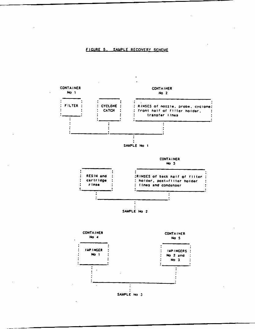
E 5 . s u VERY M
C O M A I NER CONTAINER N o 1 N o 2 - -
! * . : FILTER :
'-0 t r a n s f e r llnes
: CYCLONE : : U T 0 : : f r o n t h a l f o f f l l t e r nolaor.
: RINSES O f n m z l e . Droee. cyclone:
S W L E No I
C O M A I NER WOJ
S W L E No 2
CONTA I NE R N o 4 -
: IUPINGER : N o 1 :
CONTA I NE R Nos
: IYPIWGERS : : No 2 r n o : : N o 3 :
SCYPLE No 3

F 1 LTER
SURROGATE
EXTRACT ION
CON EXTRACT
RESIN R I NSES
SURROGATE
EXTRACTION EXTRACTION
CON EXTRACT CON EXTRACT
T L
CONCENTRATE EXTRACT
C O L W CHROLUTOGRN~
INTERNAL STANDARD
ANALYS I s
IMP RINSES I UP I NCERS
SURROGATE I
EXTRACT I ON
CON EXTRACT
CONCENTRATE EXTRACT
INTERNAL STANDARD
I
ANALYSIS

4 . 6 . 1
A. :
T h e Soxhlet apparatus ihould be cleaned by in 8-hr. Solhlet. and the solvent discarded. to the thimble. Cut the filter into - 1 1 atripr and place the entire sample and residue rinse1 (4.6.1) on top of the Na2SOq: appropriate quantrty of the murrogatc atmdard molution t o obtain the extract v o l m concentrations suggested in Section 5 .1 .5 .
Place the thimble i n the Sorblet apparatus. and add 2 5 0 d of benzene or toluene to the receiver. Assemble the Soxhlet. turn on the heating controla and cooling water. and reflux for 16 hours. After extraction. a l loar the Soxhlet to cool. Transfer to a SO0 rd round bottan flask. and add approximately SO0 uL of tetradecane. Add approximately SO d of hexane and concentrate the extract volumc to SO0 u L w i t h a Kuderna-Danish concentrator or ro tary evaporator. Transfer the extract t o an 8 mL test tube with hexane and set aside for c o l m n cleanup i f needed (Section
Add 20 g Na2SQ4
Mix h d i a t e l y and add the
4.7):
B. U:
Clean the Soxhlet apparatus 11 written in Section 3.1. The resin sample volun: will m3st.likely be too large for extraction in i mingle Soxhlct. In much carer , the m.nple can be divided into tmo portlona. Surrogate mtmdard molution should also be dlvidcd into rw approximately equal portions. W i n e one of these resin portions with the residue rinsea and proceed with each extract a s in Section 4.6.3.
4 . 6 . 3
M i n e concentrated extracts f r m the three #ample containerr 1. 2. 3 , with the cyclone, filter and renin. W i n e extracta frauthe b i n g c r a and impinger rinaar and keep aeparate fraa the other c d i n e d extract and analyze separately.
7 h e analyst may directly analyze the extracted samples. are interference8 in'the direct analysis then a preclean up atep i a r equi r cd .
If there
429-43
4 L Y - I
Several c o l m m chramtographic cleanup optimi a r e available. Either o f the turn described below, the silica and a l d n a colrnm procedures. a r e considered to be sufficient. Acceptable alternative cleanup proccdurea m y be used provided that they are damnstrated to generate acceptable accuracy and precision a8 required in Section 5.
An extract obtained as described i n the foregoing sections is concentrated to a volurr of about 1 mL using the nitrogen b l d m m apparatus, and thir is trannfcrred quantitatively (with rinsings) to either of the columr described below.
(-
4.7.1
-: am I 10 urd in the following manner:
lnsert a glasr m o l plug (cleaned) into the bottan of the colum and add a slurry of 10 grams of activated silica gel (4.5) in nxthylenc chloride and a 1 un layer of anhydrous aodimn sulfate (Section 4.5).
8 . : Pack I 1 0 m n g l a s s gravity
Pack a glass gravity coluam ( 2 5 0 . . A.
c o l u m a1 f o l l w :
lnser t a glass w o l plug (cleaned) into the b o t t r m o f the colum. Add 6 g of acid almnina prepared as dercribed in Section 4.5. Tap the c a l m gently to nettle the alunina. and add 1 aa of anhydrour s o d i m sulfate to the top. .
4.7.2
: Preelutc the collnn with 40 ml of . . A. pentane. The rate Cor a11 elutions should be about 2 ml/min. Dincard the eluate and just prior t o exporure of the s o d i m sulfate layer to the air. transfer the l m l sample extract onto the colwm uring an addltional 2 ml of hexane to crmplete the transfer. Just prior to expoaure of the s o d i m mulfate layer to the a i r , add 25 ml of pentane and contlnuc the elution of the colum.
Next. elute the c o l u m with 25 ml of mcthylent chloride/pentanc (2:3)(v/v). Concentrate the collected fraction using K-D apparatus or a rotary evaporator to required s u q l c volrplr.
B.
Elute the c o l u m w i t h 50 ml of hexane. Let the solvent f l & through the c o l a until the head of the liquid in the c o l m n i s j u s t above the s o d i m sulfate layer. Close the stopcock to stop solvent flow. (.
429-44

4LY-1
Transfer l m l of the sample extract onto the colum. Rinse out extract vial w i t h l m l hexane and add it to the c o l w m ianrdiately. TO avoid overloading t h e colum. i t i a iuggcsted that no m r e than 300 uq of extractable organics be placed on the colmm.
Just prior t o exposure of the' iodiun sulfate t o the a i r , e lu te the c o l m m with a total of 15 ml or hexane. If the extract ii in 1 ml of hexane, and if 1 ml of hexane w a s ured a r a rinie. then 13 ml of additional hexane rhould be uicd. Collect the e f f l u e n t and concentrate t o deilrtd volrm.
Transfer to a minivial uiing a hexane rinse and concentrate to the desired vol- using a gentle s t r e a m of nitrogen. Store the extracti in a freezer m y rrrm light until UX.6 analyrir.
.
429-45

5 .0
5 .1 APPARKm
5.1.1
5 . 1 . 2
5 .1 .3
5.1.4
5.1.5
An analytical system canplcte with a tmipcrature progr-ble g a r chranntograph and a11 required accessoricr including ryringer. analytical calm and gases. on c0lu.m injection ia preferred but splitless injection ir acceptable.
IkllIul
A high resolution croas-linked mcthyl silicone fused silica capillary colmn. - Capable of scanning f r a n 35 to 500 MU every 1 sec or I C S S . using 70 volt (nmrinal) electron energy in the e l e c t r o n impact ionization =de. Altcrnativcly. a high resolution masr spectrcmctcr may be used.
TnterIlcc
Any gar chrmmtograph to masr spectrmrter interface may be ured am long ai it giver acceptable calibration rcsponae Tor each analytc of Intcrcrt a t the concentration required and achiever the rcqu'ired tuning pcrfomance criteria (Section 5.3).
JhLs&u A canputer ryrtemmrrt be interfaced t o the rrmss specti-ter. The a y r t a a m r r t allow the continuous acquirition and itorage on machine-readable nxdia of a l l m a s r spectra obtained throughout the duration of the chranntographic proprun. The crmputcr m r r t have rofcaare that can rearch anyCXX6 data file for ions of a specific ma## and that can plo t ruch ion abundanccs versus time or scan nuder. ?hi# type of plot I r defined as an Extrscted Ion a r r e n t Profile (Elm). Sofmmre rmst a l s o be available that rllmvu Integrating the abundance. in any E I B becahcn specified time or rcan-nuder I i m i t r .
429-46

5.2.1
5.2.2
5.2.3
5 .2 .4
Standard iolutloni can be prepared frrm pure itandard materiili or purchaied ai certified iolutioni.
M e n canpound purity ii asiayed to be 9flIo or greater. the w i g h t may be used without correction t o calculate the concentration of the itock standard. Grnn?rcially ,prepared itock itandirdi m y be used at any concentration
i f they are certlfied by the manufacturer or by an independent iource.
Store rtock rtandard iolutioni in Teflon-sealed screw-cap bottle# at 4OC and protect f r a n light. rolutiona ihould be checked frequently f o r iignr of degradation or evaporation. especially just prior to preparing calibration standards fraa than.
Stock standard
Stock standard solutions miit be replaced after 1 year, or sooner. if canparironwith quality control check samples indicate8 a problem.
The internal itandard recmmcnded ii 2.2'-difluorobiphenyl-d4. Other c m o u n d s ~y be used as internal itandardi a i long i a the requiraacnts given in S e c t i o n 5.3.5 are mct. u'dergolng analyiii internal standard iolutlon, reiulting in a concentration of 40 ng/uL of each internal mtandard for LIlhs. For HAhs the rssulting IS concentration ihould be O.Jng/uL. Store a t 4 c o r lealahen not being Used.
Each I d iample extract ihould be iplked with IOU1 of the
Calibration standards at a m i n k o f five concentration levels should be prepared. One of the calibration standards rhould be a t a concentration near. but above, the mcthod detection 1 s t : t o the range of concentrations found in real iamplem but rhould not exceed the aorking range of the cc/lrs system. For UFrS the range ihould be 2Ong/uL to ZOOng/uL. HWS the range ihould be O.lng/uL to 5 ng/uL. Each standard should contain each analyte for detection by thin mtbod. so lut ion of iurrogate itandardi. concentration ihould be mldany on the calibration curve. Each 1-mL aliquot of calibration itandard rhould be spiked with 10111 of Internil itandard iolution prior t o analyaii.
'Ihe others ihould correspond
For
Each calibration atindird ii spiked w i t h A The resulting iurrogate
429-47

A l l standards ihould be stored a t -1OOC to -2OOC and should be freshly prepared If check rtandards Indicate a problem. prepared meekly and stored a t 4 C.
T h e daily calibratlonostandard should be
5 . 2 . 5
Listed in table 5 are the labeled isotopes used for surrogates. Determine *at concentrhtion should be in the blank e x t r a c t s a f t e r a l l extraction, cleanup, and concentration r t e p s . Inject this concentration into the 002u6 t o determine recovery of rurrogatc standards in a l l blanks, spikes. and r r q l e extracta . Take into account a11 dilutions of sample extracta.
.
429-48

4 L Y - 1
- Naphthalene
Acenapthalcnc
Accnaphthenc
Fluorene
Phenanthrene
Anthracene
Fluoranthene
F'yrene
Ben201 a ]anthracene
(atyscne
Benzo[b]f luoranthcnc
Benzo[k]fluoranthcne
Benzo[alpyrcnc .
Denzo [gh i Ipcrylenc
Di benz[ah]anthraccnc
Indeno [ 1.2,J-cdlwrene
8 Primary Sc conda rp
Quantitation Confirnation llln 128
152
154
166
178
178
202
202
228
228
252
252
252
276
278
276
Ianla)
129,127
151,153
153.152
165.167
179.176
l16.119
101.203
200,203
229.226
226,229
253,125
253,125
253,125
138,277
139,279
&*2:1 Ionization lldd
129.157.169
152.153.181
154,155,183
166.l61.195
178.179,207
118.I19.2Ql
203,231.243
203,231.243
228,229,251
228,229,257
252.253.281
252,253.281
252.253.281
276.277.305
218,279,307
276.277.305 138.227 Just use primrri-lon for €D&S quantification and identification
429-49

4LY - 1
naphthalene-dg
acenapthilenc-d
accdaphthcnc-d10
fluorcnc-d10
phcnanthrcne-d10
anthraccne-d10
fluorantbene-drO
pyrcnc-dI0
benz~[.]anthriccnc-d~~
chryeae-d12
a
bcnto [ b] f luorinthcne -d12 '
benzo[d]fl~oranthcnc-d~~
bento[a 1 p y r ~ n e - d ~ ~
bcnzo[ ghi Ipe rylene-dll
. !
429-50

4LY- 1
Dctermineubat concentration rhould be i n the blank extracts after all extraction. cleanup. and concentration itepr. Inject this concentration into the oc/hs to determine recovery of surrogate standards in all blanks , rpikei, and r q l e extracts. Take into account all dilutions of rrmple extracts.
5.3 INITIAL CALIWATICN
5 . 3 . 1 -nH
The r.eccrmunded G C M operating conditions:
initial colmm tcmperaturc and hold the. 40 O C for 4 min colum taqeraturc program: 40-27g°C at 10°c/min final colum tcmpcrature hold 270 C (until benzo[g.h.i]pcrylene. has eluted)
i n j ec t or t a q e ra tur e : 250-300°C 8 pec i f i ca t ionI injector: Grob-type. iplitleis 1.mple v o l m : 1-2 ul carrier gar: Hydrogen a t SO d s c c or beliun it 3 0 d s c c
5.3.2 .
nail range: 3s-SOOarm #can timc: liedscan source temperature: According to nanufacturer'r spec I f i Cat ionr transfer 1 ine temperature : Z50-300°C
5.3.3
Background iubtrrction should be straight foranrd and designed only to eliminate c o l m a bleed or initrrcllcnt background ionr.
?he analyit ihould tune the hE to achieve opt- perfomancc at unit resolution for = and either 3000. 5OOO. or 10,OOO for H B S .
&is spectral peak profilcr for mlz 69 (W only). 219 and 264 nuat be recorded, plotted, and reported. T h e rcan abould Include a m i n h of +/- tvm perks (i.e. adz 67-71 for the mlz 69 profile for IJM or +/- I00 ppn for HRhS at lO.OO0).
429-51

5.3.4 r
A mixture of l,l-bir(4-chlorophcnyl)-2.2,2- trichloroe thane (UJT). benzidine and pcntachorophenol ahould be used t o t e s t for colwn performance. Degradation of lJJT to 2.2- bir~4-chlorophcnyI~-l.1-dichloroethcne (LEE) and 2.2- bir(4-chlorophcnyl)-l,l-dichlorethanc (tlD) ahould not exceed 20%. Benzidine and pentachlorophenol ahould be present at t h e i r noma1 reiponrei. and no peak tailing should be visible. I t degradation is excessive and/or poor chrcmatography is noted, the injection port may require cleaning. I t may alio be necessary t o break off the first 6-12 in of the capillary colmm.
.':
Colurm resolution; Tbe colmm reiolution criteria of 7% vi1 ley be m e n benro[ b] f luoranthcne and benro[k]f luoranthcnc i a rcqui red.
5 . 3 . 5
Calibration with isotope dilution ia'used when (1) labelled caupoundr a r c available. (2) interferencer do not preclude ita u i e . and ( 3 ) the quantitation rmir extracted ion current p r o f i l e ( E I B ) arc for the crmpound ir in the calibration range. If any of . there conditions preclude irotopc dilution, internal standard mcthod ir used.
5.3.6 . A system pcrfonrance check mrt be perfomvd to ensure that m i n h average R F i a r e m e t before the calibration is used. The SyrtanPerfonnnnce n e c k Crmpoundi a r e : N- nitrgso-di-n-propyl.mine. hexachlorocyclopcntadiene; 2.4- dinitrophenol, and 4-nitrophenol. T b c m i n d acceptable average RF for there ccmpoundr SFCa ii 0.050. Tl~cse canpoundr a r t m e t the dn- requirmrnt d e n the syrtan i n calibrated.
5 . 4 W L Y ( ; 4 L I r n ( N
5.4.1
Prior to analyrir of iamplci, the tuning standard a r t be analyzed. Tbir Ii the s m criteria a s in the initial tuning crltcria given in iection 5.3.3. These criteria r m i t be dcllpnrtrated during each 12-br. shift.
429-52

4 L Y - 1
5 .4 .2
A calibration rtandard(r) at mid-level concentration containing all the rdvolati'lc analytea. including a l l required iurrogatea mist be performed every 12-hr. during analysis. Compare the response factor data fran the initial calibration for a specific inrtr-nt as per the S F C (Section 5.4.3) and 03: (Section 5.4.4) criteria.
5 .4 .3
A system performance check m a t be amde during every 12 hr. shift. If the SPCX criteria are ILIC~. a campariaon of response factora ir made for a l l canpoundr. 'Ibis is the s a m c check t h a t i s applied during the initial calibration. If the minirrrm response factorr are not a t . the aystcm m s t be evrluated. and corrective action must be taken bcrorc rlrmple analysis begina. T h e minimnnRF for saniv,ofatile SPa=a ii 0.050. This checkmrrt be rmt before analysia begina.
5.4.4
After the iyrtan perfomance check ir Illct. (IIL. acenaphthene, napthalene, fluoranthene, benzo[a ]pyrcne, and chrpsene are ured to check the validity of the initial calibration. Calculate the percent difference uaing:
RF*-RFcr 100 . %Difference - U b b r e : WI
RFl - average rerponse factor frau initial calibration RFc - rerponre factor fran current verification check
a t anda rd.
If the difference for any cmpound i r greater than 20 percent, the laboratory ihould consider thir a warning l i m i t . If the difference ia lesa than 3mo. the initial calibration Is asrllmcd to be valid. If the criterion is not met ( r30k difference) for any one (IC, corrective action m a t be taken. If no iource of the problem can be d e t e d n e d after corrective action ham been taken. new five-point calibration m a t be generated. T b i r criterion mat be mt before armple analyrir begina.
429-53

The internal standard rerponrer and retention timcr in the calibration check standard rmrt bo evaluated innxdiately a f t e r or during data acquirltion. I f the retention timc for any internal rtandard Changer by -re than 30 rec fran the l a s t check callbratlon (12hr). the chrcrnatographic syrtemnust be inspected for malfunctlonr and correction* mat be nmde ar required. If the E I B area for any of the internal standards changer by a factor of tax, ( -50% to +100%) fran the l a i c daily calibration standard check, the mass rpectrcmcter m a t be lnrpected for nnlfunctions and corrections nust be -de. ar appropriate.
!
5 . 5 CAS ANALYSIS
I t is highly r e c m m o d e d that the extract be screened on a W F I D or C U P I D using the same type of capillary colwm. This w i l l minimize contamination of the KA5 syatan fran unexpectedly high concentrationr of organic crmpounda.
Spike the I-mL extract obtained f r a n sanrple preparation with lOuL of the internal standard solution Just prior t o analysir. Analyze the I - d extract by oc/hs using a 30-m s 0.15-mn (or 0.32- d silicone-coated fused-rlllca capillary colmm. For LJW5 the V o l e t o be injected should ideally contain 100 ng of surrogate# for a 1 uL injection. For kG%S the volum t o be Injected should ideally contain 2 ng of surrogate per Injection. The recamncnded
CX2t.S operating conditionr to he used are mpeclfied in See t i on. 5.3.2.
If the response for any quntitation ion exceeds the initial calibration curve range of the ooks a y a t e m . extract dilutionmat take place. Additional internal standard m r t be added t o the diluted extract t o maintain the required 40 ng/uL of each internal standard in the extracted v o l a . 'Ihe diluted extract mst be re -ana lyzed.
Perform a11 qualitative and quantitative m c a r u r q n t r as described in Sectionr 5.6 and 5.7. Store the ex trac t . at 4 IC protected frrm light in screw-cap vialr equipped with unpierced Teflon-lined septa.
.
429-54
i

5 . 6 QALITATNE AFL9LYSIS
5 .6 .1
For IJ&5 an analyte ir Identified by ccmpariron of the rample nass spcctruawith the m r r Ipcctrun of a standard of the suspected c q o u n d (mtindard reference rpectrrrm). Mass spectra for rtandard reference sbould be obtained on the user'r OClkswithin the ruac 12 hours of the rample analyrir. T h e s e rtandard reference spectra nay be obtained through anilyrir of the calibration rcandards. For Hf&6 rclcctive ionmonitoring the ure of exact m a s s meamrerent ir used a i a conflmation of identity.
5.6.2
T h e sample canponent RKTmrst ccmparc with in 0.06RRT units of the RRT of the rtandard canponent. For reference, the standard rmst be runwi th in the 6- 12 hrs as the rample. I f coelution of interfering crmponcnts prohibitr accurate assigmunt of the munple collponent RRT f r a n the coca1 ion chramtopram. the RRT ahould be aarigncd by using extracted ion current profilea for ionr unique to the canponcnt' of interest.
5.6.3
All ions prcacnt i n the rtandard miis rpectri at a relstive iotenritp greater than 1% 6 m m t abundant ion in the rpectrua equals 100%) m r t be prerent in the rample rpcctrun.
5.6.4
7 h e relative intcnriticr of ion8 specified in Section 5.6.3 m a t agree within plur or minus 20% b e t w e n the standard and rample spectra. (&le: For an ion with an abundance of SO& In the rtandard rpcctra. the correrponding rample abundance m r t be b e w e n 30 and 70 percent.
5 .7 (&wmwnEANAtYsIS
%en a conpound ha1 been identified, the quintitation of that crmpound will be by the imotope dilutlon techniqu.e. If irotope dilution is not porrlble then the rrrthod of internal standards is used.
429-55

5 . 7 . 1
A calibration curve encanparring the concentration range is prepared for each cunpound t o be determined. The relative response (pollutant to labeled) vm concentration in standard rolutioni i n plotted w i n g linear regression. Relative Response (RR) ir determined according to the procedurer described belmv. a r e employed f o r calibration.
T h e relative response of a pollutaat t o its libeled analog is determined f r a n isotope ratio valuer canputed fran Acquired data. Three isotope ratios are used i n this process :
A m i n i m m o f five data points
Rx - the isotope ratio masurcd for the pure
Ry canpound.
R,- the isotope ratio of an analytical mixture of
The m l z ’ s a r e rclected much that R > R . I f R i s not b e m c e n 2Rx. and 0.5R , the aythodydoes noT apply and the srmple is analyzeJ by internal rtandard mc t hod.
M e n there is GC and spectral reparation of the pollutant-labelled pair:
pollutant.
- the isotope ratio mcarured for the labeled
pollutant and labelled cmpouadi.
.
A -Area of pollutant
Ai - A r e a of irotope Rx- [Ap] P R - l\[Ai] Y
RR - Relative response If signieicant Gc and spectral overlap occur, RR is computed urinp the following cquatlon:
I f the ratio of relative rcrpoore t o concentration for any canpound i s conitant (less than 20 percent coefficient of variation) over the 5 point calibration range, and averaged relative rerponsc/concentratlon ratio rmy be used for that canpound. orherprise, the c m l e t e calibration curve for that c q o u n d shall be used over the 5 point calibration range.
429-56

42Y - 1
5 .7 .2 P The internal standard m t h o d is used only d e n isotope dilution cannot be used.
Glibration requires the determination of response factors (RF) which are defined by the following equation:
Al is the area of the characteristic rrass for the compound
A. is the area of the characteristic mass f o r the
in the standard.
IS . internal standard.
Cia is the concentration of the internal standard
Ca i c the concentration of tbe crmpound in the standard
T h e response factor is determined for at a t least five concentrations appropriate to the reposnse of each canpound. ne auuund of internal standard added t o each extract ir the SLM so that Cis remains constant. is plotted VI concentration for each canpound in the rtandard t o produce a calibration curve.
If the response factor (RF) for any caupound is constant (less than 35 percent coefficient of variation) over the 5 point callbration range. an average reaponse factor nay be ured for that empound; otherwiic the crmplete caiibratlon for that crmpound shall be ured over the 5 point range.
T h e RF
5 . 1 . 3 - %en duplicate3 and apiked slmplea are analyzed. report al l data obtained with the sample results.
5.8 Q w L l l Y a N l T C l J Q J & . ~ , ~
Each laboratory that urelr these m t h o d r is required to operate a forrml quality control program. program consiit of an initlal damnatration of laboratory capability and 4n ongoing analyrir of apiked a m p l e a to evaluate and doc-nt quality data. T h e laboratory m a t maintain records to d o c e n t the quality of the data generated. Ongoing data quality checks are canpared with eatabliahed pcrfonmnce criteria to determine if the results of analyrei a c t the p e r f o w n c e characterimtica of the nrthod. M e n reiultr of a m p l e rpikes indicate atypical method perfomnce. a qualit+controI ebrck rtandard rmst be analyzed to confinn that the mearurementi - r e performtd in an in-control =de of operation.
T h e min- requirenrnts of this
429-S1

T h e experience of the analyrt performing cvk6 analyrar I r invaluable to the success of the athods. Each day that analysir is p e r f o k d . the daily calibration standard should be evaluated to '
determine if the chrrmatographic systan is operating properly. If any changer are made to the syrtan ( e . g . colmm changed). recalibratlon of the systemnust take place.
f-
5.8 .1
QlaJitv (Ihcclr: A quality (Qc) check ranple vhich contains all the analytcs is required. The sample matrix of the filter and or resin is spiked t o contain 100ug/rample for IJW or O.Sng/sampje for HU6.
T h e Qc check sample concentrate m y be prepared f r a n pure mtandard m a t e r i a l s or purchased a s certified solutions. I f prepared by the laboratory. the Qc check sample concentrate rmst be made using stock standards prepared independently frcm those used for calibration.
Analyze the mil-mixed Qc check sampler according t o the method beginning in Section 4.6 with extraction of the samplca.
5.8.2
Calculate the average recovery in ug/s.mple. Acc$ptable recoveries are 5ok to 15ok.
M e n one or m r e of the analytcs tested fail a t the recovery acceptance criteria, the analyst must proceed according t o this Section.
Locate and correct the aource oi the problem and repeat the t e s t for a11 analyter of intereat beginning with Section 5.8.1.
Beginning with Section 5.8.1 repeat the t e s t only for those analytea that failed to m e t criteria. Repeated failure. howver . will confinn a general problanwith the m a a u r m n t ryatan. If this occur8. locate and correct the rourca of the problan and repeat the t e s t for a l l crmpounds of interest beginning with Section 5.8 .1
5.8.3
i
Recavcric.: To determine acceptable accuracy and precision limits for surrogate standrrdr the following procedure should be performed.
429-58

For each lampic analyzed. calculate the percent recovery of each surrogate in the slmple.
I f recovery is not within the limits of 5oK15(A then, the following procedures are required.
Re-extract and reanalyze the ~ a a p l e if DO calculation or instrunt problam arc found.
I f there it a non-dlrcernablc problem, flag the data a s "e st ima t ed. concent ra t ion-.
5.8.4
Matrix Spike&
T h e concentration of the spike in the slmplc should be determined LI f o l l w :
The spike should be a t 1 to 5 t k s higher than the background concentration.
Analyze one sample aliquot to determine the background concentration (B) of each analyte. a new Qc check a m p l e concentrate (Section 5.8.1) appropriate for the background concentration in the armpie. Spike a second sample aliquot with 1.OQd of the qC check sample concentrate and analyze it to determine the concentration after spiking (A) of each.analyte. Calculate each percent recovery (p) a s lOO(A-B)lwr. *ere T it the knm true value of the spike. ?Ire recovery rmst be'within 501'15ok.
I f a specific analyte percent recovery falls outiide the designated range for recovery, that analyte hat failed the acceptance Criteria. analyte that failed the criteria must be analyzed as described in Section 5.8.1.
QCQeck Standard for ccmpoundt that fail acceptance criteria. If any analytc Tails the acceptance criteria Tor recovery In Section 5.8.2. a Qc check standard containing each analyte that failed rmst be prepared and ana lysed.
Note: The frequency for the required a n a l p i t of a qC check standard will depend upon the nunher of anstytea being sirmltancoutly tested. the crmplcxity of the ramplc matrix, and the performance of the laboratory. The QC check standard should be routinely analyzed with the spiked srrmpk.
If necessary. prepare
A check standard containing each
429-59

4 L Y - 1
5 . 8 . 5
5 . 8 . 6
5.8.7
Analyze the Qc check itandard to determine the concentration mcaiure (A) of each analyte. percent recovery (pi) a i lOO(A/T%, *ere T is the true value of the itandard concentration.
Calculate each
Campare the percent recovery (ps) for each analyte with the QC acceptance criteria of SWo-lSO%. that failed the test in Section 5.8 .2 need to be crmpared with'theie criteria. If the recovery of any such analyte falli outride the designated range. the laboratory performance for that analyte ia judged to be out of control. and the problemrmst be immdiately identified and corrected. T h e analytical result for that analyte i n the unspiked sample is iurpect and may not be reported for regulatory crmplirnce purposes.
Only analytes
Dcfore procesiing any r e l e a . the analyst should damnstrate through the analysis of a reagent blank. that interferences frrm the analytical system. glaasuarc. and reagenti are under control. Each time a set of samplei is extracted or there 1 1 .a change in reagentr. a reagent blank should be proceried as a safeguard against chronic laboratory contamination. 'Ihe blank sauples should be carried through a l l itagei of the iample preparation and mzasuranxt itepi. . (.
h r i n g sampling the teit crew ii required to take field blanki, a blank train and a spiked sample train.
and F-: T h e fleld blankwill be used to analyze for background levels. The blank analytical preparation and analysis will run concurrentlywith the other test samples.
The fleld ipike traInr are required to detedning the recoverlei of both the analytlcal and sampling mcthod. There sampler are to be run concurrentlywith the other teat i m p l e i . Acceptable recoveries a r e betacen 50% to Ism. If the valuci are outride thii range then the data u u i t be flagged a i ertiarated concentration".
v: These are individual samples that a r e analyzcdnnre than once to obtain the precision of the analytical method.- At least one duplicate should be analyzed per test.
429-60

5 . 8 . 8
The laboratory rhall adopt additional quality arrurrnce practicer for use w i t h thir mctbod. T h e specific practicer that a r e m D B t productive depend upon the needr of the laboratory and the nature of the ranplei. W e n doubt exirtr over :he identification of a peak on the chranatogrnm. confirmatory techniques such as gar chramtography w i t h r diarimilar colmn. specific elamnt detector, or m a r spectrmxter mist be used. M e n e v er possible. the laboratory should analyze standard reference materialr and participate in relevant p e r f o m n c e evslustion rtudier. ocurring in chromatography. the 1nAlyIt i # perpritted certain optiona to improve reparations or 1-1 the cost of IIyssurcpIcntm. Each t k ruch mdifications to the orthod are made. the analyst ia required to repeat the procedurer described in Section 5.8 and damnstrate the ability to generate data of acceptable accuracy and precirion.
In recognition of the .advances
I f an alternative test mcthod it used. the t e s ter mrst damnatrate . the alternative teat mcthod is equivalent to the mcthod specified herein to the satisfaction of the Executive Officer. n e Executive Ofricer w i l l require the rubmission of data ahawing that the quality assurance (w) program of the alternate mcthod ir equivalent t o the Q4 program rpecified heretofore. -
-
429-61
1

6 . 0
6.1 MINME--(H
The m i n k detection l imit for the the individual PAH a r e determined fran the following equationr:
Concentration. ng/dsaa - Ql I 4 'dstd) Ais X R R
M e r e :
RR - Relative response factor calculated according to Equation 6 - 5 .
Qis - h u n t of internal standard added t o each sample.
A, - &an noire for the PAHlllarr chramatogrun A t the m / z s h m i n Table 4.
Air - hS response for the internal rr'andard ion
"E b y di lut ion factor Introduced by following the procedure in Section 5 rhould be applled t o thlr calculation. .
6.2 REIIu?vE REsp(NTe,FXKRS
' Ih ir is determined fran the Tollwing equation using the data obtained in Section 5 fran the analyrlr of the calibration standards.
A, -hS rerponse for the native ion at d r given in Table 4.
C,, - Concentration of the appropriate surrogate rtandrrd. ng/uL. A - b S rerponre of the appropriate surrogate standard.
C,
ss - Concentratlon of the native ion of interert.
429-61

4 1 Y - I
6 . 3 PWcMRlXWlXY * C F ~ S u N M l l D
C a l c u l a t e the percent recovery, R. for each internal standard in the sample extract. using Equation 6-6'
6-6
m e r e :
Ais - A r e a of quantitrtion ion of the internal rtandard.
Qis - ng of internal rtandard. 6 . 4 ?]E RESnT(SE F X K E Ax Ell3MNU ICNW EE-xmRY
Calculate using data obtained fruu the inalyiir of the calibration standards according to Equation 6-7.
%ere:
Crs - Concentration of the internal standard. 6 . 5 REWLB
Any deviations f r a a the procedure1 deicribed In thin protocol rhall be docuacnted in the analytical and a.mplInp report.
6.6
Determine the concentration of PAH in the rtack gar according to Equation 6-a.
429-63

4 L Y - 1
eprWncrC 6-8
G
6 . 7 I ( N OF IMlvIulfu PNi cn4uNx The concentration of individual PAH compound8 are determined fran the foIlowing equations:
Qs 8 4 'm(8td) *a8
Concentration, ngldsan - X R R
M e r e :
RR - Relative response factor calculated according to Equation 6-5.
- h u n t of surrogate rtaadard added to each rsmple.
- LS response for native ion a t the m l s r h w m in Table 4. Q. I
As
Ass - LS rerponre for the iurrogate 8tandard ion
N3IE: Any d i l u t i o n factor introduced by following the procedure in Section 5 should be applied eo thir calculation.
!
429-64

4 L Y - 1
7 ... 7 . 1
7.2
7.3
7.4
7.5
7.6
7.7
7.8
7.9
U.S. bvirom*ntal Protection Agency/Office of Solid Wdate. W r h i n g t o n D.C.. Method 8270. Spectrmrtry for Stmivolatile Orgaaics: Capillary 61um Technique. In ' T e a t Mcthoda for Evaluating SolidUkrtc- Phyi ical/Chauical Mc thodr" W - 8 4 6 (1986).
U.S. Enviromrcntal Protection Agency/Office of Solid Waste. Uashington D.C.. Method 3611. Alumina 6 1 u m Cleanup and Separation of PCtrOltUDWdSteS. In 7 e r t kthodr for Evaluating Solid Uhstc-PhyricaI/Qcmical Mthodr" SA-846 (1986).
U.S. Enviromrnt.1 Protection Agency/Office of Solid Waste. Washington D.C.. Mcthod 3630. Silica G e l Cleanup. In 'Test Methods for Evaluating Solid White-Phyrical/(arrmcal Methods"
Gar Qramtography/kfarr
w - a 4 6 (1986).
Thamspon. J.R.. ed.. Analysis of Pesticide Residues in )Irrman and Enviromrntal Smrplca. Enviromuntal Protection Agency. Research Triangle Park, N.C. (1974).
A R B N t h o d 428. &termination of Polychlorinated Dibenzo-p- dioxin (-1 and Polychlorinated Dibenzofuran (-1 hiisionr Fran Stationary Sourccr. Novadxr. 19M7.
U. S. Envirormcntal Protection Agency. hkthod 1625 Rcvirion B - Sdvolrtile Olgknic Crmpoundr by lrotope Dilution. (b.1 (7-1-85 Edition) P t . 136. App. A.
'T.rcingogcnr-Rbrking w i t h C.rs1nogcni. - 40 (3FR
. Dcparrmcnt of Health
Education. knd Qklfase, Pub1 Ic Health Service. G n r e r for Diieaie Control. National Institute for Occupational Safety and l i e a l t h . F'ubllcation No. 77-206. Aug. 1977
Safety and Health Standards. General Indurtry." (29cFK1910). Occupational Safety and Health m n i a t r a t i o n . CCW 2206. (Revired. January 1976).
"Safety in Acadanic Claniitry Laboratories. - h r i c k a aanical Society Publlcation. G n m i t t e c on (Iranical S a f e t y . 3rd Edition. 1979.
429-65

Tkr ALMEC~A CORPORAT~ON
APPENDIX M
CARB Method 430
Determination of Formaldehyde in Emissions from Stationary Sources

FORMALDEHYDE and ACETALDEHYDE
Formaldehyde emissions were determined following the protocol
Acetaldehyde emissions were determined by analysis of the acetaldehyde peak of the HPLC chromatogram developed following Method
Additional calibration was performed to quantify the acetaldehyde
detailed in CARB Method 430.
4 3 0 .
emissions.

State of California All Resource8 Board
Proposdd Ustho8 430
Determination of Formaldehy8e In Emlsslons From Statlonary Sources
.

Method 430 Determlnatlon of Formaldehyde In Emlsslons From Statlonary Sources
1. APPLICABILITY AWD PRINCIPLE
1.1 ADDllCablllty
ThlJ method appl lea to the determlnatlon Of formaldehyde In emlsslons from statlonary sources. The method I s based on the use O f hlgh performance llpuld chromatography (HPLC).
Any modlrlcatlon or thlo method beyond those expressly permltted shall be consldered a malor AOdIfICatlOn subJect to approval By the Executive Offlcer. ‘The term Erscutlve Orflcer as used In this document shall mean the Executlve Officer or A l r Pollution Control Offlcer o f the etate or local alr POIlutlon control agency at whose request the test Io conducted. or hls or her ruthorlxed reoresentatlve.
1.2 PrlnclDle
Gaseous emlsslons are drawn through two mldoet ImDlngers In serles. each contalnlng an a((ueouo acldlc solutlon of 2.4-dlnltrophenyl- hydrazlne (DNPH). Formaldehyde reacts r l t h OWH by IXlCleODhillc addltlon on the Carbonyl followed by 1,24lImlnatlon of water and the tormatlon of the 2.4-dlnltrophenyIhydra1ons. &Id I s reqtilred to promote protonatlon of the carbonyl becauoe DNPH Is a weat nucleophlle.
After organlc eolvent ertractlon, the DNPH-formaldehfdo derlvatlve I s determlned uslng revorme phase WLC mlth an ultraviolet ( W ) adsorptlon detector operated at 360 m.
Formaldehyde In the sample Io Identified and auantilled by canparison of retentlon tlws and area m t m , respectively. rlth those or standard IMPIOO.
2. RAWCE AM) SENSITIVITI
Formaldehyde contamlnatlon of reagents can Impalr sensltlvlty l e v e l o . Wlth careful atlentlon to reagent purity and other relevant factors. a target detectlon llmlt or 400 ng/sampie can be achleved wlth thle method.
SAUPLING RUNS. TIUE. AFlD VOLulE
3.1 Sampllng Runs
3.
The number of sampllng runs must be sufflclent to provlde mlnlmal statletlcal data and should not be less than three (3) . -
430-1

3.2 SOElDle
Sampling tlme and appropriate rampllng rate should be choren to ;- obtaln the sample volume estlaated In Sectlon 3.3 without exceedlng the absorblng capaclty of the ImgInOer solution. I f a rlngle sampllng run cannot reflect the VarlaDlllty of tho PTOCOI8. the tester can conslder a representatlve range of operatlng condltlons by collectlng several samples In sequence.
3.3 Sample Volume
The sample volume must be sufflclent to provide the requlred amount of a n a l y t e to meet both the mlnlmum detectlon Ilmlt (UDL) of the analytlcal method and the regulatory Ilmlt. I f there I s no 'reOulatory Ilmtt. the target ehould be the tYDlCaI concentratton tn . smlsslons from the type of source belng tested. It may be calculated uslng the followlng formula:
100 100 1
0 C D Sample Volume - A x - x - x - Where:
A - The analytlcal UDL In rg B - Percent ( X I of the sampls requlred Der analytlcal run C - Sample recovery ( X I D - Regulatory l l m l t . or other tarbet concentratlon a8
dercrlbed abovo (ng/dscm) . 4. INTERFEREWCES
The DNPH formaldehyde. derlvstlve Is easlly 8bPlrOtOd by HPLC from the derlvatlves of other carbonyl compound8 wlth rhlch DNPH reactr.
Formaldehyde contanlnatlon of DNPH reagent can be a problem w e n after recrystalllzatlon. The DNPH must be Durlfled and used wlthln 48 hours of preparatlon.
5 . APPARATUS
The followlng sampllng apparatus I s recomnended. The tester may use an alternatlve sampllng apparatus only I f , after revlew by the Executlve Offlcer. I t I s deemed equlvalent for the purpose8 of thls test method. It I s recommended that all equipment whlch c o m a In contact wlth the sampled gas stream be of stalnless steel. g l a r ~ or Teflon unlers these materlals are found unsatisfactory and other materlals demonstrated to be sultable In speclflc sltuatlons.
5.1 Sampllng Traln
A schematlc dlagram of the sampllng triln I8 rhown In Flgure 1.
f
I
430-2

. . A
5.1.1 W: Class or other ma te r ia l am appropriate f o r the stack temperature. equipped w l t h a glasa mol plug to remove o a r t l c u l a t e matter I f necessary. A probe I s recotmended on ly If ths stack temperature doe0 not a l low d l r e c t l nse r t l on of the sample llnb (5.1.2).
5.1.2 v: Heated Tef lon tublng. 6.4 m (1/4 Inch) outs lde dlameter. Should be aa short 10 m s s l b l e . but long enough to atiow i nse r t i on in the stack away from the d i l u t e d stream r e s u l t l n o from Inleakage of amblent a i r . TO reduce the r i s k of sample contamination. new unused tub ing s h a l l be used for each a e r i e r of samples COn8ldered to constitute an emlsslone tart .
5 .1.3 m: Leak t l g h t Teflon-to-glasa connections t o connect tef lon tub ing to the Implngerr, and t o the rotameter.
5.1.4 Nasdla_Valva: To adJust sample flow ra te .
5.1.5 Q p O f f V a l v a : Teflon. To Iso late lmplnger system for leak Check.
5.1.6 w: Leak free. w l th capsc l ty of at least 2 I l t e r s per
5.1.7 -: Capable of accurate ly and p r e c l s e l y samollng 500-1000 al/mlnute of gas OamDlb (Flgure 2) . I d e a l l y a d ry gas meter I o Included In the ryr tem to record to ta l flow. I f a dry gas meter I o not aval lab le. the ooerator nust manure and record the a m l i n g flok r a t e at Intormodlate polntr during tho eu*,Ilng period. and at t he end of t he aamoiing per iod t o eetermim ompi. yoilullb. The dry teet mater aay not be accurate a t flows below 500 mL/alnute. and rhould then be rODlaCed by recorded flow readlngs a t the a t a r t , f i n loh . and every f l f t e e n minutes dur lng the co l l ec t l on .
mlnute.
5.1.8 m: Rotameter type or equlvalent, w l t h measurement range of 0.1 t o 1.0 I l t e r o per mlnute for observing eampllng ra te . outlet to a l l o w observat ion of the flou r a t e without I n te r ruDt lon of the sampling proceas. To e a l l b r a t e the . rotameter, use a soap bubble flow meter or c a l l b r s t e d wet t es t meter connected to the flow exlt. t h l r asswes t ha t the e n t i r e oysten i s seoied.
threaded connectlon between Implnger and sample container. or equivalent. The bottm part of each lmplnger I o a v l a i whlch can be removed a f t e r use and capped with a Teflon- I l n e d ocreu COD before atorage.
I dea l l y . a rotameter rhou ld be used a t the ayetem
5.1.B -: Wheaton micro lmolnoera (25 nl) w l t h grease f ree
.
5.1.10 Icsbalh: For CQOllng the lmolngerr dur ing rampling.
430-3

. . ..
5.1.11 F r l c t l a h A I : (0.0.. l -gal lon paint can) - to h o l d 8alRDlO V I a I 8
5.2 S a n ~ l e Recovery The fo l low lng I t e m are needed:
5.2.1 -: Teflon.
5.2 .2 : Chemlcally r e s l r t a n t . b o r o s i l i c a t e gins. bottles. for lmplnger and probe so lut lons and washes. 1000 aL.
5.3 Analysla
The fo l low lng egulpment Is needed:
5.3.1
5.3.2
5.3.3
5.3.4
5.3.5
5.3.0
5.3.7
5.3.8
5.3.e
(’
: A gradlent HPLC syatem Complete W I t h COIUmn SUDPIIOLI. mobile phase reservo l r . h lgh pressure pumps; h i g h Dresrure syringes. and a l l regul red accesaorlee. lncludlno an l n lec t l on valve or a n automatlc aampier w l t h an opt ional 25-uL loop InJector ; compatible a t r l p chart recorder; A data system I s recmended for measuring peak areas and re ten t i on tlmes.
5.3.1.1 w: C-18 reverse pha.0 (RP) COlUmfl (30 tll 1 3.0 nn I O )
5.3.1.2. -:Variable wavelength W detector operat ing at 380 I n .
S.3.1.3 eUmp: Gradient Wing syrtam - conatant flow.
c . Cellnan AcroPreD syr ingeleer 0.45 m PTFE mmbrane, aample f l l t e r unltr.
i t i t r a t i o n and degaODIng ayatem such as water r Part e85124 for f i l t e r i n g and degarelng mobile phaee m l v e n t r .
-: 1 L, for prepar ing the HPLC mobile Dham
w: -:
Special g l a s ~ apDaratur for r lne lng. stor lng. and dlspenelng saturated DNPH stock reagent (Figure 3)
100 - 250 In appropr iate for HPLC InJect lon.
1 L. for Dreparlng the HPLC mobile Phase
-
430-4

5.3.10 m: 10 0 1 . . glarr. with Teflon-llned rcrew cap for
5.3.11 -: - - storlng DNPH reagent.
(a) -: 10 nL. graduated (Kontes-K-570050- 1025 or eaulvalent). Callbratlon W¶t be ChOCked It the volumes OmplOYed In the teat. Ground glass Stopper I s used to prevent evaporation of t h e extracts.
(b) -: 500-cnL (Kontes IC-570001-0500 or
(e ) w: Three-ball macro (Konter IC-503000-0121
eaulvaient). Attach to concentrator tube wlth sprlngs.
or eaulvalent).
5 . 3 . 1 2 -: Solvent extracted. approrlmately 10/40 mesh (slllcon carbide or equivalent).
temmrature control (:5 C). The bath a h a i d be used In a 5 . 3 . 1 3 U: Heated wltJ concentric ring cover. capable of
hood.
5.3.14 -: 0.1 mg 8snrltlvlty.
5.3.15 P o l v a t h v l e n a : Used to handle the treated Inpingers.
. . 6. REAGENTS
Unleaa otherrlse ODeClfled. AnsrIcan Chemical !Society (ACS) reagent grade (Or equlvalent) chenlcalr rh.11 be used.
(Mention of trade names or apecific r)roducta doer not sonatltute endorsement BY the Callfornla A l r Resource8 Board. In a l l cates. eaulvalent Items from other e ~ p ~ l l e r o any be used).
6.1 Sampling
6.1.1
6.1.2
6.1.3
6.1.4
lW.n~: Delonired. dlstilied. charcoal I l l t o r e d .
-: 0.05% DNPH/2N HCI reagent prepared a8 described in Section 7.4.
w: ind~ertlngotype. 6 to 16 meoh. I f previously used. dry at 175 C (350 F ) for 2 hours. be used a8 recelved. .Alternatlveiy, other deslccanta
New silica go1 may
teauivalont or better) U Y be Used. rublect to approval by the ErecutlVe Officer.
-: heaane/msthylene chiorid. airture. and store In a*sOiVent (0.3.7) washed glasr Jar with Teflon-lined ecrew cap.
Cleaned by ortracting rlth a 70/30 (v/v) Dry in a llO°C oven,
430-6

6.1.5 h: For water bath for cool ing the lmplngera dur ing
6 . 1 . 6 m: compressed gas cy l lnder - 99.999% p u r l t y .
sampl lng.
6.2 Sample Recovery
6 . 2 . 1 -: MethanOl. Reagent grade. A blank must be screened by the ana ly t l ca l method.
6.3 Analysls
6.3 .1 -: Same as 6.1.1.
6.3 .2 W: 2.4-Dlnltrophenylhydrazine (DNPH) - Aldr lch Chemical (Catalog oD10.030-3) reagent grade or egulvalent. Recrysta l l ize (Section 7.1) at least twlce w l th W grade a c e t o n l t r l l e before uslng In standordo.
glass: or euulvalent. 6.3 .3 -: W grade, Burdlck and Jackson ' d l s t l l l e d - I n
6.3.4 -: 60% acetonl t r l le /40% water ( v l v ) . Prepared aa descrlbed in Section 9.2.
6.3 .5 tlruMn: Pest lc lde quality. Burdlck and Jackson ' D l s t l l l e d I n Glass' or egulvalent. ana ly t l ca l method.
A blank nust be ecreened by the
6.3.6 -: Po8tIclde g u a l l t y or equivalent:
6.3.7 v: Uexane/methyIene chlor ide. 7D/3D
6.3.8 m: ACS reagent grade. Granular. anhydrous. P u r i f y by e r t r a c t l n g w l t h the ex t rac t l on solv8nt (6.3.71, then a i r dry lng and heat lng In an oven a t 400 C for a t least four ncura. Store In I aolvent r l n r e d glarr b o t t l e w l t h Teflon l i ned screw cap.
( V / V ) .
6.3 .9 -: Reagent grade.
6.3.10 -: Reagent grade.
6.3.11 -: .Activated. granular.
6.3.12 HnUn: Hlgh p u r i t y grade.

7 . PREPARATION OF REAGENTS
7.1 P u r l f l c a t l o n of 2.4-QlnltrophenyIhydrrxlne (DWH)
MOTE: T h l s procedure should be performed under a prOpef!y . vent l la ted hood.
7 . 1 . 1 Preoare a supersaturated so lu t i on of DNPH by bo l l lng excess ONPH In 200 mL of a c e t o n l t r l l e for approxlmately one hour.
7.1 .2 After one hour, remove and tranefer the supernatant to a COVergd beaker on a hot p l a t e and a l low gradual coo l ing t o 40-60 C.
7.1 .3 Let covered beaker heat a t t h l s temperature range. a l lowing
7.1.4 Decant eo lu t lon to waste. and r lnse Crysta ls twlce w l t h
95% of solvent t o evaporate slowly.
three tlmes t h e l r apparent volume of a c e t o n l t r l l e .
(CAUTION: The fOllOWlng e f f e c t s are a t t r i b u t e d to the lnhalatlon of aCOtOnltr l le. A t 500 Dpm I n a l r . b r l e f lnhalat lon has produced nose and throat I r r l t a t l o n . A t 160 ppn. Inhe la t lon for 4 hours has Caused f lush ing of the face ( 2 hour delay a f t e r ezposure) and bronchial t lghtness ( 5 hour delay). Heavler exposures have produced eyetematlc e f fec te w l t h wmptane ranglng from headache, nausea. and lassltude to vomltlng. chest or abdominal Dah, reep l ra to ry depreeelon. artreme weakness. otugor. convulsions and death depending upon concentrat ion and length of erposure Der IOd).
7.1.5
7.1.6
7.1.7
7 . 1 . 8
7.1.9
Trani fer crystal. to another c lean beaker, add 200 mL of aceton i t r i le . hgat t o boll lng, and again l e t crymtaia grow slowly a t 40-80 C untll 95 percent of the aolvent has evaporated.
Repeat r l n s l n g process an descrlbed In Sectlon 7.1.4.
ace ton l t r l l e . a c l d l f y r l t h 1 mL of 2N hydrochlor ic ac id per 100 mL of DNPH aotut lon. and analyze by HPLC. A n Ideal ImDurlty leve l l e ahom In Figure 2.
the lmpur l ty level o f DNPH ehould be below the s e n s l t l v l t y (Dpb. v/v) expected for the ant lc lpated sample volume. If the Impuri ty level l a not acceptable for Intended oampllng appllcatlon, repeat rec rys ta l l l za t l on .
A sDecIaI olaee apparatus (Figure 3) should be used for the f l n a l r l n s e and atorage accordlng to the fo l low lng procedure:
Take A n a I IWOt Of the second rinse. d l l u t e 10 tlmee WIth
-
430-7

7.1.9.1 Transfer the c rys ta l s to the speclal glass
7.1 .9 .2 Add 20 mL o f ace ton l t r l i e , ag l ta te gent ly . and let
apparatus (Flgure 3) .
so lu t i on equ i l i b ra te for 10 minutes.
7.1 .9 .3 Draln the so iu t l on by DrODerlY Dosi t lon lng the three-way stopcock. (NOTE: The p u r l f l e d c r y s t a l s should not be ailowed to contact laboratory a i r except for a b r l e f moment. T h i s 15 aCCOl~~pilshed by uslng the DNPH-coated s i l l c a on the gas i n l e t o f the special glass apparatus.)
connected to measuring reservo i r .
reservo l r .
7.1 .9 .4 After dralnlng. turn stopcock so dra ln tube Is
7.1 .9 .5 introduce a c e t o n l t r l l e through measurlng
7 .1 .9 .6 Rlnslng should be repeated w i t h 20 mL m r t l o n s of a c e t o n l t r l l e unt i l a s a t l s f a c t o r i l y low lmpurl ty level in the supernatant 18 confirmed by HPLC analysis. The Impurity level should be comparable to that shown In Figure 2.
7.1.10 I f the epeclal glare apparatus I s not aval labie. t rans fer the p u r l r l e d c rys ta l s to an ail-giass reagent bottle. add 200 mL of ace ton l t r l i e . etopper, shake gent ly, and l e t stand overnight. Analyze supernatant by HPLC according to Section 8.4. The impurity level should be COmparabl? to
After pur l f ’ icat lon. p u r i t y of the DNPH reagent can be malntalned by s to r l ng In the apeclai glass apparatue.
tha t ah- In Flgure 2.
7.1.11
7.2 Preparation o f DWH-FormaIdehydo Der lvat lve
7.2 .1 T i t r a t e a saturated so lu t i on of the r e c r y s t a l l i z e d DNPH in ZN HCI w i th formaldehyde.
7.2 .2 F i l t e r the colored prec lp l ta te . wash w i t h 2N HCI and water and l e t the p r e c l p l t a t e a l r dry.
7.2 .3 Check th; p u r i t y O f the DNPH-formaldehyde de r i va t l ve by mel t ing wlnt determlnrt lon table or HPLC analysls.
7.3 Preparation of DWH-Formaldehyde Standards
7.3.1 -: Prepare a standard stock s o l u t i o n of the DNPH-formaldehyde der iva t lve by dissolving accurately weighed amounts in mobile phase (6.3.4).
430-8

7.4
7.3.2
7.3.3
A stock so lu t lon of appror lmately 100 mg/L l a prepared by dlSsoIvlng 10 mg of the solid der l va t l ve In 100 mL of mobile phase.
-: Prepare a t least 5 concentrat lon ~ e v e l s . Add accurately measurea voIumes of the stock so lu t l on t o volumetrlc f Ia3ks and d l l u t e to volume r l t h mobile phase. One concentrat lon ahould be near but above the method detect lon I l m l t . r h l l e the other concentrat lonr should correspond t o the elDeCted range of concentratlons In rea l samples, o r should define the worklng range of the detector.
of s-: Store a l l standard solut lons In a re f r l ge ra to r . They should be s tab le for approrlmately two months.
Preparatlon of lnplnger Solutlon
NOTE: Thls procedure must be performed In an atmosphere w l t h a ve ry low aldehyde background. A l l olassware and D las t lc ware must be scrupulously cleaned f l r s t by washing w l th soap and water. then r l n s l n g eeveral tlmes w l th hot water followed by d l s t l l l e d delonlxed r a t e r (8.1.1). Aldehyde f rob aCOtOnltr l le should be used for the f l n a l r lnse. Contact o f reagents w l th laboratory a l r must be mlnlnlzed.
Each batch of lmplnoer so lu t l on must be prepared and DUrlflOd w l t h l n 48 hours of 8ampllng. accordlng to the lo l lowl r ig procedure:
7.4.1
7.4.2
7.4.3
7.4.4
. Place 250 mg of eol ld 2.4-dlnltrophenylhydrazl~ and 90 al o f concentrated HCI In a 500 mL V O I U m e t r l C f lask and 1 1 1 1 the f lask to the mark r l t h reaaent water. Invert the f l aek several several tlmes or sonlcate unt l l a l l of the eo116 mater la l ha8 dlesolved.
Placd approxlmately 400 nL of the DNPH reagent (7.4.1) In a le ounce glass b o t t l e w l t h a Tef lon- l lned acre* cap. Add approrlmately 50 mL o f a 70/30 (v/v) hexane/methylene ch lo r lde mlxture t o the b o t t l e and shake the Capped b o t t l e on a rec lprocat lng shaker f o r 15 nlnutes. Decant as nuch as DOSSlble of the organlc layer, and then use I dlSDO8able p lpe t te to remove the remalnder. Dlscard the organic layer.
Extract the DNPH reagent two more tlmes as descrlbed In 7.4.2. Cap the b o t t l e t l g h t l y . seal w l t h t e f l o n tape. and place In a f r l c t l o n top can (5.1.11) contalnlng a 1 t o 2 Inch layer of granular charcoal (6.3.11). Keep the b o t t l e In the sealed can Dr lo r to use.
Prior to use, mnalyre a portlon of the DNPH reagent accordlng to the procedure descrlbed in Section 8.4. The
.
430-8

lmpurlty level of DNPH should be below the sensltlvlty
I f the lmpurlty level I s not acceptable for the Intended sampllng appllcatlon. repeat the ertractlon.
(DDb. V/V) level OXpeCted for the proposed Sample VOIUmb.
8. PROCEDURE
8.1 Sampling: Because of the COmpleIltY Of thla method. testerl should be tralned and exoerlenced with the test DrOCedUreS In order to ensure rellable results.
8 .1 .1
8 .1 .2
8.1.3
8.1.4
-est Pr-: Dlspense 15 mL of the ONPH/HCI solutlon (7.4) Into each Implnger vial. Cap the vlals tightly. seal with Teflon tape. and piace In a frlctlon-top metal can for shipment to the sampllng IOCatlOn. Sectlon 7.4 speclfles a marlmum storage tlme of 48 hours from Dreparatlon of the BOlUtlOn to sarnpllng
r y De-: Prlor to sample collectlon, Install the entlre assembly (Includlng a 'dumny' sampling Implnger) and check the flow rate at a value near the dealred rate. In general. flow rate. of 500-1000 ml/mlnute should be employed. Flow raten greater than 1000 nL/aln
lmplnger solutlon may decrease.
Ideally, a dry gar Deter I o Included In the system to record total flow. I f s dry gas meter I 1 not avallable. the operator nust measure and record the sangling ftou rate at the start, flnlsh, and every 16 nlnuter during the collectlonl
Ideally. a rotameter should be Included. even when II dry gas meter I s used. to allow observation of the flow rats wlthout lnterruptlon of the sampling process.
before and after each teat.
should not be Usad because COIIeCtlOn OffIClenCy Of the
The flOr w t O r or dry 9.. Deter l u s t be calibrated (9.1)
of Call-: Beforo samollng. remove the glass vlalr froI the friction-top metal can. Let the vlals warm to &lent tetn~eraturo before connectlng them to the sample traln. TO reducs contamlnatlon. keep all openlngs of the sampllng traln covered untll Just prlor to assembly. or untll sampllng I s about to begln. Assemble the sarnpllng traln as shorn In Flgure 1. Uslng polyethylene gloves. connect the Implngera In series to the sampllng traln so that the short end of the flrat lmplnger I s attached to the probe.
-: - Before aimole collection. Install the entlre assembly (Includlng 'burny' sampllng Implngers)
430-10
!

and check for leaks. Turn o f f the 'on/off. Teflon valve at the input end of the sampllng system. The flow meter should not IndlCAte. any air flow through the sampilng apparatus. Relleve the samDle ilne vacuum before stomlng the sample pump to prevent back flow of the lmplnger solut Ion.
8 . 1 . 5 p: Record the following Daramsters on the sampling data sheet (Figure 4 ) : date. sampllng location. tlme. amblent temperature. barometric pressure ( I f available). relative humidity ( I f avaliabie). dry gas meter readlng ( I f appropriate). flow rate. rotameter settlng. samollng lmplnger ID. and dry gas meter pump Identlflcatlon numbers.
Turn on the sampler. And adjust the flow to the deslred rate. A typical range le 0.5 to 1.0 L/mln.
Operate the sampler for the desired period. with DdrlOdlC recordlng of the variablea llsted In Flgure 4.
At the end of the s8mDilnO perlod. record the parameters llsted Above and stop the sample flow. or eauivalent total flow lndlcator Is not uaed. the fiw rate must be checked at the end of the aampling Interval. i f the f l o w rates at the beglnnlw and the end of the sampllng perlod dlffer by more than lSX, the sample should be marked as sU8peCt.
If a dry gas meter
8 . 2 Sample Recovery . Inspect the mmpllng train prior to and during disassembly and note any abnormal conditions. DOlYethYlOnb oloves, and treat thee as follows:
Disconnect the Implngers using
8.2.1 v: Cap the second Inplnger vlal. seal wlth Teflon tape. and piaeo In a frlctlon-top can contalnlng 1-2 Inches of granular charcoal. Rlnse the sample line and probe. I f one Is used. with reagent water. and add the rln5e eolutlon to the first llnplnger vIaI. Store both vIaIa In the frlctlon-top can and refrlgerate untll extractloo and HPLC analysts.
A l l samples must be ertracted within 7 daya of collectlon and cOmDletely analyzed within 30 days of extractlon.
8 . 2 . 2 W v e r v S o l u t l a n : Save a total volume of water equal to that used for rlnalng the probe.
8.3 SamDle Preparation and Storawe
8.3.1 ~xtractlon: AI-I samples must be ertracted wlthin 7 days of collection. .
430-1 1

8 . 3 . 1 . 1
8 .3 .1 .2
0.3.1.3
8.3.1.4
8.3.1.5
Shake the SamDlb vIaIo In a horlxontal posltlon on a reclprocatlng shaker for 10 mlnutes.
Remove the Vlale from the shaker. and extract wlth 10 mL of 70/30 (v/v) herane/methylene chlorlde In the same manner as deacrlbed In 8.3.1. Remove the organlc layer wlth a dlttposable plpette. and retaln In an Erlenmeyer flask.
The extractlon may alternatlvely be Carrled out In a separatory funnel.
Allow the organlc layer to separate from the water phase. I f the emulnlon Interface between layers I s more than one-thlrd the volume of the solvent layer. the analyst muit employ mechanical technlaues to complete the phase separatlon.
Assemble a Kuderna-Danlsh (K-0) concentrator by attachlnp s 1P.mL concentrator tube to a 500-mL evaporatlon flask. Other concentratlon devlces or technlaues such as nltrogen blowdown may be used In place of the K-D concentrator I f the regulremento of Sectlon 10.3 are met.
Pour the extract through a solvent-rlnsed drylng column contalnlng about 10 rn of anhydrous sodlum sulfate. and collect the drled extract In a IC-D concentrator. Rlnae the Erlemyer flask. whlch contalned the oolvent extract. wlth 20-30 mL of herandmthylene chloride extractlon oolvent arCd add It to tho W I U M to caplet. the quantltatlve transfer. .
Add OM or two clean bolllng chlpe to the flask and attach three-ball Snyder column. Prewet the Snyder column by addlng about I .I of ertractlon
aDparatue on a hot water bath (80 -80 C) 00 that the concentrator tube Io partially lmnersed In the hot water. and the entlre lower rounded surface of the flank Io bathed wlth hot vapor. AdJust the VertIcaI pooltlon of the apparatur and the water temperature no realred to complete the concentratlon In 5 to 10 mlnutea. At the Dropor rate of dlstlllatlon the ball# of the column w111 actlvely chatter but the chambers w111 not f lood wlth condensed solvent. Uhen.the apparent volume of llquld reaches 1 mL. remove the K-D apparatus from the water bath and allow It to draln and cool for bt least 10 mln.
Solvent to the tOp Of the COIU18n.o PlgCe the K-0
4 3 6 1 2
. . I'

8 . 3 . 2 Snlvent Elchanlra: Before HPLC analyils. the extraction solvent must be exchanged to acetonltrlle.
8 .3 .2 .1 Increaseothe temperature of the hot rater Bath to about 90 C. Yomentarlly remove the Snyder column. add 5 mL of acetonltrlle. a new bolllng chlp. and reattach the macro Snyder column. toncentrate the extract as descrlbed In Sectlon 8.3.1.5.
8 . 3 . 2 . 2 Remove the Snyder column and rlnse the flask and i t s lower Jolntr into the concentrator tube With 1-2 mL of acetonltrlle. A 5 4 . syrlnge I s recotmended for thlm operation. AdJust the flnal extract volume to 5.0 ml.
8 . 3 . 3 -le S w : Transfer the ext rac t to a Teflon-sealed screw-cap vlal and store refrlgerated at 4OC untll analysls. A l l samples must be COmpleteIy analyzed wlthln 30 days o f extractlon.
8.4 Analysls
The method Is restrlcted to use by or under the Supervlslon of analysts OXDBrlenCed In the use of hlgh performance llquld chromatograDhy and the lnterpretatlon of the resultlnp chromatogram. The analyst must demonstrate acceptable performance. that I s , Dreclslon and accuracy ns deflned In Sectlon 10.3.
8.4.1
8 . 4 . 2
8.4.3
Eitabllsh HPLC operatlng condltlone recrmnended In Sectlon 8.2.1. . Callbrato the oystm dally as descrlbed In Sectlon 8.2.4. Before each analyela check the detector baaellno to ensure stable operatlon.
Draw a 1Oo-uL allmot of the eample into a clean HPLC InJectlon syrlnge. Inject the sample after the 8ample InJectlon loop (25 uL) I s loaded. The first sample to be analyz.ed must be a quallty control standard. Use the same slze loop for quallty control and callbratlon standards and unknown samples.
Alternatlvely. an automated constant volume InJectlon system may also be used. The data iY8tem. I f used must be aetlvated slmultaneously wlth the InJectlon. and the polnt of InJectlon marked on the etrlp chart recorder.
After allowing sufflclent oDeratlng tlme to dlSDlaCe all of the aamole out of the loop and onto the column. return the lnlectlon valve to the .load. position so that the 8amDIa loadlng operatlon can be repeated. -
430-1 3
0 . 4 . 4
8 . 4 . 5
8 . 4 . 6
0 . 4 . 7
Rlnse or flush the syrlnge and valve In preparatlon for the next sample analysis.
After elutlon of the DNPH-formaldehyde derlvatlve (Flgure 5 ) . termlnate data 8cOulsltlon and calculate the component concentrstlons as described In Sectlon 11.
A l l o w the detector basellne to stablllxe before analyzlng the neit sample. After a stable basellno I s whleved. the system may be used for further Sample analyses sa described above.
(tbte: After several sample analyses. bulldup on the column may be removed by flUShlnQ wlth aeveral column volumes of 100% acetonltrlle.)
I f the concentratlon of analyte exceeds the Ilnear range of the Instrument. dllute the sample wl th mobile phase ( 6 . 3 . 4 ) . or InJect a smaller volume into the HPLC.
Compare the retentlon tlme(s) of the peak(e) In the sample chromatogram wlth those of the DOakS In the standard chromatograms. The rldth of the retentlon time WIndow used to make IdentlflCatlOn8 must be based upon measurements of actual retentlon tlme varlatlons of standard. over the course of a day.
determlned by the callbratlon curve. Increase or decrease the acetonltrlle/water ratlo. 08 neceasary, to obtaln the correct elutlon tlme. I f the elutlon tlne I D too lopg. Increase the ratlo; I f It I8 too ehort. decreaoe the ratio.
(NOTE:
I f the retentlon tlW I D nOt dupllCOted (*lox) . 08
The ChromatWr8phIC condl t Ion. deacr Ibed here have
Analyeto are advlsed to erperlment.wlth their HPLC system to optlmlze ChrOmatOQrOphlC condltlone for their particular analytical needs.)
been OptlmlZed for the detection O f formaldehyde.
9. CALIBRATION
Malntaln a laboratory log of a11 callbratlons.
9 . 1 Sanpllng
9.1.1 &-: Before and after.each UBO In the field. callbrate the dry gas meter wlth a NBS traceable standard meter. I f the callbratlon factors obtalned.before and after a test dlffer by more than 5 percent. the test ser les sha l l elther be volded. or calculatlona for the test ser les sha l l be DerfOrmed uslnQ whlchever factor ~ l v e s the lower value of total sample volume.'
430-14

. . .-
9 .1 .2 m: Before use In the fleld. callbrate rlth a flow meter callbrator whlch has been callbrated wlth a prlmary f l o w callbrator that 11 NBS traceable. Choose a flow meter
Ilnear range of the callbrrtlon curve.
After each fleld use. check the callbratlon. If the callbratlon factors obtalned before and after a test dlffer by more than 5 percent. the test series ahall elther be volded. or calculatlons for the test ser les shall be performed uslng whlchever factor Olves the lower value of total sample volume.
such that the flow rate to be Used In the fleld I 8 In the
9 . 2 Analytlcal
9.2.1 The HPLC system Is assembled as ahown In Flgure 6. The followlng operatlng condltlons are recommended. Other columns, chromatographlc condltlona. or detectore may be used I f the condltlons of Sectlon 10.3 are met.
The chromatographlc condltlons deSCrlbed here have been ODtlmlZed for a gradlent HPLC (Vwlan Uodel 5000) system eaulooed wlth a W detector CISCO UodeI 1840 varlable wavelength). an automatic oampler wlth a 25-uL loop Inlector and a BondaPak C-18 (3.8mn I 30 cm) column. a recorder. and an electronic Integrator. Analyrtr are advlsed to experlment wlth thelr HPLC systems to optlnlze chraatographlc condltlone for thelr partlcular analytical needs. . 9 .2 . f .1 U: Eondapak C-18 (3.9 m ID x 30 an). or
9.2.1.2 w i l e P-: 60% acetonitriiei40~ water.
9.2.1.3 m r : Yodel 490 UV/VIr operrtlng at 360 MI.
egulvalent.
Iaocratlc (9.2.2).
Sample rate 1 polnt/aec and 1.00 absorbance unite full scale (AUFS).
9.2.1.4 m: 1.0 nL/mln.
9.2.1.5 Run: 25 alnuter
9.2.1.6 -: &proximately 13.5 mlnutea for formaldehyde
9.2.1.7 v: 25 uL.
9.2 .2 The HPLC mob110 phase I . prooared bY mlxlng 600 mL of acetontrlle and 400 nL of wator. fhls mixture I s flltered
430-1 S

9 . 2 . 3
9 . 2 . 4
9.2.5
9 . 2 . 6
through a 0.22-m polyester membrane f l l t e r In an ali-glA!JS and Tef lon auction f i l t r a t i o n apparatus. The f l l t e r e d mobile phAW la degassed by purging w l t h hedim for 10-15 mlnutes (100 mL/mlnute) or by heat lng to 60 C for 5-10 mlnutes In an Erlenmeyer f l ask covered w l t h a watch glass. A constant back pressure r e s t r l c t o r (350 kPa) or short length (15-30 cn) of 0.25 m (0.01 Inch) 1.0. Tef lon tublng
m o b i l e phase wtgasslng.
The mobile phase l a placed In the HPLC solvent reserv lo r and the p u m ~ I s set a t a f l o w r a t e of 1 . 0 mL/mlnute and allowed to pump for 20-30 mlnutes before the f l r s t analysls. The detector I s swltched on a t least 30 mlnutes before the f i r s t analysis. and the detector output IS dlsplaysd on a s t r l p chart recorder or s lm l la r output devlcs a t a s e n s l t l v l t y of 1.00 AUFS. Once a s tab le basel lne has been achieved, the System Is ready fo r ca l l b ra t l on .
InJect a mlnlnnun of 5 c a l l b r a t l o n standards (7 .3 .21 using the same technlque t h a t w I I I be used to Introduce samples In to the HPLC ( 8 . 4 . 2 ) . Analyze each c a l l b r a t i o n standard accordlng to Section 8.4. The r e t e n t l b n times of tho analyte must agree r l th ln 2%. Tabulate D0.k he lght or area resmnses agalnrt the mass Injected. Use the r e s u l t s to prepare a c a l l b r a t l o n curve as I l l u s t r a t e d In Flgure 4. A I lnear response range of aporoxlmately 0.05 to 10 mg/L
through the o r l g l n I s assumed If s correlation coe f f i c i en t of a t least 0.888 10 obtalned for a l inear leaat squar is f l t of the data.
The average response factor may be used In place of a c a l l b r a t l o n curve I f I lnear response h a i been documented. One or more d a l l y c a l l b r a t l o n standards may be used to v e r l f y the worklng c a l l b r a t i o n curve o r response factor . For such v e r l f l c a t l o n uae Intermedlate concentrat lon standard8 near the an t lc lpa ted l e v e l i of the analyte but a t least 10 tlmes the detect lon I l n r l t . Use the response f o r t h e d a l l y c a l l b r a t l o n standard to ca l cu la te a response factor (RF) according to equatlon 11-5. The d a l l y RF lor the analyte should not vary frm the predicted RF by more than lox. If greater Var lAb l l l tY I s observed. reca l l b ra te or develop a new c a l l b r a t i o n curve from fresh standards.
Check the c a l l b r a t i o n of the Instrument for each run (20 or fewer samples) by analyzlng a cont ro l sample. The concentrat lon given must f a l l w l t h l n the UCL and LCL of the cont ro l sample value (10.4).
Should be placed a f te r the detector to e l lmlnate fu r ther
Should be achieved for 25 UL I n j e c t i o n VOlWs. L l n e a r l t y !
430-16

10. O U M I T Y ASSURANCE/OUUITf CONTROL
10.1 Sampling
10.1.1
10.1.2
10.1.3
Fleld W: At least two Implngers In each series of test runs shall be fleld blanks. These blanks 8hould conslet of materials that are used for sample collection. and must be handled wlth enactly the same procedures ae the samp Ies.
v: At least one sampling traln in each series of test runs shall be a blank traln. blank implnoer train 8s described In Sectlon 8.1 for the eampllng tralns. The blank train 6hall be taken through al.1 of the steps from Dreparatlon to leak Check Without actually drawlng sample gas through traln. Instead. flush wlth nltrogen (6.1.6) for the same length of time as a slngle test run. ReCOVeT the blank traln as described In Sectlons 8.2 and 8.3 for sampllng tralns.
Prepare and set up the
Flald S D W : serlee of test runs. In cases where samples are taken before and after air pollutlon control equipment. there must be fleld 8Dlkea for each location. A fleld splke shall consist of a vIaI of ImDlnoer solution spiked with a known amount of DNPH-formaldehyde, and transported to the
L . a a n D l l n g location where I t remains for the duratlon of a elngle test run. The appropriate spike level will depend on the source to be tented. carrled through a l l of the requlred eteps for dampie ’
preparation and onaly8ls.
There must be a t least one fleld spike per
The 8Dlked samples must be
10.2 AnaIytIcal
Each laboratory that unea thls method Is reQUlred to operate a formal puallty control Drogram. program conslst of an lnltlal demonstration of laboratory capablllty (according to Sectlon 10.3). and the ongoing analysls of splked samples as a contlnulng check on performance.
The inlnlmum reQulrements of thio
The laboratory must malnt.aln performance records to document the quallty of data that are generated. The laboratory must compare the results Of their OngOlng data quality checks wlth establlshed Derformance crlterla (10.3) to determlne I f the results of the analyses meet the Derformance characteristics of the method. results of sample sDIkes Indicate atypical method performance. a QualltY control check standard (10.3.2) must be analyzed to determlne whether the lnetrument was operating within the control I l m l t s .
When
In recognltlon of the ripid advances occurlng In HPLC the analyst I s permitted optlone to ImDrove separations. are subject to approval by the Executive Officer.
Such modlflcatlons The analyst m s t
430-17

a l a 0 produce data to demonstrate that the method meets the reaulrements of Sections 10.3 and 10.4 below.
10.2.1
10.2.2
10.2.3
w: the analyst must demonstrate. through analysls of a method blank (10.2.2) that Interferences frorn the analytlcal system. glassware. and reagents are under control. Each tlme a aet of samplea le extracted or there Is a change In reagents, a method blank must be processed as 8 rafeguard agalnst chronic laboratory contamlnatlon.
-: The analyst must run a laboratory
A method blank l a prepared for analysls by executlng all of the speclfled extraction stope (8.3) except for the lntroductlon of sample.
-: The laboratory must on an ongoing basis splke. wlth standard stock solutlon (7.31, at least one sample per analytical batch of 20 or fewer samples to assess the accuracy of the analytical procedure. The formaldehyde concentration of the DNPH-formaldehyde splke
Before processlng any fleld samples.
method blank along WIth each SO1 Of SamDlOI) (20 01 fewer).
Should be :
(1) the regulatory concentratlon llrlt If the anrlyte I s belng checked agalnat such n Ilmlt. or.
concentratlcm. or the OC checK samole concentration (Sectlon 10.3.21. -
Oetermlne the percent recovery of the aplkes UsIng equatlon 11-1.
(2) the larger of elther 5 times hlgher than the background !
10.3 Ouallty Control Check Samples
As an lnltlal demonatratlon of acceptable performance. the' laboratory muat document the ablllty to generate rcceptrble accuracy and preclslon wlth this method. using a laboratory control standard.
To eetabllah the ablllty to generate acceptable accuracy and preclslon. the analynt m e t perform the following.
10.3.1 Select a representative concentratlon. Use a stock standard prepared Independently from those used for callbratlon to prepare a concentrated quallty (OC) check sample w l t h mobile phase (6.3.4) as the solvent. The concentratlon of DNPH-formaldehyde should be 100 tlmes greater than the representative concentratlon selected above. -
430-18

10.3.2 Prepare OC check samples by plpettlng 1.00 mL of the OC check sample concentrate (10.3.1) Into each of four 100-mL
10.3.3 Analyxe the well-mlxed OC check sample according to Sectlons 8.3 and 8.4 beglnnlng wlth the extraction of the samples.
allqUots O I mob110 pha¶e.
10 .3 .4 Calculate the average percent recovery ( A ) using eguatlon 11 - 1 , and the standard deviation (s) of the four recovery measurements.
10.3.5 Compare 8 and R wlth the acceptance crlterla for preclslon and accuracy deternlned In Section 10.4. I f A and s meet the acceptance crlterla. the system performance I s acceptable and analysts of actual samples can begln. I f s erceeds the preclslon llmlt or R falls outside the range for accuracy, then the system performance Is unacceptable. In that case. the analy8t must locate and correct the source of the prOblbn and repeat the process beglnnlng wlth section 10.3.
10.4 Method Preclslon and Accuracy:
10.4.1 Preclslon of response to replicate HPLC lnlectlons must be *lox or less, day to day. for callbration standards. Preclrlon of retentlon tlms must be ~ 1 0 % or less. day to day. for callbration standards. Preclelon of retentlon t Imes 'must be 22% on a glven day.
10.4.2 The analyst muat calculate method performance crlterla and define the m r f o r m n t e of the laboratory for each .pike concentratlon of malyte being measured.
Calculate upper and lower control Ilnlts for method performance aa foi lma:
-
Upper Control LImlt (UCL) - R + 2 8 Lower Control Llalt (LCL) - A - 2 8
where R and s are a8 defined In Sectlon 10.3.4. The UCL and LCL can be used to construct control charta that can be used to follow trends In performance.
10.5 Standard Operating Procedure8 (SOP'S)
10.5.1 Users must generate SOP8 descrlblng the folloulng actlvltlea In thelr laboratory:
(1) assembly. callbration. and operation of the sampllng eystem. w i t h make and nodel of equipment used;
430-1 0

( 2 ) oreoaratlon. p u r l f l c a t l o n . storage. and handling o f
( 3 ) assembly, ca l lb ra t ion . and operation of the HPLC system. w l th make and model of equipment used; and
( 4 ) a11 aspects of d a t a recording and processlng. lnc lud lng l l s t s o f cOmDuter hardware and software used.
sampllng reagent and samples;
1 0 . 5 . 2 SOP?, must provide spec l f l c stepwlse Ins t ruc t l on and Should be r e a d l l y aval ldb le t o and understood by the laboratory personnel conductlng the work.
10.6 HPLC System Performance
10.6.1 The general appearance of the HPCC system should be s lml la r
10.6.2 Determlne the HPLC Ddak asynmatry fac to r and system
to that I l l u s t r a t e d In Flgure 6.
e f f l c l ency In the followlng manner: I n jec t a solutlon of DNPH-formaldehyde de r l va t l ve corresmndlng to a t least 20 tlmes the detect lon I l m l t . W l t h the recorder chart SenSl t lV l ty and SDeed Set to y l e l d a peak aDDrOXlfllatelY 75% Of ful l M C l l b and 1 clll WIde a t h a l f helght. Deterrnlna the peak a s y m t r y factor as shown In Flgure 6. Thls should be between 0.8 and 1.8.
10.6.3 Calculate the HPLC system e f f i c i ency accordlng to the fo l low lng equatlon: .
N - 5.54 (tr/U,,2)2
Where:
N - Column e f f l c l ency ( theo re t l ca l p la tes)
t r - Retentton tlm (second.) of the analyte
W - WIdth of peak Of the analy te a t h a l f helght 1/2
. . tsecondr)
A column e f f i c i e n c y of *5.000 theore t lca l p la te8 should be obt a I ned.
.
430-20

1 1 . CALCULATIONS
11.1 Nomenclature
c f
cs
F
Pttd
OA
R
R F
vE
vm (8 t d 1
'd
Concentratlon of HCHO In the Stack gas (np/dscm). dry basla. COrrgCted to slandard condltlons of 760 nm Hg and 293 K (528 R ) .
Concentration of HCHO In the stack gas (ppbv). dry ba I s
Dllutlon factor (required Only I f sample dllutlon wae needed to reduce the concentratlon Into the range of callbrat Ion)
Standard absolute pressure (760 m H g ) .
Average sample flow rate (mL/mln).
Recovery of OC check sample and spikes ( X I .
Response Factor calculated accordlnO to Equation 11-5: the rstlo of the amount of analyte Injected In the callbratlon standard to the response (usually area counts) (ng InJected/resDonse unlt)
Flnal volume of extract (ml) after dllutlon (from Sectlon
corrected to standard condltlons of 760 mn Hg and 293 a K.
'
8.4.8). . voturne of extract Injected onto the HPLC o y e t w
Totai eampieovotw (dsca) it etandard COndltlona of 780 mHg and 283 K.
Total quantity of formaldehyde-ONPH derlvatlve in the sample (ug)
11.2 Percent Recovery, (R)
Ueasured concentration (mg/L) I ,oo R - Eguatlon 11-1
Known concentration (mg/L)
11.3 Average Sample Flor Rite. OA. (nl./mlnJ
I f a dry gas meter or equlvalent tota l flow lndlcator Is not Used, the average sample flow rate (0,) must be calculaled according to equat Ion 11-2.
430-21

' ON 0, + Q ... 2 'A
N Equ8tlon 11-2
<- Where:
O . . . Q N - flow rater measured during the sampllng perlod. mL/mln
N - number of flow rate mersurementr made
11.4 T o t a l Volunetrlc Flow. VI, (d-1
Calculate the total volumetric f low (V,) uslng equatlon 11-3.
Where:
EguatIon 11-3
VI - total V O I w (d-1 sampled a t the marured temperature and pressure
T2 - stop tlw. mln T2 - atart tlw. .In
QA - average flow r a t e . mL/aln
11.5 Total S-le VOIUmO at Standard b n d l t l O t l D . VI(Dtdl. (daa)
Use Equatlon 18-4 to correct the rample volume to Dtmdard condltlona. 20 C and 760 nm Hg).
293 'bar "m(std) - 'rn X I
'atd 273 + tA
Where: - - barometric pressure a t the sampllng Slte. mn Hg
temperature of the dry gas enter Ing the flow mater (OC) t A
'bar
430-22

11.6 Response Factor. RF
Calculate t h e resDonse factor (RF) uslng eauatlon 11-5 and the data obtalned In Sectlon 8.4 from the analysis of the callbratlon standards.
cc RF -
*C
Where:
Equatlon 11-5
Ce
Ac
V I
- concentratlon (mg/L) Of an3lYte In the dally callbratlon at andard - ResDonse (area CWntSl for the analyte In the callbrrtlon
- InJected volume (uL) of callbratlon standard
standard
11.7 Concentrattons
11.7.1 .w: use DNPH-formaldehyde In the sample volume: .
Wd - RF 1 A, I - Ewatlon 1 1 4
"I where:
Am - Remponoe (area eountr) for the analyte In the mample.
11.7.2 E k E E Y 2 R e 0 ~ o E ~ ~ t k t ? Z a Z i a F i tha total concentratlon of HCHO (ng/dscm) In the Sample.
30
210 I 1000 1 __ EqUatlon 11-7
'd - 'm ( 8 t d)
Where: 30 - Uolecul@r uslght of formaldehyde (g/gmole).
210 - Uolecular uelght of DNPH-formaldehyde derlvatlve (O/Omo 10).
430-23

12.
13.
11.7.3 -wing e q W c a I cu%%% i
n of f e i n
concentrat lon of HCK) (ppbv) I n the sample.
24.05
30 I I l o 3 Equatlocr 11-8 's - '1
Where: 30 - UoIecuIar weight of formaldehyde (919 mole).
24.05 - RuT/P. L/g m l e a t 293OK and 1 atm.
Where:
RU - 0.08205 a tm. L/OK g mole
T - 293OK
P - 1 a m .
ALTERNATIVE TEST UETHOOS FOR FORWDEWDE
The Executlve Of f i cer may approve an a l te rna t l ve tes t method. provlded the Executlve O f f i ce r f inde the a l te rna t i ve t e s t method to be equivalent t o Test Method 430. TO make t h l r f indlng. the Executlve Of f l cer may requi re the person requesting the O D P r O V l l of the a i t e r n a t l v e tes t method to submlt Information needed to eupport the f Indlng.
REFERENCES
- 13.1
13.2
13.3
13.4
ARB/$$-88-02. Formaldehyde: a candldate tox l c a i r contamlnant. March, 1988. CARB. Prepared by Barbara Fry and Tea, Parker.
Uethod 105. Method for the determlnation of aldehydes and ketones I n amblent a l r uslng k lgh performance liquld chromatography (HPLC). In -- of m m d s for the w- b J I C Or-. EPA-600/4-84-041. A p r i l 1984.
Uethod Tol l . Uethod for the determination o f formaldehyde In amblent a l r uelng adsorbent car t r idge fol lowed by h igh gerformance llquld chromatography (HPLC).. In .- of
s for the -n of t ox l c or- -. EPA-600/4-84-041. December. 1988.
Southern Research I n s t l t u t e . DOVelODment of ana ly t i ca l methods for ambient monltorlng and source tes t l ng for tox lc organic compounds. Volume 1 . L i t e r a t u r e Revler. Project 5614. Ca i l fo rn la A l r Resources Board. October 31. 1988.
430-24

13.5 Southern Research Instltute. Development of analytlcrl method8 for ambient monitoring and 8ource tertlng for torlc organic compounds. Voiwne 1 1 . Ermvlrnentri Studles. ProJect 5814. Callfornla A l r Resources Board. October 31. 1986.
.
430-2s

c

. a W I- LL < C ._
E
I a I=
u; ; Ib 0

.
STOPCOCK
FIGURE 3. SPECIAL CLASS APPARATUS FOR RINSING. STORING. AND DISPENSING SATURATED DNPH STOCK SOLUTION (13.3)
SiO,
i'
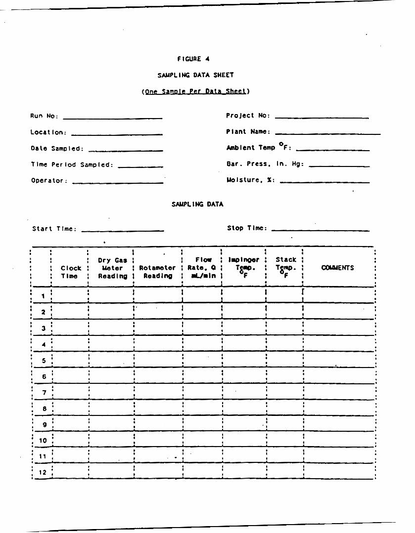
FIGURE 4
SAMPLING DATA SHEET
Run No: ProJect NO:
S W L I NG DATA
Plant Name:
- l e n t ~ e m p O F :
Bar. Press. I n . Hg:
Uolsture. I:
Stop T lne : S t a r t T lme:
, ..- llp1-r i sxacl: : ! !
’ CQDlENTS : Clock : Ueter : Rotameter : Rate. 0 : : Tllne : Reading I Reading : Urnin I
1
1 ,
I I I r 1 1 1 I I I 1 : 2 : I ’ I
; 1 : I
I I I
! ,
: 4 : I 1 *
, , !

I
I
.
I I I I I 0 10 10
TIME. mln

I
' . ., ..,. .. . ..

Aaymmatq Fanor .I BC
Thrraforr: Asymmrtry Factor I 3 I 1.1 11
FIGURE 7 . Pf3K A S W E T R Y W C l l U T I O N (13.2)

TkE ALME~A CORpORATiON
EPPENDIX N
USEPA
Draft Multiple Metals Method

A'ITACHMENT 2
EPA DRAPT MULTIPLE METAU METHOD
DRAFT 8/28/89
METHODOLOGY FOR THE DETERMINATION OF METALS ENISSIONS IN EXHAUST GASES
FROM HAZARDOUS lJASTE INCINERATION AND SIMILAR COMBUSTION PROCESSES
1. Applica.bi1ity Md P r i n c i p l e
1.1 App l i cab i l i t y . Th i s method is app l i cab le f o r t h e determinat ion of
t o t a l chromium ( C r ) . cadmium (Cd). a r sen ic ( A s ) . n i c k e l ( N i l . manganese (Mn).
beryllium (Be), copper (Cu) , z i n c (Zn). l ead (Pb) . selenium (Se) , phosphorus
(P) . thall ium ( T l ) , s i l v e r (Ag) , antimony (Sb) , barium (Da). and mercury (Hg)
emissions from hazardous wastc i n c i n e r a t o r s and similar combustion processes. This method may also bc used for the determinat ion of p a r t i c u l a t e emissions
rollowing the a d d i t i o n a l procedures descr ibed. Modif ica t ions to t h c sample
recovery and a n a l y s i s procedures descr ibed i n t h i s p ro toco l for t h e purpose of
determining par t icu la te emissions may p o t e n t i a l l y impact t h e f r o n t h a l f mercury
determination..
1.2 Pr inc ip l e . The s t a c k sample is withdrawn i s o k i n e t i c a l l y from t h e
source. with p a r t i c u l a t e emissions c o l l e c t e d i n t h e probc and on a heated
f i l t e r and gaseous emissions c o l l e c t e d i n a series of c h i l l e d impingers
conta in ing a s o l u t i o n of d i l u t e n i t r i c ac id i n hydrogen peroxide in. two impingers. and a c i d i c potassium permanganate so lu t ion i n two ( o r one) impingers. Sampling t r a i n components are recovered and d iges t ed i n separate f r o n t and back h a l f f r ac t ions .
d i w s t c d w i t h a c i d solutions to d i s so lve inorganics and to rcmovc organic
cons t i t uen t s t h a t may c r c a t e a n a l y t i c a l interfcrcnccs. Acid d i f ics t ion is
iicrCo:'mcd u s i n g conventional Parr" Domb o r microwilvc d i g c s t i o n tcchniqucs. 'nlc !iitc'ic ac id and hydrogen peroxide impinger s o l u t i o n . the a c i d i c potassium
!rcrmar.Sanate impinger s o l u t i o n . and t h e probc r i n s e and d iges t ed f i l t e r
so lu t ions nre nnalyzed f o r mercury by cold vapol' atomic nbsorpLion spcctroscopy
iCVrI t IS1.
Materials c o l l e c t e d i n t h e sampling t r a i n are
Except For t h e permanganatc s o l u t i o n . the rcmaindcv ol' t.he snmplinq
*!'icLci tests t o d a t c have sliowri t h a t ol' t lw LoLaI amount ol' mercury measured by t h e method, only 0 to < Z % w a s maasurcd i n tlrc f r o n t h a l f . Therefore . i t is ten ta t ive ly concluded. based on t h e above d a t a . t h a t p a r t i c u l a t e emissions may be measured by t h i s t r a i n , w i t h o u t significantly a l t e r i n g t h e mercury r e s u l t s .
1

.- ”
t r a i n ca tches are analyzed Tor C r . Cd. N i . Mn. Be . Cu. Zn. Pb. Se. P . T1. Ag.
Sb. Ba. and A s by induct ive ly coupled argon plasma emission spectroscopy ( I C A P )
or atomic absorpt ion spectroscopy (AAS). Graphi te furnace atomic absorp t ion
Spectroscopy (CFAAS) is used f o r a n a l y s i s o f antimony, a r s e n i c . cadmium. l e a d ,
Selenium, and thal l ium, i f these elements r e q u i r e greater a n a l y t i c a l
s e n s i t i v i t y than can be obtained by ICAP. Addi t iona l ly . if d e s i r e d . t h e tester may use AAS f o r analyses of a l l metals i f t h e r e s u l t i n g in - s t ack method
de tec t ion l i m i t s meet t h e goal o f t h e t e s t i n g program.
a l i q u o t s of each d iges ted sample r r a c t i o n CM be combined p ropor t iona l ly f o r a
single analyt ical determinat ion. The e f f i c i e n c y of t h e a n a l y t i c a l procedure is quan t i f i ed by the ana lys i s of sp iked q u a l i t y con t ro l samples con ta in ing each of the target metals including a c t u a l sample matr ix e f f e c t s checks.
For convenience,
2. Range. S e n s i t i v i t y , Prec is ion , and Interferences 2 .1 Range. For the analyses descr ibed i n t h i s methodology end f o r similar
ana lyses , the ICAP response is linear over s e v e r a l o r d e r s of magnitude.
ples conta in ing metal concentrations in t h e nanograms p e r mi l l i l i t e r (ng/ml) to micrograms pe r milliliter (ug/ml) range in t h e a n a l y t i c a l f i n i s h so lu t ion can be analyzed us ing t h i s technique. Samples con ta in ing greater than
approximately 50 ug/ml of chromium. lead. o r arsenic should be d i l u t e d to t h a t
level o r lower for f i n a l analysLs. Samples con ta in ing greeter than
approximately 20 ug/ml of cadmium should be d i l u t e d to t h a t l eve l before
ana lys i s .
Sam-
2.2 Analyt ical S e n s i t i v i t y . ICAP a n a l y t i c a l d e t e c t i o n l i m i t s for t h e
samplc so lu t ions (based on SW-8’16. Method 6010) arc approximately as roliovs:
Sb (52 n g i m l ) . A s (53 n g / m l ) . Oa ( 2 n g / m l ) . B e (0 .3 n g / m l ) . Cd (‘1 i i g / m l ) , C r (7 ng/ml). C u . ( 6 n s / m l ) . Pb (42 ng/ml). Mn ( 2 n g / m l ) . N i (15 n g / m l ) . P (75 i i g / m l ) .
Se (75 ng/ml). Ag (7 ng /ml ) . T i (40 n J m l ) . and Zn ( 2 n g / m l ) . ’I‘hc. a c t u a l
method de tec t ion limits are sample dependent and may vary as ttic samplc matrix
may afTcct t h e limits. The a n a l y t i c a l d e t c c t i o n limits for a n a l y s i s by d i r e c t
a sp i r a t ion AAS (bascd on SW-846. Mcthod 7000) arc approximately as Tollovs: Sb (200 1 i d m 1 1 . As ( 2 ng/ml). Ua (100 ng/ml). Be ( 5 n g / m l ) . Cd (5 ng/ml) . C r (50 ng/ml). Cu (20 n g / m l ) . Pb (100 ng/ml). Mn ( I O n g / m l ) . Ni (40 &nil). Se ( 2
n d m l ) . Ag (10 ng /mi ) . Tl (100 n g / m l ) . and Ln ( 5 n g / m l ) . The d e t e c t i o n l i m i t
for mercury by CVAAS’is approximately 0 . 2 ng/ml.
added s e n s i t i v i t y compared to the use of d r r e c r a s p i r a t i o n AAS for t h e The u s e of CFAAS can g ive
2

following metals: Sb ( 3 n g / m l ) . A s (1 ng/ml). B e (0.2 ng/ml). Cd (0.1 ngiml).
C r (1 ng/ml). Pb (1 n g / m l ) . Se ( 2 n g / m l ) . and T1 (1 n g / m l ) .
Using (1) t h e proccdures descr ibed i n t h i s method, ( 2 ) t h e a n a l y t i c a l
de tec t ion limits descr ibed i n t h e previous paragraph. ( 3 ) a volume of 3OO m l
f o r t h e f r o n t ha l f and 150 m l for the back h a l f samples. and (4) a s t a c k gas
sample volume of 1.25 m J . the corresponding in-s tack method d e t e c t i o n l i m i t s
a r e presented i n Table A - 1 and ca l cu la t ed as shown:
where: A = a n a l y t i c a l d e t e c t i o n l i m i t , ug /ml . B = volume of sample p r i o r to a l i q u o t for a n a l y s i s , m l . C = s t a c k sample volume, dscm (dsm]). D = in-s tack d e t e c t i o n l i m i t , ug/mI.
Values i n Table A - 1 a r e ca l cu la t ed for the f r o n t and back h a l f and/or t h e total
t r a i n . To ensure optimum s e n s i t i v i t y i n ob ta in ing t h e measurements. t h e ..... . - . ... - . . . . .. -__--I. .. - . _. - ... ' . . .
concentrpt ions of target metals i n t h e s o l u t i o n s are suggested to be a t least ten times t h e a n a l y t i c a l d e t e c t i o n l i m i t s . Under c e r t a i n cond i t ions . and wi th . greater care i n the a n a l y t i c a l procedure. t h i s concent ra t ion can be as l o w as
approximately t h r e e times t h e a n a l y t i c a l d e t e c t i o n l i m i t .
repetitive ana lyses , method of Standard a d d i t i o n s (MSA), serial d i l u t i o n . o r
--- - - I n a l l cases,
. . - ----- .. _. . . -
matrix sp ike addi t ion should be used t o e s t a b l i s h t h e q u a i i t y of t h e da ta .
Actual in-s tack method d e t e c t i o n l i m i t s w i l l be determined based on actual
source sampling parameters and a n a l y t i c a l r e s u l t s as descr ibed abovc. I f t'cquired. the method in-s tack d e t e c t i o n limits can be made more s c n s i i i v e than
those shown i n Table r\-l f o r a s p e c i f i c test by u s i n g one or morc o f ihc I'ollowing opt ions :
o A normal I-hour sampling run collects a s t a c k gas sampling volume o r
about 1.25 d. co l l ec t ed . t h e in -s tack method d e t e c t i o n limits would be o m I'ourth or t h e values shown i n Table A - 1 ( t h i s means t h a t with t h i s change.
method is four times more s e n s i t i v e tlmi normal).
The in-s tack de tec t ion l i m i t s assume t h a t a l l of t h e sample is digcsrcd
(with except ion of t h e a l i q u o t for mercury) and t h e f i n a l l i q u i d
volumes for ana lys i s a re 300 m l for t h e f r o n t ha l f and 150 m l for t h e
I f t h e sampling time is increased and 5 m J o r c
i h c
0
3

.. .
..
TABLE A - 1 . IN-STACK MtXHOD DETECTION LIMITS (ug/m') FOR T R A I N FRACTIONS USING ICAP AND AAS
F r o n t H a l f Back Half, Back Half, Frac t ion 1 Frac t ion 2 Frac t ion 3 To ta l T ra in
Metal Probe Md F i l t e r ' Impingers 1-3 Impingers 4-5
Antimony Arsenic Barium Beryllium Cadmium Chromium Copper Lead
Mercury N i c k e l Phosphorus Selenium S i l v e r Thallium Zinc
MMgMCSe
7.7 (0.7)' 3.8 (0.4)' 12.7 (0.3)' 6.4 (0.1). 0.5 0 . 3
1.7 (0.2)' 0.8 (0.1).
0.07 10.05). 0.04 (0.03)' 1.0 (0.02)' 0.5 (0.01).
11.5 (1.1). 19.1 (0.4)' 0.8 0.11 (0.08)'
2.5 (0.3)' 1.5 (0.03)'
1.4 0.7
0.5 (0.2). 0.2 (0.1 0.05.. o .03*.* 3.6 1.8
10.1 (0.2). 5.0 (0.1
18 9 18 (0.5)' 9 (0.3)' 1.7 0.9 9.6 (0.2)' 4.8 (0.1 0.5 0.3
2.1 15.1 (0.3)' 0.7 (0.3)''
. . 0.03.' 0.11.-
5.4 27
. 27 (0.8)' 2.6
0.8 14 .4 (0.3).
( ) * Detection l i m i t when analyzed by GFAAS. ** Detection l i m i t when analyzed by CVAAS.
Actual method in-s tack d e t e c t i o n l i m i t s w i l l b e determined based on actual source sampling parameters and a n a l y t i c a l results as descr ibed earlier i n this section.
back h a l f sample. If the f r o n t h a l f volume is reduced from 300 m l t o
30 m l . the f r o n t h a l f in -s tack d e t e c t i o n l i m i t s would be one t en th of t h e va lues shown above ( t e n times more s e n s i t i v e ) . If the back h a l f
volume is reduced from 150 m l t o 25 m l . t h e in-s tack d e t e c t i o n l i m i t s
would be one s i x t h of t h e above va lues . Matrix e f f e c t s c h c c k s arc
necessary on analyses of samples und t y p i c a l l y are or g r c a t c r signifi-
cance f o r samples t h a t have been concent ra ted t o less than t h c normal
sample volume. A volume less than 25 m l may n o t allow r e s o l u b i l i z n -
t i on of t h e res idue and may increasc i n t e r f e r e n c e by other compounds.
o When both or the above two improvoments are used on one samplc a t t h e
same time. the r e s u l t a n t improvements a r c m u l t i p l i c a t i v e . For example.
where s t a c k gas volume is increased by a f a c t o r of f i v e and the t o t a l
l i qu id sample d iges t ed volume of both the f ront and back ha lves is
reduced by f a c t o r of six. the in - s t ack method d e t e c t i o n l i m i t is
reduced by a factor of t h i r t y ( t h e method is t h i r t y times more s e n s i t i v e ) .
4

o Conversely, reducing s t a c k gas sample volume and i n c r e a s i n g sample
The f r o n t h a l f and back h a l f , l i q u i d volume w i l l i n c r e a s e l i m i t s .
samples (F rac t ions 1 and 2 ) can be combined p r i o r t o a n a l y s i s . The r e s u l t a n t l i q u i d volume (excluding F rac t ion 3 . which m u s t be analyzed
s e p a r a t e l y ) is recorded. Combining t h e sample as desc r ibed does not
allow determinat ion (whether f r o n t o r back h a l f ) of where i n t h e t r a i n
the sample was captured. The in-s tack method d e t e c t i o n l i m i t then
becomes a s ingle va lue for a l l metals except mercury. f o r which t h e
cont r ibu t ion of F rac t ion 3 must be considered.
o The above d i scuss ion assumes no blank co r rec t ion . Blank c o r r e c t i o n s
a r e discussed later i n t h i s method.
2.3 Prec is ion . The p r e c i s i o n s ( r e l a t i v e s t anda rd d e v i a t i o n ) f o r each
metal detected i n a method development test a t a sewage s ludge i n c i n e r a t o r . are as follows: Sb (12.7%). As (13.5%). B e (20.6%). Cd (11.5%). Cr (11.2%). Cu
(11.51). Pb (11.61). P (14.6%).. Se (15.3%). T1 (12.3%). and Zn (11.8%). Precis ion f o r n i c k e l was 7.7% for another test conducted a t a source s imula tor .
Beryllium. manganese and s i l v e r w e r e n o t de t ec t ed i n the tests; however, based
on the a n a l y t i c a l s e n s i t i v i t y of t h e ICAP for these metals. i t is assumed t h a t t h e i r p rec is ions should be similar to those for the other metals, when de tec t ed
a t similar l e v e l s .
The
2.4 In te r fe rences . Iron CM b e a spectral i n t e r f e r e n c e du r ing t h e
ana lys i s of a r sen ic . chromium. M d cadmium by ICAP. i n t e r f e rence dur ing the a n a l y s i s of a r s e n i c and l e a d by ICAP. in te r fe rences can be reduced by d i l u t i n g t h e sample. bu t t h i s i n c r c a s c s t h e
method de tec t ion l i m i t . Refer to EPA Method 6010 (SW-846) for d c t n i l s 01,
po ten t i a l i n t e r f e rences f o r th i s method. For all GFAAS ana lyscs . matr ix
Aluminum can be a s p e c t r a l
General ly . t hese
modifiers should be used to l i m i t i n t e r f e r e n c e s . and s t anda rds
matched.
3 . Apparatus
3.1 Sampling Tra in . A schematic of t h e s a m p l i n g t r a i n is
The sampling t r a i n A - 1 .
following components.
I t is similar to t h e Method 5 t ra in .
3.1.1 Probe Nozzle (Probe T ip ) and B o r o s i l l c a t e o r Q u a r t z
should be matrix
shown i t 1 Figure
consists ol' the
Glass Probe
Liner . Same a s Method 5 . Sec t ions 2.1.1 and 2.1.2.
unless an a l t e r n a t e probe t i p prevents the p o s s i b i l i t y of contaminat ion o r
Class nozz les are required
5

.-.. . .
. ..

interference o f t h e sample w i t h its materials of cons t ruc t ion . I f a probe t i p
o the r than g l a s s is used , no c o r r e c t i o n of t h e stack sample test results can be
made because of the effect on t h e r e s u l t s by t h e probe t i p .
Sec t ions 2 .1 'and 2.2. r e spec t ive ly .
a Teflon f i l t e r suppor t must be used to r e p l a c e t h e glass fri t .
3.1.2 P i t o t Tube and D i f f e r e n t i a l P res su re Gauge. Same as Method 2.
3.1.3 Filter Holder. Glass, same as Method 5. Sec t ion 2.1.5. except t h a t
3.1.4 F i l te r Heating System. Same as Method 5. Sec t ion 2.1.6. 3.1.5 Condenser. The following system s h a l l be used f o r t h e condensat ion
and c o l l e c t i o n of gaseous metals nnd f o r de te rmining the moisture con ten t of
t h e s t a c k gas. connected i n series with l eak - f r ee ground glass f i t t i n g s o r o t h e r l e a k - f r e e ,
non-contaminating f i t t i n g s . The f i r s t impinger is o p t i o n a l and is recommended
as a water knockout t r a p f o r u s e du r ing test cond i t ions which r e q u i r e such a
t r ap . The impingers to be used i n t h e metals t r a i n are now descr ibed . When
t h e f i r s t impinger is used as a water knockout, i t s h a l l b e appropr i a t e ly - s i r ed
f o r an expected large moisture c a t c h and c o n s t r u c t e d g e n e r a l l y as desc r ibed for the f irst impinger i n Method 5. Paragraph 2.1.7. first HNO,/H,O, impinger) s h a l l also be as desc r ibed for t h e f i r s t impinger i n
Method 5. impinger) s h a l l be t h e snme os t h e Greenburg Smith impinger with t h e scandard
t i p descr ibed as t h e second impinger i n Method 5. Paragraph 2.1.7. A l l o t h e r
impingers used i n the metals t r a i n are the same as t h e second impinger ( t h e
f irst HNO, /H,0, impinger ) p rev ious ly descr ibed i n t h i s paragraph.
t h e f i r s t impinger should be empty, t he second and t h i r d s h a l l con ta in known
q u a n t i t i e s of a n i t r i c acid/hydrogen peroxide s o l u t i o n (Sec t ion (1 .2 .1) . i.hc
fou r th (and f i f t h . if requ i r ed ) s h a l l con ta in a known q u a n t i t y of acidic
potassium permanganate s o l u t i o n (Sec t ion 4 . 2 . 2 ) . and t h e las t impirigcr : ;hall
conta in a known q u a n t i t y of s i l i c a gel or e q u i v a l e n t des i ccan t .
capable of measuring to wi th in 1OC (2-F) s h a l l be placed a t the o u t l e t ol' Lhc
l a s t inpinqer. When the water knockout i m p i n g c r is not necdcd. 1.1. is ~~i:nwvr!cI
l'rom t h e t r a i n and the o t h e r impingers remain t h e same. I f mercury ;Itlalysis I S
not needed, t h e potassium permanganate impingers are removed.
The condensing system should c o n s i s t of f o u r to s i x impingers
The second impinger ( o r t h e
The t h i r d impinger (or the impinger used as t h e second HNO,/H,O,
I n summary.
A Lhcrmomctcr
3.1.6 Eletering System, Barometer. and Cas Density Determination
Equipment. Same as Method 5 . Sec t ions 2 . 1 . 8 t h r o u g h 2.1.10. r e s p e c t i v e l y .

3.1.7 Teflon Tape. For capping openings and s e a l i n g connect ions on t h e
sampling t r a i n .
3.2 Sample Recovery. Same as Method 5. S e c t i o n s 2.2.1 through 2.2.8 (Nonmetallic Probe-Liner and Probe-Nozzle Brushes, Wash B o t t l e s , Sample
Storage Containers. P e t r i Dishes, Glass Graduated Cy l inde r , P l a s t i c S torage
C o n t a i n e r s . , F u ~ e l and Rubber Policeman. and Glass Funnel) . r e s p e c t i v e l y , with
t h e rollowing except ions and addi t ions :
3.2.1 Nonmetallic Probe-Liner and Probe-Nozzle Brushes. For q u a n t i t a t i v e
recovery of materials c o l l e c t e d i n the f r o n t h a l f of t h e sampling t r a i n .
Description of acceptab le a l l -Tef lon component brushes to be included i n EPA's
Emission Measurement Technical Information Cen te r (EMTIC) f i l e s .
3.2.2 Sample S torage Containers. Glass b o t t l e s with Tef lon- l ined caps.
1000- and 500-ml. s h a l l be used for KMnO,-containing samples and blanks.
Polyethylene b o t t l e s may be used for o t h e r sample types.
3.2.3 Graduated Cylinder. Glass or equivalent. 3.2.4 Funnel. Glass or equiva len t .
3.2.5 Labels. For i d e n t i f i c a t i o n of samples.
3.2.6 Polypropylene Tweezers and/or P l a s t i c Gloves. For recovery of t h e
filter from the sampling t r a in filter holder .
3.3 Sample Prepara t ion and Analysis. For the a n a l y s i s . t h e following equipment is needed:
3.3.1 Volumetric Flasks, 100 m l . 250 m l . and lo00 m l . For prepa ra t ion of
s tandards and sample d i l u t i o n .
3.3.2 Graduated Cylinders. For prepa ra t ion o f reagents .
3.3.3 Parr" Bombs or Microwave Pressure Re l i e f Vessels with Cappinl:
S t a t i o n ( C M Corporation model or equ iva len t ) .
3.3.4 Deakcrs and Watchglasses. 250 m l beakers f o r sample digestion w i t h
watchglasses LO cover t h e tops.
3.3.5 Ring S tands and Clamps. For secu r ing equipment sucii as f i l t r a t i o n apparatus.
3.3.6 F i l t e r Funnels. For holding f i l t e r paper.
3.3.7 Ldhatman 541 F i l t e r Paper ( o r e q u i v a l e n t ) . For r i l e r a t lo r1 ol'
digested samples.
3.3.8 3.3.9 Volumetric P ipe t s .
3.3.10 Analy t ica l Balance. Accurate LO w i t h i n 0.1 mg.
Disposable Pas teur P ipe t s and Bulbs.
a

3.3.11 Microwave or Conventional Oven. For h e a t i n g samples a t f ixed
Power l eve l s o r temperatures.
3.3.12 Hot P l a t e s .
3.3.13 Atomic Absorption Spectrometer ( A A S ) . Equipped w i t h a background
cor rec tor .
3.3.13.1.. Graphi te Furnace Attachment. With antimony, a r s e n i c . cadmium.
lead. selenium. tha l l ium, and hollow cathode lamps (HCLs) o r e l e c t r o d e l e s s
discharge lamps (EDLs). Same as E P A Methods 7041 (antimony), 7060 ( a r s e n i c ) .
7131 (cadmium), 7021 ( l e n d ) . 7740 (selenium). and 7841 ( t h a l l i u m ) .
3.3.13.2 Cold Vapor Mercury Attachment. With a mercury HCL or EDL. The equipment needed f o r t h e co ld vapor mercury at tachment inc ludes on n i r
r ec i r cu la t ion pump. a quar t z cell, an aerator appara tus . M d a hen t lump or des icca tor tube. The heat lamp should be capable of r a i s i n g t h e ambient
temperature a t t h e qua r t z ce l l by 10°C such t h a t no condensation forms on t h e
wall of the qua r t z ce l l . Same as EPA Method 7470. 3.3.14 Induct ive ly Coupled Argon Plasma Spectrometer. With either a
d i r e c t o r sequen t i a l r eade r and an alumina torch , Same as EPA Method 6010.
4. Reagents
Unless otherwise ind ica t ed , i t is intended that a l l reagents conform to the spec i f i ca t ions e s t a b l i s h e d by t h e Committee on Ana ly t i ca l Reagents of t h e
American Chemical Soc ie ty , where such s p e c i f i c a t i o n s are a v a i l a b l e ; o therwise ,
use the best a v a i l a b l e grade.
4 . 1 Sampling. The reagents used i n sampling are as follows:
4 . 1 . 1 Filtcrs. The f i l t e r s s h a l l conta in less than 1 . 3 ug/ in . - ' o f each or
t h e metals t o be mcasured. Analy t ica l resul ts provided by L'ilrcr manuTocturers
are acceptable. Ilowever. i f n o such r e s u l t s are a v a i l a b l c . f i l t c v blanks must
be analyzed T o r each target metal p r i o r to emission t e s t ing . 0unrt.z r ibcr or
g l a s s r ibe r r i l ters without o rgan ic binders s h a l l b e used. Thc I ' i lLcrs should
e x h i b i t a t least 99.95 percent e f f i c i e n c y (c0.05 Percent p e n c t m t i o n ) on 0 .3 micron d ioc ty l ph tha la t e smoke p a r t i c l e s . The f i l t e r e r r i c i e n c y I.usL slioL1 be
conducted i n accordance with ASTM Standard Method D2986-71 ( incorpora tcd by
reference) .
t h e f i l t e r material must be of a tYpe t h a t is unreac t ive t o SO. or SO, . a s described i n FPA Method 5. Quar tz f i b e r f i l t e r s meeting these requirements are recommended.
For p a r t i c u l a t e determinat ion i n sources conta in ing SO, o r SO,,
, .
9

.. .
.. ..
4.1.2 Water. To conform to ASTM S p e c i f i c a t i o n Dll93.77. Type I1 ( incorporated by reference). f i e l d use.
Analyze t h e water f o r a l l target metals p r i o r t o
A l l target metals should be less than 1 ng/ml.
4.1.3 Nitric Acid. Concentrated. Baker Ins t ra -ana lyzed or equ iva len t .
4.1.4 Hydrochloric Acid. Concentrated. Baker InStra-MalYzed or equiva len t . ,.
4.1.5 Hydrogen Peroxide, 30 Percent ( V / V ) .
4.1.6 Potassium Permanganate.
4.1.7 S u l f u r i c Acid. Concentrated.
4.1.8 S i l i c a G e l and Crushed Ice. Same as Method 5 . S e c t i o n s 3.1.2 and
3.1.4. respectively. 4.2 Pretest Prepara t ion for Sampling Reagents.
4.2.1 Nitric Acid (HNOl)/Hydrogen Peroxide (H,O,) Absorbing S o l u t i o n ,
5 Percent H N O ~ / ~ O Percent H,O,.
30 percent H,O, t o a 1 0 0 0 - m l vo lumetr ic f l a s k or graduated c y l i n d e r con ta in ing
approximately 500 m l of water. D i l u t e to volume with water. The reagen t s h a l l
con ta in less than 2 ng/ml of each target m e t a l .
Add 50 m 1 o f concent ra ted HNOl and 333 m l of '
4.2.2 Acidic Potassium Permanganate (KMnO, ) Absorbing S o l u t i o n , 4 Percent
KMnO, (W/V). Prepare f r e s h d a i l y . Dissolve 40 g of KMnO, i n s u f f i c i e n t 10 percent H,SO, to make 1 liter. degradat ion. The reagent s h a l l con ta in less than 2 ng/ml of Hg.
Precaut ion:
s o l u t i o n , f i l t e r the s o l u t i o n through Whatman 541 f i l t e r paper . Also. due to reaction of t h e potassium permanganate wi th t h e ac id . t h e r e may be p re s su re
bui ldup i n t h e sample s t o r a g e b o t t l e ; these b o t t l e s should n o t be f u l l y f i l l e d
and should bc vented b o t h to relieve excess pressure and prcvent cxplos ion duc
t o pressure buildup.
contamination of t h e sample: a No. 70-72 hole dr i l led i n t h c c o n t a i n e r cap and
Teflon l i n e r h a s been used.
n groduatcd c y l i n d e r conto in ing approximately 900 m l oI"untcr. Ili lutc? LO 1000
m l w i t h water. Mix w e l l . The reagent s h a l l con ta in less than 2 ng/ml 01. each
t a r g e t metal.
graduated c y l i n d e r con ta in ing 250 m l of water .
Mix well.
Prepare and store in glass b o t t l e s to prevent
To prevent a u t o c a t a l y t i c decomposition of the permanganate
Venting is h i g h l y recommended. but ' should n o t a l low
4.2.3 Nitric Acid. 0.1 N. Add 6.3 m l of concentroced HNO, (70 percent) t o
4.2.4 Hydrochloric Acid (HC1). 8 N. Add 690 m l of concen t r a t ed HCl to a
D i l u t e to 1000 m l w i t h water.
The reagent s h a l l con ta in less than 2 ng/ml o f Hg.
10

..-. ..
c ..
4.3 Glassware Cleaning Reagents.
4.3.1 N i t r i c Acid, Concentrated. F i s h e r ACS grade or e q u i v a l e n t .
4.3.2 Water. To conform t o ASTM S p e c i f i c a t i o n s D1193-77. Type XI. 4.3.3 N i t r i c Acid. 10 Percent ( V / V ) . Add 500 m l of concent ra ted HNO, t o a
graduated cy l inde r conta in ing approximately 4000 m l of water .
m 1 with water.
D i l u t e to 5000
4.4 4.4.1 Hydrochloric Acid. Concentrated.
4.4.2 Hydrofluoric Acid. Concentrated.
4.4.3 Nitric Acid. Concentrated. Baker Instra-analyzed or equ iva len t .
4.4.4 Nitric Acid. 10 Percent ( V / V ) .
Sample Digestion and Analysis Reagents.
Add 100 m l of concen t r a t ed "0, t o
800 m l of water . D i l u t e t o 1000 m 1 with water . Mix w e l l . Reagent s h a l l
contain l e s s than 2 ng/ml of each t a r g e t metal.
4.4.5 Nitric Acid. 5 Percent (V /V ) . Add 50 m l of concent ra ted HNO, to D i l u t e to 1000 m l wi th water . Reagent s h a l l conta in less 800 m l of water.
than 2 ng/ml of each t a r g e t metal. 4.4.6 Water. To conform t o ASlU S p e c i f i c a t i o n s Dl193-7?. Type XI. 4.4.7 Hydroxylamine Hydrochloride and Sodium Chloride So lu t ion . See E P A
4.4.8 Stannous Chloride.
4.4.9 4.4.10 S u l f u r i c Acid, Concentrated.
4.4.11 Nitric Acid. 50 Percent ( V / V ) .
4.4.12 Potassium P e r s u l f a t e . 5 Percent ( W / V ) .
4.4.13 Nickel N i t r a t e . Ni(N0,);6H20.
4.4.14 Lanthanum Oxide. La,O,.
4.4.15 A A S Grade Hg Standard. 1000 ug/ml .
4.4.16 A A S Grade Pb Standard. 1000 ug/ml.
4.4.17 AAS Grade A s Standard. 1000 u g / m l .
4.4.18 A A S Grade Cd Standard. 1000 ug/ml.
'1.4.19 AAS Grade Cr Standard. 1000 ug/ml.
4.4.20 AAS Grade Sb Standard, 1000 ug/ml.
4.4.21 A A S Grade Ba Standard, 1000 ug/ml . .
4.4.22 AAS Grade Be Standard. 1000 ug/ml .
4.4.23 AAS Grade Cu Standard, 1000 ug/ml.
4.4.24 A A S Grade Mn Standard, 1000 u g / m l .
Method 7470 f o r prepara t ion .
Potassium Permanganate. 5 Percent (W/V).
11

. ...
4.4.25 AAS Grade N i S tandard. 1000 ug/ml.
4 .4 .26 A A S Grade P S tandard , 1000 ug /ml .
4.4.27 AAS Grode Se Standord. LOO0 ug/ml .
4.4.28 AAS Grade Ag Standard. 1000 ug/ml.
4.4.29 AAS Grade T1 Standard, 1000 ug/ml.
4.4.30 .AAS Grade Zn Standard. 1000 ug/ml.
4.4.31 AI\s Grode A 1 Standord. 1000 ug/ml.
4.4.32 AAS Grode Fe Standard. 1000 ug/ml.
4.4.33 The metals s t anda rds may also be made from s o l i d chemicals as described i n EPA Method 200.7.
Analysis of Water and Westewoter.
t o f o r a d d i t i o n a l information on mercury s t anda rds .
EPA Method 7470 or Standard Methods f o r t h e
15th Ed i t ion , Method 303F should be r e f e r r e d
4.4.34 Mercury Standards and Q u a l i t y Con t ro l Samples. P repa re f r e s h
weekly a 10 ug/ml i n t e rmed ia t e mercury s t anda rd by adding 5 m l OF 1000 ug/ml
mercury s tock s o l u t i o n t o a 500 m 1 volumetr ic Flask: d i l u t e to 500 m l by F i r s t
adding 20 m l of 15 percent HNOl and then adding water. mercury s t anda rd s o l u t i o n Fresh d a i l y : add 5 m l of thc 10 ug/ml i n t e r m e d i a t e
s tandard to a 250 m l volumetr ic f l a s k and d i l u t e to 250 m l wi th 5 ml of
4 percent KMnO,. 5 m l o f 15 percen t HNOl. and then water. A t least s i x separate a l i q u o t s of t h e working mercury s t anda rd s o l u t i o n should b e uscd t o
prepare the s t anda rd curve. 'Ihese s l i q u o t s should c o n t a i n 0.0, 1.0. 2.0. 3.0. 4.0. Md 5.0 m l of t h e working s t anda rd s o l u t i o n .
should be prepared by making a separate 10 ug/ml s t anda rd and d i l u t i n g u n t i l i n
the range of t h e c a l i b r a t i o n .
Prepare a working
.
Q u a l i t y c o n t r o l samples
4.4.35 ICAP Standards and Q u a l i t y Control Samples. C a l i b r a t i o n s t anda rds
for ICAP a n a l y s i s can be combined in to fou r d i f f e r e n t mixcd s t anda rd s o l u t i o n s
a s shown below.
MIXED STANDARD SOLUTIONS FOR [CAP ANALYSIS
Solution Elcmcn ts
I1 On. cu. re I As. B e . Cd. Hn. Pb, Se. Zn
111 I V
~. - A l . C r . N i Ag. P . Sb. T1
Prepare these s t a n d a r d s by combining and d r l u t i n g t h e oppropr i a t e volumes of the 1000 ug/ml s o l u t i o n s wi th 5 percent nitric acid. A minimum OF one s t a n -
dard and a blank can be used to form each calibration curve. However. a
12

Separate q u a l i t y c o n t r o l sample spiked with known amounts o f t h e target metals
i n q u a n t i t i e s i n the midrange of the c a l i b r a t i o n c u r v e should be prepared.
Suggested s t anda rd leve ls are 50 ug/ml f o r A I . 25 ug/ml f o r C r and Pb, 15 ug/ml
f o r Fe. and 10 ug /ml f o r the remaining elements. S tandards c o n t a i n i n g less than 1 ug/ml'of metal should be prepared d a i l y .
than 1 ug/ml, o f metal should be s t a b l e f o r a minimum o f 1 to 2 weeks.
S tandards c o n t a i n i n g greater
4.4.36 Graphi te Furnace Ak Standards for Antimony, Arsenic , Cadmium,
Lead, Selenium. and Thallium. Prepare a 10 ug/ml s t anda rd by adding 1 m l o f
1000 ug/ml s t anda rd to a 100 m l volumetric f l a s k . D i l u t e to 100 m l with 10
percent n i t r i c acid. For g r n p h i t e Turnace AAS. t h e s t a n d a r d s must b e matr ix
matched; e.g.. i f t h e samples conta in 6 percent n i t r i c a c i d and 4 pe rcen t
hydrof luor ic ac id . t h e s t anda rds should also be made up w i t h 6 p e r c e n t n i t r i c
ac id Md 4 percent hydro f luo r i c ac id . Prepare a 100 ng/ml s t a n d a r d by adding
1 m l of the 10 ug/ml s t anda rd to a 100 m l volumetr ic f l a s k and d i l u t e to 100 m l
wi th the appropr i a t e ma t r ix s o l u t i o n .
d i l u t i o n of the 100 ng/ml s t anda rds . A t least f i v e s t a n d a r d s should be used t o
make up the s t anda rd curve. Suggested levels are 0 . 10. 50. 75. and 100 ng/ml.
Q u a l i t y c o n t r o l samples should be prepared by making a separate 10 ug/ml
s tandard and d i l u t i n g u n t i l i t is i n t h e range o f ' t h e samples. ' S tandards
conta in ing less than 1 ug/ml or metal should be prepared d a i l y .
conta in ing greater than 1 ug/ml o f metal should b e s t a b l e for a m i n i m u m o f 1 t o
2 weeks.
Other s t a n d a r d s should be prepared by
.
Standards
4.4.37 Matrix Modifiers.
4.4.37.1 Nickel N i t r a t e . 1 Percent ( V / V ) . Dissolve 4.956 g o f
N i ( N O J ) ; 6 H , 0 i n approximately 50 m l of water i n a 100 m l vo lumetr ic f l a s k .
D i l u t e t o 100 m l w i t h water.
4.4.37.2 Nickel N i t r a t e . One- t en th P e r c e n t (V/V). D i l u t e 10 m l of 1 per -
cen t n i c k e l nitrate s o l u t i o n to 100 m l with water. I n j e c t m equa l amount of
sample and t h i s modi f ie r i n t o t h e g raph i t e furnace du r ing A A S a n a l y s i s f o r A s .
4 . 4 . 3 7 . 3 Lanthanum.. Dissolve 0.5864 g of La,O, i n 10 m l of concent ra ted
HNOJ and d i l u t e to 100 m l w i t h water.
t h i s modifier i n t o t h e g r a p h i t e furnace dur ing A A S a n a l y s i s f o r Pb.
In jec t an equal m o u n t o f sample and
5. Procedure
5.1 Sampling. The complexity of t h i s method is such t h a t . to o b t a i n reli- ab le results. testers should be t r a ined e d experienced wi th t h e test procedures.

5.1.1 Pretest Preparat ion. Follow t h e same g e n e r a l procedure g iven i n
Method 5. Sec t ion 4 . 1 . 1 . except t h a t , un le s s p a r t i c u l a t e emiss ions are to be
determined. t h e f i l t e r need n o t be des i cca t ed or weighed. A l l sampling t r a i n
glassware should f irst be r i n s e d w i t h h o t t ap water and then washed i n ho t
soapy water. 'Next . glassware should be r i n s e d t h r e e times wi th t a p water ,
followed by t h r e e a d d i t i o n a l r i n s e s with water. A l l glassware should then be
soaked i n a 10 percent (V /V ) n i t r i c a c i d s o l u t i o n for a minimum of 4 hours ,
r i n sed t h r e e times w i t h water. r i n s e d a f i n a l time wi th acetone. and allowed
t o a i r dry .
covered u n t i l t he sampling t r a i n is assembled. pr ior t o sampling.
A l l glassware openings where contaminat ion CM occur should be
5.1.2 Prcl iminnry Determinations. Same as Method 5. S e c t i o n 4.1.2.
5.1.3 Prepara t ion of Sampling Tra in . Follow t h e same g e n e r a l procedures
given i n Method.5. Sec t ion 4.1.3. except p l ace 100 m l of t h e n i t r i c
acidlhydrogen peroxide s o l u t i o n (Sec t ion 4.2.1) i n t h e t w o HNO,/H,O, impingers
(normally the second and t h i r d impingers ) , p l a c e 100 m l of t h e a c i d i c potassium
permanganate s o l u t i o n (Sec t ion 4.2.2) i n t h e f o u r t h and f i f t h impinger. and
transfer approximately 200 to 300 g o f preweighed si l ica gel f r o m i ts con ta ine r
to t h e last impinger. A l t e rna t ive ly . t h e si l ica gel may be weighed d i r e c t l y i n
t h e impinger j u s t prior to t r a i n assembly.
Seve ra l op t ions arc a v a i l a b l e to the tester based on t h e sampling
condi t ions . The use o f an empty f i r s t impinger can be e l imina ted i f the
moisture to be c o l l e c t e d i n t h e impingers is c n l c u l a t e d o r determined to be
less than 150 m l . The tester s h a l l inc lude two impingers c o n t a i n i n g t h e
a c i d i c potassium permanganate s o l u t i o n f o r t he f i r s t test run. u n l e s s pos t
t e s t i n g experience a t the same or similar sources h a s shown tha t o n l y one is
necessary. The last permanganate impingcr may be d iscorded i f both
permanganate impingers have r e t a i n e d t h e i r or iginal deep pu rp le permanqonote
color. A m a x i m u m o f 200 m 1 i n each permanganate impinger (and a maximum of th ree permanganate impingers ) may be used. i f necessary. to maintain t h e
d e s i r e d color i n t h e last permanganate impinger.
Retain for reagent blanks. 100 m l o f t h e n i t r i c ucid/hydrogen peroxide
s o l u t i o n and 100 m l of the a c i d i c potassium permanganate s o l u t i o n .
s o l u t i o n s should be ' labeled and t r e a t e d as. descr ibed i n S e c t i o n 7 . ' Set up the
sampling t r a i n as shown i n Figure A-1.
sampling t r a i n connect ions. Tef lon t ape should be used i n s t e a d o f s i l i c o n e
grease to prevent contamination.
These
I f necessary to e n s u r e l e a k - f r e e
14

Precaut ion: Extreme care should be taken to prevent contaminat ion wi th in
t h e t r a i n . Prevent t h e mercury c o l l e c t i o n r eagen t ( a c i d i c potassium
permanganate) from con tac t ing any glassware of t h e t r a in which is washed and
analyzed f o r Mn. Prevent hydrogen peroxide from mixing with the a c i d i c
potassium permanganate.
5.1.4 L.eak-Check Procedures. Follow t h e leak-check procedures given i n Method 5. Sec t ion 4.1.4.1 ( P r e t e s t Leak-Check). S e c t i o n 4.1.4.2 (Leak-Checks
During the Sample R u n ) , and Sec t ion 4.1.4.3 (Pos t -Tes t Leak-Checks).
5.1.5 Sampling Tra in Operation. Follow t h e procedures given i n Method 5. For each run. record t h e d a t a r e q u i r e d on a d a t a s h e e t such as Sect ion 4.1.5.
the one shown i n Figure 5-2 of Method 5. 5.1.6 Calcula t ion of Percent I s o k i n e t i c . Same as Method 5. S e c t i o n 4.1.6. 5.2 Sample Recovery. Begin c leanup procedures as soon as t h e probe is
removed from the s t a c k a t t h e end of a sampling per iod .
The probe should be allowed t o cool p r i o r to sample recovery. \#hen i t can be s a f e l y hnndled. wipe off a l l external p a r t i c u l a t e matter n e a r t h e t i p of the probe nozz le and p lace a rinsed, non-contaminating cap over t h e probe
nozzle t o prevent los ing or gaining p a r t i c u l a t e matter. .Do not cap t h e probe
t i p t i g h t l y while the sampling t r n i n is cooling. to form i n t h e f i l t e r ho lder , thus causing t h e undes i red r e s u l t of drawing
l i q u i d from t h e impingers i n t o t h e f i l t e r .
This normally causes a vacuum
Before moving the sampling t r a i n to t h e c leanup site, remove t h e prube from the sampl ing ' t r a in and cap t h e open ou t l e t . condensate t h a t might be p re sen t . Cap t h e f i l t e r i n l e t where t h e probe was
Fastened. Remove t h e umbi l ica l cord From t h e last impinger and cap t h e
impinger. Cap off the f i l t e r ho lder o u t l e t and impinger i n l e t . Use non-
contaminating caps , whether ground-glass stoppers. p l a s t i c caps . se rum caps.
o r Teflon tape to c l o s e these openings.
B e careful n o t to lose any
Al t e rna t ive ly . the t r a i n cah be disassembled b e f o r e . t h e probe and f i l t e r
holder/oven are completely cooled. i f t h i s procedure is followed: I n i t i a l l y
disconnect t h e f i l t e r holder o u t l e t / i m p i n g e r i n l e t and loose ly cap t h e open ends. Then d isconnec t the probe from t h e f i l ter holder o r cyclone i n l e t and
loose ly cap the open ends. Cap t h e probe t i p y d remove t h e umbi l ica l cord as previously descr ibed .
Transfer t h e probe and Fi l te r - impinger assembly to a cleanup area t h a t is
clean and p ro tec t ed from t h e wind and o the r p o t e n t i a l causes of contamination
15

or loss of sample.
any abnormal condi t ions . The sample is recovered and t r e a t e d a s fol lows (see schematic i n Figure A - 2 ) . Assure t h a t ' a l l items necessary f o r recovery of the
sample do not contaminate it.
Inspec t t h e t r a i n before and du r ing disassembly and note
5.2.1 Container No., 1 ( F i l t e r ) . Ca re fu l ly remove t h e f i l t e r from the
rilter holder and p lace it i n its i d e n t i f i e d p e t r i d i s h con ta ine r .
washed polypropylene or Teflon coated tweezers or c lean . d i sposab le surgical gloves r insed w i t h water should be used t o handle t h e f i l ters. If i t is necessary t o fo ld t h e f i l t e r , make c e r t a i n t h e particulate cake is i n s i d e t h e
fold. Carefu l ly transrer the f i l t e r and any p a r t i c u l a t e matter or f i l t e r
f i b e r s t h a t adhere t o the f i l t e r ho lder g a s k e t to t h e p e t r i d i s h by u s i n g a d ry
(acid-cleaned) nylon b r i s t l e brush. Do n o t use any metal-containing materials
when recovering t h i s t r a i n . Seal t h e l a b e l e d p e t r i d i sh .
Acid-
5.2.2 Container No. 2 (Acetone Rinse) . Tnking care to see t h a t d u s t on t h e . o u t s i d e of the probe or o t h e r exterior s u r f a c e s does n o t get i n t o t h e
sample, q u a n t i t a t i v e l y recover par t iculate matter and any condensate from t h e
pmbe nozzle . probe f i t t i n g , probe l i n e r . and f r o n t h a l f of t h e f i l t e r ho lde r
by washing these components wi th 100 m l o f ace tone and p l a c i n g t h e wash i n a glass conta iner .
subsequent blank co r rec t ion pmcedures .
acetone when approved by t h e Adminis t ra tor and s h a l l be used when ' spec i f i ed .by
t h e Administrator: i n these cases. save a water blank and fol low t h e
Adminis t ra tor ' s d i r e c t i o n s on ana lys i s . Perform t h e acetone r i n s e s as follows:
Carefu l ly remove t h e probe nozzle and c lean t h e i n s i d e s u r f a c c by r i n s i n g w i t h
acetone from a wash b o t t l e and brushing w i t h a nonmetal l ic brush. Urush u n t i l
t h e acetone r i n s e shows no v i s i b l e particles. a f t e r which makc a f i n a l r i n s e of
t h e i n s ide su r face w i t h acetone.
Note: The use o f . e x a c t l y 100 ml is necessary f o r the
Disti l led w a t e r may be used i n s t e a d of
Brush and r i n s e the i n s i d e parts of t h e Swogelok I ' i t t i n g w i L l i acetone i n a
similar way u n t i l no v i s i b l e p a r t i c l e s remain.
Rinse the probe l i n e r with acetone by t i l t i n g and r o t a t i n g t h e probe w h i l e
s q u i r t i n g acetone i n t o its u p p e r end so t h a t a l l i n s i d e s u r f a c c s w i l l b e w e t t e d
with acetone. Allow t h e acetone to d r a i n from the lower end i n t o t h e sample
conta iner . A funnel may be used to a i d i n t r a n s f e r r i n g l i q u i d washings t o the
container. Follow t h e acetone r i n s e w i t h a nonmetallic probe brush. Hold t h e
probe i n an inc l ined pos i t ion . s q u i r t acetone i n t o t h e upper end as t h e probe
brush is being pushed w i t h a twis t ing a c t i o n through the probe: ho ld a sample
16

I 4 al
2 C
L W C .4 m Y C 0 U
111 W u m U
'0 C
%
.4
.4
111 al v) al
C L m
C .r(
L W P 2 z
5 m
n
e

con ta ine r underneath the lower end of t h e probe, and c a t c h any ace tone and
p a r t i c u l a t e matter which is brushed through t h e probe t h r e e times or more u n t i l no v i s i b l e p a r t i c u l a t c matter is c a r r i e d o u t wi th t h e ace tone o r u n t i l none
remains i n t h e probc l i n e r on v i s u a l i n spec t ion . Rinse t h e brush w i t h ace tone ,
and q u a n t i t a t i v e l y c o l l e c t t h e s e washings i n t h e sample c o n t a i n e r . . A f t e r t h e
brushing. make a f i n a l acet.one r i n s e o f t h e probe as desc r ibed above.
I t is recommended t h a t two people c l e a n t h e probe t o minimize sample
lo s ses . Between s i m p l i n g runs. keep brushes clean and p r o t e c t e d from
contamination.
Clean the i n s i d e of t h e f r o n t ha l f of t h e f i l t e r ho lde r by rubbing t h e
s u r f a c e s w i t h a nonmetal l ic nylon b r i s t l e brush and r i n s i n g w i t h acetone.
Rinse each s u r f a c e thrce times or more if needed t o remove v i s i b l e p a r t i c u l a t e .
Mnke a f i n a l r i n s e of t h e brush and f i l t e r holder .
and p a r t i c u l a t e matter have been collected i n t h e sample c o n t a i n e r . t i g h t e n the
l i d on t h e sample con ta ine r so t h a t ace tone w i l l n o t leak o u t when i t is shipped to t h e labora tory . Mark the h e i g h t of the f l u i d l e v e l to determine
whether or n o t lenkage occurred du r ing t r a n s p o r t .
' to i d e n t i f y its contents .
After a l l ace tone washings
Label the c o n t a i n e r c l e a r l y
5.2.3 .Container No. 3 (Probe Rinse) . R inse t h e probe l i n e r . probe nozz le ,
and f r o n t h a l f of the f i l t e r ho lde r thoroughly w i t h 100 ml of 0.1 N n i t r i c a c i d
ond p lace the wash i n t o a sample s t o r a g e con ta ine r .
100 m l is necessary f o r the subsequent blank c o r r e c t i o n procedures .
the r i n s e s a s descr ibed i n Method 12. S e c t i o n 5.2.2. combined r i n s e . Mark t h e h e i g h t o f t h e f l u i d l e v e l on the o u t s i d e of t he
s t o r a g e con ta ine r and use t h i s mark t o determine if leakage occurs d u r i n g
trmsport. Sea l t h e con ta ine r and c l e a r l y l a b e l t he con ten t s . F i n a l l y . r i n s c
the nozzle. probe l i n e r . nnd f r o n t h a l f of t h e f i l t e r ho lde r w i t h w a t c r
followed by acetone and d i s c a r d these r i n s e s .
&: The use of e x a c t l y
Perform
Record t h e volume o f t h e
5.2.4 Container No. 4 (Impingers 1 th rough 3. Contents and R i n s e s ) . Due .
t o t h e large q u a n t i t y of l i q u i d involved. t h e tester may p l a c e t h e impinger
so lu t ions i n more than one con ta ine r . Measure t h e l i q u i d i n t h e f i r s t three
impingers vo lumetr ica l ly t o w i t h i n 0 .5 m l u s i n g a graduated c y l i n d e r .
t h e volume of l i q u i d p re sen t .
moisture conten t of t h e sampled f l u e gas. Clean each o f t h e f i r s t three
impingers. the f i l t e r suppor t . t h e back h a l f o f t h e f i l t e r housing. and
connect ing glassware by thoroughly r i n s i n g w i t h LOO m l of 0.1 N n i t r i c ac id a s
18
Record
This information. is requi red to c a l c u l a t e t h e

descr ibed i n Method 12. Sec t ion 5.2.4.
N n i t r i c ac id r i n s e is necessary f o r the subsequent blank c o r r e c t i o n
Procedures. Combine t h e r i n s e s and impinger s o l u t i o n s . measure and record t h e
Volume. Ca lcu la t e the 0.1 N n i t r i c a c i d r i n s e volume by d i f f e r e n c e . Mark the
he ight of t h e f l u i d l e v e l on t h e o u t s i d e of t h e c o n t a i n e r to determine if
leakoge occurs du r ing t r anspor t . Seal the c o n t a i n e r and c l e a r l y l a b e l t h e
con t e n t s .
Note: The u s e of e x a c t l y 100 m l of 0.1
5.2.5 Conta iner No. 5 (Acid i f ied Potassium Permanganate S o l u t i o n and
Rinses. Impingers No. 4 & 5). Pour all the l i q u i d from t h e permanganate
impingers ( f o u r t h and f i f t h . if two permanganate impingers are used) i n t o a
graduated c y l i n d e r and measure the.volume to w i t h i n 0.5 ml. T h i s information
is required to c a l c u l a t e the moisturc c o n t e n t of t h e sampled f l u e gas. Using
100 m l t o t a l of the a c i d i f i e d potassium permanganate s o l u t i o n , r i n s e the
permanganate impinger (s ) and connect ing glass pieces a minimum of three times.
Combine the r i n s e s with the permanganate impinger s o l u t i o n . F i n a l l y , r inse the
permanganate impinger (s ) and connect ing glassware wi th 50 m l of 8 N HC1 to remove any res idue . Note: The use of exactly 100 m l and 50 m l for t h e two r i n s e s is necessary for the subsequent blank c o r r e c t i o n procedures . . P l a c e t h e
combined r i n s e s and impinger con ten t s i n a l a b e l e d glass storage b o t t l e . Mark
the he igh t of t h e f l u i d l e v e l on t h e o u t s i d e of the bottle to determine i f
leakage occurs du r ing t r anspor t .
Paragraph 4.2.2 and properly seal t h e bottle and clearly l a b e l t h e con ten t s .
See'the fo l lowing no te and t h e Precaut ion i n
- Note: Due to the p o t e n t i a l r e a c t i o n of t h e potassium permanganate wi th the
acid. the re may be pressure bui ldup i n the sample storage b o t t l e s . These
b o t t l e s should no t be f i l l e d f u l l and should be vented to r e l i e v e excess
pressure. Venting i s highly recommended. A No. 70-72 h o l e d r i l l e d i n t h c
con ta ine r cap and Teflon l i n e r has been found to allow adequate vent ing without
loss of sample.
5 . 2 . 6 Container No. 6 (Silica Gel). Note t h e color o f the ind ica t inc :
s i l ica gel to determine whether i t has been completely s p e n t and make a
nota t ion of its condi t ion . T rans fe r the s i l i ca gel from its impinger to i t s
original con ta ine r and s e a l . The tester may use a funnel to pour t h e s i l i c a
gel and a rubber policeman to remove the si l ica gel from t h e impinger.
small amount of p a r t i c l e s t h a t may adhere to t h e impinger w a l l need not be
removed. Do n o t u se water or o t h e r l i q u i d s to t r a n s f e r t h e s i l i ca gel since
weight gained i n t h e s i l i c a gel impinger is used for mois ture c a l c u l a t i o n s .
me
19

Alternot ive ly . if a balance is a v a i l a b l e i n t h e f i e l d , record the weight of
t h e spent s i l i ca gel (or s i l i c o gel p lus impinger) t o . t h e n e a r e s t 0.5 g .
5.2.7 Contoiner No. 7 (Acetone Blank). Once d u r i n g each f i e l d t e s t , place
100 m l of the acetone used i n t h e sample recovery process i n t o a l abe led conta iner f o r use i n t h e r r o n t h a l f f i e l d r eagen t blank. Seal t h e con ta ine r .
5.2.8 Cpntainer N o . 8 (0.1 N Nitric Acid B l a n k ) . Once du r ing each f i e l d
t e s t , place 200 m l o f the 0.1 N n i t r i c a c i d s o l u t i o n used i n t h e sample
recovery process i n t o a l abe led conta iner f o r u se i n t h e r r o n t h a l f and back
ha l f f i e l d reagent blanks. S e a l the con tn ine r .
5.2.9 Container No. 9 (5Z Nitric Acid/lO% Hydrogen Peroxide Blank) . Once
during each f i e l d t es t , ploce 200 m l of t h e 5% n i t r i c acid/ lO% hydrogen
peroxide s o l u t i o n used as t h e n i t r i c a c i d impinger r eegen t i n t o o lobe led
conta iner for use i n the back h a i r f i e l d r eagen t blank. Seal the con ta ine r .
5.2.10 Container No. 10 (Acid i f ied Potassium Permanganate B l a n k ) . Once
du r ing each f i e l d test . place 300 m l of t h e a c i d i f i e d potassium permanganate
s o l u t i o n used as the impinger s o l u t i o n and i n t h e sample recovery process i n t o
a labe led c o n t a i n e r f o r u s e i n t h e back h a l f f ie ld reagen t blank f o r mercury
analysis . . S e a l t h e con ta ine r .
- Note: This c o n t a i n e r should be vented. as desc r ibed i n S e c t i o n 5.2.4. to r e l i e v e excess pressure .
5.2.11 Container No. 1 1 ( 8 N HCl 8 l a n k ) . Once d u r i n g each r i e l d test,
place 50 m l o f the 8 N hydrochlor ic a c i d used to r i n s e the a c i d i r i e d potassium
permanganate impingers i n t o a l abe led c o n t a i n e r for use i n t h e back h a l f
reagent blank f o r mercury.
5.2.12 Container No. 12 ( F i l t e r Blank). Once d u r i n g each f i e l d test.
place an unused f i l t e r from t h e same lo t os t h e s a m p l i n g f i l ters i r r u lnbclcd
p e t r i d i sh . Sea l t h e p e t r i d i sh ; This w i l l bc used i n t h e f r o n t hair I ' icld
reagent blank. . ._ 5.3 ,Sample P repa ra t ion . Note t h e l e v e l of the l i q u i d i n eoch of t h e
conta iners and determine i f any sample w a s los t d u r i n g shipment. I f a
noticeable amount of leakage . h a s occurred. e i t lwr void t h e samplc or IISC
methods. s u b j e c t to the approve1 of t he A d m i n i s t r a t o r . t o correct t h c I ' inal
results. A diagram i l l u s t r a t i n g sample P rcpa rq t ion and a n a l y s i s procedures f o r
each of the sample t r a i n components is shown i n F igure A - 3 . 5 .3 .1 Container No. 1 ( F i l t e r ) . I f p a r t i c u l a t r e emissions are being
determined, then d e s i c c a t e t h e f i l t e r and f i l t e r c a t c h without h e a t and weigh to
20
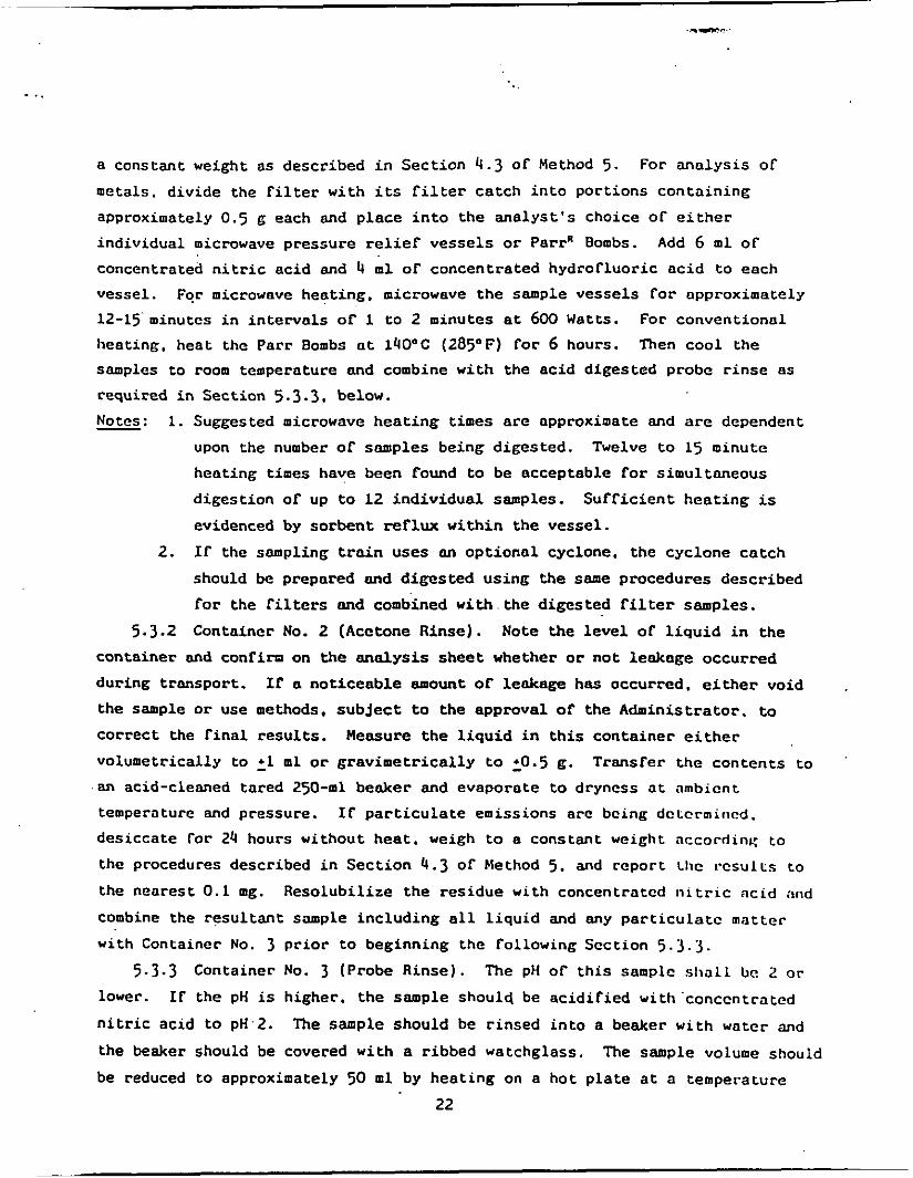
- ..
a cons tan t w e i g h t as descr ibed i n S e c t i o n 4.3 Of Method 5. metals , d iv ide t h e f i l t e r wi th its f i l t e r c a t c h i n t o po r t ions c o n t a i n i n g approximately 0 .5 6 each and p l ace i n t o t h e a n a l y s t ' s choice o f e i t h e r
ind iv idua l microwave p res su re relief v e s s e l s or Par rR Bombs.
concentrated n i t r i c a c i d and 4 m l o f concent ra ted hydro f luo r i c a c i d t o each
vesse l . For microwave hea t ing . microwave t h e sample v e s s e l s f o r approximately 12-15'minutcs i n i n t e r v a l s of 1 t o 2 minutes a t 600 Watts. heating. hea t the Pa r r Bombs a t 140°C (285°F) f o r 6 hours. Then c o o l t h e
samples t o room temperature M d combine wi th the a c i d d iges t ed probe r i n s e a s
required i n Sec t ion 5.3.3. below.
- Notes:
For m a l y s i s of
Add 6 m l OF
For convent iona l
1. Suggested microwave h e a t i n g times are approximate and are dependent
upon the number of samples being d iges t ed . Twelve to 15 minute
hea t ing times have been found to be acceptab le for s imul taneous
d i g e s t i o n of up to 12 i n d i v i d u a l samples.
evidenced by s o r b e n t r e f l u x w i t h i n t h e ves se l .
I f the sampling t r a i n uses an o p t i o n a l cyclone, the cyc lone c a t c h
should be prepared and d i g e s t e d u s i n g t h e same procedures descr ibed
f o r t h e f i l t e r s and combined w i t h . the d iges t ed f i l t e r samples.
S u f f i c i e n t h e a t i n g is
2.
5 .3 .2 Container No. 2 (Acetone Rinse) . Note the l e v e l o f l i q u i d i n t h e
con ta ine r and conf i rn on the a n a l y s i s s h e e t whether or n o t leakage occurred dur ing t ranspor t .
the sample o r use methods, s u b j e c t t o t h e approval o f t h e Administrator. to
correct the f i n a l results. Measure t h e l i q u i d i n t h i s c o n t a i n e r e i t h e r
volumetr ical ly t o '1 m l or g r a v i m e t r i c a l l y to 20.5 6.
If n n o t i c e a b l e amount of leakage has occurred , e i t h e r void
Trans fe r t h e c o n t e n t s t o
.an acid-cleaned t a red 2 5 0 4 1 beaker and evapora te to dryness a t nmbicnt
temperature and pressure. I f p a r t i c u l a t e emissions a r c bcing dctcrmincd.
des i cca t e fo r 24 hours without hea t . weigh to a cons tan t w e i g h t nccorriinK t o
the procedures descr ibed i n S e c t i o n 4 . 3 of Method 5. and r epor t Ll ic results t o
the neares t 0.1 mg. Reso lub i l i ze t h e r e s i d u e with concentratcd n i t r i c ac id ntld
combine t h e r e s u l t a n t sample i n c l u d i n g a l l l i q u i d and any p a r t i c u l a t c mat te r
w i t h Container No. 3 prior to beginning the fol lowing Sec t ion 5.3.3. 5 . 3 . 3 Container No. 3 (Probe R i n s e ) . The PH o f t h i s samplc shall be 2 OF
lower.
n i t r i c ac id to pH.2.
the beaker should be covered wi th a r ibbed watchglass .
be reduced to approximately 50 m l by h e a t i n g on a ho t p l a t e a t a temperature
IF the pH is higher . t h e sample should be a c i d i r i e d wi th ' conccn t r a t ed
The sample should be r i n s e d i n t o a beaker wi th water and
The sample volume should
22

j u s t below b o i l i n g . Inspect the sample f o r v i s i b l e p a r t i c u l a t e matter, and
depending on the r e s u l t s of t h e in spec t ion . perform one of t h e Collowing. If no
particulate matter is observed. combine t h e sample d i r e c t l y with t h e a c i d
d iges ted po r t ions of the f i l t e r prepared p rev ious ly i n Sec t ion 5.3.1. If particulate matter is observed, d i g e s t t h e sample i n microwave v e s s e l s o r Pa r rn
Bombs follosqing t h e procedures descr ibed i n S e c t i o n 5.3.1: then combine t h e
resul tant sample d i r e c t l y wi th t h e ac id d i g e s t e d po r t ions of t h e f i l t e r prepared
previously i n Sec t ion 5.3.1. The r e s u l t a n t combined sample i s r e f e r r e d to as Frac t ion 1. F i l t e r t h e combined s o l u t i o n of t h e acid d iges t ed f i l t e r and probe
r inse samples us ing Whatman 541 f i l t e r paper. D i l u t e t o 300 m l (or t h e
appropr ia te volume foc t h e expected metals concen t r a t ion ) w i th water. Measure
and record t h e combined volume of the F rac t ion 1 s o l u t i o n to wi th in 0.1 m l .
Q u a n t i t a t i v e l y remove a 50 m l a l iquot and l a b e l as F rac t ion 1B. Label t h e
remaining 250 ml por t ion as Frac t ion 1 A . F r a c t i o n 1 A is used f o r ICAP o r AAS ana lys i s . F rac t ion 1B is used f o r t h e de te rmina t ion o f f r o n t h a l f mercury.
5.3.4 Container No. 4 (Impingers 1-31. Measure and record t h e total vol- ume o f this somple (F rac t ion 2 ) to wi th in 0.5 ml. mercury a n a l y s i s and l a b e l as Frac t ion 28.
Container No. 4 as Frac t ion ZA. analyzed as descr ibed i n Section 5.4.3. If necessary. use concentrated n i t r i c a c i d to lower F rac t ion 2A to pH 2. ?he sample should be r insed i n t o a beaker wi th w a t e r and t h e beaker should be
covered with a r ibbed watchgloss. The sample volume should be reduced to
approximately 20 &by h e a t i n g on a h o t p la te a t a temperature j u s t below '
boi l ing .
5.3.4.1 and 5.3.4.2. below.
Remove a 50 m l a l i q u o t for Label t h e remaining p o r t i o n of
The f r a c t i o n 28 a l iquot should be prepared and
F r a c t i o n ZA s h a l l be pH 2 or lover.
Then follow e i t h e r of t h e d i g e s t i o n procedures desc r ibed i n Sections
5.3.4.1 Conventional Digest ion Procedure. Add 30 m l ol' 50 p e r c e n t n i t r i c ac id and h e a t f o r 30 minutes on a ho t plate t o j u s r below b o i l i n g . Add 10 m l o f
3 percent hydrogen peroxide and hea t f o r 10 mcre m i n u t e s . Add 50 rill or h o t
water and hea t t h e sample for an addi t ion01 20 minutes. Cool. f i l t e r t h e
sample, and d i l u t e t o 150 m l (or the a p p r o p r t a r c volumc Cor L I w expecrcd metals
concent ra t ions) with water.
5.3.4.2 Microwave Digestion Procedure. Add 10 m l of 50 pe rcen t n i t r i c
ac id and hea t f o r 6 minutes i n i n t e r v a l s o r I to 2 minutes a t 600 Watts. A l l o w
t h e sample to coo l . Add 10 m l o f 3 percent hydrogen peroxide and h e a t f o r 2
more m i n u t e s . Add 50 m l of h o t water and h c 8 C for an a d d i t i o n a l 5 minutes .
23

.. . ..
Cool. F i l t e r t h e sample. A d d i l u t e t o 150 m l (or t h e a p p r o p r i a t e volume for t h e
expected metals concent ra t ions) with water. - Notc: A l l microwave hea t ing times given are approximate m d are dependent
upon t h e number of samples being d iges ted a t a t i m e . Heating times as given
above have dcen found acceptab le for simultaneous d i g e s t i o n of UP t o 12 ind iv idua l -samples. S u f f i c i e n t hea t ing is evidenced 'by s o l v e n t rerlux wi th in
the vesse l .
5.3.5 Container No. 5 (Impingers 4 & 5 ) . Measure and record t h e t o t a l
volume O F t h i s sample t o wi th in 0 . 5 m l . This sample is r e f e r r e d t o a s Frac t ion
3. Follow t h e a n a l y s i s procedures descr ibed i n Sec t ion 5 .4 .3 .
5 .3 .6 Container No. 6 ( S i l i c a Gel). Weigh t h e spen t s i l i ca g e l (or s i l i c a
gel p l u s impinger) to t h e nearest 0.5 g u s i n g a balance.
may be conducted i n the f i e l d . )
(This step
5.4 Sample Analysis. For each sampling t r a i n , Five i n d i v i d u a l samples are
A schematic i d e n t i f y i n g each sample and t h e prescr ibed generated f o r a n a l y s i s .
sample prepara t ion and a n a l y s i s scheme is shown in Figure A-3. samples. l abe led Frac t ions 1 A and 10, consist of t h e d iges t ed samples from the
f r o n t ha l f o f t h e t r a i n . Frac t ion 1 A is for ICAP or AAS a n a l y s i s as descr ibed
i n Sect ions 5.4.1 and/or 5.4 .2 . mercury as descr ibed i n Sec t ion 5.4.3.
The first t w o
Frac t ion 18 is For de termina t ion of Front ha l f
The back h a l f o f t h e t r a i n w a s used to prepare t h e t h i r d through F i f t h
samples.
the digested samples from t h e H,O and KNC3,/H,O, Impingers 1 through 3. 2A is f o r ICAP or AAS ana lys i s .
The t h i r d and Fourth samples. labeled Frac t ions 2 A and 28. conta in
Frac t ion
Frac t ion 26 w i l l be analyzed f o r mercury. The F i f th sample. l abe led Frac t ion
rinses from t h e permanganate Impingers
mercury a s descr ibed i n Sec t ion 5.4 .3 . determined from the sum of Frac t ion 28
5.4 .1 ICAP Analysis . Frac t ion I A
3, c o n s i s t s of the impinger conten ts and
4 and 5. Th i s S a ~ ~ a p l C is Malyzed f o r
The total back h a l f mercury ca tch is
and F rac t ion 3.
and F rac t ion 2 A a r c analyzcd by ICAP
using €PA Method 200.7 (40 CfR 136. Appendix C ) .
an ana lys i s program as descr ibcd i t 1 Method 200.7. dures described i n Sec t ion 7 .3 .1 of t h i s method s h a l l be followed.
wavelengths f o r use i n the a n a l y s i s are 1 i s t ed .be low.
C a l i b r a t e the ICAP. and set IJO
'me q u a l i t y con t ro l procc-
necommendcd
24

E l e m c n t WavelenEth (nm) Aluminum 308.215 Antimony 206.033 Arsenic 193.696 Oarium Oeryl l ium Cadmium Chromium Copper I ron Lead Manganese Nickel Selenium S i l v e r Thallium Zinc
455.403 313.002 226.502 267.716 324.754 259.940 220.353 257.610 231.604 196.026 328.068 190.064 213.856
The wavelengths l i s t e d are recommended because of t h e i r s e n s i t i v i t y and o v e r a l l
acceptance. Other wavelengths may be s u b s t i t u t e d if they can provide t h e
needed s e n s i t i v i t y and a r e treated wi th t h e same c o r r e c t i v e techniques f o r
s p e c t r a l i n t e r f e rence .
I n i t i a l l y , analyze a l l samples f o r the target metals p l u s i r o n and
aluminum. If i r o n a i d aluminum are p resen t i n t h e sample. t h e sample may have
t o be d i l u t e d so t h a t each of t h e s e elements is at: a concen t r a t ion of less than
50 ppm to reduce t h e i r s p e c t r a l i n t e r f e r e n c e s on a r s e n i c and l ead .
- Note: When ana lyz ing samples in a hydro f luo r i c a c i d mat r ix , an alumina
torch should be used; s i n c e a l l front h a l f samples w i l l con ta in hydro f luo r i c
a c i d . use an a lumina ' to rch .
5.4.2 AAS by Direct Aspi ra t ion 'and/or Graphi te Furnace. IT a n a l y s i s of
metals i n Frac t ion 1A and F rac t ion 2A us ing g r a p h i t e furnace or d i r e c t
a s p i r a t i o n A A S is des i r ed . Table A-2 should be used to determine which
techniques and methods should be appl ied f o r each target metal. should a l s o be consul ted t o determine poss ib l e i n t e r f e r e n c e s and techniques t o
be rollowed for their minimization. C a l i b r a t e t h e ins t rument accord ing to
Sec t ion 6.3 and follow t h e q u a l i t y con t ro l procedures s p e c i f i e d i n Sec t ion
7.3.2.
Table A-2
5.4.3 Cold Vapor A A S Mercury Analysis. F r a c t i o n 18. Frac t ion 20. and
Fract ion 3 should be analyzed for mercury u s i n g co ld vapor atomic absorp t ion
spectroscopy fol lowing t h e method ou t l ined i n €PA Method 7470 or i n Standard
Methods f o r Water and Wastewater Analysis . 15th Ed i t ion . Method 303F. S e t up
25

. ..
- .. ... ..
L 0
n 3. 4
I rn n 0 5 =
C 0 .4 Y
C 0
u W L. L. 0 u C
W W N
L 0
.c M = W
W > 3 h
V C
W In
._( Y
Y
4
m
L. m
2
C 0 .- Y
A 0 VI
W
a
Y m
Y W 111
V
0 S
VI C 0 4 Y .4 V Q 5
VI
u W G. L w a, L1 .4 C .r(
E .d E
0 Y
VI L. 4J Y
Y
i L 5
W
E
a
LI 4
4 Y
0"
L W .- L .4 V 0 a Y ._( L. Y
V 0
3 CT 5 W L. VI
5 VI
-4 V a,
C . VI111
.4 4 Y w u u Y
m a ,
0 111G. u 0 1 Z Q
V C
L m .4 a
0 a a
2 sa,
a.2 2 0 - 5
I. a b
3 o e e > Y Q
M e c u Y 5 0 u U W m w a r n m + < a
u u W L L a, Y
S W Y Y V I m c c o n U V I
0 3c O P C Y L
0
L U O W L L
m Y
L w w Y m a , L Y Y m .a c c .r(
3 4 .- 4J u 4 0 U
V
a e .-
m u
2 s U
- 3 0 0 4 0 d 0 .-a
I C P - P- I- IC
3 2 4) m m m rrl - - u 1
5 3 3 0 0 0 - - IC I- IC P-
- - , c -
0 0 0 0 C C
W .4 ;I u Y 0 m m J c L. .- , e
.? 3 a LL VI - n a 2 .a
4 4 4 4
.- W .- o w .d
u u Y u v u - - L. L. L i z 2 C L
3 z z m m
1 .? .= ? .4 ._( L .4
111 VI n - i i
6 i, m W W V v m m m i , U
3111 I i n 4
- '0 0) 3 C
C 0 u
._( Y
-
26

C .+ 0 Y m c1 .+ E
C
z
.+
._(
W U C
W L L W Y C Y
P d-
W
Y m 0
VI
C . 0
m C
E m
- r
.4 Y
.d
Y
z g '.
V E O
a > L 0 0 L Y 3 U C u w m x L m 2 " C m a , E L m o u
._(
m
'0 9 - .a 3 0 '" d C 0
U W L L 0 U
V C 3 0 L bg x U CJ 0
.4 Y
'0
U ._(
m a. 1113 ZJU L O L c w 0.- U P O E P a
W L C w 0 .rl L
3 d ' w a w
I.
V I C '0 0 v v .4
L U
r m
4 -10 a
2 :
m w u - m w
L O . u
L o . E w w .rl L 0
W L 13 0 0 c 6 Y
.rl I by L d
m o m = Y m
.d
%E! z % U
.-.
W u
Y V V Q
L W Y Y m u VI
.a Y
2 0 a n a
C ._( 0 Y
C 4 E m Y C 0 0
m
Y
C L W Y
m
4 m 6 C
0 r- N +
a W .-t L W > 0 U W L,
I. 0 0 a
Y m C L W Y d m E C
(r 0 Y Y m U VI
.a Y
2 0 a W <
Y 4 U 0 U W
2
C 0 .d Y Q C .-
d Q 4)
4) VJ '.O nl P- t- p? N N
m c1
N -

t h e c a l i b r a t i o n curve as descr ibed i n Section 7.3 of Method 303F. Add
approximately 5 m l of each sample to BOD b o t t l e s . Record t h e amount of sample
added.
Dilute t o approximately 120 m l with mercury-free water. Add approximately 15 m l o f 5 percent potassium permanganate s o l u t i o n to t h e F rac t ion 28 and F rac t ion "
3 samples. Add 5 percent potassium permanganate s o l u t i o n to t h e F rac t ion 18
sample as needed t o produce a purp le s o l u t i o n las t ing a t least 15 minutes . A
minimum of 25 m l is suggested.
concentrated s u l f u r i c a c i d , and 9 m l o f 5 percen t potassium p e r s u l f a t e t o each
sample and each s tandnrd . Digest the s o l u t i o n i n t h e capped BOD b o t t l e a t 95°C (205OF) i n a convection oven o r water bath for 2 hours.
hydroxylamine hydrochlor ide s o l u t i o n and mix t h e sample. Then add 7 m l o f
stannous ch lo r ide t o each sample and analyze immediately.
The amount used is dependent upon t h e expected l e v e l s of mercury.
Add 5 m l o f 50 Percent n i t r i c a c i d , 5 m l o f
Cool. Add 5 m l of
6. Ca l ib ra t ion
Maintain a l abora to ry l o g of a l l c a l i b r a t i o n s .
6.1 Sampling Train Cal ib ra t ion . C a l i b r a t e t h e sampling t r a i n components
according t o t h e ind ica t ed s e c t i o n s o f Method 5: Probe Nozzle (Sec t ion 5.1); P i t o t Tube (Section 5 .2) : Metering System (Section 5.3); Probe Heater (Section 5.4); Temperature Gauges (Section 5.5) ; Leak-Check of the Metering System
(Section 5.6); and Barometer (Section 5.7). 6.2 Induct ive ly Coupled Argon Plasma Spectrometer Ca l ib ra t ion . Prepare
s tandards as o u t l i n e d i n Section 4.4. P r o f i l e and c a l i b r a t e the ins t rument according t o t h e instrument manufacturer ' s recommended procedures u s i n g t h e
above s tandards.
If the instrument does n o t reproduce t h e concen t r a t ions of t h e s t anda rd wi th in
10 percent , t h e complete c a l i b r a t i o n procedures should be performed.
The ins t rument c a l i b r a t i o n should be checked once p e r h o u r .
6.3 Atomic Absorption Spectrometer - Direct Asp i ra t ion , Graphi te Furnace
and Cold Vapor Mercury Analyses. Prepare t h e s t anda rds a s o u t l i n e d i n Sec t ion
4.4. Ca l ibra te the spec t rometer u s ing these prepared s t anda rds . C a l i b r a t i o n
procedures are also o u t l i n e d i n t h e E P A methods r e f e r r e d to i n Table A-2 and i n
Standard Methods For Water and Wastewater. 15 th Edi t ion . Method 303F (for
mercury). Each s tandard curve should be run i n d u p l i c a t e and the'mean va lues
used to calculate t h e c a l i b r a t i o n l i n e . i n s t r u m e n t should be r e c a l i b r a t e d
approximately once every 10 to 12 samples.
28

7. Q u a l i t y Control
7.1 Sampling. F i e ld Reagent Blanks. The blank samples i n Conta iner
Numbers 7 through 12 produced previous ly i n S e c t i o n s 5.2.7 through 5.2.11.
r e spec t ive ly , s h a l l be processed. d iges t ed , and analyzed as fo l lows . Digest
and process Container No. 12 con ten t s p e r S e c t i o n 5.3.1. Conta iner No. 7 p e r
Sect ion 5.3.2. and h a l f o f Container No. 8 p e r S e c t i o n 5.3.3. Th i s produces
Fract ion Blank 1 A and F rac t ion Blank 1B from Frac t ion Blank 1. Combine t h e
remaining h a l f of Conta iner No. 8 with the c o n t e n t s o f Conta iner No. 9 and
d i g e s t and process the r e s u l t a n t volume per S e c t i o n 5.3.4. Frac t ion Blank 2A and F rac t ion Blank 2B from Frac t ion Blank 2. Conta iner No. 10
Md Container No. 11 con ten t s are Frac t ion Blank 3. Analyze F r a c t i o n Blank L A
and Fract ion Blank 2 A per S e c t i o n 5.4.1 and/or 5.4.2. 18. Fract ion Blank 2B. and F rac t ion Blank 3 - p e r S e c t i o n 5.4.3. The a n a l y s i s of
Fract ion Blank 1 A produces the f r o n t h a l f reagent blank c o r r e c t i o n va lucs f o r
t h e metals except mercury: t h e a n a l y s i s o f F r a c t i o n Blank 18 produces t h e f r o n t
h a l f reagent blank correct va lue For mercury. The a n a l y s i s of F r a c t i o n Dlank 2A
produces the back h a l f reagent blank c o r r e c t i o n va lues for t h e metals except mercury. w h i l e s e p a r a t e a n a l y s i s of F rac t ion B l a n k s ZB and 3 .produce t h e back
h a l f reagent blank c o r r e c t i o n va lue f o r mercury.
Th i s produces
Analyze F r a c t i o n Blank
. 7.2 An a t tempt may be made to determine i f the l a b o r a t o r y r eagen t s used i n
Sec t ion 5.3 caused contamination. They should be analyzed by t h e procedures i n
Sec t ion 5.4. The Adminis t ra tor w i l l determine whether or n o t t h e l a b o r a t o r y
blank reagent va lues can be used i n t h e c a l c u l a t i o n o f the s t a t i o n a r y source
test r e s u l t s . 7.3 Q u a l i t y Control Samples. The f o l l o v i n g q u a l i t y c o n t r o l samples should
be analyzed.
7.3.1 ICAP Analysis . Follow t h e q u a l i t y c o n t r o l shown i n Sec t ion 8 of
Method 6010.
have been modified to inc lude t h e following: two ins t rument check s t anda rd
runs. tu0 c a l i b r a t i o n blank runs , one i n t e r f e r e n c e check sample a t t h e
beginning of the a n a l y s i s ( m u s t be wi th in 25% or analyze by s t anda rd a d d i t i o n ) .
one q u a l i t y c o n t r o l sample to check t h e accuracy of t h e c a l i b r a t i o n s t anda rds
(must be wi th in 25% of c a l i b r a t i o n ) . and one d u q l i c a t e a n a l y s i s (must be w i t h i n
5% o f average or r e p e a t a l l a n a l y s i s ) .
For t h e purposes of a th ree run test series, t h e s e requirements
7.3.2 Direct Asp i ra t ion and/or Graphi te Furnace A S Analysis f o r Antimony.
Arsenic. Barium. Beryllium. Cadmium, Copper. Chromium, Lead. Nickel , Manganese.
29

. ..
Mercury. Phosphorus. Selenium. S i l v e r . Thallium, and Zinc. All samples should
be analyzed i n dup l i ca t e . Perform a matrix s p i k e on one f r o n t h a l f sample and
one back ha l f sample or one combined sample.
percent or greater than 125 percent are obta ined f o r t h e ma t r ix s p i k e , analyze
each sample by the method o f add i t ions .
analyzed t o check the accuracy of the c a l i b r a t i o n s t anda rds . The r e s u l t s must
be wi th in 10% or t h e c a l i b r a t i o n repeated.
I f r ecove r i e s o f less than 75
A q u a l i t y c o n t r o l sample should be
7.3.3 Cold Vapor AAS Analysis f o r Mercury. All samples should be analyzed
i n dupl ica te . A q u a l i t y c o n t r o l sample should be analyzed to check t h e accuracy
Of the c a l i b r a t i o n s tandards (wi th in 10% o r r e p e a t c a l i b r a t i o n ) . Perform a
matrix sp ike on one sample from t h e n i t r i c impinger p o r t i o n (must be wi th in 25% o r samples must be Molyzed by t h e method o f s t anda rd a d d i t i o n s ) .
information on q u a l i t y c o n t r o l can be obta ined from EPA Method 7470 or i n
Standard Methods For Water and Wastewater. 15 th Edi t ion . Method 303F.
Addi t iona l
8. Calculations 8.1 Dry Cas Volume. Using the d a t a from t h i s test. calculate V - ( . L a , . the
d ry gas sample volume a t s t anda rd cond i t ions as o u t l i n e d i n S e c t i o n 6.3 o f
Method 5. 8.2 Volume o f Water Vapor and Moisture Content. Using t h e d a t a obta ined
from t h i s test. calculate t h e volume OF water vapor Vu( . ta , and the mois tu re con ten t By. o f t h e s t a c k gas. Use Equations 5-2 and 5-3 o f Method 5.
8.3 Stack Cas Veloci ty , Using t h e d a t a f r o m t h i s test and Equation 2-9 of
Method 2 . calculate t h e average s t a c k gas v e l o c i t y .
8 .4 Metals (Except Mercury) in Source Sample.
8.4.1 Frac t ion I A . F r o n t Half. Metals ( e x c c p t Ilg). Calcu la t e t h e moun t
of each metal c o l l e c t e d i n F rac t ion 1 o f t h e sampling t r a i n u s i n g t h e rollowing
equat ion :
M,k = c, Fd V S o l n . l Eq. 1.
* I f Frac t ions 1 A and 2A are combined, p ropor t iona l a l i q u o t s must be used. Appropriate changes must be made i n Equations 1-3 to r e f l e c t t h i s approach.

where:
M r h = t o t a l mass of each metnl (except Hg) c o l l e c t e d i n the
C, = concent ra t ion of metal i n sample F rac t ion 1 A a s read from t h e
Fd = d i l u t i o n f a c t o r (Fa = ' t h e inverse of t he f r a c t i o n a l p o r t i o n of t h e
f r o n t h a l f of the snmpling t r a i n (F rac t ion 1 ) . ug.
s tandard curve ( u g / m l ) .
concentrated snmple i n t h e s o l u t i o n a c t u a l l y used i n t h e ins t rument t o produce the reading C.. For example. when the d i l u t i o n of Frac t ion 1 A is from 2 to 10 m l . Fd = 5 ) .
V.o ,n . . 1 = total volume of d iges t ed sample s o l u t i o n (Frac t ion 1). m l .
6.4.2 Frac t ion 2A. Dock Ifolf . Metals (except Hg). Calcula te t h e amount of
each metal c o l l e c t e d i n Frac t ion 2 of t h e sampling t r a i n u s i n g t h e fol lowing
equation.
M b h = 'a
where :
Eq. 29
Mb, = t o t a l mnss of each mctal (except Hg) c o l l e c t e d i n t h e back h a l f o f t h e sampling t r a i n (Frac t ion 2 ) . ug.
s tandard c u w e (ug/ml).
Frac t ion 2A.
C, = concent ra t ion of metal i n sample F rac t ion 2A. as read From t h e
F. = a l i q u o t factor. volume of F rac t ion 2 divided by volume of a l i q u o t
V. = volume of d iges t ed sample analyzed (concentrated F rac t ion ZA). m l .
8.4.3 T o t a l Trnfn. Metals (except H g ) . Ca lcu la t e t h e t o t a l amount of each
of t h e quan t i f i ed metals collected i n the sampling t r a i n OS follows:
where:
M, = t o t a l mass of each metal ( s e p a r a t e l y s t a t e d f o r each meta l ) c o l l e c t e d i n t h e sampling t r a i n . ug .
f i e l d reagent blank. ug.
f i e l d reagent blank, us.
M r h b = blank co r rec t ion va lue for moss of metal dc tec tcd i n f r o n t h a l f
M b h , = blank co r rec t ion va lue for mess of metal de t ec t ed i n back h a l f
* I f Fract ions 1 A and 2A are combined, p ropor t iona l a l i q u o t s must be used. Appropriate changes must be made i n Esuations 1-3 to r e f l e c t t h i s approach.

. . .-
- Note: If the measured blank va lue f o r t h e f r o n t h a l f ( m r h b ) is i n t h e range 0.0
t o A u s [where A u g equals the va lue determined by m u l t i p l y i n g 1.4 ug per square
inch ( 1 . 4 ug / in .2) times the actual area i n squa re inches ( i n . 2 ) o f the f i l t e r
used i n the emission sample]. may be used to correct t h e emission sample
value ( m , , , ) ; if mlhb excceds A ug. t h e greater of t h e t w o fo l lowing va lues
( e i the r I. or 11.) moy be used:
I . A us. or IT. t h e lesser of ( a ) m K h b , or (b) 5 percen t of m , , .
If t h e measured blank va lue f o r the back h a l f ( m b h a ) is i n t h e range 0.0 to 1
U s . m b k b moy be used to correct the emission sample va lue ( m b h ) : if mbhb exceeds
1 ug. the g r e a t e r of the two fol lowing va lues may be used: 1 u g or 5 pe rcen t of
m b h '
8.5 btercury i n Source Sample.
8.5.1 Frac t ion 10. Front H a l f . Hg. Cnlcu ln te the nmount of mercury c o l l e c t e d i n t h e f r o n t h a l f . F rac t ion 1. of the sampling t r a i n u s i n g t h e
following equat ion:
4. 4
where:
Hg,, = t o t o 1 mass of mercury co l l ec t ed i n t h e f m n t half of t h e sampling t r a i n (Frac t ion 1). ug.
Q,, = q u a n t i t y of mercury i n analyzed sample. ug. V lo ln . , = total volume of d iges t ed sample s o l u t i o n (F rac t ion 1). m l .
s: v r 1 , is t h e actual amount o f . F r a c t i o n 18 analyzed. For exnmplc. i f 1 m l
of Fract ion 10 were d i l u t e d to 100 m l t o b r i n g i t i n t o t h e proper a n a l y t i c a l
range. and 1 m l of the 1 0 0 m l d i l u t i o n was analyzed. VI,, would be 0.01.
mercury co l l ec t ed i n F rac t ions 2 and 3 us ing Equat ions 5 and 6 . r e s p e c t i v e l y .
Calcu la te the total amount of mercury c o l l e c t e d i n t h e back h a l f of t h e sampling
t r a i n u s i n g Equation 7.
V,,, = volume of Frnct ion l B andyZed. m l . See t h e fo l lowing Note.
8 .5 .2 Frac t ion 2B and F rac t ion 3. Back Ha l f , Hg. Calculate t h e amount of
Eq- 5

where:
Hgbhl = t o t a l m a s s of mercury c o l l e c t e d i n F rac t ion 2. ug. Q.-* = quan t i ty of mercury i n analyzed sample. ug . - Vi;: = volume of Fract ion-28 analyzed. m l ( s e e Note i n
Sec t ion 8.5.1). - V s o , n , 2 . = t o t a l volume of Frac t ion 2. m l .
where:
.
Hgb,, = t o t a l mass of mercury co l l ec t ed i n Frac t ion 3. ug. Qbhl = q u a n t i t y of mercury i n Malyzed sample. ug.
V,) = volume of Frac t ion 3 analyzed. m l ( s e e Note i n Sec t ion 8.5.1).
V . o l n . , = to ta l volume of Frac t ion 3. m l .
where:
Hgbh = t o t a l m a s s of mercury collected i n the back h a l f of t h e sampling t r a i n , ug.
8.5.3 To ta l T ra in Mercury Catch. Calculate t h e total amount of mercury
c o l l e c t e d i n t h e sampling t r a i n us ing Equation 8.
where:
M, = total mass of mercury c o l l e c t e d i n the sampling t r n i n . Hgrhb = blank co r rec t ion va lue for mass of mercury d e t e c t e d i n f r o n t ha l f
Hg,,, = blm'k correction value for mass of mercury d e t e c t e d i n back
ug.
f i e l d reagent blank. ug.
hal f f i e l d reegent blank. ug.
- Note:
of 0 to 3 ug. t h e n . t h e total may be used to coriect t h e emission sample value
(Hg,, Hgbh); if i t exceeds 3 ug. the greater or t h e fo l lowing t w o va lues may
be used: 3 ug or 5 percent of t h e emission snvlc value (Hg,, ligb,).
I f the total of the measured blank va lues (Hg,,, H g b h b ) As i n t h e range
33

. -
8.6 Metal Concentration of S tack Gas. Ca lcu la t e t h e cadmium. t o t a l
chromium. a r sen ic . n i cke l . manganese. beryl l ium, copper. l e a d , phosphorus,
t h a l l i u m , s i l v e r , barium, z inc , selenium, antimony. and mercury concen t r a t ions
i n t h e s t ack gas (dry bas i s . ad jus t ed to s t anda rd cond i t ions ) as rollows:
where :
Cs = concentrat ion of each metal i n t h e s t a c k gas. mg/dscm. K, = 10-3 mg/ug. M, = total mass of each metal c o l l e c t e d i n t h e sampling t r a i n . ug.
v. ( . l d , = volume of gas sample as measured by t h e d ry gas meter. co r rec t ed t o d ry s tandard cond i t ions , dscm.
8.7 I s o k i n e t i c Var ia t ion and Acceptable Resul t s . Same as Method 5 . Sect ions 6.11 and 6.12, respec t ive ly .
9. Bibliography
9.1 Method 303F i n Standard Methods for t h e Examination of Water
Wastewater. 15th Edi t ion , 1980. Available from t h e American P u b l i c Heal th
Associat ion, 1015 18 th S t r e e t N.W., Washington. D.C. 20036. 9.2 EPA Methods 6010. 7000. 7041. 7060. 7131. 7421. 7470. 7740, and 7841.
T e s t Methods for EvaluatinK S o l i d Waste: Physical/Chemical Methods. SW-846. Thi rd Edition.
U. S. Environmental P ro tec t ion Agency. Washington. D.C. 20460.
Appendix C. July 1. 1987.
September 1988. Office of Solid Waste and Emergency Response.
9.3 E P A Method 200.7. Code of Federal Regulations. T i t l e 40. P a r t 136.
E P A Methods 1 through 5. Code of Federal Regulations. T i t l e 40. P a r t 9.4 60. Appendix A . Ju ly 1. 1987.
34
/
n I. A