Chapter 01- Practical Data Acquisition for instrumentation and control system
13
Transcript of Chapter 01- Practical Data Acquisition for instrumentation and control system

1
�����������
In 1981, when IBM released its first personal computer or PC (as it became widely known) its open system design encouraged the development of a wide range of com-patible add-on products by independent third party developers. In addition, the open sys-tem design has encouraged the proliferation of IBM compatible PCs in the market place, resulting in a rapid increase in the speed and power of the PC, as competitors vie for a market edge.
Accompanied by a significant drop in cost and a rapid expansion in software, which utilizes the increased power of the processor, the PC is now the most widely used plat-form for digital signal processing, image processing, data acquisition, and industrial control and communication applications. In many applications, indeed for data acqui-sition and process control, the PCs power and flexibility allow it to be configured in a number of ways, each with its own distinct advantages. The key to the effective use of the PC is the careful matching of the specific requirements of a particular data acquisition application to the appropriate hardware and software available.
This chapter reviews the fundamental concepts of data acquisition and control systems and the various system configurations, which make use of the PC.
���� ���������������� ������������ ����
Data acquisition is the process by which physical phenomena from the real world are transformed into electrical signals that are measured and converted into a digital format for processing, analysis, and storage by a computer.
In a large majority of applications, the data acquisition (DAQ) system is designed not only to acquire data, but to act on it as well. In defining DAQ systems, it is therefore useful to extend this definition to include the control aspects of the total system. Control is the process by which digital control signals from the system hardware are convened to a signal format for use by control devices such as actuators and relays. These devices then control a system or process. Where a system is referred to as a data acquisition system or DAQ system, it is possible that it includes control functions as well.
�������������������� ������������ ��������������������������� ��� �
���� ������������������� ��������
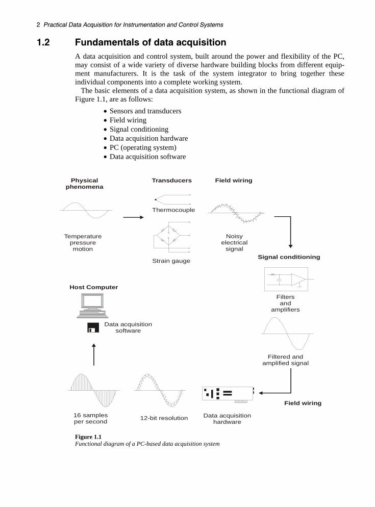
A data acquisition and control system, built around the power and flexibility of the PC, may consist of a wide variety of diverse hardware building blocks from different equip-ment manufacturers. It is the task of the system integrator to bring together these individual components into a complete working system.
The basic elements of a data acquisition system, as shown in the functional diagram of Figure 1.1, are as follows:
• Sensors and transducers • Field wiring • Signal conditioning • Data acquisition hardware • PC (operating system) • Data acquisition software
Filtersand
amplifiers
Filtered andamplified signal
Host Computer
Data acquisitionsoftware
Data acquisitionhardware12-bit resolution16 samples
per second
Physicalphenomena
Transducers Field wiring
Field wiring
Signal conditioning
Temperaturepressuremotion
Thermocouple
Strain gauge
Noisyelectrical
signal
Figure 1.1 Functional diagram of a PC-based data acquisition system

����������������
Each element of the total system is important for the accurate measurement and collection of data from the process or physical phenomena being monitored, and is dis-cussed in the following sections.
1.2.1 Transducers and sensors Transducers and sensors provide the actual interface between the real world and the data acquisition system by converting physical phenomena into electrical signals that the signal conditioning and/or data acquisition hardware can accept.
Transducers available can perform almost any physical measurement and provide a corresponding electrical output. For example, thermocouples, resistive temperature de-tectors (RTDs), thermistors, and IC sensors convert temperature into an analog signal, while flow meters produce digital pulse trains whose frequency depends on the speed of flow.
Strain gauges and pressure transducers measure force and pressure respectively, while other types of transducers are available to measure linear and angular displacement, velocity and acceleration, light, chemical properties (e.g. CO concentration, pH), volt-ages, currents, resistances or pulses. In each case, the electrical signals produced are pro-portional to the physical quantity being measured according to some defined relationship.
1.2.2 Field wiring and communications cabling Field wiring represents the physical connection from the transducers and sensors to the signal conditioning hardware and/or data acquisition hardware. When the signal conditioning and/or data acquisition hardware is remotely located from the PC, then the field wiring provides the physical link between these hardware elements and the host computer. If this physical link is an RS-232 or RS-485 communications interface, then this component of the field wiring is often referred to as communications cabling.
Since field wiring and communications cabling often physically represents the largest component of the total system, it is most susceptible to the effects of external noise, especially in harsh industrial environments. The correct earthing and shielding of field wires and communications cabling is of paramount importance in reducing the effects of noise. This passive component of the data acquisition and control system is often over-looked as an important integral component, resulting in an otherwise reliable system becoming inaccurate or unreliable due to incorrect wiring techniques.
1.2.3 Signal conditioning Electrical signals generated by transducers often need to be converted to a form acceptable to the data acquisition hardware, particularly the A/D converter which con-verts the signal data to the required digital format. In addition, many transducers require some form of excitation or bridge completion for proper and accurate operation.
The principal tasks performed by signal conditioning are: • Filtering • Amplification • Linearization • Isolation • Excitation

������������������� ������������ ��������������������������� ��� �
Filtering In noisy environments, it is very difficult for very small signals received from sensors such as thermocouples and strain gauges (in the order of mV), to survive without the sensor data being compromised. Where the noise is of the same or greater order of magnitude than the required signal, the noise must first be filtered out. Signal con-ditioning equipment often contains low pass filters designed to eliminate high frequency noise that can lead to inaccurate data.
Amplification Having filtered the required input signal, it must be amplified to increase the resolution. The maximum resolution is obtained by amplifying the input signal so that the maximum voltage swing of the input signal equals the input range of the analog-to-digital converter (ADC), contained within the data acquisition hardware.
Placing the amplifier as close to the sensor as physically possible reduces the effects of noise on the signal lines between the transducer and the data acquisition hardware.
Linearization Many transducers, such as thermocouples, display a non-linear relationship to the physical quantity they are required to measure. The method of linearizing these input signals varies between signal conditioning products. For example, in the case of thermo-couples, some products match the signal conditioning hardware to the type of thermo-couple, providing hardware to amplify and linearize the signal at the same time.
A cheaper, easier, and more flexible method is provided by signal conditioning products that perform the linearization of the input signal using software.
Isolation Signal conditioning equipment can also be used to provide isolation of transducer signals from the computer where there is a possibility that high voltage transients may occur within the system being monitored, either due to electrostatic discharge or electrical failure. Isolation protects expensive computer equipment from damage and computer ope-rators from injury. In addition, where common-mode voltage levels are high or there is a need for extremely low common mode leakage current, as for medical applications, isolation allows measurements to be accurately and safely obtained.
Excitation Signal conditioning products also provide excitation for some transducers. For example: strain gauges, thermistors and RTDs, require external voltage or current excitation signals.
1.2.4 Data acquisition hardware Data acquisition and control (DAQ) hardware can be defined as that component of a complete data acquisition and control system, which performs any of the following func-tions:
• The input, processing and conversion to digital format, using ADCs, of analog signal data measured from a system or process – the data is then transferred to a computer for display, storage and analysis
• The input of digital signals, which contain information from a system or process

����������������
• The processing, conversion to analog format, using DACs, of digital signals from the computer – the analog control signals are used for controlling a system or process
• The output of digital control signals
Data acquisition hardware is available in many forms from many different manufacturers. Plug-in expansion bus boards, which are plugged directly into the computer’s expansion bus, are a commonly utilized item of DAQ hardware. Other forms of DAQ hardware are intelligent stand-alone loggers and controllers, which can be monitored, controlled and configured from the computer via an RS-232 interface, and yet can be left to operate independently of the computer.
Another commonly used item of DAQ hardware, especially in R&D and test en-vironments, is the remote stand-alone instrument that can be configured and controlled by the computer, via the IEEE-488 communication interface. Several of the most common DAQ system configurations are discussed in the section Data acquisition and control system configuration p. 6
1.2.5 Data acquisition software Data acquisition hardware does not work without software, because it is the software run-ning on the computer that transforms the system into a complete data acquisition, ana-lysis, display, and control system.
Application software runs on the computer under an operating system that may be single-tasking (like DOS) or multitasking (like Windows, Unix, OS2), allowing more than one application to run simultaneously.
The application software can be a full screen interactive panel, a dedicated input/output control program, a data logger, a communications handler, or a combination of all of these.
There are three options available, with regard to the software required, to program any system hardware:
• Program the registers of the data acquisition hardware directly • Utilize low-level driver software, usually provided with the hardware, to
develop a software application for the specific tasks required • Utilize off-the-shelf application software – this can be application software,
provided with the hardware itself, which performs all the tasks required for a particular application; alternatively, third party packages such as LabVIEW and Labtech Notebook provide a graphical interface for programming the tasks required of a particular item of hardware, as well as providing tools to analyze and display the data acquired
1.2.6 Host computer The PC used in a data acquisition system can greatly affect the speeds at which data can be continuously and accurately acquired, processed, and stored for a particular app-lication. Where high speed data acquisition is performed with a plug-in expansion board, the throughput provided by bus architectures, such as the PCI expansion bus, is higher than that delivered by the standard ISA or EISA expansion bus of the PC.
Depending on the particular application, the microprocessor speed, hard disk access time, disk capacity and the types of data transfer available, can all have an impact on the speed at which the computer is able to continuously acquire data. All PCs, for example,
�������������������� ������������ ��������������������������� ��� �
are capable of programmed I/O and interrupt driven data transfers. The use of Direct Memory Access (DMA), in which dedicated hardware is used to transfer data directly into the computer’s memory, greatly increases the system throughput and leaves the computer’s microprocessor free for other tasks. Where DMA or interrupt driven data transfers are required, the plug-in data acquisition board must be capable of performing these types of data transfer.
In normal operation the data acquired, from a plug-in data acquisition board or other DAQ hardware (e.g. data logger), is stored directly to System Memory. Where the avail-able system memory exceeds the amount of data to be acquired, data can be transferred to permanent storage, such as a hard disk, at any time. The speed at which the data is transferred to permanent storage does not affect the overall throughput of the data acquisition system.
Where large amounts of data need to be acquired and stored at high speed, disk-streaming can be used to continuously store data to hard disk. Disk-streaming utilizes a terminate-and-stay-resident (TSR) program to continuously transfer data acquired from a plug-in data acquisition board and temporarily held in system memory, to the hard disk. The limiting factors in the streaming process may be the hard disk access time and its storage capacity. Where the storage capacity is sufficient, the amount of contiguous (unfragmented) free hard disk space available to hold the data, may affect the system performance, since the maximum rate at which data can be streamed to the disk is re-duced by the level of fragmentation.
If real-time processing of the acquired data is needed, the performance of the com-puter*s processor is paramount. A minimum requirement for high frequency signals acquired at high sampling rates would be a 32-bit processor with its accompanying co-processor, or alternatively a dedicated plug-in processor. Low frequency signals, for which only a few samples are processed each second, would obviously not require the same level of processing power. A low-end PC would therefore be satisfactory. Clearly, the performance requirements of the host computer must be matched to the specific application. As with all aspects of a data acquisition system the choice of computer is a compromise between cost and the current and future requirements it must meet.
One final aspect of the personal computer that should be considered is the type of operating system installed. This may be single-tasking (e.g. MS-DOS) or multitasking (e.g. Windows 2000). While the multitasking nature of Windows provides many advantages for a wide range of applications, its use in data acquisition is not as clear-cut. For example, the methods employed by Windows to manage memory can provide difficulties in the use of DMA. In addition, interrupt latencies introduced by the multi-tasking nature of Windows can lead to problems when interrupt driven data transfers are used. Therefore, careful consideration must be given to the operating system and its performance in relation to the type of data acquisition hardware and the methods of data transfer, especially where high-speed data transfers are required.
���� ����� ������������ ���������� ����������
In many applications, and especially for data acquisition and process control, the power and flexibility of the PC, allows DAQ systems to be configured in a number of ways, each with its own distinct advantages. The key to the effective use of the PC is the careful matching of the specific requirements of a particular data acquisition application to the appropriate hardware and software available.
The choice of hardware, and the system configuration, is largely dictated by the environment in which the system will operate (e.g. an R&D laboratory, a manufacturing

����������������
plant floor or a remote field location). The number of sensors and actuators required and their physical location in relation to the host computer, the type of signal conditioning required, and the harshness of the environment, are key factors.
Several of the most common system configurations are as follows: • Computer plug-in I/O • Distributed I/O • Stand-alone or distributed loggers and controllers • IEEE-488 instruments
1.3.1 Computer plug-in I/O Plug-in I/O boards are plugged directly into the computers expansion bus, are generally compact, and also represent the fastest method of acquiring data to the computers memory and/or changing outputs. Along with these advantages, plug-in boards often represent the lowest cost alternative for a complete data acquisition and control system and are therefore a commonly utilized item of DAQ hardware.
As shown in Figure 1.2, examples of plug-in I/O boards are, multiple analog input A/D boards, multiple analog output D/A boards, digital I/O boards, counter/timer boards, specialized controller boards (such as stepper/servo motor controllers) or specialized instrumentation boards (such as digital oscilloscopes).
Figure 1.2 Example of computer plug-in I/O boards
Multi-function DAQ boards, containing A/D converters (ADCs), D/A converters (DACs), digital I/O ports and counter timer circuitry, perform all the functions of the equivalent individual specialized boards. Depending on the number of analog inputs/outputs and digital inputs/outputs required for a particular application, multi-function boards represent the most cost effective and flexible solution for DAQ systems.

�������������������� ������������ ��������������������������� ��� �
Plug-in expansion boards are commonly used in applications where the computer is close to the sensors being measured or the actuators being controlled. Alternatively, they can be interfaced to remotely located transducers and actuators via signal conditioning modules known as two-wire transmitters. This system configuration is discussed in the following section on Distributed I/O.
1.3.2 Distributed I/O Often sensors must be remotely located from the computer in which the processing and storage of the data takes place. This is especially true in industrial environments where sensors and actuators can be located in hostile environments over a wide area, possibly hundreds of meters away. In noisy environments, it is very difficult for very small signals received from sensors such as thermocouples and strain gauges (in the order of mV) to survive transmission over such long distances, especially in their raw form, without the quality of the sensor data being compromised.
An alternative to running long and possibly expensive sensor wires, is the use of distributed I/O, which is available in the form of signal conditioning modules remotely located near the sensors to which they are interfaced. One module is required for each sensor used, allowing for high levels of modularity (single point to hundreds of points per location). While this can add reasonable expense to systems with large point counts, the benefits in terms of signal quality and accuracy may be worth it.
One of the most commonly implemented forms of distributed I/O is the digital transmitter. These intelligent devices perform all required signal conditioning functions (amplification, filtering, isolation etc), contain a micro-controller and A/D converter, to perform the digital conversion of the signal within the module itself. Converted data is transmitted to the computer via an RS-232 or RS-485 communications interface. The use of RS-485 multi-drop networks, as shown in Figure 1.3, reduces the amount of cabling required, since each signal-conditioning module shares the same cable pair. Linking up to 32 modules, communicating over distances up to 10 km, is possible when using the RS-485 multi-drop network. However, since very few computers have built in support for the RS-485 standard, an RS-232 to RS-485 converter is required to allow communications between the computer and the remote modules.
Host Computer
RS-485 InterfaceBoard
Digitaltransmitter module
Relay
Digitaltransmitter module
Relay
Power supplyDigitaltransmitter module
Thermocouple
Digitaltransmitter module
Strain gauge
Figure 1.3 Distributed I/O – digital transmitter modules

����������������
1.3.3 Stand-alone or distributed loggers/controllers As well as providing the benefits of intelligent signal conditioning modules, and the ability to make decisions remotely, the use of stand-alone loggers/controllers increases system reliability. This is because once programmed, the stand-alone logger can continue to operate, even when the host computer is not functional or connected. In fact, stand-alone loggers/controllers are specifically designed to operate independently of the host computer. This makes them especially useful for applications where the unit must be located in a remote or particularly hostile environment, (e.g. a remotely located weather station), or where the application does not allow continuous connection to a computer (e.g. controlling temperatures in a refrigerated truck).
Stand-alone loggers/controllers are intelligent powerful and flexible devices, easily interfaced to a wide range of transducers, as well as providing digital inputs and digital control outputs for process control.
The stand-alone logger/controller and logging data are programmed either by a serial communications interface or by using portable and reusable PCMCIA cards. The credit card size PCMCIA card is especially useful when the stand-alone logger/controller is remotely located, but requires an interface connected to the computer. This is shown in Figure 1.4.
Computer Memory Card Interface
PCMCIACard
Remote Data LoggerStand-alonelogger / controller
Thermocouples Strain gauges Relays
Figure 1.4 Using PCMCIA cards to program and log data from a stand-alone logger/controller
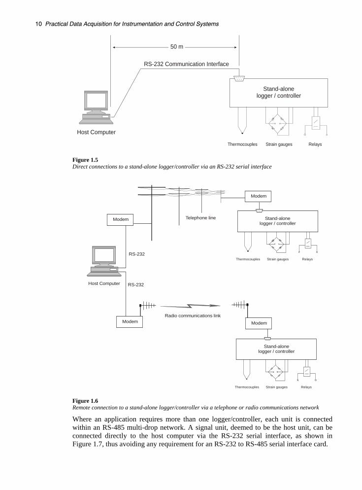
The most commonly used serial communications link for direct connection between the computer and the stand-alone logger/controller is the RS-232 serial interface. This allows programming and data logging up to distances of 50 meters, as shown in Figure 1.5. Where the stand-alone unit must be located remotely, a portable PC can be taken to the remote location or communications performed via a telephone or radio communications network using modems, as shown in Figure 1.6.
��������������������� ������������ ��������������������������� ��� �
Host Computer
50 m
RS-232 Communication Interface
Stand-alonelogger / controller
Thermocouples Strain gauges Relays
Figure 1.5 Direct connections to a stand-alone logger/controller via an RS-232 serial interface
Host Computer
RS-232
RS-232
Telephone line
Radio communications link
Stand-alonelogger / controller
Thermocouples Strain gauges Relays
Stand-alonelogger / controller
Thermocouples Strain gauges Relays
Modem
Modem Modem
Modem
Figure 1.6 Remote connection to a stand-alone logger/controller via a telephone or radio communications network
Where an application requires more than one logger/controller, each unit is connected within an RS-485 multi-drop network. A signal unit, deemed to be the host unit, can be connected directly to the host computer via the RS-232 serial interface, as shown in Figure 1.7, thus avoiding any requirement for an RS-232 to RS-485 serial interface card.

�����������������
The same methods of programming or logging data from each logger/controller are available either via the serial communications network or via using portable and reusable memory cards.
Host Computer
50 m
RS-232 InterfaceMax cable length - 1000 m
RS-485 Interface
Stand-alonelogger / controller
Thermocouples Strain gauges Relays
Stand-alonelogger / controller
Thermocouples Strain gauges Relays
Stand-alonelogger / controller
Thermocouples Strain gauges Relays
Stand-alonelogger / controller
Thermocouples Strain gauges Relays
- + + -
+ -+ -
Figure 1.7 Distributed logger/controller network
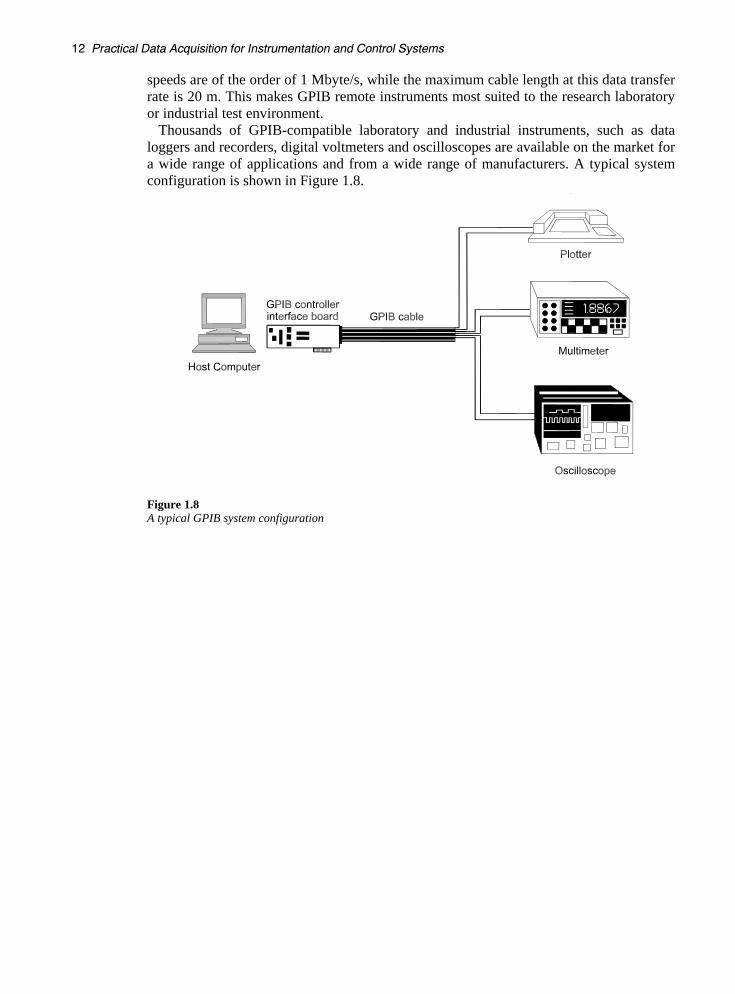
1.3.4 IEEE-488 (GPIB) remote programmable instruments The communications standard now known as GPIB (General Purpose Interface Bus), was originally developed by Hewlett-Packard in 1965 as a digital interface for interconnecting and controlling their programmable test instruments. Originally referred to as the Hewlett Packard Interface Bus (HPIB), its speed, flexibility and usefulness in connecting instru-ments in a laboratory environment led to its widespread acceptance, and finally to its adoption as a world standard (IEEE-488). Since then, it has undergone improvements (IEEE-488.2) and SCPI (Standard Commands for Programmable Instruments), to stan-dardize how instruments and their controllers communicate and operate.
Evolving from the need to collect data from a number of different stand-alone instruments in a laboratory environment, the GPIB is a high-speed parallel communications interface that allows the simultaneous connection of up to 15 devices or instruments on a short common parallel data communications bus. The most common configuration requires a GPIB controller, usually a plug-in board on the computer, which addresses each device on the bus and initiates the devices that will communicate to each other. The maximum speed of communications, the maximum length of cable, and the maximum cable distance between each device on the GPIB is dependent on the speed and processing power of the GPIB controller and the type of cabling used. Typical transfer
��������������������� ������������ ��������������������������� ��� �
speeds are of the order of 1 Mbyte/s, while the maximum cable length at this data transfer rate is 20 m. This makes GPIB remote instruments most suited to the research laboratory or industrial test environment.
Thousands of GPIB-compatible laboratory and industrial instruments, such as data loggers and recorders, digital voltmeters and oscilloscopes are available on the market for a wide range of applications and from a wide range of manufacturers. A typical system configuration is shown in Figure 1.8.
Figure 1.8 A typical GPIB system configuration