Challenger Butterfly Valve Retrofit Kit, UFLK, 3-way, SY
15
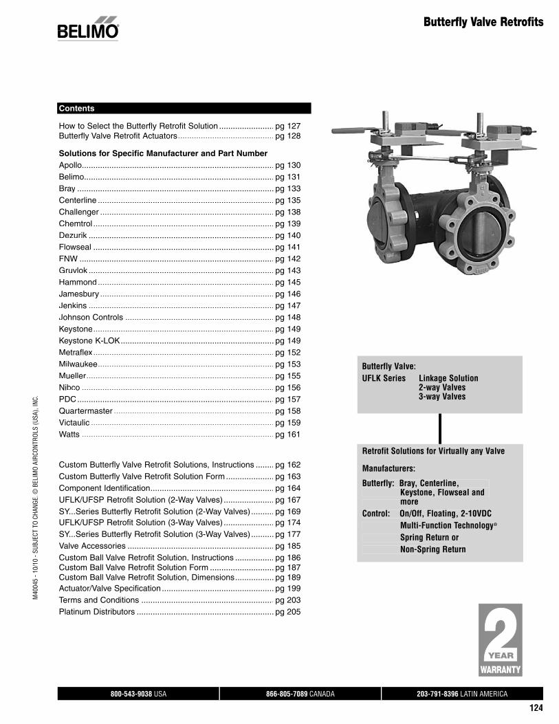
800-543-9038 USA 866-805-7089 CANADA 203-791-8396 LATIN AMERICA 124 Butterfly Valve Retrofits Butterfly Valve: UFLK Series Linkage Solution 2-way Valves 3-way Valves Contents How to Select the Butterfly Retrofit Solution ........................ pg 127 Butterfly Valve Retrofit Actuators .......................................... pg 128 Solutions for Specific Manufacturer and Part Number Apollo.................................................................................... pg 130 Belimo................................................................................... pg 131 Bray ...................................................................................... pg 133 Centerline ............................................................................. pg 135 Challenger ............................................................................ pg 138 Chemtrol ............................................................................... pg 139 Dezurik ................................................................................. pg 140 Flowseal ............................................................................... pg 141 FNW ..................................................................................... pg 142 Gruvlok ................................................................................. pg 143 Hammond ............................................................................. pg 145 Jamesbury ............................................................................ pg 146 Jenkins ................................................................................. pg 147 Johnson Controls ................................................................. pg 148 Keystone............................................................................... pg 149 Keystone K-LOK ................................................................... pg 149 Metraflex ............................................................................... pg 152 Milwaukee ............................................................................. pg 153 Mueller .................................................................................. pg 155 Nibco .................................................................................... pg 156 PDC ...................................................................................... pg 157 Quartermaster ...................................................................... pg 158 Victaulic ................................................................................ pg 159 Watts .................................................................................... pg 161 Custom Butterfly Valve Retrofit Solutions, Instructions ........ pg 162 Custom Butterfly Valve Retrofit Solution Form ..................... pg 163 Component Identification...................................................... pg 164 UFLK/UFSP Retrofit Solution (2-Way Valves) ...................... pg 167 SY...Series Butterfly Retrofit Solution (2-Way Valves) .......... pg 169 UFLK/UFSP Retrofit Solution (3-Way Valves) ...................... pg 174 SY...Series Butterfly Retrofit Solution (3-Way Valves) .......... pg 177 Valve Accessories ................................................................ pg 185 Custom Ball Valve Retrofit Solution, Instructions ................. pg 186 Custom Ball Valve Retrofit Solution Form ............................ pg 187 Custom Ball Valve Retrofit Solution, Dimensions ................. pg 189 Actuator/Valve Specification ................................................. pg 199 Terms and Conditions .......................................................... pg 203 Platinum Distributors ............................................................ pg 205 Retrofit Solutions for Virtually any Valve Manufacturers: Butterfly: Bray, Centerline, Keystone, Flowseal and more Control: On/Off, Floating, 2-10VDC Multi-Function Technology ® Spring Return or Non-Spring Return M40045 - 10/10 - SUBJECT TO CHANGE. © BELIMO AIRCONTROLS (USA), INC.
-
Upload
khangminh22 -
Category
Documents
-
view
1 -
download
0
Transcript of Challenger Butterfly Valve Retrofit Kit, UFLK, 3-way, SY
800-543-9038 USA 866-805-7089 CANADA 203-791-8396 LATIN AMERICA
124
Butterfly Valve Retrofits
Butterfly Valve:UFLK Series Linkage Solution 2-way Valves 3-way Valves
Contents
How to Select the Butterfly Retrofit Solution ........................ pg 127Butterfly Valve Retrofit Actuators .......................................... pg 128
Solutions for Specific Manufacturer and Part NumberApollo .................................................................................... pg 130Belimo ................................................................................... pg 131Bray ...................................................................................... pg 133Centerline ............................................................................. pg 135Challenger ............................................................................ pg 138Chemtrol ............................................................................... pg 139Dezurik .................................................................................k pg 140Flowseal ............................................................................... pg 141FNW ..................................................................................... pg 142Gruvlok .................................................................................k pg 143Hammond ............................................................................. pg 145Jamesbury ............................................................................ pg 146Jenkins ................................................................................. pg 147Johnson Controls ................................................................. pg 148Keystone ............................................................................... pg 149Keystone K-LOK................................................................... pg 149Metraflex ............................................................................... pg 152Milwaukee ............................................................................. pg 153Mueller.................................................................................. pg 155Nibco .................................................................................... pg 156PDC...................................................................................... pg 157Quartermaster ...................................................................... pg 158Victaulic ................................................................................ pg 159Watts .................................................................................... pg 161
Custom Butterfly Valve Retrofit Solutions, Instructions ........ pg 162Custom Butterfly Valve Retrofit Solution Form ..................... pg 163Component Identification...................................................... pg 164UFLK/UFSP Retrofit Solution (2-Way Valves) ...................... pg 167SY...Series Butterfly Retrofit Solution (2-Way Valves).......... pg 169UFLK/UFSP Retrofit Solution (3-Way Valves) ...................... pg 174SY...Series Butterfly Retrofit Solution (3-Way Valves).......... pg 177Valve Accessories ................................................................ pg 185Custom Ball Valve Retrofit Solution, Instructions ................. pg 186Custom Ball Valve Retrofit Solution Form ............................ pg 187Custom Ball Valve Retrofit Solution, Dimensions ................. pg 189Actuator/Valve Specification ................................................. pg 199Terms and Conditions .......................................................... pg 203Platinum Distributors ............................................................ pg 205
Retrofit Solutions for Virtually any Valve
Manufacturers:
Butterfly: Bray, Centerline, Keystone, Flowseal and moreControl: On/Off, Floating, 2-10VDC Multi-Function Technology®
Spring Return or Non-Spring Return
M40
045
- 10/
10 -
SUBJ
ECT
TO C
HANG
E. ©
BEL
IMO
AIRC
ONTR
OLS
(USA
), IN
C.
800-543-9038 USA 866-805-7089 CANADA 203-791-8396 LATIN AMERICA
126
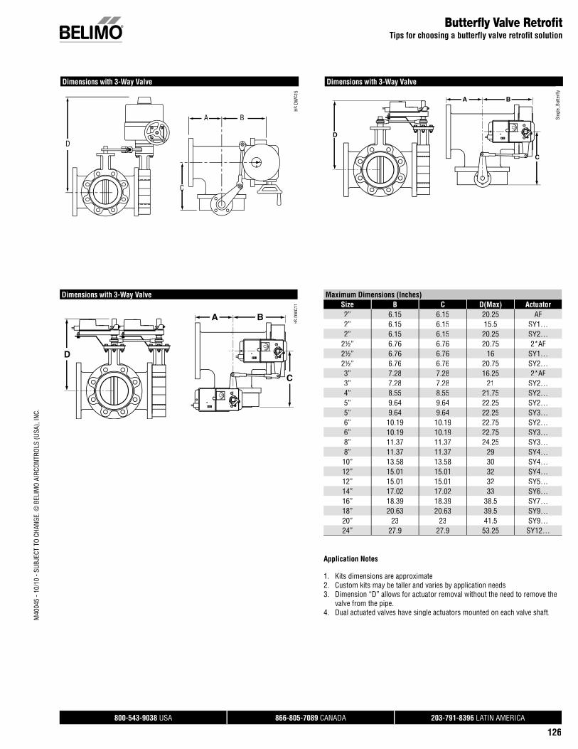
Butterfl y Valve Retrofi tTips for choosing a butterfly valve retrofit solution
Maximum Dimensions (Inches)Size B C D(Max) Actuator2” 6.15 6.15 20.25 AF2” 6.15 6.15 15.5 SY1…2” 6.15 6.15 20.25 SY2…
2½” 6.76 6.76 20.75 2*AF2½” 6.76 6.76 16 SY1…2½” 6.76 6.76 20.75 SY2…3” 7.28 7.28 16.25 2*AF3” 7.28 7.28 21 SY2…4” 8.55 8.55 21.75 SY2…5” 9.64 9.64 22.25 SY2…5” 9.64 9.64 22.25 SY3…6” 10.19 10.19 22.75 SY2…6” 10.19 10.19 22.75 SY3…8” 11.37 11.37 24.25 SY3…8” 11.37 11.37 29 SY4…
10” 13.58 13.58 30 SY4…12” 15.01 15.01 32 SY4…12” 15.01 15.01 32 SY5…14” 17.02 17.02 33 SY6…16” 18.39 18.39 38.5 SY7…18” 20.63 20.63 39.5 SY9…20” 23 23 41.5 SY9…24” 27.9 27.9 53.25 SY12…
Dimensions with 3-Way Valve
Sing
le_B
utte
rfly
Application Notes
1. Kits dimensions are approximate2. Custom kits may be taller and varies by application needs3. Dimension “D” allows for actuator removal without the need to remove the valve from the pipe.4. Dual actuated valves have single actuators mounted on each valve shaft.
Dimensions with 3-Way Valve10 0
10 0
D
A B
C
HS D
WG1
1S
0
S
D
A B
CC
Dimensions with 3-Way Valve
HS D
WG1
5
10D
A B
C
M40
045
- 10/
10 -
SUBJ
ECT
TO C
HANG
E. ©
BEL
IMO
AIRC
ONTR
OLS
(USA
), IN
C.

800-543-9038 USA 866-805-7089 CANADA 203-791-8396 LATIN AMERICA
127
M40
045
- 10/
10 -
SUBJ
ECT
TO C
HANG
E. ©
BEL
IMO
AIRC
ONTR
OLS
(USA
), IN
C.
C200 Round Top Series Butterfl y Valves 2-way 2” No 200 AM UFLK3500SY1 UFLK3538SY2 UFLK3540
Yes 200 AF UFLK35002½” No 200 GM UFLK3500
SY1 UFLK3538SY2 UFLK3540
Yes 200 2*AF UFLK35023”33 NoNoNo 200200200 GMGMGM UFLKUFLKUFLK350035003500
SY1SY1SY1SY1SY1S UFLKUFLKUFLKUFLKUFLKU 3 3835383538353835383538SY2SY2SY2SY2 UFLKUFLKUFLKUFLK3540354035403540
YesYes 200200 2*AF2*AF UFLKUFLK35023502
Valve Body Model ValveConfi guration Size Failsafe Close-Off
psi
BelimoActuator Series
(Sold Separately)
BelimoLinkage
EXAMPLE PAGECenterlineC200 Round Top Series Butterfly Valves
Linkage/Actuator Selection Guide
Non-Spring Return Actuators
MODEL Control Input Feedback PowerSupply
RunningTime(s)[Default]
VA Rating Aux. Switch
BASIC PRODUCTSGMB24-3-X1 On/Off, Floating Point Add-on 24 VAC/DC 150 seconds 6 Add-onGMB24-SR 2-10 VDC (4-20mA*) 2-10 VDC 24 VAC/DC 150 seconds 6.5 Add-on
CUSTOMIZE ITGMX24-3 On/Off, Floating Point Add on 24 VAC/DC 150 seconds 7 Add-onGMX24-SR 2-10 VDC (4-20mA*) 2-10 VDC 24 VAC/DC 150 seconds 6.5 Add-onGMX24-PC 0-20 V Phasecut 2-10 VDC 24 VAC/DC 150 seconds 7 Add-onGMX24-MFT-X1 Various Various 24 VAC/DC Various 7 Add-onGMX24-MFT95-X1 0 to 135 Ω 2-10 VDC 24 VAC/DC 150 seconds 7 Add-onGMX120-3 On/Off, Floating Point Add on 100-240 VAC 150 seconds 9 Add-on
‡ For applications that require more torque the GMB Series can be dual mounted. A maximum of 2 GMB/X... Series actuators can be mechanically connected to one damper or valve shaft. The torque is 640 in-lb.*With the 500 Ω resistor added.
How to select the Butterfl y Valve Retrofi t Solution
How to select a Butterfly Valve Retrofit SolutionFollow the four steps listed below when ordering a butterfly valve retrofit kit.
Example: Centerline C200 Series, 2½” valve, using a Non-Spring Return Belimo actuator.
1 Identify the Valve Manufacturer, Valve Series and Valve Size.
2 Determine the type of actuator you require: Belimo Spring Return, Non-Spring or SY Series Industrial. Belimo Spring and Non-Spring actuators are typically only available on smaller sizes.
Look at the solution using the Non-Spring Return Belimo Actuator. Looking at the UFLK3500, the GM Series actuator will provide a 200 psi close-off for the 2½” valve with Non-Spring Return actuation.
3 Use the actuator listings to make your final actuator selection. Decide between GMX24-3-X1 and GMX24-MFT-X1.
ACTUATOR NOT INCLUDED IN THE LIST PRICE OF THE LINKAGE.
4 HOW TO ORDER: Item 1 1pc UFLK3500 Item 2 1pc GMX24-MFT-X1
1
Select linkage solutionbased on the Valve Number, Confi guration, and Size; select theproper Linkage Solutionfor your valve.
UFLK1300Example: Centerline C200 Series,2½” valve using a non-spring returnBelimo actuation.
Choose correct linkage UFLK3500.
2
Verify close-off is suitablefor application.Looking at the UFLK3500, the GM Series actuator will provide 200 psi close-off forthe 2½” valve.
3Select actuator based on needed control type.Decide between GMB24-3-X1 and GMX24-MFT-X1.
4Complete Ordering Example:
Item 1: UFLK3500Item 2: GMX24-MFT-X1
800-543-9038 USA 866-805-7089 CANADA 203-791-8396 LATIN AMERICA
128
Butterfl y Valve Retrofi t ActuatorsActuator Selection Guide
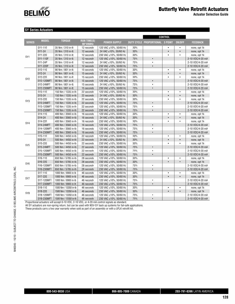
SY Series Actuators
CONTROL
SERIES MODEL TORQUE RUN TIME(S) 90°@60Hz POWER SUPPLY DUTY CYCLE PROPORTIONAL 3 POINT ON/OFF FEEDBACK
SY1
SY1-110 35 Nm / 310 in-lb 12 seconds 120 VAC ±10%, 50/60 Hz 30% • • none, opt 1kSY1-24 35 Nm / 310 in-lb 12 seconds 24 VAC ±10%, 50/60 Hz 30% • • none, opt 1kSY1-220 35 Nm / 310 in-lb 12 seconds 230 VAC ±10%, 50/60 Hz 30% • • none, opt 1kSY1-110P 35 Nm / 310 in-lb 12 seconds 120 VAC ±10%, 50/60 Hz 75% • 2-10 VDC/4-20 mASY1-24P 35 Nm / 310 in-lb 12 seconds 24 VAC ±10%, 50/60 Hz 75% • 2-10 VDC/4-20 mASY1-220P 35 Nm / 310 in-lb 12 seconds 230 VAC ±10%, 50/60 Hz 75% • 2-10 VDC/4-20 mA
SY2
SY2-110 90 Nm / 801 in-lb 15 seconds 120 VAC ±10%, 50/60 Hz 30% • • none, opt 1kSY2-24 90 Nm / 801 in-lb 15 seconds 24 VAC ±10%, 50/60 Hz 30% • • none, opt 1kSY2-220 90 Nm / 801 in-lb 15 seconds 230 VAC ±10%, 50/60 Hz 30% • • none, opt 1kSY2-120MFT 90 Nm / 801 in-lb 15 seconds 120 VAC ±10%, 50/60 Hz 75% • 2-10 VDC/4-20 mASY2-24MFT 90 Nm / 801 in-lb 15 seconds 24 VAC ±10%, 50/60 Hz 75% • 2-10 VDC/4-20 mASY2-230MFT 90 Nm / 801 in-lb 15 seconds 230 VAC ±10%, 50/60 Hz 75% • 2-10 VDC/4-20 mA
SY3
SY3-110 150 Nm / 1335 in-lb 22 seconds 120 VAC ±10%, 50/60 Hz 30% • • none, opt 1kSY3-24 150 Nm / 1335 in-lb 22 seconds 24 VAC ±10%, 50/60 Hz 30% • • none, opt 1kSY3-220 150 Nm / 1335 in-lb 22 seconds 230 VAC ±10%, 50/60 Hz 30% • • none, opt 1kSY3-24MFT 150 Nm / 1335 in-lb 22 seconds 120 VAC ±10%, 50/60 Hz 75% • 2-10 VDC/4-20 mASY3-120MFT 150 Nm / 1335 in-lb 22 seconds 120 VAC ±10%, 50/60 Hz 75% • 2-10 VDC/4-20 mASY3-230MFT 150 Nm / 1335 in-lb 22 seconds 230 VAC ±10%, 50/60 Hz 75% • 2-10 VDC/4-20 mA
SY4
SY4-110 400 Nm / 3560 in-lb 16 seconds 120 VAC ±10%, 50/60 Hz 30% • • none, opt 1kSY4-24 400 Nm / 3560 in-lb 16 seconds 24 VAC ±10%, 50/60 Hz 30% • • none, opt 1kSY4-220 400 Nm / 3560 in-lb 16 seconds 230 VAC ±10%, 50/60 Hz 30% • • none, opt 1kSY4-24MFT 400 Nm / 3560 in-lb 16 seconds 120 VAC ±10%, 50/60 Hz 75% • 2-10 VDC/4-20 mASY4-120MFT 400 Nm / 3560 in-lb 16 seconds 120 VAC ±10%, 50/60 Hz 75% • 2-10 VDC/4-20 mASY4-230MFT 400 Nm / 3560 in-lb 16 seconds 230 VAC ±10%, 50/60 Hz 75% • 2-10 VDC/4-20 mA
SY5
SY5-110 500 Nm / 4450 in-lb 22 seconds 120 VAC ±10%, 50/60 Hz 30% • • none, opt 1kSY5-24 500 Nm / 4450 in-lb 22 seconds 24 VAC ±10%, 50/60 Hz 30% • • none, opt 1kSY5-220 500 Nm / 4450 in-lb 22 seconds 230 VAC ±10%, 50/60 Hz 30% • • none, opt 1kSY5-24MFT 500 Nm / 4450 in-lb 22 seconds 120 VAC ±10%, 50/60 Hz 75% • 2-10 VDC/4-20 mASY5-120MFT 500 Nm / 4450 in-lb 22 seconds 120 VAC ±10%, 50/60 Hz 75% • 2-10 VDC/4-20 mASY5-230MFT 500 Nm / 4450 in-lb 22 seconds 230 VAC ±10%, 50/60 Hz 75% • 2-10 VDC/4-20 mA
SY6
SY6-110 650 Nm / 5785 in-lb 28 seconds 120 VAC ±10%, 50/60 Hz 30% • • none, opt 1kSY6-220 650 Nm / 5785 in-lb 28 seconds 230 VAC ±10%, 50/60 Hz 30% • • none, opt 1kSY6-120MFT 650 Nm / 5785 in-lb 28 seconds 120 VAC ±10%, 50/60 Hz 75% • 2-10 VDC/4-20 mASY6-230MFT 650 Nm / 5785 in-lb 28 seconds 230 VAC ±10%, 50/60 Hz 75% • 2-10 VDC/4-20 mA
SY7
SY7-110 1000 Nm / 8900 in-lb 46 seconds 120 VAC ±10%, 50/60 Hz 30% • • none, opt 1kSY7-220 1000 Nm / 8900 in-lb 46 seconds 230 VAC ±10%, 50/60 Hz 30% • • none, opt 1kSY7-120MFT 1000 Nm / 8900 in-lb 46 seconds 120 VAC ±10%, 50/60 Hz 75% • 2-10 VDC/4-20 mASY7-230MFT 1000 Nm / 8900 in-lb 46 seconds 230 VAC ±10%, 50/60 Hz 75% • 2-10 VDC/4-20 mA
SY8
SY8-110 1500 Nm / 13350 in-lb 46 seconds 120 VAC ±10%, 50/60 Hz 30% • • none, opt 1kSY8-220 1500 Nm / 13350 in-lb 46 seconds 230 VAC ±10%, 50/60 Hz 30% • • none, opt 1kSY8-120MFT 1500 Nm / 13350 in-lb 46 seconds 120 VAC ±10%, 50/60 Hz 75% • 2-10 VDC/4-20 mASY8-230MFT 1500 Nm / 13350 in-lb 46 seconds 230 VAC ±10%, 50/60 Hz 75% • 2-10 VDC/4-20 mA
Proportional actuators will accept 0-10 VDC, 2-10 VDC, or 4-20 mA control signals as standard.All SY actuators are non-spring return, but can be used with NSV-SY back up systems for fail-safe applications.These products carry a two year warranty when sold as part of an assembly or with a UFLK retrofi t kit.
M40
045
- 10/
10 -
SUBJ
ECT
TO C
HANG
E. ©
BEL
IMO
AIRC
ONTR
OLS
(USA
), IN
C.
800-543-9038 USA 866-805-7089 CANADA 203-791-8396 LATIN AMERICA
129
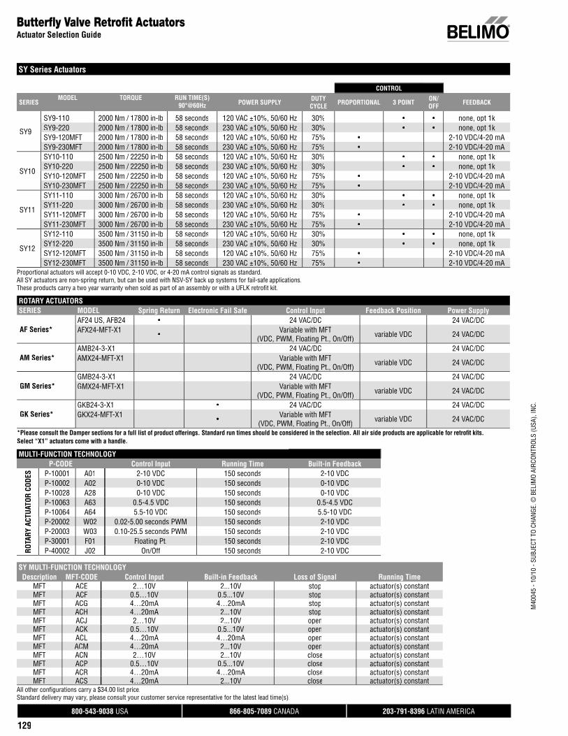
SY Series Actuators
CONTROL
SERIESMODEL TORQUE RUN TIME(S)
90°@60Hz POWER SUPPLY DUTY CYCLE PROPORTIONAL 3 POINT ON/
OFF FEEDBACK
SY9
SY9-110 2000 Nm / 17800 in-lb 58 seconds 120 VAC ±10%, 50/60 Hz 30% • • none, opt 1kSY9-220 2000 Nm / 17800 in-lb 58 seconds 230 VAC ±10%, 50/60 Hz 30% • • none, opt 1kSY9-120MFT 2000 Nm / 17800 in-lb 58 seconds 120 VAC ±10%, 50/60 Hz 75% • 2-10 VDC/4-20 mASY9-230MFT 2000 Nm / 17800 in-lb 58 seconds 230 VAC ±10%, 50/60 Hz 75% • 2-10 VDC/4-20 mA
SY10
SY10-110 2500 Nm / 22250 in-lb 58 seconds 120 VAC ±10%, 50/60 Hz 30% • • none, opt 1kSY10-220 2500 Nm / 22250 in-lb 58 seconds 230 VAC ±10%, 50/60 Hz 30% • • none, opt 1kSY10-120MFT 2500 Nm / 22250 in-lb 58 seconds 120 VAC ±10%, 50/60 Hz 75% • 2-10 VDC/4-20 mASY10-230MFT 2500 Nm / 22250 in-lb 58 seconds 230 VAC ±10%, 50/60 Hz 75% • 2-10 VDC/4-20 mA
SY11
SY11-110 3000 Nm / 26700 in-lb 58 seconds 120 VAC ±10%, 50/60 Hz 30% • • none, opt 1kSY11-220 3000 Nm / 26700 in-lb 58 seconds 230 VAC ±10%, 50/60 Hz 30% • • none, opt 1kSY11-120MFT 3000 Nm / 26700 in-lb 58 seconds 120 VAC ±10%, 50/60 Hz 75% • 2-10 VDC/4-20 mASY11-230MFT 3000 Nm / 26700 in-lb 58 seconds 230 VAC ±10%, 50/60 Hz 75% • 2-10 VDC/4-20 mA
SY12
SY12-110 3500 Nm / 31150 in-lb 58 seconds 120 VAC ±10%, 50/60 Hz 30% • • none, opt 1kSY12-220 3500 Nm / 31150 in-lb 58 seconds 230 VAC ±10%, 50/60 Hz 30% • • none, opt 1kSY12-120MFT 3500 Nm / 31150 in-lb 58 seconds 120 VAC ±10%, 50/60 Hz 75% • 2-10 VDC/4-20 mASY12-230MFT 3500 Nm / 31150 in-lb 58 seconds 230 VAC ±10%, 50/60 Hz 75% • 2-10 VDC/4-20 mA
Proportional actuators will accept 0-10 VDC, 2-10 VDC, or 4-20 mA control signals as standard.All SY actuators are non-spring return, but can be used with NSV-SY back up systems for fail-safe applications.These products carry a two year warranty when sold as part of an assembly or with a UFLK retrofi t kit.
Butterfl y Valve Retrofi t ActuatorsActuator Selection Guide
ROTARY ACTUATORSSERIES MODEL Spring Return Electronic Fail Safe Control Input Feedback Position Power Supply
AF Series*AF24 US, AFB24 • 24 VAC/DC 24 VAC/DCAFX24-MFT-X1 • Variable with MFT
(VDC, PWM, Floating Pt., On/Off) variable VDC 24 VAC/DC
AM Series*AMB24-3-X1 24 VAC/DC 24 VAC/DCAMX24-MFT-X1 Variable with MFT
(VDC, PWM, Floating Pt., On/Off) variable VDC 24 VAC/DC
GM Series*GMB24-3-X1 24 VAC/DC 24 VAC/DCGMX24-MFT-X1 Variable with MFT
(VDC, PWM, Floating Pt., On/Off) variable VDC 24 VAC/DC
GK Series*GKB24-3-X1 • 24 VAC/DC 24 VAC/DCGKX24-MFT-X1 • Variable with MFT
(VDC, PWM, Floating Pt., On/Off) variable VDC 24 VAC/DC
*Please consult the Damper sections for a full list of product offerings. Standard run times should be considered in the selection. All air side products are applicable for retrofi t kits. Select “X1” actuators come with a handle.
MULTI-FUNCTION TECHNOLOGYP-CODE Control Input Running Time Built-in Feedback
ROTA
RY A
CTUA
TOR
CODE
S P-10001 A01 2-10 VDC 150 seconds 2-10 VDCP-10002 A02 0-10 VDC 150 seconds 0-10 VDCP-10028 A28 0-10 VDC 150 seconds 0-10 VDCP-10063 A63 0.5-4.5 VDC 150 seconds 0.5-4.5 VDCP-10064 A64 5.5-10 VDC 150 seconds 5.5-10 VDCP-20002 W02 0.02-5.00 seconds PWM 150 seconds 2-10 VDCP-20003 W03 0.10-25.5 seconds PWM 150 seconds 2-10 VDCP-30001 F01 Floating Pt. 150 seconds 2-10 VDCP-40002 J02 On/Off 150 seconds 2-10 VDC
SY MULTI-FUNCTION TECHNOLOGYDescription MFT-CODE Control Input Built-in Feedback Loss of Signal Running Time
MFT ACE 2…10V 2...10V stopp actuator(s) constant( )MFT ACF 0.5…10V 0.5...10V pstop ( )actuator(s) constantMFT ACG 4…20mA 4…20mA stopp actuator(s) constant( )MFT ACH 4…20mA 2...10V pstop ( )actuator(s) constantMFT ACJ 2…10V 2...10V openp actuator(s) constant( )MFT ACK 0.5…10V 0.5...10V popen ( )actuator(s) constantMFT ACL 4…20mA 4…20mA openp actuator(s) constant( )MFT ACM 4…20mA 2...10V popen ( )actuator(s) constantMFT ACN 2…10V 2...10V close actuator(s) constant( )MFT ACP 0.5…10V 0.5...10V close ( )actuator(s) constantMFT ACR 4…20mA 4…20mA close actuator(s) constant( )MFT ACS 4…20mA 2...10V close ( )actuator(s) constant( )( )
All other confi gurations carry a $34.00 list price.Standard delivery may vary, please consult your customer service representative for the latest lead time(s).
M40
045
- 10/
10 -
SUBJ
ECT
TO C
HANG
E. ©
BEL
IMO
AIRC
ONTR
OLS
(USA
), IN
C.
Valve Body Model ValveConfi guration Size Failsafe Close-Off
psi
BelimoActuator Series
(Sold Separately)
BelimoLinkage
800-543-9038 USA 866-805-7089 CANADA 203-791-8396 LATIN AMERICA
138
M40
045
- 10/
10 -
Subj
ect t
o ch
ange
. © B
elim
o Ai
rcon
trols
(USA
), In
c.
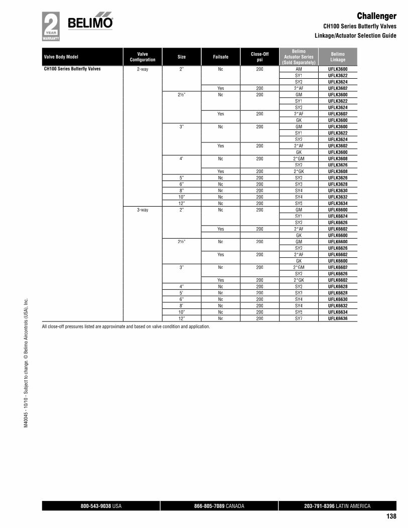
ChallengerCH100 Series Butterfly Valves
Linkage/Actuator Selection Guide
CH100 Series Butterfl y Valves 2-way 2” No 200 AM UFLK3600SY1 UFLK3622SY2 UFLK3624
Yes 200 2*AF UFLK36022½” No 200 GM UFLK3600
SY1 UFLK3622SY2 UFLK3624
Yes 200 2*AF UFLK3602GK UFLK3600
3” No 200 GM UFLK3600SY1 UFLK3622SY2 UFLK3624
Yes 200 2*AF UFLK3602GK UFLK3600
4” No 200 2*GM UFLK3608SY2 UFLK3626
Yes 200 2*GK UFLK36085” No 200 SY2 UFLK36266” No 200 SY3 UFLK36288” No 200 SY4 UFLK363010” No 200 SY4 UFLK363212” No 200 SY5 UFLK3634
3-way 2” No 200 GM UFLK6600SY1 UFLK6624SY2 UFLK6626
Yes 200 2*AF UFLK6602GK UFLK6600
2½” No 200 GM UFLK6600SY2 UFLK6626
Yes 200 2*AF UFLK6602GK UFLK6600
3” No 200 2*GM UFLK6602SY2 UFLK6626
Yes 200 2*GK UFLK66024” No 200 SY2 UFLK66285” No 200 SY3 UFLK66286” No 200 SY4 UFLK66308” No 200 SY4 UFLK663210” No 200 SY5 UFLK663412” No 200 SY7 UFLK6636
All close-off pressures listed are approximate and based on valve condition and application.
800-543-9038 USA 866-805-7089 CANADA 203-791-8396 LATIN AMERICA
166
M40
045
- 10/
10 -
SUBJ
ECT
TO C
HANG
E. ©
BEL
IMO
AIRC
ONTR
OLS
(USA
), IN
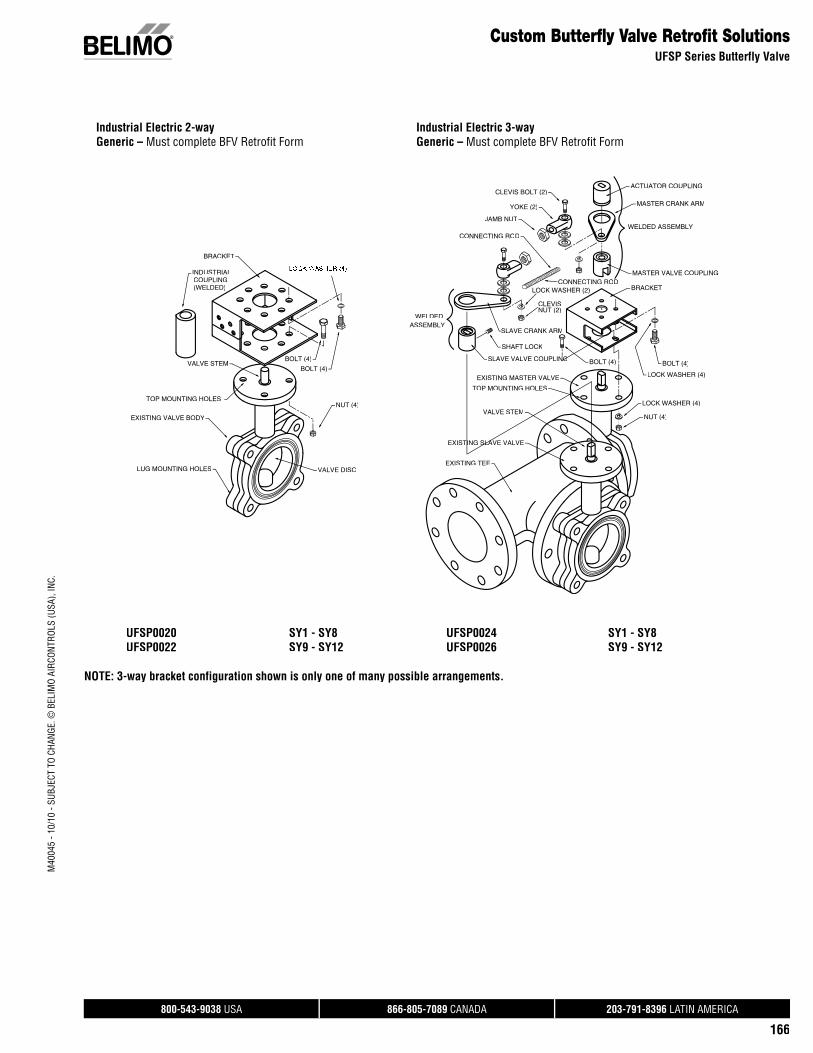
C.Custom Butterfly Valve Retrofit Solutions
UFSP Series Butterfly Valve
Industrial Electric 2-wayGeneric – Must complete BFV Retrofit Form
Industrial Electric 3-way Generic – Must complete BFV Retrofit Form
LUG MOUNTING HOLES VALVE DISC
TOP MOUNTING HOLES
EXISTING VALVE BODY
VALVE STEM
COUPLING(WELDED)
INDUSTRIAL
BRACKET
BOLT (4)
BOLT (4)
NUT (4)
MASTER VALVE COUPLING
ACTUATOR COUPLING
MASTER CRANK ARM
WELDED ASSEMBLY
BRACKET
YOKE (2)
JAMB NUT
CONNECTING ROD
CONNECTING ROD
SLAVE CRANK ARM
SLAVE VALVE COUPLINGN
SHAFT LOCK
CLEVIS BOLT (2)
LOCK WASHER (2)
CLEVISNUT (2)
BOLT (4)
LOCK WASHER (4)
NUT (4)
EXISTING TEE
EXISTING SLAVE VALVE
EXISTING MASTER VALVE
VALVE STEM
TOP MOUNTING HOLES
BOLT (4)
LOCK WASHER (4)
WELDEDASSEMBLY
UFSP0020 SY1 - SY8 UFSP0022 SY9 - SY12
UFSP0024 SY1 - SY8UFSP0026 SY9 - SY12
NOTE: 3-way bracket configuration shown is only one of many possible arrangements.

800-543-9038 USA 866-805-7089 CANADA 203-791-8396 LATIN AMERICA
177
M40
045
- 10/
10 -
SUBJ
ECT
TO C
HANG
E. ©
BEL
IMO
AIRC
ONTR
OLS
(USA
), IN
C.
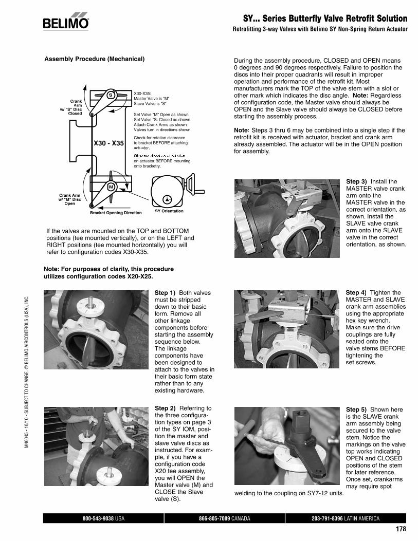
SY… Series Butterfly Valve Retrofit SolutionRetrofitting 3-way Valves with Belimo SY Non-Spring Return Actuator
Assembly Procedure for SY…Retrofit Solution
PREFERRED
DANGER
ACCEPTABLE
HORIZONTAL
90°
90°
10°
O
M
F
LN
A
H
JK
B
CD
QR
P E
EXISITING TEE
EXISITING SLAVE VALVE
EXISITING MASTER VALVE
BRACKET OPENING
WELDED
The initial step is to determine if your application can accept a retrofit solution. As shown below (Fig. 1), the valve stem must not be located belowthe horizontal plane. If this condition exists, the SY actuator could not be used in this situation. A Belimo technicalsupport person is available to help determine what solutionbest fits your application. A typical solution is shown in Fig. 2.
Depending on the orientation of the tee assembly, if the valves are mounted on the TOP and BRANCH positions (teemounted vertically), or on the LEFT and BRANCH positions (tee mounted horizontally) you will refer to configuration codes X10-X15.
Master Valve is Normally Open
Valves turn in directions shownAttach Crank Arms as shown
Slave Valve is Normally Closed
Check for rotation clearanceto bracket BEFORE attaching
Observe direction of rotationon actuator BEFORE mounting
Bracket Opening Direction
w/ "S" DiscClosed
Crank Arm
w/ "M" Disc
CrankArm
Open
M
onto bracketry.
S
Master Valve is "M"Slave Valve is "S"
actuator.
X20-X25:
SY Orientation
S0
X20 - X25
Bracket Opening Direction
w/ "S" Disc
w/ "M" Disc
S
Closed
Crank Arm
Arm
Open
CrankM
on actuator BEFORE mounting
to bracket BEFORE attaching
Set Valve "M" Open as shown
Observe direction of rotation
Check for rotation clearance
Valves turn in directions shownAttach Crank Arms as shownSet Valve "S: Closed as shown
actuator.
onto bracketry.
X10-X15:
Slave Valve is "S"Master Valve is "M"
S
X10 - X15
If the valves are mounted on the BOTTOM and BRANCHpositions (tee mounted vertically), or on the RIGHT andBRANCH positions (tee mounted horizontally) you willrefer to configuration codes X20-X25.
800-543-9038 USA 866-805-7089 CANADA 203-791-8396 LATIN AMERICA
178
M40
045
- 10/
10 -
SUBJ
ECT
TO C
HANG
E. ©
BEL
IMO
AIRC
ONTR
OLS
(USA
), IN
C.SY… Series Butterfly Valve Retrofit Solution
Retrofitting 3-way Valves with Belimo SY Non-Spring Return Actuator
Check for rotation clearance
Set Valve "S: Closed as shownSet Valve "M" Open as shown
Valves turn in directions shownAttach Crank Arms as shown
to bracket BEFORE attaching
on actuator BEFORE mounting
Bracket Opening Direction
Open
Crank Armw/ "M" Disc
w/ "S" DiscClosed
CrankArm
M
onto bracketry.
actuator.
S
Slave Valve is "S"Master Valve is "M"X30-X35:
X30 - X35
SY Orientation
S0
If the valves are mounted on the TOP and BOTTOMpositions (tee mounted vertically), or on the LEFT andRIGHT positions (tee mounted horizontally) you willrefer to configuration codes X30-X35.
Step 1) Both valvesmust be strippeddown to their basicform. Remove all other linkage components before starting the assembly sequence below. The linkage components havebeen designed to attach to the valves intheir basic form staterather than to anyexisting hardware.
Step 2) Referring tothe three configura-tion types on page 3of the SY IOM, posi-tion the master and slave valve discs asinstructed. For exam-ple, if you have a configuration code X20 tee assembly, you will OPEN the Master valve (M) andCLOSE the Slavevalve (S).
Note: For purposes of clarity, this procedureutilizes configuration codes X20-X25.
Step 3) Install the MASTER valve crank arm onto theMASTER valve in the correct orientation, as shown. Install the SLAVE valve crank arm onto the SLAVEvalve in the correctorientation, as shown.
Step 4) Tighten the MASTER and SLAVE crank arm assemblies using the appropriate hex key wrench. Make sure the drive couplings are fully seated onto the valve stems BEFORE tightening the set screws.
Step 5) Shown here is the SLAVE crank arm assembly being secured to the valve stem. Notice the markings on the valve top works indicating OPEN and CLOSED positions of the stem for later reference. Once set, crankarms may require spot
welding to the coupling on SY7-12 units.
During the assembly procedure, CLOSED and OPEN means0 degrees and 90 degrees respectively. Failure to position thediscs into their proper quadrants will result in improper operation and performance of the retrofit kit. Mostmanufacturers mark the TOP of the valve stem with a slot orother mark which indicates the disc angle. Note: Regardless of configuration code, the Master valve should always beOPEN and the Slave valve should always be CLOSED beforestarting the assembly process.
Note: Steps 3 thru 6 may be combined into a single step if the retrofit kit is received with actuator, bracket and crank armalready assembled. The actuator will be in the OPEN position for assembly.
Assembly Procedure (Mechanical)
800-543-9038 USA 866-805-7089 CANADA 203-791-8396 LATIN AMERICA
179
M40
045
- 10/
10 -
SUBJ
ECT
TO C
HANG
E. ©
BEL
IMO
AIRC
ONTR
OLS
(USA
), IN
C.
SY… Series Butterfly Valve Retrofit SolutionRetrofitting 3-way Valves with Belimo SY Non-Spring Return Actuator
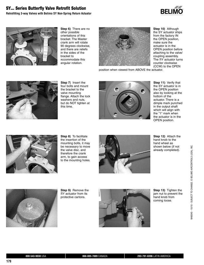
Step 6) There are no other possible orientations of this bracket. The Master crank arm will rotate 90 degrees clockwise, and there are reliefsin the sides of the bracket to accommodate this angular rotation.
Step 7) Insert thefour bolts and mountthe bracket to the valve mounting flange. Attach the lock washers and nuts,but do NOT tighten at this time.
Step 8) To facilitatethe insertion of the mounting bolts, it maybe necessary to move the valve disc, and therefore the crank arm, to gain access to the mounting holes.
Step 9) Remove the SY actuator from its protective cartons.
Step 10) Althoughthe SY actuator ships from the factory IN the OPEN position, make sure theactuator is in the OPEN position before attaching to the valve/coupling assembly. The SY actuator turns counter clockwise (CCW) to the OPEN
position when viewed from ABOVE the actuator.
Step 11) Verify thatthe SY actuator is in the OPEN position also by looking at thebottom of the actuator. There is adimple mark punchedin the output shaft which will align with the "1" mark whenthe actuator is in the OPEN position.
Step 12) Attach the hand knob to thehand wheel as shown below (if notalready completed).
Step 13) Tighten the jam nut to prevent the hand knob from coming loose.

800-543-9038 USA 866-805-7089 CANADA 203-791-8396 LATIN AMERICA
180
M40
045
- 10/
10 -
SUBJ
ECT
TO C
HANG
E. ©
BEL
IMO
AIRC
ONTR
OLS
(USA
), IN
C.SY… Series Butterfly Valve Retrofit Solution
Retrofitting 3-way Valves with Belimo SY Non-Spring Return Actuator
Step 14) Stand withthe opening in the actuator bracketfacing towards yourLEFT. Hold the SYactuator with the handwheel on the RIGHT, and the EMTconnectors to your LEFT. Align thesquare drive or keyway in the SY
actuator with the square drive or keys in the coupling (C). TheSY actuator will slide completely over the drive square and willrest ON the mounting bracket (A).
Step 15) Insert the four hex bolts (G) andlock washers (F)through the bracketand into the bottom of the SY actuator as shown. Do NOT tighten until all four sets have beeninstalled. Slight twisting of the entireSY actuator willfacilitate alignment of the bolts.
Step 16) After all four bolts have beeninserted, tighten accordingly.
Step 17) Now tightenthe four bracket bolts(B, C, D) assembledin step 6 above.
Step 18) Whenmechanical assemblyis complete, the SYactuator and MASTER valve should be oriented asshown below. Theactuator is in the OPEN position, and the valve disc is fullyOPEN, and all bolts are tight.
Step 19) The SLAVE valve is fully CLOSED with the crank armoriented as shown.
Note:The assembly now must be tested electrically beforemechanical connection is made between the MASTER and SLAVE valve crank arms. Continue with electricalassembly on page 18 for On/Off models or page 20 of the SYIOM for proportional models.
Application Note:The hand wheel on the SY actuator is engaged at all times but does not rotate when the actuator is running. It is possible at anytime to turn the hand wheel by simply rotating it CW or CCW. The hand wheel does NOT need tobe pulled or pushed into the actuator to make it operational. However, it should be noted that if a control signal andpower is present at the actuator when the hand wheel isturned, the actuator will return to its controlled position. If it is desired to have the actuator maintain its position after turning the hand wheel, it will be necessary to remove power from the actuator, either at the source or by use of an optional SY-HOA local switch.
800-543-9038 USA 866-805-7089 CANADA 203-791-8396 LATIN AMERICA
181
M40
045
- 10/
10 -
SUBJ
ECT
TO C
HANG
E. ©
BEL
IMO
AIRC
ONTR
OLS
(USA
), IN
C.
SY… Series Butterfly Valve Retrofit SolutionRetrofitting 3-way Valves with Belimo SY On/Off Non-Spring Return Actuator
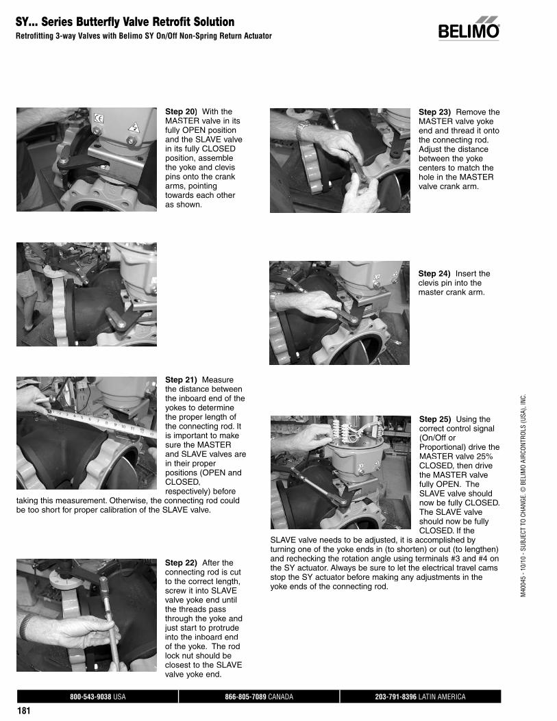
Step 21) Measure the distance betweenthe inboard end of the yokes to determine the proper length of the connecting rod. It is important to make sure the MASTER and SLAVE valves are in their proper positions (OPEN and CLOSED, respectively) before
taking this measurement. Otherwise, the connecting rod could be too short for proper calibration of the SLAVE valve.
Step 25) Using the correct control signal (On/Off or Proportional) drive the MASTER valve 25% CLOSED, then drive the MASTER valve fully OPEN. The SLAVE valve should now be fully CLOSED. The SLAVE valve should now be fully CLOSED. If the
SLAVE valve needs to be adjusted, it is accomplished byturning one of the yoke ends in (to shorten) or out (to lengthen)and rechecking the rotation angle using terminals #3 and #4 onthe SY actuator. Always be sure to let the electrical travel camsstop the SY actuator before making any adjustments in theyoke ends of the connecting rod.
Step 22) After the connecting rod is cut to the correct length, screw it into SLAVEvalve yoke end until the threads pass through the yoke andjust start to protrude into the inboard end of the yoke. The rod lock nut should be closest to the SLAVE valve yoke end.
Step 23) Remove the MASTER valve yokeend and thread it onto the connecting rod. Adjust the distance between the yokecenters to match the hole in the MASTER valve crank arm.
Step 24) Insert theclevis pin into the master crank arm.
Step 20) With the MASTER valve in itsfully OPEN position and the SLAVE valve in its fully CLOSED position, assemble the yoke and clevispins onto the crank arms, pointing towards each other as shown.
800-543-9038 USA 866-805-7089 CANADA 203-791-8396 LATIN AMERICA
182
M40
045
- 10/
10 -
SUBJ
ECT
TO C
HANG
E. ©
BEL
IMO
AIRC
ONTR
OLS
(USA
), IN
C.
Step 28) Replace the cover on the SY actuator and securethe four cover screws. One final check to make sure all bolts, screws, nuts & setscrews are tight.
Step 29) The mechanical and electrical installation of yourretrofit system is now complete.
END PROCEDURE
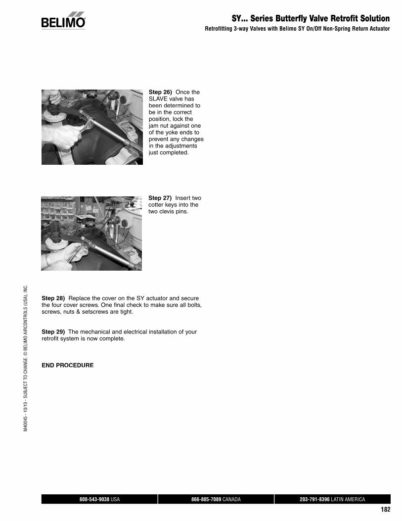
Step 26) Once the SLAVE valve hasbeen determined to be in the correct position, lock thejam nut against oneof the yoke ends to prevent any changesin the adjustments just completed.
Step 27) Insert two cotter keys into thetwo clevis pins.
SY… Series Butterfly Valve Retrofit SolutionRetrofitting 3-way Valves with Belimo SY On/Off Non-Spring Return Actuator

800-543-9038 USA 866-805-7089 CANADA 203-791-8396 LATIN AMERICA
183
M40
045
- 10/
10 -
SUBJ
ECT
TO C
HANG
E. ©
BEL
IMO
AIRC
ONTR
OLS
(USA
), IN
C.
SY… Series Butterfly Valve Retrofit SolutionRetrofitting 3-way Valves with Belimo SY On/Off Non-Spring Return Actuator
Step 1) Remove thefour hex boltssecuring the cover tothe base casting.
Step 6) Apply propervoltage to terminals #1 (Neutral) and #7(Hot). Apply properactuator voltage toterminals #1 (Neutral) and #4 (Hot) to drive the actuator CLOSED until the end-of-travelcam STOPS the actuator movement. (Note that there is no terminal #2).
Step 7) Visually check the position of the valve to make sure it reaches its full CLOSED position.
Step 2) Remove cover from the SY actuator. A flat bladescrewdriver inserted carefully into the provided slot (as shown) will facilitate removal of the cover.
Step 3) Conduit entries into the SY actuator must be selectedfor their operating location (indoors protected, indoors washdown, outdoors, etc). Be sure to follow standard NEC guidelines when selecting conduit and connector types.
Step 4) Follow the wire sizing chart in the InstallationOperation Manual (IOM) (Belimo p/n 71150-00001.C page 10) to make sure you use the correctly size wire when connectingthe SY to your power source. Failure to follow the recommendations in the table could cause actuator failure ornuisance tripping.
Step 5) Follow the wiring diagrams in the IOM (pages 18[single] and 23 [multiple]) for proper power and control wiringto the SY actuator. Make note of the following:
a. Do NOT connect multiple actuators in parallel withoutisolation relays.
b. Be sure "Hot" is connected to terminal #7 to enablethe heater circuit, and "Neutral" is connected to terminal #1.
Step 8) Apply proper actuator voltage toterminals #1 (Neutral) and #3 (Hot) to drive the actuator OPEN until the end-of-travel cam STOPS the actuator movement.
Step 9) Visually check the position of the valve disc to makesure it reaches its full OPEN position.
Step 10) If the MASTER valve functions properly, mechanicalassembly and electrical checkout are complete.
FACTORY NOTE:
The SY actuators have been calibrated at the factory before shipping to you for use in this retrofit kit. The SY actuator calibration will suffice 99% of the time for yourapplication. Improper calibration to the actuator may void your warranty. If you have any questions, please contact aBelimo technical support representative at 800-543-9038for assistance.
WARNING
Assembly Procedure (Electrical), On/Off Models

800-543-9038 USA 866-805-7089 CANADA 203-791-8396 LATIN AMERICA
184
M40
045
- 10/
10 -
SUBJ
ECT
TO C
HANG
E. ©
BEL
IMO
AIRC
ONTR
OLS
(USA
), IN
C.SY…P Series Butterfly Valve Retrofit Solution
Retrofitting 3-way Valves with Belimo SY Proportional Non-Spring Return Actuator
Step 1) Remove thefour hex boltssecuring the cover tothe base casting.
Assembly Procedure (Electrical), Proportional Models
Step 2) Remove cover from the SY actuator. A flat blade screwdriver inserted carefully into the provided slot (asshown) will facilitate removal of the cover.
Step 3) Conduit entries into the SY actuator must be selectedfor their operating location (indoors protected, indoors washdown, outdoors, etc). Be sure to follow standard NEC guidelines when selecting conduit and connector types.
Step 4) Follow the wire sizing chart in the InstallationOperation Manual (IOM) (Belimo p/n 71150-00001.C page 10) to make sure you use the correct size wire when connectingthe SY to your power source. Failure to follow therecommendations in the table could cause actuator failure or nuisance tripping.
Step 5) Follow the wiring diagrams in the IOM (pages 14-37) for proper power and control wiring to the SY actuator.
Step 6) Connect the proper electrical power and control wiring per the wiring diagrams located in the IOM (pages 14-37).
Step 7) Check the operation of the actuator by commanding the control system to generate control signals matching the needs of the job to run the valve from fully CLOSED to fully OPEN, as well as a MID-POINT position. The indicator on the top of the SY actuator will be an indicator as to the position of the actuator, and therefore,the valve position.
When operating the MASTER valve between fully OPEN and CLOSED, check the clearance between the crank armand the actuator bracket. The crank arm should NEVERcome into contact with the actuator mounting bracket. If it does, immediately remove power form the actuator and call Belimo technical support for recalibration instructions.
Step 8) If the valve functions properly, mechanical assembly and electrical checkout are complete.
FACTORY NOTE:
The SY actuators have been calibrated at the factorybefore shipping to you for use in this retrofit kit. The SY actuator calibration will suffice 99% of the time for yourapplication. Improper calibration to the actuator may voidyour warranty. If you have any questions, please contact a Belimo technical support representative at 800-543-9038 for assistance.
WARNING
Note: All SY1-P and SY2..12-MFT actuators are factory pre-setwith the proper customer requested control programming.