
CFD SIMULATIONS OF LID DRIVEN CAVITY FLOW AT MODERATE REYNOLDS NUMBER
14
European Scientific Journal May 2013 edition vol.9, No.15 ISSN: 1857 – 7881 (Print) e - ISSN 1857- 7431 22 CFD SIMULATIONS OF LID DRIVEN CAVITY FLOW AT MODERATE REYNOLDS NUMBER Reyad Omari Department of Mathematics, Al-Balqa Applied University, Irbid University college, Irbid, Jordan Abstract Computational fluid dynamics (CFD) simulations are carried out for laminar incompressible fluid flow in lid driven cavity (10 ≤ Re ≤ 1000). The ratio of the height to the width of the cavity are ranged over H/L = 0.5 to 1.5. A commercial finite volume package FLUENT was used to analyze and visualize the nature of the flow inside the cavity of different aspect ratio. The simulation results are presented in terms of velocity profile, pressure coefficient and stream contours. It was found that the pressure coefficient inside the cavity is strongly governed by the aspect ratio as well as the Reynolds number. Velocity profile for special case of a square cavity (AR = 1) was found to be in good agreement with previous experimental results. The present study has established that commercially-available software like FLUENT can provide a reasonable good solution of complicated flow structures including flow inside cavities. Keywords: CFD simulation, Laminar flow, Drag coefficient, Lid driven cavity Introduction The lid-driven cavity flow is the motion of a fluid inside a rectangular cavity created by a constant translational velocity of one side while the other sides remain at rest. Fluid flow behaviors inside lid driven cavities have been the subject of extensive computational and experimental studies over the past years. Applications of lid driven cavities are in material processing, dynamics of lakes, metal casting and galvanizing. The macroscopic variables of interest in conventional numerical methods, such as velocity and pressure are usually obtained by solving the Navier-Stokes equation. Such numerical methods for two dimensional steady incompressible Navier-Stokes equations are often tested for code validation. The one sided lid-driven square cavity flow has been used as
-
Upload
independent -
Category
Documents
-
view
3 -
download
0
Transcript of CFD SIMULATIONS OF LID DRIVEN CAVITY FLOW AT MODERATE REYNOLDS NUMBER

European Scientific Journal May 2013 edition vol.9, No.15 ISSN: 1857 – 7881 (Print) e - ISSN 1857- 7431
22
CFD SIMULATIONS OF LID DRIVEN CAVITY FLOW AT MODERATE REYNOLDS NUMBER
Reyad Omari Department of Mathematics, Al-Balqa Applied University,
Irbid University college, Irbid, Jordan
Abstract
Computational fluid dynamics (CFD) simulations are carried out for laminar
incompressible fluid flow in lid driven cavity (10 ≤ Re ≤ 1000). The ratio of the height to the
width of the cavity are ranged over H/L = 0.5 to 1.5. A commercial finite volume package
FLUENT was used to analyze and visualize the nature of the flow inside the cavity of
different aspect ratio. The simulation results are presented in terms of velocity profile,
pressure coefficient and stream contours. It was found that the pressure coefficient inside the
cavity is strongly governed by the aspect ratio as well as the Reynolds number. Velocity
profile for special case of a square cavity (AR = 1) was found to be in good agreement with
previous experimental results. The present study has established that commercially-available
software like FLUENT can provide a reasonable good solution of complicated flow structures
including flow inside cavities.
Keywords: CFD simulation, Laminar flow, Drag coefficient, Lid driven cavity
Introduction
The lid-driven cavity flow is the motion of a fluid inside a rectangular cavity created
by a constant translational velocity of one side while the other sides remain at rest. Fluid flow
behaviors inside lid driven cavities have been the subject of extensive computational and
experimental studies over the past years. Applications of lid driven cavities are in material
processing, dynamics of lakes, metal casting and galvanizing.
The macroscopic variables of interest in conventional numerical methods, such as
velocity and pressure are usually obtained by solving the Navier-Stokes equation. Such
numerical methods for two dimensional steady incompressible Navier-Stokes equations are
often tested for code validation. The one sided lid-driven square cavity flow has been used as

European Scientific Journal May 2013 edition vol.9, No.15 ISSN: 1857 – 7881 (Print) e - ISSN 1857- 7431
23
a benchmark problem for many numerical methods due to its simple geometry and
complicated flow behaviors. It is usually very difficult to capture the flow phenomena near
the singular points at the corners of the cavity (Chen, 2009 and 2011. Migeon et al. (2003)
(N. A. C. Sidik and S. M. R. Attarzadeh, 2011) considered the cubic interpolated
pseudo particle method and validate their results with the shear driven flow in shallow
cavities. (Li et al., 2011) applied the new version of multiple relaxation time lattices
Boltzmann method to investigate the fluid flow in deep cavity.
There have been some works devoted to the issue of heat transfer in the shear driven
cavity. (Manca et al., 2003) presented a numerical analysis of laminar mixed convection in an
open cavity with a heated wall bounded by a horizontally insulated plate. Results were
reported for Reynolds numbers from 100 to 1000 and aspect ratio in the ranges from 0.1 to
1.5. They presented that the maximum decrease in temperature was occurred at higher
Reynolds. The effect of the ratio of channel height to the cavity height was found to be
played a significant role on streamlines and isotherm patterns for different heating
configurations. The investigation also indicates that opposing forced flow configuration has
the highest thermal performance, in terms of both maximum temperature and average Nusselt
number.
(Gau and Sharif, 2004) reported mixed convection in rectangular cavities at various
aspect ratios with moving isothermal side walls and constant flux heat source on the bottom
wall. Numerical simulation of unsteady mixed convection in a driven cavity using an
externally excited sliding lid is conducted by (Khanafer et al. 2007). They observed that, Re
and Gr would either enhance or retard the energy transport process and drag force behavior
depending on the conduct of the velocity cycle.
(Ch.-H. Bruneau and M. Saad, 2006, Batchelor, (1956), have pointed out that, driven
cavity flows exhibit almost all the phenomena that can possibly occur in incompressible
flows: eddies, secondary flows, complex three-dimensional patterns, chaotic particle motions,
instability, and turbulence. Thus, these broad spectra of features make the cavity flows
overwhelmingly attractive for examining the computational schemes.
This paper aims to provide a CFD simulation study of incompressible viscous laminar
flow in cavity flow over arrange of aspect ratio (0.5 ≤ AR ≤ 1.5) by using commercial finite
volume package FLUENT. Another sub goal of the present study is to test whether FLUENT,
a commercial Computational Fluid Dynamics (CFD) software package, is capable of
providing the solutions for the problem under consideration.

European Scientific Journal May 2013 edition vol.9, No.15 ISSN: 1857 – 7881 (Print) e - ISSN 1857- 7431
24
Theoretical Formulation Governing equations The fluid flow in open lid driven cavity can be simulated by a set of mass and
momentum conservation equations. The flow is assumed to be two-dimensional, laminar,
incompressible and Newtonian. The governing non-linear partial differential equations can be
written as follows:
continuity equation:
0=∂∂
+∂∂
YV
XU
(1)
x-momentum equation:
∂∂
+∂∂
+∂∂
−=∂∂
+∂∂
+∂∂
2
2
2
21XU
XU
eRYP
YUV
XUUU
τ (2)
y-momentum equation:
∂∂
+∂∂
+∂∂
−=∂∂
+∂∂
+∂∂
2
2
2
21XV
XV
eRYP
YVV
XVUV
τ (3)
The above equations were non-dimensionalized as follows:
∞
=UuU ;
∞
=U
vV ; LxX = ;
LyY = ; (4)
and
LtU∞=τ ;
∞
=UpP
ρ;
νlUeR ∞= ; (5)
The L is the reference length dimension (width of the cavity along lower lid), while
U∞ is the reference velocity dimension. The fluid property ν, refers to the kinematic viscosity.
The Reynold’s number, Re, is the ratio of inertial to viscous forces, which influences the fluid
flow features within the cavity.
Boundary conditions No-slip velocity boundary condition (u = v = 0) is applied on all the walls, except the
top lid. On the top lid (U= 1 and V = 0) is applied. The bottom boundary of the domain is
modeled as wall .The boundary conditions which describing the current simulated
computational domain as well as the surface boundary layer is depicted in Figure 1.
Numerical Methods A finite volume method is employed using commercial software FLUENT 6.2 to
solve the governing equations subject to specified boundary conditions. Since the boundary
layer separation is intimately connected with the pressure and velocity distribution in the

European Scientific Journal May 2013 edition vol.9, No.15 ISSN: 1857 – 7881 (Print) e - ISSN 1857- 7431
25
boundary layer, accurate separation point predication are dependent on accurate resolution of
the boundary layer near the surface of the cavity. More cells are constructed near the surface
of the cavity to compensate the high velocity gradient in the boundary layer region of the
viscous flow. A commercial software GAMBIT is used for grid generation. The coupling
between the pressure and velocity fields is achieved using PISO. A second order upwind
scheme is used for the convection. Here in this study, following [10], we define the pressure
drag coefficient, PC as follows:
AUppC p 2
)(2
∞
∞−=
ρ (6)
∞p is the pressure of the stream, A is appropriate cavity surface area and ∞U is lid velocity.
The grid independence is achieved by comparing the results of the different grid cell size. It
was found that 65000 cells are satisfactory, and any increase beyond this size would lead to
an insignificant change in the resulting solution.
Results and Discussion Simulation results for incompressible laminar flow in square cavity (AR = 1) are
compared to experimental data to verify the validity of the CFD simulation solution. Fig. 2
and Fig. 3 show the U and V-velocity profiles along a vertical and horizontal line respectively
passing through the geometric centre of the square cavity for (AR = 1). As can be seen there
is an excellent agreement in the velocity profile between CFD simulations in this study and
the experimental measured by.
First, the influence of the cavity aspect ratio on the flow field in the cavity is shown in
Fig. 4 and 5 while the Reynolds number was fixed. Fig. 4 and 5 demonstrate the computed U-
velocity along a vertical line passing through the geometric centre of the different aspect ratio
cavity for Re = 1000 and 100 respectively. It is clear that the core of the vortices lay near the
vicinity of the corner of the cavity for large aspect ratio. In addition, one may notice that as
Reynolds number increases thin boundary layers are developed along the solid walls and the
core fluid moves as a solid body with a uniform vorticity, in the manner suggested by [3].
Fig. 6 and 7 demonstrate the computed V-velocity along a horizontal line passing through the
geometric centre of the square cavity for Re = 1000 and 100 respectively. They show a
gradually decreasing velocity near the centre and the development of narrow boundary layers
along the walls regardless the aspect ratio. For low Reynolds number a thicker boundary
layer is produced. It can be also noted that the boundary layer produced for low aspect ratio is
thinner along the walls. In both figures the changes in the velocity direction lead to vortex
development.

European Scientific Journal May 2013 edition vol.9, No.15 ISSN: 1857 – 7881 (Print) e - ISSN 1857- 7431
26
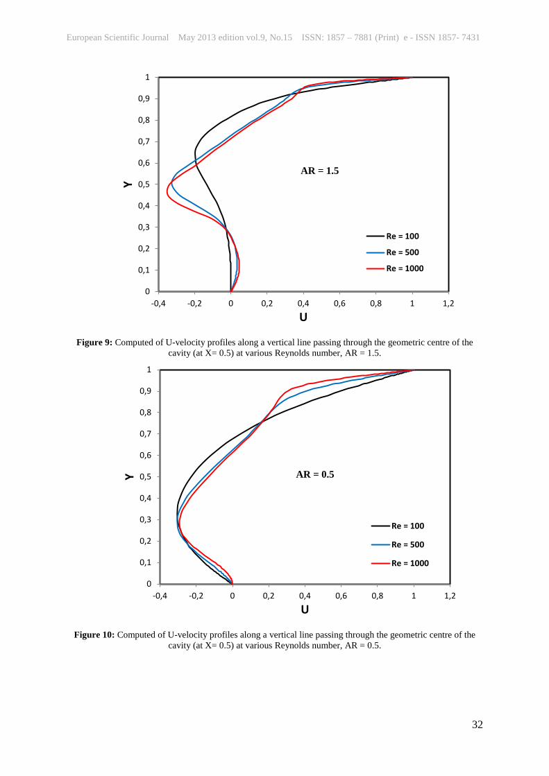
Fig. 8, 9 and 10 demonstrate the computed U- velocity along a vertical line passing
through the geometric centre of the different aspect ratio cavity for Re = 1000, 500 and 100
respectively. As might be expected, near the lid the stream wise U-component displays a
steadily thinner boundary layer as Re increased regardless the aspect ratio. But at the bottom
wall, counterintuitively, the peak U decreases with Reynolds number although it does move
towards the wall as expected. For AR = 0.5 the effect of Rynolds number on the U-velocity
is insignificant and dominant for large aspect ratio.
The dimensionless pressure drop coefficient for the cavity is an important parameter
in the design of the cavity. In Fig. 11 the variation of the pressure drop coefficient along a
vertical line passing through the geometric centre of the different aspect ratio cavity is shown.
The pressure drop coefficient is a strong function of the position, aspect ratio and Reynolds
number. It can be noted that the pressure drop coefficient is higher for lower aspect ratio. The
pressure drop coefficient attains its maximum value within the above half cavity, whereas for
most cavity aspect ratio it gains the minimum value with the bottom half cavity.
In order to visualize the overall flow patterns, the streamline plots from the
computational data for different aspect ratio are at different Reynolds number is shown in
Fig. 11 and Fig.12. For smaller aspect ratio the center of the primary eddy moves right with
respect to right wall cavity. However, as the aspect ratio increases beyond a value of 1, the
center of the primary eddy remain constant below the top lid for Reynolds number 100. At
high value of Reynolds number, strong shear force drags the flow and causes the vortex to
break into two smaller vortices for AR= 0.5 and AR =1.5. For aspect ratio AR = 1.0 and high
Reynolds number the primary eddy shifted to the center of the cavity (see Fig.12).
Conclusion Computational fluid dynamics (CFD) simulations are carried out for laminar
incompressible fluid flow in lid driven cavity fordifferent aspect ratio. The nature of the flow
inside lid driven cavity of different aspect ratio was visualized. It was found that the
dynamics and structure of primary vortex are strongly affected by the Reynolds number as
well as the aspect ratio of the cavity. It was noted that the pressure drop coefficient is a strong
function of the position, aspect ratio and Reynolds number. Comparison the simulation
results with the experimental data validate the commercially-available software FLUENT in
providing a reasonable good solution of complicated flow structures, including flow with
separation.

European Scientific Journal May 2013 edition vol.9, No.15 ISSN: 1857 – 7881 (Print) e - ISSN 1857- 7431
27
References:
(Chen S 2009) A large-eddy-based lattice Boltzmann model for turbulent flow simulation.
Applied Mathematics and Computation, 215, 591–595.
N. A. C. Sidik and S. M. R. Attarzadeh, An accurate numerical prediction of solid particle
fluid flow in a lid-driven cavity. Intl. J. Mech. 2011, 5(3): 123-128.
S.L. Li, Y.C. Chen, and C.A. Lin. Multi relaxation time lattice Boltzmann simulations of
deep lid driven cavity flows at different aspect ratios. Comput. & Fluids, 2011, 45(1): 233-
240.
A.J. Chamkha, Hydromagnetic combined convection flow in a vertical lid-driven cavity with
internal heat generation or absorption, Numer. Heat Transfer, Part A, vol. 41, pp.529-546,
2002.
K.M. Khanafer, A.M. Al-Amiri and I. Pop, Numerical simulation of unsteady mixed
convection in a driven cavity using an externally excited sliding lid, European J. Mechanics
B/Fluids, vol. 26, pp.669-687, 2007.
G.K. Batchelor. On Steady Laminar Flow with Closed Streamlines at Large Reynolds
Numbers. J. Fluid Mech. 1956; 1:177–190.
O. Manca, S. Nardini, K. Khanafer and K. Vafai, Effect of Heated Wall Position on Mixed
Convection in a Channel with an Open Cavity, Numer. Heat Transfer, Part A, vol. 43,
pp.259–282, 2003.
G. Gau and M.A.R. Sharif, Mixed convection in rectangular cavities at various aspect ratios
with moving isothermal side walls and constant flux heat source on the bottom wall Int. J.
Therm. Sci., 43, pp. 465–475, 2004.
C. Migeon, G. Pineau, and A. Texier, Three-dimensionality development inside standard
parallel pipe lid-driven cavities at Re = 1000. J. Fluids and Struc. 2003, 17 (1): 717–738.
Ch.-H. Bruneau, M. Saad, The 2D lid-driven cavity problem revisited, Computers & Fluids35
(3), 2006.

European Scientific Journal May 2013 edition vol.9, No.15 ISSN: 1857 – 7881 (Print) e - ISSN 1857- 7431
28
Figure 1: Computational mesh for the lid-driven square cavity, AR = 1 (65000 cells)
Figure 2: Comparison of U-velocity profiles along a vertical line passing through the geometric centre of the
cavity (at X= 0.5)
0
0,1
0,2
0,3
0,4
0,5
0,6
0,7
0,8
0,9
1
-0,4 -0,2 0 0,2 0,4 0,6 0,8 1
Y
U
present studyGhia at al.
Re = 1000
H
L
Lid, velocity
Right-wall Left -wall
Bottom

European Scientific Journal May 2013 edition vol.9, No.15 ISSN: 1857 – 7881 (Print) e - ISSN 1857- 7431
29
Figure 3: Comparison of V-velocity profiles along a horizontal line passing through the geometric centre of the cavity (at Y= 0.5)
Figure 4: Computed of U-velocity profiles along a vertical line passing through the geometric centre of the cavity (at X= 0.5) at various aspect ratios, Re = 1000.
-0,6
-0,5
-0,4
-0,3
-0,2
-0,1
0
0,1
0,2
0,3
0,4
0,5
0 0,2 0,4 0,6 0,8 1
V
X
present studyGhia et al.
Re = 1000
0
0,1
0,2
0,3
0,4
0,5
0,6
0,7
0,8
0,9
1
-0,4 -0,2 0 0,2 0,4 0,6 0,8 1
Y
U
AR = 0.5AR = 1.0AR = 1.5Ghia et al.
Re = 1000

European Scientific Journal May 2013 edition vol.9, No.15 ISSN: 1857 – 7881 (Print) e - ISSN 1857- 7431
30
Figure 5: Computed of U-velocity profiles along a vertical line passing through the geometric centre of the
cavity (at X= 0.5) at various aspect ratios, Re = 100.
Figure 6: Computed of V-velocity profiles along a horizontal line passing through the geometric centre of the cavity (at Y= 0.5) at various aspect ratios, Re = 1000.
0
0,1
0,2
0,3
0,4
0,5
0,6
0,7
0,8
0,9
1
-0,4 -0,2 0 0,2 0,4 0,6 0,8 1 1,2
Y
U
AR = 0.5AR = 1AR = 1.5
Re = 100
-0,8
-0,6
-0,4
-0,2
0
0,2
0,4
0,6
0 0,2 0,4 0,6 0,8 1
V
X
AR = 0.5AR = 1.0AR = 1.5Ghia et al.
Re = 1000

European Scientific Journal May 2013 edition vol.9, No.15 ISSN: 1857 – 7881 (Print) e - ISSN 1857- 7431
31
Figure 7: Computed of V-velocity profiles along a horizontal line passing through the geometric centre of the cavity (at Y= 0.5) at various aspect ratios, Re = 100.
Figure 8: Computed of U-velocity profiles along a vertical line passing through the geometric centre of the cavity (at X= 0.5) at various Reynolds number, AR = 1.
-0,4
-0,3
-0,2
-0,1
0
0,1
0,2
0,3
0 0,2 0,4 0,6 0,8 1
V
X
AR = 0.5
AR = 1.0
AR = 1.5
Re = 100
0
0,1
0,2
0,3
0,4
0,5
0,6
0,7
0,8
0,9
1
-0,6 -0,4 -0,2 0 0,2 0,4 0,6 0,8 1 1,2
Y
U
Re = 100Re = 500Re = 1000
AR = 1
European Scientific Journal May 2013 edition vol.9, No.15 ISSN: 1857 – 7881 (Print) e - ISSN 1857- 7431
32
Figure 9: Computed of U-velocity profiles along a vertical line passing through the geometric centre of the cavity (at X= 0.5) at various Reynolds number, AR = 1.5.
Figure 10: Computed of U-velocity profiles along a vertical line passing through the geometric centre of the cavity (at X= 0.5) at various Reynolds number, AR = 0.5.
0
0,1
0,2
0,3
0,4
0,5
0,6
0,7
0,8
0,9
1
-0,4 -0,2 0 0,2 0,4 0,6 0,8 1 1,2
Y
U
Re = 100
Re = 500
Re = 1000
AR = 1.5
0
0,1
0,2
0,3
0,4
0,5
0,6
0,7
0,8
0,9
1
-0,4 -0,2 0 0,2 0,4 0,6 0,8 1 1,2
Y
U
Re = 100
Re = 500
Re = 1000
AR = 0.5

European Scientific Journal May 2013 edition vol.9, No.15 ISSN: 1857 – 7881 (Print) e - ISSN 1857- 7431
33
Figure 11: Computed of pressure coefficient along a vertical line passing through the geometric centre of the cavity (at X= 0.5) at various aspect ratios, Re = 100.
AR = 0.5
AR = 1.0
AR =1.5
-0,2
-0,15
-0,1
-0,05
0
0,05
0 0,2 0,4 0,6 0,8 1
Cp
Y
AR = 0.5AR = 1.0AR = 1.5
Re = 100

European Scientific Journal May 2013 edition vol.9, No.15 ISSN: 1857 – 7881 (Print) e - ISSN 1857- 7431
34
Figure 12: Contours of stream function at different aspect ratio for Re = 100. AR = 0.5
AR = 1.0
AR = 1.5

European Scientific Journal May 2013 edition vol.9, No.15 ISSN: 1857 – 7881 (Print) e - ISSN 1857- 7431
35
Figure 13: Contours of stream function at different aspect ratio for Re = 1000.
Nomenclature
L [m] length of the cavity in the flow direction
H [m] height of the cavity in the direction normal to the flow
AR [-] aspect ratio H/L
Cp [-] pressure drag coefficient
P [N/m2] pressure
Re [-] Reynolds number
∞U [m/s] lid velocity
U [m/s] x-component velocity
V [m/s] y-component velocity
Greek Symbols
µ [Pa.s] fluid dynamic viscosity
ρ [kg/m3] fluid density