CERBERUS 2003 TEAM REPORT
28
CERBERUS 2003 TEAM REPORT H. Levent Akın * , M. Kaan Baloğlu Hatice Köse Bağcı, Suzan Bayhan, Çetin Meriçli, Damla Poslu, Ömer Sever O. Taner Yıldız Svetlozar Argirov, Boris Marinov Petya Pavlova, Nikola Shakev, Jordan Tombakov, Andon Topalov 1 Department of Computer Engineering, Boğaziçi University, 80815, Bebek, Istanbul, Turkey Department of Control Systems, Technical University Sofia, Plovdiv branch, 61, St. Petersburg Blvd, Plovdiv 4000, Bulgaria October 14, 2003 * Corresponding Author
-
Upload
independent -
Category
Documents
-
view
0 -
download
0
Transcript of CERBERUS 2003 TEAM REPORT

CERBERUS 2003 TEAM REPORT
H. Levent Akın*, M. Kaan Baloğlu Hatice Köse Bağcı, Suzan Bayhan, Çetin Meriçli, Damla Poslu, Ömer Sever O. Taner Yıldız
Svetlozar Argirov, Boris Marinov Petya Pavlova, Nikola Shakev, Jordan Tombakov, Andon Topalov
1 Department of Computer Engineering, Boğaziçi University, 80815, Bebek, Istanbul, Turkey
Department of Control Systems, Technical University Sofia, Plovdiv branch, 61, St. Petersburg
Blvd, Plovdiv 4000, Bulgaria
October 14, 2003
* Corresponding Author

ii
ACKNOWLEDGEMENTS
The members of the Boğaziçi University team would like to thank Prof. Sabih Tansal,
Rector of Boğaziçi University, Prof. Z. İlsen Önsan, Vice Rector and Chairperson of the
Executive Committee of the Boğaziçi University Research Fund, and Candan Fetvacı,
Coordinator of Boğaziçi University Foundation for their kind support throughout all the
phases of the project . We would also like to thank Profs. Ethem Alpaydın, Fikret Gürgen and
Lale Akarun and A.C. Cem Say for valuable discussions.
We gratefully acknowledge the support of our work by the Boğaziçi University Research
Fund through projects 01A101, 03A101D and Boğaziçi University Foundation.
iii
ABSTRACT
Cerberus is a joint effort of Boğaziçi University (Turkey) and Technical University of
Sofia, Plovdiv branch(Bulgaria). We have divided the robot software design into six major
tasks, and worked on those tasks in parallel. Many modules were developed using several
approaches and later integrated into the final system. In addition to using better algorithms,
improvements in the code were also made.
iv
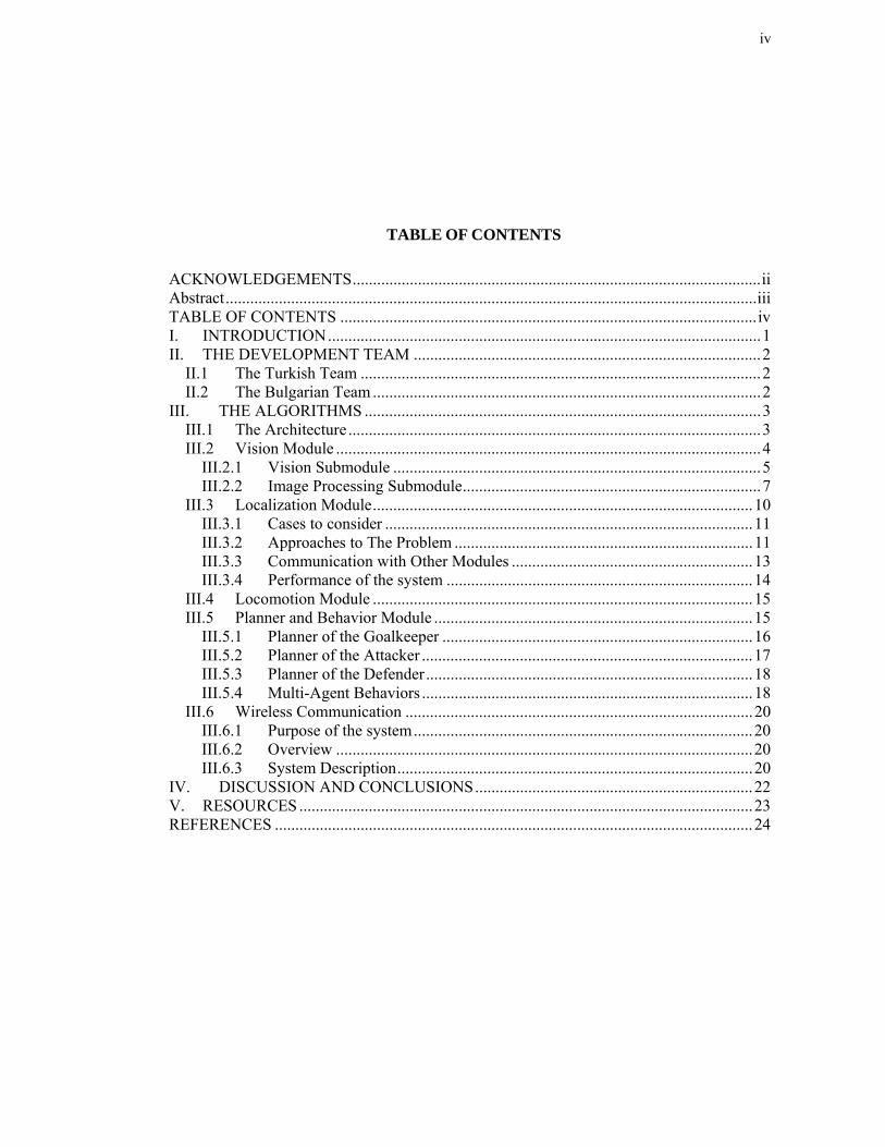
TABLE OF CONTENTS
ACKNOWLEDGEMENTS....................................................................................................ii Abstract..................................................................................................................................iii TABLE OF CONTENTS ......................................................................................................iv I. INTRODUCTION..........................................................................................................1 II. THE DEVELOPMENT TEAM .....................................................................................2
II.1 The Turkish Team ..................................................................................................2 II.2 The Bulgarian Team ...............................................................................................2
III. THE ALGORITHMS .................................................................................................3 III.1 The Architecture .....................................................................................................3 III.2 Vision Module ........................................................................................................4
III.2.1 Vision Submodule ..........................................................................................5 III.2.2 Image Processing Submodule.........................................................................7
III.3 Localization Module.............................................................................................10 III.3.1 Cases to consider ..........................................................................................11 III.3.2 Approaches to The Problem .........................................................................11 III.3.3 Communication with Other Modules ...........................................................13 III.3.4 Performance of the system ...........................................................................14
III.4 Locomotion Module .............................................................................................15 III.5 Planner and Behavior Module ..............................................................................15
III.5.1 Planner of the Goalkeeper ............................................................................16 III.5.2 Planner of the Attacker .................................................................................17 III.5.3 Planner of the Defender................................................................................18 III.5.4 Multi-Agent Behaviors .................................................................................18
III.6 Wireless Communication .....................................................................................20 III.6.1 Purpose of the system...................................................................................20 III.6.2 Overview ......................................................................................................20 III.6.3 System Description.......................................................................................20
IV. DISCUSSION AND CONCLUSIONS....................................................................22 V. RESOURCES ...............................................................................................................23 REFERENCES .....................................................................................................................24
1
I. INTRODUCTION
The Cerberus1 team made its debut in RoboCup 2001 competition. This was the first
international team participating in the league as result of the joint research effort of a group of
students and their professors from Boğaziçi University (BU), Istanbul, Turkey, and Technical
University Sofia, Plovdiv branch (TUSP), Plovdiv, Bulgaria.
Our general strategy was to divide the robot software into four major tasks, and assign one
subteam for each task. Each subteam started out by developing some working code for the
task, and by integrating it to produce a working system to begin with. Then, each subteam
gradually improved the modules. Some modules were assigned to two teams at the same time.
The groups were locomotion, localization, vision, behavior control. Taking into consideration
the deficiencies of Cerberus 2002 team, mainly in vision and locomotion, special emphasis
was given to these areas. Additionally, developing multi-agent behaviors that take into
consideration the use of wireless network card was also carried out.
Although some code from Cerberus 2002 team was used, the final implementation
consisted of mainly new algorithms, implemented using OPEN-R SDK.
1 In Greek mythology, Cerberus was the most dangerous labor of Hercules. It was a vicious beast that guarded the entrance to
Hades and kept the living from entering the world of the dead. It had three heads of wild dogs, a dragon or serpent for a tail, and heads of snakes all over his back.

2
II. THE DEVELOPMENT TEAM
The team is a joint effort of Boğaziçi University (Turkey) and Technical University of
Sofia, Branch Plovdiv (Bulgaria).
II.1 The Turkish Team
Assoc. Prof. H. Levent Akın, the head of the Artificial Intelligence Laboratory at the
Department of Computer Engineering, leads the Turkish team. The Turkish team has five
subteams:
• Vision and image processing: Olcay Taner Yıldız, and Ömer Sever.
• Localization: Hatice Köse and Suzan Bayhan.
• Locomotion: Burak Turhan, Damla Poslu.
• Wireless Communication: Cetin Mericli.
• Planner and behaviors: M.Kaan Baloğlu.
II.2 The Bulgarian Team
The Bulgarian team is led by Assoc. Prof. Andon Topalov from the Technical University of
Sofia, Plovdiv branch. The Bulgarian team has three subteams:
• Vision and image processing: Dr. Petya Pavlova, Svetlozar Argirov
• Locomotion: Nikola Shakev, Svetlozar Argirov, Jordan Tombakov
• Behaviors: Assoc. Prof. Andon Topalov, Nikola Shakev, Boris Marinov

3
III. THE ALGORITHMS
Considering the shortcomings of our team in Robocup 2002 we decided to improve mainly
the locomotion, localization, vision components. Additionally, we decided to enhance our
planner and behavior component both by using new learning algorithms and extending multi-
agent behaviors.
In the development of the Cerberus 2003 team entry we tried to follow object-oriented
software analysis and design techniques as closely as possible. For almost all modules many
different approaches have been implemented and tested. These are described below.
III.1 The Architecture
The Cerberus team has developed a behavior-based architecture (Arkin 1998) for the robots
and has been using this architecture since 2001. The main objective of our team was to build a
research platform, which allows robust and efficient carriage of the robots playing football. A
modular architecture has been adopted and implemented. This year the implementation was
done using OPEN-R SDK.
Figure III.1 The architecture of the control system
The following are the main system components: Vision, Localization, Planner and

4
Behaviors, and Locomotion and Communication. The relationship between them can be seen
in Figure III.1.
The perception level of the control system consists of the Vision and Localization modules.
The Vision module accepts images from the camera and identifies objects on the field that are
visible. It delivers the identified objects as well as the distance to the object and its relative
direction to the Planner and Localization modules. The Localization module receives the
relative position of the landmarks around the play field from the Vision module. This
information is used to approximate the position and heading of the robot on the field.
The Planner and Communication modules form the logical level. They incorporate the
memory of the robot, decision-making and inter-robot communication. The Planner module
collects the information about the visible objects from the Vision module and stores it in the
local map. The local map presents the objects around the robot in polar coordinates. The
Planner also receives the position and heading of the robot from the Localization module.
Using this information, it decides what have to be done and invokes the appropriate behavior.
Communication module enables wireless communication between teammate the robots.
Exchanging of information can be used to fill the local map or to facilitate the cooperative
operations.
In the previous years’s entries the number of logical modules was equal to the number of
binary objects. But this year we have combined them into one binary as explained in
subsubsection III.2.2.4
The components of the architecture are described briefly below.
III.2 Vision Module
The design goals of the Vision Module are to supply accurate information in a timely
manner. The Vision Module is responsible for image acquisition, processing the image and
providing useful and acceptable information in a timely manner to the other modules in the
system. For example, the Localization Module gets the current beacon information, while the
Locomotion Module gets the head orientation while searching the ball from the Vision
Module. The Planner Module also needs the Vision Module to provide the local map
information to decide on the next action (Figure III.2).
The Vision Module can be considered as the core of the system. In order to make it work
more efficiently the module is separated into two submodules as Vision submodule and Image
Processing submodule. The two submodules will be explained in detail in later sections but
mainly the Vision submodule is responsible for the inter-object communication and

5
preprocessing of the image and Image Processing submodule is responsible for more high
level operations on the image such as region finding, region merging and object recognition.
Figure III.2. Inter-object communication regarding Vision.
The Vision Module of Cerberus 2002 was not so problematic. The algorithms seem to work
well under most circumstances and provide acceptable information to the other modules in the
system. The main problem in the system was the performance of the system. There were also
some minor problems in the code that should be arranged in a way not to affect the other
modules and also the Vision Module. We have also considered implementing new algorithms
instead of existing ones to increase the performance or the accuracy of the Vision Module.
III.2.1 Vision Submodule
The main aim of this module is to acquire image, preprocess the image, send it to the Image
Processing Module and after the processing send the information such as local map, beacons
to other modules. In order to carry out these operations efficiently, Vision submodule has
inter-object communications with other modules, namely, Localization, Locomotion and
Planner Modules. As can be seen from the subject observer information given below, the
Vision Module does not get information from other modules in the system except the system
modules that are picture taking and the sensors.
Subjects
Vision.SendLocalMapInfo.TLocalMap.S
Vision.SetCmdHC.Hc.S
Vision.SendLocInfo.TBeaconArray.S
Vision.SendLedInfo.TLedObjects.S

6
Observers
Vision.GetSensor.OSensorFrameVectorData.O
Vision.snapImage.OFbkImageVectorData.O
The description of the information sent is given below:
• SendLocalMapInfo is sent to Planner. It contains information about the current status of
the environment determined from the latest image taken.
• SetCmdHC is sent to the Locomotion Module. This subject is responsible for the head
orientation during the searching of the ball.
• SendLocInfo is sent to Localization Module. It contains the beacon information such as
how many beacons can be seen, which beacons they are, the confidence levels etc. That
information should be used by the Localization module to determine the current position
of the robot.
• SendLedInfo is sent to the LED Module. This module turns the leds on and off
according to the information sent by Vision submodule.
• GetSensor is an observer used by Vision submodule and its task is to control the sensors
and sent the information that is not sent to the appropriate module. It is known that this
observer runs 32 times per second.
• snapImage is the other observer used by the system. This observer is responsible for
getting the image taken by the robot. This observer is known to run 25 times per second.
III.2.1.1 Color Classification Algorithms Mainly the algorithms developed for Cerberus 2002 were used with some speed
improvements. The first approach depends on initially performing a preliminary color
separation of the pixels in the color space described by a triple consisting of hue – H,
saturation – S and achromatic parameter (Pavlova, Tombakov, and Shakev, 2002).
The other approach is based on using machine learning techniques for classification. One of
the algorithms used for color classification of the image is MLP which uses the neural
networks and the other one is ClassifyC45 which uses decision trees for the same purpose.
Currently our system uses ClassifyC45 for color classification in which there are 10
predefined colors. For the details of these algorithms please refer to Cerberus 2002 Team
Report.

7
III.2.2 Image Processing Submodule
This module does all the operations on the image to get the necessary information from the
image. These operations include the region finding, region merging and image recognition.
All of these are done after the color classification of the image.
The region finding algorithm first preprocesses the first row and first column of the image
to prepare it for the region merging algorithm. After the classification of the pixels, each pixel
has a color assigned to it. There are 10 colors, namely, the colors of ball, goals, beacons and
the pitch in the system. These pixels should be defined as a group to make a region. After
preparing the regions the next operation is merging. Two or more rows can have regions that
are of the same class of color, so they need to be merged in order to be registered as a big
region rather than small regions. We need as big regions as possible because processing of
bigger regions is easier and also conveys more information than small images. After these
steps, the objects that are related to those regions are recognized. The merged regions are
sorted according to the dimensions of those regions. Starting from the largest to the smallest,
first the ball is tried to be recognized. Next it recognizes the beacons and then the goals.
There were two main problems in the Cerberus 2002 code concernig these operations: One
of them is the region merging mechanism which requires two pass through the image and as a
result of this decreases the performance of the system. The other problem is the order of the
object recognition. The Cerberus 2002 system assumes that if has found the beacons before
finding the ball but it tries to find the beacons just after the ball recognition algorithm
executes. So the possibility of conveying wrong information to the Vision submodule
increases. These were solved as explained below.
III.2.2.1 Labeler Software A separate tool called Labeler Software has been developed to handle data collection and
the process of making decision trees and neural networks and has been in use in several
versions since 2001. After some training phase, this is done by describing the correct colors
on the image to the Labeler; the program is able to find the regions on the image. The pictures
below show two images. One of them is before the classification and the other one is after the
classification.

8
Figure III.3. Labeler and Images
III.2.2.2 Run Length Encoding The performance problem in the vision module was solved in part by using run length
encoding for the images. This algorithm consists of replacing horizontal runs of the same
color with a run. A run stores the color it is associated with, the x, y location at which it starts,
and the number of pixels included in the run. Run length encoding reduces the size of the
image in the memory. This reduces the amount of time needed by the processor to scan over
the entire image while performing some function. Only non-background pixels are encoded
into runs, which is why the x, y location is needed. Generally, this increases the speed at
which the robot can process data. An exception to this is the last background run on each scan
line is stored. This allows for more regular code since each line has at least one run on it. The
output of this stage is a run length encoded (RLE) image.
The Run Length Encoding algorithm has given us the chance to store the image taken by
the robot with much less memory. The structure used for run length encoding is 6 bytes long
which consists of the y coordinate, begin and end of x coordinate, color and the region
number. The average number of runs for an average image is around 1000. So the total
number of bytes needed for an image is no more than 6 KB. The original image taken by the
robot takes 76,4 KB. As it can be seen, the encoded image is about 8% of the original image.
This greatly reduces the need for memory and also CPU time.
Afterwards, the regions are merged using an algorithm that passes through the regions and
merge them if possible. This process does not take considerable time since the number of
9
regions is not so high.
The merging method employs a tree-based union with path compression. This offers not
only a performance improvement that is only good in practice but also provides a hard
algorithmic bound that is for all practical purposes linear. The merging is performed in place
on the classified RLE image. This is because each run contains a field with all the necessary
information; an identifier indicating a run's parent element (the upper leftmost member of the
region). Initially, each run labels itself as its parent, resulting in a completely disjoint forest.
The merging procedure scans adjacent rows and merges runs which are of the same color
class and overlap under four-connectedness. This results in a disjoint forest where the each
run's parent pointer points upward toward the region's global parent. Thus a second pass is
needed to compress all of the paths so that each run is labeled with its actual parent. Now each
set of runs pointing to a single parent uniquely identifies a connected region. The regions are
then extracted by finding all of the runs that have the same parent. The runs for each region
are linked together into a linked list to facilitate further processing. Summary statistics are
gathered for all of the regions including: bounding box, centroid, and area. The regions are
then separated based on color into linked lists and sorted in order of decreasing area. The
linked lists of regions form the output of this last stage and the main input to the high level
vision.
III.2.2.3 Object Recognition One of the problems that affect the performance of the system is the order of object
recognition. The ball recognition algorithm assumes that all beacon information is ready but
beacon recognition is executed after the ball recognition algorithm.
The accuracy of the system has also been increased by increasing the number of sanity
checks to provide better information to the other modules in the system.
III.2.2.4 Single Module Another work done for not only the Vision part but the whole system was to make the
system work as a single module. The main aim for this was to decrease the overhead caused
by the communications between modules and increase the performance. After the operation
was complete, there was a small increase in the performance. This was not the most important
result. The most important result was the serialization of the system. Namely, the operations
are done in a predetermined order. First, image is taken by the AIBO, then Vision module
processes the image and gets the object information, then Localization gets the information
and processes it, then Planner decides on what action to do based on the local map provided
10
by the Vision module, then Locomotion Module does the action. This provides a better result
and more control over the whole system. For the multiple module system, the order of
operations is not predictable because the system is real time event-based system. The
communication between modules is done via C++ structures instead of OPEN-R objects.
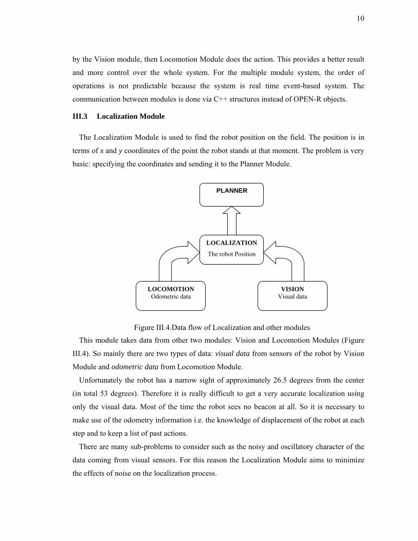
III.3 Localization Module
The Localization Module is used to find the robot position on the field. The position is in
terms of x and y coordinates of the point the robot stands at that moment. The problem is very
basic: specifying the coordinates and sending it to the Planner Module.
Figure III.4.Data flow of Localization and other modules
This module takes data from other two modules: Vision and Locomotion Modules (Figure
III.4). So mainly there are two types of data: visual data from sensors of the robot by Vision
Module and odometric data from Locomotion Module.
Unfortunately the robot has a narrow sight of approximately 26.5 degrees from the center
(in total 53 degrees). Therefore it is really difficult to get a very accurate localization using
only the visual data. Most of the time the robot sees no beacon at all. So it is necessary to
make use of the odometry information i.e. the knowledge of displacement of the robot at each
step and to keep a list of past actions.
There are many sub-problems to consider such as the noisy and oscillatory character of the
data coming from visual sensors. For this reason the Localization Module aims to minimize
the effects of noise on the localization process.
LOCOMOTION Odometric data
PLANNER
LOCALIZATION
The robot Position
VISION Visual data

11
III.3.1 Cases to consider
There are three cases to consider in localization process:
• No beacon case
• One beacon case
• Two beacons case
III.3.1.1 No-Beacon Case The most problematic situation is the case in which the robot does not see any beacons. In
this case localization relies on the odometry information. Odometric data received from
locomotion module is in the form of length moved from the previous time, and the angle of
the move. According to this data, the position of the robot is updated.
III.3.1.2 One Beacon Case One beacon is not sufficient for finding the robot position; it can only give an arc on which
the robot may be at any point. If there is past information about the robot position or beacon
data, this single beacon information may help to find the unique position of the robot.
III.3.1.3 Two Beacons Case Cross points of circles is the name of the method used for determining the position of an
object when only distances to other two objects are known. This is highly efficient method to
find the position. However here again there may be two possible points. Choosing the one of
the points may be done according to the later beacon data.
III.3.2 Approaches to The Problem
As explained above, the Vision Module processes the data provided by the camera of the
robot and sends it to the Localization Module. This information can be translated into this
form:”beacon x is seen at distance y ”. Localization module makes updates according to this
information every time it is received. Other types of information also come when the robot
makes a move. Since the data received from these two modules are in no special order,
processing them is done according to the received information. It means that if beacon
information arrives, visual update is done. Otherwise the “odometric” update is done (Köse,
Bayhan and Akın, 2003).
III.3.2.1 Methods Used The main idea of the localization process is based on the “grid world” model: The field is
divided into equal sized squares. Each square represents an area of the field corresponding to

12
some points. There are 28 grid cells at the longer side and 18 grid cells at the shorter side of
the field. There are also 2 columns representing the goal areas of each team so totally there
are 540 grid cells.
The robot position at each step is found in terms of grid coordinates. For example, it may
be (7, 8) saying that the robot is at the point that is in the borders of the grid cell (7,8). Each
update is done in the grid world.
There are two techniques used in localization process:
• Classical Method
• Fuzzy Method
III.3.2.2 Classical Method The “classical method” is also called triangulation. Here the main idea is to use beacon
information to solve second degree equations. As it is known from mathematical terms, the
points that are at the same distance from a center point in a plane forms a circle.
Figure III.5. Classical Method
Figure III.5 shows the cross-points of circles method. P0 and P1 are the positions of the
landmarks and P3 is the position of the object whose coordinates are subject to be found. By
solving the equations below and using the given data, cross points of the circles are
calculated.
a2 + h2 = r02
b2 + h2 = r12
a = (r02 - r12 + d2 ) / (2 d) P3= (x3,y3)
P2 = P0 + a ( P1 - P0 ) / d x3 = x2 +- h ( y1 - y0 ) / d
13
y3 = y2 -+ h ( x1 - x0 ) / d
Using this strategy, the possible structures representing the robot position may be an arc or
some point(s). If there is no change in the robot position (no motion), the last seen two
beacons are used for triangulation. If odometric data arrives then odometric update is done.
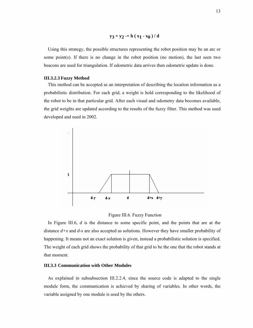
III.3.2.3 Fuzzy Method This method can be accepted as an interpretation of describing the location information as a
probabilistic distribution. For each grid, a weight is hold corresponding to the likelihood of
the robot to be in that particular grid. After each visual and odometry data becomes available,
the grid weights are updated according to the results of the fuzzy filter. This method was used
developed and used in 2002.
Figure III.6. Fuzzy Function
In Figure III.6, d is the distance to some specific point, and the points that are at the
distance d+x and d-x are also accepted as solutions. However they have smaller probability of
happening. It means not an exact solution is given, instead a probabilistic solution is specified.
The weight of each grid shows the probability of that grid to be the one that the robot stands at
that moment.
III.3.3 Communication with Other Modules
As explained in subsubsection III.2.2.4, since the source code is adapted to the single
module form, the communication is achieved by sharing of variables. In other words, the
variable assigned by one module is used by the others.

14
III.3.3.1 Vision-Localization The Vision module sends an array of beacon information after processing each snapshot.
This information includes the confidence of the information, distance to the beacon,
expiration flag and the x-coordinate of the beacon. The centroid of the beacon is used to find
the heading angle of the robot.
Tbeacon
Fields:
float confidence: confidence level of visual information
int distance: distance to that particular beacon
int expire
int centroidx: x-coordinate of the centroid in the picture
TbeaconArray
Fields:
TBeacon beacons[6]: array of beacon information
float panangle: angle between head and body
III.3.3.2 Locomotion-Localization After each movement of the robot the locomotion module (commander -cmd) sends a
motion object that is used to calculate the displacement of the robot.
Motion
Fields:
double distance
int angle
III.3.3.3 Localization-Planner At each execution cycle localization sends its outputs to the planner module. The x and y
coordinates of the grid cell the robot stands with the robot heading are sent.
III.3.4 Performance of the system
To measure the system performance, a simulator developed in C is used. Test files consist
of data points that show the robot position and after the simulator is run, outputs that are sent
to the Planner Module at each step are recorded. After all data are collected, a comparison of
the actual data with the simulator outputs is done.
15
III.3.4.1 Results of tests The accuracy of the developed algorithms highly depends on the input data. If there is no
noise in the input data, then the position calculations are exact. Thus as expected noise has a
decreasing effect on accuracy. Tests were done on assuming several noise levels, to verify the
effect of noise on the accuracy of the result.
Localization is very crucial for robust the robot navigation, which is essential for the robot
Soccer. However finding the real position of the robot is quite difficult due to the noisy data
received from the other modules. The developed algorithms can be improved by increasing
the amount of data collected considerably and thaking into consideration not only beacons but
also using of goals and field lines, and usage of statistical methods nearby our current work
would bring more accurate results.
III.4 Locomotion Module
The locomotion module generally deals with the movements of the head and the legs of the
AIBO robots with respect to the commands taken from the planner module. This emphasizes
the interaction of the locomotion module with the other modules.
In the evaluation of Cerberus 2002 code the following deficiencies were noted. The existing
code was not capable of making use of all the 12 degrees of freedom in legs. Consequently,
we did not have smooth and consistent transitions between consecutive movements of the
robot. We assigned discrete angles to joints for each type of movement directly without taking
into consideration the current state of the robot. As a result when going from one state to
another there inconsistencies between the joints of the robot occur that causes the robot to fall
down although our code is able to handle all such cases reliably. However, this is a waste of
time and unwanted event especially when going from walking style to turning style. Besides,
this kind of attitude towards the movement makes the turns quite slow and not stable. The
locomotion module was improved taking basically this into consideration. Among the notable
improvements are in the turning, walking and kick behaviors regard to performance.
III.5 Planner and Behavior Module
The Planner module is responsible for the decision-making process. It receives data about
the visible objects on the playground from the Vision module and in accordance with this
information chooses the appropriate behavior. The Behaviors module consists of several basic
reactive behaviors that can be switched by the Planner in order to achieve more complex
behaviors of the robotic players on the field (attacker, and goalkeeper). The system of 2003 is

16
different from that of 2002 in many aspects. We tried to improve the finite state machine
model as much as possible to reduce the problems we had identified. In the previous system,
all the robots other than the goalkeeper were attackers. Their only aim was to find the position
of the ball and shoot it. However, this did not work as expected, since while all the robots
were heading towards the ball, they were obstructing each other. In our new system each the
robot has roles associated with it, being the defender, the attacker and the goalie. These roles
are predefined rather than being assigned during the match through the communication of the
robots.
III.5.1 Planner of the Goalkeeper
As seen in Figure III.7 the goalie first checks to see if the ball is nearby, if it is near, then it
checks the distance, if the distance is far then it just aligns itself with the ball, if it is close
enough, it starts clearance which consists of dribbling and shooting. But at any state if the
speed of the ball is larger than a predetermined value it tries to block the ball. While making a
transition from the clear ball state to the “no threat” state, the goal keeper must perform
GOBACKWARD behavior to position itself again in its goal. This is a difficult behavior to
perform since it needs an excellent localization ability.

17
Figure III.7. Finite State Diagram for the goalkeeper
III.5.2 Planner of the Attacker
The planner of attacker given in Figure III.8 and it has been considerably simplified
compared to the one in Cerberus 2002. In our previous version the robot keeps turning and
turning if it cannot see the ball nearby, which is a waste of time. To solve this problem when
the robot completes a turn of 360 degrees it moves four steps forward to search the ball at
another place. At this state, if the robot moves towards the opponent goal, it can possibly
support a team mate attacking that goal. Once the attacker possesses the ball, it dribbles to the
opponent goal and when he is close enough he must shoot the ball.

18
Figure III.8. Finite state diagram of the attacker.
III.5.3 Planner of the Defender
The defender is the robot that is the closest to its own goal. The defender’s main
requirement is positioning itself between the ball and its goal. This can be accomplished by
computing the midpoint of the line segment between the middle of the goal and the ball, and
positioning itself at that point.
III.5.4 Multi-Agent Behaviors
With the introduction of IEEE802.11 Wireless LAN card the robots are able to
communicate effortlessly with each other by and OPEN-R SDK has enabled the
communication to be carried in a simpler manner.
The addition of the multi-agent behavior will increase the overall knowledge available to
the individual the robotic agents, since they would be able to learn what their mates know.
19
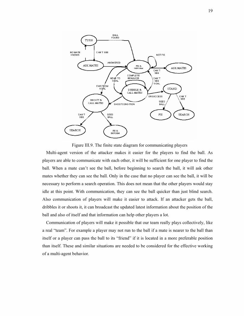
Figure III.9. The finite state diagram for communicating players
Multi-agent version of the attacker makes it easier for the players to find the ball. As
players are able to communicate with each other, it will be sufficient for one player to find the
ball. When a mate can’t see the ball, before beginning to search the ball, it will ask other
mates whether they can see the ball. Only in the case that no player can see the ball, it will be
necessary to perform a search operation. This does not mean that the other players would stay
idle at this point. With communication, they can see the ball quicker than just blind search.
Also communication of players will make it easier to attack. If an attacker gets the ball,
dribbles it or shoots it, it can broadcast the updated latest information about the position of the
ball and also of itself and that information can help other players a lot.
Communication of players will make it possible that our team really plays collectively, like
a real “team”. For example a player may not run to the ball if a mate is nearer to the ball than
itself or a player can pass the ball to its “friend” if it is located in a more preferable position
than itself. These and similar situations are needed to be considered for the effective working
of a multi-agent behavior.

20
III.6 Wireless Communication
III.6.1 Purpose of the system
Wireless communication module is responsible of inter-robot communication for
information change between the robots (i.e. positions of the robots and ball, tactical
commands etc...), communication between game controller and transferring data from the
robots to control center (log files, image data etc.) for debugging purposes.
III.6.2 Overview
The robots have IEEE 802.11 compliant wireless network adapter installed on them and
each robot is associated with an IP address. Communication is done over TCP/IP. On the
controller side, standard socket operations are used. On the robot side, there are some special
objects (Endpoint) are required to establish a TCP connection.
III.6.3 System Description
We can decompose our system into three major subsystems: The robot-robot information
exchange, Controller-robot communication, The robot-Controller information transfer for
debugging and offline training purposes.
III.6.3.1 The robot- robot information exchange Inter-robot communication is used to exchange data between teammates in the game to
increase the knowledge of a player about the positions of the other the robots and ball.
Tactical purposed commands can also be sent in the game for role assignment. We have
developed a communication protocol for exchanging the world information but due to time
limitations, the implementation of the inter-robot communication infrastructure could not be
completed. As a result, we have competed in Padova as a team of single agents.
III.6.3.2 Controller- robot communication This type of communication is used to send “Return to initial position” or “Start game” like
signals to the robot during the game. This reduces the human interaction with the robots. The
communication with game controller is completely implemented and was used during the
competition.
21
III.6.3.3 The robot-Host information transfer The hardest part of making development on the robot is debugging. In order to have an idea
about the state of the system and input data from sensors (image taken from the CCD camera,
inputs from the odometer, etc...) we have decided to develop a software that allows us
examine these information on the robot on a PC over the network. Implementation of the
debugging software and image transfer utility for vision calibration is still ongoing and we are
planning to use it in the next competition.
22
IV. DISCUSSION AND CONCLUSIONS
Cerberus is an international team in the Sony Legged League. The cooperation between the
Turkish and Bulgarian teams is mainly through the internet and only for a brief period just
before Robocup the teams are generally able to work together in person. Even though internet
provides good opportunities for communication, nevertheless distance hinders the pace for
development. This year some of the modules were developed by both of the teams to be
reviewed and then integrated into the final code.
This year, the vision module is able to process images faster and with more accuracy. The
locomotion capabilities of the robot have been improved vastly. The localization module is
able to calculate the position of the robot with greater accuracy. The effects of these were
seen in the Robocup 2003 games where the Cerberus team was more successful as compared
to the previous years. Nevertheless the locomotion module still needs considerable
improvement which will be one of the main focus of research for the team of Robocup 2004.
The full implementation of the designed multi-agent behaviors together with relevant skills
will also be carried out in 2004.

23
V. RESOURCES
Our team agreed to make its code available to other teams. Our official website can be
visited at http://the robot.cmpe.boun.edu.tr/aibo/home.php3. There exists also a local website
of the Bulgarian group of the team: http://www.cerberus.dir.bg .

24
REFERENCES
Arkin, R. C., 1998. Behavior-Based The robotics. The MIT Press, Cambridge, Mass.
Köse, H. Bayhan S., and H. L. Akın, 2003." A Fuzzy Approach to Global Localization in the
Robot Soccer Domain", TAINN 2003, The Tenth Turkish Symposium on Artificial
Intelligence and Neural Networks.
Pavlova, P. E., Tombakov, J. K., Shakev, N. G. (2002). “Fast Image Segmentation on the
Basis of Color Hue and Saturation. International conference”, CompSysTech’2002, Sofia.