CS 1110, Spring 2021: Final Exam Study Guide Parting thoughts
Upload
khangminh22Category
view
1download
0
CECW-EH-W
Engineer Manual
1110-2-3600
Department of the ArmyU.S. Army Corps of Engineers
Washington, DC 20314-1000
EM 1110-2-3600
30 November 1987
Engineering and Design
MANAGEMENT OF WATER CONTROLSYSTEMS
Distribution Restriction StatementApproved for public release; distribution is
unlimited.
~. 1110-2-3600
CEFK-EH-W
Engineer YanualNo. 1110-2-3600
DEPARTmT OF THE ARWU. S. .ArmyCorps of Engineers‘Washington, D. C. 20314-1000
Engineering ati DesignMAN.AGE~NT OF WATER CONTROL
SYSTE~
1. Purpose. This manual provides guidance to field
30 Nov4er 1987
offices for themanagment of water control projects or systems authorized by Congress andconstruct and operated by the Corps of Engineers. It also applies tocertain water control projects constructed by other agencies or entities.
7.. Applicability. This manual applies to all HQUSACE/OCE and field operatingactivities (FOA) having water control managaent responsibility for civilworks projects.
3. Discussion. ~nagaent of projects or .sYst- for water control requiresspecial techniques to analyze ad regulate water conditions to meet watermanagement objectives. This manual covers project managaent related to thehydraulic and hydrologic aspects of completed projects which are morespecifically known as water control management activities. These activitiesinclude: data collection and handling; determination of project inflow;scheduling of releases; coordination of water management decisions; anddetermination of releases. Regulation of water resource projects to meetwater control objectives involves the operation of physical project features.In this regard, physical operation of structures is addressd only in terms ofachieving the water control objectives. Non-hydraulic/hydrologic aspects ofproject operation and managaent are not addressed herein. The intent of thismanual is to compile a comprehensive compendium of elements related to themanagment of water control systems including discussions of data collectionand processing, water control analysis techniques, real-time management andsystems analysis, ad water quality, environmental ad associated aspects ofwater managment.
FOR THE CO~ER:
&gg
.Brigadier General, USAChief of Staff

CEEC-EH-W
DEPARTMENT OF THE ARMYU.S. Army Corps of EngineersWashington, D.C. 20314-1000
EM 1110-2-3600
Engineer ManualNo. 1110-2-3600 30 November 1987
Engineering and DesignMANAGEMENT OF WATER CONTROL SYSTEMS
Table of Contents
Subject Paragraph Page
CHAPTER 1 INTRODUCTIONPurpose. .< . . . . . . . . . . . . . 1-1 1-1
Scope.. . . . . . . . . . . . . . . . 1-2 1-1
References. . . . . . . . . . . . . . . 1-3 1-5
CHAPTER 2 OBJECTIVES AND PRINCIPLES OF WATER CONTROL MANAGEMENTGeneral Considerations. . . . , . . . .
Introduction . . . . . . . . . . . .Water Management Goals and
Objectives. . . . , . . . . . . .Single Purpose Project Regulation. .Multipurpose Project Regulation. . .System Control . . . . . . . . . . .Minimum Streamflow . . . . . . . . .
Flood Control . . . . . . . . . . . . .Historical Background. . . . . . . .Flood Control Measures . . . . . . .Impoundments . . . . . . . . . . . .Objectives for Reservoir Control
of Floods. . . . . . . . . . . . .Reservoir Systems. . . . . . . . . .Levees. . . . . . . . . . . . . . .Combined Impoundment and Levee
Systems. . . . . . . . . . . . . .Local Protection Projects. . , . . .
Navigation. . . . . . . . . . . . . . .Historical Background. . . . . . . .Water for Navigation . . . . . . . .Water Releases for Navigation in
Open Rivers. . . . . . . . . . . .Winter Navigation. . . . . . . . . .
2-12-la
2-lb2-lC2-id2-le2-if2-22-2a2-2b2-2C
2-2d2-2e2-2f
2-2g2-2h2-32-3a2-3b
2-3c2-3d
2-12-1
2-12-22-22-32-32-42-42-52-5
2-62-62-7
2-82-92-112-112-12
2-132-13
i

EM 1110-2-360030 NOV 87
—.. —Subject
Hydroelectric Power . . . . . . . . . .Historical Background. . . . . . . .Hydropower Evaluation. . . . . . . .Types of Projects. . . . . . . . . .Integration and Control of Federal
Hydropower Systems . . . . . . . .Non-Federal Development of
Hydropower at Corps of EngineersProjects. . . . . . . . . . . . .
Water Supply. . . . . . . . . . . . . .Irrigation. . . . . . . . . . . . .Municipal and Industrial Water
Supply Use.. . . . . . . . . . . .Water Quality . . . . . . . . . . . . .
Management Requirements. . . . . . .Objectives and Water Quality
Standards. . . . . . . . . . . . .Monitoring Water Quality Conditions.Water Quality Releases for
Downstream Control . . . . . . . .Selective Withdrawal Facilities forWater Quality Control. . . . . . .
Water Quality System Regulation. . .Fish and Wildlife. . . . . . . . . . .
Historical Background. . . . . . . .General. . . . . . . . . . . . . . .Reservoir Fisheries. . . . . , . . .Tailwater Fisheries. . . . . . . . .Fish Migration . . . . . . . . . . .Minimum Releases . . . . . . . . . .Reservoir Wildlife . . . . . . . . .
Recreation. . . . . . . . . . . . . . .Historical Background. . . . . . . .General Requirements . . . . . . . .Water Management Problems. . . . , .Long-Term Seasonal Fluctuations of
Reservoirs. . . . . . . . . . . .Control of Streamflows for
Downstream Recreational Use. . . .Erosion and Deposition Considerations
General. . . . . . . . . . . . . . .Downstream Considerations. . . . . .Upstream Considerations . . . . . .Guidelines. . . . . . . . . . . . .
Aesthetic Considerations. . . . . . . .
Paragraph Page
2-42-4a2-4b2-4c
2-4d
2-4e2-52-5a
2-5b2-62-6a
2-6b2-6c
2-6d
2-6e2-6f2-72-7a2-7b2-7c2-7d2-7e2-7f2-7g2-82-8a2-8b2-8c
2-8d
2-8e2-92-9a2-9b2-9c2-9d2-1o
2-132-132-142-14
2-14
2-152-162-16
2-182-192-19
2-202-20
2-21
2-212-222-232-232-232-242-262-272-282-282-292-292-292-30
2-30
2-302-312-312-312-322-332-34
ii

EM 1110-2-360030 Nov 87
Subject
CHAPTER 3 DEVELOPMENT OF WATER CONTROL PLANSPrinciples and Objectives . . . . . . .Water Control Plans . . . . . . . . . .
General. . . . . . . . . . . . . . .Integration of Water Quality into
the Water Control Plan . . . . . .Annual Water Management Plans. . . .Input from Other Water Regulation
Interests. . . . . . . . . . . . .Analysis of Drought Periods. . . . .Water Control Procedures During
Planning and Design. . . . . . . .Development of Regulation Schedules
and Water Control Diagrams. . . . . .Definitions. . . . . . . . . . . . .Assessments of Changed Conditions
from Planning and Design Studies .Basic Flood Control Regulation . . .Integration of Basic Seasonal Flood
Control Guide Curves with OtherObjectives. . . . . . . . . . . .
Testing Water Control Plans . . . . . .General. . . . . . . . . . . . . . .Short-Term Flood Control Analysis. .Long-Term Water Utilization Analysis
Winter Navigation . . . . . . . . . . .Revision of Water Control Plans . . . .
General. . . . . . . . . . . . . . .Additional or New Hydrologic Data. .Reevaluation of Water Control
Requirements and Objectives. . . .Updating or Modifying Water Quality
Control Procedures and Plans . . .Constraints on Water Control Plans .
Paragraph
3-13-23-2a
3-2b3-2c
3-2d3-2e
3-2f
3-33-3a
3-3b3-3C
3-3d3-43-4a3-4b3-4C3-53-63-6a3-6b
3-6c
3-6d3-6e
Page
3-13-23-2
3-33-4
3-43-5
3-6
3-63-6
3-83-1o
3-163-203-203-203-203-213-213-213-22
3-22
3-233-24
CHAPTER 4 OPERATIONAL CHARACTERISTICS OF WATER CONTROL FACILITIESGeneral Considerations. . . . . . . . . 4-1 4-1
Background Information . . . . . . . 4-la 4-1Types of Facilities. . . . . . . . . 4-lb 4-1Design Criteria. . . . . . . . . . . 4-lC 4-1Terminology. . . . . . . . . . . . . 4-id 4-2
iii

EM 1110-2-360030 NOV 87
. . —Subject t’aragraph
Spillways. . . . . . . . . . . . . . .General. . . . . . , . . . . . . . .Energy Dissipators . . . . . . . . .Spillway Gates.... . . . . . . .Spillway Capacity and DischargeRatings. . . . . . . . . . . . . .
Operation of Spillway Gates. . . . .Outlet Works. . . . . . . . . . . . . .
Functional Requirements. . . . . . .Sluices for Concrete Dams. . . . . .Gate Passageways . . . . . . . . . .Control Works. . . . . . . . . . . .Operation of the Control Works . . .Discharges. . . . . . . . . , . . .Outlet Facilities for Embankment
Dams. . . . . . . . , . . . . . .Low-Flow Facilities. . . . , . . . .Selective Withdrawal Systems . . , .Energy Dissipation . . . , . . . . .Summary. . . . . . . . . . . . . . .
Flood Control Operation . , . . . . . .Project Outflows . . . . . . . . . .Controlling and Monitoring Outlet
and Spillway Gate Regulation . . .Combined Use of Outlet Works and
Spillways. . . . . . . . . . . . .Free-Flow Operation of Gated
Spillways which Control LargeNatural Lakes. . . . . . . . . . .
Induced Surcharge Storage . . . . . . .General Principles. . . . . . . . . .Surcharge Storage for Free-FlowUngated Spillways . . . . . . . . .Development of Induced Surcharge
Envelope Curves. . . . . . . . . .Development of Spillway Gate
Regulation Schedules . . . . . . .Testing Spillway Regulation ScheduleMethods of Operation . . . . . . . .Effect on Spillway Gate Design . . ,
Outlet Works for Water Supply . . . . .General Considerations . . . . . . .Special Requirements and Problems. .
4-24-2a4-2b4-2c
4-2d4-2e4-34-3a4-3b4-3C4-3d4-3e4-3f
4-3g4-3h4-3i4-3j4-3k4-44-4a
4-4b
4-4C
4-4d4-54-5a
4-5b
4-5C
4-5d4-5e4-5f4-5g4-64-6a4-6b
Page
4-24-24-34-4
4-54-64-64-64-74-74-74-84-8
4-84-94-94-1o4-1o4-1o4-1o
4-11
4-11
4-124-134-13
4-13
4-14
4-174-194-194-224-224-224-23
iv

EM 1110-2-360030 NOV 87
Subject
Diversion and Bypass Structures . . . .Project Purposes and Types . . . . .Regulation Procedures and Schedules.
Hurricane or Tidal Barriers . . . . . .Interior Flood Control Facilities . . .
General. . . . . . . . . . . . . . .Operational Criteria . . . . . . . .Legal Requirements . . . . . . . . .
Hydroelectric Power Facilities. . . . .General. . . . . . . . . . . . . . .Engineering Manual on Hydropower
(EM 1110-2-1701) . . . . . . . . .Major Hydroelectric Facilities . . .Plant and Unit Control Systems . . .Plant and Unit Operation . . . . . .Integration into Regional Power
System., . . . . . . . . . . . . .Control Equipment. . . . . . . . . .Special Operating Problems . . . . .
Fish Passage Facilities and Use ofWater Control Facilities For FisheryEnhancement. . . . . . . . . . . . .General Considerations . . . . . . .Fish Passage Facilities. . . . . . .Fish Attraction Water. . . . . . . .Fingerling Fish Bypass Facilities. .Increased Streamflows to Aid
Passage of Downstream Migrants . .Fish Hatcheries. . . . . . . . . . .Control of Dissolved Gas
Supersaturation. . . . . . . . . .Coordination of Regulation for
Fishery. . . . . . . . . . . . . .
CHAPTER 5 WATER CONTROL DATA SYSTEMSGeneral. . . . . . . . . . . . . . . .
Purpose. . . . . . . . . . . . . . .Basic Requirements . . . . . . . . .Master Plans . . . . . . . . . . . .
Data Observation and Storage atField Sites, . . . . . . . . . . . .General. . . . . . . . . . . . . . .Hydrometeorological Data . . . . . .Project Data . . . . . . . . . . . .Water Quality Data . . . . . . . . .
Paragraph Page
4-74-7a4-7b4-84-94-9a4-9b4-9C4-1o4-10a
4-10b4-1OC4-10d4-10e
4-lof4-log4-10h
4-114-ha4-llb4-llC4-lld
4-he4-llf
4-llg
4-llh
5-15-la5-lb5-lC
5-25-2a5-2b5-2c5-2d
4-234-234-244-244-244-244-254-254-254-25
4-264-264-264-27
4-274-284-28
4-334-334-344-344-35
4-354-36
4-36
4-37
5-15-15-15-2
5-35-35-35-45-5
v

EM 1110-2-360030 NOV 87
Subject Paragraph
Manual Data Observation. . . . . . .Automated Data Observation and
Storage. . . . . . . . . . . . . .Installation and Maintenance of Data
Collection Equipment . . . . . . .Data Transmission . . . . . . . , . . .
General. . . . . . . . . . . . . . .Manual Data Transmission Systems . .Semi-Automatic Data Transmission
Systems. . . . . . . . . . . . . .Automatic Data Transmission Systems.
Decoding and Validating TransmittedData, . . . . . . . . . . . . . . . .
Water Control Data Management . . . . .and Processing. . . . . , . . . . . .Data Storage and Retrieval . . . . .Water Control Database Management. .Data Interpretation and Displays . .Data Processing. . . . . . . . . . .
Coordination of Data Collection andExchange. . . . . . . . . . . . . . .Interagency Cooperation. . . . . . .Operational Management of
Cooperative Data Systems . . . . .Data Exchange. . . . . . . . . . . .
CHAPTER 6 WATER CONTROL ANALYSIS TECHNIQUESGeneral Considerations. . . . . . . . .
Importance of Technical Evaluations.Hydrologic Analysis - Historical
Data. . . . . . . . . . . . . . .Computer Utilization for WaterManagement. . . . . . . . . . . , . .Basic Principles . . . . . . . . . .Concepts in Computer Utilization . .Types of Models . . . . . . . . . . .
Meteorological Forecasts Used inWater Control Management. . . . . . .General. . . . . . . . . . . . . . .Short-Term Weather Forecasts . . . .Long-Range Weather Forecasts . . . .
Simplified Manual Methods forAnalyzing River Response. . . . . . .Backup Procedures. . , . . . . , . .Graphical Runoff Relationships . . .
5-2e
5-2f
5-2g5-35-3a5-3b
5-3C5-3d
5-4
5-55-5a5-5b5-5C5-5d
5-65-6a
5-6b5-6c
6-16-la
6-lb
6-26-2a6-2b6-2c
6-36-3a6-3b6-3c
6-46-4a6-4b
Page
5-5
5-6
5-65-75-75-8
5-85-9
5-14
5-155-155-155-155-15
5-165-16
5-195-19
6-16-1
6-1
6-26-26-36-3
6-46-46-56-8
6-86-86-8
vi

EM 1110-2-360030 NOV 87
Subject Paragraph Page
Long-Range Predictions of Streamflow. .General. . . . . . . . . . . . . . .Statistical Procedures for
Forecasting Seasonal SnowmeltRunoff Volume . . . . . . . . . . .
Use of Deterministic HydrologicModels for Long-Term StreamflowForecasts. . . . . . . . . . . . .
Long-Range Analysis of ProjectRegulation. . . . . . . . . . . . . .General. . . . . . . . . . . . . . .Analytical Techniques. . . . . . . .Basic Data and Types of Analyses . .Utilizing Results of Long-Range
Analysis. . . . . . . . . . . . .Water Quality Forecasting . . . . . . .
General. . . . . . . . . . . . . . .Analytical Techniques. . . . . . . .Forecasts. . . . . . . . . . . . . .
Special Hydrologic Analyses . . . . . .General. . . . . . . . . . . . . . .Unsteady Flow Determinations in
Major Rivers . . . . . . . . . . .Effects of Sedimentation in Rivers
and Reservoirs . . . . . . . . . .Effects of Ice in Rivers and
Reservoirs. . . . . . . . . . . .Reservoir Evaporation. . . . . . . .Determination of Effect of Bank
Storage on Reservoir Capacity. . .Effect of Wind Setup on Water
Levels in Reservoirs, Lakes,and Tidal Estuaries. . . . . . . .
6-56-5a
6-5b
6-5c
6-66-6a6-6b6-6C
6-6d6-76-7a6-7b6-7c6-86-8a
6-8b
6-8C
6-8d6-8e
6-8f
6-8g
CHAPTER 7 REAL TIME MANAGEMENT OF WATER CONTROL PROJECTSBasic Considerations. . . . . . . . . . 7-1
Integration of GeneralizedOperating Criteria, Real-TimeSystem Analysis, and ProjectScheduling. . . . . . . . . . , . 7-la
Input from Others. . . . . . . . . . 7-lbAppraisal of Current Project
Regulation. . . . . . . . . . . . . . 7-2
6-96-9
6-10
6-11
6-126-126-126-12
6-136-146-146-146-146-156-15
6-16
6-16
6-176-18
6-18
6-18
7-1
7-17-2
7-3
vii

EM 1110-2-360030 NOV 87
-.. —Subject
Performing System Analyses for ProjectScheduling. . . . . . . . . . . . . ,Analytical Requirements for
Scheduling Water Regulation atProjects. . . . . . . . . . . . .
Preparing Model Input Data . . . . .Analysis of Results. . . . . . . . .
Water Control Decisions and ProjectScheduling. . . . . . . . . . . . . .Need for Judgmental Determinations
in Project Scheduling. . . . . . .Coordinating Water Control Decisions
with Others. . . . . . . . . . . .Project Schedules and Operating
Instructions . . . . . . . . . . .Water Quality Aspects of Water Control
Decisions. . . . . . . . . . . . . .Disseminating Regulation Schedules. . .
Corps of Engineers Projects. . . . .Non-Corps Projects . . . . . . . . .Distributing Schedules to Other
Agencies. . . . . . . . . . . . .Distributing Schedules to General
Public. . . . . . . . . . . . . .Water Management Activities During
Flood Events . . . . . . . . . . .Importance of Water ManagementActivities. . . . . . . . . . . .
Coordination of Corps Activities . .Monitoring and Reanalyzing River
and Reservoir ConditionsDuring Floods. . . . . . . . . . .
Adjusting Reservoir RegulationSchedules. . . . . . . . , . . . .
Drought Management Plans. . . . . . . .Coordinating Forecasts of Streamflow
andRiverLevels. . . . . . . . . . .General. . . . . . . . . . . . . . .Basin-Wide Forecasting Services. . .
Paragraph
7-3
7-3a7-3b7-3C
7-4
7-4a
7-4b
7-4C
7-4d7-57-5a7-5b
7-5C
7-5d
7-6
7-6a7-6b
7-6c
7-6d7-7
7-87-8a7-8b
Page
7-3
7-37-47-5
7-5
7-5
7-6
7-7
7-87-87-87-9
7-9
7-9
7-9
7-97-1o
7-12
7-127-12
7-137-137-14
viii

EM 1110-2-360030 NOV 87
Subject Paragraph Page
CHAPTER 8 ADMINISTRATIVE AND COORDINATION REQUIREMENTS FOR WATERCONTROL MANAGEMENTAdministration of Water Control
Management Activities . . . . . . . .Organization . . . . . . . . . . . .Functions. . . . . . . . . . . . . .Staffing. . . . . . . . . . . . . .Role of Project Operators. . . . . .Training. . . . . . . . . . . . . .
Briefing Room Facilities. . . . . . . .General. . . . . . . . . . . . . . .Purpose. . . . . . . . . . . . . . .Design. . . . . , . . . . . . . . .Utilization. . . . . . . . . . . . .
Administration of Water ManagementContracts. . . . . . . . . . . . . .Data Collection. . . . . . . . . . .Water Supply Contracts . . . . . . .Water Quality Data Collection. . . .Hydropower Contracts . . . . . . . .
Interagency Coordination and AgreementsTypes of Coordinating Groups . . . .Types of Water Management AgreementsCoordinating with Operating Entities
and Other Public and Private WaterUse Organizations. . . . . . . . .
Water Management Reports on PrevailingConditions. . . . . . . . . . . . . .General. . . . . . . . . . . . . . .Project Operators Reports . . . . .Water Control Morning Reports. . . .Special Advisories . . . . . . . . .Discharge Data . . . . . . . . . . .Flood Damages . . . . . . . . . . . .Reports for the Media. . . . . . . .
Documents, Reports and Records. . . . .Water Control Documents. . . , . . .Annual Operating Plans and Other
River Basin Committee Reports. . .Annual Report on Water Control
Management Activities. . . . . . .Reports on the Water Control Data
System (WCDS) Master Plan. . . . .Annual Report on the Cooperative
Stream Gaging Program. . . . . . .
8-18-la8-lb8-lc8-id8-le8-28-2a8-2b8-2c8-2d
8-38-3a8-3b8-3c8-3d8-48-4a8-4b
8-4c
8-58-5a8-5b8-5c8-5d8-5e8-5f8-5g8-68-6a
8-6b
8-6C
8-6d
8-6e
8-18-18-18-28-28-38-48-48-48-48-6
8-78-78-88-88-88-88-88-10
8-11
8-158-158-168-168-168-178-178-178-178-17
8-17
8-18
8-18
8-18
ix

EM 1110-2-360030 NOV 87
Subject Paragraph
Annual Billing for the CooperativeReporting Network. . . . . . . . .
Annual Budget Request. . . . . . . .Summary of Runoff Potential. . . . .Post Flood Reports . . . . . . . . .Water Data Records . . . . . . . . .Federal Register . . . . . . . . . .Annual Report on Project Benefits. .Annual Water Quality Report. . . . .Periodic Inspections and Reports . .
CHAPTER 9 PREP~TION OF WATER CONTROL DOCUMENTSBasic Documents . . . . . . . . . . . .
Types of Documents . . . . . . . . .Types of Projects. . . . . . . . . .Scope of Documentation . . . . . . .
Standing Instructions to ProjectOperators for Water Control . . . . .
Water Control Plans . . . . . . . . . .General. . . . . . . . . . . . . . .Interim Water Control Plan During
Construction . . . . . . . . . . .Preliminary Water Control Plans. . ,Final Water Control Plans. . . . , .
Water Control Manuals . . . . . . . . .Water Control Manuals for Individual
Projects. . . . . . . . . . . . .Master Water Control Manuals . . . .Initial Reservoir Filling Plans and
Flood Emergency Plans. . . . . . .Format of Water Control Documents . . .
General. . . . . . . . . . . . . . .Tables, Graphs, and Plates . . . . .Use of the Terms “Regulation” and
“Operation”. . . . . . . . . . . .Document Identity. . . . . . . . . .
Coordination of Water Control DocumentsGeneral. . . . . . . . . . . . . . .Coordination . . . . . . . . . . . .Water Management Agreements. . . . .
ExhibitsA. Format for Standing
Instructions to the ProjectOperator for Water Control . .
B. Format for Water Control Plan. .
8-6f8-6g8-6h8-6i8-6j8-6k8-618-6m8-6n
9-19-la9-lb9-lC
9-29-39-3a
9-3b9-3C9-3d9-4
9-4a9-4b
9-4C9-59-5a9-5b
9-5C9-5d9-69-6a9-6b9-6c
Page
8-188-188-198-198-198-198-208-208-21
9-19-19-19-2
9-29-39-3
9-39-49-49-5
9-59-6
9-69-99-99-9
9-99-99-99-99-99-1o9-11
9-119-15
x

EM 1110-2-360030 NoV 87
Subject Paragraph Page
APPENDIX A BIBLIOGRAPHYPreface. . . . . . . . . . . . . . . .Specific References . . . . . . . . . .General References. . . . . . . . . . .
A-1A-2A-4
APPENDIX B INDEX
xi

Figure
i-1.
Dale
Hollow
~,
Obey
F.iver,Tennessee;
Nashville
District

EM 1110-2-360030 NOV 87
CHAPTER 1
INTRODUCTION
1-1. Purpose. This manual is intended to provide guidance to fieldoffices for the management of water control projects or systems thathave been authorized by Congress and planned, designed andconstructed by the Corps of Engineers. It also applies to certainaspects of water control projects constructed by other agencies orentities. Technical procedures used in the planning and design ofCorps of Engineers projects are well documented in regulations andmanuals, and they are done in accordance with established authority.Management of these systems for water control, however, requiresspecial techniques beyond those used in the planning, design andconstruction phases, to analyze and regulate water conditions atindividual projects in order to meet water management objectives.
1-2. -
a. General. This manual covers project management related tothe hydrologic/hydraulic aspects of completed projects, which aremore specifically known as “water control management” activities.These activities include: data collection and handling;determination of project inflow, scheduling releases for floodcontrol, hydropower, water supply, water quality, fish and wildlife;coordination of water management decisions; and determination ofreleases; i.e. , water resource projects are “regulated” to meet watercontrol objectives by “operating” spillway gates, sluice gates,pumping plants, etc. In this regard, the “physical operation” ofstructures, such as the manipulation of gates or recognition ofstructural constraints, is addressed only in terms of achieving thewater control objectives. The term “operation” is usedinterchangeably throughout the manual to mean “regulation for watercontrol” such as project release scheduling as well as to mean the“physical operation” of projects. In the same regard, the phrase“project operator” is used interchangeably with “project manager” torefer to the person at the project site who is responsible for thephysical operation of the project. Non-hydrologic/hydraulic aspectsof project operation and maintenance are not addressed herein. It isthe intent of this manual to compile a comprehensive compendium ofelements related to the management of water control systems,including discussions of:
(1) fundamentals of multipurpose water control projects andsystem regulation;
1-1
EM 1110-2-360030 NOV 87
(2) techniques of preparing water control plans includingregulation schedules, for a single project or system, for meeting allmultipurpose objectives in accordance with project planning anddesign, and other objectives as necessary;
(3) methods for collecting, processing and disseminating basicdata required for real-time management of water control projects andsystems ;
(4) methods for analyzing river and reservoir systems on areal-time basis to determine the most suitable regulation ofprojects, including utilization of automatic data processingtechniques for simulating the response of hydrologic systems;
(5) problems and solutions related to environmental, social,economic and aesthetic aspects of water management;
(6) methods for making and implementing real-time water controldecisions;
(7) administrative and coordination requirements by the Corpsof Engineers for developing water control plans and manuals for anindividual project or system, organizing water management activitiesin Division and District offices, and reporting current conditions ofwater control systems to higher authority; and
(8) methods for coordinating water management activities withothers , on a local, regional and national basis, and providinginformation to the public regarding the current management of watercontrol systems.
b. Chapter 2. Chapter 2 is a generalized description of theobjectives and principles for the management of water for variousmultipurpose uses, including:
Flood Control
Navigation
Hydropower
Water Supply
Water Quality
1-2

EM 1110-2-360030 NOV 87
Recreation
Fish and Wildlife
The specific requirements for any one of the above-listed elements(functional, economic, environmental, social and aesthetic) areunique to a given river basin, and it is not intended to presentdetailed solutions. The manual describes each element, insofar asthe principles apply to projects generally, and the necessity forconsidering all elements as well as the safety and integrity of theproject.
c. Chavter 3. This Chapter covers the technical aspects ofdeveloping water control plans, which often encompass multipurposeand multiproject systems. Even in the case of a single purposeproject, there are often important social and/or environmentalaspects to be accounted for in the overall management of a riversystem. The manual provides guidelines for the formulation ofdetailed regulation criteria, which are based largely on planning anddesign studies, together with the use of techniques for watermanagement to attain the overall goals. Preparation of water controldiagrams, which include the regulating criteria in the form of guidecurves and release schedules, are discussed. There is also a sectionwhich deals with requirements contained in water control agreementsfor non-Corps projects, as set forth in the revision of 33 CFR208.11, published in the Federal Register, Vol. 43, No. 199, October13, 1978.
d. Chapter 4. This chapter contains a brief description of thedesign of hydraulic facilities at water control projects. Theseinclude spillways, spillway gates, regulating outlets, bypass anddiversion structures, interior drainage facilities, navigation locks,hydropower facilities, fish passage facilities, and special devicesfor regulating the quality of water released from a reservoir.Special emphasis is placed on the methods for controlling floodsthrough the combined use of spillway gates and/or regulating outletsin order to utilize surcharge storage in reservoirs. Also mentionedare special water control management problems involved in theutilization of bypass structures, hydropower facilities, navigationlocks , and fish passage facilities.
e. Chapter 5. This chapter summarizes the methods availablefor collecting, processing, storing and disseminating basic data forproject regulation. These data systems may include any or all of thefollowing:
1-3

EM 1110-2-360030 NOV 87
manual observations
land line or radio communication systems for automaticretrieval of remote data
satellite communication and sensing devices
meteor-burst communication devices
various types of sensors, processors, and relay devicesnecessary for obtaining and relaying remote hydrometeorologicand project data
centralized automatic data processing facilities required foraccessing and controlling the flow of data
This chapter also presents methods for coordinating data collectionwith other organizations, and the use of cooperatively developed datasystems.
f. Chapter 6. Chapter 6 of the manual contains methods ofhydrologic analysis which are directly applicable to management ofwater control systems. These include generalized computer techniquesto simulate the continuous natural response of hydrologic and riversystems, combined with the effects of project regulation onconditions of streamflow and river stages. These simulations areused to evaluate the effects of alternative conditions or assumptionsin forecasting streamflows and project regulation. There is adescription of meteorological assessments and forecasts that areimportant to project regulation. Systems analysis techniques alsoinclude methods for analyzing and projecting long-term regulation ofprojects for several months to a year in advance. These projectionsare based on known or assumed conditions of stream and operatingcriteria. These analyses are useful in evaluating alternatives insystem regulation and adjusting the water control plan for floodcontrol, hydropower, irrigation, navigation, water quality, fisheryrequirements, or other project purpose as may be required to assessthe particular observed and projected conditions of hydrology andproject regulation on the overall management of the water. Otheraspects of hydrologic analysis include reservoir evaporation, effectof ice and wind, streamflow determination, hurricanes, tsunami waves,tidal effects, artificial flood waves, ground water effects, effectsof changing channel capacities downstream from projects, and theeffect of forest removal and urban development on runoff.
1-4

EM 1110-2-360030 NOV 87
g. Chapter 7. This chapter presents the methods forintegrating system guidelines for water control management, criteriaand goals for scheduling water releases. The specific schedules aredeveloped utilizing all existing current information,hydrometeorological data, project data, and projections developed bysimulation techniques. There is a discussion of organization andstaffing required to perform this function, methods of arriving atdaily water control decisions, and how water control decisions may bedisseminated and implemented at the project level. Also, methods forcoordinating water releases, streamflow and regulation forecasts withother interests are discussed. There is a description ofrequirements of regulation during floods or other emergencyconditions, as opposed to normal routine regulation, and methods fordisseminating vital information to the news media and the generalpublic.
h. Chapter 8. Chapter 8 deals with the administrative andcoordination requirements of the Corps in managing water controlsystems. There are discussions of the role of the Corps in theregulation of international rivers and the authority for regulatingprojects constructed by other entities in the United States. Thecontent of this chapter is derived primarily from existingEngineering Regulations (ER’s) in summarizing the requirements foradministrative control by the Corps.
i. Chapter 9. This chapter discusses the preparation of watercontrol documents. These documents include standing instruction toproject operators, water control plans and manualsi
1-3. References
a. En~ineer Re~ulations and Manuals. The followingregulations, manuals, and other publications define policy and basicmethods directly related to water management activities by the Corpsof Engineers.
(1) ER 15-2-13, Mississippi Water Control Management Board
(2) ER 15-2-14, Committees on Tidal Hydraulics, ChannelStabilization and Water Quality
(3) ER 500-1-1, Natural Disaster Procedures
(4) ER 1105-2-20, Project Purpose Planning Guidance
1-5

EM 1110-2-360030 NOV 87
(5) ER 1110-2-50, Low Level Discharge Facilities for Draw-Downof Impoundments
(6) ER 1110-2-240, Water Control Management
(7) ER 1110-2-241, Use of Storage Allocated for FloodControl and Navigation at Non-Corps Projects
(8) ER 1110-2-248, Requirements for Water Data Transmissionusing GOES/DCS
(9) ER 1110-2-249, Management of Water Control Data Systems
(10) ER 1110-2-1150, Engineering after Feasibility Studies
(11) ER 1110-2-1400, Reservoir Control Centers
(12) ER 1110-2-1402, Hydrologic Investigations Requirementsfor Water Quality Control
(13) ER 1110-2-1454, Corps Responsibility for Non-FederalHydroelectric Power Development under the Federal PowerAct
(14) ER 1110-2-1455, Cooperative Stream Gaging Program
(15) ER 1110-2-2901, Construction Cofferdams
(16) ER 1110-2-1941, Drought Contingency Plans
(17) ER 1125-2-308, Radio Frequency and Call Sign Assignments
(18) ER 1130-2-334, Reporting Water Quality ManagementActivities at Corps Civil Works Projects
(19) ER 1130-2-415, Water Quality Data CollectionInterpretation and Application Activities
(20) ER 1130-2-419, Dam Operations Management Policy
(21) 33 CFR 208.11 (ER 1110-2-241) (Revised), Part 208, FloodControl Regulation, Use of Storage Allocated for FloodControl and Navigation Purposes, Published in FederalRegister. , Vol. 43, No. 1999, October 13, 1978
(22) EM 1110-2-1201, Reservoir Water Quality Analysis
1-6

EM 1110-2-360030 NOV 87
(23) EM 1110-2-1405, Flood Hydrography Analysis and Computation
(24) EM 1110-2-1406, Runoff from Snowmelt
(25) EM 1110-2-1408, Routing of Floods through River Channels
(26) EM 1110-2-1412, Storm Surge Analysis
(27) EM 1110-2-1413, Hydrologic Analysis of Interior Areas
(28) EM 1110-2-1602, Hydraulic Design of Outlet Works
(29) EM 1110-2-1603, Hydraulic Design of Spillways
(30) EM 1110-2-1604, Hydraulic Design of Navigation Locks
(31) EM 1110-2-1611, Layout and Design of Shallow-DraftWaterways
(32) EM 1110-2-1701, Hydropower
(33) ETL 1110-2-231, Initial Reservoir Filling Plan
(34) ETL 1110-2-251, Preparation of Water Control Manuals
b. Other Technical Publications. Appendix A consists of aselected bibliography of literature pertaining to management of watercontrol systems.
1-7

EM 1110-2-360030Nov 87
.
1-8

EM 1110-2-360030 NOV 87
CHAPTER 2
OBJECTIVES AND PRINCIPLES OF WATER
2-1. General Considerations
a. Introduction
CONTROL MANAGEMENT
(1) This chapter provides a summary of water control managementobjectives and principles for various types of water control systems.It presents a brief synopsis of the technical aspects of each of thespecific water control requirements to achieve the water managementgoals set forth below. The discussions present only broad aspects ofeach water regulation function, and their interrelationship neededfor developing a water control plan.
(2) The sections that follow in this chapter discuss theindividual functional objectives and principles in water managementto achieve flood control, navigation, hydroelectric power, watersupply (irrigation, municipal and industrial), water quality, and thepreservation or enhancement of fish and wildlife, and recreationaluse. The discussions provide background information for moredetailed presentations in subsequent chapters on methods ofdeveloping water control plans and scheduling water releases.
b. Water Mana~ement Goals and Objectives. The policy containedin Paragraph 6 of ER 1110-2-240 defines the goals and objectives forwater regulation by the Corps. In summary, the objective is toconform with specific provisions of project-authorizing legislationand water management criteria defined in Corps of Engineers reportsprepared in the planning and design of a particular project orsystem. Beyond this, the goals for water management will includeprovisions as set forth in any applicable authorities establishedafter project construction and all applicable Congressional Actsrelating to operations of Federal facilities (for example, the Fishand Wildlife Coordination Act, PL 85-624; Federal Water ProjectRegulation Act - Uniform Policies, PL 85-624; National EnvironmentalPolicy Act of 1969, PL 91-190; and Clean Water Act of 1977,PL 95-217). A general prime requirement in project regulation is thesafety of users of the facilities and the general public, both atprojects and downstream locations. The development of water controlplans and the scheduling of releases at projects will be coordinatedwith appropriate agencies or entities (international, Federal, stateor local), as necessary to meet commitments made in planning ordesign. Another goal in water management is to adjust water controlplans, whenever possible, to account for changing local conditions.
2-1

EM 1110-2-360030 NOV 87
c. Sin~le Pur~ose Proiect Regulation
(1) General. In some cases, reservoirs are authorized for asingle purpose and their operation must be for attainment of theauthorized purpose. However, the method of operation can often beflexible and this flexibility can produce significant benefits overand above the authorized objective. The operation must be tuned toproduce the benefits for environmental and social goals such as floodcontrol, instream quality, in-lake quality, recreation, power, or anyother attainable goals the project can achieve without compromisingthe authorized project purpose.
(2) Reservoirs with Uncontrolled Outlet Works
(a) Some reservoirs have been constructed with uncontrolledoutlets. Outflow is dependent on conditions of natural inflow, andstorage. With no provision for regulation by operating gates, theinduced storage results from restricted capacity of the outlet. Thatis, the project operates entirely under “free flow” conditions.While this type of project provides a consistent, well definedcontrol, it does not allow for changed conditions or provisions formultipurpose objectives.
(b) While it is unnecessary to prepare detailed regulationschedules for this type of project, it is necessary to define theuncontrolled operation and prepare water control documents to showits effect on downstream control and its relationship to otherprojects in the system.
d. MultiPur~ose Proiect Regulation. More than one watermanagement goal or objective can be accommodated in a water controlplan, and reservoir storage may be utilized compatibly for severalpurposes. The degree of compatibility for each of the water usesdepends upon the characteristics of the river system, water userequirements, and the ability to forecast runoff. Either a singlereservoir or a system of reservoirs may be regulated in a manner toinsure the proper use of storage space. Water levels in impoundmentsmay be controlled to provide sufficient storage space to controlfloods , as well as to store water for hydroelectric power,irrigation, navigation, municipal or industrial water supply use,water quality, propagation and preservation of fish and wildlife,recreation, and aesthetic purposes. Water levels in reservoirs andin rivers downstream from projects may also be regulated to achievethe desires and requirements for public use, recreation and tosupport fish and wildlife needs. The melding of all of theabove-mentioned uses is reflected in the water control plan. In manycases, the uses are somewhat conflicting, and some degree ofcompromise is required to achieve the water management goals. There
2-2

EM 1110-2-360030 NOV 87
is, however, a generally recognized Priority for each of the majoruses, whereby the defined project benefits are assured to thegreatest extent possible. The balancing of water use demands andpriorities are defined in the water control plan.
e. Svstem Control. The control of projects to meet watercontrol objectives may be considered for a single river or for ariver system consisting of several tributaries, with multipleprojects located on the main river or the tributaries. Normally, thecontrol of a multiproject system requires an integrated water controlplan whereby projects are regulated jointly in order to achieve theoverall river basin management objectives, In such cases a masterwater control manual is prepared to define system regulation. Whereriver systems are interconnected hydraulically or electrically,particularly when hydroelectric power is a major operating element,the water control plan may encompass requirements which extend beyonda single river basin boundary and entail regional water or powerrequirements.
f. Minimum Streamflow. Increasing importance has been attachedto the attainment of minimum streamflows during the last severaldecades as experience has been gained in the management of waterresource systems. Specific areas of concern include instream flowrequirements, water rights, navigation, hydropower, water quality,water supply, fish and wildlife, recreation, aestheticconsiderations, and drought periods. In many cases, minimumstreamflow which satisfies some or all of the above areas of concernis defined as a project purpose in the authorizing documents. Someprojects, however, have no formal commitment for minimum streamflowdue in large part to the lesser importance which was placed oninstream flow requirements, water quality, fish and wildlife,recreation, and aesthetic considerations in the early development ofsome river basin water management systems. Lack of formal commitmentdoes not preclude the responsibility to define and establish minimumstreamflow objectives that may be achieved without jeopardizingauthorized project purposes. When minimum streamflow goals andobjectives are established they should be based on analyses whichconsider all project and system impacts to attain the best use of alimited resource. In a multiple purpose project or system ofprojects operation to satisfy one purpose may satisfy otherrequirements. For example, water released for irrigation may satisfyother instream requirements, given adequate quantity and quality,until diverted from the river.
2-3

EM 1110-2-360030 NOV 87
2-2. Flood Control
a. Historical Background
(1) General. Federal flood control activity took definite formby establishment of the Mississippi River Commission in 1879, withjurisdiction over navigation work and flood control related theretoon the lower Mississippi River. Federal construction of floodcontrol improvements was extended outside the Mississippi Valley forthe first time in 1917, when a project for the Sacramento River, CAwas authorized. Following the disastrous flood of 1927, the 1928Flood Control Act authorized a comprehensive plan for control of theMississippi River and tributaries. The following legislation markedthe beginning of Corps construction and responsibility for Federalflood control projects throughout the nation.
(2) 1936 Flood Control Act
(a) Section 1 of this act declared flood control to be a properFederal activity; that improvements for flood control purposes are inthe interest of the general welfare; and that the Federal governmentshould improve or participate in the improvement of navigable watersor their tributaries for flood control “if the benefits to whomsoeverthey may accrue are in excess of the estimated costs, and if thelives and social security of people are otherwise adversely affected”(49 Stat. 1570, 33 U.S.C. 701a).
(b) Section 2 set forth the jurisdiction of Federal activitiesand prescribed among other things, “That, hereafter, Federalinvestigations and improvements of rivers and other waterways forflood control and allied purposes shall be under the jurisdiction ofand shall be prosecuted by the Army Department under direction of theSecretary of Army and supervision of the Chief of Engineers” (49Stat. 1570, 33 U.S.C. 701b).
(c) Section 3 stipulated for the projects authorized thereinwhat have become known as the “a-b-c” requirements of localcooperation; that local interests should: (a) provide without costto the United States all lands, easements, and rights-of-waynecessary for the construction of the project, except as otherwiseprovided herein; (b) hold and save the United States free fromdamages due to the construction works; (c) maintain and operate allthe works after completion in accordance with regulations prescribedby the Secretary of Army (49 Stat. 1571, 33 U.S.C. 701c).Requirement (b) was amended by Sec. 9 of the Water ResourcesDevelopment Act of 1974 (Pub. Law 93-251).
2-4

EM 1110-2-360030 NOV 87
(3) 1944 Flood Control Act. Section 7 of this act specifiedthat the Secretary of the Army shall prescribe regulations for theuse of storage allocated for flood control or navigation at allreservoirs constructed wholly or in part with Federal funds,including those of the Tennessee Valley Authority when the lower Ohioor Mississippi Rivers are in danger of flooding; i.e. , this lawcreated a specific requirement for reservoirs that include floodcontrol which is funded, at least in part, by Federal agencies otherthan the Corps. The act provided for developing flood control plans,allocating project costs to the flood control function, andregulating the projects to assure flood control benefits asdetermined by the Corps. All Bureau of Reclamation (USBR) projectsconstructed after (and some prior to) 1944, where flood control isone of the project purposes, are included in the provisions of thisact. Projects that come under the authority of this legislation aregenerally referred to as “Section 7“ projects. (58 Stat. 893, 33U.s.c. 709.)
b. Flood Control Measures. Control of floods by structuralremedies, such as reservoirs, levees, drainage systems, channelimprovements, etc. , has long been a national objective. In recentyears nonstructural means, such as flood plain zoning, flood proofingor flood insurance, have been incorporated into overall flood controlplans to augment structural control. In the operational phase of allof these measures, the overall objective is to minimize flood damagein a given region. Most structural alternative measures to controlfloods and alleviate flood damage require specific water controlplans of operation based on current hydrometeorological conditions,flood control objectives, and the capabilities of ~2propriate floodcontrol facilities. Unusually large floods may require flood fightactivities or other special measures to meet flood controlobjectives. Streamflow forecasting is an important element in themanagement of water during floods, and timely use of flood forecastsprovide a means for reducing damage in unprotected areas byevacuating people and moveable goods from flood areas. Themanagement of river systems must integrate the information on allaspects of flood control outlined above in order to best manage thecontrol works. Specific flood control measures and objectives arediscussed briefly in the following paragraphs. Types of facilitiesand their requirements are discussed in Chapter 4.
c. Impoundments . A principal structural remedy for flooding iscontrol of streamflows and river levels by impounding runoff. Theplanning of reservoirs and other impoundments to meet flood controlobjectives involves hydrologic studies of historical and hypotheticalfloods , various alternatives in storage capacities and location,downstream flood control objectives, inflows from uncontrolleddrainages below the project, channel capacities, flood damage
2-5
EM 1110-2-360030 NOV 87
surveys, cost-benefit determinations, and a general plan ofregulation to meet the flood control requirements. These planningstudies are used to determine the size and location of impoundments,the degree of protection to be provided and the multipurpose uses ofprojects. They are based on the overall evaluation of river basindevelopment considering economic, environmental and social values.In the design phase, the project studies are refined, and detailedstudies are made to determine design of hydraulic features and thewater control plan for the project.
d. Objectives for Reservoir Control of Floods
(1) Reservoirs are seldom designed to provide completeprotection against extremely large floods, such as the StandardProject Flood. However, the storage capacity is usually sufficientto reduce flood levels resulting from such an event to moderatelevels and to prevent a major flood disaster. Reservoirs are usuallycapable of storing the entire runoff from minor or moderate floodevents . The water control plan defines the basic goal of regulation,relative to control of minor and major floods. Usually a compromiseis achieved in the water control plan to best utilize the storagespace in reservoirs for control of both major and minor flood events.In special circumstances where reservoir inflows can be forecastseveral days or weeks in advance (for example, when the runoff occursfrom snowmelt), the degree of control for a particular flood eventmay be determined on the basis of forecasts to best utilize thestorage space. Also , the amount of flood control storage space maybe varied seasonally when runoff is seasonal, in order to utilize thereservoirs for multipurpose regulation.
(2) One of the problems of reservoir control of floods is therequirement for post flood evacuation of stored water. This mayresult in long duration of river levels at or near bankfull or minordamage stages at downstream control points. The water control planmust account for this requirement, which may entail a compromisebetween a rapid evacuation of stored water for assuring control ofsubsequent flood events, and a slow evacuation to allow downstreamriver levels to recede below bankfull stages as quickly as possible.
e. Reservoir Systems
(1) A multireservoir system is generally regulated for floodcontrol to provide flood protection both in intervening tributaryareas and at downstream main stem damage areas. The extent ofreservoir regulation required for protecting these areas depends uponlocal conditions of flood damage, uncontrolled tributary drainage,reservoir storage capacity, and the volume and time distribution ofreservoir inflows. Either the upstream or downstream requirements
2-6

EM 1110-2-360030 NOV 87
may govern the reservoir regulation, and usually the optimumregulation is based on the combination of the two. Reservoirreleases are based on the overall objectives to limit the dischargesat the control points to predetermined damage levels. The regulationmust consider the travel times caused by storage effects in the riversystem and the local inflows between the reservoir and controlpoints. Since each flood event is caused by a unique set ofhydrometeorological conditions, the plan of regulation for areservoir system for flood control should be based on a specificanalysis of that particular flood event. This is most easilyachieved by modeling the conditions of runoff and reservoirregulation through computerized simulation techniques and determiningthe control of streamflows at each project in the simulation, inorder to achieve the desired downstream control and meet the watercontrol management objectives at each reservoir.
(2) System control can incorporate the concept of a balancedreservoir regulation, with regard to filling the reservoirs inproportion to each reservoir’s flood control capability, while alsoconsidering expected residual inflows and storage available.Evacuation of flood water stored in a reservoir system must also beaccomplished on a coordinated basis. Each reservoir in the system :drawn down as quickly as possible to provide space for controllingfuture floods. Water control diagrams containing regulation triter:in the form of guide curves and regulation schedules for individualreservoirs are used as guides to define various amounts of storage
s
a
space as primary and se~ondary flood control storage. The objectivesfor withdrawal of water in the various zones of reservoir storage aredetermined to minimize the risk of encroaching into the flood controlstorage and to conserve water for future requirements.
f. Levees
(1) Flood protection of land adjacent to rivers is oftenaccomplished by means of levees. Planning and design of thesestructures are based on several categories of engineering andeconomic studies involving: (a) hydrologic studies and economicinvestigations of floods, local drainage, and flood damages;(b) construction materials, foundations, and alternative structuraldesign studies; (c) design of facilities for interior drainage behindthe levees; and (d) cost and benefit evaluations. The river controlworks may involve channel improvements and bank protectionfacilities. The degree of protection provided by levees is based onplanning and engineering considerations as well as the type of areabeing protected. Design criteria allow for freeboard above thedesign water surface elevation to account for uncertainties incomputed water levels, settlement of levees, etc. , in determining thedesign height to which the levees are constructed. The amount of
2-7

EM 1110-2-360030 NOV 87
freeboard is also dependent upon the type of area being protected.Levees which protect urban areas are usually designed with a highdegree of protection (up to Standard Project Flood, if possible)because of the severe hazard and the potential for loss of life inthe event of a levee failure.
(2) While most levee projects do not require day-to-day watermanagement, it is important that managers of water control systems beproperly appraised of the status of levee projects in conjunctionwith the overall control of a water resource system. Particularly intimes of major floods, the Water Control Center (WCC) or watermanagement element should be alerted to any signs of weakness in thelevee system. The WCC should disseminate overall evaluation of floodhazard areas in conjunction with the regulation of reservoirs ordiversion structures. Also, flood fighting activities, which involvespecial precautions to insure the safety and integrity of levees,require the coordinated efforts of the WCC, Operations Division,Emergency Management and other appropriate organizational elements.The latest forecasts of river levels and anticipated potential offuture flooding may be assessed and disseminated to the field forces.In some cases, special requirements are incorporated into the designof levees for placing temporary bulkheads at street or highwaycrossings, or sandbagging vulnerable locations to insure thecontinuity of protection by the levees, Inasmuch as this must beaccomplished ahead of the flood event, it is essential that actionstaken to relay and utilize forecasts of anticipated river levels andflood potentials be coordinated.
g. Combined Impoundment and Levee Systems. Flood protection isprovided in many river basins through the combined effects ofreservoir, other impoundments and levee systems. The design ofcombined systems is based on planning and engineering considerationsthat encompass a complete analysis of river basin development. Thedegree of protection afforded by either levees or impoundments isoften limited by economic or social considerations. The height towhich levees can feasibly be built may be limited by foundationconditions, construction material availability, feasiblerights-of-way, and overall cost-benefit analysis. Similarly, thedegree of protection which can be provided by impoundments is limitedby the availability of suitable sites, engineering and economicconsiderations, and social constraints in project developmentreservoirs. River basin studies determine how the combined use ofimpoundments and levees may offer a practical and economic solutionfor providing flood control. Management of combined systems of thistype to achieve water control objectives involve the same principlesas outlined in the preceding paragraphs for flood protection byimpoundments and levees.
2-8

EM 1110-2-360030 NOV 87
h. Local Protection Prolects. The following types of projects,when constructed by the Corps, are usually turned over to localinterests for operation and maintenance (O&M) after their completion.Those that are transferred to local interests are subjects to Part208.10, Title 33, of the Code of Federal Regulations, whichstipulates the requirements for OM but is silent in regard to watercontrol management. If either flood control or navigation is aproject purpose, the Corps must prescribe the regulation in thisregard, and water control procedures for any other authorizedpurposes are usually offered. This documentation is in the form ofStanding Instructions to the Project Operator for Water Control,which is discussed in Chapter 9.
(1) Interior Draina~e Systems
(a) Areas protected by levees often include the requirement fordrainage of water resulting from seepage of water through the leveesor storm runoff from local uncontrolled inflows which drain into thechannels behind and on the protected side of the levees. The designof drainage systems to control this type of flooding is based on useof pumping plants, tide or “flap” gates, or temporary storage ofwater in low-lying areas or channels which are not subject to flooddamage. Adequate channels must be constructed to convey the water tothe outlets or control structures. The capacities of the variousfeatures are determined from studies of runoff from storm rainfall orseepage that might reasonably occur during flood conditions on themain river for which levee protection is being provided.
(b) The facilities constructed for the control of flooding ininterior drainage systems often operate automatically and onlyrequire surveillance of physical operation during times of floods.As in the case of levee protection, inspections and maintenance ofthe facilities are also required for assurance of proper physicaloperation during times of flood.
(2) Diversion and Bvpass Structures
(a) Temporary diversions are often required to accommodate theconstruction of projects. In some river systems, however, excessflood water or water supply is diverted away from the main riverchannel by means of a permanent diversion or bypass structure andauxiliary channels for the purpose of reducing flood flows and riverlevels at main stem damage centers. The permanent structures areusually located in flood plain areas, where river slopes arerelatively flat. The control structure is usually located adjacentto the main river channel for diverting water into the auxiliarychannels . In many cases these structures are seldom used, or passonly nominal amounts of water. However, in some cases vast amounts
2-9

EM 1110-2-360030 NOV 87
of streamflow are diverted during flood periods, moderate amountsduring low flow periods, and continuously in rare cases. Thediversion of water may be controlled through use of control gates,pumps , or the structure may be designed for uncontrolled operationwhich depends upon the water level in the main river. The capacityof the structure is determined by engineering studies of desiredflood stage reduction and downstream channel capacities in the mainriver and in the auxiliary channels, in connection with the overallplan of flood control which may involve levees and impoundmentprojects upstream. The auxiliary channels may be improved to providethe required flow capacity without flooding adjacent areas, or theymay be unimproved natural overflow channels, The degree ofimprovement depends upon the frequency of flooding, land use, andeconomic factors.
(b) Water control management of diversion and bypass structuresis very important in controlling release of water through gatedstructures. It is critical that the timing and use of the structurefor diverting flood flows be determined on the basis of the bestforecasts of river flows and flood conditions. In some cases, theauxiliary channels are designed to be used only under maximum floodconditions because of adverse effects of flooding along the auxiliarychannels. For this reason, they should be utilized only when designfloods are anticipated or other conditions warrant their use.Decisions to use the structures should be based on the most completebasic data and technical evaluations available.
(c) Diversion and bypass structures which have ungatedspillways or sluices do not require specific water control decisions,since the flow of water through the structure is determined solely bywater levels in the river. It is important, however, to anticipatethe time when the facilities will operate in order to providewarnings to the people living along the auxiliary channels and totake other actions as necessary.
(3) Hurricane and Tidal Barriers
(a) These facilities are flood control projects, which provideprotection against water levels and surges resulting from hurricanesor severe storms, and are located along the ocean coastlines, acrosstidal estuaries, or along the perimeter of very large lakes with longfetches. These projects consist of rock-lined earthen dikes and/orconcrete walls and control structures that confine the water andthereby prevent flooding which would occur from unusually high watercaused by storm surges and wave action. Flooding resulting from suchoccurrences is usually of short duration, ranging from a few hours toas much as a day or two. Although these barriers are generallydesigned to provide protection against a rare combination of strong
2-1o

EM 1110-2-360030 NOV 87
winds and high tides, these are unusual events, and most of theregulation activities at these barriers are associated with intenselow pressure systems common to all parts of the country.
(b) The facilities protect low lying areas from inundation andwave action, together with control structures, to permit drainage ofinterior runoff during nonflood periods. In estuaries a movablebarrier (sector, tainter or flap gates) may be incorporated into thedesign to permit navigation through the structure during normalconditions. During tidal flooding this movable barrier closes offthe navigation channel to preserve the integrity of the barriersystem as a whole. During this closure the interior runoff is eitherdischarged by pumps through the structure or temporarily storedbehind the barrier.
(c) Inmost cases the Corps retains ownership and control ofthose elements of the barriers which contain navigation facilities;however, the local communities are usually responsible for the OMactivities for barriers that do not contain navigational features.
(d) The management and control of barrier systems requires awater control plan for regulating the structures, including pumpingstations, vehicular gate openings, sewer lines and sea water intakes.Also , in cases where such a system involves protection of an estuarywhere water levels are affected by rivers or tributaries draininginto the estuarine channels, the water control plan may involve theoverall management of the river system. Forecasts of controlled oruncontrolled tributary inflows may be an important element in theplan.
2-3. Navi~ation
a. Historical Back~round. Historically, improvements ofnational waterways for navigation was an early concern in waterresource development in the United States. The first artificialwaterways were built in the northeastern United States in the late18th century and early 19th century by private developers. Federalinvolvement became a matter of national policy because of the use ofwaterways for interstate commerce, as well as national andinternational trade. Over the past century and a half, the Federalgovernment through the Corps of Engineers has been involved in theimprovement for navigation of some 22,000 miles of inland and coastalwaterways . Types of navigational improvements include canals, locks,dams and reservoirs; maintained channels and estuaries; bankprotection, pile dikes, and other forms of channel stabilization.Making reservoir releases to increase river levels and therebyimprove channel depths is another type of navigational improvement.
2-11

EM 1110-2-360030 NOV 87
Specific developments in a particular river may involve several ofthe above-mentioned methods in providing overall navigationalimprovements , Although the requirements are related mainly tocommercial navigation, there are also navigational needs of thegeneral public for small boat operation and recreational use.Commercial needs range from those of intra-river transportation bysmall draft barges and tows to deep-draft ocean going vessels forgeneral use.
b. Water for Navigation
(1) General. Problems related to the management of water fornavigation use vary widely among river basins and types ofdevelopments. Control structures at dams, reservoirs, or otherfacilities where navigation is one of the project purposes must beregulated to provide required water flows and/or to maintain projectnavigation depths. Navigational requirements must be integrated withother water uses where developments encompass multipurpose waterresource systems. In the regulation of dams and reservoirs, thenavigational requirements involve controlling water levels in thereservoirs and at downstream locations and providing the quantity ofwater necessary for the operation of locks. There also may benavigational constraints in the regulation of dams and reservoirswith regard to rates of change of water surface elevations andoutflows. There are numerous special navigational requirements thatmay involve water control, such as ice, undesirable currents andwater flow patterns, emergency precautions, boating events,launchings, etc.
(2) Water Requirements for LockaEe and Controlled Canals
(a) Navigation locks located at dams on major rivers generallyhave sufficient water from instream flows to supply lockage waterflow requirements. Navigation requirements for downstream use inopen river channels may require large quantities of water, meteredout over a long period of time (from several months to a year), toachieve a significant, continuous increase in water levels for boator barge transportation. Usually, water released from reservoirs fornavigation is used jointly for other purposes, such as hydroelectricpower, low-flow augmentation, water quality, enhancement of fishlife, and recreation. Seasonal or annual water management plans areprepared which define the use of water for navigation. The amount ofstored water to be released depends on the conditions of waterstorage in the reservoir system and downstream requirements or goalsfor low-flow augmentation, as well as factors related to the all theuses of the water in storage.
2-12

EM 1110-2-360030 NOV 87
(b) Navigational constraints are also important for short-termregulation of projects to meet all requirements. In some rivers,supply of water for lockages is a significant problem, particularlyduring periods of low flow or droughts. The use of water forlockages is generally given priority over hydropower or irrigationusages . In critical low-water periods, a curtailment of water usefor lockages may be instituted by restricting the number of lockagesand thereby conserving the utilization of water through a moreefficient use of the navigation system. Water requirements fornavigation canals are based on lockages and instream flows asnecessary to preserve water quality in the canal.
c. Water Releases for Navigation in Open Rivers. Waterreleased from storage reservoirs to increase long-term downstreamflows for navigational purposes may be a major factor in a watercontrol plan that is based primarily on the requirements forhydroelectric power. Also, daily fluctuations in outflow resultingfrom power peaking operations may be constrained by navigationalrequirements for minimum water levels at downstream locations. Theserestrictions may apply to both daily and weekly fluctuations instreamflows and water levels and are determined by requirements fornavigation, boating, and public use of the waterway.
d. Winter Navigation. Winter navigation poses a specialproblem for water control management, The goal of an effectivewinter navigation plan is to control ice to maintain winternavigation as long as possible using structural, operational andwater management methods. This plan must also indicate when aproject can no longer manage ice and navigation should stop. Thiswinter navigation management plan should be considered forintegrating into the water control plan for the total waterwaysystem.
2-4. Hydroelectric Power
a. Historical Background. Hydroelectric power is a majorelement of many water resource projects developed by the Corps ofEngineers. Major construction of hydroelectric facilities by theCorps began with the Federal development of the Tennessee River in1918. Full-fledged national involvement in hydropower facilities bythe Corps began in the 1930’s as part of the national program forcomprehensive water resource development. This role was expandedafter the end of World War II, with many major power plantsconstructed in the Pacific Northwest, Midwest, and southern portionsof the United States. Geographically, about 65 percent of thecapacity is located in the Columbia River Basin in the PacificNorthwest; 9 percent is located in the Missouri River Basin; 15
2-13

EM 1110-2-360030 NOV 87
percent in the lower Mississippi River Basin in the south-centralUnited States; and about 10 percent is in the Southeast. Thiscomparison indicates that the importance of hydropower varies widelyfrom region to region, depending primarily upon the potential fordeveloping this resource and alternative energy sources.
b. Hydropower Evaluation. The methods for evaluatinghydropower capabilities, justification, power values, and powersystem operation are contained in EM 1110-2-1701. The reader isreferred to that publication for details on hydropower systems andthe planned use of water for producing electrical energy.
c. TvPes of Prolects
(1) Dam and reservoir projects which incorporate hydropowergenerally fall into two distinct categories: (a) storage reservoirswhich have sufficient capacity to regulate streamflows on a seasonalbasis and (b) run-of-river projects where storage capacity is minorrelative to the volume of flow.
(2) The storage projects are usually multipurpose, with waterrequirements for flood control, irrigation, navigation, municipal andindustrial water supply use, fish and wildlife, recreation as well ashydropower. Normally, the upstream reservoirs include provisions forpower production at the site, as well as for release of water fordownstream control. Run-of-river hydropower plants are usuallydeveloped in connection with navigation projects.
(3) In addition, power facilities may be developed inoff-stream water supply channels or irrigation works. In highmountain areas, off-stream diversions may be used for high-head powerplants . These are likely to be single purpose projects. Also ,“pumped storage” plants may be developed to utilize off-peak energyin an electrical, which is less costly, for pumping water to astorage reservoir in times of surplus energy and then releasing thewater from storage to help meet peak system power demands. Undercertain conditions hydropower could be developed from tidalfluctuations in bays or estuaries, but this has not yet beenaccomplished in the United States.
d. Inte~ration and Control of Federal Hydropower Systems
(1) Integration and control of a major power system involvinghydropower resources is generally accomplished by a centralized powerdispatching facility. This facility contains the equipment tomonitor the entire power system operation, including individual plantgeneration, substation operation, transmission line operation, powerloads and requirements by individual utilities and other bulk power
2-14

EM 1110-2-360030 NOV 87
users and all factors related to the electrical system control formoment-to-moment operation. The dispatching center is manned on acontinuous basis, and operators monitor and control the flow of powerthrough the system, rectify outages, and perform all the necessarysteps to assure the continuity of power system operation in meetingsystem loads.
(2) Regulation and management of hydropower systems involve twolevels of control, scheduling and dispatching. The schedulingfunction is performed by schedulers who analyze daily requirementsfor meeting power loads and resources and all other projectrequirements. Schedules are prepared and thoroughly coordinated tomeet water and power requirements of the system as a whole.Projections of system regulation, which indicate the expectedphysical operation of individual plants and the system as a whole,are prepared for one to five days in advance. These projections areupdated on a daily or more frequent basis to reflect the continuouslychanging conditions of power and water requirements.
e. Non-Federal Develo~ment of Hvdro~ower at Corps of EnpineersProiects
(1) The Federal Power Act as amended on 1 April 1975 delegatesto the Secretary of the Army and to the Commander, USACE certainfunctions necessary for the Federal Energy Regulatory Commissions’s(FERC) administration of the Act. ER 1110-2-1454 provides policy andguidance for review of preliminary permit and license applicationsfor non-federal development at or affecting Corps projects.
(2) The Corps fully supports installation of hydropower by non-federal entities at Corps’ projects, through FERC licensingprocedures, so long as this renewable resource is developed in asystematic manner consistent with other authorized functions of thesepublic projects and provided the addition of hydropower does notimpact on the safety and integrity of existing Corps’ structures. Asa general policy compatible with the Federal Power Act, developmentof non-federal hydropower at the Corps’ projects requires that totalpower potential of a site be considered. This potential can bedeveloped in stages as the local and regional demand for electricpower indicates. However, the first stage design and constructionshould include provisions for future expansion of power facilitiescompatible with the total power potential at a site and other projectuses .
(3) In the interest of hydropower operation compatible withother authorized functions of the Federal project, FERC, uponrecommendation by the Corps, will require the licensee to enter intoa Memorandum of Agreement with the Corps describing the mode of
2-15

EM 1110-2-360030 NOV 87
hydropower operation acceptable to the Corps. The FERC RegionalEngineer shall be a party to these decisions. This Memorandum ofAgreement shall be subject to revision by mutual consent of the Corpsand licensee as experience is gained by actual project operation.The Memorandum of Agreement should be negotiated between the CorpsDistrict Commander, FERC Regional Engineer and the licensee. Thenegotiated agreement should be forwarded to the Corps DivisionCommander for approval. Upon approval by Corps Division Commander,the document will be transmitted to the FERC Regional Engineer andthe licensee for concurrence and a request that tracings of theagreement be signed and returned to the Corps Division Commander.The original signed agreement along with the Plan of Regulation shallbe kept on file in HQUSACE, Washington, D.C. Signed copies of theagreement will be provided to each party.
2-5. Water Supply
a. Irri~ation
(1) Historical Background
(a) In the arid and semi-arid regions of the western UnitedStates, the use of water for irrigating arable lands has been a majorfactor in developing water resource systems. The seasonal nature ofprecipitation and the lack of rainfall in the growing season led tothe development of agricultural water supplies following the turn ofthe century. Initially these projects were instituted on a localbasis by individuals, but as the size and complexity of thedevelopments increased, it became necessary to institutionalize thesearrangements. This originated first at the local and state levels ofgovernment, but federal action was initiated by the Carey Act of1894. Subsequently, the United States Reclamation Act of 1902provided the means for federal involvement in planning and developingreclamation projects on both privately and federally ownedagricultural lands. In principle, the act provided for interest-freeloans for the construction of local irrigation projects.
(b) Initially, development of irrigation projects using surfacewater depended upon diversions from the natural flow of the rivers.As the developments increased in size, reservoirs were constructed toincrease the dependable flow of the rivers, thereby assuring watersupplies on an annual or multiyear basis when the natural flow wasinsufficient to meet demands. Initially, the reservoirs wereconstructed as single purpose developments for supplying water onlyfor irrigation, but later multipurpose developments were conceivedwhich better utilized the water resources available. Section 8 of
2-16

EM 1110-2-360030 NOV 87
the Flood Control Act of 1944 provided that Corps reservoirs mayinclude irrigation as a purpose in 17 western states.
(2) Water Dutv. The amount of water required to meet thedemands for growing crops for the entire season is termed the waterduty . This is equal to the total amount of water supplied to theland by means of gravity diversions from rivers or reservoirs orpumped from rivers, reservoirs, or underground sources of water, Netduty is the amount of water delivered to individual farm units,considering losses in canals, laterals, and waste from the point ofdiversion to the point of application on the land. In the westernUnited States, the water duty ranges from about 1 to as much as 7acre-feet per acre annually.
(3) Water Diversion Requirements and Return Flows
(a) Irrigation water diverted from reservoirs, diversion dams,or natural river channels is controlled in a manner to supply waterfor the irrigation system as necessary to meet the water dutyrequirements. The requirements vary seasonally, and in mostirrigated areas in the western United States, the agriculturalgrowing season begins in the spring months of April or May. Thediversion requirements gradually increase as the summer progresses,reaching their maximum amounts in July or August. They then recedeto relatively low amounts by late summer. By the end of the growingseason, irrigation diversions are terminated, except for minoramounts of water that may be necessary for domestic use, stock water,or other purposes.
(b) The return flow of water from irrigated lands is collectedin drainage channels, where it flows back into creeks and naturalriver channels. This return flow augments the prevailing river flow,and, depending primarily on quality, the return flow may be “re-used”for downstream irrigation or to supply some other water use function.The amount of return flow averages about 50 percent of the waterdiverted for irrigation purposes, but it may vary from about 20 to 70percent.
(4) Reservoir Re~ulation for Irrigation
(a) Corps of Engineers reservoir projects have been authorizedand constructed primarily for flood control, navigation, andhydroelectric power. However, several major Corps of Engineersmultipurpose reservoir projects west of the Mississippi River includeirrigation as a project purpose. Usually, water for irrigation issupplied from reservoir storage to augment the natural streamflows asrequired to meet irrigation demands in downstream areas. In somecases water is diverted from the reservoir by gravity through outlet
2-17

EM 1110-2-360030 NOV 87
facilities at the dam which feed directly into irrigation canals. Atsome of the run-of-river power or navigation projects, water ispumped directly from the reservoir for irrigation purposes.
(b) The general mode for regulation of water supply reservoirsto meet irrigation demands is to capture all runoff in excess ofminimum flow demands during the spring and early summer. Thisusually results in refill of the reservoirs prior to the irrigationdemand season. The water is held in storage until the natural flowrecedes to the point where it is no longer of sufficient quantity tomeet all demands for downstream irrigation. At that time, therelease of stored water from reservoirs is begun and continued on ademand basis until the end of the growing season (usually Septemberor October), During the winter, projects release water as requiredfor instream flows, stock water, or other project purposes.
b. Municipal and Industrial Water SUPDIV Use
(1) Basic Requirements
(a) Many Corps of Engineers reservoir projects supply water formunicipal and industrial use (commonly termed M&I) as an authorizedfunction. For those projects, the requirements constitute a firmcommitment for reservoir storage to be used as a source of watersupply to meet stated demands. For projects where M&I is anauthorized function, the costs and benefits related to construction,operation, and maintenance are shared by local water users with otherproject functions, in accordance with long-term contractualagreements. In some projects, M&I water may be withdrawn fromreservoirs under contractual arrangements that do not involve acommitment for the “use of the reservoir storage space”. Thes ewithdrawals are considered to be from natural flow or from water inexcess of the needs for other project functions.
(b) Chapter 7 of ER 1105-2-20 defines the objectives, policies,rights to storage, repayments, contractual requirements, and otheraspects of plan formulation involved in incorporating water supplyfor M&I use into Corps of Engineers reservoirs. The policies stemlargely from Sections 310(a) and (b) of the Water Supply Act of 1958.ER 1105-2-20 recognizes three general classifications of the use ofM&I water supply from Corps of Engineers reservoirs: (a) PermanentRights to Storage, which may be obtained by local interests underPublic Law 88-140, through water supply contracts for use of specificamounts of reservoir storage space; (b) Surplus Water (i.e. , watersurplus to that required to fulfill the needs of authorized projectpurposes), for which Section 6 of the Flood Control Act of 1944establishes the basis for non-Federal interests to make annualpayments to cover proportional costs for operation, maintenance and
2-18

EM 1110-2-360030 NOV 87
replacement; and (c) Water Withdrawal, which may be obtained by localusers pursuant to provisions of 31 U.S.C. 483a, by a contractualagreement which permits the user to construct, operate and maintainfacilities for withdrawing water from the project.
(2) Water Management Problems
(a) Regulation of reservoirs for M&I water supply is performedin accordance with contractual arrangements. Storage rights of theuser are defined in terms of acre-feet of stored water and/or the useof storage space between fixed limits of reservoir levels. Theamount of storage space is adjusted to account for change in thetotal reservoir capacity that is caused by sediment deposits. Theuser has the right to withdraw water from the lake or to orderreleases to be made through the outlet works. This is subject tocertain rights reserved for the government with regard to overallregulation of the project and to the extent of available storagespace.
(b) In times of drought, special considerations may guide theregulation of projects with regard to water supply. ER 1110-2-1941provides policy and guidance for the preparation of droughtcontingency plans. Adequate authority to permit temporary withdrawalof water from Corps projects is contained in 31 U.S.C. 483a. Suchwithdrawal requires a fee that is sufficient to recapture lostproject revenues, and a proportionate share of operation, maintenanceand major replacement expenses.
2-6. Water Qualitv
a. Management Requirements. Water quality encompasses thephysical, chemical, and biological characteristics of water and theabiotic and biotic interrelationships. The quality of the water andthe aquatic environment is significantly affected by managementpractices employed by the water control manager. The effects ofimproper management are often far-reaching and long-term; may rangefrom minor to catastrophic; and may be as obvious as a fish kill orsubtle and unnoticed. It is essential that all water controlmanagement activity and especially real-time actions include validwater quality evaluations as a part of the daily water controldecision process. It must be understood that water quality benefitsaccumulate slowly, build on each other and can become quitesubstantial over time. This is in contrast to the sudden flurry ofbenefits that can come from a flood control operation. Typically,projects built for flood control operate for flood management only 2to 3 percent of the time and must operate for water quality to somedegree all of the time. Water quality benefits can be accrued only
2-19

EM 1110-2-360030 NOV 87
by integrating on a continuous basis the input of individuals with abasic knowledge and understanding of water quality, biological,chemical and physical factors as they are related to thereservoir/river environment. This is the single most importantaspect of water control management for water quality; therefore, itis essential that the water control management team have members whoare expert in these subjects. The linkage between the water controland water quality groups should be very close, and it is preferablethat both functions reside in the same organizational element. Ofnear equal importance is first hand knowledge of the projects and thestreams influencing and influenced by the projects.
b. Objectives and Water Quality Standards
(1) Water quality control is an authorized purpose at manyCorps of Engineers reservoirs. However, even if not an authorizedproject purpose, water quality is an integral consideration duringall phases of a project’s life, from planning through operation.This Corps policy is based on Section 313 of the Clean Water Act of1979 and Executive Order 12088, 13 October 1978, both of whichrequire Federal compliance with applicable pollution controlstandards that apply to any private entity. The goal is to, as aminimum, meet State and Federal water quality standards in effect forthe lakes and tailgaters. The operating objective is to maximizebeneficial uses of the resource through enhancement andnondegradation of water quality. Attaining that goal requirescontinuous efforts at managing water quality by developing programsand objectives and performing the necessary studies, data collection,analysis, coordination, and real-time management.
(2) Water quality management objectives for new projects aredefined early in the planning phase in accordance withER 1110-2-1402. Programs to meet the objectives are subsequentlydeveloped and implemented by the start of operation of the project atthe latest. ER 1130-2-415 contains guidance on the collection,interpretation and application of water quality data within theframework of the overall management program. Guidance onestablishing Division-wide water quality management programs andrequirements for reporting of associated water quality managementactivities is contained in ER 1130-2-334.
c. Monitoring Water Quality Conditions. Knowledge of waterquality conditions is essential for effective water controlmanagement and therefore, continual water quality monitoring effortsare required. Data collection programs will be tailored to eachproject, the intent being to insure that project purposes and usesare not compromised and to monitor the effects of project regulationon lake and tailwater quality. Additionally, known or suspected
2-20

EM 1110-2-360030 NOV 87
problems such as nuisance algae or priority contaminants, requirespecial and often more intensive data collection efforts. Guidanceon data collection and reporting requirements are contained inER 1130-2-415 and ER 1130-2-334. A comprehensive treatment of allaspects of water quality monitoring and data analysis can be found inEM 1110-2-1201.
d. Water Quality Releases for Downstream Control. Waterquality releases for downstream control have both quantitative andqualitative requirements. The quality aspects relate to Corps policyand objectives to meet state water quality standards, maintainpresent water quality where standards are exceeded and maintain anacceptable tailwater habitat for aquatic life. The Corps hasresponsibility for the quality of water discharged from its projects.One of the most important measures of quality is quantity. At manyprojects authorized for water quality control, a minimum flow at somedownstream control point is the water quality objective. Anappropriate level of data collection is required for projectoperation to insure attainment of water quality requirements throughreservoir regulation activities. Coordination between water qualityand water control personnel and integration of water quality intowater control management procedures are essential and must bedescribed in project water control manuals as prescribed inETL 1110-2-251, Preparation of Water Control Manuals.
e. Selective Withdrawal Facilities for Water Quality Control
(1) Most impoundments exhibit some degree of temperaturestratification. In general, deeper lakes are more likely to becomehighly stratified each summer and are not likely to become mixed bywind or short-term temperature changes. When the surface of the lakebegins to receive a greater amount of heat from the sun and air thanis lost, it becomes warmer and less dense, while the colder, moredense water remains on the bottom. In the layer of colder water nearthe bottom, little if any oxygen is transferred from the air toreplace that depleted by oxidation of organic substances, and,eventually, anoxia may develop. Under this condition, a reducingenvironment is created, resulting in elevated levels of parameterssuch as iron, manganese, ammonia and hydrogen sulfide. Changes suchas these may result in water that is degraded and toxic to aquaticlife.
(2) Due to the great vertical variation in water quality, theprimary means of managing the water quality of reservoir releases isto provide facilities for withdrawing water from various levels inthe lake. This is accomplished by the use of intake structures withmultilevel withdrawal capability. These intake facilities should bedesigned in accordance with ER 1110-2-1402. Project releases should
2-21

EM 1110-2-360030 NOV 87
meet the desired temperature and dissolved oxygen content and otherwater quality criteria as nearly as possible. Establishment of thesecriteria is prescribed in the referenced ER 1110-2-1402. Thevertical profile may be such that all criteria may not be satisfiedby withdrawing from any one elevation. For example, it may benecessary to draw cold water from a lower level, where oxygen isdeficient, in combination with water from a higher, warm layer tosupply the required oxygen. Because of the uncertainty involved withproportioning flow through two or more intakes in a single wet well,it may be necessary to provide dual wet wells as part of theselective withdrawal facilities.
(3) Selective withdrawal structures also provide an opportunityfor managing the in-lake environment. This can be accomplished byselectively withdrawing and blending good and poor quality water whenthe resulting product will meet the release objective. This type ofintegrated management will help to prevent an overloading of lowquality water in the lake which could lead to a collapse of bothtailwater and reservoir quality.
(4) Much research has been undertaken to address operationalaspects of water quality control, such as where profiles in the lakeshould be taken, the withdrawal characteristics of intakes underdifferent flow conditions, blending of flows in single wet wells,where to measure the discharge quality, etc. Detailed technicalguidance is given in EM 1110-2-1201, and assistance in these mattersmay be obtained from the Committee on Water Quality as outlined inER 15-2-14.
f. Water Qualitv System Regulation
(1) Coordinated regulation of multiple reservoirs in a riverbasin is required to maximize benefits beyond those achievable withindividual project regulation. System regulation for quantitativeaspects, such as flood control and hydropower generation, is a widelyaccepted and established practice, and the same principle applies towater quality concerns. Water quality maintenance and enhancementbeyond the discernible effects of a single project are possiblethrough coordinated system regulation. This applies to all facets ofquality from the readily visible quantity aspect to traditionalconcerns such as temperature and dissolved oxygen.
(2) System regulation for water quality is of most value duringlow flow periods when available water must be used with greatestefficiency to avoid degrading lake or river quality. Water controldecisions are formulated based on current and forecasted basinhydrologic, meteorologic and quality conditions, reservoir status,quality objectives and knowledge of water quality characteristics of
2-22

EM 1110-2-360030 NOV 87
component parts of the system. Required flows and qualities are thenapportioned to the individual projects resulting in a quantitativelyand qualitatively balanced system. Computer programs capable ofsimulating reservoir system regulation for water quality provideuseful tools for deriving and evaluating water control alternatives.
2-7. Fish and Wildlife
a. Historical Background. The Fish and Wildlife CoordinationAct of 1958 as amended, provides that fish and wildlife receive equalconsideration with other project purposes and be coordinated withother features of water resource development programs. The waterresource construction agencies are to consult with fish and wildlifeagencies on justifiable means and measures for fish and wildlifeenhancement. The Corps may recommend project modifications andacquisition of lands for fish and wildlife conservation purposes.Section 2(a) of the Act defines the area of interest to includeimpoundment, diversion, channel deepening, or any modification of astream or other body of water. Section 2(b) of the Act specifiesthat the project plan shall include such justification means andmeasures for wildlife purposes (mitigation and enhancement) as thereporting agency finds should be adopted to obtain maximum overallproject benefits. Therefore, prevention of damages to fish andwildlife resources must be provided to the extent practicable, notonly by planning and design, but by good water management practicesas well.
b. General
(1) Fish and wildlife management opportunities and problemsrelated to water control vary widely depending upon geographicallocation, the management objectives and the operational capabilitiesof the project. The project water quality characteristics discussedpreviously, as well as the ability to manipulate these conditions,greatly influence reservoir fisheries and the ability to meet fishand wildlife management objectives.
(2) Most large water control projects are authorized anddesigned for multiple purposes and must be operated within theconstraints of these purposes. However, authorized project purposesusually contain enough flexibility to permit some manipulation ofwater levels and reservoir releases for fisheries management andother wildlife considerations. Water control managers should takethe initiative to evaluate opportunities for managing fish andwildlife habitats, by continually evaluating the effects of projectregulation. This includes being aware of pool level fluctuations,
2-23
EM 1110-2-360030 NOV 87
the quality, quantity and timing of project releases and theassociated impact on the fish and wildlife.
(3) Developing guidance for creatively managing water controlprojects for fisheries is complicated by the wide range ofhydrometeorological events that may occur, as well as the effects ofregulation for the individual projects authorized purposes. Further
complexity is introduced because habitat requirements for spawning,incubation and emergence times vary greatly among species.
(4) While the structural design of the project may limit theflexibility of regulation strategies, water control managers aretasked with the challenge of trying to meet fishery managementobjectives. Because of their understanding of the projects’ waterquality characteristics and resulting effects on reservoir ordownstream fisheries, the water control manager can be in a uniqueposition to recommend evaluation of structural modifications,possible reallocations of project storage, or modifications toregulating plans. Prior to undertaking any of these actions, theobjectives and priorities for fish and wildlife management should beidentified and coordinated with appropriate fish and natural resourceagencies. This may include state fish and wildlife agencies, theU.S. Fish and Wildlife Service, the National Marine Fishery Serviceand Indian tribes. Coordination of these actions provides moreeffective oversight of fish and wildlife in relation to other uses ofthe basin, and draws upon existing experience and expertise.
c. Reservoir Fisheries
(1) Project regulation can influence fisheries both in the pooland downstream. One of the most readily observable influences ofreservoir regulation is reservoir pool fluctuations. Periodicfluctuations in reservoir water levels present both problems andopportunities to the water control manager with regard to fisherymanagement. The seasonal fluctuation that occurs at many floodcontrol reservoirs, and the daily fluctuations that occur withhydropower operation often result in elimination of shorelinevegetation and subsequent shoreline erosion, water qualitydegradation and loss of habitat. Adverse impacts of water levelfluctuations also include loss of shoreline shelter and physicaldisruption of spawning and nests.
(2) Some of the fishery management techniques that may beimplemented include: pool level management for weed control; forcingforage fish out of shallow cover areas, making them more susceptibleto predation; maintaining appropriate pool levels during spawning;decreased wide fluctuations in pool levels. The lowering of levelsduring spawning is sometimes also combined with rough fish removal
2-24

EM 1110-2-360030 NOV 87
during drawdown to help manage for another, more desirable fishery.Wave action from slowly draining the water down can help maintainclean gravel substrates, which are favorable to some target fishspecies.
(3) The success of each management technique varies from regionto region, and lake to lake. This variability in physical,biological, chemical and operational characteristics in addition touncontrolled environmental influences, makes predicting the resultsof changes in reservoir levels and releases for fishery managementdifficult. Reservoir design, mode of operation, and specific lifehistory requirements of target fishes play primary roles indetermining water management strategies. Manipulation of waterlevels to enhance fisheries is often based on the timeliness offlooding or dewatering shoreline vegetation. Where seasonal floodingof shoreline vegetation is recommended, fishery management plans mayinclude lowering water levels during a portion of the growing seasonto permit regrowth of vegetation. By regulating the timing andduration of flooding, water level management schemes can be developedfor a particular reservoir which encourage the establishment ofdesirable innocuous macrophytes and reduce nuisance aquatic plants.
(4) A great deal of information is available to water controlmanagers to assist them in tailoring shore vegetation managementprograms to their specific projects and needs. This includesinformation on the identification of plant species suitable forshoreline revegetation and information to determine the feasibilityof revegetation at a specific project (EP 1110-1-3). In addition tostabilizing the soil, which in turn improves water quality, shorelinevegetation provides nursery grounds and cover for fish and their foodorganisms, food for birds and terrestrial wildlife.
(5) Water-level management in fluctuating warm-water andcool-water reservoirs generally involves raising water levels duringthe spring to enhance spawning and survival of young predators. Poollevels are lowered during the summer to permit regrowth of vegetationin the fluctuation zone. Fluctuations may be timed to benefit one ormore target species; therefore, several variations in operation maybe desirable. In the central United States, managers frequentlyrecommend small increases in pool levels during the autumn forwaterfowl management.
(6) Fall and winter drawdown is often recommended for shallowreservoirs that support large stands of water plants (aquaticmacrophytes) . The method is effective in concentrating prey speciesand controlling aquatic vegetation. Drawdowns that reduce surfacearea by as much as 50 percent may be desirable. As with other basic
2-25
EM 1110-2-360030 NOV 87
approaches to water-level management, numerous variation have beenapplied.
(7) In addition to actions to achieve small pool fluctuations,periodic major drawdown has been used effectively for fisherymanagement. This procedure involves drastic lowering of a reservoirpool level over an extended time period (at least one growing season)to permit vegetative regrowth in the dewatered zone. This may beaugmented by seeding of plants to establish desirable species. Someobjectives may be accomplished by selectively removing or killingvarious fish communities. After this, the reservoir is refilledduring the spring, fish are restocked, and a high water levelmaintained through the summer. This technique is effective forstimulating production of desirable sport and prey fishes, but if itconflicts with authorized reservoir purposes, it may be difficult toimplement.
(8) Water-level management in cold-water reservoirs has beenmostly oriented toward the production and enhancement of salmonoids,with anadromous species receiving primary consideration. Importantmanagement problems relating to production of salmonoids includemaintaining access to tributary streams for spawning, controllingreleases to facilitate passage of anadromous species, limiting lossesof important sport fishes, and stabilizing reservoir pool levelsduring the extended periods of egg and larval development of certainspecies.
d. Tailwater Fisheries
(1) Guidelines to meet downstream fishery management potentialsshould be developed for each project based on project water qualitycharacteristics and the water control capabilities. To do so, anunderstanding of the reservoir water quality regimes is critical fordeveloping the water control criteria to meet the objectives. Forexample, temperature is often one of the major constraints of fisherymanagement in the downstream reach, and water control managers mustunderstand the temperature regime in the pool and downstreamtemperature requirements, as well as the capability of the project toachieve the balance required between the inflows and the releases.Releasing cold-water downstream where fishery management objectivesrequire warm water will be detrimental to the downstream fishery.Conversely, releasing warm water creates difficulty in maintaining acold-water fishery downstream.
(2) Water control activities can also impact water temperatureswithin the pool by changing the volume of water available for aparticular layer. In some instances, cold-water reserves may benecessary to maintain a downstream temperature objective in the late
2-26

EM 1110-2-360030 NOV 87
summer months and therefore, the availability of cold water must bemaintained to meet this objective. For some projects, particularlyin the southern US, water control objectives include the maintenanceof warm-water sports fisheries in the pool, and in some cases,cold-water fisheries in the tailwaters. In other instances, fisherymanagement objectives may include the maintenance of a two-storyfishery in a reservoir, with a warm-water fishery in the surfacewater, and a cold-water fishery in the bottom waters. Such anobjective challenges water control managers to regulate the projectto maintain the desired temperature stratification while maintainingsufficient dissolved oxygen in the bottom waters for the cold-waterfishery. Regulation to meet this objective requires an understandingof operational effects on seasonal patterns of thermalstratification, and the ability to anticipate thermalcharacteristics.
(3) Minimum instantaneous flows can be beneficial formaintaining gravel beds downstream for species that require thishabitat. However, dramatic changes in release volumes, such as thosethat result from flood control regulation, as well as hydropower, canbe detrimental to downstream fisheries. Peaking hydropoweroperations can result in releases from near zero to very highmagnitudes during operations at full capacity. Maintaining minimumreleases and incorporating deregulation structures are two of theoptions available to mitigate this problem.
(4) In some instances tailwater fishing is at a maximum duringsummer weekends and holidays and this is a time w~en power generationmay be at a minimum and release near zero. Maintaining a minimumreleases during weekend daylight hours may improve the recreationalfishing, but may reduce the capability to meet peak power loadsduring the week because of lower water level (head) in the reservoir.In this instance, water control managers will be challenged toregulate the project with consideration of these two objectives.
(5) Opportunities for modification of reservoir regulationincrease with the complexity of the reservoir river system, (e.g. ,Columbia, Missouri, Lower Ohio River Basins) where reservoirregulation is highly integrated. Reservoirs regulated primarily forflood control generally provide greater flexibility for water levelmanagement than hydropower projects.
e. Fish Mi~ration
(1) Another concern, particularly in the Pacific northwest, isthe maintenance of successful migration of anadronomous fish, such assalmon; similar objectives exist in the northeastern U.S. and inplaces where other anadromous fish such as striped bass, have become
2-27

EM 1110-2-360030 NOV 87
established. Declines in anadronomous fish populations have beenattributed to dams due to: blockage of migration, alteration ofnormal stream flow patterns, habitat modification due to inundation,blockage of access to spawning and rearing areas, delays in migrationrates and changes in water quality.
(2) Regulation for anadromous fish is particularly importantduring certain periods of the year. Generally, upstream migration ofadult anadromous fish begins in the spring of each year and continuesthrough early fall, and downstream migration of juvenile fish occurspredominantly during the spring and summer months. The reduced watervelocities through reservoirs in comparison with preprojectconditions, may greatly lengthen the travel time for juvenile fishdownstream through the impounded reach. In addition, storage forhydropower reduces the quantity of spill, and as a result, juvenilefish must pass through the turbines. The delay in travel timesubjects the juvenile fish to greater exposure to birds and predatorfish, and passage through the powerhouse turbines increasesmortality. To improve juvenile survival, storage has been madeavailable at some projects to augment river flows, and flows arediverted away from the turbine intakes and through tailraces wherethe fish are collected for transportation or released back into theriver. Barges or tank truck can be used to transport juveniles fromthe collector dams to release sites below the projects. Other Corpsprojects have been modified so the ice and trash spillways can beoperated to provide juvenile fish passage.
(3) Regulation for adult fish passage may include selectiveoperation of power units and spillway bays to control downstream flowpatterns in a manner necessary to attract adult fish to ladderentrances. Additional information pertaining to the use of watercontrol facilities to protect and enhance anadronomous fisheries isincluded in Chapter 4.
f. Minimum Releases. The Corps is also responsible forproviding established minimum releases from water control projectsfor maintenance of downstream fisheries and the overall downstreamaquatic environment. The release influences the downstream foodsupply, water velocity and depth. Water control managers must oftenmaintain minimum releases for this purpose along with minimum flowrequirements for other instream requirements.
g. Reservoir Wildlife
(1) Project regulation can influence wildlife habitat andmanagement principally through water level fluctuations. Thesefluctuations present both problems and opportunities to the watercontrol manager relative to wildlife habitat and its management.
2-28

EM 1110-2-360030 NOV 87
(2) The beneficial aspects of periodic drawdowns on wildlifehabitat are well documented in wildlife literature. Drawdowns as awildlife management technique can, as examples, allow the natural andartificial revegetation of shallows for waterfowl; permit theinstallation and maintenance of artificial nesting structures; allowthe control of vegetation species composition; and ensure mast treesurvival in greentree reservoirs. Wildlife benefits of periodicflooding include inhibiting the growth of undesirable and perennialplants; creating access and foraging opportunities for waterfowl inareas such as greentree reservoirs; and ensuring certain water levelsin stands of vegetation to encourage waterfowl nesting andrep~oduction.
(3) Water level manipulations conducted without regard toeffects on wildlife habitat can result in many adverse impacts. Suchimpacts include the destruction of emergent and terrestrialvegetation; permitting predator access to otherwise inaccessibleareas , such as during drawdowns; abandonment of active nest sites;and rendering soils with iron oxides unproductive when dried out.
2-8. Recreation
a. Historical Background. The use of reservoir projects forrecreational purposes stems from the Flood Control Act of 1944 andthe Federal Water Project Recreation Act of 1965 (PL 89-72). TheFederal interest in the provision of recreation opportunities acCorps of Engineers projects is limited; that is, other projectpurposes, such as flood control or navigation, are needed toestablish Corps interest. Many projects, including those for whichrecreation facilities may have been included under general provisionsof the Flood Control Act of 1944, as amended, do not have separablestorage costs for recreation. While under these circumstancesrecreation is an authorized purpose, it is secondary to projectfunctions for which the storage was formulated. Any reallocation ofreservoir storage that would have a significant effect on authorizedpurposes or that would involve major structural or operationalchanges requires Congressional approval.
b. General Requirements. The general public uses reservoirsfor water-related recreational activities. Also, river systems belowdams are frequently used for recreational boating, swimming, fishing,and other water related activities. Regulation of project outflowsmust consider the effects of streamflows and water levels on theseactivities at the project site, in the reservoir area, and in therivers at downstream locations. Reservoir regulation criteriainclude special considerations for these purposes.
2-29

EM 1110-2-360030 NOV 87
c. Water Management Problems
(1) Recreational use of the reservoirs may extend throughoutthe entire year. Under most circumstances, the optimum recreationaluse of reservoirs would require that the reservoir levels he at ornear full conservation pool during the recreation season. The degreeto which this objective can be met varies widely, depending upon theregional characteristics of water supply, runoff, and the basicobjectives of water regulation for the various water use functions.Facilities constructed to enhance the recreational use of reservoirsmay be designed to be operable under the planned reservoir regulationguide curves on water control diagrams, which reflect the ranges ofreservoir levels that are to be expected during the recreationalseason.
(2) In addition to the seasonal regulation of reservoir levelsfor recreation, regulation of project outflows may encompassrequirements for specific regulation criteria to enhance the use ofthe rivers downstream from the projects, as well as to insure thesafety of the general public.
d. Lon~-Term Seasonal Fluctuations of Reservoirs. In the West,normal flood control, navigation, or power regulation may meetrecreational requirements since seasonal regulation normally permitsrefill of the storage space to normal full conservation pool duringspring or early summer. In low runoff years, or years in which therunoff is delayed because of weather conditions, it may beimpractical to meet the desired needs for full pool reservoir levelsduring the recreation season.
e. Control of Streamflows for Downstream Recreational Use. TheCorps has the responsibility to regulate projects in a manner tomaintain or enhance the recreational use of the rivers below projectsto the extent possible. In the peak recreation season, streamflowsshould be well regulated to insure the safety of the public who maybe engaged in water related activities, including boating, swimming,fishing, rafting, river drifting, etc. Also , the aesthetics of therivers may be enhanced by augmenting streamflows in the low waterperiod. Water requirements for maintaining or enhancing therecreational use of rivers are usually much smaller than other majorproject functional uses. Nevertheless, it is desirable to includespecific goals to enhance recreation in downstream rivers in thewater control plan. The goals may be minimum project outflows oraugmented streamflows at times of special need for boating orfishing. Of special importance is minimizing any danger that mightresult from changing conditions of outflows which would causeunexpected rise or fall in river levels. Also , river drifting is
2-30
EM 1110-2-360030 NOV 87
becoming an important recreational use of rivers, and in some casesit may be possible to enhance the conditions of streamflow forrelatively short periods of time for this purpose.
2-9 Erosion and DePosition Considerations
a. General. Natural stream erosion and deposition processesare significantly altered through the construction and operation ofdams . The impacts of individual projects vary significantly,depending on the streamflow and sediment characteristics of theparent stream, and the specific operating rules of a given project.Interruption of the natural sediment processes of a stream generallyresults in deposition of sediment in the upstream reservoir area, andcorresponding erosion and degradation of the streambed and banksimmediately downstream from the project. The location of deposits inthe reservoir is a function of the size of the reservoir, the sizeand magnitude of the sediments being transported, and the pool levelat the time of significant inflow. The amount of bank and shorelineerosion is closely related to the rate and magnitude of the poollevel fluctuations. The entire erosion/deposition process impactsmany project related functions, and must be recognized, considered,and carefully monitored throughout the life of a project.
b. Downstream Considerations
(1) Large reservoir projects frequently trap and retain all ofthe suspended sediment and bed material load within the upstreampool, thus releasing sediment-free water. These releases, oftenvarying from zero to maximum capacity within a very short time frameare capable of eroding both the banks and bed of the streamimmediately downstream from the outlet structure resulting in apermanent loss of valley lands. The amount and rate of this erosionis related to the composition of the bed and bank material, thevolume of water released on an annual or seasonal basis, the rate ofthese releases, and the manner in which the flow is released.Fluctuating releases often result in an initial loss of the banks,and this loss is closely related to the magnitude of the expectedstage fluctuation. The recession of banks due to fluctuatingreleases usually stabilizes in the first few years of operation, asthe underwater slope reaches a quasi state of equilibrium. Once thisequilibrium slope has been achieved, the bank erosion process behavesas in the natural channel. Periodic wetting and drying of the banksthrough fluctuating releases accelerates this process. Reservoirreleases also result in lowering of the streambed, with the maximumamount of lowering occurring immediately downstream from the outletworks, and decreasing in the downstream direction. This degradationprocess continues until the slope is reduced to its equilibrium value
2-31

EM 1110-2-360030 NOV 87
and/or the bed becomes naturally armored by removal of the fines,which exposes the coarser, non-erodible bed materials. Once the bedbecomes naturally armored, future lowering of the streambed isusually insignificant.
(2) Channels downstream from small and medium size projectsoften exhibit entirely different characteristics than describedabove, and tend to lose their channel capacity over time. Projectsthat make only intermittent releases over short periods of time, orlow level releases over extended periods of time are candidates forextensive deposition and subsequent vegetative encroachment. Thisprocess tends to build upon itself, and once established is difficultto reverse. The once-annual flushing flows capable of removingdeposits near the mouth of tributaries are often replaced by lowlevel non-erosive releases, thus contributing to the loss of channelcapacity and future operating flexibility.
c. U~stream Considerations
(1) Shoreline Erosion. Reservoir shorelines are subject to anumber of forces contributing to their instability, and frequentlyundergo major changes throughout the life of a project. Fluctuatingpool levels saturate previously unsaturated material, resulting inmassive slides when the pool level is drawn down to lower levels.This material accumulates at the base of the slope, and often formsan underwater bench, leaving steep unstable slopes above the waterline. Reservoir banks are also subjected to attack by both wind andwaves, which tend to remove this material and undercut the banks.Protection against these forces can be a very costly endeavor, and
il~ustoften be limited to specific areas of concern. Prediction ofthe amount and locations of severe bank erosion is an important long-
Ce.r;,lconcern, as it impacts on such things as the amount of projectlands that need to be purchased, location of recreation features, andgeneral use of adjacent lands.
(2) Reservoir De~osition. Sediment deposits in the reservoirpool are an important consideration and concern, as they impact notonly on the reservoir storage capacity over the life of the projsct,but also on many project purposes both adjacent to the pool and inthe backwater reach immediately upstream from the pool. Sedimentdeposits are not restricted to the lower reservoir zone frequentlyreserved as a sediment pool, but often deposit in the multipurpose orflood control pool zones in the form of large deltas and cause amultitude of problems and concerns as the project matures. Majorsediment deposits can reduce the storage reserved for flood controlto such an extent that adjustment in the pool levels becomesnecessary in order to maintain the flood storage capacity. Thedeposits also can have a significant impact on the backwater profile
2-32

EM 1110-2-360030 NOV 87
of reservoir inflows over time, resulting in increased groundwaterand surface water levels and flooding problems in the areasimmediately upstream from the reservoir pool. The location of thesediment deposits can also affect and contribute to ice accumulationsand jams which may become an operational constraint during certaintimes of the year. The impact of sediment accumulations in thereservoir, over the life of the project, should be recognized andaccounted for in the overall planning and operation of the project.
d. Guidelines. Water control managers should be cognizant ofthe impacts of operating procedures on the erosion and depositionprocess, and should operate in such a manner to minimize bothupstream and downstream adverse impacts. In order to accomplishthis, it is necessary to be fully informed of all known problemareas, and the potential impact of alternative regulation decisions.Although much of the erosion/deposition process is beyond the controlof the water manager, certain precautions can significantly minimizeproblems. These include:
- Minimize the rate of reservoir pool drawdown.
Avoid sudden increases in project releases and subsequentdownstream stage fluctuations.
Avoid sudden cutbacks in powerplant or flood control releasesand resultant stage fluctuations.
Keep reservoir pool levels as low as possible during knownperiods of high sediment inflow, thus encouraging sediment todeposit in the lower zones of the pool.
Periodically raise pool levels high enough to inundateexisting sediment deposits, thus precluding the establishmentof permanent vegetation and subsequent increased sedimentdeposits in the backwater reaches entering the pool.
Schedule periodic releases through the outlet works topreclude sediment accumulations in and near the intakestructure and in the downstream channel.
Be aware of conditions that may impact on theerosion/deposition process, such as the potential for icejams, tributary inflow, shifting channels, and localconstraints , and adjust regulation criteria to minimizeadverse impacts.
2-33

EM 1110-2-360030 NOV 87
2-1o. Aesthetic Considerations. The effects of reservoir regulationon the aesthetics of the river system are closely related to thepublic use of reservoirs and rivers and must be considered in themanagement of water control systems. Management of such systems mayinvolve the mitigation of adverse effects related to the aestheticsand the general beauty of the riverine environment. Such mitigationmay include establishing minimum streamflows and their related riverlevels, minimizing the duration of exposure of unsightly reservoirshoreline resulting from reservoir drawdown, or releasing water forspecial aesthetic purposes. For many water control projects, it maybe virtually impossible to compensate fully for such effects andstill maintain the integrity of the functions for which the projectswere authorized and constructed. For some projects, adjusting watercontrol plans to help mitigate these effects, even though they may beonly a partial remedy, may be feasible. The relative importance ofthese considerations varies widely from case to case, and thesolutions to problems involved in adjusting water control plans tomeet the aesthetic goals require judgment and full knowledge of allwater management functions.
2-34

EM 1110-2-360030 NOV 87
CHAPTER 3
DEVELOPMENT OF WATER CONTROL PMS
3-1. Princi~les and Objectives
a. Water control facilities constructed by the Corps ofEngineers, together with projects constructed by other Federal orprivate entities for which the Corps has responsibility for directingwater regulation for flood control or navigation, constitute themajor river regulation capability for the United States. Presently,there are approximately 560 dams and other water control structuresconstructed and operated by the Corps nationwide. There areapproximately 88 non-Corps dams for which streamflows are regulated,at least in part, through the supervision and direction of the Corps.Also , there are several projects constructed through internationalagreements with Canada and Mexico, in which the Corps shares waterregulation responsibility with boards or commissions that direct themanagement of the water control facilities. All of these projectshave an effect on the control, management and use of the riversystems of the United States, and the control that they provideconstitutes the principal means for achieving water management goalsfor the greatest beneficial use of the nation’s rivers. Managementof these water resource developments is a major Federalresponsibility, and the Corps, through its mandated responsibilityfor the planning, design, construction and operation of waterresource projects on a national basis, must direct the watermanagement activities on the basis of sound engineering practice.The Corps has many years of experience in water resource developmentand, as a result, has a sound technical background for carrying onwater management programs that best utilize the Nation’s waterresources.
b. The development of water control criteria for the managementof water resource systems stems from the earliest planning studies ofriver basin development and continues through the various steps ininvestigating, justifying, authorizing, designing, and constructingthe water control projects. Even after the projects have beenconstructed, there may be further refinements or enhancements of thewater control procedures, in order to account for changed conditionsresulting from new requirements, additional data, or changed socialor economic goals. Throughout the life of the project, it isnecessary to define the water control criteria in precise terms at aparticular time, in order to assure carrying out the intendedfunctional commitments in accordance with the authorizing documents.For this reason, documents related to water regulation
3-1

EM 1110-2-360030 NOV 87
are prepared during the various stages of project development toassure that the projects are regulated in accordance with the designcriteria and agreed upon procedures.
c. Throughout the nation, the variety of projects andconditions related to water control makes it impossible to develop asingle set of water management rules which apply to all projects.Each region or river basin has its own unique requirements which needto be addressed. Furthermore, there is a wide range among projects.For example, the types of criteria required for a series of singlepurpose locks and dams designed for improving navigation, as opposedto the criteria required for large multipurpose reservoir systemsinvolving several projects and complicated interactions among thevarious water uses. Nevertheless, for all projects there is anover-riding requirement that methods used in developing water controlplans be performed in accordance with general principles andguidelines established as consistent policy for all projects. It isthe purpose of this chapter to outline the various steps andtechnical considerations necessary to develop water control plans,whereby the engineers involved in these programs may apply them totheir particular projects or systems.
3-2. Water Control Plans
a. General
(1) The water control plan addresses the needs and methods fordetermining a plan of regulation considering all water managementgoals (functional, environmental, social and aesthetic), as well asvarious techniques, organizations, systems and facilities involved inthe regulation of water projects. The principle guides forscheduling project regulation are the basic criteria discussed inSection 3-3.
(2) The organization and staff required to carry out watercontrol functions are also dealt with in the water control plan.Each river basin development and Corps office has it own uniquecircumstances and meets its own staffing and organizationalrequirements for water management activities. General guidelines areset forth in existing policies and regulations. For major riversystem regulation with multipurpose requirements, water managementinvolves many activities which support the process of schedulingproject regulation. These include specialized elements which developproject regulation procedures, system modeling, hydrologic analysis,and functional water use studies such as flood control, hydroelectricpower, water quality, etc. These specialists perform evaluations and
3-2
EM 1110-2-360030 NOV 87
studies of current operations which are used for updating annualoperating plans and seasonal schedules.
b. Inte~ration of Water Quality into the Water Control Plan
(1) Integration of water quality control into the initial watercontrol plan requires carefully designed preimpoundment studies andextensive analysis of preproject conditions. These efforts arecoordinated with State and Federal resource agencies and support thedevelopment of reasonably accurate predictions regarding the qualityof reservoir inflows, storage, discharge and downstream impacts.Subsequently, a water quality control plan is developed.
(2) Predictions of reservoir inflow conditions are based oninvestigations of the watershed and the quality of surface watersand, perhaps, groundwater quality. Such investigations must considerpast, present and future land use activities (agriculture, mining,industry, etc.) in order to identify all possible parameters that mayimpact reservoir storage conditions. Water quality data must includebiological as well as physical and chemical measurements and must becollected during a reasonably complete range of hydrologic conditionsincluding wet and dry. A comprehensive data base including waterquality, hydrology and meteorology is essential for application ofmath modeling procedures.
(3) These preimpoundment studies along with coordination withthe resource agencies must also consider downstream conditions, wateruse needs and resource management objectives. Water qualitymeasurements and operating targets such as water sl~~.ply,aquatichabitat or fisheries may need special studies. This data base willaid in development of the water quality control plan and supportinvestigation of any post-impoundment impacts whether anticipated ornot.
(4) Acceptable predictive techniques require application of anappropriate mathematical model or models. These techniques providereasonably accurate predictions of the physical, chemical andbiological characteristics of impoundments. These studies providedesign criteria for water quality control structures such asselective withdrawal and predictions of discharge quality.
(5) Subsequently, the above studies and information will beused to develop a comprehensive operating plan that will best meetthe overall water quality, environmental and resource managementobjectives. These objectives will include both downstream andreservoir users and benefits. In addition, a post-impoundment planfor monitoring inflow, reservoir and tailwater conditions will bedeveloped. These monitoring activities will provide data for daily
3-3

EM 1110-2-3600
30 Nov 87
operating decisions, evaluating long-term trends or changes in waterquality conditions and tracking the effectiveness of the operatingplan. This information will be included in water control manuals.
c. Annual Water Mana~ement Plans. Annual water managementplans represent application in detail for the current operating yearfor multi-purpose regulation. They are used to define guide curvesfor water supply functions, such as hydroelectric power, irrigation,navigation, water quality, etc. , based on the current conditions ofwater management for the current year. The annual water managementplan may be used to develop an outlook for regulation for more thanone year in advance, but the plan is revised annually. The methodsof system analysis used in developing the annual plan are essentiallythe same as those used in planning and design studies.
d. Input from Other Water Re~ulation Interests
(1) Usually, management of water control systems by the Corpsinvolves input from other agencies of the Federal government, as wellas state and local authorities, public utilities, irrigationdistricts, fish and wildlife interests, and other groups that areinvolved in environmental and public use functions of projectregulation.
(2) Hydroelectric power is an example of the need forintegrating project regulation with other water management entities.The water control plan for a coordinated power system requires fullknowledge of all elements of the system, including estimates of loadsand resources for each of the operating utilities, project and powertransmission operating characteristics, methods for scheduling,dispatching, and marketing power, and a myriad of details that affectsystem regulation. These requirements for coordinated regulation,data inputs, and technical evaluations for achieving power regulationgoals can be met by establishing coordinating bodies or groups whichare voluntarily agreed upon by the parties involved. Thecoordination groups provide for the exchange of data and theestablishment of work groups for developing coordinated project poweroperating plans. The water control plan for Corps projects thatinclude hydroelectric power include descriptions of this type of dataexchange with other operating utilities or power marketing agencies,as appropriate.
(3) Other water use functions may similarly require data inputand coordination between the Corps and special interest operatinggroups. Water releases for improving water levels for navigation orscheduling of lock closures, for example, must be coordinated withnavigation companies. Scheduling water supplies for irrigation orM&I use require coordination and input from the using agencies to
3-4

EM 1110-2-360030 NOV 87
define the specific requirements and scheduling procedures. Specialwater regulation may be requested by river user groups, and the watermanager must appraise and recommend action based on informationprovided by these local groups and the effects of the proposedregulation on the overall regulation of the project. These specialrequests should consider all appropriate safety aspects prior toimplementation.
(4) Regulation of projects must consider all aspects of theconditions of the rivers and projects, as well as at downstreamlocations. Many of the functional uses have far-reaching effects onwater related systems involving major industries, utilities, andagricultural developments, which are dependent in some degree uponthe utilization of the water resource. Furthermore, projectregulation has significant effects on the use of the waterways by thegeneral public in relation to environmental and aestheticconsiderations.
e. Analysis of Drought Periods
(1) One of the principal objectives of water supply evaluationsfor a water resource system is to determine the regulation of thesystem during periods of drought. System studies for hydroelectricpower, irrigation, navigation, and municipal and industrial use,singly or in combination, are largely made to determine the assuredcapability of projects to meet these uses during the most criticalsequence of low water conditions that may reasonably be expected.These studies also may be used to determine the minimum instream flowthat can be assured at downstream control points. In view of themultipurpose regulation that generally prevails for systemregulation, the determination of minimum instream flow must be basedon system studies which consider all of the project functions. Inmany cases, the functions are complementary to each other, and fulluse of the storage space to meet all functions provides the minimuminstream flow requirements in conjunction with other uses.Streamflow augmentation in the interest of water quality is anadjunct to the minimum instream flow requirement.
(2) Determination of drought conditions, in relation to theconditions of streamflow, is usually based on the most criticallysevere sequence of low water conditions as determined from thehistorical period of record of streamflow for a particular riversystem. Inasmuch as the period of record of streamflow data varieswidely between river systems, this criterion does not yield aconsistent measure of drought severity. Hydrologic low-flow analysismay be necessary to yield consistent probabilities of low watersequences.
3-5

EM 1110-2-360030 NOV 87
f. Water Control Procedures During Planning and Desi~n. Thefirst step in the preparation of water control procedures isaccomplished in the planning and design phases of projectdevelopment. Development of the water control plans should proceedwith full knowledge of these planning and design studies, realizingthat changed conditions may require adjustments from the operatingcriteria established during these studies.
3-3. Development of Regulation Schedules and Water CQntrol DiaErams
a. Definitions
(1) A water control diagram represents a compilation ofregulating criteria, guidelines, guide curves and specifications thatgovern basically the storage and release functions of a waterresource project. The diagrams indicate pool levels and limitingrates of project releases required during various seasons of the yearto meet all functional objectives of the particular project, actingseparately or in combination with other projects in a system, Theyare usually expressed in the form of graphs and tabulations,supplemented by concise specifications, and are used to helpdetermine regulation (release) schedules. The diagrams are sometimescalled guide curves. An example of a water control diagram is shownon Figure 3-1.
(2) The water control diagrams are an important element of thewater control plan in that they provide the technical guidance andspecific rules of regulation that are mandated as the result ofstudies and the review and approval process in the planning anddesign phases as well as in the operational phase. However, thediagrams are only a part of the overall water control plan, whichprovides for adjusting project regulation on the basis of otherfactors that may develop in actual operation as the result of uniquehydrometeorological conditions, changing water control requirements,and other factors which may influence current project regulation.
(3) Water control diagrams must be documented in a manner toassure that project regulation is accomplished in accordance with thewater control plan as developed from the project regulation andsystem analysis studies. Guide curves are used to define theseasonal and monthly limits of storage which guide the regulation forplanned purposes. The regulation is in accordance with specificoperational rules that define the requirements at the project and atdownstream locations in order to meet project objectives. Physicaloperating limits are established that define the limiting dischargesand water levels at the project and in some cases at downstreamlocations, together with rates of change of discharge and
3-6

EM 1110-2-360030 NOV 87
S3MNI NI
1 1 1
I
i
/
—
—
o 00 Q
/
4/
m
-.
0N
o
Figure 3-1
3-7

EM 1110-2-360030 NOV 87
water levels. Special limitations are also applied that definelimits of operation of hydraulic water control facilities (spillways,outlet works, power generation equipment, navigation locks, fishpassage facilities, etc.) , as they may affect the scheduling of waterreleases. Detailed charts and diagrams are prepared that defineflood control regulation as related to hydrometeorologicalconditions , storage, and system regulation. Similar types of chartsand guides are prepared for control of diversion and by-passstructures, hurricane or tidal barriers, and interior drainagefacilities for levee projects. For those projects that includehydroelectric power, detailed instructions are set forth that definethe methods for scheduling power, controlling power facilities,dispatching power in an integrated power system, limitations ofoperation of the power facilities, and monitoring system operation.
b. Assessments of Chanped Conditions from Planning and DesignStudies
(1) General. Completion of a project may occur several yearsafter the design phase and perhaps decades after the time that theoriginal planning studies were made. Preparation of the watercontrol plan and the documentation of that plan in the water controlmanual must be undertaken based on current knowledge of conditionsregarding river basin management, and the manual should be completedby the time the project becomes operational. Furthermore, for manyprojects that have been operational for a number of years, the watercontrol plans and water control manuals are out-of-date, and there isa need for revising them to make them applicable to currentconditions. Many of the existing water control manuals were preparedprior to current concepts of system regulation and sophisticatedcomputerized methods of analysis. Requirements for enhancing themulti-purpose use of projects has become important, particularly withregard to environmental and public use aspects of the projects. Forall of the above reasons, there is a requirement to periodicallyreview and update the regulation procedures.
(2) Additional or New Hvdrolo~ic Data. After a project isplanned or designed, additional hydrologic data from existing or newdata stations become available, which in combination with previouslyavailable data, are used to re-study system regulation schedules.These data may be in the form of streamflow, rainfall, snowaccumulation, or other elements which are observed routinely to helpdefine the hydrologic character of a drainage basin. Theseadditional records not only extend the period of record of the basicdata used in the initial water control studies, but also enhance thedetermination of regulation criteria and basin watershedcharacteristics that are used in modeling procedures. The new datamay also include records of significant events of extreme conditions
3-8

~ 1110-2-360030 NOV 87
of flood or drought which may require modification of the watercontrol diagram. In some cases, the additional basic data warrants acomplete system hydrologic analysis for refining the derivedstreamflows at the projects. In any case, it is important to fullyutilize all available hydrologic data when revising the water controlplan.
(3) Reevaluation of Water Control Requirements
(a) In addition to the basic economic functions for which theprojects were originally authorized and constructed, water managementgoals now include environmental and social aspects of projectregulation. This conforms to public laws dealing with water relatedactivities that were enacted after the authorization of most watercontrol projects. These laws require inclusion of certain aspects ofenvironmental, fish and wildlife, and recreational uses in themanagement of the projects or improvement of the environment of therivers downstream through project regulation. The specific uses aredetermined from river basin investigations and are incorporated intothe regulation plan.
(b) Besides the new requirements for including environmentaland social goals in project regulation, there needs to bereevaluations of the water control criteria for meeting single ormulti-purpose uses for which the projects were authorized. In thespan of time between the planning or design studies and thepreparation of a detailed water control plan, there may besignificant changes in policy procedures or other conditions whichmay affect the overall regulating criteria. Therefore, a studyprogram is carried out in connection with the development of adetailed rule/guide curve (diagram) to further refine the regulatingcriteria through the use of additional basic data, water managementrequirements, and systems analysis techniques that have becomeavailable subsequent to the planning and design studies.
(c) A periodic review of flood control regulating parameters isoften required because of changed conditions with respect to seasonaldownstream channel capacities, possible downstream developmentadjacent to the river channel, and changed economic values for floodprotection. In many cases there are encroachments in the flood plainthat require a reevaluation of target control elevations for floodregulation, or controlled river levels during the post floodevacuation period. The studies may be used to refine guide curves inconjunction with the additional flood data described in subparagraph(1) above. System flood control studies for multi-purpose riverbasin developments are made using computerized system hydrologic andreservoir regulation models.
3-9

EM 1110-2-360030 NOV 87
c. Basic Flood Control Regulation
(1) Principles and Objectives
(a) The objective of regulation for flood control is to reduceflood damages to the extent possible with available facilities. Thebest method of attaining this objective is often difficult todetermine and depends principally on the location and types ofdamages to be prevented, location and amount of storage capacity,flood characteristics, flood frequencies, and extent of uncontrolleddrainage area.
(b) In selecting the water control diagram (and plan) to befollowed, a study should be made of the results of applying variousregulation schedules to the past floods of record and selectedhypothetical floods. Although there is sometimes a lack of the basicdata needed for a comprehensive investigation and a short period ofrecord may be a poor index of future events, the historical record offloods is the principal source of factual data that can be reliedupon for deriving and testing flood regulation schedules.
(c) In order to achieve flood control objectives, it isnecessary to establish and maintain existing nondamaging channelcapacities. Every effort should be made to prevent encroachmentsdownstream of the dams which would reduce existing reservoir releaserates. This can be accomplished through a joint effort between watercontrol managers and project operators. Stored floodwater can bereleased up to the maximum “nondamaging” downstream channelcapacities, consistent with regulation procedures, provided thereleases do not exceed peak inflow into the reservoir(s) . Projectoperators continually monitor downstream conditions and notify watercontrol managers immediately whenever development might adverselyaffect regulation procedures. Water control managers may visit thearea with the project operator, contact the owner, and if necessaryfollow through with correspondence stating that the Corps will notreduce the existing maximum nondamaging release rate to preventflooding of the site area. Correspondence is also forwarded toappropriate local and State agencies.
(2) Classification of Flood Regulation Methods
(a) General. Although various bases exist for a classificationof methods of flood control regulation, no simple analysis can bemade in the more complicated situations. A general plan has beenadopted, however, which classifies flood regulation by three basicmethods. These methods are described in the following paragraphs.
3-1o

EM 1110-2-360030 NOV 87
(b) Method A. Method A regulation is based on maximumbeneficial use of available storage during each flood event. Thismethod incorporates the concept of reducing damaging stages at thelocations being protected as much as possible during each flood withthe currently available storage space, thus disregarding thepossibility of having an appreciable portion of the flood controlstorage capacity filled upon the occurrence of a large subsequentflood. Where the principal damage areas are agricultural, thenondamaging stages toward which regulation is directed may beestablished at higher levels during the non-growing season thanduring the growing season when potential damages are greater. Theregulation to obtain maximum benefits in minor to moderate floods canbe only as successful as the ability to forecast flow conditions atthe control structures and the damage centers. The use ofcomputerized system hydrologic models for real-time streamflow andproject forecasting is intended to make use of this concept ofregulation and thereby maximize the flood control effectiveness ofproject regulation. It is pointed out, however, that there aredefinite limitations to the period of effective use of this type offorecasting because of the inability to reliably forecast weatherrelated parameters (rainfall, air temperature, etc.) more than a dayor two in advance. The use of computerized models enhances theability to forecast the hydrologic conditions that affect projectregulation and provide the capability of analyzing statisticalprobabilities of future events that would affect project regulation.
(c) Method B. This method of regulation is based on control ofthe project design flood. At projects where a limited amount offlood control storage is available and where the primary floodcontrol objective is to provide protection up to a specified projectdesign flood, flood regulation based on continual releases, up tospecified amounts, is often adopted. The regulation consists ofreleasing water at an established rate (as may be determined byassociated flood conditions and/or reservoir contents) and storingall excess inflow as long as flooding continues at specifiedlocations. The release rates are established so that all the storagecapacity is utilized during hypothetical regulation of a projectdesign flood when operating under the adopted schedules. Theschedules are then followed at all times on the assumption that theresult will be the best overall regulation of floods. While thismethod provides considerable assurance of satisfactory regulation ofmajor floods, less satisfactory regulation of lesser floods whichoccur more frequently may result in a substantial loss of benefitsand complaints from downstream communities. This is particularlytrue at damage centers where releases can be timed so that they donot combine with damaging flows from uncontrolled areas. Whenbenefits are desired for a considerable distance downstream, generalflood characteristics and the period of time that forecasts of river
3-11
EM 1110-2-360030 NOV 87
stages can be extended become increasingly important. Uncertaintieswhich occur with the use of this method may result from being toooptimistic about assumed project releases or the fact that each majorflood is an individual event which may significantly alter therelease patterns for control of a future flood. The effect of apossible increase in duration of downstream flooding may also bemistakenly overlooked.
(d) Method C. Method C is a combination of methods A and B,and quite often results in the most appropriate flood regulation.For instance, in protecting agricultural areas a regulation plan formaximum damage reduction during ordinary floods may be desirableduring the main farming season, but may not be the most advantageousplan during the winter or severe flood season. Furthermore, it maybe desirable to provide reserve (sometimes termed primary) storage togive increased assurance of protection for an important leveed areaor a town which is endangered only by unusual floods. Thus , afterthe lower part of the storage is filled, a fixed schedule of releaseswould be followed to assure greater control of major floods at theexpense of less regulation of moderate floods. A necessary increasein releases during emptying periods may cause difficulties byincreasing the duration of flooding during flood recessions. Insummary, each of the proposed methods for defining the plan for floodcontrol regulation has inherent strengths and weaknesses, and thedetermination of the plan for a particular system must be based onthe study effort carried out in the planning and design phase ofproject implementation, together with more detailed studies ofproject regulation performed in the operational phase. By use ofcomputerized systems analysis models, various alternatives in methodsof flood control regulation can be conveniently tested and evaluatedin order to achieve the optimum regulation. Further, the experiencegained in the application of these models for studying regulationplans can be applied in real-time regulation with the assurance ofachieving an appropriate overall regulation.
(3) Flood Re~ulation Schedule for Single Reservoir
(a) In the case of a single reservoir built for the protectionof the local area immediately downstream from the dam (smalluncontrolled intermediate area), the regulation schedule is a simplematter. The release schedule would consist of passing all inflow upto the value of the channel capacity and is the same for all themethods discussed in Paragraph 3-3c(2), above.
(b) If benefits are to be obtained at remote locations only(appreciable uncontrolled intermediate area), regulation under methodA consists of keeping the discharge at the damage center withinbankfull capacity, or a minimum release from the project (controlled
3-12

EM 1110-2-360030 NOV 87
area) when above bankfull. Releases at the dam within the limits ofavailable storage would be based on observed or forecast runoffconditions for the uncontrolled drainage area. The success of suchregulation is dependent upon advantageous time relationships or theopportunity to make adequate forecasts. Releases would be based onobserved and/or forecast conditions at the project site anddownstream locations. A regulation schedule of method B wouldprovide for releasing water at specified rates so that the designflood runoff could be controlled without exceeding flood storagecapacity.
(c) Where primary flood control benefits are sought atdownstream local and remote locations, the method of regulation andpreparation of schedules becomes more complicated than for remotebenefits alone, since additional restrictions on releases forsuccessful regulation require more storage capacity. If method A isto be followed, the adequacy of the forecasts becomes of primaryimportance, and streamflow simulation models for forecasting riverand reservoir conditions are mandatory in real-time regulation formaking most efficient use of reservoir storage for flood control.
(4) Flood Regulation Schedules for Multireservoir Svstems
(a) General regulation schedules for an integrated system ofprojects are usually developed first for the tributary projectsoperating as separate units. The adjustment of the individualregulation schedules for coordinated regulation of the varioustributary and main river projects are generally based on systemanalyses of the basin development, design floods, and historicalfloods of record. The critical flood regulation plan may bedetermined by the occurrence of a succession of moderate floodsrather than one severe flood, or an unusual flood event which isdistributed in time or space differently than the normal floodoccurrences . Also , in those cases where it is possible to forecastseasonal runoff volumes several months in advance (as, for example,snowmelt runoff) , it is desirable to establish flood regulationcriteria that considers the magnitude of expected runoff volume on aseasonal basis.
(b) Regulation based on method A is most commonly used formultireservoir systems. If channel capacities below the individualdams are limited and both local and remote benefits are obtained atlocations, it is quite possible that sufficient storage will not beavailable for complete control during a critical basin-wide flood.Regulation based on maximum utilization of available storage probablywould provide the most benefits for the system. However, todemonstrate this to be the case and to provide the necessaryinformation for successful regulation on that basis, extensive data
3-13

EM 1110-2-360030 NOV 87
on seasonal channel capacities and damage areas should be determinedand periodically updated. Stream profiles for various combinationsof releases from different projects must be established and the areasflooded at successive elevations of the profiles must be determined.With these data presented in the form of stage-damage curves forvarious reaches, controlling stages can be established so that theflood control storage may be evacuated in a reasonable length oftime, minimizing damage in the basin. These factors can be evaluatedwith computer simulation models, and through trial and error ofvarious methods of regulation, the optimum plan of flood regulationcan be formulated.
(c) The regulation schedules depend upon forecasting bothcontrolled and uncontrolled river stages at all of the controlpoints. If uncontrolled damaging stages are forecast or anticipated,reservoir releases are adjusted so that the streams will just reachflood stage or some lesser stage where the uncontrolled area is largeand a margin of safety for unpredictable runoff is desirable. Theprocess may be iterated several times to test various adjustments toreservoir releases between projects in order to achieve a balancedregulation. The results of the studies are used to prepare watercontrol diagrams which define relative amounts of storage betweenprojects and general guides to reservoir filling or evacuation. Inactual real-time regulation, the same principles are applied, but theanalysis of data is based on current forecasts of streamflow andreservoir levels rather than historical data. The forecasts changefrom time to time because of the changing conditions of weathervariables, so that adjustments to reservoir regulation are beingconstantly applied to make best use of the residual flood controlstorage at each of the projects. Also , through the process of modelsimulation, various extremes of weather related factors can be testedand evaluated to be sure of retaining sufficient storage space forcontrol of unusual rainfall or snowmelt events. In summary, theguide curves (water control diagrams) provide general guides forreservoir filling and evacuation in order to meet the flood controlobjective of maximum beneficial use of available storage. In actualoperation, the analysis afforded by real-time model simulation andforecasting provides the projections for adjusting project regulationbased on current hydrometeorological conditions and estimates offuture events, in order to achieve the optimum balanced regulationfrom the best information that is available as operating decisionsare being reached.
(d) Regulation based on method B may be feasible if channelcapacities below the dams are relatively large and the remote floodcontrol benefits are obtained at a few centralized locations.Regulation schedules are based on making fixed or variable releasesthat depend upon existing or forecast stages at downstream control
3-14

EM 1110-2-360030 NOV 87
points, and on the control of design floods at the individualprojects.
(e) Normally, for major or complex river basin developments,method A or a combination of methods A and B will provide the mostdependable benefits.
(5) Seasonal Variation in Flood Control Storage Reauirements.Water resource systems are most commonly multipurpose. Although manyCorps projects have been justified primarily for meeting floodcontrol and navigation objectives, the other water managementfunctions described in Chapter 2 have become increasingly importantin order to achieve the full utilization of water resources. Whileflood control may represent the primary function for some particularprojects, the capabilities of these projects to control floods can beassured along with other functional uses by seasonal allocations ofproject flood control storage space. The seasonal variation of theflood control requirements is determined by flood routing studies offloods of all magnitudes, distributed seasonally over the period ofhistoric record. Synthetically derived floods may also be analyzedif the historical period of record is insufficient to provide anadequate sample of flood distributions. The seasonal guide curves(water control diagrams) that define the flood control storage spacerequirement are determined from these studies for each project orsystem of projects. These guide curves are drawn as enveloping linesof storage space required for the control of all historical floods asa function of the time of year, and they are usually drawn asstraight lines on a monthly or seasonal basis. These curvesrepresent the maximum allowable reservoir levels for which water maybe stored for other multipurpose uses on a seasonal basis. Forrain-fed rivers, the seasonal flood control storage reservation guidecurves apply to all years, but for those rivers where snowmelt is asignificant contribution to runoff, a family of guide curvesrepresenting the flood control storage reservation requirements maybe derived which are based on the forecasts of anticipated seasonalrunoff volume. Also, it is possible to designate flood controlstorage in different categories. For example, the upper portion ofthe flood control storage (termed primary) is assured on a completelyfirm basis, but the lower portion (termed secondary) is conditionallyassured. The latter depends on time of year and other desiredmultipurpose uses that may partially utilize this portion of thestorage space under certain pre-planned operation rules forregulation.
(6) Planned Control of Individual Floods. The water controlplans for flood control, as described above, provide the generalconcepts and guidelines for flood control regulation. As notedpreviously, these plans are developed mostly from hindsight analysis
3-15

EM 1110-2-360030 NOV 87
of historical flood events, and they are designed to achieve ageneralized, optimally balanced plan of regulation for all floods,considering both minor and major floods of record as well as designfloods . No two flood events are the same, and the history providedin the flood records cannot possibly represent all future events.The use of hydrologic modeling on a real-time basis provides thewater control manager a means for completely analyzing the systemregulation and adjusting it hourly or daily to fulfill the requiredflood regulation.
(7) Reservoir Evacuation, Post flood evacuation of waterstored in reservoirs for rain flood regulation must be accomplishedas soon as possible following the flood event. There are two generalcriteria for post flood evacuation: (a) releases made so thatstreamflows at downstream control points are at or below bankfull ornon-damaging channel capacities, keeping in mind that nondamagingstages can vary seasonally in agricultural areas, or (b) releasesmade so that streamflows do not exceed the peak flows that occurredduring the course of the flood event, where such peaks exceedbankfull capacity. The objective of release of water stored forflood control, where such floods are caused primarily by rainfall, isto provide storage for future control of subsequent flood events. Inorder to avoid the risk of a series of floods whose combined volumewould exceed the reservoir storage capacity, it is desirable toevacuate the stored water as quickly as possible, consistent withdownstream runoff conditions and weather forecasts. To meet thisobjective, evacuation plan (b) will provide the fastest evacuation ofstored water. Release of stored water which results in abovebankfull capacities prolongs the period of downstream flooding.Evacuation plan (a), on the other hand, may result in much delayedevacuation of stored water and therefore causes a greater risk offlooding from subsequent storms. In actual practice, usually acompromise between plan (a) and plan (b) is adopted, and the postflood evacuation results in river stages somewhat higher thanbankfull, but lower than peak stages experienced during the flood dueto the contribution from uncontrolled areas. The decisions made onadopting post flood evacuation criteria are based on flood routingstudies of individual floods, damages which occur from prolongedabove bankfull stages, and risks of future flood events.
d. Inte~ration of Basic Seasonal Flood Control Guide Curveswith Other Objectives
(1) General
(a) An increasing number of multipurpose projects have beenconstructed in connection with basin-wide development of naturalresources. Therefore, development of the water control diagrams must
3-16

H 1110-2-360030 NOV 87
be compatible with all water control objectives. For some projects,storage for low-water regulation, navigation, irrigation, powerproduction, water supply, or recreation is provided by allocatingstorage capacity between particular levels for specific purposes, inaddition to that required for flood control, and the regulationschedules for the various uses may be independent of each other. Inmany reservoir systems, the multipurpose functions are compatible forjoint use of the reservoir storage space, and the allocated storagespace and project capabilities for all joint use functions aredetermined from reservoir system analysis studies. The seasonalstorage allocation for flood control, as discussed in Paragraph3-3c(5) above, provides for flood regulation in a manner similar tosingle-purpose flood control projects, and the seasonal guide curvesdefining storage capacities for all functions are depicted by chartsplotted with ordinates representing storage amounts, and abscissasrepresenting time of year.
(b) Sufficient storage capacity or water supply available fromstorage release and natural flow often is not sufficient to providefully for all the desirable functions. Development of regulationschedules under these conditions results in a semidependence betweenpurposes and requires that secondary consideration be given to otherrelated functions when schedules are being developed for a specificpurpose.
(2) Development of System Analvsis Studies for All MultipurposeUses
(a) General. The basic concepts of reservoir system analysisstudies that are performed in the planning and design phase apply tothe development of guide curves (water control diagrams). Theemphasis of the studies in the planning and design phase is todetermine the project capabilities, such as firm or secondary powerpotential, peaking capability, unit sizes, irrigation capabilities,water supply potential, low flow augmentation, etc. , based on thehistorical record streamflows and proposed regulation criteria. Theemphasis in the operational phase is to develop the general frameworkof guide curves which account for changed conditions and refinementsof planning and design studies. Further, the water control plan maycall for specific guide curves based on the known conditions ofproject regulation in the current year. These studies are also basedon computerized system analysis for multiproject or multipurposesystems.
(b) Hydropower Svstem Operation. Regulation schedules forhydropower operation cover a wide range of requirements. The generalmethods for evaluating power capabilities and determining powerregulation are described in EM 1110-2-1701, and the application of
3-17

EM 1110-2-360030 NOV 87
these methods determine the principles of regulation for a specificproject. Power guide curves are derived and define the followingcriteria:
the month-by-month reservoir schedule and operating limitsfor each project as required for system power regulation
the plant and power system capability as related to the saleof electrical energy
the regulation of each project in the system to meet itsproportional share of the electrical power system load, inconjunction with all other water management requirements
(c) Irrigation. Navigation, Fish and Wildlife, Water Quality.M&I. and Other Functional Use Requirements. As is the case forintegrating basic seasonal flood control reservoir guide curves(water control diagrams) with power operations, the water supplyrequirements for irrigation, navigation, fish and wildlife, waterquality, M&I and other functional uses may be integrated with basicflood control guide curves. Inasmuch as the water supply functionscould conflict conceptually with flood control for the assured use ofreservoir storage space, there must be definite guide curves, whichdefine the upper and lower limits of reservoir regulation for thesewater supply functions as well as for flood control. These limitsare usually defined as seasonally variable guide curves, which areinviolate in actual operation except as necessary to meet thespecific functional goals set forth in the planning and design phase.The definition of these guide curves becomes the means for balancingthe relative use of storage space in reservoirs when conflictingmultipurpose functions occur and for achieving a compromise as may benecessary to meet the project’s functional commitments. Thefunctional objectives of project regulation to provide water supplyand methods for analyzing the water control plans to account for themhave been previously described. These basic requirements areincorporated in the water systems analysis operational studies asdiscussed into this section, and the refinements in projectregulation are incorporated into the seasonal guide curves. Theguide curves are usually generalized for application to all years andwould thereby account for future variable hydrologic and operatingconditions anticipated from the system studies. In some cases, theguide curves are developed individually on a year-to-year basis inorder to account for specific operating criteria as defined for thatparticular year.
(d) Environmental. Social and Aesthetic Requirements. For manyriver systems in the United States, the awareness of environmental,social and aesthetic values has focused on the importance of these
3-18

EM 1110-2-360030 NOV 87
aspects of project regulation. Some of the requirements are setforth in Federal legislation, while others result from local, stateor regional input that may represent the desires of particularinterest groups or the general public in preserving or enhancingthese values. There is a wide range of desires that may beconsidered in connection with environmental, social and aestheticconsiderations, some of which are easily accommodated in the generalconcepts of regulation for other purposes. Other desires may bealmost completely infeasible or impractical from an economic point ofview, considering the functional uses for which the project wasauthorized and constructed. The judgment on which to baseconsideration of these requirements or desires must be made with fullknowledge of the history of project development, legislative actions,project justification, and the planning of project utilization.Various alternatives for meeting environmental and social goalsshould be tested in connection with water control plan studies inorder to determine their effects on each of the water controlfunctions, and recommendations for change should be made based on thejudgment and analyses of the results of the studies. The regulationschedules which include environmental, social, or aesthetic valuesmay be in the form of generalized relationships and rules which applyto all years of future regulation. Others are specifically developedfor a particular year or season’s and are changeable fromyear-to-year. The detailed regulation schedules may be in the formof: (1) guide curves of storage required on a seasonal basis inconjunction with other functional water uses; (2) minimum projectreleases which may vary seasonally or as a function of water instorage which is usable for downstream release and surplus to otherneeds ; (3) rates of change of discharge or water surface elevation,either at the project or at a downstream control point; or(4) special short-term releases for a particular environmental oraesthetic need.
(3) Solutions of Svstems Analysis to Determine Optimal andBalanced Regulation. The use of reservoir systems analysistechniques, discussed in Paragraph 3-3d(2), provides the basic meansfor developing and testing the detailed regulation schedules andwater control diagrams in general. The studies may be used tosimulate the regulation of projects on a foresight rather thanhindsight basis by using derived or synthetic forecasts of projectinflows. If it is not hydrologically feasible to forecast inflows,the observed conditions of runoff may be used, with the assumptionthat no reference is made to future hydrologic events in determiningthe regulation within the studies. Various assumptions forregulation criteria of each of the elements discussed in Paragraph3-3d(2) can be individually tested in conjunction with all otherelements, and the optimum and balanced regulation criteria andschedules may be derived by repetitive solutions of the simulation.
3-19

EM 1110-2-360030 NOV 87
3-4. Testing Water Control Plans
a. General. Water control diagrams are usually developed on a“hindsight” basis, using historical streamflow data, and with full orpartial knowledge of runoff events that may be used in adjusting thecriteria to best achieve the water management objectives. Theschedules may have been derived on only a portion of the historicalsequence of streamflows which had been selected as the most criticalsequences of either high- er low-flow conditions that would controlthe water management criteria for flood control and/or water supplyfunctions. In actual operation, the runoff sequences will neverduplicate those of the historical record. Therefore, i’tis desirableto test the guide curves and other criteria on the water controldiagram using independent data, in a manner similar to actualoperation. This concept applies to both flood regulation as well asregulation to meet water supply utilization for hydroelectric power,irrigation, navigation, and other water uses. The data used forinput to the test regulations may be historical data, other thanthose used in developing the schedules, or it may be independentlyderived by statistical stochastic methods or from hypotheticallyderived streamflows, design floods, etc.
b. Short-Term Flood Control Analvsis. Although the floodcontrol regulation criteria are usually developed from studies of themaximum floods of record, it is desirable to test the criteria on allmagnitudes of floods, including the infrequent design floods as wellas more frequent floods of lesser magnitude. For this reason, aprogram should be established for making simulations of streamflowand project regulation for short-term analysis, using daily orshorter time period streamflows as may be appropriate, for testingthe flood regulation criteria on independent data which encompassesthe entire spectrum of flood conditions. Procedures using computermodels simulate both natural and regulated streamflows at all inflowstations, projects and downstream control points in the system andperform the necessary routings through the structures and channel formodeling a complete river system regulation. Thu S , these models maybe used to simulate forecasts of streamflow and project conditions inreal-time, or may be used to simulate system regulation usingobserved or derived streamflows.
c. Lon~-Term Water Utilization Analysis
(1) Testing regulation guide curves and other criteria on thewater control diagram for long-term water utilization should also beperformed for those projects or systems which involve hydroelectricpower, irrigation, navigation, M&I, water quality, low-flow
3-20

EM 1110-2-360030 NOV 87
augmentation, or other water uses. The tests are performed usingsystem analysis techniques, and generally use mean monthly streamflowdata and monthly regulation criteria. The system regulation shouldusually be tested on data independent from those used in establishingthe regulation criteria. For those projects where the water controlplan uses forecasts of seasonal runoff volume as one of theparameters, the simulations should be based on forecasts of runoffvolumes which have been derived from available hydrometeorologicaldata. The simulations developed from these tests will reflect theerrors in forecasting seasonal runoff volume and accordingly providea realistic appraisal of system regulation under actual operatingconditions.
(2) Testing regulation criteria as described above provides themeans for evaluating the effectiveness of the water control plansunder actual operating conditions and for refining the water controldiagram into a final document that can be used on a daily basis. Anyserious deficiencies in regulation that are detected in the testingprogram should be dealt with by reformulating the plans.
3-5. Winter Navigation. The water control plan needs to includemanagement of ice to minimize adverse impact on winter navigation.This plan will cover the river system and include the following:
ice and related hydrometeorological data collection andmonitoring
ice forecasting
communication system (between projects, water controloffices, towing industry, and Coast Guard)
regulation plan for river system
decision matrix on when ice conditions are too severe tomaintain project operation for navigation
This plan must consider all project purposes such as navigation,water quality, flood control, hydropower, recreation, andenvironmental protection.
3-6. Revision of Water Control Plans
a. General. The water control plans and manuals for manyprojects that have been in operation for several years are out ofdate, and there is a need to revise them to be applicable to current
3-21

EM 1110-2-360030 NOV 87
conditions. Also, delays in revision often result from budget andmanpower constraints, and the high proficiency of water controlmanagers in performing their duties; i.e. , management often decidesit can get by without updating the documents and, consequently,assigns this task a very low priority. Continual vigilance byresponsible water control managers is required to overcome thisunfortunate dilemma. Many of the existing water control manuals wereprepared prior to current concepts of system regulation andsophisticated computerized methods of analysis. Requirements forenhancing the multipurpose use of projects has become important,particularly with regard to environmental and public use aspects ofthe projects. For these reasons and others that follow, there is aneed to periodically review and update the regulation criteria andprocedures,
b. Additional or New Hvdrolozic Data. In some cases it isimportant to fully utilize all available hydrologic data whenrevising the water control plan, especially when the period of recordavailable for design was relatively short. After a project isdesigned or completed, additional hydrologic data from existing ornew water data stations become available, which in combination withpreviously available data, are used to restudy system regulationschedules. The data may be in the form of streamflow, rainfall, snowaccumulation, or other elements which are observed routinely to helpdefine the hydrologic character of a drainage basin. Theseadditional records not only extend the period of record of the basicdata used in the initial water control studies, but also aid therevision of regulation criteria and basin watershed characteristicsthat are used in modeling procedures. The new data may also includerecords of significant events of extreme conditions of flood ordrought which may require modification of the water control diagram.In some cases, the additional basic data warrants a complete systemhydrologic analysis for refining the derived streamflows at theprojects.
c. Reevaluation of Water Control Requirements and Objectives
(1) In additional to the basic economic functions for which theprojects were originally authorized and constructed, water managementgoals now include environmental and social aspects of projectregulation. This conforms to public laws dealing with water relatedactivities that were enacted after the authorization of most watercontrol projects. These laws require inclusion of certain aspects ofenvironmental, fish and wildlife, and recreational uses in themanagement of the projects, or improvement of the environment of therivers downstream through project regulation. The specific uses aredetermined from river basin investigations and are incorporated intothe water control plan.
3-22

EM 1110-2-360030 NOV 87
(2) In addition to the new requi~ements for includingenvironmental and social goals in project regulation, there needs tobe reevaluations of the water control criteria for meeting single ormultipurpose uses for which the projects were authorized. Conditionsmay change. For example, a periodic review of flood controlregulating parameters is sometimes required because of changedconditions with respect to seasonal downstream channel capacities,possible downstream development adjacent to the river channel, andchanged economic values for flood protection. In many cases the areencroachments in the flood plain that require reevaluation of targetcontrol elevations for flood regulation, or controlled river levelsduring the post flood evacuation period. The studies may be used torefine guide curves and regulation schedules on water controldiagrams, in conjunction with the additional flood data describedabove, System water management studies for multipurpose project andriver basin development may now be made using computerized hydrologicand water control models.
d. UDdatin~ or Modifvin~ Water Qualitv Control Procedures andPlans
(1) If the appropriate techniques are properly implemented,water quality conditions associated with initial impoundment and thefirst several years of operation will be anticipated. In most cases,unusual but predictable phenomena will occur for the first year or soafter initial fill. For example, in stratified reservoirs, inundatedvegetation will generate high concentrations of hydrogen sulfidewhich will flush out of the project by the second or third year ofoperation.
(2) The fact that changes will occur in terms of water qualityand operating procedures must be anticipated. Land use changes,extreme or unusual weather events, etc. , may induce abrupt or long-term changes in water quality conditions. Operating procedures mayalso be modified for other reasons such as water user needs orchanges in management objectives. Operating experience may suggestalternative procedures or indicate need for major modifications.
(3) Monitoring and surveillance activities, which provide datafor operating guidance, usually include watershed surveillance,inflow and discharge monitoring and water quality profiles in thereservoir. These actions also identify long-term trends as well asabrupt changes. In some instances, special studies of reservoirconditions will be required in order to develop guidance formodifying operating procedures or, perhaps, control structures. Suchstudies may be relatively simple in time and scope or may require
3-23

EM 1110-2-360030 NOV 87
math modeling, reservoir system analysis or physical modelapplications.
(4) The above activities, information and data will alsoprovide input for updating water control plans and manuals. Waterquality data summaries will be included in project descriptions andused to identify changes in conditions. The operating experiencewill be documented in terms of success and/or failure in meetingwater quality objectives. Results of studies will be documentedparticularly when used as a basis for modifying operating procedures.
e. Constraints on Water Control Plans. The physical size andcapacity of water control structures, and other conditions that existat the time of project design, certainly impose limitations andboundaries on water control capabilities, but are not considered tobe constraints. A constraint is a condition that arises subsequentto project design that prevents (or is allowed to prevent) theachievement of a water control objective. Constraints may resultfrom physical, social or economic impacts on residual, agricultural,industrial or environmental areas that are affected by the watercontrol capabilities of a project. The purpose of the discussionhere is to acknowledge some of the kinds of constraints that come tobear on water control projects. Other than possible compensatingchanges in water control procedures, however, their resolution isbeyond the scope of this EM.
(1) Constraints due to Incomplete Proiect Develo~ment
downstream channel capacity used for design is not provided,which may have been based on clearing and snagging,realignment, enlargement, dredging, or levee construction.
inadequate, vague or complete lack of easement acquisitionthat prevents full use of storage space, or flowagedownstream of water control structures.
(2) ImDacts (Constraints) Beyond the Scope of Desipn
encroachments in the flood plain downstream and in areasupstream of water control structures impose restrictions onutilization of authorized storage space and releaseschedules.
attenuation of flows by control structures often permits andencourages low lying lands that were frequently floodedbefore project development, to be cleared and used, whichreduces the nondamaging channel capacity.
3-24

EM 1110-2-360030 NOV 87
. near bankfull flows and near constant (of higher than normal)pool levels for prolonged periods may increase erosion,requiring reduced or fluctuating releases and a change inpool levels.
. seasonal drawdown may be restricted due to development of mudflats in the reservoir area.
the time of inundation of roads and railroads may be highlyrestrictive on transportation and prolonged inundation ofboat ramps, docks and marinas may severely hamper recreationactivities.
the time required to notify the public may delayimplementation of a release schedule during floodemergencies.
earthquake potential or embankment boils may restrict orprevent use of authorized storage capacities, or structuraldeterioration may require reduced discharge capacities toensure project integrity.
structural rehabilitation may require significant changes inrelease schedules temporarily.
- point or non-point pollution and stratification can degradewater quality and render it unsuitable for fish and wildlife,water supply, and other conservation purposes.
meteorological forecasts that are unauthorized (non-Federal)for Corps use may be inaccurate and may mislead the public repotential impacts on Corps projects.
conservatively high (intentionally inaccurate) hydrologicforecasts issued by the NWS can mislead the public, ourcommon constituency, causing the public to question Corpsreleases and to seek water control action that isinappropriate.
- frequency of filling and runoff volume may increase atimpoundments over pre-project conditions, requiring higherrelease rates from reservoirs and additional pumping capacityat local protection (interior drainage) projects.
an extreme low flow event may occur that is more severe thanthe hydrologic record when the project was designed, whichdetrimentally impacts conservation purposes by restrictingreleases for water quality, water supply, hydropower, etc.
3-25

~ 1110–2–360030 ~OV 87

EM 1110-2-360030 NOV 87
CHAPTER 4
OPERATIONAL CHARACTERISTICS OF WATER CONTROL FACILITIES
4-1. General Considerations
a. Background Information. The water manager must have fullknowledge of the operational characteristics of water controlfacilities insofar as they relate to the problems of control andmanagement in the achievement of water management goals. Thisrequirement covers a broad spectrum of knowledge regarding the typesof d?sign, hydraulic characteristics and methods of operation ofthese facilities.
b. Tv~es of Facilities. The water control facilities mostcommonly used at projects for the control of water flow are(1) spillways and (2) outlet works consisting of sluices, conduits ortunnels. These facilities are usually gated, but under somecircumstances they are ungated. Furthermore, there are several othertypes of water control facilities which are constructed forspecialized functions and have an important relationship to theregulation of streamflow, water level, and the conditions of waterquality at the project or at downstream locations. These includehydroelectric power units, navigation locks, fish passage facilities,sluiceways for passing trash or ice, interior drainage facilities,hurricane and tidal barriers, bypass structures, and selectivewithdrawal facilities for outlets or power turbines. The specificdesign limitations and methods of operation must be accounted for inthe project regulation criteria, as well as in scheduling of waterreleases. This chapter will summarize the types and design of waterpassage facilities at projects and identify requirements, methods,capabilities and limitations in utilizing each of the types of waterpassage facilities to meet the water management goals.
c. Desizn Criteria. Guidance in the design of hydraulicfeatures at Corps projects is contained in Engineering Manualsprepared by HQUSACE. Specific reference is made to those manualsdealing with the design of hydraulic features, as listed in Chapter1. In the design phase of project development, specific design ofhydraulic structures is documented in the feature design memoranda.These design documents include information pertaining to thefunctional design criteria, design capacities, operatingrestrictions, control equipment, and methods of operation. Thesecriteria are arrived at in coordination between the design branch andthe water management, hydrology or other appropriate branch dealingwith water regulation activities during the design phase. After aproject becomes operational, experience gained under actual operating
4-1
EM 1110-2-360030 NOV 87
conditions may provide additional information regarding capacitiesand operating limits of these facilities.
d. Terminolo~v. The following definition of terms have beenadopted for describing flow passage facilities at dams and conformwith general design practice in the Corps:
SDillwavs. Gated or ungated structures used to releasefloodwater which normally cannot be passed by other waterpassage facilities at the dam; primarily to preventovertopping of the dam.
Outlet Works. Project outlet works or conduits required forpassing flows to meet project functions or controllingreservoir levels.
4-2. SDillwavs
a. General. There are particular operating problems that aredealt with in the design of spillways and appurtenant facilitieswhich are of significance to the water control manager. Theseinclude:
Cavitation
Erosion
Vibration of gates
Gate operation with regard to manual, remote, or automaticoperating mechanisms, incremental openings, operation underpartial gate openings, and selective spillway gate operationto achieve desired flow patterns for hydraulic considerationsor for improving fish passage.
Gate operation with regard to the functional use of storage,particularly with regard to control of floods and the use ofsurcharge storage.
Problems related to passing or handling debris.
Problems related to ice formation in the reservoir, iceflows , and the effect of ice or subfreezing temperatures ongate operation.
Problems related to the passage of upstream and downstreammigrant fish.
4-2

EM 1110-2-360030 NOV 87
EM 1110-2-1603 describes the technical aspects of design for thehydraulic features of spillways, spillway chutes, energy dissipators,and spillway gates. The various types of spillways normallyencountered at dams and reservoirs are described in the followingsubparagraphs.
(1) Concrete Overflow Spillways. Concrete gravity dams usuallyhave overflow spillways. This type of spillway may be constructedfor either high or low dams, and the cross-sectional shape ischaracterized by an ogee section which conducts the water flow fromthe headwater to the tailwater at the dam. The energy of the fallingwater is dissipated in a stilling basin or by some other means inwhich the erosive power of the high velocity water flow is safelyexpended.
(2) Chute Spillways. The chute spillway is commonly used forearth dams and is located in the abutment or a saddle some distancefrom the dam. A chute spillway consists of a spillway crest, a chutenormally constructed as a concrete-lined channel that conducts thewater from the headwater to the energy dissipator, and an energydissipation facility that provides for the safe passage of highvelocity flows in the tailwater area some distance below the dam. Insome cases the chute may be in an unlined channel, and the energydissipation may be designed to occur in erodible material.
(3) Other Spillway Inlets. Upstream inlets are sometimesnecessary for dams in narrow canyons or may prove economical at othersites where the design discharge requirements are relatively small.The spillway inlet structure may be either a side channel or amorning glory spillway. The upstream inlet usually discharges into atunnel driven through the abutment. Side channel spillways forrelatively low dams have been used in conjunction with a chutethrough an open cut in the abutment.
b. Ener~v Dissi~ators. Energy dissipation is probably the mostimportant technical hydraulic problem with regard to the design ofspillways and outlet works. Energy dissipators are designed tominimize damage resulting from high velocity flows that areexperienced either in the stilling basin or in the areas immediatelydownstream from the dam. The energy that must be dissipated isextremely high for spillways constructed at major dams, particularlyfor those with high head. For example, for dams whose hydraulic headis approximately 100 feet, between 5,000 and 20,000 horsepower perfoot of spillway width must be dissipated, depending upon the depthof water flowing over the spillway crest. In general, there are fourpossible causes of damage to energy dissipators:
4-3

EM 1110-2-360030 NOV 87
Cavitation, resulting from high velocities and negativepressures downstream from baffle blocks, lateral steps, orother projections in the stilling basin.
Abrasion, caused by the presence of gravel, boulders, orother hard materials in the stilling basin or roller bucket,which will erode the surfaces and also may enhance the damageby cavitation.
Pulsating pressures, which may cause failure or deformationof sidewalls or splinter walls constructed in or adjacent tostilling basins.
Erosion and scour of the area immediately downstream from theenergy dissipator which results in undermining.
(1) Tv~es. Three basic types of energy dissipators have beenused. The most commonly used have been stilling basins employing thehydraulic jump to dissipate energy. The roller bucket has been usedat some projects where substantial tailwater is available, and theenergy is dissipated immediately downstream from the bucket in thearea of turbulent flows created by the rolling action. The flipbucket (or ski jump spillway) throws the jet of water someconsiderable distance downstream from the dam, so any riverbederosion does not occur close to the downstream toe of the dam orterminal spillway structure. Flip buckets are generally used wherethe downstream channel is located in sound rock, where water depthsfor the impinging flow are relatively great, or where erosion in thestream bed would not endanger the dam or appurtenant structures.
(2) Operation. In the operation of prototype facilities forenergy dissipation, performance of the facilities may be of utmostimportance to the water control manager. If significant damageoccurs in the stilling basin, the basin may be inoperative or onlypartially operative for a period of repair. The scheduling ofrepairs must maintain the safety of the structure, particularly withregard to extreme flows that must be provided for during the repairperiod. Also , the scheduling must consider the normal flowrequirements that may be impacted by the repair, and suchconsiderations may require adjustments to the normal operatingschedules. The use of any other facilities that may cause damage tothe energy dissipators should be minimized. In addition,consideration should be given to minimizing adverse effects that mayresult from flow conditions in the stilling basin on fish migration,nitrogen supersaturation, navigation, and public safety.
c. SDillwav Gates. Spillway crest gates are used to controlthe spillway discharge in accordance with specified conditions of
4-4

EM 1110-2-360030 NOV 87
operation to achieve predetermined water regulation goals, primarilyfor flood control, but they may also be used for controlling waterflows in connection with other water use requirements. The fact thatgated spillways provide the ability to make sizeable releases,perhaps well in excess of the reservoir inflow, requires special carein scheduling gate releases and assuring that the outflows arecontrolled to predetermined standards of operation. There are threemain types of spillway gates commonly used and these are described asfollows:
(1) Tainter (Radial) Gates. Many major projects utilizetainter gates with a design head of 30 to 60 feet and a width of 30to 50 feet. Tainter gates are not designed for overtopping, and theyare usually designed for 2 feet of freeboard with maximum operatingpool when the gates are closed. The gate seal on the spillway crestis usually located downstream from the crest axis. This assures thatthe water jet issuing from under the gate has a downward direction,resulting in positive pressures immediately downstream from the gate.Tainter gate side arms which carry the load to the trunnions,eliminate the need for gate slots. Spillway gates have been known tovibrate for various reasons, such as bottom hip and/or spill design.Spillway gates can not always be tested upon completion because oflack of water so operators should be aware of the potential forvibration.
(2) Vertical Lift Gates. Vertical lift gates are most commonlyused on low head dams. The split-leaf option for vertical lift gatesallows the top portion to be hoisted independently of the lowportion. The hydrostatic load of a vertical lift gate is carried tothe structure through bearing plates in the gate slots rather thanthrough a trunnion as is the case with the tainter gate. The type ofside bearing characterizes the gate as a wheel gate, tractor gate, orStoney gate.
(3) Drum Gates. Drum gates, although seldom used at Corps ofEngineers projects, have been commonly used at U.S. Bureau ofReclamation dams (e.g., Grand Coulee Dam). A drum gate is designedto float on water in a chamber located in the spillway crest. Thewater which is being spilled flows over the top of the drum onto theogee section of the spillway. The drum is raised by hydrostaticpressure and its range of operation is from its lower limit wherethe top of the drum is at the spillway crest elevation (fully open)to its upper limit where the top of the drum corresponds to full poollevel (fully closed).
d. ~llwav Capacity and Dischar~e Ratings. Spillways aresized in accordance with criteria and methods for computing extremefloods contained in EM 1110-2-1405 and other instructions and
4-5

EM 1110-2-360030 NOV 87
publications issued by HQUSACE, pertaining to spillway design floodcriteria for various types of dams. The details concerning themethods for determining the ratings for spillways are presented inEM 1110-2-1603.
e. ODeration of Spillwav Gates. Spillway gate operation isbased on prescribed discharges set forth in reservoir regulationschedules. In some cases (run-of-river power-navigation projects,for example), the spillway gates are operated to maintain aparticular water level. Some gate control mechanisms have a safetyoverride feature which prevents opening the gates more than aprescribed increment without an intentional restarting of the gateoperating mechanism. Spillway gate control equipment is usuallylocated near the gate, but at some projects, the gates may beoperated remotely from the project control room, which may be at siteor at another location. At a few projects, spillway gates may beoperated by automatic control, based on reservoir levels orhydroelectric power load.
4-3. Outlet Works
a. Functional Re~uirements. The following paragraphs,extracted in part from EM 1110-2-1602, briefly summarize functionalrequirements and related design considerations for outlet works usedfor regulating streamflows at dams and reservoirs. This summaryprovides a general background of the principle elements andengineering considerations in the design and use of outlet works inthe management of water control systems.
(1) Flood Control. Flood control outlets are designed forrelatively large capacities where close regulation of flow is lessimportant than are other requirements. Although control of theoutflow by gates is usually provided, the conduits may be ungated, inwhich case the reservoir is low or empty except in time of flood.Special provisions must be made for design of gates, water passages,and energy dissipator at projects where large discharges must bereleased under high heads.
(2) Conservation. Reservoirs that store water for subsequentrelease to downstream navigation, irrigation, and water supply,usually discharge at lower capacity than flood control reservoirs,but the need for close regulation of the flow is more important.Where water quality is of concern, multiple intakes and controlmechanisms are often installed to assure reliability, to enable thewater to be drawn from any selected reservoir level to obtain waterof a desired temperature, and/or to draw from a stratum relativelyfree from silt or algae or other undesirable contents. Ease of
4-6

EM 1110-2-360030 NOV 87
maintenance and repair without interruption of service is of primaryimportance.
(3) Power. Outlet facilities required for operation ofhydroelectric power are discussed in Engineering Manual 1110-2-1701.Power tunnels or penstocks may be used for flood control and otherwater passage requirements.
(4) Diversion. Flood control outlets may be used for total orpartial diversion of the stream from its natural channel duringconstruction of the dam.
(5) Drawdown. Requirements for low-level discharge facilitiesfor drawdown of impoundments are discussed in ER 1110-2-50.
b. Sluices for Concrete Dams. Sluices constructed in concretedams may be rectangular, circular, or oblong. Those designedprimarily for flood control releases may be sized to provide arelatively large number of individual sluices, each being in thegeneral range of 4 to 6 feet wide and 6 to 10 feet high. The flowthrough each sluice is controlled by individual gates or valves,thereby providing a finer degree of control than from a smallernumber of sluices of larger cross-sectional area. Sluice intakes areprovided with trashracks where debris protection is required.
c. Gate Passazewavs. The gate section is that portion of thesluice in which the gates operate. It is specially designed toeliminate or reduce the effects of cavitation as much as possible.Particularly when high head gates are operated under partial opening,they may be subject to severe cavitation and vibration and have ahigh air demand. Air vents are provided and are specificallydesigned to reduce cavitation for control valves that do notdischarge into the atmosphere. Normally, two gates in tandem areprovided for each sluice to assure flow regulation if one becomesinoperative. Emergency gates shall be provided for each service gatepassage so that if a service gate is inoperative in any position,closure of the gate passage can be made. Bulkheads which allowinspection and maintenance of the upstream gate frame and seal arealso provided for each gate passage. Gate passages of circular crosssection are designed when necessary to accommodate circular gates orvaIves, such as knife or ring-follower gates or butterfly, fixedcone, or needle valves. Rectangular gate passages are used forslide, tainter, and tractor or wheel-type gates.
d. Control Works. Control works for sluices are classified asgates and control valves. Vertical lift gates may be either slide,fixed wheel or tractor gates, which are operated by hydrauliccylinders, cables, or rigid stem connection to the hoist mechanism.
4-7

EM 1110-2-360030 NOV 87
Hydraulically operated gates are preferred for high heads and forlong periods of operation. Tainter gates are also used as servicegates operating at high heads. Control valves, including knife gate,needle-type, fixed-cone, and various commercial valves, have beenused for flow control for discharging water freely into the air orinto an enlarged, well-vented conduit. Commonly used valves includebutterfly, needle-type (hollow jet), fixed-cone, and commerciallyavailable valves for small conduits.
e. ODeration of the Control Works. The operation of controlvalves or service gates may be based on manual, automatic, or remotecontrol. In a few cases the outlet works are under automaticcontrol, and the outlet works are controlled by water level sensors.Vertical lift gates are usually manually operated by use of liftingmechanisms , which may be “dogged” at fixed increments of elevation toapproximate a particular gate setting. Tainter or slide gates thatare driven by hydraulic or electrical hoists may be controlled eitherat the site of the gate machinery or, in some cases, remotely fromthe project control room. The gate control mechanisms may have anoverride feature that limits the opening increment to apre-established small value. The operation of the gate then requiressuccessive iterations to exceed the pre-set incremental opening.Special problems may arise with the operation of the outlet works,such as ice, trash, excessive vibration, erosion or cavitation. Suchproblems must be resolved to assure the reliable operation to meetthe water management goals and also to maintain the integrity of theproject facilities.
f. Discharges. Discharge is normally determined fromtheoretically derived discharge ratings, however, metering devicesfor monitoring flow through conduits may be provided under unusualcircumstances, especially when accuracy of flow determination isimportant for regulation of outflows.
g. Outlet Facilities for Embankment Dams. Outlet facilitiesfor embankment dams are provided through use of conduits and tunnels.The intake structure may be gated tower, multilevel, uncontrolledtwo-way riser, and/or a combination of these. The control structuremay be either in the intake tower or in a central control shaft. Acombined intake and gate structure is most commonly used, butunderground control structures may be more economical and offercertain other advantages. Gate passage and control gate designs forsluices also apply to conduits through embankment dams. Specialproblems involved in the operation of outlet works through embankmentdams include:
4-8

EM 1110-2-360030 NOV 87
- Head loss, boundary pressures, and vortices in the approachof the intake structure
Protection from debris by use of trashracks
Hydraulic loads for vertical lift gates
Gate “catapulting” , resulting from water pressure building upon the downstream side of the intake gate during the processof watering up the space between the service and emergencygates
Vibration and resonance of cable supported gates
Transitions and exit conditions of the conduit or outlettunnel
h, Low-Flow Facilities. The operation of large gates at smallopenings (less than 0.5 ft) is not recommended because of theincreased potential for cavitation downstream from the gate slot,Projects which require low-flow releases are designed with low-flowbypass culverts, center pier culverts, multilevel wet wellfacilities, or a low-flow gate incorporated into the service gate.Where a single tunnel is used and other water release facility is notavailable, a bypass is desirable to keep water in the river duringperiods of repair.
i. Selective Withdrawal Svstems. Selective withdrawal systemsmay be provided to draw water from specified elevations in thereservoir. These structures fall into three general types:(1) inclined intake on a sloping embankment; (2) freestanding intaketower, usually incorporated into the flood control outlet facilitiesof embankment dams; and (3) face-of-dam intake, constructed as anintegral part of the vertical upstream face of a concrete dam. Types
(2) and (3) predominate at Corps of Engineers projects. Selectivewithdrawal structures include: (1) inlets and collection wells,(2) control gate passages, and (3) exit passages. Inlet ports aredesigned to be operated fully open or closed, and the total flow isregulated by a downstream control gate or power unit. The inletports are operated manually with gate hoists or other operatingequipment. Some existing, successful, single-well systems allow forblending of water withdrawals from more than one level. An inletport that is not totally submerged can be operated as an inlet weir,and the combined operation of the weir and downstream control can bebalanced to provide the desired flow characteristics. Collectionwells are provided for directing the flow of water from the intakesystem to the outflow passages. In dual wet well systems blending offlows for water quality purposes should be done by blending flows
4-9
EM 1110-2-360030 NOV 87
from separate wet wells. Each wet well should have individual flowcontrol, and inlets at only one elevation should be open in each wetwell . Submerged weirs upstream of outlet works can be used toprevent withdrawal of bottom waters from reservoirs by flood controlconduits and penstocks. Conversely it may be desirable to withdrawbottom waters as rapidly as possible after a flood; for example, whenturbidity is a consideration. In general, all water quality controldevices for selective withdrawal are individually designed to meetthe particular project requirements, and the regulation of thesefacilities must be based on the experience gained during theoperational phase.
j. Ener~v Dissipation. Energy dissipation for all types ofoutlet works constructed at dams is an important feature of thehydraulic design of the water control systems. A hydraulic-jump typestilling basin is most frequently used for energy dissipation fromconduits or sluices. The stilling basin may also incorporate theenergy dissipation requirements for spillway discharges. Stillingbasins are generally but not always designed for optimum energydissipation of controlled flows equal to the capacity of the outletworks . The design of the stilling basin requires a detailedhydraulic analysis, which usually includes hydraulic model studies.In summary, the energy dissipation effected by the use of stillingbasins or other methods is an important consideration in the overallmanagement of water releases from projects, and the effectiveness ofthe system may have particular significance to the water manager.
k. Summarv. The water control manager should have generalknowledge of the hydraulic design of the outlet works in order toevaluate special operating problems that may arise. Specificknowledge of the detailed design for projects is also required inorder to fully understand design limitations, unusual operatingproblems, discharge characteristics and other factors that mayinfluence the use of these facilities on a day-to-day basis. Thissummary of outlet work design is only a general description of outletfacilities and design requirements. The reader is referred toEM 1110-2-1602 for a more complete description of the methods ofdesign for outlet works and to the individual feature designmemoranda for a description of the design of outlet works forspecific projects.
4-4. Flood Control Operation
a. Proiect Outflows. Chapter 3 presents the basic methods fordeveloping reservoir regulation schedules for flood regulation. Theproject outflows to meet the flood control schedules are usuallyobtained through use of either the spillways or outlet works, but the
4-1o

EM 1110-2-360030 NOV 87
total project outflow requirement may be met by combined use of thesefacilities and the outflows from hydroelectric power units for thoseprojects with hydropower facilities. The regulating outlets aresized to provide the pre-flood or post-flood evacuation of reservoirstorage, as well as the pre-flood requirements for maintaining thestorage space in the reservoir prior to the time that water is storedin the interest of downstream flood regulation. Also, during theflood regulation period project outflows must be frequently specifiedin order to achieve the downstream flood control objectives. Ingeneral, the outlet works are designed to be used for controllingreleases during the pre-flood period and the actual period of floodregulation. The spillway may be utilized when the reservoirapproaches full pool level or in connection with the need for inducedsurcharge storage in the reservoir. Thus , the outlet works and thespillway provide the principal means for regulating the reservoirlevels to achieve the downstream flood control objectives.
b. Controlling and Monitoring Outlet and S~illwav GateRe~ulation. The water control manager issues flood regulationschedules and operating instructions to the projects. Theseinstructions may include direction as to total discharge, gatesettings, rates of change and selection of where outflow is to bereleased. The project operational data reports (described in Chapter5) inform the water control manager of the actual operation of thefacilities in the form of discharge amounts, gate settings, andreservoir levels for monitoring the reservoir regulation. For someprojects, automatic sensors at gate openings provide continuousreservoir regulation data to the control center. The water controlmanager must be informed of any problems which may involve theoperation of the outlet works and the spillway. Any adjustments toreservoir regulation that may result from restrictions in the use ofthe outlet or spillway facilities should be coordinated between theproject operator and the water control manager.
c. Combined Use of Outlet Works and SRillwavs. One technicalhydraulic problem related to the flood control regulation ofreservoirs is the combined use of outlet works and spillways to passthe required outflows during flood periods. Many projects base thespillway design discharge capacity (usually the probable maximumflood) on the combined use of the full capacity of the spillway andoutlet works. In some cases, this capacity includes a portion of thecapacity of hydropower units that can be expected to be operable atthe time of the flood. Combined use of outlets and spillways dependson evaluations of the hydraulic and structural designs at theparticular project. These evaluations include:
4-11

EM 1110-2-360030 NOV 87
The flow characteristics of the spillway and outlet workswith regard to symmetry of flow in the spillway or outletchannel;
- The allowable head on the outlet works;
Cavitation in the outlet works or spillway;
Back pressure on the outlet tunnel resulting from hightailwater;
- Tailwater conditions which affect the performance of thestilling basin;
- Gate operation with partial gate openings for both outlet andspillway gates;
The effect of the discharges on the flow patterns in thestilling basin;
- Erosion or damage in lined or unlined channels which conductthe water to the river below the dam;
- The interrelationships among flow conditions affecting otherfacilities such as fish passage, navigation channels,revetments, etc.
Some projects are designed for rare use of spillways. This would bethe case if the outlet channel to the spillway is unlined, and theuse of the spillway would result in erosion in the spillway and thedownstream river channel. In such cases, every effort should be madeto utilize the full capacity of the outlet works in order to minimizethe probability and/or the magnitude and duration of flows passingover the spillway. The preceding discussion highlights problemsrelated to the combined use of the outlet works and spillways. Eachproject has its own particular design characteristics, and theproject should be operated in a manner to minimize damage to theproject structures based on knowledge of design, experience gainedfrom project operation and anticipated flood regulation requirements.This information should be incorporated into the project watercontrol manuals, and periodically updated to reflect the experiencegained from actual operation.
d. Free-Flow Operation of Gated S~illwavs which Control Lar~eNatural Lakes. Some projects are constructed with dams and gatecontrolled spillways to regulate the water surface elevations andoutflows of large natural lakes. Such projects may also have at-sitehydroelectric power installations, navigation locks, or other water
4-12

EM 1110-2-360030 NOV 87
control facilities. Usually, the operating range of the reservoirlevels is limited to relatively modest amounts; that is, thedifference in elevation between minimum and normal full pool levelsis normally only 15 to 25 feet. The primary purpose of theseprojects is to supply water for downstream use on a seasonal basisfor hydropower production, irrigation, or water supply, utilizing thestorage that would be approximately equal to the uncontrolled naturalstorage in the lake. The mode of operation for seasonal storageregulation for these projects is to fill the storage space during thehigh-flow season to the normal full pool level, hold the water instorage until needed for at-site or downstream flow regulation, andthen use the stored water to augment streamflows during the low-waterperiod. Projects of this type utilize spillways which are designedto provide approximately the equivalent capacity of the natural lakeoutlet. The spillway discharge may be augmented by outflows throughpower units.
4-5. Induced Surchar~e Storage
a. General Principles. Reservoirs controlled by dams withgated spillways present special operating problems during floodregulation. Particularly for large floods, the use of spillway gates(sometimes in combination with the outlet works) must be carefullyscheduled to minimize downstream flood flows to the extent possibleby optimum use of the storage capacity. Also, when circumstancesrequire that the spillway must be utilized, the transition fromnormal low outflows to significantly higher outflows resulting fromthe use of the spillway must be performed gradually so as not toconstitute a major hazard to downstream interests. The operation ofspillway gates during floods must be regulated to compensate forpotential changes to project inflow hydrographs which can resultfrom:
lost valley storage
changed river channel hydraulic properties
synchronization of tributary inflows
rain falling directly on the reservoir surface areas
b. SurcharKe StoraKe for Free-Flow Un~ated Svillwavs. Thedegree of control afforded by the free-flow operation of a spillwayis determined by reservoir storage routing of unsteady (nonuniform)inflows, expressed as a time series. The computation of storagerouting may be performed by a number of methods and uses basicstorage and flow relationships applied to the storage and flow
4-13

EM 1110-2-360030 NOV 87
characteristics of a particular reservoir. Reservoir simulationmodels can be easily applied either for study purposes to developoperating criteria or for operational use to project the effect ofreservoirs on current river system regulation and to compare naturaland regulated flow conditions for the system in real time. Theeffect of reservoir spillways operated on a free-flow basis is toinduce water into surcharge storage, causing the reservoir to riseand fall in accordance with the inflow, outflow, and storagerelationships. The regulation of flows is automatically achieved bythe storage and flow characteristics for the particular spillway andreservoir. Due to the fact that there is no chance for error inregulation based on this criterion, free-flow operation is consideredto be fail-safe and highly desirable in this regard.
c. Development of Induced Surchar~e EnveloDe Curves. Themaximum elevation of induced surcharge storage depends upon thedesign characteristics of the dam and spillway, design floodelevations , and limitations imposed by flowage rights in thereservoir. In general, the maximum elevation of induced surchargestorage is limited to approximately 4 to 8 feet. Figure 4-1illustrates the various levels and conditions which are involved inspillway gate operation for induced surcharge storage. A curverepresenting the maximum reservoir levels that would be permitted atvarious rates of spillway discharge when operating under the inducedsurcharge plan is referred to as the Induced Surcharge EnvelopeCurve. The envelope curve is developed as described in the followingsubparagraphs :
(1) A set of spillway-rating curves is computed showing thedischarges that would occur with all spillway gates raisedcollectively by successive increments of 1 foot until fully opened(see Figure 4-2).
(2) Elevations of the top of spillway gates corresponding tovarious gate openings is superimposed on the rating curves (seeCurve G, Figure 4-2). Induced surcharge storage could not exceed theelevations indicated by this curve without overflowing spillway gatesin their partially opened position. It should be limited to a lowerelevation in order to provide some freeboard, particularly after gateopenings of a few feet are attained. It is desirable to providegates with a freeboard of 1 or 2 feet above top of flood control poolwhen in the closed position.
(3) An elevation at which all spillway gates should be fullyopened is selected after consideration of several practical factors.The benefits that may be realized from partial control of spillwayreleases by induced surcharge decrease very rapidly as the gateopenings increase. Provisions for a higher induced surcharge level
4-14

EM 1110-2-360030 NOV 87
g
xu)
Figure 4-1
4-15

724,
,1
1I
1I
I1
II
um
11
11
1,
1,
I
IIII
II1
Ix
1I
1I
/
*O
+0
‘*
~o
To
po
fg
ore
corr
emn
din
gs
tovo
rio
us
op
enin
gs
1.0
k
–20
L
t
L %<GATE
SEAT
EL6710
—
DIS
CH
AR
GE
IN10
00C
.ES
.
SP
ILLW
AY
RA
TIN
GC
UR
VE
ST
AIN
TE
RG
AT
ED
IAG
RA
M
NO
TE
S:
Sp
illw
oy
equ
ipp
edw
ith
seve
n40
ft.
x29f
tto
lnte
rg
ates
.A
llgo
tes
ore
oss
um
edto
op
enu
nif
orm
ly.
Go
te~e
nin
gs
rep
rese
nt
vert
ical
dis
ton
ceo
flo
wer
edg
eo
bo
veg
ote
seo
t.C
urv
esf
po
rtio
lg
ote
op
enin
gs
wer
e●
stim
ote
dfr
om
mo
del
test
so
fsi
milo
rst
ruct
ure
s.
~
~:G
corr
esp
on
ds
ioto
po
fth
ego
tes
ot
vori
ou
so
pen
ing
s.re
pre
sen
tso
limit
ing
relo
tio
no
fg
ote
op
enin
go
nd
rese
rvo
irIe
v(
Wh
enre
serv
oir
leve
lco
rres
po
nd
ing
too
giv
eng
ate
sett
ing
isb
elo
wth
e&
curv
e,o
utf
low
isre
gu
lote
db
yth
esi
zeo
fg
ate
op
enin
gn
ot
toex
ceed
no
luro
lfl
ow
con
dit
ion
sat
the
do
msi
te.
GA
TE
DS
PIL
LWA
YD
ISC
HA
RG
EC
HA
RA
CT
ER
IST
ICS

EM 1110-2-360030 NOV 87
may require substantial changes in design at an increase in cost outof proportion to the advantage gained. Also, possible damage toproperty within the surcharge storage pool often discourages the useof induced surcharge storage more than a few feet above the top offlood control pool elevation. The selection of the elevation atwhich all spillway gates must be completely opened during anemergency operation should be based on consideration of thecircumstances prevailing at each project.
(4) The Induced Surcharge Envelope Curve is drawn from a pointcorresponding to the non-damaging flood control release at the top offlood control pool elevation to the free discharge capacity of thespillway corresponding to the elevation at which all gates must befully opened, as illustrated by Curve E, Figure 4-2. A straight-lineconnection would assure the minimum rate of increase in spillwaydischarge under critical flood conditions and may be the properselection in some cases. However, curvature as illustrated byCurve E, Figure 4-2, permits a lower release rate in the lowersurcharge ranges which would be the most frequently utilized. Theminimum permissible slope of the line at the higher elevations isgoverned by the rate of increase in spillway discharge that may beconsidered acceptable during infrequent and extraordinary floods.
d, DeveloK)ment of SDillwav Gate Re~ulation Schedules. InducedSurcharge Envelope Curve projects with gated spillways should have aSpillway Gate Regulation Schedule. This is a family of curves thatrelate inflow, outflow, and project storage. A procedure has beendeveloped that computes the minimum volume of remaining inflowexpected at a given time during a flood, based on typical recessionvolumes. The procedure is used to compute a family of curves (termedthe spillway gate regulation schedule) that relate the inflow, andresidual reservoir storage volume (including induced surchargestorage) to determine the outflow required to avoid the consequencesof making regulated downstream flows greater than under a pre-projectcondition while at the same time providing for an orderly increase inoutflows during extreme floods such that project overtopping isprevented. The first step in the procedure is to analyze recessioncharacteristics of inflow hydrography to obtain a recession constantthat will be used in predicting a minimum inflow volume that can beexpected when only reservoir elevation and the rate of rise ofreservoir elevation are known. For conservative results the assumedrecession curve should be somewhat steeper than the average observedrecession and normally can be patterned after the spillway-designflood recession. The recession constant can be obtained by plottingthe recession curve as a straight line on semilog paper, with theflow on a logarithmic scale and time on an arithmetic scale. Therecession constant, T, is defined as the time required for thedischarge to decrease from any value, say QA, to a value QB, where QB
4-17
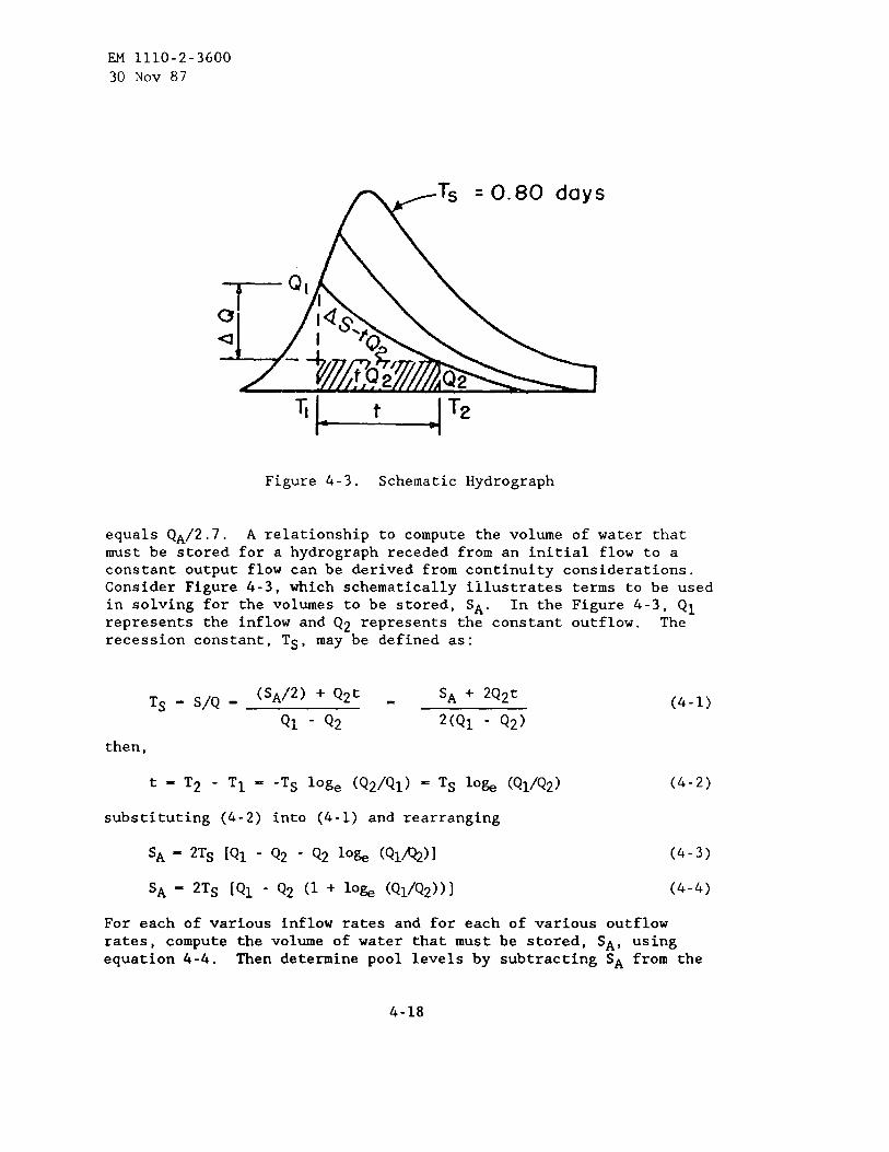
EM 1110-2-3600
30 NOV 87
or Q,
u
Figure 4-3. Schematic Hydrography
equals QA/2.7. A relationship to compute the volume of water thatmust be stored for a hydrography receded from an initial flow to aconstant output flow can be derived from continuity considerations.Consider Figure 4-3, which schematically illustrates terms to be usedin solving for the volumes to be stored, SA. In the Figure 4-3, Q1represents the inflow and Q2 represents the constant outflow. Therecession constant, Ts, may be defined as:
Ts = S/Q =(sA/2) +Q2t - SA + 2Q2t
(4-1)
QI - Q2 2(Q1 - Q2)
then,
t= T2 -Tl== -Ts loge (Q2/Ql) = Ts 10& (Q1/Q2) (4-2)
substituting (4-2) into (4-1) and rearranging
S* = 2Ts [Ql - Q2 - Q~ lo~ (Q~/Q2)]
SA - 2Ts [Ql - Q2 (1 + 10& (Q1/Q2))l
For each of various inflow rates and for
(4-3)
(4-4)
each of various outflowrates, compute the volume of water that must be stored, SA, usingequation 4-4. Then determine pool levels by subtracting SA from the
4-18

EM 1110-2-360030 Nov 87
storage value for the given outflow as defined by the inducedsurcharge envelope curve. The computations are illustrated in IHDVolume 7, Flood Control by Reservoirs, HEC ~. The pool levels thusdetermined represent the maximum pool levels that should be permittedfor the corresponding inflow and release rates. Obtain a family ofregulation curves by plotting the pool levels corresponding tovarious outflows using inflow as a parameter. The family of curvesis shown as Regulation Schedule A on Figure 4-4. A family of curvessuch as those shown in Figure 4-4 are appropriate for use in acentral office, but relationships to be used as an emergencyoperation schedule for damtenders are more directly usable if therate of rise of reservoir level is substituted for the inflow. Thisis readily accomplished by obtaining the difference between thevolume of inflow and outflow for a selected time interval andexpressing the volume as a rate of rise for any particular reservoirelevation. A typical family of curves is shown as RegulationSchedule B on Figure 4-5. The time interval to be used as a basisfor determining rate of rise should be based on a consideration ofthe reservoir and drainage basin characteristics, with 1 to 3 hoursbeing typical. Adjustment in gate openings at 1- or 2-hour intervalsis adequate for most projects.
e. Testing Spillwav Regulation Schedule. Spillway gateregulation and induced surcharge envelope curves should be tested byutilizing them in the regulation of historic or hypothetical floods.Several computer programs are available to do this conveniently. Thetests should involve a variety of storm patterns and magnitude, thatare considered reasonable for the project under consideration.
f. Methods of Operation. There are several options availableduring rising and falling reservoir stages which should be describedin project water control manuals.
(1) Risin~ Reservoir Levels. When predictions indicate thatanticipated runoff from a storm will appreciably exceed the storagecapacity remaining in the reservoir, the opening of spillway gatesmay be initiated before opening is required by the spillway gateregulating schedule. Opening of spillway gates should be scheduledto limit the rate of increase in outflow to acceptable values. Whenoutflows are required by the spillway gate regulation schedule,induced surcharge is utilized to exercise partial control overoutflow rates. The elevation attained and the volume of inducedsurcharge storage used will vary with the volume and rate ofreservoir inflow during individual floods and the exact schedule ofgate operation.
4-19

SP
ILLW
AY
GA
TE
RE
GU
LAT
ION
,S
CH
ED
ULE
A1
J

950
nv81
0I
1I
I950
CIJ
fvb
S?
6tic
,~u
ced
Surc
hOrg
e-t
=vttf
Wi
——
—1
945
~p
i‘f
fH
OY
ff8!
Ff
r/
-945
i d iu
ry
~j,1
E*
~
o m940
~~
~k
940
a,5
01-
//
: L/-
/
z~~y
‘/
//
~935/
/poly
OP
ER
AT
ING
INS
TR
UC
TIO
NS
925
Q<5
~~
,OY
[1)F
ollo
wre
gu
lor
flo
od
con
tro
lfe
gu
loti
on
w5
sctI
edu
leu
nti
lIo
rger
rele
ose
so
rere
qu
ired
by
dth
issc
hed
ule
.
~93
0(2
)A
dju
stth
eo
utf
low
each
ho
ur
on
the
bo
s,s
of
the
rote
930
~o
fri
sefo
rth
ep
rece
din
gth
ree
ho
urs
on
dtn
ecu
rren
tre
serv
oir
a/
//●
levo
tio
no
sin
dic
ote
db
yth
ecu
rves
.w m
/(3
)A
fter
the
rese
rvo
iret
evo
tio
nst
ort
sto
foil,
mo
into
incu
rren
tg
ote
w uo
pen
ing
su
nti
lth
eel
evo
tio
nre
ced
esto
947.
Wh
enre
serv
oir
isbe
low
925
elev
oti
on
947
rele
ose
ot
the
mo
m’im
um
ollo
wo
ble
rote
.92
5
920
920
0to
20
30
40
50
60
70
80
90
OUTFLOWINTHOUSANOSOF
C.F.S.
SP
ILLW
AY
GA
TE
RE
GU
LAT
ION
,S
CH
ED
ULE
B

EM 1110-2-360030 NOV 87
(2) Falling Reservoir Levels. For falling pool levels aftersurcharge storage has been induced, releases can be based on the mostappropriate of several possibilities. In any event, the surchargestorage should be evacuated rapidly, consistent with downstreamrunoff and reservoir conditions. Upon completion of drawdown to thetop of flood control pool level, the regulation schedule forreleasing stored waters should be followed. The following are someof the more common procedures for drawdown of induced surchargestorage for falling reservoir levels and decreasing inflow:
- Draw down gradually to top of flood control pool level withina specified number of hours
- Maintain maximum spillway gate opening
- Release some fixed percentage (over 100 percent) of the meaninflow for the preceding 3 hours
- Make the release in excess of the inflow by some specifiedincrement of discharge
- Make the release conform with a hydrography similar to thenatural inflow hydrography
If all spillway gates are opened fully during the storageoperation, discharge is uncontrolled until the outflow decreases tothe value at which the uncontrolled condition began. Regulatedoperation would then begin in accordance with one of the precedingrelease schedules for falling reservoir levels.
g. Effect on SDillwav Gate Desi~n. The most efficient inducedstorage operation would normally require that the spillway gates bedesigned for operation at partial openings and with individualoperating mechanisms. Unless the gates are designed for overtopping,it would be desirable for the height of gates to be 1 or 2 feetgreater than required for the induced surcharge operation since itwill not be feasible to raise all the gates simultaneously to obtainthe desired discharge.
4-6. Outlet Works for Water SUPDIV
a. General Considerations. The design requirements for outletworks in connection with their use for water supply functions aredifferent from those for flood control. Generally, the waterreleases for irrigation, navigation, municipal, industrial, or otherwater uses are fairly uniform over a period of days or weeks ascompared with the rapidly changing requirements for flood control,
4-22

EM 1110-2-360030 NOV 87
and they may be of relatively low magnitude. The use of outlet worksfor water supply functions may involve special operating problemswhich should be taken into account by the water control manager.
b. SDecial Requirements and Problems. Outlet works that aredesigned primarily for flood control may have some restrictions whenused for low-flow regulation because of cavitation. Also, operationof flood control gates may not allow the required degree of controlfor gate settings that precisely achieve the low-flow requirements.Some types of gate operating mechanisms have a tendency to “creep”over a period of time, and the gate setting must be re-adjustedperiodically to maintain the desired uniform outflow from theproject. The water control manager must also be aware of hydraulicproblems of long-term operation of outlet works, such as the adverseeffects of spray that may result from the use of a ski-jump energydissipator, turbulence or undesirable flow patterns in the downstreamtailwater area, problems related to ice formation and cold weatheroperation, and the general continuity of operation of outlet workfacilities where they are generally unattended except as required tomake adjustments in outflows.
4-7. Diversion and BYDaSs Structures
a. Project Pur~oses and Twes. Diversion structures andsystems vary widely in size, complexity of operation, and degree ofcontrol. In many cases excess flood water is carried away from amain stream by a control structure and auxiliary channel to reduceflood flow and stages at potential damage centers on the main stem.Water supply diversions for M&I and irrigation purposes are the mostcommon and include closed conduit bypass facilities, as well as openchannel flow diversions. Other.reasons for diverting flow may be forrecreational purposes, fish and wildlife enhancement, suppressingsaltwater intrusion in estuaries, or lowering the ground water table.The least common in nmber are manmade navigation channels, e.g., theTennessee-Tombigbee Waterway. Also, diversions to existing channelsfor other purposes may help provide navigation depths incidentally.Water is diverted back into some reservoirs at night following ahydropower generation cycle (pumpback) and reused for the samepurpose in the next generation cycle. Power is also generated bypassing flow through turbines in route to an auxiliary channel wherethe diversion is for other purposes. There are diversion systemswhose objectives are seasonal in nature related to high flow only,low flow only, and to both high and low flow conditions. Stillothers operate continuously, and some control the flow both into andout of given area.
4-23

EM 1110-2-360030 NOV 87
b. Regulation Procedures and Schedules. Diversion projectsthat have uncontrolled structures do not require water controldecisions; however, it is often necessary to anticipate when thesestructures will begin and cease operating in order to notify thegeneral public, evacuate auxiliary channels, and take other action asappropriate. The most complete hydrometeorological data available,including forecasts of stage and discharge, should be used whenapplying regulation procedures. Detailed analyses are often made forcontrolled structures because of the importance attributed to watermanagement, whether it be for flood control, water supply or otherproject purpose. Withdrawal from a stream or impoundment for anyreason can be a highly sensitive issue that leads to court claims,and signed agreements with appropriate interests are advisable thataddress both normal and rare climatic events. Long-range regulationschedules are made in an effort to define the duration of an eventand to define stage and discharge hydrography upstream of, at anddownstream of the control structures. Various factors are taken intoaccount: time of inundation, stream and channel capacities (stage orflow reduction targets), navigation depths, relationship to dredging,levee grades, river stage and lake levels, water quality in lakes,streams and estuaries, and seasonal considerations. In general,physical operating characteristics of the control structure, such asenergy dissipation and velocities, are critical.
4-8. Hurricane or Tidal Barriers. Hurricane barriers are operatedto protect coastal communities from tidal flooding associated withsevere storms. The design and operation of projects take intoaccount the effects of interior runoff, pumping station requirementsand availability of pending. It is also necessary to know how longit takes to open and close navigation gates and whether navigationgate opening operations can be initiated when there is significanthead differential on a gate. The manager should also be aware of thedischarge capabilities of emergency sluices, in case the navigationgate becomes stuck in the closed position or has to be closed formaintenance purposes for an appreciable length of time. It isimportant to have firsthand knowledge of the protected area and whatdamages would result at various water levels.
4-9. Interior Flood Control Facilities
a. General. Interior floodwater is normally passed through theline-of-protection by gravity outlets when the interior water levelsare higher than water levels of the exterior (gravity conditions).The floodwater is stored and/or diverted and pumped over or throughthe line-of-protection when exterior stages are higher than that ofthe interior (blocked gravity conditions). Gravity outlets, pumping
4-24

EM 1110-2-360030 NOV 87
stations, interior detention storage basins, diversions and pressureconduits are primary measures used to reduce flood losses in interiorareas. Other measures, such as reservoirs, channels, flood proofing,relocation, regulatory policies, and flood warning/emergencypreparedness actions, may also be integral elements of the interiorflood loss reduction system. Reference is made to EM 1110-2-1413,which provides general guidance for the analysis of interior floodcontrol facilities.
b. Operational Criteria. Generally the Corps plans, designsand documents detailed operating criteria for newly completedinterior flood control facilities for use by the local interestresponsible for operation and maintenance. These criteria shouldinclude instructions for obtaining and reporting appropriatehydrologic data, including current and forecasted values of exteriorriver stages, interior area rainfall and pending levels. Thecriteria should describe proper use of the data to effectivelyoperate the facilities. Provisions for obtaining supplementary datashould be included, when necessary. General flood emergencypreparedness plans and all arrangements required to assure timelyclosure of gravity drains, to implement emergency closures, and tooperate pumping plants should be carefully described. Periodicschedules for inspecting, testing and maintaining the facilitiesshould be defined.
c. Le~al Requirements. The capability of an interior floodloss reduction system to function over the project life must beassured. This requires legally binding commitments from the 16calsponsors of the project to properly operate and maintain the system.Real estate requirements and specifications for operating andmaintaining detention storage areas, pumping facilities, andconveyance networks, are integral to all agreements forimplementation of an interior system of flood measures.
4-1o. Hydroelectric Power Facilities
a. General. The functional utilization of hydropowerfacilities encompasses a broad spectrum of technical knowledge. AtCorps hydropower projects, the power units, control facilities, powertransformers, switchyards, and operational techniques all embracecomplex equipment which are under the operational control of theCorps . However, there is the much broader consideration ofelectrical power system operation and integration, which requires abasic understanding of not only the physical hydropower facilities,but also regional electrical power system operation. This knowledgeis needed to make judgments that affect the operation of the total
4-25

EM 1110-2-360030 NOV 87
regional electric power resource and the interrelationship of poweroperation with the management of multipurpose river developments.
b. En~ineerin~ Manual On Hydropower (EM 1110-2-1701>. Thismanual provides guidance on the technical aspects of hydroelectricpower studies from pre-authorization through the General DesignMemorandum (GDM) stage. Specific areas covered include need forpower, determination of streamflows and other projectcharacteristics , estimation of energy potential, sizing of powerplants, cost estimating, and power benefit analysis. Otherengineering manuals have been prepared that cover details of designfor selected hydropower facilities such as powerhouse design andselection of turbines and generators. While EM 1110-2-1701 primarilydeals with hydropower, it also provides much background informationthat pertains to operation of power systems and the general featuresof hydroelectric development.
c. Maior Hydroelectric Facilities. Hydropower projects areclassified by type of operation as run-of-river, pondage, storage,pumped storage, and deregulating projects. All hydropower plantsinclude the following major hydraulic components: dam and reservoir,intake , conduit or penstock, surge tank (when necessary), power unit,draft tube, and tailrace. The types and designs of each of thecomponents are determined by the specific design requirements forindividual projects, and they vary widely depending upon the type ofoperation and physical characteristics of the project. The heart ofa hydropower plant is the powerhouse, which shelters the turbines,generators, control and auxiliary equipment, electrical buswork anddisconnects, and sometimes erection bays and service areas.Transformers are usually placed on or adjacent to the powerhouse, andswitchyards are nearby.
d. Plant and Unit Control Svstems. Control equipment isnecessary to facilitate the automatic or manual operation of thepower units and other necessary power plant equipment. Controlsystems vary widely in scope and complexity, as a function of thesize and staffing of the plant, the level of operator skill andresponsibility, the need to automatically regulate power generationto outside demands, and the desirability and location of the centralelectrical control and dispatch center. Unattended small scale hydroplants often demand apparently disproportionate control equipmentexpenditures because of the need for automatic fail-safe operationand outside plant trouble reporting. Larger multi-unit attendedplants often have a central control room and automatic controlrequiring large computer based Supervisory Control and DataAcquisition (SCD) control systems.
4-26

EM 1110-2-360030 NOV 87
e. Plant and Unit ODeration. In general, individual powerunits, multiunit power plants, and large interconnected power systemsare operated by a variety of manual and automated control systems.In recent years, there has been a significant increase in the use ofautomated systems for operating hydropower plants remotely from acentralized control center. At Corps of Engineers projects, thehydropower facilities and control systems are generally operatedunder the supervision of the Operations Division, which has directresponsibility for the operation and maintenance of the individualprojects. The operation of these facilities for day-to-dayregulation and functional management of these resources to meet allwater management goals, including hydropower, is performed inaccordance with instructions and schedules provided by theReservoir/Water Control Center or other water regulation unit thathas responsibility for scheduling plant operation. Individual unitsmay be started and placed on line in accordance with operatingschedules and the needs for power. The starting and stopping ofindividual units may be done manually by plant operators or remotelyfrom the power plant control room or other designated projectcontroller location. The units may be operated according to aspecified load, or they may be placed under Automatic GenerationControl (GC). When units are operated to meet a specificallyscheduled load, it is termed “block loading.” Such loadings aregenerally specified as hourly values, which reflect the anticipatedneeds for power generation and the needs for all other water demands.The changes as required in scheduled plant loadings are performed bythe plant operator form the project control room or remotely from adesignated project controller or central dispatch facility. Undercertain conditions, units may be operated under “speed no load,” inwhich the unit is rotating at the speed which is synchronized withthe power system operation, but without load or significantgeneration of electric power. This type of operation may benecessary to help provide inductive or capacitive reactance to thepower system operation and enhance system stability. It alsoprovides for spinning reserve capacity which may be required forpower system operation to meet unforeseen changes in plant or systemloads. The methods of scheduling and coordinating the regulation orpower plant operation are discussed later in this section.
f. Integration into Re~ional Power System. The electricalpower produced at Corps of Engineers projects in the United States isintegrated with electric power produced by other utilities. Underthe terms of the Flood Control ct of 1944 (Public Law 78-534, datedDecember 22, 1944) and related legislation, the power produced byCorps of Engineers projects is marketed to the utilities and otherdirect service customers by five regional power marketingadministrations (PM’s) of the Department of Energy. In addition tomarketing, some of the PM’s also provide transmission and dispatching
4-27

EM 1110-2-360030 NOV 87
services. The regional electrical power networks in the UnitedStates are complex and highly integrated systems whose operation ismade possible through formal agreements between utilities or throughinformal working relationships to enhance the overall capability ofindividual utilities.
g. Control EQuiDment. Units or plants at major hydroelectricpower stations may be loaded on the basis of predetermined fixedschedules (block loading), or they may be loaded through use ofload-frequency control equipment known as Automatic GenerationControl (GC). In those cases where system control of hydroelectricpower facilities represents a major portion of the system generation,this equipment is normally part of the control facilities provided inthe power dispatching control center operated by the Power MarketingAgency (PM). The function of GC is to control power generationautomatically at one or several plants in a system in response to themoment-to-moment load variations that are imposed on the system. Itis also used to pro-rate generation automatically to several plantsas required to meet a major portion of system loads, on the basis ofpredetermined functions which represent the proportional loadings ofindividual plants. These functions, known as “break point” settings,are individually determined for each plant from power systemsimulations that project the expected loads and resources into thefuture, usually for periods of one to five days. The “break point”settings may be changed daily as a function of system requirements.In actual operation, the plant loadings computed by the GC areconverted to electrical signals, and they are received at each plantat approximately l-second intervals. The power plant internalcomputer automatically apportions the plant load change among thegenerating units on-line at that particular time. The use of theequipment is a very important tool in the power scheduling anddispatching process. The “break point” settings determine the actualloadings of each plant as a function of the continuously varyingpower requirements, and they determine the resulting streamflows ateach project under GC. It is vital that the water manager who hasprojects operated under GC be familiar with interrelationshipsbetween system controllers and the planned use of this equipment forscheduling plant operation for normal and emergency conditions.Although the planned and scheduled use of power plants is coordinatedthrough the water managers, the ultimate plant operation isdetermined by the automatic generation control equipment for thoseplants under its control. It is, therefore, important that the plantoperation be continuously monitored to assure that all of the watermanagement goals are being met and to take corrective action whennecessary.
h. Special Operating Problems. The problems of power operationvary widely among projects and systems, depending upon the importance
4-28

EM 1110-2-360030 NOV 87
of hydropower in relation to other project purposes, the methods ofhydrosystem control, and the system integration of power regulationwith other multipurpose water management requirements. The watermanager is concerned with two basic types of problems:
Project and system regulation on a seasonal basis, when poweris a consideration in the water control plan
Scheduling power regulation on a daily, weekly, or monthlybasis to meet the power needs in conjunction with the otherwater uses
Both types of problems require a large degree of coordination withall users.
(1) Seasonal Reservoir Re~ulation for Hydropower. Chapter 3describes the principles of hydropower system operation and themethods for developing reservoir regulation schedules for reservoirprojects with hydropower facilities. The Annual Operating Plan (OP)is developed on the basis of each year’s hydrologic conditions,system power requirements, and multipurpose requirements and goalsfor reservoir regulation. The studies required for developing the OPmust be coordinated with other power interests and local or regionalgroups that have an interest in the multipurpose aspects of waterregulation.
(2) Coordination. There is an imperative need for coordinationbetween the Corps of Engineers and the Power Marketing Agency (PM)when formulating power production and power marketing strategies andwhen integrating the operation of power facilities within theregional power grid. This coordination involves many aspects ofproject operation and reservoir regulation at Corps projects,including the development of the operating plan to achieve the poweroperating goals, scheduling reservoir releases, and dispatching powerunder normal and emergency conditions. All coordination requiresadministrative procedures, technical evaluations, and detailedworking arrangements to assure that the responsibilities of the twoagencies are met. This is generally accomplished by executing formalMemorandums of Understanding, which define specific duties andresponsibilities, establish coordinating groups composed of agencyrepresentatives which oversee the operations, and form work groupsassigned to specific tasks. Similar arrangements are made with otheroperating utilities in the region. During operation, however, thereare often circumstances which require unplanned minor departures fromthe operating plans in order to satisfy unforeseen requirements ordesires for river regulation. For some cases, departure fromoperating plan schedules and guidelines may have a significant effecton meeting one or more of the water management goals, and the problem
4-29

EM 1110-2-360030 NOV 87
may have to be referred to an appropriate administrative level forresolution. Chapter 8 deals with interagency coordination in greaterdetail.
(3) Schedulin~ and Dispatching Power. Scheduling anddispatching power from Corps projects are performed in accordancewith the basic operating strategies and criteria contained in theAnnual Operating Plan (OP) and Water Control Manual. As mentionedpreviously, the OP consists of guide curves and other operatingguidelines that are generalized from power operation studiesperformed on the basis of mean monthly historical streamflow data andestimated load and resource evaluations. It is also necessary tobase the actual operating schedules on current hydrologic and powerdata, together with forecast data. For small or relatively simplesystems, the schedules can be determined manually from analysis ofcurrent data and estimated projections of future operations. Forlarge integrated power systems, however, the schedules are usuallydetermined by computerized simulations, which provide currentanalyses of all hydrologic and power generation data, load forecasts,interchange requirements, and plant and unit status conditions on areal-time basis and conform to the constraints of operating rulecurves. Simulations cover in detail several days to a week inadvance, and more general projections are made for periods up to 30days or more in advance. The actual operating schedules are thenderived from the simulations of project operation. The dailyoperating schedules are forwarded to the project office (usually byteletype) for plants not on centralized control, or they are insertedinto the system controller at the power control center. They mayindicate hourly generation values for block loaded plants andanticipated plant loadings, unit status, and “break point” settingsfor plants operating under control of the GC equipment.
(4) Power Dispatchers. The continuous operation of the powersystem is under control of the power dispatchers, who monitor allaspects of plant and system operation. The dispatchers are highlytrained specialists who control the flow of power in the system undernormal operating conditions. They also recognize any abnormalitiesor departures from planned system operation and take immediate actionto correct the problem and restore the system to normal operation.Potential problems include unusual load demands, power outages,equipment failures, or loss of transmission. The dispatchers are infrequent communication with plant operators who control the operationof hydroelectric facilities at their respective plants. The plantoperators are responsible for the operation of their plants inaccordance with the operating schedules and other operating criteriathat may affect water regulation and the operation of the physicalfacilities.
4-30

EM 1110-2-360030 NOV 87
(5) Constraints on Peaking ODeration at Hvdro~ower Plants.Many hydroelectric plants are designed for meeting peaking andintermediate load requirements that result in a low load factoroperation. Some plants generate only when peak loads occur,generally less than 8 hours per day, and their generation isscheduled to help meet the morning or afternoon peak loads. Otherplants are scheduled for a more continuous operation but stillrespond to daily variations in system loads. While there are manyadvantages to operation at peak loads, fluctuating outflows resultingfrom this operation may cause water regulation problems.Environmental considerations, such as the effect of fluctuating waterlevels on fish and wildlife, aesthetics, navigation, and publicsafety, are all considered in the planning, design and operation ofpeaking power plants. In some cases, the water fluctuation problemsrelated to peaking operation are completely met by constructingderegulating reservoirs immediately downstream from peaking powerprojects. Where it is impractical to construct deregulatingreservoirs, specific operating limits for fluctuations in powerproduction and/or water level in the river system below the projectsare developed on the basis of studies made during the design phase.Pondage projects, which are developed in tandem on a major river, areoperated as a system with regard to peaking power operation. Thetotal system output is shaped to meet the fluctuating power loads, sothat all plants share in loads and fluctuations in reservoir andtailwater water levels. The analysis of this type of systemoperation is accomplished through use of the various computer modelsavailable for this purpose. In actual operation, there may berequests for restrictions in peaking operation beyond those set forthin the design or operational studies. These requests are generally aresult of changed environmental conditions or other unforeseenconditions. Requests of this nature must be carefully analyzed.
(6) Electrical Operatinz Reserves. An electrical power systemis designed to guarantee reliable service to customers. Thisrequires that reserve capacities be available to cover forcedoutages, maintenance outages, abnormal loads, and othercontingencies. Typically, power system resource planning is based onproviding about 20-percent reserve capacity above the expected annualpeak load. This capacity is called the system planning reserve. Inday-to-day system operation, an operating reserve of 5 to 10 percentof the load being carried must be maintained at all times. Half ofthis must be spinning reserve (capacity which is rotating but notunder load; see Paragraph 4-10e, Plant and Unit Operation), and theremainder is standby reserve, which must be available in a matter ofminutes. The spinning reserve is used to handle moment-by-momentload changes, while standby reserve is used to cover unexpected powerplant outages.
4-31

EM 1110-2-360030 NOV 87
(7) Load Forecasting. Load forecasting is one of the mostimportant factors in scheduling and dispatching power. Normally,this is done by the PM, as part of their service in the schedulingprocess. When the federal plants are interconnected with privateutilities and are operated under power exchange agreements forcoordinated system operation, the federal plants may also provideinterchange energy to help meet the utility system loads. Systemload forecasts prepared in conjunction with daily operation areshort-term hourly and daily loads, as compared to generalized monthlyload forecasts used in resource planning and annual operationplanning. The actual daily load forecasts are prepared from analysesof recent weather and load data, forecasted weather data, and othervariables such as time of day, day of the week, and time of year.The load may be separated into several components, such asindustrial, commercial, and residential, and detailed computerizedload forecasting programs have been developed. The load forecastsare then used to develop individual plant schedules.
(8) Emer~encv Control Procedures. The requirements forscheduling the use of power resources are based on normal operationof generation equipment, transmission and substation systems, andanticipated power loads which conform closely to the scheduledamounts. Unanticipated outages in system operation may arise andrequire immediate compensation in the electrical system to prevent abreakdown in the total system operation. Emergency actions by thedispatchers and power schedulers are required that may affect boththe use of generation equipment at hydroelectric plants andconditions of streamflow and water levels at individual plants. Inemergencies, changes in power system operation must usually beinstituted in seconds or minutes, and the recovery of the system mayrequire as much as an hour or more. In order to assure that normaloperation can be achieved within the overall capabilities of thepower system, the scheduling must allow for sufficient reserves ofgeneration capacities to meet such requirements (see Paragraph (6),above) . Short-term or disturbance-related power shortages are met bygeneration reserves. This unused generator capacity is available foruse in the event of a failure in the power generation, substation, ortransmission facilities. “Operating reserve” is generating capacitythat can be made available and loaded within 10 minutes on asustained basis. “Spinning reserve” is a component of operatingreserve and is on-line, unloaded, and ready to pick up immediately ondemand. In extreme emergencies, where the power system is unable toprovide sufficient generation to match load, automatic devicesinstitute a program of “load shedding.” Coordinated automatic loadshedding should be established to prevent the total loss of power inan area that has separated from the main network and is deficient ingeneration. Load shedding should be regarded as an “insuranceprogram” and should not be used as a substitute for adequate system
4-32

EM 1110-2-360030 NOV 87
design. The emergency conditions of power plant operation discussedin this paragraph are beyond the normal scope of coordination betweenthe Corps of Engineers and the PM. It is mandatory that the watermanager be informed immediately of any large scale interruption ofthe power system and take actions as necessary to preserve the waterregulation goals and inform others regarding the emergencyconditions.
4-11. Fish Passage Facilities and Use of Water Control Facilitiesfor Fishery Enhancement
a. General Considerations. There are two classifications offish life that are dealt with in the development of fish facilitiesfor water control projects. These are:
Anadromous (migrating) fish species such as salmon or shad,which basically maintain their habitat in the ocean andascend from the sea into rivers to breed
- Resident fish such as bass and trout, which are bred, reared,and maintain their habitat in rivers
Specially designed facilities for fish passage and enhancement offish life have been incorporated into many water control projects.These facilities may include fish ladders; fingerling fish bypasses;fish turbines, fish pumps, water conduits, or spillways or outletworks that provide water to attract fish into fish passagefacilities; fish “elevators”; and facilities that release the desiredquantity and quality of water to enhance fish life in downstreamareas . In addition to these physical facilities, other fisheryactivities, facilities and operations which may be related to watermanagement may include:
Fish hatching and rearing to supplement natural fish runs andestablish new runs
Improving fish spawning grounds
Transporting fish by truck and barge
- Modifying spillways to reduce nitrogen supersaturation duringtimes of spill and adjusting or reducing spill to helpmitigate nitrogen supersaturation
Performing basic and applied research in fish biology,particularly in regard to the effects of dams and reservoirs
4-33

EM 1110-2-360030 NOV 87
Regulating water releases to meet the streamflow and waterlevel fishery requirements in the water control plan
b. Fish Passage Facilities. Dams are designed to preserveanadromous fish runs, primarily the salmonoids. Fish ladders providesafe upstream passage of adult migrants past water controlstructures . Years of experience in the operation of properlydesigned fish ladders have shown them to be a proven method forpassing upstream migrants through a series of dams whose hydraulicheights range from 50 to 150 feet. Passing the downstream migrationof juvenile anadromous fish, however, is not accomplished with thesame degree of reliability. Various methods, such as constructingfingerling bypass facilities at dams, transporting migrants by truckor barge, passing fish through spillways rather than power units byinduced spill, and increasing streamflow through reservoirs duringmigration, have been tested. Multilevel intakes, usually considereda means to provide general water quality control, may have beenjustified primarily to meet the fishery requirements for control ofwater temperatures or other water quality parameters that affect fishlife. Scheduling the operational use of multilevel intakes isusually based on the fishery needs, and the water manager must havefull knowledge of the fishery management programs and the particularrequirements for the river reaches affected by their use.
c. Fish Attraction Water. One of the objectives in the designof fish ladders is to provide the proper water currents in thechannel area adjacent to and immediately downstream from the entranceof the ladder at the tailwater of the dam. These currents areessential in leading the upstream migrant fish into the fish ladderapproach channels (including power plant tailwater fish channels)from the tailwater area or open river. “Fish attraction water” isthe term applied to the water which is supplied for the specificpurpose of creating these currents. The hydraulic design of fishladder entrance conditions is usually based on hydraulic modelstudies. Relatively large amounts of water are required to createthe currents (1,000 to 2,000 cubic feet per second), and these may besupplied by large capacity pumps, a hydroelectric unit whose drafttube discharges into the fish ladder approach channels, or by directdiversion of water from the headwater to the approach channelsthrough gravity supply systems. These facilities must be operatedduring the season of upstream fish migration. The power output fromfish turbines is fed into the power system and represents an elementof the hydropower resource, but the output is proportionally lessthan the main units because of small discharges. Fish pumps simplyrecirculate the water in the tailwater area, but they requirerelatively large amounts of power to operate them. Direct diversionof water to supply fish attraction water is the least efficientmethod, considering the loss in energy that would otherwise be
4-34

EM 1110-2-360030 NOV 87
available by the use of the water for power production. In summary,fish attraction water is a necessary adjunct to the operation of fishladders, and the use of water or power to supply it has a bearing onthe efficient use of water for all purposes.
d. Fin~erlinz Fish Bv~ass Facilities. The operation offingerling fish bypass facilities of the type used in the dams in thelower Columbia River system require flows ranging from 300 to 600cubic feet per second in the intake area, but about 80 percent ofthis amount is pumped back from the point where the water enters thebypass diversion channel. The remaining 20 percent (about 60 to 120cubic feet per second) flows through the diversion channel or conduitto the tailwater, and this amount is lost to the functionalutilization of water at the project. The intakes for thesefacilities are constructed in conjunction with the power unitintakes. Fish screens that are located in the power unit intakesdivert the fingerlings up through the gate well slots, thence throughorifices or weirs into the fishery bypass collection channels andbypass conduits. The hydraulic systems which comprise these bypassfacilities are complex, and their operation must be carefullymonitored to assure that the fish are being transported efficientlypast the power structure. Changing conditions of pool levels andpower discharges may affect their operation, and deficiencies intheir effective passage of downstream migrants may require adjustingpower plant operation or inducing spill as an alternative means forpassing the fish.
e. Increased Streamflows to Aid Passage of Downstream Migrants.In view of the difficulties of passing downstream juvenile migratingfish past a series of large dams, particularly those withhydroelectric facilities, a number of alternative methods are beingtested in order to achieve the most satisfactory and economicsolution. The use of fingerling bypass facilities is still in thedevelopmental stage, and until these facilities are proven fullyeffective and are installed at all plants, it may be necessary toenhance the passage of downstream migrants by induced spill of waterat critical times. Further, due to longer travel times of fingerlingmigration that result from the impact of reservoirs in the riversystem, it is desirable to increase streamflows by releasing waterstored in upstream reservoirs during the downstream fish migration.These two factors are considered in the daily management of the watercontrol facilities in conjunction with all other project purposes.Although the annual operating plans may recognize and account forfishery requirements, under actual operation the many variables thataffect the daily fishery needs cannot be foreseen more than a fewdays in advance. This is particularly true of the need for inducedspill and increased discharge through the reservoirs during criticaltimes in April and May. A mathematical modelling system to simulate
4-35

EM 1110-2-360030 NOV 87
and evaluate hydraulic and fishery conditions is now being usedexperimentally as an aid in scheduling the water regulation duringthe critical times of downstream fish migration.
f. Fish Hatcheries. Water intakes for the hatcheries may befrom the reservoir or from the river channels downstream. Waterquality characteristics including temperature, pH, dissolved oxygen,and nitrogen must be maintained within specified tolerances.
g. Control of Dissolved Gas Su~ersaturation
(1) Dissolved gas supersaturation occurs in rivers below damsas water plunges over a spillway into a deep stilling basin. Gassupersaturation may injure juvenile and adult fish through theoccurrence of gas bubble disease. This condition results from longexposure to water supersaturated with dissolved air exceeding thetolerance level of the fish. The problem has been studiedextensively and measures have been taken to partially alleviate theproblem. Although it is possible to reduce gas supersaturationcaused by spill at dams, there is no way to reduce it to completenon-damaging levels under all conditions of streamflow. Also,threshold levels at which gas supersaturation becomes damaging tofish life are uncertain. Nevertheless, specific efforts are beingmade to reduce supersaturation by modifying the structural shape ofspillways, by adjusting the water regulation in the system to reducespill, and by adjusting the distribution of spill.
(2) The design and construction of “flip lips” on thedownstream ogee section of spillways has been accomplished forseveral Columbia and Snake Rivers dams. Prototype measurements haveindicated a significant reduction of gas supersaturation at thoseprojects, in the low to medium range of their spillway designcapacity. These flows correspond to those experienced during normalflood runoff conditions. It is believed, however, that when spilloccurs of the magnitude which would be experienced in major floods,the effects of the “flip lips” are drowned out, and they would havelittle or no effect on reducing gas supersaturation. Overall, the“flip lips” reduce the duration and frequency of gas supersaturationand are therefore beneficial in alleviating the problem. The use ofupstream reservoir storage to reduce spill may also alleviate theproblem. This solution must be considered with respect to all otheraspects of reservoir regulation. Normally, the plan for system wideoperation is also to lessen the spill at downstream locations andtherefore is consistent with minimizing gas supersaturation.However, it is sometimes possible that the timing of the spillreductions could be scheduled to better coincide with the fish runs.These objectives can be incorporated on a long-range basis into the
4-36

EM 1110-2-360030 NOV 87
annual operating plan, and on a short-range basis into the day-to-dayscheduling.
(3) Probably the most direct way to reduce gas supersaturationthrough water management is by adjusting spill between projects underreal-time operation. This can be accomplished by shifting powerloads to maximize spill at those projects where the spill producesthe least gas supersaturation. Also , it may be feasible to arrangefor increased power loads on the hydropower system by transferringloads from thermal plants or other outside resources. Specialcomputer programs are available which simulate the levels of gassupersaturation and can be used for analyzing and projecting thelevels resulting from the scheduled spills in the system. Theseprograms use current system data, which is essential for initializingand evaluating the effects of current conditions of spill.
h. Coordination of Regulation for Fishery. Detailed knowledgeof the fishery resource and the responsibility for its management areshared by the state and federal fish and wildlife agencies, Indiantribes , and international organizations. These agencies representthe interests of sport and commercial fishing, Indian tribes whosetreaties may involve rights for fishing, and the fishery interests ofother countries who share in the responsibility for fisherymanagement through treaties and compacts. Input from all of theseorganizations are important for determining the specific needs of themanagement of the fishery resource as it pertains to the managementof water control systems. This requires a coordinated effort amongfishery and water managers to include fishery needs in the watercontrol plans and to carry out these requirements in the day-to-daymanagement of the water and fishery resources.
4-37

Figure
4-6.
OldWver
Control
Structures,
Old
River,
huisiana;
New
Orleans
District

m 1110-2-360030 NOV 87
CHAPTER 5
WATER CONTROL DATA SYSTEMS
5-1. General
a. Purvose. This chapter will summarize the technical aspectsrequired for the planning, design, operation, and coordinationrequired for water control data systems. The information presentedis arranged by three major components: (1) data observation andcollection at field stations, (2) transmission of data and (3) datamanagement and processing in a database. The presentation willaddress the mechanisms and equipment associated with each of thesecomponents.
b. Basic Requirements
(1) The effective management of water control systems isdependent in part upon knowledge of current project and hydrologicconditions, project capabilities and restraints and water controlelements in the river system that affect streamflow, water level, andwater quality.
(2) The water control data system must be designed to meet thespecific needs of the water control manager. The data system mustinclude facilities to perform the following functions:
observation and storage of data at field stations
transmission’of data from field stations
decoding and validation of transmitted data
storage and retrieval of data in a database
management of a water control database
- providing graphical and tabular data displays
exchanging data with other users
(3) ER 1110-2-249 establishes requirements for management ofwater control data systems.
5-1

EM 1110-2-360030 NOV 87
c. Master Plans
(1) Master plans for water control data systems are prepared inconformance with ER 1110-2-240. In general, master plans include allthe essential information that set the requirements, justification,scope, and recommended procedures for implementing water control datasystems. Accordingly, they:
outline the system performance requirements, including thoseresulting from any expected expansions of Corps missions
describe the extent to which existing facilities fulfillperformance requirements
describe alternative approaches that will upgrade the systemto meet requirements not fulfilled by existing facilities, orare more cost effective than the existing system
- justify and recommend a system considering timeliness,reliability, economics and other factors deemed important
delineate system scope, implementation schedules, proposedannual capital expenditures by district, total costs, andsources of funding
(2) ER 1110-2-240 describes the administrative procedures forpreparing and updating master plans for water control data systems.It sets forth the responsibilities associated with developing thewater control plan, coordinating its approval, making fundingrequests for the costs of the proposed facilities, and updating plansas needed on an annual basis. Guidance for the management ofdedicated water control data systems including that equipment andsoftware used for acquisition, transmission, and processing of real-time data for regulating Corps projects is prescribed inER 1110-2-249.
(3) The master plan is prepared by Division water controlmanagers based on detailed studies of communication alternatives aswell as all other aspects of the overall water control data systemrequirements. Because of the rapidly advancing technology, there isno one established method or standardization of design for a watercontrol data communication system. Each existing system has beendeveloped on the basis of design conditions for that particularsystem. However, considerable experience has been gained to date byDivision and District offices in developing these automated networks.Information of these various systems are disseminated throughtechnical conferences and/or workshops on water control managementconducted or coordinated by HQUSACE.
5-2

EM 1110-2-360030 NOV 87
5-2. Data Observation and Storage at Field Sites
a. General. A majority of the data input into the watercontrol data collection system are time-variable data. Theyrepresent observations of the conditions of water regulation atvarious projects, water levels and water quality in the river system,and those hydrometeorological elements that affect any of theseconditions or elements. Although non-variable data may be includedin the data processing system (such as project characteristicsrelated to reservoir capacities, outflow limitations, etc. , orhydrologic parameters that define the runoff characteristics of theriver system), the data gathering system is designed primarily toobserve, process and transmit time-variable data. The time-variabledata observed and collected may be classified in three broadcategories:
- Hydrometeorological data
- Project data
- Water quality data
b, Hvdrometeorolo~ical Data
(1) The function of hydrometeorological data is to providecurrent information by direct observation on all significant elementsthat affect runoff within a drainage basin or rive~ system.
(2) Some of the hydrometeorological elements that may beobserved are:
water levels in rivers, lakes, and reservoirs
precipitation as measured at ground stations or as estimatedby radar, satellites , or other sensors
air temperature as measured at ground stations or by upperair atmospheric soundings
pan evaporation as measured at project sites
snow sensors or snow courses which measure the depth andwater equivalent of the incremental snow accumulation, and/orthe total accumulation of snow in the snowpack, as determinedfrom ground measurements or remote sensors
5-3
EM 1110-2-360030 NOV 87
snow covered area, as determined from aerial or groundreconnaissance , or by remote sensors from satellites oraircraft
conditions of river ice, as measured at key locations todetermine ice thickness and locations of ice jams
(3) In addition to these hydrometeorological elements,observations may also include measurements of soil moisture, soiltemperature , and ground water. They may also include atmosphericmeasurements of humidity, wind speed, wind direction, and solarradiation.
(4) The design of a data network must be based on many factors,including consideration of the hydroclimatic regime, projectregulation and forecasting requirements. The principal difficulty indefining the specific coverage and number of data stations is that ofstriking a practical balance between a theoretically completecoverage and the practical limitations imposed in obtaining andprocessing the data collected. The judgments to be made as to theamount of coverage that are justified for a particular river systemmust be based on hydrologic analysis, estimates of cost and benefitsfor incremental increases of coverage, and a general knowledge of thereservoir regulation and forecasting problems for the subject riversystem.
(5) The streamflow and rainfall reporting networks aredeveloped in cooperation with the U.S. Geological Survey and theNational Weather Service. These cooperative programs largely definethe scope of coverage of the hydrometeorological networks. In someareas , the cooperative network and stations owned and operated by theCorps supplement each other. Section 5-6 describes the coordinationof data collection programs in greater detail.
(6) The design of sensors, equipment, and facilities requiredin the construction of reporting stations is preferably performed inthe project design phase and documented in an appropriate designmemorandum. It is not within the scope of this manual to presentspecific design information or alternatives.
c. Project Data. Time-variable project data are essential forproject regulation. Hydrologic data, for observing and interpretingwater control functions at the project, is part of thehydrometeorological network discussed in Paragraph 5-2b. Other typesof data, while not strictly of a hydrologic nature, may also berequired to monitor project regulation. These include spillway andoutlet gate positions, power unit status, hourly power generation,navigation lockages, fish counts, and other water control parameters
5-4

EM 1110-2-360030 NOV 87
that are involved in daily project regulation.
d. Water Quality Data
(1) Water quality data is essential for real-time water controlmanagement. Data collection programs are tailored to individualprojects to meet water quality management objectives. Typically,data is needed for inflow, in-lake, discharge and tailwater stationsto develop an understanding of cause and effect relationships. Thisin turn provides needed information for integrating water qualityconsideration into real-time water control management decisions.
(2) Water quality data collection involves field sampling andanalysis, laboratory analysis and in-situ monitoring. Temperature,conductivity, dissolved oxygen, pH, turbidity and some parameterswith very short sample holding times are measured in the field, andthis data is immediately available for use in the water controlprocess. Laboratory analyses for other parameters provide data that,once evaluated, are available for support of real-time water controlmanagement. In-situ monitors are used at projects requiring frequentwater quality data for making operating decisions or to monitor theireffects in terms of meeting operating objectives. Typicalapplications involve thermistor strings for measuring temperaturestratification in a reservoir, an inflow monitor to detect acid slugsentering a lake and a discharge monitor for gaging results ofoperations. Monitors integrated into the Geostationary OperationalEnvironmental Satellites (GOES) data collection network greatlyenhance the ability to fine tune reservoir regulation to meetoperational objectives.
e. Manual Data Observation
(1) Historically, manual observations of water controlparameters represented the backbone of hydrometeorological systems.Even with more advanced systems, there may still be a need toincorporate manual observations into the networks. They may serve asbackup to the automated systems and may also be necessary forobserving hydrologic, project, or water quality parameters thatcannot be feasibly automated. For some projects, it may not beeconomically feasible or desirable to construct, operate, andmaintain an automated system. The Cooperative Reporting Network ofthe National Weather Service (NWS) has historically relied largely onmanually observed and reported precipitation and water level amounts.This is particularly true for those observations by cooperativeobservers that report only when certain criteria of event magnitudeare met. A goal of the NWS is to automate their cooperative networkas quickly as resources will permit.
5-5

EM 1110-2-360030 NOV 87
(2) Observers for field stations should be selected on thebasis of reliability, and they should be properly trained to meetreporting requirements. For those projects that are staffed 24 hoursper day, operating personnel are a source of reliable and currentdata. Specialized parameters related to water quality, fishmovement, aquatic life, or other unusual parameters may requireobservations by technical experts specifically trained to make theseobservations .
(3) Manually derived data may be stored briefly in digital formin preparation for its subsequent transmission. This may beaccomplished by data entry through local computer terminals, PersonalComputers, or other digital data entry devices.
f. Automated Data Observation and Storaze
(1) The first automated observation and storage capabilities atfield sites used analog methods, At a water stage station thistypically included a float system to drive a pen recorder. Such asystem produced an automatic analog record of water levels. With theavailability of digital technology the same sensing system wasadapted to drive a punched paper tape to produce an automatic digitalrecord. Other enhancements now commonly use the same float system todrive a digital shaft encoder whose output is stored in memory of alocal microprocessor at the gaging site.
(2) Any mix of analog and digital sensor outputs may be storedat specified times to produce a history of past and current digitaldata at the site.
g. Installation and Maintenance of Data Collection Eaui~ment
(1) Installation of Field Data Collection EcluiDment. Siteselection is generally based on the location of existing USGS orother gages. The site should have a structure which can be used tohouse the monitoring equipment and the data collection platform(DCP) . A DCP may include telephone equipment or a transmitter forcommunication via satellite, or both. The site should havecommercial power or a solar panel as backup to the battery power.The total installation needs to be waterproof.
(2) Maintenance of Field Data Collection Eauipment. The dataform each site should be reviewed daily to determine if the data iscorrect and the DCP is transmitting. Each site should be on regularscheduled maintenance so that all equipment can be checked and
5-6

EM 1110-2-360030 NOV 87
properly maintained. Each district should set up regular maintenanceschedules. The following is a partial list of items which may bechecked daily for each DCP.
correct channel
correct time slot
- battery voltage
DCP transmit power
modulation index
signal to noise ratio
limits within time slot
error messages
correct identifier
valid data
These items can be checked from the review of error message reportsprepared by the central receiving site operator.
5-3. Data Transmission
a. General. Single project river development systems, ormultiproject systems which are relatively small and involve onlyCorps projects, require much less complicated communication and datahandling facilities than large, complex river developments. Manuallybased and semi-automatic data handling systems may be entirelyadequate for the small river systems, but handling data in thismanner is generally cumbersome and inadequate for larger systems.The many repetitive transmissions from the data source to the datausers, the time required for transmission, the chance of errors inrepeated handling of data, and the inability to physically processthe vast amounts of data from many different sources usually dictatethe installation of an automatic data handling system. However, evenwith the installation of automated systems, there may still be a needfor manual or semi-automatic data interrogation equipment to backupthe automated systems and to provide an alternate method for userswith less sophisticated needs to obtain basic river data. In thissection, the means of transmitting data from field gaging sites(manual, semi-automatic and automatic) will be discussed.
5-7

EM 1110-2-360030 NOV 87
b. Manual Data Transmission Systems. Current manually observeddata are usually transmitted to water control managers by commercialtelephone or by government operated radio or microwave voice systems.In a large river basin, the network may consist of severalsub-systems , and data stations within a sub-system may be transmittedto data collection facilities at a project, sub-system field office,or local Weather Service Office. These offices, in turn, transmitthe data to Corps of Engineers District Offices, Weather ServiceRiver Forecast Centers, or Weather Service River District Offices.The data may then be sent to the Reservoir/Water Control Centers orother water management element, by telephone. Hydrologic data fromother federal government or state agencies may be similarlydisseminated.
c. Semi-Automatic Data Transmission Svstems
(1) Semi-automatic transmission systems are those systems thathave automated part of the data collection function, but stillrequire an individual to be present for complete functioning. Anexample of a semi-automatic transmission system still in use is theTelemark.
(2) Reporting hydrologic elements remotely by means ofTelemarks was the first step in automating hydrologic reporting datanetworks. A Telemark is a piece of equipment that provides the meansfor interrogating a hydrologic station remotely without the need fordirect observation by an observer. Interrogations are usuallyperformed manually via telephone by someone at a data center, fieldoffice, project office, or river forecast center. While such systemsdepend upon individual interrogations, these may be made at regularintervals as required for routine operation. They can also be madeat any time it is desired to monitor hydrologic conditions duringfloods or other emergencies. The Telemark equipment may be owned andoperated by the Corps of Engineers, other federal agencies such asthe Bureau of Reclamation, National Weather Service, and powermarketing agencies, or state and local water divisions or bureaus.The use of the equipment and its interrogation by others iscontrolled by the agency who owns the equipment, Many radio basedsystems report data when they are interrogated.
(3) Retrieval of field station data using Telemarks is by landline equipment and normally through the existing commercial telephoneservice. Government operated communications systems can also be usedwhen available. Telemarks that are connected to commercial telephonesystems utilize a telephone coupling device (Codaphone), whichpermits automatic answering of incoming calls. Each field station ortelemark is assigned a telephone number (often unlisted), which can
5-8

EM 1110-2-360030 NOV 87
be called from any telephone set connected to the commercialtelephone system. The manual interrogation of a telemark isinterpreted by counting the audio “beeps” corresponding to thedigital values of the measured element. Manual interrogationrequires about 20 to 30 seconds for a 4-digit reading.
(4) Manual telephone interrogation of telemarks provides directaccess to data from individual field stations, thereby avoiding theneed to access a central database. For some users such as navigationcompanies, recreational boaters, irrigation operators, etc., this isparticularly useful since they are generally interested in conditionsonly at a given site or limited reach of the river, as opposed tothose responsible for river regulation who need ready access toinformation on the entire river system. Also, telemarks are easilyaccessed whereas access to central databases often requires some typeof computer terminal. Interrogations by others must be controlled toprevent battery drain on battery operated telemarks and calloverloading, which would affect normal operation of the equipment.
(5) Call up of Telemarks by data collection centers is nowgenerally performed through use of computer terminals. Theseterminals can be programmed to automatically “dial up” the telemarksat preprogrammed times and in any desired sequence. They may also beused to interrogate individual telemarks on call if desired.
d. Automatic Data Transmission Svstems
(1) General. In recent years, full automation of field stationreporting has replaced manual and semi-automatic transmissionequipment in many areas. Data transmission media that are availableand being used are:
ground based VHF radio
environmental or general purpose communication satellites
meteor-burst communication systems
land line equipment utilizing hard wire or switchedcommercial telephone circuits
- general purpose microwave communication systems
In general, any or all of these types of transmission media may beused either singularly or in combination. Planning and design of aparticular system must consider each of these alternatives prior toselecting the one or combination of them that best meets the overallrequirements of the water control data system being designed.
5-9

~ 1110-2-360030 NOV 87
Information on these transmission media and things to consider whendesigning a system using them follows.
(2) Ground Based VHF Radio
(a) VHF radio communication systems have been developed over aperiod of many years for automatic reporting hydrologic datastations. On site equipment for land based radio systems consistsprimarily of a radio transmitter and a receiver packaged in acontainer. The electronic equipment may also have some localintelligence and some storage memory. The receiver is designed tolisten for messages/commands from a Data Acquisition Controller (DAC)and to respond accordingly by using the on site transmitter. Thus ,either current sensor readings or data stored since the lasttransmission is sent to the DAC. DAC’S are generally located at theproject office responsible for data collection from a givensub-system.
(b) Radio frequency allocatiotls for governmental use inreporting hydrologic observations are made in four bands in the 169-to 172-megahertz range and use of certain frequencies in the 406- and412-megahertz bands. The use of these frequencies requires nearly adirect line-of-sight for transmissions between sending and receivingstations. For this reason, it is usually necessary to incorporaterepeaters between the sending and receiving stations, particularly inmountainous regions. Repeaters are generally located on prominenthigh points in order to meet the line-of-sight requirements.Electrical power is required to operate this equipment. Power may besupplied from commercially available power lines if available, butfrequently, these stations are located in areas not served bycommercial power, and battery operated equipment must be used.Batteries used for this purpose may be recharged by solar cells, windchargers, or automatically controlled small electrical generators.
(3) Satellite Communication Systems
(a) Satellites are currently in use to relay ground signalsemanating from field hydrologic data gaging stations to a satellitecentral receiving site facility. Initial experiments were conductedin the New England Division using the LANDSAT polar orbitingsatellites . When the Geostationary Operational EnvironmentalSatellites (GOES) were launched in the mid-1970’s, the Corps (LowerMississippi Valley Division) started to use the Data CollectionSystem (DCS) to perform this relay function. This has proven to beso successful and such a reliable means of obtaining data duringsevere weather conditions that the Corps has shifted dramatically tothis system and is now the largest single user of the GOES DCS.
5-1o

EM 1110-2-360030 NOV 87
(b) The GOES satellites are operated by the National EarthSatellite, Dissemination and Information Service (NESDIS) of theNational Oceanic and Atmospheric Administration (NOAA). This systemis available to the Corps for transmitting environmental data. Themajor components of the DCS are the field gaging sites, thesatellite, and direct readout ground stations (sometimes referred toas downlinks) located at central receiving sites for data retrieval.
(c) NESDIS operates three GOES satellites: the easternsatellite positioned at 75 degrees west longitude, the westernsatellite positioned at 135 degrees west longitude, and a sparesatellite positioned at 105 degrees west longitude to serve as abackup for both the east and west satellites. The equipment locatedat the gaging station site necessary for the use of the GOES DCS isreferred to as a Data Collection Platform (DCP). DCP’S can either beof the interrogable type, where the DCP (site/gage) can beinterrogated at any time, the periodic reporting type, where the DCPreports at regular intervals and specified times (self-timed type),or the randomly reporting type, where the DCP reports randomly withina specific time period that can be decreased by an algorithmprogrammed in the DCP as various thresholds are met or exceeded. Anexample of the random reporting system printout is shown on Table5-1. Column 6 of the table shows the random time interval betweentransmissions , Dual channel DCP’S can also be purchased where onechannel is used in the self timed mode and the other channel in therandom reporting mode. The majority of the DCP’S purchased by theCorps since the advent of this option are the dual channel type.
(d) Several direct readout ground stations (central receivingsites) have been acquired by the Corps to receive Corps and otheragency data. These are dispersed around the country in variousDistrict/Division offices. They are operated by Corps personnel orby others either through cooperative agreements or by contract. Asthe Corps system grows, additional central receivir,g sites willundoubtedly be acquired. In addition to the Corps central receivingsites, GOES data can also be retrieved from NESDIS or through othercooperative Federal or state owned central receiving site facilities.
(4) Meteor-Burst Communication Systems
(a) Meteor-burst communication systems use meteor trails in theionosphere to reflect radio signals emanating from field gaging sitesto a ground based receiving station. One rarely gets an immediatecommunications link when interrogating a field station or when afield station, through self timed response, is attempting to send itsdata to the central receiving station. A communication link
5-11

EM 1110-2-360030 ~OV 87
Table 5-1
Example Random Reporting System Printout (NED)
GOES RRDCS RERDIM DGTE : 5/31/84 TIK 11:23(1) (11
NO. NRME o. R. M/D TIME DT STffiE +/- Q +1- CSM STORM NOTE
SQ Mx HR:MIN HRS FT FT/HR ffS Q/HR Q/DR PREC.
(2) (3) (4) (s) (6) (7) (8) (9) (10) (11) (12) (13)
38 MELLS RIVER 2644 5/31 4:55 7.3 13.73 .27 42574. 1820. 16.1
36 UEST HRRTFORD 69@ 5/31 7:39 1.1 11.23 .~ 12894. 50. la.7 4.34 URRN
3S WEST LEBRNON 4092 5/31 6:0@ 3.3 20.21 .05 5s166. 2s2. 13.5 WRRN
37 NORTH MMPDLE 5493 5/31 7:36 .7 27.S4 .10 829W. 468. 15. i URRN
6 MDNTRGUE CIW 786S 5/31 8:08 1.9 37.18 . 13 13s260 877. 17.2 FLOOD
5 GIBK CROSSING 133 5/31 11:05 3.a 7.56 .05 4616 53. 23.2 9.fZIO FLOOD
(1)(2)
(3)(4}
(!5)(6)
(7)
(8)(9)
(10)
(11)
(12)
(13)
Date and time of the creation of this listing.“ND.= and “N~= ●re data collection platfom identifiers.
D.R. — Drainage ●rea ●t the data collection platform (square ●iles).‘MID= stads for the month ●nd day of the month of the latestmessage received. This itm ●nd item S comprise the time tag.“TIME” is the hour ●nd minute of the latest message (standard time).‘DT HOURS” is-the time differe~e between the next-to-last and the lastmessages received — used in the calculation of rates of change.‘STRGE FT” is the water level (oool or river stage).‘+/- FT/HR” is the rate of change of stage in feet per hour.
‘O CFS” is the discharge in cubic feet per second ●ssociated with the
stage reported in the last message.“+/- Q/HR- is the rate of change of discharge in cubic feet per sSCOnd
per hour.‘CSM Q/DR= is the discharge in cubic feet per second per square ●ile,otherwise know as lcsml.“STORK PREC.” stands for inches of accumulated rainfall in the mostrecent stc9rm.
‘NOTE” heads ● column reserved for c~ents regarding each message,
such as nonvalid aessages, flood stage, warning stage, or low battery.
5-12

EM 1110-2-360030 NOV 87
is established only when the signal being transmitted has the properreflection angle from the meteor trail to be picked up by thereceiving station. This usually takes less than 2 or 3 minutes tooccur.
(b) A meteor-burst communication system is used by the U.S.Soil Conservation Service, who operate the “SNOTEL” system used fortransmitting snowpack and other hydrologic data from remote mountainlocations in the western United States. Another meteor-burstcommunication system is used operationally by the Alaska District ofthe Corps of Engineers, together with other federal agenciesoperating in the State of Alaska, for obtaining hydrologic data fromremote field stations.
(5) Land Line Data Transmission
(a) Land lines can provide a path for data transmission. Theymay be used for backup to critical sites that also transmit via GOESor other radio based system. In some geographic areas land lines maybe subject to outage during hurricanes or other major meteorologicalevents . Unfortunately, it is during such events that datatransmission is most critical. Land line outages are being reducedand performance improved as wires are replaced by fiber optics and aslines are placed in conduits beneath the ground.
(b) The choice between a dedicated line or the use of switchedpublic service should be based on the frequency of use, volume ofuse, cost and availability. Even if reliable public switched servicemay be functional during a flood emergency, the service may becomeoverloaded by other users.
(c) In establishing land line communications consideration mustbe given to: transmission rate (110-9600 baud), mode (synchronous orasynchronous) , protocol, error detection/correction and other issues.Different communications approaches may be appropriate whentransmitting data from a field site to a host system, than would beused between two host systems.
(d) An automated data collection system now in operational usefor hydrologic reporting networks by the National Weather Service istermed the Device for Automatic Remote Data Collection (DARDC). Theremote station equipment produces serial ASCII code to represent inengineering units various hydrologic parameters, with 4 characteridentification and 4-decimal digit representation of each measuredelement. The field station equipment can be used in conjunction withthe GOES DCS, with land line (or VHF radio communication) systemsthrough which interrogations are made from a sub-system DAC. A morerecent system now being developed by the NWS and TVA is termed the
5-13

EM 1110-2-360030 NOV 87
Limited Automatic Remote Collector (LARC), which performs the samefunctions as the DARDC field equipment, but with added capability.The LARC system includes computer memory at the field station forstoring current data, for the purpose of providing trends over recenttime. The LARC equipment also provides both audio interrogation andcomputerized ASCII code.
(6) Microwave Communication Svstems. Microwave communicationsystems provide a high capacity, line of sight, point to point,transmission path. Where microwave links have been established forother communications purposes, it may be possible to add real-timedata communication at little additional cost. However, thesecommunication systems are subject to outages during electrical stormsand are generally considered less reliable than the more conventionalmeans of water control data transmission.
(7) Communications Re~ulations. There are two regulationspertinent to the design and operation of the hydrologic datatransmission systems that use the electromagnetic spectrum.ER 1125-2-308 describes requirements for the management of call signsand radio frequencies for data communication systems. ER 1110-2-248deals specifically with data transmission via the GOES DCS.
5-4. Decoding and Validatin~ Transmitted Data
a. Information received from a data collection system must bedecoded from the transmitted format. This operation may be differentfor each possible source from which data is received. After decodinginto a standard form the data must be verified. Data received in ahost system may contain errors introduced at any step from thesensing of the parameter to its receipt by the host equipment. Mostcommon errors are associated with a failure of the sensing of theelement. Water stage floats may hang up, precipitation gages maybecome fouled with foreign material, or maintenance personnel mayreset a datum. Data transmission functions may introduce occasionalrandom errors.
b. All received data should be validated before it is used tomake water control decisions. Validation should include a range ofpossible checks. Simple checks should test data against an allowablerange of values. Extended checks should test data against allowablerates of change for that parameter. Complex checks should test databy correlations with other stations and parameters, Where data failsto meet a validity check it should be marked as such, and ifappropriate, a new value should be estimated. All actions must beclearly logged so the water control manager can accept or rejectinvalid, missing or estimated data.
5-14

EM 1110-2-360030 NOV 87
5-5. Water Control Data Mana~ement and Processing
a. Data Storaze and Retrieval
(1) A database is essential for the storage and retrieval ofwater control data. The database must provide for the storage of avariety of stations, parameters, and data versions, over various timeintervals. New data received from the data collection network shouldbe stored in the database. The database should also include forecastand project operation data.
(2) The database must be simultaneously accessible by multiplefunctions. ReporC generation, analysis tools and other routines mustbe able to retrieve data of both historical and real-time interest.Text products and non-numeric data must be included in a database fororderly storage and retrieval. This includes locally generated textreports, as well as reports received from other sources.
b. Water Control Database Management. Provision must be madefor the management of the water control database. The water controlmanager must be able to control the amount of data that is availablein the database. This includes the particular stations, parameters,time intervals and time duration. Data must be removed from thedatabase on an established periodic basis. Removed data should bestored in an archive format which will allow its restoration manyyears in the future, if needed. The database must be capable ofbeing edited to alter, add, and delete data values or entire datasets .
c. Data Interpretation and DisDlavs. The data system must becapable of providing both graphical and tabular displays ofinformation in the database. This includes any data received fromthe data collection system, or any data generated in the analysis ofreceived data. The system should allow displays to appear onterminal screens, large screen display systems that may be utilizedin briefing rooms or hardcopy device at user request. Text productsmust be displayable on these same devices as required.
d. Data Processing
(1) General. With the advent of real-time data collection,increasing water control management responsibilities, and decreasingmanpower resources, computers are essential for data handling,manipulation and analyzing various project regulation schemes toaccomplish the many tasks required of todays water control manager.These computers are generally located in District and Division
5-15
EM 1110-2-360030 NOV 87
offices or maybe in a commercially available time sharing computerfacility. The functional requirements for the computer can be suchthat they act as both a Data Acquisition Controller (DAC) and a dataprocessor. These functions may also be divided either fully orpartially between separate computers.
(2) Hardware and Software Requirements
(a) Hardware. The selection of the data processor used willdepend upon the requirements that the processor must meet. Once thefunctions to be performed have been decided, the computer orcomputers chosen must be large enough and have sufficient datahandling and analysis speeds to meet system requirements and theneeds of the water control manager. The computer that performs thedata handling functions must be a highly reliable system that iscontinuously on line to assure the dependable receipt and control ofdata inflow to the system, The computer that performs the dataprocessing and analysis computations must provide the water controlmanager with answers in sufficient time to make real-time watercontrol decisions.
(b) Loss of Commercial Power. Water control managers need torecognize the impacts and problems when the loss of commercial poweraffects communications and data collection activities. The need toinstall or develop emergency power facilities and uninterruptablepower supply systems should be considered.
(c) Software. Development of system software must be designedknowing the type or types of hardware on which it will be required torun. The DAC must include appropriate software for data processing,storage and retrieval. The software design is highly dependent onthe data system and processing requirements. Figure 5-1 is aschematic of an example water control data system showingacquisition, application and management software ~/. Water controldata and application management software has been developed by theHydrologic Engineering Center for Corps-wide use. (See References3 through 6).
5-6. Coordination of Data Collection and Exchange
a. Intera~encv Cooperation
(1) Nearly all water control data systems require coordinationwith other agencies to collect the hydrologic data necessary forwater control management. In addition to the Corps of Engineers
5-16

EM
1110-2-3600
30
NOV
87
caU
181710W
eae”p
(Al
----
----
..-
Al
L
IJ
As
I la“,
W,.
9A
,,,“
7”,
A4
I
——
----
--__
____
1
[*1
i..
tna
.u
..
,,,”
,; I
A,,
I /
I
I
..,,
co
.,,
”,,.
”:
.“0
,.”,
,”,
”.
--
..,,
.,,,
-.-
..s..
.,I
II I I I I I I
b1,,
,,,
,,
“,*,
,,
-..
.?,
...
1, A
lo
I I I I
I I iI
II
II
IA
aI
/
I
II
Ia1
3I
II I
A?
:
I
----
—--
—--
——
---—
—_
--—
____
J
T04
,0....,,,. ..,
..,4[
C,,
*.C
,~,
AN
ALV
SIS
On
OU
#(C
l--
----
---
----
----
---
____
____
___
____
____
1i I I I
II
tf
t*A
VA
0,s
...0
...
SC
.”o
m,c
,,,,
”,,,
...
.,.,
,*,
9*
A”V
L..
“..,,
.“,,
.1,,
..,,
,,,,
-,,
.,,.
..,
,a”,
e,,
,::
::,”
”””-
.●.*
*,.*
.‘..
,,,,
..,. ..,.
..,”
,“*
Be
,-
...
l...
l.t,
..,,
.--
--.“
*4,
-.
..
..
..
..4
...
.,.,
.-
..,.
.-,
..
..
..
..
..
,,4
.,
c1
tC2
tC
aC
4““
’”’’”
””-
..,.
,o
.*.,
,I I I I I / I I
??.,”*
,.,,
..O
*t*a
,,o
”a
VO
n,
c.,,
“Oo
c,
..,.
,“,
.
.*.
e,i
*e”
,“0
.,.,
0,
C*
Ca
■.,,.
..,,.
“e~,,
“.0
.,
,.[
,,,,
c1co
....
.....
.-,
...,
d.-
...
-...
.,..,
,...
.,.!!
!.0
-,.
.,m
..,
t,.
..
..
..
DAI
A~
*SE“,,,,
,,Q
“o”,
,,)~
__
__
_-—
_—
__
__
__
__
__
__
__
__
----
1i I I I i
I I I I I I 1 , 1 I.,,
”?..
.I
iI
-.........
II
-.,.,,,,,,.
III
-!,,..l
..-.
I1,
1as
n,,
Ii I*..,
I11
4*
“,,.0
,.I
II,!
”.●
III
●,*
mm
II
11,
.,.
....
A,C”
,*C
,.,.,.
.,;1
49
*I
...
....
.
II.
...
for.
.1
1!●
?I
,I____
–_–
__________________
__J
I●...
4,.
,,..
.,”
,.,.
,-.
,,..
..
.,.
,.,,
.,.
,,.
,,,
..,
I I I I IO
VE
RV
IEW
-W
AT
ER
CO
NT
RO
LS
YS
TE
M
--—
___
____
____
I_.
----
-__
_—
_—
_—
____
___
__J
AP
PLIC
AT
ION
SS
OFT
WA
RE
Figure
5-1
EM 1110-2-360030 NOV 87
requirements, other Federal agencies have major missions that requirethem to also collect hydrologic and water control data. Theseagencies
(a)
(b)
(c)
(d)
(e)
(f)
(g)
(2)
and the data they collect are listed below.
National Weather Service - Various hydrometeorologicaldata from surface observations and satellite sensors.
U.S. Geological Survey - Water levels, streamflows, andwater quality.
U.S. Soil Conservation Service - Snow water equivalent andrelated hydrologic parameters.
National Aeronautics and Space Administration - Data whichexpresses the areal extent of hydrologic elements such assnow cover, area of flooding, or soil moisture indexes asdetermined primarily from satellite measurements.
U.S. Bureau of Reclamation and Bureau of Indian Affairs -Hydrologic and water control data.
U.S. Department of Energy, through their Power MarketingAgencies (PMA’s) - Certain types of hydrologic and poweroperational data needed for hydropower system operation.
Tennessee Valley Authority - Project related hydrologic,water control, and hydropower data.
In addition to these agencies, state, local and privateorganizations may also obtain water control data needed for theoperation of their individual projects. A wide range of water datasystems coordination is accomplished through formal and informaloperating agreements between agencies, at the national level as wellas at regional and local levels. These cooperative programs havebeen entered into in order to avoid duplication of effort in theinstallation, operation, maintenance and funding of hydrologicreporting stations that meet both Corps of Engineers water controldata requirements and the cooperating agency’s needs. As describedin Section 5-3, ER 1110-2-248 defines the requirements forcoordinating water data transmission using the GOES DCS. InformationService of the National Oceanic and Atmospheric Administration.ER 1110-2-241 stipulates that the owner of this type of project willprovide hydrometeorological instrumentation and communicationequipment as necessary for real-time project regulation. Operatingarrangements for the cooperative exchange of data between the Corpsof Engineers and Federal agencies, as well as for state, local, andprivate entities, are generally made at the local level. Interagencycoordination and/or operating agreements needed for the exchange of
5-18

EM 1110-2-360030 Nov 87
water control data with other entities is normally included as partof the Master Plan for Water Control Data Systems.
(3) An example of basin-wide coordination of water control datacollection and dissemination among a number of entities (Canadian,Federal and local) is the Columbia River Operational HydrometManagement System (CROHMS). This data system, which was an outgrowthof previous interagency coordination, was developed on an interagencybasis, through the principles contained in a Memorandum ofUnderstanding, signed in 1971 by six Federal agencies. The CROHMSdata system is also utilized for the exchange of data between theUnited States and Canada, as required under the Columbia RiverDevelopment Treaty of 1961. It provides data exchange among a largenumber of non-federal hydropower projects and a variety of otherFederal, state and local interests. A summary of the design andoperation of CROHMS is contained in References 7 through 9.
b. Operational Mana~ement of Cooperative Data Systems
(1) The operation of a cooperative water data system thatincludes several agencies and organizations must be managed in amanner which meets the requirements of each agency. While design andprocurement of sub-systems is generally the responsibility of eachindividual agency, the melding of system requirements must beaccomplished in a cooperative manner in order to assure the reliableand timely access to the system for each user.
(2) Limits may be placed on access to the system by thosa notparty to the cooperative agreements, as indiscriminate use mightoverload the system. Problems associated with the design and use ofthe system as related to interagency activities must be resolved byinteragency actions. Formal or informal operating agreements signedby all participating agencies help to resolve these problems as theyarise .
c. Data Exchange
(1) Intra-Corps. Data exchange between Corps offices shouldmake use of available data communications within the agency.Real-time data transfers should use dedicated communication circuitsbetween District/Division offices. An economic analysis should beperformed to evaluate when separate dedicated circuits would beappropriate compared with shared dedicated or switch (dial-up)circuits.
(2) Inter-A~encv. Depending on the volume of data and relativelocation of each office, dedicated or switched circuits may be usedfor data transfers to other agencies.
5-19

EM 1110-2-360030 NOV 87
(3) Format. For all intra-Corps and inter-agency transfers,the data should be transferred in an approved standard format. Thecurrent adjusted format for such data transfers is the StandardHydrometeorological Exchange Fofiat (SHEF).
5-20

EM 1110-2-360030 NOV 87
CHAPTER 6
WATER CONTROL ANALYSIS TECHNIQUES
6-1. General Considerations
a. Importance of Technical Evaluations. Effective regulationof a major water resource system in real-time ultimately depends uponthe experience and judgment of the water control manager. Complexinteractions among the many meteorologic and hydrologic processes,combined with the effects of project control, encompass a widespectrum of continuously changing conditions which must be evaluatedand understood. Judgmental decisions made by the water controlmanager must be founded on the best available scientific andengineering evaluations, considering time constraints and availabledata. There are many analytical tools now available that may be usedto quantify those elements which would otherwise be subjectivelydetermined. Accordingly, it is the overall objective to performtechnical evaluations based on rigorously defined analyticalprocedures, rather than subjectively determined estimates. Thetechnical methods used in analyzing water resource systems are ofprime importance in the overall accomplishment of water managementobjectives . They constitute the technical support by which the watercontrol manager may form decisions during actual project regulation.
b. Hvdrolo~ic Analysis - Historical Data
(1) One of the primary technical problems in managing watercontrol systems in real-time is hydrologic analysis. Water is theprime resource to be managed in water control systems, and thisdemands full knowledge of the natural processes by which water isdistributed and accounted for in a river system. The science ofhydrology is defined as the body of knowledge related to the behaviorof water as it occurs in the atmosphere, on the surface of theground, and underground. Although hydrology is considered to be ascience, there is a blending of scientific theory and empiricalknowledge in the application of hydrology to the analysis of riversystems.
(2) For many years, the Corps of Engineers has utilized widelyaccepted hydrologic analysis procedures in design flood hydrology.Specific reference is made to Chapter 5 of EM 1110-2-1405 for adiscussion of factors to be considered in determining the magnitudeof design floods. Application of these principles was extended torivers affected by snowmelt runoff and is described in EM 1110-2-1406and Chapter 10 of “Snow Hydrology” ~/. Initially, these methodswere used for project planning and design studies, but more recently
6-1

EM 1110-2-360030 NOV 87
they have become the basic method of analysis for project operationand real-time project regulation. During the past 3 decades,detailed methods of analysis have been refined through continueddevelopment and application of computerized procedures for analyzingrunoff.
(3) Long-term analyses of river and project conditions arebased on historical or derived streamflows that are used inconnection with the development of water control plans, Simulationsof project regulation are computed by system analysis techniques thatwill portray river and reservoir conditions for an extended period oftime, based on current reservoir conditions and historical streamflowdata. Thus, this type of simulation may be made to test the system’scapability to meet its water demands over a long period of record (30to 50 years), based on current project conditions, recent operatingcriteria, and historical streamflow data, Simulations of projectregulation may also be made that consider each year of historicalrecord as an individual event, This is useful in obtaining aprobability distribution of project regulation conditions during theensuing year or a portion thereof, in order to assess theprobabilities of meeting water demands based on historical records ofstreamflows, current reservoir levels, and water or power demands.
(4) In summary, the overall objective in analyzing watercontrol systems in real-time is to use all the current water controldata available to apply the analytical procedures necessary toregulate projects in the most effective manner possible. This willprovide information to schedule the regulation of individual projectsand to obtain outlooks of future system regulation. Projectregulation schedules must be generalized since they are based onhistorical data and hindsight operation. When plans are applied inreal-time, however, operational decisions need to be made under theguidelines of the water control plan, but adjusted as necessary tomeet any unique conditions.
6-2. Computer Utilization for Water Management
a. Basic Principles
(1) Computers are now an accepted means for problem solvinggenerally throughout the Corps of Engineers. Computers are used tosolve engineering problems encountered in planning, design, andconstruction of water control systems, and this is especially true inthe fields of hydrology, hydraulics, and water management. Computerswere first applied to water management problems in the mid-1950’s, inconnection with application to hydrologic simulation and reservoirsystem analysis. The expansion of techniques has continued since
6-2

EM 1110-2-360030 NOV 87
that time, paralleling the expanding technology of data processingsystems. Now a major array of hardware and software systems arefully developed and available for general use. Furthermore,engineers are now trained to utilize these systems, and they areaccustomed to solving the data handling and analytical problems thatthese systems present.
(2) Initially, these computerized hydrologic and systemanalysis techniques were applied to planning and design functions,but there were also major efforts to develop the techniques forreal-time project regulation. As a result, there has been a steadyrefinement of the programs and models that can be applied to watermanagement activities, and this will continue into the future as thetechnology and data systems improve.
b. ConceDts in ComDuter Utilization
(1) In hydrologic simulation and reservoir system analysis, thecomputer provides a means for data processing and problem solvingthat would otherwise be completely infeasible. The continuoussimulation of water resource systems for a major river basin requireslarge amounts of data and computational power, as well as dataprocessing systems that are convenient to the user, in order to applythe procedures to real-time water management. Therefore, the design
of these systems must be oriented with this basic concept in mind.One of the major design factors for real-time analysis is to providea system that can be used with a minimum time required for input datapreparation, data handling, and interpretation of output.Furthermore, the algorithms that express the hydrologic functionsaffecting streamflow must be based on sound hydrologic theory, butthey must also be practical representations of hydrologic processesconsidering the availability of basic data, quality of the data, anddata processing requirements.
(2) These programs constitute tools that can be used by thewater control manager to enhance technical knowledge of waterconditions within the system. Improved water control decisions anddetailed schedules can be made as a result. In summary, computerevaluations should be considered only as an analytical tool by whichthe water control manager may conveniently test various alternativesand conditions affecting regulation within the framework of the watercontrol plans.
c. Tvves of Models
(1) The types of models which may be applied to real-timeproject regulation may be generalized into the following groups:
6-3

EM 1110-2-360030 NOV 87
(a) computer models used to simulate hydrologic processes andthereby synthesize streamflow, in order to forecast flow resultingfrom rainfall or snowmelt estimated from known hydrologic conditionsand forecasts of future meteorological events;
(b) reservoir system analysis models used to simulate single ormultipurpose projects, based on observed or derived streamflows, inorder to determine future project capabilities from known river andreservoir conditions;
(c) reservoir water temperature and water quality models usedto simulate the conditions of water quality in a reservoir and atdownstream locations for assessing future conditions of water qualityand scheduling the operation of multilevel outlet works or otherfacilities related to water quality control at the projects;
(d) water supply and forecast models used to forecast seasonalrunoff, based on statistically derived procedures using indexes ofhydrometeorological variables;
(e) special auxiliary programs used to determine water releaseschedules, summarize data, display data, and analyze particularfunctional needs that affect water regulation.
(2) A brief description of commonly used computer programs thatperform many of the described functions is included in Appendix C,EM 1110-2-1701. References 11 through 16 give detailed descriptionsof several application programs.
6-3. Meteorolo~ical Forecasts Used in Water Control Mana~ement
a. General
(1) River system response is ultimately the result ofhydrometeorological factors that affect runoff. The time, form, and
areal distribution of precipitation, together with meteorologicalfactors that affect energy inputs that cause evapotranspiration andsnowmelt, are controlled by meteorological processes in anever-changing atmosphere. The analyses in the preceding sections areconcerned not only with the current conditions of hydrometeorologicalfactors affecting runoff, but also with projections of theseconditions into the future. For this reason, meteorological analysesare an important consideration in making forecasts and projections ofproject regulation, and the water control manager should have basicknowledge of weather-related phenomena, both physical andstatistical.
6-4
EM 1110-2-360030 NOV 87
(2) All streamflow forecasts must make some specific assumptionregarding additional meteorological input during the forecast period.These expectations may be based on subjective evaluations made fromcursory examinations of current weather data, or by detailed analysesand forecasts that quantify the expected precipitation, airtemperature, wind, humidity, solar radiation, and other factors thataffect the hydrologic balance during the forecast period. Basicweather forecasts are prepared nationally by the National WeatherService (NWS). The basic weather data and national analyses areavailable to Corps offices through direct computer connections,telecommunication systems, and charts and maps. Local or regionalanalysis may be done by the local offices of the Corps or throughcooperative arrangements with the NWS forecast offices.
(3) Analyses may be performed to provide a family of forecastscovering a range of future meteorological conditions. Application ofweather data beyond the time range of reasonably accurate weatherforecasts requires additional special weather analyses for use inwater management activities. Assumptions must be made for input tocomputerized streamflow simulations for medium- or long-rangeprojections of streamflow or weather related variables that will bestrepresent the most likely occurrences of these elements. Suchassumptions may be based on single valued climatological averages ormultivalued statistical arrays, which can be used to represent thestatistical variability of future runoff events. These analyses maybe used to determine not only most likely projections of futurerunoff and project conditions, but also extremes that may occur underunusual circumstances. This tiypeof analysis is of particularimportance to the water control manager who needs to know thepotential for controlling future flood events that may occur, or forassessing the potential for low-flow or drought conditions, based oncurrent hydrometeorological and project conditions.
b. Short-Term Weather Forecasts
(1) Quantitative Precipitation Forecasts (QPF) . One of themore important types of weather forecasts for project regulation isthe Quantitative Precipitation Forecast (QPF). Normally, weatherforecasts are performed by the NWS, either in conjunction with theirNational Weather Forecast Center or through state Weather ServiceForecast Offices. The NWS Quantitative Precipitation Branch inWashington, DC, prepares a daily national map showing isohyetal linesof 24-hour QPF for the country as a whole. This information istransmitted on the NWS Automation of Field Operations and Services(AFOS) network and is available to Corps offices as a programlicensed by the NWS. The AFOS system replaces the facsimile systempreviously used. The national QPF map is generalized and does not
6-5

EM 1110-2-360030 NOV 87
provide detailed information required for individual projects orriver systems. More detailed analyses and forecasts may be made atthe local or regional level. This may be accomplished throughcooperative programs with the NWS State Forecast Offices or RiverForecast Centers or by meteorological specialists within the Corps.QPF’s may be developed as 6-hour values for specified locations ordrainage basins, for 2 days in advance, and for a 24-hour value forthe third day.
(2) Air Tem~erature Forecasts. Air temperature is important tohydrologic forecasting for differentiating the form of precipitationas rain or snow, and as an index to snowmelt rates, where snow is asignificant contribution to runoff. The weather analyses requiredfor QPF may also be used for determining forecasts of airtemperature. The forecasts are usually specified as maximum daily,minimum daily or period-by-period air temperature values for indexstations. Closely allied to forecasts of surface air temperaturesare forecasts of upper air conditions at particular atmosphericlevels , freezing levels, or melting levels. Forecasts of this typeare particularly important for determining the areas of rainfall andsnow accumulation in mountainous regions.
(3) Forecasts of Snowmelt Runoff Parameters
(a) Hydrologic forecasts for those rivers that are fed at leastin part by snowmelt runoff need weather forecasts of appropriatesnowmelt parameters. Evaluations of snowmelt runoff are very complexfrom a theoretical point of view, and considerable research efforthas been made to determine the relationships between meteorologicalparameters and snowmelt runoff (see Reference 10 and EM 1110-2-1406).
(b) Weather forecasts required for snowmelt runoff forecastingare generally confined to forecasts of air temperature. Forecast airtemperature are used as indexes for snowmelt. The air temperatureforecasts may be either maximum temperature, mean temperature, or acombination of maximum and minimum temperatures. Under somecircumstances other parameters may be included in determiningsnowmelt indexes, such as dew point, relative humidity, wind, orsolar radiation I-O/,but these are not generally used in operationalforecasting.
(4) Weather Forecasts for Tidal Barrier Regulations
(a) Hurricanes. Engineering Manual 1110-2-1412 providesguidance for storm surge analysis and design water leveldeterminations in coastal areas. The factors affecting operationsfor a hurricane are its forward speed as it moves toward a projectand the track of the storm center as it approaches the coastline.
6-6

EM 1110-2-360030 NOV 87
Speed of the storm, which often accelerates as it moves into thenorthern latitudes, affects the time permitted for mobilization,closure of gates and general preparation for the tidal surge.Location of the storm track relative to a coastal communityinfluences the magnitude of the surge. All hurricanes and othercyclones in the northern hemisphere rotate in a counterclockwisedirection. Winds are highest in the right side of these storms, andstorm surges will be highest in this side since winds will be blowingon shore. Therefore, when the storm center passes to the left of aproject, the project will be susceptible to the worst effects of thehurricane. The components affecting storm surge consist of theforward speed of the storm, hurricane wind speed, and low barometricpressure. All of these components are additive. Such conditions maycause abnormally high tides and waves that are often intensified atthe head of coves and bays. It is not yet possible for the NationalWeather Service to predict with a high degree of reliability whetherthe track of a hurricane, possibly several hundred miles away, willpass to either side of a community. Thus , in operating a hurricaneproject, it is necessary to assume that mobilization of personnel andclosure of gates will be required. It is anticipated that some ofthe storms, for which preparations have been completed, will veeraway and produce no appreciable tidal surge.
(b) Extratro~ical Storms. Extratropical storms also produceabnormal tides above damage stages; for these storms, operation of abarrier is dependent upon the wind speed and direction as well as thepredicted tide and estimated surge. From past studies and operatingexperience, it is evident that highest abnormal tides during anextratropical storm nearly coincide with the time for a predictedastronomic high tide (within 1 to 2 hours). Therefore, the time ofoperational requirements can be more readily predicted than for ahurricane. However, slow moving extratropical storms often produceabnormally high levels for several consecutive tide cycles, which mayrequire more than one operation of a barrier.
(5) Severe Weather Forecasting. Beyond the activities involvedin management of water control systems, the Corps of Engineers needsreal-time weather forecasts in connection with the operation of itsfloating plant and field installations. Forecasts of anticipatedsevere weather (primarily wind and storms, but including otherunusual weather conditions) are required to meet not only the needsin connection with operation of water control projects, but also forthe safe operation of all land based and floating equipment.Inasmuch as liaison between the National Weather Service and theCorps of Engineers is maintained through those elements of the Corpsdealing with water management activities, weather forecasts forgeneral use within Corps activities are supplied through theappropriate water management, reservoir control, or water regulation
6-7

EM 1110-2-360030 NOV 87
units within the Division or District offices.
c. Lon~-Ran~e Weather Forecasts. Long-range (monthly,seasonal, or annual) weather forecasts are considered to beexperimental. Their accuracy, when compared to the use ofstatistically derived climatological averages, does not warrant theirapplication to management of water control systems. The watermanager should be cautioned not to place a “partial” trust inlong-range weather forecasts for “shading” project regulationcriteria in response to such projections. An unjustified use of suchforecasts may, in the long run, result in misregulation of projectfacilities and under extreme conditions, jeopardize the authorizedfunctional use of the projects. Monthly weather outlooks do showsome relatively modest degree of forecasting skill in comparison withusing climatological averages of historical data.
6-4. Simplified Manual Methods for AnalyzinR River Resvonse
a. Backu~ Procedures. Manual analytical procedures may berequired to assure continuity of project regulation. Simplifiedanalytical techniques should be available for use by field or projectoffices in the event that communication is lost between the controlcenter and the projects. For these reasons, generalized manuallyapplied aids should be developed which can be used in an emergency.These would be simplified index procedures or graphical relationshipsthat can be used to estimate runoff conditions from whatever data maybe available. They may also be guides for project regulation asdetermined from known project inflows or other water control data.These aids or guides may be developed from analyses of historicaldata, and they may also be derived through use of the computerizedmethods for simulating hydrologic conditions and project response.
b. Grauhical Runoff Relationshi~s. A particularly convenientand useful method for deriving multivariable graphical aids forestimating runoff is based on the use of calibrated hydrologicsimulation models. As a study program, the forecasting diagrams arederived by simulating the runoff processes for a range of conditions,including variable amounts of rainfall and variable initialconditions of the basic soil moisture and base flow infiltrationindexes. This information can be generalized into linear orcurvilinear relationships as multiple-function co-axial diagrams.Forecasting diagrams of this general type have been developed for usein operational forecasting (see Linsley, Kohler, and Paulhus,“Hydrology for Engineers” w), based on observed conditions ofrainfall and runoff that have been correlated with computed runoffindex values, as, for example, the Antecedent Precipitation Index APImethod. The use of a computer simulation model in developing these
6-8

EM 1110-2-360030 NOV 87
relationships has a particular advantage over the use of observeddata since the various ranges of values for each of the runoffindexes and rainfall amounts may be tested as individual parameters.Thus , a series of simulation runs covering all ranges provide anarray of data which can conveniently be put into a graphicalrelationship, whereas the use of historical data is limited by theranges and amounts covered in a relatively small sample of hydrologicevents. Further, a procedure that is based on runoff characteristicsderived from multiyear calibration studies for streamflow simulationmodels provides better evaluations of runoff potentials than lessrigorously determined correlation techniques.
6-5. Lon~-Ran~e Predictions of Streamflow
a. General
(1) Up to this point the discussions of streamflow analysis andrelated weather forecasts have dealt with short-term outlookscovering a few days, or extended to a few weeks as medium-rangeprojections. There is a need, however, to consider long-rangepredictions of streamflow which cover periods of several months inadvance of the date of forecast. As indicated in Paragraph 6-4c,long-range weather forecasts can be considered at this time only asexperimental and not of sufficient accuracy for application toreal-time project regulation. The interrelationship ofhydrometeorological factors affecting runoff imposes similarrestrictions in long-range streamflow forecasts, but there are somehydrologic factors having carry-over effects which provide theability to develop useful and reliable long-range streamflowforecasts. Situations for which long-range streamflow forecasts maybe significant are described in the following paragraphs.
(2) For rainfed rivers, these effects are limited to long-termchanges in ground water conditions that may be determined at aparticular time and projected into the future as a basis forlong-range streamflow forecasts. The accuracy of such forecastslimits their use to assessing general trends in low-flow conditionsof runoff that may have significant effects on project regulation forhydropower or water supply functions. These long-range streamflowforecasts for rainfed rivers would have little or no significance toflood regulation.
(3) The runoff from predominately mountain snowfed rivers, onthe other hand, may be forecast several months in advance on thebasis of known conditions of the accumulation of the snowpack overthe watershed. In general, the snowpack accumulates progressivelythrough the winter season and then melts in the late spring or early
6-9

EM 1110-2-360030 NOV 87
summer. The knowledge of the water equivalent of the snowpackprovides as much as 4 to 6 months advance notice of the expectedrunoff volume. Forecasts based on this knowledge are extremelyuseful in managing project regulation for all purposes, includingwater supply, irrigation, navigation, flood control, hydroelectricpower, fish passage, recreation, and other environmental functions.Long-range forecasts of snowmelt runoff provide a direct measure ofthe volume of runoff to be expected in the runoff period, but they donot forecast the time-distribution of runoff. Factors affectingdaily snowmelt are related to weather parameters that cannot beforecast on a long-range basis.
b. Statistical Procedures for Forecasting Seasonal SnowmeltRunoff Volume
(1) There is a long history in the development and applicationof procedures used for forecasting seasonal snowmelt runoff volume.This development has occurred mostly for the rivers of themountainous West, in connection with regulation of multipurposeprojects, and for management and forecasting of uncontrolled riversas related to irrigation developments and flood control needs. Someof the principles involved in these methods have also been applied torivers in the Northeast, Middle West, and Alaska. Nearly all of theprocedures are based on the use of relatively simple month-to-monthindexes of snow accumulation and precipitation. Refinements inprocedures are made through use of indexes of other factors involvedin the water balances of the areas, including soil moisture increase,evapotranspiration, and changes in ground water storage. Theforecasting relationships are derived either by graphical analysis orby mathematical statistical correlations of runoff with single ormultivariable indexes. This type of analysis generally utilizes themultiple linear regression technique, applied to historical data ofrunoff and index parameters, Some procedures transform the variableslogarithmically or exponentially, whereby the correlations becomecurvilinear rather than linear. Although nearly all procedures arebased on statistical analysis of simplified indexes of runoff, someattempt has been made at a more rigorous water balance approach toseasonal runoff forecasting.
(2) Chapter 11 of “Snow Hydrology” ~/ presents a summary ofmethods used in developing procedures for forecasting seasonalsnowmelt runoff volume. It describes the index and water balanceapproaches and discusses at length the various indexes that may beused. In summary, the main emphasis of procedural development is touse rationally based indexes that represent the water balance of thearea involved. The primary index is normally that of snowaccumulation, which may be represented by direct measurement of snowaccumulation at snow courses or by indirect measurements of seasonal
6-10

EM 1110-2-360030 NOV 87
precipitation at selected climatological stations.
c. Use of Deterministic Hydrolo~ic Models for Lon~-TermStreamflow Forecasts
(1) A logical extension of the use of deterministic hydrologicmodels is their application to long-term streamflow forecasting, asan alternative to the use of statistically derived forecastingprocedures. The principle objective in formulating statisticalprocedures for forecasting seasonal snowmelt runoff volume is toselect indexes which are most highly correlated with runoff and arealso representative of the physical hydrologic processes defined bythe water balance of the area involved. Although the lumpedhydrological parameters used in deterministic simulation models arealso considered to be indexes of the hydrologic processes, theyrepresent an average basin or zonal value of these processes, as bestestimated from a large array of available data. The model simulationis considered to represent the water balance of the area involved.The models are rigorously applied in daily or smaller time incrementsto best represent the physical processes of snow accumulation,snowmelt runoff, and all other hydrologic processes involved in thewater balance of the area.
(2) Deterministic hydrologic models not only can incorporateall of the data used in statistical procedures, but also can utilizeadditional data that pertain to evaluations of snow accumulation andother hydrologic processes, and thereby better represent the truedetermination of those factors that affect future runoff. Therefore,deterministic models account for the processes in daily or smallertime increments and provide a much more rigorous analysis of runoffevents than can be done by monthly based statistical methods.Further, the fact that the application of this type of model allowsfor maintaining daily continuity of all hydrologic parameters in aforecast mode permits a continuous appraisal of runoff conditions foroperational forecasting in a way that is completely infeasible withstatistical models developed from monthly data. This is particularlyimportant for appraising changed conditions of runoff potential atany time within the month-to-month forecast evaluation periodcommonly used with statistical procedures. These procedures alsoallow for rational determination of the effects of an array ofassumed weather conditions subsequent to the date of the forecast;examples are median, mean, percentile of exceedence, or extremes.For these reasons, there will be a gradual transition from the use ofstatistically based procedures for forecasting seasonal snowmeltrunoff to procedures based on the use of deterministic hydrologicmodels .
6-11

EM 1110-2-360030 NOV 87
6-6. Lon~-Ran~e Analysis of Prefect Regulation
a. General
(1) Long-range analysis of project regulation may be necessaryon a current real-time basis in order to assess the plannedregulation, beginning with currently known project conditions andwith knowledge of current regulating criteria, which may includerevisions to the generalized criteria contained in the water controlplans . Projections of this type are used primarily in connectionwith analyzing project regulation requirements for hydropower, watersupply, or environmental considerations. Examples of revisions towater control criteria would be changed hydropower requirementscaused by revised load estimates or unplanned plant outages, specialrequirements for preserving fish runs, or other functional orenvironmental needs that arise on a current basis that were notanticipated in the water control studies.
(2) As discussed in Chapter 3, development of the water controlplan involves a lengthy process of studying project regulation fromthe planning and design stages to preparation of the regulationschedules and their documentation in the water control plan.Further, an annual operating plan may be developed that applies theregulation principles contained in the water control plan to thecurrent year’s regulation. The regulation would be based on assumedhydrologic and project conditions, which may depart significantlyfrom actual conditions. Accordingly, there is a need to re-evaluatethe current regulation as conditions change from those contained inthe water control studies, in order to reflect the effects of thecurrent operating experience on future regulation.
b. Analytical Techniques. The methods used for this type ofanalysis are essentially the same as those used in developing thewater control plans, but there may be some modification in themethods of application of those techniques. Thus , the concept ofcomputerized reservoir system analysis, which is fundamental toplanning system regulation, can also be applied to current regulationof a system of multipurpose projects. The analyses used to developwater control plans and simulation models that can be used arediscussed in Chapter 3.
c. Basic Data and TvDes of Analvses. Long-range analysesnormally cover the current year’s operation, but in situations wherethere is planned use of reservoir storage over a multiyear criticalperiod, the projections may be extended over a 2- to 3-year period.The hydrologic data used as input for current system analysis studiesare the same historical mean monthly streamflow data used in watercontrol studies, but there may be a minor modification of streamflow
6-12

EM 1110-2-360030 NOV 87
data to reflect a transition from the currently observed streamflowconditions to the historical data. The historical streamflows can beanalyzed to represent the effect of the most critical streamflowsequence on system regulation, a statistically derived sequence ofstreamflows representing median or mean conditions, or an analysis ofthe entire historical record as a continuous process to determine thelong-range effects of future system regulation based on the mostrecent data. Also, it may be desired to test the current year’sregulation by analyzing system regulation for each individual year’shistorical streamflow data as an independent event, commencing withthe current project conditions, and thereby obtain a statisticaldistribution of future probabilities of all of the elements of systemregulation for the remainder of the operating year.
d. Utilizinz Results of Lon~-Ran~e Analvsis
(1) The long-range analyses of system regulation as discussedabove have their greatest significance in assessing low-flow watersupply and hydropower capabilities. Specifically, they provide thetechnical evaluations necessary for optimizing power production, fordetermining the strategy for marketing surplus power, for assessingprobabilities of meeting firm power commitments, and for determiningthe probable effects of power operation on nonpower functions. Thesame principles of analysis may also be applied to assess futureconditions of regulation as related to other project functions, suchas irrigation, water supply, recreation, fish and wildlife, and otherenvironmental uses. Thus, by maintaining continuity and surveillanceof system regulation, long-range analyses provide the water managerwith the ability to anticipate future conditions that may be adverseto meeting the overall water management goals and to take appropriatecorrective action in time to be effective.
(2) In summary, real-time long-range projections based onmonthly reservoir system analysis techniques are used primarily as anaid in regulating large multipurpose reservoir systems. Theimportance of such analysis depends on the particular hydrologic andproject conditions that are being experienced. Under near normalstreamflow conditions, with no significant changes in the operatingcriteria from those contained in the operating plan, and with nospecial problems related to system regulation, there may be littleneed for this type of analysis. On the other hand, unusualcircumstances often occur that require careful study to determine thefuture consequences of project regulation. Any modification of theplanned regulation to meet such circumstances does indeed depend uponthese types of long-range projections, and reanalysis on a monthly orweekly basis may be required.
6-13

EM 1110-2-360030 NOV 87
6-7. Water Quality Forecasting
a. General. Up to this point this chapter has dealt with watermanagement techniques that are geared basically to managing thequantity or potential quantity of water in a river-reservoir system.There are many environmental impacts that are attributed to Corpswater control projects, and some are quite significant. It isessential that the water control management team recognize andaddress to the fullest the environmental potential of each project orsystem of projects they manage. This awareness comes from a teamapproach, blending and balancing a wide range of disciplines whichshould include hydraulic engineers, water chemists, biologists, andwhatever other specialty the particular system warrants. These teammembers must be part of the real-time operation of the projects. Itmay not be sufficient to leave the day-to-day decision making to thehydraulic engineer alone since this process often offers the bestopportunity to generate environmental benefits from water controlprojects. Many situations and opportunities arise in real-time watercontrol management that can only be recognized by specialized teammembers. Several important aspects of water quality management ofCorps projects are forecasting future quality, evaluating existingquality, and predicting the effect of various management options onthe projects and the areas influenced by the projects. There areseveral analysis and forecasting techniques available.
b. Analytical Techniques. Analytical techniques used varywidely but follow the same general types of analysis that areinvolved in weather, flow, and volume forecasting. These analysesmay involve computer simulation of historical records to evaluatevarious management options for planning purposes or be models ofreal-time, existing conditions that allow tests of a variety ofmanagement choices on present and future water quality conditions.
c. Forecasts
(1) General. There are many aspects of water quality that mayneed forecasting. Some of the more typical parameters aretemperature, dissolved oxygen, turbidity, nutrients, sediment, pH,dissolved solids, algae, fish migration, metals, and contaminants.It may be necessary to establish long-term cycles of some parameterssuch as temperature to evaluate the impact of various operatingscenarios on the project waters and on the downstream zone ofinfluence. In other cases it may be important to forecast short-termfactors, such as the passage of an “acid slug” in a stream influencedby mine drainage, and develop real-time response to deal with it.Water quality forecasting is usually the sole responsibility of thewater control manager, and he must decide what to forecast, how toforecast it, and how to use the forecast in his decision process.
6-14

EM 1110-2-360030 NOV 87
Some reservoirs have long memories, and management decisions madetoday may have an impact that will last for years. It must beunderstood that long after the physical and chemical effects of amanagement decision are gone, the biological consequences may lingerfor weeks, months, or years depending on the project and conditionsaround it.
(2) Lon~-Ran~e Forecasts. Long-range forecasting of waterquality should include projection of conditions as far in the futureas is practical and useful to project management decision making.Reasonable forecast computer models for many physical and chemicalparameters can be used to estimate weeks and months ahead.Long-range forecasting can also be much less sophisticated, utilizing
a graphical evaluation and projection of conditions. EM 1110-2-1201is a good reference for analytical techniques. Long-rangeforecasting is usually important to large projects with longerretention times.
(3) Near-Term Forecasts. Near-term forecasts are those thatevaluate or forecast for only a few days or, at most, a week or two.These forecasts are used to evaluate real-time conditions and projectmanagement alternatives that do not have far reaching consequencesand may be especially useful for managing small projects. Near-termwater quality forecasts should always be made to evaluate theconsequences of possible project management alternatives prior tomaking a decision. These decisions may be as simple as changing aport in a selective withdrawal tower or decreasing a release tostabilize a pool level. Each decision in one form or another isbased on a forecast. Decisions should not be based solely on a flowforecast but also include a quality forecast to determine if thereare better alternatives and how it may be possible to control theenvironment of the project in a more positive manner.
6-8. SDecial Hvdrolo~ic Analyses
a. General
(1) There are many other special types of analyses that dealwith specific hydrologic problems, including:
determination of streamflows and water level in a major riverwhich incorporates diversion structures in the control ofwater levels (e.g. , the Lower Mississippi River), where thedetermination of unsteady flow conditions within the confinesof the river itself is the dominant hydrologic problem
- behavior of rivers and reservoirs under conditions of ice and
6-15

EM 1110-2-360030 NOV 87
sedimentation, and their effects on projects, projectoperation, channel capacities, and flooding along the rivers
effects of winds, storms and tides on water levels in rivers,lakes , and estuaries, together with their effect ondetermination of project inflows
determination of reservoir evaporation and its effect uponregulation
determination of effect of bank storage on reservoir capacity
changing effects of forest removal and urban development onrunoff
(2) The above list indicates only the more general types ofhydrologic problems that are encountered during water managementactivities , and each river system has its own set of problems whichmay involve many other facets of hydrologic analysis. The particularanalytical methods for solving these problems are usually developedby the operating office in which they occur, and their use is usuallylimited to their particular areas of application. The followingparagraphs summarize briefly some of the specific problems andmethods that have been developed for solving these problems.
b. Unsteadv Flow Determinations in Malor Rivers. There aremany methods commonly used for simulating the response of riversystems subjected to unsteady flows. Streamflow routing proceduresrange from simple, empirical methods for translating and computingthe attenuation of the unsteady flow fluctuations, to highly complexand completely rigorous computerized solutions of the unsteady-stateflow equations. Each has its use for particular types ofapplications, depending on the type of river system, the generalranges of flow variations normally experienced, the effects ofvariable backwater conditions caused by tides, project operation, or“looped” ratings of channel flow, the overall accuracy of thecomputed fluctuations in relation to the needs for a particularapplication, the time and effort that can be expended in the solutionfor timely use, and the availability of basic data required forapplication.
c. Effects of Sedimentation in Rivers and Reservoirs.Sedimentation has long been an important aspect of planning anddesigning projects. In the operational phase of water resourcedevelopment, recognition must be made of the potential problems thatmay develop as the result of sediment deposits in both reservoirs andnatural stream channels. The problems may involve the loss of activestorage space in reservoirs, changes in channel characteristics and
6-16
EM 1110-2-360030 NOV 87
sedimentation balance for rivers downstream from projects, effects ofsediment deposits in small tributaries entering reservoirs, changesin maintenance dredging resulting from water control, and the lack ofknowledge of sediment density currents in reservoirs. These effectsrelate to water management activities in relation to changingconditions for downstream control, managing water levels, andcontrolling the regulation of multilevel intake structures or otheroutlet facilities.
d. Effects of Ice in Rivers and Reservoirs
(1) The occurrence of ice has major significance to managementof water control projects in the northern tier of states and Alaska.River ice forms in the fall or early winter and may graduallyincrease in thickness until the spring thaw. River ice mayconstitute a major threat for flooding as the result of ice jams thatbuild up at critical locations, especially at the time of the springthaw or at other times when streamflows increase and the ice jamsseverely restrict the flow of water in the river channels. Theprediction of the occurrence of ice jam flooding is particularlyimportant where it may involve the release of water from upstreamreservoirs . Ice jams are also likely to occur where tributariesenter reservoirs. This is mainly the result of reduced channelvelocities in the river immediately upstream from the reservoir.This type of occurrence may require special regulation of the watersurface in reservoirs to help mitigate adverse effects in theupstream tributaries. The occurrence of ice in river channels alsoaffects the flow rating relationships used for determiningstreamflows from reports of water levels, and special efforts must bemade to properly apply rating curves under these conditions.Formation of ice in reservoirs is common in cold climates, and icecover may persist for as much as six months, with thicknesses up tothree feet. The occurrence of ice on large reservoirs is of concernin the vicinity of the dam or control works, or as it may affectnavigation. Ice flows caused by wind may build up in reservoirs inthe vicinity of the dam and could impair the operation of outlets,spillways, navigation locks, or other facilities. In cold weather,spillway gates are susceptible to freezing, which may restrict theirnormal operation, unless specific measures such as seal heaters areincorporated into the design. The occurrence of frazzle ice inpenstocks may also restrict the operation of hydropower facilities atcertain times.
(2) The U.S. Army Cold Regions Research and EngineeringLaboratories (CRREL) have made extensive investigations of theformation and movement of ice in river channels, lakes, navigationlocks , and other water control facilities. The results of theirinvestigations are contained in research documents and reports, which
6-17

EM 1110-2-360030 NOV 87
are available from their headquarters office located in Hanover, NewHampshire.
e. Reservoir Evaporation. The hydrologic methods used in riversystem analysis for managing water control systems usually entail thelogical accounting of the water balance from both natural and mancaused effects. Reservoir evaporation may result in significantwater losses to the river system. These losses are in addition tothose which occur by natural evapotranspiration from the drainagearea contributing to runoff. The streamflow data used foroperational studies are usually adjusted to account for water loss byreservoir evaporation. There are numerous procedures being used formaking such adjustments. The degree of refinement in developingthese procedures depends upon: (a) the relative importance ofreservoir evaporation in the overall water balance of the region andits effect on the management of the system; (b) the types of basicdata available to make estimates to be applied to current andhistorical data ; and (c) practical considerations concerning theaccuracy of the estimates to be attained, as compared with the effortrequired to obtain the basic data and apply it in a computationalmethod.
f. Determination of Effect of Bank Stora~e on ReservoirCaDacitv. Reservoir area-storage-capacity curves used in operationalhydrology are normally determined by the use of topographic maps ofthe reservoir area or special field surveys. The reservoir levelpool area is determined incrementally for each of a range ofelevations that will represent the variations of area and storagewithin the operating range of the reservoir. These determinations,however, do not normally take into account any possible effects ofstorage of water within the aquifers underlying the reservoirs.There may be evidence of significant bank storage in some reservoirs,based on the geology of the area and water balance computations. Itis believed, however, that in most cases bank storage is not ofsufficient magnitude relative to the computed inflow and outflow towarrant its consideration in water control management.
g. Effect of Wind Setu~ on Water Levels in Reservoirs. Lakes.and Tidal Estuaries
(1) Water levels observed and reported for reservoirs, lakes,and tidal estuaries may reflect the effects of wind or storm tides,superimposed on the hydraulic effects of flow and tides that occurwithout wind effects. Particularly in lakes and large reservoirs,the normally assumed “flat pool” or “static pool” as used forcomputation of daily or period inflows from observed outflows andchange in storage may be invalid. Inflows computed in this mannermay show apparent fluctuations that are not real and reflect the
6-18
EM 1110-2-360030 NOV 87
effects of daily variations in wind on the lake or reservoir.Corrections must be made to properly account for the effects of windin this type of computation. A practical expedient for doing this isto maintain a continuous graphical plotting of inflows computed fromchange in storage computations for the reservoir, along with aplotting of key index inflow gaging stations whose streamflowscontribute to the reservoir inflow. The total computed inflow is“smoothed” by eye, as judged by the inflow gaging station plots, tobest represent the actual variations of project inflows. When theoperation of spillway gates or other outlet facilities aredetermined, the project releases should be based on best estimates ofinflow as adjusted for the effects of wind discussed above, or oninflows computed directly from fixed relationships between totalproject inflow and observed inflows at key upstream gaging stations.
(2) Prediction of the effect of storm tides and hurricanes onwater levels in estuaries is of great importance to water managementactivities in coastal regions. A third factor is the effect oftsunami ocean waves generated by earthquakes that may occur incoastal areas or in the ocean hundreds or even thousands of milesaway. Flood protection works that are constructed for protection ofcoastal rivers and estuaries are designed for the effects of stormtides, hurricanes, or tsunami waves as applicable. When theseprojects become operational, the occurrence of storms that wouldaffect the areas should be monitored, and, if necessary, specialprecautions should be taken to insure their proper operation or toinstitute flood fights. The methods of monitoring and predictingfloods under these conditions should be developed on the basis ofrequirements for particular areas.
6-19

Figure
6-1.
Table
-k
Dam,
White
River,
Missouri;
Little
Rock
District

EM 1110-2-360030 NOV 87
CHAPTER 7
REAL-TIME MANAGEMENT OF WATER CONTROL PROJECTS
7-1. Basic Considerations
a. Integration of Generalized Operating Criteria, Real-TimeSvstem Analvsis. and Project Scheduling
(1) The discussions contained in Chapter 3 deal with themethods used in developing project regulation schedules and operatingcriteria for project or system regulation as documented in the watercontrol manual. These criteria represent the commitment to anassured plan of regulation based on project justification and allconstraints to meet water management goals.
(2) During daily water control management activities, specialsituations or unanticipated conditions may arise. This requires thata certain degree of flexibility be maintained to depart from normaloperating criteria, if necessary. However, any decision to departfrom specified criteria must be approved by the Division Commanderand be based on a thorough knowledge of current conditions andmanagement goals as specified in ER 1110-2-240. Unusual occurrencessuch as the spill of pollutants into the waterways may requireimmediate action that may depart from normal project operation. Forexample, toxic spills into projects with water supply requireimmediate response on the part of water managers, includingprediction of dilution rates, and time of travel. Such an event willrequire extensive, complicated coordination and quick development ofalternative operating strategies. Similarly, there may beunanticipated changed requirements that involve the safety or use ofnavigation facilities and waterways, such as ship grounding,shoaling of waterways or docking facilities, or special waterrequirements for managing terminal or ship repair facilities; therescue of persons in the waterway whose lives are threatened; orother circumstances which require immediate action for the safety andwell being of the general public. In addition to the problemsrelated to normal functional use of the projects, a water managementoffice is often requested to perform a variety of miscellaneousregulations for special purposes, such as maintaining water levels ona short-term basis for construction activities in the downstreamwaterway, maintaining flows for rafting, white water canoeing orriver drifting, or regulating reservoir levels for improvement ofwildlife habitat.
(3) All of the above conditions require judgmental decisions bythe water control manager to adapt the operating guides to real-time
7-1

EM 1110-2-360030 Nov 87
management. The water control manager relies on information providedby the water control data system, for making decisions that arenecessary for daily scheduling. The majority of these decisions donot have far-reaching effects on project regulation, and thedecisions are approved as part of normal water management activities.However, some decisions may represent a significant departure fromthe water control plan or may create adverse impacts on futureproject regulation activities. If such is the case, recommendationsfor a particular operation will be referred to higher echelons forwritten approval as part of the decision making process.
b. InPut from Others. The management of nearly all riversystems now involves multiagency or multipurpose input. Even thoughsome Corps of Engineers reservoirs may have been constructedinitially as single purpose, single agency projects, the changedconditions that reflect the recently added environmental and socialimpacts of projects have brought a variety of federal, state, andlocal entities into the water management process. While theseagencies or entities do not have responsibility for control andmanagement of Corps of Engineers projects, they do providesignificant input, which reflect their technical evaluations anddesired regulation goals. Input from these agencies also includecurrent basic data that pertain to project operation and arenecessary for system-wide evaluations. These agencies include:
federal and state environmental control and fisherymanagement agencies
international, federal and state water resource developmentor regulatory agencies whose projects or jurisdictions affectthe operation of Corps of Engineers projects
international, federal, regional or state energy authorities,administrations, councils, or commissions
- private utilities or local water boards whose projects orjurisdiction may have impacts on the regulation of Corpsprojects
Other types of inputs also include current hydrologic data madeavailable from other federal or state water data gathering agencies.These include:
streamflow, water quality, or water level data from theU.S. Geological Survey or other agency
current weather data, and weatherhydrometeorological data from the
forecasts and certainNational Weather Service
7-2
EM 1110-2-360030 NOV 87
snow water equivalent data and related hydrometeorologicaldata from the U.S. Soil Conservation Service
state or local water agency hydrometeorological and water usedata covering state or local water projects
Data from any or all of the above listed agencies or entities may benecessary as input to Corps water regulation activities and would beused or considered in scheduling project regulation. Chapter 8discusses the methods for coordinating interagency water managementactivities in greater detail.
7-2. Appraisal of Current Prolect Regulation. Monitoring systemregulation and scheduling future project regulation go hand-in-hand.The objective of monitoring project regulation is to verify that thecurrent operation is proceeding according to the daily regulationschedules and in conformance with the regulation plan as defined bythe guide curves and other regulation criteria. Each day the watercontrol manager must appraise the current regulation by comparingactual and guide curve reservoir levels, together with the systemdemands for each of the functional uses. These comparisons providethe basis for analyzing regulation schedules to meet the futurerequirements of system regulation in concert with the operating guidecurves. The guidelines for scheduling project regulation may bebased on the conditions of streamflows and water levels either atdownstream control points or at the project, as necessary to n,eetsystem demands. For a system of reservoirs operated together, therelative use of storage space for functional needs is defined by theoperating guide curves. These guide curves must be analyzed on adaily basis together with the hydrologic and reservoir systemconditions to meet the overall objectives.
7-3. Performing System Analvses for Prolect Scheduling
a. Analytical Requirements for Scheduling Water Re~ulation atProiects. The daily appraisal of current project regulation providesthe water control manager with a general understanding of thehydrologic and project conditions that will affect the scheduling ofwater regulation in the immediate future. After evaluating currentconditions , the water control manager may next consider the inputfrom others which affect project schedules; e.g., immediate needs forhydropower gel~eration, water supply, or other multipurpose functionalrequirements . The water control manager will also obtain a generalreview of the current meteorological conditions and the latestforecasts of weather elements that will affect project regulation.
7-3

EM 1110-2-360030 NOV 87
Some of the information thus obtained is quantitative in nature, butnot all is susceptible to quantitative definition. To some degree,it would be possible on the basis of subjective evaluations toschedule project regulation without rigorous analysis of theoperating conditions. Usually, however, the complexity of thesystems and the many variables that must be considered quantitativelypreclude the use of simplified procedures or subjective estimates forscheduling the regulation of major water control systems.Computerized analytical procedures that are now available make itfeasible to perform analyses of the reservoir and water controlsystems on a daily basis. These procedures are objective and canaccount for the effects of each of the major hydrologic and projectregulation elements in order to analyze the system response tovarious alternative project schedules or hydrologic conditions.
b. PreParin2 Model Input Data
(1) A generalized hydrologic and reservoir regulationsimulation model requires various input data:
(a) nonvariable data, which describe physical features such asdrainage areas, watershed runoff characteristics for each componentwatershed, channel routing characteristics, reservoir storage andflow characteristics, and other physical parameters which define thesystem;
(b) initial conditions data for specifying current conditionsof all watershed indexes, incremental flow routing values forwatersheds and channels, and current reservoir lake elevations andoutflows;
(c) time-variable data expressed as a time-series forrepresenting hydrometeorological inputs and forecasts such asprecipitation, air temperature, snowmelt and evapotranspirationfunctions, streamflow data, project regulation data, or othertime-variable elements that affect runoff, project regulation andsystem requirements;
(2) The project regulation criteria for each run must also bespecified, which will conform to the general project regulationcriteria contained in the water control plan. Special requirementsfor water regulation (for example, needs expressed through inputsfrom other entities) may be included in the specifications to testthe feasibility of meeting those needs in conjunction with the watercontrol plan. The water control manager prepares the specificregulation criteria for each run from knowledge of conditions as theyexist and the normal or special regulation requirements.
7-4

EM 1110-2-360030 NOV 87
c. Analvsis of Results
(1) As stated earlier, the main purpose of real-time systemanalysis studies is to provide the water control manager with theability to simulate the proposed regulation and thereby anticipatethe effects of operating decisions on future regulation. Thesimulations are based on the most complete knowledge of present andfuture conditions in order to analyze the effects on a short- andmedium-range time frame, to test the effects of various alternativesof regulation and expected weather conditions, and thereby to providean objective and rational basis for making operating decisions andscheduling project regulation. Thus , the water control manager is inconstant touch with the actual current regulation and the projectionsof the regulation into the future. The computer system analysistechniques that are designed for this purpose can be operatedinteractively so that computed results are available in a very shortperiod.
(2) This concept of real-time system analysis provides theopportunity to make repetitive trials of system regulation whenconditions warrant it. By performing these analyses routinely, thewater control managers become completely familiar with the use ofthese techniques, so that when emergency conditions arise, they areable to make full use of these capabilities in a timely and efficientmariner.
7-4. Water Control Decisions and Proiect Scheduling
a. Need for Jud~mental Determinations in Proiect Scheduling
(1) Even with the numerical analysis described in the precedingsection, the final decisions in formulating project schedules mayrequire the tempering of derived analytical values by the judgmentand experience of the water control manager. The water control plansprovide the general guidance for project regulation, but they cannotdescribe the myriad of details that must be accounted for in dailyregulation and project scheduling. Further, while the analyticalprocedures described in the previous section are an attempt tosimulate the actual operation within the degree of the ability of themodels to represent all processes, the results reflect uncertaintiesthat may be evaluated subjectively.
(2) On a broader scale, judgments may be required to “shade”the operation when conditions indicate a particular need, as, forexample, a mid-month adjustment in operating guide curves, which arespecifically defined as month end values, and current analysis andprojections indicate a probable change in conditions by month end.
7-5

EM 1110-2-360030 NOV 87
The simulation of streamflows and project conditions provides formaintaining the continuity of the hydrologic processes and forproviding an outlook of future conditions. These evaluations mayform the basis for mid-month adjustments of guide curve operation.By being alert to changed runoff potentials as they occur, theoverall efficiency of multipurpose project regulation may besignificantly improved. It should be emphasized that modificationsof the guide curve operation must be based on rational evaluation ofrunoff conditions that warrant such departures. When suchmodifications are made, the water control manager must be constantlyalert to changed conditions that would require return to normal guidecurve operation.
b. Coordinatin~ Water Control Decisions with Others. Corpsoffices have the responsibility for managing projects under theirjurisdiction. This responsibility is delegated to the working levelthrough the water management functional elements within the operatingoffice, The management of nearly all river systems now involvesmultiagency or multipurpose input. This input, which is usuallyobtained through direct communication between the requesting agencyand the scheduling office, must be considered in formulating theproject schedules. Some of the input is coordinated as provided forin various types of water control management agreements and plans,including:
interagency water control management agreements with powermarketing authorities, fish and wildlife agencies, etc.
electrical utility coordinated power operating plans andcontractual agreements
water control plans for non-Corps projects which involveflood control or navigation requirements
water control plans for water regulation projects developedunder international treaties
water compacts with state, regional, or local agencies orcouncils
There are other types of input from agencies or entities outside ofthe Corps of Engineers that is not based on formal operatingprocedures, but through voluntary informal arrangements. The manytypes of inputs covered by these operating arrangements andagreements has widely varying significance to scheduling the use ofwater on a daily basis, but all must be coordinated in a manner tomeet the water management goals. Routine requests as called for inthe agreed-upon operating plans are normally handled by the water
7-6

EM 1110-2-360030 NOV 87
control manager, and minor adjustments may be made to achieve optimumsystem regulation. If, however, a scheduling problem is encounteredinvolving a question of policy that would significantly affect theplanned use of the reservoir storage, the question will be referredto the water control manager for recommendations and action. Thefinal decision will require approval by the Division Engineer.
c. Prolect Schedules and ODeratin~ Instructions
(1) The monitoring, coordinating, scheduling and evaluation ofproject regulation are normally performed on a daily basis, and theschedules usually represent an operating commitment for the ensuing24-hour period. Although the projections of project regulation mayprovide longer-range outlooks, these outlooks are normally subject tochange on a daily basis. The schedules and operating instructionsmay be in various forms, including one or more of the followingprovisions:
mean total project discharge in cubic feet per second, for aspecified 24-hour period, or for specified amounts forindividual period or hourly values (Under some operatingagreements, the schedules are required to be made for weeklyrather than daily periods if conditions allow.)
specific gate opening
target reservoir level as an end of daily or period vake-
mean reservoir storage change of acre-feet per day or day-cfs
specific operating constraints for the ensuing day, as, forexample, maximum and/or minimum reservoir levels, maximumand/or minimum project discharges, rates of change oftailwater levels, etc.
- power plant generation as scheduled daily or hourly amounts
special operating instructions not covered by the specifiednormal limits of project operation
special operating instructions for multilevel intakestructures
(2) It is required that all project regulation be accomplishedwithin the operating constraints as specified in the project watercontrol manuals. The constraints apply to conditions both at theproject and at downstream locations, and they may vary seasonally ormay apply to specific requirements that depend upon the conditions of
7-7

EM 1110-2-360030 NOV 87
tributary flow, fishing, or other downstream water use functions.The water control manager is responsible for seeing that the waterregulation is performed within all operating constraints and that thedaily project schedules and operating instructions are properlycarried out.
(3) In times of flood or other types of emergencies, theproject schedules must be revised as required to meet the floodregulation goals. This may require 24-hour staffing during floodemergencies when considerable effort is needed to keep abreast ofconditions and to adjust the project schedules to reflect changedconditions. These problems are discussed further in Section 7-6.
(4) In times of drought, contingency plans will be needed toassure that all flow requirements are met and reduction in releasesare made as appropriate. Their may be special local water supplyrequirements during drought situations that are not part of normalwater control management activities. Drought contingency plans arediscussed in Section 7-7.
d. Water Qualitv Aspects of Water Control Decisions. The waterquality aspects of project regulation requires a constant awarenessof the fact that every regulation decision has an impact on the waterquality of the lake and the area of influence downstream. Toevaluate the impact of any operating decision requires input from asbroad a range of relevant disciplines as possible. With this inputthe water control manager can make the best choice and derive themost benefit from the project and the resources he controls.
7-5. Disseminatin~ Regulation Schedules
a. Corps of Enzineers Proiects. Daily schedules and operatinginstructions must be transmitted from the water management office(Reservoir/Water Control Center, Reservoir Regulation Section, etc.)to each project office in a timely manner. The communication toCorps of Engineers projects may be by telephone, teletype, or otherelectronic means. For large reservoir systems, where projectoperation is integrated, it is desirable for each project to receivethe schedules for all other projects in that river system. Theinformation allows the project operators to be aware of scheduledoperations for upstream projects that may affect their projectoperation. It also provides the project operators with a morecomplete understanding of the total system regulation. The projectsmay also receive the forecasts and outlooks of future projectregulation that are obtained from current system studies as describedin Section 7-3.
7-8

EM 1110-2-360030 NOV 87
b. Non-Cor~s Proiects. Disseminating flood control andnavigation water regulation schedules to non-Corps projects isusually accomplished through the operating office of the projectowner. In some cases, however, the operating instructions aretransmitted directly to the project, in accordance with operatingagreements with the agency or utility. Although the general criteriafor scheduling the regulation of non-Corps projects is in accordancewith the procedures described herein for Corps projects, the means ofscheduling the regulation varies among projects and operatingentities. For some projects, all aspects of scheduling are performedby the operating office of the project owner, and the Corps watermanagement office monitors the operation to insure that the projectis operated in accordance with agreed-upon project regulationcriteria. For non-Corps projects that are integrated into Corps-wideflood control or navigation systems, operating schedules are preparedand dispatched directly by the Corps office.
c. Distributing Schedules to Other Agencies. There are otheragencies or entities, which are not project owners or operators, thathave a need to know daily water regulation schedules. These agenciesinclude power marketing authorities, streamflow forecasting entities,and fish and wildlife or environmental protection agencies. Theschedules are transmitted to them each day to confirm the specificwater regulation for the ensuing 24-hour period. Automated waterdata systems, as described in Chapter 5, may be used for distributingschedules to these agencies. These schedules may be distributed viacomputer terminal or teletype or telephone for systems that lack acomprehensive automated water data network.
d. Distributing Schedules to General Public. Normally, thedaily regulation schedules are considered to be internal workingdirectives that are distributed to agencies or entities directlyinvolved in the water management or streamflow forecasting activitieswithin the river system. Under some circumstances, the generalpublic needs the information contained in the operating schedules.Recreationists that use the river for fishing, boating, drifting, orother activities; navigation, and agricultural or urban riparianinterests, who are affected by the regulation of streamflows andriver levels, all may need information contained in the operatingschedules.
7-6. Water Management Activities Durin~ Flood Events
a. Im~ortance of Water Management Activities. Up to now thediscussions of scheduling daily regulation have been directed mainlyto routine operating conditions based on a cycle of normal daytimeoperations of the Reservoir/Water Control Center or other water
7-9

EM 1110-2-360030 NOV 87
management element. The intensity of water management activityincreases significantly during times of flooding, which may requirethat the water management office and affected projects be staffed 24hours per day, including weekends or holidays. Water controlmanagers must closely monitor rapidly changing hydrologic conditionsand be prepared to re-evaluate runoff conditions since they mayaffect project schedules and river conditions at downstreamlocations. Under rare circumstances, floods may result from dambreaks , earthquakes, landslides, or volcanic eruptions, which maycause serious and unexpected life threatening flood disasters. Whilethis type of occurrence cannot be forecast in advance, such disastersrequire immediate action when they do occur. Under the more normaltypes of floods occurring as the result of rain or snowmelt runoff,there is need for frequent direct communication between the watercontrol management element and project operators as the floodsprogress to obtain the most recent information of conditions at theproject that may relate to project regulation. This directcommunication is also needed to keep the projects abreast of the mostcurrent assessments of schedules and precautions that may affectcurrent operations. The water management office must respond torequirements for issuing flood reports to higher authority and keepother elements of the office fully informed of operational conditionsthat may affect other Corps activities (e.g., flood fighting,disaster emergency operations, coordination with federal, state andlocal authorities, and public relations). Under extremely criticalfloods , the entire effort of Corps installations within the regionmay be diverted to the activities associated with the flood. Thisoften includes the major basic functional Division or District officeelements of engineering, operations, construction, planning,procurement, personnel, and public affairs, as well as othersupporting elements. These activities must be directed andcoordinated by top level management, and because of the relativelysudden change of activities during flood events, the office must beprepared to adjust its normal activities to a concerted effortrequired during emergency conditions.
b. Coordination of Corps Activities
(1) Because of the changed direction of activities involvingthe various elements of the Corps offices during flood events, thereis a need for coordination and centralized direction of flood relatedactivities. One of the important aspects of the requiredcoordination is to provide authoritative and timely informationregarding the flood. The various elements of Corps offices must befully informed of current conditions. Therefore, it becomesextremely important that the water management office, as the focalpoint of water control management activities, be prepared to provideall of the latest information pertinent to the flood conditions,
7-1o

EM 1110-2-360030 NOV 87
including:
a general summary of current weather and hydrologicconditions, their effects on runoff, and areas of flooding
- forecasts of weather conditions, with particular emphasis onthe outlook for flood producing potentials
- forecasts of natural and regulated streamflows at theprojects and at key downstream locations
the current status of water control facilities as related toproject and system wide management of water for all projectpurposes, with special emphasis on the effects of regulationon the control of floods throughout the system
the expected water levels at all key downstream locations,with special emphasis on those areas protected by levees orother control structures
the planned use of storage space, interior drainagefacilities, by-pass and diversion structures for the durationof the flood
the planned use of non-Corps projects (includinginternational projects) for current flood regulation and thecoordination required to achieve the flood regulation goals
the coordination of flood regulation in the management ofmultipurpose water control projects with other interests suchas public and private utilities, power marketing authorities,fish and game agencies, and state or local water agencies
description of any special conditions related to weather andriver conditions that might affect water regulation and Corpsof Engineers activities being undertaken as the result of theflood
(2) Because of the expanded role of the water management officeduring floods, the resources of that office are fully devoted tomeeting its responsibilities for analyzing the system, scheduling andcoordinating project regulation, and maintaining continuity of datasystems and displays. The briefing room facilities available fornormal river and reservoir briefings provide all of the necessarydata and information systems required for informational summariesdescribed in the preceding paragraph. Therefore, it is generallyhighly desirable that these facilities be utilized in an EmergencyOperation Center through which the District or Division office
7-11

EM 1110-2-360030 NOV 87
commander may direct the flood activities.
c. Monitoring and Reanalyzing River and Reservoir ConditionsDurin~ Floods. The principles and methods of real-time systemanalysis for normal scheduling operations are also applied duringmajor floods, but with special emphasis on keeping abreast of currenthydrologic conditions. Because of the importance of maintainingcontinuity of the rapidly changing events during floods, the effortson analysis are intensified. During major floods, monitoring thehydrologic events throughout the river system and assessing thelatest weather forecasts that affect meteorological inputs are allimportant in reanalyzing these conditions. When computer simulationsare used for analyzing system runoff and projecting reservoirregulation, the continuity of forecasted and observed conditions arecompared frequently (perhaps hourly or on a 3- to 6-hour basis), andjudgments are made to determine the need for reanalysis of systemoperation. Thus , the results are being constantly reanalyzed andupdated during floods, in order to schedule project regulation mosteffectively.
d. Adiustin~ Reservoir Re~ulation Schedules. As a result ofthe monitoring and reanalysis of conditions it may be necessary toadjust project schedules on a frequent basis. The needs aredetermined from the knowledge and experience of the water controlmanager.
7-7. Drought Mana~ement Plans
a. ER 1110-2-1941, Drought Contingency Plans, requires that adrought management plan be developed and implemented as part ofoverall water control management responsibilities. All Corpsprojects having controlled storage must have documented droughtmanagement procedures. The Water Control Manual for each projectwill contain a section on special procedures to be followed duringdroughts. In addition, basin-wide drought management plans should beincorporated into Master Water Control Manuals.
b. When developing a drought management plan, alternatestrategies for project or basin-wide operating criteria should beformulated based on the longevity and severity of potential droughtevents. The following approach should be taken when formulatingstrategies for project regulation during droughts.
(1) Select critical low flow sequences from historical flowrecords for detailed analysis.
(2) Develop priorities of water needs considering the
7-12

EM 1110-2-360030 NOV 87
anticipated impact of the drought on activities and resources of thebasin. Consider how priorities may change under worseningconditions.
(3) Make computer drought simulations and evaluate alternativewater management operating scenarios based on selected historical lowflow sequences and the established water need priorities. Whenreduction of releases are being contemplated, both lake anddownstream users should be considered. Results of droughtsimulations and evaluations should include reservoir inflow, outflow,area, storage, elevation, and water quality parameters.
(4) Make an assessment of the impacts of alternative operatingscenarios on basin resources and activities.
(5) Develop tentative basin strategies based on the impactassessment and coordinate these strategies with appropriate local,State, and Federal agencies and other appropriate interests prior toadoption.
c. A coordination plan should be developed for making decisionsand implementing actions to be taken during drought situations. Theplan should include a public information program and theestablishment of a drought advisory committee comprised ofrepresentatives from involved agencies. Interests that mat beimpacted by drought operations should be documented in thecoordination plan.
d. After a drought management plan has been developed based onexisting constraints, long-term opportunities to modify projectsbased on changes in basin development and water supply needs shouldbe assessed. This may be accomplished by a reconnaissance study forevaluating the feasibility of alternative actions if currentoperating constraints are removed or modified. Examples of potentialmodifications include changes in project operation guide curves,minimum flow requirements, and storage allocations.
7-8. Coordinating Forecasts of Streamflow and River Levels
a. General
(1) The river and reservoir system simulation analyses,described in Section 7-3, are the principal technical evaluationsused for management of water control systems and scheduling projectoperation. For those rivers that are controlled by reservoir storageand managed in accordance with the principles outlined in thismanual, the streamflow synthesis and reservoir regulation computer
7-13

EM 1110-2-360030 NOV 87
runs constitute the primary source of data on which to base not onlythe scheduling and control of project operation, but also theforecasts of river conditions in the system as a whole. Thesecomputer runs simulate both natural and man caused effects.Therefore, they express the most recent determinations of hydrologicanalysis and project schedules by those persons who have the specificknowledge of the hydrologic conditions. Inasmuch as these persons inthe water management offices have direct operational control andmanagement of the river systems in which they operate, theiroperating decisions have primary influence on water conditions in thesystem, and the hydrologic and river system forecasts for schedulingreservoir operations become the basis for general streamflow andriver level forecasts.
(2) Federal and state agencies other than the Corps ofEngineers who are also involved in streamflow and river levelforecasts must necessarily base their forecasts on assumed orhypothetical effects of project regulation, as well as forecastedconditions of hydrometeorological variables. Water management andriver forecasting agencies should coordinate their activities so thatthe water management decisions and river forecasting data can bebased on common information. The exchange of hydrologic andoperational data is the first step in coordinating among the offices.A primary goal is to obtain a coordinated forecast which utilizes theexpertise of the agencies involved. The ability to achieve this goaldepends upon the particular circumstances within each river basinarea.
(3) It is important to emphasize that Corps water controlmanagement personnel must recognize and observe the legalresponsibility of the National Weather Service (NWS) for issuingweather forecasts and flood warnings to the public as described inER 1110-2-240. Corps water control managers often need to makeadditional forecasts of stream flows and river levels to best meetmultipurpose project water control objectives. Corps forecastsshould not be released to the general public unless done through theNws. Duplication of effort among forecasting agencies should beavoided and forecasts coordinated and shared to the greatest extentpossible.
b. Xin-Wide Forecasting Services
(1) An example of a joint operation for basin-wide forecastingof a river system, in conjunction with requirements for projectoperation and the preparation of river forecasts for the generalpublic, is the Columbia River Forecasting Service. In 1963, theCooperative Columbia River Forecasting Unit was established by formalagreement between the Chief of Engineers and the Chief of the Weather
7-14

m 1110-2-360030 NOV 87
Bureau (now the National Weather Service). Under this agreement,forecasting facilities of the North Pacific Division Office of theCorps of Engineers and the Portland River Forecast Center of theNational Weather Service (now the Northwest River Forecast Center)are utilized jointly to develop more reliable and timely forecasts ofstreamflow at key locations. In 1971 the agreement was rewritten,and the Bonneville Power Administration became a party to theagreement ~. The coordinated forecasting unit was also renamed andis now titled the Columbia River Forecasting Service (CRFS).
(2) A technical committee, which is composed of representativesof each of the three participating agencies, directs the activitiesof tileCRFS. Each of the agencies supports these activities withequipment, facilities, data handling procedures, computer hardwareand software, and manpower as required for system development andoperational use. The technical committee meets periodically todiscuss methods relating to CRFS objectives. More detailedinformation pertaining to interagency coordination of watermanagement activities is presented in Chapter 8.
(3) Within the Corps of Engineers there are other ongoingcooperative efforts of varying degrees for developing andimplementing basin-wide river forecasts.
7-15

Figure
7-1.
Garrison
Dam,
PfissouriRiver,
mrth
Dakota;
_District

EM 1110-2-360030 Nov 87
CHAPTER 8
ADMINISTRATIVE AND COORDINATION REQUIREMENTSFOR WATER CONTROL MAGEMENT
8-1. Administration of Water Control Management Activities
a. Or~anization. The overall responsibility for water controlmanagement throughout the Corps is assigned to the WaterControl/Quality Section, Hydraulics and Hydrology Branch, EngineeringDivision, Engineering and Construction Directorate, HQUSACE(CEEC-EH-W). CEEC-EH-W establishes major policy and guidancepertaining to Corps-wide water control management activities.ER 1110-2-240 establishes the authority and responsibility for watercontrol activities within the Division offices. There are currentlyseven Division offices in the Corps that have functional WaterControl Centers. These are Missouri River, North Pacific, OhioRiver, Southwestern, North Central, Lower Mississippi Valley and NewEngland. In Division offices which do not have functional WaterControl Centers the water control management responsibilities areusually carried out by the Hydrology/Hydraulics element locatedwithin Engineering Division. Although the basic mission and watercontrol objectives of each Division are similar, major differencesexist in the types of water control projects and the degree ofcentralization of responsibilities in the Division and Districtoffices for real-time water management activities. All of the WaterControl Centers closely monitor prevailing hydrometeorological andwater control conditions throughout their respective Divisions, andall have staff management responsibility over the Districts, exceptNED, which is an operational Division office having no districts.
b. Functions. There are hundreds of water control decisionsmade by the Corps each day throughout the nation during normalhydrometeorological conditions. The number and difficulty of thesedecisions vastly increases during flood events, and most of them aremade at the District level. In some Divisions, real-time watercontrol decisions for major projects are made at the Division level.The principal functions required to conduct real-time water controlmanagement, whether carried out at the District or Division level,include the following:
- hydrometeorological data collection and processing
watershed and project hydrologic and water quality analyses
inter- and intra-agency data exchange
8-1

EM 1110-2-360030 NOV 87
water control decision-making
instructions to project operators
reporting to higher authority
monitoring project effectiveness and preserving projectintegrity
The real-time functions stated above are very generalized. Theyencompass many tasks, such as information exchange, hydrologicforecasting, application of computer models, briefings and releasescheduling. Additional supportive activities such as O&.Mofinstrumentation and communication facilities in the office and in thefield are also required. Many other developments preparatory toreal-time activities are also required prior to their application,such as the formulation of water control plans and “StandingInstructions to Project Operators,” compilation of water controlmanuals, development and adaptation of numerical models, and theestablishment of discharge ratings for streams and structures. Asignificant amount of non-real-time work in the form of annual andpost-flood reports are also required. ER 1110-2-1400 providesadditional guidance on Water/Reservoir Control Centers andresponsibilities.
c. Staffing. The staffs of the Water Control Centers in theDivisions and Water Management Sections in the Districts are normallymade up of civil (hydraulic) engineers, meteorologists, environmentalengineers and hydrologic technicians. In addition, hydrologists,agricultural engineers, biologists, chemists, physical-scientists,computer technicians and mathematicians contribute significantly towater management in several offices. The responsibilities are highlydiversified, and much of the work lends itself to computerization,from basic data collection to modeling water resource systems formultiple water control objectives. Most District and Division watercontrol management elements have acquired high speed computer systemsthat are dedicated to water control management and have retained fullresponsibility for both the hardware and software.
d. Role of Proiect Operators. Physical operation of watercontrol structures for which the Corps is responsible is provided by:the Operations Division of the Corps, owners of non-Corps Federalprojects, or by local interests. Project operators, which includedamtenders, power plant superintendents, lock masters, resourcemanagers, and others, are furnished standing instructions for watercontrol by the Water Management Section. Information for inclusionin the instructions is discussed in Paragraph 9-2. The hydraulic and
8-2

EM 1110-2-360030 NOV 87
hydrologic aspects of any operation plan in O&M manuals and similardocuments are limited to the “physical operation” of structures, suchas the manipulation of gates, placement or removal of stoplogs oroperation of pumps. Except for very small water control projectswhere there is little chance for mishap by incorrect operation,project operators are also furnished oral instruction and generalinformation on a real-time basis by water control managers. Clearand direct lines of communication and authority should be establishedbetween the water control manager and the project operator. Thereshould be no delay in the communication of instructions to or thereceipt of data from the project operator during working or non-working hours. Communication is made directly with the projectoperator in order to best achieve water control objectives in atimely manner without confusion and error, and to preserve projectintegrity.
e. Training. It is of the utmost importance that Corps staffhaving the responsibility for water control management functions befamiliar with current technical procedures and computer programs thatare available to assist them in carrying out their responsibilities.Although training in the general disciplines involved in watercontrol management is offered at most colleges and universities,formal training focusing on specific aspects of water controlmanagement in the Corps is not generally available through regularprograms at these institutions. Training directly related to thekinds of problems and situations involved in water control managementis offered by selected short-term courses through the ProponentSponsored Engineer Corps Training Program (PROSPECT) managed by theHuntsville Division. Examples of courses offered through thisprogram and the facility conducting the training are listed below.
- Real-Time Water Control (Hydrologic Engineering Center - HEC)
- Hydrologic Data Management (HEC)
- Reservoir Systems Analysis (HEC)
- Water Quality Modeling of Rivers and Reservoirs (HEC)
- Hydropower Simulation (HEC)
- Water Supply Hydrology (HEC)
Sediment Transport in Rivers and Reservoirs (HEC)
- Hydrologic Analysis of Floods (HEC)
- Interior Flooding Hydrology (HEC)
8-3

EM 1110-2-360030 NOV 87
Sedimentation Analysis (Waterways Experiment Station - WES)
- Hydraulic Design for Engineers and Planners (WES)
Several of these courses are also offered periodically throughuniversity extension programs. In addition, workshops on these andother subject areas are conducted periodically by HEC and WES.
8-2. Briefing Room Facilities
a. General. Water control briefings are held in the DivisionWater Control Centers and in some District offices. Briefingfacilities range from blackboards in the work area to static displaysand overhead computer driven projectors in specially designedbriefing rooms. Periodic water control briefings are conducted dailyor weekly in some offices and only during floods or emergencies inothers.
b. Purpose. A briefing room may be developed as an adjunct ofthe Reservoir/Water Control Center for the purpose of displayingcurrent data related to water management activities and performingbriefings of current and planned river conditions and projectregulation. It is planned and designed as a focal point ofinformation related to current river regulation, to be used forexchanging information and informing others on river conditions andwater management activities on a regular and systematic basis. Thefacility includes easily understood charts, diagrams, and othervisual aids, which are useful for interpreting the data andunderstanding of water management problems. The briefings areconducted not only for the exchange of information between thevarious elements within the water management office, but also forinforming other office elements whose activities are related to watercontrol management activities. The briefing room facility is alsouseful for conducting regular or special meetings for coordinatingwater management activities, and it may serve as a point fordisseminating river information to the general public via the newsmedia. Under emergency conditions as described in Section 7-6, thebriefing room may serve as a command center for directing not onlythe water management functions, but also many other Corps ofEngineers activities related to the flood or other emergencyconditions.
c. Desi~n
(1) The briefing room is a specially designed facility toutilize a space for seating usually from 10 to 30 persons, arranged
8-4

EM 1110-2-360030 NOV 87
to easily see the visual displays of information that are manuallymaintained or electronically projected on display facilities. Thebriefing room, being designed primarily for use in daily briefings ofriver and reservoir conditions, requires facilities for both visualand audio interpretations and interchange of ideas among theparticipants . The room may also be used as a source of currentinformation at times other than for the normal river and reservoirbriefings. The visual information display systems are the mostimportant element to be considered in the design of the facility.The emphasis in the design for visual systems is in displayingtime-variable data that must be kept current on a daily or hourlybasis. (See Chapter 5 for a discussion of graphic displays used inconnection with an automated data system.) In addition, the visualdisplay system should incorporate fixed information and data that canbe easily recalled and displayed as numerical data, photographicprojections of project facilities, and numerous other types of fixeddata that may be necessary to explain current operations. Theprimary considerations for designing the display systems are:
(a) Have easily understood and readable charts or diagramsrepresenting time-variable elements which may be updated currently todisplay all types of real-time hydrologic, project, and river andreservoir regulation data, as necessary for portraying the entiresystem regulation. Time plots of current data include dataimmediately preceding the current event, as well as plots of forecastof future events, as continuous functions.
(b) Include in the time-variable chart displays indicators orplots of reference data, such as project guide curves, minimum andmaximum pool levels, established heights or discharges of variousflood categories at downstream locations, etc.
(c) Provide for both long-range and short-range historical data(i.e., daily, weekly or yearly), as well as projections of futureoperations .
(d) Provide for immediate access of data available from thewater control data system for display purposes via computerterminals. Consider use of large screen display facilities, cathoderay tube monitors, or other electronic readout devices, including theuse of color projection equipment, for easy identification of data.Consider also the use of hard copy paper plots derived from computerterminal printers, as well as x-y plotting devices, for continuoussemipermanent displays that are readily available for inspection atall times.
(e) Provide for charts and diagrams depicting current weatherconditions, prognostic charts, and weather forecasts, together with
8-5
EM 1110-2-360030 NOV 87
plots of time-variable weather indexes related to generation ofstreamflow, to show trends in weather elements.
(f) Provide for wall displays, photographic projections, orother types of pictorial representations of data pertinent to riverregulation and project operation, such as summary hydrograph data,physical characteristics and descriptions of dam and reservoirprojects and outlet facilities, generalized and detailed maps ofproject areas and river tributary systems, charts or diagramsrepresenting hydroelectric project and power transmission facilities,as well as irrigation, navigation, fish passage, and recreationfacilities, detailed maps of levee or local drainage projects,summaries and pictorial representations of channel characteristicsand flood conditions, etc. Consider use of back-lighted slideprojection equipment and large screen electronic display equipmentfor this function.
(2) In addition to the visual displays described above, thebriefing room should be designed to include the capability of two-wayconversations among participants in the briefing room as well asthose at other locations. This is important to allow participationby persons from other offices in briefing activities. The briefingroom should include the electronic equipment necessary to supportvoice communication and computer terminal facilities required fornormal operation. It should also have all communication equipmentnecessary in the event of its use as a command post during a floodemergency.
(3) In summary, the briefing room should be a speciallydesigned facility to perform the functions outlined above. Thefacilities should be designed to aid the lay persons as well as thetechnical experts in river regulation.
d. Utilization
(1) As noted above, the primary use of the briefing room is forconducting river and reservoir briefings on a periodic basis, usuallyon daily intervals. The briefings are performed by the staffengineers of the Reservoir Control Center and supporting elements,such as the River Forecast Center and/or hydraulic engineers who arespecialists in hydrologic engineering, hydropower, water quality, orother fields of water engineering. The briefings may be monitored byDistrict office water management personnel or by personnel from otheragencies. These persons may also contribute to the discussions onspecial information that is within their field of activity.Normally, the briefings are held at a fixed time each day and lastfor about one-half hour. The frequency of briefings and theattendance by staff members of the water management office and others
8-6

EM 1110-2-360030 NOV 87
depends upon the scope of the water control activities and currentriver and project conditions.
(2) The river and reservoir briefings are conducted under thesupervision of the chief of the Reservoir/Water Contl~ Center orother water management element. 4,The normal schedule o the briefingincludes the following items:
summary of current meteorological conditions and weatherforecasts
summary of unregulated (natural) streamflow forecasts
summary of system reservoir regulation requirements for flbodcontrol, hydroelectric power, irrigation, navigation, fishand wildlife, recreation, or other functional uses
description of reservoir regulation and individual schedulesof project operation in downstream order within the system
summary of outlook of water management conditions expected inthe ensuing weeks or months
questions and discussions among participants
(3) The briefings, as discussed above, represent a means forinforming those not directly involved in the scheduling process withthe conditions and rationale of current operations. Specific inplltobtained from the briefings may, however, guide future operations.Although operating decisions are generally made earlier in the daythrough the processes described in the preceding sections, thebriefings provide a means for critically reviewing current operationsto assure that the regulation is in accordance with operating plansand to achieve general coordination of current water controlactivities.
8-3. Administration of Water Management Contracts
a. Data Collection. The collection of most water data used bythe Corps is supported by the Corps. The U.S. Geological Survey(USGS), National Weather Service (NWS) and other agencies, throughcooperative arrangements, provide services to the Corps to install,operate and maintain the instrumentation for essential water datastations. The Cooperative Stream Gaging Program with USGS (stage anddischarge) and the Cooperative Reporting Network with NWS (streamstage and precipitation) were established specifically for assistanceto the Corps by these agencies. Arrangements to stlare the cost at
8-7

EM 1110-2-360030 NOV 87
stations are also made to best meet the needs and constraints of eachorganization. Arrangements may also be made with the USGS to measurestreamflow and/or to process the data, including both collection(measurement and transmission) and handling (processing, archivingand publication). Contractual arrangements for water data collectionmay be made by the Districts, and the draft agreements are submittedto the Water Control Centers or other water management element forreview and approval prior to consummation. Contracting water qualitydata collection is discussed in Paragraph 8-3c below.
b. Water SuDplv Contracts. Public and private users of storagespace in Corps projects are required to contribute a pro rata shareof project construction, water supply withdrawal and O&M costs. TheDivision formulates and processes the contracts, which stateexplicitly that the Federal government makes no representation withrespect to the quality, availability (yield), or treatment of thewater. Withdrawals may be made directly from lakes and from streamsbelow lakes.
c. Water Oualitv Data Collection. A significant amount ofwater quality data is obtained by contract for the Corps. Thecontracts may apply to physical, chemical or biological parameters inwater and sediments and may consist of everything from field surveyto interpretative reports.
d. Hydropower Contracts. Private utilities or entitiesdesiring to construct and operate a non-Federal hydropower generationfacility at a Corps project must obtain a license from the FederalEnergy Regulatory Commission (FERC). The Corps, upon receiving alicense application from FERC for hydropower construction, recommendsthe best use of the site power potential that is compatible with themultiple water resource use for the public benefit. The Departmentof Energy (DOE) markets hydropower generated at Federally ownedgenerating facilities at Corps projects and, as stated previously,operating agreements are normally made in this regard. Privateutilities enter into contracts with the regional power administrationof DOE for purchase of the hydropower.
8-4. Intera~encv Coordination and A~reements
a. TVDes of Coordinating Groups. In view of the need forformally constituted groups and methods for coordinating watermanagement activities, various levels of coordinating bodies havebeen formed which define the working relationships necessary forcoordinating scheduling activities. These include the followingtypes of groups:
8-8

EM 1110-2-360030 NOV 87
(1) International Boards. Entities and ODeratin~ Committees.These groups operate in accordance with treaties for development oruse of international rivers and waterways. These organizationsconsist of representatives of the U.S. and the adjacent countrysharing the water bodies. They may operate at national, regional, orlocal levels within their respective countries. As such, they may besupervisory bodies that meet infrequently to oversee the operationsin order to assure compliance with treaty provisions, or they may beworking organizations that meet frequently and communicate asnecessary to schedule project regulation.
(2) National Water Resource Coordinating GrOuK)s. Thesecoordinating groups are composed of representatives of those Federalagencies at the national headquarters level. These groups coordinatethe hydrologic data observation and acquisition programs, acquisitionof weather data and forecasts, satellite and ground basedcommunication systems, radio frequency assignments for hydrologicreporting networks, etc. , as required for management of water controlsystems.
(3) RePional River Basin Interaeencv Committees. ComDacts orCommissions. These groups coordinate water management activitieswithin a major river basin or regional areas of the country. Theseorganizations consist of representatives of Federal and stategovernment agencies concerned with planning and construction ofprojects, and management of water resources within the region. Theymay be formed voluntarily, by legislative action, or through riverbasin compacts. Although these organizations may be concernedprimarily with planning and construction functions for river basindevelopment, they may also be involved with the problems ofcoordinating current water management activities for an existingsystem. They may have subcommittees which deal with the specificproblems of coordinating data and river forecasts, and with thetechnical problems related to multiagency river regulation objectivesin general accordance with agency policies and objectives. Theseorganizations are generally not concerned with day-to-day scheduling,but they do deal with current monthly or seasonal regulation.
(4) ODeratin~ Committees for Water Use. These committees areformed to coordinate project operating input, as established undercontractual agreements with cooperating agencies or utilities forcoordinated operation of water control facilities. These committeesconsist of representatives of the water users, utilities, orgovernment agencies (including the Corps) who are parties to thecontract. These persons are generally at the operating level oftheir organizations, with technical expertise in the scheduling ofwater or power to meet the contractual requirements. Thesecommittees are in close touch with current operations on a monthly or
8-9

EM 1110-2-360030 NOV 87
weekly basis and provide input to water control managers for specificneeds . This input will be coordinated with other projectrequirements and integrated into project schedules. There may alsobe a supervisory management committee to periodically oversee theoperating committee activities and assure that the contractcommitments are being met.
(5) Informal Working Relationships. These relationships may beformed between Corps of Engineers water management offices andoperators of water control projects owned by navigation companies,local flood control districts, commercial or industrialorganizations, etc. , which are affected by river regulation.Although these relationships are not formalized in operatingagreements , they are an important source of information andcoordination and provide input to water control managers.
b. TvRes of Water Mana~ement Agreements
(1) General. The functions and responsibilities of all theabove coordinating groups except informal working relationships areformalized by Congressional legislation, by written agreement, or byboth . The agreements are usually in the form of Memoranda ofUnderstanding (MOU) signed by the agency heads at the national,regional, or local levels. These agreements, which cover suchactivities as hydroelectric power generation, fish and wildlife, orwater supply, form the basis for carrying out coordination of watermanagement activities by water control managers. This type ofarrangement may also be made for coordinating the flood control andnavigation regulation of non-Corps projects that are subject toSection 7 ‘of the 1944 Flood Control Act. Even though much freedommay be given another agency toward meeting a desired water controlobjective, the agreements are very explicit in stating that the Corpsis ultimately responsible for the overall achievement of watercontrol objectives, whether complementary or conflicting. There aremany such agreements concerning water control management. All suchagreements should be reviewed for approval by the appropriate WaterControl Center or water management element prior to consummation, andthey normally require signature by the Division Commander. Threeexamples follow:
(2) Data ExchanPe. Agreements are made with Federal or stateagencies regarding the exchange of hydrologic data to be used inmaking hydrologic forecasts and project regulation in general. Thesearrangements may be made at the national, regional, or local level.The need for coordination is usually associated with schedulingproject regulation. The requirements for coordination of data-gathering and exchange and forecasts and/or forecasting activitiesmust be dealt with specifically in each river basin. Actions taken
8-10

EM 1110-2-360030 NOV 87
to coordinate these activities may range from simple exchange of databetween agencies to a coordinated data and forecasting centerparticipated in jointly by agency staffs.
(3) Hvdrolo~ic Forecasting. The NWS is responsible for theforecasting of hydrological and meteorological events, and fordisseminating this information to the public. As part of itsresponsibility for water control management, the Corps will oftensupplement NWS forecasts with its internally determined projectinflow and local flow forecasts. Corps forecasts should becoordinated with the NWS and project releases provided to thatagency.
(4) Hydropower Generation
(a) An agreement concerning hydropower generation at a Corpsproject or system may be consummated between a Division Commander andthe Administrator of a regional Power Administration Office of theDepartment of Energy (DOE). Such an agreement is supplementary to awater control plan and manual and may be explicit regarding someaspects of coordination and very general in regard to others.Reasons for DOE to seek such an agreement are to clarify its role inthe use of Corps projects and to state its objective of maximizinghydropower generation. Reasons for the Corps to enter into such anagreement are to clarify the Corps overall responsibility for watercontrol management, minimize adverse impacts on flood controlactivities, prevent significant conflict with other water controlobjectives and preserve project integrity.
(b) In the interest of multipurpose water management, the Corpsrequires a signed Memorandum of Understanding with the licensee fornon-Federal hydropower construction at a Corps project whichspecifies the operational procedures and power guide curve (watercontrol diagram) to be used and that is consistent with overallproject management objectives and efficient system regulation.
c. Coordinating with O~eratin~ Entities and Other Public andPrivate Water Use Organizations
(1) General Considerations
(a) The Corps seldom works alone in the field of water controlmanagement. The job of regulating a major river system involves manyother organizations which have an interest in the current daily andseasonal water regulation from an operational or forecasting point ofview. The coordination of activities stems from many years of effortin working with others in the planning, design, and constructionphases of project development. In the operational phase,
8-11

EM 1110-2-360030 NOV 87
particularly with recently enacted public laws and regulationsgoverning the environmental and public use functions of watermanagement, there is an increasing need to coordinate all phases ofproject regulation with various interest groups. Water controlplans, particularly regulation schedules and annual operating plans,are usually developed in concert with other agencies to expresscontractual arrangements, formal operating agreements or informalaccords, in order to assure the various multipurpose water usefunctions are achieved for mutual satisfaction. These basic effortsfor coordination extend beyond the planning and design stages intocurrent operations, usually through interagency coordinating groups,operating committees, or working relationships established withindividual agencies. Mostly, these arrangements are voluntary,although many proceed out of legal commitments made in the planningand design phases of project development. The water managementactivities may require coordination on an international, national,regional, or local basis, involving countries adjacent to the bordersof the United States, as well as U.S. Federal agencies, regional orstate water or energy authorities, public or private utilities, orlocal water oriented agencies or public interest groups.
(b) Some elements of water management coordination are a majordetermining factor in scheduling project regulation, Examples arecoordinated system regulation as required under operating agreementsfor hydroelectric power, water use agreements and commitments setforth in international treaties, and flood control and navigationrequirements established for projects subject to Section 7 of the1944 Flood Control Act. These firm commitments must be fullyrecognized during project operations, and they require coordinatedefforts among the operating agencies to determine the projectschedules. This requires exchange of operating data andcommunication, as necessary, for scheduling project regulation in amanner to assure compliance with the water control plan. Whereseveral operating agencies are involved, the coordination may beachieved under the authority of an operating committee whosemembership includes representatives of each of the cooperatingentities or, for a single operating agency, by direct communicationwith that agency.
(c) Other elements of water management coordination involveagencies that do not own or operate projects, but represent waterinterests which have inputs for project regulation, These mayinclude Federal, state, or local entities involved in environmentalprotection, fish and wildlife, navigation, irrigation, water supply,recreation, or local boards concerned with land use in the operationof diversion and by-pass facilities. The needs for coordination withthese individual entities are usually met by periodic contacts withthe Water Control Center or other water management office of the
8-12

EM 1110-2-360030 NOV 87
Corps. Finally, there is need for coordinating streamflow and riverlevel forecasts. The particular requirements and methods forcoordinating water management activities with other agencies varywidely from region to region within the United States. The needs anddesires for achieving coordination depend on the local conditions,and, accordingly, there is no set procedure for doing so.
(d) Regional or river basin water management coordinatinggroups may be used to institutionalize coordination of current watermanagement activities. As noted previously, coordination may beachieved through voluntarily formed committees or groups or by anoperating committee formed as an adjunct of formal operatingagreements to implement the regulation plans involving two or moreagencies.
(e) The motivation for entering into operating committees orgroups depends on the needs and desires of the operating office.Obviously, there is little need to consider the coordination of waterregulation activities in situations where the water resource projectsare mostly single purpose and where there is little input from otherswhich would affect project schedules. On the other hand, it is morelikely that project regulation does interact with other uses of theriver system, and the multipurpose requirements cannot be determinedunilaterally. In any case, the water control manager should beresponsive to all types of river users, and have an “open door”policy to local interest groups, as well as to other operatingagencies, in order to consider special requirements or to explainoperating procedures. If the needs of this type are infrequent, theinteractions can be dealt with informally on a case-by-case basis.If, however, there is a continuing need for exchange of data orconsideration of special operating requirements, it is highlydesirable to establish formal working relationships to coordinatethese activities.
(f) In some respects, the needs and desires for interagencycoordination go hand in hand. The desires for this type of activityin any particular area may reflect long standing workingrelationships between the organizations, which over a period of time,lead to confidence and respect of individuals and organizations inattaining the water management goals through cooperative effort.There is no way to prescribe the methods to be used to achieve theserelationships, nor is it possible to direct the degree of effort tobe expended. Inasmuch as many of the procedures are based onvoluntary actions between the agencies, the decisions on thesematters must be based on the initiative and judgment of all partiesto best reflect the public interests.
(2) Conflicts in Water Use. In the process of formulating
8-13

EM 1110-2-360030 NOV 87
operating strategies for current water management, conflicts mayarise reflecting competing interests of water users. The conflictsmay be in connection with interpretation of operating rules andagreements for carrying out the authorized project functions byproject user groups (e.g., navigation, power, irrigation or floodcontrol interests), or they may be related to achieving theenvironmental or social goals in conjunction with the economic andauthorized regulation requirements. These conflicts may encompasslocal or regional problems that have major impacts on various anddiverse segments of society with regard to their social and economicwell being and their perception of importance to the public good.Although many of these types of problems are dealt with and resolvedin the planning and design phases of project development, often otherproblems of water utilization arise in the operational phase.Furthermore, there may be changes in public attitudes with regard towater management procedures that must be taken into account inscheduling project regulation. The conflicts may involve a widerange of impacts, varying from minor effects in formulatingregulation schedules to accommodate a limited water use requirement,to major effects on regional power supplies and employment, fisheryresources, flood regulation, environmental impacts, or other impactsrelated to water use.
(3) Efforts to Resolve Conflicts Throurh Coordination. Effortsto resolve conflicts in water management are initiated at the workinglevel through the concepts of coordinated operation described in thepreceding sections. There first needs to be a thorough exchange ofdata and information pertaining to the current operation and anexplanation of the scheduling requirements between the operatingoffice and the individual water user groups who have an interest inthe functional use of the project. These discussions often clarifyoperating requirements and interpretations of project regulationschedules and serve as a basis for better understanding of theoverall requirements for multipurpose regulation. From thesediscussions, it is often possible to resolve relatively minorconflicts by negotiation and judgmental decisions to adjust projectschedules and accommodate special requirements without significantlyjeopardizing other water use functions.
(4) Public Hearings on Water Management Problems. It is oftendesirable to air changes in water control plans and conflicts arisingfrom current water management activities and proposed strategies forregulating projects by holding public hearings. Such hearings may beinitiated by the District or Division Commander, in accordance withprocedures normally available for this purpose. Such meetings wouldbe publicized with an advanced public notice through the news media,and special invitations would be sent to known interested agenciesand local interest groups to present testimony. The purposes of the
8-14

EM 1110-2-360030 NOV 87
meetings are to inform the local interest groups and the generalpublic about problems related to the water management and riverregulation activities in the project area, to exchange views on theimpacts of alternative methods of regulation, and to seek input whichcould be considered in formulating operating decisions. The need forpublic meetings depends upon the severity of the conflicts and theeffects of the operating decisions on the general public, withparticular emphasis on public use functions, such as fishing,boating, recreation, and aesthetics, combined with the effects on thelocal economy, employment, safety, and general well being of thepeople.
(5) Involvement with Elected Public Officials. It is importantto keep elected public officials, particularly Congressionalrepresentatives and governors, informed in cases where watermanagement decisions have a significant effect on theirconstituencies . Informal contacts by the District or DivisionCommanders can alert these public officials to potential problemswhich may have political significance. Where issues are involvedwhich represent major conflicts and would severely impact a largesegment of the public, it may be desirable to suggest that the publicofficials conduct the public hearings as discussed in the precedingparagraph. In any case, it must be fully recognized by all echelonsof command in each Corps office having water managementresponsibilities that the Corps must be responsive to the needs anddesires of the general public in carrying out these responsibilities.The interactions can best be achieved through the elected officialsand the general public by anticipating problems, informing andexplaining technical objectives and methods of control, listening toinput from others, and conducting the operations in a reasonable andprudent manner considering all water management goals.
8-5. Water Management Reports on Prevailin~ Conditions.
a. General. Much of the project and water data collected inreal-time are stored in a data system. The data are used to regulateprojects and to prepare reports. The following reports are preparedin concise form to conduct real-time water management from data indata base systems.
b. Proiect Operators Reports. In addition to reporting watercontrol actions, water data are often monitored by project operators,as specified in the Standing Instructions to the Project Operator forWater Control (see Section 9-2), and furnished directly to the WaterManagement Section in the District or to the Water Control Center orother water management element in the Division, as appropriate. Therequirements for monitoring and reporting are usually more intensive
8-15

EM 1110-2-360030 NOV 87
during flood events.
c. Water Control Morning Re~orts. These management typereports are used to evaluate watershed and project conditions. Theyare the principal means of informing all in-house staff having a needto know prevailing conditions, and they take on many forms. Thereports are formulated from several small reports on project andhydrometeorological conditions that have been entered into a database management system each workday morning in a water managementoffice. The information in the reports includes observed water data,hydrologic forecasts, release schedules, and power generationschedules.
d. S~ecial Advisories. Advisories on potential and actualemergency events of any nature that have a significant impact onwater management associated with Corps projects (andresponsibilities) are reported immediately to the Division watercontrol management element and to CEEC-EH-W by telephone. Theadvisories provide additional information through water managementchannels on the water control aspects, when appropriate, of anysituation reports that are submitted to higher authority inaccordance with Chapter 7 of ER 500-1-1, “Natural DisasterProcedures,” 21 December 1984. Some examples are:
severe weather warnings
- high runoff potential
- flash floods
emergency conditions affecting the quality of streamflow,water quality and ecology
any unsafe condition connected with water control that couldimpact the regimen of streamflow, considering both Corps andnon-Corps projects
These advisories are required to keep the Division Commander andCommander, USACE, apprised of events such as the above and, wheneverpossible, prior to the time they come to the attention of the generalpublic and as they progress. Reports made by telephone are normallyfollowed immediately by a concise narrative summary (SpecialAdvisory) of the event. The follow-up advisories are reported by themost rapid means available for hard copy communication, often bytelecopier or computer.
e. Discharze Data. Discharge measurements are made andreported to the water management office in preliminary form as soon
8-16

EM 1110-2-360030 NOV 87
as possible (expeditiously) during flood events for select stationsthat are vital for real-time decision-making. Adjustment of thepreliminary values, when required, are also reported as soon as theyare made.
f. Flood Damages. The Districts provide flood damageestimates, potential and actual, to the Division water controlmanagement elements for specific areas during prevailing flood eventsupon special request. Complementary maps depicting areas ofinundation and land use may accompany the basic data and may befurnished as computer graphics.
g. Reports for the Media. Water control data at projects andat control points on streams are furnished to the news media.Caution is exercised to avoid furnishing river stage forecastinformation to the press or organized interest groups since forecastsof river stage are normally disseminated to the public by theNational Weather Service (NWS). However, the Districts often furnishforecasts to local interests upon request for areas that are impactedby discharge from Corps projects, after coordinating with NWS. Thissubject is addressed in ER 1110-2-240.
8-6. Documents. ReDorts and Records. Several documents and reportson water control management are prepared for use in regulating waterresource projects, administrative purposes at the Division andHQUSACE levels, and/or providing a permanent record of project andcontrol point conditions.
Water Control Documents. The basic requirement forprepa~ation of water control documents is stated in ER 1110-2-240.The contents of these documents are discussed in Chapter 9. Theyconsist of:
standing instructions to project operators
water control plans
water control manuals (for individual projects and for waterresource systems)
b. Annual ODeratin~ Plans and Other River Basin CommitteeReports. These reports commonly address the achievement of watercontrol objectives during the previous year, and the operating planfor the current or on-coming year for certain project purposes ofinteragency (joint) interest. Annual operating plans are based onlong-term runoff projections. Navigation, hydropower and watersupply are the purposes of major concern in these reports. They
8-17

EM 1110-2-360030 NOV 87
long-term runoff projections< Navigation, hydropower and watersupply are the purposes of major concern in these reports. Theyrepresent the outcome of and plans for mutually agreed to watercontrol decisions.
c. Annual Report on Water Control Management Activities. Thesereports are prepared by the Districts, consolidated for the Divisionby water control management elements, and submitted to CEEC-EH-W.They include project accomplishment, progressive development forfuture plans of the Centers, annual report on water qualityactivities, and a status of water control documents, with a schedulefor their initial preparation and revision. The report is requiredby ER 1110-2-240.
d. Reports on the Water Control Data System (WCDS) Master Plan.An annual report consists of the original WCDS Master Plan for aDivision, with annual supplements for water data collection andhandling within each District. The report applies to fieldinstrumentation and to computers used for water data collection.This report, which also includes budget request information, isrequired by ER 1110-2-240. A quarterly report is also submitted byeach Corps District that uses the Geostationary OperationalEnvironmental Satellite Data Collection System on the status of waterdata transmitters via satellite, which includes all current activetransmitters and a deployment schedule for the next four quarters.
e. Annual Report on the Cooperative Stream Ga~in~ Pro~ram.This report concerns the funding of water data collection (stage anddischarge) provided to the Corps by the U.S. Geological Survey. Thisactivity and the report are discussed in detail in ER 1110-2-1455.
f. Annual Billin~ for the Cooperative Re~ortinz Network. Thistransaction consists of a reverse billing procedure between CEEC-EH-Wand the Districts to fund water data collection provided to the Corpsby the National Weather Service.
g. Annual Budget Reauest
(1) General. Construction funds are preferably used to preparethe initial preliminary water control documents that are requiredprior to project completion and to prepare the documents in finalform within one year after project completion. Water controlmanagers in the Districts prepare budget requests two years inadvance for water control management activities and furnish them tothe Operations Division, which manages the OW, General and MR&T,Maintenance funds, for submission to HQUSACE. The requests areprepared in the March-June timeframe in accordance with annual budgetguidance provided by Programs Division, Directorate of Civil Works.
8-18

EM 1110-2-360030 NOV 87
(2) Account 609. Water Control Management. Account 609 isreserved for water control management activities and consists of thefollowing three categories:
Category E1O (09.1), Data Collection and Maintenance forWater Control and Water Quality Activities,
Category Ell (09.2), Water Control Analyses and Studies, and
Category E12 (09.3), Water Quality Analyses and Studies.
Item E1O consists of the cost for single or multiple project watercontrol/quality data collection activities.
(3) Account 630.1, Purchase of Water Control Data SvstemEauiument. Instructions for budget preparation under this accountare explained fully in the annual budget guidance. The workfunctions category code for this account is identified as E15 in theguidance. Item E15 consists of the cost to replace or purchase newequipment for a single project (a non-PRIP purchase).
h. Summarv of Runoff Potential. Seasonal reports onhydrometeorological conditions are required by ER 1110-2-240. Thesebrief reports include the outlook for floods resulting from snowaccumulation and for droughts, with supplemental reports as thesituation progresses.
i. Post Flood Reuorts. Water control managers contributesignificantly to the preparation of post flood reports (seeER 500-1-1). Project regulation effects, including evaluation ofstage reductions at key stations and estimates of damages preventedby projects, are determined and furnished to the Operations Division.
j. Water Data Records. Records of stage, discharge, waterquality parameters and other information that define water controlevents are compiled and stored in various ways, including the use ofnational archives such as STORET, administered by EPA, WATSTORE,administered by USGS, and the precipitation archive at Asheville, NC,which is administered by NWS.
k. Federal Register. See ER 1110-2-240 and ER 1110-2-241.
(1) Corps Proiects. A list of Corps and non-Corps projectsauthorized by Federal laws and directives is published in Part 222.7,Title 33 of the Code of Federal Regulations (CFR). The list is keptup-to-date by CEEC-EH-W with input from the Division and Districtoffices .
8-19

EM 1110-2-360030 NOV 87
Section 7 of the 1944 Flood Control Act is published in Part 208,Title 33 of the CFR by the Corps. The Corps is responsible forprescribing the regulation of these projects for flood control and/ornavigation since Federal funds were used for their construction.Part 208.10 applies to small local protection flood control projectsthat are turned over to local interests for physical operation andmaintenance (O&M) after their completion. The requirements in Part208.10 address O&M, but they do not address regulation of theprojects for water control. When appropriate, “Standing Instructionsto the Project Operator for Water Control” are prepared by watercontrol managers and furnished local interest group for theseprojects. Part 208.11 applies to all other projects subject toSection 7 that are not included under Part 208.10. The Corpsprepares water control manuals for projects listed under Part 208.11,including water control plans and standing instructions.
1. Annual Re~ort on Proiect Benefits. Monetary benefits aredetermined annually for all project purposes that produce tangiblebenefits. The Economics Branch in the Planning Division routinelycomputes the benefits attributable to flood control, navigation,hydropower, water supply and recreation using data contributed by theEngineering and Operations Divisions, The information is thenfurnished to HQUSACE for preparation of the Annual Report of theChief of Engineers, Civil Works Activities, When appropriate,benefits are also determined for water quality and fish and wildlifeenhancement, streambank and beach erosion control, and restoration ofthe environment (e.g. , terrestrial, wetlands or aquatic plantcontrol) . An annual flood damage report, which includes damagesprevented and damages incurred in each state, is prepared byCEEC-EH-W with significant input from NWS. The report is submittedto Congress in response to House Committee Report 98-217, Energy andWater Appropriations Act, 1984.
m. Annual Water Oualitv ReDOrt. To insure that adequateinformation on Corps water quality management activities is availableto HQUSACE, Division and District water control management elementsand other interested parties, a water quality report is preparedannually by each Division and submitted to CEEC-EH-W. The reportsummarizes the Division’s Water Quality Management Program andhighlights specific project information, planned activities and otherpertinent information, ideas and concerns. Guidance is contained inER 1130-2-334, Reporting of Water Quality Management Activities atCorps Civil Works Projects.
n. Periodic Inspections and ReDOrtS. Water control managersshould participate in periodic inspections and review preparedreports for each project to make sure there are no immediate problemsthat might adversely impact regulation procedures or project watercontrol management activities.
8-20

EM 1110-2-360030 NOV 87
CHAPTER 9
PREPARATION OF WATER CONTROL DOCUMENTS
9-1. Basic Docuents
a. TvDes of Documents. The basic documents for management ofwater control projects or systems of projects consist of one or moreof the following:
. Standing Instructions to Project Operators for Water Control
- Water Control Plans
- Water Control Manuals
- Flood Emergency Plans/Initial Reservoir Filling Plans
b. TvDes of Proiects. All water control projects are definedand categorized in the following paragraphs according to size andcomplexity in order to select the minimum amount of documentationthat is needed for a given project. These projects may include lakesand reservoirs, locks and dams, controlled channels and floodways,gated saltwater and hurricane barriers, backwater projects, or largepumping plants.
(1) TyDe I. Type I projects are relatively small waterresources projects that require closing or opening of waterpassageways, such as floodwalls and culverts using stop logs, sandbags, etc. Also included are uncontrolled weirs, fuseplugs and pumpstations at small, non-hazardous impoundments, and small gatedstructures. The Engineering Division furnishes water controlrequirements to the Operations Division for inclusion in the O&Mmanual. However, the Operations Division is normally responsibleafter that time for any water data collection, monitoring of projectconditions, operations, project integrity, and reporting to higherauthority.
(2) TvDe II. These are relatively small water resourcesprojects and require simple, straightforward water controlprocedures, such as opening or closing minor floodgates or operatingstationary pumping facilities. Operation of the structures dependson hydrometeorological conditions that can be expressed in verysimple terms to the project operators, such as reaching a given waterlevel. Many of these structures are unattended and usually require afull-open or full-closure action, as opposed to graduated gateoperations. Day-to-day monitoring of project conditions may not be
9-1

EM 1110-2-360030 NOV 87
required.
(3) TVDe III. Examples of water resources projects categorizedas Type III include deregulating structures, locks and dams andcompletely uncontrolled projects. Timely reporting of projectconditions can be vital. A water control plan is needed to assurethat all objectives for regulation of a project are satisfactorilymet. A water control manual is needed when the project is a part ofa multiproject system. Real-time water control management is theresponsibility of water control managers in the Engineering Divisionwithin the appropriate District and/or Division office.
(4) Tme IV. These are major water resources projects thatinvolve complex water control procedures, regardless of frequency ofuse . Type IV projects may include reservoirs, lakes, major diversionstructures, pumping facilities and floodways. Complexities may bedue to project size, hydrometeorological impacts, dischargefacilities, water control objectives, and constraints on watercontrol. During unusual hydrometeorological conditions, thestructures are normally attended and normally require water controldecisions on a daily basis by water control managers in the Districtoffice. However, they may be controlled remotely by communicationcommand systems. Extensive water data collection, hydrologicforecasting, and coordination are often required.
c. Scope of Documentation. There are several projects wherewater control complexity may not be sufficient to require extensivedocumentation of water control procedures. For this reason the scopeof documentation has been scaled to match the various types ofprojects discussed above. Type I projects seldom require any watercontrol documentation because of their simplicity. However, in theevent it is needed, the Engineering Division furnishes the watercontrol procedures to the Operations Division for inclusion in theO&M Manual for the project. Because of the necessity to make a cleardistinction between water control procedures and physical operation,Type I projects are the only projects where water controldocumentation is included in 0~ Manuals. Water controldocumentation for Types II, III, and IV projects are discussed in thefollowing paragraphs.
9-2. Standinz Instructions to Project Operators for Water Control
a. “Standing Instructions to Project Operators for WaterControl” are essential to ensure efficient and safe operation of theproject at all times. The instructions apply to damtenders, powerplant superintendents, lock masters, resource managers, etc. Anyphysical operating constraints should be clearly outlined to ensure
9-2

EM 1110-2-360030 NOV 87
that water control features are operated in a safe manner and withindesign limitations during all phases of project life, including theconstruction phase. Particular care in this regard is exercisedduring initial acceptance testing of the regulating features of theproject.
b. Exhibit A summarizes the information to be included in“Standing Instructions to Project Operators”. These instructionsmust be kept distinct and separate from O&M manuals and are requiredfor all Type II, III, and IV projects. However, the instructionsshould be referenced within O&M and natural disaster activitymanuals, as appropriate. It is important that the instructionsprovide the only source of information on the regulation of projectsfor water control that is included in such documents. Therefore, thehydraulic and hydrologic aspects of any operation plans in O&Mmanuals and similar documents must be limited to the “physicaloperation” of structures, such as the manipulation of gates,placement or removal of stoplogs, operation of pumps, etc. Thus, theoperation plans will apply to physical operation and not to watercontrol (see Exhibit A).
9-3, Water Control Plans
a. General. The water control plan for a project is theprincipal item among the various documents discussed in this chapter.An “Interim Water Control Plan” is prepared when a project is underconstruction; a “Preliminary Water Control Plan” is prepared wellbefore the time full-scale operation begins; and a “Final WaterControl Plan” is prepared within 1 year after operation begins.
b. Interim Water Control Plan Durin~ Construction. To ensurethat water resource projects perform safely and effectively duringconstruction or modification, it is essential that the “Interim WaterControl Plan” be prepared for Type III and IV projects. This isaccomplished prior to the date alteration of the watercourse firstoccurs, or when the construction site becomes subject to flooddamage. In~erim water control plans remain in force until theproject is formally accepted for full-scale normal operation andtherefore are prepared prior to completing the “Preliminary WaterControl Plan” for Type III and IV projects. The interim planincludes, but is not limited to, the following:
(1) a description of hydraulic features to be provided toprotect the project during each phase of construction, includingcompliance with ER 1110-2-2901;
(2) a plan for water control management during each phase of
9-3

EM 1110-2-360030 NOV 87
construction with references to the maps and plates and includingidentification of all water data collection stations, parametersmeasured, and data transmission modes, and an explanation of themethod used and time required to forecast streamflow at theconstruction site during a flood event;
(3) identification of any special conditions duringconstruction that may cause operational constraints;
(4) a description of the impacts of overtopping cofferdams,diversion dikes or embankments at the project site, of floodingborrow areas, and of high stages and high streamflow velocities ingeneral;
(5) safety precautions and appropriate warning systems forpotential hazards to upstream and downstream properties or residents,and plans for minimizing the adverse effects associated withpartially completed relocations or incomplete flowage rights;
(6) map(s) showing each construction phase, and plan views andcross-sections of diversion dikes;
(7) plates such as discharge rating, stage duration, and flowfrequency curves for natural and modified conditions, and degree ofprotection provided during each construction phase (discharge, stageand freeboard); and
(8) instructions to protect operators regarding constraints onthe physical operation of completed or partially completed watercontrol features of the project for interim regulation in general,and for acceptance testing.
c. Preliminary Water Control Plans. A “Preliminary WaterControl Plan,” pertinent data, filling schedule for storage projects,and “Preliminary Standing Instructions” are prepared at least 60 daysprior to completion of construction. The “Preliminary Water ControlPlan” is prepared using the outline in Exhibit B for Type IIIprojects or in ETL 1110-2-251 (Chapter VII) for Type IV projects.The relationship with any neighboring water resource project isexplained, and the plans for storage projects always include drawdownrequirements. Sufficient tables and graphs are included to enableunderstanding of the preliminary plan.
d. Final Water Control Plans. A “Preliminary Water ControlPlan” is replaced by a “final” plan for Type III projects or by awater control manual in final form for a Type III and IV project, asappropriate, within one year after the project is placed inoperation.
9-4

EM 1110-2-360030 NOV 87
9-4. Water Control Manuals
a. Water Control Manuals for Individual Proiects
(1) Water control manuals are prepared for Type III and IVprojects for two main purposes:
documentation of the water control plan
a reference source for higher authority and for new personnelwho will become concerned with, or responsible for,regulation of the water control project
(2) A manual is prepared for each Type III and IV project asrequired within one year after the project is placed in operation.The primary reasons for preparing a separate (individual) manual (orappendix to a master manual) for a water control project are:
to facilitate the use of specific information such asinstructions, plates, tables, diagrams and charts forexpeditious assessment of prevailing runoff events
to aid in the water control decision-making process on areal-time basis
(3) Since the main purpose of a manual is for daily use inwater control for essentially all foreseeable conditions affecting aproject or system, appreciable effort should be made to prepare ausable manual. Essentially all chapters and exhibits in a watercontrol manual should focus on full understanding of the watercontrol plan. Descriptions of structures and water controlconditions that constitute an integral part of a project, such asderegulation, pumpback or diversion facilities, should be included inthe same (individual) water control manual. The water control planfor a neighboring project within the same system that is not anintegral component of the subject project should be presented in aseparate individual manual. The required scope of certain chaptersor topics in water control manuals for individual projects may beless extensive for those projects within basins or systems whereMaster Water Control Manuals are either available or planned for thenear future. This would be the case when hydrologic forecasting is abroad areal task that encompasses watersheds for more than onestructure or project. In this case, information on forecasting maybe limited in the individual project manual, with major emphasispresented in a master manual.
9-5
EM 1110-2-360030 NOV 87
b. Master Water Control Manuals
(1) A Master Water Control Manual may be prepared for a systemof water resource projects. Appropriate cross referencing between amaster manual and appendixes (individual project manuals or plans, asrequired) can serve to reduce the scope of information regardingspecific subjects in one of the compilations. The following subjectsare well suited for detailed discussion in a master manual for awater resource system:
climate of basin and general hydrometeorology
- hydrometeorologic network and data collection
- hydrologic forecasting
description of the overall integrated Water Control Plan toaccomplish “system” objectives
management of water control activities
(2) The scope and complexity of the last three items aboveindicate when a master manual is needed for a water resource system.The extent of the first and second items, either individually orcollectively, would not constitute sufficient reason to compile amaster manual. All charts, graphs, diagrams and other itemspertaining to individual projects are presented in the appendixes tothe master manual i.e., in the individual project manuals.
c. Initial Reservoir Fillin~ Plans and Flood Emer~encv Plans
(1) General. It is necessary to prepare emergency proceduresfor all Corps-built dams to be used in the event that criticalconditions develop during the life of the project that may lead tofailure of the dam or result in controlled or uncontrolled releasesof water resulting in downstream damage. This concern has beendirected at recognizing potential dangers, outlining what actionsshould be taken, and assuring key individuals are aware of theirresponsibilities or at least have ready access to a plan of actionoutlining their roles. While the Corps must be continually on thealert for signs of weakening or undue stress within our dams, thereare certain critical periods/conditions during the life of a dam thatwarrant special attention:
During construction after diversion.
During construction after closure.
9-6

EM 1110-2-360030 NOV 87
During initial filling of the conservation pool and theflood control pool.
- During spillway operation, surcharge operation, and possibleovertopping.
During evacuation of the flood control pool.
(2) Plan of Action. Plans of action, for the most part,required for the above periods/conditions would be parallel andduplicate each other. Also , the basic objective of these plans isessentially the same, namely, to provide a ready reference for bothCorps personnel and local authorities to identify early signs ofpotentially dangerous conditions and the subsequent actions to betaken including notification of key personnel, immediate correctiveaction, and evacuation of downstream areas, if necessary. Therefore,rather than developing a separate plan for each of the aboveperiods/conditions, a single report should be developed to containcontingency plans that will satisfy requirements for potentialcritical condition occurrences.
(a) The report will contain or refer to water control plans.Water control plans, as described in Chapter 7 of ETL 1110-2-251, areprimarily intended for application after the dam is essentiallycomplete. Potential dangerous conditions could exist during projectconstruction; consequently, ER 1110-2-240 requires that water controland contingency plans be developed for use from the date that wateris stored behind a partially completed dam until the project isaccepted for normal operations. Plans developed for this report maybe incorporated, in part or totally, into respective water controlmanuals.
(b) The development of evacuation plans is the responsibilityof the state or local officials. ER 1130-2-419 further requires thatappropriate state and local officials be contacted to suggest thatevacuation plans be developed as part of the overall dam safetyprogram. Pertinent project information such as dam failureinundation maps should be provided to assist in plan preparation.Therefore, contingency plans may be submitted without the evacuationplans.
(c) The report should be incorporated into the project’sOperation and Maintenance (O&M) Manual as an appendage, or byreference to the O&M manual, etc. Inundation maps, included with theflood emergency plans, are no longer required to be placed in watercontrol manuals. Copies of the report should be provided to localauthorities, FEMA, respective CONUS Army Headquarters, and theGovernor of affected state(s).
9-7

EM 1110-2-360030 NOV 87
(3) New CorDs Reservoir Protects. A design memorandum oninitial reservoir filling plans will be developed during earlyconstruction stages, in accordance with ETL 1110-2-231, for all newCorps reservoir projects. As a minimum, the report should addressthe following:
reservoir regulations during project construction stage(s)
water control plan
- project surveillance
cultural site surveillance
- flood emergency plan
- public affairs
safety plan
. transportation and communications
(4) Existinz CorDs Reservoir Prolects. Existing Corpsprojects, where the maximum pool (top of flood pool) has not beenexperienced, should be reviewed for compliance with requirements asoutlined in Paragraph (3) above. For those conditions wherecontingency plans have not been documented and potential danger stillexists due to filling and/or impounded storage, a report should bedeveloped outlining those plans. The document may be titled “FloodEmergency Plan” providing that additional initial fillingrequirements are deemed not to have significant potential impacts onthe safety of the structure. However, such a determination does notpreclude the “Flood Emergency Plan” from containing or makingappropriate references to water control plans, project surveillance,cultural site surveillance, safety plan, transportation andcommunications, etc. The plans are prepared as described in “FloodEmergency Plans” ~. A review should be made of those projects thathave filled or have been nearly full to determine whether problemswere experienced during their initial fillings. If the reviewsurfaces experienced problems and if the problems are likely toreoccur during subsequent fillings, a filling plan should bedeveloped for those potentially hazardous conditions.
9-8

EM 1110-2-360030 NOV 87
9-5. Format of Water Control Documents
a. General. Standing instructions to project operators, watercontrol plans, and water control manuals are prepared using thesuggested format and content shown in Exhibits A and B andETL 1110-2-251, respectively. The chapter titles shown inETL 1110-2-251 should be considered for all master and individualproject water control manuals, even though some of the chapters mayrequire only limited information on the subject. Topic and subtopictitles may be varied slightly to fit the project at hand.
b. Tables. GraDhs. and Plates. Tables and graphs less thanone-half page in size may be dispersed throughout the text as theyare referred to. All remaining tables and graphs are best includedwith the plates in the back of the document to facilitate narrativecontinuity within the text, labeling them as plates rather thantables or graphs. Interrelated graphs and tables may be placed onthe same plate whenever possible.
c. Use of the Terms “Re~ulation” and “Operation”. Whenpreparing a water control document, the term “regulation” is used todefine either: (1) water control plans, procedures, and decisionsthat are normally determined by water control managers (hydrologic orhydraulic engineers); or (2) legal rules, agreements or contracts,e.g., Section 7 Flood Control or Navigation Regulations, FERClicense, Water Supply Contracts, and Rulings of Interstate Compacts.The term “operation” is used in relation to the physical manipulationof spillway gates, outlet works or instrumentation associated withprojects, insofar as practicable. Such a distinction in written formbetween “regulation” and “operation” will facilitate a betterunderstanding of the water control documents.
d. Document Identity. All water control narrative instructionand related material are documented and bound under separate coverfrom Operation and Maintenance, Emergency Operation, and NaturalDisaster Activity Manuals. This separation enables a betterunderstanding of “water control management” and “physical operation”aspects of water resource projects.
9-6. Coordination of Water Control Documents
General. The Division Commanders are responsible forappro~ing water control plans and manuals (see ER 1110-2-240).
b. Coordination. Water control documents are prepared by orunder the direction of water control managers in the EngineeringDivision. The documents are coordinated within the District and/or
9-9

EM 1110-2-360030 NOV 87
Division offices and, when appropriate, with local, state and Federalagencies for “review and comment” prior to approval in final form.Water control managers in the District offices also take theinitiative to maintain close contact with the Division Water ControlCenters or other water control management elements during developmentand revision of water control documents. A checkpoint meeting may beappropriate after completing either a water control plan or manual indraft form. This applies to initial and revised plans and manuals,both for individual projects and for water resource systems.
c. Water Management Agreements. Any inter-agency watermanagement agreements proposed by a District, such as Memorandums ofUnderstanding, are submitted to the Division Water Control Center orother water control management element for review and approval priorto consummation. Some examples are: Section 7 Flood ControlRegulations; Water Supply Contracts; Power License Contracts; FieldWorking Agreements; Memorandums of Understanding; and letters fromother agencies, minutes of River Basin Commissions, Compacts orCoordinating Committees requesting, acknowledging or concurring incertain important or unusual aspects of the plan for water control.
9-1o

EM 1110-2-360030 NOV 87
EXHIBIT A
STANDING INSTRUCTIONS TO THE PROJECT OPERATORL’
FOR WATER CONTROL(largest bold type)
STRUCTURE OR PROJECT NAME(large bold type)
STREAM
River Basin
Exhibit~/
to the
Water Control Plan (or Manual)
for
(Parent Project Name)
District Office
U. S. Army Corps of Engineers
Date
l/ Required for all Type II, III and IV projects (see Paragraph9-lb).
2/ Omit for Type II projects that are not in a water resourcesystem.
9-11

EM 1110-2-360030 NOV 87
Information to be Included in
STANDING INSTRUCTIONS TO THE PROJECT OPERATOR FOR WATER CONTROL~’
(PROJECT NAME)
Type Project
PHOTOGRAPHS OF ALL WATER CONTROL STRUCTURES (TYPE II PROJECTS ONLY)
TABLE OF CONTENTS
PERTINENT DATA
1. BACKGROUND AND RESPONSIBILITIES.
a. General Information.
(1) Reference compliance with Paragraph 9-2 of EM 1110-2-3600and ER 1110-2-240, and state that a copy of these StandingInstructions must be kept on hand at the project site at all times,and that any deviation from the Standing Instructions will requireapproval of the District Commander.
(2) Identify authorized project purposes and all water controlobjectives.
(3) Identify chain of command and the entity to which theproject operation is responsible for water control actions.
(4) State project location and brief description of watercontrol structures.
(5) Describe constraints on physical operation of the watercontrol structure.
(6) Include a statement as to whether O&M is by the Corps or bylocal interests, and a statement as to whether it is a localprotection project. Reference the Code of Federal Regulations (CFRTitle 33, Part 208.10) when it applies.
b. Role of the Proiect O~erator,
(1) Normal Conditions (not dependent on day-to-dayinstruction>. Applies to all Type II and some Type III projects.
9-12

EM 1110-2-360030 NOV 87
Include the following statements ...’’TheProject Operator isresponsible for water control actions during normalhydrometeorological conditions (non-flood, non-drought) without dailyinstruction. However, the water control manager should be contactedany time conditions are such that consultation or additionalinstruction regarding water control procedures is needed.”
OR. ..Normal Conditions (dependent on dav-to-dav instruction).Applies to some Type III and most Type IV projects. Whenappropriate, state that. ..“The Project Operator will be instructed bywater control managers on a daily basis for water control actionsunder normal conditions”.
(2) Emer~encv Conditions (flood or drou~ht). Same as above, asappropriate, during flood events and other emergency conditions.
2. DATA COLLECTION AND REPORTING.
a. Normal Conditions. Instructions for collecting water dataunder normal hydrometeorological conditions, and instructions forreporting the water data to the District office.
b. Emer~encv Conditions. Same as the above during flood eventsand other emergency conditions. Specify more intensive requirementswhen appropriate.
c. Regional Hvdrometeorolozical Conditions. State that. ,.“The Project Operator will be informed by the water control managerof regional hydrometeorological conditions that may/will impact thestructure. “
3. WATER CONTROL ACTION AND REPORTING.
a. Normal Conditions. Specific step-by-step instructions forwater control action under normal hydrometeorological conditions,taking into account any constraints on water control or physicaloperation, and specific step-by-step instructions for reporting theaction and any unusual conditions to the water control manager.
b. Emer~encv Conditions. Same as the above during flood eventsand other emergency conditions.
c. Inauiries. State that... “All significant inquiriesreceived by the Project Operator from citizens, constituents orinterest groups regarding water control procedures or actions must bereferred directly to water control managers.”
9-13

EM 1110-2-360030 Nov 87
d. Water Control Problems. State that... “The water controlmanager must be contacted immediately by the most rapid meansavailable in the event that an operational malfunction, erosion, orother incident occurs that could impact project integrity in generalor water control capability in particular.”
e. Communication Outage. Specific step-by-step instructionsfor water control action in the event a communication outage with thewater control manager occurs during either normal or emergencyconditions, considering constraints.
PLATES (to support the above, use n-inch binding edge).
a, Map of the project area showing the water controlstructures, streams, levees, dikes, channels, water data stations andparameters measured, with a vicinity map insert depicting thedrainage area above the project.
b. Schematic drawing of the project facilities, including aplan and profile of water control structures which show key waterlevels (headwater and tailwater), and other pertinent information.
c. Forms for collecting water data, reporting water data, andreporting water control actions.
d. Discharge rating curves, if appropriate, with key elevationsidentified and a rating table inserted on the graph.
e. Water control diagrams and release schedules, ifappropriate, for normal and emergency conditions, and forcommunication outages.
f. List of points of contact in District and/or Divisionoffice .
g. Other supporting plates, if needed.
1/ Required for all Type II, III and IV projects. Include projectname and type in heading. Include water management symbol in upperleft corner, and date in upper right corner of each page.
9-14

EM 1110-2-360030 NOV 87
EXHIBIT B
WATER CONTROL PMU(largest bold type)
STRUCTURE OR PROJECT NAME(large bold type)
Stream
River Basin
Appendix
to the
Master Water Control Manual
for
(Parent Project Name)
District Office
U.S. Army Corps of Engineers
Date
I-/ This format is used for Type III projects only (see Paragraph9-3); i.e., when a water control manual is not prepared. Use theformat of Chapter VII in ETL 1110-2-251 for Type III & IV projects;i.e, when a water control manual ~ prepared.
9-15

EM 1110-2-360030 NOV 87
Minimum Requirements for
WATER CONTROL PLAN
‘pROJEcT‘YE)l/Type III ProJect–
PHOTOGWPH OF ALL WATER CONTROL STRUCTURES
TABLE OF CONTENTS
PERTINENT DATA
- Information in Concise Summary Form -
1. INTRODUCTION. State the requirement for the Water Control Plan(ref ER 1110-2-240, ref Part 208.10 of CFR, Title 33, whenapplicable, and state as Type III project) , project authorization,purpose, location, description, and completion date of the principaland related projects.
2. PROJECT FEATURES. Description of all water passageways(discharge facilities, inflow and outflow channels, etc.) , relatedwater resource projects, and all public use facilities.
3. HYDROMETEOROLOGY AND WATER QUALITYZ’. Watershed description,climate, runoff, table showing average monthly precipitation ininches and average monthly runoff in both inches and cfs, waterquality, design conditions, water passageway characteristics, datacollection stations and maintenance of instrumentation, datacollection procedure and reporting (refer to exhibit on StandingInstructions to the Project Operator), method of preparing hydrologicforecasts if done in-house, and source, access procedure and overallsuitability of forecasts if obtained from NWS.
- Detailed Information -
4. WATER CONTROL PLAN3’. Overall summary of the water control plan,including objectives and major constraints, followed by: specificobjectives , the regulating procedures, and the beneficial effects ofregulation for each water control objective. Address the followingobjectives, as appropriate: flood control (include regulation fordesign flood), navigation, water supply, water quality, fish andwildlife, hydropower, recreation, and any other water controlobjectives and incidental achievements. The discussions shouldinclude examples of regulation and any constraints.
9-16

EM 1110-2-360030 NOV 87
5. PROJECT MANAGEMENT. Project owner, role of the regulatingoffice (water control managers, and summarize requirements for theWater Control Morning Report for the subject project); role of theProject Operator (refer to exhibit on Standing Instructions);communication between the District office and project operator;coordination with local, state and other Federal agencies, ifrequired, and future changes to the project and the impact on watercontrol.
PLATES (using n-inch binding edge, label tables not in text asplates).
a. Map and plan of project area with vicinity map insert.
b. Plan and profile of structure clearly showing all dischargefacilities.
c. Data collection network map (designate auto-recording,auto-reporting and key control point(s)).
d. Water Control Diagram (guide curve), with release scheduleand explanatory notes, when applicable.
e. Discharge rating curves with rating table insert (designateimportant related elevations).
f. Hydrography examples of water control regulation (inflow andoutflow) , with hyetographs (for floods of record and the designflood) .
g. Frequency and duration curves for headwater or pool andcontrol point or tailwater (discharge and stage) .
h. Other plates as required for the project at hand.
~IBITS .
a. Detailed Pertinent Data.
b. Other Exhibits, as appropriate.
c. Memorandum of Understanding or other Agreement.
d. Standing Instructions to the Project Operator for WaterControl (see Exhibit A).
9-17

EM 1110-2-360030 NOV 87
l/ This format applies only to Type III projects where the scope ofwater management does not require preparation of an individual watercontrol manual. However, the water control plan should be appendedto the Master Water Control Manual when the project is in a waterresource system. The plans and standing instructions for watercontrol structures in the system may be prepared and submitted forapproval prior to the master manual, if desired, to expedite the mostessential documentation requirements. Include project name andproject type in heading.
z/ Detailed presentation of these topics in the system master manualis preferred when one is prepared.
~\ See Chapter VII of ETL 1110-2-251 for further guidance.
9-18

EM 1110-2-360030 NOV 87
APPENDIX A
BIBLIOGWPHY
PREFACE
Much of the subject matter contained in this manual is derivedfrom actual experience gained through the real-time management ofCorps of Engineers reservoirs throughout the United States. Thesepractices are, however, based on general guidelines and criteriaestablished by HQUSACE. The principal reference material iscontained in the Engineering Regulations, Engineering Manuals,Engineering Technical Letters, and other documents as listed inChapter 1. These publications, in turn, contain many referenceswhich describe technical procedures related to the particular subjectof the publications.
Documentation of the experience of actual application of theseprinciples has been limited to technical explanations of thoseprocedures that have been developed and utilized by various Corps ofEngineers District and Division Offices, as set forth in technicalpapers and symposia proceedings. This manual has in part drawn uponthese publications and thereby represents an attempt to consolidateboth published and unpublished information, based on currentpractices in water control management by the Corps of Engineers.
The following references are technical publications dealing withtechnical methods. They are either specifically referenced in thetext, or they are general references that pertain to the subject asbackground material but not specifically referenced in this manual.There is a wealth of reference material on the general subject ofdeveloping and utilizing water control systems, but the bulk of thismaterial is concerned with the planning and design of these systems.The portion of the material dealing with real-time management is muchsmaller. The general references listed here have been selected fromthose which are directed to real-time management and exclude thosewhich are directed primarily to planning or design of water controlprojects.
A-1

EM 1110-2-360030 NOV 87
SPECIFIC REFERENCES
1
2
3,
4,
5.
6,
7,
8.
9.
10.
11.
U.S. Army Corps of Engineers, Hydrologic Engineering Center,“Flood Control by Reservoirs, Hydrologic Engineering Methods forWater Resources Development, ” International Hydrologic Decade,Volume 7, Davis, California, February 1976.
U.S. Army Corps of Engineers, Southwestern Division, “WaterControl Data System Software Manual,” Dallas, Texas,February 1983.
U.S. Army Corps of Engineers, Hydrologic Engineering Center,“Water Control Software, Data Acquisition, ” Davis, California,November 1985.
U.S. Army Corps of Engineers, Hydrologic Engineering Center,“Water Control Software, Implementation and Management,” Davis,California, November 1985.
U.S. Army Corps of Engineers, Hydrologic Engineering Center,“Water Control Software, Forecast and Operations,” Davis,California, December 1985.
U.S. Army Corps of Engineers, Hydrologic Engineering Center,“HECDSS, Users Guide and Utility Program Manual, ” Davis,California, October 1986.
U.S. Army Corps of Engineers, North Pacific Division, “ColumbiaRiver Operational Hydromet and Management System, CROHMS, ”Design Memorandum No. 1, Portland, Oregon, April 1974.
U.S. Army Corps of Engineers, North Pacific Division, “ColumbiaRiver Basin Master Water Control Manual, ” Portland, Oregon,December 1984.
U.S. Army Corps of Engineers, North Pacific Division, “ColumbiaRiver Operational Hydromet Management System, CROMS,” UsersManual, Portland, Oregon, 1978.
U.S. Army Corps of Engineers, North Pacific Division, “SummaryReport of the Snow Investigations, Snow Hydrology, ” Portland,Oregon, June 1956.
U.S. Army Corps of Engineers, North Pacific Division,“Hydro-System Seasonal Regulation Model, HYSSR,” Users Manual,Portland, Oregon, March 1972.
A-2

EM 1110-2-360030 NOV 87
12. U.S. Army Corps of Engineers, Hydrologic Engineering Center,“Simulation of Flood Control and Conservation Systems (HEC-5),”Users Manual, Davis, California, April 1982.
13. U.S. Army Corps of Engineers, North Pacific Division,“Streamflow Synthesis and Reservoir Regulation, SSARR,”Portland, Oregon, September 1972 (revised, June 1975).
14. U.S. Army Corps of Engineers, Hydrologic Engineering Center,“Flood Hydrography Package (HEC-1),” Users Manual, Davis,California, September 1981.
15. U.S. Army Corps of Engineers, North Pacific Division,“Hydro-Power System Regulation Analysis, HYSYS,” Users Manual,Portland, Oregon, May 1971.
16. U.S. Army Corps of Engineers, North Pacific Division, “HourlyLoad Distribution and Pondage Analysis Model, HLDPA,” Portland,Oregon, April 1981.
17. Linsley, R. K., M. A. Kohler, and J. L. Paulhus, Hvdrolo~v forEngineers, Second Edition, McGraw-Hill Co., New York, 1975.
18. U.S. Army Corps of Engineers, North Pacific Division,“Memorandum of Understanding, Columbia River ForecastingService,” U.S. Weather Service, and Bonneville PowerAdministration, Portland, Oregon, 1971.
19. U.S. Army Corps of Engineers, Hydrologic Engineering Center,“Flood Emergency Plans,” Davis, California, June 1980.
A-3

EM 1110-2-360030 NOV 87
GENERAL REFERENCES
1. Proceedings of a Seminar on Real-Time Water Control Management,17-19 November 1975, Hydrologic Engineering Center, Davis,California.
2. Proceedings of the National Workshop on Reservoir Systems
9
3
4
5
Operation=, August 13-17, 1979, sponsored by the Am~ricanSociety of Civil Engineers and the Office of Water Research andTechnology, U.S. Dept. of the Interior, edited by Dr. Gerrit H.Toebes and Alice A. Shepherd, and published by the AmericanSociety of Civil Engineers, New York, New York,
Proceedings of a Symposium on Accomplishments and Impacts ofReservoirs, sponsored by the ASCE Water Resources Planning andManagement Division, October 20-21, 1983, edited by Gordon G.Green and Earl E. Eiker, published by the American Society ofCivil Engineers, New York, New York.
Proceedings of a Meeting on Modeling of Snow Cover Runoff at theU.S. Army Cold Regions and Engineering Laboratory, 26-28September 1978, edited by S. C. Colbeck and M. Ray, sponsored bythe American Geophysical Union and American MeteorologicalSociety, and published by the Cold Regions Research andEngineering Laboratory, Hanover, New Hampshire.
Proceedings of the International Symposium on Rainfall-RunoffModeling, May 18-21, 1981, Mississippi State University,Mississippi, edited by Vijay P. Singh, published by WaterResources Publications, P.O. Box 2841, Littleton, Colorado80161.
NOTE : The above referenced proceedings contain many technicalpapers prepared by authors who have had experience in someparticular aspect of management of water control systems or inthe technical aspects of applied hydrology, which may be used inanalyses of water control systems.
A-4

EM 1110-2-360030 NOV 87
APPENDIX B
INDEX
Account 609 . . . . . . . .Air Vents . . . . . . . . .Aesthetic Considerations . .Algae . . . . . . . . . . .Ammonia . . . . . . . . . .Anadromous Species . . . . .Annual Water Quality ReportAquatic Life . . . . . . . .Aquatic Macrophytes . . . .Aquatic Plants . . . . . . .Automatic Generation Control
. . . . . . . . . . . . . . . 8-19
. . . . . . . . . . . . . . . 4-07
. . . . . . 2-03, 2-34, 3-05, 3-19
. . . . . . . . . 2-21, 4-06, 6-14
. . . . . . . . . . . . . . . 2-21
. . . . . . . . . . . . . . . 2-26
. . . . . . . . . . . . . . . 8-20
. . . . . . . . . . . . 2-21, 5-06
. . . . . . . . . . . . . . . 2-25
. . . . . . . . . . . . . . . 2-25
. . . . . . . . . . . . 4-27, 4-28
Bank Erosion. . . . . . . . . . . . . . . . . . . . 2-31, 2-32
Bank Storage. . . . . . . . . . . . . . . . . . . . 6-16, 6-18
BlendingofFlows . . . . . . . . . . . . . . . . . 2-22, 4-09
Briefing Room Facilities . . . . . . . . . . . . . . 7-11, 8-04Bulkheads . . . . . . . . . . . . . . . . . . . . . 2-08, 4-07
Bureau of Reclamation (USBR) . . . . . . 2-05, 4-05, 5-08, 5-18Bypass Structures . . . . . . . . 1-03, 2-09, 2-10, 4-01, 4-23
Cavitation . . . . . . . . . 4-02, 4-04, 4-07 - 4-09, 4-12, 4-23CEEC-EH-W . . . . , . . . . . . . . . . 8-01, 8-16, 8-18 - 8-20Central Receiving Site . . . . . . . . . . . . 5-07, 5-10, 3-11Channel Capacity . . . . . . . . . , . . . . . 2-32, 3-12, 3-24
Channel Routing . . . . . . . . . . . . . . . . . . . . . 7-04Chute Spillway. . . . . , . . . . . . . . . . . . . . . . 4-03
Cold Regions Research and Engineering Laboratories (CRREL) 6-17
Columbia River.... . . . . . . 2-13, 4-35, 5-19, 7-14, 7-15Columbia River Forecasting Service (CRFS). . . . . . 7-14, 7-15
Columbia River Operational Hydromet Management System(CROHMS). . . . . . . . . . . . . . . . . . . . . . . .5-19
Committee onWaterQuality . . . . . . . . . . . . . . . . 2-22
Computer Systems. . . . . . . . . . . . . . . . . . . . . 8-02
Computer Utilization . . . . . . . . . . . . . . . . 6-02, 6-03
Concrete Overflow Spillways . . . . . . . . . . . . . , . 4-03
Constraints on Water Control Plans . . . . . . . . . . . . 3-24
Control Valves. . . . . . . . . . . . . . . . . . . 4-07, 4-08
Cooperative Data Systems . . . . . . . . . . . . . . . . . 5-19
Cooperative Reporting Network . . . . . . . . 5-05, 8-07, 8-18
Cooperative Stream Gaging Program . . . . . . 1-06, 8-07, 8-18
Coordinating Groups . . . . . . . 4-29, 8-08 - 8-10, 8-12, 8-13Critical Period . . . . . . . . . . . . . . . . . . . . . 6-12
B-1

EM 1110-2-360030 NOV 87
DamSafety. . . . . . . . . . . . . . . . . . . . . . . . 9-07
Data Acquisition Controller (DAC) . . . . . . 5-10, 5-13, 5-16Data Collection . . . 1-01, 1-04, 1-06, 2-20, 2-21, 3-21, CH 5,
8-01, 8-02, 8-07, 8-08, 8-18, 8-19, 9-01, 9-02, 9-04, 9-06,9-13, 9-16, 9-17
Data Collection Platform (DCP) . . . . . . . . 5-06, 5-07, 5-11
Data Exchange . . . . . . . . . . . . . 3-04, 5-19, 8-01, 8-10Data Interpretation . . . . . . . . . . . . . . . . . . . 5-15
Data Observation and Storage . . . . . . . . . . . . 5-03, 5-06
Data Processing . . . . . . 1-02, 1-04, 5-03, 5-15, 5-16, 6-03Data Transmission . . 1-06, 5-07 - 5-09, 5-13, 5-14, 5-18, 9-04Degradation . . . . . . . . . . . . . . . . . . . . 2-24, 2-31
Department of Energy (DOE) . . . . . . . 4-27, 5-18, 8-08, 8-11
Deposition. . . . . . . . . . . . . . . . . . . . . 2-31-2-33Design Flood . . 3-11, 3-13, 4-06, 4-14, 4-17, 6-01, 9-16, 9-17Design Head . . . . . . . . . . . . . . . . . . . . . . . 4-05
DesignWaterLevel. . . . . . . . . . . . . . . . . . . . 6-06
Device for Automatic Remote Data Collection(DARDC). . . . . . . . . . . . . . . . . . . . . 5-13,5-14
Direct Readout Ground Stations . . . . . . . . . . . . . . 5-11
Dissolved Oxygen . . . . . . . . . 2-22, 2-27, 4-36, 5-05, 6-14Diversions . . . . . . . . . 2-09, 2-14, 2-16, 2-17, 4-23, 4-25Division Commander . . . . . 2-16, 7-01, 8-10, 8-11, 8-14, 8-16Drawdown . . . . 2-25, 2-26, 2-33, 2-34, 3-25, 4-07, 4-22, 9-04Drought Conditions . . . . . . . . . . . . . . . . . 3-05, 6-05
Drought Contingency Plans . . . . . . . 1-06, 2-19, 7-08, 7-12
Drought Management . . . . . . . . . . . . . . . . . 7-12, 7-13Drum Gates. . . . . . . . . . . . . . . . . . . . . . . . 4-05
Economic Analysis . . . . . . . . . . . . . . . . . . . . 5-19
Emergency Gates . . . . . . . . . . . . . . . . . . . . . 4-07
Emergency Operation Center . . . . . . . . . . . . . . . . 7-11
Emergency Preparedness . . . . . . . . . . . . . . . . . . 4-25
Energy Dissipators . . . . . . . . . . . . . . . . . 4-03, 4-04
Engineering Division . . . . . . . . . . 8-01, 9-01, 9-02, 9-09
Engineering Manuals (EM) . . . . . 1-06, l-07, 2-14, 2-21, 2-22,3-17, 3-24, 4-03, 4-05 - 4-07, 4-26, 6-01, 6-06, 6-15, 9-12
Engineering Regulations (ER) . . 1-05, 1-06, 2-01, 2-15, 2-18 -2-22, 4-07, 5-01, 5-02, 5-14, 5-18, 7-01, 7-12, 8-17, 8-18,
8-19, 8-20, 9-03, 9-07, 9-09, 9-12, 9-16Erosion . . . . 2-24, 2-31 - 2-33, 3-25, 4-02, 4-04, 4-08, 4-12,
8-20, 9-14
Estuaries . . . 2-10, 2-11, 2-14, 4-23, 4-24, 6-16, 6-18, 6-19Evaporation . . . . . . . . . . . . . . 1-04, 5-03, 6-16, 6-18
Extratropical Storms . . . . . . . . . . . . . . . . . . . 6-07
Federal Energy Regulatory Commission (FERC) . . . . 2-15, 2-16,8-08, 9-09
B-2

EM 1110-2-360030 NOV 87
Federal Power Act.... . . . . . . . . . . . . . . . . 2-15
Federal Register . . . . . . . . . . . . . . . 1-03, 1-06, 8-19Fish and Wildlife Coordination Act . . . . . . . . . 2-01, 2-23Fish and Wildlife Enhancement . . . . . . . . 2-23, 4-23, 8-20Fish andWildlife Service . . . . . . . . . . . . . . . . 2-24Fish Attraction Water . . . . . . . . . . . . . . . 4-34, 4-35
Fish Hatcheries . . . . . . . . . . . . . . . . . . . . . 4-36
Fish Migration . . . . . . . . . . 2-27, 4-04, 4-34 - 4-36, 6-14Fish Passage Facilities . . . . . 1-03, 3-08, 4-01, 4-33, 4-34Flood ControlActof1936 . . . . . . . . . . . . . . . . 2-04
Flood Control Act of 1944 . . . . 2-05, 2-16, 2-18, 2-29, 8-10,8-12, 8-20
Flood Control Benefits . . . . . . . . . . . . 2-05, 3-13, 3-14Flood Control Operation . . . . . . . . . . . . . . 2-19, 4-10
Flood Control Storage . . . . . . 2-06, 2-07, 3-11, 3-14, 3-15Flood Damage . . . . . . . . 2-05, 2-06, 2-09, 8-17, 8-20, 9-03Flood Emergency Plan . . . . . . . . . . . . . . . . . . . 9-08Flood Forecasts . . . . . . . . . . . . . . . . . . . . . 2-05Forecasting Services . . . . . . . . . . . . . . . . . . . 7-14Free-Flow . . . . . . . . . . . . . . . . . . . . . 4-12-4-14Freeboard . . . . . . . . . . . . 2-07, 2-08, 4-05, 4-14, 9-04
Gas Supersaturation . . . . . . . . . . . . . . . . 4-36, 4-37Gate Passageways. . . . . . . . . . . . . . . . . . . . . 4-07
General Public . . . . 1-05, 2-01, 2-12, 2-29, 2-30, 3-05, 3-19,4-24, 7-01, 7-09, 7-14, 8-04, 8-15, 8-16
Generating Capacity . . . . . . . . . . . . . . . . . . . 4-32Geological Survey (USGS) . . . . . 5-04, 5-06, 5-18, 7-02, 8-08,
8-07, 8-18, 8-19Geostationary Operational Environmental Satellites
(GOES) . . . . . . 1-06, 5-05, 5-10, 5-11, 5-13, 5-14, 5-18Graphic Displays. . . . . . . . . . . . . . . . . . . . . 8-05Gravity Outlets . . . . . . . . . . . . . . . . . . . . . 4-24Guide Curve . . . . . . . . . . . 3-09, 7-03, 7-06, 8-11, 9-17
Hardware and Software Requirements . . . . . . . . . . . . 5-16HQUSACE . . . . 2-16, 4-01, 4-06, 5-02, 8-01, 8-17, 8-18, 8-20Hurricane Barriers . . . . . . . . . . . . . . . . . 4-24, 9-01
Hurricanes . . . . . . . . . 1-04, 2-10, 5-13, 6-06, 6-07, 6-19Hydraulic Cylinders . . . . . . . . . . . . . . . . . . . 4-07
Hydraulic Design . . . . . . . . . . . . 1-07, 4-10, 4-34, 8-04Hydrogen Sulfide. . . . . . . . . . . . . . . . . . 2-21, 3-23Hydrography. . . . . . . . . . . . 1-07, 4-18, 4-22, 8-06, 9-17Hydrologic Data . . . 3-08, 3-09, 3-22, 4-25, 5-04, 5-08, 5-10,
5-13, 5-14, 5-16, 6-12, 7-02, 8-03, 8-09, 8-10Hydrologic Engineering Center (HEC). . . 4-19, 5-16, 8-03, 8-04Hydrologic Modeling . . . . . . . . . . . , . . . . . . . 3-16Hydropower Plants . . . . . . . . . . . 2-14, 4-26, 4-27, 4-31
B-3
EM 1110-2-360030 NOV 87
Ice Jams. . . . . . . . . . . . . . . . . . . 2-33, 5-04, 6-17Impoundments . . 1-06, 2-02, 2-05, 2-06, 2-08, 2-21, 3-03, 3-25,
4-07, 9-01
Induced Surcharge Storage . 4-11, 4-13, 4-14, 4-17, 4-19, 4-22Initial Reservoir Filling . . . . . . . 1-07, 9-01, 9-06, 9-08Instream Flow Requirements . . . . . . . . . . . . . 2-03, 3-05
Intake Structure . . . . . . . . . . . . . . . 2-33, 4-08, 4-09Interagency Coordination . . 4-30, 5-18, 5-19, 7-15, 8-08, 8-13Interagency Water Control Management Agreements . . . . . 7-06Interior Areas. . . . . . . . . . . . . . . . . . . 1-07, 4-25
Interior Drainage Facilities . . . . . . 1-03, 3-08, 4-01, 7-11Interior Flood Control . . . . . . . . . . . . . . . 4-24, 4-25
International Boards . . . . . . . . . . . . . . . . . . . 8-09
Iron. . . . . . . . . . . . . . . . . . . . . . . . 2-21, 2-29
Irrigation . . 1-04, 2-01 - 2-03, 2-13, 2-14, 2-16 - 2-18, 3-04,3-05, 3-17, 3-18, 3-20, 4-06, 4-13, 4-22, 4-23, 5-09, 6-10,
6-13, 8-06, 8-07, 8-12, 8-14
Limited Automatic Remote Collector (MC) . . . . . . . . . 5-14Large Screen Display . . . . . . . . . . . . . . . . 5-15, 8-05
Levees . . . . . . . . . . . . . . 2-05, 2-07 - 2-10, 7-11, 9-14Line-of-Protection. . . . . . . . . . . , . . . . . . . . 4-24Line-of-Sight . . . . . . . . . . . . . . . . . . . . . . 5-1oLoad Factor . . . . . . . . . . . . . . . . . . . . . . . 4-31
Local Protection Projects . . . . . . . . . . . . . . . . 2-09Lockages. . . . . . . . . . . . . . . . . . . . . . 2-13, 5-05Loss of Commercial Power . . . . . . . . . . . . . . . . . 5-16Low-FlowAnalysis . . . . . . . . . . . . . . . . . . . . 3-05Low-Flow Conditions . . . . . . . . . . . . . . . . 3-20, 6-09
Lower Mississippi Valley Division (LMVD) . . . . . . . . . 5-1o
M&I . . . . . . . . . . . . 2-18, 2-19, 3-04, 3-18, 3-20, 4-23Manganese . . . . . . . . . . . . . . . . . . . . . . . . 2-21
Master Manual . . . . . . . . . . . . . . . . 9-05, 9-06, 9-18Master Plan for Water Control Data Systems . . . . . . . . 5-19Master Water Control Manual . . . . , . 2-03, 9-06, 9-15, 9-18Media . . . . . . . . . . . 1-05, 5-09, 5-10, 8-04, 8-14, 8-17Memorandum of Understanding (MOU) . . . . 5-19, 8-10, 8-11, 9-17Meteor-Burst Communication System . . . . . . . . . . . . 5-13Microwave Communication Systems . . . . . . . . . . 5-09, 5-14Minimum Streamflows . . . . . . . . . . . . . . . . 2-03, 2-34Morning Report. . . . . . . . . . . . . . . . . . . . . . 9-17
Multilevel Withdrawal. . . . . . . . . . . . . . . . . . 2-21
National Aeronautics and Space Administration (NASA) . . . 5-18
National Earth Satellite, Dissemination and InformationService (NESDIS) . . . . . . . . . . . . . . . . . . . 5-11
B-4

EM 1110-2-360030 NOV 87
National Oceanic and Atmospheric Administration(NOAA) . . . . . . . . . . . . . . . . . . . . . 5-11.5-18
National Weather Service (NWS) . . 3-25, 5-04, 5-05, 5-08, 5-13,5-18, 6-05 - 6-07, 7-02, 7-14, 7-15, 8-07, 8-11, 8-17,
8-18 - 8-20, 9-16
Natural Disaster . . . . . . . . . . . . 1-05, 8-16, 9-03, 9-09
Navigation . . . 1-02 - 1-04, 1-06, 1-07, 2-01 - 2-05, 2-09,2-11 - 2-14, 2117, 2-18, 2-29, 2-30, 3-01, 3-02, 3-04, 3-05,3-08, 3-15, 3-17, 3-18, 3-20, 3-21, 4-01, 4-04, 4-06, 4-12,4-22 - 4-24,4-31, 5-05, 5-09, 6-10, 6-17, 7-01, 7-06, 7-09,
8-06, 8-07, 8-10, 8-12, 8-14, 8-18, 8-20, 9-09, 9-16Nesting . . . . . . . . . . . . . . . . . . . . . . . . . 2-29
New England Division (NED) . . . . . . . . . . . . . 5-10, 8-01
Non-Corps Projects . . 1-03, 1-06, 7-06, 7-09, 7-11, 8-10, 8-16,8-19
Non-Federal Hydropower . . . . . . . . . 2-15, 5-19, 8-08, 8-11
North Pacific Division (NPD) . . . . . . . . . . . . . . . 7-15
Operating Committees . . . . . . . . . . . . . 8-09, 8-12, 8-13
Operating Reserves. . . . . . . . . . . . . . . . . . . . 4-31
Operation and Maintenance (O&M) . 1-01, 2-09, 2-11, 4-25,4-27, 8-02, 8-03, 8-08, ”8~li, 8-20, 9-01 - 9-03, 9-07,
9-09, 9-12
Operations Division . 2-08, 4-27, 8-02, 8-18, 8-19, 9-01, 9-02Operators Reports . . . . . . . . . . . . . . . . . . . . 8-15
Organization, . . . . . . . . . . . . . 1-05, 3-02, 8-01, 8-08
Outages . . . . . . . 2-15, 4-30 - 4-32, 5-13, 5-14, 6-12, 9-14Outlet Works . . . . 1-07, 2-02, 2-19, 2-31, 2-33, 3-08, 4-01 -
4-03, 4-06, 4-08, 4-10 - 4-13, 4-22, 4-23 4-33, 6-04, 9-09Oxidation . . . . . . . . . . . . . . . . . . . . . . . . 2-21
Peaking Operation . . . . . . . . . . . . . . . . .Penstock. . . . . . . . . . . . . . . . . . . . . .Periodic Inspections . . . . , . . . . . . . . . . .Public Law(PL) . . . . . . . . . . . . . . . . . .Planning and Design Studies . . . 1-03, 3-04, 3-06,
Planning Guidance . . . . . . . . . . . . . . . . .Pondage . . . . . . . . . . . . . . . . . . . . . .Power Marketing Agency . . . . . . . . . . . . . . .Probable Maximum Flood . . . . . . . . . . . . . . .Project Type. . . . . . . . . . . . . . . . . . . .Proponent Sponsored Engineer Corps Training Program
(PROSPECT) . . . . . . . . . . . . . . . . . . .Protocol. . . . . . . . . . . . . . . . . . . . . .Public Hearings . . . . . . . . . . . . . . . . . .Pumping Stations. . . . . . . . . . . . . . . . . .
. . . 4-31
. . . 4-268-21
“2~Oi, 2-293-08, 3-09,3-17, 6-01
1-05“4126, 4-314-28, 4-29. . . 4-11. . . 9-18
. . . 8-035-13
“8~14, 8-152-11, 4-25
B-5

EM 1110-2-360030 NOV 87
Random Reporting System . . . . . . . .Recession Constant . . . . . . . . . . .Recreation . . . 1-03, 2-02, 2-03, 2-12,
3-17, 3-21, 3-25, 6-10, 6-13, 8-06,
Regulation Schedules . . . . 1-02, 2-02,3-13, 3-14, 3-17, 3-19, 3-22, 3-23,4-24, 4-29, 6-02, 6-12, 7-01, 7-03,
Reserve Capacity . . . . . . . . . . . .Reservoir Control Center . . . . . . . .Reservoir Deposition . . . . . . . . . .Reservoir Fisheries . . . . . . . . . .Reservoir Regulation Schedules . . . . .Reservoir System Analysis . 3-17, 3-24,Revegetation. . . . . . . . . . . . . .Ring-Follower Gates . . . . . . . . . .Run-of-River Projects . . . . . . . . .
. . . . . . . . . 5-114-17, 4-18
2-i4: 2-29; 2-30, 2-32,8-07, 8-12, 8-15, 8-20,
9-162-07, 3-06, 3-08, 3-10,4-06, 4-10, 4-11, 4-17,7-08, 7-09, 7-12, 8-12,
8-14. . . . . . 4-27, 4-31
. . . . . . . . . 8-06
. . . . . . . . . 2-322-23, 2-24
“4~06, ”4~10, 4-29, 7-126-02 - 6-04, 6-12, 6-13. . . . . . 2-25, 2-29. . . . . . . . . 4-07. . . . . . . . . 2-14
Seasonal Flood Control . . . . . . . . . . . . 3-15, 3-16, 3-18Seasonal Storage. . , . . . . . . . . . . . . . . . 3-17, 4-13
Section7 Projects. . . . . . . . . . . . . . . . . . . . 8-20Sedimentation . . . . . . . . . . . . . . . . 6-16, 6-17, 8-04Seepage . . . . . . . . . . . . . . . . . . . . . . . . . 2-09Selective Withdrawal Facilities . . . . . . . 2-21, 2-22, 4-01Shoreline Erosion . . . . . . . . . . . . . . 2-24, 2-31, 2-32Shoreline Vegetation . . . . . . . . . . . . . . . . 2-24, 2-25Simulation Models . . 3-13, 3-14, 4-14, 6-08, 6-09, 6-11, 6-12Sluice Gates. . . . . . . . . . . . . . . . . . . . . . . 1-01Sluices . . . . . . . . . . 2-10, 4-01, 4-07, 4-08, 4-10, 4-24Snowmelt . . . . . . 1-07, 2-06, 3-13 - 3-15, 6-01, 6-04, 6-06,
6-10, 6-11, 7-04, 7-10Social Values . . . . . . . . . . . . . . . . . . . . . . 2-06Soil Conservation Service . . . . . . . . . . 5-13, 5-18, 7-03Spawning . . . . . . . . . . . . . . . . 2-24 - 2-26, 2-28, 4-33Special Advisories. . . . . . . . . . . . . . . . . . . . 8-16Spillway Gate Operation . . . . . . . . . . . 4-02, 4-06, 4-14Spillway Gate Regulation Schedule 4-17, 4-19
Spillway Gates . . . . . . 1-01, 1-03: 4-03” --4~06, ”4-12 - 4-14,4-17, 4-19, 4-22, 6-17, 6-19, 9-09
Spillways 1-03, 1-07, 2-10, 2-28, 3-08, 4-01 - 4-03,4-05; 4-06, 4-10 - 4-14, 4-17, 4-33, 4-34, 4-36, 6-17
Spinning Reserve . . . . . . . . . . . . . . . 4-27, 4-31, 4-32Sport Fishes. . . . . . . . . . . . . . . . . . . . . . . 2-26Staffing. . . . . . . . . . . . . 1-05, 3-02, 4-26, 7-08, 8-02Standard Hydrometeorological Exchange Format (SHEF). . . . 5-20Standard Project Flood . . . . . . . . . . . . . . . 2-06, 2-08

EM 1110-2-360030 NOV 87
Standing Instructions 2-09, 8-02, 8-15, 8-17, 8-20,9~Oi ~ 9-04; 9-09, 9-11, 9-12, 9-16 - 9-18
Static Pool . . . . . . . . . . . . . . . . . . . . . . . 6-18Statistical Analysis . . . . . . . . . . . . . . . . . . . 6-10Statistical Procedures . . . . . . . . . . . . . . . 6-10, 6-11Stilling Basin . . . . . . . . . . 4-03, 4-04, 4-10, 4-12, 4-36Storm Surge . . . . . . . . . . . . . . . . . 1-07, 6-06, 6-07Storm Tides . . . . . . . . . . . . . . . . . . . . 6-18, 6-19Surcharge Storage . . 1-03, 4-02, 4-11, 4-13, 4-14, 4-17, 4-19,
4-22
Tailrace . . . . . . . . .Tailwater Fisheries . . .Tainter Gates . . . . . .Temperature StratificationTennessee Valley AuthorityTidal Barriers . . . . . .Tidal Hydraulics . . . . .Training . . . . . . . . .Transformers . . . . . . .Turbines . . . . , . . . .Type of Project . . . . .
. . . . . . . . . . . . . . . . 4-26
. . . . . . . . . . . . . . . . 2-26
. . . . . . . . . . . . . 4-05, 4-082-21, 2-27, 5-05
~TvAiI I I 1 I I 1 2-05, 5-13, 5-18. . . . . . . 2-10, 3-08, 4-01, 4-24. . . . . . . . . . . . . . . . 1-05. . . . . . . . . . . . . . . . 8-03. . . . . . . . . . . . . 4-25, 4-26
2-28, 4-01, 4-23, 4-26, 4-33, 4-34. . . . . . . . . . . . . 2-02, 5-18
Uncontrolled Outlet Works . . . . . . . . . . . . . . . . 2-02
Vertical Lift Gates . . . . . . . . . . . . . 4-05, 4-07 - 4-09VHFRadio . . . . . . . . . . . . . . . . . . 5-09, 5-lo, 5-13Vibration . . . . . . . . . . . . . . . 4-02, 4-05, 4-07 - 4-09
Water Balance . . . . . . . . . . . . . . . . 6-10, 6-11, 6-18Water Control Center (WCC) . . , . 2-08, 4-27, 7-08, 7-09, 8-01,
8-04, 8-07, 8-10, 8-12, 8-15, 9-10Water Control Data System (WCDS). . . . 5-01, 5-02, 5-09, 5-16,
7-02, 8-05, 8-18, 8-19Water Control Database . . . . . . . . . . . . . . . 5-01, 5-15Water Control Diagrams . . 1-03, 2-07, 2-30, 3-06, 3-14 - 3-20,
3-23, 9-14Water Control Documents . . 1-05, 2-02, 8-17, 8-18, 9-01, 9-09,
9-1o
Water Control Manual . . . . 2-03, 3-08, 4-30, 7-01, 7-12, 9-02,9-04 - 9-06, 9-15, 9-18
Water Control Plan . . . . 1-04, 2-01 - 2-03, 2-06, 2-11, 2-13,2-30, 3-02 - 3-04, 3-06, 3-08, 3-09, 3-17, 3-19, 3-21,3-22, 4-29, 4-34, 5-02, 6-02, 6-12, 7-02, 7-04, 8-11,8-12, 9-02, 9-03 - 9-06, 9-08, 9-10, 9-11, 9-16, 9-18
Water Duty. . . . . . . . . . . . . . . . . . . . . . . . 2-17
Water Level Management . . . . . . . . . . . . . . . 2-25, 2-27
B-7

EM 1110-2-360030 NOV 87
Water Management Activities 1-02, 1-05, 3-01, 3-02, 6-03,6-05, 6-07, 6-16, 6-17, 6-i9: 7-02, 7-03, 7-09, 7-15, 8-01,
8-04, 8-08 - 8-10, 8-12 - 8-14Water Management Goals . . . 2-01, 2-03, 3-01, 3-02, 3-09, 3-22,
4-01, 4-08, 4-27 - 4-29, 6-13, 7-01, 7-06, 8-13, 8-15Water Management Plan . . . . . . . . . . . . . . . . . . 3-04Water Plants. . . . . . . . . . . . . . . . . . . . . . . 2-25Water Quality Control . . . . . 1-06, 2-20 - 2-22, 3-03, 3-23,
4-10, 4-34, 6-04Water Quality Data . . 1-06, 2-20, 3-03, 3-24, 5-03, 5-05, 8-08Water Quality Forecasts . . . . . . . . . . . . . . . . . 6-15Water Quality Management Activities . . . . . . . . 2-20, 8-20Water Quality Objectives . . . . . . . . . . . . . . . . . 3-24Water Quality Releases . . . . . . . . . . . . . . . . . . 2-21Water Quality Standards . . . . . . . . . . . . . . 2-20, 2-21WaterSupplyUse . . . . . . . . . . . . . . . 2-02, 2-14, 2-18Water Use Organizations . . . . . . . . . . . . . . . . . 8-11Water Utilization . . . . . . . . . . . . . . . . . 3-20, 8-14Waterfowl Management . . . . . . . . . . . . . . . . . . . 2-25Waterways Experiment Station (WES) . . . . . . . . . . . . 8-04WATSTORE. . . . . . . . . . . . . . . . . . . . . . . . . 8-19Weather Forecasts . . 3-16, 6-05 - 6-09, 7-02, 7-12, 7-14, 8-05,
8-07Weirs . , . . . . . . . . . . . . . . . . . . 4-1o, 4-35, 9-01Wildlife Habitat . . . . . . . . . . . . . . . 2-28, 2-29, 7-01Wildlife Management . . . . . . . . . . . . . 2-23, 2-24, 2-29Wind Setup. . . . . . . . . . . , . . . . . . . . . . . . 6-18Winter Navigation . . . . . . . . . . . . . . . . . 2-13, 3-21
B-8
Copyright © 2022 FDOKUMEN