C/CV Series HOST Link Driver - HMI Store
204
1 OMRON Corporation C/CV Series HOST Link Driver 1 System Configuration ....................................................................................................... 3 2 Selection of External Device .......................................................................................... 15 3 Example of Communication Setting ............................................................................... 16 4 Setup Items .................................................................................................................... 71 5 Cable Diagram ............................................................................................................... 76 6 Supported Device......................................................................................................... 196 7 Device Code and Address Code .................................................................................. 200 8 Error Messages ............................................................................................................ 203
-
Upload
khangminh22 -
Category
Documents
-
view
3 -
download
0
Transcript of C/CV Series HOST Link Driver - HMI Store

1
OMRON Corporation
C/CV Series HOST Link Driver
1 System Configuration....................................................................................................... 3
2 Selection of External Device .......................................................................................... 15
3 Example of Communication Setting ............................................................................... 16
4 Setup Items .................................................................................................................... 71
5 Cable Diagram ............................................................................................................... 76
6 Supported Device......................................................................................................... 196
7 Device Code and Address Code.................................................................................. 200
8 Error Messages............................................................................................................ 203

C/CV Series HOST Link Driver
GP-Pro EX Device/PLC Connection Manual 2
Introduction
This manual describes how to connect the Display and the External Device (target PLC).
In this manual, the connection procedure will be described by following the below sections:
1 System Configuration
This section shows the types of External
Devices which can be connected and SIO
type.
"1 System Configuration" (page 3)
2 Selection of External Device
This section describes how to select a
driver corresponding to the External
Device to be connected.
"2 Selection of External Device" (page 15)
3 Example of Communication Settings
This section shows setting examples for
communicating between the Display and
the External Device.
"3 Example of Communication Setting" (page 16)
4 Communication Settings
Perform the communication settings
between the Display and the External
Device.
Set communication settings of the Display
with GP-Pro EX or in offline mode.
"4 Setup Items" (page 71)
5 Cable Diagram
This section shows cables and adapters
for connecting the Display and the
External Device.
"5 Cable Diagram" (page 76)
Operation

C/CV Series HOST Link Driver
GP-Pro EX Device/PLC Connection Manual 3
1 System Configuration
The system configuration in the case when the External Device of OMRON Corporation and the Display are
connected is shown.
Series CPU Link I/F SIO Type Setting Example Cable Diagram
SYSMAC C
C200H
C200H-LK201*1
C120-LK201-V1 *2 RS232CSetting Example 1 (page 16)
Cable Diagram 1 (page 76)
C200H-LK202*1
C120-LK202-V1*2
RS422/485 (4wire)
Setting Example 2 (page 20)
Cable Diagram 2 (page 78)
RS422/485 (4wire)Multilink
Setting Example 2 (page 20)
Cable Diagram 14 (page 142)
C200HS
C200H-LK201*1
C120-LK201-V1*2 RS232CSetting Example 1 (page 16)
Cable Diagram 1 (page 76)
C200H-LK202*1
RS422/485 (4wire)
Setting Example 2 (page 20)
Cable Diagram 2 (page 78)
RS422/485 (4wire)Multilink
Setting Example 2 (page 20)
Cable Diagram 14 (page 142)
Link I/F on the CPU unit*3 RS232C
Setting Example 3 (page 23)
Cable Diagram 3 (page 86)
Peripheral port on the CPU unit
RS232CSetting Example 4 (page 25)
Cable Diagram 4 (page 88) *4

C/CV Series HOST Link Driver
GP-Pro EX Device/PLC Connection Manual 4
SYSMAC C
C500C500FC1000HC2000C2000H
C120-LK201-V1*2 RS232CSetting Example 1 (page 16)
Cable Diagram 1 (page 76)
C120-LK202-V1*2
RS422/485 (4wire)
Setting Example 2 (page 20)
Cable Diagram 2 (page 78)
RS422/485 (4wire)Multilink
Setting Example 2 (page 20)
Cable Diagram 14 (page 142)
C500-LK201-V1*2
RS232CSetting Example 5 (page 27)
Cable Diagram 1 (page 76)
RS422/485 (4wire)
Setting Example 6 (page 30)
Cable Diagram 2 (page 78)
RS422/485 (4wire)Multilink
Setting Example 6 (page 30)
Cable Diagram 14 (page 142)
C500-LK203*2
RS232CSetting Example 5 (page 27)
Cable Diagram 1 (page 76)
RS422/485 (4wire)
Setting Example 6 (page 30)
Cable Diagram 5 (page 89)
RS422/485 (4wire)Multilink
Setting Example 6 (page 30)
Cable Diagram 15 (page 150)
C1000HF
C500-LK201-V1*2
RS232CSetting Example 5 (page 27)
Cable Diagram 1 (page 76)
RS422/485 (4wire)
Setting Example 6 (page 30)
Cable Diagram 2 (page 78)
RS422/485 (4wire)Multilink
Setting Example 6 (page 30)
Cable Diagram 14 (page 142)
C500-LK203*2
RS232CSetting Example 5 (page 27)
Cable Diagram 1 (page 76)
RS422/485 (4wire)
Setting Example 6 (page 30)
Cable Diagram 5 (page 89)
RS422/485 (4wire)Multilink
Setting Example 6 (page 30)
Cable Diagram 15 (page 150)
C20HC28HC40H
Link I/F on the CPU unit*3
RS232CSetting Example 7 (page 33)
Cable Diagram 6 (page 97)
Series CPU Link I/F SIO Type Setting Example Cable Diagram

C/CV Series HOST Link Driver
GP-Pro EX Device/PLC Connection Manual 5
SYSMAC C
C20PFC28PFC40PFC60PF
C20-LK201-V1*2 RS232CSetting Example 1 (page 16)
Cable Diagram 1 (page 76)
C20-LK202-V1*2
RS422/485 (4wire)
Setting Example 2 (page 20)
Cable Diagram 2 (page 78)
RS422/485 (4wire)Multilink
Setting Example 2 (page 20)
Cable Diagram 14 (page 142)
C120C120F
C120-LK201-V1*2 RS232CSetting Example 1 (page 16)
Cable Diagram 1 (page 76)
C120-LK202-V1*2
RS422/485 (4wire)
Setting Example 2 (page 20)
Cable Diagram 2 (page 78)
RS422/485 (4wire)Multilink
Setting Example 2 (page 20)
Cable Diagram 14 (page 142)
CQM1-CPU11Peripheral port on the CPU unit
RS232CSetting Example 8 (page 35)
Cable Diagram 4 (page 88) *4
CQM1-CPU21CQM1-CPU41CQM1-CPU42CQM1-CPU43CQM1-CPU44CQM1-CPU41-V1CQM1-CPU42-V1CQM1-CPU43-V1CQM1-CPU44-V1
RS232C port on the CPU unit
RS232CSetting Example 9 (page 37)
Cable Diagram 3 (page 86)
Peripheral port on the CPU unit
RS232CSetting Example 8 (page 35)
Cable Diagram 4 (page 88)*4
CPM1CPM1ACPM1A-V1
Peripheral port on the CPU unit
RS232CSetting Example 8 (page 35)
Cable Diagram 4 (page 88) *4
CPM1-CIF01 RS232CSetting Example 10 (page 39)
Cable Diagram 3 (page 86)
CPM1-CIF11
RS422/485 (4wire)
Setting Example 11 (page 41)
Cable Diagram 7 (page 99)
RS422/485 (4wire)Multilink
Setting Example 11 (page 41)
Cable Diagram 16 (page 158)
SRM1-C02CPM2A
RS232C port on the CPU unit
RS232C
Setting Example 9 (page 37) Cable Diagram 3
(page 86)CPM1-CIF01
Setting Example 10 (page 39)
CPM1-CIF11
RS422/485 (4wire)
Setting Example 11 (page 41)
Cable Diagram 7 (page 99)
RS422/485 (4wire)Multilink
Setting Example 11 (page 41)
Cable Diagram 16 (page 158)
Series CPU Link I/F SIO Type Setting Example Cable Diagram

C/CV Series HOST Link Driver
GP-Pro EX Device/PLC Connection Manual 6
SYSMAC C
CPM2C
Peripheral port on the CPU unit
RS232C
Setting Example 8 (page 35)
Cable Diagram 9 (page 111) *4
Setting Example 8 (page 35)
Cable Diagram 8 (page 108)
Peripheral port on CPM2C-CIF01
RS232CSetting Example 12 (page 43)
Cable Diagram 9 (page 111)*4
RS232C port on CPM2C-CIF01
RS232CSetting Example 13 (page 45)
Cable Diagram 3 (page 86)
RS232C port on CPM2C- CIF11
RS232CSetting Example 14 (page 47)
Cable Diagram 3 (page 86)
Terminal block on CPM2C-CIF11
RS422/485 (4wire)
Setting Example 15 (page 49)
Cable Diagram 10 (page 112)
RS422/485 (4wire)Multilink
Setting Example 15 (page 49)
Cable Diagram 17 (page 166)
CQM1H-CPU11Peripheral port on the CPU unit
RS232C
Setting Example 8 (page 35)
Cable Diagram 9 (page 111)*4
Setting Example 8 (page 35)
Cable Diagram 8 (page 108)
CQM1H-CPU21
Peripheral port on the CPU unit
RS232C
Setting Example 8 (page 35)
Cable Diagram 9 (page 111)*4
Setting Example 8 (page 35)
Cable Diagram 8 (page 108)
RS232C port on the CPU unit
RS232CSetting Example 9 (page 37)
Cable Diagram 3 (page 86)
CQM1H-CPU51CQM1H-CPU61
Peripheral port on the CPU unit
RS232C
Setting Example 8 (page 35)
Cable Diagram 9 (page 111)*4
Setting Example 8 (page 35)
Cable Diagram 8 (page 108)
RS232C port on the CPU unit
RS232CSetting Example 9 (page 37)
Cable Diagram 3 (page 86)
RS232C port on CQM1H-SCB41
RS232CSetting Example 16 (page 51)
Cable Diagram 3 (page 86)
RS422A/485 port on CQM1H-SCB41
RS422/485 (4wire)
Setting Example 17 (page 53)
Cable Diagram 11 (page 122)*5
RS422/485 (4wire)Multilink
Setting Example 17 (page 53)
Cable Diagram 18 (page 177)*5
Series CPU Link I/F SIO Type Setting Example Cable Diagram
C/CV Series HOST Link Driver
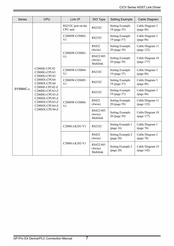
GP-Pro EX Device/PLC Connection Manual 7
SYSMAC
C200HE-CPU42C200HG-CPU63C200HG-CPU43C200HX-CPU64C200HX-CPU44C200HE-CPU42-ZC200HG-CPU63-ZC200HG-CPU43-ZC200HX-CPU85-ZC200HX-CPU65-ZC200HX-CPU64-ZC200HX-CPU44-Z
RS232C port on the CPU unit
RS232CSetting Example 18 (page 55)
Cable Diagram 3 (page 86)
C200HW-COM02-V1
RS232CSetting Example 19 (page 57)
Cable Diagram 3 (page 86)
C200HW-COM03-V1
RS422 (4wire)
Setting Example 20 (page 59)
Cable Diagram 11 (page 122)
RS422/485 (4wire)Multilink
Setting Example 20 (page 59)
Cable Diagram 18 (page 177)
C200HW-COM04-V1
RS232CSetting Example 19 (page 57)
Cable Diagram 3 (page 86)
C200HW-COM05-V1
RS232CSetting Example 19 (page 57)
Cable Diagram 3 (page 86)
C200HW-COM06-V1
RS232CSetting Example 19 (page 57)
Cable Diagram 3 (page 86)
RS422 (4wire)
Setting Example 20 (page 59)
Cable Diagram 11 (page 122)
RS422/485 (4wire)Multilink
Setting Example 20 (page 59)
Cable Diagram 18 (page 177)
C200H-LK201-V1 RS232CSetting Example 1 (page 16)
Cable Diagram 1 (page 76)
C200H-LK202-V1
RS422 (4wire)
Setting Example 2 (page 20)
Cable Diagram 2 (page 78)
RS422/485 (4wire)Multilink
Setting Example 2 (page 20)
Cable Diagram 14 (page 142)
Series CPU Link I/F SIO Type Setting Example Cable Diagram

C/CV Series HOST Link Driver
GP-Pro EX Device/PLC Connection Manual 8
SYSMAC
C200HX-CPU34C200HX-CPU54C200HX-CPU34-ZC200HX-CPU54-ZC200HE-CPU32C200HE-CPU32-ZC200HG-CPU33C200HG-CPU33-ZC200HG-CPU53C200HG-CPU53-Z
C200HW-COM02-V1
RS232CSetting Example 19 (page 57)
Cable Diagram 3 (page 86)
C200HW-COM03-V1
RS422 (4wire)
Setting Example 20 (page 59)
Cable Diagram 11 (page 122)
RS422/485 (4wire)Multilink
Setting Example 20 (page 59)
Cable Diagram 18 (page 177)
C200HW-COM04-V1
RS232CSetting Example 19 (page 57)
Cable Diagram 3 (page 86)
C200HW-COM05-V1
RS232CSetting Example 19 (page 57)
Cable Diagram 3 (page 86)
C200HW-COM06-V1
RS232CSetting Example 19 (page 57)
Cable Diagram 3 (page 86)
RS422 (4wire)
Setting Example 20 (page 59)
Cable Diagram 11 (page 122)
RS422/485 (4wire)Multilink
Setting Example 20 (page 59)
Cable Diagram 18 (page 177)
C200H-LK201-V1 RS232CSetting Example 1 (page 16)
Cable Diagram 1 (page 76)
C200H-LK202-V1
RS422 (4wire)
Setting Example 2 (page 20)
Cable Diagram 2 (page 78)
RS422/485 (4wire)Multilink
Setting Example 2 (page 20)
Cable Diagram 14 (page 142)
C200HE-CPU11C200HE-CPU11-Z
C200H-LK201-V1 RS232CSetting Example 1 (page 16)
Cable Diagram 1 (page 76)
C200H-LK202-V1
RS422 (4wire)
Setting Example 2 (page 20)
Cable Diagram 2 (page 78)
RS422/485 (4wire)Multilink
Setting Example 2 (page 20)
Cable Diagram 14 (page 142)
Series CPU Link I/F SIO Type Setting Example Cable Diagram

C/CV Series HOST Link Driver
GP-Pro EX Device/PLC Connection Manual 9
SYSMAC CV
CV500CV1000CV2000CVM1CVM1D
CV500-LK201
RS232C(connecting port 1)
Setting Example 21 (page 61)
Cable Diagram 1 (page 76)
RS232C(connecting port 2)
Setting Example 22 (page 63)
Cable Diagram 12 (page 132)
RS422/485 (4wire)(connecting port 2)
Setting Example 23 (page 65)
Cable Diagram 13 (page 134)
RS422/485 (4wire)Multilink
Setting Example 23 (page 65)
Cable Diagram 19 (page 188)
Link I/F on the CPU unit*6
RS232CSetting Example 24 (page 67)
Cable Diagram 12 (page 132)
RS422/485 (4wire)
Setting Example 25 (page 69)
Cable Diagram 13 (page 134)
RS422/485 (4wire)Multilink
Setting Example 25 (page 69)
Cable Diagram 19 (page 188)
*1 Base mounting type.
*2 CPU mounting type.
*3 Connect to RS232C port.
*4 Commercial 9 pin-25 pin conversion adapter is required.
*5 Set the 2wire/4wire toggle switch to 4wire (Only 4wire type is available to use).
*6 Connect to the HOSTLINK port.
• For SYSMAC- Series, please note as below. • We cannot guarantee the operation when you access the nonexistent data memory
area (DM6656 to DM6999).• We cannot guarantee the operation when you access to DM7000 to DM9999 without
the extension fixed DM setting.• We cannot guarantee the operation when you specify the area within the range in the
models in which the bank of the extension memory area does not exist.
Series CPU Link I/F SIO Type Setting Example Cable Diagram

C/CV Series HOST Link Driver
GP-Pro EX Device/PLC Connection Manual 10
Connection Configuration
• 1:1 Connection
• 1:n Connection
• n:1 Connection (Multilink connection)
• The maximum number of connectable Displays is 16 units. However, keeping performance in
consideration, the number of Displays that can be substantially used is up to 4.
DisplayExternal Device
Display
External Device External Device
Maximum number of connectable units: 16 units (for RS422/485 connection)
Display
Maximum number of connectable units: 16 units
External Device
Display Display

C/CV Series HOST Link Driver
GP-Pro EX Device/PLC Connection Manual 11
• n:m Connection (Multilink connection)
• The maximum number of connectable Displays is 16 units. However, keeping performance in
consideration, the number of Displays that can be substantially used is up to 4.
Display
Maximum number of connectable units: 16 units
Maximum number of connectable units: 16 units
External Device
Display Display
External Device

C/CV Series HOST Link Driver
GP-Pro EX Device/PLC Connection Manual 12
IPC COM Port
When connecting IPC with an External Device, the COM port used depends on the series and SIO type. Please
refer to the IPC manual for details.
Usable port
SeriesUsable Port
RS-232C RS-422/485(4 wire) RS-422/485(2 wire)
PS-2000BCOM1*1 , COM2, COM3*1, COM4
*1 The RI/5V can be switched. Use the IPC’s switch to change if necessary.
- -
PS-3450A, PS-3451A,PS3000-BA, PS3001-BD
COM1, COM2*1*2 COM2*1*2 COM2*1*2
PS-3650A (T41 model),PS-3651A (T41 model)
COM1*1 - -
PS-3650A (T42 model),PS-3651A (T42 model)
COM1*1*2, COM2 COM1*1*2 COM1*1*2
PS-3700A (Pentium®4-M)PS-3710A
COM1*1, COM2*1, COM3*2 , COM4
*2 Set up the SIO type with the DIP Switch. Please set up as follows according to SIO type to be used.
COM3*2 COM3*2
PS-3711A COM1*1, COM2*2 COM2*2 COM2*2
PS4000*3
*3 When making communication between an External Device and COM port on the Expansion slot, only RS-232C is supported. However, ER (DTR/CTS) control cannot be executed because of the specification of COM port.For connection with External Device, use user-created cables and disable Pin Nos. 1, 4, 6 and 9.Please refer to the IPC manual for details of pin layout.
COM1, COM2 - -
PL3000COM1*1*2, COM2*1, COM3, COM4
COM1*1*2 COM1*1*2
PE-4000B Atom N270 COM1, COM2 - -
PE-4000B Atom N2600 COM1, COM2COM3*4 , COM4*4, COM5*4, COM6*4
*4 Set up the SIO type with the BIOS. Please refer to the IPC manual for details of BIOS.
COM3*4, COM4*4, COM5*4, COM6*4
PS5000 (Slim Panel Type Core i3 Model) *5 *6 COM1, COM2*4 COM2*4 COM2*4
PS5000 (Slim Panel Type Atom Model) *5 *6
COM1, COM2*7 COM2*7 COM2*7
PS5000 (Enclosed Panel Type)*8 COM1 - -
PS5000 (Modular Type PFXPU/PFXPP)*5 *6
PS5000 (Modular Type PFXPL2B5-6)
COM1*7 COM1*7 COM1*7
PS5000 (Modular Type PFXPL2B1-4)
COM1, COM2*7 COM2*7 COM2*7

C/CV Series HOST Link Driver
GP-Pro EX Device/PLC Connection Manual 13
DIP Switch settings (PL3000 / PS3000 Series)
RS-232C
*5 When setting up communication between an External Device and the RS-232C/422/485 interface module, use the IPC (RS-232C) or PS5000 (RS-422/485) cable diagrams. However, when using PFXZPBMPR42P2 in a RS-422/485 (4-wire) configuration with no flow control, connect 7.RTS+ and 8.CTS+, and connect 6.RTS- and 9.CTS-.When using RS-422/485 communication with External Devices, you may need to reduce the transmission speed and increase the TX Wait time.
*6 To use RS-422/485 communication on the RS-232C/422/485 interface module, the DIP Switch setting is required. Please refer to "Knowledge Base" (FAQs) on the support site. (http://www.pro- face.com/trans/en/manual/1001.html)
*7 Set up the SIO type with the DIP Switch. Please refer to the IPC manual for details of DIP Switch.The BOX Atom has not a switch to set the RS-232C, RS-422/485 mode. Use the BIOS for the setting.
*8 For the connection with the External Device, on the user-created cable read as if the connector on the Display-side is a M12 A-coding 8 pin socket. The pin assignment is the same as described in the cable diagram. For the M12 A-coding connector, use PFXZPSCNM122.
DIP Switch Setting Description
1 OFF*1
*1 When using PS-3450A, PS-3451A, PS3000-BA and PS3001-BD, turn ON the set value.
Reserved (always OFF)
2 OFFSIO type: RS-232C
3 OFF
4 OFF Output mode of SD (TXD) data: Always output
5 OFF Terminal resistance (220) insertion to SD (TXD): None
6 OFF Terminal resistance (220) insertion to RD (RXD): None
7 OFF Short-circuit of SDA (TXA) and RDA (RXA): Not available
8 OFF Short-circuit of SDB (TXB) and RDB (RXB): Not available
9 OFFRS (RTS) Auto control mode: Disabled
10 OFF
Settings FAQ ID
PFXZPBMPR42P2, RS422/485 change method FA263858
PFXZPBMPR42P2 termination resistor setting FA263974
PFXZPBMPR44P2, RS422/485 change method FA264087
PFXZPBMPR44P2 termination resistor setting FA264088

C/CV Series HOST Link Driver
GP-Pro EX Device/PLC Connection Manual 14
RS-422/485 (4 wire)
RS-422/485 (2 wire)
DIP Switch Setting Description
1 OFF Reserved (always OFF)
2 ONSIO type: RS-422/485
3 ON
4 OFF Output mode of SD (TXD) data: Always output
5 OFF Terminal resistance (220) insertion to SD (TXD): None
6 OFF Terminal resistance (220) insertion to RD (RXD): None
7 OFF Short-circuit of SDA (TXA) and RDA (RXA): Not available
8 OFF Short-circuit of SDB (TXB) and RDB (RXB): Not available
9 OFF*1
*1 When the connection configuration are the n:1 and n:m connections (both Multilink connections), turn ON the set value.
RS (RTS) Auto control mode: Disabled10 OFF*1
DIP Switch Setting Description
1 OFF Reserved (always OFF)
2 ONSIO type: RS-422/485
3 ON
4 OFF Output mode of SD (TXD) data: Always output
5 OFF Terminal resistance (220) insertion to SD (TXD): None
6 OFF Terminal resistance (220) insertion to RD (RXD): None
7 ON Short-circuit of SDA (TXA) and RDA (RXA): Available
8 ON Short-circuit of SDB (TXB) and RDB (RXB): Available
9 ONRS (RTS) Auto control mode: Enabled
10 ON

C/CV Series HOST Link Driver
GP-Pro EX Device/PLC Connection Manual 15
2 Selection of External Device
Select the External Device to be connected to the Display.
Setup Items Setup Description
Number of Devices/PLCs
Enter an integer from 1 to 4 to define the number of Devices/PLCs to connect to the display.
Manufacturer Select the manufacturer of the External Device to connect. Select "OMRON Corporation".
Series
Select the External Device model (series) and the connection method. Select "C/CV Series HOST Link".In System configuration, make sure the External Device you are connecting is supported by "C/CV Series HOST Link".
"1 System Configuration" (page 3)
Port Select the Display port to connect to the External Device.
Use System Area
Check this option to synchronize the system data area of the Display and the device (memory) of the External Device. When synchronized, you can use the External Device’s ladder program to switch the display or display the window on the Display.
Cf. GP-Pro EX Reference Manual "LS Area (Direct Access Method Area)"This feature can also be set in GP-Pro EX or in the Display's offline mode.
Cf. GP-Pro EX Reference Manual "System Settings [Display Unit] - [System Area] Settings Guide"
Cf. Maintenance/Troubleshooting Guide "Main Unit - System Area Settings"

C/CV Series HOST Link Driver
GP-Pro EX Device/PLC Connection Manual 16
3 Example of Communication Setting
Examples of communication settings of the Display and the External Device, recommended by Pro-face, are
shown.
3.1 Setting Example 1
Setting of GP-Pro EX
Communication Settings
To display the setup screen, from the [Project] menu, point to [System Settings] and select [Device/PLC].

C/CV Series HOST Link Driver
GP-Pro EX Device/PLC Connection Manual 17
Device Setting
To display the [Individual Device Settings] dialog box, from [Device-Specific Settings] in the [Device/PLC]
window, select the external device and click [Settings] .
To connect multiple External Devices, from [Device-Specific Settings] in the [Device/PLC] window, click [Add
Device] to add another External Device.

C/CV Series HOST Link Driver
GP-Pro EX Device/PLC Connection Manual 18
Setting of External Device
Set the HOST link unit attached to the External Device as below.
Please refer to the manual of the External Device for more details.
C200H-LK201
Set the CTS control to 0V (always ON).
C120-LK201-V1
Rotary Switch Settings Setup Description
SW1 0 Unit No. x 10
SW2 0 Unit No. x 1
SW3 6 Transmission speed: 19.2Kbps
SW4 2 7-bit data length, 2 stop bits, Even
DIP Switch
(rear panel)Settings Setup Description
SW1 OFF Unused
SW2 OFF Unused
SW3 ON 1:N step
SW4 OFF Without 5V supply
DIP Switch 1 Settings Setup Description
SW1 OFF
Unit No.: 0
SW2 OFF
SW3 OFF
SW4 OFF
SW5 OFF
SW6 OFFUnused
SW7 OFF
SW8 ON Operation

C/CV Series HOST Link Driver
GP-Pro EX Device/PLC Connection Manual 19
DIP Switch 2 Settings Setup Description
SW1 OFF
Transmission speed: 19.2KbpsSW2 OFF
SW3 ON
SW4 OFF
SW5 OFF Unused
SW6 OFF 1:N step
SW7 ONLevel 1, 2, 3 Enabled
SW8 ON
DIP Switch 3 Settings Setup Description
SW1 ONCTS always ON
SW2 OFF
SW3 ON
Internally synchronizedSW4 OFF
SW5 ON
SW6 OFF
SW7 OFFUnused
SW8 OFF

C/CV Series HOST Link Driver
GP-Pro EX Device/PLC Connection Manual 20
3.2 Setting Example 2
Setting of GP-Pro EX
Communication Settings
To display the setup screen, from the [Project] menu, point to [System Settings] and select [Device/PLC].
Device Setting
To display the [Individual Device Settings] dialog box, from [Device-Specific Settings] in the [Device/PLC]
window, select the external device and click [Settings] .
To connect multiple External Devices, from [Device-Specific Settings] in the [Device/PLC] window, click [Add
Device] to add another External Device.

C/CV Series HOST Link Driver
GP-Pro EX Device/PLC Connection Manual 21
Setting of External Device
Set the HOST link unit attached to the External Device as below.
Please refer to the manual of the External Device for more details.
C200H-LK202
Set the rear switch as below.
• 1:N step (OFF)
• When the External Device is located at the end of the communication connection due to system configuration,
set the switch to "With termination resistance connection (ON)"; in other cases, set it to "Without termination
resistance connection (OFF)"
C120-LK202-V1
Rotary switch Settings Setup Description
SW1 0 Unit No. x 10
SW2 0 Unit No. x 1
SW3 6 Transmission speed: 19.2Kbps
SW4 2 7-bit data length, 2 stop bits, Even
DIP Switch 1 Settings Setup Description
SW1 OFF
Unit No.: 0
SW2 OFF
SW3 OFF
SW4 OFF
SW5 OFF
SW6 OFFUnused
SW7 OFF
SW8 ON Operation

C/CV Series HOST Link Driver
GP-Pro EX Device/PLC Connection Manual 22
• When the External Device is located at the end of the communication connection due to system configuration
• In Other Cases
DIP Switch 2 Settings Setup Description
SW1 OFF
Transmission speed: 19.2KbpsSW2 OFF
SW3 ON
SW4 OFF
SW5 OFF Unused
SW6 OFF 1:N step
SW7 ONLevel 1, 2, 3 Enabled
SW8 ON
DIP Switch 3 Settings Setup Description
SW1 ON
Attach termination resistance
SW2 OFF
SW3 ON
SW4 OFF
SW5 ON
SW6 OFF
SW7 OFFUnused
SW8 OFF
DIP Switch 3 Settings Setup Description
SW1 ON
Not attach termination resistance
SW2 OFF
SW3 OFF
SW4 OFF
SW5 OFF
SW6 OFF
SW7 OFFUnused
SW8 OFF

C/CV Series HOST Link Driver
GP-Pro EX Device/PLC Connection Manual 23
3.3 Setting Example 3
Setting of GP-Pro EX
Communication Settings
To display the setup screen, from the [Project] menu, point to [System Settings] and select [Device/PLC].
Device Setting
To display the [Individual Device Settings] dialog box, from [Device-Specific Settings] in the [Device/PLC]
window, select the external device and click [Settings] .
To connect multiple External Devices, from [Device-Specific Settings] in the [Device/PLC] window, click [Add
Device] to add another External Device.

C/CV Series HOST Link Driver
GP-Pro EX Device/PLC Connection Manual 24
Setting of External Device
When setting with the ladder tool
Open [PC System Setting] in the ladder tool and set the HOST link port in [HOST Link Port]. Please refer to the
manual of the External Device for more details on the ladder tool.
When setting the value in the data register
Use the ladder tool or etc. and set the value as below.
Set SW5 to OFF.
Please refer to the manual of the External Device for more details on settings.
Write the data in each register and reset the External Device.
Setup Items Setting Value
Communication
SettingsUser setting
Speed 19200
Parameter 7, 2, E
Mode HOST link
Unit No. 0 unit
Delay 0
CS Control Enable
Register Settings Setup Description
DM6645 0001(HEX) Mode selection: HOST link
DM6646 0304(HEX) 19200bps, 7-bit data length, 2 stop bits, Even parity
DM6648 0000(HEX) HOST link, Unit No.: 0

C/CV Series HOST Link Driver
GP-Pro EX Device/PLC Connection Manual 25
3.4 Setting Example 4
Setting of GP-Pro EX
Communication Settings
To display the setup screen, from the [Project] menu, point to [System Settings] and select [Device/PLC].
Device Setting
To display the [Individual Device Settings] dialog box, from [Device-Specific Settings] in the [Device/PLC]
window, select the external device and click [Settings] .
To connect multiple External Devices, from [Device-Specific Settings] in the [Device/PLC] window, click [Add
Device] to add another External Device.

C/CV Series HOST Link Driver
GP-Pro EX Device/PLC Connection Manual 26
Setting of External Device
When setting with the ladder tool
Open [PC System Setting] in the ladder tool and set the peripheral port in [Peripheral Port]. Please refer to the
manual of the External Device for more details on the ladder tool.
When setting the value in the data register
Use the ladder tool or etc. and set the value as below.
Set SW5 to OFF.
Please refer to the manual of the External Device for more details on settings.
Write the data in each register and reset the External Device.
Setup Items Setting Value
Communication
SettingsUser setting
Speed 19200
Parameter 7, 2, E
Mode HOST link
Unit No. 0 unit
Delay 0
CS Control Enable
Register Settings Setup Description
DM6650 0001(HEX) Mode selection: HOST link
DM6651 0304(HEX) 19200bps, 7-bit data length, 2 stop bits, Even parity
DM6653 0000(HEX) HOST link, Unit No.: 0
C/CV Series HOST Link Driver
GP-Pro EX Device/PLC Connection Manual 27
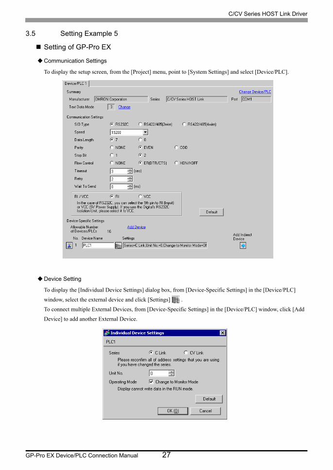
3.5 Setting Example 5
Setting of GP-Pro EX
Communication Settings
To display the setup screen, from the [Project] menu, point to [System Settings] and select [Device/PLC].
Device Setting
To display the [Individual Device Settings] dialog box, from [Device-Specific Settings] in the [Device/PLC]
window, select the external device and click [Settings] .
To connect multiple External Devices, from [Device-Specific Settings] in the [Device/PLC] window, click [Add
Device] to add another External Device.

C/CV Series HOST Link Driver
GP-Pro EX Device/PLC Connection Manual 28
Setting of External Device
Set the HOST link unit attached to the External Device as below.
Please refer to the manual of the External Device for more details on settings.
C500-LK201-V1
Mode Control Switch (front of the unit): HOST link
I/O Port (rear of the unit): RS-232C
Synchronize (rear of the unit): Internal
Termination resistance (rear of the unit): None
CTS (rear of the unit): 0V
DIP Switch 1 Settings Setup Description
SW1 OFF
Unit No.: 0
SW2 OFF
SW3 OFF
SW4 OFF
SW5 OFF
SW6 OFF Unused
SW7 OFF Unused
SW8 ON Operation
DIP Switch 2 Settings Setup Description
SW1 OFF
Transmission speed: 19.2KbpsSW2 OFF
SW3 ON
SW4 OFF
SW5 OFF Unused
SW6 OFF 1:N step
SW7 ONLevel 1, 2, 3 Enabled
SW8 ON
C/CV Series HOST Link Driver
GP-Pro EX Device/PLC Connection Manual 29
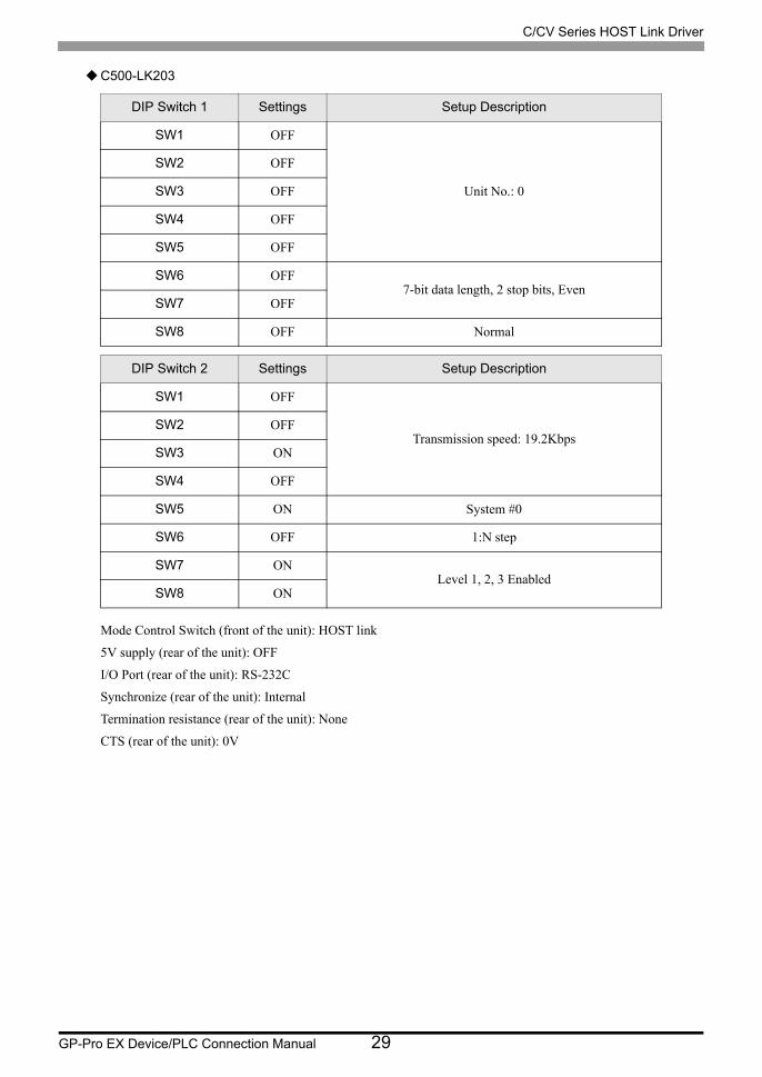
C500-LK203
Mode Control Switch (front of the unit): HOST link
5V supply (rear of the unit): OFF
I/O Port (rear of the unit): RS-232C
Synchronize (rear of the unit): Internal
Termination resistance (rear of the unit): None
CTS (rear of the unit): 0V
DIP Switch 1 Settings Setup Description
SW1 OFF
Unit No.: 0
SW2 OFF
SW3 OFF
SW4 OFF
SW5 OFF
SW6 OFF7-bit data length, 2 stop bits, Even
SW7 OFF
SW8 OFF Normal
DIP Switch 2 Settings Setup Description
SW1 OFF
Transmission speed: 19.2KbpsSW2 OFF
SW3 ON
SW4 OFF
SW5 ON System #0
SW6 OFF 1:N step
SW7 ONLevel 1, 2, 3 Enabled
SW8 ON

C/CV Series HOST Link Driver
GP-Pro EX Device/PLC Connection Manual 30
3.6 Setting Example 6
Setting of GP-Pro EX
Communication Settings
To display the setup screen, from the [Project] menu, point to [System Settings] and select [Device/PLC].
Device Setting
To display the [Individual Device Settings] dialog box, from [Device-Specific Settings] in the [Device/PLC]
window, select the external device and click [Settings] .
To connect multiple External Devices, from [Device-Specific Settings] in the [Device/PLC] window, click [Add
Device] to add another External Device.

C/CV Series HOST Link Driver
GP-Pro EX Device/PLC Connection Manual 31
Setting of External Device
Set the HOST link unit attached to the External Device as below.
Please refer to the manual of the External Device for more details on settings.
C500-LK201-V1
Mode Control Switch (front of the unit): HOST link
I/O Port (rear of the unit): RS-422
Synchronize (rear of the unit): Internal
Termination resistance (rear of the unit): When the External Device is located at the end of the communication
connection due to system configuration, set it to [With]; in other cases, set it to [Without].
CTS (rear of the unit): 0V
DIP Switch 1 Settings Setup Description
SW1 OFF
Unit No.: 0
SW2 OFF
SW3 OFF
SW4 OFF
SW5 OFF
SW6 OFF Unused
SW7 OFF Unused
SW8 ON Operation
DIP Switch 2 Settings Setup Description
SW1 OFF
Transmission speed: 19.2KbpsSW2 OFF
SW3 ON
SW4 OFF
SW5 OFF Unused
SW6 OFF 1:N step
SW7 ONLevel 1, 2, 3 Enabled
SW8 ON

C/CV Series HOST Link Driver
GP-Pro EX Device/PLC Connection Manual 32
C500-LK203
Mode Control Switch (front of the unit): HOST link
5V supply (rear of the unit): OFF
I/O Port (rear of the unit): RS-422
Synchronize (rear of the unit): Internal
Termination resistance (rear of the unit): When the External Device is located at the end of the communication
connection due to system configuration, set it to [With]; in other cases, set it to [Without].
CTS (rear of the unit): 0V
DIP Switch 1 Settings Setup Description
SW1 OFF
Unit No.: 0
SW2 OFF
SW3 OFF
SW4 OFF
SW5 OFF
SW6 OFF7-bit data length, 2 stop bits, Even
SW7 OFF
SW8 OFF Normal
DIP Switch 2 Settings Setup Description
SW1 OFF
Transmission speed: 19.2KbpsSW2 OFF
SW3 ON
SW4 OFF
SW5 ON System #0
SW6 OFF 1:N step
SW7 ONLevel 1, 2, 3 Enabled
SW8 ON
C/CV Series HOST Link Driver
GP-Pro EX Device/PLC Connection Manual 33
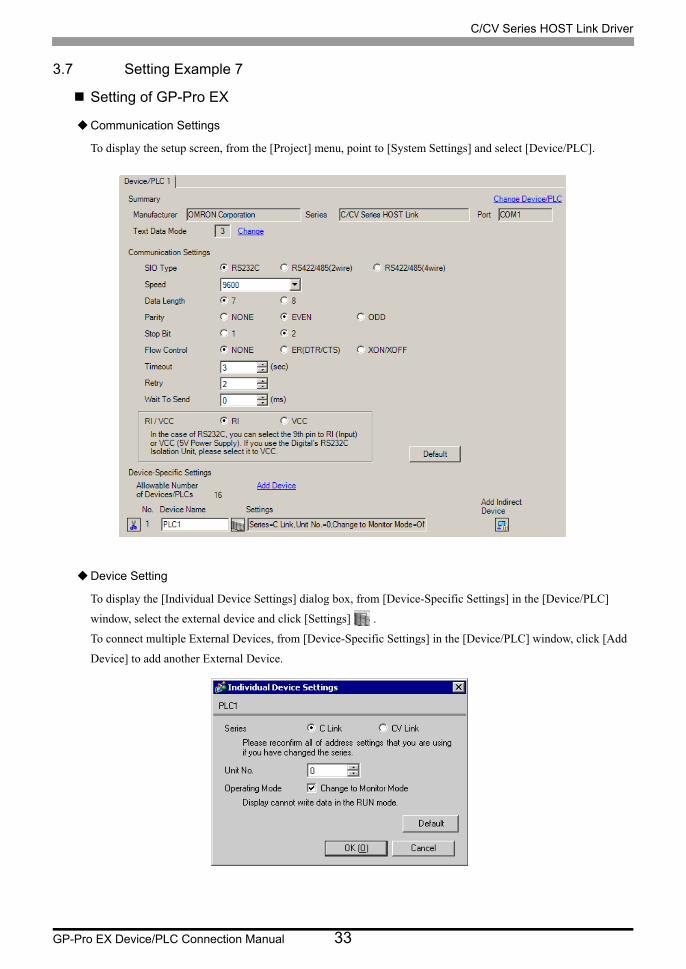
3.7 Setting Example 7
Setting of GP-Pro EX
Communication Settings
To display the setup screen, from the [Project] menu, point to [System Settings] and select [Device/PLC].
Device Setting
To display the [Individual Device Settings] dialog box, from [Device-Specific Settings] in the [Device/PLC]
window, select the external device and click [Settings] .
To connect multiple External Devices, from [Device-Specific Settings] in the [Device/PLC] window, click [Add
Device] to add another External Device.

C/CV Series HOST Link Driver
GP-Pro EX Device/PLC Connection Manual 34
Setting of External Device
Perform the communication in the standard settings (default).
Please refer to the manual of the External Device for more details on settings.
Setup Items Setting Value
Speed 9600bps
Start Bit 1 bit
Data Length 7 bits
Stop Bit 2 bits
Parity Bit Even
Unit No. No.0 unit

C/CV Series HOST Link Driver
GP-Pro EX Device/PLC Connection Manual 35
3.8 Setting Example 8
Setting of GP-Pro EX
Communication Settings
To display the setup screen, from the [Project] menu, point to [System Settings] and select [Device/PLC].
Device Setting
To display the [Individual Device Settings] dialog box, from [Device-Specific Settings] in the [Device/PLC]
window, select the external device and click [Settings] .
To connect multiple External Devices, from [Device-Specific Settings] in the [Device/PLC] window, click [Add
Device] to add another External Device.

C/CV Series HOST Link Driver
GP-Pro EX Device/PLC Connection Manual 36
Setting of External Device
Use the ladder tool etc. and set the value as below.
When connecting to CPM1 or CPM1H, set SW5 to OFF.
When connecting to CPM2C, set SW1 for "Connecting port function switch setting" to OFF, SW2 to ON. Please
refer to the manual of the External Device for more details on settings.
Write the data in each register and reset the External Device.
Register Settings Setup Description
DM6650 0001(HEX) Mode selection: HOST link
DM6651 0304(HEX) 19200bps, 7-bit data length, 2 stop bits, Even parity
DM6653 0000(HEX) HOST link, Unit No.: 0

C/CV Series HOST Link Driver
GP-Pro EX Device/PLC Connection Manual 37
3.9 Setting Example 9
Setting of GP-Pro EX
Communication Settings
To display the setup screen, from the [Project] menu, point to [System Settings] and select [Device/PLC].
Device Setting
To display the [Individual Device Settings] dialog box, from [Device-Specific Settings] in the [Device/PLC]
window, select the external device and click [Settings] .
To connect multiple External Devices, from [Device-Specific Settings] in the [Device/PLC] window, click [Add
Device] to add another External Device.

C/CV Series HOST Link Driver
GP-Pro EX Device/PLC Connection Manual 38
Setting of External Device
Use the ladder tool etc. and set the value as below.
Set SW5 to OFF.
Please refer to the manual of the External Device for more details on settings.
Write the data in each register and reset the External Device.
Register Settings Setup Description
DM6645 0001(HEX) Mode selection: HOST link
DM6646 0304(HEX) 19200bps, 7-bit data length, 2 stop bits, Even parity
DM6648 0000(HEX) HOST link, Unit No.: 0

C/CV Series HOST Link Driver
GP-Pro EX Device/PLC Connection Manual 39
3.10 Setting Example 10
Setting of GP-Pro EX
Communication Settings
To display the setup screen, from the [Project] menu, point to [System Settings] and select [Device/PLC].
Device Setting
To display the [Individual Device Settings] dialog box, from [Device-Specific Settings] in the [Device/PLC]
window, select the external device and click [Settings] .
To connect multiple External Devices, from [Device-Specific Settings] in the [Device/PLC] window, click [Add
Device] to add another External Device.

C/CV Series HOST Link Driver
GP-Pro EX Device/PLC Connection Manual 40
Setting of External Device
Use the ladder tool etc. and set the value as below.
Always set the mode setting SW on the conversion adapter to [HOST].
Please refer to the manual of the External Device for more details on settings.
*Connect the conversion adapter to the peripheral port on the CPU.
Register Settings Setup Description
DM6650 0001(HEX) Mode selection: HOST link
DM6651 0304(HEX) 19200bps, 7-bit data length, 2 stop bits, Even parity
DM6653 0000(HEX) HOST link, Unit No.: 0

C/CV Series HOST Link Driver
GP-Pro EX Device/PLC Connection Manual 41
3.11 Setting Example 11
Setting of GP-Pro EX
Communication Settings
To display the setup screen, from the [Project] menu, point to [System Settings] and select [Device/PLC].
Device Setting
To display the [Individual Device Settings] dialog box, from [Device-Specific Settings] in the [Device/PLC]
window, select the external device and click [Settings] .
To connect multiple External Devices, from [Device-Specific Settings] in the [Device/PLC] window, click [Add
Device] to add another External Device.

C/CV Series HOST Link Driver
GP-Pro EX Device/PLC Connection Manual 42
Setting of External Device
Use the ladder tool or etc. and set the value as below.
Always set the mode setting SW on the conversion adapter to [HOST].
Please refer to the manual of the External Device for more details on settings.
*Connect the conversion adapter to the peripheral port on the CPU.
Register Settings Setup Description
DM6650 0001(HEX) Mode selection: HOST link
DM6651 0304(HEX) 19200bps, 7-bit data length, 2 stop bits, Even parity
DM6653 0000(HEX) HOST link, Unit No.: 0

C/CV Series HOST Link Driver
GP-Pro EX Device/PLC Connection Manual 43
3.12 Setting Example 12
Setting of GP-Pro EX
Communication Settings
To display the setup screen, from the [Project] menu, point to [System Settings] and select [Device/PLC].
Device Setting
To display the [Individual Device Settings] dialog box, from [Device-Specific Settings] in the [Device/PLC]
window, select the external device and click [Settings] .
To connect multiple External Devices, from [Device-Specific Settings] in the [Device/PLC] window, click [Add
Device] to add another External Device.

C/CV Series HOST Link Driver
GP-Pro EX Device/PLC Connection Manual 44
Setting of External Device
When using the peripheral port on the CPM2C-CIF01
Use the ladder tool or etc. and set the value as below.
Please refer to the manual of the External Device for more details on settings.
Write the data in each register and reset the External Device.
Connecting Port Function Setting Switch on the Unit
*Connect the conversion adapter to the peripheral port on the CPU.
Register Settings Setup Description
DM6650 0001(HEX) Mode selection: HOST link
DM6651 0304(HEX) 19200bps, 7-bit data length, 2 stop bits, Even parity
DM6653 0000(HEX) HOST link, Unit No.: 0
DIP Switch Settings
SW1 OFF
SW2 ON
C/CV Series HOST Link Driver
GP-Pro EX Device/PLC Connection Manual 45
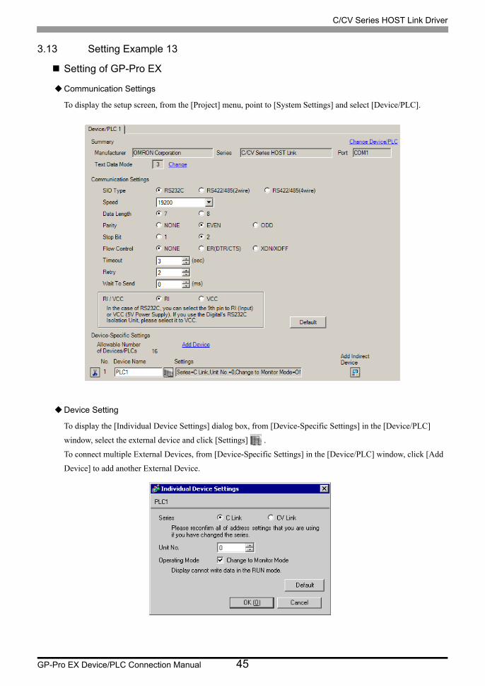
3.13 Setting Example 13
Setting of GP-Pro EX
Communication Settings
To display the setup screen, from the [Project] menu, point to [System Settings] and select [Device/PLC].
Device Setting
To display the [Individual Device Settings] dialog box, from [Device-Specific Settings] in the [Device/PLC]
window, select the external device and click [Settings] .
To connect multiple External Devices, from [Device-Specific Settings] in the [Device/PLC] window, click [Add
Device] to add another External Device.

C/CV Series HOST Link Driver
GP-Pro EX Device/PLC Connection Manual 46
Setting of External Device
When using the RS232C port on the CPM2C-CIF01
Use the ladder tool etc. and set the value as below.
Please refer to the manual of the External Device for more details on settings.
Write the data in each register and reset the External Device.
Connecting Port Function Setting Switch on the Unit
*Connect the conversion adapter to the peripheral port on the CPU.
Register Settings Setup Description
DM6645 0001(HEX) Mode selection: HOST link
DM6646 0304(HEX) 19200bps, 7-bit data length, 2 stop bits, Even parity
DM6648 0000(HEX) HOST link, Unit No.: 0
DIP Switch Settings
SW1 OFF
SW2 ON

C/CV Series HOST Link Driver
GP-Pro EX Device/PLC Connection Manual 47
3.14 Setting Example 14
Setting of GP-Pro EX
Communication Settings
To display the setup screen, from the [Project] menu, point to [System Settings] and select [Device/PLC].
Device Setting
To display the [Individual Device Settings] dialog box, from [Device-Specific Settings] in the [Device/PLC]
window, select the external device and click [Settings] .
To connect multiple External Devices, from [Device-Specific Settings] in the [Device/PLC] window, click [Add
Device] to add another External Device.

C/CV Series HOST Link Driver
GP-Pro EX Device/PLC Connection Manual 48
Setting of External Device
When using the RS232C port on the CPM2C-CIF11
Use the ladder tool etc. and set the value as below.
Please refer to the manual of the External Device for more details on settings.
Write the data in each register and reset the External Device.
Register Settings Setup Description
DM6645 0001(HEX) Mode selection: HOST link
DM6646 0304(HEX) 19200bps, 7-bit data length, 2 stop bits, Even parity
DM6648 0000(HEX) HOST link, Unit No.: 0

C/CV Series HOST Link Driver
GP-Pro EX Device/PLC Connection Manual 49
3.15 Setting Example 15
Setting of GP-Pro EX
Communication Settings
To display the setup screen, from the [Project] menu, point to [System Settings] and select [Device/PLC].
Device Setting
To display the [Individual Device Settings] dialog box, from [Device-Specific Settings] in the [Device/PLC]
window, select the external device and click [Settings] .
To connect multiple External Devices, from [Device-Specific Settings] in the [Device/PLC] window, click [Add
Device] to add another External Device.
C/CV Series HOST Link Driver
GP-Pro EX Device/PLC Connection Manual 50
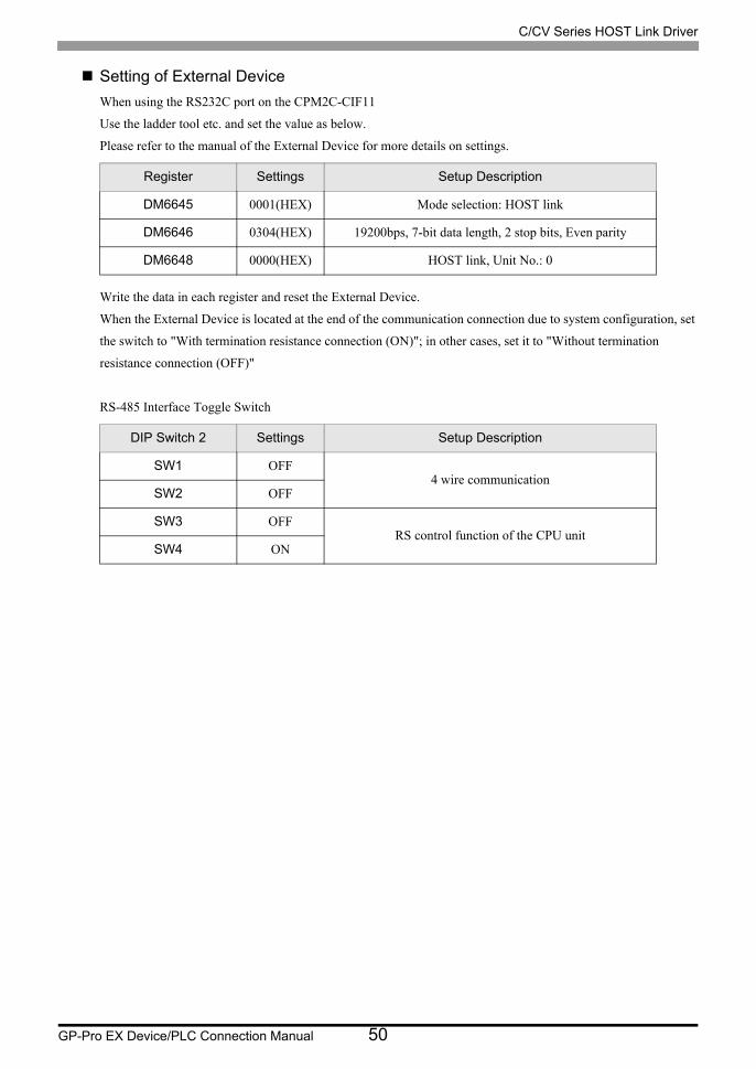
Setting of External Device
When using the RS232C port on the CPM2C-CIF11
Use the ladder tool etc. and set the value as below.
Please refer to the manual of the External Device for more details on settings.
Write the data in each register and reset the External Device.
When the External Device is located at the end of the communication connection due to system configuration, set
the switch to "With termination resistance connection (ON)"; in other cases, set it to "Without termination
resistance connection (OFF)"
RS-485 Interface Toggle Switch
Register Settings Setup Description
DM6645 0001(HEX) Mode selection: HOST link
DM6646 0304(HEX) 19200bps, 7-bit data length, 2 stop bits, Even parity
DM6648 0000(HEX) HOST link, Unit No.: 0
DIP Switch 2 Settings Setup Description
SW1 OFF4 wire communication
SW2 OFF
SW3 OFFRS control function of the CPU unit
SW4 ON

C/CV Series HOST Link Driver
GP-Pro EX Device/PLC Connection Manual 51
3.16 Setting Example 16
Setting of GP-Pro EX
Communication Settings
To display the setup screen, from the [Project] menu, point to [System Settings] and select [Device/PLC].
Device Setting
To display the [Individual Device Settings] dialog box, from [Device-Specific Settings] in the [Device/PLC]
window, select the external device and click [Settings] .
To connect multiple External Devices, from [Device-Specific Settings] in the [Device/PLC] window, click [Add
Device] to add another External Device.
C/CV Series HOST Link Driver
GP-Pro EX Device/PLC Connection Manual 52
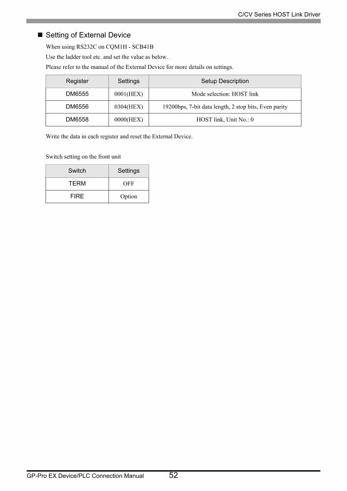
Setting of External Device
When using RS232C on CQM1H - SCB41B
Use the ladder tool etc. and set the value as below.
Please refer to the manual of the External Device for more details on settings.
Write the data in each register and reset the External Device.
Switch setting on the front unit
Register Settings Setup Description
DM6555 0001(HEX) Mode selection: HOST link
DM6556 0304(HEX) 19200bps, 7-bit data length, 2 stop bits, Even parity
DM6558 0000(HEX) HOST link, Unit No.: 0
Switch Settings
TERM OFF
FIRE Option

C/CV Series HOST Link Driver
GP-Pro EX Device/PLC Connection Manual 53
3.17 Setting Example 17
Setting of GP-Pro EX
Communication Settings
To display the setup screen, from the [Project] menu, point to [System Settings] and select [Device/PLC].
Device Setting
To display the [Individual Device Settings] dialog box, from [Device-Specific Settings] in the [Device/PLC]
window, select the external device and click [Settings] .
To connect multiple External Devices, from [Device-Specific Settings] in the [Device/PLC] window, click [Add
Device] to add another External Device.

C/CV Series HOST Link Driver
GP-Pro EX Device/PLC Connection Manual 54
Setting of External Device
When using RS422/485 port on CQM1H-SCB41B
Use the ladder tool etc. and set the value as below.
Please refer to the manual of the External Device for more details on settings.
Write the data in each register and reset the External Device.
Switch setting on the front unit
When the External Device is located at the end of the communication connection due to system configuration, set
the switch to "With termination resistance connection (ON)"; in other cases, set it to "Without termination
resistance connection (OFF)"
Register Settings Setup Description
DM6550 0001(HEX) Mode selection: HOST link
DM6551 0304(HEX) 19200bps, 7-bit data length, 2 stop bits, Even parity
DM6553 0000(HEX) HOST link, Unit No.: 0
Switch Settings
TERM ON
FIRE 4

C/CV Series HOST Link Driver
GP-Pro EX Device/PLC Connection Manual 55
3.18 Setting Example 18
Setting of GP-Pro EX
Communication Settings
To display the setup screen, from the [Project] menu, point to [System Settings] and select [Device/PLC].
Device Setting
To display the [Individual Device Settings] dialog box, from [Device-Specific Settings] in the [Device/PLC]
window, select the external device and click [Settings] .
To connect multiple External Devices, from [Device-Specific Settings] in the [Device/PLC] window, click [Add
Device] to add another External Device.

C/CV Series HOST Link Driver
GP-Pro EX Device/PLC Connection Manual 56
Setting of External Device
Use the ladder tool etc. and set the value as below.
Set SW5 to OFF.
Please refer to the manual of the External Device for more details on settings.
Write the data in each register and reset the External Device.
Register Settings Setup Description
DM6645 0001(HEX) Mode selection: HOST link
DM6646 0304(HEX) 19200bps, 7-bit data length, 2 stop bits, Even parity
DM6648 0000(HEX) HOST link, Unit No.: 0

C/CV Series HOST Link Driver
GP-Pro EX Device/PLC Connection Manual 57
3.19 Setting Example 19
Setting of GP-Pro EX
Communication Settings
To display the setup screen, from the [Project] menu, point to [System Settings] and select [Device/PLC].
Device Setting
To display the [Individual Device Settings] dialog box, from [Device-Specific Settings] in the [Device/PLC]
window, select the external device and click [Settings] .
To connect multiple External Devices, from [Device-Specific Settings] in the [Device/PLC] window, click [Add
Device] to add another External Device.
C/CV Series HOST Link Driver
GP-Pro EX Device/PLC Connection Manual 58
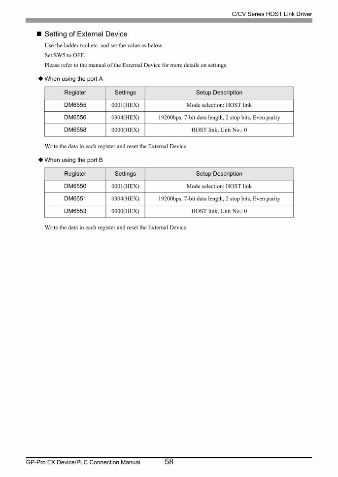
Setting of External Device
Use the ladder tool etc. and set the value as below.
Set SW5 to OFF.
Please refer to the manual of the External Device for more details on settings.
When using the port A
Write the data in each register and reset the External Device.
When using the port B
Write the data in each register and reset the External Device.
Register Settings Setup Description
DM6555 0001(HEX) Mode selection: HOST link
DM6556 0304(HEX) 19200bps, 7-bit data length, 2 stop bits, Even parity
DM6558 0000(HEX) HOST link, Unit No.: 0
Register Settings Setup Description
DM6550 0001(HEX) Mode selection: HOST link
DM6551 0304(HEX) 19200bps, 7-bit data length, 2 stop bits, Even parity
DM6553 0000(HEX) HOST link, Unit No.: 0
C/CV Series HOST Link Driver
GP-Pro EX Device/PLC Connection Manual 59
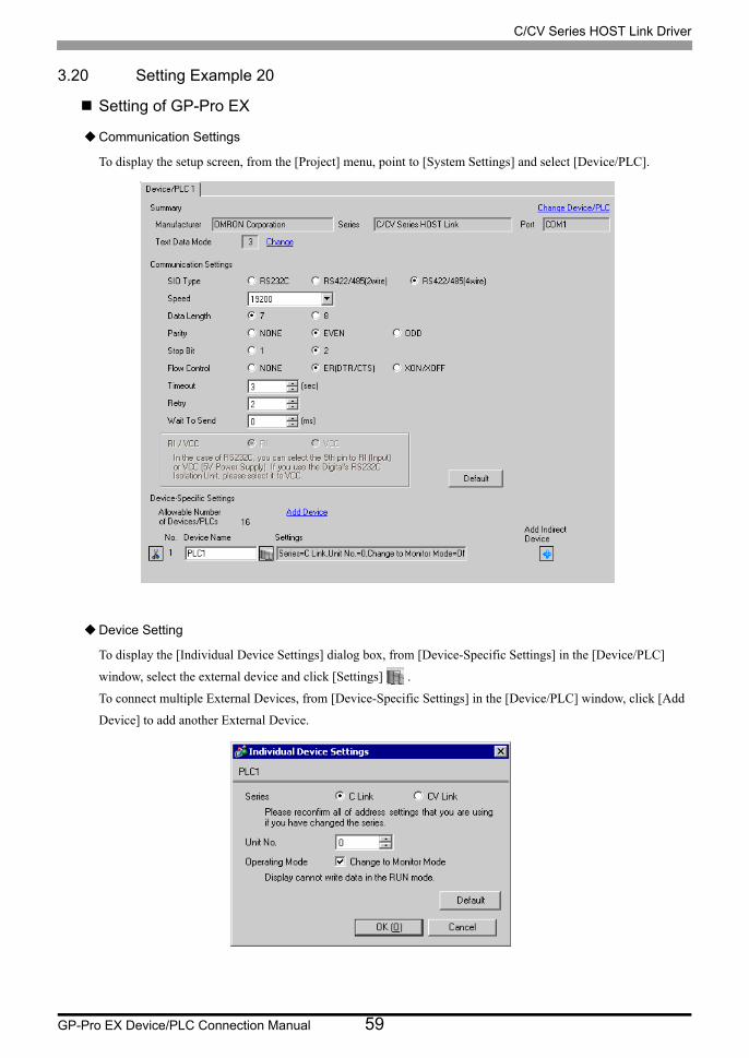
3.20 Setting Example 20
Setting of GP-Pro EX
Communication Settings
To display the setup screen, from the [Project] menu, point to [System Settings] and select [Device/PLC].
Device Setting
To display the [Individual Device Settings] dialog box, from [Device-Specific Settings] in the [Device/PLC]
window, select the external device and click [Settings] .
To connect multiple External Devices, from [Device-Specific Settings] in the [Device/PLC] window, click [Add
Device] to add another External Device.
C/CV Series HOST Link Driver
GP-Pro EX Device/PLC Connection Manual 60
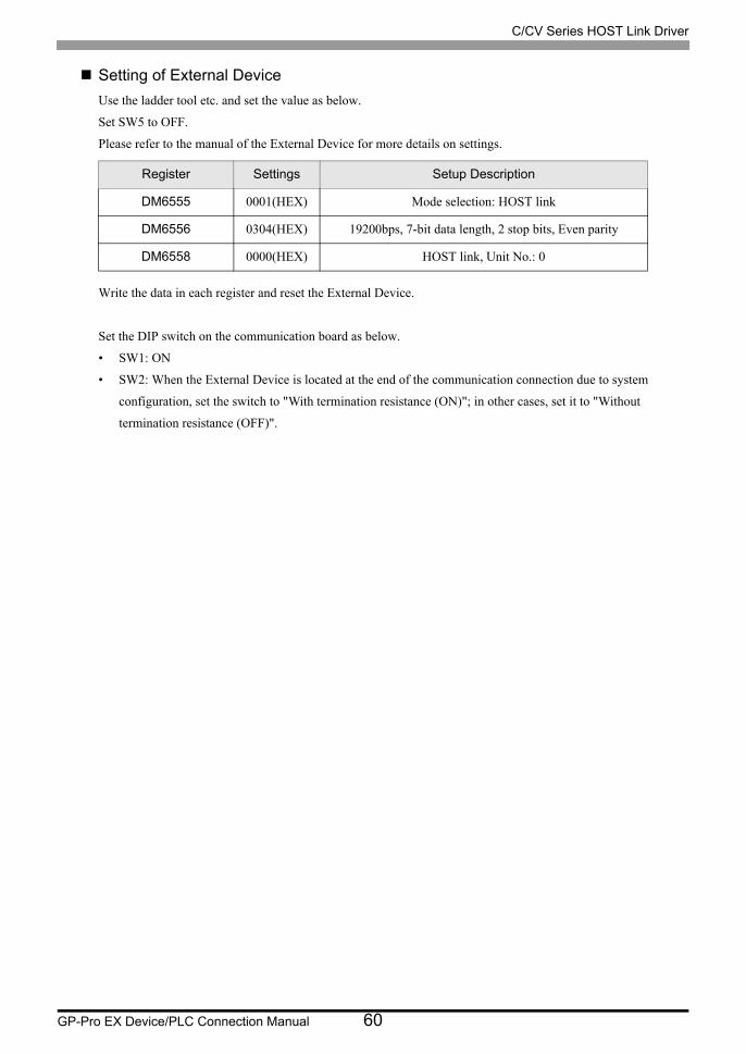
Setting of External Device
Use the ladder tool etc. and set the value as below.
Set SW5 to OFF.
Please refer to the manual of the External Device for more details on settings.
Write the data in each register and reset the External Device.
Set the DIP switch on the communication board as below.
• SW1: ON
• SW2: When the External Device is located at the end of the communication connection due to system
configuration, set the switch to "With termination resistance (ON)"; in other cases, set it to "Without
termination resistance (OFF)".
Register Settings Setup Description
DM6555 0001(HEX) Mode selection: HOST link
DM6556 0304(HEX) 19200bps, 7-bit data length, 2 stop bits, Even parity
DM6558 0000(HEX) HOST link, Unit No.: 0

C/CV Series HOST Link Driver
GP-Pro EX Device/PLC Connection Manual 61
3.21 Setting Example 21
Setting of GP-Pro EX
Communication Settings
To display the setup screen, from the [Project] menu, point to [System Settings] and select [Device/PLC].
Device Setting
To display the [Individual Device Settings] dialog box, from [Device-Specific Settings] in the [Device/PLC]
window, select the external device and click [Settings] .
To connect multiple External Devices, from [Device-Specific Settings] in the [Device/PLC] window, click [Add
Device] to add another External Device.

C/CV Series HOST Link Driver
GP-Pro EX Device/PLC Connection Manual 62
Setting of External Device
When using the port 1 (RS232C)
Rotary Switch*1
*1 SW1 and SW2 settings have no relations with the communication of the Display.
Settings Setup Description
SW3 0Unit No.: 0
SW4 0
Settings Setup Description
5V Output Setting
SWLower Not supply
Settings Setup Description
Termination
resistance SWLower Termination resistance: Without
DIP Switch Settings Setup Description
SW1 OFF 9600bps, 7-bit data length, 2 stop bits, Even parity*1
*1 Use the ladder software etc. to change the transmission speed to 19200bps.
SW2 ON Port 1: Always CTS signal ON
SW3 ON Port 2: Always CTS signal ON
SW4 OFF Reserved: Always OFF
SW5 OFF Wrap communication test: Execute normal operation.
SW6 OFF Unused

C/CV Series HOST Link Driver
GP-Pro EX Device/PLC Connection Manual 63
3.22 Setting Example 22
Setting of GP-Pro EX
Communication Settings
To display the setup screen, from the [Project] menu, point to [System Settings] and select [Device/PLC].
Device Setting
To display the [Individual Device Settings] dialog box, from [Device-Specific Settings] in the [Device/PLC]
window, select the external device and click [Settings] .
To connect multiple External Devices, from [Device-Specific Settings] in the [Device/PLC] window, click [Add
Device] to add another External Device.
C/CV Series HOST Link Driver
GP-Pro EX Device/PLC Connection Manual 64
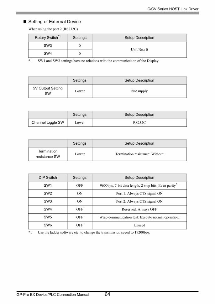
Setting of External Device
When using the port 2 (RS232C)
Rotary Switch*1
*1 SW1 and SW2 settings have no relations with the communication of the Display.
Settings Setup Description
SW3 0Unit No.: 0
SW4 0
Settings Setup Description
5V Output Setting
SWLower Not supply
Settings Setup Description
Channel toggle SW Lower RS232C
Settings Setup Description
Termination
resistance SWLower Termination resistance: Without
DIP Switch Settings Setup Description
SW1 OFF 9600bps, 7-bit data length, 2 stop bits, Even parity*1
*1 Use the ladder software etc. to change the transmission speed to 19200bps.
SW2 ON Port 1: Always CTS signal ON
SW3 ON Port 2: Always CTS signal ON
SW4 OFF Reserved: Always OFF
SW5 OFF Wrap communication test: Execute normal operation.
SW6 OFF Unused

C/CV Series HOST Link Driver
GP-Pro EX Device/PLC Connection Manual 65
3.23 Setting Example 23
Setting of GP-Pro EX
Communication Settings
To display the setup screen, from the [Project] menu, point to [System Settings] and select [Device/PLC].
Device Setting
To display the [Individual Device Settings] dialog box, from [Device-Specific Settings] in the [Device/PLC]
window, select the external device and click [Settings] .
To connect multiple External Devices, from [Device-Specific Settings] in the [Device/PLC] window, click [Add
Device] to add another External Device.

C/CV Series HOST Link Driver
GP-Pro EX Device/PLC Connection Manual 66
Setting of External Device
When using the port 2 (RS422)
Rotary Switch*1
*1 SW1 and SW2 settings have no relations with the communication of the Display.
Settings Setup Description
SW3 0Unit No.: 0
SW4 0
Settings Setup Description
5V Output Setting
SWLower Not supply
Settings Setup Description
Channel toggle SW Upper RS422
Settings Setup Description
Termination
resistance SWUpper Termination resistance: With*1
*1 Set to ON the termination resistance selection switch of only the unit which is located at the end of the system.
DIP Switch Settings Setup Description
SW1 OFF 9600bps, 7-bit data length, 2 stop bits, Even parity*1
*1 Use the ladder software etc. to change the transmission speed to 19200bps.
SW2 ON Port 1: Always CTS signal ON
SW3 ON Port 2: Always CTS signal ON
SW4 OFF Reserved: Always OFF
SW5 OFF Wrap communication test: Execute normal operation.
SW6 OFF Unused
C/CV Series HOST Link Driver
GP-Pro EX Device/PLC Connection Manual 67
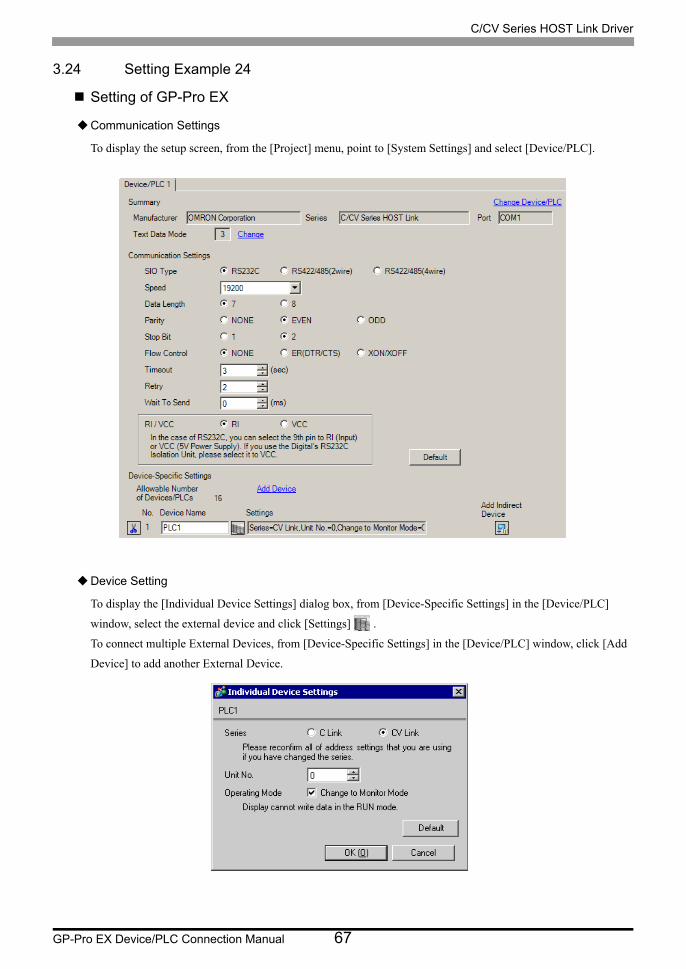
3.24 Setting Example 24
Setting of GP-Pro EX
Communication Settings
To display the setup screen, from the [Project] menu, point to [System Settings] and select [Device/PLC].
Device Setting
To display the [Individual Device Settings] dialog box, from [Device-Specific Settings] in the [Device/PLC]
window, select the external device and click [Settings] .
To connect multiple External Devices, from [Device-Specific Settings] in the [Device/PLC] window, click [Add
Device] to add another External Device.

C/CV Series HOST Link Driver
GP-Pro EX Device/PLC Connection Manual 68
Setting of External Device
When connecting the RS232C port
Settings Setup Description
Communication
Setting Toggle SWUpper RS232C SIO Type
DIP Switch*1
*1 Other DIP SW settings have no relations with the communication with GP.
Settings Setup Description
SW4 OFF19200bps, 7-bit data length, 2 stop bits, Even parity,
Unit No.: 0
SW6 OFF Termination resistance: Without

C/CV Series HOST Link Driver
GP-Pro EX Device/PLC Connection Manual 69
3.25 Setting Example 25
Setting of GP-Pro EX
Communication Settings
To display the setup screen, from the [Project] menu, point to [System Settings] and select [Device/PLC].
Device Setting
To display the [Individual Device Settings] dialog box, from [Device-Specific Settings] in the [Device/PLC]
window, select the external device and click [Settings] .
To connect multiple External Devices, from [Device-Specific Settings] in the [Device/PLC] window, click [Add
Device] to add another External Device.

C/CV Series HOST Link Driver
GP-Pro EX Device/PLC Connection Manual 70
Setting of External Device
When connecting the RS422 port
Settings Setup Description
Communication
Setting Toggle SWLower RS422 SIO Type
DIP Switch*1
*1 Other DIP SW settings have no relations with the communication with GP.
Settings Setup Description
SW4 OFF19200bps, 7-bit data length, 2 stop bits, Even parity,
Unit No.: 0
SW6 ON Termination resistance: With*2
*2 Set to ON the termination resistance selection switch of only the unit which is located at the end of the system.

C/CV Series HOST Link Driver
GP-Pro EX Device/PLC Connection Manual 71
4 Setup Items
Set communication settings of the Display with GP-Pro EX or in offline mode of the Display.
The setting of each parameter must be identical to that of External Device.
"3 Example of Communication Setting" (page 16)
4.1 Setup Items in GP-Pro EX
Communication Settings
To display the setup screen, from the [Project] menu, point to [System Settings] and select [Device/PLC].
Setup Items Setup Description
SIO Type Select the SIO type to communicate with the External Device.
Speed Select speed between the External Device and the Display.
Data Length Select data length.
Parity Select how to check parity.
Stop Bit Select stop bit length.
Flow ControlSelect the communication control method to prevent overflow of transmission and reception data.
TimeoutUse an integer from 1 to 127 to enter the time (s) for which the Display waits for the response from the External Device.
RetryIn case of no response from the External Device, use an integer from 0 to 255 to enter how many times the Display retransmits the command.
continued to next page

C/CV Series HOST Link Driver
GP-Pro EX Device/PLC Connection Manual 72
Device Setting
To display the [Individual Device Settings] dialog box, from [Device-Specific Settings] in the [Device/PLC]
window, select the external device and click [Settings] .
To connect multiple External Devices, from [Device-Specific Settings] in the [Device/PLC] window, click [Add
Device] to add another External Device..
Wait To SendUse an integer from 0 to 255 to enter standby time (ms) for the Display from receiving packets to transmitting next commands.
RI/VCCYou can switch RI/VCC of the 9th pin when you select RS232C for SIO type.It is necessary to change RI/5V by changeover switch of IPC when connect with IPC. Please refer to the manual of the IPC for more detail.
Setup Items Setup Description
Series Select the model of the External Device to be connected.
Unit No. Set the unit No. of the External Device.
Operating Mode Set the change to the monitor mode whether enable or disable.
• The External Device does not receive write from the Display in operation mode. When the
"Operating Mode" is enabled, the External Device will be changed to the monitor mode at
startup, which allows you to write to the External Device.
Setup Items Setup Description

C/CV Series HOST Link Driver
GP-Pro EX Device/PLC Connection Manual 73
4.2 Setup Items in Offline Mode
Communication Settings
To display the setting screen, touch [Device/PLC Settings] from [Peripheral Settings] in the offline mode. Touch
the External Device you want to set from the displayed list, and touch [Communication Settings].
• Refer to the Maintenance/Troubleshooting guide for information on how to enter offline mode or
about the operation.
Cf. Maintenance/Troubleshooting Guide "Offline Mode"
• The number of the setup items to be displayed for 1 page in the offline mode depends on the
Display in use. Please refer to the Reference manual for details.
Setup Items Setup Description
SIO Type
Select the SIO type to communicate with the External Device.
To make the communication settings correctly, confirm the serial interface specifications of Display unit for [SIO Type].We cannot guarantee the operation if a communication type that the serial interface does not support is specified.For details concerning the serial interface specifications, refer to the manual for Display unit.
Speed Select speed between the External Device and the Display.
Data Length Select data length.
Parity Select how to check parity.
Stop Bit Select stop bit length.
Flow ControlSelect the communication control method to prevent overflow of transmission and reception data.
TimeoutUse an integer from 1 to 127 to enter the time (s) for which the Display waits for the response from the External Device.
RetryIn case of no response from the External Device, use an integer from 0 to 255 to enter how many times the Display retransmits the command.

C/CV Series HOST Link Driver
GP-Pro EX Device/PLC Connection Manual 74
Device Setting
To display the setting screen, touch [Device/PLC Settings] from [Peripheral Settings]. Touch the External Device
you want to set from the displayed list, and touch [Device Settings].
Wait To SendUse an integer from 0 to 255 to enter standby time (ms) for the Display from receiving packets to transmitting next commands.
Setup Items Setup Description
Device/PLC NameSelect the External Device to set. Device/PLC name is a title of the External Device set with GP-Pro EX. (Initial value [PLC1])
Series Select the model of the External Device to be connected.
Unit No. Set the unit No. of the External Device.
Monitor Mode Set the change to the monitor mode whether enable or disable.
Setup Items Setup Description

C/CV Series HOST Link Driver
GP-Pro EX Device/PLC Connection Manual 75
Option
To display the setting screen, touch [Device/PLC Settings] from [Peripheral Settings]. Touch the External Device
you want to set from the displayed list, and touch [Option].
Setup Items Setup Description
RI/VCCYou can switch RI/VCC of the 9th pin when you select RS232C for SIO type.It is necessary to change RI/5V by changeover switch of IPC when connect with IPC. Please refer to the manual of the IPC for more detail.
• GP-4100 series, GP-4*01TM, GP-Rear Module, LT-4*01TM and LT-Rear Module do not
have the [Option] setting in the offline mode.

C/CV Series HOST Link Driver
GP-Pro EX Device/PLC Connection Manual 76
5 Cable Diagram
The cable diagram shown below may be different from the cable diagram recommended by OMRON
Corporation. Please be assured there is no operational problem in applying the cable diagram shown in this
manual.
• The FG pin of the main body of the External Device must be D-class grounded. Please refer to the manual of
the External Device for more details.
• SG and FG are connected inside the Display. When connecting SG to the External Device, design the system
not to form short-circuit loop.
• Connect the isolation unit, when communication is not stabilized under the influence of a noise etc..
Cable Diagram 1
Display Cable Remarks
GP3000 (COM1)GP4000*1 (COM1)SP5000*2 (COM1/2)SP-5B00 (COM1)ST (COM1)LT3000 (COM1)IPC*3
PC/AT
*1 All GP4000 models except GP-4100 Series and GP-4203T
*2 Except SP-5B00
*3 Only the COM port which can communicate by RS-232C can be used.
" IPC COM Port" (page 12)
1ARS232C cable by Pro-face
CA3-CBL232/5M-01
1B User-created cable Cable length: 15m or less
GP-4105 (COM1)GP-4115T (COM1) GP-4115T3 (COM1)
1C User-created cable Cable length: 15m or less

C/CV Series HOST Link Driver
GP-Pro EX Device/PLC Connection Manual 77
1A)
1B)
1C)
CA3-CBL232/5M-01Display External Device
SG
CD1
2
3
7
58
4
FG
SG7
2
1
3
54
20
Display
D-sub 9 pin (socket)
Pin Signalname
Shield
External Device sideD-sub 25 pin (plug)
Pin Signalname
SD(TXD)
RD(RXD)
CS(CTS)
ER(DTR)
RS(RTS)
Display side
SD(TXD)
RD(RXD)
RS(RTS)
CS(CTS)
ER(DTR)
SG
CD
FG
SG7
2
1
3
54
20
Display
Signalname
Shield
External Device sideD-sub 25 pin (plug)
Pin Signalname
SD(TXD)
RD(RXD)
CS(CTS)
ER(DTR)
RS(RTS)
SD(TXD)
RD(RXD)
RS(RTS)
CS(CTS)
ER(DTR)
Terminal blockDisplay side

C/CV Series HOST Link Driver
GP-Pro EX Device/PLC Connection Manual 78
Cable Diagram 2
Display Cable Remarks
GP3000*1 (COM1)AGP-3302B (COM2)GP-4*01TM (COM1)GP-Rear Module (COM1)ST*2 (COM2)LT3000 (COM1)IPC*3
*1 All GP3000 models except AGP-3302B
*2 All ST models except AST-3211A and AST-3302B
*3 Only the COM port which can communicate by RS-422/485 (4 wire) can be used. (Except PE-4000B, PS5000)
" IPC COM Port" (page 12)
2A
COM port conversion adapter by Pro-face
CA3-ADPCOM-01+
Terminal block conversion adapter by Pro-face
CA3-ADPTRM-01+
User-created cable
The cable length must be 500m or less.
2B User-created cable
GP3000*4 (COM2)
*4 All GP3000 models except GP-3200 series and AGP-3302B
2C
Online adapter by Pro-faceCA4-ADPONL-01
+Terminal block conversion adapter
by Pro-faceCA3-ADPTRM-01
+User-created cable
The cable length must be 500m or less.
2D
Online adapter by Pro-faceCA4-ADPONL-01
+User-created cable
GP-4106 (COM1)GP-4116T (COM1)
2E User-created cableThe cable length must be 500m or less.
GP4000*5 (COM2)GP-4201T (COM1)SP5000*6 (COM1/2)SP-5B00 (COM2)
*5 All GP4000 models except GP-4100 series, GP-4*01TM, GP-Rear Module, GP-4201T and GP-4*03T
*6 Except SP-5B00
2F
RS-422 terminal block conversion adapter by Pro-facePFXZCBADTM1*7
+User-created cable
*7 When using a Terminal Block Conversion Adapter (CA3-ADPTRM-01) instead of the RS-422 Terminal Block Conversion Adapter, refer to Cable Diagram 2A.
The cable length must be 500m or less.
2B User-created cable
PE-4000B*8
PS5000*8
*8 Only the COM port which can communicate by RS-422/485 (4 wire) can be used.
" IPC COM Port" (page 12)
2G User-created cableThe cable length must be 500m or less.

C/CV Series HOST Link Driver
GP-Pro EX Device/PLC Connection Manual 79
2A)
• 1:1 Connection
• 1:n Connection
• When the display unit you use is an IPC, turn ON the DIP switches 5 and 6 to insert the
termination resistance.
SDB
SDA
RDB
RDA
FGSG
7
59
61
3
RDA
RDB
SDA
SDB
SGTERMCA3-ADPTRM-01
CA3-ADPCOM-01Display
Terminationresistance
TerminalblockSignalname
Shield
External Device sideD-sub 9 pin (plug)
Pin Signalname
User-created cable
Terminationresistance
SDB
SDA
RDB
RDA
FGSG
7
59
61
3
RDA
RDB
SDA
SDB
SGTERMCA3-ADPTRM-01
CA3-ADPCOM-01
SDB
SDA
RDB
RDA
FGSG
7
59
61
3
Display
Terminationresistance
TerminalblockSignalname
Shield
External Device sideD-sub 9 pin (plug)
Pin Signalname
Shield
External Device sideD-sub 9 pin (plug)
Pin Signalname
Terminationresistance
User-created cable

C/CV Series HOST Link Driver
GP-Pro EX Device/PLC Connection Manual 80
2B)
• 1:1 Connection
• 1:n Connection
• When the display unit you use is an IPC, turn ON the DIP switches 5 and 6 to insert the
termination resistance.
RDARDB
ERB
SDASDBSGCSB
5
21
9
73
6
SDBSDARDBRDASG3
59
61
CSA8ERA4
FG7
Terminationresistance
Shield
External Device sideD-sub 9 pin (plug)
Pin Signalname
DisplayTerminationresistance
D-sub 9 pin (socket)
Pin Signalname
Display side
RDARDB
ERB
SDASDBSGCSB
5
21
9
73
6
SDBSDARDBRDASG3
59
61
CSA8ERA4
FG7
SDBSDARDBRDASG3
59
61
FG7
Terminationresistance
Shield
External Device sideD-sub 9 pin (plug)
Pin Signalname
Display
Terminationresistance
D-sub 9 pin (socket)
Pin Signalname
Shield
External Device sideD-sub 9 pin (plug)
Pin Signalname
Display side

C/CV Series HOST Link Driver
GP-Pro EX Device/PLC Connection Manual 81
2C)
• 1:1 Connection
• 1:n Connection
SDB
SDA
RDB
RDA
FGSG
7
59
61
3
RDA
RDB
SDA
SDB
SGTERM
Display
Terminationresistance
TerminalblockSignalname
Shield
External Device sideD-sub 9 pin (plug)
Pin Signalname
User-created cable
CA3-ADPTRM-01
CA4-ADPONL-01
SDB
SDA
RDB
RDA
FGSG
7
59
61
3
RDA
RDB
SDA
SDB
SGTERM
SDB
SDA
RDB
RDA
FGSG
7
59
61
3
Display
Terminationresistance
TerminalblockSignalname
Shield
External Device sideD-sub 9 pin (plug)
Pin Signalname
CA3-ADPTRM-01
CA4-ADPONL-01
Shield
External Device sideD-sub 9 pin (plug)
Pin Signalname
User-created cable

C/CV Series HOST Link Driver
GP-Pro EX Device/PLC Connection Manual 82
2D)
• 1:1 Connection
• 1:n Connection
TERMRX
RDA
SG
RDB
SDA
SDBTERMTX
8
2
1
5
37
9
SDB
SDA
RDA
SG
RDB
FG
1
59
36
7
Display
Shield
External Device sideD-sub 9 pin (plug)
Pin Signalname
CA4-ADPONL-01
D-sub 9 pin (plug)
Pin Signalname
User-created cable
TERMRX
RDA
SG
RDB
SDA
SDBTERMTX
8
2
1
5
37
9
SDB
SDA
RDA
SG
RDB
FG
1
59
36
7
SDB
SDA
RDA
SG
RDB
FG
1
59
36
7
Display
Shield
External Device sideD-sub 9 pin (plug)
Pin Signalname
CA4-ADPONL-01
D-sub 9 pin (plug)
Pin Signalname
Shield
External Device sideD-sub 9 pin (plug)
Pin Signalname
User-created cable
C/CV Series HOST Link Driver
GP-Pro EX Device/PLC Connection Manual 83
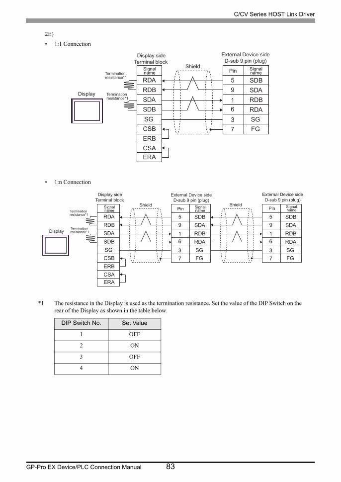
2E)
• 1:1 Connection
• 1:n Connection
*1 The resistance in the Display is used as the termination resistance. Set the value of the DIP Switch on the rear of the Display as shown in the table below.
DIP Switch No. Set Value
1 OFF
2 ON
3 OFF
4 ON
RDARDB
ERB
SDASDBSGCSB
SDBSDARDBRDASG3
59
61
CSAERA
FG7
Terminationresistance*1
Shield
External Device sideD-sub 9 pin (plug)
Pin Signalname
Display Terminationresistance*1
Signalname
Terminal blockDisplay side
RDARDB
ERB
SDASDBSGCSB
SDBSDARDBRDASG3
59
61
CSAERA
FG7
SDBSDARDBRDASG3
59
61
FG7
Terminationresistance*1
Shield
External Device sideD-sub 9 pin (plug)
Pin Signalname
Display
Terminationresistance*1
Signalname
Shield
External Device sideD-sub 9 pin (plug)
Pin Signalname
Terminal blockDisplay side

C/CV Series HOST Link Driver
GP-Pro EX Device/PLC Connection Manual 84
2F)
• 1:1 Connection
• 1:n Connection
SDBSDARDBRDA
FGSG
7
59
61
3
RDARDBSDASDB
SGTERMPFXZCBADTM1
Display
Terminationresistance
TerminalblockSignalname
Shield
External Device sideD-sub 9 pin (plug)
Pin Signalname
User-created cable
Terminationresistance
SDBSDARDBRDA
FGSG
7
59
61
3
RDARDBSDASDB
SGTERMPFXZCBADTM1
SDBSDARDBRDA
FGSG
7
59
61
3
Display
Terminationresistance
TerminalblockSignalname
Shield
External Device sideD-sub 9 pin (plug)
Pin Signalname
Shield
External Device sideD-sub 9 pin (plug)
Pin Signalname
Terminationresistance
User-created cable

C/CV Series HOST Link Driver
GP-Pro EX Device/PLC Connection Manual 85
2G)
• 1:1 Connection
• 1:n Connection
Rx-Rx+
Tx-Tx+
GNDNC
NCNCNC
5
43
9
12
6
SDBSDARDBRDASG3
59
61
87
FG7
Terminationresistance
Shield
External Device sideD-sub 9 pin (plug)
Pin Signalname
DisplayTerminationresistance
D-sub 9 pin (socket)
Pin Signalname
Display side
Rx+Rx-Tx+Tx-
NCNCNCNC
GND5
43
9
12
6
SDBSDARDBRDASG3
59
61
87
FG7
SDBSDARDBRDASG3
59
61
FG7
Terminationresistance
Shield
External Device sideD-sub 9 pin (plug)
Pin Signalname
Display
Terminationresistance
D-sub 9 pin (socket)
Pin Signalname
Shield
External Device sideD-sub 9 pin (plug)
Pin Signalname
Display side

C/CV Series HOST Link Driver
GP-Pro EX Device/PLC Connection Manual 86
Cable Diagram 3
3A)
3B)
Display Cable Remarks
GP3000 (COM1)GP4000*1 (COM1)SP5000*2 (COM1/2)SP-5B00 (COM1)ST (COM1)LT3000 (COM1)IPC*3
PC/AT
*1 All GP4000 models except GP-4100 Series and GP-4203T
*2 Except SP-5B00
*3 Only the COM port which can communicate by RS-232C can be used.
" IPC COM Port" (page 12)
3AOMRON SYSMAC link cable by Pro-face
CA3-CBLSYS-01
3B User-created cableThe cable length must be 15m or less.
GP-4105 (COM1)GP-4115T (COM1) GP-4115T3 (COM1)
3C User-created cableThe cable length must be 15m or less.
LT-4*01TM (COM1)LT-Rear Module (COM1)
3DRJ45 RS-232C Cable (5m) by Pro-face
PFXZLMCBRJR21The cable length must be 5m or less.
CA3-CBLSYS-01Display External Device
SG5
2
3
87
SGFG
4
23
95
1
Display
Shield
External Device sideD-sub 9 pin (plug)
Pin Signalname
D-sub 9 pin (socket)
Pin Signalname
Display side
SD(TXD)
RD(RXD)
RS(RTS)
CS(CTS)
SD(TXD)
RD(RXD)
RS(RTS)
CS(CTS)

C/CV Series HOST Link Driver
GP-Pro EX Device/PLC Connection Manual 87
3C)
3D)
Number Name Notes
(1)RJ45 RS-232C Cable (5m) by Pro-face
PFXZLMCBRJR21
SG SGFG
4
23
95
1
Display
Shield
External Device sideD-sub 9 pin (plug)
Pin Signalname
Signalname
SD(TXD)
RD(RXD)
RS(RTS)
CS(CTS)
SD(TXD)
RD(RXD)
RS(RTS)
CS(CTS)
Terminal blockDisplay side
SGFG
4
23
95
1
External Device sideD-sub 9 pin (plug)
Pin Signalname
SD(TXD)
RD(RXD)RS(RTS)
CS(CTS)
Display
GND
TXD
RXD
(1)

C/CV Series HOST Link Driver
GP-Pro EX Device/PLC Connection Manual 88
Cable Diagram 4
4A)
4B)
Display Cable Remarks
GP3000 (COM1)GP4000*1 (COM1)SP5000*2 (COM1/2)SP-5B00 (COM1)ST (COM1)LT3000 (COM1)IPC*3
PC/AT
*1 All GP4000 models except GP-4100 Series and GP-4203T
*2 Except SP-5B00
*3 Only the COM port which can communicate by RS-232C can be used.
" IPC COM Port" (page 12)
4AIsolation cable by OMRON Corporation
CQM1-CIF01
Commercial 9 pin-25 pin conversion adapter is required.
GP-4105 (COM1)GP-4115T (COM1) GP-4115T3 (COM1)
4B
User-created cable+
Isolation cable by OMRON CorporationCQM1-CIF01
Display External DeviceCQM1-CIF01
by OMRON Corp.
9 pin-25 pin conversion adapter
External DeviceCQM1-CIF01by OMRON Corp.
Display
Display sideTerminal block
Signal name
External Device sideD-sub 25 pin (socket)
Pin Signalname
User-created cable
CD
RD(RXD)
SD(TXD)ER(DTR)
SGDR(DSR)
RS(RTS)
CS(CTS)
6 DR(DSR)
2 SD(TXD)3 RD(RXD)
5 CS(CTS)
7 SG
4 RS(RTS)
8 CD
20 ER(DTR)

C/CV Series HOST Link Driver
GP-Pro EX Device/PLC Connection Manual 89
Cable Diagram 5
Display Cable Remarks
GP3000*1 (COM1)AGP-3302B (COM2)GP-4*01TM (COM1)GP-Rear Module (COM1)ST*2 (COM2)LT3000 (COM1)IPC*3
*1 All GP3000 models except AGP-3302B
*2 All ST models except AST-3211A and AST-3302B
*3 Only the COM port which can communicate by RS-422/485 (4 wire) can be used. (Except PE-4000B, PS5000)
" IPC COM Port" (page 12)
5A
COM port conversion adapter by Pro-faceCA3-ADPCOM-01
+Terminal block conversion adapter
by Pro-faceCA3-ADPTRM-01
+User-created cable
The cable length must be 500m or less.
5B User-created cable
GP3000*4 (COM2)
*4 All GP3000 models except GP-3200 series and AGP-3302B
5C
Online adapter by Pro-faceCA4-ADPONL-01
+Terminal block conversion adapter
by Pro-faceCA3-ADPTRM-01
+User-created cable
The cable length must be 500m or less.
5D
Online adapter by Pro-faceCA4-ADPONL-01
+User-created cable
GP-4106 (COM1)GP-4116T (COM1)
5E User-created cableThe cable length must be 500m or less.
GP4000*5 (COM2)GP-4201T (COM1)SP5000*6 (COM1/2)SP-5B00 (COM2)
*5 All GP4000 models except GP-4100 series, GP-4*01TM, GP-Rear Module, GP-4201T and GP-4*03T
*6 Except SP-5B00
5F
RS-422 terminal block conversion adapter by Pro-facePFXZCBADTM1*7
+User-created cable
*7 When using a Terminal Block Conversion Adapter (CA3-ADPTRM-01) instead of the RS-422 Terminal Block Conversion Adapter, refer to Cable Diagram 5A.
The cable length must be 500m or less.
5B User-created cable
PE-4000B*8
PS5000*8
*8 Only the COM port which can communicate by RS-422/485 (4 wire) can be used.
" IPC COM Port" (page 12)
5G User-created cableThe cable length must be 500m or less.

C/CV Series HOST Link Driver
GP-Pro EX Device/PLC Connection Manual 90
5A)
• 1:1 Connection
• 1:n Connection
• When the display unit you use is an IPC, turn ON the DIP switches 5 and 6 to insert the
termination resistance.
SDB
SDA
RDB
RDAFG7
59
61
RDA
RDB
SDA
SDB
SGTERM
Display
Terminationresistance
TerminalblockSignalname
Shield
External Device sideD-sub 9 pin (plug)
Pin Signalname
CA3-ADPCOM-01
CA3-ADPTRM-01
Terminationresistance
User-created cable
SDB
SDA
RDB
RDAFG7
59
61
RDA
RDB
SDA
SDB
SGTERM
SDB
SDA
RDB
RDAFG7
59
61
Display
Terminationresistance
TerminalblockSignalname
Shield
External Device sideD-sub 9 pin (plug)
Pin Signalname
CA3-ADPCOM-01
CA3-ADPTRM-01
Shield
External Device sideD-sub 9 pin (plug)
Pin Signalname
Terminationresistance
User-created cable

C/CV Series HOST Link Driver
GP-Pro EX Device/PLC Connection Manual 91
5B)
• 1:1 Connection
• 1:n Connection
• When the display unit you use is an IPC, turn ON the DIP switches 5 and 6 to insert the
termination resistance.
RDA
RDB
ERB
SDA
SDB
SGCSB
5
2
1
9
73
6
SDB
SDA
RDB
RDA
FG7
59
61
CSA8ERA4
Display
Terminationresistance
Shield
External Device sideD-sub 9 pin (plug)
Pin Signalname
Terminationresistance
D-sub 9 pin (socket)
Pin Signalname
Display side
RDA
RDB
ERB
SDA
SDB
SGCSB
5
2
1
9
73
6
SDB
SDA
RDB
RDA
FG7
59
61
CSA8ERA4
SDB
SDA
RDB
RDA
FG7
59
61Display
Terminationresistance
Shield
External Device sideD-sub 9 pin (plug)
Pin Signalname
Terminationresistance
D-sub 9 pin (socket)
Pin Signalname
Shield
External Device sideD-sub 9 pin (plug)
Pin Signalname
Display side

C/CV Series HOST Link Driver
GP-Pro EX Device/PLC Connection Manual 92
5C)
• 1:1 Connection
• 1:n Connection
SDB
SDA
RDB
RDAFG7
59
61
RDA
RDB
SDA
SDB
SGTERM
Display
Terminationresistance
TerminalblockSignalname
Shield
External Device sideD-sub 9 pin (plug)
Pin Signalname
CA4-ADPONL-01
CA3-ADPTRM-01
User-created cable
SDB
SDA
RDB
RDAFG7
59
61
RDA
RDB
SDA
SDB
SGTERM
SDB
SDA
RDB
RDAFG7
59
61
Display
Terminationresistance
TerminalblockSignalname
Shield
External Device sideD-sub 9 pin (plug)
Pin Signalname
CA4-ADPONL-01
CA3-ADPTRM-01
Shield
External Device sideD-sub 9 pin (plug)
Pin Signalname
User-created cable
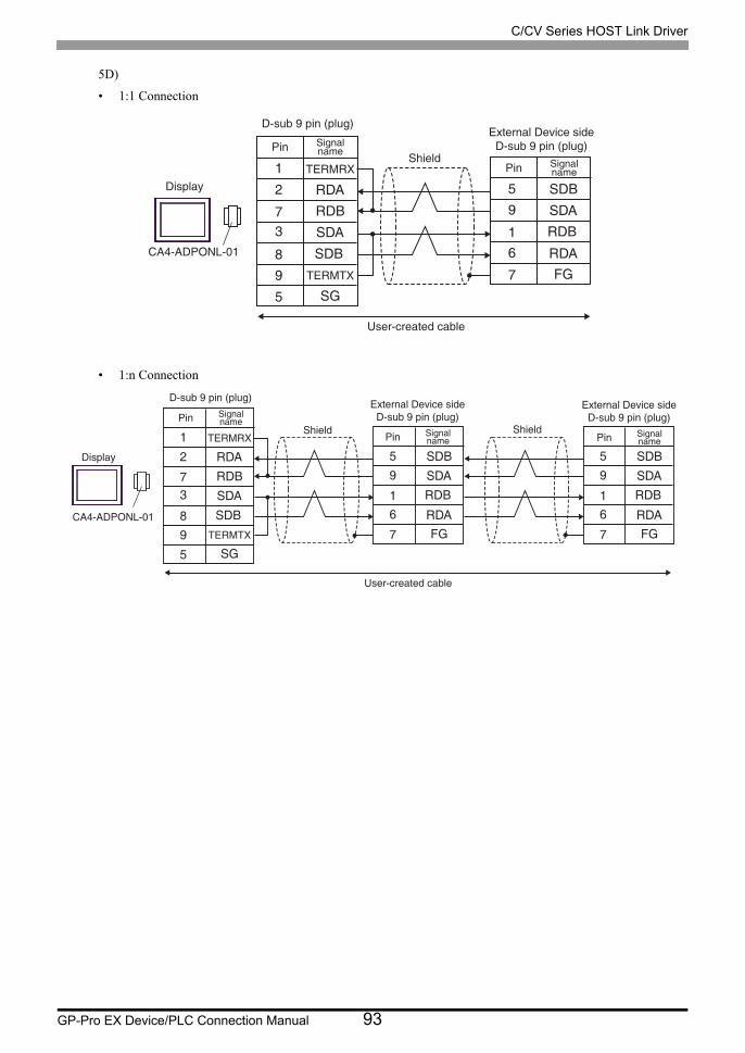
C/CV Series HOST Link Driver
GP-Pro EX Device/PLC Connection Manual 93
5D)
• 1:1 Connection
• 1:n Connection
TERMRX
RDA
SG
RDB
SDA
SDBTERMTX
8
2
1
5
37
9
SDB
SDA
RDA
RDB
FG
1
59
6
7
Display
Shield
External Device sideD-sub 9 pin (plug)
Pin Signalname
CA4-ADPONL-01
D-sub 9 pin (plug)
Pin Signalname
User-created cable
TERMRX
RDA
SG
RDB
SDA
SDBTERMTX
8
2
1
5
37
9
SDB
SDA
RDA
RDB
FG
1
59
6
7
SDB
SDA
RDA
RDB
FG
1
59
6
7
Display
Shield
External Device sideD-sub 9 pin (plug)
Pin Signalname
CA4-ADPONL-01
D-sub 9 pin (plug)
Pin Signalname
Shield
External Device sideD-sub 9 pin (plug)
Pin Signalname
User-created cable

C/CV Series HOST Link Driver
GP-Pro EX Device/PLC Connection Manual 94
5E)
• 1:1 Connection
• 1:n Connection
*1 The resistance in the Display is used as the termination resistance. Set the value of the DIP Switch on the rear of the Display as shown in the table below.
DIP Switch No. Set Value
1 OFF
2 ON
3 OFF
4 ON
RDA
RDB
ERB
SDA
SDB
SGCSB
SDB
SDA
RDB
RDA
FG7
59
61
CSAERA
Display
Terminationresistance*1
Shield
External Device sideD-sub 9 pin (plug)
Pin Signalname
Terminationresistance*1
Signalname
Display sideTerminal block
RDA
RDB
ERB
SDA
SDB
SGCSB
SDB
SDA
RDB
RDA
FG7
59
61
CSAERA
SDB
SDA
RDB
RDA
FG7
59
61Display
Terminationresistance*1
Shield
External Device sideD-sub 9 pin (plug)
Pin Signalname
Terminationresistance*1
Signalname
Shield
External Device sideD-sub 9 pin (plug)
Pin Signalname
Display sideTerminal block

C/CV Series HOST Link Driver
GP-Pro EX Device/PLC Connection Manual 95
5F)
• 1:1 Connection
• 1:n Connection
SDBSDARDBRDAFG7
59
61
RDARDBSDASDB
SGTERM
Display
Terminationresistance
TerminalblockSignalname
Shield
External Device sideD-sub 9 pin (plug)
Pin Signalname
PFXZCBADTM1
Terminationresistance
User-created cable
SDBSDARDBRDAFG7
59
61
RDARDBSDASDB
SGTERM
SDBSDARDBRDAFG7
59
61
Display
Terminationresistance
TerminalblockSignalname
Shield
External Device sideD-sub 9 pin (plug)
Pin Signalname
PFXZCBADTM1
Shield
External Device sideD-sub 9 pin (plug)
Pin Signalname
Terminationresistance
User-created cable

C/CV Series HOST Link Driver
GP-Pro EX Device/PLC Connection Manual 96
5G)
• 1:1 Connection
• 1:n Connection
Rx+
Rx-Tx+
Tx-
NC
NCNCNC
GND5
43
9
12
6
SDBSDARDBRDAFG7
59
61
87
Display
Terminationresistance
Shield
External Device sideD-sub 9 pin (plug)
Pin Signalname
Terminationresistance
D-sub 9 pin (socket)
Pin Signalname
Display side
Rx+Rx-Tx+Tx-
NCNCNCNC
GND5
43
9
12
6
SDBSDARDBRDAFG7
59
61
87
SDBSDARDBRDAFG7
59
61Display
Terminationresistance
Shield
External Device sideD-sub 9 pin (plug)
Pin Signalname
Terminationresistance
D-sub 9 pin (socket)
Pin Signalname
Shield
External Device sideD-sub 9 pin (plug)
Pin Signalname
Display side

C/CV Series HOST Link Driver
GP-Pro EX Device/PLC Connection Manual 97
Cable Diagram 6
6A)
Display Cable Remarks
GP3000 (COM1)GP4000*1 (COM1)SP5000*2 (COM1/2)SP-5B00 (COM1)ST (COM1)LT3000 (COM1)IPC*3
PC/AT
*1 All GP4000 models except GP-4100 Series and GP-4203T
*2 Except SP-5B00
*3 Only the COM port which can communicate by RS-232C can be used.
" IPC COM Port" (page 12)
6A User-created cable The cable length must be 15m or less.
GP-4105 (COM1)GP-4115T (COM1) GP-4115T3 (COM1)
6B User-created cable The cable length must be 15m or less.
LT-4*01TM (COM1)LT-Rear Module (COM1)
6CRJ45 RS-232C Cable (5m) by Pro-face
PFXZLMCBRJR21 The cable length must be 5m or less.
SG5
2
3
87
SGFG
4
23
75
1
Display
Shield
External Device sideD-sub 9 pin (plug)
Pin Signalname
D-sub 9 pin (socket)
Pin Signalname
Display side
SD(TXD)
RD(RXD)
RS(RTS)
CS(CTS)
SD(TXD)
RD(RXD)
RS(RTS)
CS(CTS)

C/CV Series HOST Link Driver
GP-Pro EX Device/PLC Connection Manual 98
6B)
6C)
Number Name Notes
(1)RJ45 RS-232C Cable (5m) by Pro-face
PFXZLMCBRJR21
SG SGFG
4
23
75
1
Display
Shield
External Device sideD-sub 9 pin (plug)
Pin Signalname
Signalname
SD(TXD)
RD(RXD)
RS(RTS)
CS(CTS)
SD(TXD)
RD(RXD)
RS(RTS)
CS(CTS)
Terminal blockDisplay side
SGFG
4
23
75
1
External Device sideD-sub 9 pin (plug)
Pin Signalname
SD(TXD)
RD(RXD)
RS(RTS)
CS(CTS)
Display
GND
TXD
RXD
(1)

C/CV Series HOST Link Driver
GP-Pro EX Device/PLC Connection Manual 99
Cable Diagram 7
Display Cable Remarks
GP3000*1 (COM1)AGP-3302B (COM2)GP-4*01TM (COM1)GP-Rear Module (COM1)ST*2 (COM2)LT3000 (COM1)IPC*3
*1 All GP3000 models except AGP-3302B
*2 All ST models except AST-3211A and AST-3302B
*3 Only the COM port which can communicate by RS-422/485 (4 wire) can be used. (Except PE-4000B, PS5000)
" IPC COM Port" (page 12)
7A
COM port conversion adapter by Pro-faceCA3-ADPCOM-01
+Terminal block conversion adapter
by Pro-faceCA3-ADPTRM-01
+User-created cable
The cable length must be 500m or less.
7BRS422 cable by Pro-face
CA3-CBL422/5M-01
7C User-created cable
GP3000*4 (COM2)
*4 All GP3000 models except GP-3200 series and AGP-3302B
7D
Online adapter by Pro-faceCA4-ADPONL-01
+Terminal block conversion adapter
by Pro-faceCA3-ADPTRM-01
+User-created cable
The cable length must be 500m or less.
7E
Online adapter by Pro-faceCA4-ADPONL-01
+User-created cable
GP-4106 (COM1)GP-4116T (COM1)
7F User-created cableThe cable length must be 500m or less.
GP4000*5 (COM2)GP-4201T (COM1)SP5000*6 (COM1/2)SP-5B00 (COM2)
*5 All GP4000 models except GP-4100 series, GP-4*01TM, GP-Rear Module, GP-4201T and GP-4*03T
*6 Except SP-5B00
7G
RS-422 terminal block conversion adapter by Pro-facePFXZCBADTM1*7
+User-created cable
*7 When using a Terminal Block Conversion Adapter (CA3-ADPTRM-01) instead of the RS-422 Terminal Block Conversion Adapter, refer to Cable Diagram 7A.
The cable length must be 500m or less.
7BRS422 cable by Pro-face
CA3-CBL422/5M-01
7C User-created cable
PE-4000B*8
PS5000*8 7H User-created cableThe cable length must be 500m or less.

C/CV Series HOST Link Driver
GP-Pro EX Device/PLC Connection Manual 100
7A)
• 1:1 Connection
• 1:n Connection
*8 Only the COM port which can communicate by RS-422/485 (4 wire) can be used.
" IPC COM Port" (page 12)
• When the display unit you use is an IPC, turn ON the DIP switches 5 and 6 to insert the
termination resistance.
SDB
SDA
RDARDB
FGSG
RDA
RDB
SDA
SDB
SGTERM
Display
Terminationresistance
TerminalblockSignalname
Shield
ExternalDevice side
Signalname
CA3-ADPCOM-01
CA3-ADPTRM-01
Terminationresistance
User-created cable
SDB
SDA
RDARDB
FGSG
RDA
RDB
SDA
SDB
SGTERM
SDB
SDA
RDARDB
FGSG
Display
Terminationresistance
TerminalblockSignalname
Shield
ExternalDevice side
Signalname
CA3-ADPCOM-01
CA3-ADPTRM-01
ExternalDevice side
Signalname
ShieldTerminationresistance
User-created cable

C/CV Series HOST Link Driver
GP-Pro EX Device/PLC Connection Manual 101
7B)
• 1:1 Connection
• 1:n Connection
RDA
RDBSDA
SDB
SG
SDB
SDA
RDA
SG
RDB
FGFG
CA3-CBL422/5M-01
Display
Signalname
ExternalDevice side
Signalname
RDA
RDBSDA
SDB
SG
SDB
SDA
RDA
SG
RDB
FGFG
CA3-CBL422/5M-01 SDB
SDA
RDA
SG
RDB
FG
Display
Signalname
ExternalDevice side
Signalname
ExternalDevice side
Signalname
User-created cable
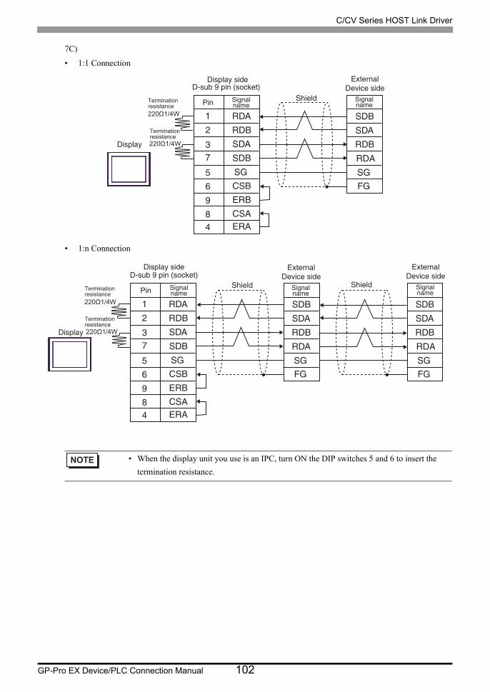
C/CV Series HOST Link Driver
GP-Pro EX Device/PLC Connection Manual 102
7C)
• 1:1 Connection
• 1:n Connection
• When the display unit you use is an IPC, turn ON the DIP switches 5 and 6 to insert the
termination resistance.
RDA
RDB
ERB
SDA
SDB
SGCSB
5
2
1
9
73
6
SDB
SDA
RDB
RDA
SG
CSA8ERA4
FG
Display
Terminationresistance
Shield
ExternalDevice side
Signalname
Terminationresistance
D-sub 9 pin (socket)
Pin Signalname
Display side
RDA
RDB
ERB
SDA
SDB
SGCSB
5
2
1
9
73
6
SDB
SDA
RDB
RDA
SG
CSA8ERA4
FG
SDB
SDA
RDB
RDA
SGFG
Display
Terminationresistance
Shield
ExternalDevice side
Signalname
Terminationresistance
D-sub 9 pin (socket)
Pin Signalname
Shield
ExternalDevice side
Signalname
Display side

C/CV Series HOST Link Driver
GP-Pro EX Device/PLC Connection Manual 103
7D)
• 1:1 Connection
• 1:n Connection
SDB
SDA
RDARDB
FGSG
RDA
RDB
SDA
SDB
SGTERM
Display
Terminationresistance
TerminalblockSignalname
Shield
ExternalDevice side
Signalname
CA4-ADPONL-01
CA3-ADPTRM-01
User-created cable
SDB
SDA
RDARDB
FGSG
RDA
RDB
SDA
SDB
SGTERM
SDB
SDA
RDARDB
FGSG
Display
Terminationresistance
TerminalblockSignalname
Shield
ExternalDevice side
Signalname
CA4-ADPONL-01
CA3-ADPTRM-01
ShieldExternal
Device sideSignalname
User-created cable

C/CV Series HOST Link Driver
GP-Pro EX Device/PLC Connection Manual 104
7E)
• 1:1 Connection
• 1:n Connection
TERMRX
RDA
SG
RDB
SDA
SDBTERMTX
8
2
1
5
37
9
SDB
SDA
RDA
RDB
FGSG
Display
Shield
D-sub 9 pin (plug)
Pin Signalname
CA4-ADPONL-01
ExternalDevice side
Signalname
User-created cable
TERMRX
RDA
SG
RDB
SDA
SDB
TERMTX
8
2
1
5
37
9
SDB
SDA
RDA
RDB
FG
SG
SDB
SDA
RDA
RDB
FG
SG
Display
Shield
D-sub 9 pin (plug)
Pin Signalname
CA4-ADPONL-01
ExternalDevice side
Signalname
ExternalDevice side
Signalname
Shield
User-created cable
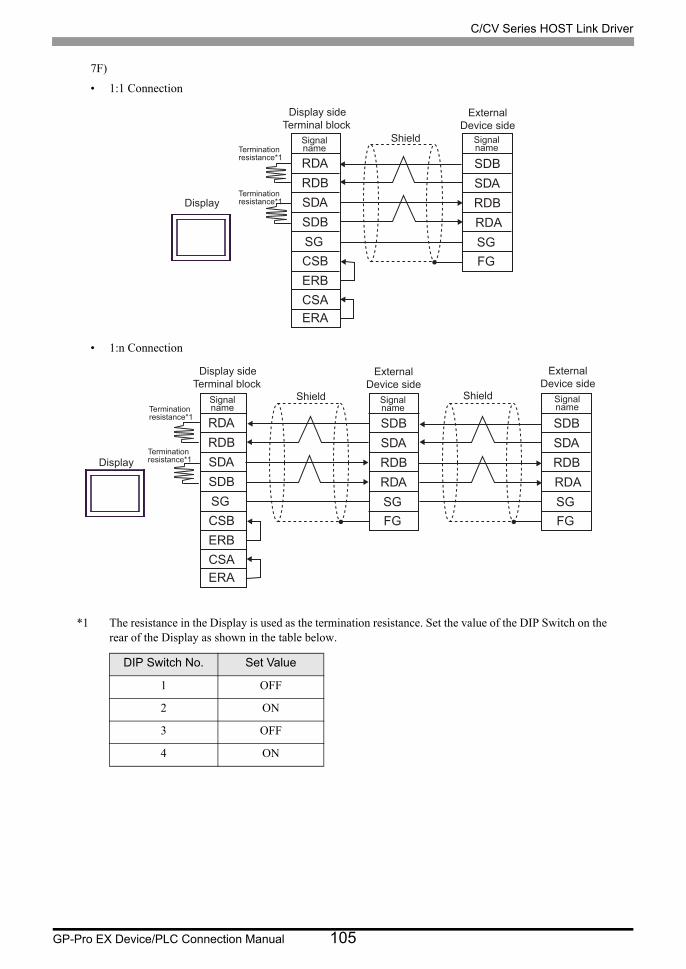
C/CV Series HOST Link Driver
GP-Pro EX Device/PLC Connection Manual 105
7F)
• 1:1 Connection
• 1:n Connection
*1 The resistance in the Display is used as the termination resistance. Set the value of the DIP Switch on the rear of the Display as shown in the table below.
DIP Switch No. Set Value
1 OFF
2 ON
3 OFF
4 ON
RDARDB
ERB
SDASDBSGCSB
SDBSDARDBRDASG
CSAERA
FG
Display
Terminationresistance*1
Shield
ExternalDevice side
Signalname
Terminationresistance*1
Signalname
Terminal blockDisplay side
RDARDB
ERB
SDASDBSGCSB
SDBSDARDBRDASG
CSAERA
FG
SDBSDARDBRDASGFG
Display
Terminationresistance*1
Shield
ExternalDevice side
Signalname
Terminationresistance*1
Signalname
Shield
ExternalDevice side
Signalname
Terminal blockDisplay side

C/CV Series HOST Link Driver
GP-Pro EX Device/PLC Connection Manual 106
7G)
• 1:1 Connection
• 1:n Connection
SDBSDA
RDARDB
FGSG
RDARDBSDASDB
SGTERM
Display
Terminationresistance
TerminalblockSignalname
Shield
ExternalDevice side
Signalname
PFXZCBADTM1
Terminationresistance
User-created cable
SDBSDA
RDARDB
FGSG
RDARDBSDASDB
SGTERM
SDBSDA
RDARDB
FGSG
Display
Terminationresistance
TerminalblockSignalname
Shield
ExternalDevice side
Signalname
PFXZCBADTM1
ExternalDevice side
Signalname
ShieldTerminationresistance
User-created cable

C/CV Series HOST Link Driver
GP-Pro EX Device/PLC Connection Manual 107
7H)
• 1:1 Connection
• 1:n Connection
Rx-Rx+
Tx-Tx+
GNDNCNCNCNC
5
43
9
12
6
SDBSDARDBRDASG
87
FG
Display
Terminationresistance
Shield
ExternalDevice side
Signalname
Terminationresistance
D-sub 9 pin (socket)
Pin Signalname
Display side
Rx-Rx+
Tx-GNDNCNCNCNC
Tx+
5
43
9
12
6
SDBSDARDBRDASG
87
FG
SDBSDARDBRDASGFG
Display
Terminationresistance
Shield
ExternalDevice side
Signalname
Terminationresistance
D-sub 9 pin (socket)
Pin Signalname
Shield
ExternalDevice side
Signalname
Display side

C/CV Series HOST Link Driver
GP-Pro EX Device/PLC Connection Manual 108
Cable Diagram 8
8A)
Display Cable Remarks
GP3000 (COM1)GP4000*1 (COM1)SP5000*2 (COM1/2)SP-5B00 (COM1)ST (COM1)LT3000 (COM1)IPC*3
PC/AT
*1 All GP4000 models except GP-4100 Series and GP-4203T
*2 Except SP-5B00
*3 Only the COM port which can communicate by RS-232C can be used.
" IPC COM Port" (page 12)
8A
User-created cable+
CS1W-CN225 (2m) or CS1W-CN625 (6m) by OMRON Corporation The cable length must
be 15m or less.
8B
User-created cable+
CS1W-CN226 (2m) or CS1W-CN626 (6m) by OMRON Corporation
GP-4105 (COM1)GP-4115T (COM1) GP-4115T3 (COM1)
8C
User-created cable+
CS1W-CN225 (2m) or CS1W-CN625 (6m) by OMRON Corporation The cable length must
be 15m or less.
8D
User-created cable+
CS1W-CN226 (2m) or CS1W-CN626 (6m) by OMRON Corporation
LT-4*01TM (COM1)LT-Rear Module (COM1)
8E
RJ45 RS-232C Cable (5m) by Pro-facePFXZLMCBRJR21
+CS1W-CN225 (2m) or CS1W-CN625 (6m)
by OMRON Corporation The cable length must be 11m or less.
8F
RJ45 RS-232C Cable (5m) by Pro-facePFXZLMCBRJR21
+CS1W-CN226 (2m) or CS1W-CN626 (6m)
by OMRON Corporation
SG5
2
3
87
SGFG
4
23
75
1
Display
D-sub 25 pin (socket)
Pin Signalname
User-created cable
D-sub 9 pin (socket)
Pin Signalname
External Device
CS1W-CN225or
CS1W-CN625
Display side
SD(TXD)
RD(RXD)
RS(RTS)
CS(CTS)
SD(TXD)
RD(RXD)
RS(RTS)
CS(CTS)

C/CV Series HOST Link Driver
GP-Pro EX Device/PLC Connection Manual 109
8B)
8C)
8D)
SG5
3
2
87
SG
7
23
58
Display
D-sub 9 pin (plug)
Pin Signalname
D-sub 9 pin (socket)
Pin Signalname
External Device
CS1W-CN226or
CS1W-CN626
User-created cable
Display side
RD(RXD)
SD(TXD)
RS(RTS)
CS(CTS)
RD(RXD)
SD(TXD)
CS(CTS)
RS(RTS)
SG SGFG
4
23
75
1
Display
D-sub 25 pin (socket)
Pin Signalname
User-created cable
Signalname
External Device
CS1W-CN225or
CS1W-CN625SD(TXD)
RD(RXD)
RS(RTS)
CS(CTS)
SD(TXD)
RD(RXD)
RS(RTS)
CS(CTS)
Display sideTerminal block
SG SG
7
23
58
Display
D-sub 9 pin (plug)
Pin Signalname
Signalname
External Device
CS1W-CN226or
CS1W-CN626
User-created cable
RD(RXD)
SD(TXD)
RS(RTS)
CS(CTS)
RD(RXD)
SD(TXD)
CS(CTS)
RS(RTS)
Display sideTerminal block

C/CV Series HOST Link Driver
GP-Pro EX Device/PLC Connection Manual 110
8E)
8F)
Number Name Notes
(1)RJ45 RS-232C Cable (5m) by Pro-face
PFXZLMCBRJR21
Number Name Notes
(1)RJ45 RS-232C Cable (5m) by Pro-face
PFXZLMCBRJR21
SGFG
4
23
75
1
D-sub 25 pin (socket)
Pin Signalname
External Device
CS1W-CN225or
CS1W-CN625SD(TXD)
RD(RXD)RS(RTS)
CS(CTS)
Display
GND
RXD
TXD
(1)
SG
7
23
58
D-sub 9 pin (plug)
Pin Signalname
External DeviceCS1W-CN226
orCS1W-CN626
RD(RXD)
SD(TXD)
CS(CTS)
RS(RTS)
Display
GND
TXD
RXD
(1)

C/CV Series HOST Link Driver
GP-Pro EX Device/PLC Connection Manual 111
Cable Diagram 9
9A)
9B
Display Cable Remarks
GP3000 (COM1)GP4000*1 (COM1)SP5000*2 (COM1/2)SP-5B00 (COM1)ST (COM1)LT3000 (COM1)IPC*3
PC/AT
*1 All GP4000 models except GP-4100 Series and GP-4203T
*2 Except SP-5B00
*3 Only the COM port which can communicate by RS-232C can be used.
" IPC COM Port" (page 12)
9A
Isolation cable by OMRON CorporationCQM1-CIF01
+Connector conversion cable by OMRON Corporation
CS1W-CN114
Commercial 9 pin/25 pin conversion adapter is required.
GP-4105 (COM1)GP-4115T (COM1) GP-4115T3 (COM1)
9B
User-created cable+
Isolation cable by OMRON CorporationCQM1-CIF01
+Connector conversion cable by OMRON Corporation
CS1W-CN114
CQM1-CIF01
CS1W-CN114
Display
9 pin-25 pin conversion adapter
External Device
CQM1-CIF01
CS1W-CN114
External Device
Display
Display sideTerminal block
Signal name
External Device sideD-sub 25 pin (socket)
Pin Signalname
User-created cable
CD
RD(RXD)SD(TXD)ER(DTR)
SGDR(DSR)
RS(RTS)CS(CTS)
6 DR(DSR)
2 SD(TXD)3 RD(RXD)
5 CS(CTS)
7 SG
4 RS(RTS)
8 CD
20 ER(DTR)

C/CV Series HOST Link Driver
GP-Pro EX Device/PLC Connection Manual 112
Cable Diagram 10
Display Cable Remarks
GP3000*1 (COM1)AGP-3302B (COM2)GP-4*01TM (COM1)GP-Rear Module (COM1)ST*2 (COM2)LT3000 (COM1)IPC*3
*1 All GP3000 models except AGP-3302B
*2 All ST models except AST-3211A and AST-3302B
*3 Only the COM port which can communicate by RS-422/485 (4 wire) can be used. (Except PE-4000B, PS5000)
" IPC COM Port" (page 12)
10A
COM port conversion adapter by Pro-faceCA3-ADPCOM-01
+Terminal block conversion adapter
by Pro-faceCA3-ADPTRM-01
+User-created cable
The cable length must be 500m or less.
10BRS422 cable by Pro-face
CA3-CBL422/5M-01
10C User-created cable
GP3000*4 (COM2)
*4 All GP3000 models except GP-3200 series and AGP-3302B
10D
Online adapter by Pro-faceCA4-ADPONL-01
+Terminal block conversion adapter
by Pro-faceCA3-ADPTRM-01
+User-created cable
The cable length must be 500m or less.
10E
Online adapter by Pro-faceCA4-ADPONL-01
+User-created cable
GP-4106 (COM1)GP-4116T (COM1)
10F User-created cableThe cable length must be 500m or less.
GP4000*5 (COM2)GP-4201T (COM1)SP5000*6 (COM1/2)SP-5B00 (COM2)
*5 All GP4000 models except GP-4100 series, GP-4*01TM, GP-Rear Module, GP-4201T and GP-4*03T
*6 Except SP-5B00
10G
RS-422 terminal block conversion adapter by Pro-facePFXZCBADTM1*7
+User-created cable The cable length
must be 500m or less.
10BRS422 cable by Pro-face
CA3-CBL422/5M-01
10C User-created cable
PE-4000B*8
PS5000*8 10H User-created cableThe cable length must be 500m or less.
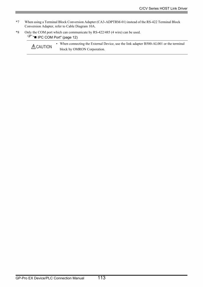
C/CV Series HOST Link Driver
GP-Pro EX Device/PLC Connection Manual 113
*7 When using a Terminal Block Conversion Adapter (CA3-ADPTRM-01) instead of the RS-422 Terminal Block Conversion Adapter, refer to Cable Diagram 10A.
*8 Only the COM port which can communicate by RS-422/485 (4 wire) can be used.
" IPC COM Port" (page 12)
• When connecting the External Device, use the link adapter B500-AL001 or the terminal
block by OMRON Corporation.
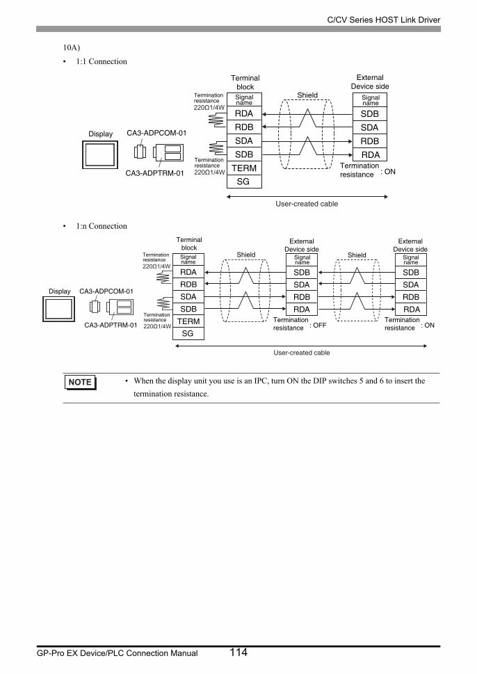
C/CV Series HOST Link Driver
GP-Pro EX Device/PLC Connection Manual 114
10A)
• 1:1 Connection
• 1:n Connection
• When the display unit you use is an IPC, turn ON the DIP switches 5 and 6 to insert the
termination resistance.
SDBSDARDBRDA
RDARDBSDASDB
SGTERM : ON
Display
Terminationresistance
TerminalblockSignalname
Shield
ExternalDevice side
Signalname
CA3-ADPCOM-01
CA3-ADPTRM-01Terminationresistance
Terminationresistance
User-created cable
SDBSDARDBRDA
RDARDBSDASDB
SGTERM : OFF
SDBSDARDBRDA
Display
Terminationresistance
TerminalblockSignalname
Shield
ExternalDevice side
Signalname
CA3-ADPCOM-01
CA3-ADPTRM-01
Shield
ExternalDevice side
Signalname
Terminationresistance : ON
Terminationresistance
Terminationresistance
User-created cable

C/CV Series HOST Link Driver
GP-Pro EX Device/PLC Connection Manual 115
10B)
• 1:1 Connection
• 1:n Connection
RDARDBSDASDBSGFG
SDBSDARDBRDA
: ON
Display
Terminationresistance
TerminalblockSignalname
Shield
ExternalDevice side
Signalname
CA3-CBL422/5M-01 Terminationresistance
User-created cable
RDARDBSDASDBSGFG
CA3-CBL422 /5M-01
SDBSDARDBRDA
: OFF
SDBSDARDBRDA
Display
Terminationresistance
TerminalblockSignalname
Shield
ExternalDevice side
Signalname
Shield
ExternalDevice side
Signalname
Terminationresistance : ON
Terminationresistance
User-created cable

C/CV Series HOST Link Driver
GP-Pro EX Device/PLC Connection Manual 116
10C)
• 1:1 Connection
• 1:n Connection
• When the display unit you use is an IPC, turn ON the DIP switches 5 and 6 to insert the
termination resistance.
RDARDB
ERB
SDASDBSGCSB
5
21
9
73
6
SDBSDARDBRDA
CSA8ERA4
: ON
Display
Terminationresistance
ShieldD-sub 9 pin (socket)
Pin Signalname
Terminationresistance
ExternalDevice side
Signalname
Terminationresistance
Display side
RDARDB
ERB
SDASDBSGCSB
5
21
9
73
6
SDBSDARDBRDA
CSA8ERA4
: OFF
SDBSDARDBRDA
Display
Terminationresistance
Signalname
ShieldD-sub 9 pin (socket)
Pin Signalname
Terminationresistance
ExternalDevice side
Shield Signalname
ExternalDevice side
Terminationresistance : ON
Terminationresistance
Display side

C/CV Series HOST Link Driver
GP-Pro EX Device/PLC Connection Manual 117
10D)
• 1:1 Connection
• 1:n Connection
SDBSDA
RDARDB
RDARDBSDASDB
SGTERM : ON
DisplayTerminationresistance
TerminalblockSignalname
Shield Signalname
CA4-ADPONL-01
CA3-ADPTRM-01
ExternalDevice side
Terminationresistance
User-created cable
SDBSDA
RDARDB
RDARDBSDASDB
SGTERM : OFF
SDBSDARDBRDA
DisplayTerminationresistance
TerminalblockSignalname
Shield
ExternalDevice side
Signalname
CA4-ADPONL-01
CA3-ADPTRM-01
ExternalDevice side
Signalname
Terminationresistance : ONTermination
resistance
Shield
User-created cable

C/CV Series HOST Link Driver
GP-Pro EX Device/PLC Connection Manual 118
10E)
• 1:1 Connection
• 1:n Connection
TERMRX
RDA
SG
RDBSDASDB
TERMTX
8
21
5
37
9
SDBSDA
RDARDB
CA4-ADPONL-01
: ON
Display
Terminationresistance
Signalname
Shield
D-sub 9 pin (plug)
Pin Signalname
ExternalDevice side
User-created cable
TERMRX
RDA
SG
RDBSDASDB
TERMTX
8
21
5
37
9
SDBSDA
RDARDB
: OFF
SDBSDARDBRDA
Display
Terminationresistance
ExternalDevice side
Signalname
Shield
D-sub 9 pin (plug)
Pin Signalname
CA4-ADPONL-01
ExternalDevice side
Signalname
Shield
: ONTerminationresistance
User-created cable

C/CV Series HOST Link Driver
GP-Pro EX Device/PLC Connection Manual 119
10F)
• 1:1 Connection
• 1:n Connection
*1 The resistance in the Display is used as the termination resistance. Set the value of the DIP Switch on the rear of the Display as shown in the table below.
DIP Switch No. Set Value
1 OFF
2 ON
3 OFF
4 ON
SDBSDARDBRDA
: ON
Display
Terminationresistance*1
Shield
ExternalDevice side
Signalname
Terminationresistance
Terminal blockDisplay side
Terminationresistance*1
RDARDB
ERB
SDASDBSGCSB
CSAERA
Signalname
RDARDB
ERB
SDASDBSGCSB
SDBSDARDBRDA
CSAERA
: OFF
SDBSDARDBRDA
Display
Terminationresistance*1
Signalname
ShieldSignalname
Terminationresistance*1
ExternalDevice side
Shield Signalname
ExternalDevice side
Terminationresistance : ON
Terminationresistance
Terminal blockDisplay side

C/CV Series HOST Link Driver
GP-Pro EX Device/PLC Connection Manual 120
10G)
• 1:1 Connection
• 1:n Connection
SDBSDARDBRDA
RDARDBSDASDB
SGTERM : ON
Display
Terminationresistance
TerminalblockSignalname
Shield
ExternalDevice side
Signalname
PFXZCBADTM1Terminationresistance
Terminationresistance
User-created cable
SDBSDARDBRDA
RDARDBSDASDB
SGTERM : OFF
SDBSDARDBRDA
Display
Terminationresistance
TerminalblockSignalname
Shield
ExternalDevice side
Signalname
PFXZCBADTM1
Shield
ExternalDevice side
Signalname
Terminationresistance : ON
Terminationresistance
Terminationresistance
User-created cable

C/CV Series HOST Link Driver
GP-Pro EX Device/PLC Connection Manual 121
10H)
• 1:1 Connection
• 1:n Connection
Rx-Rx+
Tx-GNDNCNCNCNC
Tx+
5
43
9
12
6
SDBSDARDBRDA
87
: ON
Display
Terminationresistance
ShieldD-sub 9 pin (socket)
Pin Signalname
Terminationresistance
ExternalDevice side
Signalname
Terminationresistance
Display side
Rx-Rx+
Tx-GNDNCNCNCNC
Tx+
5
43
9
12
6
SDBSDARDBRDA
87
: OFF
SDBSDARDBRDA
Display
Terminationresistance
Signalname
ShieldD-sub 9 pin (socket)
Pin Signalname
Terminationresistance
ExternalDevice side
Shield Signalname
ExternalDevice side
Terminationresistance : ON
Terminationresistance
Display side

C/CV Series HOST Link Driver
GP-Pro EX Device/PLC Connection Manual 122
Cable Diagram 11
Display Cable Remarks
GP3000*1 (COM1)AGP-3302B (COM2)GP-4*01TM (COM1)GP-Rear Module (COM1)ST*2 (COM2)LT3000 (COM1)IPC*3
*1 All GP3000 models except AGP-3302B
*2 All ST models except AST-3211A and AST-3302B
*3 Only the COM port which can communicate by RS-422/485 (4 wire) can be used. (Except PE-4000B, PS5000)
" IPC COM Port" (page 12)
11A
COM port conversion adapter by Pro-faceCA3-ADPCOM-01
+Terminal block conversion adapter
by Pro-faceCA3-ADPTRM-01
+User-created cable
The cable length must be 500m or less.
11BRS422 cable by Pro-face
CA3-CBL422/5M-01
11C User-created cable
GP3000*4 (COM2)
*4 All GP3000 models except GP-3200 series and AGP-3302B
11D
Online adapter by Pro-faceCA4-ADPONL-01
+Terminal block conversion adapter
by Pro-faceCA3-ADPTRM-01
+User-created cable
The cable length must be 500m or less.
11E
Online adapter by Pro-faceCA4-ADPONL-01
+User-created cable
GP-4106 (COM1)GP-4116T (COM1)
11F User-created cableThe cable length must be 500m or less.
GP4000*5 (COM2)GP-4201T (COM1)SP5000*6 (COM1/2)SP-5B00 (COM2)
*5 All GP4000 models except GP-4100 series, GP-4*01TM, GP-Rear Module, GP-4201T and GP-4*03T
*6 Except SP-5B00
11G
RS-422 terminal block conversion adapter by Pro-facePFXZCBADTM1*7
+User-created cable
*7 When using a Terminal Block Conversion Adapter (CA3-ADPTRM-01) instead of the RS-422 Terminal Block Conversion Adapter, refer to Cable Diagram 11A.
The cable length must be 500m or less.
11BRS422 cable by Pro-face
CA3-CBL422/5M-01
11C User-created cable
PE-4000B*8
PS5000*8 11H User-created cableThe cable length must be 500m or less.

C/CV Series HOST Link Driver
GP-Pro EX Device/PLC Connection Manual 123
* When connecting the External Device, use the link adapter B500-AL001 or the terminal block by OMRON Corporation.
*8 Only the COM port which can communicate by RS-422/485 (4 wire) can be used.
" IPC COM Port" (page 12)

C/CV Series HOST Link Driver
GP-Pro EX Device/PLC Connection Manual 124
11A)
• 1:1 Connection
• 1:n Connection
• When the display unit you use is an IPC, turn ON the DIP switches 5 and 6 to insert the
termination resistance.
RDARDBSDASDB
SGTERM
: ON
SDBSDARDBRDA
21
68
Display
Terminationresistance
TerminalblockSignalname
Shield
External Device sideD-sub 9 pin (plug)
Pin Signalname
CA3-ADPCOM-01
CA3-ADPTRM-01 Connector HoodTerminationresistance
Terminationresistance
User-created cable
RDARDBSDASDB
SGTERM
: OFF
SDBSDARDBRDA
21
68
SDBSDARDBRDA
21
68
Display
Terminationresistance
TerminalblockSignalname
Shield
External Device sideD-sub 9 pin (plug)
Pin Signalname
CA3-ADPCOM-01
CA3-ADPTRM-01
Shield
Terminationresistance : ON
Terminationresistance
Connector Hood Connector Hood
External Device sideD-sub 9 pin (plug)
Pin Signalname
Terminationresistance
User-created cable

C/CV Series HOST Link Driver
GP-Pro EX Device/PLC Connection Manual 125
11B)
• 1:1 Connection
• 1:n Connection
RDARDBSDASDBSGFG
: ON
SDBSDARDBRDA
21
68
Display
Terminationresistance
TerminalblockSignalname
Shield
External Device sideD-sub 9 pin (plug)
Pin Signalname
CA3-CBL422/5M-01 Terminationresistance
User-created cable
RDARDBSDASDBSGFG
: OFF
SDBSDARDBRDA
21
68
SDBSDARDBRDA
21
68
Display
Terminationresistance
TerminalblockSignalname
Shield
External Device sideD-sub 9 pin (plug)
Pin Signalname
CA3-CBL422/5M-01
External Device sideD-sub 9 pin (plug)
Pin Signalname
Shield
Terminationresistance
: OFFTerminationresistance
Connector Hood
User-created cable

C/CV Series HOST Link Driver
GP-Pro EX Device/PLC Connection Manual 126
11C)
• 1:1 Connection
• 1:n Connection
• When the display unit you use is an IPC, turn ON the DIP switches 5 and 6 to insert the
termination resistance.
RDARDB
ERB
SDASDBSGCSB
5
21
9
73
6
CSA8ERA4
: ON
SDBSDARDBRDA
Display
Terminationresistance
Shield
External Device sideD-sub 9 pin (plug)
Pin Signalname
Terminationresistance
Terminationresistance
D-sub 9 pin (socket)
Pin Signalname
Connector Hood
21
68
Display side
RDARDB
ERB
SDASDBSGCSB
5
21
9
73
6
CSA8ERA4
: OFF
SDBSDARDBRDA
21
68
SDBSDARDBRDA
21
68Display
Terminationresistance
Shield
External Device sideD-sub 9 pin (plug)
Pin Signalname
Terminationresistance
D-sub 9 pin (socket)
Pin Signalname
External Device sideD-sub 9 pin (plug)
Pin Signalname
Shield
Connector Hood Connector Hood
Terminationresistance : ONTermination
resistance
Display side

C/CV Series HOST Link Driver
GP-Pro EX Device/PLC Connection Manual 127
11D)
• 1:1 Connection
• 1:n Connection
RDARDBSDASDB
SGTERMCA3-ADPTRM-01
CA4-ADPONL-01
Termination resistance ON
SDBSDARDBRDA
21
68
Display
Terminationresistance
Terminal blockExternal Device side D-sub 9 pin (plug)
ShieldPin Signal
nameSignalname
Connector Hood
User-created cable
RDARDBSDASDB
SGTERMCA3-ADPTRM-01
CA4-ADPONL-01
SDBSDARDBRDA
21
68
SDBSDARDBRDA
21
68
Display
Terminationresistance
Terminal blockExternal Device side D-sub 9 pin (plug)
Shield
External Device side D-sub 9 pin (plug)
ShieldPin Signal
name Pin Signalname
Signalname
Termination resistance OFF
Connector Hood
Termination resistance ON
Connector Hood
User-created cable
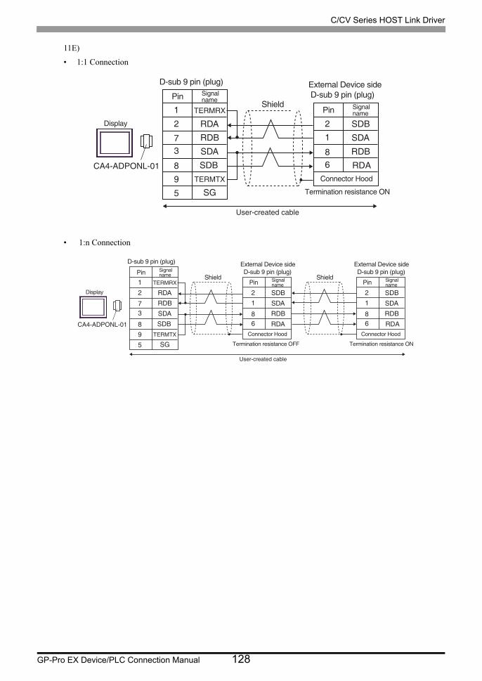
C/CV Series HOST Link Driver
GP-Pro EX Device/PLC Connection Manual 128
11E)
• 1:1 Connection
• 1:n Connection
TERMRX
RDA
SG
RDBSDASDB
TERMTX
8
21
5
37
9CA4-ADPONL-01
SDBSDARDBRDA
21
68
Display
External Device side D-sub 9 pin (plug)
D-sub 9 pin (plug)
Shield
Termination resistance ON
Pin Signalname
Pin Signalname
Connector Hood
User-created cable
TERMRX
RDA
SG
RDBSDASDB
TERMTX
8
21
5
37
9CA4-ADPONL-01
SDBSDARDBRDA
21
68
SDBSDARDBRDA
21
68
Display
External Device side D-sub 9 pin (plug)
D-sub 9 pin (plug)
Shield
External Device side D-sub 9 pin (plug)
Shield
Termination resistance ON
Pin SignalnamePin Signal
name
Pin Signalname
Connector Hood
Termination resistance OFF
Connector Hood
User-created cable

C/CV Series HOST Link Driver
GP-Pro EX Device/PLC Connection Manual 129
11F)
• 1:1 Connection
• 1:n Connection
*1 The resistance in the Display is used as the termination resistance. Set the value of the DIP Switch on the rear of the Display as shown in the table below.
DIP Switch No. Set Value
1 OFF
2 ON
3 OFF
4 ON
RDARDB
ERB
SDASDBSGCSB
CSAERA
: ON
SDBSDARDBRDA
Display
Terminationresistance*1
Shield
External Device sideD-sub 9 pin (plug)
Pin Signalname
Terminationresistance*1
Terminationresistance
Signalname
Connector Hood
21
68
Terminal blockDisplay side
RDARDB
ERB
SDASDBSGCSB
CSAERA
: OFF
SDBSDARDBRDA
21
68
SDBSDARDBRDA
21
68Display
Terminationresistance*1
Shield
External Device sideD-sub 9 pin (plug)
Pin Signalname
Terminationresistance*1
Signalname
External Device sideD-sub 9 pin (plug)
Pin Signalname
Shield
Connector Hood Connector Hood
Terminationresistance : ONTermination
resistance
Terminal blockDisplay side
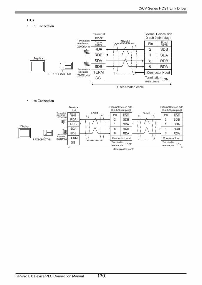
C/CV Series HOST Link Driver
GP-Pro EX Device/PLC Connection Manual 130
11G)
• 1:1 Connection
• 1:n Connection
RDARDBSDASDB
SGTERM
: ON
SDBSDARDBRDA
21
68
Display
Terminationresistance
TerminalblockSignalname
Shield
External Device sideD-sub 9 pin (plug)
Pin Signalname
PFXZCBADTM1 Connector HoodTerminationresistance
Terminationresistance
User-created cable
RDARDBSDASDB
SGTERM
: OFF
SDBSDARDBRDA
21
68
SDBSDARDBRDA
21
68
Display
Terminationresistance
TerminalblockSignalname
Shield
External Device sideD-sub 9 pin (plug)
Pin Signalname
PFXZCBADTM1
Shield
Terminationresistance : ON
Terminationresistance
Connector Hood Connector Hood
External Device sideD-sub 9 pin (plug)
Pin Signalname
Terminationresistance
User-created cable

C/CV Series HOST Link Driver
GP-Pro EX Device/PLC Connection Manual 131
11H)
• 1:1 Connection
• 1:n Connection
Rx-Rx+
Tx-
GNDNCNCNCNC
Tx+
5
43
9
12
6
87
: ON
SDBSDARDBRDA
Display
Terminationresistance
Shield
External Device sideD-sub 9 pin (plug)
Pin Signalname
Terminationresistance
Terminationresistance
D-sub 9 pin (socket)
Pin Signalname
Connector Hood
21
68
Display side
Rx-Rx+
Tx-GNDNCNCNCNC
Tx+
5
43
9
12
6
87
: OFF
SDBSDARDBRDA
21
68
SDBSDARDBRDA
21
68Display
Terminationresistance
Shield
External Device sideD-sub 9 pin (plug)
Pin Signalname
Terminationresistance
D-sub 9 pin (socket)
Pin Signalname
External Device sideD-sub 9 pin (plug)
Pin Signalname
Shield
Connector Hood Connector Hood
Terminationresistance : ONTermination
resistance
Display side

C/CV Series HOST Link Driver
GP-Pro EX Device/PLC Connection Manual 132
Cable Diagram 12
12A)
Display Cable Remarks
GP3000 (COM1)GP4000*1 (COM1)SP5000*2 (COM1/2)SP-5B00 (COM1)ST (COM1)LT3000 (COM1)IPC*3
PC/AT
*1 All GP4000 models except GP-4100 Series and GP-4203T
*2 Except SP-5B00
*3 Only the COM port which can communicate by RS-232C can be used.
" IPC COM Port" (page 12)
12A User-created cableThe cable length must be 15m or less.
GP-4105 (COM1)GP-4115T (COM1) GP-4115T3 (COM1)
12B User-created cableThe cable length must be 15m or less.
LT-4*01TM (COM1)LT-Rear Module (COM1)
12CRJ45 RS-232C Cable (5m) by Pro-face
PFXZLMCBRJR21The cable length must be 5m or less.
SG5
23
87
SG
4
23
95
Display
External DeviceD-sub 9 pin (plug)External Device sideD-sub 9 pin (plug)D-sub 9 pin (socket)
Shield
Connector Hood
Pin SignalnamePin Signal
name
Display side
SD(TXD)RD(RXD)
RS(RTS)
CS(CTS)
SD(TXD)RD(RXD)
RS(RTS)
CS(CTS)

C/CV Series HOST Link Driver
GP-Pro EX Device/PLC Connection Manual 133
12B)
12C)
Number Name Notes
(1)RJ45 RS-232C Cable (5m) by Pro-face
PFXZLMCBRJR21
SG SG
4
23
95
Display
D-sub 9 pin (plug)External Device sideD-sub 9 pin (plug)
Shield
Connector Hood
Pin Signalname
Signalname
SD(TXD)RD(RXD)
RS(RTS)
CS(CTS)
SD(TXD)RD(RXD)
RS(RTS)
CS(CTS)
Terminal blockDisplay side
SG
4
23
95
External DeviceD-sub 9 pin (plug)External Device sideD-sub 9 pin (plug)
Connector Hood
Pin Signalname
SD(TXD)RD(RXD)
RS(RTS)
CS(CTS)
Display
GND
TXD
RXD
(1)
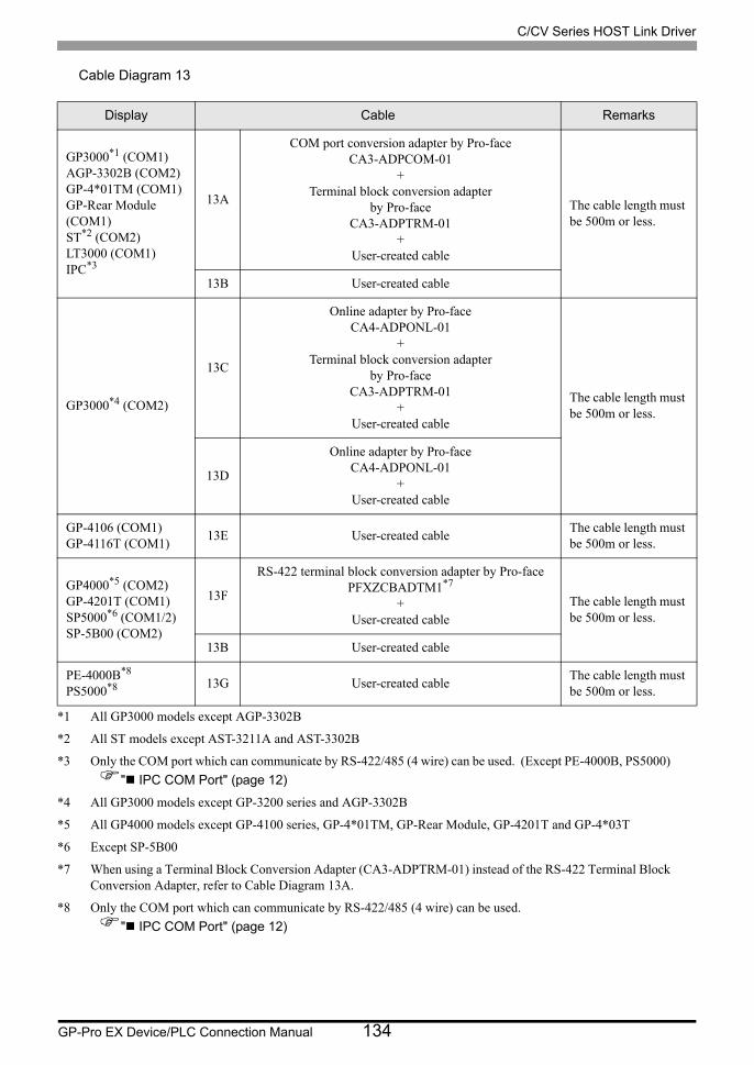
C/CV Series HOST Link Driver
GP-Pro EX Device/PLC Connection Manual 134
Cable Diagram 13
Display Cable Remarks
GP3000*1 (COM1)AGP-3302B (COM2)GP-4*01TM (COM1)GP-Rear Module (COM1)ST*2 (COM2)LT3000 (COM1)IPC*3
*1 All GP3000 models except AGP-3302B
*2 All ST models except AST-3211A and AST-3302B
*3 Only the COM port which can communicate by RS-422/485 (4 wire) can be used. (Except PE-4000B, PS5000)
" IPC COM Port" (page 12)
13A
COM port conversion adapter by Pro-faceCA3-ADPCOM-01
+Terminal block conversion adapter
by Pro-faceCA3-ADPTRM-01
+User-created cable
The cable length must be 500m or less.
13B User-created cable
GP3000*4 (COM2)
*4 All GP3000 models except GP-3200 series and AGP-3302B
13C
Online adapter by Pro-faceCA4-ADPONL-01
+Terminal block conversion adapter
by Pro-faceCA3-ADPTRM-01
+User-created cable
The cable length must be 500m or less.
13D
Online adapter by Pro-faceCA4-ADPONL-01
+User-created cable
GP-4106 (COM1)GP-4116T (COM1)
13E User-created cableThe cable length must be 500m or less.
GP4000*5 (COM2)GP-4201T (COM1)SP5000*6 (COM1/2)SP-5B00 (COM2)
*5 All GP4000 models except GP-4100 series, GP-4*01TM, GP-Rear Module, GP-4201T and GP-4*03T
*6 Except SP-5B00
13F
RS-422 terminal block conversion adapter by Pro-facePFXZCBADTM1*7
+User-created cable
*7 When using a Terminal Block Conversion Adapter (CA3-ADPTRM-01) instead of the RS-422 Terminal Block Conversion Adapter, refer to Cable Diagram 13A.
The cable length must be 500m or less.
13B User-created cable
PE-4000B*8
PS5000*8
*8 Only the COM port which can communicate by RS-422/485 (4 wire) can be used.
" IPC COM Port" (page 12)
13G User-created cableThe cable length must be 500m or less.

C/CV Series HOST Link Driver
GP-Pro EX Device/PLC Connection Manual 135
13A)
• 1:1 Connection
• 1:n Connection
• When the display unit you use is an IPC, turn ON the DIP switches 5 and 6 to insert the
termination resistance.
• When the port on the External Device does not have a SG terminal, SG connection is
unnecessary.
RDARDBSDASDB
SGTERMCA3-ADPTRM-01
CA3-ADPCOM-01
SDBSDA
SG
RDBRDARSCS
4
12
9
68
5
Display
Terminationresistance
Terminal blockExternal Device side D-sub 9 pin (plug)
ShieldPin Signal
nameSignalname
Connector Hood
Terminationresistance
User-created cable
RDARDBSDASDB
SGTERMCA3-ADPTRM-01
CA3-ADPCOM-01
SDBSDA
SG
RDBRDARSCS
4
12
9
68
5
SDBSDA
SG
RDBRDARSCS
4
12
9
68
5
Display
Terminationresistance
Terminal blockExternal Device side D-sub 9 pin (plug)
Shield
External Device side D-sub 9 pin (plug)
ShieldPin Signal
name PinSignalname
Connector HoodConnector Hood
Terminationresistance
User-created cable

C/CV Series HOST Link Driver
GP-Pro EX Device/PLC Connection Manual 136
13B)
• 1:1 Connection
• 1:n Connection
• When the display unit you use is an IPC, turn ON the DIP switches 5 and 6 to insert the
termination resistance.
• When the port on the External Device does not have a SG terminal, SG connection is
unnecessary.
RDARDB
ERB
SDASDBSGCSB
5
21
9
73
6
CSA8ERA4
SDBSDA
SG
RDBRDARSCS
4
12
9
68
5
Display
Terminationresistance
Terminationresistance
External Device side D-sub 9 pin (plug)D-sub 9 pin (socket)
ShieldPin Signal
name Pin Signalname
Connector Hood
Display side
RDARDB
ERB
SDASDBSGCSB
5
21
9
73
6
CSA8ERA4
220 1/4W
SDBSDA
SG
RDBRDARSCS
4
12
9
68
5
SDBSDA
SG
RDBRDARSCS
4
12
9
68
5
Display
Terminationresistance
Terminationresistance
External Device side D-sub 9 pin (plug)D-sub 9 pin (socket)
Shield
External Device side D-sub 9 pin (plug)
ShieldPin Signal
name Pin Signalname Pin Signal
name
Connector Hood Connector Hood
Display side

C/CV Series HOST Link Driver
GP-Pro EX Device/PLC Connection Manual 137
13C)
• 1:1 Connection
• 1:n Connection
• When the port on the External Device does not have a SG terminal, SG connection is unnecessary.
RDARDBSDASDB
SGTERMCA3-ADPTRM-01
CA4-ADPONL-01
SDBSDA
SG
RDBRDARSCS
4
12
9
68
5
Display
Terminationresistance
External Device side D-sub 9 pin (plug)
ShieldTerminal block
Pin Signalname
Signalname
Connector Hood
User-created cable
RDARDBSDASDB
SGTERM
220 1/4W
CA3-ADPTRM-01
CA4-ADPONL-01
SDBSDA
SG
RDBRDARSCS
4
12
9
68
5
SDBSDA
SG
RDBRDARSCS
4
12
9
68
5
Display
Terminationresistance
External Device side D-sub 9 pin (plug)
Shield
External Device side D-sub 9 pin (plug)
ShieldTerminal block
Pin Signalname Pin Signal
nameSignalname
Connector Hood Connector Hood
User-created cable

C/CV Series HOST Link Driver
GP-Pro EX Device/PLC Connection Manual 138
13D)
• 1:1 Connection
• 1:n Connection
• When the port on the External Device does not have a SG terminal, SG connection is unnecessary.
TERMRX
RDA
SG
RDBSDASDB
TERMTX
8
21
5
37
9CA4-ADPONL-01
SDBSDA
SG
RDBRDARSCS
4
12
9
68
5
Display
External Device side D-sub 9 pin (plug)
D-sub 9 pin (plug)
ShieldPin Signal
namePin Signal
name
Connector Hood
User-created cable
TERMRX
RDA
SG
RDBSDASDB
TERMTX
8
21
5
37
9CA4-ADPONL-01
SDBSDA
SG
RDBRDARSCS
4
12
9
68
5
SDBSDA
SG
RDBRDARSCS
4
12
9
68
5
Display
External Device side D-sub 9 pin (plug)
D-sub 9 pin (plug)
Shield
External Device side D-sub 9 pin (plug)
ShieldPin Signal
namePin Signal
name Pin Signalname
Connector Hood Connector Hood
User-created cable

C/CV Series HOST Link Driver
GP-Pro EX Device/PLC Connection Manual 139
13E)
• 1:1 Connection
• 1:n Connection
*1 The resistance in the Display is used as the termination resistance. Set the value of the DIP Switch on the rear of the Display as shown in the table below.
DIP Switch No. Set Value
1 OFF
2 ON
3 OFF
4 ON
• When the port on the External Device does not have a SG terminal, SG connection is unnecessary.
RDARDB
ERB
SDASDBSGCSB
CSAERA
SDBSDA
SG
RDBRDARSCS
4
12
9
68
5
Display
Terminationresistance*1
Terminationresistance*1
External Device sideD-sub 9 pin (plug)
ShieldSignalname Pin Signal
name
Connector Hood
Terminal blockDisplay side
RDARDB
ERB
SDASDBSGCSB
CSAERA
SDBSDA
SG
RDBRDARSCS
4
12
9
68
5
SDBSDA
SG
RDBRDARSCS
4
12
9
68
5
Display
Terminationresistance*1
Terminationresistance*1
Shield ShieldSignalname Pin Signal
name Pin Signalname
Connector Hood Connector Hood
Terminal blockDisplay side External Device side
D-sub 9 pin (plug)External Device side D-sub 9 pin (plug)

C/CV Series HOST Link Driver
GP-Pro EX Device/PLC Connection Manual 140
13F)
• 1:1 Connection
• 1:n Connection
• When the port on the External Device does not have a SG terminal, SG connection is unnecessary.
RDARDBSDASDB
SGTERMPFXZCBADTM1
SDBSDA
SG
RDBRDARSCS
4
12
9
68
5
Display
Terminationresistance
Terminal blockExternal Device side D-sub 9 pin (plug)
ShieldPin Signal
nameSignalname
Connector Hood
Terminationresistance
User-created cable
RDARDBSDASDB
SGTERMPFXZCBADTM1
SDBSDA
SG
RDBRDARSCS
4
12
9
68
5
SDBSDA
SG
RDBRDARSCS
4
12
9
68
5
Display
Terminationresistance
Terminal blockExternal Device side D-sub 9 pin (plug)
Shield
External Device side D-sub 9 pin (plug)
ShieldPin Signal
name PinSignalname
Connector HoodConnector Hood
Terminationresistance
User-created cable

C/CV Series HOST Link Driver
GP-Pro EX Device/PLC Connection Manual 141
13G)
• 1:1 Connection
• 1:n Connection
• When the port on the External Device does not have a SG terminal, SG connection is unnecessary.
Rx-Rx+
Tx-GNDNCNCNCNC
Tx+
5
43
9
12
6
87
SDBSDA
SG
RDBRDARSCS
4
12
9
68
5
Display
Terminationresistance
Terminationresistance
External Device side D-sub 9 pin (plug)D-sub 9 pin (socket)
ShieldPin Signal
name Pin Signalname
Connector Hood
Display side
Rx-Rx+
Tx-GNDNCNCNCNC
Tx+
5
43
9
12
6
87
220 1/4W
SDBSDA
SG
RDBRDARSCS
4
12
9
68
5
SDBSDA
SG
RDBRDARSCS
4
12
9
68
5
Display
Terminationresistance
Terminationresistance
External Device side D-sub 9 pin (plug)D-sub 9 pin (socket)
Shield
External Device side D-sub 9 pin (plug)
ShieldPin Signal
name Pin Signalname Pin Signal
name
Connector Hood Connector Hood
Display side

C/CV Series HOST Link Driver
GP-Pro EX Device/PLC Connection Manual 142
Cable Diagram 14
Display
(Connection Port)Cable Notes
GP3000*1 (COM1)AGP-3302B (COM2)GP-4*01TM (COM1)GP-Rear Module (COM1)ST *2 (COM2)LT3000 (COM1)IPC*3
*1 All GP3000 models except AGP-3302B
*2 All ST models except AST-3211A and AST-3302B
14A
COM port conversion adapter by Pro-faceCA3-ADPCOM-01
+Connector terminal block conversion adapter by Pro-face
CA3-ADPTRM-01+
User-created cableCable length: 500m max
14B
COM port conversion adapter by Pro-faceCA3-ADPCOM-01
+Multilink cable by Pro-face
CA3-CBLMLT-01+
User-created cable
14C User-created cable
GP3000 *4 (COM2)
14D
Online adapter by Pro-faceCA4-ADPONL-01
+Connector terminal block conversion adapter by Pro-face
CA3-ADPTRM-0+
User-created cable
Cable length: 500m max
14E
Online adapter by Pro-faceCA4-ADPONL-01
+Multilink cable by Pro-face
CA3-CBLMLT-01+
User-created cable
14F
Online adapter by Pro-faceCA4-ADPONL-01
+User-created cable
GP-4106 (COM1)GP-4116T (COM1)
14G User-created cableCable length: 500m max
GP4000*5 (COM2)GP-4201T (COM1)SP5000*6 (COM1/2)SP-5B00 (COM2)
14H
RS-422 terminal block conversion adapter by Pro-facePFXZCBADTM1*7
+User-created cable
Cable length: 500m max
14I
Multilink cable by Pro-facePFXZCBCBML1*8
+User-created cable
14C User-created cable
PE-4000B*9
PS5000*9 14J User-created cableCable length: 500m max

C/CV Series HOST Link Driver
GP-Pro EX Device/PLC Connection Manual 143
14A)
*3 Only the COM port which can communicate by RS-422/485 (4 wire) can be used. (Except PE-4000B, PS5000)
" IPC COM Port" (page 12)
*4 All GP3000 models except GP-3200 series and AGP-3302B
*5 All GP4000 models except GP-4100 series, GP-4*01TM, GP-Rear Module, GP-4201T and GP-4*03T
*6 Except SP-5B00
*7 When using a Terminal Block Conversion Adapter (CA3-ADPTRM-01) instead of the RS-422 Terminal Block Conversion Adapter, refer to Cable Diagram 14A.
*8 When using a Multilink Cable (CA3-CBLMLT-01) instead of the Multilink Cable, refer to Cable Diagram 14B.
*9 Only the COM port which can communicate by RS-422/485 (4 wire) can be used.
" IPC COM Port" (page 12)
CA3-ADPTRM-01
CA3-ADPCOM-01
CA3-ADPTRM-01
CA3-ADPCOM-01
RDA
RDB
SDA
SDB
SG
TRM
RDA
RDB
SDA
SDB
SG SG
FG
5
9
1
6
3
7
Shield Shield
User-created cable
SDB
SDA
RDB
RDA
FG
Terminationresistance220Ω 1/4W
Terminationresistance220Ω 1/4W
Terminalblock
Signal name
Terminalblock
Signal name Pin
External Device sideD-Sub 9 pin (plug)
Signal name
Display Display

C/CV Series HOST Link Driver
GP-Pro EX Device/PLC Connection Manual 144
14B)
CA3-CBLMLT-01
CA3-ADPCOM-01
CA3-CBLMLT-01
CA3-ADPCOM-01
RDA
RDB
SDA
SDB
SG
FG
RDA
RDB
SDA
SDB
SG
FG
Terminationresistance220Ω 1/4W
Terminationresistance220Ω 1/4W
Terminalblock
(M3 screw)
Signal name
Terminalblock
(M3 screw)
Signal nameShield Shield
User-created cable
Display Display
SG
5
9
1
6
3
7
SDB
SDA
RDB
RDA
FG
Pin
External Device sideD-Sub 9 pin (plug)
Signal name

C/CV Series HOST Link Driver
GP-Pro EX Device/PLC Connection Manual 145
14C)
14D)
RDARDB
CSA
SDASDBSG
ERA5
21
8
73
4
96
ERBCSB
RDA
RDB
SDA
SDB
FG
SG
RDA
RDB
SDA
SDB
FG
SG
RDARDB
CSA
SDASDBSG
ERA5
21
8
73
4
96
ERBCSB
RDA
RDB
SDA
SDB
FG
SG
Terminationresistance220Ω 1/4W
Terminationresistance220Ω 1/4W
Display
Signal name
D-sub 9 pin (socket)
Pin
Display
Signal name
D-sub 9 pin (socket)
Pin
Signal name
Terminal block(M3 screw)
Signal name
Terminal block(M3 screw)
Signal name
SG
5
9
1
6
3
7
SDB
SDA
RDB
RDA
FG
Pin Signal name
Shield Shield
Shield
ShieldExternal Device sideD-Sub 9 pin (plug)
CA3-ADPTRM-01
CA4-ADPONL-01
CA3-ADPTRM-01
CA4-ADPONL-01
RDA
RDB
SDA
SDB
SG
TRM
RDA
RDB
SDA
SDB
SG
FG
Shield Shield
User-created cable
Terminationresistance220Ω 1/4W
Terminationresistance220Ω 1/4W
Terminalblock
Signal name
Terminalblock
Signal name
Display Display
SG
5
9
1
6
3
7
SDB
SDA
RDB
RDA
FG
Pin Signal name
External Device sideD-Sub 9 pin (plug)

C/CV Series HOST Link Driver
GP-Pro EX Device/PLC Connection Manual 146
14E)
14F)
CA3-CBLMLT-01
CA4-ADPONL-01
CA3-CBLMLT-01
CA4-ADPONL-01
RDA
RDB
SDA
SDB
SG
FG
RDA
RDB
SDA
SDB
SG
FG
Shield Shield
User-created cable
Terminationresistance220Ω 1/4W
Terminationresistance220Ω 1/4W
Terminalblock
(M3 screw)Signal name
Display Display
Terminalblock
(M3 screw)Signal name
SG
5
9
1
6
3
7
SDB
SDA
RDB
RDA
FG
Pin Signal name
External Device sideD-Sub 9 pin (plug)
RDATERMRX
TERMTX
RDBSDASDBSG5
9
721
83Display
Signal name
D-sub 9 pin (plug)
Pin
RDATERMRX
TERMTX
RDBSDASDBSG5
9
721
83
Signal name
D-sub 9 pin (plug)
Pin
RDA
RDB
SDA
SDB
FG
SG
Signal name
Terminal block(M3 screw)
RDA
RDB
SDA
SDB
FG
SG
Signal name
Terminal block(M3 screw)
Display
RDA
RDB
SDA
SDB
FG
SG
Signal name
CA4-ADPONL-01
CA4-ADPONL-01
Terminationresistance220Ω 1/4W
Terminationresistance220Ω 1/4W
SG
5
9
1
6
3
7
SDB
SDA
RDB
RDA
FG
Pin Signal name
External Device sideD-Sub 9 pin (plug)Shield Shield
Shield
Shield

C/CV Series HOST Link Driver
GP-Pro EX Device/PLC Connection Manual 147
14G)
*1 The resistance in the Display is used as the termination resistance. Set the value of the DIP Switch on the rear of the Display as shown in the table below.
For the Displays other than that used as the terminal, set the DIP Switch 1-4 on the rear of the Display to OFF in the n:1 connection.
DIP Switch No. Set Value
1 OFF
2 ON
3 OFF
4 ON
RDARDB
CSA
SDASDBSG
ERA
ERBCSB
Terminationresistance*1
Terminationresistance*1
Display
Signal name
SG
5
9
1
6
3
7
SDB
SDA
RDB
RDA
FG
Pin Signal name
Shield Shield Terminal blockDisplay side
RDARDB
CSA
SDASDBSG
ERA
ERBCSB
Signal name
Terminal blockDisplay side
Display
External Device sideD-Sub 9 pin (plug)

C/CV Series HOST Link Driver
GP-Pro EX Device/PLC Connection Manual 148
14H)
14I)
PFXZCBADTM1 PFXZCBADTM1
RDA
RDB
SDA
SDB
SG
TRM
RDA
RDB
SDA
SDB
SG SG
FG
5
9
1
6
3
7
Shield Shield
User-created cable
SDB
SDA
RDB
RDA
FG
Termination resistance 220Ω 1/4W
Termination resistance 220Ω 1/4W
Terminal block
Signal name
Terminal block
Signal name Pin
External Device side D-Sub 9 pin (plug)
Signal name
Display Display
PFXZCBCBML1 PFXZCBCBML1
RDA
RDB
SDA
SDB
SG
FG
RDA
RDB
SDA
SDB
SG
FG
Termination resistance 220Ω 1/4W
Termination resistance 220Ω 1/4W
Terminal block
(M3 screw)
Signal name
Terminal block
(M3 screw)
Signal name Shield Shield
User-created cable
Display Display
SG
5
9
1
6
3
7
SDB
SDA
RDB
RDA
FG
Pin
External Device side D-Sub 9 pin (plug)
Signal name

C/CV Series HOST Link Driver
GP-Pro EX Device/PLC Connection Manual 149
14J)
Rx+Rx-Tx+Tx-
GNDNCNCNCNC
5
43
8
12
7
96
Rx+Rx-Tx+Tx-
GNDNCNCNCNC
5
43
8
12
7
96
Rx+Rx-Tx+Tx-
GNDFG
Rx+Rx-Tx+Tx-
GNDFG
Rx+Rx-Tx+Tx-
GNDFG
Terminationresistance220Ω 1/4W
Terminationresistance220Ω 1/4W
Display
Signal name
D-sub 9 pin (socket)
Pin
Display
Signal name
D-sub 9 pin (socket)
Pin
Signal name
Terminal block(M3 screw)
Signal name
Terminal block(M3 screw)
Signal name
SG
5
9
1
6
3
7
SDB
SDA
RDB
RDA
FG
Pin Signal name
Shield Shield
Shield
ShieldExternal Device sideD-Sub 9 pin (plug)

C/CV Series HOST Link Driver
GP-Pro EX Device/PLC Connection Manual 150
Cable Diagram 15
Display
(Connection Port)Cable Notes
GP3000*1 (COM1)AGP-3302B (COM2)GP-4*01TM (COM1)GP-Rear Module (COM1)ST *2 (COM2)LT3000 (COM1)IPC*3
*1 All GP3000 models except AGP-3302B
*2 All ST models except AST-3211A and AST-3302B
15A
COM port conversion adapter by Pro-faceCA3-ADPCOM-01
+Connector terminal block conversion adapter by Pro-face
CA3-ADPTRM-01+
User-created cableCable length: 500m max
15B
COM port conversion adapter by Pro-faceCA3-ADPCOM-01
+Multilink cable by Pro-face
CA3-CBLMLT-01+
User-created cable
15C User-created cable
GP3000 *4 (COM2)
15D
Online adapter by Pro-faceCA4-ADPONL-01
+Connector terminal block conversion adapter by Pro-face
CA3-ADPTRM-0+
User-created cable
Cable length: 500m max
15E
Online adapter by Pro-faceCA4-ADPONL-01
+Multilink cable by Pro-face
CA3-CBLMLT-01+
User-created cable
15F
Online adapter by Pro-faceCA4-ADPONL-01
+User-created cable
GP-4106 (COM1)GP-4116T (COM1)
15G User-created cableCable length: 500m max
GP4000*5 (COM2)GP-4201T (COM1)SP5000*6 (COM1/2)SP-5B00 (COM2)
15H
RS-422 terminal block conversion adapter by Pro-facePFXZCBADTM1*7
+User-created cable
Cable length: 500m max
15I
Multilink cable by Pro-facePFXZCBCBML1*8
+User-created cable
15C User-created cable
PE-4000B*9
PS5000*9 15J User-created cableCable length: 500m max

C/CV Series HOST Link Driver
GP-Pro EX Device/PLC Connection Manual 151
*3 Only the COM port which can communicate by RS-422/485 (4 wire) can be used. (Except PE-4000B, PS5000)
" IPC COM Port" (page 12)
*4 All GP3000 models except GP-3200 series and AGP-3302B
*5 All GP4000 models except GP-4100 series, GP-4*01TM, GP-Rear Module, GP-4201T and GP-4*03T
*6 Except SP-5B00
*7 When using a Terminal Block Conversion Adapter (CA3-ADPTRM-01) instead of the RS-422 Terminal Block Conversion Adapter, refer to Cable Diagram 15A.
*8 When using a Multilink Cable (CA3-CBLMLT-01) instead of the Multilink Cable, refer to Cable Diagram 15B.
*9 Only the COM port which can communicate by RS-422/485 (4 wire) can be used.
" IPC COM Port" (page 12)

C/CV Series HOST Link Driver
GP-Pro EX Device/PLC Connection Manual 152
15A)
15B)
CA3-ADPTRM-01
CA3-ADPCOM-01
CA3-ADPTRM-01
CA3-ADPCOM-01
RDA
RDB
SDA
SDB
SG
TRM
RDA
RDB
SDA
SDB
SG
FG
5
9
1
6
7
Shield Shield
User-created cable
SDB
SDA
RDB
RDA
FG
Terminationresistance220Ω 1/4W
Terminationresistance220Ω 1/4W
Terminalblock
Signal name
Terminalblock
Signal name Pin
External Device sideD-Sub 9 pin (plug)
Signal name
Display Display
CA3-CBLMLT-01
CA3-ADPCOM-01
CA3-CBLMLT-01
CA3-ADPCOM-01
RDA
RDB
SDA
SDB
SG
FG
RDA
RDB
SDA
SDB
SG
FG
Terminationresistance220Ω 1/4W
Terminationresistance220Ω 1/4W
Terminalblock
(M3 screw)
Signal name
Terminalblock
(M3 screw)
Signal nameShield Shield
User-created cable
Display Display
5
9
1
6
7
SDB
SDA
RDB
RDA
FG
Pin
External Device sideD-Sub 9 pin (plug)
Signal name

C/CV Series HOST Link Driver
GP-Pro EX Device/PLC Connection Manual 153
15C)
15D)
RDARDB
CSA
SDASDBSG
ERA5
21
8
73
4
96
ERBCSB
RDA
RDB
SDA
SDB
FG
SG
RDA
RDB
SDA
SDB
FG
SG
RDARDB
CSA
SDASDBSG
ERA5
21
8
73
4
96
ERBCSB
RDA
RDB
SDA
SDB
FG
SG
Terminationresistance220Ω 1/4W
Terminationresistance220Ω 1/4W
Display
Signal name
D-sub 9 pin (socket)
Pin
Display
Signal name
D-sub 9 pin (socket)
Pin
Signal name
Terminal block(M3 screw)
Signal name
Terminal block(M3 screw)
Signal name
Shield Shield
Shield
Shield
5
9
1
6
7
SDB
SDA
RDB
RDA
FG
Pin
External Device sideD-Sub 9 pin (plug)
Signal name
CA3-ADPTRM-01
CA4-ADPONL-01
CA3-ADPTRM-01
CA4-ADPONL-01
RDA
RDB
SDA
SDB
SG
TRM
RDA
RDB
SDA
SDB
SG
FG
Shield Shield
User-created cable
Terminationresistance220Ω 1/4W
Terminationresistance220Ω 1/4W
Terminalblock
Signal name
Terminalblock
Signal name
Display Display
5
9
1
6
7
SDB
SDA
RDB
RDA
FG
Pin
External Device sideD-Sub 9 pin (plug)
Signal name

C/CV Series HOST Link Driver
GP-Pro EX Device/PLC Connection Manual 154
15E)
15F)
CA3-CBLMLT-01
CA4-ADPONL-01
CA3-CBLMLT-01
CA4-ADPONL-01
RDA
RDB
SDA
SDB
SG
FG
RDA
RDB
SDA
SDB
SG
FG
Shield Shield
User-created cable
Terminationresistance220Ω 1/4W
Terminationresistance220Ω 1/4W
Terminalblock
(M3 screw)Signal name
Display Display
Terminalblock
(M3 screw)Signal name
5
9
1
6
7
SDB
SDA
RDB
RDA
FG
Pin
External Device sideD-Sub 9 pin (plug)
Signal name
RDATERMRX
TERMTX
RDBSDASDBSG5
9
721
83Display
Signal name
D-sub 9 pin (plug)
Pin
RDATERMRX
TERMTX
RDBSDASDBSG5
9
721
83
Signal name
D-sub 9 pin (plug)
Pin
RDA
RDB
SDA
SDB
FG
SG
Signal name
Terminal block(M3 screw)
RDA
RDB
SDA
SDB
FG
SG
Signal name
Terminal block(M3 screw)
Display
RDA
RDB
SDA
SDB
FG
SG
Signal name
CA4-ADPONL-01
CA4-ADPONL-01
Terminationresistance220Ω 1/4W
Terminationresistance220Ω 1/4W
Shield Shield
Shield
Shield
5
9
1
6
7
SDB
SDA
RDB
RDA
FG
Pin
External Device sideD-Sub 9 pin (plug)
Signal name

C/CV Series HOST Link Driver
GP-Pro EX Device/PLC Connection Manual 155
15G)
*1 The resistance in the Display is used as the termination resistance. Set the value of the DIP Switch on the rear of the Display as shown in the table below.
For the Displays other than that used as the terminal, set the DIP Switch 1-4 on the rear of the Display to OFF in the n:1 connection.
DIP Switch No. Set Value
1 OFF
2 ON
3 OFF
4 ON
RDARDB
CSA
SDASDBSG
ERA
ERBCSB
Terminationresistance*1
Terminationresistance*1
Display
Signal name
Shield Shield
5
9
1
6
7
SDB
SDA
RDB
RDA
FG
Pin
External Device sideD-Sub 9 pin (plug)
Signal name
Terminal blockDisplay side
RDARDB
CSA
SDASDBSG
ERA
ERBCSB
Signal name
Terminal blockDisplay side
Display

C/CV Series HOST Link Driver
GP-Pro EX Device/PLC Connection Manual 156
15H)
15I)
PFXZCBADTM1 PFXZCBADTM1
RDA
RDB
SDA
SDB
SG
TRM
RDA
RDB
SDA
SDB
SG
FG
5
9
1
6
7
Shield Shield
User-created cable
SDB
SDA
RDB
RDA
FG
Termination resistance 220Ω 1/4W
Termination resistance 220Ω 1/4W
Terminal block
Signal name
Terminal block
Signal name Pin
External Device side D-Sub 9 pin (plug)
Signal name
Display Display
PFXZCBCBML1 PFXZCBCBML1
RDA
RDB
SDA
SDB
SG
FG
RDA
RDB
SDA
SDB
SG
FG
Termination resistance 220Ω 1/4W
Termination resistance 220Ω 1/4W
Terminal block
(M3 screw)
Signal name
Terminal block
(M3 screw)
Signal name Shield Shield
User-created cable
Display Display
5
9
1
6
7
SDB
SDA
RDB
RDA
FG
Pin
External Device side D-Sub 9 pin (plug)
Signal name

C/CV Series HOST Link Driver
GP-Pro EX Device/PLC Connection Manual 157
15J)
Terminationresistance220Ω 1/4W
Terminationresistance220Ω 1/4W
Display
Signal name
D-sub 9 pin (socket)
Pin
Display
Signal name
D-sub 9 pin (socket)
Pin
Signal name
Terminal block(M3 screw)
Signal name
Terminal block(M3 screw)
Signal name
Shield Shield
Shield
Shield
59167
SDBSDARDBRDAFG
Pin
External Device sideD-Sub 9 pin (plug)
Signal name
Rx+Rx-Tx+Tx-
GNDNCNCNCNC
5
43
8
12
7
96
Rx+Rx-Tx+Tx-
GNDNCNCNCNC
5
43
8
12
7
96
Rx+Rx-Tx+Tx-
GNDFG
Rx+Rx-Tx+Tx-
GNDFG
Rx+Rx-Tx+Tx-
GNDFG

C/CV Series HOST Link Driver
GP-Pro EX Device/PLC Connection Manual 158
Cable Diagram 16
Display
(Connection Port)Cable Notes
GP3000*1 (COM1)AGP-3302B (COM2)GP-4*01TM (COM1)GP-Rear Module (COM1)ST *2 (COM2)LT3000 (COM1)IPC*3
*1 All GP3000 models except AGP-3302B
*2 All ST models except AST-3211A and AST-3302B
16A
COM port conversion adapter by Pro-faceCA3-ADPCOM-01
+Connector terminal block conversion adapter by Pro-face
CA3-ADPTRM-01+
User-created cableCable length: 500m max
16B
COM port conversion adapter by Pro-faceCA3-ADPCOM-01
+Multilink cable by Pro-face
CA3-CBLMLT-01+
User-created cable
16C User-created cable
GP3000 *4 (COM2)
16D
Online adapter by Pro-faceCA4-ADPONL-01
+Connector terminal block conversion adapter by Pro-face
CA3-ADPTRM-0+
User-created cable
Cable length: 500m max
16E
Online adapter by Pro-faceCA4-ADPONL-01
+Multilink cable by Pro-face
CA3-CBLMLT-01+
User-created cable
16F
Online adapter by Pro-faceCA4-ADPONL-01
+User-created cable
GP-4106 (COM1)GP-4116T (COM1)
16G User-created cableCable length: 500m max
GP4000*5 (COM2)GP-4201T (COM1)SP5000*6 (COM1/2)SP-5B00 (COM2)
16H
RS-422 terminal block conversion adapter by Pro-facePFXZCBADTM1*7
+User-created cable
Cable length: 500m max
16I
Multilink cable by Pro-facePFXZCBCBML1*8
+User-created cable
16C User-created cable
PE-4000B*9
PS5000*9 16J User-created cableCable length: 500m max

C/CV Series HOST Link Driver
GP-Pro EX Device/PLC Connection Manual 159
*3 Only the COM port which can communicate by RS-422/485 (4 wire) can be used. (Except PE-4000B, PS5000)
" IPC COM Port" (page 12)
*4 All GP3000 models except GP-3200 series and AGP-3302B
*5 All GP4000 models except GP-4100 series, GP-4*01TM, GP-Rear Module, GP-4201T and GP-4*03T
*6 Except SP-5B00
*7 When using a Terminal Block Conversion Adapter (CA3-ADPTRM-01) instead of the RS-422 Terminal Block Conversion Adapter, refer to Cable Diagram 16A.
*8 When using a Multilink Cable (CA3-CBLMLT-01) instead of the Multilink Cable, refer to Cable Diagram 16B.
*9 Only the COM port which can communicate by RS-422/485 (4 wire) can be used.
" IPC COM Port" (page 12)

C/CV Series HOST Link Driver
GP-Pro EX Device/PLC Connection Manual 160
16A)
16B)
CA3-ADPTRM-01
CA3-ADPCOM-01
CA3-ADPTRM-01
CA3-ADPCOM-01
RDA
RDB
SDA
SDB
SG
TRM
RDA
RDB
SDA
SDB
SG SG
FG
Shield Shield
User-created cable
SDB
SDA
RDB
RDA
FG
Terminationresistance220Ω 1/4W
Terminationresistance220Ω 1/4W
Terminalblock
Signal name
Terminalblock
Signal name
External Device side
Signal name
Display Display
CA3-CBLMLT-01
CA3-ADPCOM-01
CA3-CBLMLT-01
CA3-ADPCOM-01
RDA
RDB
SDA
SDB
SG
FG
RDA
RDB
SDA
SDB
SG
FG
Terminationresistance220Ω 1/4W
Terminationresistance220Ω 1/4W
Terminalblock
(M3 screw)
Signal name
Terminalblock
(M3 screw)
Signal nameShield Shield
User-created cable
Display Display
SG
SDB
SDA
RDB
RDA
FG
External Device side
Signal name

C/CV Series HOST Link Driver
GP-Pro EX Device/PLC Connection Manual 161
16C)
16D)
RDARDB
CSA
SDASDBSG
ERA5
21
8
73
4
96
ERBCSB
RDA
RDB
SDA
SDB
FG
SG
RDA
RDB
SDA
SDB
FG
SG
RDARDB
CSA
SDASDBSG
ERA5
21
8
73
4
96
ERBCSB
RDA
RDB
SDA
SDB
FG
SG
Terminationresistance220Ω 1/4W
Terminationresistance220Ω 1/4W
Display
Signal name
D-sub 9 pin (socket)
Pin
Display
Signal name
D-sub 9 pin (socket)
Pin
Signal name
Terminal block(M3 screw)
Signal name
Terminal block(M3 screw)
Signal name
Shield Shield
Shield
Shield
SG
SDB
SDA
RDB
RDA
FG
External Device side
Signal name
CA3-ADPTRM-01
CA4-ADPONL-01
CA3-ADPTRM-01
CA4-ADPONL-01
RDA
RDB
SDA
SDB
SG
TRM
RDA
RDB
SDA
SDB
SG
FG
Shield Shield
User-created cable
Terminationresistance220Ω 1/4W
Terminationresistance220Ω 1/4W
Terminalblock
Signal name
Terminalblock
Signal name
Display Display
SG
SDB
SDA
RDB
RDA
FG
External Device side
Signal name

C/CV Series HOST Link Driver
GP-Pro EX Device/PLC Connection Manual 162
16E)
16F)
CA3-CBLMLT-01
CA4-ADPONL-01
CA3-CBLMLT-01
CA4-ADPONL-01
RDA
RDB
SDA
SDB
SG
FG
RDA
RDB
SDA
SDB
SG
FG
Shield Shield
User-created cable
Terminationresistance220Ω 1/4W
Terminationresistance220Ω 1/4W
Terminalblock
(M3 screw)Signal name
Display Display
Terminalblock
(M3 screw)Signal name
SG
SDB
SDA
RDB
RDA
FG
External Device side
Signal name
RDATERMRX
TERMTX
RDBSDASDBSG5
9
721
83Display
Signal name
D-sub 9 pin (plug)
Pin
RDATERMRX
TERMTX
RDBSDASDBSG5
9
721
83
Signal name
D-sub 9 pin (plug)
Pin
RDA
RDB
SDA
SDB
FG
SG
Signal name
Terminal block(M3 screw)
RDA
RDB
SDA
SDB
FG
SG
Signal name
Terminal block(M3 screw)
Display
RDA
RDB
SDA
SDB
FG
SG
Signal name
CA4-ADPONL-01
CA4-ADPONL-01
Terminationresistance220Ω 1/4W
Terminationresistance220Ω 1/4W
Shield Shield
Shield
Shield
SG
SDB
SDA
RDB
RDA
FG
External Device side
Signal name

C/CV Series HOST Link Driver
GP-Pro EX Device/PLC Connection Manual 163
16G)
*1 The resistance in the Display is used as the termination resistance. Set the value of the DIP Switch on the rear of the Display as shown in the table below.
For the Displays other than that used as the terminal, set the DIP Switch 1-4 on the rear of the Display to OFF in the n:1 connection.
DIP Switch No. Set Value
1 OFF
2 ON
3 OFF
4 ON
RDARDB
CSA
SDASDBSG
ERA
ERBCSB
Terminationresistance*1
Terminationresistance*1
Display
Signal name
Shield Shield
SG
SDB
SDA
RDB
RDA
FG
External Device side
Signal name
Terminal blockDisplay side
RDARDB
CSA
SDASDBSG
ERA
ERBCSB
Signal name
Terminal blockDisplay side
Display
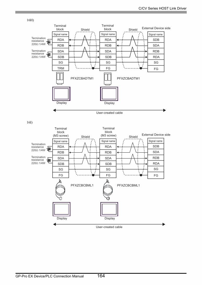
C/CV Series HOST Link Driver
GP-Pro EX Device/PLC Connection Manual 164
16H)
16I)
PFXZCBADTM1 PFXZCBADTM1
RDA
RDB
SDA
SDB
SG
TRM
RDA
RDB
SDA
SDB
SG SG
FG
Shield Shield
User-created cable
SDB
SDA
RDB
RDA
FG
Termination resistance 220Ω 1/4W
Termination resistance 220Ω 1/4W
Terminal block
Signal name
Terminal block
Signal name
External Device side
Signal name
Display Display
PFXZCBCBML1 PFXZCBCBML1
RDA
RDB
SDA
SDB
SG
FG
RDA
RDB
SDA
SDB
SG
FG
Termination resistance 220Ω 1/4W
Termination resistance 220Ω 1/4W
Terminal block
(M3 screw)
Signal name
Terminal block
(M3 screw)
Signal name Shield Shield
User-created cable
Display Display
SG
SDB
SDA
RDB
RDA
FG
External Device side
Signal name

C/CV Series HOST Link Driver
GP-Pro EX Device/PLC Connection Manual 165
16J)
Terminationresistance220Ω 1/4W
Terminationresistance220Ω 1/4W
Display
Signal name
D-sub 9 pin (socket)
Pin
Display
Signal name
D-sub 9 pin (socket)
Pin
Signal name
Terminal block(M3 screw)
Signal name
Terminal block(M3 screw)
Signal name
Shield Shield
Shield
Shield
SG
SDBSDARDBRDA
FG
External Device side
Signal name
Rx+Rx-Tx+Tx-
GNDNCNCNCNC
5
43
8
12
7
96
Rx+Rx-Tx+Tx-
GNDNCNCNCNC
5
43
8
12
7
96
Rx+Rx-Tx+Tx-
GNDFG
Rx+Rx-Tx+Tx-
GNDFG
Rx+Rx-Tx+Tx-
GNDFG

C/CV Series HOST Link Driver
GP-Pro EX Device/PLC Connection Manual 166
Cable Diagram 17
Display
(Connection Port)Cable Notes
GP3000*1 (COM1)AGP-3302B (COM2)GP-4*01TM (COM1)GP-Rear Module (COM1)ST *2 (COM2)LT3000 (COM1)IPC*3
*1 All GP3000 models except AGP-3302B
*2 All ST models except AST-3211A and AST-3302B
17A
COM port conversion adapter by Pro-faceCA3-ADPCOM-01
+Connector terminal block conversion adapter by Pro-face
CA3-ADPTRM-01+
User-created cableCable length: 500m max
17B
COM port conversion adapter by Pro-faceCA3-ADPCOM-01
+Multilink cable by Pro-face
CA3-CBLMLT-01+
User-created cable
17C User-created cable
GP3000 *4 (COM2)
17D
Online adapter by Pro-faceCA4-ADPONL-01
+Connector terminal block conversion adapter by Pro-face
CA3-ADPTRM-0+
User-created cable
Cable length: 500m max
17E
Online adapter by Pro-faceCA4-ADPONL-01
+Multilink cable by Pro-face
CA3-CBLMLT-01+
User-created cable
17F
Online adapter by Pro-faceCA4-ADPONL-01
+User-created cable
GP-4106 (COM1)GP-4116T (COM1)
17G User-created cableCable length: 500m max
GP4000*5 (COM2)GP-4201T (COM1)SP5000*6 (COM1/2)SP-5B00 (COM2)
17H
RS-422 terminal block conversion adapter by Pro-facePFXZCBADTM1*7
+User-created cable
Cable length: 500m max
17I
Multilink cable by Pro-facePFXZCBCBML1*8
+User-created cable
17C User-created cable
PE-4000B*9
PS5000*9 17J User-created cableCable length: 500m max
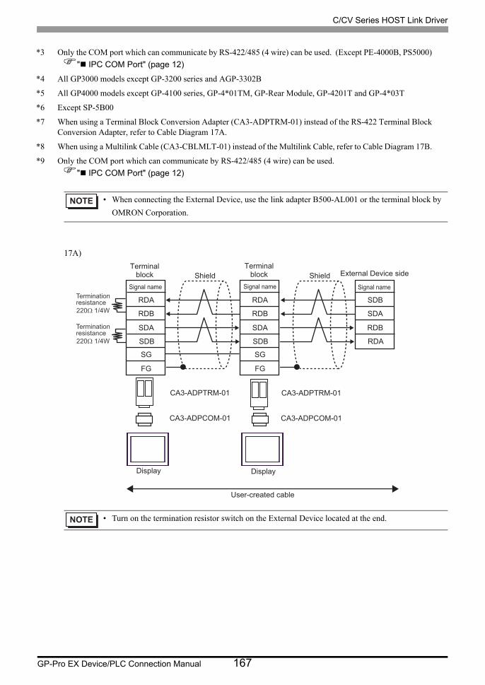
C/CV Series HOST Link Driver
GP-Pro EX Device/PLC Connection Manual 167
17A)
*3 Only the COM port which can communicate by RS-422/485 (4 wire) can be used. (Except PE-4000B, PS5000)
" IPC COM Port" (page 12)
*4 All GP3000 models except GP-3200 series and AGP-3302B
*5 All GP4000 models except GP-4100 series, GP-4*01TM, GP-Rear Module, GP-4201T and GP-4*03T
*6 Except SP-5B00
*7 When using a Terminal Block Conversion Adapter (CA3-ADPTRM-01) instead of the RS-422 Terminal Block Conversion Adapter, refer to Cable Diagram 17A.
*8 When using a Multilink Cable (CA3-CBLMLT-01) instead of the Multilink Cable, refer to Cable Diagram 17B.
*9 Only the COM port which can communicate by RS-422/485 (4 wire) can be used.
" IPC COM Port" (page 12)
• When connecting the External Device, use the link adapter B500-AL001 or the terminal block by
OMRON Corporation.
• Turn on the termination resistor switch on the External Device located at the end.
CA3-ADPTRM-01
CA3-ADPCOM-01
CA3-ADPTRM-01
CA3-ADPCOM-01
RDA
RDB
SDA
SDB
SG
FG
RDA
RDB
SDA
SDB
SG
FG
Shield Shield
User-created cable
SDB
SDA
RDB
RDA
Terminationresistance220Ω 1/4W
Terminationresistance220Ω 1/4W
Terminalblock
Signal name
Terminalblock
Signal name
External Device side
Signal name
Display Display

C/CV Series HOST Link Driver
GP-Pro EX Device/PLC Connection Manual 168
17B)
• Turn on the termination resistor switch on the External Device located at the end.
CA3-CBLMLT-01
CA3-ADPCOM-01
CA3-CBLMLT-01
CA3-ADPCOM-01
RDA
RDB
SDA
SDB
SG
FG
RDA
RDB
SDA
SDB
SG
FG
Terminationresistance220Ω 1/4W
Terminationresistance220Ω 1/4W
Terminalblock
(M3 screw)
Signal name
Terminalblock
(M3 screw)
Signal nameShield Shield
User-created cable
Display Display
External Device side
SDB
SDA
RDB
RDA
Signal name

C/CV Series HOST Link Driver
GP-Pro EX Device/PLC Connection Manual 169
17C)
• Turn on the termination resistor switch on the External Device located at the end.
RDARDB
CSA
SDASDBSG
ERA5
21
8
73
4
96
Shell
ERBCSB
FG
RDA
RDB
SDA
SDB
FG
SG
RDA
RDB
SDA
SDB
FG
SG
RDARDB
CSA
SDASDBSG
ERA5
21
8
73
4
96
ERBCSB
RDA
RDB
SDA
SDB
FG
SG
Terminationresistance220Ω 1/4W
Terminationresistance220Ω 1/4W
Display
Signal name
D-sub 9 pin (socket)
Pin
Display
Signal name
D-sub 9 pin (socket)
Pin
Signal name
Terminal block(M3 screw)
Signal name
Terminal block(M3 screw)
Signal name
Shield Shield Shield
Shield
External Device side
SDB
SDA
RDB
RDA
Signal name

C/CV Series HOST Link Driver
GP-Pro EX Device/PLC Connection Manual 170
17D)
• Turn on the termination resistor switch on the External Device located at the end.
CA3-ADPTRM-01
CA4-ADPONL-01
CA3-ADPTRM-01
CA4-ADPONL-01
RDA
RDB
SDA
SDB
SG
FG
RDA
RDB
SDA
SDB
SG
FG
Shield Shield
User-created cable
Terminationresistance220Ω 1/4W
Terminationresistance220Ω 1/4W
Terminalblock
Signal name
Terminalblock
Signal name
Display Display
External Device side
SDB
SDA
RDB
RDA
Signal name

C/CV Series HOST Link Driver
GP-Pro EX Device/PLC Connection Manual 171
17E)
• Turn on the termination resistor switch on the External Device located at the end.
CA3-CBLMLT-01
CA4-ADPONL-01
CA3-CBLMLT-01
CA4-ADPONL-01
RDA
RDB
SDA
SDB
SG
FG
RDA
RDB
SDA
SDB
SG
FG
Shield Shield
User-created cable
Terminationresistance220Ω 1/4W
Terminationresistance220Ω 1/4W
Terminalblock
(M3 screw)Signal name
Display Display
Terminalblock
(M3 screw)Signal name
External Device side
SDB
SDA
RDB
RDA
Signal name

C/CV Series HOST Link Driver
GP-Pro EX Device/PLC Connection Manual 172
17F)
• Turn on the termination resistor switch on the External Device located at the end.
RDATERMRX
TERMTX
FG
RDBSDASDBSG5
9
Shell
721
83Display
Signal name
D-sub 9 pin (plug)
Pin
RDATERMRX
TERMTX
RDBSDASDBSG5
9
721
83
Signal name
D-sub 9 pin (plug)
Pin
RDA
RDB
SDA
SDB
FG
SG
Signal name
Terminal block(M3 screw)
RDA
RDB
SDA
SDB
FG
SG
Signal name
Terminal block(M3 screw)
Display
RDA
RDB
SDA
SDB
FG
SG
Signal name
CA4-ADPONL-01
CA4-ADPONL-01
Terminationresistance220Ω 1/4W
Terminationresistance220Ω 1/4W
Shield Shield
Shield
Shield External Device side
SDB
SDA
RDB
RDA
Signal name

C/CV Series HOST Link Driver
GP-Pro EX Device/PLC Connection Manual 173
17G)
*1 The resistance in the Display is used as the termination resistance. Set the value of the DIP Switch on the rear of the Display as shown in the table below.
For the Displays other than that used as the terminal, set the DIP Switch 1-4 on the rear of the Display to OFF in the n:1 connection.
• Turn on the termination resistor switch on the External Device located at the end.
DIP Switch No. Set Value
1 OFF
2 ON
3 OFF
4 ON
RDARDB
CSA
SDASDBSG
ERA
ERBCSB
Terminationresistance*1
Terminationresistance*1
Display
Signal name
Shield External Device side
SDB
SDA
RDB
RDA
Signal name
Terminal blockDisplay side
RDARDB
CSA
SDASDBSG
ERA
ERBCSB
Signal name
Terminal blockDisplay side
Display
Shield

C/CV Series HOST Link Driver
GP-Pro EX Device/PLC Connection Manual 174
17H)
• Turn on the termination resistor switch on the External Device located at the end.
PFXZCBADTM1 PFXZCBADTM1
RDA
RDB
SDA
SDB
SG
FG
RDA
RDB
SDA
SDB
SG
FG
Shield Shield
User-created cable
SDB
SDA
RDB
RDA
Termination resistance 220Ω 1/4W
Termination resistance 220Ω 1/4W
Terminal block
Signal name
Terminal block
Signal name
External Device side
Signal name
Display Display

C/CV Series HOST Link Driver
GP-Pro EX Device/PLC Connection Manual 175
17I)
• Turn on the termination resistor switch on the External Device located at the end.
PFXZCBCBML1 PFXZCBCBML1
RDA
RDB
SDA
SDB
SG
FG
RDA
RDB
SDA
SDB
SG
FG
Termination resistance 220Ω 1/4W
Termination resistance 220Ω 1/4W
Terminal block
(M3 screw)
Signal name
Terminal block
(M3 screw)
Signal name Shield Shield
User-created cable
Display Display
External Device side
SDB
SDA
RDB
RDA
Signal name

C/CV Series HOST Link Driver
GP-Pro EX Device/PLC Connection Manual 176
17J)
• Turn on the termination resistor switch on the External Device located at the end.
Shell FG
Terminationresistance220Ω 1/4W
Terminationresistance220Ω 1/4W
Display
Signal name
D-sub 9 pin (socket)
Pin
Display
Signal name
D-sub 9 pin (socket)
Pin
Signal name
Terminal block(M3 screw)
Signal name
Terminal block(M3 screw)
Signal name
Shield Shield Shield
Shield
External Device side
SDBSDARDBRDA
Signal nameRx+Rx-Tx+Tx-
GNDNCNCNCNC
5
43
8
12
7
96
Rx+Rx-Tx+Tx-
GNDNCNCNCNC
5
43
8
12
7
96
Rx+Rx-Tx+Tx-
GNDFG
Rx+Rx-Tx+Tx-
GNDFG
Rx+Rx-Tx+Tx-
GNDFG

C/CV Series HOST Link Driver
GP-Pro EX Device/PLC Connection Manual 177
Cable Diagram 18
Display
(Connection Port)Cable Notes
GP3000*1 (COM1)AGP-3302B (COM2)GP-4*01TM (COM1)GP-Rear Module (COM1)ST *2 (COM2)LT3000 (COM1)IPC*3
*1 All GP3000 models except AGP-3302B
*2 All ST models except AST-3211A and AST-3302B
18A
COM port conversion adapter by Pro-faceCA3-ADPCOM-01
+Connector terminal block conversion adapter by Pro-face
CA3-ADPTRM-01+
User-created cableCable length: 500m max
18B
COM port conversion adapter by Pro-faceCA3-ADPCOM-01
+Multilink cable by Pro-face
CA3-CBLMLT-01+
User-created cable
18C User-created cable
GP3000 *4 (COM2)
18D
Online adapter by Pro-faceCA4-ADPONL-01
+Connector terminal block conversion adapter by Pro-face
CA3-ADPTRM-0+
User-created cable
Cable length: 500m max
18E
Online adapter by Pro-faceCA4-ADPONL-01
+Multilink cable by Pro-face
CA3-CBLMLT-01+
User-created cable
18F
Online adapter by Pro-faceCA4-ADPONL-01
+User-created cable
GP-4106 (COM1)GP-4116T (COM1)
18G User-created cableCable length: 500m max
GP4000*5 (COM2)GP-4201T (COM1)SP5000*6 (COM1/2)SP-5B00 (COM2)
18H
RS-422 terminal block conversion adapter by Pro-facePFXZCBADTM1*7
+User-created cable
Cable length: 500m max
18I
Multilink cable by Pro-facePFXZCBCBML1*8
+User-created cable
18C User-created cable
PE-4000B*9
PS5000*9 18J User-created cableCable length: 500m max

C/CV Series HOST Link Driver
GP-Pro EX Device/PLC Connection Manual 178
18A)
*3 Only the COM port which can communicate by RS-422/485 (4 wire) can be used. (Except PE-4000B, PS5000)
" IPC COM Port" (page 12)
*4 All GP3000 models except GP-3200 series and AGP-3302B
*5 All GP4000 models except GP-4100 series, GP-4*01TM, GP-Rear Module, GP-4201T and GP-4*03T
*6 Except SP-5B00
*7 When using a Terminal Block Conversion Adapter (CA3-ADPTRM-01) instead of the RS-422 Terminal Block Conversion Adapter, refer to Cable Diagram 18A.
*8 When using a Multilink Cable (CA3-CBLMLT-01) instead of the Multilink Cable, refer to Cable Diagram 18B.
*9 Only the COM port which can communicate by RS-422/485 (4 wire) can be used.
" IPC COM Port" (page 12)
• When connecting the External Device, use the link adapter B500-AL001 or the terminal block by
OMRON Corporation.
• Turn on the termination resistor switch on the External Device located at the end.
CA3-ADPTRM-01
CA3-ADPCOM-01
CA3-ADPTRM-01
CA3-ADPCOM-01
RDA
RDB
SDA
SDB
SG
TRM
RDA
RDB
SDA
SDB
SG
FG
1
2
6
8
Shield Shield
User-created cable
SDB
SDA
RDB
RDA
Connector Hood
Terminationresistance220Ω 1/4W
Terminationresistance220Ω 1/4W
Terminalblock
Signal name
Terminalblock
Signal name Pin
External Device sideD-Sub 9 pin (plug)
Signal name
Display Display

C/CV Series HOST Link Driver
GP-Pro EX Device/PLC Connection Manual 179
18B)
• Turn on the termination resistor switch on the External Device located at the end.
CA3-CBLMLT-01
CA3-ADPCOM-01
CA3-CBLMLT-01
CA3-ADPCOM-01
RDA
RDB
SDA
SDB
SG
FG
RDA
RDB
SDA
SDB
SG
FG
Terminationresistance220Ω 1/4W
Terminationresistance220Ω 1/4W
Terminalblock
(M3 screw)
Signal name
Terminalblock
(M3 screw)
Signal nameShield
User-created cable
Display Display
1
2
6
8
Shield
SDB
SDA
RDB
RDA
Connector Hood
Pin
External Device sideD-Sub 9 pin (plug)
Signal name

C/CV Series HOST Link Driver
GP-Pro EX Device/PLC Connection Manual 180
18C)
• Turn on the termination resistor switch on the External Device located at the end.
RDARDB
CSA
SDASDBSG
ERA5
21
8
73
4
96
ERBCSB
RDA
RDB
SDA
SDB
FG
SG
RDA
RDB
SDA
SDB
FG
SG
RDARDB
CSA
SDASDBSG
ERA5
21
8
73
4
96
ERBCSB
RDA
RDB
SDA
SDB
FG
SG
Terminationresistance220Ω 1/4W
Terminationresistance220Ω 1/4W
Display
Signal name
D-sub 9 pin (socket)
Pin
Display
Signal name
D-sub 9 pin (socket)
Pin
Signal name
Terminal block(M3 screw)
Signal name
Terminal block(M3 screw)
Signal name
Shield Shield
Shield
Shield
1
2
6
8
SDB
SDA
RDB
RDA
Connector Hood
Pin
External Device sideD-Sub 9 pin (plug)
Signal name

C/CV Series HOST Link Driver
GP-Pro EX Device/PLC Connection Manual 181
18D)
• Turn on the termination resistor switch on the External Device located at the end.
CA3-ADPTRM-01
CA4-ADPONL-01
CA3-ADPTRM-01
CA4-ADPONL-01
RDA
RDB
SDA
SDB
SG
TRM
RDA
RDB
SDA
SDB
SG
FG
Shield Shield
User-created cable
Terminationresistance220Ω 1/4W
Terminationresistance220Ω 1/4W
Terminalblock
Signal name
Terminalblock
Signal name
Display Display
1
2
6
8
SDB
SDA
RDB
RDA
Connector Hood
Pin
External Device sideD-Sub 9 pin (plug)
Signal name

C/CV Series HOST Link Driver
GP-Pro EX Device/PLC Connection Manual 182
18E)
• Turn on the termination resistor switch on the External Device located at the end.
CA3-CBLMLT-01
CA4-ADPONL-01
CA3-CBLMLT-01
CA4-ADPONL-01
RDA
RDB
SDA
SDB
SG
FG
RDA
RDB
SDA
SDB
SG
FG
Shield Shield
User-created cable
Terminationresistance220Ω 1/4W
Terminationresistance220Ω 1/4W
Terminalblock
(M3 screw)Signal name
Display Display
Terminalblock
(M3 screw)Signal name
1
2
6
8
SDB
SDA
RDB
RDA
Connector Hood
Pin
External Device sideD-Sub 9 pin (plug)
Signal name

C/CV Series HOST Link Driver
GP-Pro EX Device/PLC Connection Manual 183
18F)
• Turn on the termination resistor switch on the External Device located at the end.
RDATERMRX
TERMTX
RDBSDASDBSG5
9
721
83Display
Signal name
D-sub 9 pin (plug)
Pin
RDATERMRX
TERMTX
RDBSDASDBSG5
9
721
83
Signal name
D-sub 9 pin (plug)
Pin
RDA
RDB
SDA
SDB
FG
SG
Signal name
Terminal block(M3 screw)
RDA
RDB
SDA
SDB
FG
SG
Signal name
Terminal block(M3 screw)
Display
RDA
RDB
SDA
SDB
FG
SG
Signal name
CA4-ADPONL-01
CA4-ADPONL-01
Terminationresistance220Ω 1/4W
Terminationresistance220Ω 1/4W
Shield Shield
Shield
Shield
1
2
6
8
SDB
SDA
RDB
RDA
Connector Hood
Pin
External Device sideD-Sub 9 pin (plug)
Signal name

C/CV Series HOST Link Driver
GP-Pro EX Device/PLC Connection Manual 184
18G)
*1 The resistance in the Display is used as the termination resistance. Set the value of the DIP Switch on the rear of the Display as shown in the table below.
For the Displays other than that used as the terminal, set the DIP Switch 1-4 on the rear of the Display to OFF in the n:1 connection.
• Turn on the termination resistor switch on the External Device located at the end.
DIP Switch No. Set Value
1 OFF
2 ON
3 OFF
4 ON
RDARDB
CSA
SDASDBSG
ERA
ERBCSB
Terminationresistance*1
Terminationresistance*1
Display
Signal name
Shield Shield
1
2
6
8
SDB
SDA
RDB
RDA
Connector Hood
Pin
External Device sideD-Sub 9 pin (plug)
Signal name
Terminal blockDisplay side
RDARDB
CSA
SDASDBSG
ERA
ERBCSB
Signal name
Terminal blockDisplay side
Display

C/CV Series HOST Link Driver
GP-Pro EX Device/PLC Connection Manual 185
18H)
• Turn on the termination resistor switch on the External Device located at the end.
PFXZCBADTM1 PFXZCBADTM1
RDA
RDB
SDA
SDB
SG
TRM
RDA
RDB
SDA
SDB
SG
FG
1
2
6
8
Shield Shield
User-created cable
SDB
SDA
RDB
RDA
Connector Hood
Termination resistance 220Ω 1/4W
Termination resistance 220Ω 1/4W
Terminal block
Signal name
Terminal block
Signal name Pin
External Device side D-Sub 9 pin (plug)
Signal name
Display Display

C/CV Series HOST Link Driver
GP-Pro EX Device/PLC Connection Manual 186
18I)
• Turn on the termination resistor switch on the External Device located at the end.
PFXZCBCBML1 PFXZCBCBML1
RDA
RDB
SDA
SDB
SG
FG
RDA
RDB
SDA
SDB
SG
FG
Termination resistance 220Ω 1/4W
Termination resistance 220Ω 1/4W
Terminal block
(M3 screw)
Signal name
Terminal block
(M3 screw)
Signal name Shield
User-created cable
Display Display
1
2
6
8
Shield
SDB
SDA
RDB
RDA
Connector Hood
Pin
External Device side D-Sub 9 pin (plug)
Signal name
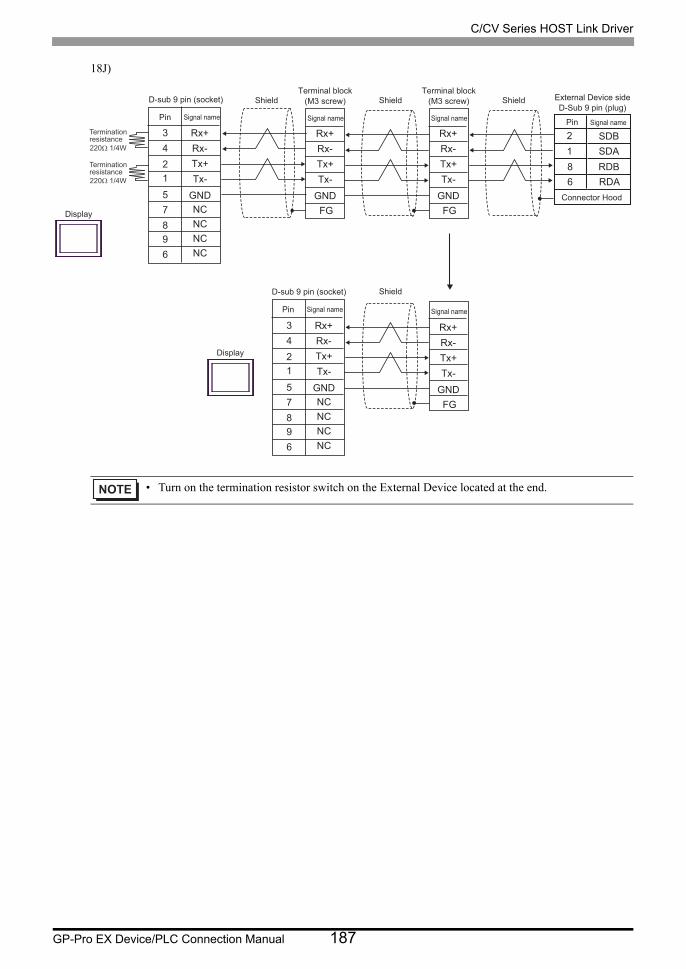
C/CV Series HOST Link Driver
GP-Pro EX Device/PLC Connection Manual 187
18J)
• Turn on the termination resistor switch on the External Device located at the end.
Terminationresistance220Ω 1/4W
Terminationresistance220Ω 1/4W
Display
Signal name
D-sub 9 pin (socket)
Pin
Display
Signal name
D-sub 9 pin (socket)
Pin
Signal name
Terminal block(M3 screw)
Signal name
Terminal block(M3 screw)
Signal name
Shield Shield
Shield
Shield
12
68
SDBSDARDBRDA
Connector Hood
Pin
External Device sideD-Sub 9 pin (plug)
Signal nameRx+Rx-Tx+Tx-
GNDNCNCNCNC
5
43
8
12
7
96
Rx+Rx-Tx+Tx-
GNDNCNCNCNC
5
43
8
12
7
96
Rx+Rx-Tx+Tx-
GNDFG
Rx+Rx-Tx+Tx-
GNDFG
Rx+Rx-Tx+Tx-
GNDFG

C/CV Series HOST Link Driver
GP-Pro EX Device/PLC Connection Manual 188
Cable Diagram 19
Display
(Connection Port)Cable Notes
GP3000*1 (COM1)AGP-3302B (COM2)GP-4*01TM (COM1)GP-Rear Module (COM1)ST *2 (COM2)LT3000 (COM1)IPC*3
*1 All GP3000 models except AGP-3302B
*2 All ST models except AST-3211A and AST-3302B
19A
COM port conversion adapter by Pro-faceCA3-ADPCOM-01
+Connector terminal block conversion adapter by Pro-face
CA3-ADPTRM-01+
User-created cableCable length: 500m max
19B
COM port conversion adapter by Pro-faceCA3-ADPCOM-01
+Multilink cable by Pro-face
CA3-CBLMLT-01+
User-created cable
19C User-created cable
GP3000 *4 (COM2)
19D
Online adapter by Pro-faceCA4-ADPONL-01
+Connector terminal block conversion adapter by Pro-face
CA3-ADPTRM-0+
User-created cable
Cable length: 500m max
19E
Online adapter by Pro-faceCA4-ADPONL-01
+Multilink cable by Pro-face
CA3-CBLMLT-01+
User-created cable
19F
Online adapter by Pro-faceCA4-ADPONL-01
+User-created cable
GP-4106 (COM1)GP-4116T (COM1)
19G User-created cableCable length: 500m max
GP4000*5 (COM2)GP-4201T (COM1)SP5000*6 (COM1/2)SP-5B00 (COM2)
19H
RS-422 terminal block conversion adapter by Pro-facePFXZCBADTM1*7
+User-created cable
Cable length: 500m max
19I
Multilink cable by Pro-facePFXZCBCBML1*8
+User-created cable
19C User-created cable
PE-4000B*9
PS5000*9 19J User-created cableCable length: 500m max

C/CV Series HOST Link Driver
GP-Pro EX Device/PLC Connection Manual 189
19A)
*3 Only the COM port which can communicate by RS-422/485 (4 wire) can be used. (Except PE-4000B, PS5000)
" IPC COM Port" (page 12)
*4 All GP3000 models except GP-3200 series and AGP-3302B
*5 All GP4000 models except GP-4100 series, GP-4*01TM, GP-Rear Module, GP-4201T and GP-4*03T
*6 Except SP-5B00
*7 When using a Terminal Block Conversion Adapter (CA3-ADPTRM-01) instead of the RS-422 Terminal Block Conversion Adapter, refer to Cable Diagram 19A.
*8 When using a Multilink Cable (CA3-CBLMLT-01) instead of the Multilink Cable, refer to Cable Diagram 19B.
*9 Only the COM port which can communicate by RS-422/485 (4 wire) can be used.
" IPC COM Port" (page 12)
• When the port on the External Device does not have a SG terminal, SG connection is unnecessary.
CA3-ADPTRM-01
CA3-ADPCOM-01
CA3-ADPTRM-01
CA3-ADPCOM-01
RDA
RDB
SDA
SDB
SG
TRM
RDA
RDB
SDA
SDB
SG SG
RS
CS
FG
FG
5
4
1
8
6
9
2
Shield Shield
User-created cable
SDB
SDA
RDB
RDA
Terminationresistance220Ω 1/4W
Terminationresistance220Ω 1/4W
Terminalblock
Signal name
Terminalblock
Signal name Pin
External Device sideD-Sub 9 pin (plug)
Signal name
Display Display
ConnectorHood

C/CV Series HOST Link Driver
GP-Pro EX Device/PLC Connection Manual 190
19B)
• When the port on the External Device does not have a SG terminal, SG connection is unnecessary.
CA3-CBLMLT-01
CA3-ADPCOM-01
CA3-CBLMLT-01
CA3-ADPCOM-01
RDA
RDB
SDA
SDB
SG
FG
RDA
RDB
SDA
SDB
SG
FG
Terminationresistance220Ω 1/4W
Terminationresistance220Ω 1/4W
Terminalblock
(M3 screw)
Signal name
Terminalblock
(M3 screw)
Signal nameShield
User-created cable
Display Display
SG
RS
CS
FG
5
4
1
8
6
9
2
Shield
SDB
SDA
RDB
RDA
Pin
External Device sideD-Sub 9 pin (plug)
Signal name
ConnectorHood

C/CV Series HOST Link Driver
GP-Pro EX Device/PLC Connection Manual 191
19C)
19D)
• When the port on the External Device does not have a SG terminal, SG connection is unnecessary.
• When the port on the External Device does not have a SG terminal, SG connection is unnecessary.
RDARDB
CSA
SDASDBSG
ERA5
21
8
73
4
96
ERBCSB
RDA
RDB
SDA
SDB
FG
SG
RDA
RDB
SDA
SDB
FG
SG
RDARDB
CSA
SDASDBSG
ERA5
21
8
73
4
96
ERBCSB
RDA
RDB
SDA
SDB
FG
SG
Terminationresistance220Ω 1/4W
Terminationresistance220Ω 1/4W
Display
Signal name
D-sub 9 pin (socket)
Pin
Display
Signal name
D-sub 9 pin (socket)
Pin
Signal name
Terminal block(M3 screw)
Signal name
Terminal block(M3 screw)
Signal name
Shield Shield
Shield
SG
RS
CS
FG
5
4
1
8
6
9
2
Shield
SDB
SDA
RDB
RDA
Pin
External Device sideD-Sub 9 pin (plug)
Signal name
ConnectorHood
CA3-ADPTRM-01
CA4-ADPONL-01
CA3-ADPTRM-01
CA4-ADPONL-01
RDA
RDB
SDA
SDB
SG
TRM
RDA
RDB
SDA
SDB
SG
FG
Shield
User-created cable
Terminationresistance220Ω 1/4W
Terminationresistance220Ω 1/4W
Terminalblock
Signal name
Terminalblock
Signal name
Display Display
SG
RS
CS
FG
5
4
1
8
6
9
2
Shield
SDB
SDA
RDB
RDA
Pin
External Device sideD-Sub 9 pin (plug)
Signal name
ConnectorHood

C/CV Series HOST Link Driver
GP-Pro EX Device/PLC Connection Manual 192
19E)
19F)
• When the port on the External Device does not have a SG terminal, SG connection is unnecessary.
• When the port on the External Device does not have a SG terminal, SG connection is unnecessary.
CA3-CBLMLT-01
CA4-ADPONL-01
CA3-CBLMLT-01
CA4-ADPONL-01
RDA
RDB
SDA
SDB
SG
FG
RDA
RDB
SDA
SDB
SG
FG
Shield
User-created cable
Terminationresistance220Ω 1/4W
Terminationresistance220Ω 1/4W
Terminalblock
(M3 screw)Signal name
Display Display
Terminalblock
(M3 screw)Signal name
SG
RS
CS
FG
5
4
1
8
6
9
2
Shield
SDB
SDA
RDB
RDA
Pin
External Device sideD-Sub 9 pin (plug)
Signal name
ConnectorHood
RDATERMRX
TERMTX
RDBSDASDBSG5
9
721
83Display
Signal name
D-sub 9 pin (plug)
Pin
RDATERMRX
TERMTX
RDBSDASDBSG5
9
721
83
Signal name
D-sub 9 pin (plug)
Pin
RDA
RDB
SDA
SDB
FG
SG
Signal name
Terminal block(M3 screw)
RDA
RDB
SDA
SDB
FG
SG
Signal name
Terminal block(M3 screw)
Display
RDA
RDB
SDA
SDB
FG
SG
Signal name
CA4-ADPONL-01
CA4-ADPONL-01
Terminationresistance220Ω 1/4W
Terminationresistance220Ω 1/4W
Shield Shield
Shield
SG
RS
CS
FG
5
4
1
8
6
9
2
Shield
SDB
SDA
RDB
RDA
Pin
External Device sideD-Sub 9 pin (plug)
Signal name
ConnectorHood

C/CV Series HOST Link Driver
GP-Pro EX Device/PLC Connection Manual 193
19G)
*1 The resistance in the Display is used as the termination resistance. Set the value of the DIP Switch on the rear of the Display as shown in the table below.
For the Displays other than that used as the terminal, set the DIP Switch 1-4 on the rear of the Display to OFF in the n:1 connection.
DIP Switch No. Set Value
1 OFF
2 ON
3 OFF
4 ON
• When the port on the External Device does not have a SG terminal, SG connection is unnecessary.
RDARDB
CSA
SDASDBSG
ERA
ERBCSB
Terminationresistance*1
Terminationresistance*1
Signal name
Display
Shield
SG
RS
CS
FG
5
4
1
8
6
9
2
Shield
SDB
SDA
RDB
RDA
Pin
External Device sideD-Sub 9 pin (plug)
Signal name
ConnectorHood
Terminal blockDisplay side
RDARDB
CSA
SDASDBSG
ERA
ERBCSB
Signal name
Terminal blockDisplay side
Display
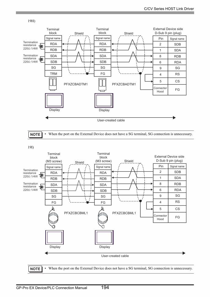
C/CV Series HOST Link Driver
GP-Pro EX Device/PLC Connection Manual 194
19H)
19I)
• When the port on the External Device does not have a SG terminal, SG connection is unnecessary.
• When the port on the External Device does not have a SG terminal, SG connection is unnecessary.
PFXZCBADTM1 PFXZCBADTM1
RDA
RDB
SDA
SDB
SG
TRM
RDA
RDB
SDA
SDB
SG SG
RS
CS
FG
FG
5
4
1
8
6
9
2
Shield Shield
User-created cable
SDB
SDA
RDB
RDA
Termination resistance 220Ω 1/4W
Termination resistance 220Ω 1/4W
Terminal block
Signal name
Terminal block
Signal name Pin
External Device side D-Sub 9 pin (plug)
Signal name
Display Display
Connector Hood
PFXZCBCBML1 PFXZCBCBML1
RDA
RDB
SDA
SDB
SG
FG
RDA
RDB
SDA
SDB
SG
FG
Termination resistance 220Ω 1/4W
Termination resistance 220Ω 1/4W
Terminal block
(M3 screw)
Signal name
Terminal block
(M3 screw)
Signal name Shield
User-created cable
Display Display
SG
RS
CS
FG
5
4
1
8
6
9
2
Shield
SDB
SDA
RDB
RDA
Pin
External Device side D-Sub 9 pin (plug)
Signal name
Connector Hood

C/CV Series HOST Link Driver
GP-Pro EX Device/PLC Connection Manual 195
19J)
• When the port on the External Device does not have a SG terminal, SG connection is unnecessary.
Terminationresistance220Ω 1/4W
Terminationresistance220Ω 1/4W
Display
Signal name
D-sub 9 pin (socket)
Pin
Display
Signal name
D-sub 9 pin (socket)
Pin
Signal name
Terminal block(M3 screw)
Signal name
Terminal block(M3 screw)
Signal name
Shield Shield
Shield
SGRS
CS
FG
5
4
1869
2
Shield
SDBSDARDBRDA
Pin
External Device sideD-Sub 9 pin (plug)
Signal name
ConnectorHood
Rx+Rx-Tx+Tx-
GNDNCNCNCNC
5
43
8
12
7
96
Rx+Rx-Tx+Tx-
GNDNCNCNCNC
5
43
8
12
7
96
Rx+Rx-Tx+Tx-
GNDFG
Rx+Rx-Tx+Tx-
GNDFG
Rx+Rx-Tx+Tx-
GNDFG

C/CV Series HOST Link Driver
GP-Pro EX Device/PLC Connection Manual 196
6 Supported Device
Range of supported device address is shown in the table below. Please note that the actually supported range of
the devices varies depending on the External Device to be used. Please check the actual range in the manual of
your External Device.
6.1 SYSMAC-C Series
:Available to set to the head address of the system device
Device Bit Address Word Address 32bits Remarks
I/O Relay
000.00 - 511.15 000-511 *1 *3
*1 Note that the actually supported range of the devices and whether write enable or disable may vary depending on the CPU. Please refer to the CPU manual for checking.
Internal Auxiliary Relay
Special Auxiliary Relay
Analog Setting Value Stored Area
220.00 - 223.15 220 - 223 *2 *3
*2 Can be used only in CQM1-CPU42.
*3 When you write the bit address, the Display reads the word address corresponding to that of the External Device first. Then, it changes the target bit address among the word data once read and returns the word data to the External Device. Note that the correct data may not be written if you change the word address value in the ladder program while the Display reads the data of the External Device and returns it to the External Device.
Data Link Relay LR00.00 - LR63.15 LR00-LR63 *3
Auxiliary Memory Relay AR00.00 - AR27.15 AR00-AR27 *3
Latch Relay HR00.00 - HR99.15 HR00-HR99 *3
Timer (Contact) TIM000-TIM511 ------
Counter (Contact) CNT000-CNT511 ------
Timer (Current Value) ------ TIM000-TIM511 *4
*4 BCD only
Counter (Current Value) ------ CNT000-CNT511 *4
Data Memory ------ DM0000-DM6655
• Please refer to the GP-Pro EX Reference Manual for system data area.
Cf. GP-Pro EX Reference Manual "LS Area (Direct Access Method Area)"• Please refer to the precautions on manual notation for icons in the table.
"Manual Symbols and Terminology"

C/CV Series HOST Link Driver
GP-Pro EX Device/PLC Connection Manual 197
6.2 SYSMAC-C Series (CQM1H-CPU51/CQM1H-CPU61)
:Available to set to the head address of the system device
Device Bit Address Word Address 32bits Remarks
I/O Relay000.00 - 243.15 000-243 *1 *3
*1 There is an area in which any address does not exist within the address range of input relay/internal auxiliary relay. Please refer to the SYSMAC-CQM1H User Manual by OMRON Corporation.
Internal Auxiliary Relay
Special Auxiliary Relay 244.00-255.07 244-255 *2 *3
*2 Bit address of the special auxiliary relay is 244.00-254.15/255.00-07. Bit address of 255.08-255.15 does not exist.
Link Relay LR00.00-LR63.15 LR00-LR63 *3
*3 When you write the bit address, the Display reads the word address corresponding to that of the External Device first. Then, it changes the target bit address among the word data once read and returns the word data to the External Device. Note that the correct data may not be written if you change the word address value in the ladder program while the Display reads the data of the External Device and returns it to the External Device.
Auxiliary Memory Relay AR00.00-AR27.15 AR00-AR27 *3
Latch Relay HR00.00-HR99.15 HR00-HR99 *3
Timer (Contact) TIM000-TIM511 ------
Counter (Contact) CNT000-CNT511 ------
Timer (Current Value) ------ TIM000-TIM511 *4
*4 BCD only
Counter (Current Value) ------ CNT000-CNT511 *4
Data Memory ------ DM0000-DM6655 *5
*5 Do not write in the store area beyond data memory DM, DM6569-DM6599 and PC system setting area DM6600-DM6655.
Extension Data Memory ------ EM0000-EM6143 *6
*6 Extension data memory EM supports only CQM1H-CPU61.
• Please refer to the GP-Pro EX Reference Manual for system data area.
Cf. GP-Pro EX Reference Manual "LS Area (Direct Access Method Area)"• Please refer to the precautions on manual notation for icons in the table.
"Manual Symbols and Terminology"

C/CV Series HOST Link Driver
GP-Pro EX Device/PLC Connection Manual 198
6.3 SYSMAC- Series
: Available to set to the head address of the system device
Device Bit Address Word Address 32bits Remarks
I/O Relay I 000.00-029.15 000-029 *1
*1 When you write the bit address, the Display reads the word address corresponding to that of the External Device first. Then, it changes the target bit address among the word data once read and returns the word data to the External Device. Note that the correct data may not be written if you change the word address value in the ladder program while the Display reads the data of the External Device and returns it to the External Device.
I/O Relay II 300.00-309.15 300-309 *1
Internal Auxiliary Relay I 030.00-235.15 030-235 *1
Internal Auxiliary Relay II 310.00-511.15 310-511 *1
Special Auxiliary Relay I 236.00-255.07 236-255 *1
Special Auxiliary Relay II 256.00-299.15 256-299 *1
Link Relay LR00.00-LR63.15 LR00-LR63 *1
Auxiliary Memory Relay AR00.00-AR27.15 AR00-AR27 *1
Latch Relay HR00.00-HR99.15 HR00-HR99 *1
Timer (Contact) TIM000-TIM511 ------
Counter (Contact) CNT000-CNT511 ------
Timer (Current Value) ------ TIM000-TIM511 *2
*2 BCD only
Counter (Current Value) ------ CNT000-CNT511 *2
Data Memory ------ DM0000-DM6655 *3
*3 We cannot guarantee the operation when you access the nonexistent data memory area (DM6656 to DM6999).
Extension Fixed Data Memory
------ DM7000-DM9999 *4
*4 We cannot guarantee the operation when you access to DM7000 to DM9999 without the extension fixed DM setting.
Extension Data Memory ------ EM0000-EM6143 *5
*5 We cannot guarantee the operation when you specify the area within the range in the models in which the bank of the extension memory area does not exist.
• Please refer to the GP-Pro EX Reference Manual for system data area.
Cf. GP-Pro EX Reference Manual "LS Area (Direct Access Method Area)"• Please refer to the precautions on manual notation for icons in the table.
"Manual Symbols and Terminology"

C/CV Series HOST Link Driver
GP-Pro EX Device/PLC Connection Manual 199
6.4 SYSMAC-CV Series
: Available to set to the head address of the system device
Device Bit Address Word Address 32bits Remarks
I/O Relay000.00 - 199.15 000-199
*1
*1 When you write the bit address, the Display reads the word address corresponding to that of the External Device first. Then, it changes the target bit address among the word data once read and returns the word data to the External Device. Note that the correct data may not be written if you change the word address value in the ladder program while the Display reads the data of the External Device and returns it to the External Device.
Internal Auxiliary Relay *1
SYSMAC BUS/2 Remote I/O Relay
0200.00 - 0999.15 0200-0999 *1
Data Link Relay 1000.00 - 1199.15 1000-1199 *1
Special Auxiliary Relay A000.00 - A511.15 A000-A511 *1
Latch Relay 1200.00 - 1499.15 1200-1499 *1
Internal Auxiliary Relay 1900.00 - 2299.15 1900-2299 *1
SYSBUS Remote I/O Relay
2300.00 - 2555.15 2300-2555 *1
Timer (Contact) T0000-T1023 ------ *2
*2 Write disable
Counter (Contact) C0000-C1023 ------ *2
Timer (Current Value) ------ T0000-T1023 *3
*3 BCD only
Counter (Current Value) ------ C0000-C1023 *3
Data Memory ------ D0000-D9999
• Please refer to the GP-Pro EX Reference Manual for system data area.
Cf. GP-Pro EX Reference Manual "LS Area (Direct Access Method Area)"• Please refer to the precautions on manual notation for icons in the table.
"Manual Symbols and Terminology"

C/CV Series HOST Link Driver
GP-Pro EX Device/PLC Connection Manual 200
7 Device Code and Address Code
Use device code and address code when you select "Device & Address" for the address type in data displays.
7.1 SYSMAC-C Series
7.2 SYSMAC-C Series (CQM1H-CPU51/CQM1H-CPU61)
Device Device NameDevice Code
(HEX)Address Code
I/O Relay
------ 0080 Word AddressInternal Auxiliary Relay
Special Auxiliary Relay
Analog Setting Value Stored Area
LR 0088 Word Address
Data Link Relay ------ 0080 Word Address
Auxiliary Memory Relay AR 0085 Word Address
Latch Relay HR 0084 Word Address
Timer (Contact) TIM 00E0 Word Address
Counter (Contact) CNT 00E2 Word Address
Timer (Current Value) TIM 0060 Word Address
Counter (Current Value) CNT 0061 Word Address
Data Memory DM 0000 Word Address
Device Device NameDevice Code
(HEX)Address Code
I/O Relay
------ 0080 Word AddressInternal Auxiliary Relay
Special Auxiliary Relay
Link Relay LR 0088 Word Address
Auxiliary Memory Relay AR 0085 Word Address
Latch Relay HR 0084 Word Address
Timer (Contact) TIM 00E0 Word Address
Counter (Contact) CNT 00E2 Word Address
Timer (Current Value) TIM 0060 Word Address
Counter (Current Value) CNT 0061 Word Address
continued to next page

C/CV Series HOST Link Driver
GP-Pro EX Device/PLC Connection Manual 201
7.3 SYSMAC- Series
Data Memory DM 0000 Word Address
Extension Data Memory EM 0001 Word Address
Device Device Name Device Code (HEX) Address Code
I/O Relay I
------ 0080 Word Address
I/O Relay II
Internal Auxiliary Relay I
Internal Auxiliary Relay II
Special Auxiliary Relay I
Special Auxiliary Relay II
Link Relay LR 0088 Word Address
Auxiliary Memory Relay AR 0085 Word Address
Latch Relay HR 0084 Word Address
Timer (Contact) TIM 00E0 Word Address
Counter (Contact) CNT 00E2 Word Address
Timer (Current Value) TIM 0060 Word Address
Counter (Current Value) CNT 0061 Word Address
Data Memory DM 0000 Word Address
Extension Fixed Data Memory DM 0000 Word Address
Extension Data Memory EM 0001 Word Address
Device Device NameDevice Code
(HEX)Address Code

C/CV Series HOST Link Driver
GP-Pro EX Device/PLC Connection Manual 202
7.4 SYSMAC-CV Series
Device Device Name Device Code (HEX) Address Code
I/O Relay
------ 0080 Word Address
Internal Auxiliary Relay
SYSMAC BUS/2 Remote I/O Relay
Data Link Relay
Special Auxiliary Relay A 0085 Word Address
Latch Relay - 0080 Word Address
Internal Auxiliary Relay - 0080 Word Address
SYSBUS Remote I/O Relay - 0080 Word Address
Timer (Contact) T 00E0 Word Address
Counter (Contact) C 00E2 Word Address
Timer (Current Value) T 0060 Word Address
Counter (Current Value) C 0061 Word Address
Data Memory D 0000 Word Address

C/CV Series HOST Link Driver
GP-Pro EX Device/PLC Connection Manual 203
8 Error Messages
Error messages are displayed on the Display screen as follows: "No.: Device Name: Error Message (Error
Occurrence Area)". Each description is shown below.
Display Examples of Error Messages
"RHAA035: PLC1: Error has been responded for device write command (Error Code: 2 [02H])"
Item Description
No. Error No.
Device NameName of the External Device where error occurs. Device name is a title of the External Device set with GP-Pro EX. (Initial value [PLC1])
Error Message Displays messages related to the error which occurs.
Error Occurrence Area
Displays IP address or device address of the External Device where error occurs, or error codes received from the External Device.
• IP address is displayed such as "IP address(Decimal): MAC address( Hex)".
• Device address is diplayed such as "Address: Device address".
• Received error codes are displayed such as "Decimal[Hex]".
• Refer to your External Device manual for details on received error codes.
• Refer to "Display-related errors" in "Maintenance/Troubleshooting Guide" for details on the error
messages common to the driver.

C/CV Series HOST Link Driver
GP-Pro EX Device/PLC Connection Manual 204