CCJ-Issue-70.pdf - Combined Cycle Journal
100
Number 70 2022 www.ccj-online.com $15 INDEPENDENT VOICE OF THE GAS-TURBINE-BASED GENERATION SECTOR User Group Reports 7F Users Group............................................. 6 2022 conference program Overview and sponsors.............................. 6 User presentations...................................... 8 Vendor solutions (May 23) ......................... 8 Vendor solutions (May 24) ....................... 12 Vendor fair Exhibit hall map ......................................... 18 May 23, Alphabetical order by exhibitor ......18 May 23, Booth number order................... 18 May 24, Alphabetical order by exhibitor ....... 18 May 24, Booth number order................... 19 2021 conference highlights User presentations.................................... 22 Vendor presentations................................ 26 7F Best Practices Intro .................................................................. 33 River Road Generating Plant ........................ 34 Steam-trap problem-solving, finding leaks with ultrasound camera, Covid-19 and the outage challenge, and more Woodbridge Energy Center........................... 38 Reduce makeup, sewer costs by separat- ing wastewater streams, collector brush system upgrade, and more Essential Power Newington........................... 42 Offline circ-water treatment boosts perfor- mance, taking confined-space precautions to the next level, and more Rumford Power ............................................... 52 Reduce time of response to address com- mon plant issues, training for emergency response Empire Generating Co ................................... 56 Removing suspended solids from a chlo- rine contact chamber Hunterstown Generating Station................... 58 LOTO accuracy, completeness improved by mapping procedures on drawings Marcus Hook Energy Center......................... 60 Successful troubleshooting halves genera- tor hydrogen consumption HA Users to meet August 9-10 .................. 65 HA Best Practices Energía del Valle de México II ....................... 66 Mechanical vaporizer enables plant to con- vert to ZLD facility during construction Fairview Energy Center ................................. 68 Use EMI to assess condition of generators, transformers, HV electrical gear Legacy Turbine Users Group..................... 77 7EA Users Group ......................................... 78 7EA Best Practices Lincoln Generating Facility............................. 80 Mobile fall-protection system Crete Energy Venture .................................... 82 Mark V improvements, LED lighting Frame 6B Users Group ............................... 86 6B Best Practice BASF Geismar ................................................ 88 Increasing the reliability of boiler drum-level controls Frame 5 Users Group .................................. 90 Turbine Tip No. 17: Use the correct names of gas-turbine components to avoid confusion Feature articles HRSG Forum discussion centers on creep damage, elemental zinc in weld HAZ areas. ....................... 61 Turbine inlet cooling, the first step on the pathway to net zero emissions ................................. 63 Online resources enable plant personnel to better prepare for upcoming outages. Summaries of webinars focusing on generator retaining rings, steam-turbine valve actuators, use of the Mark VI trender, thermal-performance audit, fuel-nozzle upgrades, reducing control-system alarms............ 71 Highlights of international meeting on film-forming substances ............................... 96 Best Practice from Pleasant Valley Generating Station on guided- wave radar............................... 97 Miscellany Power Users forms Legacy Turbine Users Group ............... 3 Sponsored content: Gas Path Solutions................. 20 EthosEnergy ........................... 28 Index to advertisers .................... 59 Book reviews: Electric co-ops—aspire to better.................................... 67 Knowledge-management processes critical to success ...76 Business partners. ...................... 98 World’s largest frame user group May 23 - 27 Fairmont Dallas (Tex) Hotel Contact: Sheila Vashi, [email protected] www.powerusers.org August 29 – September 1 San Antonio Marriott Rivercenter Contact: Sheila Vashi, sheila. [email protected] www.powerusers.org First Annual Meeting Legacy Turbine Users Group 31st Annual Meeting
-
Upload
khangminh22 -
Category
Documents
-
view
0 -
download
0
Transcript of CCJ-Issue-70.pdf - Combined Cycle Journal

Number 70 2022
www.ccj-online.com
$15
INDEPENDENT VOICE OF THE GAS-TURBINE-BASED GENERATION SECTOR
User Group Reports7F Users Group.............................................6 2022 conference program
Overview and sponsors..............................6User presentations ......................................8Vendor solutions (May 23) .........................8Vendor solutions (May 24) .......................12
Vendor fairExhibit hall map .........................................18May 23, Alphabetical order by exhibitor ......18May 23, Booth number order ...................18May 24, Alphabetical order by exhibitor .......18May 24, Booth number order ...................19
2021 conference highlightsUser presentations ....................................22Vendor presentations ................................26
7F Best PracticesIntro ..................................................................33River Road Generating Plant ........................34
Steam-trap problem-solving, finding leaks with ultrasound camera, Covid-19 and the outage challenge, and more
Woodbridge Energy Center ...........................38Reduce makeup, sewer costs by separat-ing wastewater streams, collector brush system upgrade, and more
Essential Power Newington ...........................42Offline circ-water treatment boosts perfor-mance, taking confined-space precautions to the next level, and more
Rumford Power...............................................52Reduce time of response to address com-mon plant issues, training for emergency response
Empire Generating Co ...................................56Removing suspended solids from a chlo-rine contact chamber
Hunterstown Generating Station ...................58LOTO accuracy, completeness improved by mapping procedures on drawings
Marcus Hook Energy Center .........................60Successful troubleshooting halves genera-tor hydrogen consumption
HA Users to meet August 9-10 ..................65HA Best PracticesEnergía del Valle de México II .......................66
Mechanical vaporizer enables plant to con-vert to ZLD facility during construction
Fairview Energy Center .................................68Use EMI to assess condition of generators, transformers, HV electrical gear
Legacy Turbine Users Group.....................777EA Users Group .........................................787EA Best PracticesLincoln Generating Facility.............................80
Mobile fall-protection systemCrete Energy Venture ....................................82
Mark V improvements, LED lighting Frame 6B Users Group ...............................866B Best Practice BASF Geismar................................................88
Increasing the reliability of boiler drum-level controls
Frame 5 Users Group ..................................90 Turbine Tip No. 17: Use the correct names of gas-turbine components to avoid confusion
Feature articlesHRSG Forum discussion centers on
creep damage, elemental zinc in weld HAZ areas. .......................61
Turbine inlet cooling, the first step on the pathway to net zero emissions .................................63
Online resources enable plant personnel to better prepare for upcoming outages. Summaries of webinars focusing on generator retaining rings, steam-turbine valve actuators, use of the Mark VI trender, thermal-performance audit, fuel-nozzle upgrades, reducing control-system alarms ............71
Highlights of international meeting on film-forming substances ...............................96
Best Practice from Pleasant Valley Generating Station on guided-wave radar ...............................97
MiscellanyPower Users forms Legacy
Turbine Users Group ...............3Sponsored content:
Gas Path Solutions .................20EthosEnergy ...........................28
Index to advertisers ....................59Book reviews:
Electric co-ops—aspire to better....................................67Knowledge-management processes critical to success ...76
Business partners. ......................98
World’s largest frame user groupMay 23 - 27
Fairmont Dallas (Tex) HotelContact: Sheila Vashi, [email protected]
www.powerusers.org
August 29 – September 1San Antonio Marriott RivercenterContact: Sheila Vashi, sheila.
First Annual MeetingLegacy Turbine Users Group
31st Annual Meeting


COMBINED CYCLE JOURNAL, Number 70 (2022) 3
In the world of power generation there is a significant number of mature frame gas turbines that are the backbone for industrial settings and power generation.
There are several well-established user groups that sup-port owner/operators by sharing lessons learned, technical knowledge, and troubleshooting support. It’s critical that these groups maintain a strong presence in the industry to support and benefit both the users and suppliers that keep the equipment running. Combine that with a changing industry, a pandemic, shrinking budgets, and an aging workforce you now have challenges in keeping influential groups afloat.
With any challenge there is opportunity and that’s why Power Users formed the Legacy Turbine Users Group. Currently,
LTUG comprises the 7EA, Frame 6B, and Frame 5 Users Groups. In combining forces, the future for these organizations will be stronger and have opportunity to grow. Each group maintains an independent steering committee and user forum hosted by Power Users, but when conducting a technical conference, the groups will be joining together under one roof, each in its own meeting room. Power Users believes this combined group provides many benefits to the user community and suppliers.
The first LTUG technical conference will be co-located with Power Users’ Combined Conference this coming August (see ad pages 92-93). For the first time, companies with a mixed fleet of these turbine types will be able to travel to one conference to gain the
benefit of three. Additionally, companies that may not have such diverse fleets will be able to leverage the knowledge presented by these three groups with one trip. This addresses some of the challenges we are seeing that will likely to continue. Now companies can save on travel costs by attending an all-in-one conference and not have to choose which meeting to miss in a given year. All this without losing the ben-efit of training, sharing of lessons learned, building valuable networks, and meeting the supplier network that supports these gas turbines.
Suppliers also benefit from this merger of user groups. Their budgets are equally stretched, and the pandemic has made it challenging to share their services and build networks. The LTUG conference
provides access to a diverse group of users that utilize a similar vendor base for sup-port, parts, and ser-vices. This efficiency provides a budget-friendly opportunity for suppliers to build valuable connections to sell services and parts.
O u r i n a u g u r a l LTUG conference will be held in beautiful San Antonio (Tex), August 29 through September 1 (www.powerusers.org). Plan now to participate in
this seminal event to strengthen your knowledge, build your network, share your experience, and find a supplier that can help solve problems your facility is facing.
Jake English, Duke EnergyPhyllis Gassert, Talen EnergySam Graham, TenaskaEdward Maggio, TVABen Meissner, Duke EnergyPeter So, Calpine
Marketing ServicesHow to access customers and prospects through the CCJ Network:n Print advertising.n ONline advertisingn Custom sponsorshipsn Webinarsn Special promotionsn Buyers Guiden eMarketingTo learn more, please contact: Lisa Juncaj Advertising Sales Director914-774-1947, [email protected] CYCLE Journal is published by PSI Media Inc, a Pearl Street company. Editorial offices are at 7628 Belmondo Lane, Las Vegas, Nev 89128. Office manager: Robert G Schwieger Jr.To cancel or change your subscription, write [email protected]
Editorial StaffScott G SchwiegerGeneral ManagerPrint and Electronic Products702-612-9406, [email protected] KomodaCreative DirectorSteven C StultzConsulting EditorClark G SchwiegerSpecial Projects ManagerRobert G Schwieger SrEditor Emeritus702-869-4739, [email protected]
Editorial Advisory BoardJason Makansi, Chairman President, Pearl StreetRobert W Anderson Competitive Power ResourcesRobert D Threlkeld Principal, RT Power ConsultingSam Graham Plant Manager Tenaska Virginia Generating StationPeter So Director of Project Management & Development, CalpineGabriel Fleck Manager, Gas Plant Operations Associated Electric Cooperative IncDr Barry Dooley Structural Integrity Associates Inc
Power Users forms Legacy Turbine Users Group
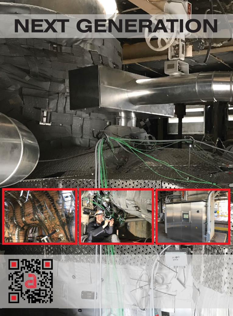
NEXT GENERATION TURBINE WARMING
Contact: Pierre Ansmann [email protected]
Ÿ Seamless Turnkey Solution
Ÿ Increase Protability
Ÿ Maintain Hot-Start Conditions
Operational Advantages
Ÿ Mitigate Case Distortion
Ÿ Eliminate Cold Starts
Ÿ Enhanced Operator Safety Features
Maintenance Advantages
Economic Advantages
Ÿ Faster Starts
Ÿ Gain Competitive Market Advantage
Ÿ Reduced Fuel Consumption
Ÿ Advanced, Customizable Control
Ÿ Easy Access to Critical AreasŸ Quick & Easy Removal / Reinstall

6 COMBINED CYCLE JOURNAL, Number 70 (2022)
SponsorsDIAMOND
SILVER PLUS
PLATINUM
31st Annual ConferenceFairmont Dallas Hotel • May 23-27This year’s vibrant, reconfigured 7F Users Group conference program promises a not-to-be-missed event. Two-dozen vendor solutions highlight each of the first two mornings—Mon-day, May 23, and Tuesday, May 24—with users-only sessions in the afternoons, and vendor fairs
following. Wednesday is dedicated to engine components, each session featuring user pre-sentations. Thursday is GE Day. Friday morning is reserved for the OEM’s deep-dive knowledge-sharing program and hands-on live outage host-ed by FieldCore.

COMBINED CYCLE JOURNAL, Number 70 (2022) 7
SponsorsSILVER
BRONZE
The world’s largest user orga-nization supporting owner/operators of GE F-class gas turbines hosts the most robust
in-person meeting of its type since the pandemic began two years ago, when the 7F Users Group meets at the Fair-mont Dallas Hotel, May 23-27..
Here’s an overview of the 2022 agenda:
Vendor solutions presentations are conducted Monday and Tuesday in four 30-minute sessions with four or five services providers present-ing simultaneously in each session. Five platinum-sponsor presentations, aggregated in a fifth 60-minute ses-sion, conclude the morning programs. Access the conference mobile app for room assignments.
Monday, attendees can listen to half-hour presentations by AGT Ser-vices, Certrec, Flow-Tech Industrial, HRST, PSM, APG, CTTS, Cutsforth, Emerson, Independent Turbine Con-sulting, Core Tech, OILKLEEN, Etho-sEnergy, NEC, RelaDyne, and Tetra Engineering; plus, hour presentations by Arnold Group, Gas Path Solutions, MD&A, Shell, and TC&E.
Tuesday’s half-hour presentations are by Camfil, GTC Control Solutions, ORR Protection, HRST, Integrity Power Solutions, MD&A, EagleBurg-
mann, JASC, Kinectrics AES, Koenig Engineering, Moog, PGAS, Lectrodry-er, NEC, Riverhawk, and Sulzer; plus, hour presentations by AGT Services, Doosan Turbomachinery Services, ExxonMobil, IAFD, and PSM.
Content thumbnails of the vendor presentations are provided in the fol-lowing section to help in planning your participation.
The general sessions include a world-class lineup of presentations and discussions by and among users on safety best practices and lessons learned, performance and controls, auxiliaries and generators, the com-pressor, combustion, and turbine sec-
tions of the 7F engine, rotor, and top fleet issues.
Vendor fairs will showcase the products and services from five- to six-dozen companies each night (p 13). The generous three-hour exhibit hall program allows you to visit all the companies on your punch list while taking advantage of the heavy hors d’oeuvres and open bar.
GE Day topics include safety; 7F fleet trends; outage planning and exe-cution; GT systems reliability, controls basics, architecture, troubleshooting, and solutions; compressor/turbine/rotor; generator and electrical systems; parts and repairs; and combustion.
Fairmont Dallas Hotel

8 COMBINED CYCLE JOURNAL, Number 70 (2022)
7F USERS GROUP
Vendor solutions, May 238:00 a.m.AGT Services Inc
GE stator-core loosenessJamie Clark explains how to inspect
stator cores in GE generators and rem-edy issues, such as core looseness, to avoid in-service failures and emergent outage scope for repairs.
Certrec CorpPitfalls, risks, and solutions for prop-
er setting of generator protective relaysUnderstand the challenges of prop-
erly setting generator frequency and voltage protective relays and how to do it correctly to meet regulatory require-ments (NERC standard PRC-024). Case study provides operating experi-ence from dozens of generating units.
Flow-Tech IndustrialElectronic water treatment: How
it worksElectronic cooling-water treatment
system is said to effectively protect against scale, biological growth, and corrosion while improving efficiency, maintenance, equipment life, and sav-ing water. Case studies of a 7F plant provides real-world results.
HRST IncCoordinating HRSG advanced
inspection techniques relative to major turbine overhauls
Highlights several advanced inspec-tion techniques and where they should be applied to allow good long-range bud-geting and proper reliability for an aging HRSG. Includes photos of inspection techniques, significant findings, and the impact they have on outage planning.
PSMEnhanced profitability and reli-
ability: Operational flexibility through complete plant optimization
Faster startups and higher ramp rates are among the significant improvements possible with modifi-cations to existing controls logic and more intelligent operational limits, while not exceeding proscribed plant equipment limits. Case studies of recent commercially implemented plant-optimization projects involving gas and steam turbines and HRSGs illustrate what’s possible operationally to improve profitability.
8:45 a.m.APG (Allied Power Group)
7F, 7FA, 7FA+, 7FA+e, 7FB, and 7FA.04 first-stage bucket design his-tory and evolution
A complete historical design, mate-rials, and coatings perspective concern-ing 7FA first-stage buckets from the early 1990s to today’s 7FA.04 single-crystal parts. Aaron Frost reviews changes over the years and the way these changes have impacted design life and repairability.
CTTSCompressor vane looseness: What
to look for and what to doPresentation shows users how to
look for indications that signal their machine may be at risk, before a sig-nificant problem arises (such as loose square-based compressor vanes), and
May 23, 8:45 a.m. APG—Allied Power Group’s Aaron Frost reviews the tech-nical history of 7F first-stage bucket design to help you make better lifetime-assessment and repair decisions
User presentations
Restructured agenda for 2022Conference organizer Sheila Vashi, president, SV Events, says the 7F Users Group’s traditional agenda was restructured for 2022 to expand the learning experience for attend-ees without sacrificing the number of user-only session hours. This is in response to feedback from gas-turbine owner/operators wanting ses-sions to end earlier each day and to have a free evening. Vendor feedback indicated a desire for more presen-tation opportunities. Some of the schedule adjustments implemented to
achieve these goals are the following:n User sessions end at 4:00 p.m. on
Monday, Tuesday, and Wednesday.n Vendor fairs are conducted on
Monday and Tuesday, giving attendees an open evening on Wednesday.
n Vendor fairs start and end earlier than previously. Doors open at 4:00 p.m. and close at 7:00.
n The number of vendor solutions presentations has been expanded and these are conducted on Mon-day and Tuesday morning.
7F 2022 steering committeeChairman: Justin McDonald, Southern CompanyVice chairman: John Rogers, SRPLuis Barrera, CalpineKaitlyn Honey, Xcel EnergyRiz James, Dominion EnergyClinton Lafferty, TVADoug Leonard, ExxonMobilEd Maggio, TVATimothy Null, Eastman ChemicalDave Such, Xcel Energy Terry Toland, Clark Public UtilitiesZach Wood, Duke Energy
User presentations and discussions dominate the first three days of the 2022 conference agenda, totaling 13 of the available 21 hours of program time. Details for the user-only portion of the agenda were not available at press time, only the overview below:Monday, May 231:00 p.m. to 4:00—Compressor sessions I and IITuesday, May 241:00 p.m. to 1:30—Safety practices and lessons learned
1:30 p.m. to 2:30—Performance and controls panel2:45 p.m. to 4:00—Auxiliaries and generator session IWednesday, May 258:00 a.m. to 8:30—Auxiliaries and generator session II8:30 a.m. to 10:00—Combustion session10:15 a.m. to 12:00—Turbine session I1:00 p.m. to 2:00—Turbine session II2:00 p.m. to 3:00—Rotor session3:15 p.m. to 4:00—7F Top Issues


10 COMBINED CYCLE JOURNAL, Number 70 (2022)
7F USERS GROUP
then what to do if the risk is confirmed. Focus is on pinning as the optimal solution for loose vanes, based on more than 200 units modified over the last 15 or so years.
Cutsforth IncA case study on shaft ground and
EMI monitoringIllustrates how multiple monitor-
ing systems, specifically shaft ground monitoring and EMSA, were used to validate an event and prevent a fail-ure. High-speed waveforms, spectrum scans, and data analyses enable SMEs to identify sources of high voltages and arcing, thereby allowing timely repairs.
Independent Turbine ConsultingGas-turbine case studies and best
practicesCompany’s experts share gas-tur-
bine lessons learned and recent experi-ences involving unit failures—including how and why they occurred, how they were corrected, and how most failures can be caught before they occur. Topics include machine alignment, vibration and soft feet, critical clearances, and casing internal alignment.
9:30 a.m.Core Tech Industrial Corp
Protecting people and assets: Water mist fire protection
Water mist is claimed to be the new industry standard for fire sup-pression, as it is the method typically selected for new units and for retro-fit on in-service machines as their low-pressure CO2 systems age out. LPCO2 can be replaced with a drop-in water-mist system during an outage. Features and benefits of water mist are reviewed.
HRST IncImpact of changes to Grade 91
ASME Code allowable stress valuesASME recently reduced the allow-
able stress values for the design of Grade 91 materials typically used for HRSG high-temperature pres-sure parts. The new stress reductions should be combined with the original design and operating history when evaluating the remaining-life and reliability risk areas within an HRSG.
OILKLEENKeys to a successful conversionFocus is on conversion from one
lube oil to another, and its impact on equipment reliability. How lab results help you determine if the conversion was successful, or not, is part of the discussion.
PSMAdvanced 7F retrofit solutions: Flex-
ibility and performance improvements for current and future power market requirements
Presentation introduces two proven retrofit solutions for 7F-pow-ered generating plants that can be installed together or separately: (1) FlameSheet™ provides the ability to burn a wide range of gaseous fuels—including hydrogen—while maintain-ing exhaust emissions compliance and performance; (2) GTOP hot-gas-path performance upgrade can significantly improve plant output and efficien-cy while simultaneously extending required inspection intervals.
10:15 a.m.EthosEnergy
Maximizing plant performance while going green
This market outlook for gas tur-bines amidst the push to renewables highlights real results (including actual data) from operational solu-tions designed to accommodate the
demands being placed on GTs—includ-ing improved operability, extended turndown, higher unit capacity, lower emissions, etc.
Independent Turbine ConsultingVibration: What’s wrong with my
turbine?Provides turbine users a keener
understanding of vibration and what vibration data mean, to help them expedite a solution to return a machine to service and avoid a lengthy outage.
National Electric CoilEffectively rewinding high-voltage
generator statorsCritical quality factors for high-
voltage stator coils are shared and explained, with recent technology advancements and tightening of tech-nical requirements discussed. Hid-den market misunderstandings that permit the use and application of inferior-quality coils are identified and explored.
RelaDynePredictive analytics and insights in
the industrial ageSpeaker shares his company’s
perspective on what world-class pre-dictive analytics look like in an indus-trial operation, shows how to use the insights the analytics provide to opti-mize your maintenance strategy, and explains how investing in this technol-ogy saves money in the long run.
Tetra Engineering Group IncHydrogen for duct burners: Concept,
issues, and deploymentPresentation makes the case for
plants with HRSG duct burners to cap-ture an existing opportunity to burn hydrogen more efficiently and economi-cally than in a gas turbine. Conclusion: Duct burners in a typical North Ameri-can combined cycle can be converted to hydrogen (operation equivalent to a 30% hydrogen blend for the gas turbine on an energy basis) at lower cost and with less technical risk.
11:00 a.m.ARNOLD Group
Advanced steam-turbine warming and casing-management system for increased and reliable IMA
Discusses the advantages of a steam-turbine warming/casing-man-agement system, the importance of insulation within the system, engi-neering and set-up of the warming system, installation, and I&C. Plus case studies.
Gas Path Solutions7F filter house repairs and upgrades
May 23, 10:15 a.m. EthosEnergy shares solutions for maximizing plant perfor-mance while going green


12 COMBINED CYCLE JOURNAL, Number 70 (2022)
7F USERS GROUP
Concentrates on issues facing the aging fleet of 7F filter houses and the life-extension retrofit/repair options available to mitigate them. Case histo-ries cover complete filter grid replace-ment, weather hoods, doors, external shell plate replacement, evap media, ladders, and platforms.
MD&A7FA rotor life assessment and
improvementsReviews the design and plant-specif-
ic information required for a rotor end-of-life assessment—including materi-als properties, accurate dimensional characterization, operating history, site conditions, location and extent of any defects (as determined by a complete non-destructive inspection), and the expected profile of future operation.
Goal is to replace weak-link com-ponents with better, more reliable, alternatives, thereby assuring long-term safe and reliable operation. Includes details of company’s rotor life-extension solutions.
Shell Oil ProductsHealthy machines through real-time
lubricant condition monitoring Focuses on technology and case
studies, with the company sharing its years of experience in lubricant management analysis and Industrial Internet of Things (IIOT) technologies to create an industry-wide system for reducing unplanned downtime and increasing maintenance efficiency.
TC&E, a division of AP4 GroupPerformance evaluations and
instrument calibrationJohn Downing describes the com-
ponents and devices most likely to degrade the performance and reliabil-ity of your 7FA gas turbine, highlight-ing the effects of gas-valve, IGV, and instrumentation calibration on the DLN 2.6 combustion system, firing temperature, and emissions.
Vendor solutions, May 248:00 a.m.Camfil Power Systems
An IOT approach to predictive maintenance
Summarizes the methodology and benefits of IoT monitoring for analyz-ing the performance of the gas-turbine inlet filtration system and its impact on turbine performance under varying ambient conditions. Other insights include long-term maintenance rec-ommendations for filter changeouts
and offline compressor water washes to minimize operating cost. Incudes a case study and live demonstration.
GTC Control SolutionsControls upgrade? Lessons learned
as an owner’s engineerThe pre-commissioning and final
commissioning associated with the upgrade of Mark VI EX2100 excita-tion control and LS2100 LCI control to Mark VIe EX2100e and LS2100e identifies details others should be aware of to assure they don’t go unno-ticed on a similar project and become expensive to correct. Focus is on loss of functionality, documentation issues, and errors in the drawings.
HRST IncDebottlenecking non-duct-fired
HRSGs after GT upgradesDiscusses approaches to debottle-
necking non-duct-fired HRSGs that have undergone 7FA GT upgrades and were forced to reduce plant output to control heat input to the HRSGs. Pre-sentation covers company’s FlexTune® steam suppression and economizer bypass solutions to control system operating pressure and maintain opti-mal performance.
Integrity Power SolutionsFrame 7F exhaust-frame R3
(replace, refurbish, or repair) modifi-cations and upgrades
MD&ACase studies on 7FH2 spring migra-
tion, changeouts of collector-ring and flex-link systems
Springs located in each generator-
May 24, 8:00 a.m. GTC Control Solutions discusses lessons learned on a controls upgrade project (Mark VI/EX2100/LS2100 to their “e” versions) and why having an owner’s engineer is beneficial
May 23, 11:00 a.m. MD&A reviews the design and plant-specific information required for a rotor assessment
May 23, 11:00 a.m. ARNOLD Group’s Pierre Ansmann explains the value of the industry’s premier steam-turbine warming and casing management system


14 COMBINED CYCLE JOURNAL, Number 70 (2022)
7F USERS GROUP
field slot between the amortisseur and slot filler may migrate in service. When this happens, the spring blocks off radial cooling passages, thereby reducing the unit’s cooling capacity. Possible result: The unit could develop thermal instabilities and cause exces-sive rotor vibration. Company’s amor-tisseur spring migration repair is said to solve the problem.
8:45 a.m. Camfil Power Systems
Inlet air-filter ratings: A new stan-dard
Presentation introduces a new test standard that consolidates existing standards into ISO 29461-1:2021, “Air Intake Filter Systems for Rotary Machinery—Test Methods.” Goal is to reduce confusion among users when selecting filters.
EagleBurgmann IndustriesOutage planning tools that can save
you time and moneyNew outage planning tool uses pre-
dicted and real-time data to accurately gauge the remaining lives of expansion joints, mechanical seals, and air inlet filters. Presenters also discuss seal modification kits for the 7FA that can upgrade your units by replacing wear components with flexible, gas-tight sealing solutions.
JASCZee: Zero-emissions equipmentSchuyler McElrath explains JASC’s
product for exercising your gas tur-
bine’s liquid fuel system from the main tank up to the fuel nozzles. It simulates turbine pressures and flows on liquid fuel from light-off up to full-speed/no-load without burning oil. System can operate full-time or at selected inter-vals to ensure operational readiness. It eliminates coke formation while enhancing reliability. Plus, it’s adapt-able to existing fuel-system designs.
MD&AOEM versus non-OEM parts:
Extending the lives of componentsProcess explains how users can
screen their entire scrap warehouse and perform component repairs on particularly high-value parts, thereby extending their lives beyond the OEM-established limits. Example covers life extension of the 7FA DLN 2.6 fuel-nozzle end-cover insert—up to 125,000 hours, or nearly three times the OEM’s limit.
ORR ProtectionImproving the life safety of CO2 fire
extinguishing systemsEven with all the new develop-
ments in fire-suppression technology, CO2 still plays an important role in many vital applications. Presentation brings you up to date on the latest code requirements and mandatory mechani-cal upgrades specified in revised NFPA 12. It also provides hands-on experi-ence with the products used to address personnel safety and reliability in new and existing systems.
9:30 a.m.HRST Inc
HRSG steam-outlet management for uncoupling the steam turbine from a 7F for rapid start to full load
Discusses two methods of steam conditioning—final attemperation and
partial steam bypass of HRSG mod-ules—to enable faster starts without damage consequences. Pros and cons, and limitations of both methods, are included; plus, their implementation.
Kinectrics AESOffline PD testing: An essential
element in condition assessment of high-voltage stator-winding insulation systems for rotating machines
The magnitudes and locations of PD’s effect on high-voltage insulation systems supports the need for evaluat-ing an asset’s condition by performing offline partial-discharge testing, as well as in-depth visual examination.
Koenig Engineering IncTurning-gear preventive mainte-
nance and overhaulsTurning-gear preventive mainte-
nance and overhauls are critical to long-term reliability of these com-ponents. Company’s recommended overhaul scope of work, failure modes, review of key findings during tear-down inspections, trends in failure and wear, methods for repair of damaged components, etc, are included in the presentation.
Moog IncNew extended life actuator bore
coating.Content includes a description of
Moog actuator/gas control valve lin-eage and model variations, control-system trends and their effects on the lives of fuel control valves, and life-extension considerations for actuator components.
PGAS IncGetting past the hype and dispel-
ling the misconceptions of optical and laser alignment
Dale Whorley, a GE retiree,
May 24, 8:45 a.m. MD&A provides guidance on how to extend the lives your high-value parts—in some cases beyond the OEM’s established limits
May 24, 8:45 a.m. JASC’s fuel-system expert, Schuyler McElrath, explains how ZEE can keep your liquid-fuel system ready to operate without test-firing—thereby avoiding coking


16 COMBINED CYCLE JOURNAL, Number 70 (2022)
shares his extensive experience on gas-turbine optical alignment (pre-ferred), laser alignment, doweling, and casing modifications. Goal is to conduct an open forum to address user needs.
10:15 a.m.Lectrodryer LLC
Operation of generator fast-purge package on a GE 7FH2 generator
Operation of a Lectrodryer genera-tor fast-purge package on a GE 7FH2 generator is the focus of this session. Recent experience shows the value of a fast-purge system when hydrogen leaks are found, and the generator must be purged immediately. Instal-lation lessons learned and operational case studies are included.
National Electric CoilCase study: GE 7FH2, Mitsubishi-
manufactured stator core and core failure
Presentation reviews the stator failure in a Mitsubishi 7FH2 generator and the repair executed just prior to the issuance of GE’s TIL 2260 pertain-ing to core step-iron damage. (Recall that Mitsubishi was one of the alter-native suppliers of 7FH2 generators during the “bubble” years.)
Failure-analysis findings, repair options, and the stator core and wind-ing execution of the unit are part of the case-study discussion.
Riverhawk CompanyProper operation of the 7F coupling-
bolt tensioning tools to include onsite troubleshooting and “tips and tricks” to assure the safest and most efficient use of the tools
Discussion on the proper handling of the 7F load-coupling-bolt tensioning tool includes an actual dem-onstration with a real tool on a mocked-up coupling flange. Speaker reviews best practices and lessons learned to help you avoid damaging parts when using the tool.
Sulzer Turbo Services Houston
Emergency rotor sup-port services case study
Presentation chroni-cles an emergency outage caused by a component failure in a 7FA compres-sor. It covers onsite pro-cedures to assess unit condition, plan to restore operations, rotor removal for post-failure inspections, findings of the shop rotor
inspections, planning of steps forward, and unit repairs in the field and shop. 11:00 a.m.AGT Services Inc
Generator bolted- and brazed-con-nection integrityJamie Clark highlights problems often
found with both bolted and brazed connections, factory/design defects, and maintenance issues that can cause extended or forced outages—the last often with significant collat-eral damage and repairs required. This is not a vendor-specific pre-sentation.
Doosan Turbomachinery Services IncFundamental repair pro-
cesses: HGP, CI, rotor, and steam turbine
Presentation and discus-sion cover these topics:n Hot-gas-path repair fun-damentals.n Rotor repair, overhaul, and lifetime-extension fun-damentals. n A d v a n c e d - g a s - p a t h replacement and repair.n Combined-cycle steam-turbine (D11 and Toshiba) challenges and solutions.
ExxonMobilMobil™ Solvancer®:
Improving turbine reliabil-ity and reducing the cost of operation through advanced cleaning technologies
Discusses use of the sol-
ubilizing agent Solvancer for quickly dissolving deposits and varnish to help maintain the cleanliness of gas- and steam-turbine bearings, seals, and hydraulic systems. Solvancer promises to help owner/operators improve equipment reliability, reduce operating cost, and attain extended overhaul-to-overhaul goals. A case history is included.
Industrial Air Flow Dynamics IncTrough and round-duct liner over-
hauls and the value of HRSG inspec-tions
Liner plate systems for 7F and HRSG inspections are covered by two presenters. The first major piece of ductwork after the GT is the round transition duct, which has a series of overlapping liner plates to protect the outer casing. Upgrades to fatigued liner systems are a focus of the dis-cussion.
Inspections downstream of this duct in the HRSG is the second topic. It can help users avoid and repair gas baffles, duct burners, pressure parts, etc.
PSMHydrogen F-class combustion ret-
rofit solutions as a pathway to decar-bonizing gas-turbine power generation
Covers the practical and technical challenges of using green hydrogen as a fuel for gas turbines to reduce their carbon intensity towards zero, and gives an overview of the progress in designing, developing, and implement-ing retrofittable, technology-enabled hydrogen combustion-system retrofits for F-class engines—including com-mercial experience.
May 24, 11:00 a.m. Doosan Turboma-chinery Services’ rotor expert Scott Keller talks inspec-tion, repair, and lifetime extension, plus steam-turbine challenges and solutions
May 24, 10:15 a.m. Sulzer Turbo Services Houston chronicles an emer-gency outage caused by the failure of a compressor component—including inspections, findings, repairs
Monitoring,Inspection,
MaintenanceOnline training on-demandat NO COSTAccess the complete course on generator monitoring, inspection, and maintenance, conducted by Clyde Maughan, president, Maughan Generator Consultants LLC, at www.ccj-online.com/onscreen. The program is divided into the following manageable one-hour segments:■ Impact of design on reliability■ Problems relating to operation■ Failure modes and root causes■ Monitoring capability and limitations■ Inspection basic principles■ Test options and risks■ Maintenance basic approaches
www.ccj-online.com/onscreen
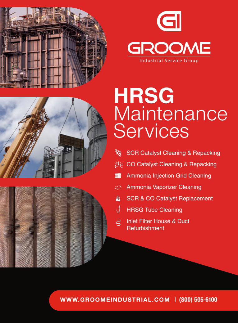
HRSGMaintenanceServices
SCR Catalyst Cleaning & Repacking
CO Catalyst Cleaning & Repacking
Ammonia Injection Grid Cleaning
Ammonia Vaporizer Cleaning
SCR & CO Catalyst Replacement
HRSG Tube Cleaning
Inlet Filter House & DuctRefurbishment
| (800) 505-6100
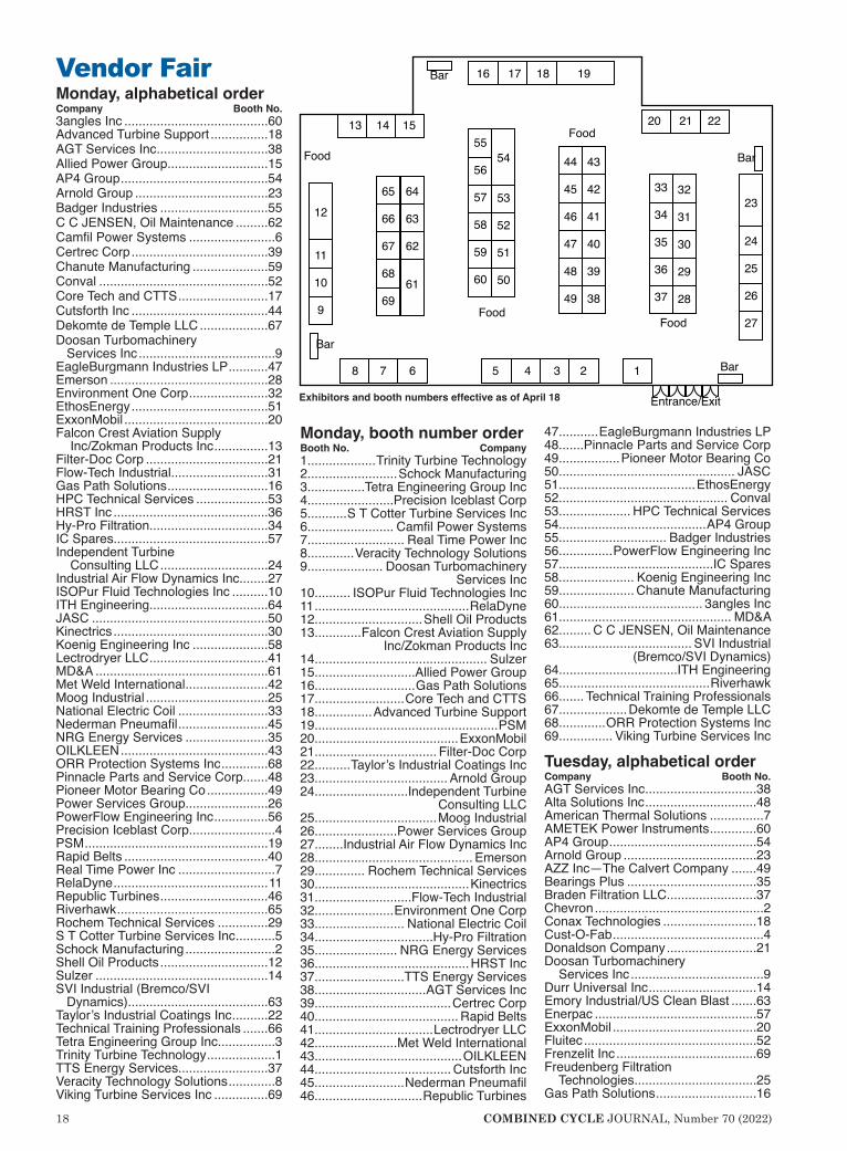
18 COMBINED CYCLE JOURNAL, Number 70 (2022)
Vendor FairMonday, alphabetical orderCompany Booth No.3angles Inc ........................................60Advanced Turbine Support ................18AGT Services Inc ...............................38Allied Power Group............................15AP4 Group .........................................54Arnold Group .....................................23Badger Industries ..............................55C C JENSEN, Oil Maintenance .........62Camfil Power Systems ........................6Certrec Corp ......................................39Chanute Manufacturing .....................59Conval ...............................................52Core Tech and CTTS .........................17Cutsforth Inc ......................................44Dekomte de Temple LLC ...................67Doosan Turbomachinery Services Inc ......................................9EagleBurgmann Industries LP ...........47Emerson ............................................28Environment One Corp ......................32EthosEnergy ......................................51ExxonMobil ........................................20Falcon Crest Aviation Supply Inc/Zokman Products Inc ...............13Filter-Doc Corp ..................................21Flow-Tech Industrial...........................31Gas Path Solutions ............................16HPC Technical Services ....................53HRST Inc ...........................................36Hy-Pro Filtration.................................34IC Spares...........................................57Independent Turbine Consulting LLC ..............................24Industrial Air Flow Dynamics Inc........27ISOPur Fluid Technologies Inc ..........10ITH Engineering.................................64JASC .................................................50Kinectrics ...........................................30Koenig Engineering Inc .....................58Lectrodryer LLC .................................41MD&A ................................................61Met Weld International .......................42Moog Industrial ..................................25National Electric Coil .........................33Nederman Pneumafil .........................45NRG Energy Services .......................35OILKLEEN .........................................43ORR Protection Systems Inc .............68Pinnacle Parts and Service Corp.......48Pioneer Motor Bearing Co .................49Power Services Group.......................26PowerFlow Engineering Inc ...............56Precision Iceblast Corp........................4PSM ...................................................19Rapid Belts ........................................40Real Time Power Inc ...........................7RelaDyne ...........................................11Republic Turbines ..............................46Riverhawk ..........................................65Rochem Technical Services ..............29S T Cotter Turbine Services Inc ...........5Schock Manufacturing .........................2Shell Oil Products ..............................12Sulzer ................................................14SVI Industrial (Bremco/SVI Dynamics) .......................................63Taylor’s Industrial Coatings Inc ..........22Technical Training Professionals .......66Tetra Engineering Group Inc................3Trinity Turbine Technology ...................1TTS Energy Services.........................37Veracity Technology Solutions .............8Viking Turbine Services Inc ...............69
Monday, booth number orderBooth No. Company1...................Trinity Turbine Technology2.........................Schock Manufacturing3................Tetra Engineering Group Inc4........................Precision Iceblast Corp5...........S T Cotter Turbine Services Inc6........................ Camfil Power Systems7........................... Real Time Power Inc8.............Veracity Technology Solutions9..................... Doosan Turbomachinery
Services Inc10.......... ISOPur Fluid Technologies Inc11 ...........................................RelaDyne12..............................Shell Oil Products13.............Falcon Crest Aviation Supply
Inc/Zokman Products Inc14................................................ Sulzer15............................Allied Power Group 16............................Gas Path Solutions17.........................Core Tech and CTTS18................Advanced Turbine Support19...................................................PSM20........................................ExxonMobil21.................................. Filter-Doc Corp22..........Taylor’s Industrial Coatings Inc23..................................... Arnold Group24..........................Independent Turbine
Consulting LLC25..................................Moog Industrial26.......................Power Services Group27........Industrial Air Flow Dynamics Inc28............................................ Emerson29.............. Rochem Technical Services30...........................................Kinectrics31...........................Flow-Tech Industrial32......................Environment One Corp33......................... National Electric Coil34.................................Hy-Pro Filtration35....................... NRG Energy Services36...........................................HRST Inc37.........................TTS Energy Services38...............................AGT Services Inc39......................................Certrec Corp40........................................ Rapid Belts41.................................Lectrodryer LLC42.......................Met Weld International43.........................................OILKLEEN44...................................... Cutsforth Inc45.........................Nederman Pneumafil46..............................Republic Turbines
47...........EagleBurgmann Industries LP48.......Pinnacle Parts and Service Corp49.................Pioneer Motor Bearing Co50................................................. JASC51......................................EthosEnergy52............................................... Conval53.................... HPC Technical Services54.........................................AP4 Group55.............................. Badger Industries56...............PowerFlow Engineering Inc57...........................................IC Spares58..................... Koenig Engineering Inc59..................... Chanute Manufacturing60........................................ 3angles Inc61................................................ MD&A62......... C C JENSEN, Oil Maintenance63..................................... SVI Industrial
(Bremco/SVI Dynamics)64.................................ITH Engineering65..........................................Riverhawk66....... Technical Training Professionals67...................Dekomte de Temple LLC68.............ORR Protection Systems Inc69............... Viking Turbine Services Inc
Tuesday, alphabetical orderCompany Booth No. AGT Services Inc ...............................38Alta Solutions Inc ...............................48American Thermal Solutions ...............7AMETEK Power Instruments .............60AP4 Group .........................................54Arnold Group .....................................23AZZ Inc—The Calvert Company .......49Bearings Plus ....................................35Braden Filtration LLC.........................37Chevron ...............................................2Conax Technologies ..........................18Cust-O-Fab ..........................................4Donaldson Company .........................21Doosan Turbomachinery Services Inc .....................................9Durr Universal Inc ..............................14Emory Industrial/US Clean Blast .......63Enerpac .............................................57ExxonMobil ........................................20Fluitec ................................................52Frenzelit Inc .......................................69Freudenberg Filtration Technologies ..................................25Gas Path Solutions ............................16
16 17 18 19
8 7 6 5 4 3 2 1
13 14 15
12
11
10
9
65
66
67
68
69
64
63
62
61
55
56
57
58
59
60
54
53
52
51
50
44
45
46
47
48
49
43
42
41
40
39
38
33
34
35
36
37
32
31
30
29
28
20 21 22
23
24
25
26
27
Bar
Bar
Bar
Bar
Entrance/Exit
Food
Food
FoodFood
Exhibitors and booth numbers effective as of April 18
COMBINED CYCLE JOURNAL, Number 70 (2022) 19
Gas Turbine Parts & Services Inc......50Groome Industrial Service Group LLC .....................................43GTC Control Solutions Inc .................45HILCO Filtration .................................42Hydralube ..........................................31HYTORC ...........................................65Industrial Air Flow Dynamics Inc........27Integrity Power Solutions ...................29K-Machine .........................................28Macemore Inc ......................................1Marioff NA ..........................................44MD&A ................................................61Mee Industries Inc .............................47Mercer Thompson LLC ......................56Miba Industrial Bearings ......................3Mitten Manufacturing ...........................6Nord-Lock Group ...............................33Olympus ............................................17Paragon ...............................................5Parker Hannifin ..................................59PGAS Inc ...........................................24Power & Industrial Services Corp ......26Power Plant Services ........................62Powmat Ltd........................................58PSM ...................................................19Reliable Industrial Group ...................51Reuter-Stokes, a Baker Hughes business ........................................39Roper Pump Company ......................36Shell Oil Products ..............................12Sohre Turbomachinery ......................34Starfish PPS LLC...............................41Stork Turbo Blading ...........................30TesTex Inc..........................................15Thomassen Amcot International (TAI) ..........................40TOPS Field Services LLC ..................64
Toshiba America Energy Systems .....55Universal Plant Services....................32Voom LLC ..........................................22W L Gore & Associates Inc ................46Woodward Inc ......................................8Young & Franklin ...............................53
Tuesday, booth number orderBooth No. ............................................ Company 1......................................Macemore Inc2...............................................Chevron3......................Miba Industrial Bearings4..........................................Cust-O-Fab5...............................................Paragon6...........................Mitten Manufacturing7............... American Thermal Solutions8......................................Woodward Inc9..................... Doosan Turbomachinery
Services Inc12..............................Shell Oil Products14..............................Durr Universal Inc15..........................................TesTex Inc16............................Gas Path Solutions17............................................ Olympus18.......................... Conax Technologies19...................................................PSM20........................................ExxonMobil21.........................Donaldson Company22..........................................Voom LLC23..................................... Arnold Group24...........................................PGAS Inc25 .....Freudenberg Filtration Technologies26......Power & Industrial Services Corp27........Industrial Air Flow Dynamics Inc28......................................... K-Machine29...................Integrity Power Solutions30...........................Stork Turbo Blading31.......................................... Hydralube
32....................Universal Plant Services33...............................Nord-Lock Group34...................... Sohre Turbomachinery35.................................... Bearings Plus36.................................Roper Pump Co37.........................Braden Filtration LLC38...............................AGT Services Inc39........Reuter-Stokes, a Baker Hughes
business40.............................Thomassen Amcot
International (TAI)41...............................Starfish PPS LLC42.................................HILCO Filtration43.................Groome Industrial Service
Group LLC44..........................................Marioff NA45.................GTC Control Solutions Inc46................W L Gore & Associates Inc47............................. Mee Industries Inc48...............................Alta Solutions Inc49....... AZZ Inc—The Calvert Company50......Gas Turbine Parts & Services Inc51...................Reliable Industrial Group52................................................Fluitec53............................... Young & Franklin54.........................................AP4 Group55.....Toshiba America Energy Systems56......................Mercer Thompson LLC57............................................. Enerpac58........................................Powmat Ltd59..................................Parker Hannifin60.............AMETEK Power Instruments61................................................ MD&A62........................ Power Plant Services63....... Emory Industrial/US Clean Blast64..................TOPS Field Services LLC65........................................... HYTORC69.......................................Frenzelit Inc
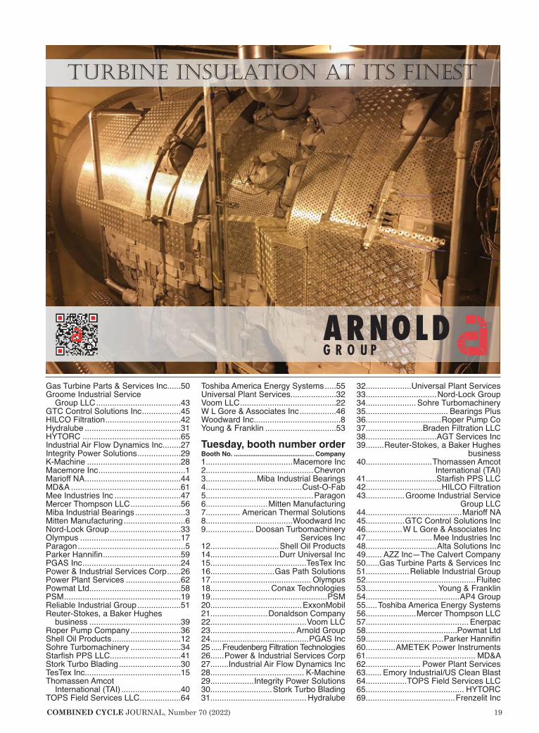
TURBınE ınSULATıOn AT ıTS FınEST


22 COMBINED CYCLE JOURNAL, Number 70 (2022)
7F USERS GROUP
Slide decks for presentations by owner/operators at the 7F Users Group’s 2021conference and vendor fair that have been made available for viewing by registered users are posted on the Power Users website (https://powerus-ers.org). The thumbnails below can quickly point you to subject matter of interest.
R9/S9 clashing damage during cas-ing lift
Clashing, defined here as contact between adjacent rotating blades and stationary vanes, has been discussed in several CCJ articles over the last decade. The early work associated with defining the problem and when and why it occurred, and then figur-ing out how to avoid clashing can be found in the archives of the 7EA Users Group published by this journal and available via the online search function at https://ccj-online.com. Evidence of clashing has been reported by owner/operators of all common GE frames—5s, 6Bs, 7Es, and 7Fs.
The presentation at the 2021 meet-ing of the 7F Users Group focused on clashing that occurred in two 7FAs when their compressor casings were being removed during disassembly for a major inspection. Contributing causes, stated succinctly by the presenter, were the following:n Rotor pushed
aft to take closing clear-ances.
n A s - f o u n d thrust was out of tolerance.
n E x c e s s i v e clearance on c a s i n g - l i f t gu ide p ins and location (body-bounds).
n Rotor blades in Rows 7 to 10 were migrating aft.
n Migrated blades were just above the horizontal split line during the casing lift.Corrective actions suggested/under-
taken by the OEM were these:n Redesigned the guide pins (made
thicker) to reduce clearance.n Place all four guide pins in body-
bound holes when possible. n Lift compressor casings slower.n Borescope under the compressor
casing as it is being removed.
Safety Roundtable: Top safety inci-dents
Discussion leader for the Safety
Roundtable, a manager in the outage services group at a power producer with dozens of gas turbines, provided valuable perspective in his opening remarks. A basic tenet of accident prevention theory, he said, is that high-severity occupational safety and health incidents are preceded by numerous lower-severity incidents and near misses, such that the ratio of lower- to higher-severity incidents exists in the form of a so-called safety triangle (Fig 1). Further, that similar causes underlie both high- and low-severity events.
The discussion leader then defined the hierarchy of hazard controls—a system used to minimize or eliminate exposure to hazards where the con-trols in the hierarchy are in order of decreasing effectiveness as shown in Fig 2. He stressed that safety is not the absence of accidents, but rather the presence of defenses.
The first polling question: Which of the following do you think are where most incidents occur performing out-age work? A dozen causes were offered. For the speaker’s company the most incidents in the last five years were logged in the material handling/moving vehicle category, followed by rigging and lifts, tool use, and slip/
trip/fall. Three incidents then were described
along with the controls or tools that could have been implemented to mitigate their occurrence. At-risk behaviors also were identified. The three incidents: burn from a heated bolt contacting exposed skin, dropping of the upper half of a generator end shield improperly rigged for installa-tion, cut forehead that occurred when a worker removed his hard hat then bumped his head while climbing into a combustion chamber.
These first-hand accounts, which preceded the open-discussion portion of the roundtable, are valuable for their learning experiences and certainly worth a read.
Stage 5 compressor vane failure The editors believe this to be one of
the most thorough presentations on a failure presented at a user-group meet-ing and worthwhile reviewing by virtu-ally all CCJ readers for how the inspec-tion and metallurgical analysis were conducted, the conclusions drawn, and the recommendations made.
What happened: During steady-state operation, a 7F gas turbine/gen-erator tripped offline as a result of a Mark VI “master protective trip,” caus-ing the 52G relay to open. A so-called enhanced borescope inspection of the entire engine was conducted by the OEM to provide a preliminary dam-age assessment. Severe damage was found in the compressor section (Fig 3). The No. 87 Stage 5 vane, located in the lower casing half one vane removed from horizontal joint on the right side of the machine (looking downstream), was liberated just above its platform.
Crack propagation occurred in two phases. The first was low-cycle fatigue, the second high-cycle fatigue—the latter causing the catastrophic dam-age. The metallurgical examination revealed crack initiation was at an area with surface damage, most likely caused by water-wash erosion of less than 0.5 mils of depth; the driving force was LCF. The fracture-surface photography provided enables a good
understanding. T h e v a n e
material, Cus-tom 450, was not at issue as the material was within specifica-tions. Experts concluded that the failure was m o s t l i k e l y caused by inad-equate frequen-cy response—the thought being that No. 87 could
have been an outlier with respect to shape, weight, or another physical parameter not related to the material. Frequency response is considered the probable root cause because further analysis was not possible, the vane having been destroyed.
Finally, erosion pitting was ruled out as a root cause because the refer-ence vanes had very minor indications of erosion pits, yet they did not develop into a crack. When compared to the reference fifth-stage vanes, the failed airfoil had a similar chemistry, hard-ness, and microstructure properties.
7F controls: Panel discussion There is no way to summarize in a
few words all that was covered during
2021 user presentations
FatalityRecordable
injury
First-aid injury
Near-miss incidents
Unsafe acts, unsafe conditionsand at-risk behaviors Least
effective
Mosteffective
PPE Protect the worker
Administrativecontrols Change the
way people work
Engineeringcontrols Isolate people
from the hazard
Substitution Replacethe hazard
EliminationPhysically remove the hazard
1. Safety triangle 2. Hierarchy of controls

http://secc.umicore.com
Smarter catalysts: two in one
Better emissions compliance
http://secc.umicore.com
Clean air is our business. The GTC-802 (NOx/CO-VOC) “Dual Function” catalyst will
help your plant meet stricter emission standards while improving performance and
profitability. GTC-802 combines two catalysts in one, delivering both superior
NOx reduction and outstanding CO and VOC oxidation. Lowest pressure drop,
near zero SO2 oxidation and reduced ammonia slip add up to improved heat
rate, increased power output and fewer cold-end maintenance issues. GTC-802 is
positioned downstream of the ammonia injection grid in the same location as the
current SCR catalyst. As an added benefit, the catalyst allows direct injection of
liquid ammonia or urea in place of the traditional vaporized ammonia.

24 COMBINED CYCLE JOURNAL, Number 70 (2022)
7F USERS GROUP
the controls segment of the meeting. A bullet-point list of the discussion top-ics follows; a summary slide for each was prepared by the session leader and these may be worth skimming, depend-ing on your “need to know.”n Auto-Tune CDM (combustion
dynamics monitoring) probe-failure mitigation.
n Fire protection, including discussion points on water mist systems.
n Online water wash and take-aways from a user’s TIL 1603-R1 experi-ence and reference to TIL 1323-3R1. Recall that TIL 1603 provides rec-ommended time durations for water washing. An observation offered: Controls portions of TILs often are overlooked.
n Water-wash controller and other upgrades. Highlights include issues facing users equipped with a variety of PLCs (GE Fanuc, Allen Bradley, etc) and the benefits of replacing them with Simplex Mark VIe controls.
n An unintentional gas-turbine start without purge during an offline water wash (TIL 2289).
n Unnecessary exhaust-spread run-backs. Recall that exhaust runbacks are initiated when controls detect failed-low and failed-high thermo-
couples. Suggestion: Add a 1-sec time delay for high and low failure detection to prevent an erratic t/c from being counted as both failed-high and failed-low.
n Mods to consider for the OEM’s origi-nal anti-icing program to reduce the possibility of compressor damage.
Faulty CDM probes and model base control
Related to some material discussed in the controls panel (see above). This short presentation reviews how to identify a faulty CDM probe and dis-connect it.
It also mentions the OEM’s efforts in developing a logic fix to ignore faulty signals and the benefits of setting up alerts in monitoring software to review data on suspected faulty CDM probes
Generator stator-core surprise This is the case history of a 7FH2
generator minor in mid-June 2021 for a unit with no known operational issues. Background:n Unit data included 224 MVA, 18
kV, 7200 amps.n Last inspection in 2015 using the
Magic robot from the collector end revealed no significant issues.
n With both endbells off during the minor, staff decided to pull the upper inner gas baffles on both ends to permit limited inspection of the stator-winding end turns and the rotor.
n Preliminary observations: Collec-tor end of the machine appeared normal, but there were signs of oil ingress. Inspection of the turbine end revealed a mysterious object in the air gap between the stator and rotor. It was magnetic, possibly stator core iron.
n Action: Pull the rotor (unplanned). n Findings included greasing of the
stator core, dings and dents on the rotor body, damage to the tur-bine-end retaining ring, debris in hydrogen coolers, damage to core iron (Fig 4), and partially blocked cooling passage. Photos illustrate all of these findings. The speaker reviewed the process
used to determine the cause of the concern and what to do about it. This involved testing of stator core iron and a stator-winding hi-pot test. There were no red flags. A review of issues associated with the 25-year-old rotor, repair options/choices considered, and restoration decisions made are spelled out in the presentation.
The investigative effort revealed that the first two dozen machines of this type/size (identifiable by serial number) were assembled using a defective core-compression process wherein key-bar nuts were torqued to 2000 ft-lb but thermal cycling may have contributed to a loosening of the core iron.
Bear in mind that because the cores are stacked vertically with the turbine end up, the loose core-iron issue occurs only on that end. Suggestion to owner/operators was that because the area of concern is difficult to inspect with Magic, they might want to consider rotor inspections going forward.
Details on the repair of damaged core iron closed out the presentation (Fig 4), which qualified users can access in the 2021 conference files at https://powerusers.com.
Several more presentations were made by users at the 2021 conference, but they had not been posted to the Power Users website prior to press time. If the subject matter below is of particular interest, you might want to check back to see if those presentations are now available. n Lube-oil detection software.n In-situ fuel-nozzle flow testing.n FlameSheet™ project update.n 7FA.05 first HGPI experience.n Rotor end-of-life maintenance con-
siderations.
3. Significant damage was found in Row 5 of the 7F compressor; vane damage is shown here
4. Damage to core iron was significant

COMBINED CYCLE JOURNAL, Number 70 (2022) 25

26 COMBINED CYCLE JOURNAL, Number 70 (2022)
7F USERS GROUP
Slide decks for all vendor presentations made at the 7F Users Group annual conference in the Marriott St. Louis Grand, Aug 23-27, 2021, are avail-able for viewing by registered owner/operators on the Power Users website (https://powerusers.org). The thumb-nails below can quickly point you to subject matter of interest. Nearly 200 users attended this meeting; 104 equipment and services providers par-ticipated in the vendor fair.
MD&ARotor life assessmentFred Willett, gas-turbine princi-
pal engineer, begins by walking you through MD&A’s four-step assess-ment process: Disassembly/unstack, thorough inspection, engineering review and risk assessment, rebuild for continued operation. Inspections described and where used are these: Visual, ultrasonic phased array, eddy current test, hardness test, metallur-gical investigation, alloy confirmation, dimensional inspection, and surface inspection.
Turbine disc problems associated with the first and second stages are identified, the benefits of MD&A’s cooling-slot shape are described, dove-tail modification and lockwire groove cracking are explained, and the 1-2 spacer issue is reviewed.
Design enhancements: 7FA 1-2 spacer cracking
Willett reviews in detail the 1-2 spacer issue identified in his earlier presentation. The findings from an
analysis of a 9FA that tripped on high vibration were these: A section of the spacer rim had liberated, cracks initi-ated on the inner surface and propa-gated outward and circumferentially, and fatigue was exacerbated by hold-time crack growth. MD&A’s solution was the spacer with improved stiffness described in the presentation.
7F gas-turbine alignmentCharles Monestere, operations man-
ager, alignment services, reviews the component checks required to assure proper alignment of turbine bearing and casing; common problems are identified. Also, he explains the impact of casing distortion and bore positions relative to the machine centerline and their impact on tip clearances.
Three-dozen slides illustrate and explain how to align a gas turbine. This “how-to” presentation would be a valu-able addition to most plant libraries for ready reference before an alignment project is undertaken.
7F component life extensionIf you’re having difficulty with
your F-class gas-turbine OEM when it comes to repair of hot-gas-path (HGP) components, MD&A wants you to know they not only have the experience you are seeking, but also enhancements, which will extend service life, plus provide better transparency and cus-tomer oversight throughout the repair process.
Jose Quinones, PE, director of engi-neering, reviews the company’s capa-bilities, experience, and customer-care process, most pointedly through
examples including nozzles, blades, and shrouds for all three turbine stages.
Gas-turbine thermodynamic analy-sis and performance testing
James Miller, PE, manager of per-formance services, walks you through a CliffsNotes of sorts dedicated to calculations plant personnel and engi-neering staff should be familiar with, including the following:n Gas-turbine performance calcula-
tions—generator, compressor, and turbine efficiency.
n Determining firing temperature.n Tuning and combustion impacts on
efficiency.n Typical degradation and its effect
on performance.n Effects of turbine boundary condi-
tions.n Example of test corrections and
reconciliation.n Example of thermal survey findings.
Equations and simple illustrations throughout make this a valuable addi-tion to your analytical toolbox.
PSM Advanced technologies for the 7F.03:
Development and implementationGreg Vogel, manager of technology,
offers the following view: To maintain relevance in the power generation merit order, F-class gas turbines must withstand higher firing temperatures, aggressive peak and turndown limits, quicker ramp rates, and maintain operations with varying fuels. Only new technologies enable these new requirements. The following are some effective upgrade technologies avail-able to increase the output and flex-ibility of existing assets. n Additive manufacturing, for exam-
ple, opens the door to novel designs. One benefit is a direct-cooling effi-ciency improvement for increased performance and lifetime capability, allowing the gas turbine to meet new operational requirements while at the same time reducing overall lifecycle cost. In 2018, PSM said it was the first company to rainbow test and F-class HGP additive-manufactured component with improved capabilities.
n Superalloys. In advanced F- and H-class units, superalloy com-ponents allow higher firing tem-peratures. However, this technol-ogy also has posed problems to operators regarding maintenance and overall operability cost. PSM has developed and implemented advanced equiaxed and direction-ally solidified alloys and has com-pleted several engineering studies on varying applications. Advantages and disadvantages of these were discussed from a technological and
2021 vendor presentations
MD&A’s laser target bracket setup is shown in the alignable No. 2 bearing ped-estal located in the exhaust casing

Turnkey solutions for:
Independent Power Operators | Regulated Industries
Power Plant Management Teams | Investors
We’re removing the burden and responsibility of protecting & managing complex emission systems for power plants. We’re delivering performance, predictability,
cash flow, and 100% risk mitigation through a turnkey solution.
844-GO-NOXCO 844-466-6926 www.gonoxco.com
NOXCO raises the bar with the very first LTSA for
emissions compliance.
Contact us today to learn more.
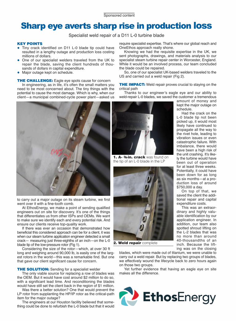
KEY POINTS● Tiny crack identified on D11 L-0 blade tip could have
resulted in a lengthy outage and production loss costing millions of dollars.
● One of our specialist welders traveled from the UK to repair the blade, saving the client hundreds of thou-sands of dollars in capital expenditure.
● Major outage kept on schedule.
THE CHALLENGE: Eagle eye spots cause for concernIn engineering, as in life, it’s often the small matters you
need to be most concerned about. The tiny things with the potential to cause the most damage. Which is why, when our client—a municipal combined-cycle power plant—asked us
to carry out a major outage on its steam turbine, we first went over it with a fine-tooth comb.
At EthosEnergy, we make a point of sending qualified engineers out on site for discovery. It’s one of the things that differentiates us from other ISPs and OEMs. We want to make sure we identify each and every potential risk. And ensure our clients receive top-quality work.
If there was ever an occasion that demonstrated how beneficial this considered approach can be for a client, it was when our steam turbine application engineer detected a small crack— measuring just three-eighths of an inch—on the L-0 blade tip of the low-pressure rotor (Fig 1).
Considering the size of the rotor—which, at over 30 ft long and weighing around 90,000 lb, is easily one of the larg-est rotors in the world—this was a remarkable find. But one that gave our client significant cause for concern.
THE SOLUTION: Sending for a specialist welder The only viable source for replacing a row of blades was
the OEM. But it would have cost around $2 million to do so, with a significant lead time. And reconditioning the blades would have still set the client back in the region of $1 million.
Was there a better solution? One that would prevent the LP rotor from supplanting the HP/IP rotor as the critical-path item for the major outage?
The engineers at our Houston facility believed that some-thing could be done to refurbish the L-0 blade but that it would
require specialist expertise. That’s where our global reach and OneEthos approach really shone.
Knowing we had the requisite expertise in the UK, we sent photographs, drawings, and materials analysis to our specialist steam turbine repair center in Worcester, England. While it would be an involved process, our team concluded the blade could be repaired.
So, one of our specialist UK-based welders traveled to the US and carried out a weld repair (Fig 2).
THE IMPACT: Weld repair proves crucial to staying on the critical path
Thanks to our engineer’s eagle eye and our ability to weld-repair L-0 blades, we saved the customer a tremendous
amount of money and kept the major outage on schedule.
Had the crack on the L-0 blade tip not been picked up, it would most likely have continued to propagate all the way to the rivet hole, leading to vibration issues or even catastrophic failure. With imbalance, there would have been a high risk of the unit crashing. It’s like-ly the turbine would have been out of operation for at least three weeks. Potentially, it could have been down for as long as six months—at a pro-duction loss of around $750,000 a day.
On top of that, we saved the client the addi-tional repair and capital expenditure costs.
This was an extraor-dinary and highly valu-able identification by our application engineer. In addition, our team also spotted shroud lifting on the L-2 blades that was no more than around 40-thousandths of an inch. Because the lift-ing was on the closing
blades, which were made out of titanium, we were unable to carry out a weld repair. But by replacing two groups of blades, we effectively wound the lifecycle back to zero hours again on those two groups.
Yet further evidence that having an eagle eye on site makes all the difference.
Sponsored content
Sharp eye averts sharp rise in production loss Specialist weld repair of a D11 L-0 turbine blade
1. A- 3⁄8-in. crack was found on the tip of an L-0 blade in the LP
2. Weld repair complete


30 COMBINED CYCLE JOURNAL, Number 70 (2022)
cost perspective. Unfortunately, PSM had not released a copy of the final presentation by press time.
n Fuel flexibility. In addition to new manufacturing techniques and advanced superalloy applications of rotating components, the industry has begun evaluating the ability to burn a variety of fuels—includ-ing hydrogen and shale gas—with the goal of lowering operating costs while keeping the gas turbine viable in a net-zero-carbon world. PSM’s FlameSheet™ is part of this solu-tion.
AGT Services Inc7FH2 generators: Crucial spare parts and replacement components every owner must consider in your service provider
Jamie Clark, well known to pow-erplant personnel for his generator knowhow, explains that while the 7FH2 fleet has a long history of com-paratively reliable operation, age is catching up with these units, which also are being asked to run harder. There are critical components, parts, and pieces to consider, he continues, whether for your own stock or for your service provider. Speed and time are crucial in being able to get your unit back in service, whether from a
planned or unplanned outage. Unfortunately, contends Clark,
many critical components aren’t readily available. He then identifies these components—such as HV bush-ings and stator windings—and urges owner/operators to evaluate service providers and identify a pathway to access them in a timely manner and minimize your risk.
Koenig Engineering IncTurning-gear low-speed drive and
maintenanceThe tag team of Tim Connor, man-
ager of aftermarket sales and field service for Koenig Engineering, and Nick Fischer, GE’s product line engi-neer and manager of overhaul/modifi-cations, provide in-depth information on what they describe as the biggest design change to the 7F turning gear in more than two decades.
Specifically, the low-speed drive modification includes a new pri-mary gear reduction and a second turning-gear motor to operate the TG at a fraction of an rpm. The low-speed drive saves power and is said to provide a 60-fold reduction in bucket-rock wear.
The presentation also discusses recent inspection findings and best practices.
EthosEnergy7FA rotor lifetime extensionJeff Schleis, product manager,
reminds owner/operators that many 7F gas turbines are approaching the OEM’s 5000 factored-start/144,000 factored-hours limits requiring life-time inspections and solutions to extend the run times of hours-based units. Presentation focuses on solu-tions that enable you to maximize the value of critical equipment, including the following:n Compressor stages R0-R5 (flared
and unflared).n R0/S0 blades (original, enhanced,
enhanced high output).n R12-R17 wheels and blades (round-
slot and flat bottom).n R14-R17 wheels (original and
robust-back-end designs).n Turbine rotor (TIL 1937, cooling
slot geometry).n Distance piece (original and reverse-
rabbet designs).n Cooling slot (original symmetrical
configuration, contoured design, enhanced design). Schleis presents the inspection
scopes for compressor and turbine wheels and distance piece/spacers/stub shaft. The good news when the inspection results say “no findings,” your rotor is reassembled with new
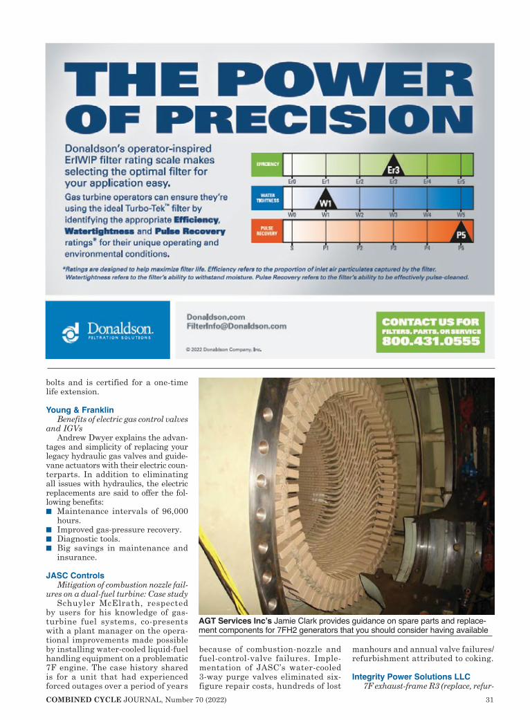
COMBINED CYCLE JOURNAL, Number 70 (2022) 31
bolts and is certified for a one-time life extension.
Young & FranklinBenefits of electric gas control valves
and IGVsAndrew Dwyer explains the advan-
tages and simplicity of replacing your legacy hydraulic gas valves and guide-vane actuators with their electric coun-terparts. In addition to eliminating all issues with hydraulics, the electric replacements are said to offer the fol-lowing benefits:n Maintenance intervals of 96,000
hours.n Improved gas-pressure recovery.n Diagnostic tools.n Big savings in maintenance and
insurance.
JASC ControlsMitigation of combustion nozzle fail-
ures on a dual-fuel turbine: Case studySchuyler McElrath, respected
by users for his knowledge of gas-turbine fuel systems, co-presents with a plant manager on the opera-tional improvements made possible by installing water-cooled liquid-fuel handling equipment on a problematic 7F engine. The case history shared is for a unit that had experienced forced outages over a period of years
because of combustion-nozzle and fuel-control-valve failures. Imple-mentation of JASC’s water-cooled 3-way purge valves eliminated six-figure repair costs, hundreds of lost
manhours and annual valve failures/refurbishment attributed to coking.
Integrity Power Solutions LLC7F exhaust-frame R3 (replace, refur-
AGT Services Inc’s Jamie Clark provides guidance on spare parts and replace-ment components for 7FH2 generators that you should consider having available
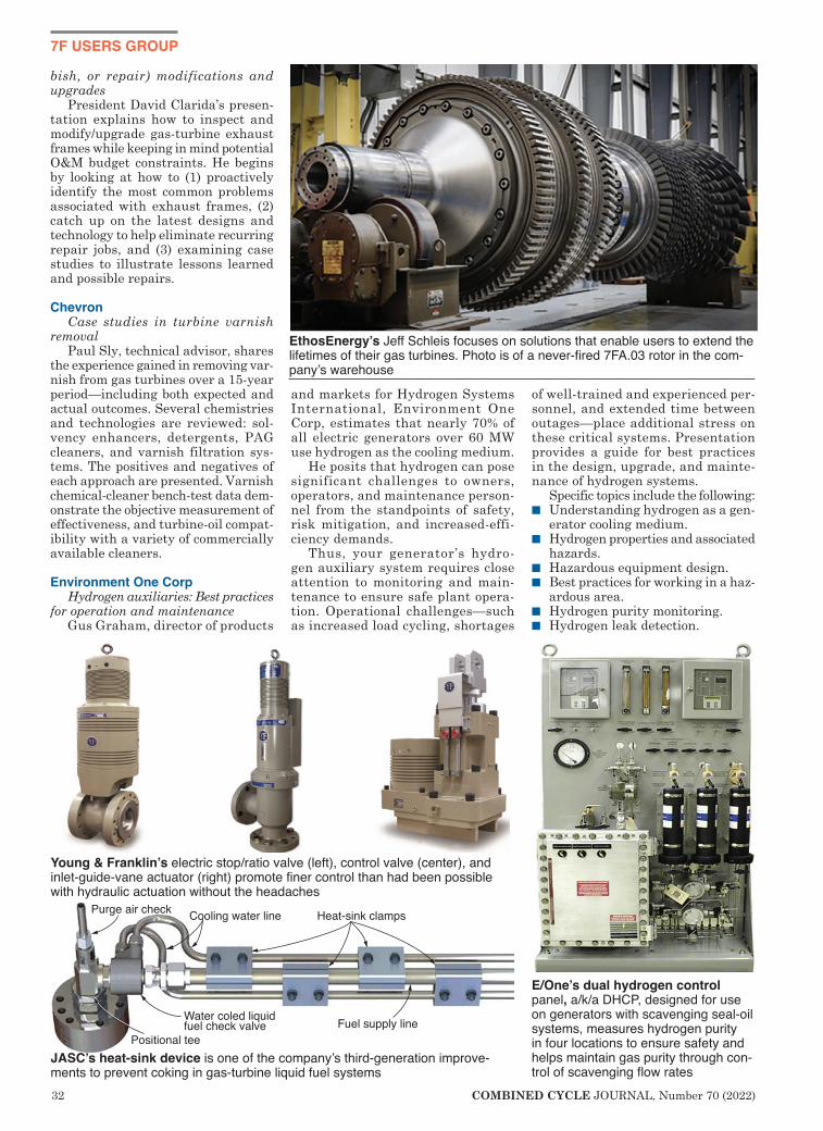
32 COMBINED CYCLE JOURNAL, Number 70 (2022)
7F USERS GROUP
bish, or repair) modifications and upgrades
President David Clarida’s presen-tation explains how to inspect and modify/upgrade gas-turbine exhaust frames while keeping in mind potential O&M budget constraints. He begins by looking at how to (1) proactively identify the most common problems associated with exhaust frames, (2) catch up on the latest designs and technology to help eliminate recurring repair jobs, and (3) examining case studies to illustrate lessons learned and possible repairs.
ChevronCase studies in turbine varnish
removalPaul Sly, technical advisor, shares
the experience gained in removing var-nish from gas turbines over a 15-year period—including both expected and actual outcomes. Several chemistries and technologies are reviewed: sol-vency enhancers, detergents, PAG cleaners, and varnish filtration sys-tems. The positives and negatives of each approach are presented. Varnish chemical-cleaner bench-test data dem-onstrate the objective measurement of effectiveness, and turbine-oil compat-ibility with a variety of commercially available cleaners.
Environment One CorpHydrogen auxiliaries: Best practices
for operation and maintenanceGus Graham, director of products
and markets for Hydrogen Systems International, Environment One Corp, estimates that nearly 70% of all electric generators over 60 MW use hydrogen as the cooling medium.
He posits that hydrogen can pose significant challenges to owners, operators, and maintenance person-nel from the standpoints of safety, risk mitigation, and increased-effi-ciency demands.
Thus, your generator’s hydro-gen auxiliary system requires close attention to monitoring and main-tenance to ensure safe plant opera-tion. Operational challenges—such as increased load cycling, shortages
of well-trained and experienced per-sonnel, and extended time between outages—place additional stress on these critical systems. Presentation provides a guide for best practices in the design, upgrade, and mainte-nance of hydrogen systems.
Specific topics include the following:n Understanding hydrogen as a gen-
erator cooling medium.n Hydrogen properties and associated
hazards.n Hazardous equipment design.n Best practices for working in a haz-
ardous area.n Hydrogen purity monitoring. n Hydrogen leak detection.
Young & Franklin’s electric stop/ratio valve (left), control valve (center), and inlet-guide-vane actuator (right) promote finer control than had been possible with hydraulic actuation without the headaches
Heat-sink clamps
Fuel supply lineWater coled liquidfuel check valve
Cooling water linePurge air check
Positional teeJASC’s heat-sink device is one of the company’s third-generation improve-ments to prevent coking in gas-turbine liquid fuel systems
E/One’s dual hydrogen control panel, a/k/a DHCP, designed for use on generators with scavenging seal-oil systems, measures hydrogen purity in four locations to ensure safety and helps maintain gas purity through con-trol of scavenging flow rates
EthosEnergy’s Jeff Schleis focuses on solutions that enable users to extend the lifetimes of their gas turbines. Photo is of a never-fired 7FA.03 rotor in the com-pany’s warehouse

COMBINED CYCLE JOURNAL, Number 70 (2022) 33
The 7F Users Group and CCJ are working together to expand the sharing of best practices and
lessons learned among owner/opera-tors of large frame engines. One of the user organization’s objectives is to help members better operate and maintain their plants, and a proac-tive best practices program sup-ports this goal.
Details for two of the four entr ies f rom 7F-powered plants judged Best of the Best in 2021—Effingham County Power and Green Country Ener-gy—appeared in CCJ No. 68, published late last fall. The remaining two 7F plants receiv-ing Best of the Best awards in 2021—River Road Generating Plant and Woodbridge Energy Center—are profiled on the pages that follow.
Other entries in the 2021 Best Practices program rec-
ognized with awards are listed in the index below. The more than two-dozen best prac-tices shared by your col-leagues at 7F facilities are likely to offer an idea or two for improving safety
and performance at your facility.
The Best Practices Awards program for owners and operators of generating facili-ties powered by gas turbines celebrates
its 18th anniversary in 2022. Over the years,
more than 800 best prac-tices entries have been received
from more than 200 individual plants and fleets.
The most successful plant in the program’s history is Effing-ham County Power, which has received eight Best of the Best awards. Its first came in 2010, seven years after COD. This year, General Manager Bob Kulbacki and his team shared two best practices, beginning on p 86 of CCJ No. 68. Particularly note-worthy about Effingham’s run is that it has spanned four owners, four plant managers, and several teams of judges.
7F 2021 Best Practices
Best Practices Awards present-ed to plants powered by 7F gas turbines in 2021Effingham County Power .......No. 68, p 86Empire Generating Co .......................... 56Essential Power Newington .................. 42Green Country Energy ...........No. 68, p 90Hunterstown Generating Station ........... 58Marcus Hook Energy Center ................. 60River Road Generating Plant ................ 34Rumford Power LLC.............................. 52Woodbridge Energy Center ................... 38

34 COMBINED CYCLE JOURNAL, Number 70 (2022)
2021 7F BEST PRACTICES AWARDS
Challenge. Over the years, River Road Generating Plant had experienced several steam-trap failures. In sum, they negatively impacted plant heat rate and allowed condensate to back up in the associated piping systems, inviting the potential for water ham-mer and the damage it causes.
Solution. Plant personnel attended an ultrasonic-detection training pro-gram where they learned both how to properly operate UT equipment and analyze the data gathered.
Next, a monthly PM was created for UT inspection of River Road’s steam traps. Ultrasound allows the inspector to listen to the work cycle of the steam trap (Fig 1). When a trap is not cycling it either is stuck open or closed. Inspection revealed many of the thermostatic steam traps were not cycling, even though they had been replaced recently. Recall that thermo-
static steam-trap operation is based on the temperature differential between steam and condensate.
River Road technicians discovered that insulation had been installed over the steam traps and was negatively affecting their operation. The insula-tion was removed and expanded-metal cages were fabricated and installed over the traps to assure as-designed operating conditions. The cages pro-tect staff from the high-temperature steam-trap body, thereby reducing the risk of contact burns.
Results. UT steam-trap inspection identified improperly installed insula-tion and prompted a creative solution to assure proper trap operation while ensuring employee safety.
Project participants:Justin Hartsoch, operations managerJake Sanderson, operations
Use ultrasound camera to locate leaks of compressed gasChallenge. Leaks of all types of com-pressed gases—plus air and vacuum—can be difficult to locate, often not found until the issue has progressed to an extreme condition or has caused a failure. Undetected leaks may cause heat-rate losses, system contamina-tion, safety issues, and component failures.
Solution. Develop a leak-detection program using an ultrasonic camera. Recall that ultrasonic imaging allows visualization of sound; many sounds inaudible to human ears can be dis-played on the device. Ultrasonic imaging technology works by pinpointing turbulences caused by gaseous mediums escaping from either a pressurized or vacuum environ-ment (Fig 2). The Distran Ultra Pro V2 acoustic monitoring camera used at River Road relies on 124 high-fre-quency microphones to stitch together accurate images of gaseous leaks using phased-array principles.
The plant team developed a peri-odic ultrasonic imagining inspection PM for these systems/components: Instrument air, natural gas, steam, gas-turbine doors/exhaust (Fig 3), boiler drums, HRSG fireside case/manways, lube-oil tank hatches, and generator hydrogen.
Inspection images upload auto-matically to Distran’s Autolytic plat-form, where analysis and report generation can be completed. Work orders then are created to address identified issues.
Results. Air tubing and valve pack-ing leaks were found easily; many were repaired immediately after dis-covery. An important benefit of the ultrasonic imaging tool is that you can see the results of your repair in real time. However, some items
River Road River Road Generating PlantOwned by Clark Public UtilitiesOperated by General Electric250 MW, gas-fired 1 × 1 7FA-pow-ered combined cycle located in Van-couver, WashPlant manager: Robert Mash
Steam-trap problem-solving begins with UT inspection
1. Technician checks steam trap for proper operation at left, views results above
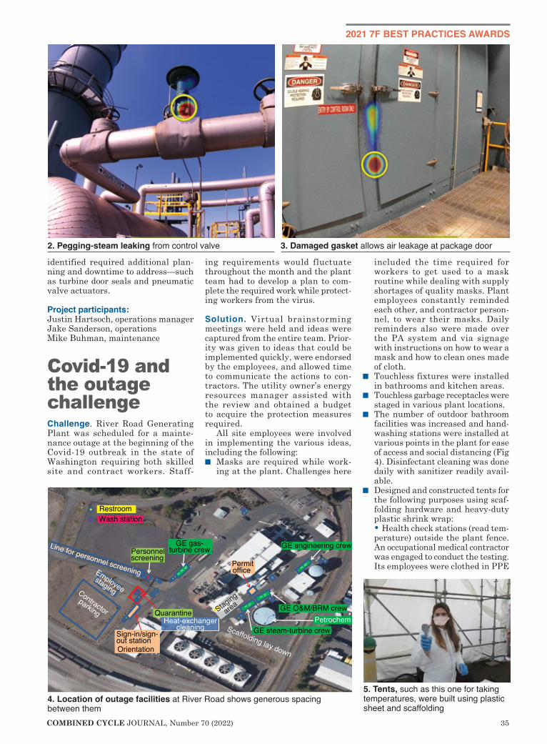
COMBINED CYCLE JOURNAL, Number 70 (2022) 35
2021 7F BEST PRACTICES AWARDS
identified required additional plan-ning and downtime to address—such as turbine door seals and pneumatic valve actuators.
Project participants:Justin Hartsoch, operations managerJake Sanderson, operationsMike Buhman, maintenance
Covid-19 and the outage challengeChallenge. River Road Generating Plant was scheduled for a mainte-nance outage at the beginning of the Covid-19 outbreak in the state of Washington requiring both skilled site and contract workers. Staff-
ing requirements would fluctuate throughout the month and the plant team had to develop a plan to com-plete the required work while protect-ing workers from the virus.
Solution. Virtual brainstorming meetings were held and ideas were captured from the entire team. Prior-ity was given to ideas that could be implemented quickly, were endorsed by the employees, and allowed time to communicate the actions to con-tractors. The utility owner’s energy resources manager assisted with the review and obtained a budget to acquire the protection measures required.
All site employees were involved in implementing the various ideas, including the following:n Masks are required while work-
ing at the plant. Challenges here
included the time required for workers to get used to a mask routine while dealing with supply shortages of quality masks. Plant employees constantly reminded each other, and contractor person-nel, to wear their masks. Daily reminders also were made over the PA system and via signage with instructions on how to wear a mask and how to clean ones made of cloth.
n Touchless fixtures were installed in bathrooms and kitchen areas.
n Touchless garbage receptacles were staged in various plant locations.
n The number of outdoor bathroom facilities was increased and hand-washing stations were installed at various points in the plant for ease of access and social distancing (Fig 4). Disinfectant cleaning was done daily with sanitizer readily avail-able.
n Designed and constructed tents for the following purposes using scaf-folding hardware and heavy-duty plastic shrink wrap:
• Health check stations (read tem-perature) outside the plant fence. An occupational medical contractor was engaged to conduct the testing. Its employees were clothed in PPE
2. Pegging-steam leaking from control valve 3. Damaged gasket allows air leakage at package door
4. Location of outage facilities at River Road shows generous spacing between them
5. Tents, such as this one for taking temperatures, were built using plastic sheet and scaffolding

36 COMBINED CYCLE JOURNAL, Number 70 (2022)
2021 7F BEST PRACTICES AWARDS
to protect site employees against possible exposure (Fig 5).
• Orientation/check-in at the front entrance to the plant. Features: Sufficient space inside the tent to accommodate social distancing, a separate room for log-in/log-out activities, entrance and exit doors are at opposite ends of the tent.
• Permit tent (Fig 6) to eliminate use of the control room for plan-ning work and permitting. It was attached to the administration building, which allowed the shift supervisors to use the plexiglass window for protection. This tent provided access to computers to communicate LOTOs, work permits, and conduct discussions of work activities with contractors. Staged lanes in the tent ensured proper distancing for opening and closing permits.
• Staged the quarantine tent out-side the plant fence to keep pos-sible symptomatic individuals at a distance and cared for by medical professionals until they could be relocated to permanent facilities.
•Increased the number of mobile trailers to keep the turbine main-tenance crews separated. Also, a break trailer was provided for site employees to limit control-room traffic and provide a separate break space from contractor work-ers. Trailer occupancy limits were posted to keep gatherings at safe levels.
• Took a fresh look at admin-istrative processes. Highlights: Contractors were scheduled to start at staggered times to reduce
traffic at the permit tent; work-scope activities were coordinated among contractor groups working in common areas to maintain social distancing; daily meetings were conducted inside and outside in small groups properly masked and separated, as well as virtually and via group phone calls.
• Rearranged some projects to com-plete them at the end of the outage when fewer workers were onsite.
• Deferred non-essential work. • Assured supplies of hand sanitiz-
er, bleach, water, and disinfectant wipes (or spray) were available to
onsite personnel. • Communicated with all contrac-
tors regarding site requirements. They were issued a map showing placement of tents, bathrooms, etc. Made clear was the expectation that breaks and lunch would be offsite or in vehicles parked outside the plant fence.
Results. The group had a short time-line to get all these actions completed, but staff and contractors worked together to complete the outage suc-cessfully. There were no confirmed Covid-19 exposures and no complaints were received regarding protection of all individuals working at the site. A critical review of the 2020 initiatives and actions identified improvements for implementation during the 2021 outage.
Project participants:Margie Brice, EHS specialistOperations teamMaintenance team
Control access to transformer yardBackground. The transformer yard houses several critical power genera-tion components: Generator breaker, step-up transformers, excitation sys-tem, and load commutated inverter (LCI); unit auxiliary transformer; and isolation/excitation transformer (Fig 7). Plant operators enter the yard,
6. Permit tent was segmented to ensure proper distancing and minimal per-sonal contact
7. Transformer yard is home to equipment critical to the operation of River Road

COMBINED CYCLE JOURNAL, Number 70 (2022) 37
located inside the plant’s chain-link boundary fence, four times daily to monitor the assets within. Access to the yard is through one of two manway gates (Fig 8). One evening, an intruder climbed over the perimeter fence and entered the unsecured transformer yard. Next, he entered the generator excitation compartment, a modular building, and climbed up to the generator breaker and opened its local controls cabinet. The intruder did not sabotage any critical equipment or interfere with power production.
Challenge. Improve transformer-yard security to prevent entry to the area by unauthorized people. The belief that this area was secure because it was inside the plant’s perimeter fence is no longer valid.
Solution. Install electronic card read-ers at the manway access points for the transformer yard and tie them into the plant’s existing access control system. Also, install tamper-resistant emergency-exit crash bars to allow per-sonnel quick egress in an emergency. A hydraulic gate closer ensures the lock-ing mechanism engages after passage.
Results. There has been no unauthor-ized entry into the transformer yard since the improvements described above were implemented.
Project participants:Jack BlairKen Roach
Facilitating fan access to make maintenance saferChallenge. The turbine-building MCC is home to 4160- and 480-V circuit breakers for various plant electrical equipment. Intake fans pull ambient air through penetra-tions in the building wall to main-tain a slight positive pressure while also providing cooling air to prevent component overheating.
The intake fans are located inside the MCC and are secured to the roof of an adjacent battery room. The two fans sit side-by-side, essentially on a high shelf above the main MCC space, but still within the building. Access to the fans for filter changes and main-tenance was challenging and posed several safety risks. Workers must climb up from the floor of the MCC room on an 8-ft ladder and transition
off the ladder while leaning through an 11-in. horizontal gap between the edge of the roof and various conduit and cable trays (Fig 9).
Emergency egress, if required, would be very difficult from this location.
Solution. With working space limited, staff had to find a creative solution to gain safe access to the intake fans. Following several brainstorming sessions among plant colleagues, an out-of-the-box idea was proposed: Cut a hole in the wall and build a stairway for access. While this idea was attractive, entry from outside the building was encumbered by an existing stairway support structure that blocked the only possible location for a new access.
Personnel worked with a local structural engineer to help with a resolution. The existing staircase support structure was re-engineered to support an additional smaller stair-case and landing that terminates at the ideal level for access to the intake fans through a newly cut doorway in the building wall (Fig 10).
A custom door was installed to allow direct access to the intake-fan area for maintenance activities.
Results. Safe access and egress dur-ing intake-fan maintenance activities were achieved. Benefits include the following:n Ability to walk into a fan location
without climbing a ladder.n Way to escape the MCC safely in
the event of an emergency. n Reduced risk of personnel injuries. n Allows for the transport of filters
and tools by one person.
Project participants:Ken Roach, maintenance managerMike Buhman, maintenance
8. Access to the transformer yard is via one of two manway gates
9. The plant, as designed, required a ladder to access the MCC intake fan and filter units
10. New staircase provides access to the intake fans via a doorway cut in the building wall
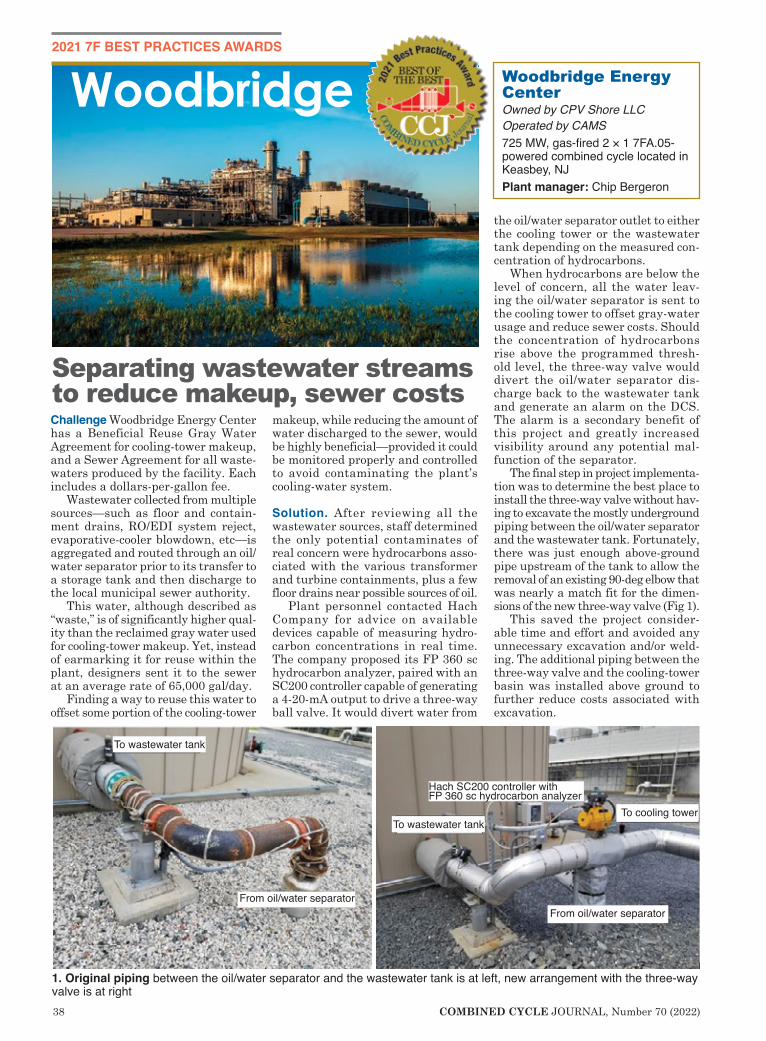
38 COMBINED CYCLE JOURNAL, Number 70 (2022)
2021 7F BEST PRACTICES AWARDS
Challenge Woodbridge Energy Center has a Beneficial Reuse Gray Water Agreement for cooling-tower makeup, and a Sewer Agreement for all waste-waters produced by the facility. Each includes a dollars-per-gallon fee.
Wastewater collected from multiple sources—such as floor and contain-ment drains, RO/EDI system reject, evaporative-cooler blowdown, etc—is aggregated and routed through an oil/water separator prior to its transfer to a storage tank and then discharge to the local municipal sewer authority.
This water, although described as “waste,” is of significantly higher qual-ity than the reclaimed gray water used for cooling-tower makeup. Yet, instead of earmarking it for reuse within the plant, designers sent it to the sewer at an average rate of 65,000 gal/day.
Finding a way to reuse this water to offset some portion of the cooling-tower
makeup, while reducing the amount of water discharged to the sewer, would be highly beneficial—provided it could be monitored properly and controlled to avoid contaminating the plant’s cooling-water system.
Solution. After reviewing all the wastewater sources, staff determined the only potential contaminates of real concern were hydrocarbons asso-ciated with the various transformer and turbine containments, plus a few floor drains near possible sources of oil.
Plant personnel contacted Hach Company for advice on available devices capable of measuring hydro-carbon concentrations in real time. The company proposed its FP 360 sc hydrocarbon analyzer, paired with an SC200 controller capable of generating a 4-20-mA output to drive a three-way ball valve. It would divert water from
the oil/water separator outlet to either the cooling tower or the wastewater tank depending on the measured con-centration of hydrocarbons.
When hydrocarbons are below the level of concern, all the water leav-ing the oil/water separator is sent to the cooling tower to offset gray-water usage and reduce sewer costs. Should the concentration of hydrocarbons rise above the programmed thresh-old level, the three-way valve would divert the oil/water separator dis-charge back to the wastewater tank and generate an alarm on the DCS. The alarm is a secondary benefit of this project and greatly increased visibility around any potential mal-function of the separator.
The final step in project implementa-tion was to determine the best place to install the three-way valve without hav-ing to excavate the mostly underground piping between the oil/water separator and the wastewater tank. Fortunately, there was just enough above-ground pipe upstream of the tank to allow the removal of an existing 90-deg elbow that was nearly a match fit for the dimen-sions of the new three-way valve (Fig 1).
This saved the project consider-able time and effort and avoided any unnecessary excavation and/or weld-ing. The additional piping between the three-way valve and the cooling-tower basin was installed above ground to further reduce costs associated with excavation.
Woodbridge Energy CenterOwned by CPV Shore LLCOperated by CAMS725 MW, gas-fired 2 × 1 7FA.05-powered combined cycle located in Keasbey, NJPlant manager: Chip Bergeron
Woodbridge
Separating wastewater streams to reduce makeup, sewer costs
To wastewater tank
To wastewater tank
From oil/water separatorFrom oil/water separator
To cooling tower
Hach SC200 controller with FP 360 sc hydrocarbon analyzer
1. Original piping between the oil/water separator and the wastewater tank is at left, new arrangement with the three-way valve is at right

COMBINED CYCLE JOURNAL, Number 70 (2022) 39
2021 7F BEST PRACTICES AWARDS
Results. In its first month of service, the three-way valve redirected to the cooling tower 1.5-million gallons of water that otherwise would have been discharged to the sewer. Taking into account the expected increase in throughput once the gas-turbine evaporative coolers come back into service, this system is expected to offset approximately 25-mil-lion gallons of gray water use annually while providing considerable additional savings on sewer-related charges. In sum, this project is on pace to save the facility $150,000 annually in water-related costs—equating to an ROI of approximately 13 months.
Project participant:Justin Hughes, production manager
Collector brush system upgrade slashes maintenance requirementsChallenge. Woodbridge was notified four months before the planned 2020 fall outage that the generator collec-tor brush systems serving its gas and steam turbines soon would be discon-tinued by the OEM. Faced with the obsolescence of a critical high-wear system, plant personnel had to move quickly to plan for the upgrade while also capitalizing on any opportunity to eliminate the various issues that plagued the existing system.
Solution. Having spent several years working with Cutsforth on the exces-sive brush wear and selectivity issues related to the OEM system, the company’s input was sought on the pending obsolescence issue. While upgrading to a Cutsforth system is
not new and something many sites might do in their lifetimes, the team need to go one step further and find a way to reduce the weekly labor hours dedicated to brush maintenance. The OEM collector system was costing the site approximately 900 man-hours annually to maintain.
To address this issue, Cutsforth proposed its most advanced brush rigging system available (Fig 2) which came complete with the company’s Brush Condition Monitor (BCM). The latter gives staff a real-time view into the health of each brush by displaying vibration, usable life, temperature, wear rate, and location. These data are readily displayed on a local PLC, which eliminates the need to manu-ally collect data for each individual brush. The site team also developed plans to bring the brush data directly into the control room where it can be recorded, trended, etc, using the historian.
Results. In its first six months of ser-vice, the benefits of the new collector brush system exceeded expectations. The brush selectivity and wear-rate issues that plagued the plant during its first five years of service were com-pletely gone, along with any signs of vibration and/or collector-ring pitting. This meant that collector ring grinds, which had become annual affairs, would likely be required only once every couple of years. The saving from the reduction in ring griding alone will save the project $40,000 annually.
Additionally, the new system has reduced the man-hours required for brush maintenance by a factor of two-thirds (about 600 man-hours annually), taking what once was a significant weekly effort and reducing it to minor-task status.
Project participants:Justin Hughes, production managerMichael Armstrong, plant engineer
Downsizing makes calibrations easierChallenge. Two years ago, Wood-bridge personnel began taking deep dives into recurring maintenance activities with the hope of reducing the man-hours required to perform these tasks. They started with the “heavy hitters” (high frequency/high man-hours) and worked their way down to the less-frequent jobs.
One task that kept coming up in discussions was the biannual Dual Hydrogen Control Panel (DHCP) analyzer calibrations. Reason was the cumbersome cylinder and sample-line setup used to perform this work. It was a leftover from commission-ing and the first year of commercial operation, when the DHCPs had to be calibrated almost daily, consuming a high volume of the required cali-bration gasses. With early lifecycle DHCP issues in the past, this was an opportunity to develop a new proce-dure that could be performed easily
2. New collector brush system for Woodbridge’s steam turbine/generator is at left, companion brush conditioning monitor from Cutsforth at right
3. Original arrangement of calibra-tion-gas cylinders is at left, new por-table kit at right
4. Portable calibration-gas kit in ser-vice illustrates the ease of use
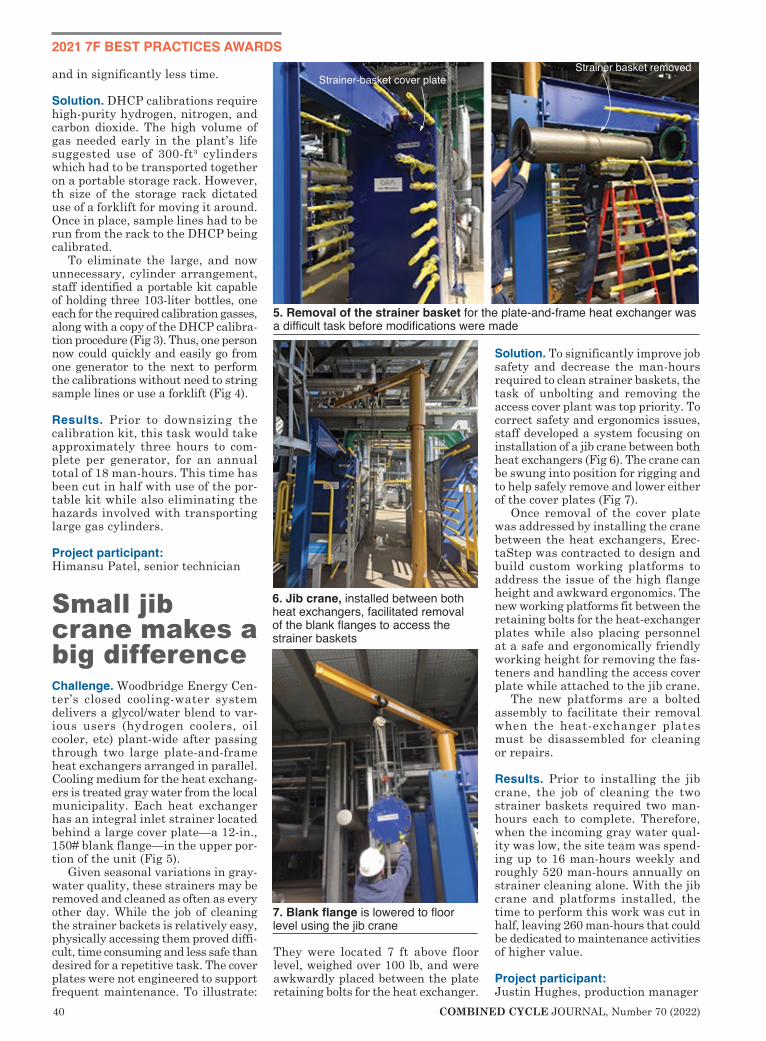
40 COMBINED CYCLE JOURNAL, Number 70 (2022)
2021 7F BEST PRACTICES AWARDS
and in significantly less time.
Solution. DHCP calibrations require high-purity hydrogen, nitrogen, and carbon dioxide. The high volume of gas needed early in the plant’s life suggested use of 300-ft³ cylinders which had to be transported together on a portable storage rack. However, th size of the storage rack dictated use of a forklift for moving it around. Once in place, sample lines had to be run from the rack to the DHCP being calibrated.
To eliminate the large, and now unnecessary, cylinder arrangement, staff identified a portable kit capable of holding three 103-liter bottles, one each for the required calibration gasses, along with a copy of the DHCP calibra-tion procedure (Fig 3). Thus, one person now could quickly and easily go from one generator to the next to perform the calibrations without need to string sample lines or use a forklift (Fig 4).
Results. Prior to downsizing the calibration kit, this task would take approximately three hours to com-plete per generator, for an annual total of 18 man-hours. This time has been cut in half with use of the por-table kit while also eliminating the hazards involved with transporting large gas cylinders.
Project participant: Himansu Patel, senior technician
Small jib crane makes a big differenceChallenge. Woodbridge Energy Cen-ter’s closed cooling-water system delivers a glycol/water blend to var-ious users (hydrogen coolers, oil cooler, etc) plant-wide after passing through two large plate-and-frame heat exchangers arranged in parallel. Cooling medium for the heat exchang-ers is treated gray water from the local municipality. Each heat exchanger has an integral inlet strainer located behind a large cover plate—a 12-in., 150# blank flange—in the upper por-tion of the unit (Fig 5).
Given seasonal variations in gray-water quality, these strainers may be removed and cleaned as often as every other day. While the job of cleaning the strainer backets is relatively easy, physically accessing them proved diffi-cult, time consuming and less safe than desired for a repetitive task. The cover plates were not engineered to support frequent maintenance. To illustrate:
They were located 7 ft above floor level, weighed over 100 lb, and were awkwardly placed between the plate retaining bolts for the heat exchanger.
Solution. To significantly improve job safety and decrease the man-hours required to clean strainer baskets, the task of unbolting and removing the access cover plant was top priority. To correct safety and ergonomics issues, staff developed a system focusing on installation of a jib crane between both heat exchangers (Fig 6). The crane can be swung into position for rigging and to help safely remove and lower either of the cover plates (Fig 7).
Once removal of the cover plate was addressed by installing the crane between the heat exchangers, Erec-taStep was contracted to design and build custom working platforms to address the issue of the high flange height and awkward ergonomics. The new working platforms fit between the retaining bolts for the heat-exchanger plates while also placing personnel at a safe and ergonomically friendly working height for removing the fas-teners and handling the access cover plate while attached to the jib crane.
The new platforms are a bolted assembly to facilitate their removal when the heat-exchanger plates must be disassembled for cleaning or repairs.
Results. Prior to installing the jib crane, the job of cleaning the two strainer baskets required two man-hours each to complete. Therefore, when the incoming gray water qual-ity was low, the site team was spend-ing up to 16 man-hours weekly and roughly 520 man-hours annually on strainer cleaning alone. With the jib crane and platforms installed, the time to perform this work was cut in half, leaving 260 man-hours that could be dedicated to maintenance activities of higher value.
Project participant:Justin Hughes, production manager
Strainer basket removedStrainer-basket cover plate
5. Removal of the strainer basket for the plate-and-frame heat exchanger was a difficult task before modifications were made
6. Jib crane, installed between both heat exchangers, facilitated removal of the blank flanges to access the strainer baskets
7. Blank flange is lowered to floor level using the jib crane
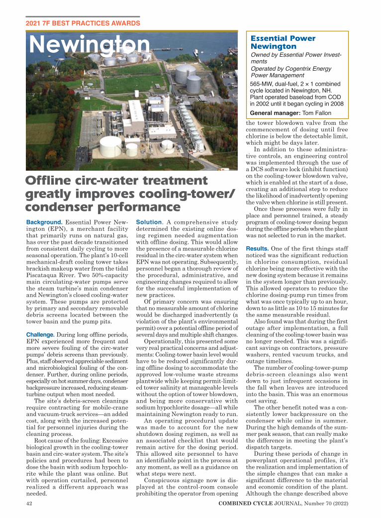
42 COMBINED CYCLE JOURNAL, Number 70 (2022)
2021 7F BEST PRACTICES AWARDS
Background. Essential Power New-ington (EPN), a merchant facility that primarily runs on natural gas, has over the past decade transitioned from consistent daily cycling to more seasonal operation. The plant’s 10-cell mechanical-draft cooling tower takes brackish makeup water from the tidal Piscataqua River. Two 50%-capacity main circulating-water pumps serve the steam turbine’s main condenser and Newington’s closed cooling-water system. These pumps are protected by primary and secondary removable debris screens located between the tower basin and the pump pits.
Challenge. During long offline periods, EPN experienced more frequent and more severe fouling of the circ-water pumps’ debris screens than previously. Plus, staff observed appreciable sediment and microbiological fouling of the con-denser. Further, during online periods, especially on hot summer days, condenser backpressure increased, reducing steam-turbine output when most needed.
The site’s debris-screen cleanings require contracting for mobile-crane and vacuum-truck services—an added cost, along with the increased poten-tial for personnel injuries during the cleaning process.
Root cause of the fouling: Excessive biological growth in the cooling-tower basin and circ-water system. The site’s policies and procedures had been to dose the basin with sodium hypochlo-rite while the plant was online. But with operation curtailed, personnel realized a different approach was needed.
Solution. A comprehensive study determined the existing online dos-ing regimen needed augmentation with offline dosing. This would allow the presence of a measurable chlorine residual in the circ-water system when EPN was not operating. Subsequently, personnel began a thorough review of the procedural, administrative, and engineering changes required to allow for the successful implementation of new practices.
Of primary concern was ensuring that no measurable amount of chlorine would be discharged inadvertently (a violation of the plant’s environmental permit) over a potential offline period of several days and multiple shift changes.
Operationally, this presented some very real practical concerns and adjust-ments: Cooling-tower basin level would have to be reduced significantly dur-ing offline dosing to accommodate the approved low-volume waste streams plantwide while keeping permit-limit-ed tower salinity at manageable levels without the option of tower blowdown, and being more conservative with sodium hypochlorite dosage—all while maintaining Newington ready to run.
An operating procedural update was made to account for the new shutdown dosing regimen, as well as an associated checklist that would remain active for the dosing period. This allowed site personnel to have an identifiable point in the process at any moment, as well as a guidance on what steps were next.
Conspicuous signage now is dis-played at the control-room console prohibiting the operator from opening
the tower blowdown valve from the commencement of dosing until free chlorine is below the detectable limit, which might be days later.
In addition to these administra-tive controls, an engineering control was implemented through the use of a DCS software lock (inhibit function) on the cooling-tower blowdown valve, which is enabled at the start of a dose, creating an additional step to reduce the likelihood of inadvertently opening the valve when chlorine is still present.
Once these processes were fully in place and personnel trained, a steady program of cooling-tower dosing began during the offline periods when the plant was not selected to run in the market.
Results. One of the first things staff noticed was the significant reduction in chlorine consumption, residual chlorine being more effective with the new dosing system because it remains in the system longer than previously. This allowed operators to reduce the chlorine dosing-pump run times from what was once typically up to an hour, down to as little as 10 to 15 minutes for the same measurable residual.
Also found was that during the first outage after implementation, a full cleaning of the cooling-tower basin was no longer needed. This was a signifi-cant savings on contractors, pressure washers, rented vacuum trucks, and outage timelines.
The number of cooling-tower-pump debris-screen cleanings also went down to just infrequent occasions in the fall when leaves are introduced into the basin. This was an enormous cost saving.
The other benefit noted was a con-sistently lower backpressure on the condenser while online in summer. During the high demands of the sum-mer peak season, that can really make the difference in meeting the plant’s dispatch targets.
During these periods of change in powerplant operational profiles, it’s the realization and implementation of the simple changes that can make a significant difference to the material and economic condition of the plant. Although the change described above
Newington Essential Power Newington Owned by Essential Power Invest-mentsOperated by Cogentrix Energy Power Management565-MW, dual-fuel, 2 × 1 combined cycle located in Newington, NH. Plant operated baseload from COD in 2002 until it began cycling in 2008General manager: Tom Fallon
Offline circ-water treatment greatly improves cooling-tower/condenser performance

COMBINED CYCLE JOURNAL, Number 70 (2022) 43
was quick to identify, it was fully studied and implemented to comply with all environmental permitting and operational requirements associated with the systems involved.
Overall, the new dosing process has realized significant cost saving for the plant, with no impact to the environ-ment and with minimal investment. While a change such as dosing time may seem minor, sometimes it really is the small changes that make the biggest impacts.
Project participants: Operations staff: Bob Crawford, Tyler
Engelhardt, Jason Gilpatrick, Mike O’Brien, Tom Paterson, Eric Pear-son, Scott Roy, Paul Shanley
Joshua Leighton, operations manager
Taking confined-space precautions to the next levelChallenge. Although contractors are trained on confined-space entry and the use of CSE permits, there are occasional gaps in knowledge or under-standing regarding OSHA and site-
specific responsibilities. Most contractors work at many different facili-ties and CSE permits from one site to another may have different lay-outs and context, which can lead to confusion. Many times, although required to be trained in confined-space entry and in the duties of a CSE attendant prior to coming onsite, the duties required of that critical attendant posi-tion may be difficult to recall.
Solution. Essential P o w e r N e w i n g t o n (EPN) staff developed a confined-space-per-mit job aide to provide CSE attendants a quick-reference summary of responsibilities and actions in the event of an emergency. The quick-reference summary was printed on a large label and placed on the red clipboards used solely for CSE permits. The clipboard and permit are
© 2014 Optimus Industries, LLC.
Who’s Behind Your HRSG
Pressure Parts?
Headers • Harps • Bundles • In-House Finning Replacement Pressure Parts from the Source
Who knows more about your pressure parts than the folks who made them?
As a contractor to the major HRSG OEMs, Chanute Manufacturing has the most experience fabricating HRSG pressure parts of any company in the U.S. There is a very good chance some of your HRSG parts originated at Chanute.
We’re familiar with all OEM designs. And if we didn’t originally fabricate your HRSG, or if drawings are not available, we can reverse-engineer your pressure parts when needed.
Contact us to discuss our recent HRSG aftermarket installations.
So, bring your replacement pressure part fabrication back home to the company with over 35 years of pressure part experience...Chanute.
Chanute Manufacturing Company a unit of Optimus Industries, LLC.
www.chanutemfg.com
“Bring It Back Home”
1. Summary of responsibilities for confined-space entry attendants is affixed to the plant’s signature red clipboards for quick reference
44 COMBINED CYCLE JOURNAL, Number 70 (2022)
turned over to the CSE attendant once a permit is opened by an authorized EPN employee.
The CSE attendant’s quick-refer-ence summary (Fig 1) has the following information:n Control room phone number and
extension.n A quick reminder of when the atten-
dant may leave the space being monitored.
n The atmospheric conditions and action levels to be monitored con-tinuously by the attendant.
n Instructions reminding the atten-dant to contact the control room or confined-space rescue team via radio or phone if the entrant becomes injured or ill.
n Guidelines for verifying proper space ventilation.
n How to remove potential hazards from the space and connected spac-es.
n Instructions for performing a non-entry rescue, if feasible. Important caution: The attendant shall NOT enter the space for rescue.
n Finally, if there are any concerns about the confined-space conditions, remove personnel immediately and request assistance.
Results. Implementing the quick-
reference job aide for CSE attendants should help reduce confusion regard-ing what an attendant’s responsibili-ties are as well as what he/she should do in the event of an emergency. The attendant’s clear understanding of his/her duties, and a constant reminder regarding their critical role, creates a safer confined-space work environment.
Project participants:Eric Pigman, engineering managerTed Karabinas, O&M technicianTom Paterson, shift supervisorJohn Pierce, EHS manager
Eliminating manual processes with electronic recordkeepingChallenge. At the onset of the Covid-19 pandemic in early 2020, it was clear that in-person meetings would cease and the ability to communicate effectively in a remote fashion would be required. Many manual processes handled through the years would have
to become automated and the need to digitize certain aspects of communi-cation in a power generation facility became increasingly important, espe-cially in remote settings.
Solution. Essential Power Newington (EPN) had been using eLogger for elec-tronic recordkeeping for several years. Staff realized this tool could be further harnessed to capture information that otherwise an e-mail or spreadsheet would capture manually. The following are a few examples of changes made using the eLogger application since the pandemic began.n Contractor safety orientation. Pre-
Covid, contractors and visitors would watch a short safety video onsite, read and sign a form, and then proceed to their plant con-tact, who would enter the visitor’s information into a Microsoft Access database for tracking. During the pandemic, the video is sent elec-tronically to contractors/suppliers beforehand; they sign and return the form and the site then enters the completion log into eLogger for tracking and recordkeeping. An easy search function provides quick access to records.
n Night orders for operations staff. Pre-Covid, as night orders/direc-
COMBINED CYCLE JOURNAL, Number 70 (2022) 45
tives were warranted, a Word document was created manually, converted to Adobe, and emailed to the night or weekend shifts. During the pandemic, staff found eLogger much better suited for this function. A PI connection string was created and important PI information is populated easily, night orders drafted as needed, acknowledgers assigned, and once complete, log entry saved. Once the log is saved, an e-mail is generated automati-cally and assigned staff can review directives at will and append logs with work statuses.
n Maintenance staff plan of the day (POD). Pre-Covid, the entire maintenance staff would attend a 30- to 45-min in-person meeting with the maintenance manager to develop the POD, which he would e-mail to the entire facility staff for situational awareness purpos-es. Under the pandemic’s social-distancing protocols, the meetings ceased but the need to commu-nicate plant activities remained very important. eLogger allows technicians to enter their PODs into the application for review by the maintenance manager. The log entries are saved and the log entry report is e-mailed to the plant staff for viewing.
n Generation outage/potential limi-
tations report. EPN is occasionally under a planned outage, output limitation, or must-run potential with local authorities. Commu-nicating these scheduled events is important for both plant and offsite staff—such as energy mar-keters and corporate executives. Remembering whom to notify and manually sending e-mails when notified of such conditions was very cumbersome. By contrast, eLog-ger allows a single log entry with all necessary information. When the log is updated by anyone with recent information, and saved, an e-mail is generated and a log report is automatically sent to a list of recipients.
Results. The aforementioned practices immediately led to time savings and efficiencies for individuals responsible for administering the listed processes. Eliminating manual processes is ben-eficial and the ability to substitute existing tools for them is the true benefit. Spreadsheets, manual e-mails, documents, and databases all were eliminated and streamlined through the eLogger application.
These were just a few of the many uses of eLogger EPN used last year. Further efforts always are investigated strategically to use this tool to the site’s advantage.
Project participants:Joshua Leighton, operations managerChad Harrison, maintenance managerJohn Pierce, EHS managerMaria Vitone, site administrator
Quiet time to update health and safety procedures a benefit of working remotelyChallenge. Essential Power Newington (EPN) maintained 34 reference health and safety (HS) procedures detailing protocols implemented to demonstrate compliance with applicable federal, state, and/or local OSHA regulations and company requirements. In sev-eral instances, guidance provided by HS procedures had become outmoded through changes in equipment, evolv-ing regulatory or industry practice, and/or ownership transition.
Historically, EPN had relied on “manual” curation of HS procedures as “controlled documents” via standard

46 COMBINED CYCLE JOURNAL, Number 70 (2022)
Qualtrax MOC workflowManagement of change (MOC) is an important process for the safe and reliable operation of a powerplant. The typical MOC approval process required an in-person meeting, docu-ment review, and change-approval signatures. When Covid-19 disrupted normal business processes in early 2020, a new solution was necessary to ensure that proposed changes could still be documented, reviewed, approved, and communicated when in-person meetings were not pos-sible.
In 2018, the site implemented Qualtrax® compliance software to pro-vide document and workflow manage-ment for NERC CIP compliance. The site’s CIP subject-matter expert (SME) already was skilled at the develop-ment and use of workflows. When the challenge was presented to develop a paperless MOC approval process, he quickly recognized that Qualtrax would be the perfect platform.
The SME developed a workflow to document basic information about the proposed change, including: descrip-tion of change, reason for change, work-order reference, and personnel designated to review the proposed change prior to approval.
The workflow directed reviewers to the site’s document server, where
all additional documentation for the proposed change is maintained. Once initial review was completed, the workflow routed through approval checkpoints, including the following: MOC approval, turnover to operations, documentation complete, and MOC closeout (diagram). The approval of each stage by multiple individuals is recorded electronically in the workflow; no paperwork is passed from indi-vidual to individual nor does it require approval at team meetings.
The workflow process is a proven paperless document management
tool that provides excellent visibility on the approval status of all MOCs. The workflow record also is useful when auditing for documentation evidence. In 2020, 23 changes were processed through the new workflow system. An added benefit has been to enhance employee involvement through the use of MOC reviewers. This step provides an opportunity to engage site employees to review and comment on the proposed change, modify the proposed change if appropriate, and route it for approval.
Management of change workflow
Startcontrol
StartMOC
details Requestemployeefeedback
MOC review/feedback
from employees
MOCapprovals
Approve
E-mail sent toEPN employees
followingapprovals
ImplementMOC
All MOC materialsretained on
public serverfor review
Turnover tooperations
Documentationupdate
Send forcloseout MOC
closeout Approve
Close
COMBINED CYCLE JOURNAL, Number 70 (2022) 47
document creation and spreadsheet products.
Use of Covid strategies for main-taining critical infrastructure oper-ability included reducing day-to-day staffing levels onsite to protect personnel by minimizing contact to the degree possible. Additional O&M personnel were provided with the technological capability to work from home and assigned administra-tive tasks.
Solution. During 2020, the O&M staff reviewed HS procedures for current applicability, obsolete refer-ences, actions, and/or forms no longer used in practice—for example, refer-ences to previous owners/contractors/technologies included throughout appendices.
Employees provided comments and suggested edits to identify poten-tial changes and updates. Prescribed requirements or actions (that is, periodic reviews, audits, preventive maintenance activities) and associ-ated time periods (annual, semian-nual, for example) were identified for vetting current compliance regimes associated with OSHA or industry standards, company requirements, or best practices.
In addition to the gap analysis described above, O&M staff analyzed
HS procedures within the context of these questions:n Was the incorporation of risks and
hazards appropriately addressed throughout the procedure?
n Are past events and accidents regarding the topic/procedure con-sidered and incorporated?
n What changes or modifications to the program details/personnel/vendor systems since last revision are not covered in the procedure?After O&M staff review and analy-
sis of HS procedures, comments and suggested edits were reviewed by man-agement and revisions implemented as warranted.
In 2018, EPN implemented Qual-trax® software to provide document and workflow management for NERC CIP compliance (sidebar). Following the staff HS procedure review initiative, HS procedures were relocated to Qualtrax with the software acting as an electronic doc-ument management system (EDMS). This ensures all documents managed by the EDMS are captured, stored, retrieved, and accessed in a manner that guarantees the archived docu-ment is an authentic rendition of the original document for the duration of preservation.
Authentic rendition means that the rendered document corresponds to the
source document as it was at the time of input in the information system, in terms of fidelity and integrity, and that this state is maintained for the dura-tion of preservation (ISO 14641:2018).
Results. Inherent in the review pro-cess was a progressive development of O&M staff familiarization with current OSHA, NFPA, industry, and company safety standards. Employees spend productive offsite work hours revalidating and improving the work-ing functionality of the HS procedure compendium.
The set was restructured into 32 active, controlled HS procedures in Qualtrax; updates to prescribed guid-ance, compliance regimes, applicable references and appendix forms gener-ated consistent procedures.
Restrictions on the use of HS procedural guidance from prior data-bases (for example, inspection forms used in preventive maintenance activities), coupled with use of the Qualtrax EDMS, ensures use of an authentic rendition of the original document.
Project participants:John Pierce, EHS manager Eric Pigman, engineering managerJoshua Leighton, operations managerSupported by the entire plant staff
DESIGN/BUILD & REPLACEMENT OF INTAKE HOODS
303 East Brooks Road, Memphis, TN 38109 www.filter-doc.com
New Yoke AssembliesGrit Blasting & CoatingsMedia Change-Outs
Combustion Turbine Inlet Services
█ Cartridge filters█ Panel filters█ New 4-point mounting hardware█ New pre-filter mounting frames█ Evaporative media█ CELdek® and DRIFdek® █ New metering and setups
Contact: Robert Murphree, Pres m: 901.734.5954 o: 901.396.3625 [email protected] Greg Murphree, VP, Sales m: 901.412.1195 o: 901.396.3625 [email protected]

48 COMBINED CYCLE JOURNAL, Number 70 (2022)
2021 7F BEST PRACTICES AWARDS
Control-system upgrades improve reliabilityBackground. The gas-turbine pack-ages at Essential Power Newington (EPN) are located in a building. The original turbine-hall air-handling and environmental-control equipment is as follows: four gas heaters spaced along a common wall, two makeup air handlers on opposite ends designed to replace air removed by GT-package cooling fans, one outside/four inside ambient temperature sensors, nine cooling fans at roof level, and six sets of louvers around the building.
Challenge. A dedicated PLC controls the equipment described above in groups through relays inside the tur-bine hall. The only access to the con-trol parameters was through a modem and HyperTerminal, or through a very non-user-friendly programming panel on the PLC.
There were no operator screens or other means of operator access for controlling this equipment, and no way for a user to access the ambient-tem-perature information for the turbine hall. PLC failures led to such problems as the turbine-hall fans starting and the louvers opening in the middle of winter, with no operator visibility to conditions in the turbine hall unless an employee happened to be walking through.
As the plant operating profile changed from baseload to cyclic, addi-tional gas heaters were added through-out the turbine hall to meet northern New England weather conditions: The original four heaters could not keep
critical equipment from freezing in winter when the turbines were offline. These heaters only had individual local thermostats. Adding heaters helped mitigate controls issues associated with the original equipment, but the original controls were a constant source of problems, and PLC pro-gramming became even more difficult because of obsolescence.
Solution. Staff decided to remove the PLC and migrate control of the HVAC equipment to the plant’s DCS. Spare wire pairs into the DCS control racks, plus some additional wiring and spare DCS I/O were used. The original relay-ing was connected to the DCS, along with new inside ambient-temperature RTDs to replace the thermistors. Fire-panel digital outputs also were connected, enabling the programming of automatic HVAC system response to fire, fuel-gas leaks, and hydrogen leaks in the turbine hall. Three-way switches were installed so equipment could be controlled locally or remotely through a DCS operator screen.
Results. Currently, the original four heaters are controlled individually by on/off switches, or as a group by their own local thermostat. Remainder of the HVAC equipment is controlled by local switches, or when in remote, by the distributed control system. The DCS control can be by an operator in manual through an operator screen (Fig 2) or automatically by DCS logic.
The control logic in the DCS looks at inside and outside ambient tem-peratures, whether or not the turbines are running, and at any active fire panel alarms to determine how to operate the equipment. There are now alarms to tell operators when ambient
temperature in the turbine hall is too cold or too hot—such as when a rollup door has ben left open in winter. All of this work was completed by staff, from development to implementation. Cost to implement the project included new RTDs and transmitters, a small amount of control wiring, and about 120 man-hours of labor.
The enhanced visibility and control could save equipment trips and startup delays caused by frozen critical instru-ments. It has the ability to prevent equipment damage by not triggering fire-protection sprinkler systems when piping is frozen, and has the potential to prevent an injury by vending flam-mable gas leaks before they have a chance to build up and possibly create an explosive atmosphere.
Project participants:Chad Harrison, maintenance managerScott Courtois, ICE technicianKyle Malenfant, ICE technicianMike Dill, ICE technician
How to remove air from your GT water-injection systemChallenge. Essential Power Newington (EPN) operates primarily on natural gas with sporadic operation on fuel oil in winter. When running on oil, demineralized water is injected into the combustors to reduce NOx emis-sions. Water is supplied at up to 250 gpm per unit from the demineralized-
2. DCS operator screen (left) and local control panel (right) facilitate control of turbine-hall HVAC equipment
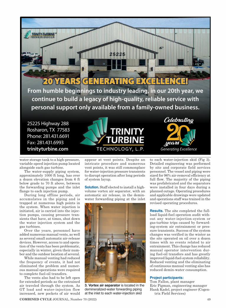
COMBINED CYCLE JOURNAL, Number 70 (2022) 49
water storage tank to a high-pressure, variable-speed injection pump located alongside each gas turbine.
The water-supply piping system, approximately 1000 ft long, has over a dozen elevation changes from 6 ft below grade to 70 ft above, between the forwarding pumps and the inlet flange to each injection pump.
During long offline periods, air accumulates in the piping and is trapped at numerous high points in the system. When water injection is initiated, air is carried into the injec-tion pumps, causing pressure tran-sients that have, at times, shut down the water injection system and the gas turbines.
Over the years, personnel have added numerous manual vents, as well as several small automatic air-release devices. However, access to and opera-tion of the vents has been problematic, especially in winter, given their num-ber and the outdoor location of several.
While manual venting had reduced the frequency of events, it had not eliminated the problem and numer-ous manual operations were required to complete fuel-oil transfers.
The vents also had to be left open for extended periods as the entrained air traveled through the system. As GT load and water-injection flow increased, new pockets of air would
appear at vent points. Despite an intricate procedure and numerous vent points, it was still commonplace for water-injection pressure transients to disrupt operation after long periods of system layup.
Solution. Staff elected to install a high-volume vortex air separator, with an automatic air release, in the demin-water forwarding piping at the inlet
to each water-injection skid (Fig 3). Detailed engineering was performed by site and corporate field services personnel. The vessel and piping were sized for 96% air-removal efficiency at full flow. The majority of the piping was prefabricated and the separators were installed in four days during a planned outage. Operating procedures and applicable drawings were updated and operations staff was trained in the revised operating procedures.
Results. The site completed the full-load liquid-fuel operation audit with-out any water-injection-system or gas-turbine trips caused by forward-ing-system air entrainment or pres-sure transients. Success of the system changes was verified in the winter as the site operated on oil over a dozen times with no events related to air entrainment. This change has reduced manual operator intervention dur-ing fuel-oil transfers and has greatly improved liquid-fuel-system reliability. Reduced venting and the eliminating of continuous manual venting also has reduced demin-water consumption.
Project participants:Tom Fallon, plant managerEric Pigman, engineering managerHank Kadel, project engineer (Cogen-
trix Field Services)
3. Vortex air separator is located in the demineralized-water forwarding piping at the inlet to each water-injection skid


52 COMBINED CYCLE JOURNAL, Number 70 (2022)
2021 7F BEST PRACTICES AWARDS
Challenge. Changing markets and location have reduced run opportuni-ties for Rumford Power. Response of the maintenance staff to the plant’s rural Maine location usually is half an hour or more. Given Rumford’s low capacity factor, response time is critical to resolving issues and returning the plant to operation: There’s little opportunity to make up for the unavailability by extending week-long runs as was done in the early 2000s.
Through the plant’s RCA process, which is implemented for every forced-outage event, staff was able to identify common areas of improvement that with a little training would enable others (for example, onsite opera-tions personnel) to troubleshoot and repair once they better understood the
affected system. This effort could help reduce the plant’s equivalent forced-outage rate (eFOR).
Solution. The plant already was using GP Strategies for web-based OSHA training. Previously, that program had been expanded to include some process safety management training. Based on the successes gained, staff decided to grow the training library further.
Looking back over the past five years of common themes or problems for call-ins at the site, the three areas that routinely came up in troubleshoot-ing events during off-hours, or when the plant was in a forced outage, were the following:n Fuel-gas letdown adjustment.n CEMS calibration-gas bottle
replacement.n Breaker racking.
The fuel-gas letdown adjustment was simply a response to a common issue the plant had in 2017-2018. Repeat failures of the gas letdown sys-tem caused starting-reliability issues, including a short period of forced-outage time. Maintenance technicians knew the process of checking and set-ting the Emerson (Fisher) 310A-32A pressure regulator (Figs 1 and 2), but the operators had little involvement in the process.
The training module created gave the background of the theory behind the “wide-open monitor” method of con-trol and use of a second downstream pressure regulator as the controlling valve. Support documentation included cutaway images of the valve with descriptions, the four basic steps in setting the letdowns, etc.
CEMS-gas bottle replacement is a common task that the plant completes, but primarily by I&C technicians. Operators assist and swap bottles, but there was no formal training or instructions for the task—just on-the-job training. While it could be months, or years, between the need to swap a calibration-gas bottle on a Sunday afternoon, the training module elimi-nates to the need to call someone in on a day off.
The training goes through the steps required to confirm proper gas iden-tification, swapping bottles, accessing the operator interface terminal, and navigation of the touch screen on the OIT (Fig 3).
Rumford
Reduce time of response to address common plant issues
Rumford Power LLCOperated by Cogentrix Energy Power Management265-MW, gas-fired, 1 × 1 7FA-powered combined cycle located in Rumford, MePlant manager: Justin Castagna
Pilot supply (¼ in.)
Pilot assemblyLoading tubing
Vent valve
Blockvalve
Inlet
Pilot-operated high-pressure regulatorBypassvalve
Vent valve Downstream control line (½ in.)
Locate six to10 pipe diameters from valve outlet
Ventvalve
Blockvalve
Alternative downstream control line tap
Outlet
1, 2. Pilot-operated, high-pressure regulator, Type 310A, is used where high capacity and accurate control are essential. Pilot assembly (Type 32A) is for pressure-reducing or wide-open monitoring applications

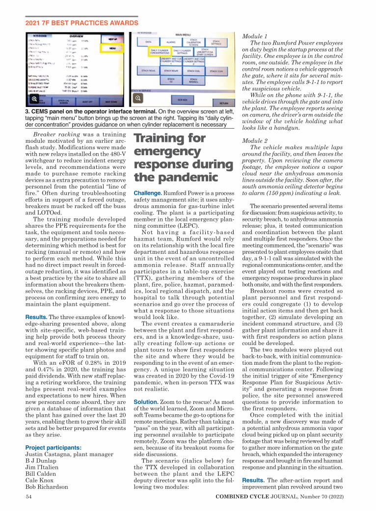
54 COMBINED CYCLE JOURNAL, Number 70 (2022)
2021 7F BEST PRACTICES AWARDS
Breaker racking was a training module motivated by an earlier arc-flash study. Modifications were made with new relays installed on the 480-V switchgear to reduce incident energy levels, and recommendations were made to purchase remote racking devices as a extra precaution to remove personnel from the potential “line of fire.” Often during troubleshooting efforts in support of a forced outage, breakers must be racked off the buss and LOTOed.
The training module developed shares the PPE requirements for the task, the equipment and tools neces-sary, and the preparations needed for determining which method is best for racking (manual or remote) and how to perform each method. While this had no direct impact result in forced-outage reduction, it was identified as a best practice by the site to share all information about the breakers them-selves, the racking devices, PPE, and process on confirming zero energy to maintain the plant equipment.
Results. The three examples of knowl-edge-sharing presented above, along with site-specific, web-based train-ing help provide both process theory and real-world experience—the lat-ter showing specific plant photos and equipment for staff to train on.
With an eFOR of 0.28% in 2019 and 0.47% in 2020, the training has paid dividends. With new staff replac-ing a retiring workforce, the training helps present real-world examples and expectations to new hires. When new personnel come aboard, they are given a database of information that the plant has gained over the last 20 years, enabling them to grow their skill sets and be better prepared for events as they arise.
Project participants:Justin Castagna, plant managerB J DunlapJim l’ItalienBill CaldenCale KnoxBob Richardson
Training for emergency response during the pandemicChallenge. Rumford Power is a process safety management site; it uses anhy-drous ammonia for gas-turbine inlet cooling. The plant is a participating member in the local emergency plan-ning committee (LEPC).
Not having a faci l ity-based hazmat team, Rumford would rely on its relationship with the local fire department and hazardous response unit in the event of an uncontrolled ammonia release. Staff annually participates in a table-top exercise (TTX), gathering members of the plant, fire, police, hazmat, paramed-ics, local regional dispatch, and the hospital to talk through potential scenarios and go over the process of what a response to those situations would look like.
The event creates a camaraderie between the plant and first respond-ers, and is a knowledge-share, usu-ally creating follow-up actions or plant tours to show first responders the site and where they would be responding to in the event of an emer-gency. A unique learning situation was created in 2020 by the Covid-19 pandemic, when in-person TTX was not realistic.
Solution. Zoom to the rescue! As most of the world learned, Zoom and Micro-soft Teams became the go-to options for remote meetings. Rather than taking a “pass” on the year, with all participat-ing personnel available to participate remotely, Zoom was the platform cho-sen, because of its breakout rooms for side discussions.
The scenario (italics below) for the TTX developed in collaboration between the plant and the LEPC deputy director was split into the fol-lowing two modules:
Module 1 The two Rumford Power employees
on duty begin the startup process at the facility. One employee is in the control room, one outside. The employee in the control room notices a vehicle approach the gate, where it sits for several min-utes. The employee calls 9-1-1 to report the suspicious vehicle.
While on the phone with 9-1-1, the vehicle drives through the gate and into the plant. The employee reports seeing on camera, the driver’s arm outside the window of the vehicle holding what looks like a handgun.
Module 2The vehicle makes multiple laps
around the facility, and then leaves the property. Upon reviewing the camera footage, the employee notices a vapor cloud near the anhydrous ammonia lines outside the facility. Soon after, the south ammonia ceiling detector begins to alarm (150 ppm) indicating a leak.
The scenario presented several items for discussion: from suspicious activity, to security breach, to anhydrous ammonia release; plus, it tested communication and coordination between the plant and multiple first responders. Once the meeting commenced, the “scenario” was presented to plant employees onsite that day, a 9-1-1 call was simulated with the regional communications center, and the event played out testing reactions and emergency response procedures in place both onsite, and with the first responders.
Breakout rooms were created so plant personnel and first respond-ers could congregate (1) to develop initial action items and then get back together, (2) simulate developing an incident command structure, and (3) gather plant information and share it with first responders so action plans could be developed.
The two modules were played out back-to-back, with initial communica-tion made from the plant to the region-al communications center. Following the initial trigger of site “Emergency Response Plan for Suspicious Activ-ity” and generating a response from police, the site personnel answered questions to provide information to the first responders.
Once completed with the initial module, a new discovery was made of a potential anhydrous ammonia vapor cloud being picked up on plant security footage that was being reviewed by staff to gather more information on the gate breach, which expanded the interagency response and brought in fire and hazmat response and planning in the situation.
Results. The after-action report and improvement plan revolved around two
3. CEMS panel on the operator interface terminal. On the overview screen at left, tapping “main menu” button brings up the screen at the right. Tapping its “daily cylin-der concentration” provides guidance on when cylinder replacement is necessary

COMBINED CYCLE JOURNAL, Number 70 (2022) 55
main core capabilities: operational coor-dination and operational communication.
Coordination strengths included the following:n Quick notifications to mutual aid
resources and supporting organizations while mobilizing needed resources.
n Hospital quick notification allowed setup of mass decontamination capabil-ity if needed at the hospital for patient surge or chemical exposure treatment.Areas of improvement included
these:n Increased visibility and familiarity
for first responders. Facility tours were provided for all first responders. Rumford Fire had many traiing experiences at the plant, but the Rumford Police Dept had not. Thus, familiarization training was pro-vided to all PD staff. Large signs were made, at the suggestion of first responders, to label the sides of the building (A, B, C, D) and to num-ber doors. These action items were completed by Rumford employees.
n Harden the plant for safe place of refuge in event of a facility breach.Rumford follows CIP-003 proto-
cols for physical security with fence, gates, and locked doors. As an added measure, deadbolts were strategically located so plant staff could create a safe room if a breach around the outer security level at the site were to occur.
Communication strengths from the TTX were the results from the simulated 9-1-1 call with dispatchers. Walking through all questions from the playbook showed plant staff what would be asked if the scenario were to arise. The Zoom break-out rooms were also deemed to be a benefit to the exercise to create an “isolation” like a real event would be, not having everyone at the same table as had been performed in years past. The plant had previously purchased a two-way radio to communicate directly with first responders if the need were to arise. A test was conducted with first responders to confirm proper operation and programming of the radio.
As a result of these activities and outcomes, the plant was named the Oxford County LEPC 2020 Facility of the Year. The deputy director of the Oxford County EMA presented this exercise to national peers in early 2021 as a demonstration of evolving with the 2020 pandemic and still achiev-ing success in keeping up-to-date with training and preparation for potential serious events.
Project participants:Justin Castagna, plant managerB J DunlapJon HambrickJustin Henry
Call Us Today! 614-488-1151x105 or 724-787-4967Email Us at [email protected]
See www.national-electric-coil.com for more about NEC and its services and products.
RotorsInspections & TestingNew or Refurbished Windings• Copper or Aluminum• Any Cooling Design• Any Profile: C, E or otherFFull-Service Balance Pit• Overspeed Testing• Running Electrical Tests• Thermal Sensitivity Testing• Vibration Analysis
Generator Engineering Design• OEM TILs• Up• Uprates• Upgrades
StatorsInspections & TestingWinding ManufacturingRewinds & OverhaulsCore RestacksRewedgesRRepairs
National Electric Coil’s Generator ServicesGroup will be at your site day or night,helping you get your generator back onlineas quickly as possible.
Our team of generator engineers, projectmanagers, logistics expeditors and experiencedsite technicians are ready site technicians are ready to helpyou determine the best short-and long-term options forreturning your unitto service.
ISO 9001Certified Quality
ManagementSystems
EMERGENCY OR PLANNED OUTAGE?

56 COMBINED CYCLE JOURNAL, Number 70 (2022)
2021 7F BEST PRACTICES AWARDS
Challenge. Empire Generating uses gray-water effluent from a local munic-ipality’s sewage treatment plant as incoming process water for both the steam-generating and cooling-water systems. Water quality, specifically total dissolved solids (measured as conductivity), varies greatly depending on the time of year and the quantity of water received. During high-con-
ductivity events, even with the pri-mary filtering mechanism, a Parkson Corp Dynasand® filter operating at optimum efficiency, the plant experi-ences carryover of impurities to its other systems.
To minimize the carryover effects and to ensure that the water is prop-erly disinfected prior to being used as a cooling medium, a 600,000-gal chlorine
contact chamber is located upstream of the cooling tower.
The chamber is designed as a series of five tanks placed within each other and partitioned such that a minimum of 486,000 gal of incoming makeup water will travel a minimum helical path of approximately 542 lineal ft at 4500 gpm to ensure a 90-min model contact time with the injected sodium hypochlorite prior to entering the cooling tower. Fol-lowing construction, the operational travel length was calculated at 695 lineal ft, verifying the required model contact time would be met.
Over more than 10 years of system operation, the tank-in-a-tank and its helical-flow-path design have proved extremely effective at removing the carryover material from the makeup water. However, system design made no provision for its removal. An ever-increasing amount of waste material reduced tank volume and increased the travel length needed to ensure
Removing suspended solids from a chlorine contact chamber
Empire Empire Generating CoOwned by Empire Acquisitions LLCOperated by NAES Corp635-MW, gas-fired 2 × 1 7FA.03-powered combined cycle located in Rensselaer, NYPlant manager: Chet Szymanski
1, 2. Semi-solid waste material is pumped from the chlorine contact chamber (left) to geotubes (right) by an engine-driven pump
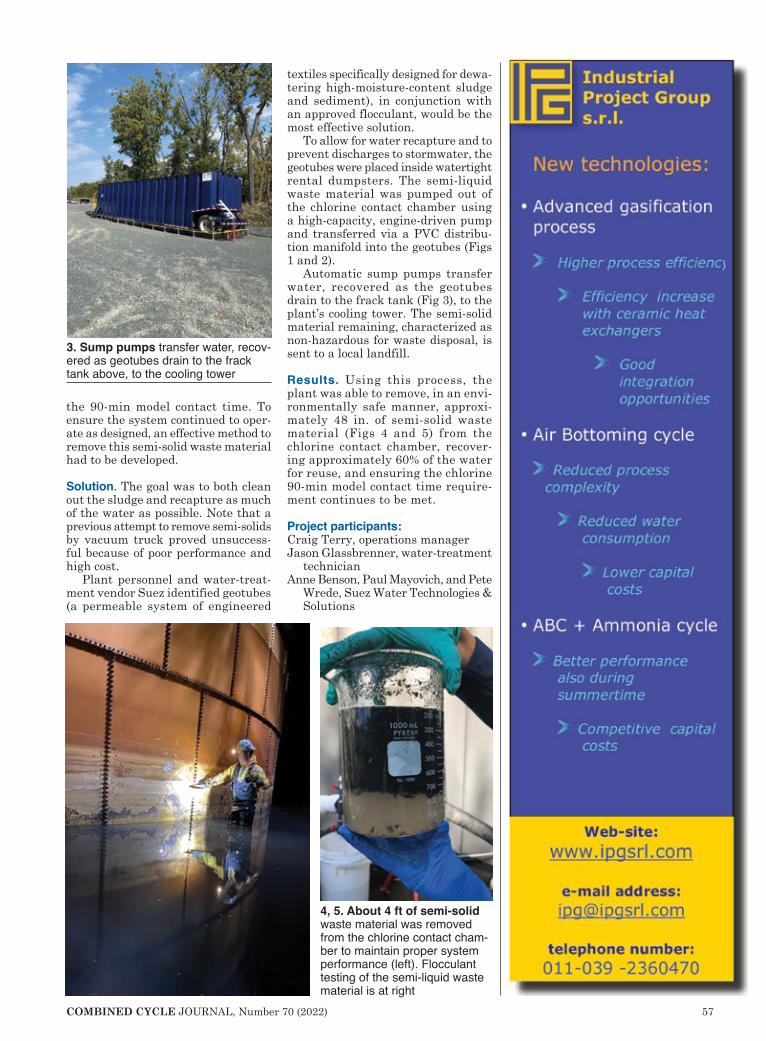
COMBINED CYCLE JOURNAL, Number 70 (2022) 57
the 90-min model contact time. To ensure the system continued to oper-ate as designed, an effective method to remove this semi-solid waste material had to be developed.
Solution. The goal was to both clean out the sludge and recapture as much of the water as possible. Note that a previous attempt to remove semi-solids by vacuum truck proved unsuccess-ful because of poor performance and high cost.
Plant personnel and water-treat-ment vendor Suez identified geotubes (a permeable system of engineered
textiles specifically designed for dewa-tering high-moisture-content sludge and sediment), in conjunction with an approved flocculant, would be the most effective solution.
To allow for water recapture and to prevent discharges to stormwater, the geotubes were placed inside watertight rental dumpsters. The semi-liquid waste material was pumped out of the chlorine contact chamber using a high-capacity, engine-driven pump and transferred via a PVC distribu-tion manifold into the geotubes (Figs 1 and 2).
Automatic sump pumps transfer water, recovered as the geotubes drain to the frack tank (Fig 3), to the plant’s cooling tower. The semi-solid material remaining, characterized as non-hazardous for waste disposal, is sent to a local landfill.
Results. Using this process, the plant was able to remove, in an envi-ronmentally safe manner, approxi-mately 48 in. of semi-solid waste material (Figs 4 and 5) from the chlorine contact chamber, recover-ing approximately 60% of the water for reuse, and ensuring the chlorine 90-min model contact time require-ment continues to be met.
Project participants:Craig Terry, operations managerJason Glassbrenner, water-treatment
technicianAnne Benson, Paul Mayovich, and Pete
Wrede, Suez Water Technologies & Solutions
3. Sump pumps transfer water, recov-ered as geotubes drain to the frack tank above, to the cooling tower
4, 5. About 4 ft of semi-solid waste material was removed from the chlorine contact cham-ber to maintain proper system performance (left). Flocculant testing of the semi-liquid waste material is at right

58 COMBINED CYCLE JOURNAL, Number 70 (2022)
2021 7F BEST PRACTICES AWARDS
Challenge. Clearly identify the LOTO scope and how it assures safe access to equipment for a specific outage work-scope. Provide the means to present and communicate the LOTO scope to all outage employees, including outside contractors.
Solution. Hunterstown requires that all outage LOTOs be mapped out on electrical and mechanical drawings. Locations of work must be delineated in the drawing package and isolation points highlighted, demonstrating the relationship between workscope and LOTO boundary.
Editor’s note: Extensive documenta-tion—including 15 E-size P&IDs—was submitted to CCJ in support of Hunt-erstown’s Best Practice, far more than was possible to publish. The ancillary material presented here—LOTO review (isolation steps), checklist for isolation and restoration of the bearing fire-protection pre-action valve serving the steam-turbine bearing area, and asso-ciated drawing—focus on one small segment of the entry to illustrate the plant’s LOTO process.
Results. This process provides the means to easily demonstrate through a drawing review and walk-down of equipment that the site’s LOTO pro-gram is effective and the specific work-scope to be performed by a contractor is compatible with the LOTO scope applied to the equipment and pre-sented in the LOTO package (including drawings). This results in clarity for contractors and confidence in the site’s safety programs. Because of this there are fewer requests from contractors to make changes that would expand LOTO scope to increase the LOTO boundary.
Feedback from contractors has been positive. One example: GE said,
“Hunterstown’s LOTO program is unmatched in providing clear under-standing to the scope of the LOTO and how the work we will be performing is covered under the LOTO hung on the equipment in the field. With our GE procedures, we are required to walk-down every LOTO and Hunter-
stown’s program provides assurance that we can clearly see on paper in the marked-up drawings how what we see in the equipment walk-down provides protection for our workforce.”
Project participant: Thomas Hart, plant manager
Hunterstown
Ensure outage LOTO accuracy, completeness by mapping procedures on drawings
Hunterstown Generating StationOwned by Platinum Equity LLCAsset managed by CPV Competitive Power VenturesOperated by NAES Corp810-MW, 3 × 1 7FA.04-powered combined cycle located in Gettys-burg, PaPlant manager: Thomas Hart

COMBINED CYCLE JOURNAL, Number 70 (2022) 59
Index to advertisersAdvanced Filtration Concepts......... 53Advanced Turbine Support LLC ..... 15AGT Services Inc ...................... 45, 70AGTSI ....................................... 70, 99AP4 Group ...................................... 41Arnold Group ......... 4-5, 19, 65, 73, 79Chanute Manufacturing .................. 43Combined Cycle Users Group ........ 92Crown Electric ................................ 25Cust-O-Fab Specialty Services ...... 30Cutsforth Inc .............................. 50-51Donaldson Company Inc ................ 31Doosan Turbomachinery Services .... 13Dürr Universal................................. 89EthosEnergy Group ................... 28-29EPT Clean Oil ................................. 87Frame 5 Users Group ..................... 93Frame 6 Users Group ..................... 93Filter-Doc Corp ............................... 47Gas Path Solutions .................... 20-21Generator Users Group .................. 92Groome Industrial Service Group ... 17Hilco................................................ 67HRST Inc ........................................ 96Indeck Power Equipment................ 89IPG Srl ............................................ 57JASC ................................................ 9KinetiClean (Groome) ................... 100MD&A .............................................. 2Millennium Power ........................... 44Mobile Excitation Services.............. 74National Breaker Services .............. 25National Electric Coil ...................... 55Noxco ............................................. 27PIC (Precision Iceblast Corp) ......... 83Power and Industrial Services Corp ............................................ 85Power Plant Controls Users Group ... 92Power Users, Legacy Conference ..... 93Power Users, Umbrella Organization ............................... 95Schock Manufacturing .................... 64Steam Turbine Users Group ........... 92SVI Industrial .................................. 62Taylor’s Industrial Coatings ............ 46TesTex ............................................ 55Trinity Turbine Technology .............. 49TTS Energy Services.......................11Umicore Catalyst USA Inc .............. 23ValvTechnologies ............................ 33Zokman Products Inc...................... 81
No. 70 (2022)

60 COMBINED CYCLE JOURNAL, Number 70 (2022)
2021 7F BEST PRACTICES AWARDS
Challenge. Marcus Hook Energy Cen-ter has four hydrogen-cooled genera-tors: three GE 7FH2 machines, one Toshiba TAKS. Hydrogen is supplied by a local firm in 16-cylinder cradles; delivery is by truck (Fig 1). Consumption of the 7FH2 generators is 500 ft³/day by design; the TAKS unit uses 1236 ft³/day. The 16-packs are moved to each generator by forklift. Challenge was to reduce H2 consumption, thereby reducing cylinder handling and improving system safety.
Solution. Operations person-nel used a spreadsheet to track 16-pack movements and hydro-gen use. All generators, save one on the gas-turbine units, were consuming well above design. The operations team worked systematically to locate the leaks, which were found to be the following: n GT2 generator. A ½-in. pop-
pet check valve in the hydro-gen supply line was found leaking and replaced.
n GT1 generator. A bad gage caused H2 supply pressure to run high and a small relief valve unseated as a result. The gage was replaced.
n ST generator. The scavenging valve for the hydrogen purity meter was allowing excessive flow and that was corrected.
Results. There has been a 50% reduction in 16-pack changes and hydrogen use. All four generators now are consuming hydrogen at a rate below design, reducing cylinder handling and onsite traffic, and the plant’s risk pro-
file. Expectation is the combined improvements will save about $50k
annually. Also under consider-ation: Reducing onsite storage of the 16-cylinder packs, thereby increasing saving.
Project participants: Mike Kelly, plant manager (cur rent)Frank Meade, plant manager (former)Dennis Shannon, operations specialistKen Bubar, production team leader (FieldCore)Bryan Kyler, production team leader (FieldCore)Tim DiVincenzo, production tech (FieldCore)
Successful troubleshooting cuts generator hydrogen consumption in half
Marcus Hook
Marcus Hook Energy CenterOwned by Marcus Hook Energy LPOperated by GE813-MW, 3 × 1 7FA-powered combined cycle located in Marcus Hook, PaPlant manager: Frank Meade (former); Mike Kelly (current)
1. Hydrogen for Marcus Hook’s generators is delivered in 16-cylinder cradles
Hyd
roge
n co
nsum
ptio
n
1614121086420
Jan Feb Mar Apr May June July Aug Sept Oct Nov Dec Jan Feb
ST generator
GT2 GT1GT3Poppet check
valve replaced
Bad gagechanged
H2 meter excess flow corrected
2. Gas consumption was reduced by locating and fixing leaks in the hydrogen sys-tems of three generators

COMBINED CYCLE JOURNAL, Number 70 (2022) 61
As usual, a tremendous amount of technical content was offered in two presentations during the HRSG Forum, Jan
28, 2022—No. 7 in a series organized by Chairman Bob Anderson. But the underlying message was more about the state of our industry.
A few participants, discussing aging of high-energy piping (HEP), said they were “astonished at the lack of knowl-edge in major NDE [non-destructive evaluation] firms” and that boiler OEMs “are different” these days and there are new people in the industry. You can interpret “new” as suppli-
ers who are inexperienced, or low-balling bidders, or doing shoddy work, but also buyers who accept low bids or don’t establish the proper design specs or QA processes and protocols.
Later in the Q&A, one Forum organizer, discussing zinc issues with boiler pres-sure parts, said HRSG OEMs are “not giving answers [about zinc] with high confidence levels” and that
it is “buyer beware” when it comes to at least one OEM.
The first presentation, “NDE, Weld-ing, and Metallurgy: Tools Support-ing the Safe, Efficient Operation of Aging HEP,” was delivered by indus-try veteran Jeff Henry, now with the Combustion Engineering Solutions (CES) division of Advanced Thermal Coatings (ATC).
There are many reasons why you should care about aging HEP, but if you’ve recently upgraded your gas tur-bine for higher output and efficiency, you are likely going to be expending the creep life of your superheater and
reheater piping faster than you might have expected. This situation makes HEP components more susceptible to catastrophic failures at the weld areas.
Creep is “time-dependent strain, or changes in dimensions of the material, that accumulates in response to stress such as load and pressure.” Over time, cavities form in the metallurgical grain structure, then begin to align into cracks which represent an “advanced stage of damage” (Fig 1). While creep can manifest as swelling of the pipe diameter, by far the most failures occur at welds, which are omnipresent in
HEP systems.Onset of creep damage
of course depends on the type of material and alloy. For Grade 22 material, the values for elevated temperature, according to Section 2, Part D of the ASME Boiler & Pressure Vessel Code, start at 952F. Code fabricated materials
should last 250,000 operating hours, Henry said, as long as piping supports
Discussion centers on creep damage, elemental zinc in weld HAZ areas
Massive carbides (typical)
Creep cavities (typical)
A B C D
1. Stages in the evolution of tertiary creep, following the onset of detectable damage (A), begin with non-aligned cavi-ties (B) which start to align (C) and then form micro-cracks (D), and finally macro-cracking and failure
Weld metal adjoining fusion boundary
Fine-grained/inter-critical region of HAZ
HAZ structure adjoining fusion boundary
Overlapping intra-weld HAZ structure
Weld-bead centerline
Fusion boundary
2. Characteristics of welds in high-tem-perature service are categorized based on these six areas of a typical weld

62 COMBINED CYCLE JOURNAL, Number 70 (2022)
are properly maintained, the com-ponents are operated within design limits, and the original fabrication was conducted to within specifica-tions. For an aging facility, that’s a lot of caveats.
Inspection is critical to identify piping condition, but indications have to be properly characterized and the root cause understood before an effec-tive repair is executed. In response to an audience question, Henry stated that 50,000 ops hours is a reason-able inspection interval if there are no operating or structural issues. When asked if there are protocols or industry standards, he recommended EPRI’s qualification and certification program for NDE detection in high-energy piping.
Many of Henry’s slides depict dam-age in six defined areas of HEP welds (Fig 2), and are not to be missed if you are responsible for an aging HRSG.
The second presentation, “Casting the Die: Implications of Zinc for Pres-sure Part Integrity,” was given by Paul James, Uniper Technologies Ltd. Main takeaway: Presence of elemental zinc (not zinc oxides) in paint used to pro-tect weld prep areas before fabrication makes pressure parts more susceptible to creep damage, especially in the weld heat-affected zone (HAZ). Fortunately, according to James, elemental zinc bands, beige-yellow which darkens with exposure to high temperatures, can be readily distinguished from the red lead oxide coating/primer tradi-tionally used (Fig 3).
James emphasized that component integrity concerns are confined to weld HAZs where depth of zinc penetration is significantly greater than the depth of penetration remote from the weld. Where elemental zinc is suspected of being present, or there’s uncertainty, a scraping of material from the area should be analyzed. Remedial work will require grinding back to bright metal more than 50 cm from the weld prep area.
During the Q&A, an informal poll of HRSG OEM representatives was cited, with several saying they’d never heard of the issue. Owner/operators need to put QA protocols in place, James cautioned, even if procurement specs explicitly prohibit the use of elemental zinc paints. ccj
3. Dark band of elemental zinc paint in the HAZs of P91 component welds (A) represents rapid diffusion of the zinc at high temperature to form inter-metallics at the edge of the HAZ (B), a “metallurgical notch” which can possibly prompt crack initiation and failure, as shown in the cross section of a failed weld (C)

COMBINED CYCLE JOURNAL, Number 70 (2022) 63
GAS-TURBINE PERFORMANCE IMPROVEMENT
Gas turbine systems produce over one-third of US electric energy requirements. They provide reliable baseload
power, in addition to that required to support the intermittent production of electricity from renewable sources. According to a Washington Post article, “Turns Out Wind and Solar have a Secret Friend: Natural Gas,” every 0.88% of capacity from renewables needs 1% capacity back-up from a fast-reacting fossil-fuel system.
Thus, gas turbines, a cornerstone energy conversion technology for the efficient production of electricity and heat today, are destined to play an important role in the emerging global quest for zero carbon emissions.
The operating capacity and energy efficiency of gas turbines is impacted by ambient temperature and humid-ity. These machines are rated at a
standard set of ambient conditions, defined by the International Stan-dards Organization (ISO) as 59F and 60% relative humidity. Increases in
Turbine inlet cooling: First step on the pathway to net zero emissionsAdding TIC to a combined cycle will eliminate the need to boost output with an aero peaker and its less-friendly emissions profile to meet grid demandBy Dharam Punwani, Turbine Inlet Cooling Association
Scan the QR codes to quickly access TICA webinars on these important topics:
Adiabatic wetted-media evaporative cooling
Fogging for evapora-tive cooling
Wet compression
Indirect heat exchange with chilled water
Thermal energy storage for chilled-water indirect heat exchange
Hybrid cooling
100
95
90
85
80
Out
put,
% o
f rat
ed p
ower
50 60 70 80 90 100Compressor inlet air temp, F
ISO design point Output of new aero
engine with compression ratio of 30
Output of existing frame engine with compression ratio of 10
Period of greatest demand
Up to 19% capacity loss at peak demand for this unit
1. Power production decreases as compressor inlet air temperature increases
Hea
t rat
e, %
of d
esig
n
104103102101100
99989740 50 60 70 80 90 100
Ambient dry-bulb temp, F
Aero
FrameFuel use increaseat peak demand
CO2 e
miss
ions
, 100
lb/M
Wh
501 1153
1210
8
6
4
2
0
CO2 emissions profile forcombined cycle upgraded with TIC to boost its output, in lieuof adding the new aeropeaker at right
New aero peaker
2. Fuel consumption increases as air temperature increases. Heat rate is directly proportional to fuel con-sumption per kilowatt-hour and inversely proportional to energy efficiency
3. CO2 emissions from the capacity gained by adding turbine inlet cooling to a nominal 500-MW combined cycle (left) are less than half those from the 50-MW simple-cycle peaker eliminated by it (right). The peaker in this example is an LM6000PC Sprint with hot SCR and TIC

64 COMBINED CYCLE JOURNAL, Number 70 (2022)
ambient temperature and humidity adversely affect output and energy efficiency of all gas turbines. Figs 1 and 2 present examples for the two major types of gas turbines: aeroderivative and industrial frame.
Since high ambient temperature reduces the performance of gas turbines, the logical solution for preventing this adverse effect is to cool the inlet air before it enters the compressor. Several technolo-gies have been used successfully for this purpose.
The Turbine Inlet Cooling Assn’s (TICA) website at https://turbineinletcooling.org is an excellent source of information on these solu-tions. The table lists them and includes QR codes that link directly to informa-tion of value in decision-making. The website also includes an inlet-cooling performance calculator, database of installations, and library of publications and presentations on all technologies.
Bear in mind that each technology has its pros and cons. No one technol-ogy is best suited for all applications. Selection of the optimum technology for your plant depends on many factors—including gas-turbine design, weather
data for the plant location, value of additional electrical energy produced, and the value of unitized fuel saving.
The following summarizes the benefits attributed to cooling of gas-turbine inlet air:n Increased power output.n Increased energy efficiency.n Reduced emissions per unit of
electric energy produced (higher efficiency).
n Reduced grid-wide emissions (reduced need to operate less-efficient systems for meeting grid demand).
n Increased thermal energy in exhaust gases, which benefits combined-cycle and cogeneration systems.
n Lower capital cost compared to the addition of a peaking unit to increase capacity.Because combined cycles are the
most efficient fuel-fired option for producing electricity, upgrading with inlet cooling eliminates the need to operate a less-desirable alternative—such as running a simple-cycle peaking turbine with a rated capacity equal to the combined-cycle output gained by
adding inlet cooling.Examples of the quantita-
tive benefits of using TIC on a 500-MW combined-cycle system for reducing emis-sions of carbon dioxide and regulated pollutants, are compared in Figs 3 and 4 to the emissions from a simple-cycle peaking turbine whose need was eliminated.
Similarly, installing inlet cooling on simple-cycle tur-
bines eliminates the need to operate less-efficient systems.
According to an estimate by TICA, the use of inlet cooling on all combined-cycle systems in the top 20 states can reduce carbon emissions by more than 22 million tons annually. ccj
0.5
0.4
0.3
0.2
0.1
0
Emis
sion
s, lb
/MW
h
Nitrogen oxides
Hydrocarbons
Carbon monoxide
New aero peakerEmissions profile forcombined cycle upgraded with TIC to boost its output, in lieuof adding the new aeropeaker at right
0.05
0.13
0.01
0.03
0.29
0.10
4. Regulated emissions from the capacity gained by adding turbine inlet cooling to a nominal 500-MW combined cycle (left) are significantly less than those from the 50-MW simple-cycle peaker eliminated by it (right). The peaker in this example is an LM6000PC Sprint with hot SCR and TIC
SCHOCK Retrofit SystemsGas Turbine Owners’ Preferred Choice for Retrofit Upgrades
Intake & Filter Systems Exhaust Silencer Upgrades Exhaust Systems Exhaust Plenum
Schedule a free site inspection/scope review: www.schock-mfg.com
From filterhouse to exhaust outlet, Schock inspects,
designs, and manufactures innovative and economical
GT auxiliary solutions. Experience on 1200+ GT
exhaust systems, 1100+ exhaust diffusers,
and 2000+ intake and filter systems.

COMBINED CYCLE JOURNAL, Number 70 (2022) 65
The 2022 HA Users Conference is designed to foster a transparent dia-logue between HA customers and GE Gas Power about the technol-ogy throughout its lifecycle, candidly discuss tech-nical issues and solutions, a n d s h a r e b e s t p r a c -tices and les-sons learned among users.
W h i l e t h e r e a r e q u a r t e r l y w e b i n a r s between the users and GE, the in-person confer-ence has been very effective in driving strong engagement between the user community and technical experts from GE. Conferences also provide an oppor-tunity to visit other HA-related facili-ties. While Covid prompted a virtual
conference in 2020, the in-person meet-ings in Fort Worth (2018) and Detroit (2021) provided an opportunity to tour an HA powerplant site, and the ses-sion in Greenville (2019) included the
opportunity to visit GE’s gas-turbine manufactur-ing facil i-ties.
The Fifth Annual HA Users Group Conference will be held as a two-day event in
Atlanta (Ga), August 9 and 10. Day One will be exclusively for HA owner/operators, allowing members to share information and experiences from their sites either in operation or in commis-sioning. Selected vendors will also be onsite, providing an opportunity to
meet in-person. On Day Two, technical experts from
GE will review latest updates, learn-ings, and improvements for the HA fleet and provide the users an opportunity to interact in an open, candid manner. Participants can also tour GE’s Moni-toring and Diagnostic Center.
Steering committees from the HA Users Group and GE are working on finalizing the agenda. A registration link for the conference will be sent out in the next few weeks. We look forward to the event to continue the strong partnership and collaboration between HA Users and GE. ccj
HA Users to meet in Atlanta, August 9-10Prepared by the HA steering committee and GE
HA steering committeeMike Banks, DTE EnergyChris Bates, NAES (Long Ridge
Energy)Mike Cashon, TVAJason Gatewood, Florida Power &
LightMeg Guillaumin, DTE EnergyJeff Klier, Exelon GenerationRama Krishna, Sharjah Hamriyah
O&M CoMeredith Neal, TVAAdam Sensenig, NAES (Birdsboro
Power)

66 COMBINED CYCLE JOURNAL, Number 70 (2022)
2021 7HA BEST PRACTICES AWARDS
Challenge. EVM II, the recently com-missioned (COD Jan 1, 2021) H-class, 2 × 1 combined cycle in Mexico State, was designed to send treated wastewa-ter to underground infiltration wells. But the plant’s discharge permit was revoked during construction because of changes to environmental laws, forcing plant staff to scramble to find an acceptable way to dispose of about 115,000 to 160,000 gal/day—the vol-ume of wastewater expected when the
plant is operating baseload year-round.
Solution. The plant owner’s technical team analyzed several options and settled on evaporation as the most cost-effective solution. However, the pond required to evaporate 160,000 gal/day naturally would cover about 50 acres, which was not practical. This calculat ion was based on the semi-arid
weather conditions at the plant loca-tion which suggested 10 ft² of pond surface was required to evaporate a gallon of water. An engineering fac-tor of 125% was added on top of that. To assist the evaporation process and reduce pond size, so-called mechanical evaporators were designed into the system. They create a mist that hangs in the air long enough for natural evaporation to occur above the pond surface. Engineers factored histori-cal weather data from the Mexican National Meteorological Service (tem-perature, humidity, wind speed, etc) into their design to assure that water would not be sprayed outside the pond area. For example, pump speed can be regulated when wind gusts are experienced.
Another design condition was that the pond be designed to hold all the rainwater from a 100-year storm event. The plant’s Best Practices entry included the data and analyses conducted in support of this goal. The outcome: Retention-pond capacity required was about 5.5-million gal-lons. Given that a nominal 2-million-gal pond was included in the original plant design, a pond of about 3.5-mil-lion gallons had to be installed onsite.
Fig 1 (left) shows the new pond during construction; the drawing at the right, the arrangement of its five mechanical evaporators (plus one in the original pond) required to achieve
Energía del Valle de México II (EVM II)Owned by EVM Energía del Valle de México Generador SAPI de CVOperated by NAES Corp 850-MW, 2 × 1 combined cycle powered by 7HA.02 gas turbines, located in Axapusco, state of Méxi-co, MéxicoPlant manager: Javier Badillo
EVM II
Mechanical vaporizer enables plant to convert to ZLD facility during construction
1. New pond under construction is at left. One mechani-cal evaporator was installed in each of the 200-ft-diam pond sec-tions outlined above
2. Mechanical evaporator is set in final position 3. Rainbow puts a finishing touch on the wastewater evapo-ration project

COMBINED CYCLE JOURNAL, Number 70 (2022) 67
the desired evaporation rate. The mechanical evaporators each serve a 200-ft-diam section of the pond. Fig 2 shows the installation of a mechanical evaporator, Fig 3 the resulting rainbow during its operation.
Results. Cost of construction and equipment for the new pond was $375,000. Installation was done by plant personnel, who also did the con-trols work to allow automatic opera-tion and commissioning. Factoring in operating expenses and infiltration fees, payback for the entire ZLD (zero liquid discharge) effort was achieved in two years.
In the first four months of opera-tion, an average of 165,000 gal/day of wastewater was processed, more than expected because the gas tur-bines’ evaporative cooling systems were forced to operate on relatively poor-quality raw water, increasing blowdown.
More recently, staff has been focus-ing on ways to improve the quality of water going to the GT evap coolers to both reduce the consumption of raw water and the amount of wastewater flowing to the evap ponds.
Project participants:Alonso Saldivar, maintenance mgrArmando Farias, plant engineer
Many rural Americans each year are invited to breakfast or lunch for pancakes or roast
beef, next given an LED lightbulb, then are given a raffle ticket for a variety of appliances attached to an electric cord. These rituals, called an annual meet-ing, are held by electric cooperatives in 48 states. At these events, customers, called “members,” also vote for the co-op Board of Direc-t o r s . W h a t many mem-bers won’t see are directors, or candidates for the office, who reflect the cultural, socio-economic, or ethnic charac-teristics of the membership.
You may be one of them. Forty-two million mem-ber-ratepayers, perhaps more, belong to an electric cooperative presided by an elected board of directors, who, as well, receive a per diem exceeding the average income of most of the mem-bers. The Board also decides who gets
what—internet service, clean water, energy conservation, jobs, electric vehi-cle financing, et al, and perhaps as well, what goes into member and employee retirement accounts.
Another thing members don’t see is the amount of carbon dioxide associat-ed with their electricity use. Members should ask their co-ops: Why not? At the same time, ask directors about the millions of dollars of members’ money they hold in their “deferred” capital credit account.
Capital Credits? Members’ heirs will learn about them when members pass on. Why not find out about the money owed you now? While you’re at it, ask the Board why there’s hardly any women on the Board or why the largely black or Hispanic membership doesn’t have a say in how the co-op spends their money?
All great questions and even more answers in this book: “Aspire to Better: The 21st Century Electric Coopera-tive,” which has been described as a book brimming with wit and passion. Others called “Aspire” a compelling narrative, while still others called it a “must read.” The sad fact is 42 million “members” juiced from their electric cooperative probably won’t. But you should.
Learn more at www.aspirebetter-book21.com.
Electric co-ops: Aspire to better
Author Mark Glaess
BOOK REVIEW

68 COMBINED CYCLE JOURNAL, Number 70 (2022)
2021 7HA BEST PRACTICES AWARDS
Challenge. Soon after commission-ing, one of Fairview’s gas turbine/generators experienced stator-ground-fault trips attributed to isophase-bus (IPB) water ingression into potential transformer (PT) cabinets, followed by persistent lower-than-expected resis-tance readings. Doble Engineering was engaged to perform electromagnetic interference (EMI) testing on several components of the plant’s three power trains to assess their condition. Gen-erators, step-up transformers (GSUs), unit auxiliary transformers (UATs), and IPB were suspect in each train (Fig 1).
Following the first trip on stator-ground-fault 64 relay, damaged cables and condensation were found in a PT cabinet (Figs 2 and 3). To learn more on the importance of addressing ground-ing issues in a timely manner, read “IEEE standards may not sufficiently address grounding issues in rotor, sta-tor windings,” by Clyde V Maughan, CCJ, 2Q/2013, p 7.
Solution. Given the extensive amount of IPB and connections, the CPV and NAES engineering teams advised the plant to perform EMI testing to iden-tify other potential sources of arcing and abnormalities. An EMI diagnostic was conducted to determine the pos-sible origin of the problems.
Recall that EMI testing is per-
Fairview
Use EMI to assess the condition of generators, transformers, HV electrical gear
Fairview Energy CenterOwned by Competitive Power Ventures (CPV)Operated by NAES Corp1050-MW, 2 × 1 combined cycle powered by 7HA.02 gas turbines, located in Johnstown, PaPlant manager: Bob Burchfield
PT compartment
GT generator 1B GT generator 1A
ST generator 1S
Isophase bus
ST generator GSU
1. EMI test loca-tions are indicated on site plan view (above)
2. Arcing on 23.5-kV PT cables was attributed to com-promised insulation and water (right)

COMBINED CYCLE JOURNAL, Number 70 (2022) 69
2021 7HA BEST PRACTICES AWARDS
formed online and can detect several mechanical and electrical defects on generators, IPB, transformers, and
motors. Defects in the bus connections or insulators generate radio-frequency signals that can be measured.
To perform an EMI diagnos-tic, a radio-fre-quency current transformer is placed around the neutral, a safety ground, or power conduit
of the asset (Fig 4) to measure and identify the signals generated from the component or system defects. The EMI diagnostic method measures a broad spectrum of radio frequencies to evaluate signal patterns—includ-ing, but not limited to, corona, partial discharge (PD), and arcing.
Additionally, a handheld device is used in conjunction with the EMI signature to further identify the defect location. This device detects the EMI signals radiated from each component or system defect, allowing the techni-cian to measure the intensity of the activity.
EMI testing is performed while the asset is in service and is a non-intrusive technique that will not cause the equipment to trip offline. A baseline measurement is helpful but not required for the analysis; there-fore, maintenance recommendations are provided starting with the very first test, and the analysis helps to prioritize maintenance based on asset condition.
The generator, IPB, UAT, and GSU for each of the three units were tested and inspected. The table sum-
Component Signal detected Suspected location ST generator 1S High PD, sparking Generator/IPB interfaceGT generator 1A High PD Generator/IPB interfaceIsophase bus 1S PD, sparking Generator/IPB interface Transformer/IPB interfaceIsophase bus 1A PD Generator/IPB interface PT cabinet
3. Condensation is in evidence in PT cabinets
4. Radio-frequency current transformer is placed around the PT cabinet’s ground bar
5. EMI signatures from the steam turbine/generator (left) and its IPB (right) reveal problems in the isophase busduct
6. EMI signatures from gas-turbine/generator 1A (left) and its IPB (right) reveal problems in the isophase busduct

70 COMBINED CYCLE JOURNAL, Number 70 (2022)
2021 7HA BEST PRACTICES AWARDS
marizes the most relevant findings. The EMI signatures in Figs 5 and 6 were acquired at different grounds on each component. The frequency ranges indicated on the EMI signatures, upon further and detailed analysis of the waveforms, revealed abnormal PD and sparking activities. Fig 7 is an example of a sparking waveform.
The activities detected typically are associated with insulation dete-rioration, defective connections, and loose hardware inside the IPB. To pinpoint the locations of the defects, a
scan was performed with a hand-held device to identify areas with high radiated EMI. After a thorough analysis, an internal inspection of different sections of the bus system was recommended.
Referring to the detailed EMI report provided by Doble, the locations identi-fied in the table were highlighted on electrical one-line and 3-phase draw-ings. These marked-up prints were used to plan lockouts, scaffold erection, and inspections at the next planned outage. Figs 8-10 show examples of
the findings in locations identified by EMI testing.
Results. Deficiencies were identified and corrected at each suspect location identified by EMI testing.
EMI testing enabled non-outage inspections of the electrical distribu-tion system, thereby reducing the length of outage inspections and facili-tating advance planning prior to the outage start date.
Given the success of the one-time EMI survey, CPV Fairview is install-ing a permanent EMI detection system. The team has initially selected the ST generator, IPB, and GSU for perma-nent monitoring.
A permanent installation may not fit everyone’s business model. As a minimum, we recommend conducting an annual survey or as-need surveys following repairs or the installation of new equipment.
Project participants: CPV: Joe Michienzi, Preston Patterson,
Tom Favinger, Ali BibongeNAES: Bill Lovejoy, chief engineer;
Rick Marshall, maintenance man-ager; Jason Havash and Aaron Roberts, I&E technicians
Doble Engineering: Roberto Martinez and Oscar Montano
7. Sparking activity is in evidence in the waveform for the HF band (12 MHz)
8. Loose neutral bushing in the GSU for the STG (left)9. Loose wire was found by EMI in the PT (right)
10. Insulator tracking was found in Phase A of the steam turbine/generator
Generating Timely Repair Solutions•Generator Testing Services
•Generator Repair Services • Stator – Rewinds, Rewedges, Core Repairs, etc..
• Rotor – Rewinds, Retaining Ring Removal/Replacement, etc…
• High Voltage Bushing Manufacturing & Refurbishment
518.843.1112
www.agtservices.com
AGT Services specializes in providing generator test, inspection, and repair
solutions, coupled with expert restorations and expedited delivery of components to
repair or rewind any Steam, Gas, or Nuclear turbine generator.
Aeroderivative Gas Turbine Support, Inc.phone: (561) 994-0000fax: (561) 994-3600email: [email protected]
1141 S. Rogers Circle, Suite 11 Boca Raton, FL 33487
LM2500LM5000LM6000LMS100GG4/FT4
Visit our newly redesigned website www.agtsi.com
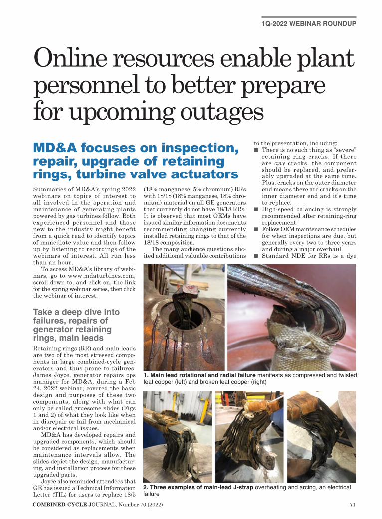
COMBINED CYCLE JOURNAL, Number 70 (2022) 71
1Q-2022 WEBINAR ROUNDUP
Summaries of MD&A’s spring 2022 webinars on topics of interest to all involved in the operation and maintenance of generating plants powered by gas turbines follow. Both experienced personnel and those new to the industry might benefit from a quick read to identify topics of immediate value and then follow up by listening to recordings of the webinars of interest. All run less than an hour.
To access MD&A’s library of webi-nars, go to www.mdaturbines.com, scroll down to, and click on, the link for the spring webinar series, then click the webinar of interest.
Take a deep dive into failures, repairs of generator retaining rings, main leadsRetaining rings (RR) and main leads are two of the most stressed compo-nents in large combined-cycle gen-erators and thus prone to failures. James Joyce, generator repairs ops manager for MD&A, during a Feb 24, 2022 webinar, covered the basic design and purposes of these two components, along with what can only be called gruesome slides (Figs 1 and 2) of what they look like when in disrepair or fail from mechanical and/or electrical issues.
MD&A has developed repairs and upgraded components, which should be considered as replacements when maintenance intervals allow. The slides depict the design, manufactur-ing, and installation process for these upgraded parts.
Joyce also reminded attendees that GE has issued a Technical Information Letter (TIL) for users to replace 18/5
(18% manganese, 5% chromium) RRs with 18/18 (18% manganese, 18% chro-mium) material on all GE generators that currently do not have 18/18 RRs. It is observed that most OEMs have issued similar information documents recommending changing currently installed retaining rings to that of the 18/18 composition.
The many audience questions elic-ited additional valuable contributions
to the presentation, including:n There is no such thing as “severe”
retaining ring cracks. If there are any cracks, the component should be replaced, and prefer-ably upgraded at the same time. Plus, cracks on the outer diameter end means there are cracks on the inner diameter end and it’s time to replace.
n High-speed balancing is strongly recommended after retaining-ring replacement.
n Follow OEM maintenance schedules for when inspections are due, but generally every two to three years and during a major overhaul.
n Standard NDE for RRs is a dye
Online resources enable plant personnel to better prepare for upcoming outagesMD&A focuses on inspection, repair, upgrade of retaining rings, turbine valve actuators
2. Three examples of main-lead J-strap overheating and arcing, an electrical failure
1. Main lead rotational and radial failure manifests as compressed and twisted leaf copper (left) and broken leaf copper (right)
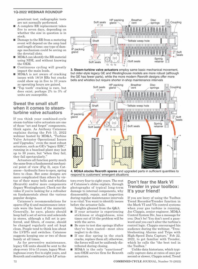
72 COMBINED CYCLE JOURNAL, Number 70 (2022)
1Q-2022 WEBINAR ROUNDUP
penetrant test; radiographic tests are not normally performed.
n A complete RR replacement takes five to seven days, depending on whether the size in question is in stock.
n Damage to the RR from a motoring event will depend on the amp load and length of time; one type of dam-age mechanism could be arcing on the dovetail slots.
n MD&A can identify the RR material using NDE, and without knowing the OEM.
n Continuous cycling will greatly impact the main leads.
n MD&A is not aware of cracking issues with 18/18 RRs but cracks could show up in five to 10 years as operating hours are gained.
n “Top tooth” cracking is rare, but does exist; perhaps 2% to 3% of units are susceptible.
Sweat the small stuff when it comes to steam-turbine valve actuatorsIf you think your combined-cycle steam-turbine valve actuators are one of those “set and forget” components, think again. As Anthony Catanese explains during the Feb 15, 2022 webinar hosted by MD&A, “Turbine Valve Actuator Operational Issues and Upgrades,” even the most robust actuators, such as GE’s “legacy EHC,” running in a baseload plant may last up to 30 years, but “when they fail, they fail spectacularly.”
Actuators all function pretty much the same from a fundamental mechani-cal point of view (Fig 3), says Cat-anese—hydraulic force to open, spring force to close. But some designs are more complicated than others by vir-tue of their many bells and whistles (Rexroth) and/or more components (legacy Westinghouse). Check out the video if you’re looking for a refresher on fundamentals about the various popular designs.
Catanese’s recommendations for spares (Fig 4) and maintenance inter-vals were the heart of the material. Generally, he says, plants should keep half a set of servos and solenoids in stores, although a full set is pre-ferred, and filters, of course, should be changed regularly and oil kept clean. People tend to think less about the LVDTs and switches. Catanese suggests keeping one or two of these handy at all times.
As for preventive maintenance, legacy GE units should be sent to the shop every 10 to 15 years, legacy West-inghouse every five to eight years, and Rexroth and combined-cycle LP actua-
tors every four to eight years. The rest of Catanese’s slides explain, through photographs of typical long-term damage to internal components, why disassembly, repair, and inspection during regular maintenance intervals is so vital: You want to identify issues before the actuator fails.
Insights gleaned from the Q&A:n If your actuator is experiencing
stickiness or sluggishness, nine times out of 10 the problem will be with the servo.
n Be sure to test disc springs if/after they’ve been coated—most sites neglect to do this.
n If one disc spring in the stack cracks, replace them all; otherwise, the forces will not be uniformly dis-tributed during closing.
n MD&A is the only “sanctioned” non-OEM service firm for Rexroth actuators.
Don’t fear the Mark VI Trender in your toolbox: It’s your friend!If you are leery of using the Toolbox Trend Recorder/Trender function in the Mark VI and VIe control systems when your gas turbine is running, Joe Clappis, senior engineer, MD&A Control System Div, has a message for you: Don’t be! You don’t need a pass-word and you can’t alter the turbine’s control logic. Clappis encouraged his audience during the webinar, “Trou-bleshooting Alarms and Trips with High-Speed Data Capture,” Feb 22, 2022, to get familiar with Trender, which he calls the “the best tool in the Toolbox.”
Unlike data historians, which typi-cally capture data at rates of once per second or slower, Clappis noted, Trend
Shaft
Soft sealsHP packing gland
Breather vent
Disc springs Coupling
Spring retainer Soft seals
1098
Soft seals
Soft seals
IP packinggland
Telltale weep hole
11 12
2
2
5
5
66
7 74 4
14 15 13
3. Steam-turbine valve actuators employ same basic mechanical movement, but older-style legacy GE and Westinghouse models are more robust (although the GE has fewer parts), while the more modern Rexroth designs offer more bells and whistles but require shorter in-shop maintenance intervals
4. MD&A stocks Rexroth spares and upgraded parts in sufficient quantities to respond to customers’ emergent situations

COMBINED CYCLE JOURNAL, Number 70 (2022) 73
Recorder takes data as fast as once per 40 milliseconds. Low-speed data cap-ture is best for slow-moving long-term trends—such as bearing metal tem-peratures and vibration. High-speed data capture allows you to analyze control valves, combustors, inlet guide vanes, exhaust temperature spreads, and other variables which can change
far more quickly.Trend Recorder also captures
alarms and events in addition to raw data and all the data can be viewed in graphical form.
“Users often send us screen shots, or smart-phone camera photos of HMI views, and ask us to troubleshoot a particular problem or event, but
these are often not helpful,” Clappis lamented. However, data summa-rized and presented in Trender can be extremely useful. You can study starts and shutdowns, compare “good starts to bad starts,” study DLN com-bustor mode transfers, and identify intermittent issues. Or Clappis and company can give you a higher-level diagnosis if you send them Trender files.
Many of Clappis’ slides showed the audience how to find Trend Recorder/Trender from the Mark VI home page, create and save a Trend Recorder file in Toolbox or ToolboxST, analyze data, simplify screen views and graphics, and drill down to actionable data. Clap-pis distinguished between actionable data and anecdotal data, like “I saw this happen and it never happened before!”
For those unfamiliar with data analysis, monitoring, and/or control systems, it’s best to follow along with the recording of Clappis’ webinar with your Mark VI screens in view. He gives explicit instructions for how to navigate within the Toolbox and Trender.
Finally, OEMs typically configure data historians and high-speed data recorders poorly, usually trying to capture too much data too fast, but also often not capturing the right
7FA 2.6 helical inserts
Wall thickness: New build, 0.197 in.; Repair 7, 0.093 in.
Wall thickness: New build, 0.478 in.; Repair 7, 0.372 in.
Wall thickness: New build, 0.197 in.; Repair 7, 0.093 in.
5. Nondestructive testing and modeling of end-cover insert pieces identified sub-stantial wall thickness available for repairs and led to an improved brazing process

74 COMBINED CYCLE JOURNAL, Number 70 (2022)
values for certain types of trouble-shooting. Factory configurations are not tailored to the site, or require much special training to extract the value from the data. “You have to be dedicated to learning the system,” Clappis stated.
As a caution, Clappis reminded participants that Trend Recorder is not a substitute for long-term data archival and retrieval. In response to an audience question, Clappis noted that the Mark IV does not include a trending program, the Mark V, “sort of.” A feature called View Tools can collect data on a limited number of data points.
More attention to fuel-nozzle upgrades, repairs pays huge dividendsBlind faith in your OEM’s DLN fuel-nozzle component repair and replace recommendations could kill your out-age budget, and that’s not all. That was the underlying message during the Feb 17, 2022 MD&A webinar, “Gas Turbine Fuel-Nozzle Flow Issues,” led by the tag team of Joe Palmer, general manager, and Pat Murphy, director of the company’s Fuel Nozzle Services Group, formerly ICS.
Fuel-nozzle overhaul is often the
lowest cost area of a scheduled out-age, and therefore not at the forefront. That’s a shame, stressed Palmer and Murphy, because many combustor issues originate with the fuel nozzles. Thus, there are other important ben-efits of upgraded fuel nozzles—easier tuning at startup, reduced tempera-ture spreads, and less risk of lean blowout. Improperly maintained fuel nozzles also adversely impact the life of major hot-gas-path (HGP) components.
MD&A has developed, and fully war-rants, upgraded fuel nozzle components for 7FA DLN 2.0- and 2.6-equipped engines (and combustors of other mod-els), especially the subassembly wear parts. Remanufactured nozzles from MD&A are warranted as “like new” and can operate nearly “indefinitely.” For example, upgraded outer/center nozzles, using several part calculation strategies, could operate for nearly 148 factored years! Meanwhile, the OEM claims a 48,000-hr lifecycle for its com-ponent. The as-new quality parts are a fraction of the cost of OEM replacement components, claims MD&A.
The third-party solutions provider’s new end-cover insert can operate over seven repair cycles. MD&A’s improved brazing process and choice of braze material have greatly improved cover life (Fig 5). Plus, the amount of cyclic insert braze cracking has been reduced.
Several of the slides are dedicated to explaining and illustrating the detail of this component “case study.”
The company offers an exclusive “in-situ flow testing” method, which helps pinpoint nozzle issues and solutions. “Component balancing and set balancing of fuel nozzles also can avoid a separate combustor inspection (CI) and extend run time to the next HGP outage.” The exclusive testing is an alternative to a complete nozzle system teardown for pinpointing flow variances and accurately and expedi-ently addressing them.
Thermal performance audit key to extracting more dollars from older plantsThe road to net zero carbon by, well, pick your date, 2030, 2035, 2050, is paved with pledges, promises, man-dates, and political rhetoric, but the

COMBINED CYCLE JOURNAL, Number 70 (2022) 75
1Q-2022 WEBINAR ROUNDUP
landscape will most surely be dotted with gas-fired combined cycles making megawatt-hours when the variable renewable resources are not, accord-ing to Jeff Schleis, gas-turbine product manager, EthosEnergy.
In a webinar conducted Jan 25, 2022, Schleis, reviewed net-zero-car-bon trends at the national level, offered some insight gleaned from Black & Veatch’s Annual Strategic Directions Report (a survey of industry leaders on top-of-mind issues and investment sce-narios), and summarized three recent net-zero forecasts on one graph (Fig 1).
Upshot of the last is that vari-able generation could exceed firm in less than 20 years. That represents opportunity for gas-fired combined cycles, but you have to be intentional about it. Schleis advocates conducting a thermal performance audit (TPA) to identify the gaps in performance, or where an older plant can extract additional value.
Equipment degrades over time, he said; the goal of the TPA is to analyze
historical operating data and glean info from the operators to build a plant model that captures current
equipment condition. Then you com-pare existing performance to original design, and individual turbines to each other, to determine where the gaps are, and what investment is required to close those gaps and extract the dollars.
The balance of Schleis’ slides (access via the QR code) is a deep dive into a case study on a 4 × 2 plant “designed to be very flexible.” The high-level results are shown in Fig 2. The one audience question directly relevant to the pre-sentation queried the time it takes to conduct the example TPA and the “timeframe for improvements.” Schleis answered that the study takes six to eight weeks depending on plant com-plexity and that the fogging issues (see figure) were “pretty quickly cor-rected,” while the duct-firing issue was resolved immediately.
Follow these steps to reclaim your control-system alarmsMany combined-cycle plant opera-tors suffer from poor control-system alarm management. Like the rest of the plant, the alarm system probably was designed with a specific operating mode in mind and brand-new equip-ment. Digital control system design-ers also tend to over-indulge in the convenience of alarming way too many
1. Melding of three net-zero studies forecasts coal generation essentially gone by 2035 and variable renewable resources outstripping firm generation in less than two decades
Unimproved
Philosophy,analysis, and
bad-actor resolution
Documentationand rationalization
Audit/enforce dynamic alarmingTwo years with poormanagement ofchange control ofthe alarm system
300150
Alar
ms
per d
ay
With audit and enforcement
More than 2000 alarms per day
Alarm management in one slide, as Holyfield put it, shows what you can achieve by following the seven-step program described in the webinar. Chart graphs the dramatic reduction in the number of important alarms likely missed by implementing the first three of the seven steps
Self-imposed duct-firing temperature constraints by operators
● Up to 20 MW per unit could be recovered● Even a 10% recovery per unit could mean over $1.6 million annually
Industry cooling-tower issue causing condenser to underperform
● Cooling water 3-4 deg F high, resulting in loss of 1.3 MW and 9 Btu/kWh per unit● Potential annual loss is greater than $600k
Hidden problem with inlet fogging in two units was reducing plant output
● Additional 2 deg F of inlet cooling recovers 3.5 MW and 72 Btu/kWh per unit● Potential annual loss is greater than $600k
Slow degradation in turbine performance during peak generating season
● Generating loss of 2 MW and 200 Btu/kWh attributed to infrequent water washing● Left unchecked, this would have amounted to an annual loss greater than $300k
2. $3.1-million of potential value was identified through the TPA of a 4 × 2 highly flexible plant, over half extracted immediately (duct firing) or pretty quickly (fogging)

76 COMBINED CYCLE JOURNAL, Number 70 (2022)
Sound knowledge management processes are critical to business success
Knowledge management is viewed by many organizations as synonymous with informa-
tion management. This is no longer true. Taking such a perspective may lead to the mistaken belief that the installation of highly sophisticated information-technology infrastruc-ture is the end-all and be-all of knowledge management and trans-formation.
Knowledge management is not like the movie Field of Dreams, where if you build it, they will come. Effective knowledge management relies less on technology as a support tool and more on how people oper-ate within the organization, based on the deep experience of author Dr Robert Mayfield, a well-respected plant manager and the author of “Knowledge Management—Automa-tion Strategies and Beyond.”
It’s time that energy organiza-tions acknowledge, address, and measure the risks associated with the loss of mission-critical knowl-edge through employee retention, recruitment, productivity, training, and benchmarking. We must trust one another and share knowledge across the entire energy industry. To stay competitive, equipment manu-facturers, vendors, contractors, and
energy organizations need to share their ideas, best prac-tices, and lessons learned. All knowledge to be shared with our competitors is not proprietary.
While actionable intel-ligence certainly plays a central role in knowledge management, it is not knowledge management. However, actionable intel-ligence is the only way to connect geographically dis-
persed people in an efficient manner. An organization’s ability to leverage technology effectively determines its sustainable competitive advantage.
In the end, that depends on the people—the execu-tives, senior manage-ment, supervisors, and workers—within an orga-nization.
The industry must recognize that people are the key to competitive-ness. It must transform hierarchical cultures into team knowledge-based cultures. Unless knowl-edge management pro-
cesses are implemented in this manner, companies will not be able to avoid a looming staffing crisis.
To be competitive, a company must establish processes and condi-tions that enable employees to grow from an assignment-based men-tality to a proactive attitude. An effective knowledge management program includes business acumen training to facilitate greater cross-departmental fertilization through a new rotation program that cracks open the departmental silos. In addition, an assessment process must be applied to identify those individuals who are stepping out, stretching their capabilities, and delivering hard results.
With knowledge management processes in place, the competi-tive organization will experience expanding opportunities with each new knowledge-enabled employee. Employees who are uniquely posi-tioned and empowered to apply
their explicit and tacit knowledge toward innovation and creativity will be able to meet unforeseeable chal-lenges. ccj
parameters.The really good news, according to
Bill Holyfield, principal alarm manage-ment consultant, Hexagon/PAS, during a webinar on alarm management Feb 4, 2022, is that 60-80% of alarm issues can be addressed by following just the first three of a seven-step program (figure): preparing an alarm philoso-phy document, analyzing historical alarms and establishing benchmarks, and resolving bad actors, like “chatter-ing” alarms, which can be up to 90% of bad actors. These three steps can often be accomplished in a few weeks at very low cost.
Holyfield set the foundation by reviewing work PAS had done with EPRI in analyzing and improving the alarm situation at 15 power-plants, including several combined cycles; defining elements of an alarm philosophy, especially setting alarm
priorities based on need, and time to operator response, and the process consequences of not properly respond-ing to the alarm; and establishing benchmarks, such as alarms per day and frequency of alarm floods, to gage progress.
Plants can even get under 300 alarms/day by going the extra miles of documentation and rationalization, audit and enforcement, and state-based, or dynamic alarming. To put that number in perspective, power-plants typically experience from 2000 to 10,000 alarms per day. Another “alarming” stat: Powerplant operators spend an average of 7% of their time facing alarm “flood” conditions, defined as 10 or more alarms coming at them every 10 minutes!
Dynamic alarming, the holy grail, simply refers to automatically altering alarm setpoints, priorities, and sup-
pression based on the plant’s current process state. For example, the alarm-ing system for a plant that runs fairly steadily five days a week then ramps down to lower load, or shuts down, over the weekend will be different from a plant that experiences two starts and four-hour run periods daily.
T h e w e b i n a r slides (access via the QR code) not only include the “flesh on the bones” of what’s summarized here, but great references for digging deeper, such as Hexagon/PAS white papers on the latest alarm statistical perfor-mance parameters, the ISA 18.2 Alarm Management Standard (produced with heavy Hexagon/PAS involvement), and the EPRI Alarm Management Guide-lines, co-authored by PAS. ccj
BOOK REVIEW
Dr Robert Mayfield

COMBINED CYCLE JOURNAL, Number 70 (2022) 77
The Legacy Turbine Users Group, formed by Power Users to facilitate the trans-fer of knowledge among
members of the Frame 7EA, 6B, and 5 Users Groups, greatly benefits owner/operators of these engines. With the number of experienced O&M personnel in decline because of retirements, and the high cost of meetings to share experiences increasing dramatically in a time of reduced plant budgets, it makes good sense to aggregate the talent on both the user and supplier sides
for all to share. A select group of independent
consultants and shop owners, most with a half century or more of direct experience with these engines, is expected to participate in the First Annual LTUG Conference at the end of August (see ad, pages 92 and 93 for details). The list includes Dave Lucier of PAL Turbine Services, Paul Tucker and Ken Knecht of FIRST/TBS, Bob Johnston, Keck Group International (formerly GE Gas Turbine Upgrades), and Mike Hoogsteden of Advanced Turbine Support, as well as several
others. They will offer guidance on how to extend the lives of your units and extract maximum value from them. ccj
Participants in the Legacy Turbine Users Group may find that many speakers talk in “shorthand,” using acronyms freely. If you’re not up to snuff on your GE legacy-engine lingo you can get lost in a hurry and possi-bly miss key points. The “cheat sheet” that follows, prepared by Dave Lucier of PAL Turbine Services LLC, can help you remain focused. If you have acronyms to add to this list, a work in progress, please email them to [email protected].
AG—Accessory gearboxAVR—Automatic voltage regulatorBLFN—Breech-load fuel nozzleBPV—Bypass valveCBV—Compressor bleed valveCCO—Constant control-oil pressure
(fuel regulator era)CDP (or PCD)—Compressor dis-
charge pressureCI—Combustion inspectionCRV—Compressor recirculation valveDSP—Digital speed setpoint (Speed-
tronic™ Mark I and II)FD—Flame detector or flow dividerFPI—Fluorescent penetrant inspectionFSNL—Full speed, no loadFSR—Fuel stroke reference (Speed-
tronic™ Mark IV, V, and VI)GCV—Gas control valveGEN—Generator GOV—Governor controlGT—Gas turbine HCF—High-cycle fatigueHGP—Hot gas pathHP—High-pressure turbine shaft
(MS3002 and MS5002)HPC—High-pressure compressor
(MS3002 and MS5002)HPCR—High-pressure compressor
rotorIGV—Inlet guide vaneLCF—Low-cycle fatigue
LG—Load gearLO—Lube oilLP—Low-pressure turbineLPC—Low-pressure compressor
(MS3002 and MS5002)LPCR—Low-pressure compressor
rotorLS—Low-pressure turbine shaft
(MS3002 and MS5002)LVTD—Linear variable differential
transformerMI—Major inspectionNHP (or TNH)—Turbine speedOEM—Original equipment manufac-
turerOST—Overspeed tripOTT—Over-temperature tripPCD (or CDP)—Compressor dis-
charge pressurePM—Project managerPN—Part numberPPP—Package power plantPT—Pressure transmitterRCA—Root cause analysisRFQ—Request for quoteRVDT—Rotary variable differential
transformerSP—Spark plug or igniterSRG—Speed reduction gearSRV—Gas stop/speed ratio valveSTIG—Steam-injected gas turbineTA—Technical advisorTBC—Thermal barrier coatingTD—Technical directorTFT—Turbine firing temperatureTNH (or NHP)—Turbine speedTTX—Turbine exhaust temperatureVASN—Variable-area second-stage
nozzles (MS3002 and MS5002)VCE—Variable control voltage (EMF)
for Speedtronic™ Mark I and IIVCO—Variable control-oil pressure
(fuel regulator era)VI—Visual inspectionVIGV—Variable inlet guide vanes
Acronyms for GE gas-turbine technology
Steering committees, 2022
Dale Anderson, East Kentucky Power Co-op
Joshua Coots, Duke EnergyTracy Dreymala, EthosEnergy
Group, San Jacinto PeakersJeff Hansen, Old Dominion Electric
Co-opGuy LeBlanc, IHI Power Services
CorpTony Ostlund, Puget Sound EnergyMike Vonallmen, Clarksdale Public
UtilitiesLane Watson, FM Global Chemical
Operations
Michael Adix, Motiva EnterprisesKevin Campbell, ChevronRobert Chapman, ChevronJonathan LaGrone, Formosa Plas-
tics Corp USADoug Leonard, ExxonMobil Technol-
ogy and EngineeringMike Wenschlag, Chevron, El
Segundo RefineryZahi Youwakim, Indorama Ventures,
Port Neches Operations
Steering committee advisers: Jeff Gillis, ExxonMobil retiredJohn F D Peterson, BASF retired
Josh Edlinger, Eastern GenerationShannon Lau, Suncor EnergyLogan Quave, Indorama Ventures
Legacy Turbine Users Group

78 COMBINED CYCLE JOURNAL, Number 70 (2022)
If you’re an owner/operator of a GE 7EA (a/k/a MS70001EA and 7E.03), or one of its predecessor engine models A, B, C, or E, the
technical meeting offering the “most bang for the buck” is the first annual Legacy Turbine Users Conference (LTUG), August 29 to September 1, at the San Antonio Marriott Rivercenter.
User groups for the other legacy GE frames—5 and 6B—will be sharing the venue, with the three organizations meeting concurrently, each in its own room. Meals and vendor fair will bring all attendees together.
As the ad on pages 92 and 93 shows, four other user groups in the Power Users family (p 95) also will be meet-ing at the same time: Combined Cycle (CCUG), Generator (GUG), Steam Turbine (STUG), and Power Plant Controls (PPCUG). A 7EA registra-tion allows your participation in any group’s meeting at any time. You can’t beat that benefit.
In sum, more than 300 users and well over 100 exhibitors are expected to participate in the late-summer con-ference.
The steering committees for the organizations served by LTUG (p 77) currently are evaluating technical content for their meetings and devel-oping agendas. The 7EA group may be furthest along in this regard, already having invited Mike Hoogsteden as its opening speaker to share what Advanced Turbine Support’s techni-cians are finding during their inspec-tions of this frame. The company is believed to conduct more inspections of legacy engines than any other firm.
Hoogsteden told the editors that his 7EA presentation will include the following:n Rotor blade/stator vane clashing.n Rotor-blade radial tip cracks and
liberations.n Advancements in the in-situ blend-
ing of compressor and turbine air-foils—including an overview of blending equipment.
n Internal and alliance-partner engi-
neering support.n New Technical Information Letters
(TILs) released by the OEM.n Update on generator robotic inspec-
tions.Hoogsteden touched on some of these
same topics in his presentation to the group last year. Owner/operators reg-istered by Power Users can access the complete PowerPoint in the 7EA con-ference file at https://www.powerusers.org. Highlights of that slide deck follow:
TIL 1854, “Compressor Rotor Stages 2 and 3 Tip Loss,” suggests blending and tipping to mitigate the impact on avail-ability and reliability of Row 2 and/or R3 tip loss (Figs 1 and 2).
Importantly, note that this TIL does not address R1 rotor-blade tips. Nor does it recommend in-situ inspec-tions, and it suggests that tip losses are low risk. Advanced Turbine Sup-
port’s resume notes that the company has conducted over 1000 in-situ visible dye-penetrant inspections, identifying more than 70 cracked rotor blades and 50 blade-tip liberations in the process.
TIL 1884, “7EA R1/S1 Inspection Rec-ommendations,” addresses the need to inspect R1 and S1 airfoils for pos-sible damage caused by clashing—the unwanted contact between the leading edges of S1 stator-vane tips and the trailing edges of rotor blades in the platform area.
The TIL recommends a visible inspection, followed by visible or fluo-rescent dye inspection, in the so-called
“area of interest” on the suction side if clashing is identified (Fig 3). Using dis-coveries as a basis for effective inspec-tion techniques, Advanced Turbine Support recommends eddy current for these inspections.
TIL 1980, “7EA S1 Suction Side Inspec-tion Recommendations,” advises users to inspect for crack indications on S1 vanes made of Type-403 stainless steel, regardless of whether clashing damage is in evidence on S1 and R1 airfoils or not.
While the TIL recommends visible or fluorescent dye, Advanced Turbine Support favors eddy current for these inspections using previous discoveries to support its opinion. The company says that if the stator vanes are coated, visible or fluorescent dye penetrant inspections may not be dependable, nor will they have an acceptable probability of detection.
UT results also could be compro-mised if coating degradation, such as debonding, occurs.
Hoogsteden explained that if the stator vanes are coated, the company’s eddy-current technique—featuring ultra-high sensitivity and very high resolution—has the ability to maintain sizing capabilities through coatings of up to 0.125 in. thick. He added that eddy current also is preferred when looking for crack initiation because it can detect problems sooner than ultrasonics.
1. Rotor-blade tip distress is most commonly caused by contact with the case during operation
2. Eddy-current inspection detect radial tip cracking shown prior to tip liberation
3. Vane cracking was identified with penetrant and eddy current
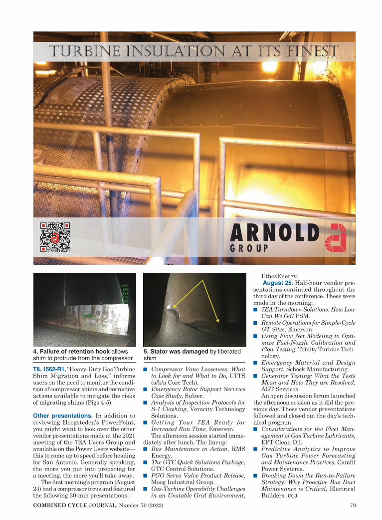
COMBINED CYCLE JOURNAL, Number 70 (2022) 79
TIL 1562-R1, “Heavy-Duty Gas Turbine Shim Migration and Loss,” informs users on the need to monitor the condi-tion of compressor shims and corrective actions available to mitigate the risks of migrating shims (Figs 4-5).
Other presentations. In addition to reviewing Hoogsteden’s PowerPoint, you might want to look over the other vendor presentations made at the 2021 meeting of the 7EA Users Group and available on the Power Users website—this to come up to speed before heading for San Antonio. Generally speaking, the more you put into preparing for a meeting, the more you’ll take away.
The first morning’s program (August 24) had a compressor focus and featured the following 30-min presentations:
n Compressor Vane Looseness: What to Look for and What to Do, CTTS (a/k/a Core Tech).
n Emergency Rotor Support Services Case Study, Sulzer.
n Analysis of Inspection Protocols for S-1 Clashing, Veracity Technology Solutions.
n Getting Your 7EA Ready for Increased Run Time, Emerson. The afternoon session started imme-
diately after lunch. The lineup:n Bus Maintenance in Action, RMS
Energy.n The GTC Quick Solutions Package,
GTC Control Solutions.n PGO Servo Valve Product Release,
Moog Industrial Group.n Gas-Turbine Operability Challenges
in an Unstable Grid Environment,
EthosEnergy. August 25. Half-hour vendor pre-
sentations continued throughout the third day of the conference. These were made in the morning:n 7EA Turndown Solutions: How Low
Can We Go? PSM.n Remote Operations for Simple-Cycle
GT Sites, Emerson.n Using Flow Net Modeling to Opti-
mize Fuel-Nozzle Calibration and Flow Testing, Trinity Turbine Tech-nology.
n Emergency Material and Design Support, Schock Manufacturing.
n Generator Testing: What the Tests Mean and How They are Resolved, AGT Services. An open discussion forum launched
the afternoon session as it did the pre-vious day. These vendor presentations followed and closed out the day’s tech-nical program: n Considerations for the Fleet Man-
agement of Gas Turbine Lubricants, EPT Clean Oil.
n Predictive Analytics to Improve Gas Turbine Power Forecasting and Maintenance Practices, Camfil Power Systems.
n Breaking Down the Run-to-Failure Strategy: Why Proactive Bus Duct Maintenance is Critical, Electrical Builders. ccj
TURBınE ınSULATıOn AT ıTS FınEST
4. Failure of retention hook allows shim to protrude from the compressor
5. Stator was damaged by liberated shim

80 COMBINED CYCLE JOURNAL, Number 70 (2022)
2021 7EA BEST PRACTICES AWARDS
Challenge. Several locations at Lincoln Generating Facility and Crete Energy Venture require fall protection, and there are no adequate tie-off points available.
One of the most notable: Generator circuit-breaker platforms at Lincoln. When performing generator breaker work from the platform, personnel have adequate fall protection. How-ever, most often the work requires climbing up to a higher level, which exposes workers to a fall risk and therefore requires fall-protection harnesses.
A problem arises when the techni-cian is standing on the highest point in the area and is only able to tie off to the equipment that he/she is stand-ing on. If the person were to fall to the platform below, the fall protection
would not work, because the drop is less than the distance required to fully engage the fall-arrest lanyard, but it’s still high enough to cause serious injury.
If the technician fell off the struc-ture entirely, the fall-arrest equip-ment would come into play; however, there is a possibility of injury by the fall-arrest system because of the dis-tance the worker would drop before activation.
Solution. Staff has explored numerous options over the years to eliminate the fall risk described—including tempo-rary scaffolding during planned main-tenance, which was not practical when required for unexpected issues forcing the unit into an outage. Permanently installed tie-off points proved costly
because of their installation and peri-odic testing requirements.
Personnel observed a demonstra-tion of an OSHA-approved mobile tie-off system, which could be used in many different locations through the site and shared between the Lincoln
Lincoln Generating FacilityOwned by Lincoln Generating Facility LLCOperated by Consolidated Asset Management Services LLC600-MW, eight-unit simple-cycle peaking facility powered by 7EA (DLN-1) gas turbines, located in Manhattan, IllPlant manager: Brad Keaton
Lincoln
Approximately 15 ft
Walkway is 2 ft wide
Distance from deck grating to bottom of coffin is 5 ft
Safety strap around ISO phase duct is approved for use with a retractable lanyard
1, 2. Personnel have adequate fall protection when generator breaker work can be performed from platforms designed into the plant
Safety, reliability foremost when purchasing a mobile fall-protection system

COMBINED CYCLE JOURNAL, Number 70 (2022) 81
and Crete sites as required. Cost of the system was half that for the per-manently installed systems consid-ered for just the breaker platforms. The mobile system demonstrated has tie-off points for three workers, which is adequate for the workscopes site personnel perform.
The mobile tie-off project received owner approval and an OSHA-approved system was purchased.
Results. The mobile tie-off system has been used successfully in many
locations throughout the facility. Its proven benefits include the following:n Cost was half that
for permanent ly installed systems considered for just the generator circuit breaker platforms.
n The mobile system has tie-off points for three workers, which is adequate for the workscopes plant personnel perform.
n Scheduling and coordination of
temporary scaffolding during out-ages is no longer required.
n Staff now is capable of safely per-forming emergency repairs.
Project participant: Jeremy Escolar, O&M technician IV
3, 4. Mobile tie-off system in travel mode at left, ready for work at right.

82 COMBINED CYCLE JOURNAL, Number 70 (2022)
2021 7EA BEST PRACTICES AWARDS
Challenge. Crete, commissioned 20 years ago during the gas-turbine boom, has experienced challenges with obso-lescence, parts availability, and OEM support. This is especially true for the Mark V gas-turbine control system. OEM declarations ceasing production support of system components in 2014, outdated HMI interfaces and hard-ware, limited OEM training offerings, plus the wear and tear of daily opera-tion, led staff to investigate methods for the continued reliable operation of the control system.
Solution. After performing their due diligence, it became clear to plant management that a full control-system upgrade was not necessary, as multiple third-party vendors provide solutions for parts repair/replacement and field service support, and the functionality of the TMR (triple modular redundant) Mark V controls remained robust.
Staff determined that multiple methods of improvement were avail-able for a comprehensive control-system reliability program and imple-mented the following solutions:
Mark V health checks. Since 2016, Crete has hired a third-party vendor on a biennial interval to perform reliabil-ity assessments of the Mark V control panels and associated equipment. It identified numerous issues lingering below the surface which eventually could have caused forced outages if not addressed.
Mark V cards, ribbon cables, and instruments have been replaced proac-tively during the assessments, and bad wiring terminations in remote junc-tion boxes have been corrected. The permanent clearing of what could be considered nuisance Mark V diagnos-tic process alarms and dc-equipment grounding issues also was a site pri-ority during the process. Result: The plant now experiences significantly fewer unplanned equipment failures than previously.
Inventory management. After the initial increase in site inventory and the addition of firmware revision-specific spares—such as EEPROMs (electrically erasable programmable read-only memory)—plant personnel continued to discuss optimized plant
inventory levels for each Mark V card and component during every reliability assessment.
Increased inventory levels of high-use/high-failure-rate boards, like the TCEA and TCPS, have proved ben-eficial on multiple occasions, reduc-ing downtime during controls-related upsets. Crete also replaced the GE TCPS power-supply boards with an upgraded aftermarket version from GTC Control Solutions after experi-encing a failure or alarm condition that predicted future issues. Any used card, or one of unknown condition, that may have been replaced dur-ing troubleshooting also is sent to an outside vendor for a condition assess-ment and in-panel test to ensure that all site inventory is functional upon installation.
BOP PLC upgrade. The original installation used an obsolete pairing of GE Fanuc 90-70 and 90-30 PLCs—each with limited parts availability, single CPUs, and the need for a no-longer-supported Genius Bus Module communications device (Fig 1 left). Personnel determined that because of
Mark V lifecycle, reliability improvements produce dramatic results
Crete Energy VentureOwned by Crete Energy Venture LLCOperated by Consolidated Asset Management Services LLC330-MW, four-unit, 7EA-powered, simple-cycle peaking facility located in Crete, IllPlant manager: Brad Keaton
Crete
1. Original BOP PLC (left) was obsolete and replaced with GE’s fully redundant RX3i PLC at right
2. A large portion of the existing ARC-net network was replaced with a fiber-optic/ethernet communications ring for reliability purposes


84 COMBINED CYCLE JOURNAL, Number 70 (2022)
2021 7EA BEST PRACTICES AWARDS
obsolescence, single-point-failure risk, and limited forward compatibility, this PLC should be replaced. The latest product offering from GE was selected and a fully redundant RX3i PLC was installed by Innovative Werks in fall 2019 (Fig 1 right).
HMI upgrade. The site’s OEM Cimplicity HMI servers were a major point of concern when assessing overall reliability, cybersecurity, and func-tionality of the turbine control system. Continued hardware issues required extensive man-hours for monthly server backups and re-boots to prevent server and ARCnet lockups. Plus, the Windows XP platform had long been obsolete, increasing cybersecurity vulnerability.
Additionally, the existing system had only one Mark V server in the con-trol room and one in Unit 2’s packaged electrical and electronics control center (PEECC), limiting access to logic forc-ing, signal name, and TC2K reports, as well as to more advanced Mark V engineering and diagnostic tools.
Crete contracted TTS Energy Ser-vices to install a redundant server TMOS HMI system in May 2020. The Traffic Management Operating System eliminated a large portion of the exist-ing ARCnet network and replaced it with a fiberoptic/ethernet communica-tions ring, removing a costly and long-lead-time failure point from the control network (Fig 2). Recall that Cimplicity HMI ARCnet cards are proprietary and difficult to source.
This system also did not require any modification or head-end upgrades to the Mark V control panels, making it a very cost-effective solution. The new network topology includes a client HMI workstation in each of the plant’s four PEECCs and the control room, giving technicians full access to the Mark V control screens and engineering tools in all locations.
Easier access to dynamic point logic, trends, and signal names/values direct-ly from the control screen provides
a more intuitive operator interface, allowing for reduced troubleshooting time during abnormal plant operating events and a more simplistic training process. It also provided the site with state-of-the-art Windows Server 2019 and Windows 10 operating systems. Continued patching and Windows sup-port for these machines allow Crete to maintain a high cybersecurity stan-dard on the controls network.
Results. While each of the aforemen-tioned projects individually would have had a positive impact on the lifecycle of the existing Mark V control system, Crete has seen marked improvements in hardware reliability and system functionality after implementing the full program. Mark V card replace-ments, when required, typically are done proactively, rather than reac-tively.
Operators are able to efficiently troubleshoot Mark V alarms using advanced tools and user-friendly inter-faces with files such as Help.QD (Fig 3) and direct click access to dynamic logic rungs. Technicians learning Mark V can be trained on specific tasks with ease, removing the tedious and time-intensive process of learning and perfecting the exact syntax and terminology used in command prompt.
Additionally, the TMOS came equipped with a historian, giving personnel access to higher-resolution operating data without requiring a View 2 file to be running to capture operating events.
With the process improvements described, and with resources in place, site personnel are confident they can continue reliable and sustainable operations with the Mark V control system for many years to come.
Project participants: Brad Keaton, plant managerJoe AlbersMike ViaterRyan Lowther
LED lighting upgrades make for safer maintenance, operationChallenge. With a staff of three, the Crete site continuously explores meth-ods for optimizing maintenance activi-ties and eliminating high-man-hour tasks that don’t directly contribute to the site’s high standard for safety, reliability, and availability. While evaluating the facility’s equipment condition and the man-hour con-tribution of different systems, staff determined that a significant amount of time was being spent on changing MCC indicator lights and fluorescent building lights. Plus, a man-lift rental was required annually for street-lamp replacement.
Constant lighting failures also presented a safety concern, because failed indicator-lamp sockets can cause confusion on equipment operating sta-tus. Plus, plus, ergonomic constraints for replacing other fixtures increased hazard exposure. Considering these issues, as well as the potential to improve energy cost efficiency and reduce hazardous waste generation, plant personnel pursued an alterna-tive, and simple, solution.
Solution. Advances in LED lighting technology afford industrial facilities the opportunity to upgrade light-ing cost-effectively. Plant personnel researched product offerings and found solutions for the majority of the site’s lighting fixtures. Outdoor high-intensity-discharge (HID) lamps were replaced with LED equiva-lents expected to reach more than 94,500 hours of useful life with vastly improved light dispersion and output (Fig 4).
MCC indicator lights and sockets in the PEECCs were replaced with relampable LED fixtures that have a much brighter display and required no modifications to wiring or bucket mounting (Fig 5). The control building, switchgear building, PEECCs, genera-tor breaker cabinets, and accessory gears all were retrofitted with LED lighting solutions over the last three years (Fig 6).
Today, the only remaining non-LED lights onsite are the turbine-compartment and fuel-gas-module lamps because there are relatively few product offerings that can with-stand the operating conditions and/or
3. Operators efficiently troubleshoot Mark V alarms using advanced tools and user-friendly interfaces with files, such as Help.QD

COMBINED CYCLE JOURNAL, Number 70 (2022) 85
regulatory requirements for hazardous atmospheres.
Results. After the lighting upgrades, the man-hours required to replace failed lighting has been reduced from about 200 hours annually to fewer than 20. Hazardous waste generation related to lighting (as well as universal waste from ballasts) has virtually been eliminated because all remaining non-LED fixtures are incandescent bulbs. The improvements to site safety also are notable, as better work-area light-ing and reduced hazard exposure are in line with Crete’s commitment to employee safety and continuous pro-cess improvement.
Project participants: Joe Albers, Mike Viater,Ryan Lowther, Kevin BrayNeil Schultz, Mike Yankovich
4. Street lighting improved dramatically with the switch to LED (right)
5. MCC indicator lights and sock-ets in the PEECCs were replaced with much brighter, relampable LED fixtures. No mods to wiring or bucket mounting were required
6. Control building looks like a new facility following the switch to LED lighting technology
86 COMBINED CYCLE JOURNAL, Number 70 (2022)
FRAME 6 BEST PRACTICE
Welcome back to in-person conferencing.
You probably remem-ber that the Frame 6B
Users Group conducted a virtual meeting last year on the first three Tuesdays of May, from 10 a.m. to about 2 p.m. Owner/operators unable to participate in that event on one or more days can catch up by listening to the recorded sessions available at www.powerusers.org. These include the compressor, I&C, combustion, and turbine roundtables; GE Day ses-sions; and technical presentations by AGT Services, GTC Control Solutions, National Electric Coil, and PSM.
Even if you attended the 2021 conference, a video review of selected sessions is a good way to prepare for this year’s meeting at the San Anto-nio Marriott Rivercenter, August 29 through September 1. User groups for the other legacy GE frames—7EA and 5—will be sharing the venue, with the three organizations meeting concurrently, each in its own room. Meals and vendor fair will bring all attendees together.
As the ad on pages 92 and 93 shows, four other user groups in the Power Users family (p 95) also will be meet-ing at the same time: Combined Cycle (CCUG), Generator (GUG), Steam Turbine (STUG), and Power Plant Controls (PPCUG). A Frame 6B reg-istration allows your participation in any group’s meeting at any time. You can’t beat that benefit.
The 2021 conference began with a compressor roundtable, chaired by J C Rawls, BASF’s Utilities Dept technol-ogy engineer at the company’s Geismar (La) facility, home to two gas-fired 1 × 1 Frame-6B-powered cogeneration units. You won’t find Rawls name on the steering-committee lineup on p 77 for the first time in a decade because the 33-year industry veteran is retiring just prior to the 2022 meeting.
His loss will be significant, espe-cially given Rawls’ boiler and related controls expertise, which he has gener-ously shared over the years with fellow
users at 6B meetings and in the pages of CCJ (p 88).
The recorded compressor round-table has value beyond keeping you informed. The well-organized program can do double duty as a training aid for new hires given its coverage of filter selection, safety, options for conditioning inlet air to boost output, value of inlet bleed heat, calibration and maintenance of inlet guide vanes, details on rotor com-ponents and extractions, etc. Here are some specific take-aways to support that thought:n Hydrophobic HEPA fil-
ters are recommended for top engine perfor-mance. The session leader reminded that a Frame 6B operating baseload ingests well over 1-million lb/hr of air, so even a small amount of fine particulate matter entrained in inlet air adds up quickly.
n A compressor kept clean year-round without washing minimizes perfor-mance loss for the entire run cycle, virtually eliminating the cost of demineralized water and soap for washing, as well as any expense and permitting associated with wastewater disposal. But before stopping online water washes, be sure your compressor blades are not susceptible to pitting from corrosive deposits.
n Fogging likely is the fastest way to boost output, provided atmospheric conditions are right. When consid-ering a retrofit be sure to conduct a rigorous system evaluation: The added water could loosen years of dirt from silencers, sidewalls, etc, which would foul the compressor quickly and reduce output. Be sure to seek advice from expe-
rienced colleagues. Example: Special consideration must be given to must-run baseload units in process plants because you can’t shut down to wash the compressor and an online wash
is not as effective as offline cleaning. I&C. The steering committee’s
Mike Wenschlag followed Rawls. The I&C roundtable that he chaired dug into key challenges of the several GE control systems associated with this frame—from the Mark IV through the latest version of the VIe. These included specific issues, support, and upgrades, plus a review of controls related Technical Information Letters from the OEM (TILs 2081, 2082, 2086, 2095, 2110, and 2134), LVTDs, servos, gas valves, and DLN tuning.
Wenschlag used Power Users’ poll-ing capability several times during his stay in the control center (the “podium” for virtual meetings) to share current information of value among the par-ticipants.
The chairman, who recently com-pleted 32 years of service at Chevron’s El Segundo (Calif) Refinery, told par-
ticipants that company personnel do most of the controls support work required at his facility; however, OEM or third-party support may be called on periodically. A lesson learned that he shared: Upgrading from a Mark IV to Mark VIe control system is a big undertaking that requires careful plan-ning and significantly more space than the original installation.
Regarding servos, Wenschlag said that over the years his plant went from no spares on hand, to periodic replacement, to service on demand after replacement with a spare from the warehouse. He added that servos and LVTDs might be different for dif-ferent systems and users should be mindful of that when ordering spares and when retrieving them from the warehouse.
An attendee reported that the changing composition of natural gas in the pipeline serving his plant can impact fuel valve operation because of sulfur deposits. Valves must be cleaned periodically. Another participant concurred, suggesting a baby-bottle cleaner with an appropriate spray is good for this purpose.
The combustion-section and tur-bine-section roundtables, chaired respectively by steering-committee members Robert Chapman, a senior repair optimization engineer for Chev-ron, and Zahi Youwakim, a principal engineer for Indorama Ventures, were conducted on the final day of the 2021 meeting. Both slide decks, like those prepared by Rawls and Wenschlag, are excellent training aids. ccj
J C Rawls


88 COMBINED CYCLE JOURNAL, Number 70 (2022)
2021 FRAME 6 BEST PRACTICES AWARD
Challenge. Most drum-level control systems employ 3-element logic, with feedback to the controller on drum level, steam outlet flow, and feedwater inlet flow. Data provided by pressure and temperature transmitters are used to enhance the accuracy of the steam-flow value. To illustrate: If the drum-level instrument is a dP-style level transmitter, a pressure transmit-ter is installed on the drum to provide the data necessary to make the density correction needed for accurate level calculations.
Thus, the term “3-element control” is somewhat misleading because it involves a minimum of six instru-ments—boiler feedwater (BFW) flow, steam flow, steam temperature, steam pressure, drum level, and drum pres-sure—for controlling the drum level.
And it is likely that more than one drum-level instrument is used. Many boilers have two drum-level instru-ments and control using the average value of the two. However, if one instrument goes bad the average value will be inaccurate. With two conflicting readings, how does one know which is the more accurate?
If any one of the instruments fails, particularly one of the main instru-ments (steam flow, BFW flow, drum level), the control system will not work. If any one of the supporting instru-ments fails (drum pressure, steam pressure, steam temperature), the control system may still work but it will be compromised.
Occasionally, Geismar’s steam flow-meter would fail. If it failed high, the signal sent to the drum-level controller would result in too much BFW flow, leading to carryover. If it failed low,
there was a risk of BFW flow being reduced to the point of tripping the boiler on low drum level.
Similarly, if the BFW flow transmit-ter failed high or low, this inevitably would lead to high drum level and car-ryover or a low-drum-level trip.
Depending on your specific pro-gramming logic, some instrument failure scenarios will default the drum-level controller to manual. Geismar boilers had two level transmitters. If they disagreed by more than 4 in., the level controller would default to manu-al. This usually would occur when the level control valve already was open or closed too much, leading either to a carryover event or trip because of low drum level. The operator then would have to control the drum level manu-ally and not have the option of return-ing the control to automatic.
During an unusually cold period one recent winter, the drum pressure transmitter froze and its milliamp signal went so high it caused an instru-
ment input/output (I/O) error; the level control system defaulted to manual. Even if the drum pressure transmit-ter were wildly inaccurate, it generally would result in a drum-level measure-ment error of only a few inches, which is preferred over a default to manual. When the system defaulted to manual the drum level likely would get out of control and the unit would trip.
Solution. Given the drum-level measurement challenges, a third
independent level instrument was installed—one using guided-wave radar technology. Having three level measurements available, control was changed from using the average of two level-instrument values to using the median value of all three instru-ments. If one went bad, the control system would continue without a hiccup; only if two instruments failed simultaneously would the level read-ing be impacted.
Regarding steam-flow measure-ment, Geismar uses a verification system to check reading accuracy. By modeling steam flow versus other operating parameters, staff can predict accurately what the steam flow should be. If measured steam flow varies from the predicted value by too much, the drum-level control system alarms and the predicted steam-flow value is used in place of the measured value.
For the plant’s conventional fired boilers, steam flow can be predicted accurately using fuel flow (figure). For
BASF GeismarBASF Chemical Co85 MW, gas fired, two 1 × 1 Frame 6-powered cogeneration units (one with an unfired HRSG, one fired) plus four conventional boilers and one small steam turbine/generator, located in Geismar, LaPlant manager: Graham White
BASF Geismar
Increasing the reliability of boiler drum-level controls
Stea
m fl
ow, 1
000
lb/h
r
300
200
100
0Boiler fuel input, % of full fuel rate0 20 40 60 80 100
Upper limit
Estimated
Lower limit
Visual representation of estimated steam production versus boiler fuel input

COMBINED CYCLE JOURNAL, Number 70 (2022) 89
the cogen unit with the unfired HRSG, steam flow is predicted based on gas-turbine output (megawatts), and for the cogen unit with the fired HRSG, on a combination of gas-turbine output and fuel flow to the duct burner.
All of these calculations are made by the DCS. So, it makes no differ-ence if the steam-flow measurement is the result of a problem with the flow, pressure, or temperature transmit-ter because the predicted steam-flow value is close enough for the system to continue accurately controlling drum level.
Regarding the BFW flowmeter, this instrument is the most critical in the drum-level control scheme because the drum-level control is actually feedwa-ter control used to regulate drum level indirectly. Geismar installed logic that monitors the difference between the measured feedwater flow and the feed-water flow setpoint. This difference nor-mally is very small. A large difference indicates a problem (either measure-ment error or feedwater valve issue) and the control scheme would transition from a 3-element arrangement to single-element (drum level), thereby removing the faulty feedwater reading from the control scheme altogether.
For the drum pressure transmit-ter, staff removed the “default-to-manual” logic that occurred when an I/O error was received, defaulting the drum-pressure reading to a constant value typically seen during normal operations.
Results. The site lost all six of its steam producers (two cogen units and four conventional boilers) during a very hard freeze in January 2018. Reason: Low drum levels caused by a combination of the failure scenarios described above—inaccurate steam-flow measurement, inaccurate BFW flow measurement, and controller default to manual attributed to failed instruments.
Following the freeze event, the changes noted above were made and deficiencies in the heat-trace system were corrected. Since that time, the boilers have successfully weathered instrument failures on the steam-flow reading, drum-pressure measurement, and drum-level measurement.
A few instruments were affected during the hard-freeze event in Febru-ary 2021, but the improvements made were sufficiently robust to keep all steam producers in service.
Project participants:J C Rawls, Utilities Dept technology
engineerTroy Braud, Utilities Dept DCS pro-
grammer
90 COMBINED CYCLE JOURNAL, Number 70 (2022)
You may recall the enduring slogan for Timex wristwatches introduced in the 1950s: “It takes a licking and keeps on
ticking.” In the electric power industry, something similar could be said for the iconic Frame 5: “It takes a licking and keeps on running.” The first engine in the seemingly ageless Frame 5 series of gas turbines shipped from GE’s Schenectady shop 65 years ago (tables); some of the very early units still are operating.
To date, industry experts say, well over 3000 of these machines have been assembled by the OEM and its manufacturing partners and shipped in both single- and two-shaft versions for electric-generation (50 and 60 Hz) and mechanical-drive applications. Units in generation service are found in simple-cycle, cogeneration, and combined-cycle facilities. They are installed both onshore and offshore (on oil rigs and power barges, for example) and may be equipped for burning oil or gas only, or both fuels.
Owner/operators of this frame essen-tially have been underserved by the user community for years, the many forums organized in the last three decades typically focusing on a single late-model engine to share experiences, thereby helping the OEMs correct design deficiencies and improve their products.
But Power Users recognized the need to start a group dedicated to this engine because of its value in today’s world for “chasing the wind” and other intermittent functions—especially given the rapidly declining number of O&M personnel with meaningful
Frame 5 experience. CCJ contacted several industry experts
to provide a snapshot of this eclectic fleet to help you navigate the conversation at the group’s first annual meeting in San Antonio at the end of August.
First, the naming convention: the Frame 5 is shorthand for the MS5001 (a/k/a Fr5, 5/1), the single-shaft version of the machine for electric generation; the MS5002 is the two-shaft version typically used to drive compressors and pumps.
Note the reference in Table 1 to the R-N/T and P-N/T models—still offered. These units typically are referred to as 51PA and 51RA engines, both of which can be upgraded with the company’s perfor-mance enhancement kit (PEK) to produce about 4% more power or to extend the maintenance intervals. Major inspec-tions are now possible on a 70,000-hr interval, liner and transition-piece inspections on a 35,000-hr interval.
Some facts that might help you better understand why there are so many different models in this fleet:n GE stopped mak-
ing gas turbines in Schenectady in 1987; however, several P-N/T and MS5002C units were made in
Greenville until the mid-1990s. Note that the model designations for the 5/2 differed from those in Table 1 for the 5/1. The five models for this frame are A, B, C, D, and E.
n When GE purchased Nuovo Pignone in 1995, manufacturing of the 5/1 and 5/2 was transferred to Florence, Italy, where the focus has been on the two-shaft machine.
n Several GE business associates made MS5001P units until 2000. That year, GE bought John Brown Engineering and European Gas Turbines/AEG Essen and shut them down. GE also canceled its manufacturing agree-ment with Thomasson, leaving NP sole responsibility for the Frame 5.
n Of the 2500 5/1 units built, one expert believes GE uprated about 200 with N/T parts. Several dozen new engines also have been shipped with the N/T uprate.
Table 3: Frame 5 control system history System Years Fuel regulator Before 1970 Mark I 1968-1975 Mark II 1974-1980 Mark III 1978-1985 Mark IV 1983-1993 Mark V 1992-2003 Mark VI 1999-2008 Mark VIe 2004-20??
Table 1: Frame 5 data have changed significantly over the years Model Years Output, Firing Exhaust Heat rate, MS5001 shipped MW1 temp, F temp, F Btu/kWh2
A 57-61 12 1500 840 15,810 C 61-64 12 1500 835 15,810 D 61-63 12 1500 834 15,810 E 63 12.9 1500 830 15,780 G 63-64 13.4 1500 830 15,120 H, J 64 14 1500 820 14,430 K 65 14 1500 820 14,430 L 66-67 15.7 1600 895 14,440 LA 68-70 17.1 1650 930 14,190 M 69-70 18 1700 965 14,050 R 70-87 19.4 1720 955 13,260 R-N/T3 87-?? 20.5 1755 970 12,780 N 70-72 24.6 1730 898 12,190 P 72-78 24.6 1730 904 12,140 P 78-86 23.4 1730 901 12,020 P-N/T4 87-?? 26.8 1765 905 11,8601All ratings based on natural gas fuel 2Based on fuel’s lower heating value 3, 4In 1987, the HGP of both the P and R turbines was updated and the models renamed PA and RA, respectively. Those models are called P-N/T and R-N/T when they are the result of an aftermarket uprate (N/T means new technology) Source: GER-4196
Table 2: Physical characteristics of Frame 5 components Turbine, Turbine, Turbine Model Compressor, R1 wheel R2 wheel HGP R2 buckets, speed, MS5001_ No. of stages type type/diam technology type rpm A-K 16 Old Old/large Pre-old tech Tie-wire 4860+ L, LA, M 16 New New/large Old tech Tie-wire 5100 M prime 16 New New/large Old tech Tip shroud 5100 M, N/T 16 New New/large New tech Tip shroud 5100 R 16 New New/small Old tech Tip shroud 5100 RA (N/T) 16 New New/small New tech Tip shroud 5100 N, P 17 New New/small Old tech Tip shroud 5100 PA (N/T) 17 New New/small New tech Tip shroud 5100Source: GER-4196

COMBINED CYCLE JOURNAL, Number 70 (2022) 91
Turbine Tip No. 17 from the PAL solu-tions library applies to all models of legacy GE gas turbines.
Components and auxiliary systems for GE gas turbines have specific names. It is important to use correct names when communicating with the manufacturer or service companies to be sure you’re understood. For some, it may be like learning to speak a new language, which can be called “GE-ology.”
In 1961, GE introduced the gas-turbine Packaged Power Plant (PPP). According to industry records, the first such unit was installed at a facility owned and operated by South Caro-lina Electric & Gas. Other units soon followed for Central Vermont Public Service and Long Island Lighting. The first PPP from GE was the MS5001—a/k/a Frame 5.
The model series (MS) was named the 5001D, with the number “1” for sin-gle-shaft. It was sometimes referred to as a Frame 5D in the evolution. When introduced, the engine was designed to produce 12 MW, a rating that pre-vailed throughout the first half of the sixties. This peaking model preceded the Great Northeast Blackout of Nov 9, 1965, when the entire Northeast Seaboard went dark for approximately 12 hours.
During the second half of the decade, demand for emergency power was unprecedented. Investor-owned electric utilities and municipalities—including such behemoths as Chicago’s Commonwealth Edison, Washington’s Potomac Electric, Detroit Edison, San Diego Gas & Electric, and Consoli-dated Edison Co of NY—placed orders for dozens of PPPs.
The PPP design had most of the auxiliary fluid systems located on the accessory base with the goal of mini-mizing installation and startup times. It included the following:n Accessory gear with water, oil, and
fuel pumps, and atomizing air com-pressor.
n Lube-oil (LO) tank integral to the I-beam base with oil pumps, cool-ers, filters, pressure regulators, etc, inside the base or above it.
n Hydraulic supply system using lube
oil to provide high-pressure fluid for operating servo valves and the ratchet rotor-turning device, and for enabling clutch engagement. Earlier systems for clutch opera-tion, diesel actuation, and ratchet engagement relied on high-pressure air.
n Fuel system components also atop the base included the following:
● Liquid-fuel pump and flow divid-er.
● Gas-fuel stop and flow-control valve.
● Cooling water system installed in the roof with radiators and fin-fan drive.
● Starting device (diesel engine or cranking motor) was on-base with jaw clutch.
Side notes: 1. The liquid-fuel forwarding skid and
fuel tank were installed off-base.
TURBINE TIPS, No. 17 in a series
By Dave Lucier, PAL Turbine Services LLC www.pondlucier.com
Aux LO pump
Emcy LO pump
Liquid-fuel filter
Liquid-fuel stop valve
LO gage panel
Accessory coupling
Starting means (diesel or motor)
Accessory gear
Transfer valve
Dual LO coolers
Fuel nozzlesVariable-inlet
guide vanes
VIGV hydraulic actuator
Combustor
Ignitor Liner
Transition piece
Load couplingTwo-stage
turbineDiffuser
Unit base
AIR INLET COMPRESSOR TURBINE EXHAUST
Aux, emergency LO pumps
FO filterFO stop valve
Control-oil filter
Stop/speed ratio and control valve
Forward engine mount
Aft engine mount
Exhaust frame assemblyTurbine shell and shroud assembly
Compressor discharge casingFuel gas piping
Combustion chamber Fuel nozzle
Aft compressor casing Forward compressor casing
Inlet housing and No. 1 bearing assembly
Accessory couplingHydraulic ratchet gear
Accessory gearbox Torque converter
Starting engine
LO cooler
1. MS5001 gas turbine (right-side view) identifies auxiliaries and their locations on the accessory base and turbine base
2. Isometric view of the engine in Fig 1 showing on-base auxiliaries
When referring to gas-turbine components, use their correct names to avoid confusion
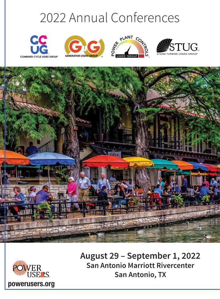

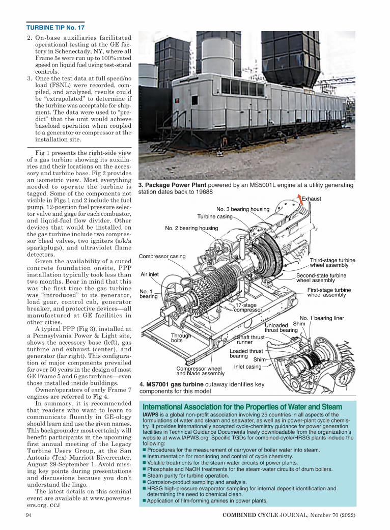
94 COMBINED CYCLE JOURNAL, Number 70 (2022)
2. On-base auxiliaries facilitated operational testing at the GE fac-tory in Schenectady, NY, where all Frame 5s were run up to 100% rated speed on liquid fuel using test-stand controls.
3. Once the test data at full speed/no load (FSNL) were recorded, com-piled, and analyzed, results could be “extrapolated” to determine if the turbine was acceptable for ship-ment. The data were used to “pre-dict” that the unit would achieve baseload operation when coupled to a generator or compressor at the installation site.
Fig 1 presents the right-side view of a gas turbine showing its auxilia-ries and their locations on the acces-sory and turbine base. Fig 2 provides an isometric view. Most everything needed to operate the turbine is tagged. Some of the components not visible in Figs 1 and 2 include the fuel pump, 12-position fuel pressure selec-tor valve and gage for each combustor, and liquid-fuel flow divider. Other devices that would be installed on the gas turbine include two compres-sor bleed valves, two igniters (a/k/a sparkplugs), and ultraviolet flame detectors.
Given the availability of a cured concrete foundation onsite, PPP installation typically took less than two months. Bear in mind that this was the first time the gas turbine was “introduced” to its generator, load gear, control cab, generator breaker, and protective devices—all manufactured at GE facilities in other cities.
A typical PPP (Fig 3), installed at a Pennsylvania Power & Light site, shows the accessory base (left), gas turbine and exhaust (center), and generator (far right). This configura-tion of major components prevailed for over 50 years in the design of most GE Frame 5 and 6 gas turbines—even those installed inside buildings.
Owner/operators of early Frame 7 engines are referred to Fig 4.
In summary, it is recommended that readers who want to learn to communicate fluently in GE-ology should learn and use the given names. This backgrounder most certainly will benefit participants in the upcoming first annual meeting of the Legacy Turbine Users Group, at the San Antonio (Tex) Marriott Rivercenter, August 29-September 1. Avoid miss-ing key points during presentations and discussions because you don’t understand the lingo.
The latest details on this seminal event are available at www.powerus-ers.org. ccj
Air inlet
Compressor casing
No. 2 bearing housing
Turbine casingNo. 3 bearing housing
Exhaust
Third-stage turbine wheel assembly
Second-state turbine wheel assembly
First-stage turbine wheel assembly
Compressor wheel and blade assembly
Through bolts
No. 1 bearing
No. 1 bearing linerShimUnloaded
thrust bearingShaft thrustrunner
Loaded thrust bearing Shim
Inlet casing
17-stage compressor
3. Package Power Plant powered by an MS5001L engine at a utility generating station dates back to 19688
4. MS7001 gas turbine cutaway identifies key components for this model
International Association for the Properties of Water and SteamIAWPS is a global non-profit association involving 25 countries in all aspects of the formulations of water and steam and seawater, as well as in power-plant cycle chemis-try. It provides internationally accepted cycle-chemistry guidance for power generation facilities in Technical Guidance Documents freely downloadable from the organization’s website at www.IAPWS.org. Specific TGDs for combined-cycle/HRSG plants include the following:■ Procedures for the measurement of carryover of boiler water into steam.■ Instrumentation for monitoring and control of cycle chemistry.■ Volatile treatments for the steam-water circuits of power plants.■ Phosphate and NaOH treatments for the steam-water circuits of drum boilers.■ Steam purity for turbine operation.■ Corrosion-product sampling and analysis.■ HRSG high-pressure evaporator sampling for internal deposit identification and determining the need to chemical clean.■ Application of film-forming amines in power plants.
TURBINE TIP No. 17
70 P 95.indd 9570 P 95.indd 95 5/6/22 10:25 PM5/6/22 10:25 PM
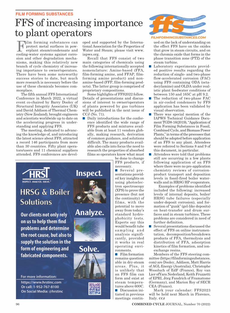
96 COMBINED CYCLE JOURNAL, Number 70 (2022)
FILM FORMING SUBSTANCES
Film forming substances can protect metal surfaces in pow-erplant steam/condensate and
cooling-water systems against corro-sion and other degradation mecha-nisms, making this relatively new branch of cycle chemistry of increas-ing importance to owner/operators. There have been some noteworthy success stories to date, but much more research is necessary before the use of these chemicals becomes com-monplace.
The fifth annual FFS International Conference in March 2022, a virtual event co-chaired by Barry Dooley of Structural Integrity Associates (UK) and David Addison of Thermal Chem-istry (New Zealand), brought engineers and scientists worldwide up to date on the accelerating progress in under-standing and applying FFS.
The meeting, dedicated to advanc-ing the knowledge of, and introducing the latest science about FFS, attracted a record 146 participants from more than 30 countries. Fifty plant opera-tors/users and 11 chemical suppliers attended. FFS conferences are devel-
oped and supported by the Interna-tional Association for the Properties of Water and Steam; please visit www.iapws.org.
Recall that FFS consist of two main categories of chemicals using the following internationally accepted nomenclature: Amine-based (FFA, film-forming amine, and FFAP, film-forming amine product) and non-amine-based (FFP, film-forming prod-ucts). The latter group is comprised of proprietary compositions.
Some highlights of FFS2022 follow. Details of presentations and discus-sions of interest to owner/operators of plants powered by gas turbines will be published in the next issue of CCJ (No. 71). n Daily introductions for the confer-
ence identified the wide range of FFS products and mixtures avail-able from at least 11 vendors glob-ally, making research, derivation of common guidance, and solutions difficult. The many products avail-able also calls into focus the need to research the properties of absorbed films so operators know what must
be done to change FFS products, if necessary. n Several pre-sentations provid-ed key insights on using photoelec-tron spectroscopy (XPS) to prove the presence (but not the continuity) of films, with the potential to move away from today’s standard hydro-phobicity tests. Experts say this would benefit tube sampl ing and analysis signifi-cantly, provided it works in real operating envi-ronments. n Film formation remains question-able in dry-steam areas. Plus, it is unlikely that an FFS film can form and exist at steam tempera-tures above 600C. n Discussion ini-tiated in previous meetings contin-
ued on the lack of understanding on the effect FFS have on the oxides that grow in steam circuits, and on the chromia oxide that forms in the phase transition zone (PTZ) of the steam turbine.
n Laboratory experiments provid-ed positive results regarding the reduction of single- and two-phase flow-accelerated corrosion (FAC) using FFS containing ODA (octa-decylamine) and OLDA under real-istic plant feedwater conditions of between 150 and 165C at pH 9.2.
n The reduction of two-phase FAC in air-cooled condensers by FFS application has been validated by visual observation.
n There was special mention of the IAPWS Technical Guidance Docu-ment TGD8-16(2019), “Application of Film Forming Substances in Fossil, Combined Cycle, and Biomass Power Plants,” in terms of the processes that should be adopted before application of an FFS to any plant. Attendees were referred to Sections 8 and 9 of this document, in particular.
n Attendees were told that problems still are occurring in a few plants following application of an FFS where there were no pre-application chemistry reviews of corrosion-product transport and deposition levels in fossil-fired boiler water-walls and in HRSG HP evaporators.
Examples of problems identified included the following: increased levels of internal deposits, boiler/HRSG tube failures (especially under-deposit corrosion), and for-mation of “gunk” (gel-like deposits) on heat-transfer and drum sur-faces and in steam turbines. These problems are considered in need of further definition.
n Several presentations discussed the effect of FFS on online instrumen-tation, decomposition/breakdown products of FFA, thermolysis and distribution of FFA, adsorption kinetics of film formation, and ion-exchange resins. Members of the FFS steering com-
mittee (https://filmformingsubstances.com) are Dooley, Addison, Matt Harris of AGL Energy (Australia), Christophe Wesoluch of EdF (France), Roy van Lier ofYara Nederland, Keith Fruzzetti of EPRI, Jörg Fandrich of Framatome (Germany), and Marion Roy of SECR CEA (France).
Mark your calendar: FFS2023 will be held next March in Florence, Italy. ccj
FFS of increasing importance to plant operators
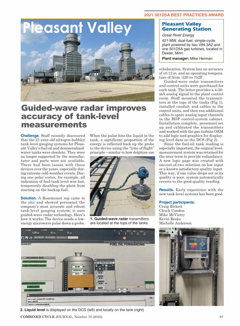
COMBINED CYCLE JOURNAL, Number 70 (2022) 97
2021 501D5A BEST PRACTICES AWARD
Challenge. Staff recently discovered that the 21-year-old nitrogen-bubbler tank-level gauging systems for Pleas-ant Valley’s fuel-oil and demineralized-water tanks were obsolete. They were no longer supported by the manufac-turer and parts were not available. There had been issues with these devices over the years, especially dur-ing extreme cold-weather events. Dur-ing one polar vortex, for example, all indication of fuel-tank level was lost, temporarily disabling the plant from starting on the backup fuel.
Solution. A Rosemount rep came to the site and showed personnel the company’s most accurate and robust tank-level gauging system; it uses guided-wave radar technology. Here’s how it works: The device sends a low-energy microwave pulse down a probe.
When the pulse hits the liquid in the tank, a significant proportion of the energy is reflected back up the probe to the device using the “time of flight” principle—similar to how dolphins use
echolocation. System has an accuracy of ±0.12 in. and an operating tempera-ture of from -320 to 752F.
Guided-wave radar transmitters and control units were purchased for each tank. The latter provides a 4-20-mA analog signal to the plant control room. Staff mounted the transmit-ters at the tops of the tanks (Fig 1), installed conduit and cables to the control units, and then ran additional cables to spare analog input channels in the BOP control-system cabinet. Installation complete, personnel set up and calibrated the transmitters and worked with the gas-turbine OEM to add logic and graphics for display-ing level data on the DCS (Fig 2).
Since the fuel-oil tank reading is especially important, the original level-measurement system was retained for the near term to provide redundancy. A new logic page was created with one-out-of-two selection on low input or a known satisfactory quality input. This way, if one value drops out or its quality is poor, system automatically reverts to the good-quality reading.
Results. Early experience with the new tank-level systems has been good.
Project participants: Craig BirkettChuck CondonMike McViettyKevin BeskeMichelle Anderson
Pleasant Valley Generating StationGreat River Energy421-MW, dual-fuel, simple-cycle plant powered by two V84.3A2 and one 501D5A gas turbines, located in Dexter, MinnPlant manager: Mike Herman
Guided-wave radar improves accuracy of tank-level measurements
Pleasant Valley
1. Guided-wave radar transmitters are located at the tops of the tanks
2. Liquid level is displayed on the DCS (left) and locally on the tank (right)
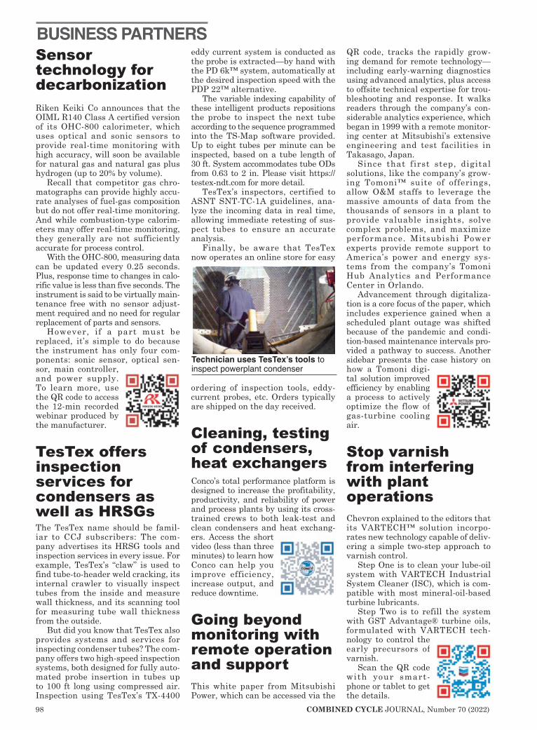
98 COMBINED CYCLE JOURNAL, Number 70 (2022)
Sensor technology for decarbonizationRiken Keiki Co announces that the OIML R140 Class A certified version of its OHC-800 calorimeter, which uses optical and sonic sensors to provide real-time monitoring with high accuracy, will soon be available for natural gas and natural gas plus hydrogen (up to 20% by volume).
Recall that competitor gas chro-matographs can provide highly accu-rate analyses of fuel-gas composition but do not offer real-time monitoring. And while combustion-type calorim-eters may offer real-time monitoring, they generally are not sufficiently accurate for process control.
With the OHC-800, measuring data can be updated every 0.25 seconds. Plus, response time to changes in calo-rific value is less than five seconds. The instrument is said to be virtually main-tenance free with no sensor adjust-ment required and no need for regular replacement of parts and sensors.
However, if a part must be replaced, it’s simple to do because the instrument has only four com-ponents: sonic sensor, optical sen-sor, main controller, and power supply. To learn more, use the QR code to access the 12-min recorded webinar produced by the manufacturer.
TesTex offers inspection services for condensers as well as HRSGsThe TesTex name should be famil-iar to CCJ subscribers: The com-pany advertises its HRSG tools and inspection services in every issue. For example, TesTex’s “claw” is used to find tube-to-header weld cracking, its internal crawler to visually inspect tubes from the inside and measure wall thickness, and its scanning tool for measuring tube wall thickness from the outside.
But did you know that TesTex also provides systems and services for inspecting condenser tubes? The com-pany offers two high-speed inspection systems, both designed for fully auto-mated probe insertion in tubes up to 100 ft long using compressed air. Inspection using TesTex’s TX-4400
eddy current system is conducted as the probe is extracted—by hand with the PD 6k™ system, automatically at the desired inspection speed with the PDP 22™ alternative.
The variable indexing capability of these intelligent products repositions the probe to inspect the next tube according to the sequence programmed into the TS-Map software provided. Up to eight tubes per minute can be inspected, based on a tube length of 30 ft. System accommodates tube ODs from 0.63 to 2 in. Please visit https://testex-ndt.com for more detail.
TesTex’s inspectors, certified to ASNT SNT-TC-1A guidelines, ana-lyze the incoming data in real time, allowing immediate retesting of sus-pect tubes to ensure an accurate analysis.
Finally, be aware that TesTex now operates an online store for easy
ordering of inspection tools, eddy-current probes, etc. Orders typically are shipped on the day received.
Cleaning, testing of condensers, heat exchangersConco’s total performance platform is designed to increase the profitability, productivity, and reliability of power and process plants by using its cross-trained crews to both leak-test and clean condensers and heat exchang-ers. Access the short video (less than three minutes) to learn how Conco can help you improve efficiency, increase output, and reduce downtime.
Going beyond monitoring with remote operation and supportThis white paper from Mitsubishi Power, which can be accessed via the
QR code, tracks the rapidly grow-ing demand for remote technology—including early-warning diagnostics using advanced analytics, plus access to offsite technical expertise for trou-bleshooting and response. It walks readers through the company’s con-siderable analytics experience, which began in 1999 with a remote monitor-ing center at Mitsubishi’s extensive engineering and test facilities in Takasago, Japan.
Since that first step, digital solutions, like the company’s grow-ing Tomoni™ suite of offerings, allow O&M staffs to leverage the massive amounts of data from the thousands of sensors in a plant to provide valuable insights, solve complex problems, and maximize performance. Mitsubishi Power experts provide remote support to America’s power and energy sys-tems from the company’s Tomoni Hub Analytics and Performance Center in Orlando.
Advancement through digitaliza-tion is a core focus of the paper, which includes experience gained when a scheduled plant outage was shifted because of the pandemic and condi-tion-based maintenance intervals pro-vided a pathway to success. Another sidebar presents the case history on how a Tomoni digi-tal solution improved efficiency by enabling a process to actively optimize the flow of gas-turbine cooling air.
Stop varnish from interfering with plant operationsChevron explained to the editors that its VARTECH™ solution incorpo-rates new technology capable of deliv-ering a simple two-step approach to varnish control.
Step One is to clean your lube-oil system with VARTECH Industrial System Cleaner (ISC), which is com-patible with most mineral-oil-based turbine lubricants.
Step Two is to refill the system with GST Advantage® turbine oils, formulated with VARTECH tech-nology to control the early precursors of varnish.
Scan the QR code with your smart-phone or tablet to get the details.
BUSINESS PARTNERS
Technician uses TesTex’s tools to inspect powerplant condenser

| (800) 505-6100
KinetiClean is safer and fasterwith the deepest cleaning effect
of any method currently used to clean HRSG fin tubes.
BeforeAfter
TThhee mmoosstt eeffffeeccttiivvee wwaayy ttoo cclleeaann aa HHRRSSGG
Groome’s patented technology uses a proven
Kinetic Shockwave cleaning method to remove
unwanted foulant. An innovative and automated
air system then distributes high-pressure,
high-volume air to liberate remaining debris.
• No manual tube movement
• Minimal-to-no scaffolding
• Other projects can continue in tandem
• No additional moisture
• Highly-trained and fully-licensedprofessionals manage explosive process

![[2019] CCJ 9 (AJ) - Election Judgments](https://static.fdokumen.com/doc/165x107/63223e3628c445989105af86/2019-ccj-9-aj-election-judgments.jpg)


![[2022] CCJ 2 (AJ) BB IN THE CARIBBEAN COURT OF ...](https://static.fdokumen.com/doc/165x107/631e6e4c1aedb9cd850fbf65/2022-ccj-2-aj-bb-in-the-caribbean-court-of-.jpg)