The algorithm of steam soot blowers operation based on the ...
Journal of Catalysis 242 (2006) 38–47
www.elsevier.com/locate/jcat
Catalytic removal of NOx and diesel soot over nanostructuredspinel-type oxides
D. Fino ∗, N. Russo, G. Saracco, V. Specchia
Department of Materials Science and Chemical Engineering, Politecnico di Torino, C.so Duca degli Abruzzi 24, 10129 Torino, Italy
Received 22 March 2006; revised 23 May 2006; accepted 25 May 2006
Available online 30 June 2006
Abstract
Nanostructured spinel-type oxide catalysts AB2O4 (where A = Co and Mn, and B = Cr and Fe), prepared by the solution combustion synthesismethod and characterized by BET, XRD, FESEM, TEM, FTIR, and catalytic activity tests, proved to be effective in the simultaneous removal ofsoot and NOx , the two prevalent pollutants in diesel exhaust gases in the temperature range of 350–450 ◦C. The activity order for soot combustionwas found to be CoCr2O4 > MnCr2O4 > CoFe2O4, whereas the activity order for NOx reduction was CoFe2O4 > CoCr2O4 > MnCr2O4. Thebest compromise between simultaneous abatement of soot and nitrogen oxide was therefore shown by CoCr2O4 catalyst; it could promote sootcombustion and appreciable NOx reduction below 400 ◦C, the maximum temperature reached in the exhaust line of a diesel engine. On the basisof oxygen temperature-programmed desorption, the prevalent catalytic combustion activity of the chromite catalysts could be explained by theirhigher concentration of suprafacial, weakly chemisorbed oxygen, which contributes actively to soot combustion by spillover in the temperaturerange of 300–500 ◦C. Tentative reaction pathways for the simultaneous reduction of NOx are outlined as well.© 2006 Elsevier Inc. All rights reserved.
Keywords: Diesel particulate combustion; Nitrogen oxides reduction; CoCr2O4; MnCr2O4; CoFe2O4 spinels; Reaction mechanism
1. Introduction
The increased industrialization, and particularly increasedtraffic, in Western and developing nations has been accom-panied by a negative impact on air quality, the environment,and human health. Diesel engines have both carbon monoxideand unburned hydrocarbon outlet concentrations much lowerthan those produced by spark-ignition engines. However, eventhe most recent diesel engines (e.g., common rail) generatenitrogen oxides and carcinogenic particulates, whose size (50–200 nm) falls in the so-called lung-damaging range [1]. Manytoxicologic and epidemiologic studies have established adversehealth effects by particulate matter (PM10, PM2.5). There is in-creasing evidence that several health effects are associated withthe ultrafine particles (diameter <100 nm) [2]. Recent researchshows that these can penetrate the cell membranes, enter the
* Corresponding author. Fax: +39 011 5644699.E-mail address: [email protected] (D. Fino).
0021-9517/$ – see front matter © 2006 Elsevier Inc. All rights reserved.doi:10.1016/j.jcat.2006.05.023
blood, and even reach the brain [3]. Some investigations indi-cate that such particles can induce inheritable mutations [4].
The automotive industry is currently facing serious chal-lenges to reduce the environmental impact from vehicles sinceEuropean legislation introduced the Euro 4 step in January2005, which for diesel cars corresponds to 0.25 g km−1 of NOx
and 0.025 g km−1 of particulate matter (PM). Despite an 80%reduction in diesel car emission standards over the levels of 10years ago, the mean NOx emission level of diesel vehicles con-tinues to be three times higher than their gasoline counterparts.
These limits cannot be accomplished by engine modifica-tions [5], fuel pretreatments [6], or simply better tuning ofthe combustion process [7]; thus, a convenient way of treatingdiesel off-gases is needed. In this context, a possible solutionto reduce the PM emissions of vehicles is to retrofit them witha particulate filter. Several diesel particulate filter systems arecurrently on the market. Wall-flow monoliths are the most com-mon type [8]. Adjacent channels in the wall-flow filters arealternatively plugged at each end, thus forcing the gas to flowthrough the porous wall, which acts as a filter medium. Themost important issue with diesel traps is the regeneration of the
D. Fino et al. / Journal of Catalysis 242 (2006) 38–47 39
filters. Various strategies for this have been considered, includ-ing catalyzed filter substrates [9–11], fuel-borne catalysts [12],continuous regenerating traps [13], electric heaters [14], fuelburners [15], and microwaves [16].
The research carried out worldwide in this field is aimedmainly at two different solutions:
1. Filtration of particulate in a first catalytic converter, inwhich the soot is trapped and burned out due to the pres-ence of a catalyst thoroughly deposited onto the filter [17],with NOx eliminated in a second catalytic converter ei-ther by reaction with suitable reducing agents (e.g., lighthydrocarbons, fuel, ammonia [18]) or by direct decompo-sition [19].
2. Simultaneous removal of soot and nitrogen oxides in a sin-gle, suitably catalyzed trap [20–32].
The second approach is clearly more ambitious than the firstone and has recently been explored in view of the consider-able advantages that it may offer in terms of both investmentcost and pressure drop reduction. It is well known that 10–15%of NOx is generally reduced during regeneration of soot-ladentraps. This reduction mostly involves NO2 molecules by directreaction with soot to form NO and, to a much lesser extent, N2and N2O [33]. This reaction, exploited in Johnson Matthey’scontinuously regenerating technology (CRT) [34], is the basisof the present study. Despite the fact that several technical prob-lems remain to be solved (e.g., determining the best catalystdeposition route on the trap and the best trap design so as toallow intimate contact between the reactants and the catalystitself), a more urgent research topic is the development of a suit-able catalyst capable of promoting both soot oxidation and NOx
reduction at comparatively low temperatures (possibly withinthe range typical of diesel exhaust, 150–380 ◦C). A recent pa-per [35] has shown that mixed-type oxides are among the mostpromising catalysts for this purpose.
In the present work, nanostructured AB2O4 (with A = Coand Mn, and B = Cr and Fe) spinel-type catalysts were pre-pared via a tailored technique (i.e., solution combustion syn-thesis [36]), characterized, and tested for their activity in thesimultaneous abatement of NOx and soot. The nanoscopic di-mensions of the catalyst crystals thus obtained was pursued soas to increase the number of contact points between the catalystand the particulate, a key feature of the reaction pathway, asdiscussed later. On the basis of the experimental work reportedhere, some conclusions are then drawn concerning the catalyststested.
2. Experimental
2.1. Catalyst preparation
Three spinel samples (CoCr2O4, MnCr2O4, and CoFe2O4)were prepared via a highly exothermic and self-sustainingreaction, the so-called solution combustion synthesis (SCS)method [36]. This technique is particularly suitable for pro-ducing nanosized catalyst particles. The combustion synthesis
process can be formally split into the following two steps (usingthe preparation of cobalt chromite as an example):
3Co(NO3)2 + 6Cr(NO3)3 → 3CoCr2O4 + 12N2 + 30O2 (1)
and
20CO(NH2)2 + 30O2 → 20CO2 + 40H2O + 20N2. (2)
The first step is the endothermic reaction (1) for the real spinelsynthesis starting from the metal nitrate precursors, whereas thesecond step is exothermic and accounts for the reaction (2) be-tween oxygen derived from nitrates decomposition and urea. Ofcourse, some direct combustion of urea with atmospheric oxy-gen cannot be excluded, because the preparation is carried outin air in an electric oven maintained at 500 ◦C, hosting the pre-cursor mixture placed in a porcelain pot. The overall set of reac-tions is markedly exothermic, which leads to a thermal peak inthe reacting solid mixture greatly exceeding 1000 ◦C for a fewseconds. To increase this sudden heat release, some NH4NO3was used. Under these conditions, nucleation of spinel crys-tals was induced, the growth of these crystals was limited, andnanosized grains were obtained, as anticipated. Each prepara-tion batch was tuned to produce 1 g of the desired catalyst.After preparation, all catalysts were ground in a ball mill atroom temperature and submitted to physical and chemical char-acterization.
A sample of the fresh CoCr2O4 was aged for 1 h at 900 ◦Cin an oven to induce a decrease in the specific surface area andto evaluate the effect of this parameter on the catalytic activity.
2.2. Catalyst characterization
Catalyst characterisation was carried out via the followingtechniques:
– Chemical analysis of the catalyst was performed by atomicabsorption spectroscopy (AAS) in a Perkin-Elmer 1100Bspectrophotometer after dissolution in strongly acidic me-dia, to verify the amount of each constituting element in theprepared spinels.
– X-ray diffraction (XRD) was done in a PW1710 Philipsdiffractometer equipped with a CuKα monochromator toconfirm that the desired spinel crystal structure was actu-ally achieved.
– Field-emission scanning electron microscopy (FESEM)with a Leo 50/50 VP with a GEMINI column and trans-mission electron microscopy (TEM) with a Philips CM30 T were carried out to analyze the microstructure of thecatalyst crystal agglomerates and the catalyst crystals them-selves.
– Nitrogen adsorption for BET specific surface area (SSA)measurements were performed with a Micromeritics ASAP2010.
– Temperature-programmed desorption (TPD) analyses werealso performed on all of the prepared catalysts in a Ther-moquest TPD/R/O 1100 analyzer, equipped with a thermalconductivity detector (TCD) and a quadrupole mass spec-trometry (MS) detector (Baltzer Quadstar 422). A fixed
40 D. Fino et al. / Journal of Catalysis 242 (2006) 38–47
bed of catalyst was enclosed in a quartz tube and sand-wiched between two quartz wool layers; before each TPDrun, the catalyst was heated under an O2 flow at a rate of40 Nml min−1 up to 750 ◦C. After 30 min at this temper-ature as a common pretreatment, the reactor temperaturewas lowered to room temperature with the same flow rateof oxygen, thereby allowing complete oxygen adsorptionover the catalyst. Afterward, helium was fed to the reactorat a rate of 10 Nml min−1, and the reactor was maintainedat room temperature for 1 h to purge any excess oxygenmolecules. The catalyst was then heated to 1100 ◦C at aconstant rate of 10 ◦C min−1 under a helium flow rate of10 Nml min−1 [37]. The quadrupole detector confirmedthat oxygen was the only desorbed species.
– Two Fourier transform infrared (FTIR) spectra were record-ed to provide crucial information about the reaction mech-anism over the most promising catalyst (CoCr2O4), pre-treated as follows: (a) fresh catalyst, as prepared, and(b) catalyst treated at 385 ◦C under NO flow (2000 ppmvin He) for 60 min and then cooled rapidly under pure Hegas flow, with the reactor then promptly removed from theoven. A 200-mg pellet was formed by pressing a mixtureof each treated catalyst and KBr (1:100 weight ratio). FTIRtransmission spectra were then obtained in the wavenumberrange 1000–2000 cm−1 using a Bruker Equinox 55 spec-trophotometer equipped with an MCT cryodetector.
2.3. Catalytic activity assessment
The catalytic activity of the prepared catalysts was testedin a temperature-programmed reaction (TPR) apparatus [38].A standard gas mixture (1000 ppm NO, 10 vol% O2, balanceHe) was fed at the constant flow rate of 1.66 × 10⁻⁶ Nm3 s−1
via a set of mass flow meters (Brooks) to a fixed-bed reactorenclosed in a quartz tube placed in an electric oven. The tubu-lar quartz reactor was loaded with 50 mg of a 9:1 by weightmixture of powdered catalyst and carbon and 150 mg of SiO2granules (0.3–0.7 mm); this inert material was added to reducethe specific pressure drops across the reactor and to preventthermal runaways (maximum temperature difference across thereactor, 20 ◦C). The catalyst weight-to-flow rate ratio in thestandard runs was W/F = 27.1 kg s Nm−3. Experiments wereperformed by using instead of real diesel soot an amorphouscarbon (printex U by Degussa) with the following properties:average particle size, 45 nm; 0.34 wt% ash after calcination at800 ◦C; and 12.2 wt% of moisture lost after drying at 110 ◦C.This material was chosen to avoid any interference due to thepresence of adsorbed HCs, sulfates, or fly ash present in realdiesel soot. Moreover, the carbon used is more difficult toburn than diesel soot, making the results achieved conservative[9,39,40]. A proper and reproducible mixing between catalystand carbon was routinely obtained by ball milling for 15 min.These mixing conditions are normally known as “tight contact”conditions [17] and were used in the present study becausethey allow for better reproducibility. The soot–catalyst contactconditions in a real catalytic trap are less intensive, however,and are usually referred to as “loose contact” conditions [17].
Similar conditions can be obtained by gently shaking the twocounterparts in a vessel. Most runs in the present investigationwere performed under tight contact conditions, because goodreproducibility is mandatory to provide a sound basis for mech-anistic studies. Reference runs on a loose contact mixture in theabsence of catalyst (noncatalytic soot combustion) or the ab-sence of soot (simple NO reduction by the catalyst) were alsoperformed for comparison purposes.
The catalyst–carbon–SiO2 fixed bed was sandwiched be-tween two quartz-wool layers, whereas the tip of a K-type ther-mocouple was located well inside the bed itself. The reactiontemperature was controlled through a PID-regulation systembased on the measurements of an external K-type thermocou-ple and varied during each TPR runs from 200 to 700 ◦C at arate of 5 ◦C min−1. A 30-min stay at 200 ◦C under He flow wasadopted as a common pretreatment to eliminate possible conta-minants, such as adsorbed water. The analysis of the outlet gaswas performed via a CO/CO2/N2O NDIR analyzer, a NO/NO2chemiluminescence analyzer, and an O2 paramagnetic analyzerby ABB. Nitrogen was measured by gas chromatography usinga Hewlett Packard 5890 Series II, equipped with Porapak Q andmolecular sieve columns and a TCD.
Specific TPR analyses were performed on the most promis-ing catalyst prepared (CoCr2O4) for the sake of gaining betterinsight into the reaction mechanism:
(i) Runs at various inlet O2 partial pressures (0, 2, 10 vol%;1000 ppmv NO; balance He).
(ii) Runs at various inlet NO concentrations of (500, 1000,2000 ppmv NO; 10 vol% O2).
(iii) Runs at various catalyst/carbon ratios in the fixed bed (4:1,9:1, 19:1, 1:0, being the amount of carbon equal to 5 mg,whenever present; at 1000 ppmv NO, 10 vol% O2, balanceHe).
3. Results and discussion
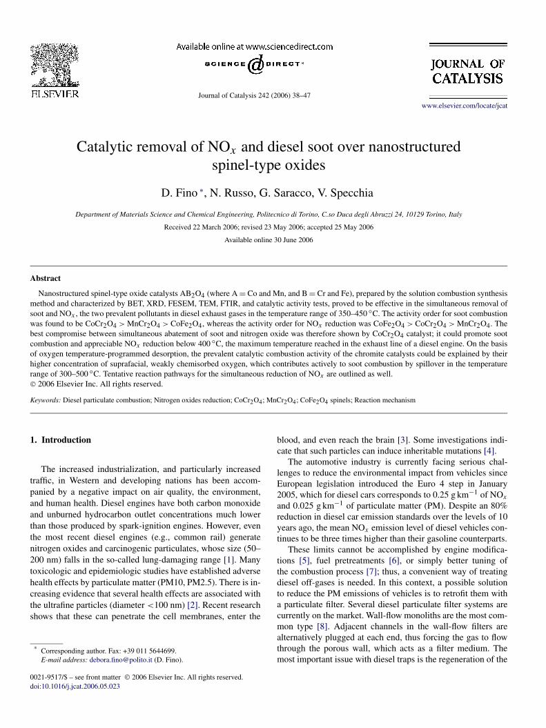
All spinel catalyst samples were well crystallized by XRDanalysis (Fig. 1). All diffraction peaks expected according tothe reference JPCDS cards (CoCr2O4, PDF 221084; CoFe2O4,PDF 221086; MnCr2O4, PDF 751614) were observed. No sec-ondary phases could be detected by this technique. XRD hasa ±4% precision, and thus the presence of amorphous phasescannot be completely excluded. Moreover, chemical analysis(dissolution and atomic absorption, O2 titration) confirmed,within the limits related to its intrinsic precision (±5%), thatthe amounts of the various constituting elements (Co, Cr, Fe,Mn, and O) were consistent with those used in the precursorsand was compatible with the phases detected by XRD.
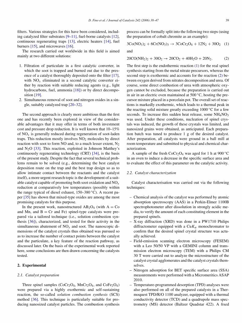
In the present context, spinel crystals with size of the sameorder of magnitude as that of the particulate nuclei (tens ofnanometers [41]) are expected to provide the highest specificnumber of contact points between the soot directly capturedover the catalyst layer of diesel particulate traps [42] and thecrystals constituting such a layer. Fig. 2 shows a TEM pictureof the CoCr2O4 spinel-type catalyst produced via SCS, whichdisplays the highest SSA value (59.0 m2 g−1). The spinel crys-
D. Fino et al. / Journal of Catalysis 242 (2006) 38–47 41
Fig. 1. XRD spectra of the three spinel-type catalysts prepared.
Fig. 2. TEM micrograph of the CoCr2O4 catalyst crystals.
tals of the considered catalyst are much smaller than 20 nm,perfectly in line with the dimensions of particulate nuclei andin substantial agreement with the SSA measured. As expected,this SSA was somehow reduced after calcination at high tem-perature (900 ◦C), even if it remains higher than that of the twoother catalytic materials prepared.
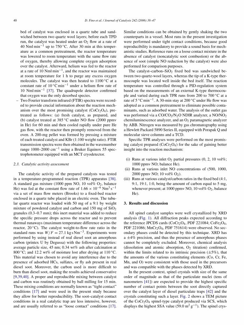
The FESEM view of the microstructure of the crystal aggre-gates of the CoCr2O4 catalyst (Fig. 3) enlightens a very foamystructure, a typical feature of catalysts synthesized by SCS. Thisshould once again strongly favor the contact between soot andcatalyst even under loose contact conditions and, once coatedon the wall flow trap channel walls, it should allow just a slightincrease in the pressure drop [42].
Beyond the SSA data, Table 1 summarizes the carbon com-bustion peak temperatures (the temperature corresponding tothe maximum carbon conversion rate to CO2, Tcomb), the maxi-
Fig. 3. FESEM view of CoCr2O4 catalyst crystal agglomerates obtained by combustion synthesis.
42 D. Fino et al. / Journal of Catalysis 242 (2006) 38–47
Table 1BET analysis and catalytic activity results
Catalyst BET(m2 g−1)
Tcomb(◦C)
Tred(◦C)
NO conversionat Tred (%)
CoCr2O4 59 396 385 36Aged CoCr2O4 39 399 389 29MnCr2O4 37 427 331 25CoFe2O4 10 446 345 43
mum NO conversion achievable, and the related NO abatementpeak temperature (Tred) for all of the catalysts investigated.The lower the Tcomb value, the higher the activity toward sootcombustion. Because the main goal of the present investigationwas the development of a catalyst for the combined abatementof soot and NOx , the CoCr2O4 catalyst was selected for fur-ther investigation because it is characterized by the best carboncombustion activity, coupled with significant NO conversion.Despite the fact that the other two catalysts promote NO con-version at lower temperatures, MnCr2O4 provides the lowestNO abatement yield, and CoFe2O4 provides the poorest sootcombustion activity.
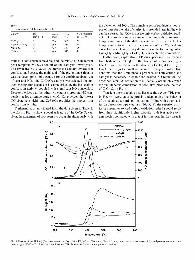
Furthermore, as anticipated from the data given in Table 1,the plots in Fig. 4a show a peculiar feature of the CoCr2O4 cat-alyst: the abatement of soot seems to occur simultaneously with
the abatement of NOx . The complete set of products is not re-ported here for the sake of clarity; it is provided later in Fig. 6. Itcan be stressed that CO2 is not the only carbon oxidation prod-uct: CO is produced in larger amounts as long as the combustiontemperature range of the different catalysts is shifted to highertemperatures. As testified by the lowering of the CO2 peak ar-eas in Fig. 4, CO2 selectivity diminishes in the following order:CoCr2O4 > MnCr2O4 > CoFe2O4 > noncatalytic combustion.
Furthermore, explorative TPR runs, performed by feedingfixed beds of the CoCr2O4 in the absence of carbon (see Fig. 7later) or with the carbon in the absence of catalyst (see Fig. 5later), lead to just a small reduction of nitrogen oxides. Thisconfirms that the simultaneous presence of both carbon andcatalyst is necessary to enable the desired NO reduction. Asdescribed later, NO reduction to N2 actually occurs only whenthe simultaneous combustion of soot takes place (see the caseof CoCr2O4 in Fig. 6).
Transient thermal analysis studies (see the oxygen TPD plotsin Fig. 4b) were quite helpful in understanding the behaviorof the catalysts toward soot oxidation. In line with other stud-ies on perovskite-type catalysts [36,43,44], the superior activ-ity of chromites toward carbon oxidation indeed should resultfrom their significantly higher capacity to deliver active oxy-gen species compared with that of ferrites. Another key issue is
Fig. 4. Results of the TPR (a) (feed concentrations: O2 = 10 vol%, NO = 1000 ppmv, He = balance; catalyst–soot mass ratio = 9:1; catalyst–soot contact condi-tions = tight; W/F = 27.1 kg s Nm−3) and oxygen TPD (b) runs performed on the prepared catalysts.
D. Fino et al. / Journal of Catalysis 242 (2006) 38–47 43
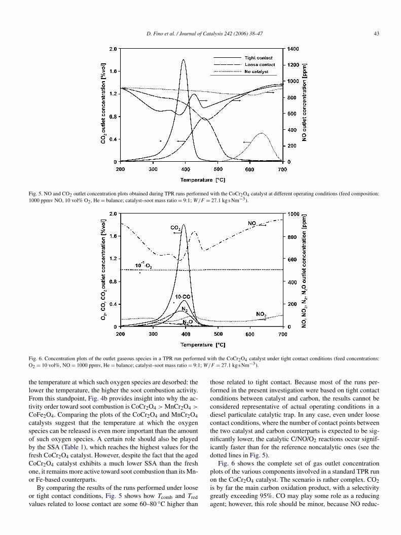
Fig. 5. NO and CO2 outlet concentration plots obtained during TPR runs performed with the CoCr2O4 catalyst at different operating conditions (feed composition:1000 ppmv NO, 10 vol% O2, He = balance; catalyst–soot mass ratio = 9:1; W/F = 27.1 kg s Nm−3).
Fig. 6. Concentration plots of the outlet gaseous species in a TPR run performed with the CoCr2O4 catalyst under tight contact conditions (feed concentrations:O2 = 10 vol%, NO = 1000 ppmv, He = balance; catalyst–soot mass ratio = 9:1; W/F = 27.1 kg s Nm−3).
the temperature at which such oxygen species are desorbed: thelower the temperature, the higher the soot combustion activity.From this standpoint, Fig. 4b provides insight into why the ac-tivity order toward soot combustion is CoCr2O4 > MnCr2O4 >
CoFe2O4. Comparing the plots of the CoCr2O4 and MnCr2O4catalysts suggest that the temperature at which the oxygenspecies can be released is even more important than the amountof such oxygen species. A certain role should also be playedby the SSA (Table 1), which reaches the highest values for thefresh CoCr2O4 catalyst. However, despite the fact that the agedCoCr2O4 catalyst exhibits a much lower SSA than the freshone, it remains more active toward soot combustion than its Mn-or Fe-based counterparts.
By comparing the results of the runs performed under looseor tight contact conditions, Fig. 5 shows how Tcomb and Tredvalues related to loose contact are some 60–80 ◦C higher than
those related to tight contact. Because most of the runs per-formed in the present investigation were based on tight contactconditions between catalyst and carbon, the results cannot beconsidered representative of actual operating conditions in adiesel particulate catalytic trap. In any case, even under loosecontact conditions, where the number of contact points betweenthe two catalyst and carbon counterparts is expected to be sig-nificantly lower, the catalytic C/NO/O2 reactions occur signif-icantly faster than for the reference noncatalytic ones (see thedotted lines in Fig. 5).
Fig. 6 shows the complete set of gas outlet concentrationplots of the various components involved in a standard TPR runon the CoCr2O4 catalyst. The scenario is rather complex. CO2is by far the main carbon oxidation product, with a selectivitygreatly exceeding 95%. CO may play some role as a reducingagent; however, this role should be minor, because NO reduc-
44 D. Fino et al. / Journal of Catalysis 242 (2006) 38–47
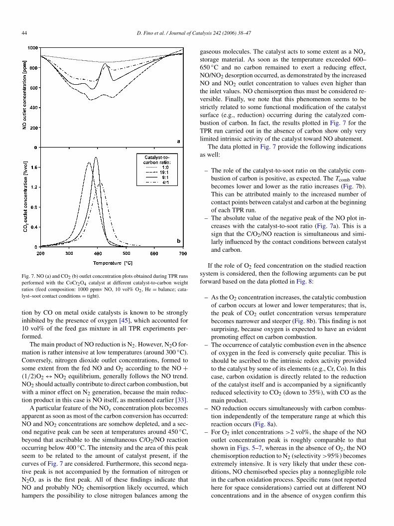
Fig. 7. NO (a) and CO2 (b) outlet concentration plots obtained during TPR runsperformed with the CoCr2O4 catalyst at different catalyst-to-carbon weightratios (feed composition: 1000 ppmv NO, 10 vol% O2, He = balance; cata-lyst–soot contact conditions = tight).
tion by CO on metal oxide catalysts is known to be stronglyinhibited by the presence of oxygen [45], which accounted for10 vol% of the feed gas mixture in all TPR experiments per-formed.
The main product of NO reduction is N2. However, N2O for-mation is rather intensive at low temperatures (around 300 ◦C).Conversely, nitrogen dioxide outlet concentrations, formed tosome extent from the fed NO and O2 according to the NO +(1/2)O2 ↔ NO2 equilibrium, generally follows the NO trend.NO2 should actually contribute to direct carbon combustion, butwith a minor effect on N2 generation, because the main reduc-tion product in this case is NO itself, as mentioned earlier [33].
A particular feature of the NOx concentration plots becomesapparent as soon as most of the carbon conversion has occurred:NO and NO2 concentrations are somehow depleted, and a sec-ond negative peak can be seen at temperatures around 450 ◦C,beyond that ascribable to the simultaneous C/O2/NO reactionoccurring below 400 ◦C. The intensity and the area of this peakseem to be related to the amount of catalyst present, if thecurves of Fig. 7 are considered. Furthermore, this second nega-tive peak is not accompanied by the formation of nitrogen orN2O, as is the first peak. All of these findings indicate thatNO and probably NO2 chemisorption likely occurred, whichhampers the possibility to close nitrogen balances among the
gaseous molecules. The catalyst acts to some extent as a NOx
storage material. As soon as the temperature exceeded 600–650 ◦C and no carbon remained to exert a reducing effect,NO/NO2 desorption occurred, as demonstrated by the increasedNO and NO2 outlet concentration to values even higher thanthe inlet values. NO chemisorption thus must be considered re-versible. Finally, we note that this phenomenon seems to bestrictly related to some functional modification of the catalystsurface (e.g., reduction) occurring during the catalyzed com-bustion of carbon. In fact, the results plotted in Fig. 7 for theTPR run carried out in the absence of carbon show only verylimited intrinsic activity of the catalyst toward NO abatement.
The data plotted in Fig. 7 provide the following indicationsas well:
– The role of the catalyst-to-soot ratio on the catalytic com-bustion of carbon is positive, as expected. The Tcomb valuebecomes lower and lower as the ratio increases (Fig. 7b).This can be attributed mainly to the increased number ofcontact points between catalyst and carbon at the beginningof each TPR run.
– The absolute value of the negative peak of the NO plot in-creases with the catalyst-to-soot ratio (Fig. 7a). This is asign that the C/O2/NO reaction is simultaneous and simi-larly influenced by the contact conditions between catalystand carbon.
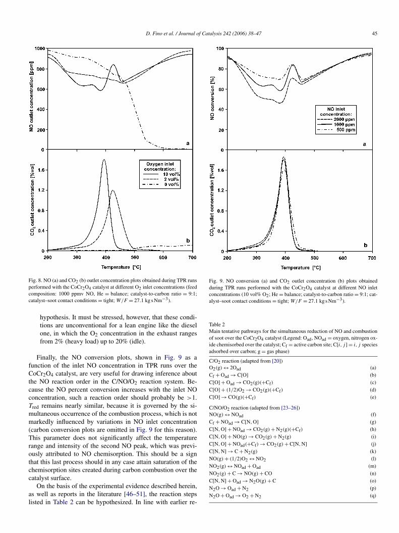
If the role of O2 feed concentration on the studied reactionsystem is considered, then the following arguments can be putforward based on the data plotted in Fig. 8:
– As the O2 concentration increases, the catalytic combustionof carbon occurs at lower and lower temperatures; that is,the peak of CO2 outlet concentration versus temperaturebecomes narrower and steeper (Fig. 8b). This finding is notsurprising, because oxygen is expected to have an evidentpromoting effect on carbon combustion.
– The occurrence of catalytic combustion even in the absenceof oxygen in the feed is conversely quite peculiar. This isshould be ascribed to the intrinsic redox activity providedto the catalyst by some of its elements (e.g., Cr, Co). In thiscase, carbon oxidation is directly related to the reductionof the catalyst itself and is accompanied by a significantlyreduced selectivity to CO2 (down to 35%), with CO as themain product.
– NO reduction occurs simultaneously with carbon combus-tion independently of the temperature range at which thisreaction occurs (Fig. 8a).
– For O2 inlet concentrations >2 vol%, the shape of the NOoutlet concentration peak is roughly comparable to thatshown in Figs. 5–7, whereas in the absence of O2, the NOchemisorption reduction to N2 (selectivity >95%) becomesextremely intensive. It is very likely that under these con-ditions, NO chemisorbed species play a nonnegligible rolein the carbon oxidation process. Specific runs (not reportedhere for space considerations) carried out at different NOconcentrations and in the absence of oxygen confirm this
D. Fino et al. / Journal of Catalysis 242 (2006) 38–47 45
Fig. 8. NO (a) and CO2 (b) outlet concentration plots obtained during TPR runsperformed with the CoCr2O4 catalyst at different O2 inlet concentrations (feedcomposition: 1000 ppmv NO, He = balance; catalyst-to-carbon ratio = 9:1;catalyst–soot contact conditions = tight; W/F = 27.1 kg s Nm−3).
hypothesis. It must be stressed, however, that these condi-tions are unconventional for a lean engine like the dieselone, in which the O2 concentration in the exhaust rangesfrom 2% (heavy load) up to 20% (idle).
Finally, the NO conversion plots, shown in Fig. 9 as afunction of the inlet NO concentration in TPR runs over theCoCr2O4 catalyst, are very useful for drawing inference aboutthe NO reaction order in the C/NO/O2 reaction system. Be-cause the NO percent conversion increases with the inlet NOconcentration, such a reaction order should probably be >1.Tred remains nearly similar, because it is governed by the si-multaneous occurrence of the combustion process, which is notmarkedly influenced by variations in NO inlet concentration(carbon conversion plots are omitted in Fig. 9 for this reason).This parameter does not significantly affect the temperaturerange and intensity of the second NO peak, which was previ-ously attributed to NO chemisorption. This should be a signthat this last process should in any case attain saturation of thechemisorption sites created during carbon combustion over thecatalyst surface.
On the basis of the experimental evidence described herein,as well as reports in the literature [46–51], the reaction stepslisted in Table 2 can be hypothesized. In line with earlier re-
Fig. 9. NO conversion (a) and CO2 outlet concentration (b) plots obtainedduring TPR runs performed with the CoCr2O4 catalyst at different NO inletconcentrations (10 vol% O2; He = balance; catalyst-to-carbon ratio = 9:1; cat-alyst–soot contact conditions = tight; W/F = 27.1 kg s Nm−3).
Table 2Main tentative pathways for the simultaneous reduction of NO and combustionof soot over the CoCr2O4 catalyst (Legend: Oad, NOad = oxygen, nitrogen ox-ide chemisorbed over the catalyst; Cf = active carbon site; C[i, j ] = i, j speciesadsorbed over carbon; g = gas phase)
C/O2 reaction (adapted from [20])(a)O2(g) ↔ 2Oad(b)Cf + Oad → C[O](c)C[O] + Oad → CO2(g)(+Cf)
(d)C[O] + (1/2)O2 → CO2(g)(+Cf)
(e)C[O] → CO(g)(+Cf)
C/NO/O2 reaction (adapted from [23–26])(f)NO(g) ↔ NOad(g)Cf + NOad → C[N,O](h)C[N,O] + NOad → CO2(g) + N2(g)(+Cf)
(i)C[N,O] + NO(g) → CO2(g) + N2(g)
(j)C[N,O] + NOad(+Cf) → CO2(g) + C[N,N](k)C[N,N] → C + N2(g)
(l)NO(g) + (1/2)O2 ↔ NO2(m)NO2(g) ↔ NOad + Oad(n)NO2(g) + C → NO(g) + CO(o)C[N,N] + Oad → N2O(g) + C(p)N2O → Oad + N2(q)N2O + Oad → O2 + N2
46 D. Fino et al. / Journal of Catalysis 242 (2006) 38–47
ports [46,47], the key players in carbon oxidation should be thefollowing ones:
– Oxygen species adsorbed (Oad) on the catalyst surface andobtained by dissociative chemisorption of gas oxygen (re-action (a)).
– Free carbon sites (Cf), particularly active, obtained in theearly stages of the combustion process (not consideredhere) and renewed over the catalyst surface as long ascombustion is occurring (see below). These sites can beconsidered those locations on the carbon surface where anoxidation process has just occurred. A deeper insight intothis has been provided previously [48].
The Oad species attack the reactive free carbon (Cf) to givethe oxygen-containing active intermediate C[O] over carbonsurface (reaction (b)), which in turn produces CO2 by react-ing with either Oad (reaction (c)) or molecular oxygen (reac-tion (d)), thereby leaving another reactive free carbon species(Cf) available for the reaction processes. Evidence of the pres-ence of such intermediate C[O] species was provided by Kuretiet al. [32] using DRIFT spectroscopy. Finally, CO productionfrom the reaction intermediate (reaction (e)) is hypothesized toaccount for the fact that CO2 selectivity is high, but not com-plete.
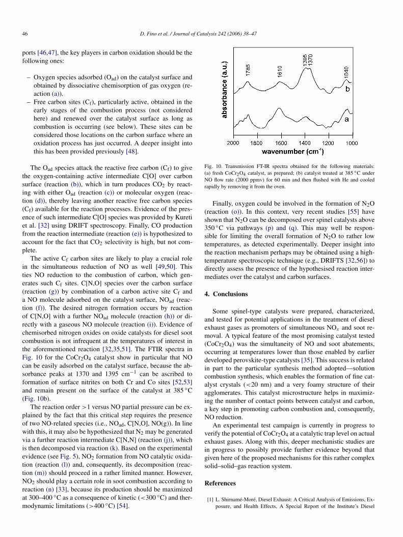
The active Cf carbon sites are likely to play a crucial rolein the simultaneous reduction of NO as well [49,50]. Thisties NO reduction to the combustion of carbon, which gen-erates such Cf sites. C[N,O] species over the carbon surface(reaction (g)) by combination of a carbon active site Cf anda NO molecule adsorbed on the catalyst surface, NOad (reac-tion (f)). The desired nitrogen formation occurs by reactionof C[N,O] with a further NOad molecule (reaction (h)) or di-rectly with a gaseous NO molecule (reaction (i)). Evidence ofchemisorbed nitrogen oxides on oxide catalysts for diesel sootcombustion is not infrequent at the temperatures of interest inthe aforementioned reaction [32,35,51]. The FTIR spectra inFig. 10 for the CoCr2O4 catalyst show in particular that NOcan be easily adsorbed on the catalyst surface, because the ab-sorbance peaks at 1370 and 1395 cm−1 can be ascribed toformation of surface nitrites on both Cr and Co sites [52,53]and remain present on the surface of the catalyst at 385 ◦C(Fig. 10b).
The reaction order >1 versus NO partial pressure can be ex-plained by the fact that this critical step requires the presenceof two NO-related species (i.e., NOad, C[N,O], NO(g)). In linewith this, it may also be hypothesized that N2 may be generatedvia a further reaction intermediate C[N,N] (reaction (j)), whichis then decomposed via reaction (k). Based on the experimentalevidence (see Fig. 5), NO2 formation from NO catalytic oxida-tion (reaction (l)) and, consequently, its decomposition (reac-tion (m)) should proceed in a rather limited manner. However,NO2 should play a certain role in soot combustion according toreaction (n) [33], because its production should be maximizedat 300–400 ◦C as a consequence of kinetic (<300 ◦C) and ther-modynamic limitations (>400 ◦C) [54].
Fig. 10. Transmission FT-IR spectra obtained for the following materials:(a) fresh CoCr2O4 catalyst, as prepared; (b) catalyst treated at 385 ◦C underNO flow rate (2000 ppmv) for 60 min and then flushed with He and cooledrapidly by removing it from the oven.
Finally, oxygen could be involved in the formation of N2O(reaction (o)). In this context, very recent studies [55] haveshown that N2O can be decomposed over spinel catalysts above350 ◦C via pathways (p) and (q). This may well be respon-sible for limiting the overall formation of N2O to rather lowtemperatures, as detected experimentally. Deeper insight intothe reaction mechanism perhaps may be obtained using a high-temperature spectroscopic technique (e.g., DRIFTS [32,56]) todirectly assess the presence of the hypothesised reaction inter-mediates over the catalyst and carbon surfaces.
4. Conclusions
Some spinel-type catalysts were prepared, characterized,and tested for potential applications in the treatment of dieselexhaust gases as promoters of simultaneous NOx and soot re-moval. A typical feature of the most promising catalyst tested(CoCr2O4) was the simultaneity of NO and soot abatements,occurring at temperatures lower than those enabled by earlierdeveloped perovskite-type catalysts [35]. This success is relatedin part to the particular synthesis method adopted—solutioncombustion synthesis, which enables the formation of fine cat-alyst crystals (<20 nm) and a very foamy structure of theiragglomerates. This catalyst microstructure helps in maximiz-ing the number of contact points between catalyst and carbon,a key step in promoting carbon combustion and, consequently,NO reduction.
An experimental test campaign is currently in progress toverify the potential of CoCr2O4 at a catalytic trap level on actualexhaust gases. Along with this, deeper mechanistic studies arein progress to possibly provide further evidence beyond thatgiven here of the proposed mechanisms for this rather complexsolid–solid–gas reaction system.
References
[1] L. Shirnamé-Moré, Diesel Exhaust: A Critical Analysis of Emissions, Ex-posure, and Health Effects, A Special Report of the Institute’s Diesel
D. Fino et al. / Journal of Catalysis 242 (2006) 38–47 47
Working Group, Health Effects Institute, Cambridge, MA (1995) pp. 221–242.
[2] D.M. Brown, M.R. Wilson, W. MacNee, V. Stone, K. Donaldson, Toxicol.Appl. Pharmacol. 175 (2001) 191.
[3] G. Oberdörster, Z. Sharp, V. Atudorei, A. Elder, R. Gelein, W. Kreyling,C. Cox, Inhal. Toxicol. 16 (2004) 437.
[4] C.M. Somers, B.E. McCarry, F. Malek, J.S. Quinn, Science 304 (2004)1008.
[5] T. Kawatani, K. Mari, I. Fukano, K. Sugakawa, T. Koyama, Technologyfor Meeting the 1994 USA, Exhaust Emission Regulations on Heavy-DutyDiesel Engine, SAE Paper No. 932654 (1993).
[6] K. Slodowske, An engine manufacturer’s prospective on diesel fuels andthe environment, in: Proceedings of the SAE Panel Presentation at SAEFuels and Lubrificant Meeting, Detroit, 20 October 1993.
[7] H. Hiroyasu, M. Arai, H. Nakanishi, SAE Paper No. 800252 (1980).[8] A.G. Konstandopoulos, H.J. Johnson, SAE Paper No. 890405 (1989).[9] D. Fino, N. Russo, C. Badini, G. Saracco, V. Specchia, AIChE J. 49 (2003)
2173.[10] P. Marecot, A. Fackhe, L. Pirault, C. Geron, G. Mabilon, M. Prigent,
J. Barbies, Appl. Catal. B 5 (1994) 57.[11] C.L. Liang, K.J. Baumgard, R.A. Gorse, J.E. Orban, J.M.E. Storey, J.C.
Tan, J.E. Thoss, W. Clark, SAE Paper No. 2000-01-1876 (2000).[12] J.M. Valentine, J.D. Peter-Hoblyn, G.K. Acres, SAE Paper No. 2000-01-
1934 (2000).[13] P. Hawker, N. Myers, V.H.Th. Hüthwohl, B. Bates, L. Magnusson,
P. Bronnenberg, SAE Paper No. 970182 (1997).[14] P. Kojetin, F. Janezich, L. Sura, D. Tuma, SAE Paper No. 930129 (1993).[15] H. Houben, R. Miebach, J.E. Sauerteich, SAE Paper No. 942264 (1994).[16] M. Gautam, S. Popuri, B. Rankin, M. Seehra, SAE Paper No. 1999-01-
3565 (1999).[17] B.A.A.L. Van Setten, M. Makkee, J.A. Moulijn, Catal. Rev.-Sci. Eng. 43
(2001) 489.[18] M. Makkee, H.C. Krijnsen, S.S. Bertin, H.P.A. Calis, C.M. van den Bleek,
J.A. Moulijn, Catal. Today 75 (2002) 459.[19] C.Y. Lee, K.Y. Chai, B.H. Ha, Appl. Catal. Part B Environ. 5 (1994) 7.[20] K. Yoshida, S. Makino, S. Sumiya, G. Muramatsu, R. Helferich, SAE Pa-
per No. 892046 (1989).[21] F. Kapteijn, A.J.C. Mierop, G. Abbel, J.A. Moulijn, J. Chem. Soc. Chem.
Commun. 16 (1984) 1085.[22] N. Kakuta, S. Sumiya, K. Yoshida, Catal. Lett. 11 (1991) 71.[23] K. Matsuoka, H. Orikasa, Y. Itoh, P. Chambrion, A. Tomita, Appl. Catal.
B 26 (2000) 89.[24] Y. Teraoka, K. Nakano, S. Kagawa, W.F. Shangguan, Appl. Catal. B 5
(1995) L181.[25] W.F. Shangguan, Y. Teraoka, S. Kagawa, Appl. Catal. B 8 (1996) 217.
[26] Y. Teraoka, K. Nakano, W.F. Shangguan, S. Kagawa, Catal. Today 27(1996) 107.
[27] W.F. Shangguan, Y. Teraoka, S. Kagawa, Appl. Catal. B 12 (1997) 237.[28] W.F. Shangguan, Y. Teraoka, S. Kagawa, Appl. Catal. B 16 (1998) 149.[29] Y. Teraoka, K. Kanada, S. Kagawa, Appl. Catal. B 34 (2001) 73.[30] S. Xiao, K. Ma, X. Tang, H. Shaw, R. Pfeffer, J.G. Stevens, Appl. Catal.
B 32 (2001) 107.[31] W. Weisweiler, K. Hizbullah, S. Kureti, Chem. Eng. Technol. 25 (2002)
140.[32] S. Kureti, W. Weisweiler, K. Hizbullah, Appl. Catal. B 43 (2003) 281.[33] B.J. Cooper, J.E. Thoss, SAE Paper No. 890404 (1989).[34] R. Allanson, B.J. Cooper, J.E. Thoss, A. Uusimäki, A.P. Walker, J.P. War-
ren, SAE Paper No. 2000-01-0480 (2000).[35] D. Fino, P. Fino, G. Saracco, V. Specchia, Appl. Catal. B 43 (2003) 243.[36] A. Civera, M. Pavese, G. Saracco, V. Specchia, Catal. Today 83 (2003)
199.[37] N. Russo, D. Fino, G. Saracco, V. Specchia, J. Catal. 229 (2005) 459.[38] D. Fino, N. Russo, G. Saracco, V. Specchia, Chem. Eng. Sci. 59 (2004)
5329.[39] A. Yezerets, N.W. Currier, H.A. Eadler, A. Suresh, P.F. Madden, M.A.
Branigin, Catal. Today 88 (2003) 17.[40] A. Yezerets, N.W. Currier, D.H. Kim, H.A. Eadler, W.S. Epling, C.H.F.
Peden, Appl. Catal. B Environ. 61 (2005) 120.[41] M. Ambrogio, G. Saracco, V. Specchia, C. van Gulijk, M. Makkee, J.A.
Moulijn, Sep. Purif. Technol. 27 (2002) 195.[42] D. Fino, P. Fino, G. Saracco, V. Specchia, Chem. Eng. Sci. 58 (2003) 951.[43] D. Fino, N. Russo, G. Saracco, V. Specchia, J. Catal. 217 (2003) 367.[44] L. Forni, I. Rossetti, Appl. Catal. B 38 (2002) 29.[45] B. Viswanathan, Catal. Rev.-Sci. Eng. 34 (1992) 337.[46] A.F. Ahlström, C.U.I. Odenbrand, Appl. Catal. 60 (1990) 143.[47] A.F. Ahlström, C.U.I. Odenbrand, Appl. Catal. 60 (1990) 157.[48] B.R. Stanmore, J.F. Brilhac, P. Gilot, Carbon 39 (2001) 2247.[49] Y. Teraoka, W.F. Shangguan, K. Jansson, M. Nygren, S. Kagawa, Bull.
Chem. Soc. Jpn. 72 (1999) 133.[50] W.F. Shangguan, Y. Teraoka, S. Kagawa, Appl. Catal. B Environ. 12
(1997) 237.[51] A.L. Goodman, E.T. Bernard, V.H. Grassian, J. Phys. Chem. 88 (2001)
6443.[52] J. Laane, J.R. Ohlsen, Prog. Inorg. Chem. 27 (1980) 465.[53] FDM FTIR Spectra of Minerals and Inorganic Compounds, Copyright©
1997, Fiveash Data Management, Inc. http://www.fdmspectra.com/.[54] J. Despres, M. Koebel, M. Elsener, A. Wokaun, PSI Scientific Rep. 2001 5
(2002) 64.[55] N. Russo, D. Fino, G. Saracco, V. Specchia, Catal. Today, in press.[56] G. Mul, F. Kapteijn, J.A. Moulijn, Carbon 37 (1999) 401.
Copyright © 2022 FDOKUMEN