Catalogue 2008 /2009 ifm electronic Position sensors and ...
537
Position sensors and object recognition Catalogue 2008 / 2009 www.ifm-electronic.com fluid sensors and diagnostic systems bus, identification and control systems position sensors and object recognition
-
Upload
khangminh22 -
Category
Documents
-
view
0 -
download
0
Transcript of Catalogue 2008 /2009 ifm electronic Position sensors and ...

ifm article no. 7511234 · Printed in Germany on non-chlorine paper.We reserve the right to make technical alterations without prior notice. · 01.2008
ifm electronic –
www.ifm-electronic.com
visit our website:
Overview ifm main catalogues:
Position sensorsand object recognition
Inductive sensorsCapacitive sensorsMagnetic sensors,cylinder sensorsSafety technologyValve sensorsPhotoelectric sensorsObject recognitionEncodersEvaluation systems,power suppliesConnection technology
Fluid sensorsand diagnostic systems
Level sensorsFlow sensorsPressure sensorsTemperature sensorsDiagnostic systemsEvaluation systems,power suppliesConnection technology
Bus systems
Bus system AS-interfacePower suppliesConnection technology
Identification systems
DataMatrix code-readingsystemsRF-identification systemsPower suppliesConnection technology
Control systems
Control systemsfor mobile vehiclesConnection technology
Position sensors andobject recognition
Catalogue 2008/2009
ww
w.if
m-e
lect
ron
ic.c
om
fluid sensorsand diagnostic
systems
bus,identification
and control systems
positionsensors
and objectrecognition
Cat
alo
gu
e 20
08/200
9if
m e
lect
ron
icPo
siti
on
sen
sors
an
d o
bje
ct r
eco
gn
itio
n
Small designs with longsensing ranges up to 70 mm.
Various designs fordemanding applications.
Extended temperature rangefor universal use.
Useable for both flushand non-flush installation.
High switching frequenciesfor different applications.
Accessories
Type Description Orderno.
Damping magnet · M 1.0 · samarium cobalt E10749
Damping magnet · M 3.0 · barium ferrite E10751
Damping magnet · M 4.0 · barium ferrite E10752
Damping magnet · M 5.0 · barium ferrite E10753
Further accessories are available starting on page 425
Connectors and splitter boxes
Type Description Orderno.
Socket, M8, group 12 m black, PUR cable E11486
Socket, M8, group 15 m black, PUR cable E11487
Socket, M8, group 22 m black, PUR cable, LED E11492
Socket, M8, group 25 m black, PUR cable, LED E11493
Socket, M12, group 72 m black, PUR cable EVC001
Socket, M12, group 75 m black, PUR cable EVC002
Socket, M12, group 72 m black, PUR cable EVC004
Socket, M12, group 75 m black, PUR cable EVC005
Further connectors and splitter boxes are availablestarting on page 393
Magnetic proximity switches3-wire DC PNP normally open
Dimensions
[mm]
Sensingrange[mm]
Material Ub
[V]
Protec-tion
f
[Hz]
Iload
[mA]
Uab
[V]
Ta
[°C]
I0
[mA]
Draw-ingno.
Orderno.
M8 connector · Output · Connector groups 1, 2, 41 · Wiring diagram no. 1
M8 / L = 60 60 V4A (316S12) 10...30 IP 67 5000 200 2.5 -25...75 10 1 ME5010
Cable 2 m · Output · Wiring diagram no. 4
M8 / L = 50 60 V4A (316S12) 10...30 IP 67 5000 200 2.5 -25...75 10 2 ME5011
M12 / L = 50 60 stainless steel 10...30 IP 67 5000 200 2.5 -25...75 10 3 MFS201
Cable 2 m · Output · Wiring diagram no. 31
M12 / L = 50 60 stainless steel 10...30 IP 67 5000 200 2.5 -25...75 10 3 MFS202
M12 connector · Output · Connector groups 7, 8 · Wiring diagram no. 1
M12 / L = 60 60 stainless steel 10...30 IP 67 5000 200 2.5 -25...75 10 4 MFS200
M18 / L = 60 70 stainless steel 10...30 IP 67 5000 200 2.5 -25...75 10 5 MGS200
Cable 2 m · Output · Wiring diagram no. 4
M18 / L = 50 70 stainless steel 10...30 IP 67 5000 200 2.5 -25...75 10 6 MGS201
M8 connector · Output · Connector groups 1, 2, 41 · Wiring diagram no. 1
28 x 10 x 16 60 PBT 10...30 IP 67 5000 200 2.5 -25...75 10 7 MS5010
Cable 2 m · Output · Wiring diagram no. 4
28 x 10 x 16 60 PBT 10...30 IP 67 5000 200 2.5 -25...75 10 8 MS5011
Common technical data
Shock and vibration resistance: 30 g (11 ms) / 10...55 Hz (1 mm)Hysteresis: 1...10 %Repeatability: 1 %Power-on delay time: < 2 msLED displays: 4 x yellow
You can find scale drawings from page 472
Magnetic sensors,cylinder sensors
Magnetic sensors For industrialapplications
162
Magneticsensors
Page
For industrialapplications
DC3-wire
162 - 163
DC3-wire
162 - 163
For hygienicand wet areas
164 - 165
Cylindersensors
For industrialapplications
MKT-slot cylinders
174 - 175
MKC-slot cylinders
182 - 183
For hygienicand wet areas
176 - 177
For hazardousareas
184 - 185
Magnetic sensors
Gen
eral
info
rmat
ion
List
of
arti
cles
Ind
uct
ive
sen
sors
Cap
acit
ive
sen
sors
Mag
net
icse
nso
rs,
cylin
der
sen
sors
Safe
tyte
chn
olo
gy
Val
ve s
enso
rsPh
oto
elec
tric
sen
sors
Ob
ject
reco
gn
itio
nEn
cod
ers
Eval
uat
ion
syst
ems,
Pow
er s
up
plie
s
Co
nn
ecti
on
tech
no
log
yA
cces
sori
esTe
chn
ical
info
rmat
ion
and
cu
sto
mer
serv
ice
163
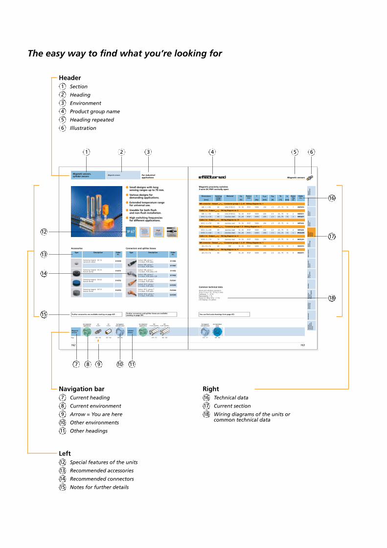
HeaderSection
Heading
Environment
Product group name
Heading repeated
Illustration
2
3
4
5
6
1
1 2 3 4 5 6
Navigation barCurrent heading
Current environment
Arrow = You are here
Other environments
Other headings
8
9
10
11
7
12
13
14
15
LeftSpecial features of the units
Recommended accessories
Recommended connectors
Notes for further details
13
14
15
12
16
17
18
RightTechnical data
Current section
Wiring diagrams of the units orcommon technical data
17
18
16
The easy way to find what you’re looking for
7 10 118 9
3
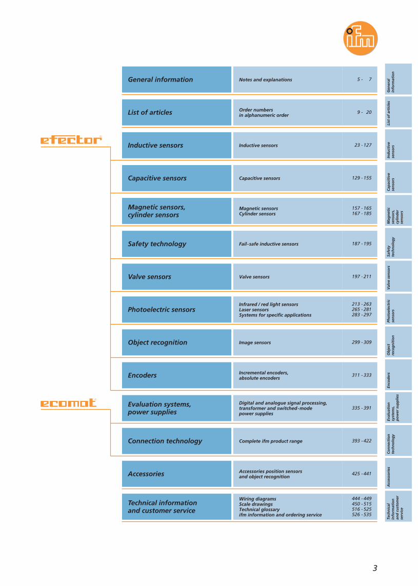
General information Notes and explanations
List of articles Order numbersin alphanumeric order
Inductive sensors Inductive sensors
Capacitive sensors Capacitive sensors
Magnetic sensors,cylinder sensors
Magnetic sensorsCylinder sensors
Photoelectric sensorsInfrared / red light sensorsLaser sensorsSystems for specific applications
Safety technology Fail-safe inductive sensors
Valve sensors Valve sensors
Object recognition Image sensors
Encoders Incremental encoders,absolute encoders
Evaluation systems,power supplies
Digital and analogue signal processing,transformer and switched-modepower supplies
Connection technology Complete ifm product range
Accessories Accessories position sensorsand object recognition
Technical informationand customer service
Wiring diagramsScale drawingsTechnical glossaryifm information and ordering service
Gen
eral
info
rmat
ion
List
of
arti
cles
Ind
uct
ive
sen
sors
Cap
acit
ive
sen
sors
Mag
net
icse
nso
rs,
cylin
der
sen
sors
Safe
tyte
chn
olo
gy
Val
ve s
enso
rsPh
oto
elec
tric
sen
sors
Ob
ject
reco
gn
itio
nEn
cod
ers
Eval
uat
ion
syst
ems,
po
wer
su
pp
lies
Co
nn
ecti
on
tech
no
log
yA
cces
sori
esTe
chn
ical
info
rmat
ion
and
cu
sto
mer
serv
ice
5 - 7
9 - 20
23 - 127
129 - 155
157 - 165167 - 185
213 - 263265 - 281283 - 297
187 - 195
197 - 211
299 - 309
311 - 333
335 - 391
393 - 422
425 - 441
444 - 449450 - 515516 - 525526 - 535


Notes and explanations
Environmental conditions,approvals and standards
6 - 7
General information
5
Gen
eral
info
rmat
ion
List
of
arti
cles
Ind
uct
ive
sen
sors
Cap
acit
ive
sen
sors
Mag
net
icse
nso
rs,
cylin
der
sen
sors
Safe
tyte
chn
olo
gy
Val
ve s
enso
rsPh
oto
elec
tric
sen
sors
Ob
ject
reco
gn
itio
nEn
cod
ers
Eval
uat
ion
syst
ems,
po
wer
su
pp
lies
Co
nn
ecti
on
tech
no
log
yA
cces
sori
esTe
chn
ical
info
rmat
ion
and
cu
sto
mer
serv
ice
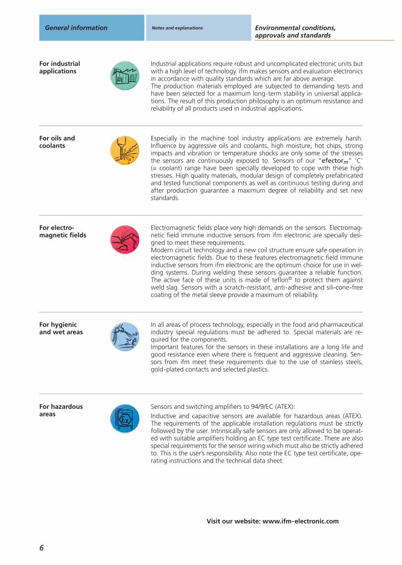
For hazardousareas
For industrialapplications
Environmental conditions,approvals and standards
Visit our website: www.ifm-electronic.com
General information Notes and explanations
6
For oils andcoolants
Especially in the machine tool industry applications are extremely harsh.Influence by aggressive oils and coolants, high moisture, hot chips, strongimpacts and vibration or temperature shocks are only some of the stressesthe sensors are continuously exposed to. Sensors of our “efectorm” ‘C’(= coolant) range have been specially developed to cope with these highstresses. High quality materials, modular design of completely prefabricatedand tested functional components as well as continuous testing during andafter production guarantee a maximum degree of reliability and set newstandards.
For electro-magnetic fields
Electromagnetic fields place very high demands on the sensors. Electromag-netic field immune inductive sensors from ifm electronic are specially desi-gned to meet these requirements.Modern circuit technology and a new coil structure ensure safe operation inelectromagnetic fields. Due to these features electromagnetic field immuneinductive sensors from ifm electronic are the optimum choice for use in wel-ding systems. During welding these sensors guarantee a reliable function.The active face of these units is made of teflon© to protect them againstweld slag. Sensors with a scratch-resistant, anti-adhesive and sili-cone-freecoating of the metal sleeve provide a maximum of reliability.
For hygienicand wet areas
In all areas of process technology, especially in the food and pharmaceuticalindustry special regulations must be adhered to. Special materials are re-quired for the components.Important features for the sensors in these installations are a long life andgood resistance even where there is frequent and aggressive cleaning. Sen-sors from ifm meet these requirements due to the use of stainless steels,gold-plated contacts and selected plastics.
Industrial applications require robust and uncomplicated electronic units butwith a high level of technology. ifm makes sensors and evaluation electronicsin accordance with quality standards which are far above average.The production materials employed are subjected to demanding tests andhave been selected for a maximum long-term stability in universal applica-tions. The result of this production philosophy is an optimum resistance andreliability of all products used in industrial applications.
Sensors and switching amplifiers to 94/9/EC (ATEX):Inductive and capacitive sensors are available for hazardous areas (ATEX).The requirements of the applicable installation regulations must be strictlyfollowed by the user. Intrinsically safe sensors are only allowed to be operat-ed with suitable amplifiers holding an EC type test certificate. There are alsospecial requirements for the sensor wiring which must also be strictly adheredto. This is the user’s responsibility. Also note the EC type test certificate, ope-rating instructions and the technical data sheet.

Gen
eral
info
rmat
ion
List
of
arti
cles
Ind
uct
ive
sen
sors
Cap
acit
ive
sen
sors
Mag
net
icse
nso
rs,
cylin
der
sen
sors
Safe
tyte
chn
olo
gy
Val
ve s
enso
rsPh
oto
elec
tric
sen
sors
Ob
ject
reco
gn
itio
nEn
cod
ers
Eval
uat
ion
syst
ems,
po
wer
su
pp
lies
Co
nn
ecti
on
tech
no
log
yA
cces
sori
esTe
chn
ical
info
rmat
ion
and
cu
sto
mer
serv
ice
Notes and explanations
Visit our website: www.ifm-electronic.com
7
CE
UL / CSA or cULus / c us Units with this marking meet the requirements of UL (Underwriters Labora-tories Inc.) and CSA (Canadian Standards Association). In many cases thisapproval is necessary to access the North American market. cULus is a com-bined approval and corresponds to the two individual approvals CSA and UL.
With the CE marking the manufacturer documents that the units sold byhim adhere to the European directives for specified electrical equipment.
EHEDG The EHEDG (European Hygienic Equipment Design Group) prepares guideli-nes for Europe concerning the requirements for measuring systems in ma-chines of the food and pharmaceutical industry.Units with the EHEDG marking have been tested and approved for the foodand pharmaceutical industry in accordance with these guidelines.
LR
CCC CCC (China Compulsory Certification) is a compulsory Chinese certificationfor certain products put on the market in China. Which products are concer-ned is specified in a catalogue created by the Chinese authorities. Amongothers, proximity sensors with a voltage range of over 36 V fall under theduty of certification.
Ex The units of the categories 1 and 2 have been tested and approved by a noti-fied European body (e.g. PTB, EXAM) for use in hazardous areas.
For safetyapplications
In automation technology position sensors with safety functions are used foroperator and machine safety. Fail-safe sensors are interlocking devices asso-ciated with guards according to EN1088. Annex IV B of the Machinery Direc-tive mentions safety components, the so-called sensor-controlled protectivesystems for operator safety such as electromagnetic detectors, that are to besubmitted to a type test by a notified approval body. The independent bodyis to verify the adherence to the standards. The fail-safe sensors and evalu-ation units are certified up to category 4 to EN 954-1 and meet the require-ments to IEC 61508.
TÜV / BGIA TÜV is internationally recognised as an independent neutral certificationauthority. The term “TÜV” stands for “Technischer Überwachung-Verein”(Technical inspection association). TÜV is a body verifying and certifying theadherence to the applicable standards for functional safety technology. TheTÜV mark indicates tested safety.The BGIA (berufsgenossenschaftliches Institut für Arbeitsschutz) is an insti-tute for occupational health and safety. It is the German Federation of theinstitutions for statutory accident insurance and prevention and the higher-level verification body of these institutions in Germany. The BGIA checks theadherence to the applicable standards for functional safety technology andcertifies products. Thus each certified product has passed a complete prod-uct test.

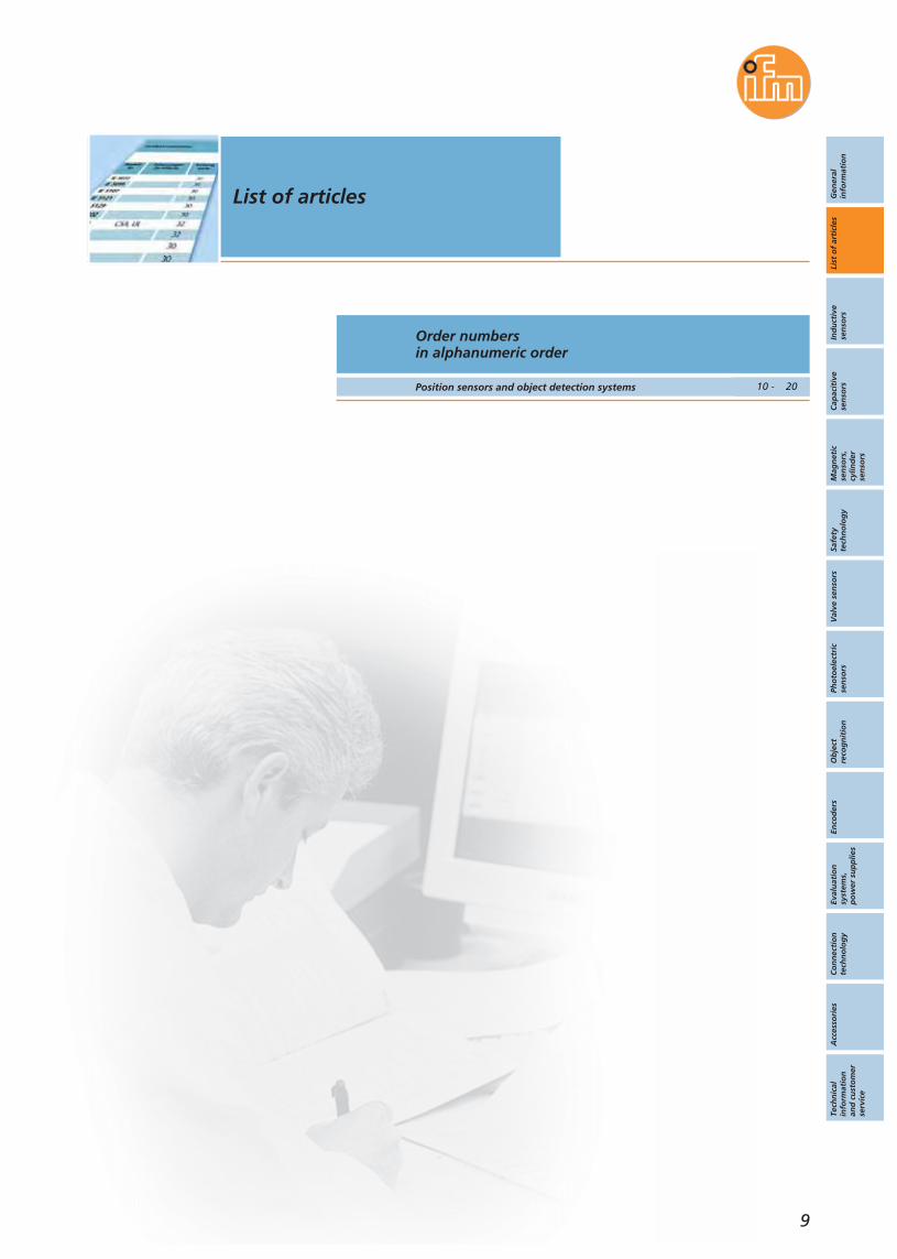
Order numbersin alphanumeric order
Position sensors and object detection systems 10 - 20
List of articles
9
Gen
eral
info
rmat
ion
List
of
arti
cles
Ind
uct
ive
sen
sors
Cap
acit
ive
sen
sors
Mag
net
icse
nso
rs,
cylin
der
sen
sors
Safe
tyte
chn
olo
gy
Val
ve s
enso
rsPh
oto
elec
tric
sen
sors
Ob
ject
reco
gn
itio
nEn
cod
ers
Eval
uat
ion
syst
ems,
po
wer
su
pp
lies
Co
nn
ecti
on
tech
no
log
yA
cces
sori
esTe
chn
ical
info
rmat
ion
and
cu
sto
mer
serv
ice
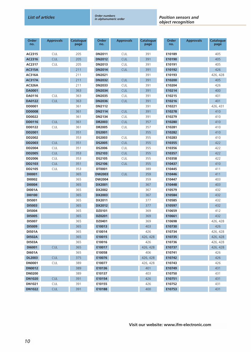
Orderno.
Approvals Cataloguepage
AC2315 CUL 205
AC2316 CUL 205
AC2317 CUL 205
AC315A 211
AC316A 211
AC317A 211
AC326A 211
DA0001 363
DA0116 CUL 363
DA0122 CUL 363
DD0001 361
DD0008 361
DD0022 361
DD0116 CUL 361
DD0122 CUL 361
DD2001 351
DD2002 353
DD2003 CUL 351
DD2004 CUL 351
DD2005 CUL 353
DD2006 CUL 353
DD2103 CUL 351
DD2105 CUL 353
DI0001 365
DI0002 365
DI0004 365
DI001A 365
DI0100 365
DI5001 365
DI5003 365
DI5004 365
DI5005 365
DI5007 365
DI5009 365
DI501A 365
DI502A 365
DI503A 365
DI6001 CUL 365
DI601A 365
DL2003 CUL 375
DN0001 CUL 389
DN0012 389
DN0200 389
DN1020 CUL 391
DN1021 CUL 391
DN1022 CUL 391
Orderno.
Approvals Cataloguepage
DN2011 CUL 391
DN2012 CUL 391
DN2013 CUL 391
DN2014 CUL 391
DN2021 391
DN2032 CUL 391
DN2033 CUL 391
DN2034 CUL 391
DN2035 CUL 391
DN2036 CUL 391
DN2112 391
DN2114 CUL 391
DN2134 CUL 391
DR2003 CUL 357
DR2005 CUL 357
DS2001 355
DS2003 CUL 355
DS2005 CUL 355
DS2006 CUL 355
DS2103 CUL 355
DS2105 CUL 355
DS2106 CUL 355
DT0001 389
DW2003 CUL 359
DW2004 359
DX2001 367
DX2002 367
DX2003 367
DX2011 377
DX2012 377
DZ0101 369
DZ0201 369
DZ0401 369
E10013 403
E10014 426
E10015 426, 428
E10016 426
E10017 426, 428
E10058 406
E10076 426, 428
E10077 426, 428
E10136 401
E10137 403
E10154 426
E10155 426
E10188 400
Orderno.
Approvals Cataloguepage
E10189 405
E10190 405
E10191 405
E10192 426
E10193 426, 428
E10200 405
E10204 426
E10214 400
E10215 401
E10216 401
E10221 426, 431
E10278 410
E10279 410
E10280 410
E10281 410
E10282 410
E10283 410
E10355 422
E10356 422
E10357 422
E10358 422
E10437 410
E10445 411
E10446 411
E10447 403
E10448 403
E10579 432
E10584 432
E10585 432
E10597 432
E10659 412
E10661 432
E10698 426, 428
E10730 426
E10734 426, 428
E10735 426, 428
E10736 426, 428
E10737 426, 428
E10741 426
E10742 426
E10743 426
E10749 431
E10750 431
E10751 431
E10752 431
E10753 431
List of articles Order numbersin alphanumeric order Position sensors and
object recognition
10
Visit our website: www.ifm-electronic.com
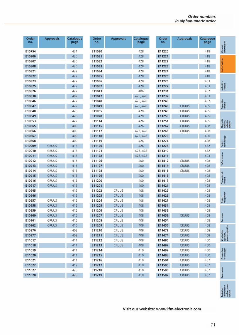
Orderno.
Approvals Cataloguepage
E10754 431
E10806 426
E10807 426
E10808 426
E10821 422
E10822 422
E10823 422
E10825 422
E10826 422
E10838 407
E10846 422
E10847 422
E10848 426
E10849 426
E10853 422
E10865 400
E10866 400
E10867 400
E10868 400
E10909 CRUUS 416
E10910 CRUUS 416
E10911 CRUUS 416
E10912 CRUUS 416
E10913 CRUUS 416
E10914 CRUUS 416
E10915 CRUUS 416
E10916 CRUUS 416
E10917 CRUUS 416
E10945 412
E10946 412
E10957 CRUUS 416
E10958 CRUUS 416
E10959 CRUUS 416
E10960 CRUUS 416
E10961 CRUUS 416
E10962 CRUUS 416
E10976 402
E10977 402
E11017 411
E11018 411
E11019 411
E11020 411
E11021 411
E11022 412
E11027 428
E11028 428
Orderno.
Approvals Cataloguepage
E11030 428
E11031 428
E11032 428
E11033 428
E11034 428
E11035 428
E11036 428
E11037 428
E11043 406
E11047 426, 428
E11048 426, 428
E11049 426, 428
E11055 428
E11078 428
E11114 426
E11115 426
E11117 426, 428
E11118 426, 428
E11119 426
E11120 426
E11121 426, 428
E11122 426, 428
E11196 400
E11197 400
E11198 400
E11199 400
E11200 400
E11201 400
E11202 CRUUS 408
E11203 CRUUS 408
E11204 CRUUS 408
E11205 CRUUS 408
E11206 CRUUS 408
E11207 CRUUS 408
E11208 CRUUS 408
E11209 CRUUS 408
E11210 CRUUS 408
E11211 CRUUS 408
E11212 CRUUS 408
E11213 CRUUS 408
E11214 410
E11215 410
E11216 410
E11217 410
E11218 410
E11219 410
Orderno.
Approvals Cataloguepage
E11220 418
E11221 418
E11222 418
E11223 418
E11224 418
E11225 418
E11226 403
E11227 403
E11231 402
E11232 403
E11243 432
E11248 CRUUS 405
E11249 CRUUS 405
E11250 CRUUS 405
E11251 CRUUS 405
E11267 CRUUS 408
E11268 CRUUS 408
E11273 406
E11274 408
E11278 432
E11310 432
E11311 403
E11412 CRUUS 408
E11414 CRUUS 408
E11415 CRUUS 408
E11416 408
E11417 408
E11421 408
E11422 408
E11426 408
E11427 408
E11431 408
E11432 408
E11452 CRUUS 408
E11454 408
E11455 CRUUS 408
E11472 CRUUS 408
E11474 CRUUS 408
E11486 CRUUS 400
E11487 CRUUS 400
E11492 CRUUS 400
E11493 CRUUS 400
E11504 CRUUS 407
E11505 CRUUS 407
E11506 CRUUS 407
E11507 CRUUS 407
Order numbersin alphanumeric order
Gen
eral
info
rmat
ion
List
of
arti
cles
Ind
uct
ive
sen
sors
Cap
acit
ive
sen
sors
Mag
net
icse
nso
rs,
cylin
der
sen
sors
Safe
tyte
chn
olo
gy
Val
ve s
enso
rsPh
oto
elec
tric
sen
sors
Ob
ject
reco
gn
itio
nEn
cod
ers
Eval
uat
ion
syst
ems,
po
wer
su
pp
lies
Co
nn
ecti
on
tech
no
log
yA
cces
sori
esTe
chn
ical
info
rmat
ion
and
cu
sto
mer
serv
ice
11
Visit our website: www.ifm-electronic.com

Orderno.
Approvals Cataloguepage
E11508 CRUUS 401
E11509 CRUUS 401
E11510 401
E11511 CRUUS 402
E11512 CRUUS 402
E11569 432
E11641 420
E11642 420
E11643 420
E11644 420
E11645 403
E11693 422
E11694 422
E11697 403
E11717 410
E11718 410
E11719 411
E11720 410
E11721 410
E11722 411
E11723 410
E11724 410
E11725 411
E11726 411
E11727 411
E11728 412
E11729 411
E11730 411
E11731 412
E11732 411
E11733 411
E11734 412
E11735 411
E11736 CSA, UL 404
E11737 CSA, UL 404
E11738 CSA, UL 404
E11739 CSA, UL 404
E11740 CSA, UL 404
E11741 CSA, UL 405
E11742 CSA, UL 405
E11743 CSA, UL 405
E11744 CSA, UL 405
E11745 CSA, UL 405
E11746 CSA, UL 405
E11747 CSA, UL 405
E11775 420
Orderno.
Approvals Cataloguepage
E11796 178
E11797 178
E11798 178
E11799 178
E11801 178
E11803 431
E11816 178, 431
E11817 178, 431
E11818 178, 431
E11819 178, 431
E11820 178, 431
E11821 178, 431
E11822 178, 431
E11823 178, 431
E11857 419
E11858 419
E11859 420
E11860 420
E11861 418
E11862 418
E11863 419
E11864 420
E11865 420
E11872 178
E11877 178
E11890 178
E11891 178
E11892 178
E11893 178
E11894 178
E11895 178
E11900 432
E11912 178
E11913 178
E11914 178
E11928 178
E11929 432
E11930 432
E11957 178
E11958 178
E11959 178
E11960 178
E11961 178
E11984 432
E11988 178
E12004 178
Orderno.
Approvals Cataloguepage
E12009 432
E12010 432
E17105 432
E17118 432
E17148 432
E17205 432
E17294 432
E17295 432
E17296 432
E17320 432
E17327 432
E17328 432
E20004 433
E20005 433
E20428 405
E20430 406
E20452 433
E20590 433, 436
E20717 433
E20718 426, 428
E20719 426, 428
E20720 433, 436
E20721 433, 436
E20722 436, 437
E20723 433
E20738 402
E20740 433
E20744 433, 437
E20811 426, 428
E20813 426
E20814 426
E20856 426
E20857 426
E20860 426
E20861 426
E20864 426
E20865 426
E20866 426, 428
E20867 426, 428
E20869 426, 428
E20870 426, 428
E20873 426, 428
E20874 426, 428
E20875 426, 428
E20938 433, 436
E20939 438
List of articles Order numbersin alphanumeric order Position sensors and
object recognition
12
Visit our website: www.ifm-electronic.com
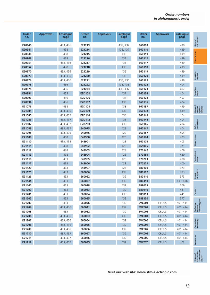
Orderno.
Approvals Cataloguepage
E20940 433, 436
E20941 438
E20946 438
E20948 438
E20951 433, 436
E20952 438
E20970 433, 436
E20973 433, 436
E20974 433, 436
E20975 436
E20976 436
E20984 433
E20993 436
E20994 436
E21076 438
E21081 433, 436
E21085 433, 437
E21086 433, 437
E21087 433, 437
E21088 433, 437
E21095 433, 436
E21109 438
E21110 433, 438
E21111 438
E21112 438
E21113 438
E21116 433
E21117 433
E21120 433
E21125 433
E21126 433
E21144 433
E21145 433
E21200 433
E21201 433
E21202 433
E21203 433
E21204 433, 436
E21205 433
E21206 433, 436
E21207 433, 436
E21208 433, 436
E21209 433, 436
E21210 433, 437
E21211 433, 437
E21212 433, 437
Orderno.
Approvals Cataloguepage
E21213 433, 437
E21214 433, 437
E21215 433
E21216 433
E21217 433
E21218 433
E21219 436
E21220 436
E21221 433, 436
E21222 433, 436
E21223 433, 437
E2D101 437
E2D106 438
E2D107 438
E2D108 438
E2D109 438
E2D110 438
E2D112 438
E2D200 438
E40075 422
E40076 422
E43900 428
E43901 428
E43902 428
E43903 428
E43904 428
E43905 428
E43906 428
E43907 428
E60006 439
E60022 439
E60027 439
E60028 439
E60033 439
E60034 439
E60035 439
E60036 439
E60041 439
E60062 439
E60063 439
E60064 439
E60065 439
E60066 439
E60067 439
E60076 439
E60095 439
Orderno.
Approvals Cataloguepage
E60098 439
E60110 439
E60111 439
E60112 439
E60117 439
E60118 439
E60119 439
E60120 439
E60121 439
E60122 404
E60123 407
E60124 404
E60128 407
E60136 404
E60137 439
E60138 439
E60141 404
E60144 404
E60146 404
E60147 404
E60157 404
E60174 403
E60175 403
E65005 371
E70142 406
E70189 420
E70203 408
E70271 400
E80100 373
E80102 373
E80110 373
E80310 433, 436
E89005 369
E89010 441
E89013 441
E89150 377
EVC001 CRUUS 401, 414
EVC002 CRUUS 401, 414
EVC003 CRUUS 401, 414
EVC004 CRUUS 401, 414
EVC005 CRUUS 401, 414
EVC006 CRUUS 401, 414
EVC007 CRUUS 401, 414
EVC008 CRUUS 401, 414
EVC009 CRUUS 401, 414
EVC070 CRUUS 402
Order numbersin alphanumeric order
Gen
eral
info
rmat
ion
List
of
arti
cles
Ind
uct
ive
sen
sors
Cap
acit
ive
sen
sors
Mag
net
icse
nso
rs,
cylin
der
sen
sors
Safe
tyte
chn
olo
gy
Val
ve s
enso
rsPh
oto
elec
tric
sen
sors
Ob
ject
reco
gn
itio
nEn
cod
ers
Eval
uat
ion
syst
ems,
po
wer
su
pp
lies
Co
nn
ecti
on
tech
no
log
yA
cces
sori
esTe
chn
ical
info
rmat
ion
and
cu
sto
mer
serv
ice
13
Visit our website: www.ifm-electronic.com

Orderno.
Approvals Cataloguepage
EVC071 CRUUS 402
EVC072 CRUUS 402
EVC073 CRUUS 402
EVC074 CRUUS 402
EVC075 CRUUS 402
EVT001 418
EVT002 418
EVT003 418
EVT004 418
EVT005 418
EVT006 418
EVT007 418
EVT008 419
EVT009 419
EVT010 419
EVT011 419
EVT012 419
EVT013 419
EVT014 419
EVT015 419
EVT042 419
EVT043 419
EVT044 419
EVT045 419
G15001 CUL 383
G15002 CUL 385
G15004 CUL 385
G15005 CUL 385
G1501S CUL 387
GG505S CUL 195
GI505S CUL 195
GM504S CUL 195
GM505S CUL 195
GM701S CUL 195
IA0004 CCC 65
IA0027 CCC 65
IA0032 CCC, CUL 65
IA5062 CUL 61
IA5063 CUL 61
IA5082 59
IA5108 CCC 63
IA5122 CCC, CUL 63
IA5127 CUL 59
IB0004 CCC 65
IB0016 CCC, CUL 65
IB0017 CCC 65
Orderno.
Approvals Cataloguepage
IB0026 CCC 65
IB0027 CCC 65
IB5063 CUL 61
IB5096 59
IB5124 CCC, CUL 63
IB5133 61
IC0003 CCC, CUL 77
IC000A 127
IC5005 CUL 73
IC500A 125
ID000A 127
ID0013 CCC, CUL 77
ID0014 CCC 77
ID0049 CCC 77
ID5005 CUL 73
ID500A 125
ID501A 121
ID5026 73
ID5046 CUL 71
ID5055 CUL 71
ID5058 71
ID5059 CUL 99
IE5072 43
IE5090 CUL 41
IE5099 43
IE5121 43
IE5129 43
IE5202 55
IE5203 CUL 53
IE5215 111
IE5222 55
IE5238 55
IE5258 CUL 41
IE5287 CUL 41
IE5288 CUL 41
IE5295 111
IE5312 41
IE5327 CUL 41
IE5338 CUL 41
IE5340 CUL 41
IE5343 CUL 43
IE5344 CUL 41
IE5345 CUL 43
IE5346 CUL 41
IE5348 CUL 43
IE5349 CUL 41
Orderno.
Approvals Cataloguepage
IE5350 CUL 41
IE5351 CUL 41
IE5352 CUL 41
IE5366 CUL 41
IE5367 CUL 41
IE5368 CUL 43
IE5369 CUL 43
IE5381 79
IE5382 79
IE5390 91
IE5391 91
IE9203 CCC 89
IE9902 CCC 89
IE9940 87
IF0001 CCC 57
IF0003 CCC 57
IF0005 CCC 57
IF0007 CCC 57
IF501A 123
IF5188 49
IF5249 49
IF5297 49
IF5313 CCC 49
IF5329 49
IF5345 49
IF5514 111
IF5594 111
IF5597 CCC 55
IF5598 CCC, CUL 53
IF5644 CCC 55
IF5645 CCC 55
IF5646 CCC 55
IF5647 CCC, CUL 53
IF5670 CUL 99
IF5675 CUL 99
IF5750 CUL 99
IF5751 CUL 99
IF5759 CCC 113
IF5760 CCC, CUL 113
IF5796 111
IF5813 111
IF5815 111
IF5851 CUL 111
IF6028 45
IF6029 45
IF6030 45
List of articles Order numbersin alphanumeric order Position sensors and
object recognition
14
Visit our website: www.ifm-electronic.com
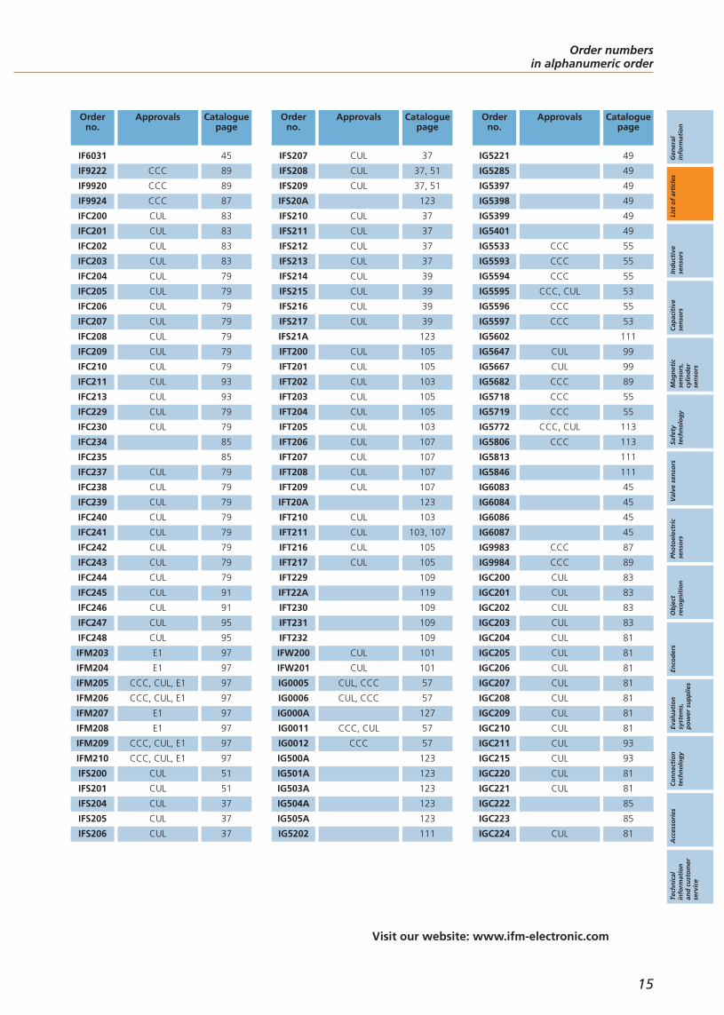
Orderno.
Approvals Cataloguepage
IF6031 45
IF9222 CCC 89
IF9920 CCC 89
IF9924 CCC 87
IFC200 CUL 83
IFC201 CUL 83
IFC202 CUL 83
IFC203 CUL 83
IFC204 CUL 79
IFC205 CUL 79
IFC206 CUL 79
IFC207 CUL 79
IFC208 CUL 79
IFC209 CUL 79
IFC210 CUL 79
IFC211 CUL 93
IFC213 CUL 93
IFC229 CUL 79
IFC230 CUL 79
IFC234 85
IFC235 85
IFC237 CUL 79
IFC238 CUL 79
IFC239 CUL 79
IFC240 CUL 79
IFC241 CUL 79
IFC242 CUL 79
IFC243 CUL 79
IFC244 CUL 79
IFC245 CUL 91
IFC246 CUL 91
IFC247 CUL 95
IFC248 CUL 95
IFM203 E1 97
IFM204 E1 97
IFM205 CCC, CUL, E1 97
IFM206 CCC, CUL, E1 97
IFM207 E1 97
IFM208 E1 97
IFM209 CCC, CUL, E1 97
IFM210 CCC, CUL, E1 97
IFS200 CUL 51
IFS201 CUL 51
IFS204 CUL 37
IFS205 CUL 37
IFS206 CUL 37
Orderno.
Approvals Cataloguepage
IFS207 CUL 37
IFS208 CUL 37, 51
IFS209 CUL 37, 51
IFS20A 123
IFS210 CUL 37
IFS211 CUL 37
IFS212 CUL 37
IFS213 CUL 37
IFS214 CUL 39
IFS215 CUL 39
IFS216 CUL 39
IFS217 CUL 39
IFS21A 123
IFT200 CUL 105
IFT201 CUL 105
IFT202 CUL 103
IFT203 CUL 105
IFT204 CUL 105
IFT205 CUL 103
IFT206 CUL 107
IFT207 CUL 107
IFT208 CUL 107
IFT209 CUL 107
IFT20A 123
IFT210 CUL 103
IFT211 CUL 103, 107
IFT216 CUL 105
IFT217 CUL 105
IFT229 109
IFT22A 119
IFT230 109
IFT231 109
IFT232 109
IFW200 CUL 101
IFW201 CUL 101
IG0005 CUL, CCC 57
IG0006 CUL, CCC 57
IG000A 127
IG0011 CCC, CUL 57
IG0012 CCC 57
IG500A 123
IG501A 123
IG503A 123
IG504A 123
IG505A 123
IG5202 111
Orderno.
Approvals Cataloguepage
IG5221 49
IG5285 49
IG5397 49
IG5398 49
IG5399 49
IG5401 49
IG5533 CCC 55
IG5593 CCC 55
IG5594 CCC 55
IG5595 CCC, CUL 53
IG5596 CCC 55
IG5597 CCC 53
IG5602 111
IG5647 CUL 99
IG5667 CUL 99
IG5682 CCC 89
IG5718 CCC 55
IG5719 CCC 55
IG5772 CCC, CUL 113
IG5806 CCC 113
IG5813 111
IG5846 111
IG6083 45
IG6084 45
IG6086 45
IG6087 45
IG9983 CCC 87
IG9984 CCC 89
IGC200 CUL 83
IGC201 CUL 83
IGC202 CUL 83
IGC203 CUL 83
IGC204 CUL 81
IGC205 CUL 81
IGC206 CUL 81
IGC207 CUL 81
IGC208 CUL 81
IGC209 CUL 81
IGC210 CUL 81
IGC211 CUL 93
IGC215 CUL 93
IGC220 CUL 81
IGC221 CUL 81
IGC222 85
IGC223 85
IGC224 CUL 81
Order numbersin alphanumeric order
Gen
eral
info
rmat
ion
List
of
arti
cles
Ind
uct
ive
sen
sors
Cap
acit
ive
sen
sors
Mag
net
icse
nso
rs,
cylin
der
sen
sors
Safe
tyte
chn
olo
gy
Val
ve s
enso
rsPh
oto
elec
tric
sen
sors
Ob
ject
reco
gn
itio
nEn
cod
ers
Eval
uat
ion
syst
ems,
po
wer
su
pp
lies
Co
nn
ecti
on
tech
no
log
yA
cces
sori
esTe
chn
ical
info
rmat
ion
and
cu
sto
mer
serv
ice
15
Visit our website: www.ifm-electronic.com

Orderno.
Approvals Cataloguepage
IGC225 CUL 81
IGC226 CUL 81
IGC227 CUL 81
IGC228 CUL 81
IGC229 CUL 81
IGC230 CUL 81
IGC231 CUL 81
IGC232 CUL 91
IGC233 CUL 91
IGC234 CUL, UL 95
IGC235 CUL 95
IGM200 E1 97
IGM201 E1 97
IGM202 E1 97
IGM203 E1 97
IGM204 CCC, CUL, E1 97
IGM205 CCC, CUL, E1 97
IGM206 CCC, CUL, E1 97
IGM207 CCC, CUL, E1 97
IGS200 CUL 51
IGS201 CUL 51
IGS204 CUL 37
IGS205 CUL 37
IGS206 CUL 37
IGS207 CUL 37
IGS208 CUL 37, 51
IGS209 CUL 37, 51
IGS20A 123
IGS210 CUL 37
IGS211 CUL 37
IGS212 CUL 37
IGS213 CUL 37
IGS214 CUL 39
IGS215 CUL 39
IGS216 CUL 39
IGS217 CUL 39
IGS21A 123
IGT200 CUL 105
IGT201 CUL 105
IGT202 CUL 103
IGT203 CUL 105
IGT204 CUL 105
IGT205 CUL 103
IGT206 CUL 107
IGT207 CUL 107
IGT208 CUL 107
Orderno.
Approvals Cataloguepage
IGT209 CUL 107
IGT20A 119
IGT211 CUL 103
IGT212 CUL 103, 107
IGT219 CUL 105
IGT220 CUL 105
IGT237 109
IGT238 109
IGT239 109
IGT240 109
IGW200 CUL 101
IGW201 CUL 101
II0005 CCC 57
II0006 CCC 57
II000A 127
II0011 CUL, CCC 57
II0012 CUL, CCC 57
II5166 49
II5256 49
II5284 49
II5300 49
II5346 49
II5369 49
II5436 55
II5488 CCC 55
II5489 CCC 55
II5490 CCC 53
II5491 CCC 55
II5492 CCC 53
II5493 CCC 55
II5503 CUL 99
II5689 CUL 111
II5733 CCC 113
II5751 CCC 113
II5776 111
II5913 45
II5914 45
II5916 45
II5917 45
IIC200 CUL 81
IIC201 CUL 81
IIC206 CUL 81
IIC207 CUL 81
IIC208 85
IIC209 85
IIC210 CUL 81
Orderno.
Approvals Cataloguepage
IIC211 CUL 81
IIC212 CUL 81
IIC213 CUL 81
IIC214 CUL 81
IIC215 CUL 81
IIC216 CUL 81
IIC217 CUL 81
IIC218 CUL 91
IIC219 CUL 91
IIC220 CUL 95
IIC221 CUL 95
IIM200 E1 97
IIM201 E1 97
IIM202 E1 97
IIM203 E1 97
IIM208 CCC, CUL, E1 97
IIM209 CCC, CUL, E1 97
IIM210 CCC, CUL, E1 97
IIM211 CCC, CUL, E1 97
IIS204 CUL 37
IIS205 CUL 37
IIS206 CUL 37
IIS207 CUL 37
IIS208 CUL 37
IIS209 CUL 37
IIS210 CUL 37
IIS211 CUL 37
IIS212 CUL 39
IIS213 CUL 39
IIS214 CUL 39
IIS215 CUL 39
IIT200 CUL 105
IIT202 CUL 103
IIT204 CUL 103
IIT205 CUL 105
IIT206 CUL 107
IIT207 CUL 107
IIT208 CUL 107
IIT209 CUL 107
IIT20A 123
IIT212 CUL 105
IIT213 CUL 105
IIT21A 123
IIT223 CUL 109
IIT224 CUL 109
IIT225 CUL 109
List of articles Order numbersin alphanumeric order Position sensors and
object recognition
16
Visit our website: www.ifm-electronic.com

Orderno.
Approvals Cataloguepage
IIT226 109
IIT22A 119
IIT23A 121
IIW200 CUL 101
IIW201 CUL 101
IJ5002 CCC 69
IL5002 CUL 69
IL5003 CUL 69
IL5004 CUL 67
IL5005 CUL 67
IL5022 CUL 69
IM000A 127
IM0010 CCC, CUL 77
IM0011 CCC, CUL 77
IM0053 CCC 77
IM0054 CCC 77
IM500A 125
IM5019 CUL 73
IM501A 125
IM5020 CUL 73
IM502A 125
IM5037 CCC 75
IM5038 CCC 75
IM5046 73
IM5115 CUL 71
IM5116 CUL 71
IM5117 CUL 71
IM5119 CUL 101
IM5120 CUL 101
IM5123 CUL 71
IM5124 CUL 101
IM5125 CUL 101
IM5126 CUL 101
IM5127 87
IM5129 101
IM5132 CUL 101
IM5133 CUL 101
IM5134 CUL 71
IM5135 CUL 101
IM5136 71
IM5137 89
IM5138 89
IM5139 45
IM5140 45
IM5141 45
IM5142 45
Orderno.
Approvals Cataloguepage
IN0073 CCC 77
IN0077 CCC 77
IN0081 CCC 77
IN0085 CCC 77
IN0108 CCC, CUL 203
IN0110 CCC 203
IN501A 125
IN502A 125
IN503A 125
IN504A 125
IN5121 69
IN5129 69
IN5186 69
IN5188 69
IN5207 CCC 75
IN5208 CCC, CUL 75
IN5212 CUL 67
IN5224 203
IN5225 CUL 203
IN5230 CUL 67
IN5251 203
IN5285 CUL 203
IN5304 203
IN5327 CUL 203
IN5334 CUL 203
IO5016 87
IO5017 89
IO5018 89
IS5001 CUL 69
IS5026 CUL 75
IS5031 CUL 69
IS5035 CUL 67
IS5070 69
IS5071 CUL 67
IT5001 59
IT5021 CUL 59
IT5034 CUL 59
IT5039 CUL 59
IT5040 CUL 59
IT5041 CUL 59
IT5042 CUL 59
IT5043 CUL 59
IT5044 CUL 59
IV5003 73
IV5004 73
IV5025 99
Orderno.
Approvals Cataloguepage
IW5048 69
IW5051 69
IW5053 69
IW5058 69
IW5062 67
IW5064 CUL 67
IX5006 207
IX5010 207
IY5029 43
IY5036 CUL 43
IY5048 CUL 43
IY5049 CUL 43
IY5052 43
IZ5026 CUL 59
IZ5035 CUL 59
IZ5046 CUL 59
IZ5047 CUL 59
IZ5048 CUL 59
IZ5051 59
IZ5052 59
JAC201 47
JAT201 47
KB0025 CCC, CUL 149
KB0029 CCC, CUL 149
KB5002 CUL 147
KB5004 CUL 147
KB5062 147
KB5096 147
KD0009 CCC 153
KD000A 155
KD0012 CCC 153
KD500A 155
KD5018 151
KD5022 151
KD5039 151
KD5044 151
KF5001 CUL 135
KF5002 CUL 135
KG0008 145
KG0009 CCC 145
KG0010 CCC 145
KG5040 143
KG5041 141
KG5043 141
KG5047 CCC 143
KG5057 141
Order numbersin alphanumeric order
Gen
eral
info
rmat
ion
List
of
arti
cles
Ind
uct
ive
sen
sors
Cap
acit
ive
sen
sors
Mag
net
icse
nso
rs,
cylin
der
sen
sors
Safe
tyte
chn
olo
gy
Val
ve s
enso
rsPh
oto
elec
tric
sen
sors
Ob
ject
reco
gn
itio
nEn
cod
ers
Eval
uat
ion
syst
ems,
po
wer
su
pp
lies
Co
nn
ecti
on
tech
no
log
yA
cces
sori
esTe
chn
ical
info
rmat
ion
and
cu
sto
mer
serv
ice
17
Visit our website: www.ifm-electronic.com
Orderno.
Approvals Cataloguepage
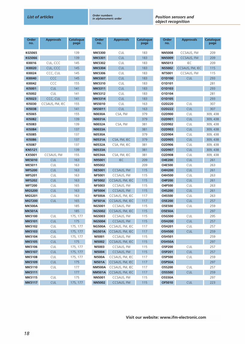
KG5065 139
KG5066 139
KI0016 CUL, CCC 145
KI0020 CUL, CCC 145
KI0024 CCC, CUL 145
KI0040 CCC 145
KI0042 CCC 155
KI5001 CUL 141
KI5002 CUL 141
KI5023 CCC, CUL 141
KI5030 CCSAUS, FM, IEC 155
KI5038 141
KI5065 155
KI5082 139
KI5083 139
KI5084 137
KI5085 137
KI5086 137
KI5087 137
KN5121 139
KX5001 CCSAUS, FM 155
ME5010 CUL 163
ME5011 CUL 163
MFS200 CUL 163
MFS201 CUL 163
MFS202 CUL 163
MFT200 CUL 165
MGS200 CUL 163
MGS201 CUL 163
MGT200 CUL 165
MK500A 185
MK501A 185
MK5100 CUL 175, 177
MK5101 CUL 175
MK5102 CUL 175, 177
MK5103 CUL 175, 177
MK5104 CUL 175, 177
MK5105 CUL 175
MK5106 CUL 175, 177
MK5107 CUL 175, 177
MK5108 CUL 175, 177
MK5109 CUL 175
MK5110 CUL 177
MK5111 177
MK5115 CUL 175
MK5117 CUL 175, 177
Orderno.
Approvals Cataloguepage
MK5300 CUL 183
MK5301 CUL 183
MK5302 CUL 183
MK5304 CUL 183
MK5306 CUL 183
MK5307 CUL 183
MK5310 CUL 183
MK5311 CUL 183
MK5312 CUL 183
MK5314 CUL 183
MS5010 CUL 163
MS5011 CUL 163
N0030A CSA, FM 379
N0031A 379
N0032A CSA, FM 381
N0033A 381
N0530A 379
N0531A CSA, FM, IEC 379
N0532A CSA, FM, IEC 381
N0533A 381
N0534A CSA, FM, IEC 381
N95001 IEC 209
N95002 209
NE5001 CCSAUS, FM 115
NF5001 CCSAUS, FM 115
NF5002 CCSAUS, FM, IEC 115
NF5003 CCSAUS, FM 115
NF5004 CCSAUS, FM 115
NF500A CCSAUS, FM, IEC 117
NF501A CCSAUS, FM, IEC 117
NG5001 CCSAUS, FM 115
NG5002 CCSAUS, FM, IEC 115
NG5003 CCSAUS, FM 115
NG5004 CCSAUS, FM 115
NG500A CCSAUS, FM, IEC 117
NG501A CCSAUS, FM, IEC 117
NI5001 CCSAUS, FM 115
NI5002 CCSAUS, FM, IEC 115
NI5003 CCSAUS, FM 115
NI5004 CCSAUS, FM 115
NI500A CCSAUS, FM, IEC 117
NI501A CCSAUS, FM, IEC 117
NM500A CCSAUS, FM, IEC 117
NM501A CCSAUS, FM, IEC 117
NN5001 CCSAUS, FM 115
NN5002 CCSAUS, FM 115
Orderno.
Approvals Cataloguepage
NN5008 CCSAUS, FM 209
NN5009 CCSAUS, FM 209
NN5013 IEC 209
NS5002 CCSAUS, FM, IEC 115
NT5001 CCSAUS, FM 115
O1D100 CUL 293
O1D101 281
O1D103 293
O1D104 281
O1D105 293
O2D220 CUL 307
O2D222 CUL 307
O2D900 CUL 309, 438
O2D901 CUL 309, 438
O2D902 CUL 309, 438
O2D903 CUL 309, 438
O2D904 CUL 309, 438
O2D905 CUL 309, 438
O2D906 CUL 309, 438
O2D907 CUL 309, 438
O2D908 CUL 309, 438
O4E200 CUL 261
O4E500 CUL 263
O4H200 CUL 261
O4H500 CUL 263
O4P200 CUL 261
O4P500 CUL 263
O4S200 CUL 261
O4S500 CUL 263
O5E200 CUL 257
O5E500 CUL 259
O5E50A 297
O5G500 CUL 295
O5H200 CUL 257
O5H201 CUL 257
O5H500 CUL 259
O5H501 259
O5H50A 297
O5P200 CUL 257
O5P201 CUL 257
O5P500 CUL 259
O5P50A 297
O5S200 CUL 257
O5S500 CUL 259
O5S50A 297
OF5010 CUL 223
List of articles Order numbersin alphanumeric order Position sensors and
object recognition
18
Visit our website: www.ifm-electronic.com
Orderno.
Approvals Cataloguepage
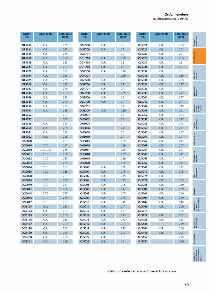
OF5012 CUL 225
OF5014 CUL 223
OF5016 CUL 225
OF5018 CUL 223
OF5019 CUL 223
OF5021 CUL 227
OF5022 CUL 227
OF5024 CUL 223
OF5025 CUL 225
OF5026 CUL 223
OF5027 CUL 225
OF5032 CUL 223
OF5048 CUL 223
OF5049 CUL 225
OF5050 CUL 223
OF5051 CUL 225
OF5052 223
OF5053 227
OF5059 CUL 223
OF5060 CUL 225
OF5061 CUL 223
OF5062 CUL 225
OG0028 CCC 237
OG0029 CCC 237
OG0030 CCC, CUL 235
OG0031 CCC 235
OG0032 CCC 237
OG0033 CCC 235
OG0034 CCC 237
OG0035 CCC 235
OG0038 CCC 237
OG0039 CCC 235
OG0040 CCC 237
OG0041 CCC 235
OG0043 CCC 237
OG0044 CCC 235
OG0047 CCC 237
OG5123 CUL 233
OG5124 CUL 233
OG5125 CUL 233
OG5126 CUL 233
OG5127 CUL 233
OG5128 CUL 233
OG5129 CUL 233
OGE200 CUL 229
OGE201 CUL 229
Orderno.
Approvals Cataloguepage
OGE500 CUL 231
OGE700 CUL 271
OGE701 271
OGH200 CUL 229
OGH500 CUL 231
OGH700 CUL 271
OGP200 CUL 229
OGP201 229
OGP500 CUL 231
OGP700 CUL 271
OGP701 CUL 271
OGS200 CUL 229
OGS500 CUL 231
OGS700 CUL 271
OGS701 271
OGT200 CUL 229
OH5001 241
OH5002 241
OH5004 241
OH5006 241
OH5008 241
OH5010 241
OH5015 239
OH5016 239
OH5017 239
OH5018 239
OH5019 239
OH5020 239
OJ5000 CUL 245
OJ5001 CUL 245
OJ5002 CUL 245
OJ5004 CUL 245
OJ5005 CUL 245
OJ5006 CUL 247
OJ5008 CUL 245
OJ5009 CUL 245
OJ5010 CUL 245
OJ5011 CUL 247
OJ5012 CUL 247
OJ5014 CUL 273
OJ5016 CUL 273
OJ5017 CUL 273
OJ5019 CUL 273
OJ5020 CUL 273
OJ5022 CUL 251
OJ5023 CUL 251
Orderno.
Approvals Cataloguepage
OJ5024 CUL 255
OJ5026 CUL 251
OJ5027 CUL 251
OJ5028 CUL 255
OJ5030 CUL 251
OJ5031 CUL 251
OJ5032 CUL 251
OJ5033 CUL 255
OJ5034 CUL 255
OJ5036 CUL 277
OJ5038 CUL 277
OJ5039 CUL 277
OJ5041 CUL 277
OJ5042 CUL 277
OJ5044 CUL 245
OJ5048 CUL 251
OJ5052 CUL 273
OJ5054 CUL 277
OJ5056 CUL 273
OJ5058 CUL 277
OJ5060 CUL 247
OJ5061 CUL 247
OJ5062 CUL 247
OJ5063 CUL 247
OJ5064 CUL 247
OJ5065 CUL 247
OJ5066 CUL 247
OJ5067 CUL 247
OJ5069 CUL 247
OJ5070 CUL 245
OJ5071 CUL 251
OJ5078 CUL 255
OJ5085 CUL 289
OJ5086 CUL 289
OJ5100 CUL 249
OJ5104 CUL 249
OJ5108 CUL 249
OJ5109 CUL 249
OJ5114 275
OJ5122 CUL 253
OJ5126 CUL 253
OJ5136 279
OJ5144 CUL 249
OJ5148 CUL 253
OJ5152 275
OJ5154 279
Order numbersin alphanumeric order
Gen
eral
info
rmat
ion
List
of
arti
cles
Ind
uct
ive
sen
sors
Cap
acit
ive
sen
sors
Mag
net
icse
nso
rs,
cylin
der
sen
sors
Safe
tyte
chn
olo
gy
Val
ve s
enso
rsPh
oto
elec
tric
sen
sors
Ob
ject
reco
gn
itio
nEn
cod
ers
Eval
uat
ion
syst
ems,
po
wer
su
pp
lies
Co
nn
ecti
on
tech
no
log
yA
cces
sori
esTe
chn
ical
info
rmat
ion
and
cu
sto
mer
serv
ice
19
Visit our website: www.ifm-electronic.com

Orderno.
Approvals Cataloguepage
OJ5158 279
OJ5185 CUL 291
OJ5186 CUL 291
OJ5189 CUL 291
OJ5190 CUL 291
OJ5191 CUL 291
OJ5192 CUL 291
OJE200 CUL 243
OJH200 CUL 243
OJP200 243
OJR200 CUL 243
OJS200 CUL 243
RA6001 CRUUS 325
RA6007 CRUUS 325
RA6011 CRUUS 325
RA6013 CRUUS 325
RA6015 CRUUS 325
RA6029 CRUUS 325
RB6001 CRUUS 319
RB6002 CRUUS 319
RB6003 CRUUS 319
RB6004 CRUUS 319
RB6005 CRUUS 319
RB6006 CRUUS 319
RB6007 CRUUS 319
RB6009 CRUUS 319
RB6010 319
RB6011 CRUUS, UR 319
RB6012 CRUUS 319
RB6013 CRUUS 319
RB6014 CRUUS 319
RB6015 CRUUS 319
RB6016 CRUUS 319
RB6029 CRUUS 319
RB6044 CRUUS 319
RM3001 CRUUS 333
RM3005 CRUUS 333
RM6101 CRUUS 331
RM6104 CRUUS 331
RN6002 CRUUS 329
RN6010 CRUUS 329
RN6024 CRUUS 329
RN6026 CRUUS 329
RO6342 CRUUS 327
RO6343 CRUUS 327
RO6344 CRUUS 327
Orderno.
Approvals Cataloguepage
RO6345 CRUUS 327
RO6348 CRUUS 327
RO6349 CRUUS 327
RO6350 CRUUS 327
RU1016 CRUUS 321
RU1024 CRUUS 321
RU1025 CRUUS 321
RU1033 CRUUS 321
RU1036 CRUUS 321
RU6003 CRUUS 321
RU6010 CRUUS 321
RU6013 CRUUS 321
RU6016 CRUUS 321
RU6024 CRUUS 321
RU6025 CRUUS 321
RU6033 CRUUS 321
RU6036 CRUUS 321
RU6040 CRUUS 321
RU6045 CRUUS 321
RU6052 CRUUS 321
RV1016 CRUUS 323
RV1024 CRUUS 323
RV1025 CRUUS 323
RV1033 CRUUS 323
RV1036 CRUUS 323
RV1051 CRUUS 323
RV6001 CRUUS 323
RV6003 CRUUS 323
RV6009 CRUUS 323
RV6010 CRUUS 323
RV6013 CRUUS 323
RV6016 CRUUS 323
RV6018 CRUUS 323
RV6024 CRUUS 323
RV6025 CRUUS 323
RV6028 CRUUS 323
RV6033 323
RV6034 CRUUS 323
RV6036 CRUUS 323
RV6040 CRUUS 323
RV6100 CRUUS 323
ZZ0196 438
List of articles Order numbersin alphanumeric order Position sensors and
object recognition
20
Visit our website: www.ifm-electronic.com

Order numbersin alphanumeric order
Gen
eral
info
rmat
ion
List
of
arti
cles
Ind
uct
ive
sen
sors
Cap
acit
ive
sen
sors
Mag
net
icse
nso
rs,
cylin
der
sen
sors
Safe
tyte
chn
olo
gy
Val
ve s
enso
rsPh
oto
elec
tric
sen
sors
Ob
ject
reco
gn
itio
nEn
cod
ers
Eval
uat
ion
syst
ems,
po
wer
su
pp
lies
Co
nn
ecti
on
tech
no
log
yA
cces
sori
esTe
chn
ical
info
rmat
ion
and
cu
sto
mer
serv
ice
21
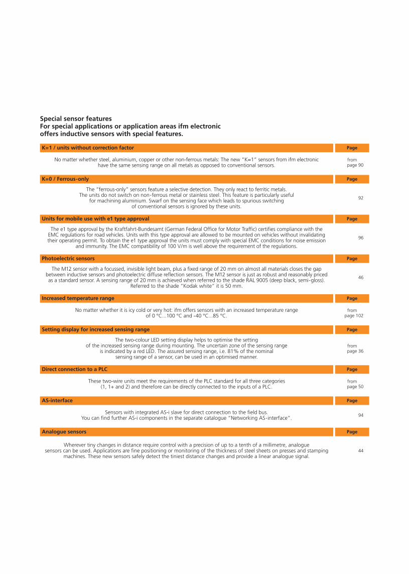
No matter whether steel, aluminium, copper or other non-ferrous metals: The new “K=1” sensors from ifm electronichave the same sensing range on all metals as opposed to conventional sensors.
K=1 / units without correction factor Page
Page
Page
Page
Page
Page
Page
The “ferrous-only” sensors feature a selective detection. They only react to ferritic metals.The units do not switch on non-ferrous metal or stainless steel. This feature is particularly useful
for machining aluminium. Swarf on the sensing face which leads to spurious switchingof conventional sensors is ignored by these units.
K=0 / Ferrous-only
The e1 type approval by the Kraftfahrt-Bundesamt (German Federal Office for Motor Traffic) certifies compliance with theEMC regulations for road vehicles. Units with this type approval are allowed to be mounted on vehicles without invalidatingtheir operating permit. To obtain the e1 type approval the units must comply with special EMC conditions for noise emission
and immunity. The EMC compatibility of 100 V/m is well above the requirement of the regulations.
Units for mobile use with e1 type approval
The M12 sensor with a focussed, invisible light beam, plus a fixed range of 20 mm on almost all materials closes the gapbetween inductive sensors and photoelectric diffuse reflection sensors. The M12 sensor is just as robust and reasonably pricedas a standard sensor. A sensing range of 20 mm is achieved when referred to the shade RAL 9005 (deep black, semi-gloss).
Referred to the shade “Kodak white” it is 50 mm.
Photoelectric sensors
No matter whether it is icy cold or very hot: ifm offers sensors with an increased temperature rangeof 0 °C...100 °C and -40 °C...85 °C.
Increased temperature range
The two-colour LED setting display helps to optimise the settingof the increased sensing range during mounting. The uncertain zone of the sensing range
is indicated by a red LED. The assured sensing range, i.e. 81% of the nominalsensing range of a sensor, can be used in an optimised manner.
Setting display for increased sensing range
These two-wire units meet the requirements of the PLC standard for all three categories(1, 1+ and 2) and therefore can be directly connected to the inputs of a PLC.
Direct connection to a PLC
Special sensor featuresFor special applications or application areas ifm electronicoffers inductive sensors with special features.
frompage 90
92
96
46
frompage 102
frompage 36
frompage 50
Page
Sensors with integrated AS-i slave for direct connection to the field bus.You can find further AS-i components in the separate catalogue “Networking AS-interface”.
AS-interface
94
Page
Wherever tiny changes in distance require control with a precision of up to a tenth of a millimetre, analogue sensors can be used. Applications are fine positioning or monitoring of the thickness of steel sheets on presses and stamping
machines. These new sensors safely detect the tiniest distance changes and provide a linear analogue signal.
Analogue sensors
44
Gen
eral
info
rmat
ion
List
of
arti
cles
Ind
uct
ive
sen
sors
Cap
acit
ive
sen
sors
Mag
net
icse
nso
rs,
cylin
der
sen
sors
Safe
tyte
chn
olo
gy
Val
ve s
enso
rsPh
oto
elec
tric
sen
sors
Ob
ject
reco
gn
itio
nEn
cod
ers
Eval
uat
ion
syst
ems,
po
wer
su
pp
lies
Co
nn
ecti
on
tech
no
log
yA
cces
sori
esTe
chn
ical
info
rmat
ion
and
cu
sto
mer
serv
ice
23
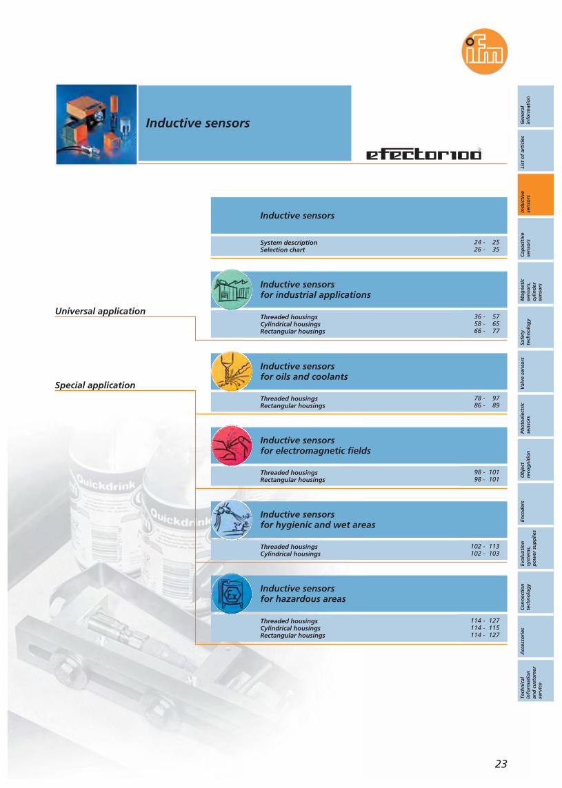
Inductive sensors
Inductive sensorsfor industrial applications
Inductive sensorsfor oils and coolants
Inductive sensorsfor electromagnetic fields
Inductive sensorsfor hygienic and wet areas
Inductive sensorsfor hazardous areas
System descriptionSelection chart
Threaded housingsCylindrical housingsRectangular housings
Threaded housingsRectangular housings
Threaded housingsRectangular housings
Threaded housingsCylindrical housings
Threaded housingsCylindrical housingsRectangular housings
Inductive sensors
Universal application
Special application
24 - 2526 - 35
36 - 5758 - 6566 - 77
78 - 9786 - 89
98 - 10198 - 101
102 - 113102 - 103
114 - 127114 - 115114 - 127

Visit our website: www.ifm-electronic.com
Inductive proximity sensors take advantage of the physical effect of thechange in the quality factor in a resonant circuit caused by eddy currentlosses in conductive materials. This is how it works: A LC tuned circuit gener-ates a high frequency electromagnetic field. This field is radiated from theactive face of the sensor. If a conductive material enters this field, eddy cur-rents will be formed in accordance with the law of inductance which drawenergy from the oscillator. This reduces the oscillation amplitude. Thechange is converted into a switching signal. The operating principle permitsdetection of all metals irrespective of whether they are moving or not.Important: The high frequency field causes no measurable heat in the objectnor is there any magnetic interference. The operation of the sensors iswithout interaction.The distance to the active face at which an electrically conductive materialcauses a change of signal in the sensor is called sensing range. The sensingrange of an inductive proximity sensor is defined by means of a target ofmild steel (Fe 360). If the switch is damped by other metals, e.g. aluminiumor copper, this is reduced. Using correction factors for every kind of metalthe user can calculate the attainable sensing ranges.
System descriptionInductive sensors Inductive sensors
24
IntroductionIn all automated processes sensors are absolutely necessary to provide thePLC with information. They supply the necessary signals on positions, limits orserve as pulse pick-ups for counting tasks or for monitoring rotational speed.Inductive and capacitive proximity sensors are nowadays indispensable forindustrial usage. As compared to mechanical switches they offer almostideal conditions: non-contact operation free from any wear and tear, highswitching frequencies and accuracy. In addition, they are insensitive to vibra-tion, dust and moisture. Inductive sensors detect all metals without contact,capacitive sensors almost all solid and liquid media such as metal, glass,wood, plastic, water, oil, etc.
Typicalapplication:Positioning sen-sing in automa-tion technology;proximity sen-sors operatereliably andwithout wear.
High frequencyelectromagnetic
field:The inductive
proximity sensordetects all metals.
common setting standard sensorscommon setting sensors withincreased snoptimised setting ifm sensors withsetting LED
Operating principle of inductive proximity sensors
A special series of inductive proximity sensors are the application sensorswhich are called “efectorm”. “m” stands for modular technology on thebasis of a new mechanical concept, new mounting technologies and aninnovative sealing system. It is based on an O-ring (made of Viton / EPDM)which is in the front cap and in the plug area. In addition, these areas aresealed using a special cast resin. The reinforced housing provides additionalmechanical stability. Manufacturing has achieved a high degree of automa-tion. This new production technology supplies high quality sensors. Duringproduction all components and the individual production steps are subjectedto a continuous function check. This severe quality test guarantees a perma-nent reliable operation even under extreme conditions.The feature shared by these proximity sensors is an increased sensingrange. It permits use where standard units meet their limits. All units have apermanent laser-etched type label. This allows clear identification of theunits even after many years.No sensor leaves production without a functional test. Furthermore eachunit is tested for full sealing. This philosophy is specially rewarding for appli-cations in wet areas.A universal connection technology has been developed so that the user canreact to his customers and markets flexibly. The switches can be used as 3-wire or 2-wire units. Thus one unit incorporates two connection variants.Pure 2-wire versions are also available. Particularity: The low leakage currentof less than 0.5 mA allows connection to every PLC types 1, 1+ and 2without problem.
Modular sensors
efectorm serieswith increasedsensing range.
incr
ease
d se
nsin
g ra
nge
[mm
]
non-flush proximity switchesM18M12
10
6
4
2
0
8

Inductive proximity sensors are also available in ATEX versions. In combina-tion with switching amplifiers these sensors can be used in zone 0 or 1 and20 or 21 hazardous areas. The amplifier is mounted outside the hazardousarea. Other versions can be used without amplifier in zones 2 and 22.
The specially designed housing increases mounting safety due to highertightening torques. The integrated setting LEDs reduce mounting time andensure utilization of the increased sensing range.Selected accessories for the application sensors simplifies mounting and set-up.
Inductive sensors
25
Visit our website: www.ifm-electronic.com
Gen
eral
info
rmat
ion
List
of
arti
cles
Ind
uct
ive
sen
sors
Cap
acit
ive
sen
sors
Mag
net
icse
nso
rs,
cylin
der
sen
sors
Safe
tyte
chn
olo
gy
Val
ve s
enso
rsPh
oto
elec
tric
sen
sors
Ob
ject
reco
gn
itio
nEn
cod
ers
Eval
uat
ion
syst
ems,
po
wer
su
pp
lies
Co
nn
ecti
on
tech
no
log
yA
cces
sori
esTe
chn
ical
info
rmat
ion
and
cu
sto
mer
serv
ice
Depending on the application the units have special features adapted to therespective requirements. The sensors can be divided into three groups: fac-tory automation, food industry and machining. The sensors for the foodindustry are extremely resistant to temperature shocks and offer a tempera-ture range of 0 to 100 °C. Only materials which comply with the regulationsof the food industry are used. The reinforced housing is made of 316L stain-less steel, the plastic of the sensing face of PEEK. The M12 connectors are fitted with gold-plated contacts for permanent corrosion resistance. Thehigh protection ratings of IP 68 and IP 69K ensure absolute sealing – alsowith respect to aggressive cleaning agents. This is confirmed in the indepen-dent certificate from Henkel.The application sensors for the severe operating conditions in machine toolsare distinguished by high quality materials such as Pocan or ceramics. Theyalso withstand permanent contact with oil, lubricants and coolants. Theceramic sensing face provides an effective protection against hotswarf.Depending on the operating conditions the sensors have a high vibrationand shock resistance.
Resistant:Permanent con-tact with aggres-sive media doesnot damage thesensor.
High excess gain:Safe detectioneven in case of
deposits, e.g.metal swarf.
Hazardous areas
As one of the leading manufacturers of inductive and capacitive sensors withthe trade name efector ifm electronic invested very early into a modern,innovative production technology which is mainly based on ifm‘s know-howof film technology for the sensor production. ifm electronic can thus gua-rantee excellent product availability even in case of increasing quantitieswith the high quality standard being maintained and ensured.
Particularity of the efectors from ifm
standard setting in practice
adjustment withsetting LED
sensing range [%]80 100
Quick setup:Optimum settingof the sensingrange is achievedwith the settingLEDs.
standard sensing rangeincreased Sn safe setting rangeincreased Sn unsafe setting range
In practise that means sensingranges more than 2.4 timesgreater than using standard sensors.

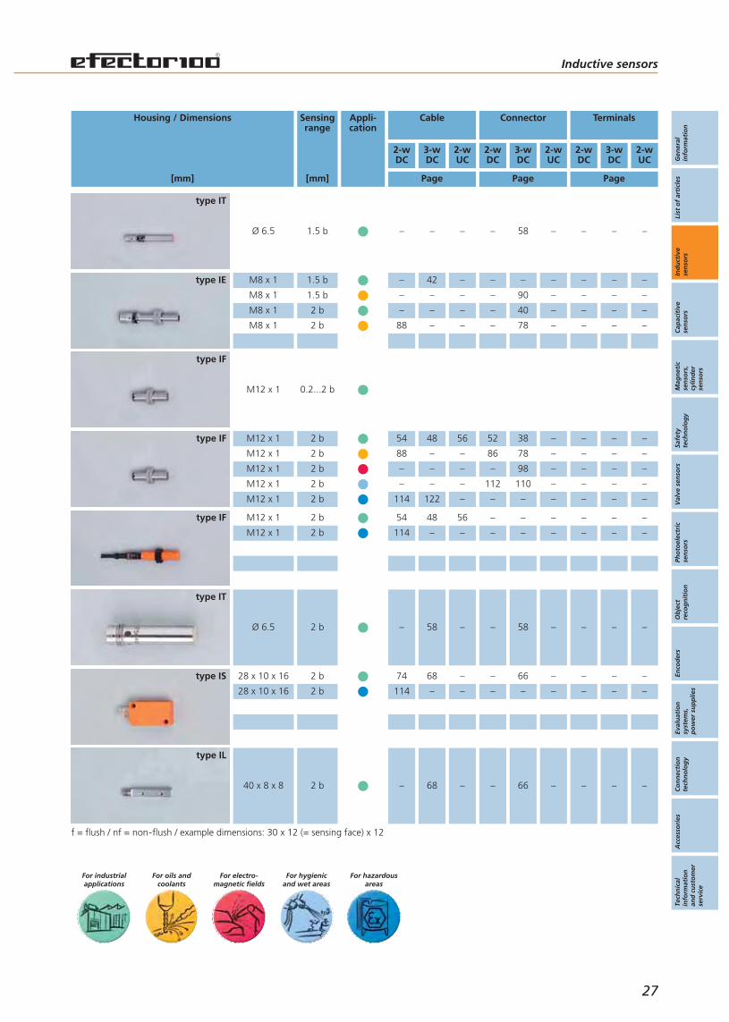
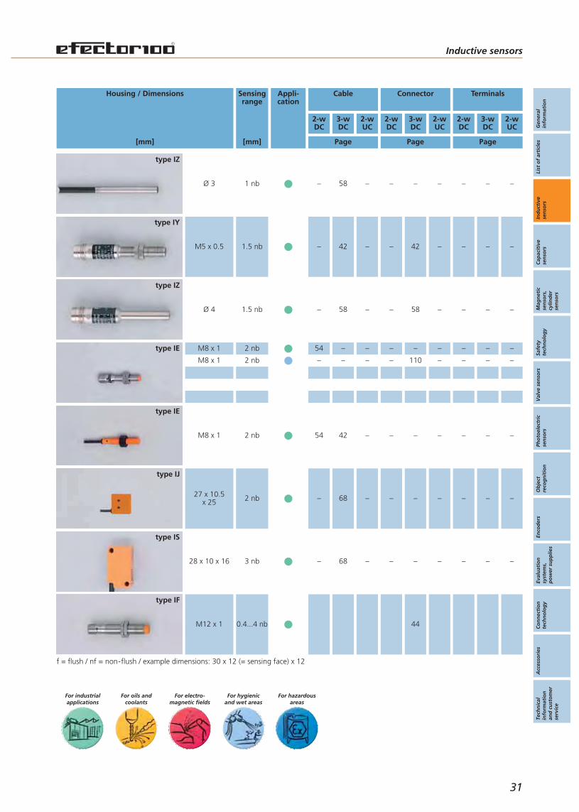
Selection chartInductive sensors Inductive sensors
For hazardousareas
For hygienicand wet areas
For electro-magnetic fields
For oils andcoolants
For industrialapplications
f = flush / nf = non-flush / example dimensions: 30 x 12 (= sensing face) x 12
Housing / Dimensions
[mm]
Sensingrange
[mm]
Appli-cation
Cable Connector Terminals
2-wDC
3-wDC
2-wUC
2-wDC
3-wDC
2-wUC
2-wDC
3-wDC
2-wUC
Page Page Page
26
type IZ
type IY
type IT
type IE
type IE
type IL
type IY
type IZ
Ø 4 0.8 b – 58 – – 58 – – – –
M5 x 0.5 0.8 b – 42 – – 42 – – –
Ø 6.5 1 b
Ø 6.5 1 b
– 58 – – 58 – – – –
114 – – – – – – – –
M8 x 1 1 b
M8 x 1 1 b
M8 x 1 1 b
M8 x 1 1 b
54 42 – 52 40 – – – –
– – – 86 – – – – –
– – – – 110 – – – –
114 – – – – – – – –
M8 x 1 1 b – 42 – – – – – – –
52 x 5 x 5 0.8 b – 68 – – – – – – –
M5 x 0.5 1.2 b – 42 – – – – – – –
Ø 4 1.2 b – 58 – – – – – – –
Inductive sensors
Gen
eral
info
rmat
ion
List
of
arti
cles
Ind
uct
ive
sen
sors
Cap
acit
ive
sen
sors
Mag
net
icse
nso
rs,
cylin
der
sen
sors
Safe
tyte
chn
olo
gy
Val
ve s
enso
rsPh
oto
elec
tric
sen
sors
Ob
ject
reco
gn
itio
nEn
cod
ers
Eval
uat
ion
syst
ems,
po
wer
su
pp
lies
Co
nn
ecti
on
tech
no
log
yA
cces
sori
esTe
chn
ical
info
rmat
ion
and
cu
sto
mer
serv
ice
Page Page Page
27
For hazardousareas
For hygienicand wet areas
For electro-magnetic fields
For oils andcoolants
For industrialapplications
f = flush / nf = non-flush / example dimensions: 30 x 12 (= sensing face) x 12
Housing / Dimensions
[mm]
Sensingrange
[mm]
Appli-cation
Cable Connector Terminals
2-wDC
3-wDC
2-wUC
2-wDC
3-wDC
2-wUC
2-wDC
3-wDC
2-wUC
type IT
type IE
type IF
type IF
type IS
type IT
type IL
type IF
Ø 6.5 1.5 b – – – – 58 – – – –
M12 x 1 2 b
M12 x 1 2 b
M12 x 1 2 b
M12 x 1 2 b
M12 x 1 2 b
54 48 56 52 38 – – – –
88 – – 86 78 – – – –
– – – – 98 – – – –
– – – 112 110 – – – –
114 122 – – – – – – –
M12 x 1 2 b
M12 x 1 2 b
54 48 56 – – – – – –
114 – – – – – – – –
28 x 10 x 16 2 b
28 x 10 x 16 2 b
74 68 – – 66 – – – –
114 – – – – – – – –
Ø 6.5 2 b – 58 – – 58 – – – –
40 x 8 x 8 2 b – 68 – – 66 – – – –
M8 x 1 1.5 b
M8 x 1 1.5 b
M8 x 1 2 b
M8 x 1 2 b
– 42 – – – – – – –
– – – – 90 – – – –
– – – – 40 – – – –
88 – – – 78 – – – –
M12 x 1 0.2...2 b
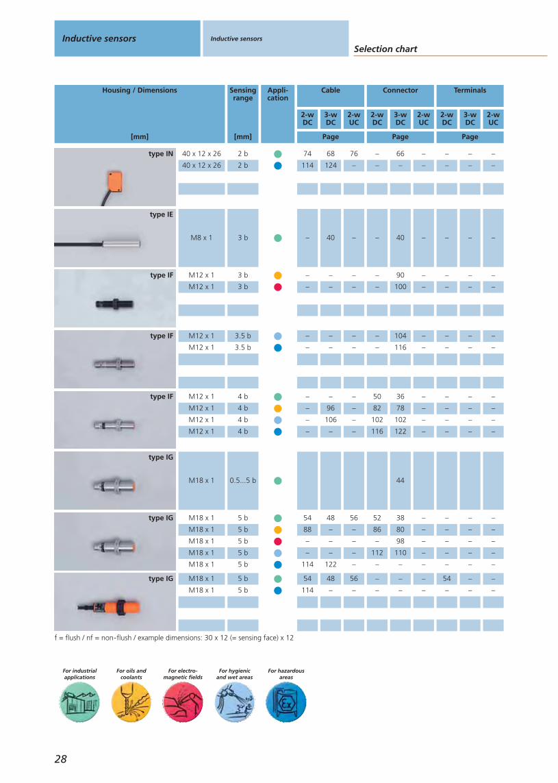
Selection chartInductive sensors Inductive sensors
For hazardousareas
For hygienicand wet areas
For electro-magnetic fields
For oils andcoolants
For industrialapplications
f = flush / nf = non-flush / example dimensions: 30 x 12 (= sensing face) x 12
Housing / Dimensions
[mm]
Sensingrange
[mm]
Appli-cation
Cable Connector Terminals
2-wDC
3-wDC
2-wUC
2-wDC
3-wDC
2-wUC
2-wDC
3-wDC
2-wUC
Page Page Page
28
type IG
type IG
type IF
type IF
type IF
type IE
type IN
type IG
M18 x 1 5 b
M18 x 1 5 b
54 48 56 – – – 54 – –
114 – – – – – – – –
M18 x 1 5 b
M18 x 1 5 b
M18 x 1 5 b
M18 x 1 5 b
M18 x 1 5 b
54 48 56 52 38 – – – –
88 – – 86 80 – – – –
– – – – 98 – – – –
– – – 112 110 – – – –
114 122 – – – – – – –
M12 x 1 3.5 b
M12 x 1 3.5 b
– – – – 104 – – – –
– – – – 116 – – – –
M12 x 1 4 b
M12 x 1 4 b
M12 x 1 4 b
M12 x 1 4 b
– – – 50 36 – – – –
– 96 – 82 78 – – – –
– 106 – 102 102 – – – –
– – – 116 122 – – – –
M12 x 1 3 b
M12 x 1 3 b
– – – – 90 – – – –
– – – – 100 – – – –
M8 x 1 3 b – 40 – – 40 – – – –
40 x 12 x 26 2 b
40 x 12 x 26 2 b
74 68 76 – 66 – – – –
114 124 – – – – – – –
M18 x 1 0.5...5 b 44
Inductive sensors
Gen
eral
info
rmat
ion
List
of
arti
cles
Ind
uct
ive
sen
sors
Cap
acit
ive
sen
sors
Mag
net
icse
nso
rs,
cylin
der
sen
sors
Safe
tyte
chn
olo
gy
Val
ve s
enso
rsPh
oto
elec
tric
sen
sors
Ob
ject
reco
gn
itio
nEn
cod
ers
Eval
uat
ion
syst
ems,
po
wer
su
pp
lies
Co
nn
ecti
on
tech
no
log
yA
cces
sori
esTe
chn
ical
info
rmat
ion
and
cu
sto
mer
serv
ice
Page Page Page
29
For hazardousareas
For hygienicand wet areas
For electro-magnetic fields
For oils andcoolants
For industrialapplications
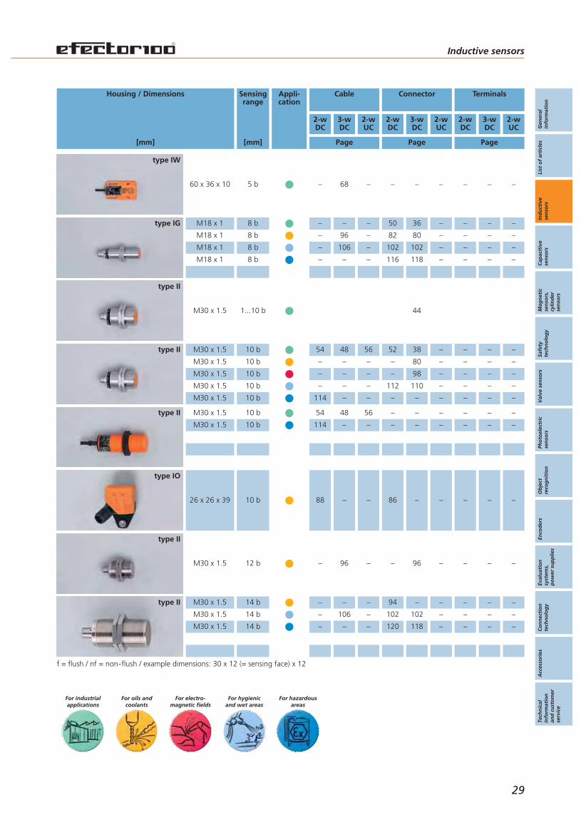
f = flush / nf = non-flush / example dimensions: 30 x 12 (= sensing face) x 12
Housing / Dimensions
[mm]
Sensingrange
[mm]
Appli-cation
Cable Connector Terminals
2-wDC
3-wDC
2-wUC
2-wDC
3-wDC
2-wUC
2-wDC
3-wDC
2-wUC
type II
type II
type IO
type II
type IW
type IG
type II
type II
M30 x 1.5 10 b
M30 x 1.5 10 b
M30 x 1.5 10 b
M30 x 1.5 10 b
M30 x 1.5 10 b
54 48 56 52 38 – – – –
– – – – 80 – – – –
– – – – 98 – – – –
– – – 112 110 – – – –
114 – – – – – – – –
M30 x 1.5 10 b
M30 x 1.5 10 b
54 48 56 – – – – – –
114 – – – – – – – –
26 x 26 x 39 10 b 88 – – 86 – – – – –
M30 x 1.5 12 b – 96 – – 96 – – – –
60 x 36 x 10 5 b – 68 – – – – – – –
M18 x 1 8 b
M18 x 1 8 b
M18 x 1 8 b
M18 x 1 8 b
– – – 50 36 – – – –
– 96 – 82 80 – – – –
– 106 – 102 102 – – – –
– – – 116 118 – – – –
M30 x 1.5 1...10 b 44
M30 x 1.5 14 b
M30 x 1.5 14 b
M30 x 1.5 14 b
– – – 94 – – – – –
– 106 – 102 102 – – – –
– – – 120 118 – – – –
Selection chartInductive sensors Inductive sensors
For hazardousareas
For hygienicand wet areas
For electro-magnetic fields
For oils andcoolants
For industrialapplications
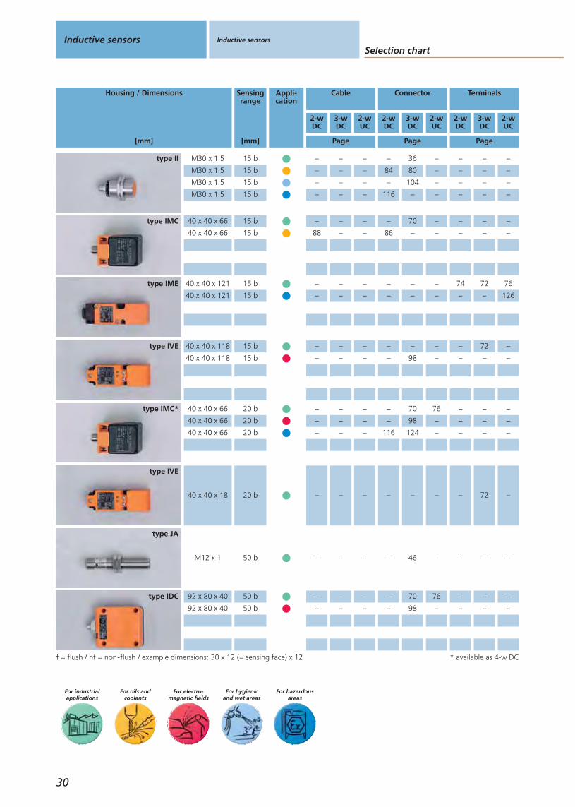
f = flush / nf = non-flush / example dimensions: 30 x 12 (= sensing face) x 12
Housing / Dimensions
[mm]
Sensingrange
[mm]
Appli-cation
Cable Connector Terminals
2-wDC
3-wDC
2-wUC
2-wDC
3-wDC
2-wUC
2-wDC
3-wDC
2-wUC
Page Page Page
30
* available as 4-w DC
type IVE
type JA
type IDC
type IVE
type IMC*
type IMC
type II
type IME
40 x 40 x 18 20 b – – – – – – – 72 –
M12 x 1 50 b – – – – 46 – – – –
92 x 80 x 40 50 b
92 x 80 x 40 50 b
– – – – 70 76 – – –
– – – – 98 – – – –
40 x 40 x 118 15 b
40 x 40 x 118 15 b
– – – – – – – 72 –
– – – – 98 – – – –
40 x 40 x 66 20 b
40 x 40 x 66 20 b
40 x 40 x 66 20 b
– – – – 70 76 – – –
– – – – 98 – – – –
– – – 116 124 – – – –
40 x 40 x 66 15 b
40 x 40 x 66 15 b
– – – – 70 – – – –
88 – – 86 – – – – –
M30 x 1.5 15 b
M30 x 1.5 15 b
M30 x 1.5 15 b
M30 x 1.5 15 b
– – – – 36 – – – –
– – – 84 80 – – – –
– – – – 104 – – – –
– – – 116 – – – – –
40 x 40 x 121 15 b
40 x 40 x 121 15 b
– – – – – – 74 72 76
– – – – – – – – 126
Inductive sensors
Gen
eral
info
rmat
ion
List
of
arti
cles
Ind
uct
ive
sen
sors
Cap
acit
ive
sen
sors
Mag
net
icse
nso
rs,
cylin
der
sen
sors
Safe
tyte
chn
olo
gy
Val
ve s
enso
rsPh
oto
elec
tric
sen
sors
Ob
ject
reco
gn
itio
nEn
cod
ers
Eval
uat
ion
syst
ems,
po
wer
su
pp
lies
Co
nn
ecti
on
tech
no
log
yA
cces
sori
esTe
chn
ical
info
rmat
ion
and
cu
sto
mer
serv
ice
Page Page Page
31
For hazardousareas
For hygienicand wet areas
For electro-magnetic fields
For oils andcoolants
For industrialapplications
f = flush / nf = non-flush / example dimensions: 30 x 12 (= sensing face) x 12
Housing / Dimensions
[mm]
Sensingrange
[mm]
Appli-cation
Cable Connector Terminals
2-wDC
3-wDC
2-wUC
2-wDC
3-wDC
2-wUC
2-wDC
3-wDC
2-wUC
type IE
type IZ
type IE
type IZ
type IS
type IJ
type IY
type IF
M8 x 1 2 nb
M8 x 1 2 nb
54 – – – – – – – –
– – – – 110 – – – –
Ø 4 1.5 nb – 58 – – 58 – – – –
M8 x 1 2 nb 54 42 – – – – – – –
Ø 3 1 nb – 58 – – – – – – –
28 x 10 x 16 3 nb – 68 – – – – – – –
27 x 10.5x 25 2 nb – 68 – – – – – – –
M5 x 0.5 1.5 nb – 42 – – 42 – – – –
M12 x 1 0.4...4 nb 44

Selection chartInductive sensors Inductive sensors
For hazardousareas
For hygienicand wet areas
For electro-magnetic fields
For oils andcoolants
For industrialapplications
Housing / Dimensions
[mm]
Sensingrange
[mm]
Appli-cation
Cable Connector Terminals
2-wDC
3-wDC
2-wUC
2-wDC
3-wDC
2-wUC
2-wDC
3-wDC
2-wUC
Page Page Page
32
f = flush / nf = non-flush / example dimensions: 30 x 12 (= sensing face) x 12
type IN
type IE
type IF
type IS
type IF
type IF
type IT
type IE
40 x 12 x 26 4 nb
40 x 12 x 26 4 nb
74 68 76 – 66 – – – –
114 124 – – 124 – – – –
M8 x 1 5 nb – 40 – – 40 – – – –
M12 x 1 7 nb
M12 x 1 7 nb
M12 x 1 7 nb
M12 x 1 7 nb
– – – 50 36 – – – –
– 96 – 82 78 – – – –
102 106 – 102 102 – – – –
– – – 116 122 – – – –
28 x 10 x 16 4 nb – 68 – – 66 – – – –
M12 x 1 4 nb
M12 x 1 4 nb
M12 x 1 4 nb
M12 x 1 4 nb
M12 x 1 4 nb
54 48 56 52 38 – – – –
– – – 78 – – – –
– – – – 98 – – – –
– – 112 110 – – – –
114 – – – – – – – –
M12 x 1 4 nb
M12 x 1 4 nb
54 48 56 – – – – – –
114 – – – – – – – –
M8 x 1 4 nb
M8 x 1 4 nb
– – – – 40 – – – –
– – – – 90 – – – –
Ø 6.5 4 nb – 58 – – 58 – – – –

Inductive sensors
Gen
eral
info
rmat
ion
List
of
arti
cles
Ind
uct
ive
sen
sors
Cap
acit
ive
sen
sors
Mag
net
icse
nso
rs,
cylin
der
sen
sors
Safe
tyte
chn
olo
gy
Val
ve s
enso
rsPh
oto
elec
tric
sen
sors
Ob
ject
reco
gn
itio
nEn
cod
ers
Eval
uat
ion
syst
ems,
po
wer
su
pp
lies
Co
nn
ecti
on
tech
no
log
yA
cces
sori
esTe
chn
ical
info
rmat
ion
and
cu
sto
mer
serv
ice
For hazardousareas
For hygienicand wet areas
For electro-magnetic fields
For oils andcoolants
For industrialapplications
Housing / Dimensions
[mm]
Sensingrange
[mm]
Appli-cation
Cable Connector Terminals
2-wDC
3-wDC
2-wUC
2-wDC
3-wDC
2-wUC
2-wDC
3-wDC
2-wUC
Page Page Page
33
f = flush / nf = non-flush / example dimensions: 30 x 12 (= sensing face) x 12
type IW
type IG
type IG
type IA
type IG
type IG
type IG
type IF
60 x 36 x 10 8 nb – 68 – – 66 – – – –
M18 x 1 12 nb – – – 50 36 – – – –
M18 x 1 12 nb – – – – 100 – – – –
M18 x 1 12 nb – 106 – 102 102 – – – –
M18 x 1 12 nb – – – 116 122 – – – –
M18 x 1 12 nb – 96 – 82 80 – – – –
M18 x 1 10 nb – – – – 110 – – – –
Ø 20 10 nb 62 58 64 – 58 – 62 60 64
M18 x 1 8 nb 54 48 56 – – – 54 – –
M18 x 1 8 nb 114 – – – – – – – –
M18 x 1 0.8...8 nb – – – – 44 – – – –
M18 x 1 8 nb
M18 x 1 8 nb
M18 x 1 8 nb
M18 x 1 8 nb
M18 x 1 0.8...8 nb
54 48 56 52 38 – – – –
– – – – 80 – – – –
– 110 – 112 110 – – – –
114 122 126 – 122 – – – –
– – – – 44 – – – –
M12 x 1 8 nb
M12 x 1 8 nb
– – – – 90 – – – –
– – – – 100 – – – –
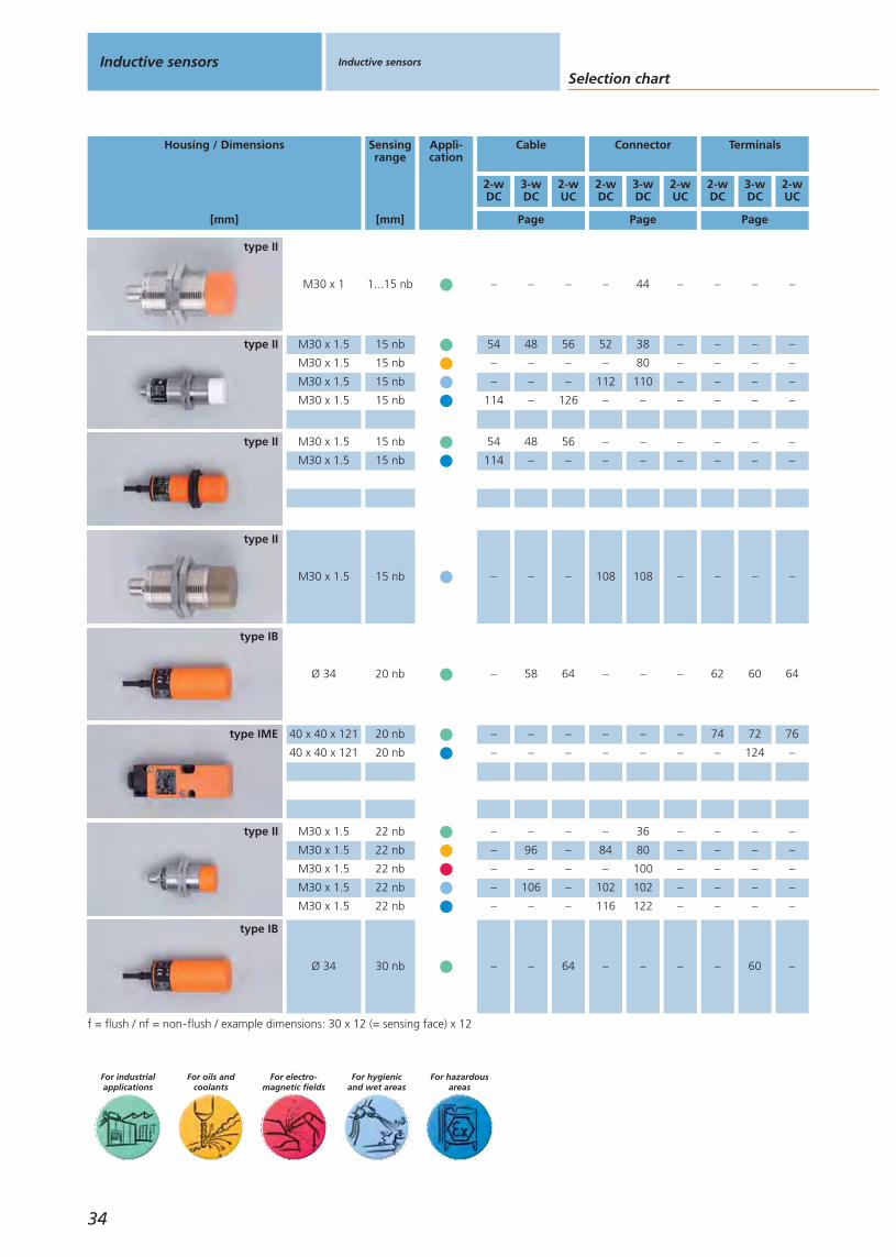
Selection chartInductive sensors Inductive sensors
34
For hazardousareas
For hygienicand wet areas
For electro-magnetic fields
For oils andcoolants
For industrialapplications
Housing / Dimensions
[mm]
Sensingrange
[mm]
Appli-cation
Cable Connector Terminals
2-wDC
3-wDC
2-wUC
2-wDC
3-wDC
2-wUC
2-wDC
3-wDC
2-wUC
Page Page Page
f = flush / nf = non-flush / example dimensions: 30 x 12 (= sensing face) x 12
type IB
type II
type IME
type II
type II
type II
type IB
type II
Ø 34 30 nb – – 64 – – – – 60 –
M30 x 1.5 22 nb
M30 x 1.5 22 nb
M30 x 1.5 22 nb
M30 x 1.5 22 nb
M30 x 1.5 22 nb
– – – – 36 – – – –
– 96 – 84 80 – – – –
– – – – 100 – – – –
– 106 – 102 102 – – – –
– – – 116 122 – – – –
40 x 40 x 121 20 nb
40 x 40 x 121 20 nb
– – – – – – 74 72 76
– – – – – – – 124 –
M30 x 1 1...15 nb – – – – 44 – – – –
M30 x 1.5 15 nb
M30 x 1.5 15 nb
M30 x 1.5 15 nb
M30 x 1.5 15 nb
54 48 56 52 38 – – – –
– – – – 80 – – – –
– – – 112 110 – – – –
114 – 126 – – – – – –
M30 x 1.5 15 nb
M30 x 1.5 15 nb
54 48 56 – – – – – –
114 – – – – – – – –
Ø 34 20 nb – 58 64 – – – 62 60 64
M30 x 1.5 15 nb – – – 108 108 – – – –

Inductive sensors
Gen
eral
info
rmat
ion
List
of
arti
cles
Ind
uct
ive
sen
sors
Cap
acit
ive
sen
sors
Mag
net
icse
nso
rs,
cylin
der
sen
sors
Safe
tyte
chn
olo
gy
Val
ve s
enso
rsPh
oto
elec
tric
sen
sors
Ob
ject
reco
gn
itio
nEn
cod
ers
Eval
uat
ion
syst
ems,
po
wer
su
pp
lies
Co
nn
ecti
on
tech
no
log
yA
cces
sori
esTe
chn
ical
info
rmat
ion
and
cu
sto
mer
serv
ice
35
For hazardousareas
For hygienicand wet areas
For electro-magnetic fields
For oils andcoolants
For industrialapplications
Housing / Dimensions
[mm]
Sensingrange
[mm]
Appli-cation
Cable Connector Terminals
2-wDC
3-wDC
2-wUC
2-wDC
3-wDC
2-wUC
2-wDC
3-wDC
2-wUC
Page Page Page
f = flush / nf = non-flush / example dimensions: 30 x 12 (= sensing face) x 12
type IDE
type ID
type IME
type ICE
type IMC
type IMC*
* available as 4-w DC
105 x 80 x 40 60 nb
105 x 80 x 40 60 nb
– – – – 70 – – 72 76
– – – – – – 120 124 126
120 x 80 x 30 50 nb – 72 76 – – – – – –
40 x 40 x 121 30 nb – – – – – – – 72 –
90 x 60 x 40 40 nb
90 x 60 x 40 40 nb
– – – – – – – 72 76
– – – – – – – 124 126
40 x 40 x 66 35 nb
40 x 40 x 66 35 nb
40 x 40 x 66 35 nb
– – – – 70 76 – – –
– – – – 100 – – – –
– – – 110 124 – – –
40 x 40 x 66 40 nb – – – – 100 – – – –

Increased sensing range for more machine uptime.
Easy to mount by LED setting display.
Safe and quick mounting due torobust and reinforced housing.
All sensors have corrosion-resistant M12 connector.
Laser etched type label forpermanent identification of the unit.
Accessories
Type Description Orderno.
Angle bracket · for type M12 · stainless steel (304S15) E10735
Mounting sleeve · Ø 12 mm · with endstop · for type M12 · brass / nickel-plated E11114
Mounting clamp · Ø 12 mm · with end stop · for type M12 · PC E11047
Mounting clip · form O · for type M12 ·spring steel wire (1.4310) E11533
Further accessories are available starting on page 425
Connectors and splitter boxes
Type Description Orderno.
Socket, For sensors withwirable E11303
Socket, M12, group 72 m black, PUR cable EVC001
Socket, M12, group 75 m black, PUR cable EVC002
Socket, M12, group 72 m black, PUR cable EVC004
Socket, M12, group 75 m black, PUR cable EVC005
Further connectors and splitter boxes are availablestarting on page 393
Inductive sensors Inductive sensors For industrialapplications
36
Inductivesensors
Page
For industrialapplications
DC3-wire
36 - 49
DC2-wire
50 - 55
AC / DC2-wire
56 - 57
DC3-wire
58 - 61
DC2-wire
62 - 63
AC / DC2-wire
64 - 65
DC3-wire
66 - 73
DC2-wire
74 - 75

Threaded housing3-wire DC PNPOptical setting aid (2 LEDs) for IGS208 / 209, IFS208 / 209, and IIS206 / 207
Housing Dimensions
[mm]
Sensingrange[mm]
Material Ub
[V]
Protec-tion
f
[Hz]
Iload
[mA]
Uab
[V]
I0
[mA]
Draw-ingno.
Orderno.
M8 connector · Output · Connector groups 1, 2, 41 · Wiring diagram no. 1
M12 / L = 46 4 f brass 10...36 IP 67 700 100 2.5 10 1 IFS210
M12 / L = 51 7 nf brass 10...36 IP 67 700 100 2.5 10 2 IFS211
M18 / L = 46 8 f brass 10...36 IP 67 400 100 2.5 10 3 IGS210
M18 / L = 52 12 nf brass 10...36 IP 67 400 100 2.5 10 4 IGS211
M12 connector · Output · Connector groups 7, 8, 10 · Wiring diagram no. 1
M12 / L = 45 4 f brass 10...36 IP 67 700 100 2.5 10 5 IFS204
M12 / L = 50 7 nf brass 10...36 IP 67 700 100 2.5 10 6 IFS205
M12 / L = 70 4 f brass 10...36 IP 67 700 100 2.5 10 7 IFS212
M12 / L = 70 7 nf brass 10...36 IP 67 700 100 2.5 10 8 IFS213
M18 / L = 46 8 f brass 10...36 IP 67 400 100 2.5 10 9 IGS204
M18 / L = 51 12 nf brass 10...36 IP 67 300 100 2.5 10 10 IGS205
M18 / L = 70 8 f brass 10...36 IP 67 400 100 2.5 10 11 IGS212
M18 / L = 70 12 nf brass 10...36 IP 67 300 100 2.5 10 12 IGS213
M30 / L = 50 15 f brass 10...36 IP 67 100 100 2.5 10 13 IIS204
M30 / L = 50 22 nf brass 10...36 IP 67 100 100 2.5 10 14 IIS205
M30 / L = 70 15 f V4A (316S12) 10...36 IP 67 100 100 2.5 10 15 IIS210
M30 / L = 70 22 nf V4A (316S12) 10...36 IP 67 100 100 2.5 10 16 IIS211
M12 connector · Output · Connector groups 7, 8 · Wiring diagram no. 2
M12 / L = 45 4 f brass 10...36 IP 67 700 100 2.5 10 5 IFS206
M12 / L = 50 7 nf brass 10...36 IP 67 700 100 2.5 10 6 IFS207
M18 / L = 46 8 f brass 10...36 IP 67 400 100 2.5 10 9 IGS206
M18 / L = 51 12 nf brass 10...36 IP 67 300 100 2.5 10 10 IGS207
M30 / L = 50 15 f brass 10...36 IP 67 100 100 2.5 10 13 IIS208
M30 / L = 50 22 nf brass 10...36 IP 67 100 100 2.5 10 14 IIS209
M12 connector · Output · Connector groups 6, 7, 8, 10 · Wiring diagram no. 64
M12 / L = 70 4 f brass 10...30 IP 67 500 100 2.8 12 7 IFS208
M12 / L = 70 7 nf brass 10...30 IP 67 500 100 2.8 12 8 IFS209
M18 / L = 70 8 f brass 10...30 IP 67 400 100 2.8 12 11 IGS208
M18 / L = 70 12 nf brass 10...30 IP 67 300 100 2.8 12 12 IGS209
M30 / L = 70 15 f brass 10...30 IP 67 100 100 2.5 10 15 IIS206
M30 / L = 70 22 nf brass 10...30 IP 67 100 100 2.5 10 16 IIS207
Operating temperature -25...80 °C
You can find scale drawings from page 450
AC / DC2-wire
76 - 77
For oils andcoolants
78 - 97
For electro-magnetic fields
98 - 101
For hygienicand wet areas
102 - 113
For hazardousareas
114 - 127
Inductive sensors
Gen
eral
info
rmat
ion
List
of
arti
cles
Ind
uct
ive
sen
sors
Cap
acit
ive
sen
sors
Mag
net
icse
nso
rs,
cylin
der
sen
sors
Safe
tyte
chn
olo
gy
Val
ve s
enso
rsPh
oto
elec
tric
sen
sors
Ob
ject
reco
gn
itio
nEn
cod
ers
Eval
uat
ion
syst
ems,
po
wer
su
pp
lies
Co
nn
ecti
on
tech
no
log
yA
cces
sori
esTe
chn
ical
info
rmat
ion
and
cu
sto
mer
serv
ice
37

High shock andvibration resistance.
Different housing lengths for almost every application.
Safe and quick mounting due torobust and reinforced housing.
All sensors have corrosion-resistant M12 connector.
Laser etched type label forpermanent identification of the unit.
Accessories
Type Description Orderno.
Angle bracket · for type M18 · stainless steel (304S15) E10736
Angle bracket · for type M30 · stainless steel (304S15) E10737
Mounting sleeve · with end stop · fortype M18 · brass / white bronze coated E11115
Mounting clamp · with end stop · for type M18 · PC E11048
Mounting clamp · with end stop · for type M30 · PC E11049
Further accessories are available starting on page 425
Connectors and splitter boxes
Type Description Orderno.
Socket · for sensors withwirable E11303
Socket, M12, group 72 m black, PUR cable EVC001
Socket, M12, group 75 m black, PUR cable EVC002
Socket, M12, group 72 m black, PUR cable EVC004
Socket, M12, group 75 m black, PUR cable EVC005
Further connectors and splitter boxes are availablestarting on page 393
Inductive sensors Inductive sensors For industrialapplications
38
Inductivesensors
Page
For industrialapplications
DC3-wire
36 - 49
DC2-wire
50 - 55
AC / DC2-wire
56 - 57
DC3-wire
58 - 61
DC2-wire
62 - 63
AC / DC2-wire
64 - 65
DC3-wire
66 - 73
DC2-wire
74 - 75
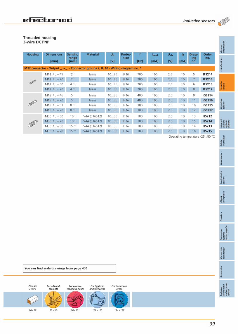
Threaded housing3-wire DC PNP
Housing Dimensions
[mm]
Sensingrange[mm]
Material Ub
[V]
Protec-tion
f
[Hz]
Iload
[mA]
Uab
[V]
I0
[mA]
Draw-ingno.
Orderno.
M12 connector · Output · Connector groups 7, 8, 10 · Wiring diagram no. 1
M12 / L = 45 2 f brass 10...36 IP 67 700 100 2.5 10 5 IFS214
M12 / L = 70 2 f brass 10...36 IP 67 700 100 2.5 10 7 IFS216
M12 / L = 50 4 nf brass 10...36 IP 67 700 100 2.5 10 6 IFS215
M12 / L = 70 4 nf brass 10...36 IP 67 700 100 2.5 10 8 IFS217
M18 / L = 46 5 f brass 10...36 IP 67 400 100 2.5 10 9 IGS214
M18 / L = 70 5 f brass 10...36 IP 67 400 100 2.5 10 11 IGS216
M18 / L = 51 8 nf brass 10...36 IP 67 300 100 2.5 10 10 IGS215
M18 / L = 70 8 nf brass 10...36 IP 67 300 100 2.5 10 12 IGS217
M30 / L = 50 10 f V4A (316S12) 10...36 IP 67 100 100 2.5 10 13 IIS212
M30 / L = 70 10 f V4A (316S12) 10...36 IP 67 100 100 2.5 10 15 IIS214
M30 / L = 50 15 nf V4A (316S12) 10...36 IP 67 100 100 2.5 10 14 IIS213
M30 / L = 70 15 nf V4A (316S12) 10...36 IP 67 100 100 2.5 10 16 IIS215
Operating temperature -25...80 °C
You can find scale drawings from page 450
AC / DC2-wire
76 - 77
For oils andcoolants
78 - 97
For electro-magnetic fields
98 - 101
For hygienicand wet areas
102 - 113
For hazardousareas
114 - 127
Inductive sensors
Gen
eral
info
rmat
ion
List
of
arti
cles
Ind
uct
ive
sen
sors
Cap
acit
ive
sen
sors
Mag
net
icse
nso
rs,
cylin
der
sen
sors
Safe
tyte
chn
olo
gy
Val
ve s
enso
rsPh
oto
elec
tric
sen
sors
Ob
ject
reco
gn
itio
nEn
cod
ers
Eval
uat
ion
syst
ems,
po
wer
su
pp
lies
Co
nn
ecti
on
tech
no
log
yA
cces
sori
esTe
chn
ical
info
rmat
ion
and
cu
sto
mer
serv
ice
39

Small designs with M8 or M12connector or cable connection.
Different housing lengths for almost every application.
Increased sensing rangefor more machine uptime.
High switching frequenciesup to 2000 Hz.
Wide selection of fixingaccessories and sockets.
Accessories
Type Description Orderno.
Angle bracket · for type M8 · stainless steel (304S15) E10734
Limit plungers · for types M8 x 1 · free cutting steel E10154
Mounting clamp · Ø 8 mm · with end stop · for type M8 · PC E11521
Further accessories are available starting on page 425
Connectors and splitter boxes
Type Description Orderno.
Socket, M8, group 12 m black, PUR cable E11486
Socket, M8, group 15 m black, PUR cable E11487
Socket, M8, group 22 m black, PUR cable, LED E11492
Socket, M8, group 25 m black, PUR cable, LED E11493
Socket, M12, group 72 m black, PUR cable EVC001
Socket, M12, group 75 m black, PUR cable EVC002
Socket, M12, group 92 m black, PUR cable, LED EVC007
Socket, M12, group 95 m black, PUR cable, LED EVC008
Further connectors and splitter boxes are availablestarting on page 393
Inductive sensors Inductive sensors For industrialapplications
40
Inductivesensors
Page
For industrialapplications
DC3-wire
36 - 49
DC2-wire
50 - 55
AC / DC2-wire
56 - 57
DC3-wire
58 - 61
DC2-wire
62 - 63
AC / DC2-wire
64 - 65
DC3-wire
66 - 73
DC2-wire
74 - 75
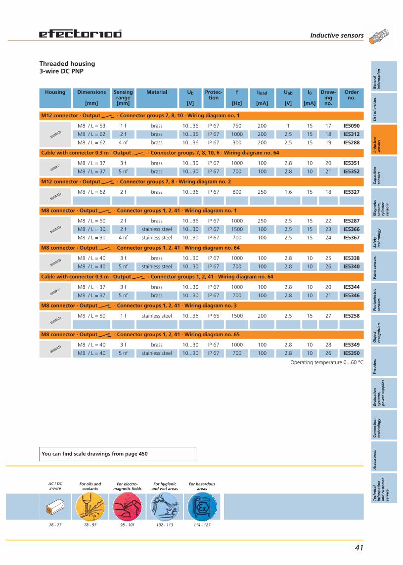
Threaded housing3-wire DC PNP
Housing Dimensions
[mm]
Sensingrange[mm]
Material Ub
[V]
Protec-tion
f
[Hz]
Iload
[mA]
Uab
[V]
I0
[mA]
Draw-ingno.
Orderno.
M12 connector · Output · Connector groups 7, 8, 10 · Wiring diagram no. 1
M8 / L = 53 1 f brass 10...36 IP 67 750 200 1 15 17 IE5090
M8 / L = 62 2 f brass 10...36 IP 67 1000 200 2.5 15 18 IE5312
M8 / L = 62 4 nf brass 10...36 IP 67 300 200 2.5 15 19 IE5288
Cable with connector 0.3 m · Output · Connector groups 7, 8, 10, 6 · Wiring diagram no. 64
M8 / L = 37 3 f brass 10...30 IP 67 1000 100 2.8 10 20 IE5351
M8 / L = 37 5 nf brass 10...30 IP 67 700 100 2.8 10 21 IE5352
M12 connector · Output · Connector groups 7, 8 · Wiring diagram no. 2
M8 / L = 62 2 f brass 10...36 IP 67 800 250 1.6 15 18 IE5327
M8 connector · Output · Connector groups 1, 2, 41 · Wiring diagram no. 1
M8 / L = 50 2 f brass 10...36 IP 67 1000 250 2.5 15 22 IE5287
M8 / L = 30 2 f stainless steel 10...30 IP 67 1500 100 2.5 15 23 IE5366
M8 / L = 30 4 nf stainless steel 10...30 IP 67 700 100 2.5 15 24 IE5367
M8 connector · Output · Connector groups 1, 2, 41 · Wiring diagram no. 64
M8 / L = 40 3 f brass 10...30 IP 67 1000 100 2.8 10 25 IE5338
M8 / L = 40 5 nf stainless steel 10...30 IP 67 700 100 2.8 10 26 IE5340
Cable with connector 0.3 m · Output · Connector groups 1, 2, 41 · Wiring diagram no. 64
M8 / L = 37 3 f brass 10...30 IP 67 1000 100 2.8 10 20 IE5344
M8 / L = 37 5 nf brass 10...30 IP 67 700 100 2.8 10 21 IE5346
M8 connector · Output · Connector groups 1, 2, 41 · Wiring diagram no. 3
M8 / L = 50 1 f stainless steel 10...36 IP 65 1500 200 2.5 15 27 IE5258
M8 connector · Output · Connector groups 1, 2, 41 · Wiring diagram no. 65
M8 / L = 40 3 f brass 10...30 IP 67 1000 100 2.8 10 28 IE5349
M8 / L = 40 5 nf stainless steel 10...30 IP 67 700 100 2.8 10 26 IE5350
Operating temperature 0...60 °C
You can find scale drawings from page 450
AC / DC2-wire
76 - 77
For oils andcoolants
78 - 97
For electro-magnetic fields
98 - 101
For hygienicand wet areas
102 - 113
For hazardousareas
114 - 127
Inductive sensors
Gen
eral
info
rmat
ion
List
of
arti
cles
Ind
uct
ive
sen
sors
Cap
acit
ive
sen
sors
Mag
net
icse
nso
rs,
cylin
der
sen
sors
Safe
tyte
chn
olo
gy
Val
ve s
enso
rsPh
oto
elec
tric
sen
sors
Ob
ject
reco
gn
itio
nEn
cod
ers
Eval
uat
ion
syst
ems,
po
wer
su
pp
lies
Co
nn
ecti
on
tech
no
log
yA
cces
sori
esTe
chn
ical
info
rmat
ion
and
cu
sto
mer
serv
ice
41
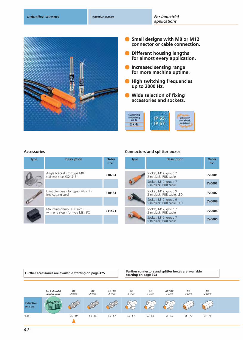
Small designs with M8 or M12connector or cable connection.
Different housing lengths for almost every application.
Increased sensing rangefor more machine uptime.
High switching frequenciesup to 2000 Hz.
Wide selection of fixingaccessories and sockets.
Accessories
Type Description Orderno.
Angle bracket · for type M8 · stainless steel (304S15) E10734
Limit plungers · for types M8 x 1 · free cutting steel E10154
Mounting clamp · Ø 8 mm · with end stop · for type M8 · PC E11521
Further accessories are available starting on page 425
Connectors and splitter boxes
Type Description Orderno.
Socket, M12, group 72 m black, PUR cable EVC001
Socket, M12, group 75 m black, PUR cable EVC002
Socket, M12, group 92 m black, PUR cable, LED EVC007
Socket, M12, group 95 m black, PUR cable, LED EVC008
Socket, M12, group 72 m black, PUR cable EVC004
Socket, M12, group 75 m black, PUR cable EVC005
Further connectors and splitter boxes are availablestarting on page 393
Inductive sensors Inductive sensors For industrialapplications
42
Inductivesensors
Page
For industrialapplications
DC3-wire
36 - 49
DC2-wire
50 - 55
AC / DC2-wire
56 - 57
DC3-wire
58 - 61
DC2-wire
62 - 63
AC / DC2-wire
64 - 65
DC3-wire
66 - 73
DC2-wire
74 - 75

Threaded housing3-wire DC PNP
Housing Dimensions
[mm]
Sensingrange[mm]
Material Ub
[V]
Protec-tion
f
[Hz]
Iload
[mA]
Uab
[V]
I0
[mA]
Draw-ingno.
Orderno.
M8 connector · Output · Connector groups 1, 2, 41 · Wiring diagram no. 1
M5 / L = 45 0.8 f stainless steel 10...36 IP 65 2000 100 2.5 15 29 IY5036
M8 connector · Output · Connector groups 1, 2 · Wiring diagram no. 1
M5 / L = 41 1.5 nf stainless steel 10...30 IP 67 1800 100 3 10 30 IY5048
Cable 2 m · Output · Wiring diagram no. 4
M5 / L = 30 0.8 f stainless steel 10...36 IP 65 2000 100 2.5 15 31 IY5029
M5 / L = 23 1.2 f stainless steel 10...30 IP 65 < 2000 100 2.5 15 32 IY5052
M5 / L = 27 1.5 nf stainless steel 10...30 IP 67 1800 100 3 10 33 IY5049
M8 / L = 35 1 f brass 10...36 IP 67 750 200 1 15 34 IE5072
M8 / L = 50 1 f brass 10...36 IP 67 750 200 1 15 35 IE5121
M8 / L = 50 1 f PBT 10...36 IP 67 1000 200 1 15 35 IE5129
M8 / L = 35 2 nf PBT 10...36 IP 67 800 200 1 15 34 IE5099
M8 / L = 20 1.5 f stainless steel 10...30 IP 67 1000 200 1.5 10 36 IE5348
M8 / L = 27 2 f stainless steel 10...30 IP 67 1500 100 2.5 15 37 IE5368
M8 / L = 27 4 nf stainless steel 10...30 IP 67 500 100 2.5 15 38 IE5369
Cable 2 m · Output · Wiring diagram no. 66
M8 / L = 37 3 f brass 10...30 IP 67 1000 100 2.8 10 20 IE5343
M8 / L = 37 5 nf brass 10...30 IP 67 700 100 2.8 10 21 IE5345
Operating temperature -25...80 °C
You can find scale drawings from page 450
AC / DC2-wire
76 - 77
For oils andcoolants
78 - 97
For electro-magnetic fields
98 - 101
For hygienicand wet areas
102 - 113
For hazardousareas
114 - 127
Inductive sensors
Gen
eral
info
rmat
ion
List
of
arti
cles
Ind
uct
ive
sen
sors
Cap
acit
ive
sen
sors
Mag
net
icse
nso
rs,
cylin
der
sen
sors
Safe
tyte
chn
olo
gy
Val
ve s
enso
rsPh
oto
elec
tric
sen
sors
Ob
ject
reco
gn
itio
nEn
cod
ers
Eval
uat
ion
syst
ems,
po
wer
su
pp
lies
Co
nn
ecti
on
tech
no
log
yA
cces
sori
esTe
chn
ical
info
rmat
ion
and
cu
sto
mer
serv
ice
43
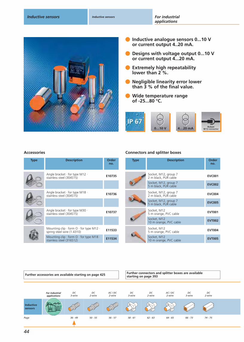
Inductive analogue sensors 0...10 V or current output 4..20 mA.
Designs with voltage output 0...10 Vor current output 4...20 mA.
Extremely high repeatabilitylower than 2 %.
Negligible linearity error lowerthan 3 % of the final value.
Wide temperature rangeof -25...80 °C.
Accessories
Type Description Orderno.
Angle bracket · for type M12 · stainless steel (304S15) E10735
Angle bracket · for type M18 · stainless steel (304S15) E10736
Angle bracket · for type M30 · stainless steel (304S15) E10737
Mounting clip · form O · for type M12 ·spring steel wire (1.4310) E11533
Mounting clip · form O · for type M18 ·stainless steel (316S12) E11534
Further accessories are available starting on page 425
Connectors and splitter boxes
Type Description Orderno.
Socket, M12, group 72 m black, PUR cable EVC001
Socket, M12, group 75 m black, PUR cable EVC002
Socket, M12, group 72 m black, PUR cable EVC004
Socket, M12, group 75 m black, PUR cable EVC005
Socket, M125 m orange, PVC cable EVT001
Socket, M1210 m orange, PVC cable EVT002
Socket, M125 m orange, PVC cable EVT004
Socket, M1210 m orange, PVC cable EVT005
Further connectors and splitter boxes are availablestarting on page 393
Inductive sensors Inductive sensors For industrialapplications
44
Inductivesensors
Page
For industrialapplications
DC3-wire
36 - 49
DC2-wire
50 - 55
AC / DC2-wire
56 - 57
DC3-wire
58 - 61
DC2-wire
62 - 63
AC / DC2-wire
64 - 65
DC3-wire
66 - 73
DC2-wire
74 - 75
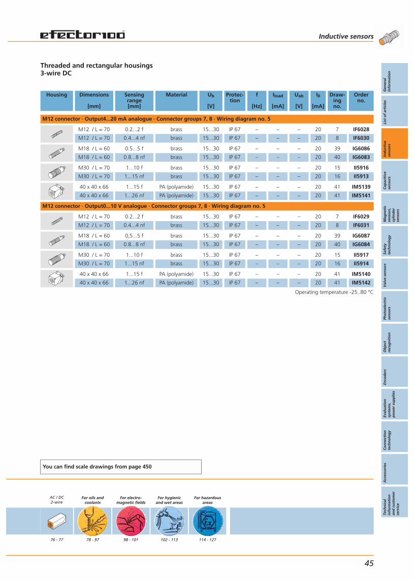
Threaded and rectangular housings3-wire DC
Housing Dimensions
[mm]
Sensingrange[mm]
Material Ub
[V]
Protec-tion
f
[Hz]
Iload
[mA]
Uab
[V]
I0
[mA]
Draw-ingno.
Orderno.
M12 connector · Output4...20 mA analogue · Connector groups 7, 8 · Wiring diagram no. 5
M12 / L = 70 0.2...2 f brass 15...30 IP 67 – – – 20 7 IF6028
M12 / L = 70 0.4...4 nf brass 15...30 IP 67 – – – 20 8 IF6030
M18 / L = 60 0.5...5 f brass 15...30 IP 67 – – – 20 39 IG6086
M18 / L = 60 0.8...8 nf brass 15...30 IP 67 – – – 20 40 IG6083
M30 / L = 70 1...10 f brass 15...30 IP 67 – – – 20 15 II5916
M30 / L = 70 1...15 nf brass 15...30 IP 67 – – – 20 16 II5913
40 x 40 x 66 1...15 f PA (polyamide) 15...30 IP 67 – – – 20 41 IM5139
40 x 40 x 66 1...26 nf PA (polyamide) 15...30 IP 67 – – – 20 41 IM5141
M12 connector · Output0...10 V analogue · Connector groups 7, 8 · Wiring diagram no. 5
M12 / L = 70 0.2...2 f brass 15...30 IP 67 – – – 20 7 IF6029
M12 / L = 70 0.4...4 nf brass 15...30 IP 67 – – – 20 8 IF6031
M18 / L = 60 0,5...5 f brass 15...30 IP 67 – – – 20 39 IG6087
M18 / L = 60 0.8...8 nf brass 15...30 IP 67 – – – 20 40 IG6084
M30 / L = 70 1...10 f brass 15...30 IP 67 – – – 20 15 II5917
M30 / L = 70 1...15 nf brass 15...30 IP 67 – – – 20 16 II5914
40 x 40 x 66 1...15 f PA (polyamide) 15...30 IP 67 – – – 20 41 IM5140
40 x 40 x 66 1...26 nf PA (polyamide) 15...30 IP 67 – – – 20 41 IM5142
Operating temperature -25..80 °C
You can find scale drawings from page 450
AC / DC2-wire
76 - 77
For oils andcoolants
78 - 97
For electro-magnetic fields
98 - 101
For hygienicand wet areas
102 - 113
For hazardousareas
114 - 127
Inductive sensors
Gen
eral
info
rmat
ion
List
of
arti
cles
Ind
uct
ive
sen
sors
Cap
acit
ive
sen
sors
Mag
net
icse
nso
rs,
cylin
der
sen
sors
Safe
tyte
chn
olo
gy
Val
ve s
enso
rsPh
oto
elec
tric
sen
sors
Ob
ject
reco
gn
itio
nEn
cod
ers
Eval
uat
ion
syst
ems,
po
wer
su
pp
lies
Co
nn
ecti
on
tech
no
log
yA
cces
sori
esTe
chn
ical
info
rmat
ion
and
cu
sto
mer
serv
ice
45
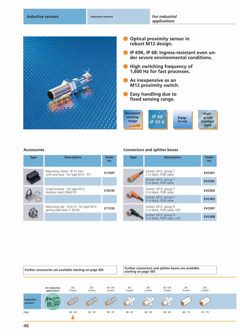
Optical proximity sensor in robust M12 design.
IP 69K, IP 68: Ingress-resistant even un-der severe environmental conditions.
High switching frequency of 1,600 Hz for fast processes.
As inexpensive as an M12 proximity switch.
Easy handling due tofixed sensing range.
Accessories
Type Description Orderno.
Mounting clamp · Ø 12 mm · with end stop · for type M12 · PC E11047
Angle bracket · for type M12 · stainless steel (304S15) E10735
Mounting clip · form O · for type M12 ·spring steel wire (1.4310) E11533
Further accessories are available starting on page 425
Connectors and splitter boxes
Type Description Orderno.
Socket, M12, group 72 m black, PUR cable EVC001
Socket, M12, group 75 m black, PUR cable EVC002
Socket, M12, group 72 m black, PUR cable EVC004
Socket, M12, group 75 m black, PUR cable EVC005
Socket, M12, group 92 m black, PUR cable, LED EVC007
Socket, M12, group 95 m black, PUR cable, LED EVC008
Further connectors and splitter boxes are availablestarting on page 393
Inductive sensors Inductive sensors For industrialapplications
46
Inductivesensors
Page
For industrialapplications
DC3-wire
36 - 49
DC2-wire
50 - 55
AC / DC2-wire
56 - 57
DC3-wire
58 - 61
DC2-wire
62 - 63
AC / DC2-wire
64 - 65
DC3-wire
66 - 73
DC2-wire
74 - 75
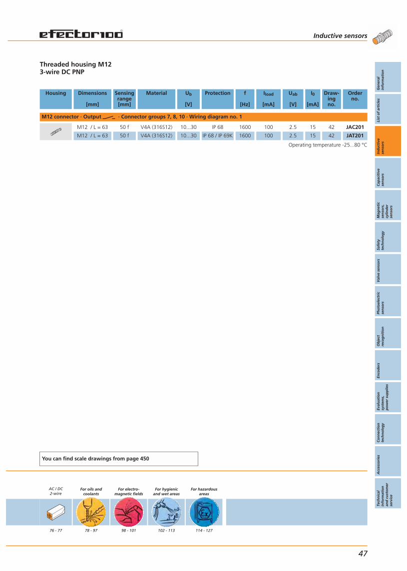
Threaded housing M123-wire DC PNP
Housing Dimensions
[mm]
Sensingrange[mm]
Material Ub
[V]
Protection f
[Hz]
Iload
[mA]
Uab
[V]
I0
[mA]
Draw-ingno.
Orderno.
M12 connector · Output · Connector groups 7, 8, 10 · Wiring diagram no. 1
M12 / L = 63 50 f V4A (316S12) 10...30 IP 68 1600 100 2.5 15 42 JAC201
M12 / L = 63 50 f V4A (316S12) 10...30 IP 68 / IP 69K 1600 100 2.5 15 42 JAT201
Operating temperature -25...80 °C
You can find scale drawings from page 450
AC / DC2-wire
76 - 77
For oils andcoolants
78 - 97
For electro-magnetic fields
98 - 101
For hygienicand wet areas
102 - 113
For hazardousareas
114 - 127
Inductive sensors
Gen
eral
info
rmat
ion
List
of
arti
cles
Ind
uct
ive
sen
sors
Cap
acit
ive
sen
sors
Mag
net
icse
nso
rs,
cylin
der
sen
sors
Safe
tyte
chn
olo
gy
Val
ve s
enso
rsPh
oto
elec
tric
sen
sors
Ob
ject
reco
gn
itio
nEn
cod
ers
Eval
uat
ion
syst
ems,
po
wer
su
pp
lies
Co
nn
ecti
on
tech
no
log
yA
cces
sori
esTe
chn
ical
info
rmat
ion
and
cu
sto
mer
serv
ice
47

Plastic and brass housingsfor different requirements.
Different housing lengthsfor almost every application.
Stable characteristics across thefull temperature and frequency range.
Tried and tested PVC cablefor various connections.
Wide range of mounting accessories.
Accessories
Type Description Orderno.
Angle bracket · for type M12 · stainless steel (304S15) E10735
Angle bracket · for type M18 · stainless steel (304S15) E10736
Angle bracket · for type M30 · stainless steel (304S15) E10737
Mounting sleeve · with end stop · for type M12 · brass / nickel-plated E10806
Mounting sleeve · with end stop · for type M18 · brass / nickel-plated E10807
Mounting sleeve · with end stop · for type M30 · brass / nickel-plated E10808
Further accessories are available starting on page 425
Inductive sensors Inductive sensors For industrialapplications
48
Inductivesensors
Page
For industrialapplications
DC3-wire
36 - 49
DC2-wire
50 - 55
AC / DC2-wire
56 - 57
DC3-wire
58 - 61
DC2-wire
62 - 63
AC / DC2-wire
64 - 65
DC3-wire
66 - 73
DC2-wire
74 - 75

Threaded housing3-wire DC PNP
Housing Dimensions
[mm]
Sensingrange[mm]
Material Ub
[V]
Protec-tion
f
[Hz]
Iload
[mA]
Uab
[V]
I0
[mA]
Draw-ingno.
Orderno.
Cable 2 m · Output · Wiring diagram no. 4
M12 / L = 35 2 f brass 10...36 IP 67 1500 150 2.5 15 43 IF5188
M12 / L = 71 2 f brass 10...36 IP 67 800 250 2.5 15 44 IF5297
M12 / L = 71 2 f PBT 10...55 IP 67 800 250 2.5 15 44 IF5313
M12 / L = 35 4 nf brass 10...36 IP 67 1500 150 2.5 15 45 IF5249
M12 / L = 71 4 nf brass 10...36 IP 67 1500 250 2.5 15 46 IF5329
M12 / L = 71 4 nf PBT 10...36 IP 67 400 250 2.5 15 44 IF5345
M18 / L = 38 5 f brass 18...36 IP 67 500 150 2.5 15 47 IG5221
M18 / L = 80 5 f brass 10...36 IP 67 500 250 2.5 15 48 IG5397
M18 / L = 80 5 f PBT 10...36 IP 67 500 250 2.5 15 48 IG5399
M18 / L = 38 8 nf brass 18...36 IP 67 200 150 2.5 15 49 IG5285
M18 / L = 80 8 nf brass 10...36 IP 67 300 250 2.5 15 50 IG5398
M18 / L = 80 8 nf PBT 10...36 IP 67 300 250 2.5 15 48 IG5401
M30 / L = 45 10 f brass 18...36 IP 67 300 150 2.5 15 51 II5166
M30 / L = 81 10 f brass 10...36 IP 67 250 250 2.5 15 52 II5256
M30 / L = 81 10 f PBT 10...36 IP 67 250 250 2.5 15 52 II5369
M30 / L = 45 15 nf brass 18...36 IP 67 250 150 2.5 15 53 II5346
M30 / L = 81 15 nf brass 10...36 IP 67 250 250 2.5 15 54 II5284
M30 / L = 81 15 nf PBT 10...36 IP 67 250 250 2.5 15 52 II5300
Operating temperature -25...80 °C
You can find scale drawings from page 450
AC / DC2-wire
76 - 77
For oils andcoolants
78 - 97
For electro-magnetic fields
98 - 101
For hygienicand wet areas
102 - 113
For hazardousareas
114 - 127
Inductive sensors
Gen
eral
info
rmat
ion
List
of
arti
cles
Ind
uct
ive
sen
sors
Cap
acit
ive
sen
sors
Mag
net
icse
nso
rs,
cylin
der
sen
sors
Safe
tyte
chn
olo
gy
Val
ve s
enso
rsPh
oto
elec
tric
sen
sors
Ob
ject
reco
gn
itio
nEn
cod
ers
Eval
uat
ion
syst
ems,
po
wer
su
pp
lies
Co
nn
ecti
on
tech
no
log
yA
cces
sori
esTe
chn
ical
info
rmat
ion
and
cu
sto
mer
serv
ice
49

Increased sensing rangefor more machine uptime.
Laser etched type label for permanent identification of the unit.
Quick and safe mountingdue to LED setting display.
Sensors with easy-to-mountM12 connector.
High shock andvibration resistance.
Accessories
Type Description Orderno.
Angle bracket · for type M12 · stainless steel (304S15) E10735
Angle bracket · for type M18 · stainless steel (304S15) E10736
Mounting clamp · Ø 12 mm · with end stop · for type M12 · PC E11047
Mounting clamp · Ø 18 mm · with end stop · for type M18 · PC E11048
Further accessories are available starting on page 425
Connectors and splitter boxes
Type Description Orderno.
Socket, wirable E11303
Socket, M12, group 72 m black, PUR cable EVC001
Socket, M12, group 75 m black, PUR cable EVC002
Socket, M12, group 72 m black, PUR cable EVC004
Socket, M12, group 75 m black, PUR cable EVC005
Further connectors and splitter boxes are availablestarting on page 393
Inductive sensors Inductive sensors For industrialapplications
50
Inductivesensors
Page
For industrialapplications
DC3-wire
36 - 49
DC2-wire
50 - 55
AC / DC2-wire
56 - 57
DC3-wire
58 - 61
DC2-wire
62 - 63
AC / DC2-wire
64 - 65
DC3-wire
66 - 73
DC2-wire
74 - 75
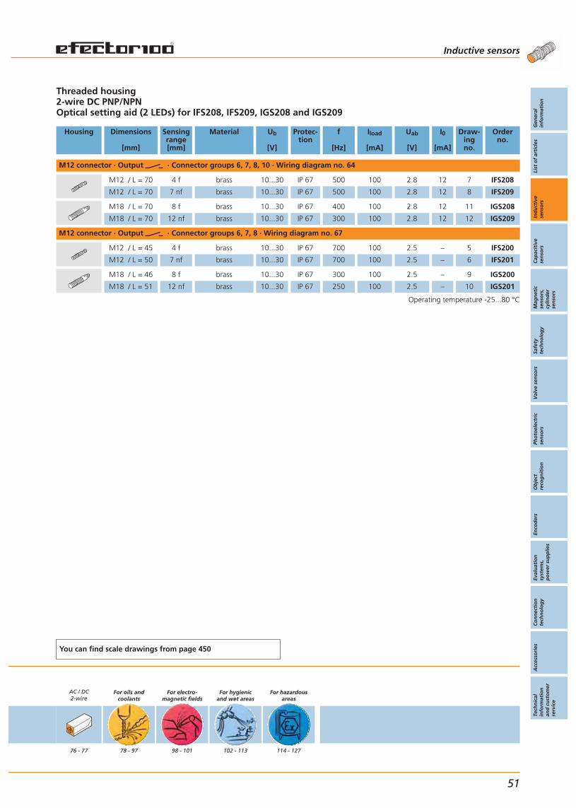
Threaded housing2-wire DC PNP/NPNOptical setting aid (2 LEDs) for IFS208, IFS209, IGS208 and IGS209
Housing Dimensions
[mm]
Sensingrange[mm]
Material Ub
[V]
Protec-tion
f
[Hz]
Iload
[mA]
Uab
[V]
I0
[mA]
Draw-ingno.
Orderno.
M12 connector · Output · Connector groups 6, 7, 8, 10 · Wiring diagram no. 64
M12 / L = 70 4 f brass 10...30 IP 67 500 100 2.8 12 7 IFS208
M12 / L = 70 7 nf brass 10...30 IP 67 500 100 2.8 12 8 IFS209
M18 / L = 70 8 f brass 10...30 IP 67 400 100 2.8 12 11 IGS208
M18 / L = 70 12 nf brass 10...30 IP 67 300 100 2.8 12 12 IGS209
M12 connector · Output · Connector groups 6, 7, 8 · Wiring diagram no. 67
M12 / L = 45 4 f brass 10...30 IP 67 700 100 2.5 – 5 IFS200
M12 / L = 50 7 nf brass 10...30 IP 67 700 100 2.5 – 6 IFS201
M18 / L = 46 8 f brass 10...30 IP 67 300 100 2.5 – 9 IGS200
M18 / L = 51 12 nf brass 10...30 IP 67 250 100 2.5 – 10 IGS201
Operating temperature -25...80 °C
You can find scale drawings from page 450
AC / DC2-wire
76 - 77
For oils andcoolants
78 - 97
For electro-magnetic fields
98 - 101
For hygienicand wet areas
102 - 113
For hazardousareas
114 - 127
Inductive sensors
Gen
eral
info
rmat
ion
List
of
arti
cles
Ind
uct
ive
sen
sors
Cap
acit
ive
sen
sors
Mag
net
icse
nso
rs,
cylin
der
sen
sors
Safe
tyte
chn
olo
gy
Val
ve s
enso
rsPh
oto
elec
tric
sen
sors
Ob
ject
reco
gn
itio
nEn
cod
ers
Eval
uat
ion
syst
ems,
po
wer
su
pp
lies
Co
nn
ecti
on
tech
no
log
yA
cces
sori
esTe
chn
ical
info
rmat
ion
and
cu
sto
mer
serv
ice
51

4 switching functions by simplyreversing the connecting wires.
Increased sensing rangefor more machine uptime.
Wide temperature rangeof -25...80 °C.
M12 connector easy to mountand maintain.
Leakage current lower than 1 mA.
Accessories
Type Description Orderno.
Angle bracket · for type M8 · stainless steel (304S15) E10734
Angle bracket · for type M12 · stainless steel (304S15) E10735
Angle bracket · for type M18 · stainless steel (304S15) E10736
Angle bracket · for type M30 · stainless steel (304S15) E10737
Mounting sleeve · with end stop · for type M8 · brass / special coated E10848
Mounting sleeve · with end stop · for type M12 · brass / nickel-plated E10806
Mounting sleeve · with end stop · for type M18 · brass / nickel-plated E10807
Mounting sleeve · with end stop · for type M30 · brass / nickel-plated E10808
Further accessories are available starting on page 425
Connectors and splitter boxes
Type Description Orderno.
Socket, M12, group 62 m black, PUR / PVC cable E10216
Socket, M12, group 65 m orange, PUR / PVC cable E10215
Socket, M12, group 62 m orange, PUR / PVC cable E10188
Socket, M12, group 65 m orange, PUR / PVC cable E10214
Further connectors and splitter boxes are availablestarting on page 393
Inductive sensors Inductive sensors For industrialapplications
52
Inductivesensors
Page
For industrialapplications
DC3-wire
36 - 49
DC2-wire
50 - 55
AC / DC2-wire
56 - 57
DC3-wire
58 - 61
DC2-wire
62 - 63
AC / DC2-wire
64 - 65
DC3-wire
66 - 73
DC2-wire
74 - 75
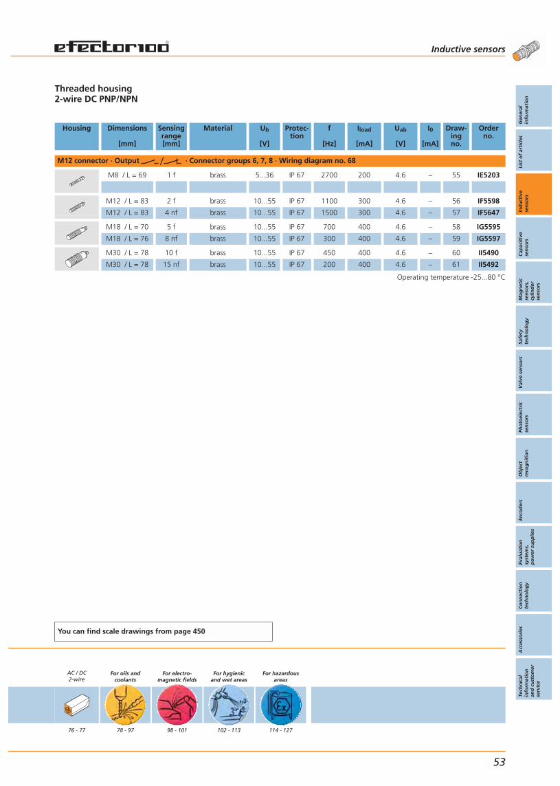
Threaded housing2-wire DC PNP/NPN
Housing Dimensions
[mm]
Sensingrange[mm]
Material Ub
[V]
Protec-tion
f
[Hz]
Iload
[mA]
Uab
[V]
I0
[mA]
Draw-ingno.
Orderno.
M12 connector · Output · Connector groups 6, 7, 8 · Wiring diagram no. 68
M8 / L = 69 1 f brass 5...36 IP 67 2700 200 4.6 – 55 IE5203
M12 / L = 83 2 f brass 10...55 IP 67 1100 300 4.6 – 56 IF5598
M12 / L = 83 4 nf brass 10...55 IP 67 1500 300 4.6 – 57 IF5647
M18 / L = 70 5 f brass 10...55 IP 67 700 400 4.6 – 58 IG5595
M18 / L = 76 8 nf brass 10...55 IP 67 300 400 4.6 – 59 IG5597
M30 / L = 78 10 f brass 10...55 IP 67 450 400 4.6 – 60 II5490
M30 / L = 78 15 nf brass 10...55 IP 67 200 400 4.6 – 61 II5492
Operating temperature -25...80 °C
You can find scale drawings from page 450
AC / DC2-wire
76 - 77
For oils andcoolants
78 - 97
For electro-magnetic fields
98 - 101
For hygienicand wet areas
102 - 113
For hazardousareas
114 - 127
Inductive sensors
Gen
eral
info
rmat
ion
List
of
arti
cles
Ind
uct
ive
sen
sors
Cap
acit
ive
sen
sors
Mag
net
icse
nso
rs,
cylin
der
sen
sors
Safe
tyte
chn
olo
gy
Val
ve s
enso
rsPh
oto
elec
tric
sen
sors
Ob
ject
reco
gn
itio
nEn
cod
ers
Eval
uat
ion
syst
ems,
po
wer
su
pp
lies
Co
nn
ecti
on
tech
no
log
yA
cces
sori
esTe
chn
ical
info
rmat
ion
and
cu
sto
mer
serv
ice
53
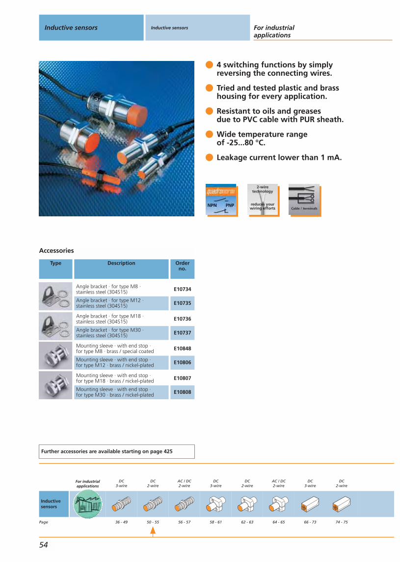
4 switching functions by simplyreversing the connecting wires.
Tried and tested plastic and brasshousing for every application.
Resistant to oils and greases due to PVC cable with PUR sheath.
Wide temperature rangeof -25...80 °C.
Leakage current lower than 1 mA.
Accessories
Type Description Orderno.
Angle bracket · for type M8 · stainless steel (304S15) E10734
Angle bracket · for type M12 · stainless steel (304S15) E10735
Angle bracket · for type M18 · stainless steel (304S15) E10736
Angle bracket · for type M30 · stainless steel (304S15) E10737
Mounting sleeve · with end stop · for type M8 · brass / special coated E10848
Mounting sleeve · with end stop · for type M12 · brass / nickel-plated E10806
Mounting sleeve · with end stop · for type M18 · brass / nickel-plated E10807
Mounting sleeve · with end stop · for type M30 · brass / nickel-plated E10808
Further accessories are available starting on page 425
Inductive sensors Inductive sensors For industrialapplications
54
Inductivesensors
Page
For industrialapplications
DC3-wire
36 - 49
DC2-wire
50 - 55
AC / DC2-wire
56 - 57
DC3-wire
58 - 61
DC2-wire
62 - 63
AC / DC2-wire
64 - 65
DC3-wire
66 - 73
DC2-wire
74 - 75

Threaded housing2-wire DC PNP/NPN
Housing Dimensions
[mm]
Sensingrange[mm]
Material Ub
[V]
Protec-tion
f
[Hz]
Iload
[mA]
Uab
[V]
I0
[mA]
Draw-ingno.
Orderno.
Cable 2 m · Output · Wiring diagram no. 69
M8 / L = 50 1 f brass 5...36 IP 67 2000 200 4.6 – 35 IE5222
M8 / L = 50 2 nf brass 5...36 IP 67 2700 200 4.6 – 62 IE5238
M8 / L = 50 2 nf PBT (Pocan) 5...36 IP 67 2000 200 4.6 – 35 IE5202
M12 / L = 71 2 f brass 10...55 IP 67 1100 400 4.6 – 44 IF5645
M12 / L = 71 2 f PBT 10...55 IP 67 1100 400 4.6 – 44 IF5644
M12 / L = 71 4 nf brass 10...55 IP 67 1500 400 4.6 – 46 IF5646
M12 / L = 71 4 nf PBT 10...55 IP 67 1500 400 4.6 – 44 IF5597
M18 / L = 80 5 f PBT 10...55 IP 67 700 400 4.6 – 48 IG5593
M18 / L = 80 5 f brass 10...55 IP 67 700 400 4.6 – 48 IG5594
M18 / L = 80 8 nf PBT 10...55 IP 67 300 400 4.6 – 48 IG5533
M18 / L = 80 8 nf brass 10...55 IP 67 300 400 4.6 – 50 IG5596
M30 / L = 45 10 f brass 10...55 IP 67 450 400 4.6 – 51 II5493
M30 / L = 81 10 f PBT 10...55 IP 67 450 400 4.6 – 52 II5488
M30 / L = 81 10 f brass 10...55 IP 67 450 400 4.6 – 52 II5489
M30 / L = 81 15 nf PBT 10...55 IP 67 200 400 4.6 – 52 II5436
M30 / L = 81 15 nf brass 10...55 IP 67 200 400 4.6 – 54 II5491
Terminals · Output · Wiring diagram no. 70
M18 / L = 110 5 f PBT 10...55 IP 65 800 400 4.6 – 63 IG5718
M18 / L = 110 8 nf PBT 10...55 IP 65 300 400 4.6 – 63 IG5719
Operating temperature -25...80 °C
You can find scale drawings from page 450
AC / DC2-wire
76 - 77
For oils andcoolants
78 - 97
For electro-magnetic fields
98 - 101
For hygienicand wet areas
102 - 113
For hazardousareas
114 - 127
Inductive sensors
Gen
eral
info
rmat
ion
List
of
arti
cles
Ind
uct
ive
sen
sors
Cap
acit
ive
sen
sors
Mag
net
icse
nso
rs,
cylin
der
sen
sors
Safe
tyte
chn
olo
gy
Val
ve s
enso
rsPh
oto
elec
tric
sen
sors
Ob
ject
reco
gn
itio
nEn
cod
ers
Eval
uat
ion
syst
ems,
po
wer
su
pp
lies
Co
nn
ecti
on
tech
no
log
yA
cces
sori
esTe
chn
ical
info
rmat
ion
and
cu
sto
mer
serv
ice
55
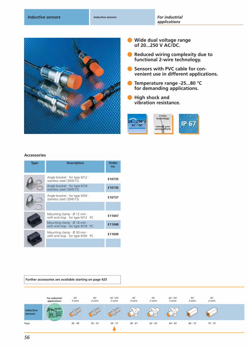
Wide dual voltage rangeof 20...250 V AC/DC.
Reduced wiring complexity due tofunctional 2-wire technology.
Sensors with PVC cable for con-venient use in different applications.
Temperature range -25...80 °Cfor demanding applications.
High shock andvibration resistance.
Accessories
Type Description Orderno.
Angle bracket · for type M12 · stainless steel (304S15) E10735
Angle bracket · for type M18 · stainless steel (304S15) E10736
Angle bracket · for type M30 · stainless steel (304S15) E10737
Mounting clamp · Ø 12 mm · with end stop · for type M12 · PC E11047
Mounting clamp · Ø 18 mm · with end stop · for type M18 · PC E11048
Mounting clamp · Ø 30 mm · with end stop · for type M30 · PC E11049
Further accessories are available starting on page 425
Inductive sensors Inductive sensors For industrialapplications
56
Inductivesensors
Page
For industrialapplications
DC3-wire
36 - 49
DC2-wire
50 - 55
AC / DC2-wire
56 - 57
DC3-wire
58 - 61
DC2-wire
62 - 63
AC / DC2-wire
64 - 65
DC3-wire
66 - 73
DC2-wire
74 - 75
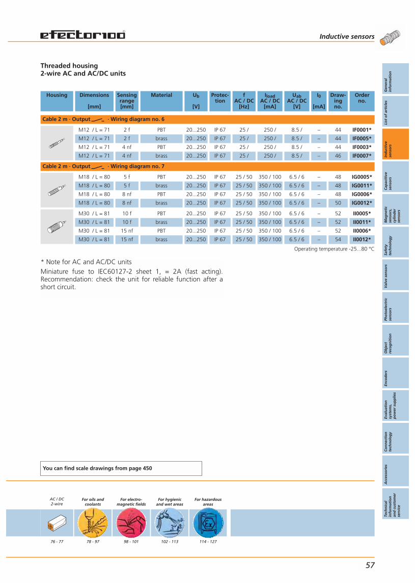
* Note for AC and AC/DC unitsMiniature fuse to IEC60127-2 sheet 1, = 2A (fast acting).Recommendation: check the unit for reliable function after ashort circuit.
Threaded housing2-wire AC and AC/DC units
Housing Dimensions
[mm]
Sensingrange[mm]
Material Ub
[V]
Protec-tion
fAC / DC
[Hz]
IloadAC / DC
[mA]
UabAC / DC
[V]
I0
[mA]
Draw-ingno.
Orderno.
Cable 2 m · Output · Wiring diagram no. 6
M12 / L = 71 2 f PBT 20...250 IP 67 25 / 250 / 8.5 / – 44 IF0001*
M12 / L = 71 2 f brass 20...250 IP 67 25 / 250 / 8.5 / – 44 IF0005*
M12 / L = 71 4 nf PBT 20...250 IP 67 25 / 250 / 8.5 / – 44 IF0003*
M12 / L = 71 4 nf brass 20...250 IP 67 25 / 250 / 8.5 / – 46 IF0007*
Cable 2 m · Output · Wiring diagram no. 7
M18 / L = 80 5 f PBT 20...250 IP 67 25 / 50 350 / 100 6.5 / 6 – 48 IG0005*
M18 / L = 80 5 f brass 20...250 IP 67 25 / 50 350 / 100 6.5 / 6 – 48 IG0011*
M18 / L = 80 8 nf PBT 20...250 IP 67 25 / 50 350 / 100 6.5 / 6 – 48 IG0006*
M18 / L = 80 8 nf brass 20...250 IP 67 25 / 50 350 / 100 6.5 / 6 – 50 IG0012*
M30 / L = 81 10 f PBT 20...250 IP 67 25 / 50 350 / 100 6.5 / 6 – 52 II0005*
M30 / L = 81 10 f brass 20...250 IP 67 25 / 50 350 / 100 6.5 / 6 – 52 II0011*
M30 / L = 81 15 nf PBT 20...250 IP 67 25 / 50 350 / 100 6.5 / 6 – 52 II0006*
M30 / L = 81 15 nf brass 20...250 IP 67 25 / 50 350 / 100 6.5 / 6 – 54 II0012*
Operating temperature -25...80 °C
You can find scale drawings from page 450
AC / DC2-wire
76 - 77
For oils andcoolants
78 - 97
For electro-magnetic fields
98 - 101
For hygienicand wet areas
102 - 113
For hazardousareas
114 - 127
Inductive sensors
Gen
eral
info
rmat
ion
List
of
arti
cles
Ind
uct
ive
sen
sors
Cap
acit
ive
sen
sors
Mag
net
icse
nso
rs,
cylin
der
sen
sors
Safe
tyte
chn
olo
gy
Val
ve s
enso
rsPh
oto
elec
tric
sen
sors
Ob
ject
reco
gn
itio
nEn
cod
ers
Eval
uat
ion
syst
ems,
po
wer
su
pp
lies
Co
nn
ecti
on
tech
no
log
yA
cces
sori
esTe
chn
ical
info
rmat
ion
and
cu
sto
mer
serv
ice
57
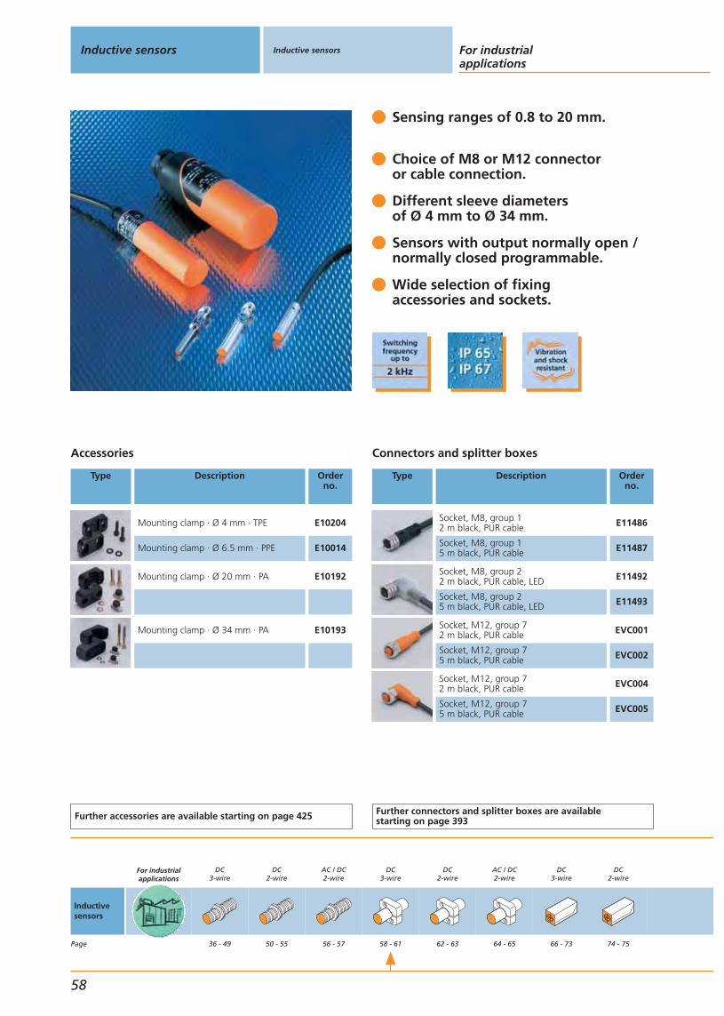
Sensing ranges of 0.8 to 20 mm.
Choice of M8 or M12 connectoror cable connection.
Different sleeve diametersof Ø 4 mm to Ø 34 mm.
Sensors with output normally open /normally closed programmable.
Wide selection of fixingaccessories and sockets.
Accessories
Type Description Orderno.
Mounting clamp · Ø 4 mm · TPE E10204
Mounting clamp · Ø 6.5 mm · PPE E10014
Mounting clamp · Ø 20 mm · PA E10192
Mounting clamp · Ø 34 mm · PA E10193
Further accessories are available starting on page 425
Connectors and splitter boxes
Type Description Orderno.
Socket, M8, group 12 m black, PUR cable E11486
Socket, M8, group 15 m black, PUR cable E11487
Socket, M8, group 22 m black, PUR cable, LED E11492
Socket, M8, group 25 m black, PUR cable, LED E11493
Socket, M12, group 72 m black, PUR cable EVC001
Socket, M12, group 75 m black, PUR cable EVC002
Socket, M12, group 72 m black, PUR cable EVC004
Socket, M12, group 75 m black, PUR cable EVC005
Further connectors and splitter boxes are availablestarting on page 393
Inductive sensors Inductive sensors For industrialapplications
58
Inductivesensors
Page
For industrialapplications
DC3-wire
36 - 49
DC2-wire
50 - 55
AC / DC2-wire
56 - 57
DC3-wire
58 - 61
DC2-wire
62 - 63
AC / DC2-wire
64 - 65
DC3-wire
66 - 73
DC2-wire
74 - 75

Cylindrical housing (smooth sleeve)3-wire DC PNP
Housing Dimensions
[mm]
Sensingrange[mm]
Material Ub
[V]
Protec-tion
f
[Hz]
Iload
[mA]
Uab
[V]
I0
[mA]
Draw-ingno.
Orderno.
M8 connector · Output · Connector groups 1, 2, 41 · Wiring diagram no. 1
Ø 4 / L = 45 0.8 f stainless steel 10...36 IP 65 2000 100 2.5 15 64 IZ5035
Ø 4 / L = 41 1.5 nf stainless steel 10...30 IP 67 1800 100 3 10 65 IZ5046
Ø 6.5 / L = 49 1.5 f brass 10...36 IP 65 2000 250 2.5 15 66 IT5034
Ø 6.5 / L = 49 1 f stainless steel 10...36 IP 65 1500 200 2.5 15 66 IT5021
Ø 6.5 / L = 30 2 f stainless steel 10...30 IP 67 1500 100 2.5 15 67 IT5040
Ø 6.5 / L = 30 4 nf stainless steel 10...30 IP 67 700 100 2.5 15 68 IT5041
Ø 6.5 / L = 50 4 nf stainless steel 10...30 IP 67 300 100 2.5 15 69 IT5044
M12 connector · Output · Connector groups 7, 8, 10 · Wiring diagram no. 1
Ø 20 / L = 92 10 nf PBT 10...36 IP 67 300 250 2.5 15 70 IA5127
Cable 2 m · Output · Wiring diagram no. 4
Ø 4 / L = 30 0.8 f stainless steel 10...36 IP 65 2000 100 2.5 15 71 IZ5026
Ø 4 / L = 23 0.8 f stainless steel 10...30 IP 65 2000 100 2.5 15 72 IZ5051
Ø 3 / L = 27 1 nf stainless steel 10...30 IP 67 5000 100 1.5 12 73 IZ5048
Ø 4 / L = 23 1.2 f stainless steel 10...30 IP 65 > 2000 100 2.5 15 72 IZ5052
Ø 4 / L = 27 1.5 nf stainless steel 10...30 IP 67 1800 100 3 10 74 IZ5047
Ø 6.5 / L = 27 2 f stainless steel 10...30 IP 67 1500 100 2.5 15 75 IT5042
Ø 6.5 / L = 27 4 nf stainless steel 10...30 IP 67 500 100 2.5 15 76 IT5043
Ø 6.5 / L = 35 1 f brass 10...36 IP 67 900 200 1 15 77 IT5001
Ø 6.5 / L = 19 2 f stainless steel 10...30 IP 67 1000 200 2.5 20 78 IT5039
Ø 20 / L = 77 10 nf PBT 10...36 IP 67 300 250 2.5 15 79 IA5082
Ø 34 / L = 82 20 nf PBT 10...36 IP 67 60 250 2.5 15 80 IB5096
Operating temperature -25...80 °C
You can find scale drawings from page 450
AC / DC2-wire
76 - 77
For oils andcoolants
78 - 97
For electro-magnetic fields
98 - 101
For hygienicand wet areas
102 - 113
For hazardousareas
114 - 127
Inductive sensors
Gen
eral
info
rmat
ion
List
of
arti
cles
Ind
uct
ive
sen
sors
Cap
acit
ive
sen
sors
Mag
net
icse
nso
rs,
cylin
der
sen
sors
Safe
tyte
chn
olo
gy
Val
ve s
enso
rsPh
oto
elec
tric
sen
sors
Ob
ject
reco
gn
itio
nEn
cod
ers
Eval
uat
ion
syst
ems,
po
wer
su
pp
lies
Co
nn
ecti
on
tech
no
log
yA
cces
sori
esTe
chn
ical
info
rmat
ion
and
cu
sto
mer
serv
ice
59
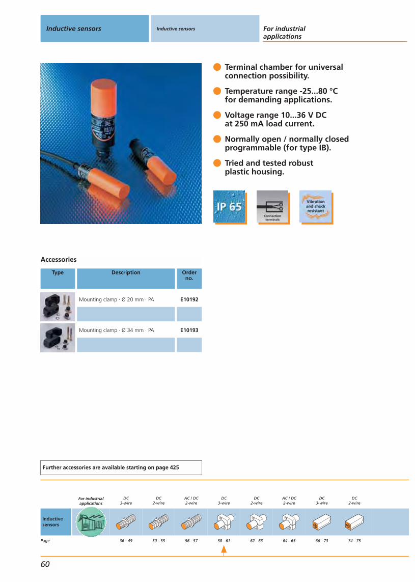
Terminal chamber for universalconnection possibility.
Temperature range -25...80 °C for demanding applications.
Voltage range 10...36 V DCat 250 mA load current.
Normally open / normally closedprogrammable (for type IB).
Tried and tested robustplastic housing.
Accessories
Type Description Orderno.
Mounting clamp · Ø 20 mm · PA E10192
Mounting clamp · Ø 34 mm · PA E10193
Further accessories are available starting on page 425
Inductive sensors Inductive sensors For industrialapplications
60
Inductivesensors
Page
For industrialapplications
DC3-wire
36 - 49
DC2-wire
50 - 55
AC / DC2-wire
56 - 57
DC3-wire
58 - 61
DC2-wire
62 - 63
AC / DC2-wire
64 - 65
DC3-wire
66 - 73
DC2-wire
74 - 75
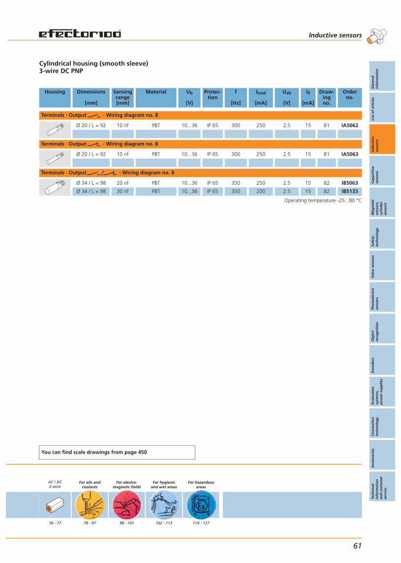
Cylindrical housing (smooth sleeve)3-wire DC PNP
Housing Dimensions
[mm]
Sensingrange[mm]
Material Ub
[V]
Protec-tion
f
[Hz]
Iload
[mA]
Uab
[V]
I0
[mA]
Draw-ingno.
Orderno.
Terminals · Output · Wiring diagram no. 8
Ø 20 / L = 92 10 nf PBT 10...36 IP 65 300 250 2.5 15 81 IA5062
Terminals · Output · Wiring diagram no. 8
Ø 20 / L = 92 10 nf PBT 10...36 IP 65 300 250 2.5 15 81 IA5063
Terminals · Output · Wiring diagram no. 8
Ø 34 / L = 98 20 nf PBT 10...36 IP 65 350 250 2.5 15 82 IB5063
Ø 34 / L = 98 30 nf PBT 10...36 IP 65 350 200 2.5 15 82 IB5133
Operating temperature -25...80 °C
You can find scale drawings from page 450
AC / DC2-wire
76 - 77
For oils andcoolants
78 - 97
For electro-magnetic fields
98 - 101
For hygienicand wet areas
102 - 113
For hazardousareas
114 - 127
Inductive sensors
Gen
eral
info
rmat
ion
List
of
arti
cles
Ind
uct
ive
sen
sors
Cap
acit
ive
sen
sors
Mag
net
icse
nso
rs,
cylin
der
sen
sors
Safe
tyte
chn
olo
gy
Val
ve s
enso
rsPh
oto
elec
tric
sen
sors
Ob
ject
reco
gn
itio
nEn
cod
ers
Eval
uat
ion
syst
ems,
po
wer
su
pp
lies
Co
nn
ecti
on
tech
no
log
yA
cces
sori
esTe
chn
ical
info
rmat
ion
and
cu
sto
mer
serv
ice
61

4 switching functions by simplyreversing the connecting wires.
Wide voltage rangeof 10...55 V DC.
Leakage current lower than 1 mA.
Wide temperature rangeof -25...80 °C.
High load current up to 400 mA.
Accessories
Type Description Orderno.
Mounting clamp · Ø 20 mm · PA E10192
Mounting clamp · Ø 34 mm · PA E10193
Further accessories are available starting on page 425
Inductive sensors Inductive sensors For industrialapplications
62
Inductivesensors
Page
For industrialapplications
DC3-wire
36 - 49
DC2-wire
50 - 55
AC / DC2-wire
56 - 57
DC3-wire
58 - 61
DC2-wire
62 - 63
AC / DC2-wire
64 - 65
DC3-wire
66 - 73
DC2-wire
74 - 75
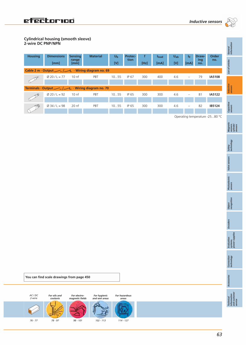
Cylindrical housing (smooth sleeve)2-wire DC PNP/NPN
Housing Dimensions
[mm]
Sensingrange[mm]
Material Ub
[V]
Protec-tion
f
[Hz]
Iload
[mA]
Uab
[V]
I0
[mA]
Draw-ingno.
Orderno.
Cable 2 m · Output · Wiring diagram no. 69
Ø 20 / L = 77 10 nf PBT 10...55 IP 67 300 400 4.6 – 79 IA5108
Terminals · Output · Wiring diagram no. 70
Ø 20 / L = 92 10 nf PBT 10...55 IP 65 300 300 4.6 – 81 IA5122
Ø 34 / L = 98 20 nf PBT 10...55 IP 65 300 300 4.6 – 82 IB5124
Operating temperature -25...80 °C
You can find scale drawings from page 450
AC / DC2-wire
76 - 77
For oils andcoolants
78 - 97
For electro-magnetic fields
98 - 101
For hygienicand wet areas
102 - 113
For hazardousareas
114 - 127
Inductive sensors
Gen
eral
info
rmat
ion
List
of
arti
cles
Ind
uct
ive
sen
sors
Cap
acit
ive
sen
sors
Mag
net
icse
nso
rs,
cylin
der
sen
sors
Safe
tyte
chn
olo
gy
Val
ve s
enso
rsPh
oto
elec
tric
sen
sors
Ob
ject
reco
gn
itio
nEn
cod
ers
Eval
uat
ion
syst
ems,
po
wer
su
pp
lies
Co
nn
ecti
on
tech
no
log
yA
cces
sori
esTe
chn
ical
info
rmat
ion
and
cu
sto
mer
serv
ice
63

Increased sensing rangefor more machine uptime.
Cable or terminal chamber.
Wide voltage rangeof 20...250 V AC/DC.
Different output functions.
Terminal chamber can be positionedeither straight or angled.
Accessories
Type Description Orderno.
Mounting clamp · Ø 20 mm · PA E10192
Mounting clamp · Ø 34 mm · PA E10193
Further accessories are available starting on page 425
Inductive sensors Inductive sensors For industrialapplications
64
Inductivesensors
Page
For industrialapplications
DC3-wire
36 - 49
DC2-wire
50 - 55
AC / DC2-wire
56 - 57
DC3-wire
58 - 61
DC2-wire
62 - 63
AC / DC2-wire
64 - 65
DC3-wire
66 - 73
DC2-wire
74 - 75
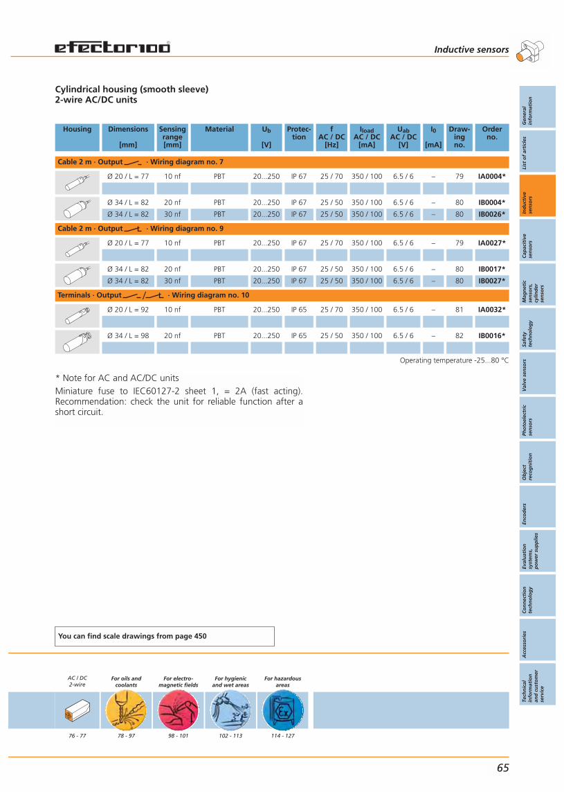
* Note for AC and AC/DC unitsMiniature fuse to IEC60127-2 sheet 1, = 2A (fast acting).Recommendation: check the unit for reliable function after ashort circuit.
Cylindrical housing (smooth sleeve)2-wire AC/DC units
Housing Dimensions
[mm]
Sensingrange[mm]
Material Ub
[V]
Protec-tion
fAC / DC
[Hz]
IloadAC / DC
[mA]
UabAC / DC
[V]
I0
[mA]
Draw-ingno.
Orderno.
Cable 2 m · Output · Wiring diagram no. 7
Ø 20 / L = 77 10 nf PBT 20...250 IP 67 25 / 70 350 / 100 6.5 / 6 – 79 IA0004*
Ø 34 / L = 82 20 nf PBT 20...250 IP 67 25 / 50 350 / 100 6.5 / 6 – 80 IB0004*
Ø 34 / L = 82 30 nf PBT 20...250 IP 67 25 / 50 350 / 100 6.5 / 6 – 80 IB0026*
Cable 2 m · Output · Wiring diagram no. 9
Ø 20 / L = 77 10 nf PBT 20...250 IP 67 25 / 70 350 / 100 6.5 / 6 – 79 IA0027*
Ø 34 / L = 82 20 nf PBT 20...250 IP 67 25 / 50 350 / 100 6.5 / 6 – 80 IB0017*
Ø 34 / L = 82 30 nf PBT 20...250 IP 67 25 / 50 350 / 100 6.5 / 6 – 80 IB0027*
Terminals · Output · Wiring diagram no. 10
Ø 20 / L = 92 10 nf PBT 20...250 IP 65 25 / 70 350 / 100 6.5 / 6 – 81 IA0032*
Ø 34 / L = 98 20 nf PBT 20...250 IP 65 25 / 50 350 / 100 6.5 / 6 – 82 IB0016*
Operating temperature -25...80 °C
You can find scale drawings from page 450
AC / DC2-wire
76 - 77
For oils andcoolants
78 - 97
For electro-magnetic fields
98 - 101
For hygienicand wet areas
102 - 113
For hazardousareas
114 - 127
Inductive sensors
Gen
eral
info
rmat
ion
List
of
arti
cles
Ind
uct
ive
sen
sors
Cap
acit
ive
sen
sors
Mag
net
icse
nso
rs,
cylin
der
sen
sors
Safe
tyte
chn
olo
gy
Val
ve s
enso
rsPh
oto
elec
tric
sen
sors
Ob
ject
reco
gn
itio
nEn
cod
ers
Eval
uat
ion
syst
ems,
po
wer
su
pp
lies
Co
nn
ecti
on
tech
no
log
yA
cces
sori
esTe
chn
ical
info
rmat
ion
and
cu
sto
mer
serv
ice
65
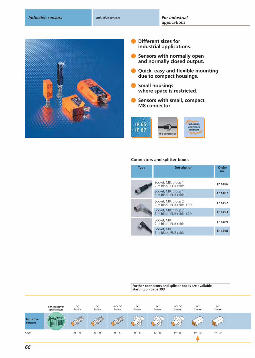
Different sizes for industrial applications.
Sensors with normally openand normally closed output.
Quick, easy and flexible mountingdue to compact housings.
Small housingswhere space is restricted.
Sensors with small, compactM8 connector
Connectors and splitter boxes
Type Description Orderno.
Socket, M8, group 12 m black, PUR cable E11486
Socket, M8, group 15 m black, PUR cable E11487
Socket, M8, group 22 m black, PUR cable, LED E11492
Socket, M8, group 25 m black, PUR cable, LED E11493
Socket, M82 m black, PUR cable E11489
Socket, M85 m black, PUR cable E11490
Further connectors and splitter boxes are availablestarting on page 393
Inductive sensors Inductive sensors For industrialapplications
66
Inductivesensors
Page
For industrialapplications
DC3-wire
36 - 49
DC2-wire
50 - 55
AC / DC2-wire
56 - 57
DC3-wire
58 - 61
DC2-wire
62 - 63
AC / DC2-wire
64 - 65
DC3-wire
66 - 73
DC2-wire
74 - 75

Rectangular housing3-wire DCIL5004: active face in front, IL5005: active face in the middle
Housing Dimensions
[mm]
Sensingrange[mm]
Material Ub
[V]
Protec-tion
f
[Hz]
Iload
[mA]
Uab
[V]
I0
[mA]
Draw-ingno.
Orderno.
M8 connector · Output · Connector groups 1, 2, 41 · Wiring diagram no. 1
28 x 10 x 16 2 f PBT 10...36 IP 67 800 200 1 15 83 IS5035
28 x 10 x 16 4 nf PBT 10...36 IP 67 2000 250 2.5 15 83 IS5071
40 x 8 x 8 2 f brass 10...36 IP 65 2000 250 1.6 15 84 IL5004
40 x 8 x 8 2 f brass 10...36 IP 65 2000 250 2.5 15 84 IL5005
40 x 12 x 26 2 f PBT 10...36 IP 65 1400 250 2.5 15 85 IN5230
40 x 12 x 26 4 nf PBT 10...36 IP 65 1300 250 2.5 15 85 IN5212
60 x 36 x 10 8 nf PBT 10...36 IP 65 300 250 2.5 15 86 IW5064
M8 connector · Output · Connector groups 1, 2, 41 · Wiring diagram no. 3
60 x 36 x 10 8 nf PBT 10...36 IP 67 300 250 2.5 5 86 IW5062
Operating temperature -25...80 °C
You can find scale drawings from page 450
AC / DC2-wire
76 - 77
For oils andcoolants
78 - 97
For electro-magnetic fields
98 - 101
For hygienicand wet areas
102 - 113
For hazardousareas
114 - 127
Inductive sensors
Gen
eral
info
rmat
ion
List
of
arti
cles
Ind
uct
ive
sen
sors
Cap
acit
ive
sen
sors
Mag
net
icse
nso
rs,
cylin
der
sen
sors
Safe
tyte
chn
olo
gy
Val
ve s
enso
rsPh
oto
elec
tric
sen
sors
Ob
ject
reco
gn
itio
nEn
cod
ers
Eval
uat
ion
syst
ems,
po
wer
su
pp
lies
Co
nn
ecti
on
tech
no
log
yA
cces
sori
esTe
chn
ical
info
rmat
ion
and
cu
sto
mer
serv
ice
67

Different sizes forspecial applications.
Quick, easy and flexible mountingdue to compact housings.
Ideal for applicationswhere space is restricted.
2 m PVC connection cable.
Inductive sensors Inductive sensors For industrialapplications
68
Inductivesensors
Page
For industrialapplications
DC3-wire
36 - 49
DC2-wire
50 - 55
AC / DC2-wire
56 - 57
DC3-wire
58 - 61
DC2-wire
62 - 63
AC / DC2-wire
64 - 65
DC3-wire
66 - 73
DC2-wire
74 - 75

Rectangular housing3-wire DC PNPIL5002: active face in front, IL5003: active face in the middle
Housing Dimensions
[mm]
Sensingrange[mm]
Material Ub
[V]
Protec-tion
f
[Hz]
Iload
[mA]
Uab
[V]
I0
[mA]
Draw-ingno.
Orderno.
Cable 2 m · Output · Wiring diagram no. 4
28 x 10 x 16 2 f PBT 10...36 IP 67 800 200 1 15 87 IS5001
28 x 10 x 16 3 nf PBT 10...36 IP 67 100 200 1 15 87 IS5031
28 x 10 x 16 4 nf PBT 10...36 IP 67 2000 250 2.5 15 88 IS5070
25 x 5 x 5 0.8 f aluminium 10...30 IP 65 1000 100 1 10 89 IL5022
40 x 8 x 8 2 f brass 10...36 IP 65 2000 250 2.5 15 90 IL5002
40 x 8 x 8 2 f brass 10...36 IP 65 2000 250 2.5 15 90 IL5003
40 x 12 x 26 2 f PBT 10...36 IP 67 1400 250 2.5 15 91 IN5121
40 x 12 x 26 4 nf PBT 10...36 IP 67 1300 250 2.5 15 91 IN5129
60 x 36 x 10 5 f PBT 10...36 IP 67 400 250 2.5 15 92 IW5051
60 x 36 x 10 8 nf PBT 10...36 IP 67 300 250 2.5 15 92 IW5058
Cable 2 m · Output · Wiring diagram no. 11
40 x 12 x 26 2 f PBT 10...36 IP 67 1400 250 2.5 15 91 IN5186
40 x 12 x 26 4 nf PBT 10...36 IP 67 1300 250 2.5 15 91 IN5188
60 x 36 x 10 5 f PBT 10...36 IP 67 400 250 2.5 15 92 IW5048
60 x 36 x 10 8 nf PBT 10...36 IP 67 300 250 2.5 15 92 IW5053
Cable 0.15 m · Output · Wiring diagram no. 11
27 x 10.5 x 25 2 nf nylon 10...36 IP 67 2000 200 2.5 10 93 IJ5002
Operating temperature -25...80 °C
You can find scale drawings from page 450
AC / DC2-wire
76 - 77
For oils andcoolants
78 - 97
For electro-magnetic fields
98 - 101
For hygienicand wet areas
102 - 113
For hazardousareas
114 - 127
Inductive sensors
Gen
eral
info
rmat
ion
List
of
arti
cles
Ind
uct
ive
sen
sors
Cap
acit
ive
sen
sors
Mag
net
icse
nso
rs,
cylin
der
sen
sors
Safe
tyte
chn
olo
gy
Val
ve s
enso
rsPh
oto
elec
tric
sen
sors
Ob
ject
reco
gn
itio
nEn
cod
ers
Eval
uat
ion
syst
ems,
po
wer
su
pp
lies
Co
nn
ecti
on
tech
no
log
yA
cces
sori
esTe
chn
ical
info
rmat
ion
and
cu
sto
mer
serv
ice
69
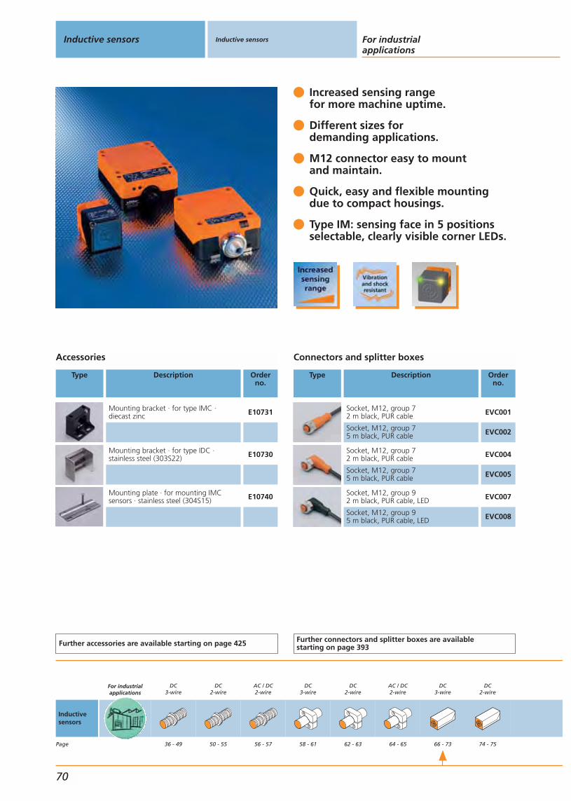
Increased sensing rangefor more machine uptime.
Different sizes fordemanding applications.
M12 connector easy to mountand maintain.
Quick, easy and flexible mountingdue to compact housings.
Type IM: sensing face in 5 positionsselectable, clearly visible corner LEDs.
Accessories
Type Description Orderno.
Mounting bracket · for type IMC · diecast zinc E10731
Mounting bracket · for type IDC ·stainless steel (303S22) E10730
Mounting plate · for mounting IMCsensors · stainless steel (304S15) E10740
Further accessories are available starting on page 425
Connectors and splitter boxes
Type Description Orderno.
Socket, M12, group 72 m black, PUR cable EVC001
Socket, M12, group 75 m black, PUR cable EVC002
Socket, M12, group 72 m black, PUR cable EVC004
Socket, M12, group 75 m black, PUR cable EVC005
Socket, M12, group 92 m black, PUR cable, LED EVC007
Socket, M12, group 95 m black, PUR cable, LED EVC008
Further connectors and splitter boxes are availablestarting on page 393
Inductive sensors Inductive sensors For industrialapplications
70
Inductivesensors
Page
For industrialapplications
DC3-wire
36 - 49
DC2-wire
50 - 55
AC / DC2-wire
56 - 57
DC3-wire
58 - 61
DC2-wire
62 - 63
AC / DC2-wire
64 - 65
DC3-wire
66 - 73
DC2-wire
74 - 75

Rectangular housing3- / 4-wire DC
Housing Dimensions
[mm]
Sensingrange[mm]
Material Ub
[V]
Protec-tion
f
[Hz]
Iload
[mA]
Uab
[V]
I0
[mA]
Draw-ingno.
Orderno.
M12 connector · Output · Connector groups 7, 8, 10 · Wiring diagram no. 1
40 x 40 x 66 20 f PA (polyamide) 10...36 IP 67 100 200 2.5 20 41 IM5115
40 x 40 x 66 35 nf PA (polyamide) 10...36 IP 67 80 200 2.5 20 41 IM5116
40 x 40 x 66 40 nf PA (polyamide) 10...36 IP 67 60 200 2.5 20 41 IM5117
92 x 80 x 40 50 f PPE 10...36 IP 67 70 250 2.5 15 94 ID5055
M12 connector · Outputnormally · Connector groups 7, 8, 10 · Wiring diagram no. 1
105 x 80 x 40 60 nf PPE 10...36 IP 65 100 250 2.5 15 95 ID5046
M12 connector · Output · Connector groups 7, 8, 10 · Wiring diagram no. 12
40 x 40 x 66 20 f PA (polyamide) 10...36 IP 67 100 200 2.5 25 41 IM5123
M12 connector · Output · Connector groups 7, 8, 9 · Wiring diagram no. 12
40 x 40 x 66 35 nf PA (polyamide) 10...36 IP 67 – 200 2.5 20 41 IM5134
40 x 40 x 66 40 nf PA (polyamide) 10...36 IP 67 – 200 2.5 20 41 IM5136
92 x 80 x 40 50 f PPE 10...36 IP 67 70 250 2.5 20 94 ID5058
Operating temperature -25...70 °C
You can find scale drawings from page 450
AC / DC2-wire
76 - 77
For oils andcoolants
78 - 97
For electro-magnetic fields
98 - 101
For hygienicand wet areas
102 - 113
For hazardousareas
114 - 127
Inductive sensors
Gen
eral
info
rmat
ion
List
of
arti
cles
Ind
uct
ive
sen
sors
Cap
acit
ive
sen
sors
Mag
net
icse
nso
rs,
cylin
der
sen
sors
Safe
tyte
chn
olo
gy
Val
ve s
enso
rsPh
oto
elec
tric
sen
sors
Ob
ject
reco
gn
itio
nEn
cod
ers
Eval
uat
ion
syst
ems,
po
wer
su
pp
lies
Co
nn
ecti
on
tech
no
log
yA
cces
sori
esTe
chn
ical
info
rmat
ion
and
cu
sto
mer
serv
ice
71

Different sizes fordemanding applications
Output functions programmable(for units with connection terminals).
Quick, easy and flexible mountingdue to compact housings.
Cable or terminal chamber.
Sensing face in 5 positionsfreely selectable for types IME / IVE.
Accessories
Type Description Orderno.
Mounting plate · for type IVE, KVE ·aluminium / anodised 10...20 μm E10072
Cable gland · M20 x 1.5 · for type IVE ·housing: polyamide, sealing: neoprene E11270
Further accessories are available starting on page 425
Inductive sensors Inductive sensors For industrialapplications
72
Inductivesensors
Page
For industrialapplications
DC3-wire
36 - 49
DC2-wire
50 - 55
AC / DC2-wire
56 - 57
DC3-wire
58 - 61
DC2-wire
62 - 63
AC / DC2-wire
64 - 65
DC3-wire
66 - 73
DC2-wire
74 - 75
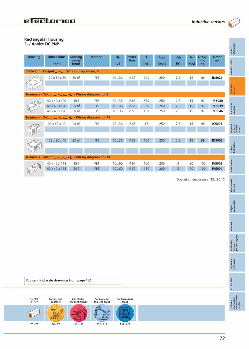
Rectangular housing3- / 4-wire DC PNP
Housing Dimensions
[mm]
Sensingrange[mm]
Material Ub
[V]
Protec-tion
f
[Hz]
Iload
[mA]
Uab
[V]
I0
[mA]
Draw-ingno.
Orderno.
Cable 2 m · Output · Wiring diagram no. 4
120 x 80 x 30 50 nf PPE 10...36 IP 67 100 250 2.5 15 96 ID5026
Terminals · Output · Wiring diagram no. 8
40 x 40 x 120 15 f PPE 10...36 IP 65 350 250 2.5 15 97 IM5020
40 x 40 x 120 20 nf PPE 10...36 IP 65 350 250 2.5 15 97 IM5019
40 x 40 x 120 30 nf PPE 10...36 IP 65 100 250 2.5 15 97 IM5046
Terminals · Output · Wiring diagram no. 71
90 x 60 x 40 40 nf PPE 10...36 IP 65 15 250 2.5 15 98 IC5005
105 x 80 x 40 60 nf PPE 10...36 IP 65 100 250 2.5 15 99 ID5005
Terminals · Output · Wiring diagram no. 13
40 x 40 x 118 15 f PBT 10...60 IP 67 150 200 3 20 100 IV5003
40 x 40 x 118 20 f PBT 10...60 IP 67 150 200 3 20 100 IV5004
Operating temperature -25...80 °C
You can find scale drawings from page 450
AC / DC2-wire
76 - 77
For oils andcoolants
78 - 97
For electro-magnetic fields
98 - 101
For hygienicand wet areas
102 - 113
For hazardousareas
114 - 127
Inductive sensors
Gen
eral
info
rmat
ion
List
of
arti
cles
Ind
uct
ive
sen
sors
Cap
acit
ive
sen
sors
Mag
net
icse
nso
rs,
cylin
der
sen
sors
Safe
tyte
chn
olo
gy
Val
ve s
enso
rsPh
oto
elec
tric
sen
sors
Ob
ject
reco
gn
itio
nEn
cod
ers
Eval
uat
ion
syst
ems,
po
wer
su
pp
lies
Co
nn
ecti
on
tech
no
log
yA
cces
sori
esTe
chn
ical
info
rmat
ion
and
cu
sto
mer
serv
ice
73

4 switching functions by simplyreversing the connecting wires.
Sensing face in 5 positions freely selectable for terminal chamber units.
Temperature range -25...80 °C for demanding applications.
Reduced wiring complexity due tofunctional 2-wire technology.
Leakage current lower than 1 mA.
Accessories
Type Description Orderno.
Cable gland · M20 x 1.5 · for type IVE ·housing: polyamide, sealing: neoprene E11270
Further accessories are available starting on page 425
Inductive sensors Inductive sensors For industrialapplications
74
Inductivesensors
Page
For industrialapplications
DC3-wire
36 - 49
DC2-wire
50 - 55
AC / DC2-wire
56 - 57
DC3-wire
58 - 61
DC2-wire
62 - 63
AC / DC2-wire
64 - 65
DC3-wire
66 - 73
DC2-wire
74 - 75

Rectangular housing2-wire DC PNP/NPN
Housing Dimensions
[mm]
Sensingrange[mm]
Material Ub
[V]
Protec-tion
f
[Hz]
Iload
[mA]
Uab
[V]
I0
[mA]
Draw-ingno.
Orderno.
Cable 2 m · Output · Wiring diagram no. 69
28 x 10 x 16 2 f PBT 5...36 IP 67 2000 200 4.6 – 87 IS5026
40 x 12 x 26 2 f PBT 10...55 IP 67 1300 400 4.6 – 91 IN5207
40 x 12 x 26 4 nf PBT 10...55 IP 67 1200 400 4.6 – 91 IN5208
Terminals · Output · Wiring diagram no. 70
40 x 40 x 120 15 f PPE 10...55 IP 65 > 350 400 4.6 – 97 IM5037
40 x 40 x 120 20 nf PPE 10...55 IP 65 > 300 400 4.6 – 97 IM5038
Operating temperature -25...80 °C
You can find scale drawings from page 450
AC / DC2-wire
76 - 77
For oils andcoolants
78 - 97
For electro-magnetic fields
98 - 101
For hygienicand wet areas
102 - 113
For hazardousareas
114 - 127
Inductive sensors
Gen
eral
info
rmat
ion
List
of
arti
cles
Ind
uct
ive
sen
sors
Cap
acit
ive
sen
sors
Mag
net
icse
nso
rs,
cylin
der
sen
sors
Safe
tyte
chn
olo
gy
Val
ve s
enso
rsPh
oto
elec
tric
sen
sors
Ob
ject
reco
gn
itio
nEn
cod
ers
Eval
uat
ion
syst
ems,
po
wer
su
pp
lies
Co
nn
ecti
on
tech
no
log
yA
cces
sori
esTe
chn
ical
info
rmat
ion
and
cu
sto
mer
serv
ice
75
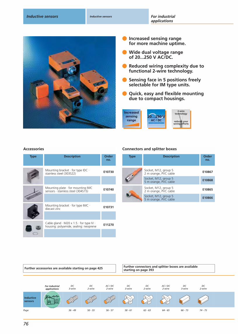
Increased sensing rangefor more machine uptime.
Wide dual voltage rangeof 20...250 V AC/DC.
Reduced wiring complexity due tofunctional 2-wire technology.
Sensing face in 5 positions freelyselectable for IM type units.
Quick, easy and flexible mountingdue to compact housings.
Accessories
Type Description Orderno.
Mounting bracket · for type IDC ·stainless steel (303S22) E10730
Mounting plate · for mounting IMCsensors · stainless steel (304S15) E10740
Mounting bracket · for type IMC · diecast zinc E10731
Cable gland · M20 x 1.5 · for type IV ·housing: polyamide, sealing: neoprene E11270
Further accessories are available starting on page 425
Connectors and splitter boxes
Type Description Orderno.
Socket, M12, group 52 m orange, PVC cable E10867
Socket, M12, group 55 m orange, PVC cable E10868
Socket, M12, group 52 m orange, PVC cable E10865
Socket, M12, group 55 m orange, PVC cable E10866
Further connectors and splitter boxes are availablestarting on page 393
Inductive sensors Inductive sensors For industrialapplications
76
Inductivesensors
Page
For industrialapplications
DC3-wire
36 - 49
DC2-wire
50 - 55
AC / DC2-wire
56 - 57
DC3-wire
58 - 61
DC2-wire
62 - 63
AC / DC2-wire
64 - 65
DC3-wire
66 - 73
DC2-wire
74 - 75
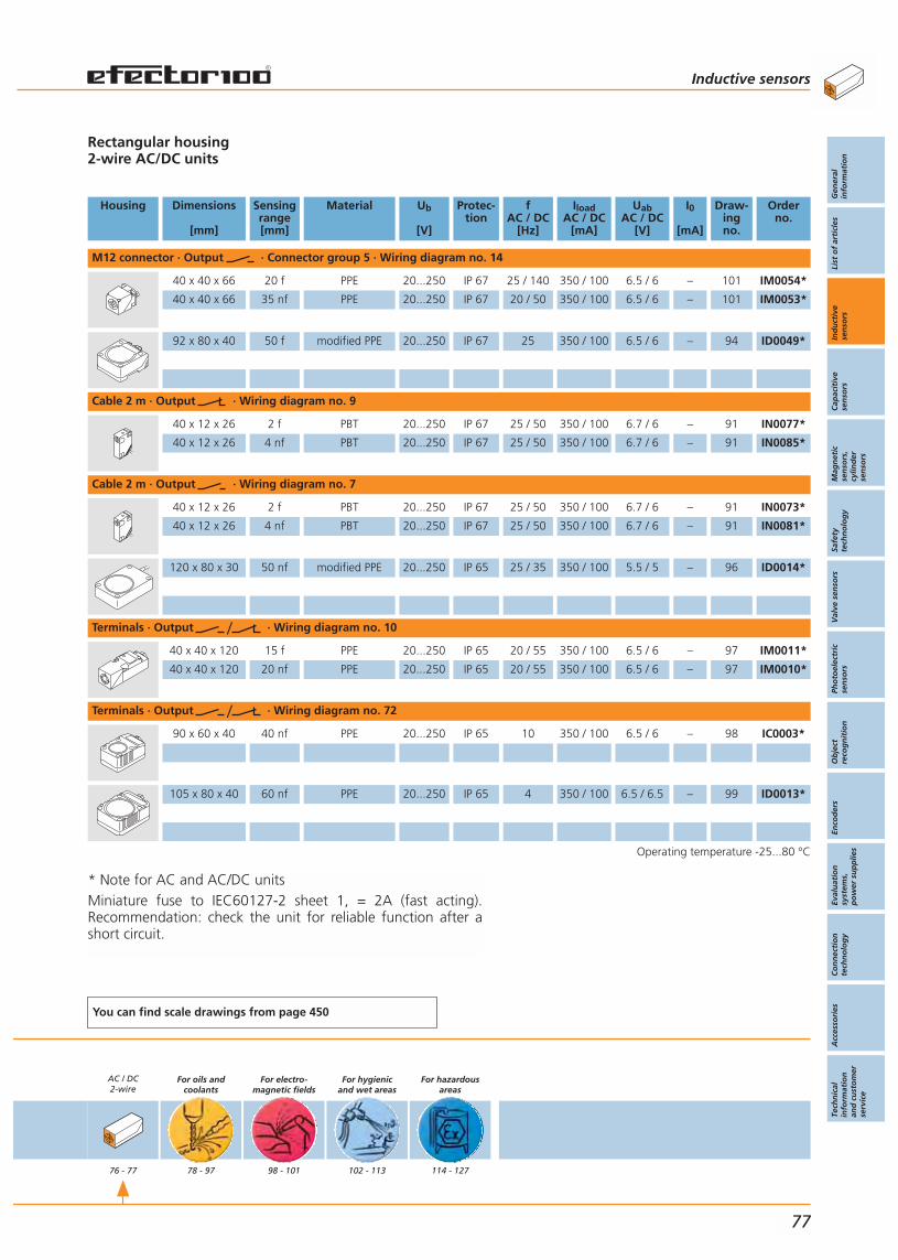
* Note for AC and AC/DC unitsMiniature fuse to IEC60127-2 sheet 1, = 2A (fast acting).Recommendation: check the unit for reliable function after ashort circuit.
Rectangular housing2-wire AC/DC units
Housing Dimensions
[mm]
Sensingrange[mm]
Material Ub
[V]
Protec-tion
fAC / DC
[Hz]
IloadAC / DC
[mA]
UabAC / DC
[V]
I0
[mA]
Draw-ingno.
Orderno.
M12 connector · Output · Connector group 5 · Wiring diagram no. 14
40 x 40 x 66 20 f PPE 20...250 IP 67 25 / 140 350 / 100 6.5 / 6 – 101 IM0054*
40 x 40 x 66 35 nf PPE 20...250 IP 67 20 / 50 350 / 100 6.5 / 6 – 101 IM0053*
92 x 80 x 40 50 f modified PPE 20...250 IP 67 25 350 / 100 6.5 / 6 – 94 ID0049*
Cable 2 m · Output · Wiring diagram no. 9
40 x 12 x 26 2 f PBT 20...250 IP 67 25 / 50 350 / 100 6.7 / 6 – 91 IN0077*
40 x 12 x 26 4 nf PBT 20...250 IP 67 25 / 50 350 / 100 6.7 / 6 – 91 IN0085*
Cable 2 m · Output · Wiring diagram no. 7
40 x 12 x 26 2 f PBT 20...250 IP 67 25 / 50 350 / 100 6.7 / 6 – 91 IN0073*
40 x 12 x 26 4 nf PBT 20...250 IP 67 25 / 50 350 / 100 6.7 / 6 – 91 IN0081*
120 x 80 x 30 50 nf modified PPE 20...250 IP 65 25 / 35 350 / 100 5.5 / 5 – 96 ID0014*
Terminals · Output · Wiring diagram no. 10
40 x 40 x 120 15 f PPE 20...250 IP 65 20 / 55 350 / 100 6.5 / 6 – 97 IM0011*
40 x 40 x 120 20 nf PPE 20...250 IP 65 20 / 55 350 / 100 6.5 / 6 – 97 IM0010*
Terminals · Output · Wiring diagram no. 72
90 x 60 x 40 40 nf PPE 20...250 IP 65 10 350 / 100 6.5 / 6 – 98 IC0003*
105 x 80 x 40 60 nf PPE 20...250 IP 65 4 350 / 100 6.5 / 6.5 – 99 ID0013*
Operating temperature -25...80 °C
You can find scale drawings from page 450
AC / DC2-wire
76 - 77
For oils andcoolants
78 - 97
For electro-magnetic fields
98 - 101
For hygienicand wet areas
102 - 113
For hazardousareas
114 - 127
Inductive sensors
Gen
eral
info
rmat
ion
List
of
arti
cles
Ind
uct
ive
sen
sors
Cap
acit
ive
sen
sors
Mag
net
icse
nso
rs,
cylin
der
sen
sors
Safe
tyte
chn
olo
gy
Val
ve s
enso
rsPh
oto
elec
tric
sen
sors
Ob
ject
reco
gn
itio
nEn
cod
ers
Eval
uat
ion
syst
ems,
po
wer
su
pp
lies
Co
nn
ecti
on
tech
no
log
yA
cces
sori
esTe
chn
ical
info
rmat
ion
and
cu
sto
mer
serv
ice
77

Resistant to aggressive oilsand coolants.
Increased sensing range for more machine uptime.
Safe mounting due torobust thick-wall housing.
Laser etched type label forpermanent identification of the unit.
Accessories
Type Description Orderno.
Angle bracket · for type M12 · stainless steel (304S15) E10735
Mounting sleeve · for type M12 · brass / nickel-plated E11114
Mounting clamp · Ø 12 mm · with end stop · for type M12 · PC E11047
Further accessories are available starting on page 425
Connectors and splitter boxes
Type Description Orderno.
Socket · for sensors withwirable E11303
Socket, M12, group 572 m black, PUR cable EVC001
Socket, M12, group 575 m black, PUR cable EVC002
Socket, M12, group 572 m black, PUR cable EVC004
Socket, M12, group 575 m black, PUR cable EVC005
Socket, M12, group 582 m black, PUR cable, LED EVC007
Socket, M12, group 585 m black, PUR cable, LED EVC008
Further connectors and splitter boxes are availablestarting on page 393
Inductive sensors Inductive sensors For oils andcoolants
78
Inductivesensors
Page
For industrialapplications
DC3-wire
36 - 49
DC2-wire
50 - 55
AC / DC2-wire
56 - 57
DC3-wire
58 - 61
DC2-wire
62 - 63
AC / DC2-wire
64 - 65
DC3-wire
66 - 73
DC2-wire
74 - 75

Threaded housing M12, 3-wire DC PNPIFC210: 2- / 3-wire DC PNP/NPN with optical setting displayIFC206, IFC210, IFC209: Ceramic sensing face to protect against hot metal swarf
Housing Dimensions
[mm]
Sensingrange[mm]
Material Ub
[V]
Protec-tion
f
[Hz]
Iload
[mA]
Uab
[V]
I0
[mA]
Draw-ingno.
Orderno.
M12 connector · Output · Connector group 57 · Wiring diagram no. 1
M8 / L = 50 4 nf stainless steel 10...36 IP 67 700 200 2.5 15 102 IE5382
M8 / L = 50 2 f stainless steel 10...36 IP 67 1000 200 2.5 15 103 IE5381
M12 / L = 45 2 f brass 10...36 IP 68 700 200 2.5 10 5 IFC239
M12 / L = 60 2 f brass 10...36 IP 68 700 200 2.5 10 104 IFC243
M12 / L = 70 2 f brass 10...36 IP 68 700 200 2.5 10 7 IFC241
M12 / L = 45 4 f brass 10...36 IP 68 700 100 2.5 10 5 IFC206
M12 / L = 45 4 f brass 10...36 IP 68 700 100 2.5 10 5 IFC204
M12 / L = 60 4 f brass 10...36 IP 68 700 200 2.5 10 104 IFC229
M12 / L = 70 4 f brass 10...36 IP 68 700 100 2.5 10 7 IFC237
M12 connector · Output · Connector group 57 · Wiring diagram no. 64
M12 / L = 70 4 f brass 10...30 IP 68 500 100 2.8 12 7 IFC210
M12 connector · Output · Connector group 57 · Wiring diagram no. 1
M12 / L = 50 4 nf brass 10...36 IP 68 700 200 2.5 10 6 IFC240
M12 / L = 60 4 nf brass 10...36 IP 68 700 200 2.5 10 105 IFC244
M12 / L = 70 4 nf brass 10...36 IP 68 700 200 2.5 10 8 IFC242
M12 / L = 50 7 nf brass 10...36 IP 68 700 100 2.5 10 6 IFC205
M12 / L = 60 7 nf brass 10...36 IP 68 700 200 2.5 10 105 IFC230
M12 / L = 70 7 nf brass 10...36 IP 68 700 100 2.5 10 8 IFC238
M12 connector · Output · Connector group 57 · Wiring diagram no. 2
M12 / L = 45 4 f brass 10...36 IP 68 700 100 2.5 10 5 IFC209
M12 / L = 45 4 f brass 10...36 IP 68 700 100 2.5 10 5 IFC207
M12 / L = 50 7 nf brass 10...36 IP 68 700 100 2.5 10 6 IFC208
Operating temperature -25...70 °C
You can find scale drawings from page 450
AC / DC2-wire
76 - 77
For oils andcoolants
78 - 97
For electro-magnetic fields
98 - 101
For hygienicand wet areas
102 - 113
For hazardousareas
114 - 127
Inductive sensors
Gen
eral
info
rmat
ion
List
of
arti
cles
Ind
uct
ive
sen
sors
Cap
acit
ive
sen
sors
Mag
net
icse
nso
rs,
cylin
der
sen
sors
Safe
tyte
chn
olo
gy
Val
ve s
enso
rsPh
oto
elec
tric
sen
sors
Ob
ject
reco
gn
itio
nEn
cod
ers
Eval
uat
ion
syst
ems,
po
wer
su
pp
lies
Co
nn
ecti
on
tech
no
log
yA
cces
sori
esTe
chn
ical
info
rmat
ion
and
cu
sto
mer
serv
ice
79

Resistant to aggressive oilsand coolants.
Increased sensing range for more machine uptime.
Safe mounting due torobust thick-wall housing.
Laser etched type label forpermanent identification of the unit.
Accessories
Type Description Orderno.
Angle bracket · for type M18 · stainless steel (304S15) E10736
Angle bracket · for type M30 · stainless steel (304S15) E10737
Mounting sleeve · for type M18 · brass / white bronze coated E11115
Mounting clamp · Ø 18 mm · with end stop · for type M18 · PC E11048
Mounting clamp · Ø 30 mm · with end stop · for type M30 · PC E11049
Further accessories are available starting on page 425
Connectors and splitter boxes
Type Description Orderno.
Socket · for sensors withwirable E11303
Socket, M12, group 572 m black, PUR cable EVC001
Socket, M12, group 575 m black, PUR cable EVC002
Socket, M12, group 572 m black, PUR cable EVC004
Socket, M12, group 575 m black, PUR cable EVC005
Socket, M12, group 582 m black, PUR cable, LED EVC007
Socket, M12, group 585 m black, PUR cable, LED EVC008
Further connectors and splitter boxes are availablestarting on page 393
Inductive sensors Inductive sensors For oils andcoolants
80
Inductivesensors
Page
For industrialapplications
DC3-wire
36 - 49
DC2-wire
50 - 55
AC / DC2-wire
56 - 57
DC3-wire
58 - 61
DC2-wire
62 - 63
AC / DC2-wire
64 - 65
DC3-wire
66 - 73
DC2-wire
74 - 75
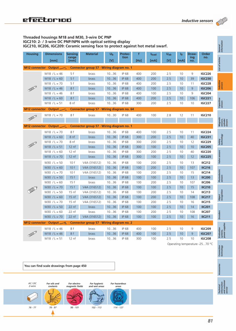
Threaded housings M18 and M30, 3-wire DC PNPIGC210: 2- / 3-wire DC PNP/NPN with optical setting displayIGC210, IIC206, IGC209: Ceramic sensing face to protect against hot metal swarf.
Housing Dimensions
[mm]
Sensingrange[mm]
Material Ub
[V]
Protec-tion
f
[Hz]
Iload
[mA]
Uab
[V]
I0
[mA]
Draw-ingno.
Orderno.
M12 connector · Output · Connector group 57 · Wiring diagram no. 1
M18 / L = 46 5 f brass 10...36 IP 68 400 200 2.5 10 9 IGC226
M18 / L = 60 5 f brass 10...36 IP 68 400 200 2.5 10 39 IGC230
M18 / L = 70 5 f brass 10...36 IP 68 400 200 2.5 10 11 IGC228
M18 / L = 46 8 f brass 10...36 IP 68 400 100 2.5 10 9 IGC206
M18 / L = 46 8 f brass 10...36 IP 68 400 100 2.5 10 9 IGC204
M18 / L = 60 8 f brass 10...36 IP 68 400 200 2.5 10 106 IGC221
M18 / L = 51 8 nf brass 10...36 IP 68 300 200 2.5 10 10 IGC227
M12 connector · Output · Connector group 57 · Wiring diagram no. 64
M18 / L = 70 8 f brass 10...30 IP 68 400 100 2.8 12 11 IGC210
M12 connector · Output · Connector group 57 · Wiring diagram no. 1
M18 / L = 70 8 f brass 10...36 IP 68 400 100 2.5 10 11 IGC224
M18 / L = 60 8 nf brass 10...36 IP 68 300 200 2.5 10 40 IGC231
M18 / L = 70 8 nf brass 10...36 IP 68 300 200 2.5 10 12 IGC229
M18 / L = 51 12 nf brass 10...36 IP 68 300 100 2.5 10 10 IGC205
M18 / L = 60 12 nf brass 10...36 IP 68 300 200 2.5 10 40 IGC220
M18 / L = 70 12 nf brass 10...36 IP 68 300 100 2.5 10 12 IGC225
M30 / L = 50 10 f V4A (316S12) 10...36 IP 68 100 200 2.5 10 13 IIC212
M30 / L = 60 10 f V4A (316S12) 10...36 IP 68 100 200 2.5 10 107 IIC216
M30 / L = 70 10 f V4A (316S12) 10...36 IP 68 100 200 2.5 10 15 IIC214
M30 / L = 50 15 f brass 10...36 IP 68 100 100 2.5 10 13 IIC200
M30 / L = 60 15 f brass 10...36 IP 68 100 200 2.5 10 107 IIC206
M30 / L = 70 15 f V4A (316S12) 10...36 IP 68 100 100 2.5 10 15 IIC210
M30 / L = 50 15 nf V4A (316S12) 10...36 IP 68 100 200 2.5 10 14 IIC213
M30 / L = 60 15 nf V4A (316S12) 10...36 IP 68 100 200 2.5 10 108 IIC217
M30 / L = 70 15 nf V4A (316S12) 10...36 IP 68 100 200 2.5 10 16 IIC215
M30 / L = 50 22 nf brass 10...36 IP 68 100 100 2.5 10 14 IIC201
M30 / L = 60 22 nf brass 10...36 IP 68 100 200 2.5 10 108 IIC207
M30 / L = 70 22 nf V4A (316S12) 10...36 IP 68 100 100 2.5 10 16 IIC211
M12 connector · Output · Connector group 57 · Wiring diagram no. 2
M18 / L = 46 8 f brass 10...36 IP 68 400 100 2.5 10 9 IGC209
M18 / L = 46 8 f brass 10...36 IP 68 400 100 2.5 10 9 IGC207
M18 / L = 51 12 nf brass 10...36 IP 68 300 100 2.5 10 10 IGC208
Operating temperature -25...70 °C
You can find scale drawings from page 450
AC / DC2-wire
76 - 77
For oils andcoolants
78 - 97
For electro-magnetic fields
98 - 101
For hygienicand wet areas
102 - 113
For hazardousareas
114 - 127
Inductive sensors
Gen
eral
info
rmat
ion
List
of
arti
cles
Ind
uct
ive
sen
sors
Cap
acit
ive
sen
sors
Mag
net
icse
nso
rs,
cylin
der
sen
sors
Safe
tyte
chn
olo
gy
Val
ve s
enso
rsPh
oto
elec
tric
sen
sors
Ob
ject
reco
gn
itio
nEn
cod
ers
Eval
uat
ion
syst
ems,
po
wer
su
pp
lies
Co
nn
ecti
on
tech
no
log
yA
cces
sori
esTe
chn
ical
info
rmat
ion
and
cu
sto
mer
serv
ice
81
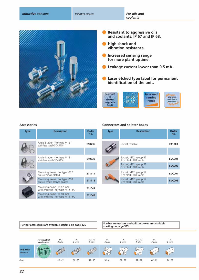
Resistant to aggressive oils and coolants, IP 67 and IP 68.
High shock and vibration resistance.
Increased sensing rangefor more plant uptime.
Leakage current lower than 0.5 mA.
Laser etched type label for permanentidentification of the unit.
Accessories
Type Description Orderno.
Angle bracket · for type M12 · stainless steel (304S15) E10735
Angle bracket · for type M18 · stainless steel (304S15) E10736
Mounting sleeve · for type M12 · brass / nickel-plated E11114
Mounting sleeve · for type M18 · brass / white bronze coated E11115
Mounting clamp · Ø 12 mm · with end stop · for type M12 · PC E11047
Mounting clamp · Ø 18 mm · with end stop · for type M18 · PC E11048
Further accessories are available starting on page 425
Connectors and splitter boxes
Type Description Orderno.
Socket, wirable E11303
Socket, M12, group 572 m black, PUR cable EVC001
Socket, M12, group 575 m black, PUR cable EVC002
Socket, M12, group 572 m black, PUR cable EVC004
Socket, M12, group 575 m black, PUR cable EVC005
Further connectors and splitter boxes are availablestarting on page 393
Inductive sensors Inductive sensors For oils andcoolants
82
Inductivesensors
Page
For industrialapplications
DC3-wire
36 - 49
DC2-wire
50 - 55
AC / DC2-wire
56 - 57
DC3-wire
58 - 61
DC2-wire
62 - 63
AC / DC2-wire
64 - 65
DC3-wire
66 - 73
DC2-wire
74 - 75

Threaded housing M122-wire DC PNP/NPN
Housing Dimensions
[mm]
Sensingrange[mm]
Material Ub
[V]
Protec-tion
f
[Hz]
Iload
[mA]
Uab
[V]
I0
[mA]
Draw-ingno.
Orderno.
M12 connector · Output · Connector group 57 · Wiring diagram no. 67
M12 / L = 45 4 f brass 10...30 IP 68 700 100 2.5 – 5 IFC200
M12 / L = 50 7 nf brass 10...30 IP 68 700 100 2.5 – 6 IFC201
M18 / L = 46 8 f brass 10...30 IP 68 400 100 2.5 – 9 IGC200
M18 / L = 51 12 nf brass 10...30 IP 68 250 100 2.5 – 10 IGC201
M12 connector · Output · Connector group 57 · Wiring diagram no. 73
M12 / L = 45 4 f brass 10...30 IP 68 700 100 2.5 – 5 IFC202
M12 / L = 50 7 nf brass 10...30 IP 68 700 100 2.5 – 6 IFC203
M18 / L = 46 8 f brass 10...30 IP 68 300 100 2.5 – 9 IGC202
M18 / L = 51 12 nf brass 10...30 IP 68 250 100 2.5 – 10 IGC203
Operating temperature -25...70 °C
You can find scale drawings from page 450
AC / DC2-wire
76 - 77
For oils andcoolants
78 - 97
For electro-magnetic fields
98 - 101
For hygienicand wet areas
102 - 113
For hazardousareas
114 - 127
Inductive sensors
Gen
eral
info
rmat
ion
List
of
arti
cles
Ind
uct
ive
sen
sors
Cap
acit
ive
sen
sors
Mag
net
icse
nso
rs,
cylin
der
sen
sors
Safe
tyte
chn
olo
gy
Val
ve s
enso
rsPh
oto
elec
tric
sen
sors
Ob
ject
reco
gn
itio
nEn
cod
ers
Eval
uat
ion
syst
ems,
po
wer
su
pp
lies
Co
nn
ecti
on
tech
no
log
yA
cces
sori
esTe
chn
ical
info
rmat
ion
and
cu
sto
mer
serv
ice
83
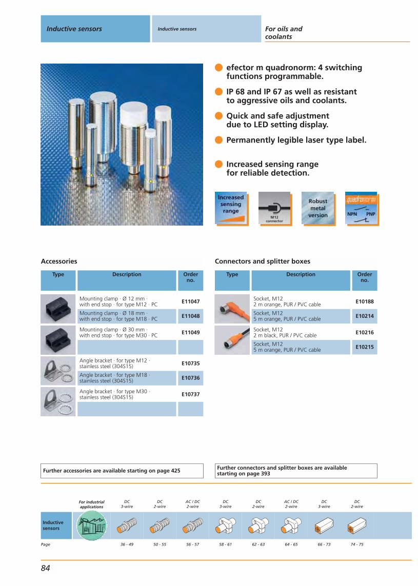
efector m quadronorm: 4 switchingfunctions programmable.
IP 68 and IP 67 as well as resistantto aggressive oils and coolants.
Quick and safe adjustmentdue to LED setting display.
Permanently legible laser type label.
Increased sensing rangefor reliable detection.
Accessories
Type Description Orderno.
Mounting clamp · Ø 12 mm · with end stop · for type M12 · PC E11047
Mounting clamp · Ø 18 mm · with end stop · for type M18 · PC E11048
Mounting clamp · Ø 30 mm · with end stop · for type M30 · PC E11049
Angle bracket · for type M12 · stainless steel (304S15) E10735
Angle bracket · for type M18 · stainless steel (304S15) E10736
Angle bracket · for type M30 · stainless steel (304S15) E10737
Further accessories are available starting on page 425
Connectors and splitter boxes
Type Description Orderno.
Socket, M122 m orange, PUR / PVC cable E10188
Socket, M125 m orange, PUR / PVC cable E10214
Socket, M122 m black, PUR / PVC cable E10216
Socket, M125 m orange, PUR / PVC cable E10215
Further connectors and splitter boxes are availablestarting on page 393
Inductive sensors Inductive sensors For oils andcoolants
84
Inductivesensors
Page
For industrialapplications
DC3-wire
36 - 49
DC2-wire
50 - 55
AC / DC2-wire
56 - 57
DC3-wire
58 - 61
DC2-wire
62 - 63
AC / DC2-wire
64 - 65
DC3-wire
66 - 73
DC2-wire
74 - 75

Threaded housing2-wire DC PNP/NPN
Housing Dimensions
[mm]
Sensingrange[mm]
Material Ub
[V]
Protec-tion
f
[Hz]
Iload
[mA]
Uab
[V]
I0
[mA]
Draw-ingno.
Orderno.
M12 connector · Output · Connector group 57 · Wiring diagram no. 68
M12 / L = 60 4 f brass 10...36 IP 68 700 100 4.6 – 104 IFC234
M12 / L = 60 7 nf brass 10...36 IP 68 500 100 4.6 – 105 IFC235
M18 / L = 70 8 f brass 10...30 IP 68 400 100 4.6 – 11 IGC222
M18 / L = 70 12 nf brass 10...36 IP 68 300 100 4.6 – 12 IGC223
M30 / L = 70 15 f brass 10...30 IP 68 100 100 4.6 – 15 IIC208
M30 / L = 70 22 nf brass 10...30 IP 68 100 100 4.6 – 16 IIC209
Operating temperature -25...70 °C
You can find scale drawings from page 450
AC / DC2-wire
76 - 77
For oils andcoolants
78 - 97
For electro-magnetic fields
98 - 101
For hygienicand wet areas
102 - 113
For hazardousareas
114 - 127
Inductive sensors
Gen
eral
info
rmat
ion
List
of
arti
cles
Ind
uct
ive
sen
sors
Cap
acit
ive
sen
sors
Mag
net
icse
nso
rs,
cylin
der
sen
sors
Safe
tyte
chn
olo
gy
Val
ve s
enso
rsPh
oto
elec
tric
sen
sors
Ob
ject
reco
gn
itio
nEn
cod
ers
Eval
uat
ion
syst
ems,
po
wer
su
pp
lies
Co
nn
ecti
on
tech
no
log
yA
cces
sori
esTe
chn
ical
info
rmat
ion
and
cu
sto
mer
serv
ice
85
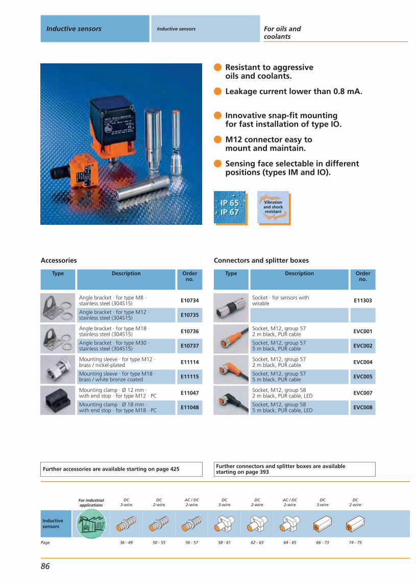
Resistant to aggressiveoils and coolants.
Leakage current lower than 0.8 mA.
Innovative snap-fit mountingfor fast installation of type IO.
M12 connector easy to mount and maintain.
Sensing face selectable in different positions (types IM and IO).
Accessories
Type Description Orderno.
Angle bracket · for type M8 · stainless steel (304S15) E10734
Angle bracket · for type M12 · stainless steel (304S15) E10735
Angle bracket · for type M18 · stainless steel (304S15) E10736
Angle bracket · for type M30 · stainless steel (304S15) E10737
Mounting sleeve · for type M12 · brass / nickel-plated E11114
Mounting sleeve · for type M18 · brass / white bronze coated E11115
Mounting clamp · Ø 12 mm · with end stop · for type M12 · PC E11047
Mounting clamp · Ø 18 mm · with end stop · for type M18 · PC E11048
Further accessories are available starting on page 425
Connectors and splitter boxes
Type Description Orderno.
Socket · for sensors withwirable E11303
Socket, M12, group 572 m black, PUR cable EVC001
Socket, M12, group 575 m black, PUR cable EVC002
Socket, M12, group 572 m black, PUR cable EVC004
Socket, M12, group 575 m black, PUR cable EVC005
Socket, M12, group 582 m black, PUR cable, LED EVC007
Socket, M12, group 585 m black, PUR cable, LED EVC008
Further connectors and splitter boxes are availablestarting on page 393
Inductive sensors Inductive sensors For oils andcoolants
86
Inductivesensors
Page
For industrialapplications
DC3-wire
36 - 49
DC2-wire
50 - 55
AC / DC2-wire
56 - 57
DC3-wire
58 - 61
DC2-wire
62 - 63
AC / DC2-wire
64 - 65
DC3-wire
66 - 73
DC2-wire
74 - 75
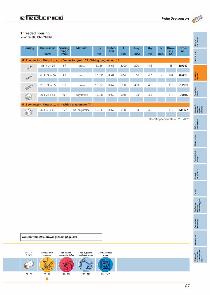
Threaded housing2-wire DC PNP/NPN
Housing Dimensions
[mm]
Sensingrange[mm]
Material Ub
[V]
Protec-tion
f
[Hz]
Iload
[mA]
Uab
[V]
I0
[mA]
Draw-ingno.
Orderno.
M12 connector · Output · Connector group 57 · Wiring diagram no. 15
M8 / L = 69 1 f brass 5...36 IP 65 2000 200 4.6 – 55 IE9940
M12 / L = 60 2 f brass 10...55 IP 67 800 100 4.6 – 109 IF9924
M18 / L = 65 5 f brass 10...55 IP 67 700 400 4.6 – 110 IG9983
26 x 26 x 43 10 f polyamide 10...36 IP 67 250 100 4.6 – 111 IO5016
M12 connector · Output · Wiring diagram no. 74
40 x 40 x 66 15 f PA (polyamide) 10...36 IP 67 200 100 4.6 – 112 IM5127
Operating temperature -25...70 °C
You can find scale drawings from page 450
AC / DC2-wire
76 - 77
For oils andcoolants
78 - 97
For electro-magnetic fields
98 - 101
For hygienicand wet areas
102 - 113
For hazardousareas
114 - 127
Inductive sensors
Gen
eral
info
rmat
ion
List
of
arti
cles
Ind
uct
ive
sen
sors
Cap
acit
ive
sen
sors
Mag
net
icse
nso
rs,
cylin
der
sen
sors
Safe
tyte
chn
olo
gy
Val
ve s
enso
rsPh
oto
elec
tric
sen
sors
Ob
ject
reco
gn
itio
nEn
cod
ers
Eval
uat
ion
syst
ems,
po
wer
su
pp
lies
Co
nn
ecti
on
tech
no
log
yA
cces
sori
esTe
chn
ical
info
rmat
ion
and
cu
sto
mer
serv
ice
87

Resistant to aggressiveoils and coolants.
Leakage current lower than 0.8 mA.
Innovative snap-fit mounting for fast installation of type IO.
Oil-resistant connection cable.
Sensing face selectable in differentpositions (types IM and IO).
Accessories
Type Description Orderno.
Angle bracket · for type M8 · stainless steel (304S15) E10734
Angle bracket · for type M12 · stainless steel (304S15) E10735
Angle bracket · for type M18 · stainless steel (304S15) E10736
Angle bracket · for type M30 · stainless steel (304S15) E10737
Mounting sleeve · for type M12 · brass / nickel-plated E11114
Mounting sleeve · for type M18 · brass / white bronze coated E11115
Mounting clamp · Ø 12 mm · with end stop · for type M12 · PC E11047
Mounting clamp · Ø 18 mm · with end stop · for type M18 · PC E11048
Further accessories are available starting on page 425
Connectors and splitter boxes
Type Description Orderno.
Socket , wirable E11303
Socket, M12, group 572 m black, PUR cable EVC001
Socket, M12, group 575 m black, PUR cable EVC002
Socket, M12, group 572 m black, PUR cable EVC004
Socket, M12, group 575 m black, PUR cable EVC005
Further connectors and splitter boxes are availablestarting on page 393
Inductive sensors Inductive sensors For oils andcoolants
88
Inductivesensors
Page
For industrialapplications
DC3-wire
36 - 49
DC2-wire
50 - 55
AC / DC2-wire
56 - 57
DC3-wire
58 - 61
DC2-wire
62 - 63
AC / DC2-wire
64 - 65
DC3-wire
66 - 73
DC2-wire
74 - 75

Threaded housing2-wire DC PNP/NPN
Housing Dimensions
[mm]
Sensingrange[mm]
Material Ub
[V]
Protec-tion
f
[Hz]
Iload
[mA]
Uab
[V]
I0
[mA]
Draw-ingno.
Orderno.
Cable with connector 0.8 m · Output · Connector group 57 · Wiring diagram no. 15
M8 / L = 42 2 f brass 10...55 IP 67 1000 100 4.5 – 113 IE9902
M12 / L = 54 2 f brass 10...55 IP 67 800 100 4.6 – 114 IF9920
M18 / L = 58 5 f brass 10...55 IP 67 700 400 4.6 – 115 IG9984
Cable with connector 0.15 m · Output · Connector group 57 · Wiring diagram no. 15
26 x 26 x 26 10 f polyamide 10...36 IP 67 250 100 4.6 – 116 IO5018
Cable with connector 0.8 m · Output · Connector group 57 · Wiring diagram no. 15
26 x 26 x 26 10 f polyamide 10...36 IP 67 250 100 4.5 – 116 IO5017
Cable with connector 0.8 m · Output · Wiring diagram no. 74
40 x 40 x 66 15 f PA (polyamide) 10...36 IP 67 200 100 4.6 – 117 IM5138
Cable 2 m · Output · Wiring diagram no. 75
M8 / L = 42 2 f brass 10...55 IP 67 1000 100 4.5 – 118 IE9203
M12 / L = 54 2 f brass 10...55 IP 67 800 100 4.6 – 119 IF9222
Cable 2 m · Output · Wiring diagram no. 16
M18 / L = 54 5 f brass 10...55 IP 67 700 400 4.6 – 120 IG5682
Cable with connector 0.8 m · Output · Wiring diagram no. 76
40 x 40 x 66 15 f PA (polyamide) 10...36 IP 67 200 100 4.6 – 117 IM5137
Operating temperature -25...70 °C
You can find scale drawings from page 450
AC / DC2-wire
76 - 77
For oils andcoolants
78 - 97
For electro-magnetic fields
98 - 101
For hygienicand wet areas
102 - 113
For hazardousareas
114 - 127
Inductive sensors
Gen
eral
info
rmat
ion
List
of
arti
cles
Ind
uct
ive
sen
sors
Cap
acit
ive
sen
sors
Mag
net
icse
nso
rs,
cylin
der
sen
sors
Safe
tyte
chn
olo
gy
Val
ve s
enso
rsPh
oto
elec
tric
sen
sors
Ob
ject
reco
gn
itio
nEn
cod
ers
Eval
uat
ion
syst
ems,
po
wer
su
pp
lies
Co
nn
ecti
on
tech
no
log
yA
cces
sori
esTe
chn
ical
info
rmat
ion
and
cu
sto
mer
serv
ice
89
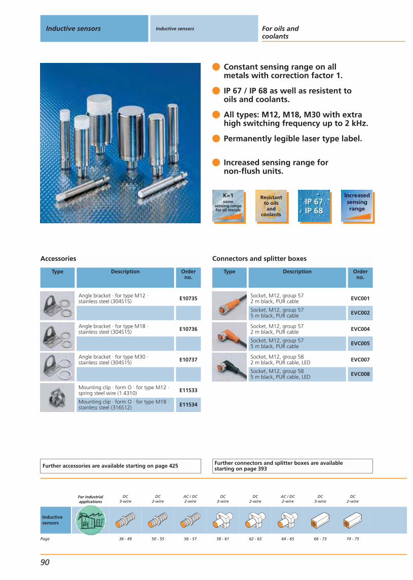
Constant sensing range on allmetals with correction factor 1.
IP 67 / IP 68 as well as resistent tooils and coolants.
All types: M12, M18, M30 with extrahigh switching frequency up to 2 kHz.
Permanently legible laser type label.
Increased sensing range fornon-flush units.
Accessories
Type Description Orderno.
Angle bracket · for type M12 · stainless steel (304S15) E10735
Angle bracket · for type M18 · stainless steel (304S15) E10736
Angle bracket · for type M30 · stainless steel (304S15) E10737
Mounting clip · form O · for type M12 ·spring steel wire (1.4310) E11533
Mounting clip · form O · for type M18 ·stainless steel (316S12) E11534
Further accessories are available starting on page 425
Connectors and splitter boxes
Type Description Orderno.
Socket, M12, group 572 m black, PUR cable EVC001
Socket, M12, group 575 m black, PUR cable EVC002
Socket, M12, group 572 m black, PUR cable EVC004
Socket, M12, group 575 m black, PUR cable EVC005
Socket, M12, group 582 m black, PUR cable, LED EVC007
Socket, M12, group 585 m black, PUR cable, LED EVC008
Further connectors and splitter boxes are availablestarting on page 393
Inductive sensors Inductive sensors For oils andcoolants
90
Inductivesensors
Page
For industrialapplications
DC3-wire
36 - 49
DC2-wire
50 - 55
AC / DC2-wire
56 - 57
DC3-wire
58 - 61
DC2-wire
62 - 63
AC / DC2-wire
64 - 65
DC3-wire
66 - 73
DC2-wire
74 - 75
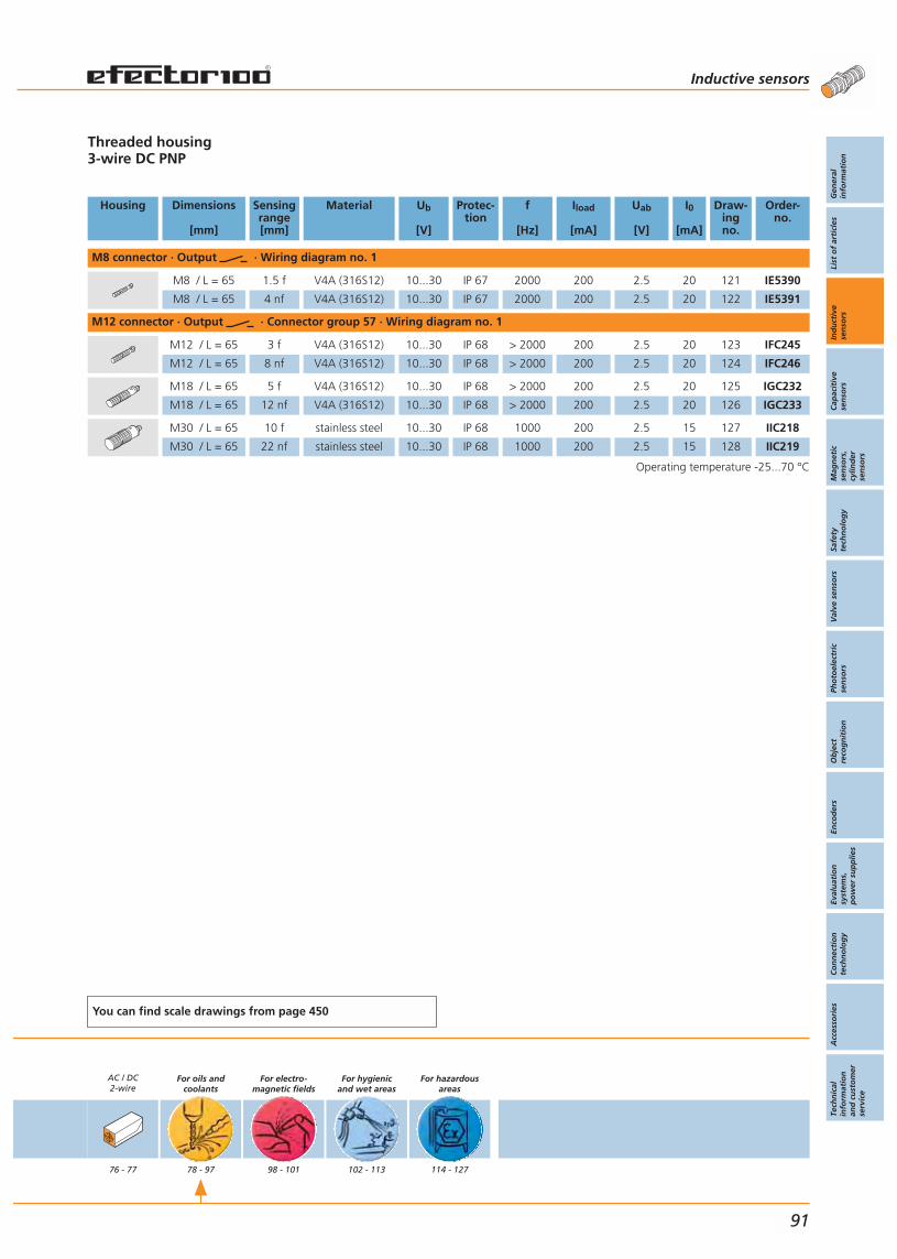
Threaded housing3-wire DC PNP
Housing Dimensions
[mm]
Sensingrange[mm]
Material Ub
[V]
Protec-tion
f
[Hz]
Iload
[mA]
Uab
[V]
I0
[mA]
Draw-ingno.
Order-no.
M8 connector · Output · Wiring diagram no. 1
M8 / L = 65 1.5 f V4A (316S12) 10...30 IP 67 2000 200 2.5 20 121 IE5390
M8 / L = 65 4 nf V4A (316S12) 10...30 IP 67 2000 200 2.5 20 122 IE5391
M12 connector · Output · Connector group 57 · Wiring diagram no. 1
M12 / L = 65 3 f V4A (316S12) 10...30 IP 68 > 2000 200 2.5 20 123 IFC245
M12 / L = 65 8 nf V4A (316S12) 10...30 IP 68 > 2000 200 2.5 20 124 IFC246
M18 / L = 65 5 f V4A (316S12) 10...30 IP 68 > 2000 200 2.5 20 125 IGC232
M18 / L = 65 12 nf V4A (316S12) 10...30 IP 68 > 2000 200 2.5 20 126 IGC233
M30 / L = 65 10 f stainless steel 10...30 IP 68 1000 200 2.5 15 127 IIC218
M30 / L = 65 22 nf stainless steel 10...30 IP 68 1000 200 2.5 15 128 IIC219
Operating temperature -25...70 °C
You can find scale drawings from page 450
AC / DC2-wire
76 - 77
For oils andcoolants
78 - 97
For electro-magnetic fields
98 - 101
For hygienicand wet areas
102 - 113
For hazardousareas
114 - 127
Inductive sensors
Gen
eral
info
rmat
ion
List
of
arti
cles
Ind
uct
ive
sen
sors
Cap
acit
ive
sen
sors
Mag
net
icse
nso
rs,
cylin
der
sen
sors
Safe
tyte
chn
olo
gy
Val
ve s
enso
rsPh
oto
elec
tric
sen
sors
Ob
ject
reco
gn
itio
nEn
cod
ers
Eval
uat
ion
syst
ems,
po
wer
su
pp
lies
Co
nn
ecti
on
tech
no
log
yA
cces
sori
esTe
chn
ical
info
rmat
ion
and
cu
sto
mer
serv
ice
91

“Ferrous-only”: Only ferrousmetals are detected.
Ideal for metal working: No faultyswitching due to aluminium chips.
IP 68, IP 67. Reliable in contact with oil and coolants.
High vibration and shock resistance.
Robust due to stainless steel sensing face and reinforced housing.
Accessories
Type Description Orderno.
Mounting sleeve · for type M18 · steel (9S20K) / galvanised E11514
Mounting sleeve · for type M12 · steel(9S20K) / galvanised, chromium-plated E11513
Mounting clamp · Ø 12 mm · with end stop · for type M12 · PC E11047
Mounting clamp · Ø 18 mm · with end stop · for type M18 · PC E11048
Angle bracket · for type M12 · stainless steel (304S15) E10735
Angle bracket · for type M18 · stainless steel (304S15) E10736
Further accessories are available starting on page 425
Connectors and splitter boxes
Type Description Orderno.
Socket, M12, group 572 m black, PUR cable EVC001
Socket, M12, group 575 m black, PUR cable EVC002
Socket, M12, group 572 m black, PUR cable EVC004
Socket, M12, group 575 m black, PUR cable EVC005
Socket, M12, group 582 m black, PUR cable, LED EVC007
Socket, M12, group 585 m black, PUR cable, LED EVC008
Further connectors and splitter boxes are availablestarting on page 393
Inductive sensors Inductive sensors For oils andcoolants
92
Inductivesensors
Page
For industrialapplications
DC3-wire
36 - 49
DC2-wire
50 - 55
AC / DC2-wire
56 - 57
DC3-wire
58 - 61
DC2-wire
62 - 63
AC / DC2-wire
64 - 65
DC3-wire
66 - 73
DC2-wire
74 - 75

Threaded housing with selective characteristics, only reacts to Fe-metals3-wire DC PNP
Housing Dimensions
[mm]
Sensingrange[mm]
Material Ub
[V]
Protec-tion
f
[Hz]
Iload
[mA]
Uab
[V]
I0
[mA]
Draw-ingno.
Orderno.
M12 connector · Output · Connector group 57 · Wiring diagram no. 1
M12 / L = 70 3 f brass 10...30 IP 68 25 200 2.5 10 7 IFC211
M18 / L = 70 5 f brass 10...30 IP 68 25 200 2.5 10 11 IGC211
M12 connector · Output · Connector group 57 · Wiring diagram no. 3
M12 / L = 70 3 f brass 10...30 IP 68 25 200 2.5 10 7 IFC213
M18 / L = 70 5 f brass 10...30 IP 68 25 200 2.5 10 11 IGC215
Operating temperature 0...60 °C
You can find scale drawings from page 450
AC / DC2-wire
76 - 77
For oils andcoolants
78 - 97
For electro-magnetic fields
98 - 101
For hygienicand wet areas
102 - 113
For hazardousareas
114 - 127
Inductive sensors
Gen
eral
info
rmat
ion
List
of
arti
cles
Ind
uct
ive
sen
sors
Cap
acit
ive
sen
sors
Mag
net
icse
nso
rs,
cylin
der
sen
sors
Safe
tyte
chn
olo
gy
Val
ve s
enso
rsPh
oto
elec
tric
sen
sors
Ob
ject
reco
gn
itio
nEn
cod
ers
Eval
uat
ion
syst
ems,
po
wer
su
pp
lies
Co
nn
ecti
on
tech
no
log
yA
cces
sori
esTe
chn
ical
info
rmat
ion
and
cu
sto
mer
serv
ice
93

Long life due to protectionIP 68 coolant.
Resistent to aggressive oilsand coolants.
AS-i specification 2.1: up to62 slaves possible per master.
Increased sensing rangefor more plant uptime.
High vibration and shock resistance.
Accessories
Type Description Orderno.
Angle bracket · for type M12 · stainless steel (304S15) E10735
Angle bracket · for type M18 · stainless steel (304S15) E10736
Angle bracket · for type M30 · stainless steel (304S15) E10737
Further accessories are available starting on page 425
Connectors and splitter boxes
Type Description Orderno.
Jumper, M120.6 m black, PUR cable E11402
Jumper, M121 m black, PUR cable E11403
Jumper, M122 m black, PUR cable E11404
Further connectors and splitter boxes are availablestarting on page 393
Inductive sensors Inductive sensors For oils andcoolants
94
Inductivesensors
Page
For industrialapplications
DC3-wire
36 - 49
DC2-wire
50 - 55
AC / DC2-wire
56 - 57
DC3-wire
58 - 61
DC2-wire
62 - 63
AC / DC2-wire
64 - 65
DC3-wire
66 - 73
DC2-wire
74 - 75

Threaded housing2-wire AS-i
Housing Dimensions
[mm]
Sensingrange[mm]
Material Ub
[V]
Protec-tion
f
[Hz]
Iload
[mA]
Uab
[V]
I0
[mA]
Draw-ingno.
Orderno.
M12 connector · Connector group 57 · Wiring diagram no. 17
M12 / L = 60 4 f V4A (316S12) 26.5...31.6 IP 68 100 – – 30 104 IFC247
M12 / L = 60 7 nf V4A (316S12) 26.5...31.6 IP 68 100 – – 30 105 IFC248
M18 / L = 60 8 f V4A (316S12) 26.5...31.6 IP 68 100 – – 20 106 IGC234
M18 / L = 60 12 nf V4A (316S12) 26.5...31.6 IP 68 100 – – 20 40 IGC235
M30 / L = 60 14 f V4A (316S12) 26.5...31.6 IP 68 100 – – 30 107 IIC220
M30 / L = 60 22 nf V4A (316S12) 26.5...31.6 IP 68 100 – – 30 108 IIC221
You can find scale drawings from page 450
AC / DC2-wire
76 - 77
For oils andcoolants
78 - 97
For electro-magnetic fields
98 - 101
For hygienicand wet areas
102 - 113
For hazardousareas
114 - 127
Inductive sensors
Gen
eral
info
rmat
ion
List
of
arti
cles
Ind
uct
ive
sen
sors
Cap
acit
ive
sen
sors
Mag
net
icse
nso
rs,
cylin
der
sen
sors
Safe
tyte
chn
olo
gy
Val
ve s
enso
rsPh
oto
elec
tric
sen
sors
Ob
ject
reco
gn
itio
nEn
cod
ers
Eval
uat
ion
syst
ems,
po
wer
su
pp
lies
Co
nn
ecti
on
tech
no
log
yA
cces
sori
esTe
chn
ical
info
rmat
ion
and
cu
sto
mer
serv
ice
95
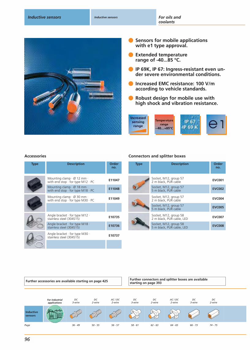
Sensors for mobile applications with e1 type approval.
Extended temperature range of -40...85 ºC.
IP 69K, IP 67: Ingress-resistant even un-der severe environmental conditions.
Increased EMC resistance: 100 V/m according to vehicle standards.
Robust design for mobile use with high shock and vibration resistance.
Accessories
Type Description Orderno.
Mounting clamp · Ø 12 mm · with end stop · for type M12 · PC E11047
Mounting clamp · Ø 18 mm · with end stop · for type M18 · PC E11048
Mounting clamp · Ø 30 mm · with end stop · for type M30 · PC E11049
Angle bracket · for type M12 · stainless steel (304S15) E10735
Angle bracket · for type M18 · stainless steel (304S15) E10736
Angle bracket · for type M30 · stainless steel (304S15) E10737
Further accessories are available starting on page 425
Connectors and splitter boxes
Type Description Orderno.
Socket, M12, group 572 m black, PUR cable EVC001
Socket, M12, group 575 m black, PUR cable EVC002
Socket, M12, group 572 m black, PUR cable EVC004
Socket, M12, group 575 m black, PUR cable EVC005
Socket, M12, group 582 m black, PUR cable, LED EVC007
Socket, M12, group 585 m black, PUR cable, LED EVC008
Further connectors and splitter boxes are availablestarting on page 393
Inductive sensors Inductive sensors For oils andcoolants
96
Inductivesensors
Page
For industrialapplications
DC3-wire
36 - 49
DC2-wire
50 - 55
AC / DC2-wire
56 - 57
DC3-wire
58 - 61
DC2-wire
62 - 63
AC / DC2-wire
64 - 65
DC3-wire
66 - 73
DC2-wire
74 - 75
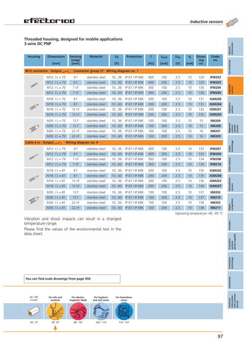
Vibration and shock impacts can result in a changedtemperature range.Please find the values of the environmental test in thedata sheet.
Threaded housing, designed for mobile applications3-wire DC PNP
Housing Dimensions
[mm]
Sensingrange[mm]
Material Ub
[V]
Protection f
[Hz]
Iload
[mA]
Uab
[V]
I0
[mA]
Draw-ingno.
Orderno.
M12 connector · Output · Connector group 57 · Wiring diagram no. 1
M12 / L = 70 4 f stainless steel 10...36 IP 67 / IP 69K 400 100 2.5 10 129 IFM203
M12 / L = 70 4 f stainless steel 10...60 IP 67 / IP 69K 400 200 2.5 10 129 IFM205
M12 / L = 70 7 nf stainless steel 10...36 IP 67 / IP 69K 300 100 2.5 10 130 IFM204
M12 / L = 70 7 nf stainless steel 10...60 IP 67 / IP 69K 300 200 2.5 10 130 IFM206
M18 / L = 70 8 f stainless steel 10...36 IP 67 / IP 69K 200 100 2.5 10 131 IGM200
M18 / L = 70 8 f stainless steel 10...60 IP 67 / IP 69K 200 200 2.5 10 131 IGM204
M18 / L = 70 12 nf stainless steel 10...36 IP 67 / IP 69K 200 100 2.5 10 132 IGM201
M18 / L = 70 12 nf stainless steel 10...60 IP 67 / IP 69K 200 200 2.5 10 132 IGM205
M30 / L = 70 12 f stainless steel 10...36 IP 67 / IP 69K 100 100 2.5 10 15 IIM200
M30 / L = 70 12 f stainless steel 10...60 IP 67 / IP 69K 100 200 2.5 10 15 IIM208
M30 / L = 70 22 nf stainless steel 10...36 IP 67 / IP 69K 100 100 2.5 10 16 IIM201
M30 / L = 70 22 nf stainless steel 10...60 IP 67 / IP 69K 100 200 2.5 10 16 IIM209
Cable 6 m · Output · Wiring diagram no. 4
M12 / L = 79 4 f stainless steel 10...36 IP 67 / IP 69K 400 100 2.5 10 133 IFM207
M12 / L = 79 4 f stainless steel 10...60 IP 67 / IP 69K 400 200 2.5 10 133 IFM209
M12 / L = 79 7 nf stainless steel 10...36 IP 67 / IP 69K 300 100 2.5 10 134 IFM208
M12 / L = 79 7 nf stainless steel 10...60 IP 67 / IP 69K 300 200 2.5 10 134 IFM210
M18 / L = 81 8 f stainless steel 10...36 IP 67 / IP 69K 200 100 2.5 10 135 IGM202
M18 / L = 81 8 f stainless steel 10...60 IP 67 / IP 69K 200 200 2.5 10 135 IGM206
M18 / L = 81 12 nf stainless steel 10...36 IP 67 / IP 69K 200 100 2.5 10 136 IGM203
M18 / L = 81 12 nf stainless steel 10...60 IP 67 / IP 69K 200 200 2.5 10 136 IGM207
M30 / L = 81 12 f stainless steel 10...36 IP 67 / IP 69K 100 100 2.5 10 137 IIM202
M30 / L = 81 12 f stainless steel 10...60 IP 67 / IP 69K 100 200 2.5 10 137 IIM210
M30 / L = 81 22 nf stainless steel 10...36 IP 67 / IP 69K 100 100 2.5 10 138 IIM203
M30 / L = 81 22 nf stainless steel 10...60 IP 67 / IP 69K 100 200 2.5 10 138 IIM211
Operating temperature -40...85 °C
You can find scale drawings from page 450
AC / DC2-wire
76 - 77
For oils andcoolants
78 - 97
For electro-magnetic fields
98 - 101
For hygienicand wet areas
102 - 113
For hazardousareas
114 - 127
Inductive sensors
Gen
eral
info
rmat
ion
List
of
arti
cles
Ind
uct
ive
sen
sors
Cap
acit
ive
sen
sors
Mag
net
icse
nso
rs,
cylin
der
sen
sors
Safe
tyte
chn
olo
gy
Val
ve s
enso
rsPh
oto
elec
tric
sen
sors
Ob
ject
reco
gn
itio
nEn
cod
ers
Eval
uat
ion
syst
ems,
po
wer
su
pp
lies
Co
nn
ecti
on
tech
no
log
yA
cces
sori
esTe
chn
ical
info
rmat
ion
and
cu
sto
mer
serv
ice
97
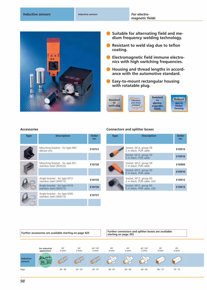
Suitable for alternating field and me-dium frequency welding technology.
Resistant to weld slag due to tefloncoating.
Electromagnetic field immune electro-nics with high switching frequencies.
Housing and thread lengths in accord-ance with the automotive standard.
Easy-to-mount rectangular housingwith rotatable plug.
Accessories
Type Description Orderno.
Mounting bracket · for type IMC · diecast zinc E10731
Mounting bracket · for type IDC ·stainless steel (303S22) E10730
Angle bracket · for type M12 · stainless steel (304S15) E10735
Angle bracket · for type M18 · stainless steel (304S15) E10736
Angle bracket · for type M30 · stainless steel (304S15) E10737
Further accessories are available starting on page 425
Connectors and splitter boxes
Type Description Orderno.
Socket, M12, group 592 m black, PUR cable E10915
Socket, M12, group 595 m black, PUR cable E10916
Socket, M12, group 592 m black, PUR cable E10909
Socket, M12, group 595 m black, PUR cable E10910
Socket, M12, group 602 m black, PUR cable, LED E10912
Socket, M12, group 605 m black, PUR cable, LED E10913
Further connectors and splitter boxes are availablestarting on page 393
Inductive sensors Inductive sensors For electro-magnetic fields
98
Inductivesensors
Page
For industrialapplications
DC3-wire
36 - 49
DC2-wire
50 - 55
AC / DC2-wire
56 - 57
DC3-wire
58 - 61
DC2-wire
62 - 63
AC / DC2-wire
64 - 65
DC3-wire
66 - 73
DC2-wire
74 - 75

Threaded and rectangular housing3- / 4-wire DC PNP
Housing Dimensions
[mm]
Sensingrange[mm]
Material Ub
[V]
Protec-tion
f
[Hz]
Iload
[mA]
Uab
[V]
I0
[mA]
Draw-ingno.
Orderno.
M12 connector · Output · Connector groups 59, 60 · Wiring diagram no. 1
M12 / L = 60 2 f brass 10...36 IP 67 1000 250 2.5 15 139 IF5670
M12 / L = 60 2 f brass 10...36 IP 67 1000 250 2.5 15 139 IF5750
M12 / L = 60 4 nf brass 10...36 IP 67 1000 250 2.5 15 140 IF5675
M12 / L = 60 4 nf brass 10...36 IP 67 1000 250 2.5 15 140 IF5751
M18 / L = 60 5 f brass 10...36 IP 67 700 250 2.5 15 39 IG5647
M18 / L = 60 5 f brass 10...36 IP 67 700 250 2.5 7.8 39 IG5667
M30 / L = 60 10 f brass 10...36 IP 67 250 250 2.5 15 141 II5503
40 x 40 x 118 15 f modified PPE 10...60 IP 67 50 200 3 20 142 IV5025
M12 connector · Output · Connector groups 59, 60 · Wiring diagram no. 12
92 x 80 x 40 50 f PPE 10...36 IP 67 70 250 2.5 20 94 ID5059
Operating temperature -25...80 °C
You can find scale drawings from page 450
AC / DC2-wire
76 - 77
For oils andcoolants
78 - 97
For electro-magnetic fields
98 - 101
For hygienicand wet areas
102 - 113
For hazardousareas
114 - 127
Inductive sensors
Gen
eral
info
rmat
ion
List
of
arti
cles
Ind
uct
ive
sen
sors
Cap
acit
ive
sen
sors
Mag
net
icse
nso
rs,
cylin
der
sen
sors
Safe
tyte
chn
olo
gy
Val
ve s
enso
rsPh
oto
elec
tric
sen
sors
Ob
ject
reco
gn
itio
nEn
cod
ers
Eval
uat
ion
syst
ems,
po
wer
su
pp
lies
Co
nn
ecti
on
tech
no
log
yA
cces
sori
esTe
chn
ical
info
rmat
ion
and
cu
sto
mer
serv
ice
99

Same sensing range for all kinds of metals (K = 1).
Ideal for alternating field and medi-um frequency welding technology.
Increased sensing range for more plant uptime.
Electronics immune to strong magnetic fields.
Resistant to weld slag due to tefloncoating
Accessories
Type Description Orderno.
Angle bracket · for type M12 · stainless steel (304S15) E10735
Angle bracket · for type M18 · stainless steel (304S15) E10736
Angle bracket · for type M30 · stainless steel (304S15) E10737
Mounting bracket · for type IMC · diecast zinc E10731
Further accessories are available starting on page 425
Connectors and splitter boxes
Type Description Orderno.
Socket, M12, group 592 m black, PUR cable E10915
Socket, M12, group 595 m black, PUR cable E10916
Socket, M12, group 592 m black, PUR cable E10909
Socket, M12, group 595 m black, PUR cable E10910
Socket, M12, group 602 m black, PUR cable, LED E10912
Socket, M12, group 605 m black, PUR cable, LED E10913
Further connectors and splitter boxes are availablestarting on page 393
Inductive sensors Inductive sensors For electro-magnetic fields
100
Inductivesensors
Page
For industrialapplications
DC3-wire
36 - 49
DC2-wire
50 - 55
AC / DC2-wire
56 - 57
DC3-wire
58 - 61
DC2-wire
62 - 63
AC / DC2-wire
64 - 65
DC3-wire
66 - 73
DC2-wire
74 - 75
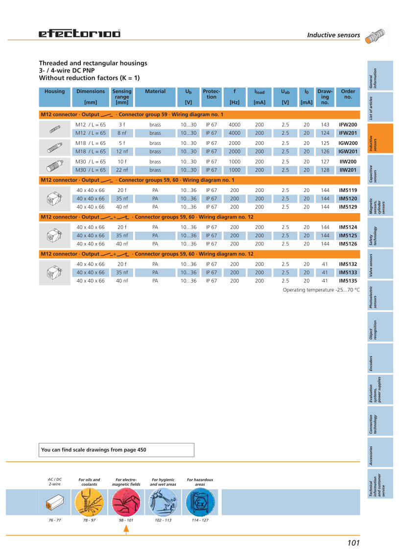
Threaded and rectangular housings3- / 4-wire DC PNPWithout reduction factors (K = 1)
Housing Dimensions
[mm]
Sensingrange[mm]
Material Ub
[V]
Protec-tion
f
[Hz]
Iload
[mA]
Uab
[V]
I0
[mA]
Draw-ingno.
Orderno.
M12 connector · Output · Connector group 59 · Wiring diagram no. 1
M12 / L = 65 3 f brass 10...30 IP 67 4000 200 2.5 20 143 IFW200
M12 / L = 65 8 nf brass 10...30 IP 67 4000 200 2.5 20 124 IFW201
M18 / L = 65 5 f brass 10...30 IP 67 2000 200 2.5 20 125 IGW200
M18 / L = 65 12 nf brass 10...30 IP 67 2000 200 2.5 20 126 IGW201
M30 / L = 65 10 f brass 10...30 IP 67 1000 200 2.5 20 127 IIW200
M30 / L = 65 22 nf brass 10...30 IP 67 1000 200 2.5 20 128 IIW201
M12 connector · Output · Connector groups 59, 60 · Wiring diagram no. 1
40 x 40 x 66 20 f PA 10...36 IP 67 200 200 2.5 20 144 IM5119
40 x 40 x 66 35 nf PA 10...36 IP 67 200 200 2.5 20 144 IM5120
40 x 40 x 66 40 nf PA 10...36 IP 67 200 200 2.5 20 144 IM5129
M12 connector · Output · Connector groups 59, 60 · Wiring diagram no. 12
40 x 40 x 66 20 f PA 10...36 IP 67 200 200 2.5 20 144 IM5124
40 x 40 x 66 35 nf PA 10...36 IP 67 200 200 2.5 20 144 IM5125
40 x 40 x 66 40 nf PA 10...36 IP 67 200 200 2.5 20 144 IM5126
M12 connector · Output · Connector groups 59, 60 · Wiring diagram no. 12
40 x 40 x 66 20 f PA 10...36 IP 67 200 200 2.5 20 41 IM5132
40 x 40 x 66 35 nf PA 10...36 IP 67 200 200 2.5 20 41 IM5133
40 x 40 x 66 40 nf PA 10...36 IP 67 200 200 2.5 20 41 IM5135
Operating temperature -25...70 °C
You can find scale drawings from page 450
AC / DC2-wire
76 - 77
For oils andcoolants
78 - 97
For electro-magnetic fields
98 - 101
For hygienicand wet areas
102 - 113
For hazardousareas
114 - 127
Inductive sensors
Gen
eral
info
rmat
ion
List
of
arti
cles
Ind
uct
ive
sen
sors
Cap
acit
ive
sen
sors
Mag
net
icse
nso
rs,
cylin
der
sen
sors
Safe
tyte
chn
olo
gy
Val
ve s
enso
rsPh
oto
elec
tric
sen
sors
Ob
ject
reco
gn
itio
nEn
cod
ers
Eval
uat
ion
syst
ems,
po
wer
su
pp
lies
Co
nn
ecti
on
tech
no
log
yA
cces
sori
esTe
chn
ical
info
rmat
ion
and
cu
sto
mer
serv
ice
101
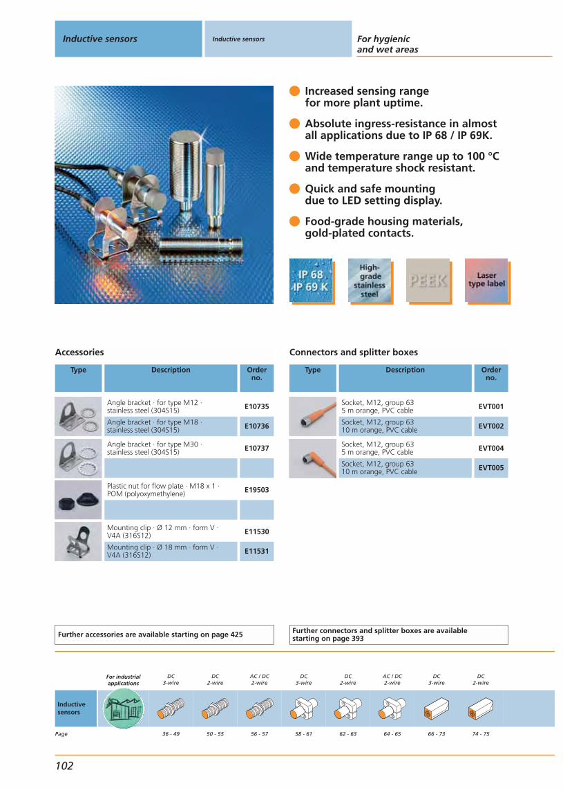
Increased sensing rangefor more plant uptime.
Absolute ingress-resistance in almost all applications due to IP 68 / IP 69K.
Wide temperature range up to 100 °Cand temperature shock resistant.
Quick and safe mountingdue to LED setting display.
Food-grade housing materials,gold-plated contacts.
Accessories
Type Description Orderno.
Angle bracket · for type M12 · stainless steel (304S15) E10735
Angle bracket · for type M18 · stainless steel (304S15) E10736
Angle bracket · for type M30 · stainless steel (304S15) E10737
Plastic nut for flow plate · M18 x 1 ·POM (polyoxymethylene) E19503
Mounting clip · Ø 12 mm · form V · V4A (316S12) E11530
Mounting clip · Ø 18 mm · form V · V4A (316S12) E11531
Further accessories are available starting on page 425
Connectors and splitter boxes
Type Description Orderno.
Socket, M12, group 635 m orange, PVC cable EVT001
Socket, M12, group 6310 m orange, PVC cable EVT002
Socket, M12, group 635 m orange, PVC cable EVT004
Socket, M12, group 6310 m orange, PVC cable EVT005
Further connectors and splitter boxes are availablestarting on page 393
Inductive sensors Inductive sensors For hygienicand wet areas
102
Inductivesensors
Page
For industrialapplications
DC3-wire
36 - 49
DC2-wire
50 - 55
AC / DC2-wire
56 - 57
DC3-wire
58 - 61
DC2-wire
62 - 63
AC / DC2-wire
64 - 65
DC3-wire
66 - 73
DC2-wire
74 - 75
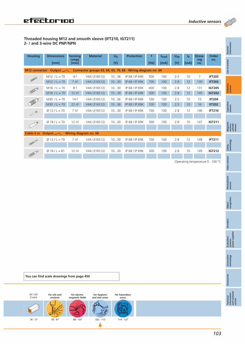
Threaded housing M12 and smooth sleeve (IFT210, IGT211)2- / and 3-wire DC PNP/NPN
Housing Dimensions
[mm]
Sensingrange[mm]
Material Ub
[V]
Protection f
[Hz]
Iload
[mA]
Uab
[V]
I0
[mA]
Draw-ingno.
Orderno.
M12 connector · Output · Connector groups 63, 64, 65, 70, 66 · Wiring diagram no. 64
M12 / L = 70 4 f V4A (316S12) 10...36 IP 68 / IP 69K 500 100 2.5 10 7 IFT205
M12 / L = 70 7 nf V4A (316S12) 10...30 IP 68 / IP 69K 700 100 2.8 12 130 IFT202
M18 / L = 70 8 f V4A (316S12) 10...30 IP 68 / IP 69K 400 100 2.8 12 131 IGT205
M18 / L = 70 12 nf V4A (316S12) 10...30 IP 68 / IP 69K 300 100 2.8 12 145 IGT202
M30 / L = 70 14 f V4A (316S12) 10...36 IP 68 / IP 69K 100 100 2.5 10 15 IIT204
M30 / L = 70 22 nf V4A (316S12) 10...36 IP 68 / IP 69K 100 100 2.5 10 16 IIT202
Ø 12 / L = 70 7 nf V4A (316S12) 10...30 IP 68 / IP 69K 700 100 2.8 12 146 IFT210
Ø 18 / L = 70 12 nf V4A (316S12) 10...30 IP 68 / IP 69K 300 100 2.8 10 147 IGT211
Cable 6 m · Output · Wiring diagram no. 66
Ø 12 / L = 79 7 nf V4A (316S12) 10...30 IP 68 / IP 69K 700 100 2.8 12 148 IFT211
Ø 18 / L = 81 12 nf V4A (316S12) 10...30 IP 68 / IP 69K 300 100 2.8 10 149 IGT212
Operating temperature 0...100 °C
You can find scale drawings from page 450
AC / DC2-wire
76 - 77
For oils andcoolants
78 - 97
For electro-magnetic fields
98 - 101
For hygienicand wet areas
102 - 113
For hazardousareas
114 - 127
Inductive sensors
Gen
eral
info
rmat
ion
List
of
arti
cles
Ind
uct
ive
sen
sors
Cap
acit
ive
sen
sors
Mag
net
icse
nso
rs,
cylin
der
sen
sors
Safe
tyte
chn
olo
gy
Val
ve s
enso
rsPh
oto
elec
tric
sen
sors
Ob
ject
reco
gn
itio
nEn
cod
ers
Eval
uat
ion
syst
ems,
po
wer
su
pp
lies
Co
nn
ecti
on
tech
no
log
yA
cces
sori
esTe
chn
ical
info
rmat
ion
and
cu
sto
mer
serv
ice
103
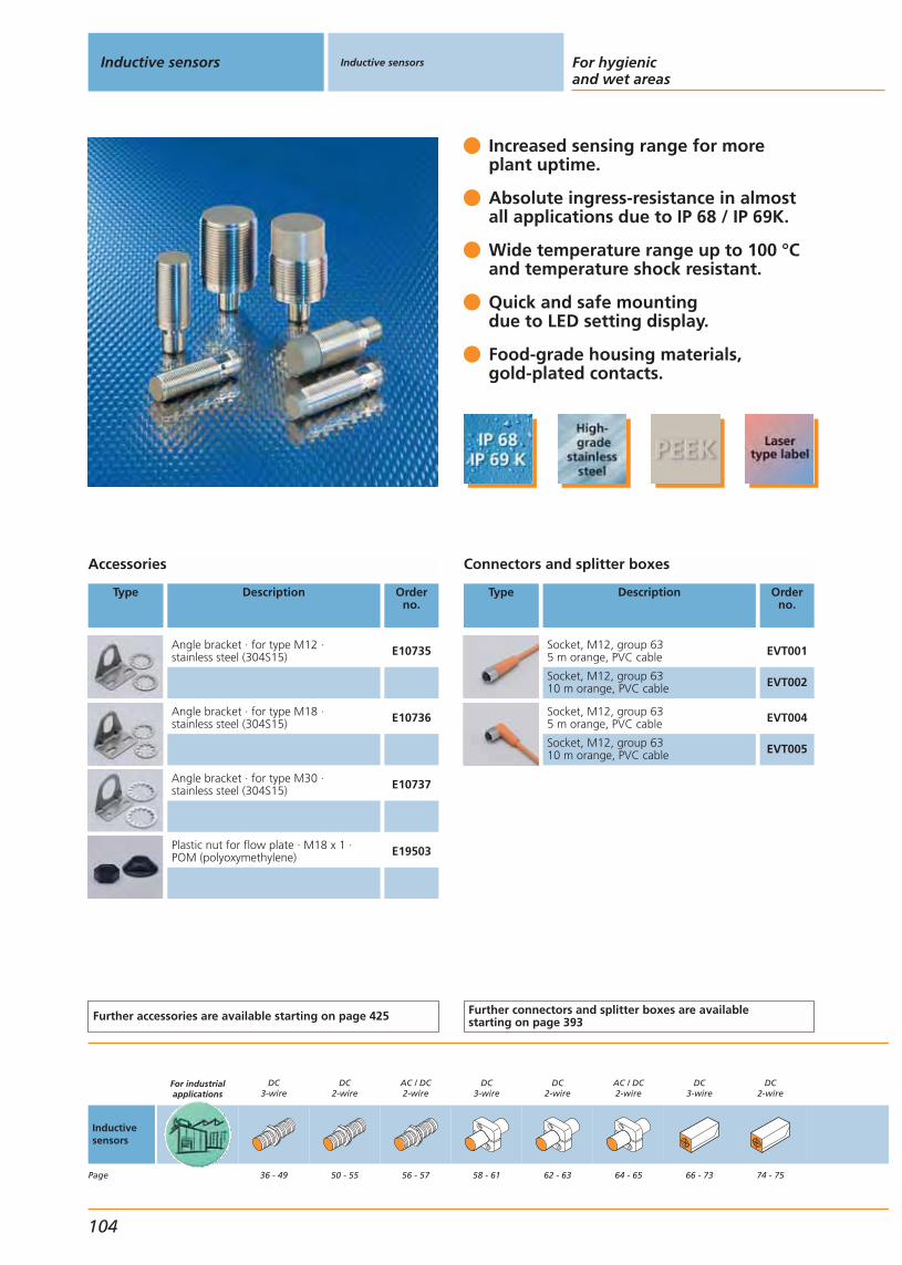
Increased sensing range for more plant uptime.
Absolute ingress-resistance in almost all applications due to IP 68 / IP 69K.
Wide temperature range up to 100 °Cand temperature shock resistant.
Quick and safe mountingdue to LED setting display.
Food-grade housing materials, gold-plated contacts.
Accessories
Type Description Orderno.
Angle bracket · for type M12 · stainless steel (304S15) E10735
Angle bracket · for type M18 · stainless steel (304S15) E10736
Angle bracket · for type M30 · stainless steel (304S15) E10737
Plastic nut for flow plate · M18 x 1 ·POM (polyoxymethylene) E19503
Further accessories are available starting on page 425
Connectors and splitter boxes
Type Description Orderno.
Socket, M12, group 635 m orange, PVC cable EVT001
Socket, M12, group 6310 m orange, PVC cable EVT002
Socket, M12, group 635 m orange, PVC cable EVT004
Socket, M12, group 6310 m orange, PVC cable EVT005
Further connectors and splitter boxes are availablestarting on page 393
Inductive sensors Inductive sensors For hygienicand wet areas
104
Inductivesensors
Page
For industrialapplications
DC3-wire
36 - 49
DC2-wire
50 - 55
AC / DC2-wire
56 - 57
DC3-wire
58 - 61
DC2-wire
62 - 63
AC / DC2-wire
64 - 65
DC3-wire
66 - 73
DC2-wire
74 - 75

Threaded housing3-wire DC PNP
Housing Dimensions
[mm]
Sensingrange[mm]
Material Ub
[V]
Protection f
[Hz]
Iload
[mA]
Uab
[V]
I0
[mA]
Draw-ingno.
Orderno.
M12 connector · Output · Connector groups 63, 64, 65, 66, 70 · Wiring diagram no. 1
M12 / L = 45 4 f V4A (316S12) 10...36 IP 68 / IP 69K 700 100 2.5 10 5 IFT203
M12 / L = 50 7 nf V4A (316S12) 10...36 IP 68 / IP 69K 700 100 2.5 10 150 IFT200
M12 / L = 70 4 f V4A (316S12) 10...36 IP 68 / IP 69K 700 100 2.5 10 7 IFT216
M12 / L = 70 7 nf V4A (316S12) 10...36 IP 68 / IP 69K 700 100 2.5 10 8 IFT217
M12 connector · Output · Connector groups 63, 64, 65, 70 · Wiring diagram no. 2
M12 / L = 45 3.5 f V4A (316S12) 10...36 IP 68 / IP 69K 700 100 2.5 10 151 IFT204
M12 / L = 50 7 nf V4A (316S12) 10...36 IP 68 / IP 69K 700 100 2.5 10 150 IFT201
M12 connector · Output · Connector groups 63, 64, 65, 66, 70 · Wiring diagram no. 1
M18 / L = 46 8 f V4A (316S12) 10...36 IP 68 / IP 69K 500 100 2.5 10 9 IGT203
M18 / L = 51 12 nf V4A (316S12) 10...36 IP 68 / IP 69K 300 100 2.5 10 152 IGT200
M18 / L = 70 8 f V4A (316S12) 10...36 IP 68 / IP 69K 400 100 2.5 10 11 IGT219
M12 connector · Output · Connector groups 63, 64, 65, 70 · Wiring diagram no. 1
M18 / L = 70 12 nf V4A (316S12) 10...36 IP 68 / IP 69K 300 100 2.5 10 12 IGT220
M12 connector · Output · Connector groups 63, 64, 65, 70 · Wiring diagram no. 2
M18 / L = 46 8 f V4A (316S12) 10...36 IP 68 / IP 69K 500 100 2.5 10 9 IGT204
M18 / L = 51 12 nf V4A (316S12) 10...36 IP 68 / IP 69K 300 100 2.5 10 152 IGT201
M12 connector · Output · Connector groups 63, 64, 65, 66, 70 · Wiring diagram no. 1
M30 / L = 50 14 f V4A (316S12) 10...36 IP 68 / IP 69K 100 100 2.5 10 13 IIT205
M30 / L = 50 22 nf V4A (316S12) 10...36 IP 68 / IP 69K 100 100 2.5 10 153 IIT200
M12 connector · Output · Connector groups 63, 64, 65, 70 · Wiring diagram no. 1
M30 / L = 70 15 f V4A (316S12) 10...36 IP 68 / IP 69K 100 100 2.5 10 15 IIT212
M30 / L = 70 22 nf V4A (316S12) 10...36 IP 68 / IP 69K 100 100 2.5 10 16 IIT213
Operating temperature 0...100 °C
You can find scale drawings from page 450
AC / DC2-wire
76 - 77
For oils andcoolants
78 - 97
For electro-magnetic fields
98 - 101
For hygienicand wet areas
102 - 113
For hazardousareas
114 - 127
Inductive sensors
Gen
eral
info
rmat
ion
List
of
arti
cles
Ind
uct
ive
sen
sors
Cap
acit
ive
sen
sors
Mag
net
icse
nso
rs,
cylin
der
sen
sors
Safe
tyte
chn
olo
gy
Val
ve s
enso
rsPh
oto
elec
tric
sen
sors
Ob
ject
reco
gn
itio
nEn
cod
ers
Eval
uat
ion
syst
ems,
po
wer
su
pp
lies
Co
nn
ecti
on
tech
no
log
yA
cces
sori
esTe
chn
ical
info
rmat
ion
and
cu
sto
mer
serv
ice
105

Increased sensing rangefor more plant uptime.
Absolute ingress-resistance in almost all applications due to IP 68 / IP 69 K.
Wide temperature range up to 100 °Cand temperature shock resistant.
Quick and safe mountingdue to LED setting display.
Food-grade housing materials, gold-plated contacts.
Accessories
Type Description Orderno.
Angle bracket · for type M12 · stainless steel (304S15) E10735
Angle bracket · for type M18 · stainless steel (304S15) E10736
Angle bracket · for type M30 · stainless steel (304S15) E10737
Plastic nut for flow plate · M18 x 1 ·POM (polyoxymethylene) E19503
Further accessories are available starting on page 425
Inductive sensors Inductive sensors For hygienicand wet areas
106
Inductivesensors
Page
For industrialapplications
DC3-wire
36 - 49
DC2-wire
50 - 55
AC / DC2-wire
56 - 57
DC3-wire
58 - 61
DC2-wire
62 - 63
AC / DC2-wire
64 - 65
DC3-wire
66 - 73
DC2-wire
74 - 75
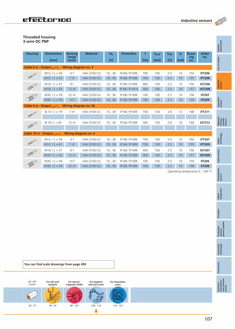
Threaded housing3-wire DC PNP
Housing Dimensions
[mm]
Sensingrange[mm]
Material Ub
[V]
Protection f
[Hz]
Iload
[mA]
Uab
[V]
I0
[mA]
Draw-ingno.
Orderno.
Cable 6 m · Output · Wiring diagram no. 4
M12 / L = 50 4 f V4A (316S12) 10...36 IP 68 / IP 69K 700 100 2.5 10 154 IFT206
M12 / L = 61 7 nf V4A (316S12) 10...36 IP 68 / IP 69K 700 100 2.5 10 155 IFT208
M18 / L = 57 8 f V4A (316S12) 10...36 IP 68 / IP 69K 400 100 2.5 10 156 IGT206
M18 / L = 62 12 nf V4A (316S12) 10...36 IP 68 / IP 69 K 300 100 2.5 10 157 IGT208
M30 / L = 59 22 nf V4A (316S12) 10...36 IP 68 / IP 69K 100 100 2.5 10 158 IIT207
M30 / L = 59 14 f V4A (316S12) 10...36 IP 68 / IP 69K 100 100 2.5 10 159 IIT209
Cable 6 m · Output · Wiring diagram no. 66
Ø 12 / L = 79 7 nf V4A (316S12) 10...30 IP 68 / IP 69K 700 100 2.8 12 148 IFT211
Ø 18 / L = 81 12 nf V4A (316S12) 10...30 IP 68 / IP 69K 300 100 2.8 10 149 IGT212
Cable 10 m · Output · Wiring diagram no. 4
M12 / L = 56 4 f V4A (316S12) 10...36 IP 68 / IP 69K 700 100 2.5 10 160 IFT207
M12 / L = 61 7 nf V4A (316S12) 10...36 IP 68 / IP 69K 700 100 2.5 10 155 IFT209
M18 / L = 57 8 f V4A (316S12) 10...36 IP 68 / IP 69K 400 100 2.5 10 156 IGT207
M18 / L = 62 12 nf V4A (316S12) 10...36 IP 68 / IP 69K 300 100 2.5 10 157 IGT209
M30 / L = 59 14 f V4A (316S12) 10...36 IP 68 / IP 69K 100 100 2.5 10 159 IIT206
M30 / L = 59 22 nf V4A (316S12) 10...36 IP 68 / IP 69K 100 100 2.5 10 158 IIT208
Operating temperature 0...100 °C
You can find scale drawings from page 450
AC / DC2-wire
76 - 77
For oils andcoolants
78 - 97
For electro-magnetic fields
98 - 101
For hygienicand wet areas
102 - 113
For hazardousareas
114 - 127
Inductive sensors
Gen
eral
info
rmat
ion
List
of
arti
cles
Ind
uct
ive
sen
sors
Cap
acit
ive
sen
sors
Mag
net
icse
nso
rs,
cylin
der
sen
sors
Safe
tyte
chn
olo
gy
Val
ve s
enso
rsPh
oto
elec
tric
sen
sors
Ob
ject
reco
gn
itio
nEn
cod
ers
Eval
uat
ion
syst
ems,
po
wer
su
pp
lies
Co
nn
ecti
on
tech
no
log
yA
cces
sori
esTe
chn
ical
info
rmat
ion
and
cu
sto
mer
serv
ice
107
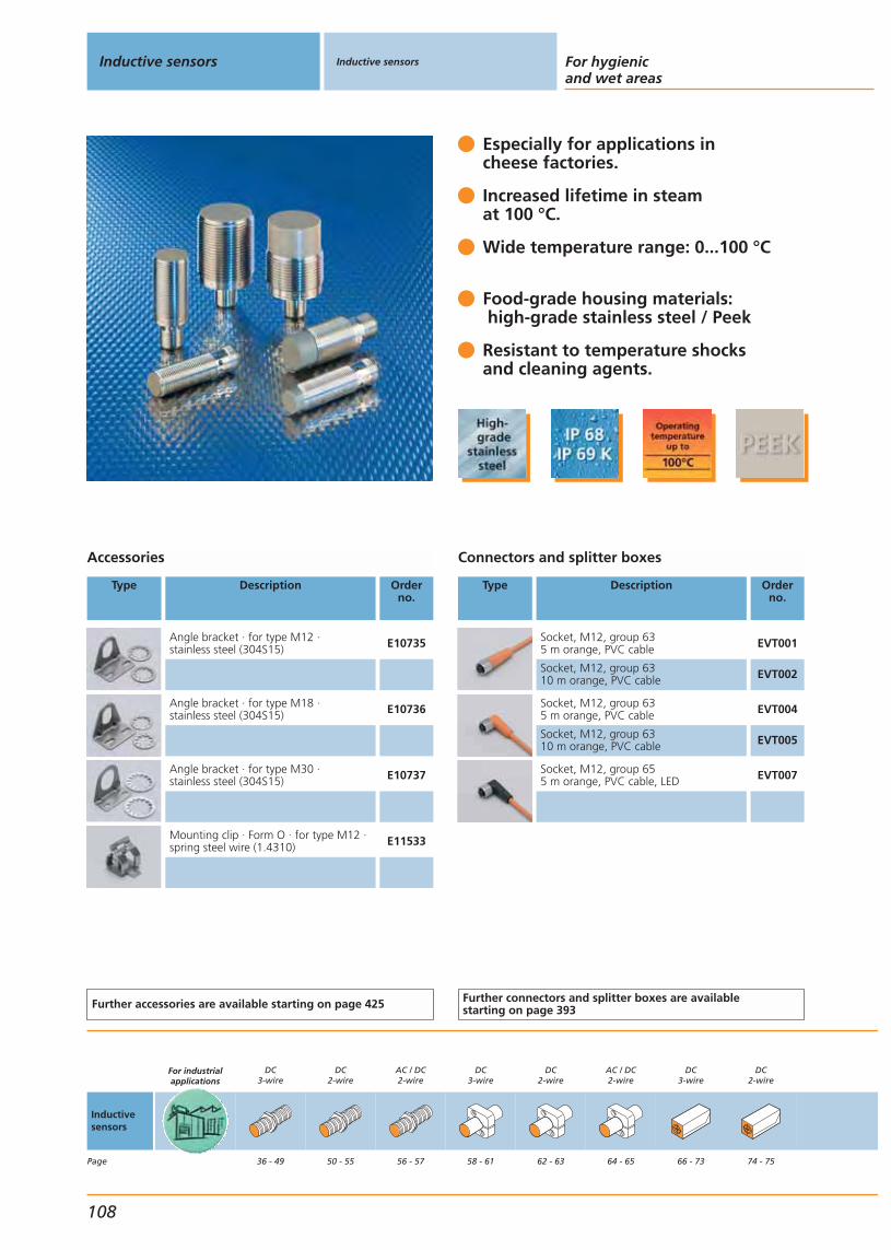
Especially for applications in cheese factories.
Increased lifetime in steam at 100 °C.
Wide temperature range: 0...100 °C
Food-grade housing materials:high-grade stainless steel / Peek
Resistant to temperature shocks and cleaning agents.
Accessories
Type Description Orderno.
Angle bracket · for type M12 · stainless steel (304S15) E10735
Angle bracket · for type M18 · stainless steel (304S15) E10736
Angle bracket · for type M30 · stainless steel (304S15) E10737
Mounting clip · Form O · for type M12 ·spring steel wire (1.4310) E11533
Further accessories are available starting on page 425
Connectors and splitter boxes
Type Description Orderno.
Socket, M12, group 635 m orange, PVC cable EVT001
Socket, M12, group 6310 m orange, PVC cable EVT002
Socket, M12, group 635 m orange, PVC cable EVT004
Socket, M12, group 6310 m orange, PVC cable EVT005
Socket, M12, group 655 m orange, PVC cable, LED EVT007
Further connectors and splitter boxes are availablestarting on page 393
Inductive sensors Inductive sensors For hygienicand wet areas
108
Inductivesensors
Page
For industrialapplications
DC3-wire
36 - 49
DC2-wire
50 - 55
AC / DC2-wire
56 - 57
DC3-wire
58 - 61
DC2-wire
62 - 63
AC / DC2-wire
64 - 65
DC3-wire
66 - 73
DC2-wire
74 - 75
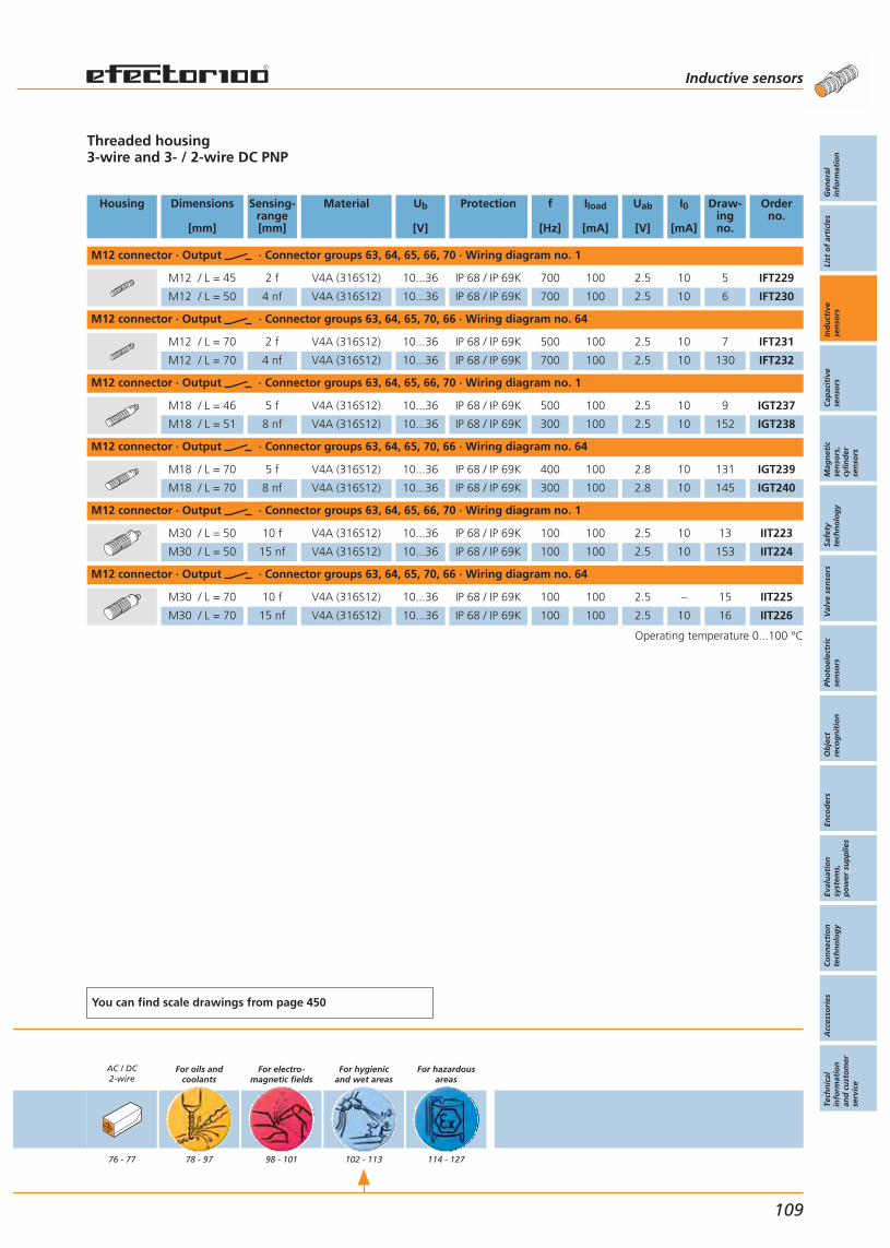
Threaded housing3-wire and 3- / 2-wire DC PNP
Housing Dimensions
[mm]
Sensing-range[mm]
Material Ub
[V]
Protection f
[Hz]
Iload
[mA]
Uab
[V]
I0
[mA]
Draw-ingno.
Orderno.
M12 connector · Output · Connector groups 63, 64, 65, 66, 70 · Wiring diagram no. 1
M12 / L = 45 2 f V4A (316S12) 10...36 IP 68 / IP 69K 700 100 2.5 10 5 IFT229
M12 / L = 50 4 nf V4A (316S12) 10...36 IP 68 / IP 69K 700 100 2.5 10 6 IFT230
M12 connector · Output · Connector groups 63, 64, 65, 70, 66 · Wiring diagram no. 64
M12 / L = 70 2 f V4A (316S12) 10...36 IP 68 / IP 69K 500 100 2.5 10 7 IFT231
M12 / L = 70 4 nf V4A (316S12) 10...36 IP 68 / IP 69K 700 100 2.5 10 130 IFT232
M12 connector · Output · Connector groups 63, 64, 65, 66, 70 · Wiring diagram no. 1
M18 / L = 46 5 f V4A (316S12) 10...36 IP 68 / IP 69K 500 100 2.5 10 9 IGT237
M18 / L = 51 8 nf V4A (316S12) 10...36 IP 68 / IP 69K 300 100 2.5 10 152 IGT238
M12 connector · Output · Connector groups 63, 64, 65, 70, 66 · Wiring diagram no. 64
M18 / L = 70 5 f V4A (316S12) 10...36 IP 68 / IP 69K 400 100 2.8 10 131 IGT239
M18 / L = 70 8 nf V4A (316S12) 10...36 IP 68 / IP 69K 300 100 2.8 10 145 IGT240
M12 connector · Output · Connector groups 63, 64, 65, 66, 70 · Wiring diagram no. 1
M30 / L = 50 10 f V4A (316S12) 10...36 IP 68 / IP 69K 100 100 2.5 10 13 IIT223
M30 / L = 50 15 nf V4A (316S12) 10...36 IP 68 / IP 69K 100 100 2.5 10 153 IIT224
M12 connector · Output · Connector groups 63, 64, 65, 70, 66 · Wiring diagram no. 64
M30 / L = 70 10 f V4A (316S12) 10...36 IP 68 / IP 69K 100 100 2.5 – 15 IIT225
M30 / L = 70 15 nf V4A (316S12) 10...36 IP 68 / IP 69K 100 100 2.5 10 16 IIT226
Operating temperature 0...100 °C
You can find scale drawings from page 450
AC / DC2-wire
76 - 77
For oils andcoolants
78 - 97
For electro-magnetic fields
98 - 101
For hygienicand wet areas
102 - 113
For hazardousareas
114 - 127
Inductive sensors
Gen
eral
info
rmat
ion
List
of
arti
cles
Ind
uct
ive
sen
sors
Cap
acit
ive
sen
sors
Mag
net
icse
nso
rs,
cylin
der
sen
sors
Safe
tyte
chn
olo
gy
Val
ve s
enso
rsPh
oto
elec
tric
sen
sors
Ob
ject
reco
gn
itio
nEn
cod
ers
Eval
uat
ion
syst
ems,
po
wer
su
pp
lies
Co
nn
ecti
on
tech
no
log
yA
cces
sori
esTe
chn
ical
info
rmat
ion
and
cu
sto
mer
serv
ice
109
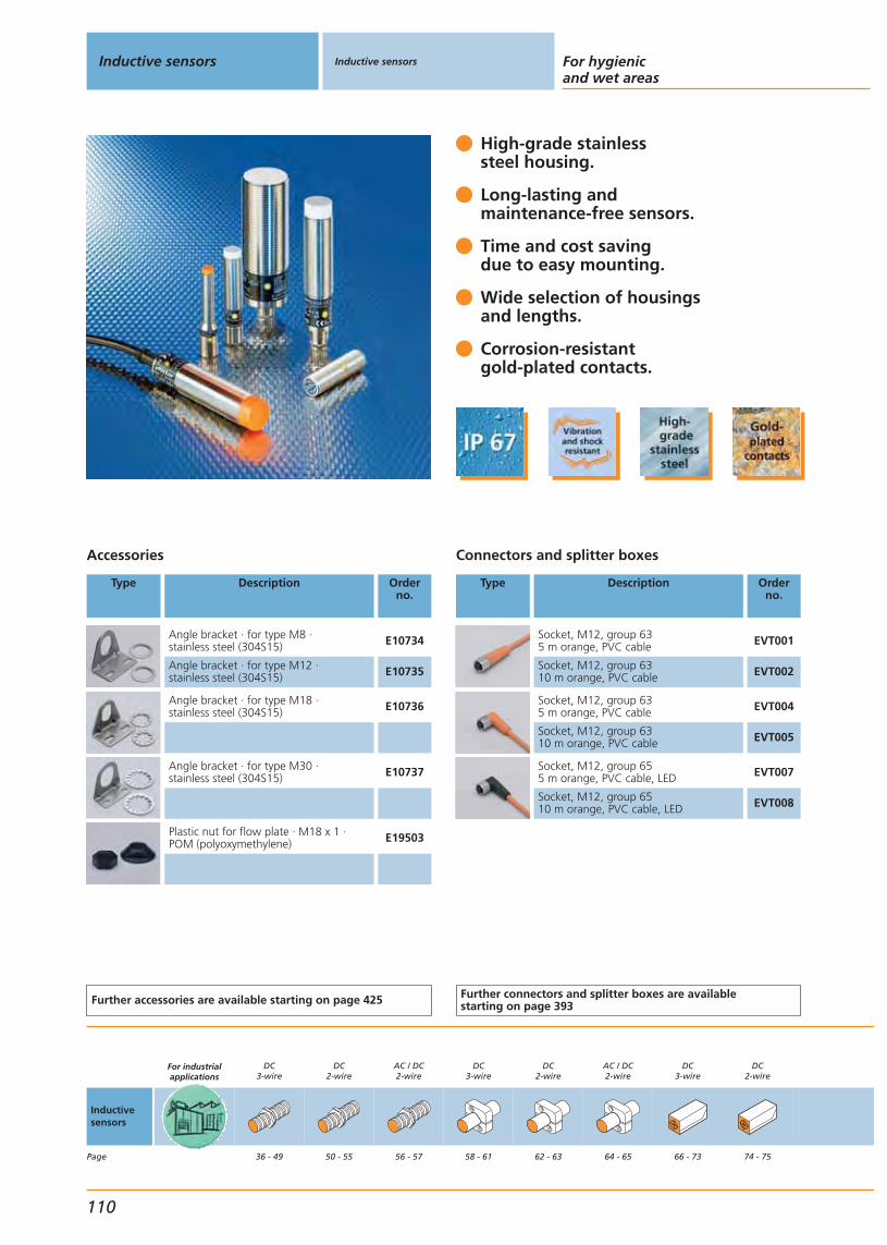
High-grade stainless steel housing.
Long-lasting andmaintenance-free sensors.
Time and cost savingdue to easy mounting.
Wide selection of housingsand lengths.
Corrosion-resistantgold-plated contacts.
Accessories
Type Description Orderno.
Angle bracket · for type M8 · stainless steel (304S15) E10734
Angle bracket · for type M12 · stainless steel (304S15) E10735
Angle bracket · for type M18 · stainless steel (304S15) E10736
Angle bracket · for type M30 · stainless steel (304S15) E10737
Plastic nut for flow plate · M18 x 1 ·POM (polyoxymethylene) E19503
Further accessories are available starting on page 425
Connectors and splitter boxes
Type Description Orderno.
Socket, M12, group 635 m orange, PVC cable EVT001
Socket, M12, group 6310 m orange, PVC cable EVT002
Socket, M12, group 635 m orange, PVC cable EVT004
Socket, M12, group 6310 m orange, PVC cable EVT005
Socket, M12, group 655 m orange, PVC cable, LED EVT007
Socket, M12, group 6510 m orange, PVC cable, LED EVT008
Further connectors and splitter boxes are availablestarting on page 393
Inductive sensors Inductive sensors For hygienicand wet areas
110
Inductivesensors
Page
For industrialapplications
DC3-wire
36 - 49
DC2-wire
50 - 55
AC / DC2-wire
56 - 57
DC3-wire
58 - 61
DC2-wire
62 - 63
AC / DC2-wire
64 - 65
DC3-wire
66 - 73
DC2-wire
74 - 75
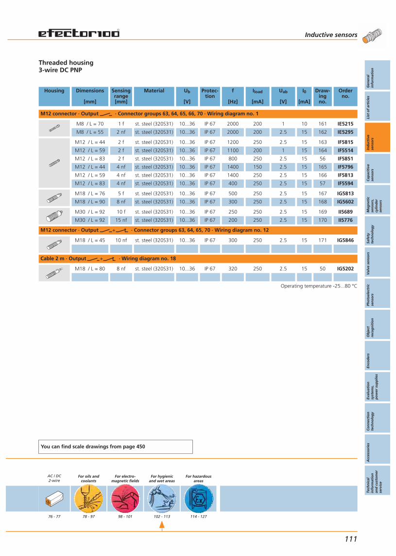
Threaded housing3-wire DC PNP
Housing Dimensions
[mm]
Sensingrange[mm]
Material Ub
[V]
Protec-tion
f
[Hz]
Iload
[mA]
Uab
[V]
I0
[mA]
Draw-ingno.
Orderno.
M12 connector · Output · Connector groups 63, 64, 65, 66, 70 · Wiring diagram no. 1
M8 / L = 70 1 f st. steel (320S31) 10...36 IP 67 2000 200 1 10 161 IE5215
M8 / L = 55 2 nf st. steel (320S31) 10...36 IP 67 2000 200 2.5 15 162 IE5295
M12 / L = 44 2 f st. steel (320S31) 10...36 IP 67 1200 250 2.5 15 163 IF5815
M12 / L = 59 2 f st. steel (320S31) 10...36 IP 67 1100 200 1 15 164 IF5514
M12 / L = 83 2 f st. steel (320S31) 10...36 IP 67 800 250 2.5 15 56 IF5851
M12 / L = 44 4 nf st. steel (320S31) 10...36 IP 67 1400 150 2.5 15 165 IF5796
M12 / L = 59 4 nf st. steel (320S31) 10...36 IP 67 1400 250 2.5 15 166 IF5813
M12 / L = 83 4 nf st. steel (320S31) 10...36 IP 67 400 250 2.5 15 57 IF5594
M18 / L = 76 5 f st. steel (320S31) 10...36 IP 67 500 250 2.5 15 167 IG5813
M18 / L = 90 8 nf st. steel (320S31) 10...36 IP 67 300 250 2.5 15 168 IG5602
M30 / L = 92 10 f st. steel (320S31) 10...36 IP 67 250 250 2.5 15 169 II5689
M30 / L = 92 15 nf st. steel (320S31) 10...36 IP 67 200 250 2.5 15 170 II5776
M12 connector · Output · Connector groups 63, 64, 65, 70 · Wiring diagram no. 12
M18 / L = 45 10 nf st. steel (320S31) 10...36 IP 67 300 250 2.5 15 171 IG5846
Cable 2 m · Output · Wiring diagram no. 18
M18 / L = 80 8 nf st. steel (320S31) 10...36 IP 67 320 250 2.5 15 50 IG5202
Operating temperature -25...80 °C
You can find scale drawings from page 450
AC / DC2-wire
76 - 77
For oils andcoolants
78 - 97
For electro-magnetic fields
98 - 101
For hygienicand wet areas
102 - 113
For hazardousareas
114 - 127
Inductive sensors
Gen
eral
info
rmat
ion
List
of
arti
cles
Ind
uct
ive
sen
sors
Cap
acit
ive
sen
sors
Mag
net
icse
nso
rs,
cylin
der
sen
sors
Safe
tyte
chn
olo
gy
Val
ve s
enso
rsPh
oto
elec
tric
sen
sors
Ob
ject
reco
gn
itio
nEn
cod
ers
Eval
uat
ion
syst
ems,
po
wer
su
pp
lies
Co
nn
ecti
on
tech
no
log
yA
cces
sori
esTe
chn
ical
info
rmat
ion
and
cu
sto
mer
serv
ice
111

4 switching functions by simplyreversing the connecting wires.
Wide voltage rangeof 10...55 V DC.
Long-lasting andmaintenance-free sensors.
Time and cost savingdue to easy mounting.
Corrosion-resistantgold-plated contacts.
Accessories
Type Description Orderno.
Angle bracket · for type M12 · stainless steel (304S15) E10735
Angle bracket · for type M18 · stainless steel (304S15) E10736
Angle bracket · for type M30 · stainless steel (304S15) E10737
Plastic nut for flow plate · M18 x 1 ·POM (polyoxymethylene) E19503
Further accessories are available starting on page 425
Connectors and splitter boxes
Type Description Orderno.
Socket, M12, group 635 m orange, PVC cable EVT001
Socket, M12, group 6310 m orange, PVC cable EVT002
Socket, M12, group 635 m orange, PVC cable EVT004
Socket, M12, group 6310 m orange, PVC cable EVT005
Socket, M12, group 655 m orange, PVC cable, LED EVT007
Socket, M12, group 6510 m orange, PVC cable, LED EVT008
Further connectors and splitter boxes are availablestarting on page 393
Inductive sensors Inductive sensors For hygienicand wet areas
112
Inductivesensors
Page
For industrialapplications
DC3-wire
36 - 49
DC2-wire
50 - 55
AC / DC2-wire
56 - 57
DC3-wire
58 - 61
DC2-wire
62 - 63
AC / DC2-wire
64 - 65
DC3-wire
66 - 73
DC2-wire
74 - 75

Threaded housing2-wire DC PNP/NPN
Housing Dimensions
[mm]
Sensingrange[mm]
Material Ub
[V]
Protec-tion
f
[Hz]
Iload
[mA]
Uab
[V]
I0
[mA]
Draw-ingno.
Orderno.
M12 connector · Output · Connector groups 63, 64, 65, 70 · Wiring diagram no. 68
M12 / L = 83 2 f st. steel (320S31) 10...55 IP 67 1100 400 4.6 – 56 IF5759
M12 / L = 83 4 nf st. steel (320S31) 10...55 IP 67 1500 300 4.6 – 57 IF5760
M18 / L = 90 5 f st. steel (320S31) 10...55 IP 67 700 400 4.6 – 172 IG5806
M18 / L = 77 8 nf st. steel (320S31) 10...55 IP 67 300 300 4.6 – 173 IG5772
M30 / L = 92 10 f st. steel (320S31) 10...55 IP 67 450 400 4.6 – 169 II5751
M30 / L = 78 15 nf st. steel (320S31) 10...55 IP 67 200 400 4.6 – 61 II5733
Operating temperature -25...80 °C
You can find scale drawings from page 450
AC / DC2-wire
76 - 77
For oils andcoolants
78 - 97
For electro-magnetic fields
98 - 101
For hygienicand wet areas
102 - 113
For hazardousareas
114 - 127
Inductive sensors
Gen
eral
info
rmat
ion
List
of
arti
cles
Ind
uct
ive
sen
sors
Cap
acit
ive
sen
sors
Mag
net
icse
nso
rs,
cylin
der
sen
sors
Safe
tyte
chn
olo
gy
Val
ve s
enso
rsPh
oto
elec
tric
sen
sors
Ob
ject
reco
gn
itio
nEn
cod
ers
Eval
uat
ion
syst
ems,
po
wer
su
pp
lies
Co
nn
ecti
on
tech
no
log
yA
cces
sori
esTe
chn
ical
info
rmat
ion
and
cu
sto
mer
serv
ice
113
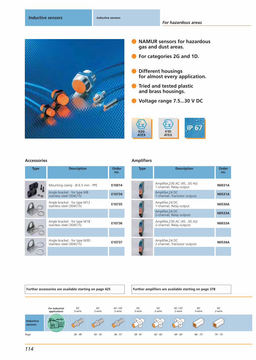
NAMUR sensors for hazardousgas and dust areas.
For categories 2G and 1D.
Different housings for almost every application.
Tried and tested plasticand brass housings.
Voltage range 7.5...30 V DC
Accessories
Type Description Orderno.
Mounting clamp · Ø 6.5 mm · PPE E10014
Angle bracket · for type M8 · stainless steel (304S15) E10734
Angle bracket · for type M12 · stainless steel (304S15) E10735
Angle bracket · for type M18 · stainless steel (304S15) E10736
Angle bracket · for type M30 · stainless steel (304S15) E10737
Further accessories are available starting on page 425
Amplifiers
Type Description Orderno.
Amplifier,230 AC (45...65 Hz)1-channel, Relay output N0031A
Amplifier,24 DC1-channel, Transistor outputs N0531A
Amplifier,24 DC1-channel, Relay output N0530A
Amplifier,24 DC2-channel, Relay outputs N0533A
Amplifier,230 AC (45...65 Hz)2-channel, Relay outputs N0033A
Amplifier,24 DC2-channel, Transistor outputs N0534A
Further amplifiers are available starting on page 378
Inductive sensors Inductive sensors
For hazardous areas
114
Inductivesensors
Page
For industrialapplications
DC3-wire
36 - 49
DC2-wire
50 - 55
AC / DC2-wire
56 - 57
DC3-wire
58 - 61
DC2-wire
62 - 63
AC / DC2-wire
64 - 65
DC3-wire
66 - 73
DC2-wire
74 - 75

Hazardous gas area category 2GHazardous dust area category 1D2-wire NAMUR
Housing Dimensions
[mm]
Sensingrange[mm]
Material Unom.at 1KΩ
[V]
Ub *
[V]
Internalcapacit.
[nf]
Internalinductance
[uH]
f
[Hz]
Draw-ingno.
Orderno.
Cable 2 m · Output · Wiring diagram no. 19
Ø 6.5 / L = 30 1 f brass 8.2 DC 7.5...30 80 70 2000 174 NT5001
M8 / L = 30 1 f brass 8.2 DC 7.5...30 80 70 2000 175 NE5001
M12 / L = 30 2 f PBT 8.2 DC 7.5...30 140 340 1200 176 NF5001
M12 / L = 30 4 nf PBT 8.2 DC 7.5...30 140 130 1500 176 NF5003
M12 / L = 30 2 f brass 8.2 DC 7.5...30 140 340 1200 176 NF5002
M12 / L = 30 4 nf brass 8.2 DC 7.5...30 140 130 1500 177 NF5004
M18 / L = 33 5 f PBT 8.2 DC 7.5...30 145 45 720 178 NG5001
M18 / L = 33 8 nf PBT 8.2 DC 7.5...30 155 50 300 178 NG5003
M18 / L = 33 5 f brass 8.2 DC 7.5...30 145 45 720 178 NG5002
M18 / L = 33 8 nf brass 8.2 DC 7.5...30 155 50 300 179 NG5004
M30 / L = 41 10 f PBT 8.2 DC 7.5...30 145 140 450 180 NI5001
M30 / L = 41 15 nf PBT 8.2 DC 7.5...30 145 110 200 180 NI5003
M30 / L = 41 10 f brass 8.2 DC 7.5...30 145 140 450 180 NI5002
M30 / L = 41 15 nf brass 8.2 DC 7.5...30 145 110 200 181 NI5004
28 x 10 x 16 2 f PBT 8.2 DC 7.5...30 80 110 800 182 NS5002
40 x 12 x 26 2 f PBT 8.2 DC 7.5...30 110 135 800 183 NN5001
40 x 12 x 26 4 nf PBT 8.2 DC 7.5...30 110 135 400 183 NN5002
Common technical data
Operating temperature: -20...70 °CCurrent consumption undamped: > 2.1 mACurrent consumption damped: < 1 mAProtection: IP 67Connection: PVC cable, 2 m* The indicated voltage range Ub isonly permissible outside the hazardous area,in the hazardous area: Ub max. = 15 V
You can find scale drawings from page 450
AC / DC2-wire
76 - 77
For oils andcoolants
78 - 97
For electro-magnetic fields
98 - 101
For hygienicand wet areas
102 - 113
For hazardousareas
114 - 127
Inductive sensors
Gen
eral
info
rmat
ion
List
of
arti
cles
Ind
uct
ive
sen
sors
Cap
acit
ive
sen
sors
Mag
net
icse
nso
rs,
cylin
der
sen
sors
Safe
tyte
chn
olo
gy
Val
ve s
enso
rsPh
oto
elec
tric
sen
sors
Ob
ject
reco
gn
itio
nEn
cod
ers
Eval
uat
ion
syst
ems,
po
wer
su
pp
lies
Co
nn
ecti
on
tech
no
log
yA
cces
sori
esTe
chn
ical
info
rmat
ion
and
cu
sto
mer
serv
ice
115

NAMUR sensors for hazardousgas and dust area.
For categories 1G, 2G and 1D.
4 different types withsensing ranges 4...35 mm.
Increased sensing rangefor more machine uptime.
Voltage range 7.5...30 V DC.
Accessories
Type Description Orderno.
Angle bracket · for type M12 · stainless steel (304S15) E10735
Angle bracket · for type M18 · stainless steel (304S15) E10736
Angle bracket · for type M30 · stainless steel (304S15) E10737
Mounting clip · Form O · for type M12 ·Spring steel wire (1.4310) E11533
Mounting clip · Form O · for type M18 ·stainless steel (316S12) E11534
Further accessories are available starting on page 425
Amplifiers
Type Description Orderno.
Amplifier,230 AC (45...65 Hz)1-channel, Relay output N0031A
Amplifier,24 DC1-channel, Transistor outputs N0531A
Amplifier,24 DC1-channel, Relay output N0530A
Amplifier,24 DC2-channel, Relay outputs N0533A
Amplifier,230 AC (45...65 Hz)2-channel, Relay outputs N0033A
Amplifier,24 DC2-channel, Transistor outputs N0534A
Further amplifiers are available starting on page 378
Inductive sensors Inductive sensors
For hazardous areas
116
Inductivesensors
Page
For industrialapplications
DC3-wire
36 - 49
DC2-wire
50 - 55
AC / DC2-wire
56 - 57
DC3-wire
58 - 61
DC2-wire
62 - 63
AC / DC2-wire
64 - 65
DC3-wire
66 - 73
DC2-wire
74 - 75

Hazardous gas area category 1G (threaded types), category 2G (rectangular types)Hazardous dust area category 1DM12 connector, 2-wire NAMUR
Housing Dimensions
[mm]
Sensingrange[mm]
Material Unom.at 1KΩ
[V]
Ub *
[V]
Internalcapacit.
[nf]
Internalinductance
[uH]
f
[Hz]
Draw-ingno.
Orderno.
M12 connector · Output · Connector group 75 · Wiring diagram no. 20
M12 / L = 45 4 f brass 8.2 DC 7.5...30 210 115 700 5 NF501A
M12 / L = 50 7 nf brass 8.2 DC 7.5...30 210 145 700 6 NF500A
M18 / L = 46 8 f brass 8.2 DC 7.5...30 200 190 400 9 NG501A
M18 / L = 51 12 nf brass 8.2 DC 7.5...30 200 85 300 10 NG500A
M30 / L = 50 15 f brass 8.2 DC 7.5...30 230 210 100 13 NI501A
M30 / L = 50 22 nf brass 8.2 DC 7.5...30 250 120 100 14 NI500A
M12 connector · Output · Connector groups 76, 77 · Wiring diagram no. 21
40 x 40 x 66 20 f PPE 8.2 DC 7.5...30 250 450 200 101 NM500A
40 x 40 x 66 35 nf PPE 8.2 DC 7.5...30 220 710 100 101 NM501A
Common technical data
Current consumption undamped: > 2.1 mACurrent consumption damped: < 1mAProtection rating IP 67* The indicated voltage range Ub isonly permissible outside the hazardous area,in the hazardous area: Ub max. = 15 V
You can find scale drawings from page 450
AC / DC2-wire
76 - 77
For oils andcoolants
78 - 97
For electro-magnetic fields
98 - 101
For hygienicand wet areas
102 - 113
For hazardousareas
114 - 127
Inductive sensors
Gen
eral
info
rmat
ion
List
of
arti
cles
Ind
uct
ive
sen
sors
Cap
acit
ive
sen
sors
Mag
net
icse
nso
rs,
cylin
der
sen
sors
Safe
tyte
chn
olo
gy
Val
ve s
enso
rsPh
oto
elec
tric
sen
sors
Ob
ject
reco
gn
itio
nEn
cod
ers
Eval
uat
ion
syst
ems,
po
wer
su
pp
lies
Co
nn
ecti
on
tech
no
log
yA
cces
sori
esTe
chn
ical
info
rmat
ion
and
cu
sto
mer
serv
ice
117
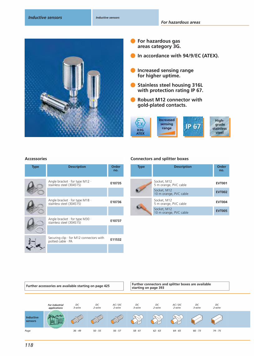
For hazardous gasareas category 3G.
In accordance with 94/9/EC (ATEX).
Increased sensing rangefor higher uptime.
Stainless steel housing 316Lwith protection rating IP 67.
Robust M12 connector with gold-plated contacts.
Accessories
Type Description Orderno.
Angle bracket · for type M12 · stainless steel (304S15) E10735
Angle bracket · for type M18 · stainless steel (304S15) E10736
Angle bracket · for type M30 · stainless steel (304S15) E10737
Securing clip · for M12 connectors withpotted cable · PA E11532
Further accessories are available starting on page 425
Connectors and splitter boxes
Type Description Orderno.
Socket, M125 m orange, PVC cable EVT001
Socket, M1210 m orange, PVC cable EVT002
Socket, M125 m orange, PVC cable EVT004
Socket, M1210 m orange, PVC cable EVT005
Further connectors and splitter boxes are availablestarting on page 393
Inductive sensors Inductive sensors
For hazardous areas
118
Inductivesensors
Page
For industrialapplications
DC3-wire
36 - 49
DC2-wire
50 - 55
AC / DC2-wire
56 - 57
DC3-wire
58 - 61
DC2-wire
62 - 63
AC / DC2-wire
64 - 65
DC3-wire
66 - 73
DC2-wire
74 - 75

Hazardous gas area category 3G3-wire DC PNP
Housing Dimensions
[mm]
Sensingrange[mm]
Material Ub
[V]
Protec-tion
f
[Hz]
Iload
[mA]
Uab
[V]
I0
[mA]
Draw-ingno.
Orderno.
M12 connector · Output · Connector group 75 · Wiring diagram no. 1
M12 / L = 45 3.5 f V4A (316S12) 10...36 IP 67 700 100 2.5 10 5 IFT22A
M18 / L = 46 8 f V4A (316S12) 10...36 IP 67 500 100 2.5 10 9 IGT20A
M30 / L = 50 14 f V4A (316S12) 10...36 IP 67 100 100 2.5 10 13 IIT22A
Common technical data
Operating temperature: 0...60 °CConnection: M12 connector
You can find scale drawings from page 450
AC / DC2-wire
76 - 77
For oils andcoolants
78 - 97
For electro-magnetic fields
98 - 101
For hygienicand wet areas
102 - 113
For hazardousareas
114 - 127
Inductive sensors
Gen
eral
info
rmat
ion
List
of
arti
cles
Ind
uct
ive
sen
sors
Cap
acit
ive
sen
sors
Mag
net
icse
nso
rs,
cylin
der
sen
sors
Safe
tyte
chn
olo
gy
Val
ve s
enso
rsPh
oto
elec
tric
sen
sors
Ob
ject
reco
gn
itio
nEn
cod
ers
Eval
uat
ion
syst
ems,
po
wer
su
pp
lies
Co
nn
ecti
on
tech
no
log
yA
cces
sori
esTe
chn
ical
info
rmat
ion
and
cu
sto
mer
serv
ice
119

Approved for use in zones 21 and 22according to 94/9/EC (ATEX).
Different designs with sensing rangesof 14...60 mm.
Voltage range 10...36 V DC.
No switching amplifier outsidehazardous areas required.
Increased sensing range for moresafety and machine uptime.
Accessories
Type Description Orderno.
Angle bracket · for type M30 · stainless steel (304S15) E10737
Further accessories are available starting on page 425
Connectors and splitter boxes
Type Description Orderno.
Socket, M125 m orange, PVC cable EVT001
Socket, M1210 m orange, PVC cable EVT002
Socket, M1225 m orange, PVC cable EVT003
Further connectors and splitter boxes are availablestarting on page 393
Inductive sensors Inductive sensors
For hazardous areas
120
Inductivesensors
Page
For industrialapplications
DC3-wire
36 - 49
DC2-wire
50 - 55
AC / DC2-wire
56 - 57
DC3-wire
58 - 61
DC2-wire
62 - 63
AC / DC2-wire
64 - 65
DC3-wire
66 - 73
DC2-wire
74 - 75

Hazardous dust area category 2D2-wire DC PNP/NPN, 3-wire DC PNPRectangular housing
Housing Dimensions
[mm]
Sensingrange[mm]
Material Ub
[V]
Protec-tion
f
[Hz]
Iload
[mA]
Uab
[V]
I0
[mA]
Draw-ingno.
Orderno.
M12 connector · Output · Connector group 75 · Wiring diagram no. 22
M30 / L = 70 14 f V4A (316S12) 10...36 IP 67 100 40 2.5 10 15 IIT23A
Terminals · Output · Wiring diagram no. 77
105 x 80 x 40 60 nf PPE 10...36 IP 65 4 40 2.5 15 184 ID501A
Common technical data
Operating temperature: 0...60 °C / -20...60 °CConnection: M12 connector / terminals up to 2.5 mm
You can find scale drawings from page 450
AC / DC2-wire
76 - 77
For oils andcoolants
78 - 97
For electro-magnetic fields
98 - 101
For hygienicand wet areas
102 - 113
For hazardousareas
114 - 127
Inductive sensors
Gen
eral
info
rmat
ion
List
of
arti
cles
Ind
uct
ive
sen
sors
Cap
acit
ive
sen
sors
Mag
net
icse
nso
rs,
cylin
der
sen
sors
Safe
tyte
chn
olo
gy
Val
ve s
enso
rsPh
oto
elec
tric
sen
sors
Ob
ject
reco
gn
itio
nEn
cod
ers
Eval
uat
ion
syst
ems,
po
wer
su
pp
lies
Co
nn
ecti
on
tech
no
log
yA
cces
sori
esTe
chn
ical
info
rmat
ion
and
cu
sto
mer
serv
ice
121
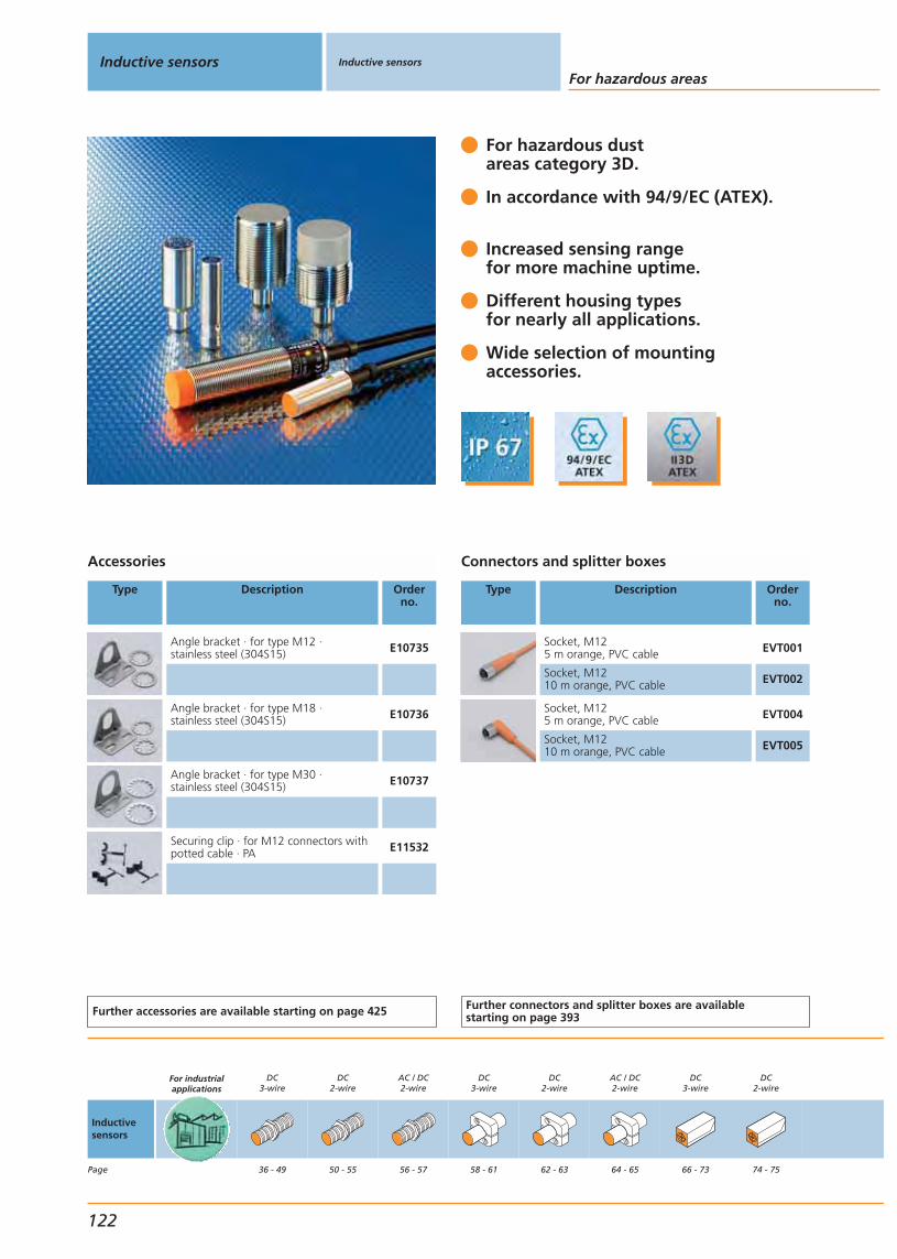
For hazardous dust areas category 3D.
In accordance with 94/9/EC (ATEX).
Increased sensing rangefor more machine uptime.
Different housing typesfor nearly all applications.
Wide selection of mountingaccessories.
Accessories
Type Description Orderno.
Angle bracket · for type M12 · stainless steel (304S15) E10735
Angle bracket · for type M18 · stainless steel (304S15) E10736
Angle bracket · for type M30 · stainless steel (304S15) E10737
Securing clip · for M12 connectors withpotted cable · PA E11532
Further accessories are available starting on page 425
Connectors and splitter boxes
Type Description Orderno.
Socket, M125 m orange, PVC cable EVT001
Socket, M1210 m orange, PVC cable EVT002
Socket, M125 m orange, PVC cable EVT004
Socket, M1210 m orange, PVC cable EVT005
Further connectors and splitter boxes are availablestarting on page 393
Inductive sensors Inductive sensors
For hazardous areas
122
Inductivesensors
Page
For industrialapplications
DC3-wire
36 - 49
DC2-wire
50 - 55
AC / DC2-wire
56 - 57
DC3-wire
58 - 61
DC2-wire
62 - 63
AC / DC2-wire
64 - 65
DC3-wire
66 - 73
DC2-wire
74 - 75

Hazardous dust area category 3D3-wire DC PNPThreaded housing
Housing Dimensions
[mm]
Sensingrange[mm]
Material Ub
[V]
Protec-tion
f
[Hz]
Iload
[mA]
Uab
[V]
I0
[mA]
Draw-ingno.
Orderno.
Cable 2 m · Output · Wiring diagram no. 4
M12 / L = 35 2 f brass 10...36 IP 67 1500 150 2.5 15 43 IF501A
M12 connector · Output · Connector group 75 · Wiring diagram no. 1
M12 / L = 45 4 f brass 10...36 IP 67 700 100 2.5 10 5 IFS20A
M12 / L = 50 7 nf brass 10...36 IP 67 700 100 2.5 10 6 IFS21A
M12 connector · Output · Connector group 75 · Wiring diagram no. 2
M12 / L = 45 4 f V4A (316S12) 10...36 IP 67 700 100 2.5 10 5 IFT20A
Cable 2 m · Output · Wiring diagram no. 4
M18 / L = 80 8 nf brass 10...55 IP 67 300 250 2.5 15 50 IG500A
M12 connector · Output · Connector group 75 · Wiring diagram no. 1
M18 / L = 45 8 nf brass 10...30 IP 67 300 100 2.5 15 185 IG501A
M18 / L = 45 8 f brass 10...30 IP 67 250 100 2.5 15 186 IG503A
Cable 2 m · Output · Wiring diagram no. 4
M18 / L = 38 5 f brass 18...36 IP 67 500 150 2.5 15 47 IG504A
M12 connector · Output · Connector group 75 · Wiring diagram no. 1
M18 / L = 89 8 nf brass 10...36 IP 67 300 250 2.5 15 187 IG505A
M18 / L = 46 8 f brass 10...36 IP 67 400 100 2.5 10 9 IGS20A
M18 / L = 51 12 nf brass 10...36 IP 67 300 100 2.5 10 10 IGS21A
M30 / L = 50 14 f V4A (316S12) 10...36 IP 67 100 100 2.5 10 13 IIT20A
M30 / L = 50 22 nf V4A (316S12) 10...36 IP 67 100 100 2.5 10 14 IIT21A
Common technical data
Operating temperature: -20...60 °CConnection: PVC cable, 2 m / M12 connector
You can find scale drawings from page 450
AC / DC2-wire
76 - 77
For oils andcoolants
78 - 97
For electro-magnetic fields
98 - 101
For hygienicand wet areas
102 - 113
For hazardousareas
114 - 127
Inductive sensors
Gen
eral
info
rmat
ion
List
of
arti
cles
Ind
uct
ive
sen
sors
Cap
acit
ive
sen
sors
Mag
net
icse
nso
rs,
cylin
der
sen
sors
Safe
tyte
chn
olo
gy
Val
ve s
enso
rsPh
oto
elec
tric
sen
sors
Ob
ject
reco
gn
itio
nEn
cod
ers
Eval
uat
ion
syst
ems,
po
wer
su
pp
lies
Co
nn
ecti
on
tech
no
log
yA
cces
sori
esTe
chn
ical
info
rmat
ion
and
cu
sto
mer
serv
ice
123

For hazardous dust areas category 3D.
In accordance with 94/9/EC (ATEX).
Different housing typesfor nearly all applications.
For units with terminal chamberNO / NC is programmable.
Tried and tested robustplastic housing.
Accessories
Type Description Orderno.
Securing clip · for M12 connectors withpotted cable · PA E11532
Further accessories are available starting on page 425
Connectors and splitter boxes
Type Description Orderno.
Socket, M125 m orange, PVC cable EVT001
Socket, M1210 m orange, PVC cable EVT002
Socket, M125 m orange, PVC cable EVT004
Socket, M1210 m orange, PVC cable EVT005
Further connectors and splitter boxes are availablestarting on page 393
Inductive sensors Inductive sensors
For hazardous areas
124
Inductivesensors
Page
For industrialapplications
DC3-wire
36 - 49
DC2-wire
50 - 55
AC / DC2-wire
56 - 57
DC3-wire
58 - 61
DC2-wire
62 - 63
AC / DC2-wire
64 - 65
DC3-wire
66 - 73
DC2-wire
74 - 75
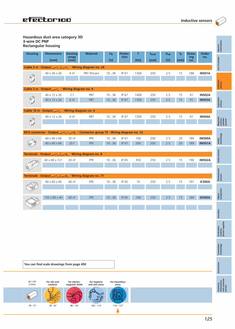
Hazardous dust area category 3D3-wire DC PNPRectangular housing
Housing Dimensions
[mm]
Sensingrange[mm]
Material Ub
[V]
Protec-tion
f
[Hz]
Iload
[mA]
Uab
[V]
I0
[mA]
Draw-ingno.
Orderno.
Cable 2 m · Output · Wiring diagram no. 24
40 x 26 x 26 4 nf PBT (Pocan) 10...36 IP 67 1300 250 2.5 15 188 IN501A
Cable 2 m · Output · Wiring diagram no. 4
40 x 12 x 26 2 f PBT 10...36 IP 67 1400 250 2.5 15 91 IN502A
40 x 12 x 26 4 nf PBT 10...36 IP 67 1300 250 2.5 15 91 IN503A
Cable 10 m · Output · Wiring diagram no. 4
40 x 12 x 26 4 nf PBT 10...36 IP 67 1300 250 2.5 15 91 IN504A
M12 connector · Output · Connector group 75 · Wiring diagram no. 12
40 x 40 x 66 35 nf PPE 10...36 IP 67 100 200 2.5 20 189 IM500A
40 x 40 x 66 20 f PPE 10...36 IP 67 200 200 2.5 20 189 IM501A
Terminals · Output · Wiring diagram no. 8
40 x 40 x 121 20 nf PPE 10...36 IP 65 350 250 2.5 15 190 IM502A
Terminals · Output · Wiring diagram no. 71
90 x 60 x 40 40 nf PPE 10...36 IP 65 10 250 2.5 15 191 IC500A
105 x 80 x 40 60 nf PPE 10...36 IP 65 100 250 2.5 15 184 ID500A
You can find scale drawings from page 450
AC / DC2-wire
76 - 77
For oils andcoolants
78 - 97
For electro-magnetic fields
98 - 101
For hygienicand wet areas
102 - 113
For hazardousareas
114 - 127
Inductive sensors
Gen
eral
info
rmat
ion
List
of
arti
cles
Ind
uct
ive
sen
sors
Cap
acit
ive
sen
sors
Mag
net
icse
nso
rs,
cylin
der
sen
sors
Safe
tyte
chn
olo
gy
Val
ve s
enso
rsPh
oto
elec
tric
sen
sors
Ob
ject
reco
gn
itio
nEn
cod
ers
Eval
uat
ion
syst
ems,
po
wer
su
pp
lies
Co
nn
ecti
on
tech
no
log
yA
cces
sori
esTe
chn
ical
info
rmat
ion
and
cu
sto
mer
serv
ice
125

For hazardous dust areas category 3D.
In accordance with 94/9/EC (ATEX).
Different housing typesfor nearly all applications.
Wide voltage range20...250 V AC/DC
Reduced wiring complexitydue to 2-wire technology.
Accessories
Type Description Orderno.
Angle bracket · for type M18 · stainless steel (304S15) E10736
Angle bracket · for type M30 · stainless steel (304S15) E10737
Further accessories are available starting on page 425
Inductive sensors Inductive sensors
For hazardous areas
126
Inductivesensors
Page
For industrialapplications
DC3-wire
36 - 49
DC2-wire
50 - 55
AC / DC2-wire
56 - 57
DC3-wire
58 - 61
DC2-wire
62 - 63
AC / DC2-wire
64 - 65
DC3-wire
66 - 73
DC2-wire
74 - 75

* Note for AC and AC/DC unitsMiniature fuse to IEC60127-2 sheet 1, = 2A (fast acting).Recommendation: check the unit for reliable function after ashort circuit.
Hazardous dust area category 3D2-wire AC/DC units
Housing Dimensions
[mm]
Sensingrange[mm]
Material Ub
[V]
Protec-tion
fAC / DC
[Hz]
IloadAC / DC
[mA]
UabAC / DC
[V]
I0
[mA]
Draw-ingno.
Orderno.
Cable 2 m · Output · Wiring diagram no. 7
M18 / L = 80 8 nf brass 20...250 IP 67 25 / 50 200 / 100 6.5 / 6 – 50 IG000A*
Cable 6 m · Output · Wiring diagram no. 7
M30 / L = 81 15 nf brass 20...250 IP 67 25 / 50 200 / 100 6.5 / 6 – 54 II000A*
Terminals · Output · Wiring diagram no. 10
40 x 40 x 121 15 f PPE 20...250 IP 65 25 / 70 200 / 100 6.5 / 6 – 190 IM000A*
Terminals · Output · Wiring diagram no. 72
90 x 60 x 40 40 nf PPE 20...250 IP 65 10 / 200 / 100 6.5 / 6 – 191 IC000A*
105 x 80 x 40 60 nf PPE 20...250 IP 65 4 / 200 / 100 6.5 / 6 – 184 ID000A*
Common technical data
Operating temperature: -20...60 °CConnection: 2 m PVC cable / 6 m PVC cableTerminals up to 2.5 mm
You can find scale drawings from page 450
AC / DC2-wire
76 - 77
For oils andcoolants
78 - 97
For electro-magnetic fields
98 - 101
For hygienicand wet areas
102 - 113
For hazardousareas
114 - 127
Inductive sensors
Gen
eral
info
rmat
ion
List
of
arti
cles
Ind
uct
ive
sen
sors
Cap
acit
ive
sen
sors
Mag
net
icse
nso
rs,
cylin
der
sen
sors
Safe
tyte
chn
olo
gy
Val
ve s
enso
rsPh
oto
elec
tric
sen
sors
Ob
ject
reco
gn
itio
nEn
cod
ers
Eval
uat
ion
syst
ems,
po
wer
su
pp
lies
Co
nn
ecti
on
tech
no
log
yA
cces
sori
esTe
chn
ical
info
rmat
ion
and
cu
sto
mer
serv
ice
127

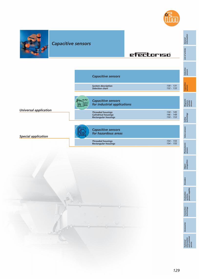
Gen
eral
info
rmat
ion
List
of
arti
cles
Ind
uct
ive
sen
sors
Cap
acit
ive
sen
sors
Mag
net
icse
nso
rs,
cylin
der
sen
sors
Safe
tyte
chn
olo
gy
Val
ve s
enso
rsPh
oto
elec
tric
sen
sors
Ob
ject
reco
gn
itio
nEn
cod
ers
Eval
uat
ion
syst
ems,
po
wer
su
pp
lies
Co
nn
ecti
on
tech
no
log
yA
cces
sori
esTe
chn
ical
info
rmat
ion
and
cu
sto
mer
serv
ice
Capacitive sensors
129
Capacitive sensorsfor industrial applications
Capacitive sensorsfor hazardous areas
Capacitive sensors
System descriptionSelection chart
Threaded housingsCylindrical housingsRectangular housings
Threaded housingsRectangular housings
Universal application
Special application
130 - 131132 - 133
134 - 145146 - 149150 - 153
154 - 155154 - 155

Visit our website: www.ifm-electronic.com
System descriptionCapacitive sensors Capacitive sensors
130
When detecting objects, very small changes in capacitance must be reliablyevaluated and converted into switching signals. The changes in capacitanceconstitute only a few femtofarads; the basic capacitance of the electrode isin the picofarad range. This makes high requirements for the electronics asthe circuit and design-related parasitic basic capacitances can make a precisecapacitance measurement much more difficult. The sensors must be design-ed so that they are insensitive to fluctuations of the parasitic basic capaci-tances, as these can amount to a multiple of the change in capacitance to bemeasured.Electromagnetic interference often occurs in typical applications. For a reli-able function, the sensors must be insensitive to such interference. The limitvalues are defined in the proximity switch standard EN 60947-5-2.Electromagnetic interference:
ESD (electrostatic discharges, e.g. for granulated plastic material)Burst (fast transients, e.g. by voltage spikes when switching motors orfluorescent tubes)Radiated high frequency (e.g. by walkie-talkies or HF welding systems)Conducted high frequency (e.g. frequency inverters, switched-modepower supplies or radio stations)
IntroductionCapacitive sensors are used for the non-contact detection of any objects. Incontrast to inductive sensors, which only detect metallic objects, capacitivesensors can also detect non-metallic materials.Typical applications are in the wood, paper, glass, plastic, food and chemicalindustries. In a packaging system, capacitive sensors for example monitor thatthe contents of a cardboard box are complete or check the presence of thenon-metallic caps. Another application is to monitor the conveying of sheetsof glass on a roller conveyor.
Not only metal:Capacitive sensors
detect almost allmaterials, herefor example a
log in a saw mill.
The capacitance between the active electrode of the sensor and the electricalearth potential is evaluated. An approaching object influences the electricalfield between these two “capacitor plates” and, consequently, the capaci-tance. This applies to metallic and non-metallic objects.The user can set the sensitivity using a potentiometer or the teach buttons.
Operating principle
Typical application in a
packaging system:Capacitive sensors
monitor theboxes for com-plete contentsand check the
presence of thenon-metallic caps.
Electronic requirements
Capacitive sensors
131
Visit our website: www.ifm-electronic.com
Gen
eral
info
rmat
ion
List
of
arti
cles
Ind
uct
ive
sen
sors
Cap
acit
ive
sen
sors
Mag
net
icse
nso
rs,
cylin
der
sen
sors
Safe
tyte
chn
olo
gy
Val
ve s
enso
rsPh
oto
elec
tric
sen
sors
Ob
ject
reco
gn
itio
nEn
cod
ers
Eval
uat
ion
syst
ems,
po
wer
su
pp
lies
Co
nn
ecti
on
tech
no
log
yA
cces
sori
esTe
chn
ical
info
rmat
ion
and
cu
sto
mer
serv
ice
ifm electronic has developed future-oriented solutions to meet the high sen-sor requirements. Special attention was given to very common noise sourcesin practice, which overlay the operating frequency of the capacitive sensors.Examples of such noise sources are frequency inverters, switched-modepower supplies, stepper-motor controllers, etc.A patented circuit concept of ifm electronic is a variant of the charge balancemethod. A clock generator controls the charging or discharging function of the sensor capacitance in the measuring range. This solution meets the highest requirements in the usual applications, especially as regards theinterference described above. By means of an advanced method, the capac-itive displacement currents of the sensor capacitance – caused by the charging or discharging processes of the capacitance – are evaluated. In conjunction with the use of microcontrollers, an improved overall perfor-mance is achieved and interfering radiation is reduced at the same time.
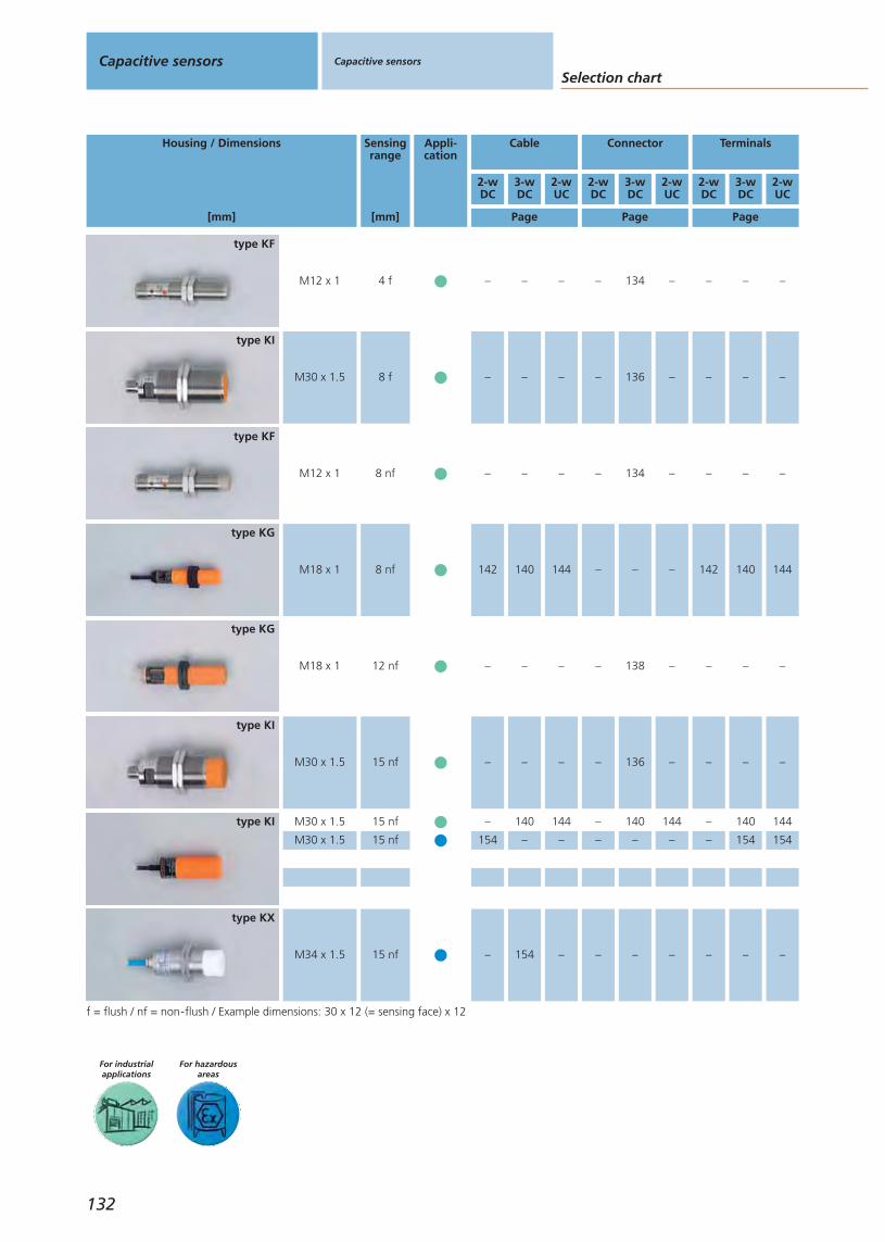
Capacitive sensors
Selection chartCapacitive sensors
For hazardousareas
For industrialapplications
Housing / Dimensions
[mm]
Sensingrange
[mm]
Appli-cation
Cable Connector Terminals
2-wDC
Page Page Page
3-wDC
2-wUC
2-wDC
3-wDC
2-wUC
2-wDC
3-wDC
2-wUC
132
f = flush / nf = non-flush / Example dimensions: 30 x 12 (= sensing face) x 12
M18 x 1 8 nf
type KG
M34 x 1.5 15 nf
type KX
M30 x 1.5 15 nf
M30 x 1.5 15 nf
type KI
M12 x 1 4 f
type KF
M30 x 1.5 8 f
type KI
M18 x 1 12 nf
type KG
M30 x 1.5 15 nf
type KI
type KF
M12 x 1 8 nf
142 140 144 – – – 142 140 144
– 154 – – – – – – –
– 140 144 – 140 144 – 140 144
154 – – – – – – 154 154
– – – – 134 – – – –
– – – – 136 – – – –
– – – – 138 – – – –
– – – – 136 – – – –
– – – – 134 – – – –
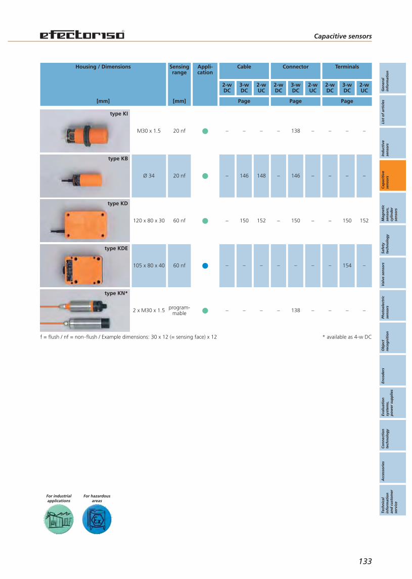
Housing / Dimensions
[mm]
Sensingrange
[mm]
Appli-cation
Cable Connector Terminals
2-wDC
Page Page Page
3-wDC
2-wUC
2-wDC
3-wDC
2-wUC
2-wDC
3-wDC
2-wUC
For hazardousareas
For industrialapplications
Capacitive sensors
Gen
eral
info
rmat
ion
List
of
arti
cles
Ind
uct
ive
sen
sors
Cap
acit
ive
sen
sors
Mag
net
icse
nso
rs,
cylin
der
sen
sors
Safe
tyte
chn
olo
gy
Val
ve s
enso
rsPh
oto
elec
tric
sen
sors
Ob
ject
reco
gn
itio
nEn
cod
ers
Eval
uat
ion
syst
ems,
po
wer
su
pp
lies
Co
nn
ecti
on
tech
no
log
yA
cces
sori
esTe
chn
ical
info
rmat
ion
and
cu
sto
mer
serv
ice
133
f = flush / nf = non-flush / Example dimensions: 30 x 12 (= sensing face) x 12
2 x M30 x 1.5 program-mable
type KN*
Ø 34 20 nf
type KB
120 x 80 x 30 60 nf
type KD
105 x 80 x 40 60 nf
type KDE
M30 x 1.5 20 nf
type KI
* available as 4-w DC
– – – – 138 – – – –
– 146 148 – 146 – – – –
– 150 152 – 150 – – 150 152
– – – – – – – 154 –
– – – – 138 – – – –

Robust stainless steel housing for higher tightening torques.
Easy setting of the sensing range using a potentiometer.
High operational reliability using noise-immune electronics.
Long sensing range for more excess gain.
Clearly visible indication of the switching status by 4-port LED.
Accessories
Type Description Orderno.
Angle bracket · for type M12 · stainless steel (304S15) E10735
Mounting clip · form O · for type M12 ·spring steel wire (1.4310) E11533
Further accessories are available starting on page 425
Connectors and splitter boxes
Type Description Orderno.
Socket, M12, group 72 m black, PUR cable EVC004
Socket, M12, group 75 m black, PUR cable EVC005
Socket, M12, group 72 m black, PUR cable EVC001
Socket, M12, group 75 m black, PUR cable EVC002
Further connectors and splitter boxes are availablestarting on page 393
Capacitive sensors Capacitive sensors For industrialapplications
134
Capacitivesensors
Page
For industrialapplications
DC3-wire
134 - 141
DC2-wire
142 - 143
AC/DC2-wire
144 - 145
DC3-wire
146 - 147
AC/DC2-wire
148 - 149
DC3-wire
150 - 151
AC/DC2-wire
152 - 153
For hazardousareas
154 - 155
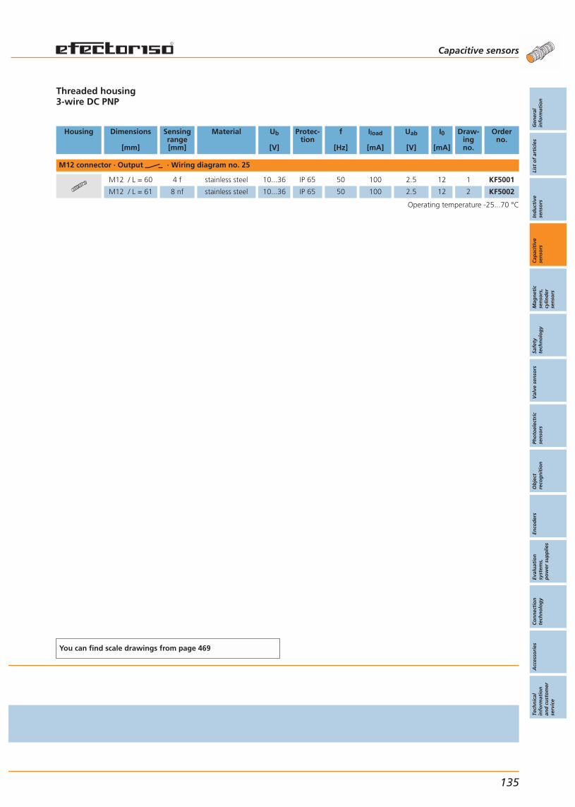
Threaded housing3-wire DC PNP
Housing Dimensions
[mm]
Sensingrange[mm]
Material Ub
[V]
Protec-tion
f
[Hz]
Iload
[mA]
Uab
[V]
I0
[mA]
Draw-ingno.
Orderno.
M12 connector · Output · Wiring diagram no. 25
M12 / L = 60 4 f stainless steel 10...36 IP 65 50 100 2.5 12 1 KF5001
M12 / L = 61 8 nf stainless steel 10...36 IP 65 50 100 2.5 12 2 KF5002
Operating temperature -25...70 °C
You can find scale drawings from page 469
Capacitive sensors
Gen
eral
info
rmat
ion
List
of
arti
cles
Ind
uct
ive
sen
sors
Cap
acit
ive
sen
sors
Mag
net
icse
nso
rs,
cylin
der
sen
sors
Safe
tyte
chn
olo
gy
Val
ve s
enso
rsPh
oto
elec
tric
sen
sors
Ob
ject
reco
gn
itio
nEn
cod
ers
Eval
uat
ion
syst
ems,
po
wer
su
pp
lies
Co
nn
ecti
on
tech
no
log
yA
cces
sori
esTe
chn
ical
info
rmat
ion
and
cu
sto
mer
serv
ice
135
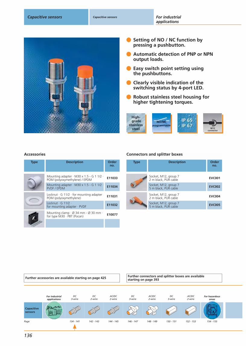
Setting of NO / NC function bypressing a pushbutton.
Automatic detection of PNP or NPNoutput loads.
Easy switch point setting using the pushbuttons.
Clearly visible indication of theswitching status by 4-port LED.
Robust stainless steel housing for higher tightening torques.
Accessories
Type Description Orderno.
Mounting adapter · M30 x 1.5 - G 1 1/2 ·POM (polyoxymethylene) / EPDM E11033
Mounting adapter · M30 x 1.5 - G 1 1/2 ·PVDF / EPDM E11034
Locknut · G 11/2 · for mounting adapterPOM (polyoxymethylene) E11031
Locknut · G 11/2 · for mounting adapter · PVDF E11032
Mounting clamp · Ø 34 mm - Ø 30 mm ·for type M30 · PBT (Pocan) E10077
Further accessories are available starting on page 425
Connectors and splitter boxes
Type Description Orderno.
Socket, M12, group 72 m black, PUR cable EVC001
Socket, M12, group 75 m black, PUR cable EVC002
Socket, M12, group 72 m black, PUR cable EVC004
Socket, M12, group 75 m black, PUR cable EVC005
Further connectors and splitter boxes are availablestarting on page 393
Capacitive sensors Capacitive sensors For industrialapplications
136
Capacitivesensors
Page
For industrialapplications
DC3-wire
134 - 141
DC2-wire
142 - 143
AC/DC2-wire
144 - 145
DC3-wire
146 - 147
AC/DC2-wire
148 - 149
DC3-wire
150 - 151
AC/DC2-wire
152 - 153
For hazardousareas
154 - 155
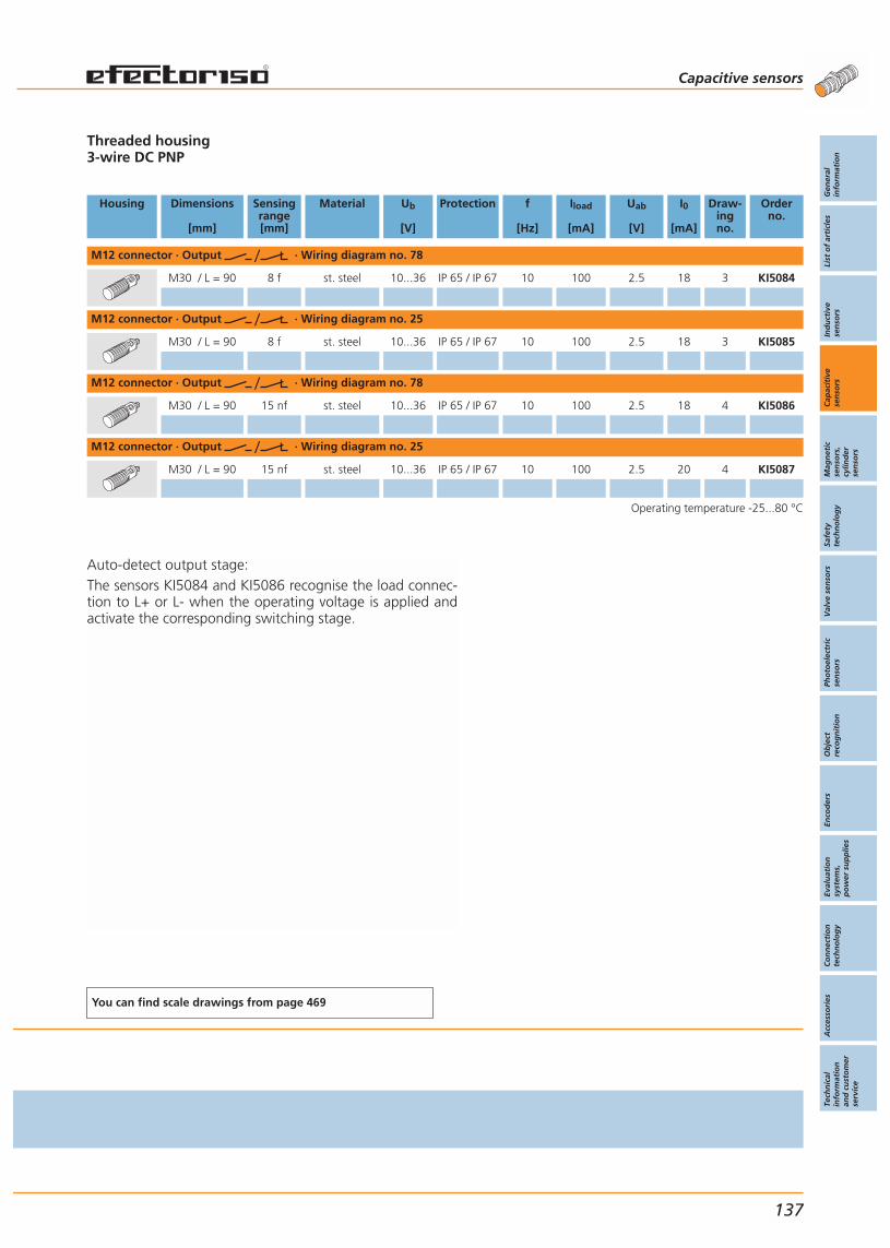
Auto-detect output stage:The sensors KI5084 and KI5086 recognise the load connec-tion to L+ or L- when the operating voltage is applied andactivate the corresponding switching stage.
Threaded housing3-wire DC PNP
Housing Dimensions
[mm]
Sensingrange[mm]
Material Ub
[V]
Protection f
[Hz]
Iload
[mA]
Uab
[V]
I0
[mA]
Draw-ingno.
Orderno.
M12 connector · Output · Wiring diagram no. 78
M30 / L = 90 8 f st. steel 10...36 IP 65 / IP 67 10 100 2.5 18 3 KI5084
M12 connector · Output · Wiring diagram no. 25
M30 / L = 90 8 f st. steel 10...36 IP 65 / IP 67 10 100 2.5 18 3 KI5085
M12 connector · Output · Wiring diagram no. 78
M30 / L = 90 15 nf st. steel 10...36 IP 65 / IP 67 10 100 2.5 18 4 KI5086
M12 connector · Output · Wiring diagram no. 25
M30 / L = 90 15 nf st. steel 10...36 IP 65 / IP 67 10 100 2.5 20 4 KI5087
Operating temperature -25...80 °C
You can find scale drawings from page 469
Capacitive sensors
Gen
eral
info
rmat
ion
List
of
arti
cles
Ind
uct
ive
sen
sors
Cap
acit
ive
sen
sors
Mag
net
icse
nso
rs,
cylin
der
sen
sors
Safe
tyte
chn
olo
gy
Val
ve s
enso
rsPh
oto
elec
tric
sen
sors
Ob
ject
reco
gn
itio
nEn
cod
ers
Eval
uat
ion
syst
ems,
po
wer
su
pp
lies
Co
nn
ecti
on
tech
no
log
yA
cces
sori
esTe
chn
ical
info
rmat
ion
and
cu
sto
mer
serv
ice
137
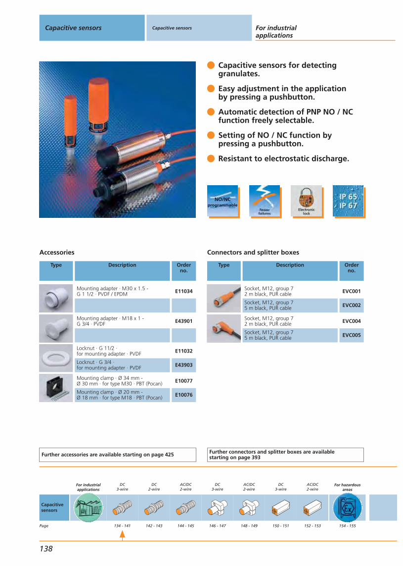
Capacitive sensors for detectinggranulates.
Easy adjustment in the application by pressing a pushbutton.
Automatic detection of PNP NO / NCfunction freely selectable.
Setting of NO / NC function bypressing a pushbutton.
Resistant to electrostatic discharge.
Accessories
Type Description Orderno.
Mounting adapter · M30 x 1.5 - G 1 1/2 · PVDF / EPDM E11034
Mounting adapter · M18 x 1 - G 3/4 · PVDF E43901
Locknut · G 11/2 · for mounting adapter · PVDF E11032
Locknut · G 3/4 · for mounting adapter · PVDF E43903
Mounting clamp · Ø 34 mm - Ø 30 mm · for type M30 · PBT (Pocan) E10077
Mounting clamp · Ø 20 mm - Ø 18 mm · for type M18 · PBT (Pocan) E10076
Further accessories are available starting on page 425
Connectors and splitter boxes
Type Description Orderno.
Socket, M12, group 72 m black, PUR cable EVC001
Socket, M12, group 75 m black, PUR cable EVC002
Socket, M12, group 72 m black, PUR cable EVC004
Socket, M12, group 75 m black, PUR cable EVC005
Further connectors and splitter boxes are availablestarting on page 393
Capacitive sensors Capacitive sensors For industrialapplications
138
Capacitivesensors
Page
For industrialapplications
DC3-wire
134 - 141
DC2-wire
142 - 143
AC/DC2-wire
144 - 145
DC3-wire
146 - 147
AC/DC2-wire
148 - 149
DC3-wire
150 - 151
AC/DC2-wire
152 - 153
For hazardousareas
154 - 155
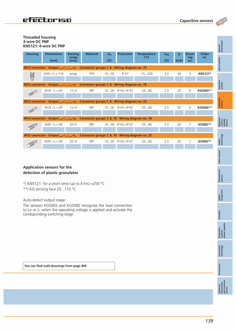
Application sensors for the detection of plastic granulates
*) KN5121: for a short time (up to 4 hrs) +250 °C**) KG sensing face 25...110 °C
Auto-detect output stage:The sensors KG5065 and KG5082 recognise the load connectionto L+ or L- when the operating voltage is applied and activate thecorresponding switching stage.
Threaded housing3-wire DC PNPKN5121: 4-wire DC PNP
Housing Dimensions
[mm]
Sensingrange[mm]
Material Ub
[V]
Protection Temperature[°C]
Uab
[V]
I0
[mA]
Draw-ingno.
Orderno.
M12 connector · Output · Connector groups 7, 8 · Wiring diagram no. 79
M30 / L = 116 progr. PPS 10...30 IP 67 -15...230 2.5 34 5 KN5121*
M12 connector · Output · Connector groups 7, 8 · Wiring diagram no. 78
M18 / L = 87 12 nf PBT 10...36 IP 65 / IP 67 -25...80 2.5 20 6 KG5065**
M12 connector · Output · Connector groups 7, 8 · Wiring diagram no. 25
M18 / L = 87 12 nf PBT 10...36 IP 65 / IP 67 -25...80 2.5 20 6 KG5066**
M12 connector · Output · Connector groups 7, 8, 10 · Wiring diagram no. 78
M30 / L = 90 20 nf PBT 10...36 IP 65 / IP 67 -25...80 2.5 20 7 KI5082**
M12 connector · Output · Connector groups 7, 8, 10 · Wiring diagram no. 25
M30 / L = 90 20 nf PBT 10...36 IP 65 / IP 67 -25...80 2.5 20 7 KI5083**
You can find scale drawings from page 469
Capacitive sensors
Gen
eral
info
rmat
ion
List
of
arti
cles
Ind
uct
ive
sen
sors
Cap
acit
ive
sen
sors
Mag
net
icse
nso
rs,
cylin
der
sen
sors
Safe
tyte
chn
olo
gy
Val
ve s
enso
rsPh
oto
elec
tric
sen
sors
Ob
ject
reco
gn
itio
nEn
cod
ers
Eval
uat
ion
syst
ems,
po
wer
su
pp
lies
Co
nn
ecti
on
tech
no
log
yA
cces
sori
esTe
chn
ical
info
rmat
ion
and
cu
sto
mer
serv
ice
139

High operational reliability due toincreased noise immunity.
Different connection options usingcable, connector or terminals.
Adjustable sensing range up to 15 mm by means of a potentiometer.
Resistant plastic housingfor various applications.
Accessories
Type Description Orderno.
Mounting clamp · Ø 20 mm - Ø 18 mm ·for type M18 · PBT (Pocan) E10076
Mounting clamp · Ø 34 mm - Ø 30 mm ·for type M30 · PBT (Pocan) E10077
Mounting adapter · M18 x 1 - G 3/4 ·POM (polyoxymethylene) E43900
Locknut · G 3/4 · for mounting adapter ·POM (polyoxymethylene) E43902
Further accessories are available starting on page 425
Connectors and splitter boxes
Type Description Orderno.
Socket, group 34wirable E10058
Further connectors and splitter boxes are availablestarting on page 393
Capacitive sensors Capacitive sensors For industrialapplications
140
Capacitivesensors
Page
For industrialapplications
DC3-wire
134 - 141
DC2-wire
142 - 143
AC/DC2-wire
144 - 145
DC3-wire
146 - 147
AC/DC2-wire
148 - 149
DC3-wire
150 - 151
AC/DC2-wire
152 - 153
For hazardousareas
154 - 155

Threaded housing3-wire DC PNP
Housing Dimensions
[mm]
Sensingrange[mm]
Material Ub
[V]
Protec-tion
f
[Hz]
Iload
[mA]
Uab
[V]
I0
[mA]
Draw-ingno.
Orderno.
connector (DIN 43650) · Output · Connector groups 34 · Wiring diagram no. 26
M30 / L = 92 15 nf PBT 10...36 IP 65 40 250 2.5 13 8 KI5038
M12 connector · Output · Connector groups 7, 8, 10 · Wiring diagram no. 1
M18 / L = 93.8 8 nf PBT 10...36 IP 67 50 250 2.5 10 9 KG5057
Cable 2 m · Output · Wiring diagram no. 4
M18 / L = 84 8 nf PBT 10...36 IP 67 50 250 2.5 10 10 KG5043
M30 / L = 81 15 nf PBT 10...36 IP 65 40 250 2.5 13 11 KI5002
Cable 2 m · Output · Wiring diagram no. 11
M30 / L = 81 15 nf PBT 10...36 IP 65 40 250 2.5 13 11 KI5001
Terminals · Output · Wiring diagram no. 27
M18 / L = 110 8 nf PBT 10...36 IP 65 50 250 2.5 10 12 KG5041
Terminals · Output · Wiring diagram no. 8
M30 / L = 125 15 nf PBT 10...55 IP 65 40 250 2.5 14 13 KI5023
Operating temperature -25...80 °C
You can find scale drawings from page 469
Capacitive sensors
Gen
eral
info
rmat
ion
List
of
arti
cles
Ind
uct
ive
sen
sors
Cap
acit
ive
sen
sors
Mag
net
icse
nso
rs,
cylin
der
sen
sors
Safe
tyte
chn
olo
gy
Val
ve s
enso
rsPh
oto
elec
tric
sen
sors
Ob
ject
reco
gn
itio
nEn
cod
ers
Eval
uat
ion
syst
ems,
po
wer
su
pp
lies
Co
nn
ecti
on
tech
no
log
yA
cces
sori
esTe
chn
ical
info
rmat
ion
and
cu
sto
mer
serv
ice
141

Different connection optionsusing cable or terminals.
Adjustable sensing range up to 8 mm by means of a potentiometer.
Output as normally open or normally closed programmable.
Resistant plastic housingfor various applications.
Accessories
Type Description Orderno.
Mounting clamp · Ø 20 mm - Ø 18 mm · for type M18 · PBT (Pocan) E10076
Mounting adapter · M18 x 1 - G 3/4 · POM (polyoxymethylene) E43900
Mounting adapter · M18 x 1 - G 1 · POM (polyoxymethylene) E43904
Locknut · G 3/4 · for mounting adapter ·POM (polyoxymethylene) E43902
Locknut · G 1 · for mounting adapter ·POM (polyoxymethylene) E43906
Mounting set · Ø 18.5 mm · for type KGst. steel (320S31) / st. steel (316C) E20870
Further accessories are available starting on page 425
Capacitive sensors Capacitive sensors For industrialapplications
142
Capacitivesensors
Page
For industrialapplications
DC3-wire
134 - 141
DC2-wire
142 - 143
AC/DC2-wire
144 - 145
DC3-wire
146 - 147
AC/DC2-wire
148 - 149
DC3-wire
150 - 151
AC/DC2-wire
152 - 153
For hazardousareas
154 - 155
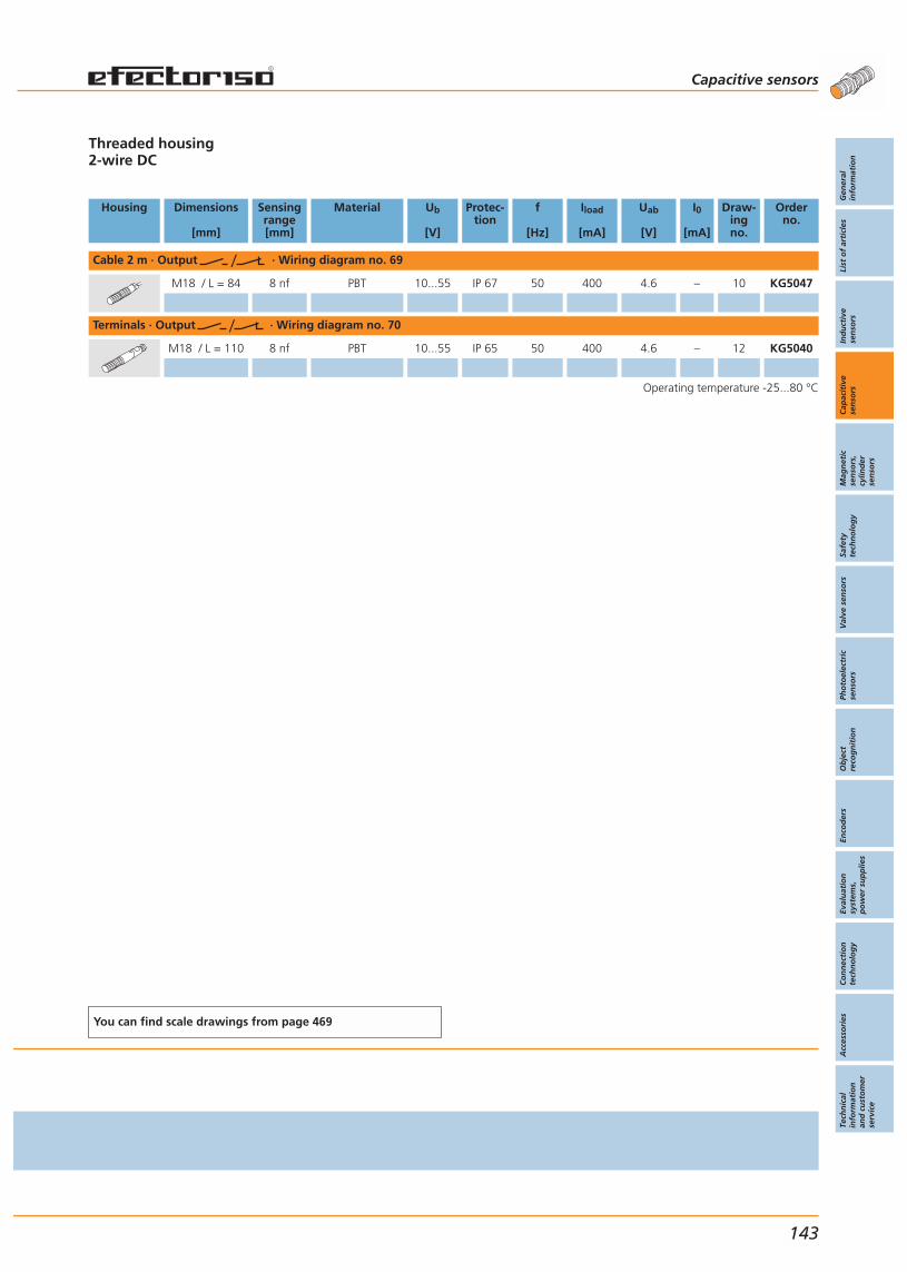
Threaded housing2-wire DC
Housing Dimensions
[mm]
Sensingrange[mm]
Material Ub
[V]
Protec-tion
f
[Hz]
Iload
[mA]
Uab
[V]
I0
[mA]
Draw-ingno.
Orderno.
Cable 2 m · Output · Wiring diagram no. 69
M18 / L = 84 8 nf PBT 10...55 IP 67 50 400 4.6 – 10 KG5047
Terminals · Output · Wiring diagram no. 70
M18 / L = 110 8 nf PBT 10...55 IP 65 50 400 4.6 – 12 KG5040
Operating temperature -25...80 °C
You can find scale drawings from page 469
Capacitive sensors
Gen
eral
info
rmat
ion
List
of
arti
cles
Ind
uct
ive
sen
sors
Cap
acit
ive
sen
sors
Mag
net
icse
nso
rs,
cylin
der
sen
sors
Safe
tyte
chn
olo
gy
Val
ve s
enso
rsPh
oto
elec
tric
sen
sors
Ob
ject
reco
gn
itio
nEn
cod
ers
Eval
uat
ion
syst
ems,
po
wer
su
pp
lies
Co
nn
ecti
on
tech
no
log
yA
cces
sori
esTe
chn
ical
info
rmat
ion
and
cu
sto
mer
serv
ice
143
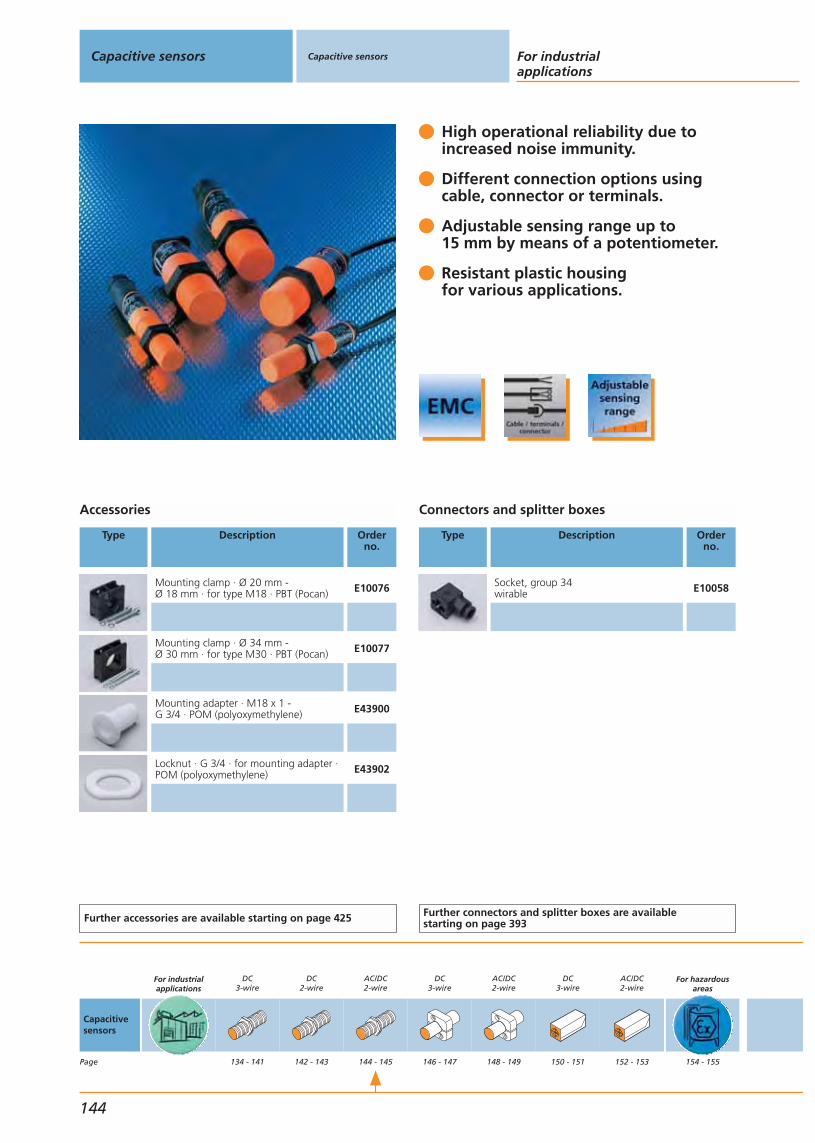
High operational reliability due toincreased noise immunity.
Different connection options usingcable, connector or terminals.
Adjustable sensing range up to 15 mm by means of a potentiometer.
Resistant plastic housingfor various applications.
Accessories
Type Description Orderno.
Mounting clamp · Ø 20 mm - Ø 18 mm · for type M18 · PBT (Pocan) E10076
Mounting clamp · Ø 34 mm - Ø 30 mm · for type M30 · PBT (Pocan) E10077
Mounting adapter · M18 x 1 - G 3/4 · POM (polyoxymethylene) E43900
Locknut · G 3/4 · for mounting adapter ·POM (polyoxymethylene) E43902
Further accessories are available starting on page 425
Connectors and splitter boxes
Type Description Orderno.
Socket, group 34wirable E10058
Further connectors and splitter boxes are availablestarting on page 393
Capacitive sensors Capacitive sensors For industrialapplications
144
Capacitivesensors
Page
For industrialapplications
DC3-wire
134 - 141
DC2-wire
142 - 143
AC/DC2-wire
144 - 145
DC3-wire
146 - 147
AC/DC2-wire
148 - 149
DC3-wire
150 - 151
AC/DC2-wire
152 - 153
For hazardousareas
154 - 155

* Note for AC and AC/DC unitsMiniature fuse to IEC60127-2 sheet 1, = 2A (fast acting).Recommendation: check the unit for reliable function after ashort circuit.
Threaded housing2-wire AC/DC
Housing Dimensions
[mm]
Sensingrange[mm]
Material Ub
[V]
Protec-tion
fAC / DC
[Hz]
IloadAC / DC
[mA]
UabAC / DC
[V]
I0
[mA]
Draw-ingno.
Orderno.
Connector (DIN 43650) · Output · Connector group 34 · Wiring diagram no. 28
M30 / L = 92 15 nf PBT 20...250 IP 65 25 / 40 250 10 / 8 – 8 KI0040*
Cable 2 m · Output · Wiring diagram no. 7
M18 / L = 84 8 nf PBT 20...250 IP 67 25 / 50 350 / 100 6 – 10 KG0009*
M30 / L = 81 15 nf PBT 20...250 IP 65 25 / 40 250 10 / 8 – 11 KI0016*
Cable 2 m · Output · Wiring diagram no. 9
M18 / L = 84 8 nf PBT 20...250 IP 67 25 / 50 350 / 100 6 – 10 KG0010*
M30 / L = 81 15 nf PBT 20...250 IP 65 25 / 40 250 10 / 8 – 11 KI0020*
Terminals · Output · Wiring diagram no. 29
M18 / L = 110 8 nf PBT 20...250 IP 65 25 / 50 350 / 100 6 – 12 KG0008*
Terminals · Output · Wiring diagram no. 10
M30 / L = 125 15 nf PBT 20...250 IP 65 25 / 40 250 10 / 8 – 13 KI0024*
Operating temperature -25...80 °C
You can find scale drawings from page 469
Capacitive sensors
Gen
eral
info
rmat
ion
List
of
arti
cles
Ind
uct
ive
sen
sors
Cap
acit
ive
sen
sors
Mag
net
icse
nso
rs,
cylin
der
sen
sors
Safe
tyte
chn
olo
gy
Val
ve s
enso
rsPh
oto
elec
tric
sen
sors
Ob
ject
reco
gn
itio
nEn
cod
ers
Eval
uat
ion
syst
ems,
po
wer
su
pp
lies
Co
nn
ecti
on
tech
no
log
yA
cces
sori
esTe
chn
ical
info
rmat
ion
and
cu
sto
mer
serv
ice
145

High operational reliability due toincreased noise immunity.
Different connection options usingcable, connector or terminals.
Adjustable sensing range up to20 mm by means of a potentiometer.
Resistant plastic housingfor various applications.
Accessories
Type Description Orderno.
Mounting clamp · Ø 34 mm · PBT(Pocan) E10017
Mounting adapter · Ø 34 mm - G 1 1/2 · POM (polyoxymethylene) E11027
Locknut · G 11/2 · for mounting adapterPOM (polyoxymethylene) E11031
Further accessories are available starting on page 425
Capacitive sensors Capacitive sensors For industrialapplications
146
Capacitivesensors
Page
For industrialapplications
DC3-wire
134 - 141
DC2-wire
142 - 143
AC/DC2-wire
144 - 145
DC3-wire
146 - 147
AC/DC2-wire
148 - 149
DC3-wire
150 - 151
AC/DC2-wire
152 - 153
For hazardousareas
154 - 155
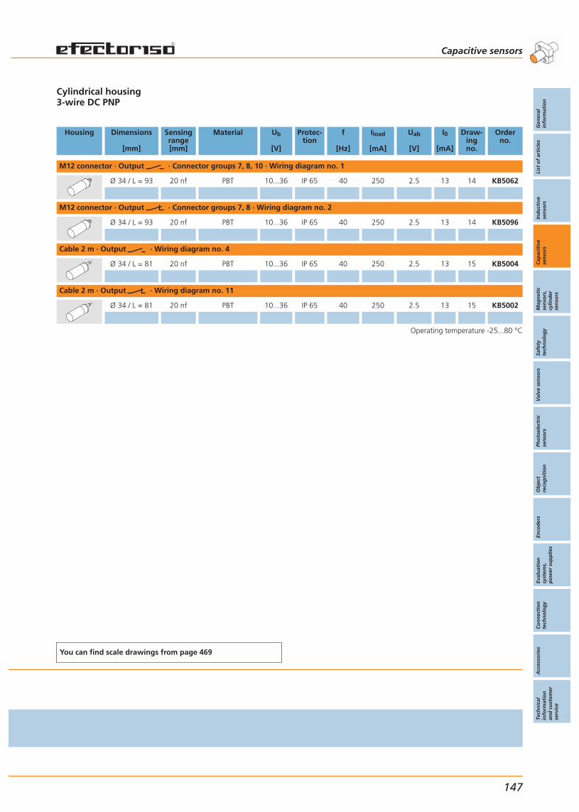
Cylindrical housing3-wire DC PNP
Housing Dimensions
[mm]
Sensingrange[mm]
Material Ub
[V]
Protec-tion
f
[Hz]
Iload
[mA]
Uab
[V]
I0
[mA]
Draw-ingno.
Orderno.
M12 connector · Output · Connector groups 7, 8, 10 · Wiring diagram no. 1
Ø 34 / L = 93 20 nf PBT 10...36 IP 65 40 250 2.5 13 14 KB5062
M12 connector · Output · Connector groups 7, 8 · Wiring diagram no. 2
Ø 34 / L = 93 20 nf PBT 10...36 IP 65 40 250 2.5 13 14 KB5096
Cable 2 m · Output · Wiring diagram no. 4
Ø 34 / L = 81 20 nf PBT 10...36 IP 65 40 250 2.5 13 15 KB5004
Cable 2 m · Output · Wiring diagram no. 11
Ø 34 / L = 81 20 nf PBT 10...36 IP 65 40 250 2.5 13 15 KB5002
Operating temperature -25...80 °C
You can find scale drawings from page 469
Capacitive sensors
Gen
eral
info
rmat
ion
List
of
arti
cles
Ind
uct
ive
sen
sors
Cap
acit
ive
sen
sors
Mag
net
icse
nso
rs,
cylin
der
sen
sors
Safe
tyte
chn
olo
gy
Val
ve s
enso
rsPh
oto
elec
tric
sen
sors
Ob
ject
reco
gn
itio
nEn
cod
ers
Eval
uat
ion
syst
ems,
po
wer
su
pp
lies
Co
nn
ecti
on
tech
no
log
yA
cces
sori
esTe
chn
ical
info
rmat
ion
and
cu
sto
mer
serv
ice
147
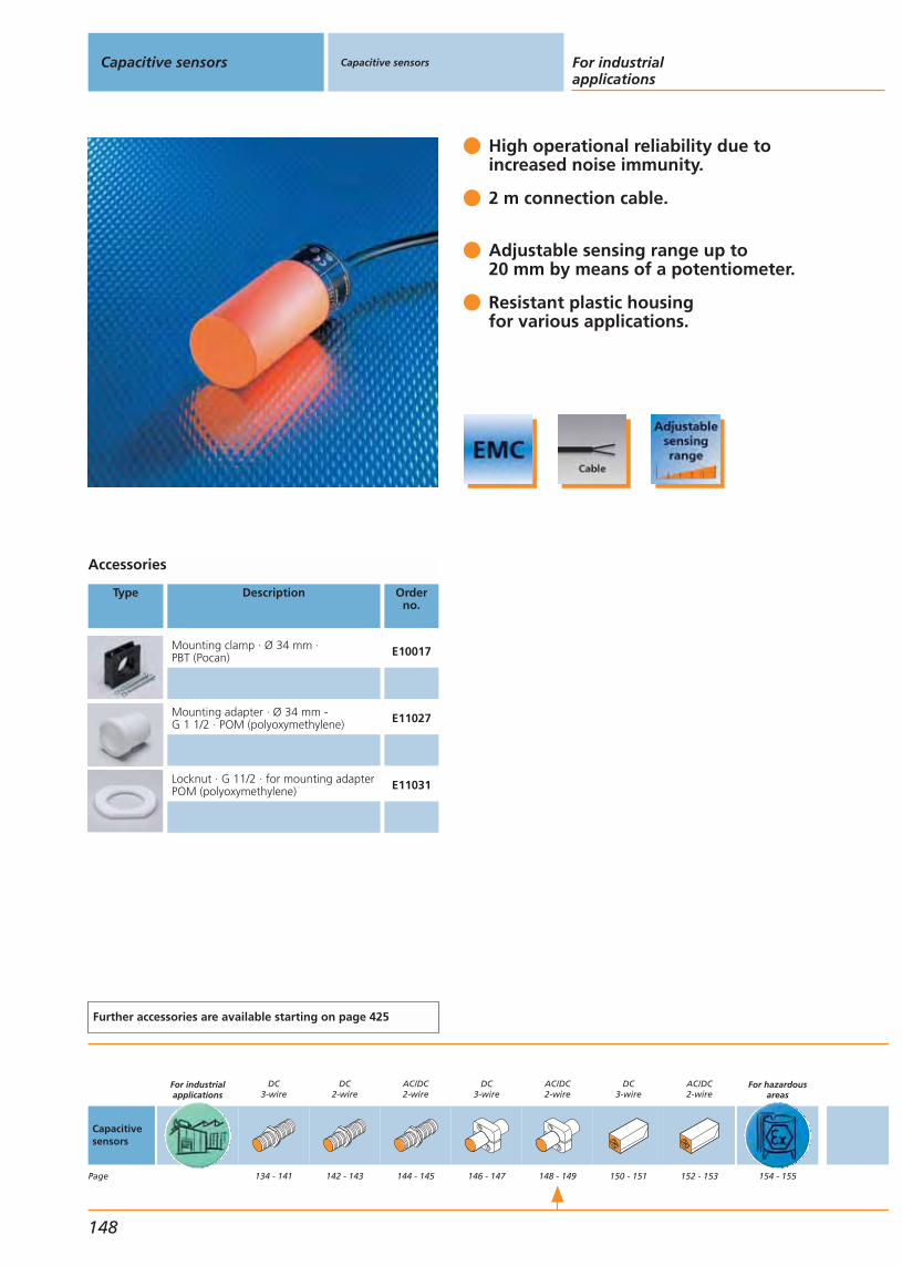
High operational reliability due toincreased noise immunity.
2 m connection cable.
Adjustable sensing range up to20 mm by means of a potentiometer.
Resistant plastic housingfor various applications.
Accessories
Type Description Orderno.
Mounting clamp · Ø 34 mm · PBT (Pocan) E10017
Mounting adapter · Ø 34 mm - G 1 1/2 · POM (polyoxymethylene) E11027
Locknut · G 11/2 · for mounting adapterPOM (polyoxymethylene) E11031
Further accessories are available starting on page 425
Capacitive sensors Capacitive sensors For industrialapplications
148
Capacitivesensors
Page
For industrialapplications
DC3-wire
134 - 141
DC2-wire
142 - 143
AC/DC2-wire
144 - 145
DC3-wire
146 - 147
AC/DC2-wire
148 - 149
DC3-wire
150 - 151
AC/DC2-wire
152 - 153
For hazardousareas
154 - 155
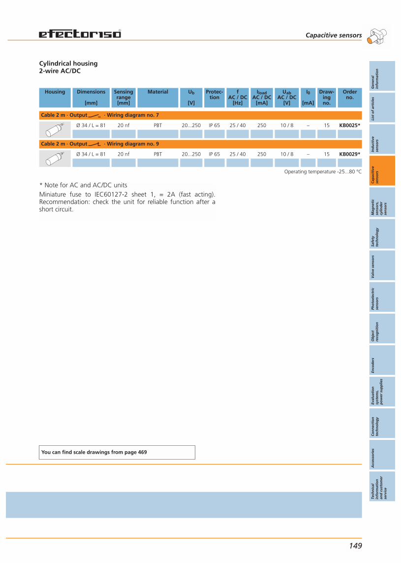
* Note for AC and AC/DC unitsMiniature fuse to IEC60127-2 sheet 1, = 2A (fast acting).Recommendation: check the unit for reliable function after ashort circuit.
Cylindrical housing2-wire AC/DC
Housing Dimensions
[mm]
Sensingrange[mm]
Material Ub
[V]
Protec-tion
fAC / DC
[Hz]
IloadAC / DC
[mA]
UabAC / DC
[V]
I0
[mA]
Draw-ingno.
Orderno.
Cable 2 m · Output · Wiring diagram no. 7
Ø 34 / L = 81 20 nf PBT 20...250 IP 65 25 / 40 250 10 / 8 – 15 KB0025*
Cable 2 m · Output · Wiring diagram no. 9
Ø 34 / L = 81 20 nf PBT 20...250 IP 65 25 / 40 250 10 / 8 – 15 KB0029*
Operating temperature -25...80 °C
You can find scale drawings from page 469
Capacitive sensors
Gen
eral
info
rmat
ion
List
of
arti
cles
Ind
uct
ive
sen
sors
Cap
acit
ive
sen
sors
Mag
net
icse
nso
rs,
cylin
der
sen
sors
Safe
tyte
chn
olo
gy
Val
ve s
enso
rsPh
oto
elec
tric
sen
sors
Ob
ject
reco
gn
itio
nEn
cod
ers
Eval
uat
ion
syst
ems,
po
wer
su
pp
lies
Co
nn
ecti
on
tech
no
log
yA
cces
sori
esTe
chn
ical
info
rmat
ion
and
cu
sto
mer
serv
ice
149

High operational reliability due toincreased noise immunity.
Different connection options usingcable, connector or terminals.
Sensing range up to 60mm adjust-able by means of a potentiometer.
Resistant plastic housingfor various applications.
Accessories
Type Description Orderno.
Mounting set · angled · for type KD · st. steel (316C) / st. steel (320S31) E11121
Mounting set · straight · for type KD · st. steel (316C) / st. steel (320S31) E11122
shaft · Ø 14 / M12 · straight · stainless steel (320S31) E20939
shaft · Ø 14 / M12 · angled · stainless steel (320S31) E20941
Further accessories are available starting on page 425
Connectors and splitter boxes
Type Description Orderno.
Socket, M12, group 72 m black, PUR cable EVC001
Socket, M12, group 75 m black, PUR cable EVC002
Socket, M12, group 72 m black, PUR cable EVC004
Socket, M12, group 75 m black, PUR cable EVC005
Further connectors and splitter boxes are availablestarting on page 393
Capacitive sensors Capacitive sensors For industrialapplications
150
Capacitivesensors
Page
For industrialapplications
DC3-wire
134 - 141
DC2-wire
142 - 143
AC/DC2-wire
144 - 145
DC3-wire
146 - 147
AC/DC2-wire
148 - 149
DC3-wire
150 - 151
AC/DC2-wire
152 - 153
For hazardousareas
154 - 155

Rectangular housing3-wire DC PNP
Housing Dimensions
[mm]
Sensingrange[mm]
Material Ub
[V]
Protec-tion
f
[Hz]
Iload
[mA]
Uab
[V]
I0
[mA]
Draw-ingno.
Orderno.
M12 connector · Output · Connector groups 7, 8, 10 · Wiring diagram no. 80
105 x 80 x 40 60 nf modified PPO 10...36 IP 65 10 250 2.5 5 16 KD5039
M12 connector · Output · Connector groups 7, 8, 10 · Wiring diagram no. 1
105 x 80 x 40 60 nf modified PPO 10...36 IP 65 10 250 2.5 5 16 KD5044
Cable 2 m · Output · Wiring diagram no. 4
120 x 80 x 30 60 nf modified PPO 10...36 IP 65 10 250 2.5 15 17 KD5022
Terminals · Output · Wiring diagram no. 71
105 x 80 x 40 60 nf modified PPO 10...36 IP 65 10 250 2.5 15 18 KD5018
Operating temperature -25...80 °C
You can find scale drawings from page 469
Capacitive sensors
Gen
eral
info
rmat
ion
List
of
arti
cles
Ind
uct
ive
sen
sors
Cap
acit
ive
sen
sors
Mag
net
icse
nso
rs,
cylin
der
sen
sors
Safe
tyte
chn
olo
gy
Val
ve s
enso
rsPh
oto
elec
tric
sen
sors
Ob
ject
reco
gn
itio
nEn
cod
ers
Eval
uat
ion
syst
ems,
po
wer
su
pp
lies
Co
nn
ecti
on
tech
no
log
yA
cces
sori
esTe
chn
ical
info
rmat
ion
and
cu
sto
mer
serv
ice
151

High operational reliability due toincreased noise immunity.
Different connection options usingcable, connector or terminals.
Adjustable sensing range up to60 mm by means of a potentiometer.
Resistant plastic housingfor various applications.
Accessories
Type Description Orderno.
Mounting set · angled · for type KD ·st. steel (316C) / st. steel (320S31) E11121
Mounting set · straight · for type KD · st. steel (316C) / st. steel (320S31) E11122
Shaft · Ø 14 / M12 · straight · stainless steel (320S31) E20939
Shaft · Ø 14 / M12 · angled ·stainless steel (320S31) E20941
Further accessories are available starting on page 425
Capacitive sensors Capacitive sensors For industrialapplications
152
Capacitivesensors
Page
For industrialapplications
DC3-wire
134 - 141
DC2-wire
142 - 143
AC/DC2-wire
144 - 145
DC3-wire
146 - 147
AC/DC2-wire
148 - 149
DC3-wire
150 - 151
AC/DC2-wire
152 - 153
For hazardousareas
154 - 155
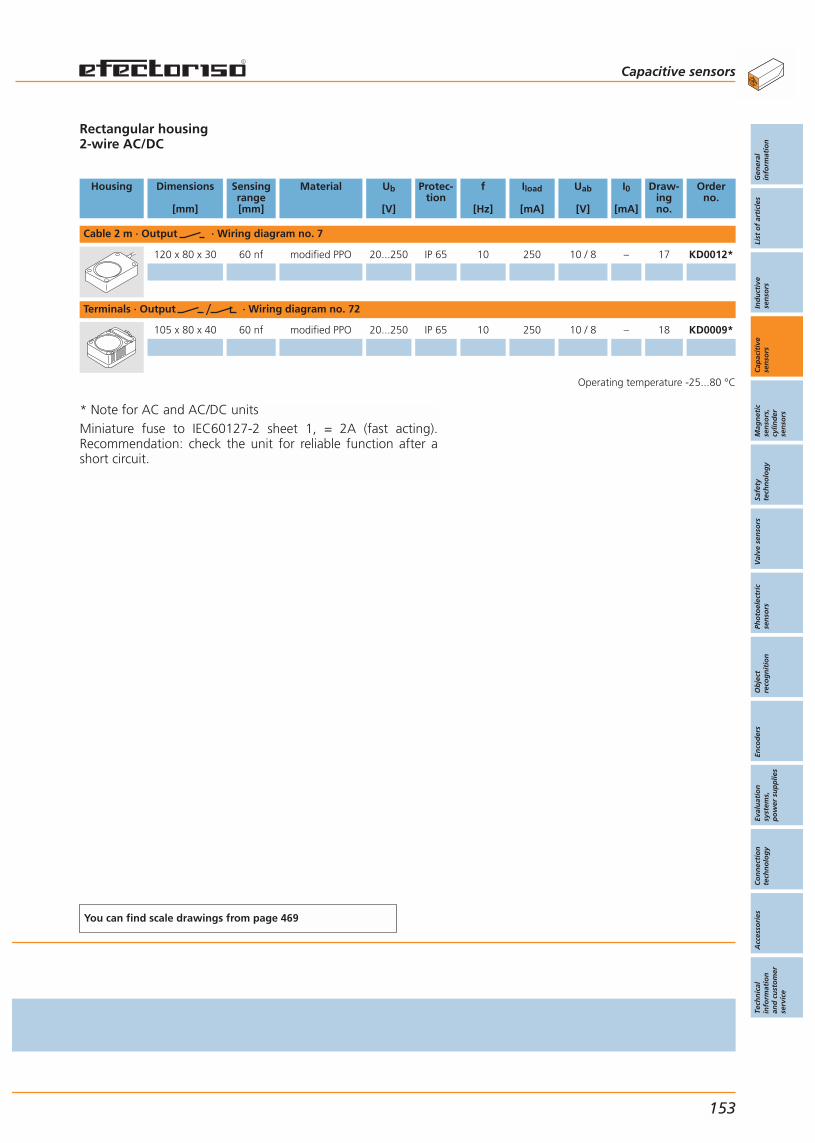
* Note for AC and AC/DC unitsMiniature fuse to IEC60127-2 sheet 1, = 2A (fast acting).Recommendation: check the unit for reliable function after ashort circuit.
Rectangular housing2-wire AC/DC
Housing Dimensions
[mm]
Sensingrange[mm]
Material Ub
[V]
Protec-tion
f
[Hz]
Iload
[mA]
Uab
[V]
I0
[mA]
Draw-ingno.
Orderno.
Cable 2 m · Output · Wiring diagram no. 7
120 x 80 x 30 60 nf modified PPO 20...250 IP 65 10 250 10 / 8 – 17 KD0012*
Terminals · Output · Wiring diagram no. 72
105 x 80 x 40 60 nf modified PPO 20...250 IP 65 10 250 10 / 8 – 18 KD0009*
Operating temperature -25...80 °C
You can find scale drawings from page 469
Capacitive sensors
Gen
eral
info
rmat
ion
List
of
arti
cles
Ind
uct
ive
sen
sors
Cap
acit
ive
sen
sors
Mag
net
icse
nso
rs,
cylin
der
sen
sors
Safe
tyte
chn
olo
gy
Val
ve s
enso
rsPh
oto
elec
tric
sen
sors
Ob
ject
reco
gn
itio
nEn
cod
ers
Eval
uat
ion
syst
ems,
po
wer
su
pp
lies
Co
nn
ecti
on
tech
no
log
yA
cces
sori
esTe
chn
ical
info
rmat
ion
and
cu
sto
mer
serv
ice
153

NAMUR sensors for hazardousgas and dust areas.
For categories 1G, 1D und 3Din accordance with 94/9/EC (ATEX).
Increased EMC immunity.
Detection of metallicand non metallic media.
Compensation for condensation or moisture.
Accessories
Type Description Orderno.
Angle bracket · for type M30 · stainlesssteel (304S15) E10737
Mounting adapter · M30 x 1.5 - G 1 1/2 ·POM (polyoxymethylene) / EPDM E11033
Mounting adapter · M30 x 1.5 - G 1 1/2 ·PVDF / EPDM E11034
Locknut · G 11/2 · for mounting adapterPOM (polyoxymethylene) E11031
Locknut · G 11/2 · for mounting adapterPVDF E11032
Protective cover · G 11/4 · for mountingadapter · PES / black transparent E11078
Further accessories are available starting on page 425
Amplifiers
Type Description Orderno.
Amplifier,230 AC (45...65 Hz)1-channel, Relay output N0031A
Amplifier,24 DC1-channel, Transistor outputs N0531A
Amplifier,24 DC1-channel, Relay output N0530A
Amplifier,24 DC2-channel, Relay outputs N0533A
Amplifier,230 AC (45...65 Hz)2-channel, Relay outputs N0033A
Amplifier,24 DC2-channel, Transistor outputs N0534A
Further amplifiers are available starting on page 378
Capacitive sensors Capacitive sensors
For hazardous areas
154
Capacitivesensors
Page
For industrialapplications
DC3-wire
134 - 141
DC2-wire
142 - 143
AC/DC2-wire
144 - 145
DC3-wire
146 - 147
AC/DC2-wire
148 - 149
DC3-wire
150 - 151
AC/DC2-wire
152 - 153
For hazardousareas
154 - 155

* Note for AC and AC/DC unitsMiniature fuse to IEC60127-2 sheet 1, = 2A (fast acting).Recommendation: check the unit for reliable function after ashort circuit.
For ATEX units the fuse must be placed outside the hazardousarea.
2-wire: KI5030, KI0042, KD000A, KX50013-wire: KI5065, KD500A
Housing Dimensions
[mm]
Sensingrange[mm]
Material Ub
[V]
Outputstage
Category Draw-ingno.
Orderno.
Cable 2 m · Output · Wiring diagram no. 19
M30 / L = 81 15 nf PBT 7.5...15 DC normally closed 1G / 1D 11 KI5030
Cable 2 m · Output · Wiring diagram no. 30
M34 / L = 92 15 nf brass 7.5...15 DC normally closed 1G / 1D 19 KX5001
Terminals · Output · Wiring diagram no. 8
M30 / L = 151 15 nf PBT 10...30 DC no / nc programmable 3D 20 KI5065
Terminals · Output · Wiring diagram no. 71
105 x 80 x 40 60 nf modified PPO 10...36 DC no / nc programmable 3D 18 KD500A
Terminals · Output · Wiring diagram no. 10
M30 / L = 151 15 nf PBT 20...250 AC/DC no / nc programmable 3D 20 KI0042*
Terminals · Output · Wiring diagram no. 72
105 x 80 x 40 60 nf modified PPO 20...250 AC/DC no / nc programmable 3D 18 KD000A*
Common technical data
Operating temperature: -20...60 °CCurrent consumption undamped: KI5030: > 2.2 mAKX5001: > 2.2 mAKI5065: < 14 mA (24 V) / < 17.5 mA (55 V)KD500A: < 13 (24 V) / < 15.5 (36 V)Current consumption damped:KI5030: < 1 mAKX5001: < 1 mAKI5065: < 4 mA (24 V) / < 7.5 mA (55 V)KD500A: < 5 (24 V) / < 8 (36 V) Protection rating: IP 65
You can find scale drawings from page 469
Capacitive sensors
Gen
eral
info
rmat
ion
List
of
arti
cles
Ind
uct
ive
sen
sors
Cap
acit
ive
sen
sors
Mag
net
icse
nso
rs,
cylin
der
sen
sors
Safe
tyte
chn
olo
gy
Val
ve s
enso
rsPh
oto
elec
tric
sen
sors
Ob
ject
reco
gn
itio
nEn
cod
ers
Eval
uat
ion
syst
ems,
po
wer
su
pp
lies
Co
nn
ecti
on
tech
no
log
yA
cces
sori
esTe
chn
ical
info
rmat
ion
and
cu
sto
mer
serv
ice
155

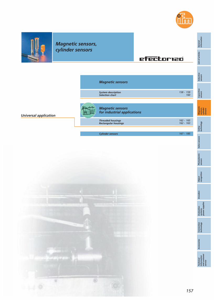
Gen
eral
info
rmat
ion
List
of
arti
cles
Ind
uct
ive
sen
sors
Cap
acit
ive
sen
sors
Mag
net
icse
nso
rs,
cylin
der
sen
sors
Safe
tyte
chn
olo
gy
Val
ve s
enso
rsPh
oto
elec
tric
sen
sors
Ob
ject
reco
gn
itio
nEn
cod
ers
Eval
uat
ion
syst
ems,
po
wer
su
pp
lies
Co
nn
ecti
on
tech
no
log
yA
cces
sori
esTe
chn
ical
info
rmat
ion
and
cu
sto
mer
serv
ice
Magnetic sensors,cylinder sensors
157
Magnetic sensorsfor industrial applications
Magnetic sensors
System descriptionSelection chart
Threaded housingsRectangular housings
Cylinder sensors
Universal application
158 - 159160
162 - 165162 - 163
167 - 185
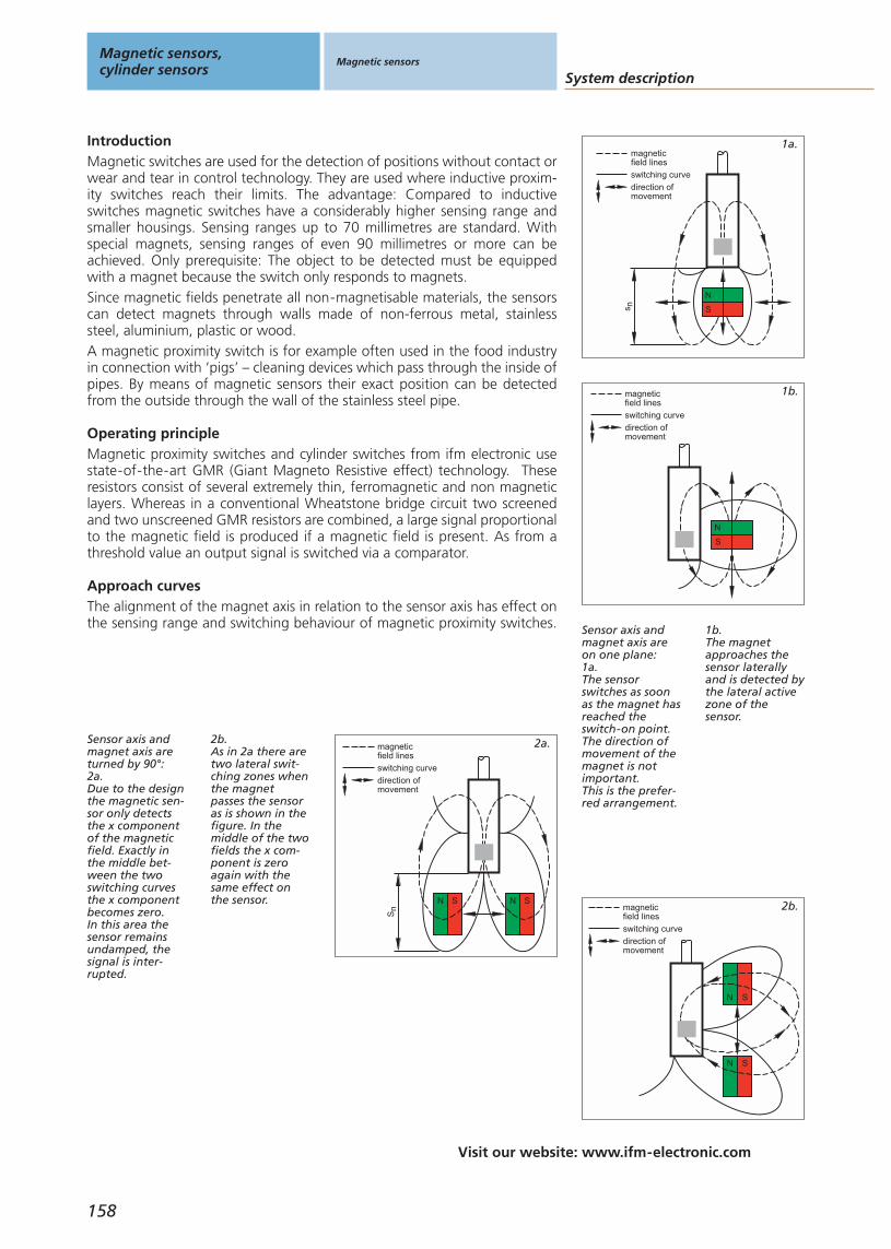
Visit our website: www.ifm-electronic.com
System description
Magnetic sensors,cylinder sensors
Magnetic sensors
158
IntroductionMagnetic switches are used for the detection of positions without contact orwear and tear in control technology. They are used where inductive proxim-ity switches reach their limits. The advantage: Compared to inductiveswitches magnetic switches have a considerably higher sensing range andsmaller housings. Sensing ranges up to 70 millimetres are standard. Withspecial magnets, sensing ranges of even 90 millimetres or more can beachieved. Only prerequisite: The object to be detected must be equippedwith a magnet because the switch only responds to magnets.Since magnetic fields penetrate all non-magnetisable materials, the sensorscan detect magnets through walls made of non-ferrous metal, stainlesssteel, aluminium, plastic or wood.A magnetic proximity switch is for example often used in the food industryin connection with ‘pigs’ – cleaning devices which pass through the inside ofpipes. By means of magnetic sensors their exact position can be detectedfrom the outside through the wall of the stainless steel pipe.
Sensor axis andmagnet axis areon one plane:1a.The sensorswitches as soonas the magnet hasreached theswitch-on point.The direction ofmovement of themagnet is notimportant.This is the prefer-red arrangement.
1b.The magnetapproaches thesensor laterallyand is detected bythe lateral activezone of thesensor.
magneticfield lines
switching curve
direction ofmovement
s n
N
S
magneticfield lines
switching curve
direction ofmovement
N
S
Magnetic proximity switches and cylinder switches from ifm electronic usestate-of-the-art GMR (Giant Magneto Resistive effect) technology. Theseresistors consist of several extremely thin, ferromagnetic and non magneticlayers. Whereas in a conventional Wheatstone bridge circuit two screenedand two unscreened GMR resistors are combined, a large signal proportionalto the magnetic field is produced if a magnetic field is present. As from athreshold value an output signal is switched via a comparator.
Operating principle
magneticfield lines
switching curve
direction ofmovement
N S
N S
The alignment of the magnet axis in relation to the sensor axis has effect onthe sensing range and switching behaviour of magnetic proximity switches.
Approach curves
magneticfield lines
switching curve
direction ofmovement
Sn
N S N S
Sensor axis andmagnet axis areturned by 90°:2a.Due to the designthe magnetic sen-sor only detectsthe x componentof the magneticfield. Exactly inthe middle bet-ween the twoswitching curvesthe x componentbecomes zero.In this area thesensor remainsundamped, thesignal is inter-rupted.
2b.As in 2a there aretwo lateral swit-ching zones whenthe magnetpasses the sensoras is shown in thefigure. In themiddle of the twofields the x com-ponent is zeroagain with thesame effect onthe sensor.
2a.
2b.
1a.
1b.
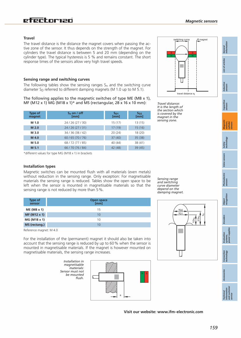
Gen
eral
info
rmat
ion
List
of
arti
cles
Ind
uct
ive
sen
sors
Cap
acit
ive
sen
sors
Mag
net
icse
nso
rs,
cylin
der
sen
sors
Safe
tyte
chn
olo
gy
Val
ve s
enso
rsPh
oto
elec
tric
sen
sors
Ob
ject
reco
gn
itio
nEn
cod
ers
Eval
uat
ion
syst
ems,
po
wer
su
pp
lies
Co
nn
ecti
on
tech
no
log
yA
cces
sori
esTe
chn
ical
info
rmat
ion
and
cu
sto
mer
serv
ice
switching curve Ø magnet
NS
travel distance st
NS
N S
a
s n
1/2s
n
2/3s
n
sD1
sD2
Magnetic sensors
159
Visit our website: www.ifm-electronic.com
TravelThe travel distance is the distance the magnet covers when passing the ac-tive zone of the sensor. It thus depends on the strength of the magnet. Forcylinders the travel distance is between 5 and 20 mm (depending on thecylinder type). The typical hysteresis is 5 % and remains constant. The shortresponse times of the sensors allow very high travel speeds.
Travel distance:It is the length ofthe section whichis covered by themagnet in thesensing zone.
Sensing range and switching curves The following tables show the sensing ranges Sn and the switching curvediameter SD referred to different damping magnets (M 1.0 up to M 5.1).
The following applies to the magnetic switches of type ME (M8 x 1),MF (M12 x 1) MG (M18 x 1)* and MS (rectangular, 28 x 16 x 10 mm):
Type ofmagnet
Sn on / off[mm]
SD2[mm]
SD1[mm]
*different values for type MG (M18 x 1) in brackets
Installation typesMagnetic switches can be mounted flush with all materials (even metals)without reduction in the sensing range. Only exception: For magnetisablematerials the sensing range is reduced. Tables show the open space to beleft when the sensor is mounted in magnetisable materials so that thesensing range is not reduced by more than 5%.
Type ofsensor
Open space[mm]
15ME (M8 x 1)
10MF (M12 x 1)
10MG (M18 x 1)
10MS (rectang.)
Reference magnet: M 4.0
For the installation of the (permanent) magnet it should also be taken intoaccount that the sensing range is reduced by up to 60% when the sensor ismounted in magnetisable materials. If the magnet is however mounted onmagnetisable materials, the sensing range increases.
Sensing rangeand switchingcurve diameterdepend on thedamping magnet.
Installation inmagnetisable
materials:Sensor must not
be mountedflush.
24 / 26 (27 / 30) 15 (17) 13 (15)
24 / 26 (27 / 31) 17 (19) 15 (16)
34 / 36 (38 / 42) 20 (24) 18 (20)
60 / 65 (70 / 76) 37 (40) 35 (38)
68 / 72 (77 / 85) 40 (44) 38 (41)
66 / 70 (76 / 84) 42 (48) 39 (45)
M 1.0
M 2.0
M 3.0
M 4.0
M 5.0
M 5.1

Selection chart
Magnetic sensors,cylinder sensors
Magnetic sensors
For hygienicand wet areas
For industrialapplications
Housing / Dimensions
[mm]
Sensingrange
[mm]
Appli-cation
Cable Connector Terminals
3-wireDC
Page Page Page
3-wireDC
3-wireDC
160
type ME
type MF
type MS
type MG
M8 x 1 60
M12 x 1 60
28 x 10 x 16 60
M18 x 1 70
162 162 –
162 162 –
M12 x 1 60 – 164 –
162 162 –
162 162 –
M18 x 1 70 – 164 –
Magnetic sensors
Gen
eral
info
rmat
ion
List
of
arti
cles
Ind
uct
ive
sen
sors
Cap
acit
ive
sen
sors
Mag
net
icse
nso
rs,
cylin
der
sen
sors
Safe
tyte
chn
olo
gy
Val
ve s
enso
rsPh
oto
elec
tric
sen
sors
Ob
ject
reco
gn
itio
nEn
cod
ers
Eval
uat
ion
syst
ems,
po
wer
su
pp
lies
Co
nn
ecti
on
tech
no
log
yA
cces
sori
esTe
chn
ical
info
rmat
ion
and
cu
sto
mer
serv
ice
161
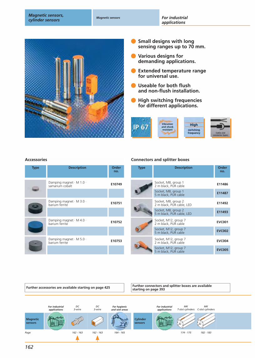
Small designs with longsensing ranges up to 70 mm.
Various designs fordemanding applications.
Extended temperature rangefor universal use.
Useable for both flushand non-flush installation.
High switching frequenciesfor different applications.
Accessories
Type Description Orderno.
Damping magnet · M 1.0 · samarium cobalt E10749
Damping magnet · M 3.0 · barium ferrite E10751
Damping magnet · M 4.0 · barium ferrite E10752
Damping magnet · M 5.0 · barium ferrite E10753
Further accessories are available starting on page 425
Connectors and splitter boxes
Type Description Orderno.
Socket, M8, group 12 m black, PUR cable E11486
Socket, M8, group 15 m black, PUR cable E11487
Socket, M8, group 22 m black, PUR cable, LED E11492
Socket, M8, group 25 m black, PUR cable, LED E11493
Socket, M12, group 72 m black, PUR cable EVC001
Socket, M12, group 75 m black, PUR cable EVC002
Socket, M12, group 72 m black, PUR cable EVC004
Socket, M12, group 75 m black, PUR cable EVC005
Further connectors and splitter boxes are availablestarting on page 393
Magnetic sensors,cylinder sensors
Magnetic sensors For industrialapplications
162
Magneticsensors
Page
For industrialapplications
DC3-wire
162 - 163
DC3-wire
162 - 163
For hygienicand wet areas
164 - 165
Cylindersensors
For industrialapplications
MKT-slot cylinders
174 - 175
MKC-slot cylinders
182 - 183
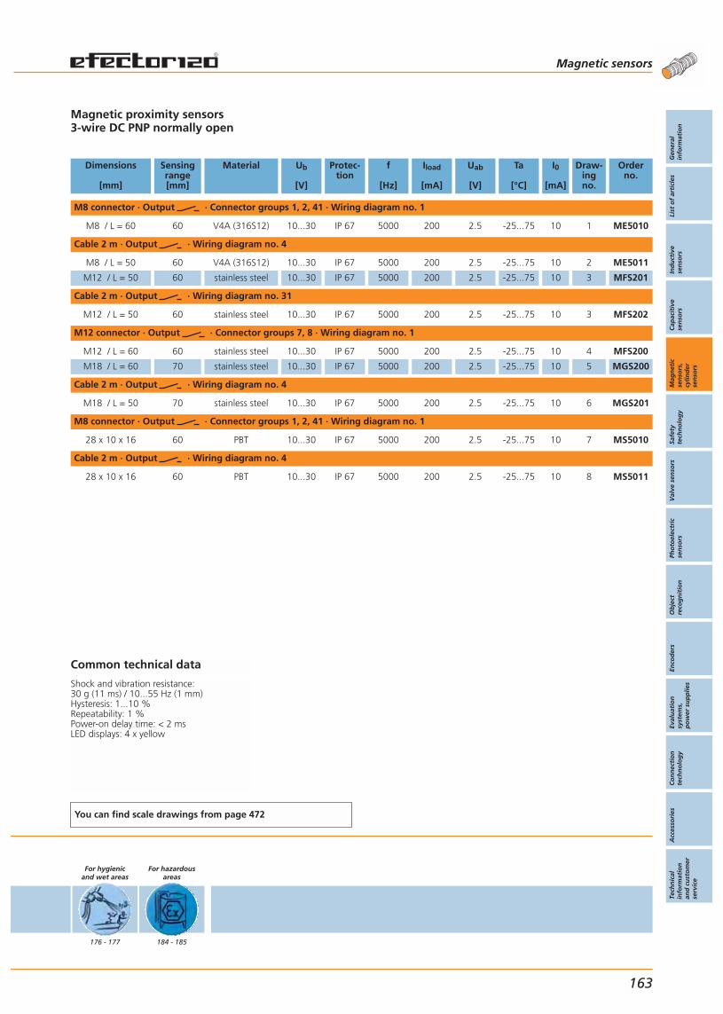
Magnetic proximity sensors3-wire DC PNP normally open
Dimensions
[mm]
Sensingrange[mm]
Material Ub
[V]
Protec-tion
f
[Hz]
Iload
[mA]
Uab
[V]
Ta
[°C]
I0
[mA]
Draw-ingno.
Orderno.
M8 connector · Output · Connector groups 1, 2, 41 · Wiring diagram no. 1
M8 / L = 60 60 V4A (316S12) 10...30 IP 67 5000 200 2.5 -25...75 10 1 ME5010
Cable 2 m · Output · Wiring diagram no. 4
M8 / L = 50 60 V4A (316S12) 10...30 IP 67 5000 200 2.5 -25...75 10 2 ME5011
M12 / L = 50 60 stainless steel 10...30 IP 67 5000 200 2.5 -25...75 10 3 MFS201
Cable 2 m · Output · Wiring diagram no. 31
M12 / L = 50 60 stainless steel 10...30 IP 67 5000 200 2.5 -25...75 10 3 MFS202
M12 connector · Output · Connector groups 7, 8 · Wiring diagram no. 1
M12 / L = 60 60 stainless steel 10...30 IP 67 5000 200 2.5 -25...75 10 4 MFS200
M18 / L = 60 70 stainless steel 10...30 IP 67 5000 200 2.5 -25...75 10 5 MGS200
Cable 2 m · Output · Wiring diagram no. 4
M18 / L = 50 70 stainless steel 10...30 IP 67 5000 200 2.5 -25...75 10 6 MGS201
M8 connector · Output · Connector groups 1, 2, 41 · Wiring diagram no. 1
28 x 10 x 16 60 PBT 10...30 IP 67 5000 200 2.5 -25...75 10 7 MS5010
Cable 2 m · Output · Wiring diagram no. 4
28 x 10 x 16 60 PBT 10...30 IP 67 5000 200 2.5 -25...75 10 8 MS5011
Common technical data
Shock and vibration resistance: 30 g (11 ms) / 10...55 Hz (1 mm)Hysteresis: 1...10 %Repeatability: 1 %Power-on delay time: < 2 msLED displays: 4 x yellow
You can find scale drawings from page 472
For hygienicand wet areas
176 - 177
For hazardousareas
184 - 185
Magnetic sensors
Gen
eral
info
rmat
ion
List
of
arti
cles
Ind
uct
ive
sen
sors
Cap
acit
ive
sen
sors
Mag
net
icse
nso
rs,
cylin
der
sen
sors
Safe
tyte
chn
olo
gy
Val
ve s
enso
rsPh
oto
elec
tric
sen
sors
Ob
ject
reco
gn
itio
nEn
cod
ers
Eval
uat
ion
syst
ems,
po
wer
su
pp
lies
Co
nn
ecti
on
tech
no
log
yA
cces
sori
esTe
chn
ical
info
rmat
ion
and
cu
sto
mer
serv
ice
163

Resistant to high-pressure cleaning:IP 68 and IP 69K.
Wide temperature range and temperature shock resistance.
Long sensing range up to 70 mm.
Resistance to cleaning agents confirmed by Henkel certificate
Food-grade housing materials: high-grade stainless steel, PEEK
Accessories
Type Description Orderno.
Damping magnet · M 4.1 · barium ferrite / stainless steel E11803
Angle bracket · for type M12 · stainless steel (304S15) E10735
Angle bracket · for type M18 · stainless steel (304S15) E10736
Mounting clip · Ø 12 mm · form V · V4A (316S12) E11530
Mounting clip · Ø 18 mm · form V · V4A (316S12) E11531
Further accessories are available starting on page 425
Connectors and splitter boxes
Type Description Orderno.
Socket, M12, group 635 m orange, PVC cable EVT004
Socket, M12, group 6310 m orange, PVC cable EVT005
Socket, M12, group 635 m orange, PVC cable EVT001
Socket, M12, group 6310 m orange, PVC cable EVT002
Socket, M12, group 655 m orange, PVC cable, LED EVT007
Socket, M12, group 6510 m orange, PVC cable, LED EVT008
Further connectors and splitter boxes are availablestarting on page 393
Magnetic sensors,cylinder sensors
Magnetic sensors For hygienicand wet areas
164
Magneticsensors
Page
For industrialapplications
DC3-wire
162 - 163
DC3-wire
162 - 163
For hygienicand wet areas
164 - 165
Cylindersensors
For industrialapplications
MKT-slot cylinders
174 - 175
MKC-slot cylinders
182 - 183

Magnetic proximity sensors3-wire DC PNP normally open
Dimensions
[mm]
Sensingrange[mm]
Material Ub
[V]
Protection f
[Hz]
Iload
[mA]
Uab
[V]
Ta
[°C]
I0
[mA]
Draw-ingno.
Orderno.
M12 connector · Output · Connector group 63, 65 · Wiring diagram no. 1
M12 / L = 60 60 V4A (316S12) 10...30 IP 68 / IP 69K 5000 200 2.5 0...100 10 4 MFT200
M18 / L = 60 70 V4A (316S12) 10...30 IP 68 / IP 69K 5000 200 2.5 0...100 10 5 MGT200
Common technical data
Shock and vibration resistance: 30 g (11 ms) / 10...55 Hz ( 1 mm)Hysteresis: 1...10 %Repeatability: 1 %Power-on delay time: < 2 msLED displays: 4 x yellow
You can find scale drawings from page 472
For hygienicand wet areas
176 - 177
For hazardousareas
184 - 185
Magnetic sensors
Gen
eral
info
rmat
ion
List
of
arti
cles
Ind
uct
ive
sen
sors
Cap
acit
ive
sen
sors
Mag
net
icse
nso
rs,
cylin
der
sen
sors
Safe
tyte
chn
olo
gy
Val
ve s
enso
rsPh
oto
elec
tric
sen
sors
Ob
ject
reco
gn
itio
nEn
cod
ers
Eval
uat
ion
syst
ems,
po
wer
su
pp
lies
Co
nn
ecti
on
tech
no
log
yA
cces
sori
esTe
chn
ical
info
rmat
ion
and
cu
sto
mer
serv
ice
165

Gen
eral
info
rmat
ion
List
of
arti
cles
Ind
uct
ive
sen
sors
Cap
acit
ive
sen
sors
Mag
net
icse
nso
rs,
cylin
der
sen
sors
Safe
tyte
chn
olo
gy
Val
ve s
enso
rsPh
oto
elec
tric
sen
sors
Ob
ject
reco
gn
itio
nEn
cod
ers
Eval
uat
ion
syst
ems,
po
wer
su
pp
lies
Co
nn
ecti
on
tech
no
log
yA
cces
sori
esTe
chn
ical
info
rmat
ion
and
cu
sto
mer
serv
ice
Magnetic sensors,cylinder sensors
167
Cylinder sensorsfor industrial applications
Cylinder sensors
System descriptionSelection chart
Universal applicationMK T-slot cylindersAdapters for different cylinder typesMK C-slot cylinders
Cylinder sensorsfor hygienic and wet areas
Special application
Magnetic sensors
MK T-slot cylindersAdapters for different cylinder types
Cylinder sensors for hazardous areas
MK C-slot cylinders
168 - 169170 - 173
174 - 175178 - 181182 - 183
157 - 165
176 - 177178 - 181
184 - 185

Visit our website: www.ifm-electronic.com
Magnetic proximity switches and cylinder sensors from ifm electronic usestate-of-the-art GMR (Giant Magneto Resistive effect) technology. Theseresistors consist of several extremely thin, ferromagnetic and non magneticlayers. Whereas in a conventional Wheatstone bridge circuit two screenedand two unscreened GMR resistors are combined, a large signal proportionalto the magnetic field is produced if a magnetic field is present. As from athreshold value an output signal is switched via a comparator.
System description
Magnetic sensors,cylinder sensors
Cylinder sensors
168
IntroductionCylinder sensors are used to sense the position of pistons in pneumatic cylin-ders. They are directly mounted onto the cylinder. The ring magnet at-tached to the piston is sensed through the housing wall of non-magnetisablematerial (e.g. aluminium, brass or stainless steel). ifm electronic offers diffe-rent solutions for various cylinder types.
Position sensing:Cylinder sensorsmonitor theposition of thepiston in a pneu-matic cylinder.
The response sensitivity applies equally to either magnetic polarity andwithout external field influence. The magnetic flux density in most pneumat-ic cylinders is between 5 and 25 mT. ifm electronic’s magnetic cylindersensors are factory set so that they detect these magnetic fields safely.
Response sensitivity
Operating principle
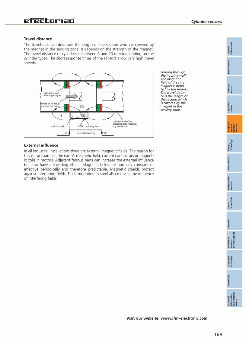
In all industrial installations there are external magnetic fields. The reason forthis is, for example, the earth’s magnetic field, current conductors or magnet-ic coils in motors. Adjacent ferrous parts can increase the external influencebut also have a shielding effect. Magnetic fields are normally constant oreffective periodically and therefore predictable. Magnetic shields protectagainst interfering fields. Flush mounting in steel also reduces the influenceof interfering fields.
Cylinder sensors
169
Visit our website: www.ifm-electronic.com
Gen
eral
info
rmat
ion
List
of
arti
cles
Ind
uct
ive
sen
sors
Cap
acit
ive
sen
sors
Mag
net
icse
nso
rs,
cylin
der
sen
sors
Safe
tyte
chn
olo
gy
Val
ve s
enso
rsPh
oto
elec
tric
sen
sors
Ob
ject
reco
gn
itio
nEn
cod
ers
Eval
uat
ion
syst
ems,
po
wer
su
pp
lies
Co
nn
ecti
on
tech
no
log
yA
cces
sori
esTe
chn
ical
info
rmat
ion
and
cu
sto
mer
serv
ice
Travel distanceThe travel distance describes the length of the section which is covered bythe magnet in the sensing zone. It depends on the strength of the magnet.The travel distance of cylinders is between 5 and 20 mm (depending on thecylinder type). The short response times of the sensors allow very high travelspeeds.
Sensing throughthe housing wall:The magneticfield of the ringmagnet is detec-ted by the sensor.The travel distan-ce is the length ofthe section whichis covered by themagnet in thesensing zone.
External influence
LEDcylinder switch sensing face
direction of move-ment of the piston
N S
N S
N S
N S
cylinder pistonwith ring magnet
cylinder wall of nonmagnetisable material,e.g. aluminium
travel distance ston off
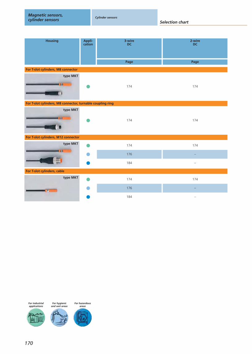
For hazardousareas
For hygienicand wet areas
For industrialapplications
Housing Appli-cation
3-wireDC
2-wireDC
Page Page
type MKT
For T-slot cylinders, M8 connector
type MKT
For T-slot cylinders, M8 connector, turnable coupling ring
type MKT
For T-slot cylinders, M12 connector
type MKT
For T-slot cylinders, cable
Selection chart
Magnetic sensors,cylinder sensors
Cylinder sensors
170
176 –
176 –
184 –
174
174
174
174
174
174
174
184 –
174
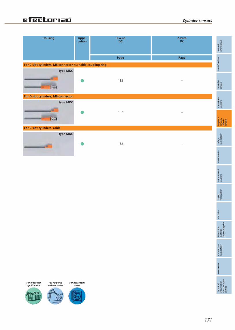
For hazardousareas
For hygienicand wet areas
For industrialapplications
Gen
eral
info
rmat
ion
List
of
arti
cles
Ind
uct
ive
sen
sors
Cap
acit
ive
sen
sors
Mag
net
icse
nso
rs,
cylin
der
sen
sors
Safe
tyte
chn
olo
gy
Val
ve s
enso
rsPh
oto
elec
tric
sen
sors
Ob
ject
reco
gn
itio
nEn
cod
ers
Eval
uat
ion
syst
ems,
po
wer
su
pp
lies
Co
nn
ecti
on
tech
no
log
yA
cces
sori
esTe
chn
ical
info
rmat
ion
and
cu
sto
mer
serv
ice
Housing Appli-cation
3-wireDC
2-wireDC
Page Page
type MKC
For C-slot cylinders, M8 connector, turnable coupling ring
type MKC
For C-slot cylinders, M8 connector
type MKC
For C-slot cylinders, cable
Cylinder sensors
171
182 –
182 –
182 –

For hazardousareas
For hygienicand wet areas
For industrialapplications
Housing Fixing Appli-cation
Cable Connector Adapter
3-wireDC
2-wireDC
Page Page Page
3-wireDC
2-wireDC
clean line cylindersØ 8...100 mm
metal
type MKT
For clean line cylinders
tie rodup to Ø 10 mm
type MKT
For cylinders with tie rod
trapezoidal slot
type MKT
For cylinders with trapezoidal slot
integrated profileup to Ø 14 mm
type MKT
For integrated profile cylinders
tie rodup to Ø 15 mm
integrated profileup to Ø 20 mm
172
Selection chart
Magnetic sensors,cylinder sensors
Cylinder sensors
174 174 179174 174
174 174 178
174 174 179
174 174 179
174
174
174
174
174
174 174 179174 174
174
174 174 179174 174
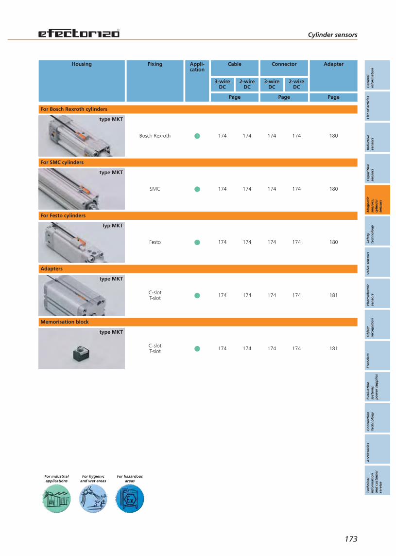
For hazardousareas
For hygienicand wet areas
For industrialapplications
Gen
eral
info
rmat
ion
List
of
arti
cles
Ind
uct
ive
sen
sors
Cap
acit
ive
sen
sors
Mag
net
icse
nso
rs,
cylin
der
sen
sors
Safe
tyte
chn
olo
gy
Val
ve s
enso
rsPh
oto
elec
tric
sen
sors
Ob
ject
reco
gn
itio
nEn
cod
ers
Eval
uat
ion
syst
ems,
po
wer
su
pp
lies
Co
nn
ecti
on
tech
no
log
yA
cces
sori
esTe
chn
ical
info
rmat
ion
and
cu
sto
mer
serv
ice
173
Cylinder sensors
Bosch Rexroth
type MKT
SMC
type MKT
Housing Fixing Appli-cation
Cable Connector Adapter
3-wireDC
2-wireDC
Page Page Page
3-wireDC
2-wireDC
C-slotT-slot
type MKT
C-slotT-slot
type MKT
For Bosch Rexroth cylinders
For SMC cylinders
Adapters
Memorisation block
Festo
Typ MKT
For Festo cylinders
174 174 180174 174
174 174 180174 174
174 174 181174 174
174 174 180174 174
174 174 181174 174

Accessories
For tailor-made accessories for fixing the cylinder sensors on clean-line, trapezoidal slot, tie-rod and inte-grated profile cylinders please refer to pages 178 - 181.
Self-clamping fixture for easyadjustment and quick mounting.
Practical: Can be easily insertedinto the T-slot from the top.
Suitable for the most commonlyused T-slots.
Unit variants available with connection cable and cable plug.
High switching frequenciesand travel speeds possible.
Connectors and splitter boxes
Type Description Orderno.
Socket, M8, group 12 m black, PUR cable E11486
Socket, M8, group 15 m black, PUR cable E11487
Socket, M12, group 72 m black, PUR cable EVC001
Socket, M12, group 75 m black, PUR cable EVC002
Splitter box, group 535 m black, PUR cable, LED E11214
Splitter box, group 555 m black, PUR cable, LED E10278
Further connectors and splitter boxes are availablestarting on page 393
Magnetic sensors,cylinder sensors
Cylinder sensors For industrialapplications
174
Magneticsensors
Page
For industrialapplications
DC3-wire
162 - 163
DC3-wire
162 - 163
For hygienicand wet areas
164 - 165
Cylindersensors
For industrialapplications
MKT-slot cylinders
174 - 175
MKC-slot cylinders
182 - 183
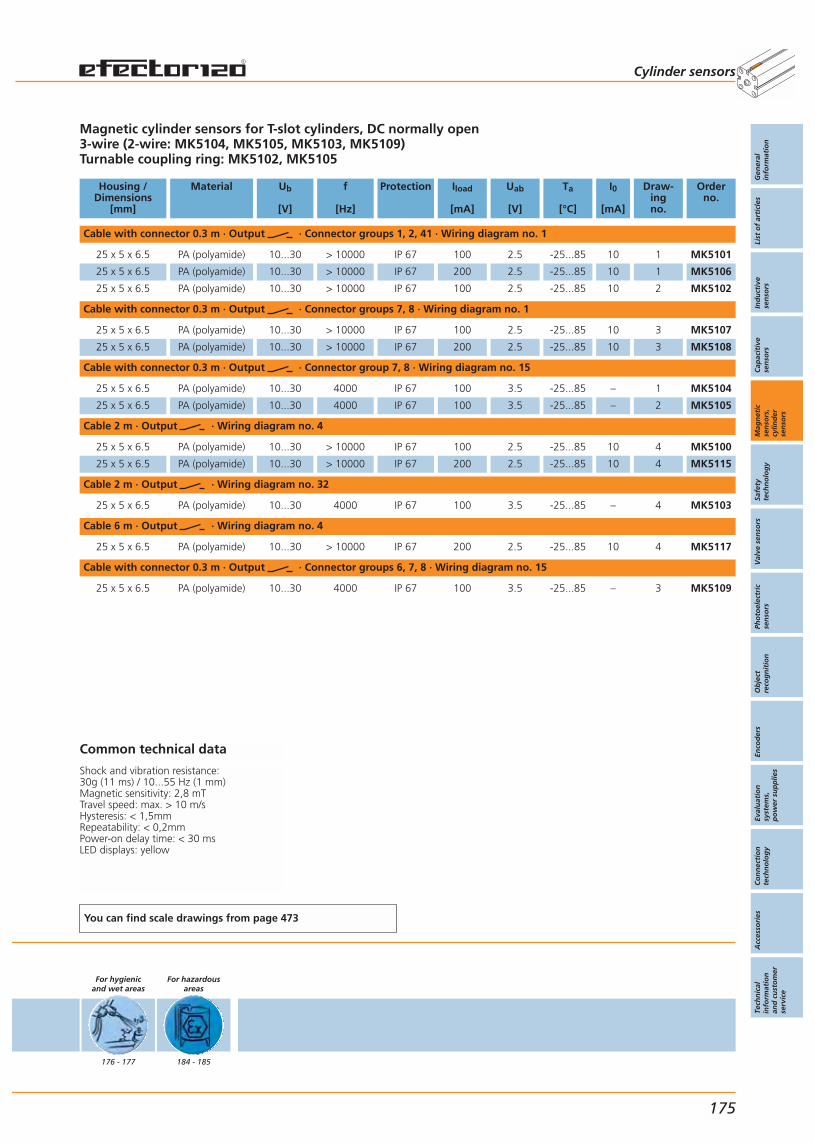
Magnetic cylinder sensors for T-slot cylinders, DC normally open3-wire (2-wire: MK5104, MK5105, MK5103, MK5109)Turnable coupling ring: MK5102, MK5105
Housing /Dimensions
[mm]
Material Ub
[V]
f
[Hz]
Protection Iload
[mA]
Uab
[V]
Ta
[°C]
I0
[mA]
Draw-ingno.
Orderno.
Cable with connector 0.3 m · Output · Connector groups 1, 2, 41 · Wiring diagram no. 1
25 x 5 x 6.5 PA (polyamide) 10...30 > 10000 IP 67 100 2.5 -25...85 10 1 MK5101
25 x 5 x 6.5 PA (polyamide) 10...30 > 10000 IP 67 200 2.5 -25...85 10 1 MK5106
25 x 5 x 6.5 PA (polyamide) 10...30 > 10000 IP 67 100 2.5 -25...85 10 2 MK5102
Cable with connector 0.3 m · Output · Connector groups 7, 8 · Wiring diagram no. 1
25 x 5 x 6.5 PA (polyamide) 10...30 > 10000 IP 67 100 2.5 -25...85 10 3 MK5107
25 x 5 x 6.5 PA (polyamide) 10...30 > 10000 IP 67 200 2.5 -25...85 10 3 MK5108
Cable with connector 0.3 m · Output · Connector group 7, 8 · Wiring diagram no. 15
25 x 5 x 6.5 PA (polyamide) 10...30 4000 IP 67 100 3.5 -25...85 – 1 MK5104
25 x 5 x 6.5 PA (polyamide) 10...30 4000 IP 67 100 3.5 -25...85 – 2 MK5105
Cable 2 m · Output · Wiring diagram no. 4
25 x 5 x 6.5 PA (polyamide) 10...30 > 10000 IP 67 100 2.5 -25...85 10 4 MK5100
25 x 5 x 6.5 PA (polyamide) 10...30 > 10000 IP 67 200 2.5 -25...85 10 4 MK5115
Cable 2 m · Output · Wiring diagram no. 32
25 x 5 x 6.5 PA (polyamide) 10...30 4000 IP 67 100 3.5 -25...85 – 4 MK5103
Cable 6 m · Output · Wiring diagram no. 4
25 x 5 x 6.5 PA (polyamide) 10...30 > 10000 IP 67 200 2.5 -25...85 10 4 MK5117
Cable with connector 0.3 m · Output · Connector groups 6, 7, 8 · Wiring diagram no. 15
25 x 5 x 6.5 PA (polyamide) 10...30 4000 IP 67 100 3.5 -25...85 – 3 MK5109
Common technical data
Shock and vibration resistance: 30g (11 ms) / 10...55 Hz (1 mm)Magnetic sensitivity: 2,8 mTTravel speed: max. > 10 m/sHysteresis: < 1,5mmRepeatability: < 0,2mmPower-on delay time: < 30 msLED displays: yellow
You can find scale drawings from page 473
For hygienicand wet areas
176 - 177
For hazardousareas
184 - 185
Cylinder sensors
Gen
eral
info
rmat
ion
List
of
arti
cles
Ind
uct
ive
sen
sors
Cap
acit
ive
sen
sors
Mag
net
icse
nso
rs,
cylin
der
sen
sors
Safe
tyte
chn
olo
gy
Val
ve s
enso
rsPh
oto
elec
tric
sen
sors
Ob
ject
reco
gn
itio
nEn
cod
ers
Eval
uat
ion
syst
ems,
po
wer
su
pp
lies
Co
nn
ecti
on
tech
no
log
yA
cces
sori
esTe
chn
ical
info
rmat
ion
and
cu
sto
mer
serv
ice
175
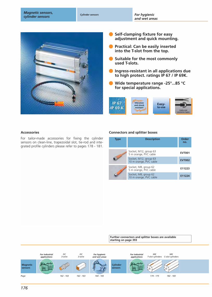
Accessories
For tailor-made accessories for fixing the cylinder sensors on clean-line, trapezoidal slot, tie-rod and inte-grated profile cylinders please refer to pages 178 - 181.
Self-clamping fixture for easy adjustment and quick mounting.
Practical: Can be easily insertedinto the T-slot from the top.
Suitable for the most commonly used T-slots.
Ingress-resistant in all applications due to high protect. ratings IP 67 / IP 69K.
Wide temperature range -25°...85 °C for special applications.
Connectors and splitter boxes
Type Description Orderno.
Socket, M12, group 635 m orange, PVC cable EVT001
Socket, M12, group 6310 m orange, PVC cable EVT002
Socket, M8, group 625 m orange, PVC cable E11223
Socket, M8, group 6210 m orange, PVC cable E11224
Further connectors and splitter boxes are availablestarting on page 393
Magnetic sensors,cylinder sensors
Cylinder sensors For hygienicand wet areas
176
Magneticsensors
Page
For industrialapplications
DC3-wire
162 - 163
DC3-wire
162 - 163
For hygienicand wet areas
164 - 165
Cylindersensors
For industrialapplications
MKT-slot cylinders
174 - 175
MKC-slot cylinders
182 - 183
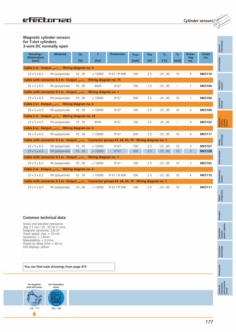
Magnetic cylinder sensors for T-slot cylinders.3-wire DC normally open
Housing /Dimensions
[mm]
Material Ub
[V]
f
[Hz]
Protection Iload
[mA]
Uab
[V]
Ta
[°C]
I0
[mA]
Draw-ingno.
Orderno.
Cable 2 m · Output · Wiring diagram no. 4
25 x 5 x 6.5 PA (polyamide) 10...30 > 10000 IP 67 / IP 69K 100 2.5 -25...85 10 4 MK5110
Cable with connector 0.3 m · Output · Wiring diagram no. 15
25 x 5 x 6.5 PA (polyamide) 10...30 4000 IP 67 100 3.5 -25...85 – 1 MK5104
Cable with connector 0.3 m · Output · Wiring diagram no. 1
25 x 5 x 6.5 PA (polyamide) 10...30 > 10000 IP 67 200 2.5 -25...85 10 1 MK5106
Cable 2 m · Output · Wiring diagram no. 4
25 x 5 x 6.5 PA (polyamide) 10...30 > 10000 IP 67 100 2.5 -25...85 10 4 MK5100
Cable 2 m · Output · Wiring diagram no. 32
25 x 5 x 6.5 PA (polyamide) 10...30 4000 IP 67 100 3.5 -25...85 – 4 MK5103
Cable 6 m · Output · Wiring diagram no. 4
25 x 5 x 6.5 PA (polyamide) 10...30 > 10000 IP 67 200 2.5 -25...85 10 4 MK5117
Cable with connector 0.3 m · Output · Connector groups 63, 64, 65, 70 · Wiring diagram no. 1
25 x 5 x 6.5 PA (polyamide) 10...30 > 10000 IP 67 100 2.5 -25...85 10 3 MK5107
25 x 5 x 6.5 PA (polyamide) 10...30 > 10000 IP 67 200 2.5 -25...85 10 3 MK5108
Cable with connector 0.3 m · Output · Wiring diagram no. 1
25 x 5 x 6.5 PA (polyamide) 10...30 > 10000 IP 67 100 2.5 -25...85 10 2 MK5102
Cable 2 m · Output · Wiring diagram no. 4
25 x 5 x 6.5 PA (polyamide) 10...30 > 10000 IP 67 / IP 69K 100 2.5 -25...85 10 4 MK5110
Cable with connector 0.3 m · Output · Connector groups 63, 64, 65, 70 · Wiring diagram no. 1
25 x 5 x 6.5 PA (polyamide) 10...30 > 10000 IP 67 / IP 69K 100 2.5 -25...85 10 5 MK5111
Common technical data
Shock and vibration resistance: 30g (11 ms) / 10...55 Hz (1 mm)Magnetic sensitivity: 2,8 mTTravel speed: max. > 10 m/sHysteresis: < 1,5mmRepeatability: < 0,2mmPower-on delay time: < 30 msLED displays: yellow
You can find scale drawings from page 473
For hygienicand wet areas
176 - 177
For hazardousareas
184 - 185
Cylinder sensors
Gen
eral
info
rmat
ion
List
of
arti
cles
Ind
uct
ive
sen
sors
Cap
acit
ive
sen
sors
Mag
net
icse
nso
rs,
cylin
der
sen
sors
Safe
tyte
chn
olo
gy
Val
ve s
enso
rsPh
oto
elec
tric
sen
sors
Ob
ject
reco
gn
itio
nEn
cod
ers
Eval
uat
ion
syst
ems,
po
wer
su
pp
lies
Co
nn
ecti
on
tech
no
log
yA
cces
sori
esTe
chn
ical
info
rmat
ion
and
cu
sto
mer
serv
ice
177
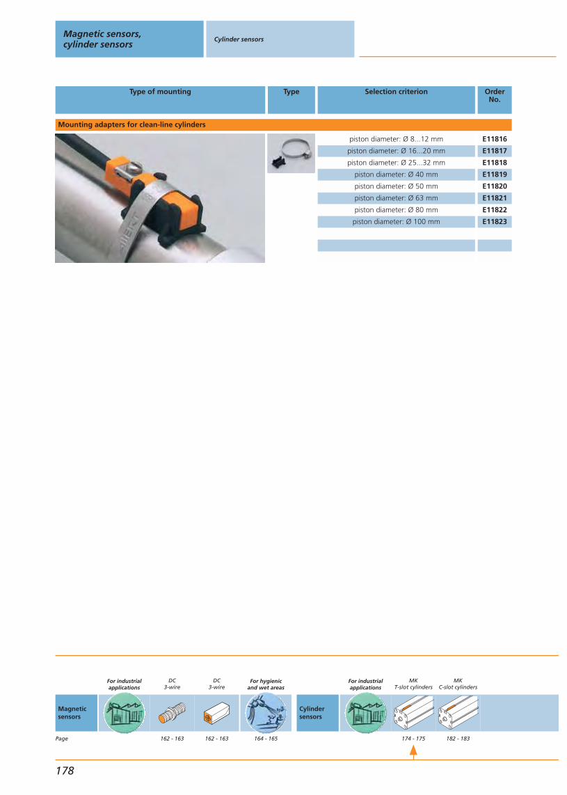
178
Magnetic sensors,cylinder sensors
Cylinder sensors
Type of mounting Type Selection criterion OrderNo.
piston diameter: Ø 8...12 mm E11816
piston diameter: Ø 16...20 mm E11817
piston diameter: Ø 25...32 mm E11818
piston diameter: Ø 40 mm E11819
piston diameter: Ø 50 mm E11820
piston diameter: Ø 63 mm E11821
piston diameter: Ø 80 mm E11822
piston diameter: Ø 100 mm E11823
Mounting adapters for clean-line cylinders
Magneticsensors
Page
For industrialapplications
DC3-wire
162 - 163
DC3-wire
162 - 163
For hygienicand wet areas
164 - 165
Cylindersensors
For industrialapplications
MKT-slot cylinders
174 - 175
MKC-slot cylinders
182 - 183
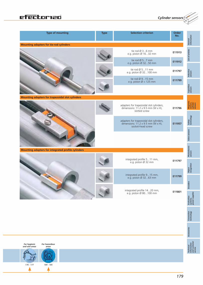
179
Cylinder sensors
Type of mounting Type Selection criterion OrderNo.
Mounting adapters for trapezoidal slot cylinders
Mounting adapters for tie-rod cylinders
Mounting adapters for integrated profile cylinders
adapters for trapezoidal slot cylinders,dimensions: 11.2 x 9.5 mm (W x H),
slotted screwE11796
adapters for trapezoidal slot cylinders,dimensions: 11.2 x 9.5 mm (W x H),
socket-head screwE11957
integrated profile 5...11 mm,e.g. piston Ø 32 mm E11797
integrated profile 9...15 mm,e.g. piston Ø 32...63 mm E11799
integrated profile 14...20 mm,e.g. piston Ø 80...100 mm E11801
tie rod Ø 3...6 mme.g. piston Ø 16...32 mm E11913
tie rod Ø 5...7 mme.g. piston Ø 32...50 mm E11912
tie rod Ø 5...11 mme.g. piston Ø 32...100 mm E11797
tie rod Ø 9...15 mme.g. piston Ø < 125 mm E11799
Gen
eral
info
rmat
ion
List
of
arti
cles
Ind
uct
ive
sen
sors
Cap
acit
ive
sen
sors
Mag
net
icse
nso
rs,
cylin
der
sen
sors
Safe
tyte
chn
olo
gy
Val
ve s
enso
rsPh
oto
elec
tric
sen
sors
Ob
ject
reco
gn
itio
nEn
cod
ers
Eval
uat
ion
syst
ems,
po
wer
su
pp
lies
Co
nn
ecti
on
tech
no
log
yA
cces
sori
esTe
chn
ical
info
rmat
ion
and
cu
sto
mer
serv
ice
For hygienicand wet areas
176 - 177
For hazardousareas
184 - 185
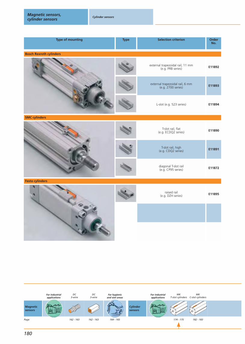
180
Magnetic sensors,cylinder sensors
Cylinder sensors
Type of mounting Type Selection criterion OrderNo.
T-slot rail, flat(e.g. ECDQ2 series) E11890
T-slot rail, high(e.g. CDQ2 series) E11891
SMC cylinders
Festo cylinders
raised rail(e.g. DZH series) E11895
diagonal T-slot rail(e.g. CP95 series) E11872
Bosch Rexroth cylinders
external trapezoidal rail, 11 mm(e.g. PRB series) E11892
external trapezoidal rail, 6 mm(e.g. 2700 series) E11893
L-slot (e.g. 523 series) E11894
Magneticsensors
Page
For industrialapplications
DC3-wire
162 - 163
DC3-wire
162 - 163
For hygienicand wet areas
164 - 165
Cylindersensors
For industrialapplications
MKT-slot cylinders
174 - 175
MKC-slot cylinders
182 - 183
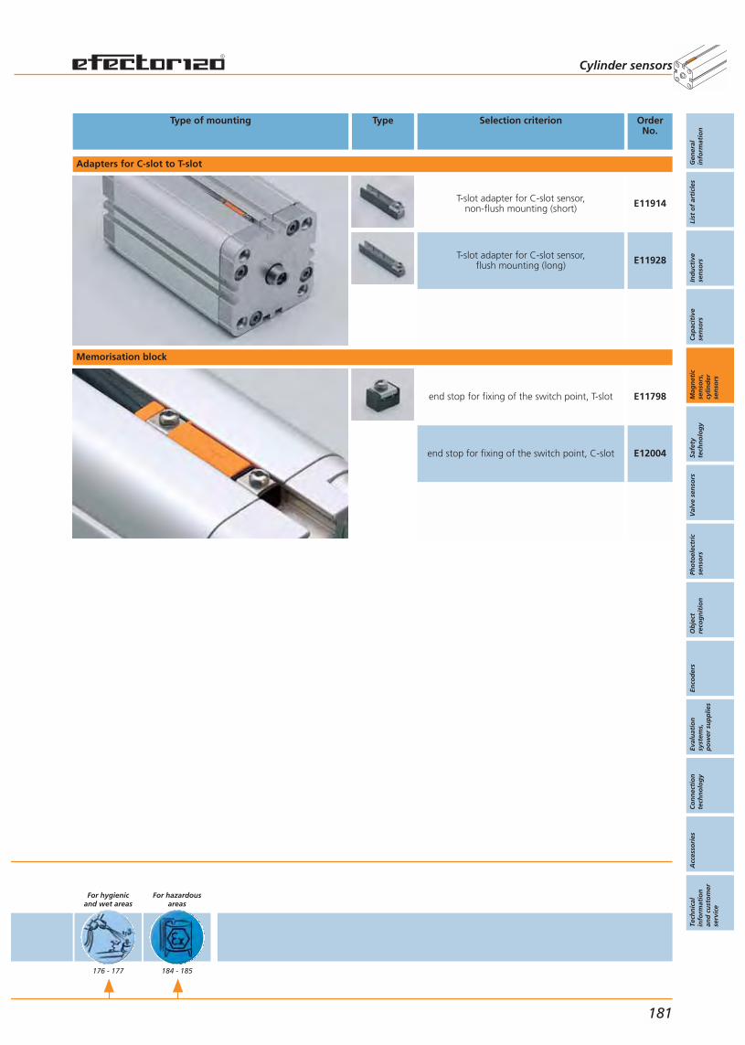
181
Cylinder sensors
Type of mounting Type Selection criterion OrderNo.
Adapters for C-slot to T-slot
T-slot adapter for C-slot sensor,non-flush mounting (short) E11914
T-slot adapter for C-slot sensor,flush mounting (long) E11928
Memorisation block
end stop for fixing of the switch point, T-slot E11798
end stop for fixing of the switch point, C-slot E12004
Gen
eral
info
rmat
ion
List
of
arti
cles
Ind
uct
ive
sen
sors
Cap
acit
ive
sen
sors
Mag
net
icse
nso
rs,
cylin
der
sen
sors
Safe
tyte
chn
olo
gy
Val
ve s
enso
rsPh
oto
elec
tric
sen
sors
Ob
ject
reco
gn
itio
nEn
cod
ers
Eval
uat
ion
syst
ems,
po
wer
su
pp
lies
Co
nn
ecti
on
tech
no
log
yA
cces
sori
esTe
chn
ical
info
rmat
ion
and
cu
sto
mer
serv
ice
For hygienicand wet areas
176 - 177
For hazardousareas
184 - 185
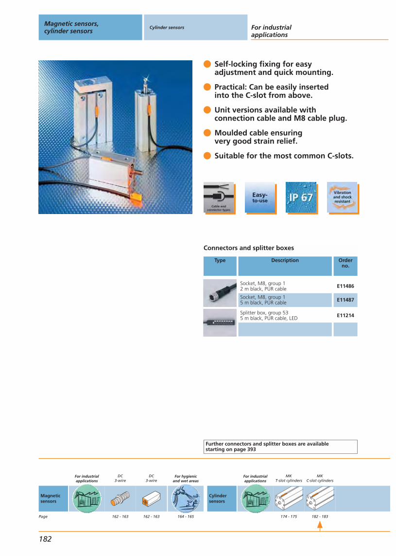
Self-locking fixing for easy adjustment and quick mounting.
Practical: Can be easily insertedinto the C-slot from above.
Unit versions available withconnection cable and M8 cable plug.
Moulded cable ensuringvery good strain relief.
Suitable for the most common C-slots.
Connectors and splitter boxes
Type Description Orderno.
Socket, M8, group 12 m black, PUR cable E11486
Socket, M8, group 15 m black, PUR cable E11487
Splitter box, group 535 m black, PUR cable, LED E11214
Further connectors and splitter boxes are availablestarting on page 393
Magnetic sensors,cylinder sensors
Cylinder sensors For industrialapplications
182
Magneticsensors
Page
For industrialapplications
DC3-wire
162 - 163
DC3-wire
162 - 163
For hygienicand wet areas
164 - 165
Cylindersensors
For industrialapplications
MKT-slot cylinders
174 - 175
MKC-slot cylinders
182 - 183
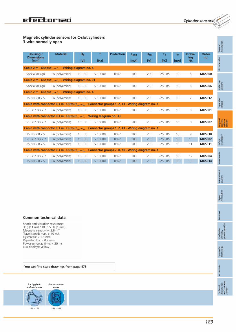
Magnetic cylinder sensors for C-slot cylinders3-wire normally open
Housing /Dimensions
[mm]
Material Ub
[V]
f
[Hz]
Protection Iload
[mA]
Uab
[V]
Ta
[°C]
I0
[mA]
Draw-ingNr.
Orderno.
Cable 2 m · Output · Wiring diagram no. 4
Special design PA (polyamide) 10...30 > 10000 IP 67 100 2.5 -25...85 10 6 MK5300
Cable 2 m · Output · Wiring diagram no. 31
Special design PA (polyamide) 10...30 > 10000 IP 67 100 2.5 -25...85 10 6 MK5306
Cable 2 m · Output · Wiring diagram no. 4
25.8 x 2.8 x 5 PA (polyamide) 10...30 > 10000 IP 67 100 2.5 -25...85 10 7 MK5312
Cable with connector 0.3 m · Output · Connector groups 1, 2, 41 · Wiring diagram no. 1
17.5 x 2.8 x 7.7 PA (polyamide) 10...30 > 10000 IP 67 100 2.5 -25...85 10 8 MK5301
Cable with connector 0.3 m · Output · Wiring diagram no. 33
17.5 x 2.8 x 7.7 PA (polyamide) 10...30 > 10000 IP 67 100 2.5 -25...85 10 8 MK5307
Cable with connector 0.3 m · Output · Connector groups 1, 2, 41 · Wiring diagram no. 1
25.8 x 2.8 x 5 PA (polyamide) 10...30 > 10000 IP 67 100 2.5 -25...85 10 9 MK5310
17.5 x 2.8 x 7.7 PA (polyamide) 10...30 > 10000 IP 67 100 2.5 -25...85 10 10 MK5302
25.8 x 2.8 x 5 PA (polyamide) 10...30 > 10000 IP 67 100 2.5 -25...85 10 11 MK5311
Cable with connector 0.3 m · Output · Connector groups 7, 8, 10 · Wiring diagram no. 1
17.5 x 2.8 x 7.7 PA (polyamide) 10...30 > 10000 IP 67 100 2.5 -25...85 10 12 MK5304
25.8 x 2.8 x 5 PA (polyamide) 10...30 > 10000 IP 67 100 2.5 -25...85 10 13 MK5314
Common technical data
Shock and vibration resistance: 30g (11 ms) / 10...55 Hz (1 mm)Magnetic sensitivity: 2.8 mTTravel speed: max. > 10 m/sHysteresis: < 1.5 mmRepeatability: < 0.2 mmPower-on delay time: < 30 msLED displays: yellow
You can find scale drawings from page 473
For hygienicand wet areas
176 - 177
For hazardousareas
184 - 185
Cylinder sensors
Gen
eral
info
rmat
ion
List
of
arti
cles
Ind
uct
ive
sen
sors
Cap
acit
ive
sen
sors
Mag
net
icse
nso
rs,
cylin
der
sen
sors
Safe
tyte
chn
olo
gy
Val
ve s
enso
rsPh
oto
elec
tric
sen
sors
Ob
ject
reco
gn
itio
nEn
cod
ers
Eval
uat
ion
syst
ems,
po
wer
su
pp
lies
Co
nn
ecti
on
tech
no
log
yA
cces
sori
esTe
chn
ical
info
rmat
ion
and
cu
sto
mer
serv
ice
183

Accessories
For tailor-made accessories for fixing the cylinder sensors on clean-line, trapezoidal slot, tie-rod and inte-grated profile cylinders please refer to pages 178 - 181.
Suitable for category 3D (zone 22) todirective 94/9/EC.
Can be easily inserted into the T-slotfrom above.
Versions with connection cable or M12cable plug available.
Mounting adapters for clean line, inte-grated profile and tie rod cylinders.
Suitable for many applications thanksto the high protection rating IP 67.
Connectors and splitter boxes
Type Description Orderno.
Socket, M125 m orange, PVC cable EVT001
Socket, M1210 m orange, PVC cable EVT002
Further connectors and splitter boxes are availablestarting on page 393
Magnetic sensors,cylinder sensors
Cylinder sensors
For hazardous areas
184
Magneticsensors
Page
For industrialapplications
DC3-wire
162 - 163
DC3-wire
162 - 163
For hygienicand wet areas
164 - 165
Cylindersensors
For industrialapplications
MKT-slot cylinders
174 - 175
MKC-slot cylinders
182 - 183

Magnetic cylinder sensors for T slot cylinders3-wire NO
Housing /Dimensions
[mm]
Material Ub
[V]
f
[Hz]
Protection Iload
[mA]
Uab
[V]
Ta
[°C]
I0
[mA]
Draw-ingno.
Orderno.
Cable with connector 0.3 m · Output · Wiring diagram no. 1
25 x 5 x 6.5 PA (polyamide) 10...30 > 10000 IP 67 100 2.5 -20...60 10 5 MK501A
Cable 2 m · Output · Wiring diagram no. 4
25 x 5 x 6.5 PA (polyamide) 10...30 > 10000 IP 67 100 2.5 -20...60 10 4 MK500A
Common technical data
Shock / vibration resistance: 30g (11 ms) / 10...55 Hz (1 mm)Magnetic sensitivity: 2,8 mTTravel speed: max. 10 m/sHysteresis: < 1,5 mmRepeatability: < 0,2 mmPower-on delay time: < 30 msLED: yellow
You can find scale drawings from page 473
For hygienicand wet areas
176 - 177
For hazardousareas
184 - 185
Cylinder sensors
Gen
eral
info
rmat
ion
List
of
arti
cles
Ind
uct
ive
sen
sors
Cap
acit
ive
sen
sors
Mag
net
icse
nso
rs,
cylin
der
sen
sors
Safe
tyte
chn
olo
gy
Val
ve s
enso
rsPh
oto
elec
tric
sen
sors
Ob
ject
reco
gn
itio
nEn
cod
ers
Eval
uat
ion
syst
ems,
po
wer
su
pp
lies
Co
nn
ecti
on
tech
no
log
yA
cces
sori
esTe
chn
ical
info
rmat
ion
and
cu
sto
mer
serv
ice
185

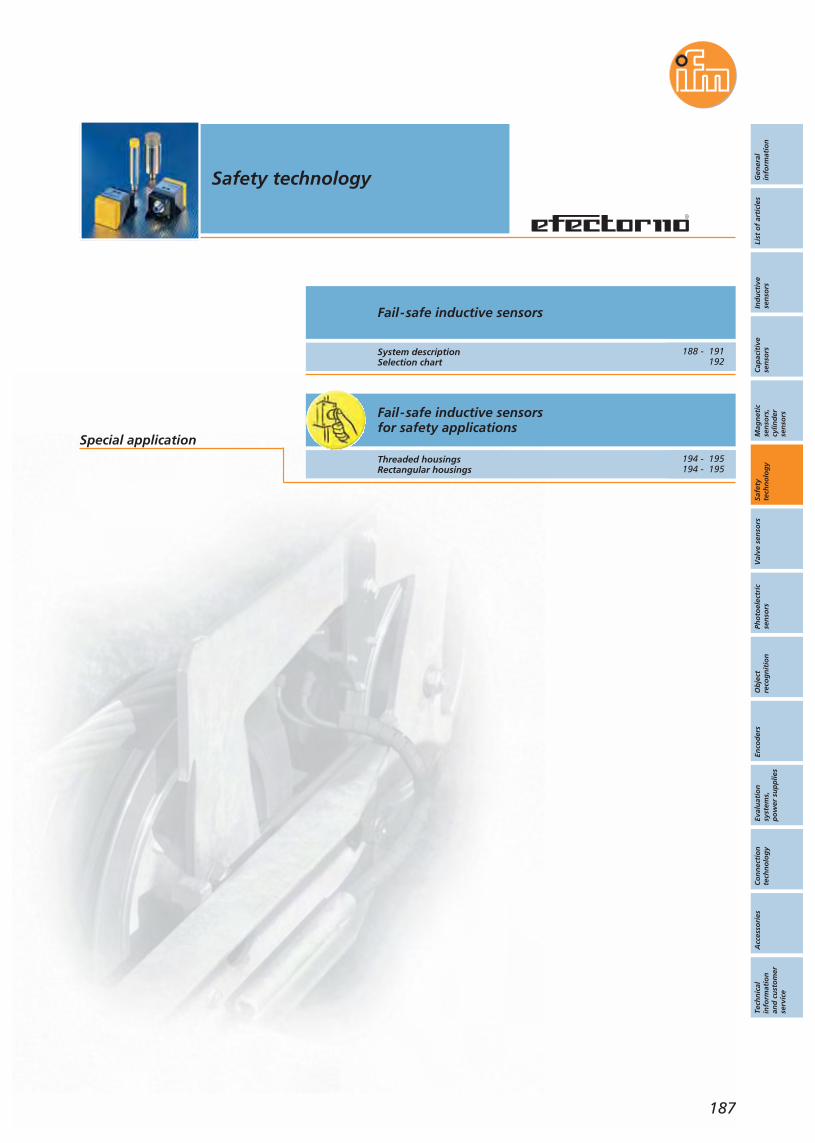
Gen
eral
info
rmat
ion
List
of
arti
cles
Ind
uct
ive
sen
sors
Cap
acit
ive
sen
sors
Mag
net
icse
nso
rs,
cylin
der
sen
sors
Safe
tyte
chn
olo
gy
Val
ve s
enso
rsPh
oto
elec
tric
sen
sors
Ob
ject
reco
gn
itio
nEn
cod
ers
Eval
uat
ion
syst
ems,
po
wer
su
pp
lies
Co
nn
ecti
on
tech
no
log
yA
cces
sori
esTe
chn
ical
info
rmat
ion
and
cu
sto
mer
serv
ice
Safety technology
187
Fail-safe inductive sensorsfor safety applications
Fail-safe inductive sensors
System descriptionSelection chart
Special applicationThreaded housingsRectangular housings
188 - 191192
194 - 195194 - 195
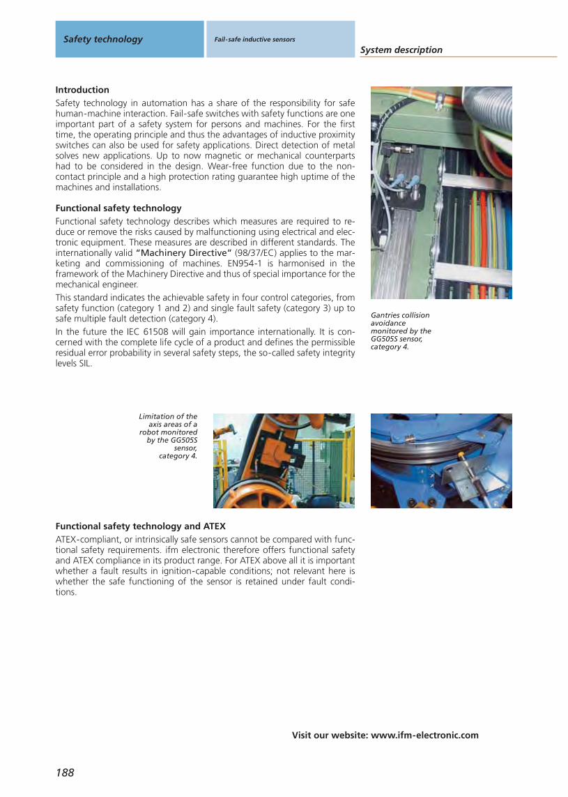
Visit our website: www.ifm-electronic.com
System descriptionSafety technology Fail-safe inductive sensors
188
Functional safety technology describes which measures are required to re-duce or remove the risks caused by malfunctioning using electrical and elec-tronic equipment. These measures are described in different standards. Theinternationally valid “Machinery Directive” (98/37/EC) applies to the mar-keting and commissioning of machines. EN954-1 is harmonised in the framework of the Machinery Directive and thus of special importance for themechanical engineer.This standard indicates the achievable safety in four control categories, fromsafety function (category 1 and 2) and single fault safety (category 3) up tosafe multiple fault detection (category 4). In the future the IEC 61508 will gain importance internationally. It is con-cerned with the complete life cycle of a product and defines the permissibleresidual error probability in several safety steps, the so-called safety integritylevels SIL.
IntroductionSafety technology in automation has a share of the responsibility for safehuman-machine interaction. Fail-safe switches with safety functions are oneimportant part of a safety system for persons and machines. For the firsttime, the operating principle and thus the advantages of inductive proximityswitches can also be used for safety applications. Direct detection of metalsolves new applications. Up to now magnetic or mechanical counterpartshad to be considered in the design. Wear-free function due to the non-contact principle and a high protection rating guarantee high uptime of themachines and installations.
Gantries collisionavoidancemonitored by theGG505S sensor,category 4.
Limitation of theaxis areas of a
robot monitoredby the GG505S
sensor,category 4.
Functional safety technology
ATEX-compliant, or intrinsically safe sensors cannot be compared with func-tional safety requirements. ifm electronic therefore offers functional safetyand ATEX compliance in its product range. For ATEX above all it is importantwhether a fault results in ignition-capable conditions; not relevant here iswhether the safe functioning of the sensor is retained under fault condi-tions.
Functional safety technology and ATEX
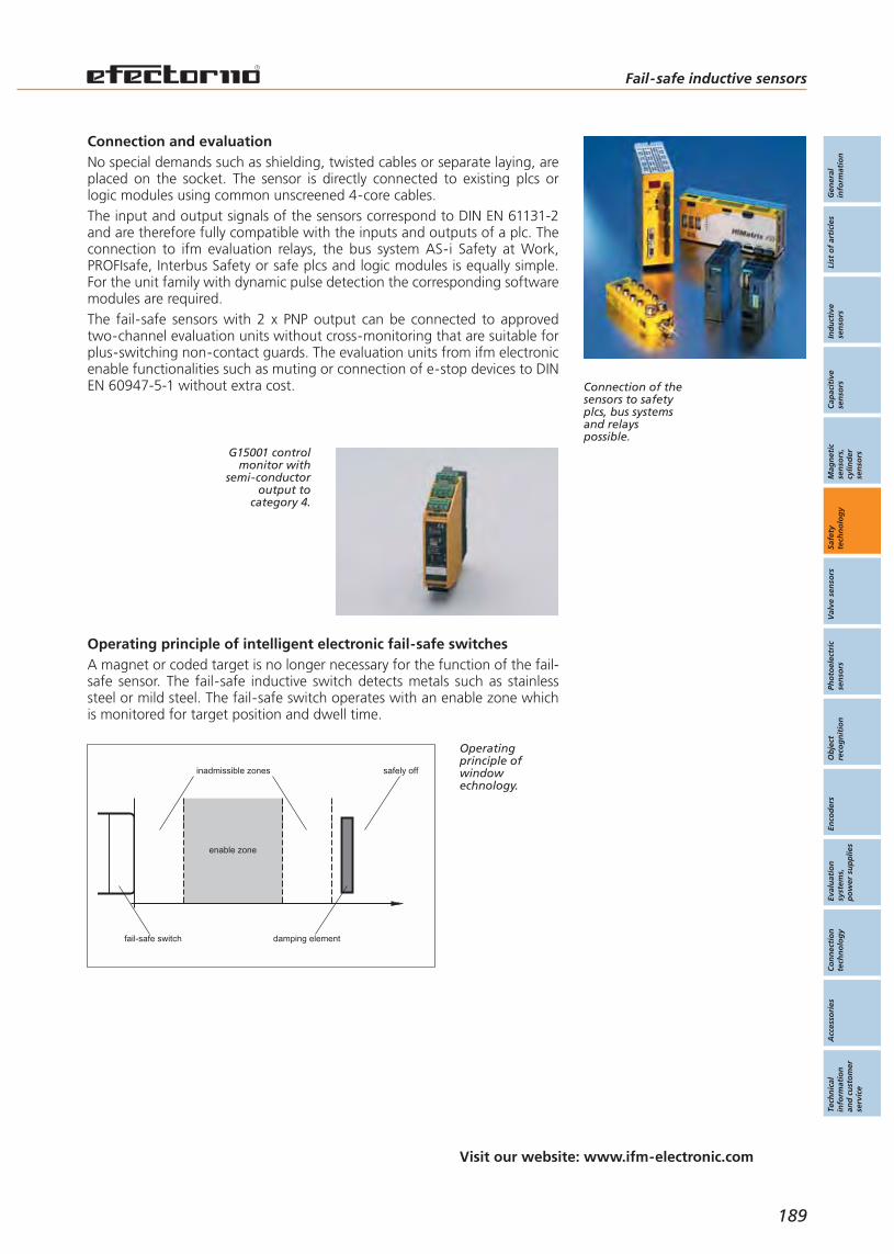
Fail-safe inductive sensors
189
Visit our website: www.ifm-electronic.com
Gen
eral
info
rmat
ion
List
of
arti
cles
Ind
uct
ive
sen
sors
Cap
acit
ive
sen
sors
Mag
net
icse
nso
rs,
cylin
der
sen
sors
Safe
tyte
chn
olo
gy
Val
ve s
enso
rsPh
oto
elec
tric
sen
sors
Ob
ject
reco
gn
itio
nEn
cod
ers
Eval
uat
ion
syst
ems,
po
wer
su
pp
lies
Co
nn
ecti
on
tech
no
log
yA
cces
sori
esTe
chn
ical
info
rmat
ion
and
cu
sto
mer
serv
ice
Operating principle of intelligent electronic fail-safe switchesA magnet or coded target is no longer necessary for the function of the fail-safe sensor. The fail-safe inductive switch detects metals such as stainlesssteel or mild steel. The fail-safe switch operates with an enable zone whichis monitored for target position and dwell time.
Connection of thesensors to safetyplcs, bus systemsand relayspossible.
No special demands such as shielding, twisted cables or separate laying, areplaced on the socket. The sensor is directly connected to existing plcs orlogic modules using common unscreened 4-core cables.The input and output signals of the sensors correspond to DIN EN 61131-2and are therefore fully compatible with the inputs and outputs of a plc. Theconnection to ifm evaluation relays, the bus system AS-i Safety at Work,PROFIsafe, Interbus Safety or safe plcs and logic modules is equally simple.For the unit family with dynamic pulse detection the corresponding softwaremodules are required.The fail-safe sensors with 2 x PNP output can be connected to approvedtwo-channel evaluation units without cross-monitoring that are suitable forplus-switching non-contact guards. The evaluation units from ifm electronicenable functionalities such as muting or connection of e-stop devices to DINEN 60947-5-1 without extra cost.
Connection and evaluation
inadmissible zones safely off
damping element
enable zone
fail-safe switch
Operatingprinciple ofwindow echnology.
G15001 controlmonitor with
semi-conductoroutput to
category 4.

190
Visit our website: www.ifm-electronic.com
System descriptionSafety technology Fail-safe inductive sensors
close range enablezone
0 30 [mm]
> 5 s
signalpower
Adjustmentmode: The enablezone is deter-mined usinga dampingelement.
0 30 [mm]
signalpower
signalpower
signalpower
enablezone
The status LEDswitches off incase of undamp-ing or interrup-tion of the supplyvoltage.
Window technology and determination of the enable zoneThe fail-safe inductive sensors operate using the “window technology”. Thistechnology is the basis for the fail-safe sensors without additional counter-part such as target or magnet. The damping element is only detected if itstays in zone 2 for a certain duration. The damping element should thus beplaced as near as possible to the middle of the window. The yellow flashingstatus LED indicates the activated adjustment mode and is used to determinethe enable zone.To determine the enable zone a metal object, the damping element, is posi-tioned directly in front of or on the active face (close ranges) of the fail-safeswitch. After approx. 5 s the yellow status LED starts to flash: The adjust-ment mode is active. As long as this mode is active, the output stage remainsin the safe state (“0”).If the sensor is in the adjustment mode, the enable zone of the sensor canbe determined by moving the damping element.If the sensor is undamped for more than 2 seconds or the supply voltage isinterrupted, the adjustment mode is deactivated and the yellow status LEDswitches off.Approach angles and directions as well as closing angles (e.g. of doors) hadto be taken into account for the safety switches used so far. For the newsystem using the inductive window technology special design considerationsare no longer necessary.
steel FE360 ≤ 10 mm
stainless steel 7.5 mm
Material Enable zone lower limit(GM504S)
≥ 15 mm
13.2 mm
AIMg3G22 2.0 mm
AI 99 % 1.4 mm
5.8 mm
5.0 mm
CuZn 37 2.3 mm
copper 0.8 mm
6.2 mm
4.3 mm
Enable zone upper limit(GM504S)

Gen
eral
info
rmat
ion
List
of
arti
cles
Ind
uct
ive
sen
sors
Cap
acit
ive
sen
sors
Mag
net
icse
nso
rs,
cylin
der
sen
sors
Safe
tyte
chn
olo
gy
Val
ve s
enso
rsPh
oto
elec
tric
sen
sors
Ob
ject
reco
gn
itio
nEn
cod
ers
Eval
uat
ion
syst
ems,
po
wer
su
pp
lies
Co
nn
ecti
on
tech
no
log
yA
cces
sori
esTe
chn
ical
info
rmat
ion
and
cu
sto
mer
serv
ice
191
Fail-safe inductive sensors
Visit our website: www.ifm-electronic.com
Series connection by using a T-piece for sensors with clock inputSeries connection minimises wiringReduced mounting effortsUp to 10 fail-safe sensors can be connected in series in combinationwith mechanical contacts.To obtain a quick-connect system a series connection using a E11569T-piece is possible.
E11569 T-piece forthe series connec-tion of up to 10fail-safe sensors.
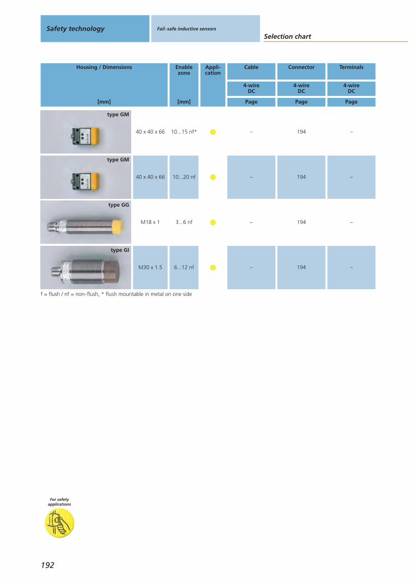
f = flush / nf = non-flush, * flush mountable in metal on one side
Housing / Dimensions
[mm]
40 x 40 x 66 10...15 nf*
type GM
Enablezone
[mm]
Appli-cation
Cable Connector Terminals
Page Page Page
4-wireDC
4-wireDC
4-wireDC
– 194 –
40 x 40 x 66 10...20 nf
type GM
– 194 –
M30 x 1.5 6...12 nf
type GI
– 194 –
type GG
M18 x 1 3...6 nf – 194 –
Selection chartSafety technology Fail-safe inductive sensors
For safetyapplications
192

Gen
eral
info
rmat
ion
List
of
arti
cles
Ind
uct
ive
sen
sors
Cap
acit
ive
sen
sors
Mag
net
icse
nso
rs,
cylin
der
sen
sors
Safe
tyte
chn
olo
gy
Val
ve s
enso
rsPh
oto
elec
tric
sen
sors
Ob
ject
reco
gn
itio
nEn
cod
ers
Eval
uat
ion
syst
ems,
po
wer
su
pp
lies
Co
nn
ecti
on
tech
no
log
yA
cces
sori
esTe
chn
ical
info
rmat
ion
and
cu
sto
mer
serv
ice
Fail-safe inductive sensors
193
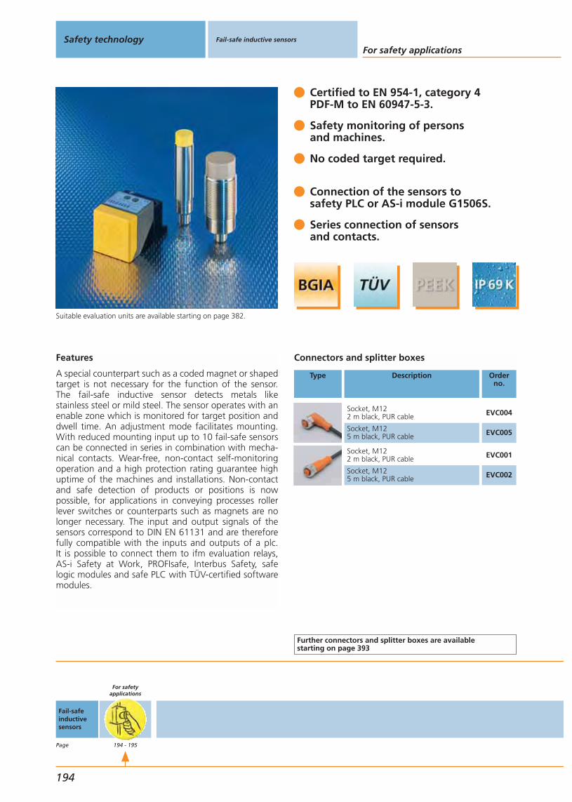
Features
A special counterpart such as a coded magnet or shapedtarget is not necessary for the function of the sensor.The fail-safe inductive sensor detects metals like stainless steel or mild steel. The sensor operates with anenable zone which is monitored for target position anddwell time. An adjustment mode facilitates mounting.With reduced mounting input up to 10 fail-safe sensorscan be connected in series in combination with mecha-nical contacts. Wear-free, non-contact self-monitoringoperation and a high protection rating guarantee highuptime of the machines and installations. Non-contactand safe detection of products or positions is now possible, for applications in conveying processes rollerlever switches or counterparts such as magnets are nolonger necessary. The input and output signals of thesensors correspond to DIN EN 61131 and are thereforefully compatible with the inputs and outputs of a plc. It is possible to connect them to ifm evaluation relays,AS-i Safety at Work, PROFIsafe, Interbus Safety, safelogic modules and safe PLC with TÜV-certified softwaremodules.
Suitable evaluation units are available starting on page 382.
Certified to EN 954-1, category 4PDF-M to EN 60947-5-3.
Safety monitoring of persons and machines.
No coded target required.
Connection of the sensors to safety PLC or AS-i module G1506S.
Series connection of sensorsand contacts.
Connectors and splitter boxes
Type Description Orderno.
Socket, M122 m black, PUR cable EVC004
Socket, M125 m black, PUR cable EVC005
Socket, M122 m black, PUR cable EVC001
Socket, M125 m black, PUR cable EVC002
Further connectors and splitter boxes are availablestarting on page 393
Safety technology Fail-safe inductive sensors
For safety applications
194
Fail-safeinductivesensors
Page
For safetyapplications
194 - 195
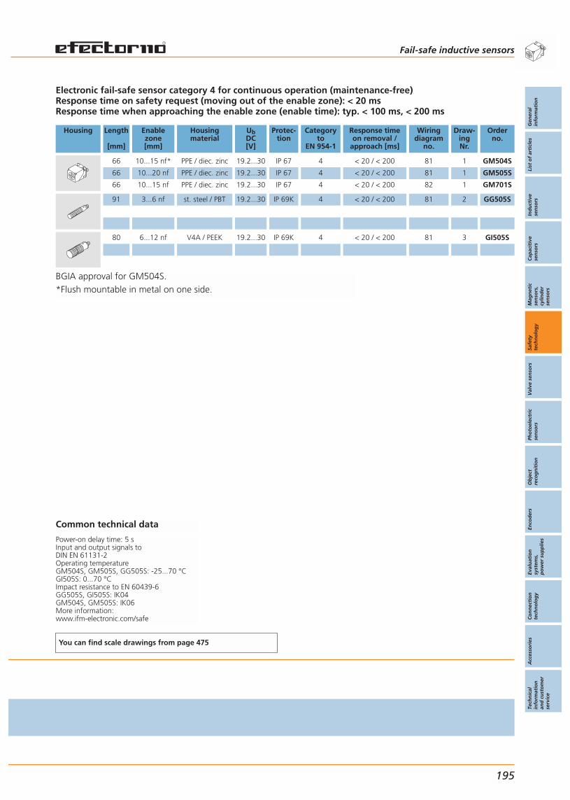
BGIA approval for GM504S.*Flush mountable in metal on one side.
Electronic fail-safe sensor category 4 for continuous operation (maintenance-free)Response time on safety request (moving out of the enable zone): < 20 msResponse time when approaching the enable zone (enable time): typ. < 100 ms, < 200 ms
Housing Length
[mm]
Enablezone[mm]
Housingmaterial
UbDC[V]
Protec-tion
Categoryto
EN 954-1
Response timeon removal /
approach [ms]
Wiringdiagram
no.
Draw-ingNr.
Orderno.
66 10...15 nf* PPE / diec. zinc 19.2...30 IP 67 4 < 20 / < 200 81 1 GM504S
66 10...20 nf PPE / diec. zinc 19.2...30 IP 67 4 < 20 / < 200 81 1 GM505S
66 10...15 nf PPE / diec. zinc 19.2...30 IP 67 4 < 20 / < 200 82 1 GM701S
91 3...6 nf st. steel / PBT 19.2...30 IP 69K 4 < 20 / < 200 81 2 GG505S
80 6...12 nf V4A / PEEK 19.2...30 IP 69K 4 < 20 / < 200 81 3 GI505S
Common technical data
Power-on delay time: 5 sInput and output signals to DIN EN 61131-2Operating temperatureGM504S, GM505S, GG505S: -25...70 °CGI505S: 0...70 °CImpact resistance to EN 60439-6GG505S, GI505S: IK04GM504S, GM505S: IK06More information:www.ifm-electronic.com/safe
You can find scale drawings from page 475
Fail-safe inductive sensors
Gen
eral
info
rmat
ion
List
of
arti
cles
Ind
uct
ive
sen
sors
Cap
acit
ive
sen
sors
Mag
net
icse
nso
rs,
cylin
der
sen
sors
Safe
tyte
chn
olo
gy
Val
ve s
enso
rsPh
oto
elec
tric
sen
sors
Ob
ject
reco
gn
itio
nEn
cod
ers
Eval
uat
ion
syst
ems,
po
wer
su
pp
lies
Co
nn
ecti
on
tech
no
log
yA
cces
sori
esTe
chn
ical
info
rmat
ion
and
cu
sto
mer
serv
ice
195


Gen
eral
info
rmat
ion
List
of
arti
cles
Ind
uct
ive
sen
sors
Cap
acit
ive
sen
sors
Mag
net
icse
nso
rs,
cylin
der
sen
sors
Safe
tyte
chn
olo
gy
Val
ve s
enso
rsPh
oto
elec
tric
sen
sors
Ob
ject
reco
gn
itio
nEn
cod
ers
Eval
uat
ion
syst
ems,
po
wer
su
pp
lies
Co
nn
ecti
on
tech
no
log
yA
cces
sori
esTe
chn
ical
info
rmat
ion
and
cu
sto
mer
serv
ice
Valve sensors
197
Valve sensorsfor industrial applications
Valve sensorsfor hazardous areas
Valve sensors
System descriptionSelection chart
Universal application
Special application
IND for quarter-turn actuatorsIX for linear valves
IND for quarter-turn actuators
198 - 199200 - 201
202 - 205206 - 207
208 - 211

Visit our website: www.ifm-electronic.com
System descriptionValve sensors Valve sensors
198
An innovative design eliminates the disadvantages of these conventionalsolutions. In 1992 ifm electronic developed a standard which is now used bymany leading actuator manufacturers. A round switch target, known as a‘puck’, with two metal screws offset by 90° is mounted on the actuatorshaft. The screws are located at a different height. A compact dual proximitysensor (type IND) with two integral sensors detects the upper or lower metalscrew depending on the valve position and thus the two switch positions.
Valve control · IntroductionIn industrial processes where liquids, air or gases are used valves are neededfor dosing and control. There is a wide variety of valve types; butterfly or ballvalves being the most common quarter-turn types.These valves are seldom operated manually. Pneumatic valve actuators arenormally used for mechanical positioning. The valve position must be moni-tored electronically. On the one hand to provide a feedback to the controllerwhen a certain position (e.g. “open” or “closed”) is reached. On the otherhand it is necessary to monitor the valves centrally.Mechanical switches are still often used for position feedback on the actua-tor shaft. For other solutions several proximity sensors are used togetherwith a switch target for position detection. Disadvantage of these methods:Mounting is mechanically complex. During switch mounting the signal wirescan be reversed when they are connected in the top-mounted junction box.Where there are temperature fluctuations condensing humidity leads to cor-rosion and thus malfunction.
Industrialprocess plant:Various mediaare controlled
using valves.
Due to the simple construction the system operates safely with no wear atall. It is virtually resistant to external influence and meets the protectionrating IP 67. Under certain conditions the unit can even be self-cleaning.Compared to conventional solutions the sensor weight is low. The sensorsare also resistant to mechanical stress such as vibration and shock.
Advantages
Operating principle
Easy as ABC:Puck with twometal targetsoffset by 90°and inductivedual sensor forposition detectionof the shaft.
Feedback:Monitoring of
pneumatic andmanual valves
must be possible.

Valve sensors
199
Visit our website: www.ifm-electronic.com
Gen
eral
info
rmat
ion
List
of
arti
cles
Ind
uct
ive
sen
sors
Cap
acit
ive
sen
sors
Mag
net
icse
nso
rs,
cylin
der
sen
sors
Safe
tyte
chn
olo
gy
Val
ve s
enso
rsPh
oto
elec
tric
sen
sors
Ob
ject
reco
gn
itio
nEn
cod
ers
Eval
uat
ion
syst
ems,
po
wer
su
pp
lies
Co
nn
ecti
on
tech
no
log
yA
cces
sori
esTe
chn
ical
info
rmat
ion
and
cu
sto
mer
serv
ice
StandardisationIt only takes a few minutes to mount the switches on the quarter-turn actu-ator. This is ensured by the mechanical interface in accordance with VDI /VDE 3845. This standard exactly defines where the threaded holes for fixingthe switches have to be located by the valve manufacturer. The ifm dual sen-sors conform exactly to this standard. For different actuators the user onlyhas to select one of three puck sizes. Keyed connectors simplify wiring. Anadditional terminal box is not required.Because of the standardised connections (mechanical and electrical) theunits provide an optimum price / performance ratio, taking mounting andmaintenance cost into account, and high operational reliability.
Standard fittings:Commondimensions inaccordancewith VDI / VDEstandard.
For use in hazardous areas ifm offers a special solution. This consists of twoNAMUR sensors for position feedback and triggering of the EX-i solenoidvalve. Both sensor and valve are connected to the controller via a 6-polecable.
Special design for hazardous areas (T1)
An extended design is the series T5. In addition to the inductive dual sensor,the unit provides an integrated connection for the solenoid valve. The con-nection to the control unit is made via a two-wire AS-i cable. The asset: Upto 61 other units can be connected to this line and separately controlled viathe AS-i master. A so-called “preventive monitoring” of the solenoid valvecan be implemented easily. Furthermore, ATEX 3G versions are available.
Special design AS-i (T5)
As complete solution ifm electronic offers an automation box for pneumaticquarter-turn actuators. In addition to the T5 sensor with AS-i capability itincludes puck, solenoid valve, silencer and wired cable. So everything theuser needs to provide his actuator with bus capability. If necessary, the option-ally available AS-i master gateways serve as an interface with Profibus,DeviceNet, Ethernet and other network topologies.
AS-i complete setHazardous areas: Sensor signalsand valve controlare carried inone cable.
efector valvis:position feed-back for singleand doubleseat valves.
The efector valvis has been designed for feedback of the valve positions onlinear valves with a stroke of up to 80 mm. The sensor is fitted over the valvespindle and continuously measures the stroke. The actual limits of travel aretransmitted to the controller via teachable switch points.The efector valvis signals up to three valve positions to the controller: valveopen, valve closed and any intermediate position, e.g. seat lifting. Further-more the resolution of the measuring distance of 0.2 mm allows condition-based maintenance of the valve seals. Maintenance intervals can be adaptedto the actual wear, which in turn increases life and uptime.Using the efector valvis eliminates the need of mounting several individualposition sensors. Convenient programming replaces the time-consumingmechanical adjustment to the respective valve positions. In the analoguetransmitter version any number of valve positions can be defined and evalu-ated in the controller.
Continuous position detection for linear valves
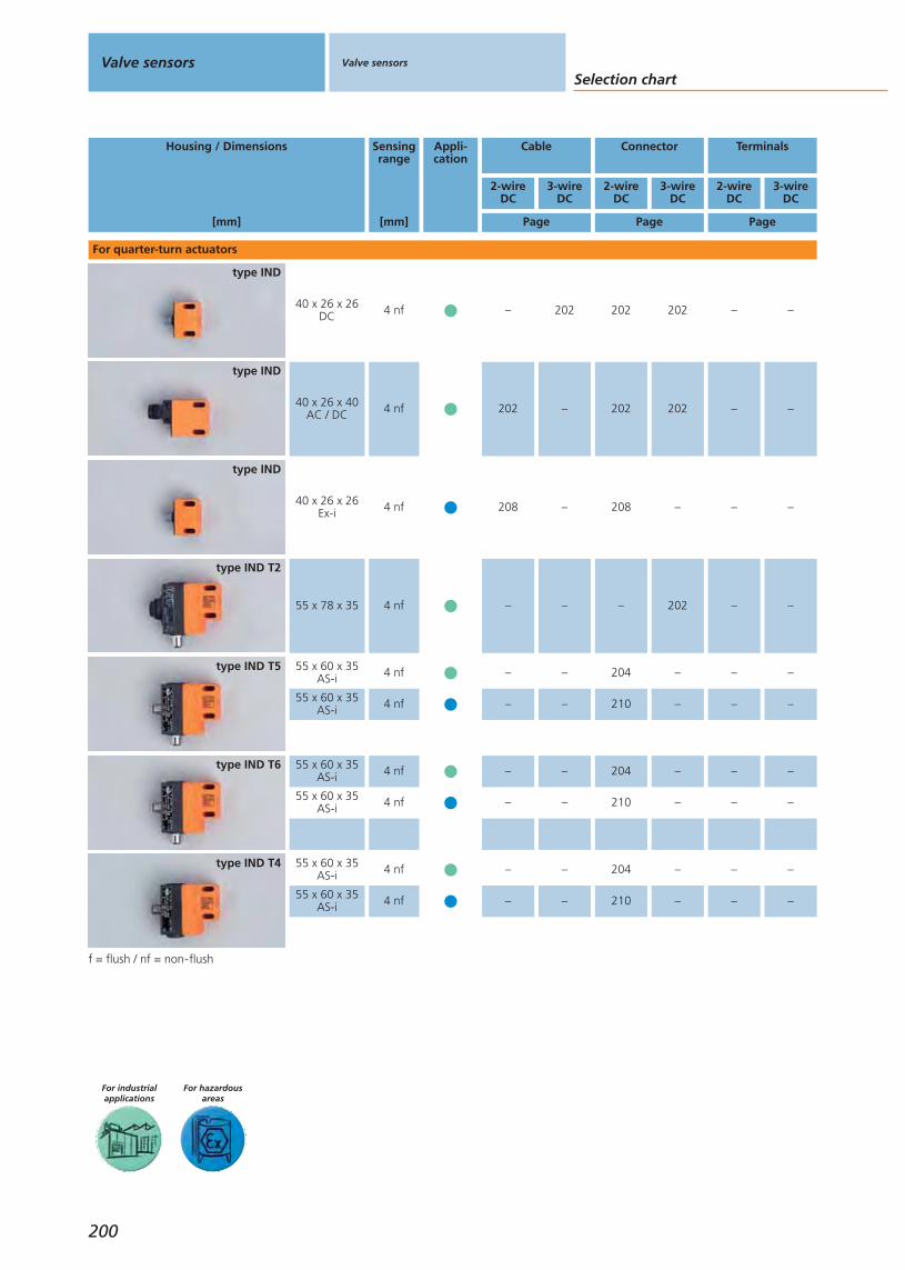
Selection chartValve sensors Valve sensors
For hazardousareas
For industrialapplications
3-wireDC
Housing / Dimensions
[mm]
Sensingrange
[mm]
Appli-cation
Cable Connector Terminals
2-wireDC
Page Page Page
2-wireDC
2-wireDC
3-wireDC
3-wireDC
55 x 60 x 35AS-i 4 nftype IND T4
f = flush / nf = non-flush
55 x 60 x 35AS-i 4 nftype IND T6
200
40 x 26 x 26DC 4 nf
type IND
40 x 26 x 40AC / DC 4 nf
type IND
40 x 26 x 26Ex-i 4 nf
type IND
55 x 78 x 35 4 nf
type IND T2
55 x 60 x 35AS-i 4 nftype IND T5
For quarter-turn actuators
55 x 60 x 35AS-i 4 nf
55 x 60 x 35AS-i 4 nf
55 x 60 x 35AS-i 4 nf
– 204 –– – –
– 210 –– – –
– 204 –– – –
– 210 –– – –
– 202 –
202 202 –
202 202 –
– 202 –
208 208 –– – –
– – –– 202 –
– 204 –– – –
– 210 –– – –

Valve sensors
Gen
eral
info
rmat
ion
List
of
arti
cles
Ind
uct
ive
sen
sors
Cap
acit
ive
sen
sors
Mag
net
icse
nso
rs,
cylin
der
sen
sors
Safe
tyte
chn
olo
gy
Val
ve s
enso
rsPh
oto
elec
tric
sen
sors
Ob
ject
reco
gn
itio
nEn
cod
ers
Eval
uat
ion
syst
ems,
po
wer
su
pp
lies
Co
nn
ecti
on
tech
no
log
yA
cces
sori
esTe
chn
ical
info
rmat
ion
and
cu
sto
mer
serv
ice
201
For hazardousareas
For industrialapplications
Housing / Dimensions
[mm]
Sensingrange
[mm]
Appli-cation
Cable Connector Terminals
2-wireDC
Page Page Page
2-wireDC
2-wireDC
3-wireDC
5-wireDC
3-wireDC
110 x 68 x 43
meas-uring
distance:80
type IX
For linear valves
– – –206 206 –
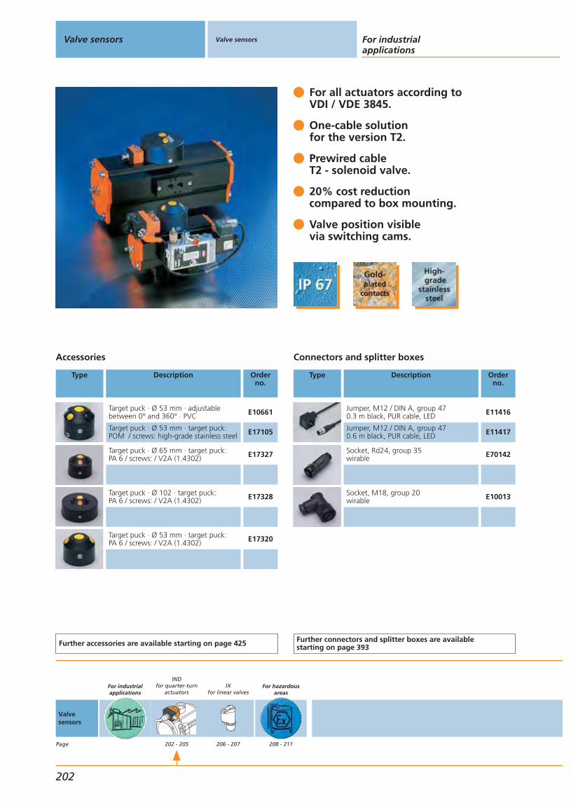
For all actuators according toVDI / VDE 3845.
One-cable solution for the version T2.
Prewired cableT2 - solenoid valve.
20% cost reductioncompared to box mounting.
Valve position visiblevia switching cams.
Accessories
Type Description Orderno.
Target puck · Ø 53 mm · adjustablebetween 0° and 360° · PVC E10661
Target puck · Ø 53 mm · target puck:POM / screws: high-grade stainless steel E17105
Target puck · Ø 65 mm · target puck: PA 6 / screws: / V2A (1.4302) E17327
Target puck · Ø 102 · target puck: PA 6 / screws: / V2A (1.4302) E17328
Target puck · Ø 53 mm · target puck: PA 6 / screws: / V2A (1.4302) E17320
Further accessories are available starting on page 425
Connectors and splitter boxes
Type Description Orderno.
Jumper, M12 / DIN A, group 470.3 m black, PUR cable, LED E11416
Jumper, M12 / DIN A, group 470.6 m black, PUR cable, LED E11417
Socket, Rd24, group 35wirable E70142
Socket, M18, group 20wirable E10013
Further connectors and splitter boxes are availablestarting on page 393
Valve sensors Valve sensors For industrialapplications
202
Valvesensors
Page
For industrialapplications
INDfor quarter-turn
actuators
202 - 205
IXfor linear valves
206 - 207
For hazardousareas
208 - 211

Terminal connection IN5334
1
+
2
3
4
5
1
L+
2
L-
3 4 5
+
6 PE
1
1
M12
PE
Rd24x 81
1 solenoid valve 24 V DC/20 W
Dual sensorsFor quarter-turn actuators or valvesSensing range: 4 mm non flush
Housing /Dimensions
[mm]
Sensingrange[mm]
Material Ub
[V]
f
[Hz]
Protection IloadAC / DC
[mA]
Uab
[V]
Ta
[°C]
I0AC / DC
[mA]
Draw-ingno.
Orderno.
M12 connector · Output · Connector groups 7, 8 · Wiring diagram no. 34
40 x 26 x 26 4 nf PBT 10...36 1300 IP 67 250 4 -20...80 – 1 IN5224
M12 connector · Output · Connector groups 7, 8, 9 · Wiring diagram no. 23
40 x 26 x 26 4 nf PBT 10...36 1300 IP 67 250 2.5 -25...80 15 1 IN5225
Cable 2 m · Output · Wiring diagram no. 24
40 x 26 x 26 4 nf PBT 10...36 1300 IP 67 250 2.5 -25...80 15 2 IN5251
M18 connector · Output · Connector group 20 · Wiring diagram no. 23
40 x 26 x 26 4 nf PBT 10...36 1300 IP 67 250 2.5 -20...80 15 3 IN5285
Cable 6 m · Output · Wiring diagram no. 24
40 x 26 x 26 4 nf PC 10...36 1300 IP 67 250 2.5 -25...80 15 2 IN5304
M12 connector · Output · Connector groups 7, 8, 9 · Wiring diagram no. 23
40 x 26 x 47 4 nf PBT 10...36 1300 IP 67 250 2.5 -25...80 15 4 IN5327
M18 connector · Output · Connector group 20 · Wiring diagram no. 35
40 x 26 x 40 4 nf PC 20...250 25 / 50 IP 67 350 / 100 6.5 -25...80 – 5 IN0108*
Cable 2 m · Output · Wiring diagram no. 36
40 x 26 x 40 4 nf PBT 20...250 25 / 50 IP 67 350 / 100 6.5 -25...80 – 6 IN0110*
Rd 24 x 1/8 connector 6 pins + PE / M12-connector 5 pins · Output · Connector groups 35, 39
40 x 26 x 60 4 nf PBT 10...36 1300 IP 67 250 2.5 -25...80 20 7 IN5334
You can find scale drawings from page 476
Valve sensors
Gen
eral
info
rmat
ion
List
of
arti
cles
Ind
uct
ive
sen
sors
Cap
acit
ive
sen
sors
Mag
net
icse
nso
rs,
cylin
der
sen
sors
Safe
tyte
chn
olo
gy
Val
ve s
enso
rsPh
oto
elec
tric
sen
sors
Ob
ject
reco
gn
itio
nEn
cod
ers
Eval
uat
ion
syst
ems,
po
wer
su
pp
lies
Co
nn
ecti
on
tech
no
log
yA
cces
sori
esTe
chn
ical
info
rmat
ion
and
cu
sto
mer
serv
ice
203
* Note for AC and AC/DC unitsMiniature fuse to IEC60127-2 sheet 1, = 2A (fast acting).Recommendation: check the unit for reliable function after ashort circuit.

Products with integratedAS-i slave - certified.
Quick and safe installationdue to “plug & play”.
Monitoring the solenoid forwire break / short circuit.
Up to 31 actuators connectable to a single master / controller.
50% cost reduction compared to parallel wiring.
Accessories
Type Description Orderno.
Target puck · Ø 53 mm · adjustablebetween 0° and 360° · PVC E10661
Target puck · Ø 53 mm · target puck:POM / screws: high-grade stainless steel E17105
Target puck · Ø 65 mm · target puck: PA 6 / screws: V2A (1.4302) E17327
Target puck · Ø 102 · target puck: PA 6 / screws: V2A (1.4302) E17328
Target puck · Ø 53 mm · target puck: PA 6 / screws: V2A (1.4302) E17320
Further accessories are available starting on page 425
Connectors and splitter boxes
Type Description Orderno.
FC insulation displacement connector,ASi, group 4 E70271
Jumper, M12 / DIN A, group 470.3 m black, PUR cable, LED E11416
Jumper, M12 / DIN A, group 470.6 m black, PUR cable, LED E11417
Jumper, M12 / DIN B, group 480.3 m black, PUR cable, LED E11421
Jumper, M12 / DIN B, group 480.6 m black, PUR cable, LED E11422
Y connection cable, M12 plug / valveplug type A, group 52 E70203
Further connectors and splitter boxes are availablestarting on page 393
Valve sensors Valve sensors For industrialapplications
204
Valvesensors
Page
For industrialapplications
INDfor quarter-turn
actuators
202 - 205
IXfor linear valves
206 - 207
For hazardousareas
208 - 211
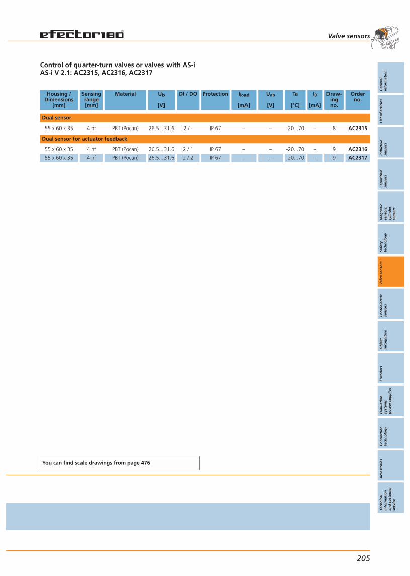
Control of quarter-turn valves or valves with AS-iAS-i V 2.1: AC2315, AC2316, AC2317
Housing /Dimensions
[mm]
Sensingrange[mm]
Material Ub
[V]
DI / DO Protection Iload
[mA]
Uab
[V]
Ta
[°C]
I0
[mA]
Draw-ingno.
Orderno.
Dual sensor
55 x 60 x 35 4 nf PBT (Pocan) 26.5...31.6 2 / - IP 67 – – -20...70 – 8 AC2315
Dual sensor for actuator feedback
55 x 60 x 35 4 nf PBT (Pocan) 26.5...31.6 2 / 1 IP 67 – – -20...70 – 9 AC2316
55 x 60 x 35 4 nf PBT (Pocan) 26.5...31.6 2 / 2 IP 67 – – -20...70 – 9 AC2317
You can find scale drawings from page 476
Valve sensors
Gen
eral
info
rmat
ion
List
of
arti
cles
Ind
uct
ive
sen
sors
Cap
acit
ive
sen
sors
Mag
net
icse
nso
rs,
cylin
der
sen
sors
Safe
tyte
chn
olo
gy
Val
ve s
enso
rsPh
oto
elec
tric
sen
sors
Ob
ject
reco
gn
itio
nEn
cod
ers
Eval
uat
ion
syst
ems,
po
wer
su
pp
lies
Co
nn
ecti
on
tech
no
log
yA
cces
sori
esTe
chn
ical
info
rmat
ion
and
cu
sto
mer
serv
ice
205

Feedback and diagnosis
The efector valvis was designed for feedback of thevalve positions on linear valves with a stroke of up to80mm. The sensor is fitted over the valve spindle andcontinuously measures the stroke. Previously selectedswitch points transmit the actual limits of travel to thecontroller. The efector valvis signals up to three impor-tant valve positions to the controller: valve open, valveclosed and any position in-between, e.g. for the seat lift.The resolution of the measuring path of 0.2mm allowspreventive maintenance of the valve disk seals. This waythe maintenance intervals can be adapted to the actualwear which in turn increases life and uptime. Using theefector valvis means that complex mounting of severalindividual position sensors is no longer required. Conve-nient programming of the switch points by simplypushing a button replaces the time-consuming mecha-nical adjustment to the respective valve positions.Mounting tolerances or sensing ranges do not need tobe taken into account any more. This means: Mountingand adjustment in a fraction of the time currently needed.
Position feedback for rising stem valves up to 80 mm.
Three switching outputs: “open”,“closed” and “rinse”.
Resolution of 0.2mm across the entire measuring range.
Easy teaching by means ofpushbuttons and LED feedback.
Permanent valve monitoring for predictive maintenance.
Valve sensors Valve sensors For industrialapplications
206
Valvesensors
Page
For industrialapplications
INDfor quarter-turn
actuators
202 - 205
IXfor linear valves
206 - 207
For hazardousareas
208 - 211
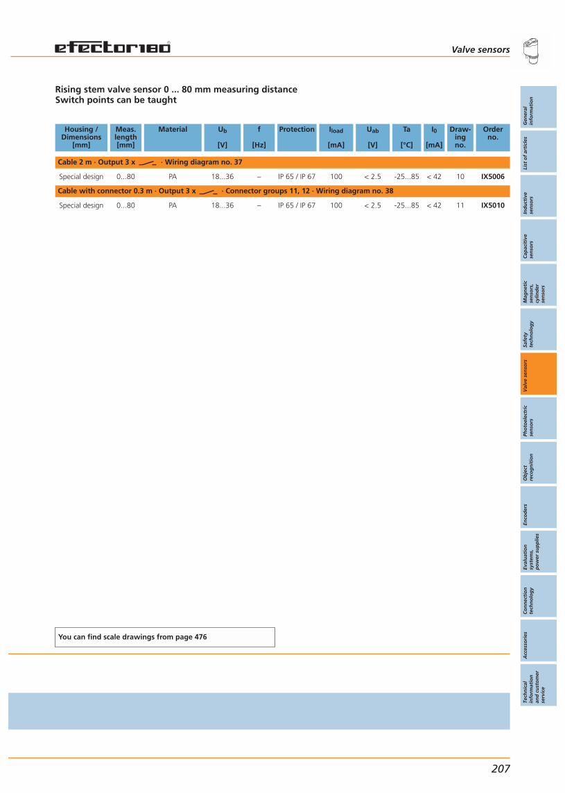
Rising stem valve sensor 0 ... 80 mm measuring distanceSwitch points can be taught
Housing /Dimensions
[mm]
Meas.length[mm]
Material Ub
[V]
f
[Hz]
Protection Iload
[mA]
Uab
[V]
Ta
[°C]
I0
[mA]
Draw-ingno.
Orderno.
Cable 2 m · Output 3 x · Wiring diagram no. 37
Special design 0...80 PA 18...36 – IP 65 / IP 67 100 < 2.5 -25...85 < 42 10 IX5006
Cable with connector 0.3 m · Output 3 x · Connector groups 11, 12 · Wiring diagram no. 38
Special design 0...80 PA 18...36 – IP 65 / IP 67 100 < 2.5 -25...85 < 42 11 IX5010
You can find scale drawings from page 476
Valve sensors
Gen
eral
info
rmat
ion
List
of
arti
cles
Ind
uct
ive
sen
sors
Cap
acit
ive
sen
sors
Mag
net
icse
nso
rs,
cylin
der
sen
sors
Safe
tyte
chn
olo
gy
Val
ve s
enso
rsPh
oto
elec
tric
sen
sors
Ob
ject
reco
gn
itio
nEn
cod
ers
Eval
uat
ion
syst
ems,
po
wer
su
pp
lies
Co
nn
ecti
on
tech
no
log
yA
cces
sori
esTe
chn
ical
info
rmat
ion
and
cu
sto
mer
serv
ice
207

NAMUR dual sensors for use inhazardous gas and dust areas.
For categories 1G / 2G and 1D.
For all actuators according toVDI / VDE 3845.
20% cost reduction due tohigher machine uptime.
Cable or plug-and-socketconnection.
Accessories
Type Description Orderno.
Target puck · Ø 53 mm · adjustablebetween 0° and 360° · PVC E10661
Target puck · Ø 53 mm · target puck:POM / screws: high-grade stainless steel E17105
Target puck · Ø 65 mm · target puck: PA 6 / screws:V2A (1.4302) E17327
Target puck · Ø 102 · target puck: PA 6 / screws: V2A (1.4302) E17328
Target puck · Ø 53 mm · target puck: PA 6 / screws: V2A (1.4302) E17320
Further accessories are available starting on page 425
Connectors and splitter boxes
Type Description Orderno.
Socket, M12, group 752 m blue, PUR / PVC cable E10355
Socket, M12, group 755 m blue, PUR / PVC cable E10356
Socket, M12, group 752 m blue, PUR / PVC cable E10357
Socket, M12, group 755 m blue, PUR / PVC cable E10358
Further connectors and splitter boxes are availablestarting on page 393
Valve sensors Valve sensors
For hazardous areas
208
Valvesensors
Page
For industrialapplications
INDfor quarter-turn
actuators
202 - 205
IXfor linear valves
206 - 207
For hazardousareas
208 - 211
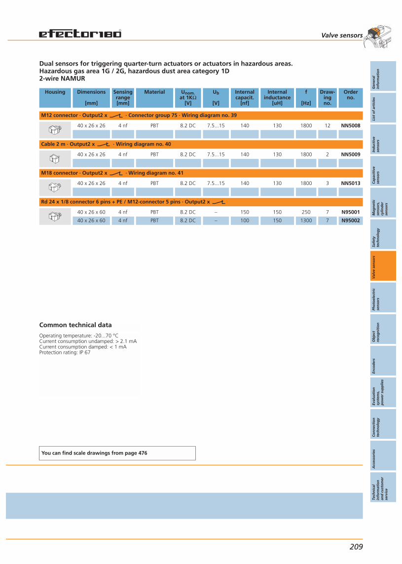
Dual sensors for triggering quarter-turn actuators or actuators in hazardous areas.Hazardous gas area 1G / 2G, hazardous dust area category 1D2-wire NAMUR
Housing Dimensions
[mm]
Sensingrange[mm]
Material Unom.at 1KΩ
[V]
Ub
[V]
Internalcapacit.
[nf]
Internalinductance
[uH]
f
[Hz]
Draw-ingno.
Orderno.
M12 connector · Output2 x · Connector group 75 · Wiring diagram no. 39
40 x 26 x 26 4 nf PBT 8.2 DC 7.5...15 140 130 1800 12 NN5008
Cable 2 m · Output2 x · Wiring diagram no. 40
40 x 26 x 26 4 nf PBT 8.2 DC 7.5...15 140 130 1800 2 NN5009
M18 connector · Output2 x · Wiring diagram no. 41
40 x 26 x 26 4 nf PBT 8.2 DC 7.5...15 140 130 1800 3 NN5013
Rd 24 x 1/8 connector 6 pins + PE / M12-connector 5 pins · Output2 x
40 x 26 x 60 4 nf PBT 8.2 DC – 150 150 250 7 N95001
40 x 26 x 60 4 nf PBT 8.2 DC – 100 150 1300 7 N95002
Common technical data
Operating temperature: -20...70 °CCurrent consumption undamped: > 2.1 mACurrent consumption damped: < 1 mAProtection rating: IP 67
You can find scale drawings from page 476
Valve sensors
Gen
eral
info
rmat
ion
List
of
arti
cles
Ind
uct
ive
sen
sors
Cap
acit
ive
sen
sors
Mag
net
icse
nso
rs,
cylin
der
sen
sors
Safe
tyte
chn
olo
gy
Val
ve s
enso
rsPh
oto
elec
tric
sen
sors
Ob
ject
reco
gn
itio
nEn
cod
ers
Eval
uat
ion
syst
ems,
po
wer
su
pp
lies
Co
nn
ecti
on
tech
no
log
yA
cces
sori
esTe
chn
ical
info
rmat
ion
and
cu
sto
mer
serv
ice
209
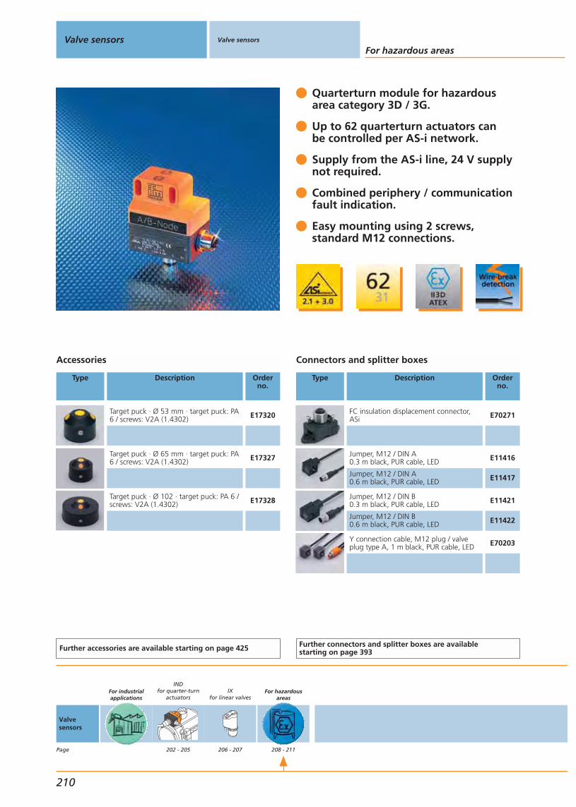
Quarterturn module for hazardousarea category 3D / 3G.
Up to 62 quarterturn actuators canbe controlled per AS-i network.
Supply from the AS-i line, 24 V supplynot required.
Combined periphery / communicationfault indication.
Easy mounting using 2 screws,standard M12 connections.
Accessories
Type Description Orderno.
Target puck · Ø 53 mm · target puck: PA6 / screws: V2A (1.4302) E17320
Target puck · Ø 65 mm · target puck: PA6 / screws: V2A (1.4302) E17327
Target puck · Ø 102 · target puck: PA 6 /screws: V2A (1.4302) E17328
Further accessories are available starting on page 425
Connectors and splitter boxes
Type Description Orderno.
FC insulation displacement connector,ASi E70271
Jumper, M12 / DIN A0.3 m black, PUR cable, LED E11416
Jumper, M12 / DIN A0.6 m black, PUR cable, LED E11417
Jumper, M12 / DIN B0.3 m black, PUR cable, LED E11421
Jumper, M12 / DIN B0.6 m black, PUR cable, LED E11422
Y connection cable, M12 plug / valveplug type A, 1 m black, PUR cable, LED E70203
Further connectors and splitter boxes are availablestarting on page 393
Valve sensors Valve sensors
For hazardous areas
210
Valvesensors
Page
For industrialapplications
INDfor quarter-turn
actuators
202 - 205
IXfor linear valves
206 - 207
For hazardousareas
208 - 211
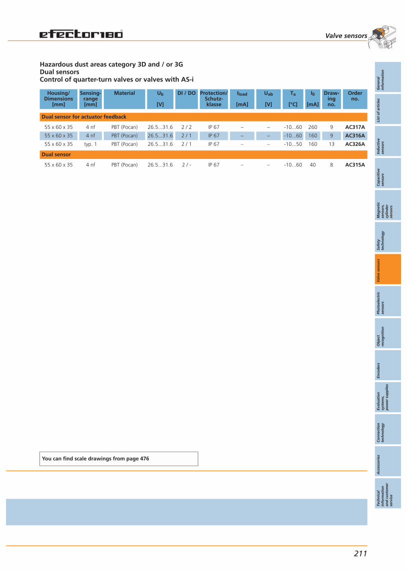
Hazardous dust areas category 3D and / or 3GDual sensorsControl of quarter-turn valves or valves with AS-i
Housing/Dimensions
[mm]
Sensing-range[mm]
Material Ub
[V]
DI / DO Protection/Schutz-klasse
Iload
[mA]
Uab
[V]
Ta
[°C]
I0
[mA]
Draw-ingno.
Orderno.
Dual sensor for actuator feedback
55 x 60 x 35 4 nf PBT (Pocan) 26.5...31.6 2 / 2 IP 67 – – -10...60 260 9 AC317A
55 x 60 x 35 4 nf PBT (Pocan) 26.5...31.6 2 / 1 IP 67 – – -10...60 160 9 AC316A
55 x 60 x 35 typ. 1 PBT (Pocan) 26.5...31.6 2 / 1 IP 67 – – -10...50 160 13 AC326A
Dual sensor
55 x 60 x 35 4 nf PBT (Pocan) 26.5...31.6 2 / - IP 67 – – -10...60 40 8 AC315A
You can find scale drawings from page 476
Valve sensors
Gen
eral
info
rmat
ion
List
of
arti
cles
Ind
uct
ive
sen
sors
Cap
acit
ive
sen
sors
Mag
net
icse
nso
rs,
cylin
der
sen
sors
Safe
tyte
chn
olo
gy
Val
ve s
enso
rsPh
oto
elec
tric
sen
sors
Ob
ject
reco
gn
itio
nEn
cod
ers
Eval
uat
ion
syst
ems,
po
wer
su
pp
lies
Co
nn
ecti
on
tech
no
log
yA
cces
sori
esTe
chn
ical
info
rmat
ion
and
cu
sto
mer
serv
ice
211


Gen
eral
info
rmat
ion
List
of
arti
cles
Ind
uct
ive
sen
sors
Cap
acit
ive
sen
sors
Mag
net
icse
nso
rs,
cylin
der
sen
sors
Safe
tyte
chn
olo
gy
Val
ve s
enso
rsPh
oto
elec
tric
sen
sors
Ob
ject
reco
gn
itio
nEn
cod
ers
Eval
uat
ion
syst
ems,
po
wer
su
pp
lies
Co
nn
ecti
on
tech
no
log
yA
cces
sori
esTe
chn
ical
info
rmat
ion
and
cu
sto
mer
serv
ice
Photoelectric sensors
213
Infrared / red light sensorsfor industrial applications
Infrared / red light sensors
System descriptionSelection chart
Laser sensorsSystems for specific applications
Universal application
Threaded housing OFThreaded housing OGRectangular housing OHRectangular housing OJRectangular housing O5Rectangular housing O4
214 - 217218 - 221
265 - 281283 - 297
222 - 227228 - 237238 - 241242 - 255256 - 259260 - 263

System description
Visit our website: www.ifm-electronic.com
The system consists of two separate components: a transmitter and a receiv-er. The transmitter emits pulsed light in the infrared or visible red wavelengthrange. The receiver detects the light beam and immediately converts a beaminterruption caused by an object in the sensing zone into a switched signal.
Photoelectric sensors Infrared / red light sensors
214
IntroductionAutomation technology can no longer be imagined without photoelectricsensors as “artificial eyes”. They are used where safe and non-contact de-tection of the exact position of objects is required. The material of theobjects to be detected is of no importance. Compared to proximity sensorsphotoelectric sensors have a much higher sensing zone. With through-beamsensors for example distances up to 60 m can be monitored.The correct selection of the system and design is decisive for the operationalreliability in the different applications.The photoelectric standard sensors are divided into three groupsdepending on the operating principle:
through-beam sensorsretro-reflective sensorsdiffuse reflection sensors
Through-beam sensors
Photoelectricsensors areused to detectpositions inautomationtechnology.
The light only travels one way (from the transmitter to the receiver). Adverseeffects in the applications, such as dust in the air, dirt on the lenses, steam ormist do not immediately interfere with the system. This is called a high insen-sitivity to dirt or a high excess gain. A through-beam sensor is distinguishedby a long range. The characteristics of the sensing zone can be describedeasily. An object must have at least the size of the optical axis, i.e. the size ofthe sensing surface or the lens to enable safe detection. This also goes forthe whole distance between transmitter and receiver.Since the transmitted light only travels one way it is very difficult to detecttransparent objects. The light beam is not sufficiently interrupted.A through-beam sensor should always operate with maximum sensitivity toensure maximum operational reliability. An exception is the detection ofpartly transparent objects. The sensitivity must be reduced accordingly.
Features of through-beam sensors
For a retro-reflective sensor the transmitter and receiver are incorporatedinto one housing. By means of a suitable reflector the transmitted light isreturned to the receiver. An object in the beam path interrupts the beam andtriggers a switching operation.
Retro-reflective sensors
Transparent objects such as bottles or foils can be detected better than witha through-beam sensor because the light beam must pass the object twiceand is thus weakened twice as much as with the through-beam sensor.
Features of retro-reflective sensors
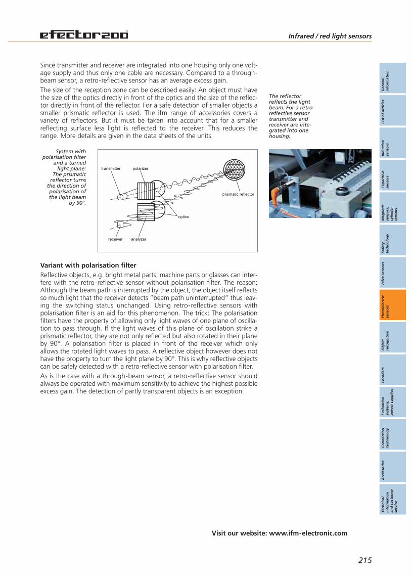
Gen
eral
info
rmat
ion
List
of
arti
cles
Ind
uct
ive
sen
sors
Cap
acit
ive
sen
sors
Mag
net
icse
nso
rs,
cylin
der
sen
sors
Safe
tyte
chn
olo
gy
Val
ve s
enso
rsPh
oto
elec
tric
sen
sors
Ob
ject
reco
gn
itio
nEn
cod
ers
Eval
uat
ion
syst
ems,
po
wer
su
pp
lies
Co
nn
ecti
on
tech
no
log
yA
cces
sori
esTe
chn
ical
info
rmat
ion
and
cu
sto
mer
serv
ice
Infrared / red light sensors
Visit our website: www.ifm-electronic.com
215
Since transmitter and receiver are integrated into one housing only one volt-age supply and thus only one cable are necessary. Compared to a through-beam sensor, a retro-reflective sensor has an average excess gain.The size of the reception zone can be described easily: An object must havethe size of the optics directly in front of the optics and the size of the reflec-tor directly in front of the reflector. For a safe detection of smaller objects asmaller prismatic reflector is used. The ifm range of accessories covers avariety of reflectors. But it must be taken into account that for a smallerreflecting surface less light is reflected to the receiver. This reduces therange. More details are given in the data sheets of the units.
System withpolarisation filter
and a turnedlight plane:
The prismaticreflector turns
the direction ofpolarisation ofthe light beam
by 90°.
The reflectorreflects the lightbeam: For a retro-reflective sensortransmitter andreceiver are inte-grated into onehousing.
optics
receiver analyzer
prismatic reflector
transmitter polarizer
Reflective objects, e.g. bright metal parts, machine parts or glasses can inter-fere with the retro-reflective sensor without polarisation filter. The reason:Although the beam path is interrupted by the object, the object itself reflectsso much light that the receiver detects “beam path uninterrupted” thus leav-ing the switching status unchanged. Using retro-reflective sensors withpolarisation filter is an aid for this phenomenon. The trick: The polarisationfilters have the property of allowing only light waves of one plane of oscilla-tion to pass through. If the light waves of this plane of oscillation strike aprismatic reflector, they are not only reflected but also rotated in their planeby 90°. A polarisation filter is placed in front of the receiver which onlyallows the rotated light waves to pass. A reflective object however does nothave the property to turn the light plane by 90°. This is why reflective objectscan be safely detected with a retro-reflective sensor with polarisation filter. As is the case with a through-beam sensor, a retro-reflective sensor shouldalways be operated with maximum sensitivity to achieve the highest possibleexcess gain. The detection of partly transparent objects is an exception.
Variant with polarisation filter
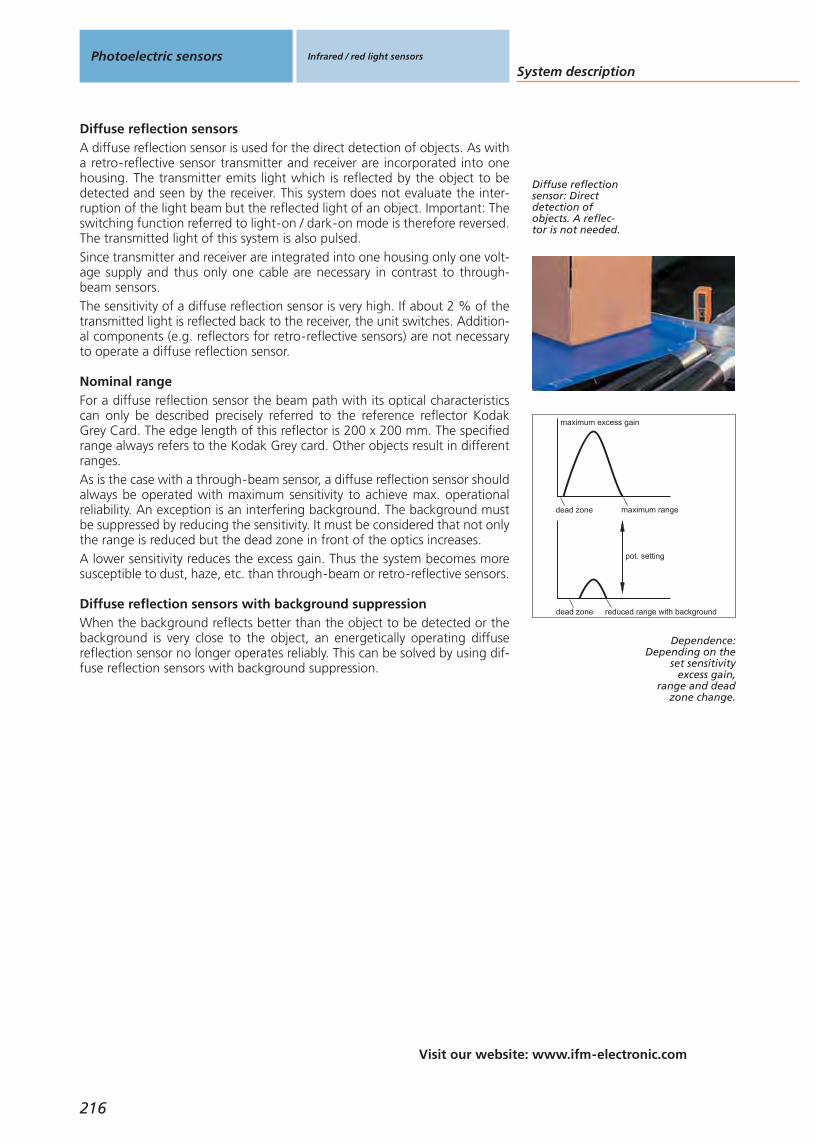
System description
Visit our website: www.ifm-electronic.com
Photoelectric sensors Infrared / red light sensors
216
A diffuse reflection sensor is used for the direct detection of objects. As witha retro-reflective sensor transmitter and receiver are incorporated into onehousing. The transmitter emits light which is reflected by the object to bedetected and seen by the receiver. This system does not evaluate the inter-ruption of the light beam but the reflected light of an object. Important: Theswitching function referred to light-on / dark-on mode is therefore reversed.The transmitted light of this system is also pulsed.Since transmitter and receiver are integrated into one housing only one volt-age supply and thus only one cable are necessary in contrast to through-beam sensors.The sensitivity of a diffuse reflection sensor is very high. If about 2 % of thetransmitted light is reflected back to the receiver, the unit switches. Addition-al components (e.g. reflectors for retro-reflective sensors) are not necessaryto operate a diffuse reflection sensor.
Diffuse reflection sensors
For a diffuse reflection sensor the beam path with its optical characteristicscan only be described precisely referred to the reference reflector KodakGrey Card. The edge length of this reflector is 200 x 200 mm. The specifiedrange always refers to the Kodak Grey card. Other objects result in differentranges.As is the case with a through-beam sensor, a diffuse reflection sensor shouldalways be operated with maximum sensitivity to achieve max. operationalreliability. An exception is an interfering background. The background mustbe suppressed by reducing the sensitivity. It must be considered that not onlythe range is reduced but the dead zone in front of the optics increases.A lower sensitivity reduces the excess gain. Thus the system becomes moresusceptible to dust, haze, etc. than through-beam or retro-reflective sensors.
Nominal range
When the background reflects better than the object to be detected or thebackground is very close to the object, an energetically operating diffusereflection sensor no longer operates reliably. This can be solved by using dif-fuse reflection sensors with background suppression.
Diffuse reflection sensors with background suppressionreduced range with background
pot. setting
dead zone
maximum rangedead zone
maximum excess gain
Diffuse reflectionsensor: Directdetection ofobjects. A reflec-tor is not needed.
Dependence:Depending on the
set sensitivityexcess gain,
range and deadzone change.

Infrared / red light sensors
217
Visit our website: www.ifm-electronic.com
Gen
eral
info
rmat
ion
List
of
arti
cles
Ind
uct
ive
sen
sors
Cap
acit
ive
sen
sors
Mag
net
icse
nso
rs,
cylin
der
sen
sors
Safe
tyte
chn
olo
gy
Val
ve s
enso
rsPh
oto
elec
tric
sen
sors
Ob
ject
reco
gn
itio
nEn
cod
ers
Eval
uat
ion
syst
ems,
po
wer
su
pp
lies
Co
nn
ecti
on
tech
no
log
yA
cces
sori
esTe
chn
ical
info
rmat
ion
and
cu
sto
mer
serv
ice
An ifm photoelectric sensor with background suppression operates on thegeometrical principle (triangulation). It does not evaluate how much (or howintensively) light is reflected by the object to be detected but at which anglethe light is incident. After the user has set the sensor, the unit detects wheth-er the reflected light comes from the object to be detected or from the bak-kground.
Background suppression
The correct mounting of the sensor is decisive for the reliable machine function.ifm electronic offers a complete component system of easy-to-use mountingsets that make installation much easier. The solutions consist of a clampwhich is fastened with only one screw, keeps the sensors safely in place andat the same time guarantees free movement in all axes. The mounting ele-ments used depend on the sensor type.The clamp can be fixed in three different ways. We offer the options for free-standing mounting, rod mounting and mounting for industrially commonaluminium extrusions.These options are available for all sensor types. In addition, ifm electronicoffers fixing solutions for optical reflectors. The system components can besupplied in die-cast zinc and stainless steel.
Fixing options
ifm fixingcomponents:
The system witha wide choice
of solutions.
S
E
Diffuse reflectionsensor withbackgroundsuppression:Objects are onlydetected in theintersecting zone.
For photoelectric sensors ifm electronic offers up to three variants dependingon the design:BasicLine
Without setting options for use in standard applications.With potentiometer for easy setting and simple applications.
PerformanceLineWith pushbutton for extremely easy setting to the application: Using aninnovative teach method the user easily and reliably sets the system tohis application. By pressing the button twice the materials to be detectedcan be sensed.
Easy handling and reliable function

Selection chartPhotoelectric sensors Infrared / red light sensors
For industrialapplications
Housing / Dimensions
[mm]
System Range
218
M12 x 1
M12 x 1
M12 x 1
M12 x 1
diffuse reflection sensor energetic 1...400 mm
retro-reflective sensor without polarisation filter 50...2000 mm
retro-reflective sensor with polarisation filter 200...800 mm
through-beam sensor – 0...4 m
type OF
M18 x 1
M18 x 1
M18 x 1
diffuse reflection sensor background suppression 15...250 mm
retro-reflective sensor with polarisation filter 100...3000 mm
through-beam sensor – 0...15 m
type OG front sensing
M18 x 1.5
M18 x 1.5
M18 x 1.5
M18 x 1.5
diffuse reflection sensor background suppression 3...100 mm
diffuse reflection sensor background suppression 6...200 mm
retro-reflective sensor without polarisation filter 0...3 m
through-beam sensor – 0...10 m
type OG side sensing
type OJ front sensing
35 x 11 x 24
35 x 11 x 24
35 x 11 x 24
35 x 11 x 24
diffuse reflection sensor energetic 1...600 mm
diffuse reflection sensor background suppression 15...400 mm
retro-reflective sensor with polarisation filter 0...2 m
through-beam sensor – 0...10 m
type OJ front sensing
35 x 11 x 24
35 x 11 x 24
35 x 11 x 24
35 x 11 x 24
diffuse reflection sensor energetic 1...600 mm
diffuse reflection sensor background suppression 15...200 mm
retro-reflective sensor with polarisation filter 0...2 m
through-beam sensor – 0...10 m
type OJ side sensing
56 x 18 x 47
56 x 18 x 47
56 x 18 x 47
56 x 18 x 47
diffuse reflection sensor background suppression 50...1400 mm
diffuse reflection sensor background suppression 50...1800 mm
retro-reflective sensor with polarisation filter 0...7 m
through-beam sensor – 0...20 m
type O5
35 x 11 x 32
35 x 11 x 32
35 x 11 x 32
35 x 11 x 32
diffuse reflection sensor energetic 1...600 mm
diffuse reflection sensor background suppression 15...400 mm
retro-reflective sensor with polarisation filter 0...2 m
through-beam sensor – 0...10 m
35 x 11 x 32
35 x 11 x 32
35 x 11 x 32
35 x 11 x 32
diffuse reflection sensor energetic 1...600 mm
diffuse reflection sensor background suppression 15...200 mm
retro-reflective sensor with polarisation filter 0...2 m
through-beam sensor – 0...10 m
type OJ side sensing

Gen
eral
info
rmat
ion
List
of
arti
cles
Ind
uct
ive
sen
sors
Cap
acit
ive
sen
sors
Mag
net
icse
nso
rs,
cylin
der
sen
sors
Safe
tyte
chn
olo
gy
Val
ve s
enso
rsPh
oto
elec
tric
sen
sors
Ob
ject
reco
gn
itio
nEn
cod
ers
Eval
uat
ion
syst
ems,
po
wer
su
pp
lies
Co
nn
ecti
on
tech
no
log
yA
cces
sori
esTe
chn
ical
info
rmat
ion
and
cu
sto
mer
serv
ice
Infrared / red light sensors
Operating voltage
DC AC
Connection
Cable Connector Terminals
Application /Page
Application /Page
219
222
222
222
222
•
•
•
•
–
–
–
–
•
•
•
•
•
•
•
•
–
––
–
–
228
228
228
•
•
•
•
•
•
•
•
•
•
•
•
–
–
–
244
244
244
244
•
•
•
•
–
–
–
–
•
•
•
•
•
•
•
•
–
–
–
–
250
250
250
250
•
•
•
•
–
–
–
–
•
•
•
•
•
•
•
•
–
–
–
–
232
232
232
232
•
•
•
•
–
–
–
–
–
–
–
–
•
•
•
•
–
–
–
–
242
242
242
242
•
•
•
•
–
–
–
–
•
•
•
•
•
•
•
•
–
–
–
–
248
248
248
248
•
•
•
•
–
–
–
–
•
•
•
•
•
•
•
•
–
–
–
–
256
256
256
256
•
•
•
•
–
–
–
–
–
–
–
–
•
•
•
•
–
–
–
–

Selection chartPhotoelectric sensors Infrared / red light sensors
For industrialapplications
Housing / Dimensions
[mm]
System Range
220
74.4 x 27 x 63.8
74.4 x 27 x 63.8
74.4 x 27 x 63.8
diffuse reflection sensor background suppression 0.1...2 m
retro-reflective sensor with polarisation filter 0.3...18 m
through-beam sensor – 0...50 m
type O4
20.6 x 13.5 x 7.6
20.6 x 13.5 x 7.6
20.6 x 13.5 x 7.6
diffuse reflection sensor background suppression 10...30 mm
retro-reflective sensor with polarisation filter ...800 mm
through-beam sensor – ...1200 mm
type OH
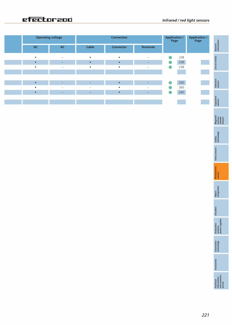
Gen
eral
info
rmat
ion
List
of
arti
cles
Ind
uct
ive
sen
sors
Cap
acit
ive
sen
sors
Mag
net
icse
nso
rs,
cylin
der
sen
sors
Safe
tyte
chn
olo
gy
Val
ve s
enso
rsPh
oto
elec
tric
sen
sors
Ob
ject
reco
gn
itio
nEn
cod
ers
Eval
uat
ion
syst
ems,
po
wer
su
pp
lies
Co
nn
ecti
on
tech
no
log
yA
cces
sori
esTe
chn
ical
info
rmat
ion
and
cu
sto
mer
serv
ice
Infrared / red light sensors
Operating voltage
DC AC
Connection
Cable Connector Terminals
Application /Page
Application /Page
221
238
238
238
•
•
•
–
–
–
•
•
•
•
•
•
–
–
–
260
260
260
•
•
•
–
–
–
–
–
–
•
•
•
–
–
–

Easy mounting due to cylindricalhousing
Metal housing for robust use.
Fixed range.
LED display to check operation,switching status and function.
Wide range of system componentsfor easy and safe mounting.
Accessories
Type Description Orderno.
Mounting set · Ø 12.2 mm · fixture:st. steel (320S31) / clamp: diecast zinc E21200
Mounting set · Ø 12.2 mm · fixture:st. steel (320S31) / clamp: diecast zinc E21202
Angle support · 90° · for type OF ·housing: / ABS / lens: / PC E20590
Head cap screw · M8 x 40 mm · ISO 4762 (DIN 912) · screw: steel E21204
Prismatic reflector · Ø 80 mm · round ·plastics E20005
Further accessories are available starting on page 425
Photoelectric sensors Infrared / red light sensors For industrialapplications
222
Infrared /red lightsensors
Page
For industrialapplications
222 - 263
OFM12 x 1
222 - 227
OGM18 x 1
228 - 237
OH20.6 x
13.5 x 7.6 mm
238 - 241
OJ35 x 24 x 11 mm
242 - 255
O518 x 47 x 56 mm
256 - 259
O474.4 x
27 x 63.8 mm
260 - 263
Lasersensors
270 - 281

Abbreviations
H = light-onD = dark-onH/D = light-on or dark-on programmableH+D = light-on and dark-onRel. = relay output
Type OF, operating voltage: DCConnection technology: cable versions
Function Connection Output Typeof light
LED
Spot Ø atmax.range[mm]
I0
[mA]
Wiringdiagram
no.
Draw-ingno.
Orderno.
Through-beam sensor · Transmitter range ...4 m
PUR cable – infrared 700 20 42 1 OF5018
Through-beam sensor · Receiver range ...4 m
PUR cable H/D PNP – – 25 83 1 OF5019
PUR cable H/D NPN – – 25 84 1 OF5052
Retro-reflective sensor · Range 0.05...2 m prismatic reflector Ø 80 (E20005)
PUR cable H/D PNP infrared 140 30 83 1 OF5014
PUR cable H/D NPN infrared 140 30 84 1 OF5050
Retro-reflective sensor · Polarisation filter · Range 0.2...0.8 m prismatic reflector Ø 80 (E20005)
PUR cable H/D PNP red 70 30 83 1 OF5024
PUR cable H/D NPN red 70 30 84 1 OF5061
Diffuse reflection sensor · Range 0.001...0.2 m
PUR cable H/D PNP infrared 92 30 83 1 OF5010
PUR cable H/D NPN infrared 92 30 85 1 OF5048
PUR cable H/D PNP infrared 92 30 83 1 OF5032
Diffuse reflection sensor · Highly focussed beam · Range 0.001...0.4 m
PUR cable H/D PNP infrared 185 30 83 1 OF5026
PUR cable H/D NPN infrared 185 30 85 1 OF5059
Common technical data
Ub: 10...36 V DCMaterial lens: PMMAHousing material: brass nickel-plated / stainless steel (320S31)Short-cicuit and overload protectionOperating temperature: -25...60 °CProtection: IP 67 IICurrent rating: 200 mASwitching status indication: LED yellowOperation: LED green
You can find scale drawings from page 479 You can find details about reflectorsfrom page 433
Systems forspecificapplications
288 - 297
Infrared / red light sensors
Gen
eral
info
rmat
ion
List
of
arti
cles
Ind
uct
ive
sen
sors
Cap
acit
ive
sen
sors
Mag
net
icse
nso
rs,
cylin
der
sen
sors
Safe
tyte
chn
olo
gy
Val
ve s
enso
rsPh
oto
elec
tric
sen
sors
Ob
ject
reco
gn
itio
nEn
cod
ers
Eval
uat
ion
syst
ems,
po
wer
su
pp
lies
Co
nn
ecti
on
tech
no
log
yA
cces
sori
esTe
chn
ical
info
rmat
ion
and
cu
sto
mer
serv
ice
223

Easy mounting due to cylindricalhousing.
Metal housing for robust use.
Adjustable range.
LED display to check operation,switching status and function.
Wide range of system components for easy and safe mounting.
Accessories
Type Description Orderno.
Mounting set · Ø 12.2 mm · fixture:st. steel (320S31) / clamp: diecast zinc E21200
Mounting set · Ø 12.2 mm · fixture:st. steel (320S31) / clamp: diecast zinc E21202
Angle support · 90° · for type OF ·housing: / ABS / lens: / PC E20590
Head cap screw · M8 x 40 mm · ISO 4762 (DIN 912) · screw: steel E21204
Prismatic reflector · Ø 80 mm · round ·plastics E20005
Further accessories are available starting on page 425
Connectors and splitter boxes
Type Description Orderno.
Socket, M12, group 72 m black, PUR cable EVC001
Socket, M12, group 75 m black, PUR cable EVC002
Socket, M12, group 72 m black, PUR cable EVC004
Socket, M12, group 75 m black, PUR cable EVC005
Socket, M125 m orange, PVC cable EVT001
Socket, M1210 m orange, PVC cable EVT002
Socket, M125 m orange, PVC cable EVT004
Socket, M1210 m orange, PVC cable EVT005
Further connectors and splitter boxes are availablestarting on page 393
Photoelectric sensors Infrared / red light sensors For industrialapplications
224
Infrared /red lightsensors
Page
For industrialapplications
222 - 263
OFM12 x 1
222 - 227
OGM18 x 1
228 - 237
OH20.6 x
13.5 x 7.6 mm
238 - 241
OJ35 x 24 x 11 mm
242 - 255
O518 x 47 x 56 mm
256 - 259
O474.4 x
27 x 63.8 mm
260 - 263
Lasersensors
270 - 281

Abbreviations
H = light-onD = dark-onH/D = light-on or dark-on programmableH+D = light-on and dark-onRel. = relay output
Type OF, operating voltage: DCConnection technology: M12 connector
Function Connection Output Typeof light
LED
Spot Ø atmax.range[mm]
I0
[mA]
Wiringdiagram
no.
Draw-ingno.
Orderno.
Retro-reflective sensor · Range 0.05...2 m prismatic reflector Ø 80 (E20005) · Connector groups 7, 8, 10
M12 connector H/D PNP infrared 140 35 86 2 OF5016
Retro-reflective sensor · Range 0.05...2 m prismatic reflector Ø 80 (E20005) · Connector groups 7, 8
M12 connector H/D NPN infrared 140 35 87 2 OF5051
Retro-reflective sensor · Polarisation filter · Range 0.2...0.8 m prismatic reflector Ø 80 (E20005) · Connector groups 7, 8, 10
M12 connector H/D PNP red 70 35 86 2 OF5025
Retro-reflective sensor · Polarisation filter · Range 0.2...0.8 m prismatic reflector Ø 80 (E20005) · Connector groups 7, 8
M12 connector H/D NPN red 70 35 87 2 OF5062
Diffuse reflection sensor · Range 0.001...0.2 m · Connector groups 7, 8, 10
M12 connector H/D PNP infrared 92 35 86 2 OF5012
Diffuse reflection sensor · Range 0.001...0.2 m · Connector groups 7, 8
M12 connector H/D NPN infrared 92 35 88 2 OF5049
Diffuse reflection sensor · Highly focussed beam · Range 0.001...0.4 m · Connector groups 7, 8, 10
M12 connector H/D PNP infrared 185 35 86 2 OF5027
Diffuse reflection sensor · Highly focussed beam · Range 0.001...0.4 m · Connector groups 7, 8
M12 connector H/D NPN infrared 185 35 88 2 OF5060
Common technical data
Ub: 10...36 V DCMaterial lens: PMMAHousing material: brass nickel-plated / brass optalloy-platedOperating temperature: -25...60 °CProtection: IP 65 IICurrent rating: 200 mASwitching status indication: LED yellowOperation: LED greenFunction check: LED redCurrent rating funct. check: max. 10 mA
You can find scale drawings from page 479 You can find details about reflectorsfrom page 433
Systems forspecificapplications
288 - 297
Infrared / red light sensors
Gen
eral
info
rmat
ion
List
of
arti
cles
Ind
uct
ive
sen
sors
Cap
acit
ive
sen
sors
Mag
net
icse
nso
rs,
cylin
der
sen
sors
Safe
tyte
chn
olo
gy
Val
ve s
enso
rsPh
oto
elec
tric
sen
sors
Ob
ject
reco
gn
itio
nEn
cod
ers
Eval
uat
ion
syst
ems,
po
wer
su
pp
lies
Co
nn
ecti
on
tech
no
log
yA
cces
sori
esTe
chn
ical
info
rmat
ion
and
cu
sto
mer
serv
ice
225
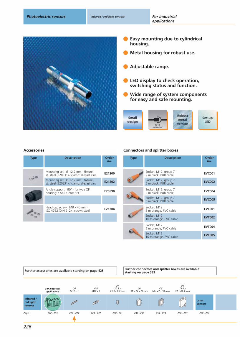
Easy mounting due to cylindricalhousing.
Metal housing for robust use.
Adjustable range.
LED display to check operation,switching status and function.
Wide range of system componentsfor easy and safe mounting.
Accessories
Type Description Orderno.
Mounting set · Ø 12.2 mm · fixture:st. steel (320S31) / clamp: diecast zinc E21200
Mounting set · Ø 12.2 mm · fixture:st. steel (320S31) / clamp: diecast zinc E21202
Angle support · 90° · for type OF ·housing: / ABS / lens: / PC E20590
Head cap screw · M8 x 40 mm · ISO 4762 (DIN 912) · screw: steel E21204
Further accessories are available starting on page 425
Connectors and splitter boxes
Type Description Orderno.
Socket, M12, group 72 m black, PUR cable EVC001
Socket, M12, group 75 m black, PUR cable EVC002
Socket, M12, group 72 m black, PUR cable EVC004
Socket, M12, group 75 m black, PUR cable EVC005
Socket, M125 m orange, PVC cable EVT001
Socket, M1210 m orange, PVC cable EVT002
Socket, M125 m orange, PVC cable EVT004
Socket, M1210 m orange, PVC cable EVT005
Further connectors and splitter boxes are availablestarting on page 393
Photoelectric sensors Infrared / red light sensors For industrialapplications
226
Infrared /red lightsensors
Page
For industrialapplications
222 - 263
OFM12 x 1
222 - 227
OGM18 x 1
228 - 237
OH20.6 x
13.5 x 7.6 mm
238 - 241
OJ35 x 24 x 11 mm
242 - 255
O518 x 47 x 56 mm
256 - 259
O474.4 x
27 x 63.8 mm
260 - 263
Lasersensors
270 - 281

Abbreviations
H = light-onD = dark-onH/D = light-on or dark-on programmableH+D = light-on and dark-onRel. = relay output
Type OF, operating voltage: DCConnection technology: M12 connector
Function Connection Output Typeof light
LED
Spot Ø atmax.range[mm]
I0
[mA]
Wiringdiagram
no.
Draw-ingno.
Orderno.
Through-beam sensor · Transmitter range ...4 m · Connector groups 7, 8
M12 connector – infrared 700 25 43 2 OF5021
Through-beam sensor · Receiver range ...4 m · Connector groups 7, 8, 10
M12 connector H/D PNP – – 30 86 2 OF5022
Through-beam sensor · Receiver range ...4 m · Connector groups 7, 8
M12 connector H/D NPN – – 30 87 2 OF5053
Common technical data
Ub: 10...36 V DCMaterial lens: PMMAHousing material: brass optalloy-platedOperating temperature: -25...60 °CProtection: IP 65 IICurrent rating: 200 mASwitching status indication: LED yellowOperation: LED greenFunction check: LED redCurrent rating funct. check: max. 10 mA
You can find scale drawings from page 479 You can find details about reflectorsfrom page 433
Systems forspecificapplications
288 - 297
Infrared / red light sensors
Gen
eral
info
rmat
ion
List
of
arti
cles
Ind
uct
ive
sen
sors
Cap
acit
ive
sen
sors
Mag
net
icse
nso
rs,
cylin
der
sen
sors
Safe
tyte
chn
olo
gy
Val
ve s
enso
rsPh
oto
elec
tric
sen
sors
Ob
ject
reco
gn
itio
nEn
cod
ers
Eval
uat
ion
syst
ems,
po
wer
su
pp
lies
Co
nn
ecti
on
tech
no
log
yA
cces
sori
esTe
chn
ical
info
rmat
ion
and
cu
sto
mer
serv
ice
227

BasicLine M18.
Adjustable background suppression via potentiometer.
Long ranges.
Robust high-grade stainless steel housing for all applications.
Universal fixing using system compo-nents and mounting accessories.
Accessories
Type Description Orderno.
Mounting set · Ø 18.5 mm · clamp:diecast zinc / fixture: steel E20721
Mounting set · Ø 18.5 mm · clamp:diecast zinc / fixture: steel E20720
Prismatic reflector · Ø 80 mm · round ·plastics E20005
Protective bracket for free-standing, rodmounting · Ø 18 mm · st. steel (316S12) E21125
Further accessories are available starting on page 425
Connectors and splitter boxes
Type Description Orderno.
Socket, M12, group 72 m black, PUR cable EVC001
Socket, M12, group 75 m black, PUR cable EVC002
Socket, M12, group 72 m black, PUR cable EVC004
Socket, M12, group 75 m black, PUR cable EVC005
Further connectors and splitter boxes are availablestarting on page 393
Photoelectric sensors Infrared / red light sensors For industrialapplications
228
Infrared /red lightsensors
Page
For industrialapplications
222 - 263
OFM12 x 1
222 - 227
OGM18 x 1
228 - 237
OH20.6 x
13.5 x 7.6 mm
238 - 241
OJ35 x 24 x 11 mm
242 - 255
O518 x 47 x 56 mm
256 - 259
O474.4 x
27 x 63.8 mm
260 - 263
Lasersensors
270 - 281
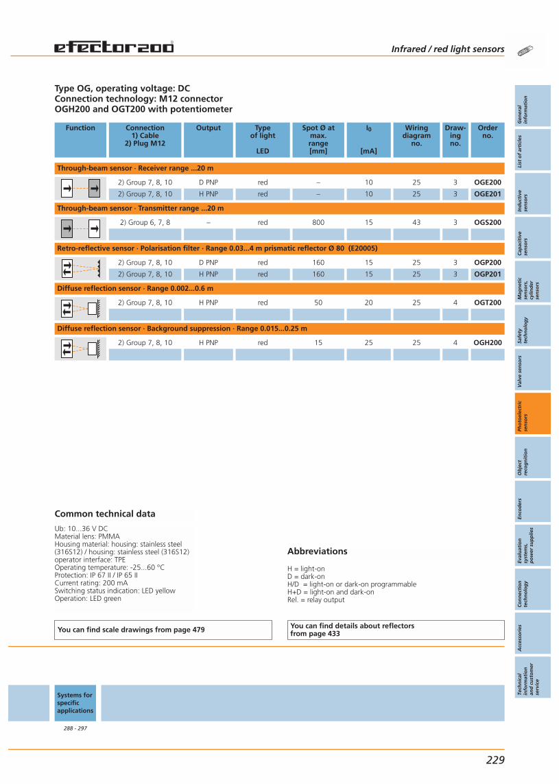
Abbreviations
H = light-onD = dark-onH/D = light-on or dark-on programmableH+D = light-on and dark-onRel. = relay output
Type OG, operating voltage: DCConnection technology: M12 connectorOGH200 and OGT200 with potentiometer
Function Connection1) Cable
2) Plug M12
Output Typeof light
LED
Spot Ø atmax.range[mm]
I0
[mA]
Wiringdiagram
no.
Draw-ingno.
Orderno.
Through-beam sensor · Receiver range ...20 m
2) Group 7, 8, 10 D PNP red – 10 25 3 OGE200
2) Group 7, 8, 10 H PNP red – 10 25 3 OGE201
Through-beam sensor · Transmitter range ...20 m
2) Group 6, 7, 8 – red 800 15 43 3 OGS200
Retro-reflective sensor · Polarisation filter · Range 0.03...4 m prismatic reflector Ø 80 (E20005)
2) Group 7, 8, 10 D PNP red 160 15 25 3 OGP200
2) Group 7, 8, 10 H PNP red 160 15 25 3 OGP201
Diffuse reflection sensor · Range 0.002...0.6 m
2) Group 7, 8, 10 H PNP red 50 20 25 4 OGT200
Diffuse reflection sensor · Background suppression · Range 0.015...0.25 m
2) Group 7, 8, 10 H PNP red 15 25 25 4 OGH200
Common technical data
Ub: 10...36 V DCMaterial lens: PMMAHousing material: housing: stainless steel(316S12) / housing: stainless steel (316S12)operator interface: TPEOperating temperature: -25...60 °CProtection: IP 67 II / IP 65 IICurrent rating: 200 mASwitching status indication: LED yellowOperation: LED green
You can find scale drawings from page 479 You can find details about reflectorsfrom page 433
Systems forspecificapplications
288 - 297
Infrared / red light sensors
Gen
eral
info
rmat
ion
List
of
arti
cles
Ind
uct
ive
sen
sors
Cap
acit
ive
sen
sors
Mag
net
icse
nso
rs,
cylin
der
sen
sors
Safe
tyte
chn
olo
gy
Val
ve s
enso
rsPh
oto
elec
tric
sen
sors
Ob
ject
reco
gn
itio
nEn
cod
ers
Eval
uat
ion
syst
ems,
po
wer
su
pp
lies
Co
nn
ecti
on
tech
no
log
yA
cces
sori
esTe
chn
ical
info
rmat
ion
and
cu
sto
mer
serv
ice
229
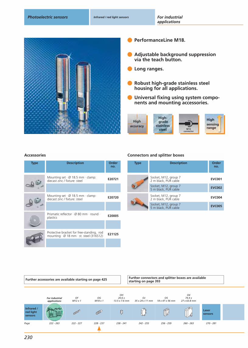
PerformanceLine M18.
Adjustable background suppression via the teach button.
Long ranges.
Robust high-grade stainless steel housing for all applications.
Universal fixing using system compo-nents and mounting accessories.
Accessories
Type Description Orderno.
Mounting set · Ø 18.5 mm · clamp:diecast zinc / fixture: steel E20721
Mounting set · Ø 18.5 mm · clamp:diecast zinc / fixture: steel E20720
Prismatic reflector · Ø 80 mm · round ·plastics E20005
Protective bracket for free-standing, rodmounting · Ø 18 mm · st. steel (316S12) E21125
Further accessories are available starting on page 425
Connectors and splitter boxes
Type Description Orderno.
Socket, M12, group 72 m black, PUR cable EVC001
Socket, M12, group 75 m black, PUR cable EVC002
Socket, M12, group 72 m black, PUR cable EVC004
Socket, M12, group 75 m black, PUR cable EVC005
Further connectors and splitter boxes are availablestarting on page 393
Photoelectric sensors Infrared / red light sensors For industrialapplications
230
Infrared /red lightsensors
Page
For industrialapplications
222 - 263
OFM12 x 1
222 - 227
OGM18 x 1
228 - 237
OH20.6 x
13.5 x 7.6 mm
238 - 241
OJ35 x 24 x 11 mm
242 - 255
O518 x 47 x 56 mm
256 - 259
O474.4 x
27 x 63.8 mm
260 - 263
Lasersensors
270 - 281

Abbreviations
H = light-onD = dark-onH/D = light-on or dark-on programmableH+D = light-on and dark-onRel. = relay output
Type OG, operating voltage: DCConnection technology: M12 connector
Function Connection1) Cable
2) Plug M12
Output Typeof light
LED
Spot Ø atmax.range[mm]
I0
[mA]
Wiringdiagram
no.
Draw-ingno.
Orderno.
Through-beam sensor · Transmitter range ...25 m
2) Group 6, 7, 8 – red 1000 20 43 5 OGS500
Through-beam sensor · Receiver range ...25 m
2) Group 7, 8, 10 H/D PNP red – 11 25 6 OGE500
Retro-reflective sensor · Polarisation filter · Range 0.03...5 m prismatic reflector Ø 80 (E20005)
2) Group 7, 8, 10 H/D PNP red 200 20 25 6 OGP500
Diffuse reflection sensor · Background suppression · Range 0.015...0.3 m
2) Group 7, 8, 10 H/D PNP red 25 25 25 6 OGH500
Common technical data
Ub: 10...36 V DCMaterial lens: PMMAHousing material: stainless steel (316S12)Operating temperature: -25...80 °CProtection: IP 67 IICurrent rating: 200 mASwitching status indication: LED yellowOperation: LED green
You can find scale drawings from page 479 You can find details about reflectorsfrom page 433
Systems forspecificapplications
288 - 297
Infrared / red light sensors
Gen
eral
info
rmat
ion
List
of
arti
cles
Ind
uct
ive
sen
sors
Cap
acit
ive
sen
sors
Mag
net
icse
nso
rs,
cylin
der
sen
sors
Safe
tyte
chn
olo
gy
Val
ve s
enso
rsPh
oto
elec
tric
sen
sors
Ob
ject
reco
gn
itio
nEn
cod
ers
Eval
uat
ion
syst
ems,
po
wer
su
pp
lies
Co
nn
ecti
on
tech
no
log
yA
cces
sori
esTe
chn
ical
info
rmat
ion
and
cu
sto
mer
serv
ice
231

BasicLine M18 with light emission on the side.
For applications withrestricted space.
Fast set-up and reliable function.
As diffuse-reflection sensor availablewith background suppression.
Comprehensive range of system com-ponents for easy and safe mounting.
Accessories
Type Description Orderno.
Mounting set · Ø 18.5 mm · clamp:diecast zinc / fixture: steel E20720
Mounting set · Ø 18.5 mm · high-grade stainless steel E21206
Angle bracket · for type M18 · stainless steel (304S15) E10736
Prismatic reflector · Ø 80 mm · round ·plastics E20005
Further accessories are available starting on page 425
Connectors and splitter boxes
Type Description Orderno.
Socket, M12, group 72 m black, PUR cable EVC001
Socket, M12, group 75 m black, PUR cable EVC002
Socket, M12, group 72 m black, PUR cable EVC004
Socket, M12, group 75 m black, PUR cable EVC005
Socket, M125 m orange, PVC cable EVT001
Socket, M1210 m orange, PVC cable EVT002
Socket, M125 m orange, PVC cable EVT004
Socket, M1210 m orange, PVC cable EVT005
Further connectors and splitter boxes are availablestarting on page 393
Photoelectric sensors Infrared / red light sensors For industrialapplications
232
Infrared /red lightsensors
Page
For industrialapplications
222 - 263
OFM12 x 1
222 - 227
OGM18 x 1
228 - 237
OH20.6 x
13.5 x 7.6 mm
238 - 241
OJ35 x 24 x 11 mm
242 - 255
O518 x 47 x 56 mm
256 - 259
O474.4 x
27 x 63.8 mm
260 - 263
Lasersensors
270 - 281

Abbreviations
H = light-onD = dark-onH/D = light-on or dark-on programmableH+D = light-on and dark-onRel. = relay output
Type OG, optics angled by 90°Operating voltage DCConnection technology: M12 connector and cable versions
Function Connection1) Cable
2) Plug M12
Output Typeof light
LED
Spot Ø atmax.range[mm]
I0
[mA]
Wiringdiagram
no.
Draw-ingno.
Orderno.
Through-beam sensor · Transmitter range ...9 m
2) Group 7, 8 – red < 3000 19 43 7 OG5129
Through-beam sensor · Receiver range ...9 m
2) Group 7, 8 H PNP red – 12 44 7 OG5127
2) Group 7, 8 D PNP red – 12 45 7 OG5128
Retro-reflective sensor · Polarisation filter · Range ...3 m prismatic reflector Ø 80 (E20005)
2) Group 7, 8 H PNP red < 96 22 44 7 OG5125
2) Group 7, 8 D PNP red < 96 22 45 7 OG5126
Diffuse reflection sensor · Background suppression · Range ...0.1 m
2) Group 7, 8 H PNP red < 16 21 44 8 OG5123
Diffuse reflection sensor · Background suppression · Range ...0.2 m
2) Group 7, 8 H PNP red < 28 21 44 8 OG5124
Common technical data
Ub: 10...30 V DCMaterial lens: PMMAHousing material: high-grade stainless steel ABSOperating temperature: -25...60 °CProtection: IP 68 IICurrent rating: 200 mASwitching status indication: LED yellowOperation: LED green
You can find scale drawings from page 479 You can find details about reflectorsfrom page 433
Systems forspecificapplications
288 - 297
Infrared / red light sensors
Gen
eral
info
rmat
ion
List
of
arti
cles
Ind
uct
ive
sen
sors
Cap
acit
ive
sen
sors
Mag
net
icse
nso
rs,
cylin
der
sen
sors
Safe
tyte
chn
olo
gy
Val
ve s
enso
rsPh
oto
elec
tric
sen
sors
Ob
ject
reco
gn
itio
nEn
cod
ers
Eval
uat
ion
syst
ems,
po
wer
su
pp
lies
Co
nn
ecti
on
tech
no
log
yA
cces
sori
esTe
chn
ical
info
rmat
ion
and
cu
sto
mer
serv
ice
233

BasicLine M18, AC/DC.
LED display to check operation,switching status and function.
Automatic switch point settingby pressing a button.
Electronic lockingof the user functions.
Suitable for AC as well as forDC supply voltage.
Accessories
Type Description Orderno.
Mounting set · Ø 18.5 mm · clamp:diecast zinc / fixture: steel E20721
Mounting set · Ø 18.5 mm · high-grade stainless steel E21207
Angle support · 90° · for type OG ·housing: ABS / lens: PC E20723
Angle support · 90° · for type OG ·housing: ABS / lens: glass E20740
Mounting set · for reflector · Ø 80 mm ·stainless steel (320S31) / diecast zinc E20914
Prismatic reflector · Ø 80 mm · round ·for type OG · plastics E20005
Further accessories are available starting on page 425
Connectors and splitter boxes
Type Description Orderno.
Socket, 1/2", group 302 m yellow, PVC cable E10190
Socket, 1/2", group 305 m yellow, PVC cable E10200
Socket, 1/2", group 302 m yellow, PVC cable E10189
Socket, 1/2", group 305 m yellow, PVC cable E10191
Further connectors and splitter boxes are availablestarting on page 393
Photoelectric sensors Infrared / red light sensors For industrialapplications
234
Infrared /red lightsensors
Page
For industrialapplications
222 - 263
OFM12 x 1
222 - 227
OGM18 x 1
228 - 237
OH20.6 x
13.5 x 7.6 mm
238 - 241
OJ35 x 24 x 11 mm
242 - 255
O518 x 47 x 56 mm
256 - 259
O474.4 x
27 x 63.8 mm
260 - 263
Lasersensors
270 - 281
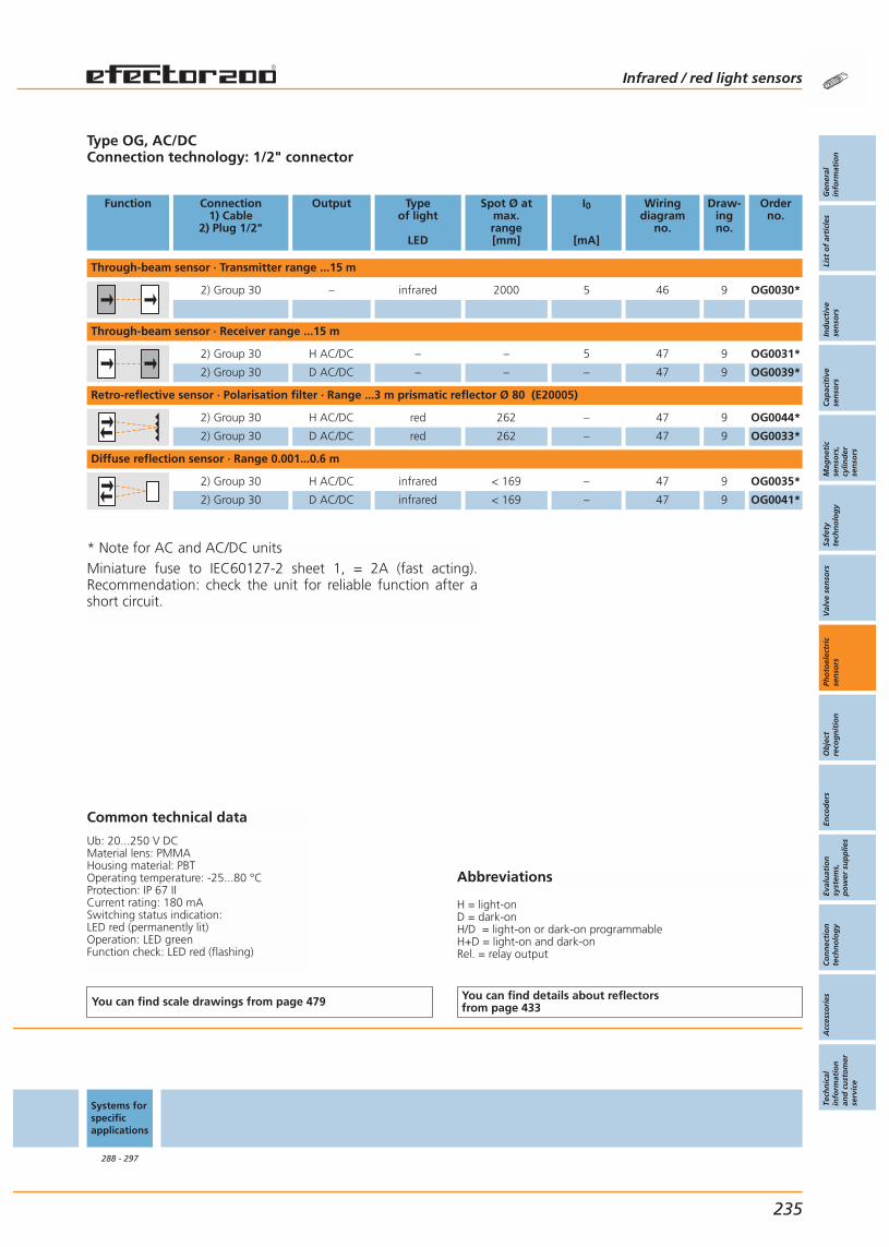
Abbreviations
H = light-onD = dark-onH/D = light-on or dark-on programmableH+D = light-on and dark-onRel. = relay output
Type OG, AC/DCConnection technology: 1/2" connector
Function Connection1) Cable
2) Plug 1/2"
Output Typeof light
LED
Spot Ø atmax.range[mm]
I0
[mA]
Wiringdiagram
no.
Draw-ingno.
Orderno.
Through-beam sensor · Transmitter range ...15 m
2) Group 30 – infrared 2000 5 46 9 OG0030*
Through-beam sensor · Receiver range ...15 m
2) Group 30 H AC/DC – – 5 47 9 OG0031*
2) Group 30 D AC/DC – – – 47 9 OG0039*
Retro-reflective sensor · Polarisation filter · Range ...3 m prismatic reflector Ø 80 (E20005)
2) Group 30 H AC/DC red 262 – 47 9 OG0044*
2) Group 30 D AC/DC red 262 – 47 9 OG0033*
Diffuse reflection sensor · Range 0.001...0.6 m
2) Group 30 H AC/DC infrared < 169 – 47 9 OG0035*
2) Group 30 D AC/DC infrared < 169 – 47 9 OG0041*
Common technical data
Ub: 20...250 V DCMaterial lens: PMMAHousing material: PBTOperating temperature: -25...80 °CProtection: IP 67 IICurrent rating: 180 mASwitching status indication: LED red (permanently lit)Operation: LED greenFunction check: LED red (flashing)
You can find scale drawings from page 479 You can find details about reflectorsfrom page 433
Systems forspecificapplications
288 - 297
Infrared / red light sensors
Gen
eral
info
rmat
ion
List
of
arti
cles
Ind
uct
ive
sen
sors
Cap
acit
ive
sen
sors
Mag
net
icse
nso
rs,
cylin
der
sen
sors
Safe
tyte
chn
olo
gy
Val
ve s
enso
rsPh
oto
elec
tric
sen
sors
Ob
ject
reco
gn
itio
nEn
cod
ers
Eval
uat
ion
syst
ems,
po
wer
su
pp
lies
Co
nn
ecti
on
tech
no
log
yA
cces
sori
esTe
chn
ical
info
rmat
ion
and
cu
sto
mer
serv
ice
235
* Note for AC and AC/DC unitsMiniature fuse to IEC60127-2 sheet 1, = 2A (fast acting).Recommendation: check the unit for reliable function after ashort circuit.

BasicLine M18, AC/DC.
LED display to check operation,switching status and function.
Automatic switch point settingby pressing a button.
Electronic locking of the userfunctions.
Suitable for AC as well as forDC supply voltage.
Accessories
Type Description Orderno.
Mounting set · Ø 18.5 mm · clamp:diecast zinc / fixture: steel E20721
Mounting set · Ø 18.5 mm · high-grade stainless steel E21207
Angle support · 90° · for type OG ·housing: ABS / lens: PC E20723
Angle support · 90° · for type OG ·housing: ABS / lens: glass E20740
Mounting set · for reflector · Ø 80 mm ·stainless steel (320S31) / diecast zinc E20914
Prismatic reflector · Ø 80 mm · round ·for type OG · plastics E20005
Further accessories are available starting on page 425
Photoelectric sensors Infrared / red light sensors For industrialapplications
236
Infrared /red lightsensors
Page
For industrialapplications
222 - 263
OFM12 x 1
222 - 227
OGM18 x 1
228 - 237
OH20.6 x
13.5 x 7.6 mm
238 - 241
OJ35 x 24 x 11 mm
242 - 255
O518 x 47 x 56 mm
256 - 259
O474.4 x
27 x 63.8 mm
260 - 263
Lasersensors
270 - 281
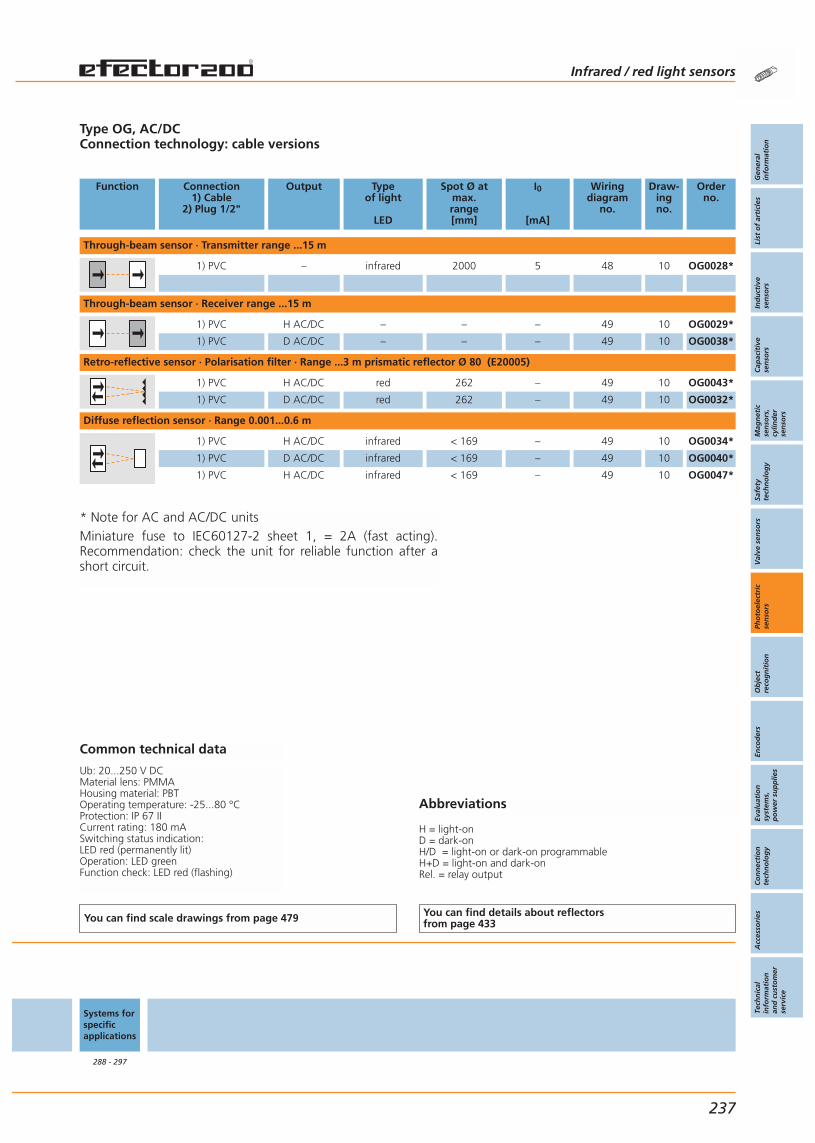
Abbreviations
H = light-onD = dark-onH/D = light-on or dark-on programmableH+D = light-on and dark-onRel. = relay output
Type OG, AC/DCConnection technology: cable versions
Function Connection1) Cable
2) Plug 1/2"
Output Typeof light
LED
Spot Ø atmax.range[mm]
I0
[mA]
Wiringdiagram
no.
Draw-ingno.
Orderno.
Through-beam sensor · Transmitter range ...15 m
1) PVC – infrared 2000 5 48 10 OG0028*
Through-beam sensor · Receiver range ...15 m
1) PVC H AC/DC – – – 49 10 OG0029*
1) PVC D AC/DC – – – 49 10 OG0038*
Retro-reflective sensor · Polarisation filter · Range ...3 m prismatic reflector Ø 80 (E20005)
1) PVC H AC/DC red 262 – 49 10 OG0043*
1) PVC D AC/DC red 262 – 49 10 OG0032*
Diffuse reflection sensor · Range 0.001...0.6 m
1) PVC H AC/DC infrared < 169 – 49 10 OG0034*
1) PVC D AC/DC infrared < 169 – 49 10 OG0040*
1) PVC H AC/DC infrared < 169 – 49 10 OG0047*
Common technical data
Ub: 20...250 V DCMaterial lens: PMMAHousing material: PBTOperating temperature: -25...80 °CProtection: IP 67 IICurrent rating: 180 mASwitching status indication: LED red (permanently lit)Operation: LED greenFunction check: LED red (flashing)
You can find scale drawings from page 479 You can find details about reflectorsfrom page 433
Systems forspecificapplications
288 - 297
Infrared / red light sensors
Gen
eral
info
rmat
ion
List
of
arti
cles
Ind
uct
ive
sen
sors
Cap
acit
ive
sen
sors
Mag
net
icse
nso
rs,
cylin
der
sen
sors
Safe
tyte
chn
olo
gy
Val
ve s
enso
rsPh
oto
elec
tric
sen
sors
Ob
ject
reco
gn
itio
nEn
cod
ers
Eval
uat
ion
syst
ems,
po
wer
su
pp
lies
Co
nn
ecti
on
tech
no
log
yA
cces
sori
esTe
chn
ical
info
rmat
ion
and
cu
sto
mer
serv
ice
237
* Note for AC and AC/DC unitsMiniature fuse to IEC60127-2 sheet 1, = 2A (fast acting).Recommendation: check the unit for reliable function after ashort circuit.

Size only 20.6 x 13.5 x 7.6 mm, ideal for restricted space.
Even tiny objects are reliably detected.
Visible laser light spot for a simple sensor alignment.
Large ranges: through-beam sensor up to 1.2 m.
Easy and quick alignment using a swivel mount clip.
Accessories
Type Description Orderno.
Prismatic reflector · 45 x 28 mm · angular · plastics E20452
Prismatic reflector · 30 x 20 mm · angular · front plate: PMMA / base: ABS E20994
Mounting set · ABS E21056
Angle bracket · for free-standingmounting · stainless steel (320S31) E21057
Further accessories are available starting on page 425
Connectors and splitter boxes
Type Description Orderno.
Socket, M8, group 12 m black, PUR cable E11486
Jumper, M8, group 412 m black, PUR cable E11268
Splitter box, group 535 m black, PUR cable, LED E11214
Further connectors and splitter boxes are availablestarting on page 393
Photoelectric sensors Infrared / red light sensors For industrialapplications
238
Infrared /red lightsensors
Page
For industrialapplications
222 - 263
OFM12 x 1
222 - 227
OGM18 x 1
228 - 237
OH20.6 x
13.5 x 7.6 mm
238 - 241
OJ35 x 24 x 11 mm
242 - 255
O518 x 47 x 56 mm
256 - 259
O474.4 x
27 x 63.8 mm
260 - 263
Lasersensors
270 - 281
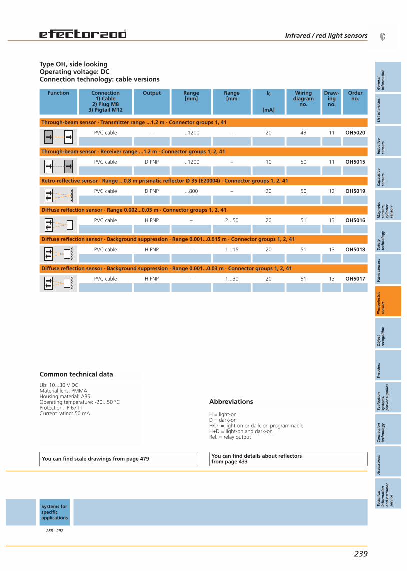
Abbreviations
H = light-onD = dark-onH/D = light-on or dark-on programmableH+D = light-on and dark-onRel. = relay output
Type OH, side lookingOperating voltage: DCConnection technology: cable versions
Function Connection1) Cable
2) Plug M83) Pigtail M12
Output Range[mm]
Range[mm
I0
[mA]
Wiringdiagram
no.
Draw-ingno.
Orderno.
Through-beam sensor · Transmitter range ...1.2 m · Connector groups 1, 41
PVC cable – ...1200 – 20 43 11 OH5020
Through-beam sensor · Receiver range ...1.2 m · Connector groups 1, 2, 41
PVC cable D PNP ...1200 – 10 50 11 OH5015
Retro-reflective sensor · Range ...0.8 m prismatic reflector Ø 35 (E20004) · Connector groups 1, 2, 41
PVC cable D PNP ...800 – 20 50 12 OH5019
Diffuse reflection sensor · Range 0.002...0.05 m · Connector groups 1, 2, 41
PVC cable H PNP – 2...50 20 51 13 OH5016
Diffuse reflection sensor · Background suppression · Range 0.001...0.015 m · Connector groups 1, 2, 41
PVC cable H PNP – 1...15 20 51 13 OH5018
Diffuse reflection sensor · Background suppression · Range 0.001...0.03 m · Connector groups 1, 2, 41
PVC cable H PNP – 1...30 20 51 13 OH5017
Common technical data
Ub: 10...30 V DCMaterial lens: PMMAHousing material: ABSOperating temperature: -20...50 °CProtection: IP 67 IIICurrent rating: 50 mA
You can find scale drawings from page 479 You can find details about reflectorsfrom page 433
Systems forspecificapplications
288 - 297
Infrared / red light sensors
Gen
eral
info
rmat
ion
List
of
arti
cles
Ind
uct
ive
sen
sors
Cap
acit
ive
sen
sors
Mag
net
icse
nso
rs,
cylin
der
sen
sors
Safe
tyte
chn
olo
gy
Val
ve s
enso
rsPh
oto
elec
tric
sen
sors
Ob
ject
reco
gn
itio
nEn
cod
ers
Eval
uat
ion
syst
ems,
po
wer
su
pp
lies
Co
nn
ecti
on
tech
no
log
yA
cces
sori
esTe
chn
ical
info
rmat
ion
and
cu
sto
mer
serv
ice
239
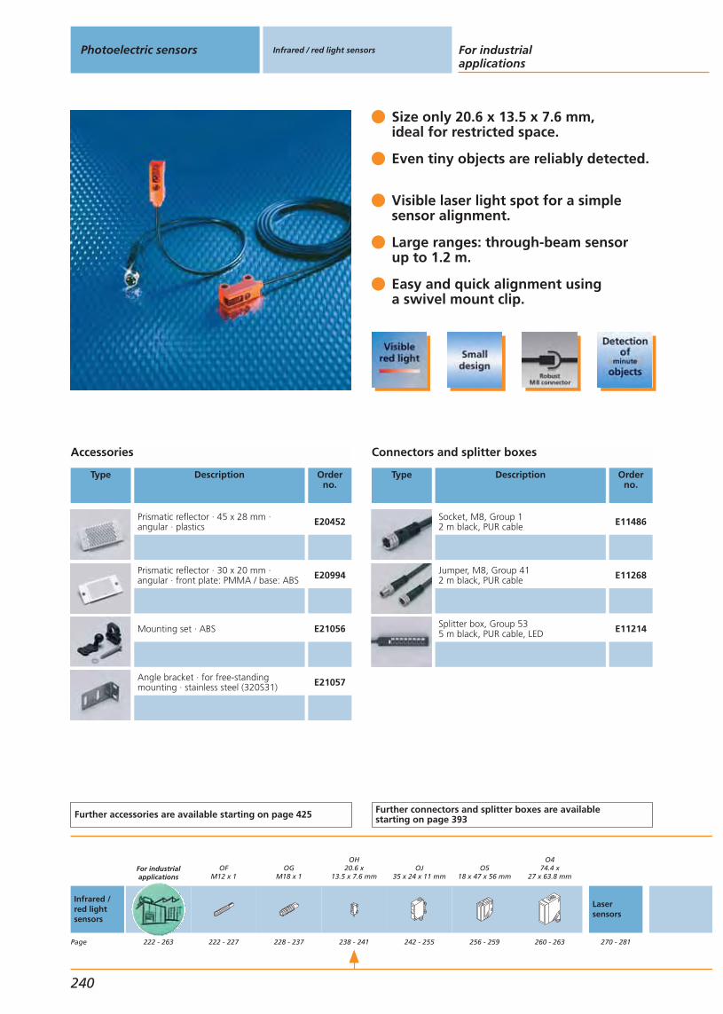
Size only 20.6 x 13.5 x 7.6 mm, ideal for restricted space.
Even tiny objects are reliably detected.
Visible laser light spot for a simple sensor alignment.
Large ranges: through-beam sensor up to 1.2 m.
Easy and quick alignment using a swivel mount clip.
Accessories
Type Description Orderno.
Prismatic reflector · 45 x 28 mm · angular · plastics E20452
Prismatic reflector · 30 x 20 mm · angular · front plate: PMMA / base: ABS E20994
Mounting set · ABS E21056
Angle bracket · for free-standingmounting · stainless steel (320S31) E21057
Further accessories are available starting on page 425
Connectors and splitter boxes
Type Description Orderno.
Socket, M8, Group 12 m black, PUR cable E11486
Jumper, M8, Group 412 m black, PUR cable E11268
Splitter box, Group 535 m black, PUR cable, LED E11214
Further connectors and splitter boxes are availablestarting on page 393
Photoelectric sensors Infrared / red light sensors For industrialapplications
240
Infrared /red lightsensors
Page
For industrialapplications
222 - 263
OFM12 x 1
222 - 227
OGM18 x 1
228 - 237
OH20.6 x
13.5 x 7.6 mm
238 - 241
OJ35 x 24 x 11 mm
242 - 255
O518 x 47 x 56 mm
256 - 259
O474.4 x
27 x 63.8 mm
260 - 263
Lasersensors
270 - 281

Abbreviations
H = light-onD = dark-onH/D = light-on or dark-on programmableH+D = light-on and dark-onRel. = relay output
Type OH, side lookingOperating voltage: DCConnection technology: cable versions
Function Connection1) Cable
2) Plug M83) Pigtail M12
Output Range[mm]
Range[mm
I0
[mA]
Wiringdiagram
no.
Draw-ingno.
Orderno.
Through-beam sensor · Transmitter range ...1.2 m
PVC cable – ...1200 – 20 42 11 OH5001
Through-beam sensor · Receiver range ...1.2 m
PVC cable D PNP ...1200 – 10 52 11 OH5002
Retro-reflective sensor · Range ...0.8 m prismatic reflector Ø 35 (E20004)
PVC cable D PNP ...800 – 20 52 12 OH5010
Diffuse reflection sensor · Background suppression · Range 0.001...0.015 m
PVC cable H PNP – 1...15 20 53 13 OH5008
Diffuse reflection sensor · Background suppression · Range 0.001...0.03 m
PVC cable H PNP – 1...30 20 53 13 OH5006
Diffuse reflection sensor · Range 0.002...0.05 m
PVC cable H PNP – 2...50 20 53 13 OH5004
Common technical data
Ub: 10...30 V DCMaterial lens: PMMAHousing material: ABSOperating temperature: -20...50 °CProtection: IP 67 IIICurrent rating: 50 mA
You can find scale drawings from page 479 You can find details about reflectorsfrom page 433
Systems forspecificapplications
288 - 297
Infrared / red light sensors
Gen
eral
info
rmat
ion
List
of
arti
cles
Ind
uct
ive
sen
sors
Cap
acit
ive
sen
sors
Mag
net
icse
nso
rs,
cylin
der
sen
sors
Safe
tyte
chn
olo
gy
Val
ve s
enso
rsPh
oto
elec
tric
sen
sors
Ob
ject
reco
gn
itio
nEn
cod
ers
Eval
uat
ion
syst
ems,
po
wer
su
pp
lies
Co
nn
ecti
on
tech
no
log
yA
cces
sori
esTe
chn
ical
info
rmat
ion
and
cu
sto
mer
serv
ice
241

OJ BasicLine with side lens and reinforced fixing holes.
Fixed range.
High-quality technology at an unbeatable price.
Visible red light facilitates alignment.
Quick and easy mounting using system components, mounting accessories.
Accessories
Type Description Orderno.
Mounting set · OJ · for side lens · diecastzinc / stainless steel (320S31) E21095
shaft · Ø 10 / M8 · straight · stainlesssteel (320S31) E21081
Cube · M8 · diecast zinc E20950
Prismatic reflector · Ø 20 mm · round ·for type OJ, · plastics E20003
Prismatic reflector · Ø 42 mm · round ·for type OJ · plastics E20004
Further accessories are available starting on page 425
Connectors and splitter boxes
Type Description Orderno.
Socket, M85 m orange, PVC cable E11498
Socket, M810 m orange, PVC cable E11499
Socket, M85 m orange, PVC cable E11495
Socket, M810 m orange, PVC cable E11496
Further connectors and splitter boxes are availablestarting on page 393
Photoelectric sensors Infrared / red light sensors For industrialapplications
242
Infrared /red lightsensors
Page
For industrialapplications
222 - 263
OFM12 x 1
222 - 227
OGM18 x 1
228 - 237
OH20.6 x
13.5 x 7.6 mm
238 - 241
OJ35 x 24 x 11 mm
242 - 255
O518 x 47 x 56 mm
256 - 259
O474.4 x
27 x 63.8 mm
260 - 263
Lasersensors
270 - 281

Abbreviations
H = light-onD = dark-onH/D = light-on or dark-on programmableH+D = light-on and dark-onRel. = relay output
Type OJ, side lookingConnecting voltage: DCConnection technology: M8 connector
Function Connection1) Cable
2) Plug M83) Pigtail M12
Output Typeof light
LED
Spot Ø atmax.range[mm]
I0
[mA]
Wiringdiagram
no.
Draw-ingno.
Orderno.
Through-beam sensor · Receiver range ...10 m · Connector groups 1, 2, 41
2) Group 1, 2, 41 D PNP – – 10 25 14 OJE200
Through-beam sensor · Transmitter range 0...10 m · Connector group
2) Group – red < 1000 30 43 14 OJS200
Retro-reflective sensor · Range ...1.8 m prismatic reflector Ø 80 (E20005) · Connector groups 1, 2, 41
2) Group 1, 2, 41 D PNP red 64 20 25 14 OJR200
Retro-reflective sensor · Polarisation filter · Range ...1.8 m prismatic reflector Ø 80 (E20005) · Connector groups 1, 2, 41
2) Group 1, 2, 41 D PNP red 64 20 25 14 OJP200
Diffuse reflection sensor · Background suppression · Range ...0.1 m · Connector groups 1, 2, 41
2) Group 1, 2, 41 H PNP red < 13 30 25 15 OJH200
Common technical data
Ub: 10...30 V DCMaterial lens: PMMAHousing material: ABS SEPSOperating temperature: -25...60 °CProtection: IP 65 / IP 67 IICurrent rating: 200 mA
You can find scale drawings from page 479 You can find details about reflectorsfrom page 433
Systems forspecificapplications
288 - 297
Infrared / red light sensors
Gen
eral
info
rmat
ion
List
of
arti
cles
Ind
uct
ive
sen
sors
Cap
acit
ive
sen
sors
Mag
net
icse
nso
rs,
cylin
der
sen
sors
Safe
tyte
chn
olo
gy
Val
ve s
enso
rsPh
oto
elec
tric
sen
sors
Ob
ject
reco
gn
itio
nEn
cod
ers
Eval
uat
ion
syst
ems,
po
wer
su
pp
lies
Co
nn
ecti
on
tech
no
log
yA
cces
sori
esTe
chn
ical
info
rmat
ion
and
cu
sto
mer
serv
ice
243

OJ PerformanceLine with front lens.
Visible red light for easy adjustment.
LED display to check operation,switching status and function.
Various connection methods:M8 plug, M12 pigtail or cable versions.
Automatic switch point settingby pressing a button.
Accessories
Type Description Orderno.
Mounting set · for front lens · fixture:st. steel (320S31) / clamp: diecast zinc E20970
Swivel-mount clip · for type OJ · diecast zinc E20974
Angle bracket · for type OJ · high-grade stainless steel E20984
Head cap screw · M8 x 40 mm · ISO 4762 (DIN 912) · screw: steel E21204
Further accessories are available starting on page 425
Connectors and splitter boxes
Type Description Orderno.
Socket, M85 m orange, PVC cable E11220
Socket, M810 m orange, PVC cable E11221
Socket, M8, group 32 m black, PUR cable E11199
Socket, M8, group 35 m black, PUR cable E11200
Socket, M12, group 72 m black, PUR cable EVC001
Socket, M12, group 75 m black, PUR cable EVC002
Further connectors and splitter boxes are availablestarting on page 393
Photoelectric sensors Infrared / red light sensors For industrialapplications
244
Infrared /red lightsensors
Page
For industrialapplications
222 - 263
OFM12 x 1
222 - 227
OGM18 x 1
228 - 237
OH20.6 x
13.5 x 7.6 mm
238 - 241
OJ35 x 24 x 11 mm
242 - 255
O518 x 47 x 56 mm
256 - 259
O474.4 x
27 x 63.8 mm
260 - 263
Lasersensors
270 - 281
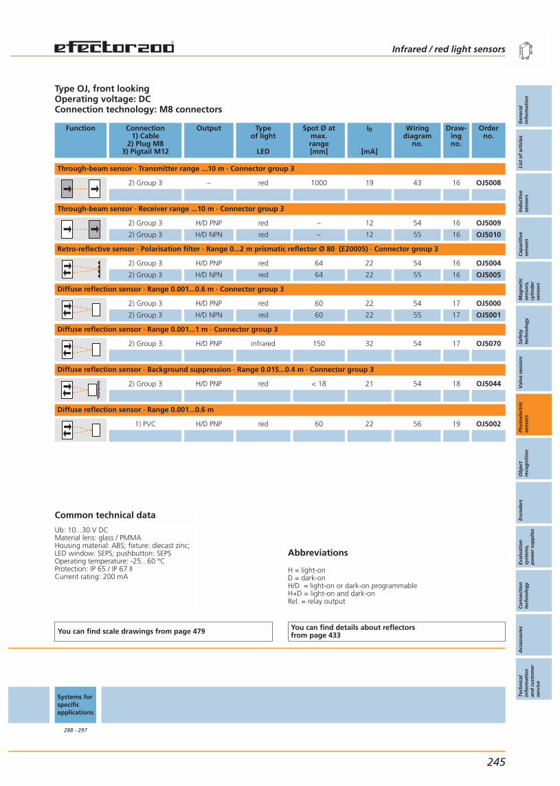
Abbreviations
H = light-onD = dark-onH/D = light-on or dark-on programmableH+D = light-on and dark-onRel. = relay output
Type OJ, front lookingOperating voltage: DCConnection technology: M8 connectors
Function Connection1) Cable
2) Plug M83) Pigtail M12
Output Typeof light
LED
Spot Ø atmax.range[mm]
I0
[mA]
Wiringdiagram
no.
Draw-ingno.
Orderno.
Through-beam sensor · Transmitter range ...10 m · Connector group 3
2) Group 3 – red 1000 19 43 16 OJ5008
Through-beam sensor · Receiver range ...10 m · Connector group 3
2) Group 3 H/D PNP red – 12 54 16 OJ5009
2) Group 3 H/D NPN red – 12 55 16 OJ5010
Retro-reflective sensor · Polarisation filter · Range 0...2 m prismatic reflector Ø 80 (E20005) · Connector group 3
2) Group 3 H/D PNP red 64 22 54 16 OJ5004
2) Group 3 H/D NPN red 64 22 55 16 OJ5005
Diffuse reflection sensor · Range 0.001...0.6 m · Connector group 3
2) Group 3 H/D PNP red 60 22 54 17 OJ5000
2) Group 3 H/D NPN red 60 22 55 17 OJ5001
Diffuse reflection sensor · Range 0.001...1 m · Connector group 3
2) Group 3 H/D PNP infrared 150 32 54 17 OJ5070
Diffuse reflection sensor · Background suppression · Range 0.015...0.4 m · Connector group 3
2) Group 3 H/D PNP red < 18 21 54 18 OJ5044
Diffuse reflection sensor · Range 0.001...0.6 m
1) PVC H/D PNP red 60 22 56 19 OJ5002
Common technical data
Ub: 10...30 V DCMaterial lens: glass / PMMAHousing material: ABS; fixture: diecast zinc;LED window: SEPS; pushbutton: SEPSOperating temperature: -25...60 °CProtection: IP 65 / IP 67 IICurrent rating: 200 mA
You can find scale drawings from page 479 You can find details about reflectorsfrom page 433
Systems forspecificapplications
288 - 297
Infrared / red light sensors
Gen
eral
info
rmat
ion
List
of
arti
cles
Ind
uct
ive
sen
sors
Cap
acit
ive
sen
sors
Mag
net
icse
nso
rs,
cylin
der
sen
sors
Safe
tyte
chn
olo
gy
Val
ve s
enso
rsPh
oto
elec
tric
sen
sors
Ob
ject
reco
gn
itio
nEn
cod
ers
Eval
uat
ion
syst
ems,
po
wer
su
pp
lies
Co
nn
ecti
on
tech
no
log
yA
cces
sori
esTe
chn
ical
info
rmat
ion
and
cu
sto
mer
serv
ice
245
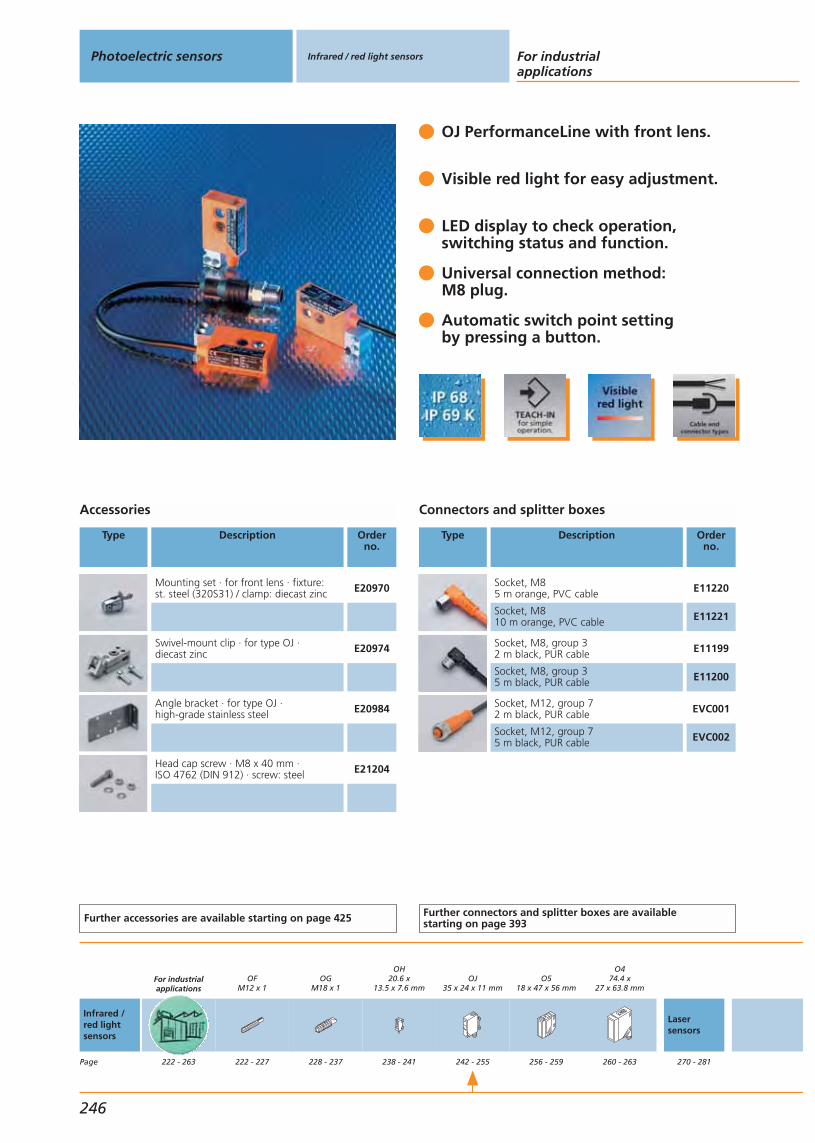
OJ PerformanceLine with front lens.
Visible red light for easy adjustment.
LED display to check operation,switching status and function.
Universal connection method:M8 plug.
Automatic switch point settingby pressing a button.
Accessories
Type Description Orderno.
Mounting set · for front lens · fixture:st. steel (320S31) / clamp: diecast zinc E20970
Swivel-mount clip · for type OJ · diecast zinc E20974
Angle bracket · for type OJ · high-grade stainless steel E20984
Head cap screw · M8 x 40 mm · ISO 4762 (DIN 912) · screw: steel E21204
Further accessories are available starting on page 425
Connectors and splitter boxes
Type Description Orderno.
Socket, M85 m orange, PVC cable E11220
Socket, M810 m orange, PVC cable E11221
Socket, M8, group 32 m black, PUR cable E11199
Socket, M8, group 35 m black, PUR cable E11200
Socket, M12, group 72 m black, PUR cable EVC001
Socket, M12, group 75 m black, PUR cable EVC002
Further connectors and splitter boxes are availablestarting on page 393
Photoelectric sensors Infrared / red light sensors For industrialapplications
246
Infrared /red lightsensors
Page
For industrialapplications
222 - 263
OFM12 x 1
222 - 227
OGM18 x 1
228 - 237
OH20.6 x
13.5 x 7.6 mm
238 - 241
OJ35 x 24 x 11 mm
242 - 255
O518 x 47 x 56 mm
256 - 259
O474.4 x
27 x 63.8 mm
260 - 263
Lasersensors
270 - 281

Abbreviations
H = light-onD = dark-onH/D = light-on or dark-on programmableH+D = light-on and dark-onRel. = relay output
Type OJ, front lookingOperating voltage: DCConnection technology: pigtail M12
Function Connection1) Cable
2) Plug M83) Pigtail M12
Output Typeof light
LED
Spot Ø atmax.range[mm]
I0
[mA]
Wiringdiagram
no.
Draw-ingno.
Orderno.
Through-beam sensor · Transmitter range ...10 m
1) PVC – red 1000 19 42 20 OJ5011
3) PVC Group 7, 8 – red 1000 19 43 20 OJ5065
3) PUR Group 7, 8 – red 1000 19 43 20 OJ5064
Through-beam sensor · Receiver range ...10 m
1) PVC H/D PNP red – 12 56 20 OJ5012
3) PVC Group 7, 8, 10 H/D PNP red – 12 54 20 OJ5067
3) PUR Group 7, 8, 10 H/D PNP red – 12 54 20 OJ5066
Retro-reflective sensor · Polarisation filter · Range 0...2 m prismatic reflector Ø 80 (E20005)
1) PVC H/D PNP red 64 22 56 20 OJ5006
3) PVC Group 7, 8, 10 H/D PNP red 64 22 54 20 OJ5063
3) PUR Group 7, 8, 10 H/D PNP red 64 22 54 20 OJ5062
Diffuse reflection sensor · Range 0.001...0.6 m
3) PVC Group 7, 8 H/D PNP red 60 22 54 19 OJ5061
3) PUR Group 7, 8 H/D PNP red 60 22 54 19 OJ5060
Diffuse reflection sensor · Background suppression · Range 0.015...0.4 m
3) PVC Group 7, 8 H/D PNP red < 18 21 54 21 OJ5069
Common technical data
Ub: 10...30 V DCMaterial lens: glass / PMMAHousing material: ABS; fixture: diecast zinc;LED window: SEPS; pushbutton: SEPSOperating temperature: -25...60 °CProtection: IP 65 / IP 67 IICurrent rating: 200 mA
You can find scale drawings from page 479 You can find details about reflectorsfrom page 433
Systems forspecificapplications
288 - 297
Infrared / red light sensors
Gen
eral
info
rmat
ion
List
of
arti
cles
Ind
uct
ive
sen
sors
Cap
acit
ive
sen
sors
Mag
net
icse
nso
rs,
cylin
der
sen
sors
Safe
tyte
chn
olo
gy
Val
ve s
enso
rsPh
oto
elec
tric
sen
sors
Ob
ject
reco
gn
itio
nEn
cod
ers
Eval
uat
ion
syst
ems,
po
wer
su
pp
lies
Co
nn
ecti
on
tech
no
log
yA
cces
sori
esTe
chn
ical
info
rmat
ion
and
cu
sto
mer
serv
ice
247
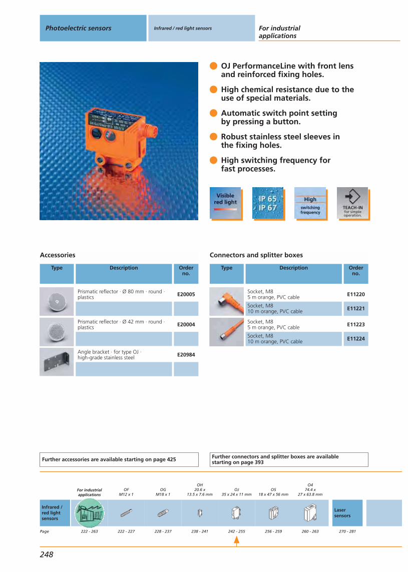
OJ PerformanceLine with front lens and reinforced fixing holes.
High chemical resistance due to the use of special materials.
Automatic switch point settingby pressing a button.
Robust stainless steel sleeves inthe fixing holes.
High switching frequency forfast processes.
Accessories
Type Description Orderno.
Prismatic reflector · Ø 80 mm · round ·plastics E20005
Prismatic reflector · Ø 42 mm · round ·plastics E20004
Angle bracket · for type OJ · high-grade stainless steel E20984
Further accessories are available starting on page 425
Connectors and splitter boxes
Type Description Orderno.
Socket, M85 m orange, PVC cable E11220
Socket, M810 m orange, PVC cable E11221
Socket, M85 m orange, PVC cable E11223
Socket, M810 m orange, PVC cable E11224
Further connectors and splitter boxes are availablestarting on page 393
Photoelectric sensors Infrared / red light sensors For industrialapplications
248
Infrared /red lightsensors
Page
For industrialapplications
222 - 263
OFM12 x 1
222 - 227
OGM18 x 1
228 - 237
OH20.6 x
13.5 x 7.6 mm
238 - 241
OJ35 x 24 x 11 mm
242 - 255
O518 x 47 x 56 mm
256 - 259
O474.4 x
27 x 63.8 mm
260 - 263
Lasersensors
270 - 281
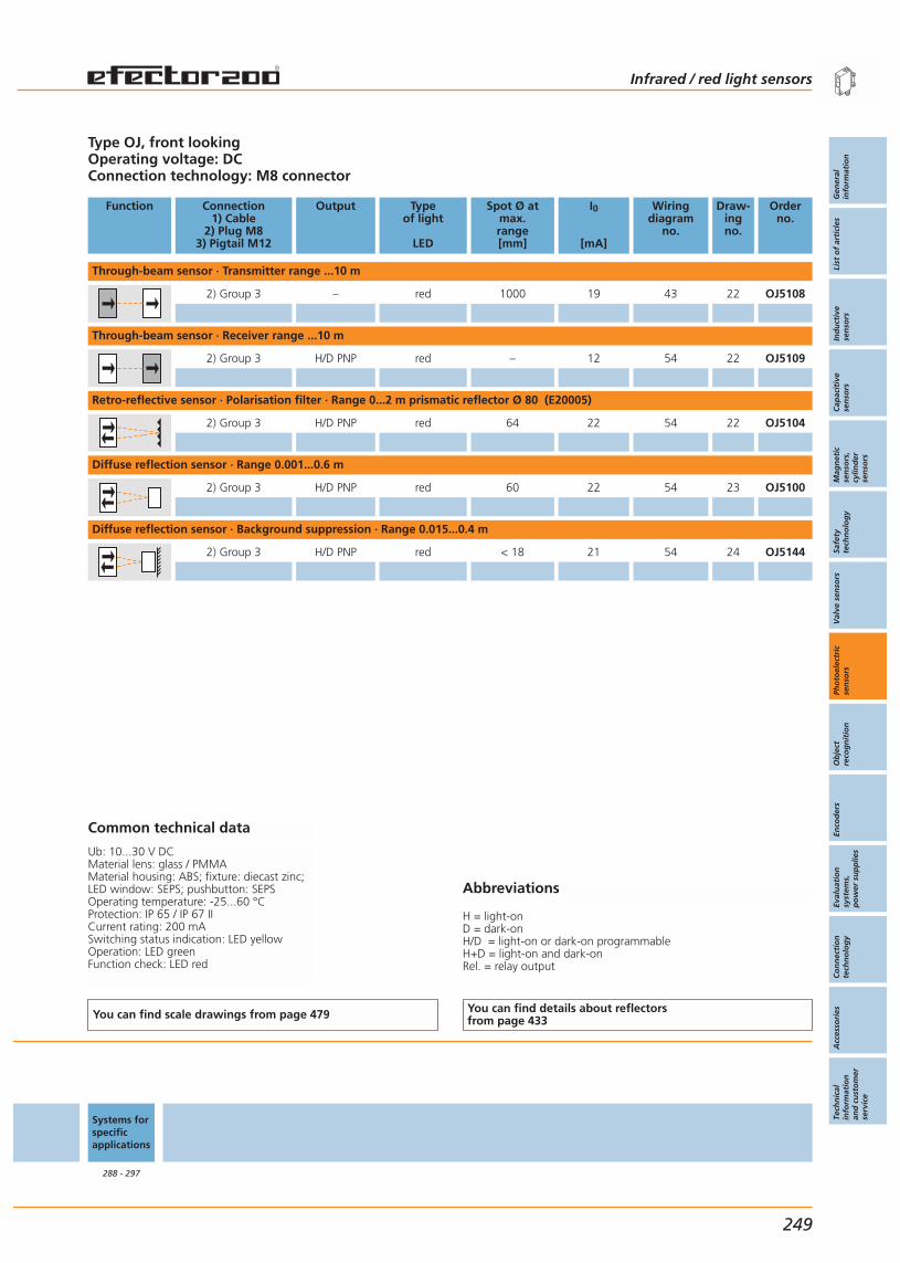
Abbreviations
H = light-onD = dark-onH/D = light-on or dark-on programmableH+D = light-on and dark-onRel. = relay output
Type OJ, front lookingOperating voltage: DCConnection technology: M8 connector
Function Connection1) Cable
2) Plug M83) Pigtail M12
Output Typeof light
LED
Spot Ø atmax.range[mm]
I0
[mA]
Wiringdiagram
no.
Draw-ingno.
Orderno.
Through-beam sensor · Transmitter range ...10 m
2) Group 3 – red 1000 19 43 22 OJ5108
Through-beam sensor · Receiver range ...10 m
2) Group 3 H/D PNP red – 12 54 22 OJ5109
Retro-reflective sensor · Polarisation filter · Range 0...2 m prismatic reflector Ø 80 (E20005)
2) Group 3 H/D PNP red 64 22 54 22 OJ5104
Diffuse reflection sensor · Range 0.001...0.6 m
2) Group 3 H/D PNP red 60 22 54 23 OJ5100
Diffuse reflection sensor · Background suppression · Range 0.015...0.4 m
2) Group 3 H/D PNP red < 18 21 54 24 OJ5144
Common technical data
Ub: 10...30 V DCMaterial lens: glass / PMMAMaterial housing: ABS; fixture: diecast zinc;LED window: SEPS; pushbutton: SEPSOperating temperature: -25...60 °CProtection: IP 65 / IP 67 IICurrent rating: 200 mASwitching status indication: LED yellowOperation: LED greenFunction check: LED red
You can find scale drawings from page 479 You can find details about reflectorsfrom page 433
Systems forspecificapplications
288 - 297
Infrared / red light sensors
Gen
eral
info
rmat
ion
List
of
arti
cles
Ind
uct
ive
sen
sors
Cap
acit
ive
sen
sors
Mag
net
icse
nso
rs,
cylin
der
sen
sors
Safe
tyte
chn
olo
gy
Val
ve s
enso
rsPh
oto
elec
tric
sen
sors
Ob
ject
reco
gn
itio
nEn
cod
ers
Eval
uat
ion
syst
ems,
po
wer
su
pp
lies
Co
nn
ecti
on
tech
no
log
yA
cces
sori
esTe
chn
ical
info
rmat
ion
and
cu
sto
mer
serv
ice
249
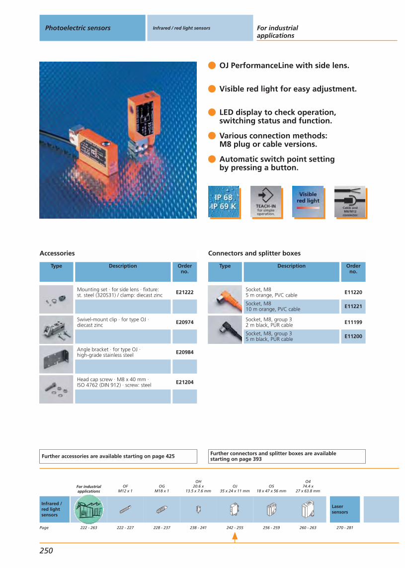
OJ PerformanceLine with side lens.
Visible red light for easy adjustment.
LED display to check operation,switching status and function.
Various connection methods:M8 plug or cable versions.
Automatic switch point settingby pressing a button.
Accessories
Type Description Orderno.
Mounting set · for side lens · fixture:st. steel (320S31) / clamp: diecast zinc E21222
Swivel-mount clip · for type OJ · diecast zinc E20974
Angle bracket · for type OJ · high-grade stainless steel E20984
Head cap screw · M8 x 40 mm · ISO 4762 (DIN 912) · screw: steel E21204
Further accessories are available starting on page 425
Connectors and splitter boxes
Type Description Orderno.
Socket, M85 m orange, PVC cable E11220
Socket, M810 m orange, PVC cable E11221
Socket, M8, group 32 m black, PUR cable E11199
Socket, M8, group 35 m black, PUR cable E11200
Further connectors and splitter boxes are availablestarting on page 393
Photoelectric sensors Infrared / red light sensors For industrialapplications
250
Infrared /red lightsensors
Page
For industrialapplications
222 - 263
OFM12 x 1
222 - 227
OGM18 x 1
228 - 237
OH20.6 x
13.5 x 7.6 mm
238 - 241
OJ35 x 24 x 11 mm
242 - 255
O518 x 47 x 56 mm
256 - 259
O474.4 x
27 x 63.8 mm
260 - 263
Lasersensors
270 - 281

Abbreviations
H = light-onD = dark-onH/D = light-on or dark-on programmableH+D = light-on and dark-onRel. = relay output
Type OJ, side lookingOperating voltage: DCConnection technology: M8 connector
Function Connection1) Cable
2) Plug M8
Output Typeof light
LED
Spot Ø atmax.range[mm]
I0
[mA]
Wiringdiagram
no.
Draw-ingno.
Orderno.
Through-beam sensor · Transmitter range ...10 m
2) Group 3 – red 1000 19 43 25 OJ5030
Through-beam sensor · Receiver range ...10 m
2) Group 3 H/D PNP red – 12 54 25 OJ5031
2) Group 3 H/D NPN red – 12 55 25 OJ5032
Retro-reflective sensor · Polarisation filter · Range 0...2 m prismatic reflector Ø 80 (E20005)
2) Group 3 H/D PNP red 64 22 54 25 OJ5026
2) Group 3 H/D NPN red 64 22 55 25 OJ5027
Diffuse reflection sensor · Range 0.001...0.6 m
2) Group 3 H/D PNP red 60 22 54 26 OJ5022
2) Group 3 H/D NPN red 60 22 55 26 OJ5023
Diffuse reflection sensor · Range 0.001...1 m
2) Group 3 H/D PNP infrared 150 32 54 26 OJ5071
Diffuse reflection sensor · Background suppression · Range 0.015...0.4 m
2) Group 3 H/D PNP red < 18 21 54 27 OJ5048
Common technical data
Ub: 10...30 V DCMaterial lens: glass / PMMAHousing material: ABS; fixture: diecast zinc;LED window: SEPS; pushbutton: SEPSOperating temperature: -25...60 °CProtection: IP 65 / IP 67 IICurrent rating: 200 mA
You can find scale drawings from page 479 You can find details about reflectorsfrom page 433
Systems forspecificapplications
288 - 297
Infrared / red light sensors
Gen
eral
info
rmat
ion
List
of
arti
cles
Ind
uct
ive
sen
sors
Cap
acit
ive
sen
sors
Mag
net
icse
nso
rs,
cylin
der
sen
sors
Safe
tyte
chn
olo
gy
Val
ve s
enso
rsPh
oto
elec
tric
sen
sors
Ob
ject
reco
gn
itio
nEn
cod
ers
Eval
uat
ion
syst
ems,
po
wer
su
pp
lies
Co
nn
ecti
on
tech
no
log
yA
cces
sori
esTe
chn
ical
info
rmat
ion
and
cu
sto
mer
serv
ice
251
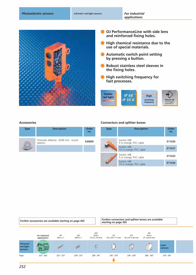
OJ PerformanceLine with side lens and reinforced fixing holes.
High chemical resistance due to theuse of special materials.
Automatic switch point settingby pressing a button.
Robust stainless steel sleeves inthe fixing holes.
High switching frequency forfast processes.
Accessories
Type Description Orderno.
Prismatic reflector · Ø 80 mm · round ·plastics E20005
Further accessories are available starting on page 425
Connectors and splitter boxes
Type Description Orderno.
Socket, M85 m orange, PVC cable E11220
Socket, M810 m orange, PVC cable E11221
Socket, M85 m orange, PVC cable E11223
Socket, M810 m orange, PVC cable E11224
Further connectors and splitter boxes are availablestarting on page 393
Photoelectric sensors Infrared / red light sensors For industrialapplications
252
Infrared /red lightsensors
Page
For industrialapplications
222 - 263
OFM12 x 1
222 - 227
OGM18 x 1
228 - 237
OH20.6 x
13.5 x 7.6 mm
238 - 241
OJ35 x 24 x 11 mm
242 - 255
O518 x 47 x 56 mm
256 - 259
O474.4 x
27 x 63.8 mm
260 - 263
Lasersensors
270 - 281
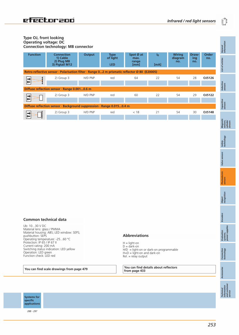
Abbreviations
H = light-onD = dark-onH/D = light-on or dark-on programmableH+D = light-on and dark-onRel. = relay output
Type OJ, front lookingOperating voltage: DCConnection technology: M8 connector
Function Connection1) Cable
2) Plug M83) Pigtail M12
Output Typeof light
LED
Spot Ø atmax.range[mm]
I0
[mA]
Wiringdiagram
no.
Draw-ingno.
Orderno.
Retro-reflective sensor · Polarisation filter · Range 0...2 m prismatic reflector Ø 80 (E20005)
2) Group 3 H/D PNP red 64 22 54 28 OJ5126
Diffuse reflection sensor · Range 0.001...0.6 m
2) Group 3 H/D PNP red 60 22 54 29 OJ5122
Diffuse reflection sensor · Background suppression · Range 0.015...0.4 m
2) Group 3 H/D PNP red < 18 21 54 30 OJ5148
Common technical data
Ub: 10...30 V DCMaterial lens: glass / PMMAMaterial housing: ABS; LED window: SEPS;pushbutton: SEPSOperating temperature: -25...60 °CProtection: IP 65 / IP 67 IICurrent rating: 200 mASwitching status indication: LED yellowOperation: LED greenFunction check: LED red
You can find scale drawings from page 479 You can find details about reflectorsfrom page 433
Systems forspecificapplications
288 - 297
Infrared / red light sensors
Gen
eral
info
rmat
ion
List
of
arti
cles
Ind
uct
ive
sen
sors
Cap
acit
ive
sen
sors
Mag
net
icse
nso
rs,
cylin
der
sen
sors
Safe
tyte
chn
olo
gy
Val
ve s
enso
rsPh
oto
elec
tric
sen
sors
Ob
ject
reco
gn
itio
nEn
cod
ers
Eval
uat
ion
syst
ems,
po
wer
su
pp
lies
Co
nn
ecti
on
tech
no
log
yA
cces
sori
esTe
chn
ical
info
rmat
ion
and
cu
sto
mer
serv
ice
253

OJ PerformanceLine with side lens.
Visible red light for easy adjustment.
LED display to check operation,switching status and function.
Various connection methods:M8 plug or cable versions.
Automatic switch point settingby pressing a button.
Accessories
Type Description Orderno.
Mounting set · for side lens · fixture:st. steel (320S31) / clamp: diecast zinc E21222
Swivel-mount clip · for type OJ · diecast zinc E20974
Angle bracket · for type OJ · high-grade stainless steel E20984
Head cap screw · M8 x 40 mm · ISO 4762 (DIN 912) · screw: steel E21204
Further accessories are available starting on page 425
Connectors and splitter boxes
Type Description Orderno.
Socket, M85 m orange, PVC cable E11220
Socket, M810 m orange, PVC cable E11221
Socket, M8, group 32 m black, PUR cable E11199
Socket, M8, group 35 m black, PUR cable E11200
Further connectors and splitter boxes are availablestarting on page 393
Photoelectric sensors Infrared / red light sensors For industrialapplications
254
Infrared /red lightsensors
Page
For industrialapplications
222 - 263
OFM12 x 1
222 - 227
OGM18 x 1
228 - 237
OH20.6 x
13.5 x 7.6 mm
238 - 241
OJ35 x 24 x 11 mm
242 - 255
O518 x 47 x 56 mm
256 - 259
O474.4 x
27 x 63.8 mm
260 - 263
Lasersensors
270 - 281

Abbreviations
H = light-onD = dark-onH/D = light-on or dark-on programmableH+D = light-on and dark-onRel. = relay output
Type OJ, side lookingOperating voltage: DCConnection technology: cable versions
Function Connection1) Cable
2) Plug M8
Output Typeof light
LED
Spot Ø atmax.range[mm]
I0
[mA]
Wiringdiagram
no.
Draw-ingno.
Orderno.
Through-beam sensor · Transmitter range ...10 m
1) PVC – red 1000 19 42 31 OJ5033
Through-beam sensor · Receiver range ...10 m
1) PVC H/D PNP red – 12 56 31 OJ5034
Retro-reflective sensor · Polarisation filter · Range 0...2 m prismatic reflector Ø 80 (E20005)
1) PVC H/D PNP red 64 22 56 31 OJ5028
Diffuse reflection sensor · Range 0.001...0.6 m
1) PVC H/D PNP red 60 22 56 32 OJ5024
Diffuse reflection sensor · Background suppression · Range 0.015...0.4 m
3) PVC Group 7, 8, 10 H/D PNP red < 18 21 54 33 OJ5078
3) PVC Group 7, 8, 10 H/D PNP red < 18 21 54 33 OJ5078
Common technical data
Ub: 10...30 V DCMaterial lens: glass / PMMAHousing material: ABS; fixture: diecast zinc;LED window: SEPS; pushbutton: SEPSOperating temperature: -25...60 °CProtection: IP 65 / IP 67 IICurrent rating: 200 mA
You can find scale drawings from page 479 You can find details about reflectorsfrom page 433
Systems forspecificapplications
288 - 297
Infrared / red light sensors
Gen
eral
info
rmat
ion
List
of
arti
cles
Ind
uct
ive
sen
sors
Cap
acit
ive
sen
sors
Mag
net
icse
nso
rs,
cylin
der
sen
sors
Safe
tyte
chn
olo
gy
Val
ve s
enso
rsPh
oto
elec
tric
sen
sors
Ob
ject
reco
gn
itio
nEn
cod
ers
Eval
uat
ion
syst
ems,
po
wer
su
pp
lies
Co
nn
ecti
on
tech
no
log
yA
cces
sori
esTe
chn
ical
info
rmat
ion
and
cu
sto
mer
serv
ice
255

O5 BasicLine.
Extremely long range, ideal for packaging and conveying.
Precise background suppression.
Extensive range of versions: Without setting funct. or with potentiometer.
Universal mounting with system com-ponents and mounting accessories.
Accessories
Type Description Orderno.
Mounting set · Clamp mounting ·st. steel (320S31), clamp: diecast zinc E21211
Mounting set · Clamp mounting ·st. steel (320S31), clamp: h.-g. st. steel E21212
Head cap screw · M10 x 120 mm · ISO4762 (DIN 912) · screw : steel galvanised E21213
Head cap screw · M10 x 120 mm · ISO4762 (DIN 912) · screw: h.-g. st. steel E21214
Angle bracket · for type O5 · stainless steel (320S31) E21085
Angle bracket · for type O5 · stainless steel (320S31) E21087
Further accessories are available starting on page 425
Connectors and splitter boxes
Type Description Orderno.
Socket, M12, group 72 m black, PUR cable EVC001
Socket, M12, group 75 m black, PUR cable EVC002
Socket, M12, group 72 m black, PUR cable EVC004
Socket, M12, group 75 m black, PUR cable EVC005
Socket, M125 m orange, PVC cable EVT001
Socket, M1210 m orange, PVC cable EVT002
Socket, M125 m orange, PVC cable EVT004
Socket, M1210 m orange, PVC cable EVT005
Further connectors and splitter boxes are availablestarting on page 393
Photoelectric sensors Infrared / red light sensors For industrialapplications
256
Infrared /red lightsensors
Page
For industrialapplications
222 - 263
OFM12 x 1
222 - 227
OGM18 x 1
228 - 237
OH20.6 x
13.5 x 7.6 mm
238 - 241
OJ35 x 24 x 11 mm
242 - 255
O518 x 47 x 56 mm
256 - 259
O474.4 x
27 x 63.8 mm
260 - 263
Lasersensors
270 - 281
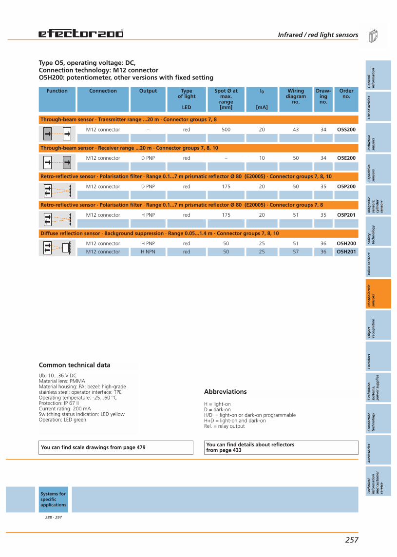
Abbreviations
H = light-onD = dark-onH/D = light-on or dark-on programmableH+D = light-on and dark-onRel. = relay output
Type O5, operating voltage: DC, Connection technology: M12 connectorO5H200: potentiometer, other versions with fixed setting
Function Connection Output Typeof light
LED
Spot Ø atmax.range[mm]
I0
[mA]
Wiringdiagram
no.
Draw-ingno.
Orderno.
Through-beam sensor · Transmitter range ...20 m · Connector groups 7, 8
M12 connector – red 500 20 43 34 O5S200
Through-beam sensor · Receiver range ...20 m · Connector groups 7, 8, 10
M12 connector D PNP red – 10 50 34 O5E200
Retro-reflective sensor · Polarisation filter · Range 0.1...7 m prismatic reflector Ø 80 (E20005) · Connector groups 7, 8, 10
M12 connector D PNP red 175 20 50 35 O5P200
Retro-reflective sensor · Polarisation filter · Range 0.1...7 m prismatic reflector Ø 80 (E20005) · Connector groups 7, 8
M12 connector H PNP red 175 20 51 35 O5P201
Diffuse reflection sensor · Background suppression · Range 0.05...1.4 m · Connector groups 7, 8, 10
M12 connector H PNP red 50 25 51 36 O5H200
M12 connector H NPN red 50 25 57 36 O5H201
Common technical data
Ub: 10...36 V DCMaterial lens: PMMAMaterial housing: PA; bezel: high-gradestainless steel; operator interface: TPEOperating temperature: -25...60 °CProtection: IP 67 IICurrent rating: 200 mASwitching status indication: LED yellowOperation: LED green
You can find scale drawings from page 479 You can find details about reflectorsfrom page 433
Systems forspecificapplications
288 - 297
Infrared / red light sensors
Gen
eral
info
rmat
ion
List
of
arti
cles
Ind
uct
ive
sen
sors
Cap
acit
ive
sen
sors
Mag
net
icse
nso
rs,
cylin
der
sen
sors
Safe
tyte
chn
olo
gy
Val
ve s
enso
rsPh
oto
elec
tric
sen
sors
Ob
ject
reco
gn
itio
nEn
cod
ers
Eval
uat
ion
syst
ems,
po
wer
su
pp
lies
Co
nn
ecti
on
tech
no
log
yA
cces
sori
esTe
chn
ical
info
rmat
ion
and
cu
sto
mer
serv
ice
257
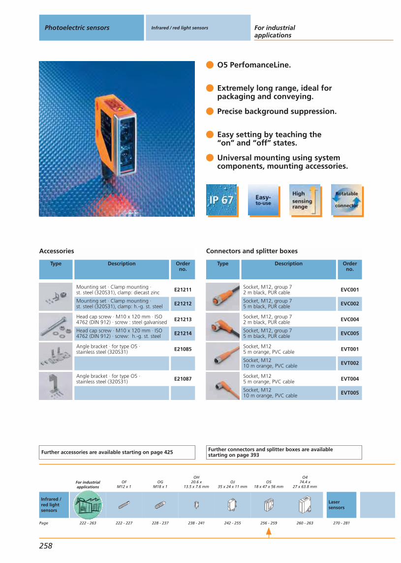
O5 PerfomanceLine.
Extremely long range, ideal for packaging and conveying.
Precise background suppression.
Easy setting by teaching the“on” and “off” states.
Universal mounting using system components, mounting accessories.
Accessories
Type Description Orderno.
Mounting set · Clamp mounting ·st. steel (320S31), clamp: diecast zinc E21211
Mounting set · Clamp mounting ·st. steel (320S31), clamp: h.-g. st. steel E21212
Head cap screw · M10 x 120 mm · ISO4762 (DIN 912) · screw : steel galvanised E21213
Head cap screw · M10 x 120 mm · ISO4762 (DIN 912) · screw: h.-g. st. steel E21214
Angle bracket · for type O5 · stainless steel (320S31) E21085
Angle bracket · for type O5 · stainless steel (320S31) E21087
Further accessories are available starting on page 425
Connectors and splitter boxes
Type Description Orderno.
Socket, M12, group 72 m black, PUR cable EVC001
Socket, M12, group 75 m black, PUR cable EVC002
Socket, M12, group 72 m black, PUR cable EVC004
Socket, M12, group 75 m black, PUR cable EVC005
Socket, M125 m orange, PVC cable EVT001
Socket, M1210 m orange, PVC cable EVT002
Socket, M125 m orange, PVC cable EVT004
Socket, M1210 m orange, PVC cable EVT005
Further connectors and splitter boxes are availablestarting on page 393
Photoelectric sensors Infrared / red light sensors For industrialapplications
258
Infrared /red lightsensors
Page
For industrialapplications
222 - 263
OFM12 x 1
222 - 227
OGM18 x 1
228 - 237
OH20.6 x
13.5 x 7.6 mm
238 - 241
OJ35 x 24 x 11 mm
242 - 255
O518 x 47 x 56 mm
256 - 259
O474.4 x
27 x 63.8 mm
260 - 263
Lasersensors
270 - 281
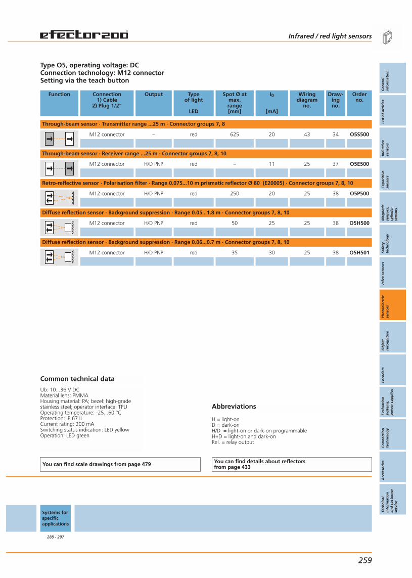
Abbreviations
H = light-onD = dark-onH/D = light-on or dark-on programmableH+D = light-on and dark-onRel. = relay output
Type O5, operating voltage: DCConnection technology: M12 connectorSetting via the teach button
Function Connection1) Cable
2) Plug 1/2"
Output Typeof light
LED
Spot Ø atmax.range[mm]
I0
[mA]
Wiringdiagram
no.
Draw-ingno.
Orderno.
Through-beam sensor · Transmitter range ...25 m · Connector groups 7, 8
M12 connector – red 625 20 43 34 O5S500
Through-beam sensor · Receiver range ...25 m · Connector groups 7, 8, 10
M12 connector H/D PNP red – 11 25 37 O5E500
Retro-reflective sensor · Polarisation filter · Range 0.075...10 m prismatic reflector Ø 80 (E20005) · Connector groups 7, 8, 10
M12 connector H/D PNP red 250 20 25 38 O5P500
Diffuse reflection sensor · Background suppression · Range 0.05...1.8 m · Connector groups 7, 8, 10
M12 connector H/D PNP red 50 25 25 38 O5H500
Diffuse reflection sensor · Background suppression · Range 0.06...0.7 m · Connector groups 7, 8, 10
M12 connector H/D PNP red 35 30 25 38 O5H501
Common technical data
Ub: 10...36 V DCMaterial lens: PMMAHousing material: PA; bezel: high-gradestainless steel; operator interface: TPUOperating temperature: -25...60 °CProtection: IP 67 IICurrent rating: 200 mASwitching status indication: LED yellowOperation: LED green
You can find scale drawings from page 479 You can find details about reflectorsfrom page 433
Systems forspecificapplications
288 - 297
Infrared / red light sensors
Gen
eral
info
rmat
ion
List
of
arti
cles
Ind
uct
ive
sen
sors
Cap
acit
ive
sen
sors
Mag
net
icse
nso
rs,
cylin
der
sen
sors
Safe
tyte
chn
olo
gy
Val
ve s
enso
rsPh
oto
elec
tric
sen
sors
Ob
ject
reco
gn
itio
nEn
cod
ers
Eval
uat
ion
syst
ems,
po
wer
su
pp
lies
Co
nn
ecti
on
tech
no
log
yA
cces
sori
esTe
chn
ical
info
rmat
ion
and
cu
sto
mer
serv
ice
259
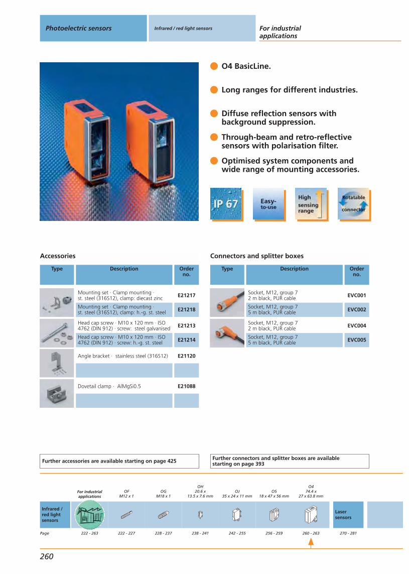
O4 BasicLine.
Long ranges for different industries.
Diffuse reflection sensors with background suppression.
Through-beam and retro-reflective sensors with polarisation filter.
Optimised system components and wide range of mounting accessories.
Accessories
Type Description Orderno.
Mounting set · Clamp mounting ·st. steel (316S12), clamp: diecast zinc E21217
Mounting set · Clamp mounting ·st. steel (316S12), clamp: h.-g. st. steel E21218
Head cap screw · M10 x 120 mm · ISO4762 (DIN 912) · screw: steel galvanised E21213
Head cap screw · M10 x 120 mm · ISO4762 (DIN 912) · screw: h.-g. st. steel E21214
Angle bracket · stainless steel (316S12) E21120
Dovetail clamp · AlMgSi0.5 E21088
Further accessories are available starting on page 425
Connectors and splitter boxes
Type Description Orderno.
Socket, M12, group 72 m black, PUR cable EVC001
Socket, M12, group 75 m black, PUR cable EVC002
Socket, M12, group 72 m black, PUR cable EVC004
Socket, M12, group 75 m black, PUR cable EVC005
Further connectors and splitter boxes are availablestarting on page 393
Photoelectric sensors Infrared / red light sensors For industrialapplications
260
Infrared /red lightsensors
Page
For industrialapplications
222 - 263
OFM12 x 1
222 - 227
OGM18 x 1
228 - 237
OH20.6 x
13.5 x 7.6 mm
238 - 241
OJ35 x 24 x 11 mm
242 - 255
O518 x 47 x 56 mm
256 - 259
O474.4 x
27 x 63.8 mm
260 - 263
Lasersensors
270 - 281

Abbreviations
H = light-onD = dark-onH/D = light-on or dark-on programmableH+D = light-on and dark-onRel. = relay output
Type O4, operating voltage DCConnection technology: M12 connector
Function Connection1) Cable
2) Plug 1/2"
Output Typeof light
LED
Spot Ø atmax.range[mm]
I0
[mA]
Wiringdiagram
no.
Draw-ingno.
Orderno.
Through-beam sensor · Transmitter range 0...50 m · Connector groups 6, 7, 8
M12 connector – red 1000 20 43 39 O4S200
Through-beam sensor · Receiver range 0...50 m · Connector groups 7, 8, 10
M12 connector D PNP red – 12 50 40 O4E200
Retro-reflective sensor · Polarisation filter · Range 0.3...18 m prismatic reflector Ø 80 (E20005) · Connector groups 7, 8, 10
M12 connector D PNP red 500 20 50 41 O4P200
Diffuse reflection sensor · Background suppression · Range 0.1...2 m · Connector groups 7, 8, 10
M12 connector H PNP red 100 25 51 42 O4H200
Common technical data
Ub: 10...36 V DCMaterial lens: PMMAHousing material: PA; bezel: high-gradestainless steel; LED window: PCOperating temperature: -25...60 °CProtection: IP 67 II / IP 65 IICurrent rating: 200 mASwitching status indication: LED 2 x yellowOperation: LED green
You can find scale drawings from page 479 You can find details about reflectorsfrom page 433
Systems forspecificapplications
288 - 297
Infrared / red light sensors
Gen
eral
info
rmat
ion
List
of
arti
cles
Ind
uct
ive
sen
sors
Cap
acit
ive
sen
sors
Mag
net
icse
nso
rs,
cylin
der
sen
sors
Safe
tyte
chn
olo
gy
Val
ve s
enso
rsPh
oto
elec
tric
sen
sors
Ob
ject
reco
gn
itio
nEn
cod
ers
Eval
uat
ion
syst
ems,
po
wer
su
pp
lies
Co
nn
ecti
on
tech
no
log
yA
cces
sori
esTe
chn
ical
info
rmat
ion
and
cu
sto
mer
serv
ice
261
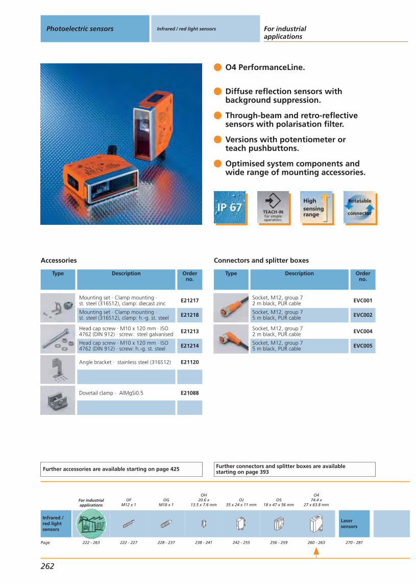
O4 PerformanceLine.
Diffuse reflection sensors with background suppression.
Through-beam and retro-reflective sensors with polarisation filter.
Versions with potentiometer or teach pushbuttons.
Optimised system components and wide range of mounting accessories.
Accessories
Type Description Orderno.
Mounting set · Clamp mounting ·st. steel (316S12), clamp: diecast zinc E21217
Mounting set · Clamp mounting ·st. steel (316S12), clamp: h.-g. st. steel E21218
Head cap screw · M10 x 120 mm · ISO4762 (DIN 912) · screw: steel galvanised E21213
Head cap screw · M10 x 120 mm · ISO4762 (DIN 912) · screw: h.-g. st. steel E21214
Angle bracket · stainless steel (316S12) E21120
Dovetail clamp · AlMgSi0.5 E21088
Further accessories are available starting on page 425
Connectors and splitter boxes
Type Description Orderno.
Socket, M12, group 72 m black, PUR cable EVC001
Socket, M12, group 75 m black, PUR cable EVC002
Socket, M12, group 72 m black, PUR cable EVC004
Socket, M12, group 75 m black, PUR cable EVC005
Further connectors and splitter boxes are availablestarting on page 393
Photoelectric sensors Infrared / red light sensors For industrialapplications
262
Infrared /red lightsensors
Page
For industrialapplications
222 - 263
OFM12 x 1
222 - 227
OGM18 x 1
228 - 237
OH20.6 x
13.5 x 7.6 mm
238 - 241
OJ35 x 24 x 11 mm
242 - 255
O518 x 47 x 56 mm
256 - 259
O474.4 x
27 x 63.8 mm
260 - 263
Lasersensors
270 - 281
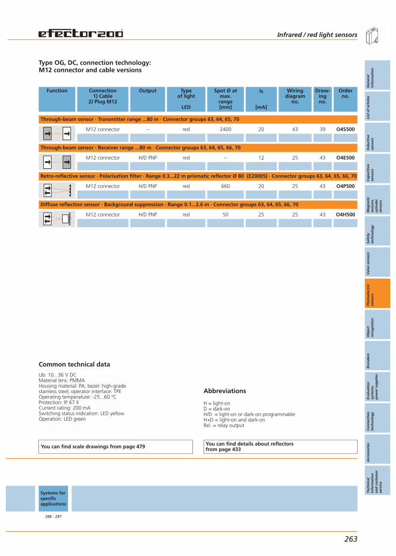
Abbreviations
H = light-onD = dark-onH/D = light-on or dark-on programmableH+D = light-on and dark-onRel. = relay output
Type OG, DC, connection technology:M12 connector and cable versions
Function Connection1) Cable
2) Plug M12
Output Typeof light
LED
Spot Ø atmax.range[mm]
I0
[mA]
Wiringdiagram
no.
Draw-ingno.
Orderno.
Through-beam sensor · Transmitter range ...80 m · Connector groups 63, 64, 65, 70
M12 connector – red 2400 20 43 39 O4S500
Through-beam sensor · Receiver range ...80 m · Connector groups 63, 64, 65, 66, 70
M12 connector H/D PNP red – 12 25 43 O4E500
Retro-reflective sensor · Polarisation filter · Range 0.3...22 m prismatic reflector Ø 80 (E20005) · Connector groups 63, 64, 65, 66, 70
M12 connector H/D PNP red 660 20 25 43 O4P500
Diffuse reflection sensor · Background suppression · Range 0.1...2.6 m · Connector groups 63, 64, 65, 66, 70
M12 connector H/D PNP red 50 25 25 43 O4H500
Common technical data
Ub: 10...36 V DCMaterial lens: PMMAHousing material: PA; bezel: high-gradestainless steel; operator interface: TPEOperating temperature: -25...60 °CProtection: IP 67 IICurrent rating: 200 mASwitching status indication: LED yellowOperation: LED green
You can find scale drawings from page 479 You can find details about reflectorsfrom page 433
Systems forspecificapplications
288 - 297
Infrared / red light sensors
Gen
eral
info
rmat
ion
List
of
arti
cles
Ind
uct
ive
sen
sors
Cap
acit
ive
sen
sors
Mag
net
icse
nso
rs,
cylin
der
sen
sors
Safe
tyte
chn
olo
gy
Val
ve s
enso
rsPh
oto
elec
tric
sen
sors
Ob
ject
reco
gn
itio
nEn
cod
ers
Eval
uat
ion
syst
ems,
po
wer
su
pp
lies
Co
nn
ecti
on
tech
no
log
yA
cces
sori
esTe
chn
ical
info
rmat
ion
and
cu
sto
mer
serv
ice
263

Gen
eral
info
rmat
ion
List
of
arti
cles
Ind
uct
ive
sen
sors
Cap
acit
ive
sen
sors
Mag
net
icse
nso
rs,
cylin
der
sen
sors
Safe
tyte
chn
olo
gy
Val
ve s
enso
rsPh
oto
elec
tric
sen
sors
Ob
ject
reco
gn
itio
nEn
cod
ers
Eval
uat
ion
syst
ems,
po
wer
su
pp
lies
Co
nn
ecti
on
tech
no
log
yA
cces
sori
esTe
chn
ical
info
rmat
ion
and
cu
sto
mer
serv
ice
Photoelectric sensors
265
Laser sensorsfor industrial applications
Laser sensors
System descriptionSelection chart
Infrared / red light sensorsSystems for specific applications
Universal applicationThreaded housing OGRectangular housing OJRectangular housing O1D
266 - 267268 - 269
213 - 263283 - 297
270 - 271272 - 279280 - 281
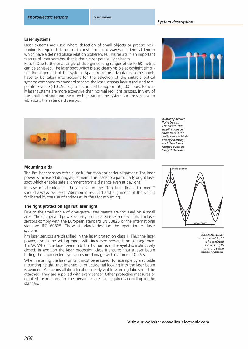
System description
Visit our website: www.ifm-electronic.com
Photoelectric sensors Laser sensors
266
Laser systemsLaser systems are used where detection of small objects or precise posi-tioning is required. Laser light consists of light waves of identical lengthwhich have a defined phase relation (coherence). This results in an importantfeature of laser systems, that is the almost parallel light beam.Result: Due to the small angle of divergence long ranges of up to 60 metrescan be achieved. The laser spot which is also clearly visible at daylight simpli-fies the alignment of the system. Apart from the advantages some pointshave to be taken into account for the selection of the suitable opticalsystem: compared to standard sensors the laser sensors have a reduced tem-perature range (-10...50 °C). Life is limited to approx. 50,000 hours. Basical-ly laser systems are more expensive than normal red light sensors. In view ofthe small light spot and the often high ranges the system is more sensitive tovibrations than standard sensors.
Almost parallellight beam:Thanks to thesmall angle ofradiation laserunits have a highenergy densityand thus longranges even atlong distances.
The ifm laser sensors offer a useful function for easier alignment: The laserpower is increased during adjustment: This leads to a particularly bright laserspot which enables safe alignment from a distance even at daylight.In case of vibrations in the application the “ifm laser fine adjustment”should always be used. Vibration is reduced and alignment of the unit isfacilitated by the use of springs as buffers for mounting.
Mounting aids
Due to the small angle of divergence laser beams are focussed on a smallarea. The energy and power density on this area is extremely high. ifm lasersensors comply with the European standard EN 60825 or the internationalstandard IEC 60825. These standards describe the operation of lasersystems.ifm laser sensors are classified in the laser protection class II. Thus the laserpower, also in the setting mode with increased power, is on average max. 1 mW. When the laser beam hits the human eye, the eyelid is instinctivelyclosed. In addition the laser protection class II ensures that a laser beam hitting the unprotected eye causes no damage within a time of 0.25 s.When installing the laser units it must be ensured, for example by a suitablemounting height, that intentional or accidental looking into the laser beamis avoided. At the installation location clearly visible warning labels must beattached. They are supplied with every sensor. Other protective measures ordetailed instructions for the personnel are not required according to thestandard.
The right protection against laser light
wave length
phase position
Coherent: Lasersensors emit light
of a definedwave length
and the samephase position.

Gen
eral
info
rmat
ion
List
of
arti
cles
Ind
uct
ive
sen
sors
Cap
acit
ive
sen
sors
Mag
net
icse
nso
rs,
cylin
der
sen
sors
Safe
tyte
chn
olo
gy
Val
ve s
enso
rsPh
oto
elec
tric
sen
sors
Ob
ject
reco
gn
itio
nEn
cod
ers
Eval
uat
ion
syst
ems,
po
wer
su
pp
lies
Co
nn
ecti
on
tech
no
log
yA
cces
sori
esTe
chn
ical
info
rmat
ion
and
cu
sto
mer
serv
ice
Laser sensors
267
Diffuse laser efector pmdWith PMD technology it is possible to make a diffuse laser with 10 m rangeand background suppression in a compact housing. There is a wide range ofapplications: efector pmd can be used from easy counting tasks to assem-bly monitoring.The core of the senor is the PMD chip. This is an innovative on-chip time offlight measurement system. Special feature: Transmitter and receiver areintegrated on a chip. This allows compact housing dimensions of just 42 x 45 x 52 mm. The PMD technology was awarded the international tech-nology prize “Hermes Award 2005”.It can be adapted to the application to within a millimetre via the teachmode. Visible laser light allows easy alignment to the object. The light spotdiameter is only 6 mm at maximum range. The diffuse laser efector pmd is a low-cost alternative to the laser distancesensor efector pmd (see chapter “Systems for specific applications”) becauseit additionally has a second output either as switching output or analogueoutput.
The core is the innovative “Smart Pixel”
receiver element,the photonicmixer device
(PMD).efector pmd –
compact diffuselaser with
10 m range.
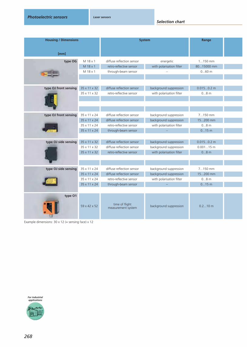
Selection chartPhotoelectric sensors Laser sensors
Housing / Dimensions
[mm]
System Range
For industrialapplications
268
M 18 x 1
M 18 x 1
M 18 x 1
diffuse reflection sensor energetic 1...150 mm
retro-reflective sensor with polarisation filter 80...15000 mm
through-beam sensor – 0...60 m
Example dimensions: 30 x 12 (= sensing face) x 12
type OG
35 x 11 x 24
35 x 11 x 24
35 x 11 x 24
35 x 11 x 24
diffuse reflection sensor background suppression 7...150 mm
diffuse reflection sensor background suppression 15...200 mm
retro-reflective sensor with polarisation filter 0...8 m
through-beam sensor – 0...15 m
type OJ front sensing
35 x 11 x 24
35 x 11 x 24
35 x 11 x 24
35 x 11 x 24
diffuse reflection sensor background suppression 7...150 mm
diffuse reflection sensor background suppression 15...200 mm
retro-reflective sensor with polarisation filter 0...8 m
through-beam sensor – 0...15 m
type OJ side sensing
59 x 42 x 52 time of flightmeasurement system background suppression 0.2...10 m
type O1
35 x 11 x 32
35 x 11 x 32
diffuse reflection sensor background suppression 0.015...0.2 m
retro-reflective sensor with polarisation filter 0...8 m
type OJ front sensing
35 x 11 x 32
35 x 11 x 32
35 x 11 x 32
diffuse reflection sensor background suppression 0.015...0.2 m
diffuse reflection sensor background suppression 0.001...15 m
retro-reflective sensor with polarisation filter 0...8 m
type OJ side sensing
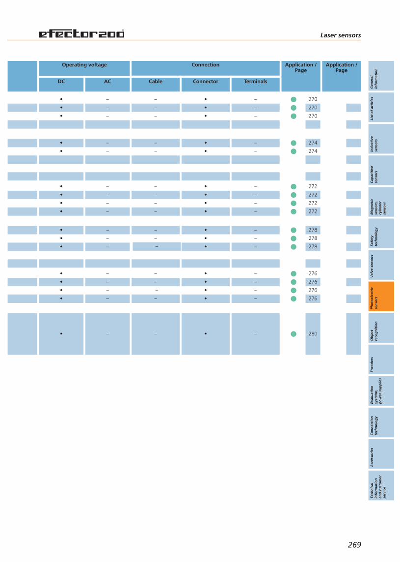
Laser sensors
Gen
eral
info
rmat
ion
List
of
arti
cles
Ind
uct
ive
sen
sors
Cap
acit
ive
sen
sors
Mag
net
icse
nso
rs,
cylin
der
sen
sors
Safe
tyte
chn
olo
gy
Val
ve s
enso
rsPh
oto
elec
tric
sen
sors
Ob
ject
reco
gn
itio
nEn
cod
ers
Eval
uat
ion
syst
ems,
po
wer
su
pp
lies
Co
nn
ecti
on
tech
no
log
yA
cces
sori
esTe
chn
ical
info
rmat
ion
and
cu
sto
mer
serv
ice
Operating voltage
DC AC
Connection
Cable Connector Terminals
Application /Page
Application /Page
269
•
•
•
–
–
–
–
–
–
•
•
•
–
–
–
•
•
•
•
–
–
–
–
–
–
–
–
•
•
•
•
–
–
–
–
•
•
•
•
–
–
–
–
–
–
–
–
•
•
•
•
–
–
–
–
• – – • –
270
270
270
272
272
272
272
276
276
276
276
•
•
–
–
–
–
•
•
–
–
274
274
•
•
•
–
–
–
–
–
–
•
•
•
–
–
–
278
278
278
280
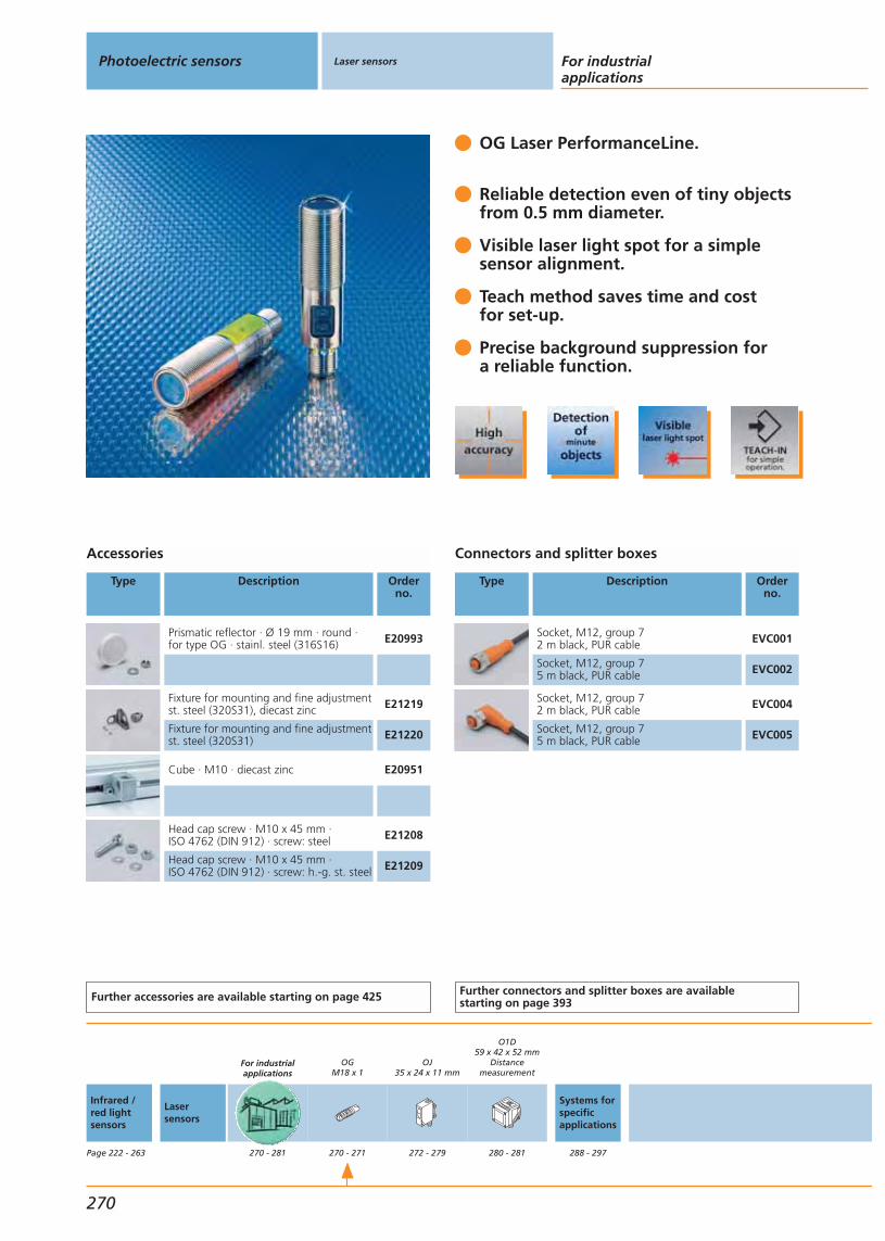
OG Laser PerformanceLine.
Reliable detection even of tiny objects from 0.5 mm diameter.
Visible laser light spot for a simple sensor alignment.
Teach method saves time and cost for set-up.
Precise background suppression for a reliable function.
Accessories
Type Description Orderno.
Prismatic reflector · Ø 19 mm · round ·for type OG · stainl. steel (316S16) E20993
Fixture for mounting and fine adjustmentst. steel (320S31), diecast zinc E21219
Fixture for mounting and fine adjustmentst. steel (320S31) E21220
Cube · M10 · diecast zinc E20951
Head cap screw · M10 x 45 mm · ISO 4762 (DIN 912) · screw: steel E21208
Head cap screw · M10 x 45 mm · ISO 4762 (DIN 912) · screw: h.-g. st. steel E21209
Further accessories are available starting on page 425
Connectors and splitter boxes
Type Description Orderno.
Socket, M12, group 72 m black, PUR cable EVC001
Socket, M12, group 75 m black, PUR cable EVC002
Socket, M12, group 72 m black, PUR cable EVC004
Socket, M12, group 75 m black, PUR cable EVC005
Further connectors and splitter boxes are availablestarting on page 393
Photoelectric sensors Laser sensors For industrialapplications
270
Infrared /red lightsensors
Page 222 - 263
Lasersensors
For industrialapplications
270 - 281
OGM18 x 1
270 - 271
OJ35 x 24 x 11 mm
272 - 279
O1D59 x 42 x 52 mm
Distancemeasurement
280 - 281
Systems forspecificapplications
288 - 297
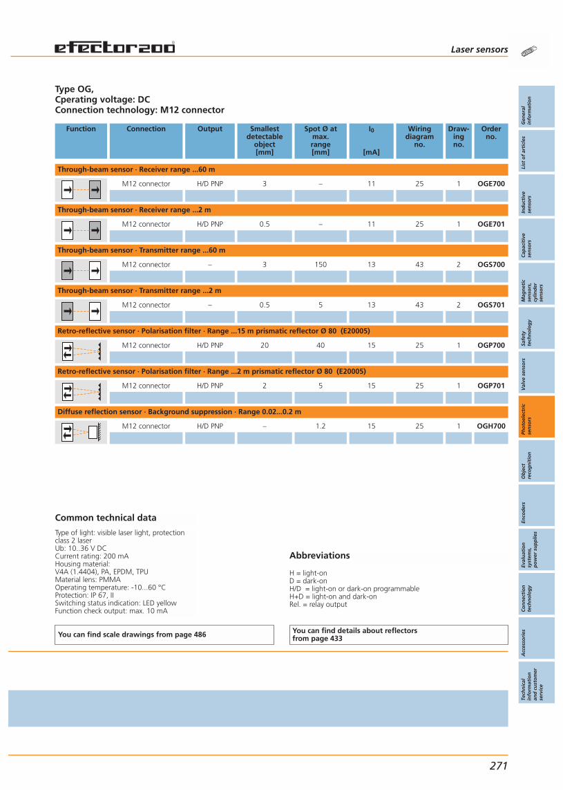
Abbreviations
H = light-onD = dark-onH/D = light-on or dark-on programmableH+D = light-on and dark-onRel. = relay output
Type OG, Cperating voltage: DCConnection technology: M12 connector
Function Connection Output Smallestdetectable
object[mm]
Spot Ø atmax.range[mm]
I0
[mA]
Wiringdiagram
no.
Draw-ingno.
Orderno.
Through-beam sensor · Receiver range ...60 m
M12 connector H/D PNP 3 – 11 25 1 OGE700
Through-beam sensor · Receiver range ...2 m
M12 connector H/D PNP 0.5 – 11 25 1 OGE701
Through-beam sensor · Transmitter range ...60 m
M12 connector – 3 150 13 43 2 OGS700
Through-beam sensor · Transmitter range ...2 m
M12 connector – 0.5 5 13 43 2 OGS701
Retro-reflective sensor · Polarisation filter · Range ...15 m prismatic reflector Ø 80 (E20005)
M12 connector H/D PNP 20 40 15 25 1 OGP700
Retro-reflective sensor · Polarisation filter · Range ...2 m prismatic reflector Ø 80 (E20005)
M12 connector H/D PNP 2 5 15 25 1 OGP701
Diffuse reflection sensor · Background suppression · Range 0.02...0.2 m
M12 connector H/D PNP – 1.2 15 25 1 OGH700
Common technical data
Type of light: visible laser light, protectionclass 2 laserUb: 10..36 V DCCurrent rating: 200 mAHousing material: V4A (1.4404), PA, EPDM, TPUMaterial lens: PMMAOperating temperature: -10...60 °CProtection: IP 67, IISwitching status indication: LED yellowFunction check output: max. 10 mA
You can find scale drawings from page 486 You can find details about reflectorsfrom page 433
Laser sensors
Gen
eral
info
rmat
ion
List
of
arti
cles
Ind
uct
ive
sen
sors
Cap
acit
ive
sen
sors
Mag
net
icse
nso
rs,
cylin
der
sen
sors
Safe
tyte
chn
olo
gy
Val
ve s
enso
rsPh
oto
elec
tric
sen
sors
Ob
ject
reco
gn
itio
nEn
cod
ers
Eval
uat
ion
syst
ems,
po
wer
su
pp
lies
Co
nn
ecti
on
tech
no
log
yA
cces
sori
esTe
chn
ical
info
rmat
ion
and
cu
sto
mer
serv
ice
271
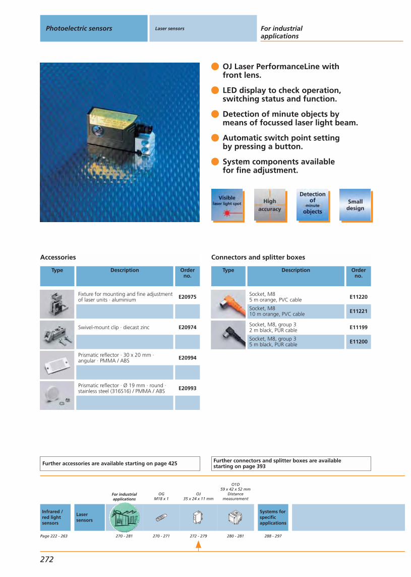
OJ Laser PerformanceLine with front lens.
LED display to check operation,switching status and function.
Detection of minute objects bymeans of focussed laser light beam.
Automatic switch point settingby pressing a button.
System components availablefor fine adjustment.
Accessories
Type Description Orderno.
Fixture for mounting and fine adjustmentof laser units · aluminium E20975
Swivel-mount clip · diecast zinc E20974
Prismatic reflector · 30 x 20 mm · angular · PMMA / ABS E20994
Prismatic reflector · Ø 19 mm · round ·stainless steel (316S16) / PMMA / ABS E20993
Further accessories are available starting on page 425
Connectors and splitter boxes
Type Description Orderno.
Socket, M85 m orange, PVC cable E11220
Socket, M810 m orange, PVC cable E11221
Socket, M8, group 32 m black, PUR cable E11199
Socket, M8, group 35 m black, PUR cable E11200
Further connectors and splitter boxes are availablestarting on page 393
Photoelectric sensors Laser sensors For industrialapplications
272
Infrared /red lightsensors
Page 222 - 263
Lasersensors
For industrialapplications
270 - 281
OGM18 x 1
270 - 271
OJ35 x 24 x 11 mm
272 - 279
O1D59 x 42 x 52 mm
Distancemeasurement
280 - 281
Systems forspecificapplications
288 - 297

Abbreviations
H = light-onD = dark-onH/D = light-on or dark-on programmableH+D = light-on and dark-onRel. = relay output
Type OJ, front lookingOperating voltage: DCConnection technology: M8 connector
Function Connection Output Smallestdetectable
object[mm]
Spot Ø atmax.range[mm]
I0
[mA]
Wiringdiagram
no.
Draw-ingno.
Orderno.
Through-beam sensor · Transmitter range ...1 m · Connector group 3
M8 connector – – < 4 12 43 3 OJ5019
Through-beam sensor · Receiver range ...1 m · Connector group 3
M8 connector H/D PNP – – 12 54 3 OJ5020
Through-beam sensor · Transmitter range ...15 m · Connector group 3
M8 connector – – < 24 12 43 3 OJ5016
Through-beam sensor · Receiver range ...15 m · Connector group 3
M8 connector H/D PNP – – 12 54 3 OJ5017
Retro-reflective sensor · Polarisation filter · Range ...8 m prismatic reflector 50 x 50 mm (E20722) · Connector group 3
M8 connector H/D PNP Ø 2.5mm < 12 15 54 3 OJ5014
Diffuse reflection sensor · Background suppression · Range 0.007...0.15 m · Connector group 3
M8 connector H/D PNP – 0.8 13 54 4 OJ5056
Diffuse reflection sensor · Background suppression · Range 0.015...0.2 m · Connector group 3
M8 connector H/D PNP – 2x1 vertical 13 54 5 OJ5052
Common technical data
Type of light: visible laser light, protectionclass 2 laserUb: 10...30 V DCMaterial lens: glassHousing material: ABSMaterial push button: SEPSOperating temperature: -10...60 °CProtection: IP 68, IP 69K IISwitching status indication: LED yellowOperation: LED greenFunction check: LED redSpecial feature: external teach
You can find scale drawings from page 486 You can find details about reflectorsfrom page 433
Laser sensors
Gen
eral
info
rmat
ion
List
of
arti
cles
Ind
uct
ive
sen
sors
Cap
acit
ive
sen
sors
Mag
net
icse
nso
rs,
cylin
der
sen
sors
Safe
tyte
chn
olo
gy
Val
ve s
enso
rsPh
oto
elec
tric
sen
sors
Ob
ject
reco
gn
itio
nEn
cod
ers
Eval
uat
ion
syst
ems,
po
wer
su
pp
lies
Co
nn
ecti
on
tech
no
log
yA
cces
sori
esTe
chn
ical
info
rmat
ion
and
cu
sto
mer
serv
ice
273
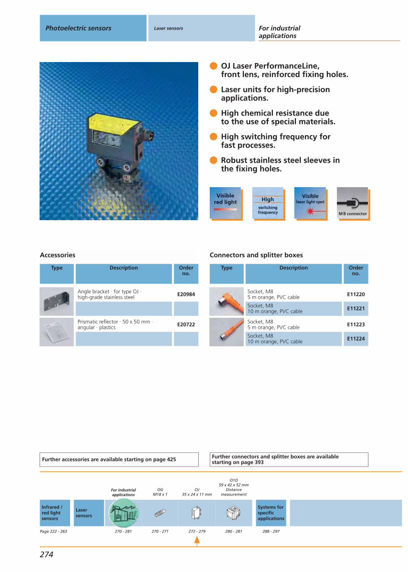
OJ Laser PerformanceLine, front lens, reinforced fixing holes.
Laser units for high-precisionapplications.
High chemical resistance dueto the use of special materials.
High switching frequency forfast processes.
Robust stainless steel sleeves inthe fixing holes.
Accessories
Type Description Orderno.
Angle bracket · for type OJ · high-grade stainless steel E20984
Prismatic reflector · 50 x 50 mm · angular · plastics E20722
Further accessories are available starting on page 425
Connectors and splitter boxes
Type Description Orderno.
Socket, M85 m orange, PVC cable E11220
Socket, M810 m orange, PVC cable E11221
Socket, M85 m orange, PVC cable E11223
Socket, M810 m orange, PVC cable E11224
Further connectors and splitter boxes are availablestarting on page 393
Photoelectric sensors Laser sensors For industrialapplications
274
Infrared /red lightsensors
Page 222 - 263
Lasersensors
For industrialapplications
270 - 281
OGM18 x 1
270 - 271
OJ35 x 24 x 11 mm
272 - 279
O1D59 x 42 x 52 mm
Distancemeasurement
280 - 281
Systems forspecificapplications
288 - 297

Abbreviations
H = light-onD = dark-onH/D = light-on or dark-on programmableH+D = light-on and dark-onRel. = relay output
Type OJ, front lookingOperating voltage: DCConnection technology: M8 connector
Function Connection1) Cable
2) Plug M83) Pigtail M12
Output Typeof light
LED
Spot Ø atmax.range[mm]
I0
[mA]
Wiringdiagram
no.
Draw-ingno.
Orderno.
Retro-reflective sensor · Polarisation filter · Range ...8 m prismatic reflector 50 x 50 mm (E20722)
2) Group 3 H/D PNP red < 12 15 54 6 OJ5114
Diffuse reflection sensor · Background suppression · Range 0.015...0.2 m
2) Group 3 H/D PNP red 2x1 vertical 13 54 7 OJ5152
Common technical data
Ub: 10...30 V DCMaterial lens: glass / PMMAMaterial housing: ABS; LED window: SEPS;pushbutton: SEPSOperating temperature: -10...60 °CProtection: IP 65 / IP 67 IICurrent rating: 200 mASwitching status indication: LED yellowOperation: LED greenFunction check: LED red
You can find scale drawings from page 486 You can find details about reflectorsfrom page 433
Laser sensors
Gen
eral
info
rmat
ion
List
of
arti
cles
Ind
uct
ive
sen
sors
Cap
acit
ive
sen
sors
Mag
net
icse
nso
rs,
cylin
der
sen
sors
Safe
tyte
chn
olo
gy
Val
ve s
enso
rsPh
oto
elec
tric
sen
sors
Ob
ject
reco
gn
itio
nEn
cod
ers
Eval
uat
ion
syst
ems,
po
wer
su
pp
lies
Co
nn
ecti
on
tech
no
log
yA
cces
sori
esTe
chn
ical
info
rmat
ion
and
cu
sto
mer
serv
ice
275

OJ Laser PerformanceLine with side lens.
LED display to check operation,switching status and function.
Detection of minute objects bymeans of focussed laser light beam.
Automatic switch point settingby pressing a button.
System components availablefor fine adjustment.
Accessories
Type Description Orderno.
Fixture for mounting and fine adjustmentof laser units · aluminium E20976
Swivel-mount clip · diecast zinc E20974
Angle bracket · for type OJ · high-grade stainless steel E20984
Prismatic reflector · 30 x 20 mm · angular · PMMA / ABS E20994
Prismatic reflector · Ø 19 mm · round ·stainless steel (316S16) / PMMA / ABS E20993
Further accessories are available starting on page 425
Connectors and splitter boxes
Type Description Orderno.
Socket, M85 m orange, PVC cable E11220
Socket, M810 m orange, PVC cable E11221
Socket, M8, group 32 m black, PUR cable E11199
Socket, M8, group 35 m black, PUR cable E11200
Further connectors and splitter boxes are availablestarting on page 393
Photoelectric sensors Laser sensors For industrialapplications
276
Infrared /red lightsensors
Page 222 - 263
Lasersensors
For industrialapplications
270 - 281
OGM18 x 1
270 - 271
OJ35 x 24 x 11 mm
272 - 279
O1D59 x 42 x 52 mm
Distancemeasurement
280 - 281
Systems forspecificapplications
288 - 297
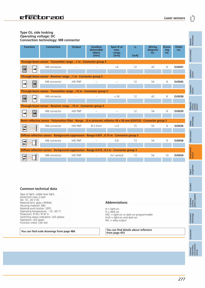
Abbreviations
H = light-onD = dark-onH/D = light-on or dark-on programmableH+D = light-on and dark-onRel. = relay output
Type OJ, side lookingOperating voltage: DCConnection technology: M8 connector
Function Connection Output Smallestdetectable
object[mm]
Spot Ø atmax.range[mm]
I0
[mA]
Wiringdiagram
no.
Draw-ingno.
Orderno.
Through-beam sensor · Transmitter range ...1 m · Connector group 3
M8 connector – – <4 12 43 8 OJ5041
Through-beam sensor · Receiver range ...1 m · Connector group 3
M8 connector H/D PNP – – 12 54 8 OJ5042
Through-beam sensor · Transmitter range ...15 m · Connector group 3
M8 connector – – < 24 12 43 8 OJ5038
Through-beam sensor · Receiver range ...15 m · Connector group 3
M8 connector H/D PNP – – 12 54 8 OJ5039
Retro-reflective sensor · Polarisation filter · Range ...8 m prismatic reflector 50 x 50 mm (E20722) · Connector group 3
M8 connector H/D PNP Ø 2.5mm <12 15 54 8 OJ5036
Diffuse reflection sensor · Background suppression · Range 0.007...0.15 m · Connector group 3
M8 connector H/D PNP – 0.8 13 54 9 OJ5058
Diffuse reflection sensor · Background suppression · Range 0.015...0.2 m · Connector group 3
M8 connector H/D PNP – 2x1 vertical 13 54 10 OJ5054
Common technical data
Type of light: visible laser light, protection class 2 laserUb: 10...30 V DCMaterial lens: glass / PMMAHousing material: ABSMaterial push button: SEPSOperating temperature: -10...60 °CProtection: IP 65 / IP 67 IISwitching status indication: LED yellowOperation: LED greenFunction check: LED red
You can find scale drawings from page 486 You can find details about reflectorsfrom page 433
Laser sensors
Gen
eral
info
rmat
ion
List
of
arti
cles
Ind
uct
ive
sen
sors
Cap
acit
ive
sen
sors
Mag
net
icse
nso
rs,
cylin
der
sen
sors
Safe
tyte
chn
olo
gy
Val
ve s
enso
rsPh
oto
elec
tric
sen
sors
Ob
ject
reco
gn
itio
nEn
cod
ers
Eval
uat
ion
syst
ems,
po
wer
su
pp
lies
Co
nn
ecti
on
tech
no
log
yA
cces
sori
esTe
chn
ical
info
rmat
ion
and
cu
sto
mer
serv
ice
277

OJ Laser PerformanceLine, side lens, reinforced fixing holes.
Laser units for high-precisionapplications.
High chemical resistance dueto the use of special materials.
High switching frequency forfast processes.
Robust stainless steel sleeves inthe fixing holes.
Accessories
Type Description Orderno.
Swivel-mount clip · for type OJ · diecast zinc E20974
Angle bracket · for type OJ · high-grade stainless steel E20984
Prismatic reflector · 30 x 20 mm · angular · PMMA / ABS E20994
Prismatic reflector · 50 x 50 mm · angular · plastics E20722
Further accessories are available starting on page 425
Connectors and splitter boxes
Type Description Orderno.
Socket, M85 m orange, PVC cable E11220
Socket, M810 m orange, PVC cable E11221
Socket, M85 m orange, PVC cable E11223
Socket, M810 m orange, PVC cable E11224
Further connectors and splitter boxes are availablestarting on page 393
Photoelectric sensors Laser sensors For industrialapplications
278
Infrared /red lightsensors
Page 222 - 263
Lasersensors
For industrialapplications
270 - 281
OGM18 x 1
270 - 271
OJ35 x 24 x 11 mm
272 - 279
O1D59 x 42 x 52 mm
Distancemeasurement
280 - 281
Systems forspecificapplications
288 - 297
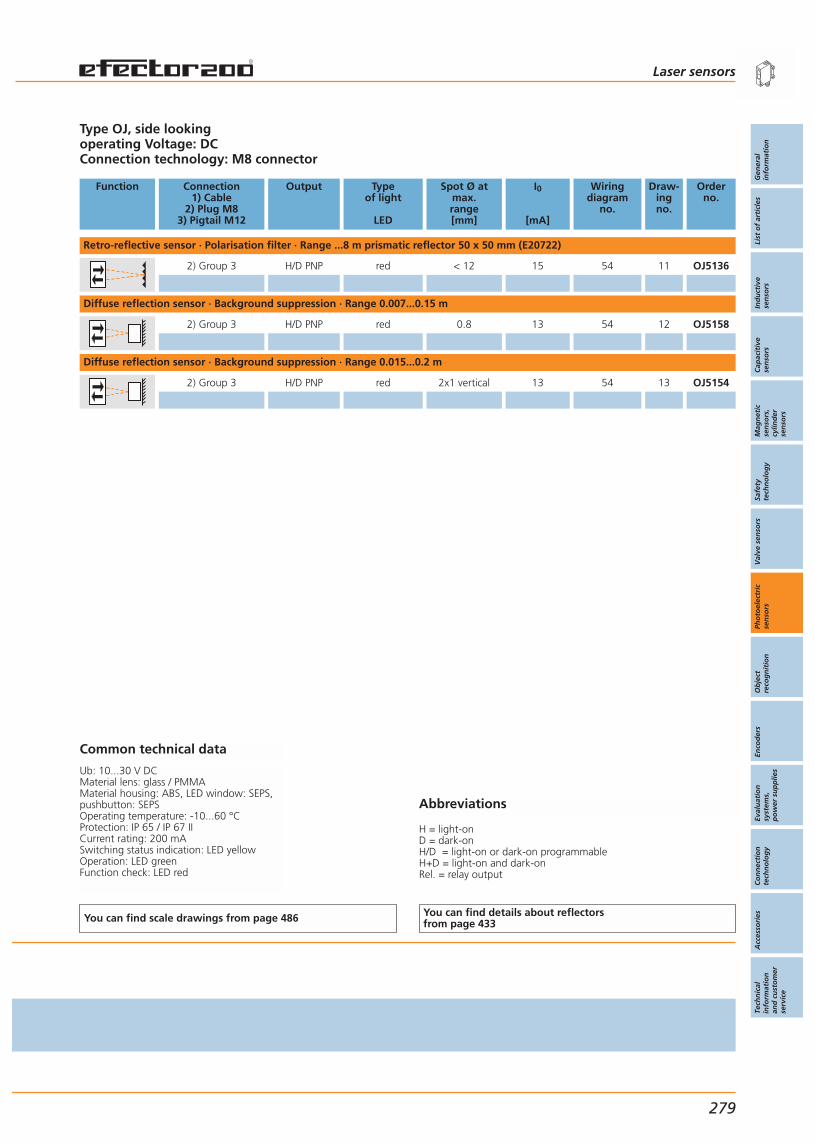
Abbreviations
H = light-onD = dark-onH/D = light-on or dark-on programmableH+D = light-on and dark-onRel. = relay output
Type OJ, side lookingoperating Voltage: DC Connection technology: M8 connector
Function Connection1) Cable
2) Plug M83) Pigtail M12
Output Typeof light
LED
Spot Ø atmax.range[mm]
I0
[mA]
Wiringdiagram
no.
Draw-ingno.
Orderno.
Retro-reflective sensor · Polarisation filter · Range ...8 m prismatic reflector 50 x 50 mm (E20722)
2) Group 3 H/D PNP red < 12 15 54 11 OJ5136
Diffuse reflection sensor · Background suppression · Range 0.007...0.15 m
2) Group 3 H/D PNP red 0.8 13 54 12 OJ5158
Diffuse reflection sensor · Background suppression · Range 0.015...0.2 m
2) Group 3 H/D PNP red 2x1 vertical 13 54 13 OJ5154
Common technical data
Ub: 10...30 V DCMaterial lens: glass / PMMAMaterial housing: ABS, LED window: SEPS,pushbutton: SEPSOperating temperature: -10...60 °CProtection: IP 65 / IP 67 IICurrent rating: 200 mASwitching status indication: LED yellowOperation: LED greenFunction check: LED red
You can find scale drawings from page 486 You can find details about reflectorsfrom page 433
Laser sensors
Gen
eral
info
rmat
ion
List
of
arti
cles
Ind
uct
ive
sen
sors
Cap
acit
ive
sen
sors
Mag
net
icse
nso
rs,
cylin
der
sen
sors
Safe
tyte
chn
olo
gy
Val
ve s
enso
rsPh
oto
elec
tric
sen
sors
Ob
ject
reco
gn
itio
nEn
cod
ers
Eval
uat
ion
syst
ems,
po
wer
su
pp
lies
Co
nn
ecti
on
tech
no
log
yA
cces
sori
esTe
chn
ical
info
rmat
ion
and
cu
sto
mer
serv
ice
279
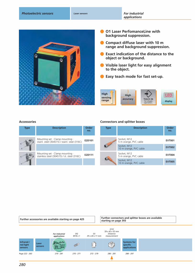
O1 Laser PerfomanceLine with background suppression.
Compact diffuse laser with 10 m range and background suppression.
Exact indication of the distance to the object or background.
Visible laser light for easy alignment to the object.
Easy teach mode for fast set-up.
Accessories
Type Description Orderno.
Mounting set · Clamp mounting ·stainl. steel (304S15) / stainl. steel (316C) E2D101
Mounting set · Clamp mounting ·stainless steel (304S15) / st. steel (316C) E2D111
Further accessories are available starting on page 425
Connectors and splitter boxes
Type Description Orderno.
Socket, M125 m orange, PVC cable EVT001
Socket, M1210 m orange, PVC cable EVT002
Socket, M125 m orange, PVC cable EVT004
Socket, M1210 m orange, PVC cable EVT005
Further connectors and splitter boxes are availablestarting on page 393
Photoelectric sensors Laser sensors For industrialapplications
280
Infrared /red lightsensors
Page 222 - 263
Lasersensors
For industrialapplications
270 - 281
OGM18 x 1
270 - 271
OJ35 x 24 x 11 mm
272 - 279
O1D59 x 42 x 52 mm
Distancemeasurement
280 - 281
Systems forspecificapplications
288 - 297

Abbreviations
H = light-onD = dark-onH/D = light-on or dark-on programmableH+D = light-on and dark-onRel. = relay output
Type O1D, operating voltage: DCConnection technology: M12 connector
Function Measuring range
[m]
Light spotdiameter
[mm]
Currentconsumption
[mA]
Switchingfrequency
[Hz]
Wiringdiagram
no.
Draw-ingno.
Orderno.
Optical distance sensor · Background suppression · Range ...10 m
0.2...10 6 (TW max. 10 m) 10...30 DC < 150 25 14 O1D101
0.2...10 6 (TW max. 10 m) 10...30 DC < 150 58 14 O1D104
Common technical data
Protection class 2 laserUb: 10...30 V DCHousing material: diecast zincFront window: glass LED window: polycarbonateProtection: IP 65, IIIOperating temperature: -10...60 °C
You can find scale drawings from page 486
Laser sensors
Gen
eral
info
rmat
ion
List
of
arti
cles
Ind
uct
ive
sen
sors
Cap
acit
ive
sen
sors
Mag
net
icse
nso
rs,
cylin
der
sen
sors
Safe
tyte
chn
olo
gy
Val
ve s
enso
rsPh
oto
elec
tric
sen
sors
Ob
ject
reco
gn
itio
nEn
cod
ers
Eval
uat
ion
syst
ems,
po
wer
su
pp
lies
Co
nn
ecti
on
tech
no
log
yA
cces
sori
esTe
chn
ical
info
rmat
ion
and
cu
sto
mer
serv
ice
281


Gen
eral
info
rmat
ion
List
of
arti
cles
Ind
uct
ive
sen
sors
Cap
acit
ive
sen
sors
Mag
net
icse
nso
rs,
cylin
der
sen
sors
Safe
tyte
chn
olo
gy
Val
ve s
enso
rsPh
oto
elec
tric
sen
sors
Ob
ject
reco
gn
itio
nEn
cod
ers
Eval
uat
ion
syst
ems,
po
wer
su
pp
lies
Co
nn
ecti
on
tech
no
log
yA
cces
sori
esTe
chn
ical
info
rmat
ion
and
cu
sto
mer
serv
ice
Photoelectric sensors
283
Systems forindustrial applications
Systems forspecific applications
System descriptionSelection chart
284 - 285286 - 287
Universal application
Systems forfor hazardous areasSpecial application
Infrared / red light sensorsLaser sensors
213 - 263265 - 281
Rectangular housing OJ, detection of transparent objectsRectangular housing O1D, distance measurementRectangular housing O5, detection of transparent objects
288 - 291292 - 293294 - 295
Rectangular housing O5, all-round photoelectric sensor 296 - 297

System description
Visit our website: www.ifm-electronic.com
Photoelectric sensors Systems forspecific applications
284
Detection of transparent objects Counting bottles and glasses or the reliable monitoring of film for tear canbe performed without problem using specially designed retro-reflective sen-sors.ifm offers retro-reflective sensors with a small switching hysteresis, in partic-ular for the detection of transparent objects. Due to the operating principle,retro-reflective sensors have the advantage that the light beam must passthe object to be detected twice. Thus the light is sufficiently weakened todetect a transparent object safely. Precise adjustment is made by means ofthe Teach button.
Typical appli-cation of sensors
of type O5G:Counting of glass
bottles.
Distance measurementThe continued development of the pmd technology (Photonic Mixer Device)now enables distance measurement to within a millimetre at high rangesusing a laser sensor. The efector pmd laser sensor operates to the time-of-flight principle.Traditional time-of-flight sensors use a photodiode as receiver element.Additional electronics is used for signal acquisition and processing. Disadvantage: This sensor design is complex, large in size and expensive andtherefore often not suitable for industrial position sensing.In comparison, the efector pmd sensor’s receiver element is a System-on-Chip design. For this design both sensor element and electronics for signalevaluation are integrated on a single silicon chip called a Photonic MixerDevice (PMD). The advantage: The sensor offers a high performance in a compact, industri-ally compatible housing at an unbeatable low price.
Operating principleBasis for the new efector pmd distance sensor is the time-of-flight princi-ple. A light beam is emitted by a transmitting element and is reflected to thereceiver element by an object. The measured time of flight relates to thedistance from the sensor to the object. If you take into account that the lightspeed is approx. 3 x 10⁸ m/s, the measurement of the resulting time of flightfor common distances in industrial processes is difficult.Example:The object is positioned at a distance of 1 m (back and forth = 2 m) This results in: t = 2 / (3 x 10⁸ m/s) = 6.7 nsThe measurement of such short times is usually only possible using expensivespecial tools. An adequate alternative is the transmission of a modulatedlight signal and the measurement of the phase difference between thetransmitted and received signal.At a distance between 0 and the final value of the measuring range a reflectedsignal b has a time offset with regard to the transmitted signal a. The distancecan be determined on the basis of the width p1. In the existing systems thesignals of channels a and b were received separately, converted into electri-cal signals and then linked. The efector pmd directly uses the PMD chip for evaluation. If light is re-ceived, charges are generated. By applying a voltage with changing polaritythese charges are transferred to two electrodes (charge swing).
a
b
p1
p2
Simplified repre-sentation of thephase difference:a = transmitted;b = received.
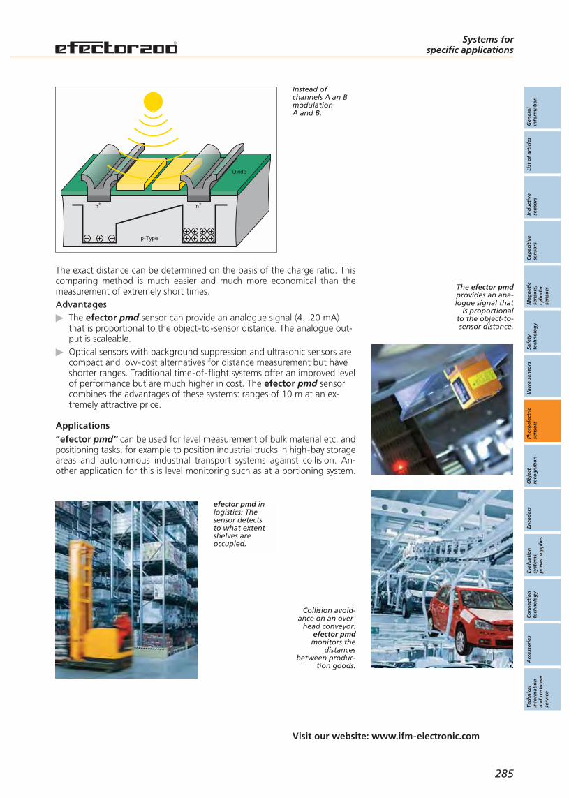
Gen
eral
info
rmat
ion
List
of
arti
cles
Ind
uct
ive
sen
sors
Cap
acit
ive
sen
sors
Mag
net
icse
nso
rs,
cylin
der
sen
sors
Safe
tyte
chn
olo
gy
Val
ve s
enso
rsPh
oto
elec
tric
sen
sors
Ob
ject
reco
gn
itio
nEn
cod
ers
Eval
uat
ion
syst
ems,
po
wer
su
pp
lies
Co
nn
ecti
on
tech
no
log
yA
cces
sori
esTe
chn
ical
info
rmat
ion
and
cu
sto
mer
serv
ice
Systems forspecific applications
Visit our website: www.ifm-electronic.com
285
p-Type
n+ n+
Oxide
Instead ofchannels A an BmodulationA and B.
The exact distance can be determined on the basis of the charge ratio. Thiscomparing method is much easier and much more economical than themeasurement of extremely short times.Advantages
The efector pmd sensor can provide an analogue signal (4...20 mA)that is proportional to the object-to-sensor distance. The analogue out-put is scaleable.Optical sensors with background suppression and ultrasonic sensors arecompact and low-cost alternatives for distance measurement but haveshorter ranges. Traditional time-of-flight systems offer an improved levelof performance but are much higher in cost. The efector pmd sensorcombines the advantages of these systems: ranges of 10 m at an ex-tremely attractive price.
Applications“efector pmd” can be used for level measurement of bulk material etc. andpositioning tasks, for example to position industrial trucks in high-bay storageareas and autonomous industrial transport systems against collision. An-other application for this is level monitoring such as at a portioning system.
efector pmd inlogistics: Thesensor detectsto what extentshelves areoccupied.
The efector pmdprovides an ana-logue signal that
is proportionalto the object-to-sensor distance.
Collision avoid-ance on an over-
head conveyor:efector pmdmonitors the
distancesbetween produc-
tion goods.
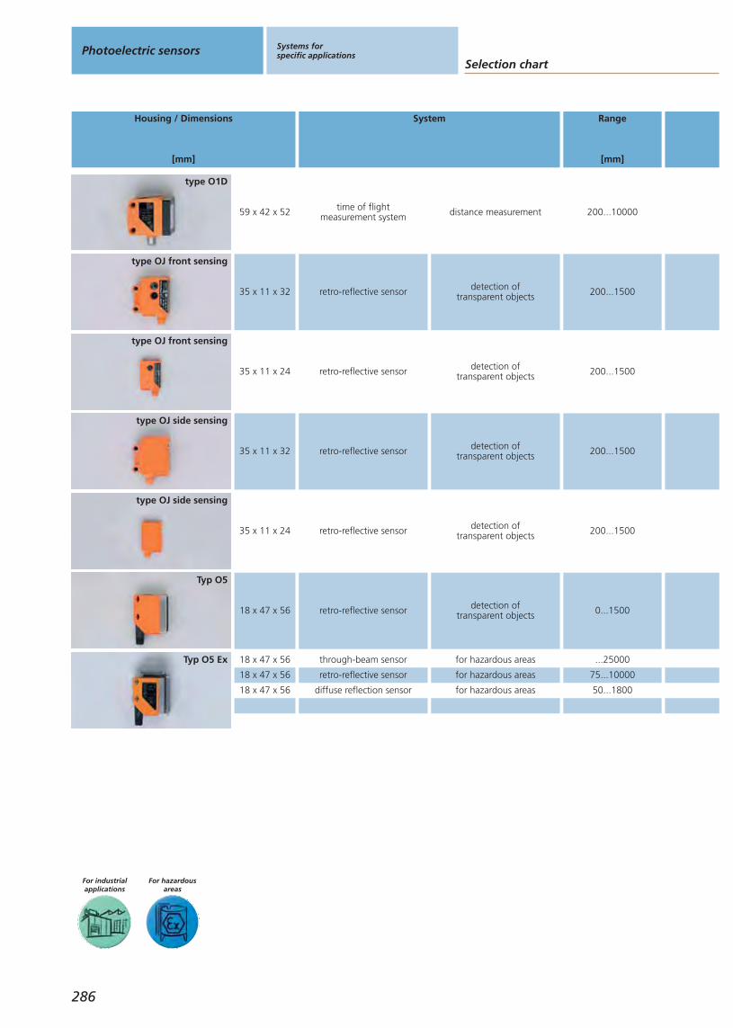
For hazardousareas
For industrialapplications
Selection chartPhotoelectric sensors Systems for
specific applications
Housing / Dimensions
[mm]
System Range
[mm]
286
35 x 11 x 32 retro-reflective sensor detection oftransparent objects 200...1500
type OJ front sensing
35 x 11 x 24 retro-reflective sensor detection oftransparent objects 200...1500
type OJ side sensing
type OJ side sensing
35 x 11 x 24 retro-reflective sensor detection oftransparent objects 200...1500
type OJ front sensing
35 x 11 x 32 retro-reflective sensor detection oftransparent objects 200...1500
59 x 42 x 52 time of flightmeasurement system distance measurement 200...10000
type O1D
18 x 47 x 56 retro-reflective sensor detection oftransparent objects 0...1500
Typ O5
Typ O5 Ex 18 x 47 x 56
18 x 47 x 56
18 x 47 x 56
through-beam sensor for hazardous areas ...25000
retro-reflective sensor for hazardous areas 75...10000
diffuse reflection sensor for hazardous areas 50...1800
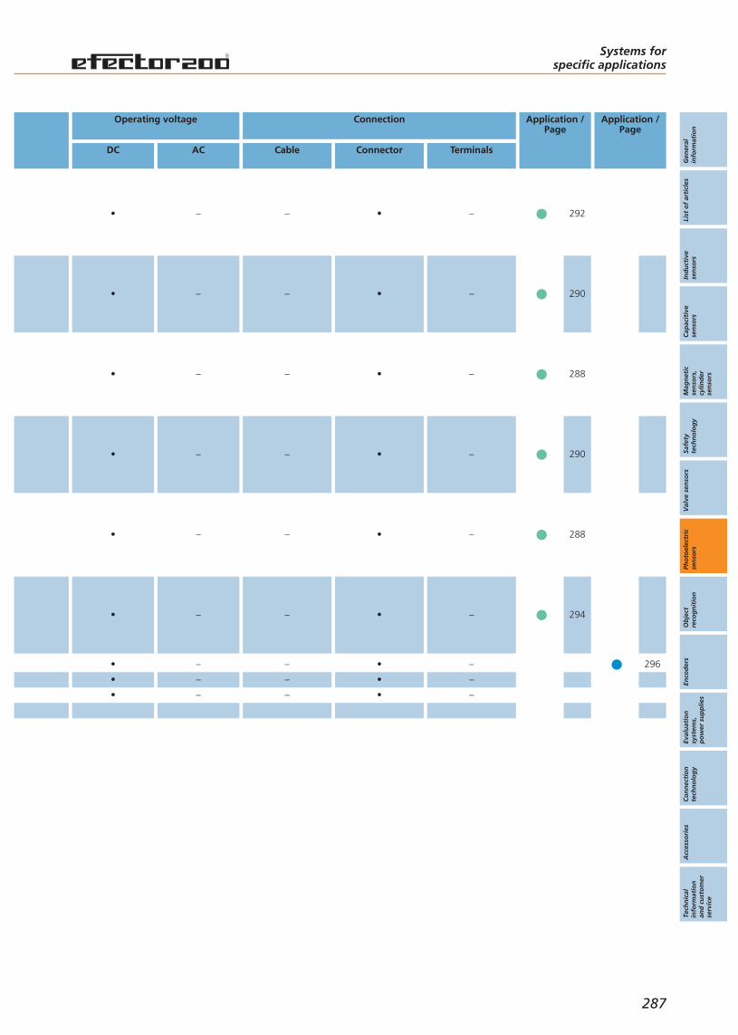
Gen
eral
info
rmat
ion
List
of
arti
cles
Ind
uct
ive
sen
sors
Cap
acit
ive
sen
sors
Mag
net
icse
nso
rs,
cylin
der
sen
sors
Safe
tyte
chn
olo
gy
Val
ve s
enso
rsPh
oto
elec
tric
sen
sors
Ob
ject
reco
gn
itio
nEn
cod
ers
Eval
uat
ion
syst
ems,
po
wer
su
pp
lies
Co
nn
ecti
on
tech
no
log
yA
cces
sori
esTe
chn
ical
info
rmat
ion
and
cu
sto
mer
serv
ice
Systems forspecific applications
Operating voltage
DC AC
Connection
Cable Connector Terminals
Application /Page
Application /Page
287
288
290• – – • –
• – – • –
290• – – • –
288• – – • –
294• – – • –
292• – – • –
296•
•
•
–
–
–
–
–
–
•
•
•
–
–
–
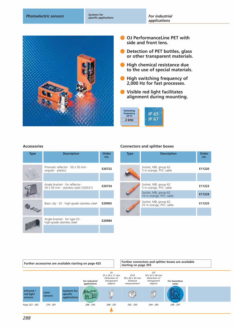
OJ PerformanceLine PET with side and front lens.
Detection of PET bottles, glass or other transparent materials.
High chemical resistance due to the use of special materials.
High switching frequency of 2,000 Hz for fast processes.
Visible red light facilitates alignment during mounting.
Accessories
Type Description Orderno.
Prismatic reflector · 50 x 50 mm · angular · plastics E20722
Angle bracket · for reflector · 50 x 50 mm · stainless steel (320S31) E20724
Basic clip · OJ · high-grade stainless steel E20965
Angle bracket · for type OJ · high-grade stainless steel E20984
Further accessories are available starting on page 425
Connectors and splitter boxes
Type Description Orderno.
Socket, M8, group 625 m orange, PVC cable E11220
Socket, M8, group 625 m orange, PVC cable E11223
Socket, M8, group 6210 m orange, PVC cable E11224
Socket, M8, group 6225 m orange, PVC cable E11225
Further connectors and splitter boxes are availablestarting on page 393
Photoelectric sensors Systems for specific applications For industrial
applications
288
Infrared /red lightsensors
Page 222 - 263
Lasersensors
270 - 281
Systems forspecificapplications
For industrialapplications
288 - 295
OJ35 x 24 x 11 mm
Detection oftransparent
objects
288 - 291
O1D59 x 42 x 52 mm
Distancemeasurement
292 - 293
O518 x 47 x 56 mm
Detection oftransparent
objects
294 - 295
For hazardousareas
296 - 297

Abbreviations
H = light-onD = dark-onH/D = light-on or dark-on programmableH+D = light-on and dark-onRel. = relay output
Type OJLight emission at the front (OJ5085) or on the side (OJ5086)Connection technology: M8 connector
Function Connection1) cable
2) plug M83) Pigtail M12
Output Typeof light
LED
Spot Ø atmax.range[mm]
I0
[mA]
Wiringdiagram
no.
Draw-ingno.
Orderno.
Retro-reflective sensor · Polarisation filter · Range 0.2...1.5 m prismatic reflector 50 x 50 mm (E20722)
2) Group 62 H/D PNP red 64 22 54 1 OJ5085
2) Group 62 H/D PNP red 64 22 54 2 OJ5086
Common technical data
Ub: 10...30 V DCMaterial lens: glassHousing material: ABS; fixture: diecast zinc;LED window: SEPS; pushbutton: SEPSOperating temperature: 0...60 °CProtection: IP 65 / IP 67 IICurrent rating: 200 mAOutput status indication: LED yellowOperating status indication: LED greenFunction check indication: LED red
You can find scale drawings from page 489 You can find details about reflectorsfrom page 433
Systems for specific applications
Gen
eral
info
rmat
ion
List
of
arti
cles
Ind
uct
ive
sen
sors
Cap
acit
ive
sen
sors
Mag
net
icse
nso
rs,
cylin
der
sen
sors
Safe
tyte
chn
olo
gy
Val
ve s
enso
rsPh
oto
elec
tric
sen
sors
Ob
ject
reco
gn
itio
nEn
cod
ers
Eval
uat
ion
syst
ems,
po
wer
su
pp
lies
Co
nn
ecti
on
tech
no
log
yA
cces
sori
esTe
chn
ical
info
rmat
ion
and
cu
sto
mer
serv
ice
289
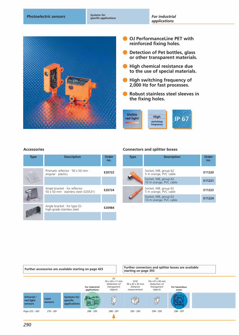
OJ PerformanceLine PET with reinforced fixing holes.
Detection of Pet bottles, glassor other transparent materials.
High chemical resistance dueto the use of special materials.
High switching frequency of2,000 Hz for fast processes.
Robust stainless steel sleeves inthe fixing holes.
Accessories
Type Description Orderno.
Prismatic reflector · 50 x 50 mm · angular · plastics E20722
Angle bracket · for reflector · 50 x 50 mm · stainless steel (320S31) E20724
Angle bracket · for type OJ · high-grade stainless steel E20984
Further accessories are available starting on page 425
Connectors and splitter boxes
Type Description Orderno.
Socket, M8, group 625 m orange, PVC cable E11220
Socket, M8, group 6210 m orange, PVC cable E11221
Socket, M8, group 625 m orange, PVC cable E11223
Socket, M8, group 6210 m orange, PVC cable E11224
Further connectors and splitter boxes are availablestarting on page 393
Photoelectric sensors Systems for specific applications For industrial
applications
290
Infrared /red lightsensors
Page 222 - 263
Lasersensors
270 - 281
Systems forspecificapplications
For industrialapplications
288 - 295
OJ35 x 24 x 11 mm
Detection oftransparent
objects
288 - 291
O1D59 x 42 x 52 mm
Distancemeasurement
292 - 293
O518 x 47 x 56 mm
Detection oftransparent
objects
294 - 295
For hazardousareas
296 - 297
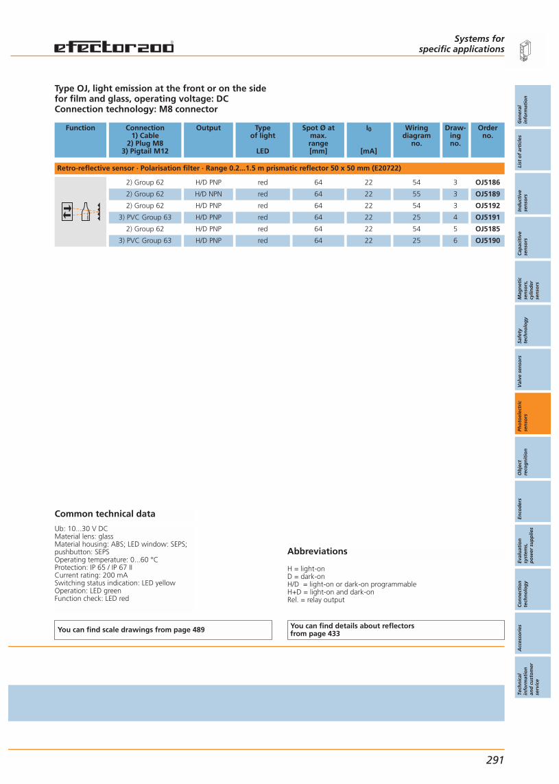
Abbreviations
H = light-onD = dark-onH/D = light-on or dark-on programmableH+D = light-on and dark-onRel. = relay output
Type OJ, light emission at the front or on the side for film and glass, operating voltage: DCConnection technology: M8 connector
Function Connection1) Cable
2) Plug M83) Pigtail M12
Output Typeof light
LED
Spot Ø atmax.range[mm]
I0
[mA]
Wiringdiagram
no.
Draw-ingno.
Orderno.
Retro-reflective sensor · Polarisation filter · Range 0.2...1.5 m prismatic reflector 50 x 50 mm (E20722)
2) Group 62 H/D PNP red 64 22 54 3 OJ5186
2) Group 62 H/D NPN red 64 22 55 3 OJ5189
2) Group 62 H/D PNP red 64 22 54 3 OJ5192
3) PVC Group 63 H/D PNP red 64 22 25 4 OJ5191
2) Group 62 H/D PNP red 64 22 54 5 OJ5185
3) PVC Group 63 H/D PNP red 64 22 25 6 OJ5190
Common technical data
Ub: 10...30 V DCMaterial lens: glassMaterial housing: ABS; LED window: SEPS;pushbutton: SEPSOperating temperature: 0...60 °CProtection: IP 65 / IP 67 IICurrent rating: 200 mASwitching status indication: LED yellowOperation: LED greenFunction check: LED red
You can find scale drawings from page 489 You can find details about reflectorsfrom page 433
Systems for specific applications
Gen
eral
info
rmat
ion
List
of
arti
cles
Ind
uct
ive
sen
sors
Cap
acit
ive
sen
sors
Mag
net
icse
nso
rs,
cylin
der
sen
sors
Safe
tyte
chn
olo
gy
Val
ve s
enso
rsPh
oto
elec
tric
sen
sors
Ob
ject
reco
gn
itio
nEn
cod
ers
Eval
uat
ion
syst
ems,
po
wer
su
pp
lies
Co
nn
ecti
on
tech
no
log
yA
cces
sori
esTe
chn
ical
info
rmat
ion
and
cu
sto
mer
serv
ice
291
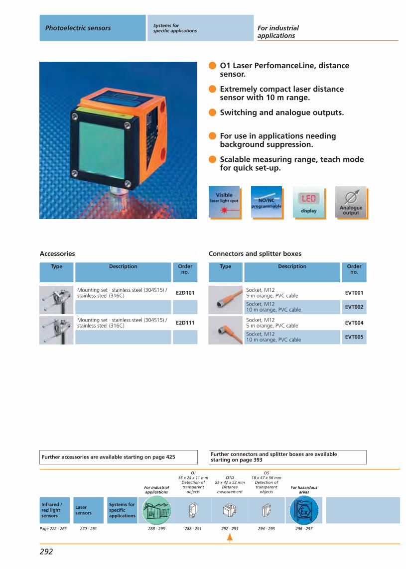
O1 Laser PerfomanceLine, distancesensor.
Extremely compact laser distancesensor with 10 m range.
Switching and analogue outputs.
For use in applications needingbackground suppression.
Scalable measuring range, teach modefor quick set-up.
Accessories
Type Description Orderno.
Mounting set · stainless steel (304S15) /stainless steel (316C) E2D101
Mounting set · stainless steel (304S15) /stainless steel (316C) E2D111
Further accessories are available starting on page 425
Connectors and splitter boxes
Type Description Orderno.
Socket, M125 m orange, PVC cable EVT001
Socket, M1210 m orange, PVC cable EVT002
Socket, M125 m orange, PVC cable EVT004
Socket, M1210 m orange, PVC cable EVT005
Further connectors and splitter boxes are availablestarting on page 393
Photoelectric sensors Systems for specific applications For industrial
applications
292
Infrared /red lightsensors
Page 222 - 263
Lasersensors
270 - 281
Systems forspecificapplications
For industrialapplications
288 - 295
OJ35 x 24 x 11 mm
Detection oftransparent
objects
288 - 291
O1D59 x 42 x 52 mm
Distancemeasurement
292 - 293
O518 x 47 x 56 mm
Detection oftransparent
objects
294 - 295
For hazardousareas
296 - 297
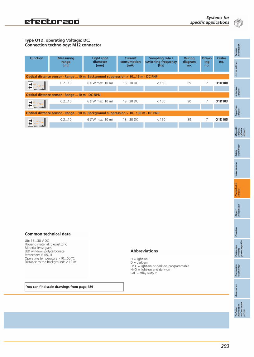
Abbreviations
H = light-onD = dark-onH/D = light-on or dark-on programmableH+D = light-on and dark-onRel. = relay output
Type O1D, operating Voltage: DC, Connection technology: M12 connector
Function Measuringrange
[m]
Light spotdiameter
[mm]
Currentconsumption
[mA]
Sampling rate /switching frequency
[Hz]
Wiringdiagram
no.
Draw-ingno.
Orderno.
Optical distance sensor · Range ...10 m, Background suppression > 10...19 m · DC PNP
0.2...10 6 (TW max. 10 m) 18...30 DC < 150 89 7 O1D100
Optical distance sensor · Range ...10 m · DC NPN
0.2...10 6 (TW max. 10 m) 18...30 DC < 150 90 7 O1D103
Optical distance sensor · Range ...10 m, Background suppression > 10...100 m · DC PNP
0.2...10 6 (TW max. 10 m) 18...30 DC < 150 89 7 O1D105
Common technical data
Ub: 18...30 V DCHousing material: diecast zincMaterial lens: glassLED window: polycarbonateProtection: IP 65, IIIOperating temperature: -10...60 °CDistance to the background: < 19 m
You can find scale drawings from page 489
Systems for specific applications
Gen
eral
info
rmat
ion
List
of
arti
cles
Ind
uct
ive
sen
sors
Cap
acit
ive
sen
sors
Mag
net
icse
nso
rs,
cylin
der
sen
sors
Safe
tyte
chn
olo
gy
Val
ve s
enso
rsPh
oto
elec
tric
sen
sors
Ob
ject
reco
gn
itio
nEn
cod
ers
Eval
uat
ion
syst
ems,
po
wer
su
pp
lies
Co
nn
ecti
on
tech
no
log
yA
cces
sori
esTe
chn
ical
info
rmat
ion
and
cu
sto
mer
serv
ice
293

O5 PerformanceLine PET.
Detection of glass, film, PET bottles and transparent packaging.
Easy setting: the new teach mode.
Switch point adjustment with soiling indication.
High switching frequency of 2,000 Hz for fast processes.
Accessories
Type Description Orderno.
Mounting set · Clamp mounting · st. steel (320S31), clamp: diecast zinc E21211
Mounting set · Clamp mounting · st. steel (320S31), clamp: h.-g. st. steel E21212
Head cap screw · M10 x 120 mm · ISO4762 (DIN 912) · screw : steel galvanised E21213
Head cap screw · M10 x 120 mm · ISO4762 (DIN 912) · screw: h.-g. st. steel E21214
Mounting sleeve · AlZnMgCu1.5 F51/52(3.4365) E21114
Prismatic reflector · 50 x 50 mm · angular · plastics E20722
Further accessories are available starting on page 425
Connectors and splitter boxes
Type Description Orderno.
Socket, M12, group 72 m black, PUR cable EVC001
Socket, M12, group 75 m black, PUR cable EVC002
Socket, M12, group 72 m black, PUR cable EVC004
Socket, M12, group 75 m black, PUR cable EVC005
Further connectors and splitter boxes are availablestarting on page 393
Photoelectric sensors Systems for specific applications For industrial
applications
294
Infrared /red lightsensors
Page 222 - 263
Lasersensors
270 - 281
Systems forspecificapplications
For industrialapplications
288 - 295
OJ35 x 24 x 11 mm
Detection oftransparent
objects
288 - 291
O1D59 x 42 x 52 mm
Distancemeasurement
292 - 293
O518 x 47 x 56 mm
Detection oftransparent
objects
294 - 295
For hazardousareas
296 - 297

Abbreviations
H = light-onD = dark-onH/D = light-on or dark-on programmableH+D = light-on and dark-onRel. = relay output
Type O5 for glass, film, PET bottles, light emission on the side, operating voltage: DCConnection technology: M12 connector
Function Connection1) Cable
2) Plug M83) Pigtail M12
Output Typeof light
LED
Spot Ø atmax.range[mm]
I0
[mA]
Wiringdiagram
no.
Draw-ingno.
Orderno.
Retro-reflective sensor · Polarisation filter · Range 0...1.5 m prismatic reflector 50 x 50 mm (E20722) · Connector groups 11, 12
2) Group 11, 12 H/D PNP/NPN red 40 mm 50 91 8 O5G500
You can find scale drawings from page 489 You can find details about reflectorsfrom page 433
Systems for specific applications
Gen
eral
info
rmat
ion
List
of
arti
cles
Ind
uct
ive
sen
sors
Cap
acit
ive
sen
sors
Mag
net
icse
nso
rs,
cylin
der
sen
sors
Safe
tyte
chn
olo
gy
Val
ve s
enso
rsPh
oto
elec
tric
sen
sors
Ob
ject
reco
gn
itio
nEn
cod
ers
Eval
uat
ion
syst
ems,
po
wer
su
pp
lies
Co
nn
ecti
on
tech
no
log
yA
cces
sori
esTe
chn
ical
info
rmat
ion
and
cu
sto
mer
serv
ice
295

Tried-and-tested photoelectric sensors now for hazardous areas.
Long ranges.
Highest precision with background suppression.
Quick setting by means of the new teach method.
Universal mounting using system components, mounting accessories.
Accessories
Type Description Orderno.
Prismatic reflector · 50 x 50 mm · angular · plastics E20744
Prismatic reflector · 95 x 95 mm · angular · plastics E20454
Angle bracket · for type O5 · stainless steel (320S31) E21087
Clamp · Ø 12 mm; M10 · clamp: diecast zinc E20716
Clamp · Ø 12 mm; M10 · clamp: stainless steel (316C) E20946
Cube · M10 · diecast zinc E20951
Further accessories are available starting on page 425
Connectors and splitter boxes
Type Description Orderno.
Socket, M122 m black, PUR cable EVC001
Socket, M125 m black, PUR cable EVC002
Socket, M122 m black, PUR cable EVC004
Socket, M125 m black, PUR cable EVC005
Securing clip E11532
Further connectors and splitter boxes are availablestarting on page 393
Photoelectric sensors Systems for specific applications
For hazardous areas
296
Infrared /red lightsensors
Page 222 - 263
Lasersensors
270 - 281
Systems forspecificapplications
For industrialapplications
288 - 295
OJ35 x 24 x 11 mm
Detection oftransparent
objects
288 - 291
O1D59 x 42 x 52 mm
Distancemeasurement
292 - 293
O518 x 47 x 56 mm
Detection oftransparent
objects
294 - 295
For hazardousareas
296 - 297
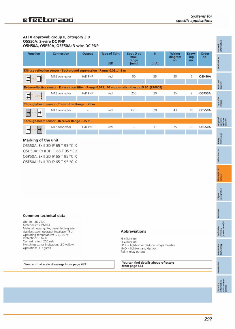
Abbreviations
H = light-onD = dark-onH/D = light-on or dark-on programmableH+D = light-on and dark-onRel. = relay output
ATEX approval: group II, category 3 DO5S50A: 2-wire DC PNPO5H50A, O5P50A, O5E50A: 3-wire DC PNP
Function Connection Output Type of light
LED
Spot Ø atmax.range[mm]
I0
[mA]
Wiringdiagram
no.
Draw-ingno.
Orderno.
Diffuse reflection sensor · Background suppression · Range 0.05...1.8 m
M12 connector H/D PNP red 50 25 25 9 O5H50A
Retro-reflective sensor · Polarisation filter · Range 0.075...10 m prismatic reflector Ø 80 (E20005)
M12 connector H/D PNP red 250 20 25 9 O5P50A
Through-beam sensor · Transmitter Range ...25 m
M12 connector – red 625 20 43 10 O5S50A
Through-beam sensor · Receiver Range ...25 m
M12 connector H/D PNP red – 11 25 9 O5E50A
Common technical data
Ub: 10...36 V DCMaterial lens: PMMAMaterial housing: PA; bezel: high-gradestainless steel; operator interface: TPUOperating temperature: -25...60 °CProtection: IP 67 IICurrent rating: 200 mASwitching status indication: LED yellowOperation: LED green
You can find scale drawings from page 489 You can find details about reflectorsfrom page 433
Systems for specific applications
Gen
eral
info
rmat
ion
List
of
arti
cles
Ind
uct
ive
sen
sors
Cap
acit
ive
sen
sors
Mag
net
icse
nso
rs,
cylin
der
sen
sors
Safe
tyte
chn
olo
gy
Val
ve s
enso
rsPh
oto
elec
tric
sen
sors
Ob
ject
reco
gn
itio
nEn
cod
ers
Eval
uat
ion
syst
ems,
po
wer
su
pp
lies
Co
nn
ecti
on
tech
no
log
yA
cces
sori
esTe
chn
ical
info
rmat
ion
and
cu
sto
mer
serv
ice
297
Marking of the unitO5S50A: Ex II 3D IP 65 T 95 °C XO5H50A: Ex II 3D IP 65 T 95 °C XO5P50A: Ex II 3D IP 65 T 95 °C XO5E50A: Ex II 3D IP 65 T 95 °C X


Gen
eral
info
rmat
ion
List
of
arti
cles
Ind
uct
ive
sen
sors
Cap
acit
ive
sen
sors
Mag
net
icse
nso
rs,
cylin
der
sen
sors
Safe
tyte
chn
olo
gy
Val
ve s
enso
rsPh
oto
elec
tric
sen
sors
Ob
ject
reco
gn
itio
nEn
cod
ers
Eval
uat
ion
syst
ems,
po
wer
su
pp
lies
Co
nn
ecti
on
tech
no
log
yA
cces
sori
esTe
chn
ical
info
rmat
ion
and
cu
sto
mer
serv
ice
Object recognition
299
Image sensors
System descriptionSelection chart
Image sensorsfor industrial applicationsUniversal application
Rectangular housing O2D and lighting elements
300 - 302304 - 305
306 - 309

System description
Visit our website: www.ifm-electronic.com
Object recognition Image sensors
300
IntroductionIn assembly and handling technology, object recognition systems are an inte-gral part in assembly monitoring. The 100 % testing before, during or afterthe individual assembly steps prevents complex and cost-intensive reworkingor rejection of material or workpieces.
Image sensorThe efector dualis image sensor solves tasks like monitoring of presence,completeness and position, quality control as well as sorting tasks. With itsdimensions of only 60 x 42 x 53 mm it sets new standards and is thus suita-ble for use in applications with very limited mounting space. Furthermore,the industrially compatible mounting and wiring technology enables easyand quick process connection even in demanding applications.
The direct object detection functions like a photo comparison. If triggered byan internal or external trigger pulse, the efector dualis image sensor cap-tures an image of the object. Following the settings defined by the user thesensor recognises certain structures and contours by the grey shades in theimage. These structures and contours generate a geometric shape which theimage sensor compares to the shapes that the user has taught before bymeans of the original workpiece. If the detected geometric shape lies withinthe determined tolerances (contour, orientation and match), the result isconsidered positive. The realisation of a geometric shape using the imagedata allows quick and flexible object recognition. Here, it is now also possibleto compare the detected shape with various taught shapes. In addition, theimage can also be divided into individual shapes which are then separatelychecked for presence. This allows recognition if part of an object is missingduring completeness monitoring. Via a freely definable process interfacethese useful information can be made available to the user for process opti-misation.
Direct object detection
The workpiece moves between the image sensor and lighting element. Justwhen the workpiece is in the image zone of the image sensor a trigger produces a flash signal and the lighting element flashes briefly. The imagesensor captures the silhouette of the workpiece and compares the contourof the captured silhouette with the geometric shape stored in the unit. If adeviation from the stored reference contour is detected, the image sensortransmits a switching signal for example to the external controller to rejectthe faulty workpiece. The efector dualis image sensor can operate with anytype of light (e.g. white light, red light, infra-red light). ifm electronic offersalso suitable lighting elements either with visible red light or with invisibleinfra-red light.
The backlighting method
Image sensorefector dualis.
The efector dualisimage sensor reliably detectsthe fixing hole onthe joint flangeby means of abacklight.
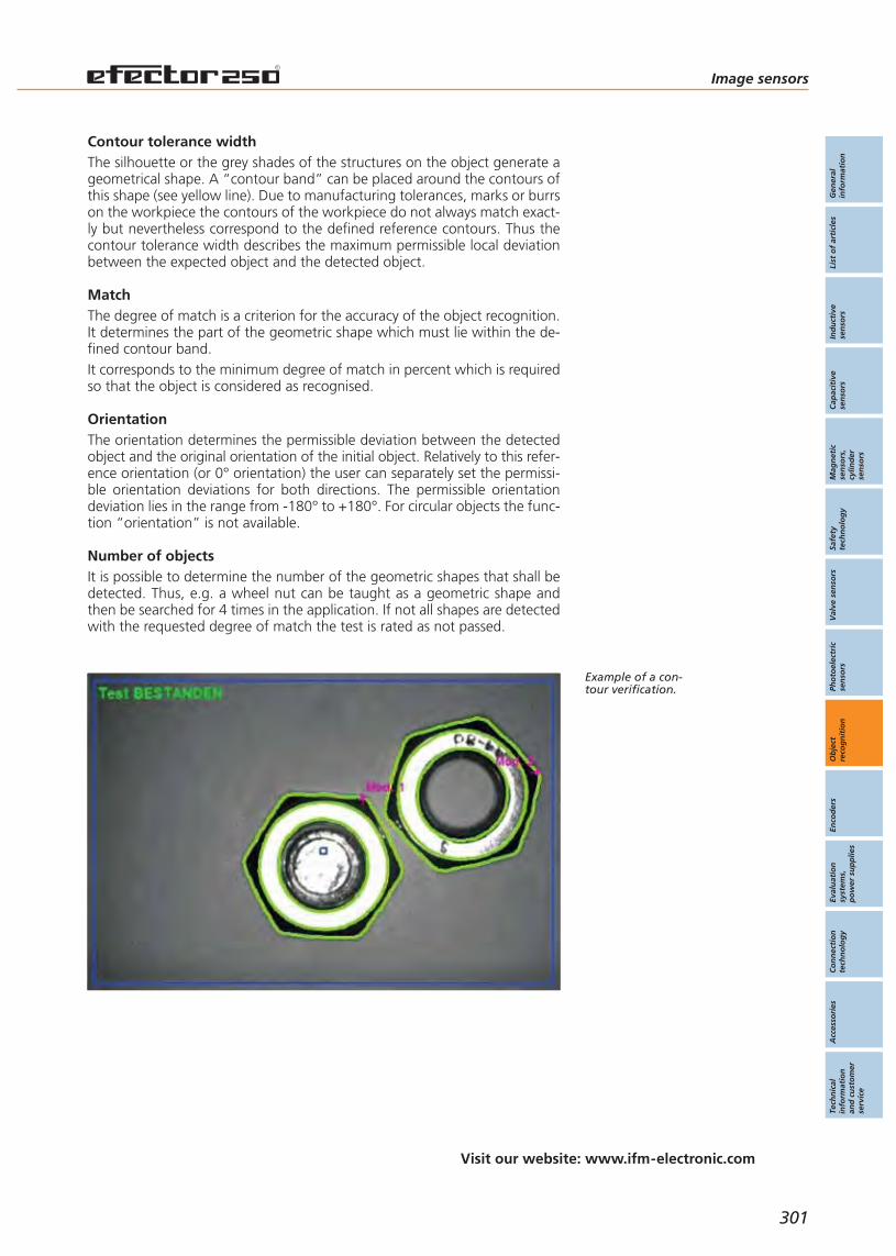
Gen
eral
info
rmat
ion
List
of
arti
cles
Ind
uct
ive
sen
sors
Cap
acit
ive
sen
sors
Mag
net
icse
nso
rs,
cylin
der
sen
sors
Safe
tyte
chn
olo
gy
Val
ve s
enso
rsPh
oto
elec
tric
sen
sors
Ob
ject
reco
gn
itio
nEn
cod
ers
Eval
uat
ion
syst
ems,
po
wer
su
pp
lies
Co
nn
ecti
on
tech
no
log
yA
cces
sori
esTe
chn
ical
info
rmat
ion
and
cu
sto
mer
serv
ice
Image sensors
Visit our website: www.ifm-electronic.com
301
Example of a con-tour verification.
MatchThe degree of match is a criterion for the accuracy of the object recognition.It determines the part of the geometric shape which must lie within the de-fined contour band.It corresponds to the minimum degree of match in percent which is requiredso that the object is considered as recognised.
OrientationThe orientation determines the permissible deviation between the detectedobject and the original orientation of the initial object. Relatively to this refer-ence orientation (or 0° orientation) the user can separately set the permissi-ble orientation deviations for both directions. The permissible orientationdeviation lies in the range from -180° to +180°. For circular objects the func-tion “orientation” is not available.
Number of objectsIt is possible to determine the number of the geometric shapes that shall bedetected. Thus, e.g. a wheel nut can be taught as a geometric shape andthen be searched for 4 times in the application. If not all shapes are detectedwith the requested degree of match the test is rated as not passed.
The silhouette or the grey shades of the structures on the object generate ageometrical shape. A “contour band” can be placed around the contours ofthis shape (see yellow line). Due to manufacturing tolerances, marks or burrson the workpiece the contours of the workpiece do not always match exact-ly but nevertheless correspond to the defined reference contours. Thus thecontour tolerance width describes the maximum permissible local deviationbetween the expected object and the detected object.
Contour tolerance width
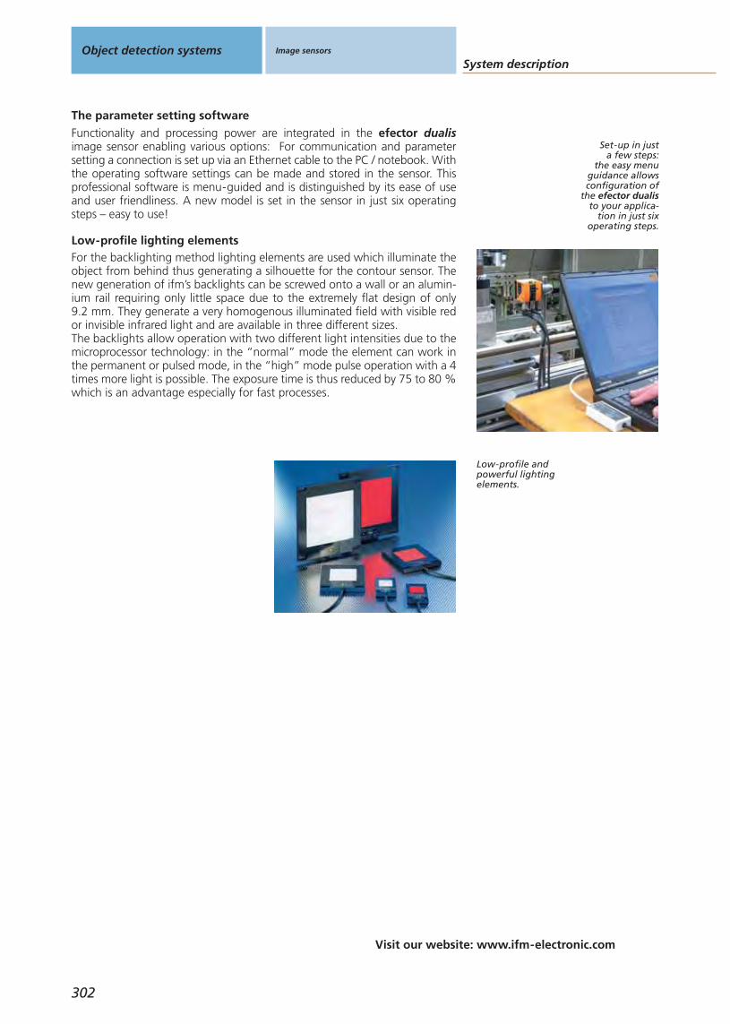
302
System description
Visit our website: www.ifm-electronic.com
Object detection systems Image sensors
Functionality and processing power are integrated in the efector dualisimage sensor enabling various options: For communication and parametersetting a connection is set up via an Ethernet cable to the PC / notebook. Withthe operating software settings can be made and stored in the sensor. Thisprofessional software is menu-guided and is distinguished by its ease of useand user friendliness. A new model is set in the sensor in just six operatingsteps – easy to use!
The parameter setting software
For the backlighting method lighting elements are used which illuminate theobject from behind thus generating a silhouette for the contour sensor. Thenew generation of ifm’s backlights can be screwed onto a wall or an alumin-ium rail requiring only little space due to the extremely flat design of only 9.2 mm. They generate a very homogenous illuminated field with visible redor invisible infrared light and are available in three different sizes.The backlights allow operation with two different light intensities due to themicroprocessor technology: in the “normal” mode the element can work inthe permanent or pulsed mode, in the “high” mode pulse operation with a 4times more light is possible. The exposure time is thus reduced by 75 to 80 %which is an advantage especially for fast processes.
Low-profile lighting elements
Low-profile andpowerful lightingelements.
Set-up in just a few steps:
the easy menuguidance allowsconfiguration of
the efector dualisto your applica-
tion in just sixoperating steps.
Gen
eral
info
rmat
ion
List
of
arti
cles
Ind
uct
ive
sen
sors
Cap
acit
ive
sen
sors
Mag
net
icse
nso
rs,
cylin
der
sen
sors
Safe
tyte
chn
olo
gy
Val
ve s
enso
rsPh
oto
elec
tric
sen
sors
Ob
ject
reco
gn
itio
nEn
cod
ers
Eval
uat
ion
syst
ems,
po
wer
su
pp
lies
Co
nn
ecti
on
tech
no
log
yA
cces
sori
esTe
chn
ical
info
rmat
ion
and
cu
sto
mer
serv
ice
303
Image sensors

Selection chartObject recognition Image sensors
For industrialapplications
Housing / Dimensions
[mm]
System Range
[mm]
304
60 x 42 x 44 contour and positionverification 2D ...2.000
type O2D
Gen
eral
info
rmat
ion
List
of
arti
cles
Ind
uct
ive
sen
sors
Cap
acit
ive
sen
sors
Mag
net
icse
nso
rs,
cylin
der
sen
sors
Safe
tyte
chn
olo
gy
Val
ve s
enso
rsPh
oto
elec
tric
sen
sors
Ob
ject
reco
gn
itio
nEn
cod
ers
Eval
uat
ion
syst
ems,
po
wer
su
pp
lies
Co
nn
ecti
on
tech
no
log
yA
cces
sori
esTe
chn
ical
info
rmat
ion
and
cu
sto
mer
serv
ice
Image sensors
Operating voltage
DC AC
Connection
Cable Connector Terminals
Application /Page
Application /Page
305
• – – • – 306

Object recognition for assembly and manufact. tasks and quality control.
Stand-alone unit with integratedlighting.
Compact and robust design.
Easy parameter setting.
Integrated Ethernet interface.
Accessories
Type Description Orderno.
Mounting set · clamp mounting · stainl.steel (304S15) / stainl. steel (316C) E2D110
Mounting set · clamp mounting · stainl.steel (304S15) / stainl. steel (316C) E2D112
Operating software · O2D E2D200
Connection piece · Ø 20 mm · stainless steel (316S12) E21076
Further accessories are available starting on page 425
Connectors and splitter boxes
Type Description Orderno.
Socket, M12, group 172 m black, PUR cable E11231
Socket, M12, group 175 m black, PUR cable E11232
Socket, M122 m black, PUR cable E11950
Socket, M125 m black, PUR cable E11807
Socket, M12, group 1710 m black, PUR cable E11311
Jumper, M12 plug / RJ45 plug2 m green, PUR cable E11898
Further connectors and splitter boxes are availablestarting on page 393
Object recognition Image sensors For industrialapplications
306
Imagesensors
Page
For industrialapplications
O2D60 x 42 x 44 mm
and lightingelements
306 - 309

Type O2D for contour and position recognitionOperating voltage: DCConnection technology: M12 connector
Function Dimensions
[mm]
Max. fieldof view size
[mm]
Angle ofaperture
[°]
Detectiorate
[Hz]
Motion speed(max.)[ms/s]
Wiringdiagram
no.
Draw-ingno.
Orderno.
60 x 42 x 44 640 x 480 5.5 10 1 92 1 O2D220
60 x 42 x 44 1280 x 960 8.3 10 1 92 1 O2D222
You can find scale drawings from page 491
Image sensors
Gen
eral
info
rmat
ion
List
of
arti
cles
Ind
uct
ive
sen
sors
Cap
acit
ive
sen
sors
Mag
net
icse
nso
rs,
cylin
der
sen
sors
Safe
tyte
chn
olo
gy
Val
ve s
enso
rsPh
oto
elec
tric
sen
sors
Ob
ject
reco
gn
itio
nEn
cod
ers
Eval
uat
ion
syst
ems,
po
wer
su
pp
lies
Co
nn
ecti
on
tech
no
log
yA
cces
sori
esTe
chn
ical
info
rmat
ion
and
cu
sto
mer
serv
ice
307
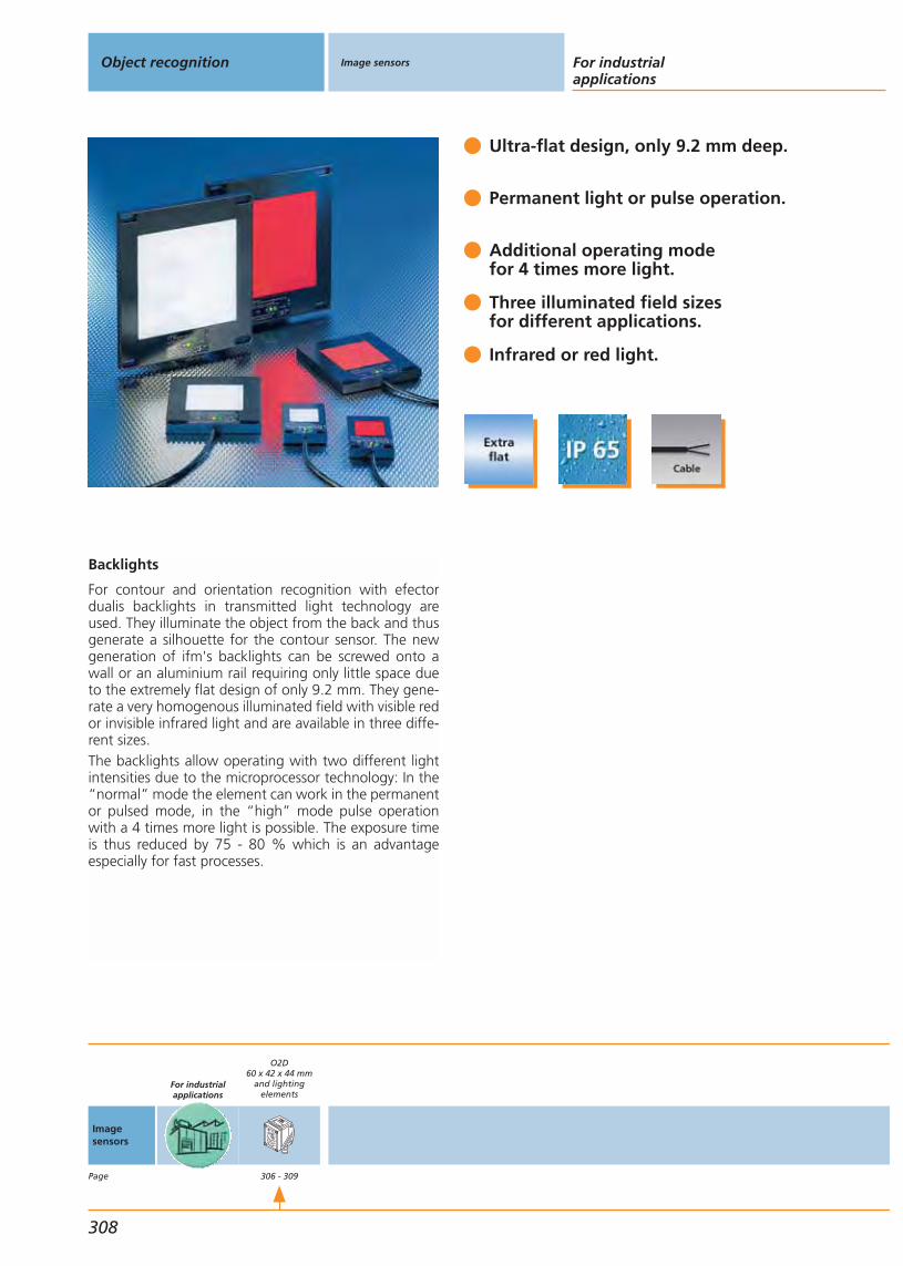
Ultra-flat design, only 9.2 mm deep.
Permanent light or pulse operation.
Additional operating mode for 4 times more light.
Three illuminated field sizesfor different applications.
Infrared or red light.
Backlights
For contour and orientation recognition with efectordualis backlights in transmitted light technology areused. They illuminate the object from the back and thusgenerate a silhouette for the contour sensor. The newgeneration of ifm's backlights can be screwed onto awall or an aluminium rail requiring only little space dueto the extremely flat design of only 9.2 mm. They gene-rate a very homogenous illuminated field with visible redor invisible infrared light and are available in three diffe-rent sizes.The backlights allow operating with two different lightintensities due to the microprocessor technology: In the“normal” mode the element can work in the permanentor pulsed mode, in the “high” mode pulse operationwith a 4 times more light is possible. The exposure timeis thus reduced by 75 - 80 % which is an advantageespecially for fast processes.
Object recognition Image sensors For industrialapplications
308
Imagesensors
Page
For industrialapplications
O2D60 x 42 x 44 mm
and lightingelements
306 - 309

Supply voltage: DCConnection technology: cable versions
Function Dimensions
[mm]
Illuminatedarea
[mm]
I0normal light
intensity[mA]
I0high lightintensity *
[mA]
Wiringdiagram
no.
Draw-ingno.
Orderno.
Transmitter red light 660 nm
66.5 x 33.4 x 9.2 25 x 25 50 25 59 2 O2D900
103 x 81 x 9.2 50 x 50 200 100 59 3 O2D902
156 x 133 x 9.2 100 x 100 450 250 59 4 O2D904
Transmitter infrared 880 nm
66.5 x 33.4 x 9.2 25 x 25 50 25 59 2 O2D901
103 x 81 x 9.2 50 x 50 200 100 59 3 O2D903
156 x 133 x 9.2 100 x 100 450 250 59 4 O2D905
Transmitter infrared 880 nm · Connector groups 7, 8
66.5 x 33.4 x 9.2 25 x 25 50 25 60 2 O2D906
103 x 81 x 9.2 50 x 50 200 100 60 3 O2D907
156 x 133 x 9.2 100 x 100 450 250 60 4 O2D908
Common technical data
Ub: 24 V DCMaterial housing: aluminiumMaterial lens: PMMAOperating temperature: 0...50 °CProtection: IP 65 / IIIConnection: PUR cable / 2 m; 4 x 0.34 mmTemperature protectionTrigger: external, 24 V PNP to IEC 61131-1Operating status indication: 3 x LED (green, yellow, red)* High light intensity: max. pulse length 50 ms, max. mark-to-space ratio: 1:10
You can find scale drawings from page 491
Image sensors
Gen
eral
info
rmat
ion
List
of
arti
cles
Ind
uct
ive
sen
sors
Cap
acit
ive
sen
sors
Mag
net
icse
nso
rs,
cylin
der
sen
sors
Safe
tyte
chn
olo
gy
Val
ve s
enso
rsPh
oto
elec
tric
sen
sors
Ob
ject
reco
gn
itio
nEn
cod
ers
Eval
uat
ion
syst
ems,
po
wer
su
pp
lies
Co
nn
ecti
on
tech
no
log
yA
cces
sori
esTe
chn
ical
info
rmat
ion
and
cu
sto
mer
serv
ice
309


Gen
eral
info
rmat
ion
List
of
arti
cles
Ind
uct
ive
sen
sors
Cap
acit
ive
sen
sors
Mag
net
icse
nso
rs,
cylin
der
sen
sors
Safe
tyte
chn
olo
gy
Val
ve s
enso
rsPh
oto
elec
tric
sen
sors
Ob
ject
reco
gn
itio
nEn
cod
ers
Eval
uat
ion
syst
ems,
po
wer
su
pp
lies
Co
nn
ecti
on
tech
no
log
yA
cces
sori
esTe
chn
ical
info
rmat
ion
and
cu
sto
mer
serv
ice
311
Encoders
Incremental encodersfor industrial applications
Absolute encodersfor industrial applications
Incremental encoders,absolute encoders
System descriptionSelection chart
Universal applicationHousing RBHousing RUHousing RVHousing RAHousing RO
Housing RN parallelHousing RM SSIHousing RM Profibus
312 - 315316 - 317
318 - 319320 - 321322 - 323324 - 325326 - 327
328 - 329330 - 331332 - 333
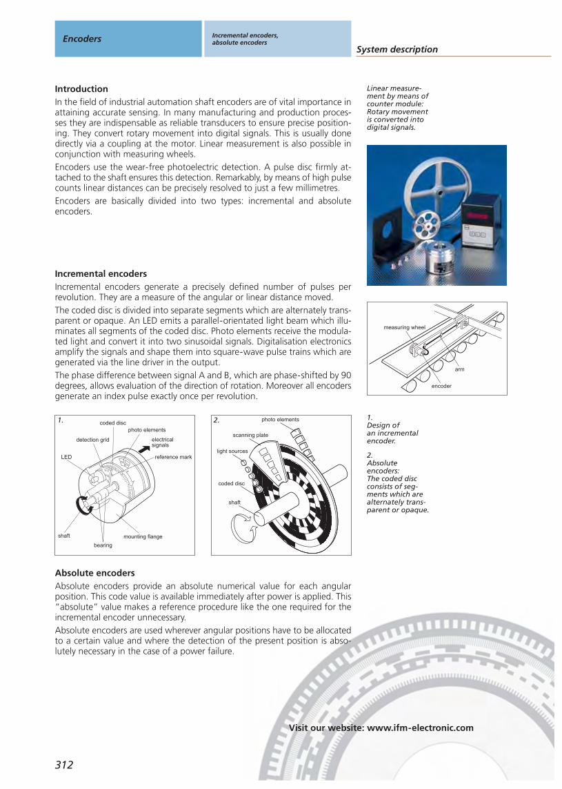
System description
Visit our website: www.ifm-electronic.com
Encoders Incremental encoders,absolute encoders
312
IntroductionIn the field of industrial automation shaft encoders are of vital importance inattaining accurate sensing. In many manufacturing and production proces-ses they are indispensable as reliable transducers to ensure precise position-ing. They convert rotary movement into digital signals. This is usually donedirectly via a coupling at the motor. Linear measurement is also possible inconjunction with measuring wheels.Encoders use the wear-free photoelectric detection. A pulse disc firmly at-tached to the shaft ensures this detection. Remarkably, by means of high pulsecounts linear distances can be precisely resolved to just a few millimetres.Encoders are basically divided into two types: incremental and absoluteencoders.
Incremental encoders generate a precisely defined number of pulses perrevolution. They are a measure of the angular or linear distance moved.The coded disc is divided into separate segments which are alternately trans-parent or opaque. An LED emits a parallel-orientated light beam which illu-minates all segments of the coded disc. Photo elements receive the modula-ted light and convert it into two sinusoidal signals. Digitalisation electronicsamplify the signals and shape them into square-wave pulse trains which aregenerated via the line driver in the output.The phase difference between signal A and B, which are phase-shifted by 90degrees, allows evaluation of the direction of rotation. Moreover all encodersgenerate an index pulse exactly once per revolution.
Incremental encoders
measuring wheel
encoder
arm
photo elementscoded disc
detection grid
LED
shaft
bearing
mounting flange
electricalsignals
reference mark
photo elements
scanning plate
light sources
coded disc
shaft
Absolute encoders provide an absolute numerical value for each angularposition. This code value is available immediately after power is applied. This“absolute” value makes a reference procedure like the one required for theincremental encoder unnecessary.Absolute encoders are used wherever angular positions have to be allocatedto a certain value and where the detection of the present position is abso-lutely necessary in the case of a power failure.
Absolute encoders
1.Design ofan incrementalencoder.
1. 2.
2.Absoluteencoders:The coded discconsists of seg-ments which arealternately trans-parent or opaque.
Linear measure-ment by means ofcounter module:Rotary movementis converted intodigital signals.
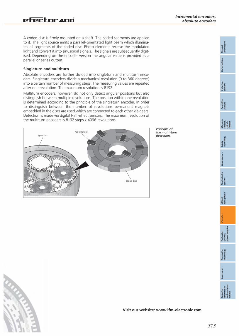
Gen
eral
info
rmat
ion
List
of
arti
cles
Ind
uct
ive
sen
sors
Cap
acit
ive
sen
sors
Mag
net
icse
nso
rs,
cylin
der
sen
sors
Safe
tyte
chn
olo
gy
Val
ve s
enso
rsPh
oto
elec
tric
sen
sors
Ob
ject
reco
gn
itio
nEn
cod
ers
Eval
uat
ion
syst
ems,
po
wer
su
pp
lies
Co
nn
ecti
on
tech
no
log
yA
cces
sori
esTe
chn
ical
info
rmat
ion
and
cu
sto
mer
serv
ice
Incremental encoders,absolute encoders
Visit our website: www.ifm-electronic.com
313
gear box
hall element
coded disc
Absolute encoders are further divided into singleturn and multiturn enco-ders. Singleturn encoders divide a mechanical revolution (0 to 360 degrees)into a certain number of measuring steps. The measuring values are repeatedafter one revolution. The maximum resolution is 8192.Multiturn encoders, however, do not only detect angular positions but alsodistinguish between multiple revolutions. The position within one revolutionis determined according to the principle of the singleturn encoder. In orderto distinguish between the number of revolutions permanent magnetsembedded in the discs are used which are connected to each other via gears.Detection is made via digital Hall-effect sensors. The maximum resolution ofthe multiturn encoders is 8192 steps x 4096 revolutions.
Singleturn and multiturn
Principle ofthe multi-turndetection.
A coded disc is firmly mounted on a shaft. The coded segments are appliedto it. The light source emits a parallel-orientated light beam which illumina-tes all segments of the coded disc. Photo elements receive the modulatedlight and convert it into sinusoidal signals. The signals are subsequently digit-ised. Depending on the encoder version the angular value is provided as aparallel or series output.

System description
Visit our website: www.ifm-electronic.com
Encoders Incremental encoders,absolute encoders
314
Profibus encoderDue to the implementation of an interface for PROFIBUS-DP this encodercan be directly connected to the bus. The advantage: there is no further costfor the user for additional controller hardware. He simply needs to set theslave address and the encoder is a PROFIBUS-DP participant.The encoders operate to the requirement profile of the Profibus user organi-sation and support the device class 2. Thus immediate and decentralisedprocessing of many controller functions can be performed in the encoder:the resolution of 25 bits is freely scaleable and the direction of rotation forrising code values can be programmed. This is useful for machines with dif-ferent directions of rotation of the axes.Further controller features are the limit switch function, the detection ofmovements and the preset value function. Thus the zero point of the encod-er is conveniently adapted to the mechanical zero point of the installation. Incase of a fault the units transfer diagnostic messages and warnings. Thusmachine downtimes and related cost are reduced to a minimum.
Controllerintegrated:Multiturn enco-der with integra-ted PROFIBUS-DPinterface.
CodeThe rotating coded disc of absolute encoders is encoded in the so-called“Gray” code. This code proceeds by one step, i.e. when going from onenumber to the following only one single bit changes. This means an addition-al reliability factor.As opposed to the binary code where each bit combination is allotted a cer-tain decimal number the individual bits in the Gray code do not correspondto a numerical value. The bit combination read is converted into a binarycode by a suitable code converter (in the PLC) and can then be further pro-cessed.The genuine Gray code, i.e. the one fully using the number of bits, countsfrom zero to ... 2n–1 (n is the number of bits).Sometimes, however, resolutions are requested which cannot be represent-ed by a power to two such as the value 360. To represent this number in theGray code on the coded disc a trick is used:For a required resolution the Gray code for the next highest number (whichmust be a power of 2) is taken as a basis, but only the mid-section of thecode is used, i.e. the excess codes at the beginning and at the end are de-leted. This ensures that for each increment no more than one step will changeeven when counting past zero. This type of code is called Gray excess code. Gray excess code:
These bitcombinations
allow the use ofall resolutionswhich can be
divided by two.
D C B A
8 4 2 1
0123456789
101112131415
binary code
0123456789
101112131415
Gray code
D C B A
0123456789
10 Gray excesscode 3
none
D C B A
none
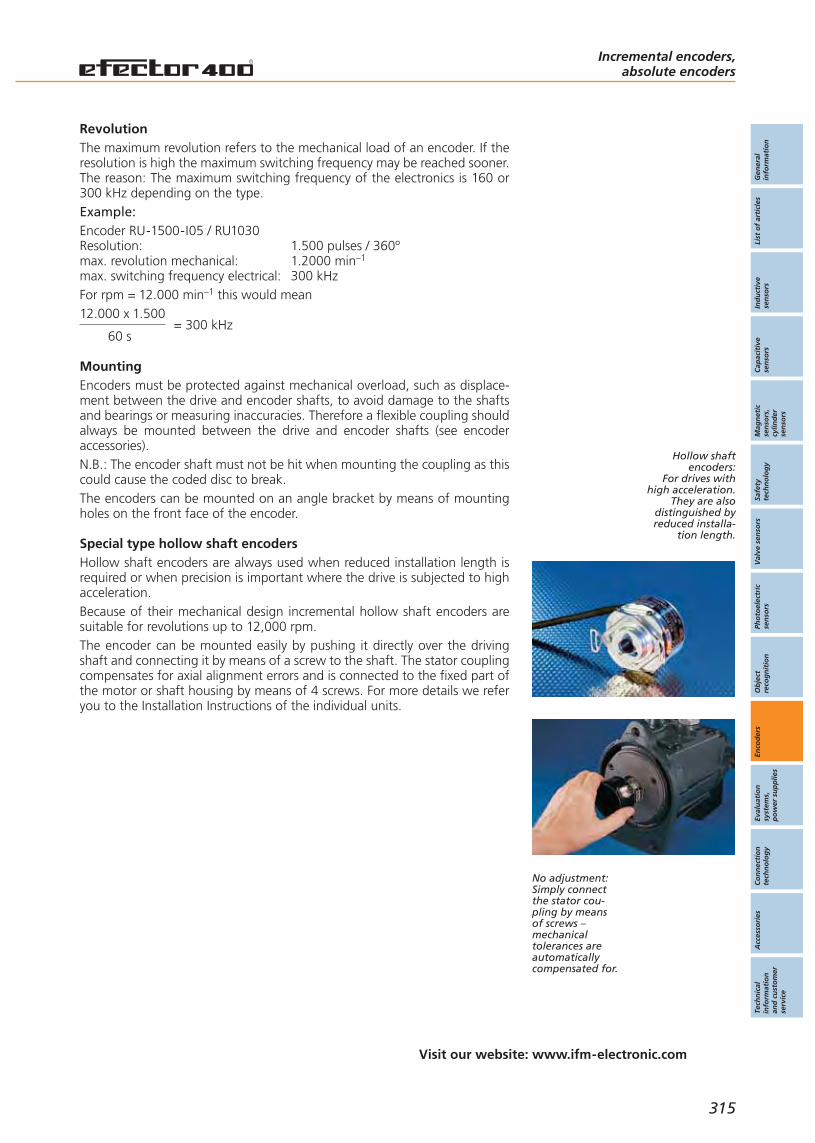
Incremental encoders,absolute encoders
315
Visit our website: www.ifm-electronic.com
Gen
eral
info
rmat
ion
List
of
arti
cles
Ind
uct
ive
sen
sors
Cap
acit
ive
sen
sors
Mag
net
icse
nso
rs,
cylin
der
sen
sors
Safe
tyte
chn
olo
gy
Val
ve s
enso
rsPh
oto
elec
tric
sen
sors
Ob
ject
reco
gn
itio
nEn
cod
ers
Eval
uat
ion
syst
ems,
po
wer
su
pp
lies
Co
nn
ecti
on
tech
no
log
yA
cces
sori
esTe
chn
ical
info
rmat
ion
and
cu
sto
mer
serv
ice
RevolutionThe maximum revolution refers to the mechanical load of an encoder. If theresolution is high the maximum switching frequency may be reached sooner.The reason: The maximum switching frequency of the electronics is 160 or300 kHz depending on the type.Example:Encoder RU-1500-I05 / RU1030Resolution: 1.500 pulses / 360ºmax. revolution mechanical: 1.2000 min–1
max. switching frequency electrical: 300 kHzFor rpm = 12.000 min–1 this would mean12.000 x 1.500
= 300 kHz60 s
MountingEncoders must be protected against mechanical overload, such as displace-ment between the drive and encoder shafts, to avoid damage to the shaftsand bearings or measuring inaccuracies. Therefore a flexible coupling shouldalways be mounted between the drive and encoder shafts (see encoderaccessories).N.B.: The encoder shaft must not be hit when mounting the coupling as thiscould cause the coded disc to break.The encoders can be mounted on an angle bracket by means of mountingholes on the front face of the encoder.
Special type hollow shaft encodersHollow shaft encoders are always used when reduced installation length isrequired or when precision is important where the drive is subjected to highacceleration.Because of their mechanical design incremental hollow shaft encoders aresuitable for revolutions up to 12,000 rpm.The encoder can be mounted easily by pushing it directly over the drivingshaft and connecting it by means of a screw to the shaft. The stator couplingcompensates for axial alignment errors and is connected to the fixed part ofthe motor or shaft housing by means of 4 screws. For more details we referyou to the Installation Instructions of the individual units.
No adjustment:Simply connectthe stator cou-pling by meansof screws –mechanicaltolerances areautomaticallycompensated for.
Hollow shaftencoders:
For drives withhigh acceleration.
They are alsodistinguished byreduced installa-
tion length.

Selection chartEncoders Incremental encoders,
absolute encoders
Incremental encoders
For industrialapplications
Housing / Dimensions
[mm]
Operatingvoltage
[V]
Shaft Ø[mm]
ResolutionPulses
Solidshaft
Hollowshaft
from to
Application /Page
316
Ø 35L = 45 – 6 10 1000 5 DC /
10...30 DC
Ø 35L = 40 6 – 5 1000 5 DC /
10...30 DC
Ø 58L = 46 6 – 48 10000 5 DC /
10...30 DC
Ø 58L = 46 10 – 50 5000 5 DC /
10...30 DC
Ø 58L = 46 – 10
12 100 5000 5 DC /10...30 DC
type RA
type RB
type RU
type RV
type RO
324
318
320
322
326
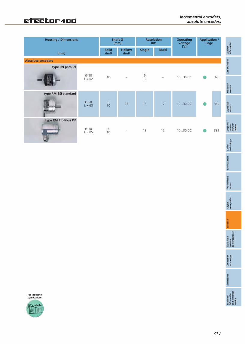
For industrialapplications
34Absolute encoders
Housing / Dimensions
[mm]
Operatingvoltage
[V]
Shaft Ø[mm]
ResolutionBits
Solidshaft
Hollowshaft
Single Multi
Application /Page
Gen
eral
info
rmat
ion
List
of
arti
cles
Ind
uct
ive
sen
sors
Cap
acit
ive
sen
sors
Mag
net
icse
nso
rs,
cylin
der
sen
sors
Safe
tyte
chn
olo
gy
Val
ve s
enso
rsPh
oto
elec
tric
sen
sors
Ob
ject
reco
gn
itio
nEn
cod
ers
Eval
uat
ion
syst
ems,
po
wer
su
pp
lies
Co
nn
ecti
on
tech
no
log
yA
cces
sori
esTe
chn
ical
info
rmat
ion
and
cu
sto
mer
serv
ice
Incremental encoders,absolute encoders
317
Ø 58L = 63
610 12 13 12 10...30 DC
Ø 58L = 85
610 – 13 12 10...30 DC
Ø 58L = 62 10 – 9
12 – 10...30 DC
type RN parallel
type RM SSI standard
type RM Profibus DP
328
330
332
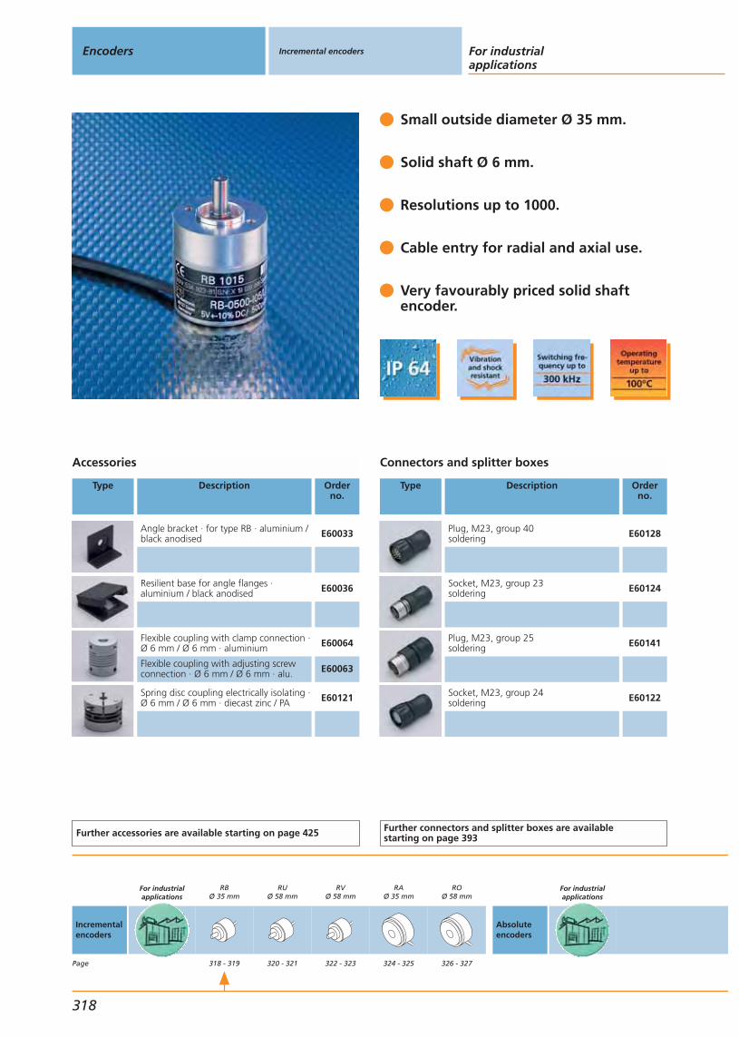
Small outside diameter Ø 35 mm.
Solid shaft Ø 6 mm.
Resolutions up to 1000.
Cable entry for radial and axial use.
Very favourably priced solid shaftencoder.
Accessories
Type Description Orderno.
Angle bracket · for type RB · aluminium /black anodised E60033
Resilient base for angle flanges ·aluminium / black anodised E60036
Flexible coupling with clamp connection ·Ø 6 mm / Ø 6 mm · aluminium E60064
Flexible coupling with adjusting screwconnection · Ø 6 mm / Ø 6 mm · alu. E60063
Spring disc coupling electrically isolating ·Ø 6 mm / Ø 6 mm · diecast zinc / PA E60121
Further accessories are available starting on page 425
Connectors and splitter boxes
Type Description Orderno.
Plug, M23, group 40soldering E60128
Socket, M23, group 23soldering E60124
Plug, M23, group 25soldering E60141
Socket, M23, group 24soldering E60122
Further connectors and splitter boxes are availablestarting on page 393
Encoders Incremental encoders For industrialapplications
318
Incrementalencoders
Page
For industrialapplications
RBØ 35 mm
318 - 319
RUØ 58 mm
320 - 321
RVØ 58 mm
322 - 323
RAØ 35 mm
324 - 325
ROØ 58 mm
326 - 327
Absoluteencoders
For industrialapplications

Incremental encoder type RBwith solid shaft Ø 6 mm.
Resolution Ub
[V]
f
[kHz]
Iload
[mA]
Operatingtemperature
[°C]
Wiringdiagram
Draw-ingno.
Orderno.
Cable 2 m · Output HTL-output 50 mA, short-circuit protected < 1 min
5 10...30 160 50 -40...70 1 1 RB6044
10 10...30 160 50 -40...70 1 1 RB6001
20 10...30 160 50 -40...70 1 1 RB6002
25 10...30 160 50 -40...70 1 1 RB6003
30 10...30 160 50 -40...70 1 1 RB6004
50 10...30 160 50 -40...70 1 1 RB6005
60 10...30 160 50 -40...70 1 1 RB6006
100 10...30 160 50 -40...70 1 1 RB6007
125 10...30 160 50 -40...70 1 1 RB6009
150 10...30 160 50 -40...70 1 1 RB6010
200 10...30 160 50 -40...70 1 1 RB6011
250 10...30 160 50 -40...70 1 1 RB6012
360 10...30 160 50 -40...70 1 1 RB6013
400 10...30 160 50 -40...70 1 1 RB6014
500 10...30 160 50 -40...70 1 1 RB6015
600 10...30 160 50 -40...70 1 1 RB6016
1000 10...30 160 50 -40...70 1 1 RB6029
Common technical data
Current consumption: 95 (max. 150) mAMax. perm. rpm / mech.: 10000 1/minStarting torque: < 1 (20 °C) NcmVibration resistance: 10 (55 - 2000 Hz) gShock resistance: 100 (6 ms) gMax. shaft load: axial 5 N, radial 10 N, at the shaft endConnection: PUR cable, 2 m
You can find scale drawings from page 492
RN (parallel)Ø 58 mm
328 - 329
RM (SSI)Ø 58 mm
330 - 331
RM (Profibus)Ø 58 mm
332 - 333
Incremental encoders
Gen
eral
info
rmat
ion
List
of
arti
cles
Ind
uct
ive
sen
sors
Cap
acit
ive
sen
sors
Mag
net
icse
nso
rs,
cylin
der
sen
sors
Safe
tyte
chn
olo
gy
Val
ve s
enso
rsPh
oto
elec
tric
sen
sors
Ob
ject
reco
gn
itio
nEn
cod
ers
Eval
uat
ion
syst
ems,
po
wer
su
pp
lies
Co
nn
ecti
on
tech
no
log
yA
cces
sori
esTe
chn
ical
info
rmat
ion
and
cu
sto
mer
serv
ice
319
Wiring
white/green: 0Vbrown/green: L+brown: Agreen: 0V Agrey: Bpink: 0V Bred: 0 indexblack: 0V 0 indexlilac: error (inv.)screen: housing
Wiring no. 1
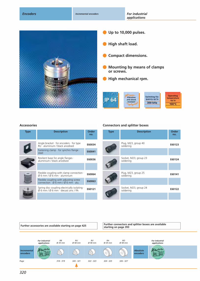
Up to 10,000 pulses.
High shaft load.
Compact dimensions.
Mounting by means of clampsor screws.
High mechanical rpm.
Accessories
Type Description Orderno.
Angle bracket · for encoders · for typeRU · aluminium / black anodised E60034
Fastening clamp · for synchro flange ·steel E60041
Resilient base for angle flanges ·aluminium / black anodised E60036
Flexible coupling with clamp connection ·Ø 6 mm / Ø 6 mm · aluminium E60064
Flexible coupling with adjusting screwconnection · Ø 6 mm / Ø 6 mm · alu. E60063
Spring disc coupling electrically isolating ·Ø 6 mm / Ø 6 mm · diecast zinc / PA E60121
Further accessories are available starting on page 425
Connectors and splitter boxes
Type Description Orderno.
Plug, M23, group 40soldering E60123
Socket, M23, group 23soldering E60124
Plug, M23, group 25soldering E60141
Socket, M23, group 24soldering E60122
Further connectors and splitter boxes are availablestarting on page 393
Encoders Incremental encoders For industrialapplications
320
Incrementalencoders
Page
For industrialapplications
RBØ 35 mm
318 - 319
RUØ 58 mm
320 - 321
RVØ 58 mm
322 - 323
RAØ 35 mm
324 - 325
ROØ 58 mm
326 - 327
Absoluteencoders
For industrialapplications

Further encoders on request.
Incremental encoder type RUwith solid shaft Ø 6 mmSynchro flange
Resolution Ub
[V]
f
[kHz]
Iload
[mA]
Operatingtemperature
[°C]
Wiringdiagram
Draw-ingno.
Orderno.
Cable 2 m · Output TTL output 20 mA
500 5 300 20 -40...100 1 2 RU1016
1000 5 300 20 -40...100 1 2 RU1024
1024 5 300 20 -40...100 1 2 RU1025
2000 5 300 20 -40...100 1 2 RU1033
2500 5 300 20 -40...100 1 2 RU1036
Cable 2 m · Output HTL-output 50 mA, short-circuit protected < 1 min
100 10...30 300 50 -40...100 1 2 RU6003
250 10...30 300 50 -40...100 1 2 RU6010
360 10...30 300 50 -40...100 1 2 RU6013
500 10...30 300 50 -40...100 1 2 RU6016
1000 10...30 300 50 -40...100 1 2 RU6024
1024 10...30 300 50 -40...100 1 2 RU6025
2000 10...30 300 50 -40...100 1 2 RU6033
2500 10...30 300 50 -40...100 1 2 RU6036
3600 10...30 300 50 -40...100 1 2 RU6040
5000 10...30 300 50 -40...100 1 2 RU6045
10000 10...30 300 50 -40...100 1 2 RU6052
Common technical data
Current consumption: < 150 mAMax. perm. rpm / mech.: 16000 1/minStarting torque: < 1 (20 °C) NcmVibration resistance: 30 g (55...2000 Hz)Shock resistance: 200 g (6 ms)Max. shaft load: axial 10 N, radial 20 N, at the shaft endConnection: PUR cable, 2 m
You can find scale drawings from page 492
RN (parallel)Ø 58 mm
328 - 329
RM (SSI)Ø 58 mm
330 - 331
RM (Profibus)Ø 58 mm
332 - 333
Incremental encoders
Gen
eral
info
rmat
ion
List
of
arti
cles
Ind
uct
ive
sen
sors
Cap
acit
ive
sen
sors
Mag
net
icse
nso
rs,
cylin
der
sen
sors
Safe
tyte
chn
olo
gy
Val
ve s
enso
rsPh
oto
elec
tric
sen
sors
Ob
ject
reco
gn
itio
nEn
cod
ers
Eval
uat
ion
syst
ems,
po
wer
su
pp
lies
Co
nn
ecti
on
tech
no
log
yA
cces
sori
esTe
chn
ical
info
rmat
ion
and
cu
sto
mer
serv
ice
321
Wiring
brown: Agreen: A (inv.)grey: Bpink: B (inv.)red: 0 indexblack: 0 index (inv.)blue: L+ (sensor)white: 0V (sensor)brown/green: L+ (Up)white/green: 0V (Un)lilac: error (inv.)screen: housing
Wiring no. 1

Robust design.
High shaft load.
Long centring collar Ø 36 mm.
Resolution up to 5,000 pulses.
Mounting by clamping ringor screws.
Accessories
Type Description Orderno.
Angle bracket · for encoders · for typeRV · aluminium / black anodised E60035
Resilient base for angle flanges ·aluminium / black anodised E60036
Flexible coupling with clamp connection ·Ø 6 mm / Ø 10 mm · aluminium E60066
Flexible coupling with adjusting screwconnection · Ø 6 mm / Ø 10 mm · alu. E60028
Spring disc coupling electrically isolating ·Ø 6 mm / Ø 10 mm · diecast zinc / PA E60117
Further accessories are available starting on page 425
Connectors and splitter boxes
Type Description Orderno.
Plug, M23, group 40soldering E60123
Socket, M23, group 23soldering E60124
Plug, M23, group 25soldering E60141
Socket, M23, group 24soldering E60122
Further connectors and splitter boxes are availablestarting on page 393
Encoders Incremental encoders For industrialapplications
322
Incrementalencoders
Page
For industrialapplications
RBØ 35 mm
318 - 319
RUØ 58 mm
320 - 321
RVØ 58 mm
322 - 323
RAØ 35 mm
324 - 325
ROØ 58 mm
326 - 327
Absoluteencoders
For industrialapplications

Further encoders on request.
Incremental encoder type RVwith solid shaft Ø 10 mm with recessed surfaceClamp flange
Resolution Ub
[V]
f
[kHz]
Iload
[mA]
Operatingtemperature
[°C]
Wiringdiagram
Draw-ingno.
Orderno.
Cable 2 m · Output TTL output 20 mA
500 5 300 20 -40...100 1 3 RV1016
1000 5 300 20 -40...100 1 3 RV1024
1024 5 300 20 -40...100 1 3 RV1025
2000 5 300 20 -40...100 1 3 RV1033
2500 5 300 20 -40...100 1 3 RV1036
5000 5 300 20 -40...100 1 3 RV1051
Cable 2 m · Output HTL-output 50 mA, short-circuit protected < 1 min
50 10...30 300 50 -40...100 1 3 RV6001
100 10...30 300 50 -40...100 1 3 RV6003
200 10...30 300 50 -40...100 1 3 RV6009
250 10...30 300 50 -40...100 1 3 RV6010
360 10...30 300 50 -40...100 1 3 RV6013
500 10...30 300 50 -40...100 1 3 RV6016
600 10...30 300 50 -40...100 1 3 RV6018
1000 10...30 300 50 -40...100 1 3 RV6024
1024 10...30 300 50 -40...100 1 3 RV6025
1250 10...30 300 50 -40...100 1 3 RV6028
2000 10...30 300 50 -40...100 1 3 RV6033
2048 10...30 300 50 -40...100 1 3 RV6034
2500 10...30 300 50 -40...100 1 3 RV6036
3600 10...30 300 50 -40...100 1 3 RV6040
5000 10...30 300 50 -40...100 1 3 RV6100
Common technical data
Current consumption: < 150 mAMax. perm. rpm / mech.: 12000 1/minStarting torque: < 1 (20 °C) NcmVibration resistance: 30 g (55...2000 Hz)Shock resistance: 200 g (6 ms)Max. shaft load: axial 10 N, radial 20 N, at the shaft endConnection: PUR cable, 2 m
You can find scale drawings from page 492
RN (parallel)Ø 58 mm
328 - 329
RM (SSI)Ø 58 mm
330 - 331
RM (Profibus)Ø 58 mm
332 - 333
Incremental encoders
Gen
eral
info
rmat
ion
List
of
arti
cles
Ind
uct
ive
sen
sors
Cap
acit
ive
sen
sors
Mag
net
icse
nso
rs,
cylin
der
sen
sors
Safe
tyte
chn
olo
gy
Val
ve s
enso
rsPh
oto
elec
tric
sen
sors
Ob
ject
reco
gn
itio
nEn
cod
ers
Eval
uat
ion
syst
ems,
po
wer
su
pp
lies
Co
nn
ecti
on
tech
no
log
yA
cces
sori
esTe
chn
ical
info
rmat
ion
and
cu
sto
mer
serv
ice
323
Wiring
brown: Agreen: A (inv.)grey: Bpink: B (inv.)red: 0 indexblack: 0 index (inv.)blue: L+ (sensor)white: 0V (sensor)brown/green: L+ (Up)white/green: 0V (Un)lilac: error (inv.)screen: housing
Wiring no. 1

Mounting:
The incremental shaft encoders with stator coupling aremounted without any further mounting accessories. Theencoder is pushed onto the rotating shaft and connec-ted to the shaft at the rotor by means of screws orclamps.The stator coupling is then fixed to the non-rotating partas torque bracket.
Small outside diameter Ø 35 mm.
Hollow shaft opento one side Ø 6 mm.
Resolutions up to 1000.
Cable entry for radial and axial use.
Excellent price / performance ratio.
Connectors and splitter boxes
Type Description Orderno.
Plug, M23, group 40soldering E60128
Socket, M23, group 23soldering E60124
Plug, M23, group 25soldering E60141
Socket, M23, group 24soldering E60122
Further connectors and splitter boxes are availablestarting on page 393
Encoders Incremental encoders For industrialapplications
324
Incrementalencoders
Page
For industrialapplications
RBØ 35 mm
318 - 319
RUØ 58 mm
320 - 321
RVØ 58 mm
322 - 323
RAØ 35 mm
324 - 325
ROØ 58 mm
326 - 327
Absoluteencoders
For industrialapplications
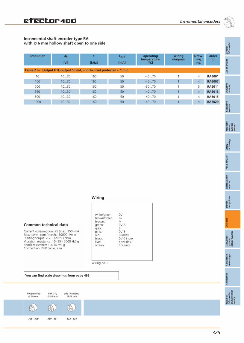
Incremental shaft encoder type RAwith Ø 6 mm hollow shaft open to one side
Resolution Ub
[V]
f
[kHz]
Iload
[mA]
Operatingtemperature
[°C]
Wiringdiagram
Draw-ingno.
Orderno.
Cable 2 m · Output HTL-output 50 mA, short-circuit protected < 1 min
10 10...30 160 50 -40...70 1 4 RA6001
100 10...30 160 50 -40...70 1 4 RA6007
200 10...30 160 50 -30...70 1 5 RA6011
360 10...30 160 50 -40...70 1 4 RA6013
500 10...30 160 50 -40...70 1 4 RA6015
1000 10...30 160 50 -40...70 1 4 RA6029
Common technical data
Current consumption: 95 (max. 150) mAMax. perm. rpm / mech.: 10000 1/minStarting torque: < 2,5 (20 °C) NcmVibration resistance: 10 (55 - 2000 Hz) gShock resistance: 100 (6 ms) gConnection: PUR cable, 2 m
You can find scale drawings from page 492
RN (parallel)Ø 58 mm
328 - 329
RM (SSI)Ø 58 mm
330 - 331
RM (Profibus)Ø 58 mm
332 - 333
Incremental encoders
Gen
eral
info
rmat
ion
List
of
arti
cles
Ind
uct
ive
sen
sors
Cap
acit
ive
sen
sors
Mag
net
icse
nso
rs,
cylin
der
sen
sors
Safe
tyte
chn
olo
gy
Val
ve s
enso
rsPh
oto
elec
tric
sen
sors
Ob
ject
reco
gn
itio
nEn
cod
ers
Eval
uat
ion
syst
ems,
po
wer
su
pp
lies
Co
nn
ecti
on
tech
no
log
yA
cces
sori
esTe
chn
ical
info
rmat
ion
and
cu
sto
mer
serv
ice
325
Wiring
white/green: 0Vbrown/green: L+brown: Agreen: 0V Agrey: Bpink: 0V Bred: 0 indexblack: 0V 0 indexlilac: error (inv.)screen: housing
Wiring no. 1
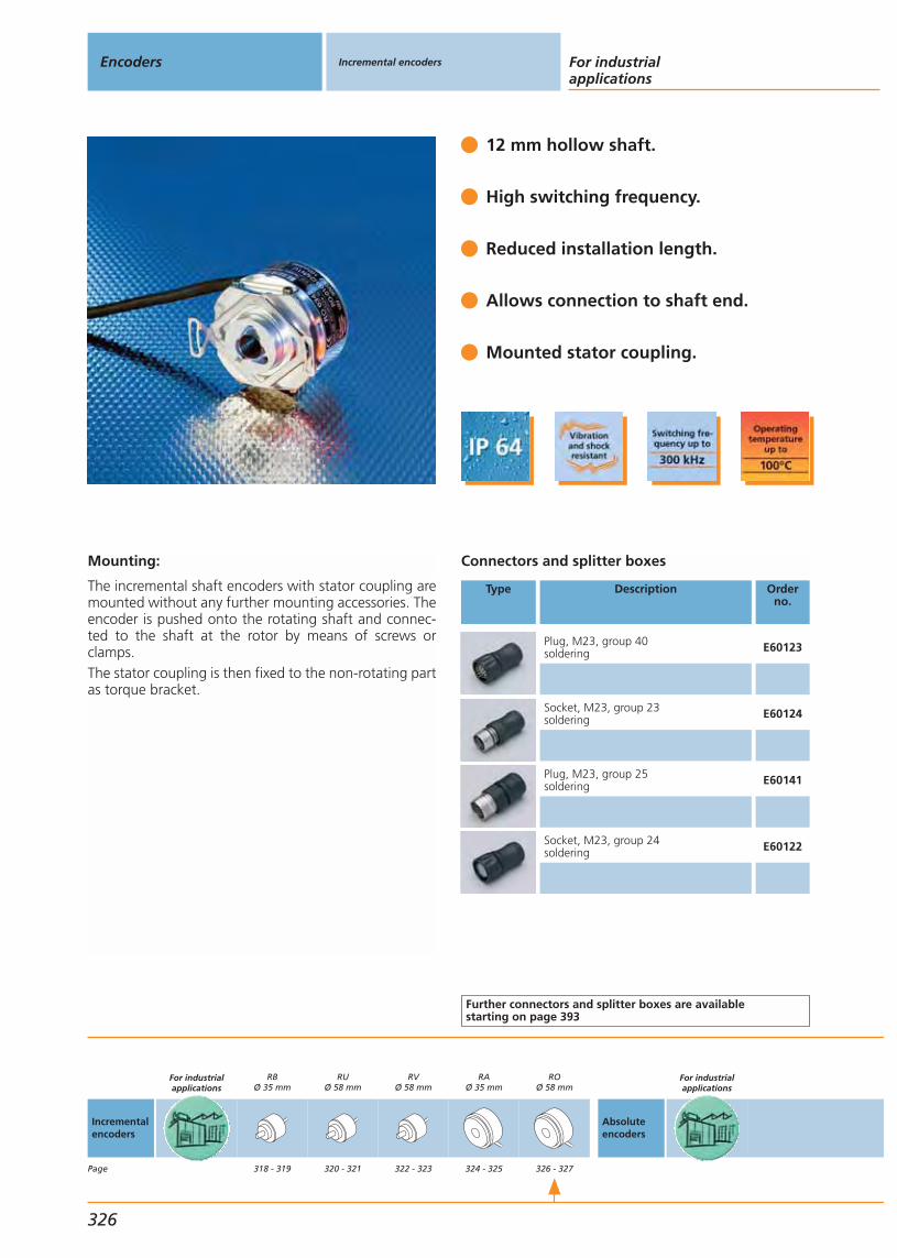
Mounting:
The incremental shaft encoders with stator coupling aremounted without any further mounting accessories. Theencoder is pushed onto the rotating shaft and connec-ted to the shaft at the rotor by means of screws orclamps.The stator coupling is then fixed to the non-rotating partas torque bracket.
12 mm hollow shaft.
High switching frequency.
Reduced installation length.
Allows connection to shaft end.
Mounted stator coupling.
Connectors and splitter boxes
Type Description Orderno.
Plug, M23, group 40soldering E60123
Socket, M23, group 23soldering E60124
Plug, M23, group 25soldering E60141
Socket, M23, group 24soldering E60122
Further connectors and splitter boxes are availablestarting on page 393
Encoders Incremental encoders For industrialapplications
326
Incrementalencoders
Page
For industrialapplications
RBØ 35 mm
318 - 319
RUØ 58 mm
320 - 321
RVØ 58 mm
322 - 323
RAØ 35 mm
324 - 325
ROØ 58 mm
326 - 327
Absoluteencoders
For industrialapplications
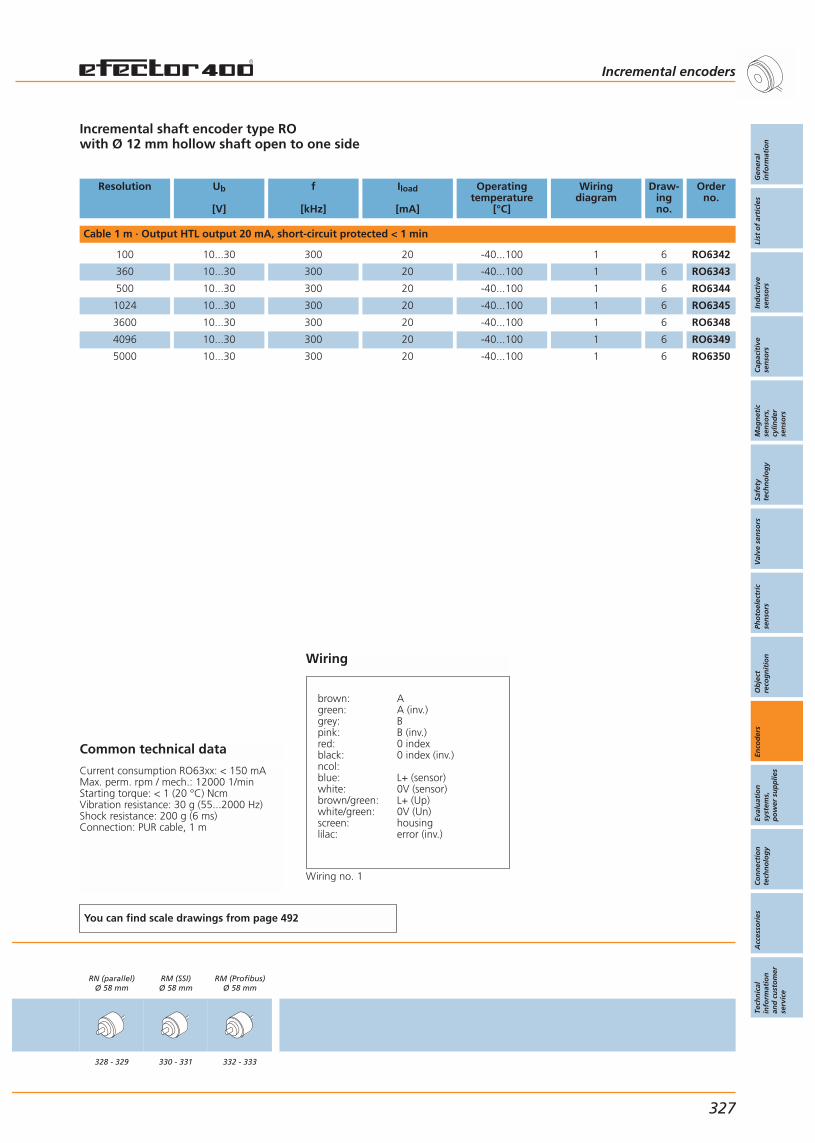
Incremental shaft encoder type ROwith Ø 12 mm hollow shaft open to one side
Resolution Ub
[V]
f
[kHz]
Iload
[mA]
Operatingtemperature
[°C]
Wiringdiagram
Draw-ingno.
Orderno.
Cable 1 m · Output HTL output 20 mA, short-circuit protected < 1 min
100 10...30 300 20 -40...100 1 6 RO6342
360 10...30 300 20 -40...100 1 6 RO6343
500 10...30 300 20 -40...100 1 6 RO6344
1024 10...30 300 20 -40...100 1 6 RO6345
3600 10...30 300 20 -40...100 1 6 RO6348
4096 10...30 300 20 -40...100 1 6 RO6349
5000 10...30 300 20 -40...100 1 6 RO6350
Common technical data
Current consumption RO63xx: < 150 mAMax. perm. rpm / mech.: 12000 1/minStarting torque: < 1 (20 °C) NcmVibration resistance: 30 g (55...2000 Hz)Shock resistance: 200 g (6 ms)Connection: PUR cable, 1 m
You can find scale drawings from page 492
RN (parallel)Ø 58 mm
328 - 329
RM (SSI)Ø 58 mm
330 - 331
RM (Profibus)Ø 58 mm
332 - 333
Incremental encoders
Gen
eral
info
rmat
ion
List
of
arti
cles
Ind
uct
ive
sen
sors
Cap
acit
ive
sen
sors
Mag
net
icse
nso
rs,
cylin
der
sen
sors
Safe
tyte
chn
olo
gy
Val
ve s
enso
rsPh
oto
elec
tric
sen
sors
Ob
ject
reco
gn
itio
nEn
cod
ers
Eval
uat
ion
syst
ems,
po
wer
su
pp
lies
Co
nn
ecti
on
tech
no
log
yA
cces
sori
esTe
chn
ical
info
rmat
ion
and
cu
sto
mer
serv
ice
327
Wiring
brown: Agreen: A (inv.)grey: Bpink: B (inv.)red: 0 indexblack: 0 index (inv.)ncol:blue: L+ (sensor)white: 0V (sensor)brown/green: L+ (Up)white/green: 0V (Un)screen: housinglilac: error (inv.)
Wiring no. 1
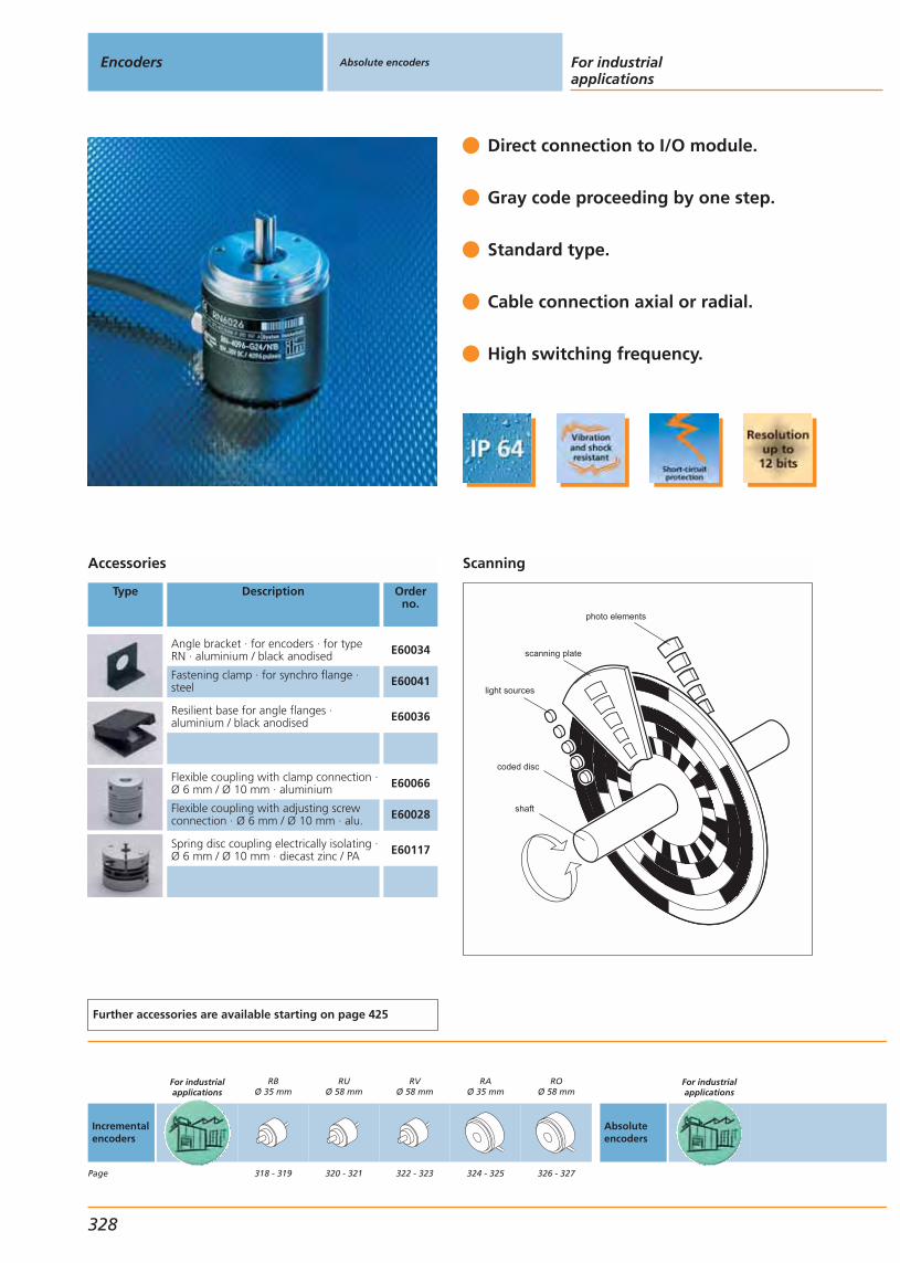
Direct connection to I/O module.
Gray code proceeding by one step.
Standard type.
Cable connection axial or radial.
High switching frequency.
Accessories
Type Description Orderno.
Angle bracket · for encoders · for typeRN · aluminium / black anodised E60034
Fastening clamp · for synchro flange ·steel E60041
Resilient base for angle flanges ·aluminium / black anodised E60036
Flexible coupling with clamp connection ·Ø 6 mm / Ø 10 mm · aluminium E60066
Flexible coupling with adjusting screwconnection · Ø 6 mm / Ø 10 mm · alu. E60028
Spring disc coupling electrically isolating ·Ø 6 mm / Ø 10 mm · diecast zinc / PA E60117
Further accessories are available starting on page 425
Scanning
photo elements
scanning plate
light sources
coded disc
shaft
Encoders Absolute encoders For industrialapplications
328
Incrementalencoders
Page
For industrialapplications
RBØ 35 mm
318 - 319
RUØ 58 mm
320 - 321
RVØ 58 mm
322 - 323
RAØ 35 mm
324 - 325
ROØ 58 mm
326 - 327
Absoluteencoders
For industrialapplications
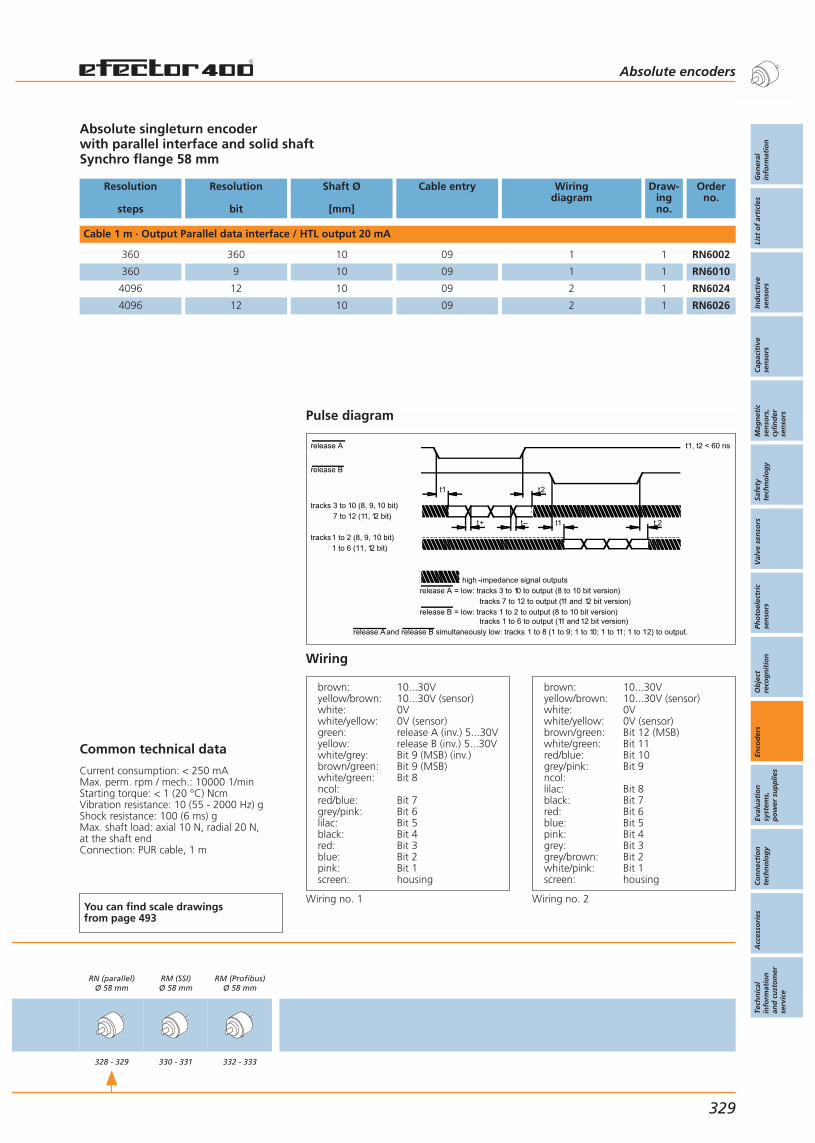
Absolute singleturn encoderwith parallel interface and solid shaftSynchro flange 58 mm
Resolution
steps
Resolution
bit
Shaft Ø
[mm]
Cable entry Wiringdiagram
Draw-ingno.
Orderno.
Cable 1 m · Output Parallel data interface / HTL output 20 mA
360 360 10 09 1 1 RN6002
360 9 10 09 1 1 RN6010
4096 12 10 09 2 1 RN6024
4096 12 10 09 2 1 RN6026
Common technical data
Current consumption: < 250 mAMax. perm. rpm / mech.: 10000 1/minStarting torque: < 1 (20 °C) NcmVibration resistance: 10 (55 - 2000 Hz) gShock resistance: 100 (6 ms) gMax. shaft load: axial 10 N, radial 20 N, at the shaft endConnection: PUR cable, 1 m
You can find scale drawings from page 493
RN (parallel)Ø 58 mm
328 - 329
RM (SSI)Ø 58 mm
330 - 331
RM (Profibus)Ø 58 mm
332 - 333
Absolute encoders
Gen
eral
info
rmat
ion
List
of
arti
cles
Ind
uct
ive
sen
sors
Cap
acit
ive
sen
sors
Mag
net
icse
nso
rs,
cylin
der
sen
sors
Safe
tyte
chn
olo
gy
Val
ve s
enso
rsPh
oto
elec
tric
sen
sors
Ob
ject
reco
gn
itio
nEn
cod
ers
Eval
uat
ion
syst
ems,
po
wer
su
pp
lies
Co
nn
ecti
on
tech
no
log
yA
cces
sori
esTe
chn
ical
info
rmat
ion
and
cu
sto
mer
serv
ice
329
Wiring
brown: 10...30Vyellow/brown: 10...30V (sensor)white: 0Vwhite/yellow: 0V (sensor)green: release A (inv.) 5...30Vyellow: release B (inv.) 5...30Vwhite/grey: Bit 9 (MSB) (inv.)brown/green: Bit 9 (MSB)white/green: Bit 8ncol:red/blue: Bit 7grey/pink: Bit 6lilac: Bit 5black: Bit 4red: Bit 3blue: Bit 2pink: Bit 1screen: housing
Wiring no. 1
brown: 10...30Vyellow/brown: 10...30V (sensor)white: 0Vwhite/yellow: 0V (sensor)brown/green: Bit 12 (MSB)white/green: Bit 11red/blue: Bit 10grey/pink: Bit 9ncol:lilac: Bit 8black: Bit 7red: Bit 6blue: Bit 5pink: Bit 4grey: Bit 3grey/brown: Bit 2white/pink: Bit 1screen: housing
Wiring no. 2
Pulse diagram
t1, t2 < 60 ns
release A
release B
= low: tracks 3 to 10 to output (8 to 10 bit version)
= low: tracks 1 to 2 to output (8 to 10 bit version)
high -impedance signal outputs
tracks 7 to 12 to output (11 and 12 bit version)
tracks 1 to 6 to output (11 and12 bit version)
release B
release A
t1 t2
t+ t– t1 t 2
tracks 3 to 10 (8, 9, 10 bit)7 to 12 (11, 12 bit)
tracks1 to 2 (8, 9, 10 bit)1 to 6 (11, 12 bit)
release Aand release B simultaneously low: tracks 1 to 8 (1 to 9; 1 to 10; 1 to 11; 1 to 12) to output.
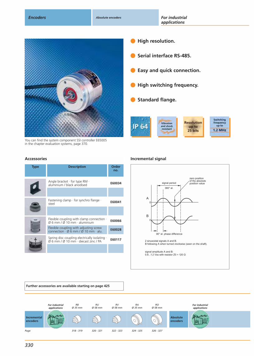
You can find the system component SSI controller E65005in the chapter evaluation systems, page 370.
High resolution.
Serial interface RS-485.
Easy and quick connection.
High switching frequency.
Standard flange.
Accessories
Type Description Orderno.
Angle bracket · for type RM · aluminium / black anodised E60034
Fastening clamp · for synchro flange ·steel E60041
Flexible coupling with clamp connection ·Ø 6 mm / Ø 10 mm · aluminium E60066
Flexible coupling with adjusting screwconnection · Ø 6 mm / Ø 10 mm · alu. E60028
Spring disc coupling electrically isolating ·Ø 6 mm / Ø 10 mm · diecast zinc / PA E60117
Further accessories are available starting on page 425
Incremental signal
90° el. phase difference
signal period
360° el.
zero positionof the absoluteposition value
0
0
A
B
2 sinusoidal signals A and B.B following A when turned clockwise (seen on the shaft).
signal amplitude A and B:0.8...1.2 Vss with resistor Z0 = 120
Encoders Absolute encoders For industrialapplications
330
Incrementalencoders
Page
For industrialapplications
RBØ 35 mm
318 - 319
RUØ 58 mm
320 - 321
RVØ 58 mm
322 - 323
RAØ 35 mm
324 - 325
ROØ 58 mm
326 - 327
Absoluteencoders
For industrialapplications
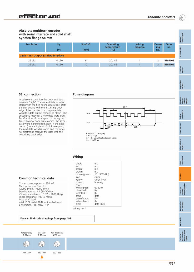
SSI connection
In quiescent condition the clock and datalines are “high”. The current data word isstored with the first falling clock edge. Datatransfer begins with the first rising clockedge. After transfer of a complete dataword the data output remains at “low”. Theencoder is ready for a new data word trans-fer after time t3 has elapsed. If during thistime t3 a new clock pulse comes, the samedata word is transferred again. If the dataoutput (clock = high for t3) is interrupted,the next data word is stored and the exter-nal electronics receives the data with thenext rising clock edge.
Absolute multiturn encoderwith serial interface and solid shaftSynchro flange 58 mm
Resolution Ub
[V]
Shaft Ø
[mm]
Operatingtemperature
[°C]
Wiringdiagram
Draw-ingno.
Orderno.
Cable 1 m · Output SSI data interface
25 bits 10...30 6 -20...85 1 2 RM6101
25 bits 10...30 10 -20...85 1 2 RM6104
Common technical data
Current consumption: < 250 mAMax. perm. rpm / mech.: 12000 1/min / 10000 1/minStarting torque: < 1 (20 °C) NcmVibration resistance: 10 (55 - 2000 Hz) gShock resistance: 100 (6 ms) gMax. shaft load: axial 10 N, radial 20 N, at the shaft endConnection: PUR cable, 1 m
You can find scale drawings from page 493
RN (parallel)Ø 58 mm
328 - 329
RM (SSI)Ø 58 mm
330 - 331
RM (Profibus)Ø 58 mm
332 - 333
Absolute encoders
Gen
eral
info
rmat
ion
List
of
arti
cles
Ind
uct
ive
sen
sors
Cap
acit
ive
sen
sors
Mag
net
icse
nso
rs,
cylin
der
sen
sors
Safe
tyte
chn
olo
gy
Val
ve s
enso
rsPh
oto
elec
tric
sen
sors
Ob
ject
reco
gn
itio
nEn
cod
ers
Eval
uat
ion
syst
ems,
po
wer
su
pp
lies
Co
nn
ecti
on
tech
no
log
yA
cces
sori
esTe
chn
ical
info
rmat
ion
and
cu
sto
mer
serv
ice
331
Wiring
black: n.c.red: n.c.green: n.c.brown: n.c.brown/green: 10...30V (Up)lilac: clockyellow: clock (inv.)screen: housingncol:white/green: 0V (Un)blue/black: B+red/black: B-grey: datagreen/black: A+yellow/black: A-pink: data (inv.)
Wiring no. 1
Pulse diagram
t1 T25T
t3
t2
25 2 1LSBMSB
data
cycle
24 23
T = 0,9 to 11 µs (cycle)t1 = > 0,45 µst2 = 0,4 µs (without extension cable)t3 = 12 to 35 µs
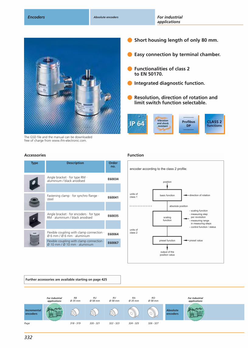
Function
encoder according to the class 2 profile:
units ofclass 1
units ofclass 2
basic function
scalingfunction
preset function
position
output of theposition value
direction of rotation
- scaling function
- measuring step per revolution
- measuring range in measuring steps
- control function / status
preset value
absolute position. . . . . . . . . . . . . .
The GSD file and the manual can be downloadedfree of charge from www.ifm-electronic.com.
Short housing length of only 80 mm.
Easy connection by terminal chamber.
Functionalities of class 2to EN 50170.
Integrated diagnostic function.
Resolution, direction of rotation andlimit switch function selectable.
Accessories
Type Description Orderno.
Angle bracket · for type RM · aluminium / black anodised E60034
Fastening clamp · for synchro flange ·steel E60041
Angle bracket · for encoders · for typeRM · aluminium / black anodised E60035
Flexible coupling with clamp connection ·Ø 6 mm / Ø 6 mm · aluminium E60064
Flexible coupling with clamp connection ·Ø 10 mm / Ø 10 mm · aluminium E60067
Further accessories are available starting on page 425
Encoders Absolute encoders For industrialapplications
332
Incrementalencoders
Page
For industrialapplications
RBØ 35 mm
318 - 319
RUØ 58 mm
320 - 321
RVØ 58 mm
322 - 323
RAØ 35 mm
324 - 325
ROØ 58 mm
326 - 327
Absoluteencoders
For industrialapplications
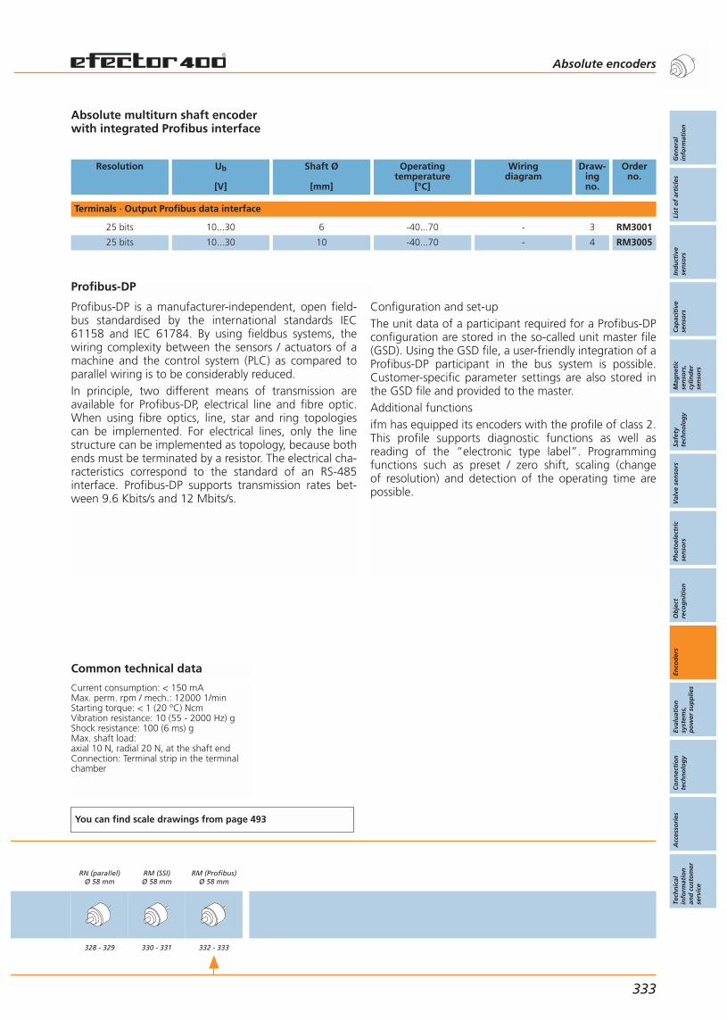
Profibus-DP
Profibus-DP is a manufacturer-independent, open field-bus standardised by the international standards IEC61158 and IEC 61784. By using fieldbus systems, thewiring complexity between the sensors / actuators of amachine and the control system (PLC) as compared toparallel wiring is to be considerably reduced.In principle, two different means of transmission areavailable for Profibus-DP, electrical line and fibre optic.When using fibre optics, line, star and ring topologiescan be implemented. For electrical lines, only the linestructure can be implemented as topology, because bothends must be terminated by a resistor. The electrical cha-racteristics correspond to the standard of an RS-485interface. Profibus-DP supports transmission rates bet-ween 9.6 Kbits/s and 12 Mbits/s.
Absolute multiturn shaft encoderwith integrated Profibus interface
Resolution Ub
[V]
Shaft Ø
[mm]
Operatingtemperature
[°C]
Wiringdiagram
Draw-ingno.
Orderno.
Terminals · Output Profibus data interface
25 bits 10...30 6 -40...70 - 3 RM3001
25 bits 10...30 10 -40...70 - 4 RM3005
Common technical data
Current consumption: < 150 mAMax. perm. rpm / mech.: 12000 1/minStarting torque: < 1 (20 °C) NcmVibration resistance: 10 (55 - 2000 Hz) gShock resistance: 100 (6 ms) gMax. shaft load: axial 10 N, radial 20 N, at the shaft endConnection: Terminal strip in the terminalchamber
You can find scale drawings from page 493
RN (parallel)Ø 58 mm
328 - 329
RM (SSI)Ø 58 mm
330 - 331
RM (Profibus)Ø 58 mm
332 - 333
Absolute encoders
Gen
eral
info
rmat
ion
List
of
arti
cles
Ind
uct
ive
sen
sors
Cap
acit
ive
sen
sors
Mag
net
icse
nso
rs,
cylin
der
sen
sors
Safe
tyte
chn
olo
gy
Val
ve s
enso
rsPh
oto
elec
tric
sen
sors
Ob
ject
reco
gn
itio
nEn
cod
ers
Eval
uat
ion
syst
ems,
po
wer
su
pp
lies
Co
nn
ecti
on
tech
no
log
yA
cces
sori
esTe
chn
ical
info
rmat
ion
and
cu
sto
mer
serv
ice
333
Configuration and set-upThe unit data of a participant required for a Profibus-DPconfiguration are stored in the so-called unit master file(GSD). Using the GSD file, a user-friendly integration of aProfibus-DP participant in the bus system is possible.Customer-specific parameter settings are also stored inthe GSD file and provided to the master.Additional functionsifm has equipped its encoders with the profile of class 2.This profile supports diagnostic functions as well asreading of the “electronic type label”. Programmingfunctions such as preset / zero shift, scaling (change of resolution) and detection of the operating time arepossible.


Gen
eral
info
rmat
ion
List
of
arti
cles
Ind
uct
ive
sen
sors
Cap
acit
ive
sen
sors
Mag
net
icse
nso
rs,
cylin
der
sen
sors
Safe
tyte
chn
olo
gy
Val
ve s
enso
rsPh
oto
elec
tric
sen
sors
Ob
ject
reco
gn
itio
nEn
cod
ers
Eval
uat
ion
syst
ems,
po
wer
su
pp
lies
Co
nn
ecti
on
tech
no
log
yA
cces
sori
esTe
chn
ical
info
rmat
ion
and
cu
sto
mer
serv
ice
Evaluation systems,power supplies
335
Digital and analogue signal processingfor industrial applications
Digital and analogue signal processingfor safety applications
Digital and analogue signal processingTransformer and switched-mode power supplies
System descriptionSelection chart
Pulse evaluation systemsMeasurement and displayCounting and displayingEncoder evaluation systemsDigital signal processingStandard signal evaluation and display
Universal application
Evaluation systems for safety applications
Special applicationDigital and analogue signal processingfor hazardous areas
Transformer and switched-mode power suppliesfor industrial applications
Universal applicationTransformer power suppliesSwitched-mode power supplies
Switching amplifiers intrinsically safe
336 - 343344 - 349
350 - 365366 - 367368 - 369370 - 371372 - 373374 - 377
378 - 381
382 - 387
388 - 389390 - 391
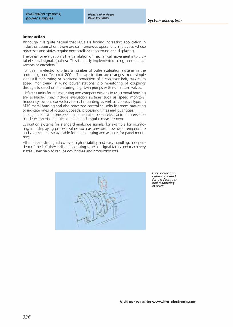
System description
Visit our website: www.ifm-electronic.com
Evaluation systems,power supplies
Digital and analoguesignal processing
336
IntroductionAlthough it is quite natural that PLCs are finding increasing application inindustrial automation, there are still numerous operations in practice whoseprocesses and states require decentralised monitoring and displaying.The basis for evaluation is the translation of mechanical movement into digi-tal electrical signals (pulses). This is ideally implemented using non-contactsensors or encoders.For this ifm electronic offers a number of pulse evaluation systems in theproduct group “ecomat 200”. The application area ranges from simplestandstill monitoring or blockage protection of a conveyor belt, maximumspeed monitoring in wind power stations, slip monitoring of couplingsthrough to direction monitoring, e.g. twin pumps with non-return valves.Different units for rail mounting and compact designs in M30 metal housingare available. They include evaluation systems such as speed monitors, frequency-current converters for rail mounting as well as compact types inM30 metal housing and also processor-controlled units for panel mountingto indicate rates of rotation, speeds, processing times and quantities.In conjunction with sensors or incremental encoders electronic counters ena-ble detection of quantities or linear and angular measurement. Evaluation systems for standard analogue signals, for example for monito-ring and displaying process values such as pressure, flow rate, temperatureand volume are also available for rail mounting and as units for panel moun-ting.All units are distinguished by a high reliability and easy handling. Indepen-dent of the PLC they indicate operating states or signal faults and machinerystates. They help to reduce downtimes and production loss.
Pulse evaluationsystems are usedfor the decentral-ised monitoringof drives.

Gen
eral
info
rmat
ion
List
of
arti
cles
Ind
uct
ive
sen
sors
Cap
acit
ive
sen
sors
Mag
net
icse
nso
rs,
cylin
der
sen
sors
Safe
tyte
chn
olo
gy
Val
ve s
enso
rsPh
oto
elec
tric
sen
sors
Ob
ject
reco
gn
itio
nEn
cod
ers
Eval
uat
ion
syst
ems,
po
wer
su
pp
lies
Co
nn
ecti
on
tech
no
log
yA
cces
sori
esTe
chn
ical
info
rmat
ion
and
cu
sto
mer
serv
ice
Digital and analoguesignal processing
Visit our website: www.ifm-electronic.com
337
The double systemFR-2 monitors the
rotational speedof two independ-
ent drives.
The monitor FS-1for rotationalspeed monitoring.
Synchronousmonitoring with
FS-3 monitor.
The different evaluation systemsMonitorsThe monitor series includes speed monitors, slip / synchronous monitors,direction monitors, frequency-current / voltage converters and thresholdrelays for standard analogue signals.The units have numerous options. A combined 7 1/4-segment LCD displayserves to indicate the actual values of input frequencies and analogue out-put signals. Furthermore, it supports the user with parameter setting. Practi-cal setting ranges, freely selectable switching functions and combined relay /transistor outputs enable adaptation to different applications.Various special functions such as delay times, fleeting function for the out-put relays, external release of the start-up delay and the fault memory withexternal reset option underline functionality and flexible adaptability to theapplication. This eliminates the need to use additional switchgear such astimer or blocking relays.The inputs are designed for PNP or NPN switching sensors, 24 V DC NAMURsensors, encoder signals, mechanical pulse pick-ups or standard analoguesignals.Their wide-range voltage inputs ensure that they are suited for almost alloperating voltages world-wide. The UL/CSA approvals support the world-wide use of these units.FR-1: Single pulse evaluation systems for rates of rotation speed,speed, machine cyclesWith one pulse input, two switch points and an analogue output the unitmonitors whether the actual speed of a drive is below or above the setspeed. Setting and indication are in RPM (revolutions per minute) or Hertz(Hz). With the integrated frequency-to-current converter a frequency rangecan be converted into an analogue signal (0 /4 to 20 mA).FR-2: Double pulse evaluation systems for rates of rotation speed,speed, machine cyclesThis double system with the functions of the FR-1 (but without analogueoutput) allows monitoring of two independent drives. Each pulse input isassigned a switch point and switching output.FS-1 / FS-2 / FS-3: Pulse evaluation systems for rotational speed, slip /synchronisation, skew, torsionThe system has two pulse inputs to compare two pulse sequences (rotationalspeeds, linear movement) and determines the deviation – either as slip inpercent on the master / slave principle (FS-1) or by means of differential pul-ses per time unit and reset time (FS-2). The FS-3 works without reset timeand determines the pulse difference across any stretch of time. The relay /transistor outputs switch when the set slip or pulse difference is exceeded.With the FS-1 it is also possible to monitor whether the actual speed of thedrive (master) is above or below a set value.FD-1 / FD-2: Pulse evaluation systems for direction monitoringThe direction of rotation is monitored by means of two sensors or an enco-der. The detected direction is signalled with one relay output each for“right” and “left”. As an alternative a combined direction / rotational speedmonitoring with separate outputs for direction and rotational speed can beimplemented.
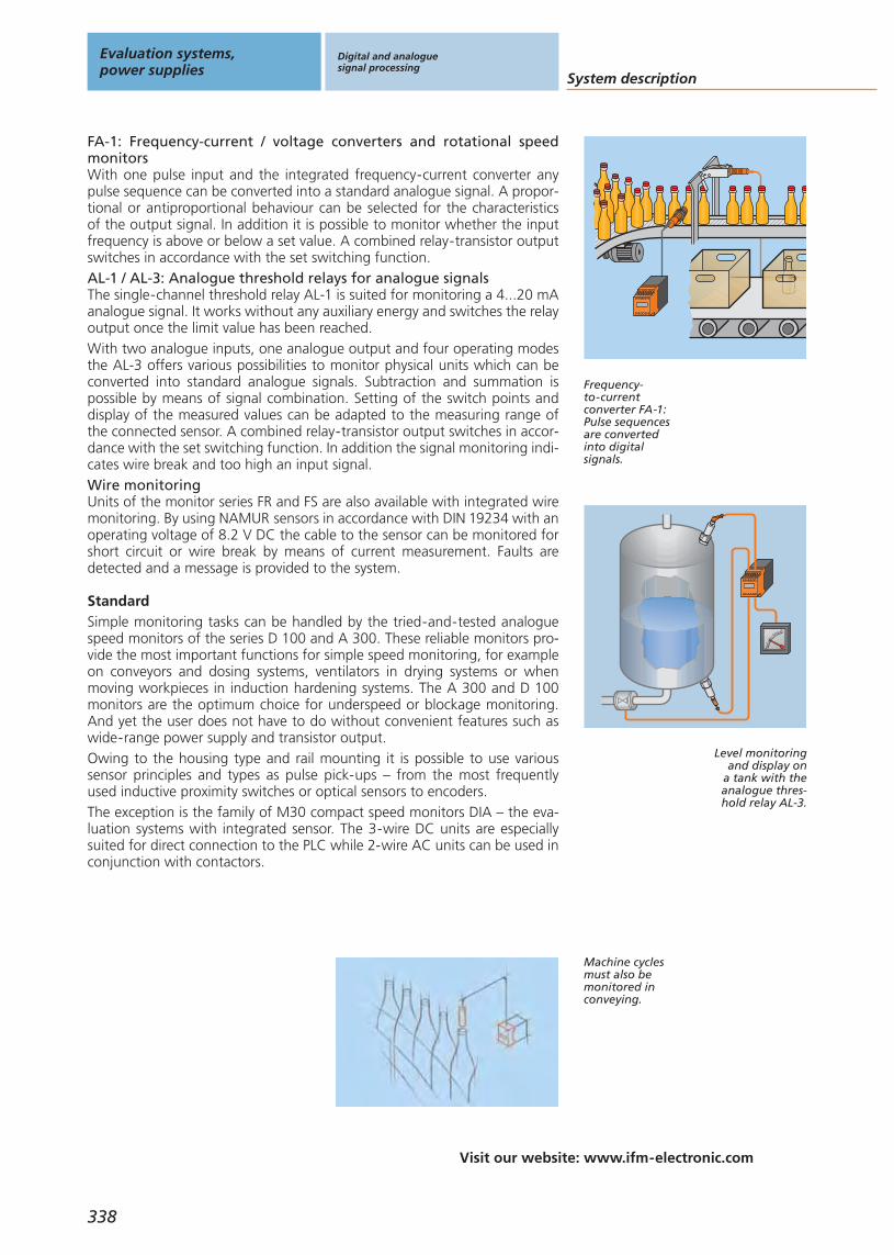
Visit our website: www.ifm-electronic.com
338
StandardSimple monitoring tasks can be handled by the tried-and-tested analoguespeed monitors of the series D 100 and A 300. These reliable monitors pro-vide the most important functions for simple speed monitoring, for exampleon conveyors and dosing systems, ventilators in drying systems or whenmoving workpieces in induction hardening systems. The A 300 and D 100monitors are the optimum choice for underspeed or blockage monitoring.And yet the user does not have to do without convenient features such aswide-range power supply and transistor output. Owing to the housing type and rail mounting it is possible to use varioussensor principles and types as pulse pick-ups – from the most frequentlyused inductive proximity switches or optical sensors to encoders.The exception is the family of M30 compact speed monitors DIA – the eva-luation systems with integrated sensor. The 3-wire DC units are especiallysuited for direct connection to the PLC while 2-wire AC units can be used inconjunction with contactors.
FA-1: Frequency-current / voltage converters and rotational speedmonitorsWith one pulse input and the integrated frequency-current converter anypulse sequence can be converted into a standard analogue signal. A propor-tional or antiproportional behaviour can be selected for the characteristics of the output signal. In addition it is possible to monitor whether the inputfrequency is above or below a set value. A combined relay-transistor outputswitches in accordance with the set switching function.AL-1 / AL-3: Analogue threshold relays for analogue signalsThe single-channel threshold relay AL-1 is suited for monitoring a 4...20 mAanalogue signal. It works without any auxiliary energy and switches the relayoutput once the limit value has been reached.With two analogue inputs, one analogue output and four operating modesthe AL-3 offers various possibilities to monitor physical units which can beconverted into standard analogue signals. Subtraction and summation ispossible by means of signal combination. Setting of the switch points anddisplay of the measured values can be adapted to the measuring range ofthe connected sensor. A combined relay-transistor output switches in accor-dance with the set switching function. In addition the signal monitoring indi-cates wire break and too high an input signal.Wire monitoringUnits of the monitor series FR and FS are also available with integrated wiremonitoring. By using NAMUR sensors in accordance with DIN 19234 with anoperating voltage of 8.2 V DC the cable to the sensor can be monitored forshort circuit or wire break by means of current measurement. Faults aredetected and a message is provided to the system.
Machine cyclesmust also bemonitored inconveying.
Level monitoringand display on
a tank with theanalogue thres-hold relay AL-3.
Frequency-to-currentconverter FA-1:Pulse sequencesare convertedinto digitalsignals.
System description
Evaluation systems,power supplies
Digital and analoguesignal processing

Gen
eral
info
rmat
ion
List
of
arti
cles
Ind
uct
ive
sen
sors
Cap
acit
ive
sen
sors
Mag
net
icse
nso
rs,
cylin
der
sen
sors
Safe
tyte
chn
olo
gy
Val
ve s
enso
rsPh
oto
elec
tric
sen
sors
Ob
ject
reco
gn
itio
nEn
cod
ers
Eval
uat
ion
syst
ems,
po
wer
su
pp
lies
Co
nn
ecti
on
tech
no
log
yA
cces
sori
esTe
chn
ical
info
rmat
ion
and
cu
sto
mer
serv
ice
Speed monitor D100The universal speed monitor with a setting range of 5...5,000 pulses / minu-te, switch point, hysteresis and start-up delay is set via a potentiometer. Theunits with wide-range power supply have a combined relay-transistor out-put. Its four switching functions enable it to indicate operating states such as
drive is runningrotational speed reached
or fault situations, e.g.speed exceededunderspeedstandstill / blockage
Standstill monitor A100The A300 with a setting range of 5...100 pulses per minute is normally usedfor underspeed monitoring, easy standstill messages or as a protectionagainst blockage. Hysteresis and start-up delay are fixed while the switchpoint is set using a potentiometer. The units with wide-range power supplyhave a combined relay-transistor output. Two switching functions are availa-ble for indicating
underspeedstandstill / blockage
Speed monitor compact DIAThe compact speed monitor is an analogue evaluation system for monitoringrotational speed – preferably whether the actual speed is below the presetvalue and blockage (standstill). Sensor and evaluation electronics are inte-grated into a compact M30 metal housing. The switch point is set within a large setting range using a spindle potentiometer. Switching function,start-up delay and hysteresis are fixed.The typical monitoring function is the indication of standstill or underspeed.This means that the output is only switched when the rotational speed isgreater than the set switch point.The unit is also suited for ATEX 3D applications.
339
Visit our website: www.ifm-electronic.com
DisplaysDisplays are used for local indication and monitoring of measured values.The user always has an overview of the various machine and plant parame-ters in automated processes. Thanks to the 15 mm characters the displaysensure good readability. Different functions enable various applications withone unit only. In addition there are variants with switching output or analo-gue output with standard signals.
Displays:Different machineparameters canbe directly indi-cated locally.
Compact speedmonitor:
The evaluationelectronics for
rotational speedmonitoring
is integratedinto the sensor
housing.
Digital and analoguesignal processing
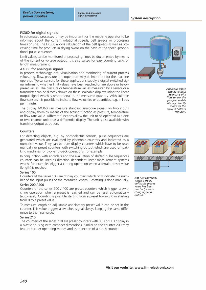
Visit our website: www.ifm-electronic.com
340
CountersFor detecting objects, e.g. by photoelectric sensors, pulse sequences aregenerated which are evaluated by electronic counters and indicated as anumerical value. They can be pure display counters which have to be resetmanually or preset counters with switching output which are used on pak-king machines for pick-and-pack operations, for example.In conjunction with encoders and the evaluation of shifted pulse sequencescounters can be used as direction-dependent linear measurement systemswhich, for example, trigger a cutting operation when a certain preset value(length) is reached.Series 100Counters of the series 100 are display counters which only indicate the num-ber of the input pulses or the measured length. Resetting is done manually. Series 200 / 400Counters of the series 200 / 400 are preset counters which trigger a swit-ching operation when a preset is reached and can be reset automatically(auto reset). Counting is possible starting from a preset towards 0 or startingfrom 0 to a preset value.To measure length an adjustable anticipatory preset value can be set in thecounter. This value triggers a switched signal always keeping the same diffe-rence to the final value. Series 210The counters of the series 210 are preset counters with LCD or LED display ina plastic housing with compact dimensions. Similar to the counter 200 theyfeature further operating modes and the function of a batch counter.
Not just counting:When a freelydefinable presetvalue has beenreached, a swit-ching signal isoutput.
FX360 for digital signalsIn automated processes it may be important for the machine operator to beinformed about the current rotational speeds, belt speeds or processingtimes on site. The FX360 allows calculation of the belt speeds as well as pro-cessing time for products in drying ovens on the basis of the speed-propor-tional pulse sequences.Limit values can be monitored or processing times be documented by meansof the current or voltage output. It is also suited for easy counting tasks orlength measurement.AX360 for analogue signalsIn process technology local visualisation and monitoring of current processvalues, e.g. flow, pressure or temperature may be important for the machineoperator. Typical sensors for these applications supply a digital switched sig-nal informing whether limit values have been reached or are above or belowpreset values. The pressure or temperature values measured by a sensor or atransmitter can be directly shown on these scaleable displays using the linearoutput signal which is proportional to the measured quantity. With suitableflow sensors it is possible to indicate flow velocities or quantities, e.g. in litresper minute. The display AX360 can measure standard analogue signals on two inputsand display them by means of the scaling function as pressure, temperatureor flow rate value. Different functions allow the unit to be operated as a oneor two-channel unit or as a differential display. The unit is also available withtransistor output at option.
Analogue valuedisplay AX360:By means of a
flow sensor theprogrammabledisplay directly
indicates theflow in “litres /
minute”.
System description
Evaluation systems,power supplies
Digital and analoguesignal processing
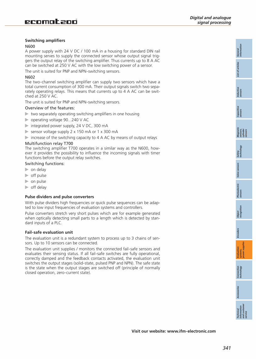
Gen
eral
info
rmat
ion
List
of
arti
cles
Ind
uct
ive
sen
sors
Cap
acit
ive
sen
sors
Mag
net
icse
nso
rs,
cylin
der
sen
sors
Safe
tyte
chn
olo
gy
Val
ve s
enso
rsPh
oto
elec
tric
sen
sors
Ob
ject
reco
gn
itio
nEn
cod
ers
Eval
uat
ion
syst
ems,
po
wer
su
pp
lies
Co
nn
ecti
on
tech
no
log
yA
cces
sori
esTe
chn
ical
info
rmat
ion
and
cu
sto
mer
serv
ice
N600A power supply with 24 V DC / 100 mA in a housing for standard DIN railmounting serves to supply the connected sensor whose output signal trig-gers the output relay of the switching amplifier. Thus currents up to 8 A ACcan be switched at 250 V AC with the low switching power of a sensor.The unit is suited for PNP and NPN-switching sensors.N602The two-channel switching amplifier can supply two sensors which have atotal current consumption of 300 mA. Their output signals switch two sepa-rately operating relays. This means that currents up to 4 A AC can be swit-ched at 250 V AC.The unit is suited for PNP and NPN-switching sensors.Overview of the features:
two separately operating switching amplifiers in one housingoperating voltage 90...240 V ACintegrated power supply, 24 V DC, 300 mAsensor voltage supply 2 x 150 mA or 1 x 300 mAincrease of the switching capacity to 4 A AC by means of output relays
Multifunction relay T700The switching amplifier T700 operates in a similar way as the N600, how-ever it provides the possibility to influence the incoming signals with timerfunctions before the output relay switches.Switching functions:
on delayoff pulseon pulseoff delay
341
Visit our website: www.ifm-electronic.com
Switching amplifiers
Pulse dividers and pulse convertersWith pulse dividers high frequencies or quick pulse sequences can be adap-ted to low input frequencies of evaluation systems and controllers.Pulse converters stretch very short pulses which are for example generatedwhen optically detecting small parts to a length which is detected by stan-dard inputs of a PLC.
Digital and analoguesignal processing
Fail-safe evaluation unitThe evaluation unit is a redundant system to process up to 3 chains of sen-sors. Up to 10 sensors can be connected.The evaluation unit supplies / monitors the connected fail-safe sensors andevaluates their sensing status. If all fail-safe switches are fully operational,correctly damped and the feedback contacts activated, the evaluation unitswitches the output stages (solid-state, pulsed PNP and NPN). The safe stateis the state when the output stages are switched off (principle of normallyclosed operation, zero-current state).
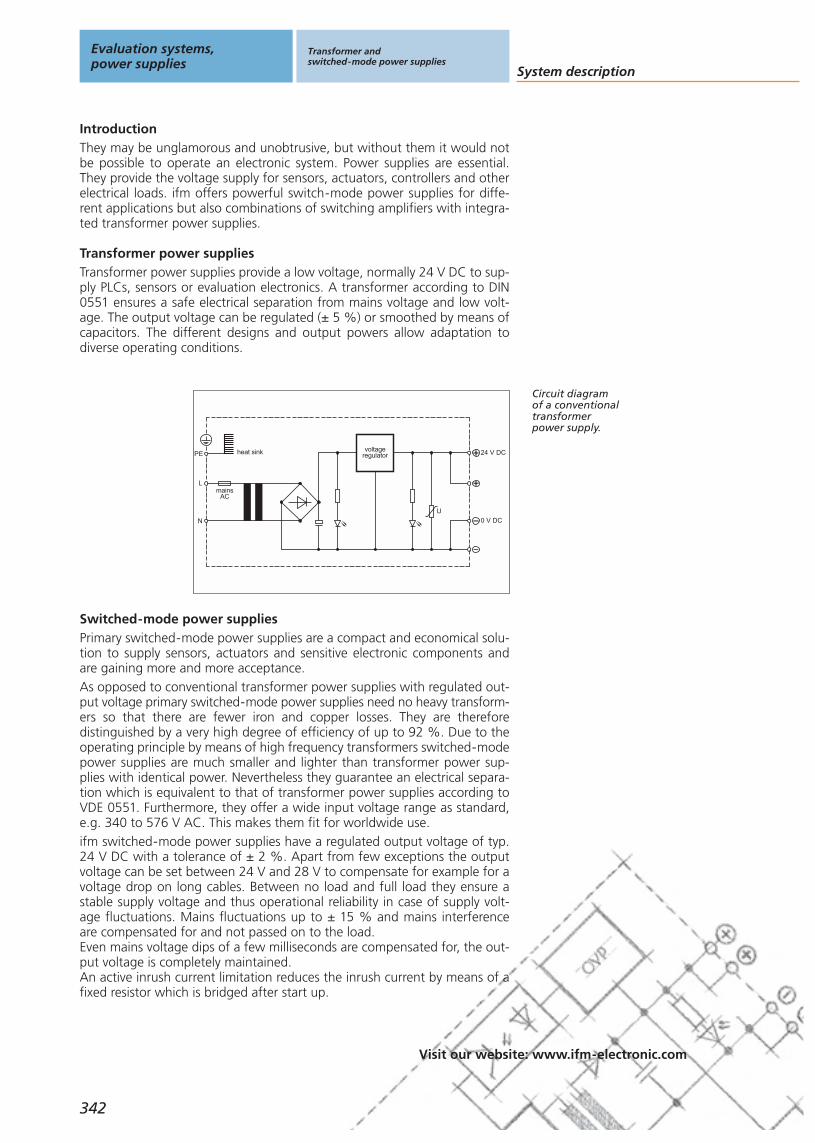
System description
Visit our website: www.ifm-electronic.com
Primary switched-mode power supplies are a compact and economical solu-tion to supply sensors, actuators and sensitive electronic components andare gaining more and more acceptance. As opposed to conventional transformer power supplies with regulated out-put voltage primary switched-mode power supplies need no heavy transform-ers so that there are fewer iron and copper losses. They are thereforedistinguished by a very high degree of efficiency of up to 92 %. Due to theoperating principle by means of high frequency transformers switched-modepower supplies are much smaller and lighter than transformer power sup-plies with identical power. Nevertheless they guarantee an electrical separa-tion which is equivalent to that of transformer power supplies according toVDE 0551. Furthermore, they offer a wide input voltage range as standard,e.g. 340 to 576 V AC. This makes them fit for worldwide use.ifm switched-mode power supplies have a regulated output voltage of typ.24 V DC with a tolerance of ± 2 %. Apart from few exceptions the outputvoltage can be set between 24 V and 28 V to compensate for example for avoltage drop on long cables. Between no load and full load they ensure astable supply voltage and thus operational reliability in case of supply volt-age fluctuations. Mains fluctuations up to ± 15 % and mains interferenceare compensated for and not passed on to the load.Even mains voltage dips of a few milliseconds are compensated for, the out-put voltage is completely maintained.An active inrush current limitation reduces the inrush current by means of afixed resistor which is bridged after start up.
Evaluation systems,power supplies
Transformer andswitched-mode power supplies
342
IntroductionThey may be unglamorous and unobtrusive, but without them it would notbe possible to operate an electronic system. Power supplies are essential.They provide the voltage supply for sensors, actuators, controllers and otherelectrical loads. ifm offers powerful switch-mode power supplies for diffe-rent applications but also combinations of switching amplifiers with integra-ted transformer power supplies.
Circuit diagramof a conventionaltransformerpower supply.
Switched-mode power supplies
L
PE
N
voltageregulator 24 V DC
0 V DC
U
mainsAC
heat sink
Transformer power suppliesTransformer power supplies provide a low voltage, normally 24 V DC to sup-ply PLCs, sensors or evaluation electronics. A transformer according to DIN0551 ensures a safe electrical separation from mains voltage and low volt-age. The output voltage can be regulated (± 5 %) or smoothed by means ofcapacitors. The different designs and output powers allow adaptation todiverse operating conditions.

Transformer andswitched-mode power supplies
343
Visit our website: www.ifm-electronic.com
Gen
eral
info
rmat
ion
List
of
arti
cles
Ind
uct
ive
sen
sors
Cap
acit
ive
sen
sors
Mag
net
icse
nso
rs,
cylin
der
sen
sors
Safe
tyte
chn
olo
gy
Val
ve s
enso
rsPh
oto
elec
tric
sen
sors
Ob
ject
reco
gn
itio
nEn
cod
ers
Eval
uat
ion
syst
ems,
po
wer
su
pp
lies
Co
nn
ecti
on
tech
no
log
yA
cces
sori
esTe
chn
ical
info
rmat
ion
and
cu
sto
mer
serv
ice
Compared to the normal NTC resistors this has the advantage of a betterwarm and cold start action, e.g. after short power failures or extremely lowoperating temperatures.
The outputs are protected against short circuits and overload. Special outputcharacteristics allow a current which can be up to 1.7 higher than the nomi-nal current without switch-off with the voltage being reduced at the sametime. Only with few power supplies the output begins to cycle (hickup modeat < 14 V). The outputs are also protected against no load operation, i.e.they need no minimum load at the output.Power supplies of the latest generation have two selectable output re-sponses, the “overload mode” as described above and the “switch-offmode” where the output is switched off after a few seconds in case of ashort circuit.
Output response
The dimensioning of the components allows a 20 to 25 % higher outputcurrent for a short time. This power reserve is provided by all power suppliesas from 2.5 A for a period of one minute. At an operating temperature of upto 45°C this power is available continuously.
Power reserves
Suitable forthe application:ifm providespower suppliesin differentpower classes.
Lflyback
converter
typ.100 kHz
PE
N
UV
regulator
OVP
Vout
GND
filter
115/230V AC
Circuit diagramof a primary
switched-modepower supply.
By means of the new mounting technology all power supplies can be safelyand tightly mounted on a TS 35 DIN rail which is 7.5 or 15 mm high. Theycan be removed without a tool. For the electrical connection stable screwterminals are used for cables up to 6 mm2 or 2 x 2.5 mm2 with a 1 A powersupply.
Mounting and connection
All switched-mode power supplies of 2.5 to 40 A comply with EN 50081(noise emission) and EN 50082 (noise immunity) in the severest class. Fur-thermore, they are fitted with a radio interference suppressor in the outputso that even long, unscreened cables do not radiate.The more powerful power supplies have an active transient filter to makevoltage spike on the side of the mains harmless. Thanks to the active inrushcurrent limitation which is also effective for warm units common circuit-break-ers can be used for protection. The integrated phase monitoring for three-phrase inputs prevents the unit and mains from being overloaded if onephase fails. With these features it is ensured that the CE certification alsocovers EMC. Concerning the international approvals EN 60950, UL1950,CUL CSA-C22.2 the power supplies already comply with the future standardEN 50178.
Important: EMC
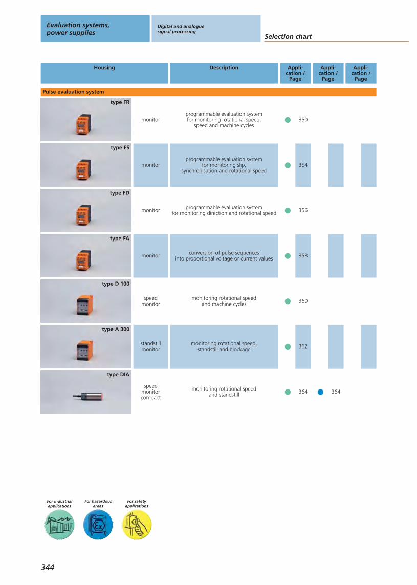
For safetyapplications
Housing Description
monitorprogrammable evaluation systemfor monitoring rotational speed,
speed and machine cycles
type FR
Appli-cation /
Page
monitorprogrammable evaluation system
for monitoring slip,synchronisation and rotational speed
type FS
monitor programmable evaluation systemfor monitoring direction and rotational speed
type FD
monitor conversion of pulse sequencesinto proportional voltage or current values
type FA
speedmonitor
monitoring rotational speedand machine cycles
type D 100
standstillmonitor
monitoring rotational speed,standstill and blockage
type A 300
speedmonitorcompact
monitoring rotational speedand standstill
type DIA
Appli-cation /
Page
Appli-cation /
Page
Pulse evaluation system
Selection chart
Evaluation systems,power supplies
Digital and analoguesignal processing
For hazardousareas
For industrialapplications
344
364
350
354
356
358
360
362
364

Gen
eral
info
rmat
ion
List
of
arti
cles
Ind
uct
ive
sen
sors
Cap
acit
ive
sen
sors
Mag
net
icse
nso
rs,
cylin
der
sen
sors
Safe
tyte
chn
olo
gy
Val
ve s
enso
rsPh
oto
elec
tric
sen
sors
Ob
ject
reco
gn
itio
nEn
cod
ers
Eval
uat
ion
syst
ems,
po
wer
su
pp
lies
Co
nn
ecti
on
tech
no
log
yA
cces
sori
esTe
chn
ical
info
rmat
ion
and
cu
sto
mer
serv
ice
Housing Description Appli-cation /
Page
Appli-cation /
Page
Appli-cation /
Page
For safetyapplications
displaydisplay for frequencies, rotational speed,
speed and processing times,counting function
type FX
counter display counter
type 100
counter preset counter, one preset
type 200
counter programmable preset counterwith 2 presets
type 210
Measurement and display
counter preset counter, with sliding preset
type 400
SSI controller
interface implementationfor I / O modules of the PLC
type SSI
Digital and analoguesignal processing
345
For hazardousareas
For industrialapplications
Counting and displaying
Encoder evaluation systems
366
368
368
368
368
370

For safetyapplications
Housing Description
pulse divider to extend the input frequency rangeof PLCs and evaluation systems
type E 80
Appli-cation /
Page
pulseconverter
to extend the input frequency rangeof PLCs and evaluation systems
type E 80
monitorprogrammable 2-channel threshold relay
for standard signals with integratedcomparator
type AL
LED display display of physical quantitiesfrom analogue standard signals
type AX
LCD displaydisplay of physical quantities
from analogue standard signalsvia 3 1 / 2-digit LCD display
type LC
NAMUR switching amplifier 1-channel withintrinsically safe control circuit
type N
Appli-cation /
Page
Appli-cation /
Page
ATEX switching amplifier 2-channel withintrinsically safe control circuit
type N
Digital signal processing
Selection chart
Evaluation systems,power supplies
Digital and analoguesignal processing
For hazardousareas
For industrialapplications
346
Standard signal evaluation and display
Switching amplifiers intrinsically safe
372
372
378
378
376
376
374
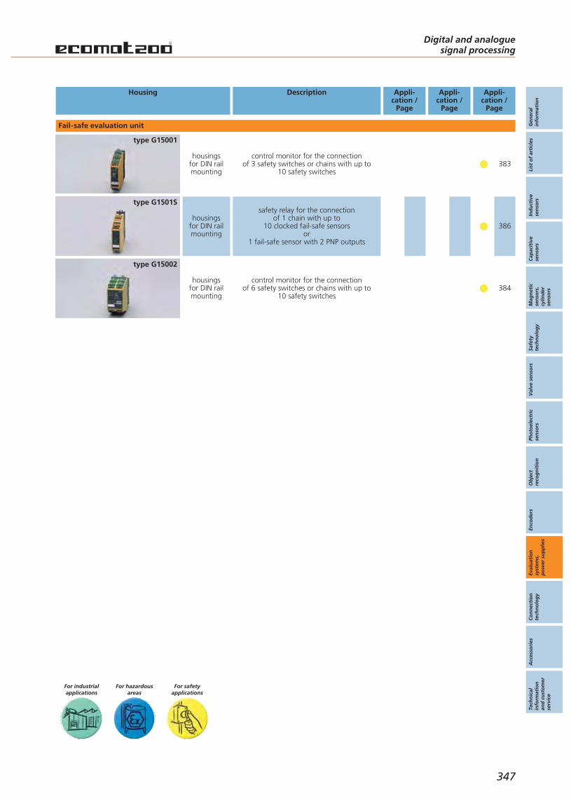
Gen
eral
info
rmat
ion
List
of
arti
cles
Ind
uct
ive
sen
sors
Cap
acit
ive
sen
sors
Mag
net
icse
nso
rs,
cylin
der
sen
sors
Safe
tyte
chn
olo
gy
Val
ve s
enso
rsPh
oto
elec
tric
sen
sors
Ob
ject
reco
gn
itio
nEn
cod
ers
Eval
uat
ion
syst
ems,
po
wer
su
pp
lies
Co
nn
ecti
on
tech
no
log
yA
cces
sori
esTe
chn
ical
info
rmat
ion
and
cu
sto
mer
serv
ice
For safetyapplications
Housing Description Appli-cation /
Page
Appli-cation /
Page
Appli-cation /
Page
housingsfor DIN railmounting
control monitor for the connectionof 3 safety switches or chains with up to
10 safety switches
type G15001
housingsfor DIN railmounting
control monitor for the connectionof 6 safety switches or chains with up to
10 safety switches
type G15002
Fail-safe evaluation unit
Digital and analoguesignal processing
347
For hazardousareas
For industrialapplications
housingsfor DIN railmounting
safety relay for the connection of 1 chain with up to
10 clocked fail-safe sensorsor
1 fail-safe sensor with 2 PNP outputs
type G1501S
383
386
384

Selection chart
Evaluation systems,power supplies
Transformer andswitched-mode power supplies
For industrialapplications
Housing Nominal voltageAC[V]
Output voltageDC[V]
Output current
[A]
Application /Page
348
1 channel 110 / 230 24 0.1
type N 600
2 channels 110 / 230 24 0.3
type N 600
1 channelwith
timer function110 / 230 24 0.04
type T 700
Transformer power supplies / Switching amplifiers
1~ 115 / 230selectable 24 2.5
type DN
1~ 115 / 230selectable 12...15 3
type DN
1~ 115 / 230selectable 24 5
type DN
Switched-mode power supplies single phase
1~ 100...240 24...281.3or2.1
type DN
1~ 100...240 24...28 4.1
type DN
388
388
388
390
390
390
390
390

Transformer andswitched-mode power supplies
Gen
eral
info
rmat
ion
List
of
arti
cles
Ind
uct
ive
sen
sors
Cap
acit
ive
sen
sors
Mag
net
icse
nso
rs,
cylin
der
sen
sors
Safe
tyte
chn
olo
gy
Val
ve s
enso
rsPh
oto
elec
tric
sen
sors
Ob
ject
reco
gn
itio
nEn
cod
ers
Eval
uat
ion
syst
ems,
po
wer
su
pp
lies
Co
nn
ecti
on
tech
no
log
yA
cces
sori
esTe
chn
ical
info
rmat
ion
and
cu
sto
mer
serv
ice
Housing Nominal voltageAC[V]
Output voltageDC[V]
Output current
[A]
Application /Page
349
For industrialapplications
1~115 / 230
or230
24...28adjustable 20
type DN
Switched-mode power supplies single phase
3~ 3 x 400...500 24...28adjustable 5
type DN
3~ 3 x 400...500 24...28adjustable 10
type DN
3~3 x 400
or3 x 400...500
24...28adjustable 20
type DN
3~ 3 x 400...500 24...28adjustable 30
type DN
3~ 3 x 400...500 24...28adjustable 40
type DN
Switched-mode power supplies three-phase
1~ 115 / 230selectable
24...28adjustable 10
type DN
390
390
390
390
390
390
390
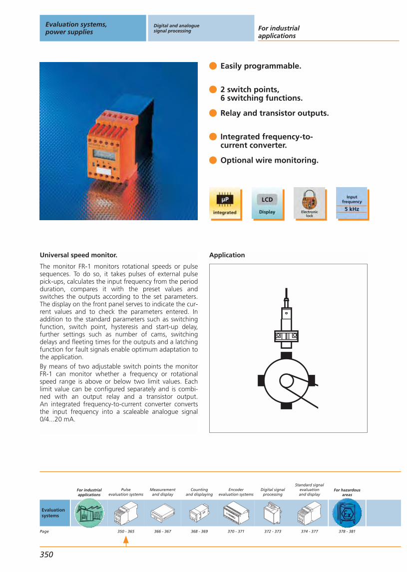
Universal speed monitor.
The monitor FR-1 monitors rotational speeds or pulsesequences. To do so, it takes pulses of external pulsepick-ups, calculates the input frequency from the periodduration, compares it with the preset values and switches the outputs according to the set parameters.The display on the front panel serves to indicate the cur-rent values and to check the parameters entered. Inaddition to the standard parameters such as switchingfunction, switch point, hysteresis and start-up delay,further settings such as number of cams, switchingdelays and fleeting times for the outputs and a latchingfunction for fault signals enable optimum adaptation tothe application. By means of two adjustable switch points the monitorFR-1 can monitor whether a frequency or rotationalspeed range is above or below two limit values. Eachlimit value can be configured separately and is combi-ned with an output relay and a transistor output. An integrated frequency-to-current converter convertsthe input frequency into a scaleable analogue signal0/4...20 mA.
Easily programmable.
2 switch points,6 switching functions.
Relay and transistor outputs.
Integrated frequency-to-current converter.
Optional wire monitoring.
Application
Evaluation systems,power supplies
Digital and analoguesignal processing For industrial
applications
350
Evaluationsystems
Page
For industrialapplications
Pulseevaluation systems
350 - 365
Measurementand display
366 - 367
Countingand displaying
368 - 369
Encoderevaluation systems
370 - 371
Digital signalprocessing
372 - 373
Standard signalevaluationand display
374 - 377
For hazardousareas
378 - 381
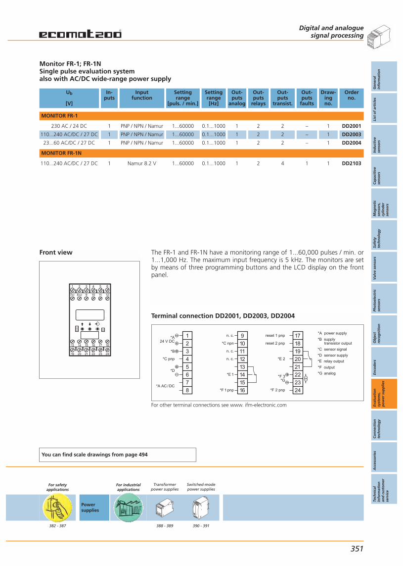
Front view
1 4 652
19 20 21 22 23 24
13 14 15 16 17 18
3
97A1 8A2 10 11 12
Monitor FR-1; FR-1NSingle pulse evaluation systemalso with AC/DC wide-range power supply
Ub
[V]
In-puts
Inputfunction
Settingrange
[puls. / min.]
Settingrange[Hz]
Out-puts
analog
Out-puts
relays
Out-puts
transist.
Out-puts
faults
Draw-ingno.
Orderno.
MONITOR FR-1
230 AC / 24 DC 1 PNP / NPN / Namur 1...60000 0.1...1000 1 2 2 – 1 DD2001
110...240 AC/DC / 27 DC 1 PNP / NPN / Namur 1...60000 0.1...1000 1 2 2 – 1 DD2003
23...60 AC/DC / 27 DC 1 PNP / NPN / Namur 1...60000 0.1...1000 1 2 2 – 1 DD2004
MONITOR FR-1N
110...240 AC/DC / 27 DC 1 Namur 8.2 V 1...60000 0.1...1000 1 2 4 1 1 DD2103
You can find scale drawings from page 494
For safetyapplications
382 - 387
Powersupplies
For industrialapplications
Transformerpower supplies
388 - 389
Switched-modepower supplies
390 - 391
Digital and analoguesignal processing
Gen
eral
info
rmat
ion
List
of
arti
cles
Ind
uct
ive
sen
sors
Cap
acit
ive
sen
sors
Mag
net
icse
nso
rs,
cylin
der
sen
sors
Safe
tyte
chn
olo
gy
Val
ve s
enso
rsPh
oto
elec
tric
sen
sors
Ob
ject
reco
gn
itio
nEn
cod
ers
Eval
uat
ion
syst
ems,
po
wer
su
pp
lies
Co
nn
ecti
on
tech
no
log
yA
cces
sori
esTe
chn
ical
info
rmat
ion
and
cu
sto
mer
serv
ice
351
The FR-1 and FR-1N have a monitoring range of 1...60,000 pulses / min. or1...1,000 Hz. The maximum input frequency is 5 kHz. The monitors are setby means of three programming buttons and the LCD display on the frontpanel.
Terminal connection DD2001, DD2003, DD2004
*A power supply
*C sensor signal
*B supply transistor output
*E relay output
*D sensor supply
*F output
*G analog
1
2
3
4
5
6
7
8
*A24 V DC
*B
*C pnp
*D
*A AC / DC
9
10
11
12
13
14
15
16
n. c.
*C npn
n. c.
n. c.
*E 1
*F 1 pnp
17
18
19
20
21
22
23
24
reset 1 pnp
reset 2 pnp
*E 2
*F 3*G
*F 2 pnp
For other terminal connections see www. ifm-electronic.com
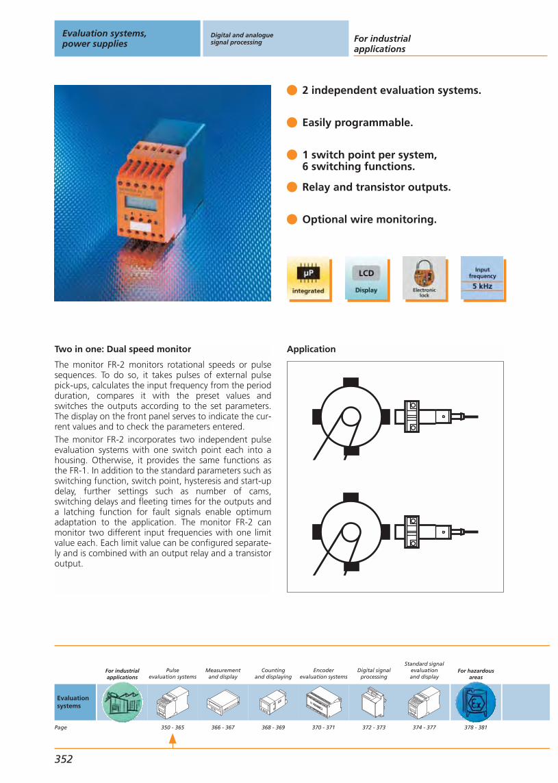
Two in one: Dual speed monitor
The monitor FR-2 monitors rotational speeds or pulsesequences. To do so, it takes pulses of external pulsepick-ups, calculates the input frequency from the periodduration, compares it with the preset values and switches the outputs according to the set parameters.The display on the front panel serves to indicate the cur-rent values and to check the parameters entered.The monitor FR-2 incorporates two independent pulseevaluation systems with one switch point each into ahousing. Otherwise, it provides the same functions asthe FR-1. In addition to the standard parameters such asswitching function, switch point, hysteresis and start-updelay, further settings such as number of cams, switching delays and fleeting times for the outputs and a latching function for fault signals enable optimumadaptation to the application. The monitor FR-2 canmonitor two different input frequencies with one limitvalue each. Each limit value can be configured separate-ly and is combined with an output relay and a transistor output.
2 independent evaluation systems.
Easily programmable.
1 switch point per system,6 switching functions.
Relay and transistor outputs.
Optional wire monitoring.
Application
Evaluation systems,power supplies
Digital and analoguesignal processing For industrial
applications
352
Evaluationsystems
Page
For industrialapplications
Pulseevaluation systems
350 - 365
Measurementand display
366 - 367
Countingand displaying
368 - 369
Encoderevaluation systems
370 - 371
Digital signalprocessing
372 - 373
Standard signalevaluationand display
374 - 377
For hazardousareas
378 - 381

Front view
1 4 652
19 20 21 22 23 24
13 14 15 16 17 18
3
97A1 8A2 10 11 12
Monitor FR-2; FR-2NDouble pulse evaluation systemalso with AC/DC wide-range power supply
Ub
[V]
In-puts
Inputfunction
Settingrange
[puls. / min.]
Settingrange[Hz]
Out-puts
analog
Out-puts
relays
Out-puts
transist.
Out-puts
faults
Draw-ingno.
Orderno.
MONITOR FR-2
230 AC / 24 DC 2 PNP / NPN / Namur 1...60000 0.1...1000 – 2 2 – 1 DD2002
110...240 AC/DC / 27 DC 2 PNP / NPN / Namur 1...60000 0.1...1000 – 2 2 – 1 DD2005
23...60 AC/DC / 27 DC 2 PNP / NPN / Namur 1...60000 0.1...1000 – 2 2 – 1 DD2006
MONITOR FR-2N
110...240 AC/DC / 27 DC 2 Namur 8.2 V 1...60000 0.1...1000 – 2 2 2 1 DD2105
You can find scale drawings from page 494
For safetyapplications
382 - 387
Powersupplies
For industrialapplications
Transformerpower supplies
388 - 389
Switched-modepower supplies
390 - 391
Digital and analoguesignal processing
Gen
eral
info
rmat
ion
List
of
arti
cles
Ind
uct
ive
sen
sors
Cap
acit
ive
sen
sors
Mag
net
icse
nso
rs,
cylin
der
sen
sors
Safe
tyte
chn
olo
gy
Val
ve s
enso
rsPh
oto
elec
tric
sen
sors
Ob
ject
reco
gn
itio
nEn
cod
ers
Eval
uat
ion
syst
ems,
po
wer
su
pp
lies
Co
nn
ecti
on
tech
no
log
yA
cces
sori
esTe
chn
ical
info
rmat
ion
and
cu
sto
mer
serv
ice
353
The FR-2 and FR-2N have a monitoring range of 1...60,000 pulses / min. or1...1,000 Hz. The maximum input frequency is 5 kHz. The monitors are setby means of three programming buttons and the LCD display on the frontpanel.
Terminal connection DD2002, DD2005, DD2006
*A power supply
*C sensor supply
*B supply transistor output
*D relay output
*E output
*F n.c. for FD-2
n. c.
n. c.
1
2
3
4
5
6
7
8
*A24 V DC
*B
1 pnp
*C
*AAC / DC
9
10
11
12
13
14
15
16
n. c.
1 npn
2 pnp
2 npn
*D 1
*E 1 pnp
17
18
19
20
21
22
23
24
reset 1 pnp
*F reset 2 pnp
*D 2
*E 2 pnp
sensor
sensor
For other terminal connections see www. ifm-electronic.com
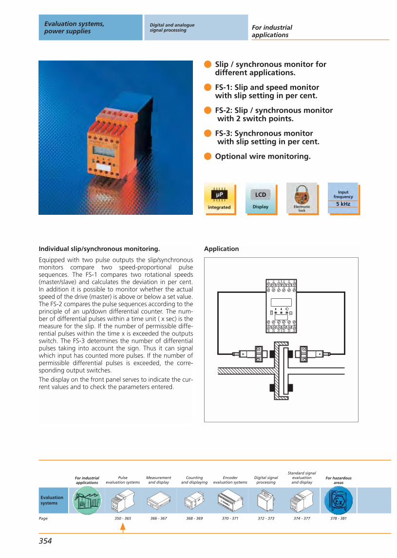
Individual slip/synchronous monitoring.
Equipped with two pulse outputs the slip/synchronousmonitors compare two speed-proportional pulsesequences. The FS-1 compares two rotational speeds(master/slave) and calculates the deviation in per cent.In addition it is possible to monitor whether the actualspeed of the drive (master) is above or below a set value.The FS-2 compares the pulse sequences according to theprinciple of an up/down differential counter. The num-ber of differential pulses within a time unit ( x sec) is themeasure for the slip. If the number of permissible diffe-rential pulses within the time x is exceeded the outputsswitch. The FS-3 determines the number of differentialpulses taking into account the sign. Thus it can signalwhich input has counted more pulses. If the number ofpermissible differential pulses is exceeded, the corre-sponding output switches.The display on the front panel serves to indicate the cur-rent values and to check the parameters entered.
Slip / synchronous monitor for different applications.
FS-1: Slip and speed monitor with slip setting in per cent.
FS-2: Slip / synchronous monitorwith 2 switch points.
FS-3: Synchronous monitorwith slip setting in per cent.
Optional wire monitoring.
Application
1 4 652
19 20 21 22 23 24
13 14 15 16 17 18
3
97A1 8A2 10 11 12
Evaluation systems,power supplies
Digital and analoguesignal processing For industrial
applications
354
Evaluationsystems
Page
For industrialapplications
Pulseevaluation systems
350 - 365
Measurementand display
366 - 367
Countingand displaying
368 - 369
Encoderevaluation systems
370 - 371
Digital signalprocessing
372 - 373
Standard signalevaluationand display
374 - 377
For hazardousareas
378 - 381
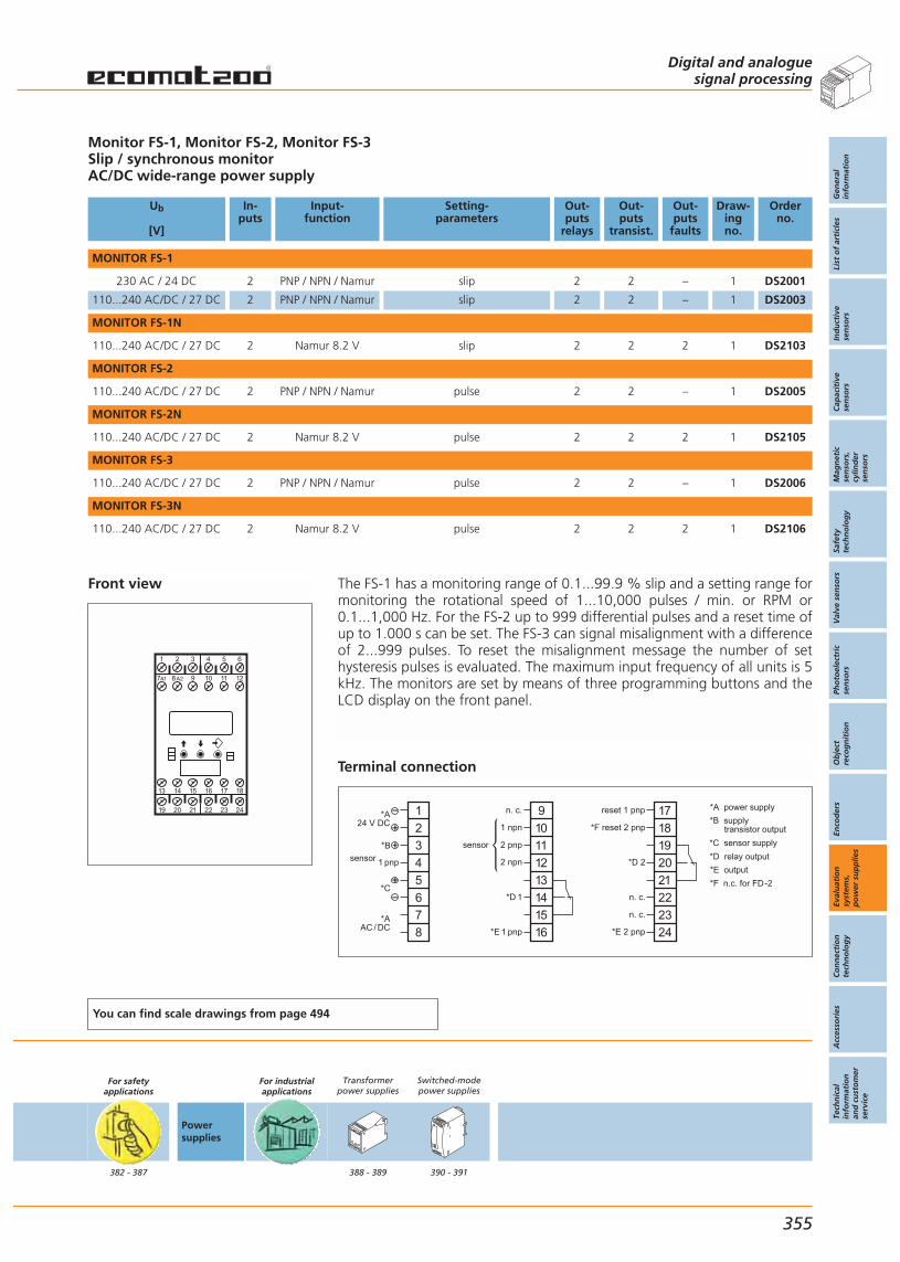
Front view
1 4 652
19 20 21 22 23 24
13 14 15 16 17 18
3
97A1 8A2 10 11 12
Monitor FS-1, Monitor FS-2, Monitor FS-3Slip / synchronous monitorAC/DC wide-range power supply
Ub
[V]
In-puts
Input-function
Setting-parameters
Out-puts
relays
Out-puts
transist.
Out-puts
faults
Draw-ingno.
Orderno.
MONITOR FS-1
230 AC / 24 DC 2 PNP / NPN / Namur slip 2 2 – 1 DS2001
110...240 AC/DC / 27 DC 2 PNP / NPN / Namur slip 2 2 – 1 DS2003
MONITOR FS-1N
110...240 AC/DC / 27 DC 2 Namur 8.2 V slip 2 2 2 1 DS2103
MONITOR FS-2
110...240 AC/DC / 27 DC 2 PNP / NPN / Namur pulse 2 2 – 1 DS2005
MONITOR FS-2N
110...240 AC/DC / 27 DC 2 Namur 8.2 V pulse 2 2 2 1 DS2105
MONITOR FS-3
110...240 AC/DC / 27 DC 2 PNP / NPN / Namur pulse 2 2 – 1 DS2006
MONITOR FS-3N
110...240 AC/DC / 27 DC 2 Namur 8.2 V pulse 2 2 2 1 DS2106
You can find scale drawings from page 494
For safetyapplications
382 - 387
Powersupplies
For industrialapplications
Transformerpower supplies
388 - 389
Switched-modepower supplies
390 - 391
Digital and analoguesignal processing
Gen
eral
info
rmat
ion
List
of
arti
cles
Ind
uct
ive
sen
sors
Cap
acit
ive
sen
sors
Mag
net
icse
nso
rs,
cylin
der
sen
sors
Safe
tyte
chn
olo
gy
Val
ve s
enso
rsPh
oto
elec
tric
sen
sors
Ob
ject
reco
gn
itio
nEn
cod
ers
Eval
uat
ion
syst
ems,
po
wer
su
pp
lies
Co
nn
ecti
on
tech
no
log
yA
cces
sori
esTe
chn
ical
info
rmat
ion
and
cu
sto
mer
serv
ice
355
The FS-1 has a monitoring range of 0.1...99.9 % slip and a setting range formonitoring the rotational speed of 1...10,000 pulses / min. or RPM or0.1...1,000 Hz. For the FS-2 up to 999 differential pulses and a reset time ofup to 1.000 s can be set. The FS-3 can signal misalignment with a differenceof 2...999 pulses. To reset the misalignment message the number of sethysteresis pulses is evaluated. The maximum input frequency of all units is 5kHz. The monitors are set by means of three programming buttons and theLCD display on the front panel.
Terminal connection
*A power supply
*C sensor supply
*B supply transistor output
*D relay output
*E output
*F n.c. for FD-2
n. c.
n. c.
1
2
3
4
5
6
7
8
*A24 V DC
*B
1 pnp
*C
*AAC / DC
9
10
11
12
13
14
15
16
n. c.
1 npn
2 pnp
2 npn
*D 1
*E 1 pnp
17
18
19
20
21
22
23
24
reset 1 pnp
*F reset 2 pnp
*D 2
*E 2 pnp
sensor
sensor
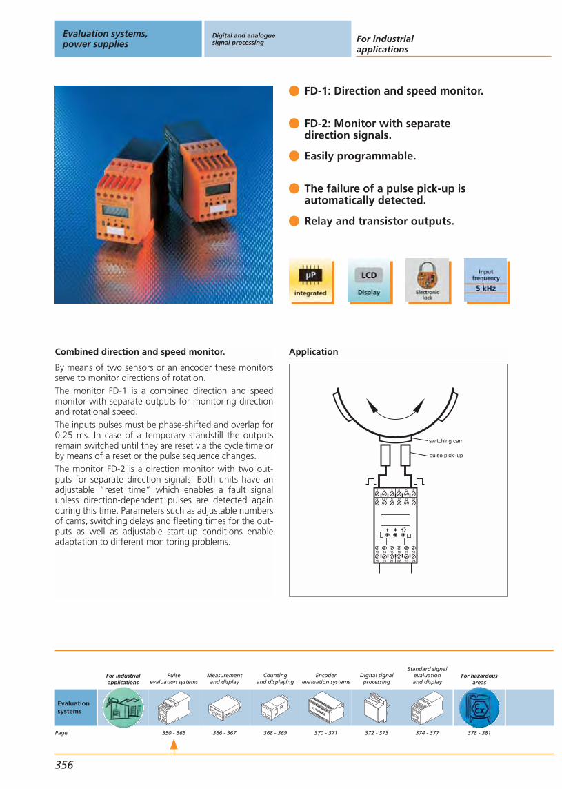
Combined direction and speed monitor.
By means of two sensors or an encoder these monitorsserve to monitor directions of rotation.The monitor FD-1 is a combined direction and speedmonitor with separate outputs for monitoring directionand rotational speed.The inputs pulses must be phase-shifted and overlap for0.25 ms. In case of a temporary standstill the outputsremain switched until they are reset via the cycle time orby means of a reset or the pulse sequence changes. The monitor FD-2 is a direction monitor with two out-puts for separate direction signals. Both units have anadjustable “reset time” which enables a fault signalunless direction-dependent pulses are detected againduring this time. Parameters such as adjustable numbersof cams, switching delays and fleeting times for the out-puts as well as adjustable start-up conditions enableadaptation to different monitoring problems.
FD-1: Direction and speed monitor.
FD-2: Monitor with separatedirection signals.
Easily programmable.
The failure of a pulse pick-up isautomatically detected.
Relay and transistor outputs.
Application
switching cam
pulse pick-up
1 4 652
19 20 21 22 23 24
13 14 15 16 17 18
3
97A1 8A2 10 11 12
Evaluation systems,power supplies
Digital and analoguesignal processing For industrial
applications
356
Evaluationsystems
Page
For industrialapplications
Pulseevaluation systems
350 - 365
Measurementand display
366 - 367
Countingand displaying
368 - 369
Encoderevaluation systems
370 - 371
Digital signalprocessing
372 - 373
Standard signalevaluationand display
374 - 377
For hazardousareas
378 - 381
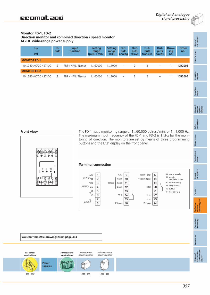
Front view
1 4 652
19 20 21 22 23 24
13 14 15 16 17 18
3
97A1 8A2 10 11 12
Monitor FD-1, FD-2Direction monitor and combined direction / speed monitorAC/DC wide-range power supply
Ub
[V]
In-puts
Inputfunction
Settingrange
[puls. / min.]
Settingrange[Hz]
Out-puts
analog
Out-puts
relays
Out-puts
transist.
Out-puts
faults
Draw-ingno.
Orderno.
MONITOR FD-1
110...240 AC/DC / 27 DC 2 PNP / NPN / Namur 1...60000 1...1000 – 2 2 – 1 DR2003
MONITOR FD-2
110...240 AC/DC / 27 DC 2 PNP / NPN / Namur 1...60000 1...1000 – 2 2 – 1 DR2005
You can find scale drawings from page 494
For safetyapplications
382 - 387
Powersupplies
For industrialapplications
Transformerpower supplies
388 - 389
Switched-modepower supplies
390 - 391
Digital and analoguesignal processing
Gen
eral
info
rmat
ion
List
of
arti
cles
Ind
uct
ive
sen
sors
Cap
acit
ive
sen
sors
Mag
net
icse
nso
rs,
cylin
der
sen
sors
Safe
tyte
chn
olo
gy
Val
ve s
enso
rsPh
oto
elec
tric
sen
sors
Ob
ject
reco
gn
itio
nEn
cod
ers
Eval
uat
ion
syst
ems,
po
wer
su
pp
lies
Co
nn
ecti
on
tech
no
log
yA
cces
sori
esTe
chn
ical
info
rmat
ion
and
cu
sto
mer
serv
ice
357
The FD-1 has a monitoring range of 1...60,000 pulses / min. or 1...1,000 Hz.The maximum input frequency of the FD-1 and FD-2 is 1 kHz for the moni-toring of direction. The monitors are set by means of three programmingbuttons and the LCD display on the front panel.
Terminal connection
*A power supply
*C sensor supply
*B supply transistor output
*D relay output
*E output
*F n.c. for FD-2
n. c.
n. c.
1
2
3
4
5
6
7
8
*A24 V DC
*B
1 pnp
*C
*AAC / DC
9
10
11
12
13
14
15
16
n. c.
1 npn
2 pnp
2 npn
*D 1
*E 1 pnp
17
18
19
20
21
22
23
24
reset 1 pnp
*F reset 2 pnp
*D 2
*E 2 pnp
sensor
sensor
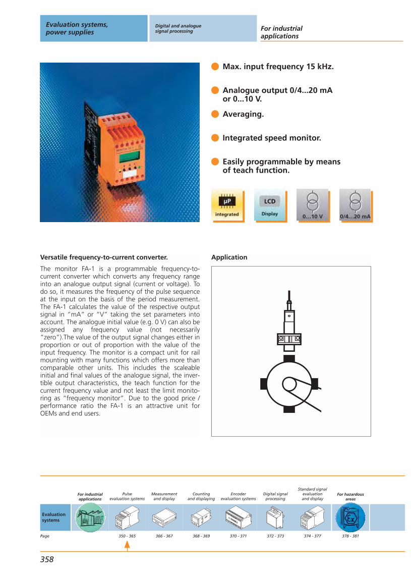
Versatile frequency-to-current converter.
The monitor FA-1 is a programmable frequency-to-current converter which converts any frequency rangeinto an analogue output signal (current or voltage). Todo so, it measures the frequency of the pulse sequenceat the input on the basis of the period measurement.The FA-1 calculates the value of the respective outputsignal in “mA” or “V” taking the set parameters intoaccount. The analogue initial value (e.g. 0 V) can also beassigned any frequency value (not necessarily“zero”).The value of the output signal changes either inproportion or out of proportion with the value of theinput frequency. The monitor is a compact unit for railmounting with many functions which offers more thancomparable other units. This includes the scaleable initial and final values of the analogue signal, the inver-tible output characteristics, the teach function for thecurrent frequency value and not least the limit monito-ring as “frequency monitor”. Due to the good price /performance ratio the FA-1 is an attractive unit forOEMs and end users.
Max. input frequency 15 kHz.
Analogue output 0/4...20 mAor 0...10 V.
Averaging.
Integrated speed monitor.
Easily programmable by means of teach function.
Application
Evaluation systems,power supplies
Digital and analoguesignal processing For industrial
applications
358
Evaluationsystems
Page
For industrialapplications
Pulseevaluation systems
350 - 365
Measurementand display
366 - 367
Countingand displaying
368 - 369
Encoderevaluation systems
370 - 371
Digital signalprocessing
372 - 373
Standard signalevaluationand display
374 - 377
For hazardousareas
378 - 381

Front view
1 4 652
19 20 21 22 23 24
13 14 15 16 17 18
3
97A1 8A2 10 11 12
Monitor FA-1Frequency-to-current converterSpeed monitor / jam indicator
Ub
[V]
In-puts
Inputfunction
Settingrange
[puls. / min.]
Settingrange[Hz]
Out-puts
analog
Out-puts
relays
Out-puts
transist.
Out-puts
faults
Draw-ingno.
Orderno.
27 DC 2 PNP / NPN / Namur 0...600000 0.0...10000 2 2 2 – 1 DW2004
110...240 AC/DC / 27 DC 2 PNP / NPN / Namur 0...600000 0.0...10000 2 2 2 – 1 DW2003
You can find scale drawings from page 494
For safetyapplications
382 - 387
Powersupplies
For industrialapplications
Transformerpower supplies
388 - 389
Switched-modepower supplies
390 - 391
Digital and analoguesignal processing
Gen
eral
info
rmat
ion
List
of
arti
cles
Ind
uct
ive
sen
sors
Cap
acit
ive
sen
sors
Mag
net
icse
nso
rs,
cylin
der
sen
sors
Safe
tyte
chn
olo
gy
Val
ve s
enso
rsPh
oto
elec
tric
sen
sors
Ob
ject
reco
gn
itio
nEn
cod
ers
Eval
uat
ion
syst
ems,
po
wer
su
pp
lies
Co
nn
ecti
on
tech
no
log
yA
cces
sori
esTe
chn
ical
info
rmat
ion
and
cu
sto
mer
serv
ice
359
The FA-1 has a transmission range of 0...600,000 pulses / min. or0.1...10,000 Hz for the frequency-to-current conversion and a setting rangefor monitoring the rotational speed of 1...60,000 pulses / min. or 01....1,000Hz. The maximum input frequency for the FA-1 is 5 kHz. The monitor FA-1 isset by means of three programming buttons and the LCD display on thefront panel.
Terminal connection
*A power supply
*C sensor signal
*B supply transistor output
*E relay output
*D sensor supply
*F transistor output
*G analogue
1
2
3
4
5
6
7
8
*A24 V DC
*B
*C pnp
9
10
11
12
13
14
15
16
n. c.
reset pnp
*F pnp
*E
n. c.
17
18
19
20
21
22
23
24
*G
V
*D
*D
n. c.
n. c.
*C npn
n. c.
n. c.
n. c.
n. c.
n. c.
mA

Standard speed monitor.
The D 100 is an analogue evaluation system for easymonitoring of rotational speeds and pulse sequences. Todo so, it takes for example signals of inductive, capaci-tive or photoelectric sensors, incremental encoders ormechanical pulse pick-ups. From the period duration(time difference between the pulses) it determines theinput frequency (current value), compares it with the setswitch point (preset value) and switches the outputsaccordingly. The D 100 is set by means of selector switches for the switching functions and frequency ranges. The user can set the parameters for switchpoint, hysteresis and start-up delay using a potentio-meter on the front panel of the unit.
Easily adjustable.
4 switching functions.
AC/DC wide-range power supply.
Relay and transistor outputs.
Favourable price / performance ratio.
Application
Evaluation systems,power supplies
Digital and analoguesignal processing For industrial
applications
360
Evaluationsystems
Page
For industrialapplications
Pulseevaluation systems
350 - 365
Measurementand display
366 - 367
Countingand displaying
368 - 369
Encoderevaluation systems
370 - 371
Digital signalprocessing
372 - 373
Standard signalevaluationand display
374 - 377
For hazardousareas
378 - 381

Front view
1 2 3 4 5 6 7 8
9 10 11 12 13 14 15 16
Speed monitor D 100Standard pulse evaluation system
Ub
[V]
In-puts
Inputfunction
Settingrange
[puls. / min.]
Settingrange[Hz]
Out-puts
analog
Out-puts
relays
Out-puts
transist.
Out-puts
faults
Draw-ingno.
Orderno.
230 AC / 24 DC 1 PNP 5...5000 – – 1 – – 2 DD0001
12 / 24 DC 1 PNP 5...5000 – – 1 – – 2 DD0008
230 AC / 24 DC 1 PNP 10...10000 – – 1 – – 2 DD0022
110...240 AC/DC / 27 DC 1 PNP 5...5000 – – 1 1 – 2 DD0116
27...60 AC/DC / 27 DC 1 PNP 5...5000 – – 1 1 – 2 DD0122
You can find scale drawings from page 494
For safetyapplications
382 - 387
Powersupplies
For industrialapplications
Transformerpower supplies
388 - 389
Switched-modepower supplies
390 - 391
Digital and analoguesignal processing
Gen
eral
info
rmat
ion
List
of
arti
cles
Ind
uct
ive
sen
sors
Cap
acit
ive
sen
sors
Mag
net
icse
nso
rs,
cylin
der
sen
sors
Safe
tyte
chn
olo
gy
Val
ve s
enso
rsPh
oto
elec
tric
sen
sors
Ob
ject
reco
gn
itio
nEn
cod
ers
Eval
uat
ion
syst
ems,
po
wer
su
pp
lies
Co
nn
ecti
on
tech
no
log
yA
cces
sori
esTe
chn
ical
info
rmat
ion
and
cu
sto
mer
serv
ice
361
The D 100 has a monitoring range of 5...5,000 pulses / min. The maximuminput frequency is 250 Hz or 15,000 pulses / min. The D 100 is set by meansof two selector switches for the switching functions and frequency ranges.Switch point, hysteresis and start-up delay are set with potentiometers onthe front panel of the unit.
Terminal connection DD0116, DD0122
*A power supply
1
2
3
4
5
6
7
8
9
10
11
12
13
14
15
16
*A 24 V DC
sensor
signal
~ +
~ –
relay output
transistor output
*A AC / DC
For other terminal connections see www. ifm-electronic.com
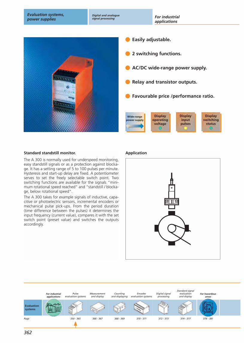
Standard standstill monitor.
The A 300 is normally used for underspeed monitoring,easy standstill signals or as a protection against blocka-ge. It has a setting range of 5 to 100 pulses per minute.Hysteresis and start-up delay are fixed. A potentiometerserves to set the freely selectable switch point. Two switching functions are available for the signals “mini-mum rotational speed reached” and “standstill / blocka-ge, below rotational speed”.The A 300 takes for example signals of inductive, capa-citive or photoelectric sensors, incremental encoders ormechanical pulse pick-ups. From the period duration(time difference between the pulses) it determines theinput frequency (current value), compares it with the setswitch point (preset value) and switches the outputsaccordingly.
Easily adjustable.
2 switching functions.
AC/DC wide-range power supply.
Relay and transistor outputs.
Favourable price /performance ratio.
Application
Evaluation systems,power supplies
Digital and analoguesignal processing For industrial
applications
362
Evaluationsystems
Page
For industrialapplications
Pulseevaluation systems
350 - 365
Measurementand display
366 - 367
Countingand displaying
368 - 369
Encoderevaluation systems
370 - 371
Digital signalprocessing
372 - 373
Standard signalevaluationand display
374 - 377
For hazardousareas
378 - 381

Front view
1 2 3 4 5 6 7 8
9 10 11 12 13 14 15 16
Standstill monitor A 300Standard pulse evaluation system
Ub
[V]
In-puts
Inputfunction
Settingrange
[puls. / min.]
Settingrange[Hz]
Out-puts
analog
Out-puts
relays
Out-puts
transist.
Out-puts
faults
Draw-ingno.
Orderno.
230 AC / 24 DC 1 PNP 5...25 / 20...100 – – 1 – – 3 DA0001
110...240 AC/DC / 27 DC 1 PNP 5...25 / 20...100 – – 1 1 – 3 DA0116
27...60 AC/DC / 27 DC 1 PNP 5...25 / 20...100 – – 1 1 – 3 DA0122
You can find scale drawings from page 494
For safetyapplications
382 - 387
Powersupplies
For industrialapplications
Transformerpower supplies
388 - 389
Switched-modepower supplies
390 - 391
Digital and analoguesignal processing
Gen
eral
info
rmat
ion
List
of
arti
cles
Ind
uct
ive
sen
sors
Cap
acit
ive
sen
sors
Mag
net
icse
nso
rs,
cylin
der
sen
sors
Safe
tyte
chn
olo
gy
Val
ve s
enso
rsPh
oto
elec
tric
sen
sors
Ob
ject
reco
gn
itio
nEn
cod
ers
Eval
uat
ion
syst
ems,
po
wer
su
pp
lies
Co
nn
ecti
on
tech
no
log
yA
cces
sori
esTe
chn
ical
info
rmat
ion
and
cu
sto
mer
serv
ice
363
The A 300 has a monitoring range of 5...100 pulses / min. The maximuminput frequency is 250 Hz or 15,000 pulses / min. The switch point of the A 300 is set by means of a potentiometer on the front panel of the unit. Switching functions and frequency ranges are set using a selector switch.The hysteresis and the start-up delay are fixed.
Terminal connection DA0116, DA0122
*A power supply
1
2
3
4
5
6
7
8
9
10
11
12
13
14
15
16
*A 24 V DC
sensor
signal
~ +
~ –
relay output
transistor output
*A AC / DC
For other terminal connections see www. ifm-electronic.com
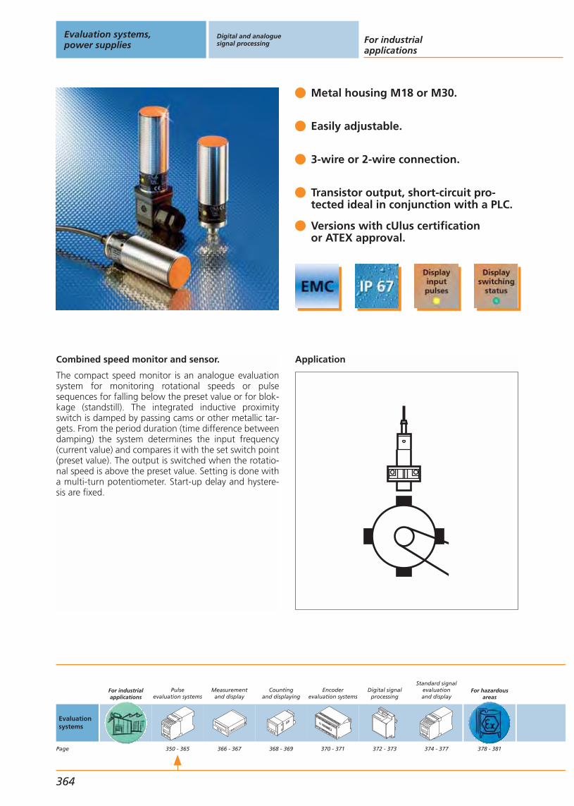
Combined speed monitor and sensor.
The compact speed monitor is an analogue evaluationsystem for monitoring rotational speeds or pulsesequences for falling below the preset value or for blok-kage (standstill). The integrated inductive proximityswitch is damped by passing cams or other metallic tar-gets. From the period duration (time difference betweendamping) the system determines the input frequency(current value) and compares it with the set switch point(preset value). The output is switched when the rotatio-nal speed is above the preset value. Setting is done witha multi-turn potentiometer. Start-up delay and hystere-sis are fixed.
Metal housing M18 or M30.
Easily adjustable.
3-wire or 2-wire connection.
Transistor output, short-circuit pro-tected ideal in conjunction with a PLC.
Versions with cUlus certification or ATEX approval.
Application
Evaluation systems,power supplies
Digital and analoguesignal processing For industrial
applications
364
Evaluationsystems
Page
For industrialapplications
Pulseevaluation systems
350 - 365
Measurementand display
366 - 367
Countingand displaying
368 - 369
Encoderevaluation systems
370 - 371
Digital signalprocessing
372 - 373
Standard signalevaluationand display
374 - 377
For hazardousareas
378 - 381
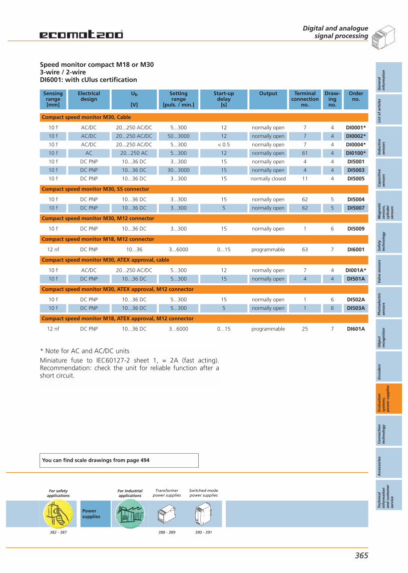
* Note for AC and AC/DC unitsMiniature fuse to IEC60127-2 sheet 1, = 2A (fast acting).Recommendation: check the unit for reliable function after ashort circuit.
Speed monitor compact M18 or M303-wire / 2-wireDI6001: with cUlus certification
Sensingrange[mm]
Electricaldesign
Ub
[V]
Settingrange
[puls. / min.]
Start-updelay
[s]
Output Terminalconnection
no.
Draw-ingno.
Orderno.
Compact speed monitor M30, Cable
10 f AC/DC 20...250 AC/DC 5...300 12 normally open 7 4 DI0001*
10 f AC/DC 20...250 AC/DC 50...3000 12 normally open 7 4 DI0002*
10 f AC/DC 20...250 AC/DC 5...300 < 0.5 normally open 7 4 DI0004*
10 f AC 20...250 AC 5...300 12 normally open 61 4 DI0100*
10 f DC PNP 10...36 DC 3...300 15 normally open 4 4 DI5001
10 f DC PNP 10...36 DC 30...3000 15 normally open 4 4 DI5003
10 f DC PNP 10...36 DC 3...300 15 normally closed 11 4 DI5005
Compact speed monitor M30, SS connector
10 f DC PNP 10...36 DC 3...300 15 normally open 62 5 DI5004
10 f DC PNP 10...36 DC 3...300 5 normally open 62 5 DI5007
Compact speed monitor M30, M12 connector
10 f DC PNP 10...36 DC 3...300 15 normally open 1 6 DI5009
Compact speed monitor M18, M12 connector
12 nf DC PNP 10...36 3...6000 0...15 programmable 63 7 DI6001
Compact speed monitor M30, ATEX approval, cable
10 f AC/DC 20...250 AC/DC 5...300 12 normally open 7 4 DI001A*
10 f DC PNP 10...36 DC 5...300 15 normally open 4 4 DI501A
Compact speed monitor M30, ATEX approval, M12 connector
10 f DC PNP 10...36 DC 5...300 15 normally open 1 6 DI502A
10 f DC PNP 10...36 DC 5...300 5 normally open 1 6 DI503A
Compact speed monitor M18, ATEX approval, M12 connector
12 nf DC PNP 10...36 DC 3...6000 0...15 programmable 25 7 DI601A
You can find scale drawings from page 494
For safetyapplications
382 - 387
Powersupplies
For industrialapplications
Transformerpower supplies
388 - 389
Switched-modepower supplies
390 - 391
Digital and analoguesignal processing
Gen
eral
info
rmat
ion
List
of
arti
cles
Ind
uct
ive
sen
sors
Cap
acit
ive
sen
sors
Mag
net
icse
nso
rs,
cylin
der
sen
sors
Safe
tyte
chn
olo
gy
Val
ve s
enso
rsPh
oto
elec
tric
sen
sors
Ob
ject
reco
gn
itio
nEn
cod
ers
Eval
uat
ion
syst
ems,
po
wer
su
pp
lies
Co
nn
ecti
on
tech
no
log
yA
cces
sori
esTe
chn
ical
info
rmat
ion
and
cu
sto
mer
serv
ice
365
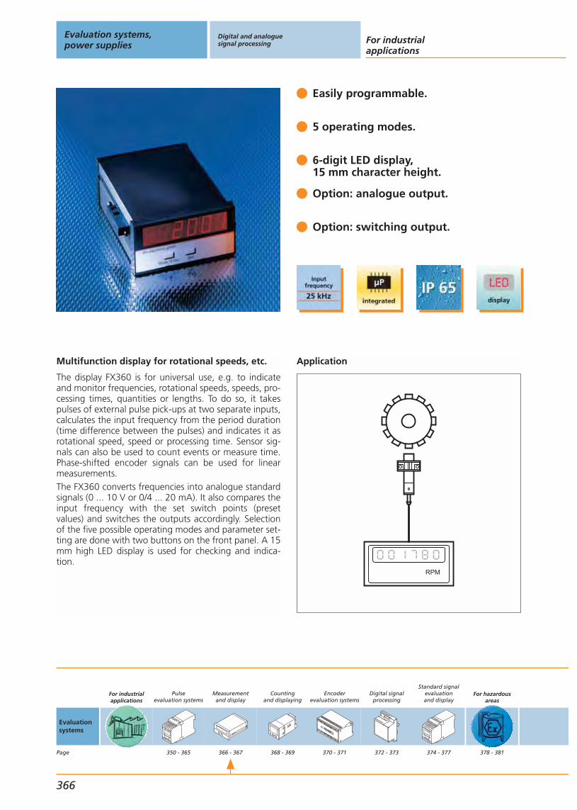
Multifunction display for rotational speeds, etc.
The display FX360 is for universal use, e.g. to indicateand monitor frequencies, rotational speeds, speeds, pro-cessing times, quantities or lengths. To do so, it takespulses of external pulse pick-ups at two separate inputs,calculates the input frequency from the period duration(time difference between the pulses) and indicates it asrotational speed, speed or processing time. Sensor sig-nals can also be used to count events or measure time.Phase-shifted encoder signals can be used for linearmeasurements.The FX360 converts frequencies into analogue standardsignals (0 ... 10 V or 0/4 ... 20 mA). It also compares theinput frequency with the set switch points (presetvalues) and switches the outputs accordingly. Selectionof the five possible operating modes and parameter set-ting are done with two buttons on the front panel. A 15mm high LED display is used for checking and indica-tion.
Easily programmable.
5 operating modes.
6-digit LED display,15 mm character height.
Option: analogue output.
Option: switching output.
Application
RPM
Evaluation systems,power supplies
Digital and analoguesignal processing For industrial
applications
366
Evaluationsystems
Page
For industrialapplications
Pulseevaluation systems
350 - 365
Measurementand display
366 - 367
Countingand displaying
368 - 369
Encoderevaluation systems
370 - 371
Digital signalprocessing
372 - 373
Standard signalevaluationand display
374 - 377
For hazardousareas
378 - 381

Front view
Display FX360Frequency, rotational speed and speed meterIndustrial timer and counter
Ub
[V]
In-puts
Inputfunction
Settingrange
[puls. / min.]
Settingrange[Hz]
Out-puts
analog
Out-puts
relays
Out-puts
transist.
Out-puts
faults
Draw-ingno.
Orderno.
115 / 230 AC; 24 DC 1 PNP / NPN / Namur 6...99999 0.1...25000 – – – – 8 DX2001
115 / 230 AC; 24 DC 1 PNP / NPN / Namur 6...99999 0.1...25000 1 – – – 8 DX2002
115 / 230 AC; 24 DC 1 PNP / NPN / Namur 6...99999 0.1...25000 – – 2 – 8 DX2003
You can find scale drawings from page 494
For safetyapplications
382 - 387
Powersupplies
For industrialapplications
Transformerpower supplies
388 - 389
Switched-modepower supplies
390 - 391
Digital and analoguesignal processing
Gen
eral
info
rmat
ion
List
of
arti
cles
Ind
uct
ive
sen
sors
Cap
acit
ive
sen
sors
Mag
net
icse
nso
rs,
cylin
der
sen
sors
Safe
tyte
chn
olo
gy
Val
ve s
enso
rsPh
oto
elec
tric
sen
sors
Ob
ject
reco
gn
itio
nEn
cod
ers
Eval
uat
ion
syst
ems,
po
wer
su
pp
lies
Co
nn
ecti
on
tech
no
log
yA
cces
sori
esTe
chn
ical
info
rmat
ion
and
cu
sto
mer
serv
ice
367
The FX360 has a monitoring and display range of 0.1...25 kHz or 99,999pulses / min. The time range is up to 999,999 seconds and the countingrange covers -99,999...+99,999. The parameter values are set by means oftwo programming buttons and the LCD display on the front panel.
Terminal connection
electrical connections DX 2001...2003
GND
230 V AC
115 V AC
0 V AC
24 V DC Out
GND
reset
input B
input A
18...30 V DC IN
GND
DX 2002
10
9
8
0/4...20 mA
+/– 10 V
GND
DX 2001
10
9
8
NC
NC
NC
DX 2003
10
9
8
Out 2
Out 1
COM +
7
6
5
4
3
2
1
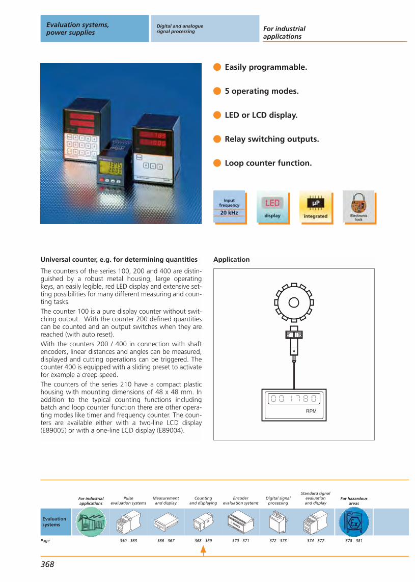
Universal counter, e.g. for determining quantities
The counters of the series 100, 200 and 400 are distin-guished by a robust metal housing, large operatingkeys, an easily legible, red LED display and extensive set-ting possibilities for many different measuring and coun-ting tasks.The counter 100 is a pure display counter without swit-ching output. With the counter 200 defined quantitiescan be counted and an output switches when they arereached (with auto reset).With the counters 200 / 400 in connection with shaftencoders, linear distances and angles can be measured,displayed and cutting operations can be triggered. Thecounter 400 is equipped with a sliding preset to activatefor example a creep speed.The counters of the series 210 have a compact plastichousing with mounting dimensions of 48 x 48 mm. Inaddition to the typical counting functions includingbatch and loop counter function there are other opera-ting modes like timer and frequency counter. The coun-ters are available either with a two-line LCD display(E89005) or with a one-line LCD display (E89004).
Easily programmable.
5 operating modes.
LED or LCD display.
Relay switching outputs.
Loop counter function.
Application
RPM
Evaluation systems,power supplies
Digital and analoguesignal processing For industrial
applications
368
Evaluationsystems
Page
For industrialapplications
Pulseevaluation systems
350 - 365
Measurementand display
366 - 367
Countingand displaying
368 - 369
Encoderevaluation systems
370 - 371
Digital signalprocessing
372 - 373
Standard signalevaluationand display
374 - 377
For hazardousareas
378 - 381

Front view
P
Reset
>
Out
>
Display counter 100Preset counter 200Preset counter 400 with sliding preset
Ub
[V]
In-puts
Inputfunction
Countingfrequency
[Hz]
Out-puts
analog
Out-puts
relays
Out-puts
transist.
Out-puts
faults
Draw-ingno.
Orderno.
230 AC / 24 DC 2 PNP / NPN 20000 – – – – 9 DZ0101
230 AC / 24 DC 2 PNP / NPN 20000 – 1 – – 10 DZ0201
230 AC / 24 DC 2 PNP / NPN 20000 – 2 – – 11 DZ0401
90...260 AC 2 PNP / NPN 10000 – 2 – – 12 E89005
You can find scale drawings from page 494
For safetyapplications
382 - 387
Powersupplies
For industrialapplications
Transformerpower supplies
388 - 389
Switched-modepower supplies
390 - 391
Digital and analoguesignal processing
Gen
eral
info
rmat
ion
List
of
arti
cles
Ind
uct
ive
sen
sors
Cap
acit
ive
sen
sors
Mag
net
icse
nso
rs,
cylin
der
sen
sors
Safe
tyte
chn
olo
gy
Val
ve s
enso
rsPh
oto
elec
tric
sen
sors
Ob
ject
reco
gn
itio
nEn
cod
ers
Eval
uat
ion
syst
ems,
po
wer
su
pp
lies
Co
nn
ecti
on
tech
no
log
yA
cces
sori
esTe
chn
ical
info
rmat
ion
and
cu
sto
mer
serv
ice
369
All counters have an integrated 24 V DC voltage supply for the pulse pick-ups. For the series 100 / 200 / 400 it is also possible to supply shaft encoderswith a current consumption of up to 200 mA. The counters of the series 210can have a load of 60 mA.All counters can be locked to avoid unauthorised changes of the parame-ters.
Terminal connection
reset 13
12
11
10
9
8
7
6
5
4
3
2
1
ZU
PE
N
L1
230 V AC
24 V DC
Prog.MODE
subtraction B
addition A
sensor
power supply
Out 1
1
2
3
4
5
6
7
8
9
Out 1
1
2
3
4
5
6
7
8
9
Out 2
counter 100, 200, 400
counter 200 counter 400

SSI controller
The SSI controller enables connection of absolute enco-ders with SSI interface to the I/O module of the PLC. Thedata provided in Gray code are converted into paralleldata by the SSI controller. The output code can be set asbinary or BCD using a slide switch. The requested reso-lution can also be selected by means of a switch.Measured values are synchronised by clocking the PLC.The controller provides additional functions which indi-cate wire break, operator’s faults and voltage faults tothe user.
Output data scaleable.
Internal and external zeroing.
Integrated monitoring function.
Binary or BCD as outputcode selectable.
Short-circuit protected paralleloutputs.
Application
serial parallel
24 V DC
multiturnRM
SSI-controller
PLC
+ –
power adapter
Evaluation systems,power supplies
Digital and analoguesignal processing For industrial
applications
370
Evaluationsystems
Page
For industrialapplications
Pulseevaluation systems
350 - 365
Measurementand display
366 - 367
Countingand displaying
368 - 369
Encoderevaluation systems
370 - 371
Digital signalprocessing
372 - 373
Standard signalevaluationand display
374 - 377
For hazardousareas
378 - 381

Front view
1 2 3 4 5 6 7 8 9 10 11 12 13 14 15 16 17 18 19 20 21 22 23
24 25 26 27 28 29 30 31 32 33 34 35 36 37 38 39 40 41 42 43 44 45 46
Operating voltage 24 V DC ± 20%SSI input according to RS-485Short-circuit protected parallel outputs
Ub
[V]
Signal levelpulse pick-up
Signal leveloutput
Data frequencyoutput
Draw-ingno.
Orderno.
24 DC ± 20 % TTL compatible signals (according to RS485) High = 22.8 V / Low = 1.4 V
bin. 1 kHz, BCD 0.6 kHz dataoutput level High 22.8 V without
load / Low 1.4 V without load13 E65005
You can find scale drawings from page 494
For safetyapplications
382 - 387
Powersupplies
For industrialapplications
Transformerpower supplies
388 - 389
Switched-modepower supplies
390 - 391
Digital and analoguesignal processing
Gen
eral
info
rmat
ion
List
of
arti
cles
Ind
uct
ive
sen
sors
Cap
acit
ive
sen
sors
Mag
net
icse
nso
rs,
cylin
der
sen
sors
Safe
tyte
chn
olo
gy
Val
ve s
enso
rsPh
oto
elec
tric
sen
sors
Ob
ject
reco
gn
itio
nEn
cod
ers
Eval
uat
ion
syst
ems,
po
wer
su
pp
lies
Co
nn
ecti
on
tech
no
log
yA
cces
sori
esTe
chn
ical
info
rmat
ion
and
cu
sto
mer
serv
ice
371
The SSI controller has a typical current consumption of 150 mA for non-switch outputs. The encoder data are read at a frequency of 100 kHz. Thehousing has the protection rating IP 40, the terminals IP 20. The operatingtemperature is between 0...50 °C. It is fixed with two screws or on a DIN rail.For connection there are 46 self-opening terminals for a wire cross-sectionup to 2.5 mm .
Terminal connection
LSB
D 00 D 01 D 02 D 03 D 04 D 05 D 06 D 07 D 08 D 09 D 10 D 11 D 12 D 13 D 14 D 15 D 16 D 17 D 18 D 19 D 20 D 21 D 22
outputsmultiturn
LSB outputssingleturn
T TD DUN UP-SOENSTR
24 VDAV PYB D 30 D 29 D 28 D 27 D 26 D 25 D 24 D 23
outputsmultiturn
SSI-encoder -inputsupply
RSTn.c. n.c.

Extension of the input frequency range.
With pulse dividers high frequencies or quick pulsesequences can be adapted to low input frequencies ofevaluation systems and controllers. Pulse stretchersextend very short pulses, which are for example genera-ted while small parts are optically detected or toothedwheels are sensed, to a pulse length which is detectedby standard inputs of a PLC. Using the pulse divider thuseliminates the need of fast input cards.In addition, the pulse divider can also be used as a levelconverter of TTL and HTL signals irrespective of the setdivision factor.
Pulse divider adjustable up to 255:1.
100 kHz input frequency.
Converter TTL - HTL integrated.
Pulse divider 10:1; 2.5 kHz.
Pulse stretcher.
Schematics
10
1
Evaluation systems,power supplies
Digital and analoguesignal processing For industrial
applications
372
Evaluationsystems
Page
For industrialapplications
Pulseevaluation systems
350 - 365
Measurementand display
366 - 367
Countingand displaying
368 - 369
Encoderevaluation systems
370 - 371
Digital signalprocessing
372 - 373
Standard signalevaluationand display
374 - 377
For hazardousareas
378 - 381
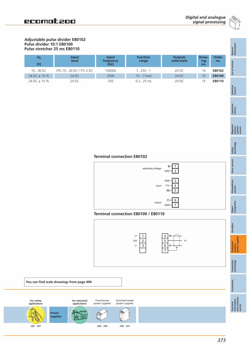
Adjustable pulse divider E80102Pulse divider 10:1 E80100Pulse stretcher 25 ms E80110
Ub
[V]
Inputlevel
Inputfrequency
[Hz]
Functionrange
Outputssolid-state
Draw-ingno.
Orderno.
10...36 DC HTL 10...30 DC / TTL 5 DC 100000 1...255 : 1 24 DC 14 E80102
24 DC ± 10 % 24 DC 2500 10 : 1 fixed 24 DC 15 E80100
24 DC ± 10 % 24 DC 250 0.2...25 ms 24 DC 15 E80110
You can find scale drawings from page 494
For safetyapplications
382 - 387
Powersupplies
For industrialapplications
Transformerpower supplies
388 - 389
Switched-modepower supplies
390 - 391
Digital and analoguesignal processing
Gen
eral
info
rmat
ion
List
of
arti
cles
Ind
uct
ive
sen
sors
Cap
acit
ive
sen
sors
Mag
net
icse
nso
rs,
cylin
der
sen
sors
Safe
tyte
chn
olo
gy
Val
ve s
enso
rsPh
oto
elec
tric
sen
sors
Ob
ject
reco
gn
itio
nEn
cod
ers
Eval
uat
ion
syst
ems,
po
wer
su
pp
lies
Co
nn
ecti
on
tech
no
log
yA
cces
sori
esTe
chn
ical
info
rmat
ion
and
cu
sto
mer
serv
ice
373
Terminal connection E80102
TTL
GND
GND
GND
1
2operating voltage
input
output
3
4
5
6
7
Terminal connection E80100 / E80110
1
2
3
Out
4
5
6
7
L+
L
In

2-channel threshold relay for standard signals
The Monitor AL-3 is a programmable, analogue thres-hold relay for the evaluation of physical values derivedfrom analogue standard signals. The analogue current signals at both inputs can be scaled, displayed and monitored independently of eachother. The start and end values of the current signal canbe assigned any numerical value, corresponding to themeasuring range of the sensor (e.g. 4...20 mA corre-sponding to 0...250 bar). The setting of the limit valuesis supported by the teach function.The monitor compares the actual values with the setlimit values and switches the assigned outputs depen-ding on the set parameter values and functions. At thesame time the analogue output provides the input sig-nal IN 1 unchanged or scaled for further use. The diffe-rential or the total value from the two input signals canalso be displayed, evaluated, compared with the setlimit values, and provided as analogue signal.
Two analogue inputs for 0 / 4...20 mA.
Scaleable display of the actual values.
Analogue output 0 / 4...20 mA.
Formation of the signal difference, e.g. for differential pressure monitoring.
RS-232 interface for parameter setting and communication.
Application
Evaluation systems,power supplies
Digital and analoguesignal processing For industrial
applications
374
Evaluationsystems
Page
For industrialapplications
Pulseevaluation systems
350 - 365
Measurementand display
366 - 367
Countingand displaying
368 - 369
Encoderevaluation systems
370 - 371
Digital signalprocessing
372 - 373
Standard signalevaluationand display
374 - 377
For hazardousareas
378 - 381
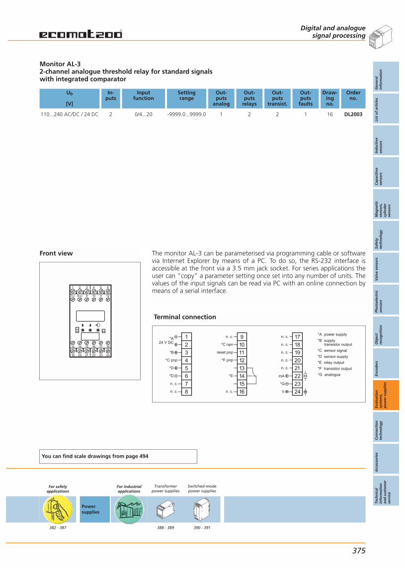
Front view
1 4 652
19 20 21 22 23 24
13 14 15 16 17 18
3
97A1 8A2 10 11 12
Monitor AL-32-channel analogue threshold relay for standard signalswith integrated comparator
Ub
[V]
In-puts
Inputfunction
Settingrange
Out-puts
analog
Out-puts
relays
Out-puts
transist.
Out-puts
faults
Draw-ingno.
Orderno.
110...240 AC/DC / 24 DC 2 0/4...20 -9999.0...9999.0 1 2 2 1 16 DL2003
You can find scale drawings from page 494
For safetyapplications
382 - 387
Powersupplies
For industrialapplications
Transformerpower supplies
388 - 389
Switched-modepower supplies
390 - 391
Digital and analoguesignal processing
Gen
eral
info
rmat
ion
List
of
arti
cles
Ind
uct
ive
sen
sors
Cap
acit
ive
sen
sors
Mag
net
icse
nso
rs,
cylin
der
sen
sors
Safe
tyte
chn
olo
gy
Val
ve s
enso
rsPh
oto
elec
tric
sen
sors
Ob
ject
reco
gn
itio
nEn
cod
ers
Eval
uat
ion
syst
ems,
po
wer
su
pp
lies
Co
nn
ecti
on
tech
no
log
yA
cces
sori
esTe
chn
ical
info
rmat
ion
and
cu
sto
mer
serv
ice
375
The monitor AL-3 can be parameterised via programming cable or softwarevia Internet Explorer by means of a PC. To do so, the RS-232 interface isaccessible at the front via a 3.5 mm jack socket. For series applications theuser can “copy” a parameter setting once set into any number of units. Thevalues of the input signals can be read via PC with an online connection bymeans of a serial interface.
Terminal connection
*A power supply
*C sensor signal
*B supply transistor output
*E relay output
*D sensor supply
*F transistor output
*G analogue
1
2
3
4
5
6
7
8
*A24 V DC
*B
*C pnp
9
10
11
12
13
14
15
16
n. c.
reset pnp
*F pnp
*E
n. c.
17
18
19
20
21
22
23
24
*G
V
*D
*D
n. c.
n. c.
*C npn
n. c.
n. c.
n. c.
n. c.
n. c.
mA
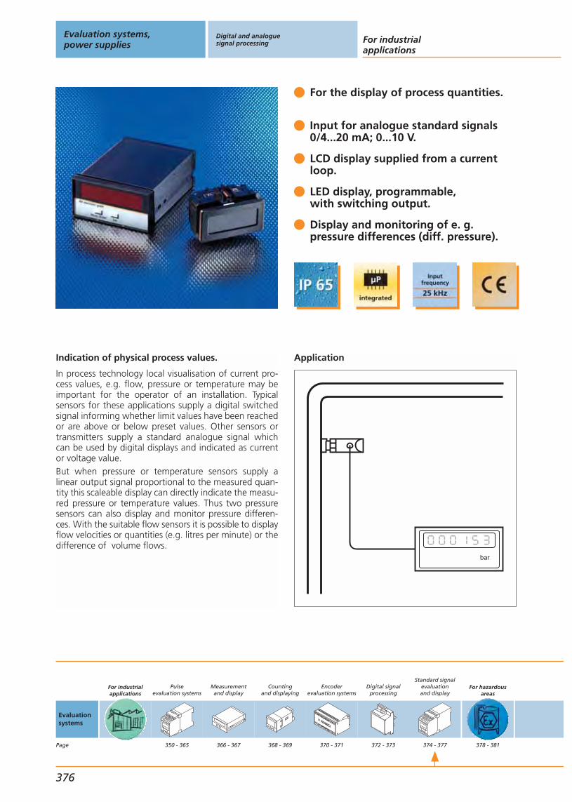
Indication of physical process values.
In process technology local visualisation of current pro-cess values, e.g. flow, pressure or temperature may beimportant for the operator of an installation. Typical sensors for these applications supply a digital switched signal informing whether limit values have been reachedor are above or below preset values. Other sensors ortransmitters supply a standard analogue signal whichcan be used by digital displays and indicated as currentor voltage value.But when pressure or temperature sensors supply a linear output signal proportional to the measured quan-tity this scaleable display can directly indicate the measu-red pressure or temperature values. Thus two pressuresensors can also display and monitor pressure differen-ces. With the suitable flow sensors it is possible to displayflow velocities or quantities (e.g. litres per minute) or thedifference of volume flows.
For the display of process quantities.
Input for analogue standard signals0/4...20 mA; 0...10 V.
LCD display supplied from a currentloop.
LED display, programmable,with switching output.
Display and monitoring of e. g.pressure differences (diff. pressure).
Application
bar
Evaluation systems,power supplies
Digital and analoguesignal processing For industrial
applications
376
Evaluationsystems
Page
For industrialapplications
Pulseevaluation systems
350 - 365
Measurementand display
366 - 367
Countingand displaying
368 - 369
Encoderevaluation systems
370 - 371
Digital signalprocessing
372 - 373
Standard signalevaluationand display
374 - 377
For hazardousareas
378 - 381

Front view E89150
Digital displaysAX360: DX2011, DX2012; 6-digit LED display with 15 mm character height, switching outputLCD display, 3 1/2-digit, without auxiliary energy, supply from the 4...20 mA current loop
Ub
[V]
In-puts
Inputfunction
Displayrange
Out-puts
analog
Out-puts
relays
Out-puts
transist.
Out-puts
faults
Draw-ingno.
Orderno.
Digital display
115 / 230 AC; 24 DC 2 0/4...20mA, 0...10V -999999...999999 – – – – 8 DX2011
115 / 230 AC; 24 DC 2 0/4...20mA, 0...10V -999999...999999 – – 2 – 8 DX2012
LC display
from the current loop 1 4...20mA -1999...1999 – – – – 17 E89150
You can find scale drawings from page 494
For safetyapplications
382 - 387
Powersupplies
For industrialapplications
Transformerpower supplies
388 - 389
Switched-modepower supplies
390 - 391
Digital and analoguesignal processing
Gen
eral
info
rmat
ion
List
of
arti
cles
Ind
uct
ive
sen
sors
Cap
acit
ive
sen
sors
Mag
net
icse
nso
rs,
cylin
der
sen
sors
Safe
tyte
chn
olo
gy
Val
ve s
enso
rsPh
oto
elec
tric
sen
sors
Ob
ject
reco
gn
itio
nEn
cod
ers
Eval
uat
ion
syst
ems,
po
wer
su
pp
lies
Co
nn
ecti
on
tech
no
log
yA
cces
sori
esTe
chn
ical
info
rmat
ion
and
cu
sto
mer
serv
ice
377
The parameters of the AX 360 are set by means of a display and 2 buttonson the front panel. Standard parameters like scaling factor, averaging andswitch points can be set as well as operating modes like “input A – input B”or “input A + input B”. The LCD display is set using potentiometers for cour-se and fine setting of the initial and final values.
Terminal connection DX2011, DX2012
1
2
3
4
5
6
7
8
9
10
18...30 V DC
input B
input A
GND
analogue GND
GND
24 V DC
n. c.
n. c.
n. c.
DX 2011
GND
230 V AC
115 V AC
0 V
8
9
10
COM +
Out 1
Out 2
DX 2012
For other terminal connections see www. ifm-electronic.com
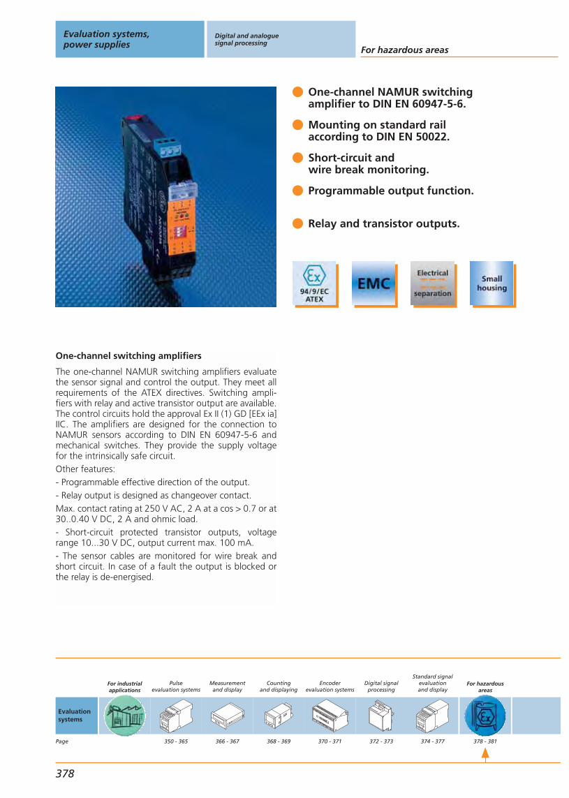
One-channel switching amplifiers
The one-channel NAMUR switching amplifiers evaluatethe sensor signal and control the output. They meet allrequirements of the ATEX directives. Switching ampli-fiers with relay and active transistor output are available.The control circuits hold the approval Ex II (1) GD [EEx ia]IIC. The amplifiers are designed for the connection toNAMUR sensors according to DIN EN 60947-5-6 andmechanical switches. They provide the supply voltagefor the intrinsically safe circuit. Other features:- Programmable effective direction of the output.- Relay output is designed as changeover contact.Max. contact rating at 250 V AC, 2 A at a cos > 0.7 or at30..0.40 V DC, 2 A and ohmic load.- Short-circuit protected transistor outputs, voltagerange 10...30 V DC, output current max. 100 mA.- The sensor cables are monitored for wire break andshort circuit. In case of a fault the output is blocked orthe relay is de-energised.
One-channel NAMUR switching amplifier to DIN EN 60947-5-6.
Mounting on standard rail according to DIN EN 50022.
Short-circuit andwire break monitoring.
Programmable output function.
Relay and transistor outputs.
Evaluation systems,power supplies
Digital and analoguesignal processing
For hazardous areas
378
Evaluationsystems
Page
For industrialapplications
Pulseevaluation systems
350 - 365
Measurementand display
366 - 367
Countingand displaying
368 - 369
Encoderevaluation systems
370 - 371
Digital signalprocessing
372 - 373
Standard signalevaluationand display
374 - 377
For hazardousareas
378 - 381

Front view
ATEX-NAMUR switching amplifier1-channel versionsHazardous gas and dust areas category 1G and 1D
Ub
[V]
Power/ Currentconsumption[VA] / [mA]
f
[Hz]
Ta
[°C]
Output Protection Draw-ingno.
Orderno.
230 1.0 / 10 -20...60 relay (1 changeover contact) IP 20 18 N0031A
115 1.0 / 10 -20...60 relay (1 changeover contact) IP 20 18 N0030A
24 / < 23 10 -20...60 relay (1 changeover contact) IP 20 18 N0530A
24 / < 50 5000 -20...60 2 transistor outputs PNP (100 mA,short-circuit protection) IP 20 18 N0531A
You can find scale drawings from page 494
For safetyapplications
382 - 387
Powersupplies
For industrialapplications
Transformerpower supplies
388 - 389
Switched-modepower supplies
390 - 391
Digital and analoguesignal processing
Gen
eral
info
rmat
ion
List
of
arti
cles
Ind
uct
ive
sen
sors
Cap
acit
ive
sen
sors
Mag
net
icse
nso
rs,
cylin
der
sen
sors
Safe
tyte
chn
olo
gy
Val
ve s
enso
rsPh
oto
elec
tric
sen
sors
Ob
ject
reco
gn
itio
nEn
cod
ers
Eval
uat
ion
syst
ems,
po
wer
su
pp
lies
Co
nn
ecti
on
tech
no
log
yA
cces
sori
esTe
chn
ical
info
rmat
ion
and
cu
sto
mer
serv
ice
379
Terminal connection
* wire break (S2=I) or signal (S2=II)
IN
1
2
3
sensor
OUT relay
7
8
9
OUT transistor
7
8
9
OUT 1
OUT 2*
AC supply
L1
13
14
15 N
DC supply
L+
13
14
15 L–
unused terminals mustnot be connected

Two-channel switching amplifiers
The two-channel NAMUR switching amplifiers evaluatethe sensor signal and control the output. They meet allrequirements of the ATEX directives. Switching ampli-fiers with relay and active transistor and potential-freeoptocoupler outputs are available. The control circuitshold the approval Ex II (1) GD [EEx ia] IIC. The amplifiersare designed for the connection to NAMUR sensorsaccording to DIN EN 60947-5-6 and mechanical switches. They provide the supply voltage for the intrin-sically safe circuit. Other features:- Programmable effective direction of the output.- Relay output is designed as changeover contact.Max. contact rating at 250 V AC, 2 A at a cos > 0.7 or at30..0.40 V DC, 2 A and ohmic load.- Short-circuit protected transistor or opto-coupler out-put, voltage range 10...30 V DC, output current max.100 mA.- The sensor cables are monitored for wire break andshort circuit. In case of a fault the output is blocked orthe relay is de-energised.
2-channel NAMUR switching amplifier to DIN EN 60947-5-6
Mounting on standard railaccording to DIN EN 50022.
Short-circuit andwire break monitoring.
Programmable output function.
Relay, transistor andoptocoupler outputs.
Evaluation systems,power supplies
Digital and analoguesignal processing
For hazardous areas
380
Evaluationsystems
Page
For industrialapplications
Pulseevaluation systems
350 - 365
Measurementand display
366 - 367
Countingand displaying
368 - 369
Encoderevaluation systems
370 - 371
Digital signalprocessing
372 - 373
Standard signalevaluationand display
374 - 377
For hazardousareas
378 - 381
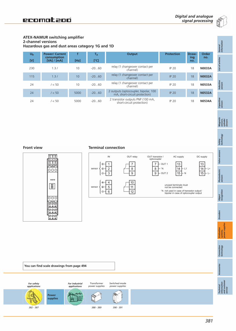
Front view
ATEX-NAMUR switching amplifier2-channel versionsHazardous gas and dust areas category 1G and 1D
Ub
[V]
Power/ Currentconsumption[VA] / [mA]
f
[Hz]
Ta
[°C]
Output Protection Draw-ingno.
Orderno.
230 1.3 / 10 -20...60 relay (1 changeover contact perchannel) IP 20 18 N0033A
115 1.3 / 10 -20...60 relay (1 changeover contact perchannel) IP 20 18 N0032A
24 / < 50 10 -20...60 relay (1 changeover contact perchannel) IP 20 18 N0533A
24 / < 50 5000 -20...60 2 outputs (optocoupler, bipolar, 100mA, short-circuit protection) IP 20 18 N0532A
24 / < 50 5000 -20...60 2 transistor outputs PNP (100 mA,short-circuit protection) IP 20 18 N0534A
You can find scale drawings from page 494
For safetyapplications
382 - 387
Powersupplies
For industrialapplications
Transformerpower supplies
388 - 389
Switched-modepower supplies
390 - 391
Digital and analoguesignal processing
Gen
eral
info
rmat
ion
List
of
arti
cles
Ind
uct
ive
sen
sors
Cap
acit
ive
sen
sors
Mag
net
icse
nso
rs,
cylin
der
sen
sors
Safe
tyte
chn
olo
gy
Val
ve s
enso
rsPh
oto
elec
tric
sen
sors
Ob
ject
reco
gn
itio
nEn
cod
ers
Eval
uat
ion
syst
ems,
po
wer
su
pp
lies
Co
nn
ecti
on
tech
no
log
yA
cces
sori
esTe
chn
ical
info
rmat
ion
and
cu
sto
mer
serv
ice
381
Terminal connection
IN
1
2
3
sensor
4
5
6
sensor
OUT relay
7
8
9
10
11
12
OUT transistor /optocoupler
*A
*A not used in case of transistor output/ bipolar in case of optocoupler output
7
8
9
OUT 1
OUT 2
AC supply
L1
13
14
15 N
DC supply
L+
13
14
15 L–
unused terminals mustnot be connected
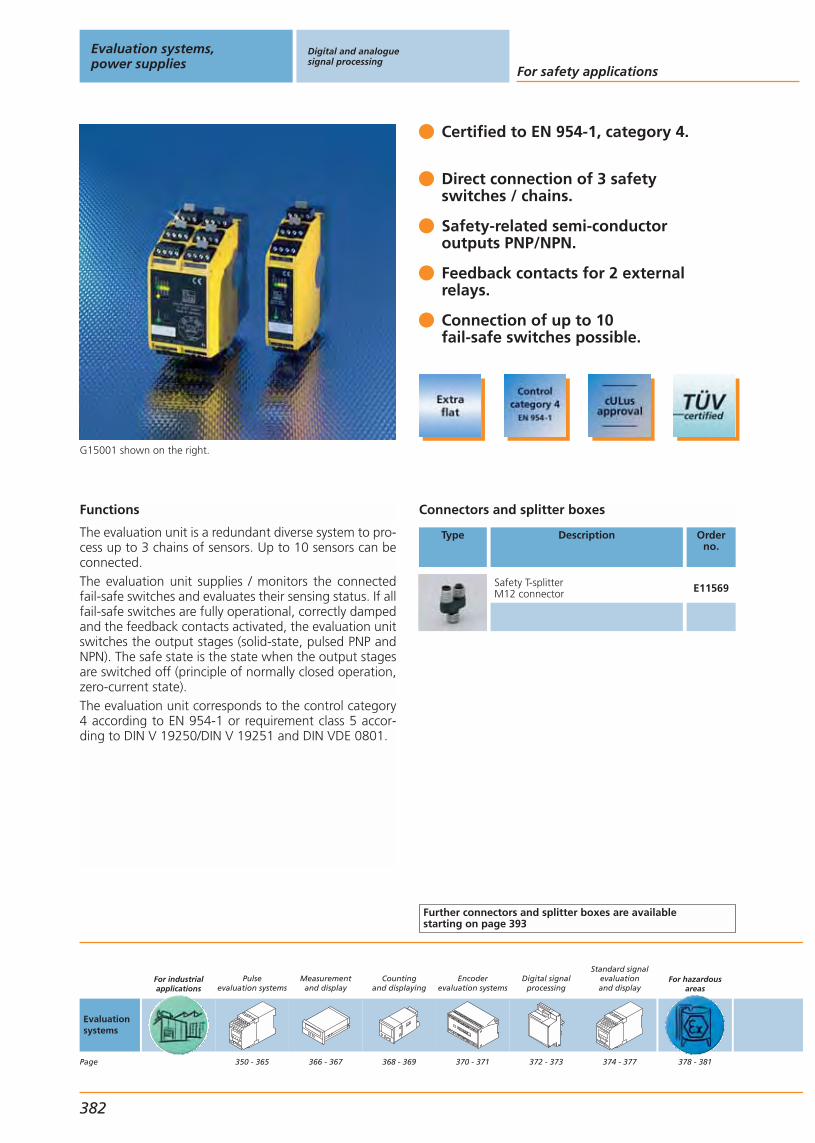
G15001 shown on the right.
Certified to EN 954-1, category 4.
Direct connection of 3 safety switches / chains.
Safety-related semi-conductor outputs PNP/NPN.
Feedback contacts for 2 externalrelays.
Connection of up to 10 fail-safe switches possible.
Connectors and splitter boxes
Type Description Orderno.
Safety T-splitter M12 connector E11569
Further connectors and splitter boxes are availablestarting on page 393
Functions
The evaluation unit is a redundant diverse system to pro-cess up to 3 chains of sensors. Up to 10 sensors can beconnected.The evaluation unit supplies / monitors the connectedfail-safe switches and evaluates their sensing status. If allfail-safe switches are fully operational, correctly dampedand the feedback contacts activated, the evaluation unitswitches the output stages (solid-state, pulsed PNP andNPN). The safe state is the state when the output stagesare switched off (principle of normally closed operation,zero-current state).The evaluation unit corresponds to the control category4 according to EN 954-1 or requirement class 5 accor-ding to DIN V 19250/DIN V 19251 and DIN VDE 0801.
Evaluation systems,power supplies
Digital and analoguesignal processing
For safety applications
382
Evaluationsystems
Page
For industrialapplications
Pulseevaluation systems
350 - 365
Measurementand display
366 - 367
Countingand displaying
368 - 369
Encoderevaluation systems
370 - 371
Digital signalprocessing
372 - 373
Standard signalevaluationand display
374 - 377
For hazardousareas
378 - 381

Terminal connection
L-
A
TE
L+
GNDP1P2V+
L+ TE A L L+ TE A L L+ TE A L L+ TE A L
24 V (20,4...30 V)
Safety classification: Category 4Semi-conductor outputs PNP / NPNTypical connection of up to 10 sensors.
Ub
[V]
Sensorinput / output
Safety-relatedoutput
Signalcontacts
(nor. closed)
Feedback-contacts
Responsetime[ms]
Off -delay[ms]
Draw-ingno.
Orderno.
24 DC (20.4...30 DC) 3 1 PNP / 1 NPN – 2 < 210 – 19 G15001
Common technical data
Current rating: 200 mACurrent consumption: 250 mAShort-circuit protection, pulsed Protection housing / terminals: IP 30 / IP 20Output status indication: LEDsPower-on delay time for release: typ. 5s / 1 s (power on/normal operation)Operating temperature: 0...60 °CHousing material: Polyamid (PA)
You can find scale drawings from page 494
For safetyapplications
382 - 387
Powersupplies
For industrialapplications
Transformerpower supplies
388 - 389
Switched-modepower supplies
390 - 391
Digital and analoguesignal processing
Gen
eral
info
rmat
ion
List
of
arti
cles
Ind
uct
ive
sen
sors
Cap
acit
ive
sen
sors
Mag
net
icse
nso
rs,
cylin
der
sen
sors
Safe
tyte
chn
olo
gy
Val
ve s
enso
rsPh
oto
elec
tric
sen
sors
Ob
ject
reco
gn
itio
nEn
cod
ers
Eval
uat
ion
syst
ems,
po
wer
su
pp
lies
Co
nn
ecti
on
tech
no
log
yA
cces
sori
esTe
chn
ical
info
rmat
ion
and
cu
sto
mer
serv
ice
383

G15002 / G15004 / G15005 shown on the left.
Certified to EN 954-1, category 4.
Direct connection of 6 safety switches / chains.
Set-up override,emergency stop.
Feedback contacts for 2 externalrelays.
Connection of up to 10fail-safe switches possible.
Connectors and splitter boxes
Type Description Orderno.
Safety T-splitter M12 connector E11569
Further connectors and splitter boxes are availablestarting on page 393
Functions
The evaluation unit is a redundant diverse system to pro-cess up to 6 chains of sensors. Up to 10 sensors can beconnected.The evaluation unit supplies / monitors the connectedfail-safe switches and evaluates their sensing status. If allfail-safe switches are fully operational, correctly dampedand the feedback contacts activated, the evaluation unitswitches the output stages (relais). The safe state is thestate when the output stages are switched off (principleof normally closed operation, zero-current state).The evaluation unit can be deactivated externally, on thecondition that relevant safety measures are taken intoaccount.
Evaluation systems,power supplies
Digital and analoguesignal processing
For safety applications
384
Evaluationsystems
Page
For industrialapplications
Pulseevaluation systems
350 - 365
Measurementand display
366 - 367
Countingand displaying
368 - 369
Encoderevaluation systems
370 - 371
Digital signalprocessing
372 - 373
Standard signalevaluationand display
374 - 377
For hazardousareas
378 - 381

Terminal connection
L-
A
TE
L+
GNDP1P2V+
L+ TE A L L+ TE A L L+ TE A L L+ TE A L
24 V (20,4...30 V)
Safety classification: category 4Relay outputsTypical connection of up to 10 sensors
Ub
[V]
Sensorinput / output
Safety-relatedoutput
Signalcontacts
(nor. closed)
Feedback-contacts
Responsetime[ms]
Off -delay[ms]
Draw-ingno.
Orderno.
24 DC (20.4...30 DC) 6 3 2 2 < 210 – 20 G15002
24 DC (20.4...30 DC) 6 3 2 2 < 210 – 21 G15004
24 DC (20.4...30 DC) 6 3 2 2 < 210 < 10 21 G15005
Common technical data
Current rating AC/DC: 6 ACurrent consumption: < 200 mAOutput status indication: LEDsPower-on delay time for release: typ. 5s / 1 s (power on/normal operation)Operating temperature: 0...70 °CProtection housing / terminal: IP 30 / IP 20Housing material: Polyamide (PA)
You can find scale drawings from page 494
For safetyapplications
382 - 387
Powersupplies
For industrialapplications
Transformerpower supplies
388 - 389
Switched-modepower supplies
390 - 391
Digital and analoguesignal processing
Gen
eral
info
rmat
ion
List
of
arti
cles
Ind
uct
ive
sen
sors
Cap
acit
ive
sen
sors
Mag
net
icse
nso
rs,
cylin
der
sen
sors
Safe
tyte
chn
olo
gy
Val
ve s
enso
rsPh
oto
elec
tric
sen
sors
Ob
ject
reco
gn
itio
nEn
cod
ers
Eval
uat
ion
syst
ems,
po
wer
su
pp
lies
Co
nn
ecti
on
tech
no
log
yA
cces
sori
esTe
chn
ical
info
rmat
ion
and
cu
sto
mer
serv
ice
385
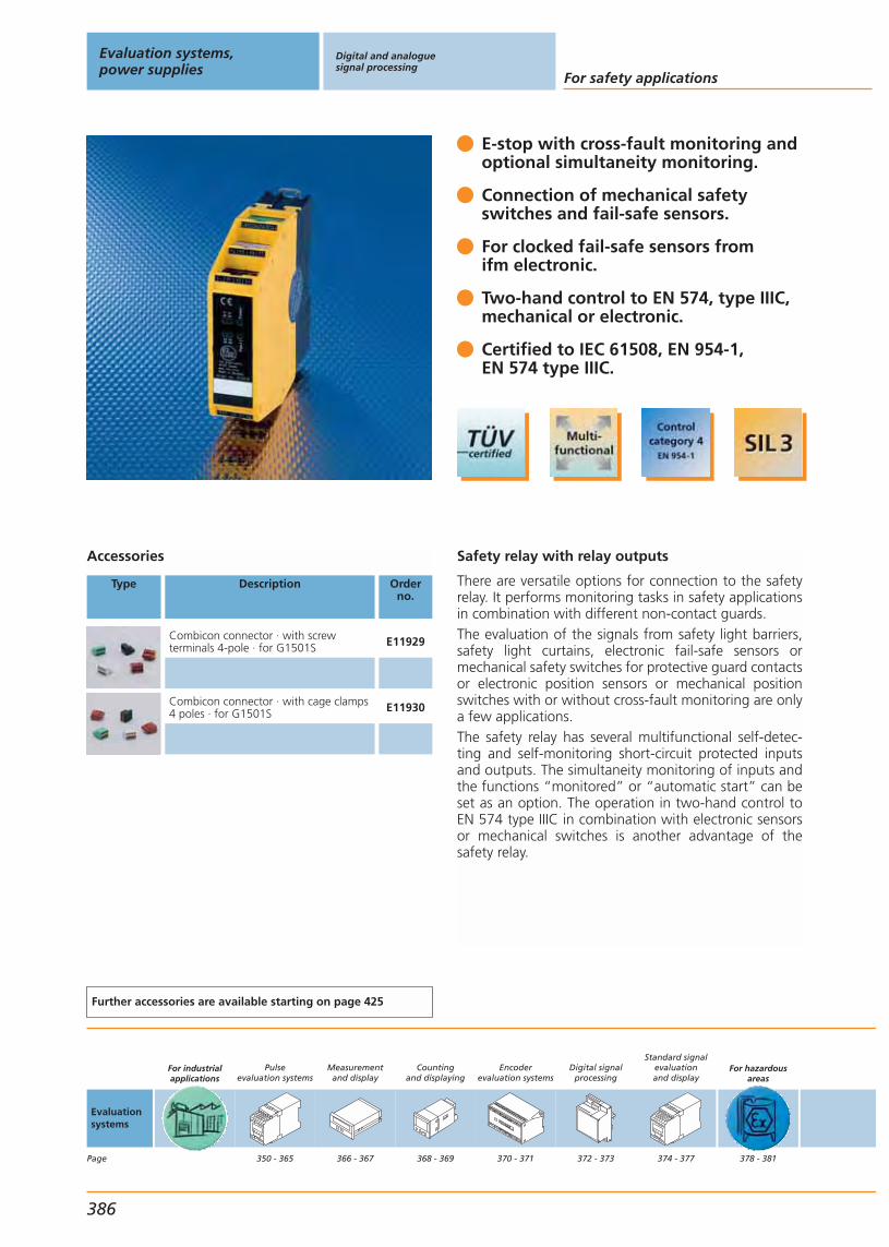
Safety relay with relay outputs
There are versatile options for connection to the safetyrelay. It performs monitoring tasks in safety applicationsin combination with different non-contact guards.The evaluation of the signals from safety light barriers,safety light curtains, electronic fail-safe sensors ormechanical safety switches for protective guard contactsor electronic position sensors or mechanical positionswitches with or without cross-fault monitoring are onlya few applications.The safety relay has several multifunctional self-detec-ting and self-monitoring short-circuit protected inputsand outputs. The simultaneity monitoring of inputs andthe functions “monitored” or “automatic start” can beset as an option. The operation in two-hand control toEN 574 type IIIC in combination with electronic sensorsor mechanical switches is another advantage of thesafety relay.
E-stop with cross-fault monitoring and optional simultaneity monitoring.
Connection of mechanical safety switches and fail-safe sensors.
For clocked fail-safe sensors from ifm electronic.
Two-hand control to EN 574, type IIIC, mechanical or electronic.
Certified to IEC 61508, EN 954-1, EN 574 type IIIC.
Accessories
Type Description Orderno.
Combicon connector · with screwterminals 4-pole · for G1501S E11929
Combicon connector · with cage clamps4 poles · for G1501S E11930
Further accessories are available starting on page 425
Evaluation systems,power supplies
Digital and analoguesignal processing
For safety applications
386
Evaluationsystems
Page
For industrialapplications
Pulseevaluation systems
350 - 365
Measurementand display
366 - 367
Countingand displaying
368 - 369
Encoderevaluation systems
370 - 371
Digital signalprocessing
372 - 373
Standard signalevaluationand display
374 - 377
For hazardousareas
378 - 381

Safety classification: category 4
Ub
[V]
Sensorinput / output
Safety-relatedoutput
Signalcontacts
(nor. closed)
Feedback-contacts
Responsetime[ms]
Off -delay[ms]
Draw-ingno.
Orderno.
24 DC (19.2...30 DC) 1/2 2 1 1 < 180 – 22 G1501S
You can find scale drawings from page 494
For safetyapplications
382 - 387
Powersupplies
For industrialapplications
Transformerpower supplies
388 - 389
Switched-modepower supplies
390 - 391
Digital and analoguesignal processing
Gen
eral
info
rmat
ion
List
of
arti
cles
Ind
uct
ive
sen
sors
Cap
acit
ive
sen
sors
Mag
net
icse
nso
rs,
cylin
der
sen
sors
Safe
tyte
chn
olo
gy
Val
ve s
enso
rsPh
oto
elec
tric
sen
sors
Ob
ject
reco
gn
itio
nEn
cod
ers
Eval
uat
ion
syst
ems,
po
wer
su
pp
lies
Co
nn
ecti
on
tech
no
log
yA
cces
sori
esTe
chn
ical
info
rmat
ion
and
cu
sto
mer
serv
ice
387
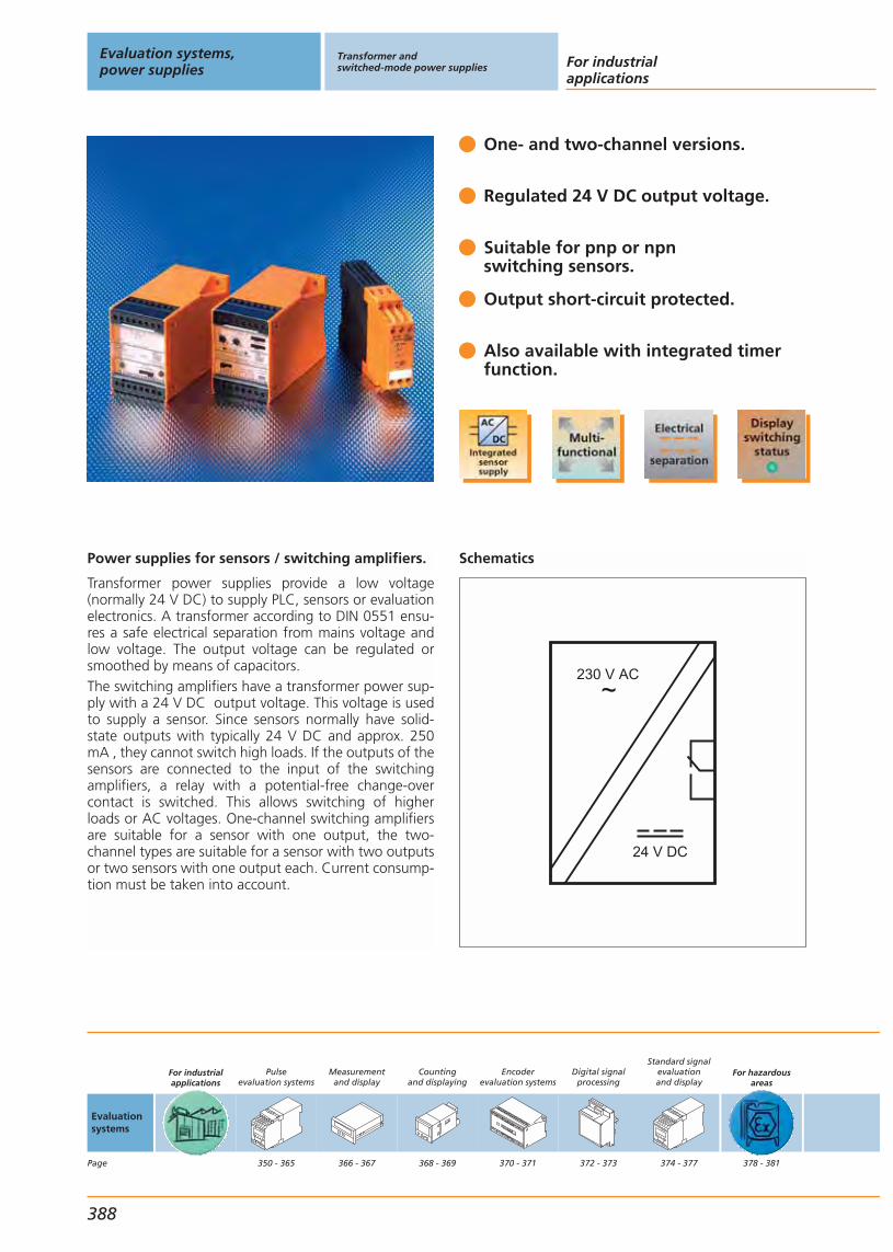
Power supplies for sensors / switching amplifiers.
Transformer power supplies provide a low voltage (normally 24 V DC) to supply PLC, sensors or evaluationelectronics. A transformer according to DIN 0551 ensu-res a safe electrical separation from mains voltage andlow voltage. The output voltage can be regulated orsmoothed by means of capacitors. The switching amplifiers have a transformer power sup-ply with a 24 V DC output voltage. This voltage is usedto supply a sensor. Since sensors normally have solid-state outputs with typically 24 V DC and approx. 250mA , they cannot switch high loads. If the outputs of thesensors are connected to the input of the switchingamplifiers, a relay with a potential-free change-overcontact is switched. This allows switching of higherloads or AC voltages. One-channel switching amplifiersare suitable for a sensor with one output, the two-channel types are suitable for a sensor with two outputsor two sensors with one output each. Current consump-tion must be taken into account.
One- and two-channel versions.
Regulated 24 V DC output voltage.
Suitable for pnp or npnswitching sensors.
Output short-circuit protected.
Also available with integrated timerfunction.
Schematics
230 V AC~
24 V DC
Evaluation systems,power supplies
Transformer andswitched-mode power supplies For industrial
applications
388
Evaluationsystems
Page
For industrialapplications
Pulseevaluation systems
350 - 365
Measurementand display
366 - 367
Countingand displaying
368 - 369
Encoderevaluation systems
370 - 371
Digital signalprocessing
372 - 373
Standard signalevaluationand display
374 - 377
For hazardousareas
378 - 381

Front view DN0200
L+ L– I1
L N I2
12 14 11
2221 24
Switching amplifier 1-channel (DN0001, DN0012) Switching amplifier 1-channel with timer function (DT0001, DT0012)Switching amplifier 2-channel (DN0200)
Current
[mA]
Outputvoltage
[V]
Nominalvoltage
[V]
Output Draw-ingno.
Orderno.
max. 100 mA 24 DC; ±5% 230 AC Relais 1 DN0001
max. 100 mA 24 DC; ±5% 110 AC Relais 1 DN0012
max. 300 mA 24 V DC; ± 3 % 110...240 Relais 2 DN0200
max. 40 mA 24 DC; ±5% 230 AC / 24 DC Relais 1 DT0001
You can find scale drawings from page 498
For safetyapplications
382 - 387
Powersupplies
For industrialapplications
Transformerpower supplies
388 - 389
Switched-modepower supplies
390 - 391
Transformer andswitched-mode power supplies
Gen
eral
info
rmat
ion
List
of
arti
cles
Ind
uct
ive
sen
sors
Cap
acit
ive
sen
sors
Mag
net
icse
nso
rs,
cylin
der
sen
sors
Safe
tyte
chn
olo
gy
Val
ve s
enso
rsPh
oto
elec
tric
sen
sors
Ob
ject
reco
gn
itio
nEn
cod
ers
Eval
uat
ion
syst
ems,
po
wer
su
pp
lies
Co
nn
ecti
on
tech
no
log
yA
cces
sori
esTe
chn
ical
info
rmat
ion
and
cu
sto
mer
serv
ice
389
Terminal connection DN0001, DN0012, DT0001, DT0012
*A power supply
1
2
3
4
5
6
7
8
9
10
11
12
13
14
15
16
sensor
signal
*A ACL1
N
relay output
Terminal connection DN0200
*A power supply
*C signal input
*B relay output
*D sensor supply
*C 1 I1
L–
L+
11
14
12
*D
I2
N
L
22
24
21
*B 2
L1
*C 2
*B 1
N*A AC
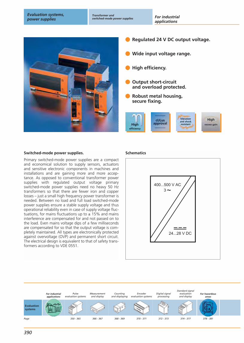
Switched-mode power supplies.
Primary switched-mode power supplies are a compactand economical solution to supply sensors, actuatorsand sensitive electronic components in machines andinstallations and are gaining more and more accep-tance. As opposed to conventional transformer powersupplies with regulated output voltage primary switched-mode power supplies need no heavy 50 Hztransformers so that there are fewer iron and copperlosses – just a small high frequency power transformer isneeded. Between no load and full load switched-modepower supplies ensure a stable supply voltage and thusoperational reliability even in case of supply voltage fluc-tuations, for mains fluctuations up to ± 15% and mainsinterference are compensated for and not passed on tothe load. Even mains voltage dips of a few millisecondsare compensated for so that the output voltage is com-pletely maintained. All types are electronically protectedagainst overvoltage (OVP) and permanent short circuit.The electrical design is equivalent to that of safety trans-formers according to VDE 0551.
Regulated 24 V DC output voltage.
Wide input voltage range.
High efficiency.
Output short-circuitand overload protected.
Robust metal housing,secure fixing.
Schematics
400...500 V AC3 ~
24...28 V DC
Evaluation systems,power supplies
Transformer andswitched-mode power supplies For industrial
applications
390
Evaluationsystems
Page
For industrialapplications
Pulseevaluation systems
350 - 365
Measurementand display
366 - 367
Countingand displaying
368 - 369
Encoderevaluation systems
370 - 371
Digital signalprocessing
372 - 373
Standard signalevaluationand display
374 - 377
For hazardousareas
378 - 381
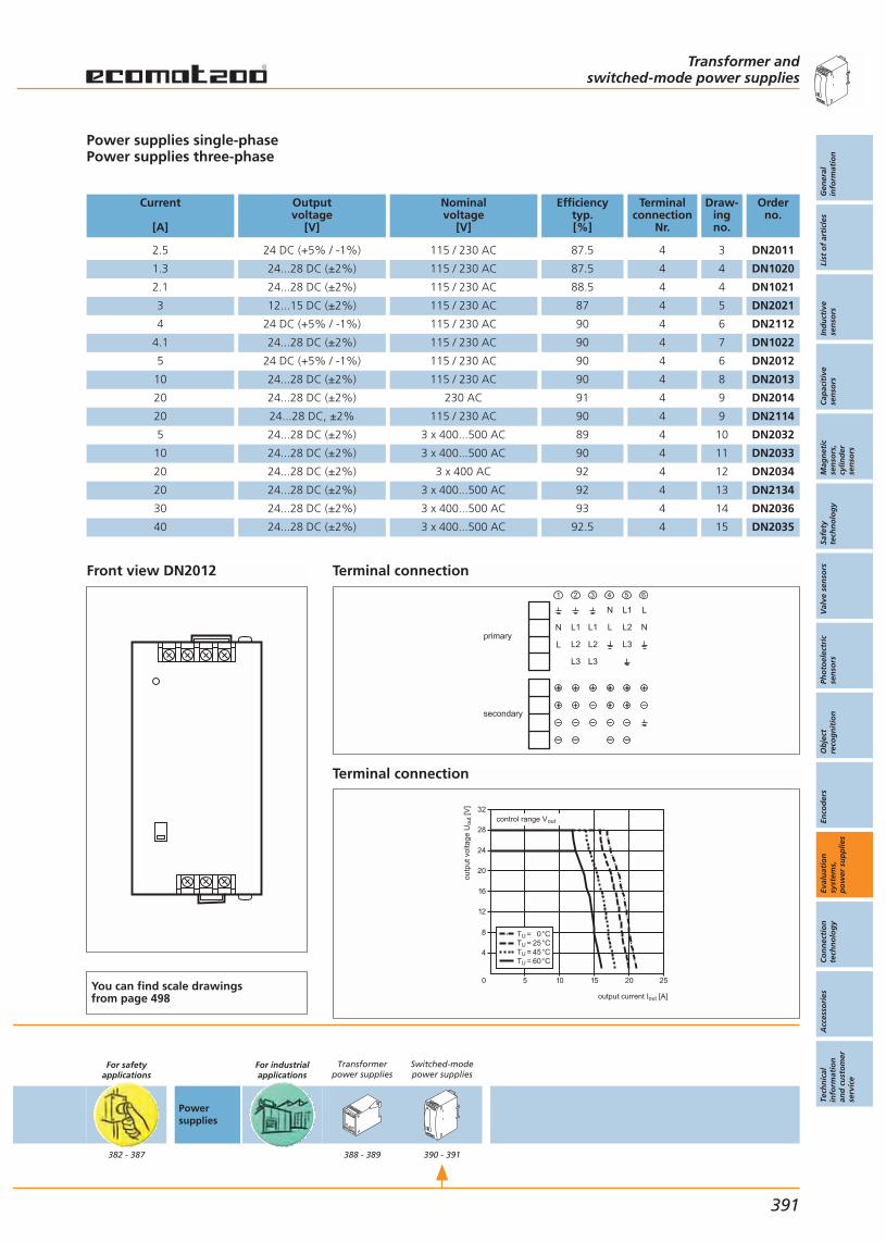
Front view DN2012
Power supplies single-phasePower supplies three-phase
Current
[A]
Outputvoltage
[V]
Nominalvoltage
[V]
Efficiencytyp.[%]
Terminalconnection
Nr.
Draw-ingno.
Orderno.
2.5 24 DC (+5% / -1%) 115 / 230 AC 87.5 4 3 DN2011
1.3 24...28 DC (±2%) 115 / 230 AC 87.5 4 4 DN1020
2.1 24...28 DC (±2%) 115 / 230 AC 88.5 4 4 DN1021
3 12...15 DC (±2%) 115 / 230 AC 87 4 5 DN2021
4 24 DC (+5% / -1%) 115 / 230 AC 90 4 6 DN2112
4.1 24...28 DC (±2%) 115 / 230 AC 90 4 7 DN1022
5 24 DC (+5% / -1%) 115 / 230 AC 90 4 6 DN2012
10 24...28 DC (±2%) 115 / 230 AC 90 4 8 DN2013
20 24...28 DC (±2%) 230 AC 91 4 9 DN2014
20 24...28 DC, ±2% 115 / 230 AC 90 4 9 DN2114
5 24...28 DC (±2%) 3 x 400...500 AC 89 4 10 DN2032
10 24...28 DC (±2%) 3 x 400...500 AC 90 4 11 DN2033
20 24...28 DC (±2%) 3 x 400 AC 92 4 12 DN2034
20 24...28 DC (±2%) 3 x 400...500 AC 92 4 13 DN2134
30 24...28 DC (±2%) 3 x 400...500 AC 93 4 14 DN2036
40 24...28 DC (±2%) 3 x 400...500 AC 92.5 4 15 DN2035
You can find scale drawings from page 498
For safetyapplications
382 - 387
Powersupplies
For industrialapplications
Transformerpower supplies
388 - 389
Switched-modepower supplies
390 - 391
Transformer andswitched-mode power supplies
Gen
eral
info
rmat
ion
List
of
arti
cles
Ind
uct
ive
sen
sors
Cap
acit
ive
sen
sors
Mag
net
icse
nso
rs,
cylin
der
sen
sors
Safe
tyte
chn
olo
gy
Val
ve s
enso
rsPh
oto
elec
tric
sen
sors
Ob
ject
reco
gn
itio
nEn
cod
ers
Eval
uat
ion
syst
ems,
po
wer
su
pp
lies
Co
nn
ecti
on
tech
no
log
yA
cces
sori
esTe
chn
ical
info
rmat
ion
and
cu
sto
mer
serv
ice
391
Terminal connection
primaryN
secondary
N L1 L
NL2LL1L1
L L3L2L2
L3L3
1 2 3 4 5 6
Terminal connection
outp
ut v
olta
ge U
out [
V]
output current Iout [A]
10 15 20 25
8
16
24
32
50
4
12
20
28
TU = 0°CTU = 25°CTU = 45°CTU = 60°C
control range Vout


Gen
eral
info
rmat
ion
List
of
arti
cles
Ind
uct
ive
sen
sors
Cap
acit
ive
sen
sors
Mag
net
icse
nso
rs,
cylin
der
sen
sors
Safe
tyte
chn
olo
gy
Val
ve s
enso
rsPh
oto
elec
tric
sen
sors
Ob
ject
reco
gn
itio
nEn
cod
ers
Eval
uat
ion
syst
ems,
po
wer
su
pp
lies
Co
nn
ecti
on
tech
no
log
yA
cces
sori
esTe
chn
ical
info
rmat
ion
and
cu
sto
mer
serv
ice
Connection technology
393
Connectors and splitter boxesfor industrial applications
Complete ifm product range
System descriptionSelection chart
SocketsCable plugsCablesSplitter boxes
Universal application
Connectors and splitter boxesfor oils and coolants
Sockets
Special application
Connectors and splitter boxesfor electromagnetic fields
Sockets
Connectors and splitter boxesfor hygienic and wet areas
SocketsCable plugsCablesSplitter boxes
Connectors and splitter boxesfor hazardous areas
SocketsCable plugsCables
394 - 395396 - 398
400 - 406407
408 - 409410 - 412
414
416
418 - 420419 - 420419 - 420
420
422422422
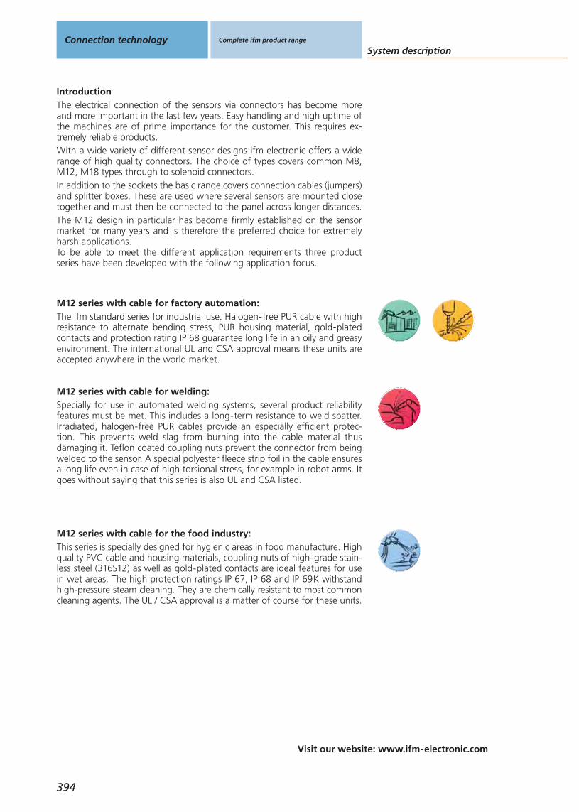
Visit our website: www.ifm-electronic.com
System description
This series is specially designed for hygienic areas in food manufacture. Highquality PVC cable and housing materials, coupling nuts of high-grade stain-less steel (316S12) as well as gold-plated contacts are ideal features for usein wet areas. The high protection ratings IP 67, IP 68 and IP 69K withstandhigh-pressure steam cleaning. They are chemically resistant to most commoncleaning agents. The UL / CSA approval is a matter of course for these units.
M12 series with cable for the food industry:
Connection technology Complete ifm product range
394
IntroductionThe electrical connection of the sensors via connectors has become moreand more important in the last few years. Easy handling and high uptime ofthe machines are of prime importance for the customer. This requires ex-tremely reliable products.With a wide variety of different sensor designs ifm electronic offers a widerange of high quality connectors. The choice of types covers common M8,M12, M18 types through to solenoid connectors.In addition to the sockets the basic range covers connection cables (jumpers)and splitter boxes. These are used where several sensors are mounted closetogether and must then be connected to the panel across longer distances.The M12 design in particular has become firmly established on the sensormarket for many years and is therefore the preferred choice for extremelyharsh applications.To be able to meet the different application requirements three productseries have been developed with the following application focus.
The ifm standard series for industrial use. Halogen-free PUR cable with highresistance to alternate bending stress, PUR housing material, gold-platedcontacts and protection rating IP 68 guarantee long life in an oily and greasyenvironment. The international UL and CSA approval means these units areaccepted anywhere in the world market.
M12 series with cable for factory automation:
Specially for use in automated welding systems, several product reliabilityfeatures must be met. This includes a long-term resistance to weld spatter.Irradiated, halogen-free PUR cables provide an especially efficient protec-tion. This prevents weld slag from burning into the cable material thusdamaging it. Teflon coated coupling nuts prevent the connector from beingwelded to the sensor. A special polyester fleece strip foil in the cable ensuresa long life even in case of high torsional stress, for example in robot arms. Itgoes without saying that this series is also UL and CSA listed.
M12 series with cable for welding:
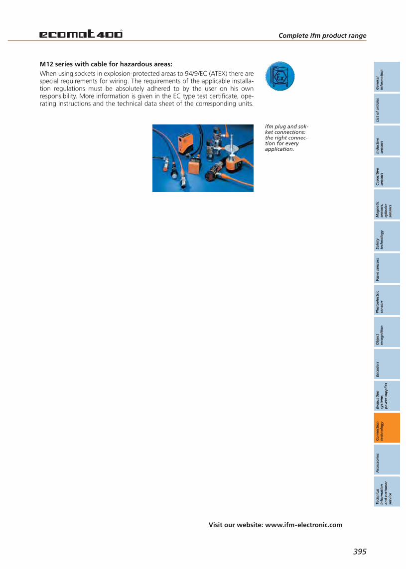
Gen
eral
info
rmat
ion
List
of
arti
cles
Ind
uct
ive
sen
sors
Cap
acit
ive
sen
sors
Mag
net
icse
nso
rs,
cylin
der
sen
sors
Safe
tyte
chn
olo
gy
Val
ve s
enso
rsPh
oto
elec
tric
sen
sors
Ob
ject
reco
gn
itio
nEn
cod
ers
Eval
uat
ion
syst
ems,
po
wer
su
pp
lies
Co
nn
ecti
on
tech
no
log
yA
cces
sori
esTe
chn
ical
info
rmat
ion
and
cu
sto
mer
serv
ice
Visit our website: www.ifm-electronic.com
Complete ifm product range
395
ifm plug and sok-ket connections:the right connec-tion for everyapplication.
When using sockets in explosion-protected areas to 94/9/EC (ATEX) there arespecial requirements for wiring. The requirements of the applicable installa-tion regulations must be absolutely adhered to by the user on his ownresponsibility. More information is given in the EC type test certificate, ope-rating instructions and the technical data sheet of the corresponding units.
M12 series with cable for hazardous areas:

Selection chartConnection technology Complete ifm product range
396
DescriptionFor hygienic
and wet areasFor electro-
magnetic fieldsFor oils and
coolantsFor industrialapplications
For hazardousareas
from page 400 from page 414 from page 416 from page 418 from page 422
Socket M8, 3-pole, 3-wire
Socket M8, 3-pole, 3-wire, LED, PNP
Socket M8, 4-pole, 4-wire
Socket M12, 2-pole,for AS-i isolation displacement connector
Socket M12, 2-pole + PE, 3-wire
Socket M12, 4-pole, 4-wire
Socket M12, 5 / 4-pole, 2-wire,for quadronorm units
Socket M12, 4-pole
Socket M12, 4-pole, 4-wire, LED, PNP
Socket M12, 4-pole, LED, PNP
Socket M12, 5-pole
Socket M12, 5-pole, 5-wire
Socket M12, 8-pole, 6-wire
Socket M12, 8-pole, 7-wire
Socket M12, 8-pole, 8-wire,for temperature sensors TR 8...
Socket M16, 14-pole, 10-wire
Socket M16, 14-pole, 12-wire
Socket M18, 4-pole
Socket M18, 12-pole
Socket M23, 12-pole, pin numbering anticlockwise,for splitter boxes
Socket M23, 12-pole, external thread,pin numbering anticlockwise, for encoders
Socket M23, 12-pole, pin numbering clockwise, for encoders
Cable plug M23, 12-pole, pin numbering anticlockwise, for encoders
Socket M23, 17-pole, pin numbering clockwise, for encoders
Socket M23, 21-pole,pin numbering clockwise, for encoders
Socket M23, 12-pole for splitter boxes
Socket M23, 19-pole for splitter boxes
Sockets – Groups
1
2
3 62
4
5
7 57 59 63 75
6
8 64
9 58 60 65
10 66
11 71
12 / 13 61 67 76 / 77
14 / 15
16
17
19
18
20
21
22
23
24
25
26
27
28
29
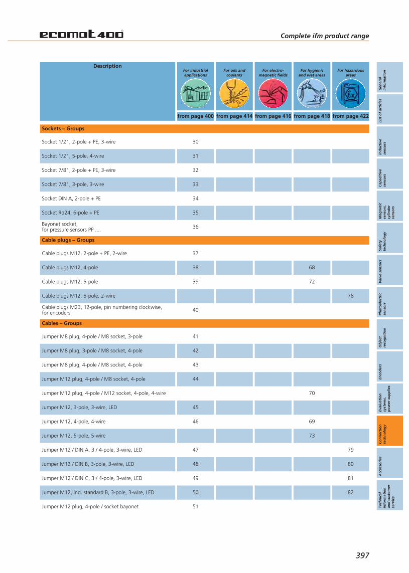
Gen
eral
info
rmat
ion
List
of
arti
cles
Ind
uct
ive
sen
sors
Cap
acit
ive
sen
sors
Mag
net
icse
nso
rs,
cylin
der
sen
sors
Safe
tyte
chn
olo
gy
Val
ve s
enso
rsPh
oto
elec
tric
sen
sors
Ob
ject
reco
gn
itio
nEn
cod
ers
Eval
uat
ion
syst
ems,
po
wer
su
pp
lies
Co
nn
ecti
on
tech
no
log
yA
cces
sori
esTe
chn
ical
info
rmat
ion
and
cu
sto
mer
serv
ice
Complete ifm product range
397
DescriptionFor hazardous
areasFor hygienic
and wet areasFor electro-
magnetic fieldsFor oils and
coolantsFor industrialapplications
from page 400 from page 414 from page 416 from page 418 from page 422
Bayonet socket,for pressure sensors PP ....
Socket Rd24, 6-pole + PE
Sockets – Groups
Cable plugs M12, 4-pole
Cable plugs M12, 5-pole
Cable plugs M12, 2-pole + PE, 2-wire
Cable plugs M12, 5-pole, 2-wire
Cable plugs M23, 12-pole, pin numbering clockwise,for encoders
Cable plugs – Groups
Jumper M8 plug, 3-pole / M8 socket, 4-pole
Jumper M8 plug, 4-pole / M8 socket, 3-pole
Jumper M8 plug, 4-pole / M8 socket, 4-pole
Jumper M12 plug, 4-pole / M8 socket, 4-pole
Jumper M12, 3-pole, 3-wire, LED
Jumper M12, 4-pole, 4-wire
Jumper M12, 5-pole, 5-wire
Jumper M12 / DIN A, 3 / 4-pole, 3-wire, LED
Jumper M12 / DIN B, 3-pole, 3-wire, LED
Jumper M12 / DIN C, 3 / 4-pole, 3-wire, LED
Jumper M12, ind. standard B, 3-pole, 3-wire, LED
Jumper M12 plug, 4-pole / socket bayonet
Cables – Groups
Socket 1/2", 2-pole + PE, 3-wire
Socket 1/2", 5-pole, 4-wire
Socket 7/8", 2-pole + PE, 3-wire
Socket 7/8", 3-pole, 3-wire
Socket DIN A, 2-pole + PE
Jumper M12 plug, 4-pole / M12 socket, 4-pole, 4-wire
36
35
38 68
39 72
78
37
40
42
41
43
44
70
45
46 69
73
47 79
48 80
49 81
50 82
51
30
31
32
33
34
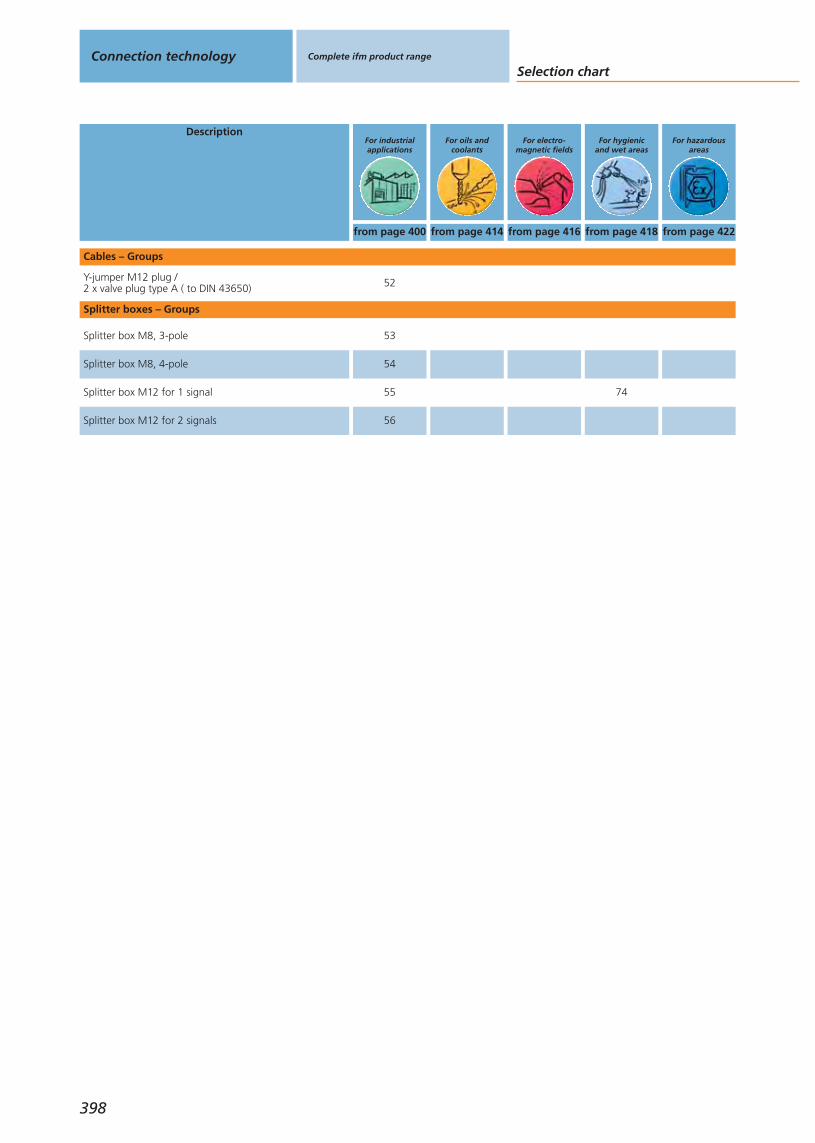
Selection chartConnection technology Complete ifm product range
from page 400 from page 414 from page 416 from page 418 from page 422
398
Description
Splitter box M12 for 2 signals
Splitter boxes – Groups
For hygienicand wet areas
For electro-magnetic fields
For oils andcoolants
For industrialapplications
For hazardousareas
Splitter box M8, 4-pole
Splitter box M8, 3-pole
Splitter box M12 for 1 signal
Cables – Groups
Y-jumper M12 plug /2 x valve plug type A ( to DIN 43650)
54
53
55 74
56
52
Gen
eral
info
rmat
ion
List
of
arti
cles
Ind
uct
ive
sen
sors
Cap
acit
ive
sen
sors
Mag
net
icse
nso
rs,
cylin
der
sen
sors
Safe
tyte
chn
olo
gy
Val
ve s
enso
rsPh
oto
elec
tric
sen
sors
Ob
ject
reco
gn
itio
nEn
cod
ers
Eval
uat
ion
syst
ems,
po
wer
su
pp
lies
Co
nn
ecti
on
tech
no
log
yA
cces
sori
esTe
chn
ical
info
rmat
ion
and
cu
sto
mer
serv
ice
Complete ifm product range
399

Type Cable Wirespecification
Materialhousing/
nut
U
[V]
Ta
[°C]
Pro-tection
Gold-con-tacts
LEDs Draw-ingno.
Orderno.
Group 1 · Socket M8, 3-pole, 3-wire
2 m blackPUR cable
3 x 0.25 mm2
Ø 4.1 mmPUR /brass
60 AC75 DC -25...85 IP 68 • – 1 E11486
5 m blackPUR cable
3 x 0.25 mm2
Ø 4.1 mmPUR /brass
60 AC75 DC -25...85 IP 68 • – 1 E11487
Group 2 · Socket M8, 3-pole, 3-wire, LED, PNP
2 m blackPUR cable
3 x 0.25 mm2
Ø 4.1 mmPUR /brass
10...30DC -25...85 IP 68 • green /
yellow 2 E11492
5 m blackPUR cable
3 x 0.25 mm2
Ø 4.1 mmPUR /brass
10...30DC -25...85 IP 68 • green /
yellow 2 E11493
Group 3 · Socket M8, 4-pole, 4-wire
2 m blackPUR cable
4 x 0.25 mm2
Ø 5 mmPUR /brass
60 AC75 DC -25...80 IP 68 • – 3 E11199
5 m blackPUR cable
4 x 0.25 mm2
Ø 5 mmPUR /brass
60 AC75 DC -25...80 IP 68 • – 3 E11200
10 m blackPUR cable
4 x 0.25 mm2
Ø 5 mmPUR /brass
60 AC75 DC -25...80 IP 68 • – 3 E11201
2 m blackPUR cable
4 x 0.25 mm2
Ø 5 mmPUR /brass
60 AC75 DC -25...80 IP 68 • – 4 E11196
5 m blackPUR cable
4 x 0.25 mm2
Ø 5 mmPUR /brass
60 AC75 DC -25...80 IP 68 • – 4 E11197
10 m blackPUR cable
4 x 0.25 mm2
Ø 5 mmPUR /brass
60 AC75 DC -25...80 IP 68 • – 4 E11198
Group 4 · socket M12, 2-pole for AS-i isolation displacement connector
– – NBR – -25...70 IP 67 – – 5 E70271
Group 5 · socket M12, 2-pole + PE, 3-wire
2 m orangePVC cable
3 x AWG 22(3 x 0.34 mm2)
TPU /brass
250 AC300 DC -25...90 IP 67 – – 6 E10865
5 m orangePVC cable
3 x AWG 22(3 x 0.34 mm2)
TPU /brass
250 AC300 DC -25...90 IP 67 – – 6 E10866
2 m orangePVC cable
3 x AWG 22(3 x 0.34 mm2)
TPU /brass
250 AC300 DC -25...90 IP 67 – – 7 E10867
5 m orangePVC cable
3 x AWG 22(3 x 0.34 mm2)
TPU /brass
250 AC300 DC -25...90 IP 67 – – 7 E10868
Group 6 · Socket M12, 5/4-pole, 2-wire
2 m orangePUR / PVC cable
2 x 0.34 mm2
Ø 5 mmTPU /brass
250 AC300 DC -25...90 IP 67 – – 8 E10188
5 m orangePUR / PVC cable
2 x 0.34 mm2
Ø 5 mmTPU /brass
250 AC300 DC -25...90 IP 67 – – 8 E10214
Connection technology Complete ifm product range For industrialapplications
400
Completeifm productrange
Page
For industrialapplications Socket
400 - 406
Cable plugs
406 - 407
Cables
408 - 409
Splitter boxes
410 - 412
For oils andcoolants
414 - 414
For electro-magnetic fields
416 - 416
For hygienicand wet areas
418 - 420
For hazardousareas
422 - 422
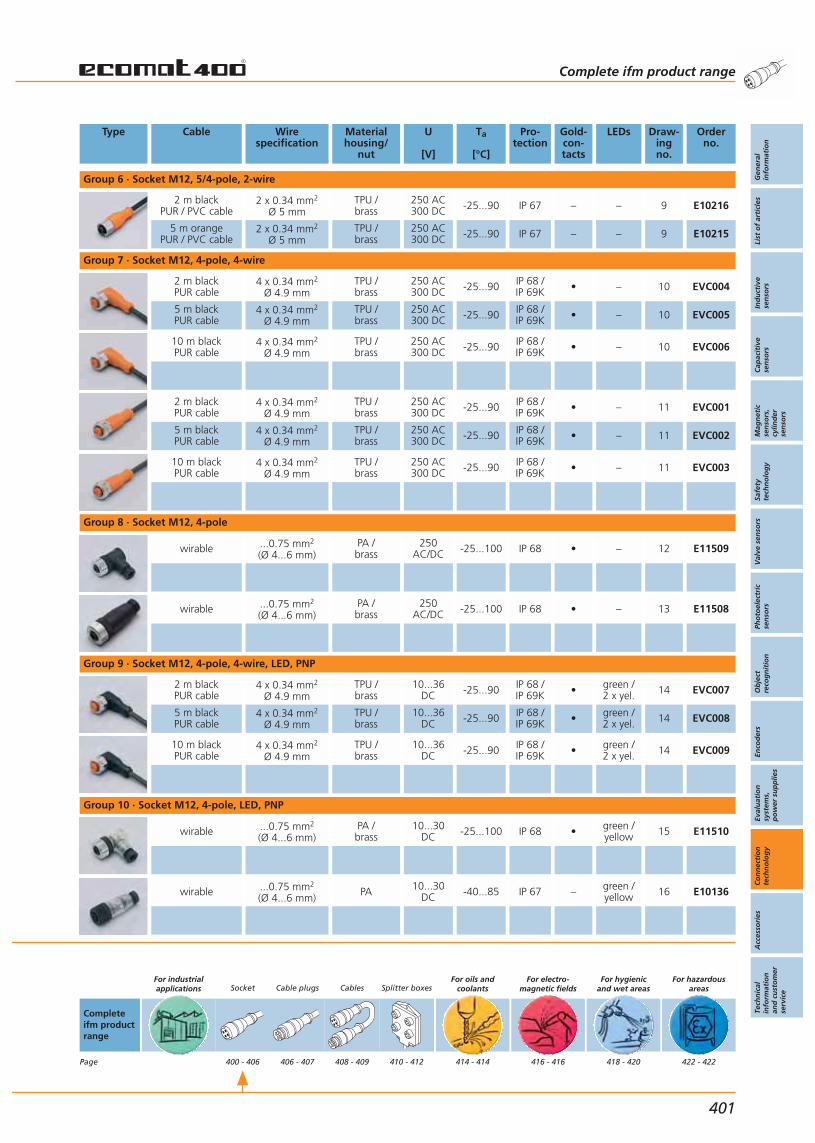
Type Cable Wirespecification
Materialhousing/
nut
U
[V]
Ta
[°C]
Pro-tection
Gold-con-tacts
LEDs Draw-ingno.
Orderno.
Group 6 · Socket M12, 5/4-pole, 2-wire
2 m blackPUR / PVC cable
2 x 0.34 mm2
Ø 5 mmTPU /brass
250 AC300 DC -25...90 IP 67 – – 9 E10216
5 m orangePUR / PVC cable
2 x 0.34 mm2
Ø 5 mmTPU /brass
250 AC300 DC -25...90 IP 67 – – 9 E10215
Group 7 · Socket M12, 4-pole, 4-wire
2 m blackPUR cable
4 x 0.34 mm2
Ø 4.9 mmTPU /brass
250 AC300 DC -25...90 IP 68 /
IP 69K • – 10 EVC004
5 m blackPUR cable
4 x 0.34 mm2
Ø 4.9 mmTPU /brass
250 AC300 DC -25...90 IP 68 /
IP 69K • – 10 EVC005
10 m blackPUR cable
4 x 0.34 mm2
Ø 4.9 mmTPU /brass
250 AC300 DC -25...90 IP 68 /
IP 69K • – 10 EVC006
2 m blackPUR cable
4 x 0.34 mm2
Ø 4.9 mmTPU /brass
250 AC300 DC -25...90 IP 68 /
IP 69K • – 11 EVC001
5 m blackPUR cable
4 x 0.34 mm2
Ø 4.9 mmTPU /brass
250 AC300 DC -25...90 IP 68 /
IP 69K • – 11 EVC002
10 m blackPUR cable
4 x 0.34 mm2
Ø 4.9 mmTPU /brass
250 AC300 DC -25...90 IP 68 /
IP 69K • – 11 EVC003
Group 8 · Socket M12, 4-pole
wirable ...0.75 mm2
(Ø 4...6 mm)PA /brass
250AC/DC -25...100 IP 68 • – 12 E11509
wirable ...0.75 mm2
(Ø 4...6 mm)PA /brass
250AC/DC -25...100 IP 68 • – 13 E11508
Group 9 · Socket M12, 4-pole, 4-wire, LED, PNP
2 m blackPUR cable
4 x 0.34 mm2
Ø 4.9 mmTPU /brass
10...36DC -25...90 IP 68 /
IP 69K • green /2 x yel. 14 EVC007
5 m blackPUR cable
4 x 0.34 mm2
Ø 4.9 mmTPU /brass
10...36DC -25...90 IP 68 /
IP 69K • green /2 x yel. 14 EVC008
10 m blackPUR cable
4 x 0.34 mm2
Ø 4.9 mmTPU /brass
10...36DC -25...90 IP 68 /
IP 69K • green /2 x yel. 14 EVC009
Group 10 · Socket M12, 4-pole, LED, PNP
wirable ...0.75 mm2
(Ø 4...6 mm)PA /brass
10...30DC -25...100 IP 68 • green /
yellow 15 E11510
wirable ...0.75 mm2
(Ø 4...6 mm)PA 10...30
DC -40...85 IP 67 – green /yellow 16 E10136
Complete ifm product range
Gen
eral
info
rmat
ion
List
of
arti
cles
Ind
uct
ive
sen
sors
Cap
acit
ive
sen
sors
Mag
net
icse
nso
rs,
cylin
der
sen
sors
Safe
tyte
chn
olo
gy
Val
ve s
enso
rsPh
oto
elec
tric
sen
sors
Ob
ject
reco
gn
itio
nEn
cod
ers
Eval
uat
ion
syst
ems,
po
wer
su
pp
lies
Co
nn
ecti
on
tech
no
log
yA
cces
sori
esTe
chn
ical
info
rmat
ion
and
cu
sto
mer
serv
ice
401
Completeifm productrange
Page
For industrialapplications Socket
400 - 406
Cable plugs
406 - 407
Cables
408 - 409
Splitter boxes
410 - 412
For oils andcoolants
414 - 414
For electro-magnetic fields
416 - 416
For hygienicand wet areas
418 - 420
For hazardousareas
422 - 422
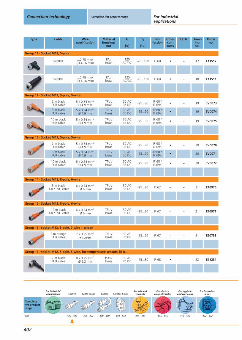
Type Cable Wirespecification
Materialhousing/
nut
U
[V]
Ta
[°C]
Pro-tection
Gold-con-tacts
LEDs Draw-ingno.
Orderno.
Group 11 · Socket M12, 5-pole
wirable ...0.75 mm2
(Ø 4...6 mm)PA /brass
125AC/DC -25...100 IP 68 • – 17 E11512
wirable ...0.75 mm2
(Ø 4...6 mm)PA /brass
125AC/DC -25...100 IP 68 • – 18 E11511
Group 12 · Socket M12, 5-pole, 5-wire
2 m blackPUR cable
5 x 0.34 mm2
Ø 4.9 mmTPU /brass
30 AC36 DC -25...90 IP 68 /
IP 69K • – 19 EVC073
5 m blackPUR cable
5 x 0.34 mm2
Ø 4.9 mmTPU /brass
30 AC36 DC -25...90 IP 68 /
IP 69K • – 19 EVC074
10 m blackPUR cable
5 x 0.34 mm2
Ø 4.9 mmTPU /brass
30 AC36 DC -25...90 IP 68 /
IP 69K • – 19 EVC075
Group 13 · Socket M12, 5-pole, 5-wire
2 m blackPUR cable
5 x 0.34 mm2
Ø 4.9 mmTPU /brass
30 AC36 DC -25...90 IP 68 /
IP 69K • – 20 EVC070
5 m blackPUR cable
5 x 0.34 mm2
Ø 4.9 mmTPU /brass
30 AC36 DC -25...90 IP 68 /
IP 69K • – 20 EVC071
10 m blackPUR cable
5 x 0.34 mm2
Ø 4.9 mmTPU /brass
30 AC36 DC -25...90 IP 68 /
IP 69K • – 20 EVC072
Group 14 · Socket M12, 8-pole, 6-wire
5 m blackPUR / PVC cable
6 x 0.34 mm2
Ø 6 mmTPU /brass
30 AC36 DC -25...90 IP 67 – – 21 E10976
Group 15 · Socket M12, 8-pole, 6-wire
10 m blackPUR / PVC cable
6 x 0.34 mm2
Ø 6 mmTPU /brass
30 AC36 DC -25...90 IP 67 – – 21 E10977
Group 16 · socket M12, 8-pole, 7-wire + screen
2 m orangePUR cable
7 x 0.25 mm2
+ screenTPU /brass
30 AC36 DC -25...90 IP 67 – – 21 E20738
Group 17 · socket M12, 8-pole, 8-wire, for temperature sensors TR 8...
2 m blackPUR cable
8 x 0.25 mm2
Ø 6.2 mmPUR /brass
30 AC36 DC -25...80 IP 68 • – 22 E11231
Connection technology Complete ifm product range For industrialapplications
402
Completeifm productrange
Page
For industrialapplications Socket
400 - 406
Cable plugs
406 - 407
Cables
408 - 409
Splitter boxes
410 - 412
For oils andcoolants
414 - 414
For electro-magnetic fields
416 - 416
For hygienicand wet areas
418 - 420
For hazardousareas
422 - 422

Type Cable Wirespecification
Materialhousing/
nut
U
[V]
Ta
[°C]
Pro-tection
Gold-con-tacts
LEDs Draw-ingno.
Orderno.
Group 17 · socket M12, 8-pole, 8-wire, for temperature sensors TR 8...
5 m blackPUR cable
8 x 0.25 mm2
Ø 6.2 mmPUR /brass
30 AC36 DC -25...80 IP 68 • – 22 E11232
10 m blackPUR cable
8 x 0.25 mm2
Ø 6.2 mmPUR /brass
30 AC36 DC -25...80 IP 68 – – 23 E11311
Group 18 · socket M16, 14-pole, 10-wire
5 m blackPUR cable
8 x 0.34 mm2
+ 2 x 0.75 mm2PUR /brass 30 DC -25...90 IP 68 – – 24 E11226
10 m blackPUR cable
8 x 0.34 mm2
+ 2 x 0.75 mm2PUR /brass 30 DC -25...90 IP 68 – – 24 E11227
Group 19 · Socket , 14-pole, 12-wire
2 m blackPUR cable
10 x 0.25 mm2
+ 2 x 0.34 mm2PUR /brass 30 DC -25...90 IP 67 – – 25 E11645
5 m blackPUR cable
10 x 0.25 mm2
+ 2 x 0.34 mm2PUR /brass 30 DC -25...90 IP 67 – – 25 E11697
Group 20 · Socket M18, 4-pole
wirable ...0.75 mm2
(Ø 6...8 mm)PA 20...250
AC/DC -40...85 IP 65 – – 26 E10013
wirable ...0.75 mm2
(Ø 6...8 mm)PA /
ULTRAMID20...250AC/DC -40...85 IP 65 – – 27 E10137
Group 21 · Socket M18, 12-pole
soldering ...0.25 mm2
(Ø 6...8 mm)brass 4.5...30
DC -40...85 IP 67 – – 28 E60174
soldering ...0.25 mm2
(Ø 6...8 mm)brass 4.5...30
DC -40...85 IP 67 – – 29 E60175
Group 22 · socket M23, 12-pole, numbering anticlockwise
soldering ...1 mm2
(Ø 10...14 mm)brass 10...30
DC -25...90 IP 65 – – 30 E10447
soldering ...1 mm2
(Ø 10...14 mm)brass 10...30
DC -25...90 IP 65 – – 31 E10448
Complete ifm product range
Gen
eral
info
rmat
ion
List
of
arti
cles
Ind
uct
ive
sen
sors
Cap
acit
ive
sen
sors
Mag
net
icse
nso
rs,
cylin
der
sen
sors
Safe
tyte
chn
olo
gy
Val
ve s
enso
rsPh
oto
elec
tric
sen
sors
Ob
ject
reco
gn
itio
nEn
cod
ers
Eval
uat
ion
syst
ems,
po
wer
su
pp
lies
Co
nn
ecti
on
tech
no
log
yA
cces
sori
esTe
chn
ical
info
rmat
ion
and
cu
sto
mer
serv
ice
403
Completeifm productrange
Page
For industrialapplications Socket
400 - 406
Cable plugs
406 - 407
Cables
408 - 409
Splitter boxes
410 - 412
For oils andcoolants
414 - 414
For electro-magnetic fields
416 - 416
For hygienicand wet areas
418 - 420
For hazardousareas
422 - 422

Type Cable Wirespecification
Materialhousing/
nut
U
[V]
Ta
[°C]
Pro-tection
Gold-con-tacts
LEDs Draw-ingno.
Orderno.
Group 23 · socket M23, 12-pole, numbering anticlockwise
soldering ...1 mm2
Ø 8 mmbrass 4.5...30
DC -40...125 IP 67 – – 32 E60124
Group 24 · socket M23, 12-pole, numbering clockwise, for encoders
soldering ...1 mm2
Ø 8 mmbrass 4.5...30
DC -40...125 IP 67 – – 33 E60122
soldering ...1 mm2
(Ø 4.5...6 mm)brass 4.5...30
DC -40...125 IP 67 – – 34 E60136
5 m PUR cable
8 x 0.14 mm2
+ 4 x 0.5 mm2 brass 4.5...30DC -25...80 IP 67 – – 35 E60144
10 m PUR cable
8 x 0.14 mm2
+ 4 x 0.5 mm2 brass 4.5...30DC -25...80 IP 67 – – 35 E60147
Group 25 · plug M23, 12-pole, numbering anticlockwise
soldering ...1 mm2
Ø 8 mmbrass 4.5...30
DC -40...125 IP 67 – – 36 E60141
Group 26 · socket M23, 17-pole, numbering clockwise
Soldering/crimpingconnection
...0.5 mm2
Ø 8 mmbrass 4.5...30
DC -40...125 IP 67 – – 37 E60157
Group 27 · socket M23, 21-pole, numbering clockwise
Soldering/crimpingconnection
...0.5 mm2
Ø 8 mmbrass 4.5...30
DC -40...125 IP 67 – – 38 E60146
Group 28 · Socket , 12-pole
5 m blackPUR cable
8 x 0.5 mm2
+ 3 x 1.0 mm2PUR /brass
250AC/DC -25...80 IP 67 – – 39 E11736
10 m blackPUR cable
8 x 0.5 mm2
+ 3 x 1.0 mm2PUR /brass
250AC/DC -25...80 IP 67 – – 39 E11737
15 m blackPUR cable
8 x 0.5 mm2
+ 3 x 1.0 mm2PUR /brass
250AC/DC -25...80 IP 67 – – 39 E11738
5 m blackPUR cable
8 x 0.5 mm2
+ 3 x 1.0 mm2PUR /brass
250AC/DC -25...80 IP 67 – – 40 E11739
10 m blackPUR cable
8 x 0.5 mm2
+ 3 x 1.0 mm2PUR /brass
250AC/DC -25...80 IP 67 – – 40 E11740
Connection technology Complete ifm product range For industrialapplications
404
Completeifm productrange
Page
For industrialapplications Socket
400 - 406
Cable plugs
406 - 407
Cables
408 - 409
Splitter boxes
410 - 412
For oils andcoolants
414 - 414
For electro-magnetic fields
416 - 416
For hygienicand wet areas
418 - 420
For hazardousareas
422 - 422
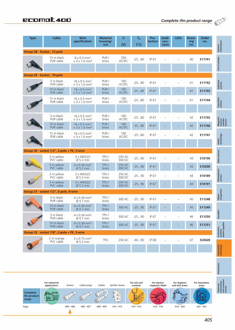
Type Cable Wirespecification
Materialhousing/
nut
U
[V]
Ta
[°C]
Pro-tection
Gold-con-tacts
LEDs Draw-ingno.
Orderno.
Group 28 · Socket , 12-pole
15 m blackPUR cable
8 x 0.5 mm2
+ 3 x 1.0 mm2PUR /brass
250AC/DC -25...80 IP 67 – – 40 E11741
Group 29 · Socket , 19-pole
5 m blackPUR cable
16 x 0.5 mm2
+ 3 x 1.0 mm2PUR /brass
160AC/DC -25...80 IP 67 – – 41 E11742
10 m blackPUR cable
16 x 0.5 mm2
+ 3 x 1.0 mm2PUR /brass
160AC/DC -25...80 IP 67 – – 41 E11743
15 m blackPUR cable
16 x 0.5 mm2
+ 3 x 1.0 mm2PUR /brass
160AC/DC -25...80 IP 67 – – 41 E11744
5 m blackPUR cable
16 x 0.5 mm2
+ 3 x 1.0 mm2PUR /brass
160AC/DC -25...80 IP 67 – – 42 E11745
10 m blackPUR cable
16 x 0.5 mm2
+ 3 x 1.0 mm2PUR /brass
160AC/DC -25...80 IP 67 – – 42 E11746
15 m blackPUR cable
16 x 0.5 mm2
+ 3 x 1.0 mm2PUR /brass
160AC/DC -25...80 IP 67 – – 42 E11747
Group 30 · socket 1/2", 2-pole + PE, 3-wire
2 m yellowPVC cable
3 x AWG22Ø 5.2 mm
TPU /brass
250 AC300 DC -25...90 IP 67 – – 43 E10190
5 m yellowPVC cable
3 x 0.34 mm2
Ø 5.2 mmTPU /brass
250 AC300 DC -25...90 IP 67 – – 43 E10200
2 m yellowPVC cable
3 x AWG22Ø 5.2 mm
TPU /brass
250 AC300 DC -25...90 IP 67 – – 44 E10189
5 m yellowPVC cable
3 x AWG22Ø 5.2 mm
TPU /brass
250 AC300 DC -25...90 IP 67 – – 44 E10191
Group 31 · socket 1/2", 5-pole, 4-wire
5 m blackPUR cable
4 x 0.34 mm2
Ø 4.7 mmTPU /brass 300 AC -25...90 IP 67 – – 45 E11248
10 m blackPUR cable
4 x 0.34 mm2
Ø 4.7 mmTPU /brass 300 AC -25...90 IP 67 – – 45 E11249
5 m blackPUR cable
4 x 0.34 mm2
Ø 4.7 mmTPU /brass 300 AC -25...90 IP 67 – – 46 E11250
10 m blackPUR cable
4 x 0.34 mm2
Ø 4.7 mmTPU /brass 300 AC -25...90 IP 67 – – 46 E11251
Group 32 · socket 7/8", 2-pole + PE, 3-wire
2 m orangePVC cable
3 x 0.75 mm2
Ø 5.2 mmTPU 250 AC -40...90 IP 68 – – 47 E20428
Complete ifm product range
Gen
eral
info
rmat
ion
List
of
arti
cles
Ind
uct
ive
sen
sors
Cap
acit
ive
sen
sors
Mag
net
icse
nso
rs,
cylin
der
sen
sors
Safe
tyte
chn
olo
gy
Val
ve s
enso
rsPh
oto
elec
tric
sen
sors
Ob
ject
reco
gn
itio
nEn
cod
ers
Eval
uat
ion
syst
ems,
po
wer
su
pp
lies
Co
nn
ecti
on
tech
no
log
yA
cces
sori
esTe
chn
ical
info
rmat
ion
and
cu
sto
mer
serv
ice
405
Completeifm productrange
Page
For industrialapplications Socket
400 - 406
Cable plugs
406 - 407
Cables
408 - 409
Splitter boxes
410 - 412
For oils andcoolants
414 - 414
For electro-magnetic fields
416 - 416
For hygienicand wet areas
418 - 420
For hazardousareas
422 - 422
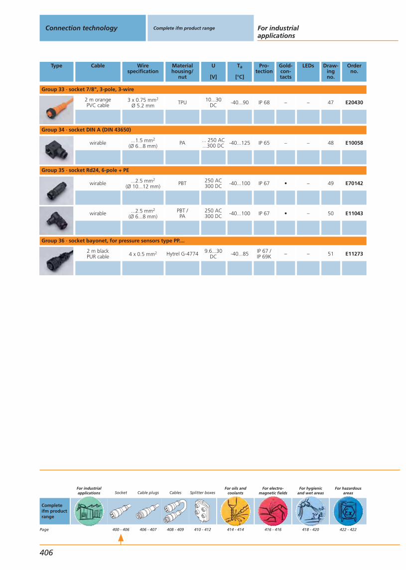
Type Cable Wirespecification
Materialhousing/
nut
U
[V]
Ta
[°C]
Pro-tection
Gold-con-tacts
LEDs Draw-ingno.
Orderno.
Group 33 · socket 7/8", 3-pole, 3-wire
2 m orangePVC cable
3 x 0.75 mm2
Ø 5.2 mmTPU 10...30
DC -40...90 IP 68 – – 47 E20430
Group 34 · socket DIN A (DIN 43650)
wirable ...1.5 mm2
(Ø 6...8 mm)PA ... 250 AC
...300 DC -40...125 IP 65 – – 48 E10058
Group 35 · socket Rd24, 6-pole + PE
wirable ...2.5 mm2
(Ø 10...12 mm)PBT 250 AC
300 DC -40...100 IP 67 • – 49 E70142
wirable ...2.5 mm2
(Ø 6...8 mm)PBT /PA
250 AC300 DC -40...100 IP 67 • – 50 E11043
Group 36 · socket bayonet, for pressure sensors type PP....
2 m blackPUR cable 4 x 0.5 mm2 Hytrel G-4774 9.6...30
DC -40...85 IP 67 /IP 69K – – 51 E11273
Connection technology Complete ifm product range For industrialapplications
406
Completeifm productrange
Page
For industrialapplications Socket
400 - 406
Cable plugs
406 - 407
Cables
408 - 409
Splitter boxes
410 - 412
For oils andcoolants
414 - 414
For electro-magnetic fields
416 - 416
For hygienicand wet areas
418 - 420
For hazardousareas
422 - 422
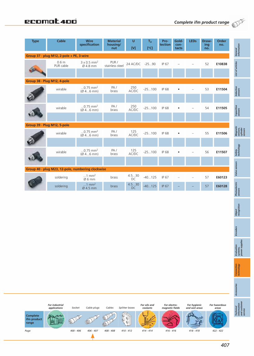
Type Cable Wirespecification
Materialhousing/
nut
U
[V]
Ta
[°C]
Pro-tection
Gold-con-tacts
LEDs Draw-ingno.
Orderno.
Group 37 · plug M12, 2-pole + PE, 3-wire
0.6 m PUR cable
3 x 0.5 mm2
Ø 4.8 mmPUR /
stainless steel 24 AC/DC -25...90 IP 67 – – 52 E10838
Group 38 · Plug M12, 4-pole
wirable ...0.75 mm2
(Ø 4...6 mm)PA /brass
250AC/DC -25...100 IP 68 • – 53 E11504
wirable ...0.75 mm2
(Ø 4...6 mm)PA /brass
250AC/DC -25...100 IP 68 • – 54 E11505
Group 39 · Plug M12, 5-pole
wirable ...0.75 mm2
(Ø 4...6 mm)PA /brass
125AC/DC -25...100 IP 68 • – 55 E11506
wirable ...0.75 mm2
(Ø 4...6 mm)PA /brass
125AC/DC -25...100 IP 68 • – 56 E11507
Group 40 · plug M23, 12-pole, numbering clockwise
soldering ...1 mm2
Ø 6 mmbrass 4.5...30
DC -40...125 IP 67 – – 57 E60123
soldering ...1 mm2
Ø 4.5 mmbrass 4.5...30
DC -40...125 IP 67 – – 57 E60128
Completeifm productrange
Page
For industrialapplications Socket
400 - 406
Cable plugs
406 - 407
Cables
408 - 408
Splitter boxes
410 - 412
For oils andcoolants
414 - 414
For electro-magnetic fields
416 - 416
For hygienicand wet areas
418 - 418
For hazardousareas
422 - 422
Complete ifm product range
Gen
eral
info
rmat
ion
List
of
arti
cles
Ind
uct
ive
sen
sors
Cap
acit
ive
sen
sors
Mag
net
icse
nso
rs,
cylin
der
sen
sors
Safe
tyte
chn
olo
gy
Val
ve s
enso
rsPh
oto
elec
tric
sen
sors
Ob
ject
reco
gn
itio
nEn
cod
ers
Eval
uat
ion
syst
ems,
po
wer
su
pp
lies
Co
nn
ecti
on
tech
no
log
yA
cces
sori
esTe
chn
ical
info
rmat
ion
and
cu
sto
mer
serv
ice
407
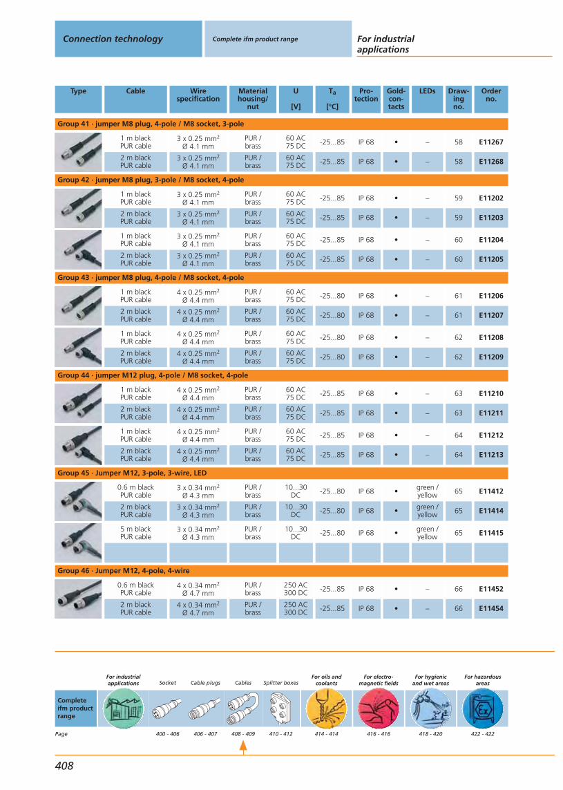
Type Cable Wirespecification
Materialhousing/
nut
U
[V]
Ta
[°C]
Pro-tection
Gold-con-tacts
LEDs Draw-ingno.
Orderno.
Group 41 · jumper M8 plug, 4-pole / M8 socket, 3-pole
1 m blackPUR cable
3 x 0.25 mm2
Ø 4.1 mmPUR /brass
60 AC75 DC -25...85 IP 68 • – 58 E11267
2 m blackPUR cable
3 x 0.25 mm2
Ø 4.1 mmPUR /brass
60 AC75 DC -25...85 IP 68 • – 58 E11268
Group 42 · jumper M8 plug, 3-pole / M8 socket, 4-pole
1 m blackPUR cable
3 x 0.25 mm2
Ø 4.1 mmPUR /brass
60 AC75 DC -25...85 IP 68 • – 59 E11202
2 m blackPUR cable
3 x 0.25 mm2
Ø 4.1 mmPUR /brass
60 AC75 DC -25...85 IP 68 • – 59 E11203
1 m blackPUR cable
3 x 0.25 mm2
Ø 4.1 mmPUR /brass
60 AC75 DC -25...85 IP 68 • – 60 E11204
2 m blackPUR cable
3 x 0.25 mm2
Ø 4.1 mmPUR /brass
60 AC75 DC -25...85 IP 68 • – 60 E11205
Group 43 · jumper M8 plug, 4-pole / M8 socket, 4-pole
1 m blackPUR cable
4 x 0.25 mm2
Ø 4.4 mmPUR /brass
60 AC75 DC -25...80 IP 68 • – 61 E11206
2 m blackPUR cable
4 x 0.25 mm2
Ø 4.4 mmPUR /brass
60 AC75 DC -25...80 IP 68 • – 61 E11207
1 m blackPUR cable
4 x 0.25 mm2
Ø 4.4 mmPUR /brass
60 AC75 DC -25...80 IP 68 • – 62 E11208
2 m blackPUR cable
4 x 0.25 mm2
Ø 4.4 mmPUR /brass
60 AC75 DC -25...80 IP 68 • – 62 E11209
Group 44 · jumper M12 plug, 4-pole / M8 socket, 4-pole
1 m blackPUR cable
4 x 0.25 mm2
Ø 4.4 mmPUR /brass
60 AC75 DC -25...85 IP 68 • – 63 E11210
2 m blackPUR cable
4 x 0.25 mm2
Ø 4.4 mmPUR /brass
60 AC75 DC -25...85 IP 68 • – 63 E11211
1 m blackPUR cable
4 x 0.25 mm2
Ø 4.4 mmPUR /brass
60 AC75 DC -25...85 IP 68 • – 64 E11212
2 m blackPUR cable
4 x 0.25 mm2
Ø 4.4 mmPUR /brass
60 AC75 DC -25...85 IP 68 • – 64 E11213
Group 45 · Jumper M12, 3-pole, 3-wire, LED
0.6 m blackPUR cable
3 x 0.34 mm2
Ø 4.3 mmPUR /brass
10...30DC -25...80 IP 68 • green /
yellow 65 E11412
2 m blackPUR cable
3 x 0.34 mm2
Ø 4.3 mmPUR /brass
10...30DC -25...80 IP 68 • green /
yellow 65 E11414
5 m blackPUR cable
3 x 0.34 mm2
Ø 4.3 mmPUR /brass
10...30DC -25...80 IP 68 • green /
yellow 65 E11415
Group 46 · Jumper M12, 4-pole, 4-wire
0.6 m blackPUR cable
4 x 0.34 mm2
Ø 4.7 mmPUR /brass
250 AC300 DC -25...85 IP 68 • – 66 E11452
2 m blackPUR cable
4 x 0.34 mm2
Ø 4.7 mmPUR /brass
250 AC300 DC -25...85 IP 68 • – 66 E11454
Connection technology Complete ifm product range For industrialapplications
408
Completeifm productrange
Page
For industrialapplications Socket
400 - 406
Cable plugs
406 - 407
Cables
408 - 409
Splitter boxes
410 - 412
For oils andcoolants
414 - 414
For electro-magnetic fields
416 - 416
For hygienicand wet areas
418 - 420
For hazardousareas
422 - 422
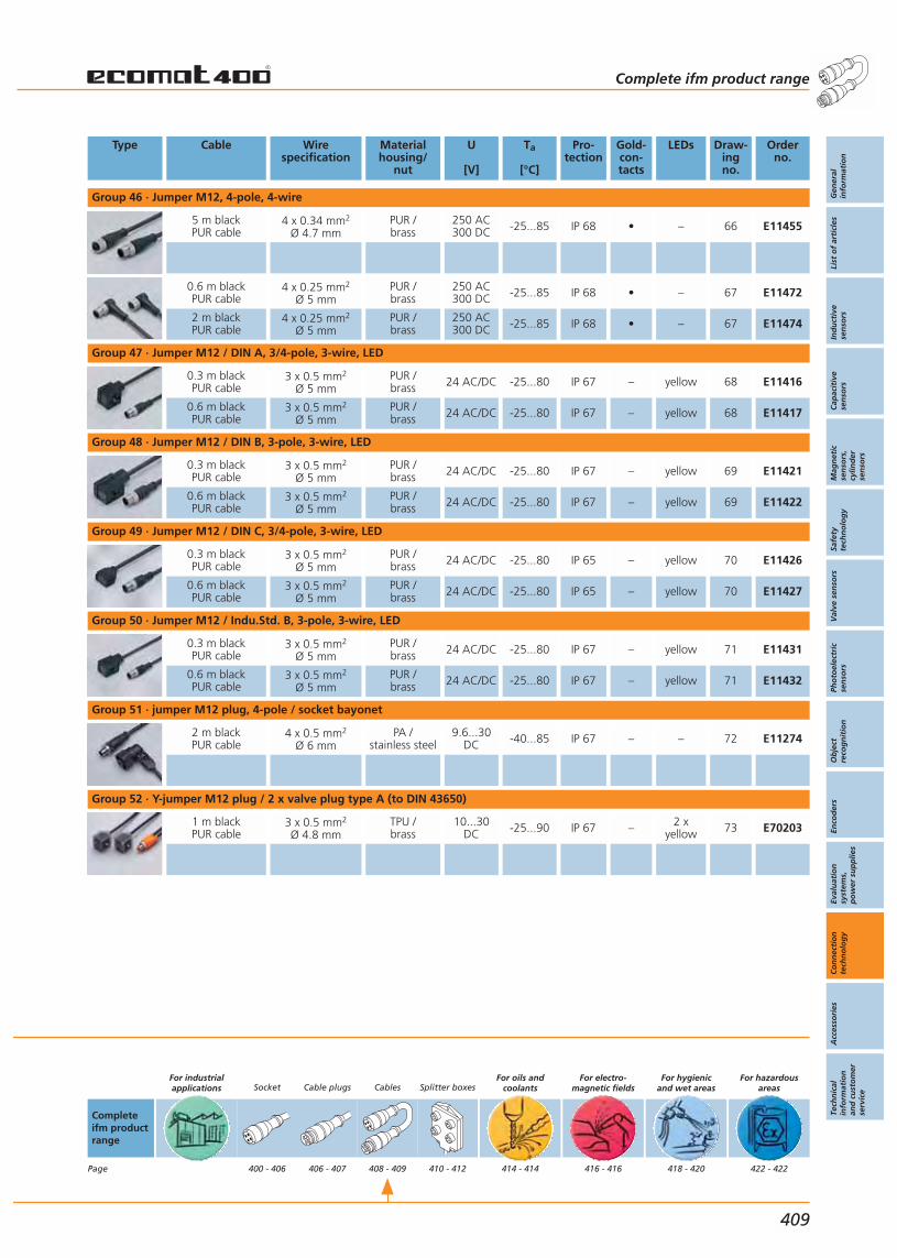
Type Cable Wirespecification
Materialhousing/
nut
U
[V]
Ta
[°C]
Pro-tection
Gold-con-tacts
LEDs Draw-ingno.
Orderno.
Group 46 · Jumper M12, 4-pole, 4-wire
5 m blackPUR cable
4 x 0.34 mm2
Ø 4.7 mmPUR /brass
250 AC300 DC -25...85 IP 68 • – 66 E11455
0.6 m blackPUR cable
4 x 0.25 mm2
Ø 5 mmPUR /brass
250 AC300 DC -25...85 IP 68 • – 67 E11472
2 m blackPUR cable
4 x 0.25 mm2
Ø 5 mmPUR /brass
250 AC300 DC -25...85 IP 68 • – 67 E11474
Group 47 · Jumper M12 / DIN A, 3/4-pole, 3-wire, LED
0.3 m blackPUR cable
3 x 0.5 mm2
Ø 5 mmPUR /brass 24 AC/DC -25...80 IP 67 – yellow 68 E11416
0.6 m blackPUR cable
3 x 0.5 mm2
Ø 5 mmPUR /brass 24 AC/DC -25...80 IP 67 – yellow 68 E11417
Group 48 · Jumper M12 / DIN B, 3-pole, 3-wire, LED
0.3 m blackPUR cable
3 x 0.5 mm2
Ø 5 mmPUR /brass 24 AC/DC -25...80 IP 67 – yellow 69 E11421
0.6 m blackPUR cable
3 x 0.5 mm2
Ø 5 mmPUR /brass 24 AC/DC -25...80 IP 67 – yellow 69 E11422
Group 49 · Jumper M12 / DIN C, 3/4-pole, 3-wire, LED
0.3 m blackPUR cable
3 x 0.5 mm2
Ø 5 mmPUR /brass 24 AC/DC -25...80 IP 65 – yellow 70 E11426
0.6 m blackPUR cable
3 x 0.5 mm2
Ø 5 mmPUR /brass 24 AC/DC -25...80 IP 65 – yellow 70 E11427
Group 50 · Jumper M12 / Indu.Std. B, 3-pole, 3-wire, LED
0.3 m blackPUR cable
3 x 0.5 mm2
Ø 5 mmPUR /brass 24 AC/DC -25...80 IP 67 – yellow 71 E11431
0.6 m blackPUR cable
3 x 0.5 mm2
Ø 5 mmPUR /brass 24 AC/DC -25...80 IP 67 – yellow 71 E11432
Group 51 · jumper M12 plug, 4-pole / socket bayonet
2 m blackPUR cable
4 x 0.5 mm2
Ø 6 mmPA /
stainless steel9.6...30
DC -40...85 IP 67 – – 72 E11274
Group 52 · Y-jumper M12 plug / 2 x valve plug type A (to DIN 43650)
1 m blackPUR cable
3 x 0.5 mm2
Ø 4.8 mmTPU /brass
10...30DC -25...90 IP 67 – 2 x
yellow 73 E70203
Complete ifm product range
Gen
eral
info
rmat
ion
List
of
arti
cles
Ind
uct
ive
sen
sors
Cap
acit
ive
sen
sors
Mag
net
icse
nso
rs,
cylin
der
sen
sors
Safe
tyte
chn
olo
gy
Val
ve s
enso
rsPh
oto
elec
tric
sen
sors
Ob
ject
reco
gn
itio
nEn
cod
ers
Eval
uat
ion
syst
ems,
po
wer
su
pp
lies
Co
nn
ecti
on
tech
no
log
yA
cces
sori
esTe
chn
ical
info
rmat
ion
and
cu
sto
mer
serv
ice
409
Completeifm productrange
Page
For industrialapplications Socket
400 - 406
Cable plugs
406 - 407
Cables
408 - 409
Splitter boxes
410 - 412
For oils andcoolants
414 - 414
For electro-magnetic fields
416 - 416
For hygienicand wet areas
418 - 420
For hazardousareas
422 - 422
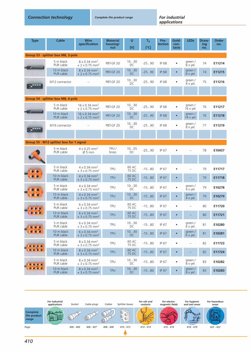
Type Cable Wirespecification
Materialhousing/
nut
U
[V]
Ta
[°C]
Pro-tection
Gold-con-tacts
LEDs Draw-ingno.
Orderno.
Group 53 · splitter box M8, 3-pole
5 m blackPUR cable
8 x 0.34 mm2
+ 2 x 0.75 mm2 PBT-GF 20 10...30DC -25...90 IP 68 • green /
8 x yel. 74 E11214
10 m blackPUR cable
8 x 0.34 mm2
+ 2 x 0.75 mm2 PBT-GF 20 10...30DC -25...90 IP 68 • green /
8 x yel. 74 E11215
M12 connector – PBT-GF 20 10...30DC -25...90 IP 68 • green /
4 x yel. 75 E11216
Group 54 · splitter box M8, 4-pole
5 m blackPUR cable
16 x 0.34 mm2
+ 2 x 0.75 mm2 PBT-GF 20 10...30DC -25...90 IP 68 • green /
16 x yel. 76 E11217
10 m blackPUR cable
16 x 0.34 mm2
+ 2 x 0.75 mm2 PBT-GF 20 10...30DC -25...90 IP 68 • green /
16 x yel. 76 E11218
M16 connector – PBT-GF 20 10...30DC -25...90 IP 68 • green /
8 x yel. 77 E11219
Group 55 · M12 splitter box for 1 signal
5 m blackPUR cable
4 x 0.25 mm2
Ø 5 mmTPU /brass
10...55DC -25...90 IP 67 • – 78 E10437
5 m blackPUR cable
4 x 0.34 mm2
+ 3 x 0.75 mm2 TPU 60 AC75 DC -15...80 IP 67 • – 79 E11717
10 m blackPUR cable
4 x 0.34 mm2
+ 3 x 0.75 mm2 TPU 60 AC75 DC -15...80 IP 67 • – 79 E11718
5 m blackPUR cable
4 x 0.34 mm2
+ 3 x 0.75 mm2 TPU 10...30DC -15...80 IP 67 • green /
4 x yel. 79 E10278
10 m blackPUR cable
4 x 0.34 mm2
+ 3 x 0.75 mm2 TPU 10...30DC -15...80 IP 67 • green /
4 x yel. 79 E10279
5 m blackPUR cable
6 x 0.34 mm2
+ 3 x 0.75 mm2 TPU 60 AC75 DC -15...80 IP 67 • – 80 E11720
10 m blackPUR cable
6 x 0.34 mm2
+ 3 x 0.75 mm2 TPU 60 AC75 DC -15...80 IP 67 • – 80 E11721
5 m blackPUR cable
6 x 0.34 mm2
+ 3 x 0.75 mm2 TPU 10...30DC -15...80 IP 67 • green /
6 x yel. 81 E10280
10 m blackPUR cable
6 x 0.34 mm2
+ 3 x 0.75 mm2 TPU 10...30DC -15...80 IP 67 • green /
6 x yel. 81 E10281
5 m blackPUR cable
8 x 0.34 mm2
+ 3 x 0.75 mm2 TPU 60 AC75 DC -15...80 IP 67 • – 82 E11723
10 m blackPUR cable
8 x 0.34 mm2
+ 3 x 0.75 mm2 TPU 60 AC75 DC -15...80 IP 67 • – 82 E11724
5 m blackPUR cable
8 x 0.34 mm2
+ 3 x 0.75 mm2 TPU 10...30DC -15...80 IP 67 • green /
8 x yel. 83 E10282
10 m blackPUR cable
8 x 0.34 mm2
+ 3 x 0.75 mm2 TPU 10...30DC -15...80 IP 67 • green /
8 x yel. 83 E10283
Connection technology Complete ifm product range For industrialapplications
410
Completeifm productrange
Page
For industrialapplications Socket
400 - 406
Cable plugs
406 - 407
Cables
408 - 408
Splitter boxes
410 - 412
For oils andcoolants
414 - 414
For electro-magnetic fields
416 - 416
For hygienicand wet areas
418 - 418
For hazardousareas
422 - 422
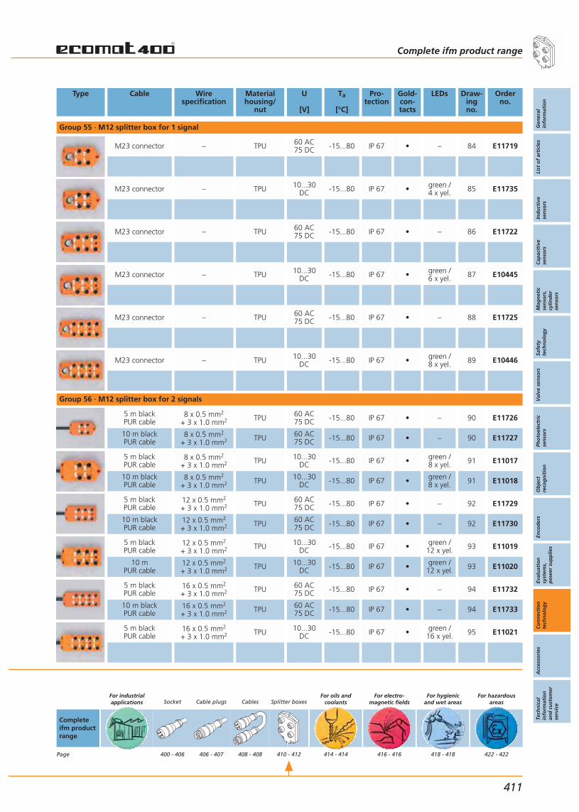
Type Cable Wirespecification
Materialhousing/
nut
U
[V]
Ta
[°C]
Pro-tection
Gold-con-tacts
LEDs Draw-ingno.
Orderno.
Group 55 · M12 splitter box for 1 signal
M23 connector – TPU 60 AC75 DC -15...80 IP 67 • – 84 E11719
M23 connector – TPU 10...30DC -15...80 IP 67 • green /
4 x yel. 85 E11735
M23 connector – TPU 60 AC75 DC -15...80 IP 67 • – 86 E11722
M23 connector – TPU 10...30DC -15...80 IP 67 • green /
6 x yel. 87 E10445
M23 connector – TPU 60 AC75 DC -15...80 IP 67 • – 88 E11725
M23 connector – TPU 10...30DC -15...80 IP 67 • green /
8 x yel. 89 E10446
Group 56 · M12 splitter box for 2 signals
5 m blackPUR cable
8 x 0.5 mm2
+ 3 x 1.0 mm2 TPU 60 AC75 DC -15...80 IP 67 • – 90 E11726
10 m blackPUR cable
8 x 0.5 mm2
+ 3 x 1.0 mm2 TPU 60 AC75 DC -15...80 IP 67 • – 90 E11727
5 m blackPUR cable
8 x 0.5 mm2
+ 3 x 1.0 mm2 TPU 10...30DC -15...80 IP 67 • green /
8 x yel. 91 E11017
10 m blackPUR cable
8 x 0.5 mm2
+ 3 x 1.0 mm2 TPU 10...30DC -15...80 IP 67 • green /
8 x yel. 91 E11018
5 m blackPUR cable
12 x 0.5 mm2
+ 3 x 1.0 mm2 TPU 60 AC75 DC -15...80 IP 67 • – 92 E11729
10 m blackPUR cable
12 x 0.5 mm2
+ 3 x 1.0 mm2 TPU 60 AC75 DC -15...80 IP 67 • – 92 E11730
5 m blackPUR cable
12 x 0.5 mm2
+ 3 x 1.0 mm2 TPU 10...30DC -15...80 IP 67 • green /
12 x yel. 93 E11019
10 m PUR cable
12 x 0.5 mm2
+ 3 x 1.0 mm2 TPU 10...30DC -15...80 IP 67 • green /
12 x yel. 93 E11020
5 m blackPUR cable
16 x 0.5 mm2
+ 3 x 1.0 mm2 TPU 60 AC75 DC -15...80 IP 67 • – 94 E11732
10 m blackPUR cable
16 x 0.5 mm2
+ 3 x 1.0 mm2 TPU 60 AC75 DC -15...80 IP 67 • – 94 E11733
5 m blackPUR cable
16 x 0.5 mm2
+ 3 x 1.0 mm2 TPU 10...30DC -15...80 IP 67 • green /
16 x yel. 95 E11021
Complete ifm product range
Gen
eral
info
rmat
ion
List
of
arti
cles
Ind
uct
ive
sen
sors
Cap
acit
ive
sen
sors
Mag
net
icse
nso
rs,
cylin
der
sen
sors
Safe
tyte
chn
olo
gy
Val
ve s
enso
rsPh
oto
elec
tric
sen
sors
Ob
ject
reco
gn
itio
nEn
cod
ers
Eval
uat
ion
syst
ems,
po
wer
su
pp
lies
Co
nn
ecti
on
tech
no
log
yA
cces
sori
esTe
chn
ical
info
rmat
ion
and
cu
sto
mer
serv
ice
411
Completeifm productrange
Page
For industrialapplications Socket
400 - 406
Cable plugs
406 - 407
Cables
408 - 408
Splitter boxes
410 - 412
For oils andcoolants
414 - 414
For electro-magnetic fields
416 - 416
For hygienicand wet areas
418 - 418
For hazardousareas
422 - 422

Type Cable Wirespecification
Materialhousing/
nut
U
[V]
Ta
[°C]
Pro-tection
Gold-con-tacts
LEDs Draw-ingno.
Orderno.
Group 56 · M12 splitter box for 2 signals
10 m PUR cable
16 x 0.5 mm2
+ 3 x 1.0 mm2 TPU 10...30DC -15...80 IP 67 • green /
16 x yel. 95 E11022
M23 connector – TPU 60 AC75 DC -15...80 IP 67 • – 96 E11728
M23 connector – TPU 10...30DC -15...80 IP 67 • green /
8 x yel. 97 E10945
M23 connector – TPU 60 AC75 DC -15...80 IP 67 • – 98 E11731
M23 connector – TPU 10...30DC -15...80 IP 67 • green /
12 x yel. 99 E10946
M23 connector – TPU 60 AC75 DC -15...80 IP 67 • – 100 E11734
M23 connector – TPU 10...30DC -15...80 IP 67 • green /
16 x yel. 101 E10659
Connection technology Complete ifm product range For industrialapplications
412
Completeifm productrange
Page
For industrialapplications Socket
400 - 406
Cable plugs
406 - 407
Cables
408 - 408
Splitter boxes
410 - 412
For oils andcoolants
414 - 414
For electro-magnetic fields
416 - 416
For hygienicand wet areas
418 - 418
For hazardousareas
422 - 422

Complete ifm product range
Gen
eral
info
rmat
ion
List
of
arti
cles
Ind
uct
ive
sen
sors
Cap
acit
ive
sen
sors
Mag
net
icse
nso
rs,
cylin
der
sen
sors
Safe
tyte
chn
olo
gy
Val
ve s
enso
rsPh
oto
elec
tric
sen
sors
Ob
ject
reco
gn
itio
nEn
cod
ers
Eval
uat
ion
syst
ems,
po
wer
su
pp
lies
Co
nn
ecti
on
tech
no
log
yA
cces
sori
esTe
chn
ical
info
rmat
ion
and
cu
sto
mer
serv
ice
413
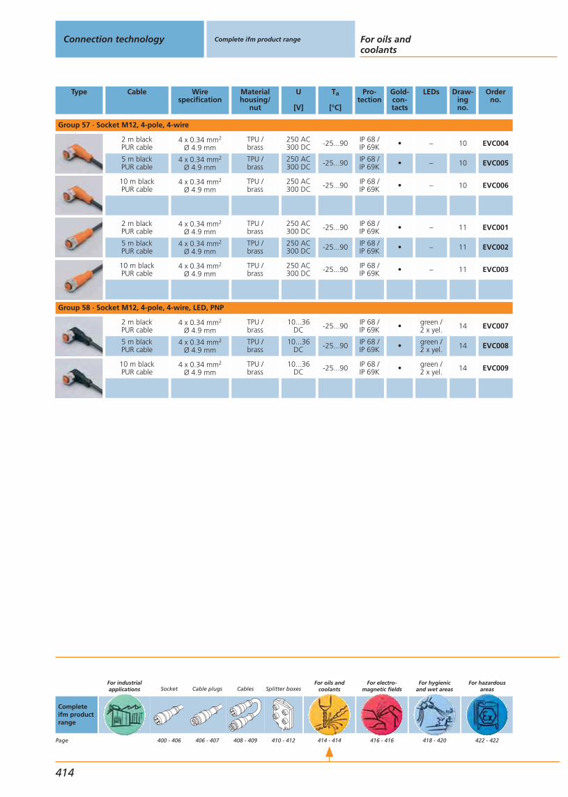
Type Cable Wirespecification
Materialhousing/
nut
U
[V]
Ta
[°C]
Pro-tection
Gold-con-tacts
LEDs Draw-ingno.
Orderno.
Group 57 · Socket M12, 4-pole, 4-wire
2 m blackPUR cable
4 x 0.34 mm2
Ø 4.9 mmTPU /brass
250 AC300 DC -25...90 IP 68 /
IP 69K • – 10 EVC004
5 m blackPUR cable
4 x 0.34 mm2
Ø 4.9 mmTPU /brass
250 AC300 DC -25...90 IP 68 /
IP 69K • – 10 EVC005
10 m blackPUR cable
4 x 0.34 mm2
Ø 4.9 mmTPU /brass
250 AC300 DC -25...90 IP 68 /
IP 69K • – 10 EVC006
2 m blackPUR cable
4 x 0.34 mm2
Ø 4.9 mmTPU /brass
250 AC300 DC -25...90 IP 68 /
IP 69K • – 11 EVC001
5 m blackPUR cable
4 x 0.34 mm2
Ø 4.9 mmTPU /brass
250 AC300 DC -25...90 IP 68 /
IP 69K • – 11 EVC002
10 m blackPUR cable
4 x 0.34 mm2
Ø 4.9 mmTPU /brass
250 AC300 DC -25...90 IP 68 /
IP 69K • – 11 EVC003
Group 58 · Socket M12, 4-pole, 4-wire, LED, PNP
2 m blackPUR cable
4 x 0.34 mm2
Ø 4.9 mmTPU /brass
10...36DC -25...90 IP 68 /
IP 69K • green /2 x yel. 14 EVC007
5 m blackPUR cable
4 x 0.34 mm2
Ø 4.9 mmTPU /brass
10...36DC -25...90 IP 68 /
IP 69K • green /2 x yel. 14 EVC008
10 m blackPUR cable
4 x 0.34 mm2
Ø 4.9 mmTPU /brass
10...36DC -25...90 IP 68 /
IP 69K • green /2 x yel. 14 EVC009
Connection technology Complete ifm product range For oils andcoolants
414
Completeifm productrange
Page
For industrialapplications Socket
400 - 406
Cable plugs
406 - 407
Cables
408 - 409
Splitter boxes
410 - 412
For oils andcoolants
414 - 414
For electro-magnetic fields
416 - 416
For hygienicand wet areas
418 - 420
For hazardousareas
422 - 422

Complete ifm product range
Gen
eral
info
rmat
ion
List
of
arti
cles
Ind
uct
ive
sen
sors
Cap
acit
ive
sen
sors
Mag
net
icse
nso
rs,
cylin
der
sen
sors
Safe
tyte
chn
olo
gy
Val
ve s
enso
rsPh
oto
elec
tric
sen
sors
Ob
ject
reco
gn
itio
nEn
cod
ers
Eval
uat
ion
syst
ems,
po
wer
su
pp
lies
Co
nn
ecti
on
tech
no
log
yA
cces
sori
esTe
chn
ical
info
rmat
ion
and
cu
sto
mer
serv
ice
415

Type Cable Wirespecification
Materialhousing/
nut
U
[V]
Ta
[°C]
Pro-tection
Gold-con-tacts
LEDs Draw-ingno.
Orderno.
Group 59 · socket M12, 4-pole, 4-wire, irradiated cable
2 m blackPUR cable
4 x 0.34 mm2
Ø 4.8 mmTPU /brass
250 AC300 DC -25...90 IP 68 • – 102 E10909
5 m blackPUR cable
4 x 0.34 mm2
Ø 4.8 mmTPU /brass
250 AC300 DC -25...90 IP 68 • – 102 E10910
10 m blackPUR cable
4 x 0.34 mm2
Ø 4.8 mmTPU /brass
250 AC300 DC -25...90 IP 68 • – 102 E10911
2 m blackPUR cable
4 x 0.34 mm2
Ø 4.8 mmTPU /brass
250 AC300 DC -25...90 IP 68 • – 103 E10915
5 m blackPUR cable
4 x 0.34 mm2
Ø 4.8 mmTPU /brass
250 AC300 DC -25...90 IP 68 • – 103 E10916
10 m blackPUR cable
4 x 0.34 mm2
Ø 4.8 mmTPU /brass
250 AC300 DC -25...90 IP 68 • – 103 E10917
Group 60 · socket M12, 4-pole, 4-wire, irradiated cable, LED, PNP
2 m blackPUR cable
4 x 0.34 mm2
Ø 4.8 mmTPU /brass
10...30DC -25...90 IP 68 • green /
2 x yel. 104 E10912
5 m blackPUR cable
4 x 0.34 mm2
Ø 4.8 mmTPU /brass
10...30DC -25...90 IP 68 • green /
2 x yel. 104 E10913
10 m blackPUR cable
4 x 0.34 mm2
Ø 4.8 mmTPU /brass
10...30DC -25...90 IP 68 • green /
2 x yel. 104 E10914
Group 61 · Socket M12, 5-pole, 5-wire
2 m blackPUR cable
5 x 0.34 mm2
Ø 5.5 mmTPU /brass
30 AC36 DC -25...90 IP 68 • – 8 E10957
5 m blackPUR cable
5 x 0.34 mm2
Ø 5.5 mmTPU /brass
30 AC36 DC -25...90 IP 68 • – 8 E10958
10 m blackPUR cable
5 x 0.34 mm2
Ø 5.5 mmTPU /brass
30 AC36 DC -25...90 IP 68 • – 8 E10959
2 m blackPUR cable
5 x 0.34 mm2
Ø 5.5 mmTPU /brass
30 AC36 DC -25...90 IP 68 • – 9 E10960
5 m blackPUR cable
5 x 0.34 mm2
Ø 5.5 mmTPU /brass
30 AC36 DC -25...90 IP 68 • – 9 E10961
10 m blackPUR cable
5 x 0.34 mm2
Ø 5.5 mmTPU /brass
30 AC36 DC -25...90 IP 68 • – 9 E10962
Connection technology Complete ifm product range For electro-magnetic fields
416
Completeifm productrange
Page
For industrialapplications Socket
400 - 406
Cable plugs
406 - 407
Cables
408 - 408
Splitter boxes
410 - 410
For oils andcoolants
414 - 414
For electro-magnetic fields
416 - 416
For hygienicand wet areas
418 - 418
For hazardousareas
422 - 422

Complete ifm product range
Gen
eral
info
rmat
ion
List
of
arti
cles
Ind
uct
ive
sen
sors
Cap
acit
ive
sen
sors
Mag
net
icse
nso
rs,
cylin
der
sen
sors
Safe
tyte
chn
olo
gy
Val
ve s
enso
rsPh
oto
elec
tric
sen
sors
Ob
ject
reco
gn
itio
nEn
cod
ers
Eval
uat
ion
syst
ems,
po
wer
su
pp
lies
Co
nn
ecti
on
tech
no
log
yA
cces
sori
esTe
chn
ical
info
rmat
ion
and
cu
sto
mer
serv
ice
417
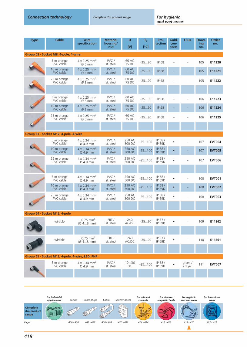
Type Cable Wirespecification
Materialhousing/
nut
U
[V]
Ta
[°C]
Pro-tection
Gold-con-tacts
LEDs Draw-ingno.
Orderno.
Group 62 · Socket M8, 4-pole, 4-wire
5 m orangePVC cable
4 x 0.25 mm2
Ø 5 mmPVC /
st. steel60 AC75 DC -25...90 IP 68 – – 105 E11220
10 m orangePVC cable
4 x 0.25 mm2
Ø 5 mmPVC /
st. steel60 AC75 DC -25...90 IP 68 – – 105 E11221
25 m orangePVC cable
4 x 0.25 mm2
Ø 5 mmPVC /
st. steel60 AC75 DC -25...90 IP 68 – – 105 E11222
5 m orangePVC cable
4 x 0.25 mm2
Ø 5 mmPVC /
st. steel60 AC75 DC -25...90 IP 68 – – 106 E11223
10 m orangePVC cable
4 x 0.25 mm2
Ø 5 mmPVC /
st. steel60 AC75 DC -25...90 IP 68 – – 106 E11224
25 m orangePVC cable
4 x 0.25 mm2
Ø 5 mmPVC /
st. steel60 AC75 DC -25...90 IP 68 – – 106 E11225
Group 63 · Socket M12, 4-pole, 4-wire
5 m orangePVC cable
4 x 0.34 mm2
Ø 4.9 mmPVC /
st. steel250 AC300 DC -25...100 IP 68 /
IP 69K • – 107 EVT004
10 m orangePVC cable
4 x 0.34 mm2
Ø 4.9 mmPVC /
st. steel250 AC300 DC -25...100 IP 68 /
IP 69K • – 107 EVT005
25 m orangePVC cable
4 x 0.34 mm2
Ø 4.9 mmPVC /
st. steel250 AC300 DC -25...100 IP 68 /
IP 69K • – 107 EVT006
5 m orangePVC cable
4 x 0.34 mm2
Ø 4.9 mmPVC /
st. steel250 AC300 DC -25...100 IP 68 /
IP 69K • – 108 EVT001
10 m orangePVC cable
4 x 0.34 mm2
Ø 4.9 mmPVC /
st. steel250 AC300 DC -25...100 IP 68 /
IP 69K • – 108 EVT002
25 m orangePVC cable
4 x 0.34 mm2
Ø 4.9 mmPVC /
st. steel250 AC300 DC -25...100 IP 68 /
IP 69K • – 108 EVT003
Group 64 · Socket M12, 4-pole
wirable ...0.75 mm2
(Ø 4...8 mm)PBT /
st. steel240
AC/DC -25...90 IP 67 /IP 69K • – 109 E11862
wirable ...0.75 mm2
(Ø 4...8 mm)PBT /
st. steel240
AC/DC -25...90 IP 67 /IP 69K • – 110 E11861
Group 65 · Socket M12, 4-pole, 4-wire, LED, PNP
5 m orangePVC cable
4 x 0.34 mm2
Ø 4.9 mmPVC /
st. steel10...36
DC -25...100 IP 68 /IP 69K • green /
2 x yel. 111 EVT007
Connection technology Complete ifm product range For hygienicand wet areas
418
Completeifm productrange
Page
For industrialapplications Socket
400 - 406
Cable plugs
406 - 407
Cables
408 - 408
Splitter boxes
410 - 412
For oils andcoolants
414 - 414
For electro-magnetic fields
416 - 416
For hygienicand wet areas
418 - 420
For hazardousareas
422 - 422

Type Cable Wirespecification
Materialhousing/
nut
U
[V]
Ta
[°C]
Pro-tection
Gold-con-tacts
LEDs Draw-ingno.
Orderno.
Group 65 · Socket M12, 4-pole, 4-wire, LED, PNP
10 m orangePVC cable
4 x 0.34 mm2
Ø 4.9 mmPVC /
st. steel10...36
DC -25...100 IP 68 /IP 69K • green /
2 x yel. 111 EVT008
25 m orangePVC cable
4 x 0.34 mm2
Ø 4.9 mmPVC /
st. steel10...36
DC -25...100 IP 68 /IP 69K • green /
2 x yel. 111 EVT009
Group 66 · Socket M12, 4-pole, LED, PNP
wirable ...0.75 mm2
(Ø 4...8 mm)PBT /
st. steel10...30
DC -25...90 IP 67 /IP 69K • green /
yellow 109 E11863
Group 67 · Socket M12, 5-pole, 5-wire
5 m orangePVC cable
5 x 0.34 mm2
Ø 5.1 mmPVC /
st. steel30 AC36 DC -25...100 IP 68 /
IP 69K • – 112 EVT013
10 m orangePVC cable
5 x 0.34 mm2
Ø 5.1 mmPVC /
st. steel30 AC36 DC -25...100 IP 68 /
IP 69K • – 112 EVT014
25 m orangePVC cable
5 x 0.34 mm2
Ø 5.1 mmPVC /
st. steel30 AC36 DC -25...100 IP 68 /
IP 69K • – 112 EVT015
5 m orangePVC cable
5 x 0.34 mm2
Ø 5.1 mmPVC /
st. steel30 AC36 DC -25...100 IP 68 /
IP 69K • – 113 EVT010
10 m orangePVC cable
5 x 0.34 mm2
Ø 5.1 mmPVC /
st. steel30 AC36 DC -25...100 IP 68 /
IP 69K • – 113 EVT011
25 m orangePVC cable
5 x 0.34 mm2
Ø 5.1 mmPVC /
st. steel30 AC36 DC -25...100 IP 68 /
IP 69K • – 113 EVT012
Group 68 · Plug M12, 4-pole
wirable ...0.75 mm2
(Ø 4...8 mm)PBT /
st. steel240
AC/DC -25...90 IP 67 /IP 69K • – 114 E11858
wirable ...0.75 mm2
(Ø 4...8 mm)PBT /
st. steel240
AC/DC -25...90 IP 67 /IP 69K • – 115 E11857
Group 69 · Jumper M12, 4-pole, 4-wire
1 m orangePVC cable
4 x 0.34 mm2
Ø 4.9 mmPVC /
st. steel250 AC300 DC -25...100 IP 68 /
IP 69K • – 116 EVT042
2 m orangePVC cable
4 x 0.34 mm2
Ø 4.9 mmPVC /
st. steel250 AC300 DC -25...100 IP 68 /
IP 69K • – 116 EVT043
5 m orangePVC cable
4 x 0.34 mm2
Ø 4.9 mmPVC /
st. steel250 AC300 DC -25...100 IP 68 /
IP 69K • – 116 EVT044
10 m orangePVC cable
4 x 0.34 mm2
Ø 4.9 mmPVC /
st. steel250 AC300 DC -25...100 IP 68 /
IP 69K • – 116 EVT045
Complete ifm product range
Gen
eral
info
rmat
ion
List
of
arti
cles
Ind
uct
ive
sen
sors
Cap
acit
ive
sen
sors
Mag
net
icse
nso
rs,
cylin
der
sen
sors
Safe
tyte
chn
olo
gy
Val
ve s
enso
rsPh
oto
elec
tric
sen
sors
Ob
ject
reco
gn
itio
nEn
cod
ers
Eval
uat
ion
syst
ems,
po
wer
su
pp
lies
Co
nn
ecti
on
tech
no
log
yA
cces
sori
esTe
chn
ical
info
rmat
ion
and
cu
sto
mer
serv
ice
419
Completeifm productrange
Page
For industrialapplications Socket
400 - 406
Cable plugs
406 - 407
Cables
408 - 408
Splitter boxes
410 - 412
For oils andcoolants
414 - 414
For electro-magnetic fields
416 - 416
For hygienicand wet areas
418 - 420
For hazardousareas
422 - 422

Type Cable Wirespecification
Materialhousing/
nut
U
[V]
Ta
[°C]
Pro-tection
Gold-con-tacts
LEDs Draw-ingno.
Orderno.
Group 70 · jumper M12 plug, 4-pole / M12 socket, 4-pole, 4-wire
10 m orangePVC cable
4 x 0.34 mm2
Ø 5.3 mmPVC /
st. steel250 AC300 DC -25...100 IP 68 /
IP 69K • – 117 E70189
Group 71 · Socket M12, 5-pole
wirable ...0.75 mm2
(Ø 4...8 mm)PBT /
st. steel 60 AC/DC -25...90 IP 67 /IP 69K • – 118 E11865
wirable ...0.75 mm2
(Ø 4...8 mm)PBT /
st. steel 60 AC/DC -25...90 IP 67 /IP 69K • – 119 E11864
Group 72 · Plug M12, 5-pole
wirable ...0.75 mm2
(Ø 4...8 mm)PBT /
st. steel 60 AC/DC -25...90 IP 67 /IP 69K • – 120 E11860
wirable ...0.75 mm2
(Ø 4...8 mm)PBT /
st. steel 60 AC/DC -25...90 IP 67 /IP 69K • – 121 E11859
Group 73 · Jumper M12, 5-pole, 5-wire
0.6 m orangePVC cable
5 x 0.25 mm2
Ø 5.3 mmPVC /
st. steel30 AC36 DC -25...100 IP 68 /
IP 69K • – 122 E11641
1 m orangePVC cable
5 x 0.25 mm2
Ø 5.3 mmPVC /
st. steel30 AC36 DC -25...100 IP 68 /
IP 69K • – 122 E11642
2 m orangePVC cable
5 x 0.25 mm2
Ø 5.3 mmPVC /
st. steel30 AC36 DC -25...100 IP 68 /
IP 69K • – 122 E11643
5 m orangePVC cable
5 x 0.25 mm2
Ø 5.3 mmPVC /
st. steel30 AC36 DC -25...100 IP 68 /
IP 69K • – 122 E11644
Group 74 · splitter box M12
10 m blackPUR / PVC cable
3 x 0.75 mm2
+ 16 x 0.34 mm2 st. steel 10...36DC -5...70 IP 69K – green /
16 x yel. 123 E11775
Connection technology Complete ifm product range For hygienicand wet areas
420
Completeifm productrange
Page
For industrialapplications Socket
400 - 406
Cable plugs
406 - 407
Cables
408 - 408
Splitter boxes
410 - 412
For oils andcoolants
414 - 414
For electro-magnetic fields
416 - 416
For hygienicand wet areas
418 - 420
For hazardousareas
422 - 422

Complete ifm product range
Gen
eral
info
rmat
ion
List
of
arti
cles
Ind
uct
ive
sen
sors
Cap
acit
ive
sen
sors
Mag
net
icse
nso
rs,
cylin
der
sen
sors
Safe
tyte
chn
olo
gy
Val
ve s
enso
rsPh
oto
elec
tric
sen
sors
Ob
ject
reco
gn
itio
nEn
cod
ers
Eval
uat
ion
syst
ems,
po
wer
su
pp
lies
Co
nn
ecti
on
tech
no
log
yA
cces
sori
esTe
chn
ical
info
rmat
ion
and
cu
sto
mer
serv
ice
421
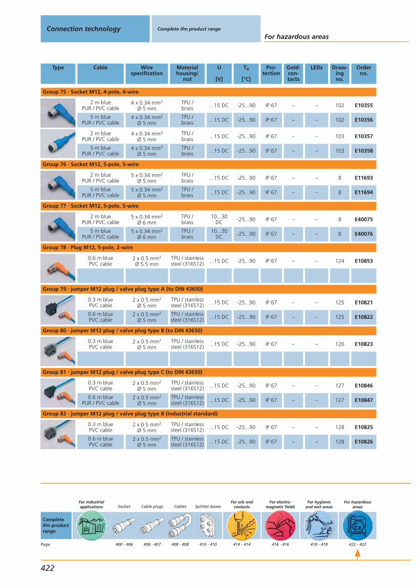
Type Cable Wirespecification
Materialhousing/
nut
U
[V]
Ta
[°C]
Pro-tection
Gold-con-tacts
LEDs Draw-ingno.
Orderno.
Group 75 · Socket M12, 4-pole, 4-wire
2 m bluePUR / PVC cable
4 x 0.34 mm2
Ø 5 mmTPU /brass ...15 DC -25...90 IP 67 – – 102 E10355
5 m bluePUR / PVC cable
4 x 0.34 mm2
Ø 5 mmTPU /brass ...15 DC -25...90 IP 67 – – 102 E10356
2 m bluePUR / PVC cable
4 x 0.34 mm2
Ø 5 mmTPU /brass ...15 DC -25...90 IP 67 – – 103 E10357
5 m bluePUR / PVC cable
4 x 0.34 mm2
Ø 5 mmTPU /brass ...15 DC -25...90 IP 67 – – 103 E10358
Group 76 · Socket M12, 5-pole, 5-wire
2 m bluePUR / PVC cable
5 x 0.34 mm2
Ø 5 mmTPU /brass ...15 DC -25...90 IP 67 – – 8 E11693
5 m bluePUR / PVC cable
5 x 0.34 mm2
Ø 5 mmTPU /brass ...15 DC -25...90 IP 67 – – 8 E11694
Group 77 · Socket M12, 5-pole, 5-wire
2 m bluePUR / PVC cable
5 x 0.34 mm2
Ø 6 mmTPU /brass
10...30DC -25...90 IP 67 – – 8 E40075
5 m bluePUR / PVC cable
5 x 0.34 mm2
Ø 6 mmTPU /brass
10...30DC -25...90 IP 67 – – 8 E40076
Group 78 · Plug M12, 5-pole, 2-wire
0.6 m bluePVC cable
2 x 0.5 mm2
Ø 5.5 mmTPU / stainlesssteel (316S12) ...15 DC -25...90 IP 67 – – 124 E10853
Group 79 · jumper M12 plug / valve plug type A (to DIN 43650)
0.3 m bluePVC cable
2 x 0.5 mm2
Ø 5 mmTPU / stainlesssteel (316S12) ...15 DC -25...90 IP 67 – – 125 E10821
0.6 m bluePVC cable
2 x 0.5 mm2
Ø 5 mmTPU / stainlesssteel (316S12) ...15 DC -25...90 IP 67 – – 125 E10822
Group 80 · jumper M12 plug / valve plug type B (to DIN 43650)
0.3 m bluePVC cable
2 x 0.5 mm2
Ø 5 mmTPU / stainlesssteel (316S12) ...15 DC -25...90 IP 67 – – 126 E10823
Group 81 · jumper M12 plug / valve plug type C (to DIN 43650)
0.3 m bluePVC cable
2 x 0.5 mm2
Ø 5 mmTPU / stainlesssteel (316S12) ...15 DC -25...90 IP 67 – – 127 E10846
0.6 m bluePUR / PVC cable
2 x 0.5 mm2
Ø 5 mmTPU / stainlesssteel (316S12) ...15 DC -25...90 IP 67 – – 127 E10847
Group 82 · jumper M12 plug / valve plug type B (industrial standard)
0.3 m bluePVC cable
2 x 0.5 mm2
Ø 5 mmTPU / stainlesssteel (316S12) ...15 DC -25...90 IP 67 – – 128 E10825
0.6 m bluePVC cable
2 x 0.5 mm2
Ø 5 mmTPU / stainlesssteel (316S12) ...15 DC -25...90 IP 67 – – 128 E10826
Connection technology Complete ifm product range
For hazardous areas
422
Completeifm productrange
Page
For industrialapplications Socket
400 - 406
Cable plugs
406 - 407
Cables
408 - 408
Splitter boxes
410 - 410
For oils andcoolants
414 - 414
For electro-magnetic fields
416 - 416
For hygienicand wet areas
418 - 418
For hazardousareas
422 - 422
Complete ifm product range
Gen
eral
info
rmat
ion
List
of
arti
cles
Ind
uct
ive
sen
sors
Cap
acit
ive
sen
sors
Mag
net
icse
nso
rs,
cylin
der
sen
sors
Safe
tyte
chn
olo
gy
Val
ve s
enso
rsPh
oto
elec
tric
sen
sors
Ob
ject
reco
gn
itio
nEn
cod
ers
Eval
uat
ion
syst
ems,
po
wer
su
pp
lies
Co
nn
ecti
on
tech
no
log
yA
cces
sori
esTe
chn
ical
info
rmat
ion
and
cu
sto
mer
serv
ice
423

Gen
eral
info
rmat
ion
List
of
arti
cles
Ind
uct
ive
sen
sors
Cap
acit
ive
sen
sors
Mag
net
icse
nso
rs,
cylin
der
sen
sors
Safe
tyte
chn
olo
gy
Val
ve s
enso
rsPh
oto
elec
tric
sen
sors
Ob
ject
reco
gn
itio
nEn
cod
ers
Eval
uat
ion
syst
ems,
po
wer
su
pp
lies
Co
nn
ecti
on
tech
no
log
yA
cces
sori
esTe
chn
ical
info
rmat
ion
and
cu
sto
mer
serv
ice
Accessories
425
Accessories position sensorsand object recognition
Inductive sensorsCapacitive sensorsMagnetic sensors, cylinder sensorsSafety technologyValve sensorsPhotoelectric sensors, infrared / red light sensorsPhotoelectric sensors, laser sensorsPhotoelectric sensors, systems for specific applicationsObject recognitionEncodersEvaluation systems, power supplies
426 - 428428 - 431431 - 432
432432 - 433433 - 436436 - 437437 - 438438 - 440440 - 441
441
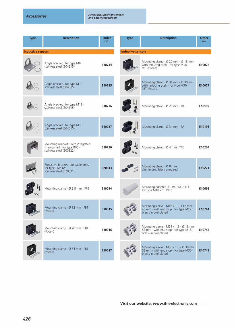
Type Description Orderno.
Inductive sensors
Angle bracket · for type M8 · stainless steel (304S15) E10734
Angle bracket · for type M12 · stainless steel (304S15) E10735
Angle bracket · for type M18 · stainless steel (304S15) E10736
Angle bracket · for type M30 · stainless steel (304S15) E10737
Mounting bracket · with integrated snap-on rail · for type IDC · stainless steel (303S22)
E10730
Protective bracket · for cable units · for type OW, IW · stainless steel (320S31)
E20813
Mounting clamp · Ø 6.5 mm · PPE E10014
Mounting clamp · Ø 12 mm · PBT(Pocan) E10015
Mounting clamp · Ø 20 mm · PBT(Pocan) E10016
Mounting clamp · Ø 34 mm · PBT(Pocan) E10017
Type Description Orderno.
Inductive sensors
Mounting clamp · Ø 20 mm - Ø 18 mm ·with reducing bush · for type M18 · PBT (Pocan)
E10076
Mounting clamp · Ø 34 mm - Ø 30 mm ·with reducing bush · for type M30 · PBT (Pocan)
E10077
Mounting clamp · Ø 20 mm · PA E10192
Mounting clamp · Ø 34 mm · PA E10193
Mounting clamp · Ø 4 mm · TPE E10204
Mounting clamp · Ø 8 mm · aluminium / black anodised E10221
Mounting adapter · G 3/4 - M18 x 1 · for type M18 x 1 · PTFE E10698
Mounting sleeve · M16 x 1 - Ø 12 mm ·45 mm · with end stop · for type M12 ·brass / nickel-plated
E10741
Mounting sleeve · M24 x 1.5 - Ø 18 mm58 mm · with end stop · for type M18 ·brass / nickel-plated
E10742
Mounting sleeve · M36 x 1.5 - Ø 30 mm58 mm · with end stop · for type M30 ·brass / nickel-plated
E10743
Accessories Accessories position sensorsand object recognition
426
Visit our website: www.ifm-electronic.com

Type Description Orderno.
Inductive sensors
Mounting sleeve · M16 x 1 - Ø 12 mm ·34 mm · with end stop · for type M12 ·brass / nickel-plated
E10806
Mounting sleeve · M24 x 1.5 - Ø 18 mm36 mm · with end stop · for type M18 ·brass / nickel-plated
E10807
Mounting sleeve · M36 x 1.5 - Ø 30 mm36 mm · with end stop · for type M30 ·brass / nickel-plated
E10808
Mounting sleeve · M12 x 1 - Ø 8 mm ·32 mm · with end stop · for type M8 ·brass / special coated
E10848
Mounting sleeve · M12 x 1 - Ø 8 mm ·42 mm · with end stop · for type M8 ·brass / special coated
E10849
Mounting clamp · Ø 12 mm · with end stop · for type M12 · PC E11047
Mounting clamp · Ø 18 mm · with end stop · for type M18 · PC E11048
Mounting clamp · Ø 30 mm · with end stop · for type M30 · PC E11049
Mounting sleeve · M16 x 1 - Ø 12 mm ·with end stop · for type M12 · brass / nickel-plated
E11114
Mounting sleeve · M22 x 1 - Ø 18 mm ·with end stop · for type M18 · brass / white bronze coated
E11115
Type Description Orderno.
Inductive sensors
Mounting set · straight · Clampmounting · for type IA, IB, KA, KB ·clamp: stainless steel (316C) / fixture: stainless steel (320S31)
E11117
Mounting set · angled · Clamp mounting · for type IA, IB, KA, KBclamp: stainless steel (316C) / fixture:stainless steel (320S31)
E11118
Mounting set · angled · only for flush-mountable sensors · Clamp mounting ·for type IME, IMC · clamp: stainless steel(316C) / fixture: stainless steel (320S31)
E11119
Mounting set · straight · only for flush-mountable sensors · Clamp mounting ·for type IME, IMC · clamp: stainless steel(316C) / fixture: stainless steel (320S31)
E11120
Mounting set · angled · Clamp mountingfor type ICE, ID, KD · clamp: stainlesssteel (316C) / fixture: stainless steel(320S31)
E11121
Mounting set · straight · Clampmounting · for type ICE, ID, KD · clamp:stainless steel (316C) / fixture: stainlesssteel (320S31)
E11122
Mounting set · Ø 18.5 mm · Clampmounting · for type OG, IG, KG · clamp:diecast zinc / fixture: steel
E20718
Mounting set · Ø 18.5 mm · Clampmounting · for type OG, IG, KG · clamp:diecast zinc / fixture: steel
E20719
Angle bracket · Clamp mounting · for type OW, IW, KW · stainless steel(320S31)
E20811
Protective bracket · for cable units · for type OW, IW · stainless steel (320S31)
E20813
Accessories position sensorsand object recognition
Gen
eral
info
rmat
ion
List
of
arti
cles
Ind
uct
ive
sen
sors
Cap
acit
ive
sen
sors
Mag
net
icse
nso
rs,
cylin
der
sen
sors
Safe
tyte
chn
olo
gy
Val
ve s
enso
rsPh
oto
elec
tric
sen
sors
Ob
ject
reco
gn
itio
nEn
cod
ers
Eval
uat
ion
syst
ems,
po
wer
su
pp
lies
Co
nn
ecti
on
tech
no
log
yA
cces
sori
esTe
chn
ical
info
rmat
ion
and
cu
sto
mer
serv
ice
427
Visit our website: www.ifm-electronic.com
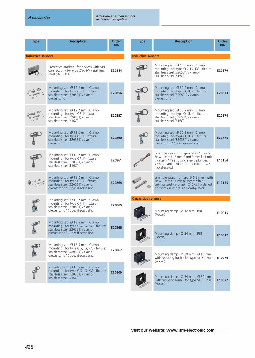
Type Description Orderno.
Inductive sensors
Protective bracket · for devices with M8connection · for type OW, IW · stainlesssteel (320S31)
E20814
Mounting set · Ø 12.2 mm · Clampmounting · for type OF, IF · fixture:stainless steel (320S31) / clamp: diecast zinc
E20856
Mounting set · Ø 12.2 mm · Clampmounting · for type OF, IF · fixture:stainless steel (320S31) / clamp: stainless steel (316C)
E20857
Mounting set · Ø 12.2 mm · Clampmounting · for type OF, IF · fixture:stainless steel (320S31) / clamp: diecast zinc
E20860
Mounting set · Ø 12.2 mm · Clampmounting · for type OF, IF · fixture:stainless steel (320S31) / clamp: stainless steel (316C)
E20861
Mounting set · Ø 12.2 mm · Clampmounting · for type OF, IF · fixture:stainless steel (320S31) / clamp: diecast zinc / Cube: diecast zinc
E20864
Mounting set · Ø 12.2 mm · Clampmounting · for type OF, IF · fixture:stainless steel (320S31) / clamp: diecast zinc / Cube: diecast zinc
E20865
Mounting set · Ø 18.5 mm · Clampmounting · for type OG, IG, KG · fixture:stainless steel (320S31) / clamp: diecast zinc / Cube: diecast zinc
E20866
Mounting set · Ø 18.5 mm · Clampmounting · for type OG, IG, KG · fixture:stainless steel (320S31) / clamp: diecast zinc / Cube: diecast zinc
E20867
Mounting set · Ø 18.5 mm · Clampmounting · for type OG, IG, KG · fixture:stainless steel (320S31) / clamp: stainless steel (316C)
E20869
Type Description Orderno.
Inductive sensors
Mounting set · Ø 18.5 mm · Clampmounting · for type OG, IG, KG · fixture:stainless steel (320S31) / clamp: stainless steel (316C)
E20870
Mounting set · Ø 30.2 mm · Clampmounting · for type OI, II, KI · fixture:stainless steel (320S31) / clamp: diecast zinc
E20873
Mounting set · Ø 30.2 mm · Clampmounting · for type OI, II, KI · fixture:stainless steel (320S31) / clamp: stainless steel (316C)
E20874
Mounting set · Ø 30.2 mm · Clampmounting · for type OI, II, KI · fixture:stainless steel (320S31) / clamp: diecast zinc / Cube: diecast zinc
E20875
Limit plungers · for types M8 x 1 · withSn = 1 mm f, 2 mm f and 3 mm f · Limitplungers / free cutting steel / plunger:C45K / hardened on front / nut: brass /nickel-plated
E10154
Limit plungers · for type Ø 6.5 mm · withSn = 1 mm f · Limit plungers / freecutting steel / plunger: C45K / hardenedon front / nut: brass / nickel-plated
E10155
Capacitive sensors
Mounting clamp · Ø 12 mm · PBT(Pocan) E10015
Mounting clamp · Ø 34 mm · PBT(Pocan) E10017
Mounting clamp · Ø 20 mm - Ø 18 mm ·with reducing bush · for type M18 · PBT(Pocan)
E10076
Mounting clamp · Ø 34 mm - Ø 30 mm ·with reducing bush · for type M30 · PBT(Pocan)
E10077
Accessories Accessories position sensorsand object recognition
428
Visit our website: www.ifm-electronic.com

Type Description Orderno.
Capacitive sensors
Mounting clamp · Ø 34 mm · PA E10193
Mounting adapter · G 3/4 - M18 x 1 · for type M18 x 1 · PTFE E10698
Angle bracket · for type M8 · stainless steel (304S15) E10734
Angle bracket · for type M12 · stainless steel (304S15) E10735
Angle bracket · for type M18 · stainless steel (304S15) E10736
Angle bracket · for type M30 · stainless steel (304S15) E10737
Mounting adapter · Ø 34 mm - G 1 1/2 ·POM (polyoxymethylene) E11027
Mounting adapter · Ø 34 mm - G 1 1/4 ·PVDF E11028
Locknut · G 11/4 · for mounting adapter · PVDF E11030
Locknut · G 11/2 · for mounting adapter · POM (polyoxymethylene)
E11031
Type Description Orderno.
Capacitive sensors
Locknut · G 1 1/2 · for mounting adapter · PVDF E11032
Mounting adapter · M30 x 1.5 - G 1 1/2 ·POM (polyoxymethylene) / EPDM E11033
Mounting adapter · M30 x 1.5 - G 1 1/2 ·PVDF / EPDM E11034
Mounting adapter · M30 x 1.5 - G 1 1/4 ·POM (polyoxymethylene) / EPDM E11035
Mounting adapter · M30 x 1.5 - G 1 1/4 ·PVDF / EPDM E11036
Mounting set · M30 x 1.5 / G 1/4...G 1 ·for capacitive sensors on rising pipes G1/4" - 1" · POM (polyoxymethylene)
E11037
Mounting clamp · Ø 12 mm · with end stop · for type M12 · PC E11047
Mounting clamp · Ø 18 mm · with end stop · for type M18 · PC E11048
Mounting clamp · Ø 30 mm · with end stop · for type M30 · PC E11049
Locknut · G 11/4 · for mounting adapter · POM (polyoxymethylene)
E11055
Accessories position sensorsand object recognition
Gen
eral
info
rmat
ion
List
of
arti
cles
Ind
uct
ive
sen
sors
Cap
acit
ive
sen
sors
Mag
net
icse
nso
rs,
cylin
der
sen
sors
Safe
tyte
chn
olo
gy
Val
ve s
enso
rsPh
oto
elec
tric
sen
sors
Ob
ject
reco
gn
itio
nEn
cod
ers
Eval
uat
ion
syst
ems,
po
wer
su
pp
lies
Co
nn
ecti
on
tech
no
log
yA
cces
sori
esTe
chn
ical
info
rmat
ion
and
cu
sto
mer
serv
ice
429
Visit our website: www.ifm-electronic.com

Type Description Orderno.
Capacitive sensors
Protective cover · G 11/4 · for mountingadapter · PES / black transparent E11078
Mounting set · straight · Clampmounting · for type IA, IB, KA, KB ·clamp: stainless steel (316C) / fixture:stainless steel (320S31)
E11117
Mounting set · angled · Clamp mountingfor type IA, IB, KA, KB · clamp: stainlesssteel (316C) / fixture: stainless steel(320S31)
E11118
Mounting set · angled · Clamp mountingfor type ICE, ID, KD · clamp: stainlesssteel (316C) / fixture: stainless steel(320S31)
E11121
Mounting set · straight · Clampmounting · for type ICE, ID, KD · clamp:stainless steel (316C) / fixture: stainlesssteel (320S31)
E11122
Mounting set · Ø 18.5 mm · Clampmounting · for type OG, IG, KG · clamp:diecast zinc / fixture: steel
E20718
Mounting set · Ø 18.5 mm · Clampmounting · for type OG, IG, KG · clamp:diecast zinc / fixture: steel
E20719
Angle bracket · Clamp mounting · fortype OW, IW, KW · stainless steel(320S31)
E20811
Mounting set · Ø 18.5 mm · Clampmounting · for type OG, IG, KG · fixture:stainless steel (320S31) / clamp: diecastzinc / Cube: diecast zinc
E20866
Mounting set · Ø 18.5 mm · Clampmounting · for type OG, IG, KG · fixture:stainless steel (320S31) / clamp: diecastzinc / Cube: diecast zinc
E20867
Type Description Orderno.
Capacitive sensors
Mounting set · Ø 18.5 mm · Clampmounting · for type OG, IG, KG · fixture:stainless steel (320S31) / clamp: stainlesssteel (316C)
E20869
Mounting set · Ø 18.5 mm · Clampmounting · for type OG, IG, KG · fixture:stainless steel (320S31) / clamp: stainlesssteel (316C)
E20870
Mounting set · Ø 30.2 mm · Clampmounting · for type OI, II, KI · fixture:stainless steel (320S31) / clamp: diecastzinc
E20873
Mounting set · Ø 30.2 mm · Clampmounting · for type OI, II, KI · fixture:stainless steel (320S31) / clamp: stainlesssteel (316C)
E20874
Mounting set · Ø 30.2 mm · Clampmounting · for type OI, II, KI · fixture:stainless steel (320S31) / clamp: diecastzinc / Cube: diecast zinc
E20875
Mounting adapter · M18 x 1 - G 3/4 ·POM (polyoxymethylene) E43900
Mounting adapter · M18 x 1 - G 3/4 ·PVDF E43901
Locknut · G 3/4 · for mounting adapter ·POM (polyoxymethylene) E43902
Locknut · G 3/4 · for mounting adapter ·PVDF E43903
Mounting adapter · M18 x 1 - G 1 · POM(polyoxymethylene) E43904
Accessories Accessories position sensorsand object recognition
430
Visit our website: www.ifm-electronic.com
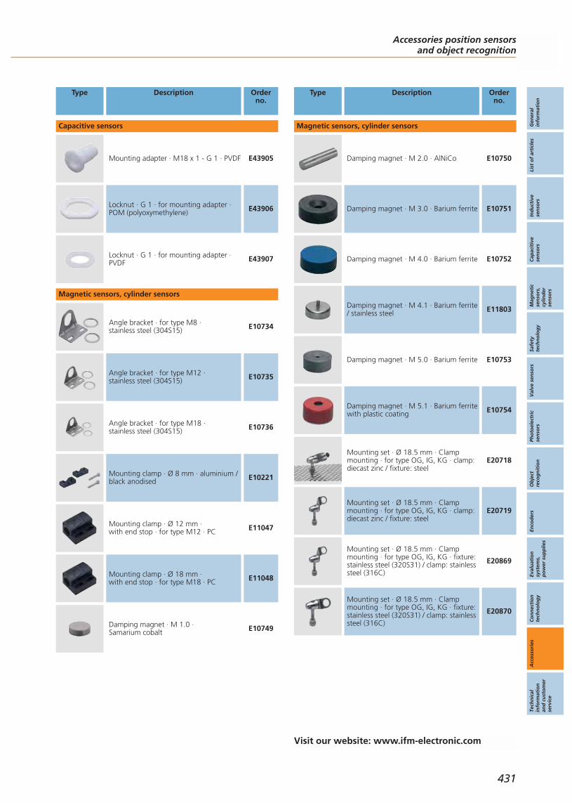
Type Description Orderno.
Capacitive sensors
Mounting adapter · M18 x 1 - G 1 · PVDF E43905
Locknut · G 1 · for mounting adapter ·POM (polyoxymethylene) E43906
Locknut · G 1 · for mounting adapter ·PVDF E43907
Magnetic sensors, cylinder sensors
Angle bracket · for type M8 · stainless steel (304S15) E10734
Angle bracket · for type M12 · stainless steel (304S15) E10735
Angle bracket · for type M18 · stainless steel (304S15) E10736
Mounting clamp · Ø 8 mm · aluminium /black anodised E10221
Mounting clamp · Ø 12 mm · with end stop · for type M12 · PC E11047
Mounting clamp · Ø 18 mm · with end stop · for type M18 · PC E11048
Damping magnet · M 1.0 · Samarium cobalt E10749
Type Description Orderno.
Magnetic sensors, cylinder sensors
Damping magnet · M 2.0 · AlNiCo E10750
Damping magnet · M 3.0 · Barium ferrite E10751
Damping magnet · M 4.0 · Barium ferrite E10752
Damping magnet · M 4.1 · Barium ferrite/ stainless steel E11803
Damping magnet · M 5.0 · Barium ferrite E10753
Damping magnet · M 5.1 · Barium ferritewith plastic coating E10754
Mounting set · Ø 18.5 mm · Clampmounting · for type OG, IG, KG · clamp:diecast zinc / fixture: steel
E20718
Mounting set · Ø 18.5 mm · Clampmounting · for type OG, IG, KG · clamp:diecast zinc / fixture: steel
E20719
Mounting set · Ø 18.5 mm · Clampmounting · for type OG, IG, KG · fixture:stainless steel (320S31) / clamp: stainlesssteel (316C)
E20869
Mounting set · Ø 18.5 mm · Clampmounting · for type OG, IG, KG · fixture:stainless steel (320S31) / clamp: stainlesssteel (316C)
E20870
Accessories position sensorsand object recognition
Gen
eral
info
rmat
ion
List
of
arti
cles
Ind
uct
ive
sen
sors
Cap
acit
ive
sen
sors
Mag
net
icse
nso
rs,
cylin
der
sen
sors
Safe
tyte
chn
olo
gy
Val
ve s
enso
rsPh
oto
elec
tric
sen
sors
Ob
ject
reco
gn
itio
nEn
cod
ers
Eval
uat
ion
syst
ems,
po
wer
su
pp
lies
Co
nn
ecti
on
tech
no
log
yA
cces
sori
esTe
chn
ical
info
rmat
ion
and
cu
sto
mer
serv
ice
431
Visit our website: www.ifm-electronic.com
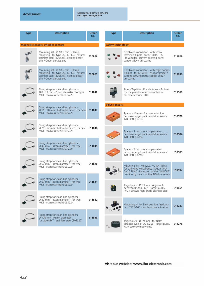
Type Description Orderno.
Magnetic sensors, cylinder sensors
Mounting set · Ø 18.5 mm · Clampmounting · for type OG, IG, KG · fixture:stainless steel (320S31) / clamp: diecastzinc / Cube: diecast zinc
E20866
Mounting set · Ø 18.5 mm · Clampmounting · for type OG, IG, KG · fixture:stainless steel (320S31) / clamp: diecastzinc / Cube: diecast zinc
E20867
Fixing strap for clean-line cylinders · Ø 8...12 mm · Piston diameter · for typeMKT · stainless steel (303S22)
E11816
Fixing strap for clean-line cylinders · Ø 16...20 mm · Piston diameter · for typeMKT · stainless steel (303S22)
E11817
Fixing strap for clean-line cylinders · Ø 25...32 mm · Piston diameter · for typeMKT · stainless steel (303S22)
E11818
Fixing strap for clean-line cylinders · Ø 40 mm · Piston diameter · for typeMKT · stainless steel (303S22)
E11819
Fixing strap for clean-line cylinders · Ø 50 mm · Piston diameter · for typeMKT · stainless steel (303S22)
E11820
Fixing strap for clean-line cylinders · Ø 63 mm · Piston diameter · for typeMKT · stainless steel (303S22)
E11821
Fixing strap for clean-line cylinders · Ø 80 mm · Piston diameter · for typeMKT · stainless steel (303S22)
E11822
Fixing strap for clean-line cylinders · Ø 100 mm · Piston diameter · for type MKT · stainless steel (303S22)
E11823
Type Description Orderno.
Safety technology
Combicon connector · with screwterminals 4-pole · for G1501S · PA(polyamide) / current carrying parts:copper alloy / tin-coated
E11929
Combicon connector · with cage clamps4 poles · for G1501S · PA (polyamide) /current carrying parts: copper alloy / tin-coated
E11930
Safety T-splitter · ifm electronic · T-piecefor the pseudo-serial connection of fail-safe sensors · PUR
E11569
Valve sensors
Spacer · 10 mm · for compensationbetween target pucks and dual sensorIND · PBT (Pocan)
E10579
Spacer · 3 mm · for compensationbetween target pucks and dual sensorIND · PBT (Pocan)
E10584
Spacer · 5 mm · for compensationbetween target pucks and dual sensorIND · PBT (Pocan)
E10585
Mounting kit · MS-MEC-KU-RA--F04A ·for ball valve Mecafrance ISO5211/F04DN25 PN40 · Detection of the “ON/OFF”position by means of the IND dual sensor
E10597
Target puck · Ø 53 mm · Adjustablebetween 0° and 360° · Target puck / PVC / screws: high-grade stainless steel
E10661
Mounting kit for limit position feedback ·tyco 792E-100 · for Keystone actuators E11243
Target puck · Ø 59 mm · for Nelesactuator type B1CU 6/20E · Target puck /POM (polyoxymethylene)
E11278
Accessories Accessories position sensorsand object recognition
432
Visit our website: www.ifm-electronic.com

Type Description Orderno.
Valve sensors
Reinforcement bracket · for type IND ·stainless steel (320S31) E11310
Mounting adapter · accessory for IX5010· adapter: PA (polyamide) / Target:stainless steel (316S12)
E11900
Mounting adapter · for Georg Fischerdiaphragm valve Diastar with strokelimiter M12 · accessory for IX5010 ·adapter: POM (polyoxymethylene) /Target: stainless steel
E12009
Mounting adapter · for Georg Fischerdiaphragm valve Diastar with strokelimiter M16 · accessory for IX5010 ·adapter: POM (polyoxymethylene) /Target: stainless steel
E12010
Target puck · Ø 53 mm · 6 possibleswitching flag positions · with drain holesTarget puck / POM (polyoxymethylene) /screws: high-grade stainless steel
E17105
Target puck · Ø 53 mm · Target puck /PBT (Pocan) / screws: high-grade stainlesssteel
E17118
Target puck · Ø 65 mm · Target puck /PVC / screws: high-grade stainless steel E17148
Target puck · Ø 55 mm · Invertedfunction · Target puck / PVC / screws:high-grade stainless steel / Metal ring:stainless steel
E17205
Target puck · Ø 53 mm · 8 possibleswitching flag positions · with drain holesTarget puck / POM (polyoxymethylene) /screws: high-grade stainless steel
E17294
Direction indicator black · 12 x 4.8 · For target puck E17320 · POM(polyoxymethylene)
E17295
Type Description Orderno.
Valve sensors
Direction indicator yellow · 12 x 4.8 · for target puck E17320 · POM(polyoxymethylene)
E17296
Target puck · Ø 53 mm · Target puck / PA 6 / screws: V2A (1.4302) E17320
Target puck · Ø 65 mm · Target puck / PA 6 / screws: V2A (1.4302) E17327
Target puck · Ø 102 · Target puck / PA 6 / screws: V2A (1.4302) E17328
protective housing · accessory for valvesensors · for type IND · stainless steel E11984
Photoelectric sensors - infrared / red light sensors
Prismatic reflector · Ø 42 mm · round ·for type O5P, OA, OC, OE, OF, OG, OH,OI, OJ, OL, OM, OR, OS, OT, OU · plastics
E20004
Prismatic reflector · Ø 80 mm · round ·for type O4P, O5P, OG, OJ, OA, OC, OEOF, OH, OI, OM, OR, OS, OT, OU ·plastics
E20005
Prismatic reflector · 45 x 28 mm · angularfor type O5P, OA, OC, OE OF, OG, OH,OI, OJ, OM, OR, OS, OT, OU · plastics
E20452
Prismatic reflector · 50 x 50 mm · angularfor type OA, OC, OE OF, OG, OH, OI, OJ,OM, OR, OS, OS, OT, OU · plastics
E20744
Angle support · 90° · for type OF ·housing: ABS / lens: PC E20590
Accessories position sensorsand object recognition
Gen
eral
info
rmat
ion
List
of
arti
cles
Ind
uct
ive
sen
sors
Cap
acit
ive
sen
sors
Mag
net
icse
nso
rs,
cylin
der
sen
sors
Safe
tyte
chn
olo
gy
Val
ve s
enso
rsPh
oto
elec
tric
sen
sors
Ob
ject
reco
gn
itio
nEn
cod
ers
Eval
uat
ion
syst
ems,
po
wer
su
pp
lies
Co
nn
ecti
on
tech
no
log
yA
cces
sori
esTe
chn
ical
info
rmat
ion
and
cu
sto
mer
serv
ice
433
Visit our website: www.ifm-electronic.com

Type Description Orderno.
Photoelectric sensors - infrared / red light sensors
Angle bracket · Ø 12 mm · with end stopMounting clamp · Clamp mounting · fortype OG, IG, KG · clamp: diecast zinc /fixture: stainless steel (304S15) /Mounting clamp / PC / black
E21144
Mounting set · Ø 12.2 mm · Clampmounting · for type OF, IF · fixture:stainless steel (320S31) / clamp: diecast zinc
E21200
Mounting set · Ø 12.2 mm · Clampmounting · for type OF, IF · fixture:stainless steel (320S31) / clamp: stainless steel (316C)
E21201
Mounting set · Ø 12.2 mm · Clampmounting · for type OF, IF · fixture:stainless steel (320S31) / clamp: diecast zinc
E21202
Mounting set · Ø 12.2 mm · Clampmounting · for type OF, IF · fixture:stainless steel (320S31) / clamp: stainless steel (316C)
E21203
Angle support · 90° · for type OF ·housing: ABS / lens: PC E20590
Rod mounting · Ø 10 / M8 · straight ·stainless steel (320S31) E21081
Rod mounting · Ø 10 / M8 · angled ·stainless steel (320S31) E80310
Head cap screw · M8 x 40 mm · ISO 4762 (DIN 912) · screw / steel /galvanised
E21204
Head cap screw · M8 x 40 mm · ISO 4762 (DIN 912) · screw / high-gradestainless steel
E21205
Type Description Orderno.
Photoelectric sensors - infrared / red light sensors
Mounting set · Ø 18.5 mm · Clampmounting · for type OG, IG, KG · clamp:diecast zinc / fixture: steel
E20720
Mounting set · Ø 18.5 mm · Clampmounting · for type OG, IG, KG · clamp:diecast zinc / fixture: steel
E20721
Mounting set · Ø 18.5 mm · Clampmounting · for type OG, IG, KG · clamp:high-grade stainless steel / fixture: high-grade stainless steel
E21206
Mounting set · Ø 18.5 mm · Clampmounting · for type OG, IG, KG · clamp:high-grade stainless steel / fixture: high-grade stainless steel
E21207
Rod mounting · Ø 12 / M10 · straight ·stainless steel (320S31) E20938
Rod mounting · Ø 12 / M10 · angled ·stainless steel (320S31) E20940
Cube · M10 · diecast zinc E20951
Protective bracket for free-standing and rod mounting · Ø 18 mm · Clampmounting · Protective bracket for free-standing and rod mounting / stainlesssteel (316S12)
E21125
Protective bracket for free-standing androd mounting · Ø 18 mm · with end stopMounting clamp · PC / black / Protectivebracket for free-standing and rodmounting / stainless steel (316S12)
E21126
Angle bracket · Ø 18 mm · with end stopMounting clamp · Clamp mounting · for type OG, IG, KG · clamp: diecast zinc/ fixture: stainless steel (304S15) /Mounting clamp / PC / black
E21145
Accessories Accessories position sensorsand object recognition
434
Visit our website: www.ifm-electronic.com
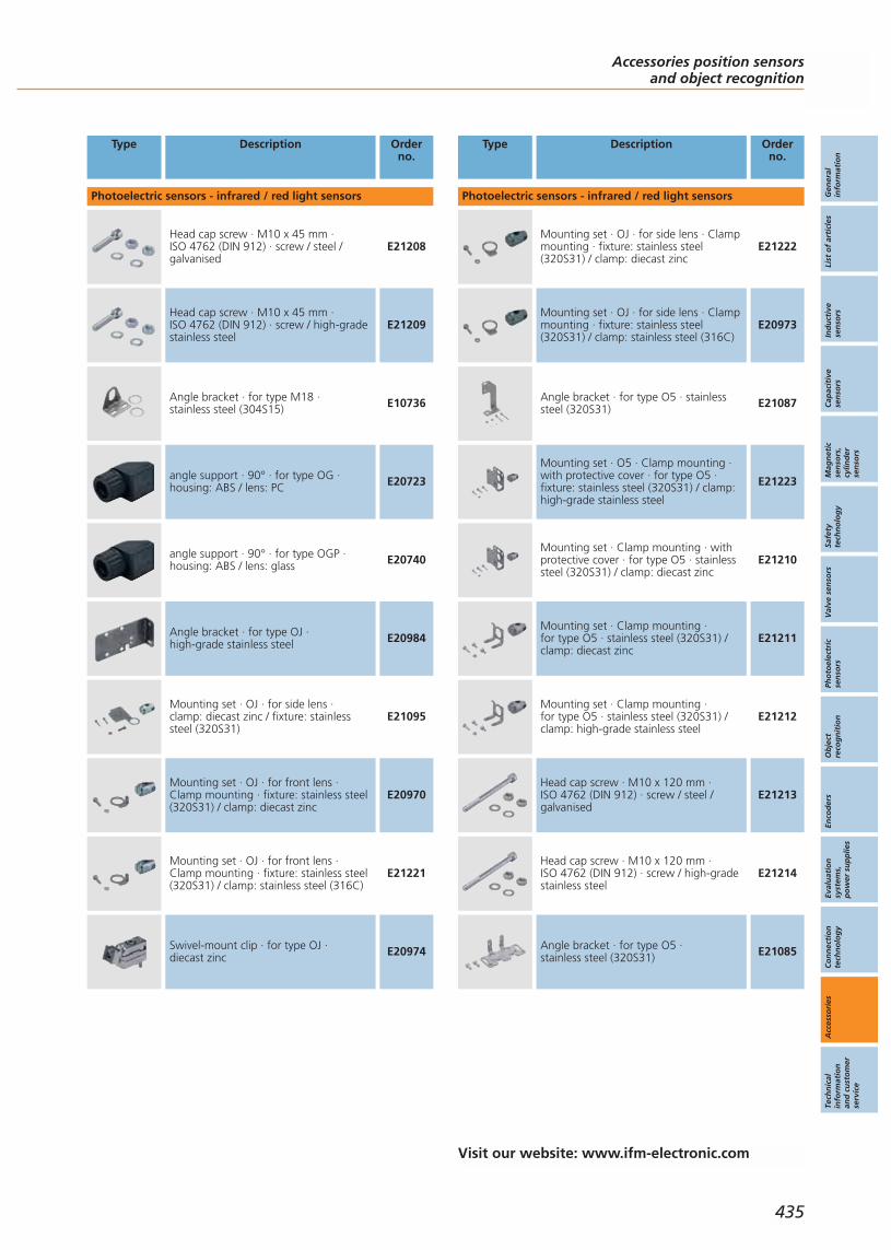
Type Description Orderno.
Photoelectric sensors - infrared / red light sensors
Head cap screw · M10 x 45 mm · ISO 4762 (DIN 912) · screw / steel /galvanised
E21208
Head cap screw · M10 x 45 mm · ISO 4762 (DIN 912) · screw / high-gradestainless steel
E21209
Angle bracket · for type M18 · stainless steel (304S15) E10736
angle support · 90° · for type OG ·housing: ABS / lens: PC E20723
angle support · 90° · for type OGP ·housing: ABS / lens: glass E20740
Angle bracket · for type OJ · high-grade stainless steel E20984
Mounting set · OJ · for side lens · clamp: diecast zinc / fixture: stainlesssteel (320S31)
E21095
Mounting set · OJ · for front lens · Clamp mounting · fixture: stainless steel(320S31) / clamp: diecast zinc
E20970
Mounting set · OJ · for front lens · Clamp mounting · fixture: stainless steel(320S31) / clamp: stainless steel (316C)
E21221
Swivel-mount clip · for type OJ · diecast zinc E20974
Type Description Orderno.
Photoelectric sensors - infrared / red light sensors
Mounting set · OJ · for side lens · Clampmounting · fixture: stainless steel(320S31) / clamp: diecast zinc
E21222
Mounting set · OJ · for side lens · Clampmounting · fixture: stainless steel(320S31) / clamp: stainless steel (316C)
E20973
Angle bracket · for type O5 · stainlesssteel (320S31) E21087
Mounting set · O5 · Clamp mounting ·with protective cover · for type O5 ·fixture: stainless steel (320S31) / clamp:high-grade stainless steel
E21223
Mounting set · Clamp mounting · withprotective cover · for type O5 · stainlesssteel (320S31) / clamp: diecast zinc
E21210
Mounting set · Clamp mounting · for type O5 · stainless steel (320S31) /clamp: diecast zinc
E21211
Mounting set · Clamp mounting · for type O5 · stainless steel (320S31) /clamp: high-grade stainless steel
E21212
Head cap screw · M10 x 120 mm · ISO 4762 (DIN 912) · screw / steel /galvanised
E21213
Head cap screw · M10 x 120 mm · ISO 4762 (DIN 912) · screw / high-gradestainless steel
E21214
Angle bracket · for type O5 · stainless steel (320S31) E21085
Accessories position sensorsand object recognition
Gen
eral
info
rmat
ion
List
of
arti
cles
Ind
uct
ive
sen
sors
Cap
acit
ive
sen
sors
Mag
net
icse
nso
rs,
cylin
der
sen
sors
Safe
tyte
chn
olo
gy
Val
ve s
enso
rsPh
oto
elec
tric
sen
sors
Ob
ject
reco
gn
itio
nEn
cod
ers
Eval
uat
ion
syst
ems,
po
wer
su
pp
lies
Co
nn
ecti
on
tech
no
log
yA
cces
sori
esTe
chn
ical
info
rmat
ion
and
cu
sto
mer
serv
ice
435
Visit our website: www.ifm-electronic.com
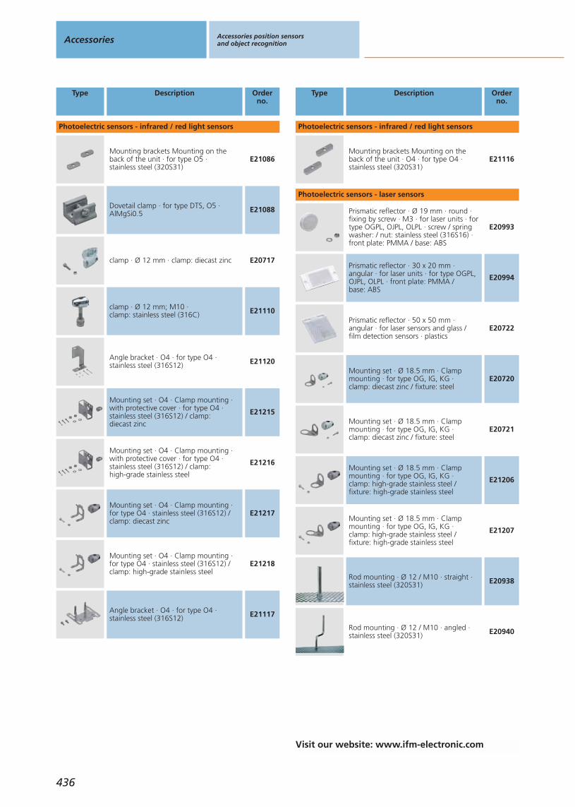
Type Description Orderno.
Photoelectric sensors - infrared / red light sensors
Mounting brackets Mounting on theback of the unit · for type O5 · stainless steel (320S31)
E21086
Dovetail clamp · for type DTS, O5 ·AlMgSi0.5 E21088
clamp · Ø 12 mm · clamp: diecast zinc E20717
clamp · Ø 12 mm; M10 · clamp: stainless steel (316C) E21110
Angle bracket · O4 · for type O4 ·stainless steel (316S12) E21120
Mounting set · O4 · Clamp mounting ·with protective cover · for type O4 ·stainless steel (316S12) / clamp: diecast zinc
E21215
Mounting set · O4 · Clamp mounting ·with protective cover · for type O4 ·stainless steel (316S12) / clamp: high-grade stainless steel
E21216
Mounting set · O4 · Clamp mounting ·for type O4 · stainless steel (316S12) /clamp: diecast zinc
E21217
Mounting set · O4 · Clamp mounting ·for type O4 · stainless steel (316S12) /clamp: high-grade stainless steel
E21218
Angle bracket · O4 · for type O4 ·stainless steel (316S12) E21117
Type Description Orderno.
Photoelectric sensors - infrared / red light sensors
Mounting brackets Mounting on theback of the unit · O4 · for type O4 ·stainless steel (320S31)
E21116
Photoelectric sensors - laser sensors
Prismatic reflector · Ø 19 mm · round ·fixing by screw · M3 · for laser units · fortype OGPL, OJPL, OLPL · screw / springwasher: / nut: stainless steel (316S16) ·front plate: PMMA / base: ABS
E20993
Prismatic reflector · 30 x 20 mm · angular · for laser units · for type OGPL,OJPL, OLPL · front plate: PMMA / base: ABS
E20994
Prismatic reflector · 50 x 50 mm · angular · for laser sensors and glass / film detection sensors · plastics
E20722
Mounting set · Ø 18.5 mm · Clampmounting · for type OG, IG, KG · clamp: diecast zinc / fixture: steel
E20720
Mounting set · Ø 18.5 mm · Clampmounting · for type OG, IG, KG · clamp: diecast zinc / fixture: steel
E20721
Mounting set · Ø 18.5 mm · Clampmounting · for type OG, IG, KG · clamp: high-grade stainless steel / fixture: high-grade stainless steel
E21206
Mounting set · Ø 18.5 mm · Clampmounting · for type OG, IG, KG · clamp: high-grade stainless steel / fixture: high-grade stainless steel
E21207
Rod mounting · Ø 12 / M10 · straight ·stainless steel (320S31) E20938
Rod mounting · Ø 12 / M10 · angled ·stainless steel (320S31) E20940
Accessories Accessories position sensorsand object recognition
436
Visit our website: www.ifm-electronic.com
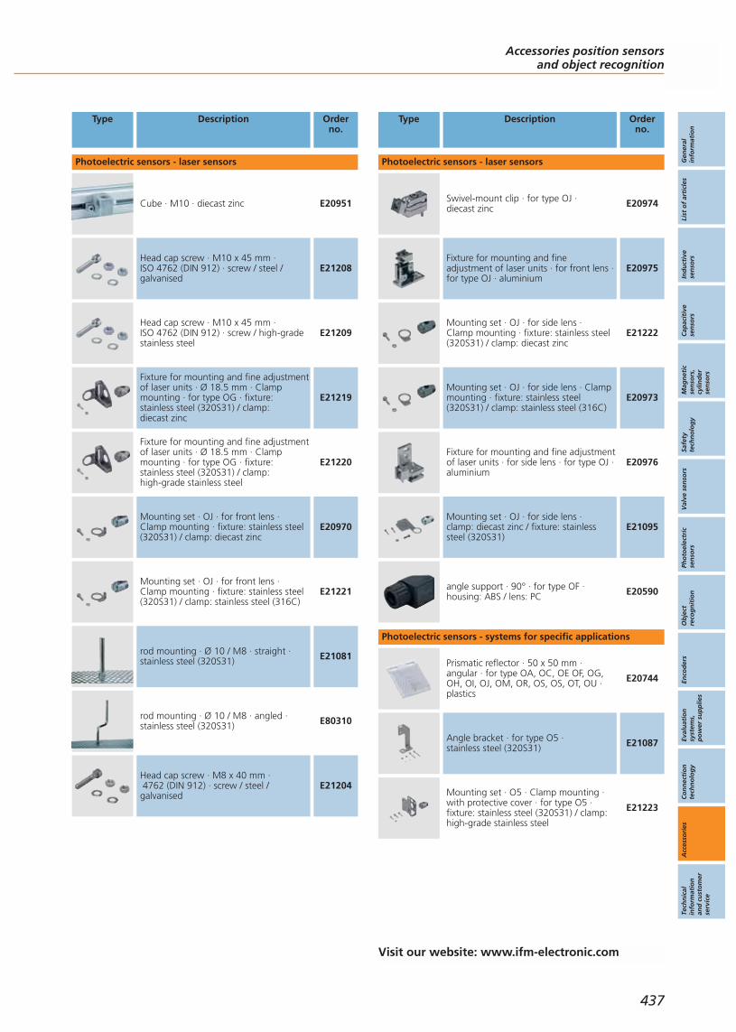
Type Description Orderno.
Photoelectric sensors - laser sensors
Cube · M10 · diecast zinc E20951
Head cap screw · M10 x 45 mm · ISO 4762 (DIN 912) · screw / steel /galvanised
E21208
Head cap screw · M10 x 45 mm · ISO 4762 (DIN 912) · screw / high-gradestainless steel
E21209
Fixture for mounting and fine adjustmentof laser units · Ø 18.5 mm · Clampmounting · for type OG · fixture: stainless steel (320S31) / clamp: diecast zinc
E21219
Fixture for mounting and fine adjustmentof laser units · Ø 18.5 mm · Clampmounting · for type OG · fixture: stainless steel (320S31) / clamp: high-grade stainless steel
E21220
Mounting set · OJ · for front lens · Clamp mounting · fixture: stainless steel(320S31) / clamp: diecast zinc
E20970
Mounting set · OJ · for front lens · Clamp mounting · fixture: stainless steel(320S31) / clamp: stainless steel (316C)
E21221
rod mounting · Ø 10 / M8 · straight ·stainless steel (320S31) E21081
rod mounting · Ø 10 / M8 · angled ·stainless steel (320S31) E80310
Head cap screw · M8 x 40 mm · 4762 (DIN 912) · screw / steel /galvanised
E21204
Type Description Orderno.
Photoelectric sensors - laser sensors
Swivel-mount clip · for type OJ · diecast zinc E20974
Fixture for mounting and fine adjustment of laser units · for front lens · for type OJ · aluminium
E20975
Mounting set · OJ · for side lens · Clamp mounting · fixture: stainless steel(320S31) / clamp: diecast zinc
E21222
Mounting set · OJ · for side lens · Clampmounting · fixture: stainless steel(320S31) / clamp: stainless steel (316C)
E20973
Fixture for mounting and fine adjustmentof laser units · for side lens · for type OJ ·aluminium
E20976
Mounting set · OJ · for side lens · clamp: diecast zinc / fixture: stainlesssteel (320S31)
E21095
angle support · 90° · for type OF ·housing: ABS / lens: PC E20590
Photoelectric sensors - systems for specific applications
Prismatic reflector · 50 x 50 mm · angular · for type OA, OC, OE OF, OG,OH, OI, OJ, OM, OR, OS, OS, OT, OU ·plastics
E20744
Angle bracket · for type O5 · stainless steel (320S31) E21087
Mounting set · O5 · Clamp mounting ·with protective cover · for type O5 ·fixture: stainless steel (320S31) / clamp:high-grade stainless steel
E21223
Accessories position sensorsand object recognition
Gen
eral
info
rmat
ion
List
of
arti
cles
Ind
uct
ive
sen
sors
Cap
acit
ive
sen
sors
Mag
net
icse
nso
rs,
cylin
der
sen
sors
Safe
tyte
chn
olo
gy
Val
ve s
enso
rsPh
oto
elec
tric
sen
sors
Ob
ject
reco
gn
itio
nEn
cod
ers
Eval
uat
ion
syst
ems,
po
wer
su
pp
lies
Co
nn
ecti
on
tech
no
log
yA
cces
sori
esTe
chn
ical
info
rmat
ion
and
cu
sto
mer
serv
ice
437
Visit our website: www.ifm-electronic.com
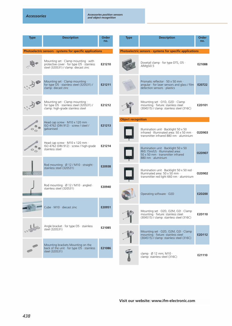
Type Description Orderno.
Photoelectric sensors - systems for specific applications
Mounting set · Clamp mounting · withprotective cover · for type O5 · stainlesssteel (320S31) / clamp: diecast zinc
E21210
Mounting set · Clamp mounting · for type O5 · stainless steel (320S31) /clamp: diecast zinc
E21211
Mounting set · Clamp mounting · for type O5 · stainless steel (320S31) /clamp: high-grade stainless steel
E21212
Head cap screw · M10 x 120 mm · ISO 4762 (DIN 912) · screw / steel /galvanised
E21213
Head cap screw · M10 x 120 mm · ISO 4762 (DIN 912) · screw / high-gradestainless steel
E21214
Rod mounting · Ø 12 / M10 · straight ·stainless steel (320S31) E20938
Rod mounting · Ø 12 / M10 · angled ·stainless steel (320S31) E20940
Cube · M10 · diecast zinc E20951
Angle bracket · for type O5 · stainlesssteel (320S31) E21085
Mounting brackets Mounting on theback of the unit · for type O5 · stainlesssteel (320S31)
E21086
Type Description Orderno.
Photoelectric sensors - systems for specific applications
Dovetail clamp · for type DTS, O5 ·AlMgSi0.5 E21088
Prismatic reflector · 50 x 50 mm · angular · for laser sensors and glass / filmdetection sensors · plastics
E20722
Mounting set · O1D, O2D · Clampmounting · fixture: stainless steel(304S15) / clamp: stainless steel (316C)
E2D101
Object recognition
Illumination unit · Backlight 50 x 50infrared · Illuminated area: 50 x 50 mm ·transmitter infrared 880 nm · aluminium
O2D903
Illumination unit · Backlight 50 x 50IR/0.15m/US · Illuminated area: 50 x 50 mm · transmitter infrared 880 nm · aluminium
O2D907
Illumination unit · Backlight 50 x 50 red ·Illuminated area: 50 x 50 mm ·transmitter red light 660 nm · aluminium
O2D902
Operating software · O2D E2D200
Mounting set · O2D, O2M, O2I · Clampmounting · fixture: stainless steel(304S15) / clamp: stainless steel (316C)
E2D110
Mounting set · O2D, O2M, O2I · Clampmounting · fixture: stainless steel(304S15) / clamp: stainless steel (316C)
E2D112
clamp · Ø 12 mm; M10 · clamp: stainless steel (316C) E21110
Accessories Accessories position sensorsand object recognition
438
Visit our website: www.ifm-electronic.com
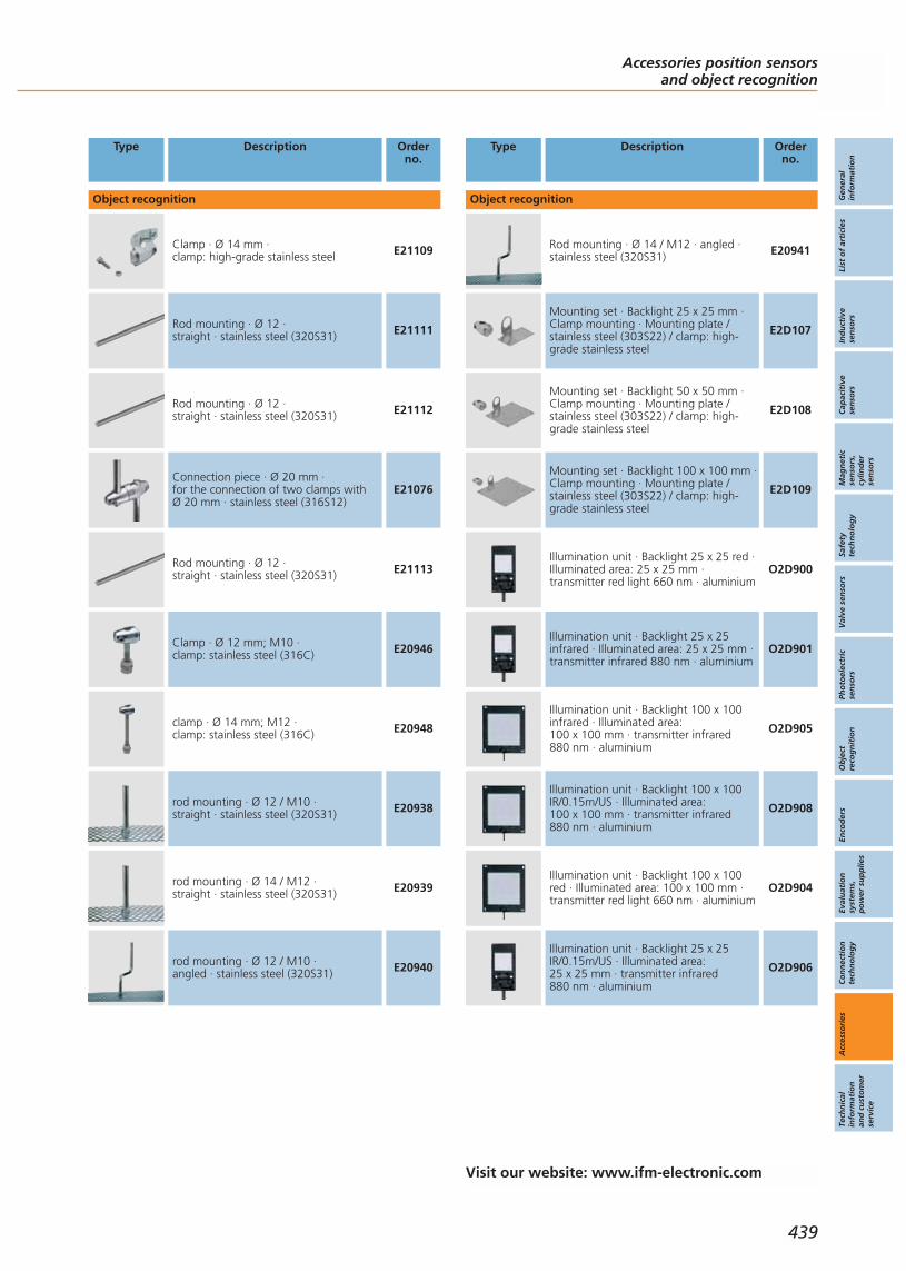
Type Description Orderno.
Object recognition
Clamp · Ø 14 mm · clamp: high-grade stainless steel E21109
Rod mounting · Ø 12 · straight · stainless steel (320S31) E21111
Rod mounting · Ø 12 · straight · stainless steel (320S31) E21112
Connection piece · Ø 20 mm · for the connection of two clamps with Ø 20 mm · stainless steel (316S12)
E21076
Rod mounting · Ø 12 · straight · stainless steel (320S31) E21113
Clamp · Ø 12 mm; M10 · clamp: stainless steel (316C) E20946
clamp · Ø 14 mm; M12 · clamp: stainless steel (316C) E20948
rod mounting · Ø 12 / M10 · straight · stainless steel (320S31) E20938
rod mounting · Ø 14 / M12 · straight · stainless steel (320S31) E20939
rod mounting · Ø 12 / M10 · angled · stainless steel (320S31) E20940
Type Description Orderno.
Object recognition
Rod mounting · Ø 14 / M12 · angled ·stainless steel (320S31) E20941
Mounting set · Backlight 25 x 25 mm ·Clamp mounting · Mounting plate /stainless steel (303S22) / clamp: high-grade stainless steel
E2D107
Mounting set · Backlight 50 x 50 mm ·Clamp mounting · Mounting plate /stainless steel (303S22) / clamp: high-grade stainless steel
E2D108
Mounting set · Backlight 100 x 100 mm ·Clamp mounting · Mounting plate /stainless steel (303S22) / clamp: high-grade stainless steel
E2D109
Illumination unit · Backlight 25 x 25 red ·Illuminated area: 25 x 25 mm ·transmitter red light 660 nm · aluminium
O2D900
Illumination unit · Backlight 25 x 25infrared · Illuminated area: 25 x 25 mm ·transmitter infrared 880 nm · aluminium
O2D901
Illumination unit · Backlight 100 x 100infrared · Illuminated area: 100 x 100 mm · transmitter infrared 880 nm · aluminium
O2D905
Illumination unit · Backlight 100 x 100IR/0.15m/US · Illuminated area: 100 x 100 mm · transmitter infrared 880 nm · aluminium
O2D908
Illumination unit · Backlight 100 x 100red · Illuminated area: 100 x 100 mm ·transmitter red light 660 nm · aluminium
O2D904
Illumination unit · Backlight 25 x 25IR/0.15m/US · Illuminated area: 25 x 25 mm · transmitter infrared 880 nm · aluminium
O2D906
Accessories position sensorsand object recognition
Gen
eral
info
rmat
ion
List
of
arti
cles
Ind
uct
ive
sen
sors
Cap
acit
ive
sen
sors
Mag
net
icse
nso
rs,
cylin
der
sen
sors
Safe
tyte
chn
olo
gy
Val
ve s
enso
rsPh
oto
elec
tric
sen
sors
Ob
ject
reco
gn
itio
nEn
cod
ers
Eval
uat
ion
syst
ems,
po
wer
su
pp
lies
Co
nn
ecti
on
tech
no
log
yA
cces
sori
esTe
chn
ical
info
rmat
ion
and
cu
sto
mer
serv
ice
439
Visit our website: www.ifm-electronic.com
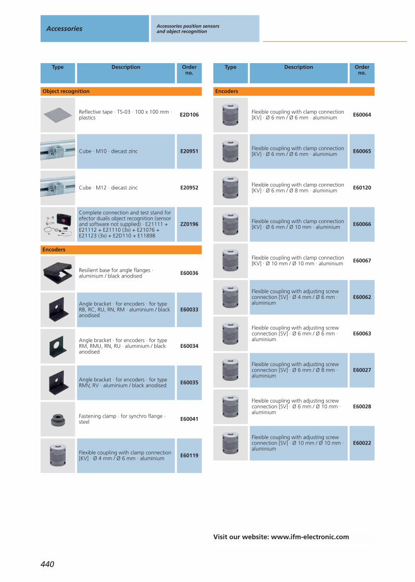
Type Description Orderno.
Object recognition
Reflective tape · TS-03 · 100 x 100 mm ·plastics E2D106
Cube · M10 · diecast zinc E20951
Cube · M12 · diecast zinc E20952
Complete connection and test stand forefector dualis object recognition (sensorand software not supplied) · E21111 +E21112 + E21110 (3x) + E21076 +E21123 (3x) + E2D110 + E11898
ZZ0196
Encoders
Resilient base for angle flanges ·aluminium / black anodised E60036
Angle bracket · for encoders · for typeRB, RC, RU, RN, RM · aluminium / blackanodised
E60033
Angle bracket · for encoders · for typeRM, RMU, RN, RU · aluminium / blackanodised
E60034
Angle bracket · for encoders · for typeRMV, RV · aluminium / black anodised E60035
Fastening clamp · for synchro flange ·steel E60041
Flexible coupling with clamp connection[KV] · Ø 4 mm / Ø 6 mm · aluminium E60119
Type Description Orderno.
Encoders
Flexible coupling with clamp connection[KV] · Ø 6 mm / Ø 6 mm · aluminium E60064
Flexible coupling with clamp connection[KV] · Ø 6 mm / Ø 6 mm · aluminium E60065
Flexible coupling with clamp connection[KV] · Ø 6 mm / Ø 8 mm · aluminium E60120
Flexible coupling with clamp connection[KV] · Ø 6 mm / Ø 10 mm · aluminium E60066
Flexible coupling with clamp connection[KV] · Ø 10 mm / Ø 10 mm · aluminium E60067
Flexible coupling with adjusting screwconnection [SV] · Ø 4 mm / Ø 6 mm ·aluminium
E60062
Flexible coupling with adjusting screwconnection [SV] · Ø 6 mm / Ø 6 mm ·aluminium
E60063
Flexible coupling with adjusting screwconnection [SV] · Ø 6 mm / Ø 8 mm ·aluminium
E60027
Flexible coupling with adjusting screwconnection [SV] · Ø 6 mm / Ø 10 mm ·aluminium
E60028
Flexible coupling with adjusting screwconnection [SV] · Ø 10 mm / Ø 10 mm ·aluminium
E60022
Accessories Accessories position sensorsand object recognition
440
Visit our website: www.ifm-electronic.com
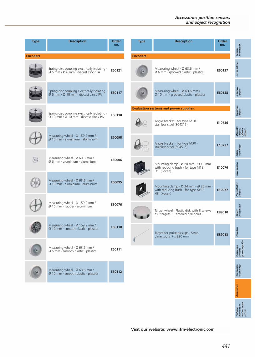
Type Description Orderno.
Encoders
Spring disc coupling electrically isolating ·Ø 6 mm / Ø 6 mm · diecast zinc / PA E60121
Spring disc coupling electrically isolating ·Ø 6 mm / Ø 10 mm · diecast zinc / PA E60117
Spring disc coupling electrically isolating ·Ø 10 mm / Ø 10 mm · diecast zinc / PA E60118
Measuring wheel · Ø 159.2 mm / Ø 10 mm · aluminium · aluminium E60098
Measuring wheel · Ø 63.6 mm / Ø 6 mm · aluminium · aluminium E60006
Measuring wheel · Ø 63.6 mm / Ø 10 mm · aluminium · aluminium E60095
Measuring wheel · Ø 159.2 mm / Ø 10 mm · rubber · aluminium E60076
Measuring wheel · Ø 159.2 mm / Ø 10 mm · smooth plastic · plastics E60110
Measuring wheel · Ø 63.6 mm / Ø 6 mm · smooth plastic · plastics E60111
Measuring wheel · Ø 63.6 mm / Ø 10 mm · smooth plastic · plastics E60112
Type Description Orderno.
Encoders
Measuring wheel · Ø 63.6 mm / Ø 6 mm · grooved plastic · plastics E60137
Measuring wheel · Ø 63.6 mm / Ø 10 mm · grooved plastic · plastics E60138
Evaluation systems and power supplies
Angle bracket · for type M18 · stainless steel (304S15) E10736
Angle bracket · for type M30 · stainless steel (304S15) E10737
Mounting clamp · Ø 20 mm - Ø 18 mm ·with reducing bush · for type M18 · PBT (Pocan)
E10076
Mounting clamp · Ø 34 mm - Ø 30 mm ·with reducing bush · for type M30 · PBT (Pocan)
E10077
Target wheel · Plastic disk with 8 screwsas “target” · Centered drill holes E89010
Target for pulse pickups · Strapdimensions 7 x 220 mm E89013
Accessories position sensorsand object recognition
Gen
eral
info
rmat
ion
List
of
arti
cles
Ind
uct
ive
sen
sors
Cap
acit
ive
sen
sors
Mag
net
icse
nso
rs,
cylin
der
sen
sors
Safe
tyte
chn
olo
gy
Val
ve s
enso
rsPh
oto
elec
tric
sen
sors
Ob
ject
reco
gn
itio
nEn
cod
ers
Eval
uat
ion
syst
ems,
po
wer
su
pp
lies
Co
nn
ecti
on
tech
no
log
yA
cces
sori
esTe
chn
ical
info
rmat
ion
and
cu
sto
mer
serv
ice
441
Visit our website: www.ifm-electronic.com


Gen
eral
info
rmat
ion
List
of
arti
cles
Ind
uct
ive
sen
sors
Cap
acit
ive
sen
sors
Mag
net
icse
nso
rs,
cylin
der
sen
sors
Safe
tyte
chn
olo
gy
Val
ve s
enso
rsPh
oto
elec
tric
sen
sors
Ob
ject
reco
gn
itio
nEn
cod
ers
Eval
uat
ion
syst
ems,
po
wer
su
pp
lies
Co
nn
ecti
on
tech
no
log
yA
cces
sori
esTe
chn
ical
info
rmat
ion
and
cu
sto
mer
serv
ice
443
Technical informationand customer service
Scale drawings
Inductive sensorsCapacitive sensorsMagnetic sensors, cylinder sensorsSafety technologyValve sensorsPhotoelectric sensorsObject recognitionEncodersEvaluation systems, power suppliesConnection technology
Technical glossary
Position sensors and object recognition
ifm information and ordering service
Other ifm productsInternet serviceCustomer serviceOrdering serviceAddresses
Wiring diagrams
Position sensors and object recognition
450 - 468469 - 471472 - 474
475476 - 478479 - 490
491492 - 493494 - 501502 - 515
516 - 525
526 - 529530 - 531
532533
534 - 535
444 - 449
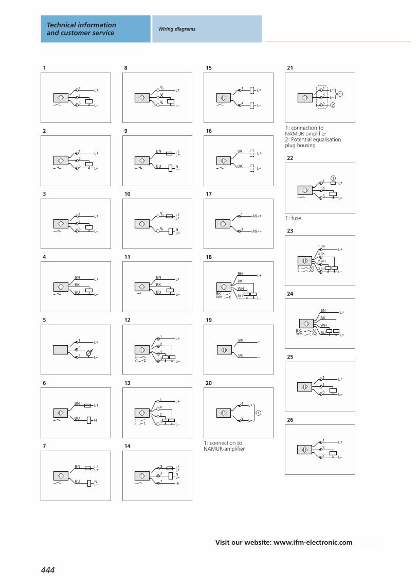
1
L+
L
1
4
3
2
L+
L
1
2
3
3
L+
L
1
4
3
4
BN
BK
BU
L+
L
5
L+
L
1
3
2
6
BN
BU
L1
N
7
BN
BU
L+L1
LN
8
/L+
L
13
/2 4
9
BN
BU
L+L1
LN
10
/1 3
/2 4
L1L+
LN
11
BN
BK
BU
L+
L
12
4
L
L+1
2
32:4:
13
L
L+
4
2
1
32:4:
14
1
3
2
L1L+
LN
15
L+
L
1
4
16
BK
BK
L+
L
17
AS-i+1
3 AS-i
18
L
L+
WH:BK :
BK
BU
WH
BN
19
+BN
BU
20
L+
L2
1
1
1: connection to NAMUR-amplifier
21
L+
L2
1
1
5 2
1: connection to NAMUR-amplifier2: Potential equalisation plug housing
22
L+
L
1
4
3
1
1: fuse
23
L
L+
3 BU
2 WH
4 BK
1 BN
2:4: A1
A2
24
L
L+
BK
WH
BN
BUWH:BK: A1
A2
25
L+
L
1
4
3
26
L+
L
1
3
2
Technical informationand customer service
Wiring diagrams
444
Visit our website: www.ifm-electronic.com
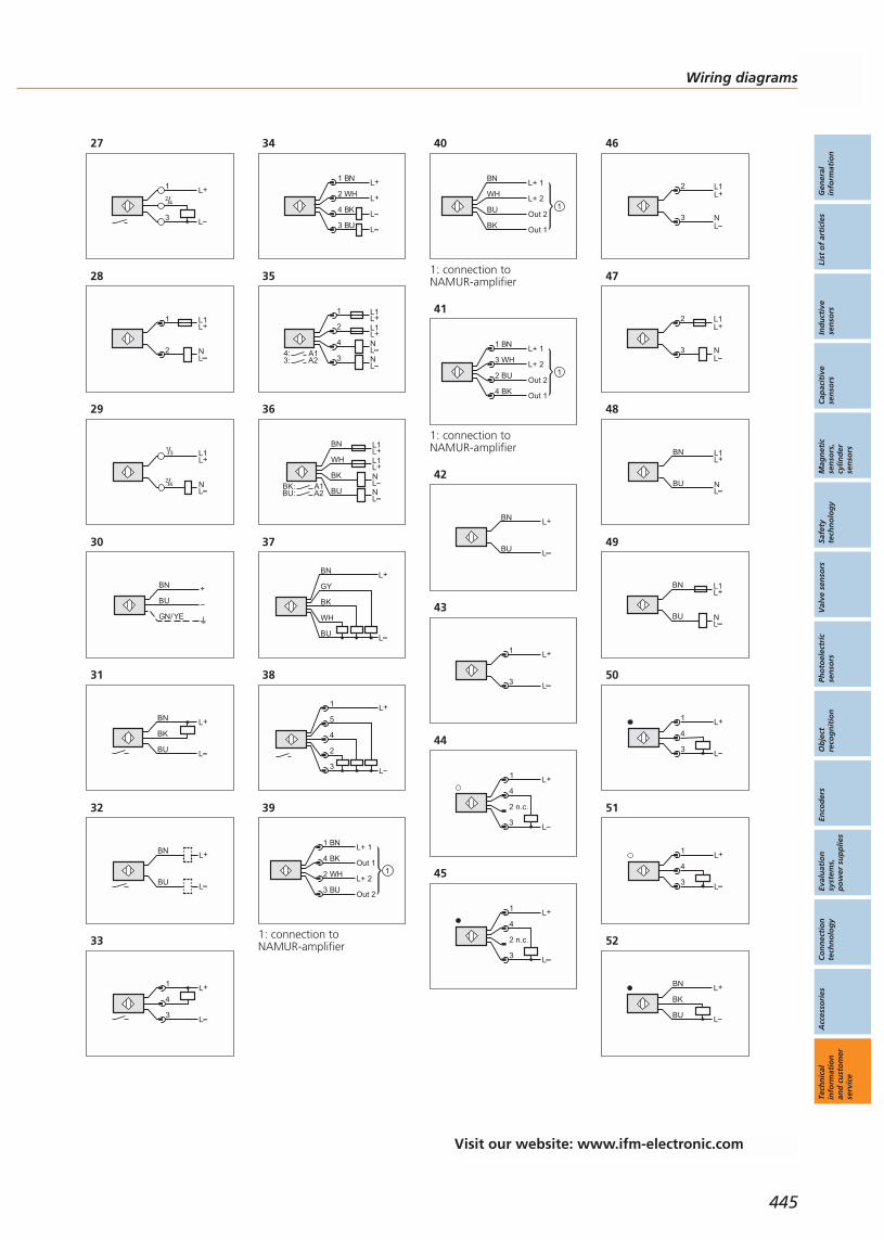
27
L
L+
/2 4
1
3
28
1
2
L1
N
L+
L
29
/1 3
/2 4
L1L+
LN
30
BN
GN/YE
BU
+
31
L
BN
BK
BU
L+
32
L
BN
BU
L+
33
L+
L
1
4
3
34
L
L+
L+
L
2 WH
1 BN
4 BK
3 BU
35
L+L1
LNL+L1
LN
1
2
4
33:4: A1
A2
36
BN
BU
L+L1
LN
WHL+L1
BK
LNBU:
BK: A1A2
37
GY
WH
BK
BN
BU L
L+
38
L+
L
1
5
4
2
3
39
Out 1
3 BU
2 WH
4 BK
1 BNL+ 1
L+ 2
Out 2
1
1: connection to NAMUR-amplifier
40
Out 1BK
BU
WH
BNL+ 1
L+ 2
Out 21
1: connection to NAMUR-amplifier
41
Out 2
4 BK
2 BU
3 WH
1 BNL+ 1
L+ 2
Out 1
1
1: connection to NAMUR-amplifier
42
L+
L
BN
BU
43
1
3
L+
L
44
L
L+
4
2 n.c.
1
3
45
L+
4
2 n.c.
1
3L
46
2
3
L1
N
L+
L
47
2
3
L1
N
L+
L
48
L1L+
LN
BN
BU
49
L1L+
LN
BN
BU
50
L+
L
1
4
3
51
L+
L
1
4
3
52
L
BN
BK
BU
L+
Wiring diagrams
Gen
eral
info
rmat
ion
List
of
arti
cles
Ind
uct
ive
sen
sors
Cap
acit
ive
sen
sors
Mag
net
icse
nso
rs,
cylin
der
sen
sors
Safe
tyte
chn
olo
gy
Val
ve s
enso
rsPh
oto
elec
tric
sen
sors
Ob
ject
reco
gn
itio
nEn
cod
ers
Eval
uat
ion
syst
ems,
po
wer
su
pp
lies
Co
nn
ecti
on
tech
no
log
yA
cces
sori
esTe
chn
ical
info
rmat
ion
and
cu
sto
mer
serv
ice
445
Visit our website: www.ifm-electronic.com

53
L
BN
BK
BU
L+
54
L+
2
4
1
3L
2: Teach
55
L+
2
4
1
3L
2: Teach
56
WH
BK
BN
BU
L+
LWH: Teach
57
L+
L
1
4
3
58
L+
L
1
4
3
59
L+
L
BN
BK
WH
BU
BK: TriggerWH: Operating mode “high light intensity”
60
L+
L
1
4
2
3
1: Trigger2: Operating mode “high light intensity”
61
L1
N
BN
BU
BK
62
L+
L
1
3
2
63
4
L
L+1
2
3
2: pulse output (the pulsesequence corresponds to thedamping frequency)4: switching output (adjustable)
Technical informationand customer service
Wiring diagrams
446
Visit our website: www.ifm-electronic.com
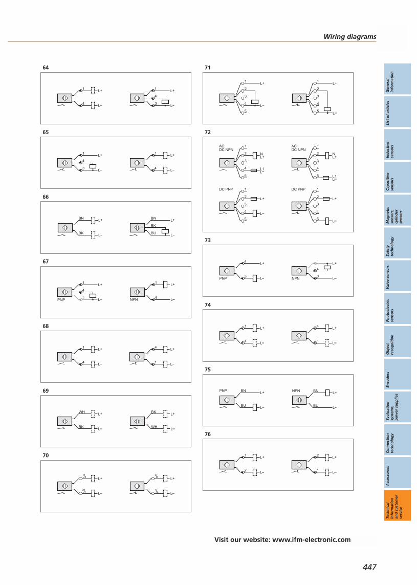
Wiring diagrams
Gen
eral
info
rmat
ion
List
of
arti
cles
Ind
uct
ive
sen
sors
Cap
acit
ive
sen
sors
Mag
net
icse
nso
rs,
cylin
der
sen
sors
Safe
tyte
chn
olo
gy
Val
ve s
enso
rsPh
oto
elec
tric
sen
sors
Ob
ject
reco
gn
itio
nEn
cod
ers
Eval
uat
ion
syst
ems,
po
wer
su
pp
lies
Co
nn
ecti
on
tech
no
log
yA
cces
sori
esTe
chn
ical
info
rmat
ion
and
cu
sto
mer
serv
ice
447
64
L+
L
1
4
L+
L
1
4
3
65
L+
L
1
4
3
L+
L
1
4
66
L+
L
BN
BK
BU
L+
L
BN
BK
67
L+
L
1
4NPN
L+
L
1
4
3PNP
68
L+
L1
4L+
L
1
4
69
WH
BK
L+
L L
BK
WH
L+
70
L+
L
/1 3
/2 4
L+
L/1 3
/2 4
71
2
4
3
1
5
L+
L
2
4
3
1
5
L+
L
72
2
4
3
1
5
AC;DC NPN
L+N
LL1
2
4
3
1
5
AC;DC NPN
L+N
LL1
2
4
3
1
5
DC PNP
L+
L
2
4
3
1
5
DC PNP
L+
L
73
L+
L
4
3PNP
L+
L
1
4
3NPN
74
L+
L1
4L+
L
1
4
75
BN
BU
L+
L
NPNBN
BU
L+
L
PNP
76
L+
L1
2L+
L
1
2
Visit our website: www.ifm-electronic.com
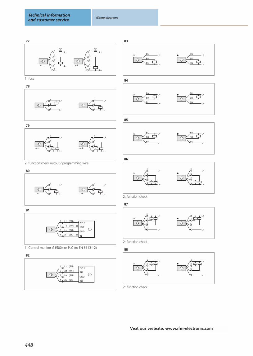
77
5
4
3
2
1L+
L
1
5
4
3
2
1L+
L
1
1: fuse
78
L+
L
1
4
3
L+
L
1
4
3
79
L
L+
4
2
3
1
2
L
L+
4
1
3
2: function check output / programming wire
80
L+
L
1
4
3
L+
L
1
4
2
81
(BK)
3
1
4
2
L+
L
(BN)
A
TE
(BU)
(WH)+24 V
OUT
GND
IN
1
1: Control monitor G1500x or PLC (to EN 61131-2)
82
(BK)
3
1
4
2
L+
L
(BN)
A2
A1
(BU)
(WH)+24 V
IN1
GND
IN2
1
83
L
BN
BK
BU
L+
L
BU
BK
BN
L+
84
L
BU
BK
BN
L+
L
BN
BK
BU
L+
85
L
BN
BK
BU
L+
L
BU
BK
BN
L+
86
L
L+
3
2
4
1
L
L+
1
2
4
3
2: function check
87
L
L+
1
4
2
3
L
L+
3
4
2
1
2: function check
88
L
L+
3
4
2
1
L
L+
1
4
2
3
2: function check
Technical informationand customer service
Wiring diagrams
448
Visit our website: www.ifm-electronic.com
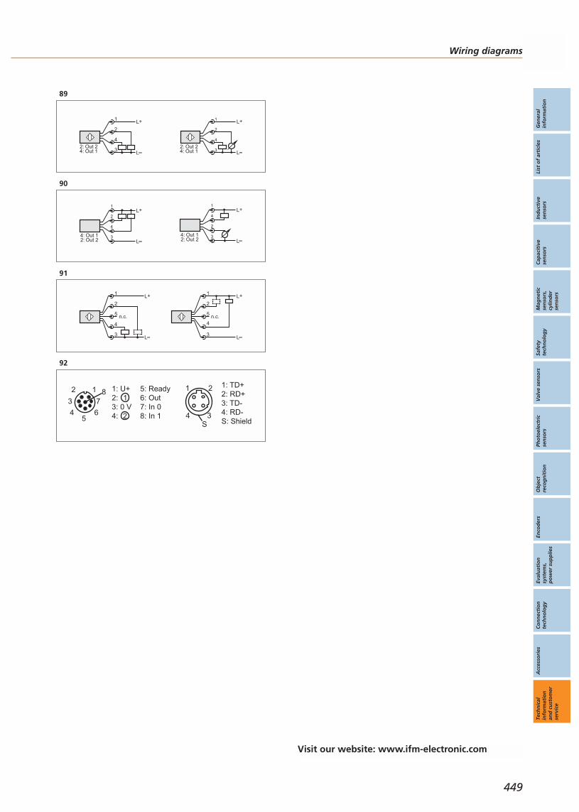
89
L+
L3
4
2
1
Out 1Out 2
4:2:
4
L
L+1
2
3Out 1Out 2
4:2:
90
L
L+
Out 2Out 1
2:4: 3
4
2
1L+
LOut 2Out 1
2:4: 3
2
4
1
91
L+
L
2
5
1
4
3
n.c.
L+
L
2
5
1
4
3
n.c.
92
1: TD+2: RD+3: TD-4: RD-S: Shield
6
2 1
45
738 1: U+
2:3: 0 V4:
5: Ready6: Out7: In 08: In 1
1
2
1
4 3
2
S
Wiring diagrams
Gen
eral
info
rmat
ion
List
of
arti
cles
Ind
uct
ive
sen
sors
Cap
acit
ive
sen
sors
Mag
net
icse
nso
rs,
cylin
der
sen
sors
Safe
tyte
chn
olo
gy
Val
ve s
enso
rsPh
oto
elec
tric
sen
sors
Ob
ject
reco
gn
itio
nEn
cod
ers
Eval
uat
ion
syst
ems,
po
wer
su
pp
lies
Co
nn
ecti
on
tech
no
log
yA
cces
sori
esTe
chn
ical
info
rmat
ion
and
cu
sto
mer
serv
ice
449
Visit our website: www.ifm-electronic.com
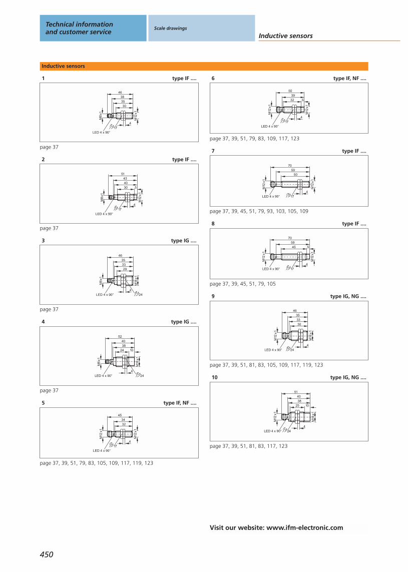
Inductive sensors
1 type IF ....
3530
M12
x1
174
46
LED 4 x 90°
38M
8x1
page 37
2 type IF ....
4030
M12
x1
174
51
LED 4 x 90°
43
M8
x1
5
page 37
3 type IG ....
46
LED 4 x 90°
M18
x1
4
3335
24
M8
x1
29
page 37
4 type IG ....
52
LED 4 x 90°
M18
x1
4
3840
10
24
M8
x1
24
page 37
5 type IF, NF ....
453432
M12
x1
174
M12
x1
LED 4 x 90°
page 37, 39, 51, 79, 83, 105, 109, 117, 119, 123
6 type IF, NF ....
32
M12
x1
174
5
M12
x1
3950
LED 4 x 90°
page 37, 39, 51, 79, 83, 109, 117, 123
7 type IF ....
70
LED 4 x 90°
5950
M12
x1
174
M12
x1
page 37, 39, 45, 51, 79, 93, 103, 105, 109
8 type IF ....
45
M12
x1
174
5
M12
x1
5970
LED 4 x 90°
page 37, 39, 45, 51, 79, 105
9 type IG, NG ....
M18
x1
M12
x1
3033
4635
424LED 4 x 90°
page 37, 39, 51, 81, 83, 105, 109, 117, 119, 123
10 type IG, NG ....
M18
x1
M12
x1
2538
5140
424
10
LED 4 x 90°
page 37, 39, 51, 81, 83, 117, 123
Technical informationand customer service
Scale drawings
Inductive sensors
450
Visit our website: www.ifm-electronic.com
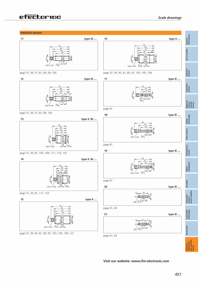
Inductive sensors
11 type IG ....
M18
x1
M12
x1
4956
7059
424LED 4 x 90°
page 37, 39, 51, 81, 85, 93, 105
12 type IG ....
M18
x1
M12
x1
3956
70
LED 4 x 90°
59
10
424
page 37, 39, 51, 81, 85, 105
13 type II, NI ....
39
33
M30
x1,5
37
50
M12
x1
LED 4 x 90°5
36
page 37, 39, 81, 105, 109, 117, 119, 123
14 type II, NI ....
39
19
M30
x1,5
37
50
M12
x1
LED 2 x 180°5
15
36
page 37, 39, 81, 117, 123
15 type II ....
59
53
M30
x1,5
57
70
M12
x1
LED 4 x 90°5
36
page 37, 39, 45, 81, 85, 97, 103, 105, 109, 121
16 type II ....
LED 4 x 90°
59
38
M30
x1,5
5
57
70
36
M12
x1
15
page 37, 39, 45, 81, 85, 97, 103, 105, 109
17 type IE ....
2734
M8
x1
LED 4
13
M12
x1
53
page 41
18 type IE ....
M8
x1
4
13
M12
x1
6247
40
LED 4 x 90°
page 41
19 type IE ....M
8x1
4
13
M12
x1
624738 2
LED 4 x 90°
page 41
20 type IE ....
35
LED
M8
x1
413
2
page 41, 43
21 type IE ....
27
LED
M8
x1
413
82
page 41, 43
Scale drawings
Gen
eral
info
rmat
ion
List
of
arti
cles
Ind
uct
ive
sen
sors
Cap
acit
ive
sen
sors
Mag
net
icse
nso
rs,
cylin
der
sen
sors
Safe
tyte
chn
olo
gy
Val
ve s
enso
rsPh
oto
elec
tric
sen
sors
Ob
ject
reco
gn
itio
nEn
cod
ers
Eval
uat
ion
syst
ems,
po
wer
su
pp
lies
Co
nn
ecti
on
tech
no
log
yA
cces
sori
esTe
chn
ical
info
rmat
ion
and
cu
sto
mer
serv
ice
451
Visit our website: www.ifm-electronic.com
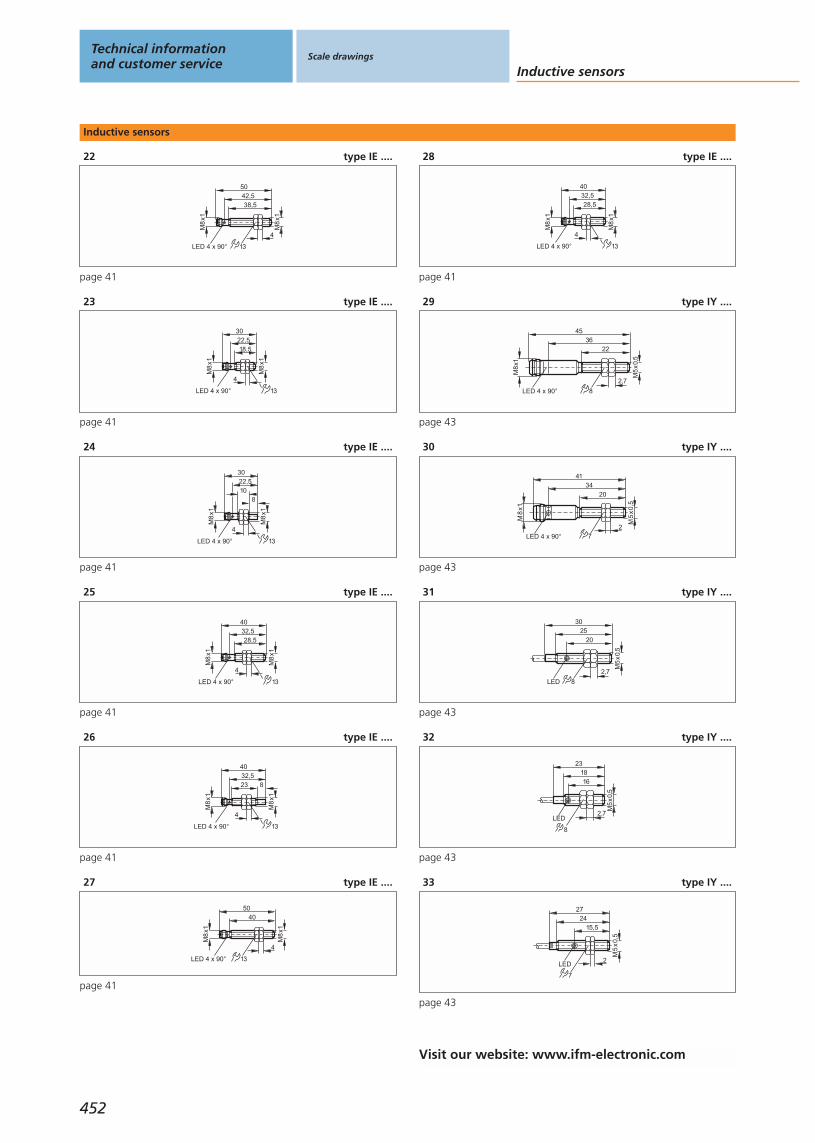
Inductive sensors
22 type IE ....
38,542,5
M8
x1
4
13
M8
x1
LED 4 x 90°
50
page 41
23 type IE ....
18,5
30
M8
x1
4
13
M8
x1
22,5
LED 4 x 90°
page 41
24 type IE ....
10
30
M8
x1
LED 4 x 90°
M8
x1
8
22,5
4
13
page 41
25 type IE ....
4
13
28,5
40
M8
x1
LED 4 x 90°
M8
x1
32,5
page 41
26 type IE ....
23
40
M8
x1
LED 4 x 90°
4
13
M8
x1
832,5
page 41
27 type IE ....
4050
M8
x1
LED 4 x 90°
4
13
M8
x1
page 41
28 type IE ....
4
13
28,5
40
M8
x1
LED 4 x 90°
M8
x1
32,5
page 41
29 type IY ....
LED 4 x 90° 8
22
45
M5
x0,
5
2,7
M8
x1
36
page 43
30 type IY ....
7
20
41
2LED 4 x 90°
M8
x1
34
M5
x0,
5
page 43
31 type IY ....
8LED
20
2530
M5
x0,
5
2,7
page 43
32 type IY ....
16
LED
1823
M5
x0,
5
2,7
8
page 43
33 type IY ....
15,5
LED
2427
M5
x0,
5
7
2
page 43
Technical informationand customer service
Scale drawings
Inductive sensors
452
Visit our website: www.ifm-electronic.com

Inductive sensors
34 type IE ....
2735
M8
x1
LED 4
13
page 43
35 type IE ....
3942
50
LED
M8
x1
413
page 43, 55
36 type IE ....
20
LED
M8
x1
4
13
page 43
37 type IE ....
27
M8
x1
4LED
13
23
page 43
38 type IE ....
2715
M8
x1
4
8
LED
13
page 43
39 type IG, MG ....
24
4947
40
M18
x1
4
M12
x1
60
LED 4 x 90°
page 45, 81, 99
40 type IG ....
M18
x1
30 10
M12
x1
47
60
LED 4 x 90°
49
424
page 45, 81, 95
41 type IM ....
40
66
40
54
M12
x130
30 2
2
1
46
46
5,5
5,5
29,5
1: LED yellow, 2: LED green, page 45, 71, 101
42 type JA ....
M12
x1
174
4
M12
x1
5263
LED 4 x 90°
43
page 47
43 type IF ....
3524
M12
x1
4LED
17
9
18
page 49, 123
44 type IF ....
9
18 7160
50
M12
x1
LED 174
page 49, 55, 57
Scale drawings
Gen
eral
info
rmat
ion
List
of
arti
cles
Ind
uct
ive
sen
sors
Cap
acit
ive
sen
sors
Mag
net
icse
nso
rs,
cylin
der
sen
sors
Safe
tyte
chn
olo
gy
Val
ve s
enso
rsPh
oto
elec
tric
sen
sors
Ob
ject
reco
gn
itio
nEn
cod
ers
Eval
uat
ion
syst
ems,
po
wer
su
pp
lies
Co
nn
ecti
on
tech
no
log
yA
cces
sori
esTe
chn
ical
info
rmat
ion
and
cu
sto
mer
serv
ice
453
Visit our website: www.ifm-electronic.com
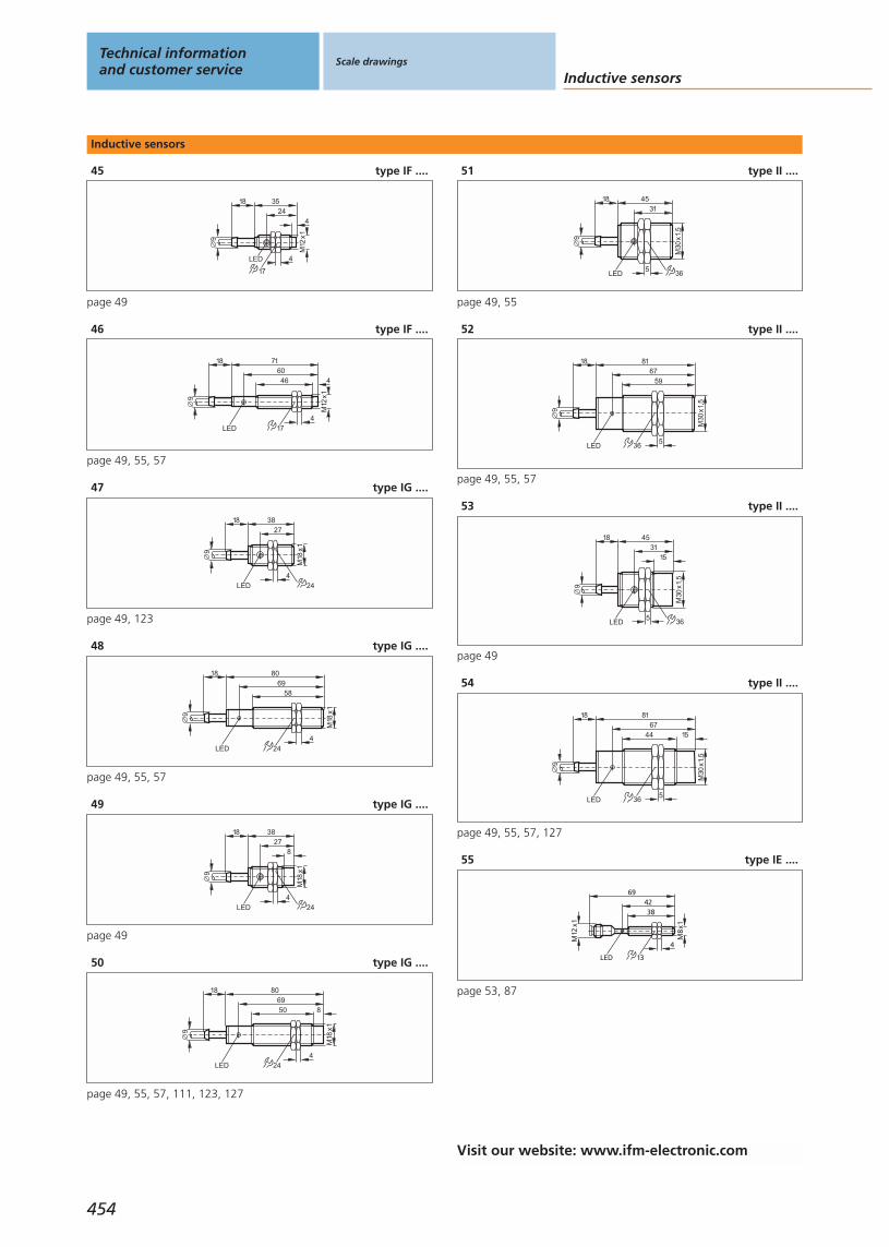
Inductive sensors
45 type IF ....
4
3524
M12
x1
4LED
17
9
18
page 49
46 type IF ....
9
18 716046
M12
x1
LED 174
4
page 49, 55, 57
47 type IG ....
3827
M18
x1
4LED 24
9
18
page 49, 123
48 type IG ....
24LED
801869
58
M18
x1
4
9
page 49, 55, 57
49 type IG ....
9
18
M18
x1
4LED 24
3827
8
page 49
50 type IG ....
24LED
80186950
M18
x1
4
9
8
page 49, 55, 57, 111, 123, 127
51 type II ....
4531
5
M30
x1,5
36LED
9
18
page 49, 55
52 type II ....
36
8167
59
5
M30
x1,5
9
18
LED
page 49, 55, 57
53 type II ....
15
4531
5
M30
x1,5
36LED
9
18
page 49
54 type II ....
8167
5
1544
36
M30
x1,5
9
18
LED
page 49, 55, 57, 127
55 type IE ....
3842
M8
x1
LED
4
13
69
M12
x1
page 53, 87
Technical informationand customer service
Scale drawings
Inductive sensors
454
Visit our website: www.ifm-electronic.com

Inductive sensors
56 type IF ....
M12
x1
7460
51
M12
x1
LED 174
83
page 53, 111, 113
57 type IF ....
83
6047
M12
x1
LED 174
4
M12
x1
74
page 53, 111, 113
58 type IG ....
24LED 4 x 90°
5957
50
M18
x1
4
M12
x1
70
page 53
59 type IG ....
24
675542
M18
x1
4LED
8
M12
x1
76
page 53
60 type II ....
36
685350
5LED
M30
x1,5
M12
x1
78
page 53
61 type II ....
15
36
6853
35
5LED
M30
x1,5
M12
x1
78
page 53, 113
62 type IE ....
36,542
50
LED
M8
x1
413
2,5
page 55
63 type IG ....
79
24
50
M18
x1
4
110
20
30
81LED
page 55
64 type IZ ....
36
LED 4 x 90°
M8
x1
4
45
22
page 59
65 type IZ ....
34
LED 4 x 90°
M8
x1
4
41
20
page 59
66 type IT ....
40
M8
x1
6,5
49
LED 4 x 90°
page 59
Scale drawings
Gen
eral
info
rmat
ion
List
of
arti
cles
Ind
uct
ive
sen
sors
Cap
acit
ive
sen
sors
Mag
net
icse
nso
rs,
cylin
der
sen
sors
Safe
tyte
chn
olo
gy
Val
ve s
enso
rsPh
oto
elec
tric
sen
sors
Ob
ject
reco
gn
itio
nEn
cod
ers
Eval
uat
ion
syst
ems,
po
wer
su
pp
lies
Co
nn
ecti
on
tech
no
log
yA
cces
sori
esTe
chn
ical
info
rmat
ion
and
cu
sto
mer
serv
ice
455
Visit our website: www.ifm-electronic.com

Inductive sensors
67 type IT ....
3022,5
LED 4 x 90°
M8
x1 6,5
page 59
68 type IT ....
3022,5
LED 4 x 90°
M8
x1 6,5
8
page 59
69 type IT ....
5034,5
LED 4 x 90°
M8
x1 6,5
8
page 59
70 type IA ....
20
9281
55
M12
x1
LED 4 x 90°
page 59
71 type IZ ....
LED
3020 4
page 59
72 type IZ ....
LED
2316 4
page 59
73 type IZ ....
LED
2717 3
page 59
74 type IZ ....
LED
2715,4 4
page 59
75 type IT ....
LED
3,5 27 6,5
page 59
76 type IT ....
LED 8
3,5
27
6,5
page 59
77 type IT ....
LED
6,5
3527
page 59
78 type IT ....
6,515
19
page 59
79 type IA ....
9
18
20
7766
55
LED
page 59, 63, 65
Technical informationand customer service
Scale drawings
Inductive sensors
456
Visit our website: www.ifm-electronic.com
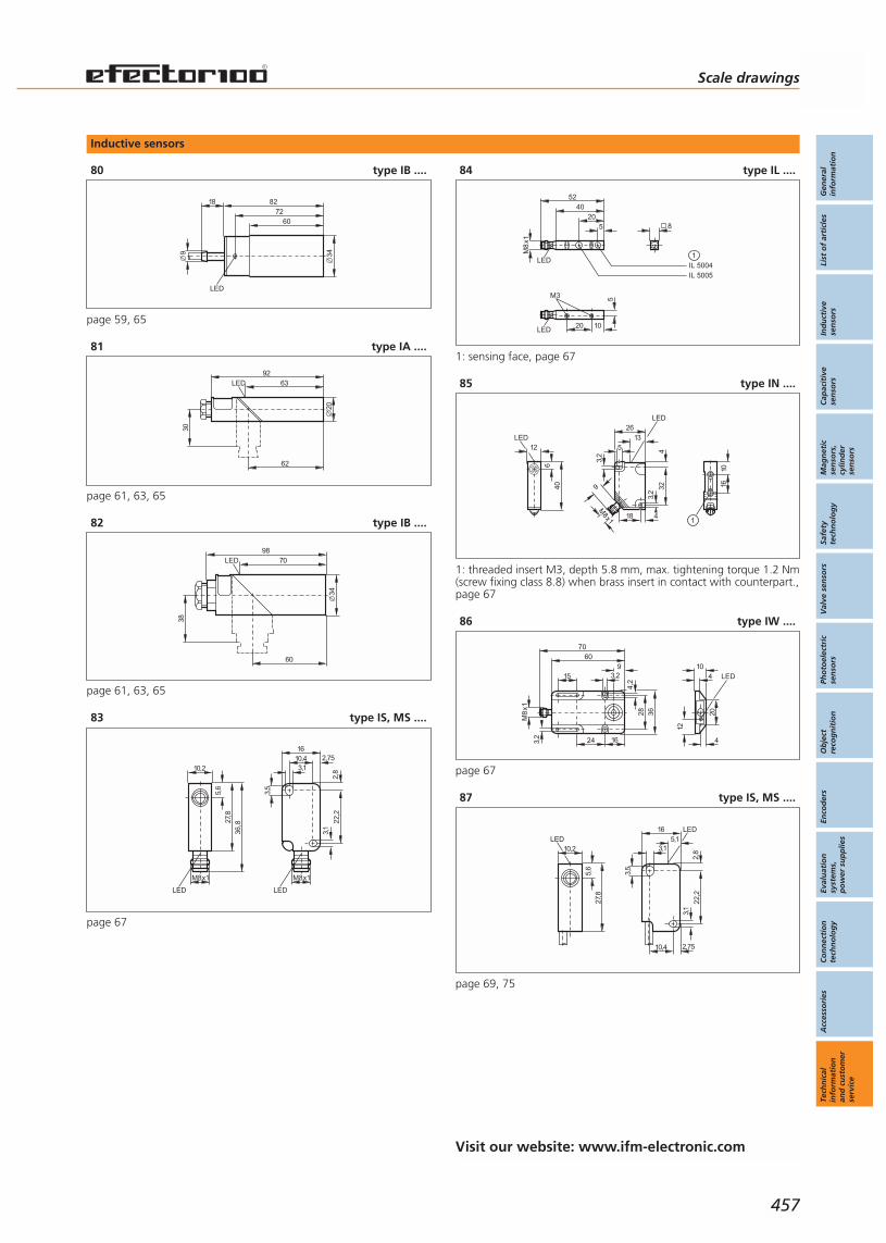
Inductive sensors
80 type IB ....9
18
LED
34
8272
60
page 59, 65
81 type IA ....
62
9263
30
LED
20
page 61, 63, 65
82 type IB ....
9870LED
34
38
60
page 61, 63, 65
83 type IS, MS ....
10,2
27,8
LED
5,6
M8x1
36,8
16
22,2
2,75
3,1
3,5
2,83,1
10,4
M8x1
LED
page 67
84 type IL ....
LED20 10
5M3
8
40
520
M8
x1
LED
52
IL 5005IL 50041
1: sensing face, page 67
85 type IN ....
4
2613
32
3,2
45
LED
3,2
18
M8x1
9406
12LED
1610
1
1: threaded insert M3, depth 5.8 mm, max. tightening torque 1.2 Nm(screw fixing class 8.8) when brass insert in contact with counterpart.,page 67
86 type IW ....
6036
163,2
28
3,2159
24
4,2
M8
x1
70
LED10
4
20
12
4
page 67
87 type IS, MS ....
10,2
27,8
LED
5,6
165,1
22,2
2,75
3,1
3,5
2,83,1
LED
10,4
page 69, 75
Scale drawings
Gen
eral
info
rmat
ion
List
of
arti
cles
Ind
uct
ive
sen
sors
Cap
acit
ive
sen
sors
Mag
net
icse
nso
rs,
cylin
der
sen
sors
Safe
tyte
chn
olo
gy
Val
ve s
enso
rsPh
oto
elec
tric
sen
sors
Ob
ject
reco
gn
itio
nEn
cod
ers
Eval
uat
ion
syst
ems,
po
wer
su
pp
lies
Co
nn
ecti
on
tech
no
log
yA
cces
sori
esTe
chn
ical
info
rmat
ion
and
cu
sto
mer
serv
ice
457
Visit our website: www.ifm-electronic.com
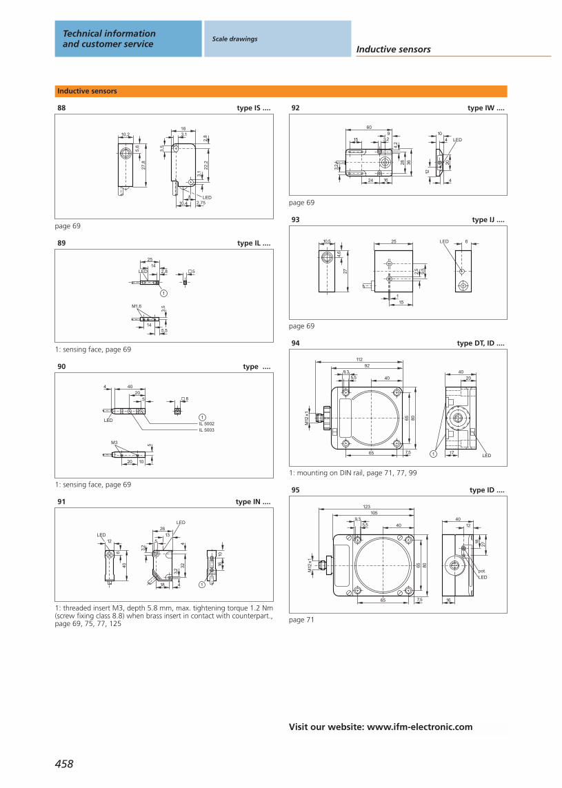
Inductive sensors
88 type IS ....
10,2
27,8
5,6
16
22,2
2,753,
1
3,5
2,83,1
LED10,4
8
page 69
89 type IL ....
5
145,5
3,5M1,6
25
2,814
LED
1
1: sensing face, page 69
90 type ....
20 10
5M3
8
LED
40
520
IL 5003
4
IL 50021
1: sensing face, page 69
91 type IN ....
406
12LED
4
2613
32
3,2
45
LED
3,2
18
1610
1
1: threaded insert M3, depth 5.8 mm, max. tightening torque 1.2 Nm(screw fixing class 8.8) when brass insert in contact with counterpart.,page 69, 75, 77, 125
92 type IW ....
LED10
4
20
12
4
60
36
16
3,2 28
3,2159
24
4,2
page 69
93 type IJ ....
10,5
274,
6
LED 625
15
9,5
1
2,5
page 69
94 type DT, ID ....
92
80
40
7,565
65
5,59,3
M12
x1
112
40
LED171
20
1: mounting on DIN rail, page 71, 77, 99
95 type ID ....
105
80
40
7,565
65
5,59,3
M12
x1
123
4012
2718
LED
pot.
16
page 71
Technical informationand customer service
Scale drawings
Inductive sensors
458
Visit our website: www.ifm-electronic.com
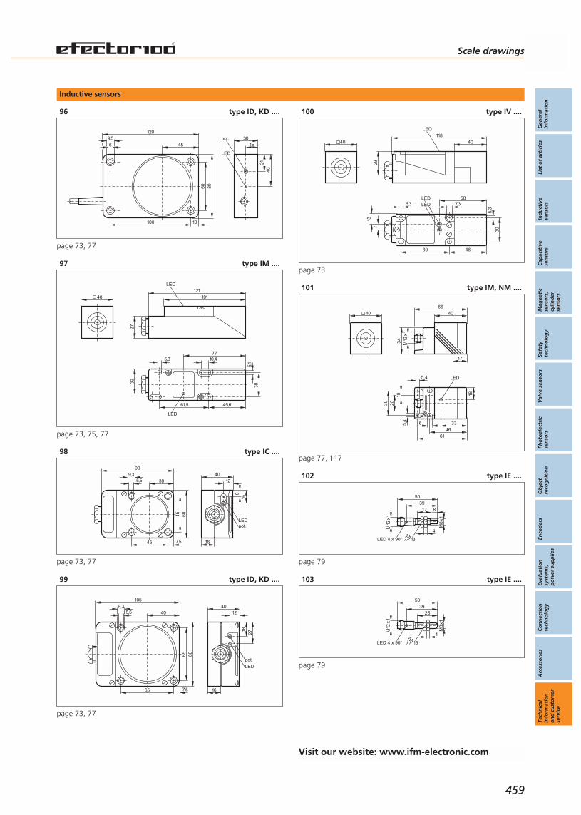
Inductive sensors
96 type ID, KD ....
120
45
8060
10100
69,5
4021
3015
pot.
LED
page 73, 77
97 type IM ....
40
10,4
45,6
LED
32
5,3
30
61,5
77
5,1
121101
LED
27
page 73, 75, 77
98 type IC ....
90
30
45
7,545
9,35,5
60
16
LEDpot.
4012
8
16
page 73, 77
99 type ID, KD ....
105
80
40
7,565
65
5,59,3 40
12
2718
LED
pot.
16
page 73, 77
100 type IV ....
7,35,3
46
LED
30
60
137
LED58
5,3
40118
LED
29
40
page 73
101 type IM, NM ....
40
M12
x1
4066
17
34
LED
4661
30 20
5,4
105,
4
6
16
33
page 77, 117
102 type IE ....
M8
x1
M12
x1
503917 8
LED 4 x 90° 13
4
page 79
103 type IE ....
M12
x1
5039
25
LED 4 x 90° 13
4
M8
x1
page 79
Scale drawings
Gen
eral
info
rmat
ion
List
of
arti
cles
Ind
uct
ive
sen
sors
Cap
acit
ive
sen
sors
Mag
net
icse
nso
rs,
cylin
der
sen
sors
Safe
tyte
chn
olo
gy
Val
ve s
enso
rsPh
oto
elec
tric
sen
sors
Ob
ject
reco
gn
itio
nEn
cod
ers
Eval
uat
ion
syst
ems,
po
wer
su
pp
lies
Co
nn
ecti
on
tech
no
log
yA
cces
sori
esTe
chn
ical
info
rmat
ion
and
cu
sto
mer
serv
ice
459
Visit our website: www.ifm-electronic.com
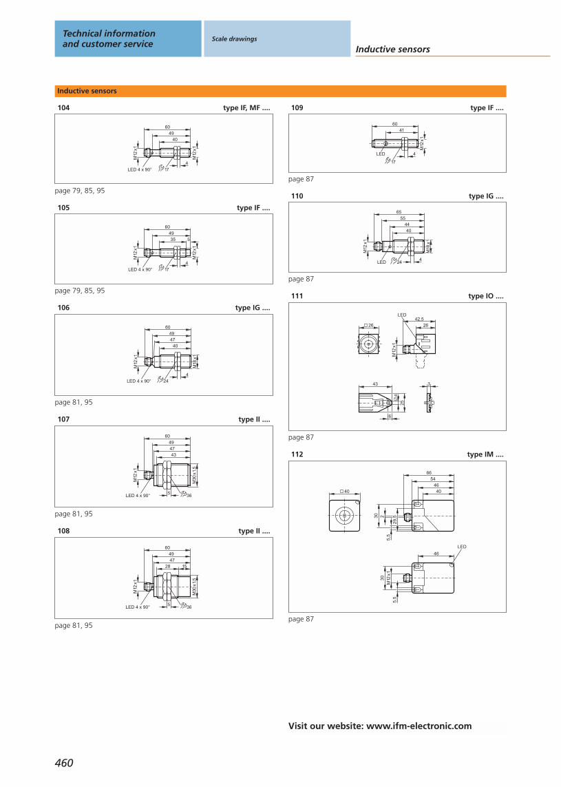
Inductive sensors
104 type IF, MF ....
4940
M12
x1
174
M12
x1
LED 4 x 90°
60
page 79, 85, 95
105 type IF ....
4935
M12
x1
174
M12
x1
LED 4 x 90°
60
5
page 79, 85, 95
106 type IG ....
M18
x1
M12
x1
4047
60
LED 4 x 90°4
24
49
page 81, 95
107 type II ....
49
43
M30
x1,5
5
47
60
M12
x1
LED 4 x 90° 36
page 81, 95
108 type II ....
49
28
M30
x1,5
5
47
60
M12
x1
LED 4 x 90°
15
36
page 81, 95
109 type IF ....
6041
M12
x1
4LED
17
page 87
110 type IG ....
55
M18
x1
4LED 24
M12
x1
4044
65
page 87
111 type IO ....
343
254
6
26
M12
x1
42,526
LED
page 87
112 type IM ....
40
66
40
54
M12
x130
30 2
46
46
5,5
5,5
LED
29,5
page 87
Technical informationand customer service
Scale drawings
Inductive sensors
460
Visit our website: www.ifm-electronic.com
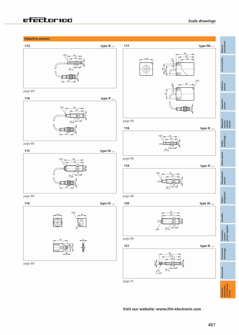
Inductive sensors
113 type IE ....
42
M12
x1
13
35
M8
x1
4
LED 42
page 89
114 type IF ....
42
M12
x1
LED40
M12
x1
417
54
page 89
115 type IG ....
42
M12
x1
5852
M18
x1
4
24
LED
page 89
116 type IO ....
343
254
6
26 26LED
page 89
117 type IM ....
40 40
54
30
46
5,5
30
46
LED
5,5
M12
x1
29,5
page 89
118 type IE ....
13
35
M8
x1
4
LED 42
page 89
119 type IF ....
LED40
M12
x1
417
54
page 89
120 type IG ....
24
5452
M18
x1
4LED
page 89
121 type IE ....
46,5
65
M8x
1
LED4 x 90°
M8x
1
4
13
57,3
page 91
Scale drawings
Gen
eral
info
rmat
ion
List
of
arti
cles
Ind
uct
ive
sen
sors
Cap
acit
ive
sen
sors
Mag
net
icse
nso
rs,
cylin
der
sen
sors
Safe
tyte
chn
olo
gy
Val
ve s
enso
rsPh
oto
elec
tric
sen
sors
Ob
ject
reco
gn
itio
nEn
cod
ers
Eval
uat
ion
syst
ems,
po
wer
su
pp
lies
Co
nn
ecti
on
tech
no
log
yA
cces
sori
esTe
chn
ical
info
rmat
ion
and
cu
sto
mer
serv
ice
461
Visit our website: www.ifm-electronic.com
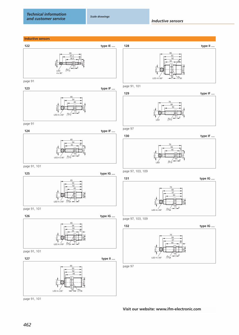
Inductive sensors
122 type IE ....
38,5
65
M8x
1
LED4 x 90°
M8x
1
4
13
57,38
page 91
123 type IF ....
5445
M12
x1
4
M12
x1
LED 4 x 90°
65
17
page 91
124 type IF ....
5442
M12
x1
M12
x1
LED 4 x 90°
65
10
174
page 91, 101
125 type IG ....
M18
x1
4LED 4 x 90° 24
M12
x1
5254
65
45
page 91, 101
126 type IG ....
10
M18
x1
4LED 4 x 90° 24
M12
x1
35
5465
52
page 91, 101
127 type II ....
53
49
M30
x1,5
5
52
65
M12
x1
LED 4 x 90° 36
page 91, 101
128 type II ....
53
34
M30
x1,5
5
52
65
M12
x1
LED 4 x 90°
15
36
page 91, 101
129 type IF ....
5950
M12
x1
174
M12
x1
LED
70
page 97
130 type IF ....
45
M12
x1
174
5
M12
x1
5970
LED
page 97, 103, 109
131 type IG ....M
18x1
M12
x1
5057
7059
424LED 4 x 90°
page 97, 103, 109
132 type IG ....
M18
x1
M12
x1
4057
70
LED 4 x 90°
59
10
424
page 97
Technical informationand customer service
Scale drawings
Inductive sensors
462
Visit our website: www.ifm-electronic.com

Inductive sensors
133 type IF ....5,
4
7962
53
M12
x1
LED 4 x 90° 174
page 97
134 type IF ....
5,4
796248
LED 4 x 90° 174
M12
x1
5
page 97
135 type IG ....
64
LED 4 x 90° 24
81
5750
M18
x1
4
page 97
136 type IG ....
64
LED 4 x 90° 24
81
5740
M18
x1
4
10
page 97
137 type II ....
36
53
M30
x1,5
57
5
5
64
LED 4 x 90°
81
page 97
138 type II ....
36
38
M30
x1,5
1557
5
5
64
LED 4 x 90°
81
page 97
139 type IF ....
4840
M12
x1
174
M12
x1
5160
LED 4 x 90°
page 99
140 type IF ....
36
M12
x1
174
4
M12
x1
4851
60
LED 4 x 90°
page 99
141 type II ....
48
40
M30
x1,5
5
46,5
60
M12
x1
36LED 4 x 90°
page 99
142 type IV ....
40118
LED
M12
x1
136
13
7,35,3
46
30
60
LED58
5,3
40
page 99
Scale drawings
Gen
eral
info
rmat
ion
List
of
arti
cles
Ind
uct
ive
sen
sors
Cap
acit
ive
sen
sors
Mag
net
icse
nso
rs,
cylin
der
sen
sors
Safe
tyte
chn
olo
gy
Val
ve s
enso
rsPh
oto
elec
tric
sen
sors
Ob
ject
reco
gn
itio
nEn
cod
ers
Eval
uat
ion
syst
ems,
po
wer
su
pp
lies
Co
nn
ecti
on
tech
no
log
yA
cces
sori
esTe
chn
ical
info
rmat
ion
and
cu
sto
mer
serv
ice
463
Visit our website: www.ifm-electronic.com

Inductive sensors
143 type IF ....
5452
M12
x1
4
M12
x1
LED 4 x 90°
65
17
page 101
144 type IM ....
40
66
40
54
M12
x130
30 2
5,5
5,5
1
2
46
46
29,5
page 101
145 type IG ....
M18
x1
M12
x1
3956
70
LED
59
10
424
page 103, 109
146 type IF ....
50
5
M12
x1
5970
LED 4 x 90°
12
47
1
1: locating groove, page 103
147 type IG ....
59
LED 4 x 90°
70
5750
10
18
37
M12
x1
1
1: locating groove, page 103
148 type IF ....
5
7962
47
LED 4 x 90°
5
12
55
1
1: locating groove, page 103, 107
149 type IG ....
5
64
LED 4 x 90°
81
5750
10
18
37
1
1: locating groove, page 103, 107
150 type IF ....
32
M12
x1
174
5
M12
x1
3950
LED 2 x 180°
page 105
151 type IF ....
3432
M12
x1
174
M12
x1
LED 2 x 180°
45
page 105
Technical informationand customer service
Scale drawings
Inductive sensors
464
Visit our website: www.ifm-electronic.com

Inductive sensors
152 type IG ....
M18
x1
M12
x125
38
5140
424
10
LED 4 x 90°
page 105, 109
153 type II ....
39
18
M30
x1,5
37
50
M12
x1
LED 4 x 90°5
15
36
page 105, 109
154 type IF ....
5037
29
M12
x1
174
LED
page 107
155 type IF ....
5
614428
M12
x1
LED 4 x 90° 174
5
page 107
156 type IG ....
57
39,5
29
33
LED4 x 90°
M18
x1
424
5
page 107
157 type IG ....
6244,5
24
LED4 x 90°
38
M18
x1
424
10
page 107
158 type II ....
16
M30
x1,5
1535
5
42
LED 4 x 90°
59
536
page 107
159 type II ....
31
M30
x1,5
355
42
LED 4 x 90°
59
365
page 107
160 type ....
5
5639
28
M12
x1
LED 4 x 90° 174
page 107
161 type IE ....
40
M8
x1
4
13
70
M12
x1
page 111
Scale drawings
Gen
eral
info
rmat
ion
List
of
arti
cles
Ind
uct
ive
sen
sors
Cap
acit
ive
sen
sors
Mag
net
icse
nso
rs,
cylin
der
sen
sors
Safe
tyte
chn
olo
gy
Val
ve s
enso
rsPh
oto
elec
tric
sen
sors
Ob
ject
reco
gn
itio
nEn
cod
ers
Eval
uat
ion
syst
ems,
po
wer
su
pp
lies
Co
nn
ecti
on
tech
no
log
yA
cces
sori
esTe
chn
ical
info
rmat
ion
and
cu
sto
mer
serv
ice
465
Visit our website: www.ifm-electronic.com
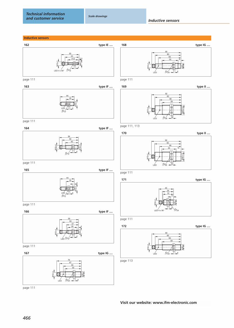
Inductive sensors
162 type IE ....
31,543
M8
x1
4
13
55
M12
x12,5
LED 4 x 90°
page 111
163 type IF ....
4425
M12
x1
4
17
LED
page 111
164 type IF ....
5040
M12
x1
174
M12
x1
59
page 111
165 type IF ....
17
4
4425
M12
x1
4LED
page 111
166 type IF ....
50
29
M12
x1
174
4
M12
x1
59
37
LED
page 111
167 type IG ....
67
24
5550
M18
x1
4LED
M12
x1
76
page 111
168 type IG ....
24
806950
M18
x1
4LED
8
M12
x1
90
page 111
169 type II ....
36
8266
59
5LED
M30
x1,5
M12
x1
92
page 111, 113
170 type II ....
36
8266
44
5LED
M30
x1,5
M12
x1
92
15
page 111
171 type IG ....
45
M12
x1
M18
x1
4
3234
8
24LED 4 x 90°
page 111
172 type IG ....
24
8069
58
M18
x1
4LED
M12
x1
90
page 113
Technical informationand customer service
Scale drawings
Inductive sensors
466
Visit our website: www.ifm-electronic.com
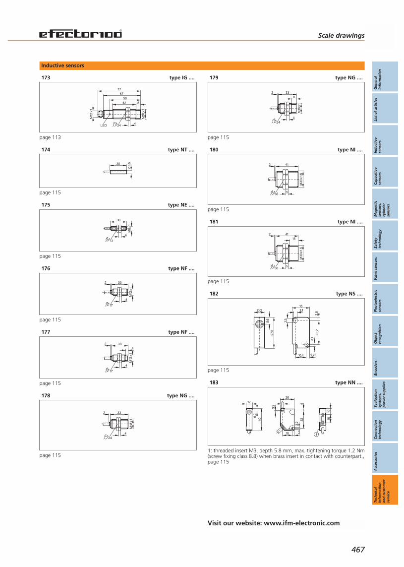
Inductive sensors
173 type IG ....
24
675642
M18
x1
4LED
8
M12
x177
page 113
174 type NT ....
6,530
page 115
175 type NE ....
30
M8
x1
4
13
page 115
176 type NF ....
30
M12
x1
4
2
17
page 115
177 type NF ....
430
M12
x1
4
2
17
page 115
178 type NG ....
33
M18
x1
4
2
24
page 115
179 type NG ....
M18
x1
4
2 338
24
page 115
180 type NI ....
2 41
5
M30
x1,5
36
page 115
181 type NI ....
2 41
5
M30
x1,5
15
36
page 115
182 type NS ....
10,2
27,8
5,6
16
22,2
2,75
3,1
3,5
2,83,1
10,4
page 115
183 type NN ....
1610
4
26
32
3,2
45
3,2
18
40
6,2
12
1
1: threaded insert M3, depth 5.8 mm, max. tightening torque 1.2 Nm(screw fixing class 8.8) when brass insert in contact with counterpart.,page 115
Scale drawings
Gen
eral
info
rmat
ion
List
of
arti
cles
Ind
uct
ive
sen
sors
Cap
acit
ive
sen
sors
Mag
net
icse
nso
rs,
cylin
der
sen
sors
Safe
tyte
chn
olo
gy
Val
ve s
enso
rsPh
oto
elec
tric
sen
sors
Ob
ject
reco
gn
itio
nEn
cod
ers
Eval
uat
ion
syst
ems,
po
wer
su
pp
lies
Co
nn
ecti
on
tech
no
log
yA
cces
sori
esTe
chn
ical
info
rmat
ion
and
cu
sto
mer
serv
ice
467
Visit our website: www.ifm-electronic.com

Inductive sensors
184 type ID ....
105
80
40
7,565
65
5,59,3
24
4012
2718
LED
pot.
16
page 121, 125, 127
185 type IG ....
M18
x1
M12
x1
2433
45
4
8
LED 4 x 90° 24
page 123
186 type IG ....
M18
x1
M12
x1
3233
45
424LED 4 x 90°
page 123
187 type IG ....
24
796950
M18
x1
4LED
8
M12
x1
89
page 123
188 type IN, NN ....
40
2613
9LED
A1
A2 6,5
LED
8,54 26
4,5
5,5
30
page 125
189 type GM, IM ....
40
M12
x1
4066
17
34
LED
4661
30 20
5,4
105,
4
6
8,5
33
page 125
190 type IM ....
10,4
45,6
LED
32
5,3
30
61,5
77
5,1
24
121101
LED
27
40
page 125, 127
191 type IC ....16
LEDpot.
4012
8
1624
90
30
45
7,545
9,35,5
60
page 125, 127
Technical informationand customer service
Scale drawings
Inductive sensors
468
Visit our website: www.ifm-electronic.com
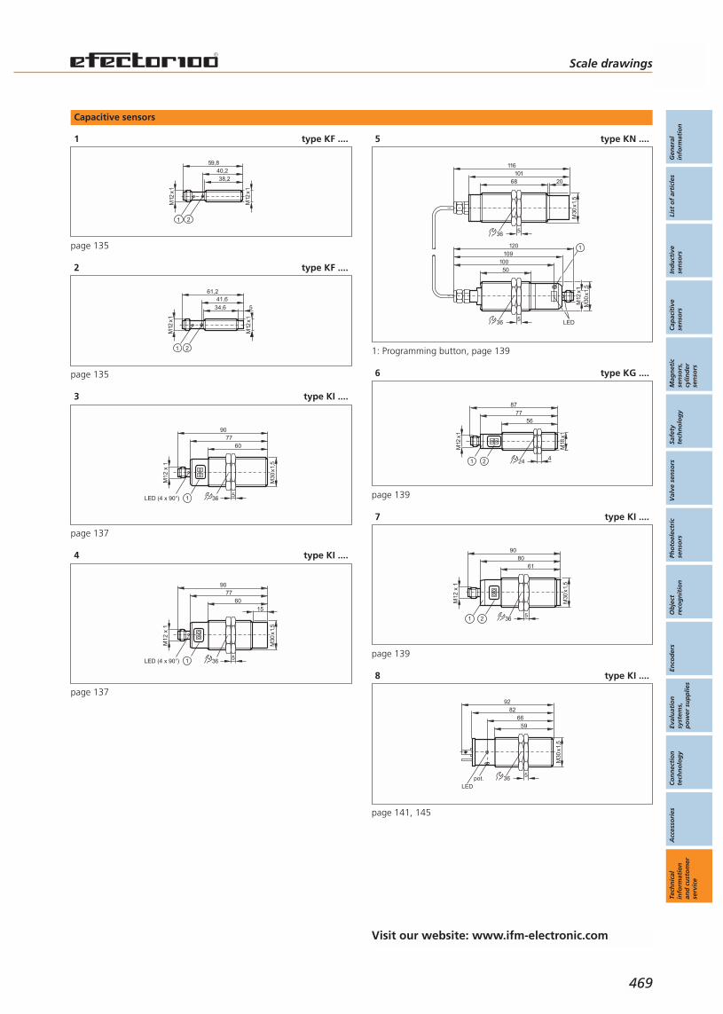
Capacitive sensors
1 type KF ....
40,238,2
M12
x1
M12
x159,8
1 2
page 135
2 type KF ....
34,6
M12
x1
5
M12
x1
41,661,2
1 2
page 135
3 type KI ....
60
M30
x1,5
7790
LED (4 x 90°) 5
M12
x 1
361
page 137
4 type KI ....
60
M30
x1,5
7790
LED (4 x 90°) 5
M12
x 1
361
15
page 137
5 type KN ....
116
5
68 20
36
M30
x1,5
101
109
5
50
36
M30
x1,5
M12
x1
LED
120
100
1
1: Programming button, page 139
6 type KG ....
24
7756
M18
x1
4M
12x1
87
1 2
page 139
7 type KI ....
61M
30x1
,580
90
5
M12
x 1
3621
page 139
8 type KI ....
LED36
66
5
59
M30
x1,5
92
pot.
82
page 141, 145
Visit our website: www.ifm-electronic.com
Scale drawings
Gen
eral
info
rmat
ion
List
of
arti
cles
Ind
uct
ive
sen
sors
Cap
acit
ive
sen
sors
Mag
net
icse
nso
rs,
cylin
der
sen
sors
Safe
tyte
chn
olo
gy
Val
ve s
enso
rsPh
oto
elec
tric
sen
sors
Ob
ject
reco
gn
itio
nEn
cod
ers
Eval
uat
ion
syst
ems,
po
wer
su
pp
lies
Co
nn
ecti
on
tech
no
log
yA
cces
sori
esTe
chn
ical
info
rmat
ion
and
cu
sto
mer
serv
ice
469
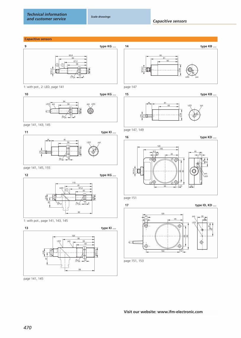
Capacitive sensors
9 type KG ....
1
24
58
4
84
M18
x1
93,8
67,2
M12
x1
2
1: with pot., 2: LED, page 141
10 type KG ....
24
58
4
84
M18
x1
pot.LED LEDpot.
page 141, 143, 145
11 type KI ....
36
8159
5
M30
x1,5
9
18pot.LED
page 141, 145, 155
12 type KG ....
80
24
67,250
M18
x1
4
110
20
30
81LED
17
1
1: with pot., page 141, 143, 145
13 type KI ....
36
6454
5
M30
x1,5
95125
3725
88
LED pot.
page 141, 145
14 type KB ....
34
8160
M12
x1
93
LED pot.
page 147
15 type KB ....
9
18
34
8160 LED pot.
page 147, 149
16 type KD ....
105
80
40
7,565
65
5,59,3
M12
x1
120
40
12
27
18
LED
pot.
16
page 151
17 type ID, KD ....
120
45
8060
10100
69,5
4021
3015
pot.
LED
page 151, 153
Technical informationand customer service
Scale drawings
Capacitive sensors
470
Visit our website: www.ifm-electronic.com
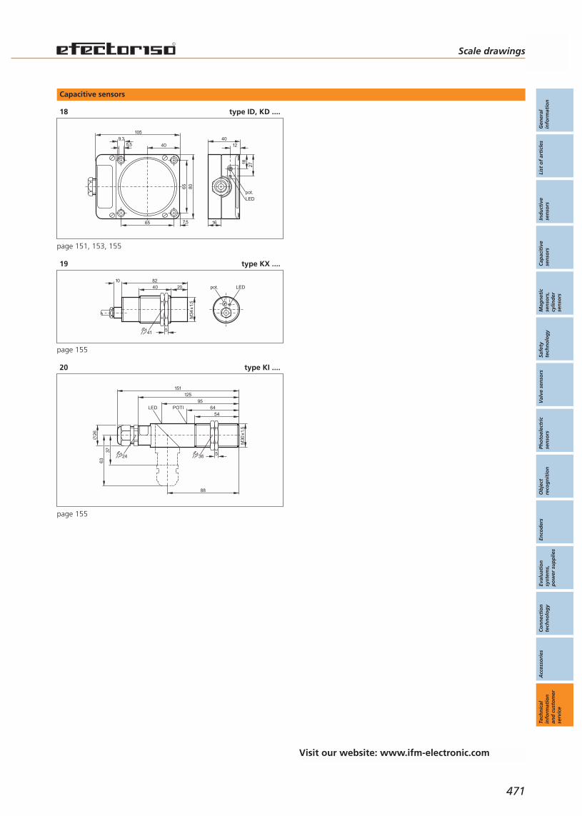
Capacitive sensors
18 type ID, KD ....
105
80
40
7,565
65
5,59,3 40
12
2718
LED
pot.
16
page 151, 153, 155
19 type KX ....
822040
M34
x1,5
10
541
LEDpot.
page 155
20 type KI ....
36
6454
5
M30
x1,5
95125
37
88
LED POTI
26
151
63
24
page 155
Scale drawings
Gen
eral
info
rmat
ion
List
of
arti
cles
Ind
uct
ive
sen
sors
Cap
acit
ive
sen
sors
Mag
net
icse
nso
rs,
cylin
der
sen
sors
Safe
tyte
chn
olo
gy
Val
ve s
enso
rsPh
oto
elec
tric
sen
sors
Ob
ject
reco
gn
itio
nEn
cod
ers
Eval
uat
ion
syst
ems,
po
wer
su
pp
lies
Co
nn
ecti
on
tech
no
log
yA
cces
sori
esTe
chn
ical
info
rmat
ion
and
cu
sto
mer
serv
ice
471
Visit our website: www.ifm-electronic.com

Magnetic sensors
1 type ME ....
4552
M8
x1
4
13
M8
x1
LED 4 x 90°
60
page 163
2 type ME ....
4050
M8
x1
4
13LED
page 163
3 type MF ....
5029
M12
x1
4LED
17
page 163
4 type IF, MF ....
4940
M12
x1
174
M12
x1
LED 4 x 90°
60
page 163, 165
5 type IG, MG ....
24
4947
40
M18
x1
4
M12
x1
60
LED 4 x 90°
page 163, 165
6 type MG ....
24
504340
M18
x1
2LED
4
page 163
7 type IS, MS ....
10,2
27,8
LED
5,6
M8x1
36,8
16
22,2
2,75
3,1
3,5
2,83,1
10,4
M8x1
LED
page 163
8 type IS, MS ....
10,2
27,8
LED
5,6
165,1
22,2
2,75
3,1
3,5
2,83,1
LED
10,4
page 163
Technical informationand customer service
Scale drawings Magnetic sensors,cylinder sensors
472
Visit our website: www.ifm-electronic.com

Scale drawings
Gen
eral
info
rmat
ion
List
of
arti
cles
Ind
uct
ive
sen
sors
Cap
acit
ive
sen
sors
Mag
net
icse
nso
rs,
cylin
der
sen
sors
Safe
tyte
chn
olo
gy
Val
ve s
enso
rsPh
oto
elec
tric
sen
sors
Ob
ject
reco
gn
itio
nEn
cod
ers
Eval
uat
ion
syst
ems,
po
wer
su
pp
lies
Co
nn
ecti
on
tech
no
log
yA
cces
sori
esTe
chn
ical
info
rmat
ion
and
cu
sto
mer
serv
ice
473
Cylinder sensors
1 type MK ....
L
25
5
LED
2
1
M8
x1
376,5
5,1
1: Fastening clamp, 2: sensing face, page 175, 177
2 type MK ....
M8
x1
L
6,5
5,1
25
5
LED
2
141,5
1: Fastening clamp, 2: sensing face, page 175, 177
3 type MK ....
L
M12
x1
25
5
LED
2
155
6,5
5,1
1: Fastening clamp, 2: sensing face, page 175, 177
4 type MK ....
6,5
5,1
25
5
LED
2
1
1: Fastening clamp, 2: sensing face, page 175, 177, 185
5 type MK ....
L
M12
x1
25
5
LED
2
155
6,5
5,1
1: Fastening clamp, 2: sensing face, page 177, 185
6 type MK ....
17,5
7,7
2,84,8
1
4,2LED
2
1: Fastening clamp, 2: sensing face, page 183
7 type MK ....
LED
2,84,8
1
25,8
5
6,5
2
1: Fastening clamp, 2: sensing face, page 183
8 type MK ....
M8
x1
L
37
17,5
7,7
LED
2,84,8
1 2
4,2
1: Fastening clamp, 2: sensing face, page 183
9 type MK ....
M8
x1
L
37LED
2,84,8
1
25,8
5
6,5
2
1: Fastening clamp, 2: sensing face, page 183
10 type MK ....
L
M8
x1
41,5
17,5
7,7
LED
2,84,8
1 2
4,2
1: Fastening clamp, 2: sensing face, page 183
Visit our website: www.ifm-electronic.com

Cylinder sensors
11 type MK ....
L
M8
x1
41,5LED
2,84,8
1
25,8
5
6,5
2
1: Fastening clamp, 2: sensing face, page 183
12 type MK ....
L
M12
x1
55
17,5
7,7
LED
2,84,8
1 2
4,2
page 183
13 type MK ....
L
M12
x1
LED
2,84,8
1
25,8
5
6,5
2
40
1: Fastening clamp, 2: sensing face, page 183
Technical informationand customer service
Scale drawings Magnetic sensors,cylinder sensors
474
Visit our website: www.ifm-electronic.com

Scale drawings
Gen
eral
info
rmat
ion
List
of
arti
cles
Ind
uct
ive
sen
sors
Cap
acit
ive
sen
sors
Mag
net
icse
nso
rs,
cylin
der
sen
sors
Safe
tyte
chn
olo
gy
Val
ve s
enso
rsPh
oto
elec
tric
sen
sors
Ob
ject
reco
gn
itio
nEn
cod
ers
Eval
uat
ion
syst
ems,
po
wer
su
pp
lies
Co
nn
ecti
on
tech
no
log
yA
cces
sori
esTe
chn
ical
info
rmat
ion
and
cu
sto
mer
serv
ice
475
Fail-safe inductive sensors
1 type GM, IM ....
40
M12
x1
4066
17
34
LED
4661
30 20
5,4
105,
4
6
8,5
33
page 195
2 type GG ....
M18
x1
55 10
M12
x1
90,5
LED 8 x 45°
79
424
page 195
3 type GI ....
LED 4 x 90°
69
39
M30
x1,5
5
67
80
36
M12
x1
15
page 195
Visit our website: www.ifm-electronic.com
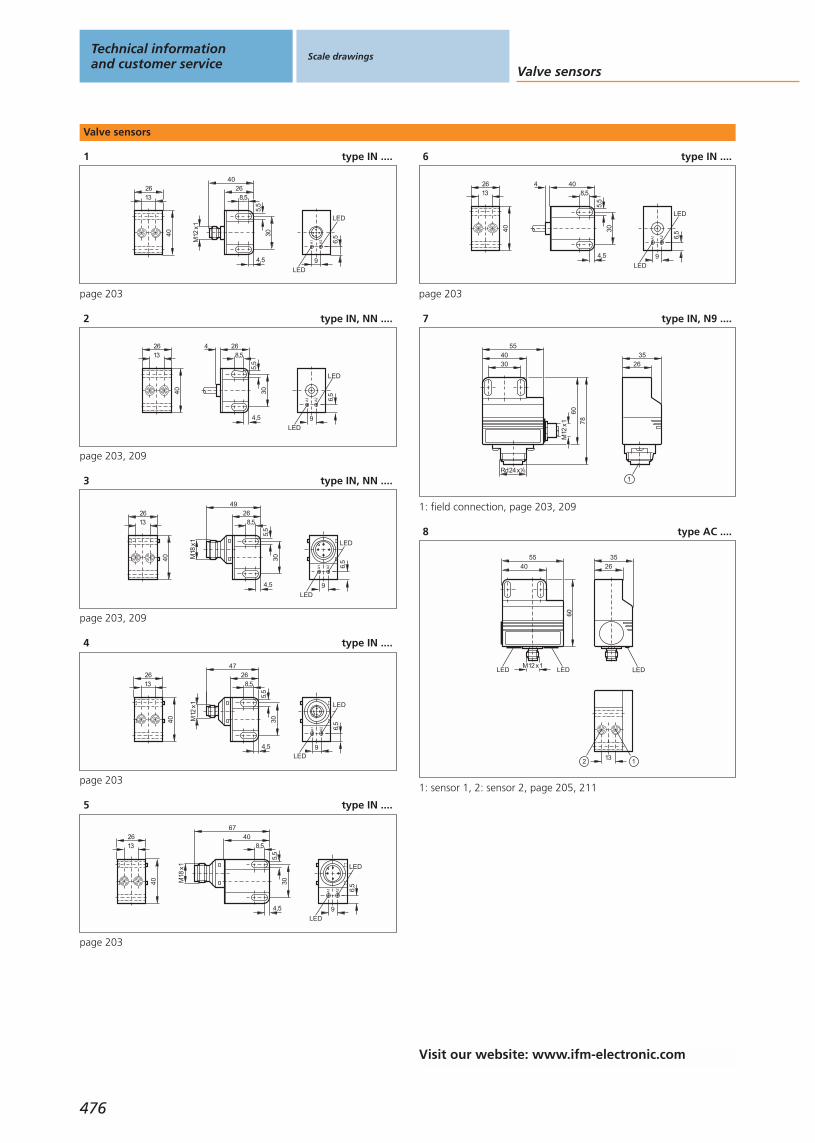
Valve sensors
1 type IN ....40
2613
M12
x18,5
26
4,55,
5
30
40
9LED
A1
A2 6,5
LED
page 203
2 type IN, NN ....
40
2613
9LED
A1
A2 6,5
LED
8,54 26
4,5
5,5
30
page 203, 209
3 type IN, NN ....
40
2613
9LED
A1
A2 6,5
LED
8,526
4,5
5,5
30
49
M18
x1
page 203, 209
4 type IN ....
40
2613
9LED
A1
A2 6,5
LED
8,526
4,5
5,5
30
47
M12
x1
page 203
5 type IN ....
40
2613
9LED
A1
A2 6,5
LED
8,540
4,5
5,5
30M18
x1
67
page 203
6 type IN ....
40
2613
9LED
A1
A2 6,5
LED
8,54 40
4,5
5,5
30
page 203
7 type IN, N9 ....
M12
x1
4055
60
Rd24x1 8
78
30 2635
1
1: field connection, page 203, 209
8 type AC ....
2635
LEDM12 x1
4055
LEDLED
60
1312
1: sensor 1, 2: sensor 2, page 205, 211
Technical informationand customer service
Scale drawings
Valve sensors
476
Visit our website: www.ifm-electronic.com
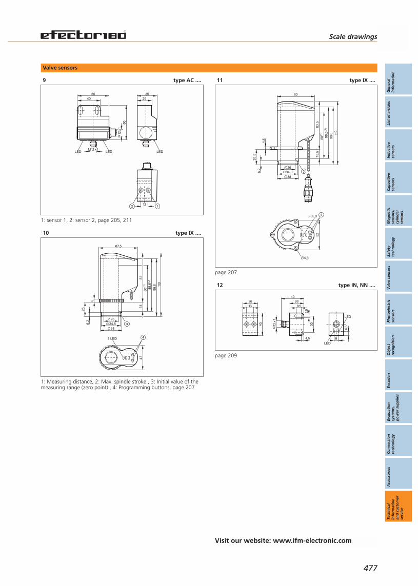
Valve sensors
9 type AC ....
2635
LEDM12 x1
M12
x1
4055
LEDLED
60
1312
1: sensor 1, 2: sensor 2, page 205, 211
10 type IX ....
43
3 LED 4
67,5
85
110
99,6
26
80 88,6
34,838
6,2
6
25
14
3
(1)
(2)
1: Measuring distance, 2: Max. spindle stroke , 3: Initial value of themeasuring range (zero point) , 4: Programming buttons, page 207
11 type IX ....
52
3 LED 4
65
83,5
110
99,6
26
80 88,6
34,838
6,2
4,5
26,5 15
,5(1
)
(2)
3
4,3
page 207
12 type IN, NN ....
40
2613
9LED
A1
A2 6,5
LED
M12
x1
8,526
4,5
5,5
30
40
page 209
Scale drawings
Gen
eral
info
rmat
ion
List
of
arti
cles
Ind
uct
ive
sen
sors
Cap
acit
ive
sen
sors
Mag
net
icse
nso
rs,
cylin
der
sen
sors
Safe
tyte
chn
olo
gy
Val
ve s
enso
rsPh
oto
elec
tric
sen
sors
Ob
ject
reco
gn
itio
nEn
cod
ers
Eval
uat
ion
syst
ems,
po
wer
su
pp
lies
Co
nn
ecti
on
tech
no
log
yA
cces
sori
esTe
chn
ical
info
rmat
ion
and
cu
sto
mer
serv
ice
477
Visit our website: www.ifm-electronic.com

Valve sensors
13 type AC ....
M12
x1
M12 x1
4055
LED
LED
60
132
105
30
42
M5
page 211
Technical informationand customer service
Scale drawings
Valve sensors
478
Visit our website: www.ifm-electronic.com

Scale drawings
Gen
eral
info
rmat
ion
List
of
arti
cles
Ind
uct
ive
sen
sors
Cap
acit
ive
sen
sors
Mag
net
icse
nso
rs,
cylin
der
sen
sors
Safe
tyte
chn
olo
gy
Val
ve s
enso
rsPh
oto
elec
tric
sen
sors
Ob
ject
reco
gn
itio
nEn
cod
ers
Eval
uat
ion
syst
ems,
po
wer
su
pp
lies
Co
nn
ecti
on
tech
no
log
yA
cces
sori
esTe
chn
ical
info
rmat
ion
and
cu
sto
mer
serv
ice
479
Infrared / Red light sensors
1 type OF ....
5540
M12
x1
174
52 LED
page 223
2 type OF ....
M12
x1
745554
M12
x1
3 LED 174
85
pot.
17
page 225, 227
3 type OG ....
M18
x1
M12
x1
4047
6049
LED 4 x 90°
4
24
page 229
4 type OG ....
M18
x1
M12
x1
44
59
7261
LED 4 x 90°
50
1
4
24
1: with pot., page 229
5 type OG ....
M18
x1
M12
x1
3459
7261
LED 4 x 90°4
24
page 231
6 type OG ....
M18
x1
M12
x1
3459
7261
LED 4 x 90°
1
4
24
1: Programming buttons, page 231
7 type OG ....
14,5
24
M18 x1
M12 x1
70,159
,334
416
LED 4 x 90°
8,2
page 233
8 type OG ....
M18 x1
M12 x1
7665
29
419
9,7
27
LED 4 x 90°
13,6
24
page 233
9 type OG ....
766453
M18
x1
4
5,2
86
24
LED
"20U
NF
21
1
1: push button, page 235
10 type OG ....
766453
M18
x1
4
5,2
78,5
24
LED
1
1: push button, page 237
Visit our website: www.ifm-electronic.com
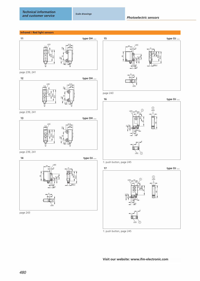
Infrared / Red light sensors
11 type OH ....
3,9 9,6
12,5
3,2 15
2,9
7,66,
420
,625
,1
LED
page 239, 241
12 type OH ....
3,9 9,6
12,5
3,2 15
2,9
7,6
6,4
20,6
25,15,
7
LED
page 239, 241
13 type OH ....
3,9 9,6
12,5
3,2 15
2,9
7,6
7,2
20,6
25,15
LED
page 239, 241
14 type OJ ....
24LED
35
8,5
1,8 5,
3 19
3,5
5
M8x1
36,5
11
8,2
43,5
9
LED
4
11,6
page 243
15 type OJ ....
9
LED
4
11,6
19,5
M8x1
36,5
11
43,5
9,5
24LED
35
8,5
1,8 5,
3 19
3,5
5
page 243
16 type OJ ....
45
11
LED
1
4
LED
4
1
24
8,2
12
35
8,8
3,2
3,1
3,1
LED
M8x1
1
1: push button, page 245
17 type OJ ....
45
11
LED
1
3,1
24
7,6
16,6
12
35
8,8
3,2
3,1
LED
M8x1
1
4
LED
4
1
1: push button, page 245
Technical informationand customer service
Scale drawings
Photoelectric sensors
480
Visit our website: www.ifm-electronic.com

Infrared / Red light sensors
18 type OJ ....
45
11
LED
1
24
9,5
19,5
12
35
8,8
3,2
3,1
3,1
LED
M8x1
1
LED
44
1
1: push button, page 245
19 type OJ ....
45
11
LED
1
24
7,6
16,6
12
35
8,8
3,2
3,1
3,1
LED 1
4
LED
4
1
1: push button, page 245, 247
20 type OJ ....
45
11
LED
1
2412
8,8
3,2
3,1
3,1
LED
8,2
35
1
4
LED
4
1
1: push button, page 247
21 type OJ ....
48
M12
x1
45
11
LED
1
LED
44
1
24
9,5
19,5
12
35
8,8
3,2
3,1
3,1
LED
2
3
1
1: push button, 2: Receiver, 3: Transmitter, page 247
22 type OJ ....
1LED
44
11,6
1
36,5
11
LED
43,5
M8x1
19
12412
LED
8,2
35
3,58,5
5
1,85,3
1: push button, page 249
23 type OJ ....
1LED
44
11,6
M8x1
1
36,5
11
LED
43,519
12412
LED
3,58,5
5
1,85,3 7,
6 16,6
35
1: push button, page 249
Scale drawings
Gen
eral
info
rmat
ion
List
of
arti
cles
Ind
uct
ive
sen
sors
Cap
acit
ive
sen
sors
Mag
net
icse
nso
rs,
cylin
der
sen
sors
Safe
tyte
chn
olo
gy
Val
ve s
enso
rsPh
oto
elec
tric
sen
sors
Ob
ject
reco
gn
itio
nEn
cod
ers
Eval
uat
ion
syst
ems,
po
wer
su
pp
lies
Co
nn
ecti
on
tech
no
log
yA
cces
sori
esTe
chn
ical
info
rmat
ion
and
cu
sto
mer
serv
ice
481
Visit our website: www.ifm-electronic.com

Infrared / Red light sensors
24 type OJ ....
M8x1
1
36,5
11
LED
43,5
1LED
44
11,6
19
12412
LED
3,58,5
5
1,85,3
9,5
3519
,5
1: push button, page 249
25 type OJ ....
45
11
LED
8,2
1
24
3,2
3,1
LED
35
M8x1
8,83,1
1
9
LED
4
1
1: push button, page 251
26 type OJ ....
11
LED
7,6
16,6
45
1
24
3,2
3,1
LED
35
M8x1
8,83,1
1
9
LED
4
1
1: push button, page 251
27 type OJ ....
11
LED
45
9,5
19,5
1
9
LED
4
1
24
3,2
3,1
LED
35
M8x1
8,83,1
1
1: push button, page 251
28 type OJ ....
1
9
LED
4
11,6
M8x1
1
36,5
11
LED
8,2
43,5
1
24LED
35
8,5
1,8 5,
3 19
3,5
5
1: push button, page 253
29 type OJ ....
9
LED
4
11,6
1
24LED
35
8,5
1,8 5,
3 19
3,5
5
1
M8x1
36,5
11
LED
43,57,
6 16,6
1
1: push button, page 253
Technical informationand customer service
Scale drawings
Photoelectric sensors
482
Visit our website: www.ifm-electronic.com
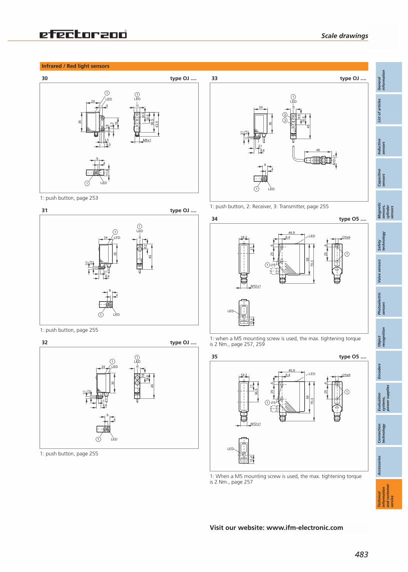
Infrared / Red light sensors
30 type OJ ....
24LED
35
8,5
1,8 5,
3 19
3,5
5
1
9
LED
4
11,6
1
19,5
M8x1
36,5
11
LED
43,5
1
9,5
1: push button, page 253
31 type OJ ....
45
11
LED
8,2
1
9
LED
4
1
24
8,8
3,2
3,1
3,1
LED
35
1
1: push button, page 255
32 type OJ ....
11
LED
7,6
16,6
45
1
9
LED
4
1
24
8,8
3,2
3,1
3,1
LED
35
1
1: push button, page 255
33 type OJ ....
24
3,2
3,1
35
8,83,1
9
LED
4
1
1
48
M12
x1
11
LED
45
9,5
19,5
2
3
1: push button, 2: Receiver, 3: Transmitter, page 255
34 type O5 ....
LED
15,4
18,2
M12 x1
17
5x9
625 1
56
6,446,8
25
70,3
5
LED
6
1
1: when a M5 mounting screw is used, the max. tightening torque is 2 Nm., page 257, 259
35 type O5 ....
18,2
M12 x1
1736
,5
LED
15,4
5x9
625 1
56
6,446,8
25
70,3
5
LED
6
1
1: When a M5 mounting screw is used, the max. tightening torque is 2 Nm., page 257
Scale drawings
Gen
eral
info
rmat
ion
List
of
arti
cles
Ind
uct
ive
sen
sors
Cap
acit
ive
sen
sors
Mag
net
icse
nso
rs,
cylin
der
sen
sors
Safe
tyte
chn
olo
gy
Val
ve s
enso
rsPh
oto
elec
tric
sen
sors
Ob
ject
reco
gn
itio
nEn
cod
ers
Eval
uat
ion
syst
ems,
po
wer
su
pp
lies
Co
nn
ecti
on
tech
no
log
yA
cces
sori
esTe
chn
ical
info
rmat
ion
and
cu
sto
mer
serv
ice
483
Visit our website: www.ifm-electronic.com
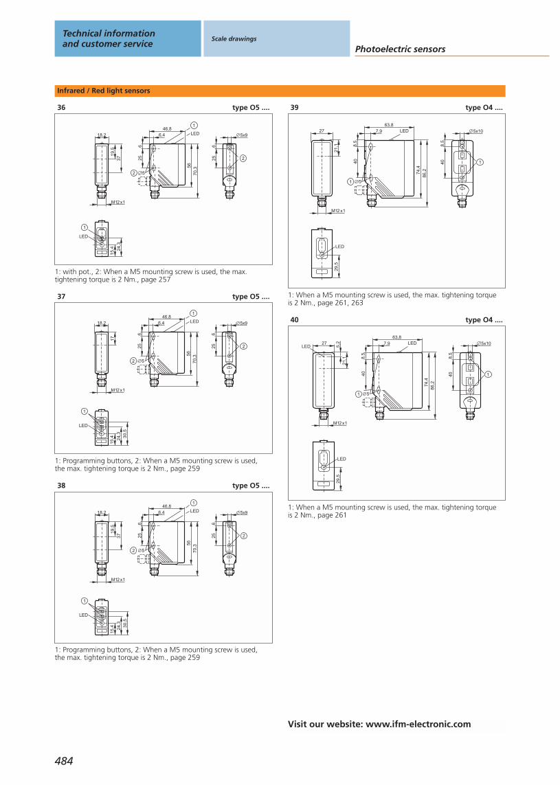
Infrared / Red light sensors
36 type O5 ....
1
38
10
1
LED
24,3
15,4
18,2
M12 x1
19,5
37
5x9
625 2
56
6,446,8
25
70,3
5
1
LED6
2
1: with pot., 2: When a M5 mounting screw is used, the max. tightening torque is 2 Nm., page 257
37 type O5 ....
1
LED
30,5
24,3
15,4
5x9
625 2
56
6,446,8
25
70,3
5
1
LED
6
2
18,2
M12 x1
17
1: Programming buttons, 2: When a M5 mounting screw is used, the max. tightening torque is 2 Nm., page 259
38 type O5 ....
18,2
M12 x1
19,5
37
1
LED
30,5
24,3
15,4
56
6,446,8
25
70,3
5
1
LED
6
2
5x9
625 2
1: Programming buttons, 2: When a M5 mounting screw is used, the max. tightening torque is 2 Nm., page 259
39 type O4 ....
7,963,8
LED
40
5
8,5
74,4
86,2
1
8,5
40
5x10
1
M12 x1
27
21,1
LED
29,5
1: When a M5 mounting screw is used, the max. tightening torque is 2 Nm., page 261, 263
40 type O4 ....
7,963,8
LED
40
5
8,5
74,4
86,2
1
8,5
40
5x10
1
LED
29,5
M12 x1
27
5,2
21,1
LED
1: When a M5 mounting screw is used, the max. tightening torque is 2 Nm., page 261
Technical informationand customer service
Scale drawings
Photoelectric sensors
484
Visit our website: www.ifm-electronic.com

Infrared / Red light sensors
41 type O4 ....
7,963,8
LED
40
5
8,5
74,4
86,2
1
8,5
40
5x10
1
M12 x1
27
21,1
50,9
LED
29,5
1: When a M5 mounting screw is used, the max. tightening torque is 2 Nm., page 261
42 type O4 ....
7,963,8 LED
40
5
8,5
74,4
86,2
2
1
8,5
40
5x10
2
M12 x1
27
25,3
54,8
LED
29,5
1
38
10
38,6
1
1: with pot., 2: When a M5 mounting screw is used, the max. tightening torque is 2 Nm., page 261
43 type O4 ....
7,963,8
LED
40
5
8,5
74,4
86,2
1
8,5
40
5x10
1
M12 x1
27
5,2
21,1
LED
29,5 44
,538
,3
2
LED
page 263
Scale drawings
Gen
eral
info
rmat
ion
List
of
arti
cles
Ind
uct
ive
sen
sors
Cap
acit
ive
sen
sors
Mag
net
icse
nso
rs,
cylin
der
sen
sors
Safe
tyte
chn
olo
gy
Val
ve s
enso
rsPh
oto
elec
tric
sen
sors
Ob
ject
reco
gn
itio
nEn
cod
ers
Eval
uat
ion
syst
ems,
po
wer
su
pp
lies
Co
nn
ecti
on
tech
no
log
yA
cces
sori
esTe
chn
ical
info
rmat
ion
and
cu
sto
mer
serv
ice
485
Visit our website: www.ifm-electronic.com
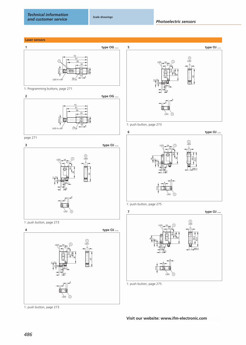
Laser sensors
1 type OG ....
M18
x1
M12
x1
3459
7261
LED 4 x 90°
1
4
24
1: Programming buttons, page 271
2 type OG ....
M18
x1
M12
x1
3459
7261
LED 4 x 90°4
24
page 271
3 type OJ ....
45
11
LED
1
4
LED
4
1
24
8,2
12
35
8,8
3,2
3,1
3,1
LED
M8x1
1
1: push button, page 273
4 type OJ ....
45
11
LED
1
LED
44
1
24
9,5
15,5
12
35
8,8
3,2
3,1
3,1
LED
M8x1
1
1: push button, page 273
5 type OJ ....
45
11
LED
1
24
9,5
19,5
12
35
8,8
3,2
3,1
3,1
LED
M8x1
1
LED
44
1
1: push button, page 273
6 type OJ ....
1LED
44
11,6
1
36,5
11
LED
43,5
M8x1
19
12412
LED
8,2
35
3,58,5
5
1,85,3
1: push button, page 275
7 type OJ ....
M8x1
1
36,5
11
LED
43,5
1LED
44
11,6
19
12412
LED
3,58,5
5
1,85,3
9,5
3519
,5
1: push button, page 275
Technical informationand customer service
Scale drawings
Photoelectric sensors
486
Visit our website: www.ifm-electronic.com

Laser sensors
8 type OJ ....
45
11
LED
8,2
1
24
3,2
3,1
LED
35
M8x1
8,83,1
1
9
LED
4
1
1: push button, page 277
9 type OJ ....
11
LED
45
9,5
15,5
1
24
3,2
3,1
LED
35
M8x1
8,83,1
1
9
LED
4
1
1: push button, page 277
10 type OJ ....
11
LED
45
9,5
19,5
1
9
LED
4
1
24
3,2
3,1
LED
35
M8x1
8,83,1
1
1: push button, page 277
11 type OJ ....
1
9
LED
4
11,6
M8x1
1
36,5
11
LED
8,2
43,5
1
24LED
35
8,5
1,8 5,
3 19
3,5
5
1: push button, page 279
12 type OJ ....
24LED
35
8,51,
8 5,3 19
3,5
5
1
9
LED
4
11,6
1
M8x1
36,5
11
LED
43,5
1
9,5
15,5
1: push button, page 279
13 type OJ ....
24LED
35
8,5
1,8 5,
3 19
3,5
5
1
9
LED
4
11,6
1
19,5
M8x1
36,5
11
LED
43,5
1
9,5
1: push button, page 279
Scale drawings
Gen
eral
info
rmat
ion
List
of
arti
cles
Ind
uct
ive
sen
sors
Cap
acit
ive
sen
sors
Mag
net
icse
nso
rs,
cylin
der
sen
sors
Safe
tyte
chn
olo
gy
Val
ve s
enso
rsPh
oto
elec
tric
sen
sors
Ob
ject
reco
gn
itio
nEn
cod
ers
Eval
uat
ion
syst
ems,
po
wer
su
pp
lies
Co
nn
ecti
on
tech
no
log
yA
cces
sori
esTe
chn
ical
info
rmat
ion
and
cu
sto
mer
serv
ice
487
Visit our website: www.ifm-electronic.com
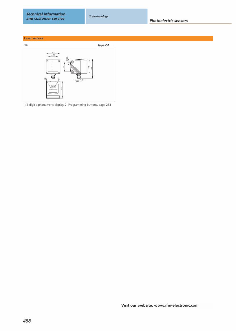
Laser sensors
14 type O1 ....
52
1 2
30
M12x1
4,5
4559
4230
1: 4-digit alphanumeric display, 2: Programming buttons, page 281
Technical informationand customer service
Scale drawings
Photoelectric sensors
488
Visit our website: www.ifm-electronic.com
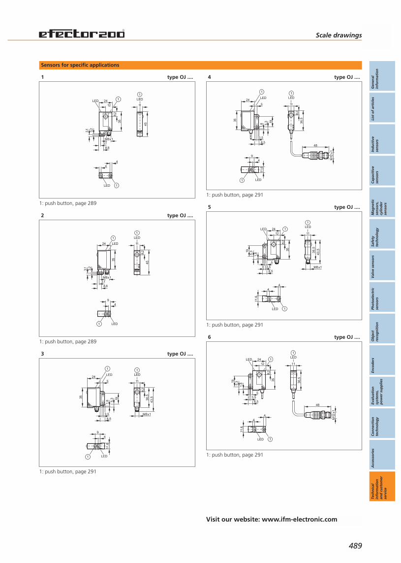
Sensors for specific applications
1 type OJ ....
45
11
LED
1
4
LED
4
1
24
8,2
12
35
8,8
3,2
3,1
3,1
LED
M8x1
1
1: push button, page 289
2 type OJ ....
45
11
LED
8,2
1
24
3,2
3,1
LED
35
M8x1
8,83,1
1
9
LED
4
1
1: push button, page 289
3 type OJ ....
1
9
LED
4
11,6
M8x1
1
36,5
11
LED
8,2
43,5
1
24LED
35
8,5
1,8 5,
3 19
3,5
5
1: push button, page 291
4 type OJ ....
1
36,5
11
LED
8,2
1
9
LED
4
11,6
1
24LED
35
8,5
1,8 5,
3 19
3,5
5
48
M12
x1
1: push button, page 291
5 type OJ ....
1LED
44
11,6
1
36,5
11
LED
43,5
M8x1
19
12412
LED
8,2
35
3,58,5
5
1,85,3
1: push button, page 291
6 type OJ ....
1
36,5
11
LED
LED
44
1
11,6
2412
LED
8,2
35
3,58,5
5
1,85,319
1
48
M12
x1
1: push button, page 291
Visit our website: www.ifm-electronic.com
Scale drawings
Gen
eral
info
rmat
ion
List
of
arti
cles
Ind
uct
ive
sen
sors
Cap
acit
ive
sen
sors
Mag
net
icse
nso
rs,
cylin
der
sen
sors
Safe
tyte
chn
olo
gy
Val
ve s
enso
rsPh
oto
elec
tric
sen
sors
Ob
ject
reco
gn
itio
nEn
cod
ers
Eval
uat
ion
syst
ems,
po
wer
su
pp
lies
Co
nn
ecti
on
tech
no
log
yA
cces
sori
esTe
chn
ical
info
rmat
ion
and
cu
sto
mer
serv
ice
489

Sensors for specific applications
7 type O1 ....
52
1 2
30
M12x1
4,5
4559
4230
1: 4-digit alphanumeric display, 2: Programming buttons, page 293
8 type O5 ....
18,2
M12 x1
19,5
37
1
LED
30,5
24,3
15,4
56
6,446,8
25
70,3
5
1
LED
6
2
5x9
625 2
1: Programming buttons, 2: When a M5 mounting screw is used, the max. tightening torque is 2 Nm., page 295
9 type O5 ....
30
M12 x1
6378
,3
1LED
50
30
50
38
254
4,2
5,3
2013,5
12
36
1: Programming buttons, page 297
10 type O5 ....
30
M12 x1
6378
,3
50
38
254
4,2
5,3
2013,5
12
36
LED
50
30
page 297
Technical informationand customer service
Scale drawings
Photoelectric sensors
490
Visit our website: www.ifm-electronic.com
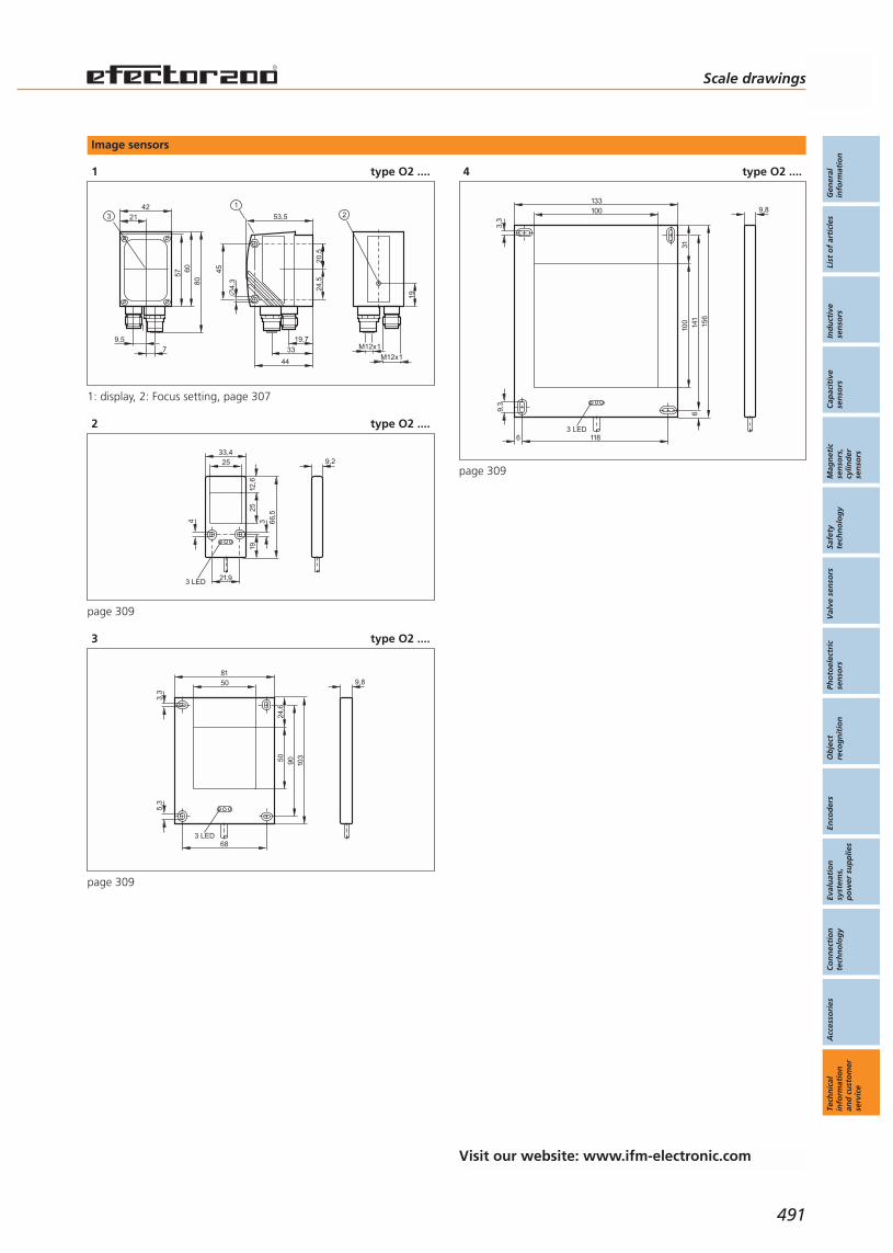
Scale drawings
Gen
eral
info
rmat
ion
List
of
arti
cles
Ind
uct
ive
sen
sors
Cap
acit
ive
sen
sors
Mag
net
icse
nso
rs,
cylin
der
sen
sors
Safe
tyte
chn
olo
gy
Val
ve s
enso
rsPh
oto
elec
tric
sen
sors
Ob
ject
reco
gn
itio
nEn
cod
ers
Eval
uat
ion
syst
ems,
po
wer
su
pp
lies
Co
nn
ecti
on
tech
no
log
yA
cces
sori
esTe
chn
ical
info
rmat
ion
and
cu
sto
mer
serv
ice
491
Image sensors
1 type O2 ....
M12x1
2
19
M12x1
53,5
4,3
20,5
44
19,7
33
1
45
24,5
42
57
8060
21
9,57
3
1: display, 2: Focus setting, page 307
2 type O2 ....
9,233,425
25
21,9
66,5
1934
3 LED
12,6
page 309
3 type O2 ....
8150
50
103
90
68
3,3
5,3
3 LED
24,6
9,8
page 309
4 type O2 ....
9,8133100
100 15
614
1
118
9,3
3 LED
3,3
6
631
page 309
Visit our website: www.ifm-electronic.com

Incremental encoders
1 type RB ....
38
618 36
,5
2
15
30°
4,5
25
12
1: reference mark, 2: M3 5 mm deep, page 319
2 type RU ....
4
3
6
50 58
3
10
h7
46,7±0,5
6
120°
421 2
1: reference mark, 2: M4 5 mm deep, page 321
3 type RV ....
10
36 58
f8
1
1,52046,7±0,5
106
48
120°
1 2
1: reference mark, 2: M3 5 mm deep, page 323
4 type RA ....
32
6
36,5
1,52 x
13,5
45
21
H7
30°
4,5
3,3
4247
,6
20
page 325
5 type RA ....
3,3
42
20
6
35
1,52 x
13,5
42,1
21
H7
30°
4,5
page 325
6 type RO ....
20
63 68
3,2
6
34,5
12H
7
24
28
47,2±0,5
58
TX 8
page 327
Technical informationand customer service
Scale drawings
Encoders
492
Visit our website: www.ifm-electronic.com
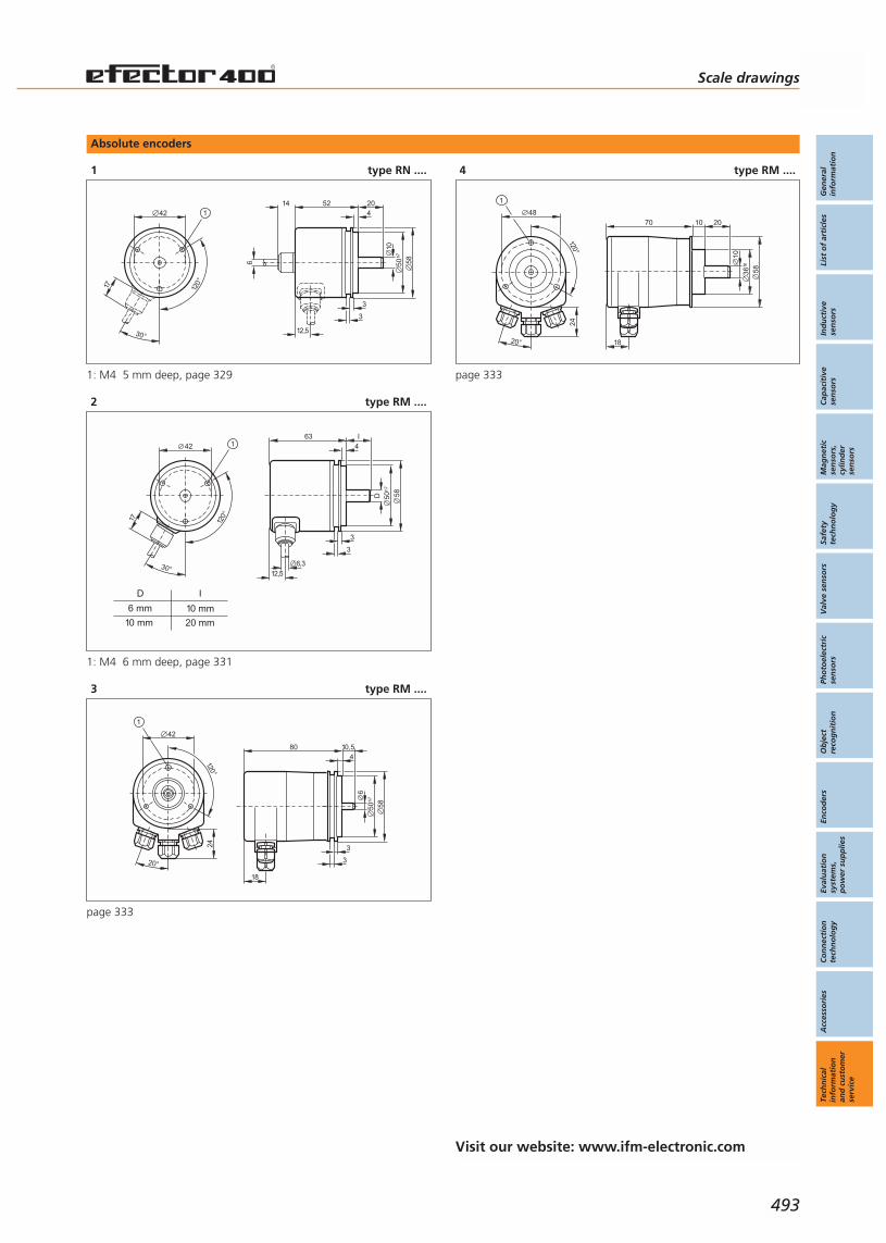
Absolute encoders
1 type RN ....
120°
30°
42
17
152
4
3
50 58
3
20
h7
14
6
12,5
10
1: M4 5 mm deep, page 329
2 type RM ....
634
3
D 50 58
3
I
h7
6,3
12,5
6 mm
10 mm
10 mm
20 mm
D I
120°
30°
42
17
1
1: M4 6 mm deep, page 331
3 type RM ....120°
42
20°
24
1
80
18
4
3
6
50 58
3
10,5
h7
page 333
4 type RM ....
120°
48
20°
24
1
70
18
10
36 58
20
f8
10
page 333
Visit our website: www.ifm-electronic.com
Scale drawings
Gen
eral
info
rmat
ion
List
of
arti
cles
Ind
uct
ive
sen
sors
Cap
acit
ive
sen
sors
Mag
net
icse
nso
rs,
cylin
der
sen
sors
Safe
tyte
chn
olo
gy
Val
ve s
enso
rsPh
oto
elec
tric
sen
sors
Ob
ject
reco
gn
itio
nEn
cod
ers
Eval
uat
ion
syst
ems,
po
wer
su
pp
lies
Co
nn
ecti
on
tech
no
log
yA
cces
sori
esTe
chn
ical
info
rmat
ion
and
cu
sto
mer
serv
ice
493

Digital and analogue signal processing
1 Type DD, DS,DR, DW ....
45
78
1 4 652
19 20 21 22 23 24
13 14 15 16 17 18
3
97A1 8A2 10 11 12
120
35,5
1
1: mounting on DIN rail, page 351, 353, 355, 357, 359
2 Type DD ....
55
75
1 2 3 4 5 6 7 8
9 10 11 12 13 14 15 16
110
35,5
1
1: mounting on DIN rail, page 361
3 Type DA ....
55
75
1 2 3 4 5 6 7 8
9 10 11 12 13 14 15 16
110
35,5
1
1: mounting on DIN rail, page 363
4 Type DI ....
36
8167
58
5
M30
x1,5
9
18
2 LED
pot. 61
page 365
5 Type DI ....
312
2918
41
M323
36
8167
58
5
M30
x1,5
2 LED
pot. 61
92
page 365
6 Type DI ....
36
8266
59
5LED
M30
x1,5
M12
x1
92
pot.
page 365
7 Type DI ....M
12x1
77
5640
M18
x1
68
10
4
2421
1: 3 LED, 2: setting pushbutton, page 365
8 Type DX ....
96
48
129 9
page 367, 377
Technical informationand customer service
Scale drawings Evaluation systems,power supplies
494
Visit our website: www.ifm-electronic.com

Digital and analogue signal processing
9 Type DZ ....
91
7277,5
1572
96
P
Reset
page 369
10 Type DZ ....
91
7277,5
1572
96
P
Reset
Out
page 369
11 Type DZ ....
91
7277,5
1572
96
987
654
321
C
0
PReset
Out 1 Out 2
S
page 369
12 Type DZ ....
48105
86,5 3
45
page 369
13 Type E6 ....
110
35,5
149
75
1 2 3 4 5 6 7 8 9 10 11 12 13 14 15 16 17 18 19 20 21 22 23
24 25 26 27 28 29 30 31 32 33 34 35 36 37 38 39 40 41 42 43 44 45 46
page 371
14 Type E8 ....
98
59
LED
71
page 373
Scale drawings
Gen
eral
info
rmat
ion
List
of
arti
cles
Ind
uct
ive
sen
sors
Cap
acit
ive
sen
sors
Mag
net
icse
nso
rs,
cylin
der
sen
sors
Safe
tyte
chn
olo
gy
Val
ve s
enso
rsPh
oto
elec
tric
sen
sors
Ob
ject
reco
gn
itio
nEn
cod
ers
Eval
uat
ion
syst
ems,
po
wer
su
pp
lies
Co
nn
ecti
on
tech
no
log
yA
cces
sori
esTe
chn
ical
info
rmat
ion
and
cu
sto
mer
serv
ice
495
Visit our website: www.ifm-electronic.com
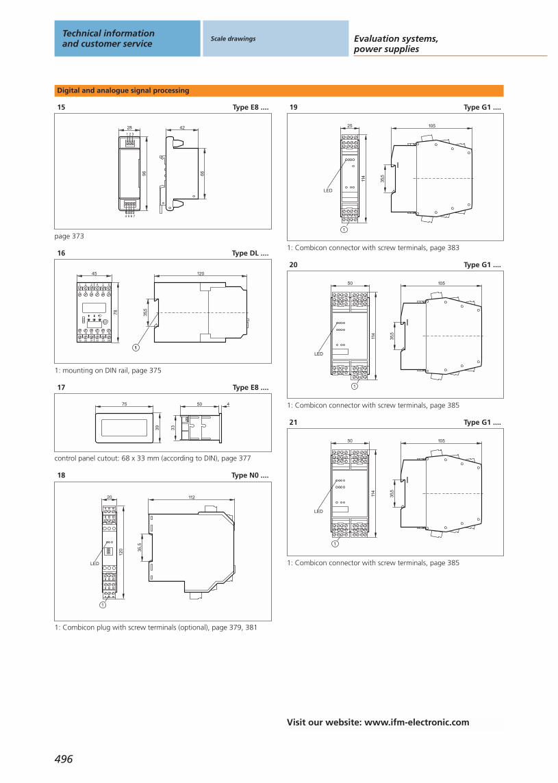
Digital and analogue signal processing
15 Type E8 ....
66
4228
96
1 2 3
4 5 6 7
page 373
16 Type DL ....
45
78
1 4 652
19 20 21 22 23 24
13 14 15 16 17 18
3
97 8 10 11 12
120
35,5
11
1: mounting on DIN rail, page 375
17 Type E8 ....
75
39
50 4
33
control panel cutout: 68 x 33 mm (according to DIN), page 377
18 Type N0 ....
112
35,5
20
120
LED
1
1: Combicon plug with screw terminals (optional), page 379, 381
19 Type G1 ....
105
35,5
25
114
LED
1
1: Combicon connector with screw terminals, page 383
20 Type G1 ....
105
35,5
50
114
LED
1
1: Combicon connector with screw terminals, page 385
21 Type G1 ....
105
35,5
50
114
LED
1
1: Combicon connector with screw terminals, page 385
Technical informationand customer service
Scale drawings Evaluation systems,power supplies
496
Visit our website: www.ifm-electronic.com
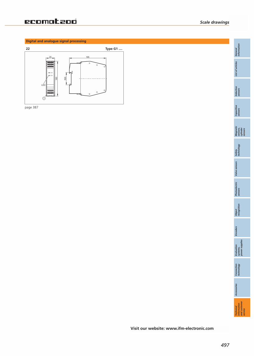
Digital and analogue signal processing
22 Type G1 ....
105
35,5
2510
0
1
LED
page 387
Scale drawings
Gen
eral
info
rmat
ion
List
of
arti
cles
Ind
uct
ive
sen
sors
Cap
acit
ive
sen
sors
Mag
net
icse
nso
rs,
cylin
der
sen
sors
Safe
tyte
chn
olo
gy
Val
ve s
enso
rsPh
oto
elec
tric
sen
sors
Ob
ject
reco
gn
itio
nEn
cod
ers
Eval
uat
ion
syst
ems,
po
wer
su
pp
lies
Co
nn
ecti
on
tech
no
log
yA
cces
sori
esTe
chn
ical
info
rmat
ion
and
cu
sto
mer
serv
ice
497
Visit our website: www.ifm-electronic.com

Transformer and switched-mode power supplies
1 Type DN ....
5575
1 2 3 4 5 6 7 8
9 10 11 12 13 14 15 16
110
35,5
1
1: mounting on DIN rail, page 389
2 Type DN ....
22,5
78
L+ L– I1
L N I2
12 14 11
2221 24
35,5
120
1
1: mounting on DIN rail, page 389
3 Type DN ....
89
4
10712
4
49
LED 131
page 391
4 Type DN ....
35,5
9645
75 83
LED
pot.
page 391
5 Type DN ....
89
4
107
124
49
LED 131
page 391
Technical informationand customer service
Scale drawings Evaluation systems,power supplies
498
Visit our website: www.ifm-electronic.com
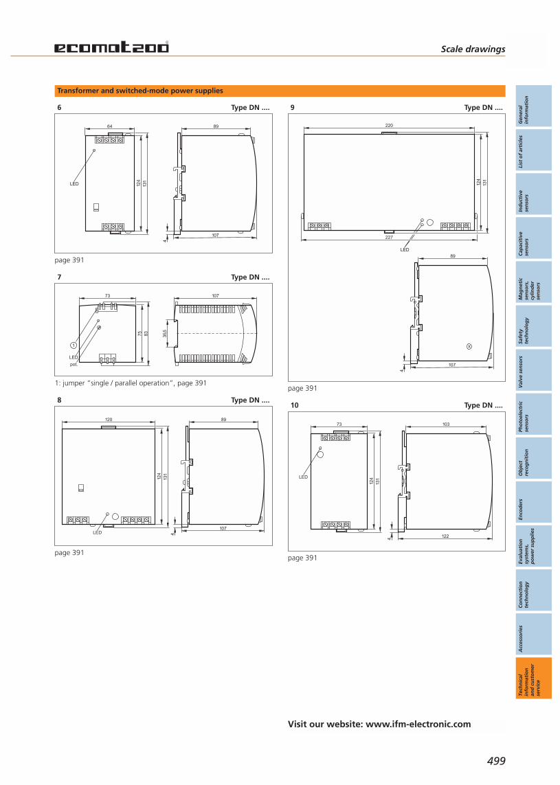
Transformer and switched-mode power supplies
6 Type DN ....
124
64
LED 131
89
4
107
page 391
7 Type DN ....
35,5
10773
75 83
LED
pot.
1
1: jumper “single / parallel operation”, page 391
8 Type DN ....
89
4
107
124
120
131
LED
page 391
9 Type DN ....
124
220
131
LED
227
89
4
107
page 391
10 Type DN ....
124
73
LED
131
4 122
103
page 391
Scale drawings
Gen
eral
info
rmat
ion
List
of
arti
cles
Ind
uct
ive
sen
sors
Cap
acit
ive
sen
sors
Mag
net
icse
nso
rs,
cylin
der
sen
sors
Safe
tyte
chn
olo
gy
Val
ve s
enso
rsPh
oto
elec
tric
sen
sors
Ob
ject
reco
gn
itio
nEn
cod
ers
Eval
uat
ion
syst
ems,
po
wer
su
pp
lies
Co
nn
ecti
on
tech
no
log
yA
cces
sori
esTe
chn
ical
info
rmat
ion
and
cu
sto
mer
serv
ice
499
Visit our website: www.ifm-electronic.com

Transformer and switched-mode power supplies
11 Type DN ....
4
121110
90
124
131
3
2
1
6
5
4
1: LED red, 2: reset push button, 3: jumper “overload performance”,4: jumper “single / parallel operation”, 5: with pot., 6: LED green,page 391
12 Type DN ....
89
4
107
124
220
131
227
LED
page 391
13 Type DN ....
4 127
108
124
150
131
157
LED
page 391
14 Type DN ....
89
4
107
124
240
131
LED
247
page 391
Technical informationand customer service
Scale drawings Evaluation systems,power supplies
500
Visit our website: www.ifm-electronic.com
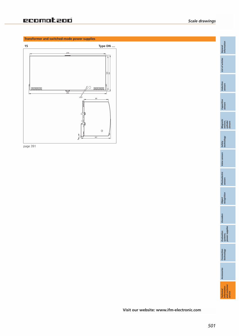
Transformer and switched-mode power supplies
15 Type DN ....
89
4
107
124
275
131
282
LED
page 391
Scale drawings
Gen
eral
info
rmat
ion
List
of
arti
cles
Ind
uct
ive
sen
sors
Cap
acit
ive
sen
sors
Mag
net
icse
nso
rs,
cylin
der
sen
sors
Safe
tyte
chn
olo
gy
Val
ve s
enso
rsPh
oto
elec
tric
sen
sors
Ob
ject
reco
gn
itio
nEn
cod
ers
Eval
uat
ion
syst
ems,
po
wer
su
pp
lies
Co
nn
ecti
on
tech
no
log
yA
cces
sori
esTe
chn
ical
info
rmat
ion
and
cu
sto
mer
serv
ice
501
Visit our website: www.ifm-electronic.com
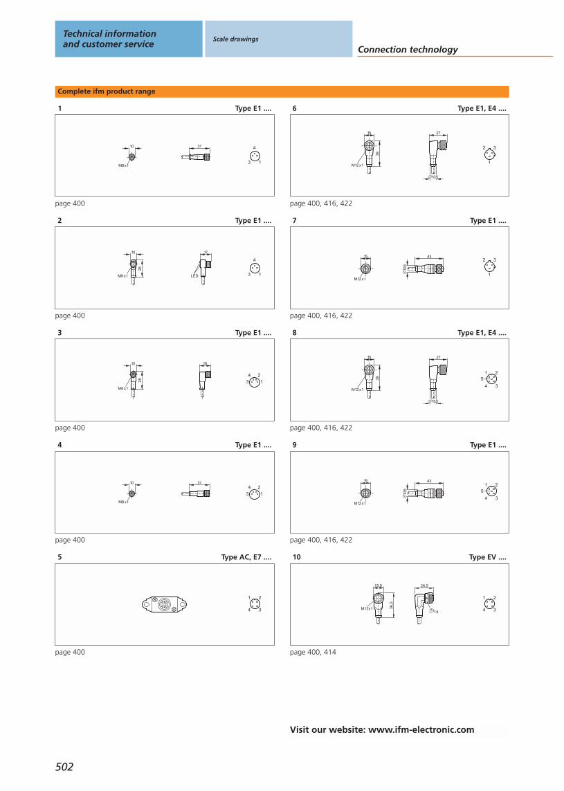
Complete ifm product range
1 Type E1 ....
10
M8 x1
31
1
4
3
page 400
2 Type E1 ....
10
26
M8 x1 LED
17
1
4
3
page 400
3 Type E1 ....
10
28
M8 x1
18
4
3
2
1
page 400
4 Type E1 ....
10
M8 x1
314
3
2
1
page 400
5 Type AC, E7 ....
3
1 2
4
page 400
6 Type E1, E4 ....
15
M12 x1
39
27
10,5
3
1
2
page 400, 416, 422
7 Type E1 ....
15
M12 x1
10,5
433
1
2
page 400, 416, 422
8 Type E1, E4 ....
15
M12 x1
39
27
10,5
3
1 2
4
5
page 400, 416, 422
9 Type E1 ....
15
M12 x1
10,5
43
3
1 2
4
5
page 400, 416, 422
10 Type EV ....
15,5
M12x1 36,5
26,5
14 3
1 2
4
page 400, 414
Technical informationand customer service
Scale drawings
Connection technology
502
Visit our website: www.ifm-electronic.com
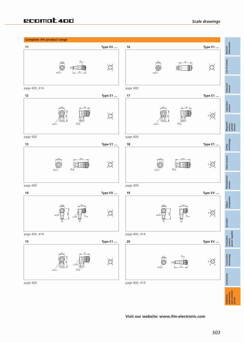
Complete ifm product range
11 Type EV ....
15,5
M12x1 45
14
3
1 2
4
page 400, 414
12 Type E1 ....
M12 x1
20
38
35
19
3
1 2
4
page 400
13 Type E1 ....
M12 x1
20 52,5
19
3
1 2
4
page 400
14 Type EV ....
15,5
M12x1 36,5
26,5
143 LED 3
1 2
4
page 400, 414
15 Type E1 ....
M12 x1
20
38
35
19
2 LED 3
1 2
4
page 400
16 Type E1 ....
18
M12 x1
46
3
1 2
4
page 400
17 Type E1 ....
M12 x1
20
38
35
19
3
1 2
4
5
page 400
18 Type E1 ....
M12 x1
20 52,5
19
3
1 2
4
5
page 400
19 Type EV ....
15,5
M12x1 36,5
26,5
14 3
1 2
4
5
page 400, 414
20 Type EV ....
15,5
M12x1 45
14
3
1 2
4
5
page 400, 414
Scale drawings
Gen
eral
info
rmat
ion
List
of
arti
cles
Ind
uct
ive
sen
sors
Cap
acit
ive
sen
sors
Mag
net
icse
nso
rs,
cylin
der
sen
sors
Safe
tyte
chn
olo
gy
Val
ve s
enso
rsPh
oto
elec
tric
sen
sors
Ob
ject
reco
gn
itio
nEn
cod
ers
Eval
uat
ion
syst
ems,
po
wer
su
pp
lies
Co
nn
ecti
on
tech
no
log
yA
cces
sori
esTe
chn
ical
info
rmat
ion
and
cu
sto
mer
serv
ice
503
Visit our website: www.ifm-electronic.com
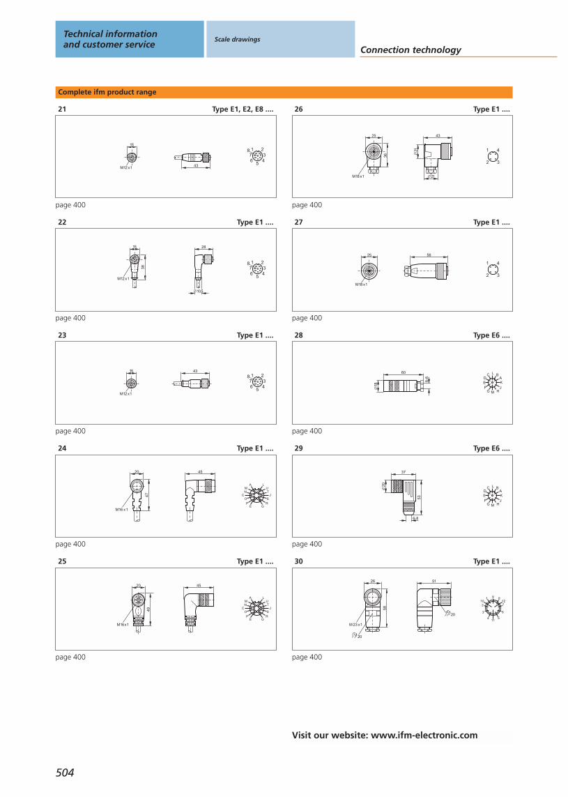
Complete ifm product range
21 Type E1, E2, E8 ....
43
15
M12 x1
4
1 2
65
378
page 400
22 Type E1 ....
15
38
M12 x1
28
10,5
4
1 2
65
378
page 400
23 Type E1 ....
15
M12 x1
43
4
1 2
65
378
page 400
24 Type E1 ....
20
M16 x1
47
45
AMN
COP
E
LUT
JS
RG
page 400
25 Type E1 ....
4520
M16x1
49
AMN
COP
E
LUT
JS
RG
page 400
26 Type E1 ....
25
M18 x1
36
21
43
21
3
1 4
2
page 400
27 Type E1 ....
25
M18 x1
56
3
1 4
2
page 400
28 Type E6 ....
1860
6-8
L BCAKJ
HM
DEF
G
page 400
29 Type E6 ....
20
37
6-8
53
L BCAKJ
HM
DEF
G
page 400
30 Type E1 ....
20
58
26
M 23 x1
51
20
1
2
3
411
5
6
7
8910 12
page 400
Technical informationand customer service
Scale drawings
Connection technology
504
Visit our website: www.ifm-electronic.com

Complete ifm product range
31 Type E1 ....
49
20
26
M 23 x1
1
2
3
411
5
6
7
8910 12
page 400
32 Type E6 ....
28
53 9 8112
7
6511
10
2
34
page 400
33 Type E6 ....
52
28
98 112
7
65 11
10
2
34
page 400, 407
34 Type E6 ....
45
25
20
98 112
7
65 11
10
2
34
page 400
35 Type E6 ....
52
28
L
8
98 112
7
65 11
10
2
34
page 400
36 Type E6 ....
53
26
9 8112
7
6511
10
2
34
page 400
37 Type E6 ....
52
28
12 111
2
3
4
56
10
9
8
7
16
1517
13
14
page 400, 407
38 Type E6 ....
52
28
4
11
2015
13112
3
56
10
9
8
19
18 16
7
21
17
142
page 400, 407
39 Type E1 ....
26
M 23 x1
859 81
12
7
6511
10
2
34
page 400
40 Type E1 ....
51
70
26
M 23 x1
9 8112
7
6511
10
2
34
page 400
Scale drawings
Gen
eral
info
rmat
ion
List
of
arti
cles
Ind
uct
ive
sen
sors
Cap
acit
ive
sen
sors
Mag
net
icse
nso
rs,
cylin
der
sen
sors
Safe
tyte
chn
olo
gy
Val
ve s
enso
rsPh
oto
elec
tric
sen
sors
Ob
ject
reco
gn
itio
nEn
cod
ers
Eval
uat
ion
syst
ems,
po
wer
su
pp
lies
Co
nn
ecti
on
tech
no
log
yA
cces
sori
esTe
chn
ical
info
rmat
ion
and
cu
sto
mer
serv
ice
505
Visit our website: www.ifm-electronic.com
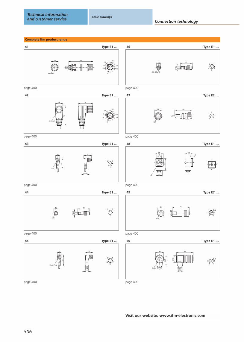
Complete ifm product range
41 Type E1 ....
26
M 23 x1
85
12
3
45 6 7
8
9
101112
13
14
15
16
17
1819
page 400
42 Type E1 ....
51
70
26
M 23 x1
12
3
45 6 7
8
9
101112
13
14
15
16
17
1819
page 400
43 Type E1 ....
27
10,5
15
39
G 21
3
1
2
page 400
44 Type E1 ....
42
10,5
15
G 21
3
1
2
page 400
45 Type E1 ....
27
10,5
15
39
"-20UNF213
2
5 1
4
page 400
46 Type E1 ....
42
10,5
15
"-20UNF21
32
5 1
4
page 400
47 Type E2 ....
6026
G 87
1
2
3
page 400
48 Type E1 ....
2918
42
M322
282
21
3
page 400
49 Type E7 ....
29
Rd 24
71
4
1 6
352
page 400
50 Type E1 ....
29
Rd 24
38,5
20
59
26
4
1 6
352
page 400
Technical informationand customer service
Scale drawings
Connection technology
506
Visit our website: www.ifm-electronic.com
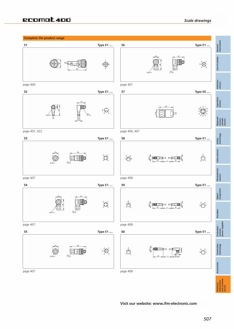
Complete ifm product range
51 Type E1 ....
30
68
3
2
4
1
page 400
52 Type E1 ....
M12 x1
39
15
30
10,5
1443
5
page 407, 422
53 Type E1 ....
M12 x1
58
19
20
4
2 1
3
page 407
54 Type E1 ....
M12 x1
20
38
40
19
4
2 1
3
page 407
55 Type E1 ....
M12 x1
58
19
20
4
2 1
3
5
page 407
56 Type E1 ....
M12 x1
20
38
40
19
4
2 1
3
5
page 407
57 Type E6 ....
52
28
98 112
7
65 11
10
2
34
page 400, 407
58 Type E1 ....
3137 L
M8
x1
M8
x12
1
4
31
4
3
page 408
59 Type E1 ....
3137 L
M8
x1
M8
x1
3
4
1
4
3
2
1
page 408
60 Type E1 ....
26
M8x1
37 L
M8
x1
17
3
4
1
4
3
2
1
page 408
Scale drawings
Gen
eral
info
rmat
ion
List
of
arti
cles
Ind
uct
ive
sen
sors
Cap
acit
ive
sen
sors
Mag
net
icse
nso
rs,
cylin
der
sen
sors
Safe
tyte
chn
olo
gy
Val
ve s
enso
rsPh
oto
elec
tric
sen
sors
Ob
ject
reco
gn
itio
nEn
cod
ers
Eval
uat
ion
syst
ems,
po
wer
su
pp
lies
Co
nn
ecti
on
tech
no
log
yA
cces
sori
esTe
chn
ical
info
rmat
ion
and
cu
sto
mer
serv
ice
507
Visit our website: www.ifm-electronic.com
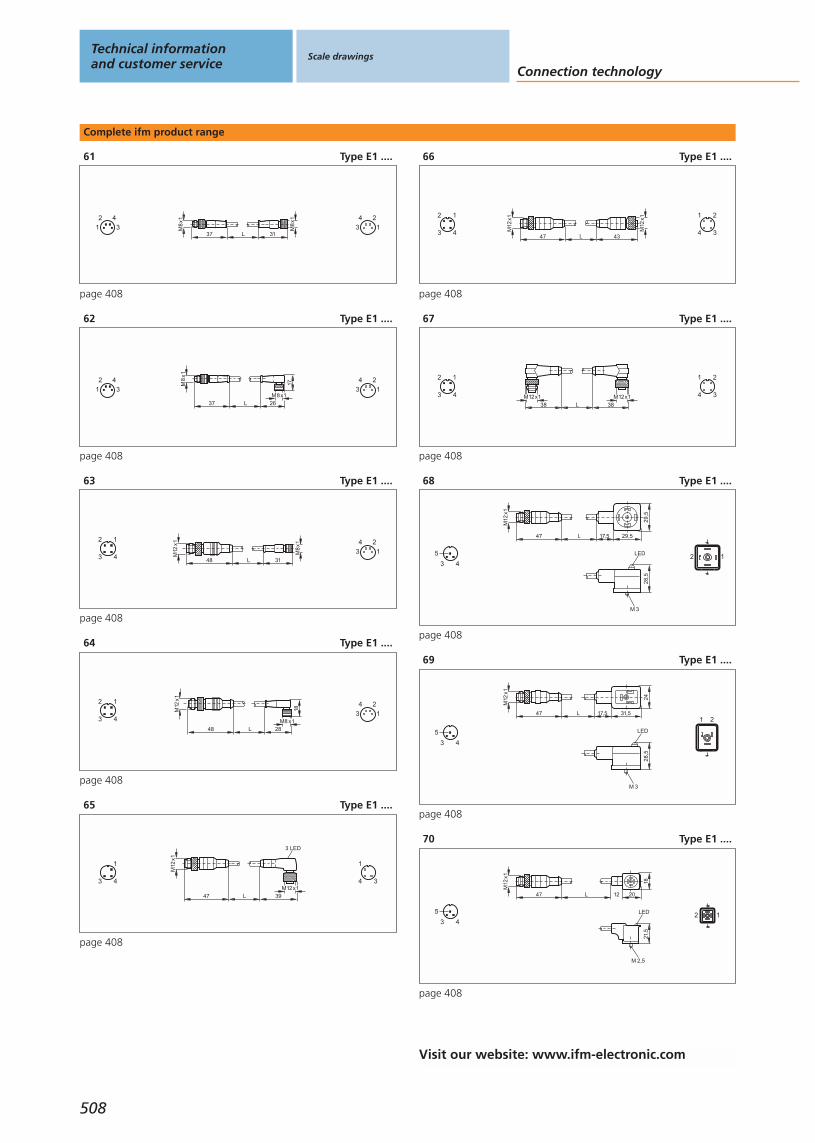
Complete ifm product range
61 Type E1 ....
3137 L
M8
x1
M8
x12
1
4
3
4
3
2
1
page 408
62 Type E1 ....
26
M8x1
37 L
M8
x1
17
2
1
4
3
4
3
2
1
page 408
63 Type E1 ....
3148 L
M8
x1
M12
x1
4
2 1
3
4
3
2
1
page 408
64 Type E1 ....
48 L
M12
x1
18
28M8 x14
2 1
3
4
3
2
1
page 408
65 Type E1 ....
M12
x1
47 L 39M12x1
3 LED
4
1
3 3
1
4
page 408
66 Type E1 ....
L 43
M12
x1
M12
x1
474
2 1
3 3
1 2
4
page 408
67 Type E1 ....
M12x1
38 L 38
M12x14
2 1
3 3
1 2
4
page 408
68 Type E1 ....
L 17,5 29,5
29,5
M12
x1
47
LED
M 3
28,5
43
5 2 1
page 408
69 Type E1 ....
LED
M 3
28,5
L 17,5 31,5
24
M12
x1
47
43
5
1 2
page 408
70 Type E1 ....
L 12 20
18
M12
x1
47
LED
M 2,5
21,5
43
5 12
page 408
Technical informationand customer service
Scale drawings
Connection technology
508
Visit our website: www.ifm-electronic.com
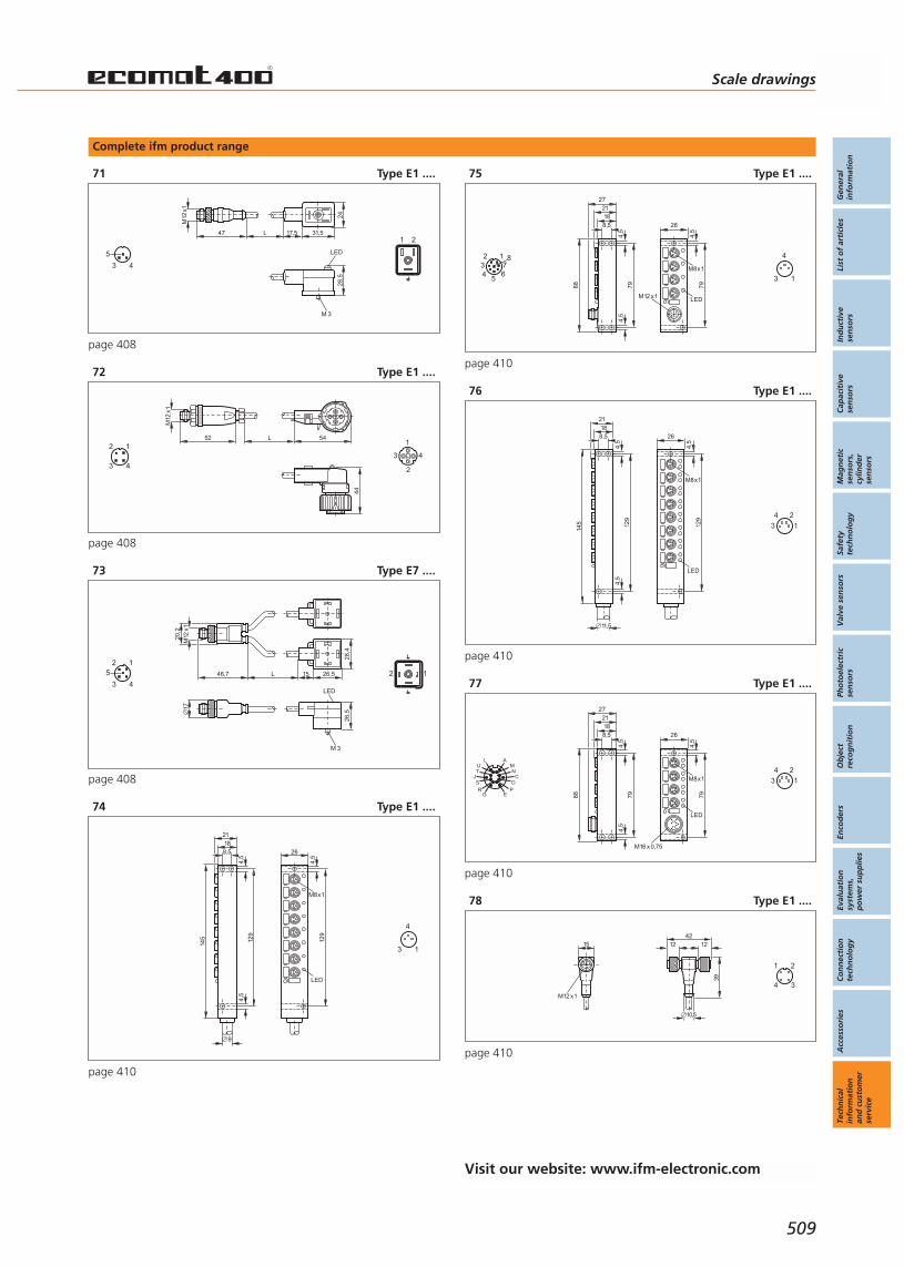
Complete ifm product range
71 Type E1 ....
LED
M 3
28,5
L 17,5 31,5
24
M12
x1
47
43
5
1 2
page 408
72 Type E1 ....
L52 54
M12
x1
44
4
2 1
33
2
4
1
page 408
73 Type E7 ....
L 15 26,5
28,4
46,7
M12
x120
,2
LED
M 3
26,5
17
4
2 1
3
5 2 1
page 408
74 Type E1 ....
145 12
9
4,5
4,5
8,51821
9
M8x1
LED
129
4,5
26
1
4
3
page 410
75 Type E1 ....
88
27
79
4,5
4,5
8,51821
M8x1
LED
79
4,5
26
M12 x1
6
2 1
45
738
1
4
3
page 410
76 Type E1 ....
145 12
9
4,5
4,5
8,51821
11,5
M8x1
LED
129
4,5
26
4
3
2
1
page 410
77 Type E1 ....
88
27
79
4,5
4,5
8,51821
M16 x 0,75
M8x1
LED
79
4,5
26
LUT
JSR
G
AMN
CO
PE
4
3
2
1
page 410
78 Type E1 ....
15
M12 x1
12
10,5
4212
39
3
1 2
4
page 410
Scale drawings
Gen
eral
info
rmat
ion
List
of
arti
cles
Ind
uct
ive
sen
sors
Cap
acit
ive
sen
sors
Mag
net
icse
nso
rs,
cylin
der
sen
sors
Safe
tyte
chn
olo
gy
Val
ve s
enso
rsPh
oto
elec
tric
sen
sors
Ob
ject
reco
gn
itio
nEn
cod
ers
Eval
uat
ion
syst
ems,
po
wer
su
pp
lies
Co
nn
ecti
on
tech
no
log
yA
cces
sori
esTe
chn
ical
info
rmat
ion
and
cu
sto
mer
serv
ice
509
Visit our website: www.ifm-electronic.com
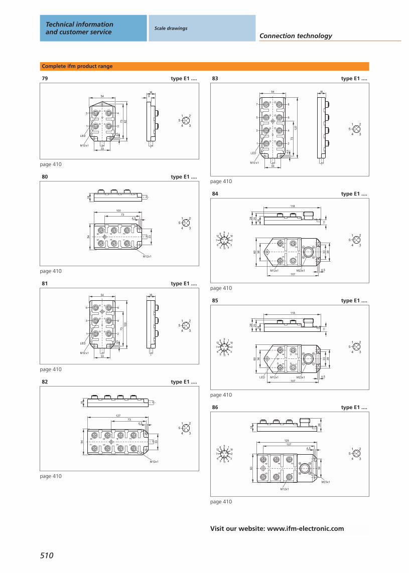
Complete ifm product range
79 type E1 ....
918
54
73
M12 x1
82
4,5
33
LED
3
1
4
2 3
1 2
4
5
page 410
80 type E1 ....
1854
73
M12x1
100
4,5
33
34
12
56
3
1 2
4
5
page 410
81 type E1 ....
1854
73
M12 x1
100
4,5
33
LED
5
3
1
6
4
23
1 2
4
5
page 410
82 type E1 ....
1854
73
M12x1
127
4,5
33
34
12
56
78
3
1 2
4
5
page 410
83 type E1 ....
1854
73
M12 x1
127
4,5
33
LED
7
5
3
1
8
6
4
2
3
1 2
4
5
page 410
84 type E1 ....
M23x1
60
107
39
4,5
36
34
12
M12x1
3311
118
182528
98 112
7
65 11
10
2
34
3
1 2
4
5
page 410
85 type E1 ....
M23x1
60
107
39
4,5
36
34
12
LED M12x1
3311
118
182528
98 112
7
65 11
10
2
34
3
1 2
4
5
page 410
86 type E1 ....
60
107
M12x1
4,5
39
125
M23x1
34
12
56
18
28
98 112
7
65 11
10
2
34
3
1 2
4
5
page 410
Technical informationand customer service
Scale drawings
Connection technology
510
Visit our website: www.ifm-electronic.com
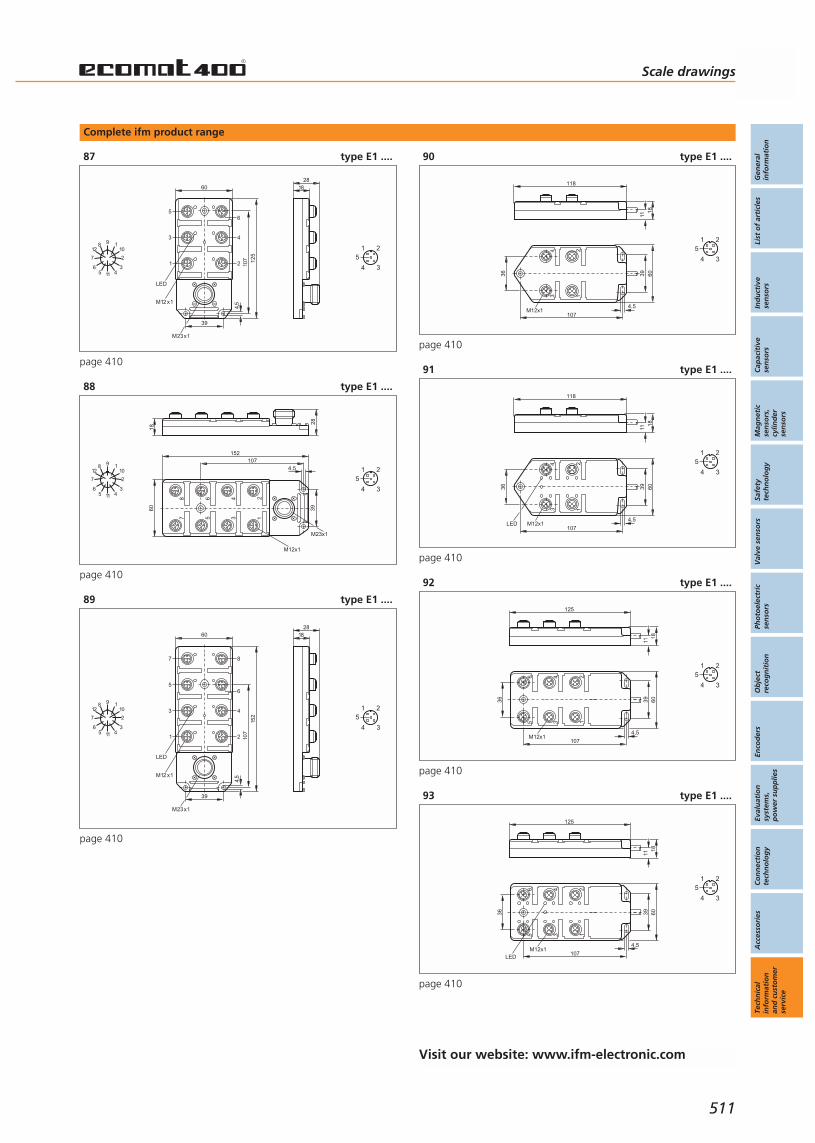
Complete ifm product range
87 type E1 ....
1828
60
107
M12 x1
4,5
39
LED
125
M23x1
5
3
1
6
4
2
98 112
7
65 11
10
2
34
3
1 2
4
5
page 410
88 type E1 ....
28
1860
107
M12x1
4,5
39
M23x1
152
34
12
56
78
98 112
7
65 11
10
2
34
3
1 2
4
5
page 410
89 type E1 ....
1828
60
107
M12 x1
4,5
39
LED
M23x1
152
7
5
3
1
8
6
4
2
98 112
7
65 11
10
2
34
3
1 2
4
5
page 410
90 type E1 ....
1118
118
60
107
39
4,5
36
34
12
M12x1
3
1 2
4
5
page 410
91 type E1 ....
1118
118
60
107
39
4,5
36
34
12
LED M12x1
3
1 2
4
5
page 410
92 type E1 ....
60
107
39
4,5
36
12
34
56
M12x1
125
1118
3
1 2
4
5
page 410
93 type E1 ....
125
1118
60
107
39
4,5
36
12
34
56
M12x1LED
3
1 2
4
5
page 410
Scale drawings
Gen
eral
info
rmat
ion
List
of
arti
cles
Ind
uct
ive
sen
sors
Cap
acit
ive
sen
sors
Mag
net
icse
nso
rs,
cylin
der
sen
sors
Safe
tyte
chn
olo
gy
Val
ve s
enso
rsPh
oto
elec
tric
sen
sors
Ob
ject
reco
gn
itio
nEn
cod
ers
Eval
uat
ion
syst
ems,
po
wer
su
pp
lies
Co
nn
ecti
on
tech
no
log
yA
cces
sori
esTe
chn
ical
info
rmat
ion
and
cu
sto
mer
serv
ice
511
Visit our website: www.ifm-electronic.com

Complete ifm product range
94 type E1 ....
152
1118
60
10739
4,5
36
12
34
56
78
M12x1
3
1 2
4
5
page 410
95 type E1 ....
60
107
39
4,5
36
12
34
56
78
M12x1LED
152
1118
3
1 2
4
5
page 410
96 type E1 ....
M23x1
60
107
39
4,5
36
34
12
M12x1
3311
118
182528
12
3
456
78
9
1011 12
13
14
15
16
17
1819
3
1 2
4
5
page 410
97 type E1 ....
M23x1
60
107
39
4,5
36
34
12
LED M12x1
3311
118
182528
12
3
456
78
9
1011 12
13
14
15
16
17
1819
3
1 2
4
5
page 410
98 type E1 ....
60
107
M12x1
4,5
39
125
M23x1
34
12
56
18
28
12
3
456
78
9
1011 12
13
14
15
16
17
1819
3
1 2
4
5
page 410
99 type E1 ....
18
28
60
107
M12x1
4,5
39
LED
125
M23x1
34
12
56
12
3
456
78
9
1011 12
13
14
15
16
17
1819
3
1 2
4
5
page 410
100 type E1 ....
28
1860
107
M12x1
4,5
39
M23x1
152
34
12
56
78
12
3
456
78
9
1011 12
13
14
15
16
17
1819
3
1 2
4
5
page 410
101 type E1 ....
28
1860
107
M12x1
4,5
39
LED
M23x1
152
34
12
56
78
12
3
456
78
9
1011 12
13
14
15
16
17
1819
3
1 2
4
5
page 410
Technical informationand customer service
Scale drawings
Connection technology
512
Visit our website: www.ifm-electronic.com
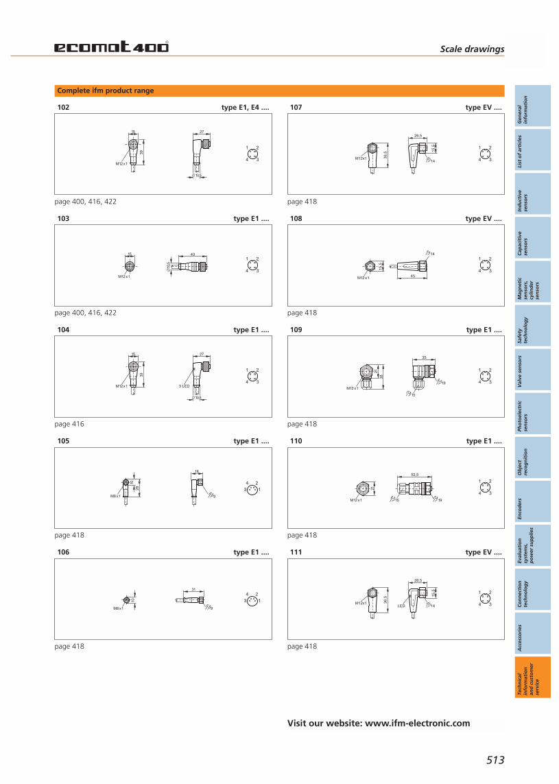
Complete ifm product range
102 type E1, E4 ....
15
M12 x1
39
27
10,5
3
1 2
4
page 400, 416, 422
103 type E1 ....
15
M12 x1
10,5
43
3
1 2
4
page 400, 416, 422
104 type E1 ....
15
M12 x1
39
27
3 LED
10,5
3
1 2
4
page 416
105 type E1 ....
18
9
28
M8 x1
10 4
3
2
1
page 418
106 type E1 ....
10
M8 x1
31
9
4
3
2
1
page 418
107 type EV ....
15,5
M12x1 36,5
26,5
14 3
1 2
4
page 418
108 type EV ....
15,5
45
14
M12 x1
3
1 2
4
page 418
109 type E1 ....
35
19
15
21
M12 x1
383
1 2
4
page 418
110 type E1 ....
52,5
15 19
21
M12 x1
3
1 2
4
page 418
111 type EV ....
15,5
M12x1 36,5
26,5
14LED 3
1 2
4
page 418
Scale drawings
Gen
eral
info
rmat
ion
List
of
arti
cles
Ind
uct
ive
sen
sors
Cap
acit
ive
sen
sors
Mag
net
icse
nso
rs,
cylin
der
sen
sors
Safe
tyte
chn
olo
gy
Val
ve s
enso
rsPh
oto
elec
tric
sen
sors
Ob
ject
reco
gn
itio
nEn
cod
ers
Eval
uat
ion
syst
ems,
po
wer
su
pp
lies
Co
nn
ecti
on
tech
no
log
yA
cces
sori
esTe
chn
ical
info
rmat
ion
and
cu
sto
mer
serv
ice
513
Visit our website: www.ifm-electronic.com

Complete ifm product range
112 type EV ....
15,5
M12x1 36,5
26,5
14 3
1 2
4
5
page 418
113 type EV ....
15,5
45
14
M12 x1
3
1 2
4
5
page 418
114 type E1 ....
40
15
19
21
M12 x1
38
4
2 1
3
page 418
115 type E1 ....
58
15 19
21
M12 x1
4
2 1
3
page 418
116 type EV ....
L
15,5
M12 x1
49
14
45
15,5
M12 x1 14
4
2 1
3 3
1 2
4
page 418
117 type E1 ....
42
14
L46
14
M12
x1
M12
x1
4
2 1
3 3
1 2
4
page 418
118 type E1 ....
35
19
15
21
M12 x1
38
3
1 2
4
5
page 418
119 type E1 ....
52,5
15 19
21
M12 x1
3
1 2
4
5
page 418
120 type E1 ....
40
15
19
21
M12 x1
38
4
2 1
3
5
page 418
121 type E1 ....
58
15 19
21
M12 x1
4
2 1
3
5
page 418
Technical informationand customer service
Scale drawings
Connection technology
514
Visit our website: www.ifm-electronic.com

Complete ifm product range
122 type E1 ....
46
M12
x1
51 L
M12
x1
1414
4
2 1
3
5
3
1 2
4
5
page 418
123 type E1 ....
137,
3
M12 x1
LED
7234
3
1 2
4
5
page 418
124 type E1 ....
M12 x1
39
15
30
10,5
144
2 1
3
5
page 407, 422
125 type E1 ....
M12 x1
L3915
15 26,5
28,4
30
14
10,5
M 3
26,5
4
2 1
3
5 2 1
page 422
126 type E1 ....
M12 x1
L3915
15 28,5
22,4
30
14
10,5
M 3
26,5
4
2 1
3
5
1 2
page 422
127 type E1 ....
M12 x1
L39
1520,5 15
15
30
14
10,5
M 2,5
25,3
4
2 1
3
5 12
page 422
128 type E1 ....
L
26,5
M3
28,515
22,4
15
M12x1
39
30
4
2 1
3
5
1 2
page 422
Scale drawings
Gen
eral
info
rmat
ion
List
of
arti
cles
Ind
uct
ive
sen
sors
Cap
acit
ive
sen
sors
Mag
net
icse
nso
rs,
cylin
der
sen
sors
Safe
tyte
chn
olo
gy
Val
ve s
enso
rsPh
oto
elec
tric
sen
sors
Ob
ject
reco
gn
itio
nEn
cod
ers
Eval
uat
ion
syst
ems,
po
wer
su
pp
lies
Co
nn
ecti
on
tech
no
log
yA
cces
sori
esTe
chn
ical
info
rmat
ion
and
cu
sto
mer
serv
ice
515
Visit our website: www.ifm-electronic.com
Active zone / sensing face The active zone is the area over the sensing face in which a sensor reacts tothe approach of damping material, i.e. where it changes its switching status.
Ambient temperature range The temperature range in which the safe functioning of the sensor is guar-anteed.
ATEX ATEX (Atmosphère explosible) is an abbreviation for uniform EU directivesfor explosion protection in the industry (hazardous areas). Units for hazar-dous areas have to be approved according to these guidelines if they arelaunched after 30 June 2003.
Cable sheath materials Depending on environment and application the materials show differentresistances. Therefore certain properties or the suitability for a certain appli-cation cannot be guaranteed. Concerning the specific resistances we referyou to the explanations under “PUR cable”, “PVC cable” and “PPU cable”.The general notes given there do not exempt from any tests.
CIP / SIP Common abbreviations in the food industry:CIP = Cleaning in place.SIP = Sterilisation in place.They identify cleaning and sterilisation processes within closed installationswith cleaning/disinfecting solutions circulating in the circuit. Temperaturesup to 140°C may occur for a short time.
Correction factors The correction factors (K) indicate the reduction of the real sensing range if adifferent material other than mild steel (Fe360) is used. The change of thereal sensing range depends on the type, internal structure, size and geome-try of the material to be sensed.
Typical correction factors for inductive units:steel = 1, stainless steel approx. 0.7, brass approx. 0.4, aluminium approx.0.3, copper approx. 0.2
Typical correction factors for capacitive units:water = 1, glass approx. 0.4, ceramics approx. 0.2, PVC approx. 0.2
Some inductive sensors use a constant correction factor (K=1) for all metals.
Current consumption Current for the internal consumption of the unit. The value specified in thedata sheet applies to the switched unit without load.
Current rating / continuous The current at which units can be continuously operated. The units are pro-tected against short circuits, overload and reverse polarity. In the case of ashort circuit the output transistor is blocked immediately. When the short cir-cuit has been rectified, the unit is ready again for operation.
Current rating / peak The maximum current which may flow for a short time when power is app-lied without influencing the functioning of the sensor.
Technical informationand customer service
Technical glossary Position sensors andobject recognition
516
Visit our website: www.ifm-electronic.com
Dark-on mode For through-beam and retro-reflective sensors: the output is switched whenthe light beam between transmitter and receiver is interrupted. For diffusereflection sensors: the output is switched when the light beam is not reflec-ted back to the receiver by the object to be detected.
Data transfer Referred to absolute encoders there are two types of data transfer:
parallel:For absolute encoders with parallel data output each track has a separatedata line. The data are either constantly available or are released on a givensignal.
SSI - Synchronous-serial interface:During the transfer of the absolute position the data word is provided at theoutput synchronously to the given cycle of the controller. The data wordstarts with the most significant bit (MSB) and ends with the least significantbit (LSB).
Degree of soiling Defines the environmental conditions under which units can be used.
ifm sensors are designed for installation in environments according to soilingdegree 3. This applies to the complete system to which the IP data in thedata sheet apply, such as for the connector or the terminal chamber. Thedefinition of soiling degree 3 is as follows: Conductive soiling or dry non-conductive soiling which can become conductive as a result of condensa-tion.
Electrical design DC PNP: DC unit with positive output signal (sourcing).DC NPN: DC unit with negative output signal (sinking).AC/DC dual voltage: connection either to DC or AC voltage.
Electromagnetic field immunesensors
Electromagnetic field immune sensors of ifm electronic are designed so thatthey can be used close to strong magnetic fields. Typical applications are forexample position detection on welding robots, also in close vicinity to wel-ding electrodes. The proximity switches are internally protected by compen-sation electrodes and therefore operate reliably during the welding opera-tion in DC and medium-frequency welding systems. To externally protect theproximity switches against weld slag the “/SC” marked series possess anadditional teflon coating which prevents weld spatter from burning into theplastic or metal parts from being welded together.
Excess gain Photoelectric sensors feature an excess gain to ensure the highest possibleoperational safety when the lenses are soiled. The excess gain is defined asthe ratio of radiated energy received to the minimum radiated energy thephotoelectric sensor requires to switch safely. The excess gain depends onthe selected range and the type of unit.
Flush mounting The active face of a sensor can be mounted flush with the damping material.
Technical glossary
Gen
eral
info
rmat
ion
List
of
arti
cles
Ind
uct
ive
sen
sors
Cap
acit
ive
sen
sors
Mag
net
icse
nso
rs,
cylin
der
sen
sors
Safe
tyte
chn
olo
gy
Val
ve s
enso
rsPh
oto
elec
tric
sen
sors
Ob
ject
reco
gn
itio
nEn
cod
ers
Eval
uat
ion
syst
ems,
po
wer
su
pp
lies
Co
nn
ecti
on
tech
no
log
yA
cces
sori
esTe
chn
ical
info
rmat
ion
and
cu
sto
mer
serv
ice
517
Visit our website: www.ifm-electronic.com
Function check output In addition to the function display some units have a function check output.This can be used, e.g. via a plc, to monitor the operation of the sensor.
Housing materials Metal housing:aluminium, galvanised steel, Optalloy-plated brass, Teflon-plated brass,
stainless steel (rustfree 303S22, acid-resistant 320S31):stainless steel material no. 303S22 (X10 Cr NiS 18 9)stainless steel material no. 316S12 (X2 Cr Ni Mo 1713 2)316S12 (X2 Cr Ni Mo 18 14 3)320S31 (X6 Cr Ni Mo Ti 17 12 2)
Plastic housing:PBT (polybutyleneterephthalate)The housing is largely resistant to aliphatic and aromatic hydrocarbons, oils,greases, hydraulic fluids, fuels; no stress cracking when exposed to air.The housing is not resistant to hot water, hot steam, acetone , halocarbons,concentrated acids and alkalis.
Modified PPO:The housing is largely resistant to diluted mineral acids, weak alkalis, somealcohols, oils and greases depending on additives; resistant to hydrolysis inhot and cold water.The housing is not resistant to aromatic hydrocarbons and hydrocarbonscontaining chlorine, petrol, oils and greases depending on additives.
Chemically resistant fluoroplastics:PTFE (polytetrafluoroethylene), LCP. PEEK, PEI, PA, mod. PCDepending on environment and application plastics show different resistan-ces. Therefore certain properties or the suitability for a certain applicationcannot be guaranteed.For frequent or permanent exposure to chemicals all housing materialsrequire testing prior to use.
HTL HTL signals are square-wave pulse trains with a voltage level higher than 10 V.HTL = High-threshold logic.
Hysteresis The difference between the switch-on and the switch-off point.
Technical informationand customer service
Technical glossary Position sensors andobject recognition
518
Visit our website: www.ifm-electronic.com
Increased sensing range Sensors with increased sensing range have nominal sensing ranges up to100% greater than conventional sensors, yet are designed to meet therequirements of the standard for flush or non-flush installation. In case offlush installation sensors are usually influenced by the surrounding metal.The special design and material selection of the sensor prevent this to a largeextent so that these sensors also have a high operational reliability over thecomplete temperature range. The high excess gain guarantees safe functio-ning, even in case of deposits on the front face.
K=1 Sensors with K=1 (correction factor = 1) have the full sensing range foralmost all metals. They are used where high sensing ranges have to be achie-ved for non-ferrous metals or stainless steel.
Laser protection class The photocells with laser diode in this catalogue comply with the laser pro-tection class 2, as described in EN 60825. The accessible laser radiation isonly in the visible spectral range (400nm - 700nm). In case of short-termradiation (up to 0.25s) it is harmless, even for the eye. The limit value of theaccessible radiation is 1mW. Nevertheless laser installations of class 2 mustnot be used without additional protective measures. Please refer to theabove standard.
Light-on mode For through-beam and retro-reflective sensors: the output is switched whenthe light beam between transmitter and receiver or between transmitter /receiver unit and prismatic reflector is not interrupted. For diffuse reflectionsensors: the output is switched when the light beam is reflected from theobject to be detected to the receiver.
LSB Least significant bit
Measurement of the sensingrange
The sensing range is determined according to EN 60947-5-2 with a standardrectangular measuring plate made of mild steel with a thickness of 1 mm.The side length of the square equals the sensor diameter or three times therated sensing range, whichever is greater.
Minimum load current The smallest current which must flow when the output is switched to ensure reliable operation of 2-wire sensors.
MSB Most significant bit
Multi-turn encoder The multi-turn encoder does not only count resolution but also the numberof revolutions.
Noise immunity To avoid malfunction as a result of too high voltage peaks which might occurin critical applications, we recommend laying the cables of sensors separa-tely from other cables (e.g. motors, solenoid valves). In especially difficultcases it might be necessary to lay screened cables. If in doubt please contactour engineers.
Technical glossary
Gen
eral
info
rmat
ion
List
of
arti
cles
Ind
uct
ive
sen
sors
Cap
acit
ive
sen
sors
Mag
net
icse
nso
rs,
cylin
der
sen
sors
Safe
tyte
chn
olo
gy
Val
ve s
enso
rsPh
oto
elec
tric
sen
sors
Ob
ject
reco
gn
itio
nEn
cod
ers
Eval
uat
ion
syst
ems,
po
wer
su
pp
lies
Co
nn
ecti
on
tech
no
log
yA
cces
sori
esTe
chn
ical
info
rmat
ion
and
cu
sto
mer
serv
ice
519
Visit our website: www.ifm-electronic.com
Nominal sensing range (Sn) Also called rated sensing range.A characteristic value which does not take into account the deviation resul-ting from external influences such as temperature and voltage.
Non-flush mounting A sensor is non-flush mountable when a specified free zone around its sen-sing face is necessary in order to maintain its characteristics.
Operating distance Also called safe sensing range.The operating distance is any distance from the sensing face at which a sen-sor functions correctly at a given temperature and supply voltage.
Operating temperature Temperature range which guarantees a safe functioning of the device. Theoperating temperature of the unit must be within the range indicated in thedata sheet and must not be above or below this range.
Operating voltage The voltage range for which the device is rated. The stated nominal voltageand the tolerance result in the operating voltage range in which the devicefunctions safely. Exceeding or falling below the maximum or minimumvalues is only allowed within the limits specified in the data sheets.
Optical setting aid Inductive sensors with a two-colour setting LED increase operational reliabi-lity and thus machine uptime. An additional LED indicates to the user thatthe distance between the sensors and the damping target is uncertain. Inthis case readjustment is urgently recommended!
Output function Normally open: object within the active zone – output closed / high signal.Normally closed: object within the active zone – output open / low signal.Programmable: choice between normally closed or normally open.Complementary: normally open and normally closed outputs available simul-taneously.
Overload protected The response threshold for the short circuit protection is above the valuespecified for the continuous current rating. Units protected against overloadare protected against destruction in this range as well.
PELV PELV (Protective Extra Low Voltage) describes an electrical system in whichthe voltage cannot exceed the value of 60 V DC. It also includes a protectivemeasure against direct and indirect contact with dangerous voltage, the so-called “safe isolation” from the supply system. Circuits and / or bodies ina PELV system can be connected to ground - in contrast to the SELV system.
Power-on delay time The power-on delay time is the time which elapses between the applicationof the operating voltage and the readiness of the device to generate the correct switching signal.
Programmable output function The switching output can be programmed as normally open or normally closed (for photoelectric sensors light-on or dark-on) by means of the choiceof the wire connection or via programming buttons.
Technical informationand customer service
Technical glossary Position sensors andobject recognition
520
Visit our website: www.ifm-electronic.com

Protection classes Protection class 1 (I): units with protective wire connectionProtection class 2 (II): units with protective insulation (double insulation) Protection class 3 (III): units for connection to protective extra-low voltageVoltage supply to EN 50178, PELV, SELV
All units marked protection class III or all units without protective wire con-nection or protective insulation mark must be connected to protective extra-low voltage (max. 60 V DC). For inductive sensors this can be SELV or PELV.
Protection rating The protection rating (to IEC 529 / DIN 40 050) defines the degree of pro-tection from ingress of dust and moisture into the sensor.
IP64Complete protection against contact with dangerous parts; protectionagainst ingress of dust and water splashesIP 65Complete protection against contact with dangerous parts; protectionagainst ingress of dust; protection against water jets.IP66Complete protection against contact with dangerous parts; protectionagainst ingress of dust. Protection against strong water jets.IP 67Complete protection against contact with dangerous parts; protectionagainst ingress of dust; protection when immersed temporarily in water: 1 mdepth of water for 30 minutes.IP 68 (ifm specific definition)Complete protection against contact with dangerous parts; protectionagainst ingress of dust; protection when permanently immersed in water.According to ifm factory standard: 1 m depth of water for 7 days.IP 69KComplete protection against contact with dangerous parts, protectionagainst ingress of dust, protection against ingress of water during high-pres-sure steam cleaning
PTB / INERIS National bodies testing electrical equipment and approving it for hazardousareas.PTB = Physikalisch-Technische Bundesanstalt Braunschweig und Berlin.INERIS = Institut National de L'Environnement Industriel et de Risques (France).
PUR cable Oil-resistant cable. Not resistant to hydrolysis, therefore not suited for per-manent contact with water. In order to avoid breakage the cables should notbe moved if the temperature falls below -5 °C.
PUR/PVC cable (PPU cable) PVC cable with additional PUR sheathing. Oil-resistant cable. Not resistant tohydrolysis, therefore not suited for permanent contact with water. In orderto avoid breakage the cables should not be bent if the temperature fallsbelow -5 °C (-> plastics).
Technical glossary
Gen
eral
info
rmat
ion
List
of
arti
cles
Ind
uct
ive
sen
sors
Cap
acit
ive
sen
sors
Mag
net
icse
nso
rs,
cylin
der
sen
sors
Safe
tyte
chn
olo
gy
Val
ve s
enso
rsPh
oto
elec
tric
sen
sors
Ob
ject
reco
gn
itio
nEn
cod
ers
Eval
uat
ion
syst
ems,
po
wer
su
pp
lies
Co
nn
ecti
on
tech
no
log
yA
cces
sori
esTe
chn
ical
info
rmat
ion
and
cu
sto
mer
serv
ice
521
Visit our website: www.ifm-electronic.com

PVC cable Tried-and-tested standard cable. In order to avoid breakage the cablesshould not be moved if the temperature falls below -5 °C. PVC cables arenot designed for continuous operation in oily environments. They are neitherresistant to ozone nor to ultra-violet light.
Real sensing range (Sr) A value which is measured with a target to EN 60947-5-2 and at rated voltage and operating temperature (23.5 °C). It must lie between 90 % and110 % of the nominal sensing range.
Repeatability The repeatability of two measurements under standard conditions. The dif-ference of the measured values must not exceed 10 %.
Residual ripple The standing ripple component of the DC output voltage. It is either statedas root-mean-square value (rms) or as peak-to-peak value (pp).
Resistant to weld slag Units with “.../SC” (“safecoated”) in the designation have a protectiveTeflon-like coating which largely prevents weld spatter burning into the surface. The destruction of the units or malfunctioning due to deposits ofweld slag on the active face is thus avoided. Units with this protection incre-ase the operational reliability and the uptime of the installation.
Revolution, maximum mechanical
The maximum permissible revolution of the encoder shaft. The maximumvalue is stated in the data sheet together with the other mechanical data.
SELV SELV (Safe Extra Low Voltage) describes an electrical system in which the vol-tage does not exceed the value of 60 V DC. It includes a protective measureagainst direct and indirect contact with dangerous voltage, the so-called“safe isolation” from the supply system. In contrast to a PELV system a SELVsystem must not be grounded.
Sensing range The sensing range is the distance at which an object approaching the sen-sing face of the sensor triggers a change of signal.
Setting range Within the setting range the flow monitors can be adjusted to any switchpoint. It is recommended to select the switch point if possible within the areaof the greatest sensitivity.
Technical informationand customer service
Technical glossary Position sensors andobject recognition
522
Visit our website: www.ifm-electronic.com

Shock and vibration resistance The shock and vibration resistance of all sensors is tested.
VibrationAccording to EN 60068-2-6 under the following conditions:along 3 mutually perpendicular axes,Frequency range: 10 Hz to 55 Hz
Example sensors:Amplitude: 1mm for inductive and capacitive sensors. 0.5 mm for photo-electric sensors.Vibration duration: 5 min.Duration of the time of exposure at resonant frequency or at 55 Hz: 30 minin each axis (at total of 90 min.).
Shock resistanceAccording to EN 60068-2-27 under the following conditions:6 shocks in each direction along axes perpendicular to each other (6 indivi-dual tests).
Example sensors:Pulse shape: half-sine.Peak acceleration: 30 g.Pulse duration: 11 ms.
Short-circuit protection Most ifm sensors are protected against excessive current by means of a pul-sed short-circuit protection.
Single-turn encoder Absolute encoder converting a mechanical revolution into a binary codedsignal.
Switch-point drift also called temperature drift. The shifting of the switch point owing to chan-ges in the ambient temperature. Within the range specified in the data sheetthe sensing range usually varies by max. ± 10 % referred to an operatingtemperature of 23 5 C.
Switching frequency The maximum number of signal changes at the output within one second(stated in Hertz).
Temperature drift also called switch point drift.The shifting of the switch point owing to changes in the ambient tempera-ture. Within the range specified in the data sheet the sensing range usuallyvaries by max. ± 10 % referred to an operating temperature of 23.5 °C.
TPR cable Cable for operating temperatures from -40 °C to +150 °C. Good resistanceto oils, fuels, acids and alkalies.
Technical glossary
Gen
eral
info
rmat
ion
List
of
arti
cles
Ind
uct
ive
sen
sors
Cap
acit
ive
sen
sors
Mag
net
icse
nso
rs,
cylin
der
sen
sors
Safe
tyte
chn
olo
gy
Val
ve s
enso
rsPh
oto
elec
tric
sen
sors
Ob
ject
reco
gn
itio
nEn
cod
ers
Eval
uat
ion
syst
ems,
po
wer
su
pp
lies
Co
nn
ecti
on
tech
no
log
yA
cces
sori
esTe
chn
ical
info
rmat
ion
and
cu
sto
mer
serv
ice
523
Visit our website: www.ifm-electronic.com

TTL TTL signals are square-wave pulse trains with a voltage level Uhigh: >= 2.5Vand Ulow: <>= 0.5 V.TTL = Transistor-transistor logic.
Voltage drop As the switching output consists of a semiconductor (transistor, thyristor ortriac), in the switched state a (small) drop in the voltage in series to the loadoccurs. In two-wire technology the voltage drop also serves to provide ener-gy to the electronics of the sensor. The voltage drop is measured across thesensor in its switched state at max. current load. EN 50008 - 025, 036, 038.
Wide-range power supply Power supplies with wide-range input can be used with different mains vol-tages without requiring manual or automatic changeover.
Technical informationand customer service
Technical glossary Position sensors andobject recognition
524
Visit our website: www.ifm-electronic.com

Technical glossary
Gen
eral
info
rmat
ion
List
of
arti
cles
Ind
uct
ive
sen
sors
Cap
acit
ive
sen
sors
Mag
net
icse
nso
rs,
cylin
der
sen
sors
Safe
tyte
chn
olo
gy
Val
ve s
enso
rsPh
oto
elec
tric
sen
sors
Ob
ject
reco
gn
itio
nEn
cod
ers
Eval
uat
ion
syst
ems,
po
wer
su
pp
lies
Co
nn
ecti
on
tech
no
log
yA
cces
sori
esTe
chn
ical
info
rmat
ion
and
cu
sto
mer
serv
ice
525

Visit our website: www.ifm-electronic.com
Other ifm products
Technical informationand customer service
ifm informationand ordering service
526
Position sensorsand objectrecognition
Electromagnetic field immune and temperature shock resistant sensors · High-gradestainless steel housings · Protection up to IP 69 K · Versions with increased sensingrange · Analogue output · Use e.g. in hazardous areas, in the food industry and inmobile machines · Sensors with correction factor 0 or 1
Inductive sensors
High operational reliability by increased noise immunity · Adjustable sensing ranges ·Variable connection options by cable, connector or terminals · Versions for industrialapplications and use in hazardous areas
Capacitive sensors
Cylinder sensors: For robust industrial applications · For position detection of pistonsin pneumatic cylinders · Versions with ATEX approval · Accessories for all commoncylinder types · Magnetic sensors: For position detection · Polarity independent ·Ingress resistant to high-pressure cleaning
Magnetic sensors, cylinder sensors
Sensors in compliance with the machinery directive · All four control categoriesavailable · Direct connection to PLCs and logic modules · Sensors operating withoutcoded target · Enable zone monitored for target position and dwell time
Safety technology
Absolutely safely with no wear at all · Protection rating IP 67 · Resistant to mechanicalstress such as shock or vibration · Special versions for AS-interface and hazardousareas · Quick and easy mounting
Valve sensors
Infrared and red light sensors: Through-beam, retro-reflective and retro-reflectivesensors with polarisation filter · Diffuse reflection sensors · Fibre optics · Laser sensors ·Colour and contrast detection · Glass and film detection· Laser distance sensors withPMD technology: 10 m range · Background suppression
Photoelectric sensors
Object recognition for assembly and manufacturing tasks and quality control · Orientation-independent recognition of contour and orientation · Ultra-flat back-lights for 4 times higher luminous power
Object recognition
Incremental encoders: Solid shaft encoders · Hollow shaft encoders with integratedstator coupling · Absolute encoders: Singleturn and multiturn · SSI interface · ProfibusDP gateway
Encoders
Pulse processing and display: Monitors with various pulse evaluation functions · Speedmonitors · Programmable counters · Digital displays · Hazardous dust areas · Trans-former and switched-mode power supplies: Versions from 1 to 40 A
Evaluation systems, power supplies
High-quality connectors · From M8, M12, M18 standard versions to the valve plug · Fordifferent applications: Industrial applications, oils and coolants, electromagnetic fields,robotics, hygienic and wet areas as well as explosive atmospheres
Connection technology
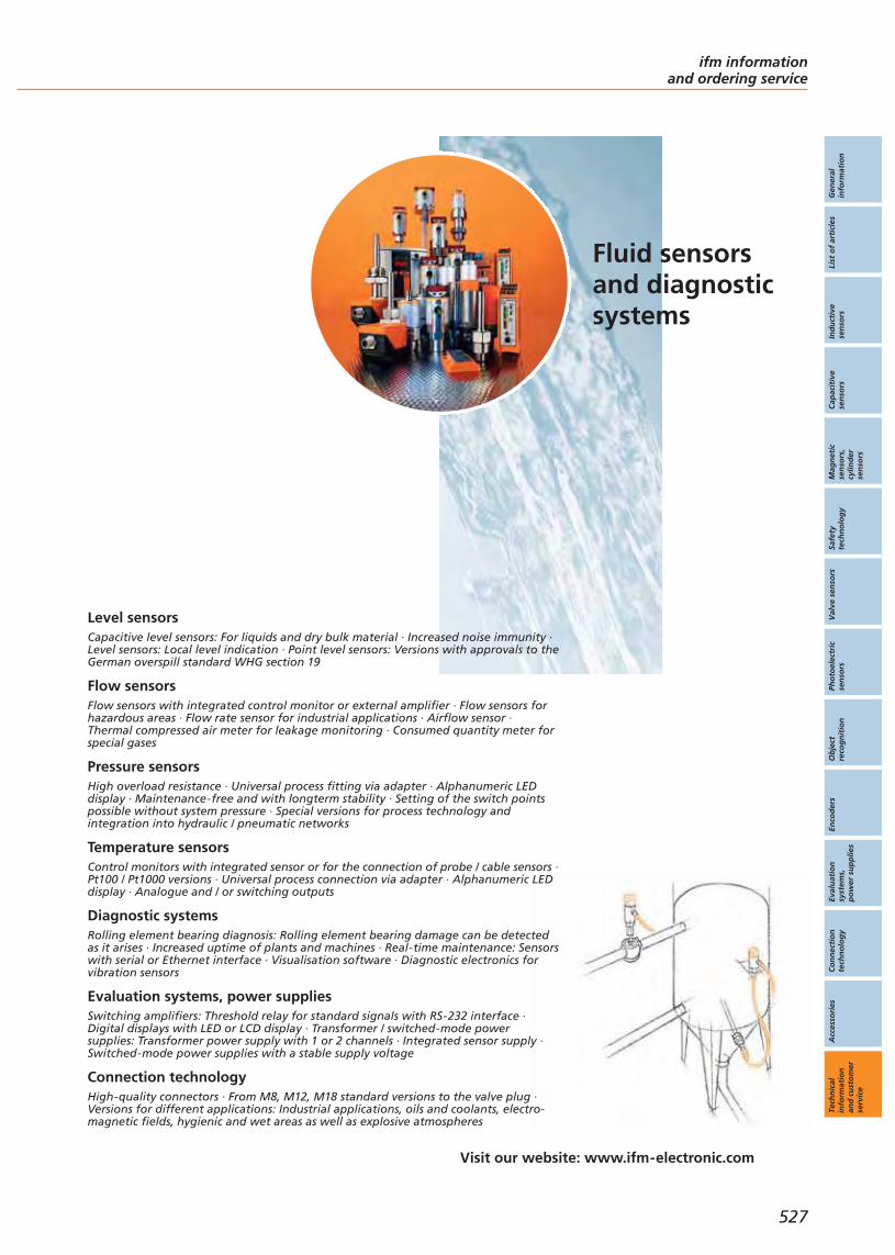
Gen
eral
info
rmat
ion
List
of
arti
cles
Ind
uct
ive
sen
sors
Cap
acit
ive
sen
sors
Mag
net
icse
nso
rs,
cylin
der
sen
sors
Safe
tyte
chn
olo
gy
Val
ve s
enso
rsPh
oto
elec
tric
sen
sors
Ob
ject
reco
gn
itio
nEn
cod
ers
Eval
uat
ion
syst
ems,
po
wer
su
pp
lies
Co
nn
ecti
on
tech
no
log
yA
cces
sori
esTe
chn
ical
info
rmat
ion
and
cu
sto
mer
serv
ice
Visit our website: www.ifm-electronic.com
ifm informationand ordering service
527
Fluid sensorsand diagnosticsystems
Capacitive level sensors: For liquids and dry bulk material · Increased noise immunity ·Level sensors: Local level indication · Point level sensors: Versions with approvals to theGerman overspill standard WHG section 19
Level sensors
Flow sensors with integrated control monitor or external amplifier · Flow sensors forhazardous areas · Flow rate sensor for industrial applications · Airflow sensor ·Thermal compressed air meter for leakage monitoring · Consumed quantity meter forspecial gases
Flow sensors
High overload resistance · Universal process fitting via adapter · Alphanumeric LEDdisplay · Maintenance-free and with longterm stability · Setting of the switch pointspossible without system pressure · Special versions for process technology andintegration into hydraulic / pneumatic networks
Pressure sensors
Control monitors with integrated sensor or for the connection of probe / cable sensors ·Pt100 / Pt1000 versions · Universal process connection via adapter · Alphanumeric LEDdisplay · Analogue and / or switching outputs
Temperature sensors
Rolling element bearing diagnosis: Rolling element bearing damage can be detectedas it arises · Increased uptime of plants and machines · Real-time maintenance: Sensorswith serial or Ethernet interface · Visualisation software · Diagnostic electronics forvibration sensors
Diagnostic systems
Switching amplifiers: Threshold relay for standard signals with RS-232 interface ·Digital displays with LED or LCD display · Transformer / switched-mode powersupplies: Transformer power supply with 1 or 2 channels · Integrated sensor supply ·Switched-mode power supplies with a stable supply voltage
Evaluation systems, power supplies
High-quality connectors · From M8, M12, M18 standard versions to the valve plug ·Versions for different applications: Industrial applications, oils and coolants, electro-magnetic fields, hygienic and wet areas as well as explosive atmospheres
Connection technology
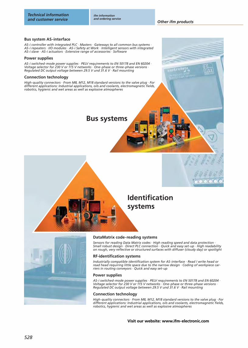
528
Visit our website: www.ifm-electronic.com
Other ifm products
Technical informationand customer service
ifm informationand ordering service
Visit our website: www.ifm-electronic.com
Connection technologyHigh-quality connectors · From M8, M12, M18 standard versions to the valve plug · Fordifferent applications: Industrial applications, oils and coolants, electromagnetic fields,robotics, hygienic and wet areas as well as explosive atmospheres
Bus systems
Identificationsystems
AS-i controller with integrated PLC · Masters · Gateways to all common bus systems ·AS-i repeaters · I/O modules · AS-i Safety at Work · Intelligent sensors with integratedAS-i slave · AS-i actuators · Extensive range of accessories · Software
Bus system AS-interface
AS-i switched-mode power supplies · PELV requirements to EN 50178 and EN 60204 ·Voltage selector for 230 V or 115 V networks · One-phase or three-phase versions ·Regulated DC output voltage between 29.5 V und 31.6 V · Rail mounting
Power supplies
Industrially compatible identification system for AS-interface · Read / write head orread head requiring little space due to the narrow design · Coding of workpiece car-riers in routing conveyors · Quick and easy set-up
RF-identification systems
Sensors for reading Data Matrix codes · High reading speed and data protection ·Small robust design · Direct PLC connection · Quick and easy set-up · High readabilityon rough, very reflective or structured surfaces with diffuser (cloudy day) or spotlight
DataMatrix code-reading systems
AS-i switched-mode power supplies · PELV requirements to EN 50178 and EN 60204 ·Voltage selector for 230 V or 115 V networks · One-phase or three-phase versions ·Regulated DC output voltage between 29.5 V und 31.6 V · Rail mounting
Power supplies
High-quality connectors · From M8, M12, M18 standard versions to the valve plug · Fordifferent applications: Industrial applications, oils and coolants, electromagnetic fields,robotics, hygienic and wet areas as well as explosive atmospheres
Connection technology
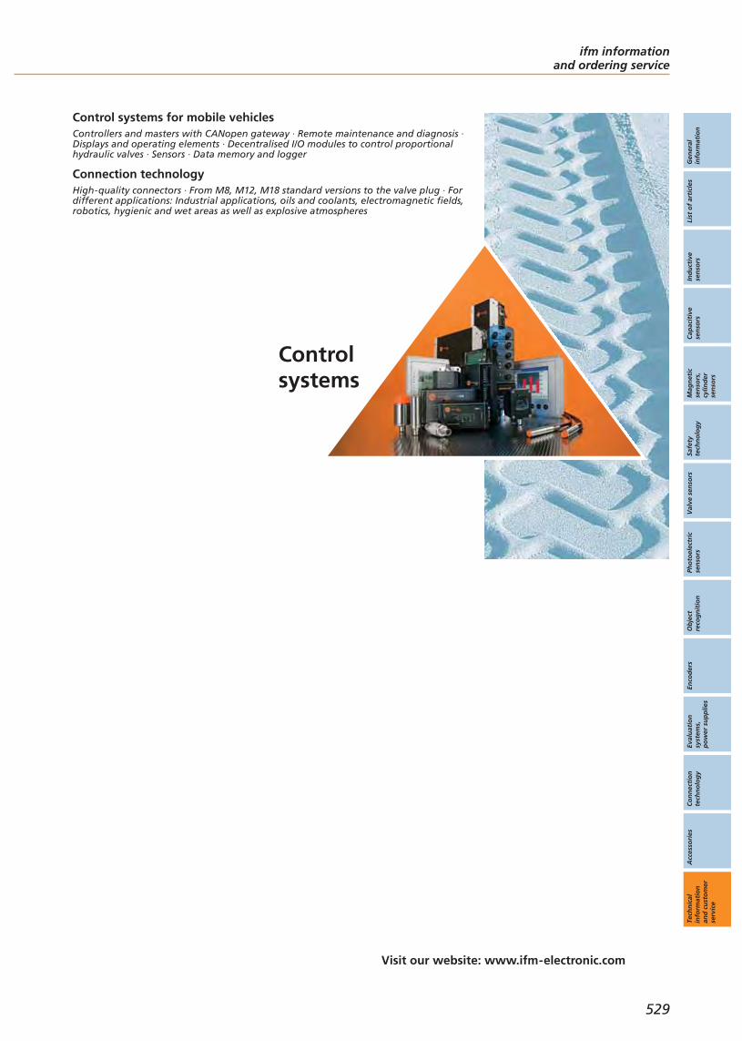
Gen
eral
info
rmat
ion
List
of
arti
cles
Ind
uct
ive
sen
sors
Cap
acit
ive
sen
sors
Mag
net
icse
nso
rs,
cylin
der
sen
sors
Safe
tyte
chn
olo
gy
Val
ve s
enso
rsPh
oto
elec
tric
sen
sors
Ob
ject
reco
gn
itio
nEn
cod
ers
Eval
uat
ion
syst
ems,
po
wer
su
pp
lies
Co
nn
ecti
on
tech
no
log
yA
cces
sori
esTe
chn
ical
info
rmat
ion
and
cu
sto
mer
serv
ice
529
ifm informationand ordering service
Visit our website: www.ifm-electronic.com
Controlsystems
Controllers and masters with CANopen gateway · Remote maintenance and diagnosis ·Displays and operating elements · Decentralised I/O modules to control proportionalhydraulic valves · Sensors · Data memory and logger
Control systems for mobile vehicles
High-quality connectors · From M8, M12, M18 standard versions to the valve plug · Fordifferent applications: Industrial applications, oils and coolants, electromagnetic fields,robotics, hygienic and wet areas as well as explosive atmospheres
Connection technology

Visit our website: www.ifm-electronic.com
Internet service
Technical informationand customer service
ifm informationand ordering service
530
*Some offered information is available country-specific.
www.ifm-electronic.comInformation around the clock andaround the globe in 18 languages on the internet.
• Information- product innovations- company news- exhibition info- locations- jobs
• Documentation- data sheets- operating instructions- manuals- approvals- CAD data
• Communication*- request for documents- recall service- live advice- newsletter
• Selection- interactive product selection aids- configuration tools- data sheet direct
• Animation- virtual product animations- flash movies (video sequences)
• Application- applications- product recommendations- calculation aids
• Transaction*- e-shop processing- e-procurement catalogues- B2B services

Gen
eral
info
rmat
ion
List
of
arti
cles
Ind
uct
ive
sen
sors
Cap
acit
ive
sen
sors
Mag
net
icse
nso
rs,
cylin
der
sen
sors
Safe
tyte
chn
olo
gy
Val
ve s
enso
rsPh
oto
elec
tric
sen
sors
Ob
ject
reco
gn
itio
nEn
cod
ers
Eval
uat
ion
syst
ems,
po
wer
su
pp
lies
Co
nn
ecti
on
tech
no
log
yA
cces
sori
esTe
chn
ical
info
rmat
ion
and
cu
sto
mer
serv
ice
ifm informationand ordering service
531
Visit our website: www.ifm-electronic.com
**Available in Germany, France, United Kingdom, Switzerland and in the USA.More countries in preparation.
Convenient order processingvia the e-shop** on the internet.
Secured authentication
Customer-related priceindication
Real time availability check
Personal product favourites
Online parcel tracking
Individual order history
Convenient quick input form
Simple order processing
Management of shippingaddresses
Confirmations by e-mail

Visit our website: www.ifm-electronic.com
Customer serviceOrdering service
Technical informationand customer service
ifm informationand ordering service
532
The company in close contact with youifm is present on all important markets – in more than 70 countries world-wide. Wherever you export, we are always close to you. In Germany aloneover 100 employees in 7 branches advise our customers. ifm production sitesare located in Germany and the USA. We support you with work-shops andseminars in our worldwide training centres and in your plant.
At home in your industryWe provide you with standard solutions and concepts tailored to the require-ments of your industry. This is backed by the knowledge of our engineerswho are always up to date. Our worldwide application know-how is con-stantly updated via our company own Intranet.Our special project service helps you with tenders and project plannings.
Investments in product availabilityFor our customers we invested a lot in development and production capaci-ties. Due to state-of-the-art production technology we can manufacture bigquantities quickly and in a consistently high quality. The central logistic centre guarantees high availability of our products.

ifm informationand ordering service
533
Visit our website: www.ifm-electronic.com
Gen
eral
info
rmat
ion
List
of
arti
cles
Ind
uct
ive
sen
sors
Cap
acit
ive
sen
sors
Mag
net
icse
nso
rs,
cylin
der
sen
sors
Safe
tyte
chn
olo
gy
Val
ve s
enso
rsPh
oto
elec
tric
sen
sors
Ob
ject
reco
gn
itio
nEn
cod
ers
Eval
uat
ion
syst
ems,
po
wer
su
pp
lies
Co
nn
ecti
on
tech
no
log
yA
cces
sori
esTe
chn
ical
info
rmat
ion
and
cu
sto
mer
serv
ice
Request for quotation
Request for sample
Request for technical data
Quantity required Order no. Quantity required Order no.
Company
Department
Name
Street
Post code / town
Tel.
Date
First name
Signature

Technical informationand customer service
ifm informationand ordering service
Addresses
534
Visit our website: www.ifm-electronic.com
Argentina and UruguayAparatos ElèctricosAutomaticos S.A.C.I.F.Asunción 21301419 - Buenos AiresArgentinaTel. +54 / 11 / 45 74 1555Fax +54 / 11 / 45 74 [email protected]
Australiaifm efector pty ltd.P.O. Box 4084Suite 3, 745 Springvale RoadMulgrave VIC 3170Tel. 1300 365 088Fax 1300 365 [email protected]
Austriaifm electronic gmbhWienerbergstraße 41Gebäude E1120 ViennaTel. +43 / 1 / 617 45 00Fax +43 / 1 / 617 45 00 [email protected]
BangladeshSensotec AutomationRed Crescent Chamber87, Motijheel CommercialAreaDhaka 1000BangladeshTel. +880 171 546 [email protected]
BelarusDEPOSIT INVESTJoint-Stock CompanyBlock 2, 27 Zheleznodorovhnaya street220089 MinskRepublic of BelarusTel. +375-17-270 75 06Fax +375-17-270 75 [email protected]
Belgium and Luxembourgifm electronic n.v./s.a.Zuiderlaan 911731 ZellikBelgiëTel. +32 2 481 0220Fax +32 2 463 [email protected]
Brazilifm electronic Ltda.Rua Eleonora Cintra, 140Jardim Analia Franco03337-000 São Paulo/SPTel. +55-11-6672-1730Fax +55-11-6673-3501info.br@ifm-electronic.comwww.ifm-electronic.com.br
BulgariaANIPALVranja Str. 301233 SofiaTel. +359-2-33 32 37Fax +359-2-931 15 [email protected]
Canadaifm efector Canada Inc. 700 Dorval Drive/CorporateCentreOakville; L6K3V3 OntarioTel. +1-800-441-8246 Fax [email protected]
ChileElectronica IndustrialSchädler y Cia. Ltda.Av. Antonio Varas 1871Providencia6641545 SantiagoTel. +56 / 2 / 274 74 30Fax +56 / 2 / 204 93 [email protected]
Chinaifm electronic (Shanghai)Co., LtdBuilding 4 56 Meisheng RoadWaigaoqiao Free Trade ZoneShanghaiPeople’s Republic of ChinaTel. +86-21-51 17 27 18 Fax +86-21-51 17 27 19 [email protected] www.ifm-electronic.com.cnifm electronic (HK) LtdUnits 1103-1104, 11/F. Tower 2, MetroplazaNo. 223 Hing Fong Road KWAI CHUNGN.T., HONG KONGTel. +852 9457-0360Fax +852 3697-0222info.hk@ifm-electronic-comwww.ifm-electronic.hkEverharmony-Enterprise, Inc26, Lane 63Tung Hwa South Road, Sec. 2P.O. Box 96-47 Taipei Tel. +886 / 2 / 270 700 69 Fax +886 / 2 / 270 247 [email protected]
Croatiaifm electronic gmbhWienerbergstr. 41Gebäude EA-1120 WienTel. +43 / 1 / 617 45 00Fax +43 / 1 / 617 45 00 [email protected]
Czech Republicifm electronic spol.s.r.o.U Krízku 571252 43 PragueTel. +420 / 2 / 67 990 211 Fax +420 / 2 / 67 750 180 [email protected]
Denmarkifm electronic a/sRingager 4A, 1.sal tv.2605 BrøndbyTel +45 70 20 11 08Fax +45 70 20 11 [email protected]
Dominican RepublicWECH AUTOCONTROLES S. A.Ave. Romulo Betancourt 2158 Edificio WechUrb. RenacimientoSanto DomingoDominican RepublicTel.: + 1 809-531-0550Fax: + 1 [email protected]
EgyptEgyptian Establishment forElectromechanical SuppliesMr. Ahmed Gouda27 Al-Salam StreetAl Arezona, Al Haram RoadGiza 12111, CairoTel. +20 / 2 / 586 49 49Fax +20 / 2 / 586 49 49Mobile +20 10 10 61 [email protected]
EstoniaPesmel Estonia LTDSegu 476505 SaueEstoniaTel.: +372 674 73 30 Fax: +372 674 73 [email protected]
Finlandifm electronic oyVaakatie 5 00440 Helsinki Tel. +358 / 9 / 751 777 00 Fax +358 / 9 / 751 777 10 [email protected]
Franceifm electronicSiège :Savoie Technolac BP22673374 Le Bourget du LacAgence commerciale :Immeuble Uranus1-3 rue Jean Richepin93192 NOISY LE GRANDCEDEXTél: 0820 22 30 01Fax: 0820 22 22 [email protected]
Germanyifm electronic gmbhTeichstraße 445127 EssenTel. +49 201 2 42 20Fax +49 201 2 42 22 [email protected]
Greeceifm electronic monoprosopi E.P.E.27, Andrea Papandreou Street15125 AmaroussiGreeceTel +30 210 61 800 90Fax +30 210 61 994 [email protected]
Hungaryifm electronic kft.Közép u. 16. II.em. 208. irodaH-9024 GyörTel. +36-96 / 518-397Fax +36-96 / 518-398www.ifm-electronic.hu
Indiaifm electronic India Branch OfficePlot No. P-39/1MIDC Gokul ShirgaonKolhapur – 416234Maharashtra State, IndiaTel. +91 / 231 / 267 27 70Fax +91 / 231 / 267 23 [email protected]
IndonesiaPT Indoserako SejahteraJl. P. Jayakarta 121 No. 5910730 Jakarta PusatTel. +62 / 21 6 24 8923Fax +62 / 21 6 24 [email protected]
IranMEHR KANAZ Co.No. 31, Koosha St. Shariati Ave.P.O. Box 19395 - 4481 Teheran Tel. +98 / 21/ 2222 6994Fax +98 / 21/ 2222 [email protected]
Irelandifm electronic (Ireland) Ltd.No. 7, The CourtyardKilcarbery Business ParkNew Nangor RoadClondalkinDublin 22Tel. +353 / 1 / 413 60 66Fax +353 / 1 / 457 38 [email protected]
IsraelAstragal Ltd.3, Hashikma Str.Azur 58001P.O. Box 99Azur 58190Tel. +972 / 3 / 5 59 16 60Fax +972 / 3 / 5 59 23 [email protected]
Italyifm electronicCentro Direzionale ColleoniPalazzo Andromeda 2Via Paracelso No. 1820041 Agrate-Brianza (Milan)Tel. +39 / 68 99 982Fax +39 / 68 99 [email protected]
Japanefector co. ltd.Chiba Higashi Techno Green Park2-9-20 OkayamadaiTogane-shi, Chiba 283-0826Tel. +81 / 475 50 3003Fax +81 / 475 50 [email protected]
JordanAl Mashreqan Trading SuppliesP.O.Box.85105411185 SwaifiehAmman - Jordan.Tel. +962 6 581 8841Fax +962 6 581 [email protected]
Koreaifm electronic Ltd.2F Hyundai Liberty House 201Hannam-Dong 258, Yongsan-Gu, Seoul, KoreaTel +82 2-790-5610Fax +82 2-790-5613info.kr@ifm-electronic.comwww.ifm-electronic.krEnterprises Co., Ltd.Suite 404 Royal Plaza 864-1Jnaghang, Ilsan410-837 Goyang, Gyunggi-DoTel +82 31 903 3731Fax +82 31 908 [email protected]
LatviaEC SystemsKatlakalna Str. 4A1073 RigaLatviaTel.: +371 724 1231Fax: +371 724 [email protected]
LebanonMiddle East DevelopmentCo. SAL (MEDEVCO)Medevco Building Jeita Main Road Jeita - Kesrouan LebanonMail address :P.O.Box 67 Jounieh LebanonTel + 961-9-233550 Fax + 961-9-233554 [email protected]
ifm informationand ordering service
535
LithuaniaElinta UABPramones pr.. 16E51187 KaunasLithuaniaTel.: +370 37 351 987Fax: +370 37 452 [email protected]
Malaysiaifm electronic Pte. LtdMalaysian Branch Office12.03A Level 12, MenaraSummitPersiaran Kewajipan USJ 147600 UEP - Subang Jaya,Selangor.Tel. +60 / 3 / 8024 5022Fax +60 / 3 / 8024 [email protected] electronicAsia Regional OfficeNo. 21, Jalan Kemunting,Taman Kebun The80250 Johor BahruJohor, West MalaysiaTel. +60 / 7 / 332 5022Fax +60 / 7 / 332 [email protected]
Mexicoifm efector S. de R.L. de C.V.Anillo Periférico, 1816-1Col. Hacienda San JerónimoMonterrey, N.L.Mexico 64630Tel. +52-81-8040-3535Fax +52-81-8040-2343www.ifmefector.mx
Netherlandsifm electronic b.v.Deventerweg 1 E3843 GA HarderwijkTel. +31 / 341 438 438Fax +31 / 341 438 [email protected]
New Zealandifm efector pty ltd.Unit B, 20 Cain RoadPenrose, AucklandTel. +64 / 95 79 69 91Fax +64 / 95 79 92 [email protected]
NigeriaAutomated Process Ltd3rd Floor, 32 Lagos AbeokutaExpresswayNear Cement Bus StopDopemu, AgegeLagos State, NigeriaTel. + 234 / 01 / 4729 967Fax + 234 /01 / 4925 [email protected]
NorwaySiv.Ing. J.F.Knudtzen ASBillingstadsletta 971396 BillingstadPostboks 1601378 NesbruTel. +47 / 66 98 33 50Fax +47 / 66 98 09 [email protected]
OmanTechnical Engineering Company LLC.P.O.Box. 59 Madinat Al Sultan QaboosPostal Code 115 Sultanate of OmanTel + 968 24503593Fax + 968 [email protected]
PakistanAB AutomationShop No.2. Rubab ChamberM.A. Jinnah RoadOff Sarai RoadKarachiTel. +92 / 21 / 2412 278Fax +92 / 21 / 2422 [email protected]
Perudekatec s.a.c.Los Calderos 188Urb. Vulcano, AteLima / PeruTel. +511 / 348 0293Tel. +511 / 348 0458Tel. +511 / 348 2269Fax +511 / 349 [email protected]
PhilippinesGram Industrial, Inc.Unit 410 Common GoalTowerFinance cor. Industry St.,Madrigal Business Park,Ayala Alabang, MuntinlupaCity1770 Philipines Telefax: (+632) 850-8496 Tel.: (+632) [email protected]
Polandifm electronic Sp.z o.o.ul. Kosciuszki 175PL 40-524 KatowiceTel. +48 / 32 / 60 87 454Fax +48 / 32 / 60 87 [email protected]
Portugalifm electronic – Sucursal em PortugalAvenida da Republica 25034430-208 Vila Nova de GaiaTel. +351 / 22 / 37 17 108Fax +351 / 22 / 37 17 [email protected]
Romaniaifm electronic s.r.l.Str. Cristian Nr. 5550073 SibiuTel.: 0040 269 224550Fax: 0040 269 [email protected]
Russiaifm electronicIbragimova, 31, k.50office 607105318 MoscowTel.: +7 (095) 101-44-14Fax: +8 (501) [email protected]
Saudi ArabiaNoor Al-Shomoe for Electric & MaintenanceKing Khalid Street, Cross 5P.O. Box 2571Al-Khobar 31952Kingdom of Saudi ArabiaTel. +9 663 864 49 58Fax +9 663 894 63 [email protected]
Singaporeifm electronic Pte. Ltd.25, Intern. Business Park#03-104 German Center609 916 SingaporeTel. +65 / 6 / 5 62 86 61Fax +65 / 6 / 5 62 86 [email protected]
Slovakiaifm electronic spol. s.r.o.Rybnicna 40835 54 BratislavaTel. +421 / 2 / 44 87 23 29Fax +421 / 2 / 44 64 60 [email protected]
South AfricaShorrock Automation (Pty) Ltd.Postnet SuitePrivate Bag X8Elardus Park 2190047 PretoriaFor Visitors and mail-orderaddress: Shorrok House44 Sovereign DriveRoute 21, Corporate ParkIrene Ext. 30Centurion, Pretoria Tel. +27 / 12 / 345 44 49Fax +27 / 12 / 345 51 [email protected]
Spainifm electronic – Sucursal en EspañaEdificio Prima Muntadas AParc Mas BlauC/Berguedà 108820 El Prat de LlobregatTel. +34 / 93 / 479 30 80Fax +34 / 93 / 479 30 [email protected]
Swedenifm electronic abHallavägen 10 512 60 Överlida Office Gothenburg:Drakegatan 641250 GothenburgTel. +46 / 325 / 66 15 00 Tel. +46 / 325 / 66 15 50Fax +46 / 325 / 66 15 [email protected]
Switzerlandifm electronic agAltgraben 274624 HärkingenTel. +41 / 62 / 388 80 30Fax +41/ 62 / 388 80 [email protected]
SyriaI.E.C. Industrial Engineering CenterP.O. Box 15 Sehnaya, DamascusSyriaTel. + 963 11 532 13 19Fax. + 963 11 442 12 [email protected]
ThailandSang Chai Meter Co., Ltd.694/23-26 Phaholyothin RoadSamsen Nai, Phayathai Bangkok 10400 Tel. +66 / 2 / 616 8031Fax +66 / 2 / 616 [email protected]
Turkeyifm electronic Ltd. Sti.Perpa Ticaret Merkezi ElektrokentA Blok Kat:11 NO: 1557/155934384 Okmeydani/ IstanbulTelefon +90 / 212 / 210 5080Faks +90 / 212 / 221 [email protected]
Ukrainaifm electronicMariny Raskovoj 1102660 KievUkraineTel. +380 44 501 8543Fax +380 44 501 [email protected]
United Arab Emirates – DubaiNoor Al-Shomoe ElectricalEquipments Est.P.O.Box. 64052Unit no. 36Reef Real EstateJebel Ali Industrial Area no. 3DubaiUnited Arab Emirates.Tel.. + 971 4 880 3838Fax.+ 971 4 880 3883Mobile: + 971 [email protected] Arab Emirates – Abu DhabiAl Injazat Technical Trading ServicesP.O. Box 42895Abu DhabiUnited Arab EmiratesTel. +971 2 622 6030Fax +971 2 622 [email protected]
United Kingdomifm electronic Ltd.efector HouseKingsway Business ParkOldfield RoadHamptonMiddlesex TW12 2HDTel. +44 / 20 / 8213 0000Fax +44 / 20 / 8213 [email protected]
USAefector inc.805 Springdale Drive Exton, PA 19341 Tel. +1 / 610 524 2000 Fax +1 / 610 524 [email protected]
VenezuelaPetrobornas, C.A.Zona Industrial Los PinosAvda. Principal UD 304C. C. Los Pinos - Local "E"(8015) - Puerto Ordaz - Edo.BolivarVenezuelaTel. +58 / 286 / 717 31 52Fax +58 / 286 / 717 31 [email protected]
VietnamThien Viet Electrical Serviceand Trading Co., Ltd.784 Dien Bien Phu Str.Ward 11, Dist. 10Ho-Chi-Minh-City, Viet NamTel. +84 / 8 / 830 9916 Fax +84 / 8 / 830 [email protected]
Gen
eral
info
rmat
ion
List
of
arti
cles
Ind
uct
ive
sen
sors
Cap
acit
ive
sen
sors
Mag
net
icse
nso
rs,
cylin
der
sen
sors
Safe
tyte
chn
olo
gy
Val
ve s
enso
rsPh
oto
elec
tric
sen
sors
Ob
ject
reco
gn
itio
nEn
cod
ers
Eval
uat
ion
syst
ems,
po
wer
su
pp
lies
Co
nn
ecti
on
tech
no
log
yA
cces
sori
esTe
chn
ical
info
rmat
ion
and
cu
sto
mer
serv
ice

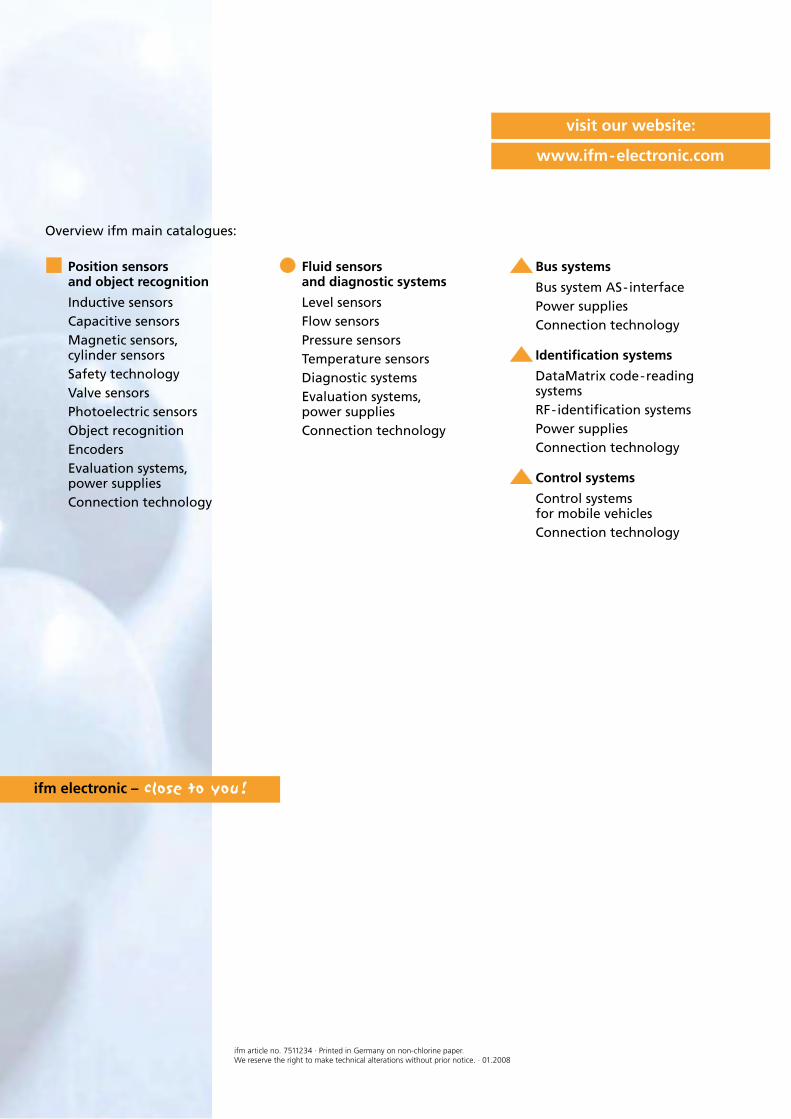
ifm article no. 7511234 · Printed in Germany on non-chlorine paper.We reserve the right to make technical alterations without prior notice. · 01.2008
ifm electronic –
www.ifm-electronic.com
visit our website:
Overview ifm main catalogues:
Position sensorsand object recognition
Inductive sensorsCapacitive sensorsMagnetic sensors,cylinder sensorsSafety technologyValve sensorsPhotoelectric sensorsObject recognitionEncodersEvaluation systems,power suppliesConnection technology
Fluid sensorsand diagnostic systems
Level sensorsFlow sensorsPressure sensorsTemperature sensorsDiagnostic systemsEvaluation systems,power suppliesConnection technology
Bus systems
Bus system AS-interfacePower suppliesConnection technology
Identification systems
DataMatrix code-readingsystemsRF-identification systemsPower suppliesConnection technology
Control systems
Control systemsfor mobile vehiclesConnection technology
Position sensors andobject recognition
Catalogue 2008/2009
ww
w.if
m-e
lect
ron
ic.c
om
fluid sensorsand diagnostic
systems
bus,identification
and control systems
positionsensors
and objectrecognition
Cat
alo
gu
e 20
08/200
9if
m e
lect
ron
icPo
siti
on
sen
sors
an
d o
bje
ct r
eco
gn
itio
n