
Product innovations automation technology - IFM
111
Product innovations automation technology NEWSBOOK 2019
-
Upload
khangminh22 -
Category
Documents
-
view
3 -
download
0
Transcript of Product innovations automation technology - IFM

Product innovations automation technology
NEWSBOOK 2019

3
Inductive sensors
Encoders
Position sensors
Nothing escapes its attention: smart sensor in flat pack design with IO-LinkFull-metal sensors that always know where the target isFull-metal sensors for use in the smallest of spaces
(04.2019)
(11.2018)
(11.2018)
6 - 7 8 - 9 10 - 11
Laser sensors / distance sensors
Millimetre perfect. The new OGD Precision from the PMDLineFarsighted: the OGD Long Range – new compact PMDLine sensor
(11.2018)
(11.2018)
Ingeniously simple: display guide for the perfect setting
Capacitive sensors
(04.2018) 12 - 13
It can take a beating! Robust position sensor for welding applicationsHard on the outside, smart on the inside: predict downtime in advanceSafety that attracts! Magnetically-coded sensors
Magnetic sensors
(04.2019)
(04.2019)
(04.2018)
14 - 15 16 - 17 18 - 19
28 - 29 30 - 31
Ultrasonic sensors
Continuous level measurement and object detection to up to 8 m (11.2018) 20 - 21
Stainless steel encoders for wet areas (04.2018)
Sensors for motion control
36 - 37
Precise inclination measurement in dynamic applications
Inclination sensors
(04.2019) 38 - 39
Multifunctional analogue display with IO-Link
Systems for evaluation of standard signals
(04.2018) 40 - 41
Photoelectric sensors
The measure of things: measuring photoelectric sensor O8 in compact designOG Cube: photoelectric sensor in rectangular design with M18 thread
(04.2019)
(04.2019)
22 - 23 24 - 25
Optical fork sensors / optical angle sensors
Easy, quick and precise from all angles (11.2018) 26 - 27
TOP
TOP
TOP
Feedback systems for valves and valve actuators
Continuous position feedback and diagnostics (04.2018) 34 - 35
Touch sensors
Show your colours! Multi-colour touch sensors with IO-Link (04.2019) 32 - 33
Decentralised display, preprocessing and conversion of analogue signals
Systems for signalling and indication
(11.2018) 42 - 43

44
Pressure sensors
Process sensors
Pressure transmitter for hygienic applications with IO-Link and 4...20 mANew pressure sensors with robust pressure measuring cell for homogenisersAll at sea? Pressure, temperature, level and flow sensors with DNV-GL
(04.2018)
(04.2019)
(04.2018)
54 - 55 56 - 57 58 - 59
Thermal compressed air meter of the highest levelMechatronic flow sensors – especially for oils
Flow sensors / flow meters
(04.2019)
(11.2018)
60 - 61 62 - 63
Temperature sensors
Fast hygienic temperature transmitter up to 200 °CSensors for the food industry with free factory certificate
(04.2019)
(11.2018)
64 - 65 66 - 67
Industrial communication
Worldwide innovation: AS-i signal transmission via fibre optic
AS-Interface wiring technology
(11.2018) 68 - 69
TOP
TOP
Industrial imaging
3D volume control for segmented containers3D sensors for flexible automation of robot grippersDepalletising of uniform packages made easy
3D sensors
(04.2019)
(11.2018)
(11.2018)
44 - 45 46 - 47 48 - 49
IO-Link master for intelligent sensors in the control cabinetIO-Link master: connection of sensors to the PLC and to the IT worldIO-Link master meets wiring systemStarter kit IO-Link master: fieldbus systemsInternet of Things starter kit
IO-Link masters
(11.2018)
(11.2018)
(11.2018)
(04.2019)
(04.2019)
70 - 71 72 - 73 74 - 75 76 - 77 78 - 79
IO-Link
Illumination
LED dome – the right illumination makes it possible (11.2018) 50 - 51
Safety technology
Safety light grids
All in one unit: light grid with integrated muting unit (04.2019) 52 - 53
IO-Link device: actuator switching via IO-LinkIO-Link modules collect and convert digital signals
(04.2019)
(11.2018)
80 - 81 82 - 83
IO-Link modules
Increased IO-Link range with new repeaters (04.2019) 84 - 85
IO-Link accessories

55
Identification systems
New antenna versions, perfect for the DTE10x RFID systemLarge selection of RFID antennas with IO-LinkComplete HF RFID system in a compact housing
RFID 13.56 MHz
(04.2019)
(04.2019)
(04.2019)
86 - 87 88 - 89 90 - 91
Connection technology
Use in wet areas and in the food and beverage industry
ecolink M12, A coded – now wirable for hygienic and wet areasecolink M12/RJ45: the new connection for special applicationsecolink M8 and M12 – T splitters for demanding applications
(04.2018)
(11.2018)
(04.2019)
96 - 97 98 - 99 100 - 103
TOP
Power supplies
Electronic 24 V DC circuit breakers
Circuit protection with monitoring function for the 24 V secondary circuit (11.2018) 106 - 107
ifm system sales – solutions for your installation from a single source 108 - 109
The ifm sales platform 110 - 111
Powerful multicode reader – simple like a sensor
1D / 2D code readers
(04.2019) 94 - 95
Far-sighted: UHF RFID system with integrated antenna
RFID UHF
(04.2019) 92 - 93
TOP
Always a reliable connection. ecolink M12 – even for special applications
M12 sockets with LEDs
(04.2019) 104 - 105

6
Position sensors
Nothing escapes itsattention: smart sensor in flat packdesign with IO-LinkInductive sensors
Continuous position feedbackvia IO-Link
Switch points can be easily adapted via IO-Link at any time
Setting options PNP/NPN orNO/NC help to reduce storagecosts
Long life and robustness thanksto flush installation and a hightemperature range
Compact rectangular housingfor installation in restricted spaces
Space-saving and robustThe new compact IQ rectangular housing is ideal for the limited spacefound in conveyor technology and factory automation. The flush installation of the sensor facilitates mounting and prevents mechanical damage. Together with a high impact and vibration resistance and a wide temperature range, this ensures long life.
Versatile thanks to IO-LinkIn order to solve demanding position detection tasks, the distance value iscontinuously provided via IO-Link. Two switch points can be set to the nearest millimetre via IO-Link. Besides, the sensor provides various configurationoptions, such as NO/NC or PNP/NPN, which reduces storage costs for different sensor types.
7
(04.2019)
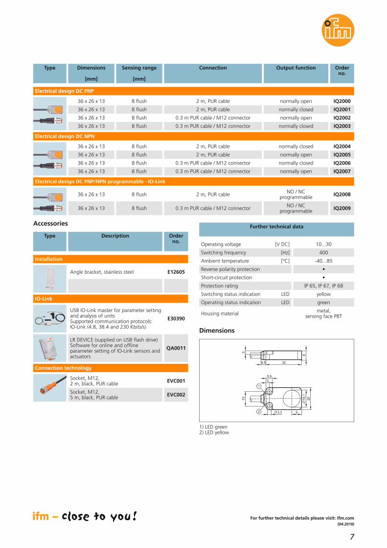
Dimensions
[mm]
Output function Orderno.
Type Sensing range
[mm]
Operating voltage [V DC] 10...30
Switching frequency [Hz] 400
Ambient temperature [°C] -40...85
Reverse polarity protection •
Short-circuit protection •
Protection rating IP 65, IP 67, IP 68
Switching status indication LED yellow
Operating status indication LED green
Further technical data
Dimensions
Electrical design DC PNP
8 flush36 x 26 x 13 normally open IQ2000
8 flush36 x 26 x 13 normally closed IQ2001
Connection
2 m, PUR cable
2 m, PUR cable
8 flush36 x 26 x 13 normally open IQ20020.3 m PUR cable / M12 connector
8 flush36 x 26 x 13 normally closed IQ2003
8 flush36 x 26 x 13 normally closed IQ2004
0.3 m PUR cable / M12 connector
2 m, PUR cable
8 flush36 x 26 x 13 normally open IQ20052 m, PUR cable
8 flush36 x 26 x 13 normally closed IQ20060.3 m PUR cable / M12 connector
8 flush36 x 26 x 13 normally open IQ20070.3 m PUR cable / M12 connector
For further technical details please visit: ifm.com
Electrical design DC NPN
8 flush36 x 26 x 13 NO / NC programmable IQ20082 m, PUR cable
8 flush36 x 26 x 13 NO / NC programmable IQ20090.3 m PUR cable / M12 connector
Electrical design DC PNP/NPN programmable · IO-Link
Housing material metal,sensing face PBT
USB IO-Link master for parameter settingand analysis of unitsSupported communication protocols: IO-Link (4.8, 38.4 and 230 Kbits/s)
E30390
LR DEVICE (supplied on USB flash drive)Software for online and offlineparameter setting of IO-Link sensors andactuators
QA0011
IO-Link
Angle bracket, stainless steel E12605
Type Description Orderno.
Accessories
Installation
Socket, M12,2 m, black, PUR cable EVC001
Socket, M12,5 m, black, PUR cable EVC002
Connection technology
20
13
3
5,9
3,3 9
16
,1
1
2
4,5
3
32
8
1) LED green2) LED yellow

8
Position sensors
Full-metal sensorsthat always knowwhere the target is
Inductive sensors
Reliable end position detectionvia distance measurement
High-grade stainless steel housing (316L)
Large temperature range up to 100 °C
For universal use, IP 65 to IP 69K
Adjustable thanks to IO-Linksmart sensor profile
Full-metal IO-Link sensorsIn harsh operating conditions, full-metal sensors cope with multiple requirements. Their large temperature range and high protection ratingsallow for universal use. Due to the measuring sensor, the distance to thetarget can be permanently monitored. A change in the mechanical distances is immediately detected, allowing for preventive readjustment so as to reduce possible standstill times.The smart sensor profile provides various setting options. Switch points andoutput functions can be configured. Stock-keeping of different sensor typesis no longer necessary as any required setting can be obtained by means ofthe IO-Link interface.

9
(11.2018)
Measuringrange[mm]
Ambienttemperature
[°C]
Orderno.
Type Total length
[mm]
Operating voltage [V DC] 10...30
Current rating [mA] 100
Switching output SIO mode
NO, NC, PNP, NPN and switch point
programmable via IO-Link SSC1
Protection class III
IO-Link revision 1.1
Type of transmission COM2 (38.4 kbaud)
Profile Smart sensor
SIO mode •
Required master port class A
Min. process cycle time [ms] 3
IO-Link mode distance value 12 bits cyclical
Linearity error [%] ± 2 of the final value ofthe measuring range
Repeatability [%] ± 1 of the final value ofthe measuring range
Outputs 2 x SSC
Output functionsinglepoint,
twopoint and window mode
Housing material high-grade stainless steel(316L)
Further technical data
Connection technology
Type Description Orderno.
49
45
M12
x1
M12
x1
60
LED 4 x 90° 17
4
Dimensions
IFC277, IFT258
M18
x1
M12
x1
45
49
60
LED 4 x 90° 24
4
IGC260, IGT260
53
49
M30
x1,
5
5
52
65
M12
x1
LED 4 x 90° 36
IIC236, IIT244
Suitable for industrial, mobile, cooling and lubricating applications with M12 connector
60 0.375...3.75 -40...85 IFC277M12 x 1
M18 x 1 60 0.75...7.5 -40...85 IGC260
Protection rating
IP 65, IP 66, IP 67, IP 68, IP 69K
IP 65, IP 66, IP 67, IP 68, IP 69K
M30 x 1.5 65 1.3...13 -40...85 IIC236IP 65, IP 66, IP 67, IP 68, IP 69K
60 0.375...3.75 0...100 IFT258M12 x 1
M18 x 1 60 0.75...7.5 0...100 IGT260
IP 65, IP 66, IP 67, IP 68, IP 69K
IP 65, IP 66, IP 67, IP 68, IP 69K
M30 x 1.5 65 1.3...13 0...100
Output
IO Link / programmable
IO Link / programmable
IO Link / programmable
IO Link / programmable
IO Link / programmable
IO Link / programmable IIT244IP 65, IP 66, IP 67, IP 68, IP 69K
Type Description Orderno.
Accessories
Angle bracket for M30 design,stainless steel E10737
Angle bracket for M12 design,stainless steel E10735
Angle bracket for M18 design,stainless steel E10736
For further technical details please visit: ifm.com
Socket, M12, 4 poles5 m, grey, MPPE cable EVF001
Socket, M12, 4 poles2 m, grey, MPPE cable EVF064
Wiring diagram
L+
L
1
4
3
L+
L
1
4
3
Suitable for hygienic applications with M12 connector
Socket, M12, 4 poles2 m, black, PUR cable EVC001
Socket, M12, 4 poles5 m, black, PUR cable EVC002

10
Position sensors
Full-metal sensorsfor use in the smallest of spaces
Inductive sensors
High-quality stainless steel housing
Compact dimensions for use in the smallest of spaces
Large temperature range up to 100 °C
Easy connection via M12 connector
Thread area can be entirely used
IP 65 to IP 69K for greater reliability
Full-metal sensorsWherever sensors have to cope with harsh operating conditions, full-metalsensors are the right choice. Even temperatures up to 100 °C do not affectreliable end position detection. The high-quality stainless steel housing in combination with the ecolink connector allows for permanent use even when in contact with cleaning agents and humidity. Increased sensing ranges guarantee reliable detection and provide sufficient excess gain.The compact dimensions and the possibility to mount sensors of the same type directly next to each other allow for permanent and reliable endposition detection even in the smallest of spaces.
11
(11.2018)
Sensing range
[mm]
Ambienttemperature
[°C]
Orderno.
Type Total length
[mm]
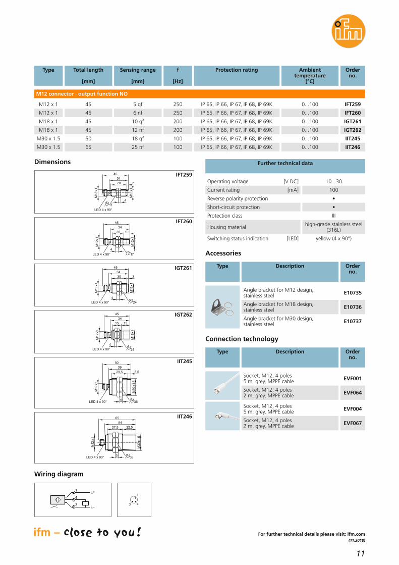
Operating voltage [V DC] 10...30
Current rating [mA] 100
Reverse polarity protection •
Short-circuit protection •
Protection class III
Housing material high-grade stainless steel(316L)
Switching status indication [LED] yellow (4 x 90°)
Further technical data
Connection technology
Type Description Orderno.
34
28
M12
x1
17
4
M12
x1
45
LED 4 x 90°
2
Dimensions
IFT259
4
17LED 4 x 90°
20
34
45
M1
2x1
M1
2x1
10
IFT260
M18
x1
M12
x1
30
45
34
4
LED 4 x 90°
3
24
IGT261
LED 4 x 90°
45
34
1515
M1
2x1
4
M1
8x1
24
IGT262
5,5
M30
x1,
5
39
29,5
50
M12
x1
LED 4 x 90°5
36
IIT245
54
27,5
M30
x1,
5
5
65
M12
x1
22,5
36LED 4 x 90°
IIT246
M12 connector · output function NO
45 5 qf 0...100 IFT259M12 x 1
M12 x 1 45 6 nf 0...100 IFT260
f
[Hz]
250
Protection rating
IP 65, IP 66, IP 67, IP 68, IP 69K
250 IP 65, IP 66, IP 67, IP 68, IP 69K
M18 x 1 45 10 qf 0...100 IGT261200 IP 65, IP 66, IP 67, IP 68, IP 69K
45 12 nf 0...100 IGT262M18 x 1
M30 x 1.5 50 18 qf 0...100 IIT245
200 IP 65, IP 66, IP 67, IP 68, IP 69K
100 IP 65, IP 66, IP 67, IP 68, IP 69K
M30 x 1.5 65 25 nf 0...100 IIT246100 IP 65, IP 66, IP 67, IP 68, IP 69K
Type Description Orderno.
Accessories
Angle bracket for M30 design,stainless steel E10737
Angle bracket for M12 design,stainless steel E10735
Angle bracket for M18 design,stainless steel E10736
For further technical details please visit: ifm.com
Socket, M12, 4 poles5 m, grey, MPPE cable EVF001
Socket, M12, 4 poles2 m, grey, MPPE cable EVF064
Socket, M12, 4 poles5 m, grey, MPPE cable EVF004
Socket, M12, 4 poles2 m, grey, MPPE cable EVF067
Wiring diagram
4
1
3
L+
L
1
4
3

12
Position sensors
Ingeniously simple: display guide for the perfect setting
Capacitive sensors
Unique visualisation and handling concept via LED display
See and compensate switchpoint movement
IP 69K gives high ingress resistance
PNP/ NPN, NO/ NC, timerfunction
For medium temperatures up to 110 °C
Visualised switch pointThe new capacitive sensors stand out not only because of their excellenttechnical data but most of all with their new and unique visualisation concept. Using a 12-LED bar display of the PerformanceLine the user canalways adapt the switch point to suit the application conditions – it is always in the centre of the display. The green LEDs either side of the switchpoint indicate the reliability of the switch point. Deposits, material changesetc. are displayed directly on the sensor and the user can readjust theswitch point precisely as needed. An imminent error can be detected ingood time and avoided thus minimising the risk of failures or deactivation.If help is needed with the effects of process changes this is much easier to explain and rectify with the LED display. Over the phone the user candescribe the LED behaviour and a support engineer can easily advise corrective measures.

13
(04.2018)
Further technical data
PerfomanceLine · M12 connector ·3 wires
StandardLine · connection cable 2 m PUR· 3 wires
Type Description Orderno.
Mounting accessories
Type Description Orderno.
Operating voltage [V DC] 10...30
Short-circuit protection •
Reverse polarity / overload protection • / •
Ambient temperature [°C] -25...80
Mounting clamp with end stop for M18 types E11048
Mounting clamp with end stop for M30 types E11049
Fixing clamp with reducing bush for M18 types E10076
Fixing clamp with reducing bush for M30 types E10077
Mounting adapter for M30 types,G 1 1/1", POM E11033
Mounting adapter for M30 types,G 1 1/4", PVDF E11036
Switching frequency [HZ] 40
Medium temperature [°C] -25...110
Housing material PBT
Type Output stage Sensing range
[mm]
Protection rating/protection class
Orderno.
Setting range
[mm]
Communicationinterface
For further technical details please visit: ifm.com
Memory plug, parameter memoryfor IO-Link sensors E30398
LR DEVICE (supplied on USB flash drive)Software for online and offline parameter setting of IO-Link sensors
QA0011
USB IO-Link master for parameter settingand analysis of unitsSupported communication protocols: IO-Link (4.8, 38.4 and 230 kBits/s)
E30390
M30 PNP, NO/NC 25 nf IP 65, IP 67, IP 69K / III KI60000.5...40
M30 NPN, NO 25 nf IP 65, IP 67, IP 69K / III KI5300
M30 PNP, NC 25 nf IP 65, IP 67, IP 69K / III KI5301
0.5...40
0.5...40
IO-Link COM 2
IO-Link COM 2
M30 NPN, NC 25 nf IP 65, IP 67, IP 69K / III KI5302
M30 PNP, NO 25 nf IP 65, IP 67, IP 69K / III KI5303
0.5...40
0.5...40
IO-Link COM 2
IO-Link COM 2
M30 PNP, NC 15 qf IP 65, IP 67, IP 69K / III KI5304
M30 PNP, NO 15 qf IP 65, IP 67, IP 69K / III KI5305
0.5...24
0.5...24
IO-Link COM 2
IO-Link COM 2
M30 NPN, NO 25 nf IP 65, IP 67, IP 69K / III KI5306
M30 PNP, NC 25 nf IP 65, IP 67, IP 69K / III KI5307
0.5...40
0.5...40
IO-Link COM 2
IO-Link COM 2
M30 NPN, NO 25 nf IP 65, IP 67, IP 69K / III KI5308
M30 PNP, NO 25 nf IP 65, IP 67, IP 69K / III KI5309
0.5...40
0.5...40
IO-Link COM 2
IO-Link COM 2
M30 PNP, NC 15 qf IP 65, IP 67, IP 69K / III KI5310
M30 PNP, NO 15 qf IP 65, IP 67, IP 69K / III KI5311
0.5...24
0.5...24
IO-Link COM 2
IO-Link COM 2
M18 NPN, NO 15 nf IP 65, IP 67, IP 69K / III KG5306
M18 PNP, NC 15 nf IP 65, IP 67, IP 69K / III KG5307
0.5...30
0.5...30
IO-Link COM 2
IO-Link COM 2
M18 NPN, NO 15 nf IP 65, IP 67, IP 69K / III KG5308
M18 PNP, NO 15 nf IP 65, IP 67, IP 69K / III KG5309
0.5...30
0.5...30
IO-Link COM 2
IO-Link COM 2
M18 PNP, NC 8 qf IP 65, IP 67, IP 69K / III KG5310
M18 PNP, NO 8 qf IP 65, IP 67, IP 69K / III KG5311
0.5...9
0.5...9
IO-Link COM 2
IO-Link COM 2
IO-Link COM 2
M18 PNP, NO/NC 15 nf IP 65, IP 67, IP 69K / III KG60000.5...30 IO-Link COM 2
Mounting adapter for M18 types,G 3/4", POM E43900
Mounting adapter for M18 types,G 1", PVDF E43904
IO-Link accessories
StandardLine · M12 connector ·3 wires
PerfomanceLine · connection cable 2 m PUR· 3 wires
M30 PNP, NO/NC 25 nf IP 65, IP 67, IP 69K / III KI60010.5...40 IO-Link COM 2
M18 PNP, NO/NC 15 nf IP 65, IP 67, IP 69K / III KG60010.5...30 IO-Link COM 2

14
Position sensors
It can take a beating!Robust position sensor for weldingapplicationsMagnetic and cylinder sensors
Non-stick coating to preventsticking of weld slag
Object detection through acover to protect the sensor
Reliable switching signal evenin cases of heavy soiling of thesensor
Robust and impact resistantthanks to active face made ofmetal
Space-saving design for limitedspace
Made for demanding environmentsThe new compact power pack from ifm is predestined for the rough environments in welding applications. Its non-stick coating prevents thesticking of weld slag, which simply rolls off the robust metal housing. Even in cases of heavy soiling and impact the sensor functions reliably and always guarantees safe operation.
Non-contact sensing through coversThe sensor can detect objects through non-ferromagnetic covers, an additional protection. The low-cost cover can be exchanged easily withoutany technical staff.
15
(04.2019)
20
13
3
5,9
3,3 9
16,1
1
2
4,5
3
32
8
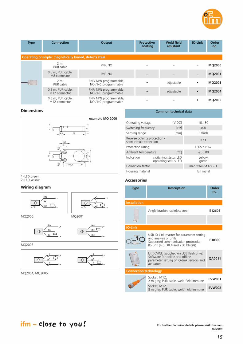
Type Connection Protectivecoating
Orderno.
Operating principle: magnetically biased, detects steel
2 m, PUR cable
Output
PNP, NO – MQ2000
0.3 m, PUR cable, M8 connector PNP, NO – MQ2001
2 m, PUR cable
PNP/ NPN programmable, NO / NC programmable • MQ2003
0.3 m, PUR cable, M12 connector
PNP/ NPN programmable, NO / NC programmable • MQ2004
0.3 m, PUR cable, M12 connector
PNP/ NPN programmable, NO / NC programmable – MQ2005
Common technical data
Weld field resistant
–
–
adjustable
adjustable
–
IO-Link
–
–
•
•
•
For further technical details please visit: ifm.com
Operating voltage [V DC] 10...30
Switching frequency [Hz] 400
Sensing range [mm] 5 flush
Reverse polarity protection / short-circuit protection • / •
Protection rating IP 65 / IP 67
Ambient temperature [°C] -25...80
Housing material full metal
Indication switching status LED operating status LED
yellowgreen
Dimensions
example MQ 2000
USB IO-Link master for parameter settingand analysis of unitsSupported communication protocols: IO-Link (4.8, 38.4 and 230 Kbits/s)
E30390
LR DEVICE (supplied on USB flash drive)Software for online and offline parameter setting of IO-Link sensors andactuators
QA0011
IO-Link
Angle bracket, stainless steel E12605
Type Description Orderno.
Accessories
Installation
Socket, M12,2 m grey, PUR cable, weld-field immune EVW001
Socket, M12,5 m grey, PUR cable, weld-field immune EVW002
Connection technology
Wiring diagram
L+
L
1
4
3
BN
BK
BU
L+
L
L
L+BN
BK
BUL
L+BN
BK
BU
L+
L
1
4
3
L+
L
1
4
3
MQ2000
MQ2003
MQ2004, MQ2005
MQ2001
1) LED green2) LED yellow
Correction factor mild steel (St37) = 1

16
Position sensors
Hard on the outside,smart on the inside:predict downtime inadvanceMagnetic and cylinder sensors
High machine uptime: signalswear when the sensing rangedecreases
Preventive maintenance: detects the degree of soiling in the switching zone
Monitor the life of tools: integrated operating hours andswitching cycles counter
Fast application-specific switchpoint setting
Magnetic position sensor and condition monitoring in one housingThe new smart ifm sensor signals what would only become obvious whenit’s too late. Its high resolution allows the sensor to detect even tiny changes in the switching area. In addition to its position sensor functions, it alsoprovides additional information for condition-based maintenance in theuser’s installation. The MQ2 continuously detects ferromagnetic objects infront of its active face. It signals soiling via IO-Link when the current valueexceeds the set threshold so that cleaning can be arranged. The same applies to changes in the switching area, e.g. caused by mechanical wear. The integrated operating hours and switching cycles counter allows theprovision of a signal if the selected number of switching operations hasbeen reached, enabling targeted maintenance of tools.

17
(04.2019)
For further technical details please visit: ifm.com
MQ2004
AL1300
PLC
E30443
E12490
EVC013EVW025
Mounting accessories
Angle bracket type MQ2 / IQ2, stainless steel E12605
IO-Link accessories
Memory plug, parameter memory for IO-Link sensors E30398
USB IO-Link master for parameter settingand analysis of unitsSupported communication protocols: IO-Link (4.8, 38.4 and 230 Kbits/s)
E30390
Sensor, 0.3 m, PUR cable, M12 connector MQ2004
IO-Link master DataLine Profinet interface, 4 ports AL1300
IO-Link master display, connection to master E30443
Connection cable, M12, 2 m, black, PUR cable EVC013
Connection cable, M12, 2 m grey, PUR cable, weld-field immune EVW025
Ethernet cable M12 / RJ45 0.5 m E12490
Type Description Orderno.
Integration of smart sensors into a machine as a package
Package accessories (individual components)
The benefits of IO-Link– set two different switch points to detect drifts,
e.g. caused by wear or soiling, in the plant– switch-on delay to distinguish between soiling and
an approaching object– integrated operating hours and switching cycles
counter for targeted tool exchange– easy configuration via laptop without having to go
into the installation– plant and location identification for easy localisation
of the sensor in inaccessible areas– the display allows easy reading of the ”health status“
outside the machine
”Too close“ function
500 300 100
500 300 100
SSC1
SSC2
OFF
OFF ON
OFF
ON
ON100
300
500
600
00 0003 1005
0
0
0
0
300
Two IO-Link switch points can be easily set via the LRDevice software. The first switch point of the sensor becomes active and the orange LED lights when theworkpiece is at the selected distance (e.g. 300 digits). If the distance is smaller (e.g. 100 digits), that is theworkpiece comes unusually close, this implies wear inthe plant, e.g. bending of the spanner. In this case thesecond switch point becomes active and a signal is provided via IO-Link. This makes maintenance whenneeded possible for the user.
LR DEVICE (supplied on USB flash drive)Software for online and offline parameter setting of IO-Link sensors andactuators
QA0011
Plug-in power supply, 230 V/24 V E30080
Package set ZZ0588
Package components (complete set)
In addition to the connection to the machine control there is the option to evaluate secondary data for preventive maintenance in parallel.

18
Position sensors
Safety that attracts!Magnetically-codedsensors
Magnetic sensors
Activation from different directions aids installation
Conceal behind stainless steel for enhanced tamper prevention
Connect in series and still identify which door is open
Meets the new interface description CB24I from ZVEI
Meets highest safety level to ISO 13849-1 and SILCL 3 toIEC 62061
Non-contact door monitoringMagnetic sensors allow monitoring of the door status without contact. * Can reach PL e to ISO 13849-1 and SILCL 3 to IEC 62061 when used withsuitable evaluation units.
Easy connectionVarious connection versions with cable, M8 connector (4-pin) and M12 connector (4-pin) provide a standardised connection.With the UL and EAC approvals your machine can be operated worldwidewithout any concerns.
Easy installationThe standard designs in a small and large version ensure various applications even if there is only little space.
* *
19
(04.2018)
For further technical details please visit: ifm.com
Connection technology
Type Description Orderno.
Socket, M8, 4-pole2 m black, PUR cable EVC150
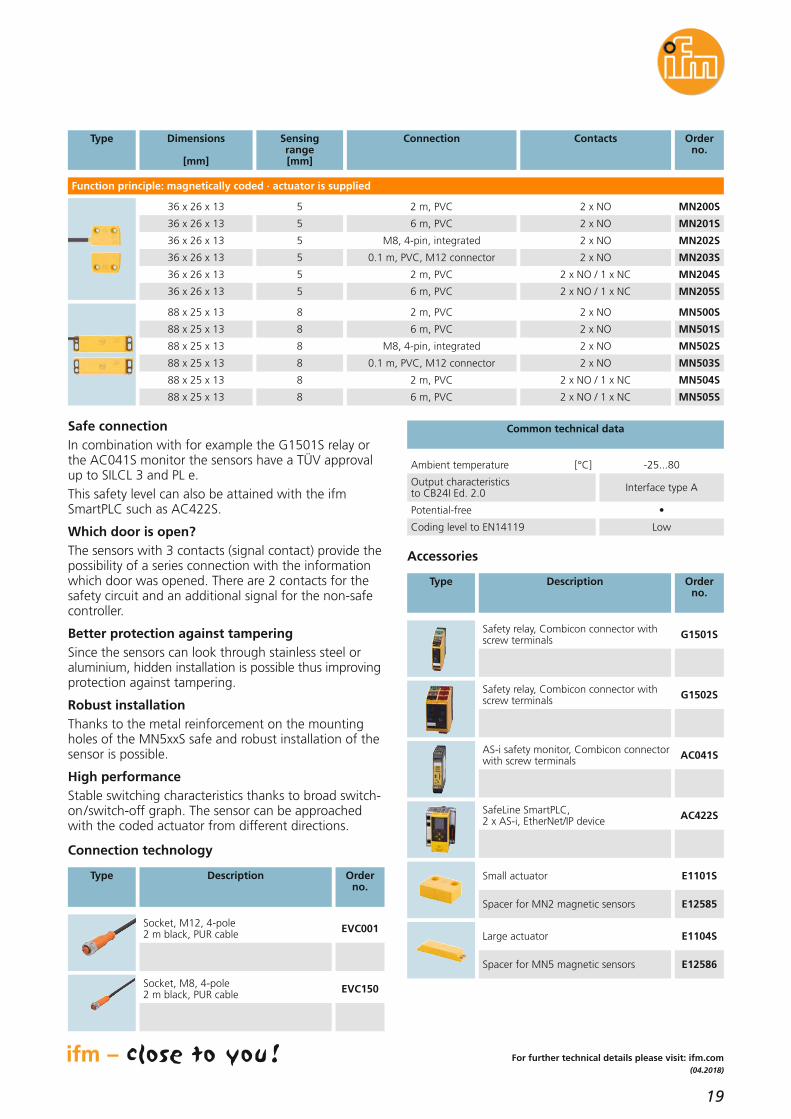
Type Sensingrange[mm]
Dimensions
[mm]
Contacts Orderno.
Function principle: magnetically coded · actuator is supplied
5
Connection
2 m, PVC36 x 26 x 13 2 x NO MN200S
5 6 m, PVC36 x 26 x 13 2 x NO MN201S
5 M8, 4-pin, integrated36 x 26 x 13 2 x NO MN202S
5 0.1 m, PVC, M12 connector36 x 26 x 13 2 x NO MN203S
5 2 m, PVC36 x 26 x 13 2 x NO / 1 x NC MN204S
5 6 m, PVC36 x 26 x 13 2 x NO / 1 x NC MN205S
8 2 m, PVC88 x 25 x 13 2 x NO MN500S
8 6 m, PVC88 x 25 x 13 2 x NO MN501S
8 M8, 4-pin, integrated88 x 25 x 13 2 x NO MN502S
8 0.1 m, PVC, M12 connector88 x 25 x 13 2 x NO MN503S
8 2 m, PVC88 x 25 x 13 2 x NO / 1 x NC MN504S
8 6 m, PVC88 x 25 x 13 2 x NO / 1 x NC MN505S
Ambient temperature [°C] -25...80
Output characteristics to CB24I Ed. 2.0 Interface type A
Potential-free •
Coding level to EN14119 Low
Common technical data
Accessories
Type Description Orderno.
Safety relay, Combicon connector withscrew terminals G1501S
Safety relay, Combicon connector withscrew terminals G1502S
AS-i safety monitor, Combicon connectorwith screw terminals AC041S
SafeLine SmartPLC, 2 x AS-i, EtherNet/IP device AC422S
Small actuator E1101S
Spacer for MN2 magnetic sensors E12585
Large actuator E1104S
Spacer for MN5 magnetic sensors E12586
Socket, M12, 4-pole2 m black, PUR cable EVC001
Safe connectionIn combination with for example the G1501S relay orthe AC041S monitor the sensors have a TÜV approvalup to SILCL 3 and PL e.This safety level can also be attained with the ifmSmartPLC such as AC422S.
Which door is open?The sensors with 3 contacts (signal contact) provide thepossibility of a series connection with the informationwhich door was opened. There are 2 contacts for thesafety circuit and an additional signal for the non-safecontroller.
Better protection against tamperingSince the sensors can look through stainless steel oraluminium, hidden installation is possible thus improving protection against tampering.
Robust installationThanks to the metal reinforcement on the mountingholes of the MN5xxS safe and robust installation of thesensor is possible.
High performanceStable switching characteristics thanks to broad switch-on/switch-off graph. The sensor can be approachedwith the coded actuator from different directions.
20
Position sensors
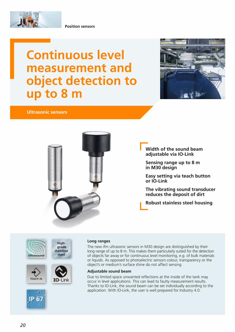
Continuous levelmeasurement andobject detection toup to 8 mUltrasonic sensors
Width of the sound beam adjustable via IO-Link
Sensing range up to 8 m in M30 design
Easy setting via teach button or IO-Link
The vibrating sound transducerreduces the deposit of dirt
Robust stainless steel housing
Long rangesThe new ifm ultrasonic sensors in M30 design are distinguished by theirlong range of up to 8 m. This makes them particularly suited for the detection of objects far away or for continuous level monitoring, e.g. of bulk materials or liquids. As opposed to photoelectric sensors colour, transparency or theobject’s or medium’s surface shine do not affect sensing.
Adjustable sound beamDue to limited space unwanted reflections at the inside of the tank mayoccur in level applications. This can lead to faulty measurement results.Thanks to IO-Link, the sound beam can be set individually according to theapplication. With IO-Link, the user is well prepared for Industry 4.0.
21
(11.2018)
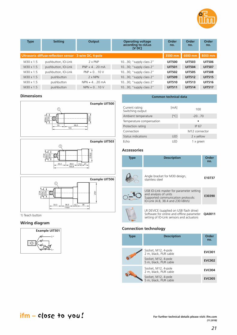
Ultrasonic diffuse-reflection sensor · 3-wire DC, 4-pole
SettingType
pushbutton, IO-Link
Operating voltageaccording to cULus
[V DC]
10...30; “supply class 2”
Orderno.
UIT500
3500 mm
Orderno.
UIT503
6000 mm
Output
2 x PNP
pushbutton 10...30; “supply class 2” UIT509 UIT5122 x NPN
pushbutton 10...30; “supply class 2” UIT510
10...30; “supply class 2” UIT511
UIT513NPN + 4…20 mA
pushbutton UIT514NPN + 0…10 V
M30 x 1.5
M30 x 1.5
M30 x 1.5
M30 x 1.5
Orderno.
UIT506
pushbutton, IO-Link 10...30; “supply class 2” UIT501 UIT504PNP + 4…20 mAM30 x 1.5 UIT507
pushbutton, IO-Link 10...30; “supply class 2” UIT502 UIT505PNP + 0…10 VM30 x 1.5 UIT508
8000 mm
UIT515
UIT516
UIT517
Accessories
Type Description Orderno.
Common technical data
Temperature compensation •
Ambient temperature [°C] -20...70
Current rating [mA]Switching output 100
Protection rating IP 67
Echo LED 1 x green
Status indications LED 2 x yellow
Connection M12 connector
Connection technology
Type Description Orderno.
Socket, M12, 4-pole 2 m, black, PUR cable EVC001
Socket, M12, 4-pole5 m, black, PUR cable EVC002
Socket, M12, 4-pole2 m, black, PUR cable EVC004
Socket, M12, 4-pole5 m, black, PUR cable EVC005
Wiring diagram
Angle bracket for M30 design, stainless steel E10737
For further technical details please visit: ifm.com
LR DEVICE (supplied on USB flash drive)Software for online and offline parameter setting of IO-Link sensors and actuators
QA0011
USB IO-Link master for parameter settingand analysis of unitsSupported communication protocols: IO-Link (4.8, 38.4 and 230 kBit/s)
E30390
Dimensions
Example UIT500
Example UIT503
Example UIT506
1) Teach button
Example UIT501
L+
L3
4
2
1
M1
2x1
M3
0x1
103
69,533
1
M3
0x1
,5
M1
2x1
M3
0x1
,5
103,8
36,5 13 2133,3
1
38
,8
34
M1
2x1
118,8
36,5 13 3633,3
1
61
M3
0x1
,5
34

22
Position sensors
The measure ofthings: measuringphotoelectric sensorO8 in compact designPhotoelectric sensors
Colour-independent distancemeasurement even of very flator reflective objects
Easy parameter setting andmeasured value output to thenearest millimetre via IO-Link
Compact light spot for precise detection even at longer distances
Extremely reliable backgroundsuppression
Installation within seconds,space-saving design
Compact photoelectric sensor with maximum precisionThe new powerful O8 is an optimum choice for applications where space is at a premium, for example handling technology and robotics. With the quick mounting set the sensor can be mounted with just one M3 screw within seconds. The new O8 guarantees a reliable distance measurement thanks to its colour-independent operating principle and reliable background suppression. This allows correct detection of small, flat or reflective objects.
Reliable and efficient thanks to IO-LinkThe range can easily be set via IO-Link. As an alternative, the distance value can be provided continuously to the nearest millimetre similar to analogue sensors. So a binary diffuse reflection sensor turns into a precisedistance sensor, for example, for height and linear measurement of objects.

23
(04.2019)
For further technical details please visit: ifm.com
Diffuse reflection sensor with background suppression, 3 wires DC PNP
Range
[mm]
Spot Ø at max. range
[mm]
80
Type
[H, W, D]
4
Connection
Rectangular28.1 x 8.1 x
14.4 mm
Orderno.
O8H270
80 4
2 m, PVC cable
0.3 m PVC cable / M8 connector, 3 poles O8H271
80 4 O8H272
80 4
0.3 m PVC cable / M8 connector, 4 poles
0.3 m PVC cable / M12 connector, 4 poles O8H273
Common technical data
Operating voltage [V DC] 10...30
Switching frequency [Hz] 1000
Protection rating, protection class
IP65 / IP67,III
Type of light / wave length red light, 633 nm
Outputlight-on / dark-on mode
light-on / dark-on selectable
Switching status indication LED yellow
Voltage drop [V] < 2.5
Short-circuit protection, pulsed •
Reverse polarity / overload protection • / •
Ambient temperature [°C] -25...60
HousingMaterials Lens
ABS; 316L / 1.4404
PMMA
Current rating [mA] 100
Operation LED green
AL1300
PLC
E30443
E12490
EVC013EVT215
O8H272
Package accessories
Accessories
Type Description Orderno.
Installation
Angle bracket for free-standing mounting, quick mounting, stainless steel E21289
Angle bracket for free-standing mounting, stainless steel E21291
Mounting set for clamp mounting, stainless steel, Ø 12 mm E21297
Mounting set for clamp mounting, stainless steel, Ø 10 mm E21298
Rod, 120 mm, Ø 10 mm, M8 thread, stainless steel E21081
IO-Link
Memory plug, parameter memory for IO-Link sensors E30398
USB IO-Link master for parameter settingand analysis of unitsSupported communication protocols: IO-Link (4.8, 38.4 and 230 kBit/s)
E30390
Sensor, 0.3 m, PUR cable, M8 connector O8H272
IO-Link master DataLine PROFINET interface, 4 ports AL1300
IO-Link master display, connection to master E30443
Connection cable, M12, 2 m, black, PUR EVC013
Ethernet connection cable M12 / RJ45, 0.5 m E12490
Package accessories, system components
LR DEVICE (supplied on USB stick)Software for online and offline parameter setting of IO-Link sensors andactuators
QA0011
Connection cable, M12 / M8, 2 m orange, PVC EVT215

24
Position sensors
OG Cube: photoelectric sensorin rectangular designwith M18 threadPhotoelectric sensors
Continuous measurement andmonitoring of distances in therunning process
Quick and easy setting ofswitch points via IO-Link
Compact design with standardM18 thread for easy installation
High protection ratings and robust metal housing for harshindustrial environments
Long ranges for universal use
Photoelectric compact sensor for limited spaceThe compact rectangular housing is designed for use in applications with limited installation space. Thanks to the lateral M18 thread and the connector facing downwards, this type is ideally suited for use in conveying applications. The sensor achieves long ranges when detecting light or dark objects.
Continuous distance measurement via IO-Linkifm offers the new OG Cubes as diffuse reflection, retro-reflective andthrough-beam sensors. For the diffuse reflection sensors with backgroundsuppression, the ranges can be set via IO-Link and, similar to analogue sensors, the distance value is provided to the nearest millimetre. Besides, all versions feature varied setting options, such as light-on/dark-on mode or switch-on and switch-off delay for a fast set-up.

25
(04.2019)
Socket, M12,2 m, black, PUR cable EVC001
Socket, M12,5 m, black, PUR cable EVC002
Socket, M12,2 m, black, PUR cable EVC004
Socket, M12,5 m, black, PUR cable EVC005
Accessories
Type Description Orderno.
Mounting set for clamp mounting, M10 thread, diecast zinc E20718
Mounting set for clamp mounting, M10 thread, stainless steel E20870
Mounting set for clamp mounting, Ø 12 mm, diecast zinc E20836
Mounting set for clamp mounting, Ø 12 mm, stainless steel E21207
Cube for mounting on an aluminiumprofile, M10 thread, diecast zinc E20951
Installation
Memory plug, parameter memoryfor IO-Link sensors E30398
IO-Link master with PROFINET interface AL1100
USB IO-Link master for parameter settingand analysis of unitsSupported communication protocols: IO-Link (4.8, 38.4 and 230 Kbits/s)
E30390
LR DEVICE (supplied on USB flash drive)Software for online and offline parameter setting of IO-Link sensors and actuators
QA0011
Rod, 100 mm, Ø 12 mm, M10 thread, stainless steel E20938
Connection technology
For further technical details please visit: ifm.com
* white paper 200 x 200 mm 90 % remission / ** referred to prismatic reflector Ø 80 mm E20005 / *** adjustable via IO-Link
Common technical data
Operating voltage [V DC] 10...30
Switching frequency [Hz] 1000
Type of light / wave length red light, 624 nm
Switching status indication LED yellow
Short-circuit protection, pulsed •
Reverse polarity protection / overload protection • / •
Max. voltage drop [V] 2.5
Operation LED green
IO-Link accessories
Type Description Orderno.
Diffuse reflection sensor with background suppression, 3-wire DC
100* 753 x 20 x 36
200* 13
IP 67 / III
IP 67 / III
H
H
OGH280
PNP
OGH281
Diffuse reflection sensor with background suppression, 3-wire DC, programming button
15...200* 1353 x 20 x 36 IP 67 / IIIH / D selectable OGH580
Retro-reflective sensor with polarisation filter, 3-wire DC
100...4000** 16053 x 20 x 36
IP 67 / IIID OGP280
PNP
100...4000** 160 IP 67 / IIIH OGP281
Through-beam sensor transmitter, DC
<15,000 80053 x 20 x 36 IP 67 / III– OGS280
Through-beam sensor receiver, 3-wire DC
<15,000 –53 x 20 x 36
IP 67 / IIID OGE280
PNP
<15,000 – IP 67 / IIIH OGE281
PNP
Range
[mm]
Spot Ø at max. range*
[mm]
Type
[H, W, D mm]
Protection rating/protection class
OutputH = light-on mode /
D = dark-on mode***
Orderno.

26
Position sensors
Easy, quick and precise from all angles
Optical fork sensors / optical angle sensors
Quick set-up: no need to aligntransmitter and receiver
Easy setting via potentiometeror IO-Link
Application-specific sensor modes via IO-Link
Indication of soiling by permanent monitoring of the emitted amount of light via IO-Link
Optical fork and angle sensorsThe new devices from ifm are used for part monitoring in feeder systems aswell as in assembly and handling applications. Compared to through-beamsensors, their advantage is that the time-consuming alignment of transmitter and receiver is not necessary.
Settings and diagnostics with IO-LinkA wide range of applications can be solved by using standard optical forkand angle sensors. However, when it comes to the detection of very smallparts or to high speed applications, conventional optical fork and anglesensors rapidly reach their limits. Thanks to IO-Link, individual setting ispossible. Due to adjustable switching frequencies of up to 14,000 Hz, thesensors are suited even for applications with very high speeds. A soiled lensis automatically detected by the sensor so as to allow for cleaning in goodtime in order to guarantee process safety.

27
(11.2018)
Switching status indication LED yellow
Protection rating, protection class
IP 67,III
OutputH = light-on mode / D = dark-on mode
H / D selectable
Current rating [mA] 100
Short-circuit protection, pulsed •
Reverse polarity protection / overload protection • / •
Ambient temperature [°C] -25...60
Housing materialdiecast zinc,
black, powder coated
Optical fork sensor type OPU · IO-Link 1.1 · M8 connector · 3-pole · infrared
Fork width(w)
[mm]
Fork depth(d)
[mm]
10
Type (H, W, D)
[mm]
17
Smallest detectable object Ø
[mm]
25 x 45 x 10 0.2 (0.1)*
Switching frequency
[Hz]
10000 (14000)** OPU200
PNP/NPN
–
NPN
Optical fork sensor type OPU · IO-Link 1.1 · M8 connector · 3-pole · red light
20 2540 x 50 x 10 0.3 (0.2)* 5000 (8000)** OPU201
PNP/NPN
OPU207
30 3550 x 60 x 10 0.3 (0.2)* 5000 (8000)** OPU202 OPU208
50 5570 x 80 x 10 0.3 (0.2)* 5000 (8000)** OPU203 OPU209
80 55100 x 80 x 10 0.3 (0.2)* 5000 (8000)** OPU204 OPU210
120 60144 x 90 x 12 0.3 (0.2)* 5000 (8000)** OPU205 OPU211
NPN
Orderno.
Orderno.
Common technical data
Operating voltage [V DC] 10...30
For further technical details please visit: ifm.com
Optical angle sensor type OPL · IO-Link 1.1 · M8 connector · 3-pole · red light
Side length(x, y)[mm]
Sensor width(z)
[mm]
50
Type(H, W, D)
[mm]
60
Smallest detectable object Ø
[mm]
75 x 75 x 10 0.3 (0.2)*
Switching frequency
[Hz]
5000 (8000)** OPL200
PNP/NPN
OPL202
80 100105 x 105 x 10 0.3 (0.2)* 5000 (8000)** OPL201 OPL203
NPN
Orderno.
Orderno.
Sensor mode: * high-resolution / ** speed
Connection technology
Type Description Orderno.
Socket, M8, 3-pole2 m, black, PUR cable EVC141
Socket, M8, 3-pole5 m, black, PUR cable EVC142
Adapter cable for connection betweenUSB IO-Link master E30390 and sensorwith M8 connector 3 poles / M12 connector 4 poles
EVC215
Memory plug, parameter memory for IO-Link sensors E30398
IO-Link master with PROFINET interface AL1100
IO-Link accessories
Type Description Orderno.
USB IO-Link master for parameter settingand analysis of unitsSupported communication protocols: IO-Link (4.8, 38.4 and 230 kbits/s)
E30390
LR DEVICE (supplied on USB flash drive)software for online and offline parametersetting of IO-Link sensors and actuators
QA0011 W=
20
4,34,5
4,5
D=25
5
50
M8x1
10
LED
12,5 10
10
4,5
12 20,5
10
Dimensions
Example OPU201
75
10
Z
60
Y=
50
75
22,5
4,3
4,5
4,5
42
50
X=50
M8x1
425
0
10,5
LED
17,5 25,5 35,5
10
Example OPL200
1) sensitivity potentiometer2) output function switch

28
Position sensors
Millimetre perfect.The new OGDPrecision from thePMDLineLaser sensors / distance sensors
Small compact design withstandard M18 thread and timeof flight technology
Precise distance measurementto the nearest millimetre
Distance value shown on 2-co-lour display and sent via IO-Link
Easy setting with 3-buttons orIO-Link
Precise ToF distance sensor for demanding applicationsThanks to the innovative on-chip time-of-flight principle with PMD technology (photonic mixer device), this sensor offers all the capability of a very precisemeasurement system. The distance information can determine the presenceof parts or their correct installation, e.g. if an O-ring has or has not beenmounted. The excellent reflection resistance and background suppression,together with a high excess gain, enable reliable operation. The PMD technology of the OGD is vastly superior to conventional diffusereflection laser sensors. The OGD Precision is available with an extremelysmall light spot at a 300 mm range to detect very small parts.
Easy handlingThe switch point is easily set to the nearest millimetre via the three operating keys or alternatively via IO-Link, which also allows read-out of the currentdistance value.

29
(11.2018)
For further technical details please visit: ifm.com
Further technical data
Socket, M12,2 m black, PUR cable EVC001
Socket, M12,5 m black, PUR cable EVC002
Socket, M12,2 m black, PUR cable EVC004
Socket, M12,5 m black, PUR cable EVC005
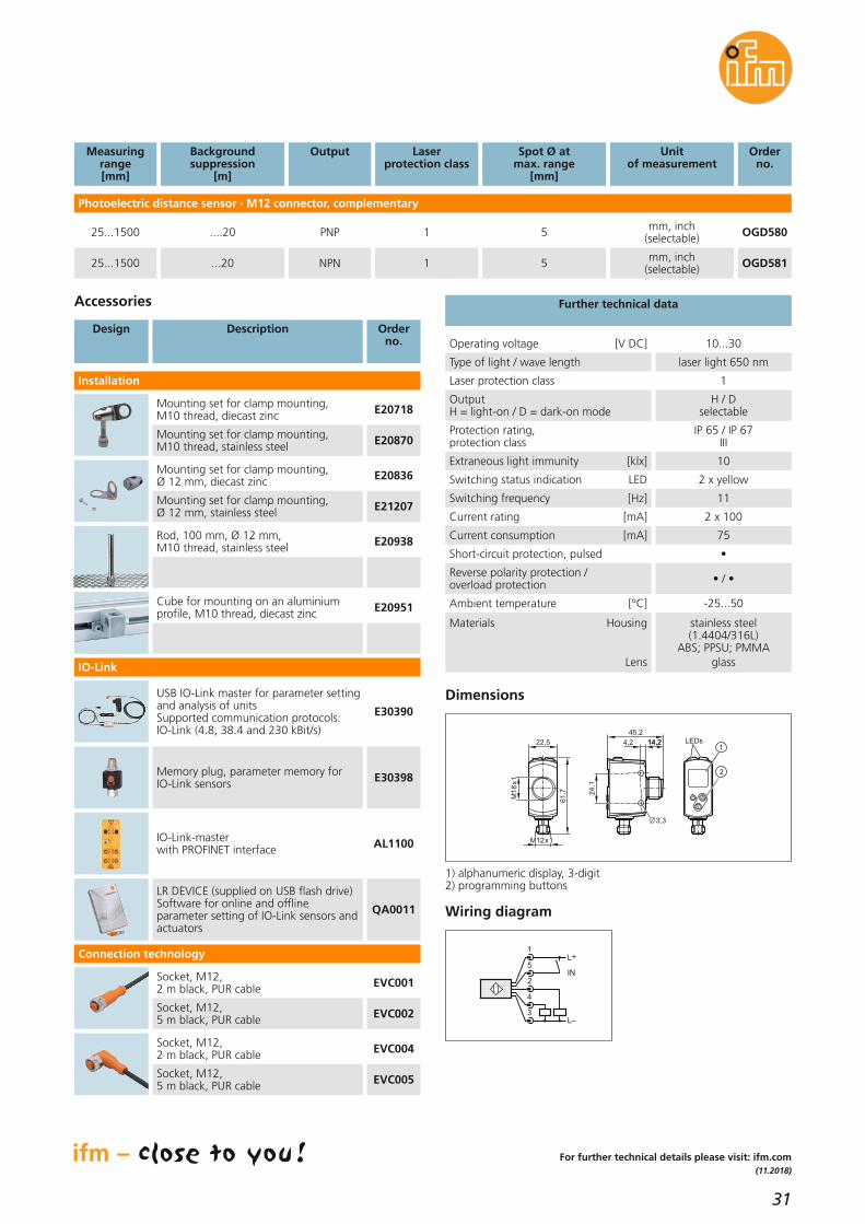
Photoelectric distance sensor · M12 connector, complementary
25...300 OGD592PNP 3* mm, inch (selectable)
Accessories
Type Description Orderno.
Mounting set for clamp mounting, M10 thread, diecast zinc E20718
Mounting set for clamp mounting, M10 thread, stainless steel E20870
Mounting set for clamp mounting, Ø 12 mm, diecast zinc E20836
Mounting set for clamp mounting, Ø 12 mm, stainless steel E21207
Cube for mounting on an aluminiumprofile, M10 thread, diecast zinc E20951
Measuringrange[mm]
Backgroundsuppression
[m]
Output Spot Ø atmax. range
[mm]
Orderno.
Unit of measurement
Laserprotection class
1
* spot Ø focussed (at 150 mm): 1 mm
Installation
Memory plug, parameter memory for IO-Link sensors E30398
IO-Link master with Profinet interface AL1100
USB IO-Link master for parameter settingand analysis of unitsSupported communication protocols: IO-Link (4.8, 38.4 and 230 kBit/s)
E30390
LR DEVICE (supplied on USB flash drive)Software for online and offline parameter setting of IO-Link sensors andactuators
QA0011
Rod, 100 mm, Ø 12 mm, M10 thread, stainless steel E20938
IO-Link
Connection technology
Extraneous light immunity [klx] 10
Protection rating, protection class
IP 65 / IP 67III
OutputH = light-on mode / D = dark-on mode
light-on / dark-on selectable
Switching status indication LED 2 x yellow
Current consumption [mA] 75
Short-circuit protection, pulsed •
Reverse polarity protection / overload protection • / •
Ambient temperature [°C] -25...50
Materials Housing
Lens
stainless steel (1.4404/316L);
ABS; PPSU;PMMAglass
Current rating [mA] 2 x 100
Switching frequency [Hz] 11
Operating voltage [V DC] 10...30
Type of light / wave length laser light 650 nm
Laser protection class 1
24,1
45,2
14,24,2 14,2
3,3
LEDs
M1
8x
1
22,5
M12x1
61,7
1
2
Dimensions
Wiring diagram
L+
L
5
1
4
3
2IN
1) alphanumeric display, 3-digit2) programming buttons
...19,2
25...300 ...19,2 OGD593NPN 3* mm, inch (selectable)1

30
Position sensors
Farsighted: theOGD Long Range –new compactPMDLine sensorLaser sensors / distance sensors
Small compact design withstandard M18 thread and timeof flight technology
Excellent range of 1.5 m – independent of the colour
Visualisation and setting of thedistance value via IO-Link and2-colour display on the unit
Sensors with laser protectionclass 1 – perfectly suited for theautomotive industry
Long-range time of flight sensor for demanding applicationsThe new PMDLine sensor with a compact stainless steel housing is distinguished by a very long range. It uses the innovative on-chip time-of-flight measurement system with PMD (photonic mixer device) technology.The class 1 laser sensor performs better than conventional red light sensorseven in very demanding circumstances e.g. in detecting shiny metallic surfaces. The excellent reflection resistance and background suppression,together with a high excess gain, enable reliable operation. Typical applications are found in the automotive industry, conveying andmaterials handling.
Easy handlingThe switch point is easily set using the three buttons on the unit or alternatively via IO-Link, which also allows read-out of the current distancevalue.
31
(11.2018)
For further technical details please visit: ifm.com
Further technical data
Socket, M12,2 m black, PUR cable EVC001
Socket, M12,5 m black, PUR cable EVC002
Socket, M12,2 m black, PUR cable EVC004
Socket, M12,5 m black, PUR cable EVC005
Photoelectric distance sensor · M12 connector, complementary
25...1500 ....20 OGD580PNP 5 mm, inch (selectable)
Accessories
Design Description Orderno.
Mounting set for clamp mounting, M10 thread, diecast zinc E20718
Mounting set for clamp mounting, M10 thread, stainless steel E20870
Mounting set for clamp mounting, Ø 12 mm, diecast zinc E20836
Mounting set for clamp mounting, Ø 12 mm, stainless steel E21207
Cube for mounting on an aluminiumprofile, M10 thread, diecast zinc E20951
Measuringrange[mm]
Backgroundsuppression
[m]
Output Spot Ø atmax. range
[mm]
Orderno.
Unit of measurement
Laserprotection class
1
Installation
Memory plug, parameter memory for IO-Link sensors E30398
IO-Link-master with PROFINET interface AL1100
USB IO-Link master for parameter settingand analysis of unitsSupported communication protocols: IO-Link (4.8, 38.4 and 230 kBit/s)
E30390
LR DEVICE (supplied on USB flash drive)Software for online and offline parameter setting of IO-Link sensors andactuators
QA0011
Rod, 100 mm, Ø 12 mm, M10 thread, stainless steel E20938
IO-Link
Connection technology
Extraneous light immunity [klx] 10
Protection rating, protection class
IP 65 / IP 67III
OutputH = light-on / D = dark-on mode
H / D selectable
Switching status indication LED 2 x yellow
Current consumption [mA] 75
Short-circuit protection, pulsed •
Reverse polarity protection / overload protection • / •
Ambient temperature [°C] -25...50
Materials Housing
Lens
stainless steel(1.4404/316L)
ABS; PPSU; PMMAglass
Current rating [mA] 2 x 100
Switching frequency [Hz] 11
Operating voltage [V DC] 10...30
Type of light / wave length laser light 650 nm
Laser protection class 1
24,1
45,2
14,24,2 14,2
3,3
LEDs
M1
8x
1
22,5
M12x1
61,7
1
2
Dimensions
Wiring diagram
L+
L
5
1
4
3
2IN
1) alphanumeric display, 3-digit2) programming buttons
25...1500 ...20 OGD581NPN 5 mm, inch (selectable)1

32
Position sensors
Show your colours! Multi-colour touchsensors with IO-Link
Touch sensors
Ergonomic working by softlytouching the sensor
Start-up delay prevents unintentional switching
Various setting options such as colour, NO/NC or triggeringvia IO-Link
Adjustable brightness and sensitivity in wet environmentsor when operators wear gloves
Plant condition indicated viaRGB LEDs
Versatile sensor for all applicationsThe new multi-colour touch sensors from ifm allow flexible adaptation toyour application. Where many different sensors were required before, oneindividually adjustable sensor is sufficient today. The NO/NC function or thecolours for different operating states can be set within seconds. In addition,dynamic, static or bistable switching of the sensor can be selected.
Adaptable to the environmentThe adjustable sensitivity allows use in very wet environments or actuationwith gloves.The implemented delay time prevents unintentional switchingof a sensor. All settings remain stored even if the sensor is used without IO-Link. The sensor also counts the switching cycles for demand-orientedmaintenance of the machine.
33
(04.2019)
ConnectionTotal length / thread[mm]
Orderno.
Type
Operating voltage [V DC] 24, (10...30)
Current consumption [mA] 30
Current rating [mA] 200
Illumination circular on the upper side
LED states can be configured
Communication via IO-Link
illumination colour,illumination intensity,
switching characteristics,output function,electrical design,
sensitivity
Further technical data
29
22 5,3
39
48,4
M22x1,5
7,5
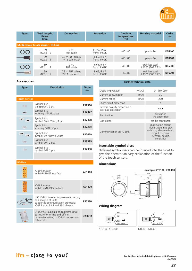
Dimensions
example KT6100, KT6300
Multi-colour touch sensor · IO-Link
2 m, PUR cable
39 M22 x 1.5 KT6100
Protection
IP 65 / IP 67front: IP 69K
Housing material
plastic PA
0.3 m PUR cable / M12 connector
39 M22 x 1.5 KT6101IP 65, IP 67
front: IP 69K plastic PA
Type Description Orderno.
Accessories
Symbol disc, transparent, 2 pcs E12386
Symbol disc, lettering: START, 2 pcs E12377
Symbol disc, symbol: Start / Stop, 2 pcs E12468
Symbol disc, lettering: STOP, 2 pcs E12378
Symbol disc, symbol: Up / Down, 2 pcs E12469
Symbol disc, symbol: ON, 2 pcs E12379
Symbol disc, symbol: OFF, 2 pcs E12380
For further technical details please visit: ifm.com
Wiring diagram
BU
+BN
BK
WH (LED)+
-L
L+1
4
2 (LED)
3
+
Ambienttemperature
[°C]
-40...85
-40...85
2 m, PUR cable
39 M22 x 1.5 KT6300IP 65, IP 67
front: IP 69Kstainless steel
1.4305 (303 S 22)
0.3 m PUR cable / M12 connector
39 M22 x 1.5 KT6301IP 65, IP 67
front: IP 69Kstainless steel
1.4305 (303 S 22)
-40...85
-40...85
Short-circuit protection •
Reverse polarity protection / overload protection • / •
IO-Link master with PROFINET interface AL1100
IO-Link master with EtherNet/IP interface AL1120
USB IO-Link master for parameter settingand analysis of unitsSupported communication protocols: IO-Link (4.8, 38.4 and 230 Kbits/s)
E30390
LR DEVICE (supplied on USB flash drive)Software for online and offline parameter setting of IO-Link sensors andactuators
QA0011
IO-Link
Touch sensor
KT6100, KT6300 KT6101, KT6301
Insertable symbol discsDifferent symbol discs can be inserted into the front togive the operator an easy explanation of the functionof the touch sensors.

34
Position sensors
Continuous position feedbackand diagnostics
Valve feedback systems
Great all-round position visibility from a distance
Continuous position feedback
Easy setting via teach button or IO-Link
Diagnostic functions: cycle time and count, seal monitoring
Flexible configurationThe smart valve sensor matches settings to the application software (LR Device) or inductive teach button. Any end position of the valve and thesize of the sensing range can be set. A third switch point can be selected,for example for three-way valves or for switching off the pump to avoidpressure peaks.
Diagnostic functionsThe IO-Link communication interface allows the identification of differentwear conditions. On the one hand, the sensor features seal monitoring indicating a change of the closed position, which can point to deposits orwear of the seal, for example. On the other hand, the different positionscan be counted and the time taken can be measured.

35
(04.2018)
Accessories
Design Description Orderno.
Adapter 80 x 30 x 10 mm E12569
Adapter 130 x 30 x 10 mm E12573
For further technical details please visit: ifm.com
Connection technology
Design Description Orderno.
Socket, M12,2 m black, PUR cable
Socket, M12,5 m black, PUR cable
Socket, M12,2 m black, PUR cable
Socket, M12,5 m black, PUR cable
Memory plug, parameter memory for IO-Link sensors E30398
Accessories IO-Link
Design Description Orderno.
LR DEVICE (supplied on USB flash drive)Software for online and offline parameter setting of IO-Link sensors andactuators
QA0011
USB IO-Link master for parameter settingand analysis of unitsSupported communication protocols: IO-Link (4.8, 38.4 and 230 kBit/s)
E30390
IO-Link master with PROFINET interface AL1100
Ambienttemperature
[°C]
Outputfunction
Housing materials Orderno.
VDI/VDE 3845
Smart valve sensor · M12 connector
IP 65 / IP 67-25...70 3 x NO / NC(selectable)
PA; stainless steel plug MVQ10110...30 80 x 20
Ub
[V DC]
Protection
Detection range [°] 360
Further technical data
Reverse polarity protection •
Short-circuit protection •
Resolution [°] 0.1
Tolerance [°] ± 0.1...15
Repeatability [°] 0.1
Type of transmission COM2 (38.4 kbaud)
IO-Link revision 1.1
Min. process cycle time [ms] 4
Required master port class A
SIO mode •
Profiles
Smart sensor: Device Identification;
Device Diagnosis; Device Teach Channel; Binary Data Channel; Process Data Variable;
Measurement Data Channel
L+
L
1
5
2
4
3
2: OUT2
4: OUT1/
IO-Link
5: OUT3
Wiring diagram
Dimensions
95
25
24
2
57M1
2x1
50
30
24,6
80
5,4
1,5
25
,5
41,7
31,3
EVC070
EVC071
EVC073
EVC074

36
Sensors for motion control
Stainless steel encoders for wetareas
Encoders
Longevity: Stainless-steel housing for corrosion resistance
Cost reduction: IO-Link allowsthe use of three-core cables
Permanent: Clearly legible lasertype label
No loss of values: Can also be configured as singleturn encoder via IO-Link
Programmable parametersmean fewer types needed
For demanding environmental conditionsifm’s stainless steel incremental encoders, for applications such as conveyor belt synchronisation, ensure longer maintenance intervals in harsh environments. The increased protection rating IP 67 qualifies themfor use in wet areas in the food industry.
Versatile thanks to IO-LinkAll incremental encoders from ifm operate like absolute singleturn encoderswhen used on IO-Link. They detect and save their position value even ifpower fails.
IO-Link communicationProcess values, parameter setting and diagnostic data can be transmittedvia IO-Link. Preventive maintenance is now as easy as child’s play.

37
(04.2018)
For further technical details please visit: ifm.com
Accessories
Type Description Orderno.
Stator coupling for RO design stainless steel (301 / 1.4310) E60205
Fastening clamp E60041
Target wheel,circumference / shaft diameter 500 mm / 10 mm
E60217
Bellows coupling with adjusting screws,Ø 6 mm / 10 mm E60215
Bellows coupling with adjusting screws,Ø 10 mm / 10 mm E60216
Reducing bush for RO3, ROP designs 15...14 mm E60210
Reducing bush for RO3, ROP designs 15...10 mm E60211
Reducing bush for RO3, ROP designs 15...8 mm E60212
Reducing bush for RO3, ROP designs 15...6 mm E60213
Reducing bush for RO3, ROP designs 15...12 mm E60214
Flange IO-LinkResolution
[pulses / revolution]
Orderno.
Solid shaft
clamp •max. 10,000 (adjustable) RV311010
Connection
M12, 5-pole
synchro •max. 10,000 (adjustable) RU31106 M12, 5-pole
Shaft Ø
[mm]
58
58
Hollow shaft with 2 integrated stator couplings
direct •max. 10,000 (adjustable) RO311015 M12, 5-pole58
Housing Ø
[mm]
Switching frequency [kHz] 1000
Operating voltage [V DC] 4.75...30
Protection
IP 67 / IP 67(on the housing);
IP 67 (on the shaft)
Further technical data
Memory plug, parameter memory for IO-Link sensors E30398
IO-Link display, connection to master E30391
IO-Link display, connection between master and sensor (incl. Y splitter) E30430
LR DEVICE (supplied on USB flash drive)Software for online and offline parameter setting of IO-Link sensors andactuators
QA0011
Accessories IO-Link
Type Description Orderno.
Connection technology
Type Description Orderno.
USB IO-Link master for parameter settingand analysis of unitsSupported communication protocols: IO-Link (4.8, 38.4 and 230 kBit/s)
E30390
Socket, M12, wet areas, 5 m, grey, MPPE cable, 5-pole EVF481
Socket, M12, wet areas, 2 m, grey, MPPE cable, 5-pole EVF480
Socket, M12, shielded,5 m, orange , PVC cable, 5-pole EVT406
Socket, M12, shielded,2 m, orange , PVC cable, 5-pole EVT405
Adapter cable for the connection between E30390 USB IO-Link master and 3-pole / 8-pole encoder
E12432
IO-Link masterProfinet, 4-port AL1101
IO-Link masterEtherNet/IP, 4-port AL1121
high-grade stainless steel(316Ti / 1.4571)
stainless steel(443 / 1.4521)
high-grade stainless steel(316Ti / 1.4571)
stainless steel (316 / 1.4401)
Flange HousingMaterials Shaft Plug

38
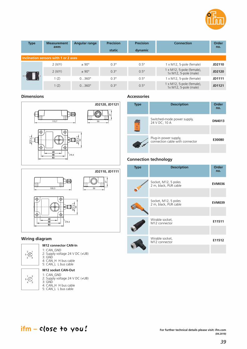
Sensors for motion control
Precise inclinationmeasurement in dynamic applications
Inclination sensors
Inclination sensors with 1 and 2axes and 6 degrees of freedom
Fast response time and high signal quality thanks to innova-tive sensor fusion algorithm
The raw data of the accelera-tion and gyro sensor provideextended functionality
High protection rating IP 68 / IP 69K for use under extreme conditions
Noise-immune inclination measurementThe dynamic inclination sensors of the JD series set new standards with regard to signal quality and response characteristics. They use a 3D gyrosensor as well as a 3D acceleration sensor. A 6-axes IMU (Inertial Measurement Unit) with intelligent sensor fusion filters determines the precise inclination values on this basis. Interference,as may for example occur in mobile applications due to vibrations, impactor starting and braking behaviour, do not falsify the measured values.
Flexible interfaceThe inclination sensor features a CANopen interface for the transmission of the measured values and for parameter setting. If required, an integratedterminating resistor can be activated via software.
39
(04.2019)
Dimensions
Switched-mode power supply,24 V DC; 10 A DN4013
Plug-in power supply,connection cable with connector E30080
Accessories
Type Description Orderno.
Type Measurementaxes
Angular range Precision
static
Orderno.
Inclination sensors with 1 or 2 axes
2 (X/Y) ± 90° 0.3° JD2110
2 (X/Y) ± 90° 0.3° JD2120
1 (Z) 0...360° 0.3° JD1111
1 (Z) 0...360° 0.3°
Precision
dynamic
0.5°
0.5°
0.5°
0.5° JD1121
Connection
1 x M12, 5-pole (female)
1 x M12, 5-pole (female),1x M12, 5-pole (male)
1 x M12, 5-pole (female)
1 x M12, 5-pole (female),1x M12, 5-pole (male)
For further technical details please visit: ifm.com
Connection technology
Type Description Orderno.
Socket, M12, 5 poles2 m, black, PUR cable EVM036
Socket, M12, 5 poles2 m, black, PUR cable EVM039
Wirable socket, M12 connector E11511
Wirable socket, M12 connector E11512Wiring diagram
4
2 1
3
5
3
1 2
4
5
M12 connector CAN-In1: CAN_GND2: Supply voltage 24 V DC (+UB)3: GND4: CAN_H H bus cable5: CAN_L L bus cable
M12 socket CAN-Out1: CAN_GND2: Supply voltage 24 V DC (+UB)3: GND4: CAN_H H bus cable5: CAN_L L bus cable
115,7 59
27
6,468
49
83
68
49
83
M1
2 x
1
M1
2 x
1
44
JD2120, JD1121
105,3 59
27
6,468
49
83
68
49
83
M1
2 x
1
44
JD2110, JD1111

40
Sensors for motion control
Multifunctional analogue display with IO-Link
Systems for evaluation of standard signals
Clearly legible display
Different modes configurablevia IO-Link or setting menu
Change of display to red/yellow/green when setlimit is exceeded or not reached
16-bit resolution
Additional functions such as tare, filter, averaging, signal combination
Analogue display 4.0The new multifunctional display is more than just a display: It pre-processes digital signals in a decentralised manner and, if necessary,passes this information on to a higher-level controller. This intelligent feature makes it ideally suited for Industry 4.0 applications.
Versatile analogue value displayThe intelligent display visualises different process parameters of sensorswith an analogue output or of transmitters with a standard signal output.The freely adjustable scaling factors make it possible to convert and indicate the input signals as physical values (e.g. pressure, temperature or volumetric flow quantity). If you use a pressure transmitter, for example, the volume of a tank can bedisplayed. It is also possible to offset input signals against each other, e.g.for differential pressure measurement.

41
(04.2018)
For further technical details please visit: ifm.com
Analogue inputs -10...+10 V, 0...20 mA / 4...20 mA
User-friendly handlingAll settings can be made via a modern, resistive touch-screen interface. The display automatically changesfrom display mode to parameter setting mode. Alternatively, all settings can also be made via IO-Link.All parameters are displayed in clear text on the screen,enabling an easy and intuitive use. A password mechanism provides protection against manipulation.
Monitoring of limit valuesThe user can define up to four limit values. Up to fourtransistor outputs switch if a set limit is not reached orexceeded. In addition the IO-Link version sends the pre-processed information directly to the PLC.
Clear displayThe states of the outputs are displayed and the colourof the display can be shown in red, yellow or green depending on the process value.With free text entry, units can be assigned to those values that are not already listed.
The basic functions:Single mode: one-channel operation (only input A)Dual mode: two-channel operation (input A and B separately)A a B: summation mode (input A + input B) A – B: differential mode (input A - input B) A d B: dividing mode (relation A : B) A m B: multiplication mode (product A x B)
Operating voltage [V DC] [V AC]
18...30115 / 230
Current consumption (DC) approx. 100 mA (without load)
Sensor supply (DC) [V DC] Output current
UB -1 Vmax. 250 mA
Current consumption (AC) approx. 3 VA (without load)
Sensor supply (AC) [V DC] Output current
approx. 24 V DC (± 15 %)150 mA to 45 °C,80 mA from 45 °C
Control inputs Format Frequency
HTL, PNP (10...30 V)max. 10 kHz
Control outputs Format / level
Output current
5...30 V (depending on the voltage on Com+),
PNP max. 200 mA (max. 150 mA at Com+ <10 V)
Display Type Colour
Handling
LCD (backlight)red/yellow/green
(selectable)Touch screen (resistive)
Ambient temperature [°C] -20...45/60
Dimensions (W x H x D) [mm] 112 x 48 x 116
Common technical data
Dimensions
48
96 116
112
Operating voltage
[V]
Type Inputsanalogue
Inputsprogrammable
Outputstransistor
Orderno.
Multifunction display · touch display and clear text
115 / 230 AC; 24 DC 2 3 – DX2041
115 / 230 AC; 24 DC 2 3 4 DX2042
24 DC 2 3 – DX2051
24 DC 2 3
Outputsanalogue
–
–
115 / 230 AC; 24 DC 2 3 4 DX20431
–
– 4 DX2052
24 DC 2 3 1 4 DX2053
Multifunction display with IO-Link · touch display and clear text
115 / 230 AC; 24 DC 2 3 4 DX2045
24 DC 2 3 4 DX2055
–
–
Analogue outputs (DX2043, DX2053) Voltage output Current output Resolution Accuracy
-10...10 V, 0...20 mA / 4...20 mA
16 Bit± 0.1 %

42
Sensors for motion control
Decentralised display, preprocessing and conversion ofanalogue signalsSystems for signalling and indication
Mini display to monitor values
Compact design with protection rating IP 67
Parameter setting via IO-Link
Conversion of analogue measured values to an IO-Linkcommunication
Conversion of IO-Link values totwo analogue output signals
Analogue signals at a glanceThe compact connector unit DP2200 is simply inserted in the connectioncable of analogue sensors (4...20 mA). It displays the measured values locally. The user can set a switch point or limit at which the transistor output switches. A colour change (red /green) of the display indicates this unmistakably. Critical process states or operational problems are reliably signalled.
Converter for Industry 4.0A special feature is the signal conversion: The threshold display DP2200converts analogue signals to digital IO-Link signals. The DP1213 converter,on the contrary, allows for generation of two analogue 4...20 mA signalsfrom IO-Link data.

43
(11.2018)
Threshold display
Dimensions
31
24
3
30
M12 x 1
M12 x 1
63
1
2
1) Push ring2) LEDs3) Display
Wiring diagram DP2200
43
2 1
3
1 2
4
5
M12: plugPin 1: L+ supplyPin 2: OUT2 analogue outputPin 3: L- supplyPin 4: OUT1 switching output 1 or IO-Link
M12: socketPin 1: L+ sensor supplyPin 2: 4...20 mA analogue inputPin 3: L- sensor supplyPin 4: not usedPin 5: not used
Operating voltage [V DC] 27 (typ. 24)
Inputs 1 x analogue,4...20 mA
Ambient temperature [°C] -25...70
Protection IP 67
Output status indication LED yellow
Operation LED green
Wiring M12 connector
Outputs
1 x digital / IO-Link,normaly open / closed
programmable1 x analogue, 4...20 mA
Display
7-segment LED display 4-digit
red/green programmable
Technical data
For further technical details please visit: ifm.com
Accessories
Type Description Orderno.
Mounting clip E89208
LR DEVICE (supplied on USB flash drive)Software for online and offline parameter setting of IO-Link sensors and actuators
QA0011
USB IO-Link master for parameter settingand analysis of unitsSupported communication protocols: IO-Link (4.8, 38.4 and 230 kbits/s)
E30390Wiring diagram DP1213
43
2 1
3
1 2
4
5
M12: plugPin 1: L+Pin 2: not usedPin 3: L-Pin 4: C/Q IO-Link
M12: socketPin 1: L+Pin 2: 4...20 mA analogue output 2Pin 3: L-Pin 4: 4...20 mA analogue output 1Pin 5: not used
DP2200
31
24
30
M12 x 1
M12 x 1
63
1
DP1213
1) LEDs
Operating voltage [V DC] 18...30
Inputs IO-Link
Ambient temperature [°C] -25...70
Protection IP 67
Output status indication LED yellow
Operation LED green
Wiring M12 connector
Analogue outputs 2 x 4...20 mA
Display –
Current consumption [mA] 300
ConverterIO-Link / 2 x 4...20 mA
Order no.DP1213
Order no.DP2200
44
Industrial imaging
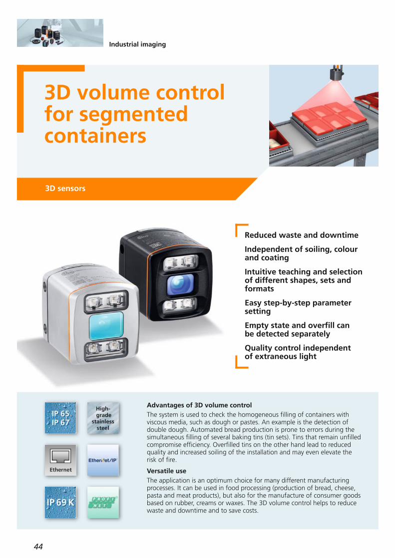
3D volume controlfor segmented containers
3D sensors
Reduced waste and downtime
Independent of soiling, colourand coating
Intuitive teaching and selectionof different shapes, sets and formats
Easy step-by-step parametersetting
Empty state and overfill can be detected separately
Quality control independent of extraneous light
Advantages of 3D volume control The system is used to check the homogeneous filling of containers with viscous media, such as dough or pastes. An example is the detection ofdouble dough. Automated bread production is prone to errors during thesimultaneous filling of several baking tins (tin sets). Tins that remain unfilledcompromise efficiency. Overfilled tins on the other hand lead to reducedquality and increased soiling of the installation and may even elevate therisk of fire.
Versatile useThe application is an optimum choice for many different manufacturingprocesses. It can be used in food processing (production of bread, cheese,pasta and meat products), but also for the manufacture of consumer goodsbased on rubber, creams or waxes. The 3D volume control helps to reducewaste and downtime and to save costs.

45
(04.2019)
Technical data volume control
Operating distance [m] 0.3...5
Max. handling unit size 64 objects
Sampling rate / [Hz]switching frequencyThe image repetition frequency is reduced by using the position trackingfunction
10
Minimum size of objects [mm]Object speed: 0...0.2 m/sObject speed: > 0.2 m/s
2545
For further technical details please visit: ifm.com
Further technical data
Operating voltage [V DC] 20.4...28.8
Current consumption [mA]
< 2400 peak current pulsed;
typ. mean value 420
Current rating [mA](per switching output) 100
Real chip resolution 25,000 / 100,000
Resulting resolution 176 x 132 pixels
Function display LED 2 x yellow,2 x green
Illumination 850 nm,infrared
Ambient temperature [°C] -10...50
Short-circuit protection, pulsed •
Overload protection •
Immunity to extraneous light [klx]
8 (up to 100 klx possible
with reduced measuring accuracy and
repeatability)
Trigger
external; 24 V PNP/NPN according to
IEC 61131-2 type 3
Switching inputs
2 (configurable), 24 V PNP/NPNaccording to
IEC 61131-2 type 3
Switching outputsdigital
3 (configurable), 24 V PNP/NPN, according to IEC 61131-2
Switching outputsanalogue
1 (can be configured as
current output 4...20 mAor voltage
output 0...10 V)
Parameter setting interface Ethernet 10 Base-T /100 Base-TX
Parameter setting options via PC / notebook
Dimensions (H, W, D) [mm] 72 x 67.1 x 95
Type of sensor Materialfront pane / LED window
Angle of aperture
[°]
Protection rating / protection class
Orderno.
PMD 3D sensors · Type O3D · M12 connector · Housing material: Aluminium
PMD 3D ToF chip Gorilla glass / polyamide 40 x 30IP 65, IP 67 / III O3D300
Max.field of view size
[m]
2.61 x 3.47
PMD 3D ToF chip Gorilla glass / polyamide 60 x 45IP 65, IP 67 / III O3D3023.75 x 5.00
PMD 3D ToF chip Gorilla glass / polyamide 70 x 51IP 65, IP 67 / III 4.00 x 5.50 O3D304
PMD 3D sensors · Type O3D · M12 connector · Housing material: Stainless steel
PMD 3D ToF chip PMMA / polyamide 40 x 30IP 65, IP 67, IP 69K / III O3D3102.61 x 3.47
PMD 3D ToF chip PMMA / polyamide 60 x 45IP 65, IP 67, IP 69K / III O3D3123.75 x 5.00
PMD 3D ToF chip PMMA / polyamide 70 x 51IP 65, IP 67, IP 69K / III 4.00 x 5.50 O3D314
Ethernet, cross-over patch cable,2 m, PVC cable, M12 / RJ45 E11898
Ethernet, jumper cable,2 m, PVC cable, M12 / M12 E21138
Socket, M12,2 m black, PUR cable, 8-pole E11950
Design Description Orderno.
Mounting accessories
Connection technology
Mounting set for O3D E3D301
Accessories
Dissipators E3D302
Double cooling element E3D304
Heat conductor E3D303
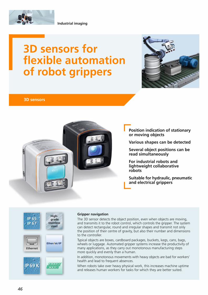
46
Industrial imaging
3D sensors for flexible automation of robot grippers
3D sensors
Position indication of stationary or moving objects
Various shapes can be detected
Several object positions can beread simultaneously
For industrial robots and lightweight collaborative robots
Suitable for hydraulic, pneumatic and electrical grippers
Gripper navigationThe 3D sensor detects the object position, even when objects are moving,and transmits it to the robot control, which controls the gripper. The systemcan detect rectangular, round and irregular shapes and transmit not onlythe position of their centre of gravity, but also their number and dimensionsto the controller.Typical objects are boxes, cardboard packages, buckets, kegs, cans, bags,wheels or luggage. Automated gripper systems increase the productivity ofmany applications, as they carry out monotonous manufacturing stepsmore quickly and evenly than a human.In addition, monotonous movements with heavy objects are bad for workers’ health and lead to frequent absences.When robots take over heavy physical work, this increases machine uptimeand releases human workers for tasks for which they are better suited.
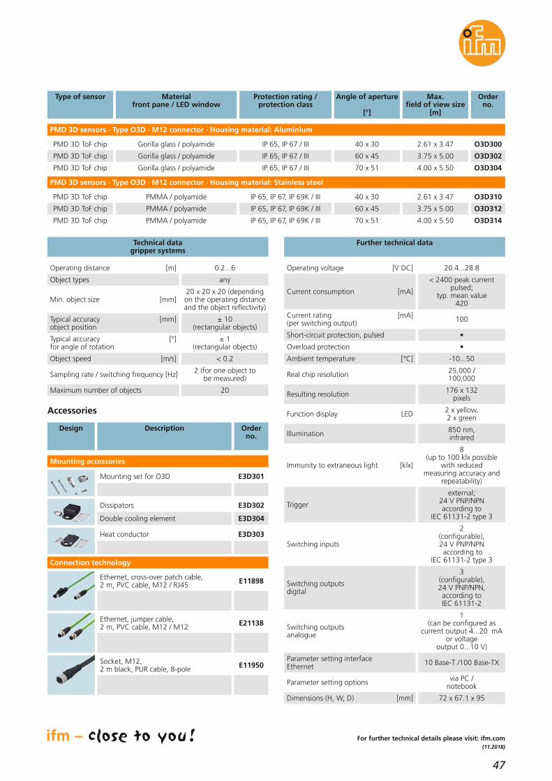
47
(11.2018)
For further technical details please visit: ifm.com
Further technical data
Operating voltage [V DC] 20.4...28.8
Current consumption [mA]
< 2400 peak current pulsed;
typ. mean value 420
Current rating [mA](per switching output) 100
Real chip resolution 25,000 / 100,000
Resulting resolution 176 x 132 pixels
Function display LED 2 x yellow,2 x green
Illumination 850 nm,infrared
Ambient temperature [°C] -10...50
Short-circuit protection, pulsed •
Overload protection •
Technical data gripper systems
Operating distance [m] 0.2...6
Object types any
Min. object size [mm]20 x 20 x 20 (dependingon the operating distanceand the object reflectivity)
Typical accuracy [mm]object position
± 10 (rectangular objects)
Typical accuracy [°]for angle of rotation
± 1(rectangular objects)
Sampling rate / switching frequency [Hz] 2 (for one object to be measured)
Maximum number of objects 20
Object speed [m/s] < 0.2
Immunity to extraneous light [klx]
8 (up to 100 klx possible
with reduced measuring accuracy and
repeatability)
Trigger
external; 24 V PNP/NPN according to
IEC 61131-2 type 3
Switching inputs
2 (configurable), 24 V PNP/NPNaccording to
IEC 61131-2 type 3
Switching outputsdigital
3 (configurable), 24 V PNP/NPN, according to IEC 61131-2
Switching outputsanalogue
1 (can be configured as
current output 4...20 mAor voltage
output 0...10 V)
Parameter setting interface Ethernet 10 Base-T /100 Base-TX
Parameter setting options via PC / notebook
Dimensions (H, W, D) [mm] 72 x 67.1 x 95
Type of sensor Materialfront pane / LED window
Angle of aperture
[°]
Protection rating / protection class
Orderno.
PMD 3D sensors · Type O3D · M12 connector · Housing material: Aluminium
PMD 3D ToF chip Gorilla glass / polyamide 40 x 30IP 65, IP 67 / III O3D300
Max.field of view size
[m]
2.61 x 3.47
PMD 3D ToF chip Gorilla glass / polyamide 60 x 45IP 65, IP 67 / III O3D3023.75 x 5.00
PMD 3D ToF chip Gorilla glass / polyamide 70 x 51IP 65, IP 67 / III 4.00 x 5.50 O3D304
PMD 3D sensors · Type O3D · M12 connector · Housing material: Stainless steel
PMD 3D ToF chip PMMA / polyamide 40 x 30IP 65, IP 67, IP 69K / III O3D3102.61 x 3.47
PMD 3D ToF chip PMMA / polyamide 60 x 45IP 65, IP 67, IP 69K / III O3D3123.75 x 5.00
PMD 3D ToF chip PMMA / polyamide 70 x 51IP 65, IP 67, IP 69K / III 4.00 x 5.50 O3D314
Ethernet, cross-over patch cable,2 m, PVC cable, M12 / RJ45 E11898
Ethernet, jumper cable,2 m, PVC cable, M12 / M12 E21138
Socket, M12,2 m black, PUR cable, 8-pole E11950
Design Description Orderno.
Mounting accessories
Connection technology
Mounting set for O3D E3D301
Accessories
Dissipators E3D302
Double cooling element E3D304
Heat conductor E3D303

48
Industrial imaging
Depalletising of uniform packagesmade easy
3D sensors
Depalletising of a completelayer or individual packages
Slip sheet detection
Calculation of the remainingitems
Integrated collision avoidance
Automatic calibration of robotcamera coordinates
Economic and ergonomic
Optimisation of logistic processesThe automatic depalletising of packages of the same size, e.g. cardboardboxes, crates, outer packaging or containers, optimises logistic processes bydynamic feeding.The 3D sensor detects displaced loads and compensates for incorrect positioning with the depalletising system. Position indication allows fullyautomated depalletising of complete layers or individual packages, independent of the palletising pattern. Besides the data for robot control,the Ethernet process interface provides information for the material andwarehouse management software.Automated depalletising systems provide a clear increase in performance by means of economic tools and reduce the employees’ load due to ergo-nomically optimised working environments.

49
(11.2018)
For further technical details please visit: ifm.com
Further technical data
Operating voltage [V DC] 20.4...28.8
Current consumption [mA]
< 2400 peak current pulsed;
typ. mean value 420
Current rating [mA](per switching output) 100
Real chip resolution 25,000 / 100,000
Resulting resolution 176 x 132 pixels
Function display LED 2 x yellow,2 x green
Illumination 850 nm,infrared
Immunity to extraneous light [klx]
8 (up to 100 klx possible
with reduced measuring accuracy and
repeatability)
Trigger
external; 24 V PNP/NPN according to
IEC 61131-2 type 3
Switching inputs
2 (configurable), 24 V PNP/NPNaccording to
IEC 61131-2 type 3
Switching outputsdigital
3 (configurable), 24 V PNP/NPN, according to IEC 61131-2
Switching outputsanalogue
1 (can be configured as
current output 4...20 mAor voltage
output 0...10 V)
Ambient temperature [°C] -10...50
Ethernet, cross-over patch cable,2 m, PVC cable, M12 / RJ45 E11898
Ethernet, jumper cable,2 m, PVC cable, M12 / M12 E21138
Socket, M12,2 m black, PUR cable, 8-pole E11950
Design Description Orderno.
Short-circuit protection, pulsed •
Overload protection •
Parameter setting interface Ethernet 10 Base-T /100 Base-TX
Possible parameter settings via PC / notebook
Dimensions (H, W, D) [mm] 72 x 67.1 x 95
Technical data depalletising systems
Operating distance [m] 0.5...6
Object types Closed rectangular objects
Min. object size [mm]50 x 50 x 50(at minimum
operating distance)
Typical accuracy [mm]Object position ± 15
Typical accuracy [°]for angle of rotation ± 3
Sampling rate / switching frequency [Hz] 1
Mounting accessories
Connection technology
Mounting set for O3D E3D301
Accessories
Dissipators E3D302
Double cooling element E3D304
Heat conductor E3D303
Type of sensor Materialfront pane / LED window
Angle of aperture
[°]
Protection rating / protection class
Orderno.
PMD 3D sensors · Type O3D · M12 connector · Housing material: Aluminium
PMD 3D ToF chip Gorilla glass / polyamide 40 x 30IP 65, IP 67 / III O3D300
Max.field of view size
[m]
2.61 x 3.47
PMD 3D ToF chip Gorilla glass / polyamide 60 x 45IP 65, IP 67 / III O3D3023.75 x 5.00
PMD 3D ToF chip Gorilla glass / polyamide 70 x 51IP 65, IP 67 / III 4.00 x 5.50 O3D304
PMD 3D sensors · Type O3D · M12 connector · Housing material: Stainless steel
PMD 3D ToF chip PMMA / polyamide 40 x 30IP 65, IP 67, IP 69K / III O3D3102.61 x 3.47
PMD 3D ToF chip PMMA / polyamide 60 x 45IP 65, IP 67, IP 69K / III O3D3123.75 x 5.00
PMD 3D ToF chip PMMA / polyamide 70 x 51IP 65, IP 67, IP 69K / III 4.00 x 5.50 O3D314
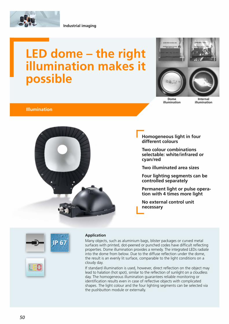
50
Industrial imaging
LED dome – the rightillumination makes itpossible
Illumination
Homogeneous light in four different colours
Two colour combinations selectable: white/infrared orcyan/red
Two illuminated area sizes
Four lighting segments can becontrolled separately
Permanent light or pulse opera-tion with 4 times more light
No external control unit necessary
ApplicationMany objects, such as aluminium bags, blister packages or curved metalsurfaces with printed, dot-peened or punched codes have difficult reflecting properties. Dome illumination provides a remedy. The integrated LEDs radiate into the dome from below. Due to the diffuse reflection under the dome,the result is an evenly lit surface, comparable to the light conditions on acloudy day.If standard illumination is used, however, direct reflection on the object maylead to halation (hot spot), similar to the reflection of sunlight on a cloudless day. The homogeneous illumination guarantees reliable monitoring or identification results even in case of reflective objects with complicated shapes. The light colour and the four lighting segments can be selected viathe pushbutton module or externally.
Dome illumination
Internal illumination

51
(11.2018)
Mounting set E2D117
Further technical dataAccessories
Operating voltage [V DC] 24 ± 10 %
Protection rating, protection class
IP65, III
Operating status indications operation LED illuminated state LED
greenred
Ambient temperature [°C] -10...40
Socket, M12,2 m black, PUR cable, 5-pole EVC070
Type Length
[mm]
Height
[mm]
Width
[mm]
Orderno.
M12 connector
136
Light spotdiameter[Ø mm]
80 75193 O2D930
Operating principle
indirect light
Light colour
white / infrared
13680 75193 O2D931indirect light cyan / red
197130 107257 O2D932indirect light white / infrared
197130 107257 O2D933indirect light cyan / red
Socket, M12,2 m black, PUR cable, 8-pole E11950
Type Description Orderno.
Maximum flash frequency [Hz] 310
Trigger external, 24 V PNP
Overload protection •
Mounting accessories
Connection technology
For further technical details please visit: ifm.com
Cube for mounting on an aluminiumprofile, M10 thread, diecast zinc E20951
Rod, 150 mm, Ø 12 mm, stainless steel E21111
Rod, 200 mm, Ø 12 mm, stainless steel E21112
Rod, 300 mm, Ø 12 mm, stainless steel E21113
Connection piece for clamps, stainless steel E21076
Clamp for mounting rod Ø 12 mm,stainless steel E21110
Rod, 100 mm, Ø 12 mm, M10 thread, stainless steel E20938
Dimensions
27,3 31
75
40
,3
27,3
66
30
42
136
19
3
50
13
4
28
,5
76
M12 x1
Example O2D930
Housing material aluminium, ABS
LED dome

52
Safety technology
All in one unit: light grid with integrated muting unitSafety light grids
Easy connection of the mutingsensors directly to the safetylight grid
Muting arms with pre-mountedsensors for rapid set-up
Parallel or crossbeam mutingversion for detection of variableobject sizes
Integrated status light
User-friendly configuration viahardware wiring
Safety light grid with integrated muting functionThe new generation of light grids allows for the muting mode without anexternal junction box or a muting relay being required as they are alreadyintegrated into the receiving element. The supported muting versions are available as either crossbeam or parallelmuting. Both versions allow transported material to be safely passed in orout, via the protected area. A status light, integrated into the receiver, allows for indication of the operating status. The muting arms can easily be directly installed on the light grid and are available in two versions: either as muting arms with multi-beam sensors, similar to a miniature light grid,or as pre-mounted mounting set with single-beam sensors. No complex installation and adjustments are necessary anymore. In conclusion, a complete package for increased safety, configured for yourapplication, quick and easy to mount.

53
(04.2019)
Common technical data
Protected area width 0...4 m / 3...12 m
OY511S2 510
Number of beams
Orderno.
Protected area height
[mm]
OY512S3 810
OY513S4 910
Connection transmitter receiver
M12, 5-poleM12, 12-pole
Protection rating, protection class
IP 65 / IP 67III
Safety categoryIEC 61496-1: 2012 / IEC 61496-2: 2013IEC 62061: 2005/A2: 2015EN ISO 13849-1: 2015IEC 61508: 2010
Type 4SILCL 3
Category 4, PLeSIL 3
Max. connection length [m] 100
Operating voltage [V DC] 19.2...28.8 (SELV)
Current rating [mA] 2 x 300
Current consumption transmitter [mA] receiver [mA]
4284
Outputs (OSSDs) 2 x PNP
Ambient temperature [°C] -30...55
Accessories
Type Description Orderno.
Safety relay with potential-free output contacts G1501S
Safety relay with semiconductor outputs G1503S
Safety relay
5 m, 12-pole E12502
10 m, 12-pole E12503
15 m, 12-pole E12504
Connection technology, receiver connection cable
5 m, 5-pole EVC071
10 m, 5-pole EVC072
15 m, 5-pole EVC197
Connection technology, receiver connection cable
programmable AS-i safety monitor AC041S
AS-i safety monitor
Type Description Orderno.
Crossbeam muting with 2 through-beam sensors EY5010
Crossbeam muting with 2 crossbeammulti-beam light barriers EY5020
Sequential muting with 4 parallel retro-reflective sensors EY5011
Sequential muting with 4 parallel multi-beam light barriers EY5021
Muting arm sets
2-beam unit (510 mm), 1 pcs. EY5050
3-beam unit (810 mm), 1 pcs. EY5051
4-beam unit (910 mm), 1 pcs. EY5052
Base, suitable for floor mounting with vibration damping EY2005
Bases
For further technical details please visit: ifm.com
Products
Type
T muting for goods to be passed in or out
2 photoelectric sensors positioned crosswise Both sensors must be interrupted simultaneously. Thegoods should therefore have an appropriate width andbe positioned in the centre.
4 photoelectric sensors positioned in parallelThe sensors must be interrupted according to a predeter-mined sequence. The goods should be of a sufficientlength to ensure that all 4 sensors are temporarily inter-rupted. Their width and position do not matter.

54
Process sensors
Pressure transmitterfor hygienic applications with IO-Link and 4...20 mAPressure sensors
High accuracyThe new PM type pressure transmitter has a total accuracy of 0.2 %. Furthermore, temperature compensation with fast temperature changes(e.g. in CIP/SIP processes) has been improved considerably. The sensor istherefore suitable for all common food applications.
Free factory certificateFor every PM pressure sensor a factory certificate can be downloaded free at factory-certificate.ifm. This allows easy access even after the sensor has been bought.
Flexible fittingifm offers all common process connections (e.g. welding adapter, Tri Clamp, Varivent, etc.) as accessories for the adapter threads G1 sealing cone andG1 Aseptoflex Vario of the PM pressure sensor.
0.2 % accuracy
Overload-resistant ceramic-capacitive measuring cell withgood long-term stability
Factory certificate for downloadfree of charge
Rear hexagonal nut for easy installation in tanks with double walls and blind fittings.
Zero point calibration via teachbutton or IO-Link

55
(04.2018)
For further technical details please visit: ifm.com
Factory settingMeasuring range
[bar]
Measuring rangeRelative pressure
[bar]
Poverloadmax. [bar]
Orderno.
G1 sealing cone, 4...20 mA, IO-Link
0...100 200 PM1602
0...25 100 PM1603
0...16 75 PM1614
0...10 50 PM1604
-1...100
-1...25
-1...16
-1...10
0...6 30 PM1615
0...4 30 PM1605
-1...6
-1...4
0...2.5 20 PM1606
0...1.6 15 PM1617
0...1 10 PM1607
-1...1 10 PM1609
-0.125...2.5
-0.1...1.6
-0.05...1
-1...1
0...0.25 10 PM1608
0...0.1 4 PM1689
-0.0125...0.25
-0.005...0.1
Aseptoflex Vario, 4...20 mA, IO-Link
0...25
0...16
100 PM1703
0...10
75 PM1714
0...6
50 PM1704
-1...25
-1...16
-1...10
0...4
30 PM1715
0...2.5
30 PM1705
-1...6
-1...4
0...1.6
20 PM1706
0...1
15 PM1717
-1...1
10 PM1707
-0.125...2.5
-0.1...1.6
-0.05...1
10 PM1709-1...1
0...0.25 10 PM1708
0...0.1 4 PM1789
-0.0125...0.25
-0.005...0.1
Accessories
Type Description Orderno.
Connection technology
Type Description Orderno.
Socket, M12, 4-pole5 m, grey, MPPE cable EVF001
Socket, M12, 4-pole10 m, grey, MPPE cable EVF002
Socket, M12, 4-pole5 m, grey, MPPE cable EVF004
Socket, M12, 4-pole10 m, grey, MPPE cable EVF005
Accuracy / deviation(in % of the span)Deviation of the characteristics (to DIN EN 61298-2) incl. non-linearity for limit value setting (LS), hysteresis, non-repeatabilityRepeatabilityLong-term stabilityTemperature coefficient (TEMPCO) in the temperature range 0...70 °C (in % of the span per 10 K)TEMPCO of zeroTEMPCO of the span
< ± 0.2
< ± 0.1< ± 0.1
< ± 0.05< ± 0.15
PM1x89
< ± 0.5
< ± 0.1< ± 0.1
< ± 0.1< ± 0.2
PM1602
< ± 0.5
< ± 0.1< ± 0.1
< ± 0.2< ± 0.2
Operating voltage [V DC] 18...30
Common technical data
Medium temperature [°C] -25...125 (150 max. 1h)
Materials in contact with the medium
Ceramics 99.9 %, PTFE,stainless steel
(1.4435 / 316L)
Protection IP 67 / IP 68 / IP 69K
Communication interfaceIO-Link 1.1
COM2 slave;38.4 kbaud
Reverse polarity protection •
Step response time [ms]Analogue output 30 (2L) / 7 (3L)
Teach button, stainless steel (1.4404 / 316L); PA; FFKM; PBT
E30425
Aseptoflex Vario adapter Clamp 1-1.5" with O-ring, ISO 2852,stainless steel (1.4435 / 316L)
E33201
Welding adapter Ø 60 mm with O-ring,stainless steel (1.4435 / 316L) E30150
LR DEVICE (supplied on USB flash drive)Software for online and offline parameter setting of IO-Link sensors andactuators
QA0011
USB IO-Link master for parameter settingand analysis of unitsSupported communication protocols: IO-Link (4.8, 38.4 and 230 kBit/s)
E30390
Dimensions
16
,71
6,8
G1
13,5
27
65
24
,7
11
1,4
37,9
30,2
M12 x 1
Example PM1707

56
Process sensors
New pressure sensorswith robust pressuremeasuring cell forhomogenisersPressure sensors
Highest functionalityThe pressure sensors for homogenisers have been updated and now feature IO-Link, switching output, scalable analogue output, an additional pressurerange and better performance in addition to the new housing. They alsofeature setting via 3 push-buttons, 2-colour display as well as clearly visibleswitch point LEDs. In homogenisers you can often find very high pressurepeaks which can damage the pressure sensors. The new sensors are equipped with extremely robust diaphragm seals and have been tested successfully at1.2 times the nominal pressure and 60 million cycles.
Process connections especiallyfor homogenisers
Latest diaphragm seal technology
High pressure resistance andhigh bursting pressure
Measuring range of 250, 400and 600 bar
Compact design for limitedspace

57
(04.2019)
M1
2x
1
34
3
2
1
30
21
62
15
1
40
49,4
31
37,5
34
26
4
10
11
Accessories
Operating voltage [V DC] 18...30
Common technical data
Protection rating IP 67
Materials in contact with the medium
high-grade stainless steel (1.4435)
Step response time [ms] 3
Reverse polarity protection •
Medium temperature [°C] 5...90 (<1h: 145)
Ambient temperature [°C] 5...80
IO-Link revision 1.1
Accuracy / deviation(in % of the span)Linearity errorLinearityHysteresisRepeatabilityLong-term stabilityTemperature coefficient (TEMPCO) inthe temperature range -40...90 °C (in % of the span per 10 K)TEMPCO of zeroTEMPCO of the span
Connection technology
Type Description Orderno.
Socket, M12, 2 m, grey, MPPE cable EVF067
Socket, M12, 5 m, grey, MPPE cable EVF004
Socket, M12, 10 m, grey, MPPE cable EVF005
Dimensions
PY9060, PY9001
< ± 1.0< ± 0.4< ± 0.1< ± 0.1< ± 0.05
< ± 0.2< ± 0.2
Type Description Orderno.
Protective cover E30420
Tag clip E30422
For further technical details please visit: ifm.com
Measuring rangerelative pressure
[bar]
Poverloadmax.[bar]
Pburstmin.[bar]
Orderno.
0...600 1200 PY9060
0...400 1000 PY9070
0...250 1000 PY9001
800
600
500
4
L
L+
2
1
3Out 1Out 2
4:2:
4
L
L+
2
1
3Out 1Out 2
4:2:
4
1
3
2
L+
LOut 1Out 2
4:2:
2
1
3
4
L+
LOut 1Out 2
4:2:
Wiring diagram
1) LEDs (display unit / switching status)2) 4-digit alphanumeric display / alternating indication
(red and green)3) programming button4) upper part of the housing can be rotated by 345°
34
19
7
10
7
2
1
3
4
75
95
60,5
43
17,5
30
28
12
,5 20
23,5
33,5
48
10
94
0
49,4
M1
2x
1
21
PY9070

58
Process sensors
All at sea?Pressure, temperature, level and flow sensors with DNV-GLPressure, temperature, level and flow sensors
Reliable also under extreme conditionsNew DMV-GL approval means ifm’s tried-and-tested fluid sensors can nowalso be used in maritime applications. The approved components help theuser to overcome obstacles in ship and plant approval.The sensors are distinguished by their compact and robust design and aretherefore ideal for demanding applications, for example in hydraulics. Besides, ifm offers a 5-year warranty.
DNV-GL approval for applications on ships
Pressure transmitters, submersible pressure transmitters and sensors with display
Temperature transmitters
Flow sensor with programmable switching output
Sensors for point level detection

59
(04.2018)
For further technical details please visit: ifm.com
Pressure transmitters
Output function 4...20 mA, G 1/4
0...6 to 0...600 200...2400 PT53xx15...1200 PT54xx
Out pin3Out pin2
Output function 4...20 mA, 1/4 NPT
0...6 to 0...600 200...2400 –15...1200 PT24xx
Out pin3Out pin2
Measuring rangerelative pressure
[bar]
Poverloadmax.[bar]
Pburstmin.[bar]
Orderno.
2 x NO/NC or 1x NO/NC + analogue, IO-Link, FKM seal
0...0.25 to 0...600 30...2500 PN25xx6...800
Orderno.
PN207xPN209xPN216x
G 1/4 AG 1/4
2 x NO/NC or 1x NO/NC + analogue, IO-Link, FKM seal
0...6 to 0...600 200...2400 PN26xx15...1200 PN227xPN229x
1/4 NPTA1/4 NPT
2 x NO/NC or 1x NO/NC + analogue, IO-Link, EPDM seal, ceramic measuring cell
0...1 to 0...250 50...1200 PE25xx20...500 PE20xx
G 1/4 AG 1/4
Pressure sensors with display
Measuring rangerelative pressure
[bar]
Poverloadmax.[bar]
Pburstmin.[bar]
Orderno.
Orderno.
Measuring rangerelative pressure
[bar]
Poverloadmax.[bar]
Pburstmin.[bar]
Orderno.
Output function 4...20 mA, ATEX approval
0...0.25 to 0...1 2.4 PS3xxA2
Submersible pressure transmitters
Setting range
[cm/s]
Nominal length[mm]
Pressure rating[bar]
Orderno.
Output function 2 x NO / NC PNP, M18 x 1.5
3...300 300 SI052145
Flow sensors
Output function 4…20 mA, scalable, IO-Link
30...150 G 1/2 TA24x5
-50...150 °C
25...150 G 1/4 TA21x5
TA24x7
0...100 °C
–
Output function 4…20 mA, scalable, IO-Link
30...150 1/2 NPT TA23x3
0…300 °F
25...150 1/4 NPT TA26x3
–
–
Temperature transmitters
Nominal length
[mm]
Processconnection
Order no.
Factory setting
2 x NO/NC, IO-Link
G 1/2 12 LMC100
Water
G 1/2 21 LMC400
LMC110
Oil
LMC410
1/2 NPT 34 LMC500 LMC510
Level sensors
Processconnection
Probe length[mm]
Order no.
Dimensions
12
66
52
M12 x1
19
G1
4/
19
1
Example PT5415
1) Seal
27
147
Example PS308A
22
1 2
11
3
60 65
14
8,2
45
50
27
63
M12
x1
3
Example SI0521
1) LED bar display2) Set button3) Tightening torque 25 Nm
6
M12
x1
18
,7
15,9 48 14
27LED G ½
ELExample TA2405

60
Process sensors
Thermal compressed air meter of the highest level
Flow sensors / flow meters
Exact allocation of energy costsdue to precise consumptionmeasurement
Improvement of energy effi-ciency via leakage monitoring
Reduction of installation, maintenance and hardwarecosts
The basis for a comprehensiveenergy management system according to DIN EN ISO 50001
Pressure monitoring thanks tothe integrated pressure sensor
”All-in-one sensor“ reduces costs This new thermal compressed air meter for compressed air in industrial usedistinguishes itself as a real all-rounder. It does not only have an integratedtemperature sensor but it also features a pressure sensor, allowing the userto read four process values at once (volumetric flow, pressure, temperature,totaliser = total quantity meter) and optimise the production.
Compressed air monitoring at a glance Integration of the SD compressed air meter into the maintenance unit ofexisting or new installations provides additional advantages. Now the process values of compressed air in industrial use can be effectively monitored incommon compressed-air networks via the integrated TFT display, which allows for selection between four different and individually adjustable graphic layouts. The process values can also be transmitted via IO-Link.

61
(04.2019)
FlowMeasuring range [m3/h]Accuracy [%]Repeatability [%]Response time [s]
0.04...700± (2.0 MV + 0.5 VMR)(0.8 MV + 0.2 VMR)
0.1
TemperatureMeasuring range [°C]Accuracy [K]Response time T09 [s]
-10...60± 0.50.5
PressureMeasuring range [bar]Deviation of the characteristics [%]Repeatability [%]Response time [s]
0...16< ± 0.5 (BFSL)
± 0.20.05
Output signal
switching output, analogue output,
pulse output, IO-Link (configurable)
Common technical dataType SD
Leakage monitoring
Loss o
f air in [m
3 / h
]
Leakage diameter [Ø]6 bar
1 mm
4.3 5
3 mm 5 mm0
50
100
150
200
250
74.9
111.2
210.6
40
12 bar
For further technical details please visit: ifm.com
Measuring range
[Nm3/h]
Medium Processconnection
Orderno.
SD5500
SD6500
SD8500
The SD’s precise flow monitoring allows for leakage detection and energy cost savings. In addition, theunit’s high repeatability enables exact allocation of thecosts of compressed air to the respective productionline as well as optimised product cost calculation.
The basis for a comprehensive energy managementsystem according to DIN EN ISO 50001Following the EU directive on energy efficiency DIN EN ISO 50001, all Member States have undertakento achieve energy savings. The requirement for obtaining energy tax reductions is the implementation of an energy management system. The standard requires records on measurement equipment calibration to ensure correctness and repeatability of the measured data.Combining the new SD compressed air meter with regular DAkkS calibrations provides the optimum basisfor a reliable energy management system.
Added value of pressure measurement
Waste of energy Productivity decrease
Air c
on
su
mp
tio
n [%
]
Pressure [bar]
8 7 6.3 6 5 4
20
40
60
80
100
120
140
0
op
tim
um
Efficient monitoring of the operating pressure
Reduction of installation, maintenance and hardware costsIntegration of several measuring parameters in just onesensor does not only save considerable hardware costs(pressure sensor, temperature sensor, wiring and inputcards) but also installation and maintenance costs.
For further interesting information go to: ifm.de/compressed air meter
Improvement of energy efficiency due to the integrated leakage monitoring in the installation
Thanks to the integrated pressure measurement, boththe pressure drop on the polluted filter systems and thecompressed air system’s general operating pressure canbe optimally monitored which is quite important because if the installation comprises actuators that are operatedat 5 bar instead of the ideal 6.3 bar, load speed is already reduced by 25%, with productivity decreasing. On the other hand, an excessive operating pressure does not increase the performance but generates increasedconsumption of compressed air and increased wear ofthe unit.
ISO calibration(6 calibration points) ZC0020
DAkkS calibration (6 calibration points) ZC0075
Calibration certificate for flow sensors (SD)*
* Applies to the specified article(s) and must be requested when ordering the sensor. Subsequent orders are only possible if the device is returned.
0.05...15 G 1/4 (DN8)Air
0.25...75 R 1/2 (DN15)Air
0.8...225 R 1 (DN25)Air

62
Process sensors
Mechatronic flowsensors – especiallyfor oils
Flow sensors / flow meters
Specifically adjusted to oil foroptimum measurement results
Volumetric flow quantities up to200 l/min
Integrated temperature measurement and compensation
Pressure resistance up to 100 bar
Measured value transfer without conversion losses andeasy setting via IO-Link
No inlet and outlet pipe lengthsrequired
Multiple applicationsDifferent media require different sensor characteristics. With the new mechatronic flow sensor, designed especially for oils, ifm provides the perfect combination of accuracy, speed and adaptability to the application.This also increases economic efficiency.
High performanceDue to a complex adjustment carried out during production and the use ofoil-specific mechanical parts, the new sensor does not only provide precisemeasured values for the selected oil curve. It is also distinguished by an integrated temperature compensation. ifm also offers individually designedspecial units for particular oil viscosities.
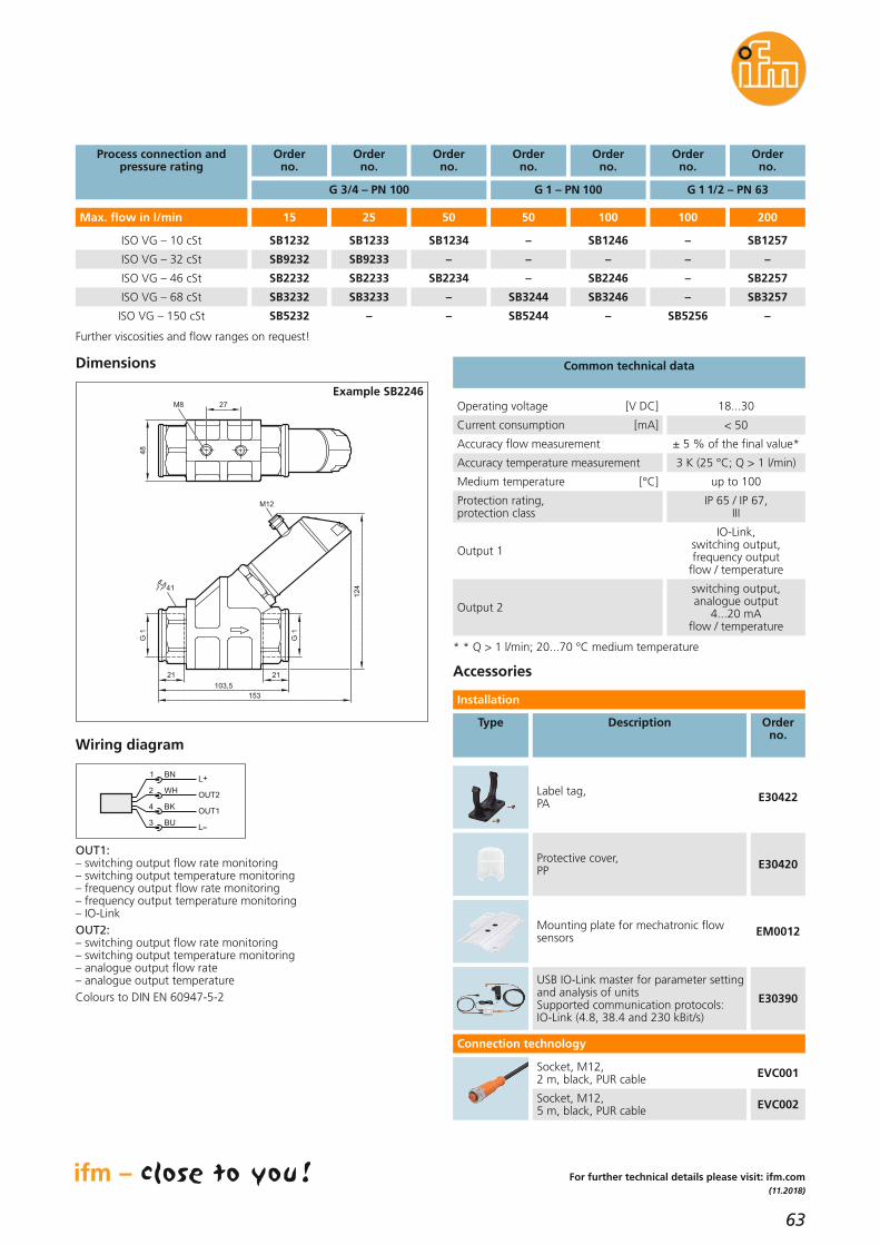
63
(11.2018)
Output 2
switching output, analogue output
4...20 mA flow / temperature
Accessories
Type Description Orderno.
Mounting plate for mechatronic flowsensors EM0012
Label tag,PA E30422
Protective cover,PP E30420
BN
WH
BK
BU
4
1
3
2OUT2
L+
L
OUT1
Wiring diagram
Dimensions
M12
153
12
4
103,5
21 21
41
G 1
G 1
48
27M8
Example SB2246
OUT1:– switching output flow rate monitoring– switching output temperature monitoring– frequency output flow rate monitoring– frequency output temperature monitoring– IO-LinkOUT2:– switching output flow rate monitoring– switching output temperature monitoring– analogue output flow rate– analogue output temperatureColours to DIN EN 60947-5-2
For further technical details please visit: ifm.com
USB IO-Link master for parameter settingand analysis of unitsSupported communication protocols: IO-Link (4.8, 38.4 and 230 kBit/s)
E30390
Socket, M12,2 m, black, PUR cable EVC001
Socket, M12,5 m, black, PUR cable EVC002
Operating voltage [V DC] 18...30
Current consumption [mA] < 50
Accuracy flow measurement ± 5 % of the final value*
Accuracy temperature measurement 3 K (25 °C; Q > 1 l/min)
Medium temperature [°C] up to 100
Output 1
IO-Link, switching output, frequency output
flow / temperature
Common technical data
Protection rating, protection class
IP 65 / IP 67, III
Installation
Connection technology
* * Q > 1 l/min; 20...70 °C medium temperature
Max. flow in l/min
Process connection and pressure rating
ISO VG – 10 cSt
ISO VG – 46 cSt
Orderno.
–
ISO VG – 32 cSt –
100 200
–
Orderno.
SB1246
–
100
SB2246
Orderno.
–
–
50
–
Orderno.
SB1234
–
50
SB2234
Orderno.
SB1233
SB9233
25
SB2233
Orderno.
G 1 1/2 – PN 63G 1 – PN 100G 3/4 – PN 100
SB1232
SB9232
15
SB2232
ISO VG – 68 cSt –
ISO VG – 150 cSt SB5256
Orderno.
SB1257
–
SB2257
SB3257
–
SB3246
–
SB3244
SB5244
–
–
SB3233
–
SB3232
SB5232
Further viscosities and flow ranges on request!

64
Process sensors
Fast hygienic temperature transmitter up to 200 °CTemperature sensors
Also suitable for small nominal pipe diameters andconfined spaces
Very fast response time< 0,25 / < 1 s
Free 3-point factory certificateavailable online
Different hygienic process connections and probe diameters selectable
Different installation lengths up to 350 mm
Analogue and IO-LinkThe temperature transmitter has an analogue output with 4...20 mA. The parameters are set via the integrated IO-Link interface which can alsobe used as a communication interface.Precise and quickThe TA temperature sensors achieve a high accuracy. The user candownload the 3-point factory certificate for his sensor for free at factory-certificate.ifm.The innovation besides the maximum temperaturerange is the excellent response time. Therefore the sensor is suitable for all highly-precise and fast processes in hygienic environments.Transparent and flexibleAn LED clearly signals the readiness for operation. Compact design, integrated process connections, different probe lengths and diameters(Ø 3 mm, Ø 6 mm) enable easy and flexible installation.

65
(04.2019)
For further technical details please visit: ifm.com
Installation length[mm]
Factory setting
[°C]
Orderno.
Process connection Clamp 3/4“
25
60
Process connection Clamp 1.5“
30
50
100
150
Operating voltage [V DC] 18...32
Protection rating,protection class
Materials in contact with the medium
high-grade stainless steel(1.4404 /316L)
Further technical data
Reverse polarity / overload protection • / •
Output function [mA] 4...20
Accuracy [K] ± 0.3 + (± 0.1 % MS)
Measuring range [°C] -50...200
Ambient temperature [°C] -25...80
IO-Link revision 1.1
Accessories
Type Description Orderno.
TA2002
TA2012
TA2802
TA2812
TA2832
TA2842
Process connection G 1/2 with sealing cone
30
50
100
150
0...200
0...200
0...200
0...200
TA2502
TA2512
50 0...100 TA2517
50 -10...150 TA2511
TA2532
100 0...100 TA2537
100 -10...150 TA2531
TA2542
Process connection Ø 6 mm
50
100
150
0...200
0...200
0...200
TA2212
TA2232
TA2242
Process connection G 3/8 with coupling nut Ø 3 mm
83
83
83
0...200
0...200
0...200
0...200
0...200
0...200
0...200
0...100
-10...150
TA1322
TA1327
TA1321
Type
LR DEVICE (supplied on USB flash drive)Software for online and offline parameter setting of IO-Link sensors andactuators
QA0011
USB IO-Link master for parameter settingand analysis of unitsSupported communication protocols: IO-Link (4.8, 38.4 and 230 kBit/s)
E30390
150 0...100 TA2247
150 -10...150 TA2241
250 0...200 TA2262
350 0...200 TA2292
Process connection M12 x 1,5 with sealing cone
17
17
17
0...200
0...100
-10...150
TA1102
TA1107
TA1101
Installation length[mm]
Factory setting
[°C]
Orderno.
Probe diameter 3 mm
Type
Probe diameter 6 mm
IP 67, IP 68, IP 69K,III
Welding adapter for type TA11
M12 x 1.5 / Ø 19 mm, high-grade stainless steel (316L) E30151
M12 x 1,5 / Ø 19 mm, with leakage port,high-grade stainless steel (316L) E30152
M12 x 1.5 / Ø 25 mm, high-grade stainless steel (316L) E30153
M12 x 1.5 / Ø 25 mm, high-grade stainless steel (316L) E30155
IO-Link
E38505
E38515
E38425
E38395
E38825
E38795
G 1/2, installation length 20 mm
G 1/2, installation length 30 mm
Welding thermowell, ball
Welding thermowell, straight
Clamp 1.5", installation length 50 mm
Clamp 3/4", installation length 38 mm
Thermowells for type TA13

66
Process sensors
Sensors for thefood industrywith freefactory certificatePressure sensors / temperature sensors
Factory certificate as documentary evidence of the accuracy
For selected pressure and temperature sensors in thefood industry
Download at: factory-certificate.ifm
Saves costs and simplifies ordering
Further detailed and individualcalibration certificates can beordered separately
Simply download the calibration certificateThe accuracy of measuring devices in production processes is decisive forthe quality of the end product. This is why ifm offers a free 3-point factorycertificate for selected pressure and temperature sensors for the food industry. This certificate remains available for download for five years. Simply log in to “my ifm” at factory-certificate.ifm, enter the serial number and download the certificate.This procedure saves costs and time, as a separate order is no longer required. Thanks to the factory certificate no initial calibration at the customer’s is required any more.
Further certificatesFurther certificates, e.g. declarations of compliance or material inspectioncertificates to EN 10204 as well as calibration certificates to ISO or DAkkS,can still be ordered separately.

67
(11.2018)
For further technical details please visit: ifm.com
* Applies to the specified article(s) and must be requested when ordering the sensor. Subsequent orders are only possible if the device is returned.
The free 3-point factory certificate is available forthe following pressure and temperature sensors:Temperature sensors of type: TD, TA20, TA22, TA25, TA28, TA13 and TA11Pressure sensors of type: PI27, PI28, PI2602 and PM1All certificates are issued in two languages (German/English)
CertificateISO calibration
Pressure sensors*
Description
Flow sensors (SD)*
ISO calibration for pressure sensors (6 calibration points)
ISO calibration for flow sensors (6 calibration points)
Temperature sensors n-point* Number (max. 4) and positions of the calibration points as requested by the customer (-20...150 °C)
ZC0004
ZC0020
Flow sensors (SM)*
Flow sensors (SU)*
ISO calibration for flow sensors (4 calibration points)
ISO calibration for flow sensors (4 calibration points)
ZC0052
ZC0053
Temperature sensors 3-point*
Temperature sensors 5-point*
Calibration at three defined temperatures: 65-85-123 °C
Calibration at five defined temperatures: 20-65-85-100-123 °C
ZC0016
ZC0017
ZC0018
Orderno.
Created according to the requirements to DIN EN ISO 9001:2008
Certificate According to
Declaration of compliance* EN10204-2.1
Description
Test report* EN10204-2.2
Certifies that the listed articles / article groups conform to the indications in
the corresponding data sheet and have been subjected to a final test.
Certifies that the listed articles conform to the indications in the corresponding data sheet and have been subjected to a 100 % final test.
Annexes: description of the 100 % tests, data sheet and, where applicable, test specification
ZC0001
ZC0002
Orderno.
Moreover, the following certificates are available:
CertificateDAkkS calibration
Pressure sensors*
Description
Temperature sensors 3-point*
Number of calibration points to DAkkS
Calibration at three defined temperatures: 65-85-123 °C
ZC0005
ZC0013
Temperature sensors 5-point*
Temperature sensors n-point*
Calibration at five defined temperatures: 20-65-85-100-123 °C
Number (max. 4) and positions of the calibration points as requested by the customer (-20...150 °C)
ZC0014
ZC0015
Orderno.
Created to the requirements of the DAkkS (German accreditation body)
Certificate According to
Inspection certificate material* EN10204-3.1
Description
Results of batch-related tests to prove that the requirements for
material characteristics and quality are met.
ZC0003
Orderno.
The following documents are moreover available for selected fluid sensor products:
Flow sensors (SD)* Number of calibration points to DAkkS ZC0075

68
Industrial communication
Worldwide innovation: AS-i signal transmissionvia fibre opticAS-Interface wiring technology
AS-Interface signal transmissionover a distance of up to 3.2 km
Possibility of mixed operation(AS-i flat cable and fibre optic)
Lightning protection, radiatedEM interference immunity
High operational reliability
Electrical separation
Plug-in connection terminals
AS-i fibre optic repeaterifm’s new AS-i fibre optic repeater enables AS-Interface signal transmissionvia an optical medium and vice versa. This allows for considerable cablelength extension in the AS-i network.Every AS-i fibre optic repeater has two independent channels that consist of a transmitting and a receiving element which are supplied via the AS-Interface system. Various LEDs indicate the current operating status.This innovation is integrated into the new SmartLine housing.While conventional repeaters usually have a temperature range from 0...55 °C, the new unit from ifm operates reliably across a broad range from -25...70 °C. Another new feature: the integrated passive bus termination.

69
(11.2018)
For further technical details please visit: ifm.com
Products
Cable length in the AS-i network of up to 3.2 km, integrated passive bus termination, protection rating IP20, COMBICON connectors
AC3227
Total current consumption [mA]via AS-i 60
AS-i specification 2.11 + 3.0
Fibre optic connector ST
Compatible fibre types Multimode: 50/125 μm, 62.5/125 μm
Ambient temperature [°C] -25...70
Protection IP 20
Smartline AS-i fibre optic repeater AC3227
Smartline AS-i fibre optic repeater
Dimensions
108
3
35,5
25,4
93
10
9,4
1
LED
2
Rx
Tx
Operating voltage [V DC] 26.5...31.6
Accessories
Orderno.
Type Description
Fibre optic cable, ST / ST, IP 20, 50 μm, 20 m, PUR E74800
Fibre optic cable, ST / ST, IP 20, 50 μm, 50 m, PUR E74801
Fibre optic cable, ST / ST, IP 20, 50 μm, 100 m, PUR E74802
Performance in the fieldOptical transmission means there is no interfering radiation, nor are there any ground problems. Fibreoptic transmission systems exclude any EMC risk, as a matter of principle. As to distance related losses due to inductances, capacities and resistances (as is the case with coppercables for example), they do not occur either. Consequently, the new AS-i fibre optic repeater contributes decisively to life time extension and cost reduction.Using the new AS-i fibre optic repeater allows for additional fibre optic network topologies (line topology,star topology).
Orderno.
Type Description
1) plug with cage clamp connection2) panel for labelling3) mounting on DIN rail
Technical dataAC3227
10825,4
93
12
5,7
1
LED
2
3
35,5
1) plug with cage clamp connection2) panel for labelling3) mounting on DIN rail
AC3226
SmartLine AS-i repeater
Cable length in the AS-i network of up to 200 m, integrated passive bus termination, protection rating IP20, COMBICON connectors
AC3226
Total current consumption [mA]via AS-i 2 x 60
Ambient temperature [°C] -25...70
Housing material PA 6.6
SmartLine AS-i repeaterAC3226
Operating voltage [V DC] 26.5...31.6
Protection IP 20
Housing material PA 6.6
AS-i power supply 115/230 V AC, output current (AS-i) 8 A AC1258
AS-i power supply 115/230 V AC, output current (AS-i) 2,8 A AC1256
AS-i power supply 115/230 V AC, output current (AS-i) 4 A AC1257

70
IO-Link
IO-Link master for intelligent sensors inthe control cabinet
IO-Link masters CabinetLine
Separation between automation and IT network
Industry 4.0 ready via new IoT core
8 IO-Link ports with full V1.1 functionality
PROFINET, EtherNet/IP, EtherCat,Modbus TCP or TCP/IP JSON
Master and device configurablevia the LR DEVICE software
IO-Link master for the automation and IT worldThe IO-Link master modules for the control cabinet serve as a gateway between intelligent IO-Link sensors and the field bus. Besides, important information of the intelligent sensors can simultaneously be sent into the IT world.With a separate IoT Ethernet socket the IT network can be set up completely separated from the automation network. Sensor information is transferredinto the IT world via the established TCP/IP JSON interface.
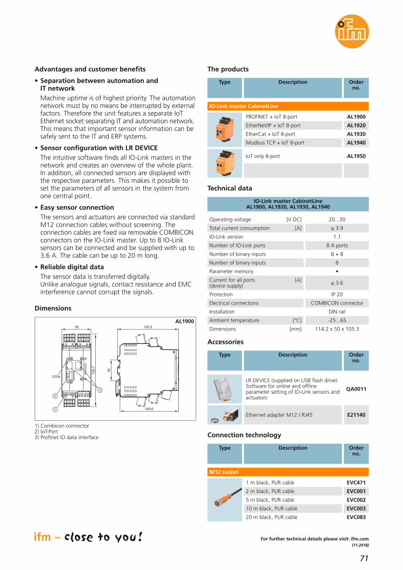
71
(11.2018)
For further technical details please visit: ifm.com
Advantages and customer benefits
• Separation between automation and IT network
Machine uptime is of highest priority. The automationnetwork must by no means be interrupted by external factors. Therefore the unit features a separate IoTEthernet socket separating IT and automation network. This means that important sensor information can besafely sent to the IT and ERP systems.
• Sensor configuration with LR DEVICEThe intuitive software finds all IO-Link masters in thenetwork and creates an overview of the whole plant.In addition, all connected sensors are displayed withthe respective parameters. This makes it possible toset the parameters of all sensors in the system fromone central point.
• Easy sensor connectionThe sensors and actuators are connected via standardM12 connection cables without screening. The connection cables are fixed via removable COMBICON connectors on the IO-Link master. Up to 8 IO-Linksensors can be connected and be supplied with up to3.6 A. The cable can be up to 20 m long.
• Reliable digital dataThe sensor data is transferred digitally. Unlike analogue signals, contact resistance and EMCinterference cannot corrupt the signals.
Total current consumption [A] ≤ 3.9
IO-Link version 1.1
Number of IO-Link ports 8 A ports
Number of binary inputs 8 + 8
Number of binary inputs 8
Parameter memory •
Current for all ports [A](device supply) ≤ 3.6
Protection IP 20
Electrical connections COMBICON connector
Installation DIN rail
Ambient temperature [°C] -25...65
Dimensions [mm] 114.2 x 50 x 105.3
IO-Link master CabinetLine AL1900, AL1920, AL1930, AL1940
Technical data
Operating voltage [V DC] 20...30
The products
PROFINET + IoT 8-port AL1900
EtherNet/IP + IoT 8-port AL1920
IO-Link master CabinetLine
Accessories
Orderno.
LR DEVICE (supplied on USB flash drive)Software for online and offline parameter setting of IO-Link sensors andactuators
QA0011
Type Description
Ethernet adapter M12 / RJ45 E21140
Orderno.
Type Description
EtherCat + IoT 8-port AL1930
Modbus TCP + IoT 8-port AL1940
M12 socket
Connection technology
Type Description Orderno.
1 m black, PUR cable EVC471
2 m black, PUR cable EVC001
5 m black, PUR cable EVC002
10 m black, PUR cable EVC003
20 m black, PUR cable EVC083
LEDs
1
2
3
50
12
5,7
35
105,3
100,6
Dimensions
AL1900
1) Combicon connector2) IoT-Port3) Profinet IO data interface
IoT only 8-port AL1950
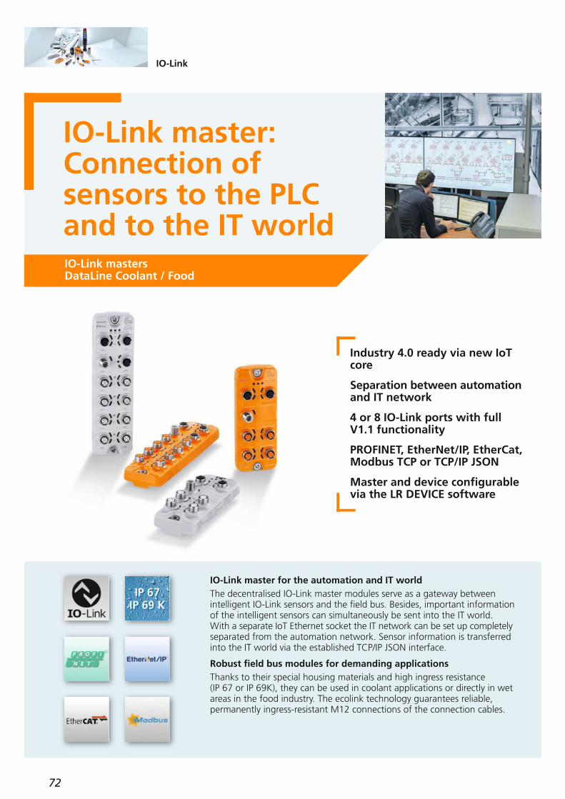
72
IO-Link
IO-Link master: Connection of sensors to the PLCand to the IT worldIO-Link mastersDataLine Coolant / Food
Industry 4.0 ready via new IoTcore
Separation between automation and IT network
4 or 8 IO-Link ports with fullV1.1 functionality
PROFINET, EtherNet/IP, EtherCat,Modbus TCP or TCP/IP JSON
Master and device configurablevia the LR DEVICE software
IO-Link master for the automation and IT worldThe decentralised IO-Link master modules serve as a gateway between intelligent IO-Link sensors and the field bus. Besides, important informationof the intelligent sensors can simultaneously be sent into the IT world. With a separate IoT Ethernet socket the IT network can be set up completely separated from the automation network. Sensor information is transferredinto the IT world via the established TCP/IP JSON interface.
Robust field bus modules for demanding applicationsThanks to their special housing materials and high ingress resistance (IP 67 or IP 69K), they can be used in coolant applications or directly in wetareas in the food industry. The ecolink technology guarantees reliable, permanently ingress-resistant M12 connections of the connection cables.

73
(11.2018)
For further technical details please visit: ifm.com
Total currentconsumption ≤ 3.9 A
IO-Link version 1.1
Number of IO-Linkports
4 A ports
8 A ports
Number of binary inputs 4 + 4
Number of binary outputs 4
8 + 8
8
4 A ports
8 A ports
4 + 4
4
8 + 8
8
Parameter memory •
Current for all A ports
≤ 3.6 A(device supply)
Protection IP 65, IP 67
Ambienttemperature -25...60 °C
Housing materials / socket
Polyamide / brass
nickel-plated
IP 65, IP 67, IP 69K
Polyamide / stainless steel
IO-Link master DataLine
Coolant / Food
Technical data
Operating voltage 20...30 V DC
The products
Profinet + IoT 4-port
EtherNet/IP + IoT 4-port
EtherCat + IoT 4-port
IO-Link master DataLine
Order no.
Advantages and customer benefits
• Separation between automation and IT network
Machine uptime is of highest priority. The automationnetwork must by no means be interrupted by external factors. Therefore the unit features a separate IoTEthernet socket separating IT and automation network. This means that important sensor information can besafely sent to the IT and ERP system.
• Sensor configuration with LR DEVICEThe intuitive software finds all IO-Link masters in thenetwork and creates an overview of the whole plant.In addition, all connected sensors are displayed withthe respective parameters. This makes it possible toset the parameters of all sensors in the system fromone central point.
• Easy sensor connectionThe sensors and actuators are connected via standardM12 connection cables without screening. Depending on the device type, up to 4 or 8 IO-Link sensors canbe connected and supplied with up to 3.6 A. With the EVC693 or EVF693 accessories, additionalauxiliary power for the connection of IO-Link actuators can be supplied. The cable can be up to 20 m long.
Connection technology
Accessories
Orderno.
LR DEVICE (supplied on USB flash drive)Software for online and offline parameter setting of IO-Link sensors andactuators
QA0011
Type Description
Coolant, protective caps M12 (10 pcs)
E73004
0.5 m EVF530
2 m EVF531
5 m EVF532
10 m EVF533
Type Description
Ethernet cable (fieldbus)
2 m EVF480
5 m EVF481
10 m EVF482
20 m EVF483
M12 socket 1 mm2 (power)
1 m EVF042
2 m EVF043
5 m EVF044
10 m EVF045
E12490
E12090
E12491
E12492
EVC706
EVC707
EVC708
EVC709
EVC042
EVC043
EVC044
EVC493
1 m EVF693
2 m EVF694
5 m EVF695
10 m EVF696
EVC693
EVC694
EVC695
EVC696
M12 jumper cable 0.34 mm2 (sensor)
Y splitter (adapter A port / B port)
Order no.
FoodCoolant
Type
AL1301
AL1321
AL1331
AL1300
AL1320
AL1330
Profinet + IoT 8-port
EtherNet/IP + IoT 8-port
EtherCat + IoT 8-port
AL1303
AL1323
AL1333
AL1302
AL1322
AL1332
Food,protective caps M12 4 pcs, high-grade stainless steel
E12542
Modbus TCP + IoT 4-port AL1341AL1340
Modbus TCP + IoT 8-port AL1343AL1342
AL1302AL1322AL1332AL1342AL1352
AL1300AL1320AL1330AL1340AL1350
AL1303AL1323AL1333AL1343AL1353
AL1301AL1321AL1331AL1341AL1351
IoT only 8-port AL1351AL1350
IoT only 8-port AL1353AL1352
Description Order no.
FoodCoolant

74
IO-Link mastermeets wiring system
IO-Link mastersAS-i Coolant / Food
Perfect completion of the AS-i wiring system
4 IO-Link ports with full V1.1 functionality
An integrated parameter memory facilitates sensor replacement
Extended diagnostics for IO-Link devices
Field module with IP 69K for the food industry
IO-Link master for the AS-i wiring systemThe decentralised IO-Link master modules serve as a gateway between intelligent IO-Link sensors and the AS-Interface field bus. With the 4-port IO-Link master you combine the advantages of the AS-i wiring system withthe standardised IO-Link communication.IO-Link provides detailed sensor or actuator diagnostics and allows you toincrease machine uptime. The integrated parameter memory of the IO-Linkmaster also allows easy sensor replacement during night shifts.
Robust field bus modules for demanding applicationsThanks to their special housing materials and high ingress resistance (IP 67 or IP 69K), they can be used in coolant applications or directly in wet areas in the food industry. The ecolink technology guarantees reliable,permanently ingress-resistant M12 connections of the connection cables.
IO-Link
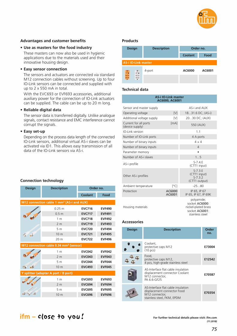
75
(11.2018)
Technical data
Products
4-port
AS-i IO-Link master
Advantages and customer benefits
• Use as masters for the food industryThese masters can now also be used in hygienic applications due to the materials used and their innovative housing design.
• Easy sensor connectionThe sensors and actuators are connected via standardM12 connection cables without screening. Up to fourIO-Link sensors can be connected and supplied withup to 2 x 550 mA in total.With the EVC693 or EVF693 accessories, additionalauxiliary power for the connection of IO-Link actuators can be supplied. The cable can be up to 20 m long.
• Reliable digital dataThe sensor data is transferred digitally. Unlike analogue signals, contact resistance and EMC interference cannot corrupt the signals.
• Easy set-upDepending on the process data length of the connected IO-Link sensors, additional virtual AS-i slaves can beactivated via ID1. This allows easy transmission of alldata of the IO-Link sensors via AS-i.
Connection technology
Accessories
Orderno.
Design Description
Coolant, protective caps M12 (10 pcs)
E73004
0.25 m EVF490
0.5 m EVF491
Design Description
2 m EVF493
5 m EVF494
10 m EVF495
20 m EVF496
M12 connection cable 1 mm2 (AS-i and AUX)
1 m EVF042
2 m EVF043
5 m EVF044
10 m EVF045
EVC716
EVC717
1 m EVF492EVC718
EVC719
EVC720
EVC721
EVC722
EVC042
EVC043
EVC044
EVC493
1 m EVF693
2 m EVF694
5 m EVF695
10 m EVF696
EVC693
EVC694
EVC695
EVC696
M12 connection cable 0.34 mm2 (sensor)
Y splitter (adapter A port / B port)
Order no.
FoodCoolant
Design Description Order no.
FoodCoolant
AC6001AC6000
Food,protective caps M12, 4 pcs, high-grade stainless steel
E12542
AS-Interface flat cable insulation displacement connector Coolant M12 connector,PA 6.6-GF25
E70587
AS-Interface flat cable insulation displacement connector Food M12 connector, stainless steel, FKM, EPDM
E70354
For further technical details please visit: ifm.com
Operating voltage [V] 18...31.6 DC; (AS-i)
Additional voltage supply [V] 20...30 DC; (AUX)
Current for all ports [mA](device supply) 550 (AUX)
IO-Link version 1.1
Number of IO-Link ports 4 A ports
Number of binary inputs 4 + 4
Number of binary inputs 4
Parameter memory •
Number of AS-i slaves 1...5
AS-i profile S-7.4.E (CTT1 input)
Other AS-i profiles
S-7.3.E (CTT1 input)
S-7.3.2 (CTT1 output)
Ambient temperature [°C] -25...80
Protection AC6000 AC6001
IP 65, IP 67IP 65, IP 67, IP 69K
Housing materials
polyamide; socket AC6000:
nickel-plated brasssocket AC6001:
stainless steel
AS-i IO-Link master AC6000, AC6001
Sensor and master supply AS-i and AUX

76
IO-Link
Starter kit IO-Link master: fieldbus systems
IO-Link mastersStandardLine Coolant
4-port IO-Link master with PROFINET or EtherNet/IP interface
230V/24V plug-in power supply
LR DEVICE (USB stick) IO-Linkparameter setting software
Photoelectric IO-Link distancesensor
Ethernet cable M12/RJ45, 0.5 m
Sensor cable M12/M12, 0.6 m
Starter kit IO-Link masterWith this starter kit you can basically give the advantages of our IO-Linksensors a try directly on your desk. Transform a binary photoelectric distance sensor that only delivers a switch point 1 or 0 on a digital inputcard into an intelligent sensor and even measure the distance to the object.Besides the IO-Link master and the IO-Link sensor can be configured bymeans of the intuitive IO-Link parameter setting software. Complicated parameter setting on the display of the sensor is no longer necessary.The decentralised IO-Link master serves as a gateway between intelligentIO-Link sensors and the PROFINET or EtherNet/IP fieldbus. This means that itis also possible to set up a simple PROFINET or EtherNet/IP connection e.g.to a Siemens or Rockwell controller.To do this, please download the PROFINET “startup package” for theAL1100 or the EtherNet/IP “startup package” for the AL1120 from ourwebsite: ifm.com

77
(04.2019)
For further technical details please visit: ifm.com
Advantages and customer benefits
• Sensor configuration with LR DEVICEThe intuitive software finds all IO-Link masters in thenetwork and creates an overview of the whole plant.In addition, all connected sensors are displayed withthe respective parameters. This makes it possible toset the parameters of all sensors in the system fromone central point.
• Easy sensor connectionThe sensors and actuators are connected via standardM12 connection cables without screening. Depending on the device type, up to 4 or 8 IO-Link sensors canbe connected and supplied with up to 3.6 A. Withthe EVC693 accessories, additional auxiliary powerfor the connection of IO-Link actuators can be supplied. The cable can be up to 20 m long.
• Reliable digital dataThe sensor data is transferred digitally. Unlike analogue signals, contact resistance and EMC interference cannot corrupt the signals.
• Direct connection to the ITIoT-Core is capable of transmitting the process valuesdirectly to ERP systems, without detour via the PLC. This second communication path is available in parallel to the fieldbus via the bus wiring.
Total current consumption [A] ≤ 3.9
IO-Link version 1.1
Number of IO-Link ports 4 A ports 8 A ports
Number of binary inputs(IO-Link in SIO mode) 4 + 4
Number of binary inputs(IO-Link in SIO mode) 4
8 + 8
8
Parameter memory •
Current for all ports [A](device supply) ≤ 3.6
Protection IP 65, IP 67
Ambient temperature [°C] -25...60
Housing materialsPolyamide;
socket: nickel-plated brass
IO-Link Master StandardLine Coolant
Further technical data
Operating voltage [V DC] 20...30
The products
Profinet 4-port AL1100
EtherNet/IP 4-port AL1120
IO-Link master StandardLine Coolant
Profinet 8-port AL1102
EtherNet/IP 8-port AL1122
Order no.
AL1102AL1122
AL1100AL1120
Description
4-port IO-Link master AL1120
Starter kit IO-Link master ZZ1120
Plug-in power supply, 230V/24V –
Plug-in power supply with interchangeable adapter, 230 V / 24 V
onrequest
Starter kit (complete set)
LR DEVICE (USB stick), IO-Link parameter setting software
Photoelectric IO-Link distance sensor
Ethernet cable M12 / RJ45 0.5 m
Sensor cable M12 / M12, 0.6 m
AL1100
ZZ1100
E30080
–
QA0011
O5D150
E12490
EVC041
Starter kit (individual components)
Order no.
EtherNet/IPPROFINET

78
IO-Link
Internet of Thingsstarter kit
IO-Link mastersDataLine Coolant
4-port IO-Link master with IoT core and MQTT interface
Start-up package for IoT applications for download
IO-Link parameter setting software ”LR DEVICE“ on USB stick
Including IO-Link temperaturesensor, plug-in power supplywith interchangeable adapter,Ethernet and sensor cable
Starter kit IO-Link masterWith this starter kit you can immediately try out the IoT core interface ofthe IO-Link master on your desk.Connect the IO-Link temperature sensor to the IO-Link master and transmit the value of the sensor to different IoTsoftware environments via TCP/IP JSON or MQTT. This is how you easilyconnect robust components from automation technology to the IT world.
Start-up package for IoT applications for downloadIn this IoT start-up package, you will find practical examples on how to simply read and process temperature values with an internet browser, Excel,Postman or NodeRed.You can find the free ”start-up package | IO-Link | IoT - JSON“ on our website: ifm.com at Service / Downloads / IO-Link Setup Guide & Software.

79
(04.2019)
Advantages and customer benefits
• IoT core interface for the IT worldThe IoT core allows access to all data ranges of theIO-Link master and sensors. Established HTTP callsand JSON commands allow reading or writing of information. Connection to the IT world is made viathe IoT core interface. In addition, ifm offers furtherIO-Link masters with different fieldbus interfaces forthe automation level.
• Display measured values in the internet browser or in Excel
The quickest and simplest HTTP call can be madeusing an internet browser or Excel. The start-up package contains a small example of how you candisplay the temperature value in every internetbrowser. You can also record temperature values inExcel for subsequent analysis and optimisation ofyour installation. You can find more practical examples with other toolsin the IoT start-up package at ifm.com.
• Sensor configuration with LR DEVICEThe intuitive software finds all IO-Link masters in thenetwork and creates an overview of the whole plant.In addition, all sensors connected are indicated withthe respective parameters. This means that parametersetting of all sensors in the system is possible fromone central point.
• Easy sensor connectionThe sensors and actuators are connected via standardM12 connection cables without screening. Up to 4IO-Link sensors can be connected and supplied with atotal of up to 3.6 A. The cable can be up to 20 mlong.
• Secure digital dataThe sensor data is transferred digitally. Unlike analogue signals, contact resistance and EMCinterference cannot corrupt the signals.
For further technical details please visit: ifm.com
Products
Orderno.
Description
4-port IO-Link master with IoT interface AL1350
Starter kit IO-Link master ZZ1350
Plug-in power supply with interchangeable adapter, 230 V / 24 V
onrequest
Starter kit (complete set)
LR DEVICE (USB stick), IO-Link parameter setting software QA0011
IO-Link temperature sensor TV7105
Ethernet cable M12 / RJ45, 0.5 m E12490
Sensor cable M12 / M12, 0.6 m EVC041
Starter kit (individual components)
IoT + PROFINET 4 ports
IoT + EtherNet/IP 4 ports
IoT + EtherCat 4 ports
IO-Link master DataLine
Type Description Order no.
FoodCoolant
AL1301
AL1321
AL1331
AL1300
AL1320
AL1330
IoT + PROFINET 8 ports
IoT + EtherNet/IP 8 ports
IoT + EtherCat 8 ports
AL1303
AL1323
AL1333
AL1302
AL1322
AL1332
IoT + Modbus TCP 4 ports AL1341AL1340
IoT + MQTT 4 ports AL1351AL1350
IoT + Modbus TCP 8 ports AL1343AL1342
IoT + MQTT 8 ports AL1353AL1352
IoT + PROFINET 8 ports AL1900
IoT + EtherNet/IP 8 ports AL1920
IO-Link master CabinetLine
Orderno.
Type Description
IoT + EtherCat 8 ports AL1930
IoT + Modbus TCP 8 ports AL1940
IoT + MQTT 8 ports AL1950
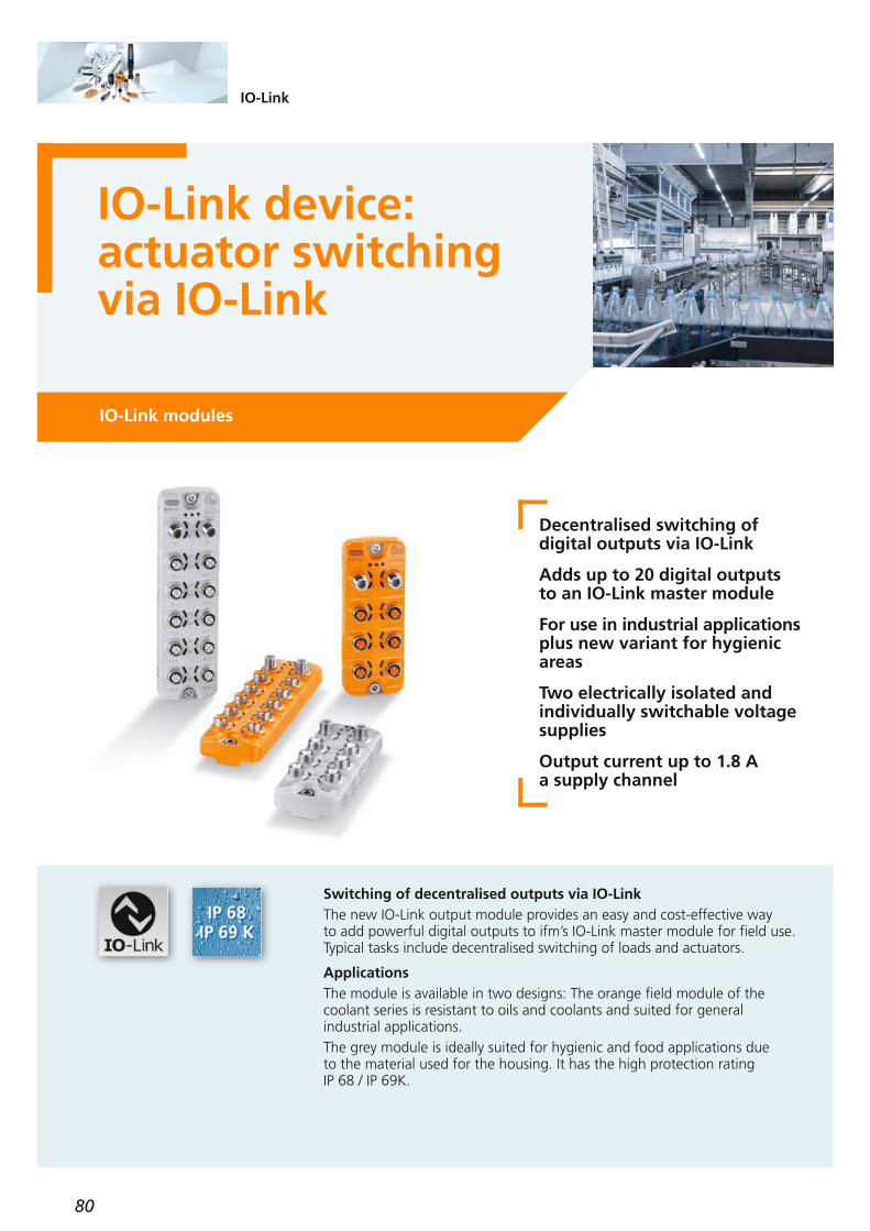
80
IO-Link
IO-Link device: actuator switchingvia IO-Link
IO-Link modules
Decentralised switching of digital outputs via IO-Link
Adds up to 20 digital outputs to an IO-Link master module
For use in industrial applications plus new variant for hygienicareas
Two electrically isolated and individually switchable voltagesupplies
Output current up to 1.8 A a supply channel
Switching of decentralised outputs via IO-LinkThe new IO-Link output module provides an easy and cost-effective way to add powerful digital outputs to ifm’s IO-Link master module for field use.Typical tasks include decentralised switching of loads and actuators.
ApplicationsThe module is available in two designs: The orange field module of thecoolant series is resistant to oils and coolants and suited for general industrial applications.The grey module is ideally suited for hygienic and food applications due to the material used for the housing. It has the high protection rating IP 68 / IP 69K.
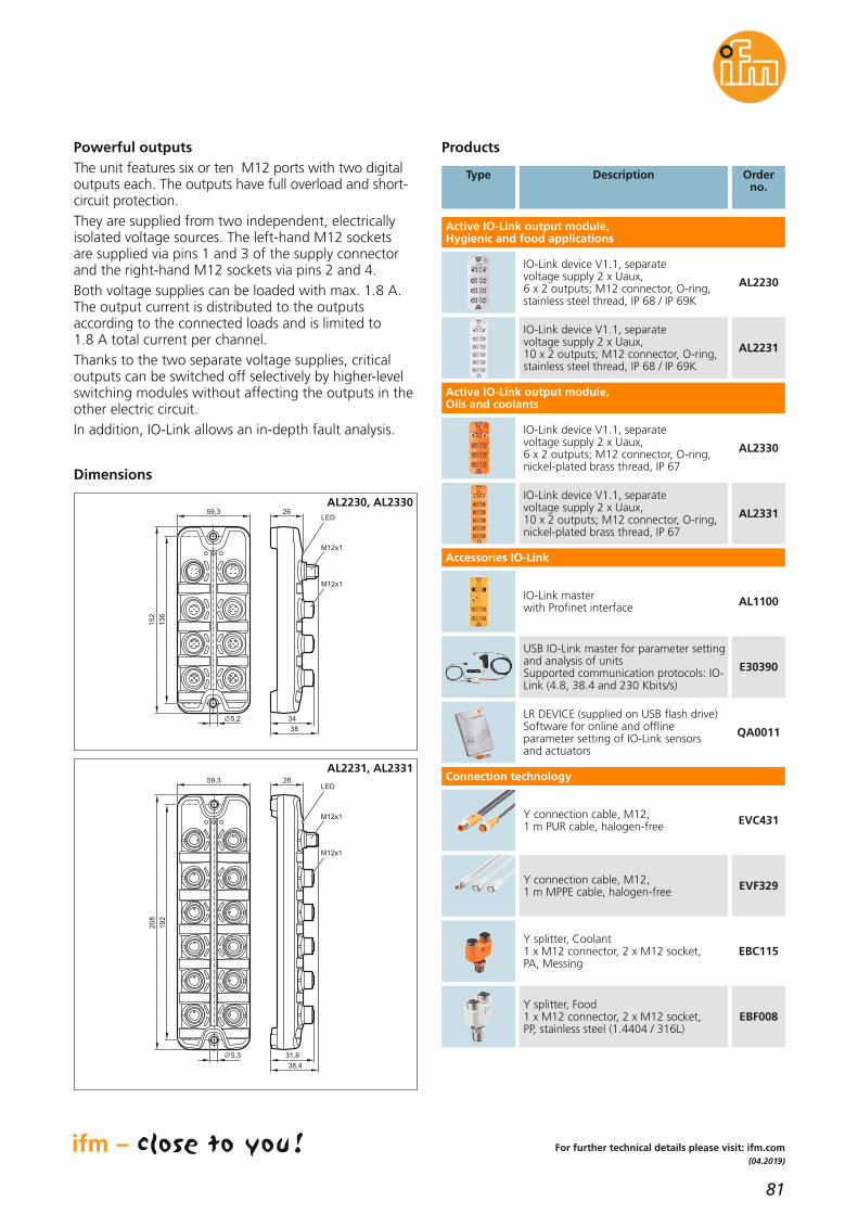
81
(04.2019)
For further technical details please visit: ifm.com
Dimensions
Powerful outputsThe unit features six or ten M12 ports with two digitaloutputs each. The outputs have full overload and short-circuit protection.They are supplied from two independent, electricallyisolated voltage sources. The left-hand M12 sockets are supplied via pins 1 and 3 of the supply connectorand the right-hand M12 sockets via pins 2 and 4.Both voltage supplies can be loaded with max. 1.8 A.The output current is distributed to the outputs according to the connected loads and is limited to 1.8 A total current per channel.Thanks to the two separate voltage supplies, criticaloutputs can be switched off selectively by higher-levelswitching modules without affecting the outputs in theother electric circuit.In addition, IO-Link allows an in-depth fault analysis.
Products
IO-Link device V1.1, separate voltage supply 2 x Uaux, 6 x 2 outputs; M12 connector, O-ring, stainless steel thread, IP 68 / IP 69K
AL2230
Active IO-Link output module,Hygienic and food applications
IO-Link master with Profinet interface AL1100
LR DEVICE (supplied on USB flash drive)Software for online and offline parameter setting of IO-Link sensors and actuators
QA0011
Orderno.
IO-Link device V1.1, separate voltage supply 2 x Uaux, 6 x 2 outputs; M12 connector, O-ring, nickel-plated brass thread, IP 67
AL2330
Active IO-Link output module,Oils and coolants
USB IO-Link master for parameter settingand analysis of unitsSupported communication protocols: IO-Link (4.8, 38.4 and 230 Kbits/s)
E30390
Type Description
15
2
13
6
59,3
5,2
26
34
38
LED
M12x1
M12x1
AL2230, AL2330
20
8
19
2
59,3
5,3
LED
M12x1
M12x1
26
31,6
38,4
AL2231, AL2331
IO-Link device V1.1, separate voltage supply 2 x Uaux, 10 x 2 outputs; M12 connector, O-ring, stainless steel thread, IP 68 / IP 69K
AL2231
IO-Link device V1.1, separate voltage supply 2 x Uaux, 10 x 2 outputs; M12 connector, O-ring, nickel-plated brass thread, IP 67
AL2331
Y connection cable, M12, 1 m PUR cable, halogen-free EVC431
Y connection cable, M12, 1 m MPPE cable, halogen-free EVF329
Y splitter, Coolant1 x M12 connector, 2 x M12 socket,PA, Messing
EBC115
Y splitter, Food1 x M12 connector, 2 x M12 socket,PP, stainless steel (1.4404 / 316L)
EBF008
Accessories IO-Link
Connection technology

82
IO-Link
IO-Link modulescollect and convertdigital signals
IO-Link modules
Effective connection of binarysensors to IO-Link
Adds up to 20 digital inputs toan IO-Link master
For use in industrial applications plus new variant for hygienicareas
High protection rating IP 68 / 69K
Pre-processing of the input signals by digital input filters
Decentralised collection of digital signals via IO-LinkThe new IO-Link input modules for field applications allow easy and economical adding of up to 20 digital inputs to IO-Link masters.The activation of digital input filters such as debouncing, stretching or inverting allows easy optimisation of the input signals.
ApplicationsThe module is available in two designs: The orange field module from the coolant series is resistant to oils and coolants and suited for general industrial applications.The grey module is ideally suited for hygienic and food applications due to the material used for the housing. It has the high protection ratingIP 68 / IP 69K.

83
(11.2018)
LED
M12x1
26
34
38
15
2
13
6
59,3
5,3
For further technical details please visit: ifm.com
Dimensions
Field modules with IO-Link connectionUp to 20 conventional sensors can be connected to these modules. IO-Link transfers the signals to anyIO-Link master / PLC via one unscreened M12 cable.A special feature of the modules is the pre-processingof the input signals via different filters before passingthem on to IO-Link.The following filters are available: debouncing (suppressnoise signals), stretching (longer signals), inverting.This allows reliable detection of signals with a minimumlength of 1.5 ms.The decentralised positioning of the module reduceswiring costs and makes complex cabling obsolete. Asopposed to bus systems IO-Link does not require anyconfiguration or addressing. This simplifies installation.Pins 2 and 4 of each M12 socket are configured as binary inputs. That means that dual sensors, normallyclosed or normally open, can be connected without anyproblem. The inputs have full overload and short-circuitprotection.
Products
Accessories
Orderno.
IO-Link master with PROFINET interface AL1100
Design Description
LR DEVICE (supplied on USB flash drive)Software for online and offline parameter setting of IO-Link sensors and actuators
QA0011
Digital output module food, IO-Link device V1.1, M12 connector, O-ring, thread: stainless steel, IP 68 / IP 69K
AL2230
Digital output module coolant, IO-Link device V1.1, M12 connector, O-ring, thread: nickel-plated brass, IP 67
AL2330
USB IO-Link master for parameter settingand analysis of unitsSupported communication protocols: IO-Link (4.8, 38.4 and 230 kbits/s)
E30390
Orderno.
Design Description
LED
M12
M12
26
31,6
38,4
20
8
19
2
59,3
5,3
AL2241,AL2341
AL2240,AL2340
IO-Link device V1.1; 6 x 2 inputs;M12 connector; O-ring; stainless steel thread; IP 68, IP 69K
AL2240
IO-Link device V1.1; 10 x 2 inputs;M12 connector; O-ring; stainless steel thread; IP 67
AL2341
Active IO-Link input module,hygienic and food applications
IO-Link device V1.1; 6 x 2 inputs;M12 connector; O-ring; stainless steel thread; IP 67
AL2340
Active IO-Link input module,oils and coolants
IO-Link device V1.1; 10 x 2 inputs;M12 connector; O-ring; stainless steel thread; IP 68, IP 69K
AL2241
EBC113
Y splitter, food, 1 x M12 connector, 2 x M12 plug, PA, stainless steel (1.4404 / 316L)
EBF006
Y splitter, coolant, 1 x M12 connector, 2 x M12 plug, PA, brass
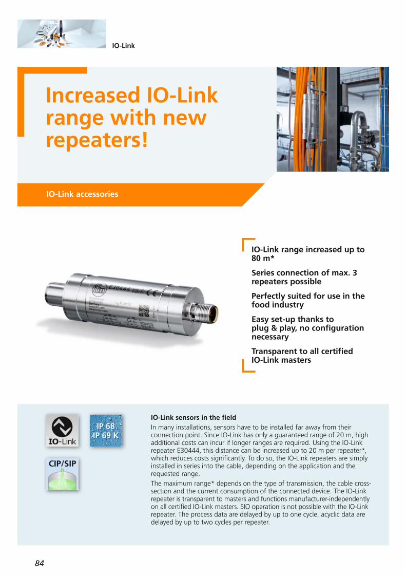
84
IO-Link
Increased IO-Linkrange with new repeaters!
IO-Link accessories
IO-Link range increased up to 80 m*
Series connection of max. 3repeaters possible
Perfectly suited for use in thefood industry
Easy set-up thanks to plug & play, no configurationnecessary
Transparent to all certified IO-Link masters
IO-Link sensors in the fieldIn many installations, sensors have to be installed far away from their connection point. Since IO-Link has only a guaranteed range of 20 m, highadditional costs can incur if longer ranges are required. Using the IO-Linkrepeater E30444, this distance can be increased up to 20 m per repeater*,which reduces costs significantly. To do so, the IO-Link repeaters are simplyinstalled in series into the cable, depending on the application and therequested range.The maximum range* depends on the type of transmission, the cable cross-section and the current consumption of the connected device. The IO-Linkrepeater is transparent to masters and functions manufacturer-independently on all certified IO-Link masters. SIO operation is not possible with the IO-Link repeater. The process data are delayed by up to one cycle, acyclic data aredelayed by up to two cycles per repeater.

85
(04.2019)
Accessories
Type Description Orderno.
IO-Link master StandardLine, Profinet, 4 ports AL1100
IO-Link master StandardLine, Profinet, 8 ports AL1102
IO-Link master StandardLine, EtherNet/IP, 4 ports AL1120
IO-Link master StandardLine, EtherNet/IP, 8 ports AL1122
Current consumption [mA] < 20
IO-Link deviceTransmission typeIO-Link revisionSDCI standardSIO modeRequires master port class
COM1, COM2, COM3compatible with 1.0 and 1.1
IEC 61131-9–
A /B
Ambient temperature [°C] -25...65
Protection IP 68, IP 69K
Materials
high-grade stainless steel(316L/1.4404),
PEI, PA fibre-reinforced, FKM
Operating voltage [V DC] 18...30
Reverse polarity protection on the master side •
IO-Link repeater Orderno.
E30444
For further technical details please visit: ifm.com
Technical data
Connection cable, M12,20 m, black, PUR cable EVC118
Connection cable, M12,30 m, black, PUR cable EVC160
Socket, M12,40 m, black, PUR cable EVC759
Connection technology
Type Description Orderno.
Dimensions
M12
15
84
116
14
M1
2
10
7 7 30
Wiring diagram
1
2
4
5
3
BN
GY
WH
BK
BU
E30444
1
2
4
5
3
BN
GY
WH
BK
BU
* Details regarding the maximum range, compatibility and necessary cable cross sections can be found in the operating instructions or the data sheet of the repeater.

86
Identification systems
New antenna versions, perfect for the DTE10x RFIDsystemRFID 13.56 MHz
Diagnostic and display LEDs foreasy set-up
Communication to the PLC viaDTE10x evaluation unit
M12 connector for standard cables of up to 20 m
Extensive range of mountingaccessories
Perfect for applications where high data volumes are to be transmitted quickly
A multitude of applications with long rangesThe RFID antennas are ideal for long writing / reading distances.A typical application is product tracking in the production process. TheANT600 may be used for storing e.g. production data or quality parameterson the ID tags.In material logistics, the RFID system can easily determine whether the material and quantity of material match the production order.In plant control, product-specific machine parameters can be read from the ID tag attached to the product.

87
(04.2019)
For further technical details please visit: ifm.com
Advantages of ifm’s RFID solutions:
Connection to the RFID evaluation units of theDTE10x series.The RFID antennas are designed for connection to thecompact ifm evaluation unit DTE10x. This unit offersfour M12 sockets for connection of up to four RFID antennas. Optionally, unused RFID inputs can also beused for the control of outputs or the detection of digital input signals. Two digital sensors can be connected to each socket setas an input; and an actuator to each output.For communication to the higher-level controller, theDTE10x has an EtherCAT, Profibus, Ethernet TCP/IP,EtherNet/IP or PROFINET interface, depending on thedesign.The robust design with protection rating IP 67 permitsuse in harsh industrial environments.
DTE103RFID evaluation unit, EtherCAT interface
DTE102RFID evaluation unit, EtherNet/IP interface
DTE104RFID evaluation unit, Ethernet TCP/IP interface
Products
DTE100RFID evaluation unit, Profibus DP interface
DTE101RFID evaluation unit, PROFINET interface
RFID evaluation unit
ANT512RFID antenna 125 KHz
ANT513RFID antenna 13.56 MHz,ISO 15693
ANT515RFID antenna 13.56 MHz,1 m cable, M12 plug
ANT516RFID antenna 13.56 MHz,2 m cable, M12 plug
ANT410RFID antenna 13.56 MHz,M12 design, flush
ANT411RFID antenna 13.56 MHz,M12 design, non-flush
ANT430RFID antenna 13.56 MHz,M30 design, flush
ANT431RFID antenna 13.56 MHz,M30 design, non-flush
ANT420RFID antenna 13.56 MHz,M18 design, flush
ANT421RFID antenna 13.56 MHz,M18 design, non-flush
E80400ID tag/51x51/06 – 13.56 MHz, 10 pcs
E80401ID tag holder for ID tag E80400
E80347ID tag/M5x16.5/06 – 13.56 MHz, 10 pcs
E80348Tag fixture for workpiece carriers with ID tag E80345, 13.56 MHz, 896 bits
E80342ID tag/34X6.0/06 – 13.56 MHz, 1024 bits, 10 pcs
E80343ID tag/90X34x7/06 – 13.56 MHz, 896 bits, 5 pcs
E80344ID tag/16X3/06 – 13.56 MHz, 896 bits, 10 pcs
RFID transponders
E80335
E80336
E80337
Mounting accessories for: ANT600
Bracket fixture
Perforated sheet fixture
Bracket rod fixture
RFID antennas
RFID antenna adapters
E80390
Adapter to increase the ranges for RFID antenna type M18ANT420 / ANT424ANT421 / ANT425
E80391Adapter to increase the ranges for RFID antenna typeANT515 / ANT516
E80392Adapter to increase the travel speed for RFID antenna typeANT515 / ANT516
Accessories
Orderno.
Type Description
Orderno.
Type Description
ANT434RFID antenna 13.56 MHz,M30 design, flush
ANT435RFID antenna 13.56 MHz,M30 design, non-flush
ANT424RFID antenna 13.56 MHz,M18 design, flush
ANT425RFID antenna 13.56 MHz,M18 design, non-flush
ANT600RFID antenna 13.56 MHz,rectangular design 120 x 50 x 113 mmM12 plug

88
Identification systems
Large selection ofRFID antennas withIO-Link
RFID 13.56 MHz
Many unit versions for different applications
Flexible parameter setting, diagnostics and data handlingthanks to IO-Link
Perfect for identification taskswith small data volumes
Easy visualisation of the antenna parameters with LR DEVICE or IO-Link master via the IODD
ApplicationsThanks to the easy integration via IO-Link the new RFID antennas are suitable for a wide range of applications.They are perfect for use for the identification of workpiece carriers in conveyor technology, as only a small amount of data needs to be transmitted.In machine tools, magazines and moulded parts can be detected via RFIDand IO-Link. This reduces cycle times and increases the production quantity.In automotive production, body components or engines are compared toorder numbers via RFID in order to control processing steps or check thefinal assembly.

89
(04.2019)
For further technical details please visit: ifm.com
Advantages of the RFID solutions from ifm:ifm offers the largest product range of IO-Link sensorson the market. The new RFID antennas now completethe range.The RFID antennas are designed for the connection toIO-Link masters. These masters offer up to eight M12sockets for the connection of IO-Link RFID antennas.Depending on the version, the IO-Link masters have an EtherCAT, Profibus, Ethernet TCP/IP, EtherNet/IP orPROFINET interface for communication to the PLC.The robust design of the antennas with protection rating IP 67 and IP 69K permits use in harsh industrialenvironments.All RFID tags to HF standard ISO 15693 can be used.
Data widthThe process data width in the process image is 32 bytes. The user data width in the process image is 28 byteseach in the input and output.
IO-Link functions– Upload/download of parameters for device
replacement– Reading of transponder UIDs– Reading and writing of transponder user data
IO-Link additional functions:– Indication of the tag presence bit– Antenna on/off– Data hold time adjustable
E80400ID tag/51x51/06 – 13.56 MHz, 10 pcs
E80401Bracket for ID tag E80400
E80347ID tag/M5x16.5/06 – 13.56 MHz, 10 pcs
Products
E80348Tag fixture for workpiece carriers with ID tag E80345, 13.56 MHz, 896 bits
E80342ID tag/34X6.0/06 – 13.56 MHz, 1024 bits, 10 pcs
E80343ID tag/90X34x7/06 – 13.56 MHz, 896 bits, 5 pcs
E80344ID tag/16X3/06 – 13.56 MHz, 896 bits, 10 pcs
Selection RFID transponders
DTI513RFID antenna 13.56 MHz, rectangular design 40 x 40 mm
IO-Link RFID antennas
DTI515RFID antenna 13.56 MHz,rectangular design 20 x 7 x 48 mm1 m cable, M12 plug
DTI516RFID antenna 13.56 MHz,rectangular design 20 x 7 x 48 mm2 m cable, M12 plug
DTI410RFID antenna 13.56 MHz,M12 design, flush
DTI411RFID antenna 13.56 MHz,M12 design, non flush
DTI430RFID antenna 13.56 MHz,M30 design, flush
DTI431RFID antenna 13.56 MHz,M30 design, non flush
DTI420RFID antenna 13.56 MHz,M18 design, flush
DTI421RFID antenna 13.56 MHz,M18 design, non flush
IO-Link masters
Orderno.
Design Description
Profinet 4-port
EtherNet/IP 4-port
EtherCat 4-port
DataLine
AL1300
AL1320
AL1330
Profinet 8-port
EtherNet/IP 8-port
EtherCat 8-port
AL1302
AL1322
AL1332
Modbus TCP 4-port AL1340
Modbus TCP 8-port AL1342
Orderno.
Design Description
RFID antenna adapters
E80390
Adapter to increase the ranges for RFID antenna type M18DTI420 / DTI424DTI421 / DTI425
E80391Adapter to increase the ranges for RFID antenna typeDTI515 / DTI516
E80392Adapter to increase the travel speed for RFID antenna typeDTI515 / DTI516
Accessories
Orderno.
Type Description
DTI434RFID antenna 13.56 MHz,M30 design, flush
DTI435RFID antenna 13.56 MHz,M30 design, non flush
DTI424RFID antenna 13.56 MHz,M18 design, flush
DTI425RFID antenna 13.56 MHz,M18 design, non flush
DTI600RFID antenna 13.56 MHz,Bauform Quader 120 x 50 x 113 mmM12 plug
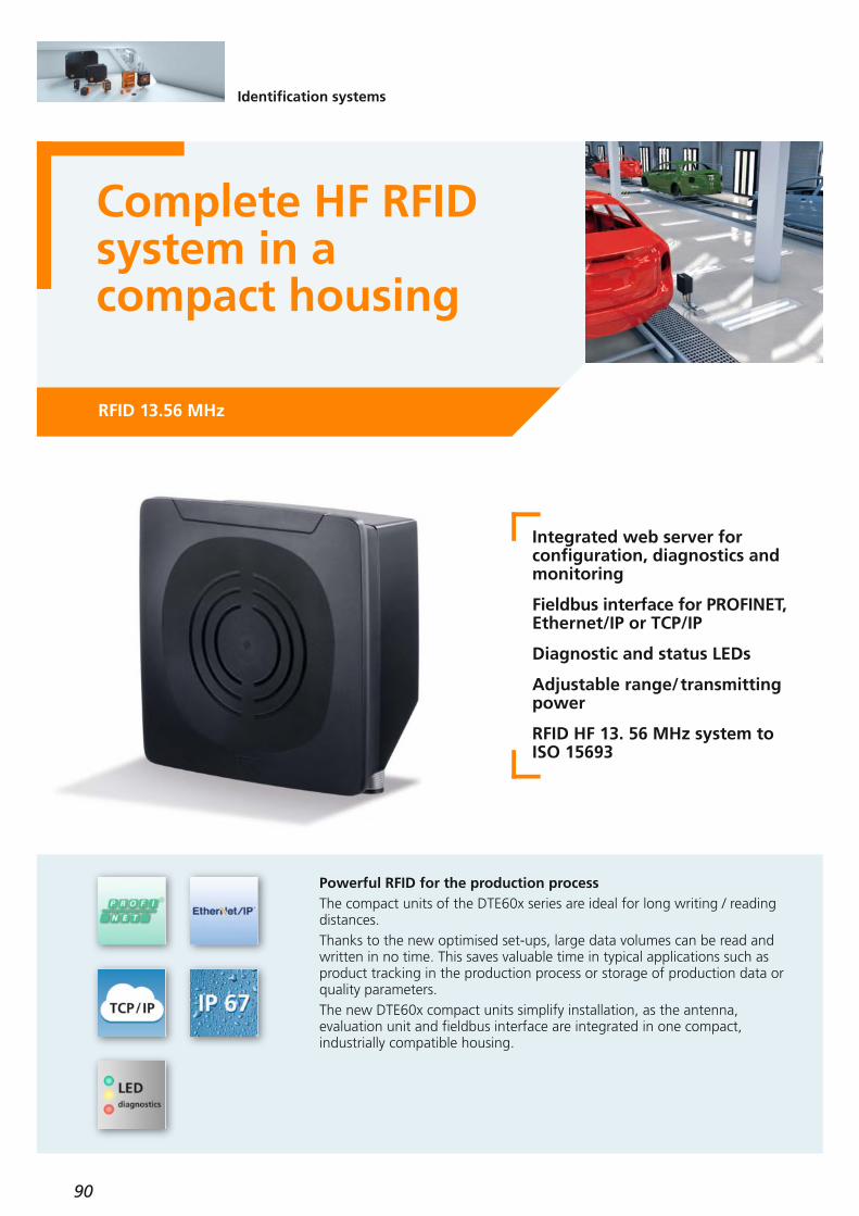
90
Identification systems
Complete HF RFID system in a compact housing
RFID 13.56 MHz
Integrated web server for configuration, diagnostics andmonitoring
Fieldbus interface for PROFINET,Ethernet/IP or TCP/IP
Diagnostic and status LEDs
Adjustable range/transmittingpower
RFID HF 13. 56 MHz system toISO 15693
Powerful RFID for the production processThe compact units of the DTE60x series are ideal for long writing / readingdistances.Thanks to the new optimised set-ups, large data volumes can be read andwritten in no time. This saves valuable time in typical applications such asproduct tracking in the production process or storage of production data orquality parameters.The new DTE60x compact units simplify installation, as the antenna, evaluation unit and fieldbus interface are integrated in one compact, industrially compatible housing.

91
(04.2019)
Advantages of ifm’s HF RFID solution:
Easy integrationData access to the RFID device is fast and simple, viafunction blocks as well as directly via the process imageof the controller. Function blocks for standard controllers, e.g. from Siemens, Schneider, Allen Bradley or Omron,are supplied.
Integrated web serverThe read/write units feature an integrated web server.Users can log in via an HTTP address to fully access thedevice.
Industrially compatibleThe robust design with protection rating IP 67 permitsuse in harsh industrial environments.
Additional digital inputsThe unit has two additional digital inputs and outputs,e.g. for controlling a light tower.
Status LEDsA 5-digit LED bar graph display indicates the RSSI value(signal strength) to visualise the distance of the tag.
Versions with various interfaces
DTE604 with TCP/IPThe RFID compact unit is ideal for direct connection to PCs, industrial PCs or PLCs that have no standardisedfieldbus interface.
DTE601 with PROFINETThis unit is, in particular, intended for customers with a Siemens controller.
DTE602 with EtherNet/IPThis version is optimised for controllers from SchneiderElectric or Rockwell Automation.
All units have an integrated switch for direct connection of further devices.
Orderno.
Products
HF RFID system
DTE601Compact unit, PROFINET interface
DTE602Compact unit, EtherNet/IP interface
DTE604Compact unit, TCP/IP interface
For further technical details please visit: ifm.com
Type Description
E80400ID tag/51x51/06 – 13.56 MHz, 10 pcs
E80401Bracket for ID tag E80400
E80410ID tag/30X65/06 – 13.56 MHz, 50 pcs
E80342ID tag/34X6.0/06 – 13.56 MHz, 1024 bits, 10 pcs
E80343ID tag/90X34x7/06 – 13.56 MHz, 896 bits, 5 pcs
E80344ID tag/16X3/06 – 13.56 MHz, 896 bits, 10 pcs
Selection RFID transponders
Connection technology
E11898Jumper cable,Ethernet, cross-over patch cable,2 m, PVC cable, M12 / RJ45
E12204Jumper cable,Ethernet, patch cable,10 m, PVC cable, M12 / RJ45
E21138Ethernet jumper,2 m, PVC cable, M12 / M12
Mounting accessories for DTE60x
E80335Mounting bracket,stainless steel (1.4301 / 304)
E80336Mounting plate,stainless steel (1.4301 / 304)
E80337Mounting rod,stainless steel (1.4301 / 304)
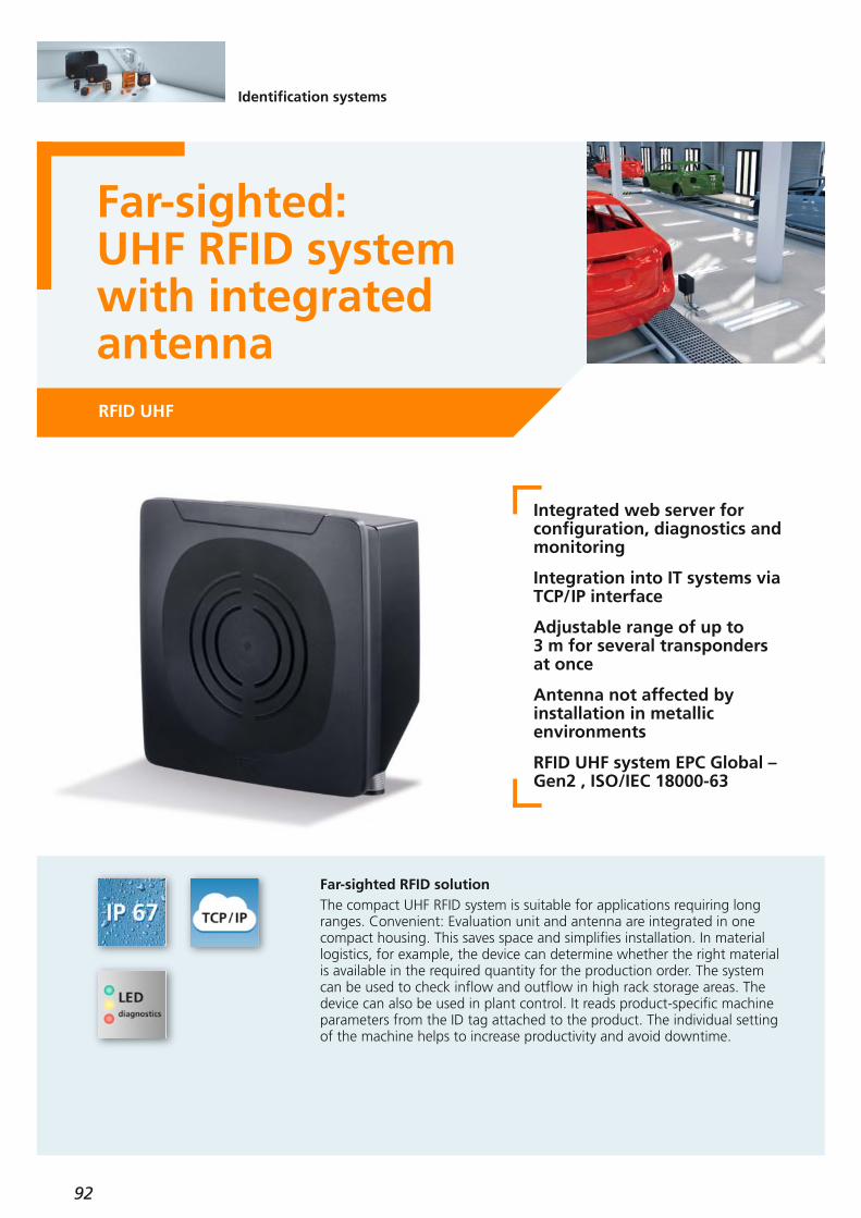
92
Identification systems
Far-sighted: UHF RFID systemwith integrated antennaRFID UHF
Integrated web server for configuration, diagnostics andmonitoring
Integration into IT systems viaTCP/IP interface
Adjustable range of up to 3 m for several transponders at once
Antenna not affected by installation in metallic environments
RFID UHF system EPC Global –Gen2 , ISO/IEC 18000-63
Far-sighted RFID solutionThe compact UHF RFID system is suitable for applications requiring longranges. Convenient: Evaluation unit and antenna are integrated in onecompact housing. This saves space and simplifies installation. In material logistics, for example, the device can determine whether the right materialis available in the required quantity for the production order. The systemcan be used to check inflow and outflow in high rack storage areas. Thedevice can also be used in plant control. It reads product-specific machineparameters from the ID tag attached to the product. The individual settingof the machine helps to increase productivity and avoid downtime.

93
(04.2019)
Advantages of ifm’s UHF RFID solution:
Robust and expandableAntenna, evaluation unit and TCP/IP interface are integrated in one compact, robust housing with protection rating IP 67 / IP 69K. This makes the systemperfectly suited for use in harsh industrial environments.
Powerful antennaThanks to the internal antenna with circular polarisation, the device can be installed in metallic housings withoutreception being affected.
Integrated web serverThe read/write units feature an integrated web server.Users can log in via an HTTP address to fully access thedevice.
Universal interfaceThe UHF RFID compact unit is ideal for direct connection to PCs, industrial PCs or PLCs that have no standardisedfieldbus interface.
Additional digital inputsThe unit has two additional digital inputs and outputs,e.g. for controlling a light tower.
Status LEDsA 5-digit LED bar graph display indicates the RSSI value(signal strength). This visualises the distance of the tag.
ApplicationsThe DTE804 is ideal for track and trace and traceabilityapplications, e.g.:– product tracking– access control– asset management– tracking of material– assembly stations
Advantages:– increase in productivity– adherence to delivery dates– material movement management – avoidance of standstills– increase of uptime
Orderno.
Products
UHF RFID system
DTE804Compact unit, TCP/IP interface
For further technical details please visit: ifm.com
Type Description
E80353ID tag/R30X10/04 – 865...870 MHz, 96 bits
E80386ID tag/73.5X21.2/04 – 1000 pcs on reel
E80393ID tag/139 x 53 x 15/04
E80394ID tag/174 x 70 x 17.6/04
Selection RFID transponders
Connection technology
E11898Jumper cable,Ethernet, cross-over patch cable,2 m, PVC cable, M12 / RJ45
E12204Jumper cable,Ethernet, patch cable,10 m, PVC cable, M12 / RJ45
E21138Ethernet jumper,2 m, PVC cable, M12 / M12
Mounting accessories for DTE804
E80335Mounting bracket,stainless steel (1.4301 / 304)
E80336Mounting plate,stainless steel (1.4301 / 304)
E80337Mounting rod,stainless steel (1.4301 / 304)

94
Identification systems
Powerful multicodereader – simple like asensor
1D / 2D code readers
Powerful detectionThe new multicode reader reliably detects 1D and 2D codes. It ensures reliable identification even under difficult conditions, e.g. in case of changing extraneous light or shiny surfaces. Several different codes in one or moreimages can be evaluated in just a few milliseconds.Quick set-up via pushbuttonSimple applications with one code per image can be set quickly via teachbutton. This saves time and costs. The preset device configuration can bechanged by means of a user-friendly smartphone app.Vision Assistant software For complex identification tasks, the multicode reader can be configuredusing the award-winning Vision Assistant software. The intuitive navigationand the visualisation help you to keep track.
Robust, industrially compatiblediecast housing
Teaching via one button andconfiguration via smartphoneapp
Comprehensive features: integrated ifm memory stick,polarisation filter, automatic focusing
Integrated fieldbus interfaces
Award-winning Vision Assistant software for configuration

95
(04.2019)
Orderno.
Products
Multicode reader
O2I500Standard lens, red light, Ethernet/IP, TCP/IP
O2I501Standard lens, infrared, Ethernet/IP, TCP/IP
O2I502Wide-angle lens, red light, Ethernet/IP, TCP/IP
O2I503Wide-angle lens, infrared, Ethernet/IP, TCP/IP
O2I504Telephoto lens, red light, Ethernet/IP, TCP/IP
O2I505Telephoto lens, infrared, Ethernet/IP, TCP/IP
For further technical details please visit: ifm.com
Type Description
Connection technology
EVC847Y splitter,adapter cable for O2I5xx, trigger sensor,0.4 m PUR cable
EVC848Y splitter,adapter cable for external illumination,0.4 m PUR cable
Accessories
E2D500Mounting set
O2D931
Illumination unit, 193 x 136 x 75 mm, red light, cyan light, M12 connector
O2D933
Illumination unit, 256.8 x 197 x 106.7 mm, red light, cyan light, M12 connector
This QR code leads to the Android app“O2I Teach” in the Google Play Store:
This QR code leads to the iOS app“O2I Teach” in the Apple Store:
Looking for the smartphone app?
Powerful features
Teach buttonOne of the sensor’s highlights is the simple teaching viaone button. After pressing the teach button, the useraligns the multicode reader to the code by means of alaser marking. Focusing, exposure setting and detectionof the code type are automatically carried out by thesensor. A few seconds later, the sensor is ready for use.
Configuration via smartphone appA smartphone app (iOS, Android) is available for basicconfiguration of the device. The user can e.g. use it todefine the trigger or IP address. Based on these settings, a Data Matrix code is generated on the smart phone’sdisplay. When this code is held into the multicode reader’s field of view, the configuration is automaticallyadopted.
Vision AssistantFor complex identification tasks, the multicode reader can be configured using the award-winning Vision Assistantsoftware.For example, the auto-find function detects several different codes in one image. The user can easily assignthese codes in the Vision Assistant.Thanks to different logic functions, the sensor can be programmed for sequential control. An expensiveevaluation unit is not necessary.The live image and extensive visualisation of all settingsprovide an optimum overview.
ifm memory stickThe device has an exchangeable ifm memory stick. It can be used to save or load complete configurations of themulticode reader. This simplifies device replacementand the set-up of several units for the same application.
Polarisation filterThe integrated optional illumination with polarisationfilter ensures sufficient contrasts to reliably detect codeseven in case of shiny surfaces such as metal.

96
Connection technology
ecolink M12, A coded – now wireable for hygienicand wet areasFor use in wet areas and in the food industry
Innovative strain relief
Highly elastic seal
Tried-and-tested ecolink technology
Shock and vibration resistance
Protection rating: IP 65, IP 67, IP 68, IP 69K
Easy to assemble correctly
Halogen-free and silicone-free
Reliably sealed – even in case of intense cable movementA special challenge is the reliable and permanent sealing of the cable. With this innovative and patented technology, strain relief and cable sealare strictly separated from each other, the strain relief being guaranteed by means of an extremely strong three-way ball clamp that reliably clampsthe cable even in case of intense tensile strain. The highly elastic cable seal is positioned right at the cable entry so as toprevent any contamination due to penetration of dirt. The highly elasticmaterial prevents cable sheath deformation and reliably seals even in caseof intense cable movement.
Simple and safe mounting These connectors also feature the perfectly tried-and-tested ecolink technology that allows for reliable and manual M12 connection to the device without use of tools.
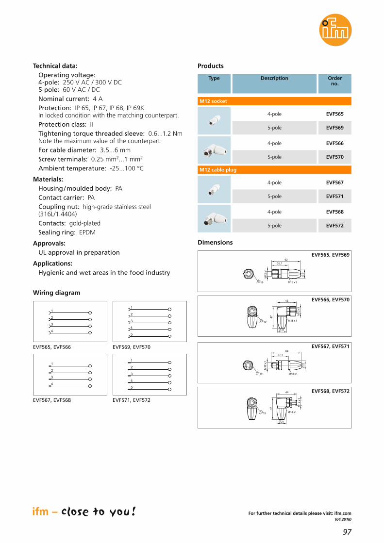
97
(04.2018)
For further technical details please visit: ifm.com
Technical data:Operating voltage:4-pole: 250 V AC / 300 V DC5-pole: 60 V AC / DCNominal current: 4 AProtection: IP 65, IP 67, IP 68, IP 69K In locked condition with the matching counterpart.Protection class: IITightening torque threaded sleeve: 0.6...1.2 Nm Note the maximum value of the counterpart.For cable diameter: 3.5...6 mmScrew terminals: 0.25 mm2...1 mm2
Ambient temperature: -25...100 °C
Materials:Housing / moulded body: PAContact carrier: PACoupling nut: high-grade stainless steel(316L/1.4404)Contacts: gold-platedSealing ring: EPDM
Approvals:UL approval in preparation
Applications:Hygienic and wet areas in the food industry
Products
M12 socket
4-pole
5-pole
EVF565
EVF569
4-pole
5-pole
EVF566
EVF570
4-pole
5-pole
EVF567
EVF571
4-pole
5-pole
EVF568
EVF572
M12 cable plug
Type Description Orderno.
Dimensions
21
35,1
62
M1
2x
1
M18 x119
EVF565, EVF569
19
47
42
M1
2x
1
M18 x1
21
EVF566, EVF5702
1
37,1
64
M1
2x
1
M18 x119
EVF567, EVF571
19
M1
2x
1
47
44
M18 x1
21
EVF568, EVF572
1
2
3
4
Wiring diagram
1
2
3
4
5
EVF565, EVF566 EVF569, EVF570
1
2
3
4
1
2
3
4
5
EVF567, EVF568 EVF571, EVF572

98
Connection technology
ecolink M12/RJ45: the new connectionfor special applicationsUse in wet areas and in the food and beverage industry
Halogen-free and silicone-free
Contoured nut with enhancedgrip makes for optimum sealingeven when hand tightened
Permanent vibration protectionwith saw tooth contour
High material resistance tocommon cleaning agents usedin the food industry
ecolink M12 for hygienic and wet areas in the food industryMost applications require special solutions. Only high-quality materials, safe production processes and faultless mounting lead to success in thelong run.The asymmetrically acting vibration protection holds the nut tight in its position, guaranteeing an optimum and permanent seal.No tools are needed for installation and removal which can be done manually without any problem.High-quality materials especially adapted to the application and intensivemonitoring during and after production guarantee maximum quality standards.

99
(11.2018)
For further technical details please visit: ifm.com
Technical data:Operating voltage: 30 V AC / 60 V DCNominal current: 1.5 AProtection: IP 65, IP 67, IP 68, IP 69KIn locked condition with the matching counterpart.RJ45 connector: IP 20Tightening torque nut: 0.6...1.2 NmNote the maximum value of the counterpart.Ambient temperature:-25...80 °C, RJ45 connector: -40...70 °CVibration / shock: 750 g, 1 million cycles
Materials:Housing / moulded body: PPM12 connector: PP, RJ45 connector: PCContact carrier: PA 6.6Coupling nut: high-grade stainless steel (316L / 1.4404)Contacts: gold-platedSealing ring: EPDMCable: MPPE halogen-free, silicone-free, shielded, screen connected to the plug4-pole: 4 x 0.34 mm2, Ø 6.5 mm
Applications:Hygienic and wet areas in the food industry
Type Description Orderno.
Products
Connection cable M12 connector / RJ45 connector
0.5 m
1.0 m
2.0 m
5.0 m
10.0 m
20.0 m
EVF549
EVF550
EVF551
EVF552
EVF553
EVF554
Dimensions
Example EVF549
Wiring diagram
L49
14
15
,5
M12 x1
42
1
2
3
1
3
2
4
YE(TD+)
WH(RD+)
OG(TD-)
BU(RD-) 6
screen

100
Connection technology
ecolink M12 –T splitters for difficult applicationsUse in wet areas and in the food and beverage industry
Halogen and silicone-free
Connection technology meetsthe standard EN 61076
Optimum sealing even whenmounted without tools
The mechanical end stop protects the O-ring against destruction
Visible and tactile marking of the ports
ecolink M8 and M12 for hygienic and wet areas in the food industryMost applications require special solutions. Only high-quality materials, safe production processes and faultless mounting lead to success in thelong run.The integrated end stop protects the O-ring against destruction caused by tightening the nut too much. Mounting and removal are carried out without tools.High-quality materials especially adapted to the application and intensivemonitoring during and after production guarantee maximum quality standards.

101
(04.2019)
For further technical data please go to: www.ifm.com
Technical dataOperating voltage:4-pole: 250 V AC / 300 V DC5-pole: 60 V AC / DCEBF012: 50 V AC / 60 V DCNominal current: 4 A; EBF012: 3 AProtection rating: IP 67, IP 68, IP 69Kin locked condition with the matching counterpart.Tightening torque: 0.6...1.5 Nm;M8 ports: 0.3...0.6 NmAmbient temperature: -25...100 °C
Materials:Housing / moulded body: PACoupling nut (non-rotatable):high-grade stainless steel (316L / 1.4404)Contacts: gold-platedSealing ring: EPDM
Approvals:cRUus in preparation
Applications:For hygienic and wet areas in the food industry
Products
Type Wiring diagramno.
Order no.LED
1 x M12 connector, 2 x M12 plug
1 –
2
3
4
–
–
–
5
6
–
–
Wiring diagram
4
1 1
3
4
3
2
B
A
1
3
4
C
1 1
33
55
B
A
2
4
2
1
3
5
4
2
4
C
1 1
3
5
3
5
44
B
A
1
3
5
4
2
C
1 1
2
3
2
3
4
B
A
1
2
3
4
5
5
4
5
C
1
2
3
4
1 1
3
5
3
5
22
B
A
1
3
5
2
4
C
5
1 1
3
5
4
3
4
B
A
1
3
4
5
C
5
6
EBF006
EBF007
EBF008
EBF009
EBF010
EBF011
Dimensions
M12x1
48,7163
8
9
21
M12x1
C
B
A
M12x1
14
EBF006...EBF011
M8x1
45,916
38
9
21
M8x1
C
B
A
M12x1
14
EBF012
1 x M12 connector, 2 x M8 plug
1 EBF012–

102
Connection technology
Use in wet areas and in the food and beverage industry
ecolink M8 and M12 for demanding applicationsMost applications require special solutions. Only high-quality materials, safe production processes and faultless mounting lead to success in thelong run.The integrated end stop protects the O-ring against destruction caused by tightening the nut too much. Mounting and removal are carried out without tools.High-quality materials especially adapted to the application and intensivemonitoring during and after production guarantee maximum quality standards.
ecolink M12 –T splitters for difficult applications
Halogen and silicone-free
Connection technology meetsthe standard EN 61076
Optimum sealing even whenmounted without tools
The mechanical end stop protects the O-ring against destruction
Visible and tactile marking of the ports

103
(04.2019)
For further technical data please go to: www.ifm.com
Technical dataOperating voltage:4-pole: 250 V AC / 300 V DC5-pole: 60 V AC / DCEBT012: 50 V AC / 60 V DCNominal current: 4 A; EBT012: 3 AProtection rating: IP 67, IP 68, IP 69Kin locked condition with the matching counterpart.Tightening torque: 0.6...1.5 Nm;M8 ports: 0.3...0.6 NmAmbient temperature: -25...100 °C
Materials:Housing / moulded body: PACoupling nut (non-rotatable):high-grade stainless steel (316L / 1.4404)Contacts: gold-platedSealing ring: EPDM
Approvals:cRUus in preparation
Applications:For hygienic and wet areas in the food industry
Products
Type Wiring diagramno.
Order no.LED
1 x M12 connector, 2 x M12 plug
Wiring diagram
4
1 1
3
4
3
2
B
A
1
3
4
C
1 1
33
55
B
A
2
4
2
1
3
5
4
2
4
C
1 1
3
5
3
5
44
B
A
1
3
5
4
2
C
1 1
2
3
2
3
4
B
A
1
2
3
4
5
5
4
5
C
1
2
3
4
1 1
3
5
3
5
22
B
A
1
3
5
2
4
C
5
1 1
3
5
4
3
4
B
A
1
3
4
5
C
5
6
Dimensions
M8x1
45,916
38
9
21
M8x1
C
B
A
M12x1
14
EBT012
1 x M12 connector, 2 x M8 plug
M12x1
48,7163
8
9
21
M12x1
C
B
A
M12x1
14
EBT006...EBT011
1 EBT006–
2 EBT007
3 EBT008
4 EBT009
–
–
–
5 EBT010
6 EBT011
–
–
1 EBT012–

104
Connection technology
Always a reliableconnection. ecolinkM12 – even for special applicationsM12 sockets with LEDs
Connection technology meetsthe M12 standard (EN 61076)
Optimum sealing even when fastened by hand
The mechanical end stop protects the O-ring against destruction
Permanent vibration protectionwith saw tooth contour
LEDs clearly visible even inbright lighting conditions
ecolink M12 for demanding applicationsMost applications require special solutions. Only reliable production pro-cesses and faultless assembly lead to success in the long run.The integrated end stop protects the O-ring against destruction caused by over-tightening the nut. No tools needed for installation and removal.The asymmetrically acting vibration protection holds the nut tight in its position, guaranteeing an optimum and permanent seal.High-quality materials and intense monitoring during and after the pro-duction guarantee the highest quality standard.
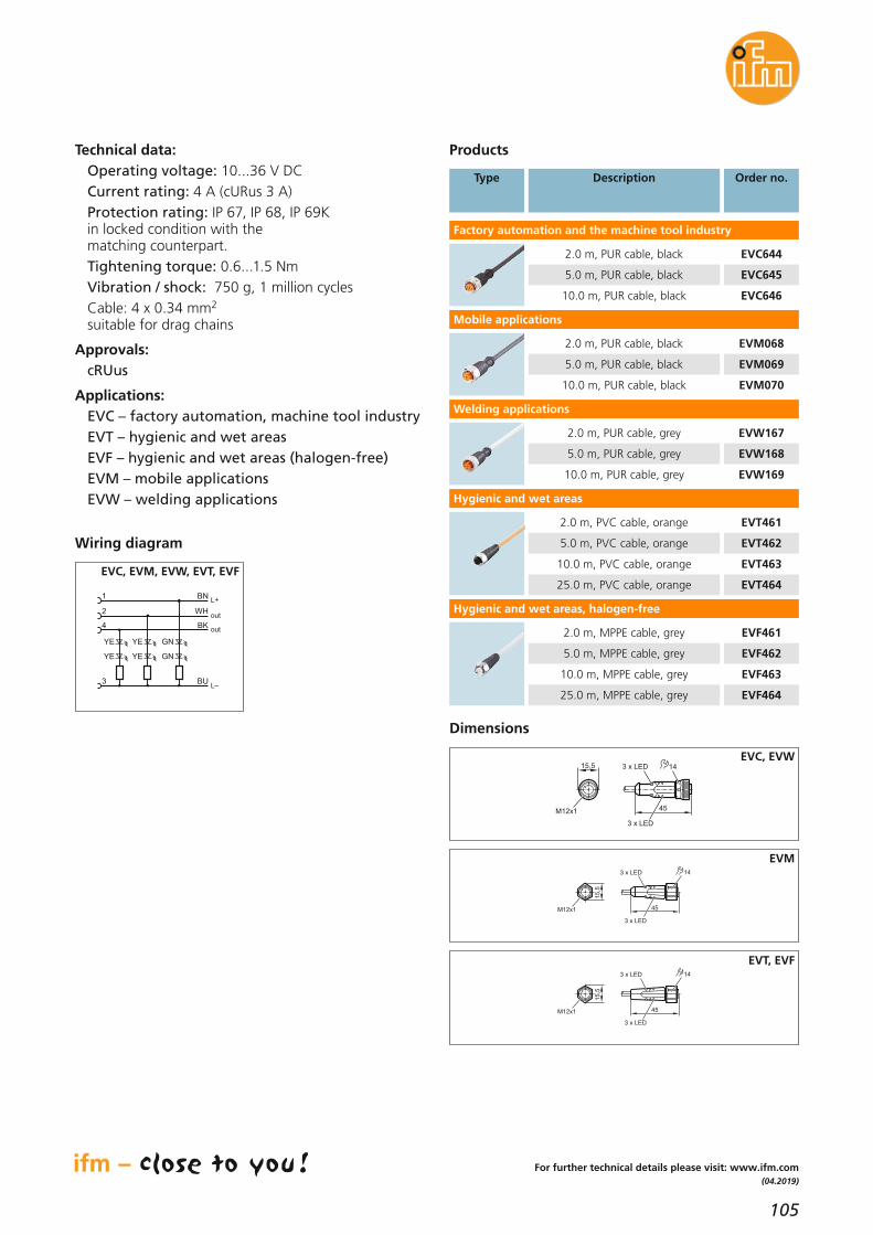
105
(04.2019)
For further technical details please visit: www.ifm.com
Technical data:Operating voltage: 10...36 V DCCurrent rating: 4 A (cURus 3 A)Protection rating: IP 67, IP 68, IP 69Kin locked condition with the matching counterpart.Tightening torque: 0.6...1.5 NmVibration / shock: 750 g, 1 million cyclesCable: 4 x 0.34 mm2
suitable for drag chains
Approvals:cRUus
Applications:EVC – factory automation, machine tool industryEVT – hygienic and wet areasEVF – hygienic and wet areas (halogen-free)EVM – mobile applicationsEVW – welding applications
Products
Type Description Order no.
Factory automation and the machine tool industry
2.0 m, PUR cable, black EVC644
5.0 m, PUR cable, black EVC645
10.0 m, PUR cable, black EVC646
Mobile applications
2.0 m, PUR cable, black EVM068
5.0 m, PUR cable, black EVM069
10.0 m, PUR cable, black EVM070
Welding applications
2.0 m, PUR cable, grey EVW167
5.0 m, PUR cable, grey EVW168
10.0 m, PUR cable, grey EVW169
Hygienic and wet areas
2.0 m, PVC cable, orange EVT461
5.0 m, PVC cable, orange EVT462
10.0 m, PVC cable, orange EVT463
25.0 m, PVC cable, orange EVT464
out
out
L+
L
1
3
4
YE GN
BN
BU
BK
2 WH
YE
YE GNYE
Wiring diagram
EVC, EVM, EVW, EVT, EVF
Dimensions
3 x LED
3 x LED
15,5
M12x1 45
14
EVC, EVW
3 x LED
3 x LED
45
14
15
,5
M12x1
EVM
3 x LED
3 x LED
45
14
15
,5
M12x1
EVT, EVF
Hygienic and wet areas, halogen-free
2.0 m, MPPE cable, grey EVF461
5.0 m, MPPE cable, grey EVF462
10.0 m, MPPE cable, grey EVF463
25.0 m, MPPE cable, grey EVF464

106
Power supplies
Circuit protectionwith monitoringfunction for the 24 Vsecondary circuitElectronic 24 V DC circuit breakers
Modular and selective protec-tion in plant and machinery
Reliable circuit protection allows reduction of wire cross-sections
Fast replacement using innova-tive connection technology
Detection of triggering cause (via IO-Link)
Current and voltage measurement in each channel(via IO-Link)
Safety on the 24 V sideAs opposed to the 230 V primary side, the circuit protection in the secondary circuit is often neglected. Another issue is that in the event of afailure of the 24 V DC voltage supply standard mechanical circuit breakersoften do not trigger. This may happen with long cables, for example.The electronic circuit breakers from ifm monitor the circuit ideally and, if required, disconnect reliably. Individual branch circuits can be selectivelydisconnected. This allows a reduction of wire cross-sections in the load circuit of the switched-mode power supplies. On the new adjustable protection modules, the tripping current can be set, allowing for optimumadaptation of the plant's circuits to the machinery. The IO-Link version alsoallows evaluation of important diagnostic data.

107
(11.2018)
For further technical details please visit: ifm.com
Modular installationThe system has a modular structure and consists of asupply module to feed max. 40 A. The protection modules can be mounted side by side. This is done viaa simple clip mechanism, completely without anybridges, jumpers or the like.Easy mounting and minimised wiring complexity savecost and time. With the standard version the user canconnect up to 10 and with the IO-Link version up to 8 safety modules to the head module.
VersionsIn addition to the triggering mechanism, the modulesfeature an LED for signalling if the module has triggered, if it is active and to what extent it is utilised. By means of a pushbutton each channel can be activated, deactivated or set. The feed module has an additional collective output toprovide a warning signal if a module has triggered.
More transparency with IO-LinkThe IO-Link version has the same function; there is, however, additional information about each channel:• effective nominal current (1 byte cyclical)• output voltage (acyclical) • triggering counter (acyclical)• current unit status (1 byte cyclical): – short circuit – overload – undervoltage – limit reached (80 % IN)• activation/deactivation • reset with triggering • reset triggering counterExtended functions DF2101 IO-Link supply module:• min. / max. value generation of the measured current and voltage value for each channel over any period of time• averaging of the measured current and voltage value for each channel over any period of time• permanent switching on of individual channels in order to ignore the cyclic data exchange (e.g. to guarantee the voltage supply of important devices during the initialisation phase). The safety function remains active.The protection modules are available in the fixed sizes 2 A, 4 A, 6 A, 8 A and 10 A and also as adjustable version 1...10 A. The fixed current values prevent subsequent misuse by changing the max. current value.The adjustable modules enable flexible set-up.
InterfaceInputs
[V DC]
Orderno.
Supply module, standard
–24, 40 A DF1100
Nominal current
[A]
–
Protection module, standard
–– DF12122 x 2
–– DF12142 x 4
–– DF12162 x 6
Operating voltage [V DC] 24 (18...30)
Switch-off characteristics time-current characteristics
Temperature range [°C] -25...60
Approvals
UL508listed, NEC Class2 (for
DF1212 / DF1214 DF2212 / DF2214)
Fail-safe element = nominal current (e.g. 4 A = 4 A)
Switching status indication LEDmulti-colour,
signal contact via feeding module
Further technical data
Supply module, IO-Link
Protection module, IO-Link
IO-Link in combinationwith head module– DF22122 x 2
IO-Link in combinationwith head module– DF22142 x 4
IO-Link in combinationwith head module– DF22162 x 6
Accessories
Description Orderno.
–– DF12081 x 8
–– DF12101 x 10
IO-Link in combinationwith head module– DF22081 x 8
IO-Link in combinationwith head module– DF22101 x 10
IO-Link24, 40 A DF2101–
–– DF12202 x 1...10
IO-Link in combinationwith head module– DF22202 x 1...10
IO-Link connection cable, 0.5 m, M12 connector E12613
IO-Link connection cable, 2 m, open end E12614

108
Customer
ifmSystems Sales
Engineer
IoT / I 4.0contacts
Connectivity /interfaces
Quotationfor simple
and complexinstallations
SAP PMconnection(first level)
Softwaresolutions
Applicationsupport
Competence:Trust our application know-how.We have been developing automa-tion solutions for our customersfor 50 years and know tomorrow’srequirements.
Automation froma single source:We do not only offer hardware,but also the matching softwareand IT connection.
Personal:You have a permanent contact whosupports your project on site.
Together:We support your project from adviceand quotation to set-up. Even afterproject completion, we will continueto support you as a reliable partner.
ifm system sales network.
Your personal ifm System Sales Engineer will provide you with the entire ifm know-howto realise and optimise your plant monitoring.
ifm system consulting.
You want to make your application
transparent? Fans, pumps, compressors
or cooling circuits: Our system consultant
helps you to find the ideal solution for
monitoring your installation. Our service
includes competent advice at your site,
a fair offer, personal project assistance
and support for set-up.
We offer sensors, evaluation systems
and software for connection to
ERP systems – all from a single source.
Together we will make your project
successful.
Do not hesitate to contact us:
ifm system sales –solutions for yourinstallation froma single source
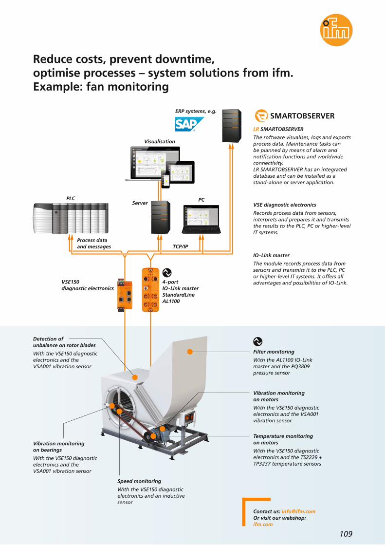
109
Visualisation
Server
Reduce costs, prevent downtime,optimise processes – system solutions from ifm.Example: fan monitoring
Filter monitoring
With the AL1100 IO-Linkmaster and the PQ3809pressure sensor
Temperature monitoring on motors
With the VSE150 diagnosticelectronics and the TS2229 +TP3237 temperature sensors
Vibration monitoring on motors
With the VSE150 diagnosticelectronics and the VSA001vibration sensor
Detection ofunbalance on rotor blades
With the VSE150 diagnosticelectronics and theVSA001 vibration sensor
ERP systems, e.g.
TCP/IP
PLC PC
Process dataand messages
4-portIO-Link masterStandardLineAL1100
VSE150diagnostic electronics
Vibration monitoringon bearings
With the VSE150 diagnosticelectronics and theVSA001 vibration sensor
Speed monitoring
With the VSE150 diagnosticelectronics and an inductivesensor
VSE diagnostic electronics
Records process data from sensors,interprets and prepares it and transmitsthe results to the PLC, PC or higher-levelIT systems.
LR SMARTOBSERVER
The software visualises, logs and exportsprocess data. Maintenance tasks canbe planned by means of alarm andnotification functions and worldwideconnectivity.LR SMARTOBSERVER has an integrateddatabase and can be installed as astand-alone or server application.
SMARTOBSERVER
IO-Link master
The module records process data fromsensors and transmits it to the PLC, PCor higher-level IT systems. It offers alladvantages and possibilities of IO-Link.
Contact us: [email protected] visit our webshop:ifm.com

110
More clarity
For each product group you can makea first selection via the platforms.
A clear visual language and explanatorytexts give you a first impression of theproducts.
Compare products with each other
The selectors are the heart of theproduct search.The displayed selection criteria areadapted to each product range and thetechnical features of the products.The results can be displayed as tiles orlists.
Overview:The ifm product range is clearlystructured and the individual productplatforms ensure quick orientation.
Selectors:Choose between the most importanttechnical data and you will get theproduct selection suitable for yourrequirements.
Compare:You can compare the technical dataof up to 3 products. Differences aremarked in colour.
Search and find:Enter the search term in the full textsearch and get suggestions for pro-ducts, topics and product groups.
Order:We provide a quick-order and csvimport function for the shoppingbasket on the product pages.
The ifm sales platform

111
For all types of display
Whether PC, laptop, tablet or smart-phone – the design of the sales platformadapts to any screen size thus increasinguser-friendliness. This also makes itpossible to buy products using mobileequipment such as a smartphone.
Easy purchasing
You are in control of everything in the
shopping basket: quantity, modes of
shipment and payment. We provide you
with everything you can expect from a
modern shop.
Customers relying on long-standing
tried-and-tested articles can quickly
order by entering the article number in
the shopping basket. This saves time,
in particular when a product has to be
quickly reordered.
Navigation in the menu structure is no
longer necessary.
Try us.Click here to directly get to our homepage: ifm.com

ifm a
rtic
le n
o. 7
8003
178
· We
rese
rve
the
right
to
mak
e te
chni
cal a
ltera
tions
with
out
prio
r no
tice.
· Pr
inte
d in
Ger
man
y on
non
-chl
orin
e bl
each
ed p
aper
. 03
/19
Position sensors
Sensors formotion control
Industrial imaging
Safety technology
Process sensors
Systems formobile machines
Industrialcommunication
Condition monitoringsystems
Connectiontechnology
Software
Power supplies
AccessoriesIO-Link
years
W
ARRANTY
on ifm products
Identification systems
ifm electronic gmbhFriedrichstraße 145128 EssenTel. +49 / 201 / 24 22-0Fax +49 / 201 / 24 22-1200E-mail [email protected]
Inform, select, orderin the ifm webshop
Go ifmonline!
ifm.com