Device manual Supplement S7 library for evaluation unit ... - IFM
39
Device manual Supplement S7 library for evaluation unit DTE100 706146 / 00 04 / 2012 UK
-
Upload
khangminh22 -
Category
Documents
-
view
1 -
download
0
Transcript of Device manual Supplement S7 library for evaluation unit ... - IFM

Device manual Supplement
S7 library for evaluation unit DTE100
7061
46 /
00 0
4 / 2
012
UK

2
Contents1 Preliminary note � � � � � � � � � � � � � � � � � � � � � � � � � � � � � � � � � � � � � � � � � � � � � � � � � 3
1�1 Symbols used� � � � � � � � � � � � � � � � � � � � � � � � � � � � � � � � � � � � � � � � � � � � � � � 32 General � � � � � � � � � � � � � � � � � � � � � � � � � � � � � � � � � � � � � � � � � � � � � � � � � � � � � � � � 33 Installation� � � � � � � � � � � � � � � � � � � � � � � � � � � � � � � � � � � � � � � � � � � � � � � � � � � � � � 4
3�1 Modules available in the hardware configuration � � � � � � � � � � � � � � � � � � � � 53�2 Module parameterisation � � � � � � � � � � � � � � � � � � � � � � � � � � � � � � � � � � � � � � 6
3�2�1 Description of the parameters � � � � � � � � � � � � � � � � � � � � � � � � � � � � � � 74 Function blocks� � � � � � � � � � � � � � � � � � � � � � � � � � � � � � � � � � � � � � � � � � � � � � � � � � 8
4�1 COM_FB � � � � � � � � � � � � � � � � � � � � � � � � � � � � � � � � � � � � � � � � � � � � � � � � � � 84�2 FB_CONFIG_READ� � � � � � � � � � � � � � � � � � � � � � � � � � � � � � � � � � � � � � � � � �114�3 FB_CONFIG_WRITE � � � � � � � � � � � � � � � � � � � � � � � � � � � � � � � � � � � � � � � � 134�4 FB_PHYSICAL_READ� � � � � � � � � � � � � � � � � � � � � � � � � � � � � � � � � � � � � � � 154�5 FB_PHYSICAL_WRITE � � � � � � � � � � � � � � � � � � � � � � � � � � � � � � � � � � � � � � 184�6 FB_DEV_STATUS � � � � � � � � � � � � � � � � � � � � � � � � � � � � � � � � � � � � � � � � � � 214�7 FB_WRITE_IM1 � � � � � � � � � � � � � � � � � � � � � � � � � � � � � � � � � � � � � � � � � � � � 234�8 FB_GET � � � � � � � � � � � � � � � � � � � � � � � � � � � � � � � � � � � � � � � � � � � � � � � � � � 254�9 FB_PUT � � � � � � � � � � � � � � � � � � � � � � � � � � � � � � � � � � � � � � � � � � � � � � � � � � 284�10 FB_DIAG � � � � � � � � � � � � � � � � � � � � � � � � � � � � � � � � � � � � � � � � � � � � � � � � 304�11 FB_SET_ANTENNA� � � � � � � � � � � � � � � � � � � � � � � � � � � � � � � � � � � � � � � � 324�12 User-defined data type � � � � � � � � � � � � � � � � � � � � � � � � � � � � � � � � � � � � � � 34
Licences and trademarksThe screen areas shown in this document are subject to the copyright© of Siemens AG� All trademarks and company names are subject to the copyright of the respective companies�

UK
3
1 Preliminary noteThese instructions serve for the set-up and parameter setting of the communica-tion between the RFID evaluation unit DTE100 from ifm electronic and a Simatic S7 controller from Siemens�
1.1 Symbols used► Instructions> Reaction, result
Information Supplementary note
2 GeneralThe function blocks of the library DTE100_L allow easy access to the data of the device DTE100 and its connected periphery� (Up to 4 read/write heads or IEC61131 inputs and outputs�)The 4 channels of the DTE100, IO-1, IO-2, IO-3 and IO-4 can be configured to the respective periphery on a modular basis depending on the application�
4
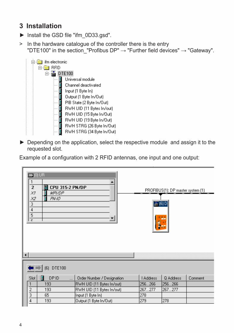
3 Installation ► Install the GSD file "ifm_0D33�gsd"�
> In the hardware catalogue of the controller there is the entry "DTE100" in the section_"Profibus DP" → "Further field devices" → "Gateway".
► Depending on the application, select the respective module and assign it to the requested slot�
Example of a configuration with 2 RFID antennas, one input and one output:

UK
5
3.1 Modules available in the hardware configuration
Application Module name Description Note
Unused channel Channel deactivated Deactivation of the channel
-
Switching outputs of sensors, IEC61131 input signal
Input (1 byte In) Cyclic reading of the input
Data is stored in the periphery input image of the controller� No library access required�
Switching inputs of controllers, valves, actuators with 24 V voltage supply
Output (1 byte In/Out) Cyclic reading of the output
Data is read from the periphery output image of the controller and written to the output� No library access required�
RFID antennas of the ANT51x family
PIB state (2 bytes In/Out ) Acyclic command chan-nel (MS0/MS1)
Library access required�
RFID antennas of the ANT51x family
RWH UID (11 bytes In/Out) Cyclic reading of UID with 64 bits
Data is stored in the periphery input image of the controller� No library access required�
RWH UID (15 bytes In/Out) Cyclic reading of UID with 96 bits
Data is stored in the periphery input image of the controller� No library access required�
RWH UID (19 bytes In/Out) Cyclic reading of UID with 128 bits
Data is stored in the periphery input image of the controller� No library access required
RFID antennas of the ANT51x family
RWH STRG (26 bytes In/Out)
Cyclic command chan-nel (MS0)
Library access required�
RWH STRG (34 bytes In/Out)
Cyclic command chan-nel (MS0)
Library access required�
RWH STRG (42 bytes In/Out)
Cyclic command chan-nel (MS0)
Library access required�
For a detailed description of the modules see the device manual of the evaluation unit�

6
3.2 Module parameterisationEach module allows additional, individual parameterisation�
Module name Description
Channel deactivated no parameterisation available
Input
Output
PIB state
RWH UID
RWH STRG

UK
7
3.2.1 Description of the parametersData hold timeTime in seconds for which the input signals C/Qi, I/Q and UID are to be maintained at channels IO-1 …IO-4 in the data input image (pulse stretching)�With the setting 0�0 s the signal is maintained as long as the respective input detects it�Overload detectionActivate or deactivate overload detection on pin L+ for channels IO-1 … IO-4�Overcurrent detectionActivate or deactivate overload detection on pin L+ for channels IO-1 … IO-4� Data block lengthData block length of the user memory on the transponder (tag) which is to be read or written�You will find the data block length in the data sheet of the transponder/tag at:
www�ifm�com → Data sheet searchRead of UID edge controlledActivate or deactivate trigger for reading UID on channels IO-1 … IO-4�If this parameter is deactivated, the UID is read by the RFID antenna every 6 ms and transmitted via the Profibus to the controller (cyclic scanning/screening)�If the parameter is activated, scanning of the UID is made with a positive edge of bit RD in the output image of the module RWH UID (edge-controlled scanning)�High current 1A on IO-3, IO-4Activate or deactivate the output current of 1 ampere on channels IO-3 und IO-4�If this parameter is deactivated, the maximum output voltage is limited to 0�5 am-pere�

8
4 Function blocksThe following section describes the available function blocks and their input and output parameters�
4.1 COM_FB
The POU COM_FB assumes the communication between the controller and the evaluation unit DTE100� The POUs FB_CONFIG_READ, FB_CONFIG_WRITE, FB_PHYSICAL_READ, FB_PHYSICAL_WRITE, FB_GET and FB_PUT need it for exchanging data within the controller�When the modules PIB_STATE or RWH_STRG are used, it must be called cycli-cally in the organisation POU OB1�It should be ensured that only those channels are activated via the inputs IOx_ENABLE on which a module PIB_STATE or RWH_STRG has been configured�Unused channels must be deactivated via the inputs IOx_ENABLE� Otherwise an error message will be generated on output STATUS�The function blocks FB_CONFIG_READ, FB_CONFIG_WRITE, FB_PHYSICAL_READ, FB_PHYSICAL_WRITE, FB_GET and FB_PUT may only be called after the function block COM_FB has been successfully initialised on the respective channel and this was signalled on the output IOx_Ready�

UK
9
Input parameter IN
Name Data type Description
EXECUTE BOOL0: Deactivate POU1: Execute POU0 → 1: Initialisation routine is started.
DPM_SYSTEM_ID BYTE Number of the DP master system from the S7 hardware confi-guration
IDU_DP_ADDR WORD Profibus address of the evaluation unit DTE100 (ident unit, IDU)
IO1_ENABLE BOOL0: Deactivate IO-1 interface1: Activate IO-1 interface
IO2_ENABLE BOOL0: Deactivate IO-2 interface1: Activate IO-2 interface
IO3_ENABLE BOOL0: Deactivate IO-3 interface1: Activate IO-3 interface
IO4_ENABLE BOOL0: Deactivate IO-4 interface1: Activate IO-4 interface
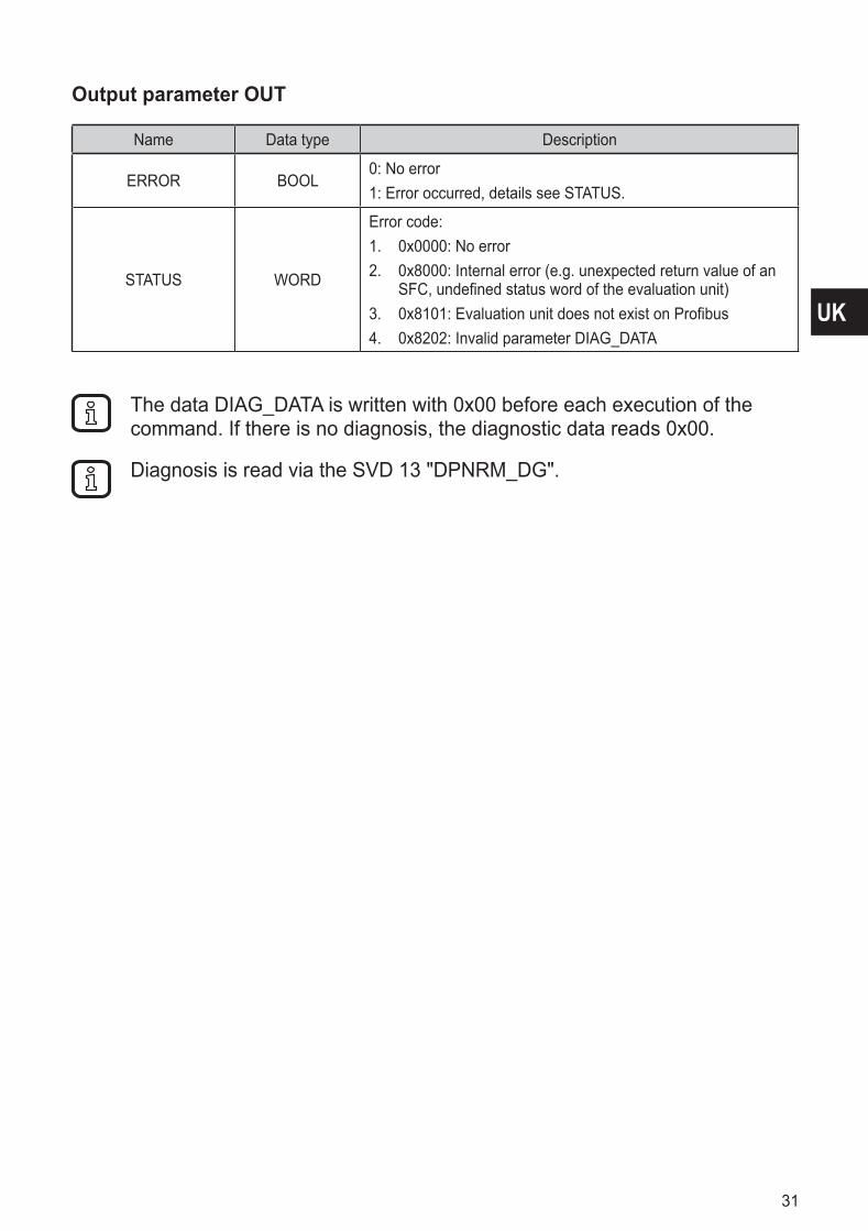
Output parameter OUT
Name Data type Description
ERROR BOOL
0: No error1: Error occurred, details see STATUS� The POU is not pro-
cessed any further and must be restarted via a positive edge on EXECUTE�
STATUS WORD
Error code:1� 0x0000: No error 2� 0x8000: Internal error (e�g� unexpected return value of an
SFC, undefined status word of the evaluation unit)3� 0x8100: 60s timeout for initialisation expired4� 0x8101: Evaluation unit does not exist on Profibus5� 0x8102: No IO interface was activated via IOx_ENABLE6� 0x8201: Parameter DPM_SYSTEM_ID invalid7� 0x8202: Parameter IDU_DP_ADDR invalid8� 0x830x: IOx activated but not available (x = 1���4)9� 0x840x: IOx with configuration error (e�g� IOx activated
but projected as inactive, input or output or UID module projected) (x =1��4)
10� 0x850x: IOx could not be initialised (e�g� because the bit ACP is not implemented at MS1) (x = 1-4)
IO1_READY BOOL0: IO-1 interface not ready (see STATUS)1: IO-1 interface ready, commands can be processed

10
Name Data type Description
IO2_READY BOOL0: IO-2 interface not ready1: IO-2 interface ready, commands can be processed
IO3_READY BOOL0: IO-3 interface not ready1: IO-3 interface ready, commands can be processed
IO4_READY BOOL0: IO-4 interface not ready1: IO-4 interface ready, commands can be processed
UK
11
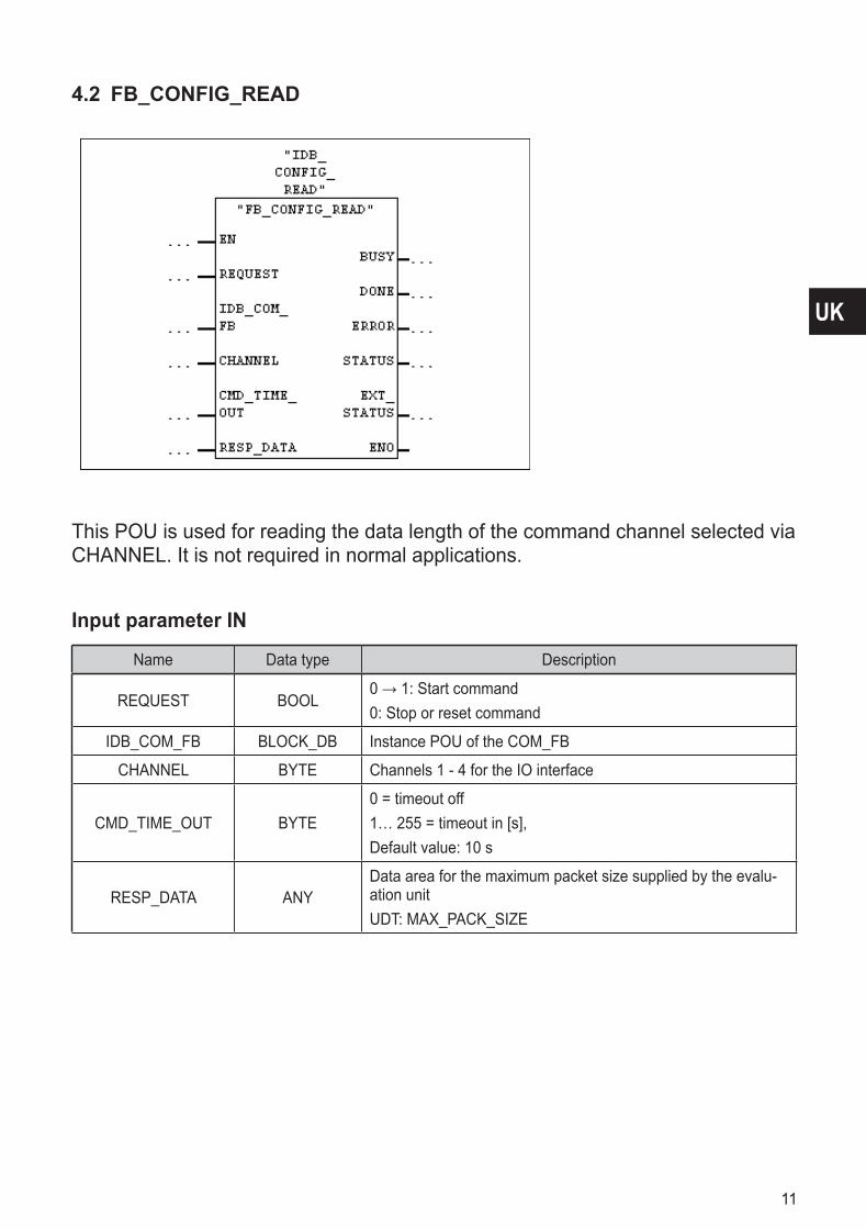
4.2 FB_CONFIG_READ
This POU is used for reading the data length of the command channel selected via CHANNEL� It is not required in normal applications�
Input parameter IN
Name Data type Description
REQUEST BOOL0 → 1: Start command0: Stop or reset command
IDB_COM_FB BLOCK_DB Instance POU of the COM_FB
CHANNEL BYTE Channels 1 - 4 for the IO interface
CMD_TIME_OUT BYTE0 = timeout off1… 255 = timeout in [s], Default value: 10 s
RESP_DATA ANYData area for the maximum packet size supplied by the evalu-ation unitUDT: MAX_PACK_SIZE

12
Output parameter OUT
Name Data type Description
BUSY BOOL0: POU ready for new command1: Command is processed
DONE BOOL0: No command initiated or command not yet completed1: Command executed
ERROR BOOL0: No error1: Error occurred, details see STATUS
STATUS WORD
Error code:1� 0x0000: No error2� 0x8000: Internal error (e�g� unexpected return value of an
SFC, undefined status word of the evaluation unit)3� 0x8001: Negative response of the evaluation unit, for more
details see EXT_STATUS4� 0x8002: RAM battery flat5� 0x8100: Timeout for command processing expired6� 0x8201: Invalid parameter IDB_COM_FB7� 0x8202: Invalid parameter CHANNEL8� 0x8203: Invalid parameter RESP_DATA9� 0x8500: Slot with RWH UID configuration, the command
cannot be executed
EXT_STATUS DWORD
Error code:1� 0x0000 0000: No extended information available2. Otherwise: see device manual → Function Num, Error
Decode, Error Code 1, Error Code 2
The RESP_DATA is deleted before writing (0x00)�

UK
13
4.3 FB_CONFIG_WRITE
This POU is used to synchronise the evaluation unit DTE100 with the PLC pro-gram within the POU COM_FB� In common applications it is not required�
Input parameter IN
Name Data type Description
REQUEST BOOL0 → 1: Start command0: Stop or reset command
IDB_COM_FB BLOCK_DB Instance POU of the COM_FB
CHANNEL BYTE Channels 1 - 4 for the IO interface
CMD_TIME_OUT BYTE0 = timeout off1… 255 = timeout in [s], Default value: 10 s
RESP_DATA ANYData area for the maximum packet size supplied by the evalu-ation unitUDT: MAX_PACK_SIZE

14
Output parameter OUT
Name Data type Description
BUSY BOOL0: POU ready for new command1: Command is processed
DONE BOOL0: No command initiated or command not yet completed1: Command executed
ERROR BOOL0: No error 1: Error occurred, details see STATUS
STATUS WORD
Error code:1� 0x0000: No error 2� 0x8000: Internal error (e�g� unexpected return value of an
SFC, undefined status word of the evaluation unit)3� 0x8001: Negative response of the evaluation unit, for more
details see EXT_STATUS4� 0x8002: RAM battery flat5� 0x8100: Timeout for command processing expired6� 0x8201: Invalid parameter IDB_COM_FB7� 0x8202: Invalid parameter CHANNEL8� 0x8203: Invalid parameter CMD_DATA9� 0x8500: Slot with RWH UID configuration, the command
cannot be executed
EXT_STATUS DWORD
Error code:1� 0x0000 0000: No extended information available2� Otherwise: Function Num, Error Decode, Error Code 1,
Error Code 2
MS0: ConfigIn = 0x00, no other command data�MS0/MS1: ConfigIn = 0x04, no other command data�

UK
15
4.4 FB_PHYSICAL_READ
This POU is used for reading the user memory range within the transponder (tag)� Depending on the tag type the data block length has to be entered within the user configuration of the modules PIB and RHW_STRG�You will find the data block length in the data sheet of the transponder/tag at:
www�ifm�com → Data sheet search
ExampleSetting with "Data block length" = 8 bytes:

16
Input parameter IN
Name Data type Description
REQUEST BOOL0 → 1: Start command0: Stop or reset command
IDB_COM_FB BLOCK_DB Instance POU of the COM_FB
CHANNEL BYTE Channels 1 - 4 for the IO interface
CMD_TIME_OUT BYTE0 = timeout off1… 255 = timeout in [s], Default value: 10 s
UID ARRAY [1���8] OF BYTE
UID != 0:The DTE100 must wait until a tag with the indicted UID is read, then the command is executed by the DTE100�UID = 0:Immediate execution of the command by DTE100�
START_ADR DWORD Start address of the tag memory area as from where reading starts�
LEN INT Number of bytes to be read by the tag�
RESP_DATA ANY
Data area for the data read by the evaluation unitExample:Reference to a data POU "DATA_PHYSICAL_READ“ or DB4 with the structure "Array[0…2048] of Byte,“ name "data“:"DATA_PHYSICAL_READ"�data or DB4�data
Output parameter OUT
Name Data type Description
BUSY BOOL0: POU ready for new command1: Command is processed
DONE BOOL0: No command initiated or command not yet completed1: Command executed
ERROR BOOL0: No error1: Error occurred, details see STATUS�

UK
17
Name Data type Description
STATUS WORD
Error code:1� 0x0000: No error 2� 0x8000: Internal error (e�g� unexpected return value of an
SFC, undefined status word of the evaluation unit)3� 0x8001: Negative response of the evaluation unit, for more
details see EXT_STATUS4� 0x8002: RAM battery flat5� 0x8100: Timeout for command processing expired6� 0x8201: Invalid parameter IDB_COM_FB7� 0x8202: Invalid parameter CHANNEL8� 0x8203: Invalid parameter RESP_DATA9� 0x8204: Invalid parameter LEN10� 0x8500: Module deactivated or configured with RWH UID,
input or output� The command cannot be executed
EXT_STATUS DWORD
Error code:1� 0x0000 0000: No extended information available2� Otherwise: Function Num, Error Decode, Error Code 1,
Error Code 2
The RESP_DATA is deleted before writing (0x00)�

18
4.5 FB_PHYSICAL_WRITE
This POU is used for writing the user memory range within the transponder (tag)� Depending on the tag type the data block length has to be entered within the user configuration of the modules PIB and RHW_STRG�
ExampleSetting with "Data block length" = 8 bytes:

UK
19
Input parameter IN
Name Data type Description
REQUEST BOOL0 → 1: Start command0: Stop or reset command
IDB_COM_FB BLOCK_DB Instance POU of the COM_FB
CHANNEL BYTE Channels 1 - 4 for the IO interface
CMD_TIME_OUT BYTE0 = timeout off1… 255 = timeout in [s],Default value: 10 s
UID ARRAY [1���8] OF BYTE
UID != 0:The DTE100 must wait until a tag with the indicted UID is read, then the command is executed by the DTE100� UID = 0:Immediate execution of the command by DTE100�
START_ADR DWORD Start address of the tag memory range as from where writing starts�
LEN INT Number of bytes to be written to the tag�
CMD_DATA ANY
Data area with the data to be sent to the evaluation unit�Example:Reference to a data POU "DATA_PHYSICAL_WRITE“ or DB3 with the structure "Array[0…2048] of Byte,“ name "data":"DATA_PHYSICAL_WRITE"�data or DB3�data
Output parameter OUT
Name Data type Description
BUSY BOOL0: POU ready for new command1: Command is processed
DONE BOOL0: No command initiated or command not yet completed1: Command executed
ERROR BOOL0: No error1: Error occurred, details see STATUS�

20
Name Data type Description
STATUS WORD
Error code:1� 0x0000: No error 2� 0x8000: Internal error (e�g� unexpected return value of an
SFC, undefined status word of the evaluation unit)3� 0x8001: Negative response of the evaluation unit, for more
details see EXT_STATUS4� 0x8002: RAM battery flat5� 0x8100: Timeout for command processing expired6� 0x8201: Invalid parameter IDB_COM_FB7� 0x8202: Invalid parameter CHANNEL8� 0x8203: Invalid parameter CMD_DATA9� 0x8204: Invalid parameter LEN10� 0x8500: Module deactivated or configured with RWH UID,
input or output� The command cannot be executed
EXT_STATUS DWORD
Error code:1� 0x0000 0000: No extended information available2� Otherwise: Function Num, Error Decode, Error Code 1,
Error Code 2

UK
21
4.6 FB_DEV_STATUS
This POU is used for reading the Profibus identification and maintenance data I&M and I&M1�
Input parameter IN
Name Data type Description
REQUEST BOOL0 → 1: Start command0: Stop or reset command
IDB_COM_FB BLOCK_DB Instance POU of the COM_FB
CHANNEL BYTE Channels 1 - 4 for the IO interface
CMD_TIME_OUT BYTE0 = timeout off1… 255 = timeout in [s],Default value: 10 s
CMD_ATTRIBUTE BYTE0x04: Reading the I&M0 data structure0x05: Reading the I&M1 data structure
RESP_DATA ANYData area for the I&M data read by the evaluation unitUDT: IM0_DATA or IM1_DATA

22
Output parameter OUT
Name Data type Description
BUSY BOOL0: POU ready for new command1: Command is processed
DONE BOOL0: No command initiated or command not yet completed1: Command executed
ERROR BOOL0: No error1: Error occurred, details see STATUS�
STATUS WORD
Error code:1� 0x0000: No error 2� 0x8000: Internal error (e�g� unexpected return value of an
SFC, undefined status word of the evaluation unit)3� 0x8001: Negative response of the evaluation unit, for more
details see EXT_STATUS4� 0x8002: RAM battery flat5� 0x8100: Timeout for command processing expired6� 0x8101: Evaluation unit does not exist on Profibus7� 0x8201: Invalid parameter IDB_COM_FB8� 0x8202: Invalid parameter CHANNEL9� 0x8203: Invalid parameter RESP_DATA10� 0x8204: Invalid parameter CMD_ATTRIBUTE11� 0x8500: Slot with RWH UID configuration, the command
cannot be executed
EXT_STATUS DWORD
Error code:1� 0x0000 0000: No extended information available2� Otherwise: Function Num, Error Decode, Error Code 1,
Error Code 2

UK
23
4.7 FB_WRITE_IM1
This POU is used for writing the Profibus identification and maintenance data I&M1�
Input parameter IN
Name Data type Description
REQUEST BOOL0 → 1: Start command0: Stop or reset command
IDB_COM_FB BLOCK_DB Instance POU of the COM_FB
IM1_DATA ANYData area with the I&M1 data to be sent to the evaluation unit� UDT: IM1_DATA

24
Output parameter OUT
Name Data type Description
BUSY BOOL0: POU ready for new command1: Command is processed
DONE BOOL0: No command initiated or command not yet completed1: Command executed
ERROR BOOL0: No error1: Error occurred, details see STATUS�
STATUS WORD
Error code:1� 0x0000: No error 2� 0x8101: Evaluation unit does not exist on Profibus3� 0x8201: Invalid parameter IDB_COM_FB or COM_FB not
yet initialised4� 0x8202: Invalid parameter IM1_DATA
In contrast to the Profibus specification, the POU internally starts the sys-tem function block SFB53 (WR_REC) on slot 0 and index 254 with the data indicated in "IM1_DATA" �

UK
25
4.8 FB_GET
This POU is used for executing different individual commands which can be selec-ted via the input SUB_CMD:
Application Subcommand Description
Read the Ethernet settings Get_Ethernet_Parameter IP address, gateway address, subnet mask
Read the device settings Get_Ident_Unit_Parameter Data format, overload setting, overcurrent setting, high-current setting
Read the time Get_Clock Year, month, day, hour, minute, second, hundredth of a second
Read the device informati-on of the RFID antennas Get_Ant_Type Article number, type, hardware version,
software version, production date
Read the set data block information of the tag Get_Block_Parameter Maximum number of blocks, block length of
the device
Read the data block infor-mation of the tag Get_Transponder_Type Maximum number of blocks, block length of
the tag
Read the available diag-nostic information Get_Ident_Diagnosis Device diagnosis, channel diagnosis
Read the MAC address of the Ethernet port Get_MAC_Address Ethernet media access control register
Read the available diag-nostic information of the
RFID antennaGet_Ant_Diagnosis Read the different diagnosis objects from the
RFID antenna
Read the modular confi-guration of the selected
channelGet_Channel_Mode -

26
Application Subcommand Description
Read the UID of the tag Get_UID -
Input parameter IN
Name Data type Description
REQUEST BOOL0 → 1: Start command0: Stop or reset command
IDB_COM_FB BLOCK_DB Instance POU of the COM_FB
CHANNEL BYTE Channels 1 - 4 for the IO interface
CMD_TIME_OUT BYTE0 = timeout off1… 255 = timeout in [s], Default value: 10 s
SUB_CMD BYTE
Subcommand0xC1: GET_ETHERNET_PARAMETER (UDT: ETH_PARA)0xC2: GET_IDENT_UNIT_PARAMETER (UDT: IDENT_UNIT_
PARA)0xC3: GET_CLOCK (UDT: CLOCK)0xC5: GET_ANT_TYPE (UDT: ANT_TYPE)0xC6: GET_BLOCK_PARAMETER (UDT: BLOCK_PARA)0xC7: GET_TRANSPONDER_TYPE (UDT: TRANSPON-
DER_TYPE)0xC8: GET_IDENT_DIAGNOSIS (UDT: IDENT_DIAG)0xC9: GET_MAC_ADDRESS (UDT: MAC_ADDRESS)0xCA: GET_ANT_DIAGNOSIS (UDT: ANT_DIAG)0xCB: GET_CHANNEL_MODE (UDT: CHANNEL_MODE) 0xCD: GET_UID (UDT: CHANNEL_MODE)
SUB_CMD_DATA BYTE Extended option for the subcommand
RESP_DATA ANYData area for the data read by the evaluation unit UDT: see SUB_CMD

UK
27
Output parameter OUT
Name Data type Description
BUSY BOOL0: POU ready for new command1: Command is processed
DONE BOOL0: No command initiated or command not yet completed1: Command executed
ERROR BOOL0: No error1: Error occurred, details see STATUS�
STATUS WORD
Error code:1� 0x0000: No error 2� 0x8000: Internal error (e�g� unexpected return value of an
SFC, undefined status word of the evaluation unit)3� 0x8001: Negative response of the evaluation unit, for more
details see EXT_STATUS4� 0x8002: RAM battery flat5� 0x8100: Timeout for command processing expired6� 0x8201: Invalid parameter IDB_COM_FB7� 0x8202: Invalid parameter CHANNEL8� 0x8203: Invalid parameter RESP_DATA9� 0x8204: Invalid parameter SUB_CMD10� 0x8205: Invalid parameter SUB_CMD_DATA (no DB or DB
of the wrong UDT type was transferred)11� 0x8500: Slot with RWH UID configuration, the command
cannot be executed
EXT_STATUS DWORD
Error code:75� 0x0000 0000: No extended information available76� Otherwise: Function Num, Error Decode, Error Code 1,
Error Code 2
The RESP_DATA is deleted before writing (0x00)�

28
4.9 FB_PUT
This POU is used for executing different individual commands which can be selec-ted via the input SUB_CMD:
Application Subcommand Description
Programming of the Ethernet settings
Set_Ethernet_Parameter IP address, gateway address, subnet mask
Programming of the device settings
Set_Ident_Unit_Parameter Data format, overload setting, overcurrent setting, high-current setting
Programming of the time Set_Clock Year, month, day, hour, minute, second, hundredth of a second
Restoration of the factory settings Set_Defaults Article number, type, hardware version,
software version, production date
Programming of the data block settings Set_Block_Parameter
Setting of the default values of the IP address, gateway address, subnet mask, data format, time, Profibus address
Input parameter IN
Name Data type Description
REQUEST BOOL0 → 1: Start command0: Stop or reset command
IDB_COM_FB BLOCK_DB Instance POU of the COM_FB
CHANNEL BYTE Channels 1 - 4 for the IO interface

UK
29
Name Data type Description
CMD_TIME_OUT BYTE0 = timeout off1… 255 = timeout in [s], Default value: 10 s
SUB_CMD BYTE
Subcommand0xD1: SET_ETHERNET_PARAMETER (UDT: ETH_PARA) 0xD2: SET_IDENT_UNIT_PARAMETER (UDT: IDENT_UNIT_
PARA) 0xD3: SET_CLOCK (UDT: CLOCK)0xD5: SET_DEFAULTS (UDT: - )0xD6: SET_BLOCK_PARAMETER (UDT: BLOCK_PARA)
CMD_DATA ANYData area with the data to be sent to the evaluation unit�UDT: see SUB_CMD
Output parameter OUT
Name Data type Description
BUSY BOOL0: POU ready for new command1: Command is processed
DONE BOOL0: No command initiated or command not yet completed1: Command executed
ERROR BOOL0: No error1: Error occurred, details see STATUS�
STATUS WORD
Error code:1� 0x0000: No error 2� 0x8000: Internal error (e�g� unexpected return value of an
SFC, undefined status word of the evaluation unit)3� 0x8001: Negative response of the evaluation unit, for more
details see EXT_STATUS4� 0x8002: RAM battery flat5� 0x8100: Timeout for command processing expired6� 0x8201: Invalid parameter IDB_COM_FB7� 0x8202: Invalid parameter CHANNEL8� 0x8203: Invalid parameter SUB_CMD9� 0x8204: Invalid parameter SUB_CMD_DATA (no DB or DB
of the wrong UDT type was transferred)10� 0x8500: Slot with RWH UID configuration, the command
cannot be executed
EXT_STATUS DWORD
Error code:1� 0x0000 0000: No extended information available2� Otherwise: Function Num, Error Decode, Error Code 1,
Error Code 2

30
4.10 FB_DIAG
This POU is used for reading the Profibus DP diagnosis within the device
Input parameter IN
Name Data type Description
ENABLE BOOL0: The POU is deactivated�1: The diagnostic data is read cyclically and stored at DIAG_
DATA
IDU_ADR WORD Profibus address of the evaluation unit
DIAG_DATA ANYData area for the diagnostic data read by the evaluation unit UDT: DIAG_DATA
UK
31
Output parameter OUT
Name Data type Description
ERROR BOOL0: No error1: Error occurred, details see STATUS�
STATUS WORD
Error code:1� 0x0000: No error 2� 0x8000: Internal error (e�g� unexpected return value of an
SFC, undefined status word of the evaluation unit)3� 0x8101: Evaluation unit does not exist on Profibus4� 0x8202: Invalid parameter DIAG_DATA
The data DIAG_DATA is written with 0x00 before each execution of the command� If there is no diagnosis, the diagnostic data reads 0x00�
Diagnosis is read via the SVD 13 "DPNRM_DG"�

32
4.11 FB_SET_ANTENNA
This POU is used to activate/deactivate the transmission field of the RFID anten-na�
Input parameter IN
Name Data type Description
REQUEST BOOL0 → 1: Start command0: Stop or reset command
IDB_COM_FB BLOCK_DB Instance POU of the COM_FB
CMD_TIME_OUT BYTE0 = timeout off1… 255 = timeout in [s],Default value: 10 s
ANT1_ENABLE BOOL0: Deactivate antenna 11: Activate antenna 1
ANT2_ENABLE BOOL0: Deactivate antenna 21: Activate antenna 2
ANT3_ENABLE BOOL0: Deactivate antenna 31: Activate antenna 3

UK
33
Name Data type Description
ANT4_ENABLE BOOL0: Deactivate antenna 41: Activate antenna 4
Output parameter OUT
Name Data type Description
BUSY BOOL0: POU ready for new command1: Command is processed
DONE BOOL0: No command initiated or command not yet completed1: Command executed
ERROR BOOL0: No error1: Error occurred, details see STATUS�
STATUS WORD
Error code:1� 0x0000: No error2� 0x800x: Error when activating/deactivating the antennas
(bits 0��3 = error on antennas 1-4)3� 0x8100: Timeout for command processing expired4� 0x8201: Parameter IDB_COM_FB invalid

34
4.12 User-defined data type
UDT1: ETH_PARA
UDT2: MAC_ADDRESS
UDT3: IDENT_UNIT_PARA
UDT4: CLOCK

UK
35
UDT5: TRACEBUFFER
UDT6: ANT_TYPE

36
UDT7: BLOCK_PARA
UDT8: TRANSPONDER_TYPE
UDT9: IDENT_DIAG

UK
37
UDT10: ANT_DIAG
UDT11: CHANNEL_MODE
UDT15: MAX_PACK_SIZE
UDT16: DIAG_DATA

38

UK
39
UDT17: IM0_DATA
UDT18: IM1_DATA