Cardell Touch Veterinary Vital Signs Monitor - Midmark
96
TP200 Rev. A Cardell Touch Veterinary Vital Signs Monitor For Models: 8013-001 8013-002 8013-003 8013-004 User’s Guide 003-2647-00 Rev. J (8/29/14)
-
Upload
khangminh22 -
Category
Documents
-
view
5 -
download
0
Transcript of Cardell Touch Veterinary Vital Signs Monitor - Midmark
TP200 Rev. A
Cardell Touch Veterinary Vital Signs Monitor
For Models:8013-0018013-0028013-0038013-004
User’s Guide 003-2647-00 Rev. J (8/29/14)

TP200 Rev. A i © Midmark Corporation 2014
Product Information
Dealer: Date of Purchase:
Model / Serial Number: Midmark Authorized Service Company:
Model/Serial
Number Location
Product RegistrationTo register your product, go to www.midmark.com

ii
SECTION 1 - PREFACE 1
1.1 General ................................................................... 1
1.2 Compliance ............................................................ 1
SECTION 2 - SAFETY 2
2.1 Safety Notice ......................................................... 2
2.1.1 Intended Use ..................................................... 2
2.1.2 Application Environment ................................... 2
2.1.3 Operator Requirements .................................... 2
2.1.4 Terminology ....................................................... 2
2.1.5 Monitor Safety ................................................... 2
2.2 Safety Requirements ............................................ 3
2.2.1 WARNING: ........................................................ 3
2.2.2 CAUTION: ......................................................... 3
2.3 Safety Symbols .................................................... 4
SECTION 3 - CONTROLS AND CONNECTORS 5
3.1 Installation and Connection ................................. 5
3.1.1 Environment Requirements .............................. 5
3.1.2 Power Supply Requirements ............................ 5
3.1.3 Shock Protection ............................................... 5
3.1.4 Patient Grounding ............................................. 5
3.1.5 Combination of Equipment ................................ 5
3.1.6 Unpacking ......................................................... 6
3.2 Before Monitoring ................................................. 6
3.3 Front Panel ............................................................ 7
3.4 Rear Panel .............................................................. 8
3.5 Side Panels ............................................................ 9
3.6 Power ................................................................... 10
3.6.1 AC Power ........................................................ 10
3.6.2 Battery Power ................................................. 10
3.7 Navigation Options ............................................. 10
3.7.1 Color TFT Touch Screen ................................. 10
3.8 Printing (Optional) ................................................11
3.8.1 Recorder ..........................................................11
3.8.2 Manually Controlled Printing ........................... 12
3.8.3 Alarm Triggered Printing ................................. 12
3.8.4 Interval Printing ............................................... 12
3.8.5 Print Header .................................................... 12
3.8.6 Printing Paper ................................................. 12
3.8.7 Installing Paper ............................................... 12
3.9 Display Screen .................................................... 13
3.9.1 Main Screen Display ....................................... 13
3.9.2 Status Bar ....................................................... 14
3.9.3 Waveform Area ............................................... 14
3.9.4 Parameter Box ................................................ 15
3.9.5 Touch Screen Menu ........................................ 15
SECTION 4 - ALARM SETUP 16
4.1 General Information ............................................ 16
4.2 Alarm Silence ....................................................... 16
4.3 Alarm Setup ......................................................... 17
4.3.1 Alarm Setup Menu .......................................... 17
4.3.2 Alarm Parameter Setup Menu ......................... 17
4.3.3 Current and Custom Alarm Settings ............... 18
4.3.4 Changes Made to Custom Alarm Settings ...... 19
4.3.5 Alarm Volume and Sound Setup ..................... 19
4.3.6 Default Alarm Limit .......................................... 19
SECTION 5 - SETTING UP THE MONITOR 22
5.1 Display Setup ...................................................... 22
5.1.1 Parameter Display .......................................... 22
5.1.2 Display Mode Setup ........................................ 22
5.2 Historical Data Mode ........................................... 22
5.3 Large Font Mode ................................................. 22
5.4 AG Screen Mode .................................................. 22
5.5 Demo Mode .......................................................... 23
Table of Contents

iii
6.6.2 Parameter Adjustment Range ......................... 35
6.6.3 Abnormal Status Alarm ................................... 35
6.7 Precautions .......................................................... 35
6.8 Cleaning and Maintenance ................................. 36
6.8.1 ECG Cable Cleaning ....................................... 36
6.8.2 ECG Cable Disinfection .................................. 36
6.9 Troubleshooting .................................................. 36
6.9.1 Inaccurate Heart Rate ..................................... 36
6.9.2 No ECG Waveform ......................................... 36
6.9.3 ECG Baseline Shift ......................................... 36
SECTION 7 - NIBP MONITORING 37
7.1 General Information ............................................ 37
7.2 Cuff Placement .................................................... 37
7.2.1 Cuff Placement for Cat .................................... 37
7.2.2 Cuff Placement for Dog ................................... 37
7.2.3 Large Animals ................................................. 38
7.2.4 Cuff size selections ......................................... 38
7.3 NIBP Setup ........................................................... 39
7.3.1 NIBP Setup Menu ........................................... 39
7.3.2 Select Cuff Size............................................... 40
7.3.3 Select Measurement Mode ............................. 40
7.3.4 Alarm Limit Setup ............................................ 41
7.3.5 Alarm for Abnormal Status .............................. 41
7.4 Troubleshooting .................................................. 41
7.5 Precautions .......................................................... 41
7.6 Preparations ........................................................ 41
7.7 Maintenance ........................................................ 42
7.7.1 Cuffs ................................................................ 42
7.7.2 Reusable (Nylon) Large Cuffs ......................... 42
7.7.3 Disposable (Vivnyl) Small Cuffs ...................... 42
SECTION 8 - SpO2 MONITORING 43
8.1 General Information ..................................... 43
8.2 Sensor Placement ............................................... 43
5.6 Trend Display ....................................................... 23
5.6.1 Displaying Trend Graph .................................. 23
5.6.2 Displaying Trend Table .................................... 23
5.6.3 Deleting Trend Information .............................. 24
5.7 Monitor Video Output .......................................... 24
5.8 Export Trend and ECG Data ............................... 24
5.9 Cardell Touch Visualizer Tool ............................ 25
5.9.1 Importing ECG Data into the Visualizer .......... 25
5.9.2 Visualizer Data Tabs ....................................... 25
5.9.3 Reviewing Waveforms .................................... 26
5.9.4 Printing Waveforms ........................................ 26
5.9.5 Cardell Touch Visualizer Troubleshooting ....... 26
5.10 Printing Setup (Optional) .................................. 28
5.11 Patient Setup ..................................................... 28
5.12 Date and Time Setup ......................................... 29
5.13 Sound and Volume Setup ................................. 30
5.14 Recall Functions ............................................... 30
5.14.1 NIBP Recall ................................................... 30
5.14.2 Alarm Recall .................................................. 30
5.14.3 Wave Recall .................................................. 31
SECTION 6 - ECG MONITORING 32
6.1 General Information ............................................ 32
6.2 Patient Cable ....................................................... 32
6.3 Animal Preparation and Lead Contact .............. 32
6.4 Attaching ECG Electrodes .................................. 32
6.4.1 Lead Wires and Color ..................................... 32
6.4.2 Lead Placement .............................................. 33
6.4.3 Positioning Anesthetized Patients ................... 33
6.4.4 Positioning Conscious Patients ....................... 33
6.5 ECG Setup ........................................................... 34
6.5.1 ECG Setup Menu ............................................ 34
6.5.2 Filter Menu ...................................................... 34
6.6 Alarm Setup ......................................................... 35
6.6.1 Alarm Limit Setup ............................................ 35

iv
8.3 SpO2 Setup Menu ............................................... 44
8.4 Alarm Setup ......................................................... 45
8.4.1 Alarm Range ................................................... 45
8.5 Preparation for Monitoring ................................. 46
8.6 Precautions .......................................................... 46
8.7 Cleaning and Maintenance ................................. 47
8.7.1 Clean the Sensor and Clip .............................. 47
8.7.2 Clean the Cable .............................................. 47
8.8 Troubleshooting .................................................. 47
8.8.1 No SpO2 Data ................................................. 47
8.8.2 Intermittent SpO2 Value .................................. 48
SECTION 9 - TEMPERATURE AND RESPIRATION MONITORING 49
9.1 General Information ............................................ 49
9.1.1 Temperature ................................................... 49
9.2 Temperature Monitoring ..................................... 49
9.3 Temperature Setup Menu ................................... 50
9.4 Temperature Probe Cleaning ............................. 50
9.5 Respiration Monitoring ....................................... 50
9.6 Respiration Setup Menu ..................................... 51
9.7 Alarm Setup ......................................................... 51
SECTION 10 - CO2 MONITORING (Optional) 53
10.1 General Information .......................................... 53
10.2 CO2 Setup Menu ............................................... 53
10.3 Capnostat Sensor ............................................. 54
10.3.1 Sensor Connections ...................................... 54
10.4 LoFlo CO2 Sensor - Sidestream ...................... 55
10.4.1 Connecting the LoFlo CO2 Sensor to the Monitor ...................................................................... 55
10.5 Zeroing the CO2 Sensors ................................. 56
10.6 LoFlo CO2 Sensor Holder (Optional)............... 57
10.7 Removing Exhaust Gases from the System ... 57
10.8 Alarm Setup ....................................................... 57
10.9 Cleaning & Maintenance ................................... 58
10.9.1 CAPNOSTAT 5 CO2 Sensor ......................... 58
10.9.2 LoFlo CO2 Sensor ........................................ 58
10.9.3 Airway Adapters ............................................ 58
SECTION 11 - IBP MONITORING (Optional) 59
11.1 General Information .......................................... 59
11.2 IBP Setup Menu ................................................. 59
11.3 Transducer ......................................................... 60
11.3.1 Transducer Connection ................................. 60
11.4 Preparation for Measurement .......................... 61
11.5 Zeroing the IBP Sensor ..................................... 61
11.6 IBP Labeling ....................................................... 62
11.7 Alarm Setup ....................................................... 62
11.8 Precautions ........................................................ 62
SECTION 12 - MULTI-GAS MONITORING (Optional) 64
12.1 General Information ..................................... 64
12.2 Installation and Connection ........................ 64
12.2.1 Parts .............................................................. 64
12.2.2 IRMA Connection Procedures ....................... 64
12.2.3 ISA Connection Procedures .......................... 65
12.2.4 Turn on the Multi-gas Module ....................... 66
12.2.5 Turn on the Multi-gas Screen Display ........... 66
12.2.6 Turn On or Off the Multi-gas Work Mode ...... 66
12.2.7 Multi-gas Exhaust ......................................... 67
12.3 Multi-gas Setup Menu ....................................... 67
12.3.1 Multi-gas Measurement Menu: ..................... 67
12.3.2 CO2 Setup Menu Options ............................. 67
Please see the follow chart for setting the AG Apnea Alarm: ........................................................................ 68
12.3.3 N2O Setup Menu Options ............................. 68
12.3.4 AG Setup Menu Options .............................. 68
12.4 Monitoring .................................................. 69
12.4.1 Pre-Use Checks ........................................... 69
12.4.2 Using Multi-gas ............................................ 69

v
12.4.3 Zeroing IRMA ................................................ 69
12.4.4 Zeroing ISA ................................................... 70
12.5 Alarm Setup ....................................................... 70
12.6 Cleaning and Maintenance ............................... 71
SECTION 13 - CLEANING, MAINTENANCE, WARRANTY 73
13.1 Cleaning ............................................................. 73
13.1.1 The Monitor ................................................... 73
13.1.2 The Display ................................................... 73
13.1.3 Patient Cable and Lead Wires ...................... 74
13.1.4 Cuffs .............................................................. 74
13.1.5 Reusable (Nylon) Cuffs ................................. 74
13.1.6 Disposable (Vinyl) Cuffs ................................ 74
13.1.7 Pneumatic Tubing ......................................... 74
13.1.8 Sensor and Clips ........................................... 74
13.1.9 Temperature Probes...................................... 75
13.2 Limited Warranty ............................................... 75
13.2.1 Registration ................................................... 75
13.2.2 Scope of Warranty ........................................ 75
13.2.3 Applicable Warranty Period ........................... 75
13.2.4 Exclusions ..................................................... 75
13.2.5 Exclusive Remedy; Consequential Damages Disclaimer ................................................................. 76
13.2.6 No Authorization ............................................ 76
13.2.7 Warranty Disclaimer ...................................... 76
13.2.8 Statute of Limitations .................................... 76
13.3 After-sale Service and Support ........................ 76
APPENDIX 1 - SPECIFICATIONS 77
I. Safety ...................................................................... 77
II. Power Supply Requirements ............................... 77
III. Parameter Specifications .................................... 77
A. ECG ..................................................................... 77
B. Pulse Oximetry (SpO2) - Nellcor ........................ 77
C. Non-invasive Blood Pressure (NIBP) – Cardell® 78
D. End-tidal CO2 – Respironics (Optional) .............. 78
E. Temperature (2-channel) ..................................... 78
F. Respiration ........................................................... 78
G. Multi-gas (Optional) ............................................. 79
H. IBP (Optional) ...................................................... 79
I. Display .................................................................. 79
J. Recorder (Optional) .............................................. 79
K. Physical Specifications ........................................ 79
APPENDIX 2 - BP REFERENCE VALUES 80
APPENDIX 3 - DEAD SPACE 82
APPENDIX 4 - DIRECT BP MONITORING 84
APPENDIX 5 - SPECTRAL BROADENING 87
I. Nitrous oxide, N2O .................................................. 87
II. Oxygen O2 ................................................................................................................87
APPENDIX 6 - ACCESSORIES 88

TP200 Rev. A 1 © Midmark Corporation 2014
SECTION 1 - PREFACE
1.1 GeneralWelcome and thank you for choosing the Cardell® Touch portable multi-parameter veterinary monitor. The Cardell® Touch continuously monitors and displays the following physiological parameters: ECG waveforms and heart rate, arterial blood oxygen saturation of arterial hemoglobin (SpO2) and pulse rate, respiration rate, systolic (SYS), diastolic (DIA) and mean arterial pressure (MAP), and temperature. Available options for this monitor include Invasive Blood Pressure, a built in printer, and export power cords.
This Cardell® Touch can be upgraded to offer CO2 or Multigas monitoring at any time. With the addition of the Capnostat Mainstream CO2 probe or LoFlo Sidestream sensor, one can also measure end-tidal CO2 as well as inspired CO2. With the addition of the Masimo Sweden Mainstream or Sidestream Multigas analyzer, one also has the ability to measure N2O as well as five anesthetic agents (HAL, ENF, ISO, SEV, DES) in addition to CO2.
This User’s Guide is an integral part of the product and contains detailed information about the performance specifications, operation, and maintenance of the Cardell® Touch and its intended use. Observance of this User’s Guide is a prerequisite for proper product performance and correct operation and ensures patient and operator safety. It should always be kept close to the equipment.
1.2 ComplianceThe manufacturer’s quality management system complies with the international standards ISO 9001:2008 and ISO 13485:2003 and has the certificate issued by DNV.

TP200 Rev. A 2 © Midmark Corporation 2014
SECTION 2 - SAFETY
2.1 Safety Notice
2.1.1 Intended Use
The Cardell® Touch is a portable multi-parameter monitoring device for animals intended to give qualified veterinarians and technicians an efficient and accurate patient vital sign monitoring solution during veterinarian procedures.
2.1.2 Application Environment
This device is for use by trained veterinary personnel in veterinary centers. The device is to be used on one patient at a time.
Transport and Storage ConditionsTemperature: 14°F (-10°C) to 104°F (40°C)Humidity: ≤95% (non-condensing)Atmospheric Pressure: 50kPa to 106kPa
Working ConditionsTemperature: 41°F (5°C) to 104°F (40°C)Humidity: ≤80% (non-condensing)Atmospheric Pressure: 86kPa to 106kPa
2.1.3 Operator Requirements
Only qualified veterinary personnel who have read the User’s Guide should use this monitor. The monitor is intended only as an adjunct in patient assessment. It must be used in conjunction with clinical signs and symptoms. United States Federal Law restricts this device to sale, distribution and use by or on the order of a veterinarian.
2.1.4 Terminology
The terms NOTE, CAUTION, and WARNING are used throughout this User’s Guide to point out hazards and to designate a degree or level of seriousness. Familiarize yourself with their definitions and significance.
NOTEprovides application tips or other useful information to assure that you get the most from your equipment.
CAUTIONindicates a potential hazard or unsafe practice which, if not avoided, could result in minor personal injury or product /property damage.
WARNINGindicates a potential hazard or unsafe practice which, if not avoided, could result in death or serious injury.
2.1.5 Monitor Safety
The safety statements presented in this chapter refer to the equipment in general and in most cases, apply to all aspects of the monitor. There are additional safety statements in the parameter chapters, which are specific to that monitored parameter.
The order in which safety statements are presented in no way implies order of importance.

TP200 Rev. A 3 © Midmark Corporation 2014
2.2 Safety Requirements
The following warnings and cautions must be read and understood before operating the veterinary monitor.
2.2.1 WARNING:
• The Cardell® Touch veterinary monitor is not intended to be used as an apnea monitor.
• The Cardell® Touch veterinary monitor is not intended to be used during MRI or CT scan.
• Please do not rely on the alarm functions of the veterinary monitor. The alarm limits may have been improperly set or the alarm may have been disabled.
• Alarm functions of the veterinary monitor must be checked regularly.
• Before putting the system into operation, visually inspect all connecting cables for signs of damage. Damaged cables and connectors must be replaced immediately.
• When several devices are used on the same patient, leakage current may increase and become a danger to the patient. Before using, please consult a professional to do a leakage current test to make sure the leakage current is within safety limits.
• When a defibrillator is used, make sure the patient does not make contact with the ground, metal objects, or other conductors or devices. During defibrillation, never touch the patient, table or the device.
• Before using on another patient, make sure the previous monitoring data is cleared.
• Use properly grounded power sockets and ensure adequate grounding. If there is any doubt about the grounding, please use battery operation.
2.2.2 CAUTION:
• Check accessories on a regular basis and discard damaged accessories properly.
• To ensure patient’s safety and performance of the product, use only the manufacturer recommended accessories.
• Service parts must be in conformity with IEC 60601 standards. The system configuration of the monitor must be in conformity with IEC 60601-1-1 medical electric standard; otherwise, it will reduce the safety of the monitor.
• Even while not being used, the battery may still discharge. Check battery level every month.
• The ECG cable socket is for connecting ECG lead wires only. Please do not connect it to any other signal source. Pay attention to the color label and marks of ECG lead wires.
• Please clean the monitor and accessories according to instructions. Always unplug the power cord before cleaning.
• Electromagnetic Interference - This product is designed and built to minimize electromagnetic interference with other devices. However, if interference is noticed between another device and this monitor:
◦ Remove interfering device from room
◦ Plug cart into an isolated circuit
◦ Increase separation between Midmark product and interfering device
◦ Contact Midmark if interference persists
• For continual safe use of this equipment, it is necessary to follow the instructions. However, instructions listed in this User’s Guide in no way supersede established medical practices concerning patient care.
• In the event of interrupted data or loss of data, please keep patient under close observation until the device returns to normal.
• Other devices connecting to the device should meet IEC standards (for example, data processing device should meet IEC 950, and medical device should meet IEC60601-1) and the whole system should meet the latest version of IEC60601-1-1 standards.
• Plastic bags and other packaging materials should be disposed of in accordance with related regulations.
• At the end of product life, the monitor, accessories, and other consumable goods may become contaminated from normal use. Consult local codes and ordinances for proper disposal of equipment and other consumable goods.

TP200 Rev. A 4 © Midmark Corporation 2014
• Do not open the enclosure of the monitor to avoid the risk of electrical shock.
2.3 Safety Symbols
NOTE Some symbols may not appear on all equipment.
BF Applied Part: F-type applied part (floating/insulated) complying with the specified requirements of IEC 60601-1 Medical Standards to provide a higher degree of protection against electric shock than that provided by Type B applied parts.Type CF Applied Part: F-type applied part (floating/insulated) complying with the specified requirements of IEC 60601-1 Medical Standards to provide a higher degree of protection against electric shock than that provided by Type BF applied parts.Attention: Consult accompanying documents.
Fuse
Equipotentiality
Power ON/OFF
Alternating
Current Earth Connector

TP200 Rev. A 5 © Midmark Corporation 2014
SECTION 3 - CONTROLS AND CONNECTORS
3.1 Installation and Connection
3.1.1 Environment Requirements
To ensure electric installation safety, the environment should be reasonably dust free, without corrosive or combustible gas, or extreme temperature or humidity.
Keep a space for the veterinary monitor at least 5cm from the wall to ensure good air ventilation.
Extreme temperature can affect the accuracy of the monitor and damage accessories or circuits.
Please ensure that water does not condense in the veterinary monitor when using the device. For instance, when the monitor is transferred between buildings, there is a risk of condensation because of exposure to humidity combined with a difference in temperature.
WARNINGNever use the veterinary monitor in an environment with combustible anesthetic gases.
3.1.2 Power Supply Requirements
Rated Input Voltage: AC100V~250VRated Frequency: 50Hz/60HzRated Input Power: 40VA-60VAFuses: T1.6L, 250V fuse, (2)Battery: 14.8V 4400mAh Lithium polymer
3.1.3 Shock Protection
The Cardell® Touch multi-parameter veterinary monitor is a Class I device, in conformity with IEC60601/EN60601 requirements, with protective grounding (through three pin power plug).
WARNINGTo turn off the AC power, please unplug the power cord from power socket or unplug the power cord from the AC power receptacle on the monitor.
The On/Off button will not turn off the AC power of the veterinary monitor.
3.1.4 Patient Grounding
The equipotential or grounding cable may be yellow or yellow and green.
During heart or head check, in order to eliminate the potential difference between different equipment, the monitor has a special cable to connect to the grounding system. The grounding cable should be used when using high electrical output equipment such as a defibrillator or electric cautery, or any equipment that may cause interference with the monitor.
Connect the small end of the grounding cable to the grounding (Equipotentiality) connector on the monitor as shown in Fig. 3-2, Item 8. The large end (which may be a clamp-like object) of the grounding cable should be connected to any metal surface or copper pipes.
3.1.5 Combination of Equipment
Both medical and non-medical equipment must comply with IEC60601-1-1 standard.

TP200 Rev. A 6 © Midmark Corporation 2014
CAUTIONThe use of several machines together can increase the current leakage which risks injury to patient and medical personnel.
3.1.6 Unpacking
After confirming the outside packing is intact, please open the box and inspect the contents:
• Cardell® Touch Multiparameter Veterinary Monitor
• Battery
• Component Package
If any damage is found during shipping, please keep the package and contact Midmark immediately.
3.2 Before MonitoringBefore monitoring patient, please check the following:
• Check if there is any mechanical damage.
• Check the external connections.
• Check if the veterinary monitor is in good working condition.
WARNINGIf any abnormalities are found or mechanical damage is suspected, please do not use the monitor and contact Midmark as soon as possible.
Step 1: Turn the monitor on. The monitor will begin a sequence of self-diagnostic tests. If the tests are successful, you can start monitoring the patient. If changes need to be made to the operation or settings of the monitor, see the User’s Guide.
Step 2: Make sure the monitor is connected to the patient with the appropriate accessories.
Step 3: After connections are in place, there should be waveforms or data on the screen, otherwise:
• Check the connections to the patient.
• Check the connections to the monitor.

TP200 Rev. A 7 © Midmark Corporation 2014
3.3 Front PanelThe front panel of the Cardell® Touch veterinary monitor is as shown in Fig.3-1:
The Cardell® Touch veterinary monitor front enclosure (Fig.3-1)
1. Power Switch: When the monitor is connected to the wall socket or there is enough battery power, press this button and the veterinary monitor will turn on or off. After the veterinary monitor is turned off, the battery continues to charge if the monitor is connected to AC power.
2. Power Indicator: AC indicator. When the monitor is connected to the wall socket, whether the veterinary monitor is turned on or not, the indicator light will remain on.
3. Battery Charging Indicator: When the battery is charging, the indicator light is lit. When the battery is fully charged, the indicator light will not be lit.
4. Silence: Press this button to enable /disable the alarm sound.
5. Freeze/Restore: When the waveform is sweeping across the screen, press this button to freeze the waveform. Press the button again to unfreeze the waveform sweep.
6. Start/Stop Printing: Press this button to start printing. Press it again to stop printing. If this button is not pressed to stop printing, the monitor will stop printing automatically after printing out 8 seconds worth of data/waveform. The monitor may also be set to print at user selected intervals.
7. Start/Stop BP: Press this button to start blood pressure measurement; press it again to stop blood pressure measurement. If this button is not pressed to stop blood pressure measurement, the monitor will stop automatically when the measurement is completed.

TP200 Rev. A 8 © Midmark Corporation 2014
8. Return: Press the Return Key to return to the Main Screen from any menu or submenu. If no menus are open, press the Return Key to access the Main Menu.
9. Knob: Rotate this knob to navigate the menus. Press the knob to confirm a selection or to enter into an editable field.
10. Alarm Indicator: Dual-color (red/yellow alarm indicator). This lights up whenever there is an alarm.
For physiological alarms, it is dependent on the alarm level for each parameter. Red LED flashes if the parameter alarm level is set to High. Yellow LED flashes if the parameter alarm level is set to Med. Yellow LED stays on without flashing if the parameter alarm level is set to Low.
For technical alarms, the user is not able to adjust alarm levels. Therefore, it will also be a Yellow LED light, no flashing.
3.4 Rear PanelThe rear panel of the Cardell® Touch veterinary monitor is as shown in Fig.3-2:
The Cardell® Touch veterinary monitor rear panel (Fig.3-2)
1. Speaker 7. USB Port2. AC Power Connector 8. Grounding (Equipotentiality) Port3. Label 9. Stylus Holder4. Pole Mount Attachment Point 10. Stylus5. VGA Port 11. Handle6. Ethernet Port

TP200 Rev. A 9 © Midmark Corporation 2014
WARNINGOther equipment connected to the device should be certified according to IEC standards (i.e. IEC 950 for data-processing equipment, IEC 60601-1 for medical equipment and IEC 60601-1-1 for whole system).
3.5 Side PanelsThe side panel of the Cardell® Touch veterinary monitor is as shown in Fig.3-3:
The Cardell® Touch veterinary monitor side panel (Fig.3-3)
1. IBP 1/2: Receptacles for IBP cables. (Optional)
2. Temperature 1/2: Receptacles for temperature probes.3. ECG: Receptacle for ECG cable.4. CO2 /AG: Receptacle for optional Capnostat Mainstream/LoFlo Sidestream CO2 or Masimo Sweden Mainstream or
Sidestream Multigas sensor.5. NIBP: Receptacle for NIBP inflation hose.6. SpO2: Receptacle for SpO2 extension cable.7. Fan (for heat dissipation)8. Printer: Internal built in printer. (Optional)8a. Printer: Power indicator light.8b. Printer: Error indicator light.8c. Printer: Paper compartment.9. Battery compartment.
NOTEThe monitor you receive may differ from the image above depending on the parameters ordered.

TP200 Rev. A 10 © Midmark Corporation 2014
3.6 Power
3.6.1 AC Power
When AC power is used, the Cardell® Touch may be turned on at any time. Before plugging it into AC power, compare the resident power output with the requirements of the device. On the rear panel, you can see the power supply requirements.
After confirming all cables are properly connected, press the power button on the front panel. The system will start a self-diagnostic test which lasts about 15 seconds. If the tests are successful, the monitor will display the main screen and the power indicator on the front panel will light up. The device can then be used for vital signs monitoring, communication, and battery charging.
When the device is plugged into AC power and turned off, the power indicator on the front panel continues to be lit, indicating the monitor is in standby mode and the battery is being charged.
3.6.2 Battery Power
When AC power is shut off, the Cardell® Touch monitor can still work using the internal battery. Before use, the battery must be charged. Whenever the device is plugged into AC power, the battery will automatically be charged. The battery needs to be charged for at least 8 hours before a full charge is achieved. To ensure the battery is fully charged, it is recommended that the device be plugged into AC power even when the device is not in use.
A fully charged battery can support a working device continuously for approximately 2-4 hours, depending on the parameters in use. The frequency of NIBP measurements and printing may accelerate the consumption of battery power. As the battery power depletes the battery icon in the top right hand corner of the monitor changes from four to three green bars to two yellow bars and finally to one red bar. When the battery power is almost depleted, the alarm indicator light in the upper left hand corner of the monitor will flash red and a flashing red warning signal with 60 second countdown appears in the Status Bar . This alerts the user to plug the device into AC power as soon as possible or the unit will shutdown in 60 seconds.
WARNING
• Even when the device is not working, the battery power will be discharged slowly.
• When the device is being stored for a long time, remove the battery prior to storage.
• Check the battery status and recharge at least once a month.
3.7 Navigation Options
3.7.1 Color TFT Touch Screen
The Cardell® Touch features a color touch screen for ease of navigation. Use your finger or the stylus and press on the screen to access menus and input data. The stylus can be stored away by snapping it into the stylus holder at the back of the monitor.
Touch Screen Quick Access Buttons: These touch screen buttons allow quick access to frequently used menus and functions.
There are 2 rows of Touch Screen Quick Access Buttons. The image below shows the first row, which is the row that appears by default when the monitor is first powered on.
First row Touch Screen Quick Access Buttons (Fig.3-4)

TP200 Rev. A 11 © Midmark Corporation 2014
SILENCE Press this button to silence the alarm. Alarm will sound again automatically after the predetermined time setting runs out. The factory default is set at 120 seconds. Press it again to un-silence the alarm before 120 seconds has been reached.
To change the duration of the Silence feature for the alarms, follow the steps below:
• Press the “NEXT” Touch Screen Quick Access Button to display the next row of buttons.
• Press the “MAIN MENU” Touch Screen Quick Access Button to display the Main Menu.
• Press the “MONITOR SETUP” button to display the Monitor Setup Menu.
• Press the “ALARM SETUP” to display the Alarm Setup Menu.
• Press “ALM PAUSE TIME” to open up the options for the alarm pause time. Select from Forever, 1Min, 2Min, 3Min, 5Min, and 10Min.
• Press the selection to make the change.
• Press the “X” button on the upper right corner to exit all the menus.FREEZE Press this button to freeze the waveform on the screen for closer observation. Press the BACK button
to unfreeze. Press FIRST PAGE to display the waveforms from 240 seconds prior to pressing the freeze button. Press PRE PAGE or NEXT PAGE to move backward or forward in time by 8 second increments, respectively. Press LAST PAGE to move to the 8 second period before freeze was pressed. A yellow FREEZE RECALL depicting point in time will display at the top of the screen.
DISPLAY MODES Press this button to access the Display Modes Menu. Choose from STANDARD, HISTORICAL DATA, LARGE FONT, and DEMO mode.
NIBP START Press this button to start taking NIBP manually. Press again to stop.DATA EXPORT/FTP Press this button to access the USB Data Export and FTP Remote Server functions.PRINT Press this button to start printing manually. Printing will automatically stop after reaching the default time
set. Press again to stop printing before the default time limit is reached. SCR LOCK Press this button to lock the screen. This will disable the Touch Screen function. To enable the Touch
Screen function again, press and hold the “SCR LOCK” button for 3 seconds. Alternatively, the user can use the knob to navigate to the “SCR LOCK” button and then press the knob to unlock the screen.
NEXT Press this button to access the next row of Touch Screen Quick Access Buttons.
Press the “NEXT” button on the first row to access the next row.
Second row Touch Screen Quick Access Buttons (Fig.3-5)
PATIENT SETUP Press this button to access the Patient Setup Menu.ALARM PARA SETUP Press this button to access the Alarm Parameter Setup Menu. This menu will display all available Alarm
Setup submenus for all of the parameters enabled for the monitor.PARAMETER SETUP Press this button to access the Parameter Setup Menu. This menu will display all available Parameter
Setup submenus for all of the parameters enabled for the monitor.MAIN MENU Press this button to access the Main Menu. Main Menu includes some of the Touch Screen Quick
Access Button menus as well as other menus not found among the Touch Screen Quick Access Buttons.TREND Press this button to access the Trend Graph and Trend Table functions.PREV. Press this button to access the previous row of Touch Screen Quick Access Buttons.
Press “PREV.” on the second row to return to first row.
3.8 Printing (Optional)
3.8.1 Recorder
The Cardell® Touch uses a built-in 3-channel thermal recorder.
TP200 Rev. A 12 © Midmark Corporation 2014
3.8.2 Manually Controlled Printing
Press the Print Button on the front panel to print the physiological parameters, history data, and monitoring waveforms. The printer will print for 8 seconds by default. To stop the printing before the 8 seconds, press the Print Button again. The user may change the default print time by accessing the Printer Setup Menu and following the steps below.
Step 1: Turn on the monitor.
Step 2: Press the “NEXT” Touch Screen Quick Access Button to display the next row of buttons.
Step 3: Press the “MAIN MENU” Touch Screen Quick Access Button to display the Main Menu.
Step 4: Choose “MONITOR SETUP” on the list and then choose “PRINTER SETUP” on the next list.
Step 5: In the Printer Setup Menu, Section 5.10, the user may change all settings for the printer, including the RT REC TIME, which is the default recording time frame. RT REC TIME is found on page 2 of the Printer Setup Menu.
3.8.3 Alarm Triggered Printing
Alarm triggered printing is available within each individual parameter menu. To turn on the alarm triggered printing for a particular parameter, go into the parameter menu for the parameter you would like to change and select ALM REC. Turn ALM REC to ON to enable alarm triggered printing for that particular parameter. There is no master switch to turn the alarm triggered printing on for all parameters all at once.
When the alarm triggered printing function is turned ON for a particular parameter, whenever there is an alarm, the recorder will automatically print the data and waveform, if applicable, of the alarm event 2 seconds before the alarm and 8 seconds after the alarm.
Anytime during printing, the user may press the Print Button to stop printing.
3.8.4 Interval Printing
The monitor may be set to print at user selected intervals. Follow the steps below to enable interval printing:
Step 1: Press the “MAIN MENU” Touch Screen Quick Access Button to display the Main Menu.
Step 2: Choose “MONITOR SETUP” on the list and then choose “PRINTER SETUP” on the next list.
Step 3: In the Printer Setup Menu, selected the TIMING REC TIME. This will allow you to choose between Off, 5min, 10min, 15min, 30min and 1hour. The monitor will automatically print at the chosen interval.
To choose how many seconds to print every time, follow the steps below:
Step 1: Press the “MAIN MENU” Touch Screen Quick Access Button to display the Main Menu.
Step 2: Choose “MONITOR SETUP” on the list and then choose “PRINTER SETUP” on the next list.
Step 3: In the Printer Setup Menu, select RT REC TIME, which is the default recording time frame. This is found on page 2 of the Printer Setup Menu. Choose between Continual, 3s, 5s, and 8s.
3.8.5 Print Header
The printed report header includes name, time, print time setting, date, time, printing speed, and parameter values. Each time a waveform is printed, the above contents will also be printed.
3.8.6 Printing Paper
The printing paper width is 50 mm. The paper should be kept in a cool and dry place, away from direct sunlight, high temperature, and humidity. For long-term storage (>5 years), it is recommended that photocopies be made.
3.8.7 Installing Paper
To install the paper roll in the printer, first press down on the grey-colored latch (with the word “Open” above it) on the printer compartment. Place the roll of paper between the two tabs on the paper holder door with the paper hanging over and off of the bottom of the roll. Pull enough paper from the roll so it hangs over the door when closed. See Fig.3-6 below.
TP200 Rev. A 13 © Midmark Corporation 2014
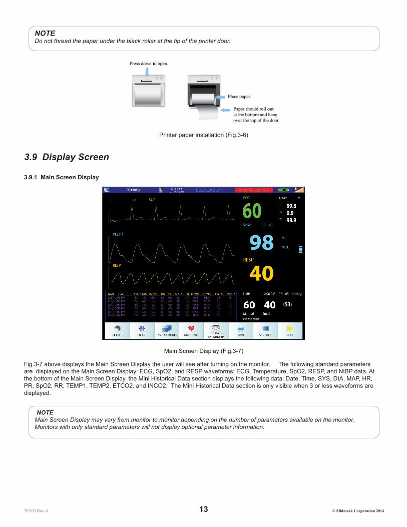
NOTEDo not thread the paper under the black roller at the tip of the printer door.
Printer paper installation (Fig.3-6)
3.9 Display Screen
3.9.1 Main Screen Display
Main Screen Display (Fig.3-7)
Fig.3-7 above displays the Main Screen Display the user will see after turning on the monitor. The following standard parameters are displayed on the Main Screen Display: ECG, SpO2, and RESP waveforms; ECG, Temperature, SpO2, RESP, and NIBP data. At the bottom of the Main Screen Display, the Mini Historical Data section displays the following data: Date, Time, SYS, DIA, MAP, HR, PR, SpO2, RR, TEMP1, TEMP2, ETCO2, and INCO2. The Mini Historical Data section is only visible when 3 or less waveforms are displayed.
NOTEMain Screen Display may vary from monitor to monitor depending on the number of parameters available on the monitor. Monitors with only standard parameters will not display optional parameter information.

TP200 Rev. A 14 © Midmark Corporation 2014
3.9.2 Status Bar
Main Screen Status Bar (Fig.3-8)
The Status Box is located at the very top of the Main Screen. The Status Box provides the following information: Network Setting Status, Patient Information, Date and Time, Alarm Messages, Battery Power Status, Battery Charging Status, and Sound Settings. Press on the different icon/section within the Status Box to access the menu related to that icon/section.
1. This icon displays the Network Setting Status for the monitor. Pressing the screen in this area will open up the menu for Network Settings.
2. This area displays the patient name. Pressing the screen in this area will open up the Patient Setup menu.
3. This area displays the patient species in picture format. The only species available for display in picture format are cats, dogs, and horses. If “Other” is chosen, no picture will be displayed. To change species, press the area associated with the patient name (No. 2 in Fig.3-8 above).
4. This area displays the date in YYYY-MM-DD format and time in HH:MM:SS format. Pressing the screen in this area will open the Date/Time Setup menu.
5. This area displays technical alarm messages. If multiple alarm events are occurring simultaneously, this area will rotate through all alarm event messages.
6. This area displays physiological alarm messages. If multiple alarm events are occurring simultaneously, this area will rotate through all alarm event messages.
7. This area displays the alarm volume in 10 increments. The monitor is loudest when all 10 bar increments are lit. The bell icon above the alarm volume bar increments displays sound status. An “X” will appear over the bell icon whenever alarms are silenced. Pressing the screen in this area will open up the Sound Setup menu.
8. This area displays the charge status of the battery as well as AC connection status. The more green segments present within the battery icon, the more power is in the battery. A plug icon will be displayed within the battery icon whenever the monitor is connected to AC power.
3.9.3 Waveform Area
Main Screen Waveform Area (Fig.3-9)
The Waveform Area displays real-time waveform data for ECG, SpO2, Respiration, CO2, IBP, and AG depending on monitor settings. Press on a waveform to access the menu associated with that waveform parameter.

TP200 Rev. A 15 © Midmark Corporation 2014
Waveforms include the following:
• ECG 3-Leads: I, II, III
• ECG 5-Leads: I, II, III, V, avL, avR, avF
• SpO2
• Respiration Leads: RA-LA (I), RA-LL (II)
• CO2
• IBP: ART1, ART2, PA, CVP, AO, RA, ICP, FA
• AG: CO2, N2O, ISO, DES, HAL, ENF, SEV
3.9.4 Parameter Box
Main Screen Parameter Box (Fig.3-10)
The Parameter Box is located on the right side of the Main Screen and displays numerically the following parameter values in real-time: HR/PR, SpO2%, DIA/SYS/MAP NIBP, EtCO2, InCO2, RR, TEMP1, TEMP2, and Temperature Difference. Press on a displayed parameter to access that parameter’s setup menu.
NOTEMain Screen Display may vary from monitor to monitor depending on the number of parameters available on the monitor. Monitors with only standard parameters will not display optional parameter information.
3.9.5 Touch Screen Menu
The Touch Screen offers easy access to parameter menus by attaching them to each displayed waveform within the Waveform Area and each displayed parameter within the Parameter Box. To configure the displayed parameters, press on a parameter (waveform or numeric) to access the setup menu associated with that parameter. The Knob can also be used to access all the available options shown on the Main Screen Display. Rotate the Knob to navigate to the desired selection and press the Knob to confirm the selection and access the selected setup menu.

TP200 Rev. A 16 © Midmark Corporation 2014
SECTION 4 - ALARM SETUP
4.1 General InformationAlarms are designed to give an alert when the monitoring results are abnormal. These alerts are given via audible sounds, visual LED indicators, and flashing alarm messages. Alarms have three levels: Emergency (High) (2 sets of 5 beeps every 5-10 seconds with continuous red flashing visual alarm), Medium: (3 beeps every 10 seconds with yellow flashing visual alarm) and Warning (Low) (1 beep every 10 seconds with yellow solid visual alarm).
• Emergency Alarms: Example: Asystole, Parameter values exceed set limits when Alarm Level is defaulted to “High”, SYS-DIA is too low, Apnea Alarm Low Battery Alarm
• Medium alarms: Example: Parameter values exceed set limits when Alarm Level is defaulted to Medium.
• Warning Alarms: Example: Equipment Alarms or when parameter values exceed set limits when Alarm Level is defaulted to Low..
Typical warning alarms for equipment conditions are as follows:
• LEAD OFF
• PROBE OFF
• SENSOR OFF
• AIR LEAKAGE
• OVER PRESSURE
Other alarm messages will appear depending on the parameter in use.
When sensors are unplugged, the screen will display “NO SENSOR”. When probes are not connected to a patient, the screen will display “PROBE OFF”.
NOTEWhen “Asystole” is displayed on the screen, please check the ECG gain of the relative channel to see if it is too low to detect heart rate. If so, the user can adjust ECG gain, switch the ECG lead, or change the ECG filtering mode.
Different aspects of the alarm function, such as Alarm Sound ON/OFF and Alarm Level (which will change the tone alarm) maybe adjusted within the setup menu of each individual parameter.
4.2 Alarm Silence
To silence the alarm for a pre-determined amount of time, press the Silence Button on the front panel of the veterinary monitor or press the Touch Screen Quick Access Button shown below.
Touch Screen Quick Access Silence Button (Fig.4-1)
To end the silence timer or ALM PAUSE TIME before the pre-determined time frame has elapsed, press the Silence Button or the Touch Screen Quick Access Silence Button again. The alarm will also resume normal alarm functions when the pre-determined alarm silence period expires.
The default ALM PAUSE TIME is 120 seconds.

TP200 Rev. A 17 © Midmark Corporation 2014
The ALM PAUSE TIME can be changed by accessing the Alarm Setup Menu as follows:
Step 1: Press the “MAIN MENU” Touch Screen Quick Access Button to display the Main Menu.
Step 2: Choose “MONITOR SETUP” on the list and then choose “ALARM SETUP” on the next list.
Step 3: In the Alarm Setup Menu, selected the ALM PAUSE TIME. This will allow you to choose between Forever, 1min, 2min, 3min, 5min, or 10min.
When the alarm is silenced using the Silence Button, the occurrence of a new technical alarm, such as probe off, will cancel the silence feature. This will end the silence function before the silence timer runs out and sound the new alarm as well as the old alarms.
WARNINGNew technical alarms, such as leads off, as well as new physiological alarms, such as exceeding upper limits, will cancel the silence feature.
WARNINGThe Low Battery Power Alarm may be silenced by the Silence Button. Please plug the monitor into AC power as soon as you see and hear the Low Battery Power Alarm
WARNINGWhen the alarm sound is silenced using the Silence Button, the user should pay close attention to the patient and the monitor screen for visual cues to ensure the safety of the patient.
4.3 Alarm Setup
4.3.1 Alarm Setup Menu
Using the Touch Screen or the Knob, follow the steps below to access the Alarm Setup Menu:
Step 1: Select the “MAIN MENU” Touch Screen Quick Access Button.
Step 2: Select the “MONITOR SETUP” Touch Screen Button.
Step 3: Select the “ALARM SETUP” Touch Screen Button.
Alarm Setup Menu Options:
ALM REC TIME ALM REC TIME is used for Alarm Triggered Printing. Alarm Record Time can be set up to record 4s, 8s, or 16s during an alarm event.
ALM PAUSE TIME Alarm pause time is the setting used for the Alarm Silence feature. The Alarm Silence Period can be set to Forever, 1Min, 2Min, 3Min, 5Min, or 10Min.
ALM LIMIT Turning the ALM LIMIT on will display the upper and lower limits of each parameter next to their parameter values within the Main Screen Parameter Box. User can set this to Off or On.
ALM LATER ALM LATER allows the user to delay alarms. The user can set this to Disabled, 5s, 10s, 15s, and 20s. If turned on, an alarm event will not trigger an alarm until the set time has passed. If the alarm resolves before the set time has passed, no audio or visual alarms will sound at all.
4.3.2 Alarm Parameter Setup Menu
Alarm limits include upper and lower limits that are user adjustable. All parameter limits are available within one menu on the Cardell® Touch veterinary monitor.
Accessing the Alarm Parameter Setup Menu using the Touch Screen or the Knob:
Step 1: Select the “NEXT” Touch Screen Quick Access Button.

TP200 Rev. A 18 © Midmark Corporation 2014
Step 2: Select the “ALARM PARA SETUP” Touch Screen Quick Access Button.
Step 3: Select the alarm limits to be adjusted. The following parameter alarm limits are available: ECG, SpO2, Temp1, Temp2, Respiration, IBP1, IBP2, NIBP, Multigas, and CO2. Make sure to press the name of the parameter to access the parameter menu (ex. ECG, TEMP…etc.).
Changing Alarm Limits through the Parameter Setup Menu:
Step 1: Once inside the Alarm Parameter Setup Menu, press on the parameter you would like to set up. This will open the menu for that specific parameter. Make sure to press the title of the parameter such as ECG, TEMP…etc.
Step 2: Press on the upper or lower limit buttons to display a number pad. The default limit number will be displayed initially.
Step 3: Use the “Del” button to delete the current number and then enter the new number using the number pad.
Step 4: Press the “Enter” button on the number pad once the new number has been entered. This will return the user to the setup menu for that specific parameter. The changes will not be applied without completing the steps below.
Step 5: In the setup menu of the selected parameter, scroll to the last page of the menu and press the “Enter” button. This will return the user to the Alarm Parameter Setup Menu. The number displayed under that parameter should now display the changes that were just made. The changes will not be applied without completing the step below.
Step 6: Press the “Enter” button at the bottom of the menu to apply the changes and exit.
NOTEThe user can make changes to all the parameters before pressing the “Enter” button located on the bottom right of the Alarm Parameter Setup Menu to apply them.
NOTEUnless the user presses the “Enter” button within each menu and submenus, the parameter change will not be applied. It is very important to press the “Enter” button on the Alarm Parameter Setup Menu when everything is complete to apply the changes.
Changing Alarm Limits through the Waveform Area:
Press on any waveform within the Waveform Area to access the menu for that particular parameter. Within this menu, the user may also set the upper and lower limits associated to that particular parameter.
Changing Alarm Limits through the Parameter Box:
Press on any data within the Parameter Box to access the menu for that particular parameter. Within this menu, the user may also set the upper and lower limits associated to that particular parameter.
4.3.3 Current and Custom Alarm Settings
There are four total alarm setting accounts available within the Alarm Parameter Setup Menu: Current, User 1, User 2, and User 3. The monitor will come with factory default settings within the Alarm Parameter Setup Menu. When the user first enters the Alarm Parameter Setup Menu, the “Current” account is open.
Users may change the limits as required and save up to 3 customer accounts using the steps below:
Step 1: Follow the instructions in Section 4.3.2 (Changing Alarm Limits through the Parameter Setup Menu) to setup all the parameter settings. Make sure to press “Enter” on the Alarm Parameter Setup Menu when all the settings have been entered. This will exit the user from the menu into the Main Screen.
Step 2: Go back into the Alarm Parameter Setup Menu. Check to make sure the parameter settings are as desired.
Step 3: Press the SAVE AS button on the bottom of the menu. This will open the Save As Menu.
Step 4: Choose which account you would like to save this setup in. For this example, we will choose User 1. Press User 1 to display the onscreen key board.
Step 5: Type in the name you wish to use. For example: Cat, Dog, Dr. Smith, Small Surgery…etc. Press enter to apply the name. This will take you back into the Save As Menu. Press “Enter” again to save. A pop up alert window will ask for permission to save:
Select YES to save the current alarm config to USER1 file. The previous configuration will be lost!

TP200 Rev. A 19 © Midmark Corporation 2014
Step 6: Select YES to proceed. Now the user has been saved. Pressing yes will bring you back out to the Alarm Parameter Setup Menu. The new user name is displayed on the top of the screen next to Alarm Setting Name. If you exit this menu, the name will change back to “Current”. You must first load the account to display it correctly.
Step 7: Enter the Alarm Parameter Setup menu. Press the “Alarm Setting Name” button. This will display the Alarm Setting Name menu. Choose the user account you would like to use. A pop up window will display the following alert message:
Select YES to return to the USER 1 configuration. The current configuration will be lost!
Step 8: Select YES to load the configuration. The warning message will always display USER 1, USER 2, or USER 3. However, once loaded, the Alarm Parameter Setup menu will show the name the user has entered for this account.
Step 9: Press the ENTER button at the bottom of the menu to apply the changes and exit.
4.3.4 Changes Made to Custom Alarm Settings
CAUTIONIt is recommended that before using the monitor on a patient, the desired Alarm Parameter Setting Account is re-loaded onto the monitor using the steps described in Section 4.3.3.
The alarm parameter settings may be changed by different users throughout the day. To ensure that the proper setting is being used, always reload the Alarm Parameter Setting Account associated with the current patient before using the monitor.
In order to save an alarm parameter setting change, the user must do a SAVE AS for the intended user and “Enter” on the User menu, and “Enter” on the Save As menu. In order for those changes to also save to the “Current” user, the user must also press “Enter” on the Alarm Setup menu.
4.3.5 Alarm Volume and Sound Setup
Sound Setup Menu
Press the sound icon located on the Status Bar to access the Sound Setup Menu.
Select from Sound Setup Menu options below:
ALARM VOL Choose from Off, 1-10, 10 being the loudest. If ALARM VOL is set to Off, there will not be any audio alarms for either the physiological or technical alarms. However, the visual alarms will still be active.
BEAT VOL Choose from Off, 1-10, 10 being the loudest.KNOB VOL Choose from Off, 1-10, 10 being the loudest.TOUCH SOUND On or Off
Parameter Alarm Sound ON/OFF
The user may choose to turn the alarm sound On or Off for each particular parameter. For this example, we will use the ECG Alarm Sound feature.
To turn the alarm sound off for the ECG function, follow the steps below:
Step 1: Select the “PARAMETER SETUP” Touch Screen Quick Access Button.
Step 2: Select the parameter you wish to modify. In this case, select the “ECG SETUP”.
Step 3: Select “ALM SOUND”. Choose Off. The physiological out of range audio alarms for the ECG parameter will no longer sound. Alarms relating to the detection of a heart beat (Asystole) will continue to sound, until the Silence Button is pressed .
Repeat Steps 1 – 3 above to set up the ALM SOUND option for each individual parameter.
4.3.6 Default Alarm Limit
The Cardell® Touch includes default alarm limits recommended by members of the American College of Veterinary Anesthesia for general veterinary practice.

TP200 Rev. A 20 © Midmark Corporation 2014
Using the Touch Screen or the Knob, follow the steps below to return to the factory alarm setting, i.e., default alarm limits:
Step 1: Select the “NEXT” Touch Screen Quick Access Button.
Step 2: Select the “ALARM PARA SETUP” Touch Screen Quick Access Button.
Step 3: Select the “Alarm Setting Name” Touch Screen Button.
Step 4: Select the “Default Setup” Touch Screen Button.
Step 5: A pop up box will appearing warning the user that the current configuration will be lost if they continue.
Step 6: Select “Yes” to return to the default configuration! The current configuration will be lost!
There are 4 default category of animal sizes to choose from: Cat, Dog, Horse, and Other. The following default alarm limits were set in the factory before delivery for each category:
Parameter Cat Dog Horse OtherLow High Low High Low High Low High
HR/PR (bpm) 90 180 50 180 24 50 50 180SpO2 (%) 90 100 90 100 90 100 90 100NIBP SYS (mmHg) 70 160 70 160 70 160 70 160NIBP DIA (mmHg) 40 100 40 100 40 100 40 100NIBP MAP (mmHg) 70 140 70 140 70 140 70 140Resp. (rpm) 5 55 5 55 5 55 5 55Temp. (°F) 96.8 104 96.8 104 96.8 104 96.8 104AwRR (rpm) 5 55 5 55 5 55 5 55Et CO2 (mmHg) 20 60 20 60 20 60 20 60In CO2 (mmHg) 0 10 0 10 0 10 0 10IBP SYS (mmHg) – ART1, ART2, AO, RA, FA
100 160 100 160 100 130 100 160
IBP DIA (mmHg) – ART1, ART2, AO, RA, FA
50 90 50 90 50 80 50 90
IBP MAP (mmHg) –ART1, ART2, AO, RA, FA
60 120 70 130 60 100 70 130
IBP SYS (mmHg) – PA 5 38 5 38 5 38 5 38IBP DIA (mmHg) – PA -4 4 -4 4 0 16 -4 4IBP MAP (mmHg) – PA 12 16 12 16 8 25 12 16IBP MAP (mmHg) – CVP 0 7 0 7 0 23 0 7IBP MAP (mmHg) – ICP 0 4 0 4 0 10 0 4AG: Et CO2 (mmHg) 20 60 20 60 20 60 20 60AG: Fi CO2 (mmHg) 0 10 0 10 0 10 0 10AG: AwRR (rpm) 5 55 5 55 5 55 5 55AG: Et N2O (%) 40 70 40 70 40 70 40 70AG: Fi N2O (%) 40 70 40 70 40 70 40 70AG: Et HAL (%) 1.0 3.0 1.0 3.0 2.0 4.0 1.0 3.0AG: Fi HAL (%) 1.0 3.0 1.0 3.0 2.0 4.0 1.0 3.0AG: Et ENF (%) 2.0 5.0 2.0 5.0 2.0 5.0 2.0 5.0AG: Fi ENF (%) 2.0 5.0 2.0 5.0 2.0 5.0 2.0 5.0AG: Et ISO (%) 1.5 3.0 1.0 3.0 1.5 3.5 1.0 3.0AG: Fi ISO (%) 1.5 3.0 1.0 3.0 1.5 3.5 1.0 3.0AG: Et DES (%) 9.0 14 7.0 14 7.0 15 7.0 14AG: Fi DES (%) 9.0 14 7.0 14 7.0 15 7.0 14

TP200 Rev. A 21 © Midmark Corporation 2014
AG: Et SEV (%) 2.5 5.0 2.0 5.0 2.5 6.0 2.0 5.0AG: Fi SEV (%) 2.5 5.0 2.0 5.0 2.5 6.0 2.0 5.0
TP200 Rev. A 22 © Midmark Corporation 2014
SECTION 5 - SETTING UP THE MONITOR
5.1 Display Setup
5.1.1 Parameter Display
The waveform display of each parameter can be changed by pressing on the waveform. This will open the selected waveform’s Setup menu. Use the down arrows to scroll through the parameter setup menus. The user may change the Sweep speed, Wave Type, and Wave Color of the waveform.
Sweep speed is the speed the waveform travels across the screen. This value is in mm/sec.
Wave Type is the option to show the waveform in Line or Fill. Fill will make the underside of the waveform solid. This option is not available for ECG or Multigas waveforms.
Wave Color is the option to change the color of the waveform to Green, Cyan, Red, Yellow, White, Blue, or Purple. Display Color is also an option for parameters without a waveform.
5.1.2 Display Mode Setup
By default, the Standard Display Mode is chosen. Another display mode may be selected by accessing the Display Modes Menu.
Press the Display Modes Touch Screen Quick Access Button. Select from Standard, Historical Data, Large Font, AG Screen (if AG module is ON) or Demo modes. The Knob can also be used to navigate to the “DISPLAY MODES” Touch Screen Quick Access Button.
5.2 Historical Data ModeFollow the steps below to enter Historical Data Mode using the Touch Screen Quick Access Buttons:
Step 1: Select the “DISPLAY MODES” Touch Screen Quick Access Button.
Step 2: Select “Historical Data”.
Historical Data Mode may be used to review numerical data for the patient. The information is displayed in table format, including the following: Date, Time, SYS, DIA, MAP, HR, PR, SpO2, RR, Temp1, Temp2, Et CO2, In CO2, IBP1, and IBP2.
The system stores up to 2000 sets of history data. The Historical Data screen can display 20 sets of data per page. On the bottom of the screen, there is a set of Touch Screen Buttons that will allow the user to navigate through the Historical Data screen. As always, the Knob can also be used to navigate to these Touch Screen Buttons.
Historical Data will automatically clear itself if the Patient Name is changed.
5.3 Large Font ModeFollow the steps below to enter Large Font Mode using the Touch Screen Quick Access Buttons:
Step 1: Select the “DISPLAY MODES” Touch Screen Quick Access Button.
Step 2: Select “Large Font”.
Large Font Mode may be used when observing the screen from a long distance. The Large Font Mode is only visible when 3 or less waveforms are displayed. Large Font Mode will display IBP data values but not IBP waveforms. Large Font Mode is not available while the AG screen is displayed.
5.4 AG Screen ModeFollow the steps in 12.2.5 to turn on the Multigas Screen Display

TP200 Rev. A 23 © Midmark Corporation 2014
5.5 Demo ModeFor the purpose of training, the Cardell® Touch provides a Demo Mode function.
CAUTIONNever attempt to use the Demo Mode while monitoring patients.
Follow the steps below to enter the Demo Mode:
Step 1: Press the “DISPLAY MODES” Touch Screen Quick Access Button.
Step 2: Press “Demo” to bring up the password dialogue box for Demo Mode.
Step 3: Use the key pad to input “5188” and press “Enter”.
To confirm that the monitor is in Demo Mode, the word “DEMO” should be displayed at the top of the Waveform Area in yellow.
To exit Demo Mode, simply press the “DISPLAY MODES” Touch Screen Quick Access Button and then press “Exit Demo”.
5.6 Trend Display
5.6.1 Displaying Trend Graph
Follow the steps below to enter the Trend Graph Screen:
Step 1: Press the “NEXT” Touch Screen Quick Access Button.
Step 2: Press the “TREND” Touch Screen Quick Access Button.
Step 3: Press “Trend Graph”.
Trend Display Buttons:
PARAM: Use the Parameter button on the bottom left corner to choose the parameter to observe. The user may choose from: HR, RR, SpO2, PR, Temp, NIBP, IBP1, IBP2, CO2, InCO2, or AwRR.
RES.: Use the resolution button to set the resolution for the graph. Choose from 1s, 5s, 1Min, 5Min, or 10Min.TIME AXIS Select the Time Axis to move the range. When Time Axis is selected, use the arrows located below this
button to move the X-axis forward in time or backwards in time.CURSOR The cursor is a little arrow that is on the very top of the trend graph. When the Cursor is selected, use the
arrows located below this button to move the cursor along the X-axis. The date / time stamp on the top of the graph will change depending on where the cursor is pointing to.
Left and Right Arrows These buttons are used in conjunction with the Time Axis button and the Cursor button to navigate across the X-axis.
Up and Down Arrows These buttons are found to the right of the trend graph and is used to navigate across the Y-axis.
5.6.2 Displaying Trend Table
Follow the steps below to enter the Trend Table Screen:
Step 1: Press the “NEXT” Touch Screen Quick Access Button.
Step 2: Press the “TREND” Touch Screen Quick Access Button.
Step 3: Press “Trend Table”.
The Trend Table will display the following parameters: AG AAET. AG AAFI, AG N2OET, AG N2OFI, AG CO2ET, AG CO2FI, AG AWRR, CO2, INCO2, AWRR, IBP2, IBP1, NIBP, SpO2, PR, T1, T2, TD, and RR. NOTE: AG data will not display if AG module is OFF.

TP200 Rev. A 24 © Midmark Corporation 2014
Trend Table Buttons:
RES.: Use the resolution button to set the resolution for the graph. Choose from 1Min, 5Min, 10Min, 30Min, or 60Min.
Left and Right Arrows These buttons are found on the top of the table and is used to navigate to different parameters.Up and Down Arrows These buttons are found on the bottom of the table and is used to navigate through the time range
displayed on the left side of the table for each parameter.
5.6.3 Deleting Trend Information
To delete the trend information, the user may press Clear Patient Data within the Patient Setup Menu, or restart the monitor.
CAUTIONClearing patient data erases all historical data as well as trend information. The user may restart the monitor to retain historical data .
5.7 Monitor Video OutputThe Cardell Touch provides a VGA (15-pin) output for mirrored display on a computer monitor. For best results, please use a VGA-to-VGA cable and follow the computer monitor’s instructions for selecting signal source.
NOTESome computer monitors will flash a warning box to ask the user to adjust the refresh rate on the Touch. This is not needed. Ignore the warning and continue using the monitor.
5.8 Export Trend and ECG DataTo Export Trend and ECG Data, follow the steps below:
Step 1: Make sure your USB device is plugged in.
Step 2: Press the “DATA EXPORT/FTP” Touch Screen Quick Access Button.
Step 3: Press “USB DATA EXPORT”. The button will highlight and start export. Once export has been successful, a message will be displayed: “File export success”.
Two excel files will be exported and placed onto the USB device under a folder named CARDELL_DATA_EXPORT. One file will contain up to 24 hours of Trend information. The other file will contain the last 12 minutes of ECG waveform information. Only data from Lead II will be exported. The file name format is as shown below:
Patient name-Trend-Year-MonthDay-HoursMinutesSeconds
Patient name-ECG-Year-MonthDay-HoursMinutesSeconds
For example:
Fluffy-Trend-2014-0318-171838
Fluffy-ECG-2014-0318-171838
NOTEPlease note that the hours are counted in the 24 hour format. For example, 17:00 hour is 5:00pm.
NOTEOnly data from Lead II will be exported regardless of Lead viewed on screen.

TP200 Rev. A 25 © Midmark Corporation 2014
Saved files will not be deleted unless the user manually deletes it from the USB device. All new files will be saved onto the USB device until the USB device is full.
NOTEIf exporting of data is used frequently, please keep the USB storage device plugged into the monitor at all times. Since all data stored on the monitor is purged when power is lost or the monitor is turned off, be sure to download the case data before powering down or if running on battery power and a low-battery status message appears.
5.9 Cardell Touch Visualizer ToolThe Cardell® Touch comes with a USB device preloaded with the Cardell Touch Visualizer Tool. This tool will take the exported ECG data and map it into a waveform for easy reference. This tool requires Microsoft Excel 2007 or 2010 to work.
NOTEThe Cardell Touch Visualizer Tool is for use with the ECG data export only. It is not meant to be used with the Trend data export. Please do not load the Trend data into the visualizer.
5.9.1 Importing ECG Data into the Visualizer
To import ECG data into the visualizer, follow the steps below:
Step 1: Connect the USB device to your computer.
Step 2: Copy the Cardell Touch Visualizer Tool onto the computer. You only need to do this once.
Step 3: Copy the exported data onto the computer.
Step 4: Double click on the Cardell Touch Visualizer Tool to open it. If a warning pops up for the macro embedded within the program, please see the Section 5.9.5 on Cardell Touch Visualizer Troubleshooting.
Step 5: Once opened, the Start Menu will appear as shown below:
Step 6: Click on the “Import New ECG Data” button. Navigate to the ECG excel file exported from the monitor (see 5.8) and click “Open”.
Step 7: Once the data has been imported, the Start Menu will pop up again. Click on the Review Waveform button. This will close the Start Menu and allow the user to look over the waveform.
5.9.2 Visualizer Data Tabs
The visualizer will look like an excel document. There are 4 worksheet tabs on the bottom.

TP200 Rev. A 26 © Midmark Corporation 2014
ECGData This worksheet stores the ECG Data that was imported. The user does not need to use this worksheet.NewECGData This worksheet interprets the ECG data that was imported. The user does not need to use this worksheet.ECGWave This worksheet is where the ECG data will be displayed as a waveform. Please see below for a more
detailed explanation.ECGPrintCharts This worksheet stores the most recently printed waveforms with the exception of current view (print).
5.9.3 Reviewing Waveforms
1. Menu Button. Allows user to import new ECG data, review ECG data or print ECG data.2. Waveform Information. Includes date of export, patient name, patient number, client name, species, ECG lead used, and ECG
gain used.3. ECG mV4. ECG waveform interpreted from the imported data.5. Time of data point.6. Time frame scroll bar. The ECG visualizer will interpret up to 12 minutes of ECG data. However, this is not enough space on
the screen to show all 12 minutes at the same time. Move the scroll bar left and right to show different ranges of time within the 12 minutes.
7. Sweep speed scroll bar. Click on the arrow keys on the top or bottom of the scroll bar to display the ECG waveform at 25mm/sec, 30mm/sec, 50mm/sec or 100mm/sec, which will be displayed under the waveform. The user may also move the scroll bar with the mouse to increase or decrease the sweep speed outside of the preset sweep speeds noted above. Using this method, a “CUSTOM” message will be displayed under the waveform.
5.9.4 Printing Waveforms
To print the waveforms from the visualizer, follow the steps below:
Step 1: Click on the “Menu” button.
Step 2: Click on the “Print Waveform” button. The print menu will be displayed.
Step 3: Use the drop down buttons to select the range of ECG data you would like to print. Choose from “Current View”, “Entire 12 mins”, or “Specific Time Range”. If “Specific Time Range” is chosen, the Print Range section below will become editable. Choose the desired time range and click on “Print”.
NOTEThe ECG waveform chosen to be printed will also be displayed in the ECGPrintCharts tab. Only the most recently printed ECG waveform will be displayed here. Note: Current View (Print) does not display in the ECGPrintCharts tab.
5.9.5 Cardell Touch Visualizer Troubleshooting
Error Message Resolution

TP200 Rev. A 27 © Midmark Corporation 2014
Run Time Error (when loading an ECG file)
Make sure the patient’s name does not contain any symbols. Use of capital letters, small case letters, and spaces are acceptable. Do not use symbols.
Security Warning for Macros and Active X
Macros from an unknown source may cause harm to the computer. However, the Cardell Touch Visualizer Tool utilizes macros and will not operate without having macros enabled. To do this safely, please follow the steps below:Step 1: Create a new folder on the computer and name it Cardell Touch Visualizer Tool.Step 2: Open Microsoft Excel. Click on “File” and then click on “Options”. Choose “Trust Center” and then click on “Trust Center Settings” as shown below.
Step 3: Click on “Trusted Locations” and then click on “Add new location”.
Step 4: Use the “Browse” button to navigate to the folder you just made in Step 1 and click “OK”. Make sure the check box for “Subfolders of this location are also trusted” is checked. Click “OK”.

TP200 Rev. A 28 © Midmark Corporation 2014
Step 5: This will add the location of that folder into the list of trusted locations displayed in the window shown in Step 3. Click “OK” to save. If you do not click “OK” here, the added folder will not save.Step 6: Go to the Midmark USB and save the Cardell Touch Visualizer Tool into the folder you have just created. You can drag the files from the USB window right into the folder.Step 7: Go to the folder and double click the Cardell Touch Visualizer Tool. It should now open without any security warnings.
5.10 Printing Setup (Optional)For monitors ordered with an internal printer option, follow the steps below to enter the Printer Setup Menu:
Step 1: Press the “NEXT” Touch Screen Quick Access Button.
Step 2: Press the “MAIN MENU” Touch Screen Quick Access Button.
Step 3: Press “Monitor Setup”.
Step 4: Press “Printer Setup”.
Printer Setup Menu Options:
REC WAVE1 Waveform 1 defaults to ECG. It can be changed. REC WAVE2 Waveform 2 defaults to SpO2. It can be changed.REC WAVE 3 Waveform 3 defaults to RESP or CO2 depending on the modules setup with the monitor. It can be
changed.REC RATE: The user may choose between 12.5mm/s, 25.0mm/s or 50.0mm/sREC GRID: The user may choose to turn grid printing ON or OFF.RT REC TIME: The user may choose between Continual, 3s, 5s, or 8s of printing time range.TIMING REC TIME: The user may choose between Off, 5Min, 10Min, 15Min, 30Min, or 1Hr.PRINT FORMAT The user may choose between Wave Data and List Data. Wave data prints the waveforms and parameter
values (with the exception of multigas) based on parameters selected in the printer setup menu. List data prints parameter values (with the exception of multigas) from the last 8 minutes.
The printer may also be set to print automatically when an alarm goes off for a particular parameter. This feature is not located within the Printer Setup menu. ALM REC can be set to ON or OFF for each individual parameter. Therefore, the user must enter the setup menu for each individual parameter to turn it ON or OFF. When an alarm occurs, the monitor will automatically activate the printer to print out the waveform 5 seconds before the alarm if ALM REC is set to ON.
If the ALM REC is set to OFF, the monitor will not print during an alarm.
5.11 Patient SetupFollow the steps below to enter the Patient Setup Menu:
Step 1: Press the “NEXT” Touch Screen Quick Access Button.
Step 2: Press “Patient Setup” or the “MAIN MENU” Touch Screen Quick Access Button then press “Patient Setup”.

TP200 Rev. A 29 © Midmark Corporation 2014
NOTEThe Patient Menu can also be accessed by pressing on the Patient Setup Area on the Status Bar.
NOTEThe Status Bar has an area reserved for Patient Information and it may display a patient name already or it may be empty. Pressing this area with or without a name displayed will allow access to the Patient Setup Menu.
Patient ID Options:
PAT NO: Enter Patient Number here. 10 character limit.CLIENT NAME: Enter Client Name here. 12 character limit.PATIENT NAME: Enter Patient Name here. 12 character limit. Use of capital letters, small case letters, and spaces are
acceptable. Do not use symbols.SEX: Enter the Sex of the animal here.SPECIES: Choose from Cat, Dog, Horse or Other. Every selection with the exception of Other will have a
corresponding picture displayed next to the Patient Name on the Status Bar.DOCTOR: Enter Doctor Name here. 12 character limit .CLEAR PATIENT DATA Clear current patient data. Please note that all data of the currently monitored patient will be deleted if this
option is chosen. Clear patient data should be done before entering the new patient data
5.12 Date and Time SetupFollow the steps below to enter the Date and Time Setup Menu:
Step 1: Press the “NEXT” Touch Screen Quick Access Button.
Step 2: Press the “MAIN MENU” Touch Screen Quick Access Button.
Step 3: Select “Monitor Setup” to enter the Monitor Setup Menu.
Step 4: Select “Time Setup” to enter the Time Menu.
NOTE The Date and Time Setup Menu can also be accessed by pressing on the Date and Time area on the Status Bar.
Year: Enter the year.Month: Enter the month.Day: Enter the day.Hour: Enter the hour.Minute: Enter the minute.Time Format: Choose between 12 hour or 24 hour format.
Set Time
The monitor displays the date/time. Each time the machine is turned on, the system will display the current date and time in the time status box.
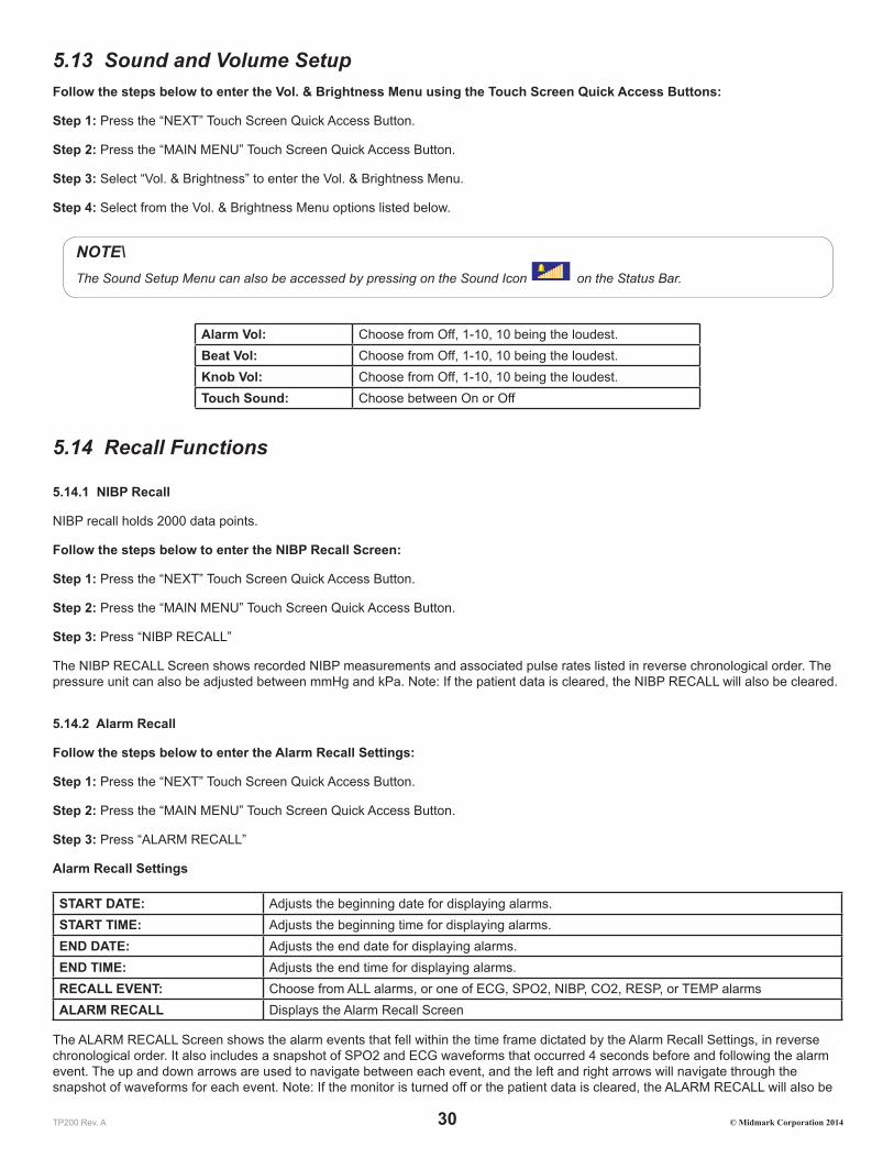
TP200 Rev. A 30 © Midmark Corporation 2014
5.13 Sound and Volume SetupFollow the steps below to enter the Vol. & Brightness Menu using the Touch Screen Quick Access Buttons:
Step 1: Press the “NEXT” Touch Screen Quick Access Button.
Step 2: Press the “MAIN MENU” Touch Screen Quick Access Button.
Step 3: Select “Vol. & Brightness” to enter the Vol. & Brightness Menu.
Step 4: Select from the Vol. & Brightness Menu options listed below.
NOTE\The Sound Setup Menu can also be accessed by pressing on the Sound Icon on the Status Bar.
Alarm Vol: Choose from Off, 1-10, 10 being the loudest.Beat Vol: Choose from Off, 1-10, 10 being the loudest.Knob Vol: Choose from Off, 1-10, 10 being the loudest.Touch Sound: Choose between On or Off
5.14 Recall Functions
5.14.1 NIBP Recall
NIBP recall holds 2000 data points.
Follow the steps below to enter the NIBP Recall Screen:
Step 1: Press the “NEXT” Touch Screen Quick Access Button.
Step 2: Press the “MAIN MENU” Touch Screen Quick Access Button.
Step 3: Press “NIBP RECALL”
The NIBP RECALL Screen shows recorded NIBP measurements and associated pulse rates listed in reverse chronological order. The pressure unit can also be adjusted between mmHg and kPa. Note: If the patient data is cleared, the NIBP RECALL will also be cleared.
5.14.2 Alarm Recall
Follow the steps below to enter the Alarm Recall Settings:
Step 1: Press the “NEXT” Touch Screen Quick Access Button.
Step 2: Press the “MAIN MENU” Touch Screen Quick Access Button.
Step 3: Press “ALARM RECALL”
Alarm Recall Settings
START DATE: Adjusts the beginning date for displaying alarms.START TIME: Adjusts the beginning time for displaying alarms.END DATE: Adjusts the end date for displaying alarms.END TIME: Adjusts the end time for displaying alarms.RECALL EVENT: Choose from ALL alarms, or one of ECG, SPO2, NIBP, CO2, RESP, or TEMP alarmsALARM RECALL Displays the Alarm Recall Screen
The ALARM RECALL Screen shows the alarm events that fell within the time frame dictated by the Alarm Recall Settings, in reverse chronological order. It also includes a snapshot of SPO2 and ECG waveforms that occurred 4 seconds before and following the alarm event. The up and down arrows are used to navigate between each event, and the left and right arrows will navigate through the snapshot of waveforms for each event. Note: If the monitor is turned off or the patient data is cleared, the ALARM RECALL will also be

TP200 Rev. A 31 © Midmark Corporation 2014
cleared.
5.14.3 Wave Recall
Follow the steps below to enter the Wave Recall Settings:
Step 1: Press the “NEXT” Touch Screen Quick Access Button.
Step 2: Press the “MAIN MENU” Touch Screen Quick Access Button.
Step 3: Press “WAVE RECALL”
Wave Recall Settings
RECALL DATE: Adjusts the start date for displaying ECG waveforms.RECALL TIME: Adjusts the start time for displaying ECG waveforms.WAVE RECALL Displays the Wave Recall Screen
The WAVE RECALL Screen shows 4 lines of ECG waveforms that occurred following the time dictated by the Wave Recall Settings. The up and down arrows are used to navigate 20 seconds forward or backward from the displayed start time. Note: If the monitor is turned off or the patient data is cleared, the WAVE RECALL will also be cleared.

TP200 Rev. A 32 © Midmark Corporation 2014
SECTION 6 - ECG MONITORING
6.1 General InformationThe Cardell® Touch Monitor records heart rate with electrode clips attached to the patient. Electrodes detect signals caused by changes of electrical conduction in the heart during the cardiac cycle. Heart rate is computed on a beat-to-beat basis using the R-R interval of the QRS complex. It is necessary to make sufficient preparations before monitoring in order to get accurate readings.
6.2 Patient CableThe patient cables consist of the main cable (connected to the veterinary monitor) and the lead wires (connected to the patient).
CAUTIONUse only electrodes, ECG cable and lead wires recommended by Midmark.
6.3 Animal Preparation and Lead ContactAccurate electrode placement is very important for obtaining a clear quality ECG trace. Sites where leads are attached to the body must be properly prepared to optimize contact. Dogs and cats have enough electrolyte material on their skin and hair so that merely moistening lead sites with 70% isopropyl alcohol is appropriate. This will usually be sufficient for ECG recording/monitoring for a short time, 30 to 60 minutes, depending upon the relative humidity.
For monitoring during longer periods, an electrode gel should be used. It is best to first wet the hair at the lead attachment site with alcohol; then place gel on the moistened hair and skin. It is important that the gel be in direct contact with skin. For patients with dense undercoat, rub gel with fingers to assure that it has made contact with skin.
Copper alligator clips are supplied with this monitor and they must opened wide enough to firmly but gently grasp the skin.
6.4 Attaching ECG Electrodes
6.4.1 Lead Wires and Color
Table 6-1: 5-Lead Color and Coding
USA StandardLA = black (Left Foreleg)
RA = white (Right Foreleg)RL = green (Right Hind Leg)
LL = red (Left Hind Leg)V = brown (explore)
Table 6-2: 3-Lead Color and Coding
USA StandardLA = black (Left Foreleg)
RA = white (Right Foreleg)LL = red (Left Hind Leg)

TP200 Rev. A 33 © Midmark Corporation 2014
6.4.2 Lead Placement
Figure 6-1: 5-Lead Placement
For a 5 lead system, four limb leads can be applied (RA, LA, RL, and LL) with the exploring lead (brown) used for diagnostic purposes as needed. Otherwise, the exploring lead may be left unattached. Refer to Figure 6-1 and Table 6-1 for more information.
Figure 6-2: 3-Lead Placement
For a 3 lead system, leads should be attached just below the elbow on the front leg and just above the stifle on the hind leg. The following lead sequence should be applied for a 3 lead system: Right Foreleg (RA-white); Left Foreleg (LA-black); Left Hind Leg (LL-red). Refer to Figure 6-2 and Table 6-2 for more information.
6.4.3 Positioning Anesthetized Patients
For ECG monitoring during anesthesia, it is most important to position patients properly on the table for the procedure. If standard lead placement as described above is not possible, leads should be attached to the body where they will be least subject to movement and away from the surgical site. It is preferable to view an upright QRS complex for monitoring ECG. A heart base to apex lead arrangement will be best if the negative lead is placed at the base (point of right shoulder at thoracic inlet) and the positive lead at the apex (low on caudal left thorax). Standard right forelimb lead is negative and standard left hind leg is positive in lead two; so if these leads are properly placed and the machine is set to Lead II, an upright complex should be the result.
6.4.4 Positioning Conscious Patients
Standard position for recording diagnostic ECG in dogs is right lateral recumbency. Diagnostic tracings can be obtained in cats in either right lateral or sternal position. Limbs should be perpendicular to the spine and parallel with their opposite member. For awake cats and

TP200 Rev. A 34 © Midmark Corporation 2014
dogs, it is best to have the patient held by a veterinary technician or veterinary assistant. One lead should be applied first to determine comfort level and adjustment made as needed. Then the other clamps can be placed in position. It is important that the patient be kept still. A moving patient may cause clips to saw into skin tissue leading to discomfort and change in position of electrodes.
NOTEIf lead (alligator clip) is touching both the patient’s leg and body simultaneously this may distort the ECG waveform resulting in fluctuating or inaccurate HR.
6.5 ECG Setup
6.5.1 ECG Setup Menu
Follow the steps below to enter the ECG Setup Menu:
Step 1: Press the “NEXT” Touch Screen Quick Access Button.
Step 2: Press the “PARAMETER SETUP” Touch Screen Quick Access Button.
Step 3: Select “ECG Setup” to enter the ECG Setup Menu.
NOTEUsers can also access the ECG Setup Menu by pressing on the ECG waveform in the Waveform Area or pressing the ECG data in the Parameter Box.
ECG Setup Menu Options:
LEAD NAME Choose from I, II, and III if using 3-lead ECG settings. Choose from I,II, III, aVR, aVL, aVF, or V if using 5-lead ECG settings. See Lead Type below.
GAIN Choose from x0.25, x0.5, x1, x2, x4, or Auto.FILTER Choose from Diagnostic (DIA), Monitoring (Mon), or Surgery (SUR). See definitions in 6.5.2 below.HR UPPER LIMIT Use the number pad to enter the Upper LimitHR LOWER LIMIT Use the number pad to enter the Lower LimitSWEEP Choose from 12.5, 25.0, or 50.0ALM SOUND Choose from On or Off.ALM LEV Choose from High, Medium (MED), or Low.LEAD TYPE Choose from 3 Leads or 5 Leads.HR FROM Choose from ECG, SpO2 or Auto. Auto will display HR from ECG unless there is not an ECG signal.HR CHANNEL Choose from Ch1, Ch2, or Auto. This is the channel the HR will be calculated from.WAVE COLOR Choose from Green, Cyan, Red, Yellow, White, Blue, or Purple.ALM REC Choose from On or Off.DEFAULT Allow the monitor to return to factory default settings for the ECG parameter only. No other parameter will
be affected. If DEFAULT is selected, the current configuration for this parameter will be lost.
Once the parameters are all set up, press the “X” button located on the upper right side of the menu to exit to the Main Screen.
NOTEChanges to the monitor may be made using the touch screen or the knob, depending on the user’s preference. To use the touch screen, press on the screen with your finger or the stylus. To use the knob, rotate the knob to navigate and press the knob to select/confirm.
6.5.2 Filter Menu
The Surgical/Diagnosis/Monitoring mode gives the user three levels of filters to accommodate different circumstances.
Diagnosis Mode: Displays the original ECG waveform unfiltered.

TP200 Rev. A 35 © Midmark Corporation 2014
Monitoring Mode: Filters out low-level interference.
Surgical Mode: When there is a high degree of interference and the ECG waveform is significantly distorted (in an operating room, for example).
6.6 Alarm SetupECG monitoring alarms include parameter out of limit alarms and abnormal status alarms. When the monitored parameters are out of the preset limits, the monitor will give an audible and visible alarm.
6.6.1 Alarm Limit Setup
To set up the alarm parameters, please reference Section 4.3 Alarm Setup.
WARNINGThe default alarm limits are designed as general guidelines and for convenience so that values can be reset automatically to common starting points, but these may be adjusted with each patient according to their individual circumstances.
6.6.2 Parameter Adjustment Range
Parameter Adjustment RangeHR 15-300 bpm
6.6.3 Abnormal Status Alarm
Abnormal Status alarm includes “Asystole” and “lead off”.
CAUTIONWhen ECG amplitude is too low (waveform is small), it may result in inaccurate heart rate or pseudo asystole. Try increasing the gain size and using the electrode gel to amplify the signal. Another option would be to try an alternate ECG lead which has a stronger amplitude. Otherwise, the monitor may give an “Asystole” alarm.
6.7 Precautions
WARNINGWhen using a defibrillator, make sure the electrode and patient cable are not in contact with metal or other conductive surfaces or grounding devices. During defibrillation, do not touch patient, table or any instruments in contact with the patient.
WARNINGEnsure conductive parts including electrodes of the patient cable do not come into contact with any conductive surfaces.
WARNINGDo not use the veterinary monitor during MRI or CT scan.
CAUTIONLeads and cables should be away from patient’s neck.

TP200 Rev. A 36 © Midmark Corporation 2014
6.8 Cleaning and Maintenance
CAUTIONWhen the cable or any leadwire is found to be worn out or damaged, replace it immediately.
6.8.1 ECG Cable Cleaning
In order to keep the cable dust-free, clean it with a clean cloth and soapy water or a mild detergent.
6.8.2 ECG Cable Disinfection
In order to avoid long-term damage to the cable, we recommend that you only disinfect the cable when it’s necessary by wiping it with
an agent such as 70% isopropyl alcohol or according to your hospital regulations. Do not immerse the cable in liquid.
CAUTIONDo not autoclave the cable.
6.9 Troubleshooting
6.9.1 Inaccurate Heart Rate
• Check patient’s ECG signal.
◦ Check /adjust lead placement.
◦ Check/clean the patient’s skin.
◦ Check/replace ECG electrodes.
• Check if ECG waveform amplitude is normal.
6.9.2 No ECG Waveform
After lead wires are connected but there is no ECG waveform and the screen shows “lead off” or “no signal received ”.
• Check if the electrodes are in good contact with the patient and if the leadwires are in good condition.
• Check all the external connections of the ECG leadwires.
• Check the ECG electrodes. Prolonged placement of electrodes may result in polarized voltage and the electrodes should be replaced.
• If “no signal received ” is displayed on the ECG channel, then the ECG module has a communication problem with the main unit. Turn off the machine and turn it on again. If problem still remains, contact Midmark.
6.9.3 ECG Baseline Shift
ECG scan baseline is not stable on the display.
• Check if the working environment is too humid and if the machine has moisture inside. If yes, keep the machine on for 24 hours and keep the ambient environment dry.
• Check the electrode quality and whether the skin is clean where the electrode is placed.

TP200 Rev. A 37 © Midmark Corporation 2014
SECTION 7 - NIBP MONITORING
7.1 General InformationThe Cardell® Touch uses oscillometric principles to calculate the systolic (SYS), diastolic (DIA), and mean arterial pressure (MAP) values. The MAP is calculated as the lowest cuff pressure that provides the maximum cuff oscillations. Therefore, MAP is the largest signal received and is the most accurate reading using oscillometric methods. Systolic pressure is calculated as the cuff pressure at which an increase in cuff oscillations is perceived. The diastolic pressure is the cuff pressure when oscillations are no longer decreasing as pressure is released from the cuff. Special veterinary specific algorithms have been designed to ensure reliable and accurate measurements from kittens to horses.
The veterinary monitor first inflates the cuff to a pressure of around 30 mmHg higher than the systolic pressure, then, slowly deflates the cuff. When the cuff pressure is higher than systolic pressure, the artery is blocked and there are small amplitude oscillometric waveforms. When the cuff pressure is equal to the systolic pressure, the oscillometric amplitude will increase. With the decrease of the cuff pressure, the oscillometric amplitude increases. When the cuff pressure reaches a certain value, the oscillometric amplitude reaches a maximum value, and then the cuff pressure is mean arterial pressure. It uses the changes of the oscillometric amplitude under different cuff pressures to identify mean pressure and calculate the systolic and diastolic pressure.
WARNINGThere is a label below the NIBP receptacle, indicating that the signal input is insulated and defibrillator proof.
7.2 Cuff Placement
CAUTIONOnly accessories recommended by Midmark should be used.
NOTEPlace the patient on a padded surface to provide comfort, and warmth. Any movement, even inadvertent shivering, may prevent the monitor from taking an accurate measurement.
7.2.1 Cuff Placement for Cat
A cat may be left in its owner’s lap to keep it calm. Measurements are best done in an area of the hospital away from noise and bright lights. The animal may be held so that the front limbs are free for cuff placement. In conscious patients, the tail may be the most appropriate location for placement of the cuff. Cats may be most comfortable in sternal recumbency making the tail a more preferable site. For the median artery on the foreleg, place the cuff around the forelimb, between the elbow and carpus. It is not necessary to center the cuff over the artery which is on the medial side of the leg because of the fully encircling bladder design. Hair need not be clipped except when heavily matted. In cats less than five (5) pounds when measurements are difficult to obtain, place the cuff around the leg above the elbow to obtain measurements from the brachial artery. Measurements from the coccygeal artery may be used by placing the cuff around the base of the tail but not in anesthetized patients.
7.2.2 Cuff Placement for Dog
For measurements in dogs, it is preferable to use the right lateral, sternal or dorsal recumbent positions. That is not a problem in anesthetized patients, but it may be difficult to get large dogs to cooperate for proper positioning when conscious. If the dog is in a

TP200 Rev. A 38 © Midmark Corporation 2014
sitting position, place the front paw on the operator’s knee and take measurements from the metacarpus. Sites for cuff placement are the metacarpus, metatarsus and anterior tibial. In anesthetized patients, most surgeries are done on the posterior part of the body so the metacarpal area of the forelimb is most convenient. In situations where this is not possible, the cuff should be wrapped around the metatarsus just proximal to the tarsal pad or around the hind leg just distal to the hock. The tail site should not be used for cuff placement during anesthesia. It is not necessary to center the cuff over the artery because of the fully encircling bladder design. If the hair over the artery site is too thick or matted for good contact, it should be clipped.
NOTETo achieve the most accurate readings, it is important to keep the cuff on a horizontal plane with the heart.
7.2.3 Large Animals
A large animal such as a horse should be in a stock, standing still, or lying down. For horses and cows, the cuff can be wrapped around the base of the tail using the coccygeal artery on the ventral surface.
WARNINGWhen monitoring over an extended period of time, or at frequent intervals, periodically observe the patient’s limb to make sure that the circulation is not impaired for a prolonged period of time.
7.2.4 Cuff size selections
The widest cuff that can be placed on the patient, without extending beyond the joint, should be selected. Appropriate sized cuffs may be selected based on published guidelines that cuff width should be 40 – 60% of limb circumference. We recommend the use of the Cardell® Cuff Selector included with the accessory pack. The cuff should be wrapped for a snug fit.
Overlapping the cuff will not affect measurement results. Make sure the hook and loop sections of the cuff are fully engaged when it is wrapped around the limb. If not fully engaged, the cuff will detach during bladder inflation. If that happens, select the next size bigger cuff. Adhesive tape or other material should not be used to secure the cuff.
In addition to the Cardell® Cuff Selector, the following table may be used as a guide to select the correct size.
Small Animal Cuff Selection
Cuff Reorder Number Bladder Size (width) Limb Circumference RangeSV1 2.0 cm 3-6 cmSV2 2.5 cm 4-8 cmSV3 3.5 cm 6-11 cmSV4 4.0 cm 7-13 cmSV5 5.0 cm 8-15 cm
SV600 (Kit) Includes all the above

TP200 Rev. A 39 © Midmark Corporation 2014
Large Animal Cuff Selection
Cuff Reorder Number Bladder Size (width) Limb Circumference RangeSV8 8.0 cm 13-20 cm
SV10 10.2 cm 18-26 cm
References:
Pedersen KM, Butler MA, Ersboll AK, Pedersen HD (2002). Evaluation of an oscillometric blood pressure monitor for use in anesthetized cats. JAVMA 221: 646-650.
Sawyer DC, Guikema AH, Siegel EM (2004). Evaluation of a new oscillometric blood pressure monitor in isoflurane anesthetized dogs. Vet Anaesth Analg 31: 27 – 39.
NOTEFor species specific reference values, see Appendix 2.
7.3 NIBP Setup
7.3.1 NIBP Setup Menu
Follow the steps below to enter the NIBP Setup Menu:
Step 1: Press the “NEXT” Touch Screen Quick Access Button.
Step 2: Press the “PARAMETER SETUP” Touch Screen Quick Access Button.
Step 3: Select “NIBP Setup” to enter the NIBP Setup Menu.
NOTEUsers can also access the NIBP Setup Menu by pressing on the NIBP data in the Parameter Box.
NIBP Setup Menu Options:
CUFF SIZE Large or SmallINTERVAL Manual, AUTO (1Min, 2Min, 3Min, 4Min, 5Min, 10Min, 15Min, 30Min, 60Min or 90Min).CONTINUAL 5Min/5Sec. Pause. This is the STAT mode. INFLATION Enter the inflation value to be used. The default setting is 150ALM SOUND Alarm On or OffALM LEV High, Med or LowSYS UPPER LIMIT Enter the SYS upper limit to be used.SYS LOWER LIMIT Enter the SYS lower limit to be used. DIA UPPER LIMIT Enter the DIA upper limit to be used.DIA LOWER LIMIT Enter the DIA lower limit to be used. MAP UPPER LIMIT Enter the MAP upper limit to be used.MAP LOWER LIMIT Enter the MAP lower limit to be used.UNIT mmHg or kPaDISP COLOR Green, Cyan, Red, Yellow, White, Blue, or Purple.ALM REC On or OffDEFAULT Allow the monitor to return to factory default settings for the NIBP parameter only. No other parameter
will be affected. If used, the current configuration for this parameter will be lost.
Once the parameters are all set up, press the “X” button located on the upper right side of the menu to exit to the Main Screen.
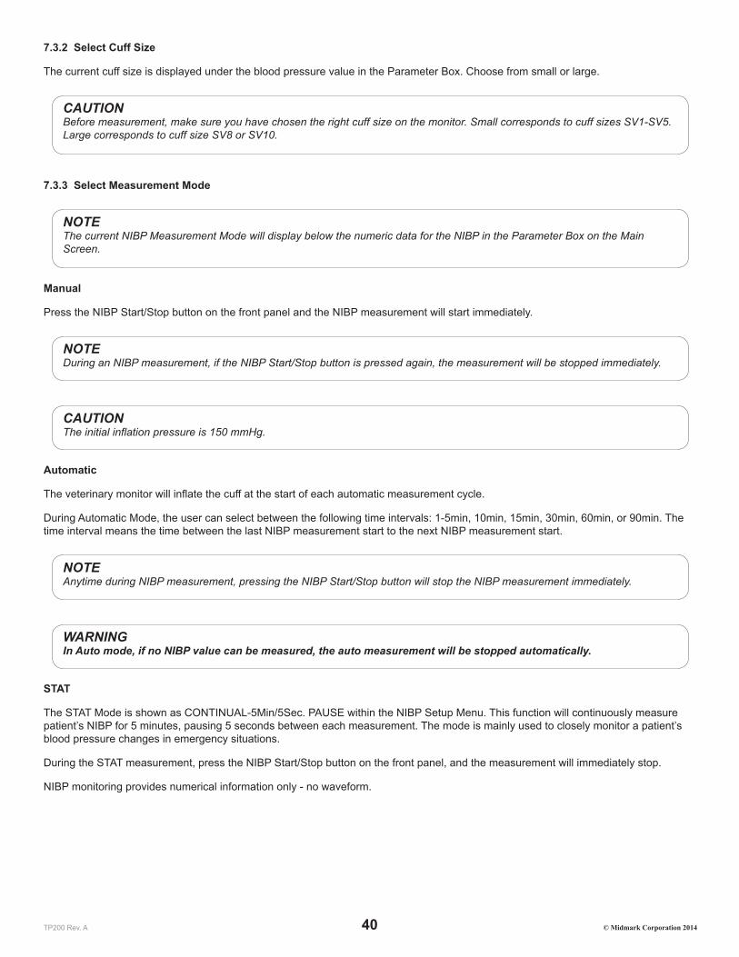
TP200 Rev. A 40 © Midmark Corporation 2014
7.3.2 Select Cuff Size
The current cuff size is displayed under the blood pressure value in the Parameter Box. Choose from small or large.
CAUTIONBefore measurement, make sure you have chosen the right cuff size on the monitor. Small corresponds to cuff sizes SV1-SV5. Large corresponds to cuff size SV8 or SV10.
7.3.3 Select Measurement Mode
NOTEThe current NIBP Measurement Mode will display below the numeric data for the NIBP in the Parameter Box on the Main Screen.
Manual
Press the NIBP Start/Stop button on the front panel and the NIBP measurement will start immediately.
NOTEDuring an NIBP measurement, if the NIBP Start/Stop button is pressed again, the measurement will be stopped immediately.
CAUTIONThe initial inflation pressure is 150 mmHg.
Automatic
The veterinary monitor will inflate the cuff at the start of each automatic measurement cycle.
During Automatic Mode, the user can select between the following time intervals: 1-5min, 10min, 15min, 30min, 60min, or 90min. The time interval means the time between the last NIBP measurement start to the next NIBP measurement start.
NOTEAnytime during NIBP measurement, pressing the NIBP Start/Stop button will stop the NIBP measurement immediately.
WARNINGIn Auto mode, if no NIBP value can be measured, the auto measurement will be stopped automatically.
STAT
The STAT Mode is shown as CONTINUAL-5Min/5Sec. PAUSE within the NIBP Setup Menu. This function will continuously measure patient’s NIBP for 5 minutes, pausing 5 seconds between each measurement. The mode is mainly used to closely monitor a patient’s blood pressure changes in emergency situations.
During the STAT measurement, press the NIBP Start/Stop button on the front panel, and the measurement will immediately stop.
NIBP monitoring provides numerical information only - no waveform.

TP200 Rev. A 41 © Midmark Corporation 2014
7.3.4 Alarm Limit Setup
For different patients, different limits may be required. To set up the alarm parameters, reference Section 4.3 Alarm Setup.
Parameter RangeSystolic Pressure 10 to 240 mmHgDiastolic Pressure 10 to 210 mmHgMean Pressure 20 to 230 mmHg
7.3.5 Alarm for Abnormal Status
The Alarm trigger when the following abnormal events occur and messages will be displayed in the NIBP parameter area: “Loose Cuff”, “Air Leak”, “Meas. (Measurement) error”, or “Time Out”. Take the following steps after seeing the messages.
7.4 TroubleshootingLoose Cuff: If the NIBP status bar displays “Loose Cuff ”, please check the position of the cuff first, and check whether the inflation hose is damaged.
Air Leak: If the NIBP status bar displays “Air Leak”, check the cuffs and the extension tube for damage. If the NIBP cuff and extension tube is undamaged, check that they are connected properly to each other and that the tube is connected properly to the monitor. If this does not resolve the problem, try to measure the NIBP with a different cuff and tube set. If error persists, contact Midmark.
Meas. (Measurement) Error: If the NIBP status bar displays “Measurement Error”, it may be the result of a system self-test error, the patient being over excited, trembling or there may be an air leakage. Calm the patient down and perform the measurement again. If the message persists, please contact Midmark.
Time Out: This may occur if the NIBP is set to Continual or Interval Use. To correct this error, go into the NIBP Setup Menu and change the NIBP back to Manual. Then reset it to Continual or Interval as desired. If error persists, contact Midmark.
7.5 PrecautionsThe following circumstances may affect the measurement results:
1. Patient motion
2. Rapid change in pressure
3. Shock or hypothermia
WARNINGS:
1. Make sure there is no other pressure on the cuff.
2. Wrong cuff size may result in inaccurate measurements.
3. Make sure monitor is set to Large/Small corresponding to cuff used.
4. To ensure the patient’s safety, never use cuff on the same limb where an infusion is going on.
5. Do not measure SpO2 or other parameters on the same limb where blood pressure is measured.
6. Do not apply cuff on an injured limb.
7. Do not measure a patient’s blood pressure continuously or repetitively for a long time.
8. Use only accessories recommended by the manufacturer.
7.6 Preparations1. Use cuffs of proper sizes.
2. Ensure the cuff has been completely deflated.

TP200 Rev. A 42 © Midmark Corporation 2014
3. Place the properly sized cuff on the patient’s limb.
4. Install the cuff hose to the NIBP connector of the veterinary monitor.
5. Make sure there is no block between the monitor and the hose.
6. Set blood pressure measurement correctly in the setup menu.
7. The cuff on the patient’s limb should be at the same level as the heart.
8. Press the blood pressure start key and start measuring blood pressure.
7.7 Maintenance
7.7.1 Cuffs
Prior to each patient use, inspect the blood pressure cuff and its hose for damage.
NOTEWe do not recommend submersion of the cuff. Liquid should not be permitted to enter the cuff bladder because instrument damage may occur. The cuff should be allowed to thoroughly dry before use.
7.7.2 Reusable (Nylon) Large Cuffs
As necessary, wipe the cuff with mild detergents/dilute bleach solution (1-2%), rinse with water and dry.
7.7.3 Disposable (Vivnyl) Small Cuffs
As necessary, the preferred method for cleaning the cuff is to wipe it down with a damp, soapy cloth. A damp, detergent-free cloth should then be used to rinse the cuff.
In certain situations, the cuff may become soiled during its use. In these situations a water-based detergent is suitable for wiping the cuff.

TP200 Rev. A 43 © Midmark Corporation 2014
SECTION 8 - SpO2 MONITORING
8.1 General Information The Cardell® Touch continuously monitors and displays arterial blood oxygen saturation (SpO2) and pulse rate. If the ECG HR From is set to SPO2 or Auto and there is no ECG signal, the monitor beeps with each pulse beat. It allows you to choose alarm limits and audible tone volumes. You can select the high and low alarm limits for SpO2 and pulse rate and choose the alarm level.
The Cardell® Touch determines SpO2 and pulse rate by passing two wavelengths of light, one red (660nm) and the other infrared (940nm), through body tissue to a photo detector. Pulse identification is accomplished by using plethysmographic techniques, and oxygen saturation measurements are determined using spectrophotometric oximetry principles. During measurement, the signal strength resulting from each light source depends on the color and thickness of the body tissue, the sensor placement, the intensity of the light sources, and the absorption of the arterial and venous blood (including the time varying effects of the pulse) in the body tissues.
The monitor processes these signals, separating the time invariant parameters (tissue thickness, skin color, light intensity, and venous blood) from the time variant parameters (arterial volume and SpO2) to identify the pulse and calculate oxygen saturation. Oxygen saturation calculations can be performed because blood saturated with oxygen predictably absorbs less red light than oxygen depleted blood.
Since measurement of SpO2 depends on a pulsating vascular bed, any condition that restricts blood flow, such as use of a blood pressure cuff or extremes in systemic vascular resistance, may cause an inability to determine accurate pulse and SpO2 readings.
CAUTIONSpO2 sensors are fragile and must be handled with care.
8.2 Sensor Placement
WARNINGUse only Nellcor® veterinary oxygen sensors. Use of other oxygen sensors may cause improper performance.
Instructions for Use
NOTEReusable sensors may be used on the same site for a maximum of four (4) hours, provided the site is inspected routinely to ensure skin integrity and correct positioning. Because individual skin condition affects the ability of the skin to tolerate sensor placement, it may be necessary to change the sensor site more frequently with some patients. If skin integrity changes, move the sensor to another site.
1. Select a sensor and clip that is appropriate for the patient. There are two (2) sizes of VetSat veterinary sensor clips: model VSC-S (small), and model VSC-L (large).
2. Clean the VetSat sensor and clip separately before and after each use.
3. Open the clip by pressing with the thumb and forefinger.
4. Slide one of the sensor’s alignment buttons along the clip slot until the sensor pad is fully engaged in the clip.
5. Slide the second sensor button along the other clip slot until the second sensor pad is fully engaged in its side of the clip.
NOTEVerify the sensor pads are oriented so the optical components face each other directly.
6. The sensor is now ready to be applied to the patient. The preferred sensor application site for canine, feline and equine animals is on the tongue, with the sensor’s optical components positioned on the center of the tongue. Alternatively, the sensor and clip may be applied to the animal’s lip, toe, ear, prepuce, or vulva.

TP200 Rev. A 44 © Midmark Corporation 2014
NOTEIf the sensor does not track the pulse reliably, it may be incorrectly positioned, or the sensor site may be too thick, thin, or deeply pigmented to permit appropriate light transmission. If any of these situations occur, reposition the sensor or try another sensor site. If the sensor site is covered with fur, try shaving the site and reapplying the sensor.
7. Be sure to position the sensor cable along the side of the animal’s face and body to avoid entanglement with the animal.
WARNINGDo not use supplemental tape to adhere the clip and sensor directly to the site; this can restrict blood flow and cause inaccurate measurements. For best results, secure the sensor cable independently from the sensor.
8. Connect the sensor assembly to the Interface Cable:
9. Place the plastic hinged cover in the unlocked position (perpendicular to the connector).
10. Connect the sensor assembly to the Interface Cable.
11. Lock the plastic hinged cover to prevent accidental cable disconnection.
12. Plug the Interface Cable into the SpO2 connector on the side panel of the monitor. Push the cable in until you hear an audible “click”.
WARNINGThe indicates that the SpO2 sensor connector is insulated and defibrillation proof, allowing for patient and monitor safety during defibrillation and electrosurgery.
13. Verify that the sensor is properly positioned by observing at least ten seconds of a continuous SpO2 waveform being displayed across the screen. When a valid signal is detected, the monitor displays the % SpO2 and Pulse Rate values. If the perfusion light level is low, reposition the sensor or try a different sensor. If normal operation cannot be achieved, contact Midmark.
NOTEIn addition to the V-SAT sensor and clips that are included with the monitor, there is an optional reflectance sensor, the MAXFAST-1 that can be used on the base of the tail. This is mainly used as an alternative when head/neck/dental procedures are being performed.
8.3 SpO2 Setup MenuFollow the steps below to enter the SpO2 Setup Menu:
Step 1: Press the “NEXT” Touch Screen Quick Access Button.
Step 2: Press the “PARAMETER SETUP” Touch Screen Quick Access Button.
Step 3: Press “SpO2 Setup” to enter the SpO2 Setup Menu.

TP200 Rev. A 45 © Midmark Corporation 2014
NOTEUsers can also access the SpO2 Setup Menu by pressing on the SpO2 waveform in the Waveform Area or pressing the SpO2 data in the Parameter Box.
SpO2 Setup Menu Options:
SPO2 UPPER LIMIT The user may set the upper limit using the number pad provided.SPO2 LOWER LIMIT The user may set the lower limit using the number pad provided.PR UPPER LIMIT The user may set the upper limit using the number pad provided.PR LOWER LIMIT The user may set the lower limit using the number pad provided.ALM SOUND Alarm On or OffALM LEV High, Med or LowSWEEP 12.5 or 25.0mm/sWAVE TYPE Line or FillWAVE COLOR Green, Cyan, Red, Yellow, White, Blue, or Purple.ALM REC On or OffSatSecond Disabled, 10, 25, 50, or 100DEFAULT Allow the monitor to return to factory default settings for the SpO2 parameter only. No other
parameter will be affected. If used, the current configuration for this parameter will be lost.
SatSeconds™ Alarm Management
The SatSeconds function can be activated from the SpO2 Setup menu by selecting a SatSeconds limit, or “clock” of 10, 25, 50, 100 or Disabled SatSeconds. Clinicians who choose to employ the SatSeconds function should select a limit suited to their clinical environment and patient conditions. Think of SatSeconds as the product of magnitude and time a patient exceeds SpO2 alarm limits. For example,3 points below the alarm limit for 10 seconds equals 30 SatSeconds. An alarm is only triggered if a desaturation event occurs that reaches the SatSeconds limit you selected. As a safety net, when three or more SpO2 alarm violations occur within 60 seconds, an alarm will sound even if the SatSeconds limit has not been reached .
When SatSeconds is set to Disabled, the monitor will immediately alarm for %SpO2 limit violations based on the selection made in the Alarm Limits menu.
Once the parameters are all set up, press the “X” button located on the upper right side of the menu to exit to the Main Screen.
NOTEChanges to the monitor may be made using the touch screen or the knob, depending on the user’s preference. To use the touch screen, press on the screen with your finger or the stylus. To use the knob, rotate the knob to navigate and press the knob to select/confirm.
8.4 Alarm SetupThe SpO2 alarm is for parameter out of limit or abnormal status. When the parameter exceeds the limit, the monitor will give both visual and audio alarms. For different patients, different limits may be required. To set up the alarm parameters, reference Section 4.3 Alarm Setup.
8.4.1 Alarm Range
Parameter RangeSpO2 0 to 100%Pulse Rate 20 to 240 bpm
WARNINGIf the SpO2 upper limit is set to 100%, then, it is equivalent to no alarm limit.

TP200 Rev. A 46 © Midmark Corporation 2014
Abnormal Status Alarm: “SpO2 PROBE OFF” alarm
8.5 Preparation for Monitoring1. Select a sensor and clip that is appropriate for the patient.
2. Apply the sensor to a proper position on the patient. If possible, keep the sensor at the same level of the patient’s heart.
WARNING
• Do not apply the SpO2 sensor to an extremity where there is arterial catheter, blood pressure cuff or injection tube.
• Make sure the light emitting part and light detecting part face each other.
• Make sure the sensor is applied to a region of arterial blood flow.
• Make sure there is no extreme motion.
• Make sure skin where the sensor is applied is neither too thick nor too thin.
• Make sure there is no strong ambient light coming into the sensor. Cover the site with opaque material.
3. Plug the Interface Cable into the SpO2 connector on the side panel of the monitor.
4. Set the upper and lower limits of SpO2.
CAUTIONHandle the sensor and the wiring with care. There are sensitive electrical parts in the sensor that can be damaged by negligent treatment. Keep the wiring away from pointed items. Normal wear-and-tear caused by patient motion or sensor cleaning will limit the life of the probe. Longevity can be extended by careful treatment.
WARNINGReusable sensors may be used on the same site for a maximum of four (4) hours, provided the site is inspected routinely to ensure skin integrity and correct positioning. Because individual skin condition affects the ability of the skin to tolerate sensor placement, it may be necessary to change the sensor site more frequently with some patients. If skin integrity changes, move the sensor to another site.
Sensor Removal
CAUTIONFor the comfort of the patient and to avoid damaging the sensor, do not pull on the interface or sensor cable when removing the sensor and clip from the sensor site, but rather, press the clip open and remove.
When SpO2 monitoring is completed, remove the sensor from the patient.
To remove the sensor and clip from the patient, press the clip open and remove. When the probe is removed from the patient, the message “SpO2 Probe OFF” is displayed and an audible alarm sounds, indicating a connection has been lost. To acknowledge the alarm, press the SILENCE/RESET pushbutton. The monitor silences the audible and visual alarms for the ALM PAUSE TIME (default is 120 seconds) and the message “SpO2 Probe OFF” remains on the display.
8.6 Precautions
CAUTIONClean the sensor and sensor clip separately before and after each use. See 8.7 Cleaning and Maintenance below.

TP200 Rev. A 47 © Midmark Corporation 2014
CAUTIONDo not sterilize the sensor or clip by irradiation, steam, or ethylene oxide.
8.7 Cleaning and Maintenance
CAUTIONDo not sterilize the sensor or clip by irradiation, steam, or ethylene oxide.
CAUTIONTo avoid damage to the sensor, remove it from the clip before cleaning either piece.
8.7.1 Clean the Sensor and Clip
1. To remove the sensor from the clip, grasp the end of each sensor pad and pull it through to the inside of the clip. The sensor should pop out of the clip easily. Do not pull on the sensor or interface cable.
2. The sensor may be surface-cleaned by wiping it with an agent such as 70% isopropyl alcohol. Do not immerse the sensor in liquid. The clip may be cleaned by either wiping it with, or soaking it for ten minutes in, 70% isopropyl alcohol. If the clip is soaked, be sure to rinse it with water and air dry it prior to use on the next animal.
3. After each cleaning and prior to each use, inspect the sensor and cable for fraying, cracking, breakage, or other damage. Inspect the clip for cracking or breakage, or loss of spring tension that would allow slippage or movement of the sensor from its proper position. If defects are noted, do not use the sensor or clip.
8.7.2 Clean the Cable
1. Clean the cable surface with soapy water or alcohol. Do not let liquid enter the connecting parts.
2. Dry it with clean cloth.
CAUTIONDo not immerse the cable or sensor in any liquid or let the liquid enter into the connectors.
8.8 Troubleshooting
8.8.1 No SpO2 Data
Failure Phenomenon: During monitoring process, there is no SpO2 waveform or data.
Inspection Method: Check if the red light on the sensor is on.
Solution: If there is no red light inside the sensor, the wiring connectors may have become loose, or the wire inside the cable may have grown frayed over time. Try it on your finger or earlobe, and if no reading is obtained, it may indicate that the V-SAT sensor must be replaced. If “No signal received ” is displayed on the screen, then there is a communication problem between the SpO2 module and the host. Turn off the machine and turn it on again. If the problem still remains, consult Midmark.
CAUTIONCertain drugs, including alpha-2s, are vaso-constrictive, and may cause difficulty in obtaining readings on patient extremities. Moving the sensor further back on the patient’s tongue, or exploring alternate sites (lip, ear, toe webbing, prepuce, vulva), may restore the readings.

TP200 Rev. A 48 © Midmark Corporation 2014
8.8.2 Intermittent SpO2 Value
Failure Phenomenon: When patient SpO2 is measured, the SpO2 value is not continuous.
Inspection Method:
1. Check for patient motion.
2. Check for loose connections with the SpO2 extension cable or V-SAT sensor.
Solution: Keep the patient as still as possible. Value loss caused by patient motion can be considered normal.

TP200 Rev. A 49 © Midmark Corporation 2014
SECTION 9 - TEMPERATURE AND RESPIRATION MONITORING
9.1 General Information
9.1.1 Temperature
A continuous temperature monitor is used to measure a patient’s core body temperature during the administration of general anesthesia, detection and treatment of hyperthermia, post-surgical recovery, and other various cases that may require constant body temperature monitoring.
The monitor has 2 channels available to display continuous electronic temperature readings of the core body temperature via a rectal/esophageal probe included with the monitor. ECG, respiration, and temperature can also be monitored with optional ECG esophageal probes.
Temperature monitoring provides numerical information only - no waveform. As with other parameters, data is displayed in the temperature parameter window on the right side of the screen.
WARNINGTEMP sockets are labeled with ,showing the signal input part is insulated and defibrillation proof.
9.2 Temperature Monitoring1. Select temperature probe.
WARNINGRectal/esophageal probes are not exchangeable.
2. Probe provided with the monitor may be used either in the esophagus or the rectum of the patient.
CAUTIONTo avoid cross-contamination, we suggest you label the probe with tape indicating which way it’s been used.
3. Insert the temperature probe into one of the two temperature sockets in the side panel.
WARNINGConnect temperature probe with patient and insert the other end of the cable into the temperature socket of the monitor completely. The screen will display the temperature reading.
4. Set temperature alarm limits. To set up the alarm parameters, reference Section 4.3 Alarm Setup.
WARNINGBefore performing temperature measurement, do not get the temperature probe close to a heat source. If it has been close to a heat source, then let it cool down for 5 minutes before performing measurement.
5. Start to monitor patient’s temperature.
CAUTIONIt takes 8 seconds for the veterinary monitor to display stable reading.
If you use a disposable temperature probe, please do not try to disinfect and reuse it. Follow the manufacturer’s recommendation for proper disposal.

TP200 Rev. A 50 © Midmark Corporation 2014
9.3 Temperature Setup MenuFollow the steps below to enter the TEMP Setup Menu:
Step 1: Press the “NEXT” Touch Screen Quick Access Button.
Step 2: Press the “PARAMETER SETUP” Touch Screen Quick Access Button.
Step 3: Press “TEMP Setup” to enter the TEMP Setup Menu.
NOTEUsers can also access the TEMP Setup Menu by pressing the TEMP data in the Parameter Box.
TEMP Setup Menu Options:
T1 UPPER LIMIT The user may set the upper limit using the number pad provided.T1 LOWER LIMIT The user may set the lower limit using the number pad provided.T2 UPPER LIMIT The user may set the upper limit using the number pad provided.T2 LOWER LIMIT The user may set the lower limit using the number pad provided.ALM SOUND Choose from On or OffALM LEV Choose from High, Med, or LowTEMP UNIT Choose from °F or °CDISP COLOR Green, Cyan, Red, Yellow, White, Blue, or Purple.ALM REC Alarm record On or OffDEFAULT Allow the monitor to return to factory default settings for the Temperature parameter only. No other
parameter will be affected. If used, the current configuration for this parameter will be lost.
Once the parameters are all set up, press the “X” button located on the upper right side of the menu to exit to the Main Screen.
NOTEChanges to the monitor may be made using the touch screen or the knob, depending on the user’s preference. To use the touch screen, press on the screen with your finger or the stylus. To use the knob, rotate the knob to navigate and press the knob to select/confirm.
9.4 Temperature Probe CleaningAs necessary, the probes should be cleaned with a mild detergent and water to remove excess bioburden. When necessary, the probes may be disinfected using a soft cloth saturated with a 10% (1:10) solution of chlorine bleach in tap water or 70% isopropyl alcohol. When all of the surfaces have been disinfected, wipe the entire surface of the probe using a soft cloth dampened with fresh water to remove any trace amounts of residue and/or fumes.
9.5 Respiration MonitoringThe monitor provides two respiration monitoring methods: thoracic impedance (indirect) and through the optional Capnostat mainstream and LoFlo sidestream CO2 probes (direct).
1. Place electrodes in proper positions.
2. Select proper respiration lead combination.
3. Set respiration alarm limits.
NOTEElectrodes must be placed in proper positions.

TP200 Rev. A 51 © Midmark Corporation 2014
CAUTIONPatient motion may result in a respiration measurement error.
NOTEIf the patient is intubated, direct respiration monitoring through the CO2 sample line is recommended. If you choose to monitor respiration using the thoracic impedance method, place the ECG electrodes on the patient’s trunk for more reliable readings.
9.6 Respiration Setup MenuFollow the steps below to enter the RESP Setup Menu:
Step 1: Press the “NEXT” Touch Screen Quick Access Button.
Step 2: Press the “PARAMETER SETUP” Touch Screen Quick Access Button.
Step 3: Press “RESP Setup” to enter the RESP Setup Menu.
NOTEUsers can also access the RESP Setup Menu by pressing on the RESP waveform in the Waveform Area or pressing the RESP data in the Parameter Box.
RESP Setup Menu Options:
APNEA ALM Choose from No, 1s, 2s, 5s, 10s, 15s, 20s, 25s, 30s, 35s, or 40s. Within the specified time, if there is no respiration waveform, apnea alarm will be activated.
RR UPPER LIMIT The user may set the upper limit using the number pad provided.RR LOWER LIMIT The user may set the lower limit using the number pad providedGAIN x0.25, x0.5, x1, x2, x4SWEEP 6.25, 12.5, 25.0WAVE COLOR Green, Cyan, Red, Yellow, White, Blue, or PurpleWAVE TYPE Line or FillALM SOUND Alarm On or OffALM LEV High, Med, or LowALM REC Alarm record On or OffRESP LEAD RA-LA(I), RA-LL(II)ENHANCE FILTER Used to filter out cardiac interference. ON, OFF DEFAULT Allow the monitor to return to factory default settings for the Respiration parameter only. No other
parameter will be affected. If used, the current configuration for this parameter will be lost.
Once the parameters are all set up, press the “X” button located on the upper right side of the menu to exit to the Main Screen.
NOTEChanges to the monitor may be made using the touch screen or the knob, depending on the user’s preference. To use the touch screen, press on the screen with your finger or the stylus. To use the knob, rotate the knob to navigate and press the knob to select/confirm.
9.7 Alarm SetupThe respiration and temperature alarms include a parameter out-of-limit alarm and an abnormal status alarm. When the parameter is out of limit, the monitor will give an alarm sound automatically, and the value displayed on the screen flashes at the same time.

TP200 Rev. A 52 © Midmark Corporation 2014
WARNINGAlarm limits should be adjusted based on an individual patient’s condition.
Parameter Range:
Parameter Adjustment RangeRespiration 0 to 150 rpmTemperature 1 32 to 122 °FTemperature 2 32 to 122 °F
Alarm for abnormal status:
Parameter AlarmRespiration “ECG LEAD OFF”Temperature T”X”, “SENSOR OFF”
To set up the alarm parameters, reference Section 4.3 Alarm Setup.

TP200 Rev. A 53 © Midmark Corporation 2014
SECTION 10 - CO2 MONITORING (Optional)
10.1 General InformationThe Cardell® Touch includes the capability to monitor end-tidal CO2 using the optional Capnostat or LoFlo CO2 sensor. This measures CO2 by using the infrared absorption technique, which has endured and evolved in the clinical setting for over two decades and remains the most popular and versatile technique today.
The principle is based on the fact that CO2 molecules absorb infrared (IR) light energy of specific wavelengths, with the amount of energy absorbed being directly related to the CO2 concentration. When an IR beam is passed through a gas sample containing CO2, the electronic signal from the photodetector (which measures the remaining light energy) can be obtained. This signal is then compared to the energy of the IR source and calibrated to accurately reflect CO2 concentration in the sample. To calibrate, the photodetector’s response to a known concentration of CO2 is stored in the monitor’s memory. A reference channel accounts for optical changes in the sensor, allowing the system to remain in calibration without user intervention.
If you have a Multigas analyzer, refer to Section 12 for Multigas monitoring which includes CO2.
10.2 CO2 Setup MenuThe CO2 Menu will only be available if the CO2 module is turned on.
Follow the steps below to turn on the CO2 module:
Step 1: Press the “NEXT” Touch Screen Quick Access Button.
Step 2: Press the “MAIN MENU” Touch Screen Quick Access Button.
Step 3: Press “Monitor Setup”.
Step 4: Press “Module Setup”.
Step 5: Press “CO2” to turn on the module (on page 2 of the menu).
NOTEThis will turn off the RESP waveform automatically and replace the RESP waveform on the Main Screen with the CO2 waveform.
Follow the steps below to enter the CO2 Setup Menu:
Step 1: Press the “NEXT” Touch Screen Quick Access Button.
Step 2: Press the “PARAMETER SETUP” Touch Screen Quick Access Button.
Step 3: Press “CO2 Setup” to enter the CO2 Setup Menu.
NOTEUsers can also access the CO2 Setup Menu by pressing on the CO2 waveform in the Waveform Area or pressing the CO2 data in the Parameter Box.
CO2 Setup Menu Options:
APNEA ALM Choose from No, 1s, 2s, 5s, 10s, 15s, 20s, 25s, 30s, 35s, or 40s. Within the specified time, if there is no CO2 waveform, apnea alarm will be activated.
CO2 ON/OFF Choose from On or Off.ZERO CAL Selectable once the module is plugged in. Note: airway adapter needs to be installed prior to zeroingAWRR UPPER LIMIT The user may set the upper limit using the number pad provided.AWRR LOWER LIMIT The user may set the lower limit using the number pad provided.EtCO2 UPPER LIMIT The user may set the upper limit using the number pad provided.

TP200 Rev. A 54 © Midmark Corporation 2014
EtCO2 LOWER LIMIT The user may set the lower limit using the number pad provided.InCO2 UPPER LIMIT The user may set the upper limit using the number pad provided.InCO2 LOWER LIMIT The user may set the lower limit using the number pad provided.ALM SOUND Choose from On or Off.SWEEP Choose from 12.5 or 25.0.WAVE COLOR Choose from Green, Cyan, Red, Yellow, White, Blue, or Purple.WAVE TYPE Choose from Line or Fill.ALM LEV Choose from High, Med, or Low.UNIT Choose from mmHg or kPa.ALM REC Choose from On or Off.O2 COMPEN Oxygen compensation, the user can input a number using the number pad. (See appendix 5)BALAN GAS Choose from Room Air, N2O, or Helium.ALTITUDE UNIT Choose from m (meter) or ft (feet).ALTITUDE Use the up and down arrow to adjust altitude then press OK to save. Increments of 250 ft or 76.2 m.BARO. PRESSURE Default set to 760 mmHg at 0 ft altitude. This cannot be changed by the user. It is calculated
automatically depending on the Altitude value.DEFAULT Allow the monitor to return to factory default settings for the CO2 parameter only. No other parameter
will be affected. If used, the current configuration for this parameter will be lost.
Once the parameters are all set up, press the “X” button located on the upper right side of the menu to exit to the Main Screen.
NOTEChanges to the monitor may be made using the touch screen or the knob, depending on the user’s preference. To use the touch screen, press on the screen with your finger or the stylus. To use the knob, rotate the knob to navigate and press the knob to select/confirm.
10.3 Capnostat SensorThe CAPNOSTAT 5 CO2 Sensor is a rugged, solid-state, mainstream sensor. It is factory calibrated and does not require further calibration.
10.3.1 Sensor Connections
Connecting the CAPNOSTAT 5 CO2 Sensor to the Monitor
1. Insert the CAPNOSTAT 5 CO2 Sensor connector into the CO2/AG receptacle of the Cardell® Touch as shown below.

TP200 Rev. A 55 © Midmark Corporation 2014
2. Make sure the arrows on the connector are at the top of the connector. Line up the two keys of the connector with the receptacle and insert.
3. To remove the connector, grasp the body portion of the connector, pull in direction of arrow and remove.
NOTEDo not remove by pulling cable.
Connecting the CAPNOSTAT 5 CO2 Sensor to a Respironics CO2 airway adapter.
CAPNOSTAT 5 CO2 Sensor Window
1. Connect: Press the CAPNOSTAT CO2 sensor onto the airway adapter. It will click into place when properly seated. Keep the windows of the adapter in the vertical position as shown during use. This will keep water and patient secretions from pooling on the windows.
2. Make sure to Zero your sensor before use. (See section 10.5)
3. Remove: Remove by sliding airway adaptor from CAPNOSTAT 5 CO2 sensor.
Shown below is the CAPNOSTAT 5 CO2 Sensor with a patient circuit:
10.4 LoFlo CO2 Sensor - SidestreamFor Sidestream CO2, use the LoFlo CO2 sensor accessory.
10.4.1 Connecting the LoFlo CO2 Sensor to the Monitor
1. Plug the sensor cable into the monitor’s CO2 input receptacle.
2. Wait two minutes to allow the sensor to initialize and warm up.

TP200 Rev. A 56 © Midmark Corporation 2014
3. Connect the airway adapter or sample line to the sensor. It will click into place when seated correctly.
4. Make sure to Zero your sensor before use. (See section 10.5)
5. For intubated patients requiring an airway adapter, install the airway adapter at the proximal end of the circuit, between the elbow and the ventilator Y-section.
6. For intubated patients with an integrated airway adapter in the breathing circuit, connect the mail luer connector on the straight sample line to the female port on the airway adapter.
CAUTIONLoFlo CO2 consumables are intended for single patient use in human medicine, but in the veterinary setting, may be reused provided any moisture is allowed to dry between uses. The filter lines should be replaced after 120 hours of use. Do not attempt to disinfect or flush the filter line as the monitor can be damaged. Refer to the manufacturer’s instructions located on the filter line package for additional information.
WARNINGAlways connect the airway adapter to the sensor before inserting the airway adapter into the breathing circuit. In reverse, always remove the airway adapter from the breathing circuit before removing the sensor.
10.5 Zeroing the CO2 SensorsMake sure to Zero your Capnostat and LoFlo sensors before use.
CAUTIONNever zero the Capnostat® or LoFlo® sensor without an adapter or sampling kit installed. When zeroing, always remove the adapter or cannula from the patient and keep all sources of CO2 away from the sensor, including your own breath. CO2 is heavier than air.
To Zero your sensor, follow the steps below:
Step 1: Plug in the Respironics CO2 sensor.
Step 2: Install the airway adapter or sampling line
Step 3: Turn on the monitor. When you start the monitor, you are in the Main Screen, displaying the first row of Touch Screen Quick Access Buttons. Press the “NEXT” Touch Screen Quick Access Button. This will display the next set of Touch Screen Quick Access Buttons.
NOTEThe Respironics® module may be plugged in before or after you start the monitor.
Step 4: Press the “PARAMETER SETUP” Quick Access Button. This will display the Parameter Setup menu.
Step 5: Press the “CO2 SETUP” button.
Step 6: Make sure the sensor is not being used or connected to the patient. Press “ZERO CAL”.

TP200 Rev. A 57 © Midmark Corporation 2014
Step 7: The “ZERO CAL” function will now be grayed out on the menu. A zero in progress message (“Zero In Pro”) will appear at the bottom of the CO2 section in the Parameter Box. The message will also contain a 30 second countdown. Once the countdown reaches 0, the message will disappear and your zeroing process is complete. The “ZERO CAL” function will again be selectable within the menu.
Step 8: If zeroing fails, the monitor will display the error message: “Zero Failure”.
NOTEUsers can also access the CO2 Setup Menu by pressing on the CO2 waveform in the Waveform Area or pressing the CO2 data in the Parameter Box.
10.6 LoFlo CO2 Sensor Holder (Optional)The Sidestream sensor holder can be used to clamp the sensor onto an IV pole or a shelf.
1. Push the sensor into the holder until it clicks into position.
2. Clamp the holder onto an IV pole, a shelf, or another appropriate location.
3. To remove the sensor from the holder, release the clip and pull the sensor out of the holder.
10.7 Removing Exhaust Gases from the System
WARNINGRegarding Anesthetics: When using the Sidestream CO2 measurement on patients who are receiving or have recently received anesthetics, connect the outlet to a scavenging system, to avoid exposing the veterinary staff to anesthetics.
Use an exhaust tube to remove the sample gas to a scavenging system. Attach it to the Sidestream sensor at the outlet connector.
10.8 Alarm SetupThe CO2 alarm is for parameter out of limit or abnormal status. When the parameter exceeds the limit, the monitor will give both visual and audio alarms.
Alarm Range:
Parameter RangeAirway Respiratory Rate 0 to 150 rpmEtCO2 0 to 150 mmHgInCO2 0 to 10 mmHg
WARNINGAlarm limits should be adjusted based on an individual patient’s condition.
To set up the alarm parameters, please reference Section 4.3 Alarm Setup.

TP200 Rev. A 58 © Midmark Corporation 2014
10.9 Cleaning & Maintenance
10.9.1 CAPNOSTAT 5 CO2 Sensor
Cleaning the outside of the CAPNOSTAT 5 CO2 Sensor:
1. Use a cloth dampened with isopropyl alcohol 70%, a 10% aqueous solution of sodium hypochlorite (bleach), disinfectant spray cleaner such as Steris Coverage® Spray HB, ammonia, or mild soap.
2. Wipe down with a clean water-dampened lint free cloth to rinse and dry before use. Make certain that the sensor windows are clean and dry before reuse. Care should be taken when cleaning the sensor windows to avoid scratching.
3. Keeping an airway adapter installed when not in use will protect the sensor windows.
10.9.2 LoFlo CO2 Sensor
Cleaning the LoFlo CO2 Module case, Cable and connector:
1. Use a cloth dampened with isopropyl alcohol 70%, a 10% aqueous solution of sodium hypochlorite (bleach), a 2% gluteraldehyde solution, ammonia, mild soap or disinfectant spray cleaner such as Steris Coverage® Spray HB.
2. Wipe down with a clean water-dampened cloth to rinse and dry before use. Make certain that the sensor windows are clean and dry before reuse.
10.9.3 Airway Adapters
Capnostat airway adapters are intended for single patient use.
CAUTIONDO NOT insert any object, such as a brush, into the CAPNOSTAT 5 CO2 airway adapter. Irreparable damage may occur to the CO2 windows.
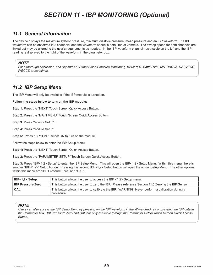
TP200 Rev. A 59 © Midmark Corporation 2014
SECTION 11 - IBP MONITORING (Optional)
11.1 General InformationThe device displays the maximum systolic pressure, minimum diastolic pressure, mean pressure and an IBP waveform. The IBP waveform can be observed in 2 channels, and the waveform speed is defaulted at 25mm/s. The sweep speed for both channels are linked but may be altered to the user’s requirements as needed. In the IBP waveform channel has a scale on the left and the IBP reading is displayed to the right of the waveform in the parameter box.
NOTEFor a thorough discussion, see Appendix 4; Direct Blood Pressure Monitoring, by Marc R. Raffe DVM, MS, DACVA, DACVECC, IVECCS proceedings.
11.2 IBP Setup MenuThe IBP Menu will only be available if the IBP module is turned on.
Follow the steps below to turn on the IBP module:
Step 1: Press the “NEXT” Touch Screen Quick Access Button.
Step 2: Press the “MAIN MENU” Touch Screen Quick Access Button.
Step 3: Press “Monitor Setup”.
Step 4: Press “Module Setup”.
Step 5: Press “IBP<1,2>” select ON to turn on the module.
Follow the steps below to enter the IBP Setup Menu:
Step 1: Press the “NEXT” Touch Screen Quick Access Button.
Step 2: Press the “PARAMETER SETUP” Touch Screen Quick Access Button.
Step 3: Press “IBP<1,2> Setup” to enter the IBP Setup Menu. This will open the IBP<1,2> Setup Menu. Within this menu, there is another “IBP<1,2>” Setup button. Pressing this second IBP<1,2> Setup button will open the actual Setup Menu. The other options within this menu are “IBP Pressure Zero” and “CAL”.
IBP<1,2> Setup This button allows the user to access the IBP <1,2> Setup menu.IBP Pressure Zero This button allows the user to zero the IBP. Please reference Section 11.5 Zeroing the IBP Sensor. CAL This button allows the user to calibrate the IBP. WARNING: Never perform a calibration during a
procedure.
NOTEUsers can also access the IBP Setup Menu by pressing on the IBP waveform in the Waveform Area or pressing the IBP data in the Parameter Box. IBP Pressure Zero and CAL are only available through the Parameter SetUp Touch Screen Quick Access Button.
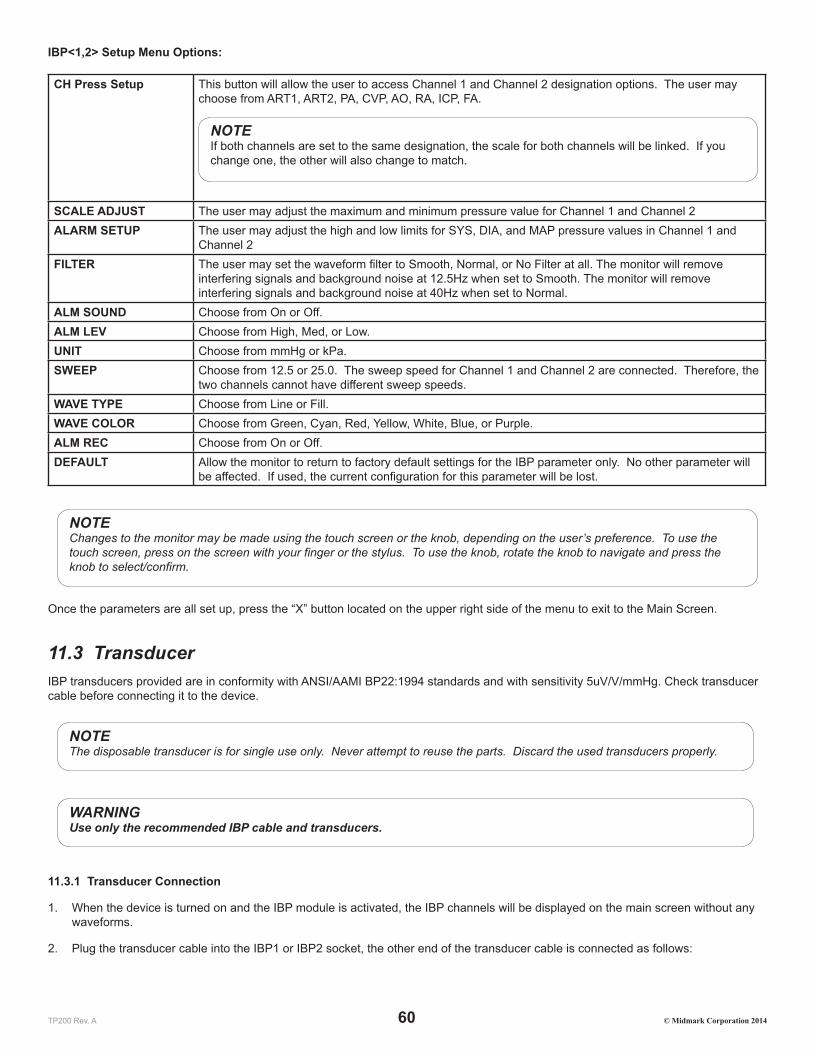
TP200 Rev. A 60 © Midmark Corporation 2014
IBP<1,2> Setup Menu Options:
CH Press Setup This button will allow the user to access Channel 1 and Channel 2 designation options. The user may choose from ART1, ART2, PA, CVP, AO, RA, ICP, FA.
NOTEIf both channels are set to the same designation, the scale for both channels will be linked. If you change one, the other will also change to match.
SCALE ADJUST The user may adjust the maximum and minimum pressure value for Channel 1 and Channel 2ALARM SETUP The user may adjust the high and low limits for SYS, DIA, and MAP pressure values in Channel 1 and
Channel 2FILTER The user may set the waveform filter to Smooth, Normal, or No Filter at all. The monitor will remove
interfering signals and background noise at 12.5Hz when set to Smooth. The monitor will remove interfering signals and background noise at 40Hz when set to Normal.
ALM SOUND Choose from On or Off.ALM LEV Choose from High, Med, or Low.UNIT Choose from mmHg or kPa.SWEEP Choose from 12.5 or 25.0. The sweep speed for Channel 1 and Channel 2 are connected. Therefore, the
two channels cannot have different sweep speeds.WAVE TYPE Choose from Line or Fill.WAVE COLOR Choose from Green, Cyan, Red, Yellow, White, Blue, or Purple.ALM REC Choose from On or Off.DEFAULT Allow the monitor to return to factory default settings for the IBP parameter only. No other parameter will
be affected. If used, the current configuration for this parameter will be lost.
NOTEChanges to the monitor may be made using the touch screen or the knob, depending on the user’s preference. To use the touch screen, press on the screen with your finger or the stylus. To use the knob, rotate the knob to navigate and press the knob to select/confirm.
Once the parameters are all set up, press the “X” button located on the upper right side of the menu to exit to the Main Screen.
11.3 TransducerIBP transducers provided are in conformity with ANSI/AAMI BP22:1994 standards and with sensitivity 5uV/V/mmHg. Check transducer cable before connecting it to the device.
NOTEThe disposable transducer is for single use only. Never attempt to reuse the parts. Discard the used transducers properly.
WARNINGUse only the recommended IBP cable and transducers.
11.3.1 Transducer Connection
1. When the device is turned on and the IBP module is activated, the IBP channels will be displayed on the main screen without any waveforms.
2. Plug the transducer cable into the IBP1 or IBP2 socket, the other end of the transducer cable is connected as follows:
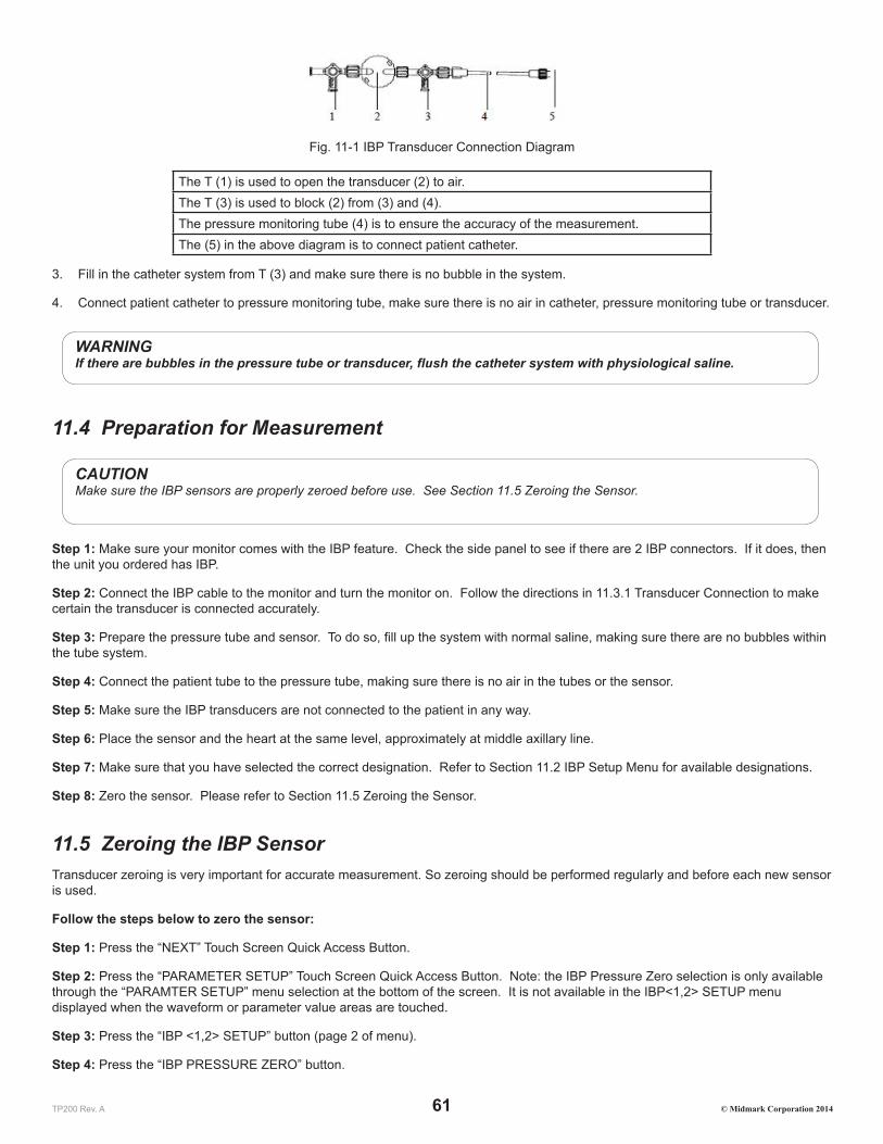
TP200 Rev. A 61 © Midmark Corporation 2014
Fig. 11-1 IBP Transducer Connection Diagram
The T (1) is used to open the transducer (2) to air.The T (3) is used to block (2) from (3) and (4).The pressure monitoring tube (4) is to ensure the accuracy of the measurement.The (5) in the above diagram is to connect patient catheter.
3. Fill in the catheter system from T (3) and make sure there is no bubble in the system.
4. Connect patient catheter to pressure monitoring tube, make sure there is no air in catheter, pressure monitoring tube or transducer.
WARNINGIf there are bubbles in the pressure tube or transducer, flush the catheter system with physiological saline.
11.4 Preparation for Measurement
CAUTIONMake sure the IBP sensors are properly zeroed before use. See Section 11.5 Zeroing the Sensor.
Step 1: Make sure your monitor comes with the IBP feature. Check the side panel to see if there are 2 IBP connectors. If it does, then the unit you ordered has IBP.
Step 2: Connect the IBP cable to the monitor and turn the monitor on. Follow the directions in 11.3.1 Transducer Connection to make certain the transducer is connected accurately.
Step 3: Prepare the pressure tube and sensor. To do so, fill up the system with normal saline, making sure there are no bubbles within the tube system.
Step 4: Connect the patient tube to the pressure tube, making sure there is no air in the tubes or the sensor.
Step 5: Make sure the IBP transducers are not connected to the patient in any way.
Step 6: Place the sensor and the heart at the same level, approximately at middle axillary line.
Step 7: Make sure that you have selected the correct designation. Refer to Section 11.2 IBP Setup Menu for available designations.
Step 8: Zero the sensor. Please refer to Section 11.5 Zeroing the Sensor.
11.5 Zeroing the IBP SensorTransducer zeroing is very important for accurate measurement. So zeroing should be performed regularly and before each new sensor is used.
Follow the steps below to zero the sensor:
Step 1: Press the “NEXT” Touch Screen Quick Access Button.
Step 2: Press the “PARAMETER SETUP” Touch Screen Quick Access Button. Note: the IBP Pressure Zero selection is only available through the “PARAMTER SETUP” menu selection at the bottom of the screen. It is not available in the IBP<1,2> SETUP menu displayed when the waveform or parameter value areas are touched.
Step 3: Press the “IBP <1,2> SETUP” button (page 2 of menu).
Step 4: Press the “IBP PRESSURE ZERO” button.

TP200 Rev. A 62 © Midmark Corporation 2014
Step 5: Press either the “CH1 ZERO” or “CH2 ZERO” to zero the channel you are using for IBP. If you are using both channels, you must zero both channels separately. Once you press the “CH1 ZERO” or “CH2 ZERO” button, the button will turn yellow. In addition, the status bar at the very top will display a message: “IBP1 Zeroing” or “IBP2 Zeroing” depending on the channel the user has chosen. Once it is complete, the message will change to “IBP1 Zero Success” or “IBP2 Zero Success”. If the zeroing failed, the message will be “IBP1 Zero Fail” or “IBP2 Zero Fail”.
11.6 IBP LabelingThe Cardell Touch allows you to label various sites for monitoring pressure. The possible labels consist of: ART1, ART2, PA, CVP, AO, RA, ICP, and FA.
ART1 or ART2: Arterial Pressure, i.e. the arterial blood pressure being monitored
PA: Pulmonary Artery Pressure
CVP: Central Vein Pressure
AO: Aorta Pressure
RA: Radial Artery Pressure
ICP: Intracranial Pressure
FA: Femoral Artery Pressure
11.7 Alarm SetupIBP monitoring alarm includes parameter limit alarm and abnormal status alarm. Alarm is to give alert when the monitoring results are abnormal. It is audible and visual with LED indicators and flashing readings.
NOTEAdjust default alarm limits according to the circumstances and the patient status.
Cat Dog Horse OtherParameter Low High Low High Low High Low HighIBP SYS (mmHg) – ART1, ART2, AO, RA, FA
100 160 100 160 100 130 100 160
IBP DIA (mmHg) – ART1, ART2, AO, RA, FA
50 90 50 90 50 80 50 90
IBP MAP (mmHg) –ART1, ART2, AO, RA, FA
60 120 70 130 60 100 70 130
IBP SYS (mmHg) – PA 5 38 5 38 5 38 5 38IBP DIA (mmHg) – PA -4 4 -4 4 0 16 -4 4IBP MAP (mmHg) – PA 12 16 12 16 8 25 12 16IBP MAP (mmHg) – CVP 0 7 0 7 0 23 0 7IBP MAP (mmHg) – ICP 0 4 0 4 0 10 0 4
NOTEIf CVP or ICP mode is selected, there are no SYS and DIA alarms.
To set up the alarm parameters, please reference Section 4.3 Alarm Setup.
11.8 PrecautionsWARNING:
• If liquid enters the monitor, turn it off immediately, and contact Midmark.

TP200 Rev. A 63 © Midmark Corporation 2014
• If liquid enters the accessories, turn off the monitor and disconnect the sensors from the patient. Switch to another sensor and alert hospital technicians or contact Midmark to repair or replace the original sensor as needed.
• When the monitor is connected to electrosurgical units, make sure the transducers and cables do not make contact with the electrosurgical unit. The patient lead and conducting wire must be far away from the operating table and other devices. The electrosurgical unit should be properly grounded.
• When a defibrillator is used, make sure the patient cable is not in contact with metal or other conductors or device grounding part. During defibrillation, do not touch the patient, table or device.
• When using an accessory, make sure that the selected accessory meets medical instrument safety requirements.
• When connecting or using an accessory, avoid touching any metal part connected to an electric appliance.
• When the monitor is connected to high frequency electrosurgical equipment, do not allow the sensor from the monitor to come into contact with the high frequency electrosurgical equipment or its cables. Otherwise, electric leakage may occur and may cause burns to the patient.
• Do not repeatedly use a disposable pressure sensor.
• Before starting monitoring, check to make sure the sensor cable is working and undamaged.
CAUTION
• Before starting IBP monitoring, the user should carry out zeroing on the transducer.
• During monitoring, the user should make certain the pressure sensor is at the heart level at all times to prevent the tube from clogging. Heparin saline should be continuously injected to wash the tube and maintain the unobstructed condition of the pressure measurement path. The tube must be securely fixed to prevent it from moving or coming off, which will affect invasive blood pressure measurement.

TP200 Rev. A 64 © Midmark Corporation 2014
SECTION 12 - MULTI-GAS MONITORING (Optional)
12.1 General Information The Cardell® Touch multi-gas module (AG) measures CO2, N2O, and one of the five anesthesia gases (Halothane, Isoflurane, Enflurane, Sevoflurane, Desflurane). Each gas is displayed in a monitoring channel, with waveforms showing minimum inhalation volume and maximum exhalation volume. Multigas monitoring is available by using the optional Masimo Sweden IRMA™ and ISA™ gas analyzers.
Please refer to this chapter as well as the Masimo User’s Guide provided with your IRMA™ and ISA™ gas analyzers.
NOTEEach channel displays only one gas at a time.
Gas Measurement: Non-dispersive infrared technology is used in the multi-gas measurement.
12.2 Installation and Connection
12.2.1 Parts
The following parts are included with your Multigas kit:
• Multi-gas ISA™ (sidestream) analyzer or IRMA™ (mainstream) analyzer
• Multi-gas module connecting cable
• IRMA airway adapters (with mainstream kit)
• Sampling line w/large airway adapter (with sidestream kit)
12.2.2 IRMA Connection Procedures
Connecting the IRMA probe to the monitor
1. Plug the IRMA analyzer into the Multi-gas extension cable provided with your multigas kit.
2. Plug the Multi-gas extension cable into the monitor side panel.
3. Turn ON the monitor.
4. Turn on the Multi-gas Module within the Main Menu. Refer to Section 12.2.4 Turn on the Multi-gas Module.
5. Turn on the Multi-gas Screen Display. Refer to Section 12.2.5 Turn on the Multi-gas Screen Display.
NOTEThe end user must turn on the Multi-gas module function within the monitor the first time the Multi-gas module is plugged in for use. Refer to Section 12.2.4 Turn on the Multigas Module. Keep the Multi-gas module plugged in during all restarts of the monitor. Otherwise, the monitor will alarm as it will no longer be able to detect the module. To use the monitor without Multi-gas, the end user must turn the module off again.
NOTEThe end user must turn on the Multi-gas display (AG Screen) once the Multi-gas module is turned on. Refer to Section 12.2.5 Turn on the Multi-gas Screen Display.
6. Snap the IRMA probe on top of the IRMA airway adapter. It will click into place when properly seated. A green LED indicates that the IRMA probe is ready for use.

TP200 Rev. A 65 © Midmark Corporation 2014
7. Connect IRMA/airway adapter male connector to the breathing circuit Y-piece. Connect the IRMA/airway adapter female connector to the patient’s endotracheal tube. Position the IRMA analyzer with the LED pointing upwards.
A HME (Heat Moisture Exchanger) may be connected between the patient’s endotracheal tube and the IRMA analyzer to protect the airway adapter from secretions and effects of water vapor and eliminate the need of changing the adapter. It allows free positioning of the IRMA analyzer as well.
NOTEA HME will add Dead Space and Resistance to the breathing circuit. Refer to manufacturer’s information for amounts and recommendations for replacement.
NOTEUnless the IRMA analyzer is protected with a HME, always position the IRMA analyzer with the LED pointing upwards.
The IRMA disposable airway adapter is inserted between the endotracheal tube and the Y-piece of the breathing circuit. The respiratory gas measurements are obtained through the XTP windows in the sides of the adapter. As the airway adapter is positioned directly in the airway, its performance can be affected by water vapor, patient secretions or nebulized medications that can accumulate on the adapter’s windows. For optimal results, the airway adapter shall not be placed between an endotracheal tube and an elbow, as this may allow patient secretions to block the adapter windows. The IRMA airway adapter shall be positioned with its windows in a vertical position to help keep patient secretions from pooling on the windows.
WARNINGThe IRMA analyzer is not intended to be in patient contact.
When connecting the IRMA analyzer to a patient circuit it is important to avoid a direct contact between the IRMA analyzer and the patient’s body. If, for whatever the reason, the IRMA probe is in direct contact with any parts of the patient’s body an insulation material shall be placed between the IRMA analyzer and the body.
12.2.3 ISA Connection Procedures
Connecting the ISA analyzer to the monitor
The multi-gas ISA™ analyzer is an external and independent part of the Cardell® TOUCH patient monitor.
1. Securely mount or place the ISA analyzer in a safe location.
2. Plug the ISA analyzer into the Multi-gas extension cable provided with your multigas kit.
3. Plug the Multi-gas extension cable into the monitor side panel.
4. Connect a sampling line to the ISA analyzer input connector.
5. Connect the gas sample exhaust port to a scavenging system or return the gas to the patient circuit to prevent pollution of the operation room when N2O and/or anesthetic agents are being used.
6. Turn ON the monitor.
7. A green LED indicates that the ISA analyzer is ready for use. Perform a pre-use check as described in the Section 12.4.1 Pre-Use Checks.
8. Turn on the Multi-gas Module within the Main Menu. Refer to Section 12.2.4 Turn on the Multi-gas Module.
9. Turn on the Multi-gas Screen Display. Refer to Section 12.2.5 Turn on the Multi-gas Screen Display.

TP200 Rev. A 66 © Midmark Corporation 2014
NOTEThe end user must turn on the Multi-gas module function within the monitor the first time the Multi-gas module is plugged in for use. Refer to Section 12.2.4 Turn on the Multi-gas Module. Keep the Multi-gas module plugged in during all restarts of the monitor. Otherwise, the monitor will alarm as it will no longer be able to detect the module. To use the monitor without Multi-gas, the end user must turn the module off again.
NOTEThe end user must turn on the Multi-gas display (AG Screen) once the Multi-gas module is turned on . Refer to Section 12.2.5 Turn on the Multi-gas Screen Display.
CAUTIONIn order to ensure good ventilation of the module, please keep a minimum of 5cm from each side of the analyzer to the wall or cabinet.
It is recommended to place the Multi-gas ISA™ module in a place higher or in the same level of patient position.
12.2.4 Turn on the Multi-gas Module
Please refer to the instructions included in the Multigas Kit.
Step 1: Press the “Monitor Setup” button within the “Main Menu”.
Step 2: Press the “Module Setup” button.
Step 3: Press “AG” to show the side menu which displays “ON” and “OFF”.
Step 4: Press “ON” to turn the AG module on. The side menu will automatically close once ON or OFF buttons are pressed.
12.2.5 Turn on the Multi-gas Screen Display
The end user must turn on the Multi-gas Screen Display in order to see the Multi-gas data.
To turn on the Multi-gas Screen Display, follow the steps below:
Step 1: Turn on the monitor.
Step 2: Press the “Display Modes” Touch Screen Quick Access Button.
Step 3: Press the “AG Screen” button.
12.2.6 Turn On or Off the Multi-gas Work Mode
When the monitor is turned on and the user plugs in the multigas IRMA analyzer, the monitor will automatically detect the sensor and change to Measure mode.
When the monitor is turned on with the multigas IRMA analyzer already plugged in, the monitor will start in Standby mode.
To use multigas, the user will need to turn the feature on manually by following the steps below:
Step 1: Press the “Parameter Setup” Touch Screen Quick Access Button.
NOTEThe AG Work Mode selection is only available through the “PARAMTER SETUP” menu selection at the bottom of the screen. It is not available in the CO2, N2O, or AG AA menus displayed when the waveform or parameter value areas are touched.
Step 2: Press the “AG Setup” button.
Step 3: Press the “Work Mode” button.

TP200 Rev. A 67 © Midmark Corporation 2014
Step 4: Press the “Measure” button.
For the ISA analyzer, no matter if it was plugged in before or after the monitor is turned on, it will always switch automatically to Measurement mode in order to Zero itself. To save operational time, the user may elect to turn the monitor to Standby mode when not using the ISA analyzer.
12.2.7 Multi-gas Exhaust
Connect the gas sample exhaust port to a scavenging system or return the gas to the patient circuit to prevent pollution of the operation room when N2O and/or anesthetic agents are being used. Due to the risk of patient cross-infection, always use a bacteria filter on the exhaust port side if sampled gas is intended to be re-breathed.
12.3 Multi-gas Setup Menu
12.3.1 Multi-gas Measurement Menu:
The AG Menu will only be available if the AG module is turned on. Follow the steps in Section 12.2.4 to turn on the AG Module.
Follow the steps below to enter the AG Setup Menu:
Step 1: Press the “NEXT” Touch Screen Quick Access Button.
Step 2: Press the “PARAMETER SETUP” Touch Screen Quick Access Button.
Step 3: Press “AG Setup” to enter the AG Setup Menu.
Step 4: Press “CO2”, N2O” or “AG” to enter the Setup Menu specific to each monitored gas.
NOTEUsers can also access the individual gas Setup Menus (CO2, N2O, or AG) by pressing on the appropriate waveform in the Waveform Area or pressing the appropriate data in the Parameter Box. Note: the AG Work Mode and Zero Calibrating selection is only available through the Parameter SetUp Touch Screen Quick Access Button.
AG Setup Menu Options:
WORK MODE Choose from Standby or Measurement. (See Section 12.2.6) CO2 Choose to access the CO2 Setup MenuN2O Choose to access the N2O Setup MenuAG Choose to access the AG (HAL, ISO, ENF, SEV, DES) Setup MenuAG ZERO CALIBRATING For use when manually adjusting the IRMA probe - (See Section 12.4.3)
12.3.2 CO2 Setup Menu Options
APNEA ALM Choose from No, 1s, 2s, 5s, 10s, 15s, 20s, 25s, 30s, 35s, or 40s. Within the specified time, if there is no respiration waveform, apnea alarm will be activated.
ET ALM HI The user may set the upper limit using the number pad provided.ET ALM LO The user may set the lower limit using the number pad provided.FI ALM HI The user may set the upper limit using the number pad provided.FI ALM LO The user may set the lower limit using the number pad provided.AWRR ALM HI The user may set the upper limit using the number pad provided.AWRR ALM LO The user may set the lower limit using the number pad provided.

TP200 Rev. A 68 © Midmark Corporation 2014
ALM SOUND Choose from On or Off.ALM LEV Choose from High, Med, or Low.UNIT Choose from mmHg or kPa.SWEEP Choose from 6.25 or 12.5 mm/s.GAIN Choose from 1x or 2x.WAVE COLOR Choose from Green, Cyan, Red, Yellow, White, Blue, or Purple.O2 COMPENSATE Oxygen compensation, the user can select Low, Med, or High. (Appendix 5)N2O COMPENSATE Nitrous Oxide compensation, the user can enable or disable. (Appendix 5)DEFAULT Allow the monitor to return to factory default settings for the CO2 parameter only. No other parameter
will be affected. If used, the current configuration for this parameter will be lost.
Please see the follow chart for setting the AG Apnea Alarm:
Apnea ALM Setting (seconds) Apnea Time (sent to probe) Total Time until "AG Apnea"1 20s 21s2 20s 22s5 20s 25s
10 20s 30s15 20s 35s20 20s 40s25 25s 50s30 30s 60s35 35s 70s40 40s 80s
12.3.3 N2O Setup Menu Options
ET ALM HI The user may set the upper limit using the number pad provided.ET ALM LO The user may set the lower limit using the number pad provided.FI ALM HI The user may set the upper limit using the number pad provided.FI ALM LO The user may set the lower limit using the number pad provided.ALM SOUND Choose from On or Off.ALM LEV Choose from High, Med, or Low.SWEEP Choose from 6.25 or 12.5 mm/s.WAVE COLOR Choose from Green, Cyan, Red, Yellow, White, Blue, or Purple.DEFAULT Allow the monitor to return to factory default settings for the N2O parameter only. No other parameter
will be affected. If used, the current configuration for this parameter will be lost.
12.3.4 AG Setup Menu Options
ET ALM HI The user may set the upper limit using the number pad provided.ET ALM LO The user may set the lower limit using the number pad provided.FI ALM HI The user may set the upper limit using the number pad provided.FI ALM LO The user may set the lower limit using the number pad provided.ALM SOUND Choose from On or Off.ALM LEV Choose from High, Med, or Low.SWEEP Choose from 6.25 or 12.5 mm/s.WAVE COLOR Choose from Green, Cyan, Red, Yellow, White, Blue, or Purple.

TP200 Rev. A 69 © Midmark Corporation 2014
DEFAULT Allow the monitor to return to factory default settings for the Anesthetic Gas parameter only. No other parameter will be affected. If used, the current configuration for this parameter will be lost.
12.4 Monitoring
12.4.1 Pre-Use Checks
IRMA
• Always verify gas readings and waveforms on the monitor before connecting the airway adapter to the patient circuit.
• Perform the tightness check of the patient circuit with the IRMA analyzer snapped on the IRMA airway adapter.
ISA
Before connecting the sampling line to the breathing circuit, do the following:
1. Connect the sampling line to the ISA light emitting gas inlet connector (LEGI)
2. Check that the LEGI shows a steady green light (indicating that the system is OK)
3. Breathe into the sampling line and check that valid CO2 waveforms and values are displayed.
4. Occlude the sampling line with a fingertip and wait for 10 seconds.
5. Check that an occlusion alarm is displayed and that the LEGI shows a flashing red light.
6. If applicable: Perform a tightness check of the patient circuit with the sampling line attached.
Leakage Check
Leakage check should be performed if there is a suspected leakage and also annually. Leakage tests shall be performed by an authroized service technician only as it requires proprietary software. Please contact your service technician or Midmark for assistance.
12.4.2 Using Multi-gas
1. Connect the module to the Cardell Touch and turn the monitor on.
2. Turn on the multi-gas module. Refer to Section 12.2.4.
3. Turn on the multi-gas display screen. Refer to Section 12.2.5.
4. The ISA analyzer will perform a zeroing procedure automatically. For the IRMA, please refer to Section 12.4.3 to manually zero the probe.
5. Connect the module to the patient circuit. Once the module detects breathing, the module status will change automatically from “Sleep Mode” to “Measurement Mode”.
NOTEThe infrared gas analyzer needs to establish a zero reference level for the CO2, N2O and anesthetic agent gas measurement. This zero calibration is here referred to as “zeroing”.
WARNINGIncorrect analyzer zeroing will result in false gas readings.
12.4.3 Zeroing IRMA
In order to secure high precision of the IRMA probe measurements the following zeroing recommendations should be followed:
• Special care should be taken to avoid breathing near the airway adapter before or during the Zeroing procedure. The presence of ambient air (21% O2 and 0% CO2) in the IRMA airway adapter is of crucial importance for a successful Zeroing. If a “Zero

TP200 Rev. A 70 © Midmark Corporation 2014
required” alarm should appear directly after a Zeroing procedure, the procedure has to be repeated.
• Always perform a pre-use check after zeroing the probe.
• Zeroing should be performed every time the IRMA airway adapter is replaced, or whenever an offset in gas values or an unspecified gas accuracy message is displayed.
• Allow 30 seconds for warm up of the IRMA AX+ analyzer after power on and after changing the IRMA airway adapter before proceeding with the Zeroing Procedure. The green LED on the probe will be blinking for approximately 5 seconds while zeroing is in progress.
Step 1: Snap a new IRMA airway adapter onto the IRMA probe, without connecting the airway adapter to the patient circuit
Step 2: Press the “NEXT” Touch Screen Quick Access Button.
Step 3: Press the “PARAMETER SETUP” Touch Screen Quick Access Button.
Step 4: Press “AG SETUP” to enter the AG Setup Menu.
Step 5: Press “AG ZERO CALIBRATING”. The visual technical alarm “AG Start Zeroing” will appear along with the technical audible alarm.
12.4.4 Zeroing ISA
ISA sidestream gas analyzers perform zeroing automatically by switching the gas sampling from the respiratory circuit to ambient air. The automatic zeroing is performed 1 to 3 times per 24 hours, and takes less than 10 seconds for ISA Multi-gas analyzers.
12.5 Alarm SetupThe Masimo Sweden analyzers come with a LED status indicator on the probe themselves, shown in the below table.
Indication StatusSteady Green Light System OKBlinking Green Light Zeroing In ProgressSteady Blue Light Anesthetic Agent PresentSteady Red Light Sensor ErrorBlinking Red Light Check Sampling Line or Adapter
The multi-gas module has alarms for values exceeding the preset limits, apnea, and for abnormal status.
NOTEAlarm sound can be turned off in the setup menu.
Alarm for Parameters Exceeding Preset Limits
Alarm will be activated when the measured parameter exceeds the preset parameter alarm limits.
Cat Dog Horse OtherAG: Et CO2 (mmHg) 20 60 20 60 20 60 20 60AG: Fi CO2 (mmHg) 0 10 0 10 0 10 0 10AG: AwRR (rpm) 5 55 5 55 5 55 5 55AG: Et N2O (%) 40 70 40 70 40 70 40 70AG: Fi N2O (%) 40 70 40 70 40 70 40 70AG: Et HAL (%) 1.0 3.0 1.0 3.0 2.0 4.0 1.0 3.0AG: Fi HAL (%) 1.0 3.0 1.0 3.0 2.0 4.0 1.0 3.0AG: Et ENF (%) 2.0 5.0 2.0 5.0 2.0 5.0 2.0 5.0

TP200 Rev. A 71 © Midmark Corporation 2014
AG: Fi ENF (%) 2.0 5.0 2.0 5.0 2.0 5.0 2.0 5.0AG: Et ISO (%) 1.5 3.0 1.0 3.0 1.5 3.5 1.0 3.0AG: Fi ISO (%) 1.5 3.0 1.0 3.0 1.5 3.5 1.0 3.0AG: Et DES (%) 9.0 14 7.0 14 7.0 15 7.0 14AG: Fi DES (%) 9.0 14 7.0 14 7.0 15 7.0 14AG: Et SEV (%) 2.5 5.0 2.0 5.0 2.5 6.0 2.0 5.0AG: Fi SEV (%) 2.5 5.0 2.0 5.0 2.5 6.0 2.0 5.0
Apnea Alarm
When apnea alarm is on, if no breath is detected for the preset period, the apnea alarm will be activated.
NOTEThe Multi-gas module and the patient monitor system have a smart apnea alarm function. That is, there will be no alarm during the period when the patient monitor is just powered on. It will only activate the apnea alarm after it has detected respiration and later it identifies there is an apnea.
NOTEThe apnea alarm is a high priority alarm. So when the apnea alarm occurs, the red light flashes.
Abnormal Status
Abnormal status refers to technical alarms such as a sampling line occlusion or an airway adapter error. Each alarm and the abnormal status it relates to is shown in the below table.
Technical Alarm Text Abnormal StatusCO2, N2O out of range The named gas is outside of the specified accuracy range.AX out of range At least one anesthetic agent is outside of the specified accuracy range.Ag Temp out of range The internal temperature of the probe is outside of the operating range.Pressure out of range The ambient pressure is outside of the operating range.Zero Required Zero reference calibration of IR is required for accurate measurements.AG Conc. unreliable Agent identification and concentrations are unreliable.Software Error There’s an error with the software.Hardware Error There’s an error with the hardware.Ag speed out of bounds The analyzer’s motor speed is out of bounds.Factory Calibration Lost The factory calibration is lost or missing.Sampling Line Clogged The sampling line is clogged.No Sampling Line There’s no sampling line detected.AG is Sleeping Changing the Work Mode is required to operate the sensor.
12.6 Cleaning and MaintenanceMulti-gas Module Cleaning
The IRMA probe can be cleaned using a cloth moistened with ethanol or isopropyl alcohol (< 70 %).
CAUTIONThe IRMA sensor and airway adapters are non-sterile devices. Do not autoclave the devices as this will damage them.

TP200 Rev. A 72 © Midmark Corporation 2014
CAUTIONNever sterilize or immerse the IRMA analyzer in liquid.
The ISA sidestream gas analyzers and sampling line adapter can be cleaned using a cloth moistened (not wet) with max 70% ethanol or isopropyl alcohol.
To prevent cleaning liquids and dust from entering the ISA gas analyzer through its LEGI connector, keep the sampling line connected while cleaning the analyzer.
WARNINGNever sterilize or immerse the ISA sidestream gas analyzer in liquid.
ISA Maintenance
Once every year, or whenever gas readings are questionable, perform a leakage check according to section 12.4.1 and verify gas readings with a reference instrument or with calibration gas. Calibration gas can be ordered from Masimo Sweden AB (www.masimo.com).

TP200 Rev. A 73 © Midmark Corporation 2014
SECTION 13 - CLEANING, MAINTENANCE, WARRANTY
13.1 Cleaning
CAUTIONDO NOT open the monitor to clean or repair it. Contact Midmark for service needs.
WARNINGDO NOT, under any circumstances, perform any testing or maintenance on the monitor while the monitor is being used to monitor a patient. The monitor must be turned “OFF”. Unplug the monitor from AC power source and remove the internal battery.
CAUTIONDisconnect all accessories from the monitor before cleaning. DO NOT immerse any part of the electrical connectors of cables or accessories in the cleaning or disinfection solution at any time. DO NOT use an abrasive cloth or cleaner on the accessories. Immersing the cables or lead wires in any liquid may result in moisture entering. This may cause internal damage and reduce the product life. Alcohol and organic solvents may cause stiffness and brittleness.
13.1.1 The Monitor
On a daily basis, examine the monitor’s case for damage and check the AC power cord for bent or broken prongs, cracks or fraying. Neither the monitor nor the power cord should be used if damaged. If any damage is noted, contact the appropriate service personnel.
CAUTIONDo not spray or pour any water or cleaning solution directly onto the monitor.
As needed, clean the monitor using a soft cloth dampened with a mild dishwashing detergent solution. Gently rub the soiled area until clean. Use a clean soft cloth to dry the monitor. Do not use abrasive cleaners on the monitor. Do not use either isopropyl alcohol or solvent to clean the monitor. Use of these cleaners can cause damage to the monitor’s surface. Do not immerse the monitor or power cord in the cleaning solution.
When necessary, the monitor surfaces may be disinfected using a soft cloth saturated with a 10% (1:10) solution of chlorine bleach in tap water. When all of the surfaces have been disinfected, wipe the entire surface of the monitor using a soft cloth dampened with fresh water to remove any trace amounts of residue and/or fumes.
NOTEThoroughly wipe off any excess cleaning solutions. Care should be taken to prevent water or cleaning solution to run into connector openings or crevices.
13.1.2 The Display
CAUTIONUse care when cleaning the display. Do not use a paper towel to clean the display as this may cause scratches
Occasionally, as needed, clean the display window using a soft, lint-free cloth sprayed with an alcohol free glass cleaner. Do not use either isopropyl alcohol or solvent to clean the display. Use of these cleaners can cause damage to the display. The use of paper towels is not recommended as it may scratch the surface.

TP200 Rev. A 74 © Midmark Corporation 2014
13.1.3 Patient Cable and Lead Wires
Prior to each patient use, inspect the patient cable and lead wires for damage. As necessary, clean the patient cable and lead wires using a soft cloth dampened with a germicidal solution.
13.1.4 Cuffs
Prior to each patient use, inspect the blood pressure cuff and its hose for damage.
13.1.5 Reusable (Nylon) Cuffs
As necessary, for normal cleaning with mild detergents / dilute bleach solution (1-2%), wipe the cuff with the cleaning solution, rinse with water and dry.
NOTEMidmark does not recommend submersion of the cuff. Liquid should not be permitted to enter the cuff bladder because instrument damage may occur. The cuff should be allowed to thoroughly dry before use.
13.1.6 Disposable (Vinyl) Cuffs
In certain situations, the cuff may become soiled during its use. In these situations a water-based detergent is suitable for wiping the cuff.
As necessary, the preferred method for cleaning the cuff is to wipe it down with a damp, soapy cloth. A damp, detergent-free cloth should then be used to rinse the cuff.
NOTEMidmark does not recommend submersion of the cuff. Liquid should not be permitted to enter the cuff bladder because instrument damage may occur. The cuff should be allowed to thoroughly dry before use.
13.1.7 Pneumatic Tubing
Prior to each patient use, inspect the NIBP Inflation Hose for proper connection, cracks and kinks. As necessary, clean the pneumatic tubing using a soft cloth dampened with a germicidal solution.
13.1.8 Sensor and Clips
CAUTIONTo avoid damage to the V-SAT sensor, remove it from the clip before cleaning either piece.
CAUTIONDO NOT sterilize the sensor or clips by irradiation, steam or ethylene oxide. DO NOT immerse the sensors in water or cleaning solution.
When necessary, the sensor may be surface-cleaned by wiping it with an agent such as 70% Isopropyl Alcohol.
The clip may be cleaned by either wiping it with, or soaking it for ten (10) minutes in, 70% Isopropyl Alcohol. If the clip is soaked, be sure to rinse it with water and air-dry it prior to use on the next patient.
After each cleaning and prior to each use, inspect the sensor and cable for fraying, cracking, breakage, or other damage. Inspect the clip for cracking or breakage, or loss of spring tension that would allow slippage or movement of the sensor from its proper position.
NOTEIf defects are noted, do not use the sensor or clip.

TP200 Rev. A 75 © Midmark Corporation 2014
Refer to the Directions For Use pamphlet enclosed with the sensor for more information.
13.1.9 Temperature Probes
As necessary, the probes should be cleaned with a mild detergent and water to remove excess bioburden. When necessary, the probes may be disinfected using a soft cloth saturated with a 10% (1:10) solution of chlorine bleach in tap water or 70% isopropyl alcohol. When all of the surfaces have been disinfected, wipe the entire surface of the monitor using a soft cloth dampened with fresh water to remove any trace amounts of residue and/or fumes.
13.2 Limited Warranty
13.2.1 Registration
Register your monitor at midmark.com/vet-register to:
• Log your product warranty with Midmark
• Keep you informed on important warranty information and product updates
• Provide you with faster, more convenient service in the event you experience a problem
• Enhance customer service benefits tailored to your product and account
13.2.2 Scope of Warranty
Midmark Corporation (“Midmark”) warrants to the original retail purchaser that it will repair or replace components of the animal health products manufactured by Midmark (except for products and components not warranted under “Exclusions”) that are defective in material or workmanship under normal use and service. The sole remedy under this limited warranty is the repair or replacement, at Midmark’s option, of the applicable products or components. This limited warranty shall only apply to defects that: (i) are reported to Midmark within the applicable warranty period; and (ii) are determined to exist upon examination by Midmark. This limited warranty extends only to the original retail purchaser of a product, and is not transferable or assignable.
13.2.3 Applicable Warranty Period
The applicable warranty period for each Midmark product commences on the date of delivery to the original retail purchaser of the product and shall continue for the period specified. The Cardell ® Touch Monitor is warranted against defect in material and workmanship for a period of two years from the time of delivery.
Monitor Accessories are warranted against defect in material and workmanship for a period indicated below from the time of delivery:
• Capnostat Mainstream and LoFlo SidestreamCO2 Modules 2 years• Battery and Temperature Probes 1 year• Nellcor V-SAT SpO2 Sensors 9 months• Multigas Mainstream and Sidestream Modules 1 year• ECG Esophageal Probes 6 months• Blood pressure cuffs, CO2 sidestream sampling lines, CO2 mainstream adapters and ECG cable/wire sets *
*The warranty as to these products or components only applies if such products or components are defective in material or workmanship at the time of delivery to the original retail purchaser and such defects are reported to Midmark within three (3) days from the date of delivery.
13.2.4 Exclusions
This limited warranty does not cover and Midmark shall not be liable for the following:
• defects, damage, or other conditions caused, in whole or in part, by misuse, abuse, negligence, alteration, accident (including animal acts of any kind), freight damage, tampering, or failure to seek and obtain repair or replacement in a timely manner;
• matching of color, grain, or texture except to commercially acceptable standards;
• changes in color caused by natural or artificial light;
• products which are not installed, used, and properly cleaned and maintained as required in the Users Manuals and Quick

TP200 Rev. A 76 © Midmark Corporation 2014
Reference Guide for the applicable product;
• products considered to be of a consumable nature;
• accessories or parts not manufactured by Midmark;
• specially manufactured products;
• charges by anyone (including Midmark’s authorized dealers) for adjustments, repairs, replacement parts, installation, or other work performed upon or in connection with such products which are not expressly authorized in writing in advance by Midmark;
• costs and expenses of routine maintenance and cleaning;
• all sinks, faucets, and plumbing accessories;
• representations and warranties made by any person or entity other than Midmark; and
• with respect to software that is a product or a component thereof, that the software will be error free, can be used without problems or interruptions, or will be free from vulnerability to intrusion or attack by viruses or other methods.
13.2.5 Exclusive Remedy; Consequential Damages Disclaimer
Midmark’s only obligation under this LIMITED warranty is the repair or replacement of defective parts. Midmark shall not be liable for and hereby disclaims any direct, special, indirect, incidental, exemplary or consequential damages or delays including, but not limited to, damages for loss of profits or income, loss of use, downtime, cover, and employee or independent contractor wages, payments, and benefits. This disclaimer shall survive any failure or asserted failure of the essential purpose of this limited warranty or its remedies specified herein.
13.2.6 No Authorization
No person or firm is authorized to create or approve for Midmark any other obligation or liability in connection with Midmark products.
13.2.7 Warranty Disclaimer
THIS WARRANTY IS MIDMARK’S ONLY WARRANTY AND IS IN LIEU OF ALL OTHER WARRANTIES, EXPRESSED OR IMPLIED. MIDMARK MAKES NO IMPLIED WARRANTIES OF ANY KIND INCLUDING ANYWARRANTIES OF MERCHANTABILITY OR FIT-NESS FOR ANY PARTICULAR PURPOSE.
13.2.8 Statute of Limitations
No action may be brought against Midmark for breach of this limited warranty, an implied warranty, if any, or for any other claim arising out of or relating to the products, more than ninety (90) days following expiration of the warranty period. In the event multiple warranty periods exist with respect to a product, the ninety (90) day period provided for herein shall begin to run from expiration of the warranty period for the component to which the claim relates.
13.3 After-sale Service and SupportTo obtain service or product support, please contact Midmark at 800-643-6275 or visit the website at midmark.com. Have the following information available:
• Model and serial number of the equipment
• Date of purchase and distributor name

TP200 Rev. A 77 © Midmark Corporation 2014
APPENDIX 1 - SPECIFICATIONS
I. Safety
Type: Class I, with internal power supplyProtection: BF, CFCategory: Continuous operation non AP/APG common device
II. Power Supply Requirements
Rated Input Voltage: AC100-250 VRated Frequency: 50Hz/60 HzRated Input power: 40-60 VAFuses: T1.6L, 250V fuse (2)Battery: 14.8V, 4400 mAh Lithium polymer
III.ParameterSpecifications
A. ECG
Heart Rate Measurement and Alarm Range: 15-300bpmAccuracy: +/-1bpm or 1% whichever is greaterHeart Rate Average: 8 beatsConnector: AAMI 6-1 pinLead Selection: I, II, III, V, avR, avL, avFLead Off Alarm: Visual and audibleInput: 3-lead ECG cable or 5-lead ECG cableQRS Indicator: Visual and audibleSweep Speed: 12.5 /25 /50mm/sAmplitude Selection: x1/4, x1/2, x1, x2, x4, AutoTrend: 120hrs max(monitor), 1 hr max (export)Bandwidth: Monitoring mode: 0.5 to 35Hz
Diagnostic mode: 0.05 to 100HzSurgical mode: 0.5 to 25 Hz
Heart Rate Alarm Response Time: Less than 7 seconds
B. Pulse Oximetry (SpO2) - Nellcor
Measurement and Alarm Range: 0-100%SpO2 Average: 8 beat averageAccuracy: +/-2% (70-100%), +/-3% (50-69%)SpO2 Pulse Rate Range: 20-300bpmSpO2 Pulse Rate Average: 8 secondsSpO2 Pulse Rate Accuracy: +/-3 bpmRefresh Time: Approx. ≤3 seconds

TP200 Rev. A 78 © Midmark Corporation 2014
Pulse Sound: Pulse sound indicationSensor Type: Nellcor V-SAT digital lingual sensor provided with small and large clip
C. Non-invasive Blood Pressure (NIBP) – Cardell®
Measurement Method: OscillometricParameters: Systolic, Diastolic, Mean, PulseUnit: mmHg or kPaOperation Mode: Auto, Manual, STAT MeasurementAlarm Range: Systolic: 10-240mmHGg
Diastolic: 10-210mmHgMean: 20-230mmHGg
Cuff Pressure Range: 60-240 mmHg (small cuff), 80-240 mmHg (large cuff)Initial Cuff Inflation Pressure: 150mmHgSubsequent Cuff Inflation: 30mmHg (4.0kPa) higher than last systolic pressure. Auto Cycle Time: 1, 2, 3, 4, 5, 10, 15, 30, 90 (Min)
D. End-tidal CO2 – Respironics (Optional)
Method: Mainstream or Sidestream CapnographyPrinciple of Operation: Non-dispersive infrared (NDIR) single beam optics, dual wavelength, no moving partsInitialization time: Displayed in less than 15 seconds, full specifications within 2 minutesMeasurement range: 0-150mmHg, 0 to 19.7%, 0 to 20kPa (at 760mmHg)Rise time: Less than 60ms.CO2 Resolution: 0.1mmHg 0 to 69 mmHg
0.25 mmHg 70 to 150 mmHgCO2 Accuracy: 0-40 mmHg ±2 mmHg
41-70mmHg ±5% of reading71-100mmHg ±8% of reading101-150mmHg ±10% of reading
Respiration range: 0 to 150 Breaths/minuteRespiration accuracy: ±1 breath.Calibration: No routine user calibration required.
E. Temperature (2-channel)
Measurement and Alarm Limit: 0-50°CProbe: Skin surface or rectal /esophagealUnit: Celsius/FahrenheitAccuracy: +/-0.1°C from 24-45°C, +/-.2°C from -1 to 60°CResolution: 0.1°CRefresh time: Approx. 1 second
F. Respiration
Measurement Mode: Thoracic Impedance (indirect) or through Capnography (direct)Respiration Rate Measurement and Alarm Range: 0-150brpm +/-2brpmWaveform Display Speed: 6.25, 12.5 and 25mm/sRefresh time: 2 seconds

TP200 Rev. A 79 © Midmark Corporation 2014
G. Multi-gas (Optional)
The measurement range and accuracy of each gas are as follows (dry single gases at 22 ± 5 °C and 101.3 ± 4.0 kPa):
CO2: 0~15 Vol. % ± (0.2 Vol. % + 2 % of reading)N2O: 0~100 Vol. % ± (2 Vol. % + 2 % of reading)
Anesthetic Agents:
HAL: 0~8 Vol. % ± (0.15 Vol. % + 5 % of reading)ISO: 0~8 Vol. % ± (0.15 Vol. % + 5 % of reading)ENF: 0~10 Vol. % ± (0.15 Vol. % + 5 % of reading)SEV: 0~10 Vol. % ± (0.15 Vol. % + 5 % of reading)DES: 0~22 Vol. % ± (0.15 Vol. % + 5 % of reading)
During measurement, only the detected anesthetic agent is displayed.
H. IBP (Optional)
Measurement and alarm range: ART1, ART2: 0-300mmHgFA: -50 to 300mmHgICP/CVP/AO/RA: -10 to 40mmHgPA: -6 to 120mmHgUnit: mmHg/kPaChannel: 1 or 2Resolution: 1 mmHgTrend: 120 hours maxSweep Speed: 12.5/ 25 mm/s
I. Display
Display type: Color TFT LCD Touch Screen Size: 10.4 inchesResolution: 800 (H) x 600 (V) pixels Display channel: Minimum of 2. Maximum of 8.
J. Recorder (Optional)
Type: 3-channel thermal recorderPrinting mode: real-time or alarm triggered printing of text and graphicResolution: Vertical (400dpi), Horizontal (800dpi) Printing speed: 12.5/25.0/50 mm/s
K. Physical Specifications
Net weight without batteries: 8.1 lbs (3.7kg)Net weight with batteries: 9.1 lbs (4.1kg)Dimensions: 11.4in (28.89cm) x 5.6in (14.17cm) x 10in (25.4cm)Weight subject to change depending on parameters and materials chosen.Specifications are subject to change without prior notice.

TP200 Rev. A 80 © Midmark Corporation 2014
APPENDIX 2 - BP REFERENCE VALUES
Which Blood Pressure is Normal in Dogs or Cats?1
It is essential to know the reference range of blood pressure in a given species in order to properly evaluate the animal’s blood pressure and detect hypertension or hypotension. When using different measurement techniques (oscillometry or direct blood pressure measurements), one must also remember that methodological factors influence results. Therefore, technique-specific reference values should be known. Species-specific, breed- specific, and individual differences in normal blood pressure ranges can be observed. The most accurate assessments are made by comparing different blood pressure readings over time using serial measurements made at regular intervals (at least once yearly). This makes it possible to detect the initial signs of related disease (e.g. cardiovascular and renal disease) more sensitively and at an earlier stage. The normal values for dogs and cats are not identical.
FELINE NORMAL VALUES
The blood pressure values for cats are not breed-specific. However, the most sensitive way to detect changes in feline blood pressure is also by comparing individual blood pressure readings taken over time.
Normal feline blood pressure: 124/84
Feline Reference ValuesSystolic (mmHg) Diastolic (mmHg)125 ± 11 89 ± 9 Brown et al, 1997123 ± 14 88 ± 15 Curtet, 2001125 ± 12 86 ± 15 Weber et al, 2002
Other investigators have reported comparable reference values.
CANINE NORMAL VALUES
The normal values for dogs are breed-specific. Those for Golden Retrievers, Labradors and giant breeds tend to be lower than the overall average and those for greyhounds and in general racing hounds tend to be higher. The table that follows lists the normal values for common dog breeds using oscillometric blood pressure monitors.
Average canine blood pressure: 133/75
This figure was calculated as the mean of 1782 oscillometric measurements in clinically healthy dogs of different breeds. The overall average serves as a point of reference only. The individual or at least breed-specific value must be known to accurately determine whether a given patient’s blood pressure deviates from normal.
Breed Systolic (mmHg) Diastolic (mmHg) Pulse RateLabrador Retriever 118 ± 17 66 ± 13 99 ± 19Golden Retriever 122 ± 14 70 ± 11 95 ± 15Great Pyrenees 120 ± 16 66 ± 6 95 ± 15Yorkshire Terrier 121 ± 12 69 ± 13 120 ± 14West Highland 126 ± 6 83 ± 7 112 ± 13Border Collie 131 ± 14 75 ± 12 101 ± 21King Charles Spaniel 131 ± 16 72 ± 14 124 ± 24German Shepherd 132 ± 13 75 ± 10 108 ± 23Terrier 136 ± 16 76 ± 12 104 ± 16Bullterrier 134 ± 12 77 ± 17 122 ± 6Chihuahua 134 ± 9 84 ± 12 109 ± 12Miniature Breeds 136 ± 13 74 ± 17 117 ± 13Pomeranian 136 ± 12 76 ± 13 131 ± 14Beagle 140 ± 15 79 ± 13 104 ± 16Dachshund 142 ± 10 85 ± 15 98 ± 17Saluki 143 ± 16 88 ± 10 98 ± 22Greyhound 149 ± 20 87 ± 16 114 ± 28

TP200 Rev. A 81 © Midmark Corporation 2014
Pointer 145 ± 17 83 ± 15 102 ± 14
GUIDELINES1
Mean Arterial Pressure (MAP): Minimum to adequately perfuse all peripheral tissue beds: 60-70 mmHg.
Hypertension: Suspect with systolic pressure greater than 150 mmHg; affirmed when above 160 170 mmHg; also affirmed in cats when diastolic pressure is above 100 mmHg.
Hypotension: During anesthesia, generally maintain systolic pressure above 80 mmHg.
1Info per Dr. Donald Sawyer, Michigan State University

TP200 Rev. A 82 © Midmark Corporation 2014
APPENDIX 3 - DEAD SPACE
Cause, Effect, & Control in Small Animal Anesthesia
Robert M. Stein, D.V.M.. DAAPM
Founder www.VASG.org
Dead space is an often misunderstood and overlooked aspect of veterinary anesthesia patient management. Dead space is always present as a component of the patient’s airway and, to a variable degree, as a component of the anesthetic system. Ignoring the harmful consequences of system dead space can lead to potentially fatal patient outcomes. This is especially worrisome when managing small patients.
There are three different types of dead space: anatomic, alveolar, and mechanical (equipment). Dead space ventilation involves that component of the respiratory gases that does not participate in gas exchange. Simply said, there is no patient benefit from dead space ventilation. If mechanical dead space volume equals or exceeds alveolar ventilation volume the patient will not be able to clear carbon dioxide at all. Ideally, your goal should be to minimize dead space through proper patient planning and to detect excess dead space consequences through end-tidal CO2 monitoring.
Anatomic dead space is comprised of the upper airway structures that do not participate in gas exchange. This includes the gases in the nasal passages, nasopharynx, larynx, trachea, and in the larger airways. Alveolar dead space represents those alveoli that are ventilated with fresh gas but not perfused by the pulmonary circulation. Mechanical or equipment dead space is made up of any portion of the endotracheal tube extending beyond the patient’s incisors, veterinary monitor adaptors (ET CO2, apnea alert, etc.), any adaptors used to facilitate patient/system positioning (right-angle or swivel adaptors used to reduce the risk of tracheal trauma during patient rotation), the pace within a mask not occupied by the patient’s nose, humidification management exchangers (HME), and the “Y” piece (defined as the terminal end of an F circuit or noncircle system and the inhalation/exhalation hose connector in a circle system).
Exhausted soda lime or malfunctioning one-way valves can also contribute to increasing mechanical dead space. Dead space also increases in a non-rebreathing system when fresh gas flows are inadequate or when certain defects are present in the system (for instance, when the center tube of a Bain system or F circuit is cracked or broken). These dead space contributors can all be controlled through proper system inspection and maintenance.
Mechanical dead space gas is the first gas inhaled at the beginning of the each respiratory cycle. As the mechanical dead space volume increases, less fresh gas moves into the patient’s alveoli, limiting gas exchange.
Anesthetic SystemNorman Elbow Jackson-Rees Bain Ped circle Adult circle Adult F Ped F
Dead space <1 ml 3 ml 4 ml 4 ml 8 ml 8 ml 15 ml
AdaptorsET tube Monitor - ped Monitor - adult Positional Heat & Moisture Exchanger (HME)
Dead Space 2 ml 2 ml 7 ml 8 ml 2.5 to 90 ml
The consequences of excessive mechanical dead space can be substantial and, potentially, fatal. As dead space volume from any cause increases, effective alveolar ventilation decreases. In patients breathing 100% oxygen there may be negligible initial effect on arterial oxygen tension. Arterial CO2, however, can reach impressive levels. It is possible to have an end-tidal CO2 level greater than 110 mmHg in patients with a normal pulse oximeter reading.
• Increased arterial CO2 causes:
◦ Respiratory acidosis
◦ Sympathetic stimulation
◦ Cardiac arrhythmias
◦ A mix of sympathetic stimulation and hypoxemic effects
◦ Variable peripheral vasoconstriction (sympathetic effect) followed by peripheral vasodilation as a direct effect on peripheral vessels
◦ CNS depressant effect and, eventually narcosis
◦ Pa CO2 levels above 100 mmHg have an anesthetic effect

TP200 Rev. A 83 © Midmark Corporation 2014
◦ Increased cerebral blood flow and intracranial pressure
◦ Tachypnea and an increased work of breathing which can negatively impact a debilitated patient
• Arterial O2 levels may eventually decrease enough to cause hypoxemia, especially in a patient breathing room air
• Inadequate ventilation interferes with adjustments in anesthetic levels
Controlling mechanical dead space is a simple matter.
• Mechanical dead space is most concerning for patients under 6 kg body weight
◦ Minimize the connectors attached to the endotracheal tube, particularly in small patients.
◘ For example, in a 6 kg patient under anesthesia the patient’s alveolar ventilation volume would be 31.5 ml. Using a pediatric F circuit with adult EtCO2 monitor and right angle adaptor (or apnea alert adaptor) could create 30 ml of mechanical dead space; effectively eliminating 95% of normal spontaneous alveolar ventilation.
• Make sure you regularly inspect all anesthetic machines and systems paying particular attention to valve function and inner hose integrity
• Make sure that the ET tube is not excessively long
• Select your anesthetic system carefully
◦ DO NOT use a pediatric F circuit as a substitute for conventional pediatric circle hoses or a noncircle system
• Using no more than one monitor adaptor
◦ Make sure it is a pediatric, low volume adaptor for smaller patients to avoid any significant impact on total mechanical dead space
• Avoid the use of positional (right angle) adaptors in smaller patients
• Avoid maintaining anesthesia with a facemask
Simply put, anesthetized patients should have their end-tidal CO2 monitored for maximal patient safety.
TP200 Rev. A 84 © Midmark Corporation 2014
APPENDIX 4 - DIRECT BP MONITORING
Marc R. Raffe DVM, MS, DACVA, DACVECC
Pfizer Inc., St. Paul MN
Blood pressure is considered an important component of patient monitoring in emergency and critical care medicine. Blood pressure is a product of several cardiovascular parameters including cardiac output (stroke volume x heart rate), volumetric compliance of peripheral blood vessels (systemic vascular resistance) and effective circulating blood volume. Veterinary medicine has
embraced blood pressure measurement as an important monitoring tool for a variety of medical and surgical situations. In most cases, current clinical practice measures blood pressure by an indirect technique which relies on surface pressure occlusion of a superficial artery using a pneumatic cuff and a method to detect blood flow distal to the site of cuff occlusion. Accepted detection methods to identify blood flow include auscultation, oscillometry, palpation, ultrasonic, and photoelectric methods. Although valuable, it has long been recognized that all indirect methods have limitations in accurate measurement associated with both patient and operator factors. Also, indirect blood pressure measurement is not robust, meaning that it cannot be accurately measured during low pressure and vasoconstricted states.
Because there are limits to indirect blood pressure measurement, there is increased interest in direct blood pressure monitoring in patients demonstrating abnormal physiology that may render indirect measurement techniques inaccurate or impossible. Direct blood pressure measurement requires introduction of a catheter into an arterial or venous lumen and equipment and
supplies to transfer pressure from the catheter tip to a measurement device. For this reason, direct measurement is technically more demanding than indirect techniques but less prone to measurement error. The purpose of this presentation is to review the theory, practice, and techniques for direct arterial blood pressure measurement in dogs and cats.
Equipment needed for direct blood pressure measurement
Equipment and supplies: Essential equipment and supplies needed for direct blood pressure monitoring include arterial catheters (see below), side port catheter adapter, low compliance extension tubing, three way stopcocks, pressure measurement device (transducer), pressure analysis and display device (ECG/BP monitor), heparinized saline, and syringes/needles. For long term placement, a constant flush device (Intraflow®), IV tubing, 1L normal saline, heparin, and pressure infuser device permits continuous flush infusion to prevent clot formation. General supplies such as elasticized and regular tape, suture, scrub solution, and assorted needles should be available. Local anesthesia (2% lidocaine HCl) may be injected in the vicinity of the artery to reduce vasospasm during the procedure.
Catheter selection: Either short or long catheters may be successfully used for direct blood pressure measurement. The preferred biomaterials for arterial catheters are either PFE (Teflon®) or polyurethane. In most cases, short length catheters (2-3”)are used in patients who require short term blood pressure monitoring (i.e. anesthesia, short term procedures) or are relatively immobile. Long length indwelling catheters (4+”) are preferred for long term monitoring or in mobile patients. The gauge of catheter is based on vessel diameter at the placement site. In dogs, 20-24 G x 2-3” over the needle catheters are used in the dorsal pedal, metatarsal, and popliteal arteries. In cats, a 22-24G x 2” catheter is selected for the same arterial sites. Large diameter arterial segments (femoral and brachial a.) may accommodate a 20 G x 2-3” over the needle
catheter in the dog and a 22 G x 2-3” catheter in the cat. Several manufacturers (Arrow,
BD) offer an over the needle catheter system with a built in guide wire that is intended to facilitate arterial catheter placement. In these systems, the guide wire is first advanced and the catheter is then placed over the guide wire. This system is helpful when challenging cases are encountered. Long catheters are generally selected in large bore (femoral and brachial a.) arteries where stabilization is challenging. The additional length of the catheter allows the catheter tip to be located in a more central arterial location and adds additional length that reduces accidental catheter dislodgment.
Technique for setting up direct blood pressure monitoring
Equipment set up and preparation: Prior to beginning the procedure, all equipment and supplies should be assembled and be ready to use. The first step is to attach the pressure transducer to the patient monitor at the appropriate plug site. Following attachment, connect three way stopcocks to the luer adapters in the transducer housing. In permanent transducers, two stopcocks are required, in disposable units, only one may be necessary.
Leave one stopcock “open” to room air and fill the chamber with heparinized saline being sure that ALL air bubbles are removed. After filling, leave the stopcock open and “zero” the transducer to the machine by pressing the zero control button on the monitor panel. This adjusts the electronics to provide accurate measurement. This step will be repeated after patient attachment occurs. After filling and zeroing the transducer, a flush infusion device is attached to one stopcock unless it is embedded in the transducer device. An IV bag with heparinzed saline is placed in a pressure sleeve and an IV infusion set (microdrip) is attached to the flush device and the bag pressurized to 300 mm Hg. A 6-12” length of low compliance IV tubing is attached to a stopcock to interface the catheter to the transducer. This tubing is flushed and filled with heparinzed saline. The stopcock is turned off to prevent fluid drainage once the tubing is filled. A catheter adapter with a side port is flushed with heparinized saline filled syringe with the syringe attached after flushing. The catheter, catheter supplies, and prep solution are assembled and organized on a work surface for easy access.

TP200 Rev. A 85 © Midmark Corporation 2014
Catheter placement sites: A superficial artery amenable to catheter placement is identified. Reported sites for arterial catheter placement in dogs and cats include the dorsal pedal, metatarsal, popliteal and femoral arteries in the hind limb and the brachial artery in the forelimb. In general, distal rear limb sites are selected based on ease of identification, catheter placement, and stabilization following catheter insertion. The selected site must be clipped and surgically prepped prior to catheter placement. Failure to aseptically prepare the area can lead to systemic infection.
Catheterization technique: The artery is palpated for pulse quality. In hypotensive patients, peripheral arterial sites may not be detectable due to low blood flow and poor pulse quality. Following identification, a small amount of 2% lidocaine is infiltrated in proximity to the vessel to reduce vasospasm and desensitize the area for catheter placement. Do not remove the filter cap from the needle hub prior to placement. You will be entering a high pressure vessel and will have a sudden burst of blood back through the catheter hub if it is uncovered. The catheter is initially introduced through the skin. In some cases, a pilot wound is created if skin is tough and may damage initial catheter insertion. Once the catheter is inserted through the skin, it is SLOWLY advanced while a finger is kept over the artery to “feel” when the catheter intersects the vessel. You can feel the vessel wall because it is a muscular structure and may actually feel a pulsation as the needle tip engages the arterial wall. At this point, a “flash” may be noted in the needle hub. Once the “flash” is noted, stabilize the catheter unit. If you are using a guide wire catheter, slowly advance the wire stylette. It should move easily or only encounter slight resistance if you are in the vessel lumen. Once the guide wire is inserted full length, slowly advance the catheter until the catheter hub is at the skin surface. If using a standard catheter, slowly advance the catheter. There should be slight resistance due to tissue “drag” but the catheter should go smoothly. After catheter placement is confirmed, gently compress over the vessel at the catheter tip, remove the stylette and needle, and cap the catheter hub with the adapter. An initial aspiration should easily produce a blood “flash” into the saline solution. Flush in 2-3 cc of heparinized saline solution to clear blood from the catheter lumen. Secure the catheter in place prior to proceeding further.
Connection to BP monitor: Flush the connecting tubing with saline using the flush device embedded in the disposable transducer or by using a saline filled syringe attached to the stopcock immediately adjacent to the extension tubing. Be sure that there are no visible air bubbles following the flush procedure. Attach the connecting tubing to the catheter adapter extension. You should see a pressure waveform on the monitor screen after opening the stopcocks to the system. Level the transducer at the estimated base of the heart (point of the shoulder). Close the line to the patient and open it up to room air using the stopcock. Press the zero button again to recalibrate the system to the patient. Close the stopcock to air and open the line to the patient. You are now measuring direct blood pressure.
Blood pressure waveform
Arterial waveforms emanate from the pulse pressure created by ventricular systole and diastole. The arterial pulse pressure wave begins as left ventricular contraction and forward blood flow (stroke volume) creates aortic distention within the closed vascular system. Peak aortic blood flow produces the initial upstroke in the pressure pulse while continuous ejection of blood from the ventricle during systole fills out or sustains the pulse waveform. As pressure and flow reach their maximum values, the curve flattens and reaches peak pressure. The rounded, sustained portion of the pressure wave represents a combined effect of ventricular volume ejection, distention of the entire aorta, and runoff into aortic branches. Following this point, the curve begins to descend until a defined upstroke or “notch” on the downside of the pressure curve is noted. This notch, referred to as the dicrotic notch, represents closure of the aortic valve and secondary pressure generation that occurs by distention and compression of the aortic root following valve closure. As pressure falls further during “run off” of blood into the arterial ranches, the pressure curve descends to its lowest pressure point just prior to the next cardiac cycle.
The arterial waveform varies with the site of catheter placement and its distance from the aortic root. The further the distance from the heart, the more “tented” or “peaked” the waveform appears. This is accompanied by a narrower base or distance from the beginning to end of the waveform. This appearance change is due to several factors including pressure drop and diameter of blood vessel. The important point is that the waveform change reflects a lower mean arterial pressure, which is essential for forward blood flow to all tissues and organs.
When concurrently monitoring electrocardiogram (ECG) and arterial blood pressure, one notes a slight “delay” between the ECG signal and blood pressure waveform during a cardiac cycle. This delay represents the time required to produce electromechanical coupling and isometric ventricular contraction prior to forward blood flow and pressure wave generation.
Factors affecting measurement
Direct blood pressure measurement is affected by both patient and technical factors. Physiologic status of the patient including circulating blood volume, cardiac contractility, neuroendocrine status, and peripheral vascular state all contribute to blood pressure values. Support measures such as mechanical ventilation or other procedures which impact on cardiovascular physiology also contribute to accurate measurement. The reader is referred to reference material for further discussion of these issues. Technical issues also affect accurate measurement. Technical issues generally fall into three categories, catheter management, appropriate set up and management of the measurement apparatus, and operator error. Arterial catheter management is a critical issue in success. Placement should be on a “flat” surface away from joints or other structures which may intermittently occlude the catheter lumen due to position or movement.
Continuous flushing of the catheter to avoid intraluminal clots is essential for long term patency and accuracy of measurement. Ensuring an uninterrupted fluid interface between the catheter and transducer device is essential. Air bubbles in the transducer or extension tubing may “dampen” the signal producing errors. Correct procedural set up with “zeroing” the system is critical to ensure accurate values are measured. Attention to detail of the catheter and operating system by personnel is important to avoid errors and

TP200 Rev. A 86 © Midmark Corporation 2014
complications. Any break in the protocol may contribute to inaccurate measurement and increased patient risk.
Complications
Reported hazards of invasive arterial pressure monitoring include vascular injury, disconnection, accidental injection of drugs, infection, and damage to nearby nerves. In the author’s experience, accidental disconnection and infection are two most common complications. Accidental disconnection can produce rapid exsanguination with the risk of hypotension, shock and death is possible if not immediately identified. Constant monitoring of the extension tubing and connection points is important to avoid this complication. Nosocomial infection may lead to bacteremia and sepsis. Sources of infection include catheter wound site, contamination of tubing and stopcocks during routine maintenance procedures, and reuse of non-sterile transducers. Attention to standard protocols targeted to reduce introduction of pathogens at tubing connection sites or ports is also important to decrease risk in these patients. In recent years, “closed” tubing systems which isolate operator maintenance functions from the primary system have become popular in human medicine.
References:
Ahrens TS, Taylor LA. Hemodynamic Waveform Analysis. St. Louis, MO: WB Saunders;
1992; pp. 91-120
Lake CL, Hines RL, Blitt CD. Clinical Monitoring-Practical Applications for Anesthesia and
Critical Care. Philadelphia PA: WB Saunders; 2001; pp. 181-204
Macintire DK, Drobatz KJ, Haskins SC, Saxon WD. Manual of Small Animal Emergency and
Critical Care Medicine. Philadelphia PA: Lippincott, Williams and Wilkins; 2005; pp. 73-74
Parbrook GD, Davis PD, Parbrook EO: Basic Physics and Measurement in Anaesthesia, 3rd
ed. Oxford UK: Butterworths; 1990: pp. 218-231 3 Reprinted with permission from IVECCS.

TP200 Rev. A 87 © Midmark Corporation 2014
APPENDIX 5 - SPECTRAL BROADENING
(Taken from Appendix B of IRMA™ Developer’s Manual, and Section 7.8 of ISA™ Developer’s Manual)
The presence of oxygen and nitrous oxide can cause some interference in the CO2 measurement. This is known as spectral broadening, and must be compensated.
I. Nitrous oxide, N2ONitrous oxide is measured and automatically compensated for in all IRMA or ISA probes except for in IRMA CO2 or ISA modules that don’t measure N2O. When using a gas analyzer without this capability, the current nitrous oxide concentration should be transmitted to the ISA or IRMA Gas analyzer using the SetN2O command.
For most applications, sufficient CO2 accuracy will be achieved by setting N2O to one of two standard values depending on the N2O concentration in the patient circuit. If for instance a SetN2O value of 0 is used for patient circuit concentration below 30 vol% N2O and 50 is used otherwise, the maximum CO2 error will be limited to 3.2 % relative (please refer to the table below).
N2O range SetN2O parameter Cardell Touch Setting “N2O Compensate”0-30 vol% 0 OFF30-70 vol% 50 ON
Below is the typical effect if using the default value (0 vol% N2O) when measureing on gas mixtures with different N2O concentrations:
N2O conc. in gas mix Effect on gas reading Displayed value if true conc. is 5.0 vol% CO2
0 vol% 0 % relative 5.0 vol%30 vol% 5.17 % relative 5.3 vol%60 vol% 10.34 % relative 5.5 vol%82 vol% 14.14 % relative 5.7 vol%
II. Oxygen O2
The current oxygen concentration should be transmitted to the IRMA or ISA probe using the SetO2 command.
For most applications, sufficient CO2 accuracy will be achieved by setting O2 to one of three standard values depending on the O2 concentration in the patient circuit. If for instance a SetO2 value of 21 is used for patient circuit concentrations below 30 vol% O2, 50 is used for patient concentrations in the range 30 to 70 vol% O2 and 85 is used otherwise, the maximum CO2 error will be limited to 1.2 % relative (please refer to table below).
O2 Range SetO2 Parameter Cardell Touch Setting “O2 Compensate”0 – 30 vol% 21 LOW30 – 70 vol% 50 MED70 – 100 vol% 85 HIGH
Below is the typical effect if the default value (21 vol% O2) when measuring on gas mixtures with different O2 concentrations:
O2 conc. in gas mix Effect on gas reading Displayed value if true conc. is 5.0 vol% CO2
21 vol% 0 % relative 5.0 vol%50 vol% -2.76 % relative 4.9 vol%70 vol% -4.67 % relative 4.8 vol%95 vol% -7.05 % relative 4.7 vol%

TP200 Rev. A 88 © Midmark Corporation 2014
APPENDIX 6 - ACCESSORIES
The following items are included in the standard monitor kit and can be reordered from your distributor or directly from Midmark using the associated reorder codes.
Reorder # Description Qty.SV-1 Small animal BP cuff for 3-6cm limb circumference 1SV-2 Small animal BP cuff for 4-8cm limb circumference 2SV-3 3.5cm BP cuff for 6-11cm limb circumference 3SV-4 4.0cm BP cuff for 7-13cm limb circumference 3SV-5 5.0cm BP cuff for 13-20cm limb circumference 2SV-8 Large animal BP cuff for 13-20cm limb circumference 1SV-10 Large animal BP cuff for 18-26cm limb circumference 101-03-0162 6ft air hose w/ quick disconnect 1016-1602-00 ECG trunk cable 1016-1604-00 3-lead ECG wire set 1ECG-A3 Copper ECG alligator clips 3V-SAT Nellcor VetSat SpO2 sensor w/ lingual clips 101-02-0183 Nellcor SpO2 extension cable 1590004 Esophageal/Rectal temperature probe 1PAPER-4F Printer paper (50mm) (1 package contains 4 rolls) 101-02-0395 Power cord, domestic, hospital grade 1015-3297-00 Battery 1PL-200 Redux gel for ECG use 1015-3091-00 Ground wire 1061-1016-00 Blood pressure cuff selector 1016-1618-00 Stylus 1015-3322-00 USB-Cardell® Touch 1
The following are optional accessories for use with the Cardell® Touch series:
Reorder # DescriptionC-Stat5 Capnostat Mainstream CO2 probe (incl. airway adapters 6063 & 6312)6063-00 CO2 small animal airway adapter (<5cc dead space)6312-00 CO2 exotic animal airway adapter (<1cc dead space)LoFlo LoFlo Sidestream CO2 module (incl. sampling lines 3473INF & 3473ADU)3473INF-00 LoFlo airway adapter w/filter – small/neonate3473ADU-00 LoFlo airway adapter w/filter – adult/pediatric3475-00 LoFlo sampling line1027730 LoFlo module mounting bracketSV600 Package of 5 Cardell small animal cuffs (1 of each size)MaxFast-1 Nellcor MaxFast Reflectance sensor & posey wrapEP-S Small esophageal ECGEP-L Large esophageal ECGEP-XS Extra small esophageal ECGCD-0019 Flat ECG clips (5PK)016-1603-00 5-lead ECG wire setECG-SN Snap-on ECG clip01-05-0507 Small pregelled electrode for snap-on wire sets 60/box01-05-0508 Large pregelled electrode for snap-on wire sets 60/box

TP200 Rev. A 89 © Midmark Corporation 2014
01-02-0384 Power cord, UK01-02-0385 Power cord, Australia01-02-0386 Power cord, Europe8008-002 Touch rolling stand w/ basket and mounting plate8008-004 Monitor mount for Canis Major lift table9A465002 Monitor mount for VMS Plus anesthesia machine9A465004 Monitor pole mount9A465006 Monitor Stud mount9A465008 Monitor wall mount002-1684-00 5-lead kit002-1745-00 Multigas Mainstream sensor kit002-1746-00 Multigas Sidestream sensor kit015-3356-00 Multigas to monitor cable016-1651-00 Phasein small airway adapter016-1652-00 Phasein exotic airway adapter016-1653-00 Phasein sampling line with large airway adapter016-1654-00 Phasein sampling line with male luer adapter016-1655-00 Phasein tee airway adapter

TP200 Rev. A © Midmark Corporation 2014
Midmark Corporation60 Vista DriveVersailles, OH 45380 USA1-800-643-6275 1-937-526-3662www.midmark.com