
Hydrolytic Stability and Hydrogen Peroxide Activation of Zirconium-Based Oxoclusters
Surface & Coatings Technology 205 (2011) 3012–3019
Contents lists available at ScienceDirect
Surface & Coatings Technology
j ourna l homepage: www.e lsev ie r.com/ locate /sur fcoat
Carburizing of zirconium using a low energy Mather type plasma focus
Ghulam Murtaza a, S.S. Hussain a, N.U. Rehman b, S. Naseer c, M. Shafiq a, M. Zakaullah a,⁎a Department of Physics, Quaid-i-Azam University, Islamabad 45320, Pakistanb Department of Physics, COMSATS Institute of Information Technology, Islamabad 44000, Pakistanc Department of Physics, Peshawar University, Peshawar 25120, Pakistan
⁎ Corresponding author.E-mail address: [email protected] (M. Zakaull
0257-8972/$ – see front matter © 2010 Elsevier B.V. Adoi:10.1016/j.surfcoat.2010.11.015
a b s t r a c t
a r t i c l e i n f oArticle history:Received 2 June 2010Accepted in revised form 3 November 2010Available online 9 November 2010
Keywords:Plasma focusCarburizingZirconiumHardness
Carburizing of zirconium is achieved using the energetic carbon ions emitted from a low energy (1.45 kJ)Mather type plasma focus device operated with methane. The zirconium samples are placed at a fix axialdistance from a hollow tapered copper anode for the exposure to different carbon ion dose. The peak intensityratios of the D-band to G-band (ID/IG), G-peak position and G-linewidth in the Raman spectra of treatedsamples are used to verify the existence and variation of sp2 and sp3 hybridized carbon content. ZrC phase inthe irradiated samples is confirmed by X-ray diffraction analyses. A gradual increase of carbon concentrationin the exposed samples as a function of ion dose is found in energy dispersive X-ray spectroscopy analyses.The crystallites growth and variation in surface smoothness with increasing ion dose exposure is revealed byscanning electron microscope results. Maximum hardness of about 8.51±0.60 GPa, approximately 5 times ascompared to that of pristine zirconium surface, is evident for the sample exposed to 60 plasma focusdischarges.
ah).
ll rights reserved.
© 2010 Elsevier B.V. All rights reserved.
1. Introduction
Zirconium and its alloys have gained recognition for their engineer-ing uses in several industries. In nuclear industry they are frequentlyused owing to their low thermal neutrons capture cross section,favorable mechanical properties and good corrosion resistance. Itsthermal conductivity, corrosion resistance, formability, strength andminimumcreep characteristics underhigh operational temperature andpressure propose zirconium as a logical metal to be used in makingcrucibles for melting metals, gas turbines, liner for jet, rocket motorstubes, high resistance and ultra high frequency furnaces and refractory.Its ability towithstand acidic and basic environmentsmakes it a suitableand cost effective candidate for construction of piping system to handlethe hot corrosive acids and other liquids.
However, with the development of high burn up fuels, high per-formance of zirconium and its alloys with improved properties areintensively required. Zirconium carbide (ZrC) is an advance materialcharacterized by high hardness, highmelting point, chemical inertness,solid state phase stability, thermo chemical and mechanical stability,and lower work function for electron emission[1,2]. Xiao-Ming et al. [3]have studied the structural characteristics and hardness of ZrC filmsprepared by tri-ion beam-assisted deposition. They used two Ar ionbeams to sputter a zirconium target and a graphite target separatelywhere as the third Ar ion beam simultaneously bombarded the growingfilm. They investigated the effects of the arrival rate ratio of zirconium to
carbon and the bombardingAr ions energies on the formation, structureand properties of the growing films. Fujihana et al. [4] investigatedcrystal structure and lattice parameters of carbon-implanted zirconium.The implantation doses varied from 1×10¹⁷ to 1.5×10¹⁸ ions/cm2 at100 keV. Craciun et al. [5] carried out epitaxial ZrC thin films grown onsilicon by pulsed laser deposition. Depositions were performed under1.33×104 to 1.33×10⁶ Pa in CH4 atmosphere. Inoue et al. [6] inves-tigated the surface of Ti, Zr and TiAl that was directly transformed toceramics with a graded composition by carburizing, nitriding andoxidizing using novel reactive plasma processing. They found that theinterstitial C atoms exhibit high covalency with the proximal Zr atoms.The hardness and elastic modulus of the modified layer significantlyimproved from those of the substrate. They observed that thickness ofthe carburized layer on Zr plates increases with increase of processingtemperature. Nunogaki et al. [7] successfully synthesized a ZrC layer.They calculated hardness of 1300 kgf mm−2 for indentation load of0.98 N in 100 μm thickness at 1673 K.
Recently, ZrC films have been prepared by vacuum evaporation [8],reactive magnetron sputtering deposition [9], chemical vapor deposi-tion [10], reactive plasma processing [6] and vacuum plasma sprayprocesses [11]. However, all these ZrC films were synthesized at highersubstrate temperatures approximately N380 °C. But the detailedanalysis of the structure and properties of ZrC films formed at lowsubstrate temperatures are still required. Unlike the techniquesmentioned, ion beam-assisted deposition using plasma focus devicecan deposit solid films on conventional materials at near roomtemperature [12–16]. Energetic ion bombardment with higher ionflux may provide additional energy to enhance film formation andsurface modification processes, so that some compounds and
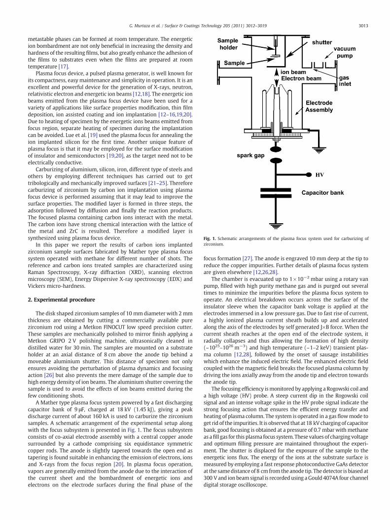
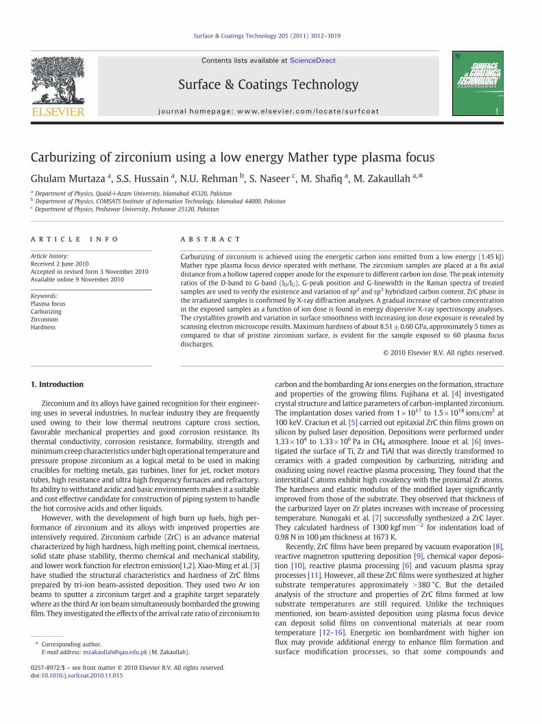
Fig. 1. Schematic arrangements of the plasma focus system used for carburizing ofzirconium.
3013G. Murtaza et al. / Surface & Coatings Technology 205 (2011) 3012–3019
metastable phases can be formed at room temperature. The energeticion bombardment are not only beneficial in increasing the density andhardness of the resulting films, but also greatly enhance the adhesion ofthe films to substrates even when the films are prepared at roomtemperature [17].
Plasma focus device, a pulsed plasma generator, is well known forits compactness, easy maintenance and simplicity in operation. It is anexcellent and powerful device for the generation of X-rays, neutron,relativistic electron and energetic ion beams [12,18]. The energetic ionbeams emitted from the plasma focus device have been used for avariety of applications like surface properties modification, thin filmdeposition, ion assisted coating and ion implantation [12–16,19,20].Due to heating of specimen by the energetic ions beams emitted fromfocus region, separate heating of specimen during the implantationcan be avoided. Lue et al. [19] used the plasma focus for annealing theion implanted silicon for the first time. Another unique feature ofplasma focus is that it may be employed for the surface modificationof insulator and semiconductors [19,20], as the target need not to beelectrically conductive.
Carburizing of aluminium, silicon, iron, different type of steels andothers by employing different techniques has carried out to gettribologically and mechanically improved surfaces [21–25]. Thereforecarburizing of zirconium by carbon ion implantation using plasmafocus device is performed assuming that it may lead to improve thesurface properties. The modified layer is formed in three steps, theadsorption followed by diffusion and finally the reaction products.The focused plasma containing carbon ions interact with the metal.The carbon ions have strong chemical interaction with the lattice ofthe metal and ZrC is resulted. Therefore a modified layer issynthesized using plasma focus device.
In this paper we report the results of carbon ions implantedzirconium sample surfaces fabricated by Mather type plasma focussystem operated with methane for different number of shots. Thereference and carbon ions treated samples are characterized usingRaman Spectroscopy, X-ray diffraction (XRD), scanning electronmicroscopy (SEM), Energy Dispersive X-ray spectroscopy (EDX) andVickers micro-hardness.
2. Experimental procedure
The disk shaped zirconium samples of 10 mmdiameter with 2 mmthickness are obtained by cutting a commercially available purezirconium rod using a Metkon FINOCUT low speed precision cutter.These samples are mechanically polished to mirror finish applying aMetkon GRIPO 2 V polishing machine, ultrasonically cleaned indistilled water for 30 min. The samples are mounted on a substrateholder at an axial distance of 8 cm above the anode tip behind amoveable aluminium shutter. This distance of specimen not onlyensures avoiding the perturbation of plasma dynamics and focusingaction [26] but also prevents the mere damage of the sample due tohigh energy density of ion beams. The aluminium shutter covering thesample is used to avoid the effects of ion beams emitted during thefew conditioning shots.
A Mather type plasma focus system powered by a fast dischargingcapacitor bank of 9 μF, charged at 18 kV (1.45 kJ), giving a peakdischarge current of about 160 kA is used to carburize the zirconiumsamples. A schematic arrangement of the experimental setup alongwith the focus subsystem is presented in Fig. 1. The focus subsystemconsists of co-axial electrode assembly with a central copper anodesurrounded by a cathode comprising six equidistance symmetriccopper rods. The anode is slightly tapered towards the open end astapering is found suitable in enhancing the emission of electrons, ionsand X-rays from the focus region [20]. In plasma focus operation,vapors are generally emitted from the anode due to the interaction ofthe current sheet and the bombardment of energetic ions andelectrons on the electrode surfaces during the final phase of the
focus formation [27]. The anode is engraved 10 mm deep at the tip toreduce the copper impurities. Further details of plasma focus systemare given elsewhere [12,26,28].
The chamber is evacuated up to 1×10⁻² mbar using a rotary vanpump, filled with high purity methane gas and is purged out severaltimes to minimize the impurities before the plasma focus system tooperate. An electrical breakdown occurs across the surface of theinsulator sleeve when the capacitor bank voltage is applied at theelectrodes immersed in a low pressure gas. Due to fast rise of current,a highly ionized plasma current sheath builds up and acceleratedalong the axis of the electrodes by self generated J×B force. When thecurrent sheath reaches at the open end of the electrode system, itradially collapses and thus allowing the formation of high density(~1025–1026 m−3) and high temperature (~1–2 keV) transient plas-ma column [12,28], followed by the onset of sausage instabilitieswhich enhance the induced electric field. The enhanced electric fieldcoupled with the magnetic field breaks the focused plasma column bydriving the ions axially away from the anode tip and electron towardsthe anode tip.
The focusing efficiency ismonitored by applying a Rogowski coil anda high voltage (HV) probe. A steep current dip in the Rogowski coilsignal and an intense voltage spike in the HV probe signal indicate thestrong focusing action that ensures the efficient energy transfer andheating of plasma column. The system is operated in a gas flowmode toget rid of the impurities. It is observed that at 18 kVchargingof capacitorbank, good focusing is obtained at a pressure of 0.7 mbar with methaneas afill gas for this plasma focus system. These values of charging voltageand optimum filling pressure are maintained throughout the experi-ment. The shutter is displaced for the exposure of the sample to theenergetic ions flux. The energy of the ions at the substrate surface ismeasured by employing a fast response photoconductive GaAs detectorat the samedistance of 8 cm from the anode tip. The detector is biased at300 V and ion beamsignal is recordedusing aGould 4074A four channeldigital storage oscilloscope.

Fig. 2. a) A typical ion beam signal recorded by GaAs detector. b) Energy spectrum ofcarbon and hydrogen ion beams.
3014 G. Murtaza et al. / Surface & Coatings Technology 205 (2011) 3012–3019
It is experienced that it always takes several focus shots to get strongfocusing after each fresh loadingof the sample for carburizing. In a singlefocus shot, ions are emitted from the pinched region in several buncheswith timeduration of fewnanoseconds [29]. The ions emitted in thefirstbunch cause etching, cleaning and heating of the substrate surface. Athin surface layer with elevated temperature is achieved and separateheating of specimen avoided. The subsequent ion beams are responsiblefor carburizing in our system. Thereafter, the residual plasma interactswith the high temperature target surface. High surface temperature isbeneficial for the addition of carbon into the surface and carbon dif-fusion towards the deeper layers.
Different techniques are applied to characterize the virgin andplasma carburized samples. Raman spectroscopic measurements areobtained using anAvantes Ramanmicroprobewhich is equippedwith a785 nm line of diode laser as an excitation source. The XRD patterns areachieved at a grazing incidence of 1° by operating the machine at 40 kVand 40 mA by employing CuKα radiation using a Philips PW 30440/X0X'PERT PRO MPD theta–theta diffractrometer. The micrographs of thesamples are acquired using JEOL JSM-5910 SEM operated at 21 kV. TheINCA 200: Oxford Instrument, UK, EDX attachment of the SEM isoperated at 21 keV with 50 s collection time to analyze the elementalcomposition. The surface hardness is estimated using a WilsonInstruments 401 MVA Vickers micro-hardness tester equipped with a136° diamond indenter.
3. Results and discussion
A typical GaAs detector signal of ions beam recorded by theoscilloscope for a single good focus shot is shown in Fig. 2a. The firstlow intensity peak is caused by theX-rays emitted from the focus regionwhereas the second peak corresponds to hydrogen ions and third peakindicating the carbon ions. The time of flight technique is employed toestimate the energy of hydrogen and carbon ions generating the signal.The hydrogen and carbon ions sweep the energy regions 5–100 keV and20–300 keV respectively. Implantation depth of about 570 nm (with arange straggling of 125 nm) and 430 nm (with a range straggling of165 nm) in Zirconium are estimated by the SRIM [30] for 100 keVhydrogen and 300 keV carbon ions respectively. The charge states ofcarbon ions could not be differentiated by the energy resolution definedby the GaAs detector signal. However Bhuyan et al. [31] investigated theion beam emission from a low energy 1.8 kJ Mather type plasma focusoperating with methane and found that dominant carbon ion specieswere C+4 and C+5. Deconvolution is applied to the ion beam signalassuming that the peak shapes are Gaussian. The ion emission timeestimated as the temporal width of X-ray pulse is ~40 ns. The energyspectrum of hydrogen and carbon ions is deduced from the detectorsignal utilizing the time of flight technique and the simple relation [32].
Ni = V= RqAv;
where Ni is the number density of ions; V is the maximum voltage ofthe ion pulse corresponding to the ions with velocity and charge q; Ais the area of the pinhole aperture of the detector; R is the inputresistance of the oscilloscope across which output of the ion pulsemeasured. The energy distribution of hydrogen and carbon ions isshown in Fig. 2b.
Raman spectroscopy is a standard nondestructive experimentaltechnique for probing the vibrational and structural properties ofcarbon rich materials. Raman spectroscopy of carbon ions treatedsamples is performed in a back scattering geometry by operating themachine at a power level of 100 mW with spectral range of 100–2000 cm−1. These spectra give information about bonding type, thelevel of internal stress, the phase changes and domain size of sp2 andsp3. The typical Raman spectra of carbon ions treated zirconiumsamples for multiple shots (10–60) in dense plasma focus environ-ment with methane as fill gas are shown in Fig. 3a. No significant
changes are observed up to 5 focus shots. In the range of 100–700 cm−1
the spectra provide information about the Zr–O bonds. The monoclinicZr–O Raman bands are present at about 190, 380, 476, and 617 cm−1
[33,34] while the tetragonal form located at about 260 and 640 cm−1
[34,35]. The broadening and shifting of Zr–O peaks toward the lowervalue occur with increasing ion dose. This may be due to the damagestress produced by the carbon irradiation in the surrounding ofZirconium matrix. The intensity of Zr–O peaks also decreases withincreasingnumberof focus shots as thenativeoxide layer is purgedwithincreasing number of focus shots.
The Raman spectroscopy does not provide much informationabout Zr–C bonding but it is well suited for the detection of C–C bonds.The part of implanted carbon which is not utilized in the formation ofZrC appears as C–C clusters. The spectra indicate two sharp modes inthe range of 1100–1700 cm−1. The G-peak around 1500–1630 cm−1
is corresponding to the zone centre E2g bond stretching mode ofgraphite and present in all sp2 bonded carbon films. The D peakaround 1330–1350 cm−1, disorder-activated k-zone boundary mode,is forbidden in perfect graphite and assigned to the A1g symmetrybreathing motion of six fold aromatic rings [36]. This mode isdispersive and varies with phonon excitation energy. The spectrademonstrate that shape, intensity and position of D and G-peaks varywith increasing ion dosage. The variations in D-band peak position arevery small and can be observed at enlarged spectrum. The D-band peakposition shifted to lower wave numbers up to 40 focus shots and thenshifted to higher wave number. The variations in sp3/sp2-bonding and
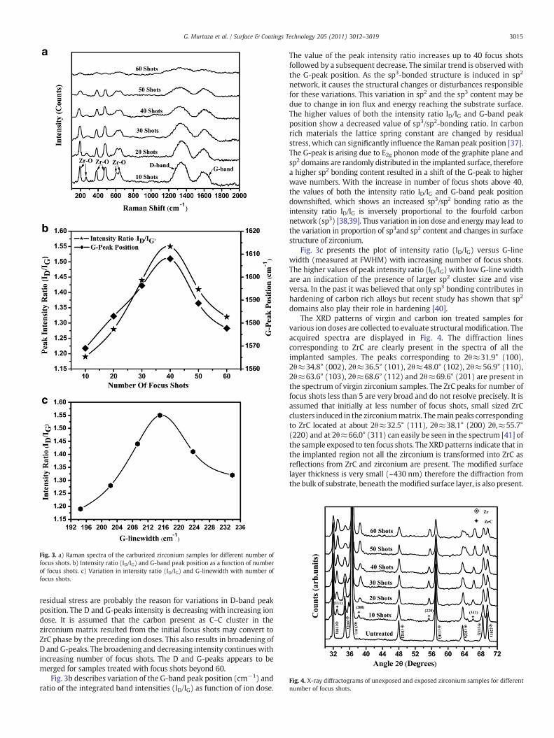
Fig. 3. a) Raman spectra of the carburized zirconium samples for different number offocus shots. b) Intensity ratio (ID/IG) and G-band peak position as a function of numberof focus shots. c) Variation in intensity ratio (ID/IG) and G-linewidth with number offocus shots.
Fig. 4. X-ray diffractograms of unexposed and exposed zirconium samples for differentnumber of focus shots.
3015G. Murtaza et al. / Surface & Coatings Technology 205 (2011) 3012–3019
residual stress are probably the reason for variations in D-band peakposition. The D and G-peaks intensity is decreasing with increasing iondose. It is assumed that the carbon present as C–C cluster in thezirconium matrix resulted from the initial focus shots may convert toZrC phase by the preceding ion doses. This also results in broadening ofD andG-peaks. The broadening and decreasing intensity continueswithincreasing number of focus shots. The D and G-peaks appears to bemerged for samples treated with focus shots beyond 60.
Fig. 3b describes variation of the G-band peak position (cm−1) andratio of the integrated band intensities (ID/IG) as function of ion dose.
The value of the peak intensity ratio increases up to 40 focus shotsfollowed by a subsequent decrease. The similar trend is observed withthe G-peak position. As the sp3-bonded structure is induced in sp2
network, it causes the structural changes or disturbances responsiblefor these variations. This variation in sp2 and the sp3 content may bedue to change in ion flux and energy reaching the substrate surface.The higher values of both the intensity ratio ID/IG and G-band peakposition show a decreased value of sp3/sp2-bonding ratio. In carbonrich materials the lattice spring constant are changed by residualstress, which can significantly influence the Raman peak position [37].The G-peak is arising due to E2g phonon mode of the graphite plane andsp2 domains are randomly distributed in the implanted surface, thereforea higher sp2 bonding content resulted in a shift of the G-peak to higherwave numbers. With the increase in number of focus shots above 40,the values of both the intensity ratio ID/IG and G-band peak positiondownshifted, which shows an increased sp3/sp2 bonding ratio as theintensity ratio ID/IG is inversely proportional to the fourfold carbonnetwork (sp3) [38,39]. Thus variation in ion dose and energymay lead tothe variation in proportion of sp3and sp2 content and changes in surfacestructure of zirconium.
Fig. 3c presents the plot of intensity ratio (ID/IG) versus G-linewidth (measured at FWHM) with increasing number of focus shots.The higher values of peak intensity ratio (ID/IG) with low G-line widthare an indication of the presence of larger sp2 cluster size and viseversa. In the past it was believed that only sp3 bonding contributes inhardening of carbon rich alloys but recent study has shown that sp2
domains also play their role in hardening [40].The XRD patterns of virgin and carbon ion treated samples for
various ion doses are collected to evaluate structuralmodification. Theacquired spectra are displayed in Fig. 4. The diffraction linescorresponding to ZrC are clearly present in the spectra of all theimplanted samples. The peaks corresponding to 2θ≈31.9° (100),2θ≈34.8° (002), 2θ≈36.5° (101), 2θ≈48.0° (102), 2θ≈56.9° (110),2θ≈63.6° (103), 2θ≈68.6° (112) and 2θ≈69.6° (201) are present inthe spectrum of virgin zirconium samples. The ZrC peaks for number offocus shots less than 5 are very broad and do not resolve precisely. It isassumed that initially at less number of focus shots, small sized ZrCclusters induced in the zirconiummatrix. Themainpeaks correspondingto ZrC located at about 2θ≈32.5° (111), 2θ≈38.1° (200) 2θ,≈55.7°(220) and at 2θ≈66.0° (311) can easily be seen in the spectrum [41] ofthe sample exposed to ten focus shots. The XRD patterns indicate that inthe implanted region not all the zirconium is transformed into ZrC asreflections from ZrC and zirconium are present. The modified surfacelayer thickness is very small (~430 nm) therefore the diffraction fromthe bulk of substrate, beneath themodified surface layer, is also present.
3016 G. Murtaza et al. / Surface & Coatings Technology 205 (2011) 3012–3019
Well broad but resolvable peaks with increasing intensity for ZrC phaseare also observed for the samples treated with higher number of focusshots. The increase in intensity of peaks corresponding to ZrC phase anddecrease in peak intensity of zirconium phase continue with theincreasing ion dose up to 50 focus shots. This indicates the growth of ZrCprecipitates with increasing ion dose. It may be due to the coalescenceprocess and migration of carbon atoms from C–C clusters present inthe zirconium matrix as a result of preceding focus shots. It is alsoconsidered that target surface is in liquid phase during the interaction ofsecondary ion beams and plasma species may diffuse in the deeperlayers. Consequently, a ceramic layer of several nanometers in thicknessis achievedwhich grows as a function of ion dose. The precipitate size isestimated using the Scherrer formula [42]:
d = Kλ= B cos θ
where K is Scherrer constant (~0.99); λ is wavelength of CuKα
(=0.15406 nm); B is the FWHM intensity of the peak in radian(which is estimated after a Gaussian fit on the peaks); θ is the angle ofthe peak. Using the Scherrer formula the maximum grain size of ZrC isfound approximately 48±5 nm. The ZrC peak intensity value doesnot seem to increase significantly for the samples exposed to focus shotsbeyond 50, but the broadening of zirconium and ZrC peaks withdecrease in zirconium peak intensity continues. It may be due to thedamage produced in the zirconium matrix along with the ZrC
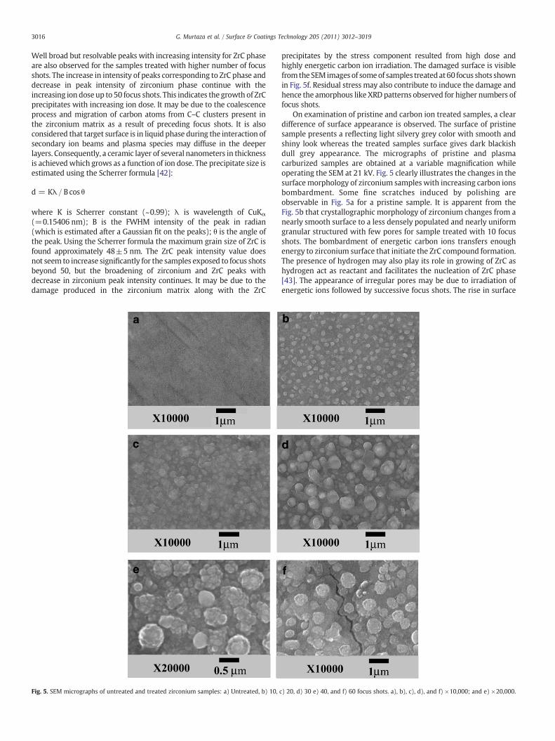
Fig. 5. SEM micrographs of untreated and treated zirconium samples: a) Untreated, b) 10,
precipitates by the stress component resulted from high dose andhighly energetic carbon ion irradiation. The damaged surface is visiblefromtheSEM images of someof samples treatedat60 focus shots shownin Fig. 5f. Residual stress may also contribute to induce the damage andhence the amorphous like XRD patterns observed for higher numbers offocus shots.
On examination of pristine and carbon ion treated samples, a cleardifference of surface appearance is observed. The surface of pristinesample presents a reflecting light silvery grey color with smooth andshiny look whereas the treated samples surface gives dark blackishdull grey appearance. The micrographs of pristine and plasmacarburized samples are obtained at a variable magnification whileoperating the SEM at 21 kV. Fig. 5 clearly illustrates the changes in thesurfacemorphology of zirconium samples with increasing carbon ionsbombardment. Some fine scratches induced by polishing areobservable in Fig. 5a for a pristine sample. It is apparent from theFig. 5b that crystallographic morphology of zirconium changes from anearly smooth surface to a less densely populated and nearly uniformgranular structured with few pores for sample treated with 10 focusshots. The bombardment of energetic carbon ions transfers enoughenergy to zirconium surface that initiate the ZrC compound formation.The presence of hydrogen may also play its role in growing of ZrC ashydrogen act as reactant and facilitates the nucleation of ZrC phase[43]. The appearance of irregular pores may be due to irradiation ofenergetic ions followed by successive focus shots. The rise in surface
c) 20, d) 30 e) 40, and f) 60 focus shots. a), b), c), d), and f) ×10,000; and e) ×20,000.
3017G. Murtaza et al. / Surface & Coatings Technology 205 (2011) 3012–3019
temperature and removal of native oxide by the ion bombardmentmay be the other reason. The transient surface temperature rise up toseveral thousands degree centigrade for each focus shot is immedi-ately followed by fast melting and resolidification [44]. The solidliquid reaction of carbon andmolten zirconium takes place and resultsthe formation of ZrC phase. The transient thermal temperature risealso acts to thermally annealing the sample surface. Thus rearrange-ments of atoms in surface layer leads to a higher diffusion of carbonatoms into surface layer. It is known that carbon can form strongcovalent bonds with zirconium and cause the formation of crystallineZrC compound with high melting temperature [45]. Also zirconiumhas a much larger negative heat of mixing [46] with carbon. Thus Zrand carbon have large driving forces for reactionwhich leads to nearlyuniform distribution of ZrC phase in zirconium matrix. Fig. 5c showsrelatively smooth surface closely stacked by grains for 20 focus shotswhich may be due to suitable ion energy flux for grain growth. It isassumed that besides the formation ZrC phase and C–C clusters, theenergy density of ions is suitable to remove certain voids, asperitiesand rough particles by sputtering, etching and deposition processes.The parallel transient annealing with increasing ion doses also facil-itate the agglomeration process and provide assistance in smoothercarburized surface. The observed increase of nearly spherical shapedgrain size and increased grain density with increasing ion dose isresulted from higher atomic mobility and grain boundary mobility atelevated temperature due to successive focus shots. Themicrograph fora sample surface treated with 30 focus shots shown in Fig. 5d. It isassumed that the ZrC crystallites grow further and coalescence occurs.This continues for the sample treated with 40 focus shots. The samplesurface treated with 40 focus shots shown in Fig. 5e indicates thepresence of crystallites in the form of clusters at higher magnification.The micrograph of sample treated with 50 focus shots showsapproximately similar appearance. Some of the samples treated with60 focus shots show rougher surface with somemicro-cracks shown inFig. 5f. High doses of carbon and unbound carbon result in surfaceswelling of substrate increasing its roughness as in the case of nitriding[47]. It is assumed that highly energetic ion flux generated by stable andstrong focusing action deliver an excessive energy to the substratesurface causes sputtering and etching and hence results in surfacedamage and roughness. The partial melting by the highly energetic ionsand abrupt resolidification after cooling down may be another reasonfor surface roughness. The micro-cracks may also be due to the thermalshock, taking place during the ion beam incidence consisting of fastheating and strong temperature gradients [44]. A decrease in surfacesmoothness with increased micro-cracks is also observed for samplestreated beyond the60 focus shots. It is concluded that zirconiumcarbidecrystallites formed and grow as a function of ion dose. This is well inagreementwith XRD results.Wemay say thatmicro-structural changesdepend upon the ion dose and energy deliver to the samples surface byplasma focus system.
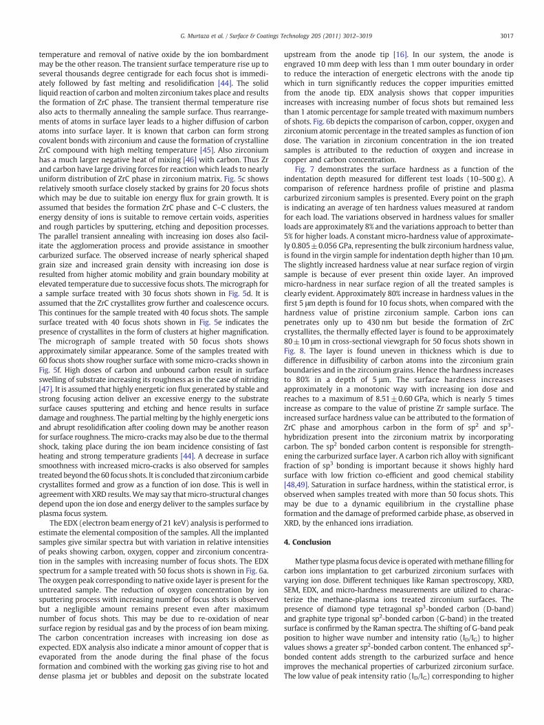
The EDX (electron beam energy of 21 keV) analysis is performed toestimate the elemental composition of the samples. All the implantedsamples give similar spectra but with variation in relative intensitiesof peaks showing carbon, oxygen, copper and zirconium concentra-tion in the samples with increasing number of focus shots. The EDXspectrum for a sample treated with 50 focus shots is shown in Fig. 6a.The oxygen peak corresponding to native oxide layer is present for theuntreated sample. The reduction of oxygen concentration by ionsputtering process with increasing number of focus shots is observedbut a negligible amount remains present even after maximumnumber of focus shots. This may be due to re-oxidation of nearsurface region by residual gas and by the process of ion beam mixing.The carbon concentration increases with increasing ion dose asexpected. EDX analysis also indicate a minor amount of copper that isevaporated from the anode during the final phase of the focusformation and combined with the working gas giving rise to hot anddense plasma jet or bubbles and deposit on the substrate located
upstream from the anode tip [16]. In our system, the anode isengraved 10 mm deep with less than 1 mm outer boundary in orderto reduce the interaction of energetic electrons with the anode tipwhich in turn significantly reduces the copper impurities emittedfrom the anode tip. EDX analysis shows that copper impuritiesincreases with increasing number of focus shots but remained lessthan 1 atomic percentage for sample treated with maximum numbersof shots. Fig. 6b depicts the comparison of carbon, copper, oxygen andzirconium atomic percentage in the treated samples as function of iondose. The variation in zirconium concentration in the ion treatedsamples is attributed to the reduction of oxygen and increase incopper and carbon concentration.
Fig. 7 demonstrates the surface hardness as a function of theindentation depth measured for different test loads (10–500 g). Acomparison of reference hardness profile of pristine and plasmacarburized zirconium samples is presented. Every point on the graphis indicating an average of ten hardness values measured at randomfor each load. The variations observed in hardness values for smallerloads are approximately 8% and the variations approach to better than5% for higher loads. A constant micro-hardness value of approximate-ly 0.805±0.056 GPa, representing the bulk zirconium hardness value,is found in the virgin sample for indentation depth higher than 10 μm.The slightly increased hardness value at near surface region of virginsample is because of ever present thin oxide layer. An improvedmicro-hardness in near surface region of all the treated samples isclearly evident. Approximately 80% increase in hardness values in thefirst 5 μm depth is found for 10 focus shots, when compared with thehardness value of pristine zirconium sample. Carbon ions canpenetrates only up to 430 nm but beside the formation of ZrCcrystallites, the thermally effected layer is found to be approximately80±10 μm in cross-sectional viewgraph for 50 focus shots shown inFig. 8. The layer is found uneven in thickness which is due todifference in diffusibility of carbon atoms into the zirconium grainboundaries and in the zirconium grains. Hence the hardness increasesto 80% in a depth of 5 μm. The surface hardness increasesapproximately in a monotonic way with increasing ion dose andreaches to a maximum of 8.51±0.60 GPa, which is nearly 5 timesincrease as compare to the value of pristine Zr sample surface. Theincreased surface hardness value can be attributed to the formation ofZrC phase and amorphous carbon in the form of sp2 and sp3-hybridization present into the zirconium matrix by incorporatingcarbon. The sp2 bonded carbon content is responsible for strength-ening the carburized surface layer. A carbon rich alloy with significantfraction of sp3 bonding is important because it shows highly hardsurface with low friction co-efficient and good chemical stability[48,49]. Saturation in surface hardness, within the statistical error, isobserved when samples treated with more than 50 focus shots. Thismay be due to a dynamic equilibrium in the crystalline phaseformation and the damage of preformed carbide phase, as observed inXRD, by the enhanced ions irradiation.
4. Conclusion
Mather typeplasma focus device is operatedwithmethanefilling forcarbon ions implantation to get carburized zirconium surfaces withvarying ion dose. Different techniques like Raman spectroscopy, XRD,SEM, EDX, and micro-hardness measurements are utilized to charac-terize the methane-plasma ions treated zirconium surfaces. Thepresence of diamond type tetragonal sp3-bonded carbon (D-band)and graphite type trigonal sp2-bonded carbon (G-band) in the treatedsurface is confirmed by the Raman spectra. The shifting of G-band peakposition to higher wave number and intensity ratio (ID/IG) to highervalues shows a greater sp2-bonded carbon content. The enhanced sp2-bonded content adds strength to the carburized surface and henceimproves the mechanical properties of carburized zirconium surface.The low value of peak intensity ratio (ID/IG) corresponding to higher
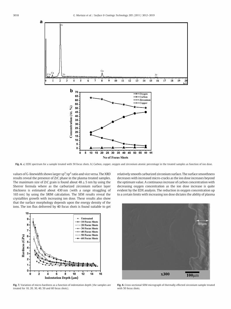
Fig. 6. a) EDX spectrum for a sample treated with 50 focus shots. b) Carbon, copper, oxygen and zirconium atomic percentage in the treated samples as function of ion dose.
3018 G. Murtaza et al. / Surface & Coatings Technology 205 (2011) 3012–3019
values of G-linewidth shows larger sp3/sp2 ratio andvice versa. TheXRDresults reveal the presence of ZrC phase in the plasma treated samples.The maximum size of ZrC grain is found about 48±5 nm by using theSherrer formula where as the carburized zirconium surface layerthickness is estimated about 430 nm (with a range straggling of165 nm) by using the SRIM calculation. The SEM results reveal thecrystallites growth with increasing ion dose. These results also showthat the surface morphology depends upon the energy density of theions. The ion flux delivered by 40 focus shots is found suitable to get
Fig. 7. Variation of micro-hardness as a function of indentation depth (the samples aretreated for 10, 20, 30, 40, 50 and 60 focus shots).
relatively smooth carburized zirconiumsurface. The surface smoothnessdecreaseswith increasedmicro-cracks as the ion dose increases beyondthe optimumvalue. A continuous increase of carbon concentrationwithdecreasing oxygen concentration as the ion dose increase is quiteevident by the EDX analysis. The reduction in oxygen concentration upto a certain limits with increasing ion dose dictates the ability of plasma
Fig. 8. Cross-sectional SEM micrograph of thermally effected zirconium sample treatedwith 50 focus shots.

3019G. Murtaza et al. / Surface & Coatings Technology 205 (2011) 3012–3019
focus to remove native oxide layer. Approximately five times improvedmicro-hardness as compared to zirconium surface is observed forsample treatedwith 60 focus shots. The surface hardness is attributed tosp2 and sp3-bonded carbon content and the cubic ZrC phase. From theseresults, it is also concluded that native oxide layer, surface conditionsand contamination rising from device or filling gas impurities are not aproblem in processing for highly energetic carbon ions emanating fromfocus plasma. The time gap between the two successive focus shots is60 s but the actual processing time is fewmicro seconds. The total timecan be reduced using a repetitive plasma focus device. Based on theseinvestigations the plasma focus device is found to be an efficient systemto get a carburized zirconium surface.
Acknowledgments
Ghulam Murtaza and S. S. Hussain acknowledge the financialsupport of HEC for their doctoral studies. The work was partiallysupported by Pakistan Science Foundation project no. PSF/Res/C-QU/Phys (136) for Plasma Physics. We also acknowledge Dr. Riaz Khan,and Mr. Abdullah Jan of Centralized Resource Laboratory, PeshawarUniversity, for carrying out the EDX and SEM analyses.
References
[1] D. Temple, Mater. Sci. Eng. R24 (1999) 185.[2] E.K. Sorms, The Refractory Carbides, Academic Press, New York, 1967.[3] HeX.M. , ShuL. , LiH.B. , LiH.D. , J. Vac. Sci. Technol. A16 (4) (1998) 2337.[4] T. Fujihana, M. Taniguchi, Y. Okabe, M. Iwaki, Surf. Coat. Technol. 83 (1996) 120.[5] V. Craciun, J. Wooa, D. Craciun, R.K. Singh, Appl. Surf. Sci. 252 (2006) 4615.[6] M. Inoue, M. Nunogaki, T. Yamamoto, Mater. Manuf. Processes 17 (2002) 553.[7] M. Nunogaki, Y. Susuki, K. Kitahama, Y. Nakata, F. Hori, R. Oshima, S. Emura, Proc.
Mater. Res. Soc. Symp. 551 (1999) 303.[8] W.A. Mackie, T.B. Xie, P.R. Davis, J. Vac. Sci. Technol. B 13 (1995) 2459.[9] J. Bruckner, T. Manytla, Surf. Coat. Technol. 59 (1993) 166.
[10] D.C. Smith, R.R. Rubiano, M.D. Healy, R.W. Springer, Mater. Res. Soc. Symp. Proc.282 (1993) 643.
[11] D.J. Varacalle Jr., L.B. Lundberg, H. Herman, G. Bancke, W.L. Riggs, Surf. Coat.Technol. 68 (69) (1994) 86.
[12] S. Zeb, G. Murtaza, M. Zakaullah, J. Appl. Phys. 101 (2007) 063307.[13] S. Zeb, M. Sadiq, A. Qayyum, G. Murtaza, M. Zakaullah, Mater. Chem. Phys. 103
(2007) 235.[14] R.S. Rawat, T. Zhang, K.S.G. Thomas, P. Lee, R.V. Ramanujan, Appl. Surf. Sci. 253
(2006) 1611.
[15] R.S. Rawat, W.M. Chew, T. White, S. Lee, Surf. Coat. Technol. 173 (2003) 276.[16] H. Bhuyan, M. Favre, E. Valderrama, A. Henriquez, G. Vogel, H. Chuaqui1, E.
Wyndham, A. Cabrera1, E. Ramos-Moore, P.A. Nunez, H. Kelly, D. Grondona, S.Goyanes, J. Phys. D Appl. Phys. 42 (2009) 205207.
[17] X.M. He, W.Z. Li, H.D. Li, J. Vac. Sci. Technol. A 14 (1996) 2039.[18] S. Ahmad, S.S. Husain, M. Sadiq, M. Shafiq, A. Waheed, P. Lee, M. Zakaullah, Plasma
Phys. Controlled Fusion 48 (2006) 745.[19] J.T. Lue, C.K. Yeh, Y.Y. Huo, IEEE Electron Device Lett. 4 (1983) 457.[20] M. Sadiq, S. Ahmad, M. Shafiq, M. Zakaullah, Plasma Processes Polym. 4 (2007) 186.[21] C.E. Foerster, S.L.R. da Silva, T. Fitz, T. Dekorsy, F. Prokert, U. Kreibig, E. Richter, W.
Moller, A.Mucklich, C.M. Lpienski, C.J. deM. Siqueira, Surf. Coat. Technol. 200 (2006)5210.
[22] MurtazaG. , HussainS.S. , SadiqM. , ZakaullahM. , Thin Solid Films 517 (2009) 6777.[23] F. Fariaut, C. Boulmer-Leborgne, E.L. Menn, T. Sauvage, C. Andreazza-Vignolle, P.
Andreazza, C. Langlade, Appl. Surf. Sci. 186 (2002) 105.[24] E. Carpene, A.M. Flank, A. Traverse, P. Schaaf, J. Phys. D Appl. Phys. 35 (2002) 1428.[25] C. Li, Q. He, W. Tang, F. Lu, Surf. Coat. Technol. 187 (2004) 1.[26] S. Lee, M.A. Alabraba, A.A. Gholap, S. Kumar, K.H. Kwek, M. Nisar, R.S. Rawat, J.
Singh, IEEE Trans. Plasma Sci. 18 (1990) 1028.[27] H. Bhuyan, M. Favre, E. Valderrama, H. Chuaqui, E.Wyndham, J. Phys. D Appl. Phys.
39 (2006) 3596.[28] J.W. Mather, Phys. Fluids 11 (1968) 611.[29] M. Sadowski, H. Schmidt, H. Herold, Phys. Lett. A 83 (1981) 435.[30] http://www.srim.org.[31] H. Bhuyan, H. Chuaqui, M. Favre, I. Mitchell, E. Wyndham, J. Phys. D Appl. Phys. 38
(2005) 1164.[32] S.R. Mohanty, H. Bhuyan, N.K. Neog, R.K. Rout, E. Hotta, Jpn. J. Appl. Phys. 44 (2005)
5199.[33] J.A. Valdez, M. Tang, Z. Chi, M.I. Peters, K.E. Sickafus, Nucl. Instrum. Methods B 218
(2004) 103.[34] B. Kim, J. Hahn, K.R. Han, J. Mater. Sci. Lett. 16 (1997) 669.[35] J.M. Costantini, A.K. Harari, F. Beuneu, F. Couvreur, J. Appl. Phys. 99 (2006) 123501.[36] M.A. Tamor, W.C. Vassell, J. Appl. Phys. 76 (1994) 3823.[37] J.K. Shin, LeeC.S. , K.R. Lee, K.Y. Eun, Appl. Phys. Lett. 631 (2001).[38] S. Zhang, X.T. Zeng, H. Xie, P. Hing, Surf. Coat. Technol. 123 (2000) 256.[39] L.Y. Soh, P. Lee, X. Shuyan, S. Lee, R.S. Rawat, IEEE Trans. Plasma Sci. 32 (2004) 448.[40] P.K. Chu, L. Li, Mater. Chem. Phys. 96 (2006) 253.[41] Powder Diffraction File, Joint Committee on Powder Diffraction Standards, , 20008
Card # 35-0784.[42] M.E. Rabanal, VarezA. , B. Levenfeld, J.M. Torralba, J.Mater. Process. Technol. 143/144
(2003) 470.[43] J.H. Park, C.H. Jung, D.J. Kim, J.Y. Park, Surf. Coat. Technol. 203 (2008) 87.[44] G. Sanchez, J. Feugcas, J. Phys. D Appl. Phys. 30 (1997) 927.[45] B.M. Clemens, R. Sinclair, MRS Bull. 15 (1990) 19.[46] F.R. de Boer, R. Boom, W.C.M. Mattens, A.R. Miedema, A.K. Niessen, Cohesion in
Metals: Transition Metal Alloys, North-Holland, Amsterdam, 1988.[47] S. Gredelj, A.R. Gerson, S. Kumar, G.P. Cavallaro, Appl. Surf. Sci. 174 (2001) 240.[48] K. Enke, Thin Solid Films 80 (1981) 227.[49] Neuville Stephan, Diamond Relat. Mater. 11 (2002) 1721.
Copyright © 2022 FDOKUMEN