Wilo Mather and Platt – Vertical Ring Section pumps
29
0 Wilo Mather and Platt_RS_20131005_02 Wilo Mather and Platt – Vertical Ring Section pumps en Installation and operat ing instructions Installation and operating instructions Wilo Mather and Platt –Ring Section Pumps
-
Upload
khangminh22 -
Category
Documents
-
view
0 -
download
0
Transcript of Wilo Mather and Platt – Vertical Ring Section pumps
0
Wilo
Math
er
and P
latt
_R
S_
20
13
10
05
_0
2
Wilo Mather and Platt – Vertical Ring Section pumps
en Installation and operating instructions
Installation and operating instructions Wilo Mather and Platt –Ring Section Pumps
1
Disclaimer Wilo Mather and Platt is very grateful for your interest in its products. The basic objective of
this document is to provide instructions for maintaining and operating Wilo Mather and Platt
Ring Section pumps. Instructions are complied for the person having a working knowledge of
Ring section pumps and the pumps shall be installed under expert supervision and guidance.
With this document Wilo Mather and Platt does not accept any liability for inaccurate
installation, operation or maintenance of the product at site. The authorities that install and
maintain the pump shall be responsible for hassle free installation operation or maintenance
of the product.
This document is prepared with at most care to ensure correct and accurate information,
enabling the user to have trouble free installation and operational support. However, there can
be few areas for improvement to make this document error free.
We welcome your valuable suggestions to make this document complete in all respects.
WILO Mather and Platt Pumps Pvt. Ltd.
Mumbai-Pune Road, Chinchwad,
Pune- 411 019, Maharashtra (India)
Tel: +91 20 27442100/1/2/3/4,
Toll Fee Service: 1-800-266-8866
Fax: +91 2027442111
www.wilo.in
Installation and operating instructions Wilo Mather and Platt –Ring Section Pumps

\
'\J
0
'c r
1---
1---
,..J
1---
1---
1---
/! ='!\\" lj •• 4 '
" ..j
' ;.. : :
Installation ond operating instructions Wilo Mather and Platt -Ring Section Pumps

Installation and ap«<tfng lnlltructlons Wlo Mather and Platt -Ring Section Pump• 2

- -
3

Fig.7: Coupling assembly
Fig 8 :Forces and Moments
Installation and operating instructions Wilo Mather and Platt –Ring Section Pumps 4

2
1 General information ............................................................................................................3
2 Safety ............................................................................................................................ 3
2.1 Designation of information in the operating instructions .................................................... 3
2.2 Personnel qualifications ...................................................................................................3
2.3 Danger in event of non-observance of the safety instructions ..............................................3
2.4 Safety consciousness on the job ........................................................................................4
2.5 Safety instructions for the operator ...................................................................................4
2.6 Safety instructions for installation and maintenance work ...................................................4
2.7 Unauthorized modification and manufacture of spare parts .................................................4
2.8 Improper use ....................................................................................................................4
2.9 Safety & control devices ...................................................................................................4
3 Transport and interim storage ...........................................................................................5
3.1 Handling ..........................................................................................................................5
3.2 Delivery ...........................................................................................................................5
3.3 Storage ...........................................................................................................................5
3.4 Pump returning back to the supplier ..................................................................................6
4 Intended use ....................................................................................................................6
5 Product information........................................................................................................ .6 5.1 Data plate ......................................................................................................................6 5.2 Type key ..........................................................................................................................6
5.3 Scope of delivery ..............................................................................................................6
5.4 Accessories.......................................................................................................................6
6 Description and function ...................................................................................................7 6.1 Description of the product .................................................................................................7
7 Installation and electrical connection (Motor / pump coupling system) .................................8
7.2 Installation of the complete pump set ................................................................................8
8 Commissioning .................................................................................................................13 8.1 Cleaning prior to start .......................................................................................................13
8.2 Filling and venting ............................................................................................................13
8.3 Starting the pump ............................................................................................................14
9 Maintenance ...................................................................................................................16 9.1 Routine maintenance and frequency of inspection .............................................................16
9.2 Overhaul maintenance ......................................................................................................17
9.3 Disassembling the pump ...................................................................................................18
9.4 Examination of internal components ..................................................................................18
9.5 Reassembling the pump ....................................................................................................19
9.6 Recommended spare parts ................................................................................................21
10 Faults, causes and remedies ..............................................................................................21
11 Decommissioning and recycling .........................................................................................22
Installation and operating instructions Wilo Mather and Platt –Ring Section Pumps
3
1 General information
About this document
The language of the original operating instructions is English. All other languages of these instructions are translations of the
original operating instructions.
These installation and operating instructions are an integral part of the product. They must be kept readily available at the
place where the product is installed. Strict adherence to these instructions is a precondition for the proper use and correct
operation of the product.
These installation and operating instructions correspond to the relevant version of the product and the underlying safety
standards valid at the time of going to print. Supplied pump will operate trouble free and satisfactorily on the condition that,
it is installed with due care and maintained properly.
For hassle free operating life, it is recommended that the pump should operate under specified “Operating conditions”.
Pump operating conditions are mentioned on the “Nameplate” affixed to the pump.
If operating parameters deviate from the specified parameters as on the “Nameplate”, please contact manufacturer.”
2 Safety These operating instructions contain basic information which must be adhered to during installation and operation. For this
reason, these operating instructions must, without fail, be read by the service technician and the responsible operator before
installation and commissioning. The machine operator list must be filled out completely. By signing this list, all persons
working on or with the product confirms that they have received, read and understood this operating & maintenance
manual.
It is not only the general safety instructions listed under the main point "safety" that must be adhered to but also the special
safety instructions with danger symbols included under the following main points.
2.1 Designation of information in the operating instructions
Symbols:
General danger symbol
Danger due to electrical voltage
NOTE: ...
Signal words: DANGER!
Acutely dangerous situation.
Non-observance results in death or the most serious of injuries.
WARNING!
The user can suffer (serious) injuries. “Warning” implies that (serious) injury to persons is probable if this information is
disregarded.
CAUTION!
There is a risk of damaging the pump/installation. “Caution” implies that damage to the pro- duct is likely if the
information is disregarded. NOTE:
Useful information on using the product. It also draws attention to possible problems.
2.2 Personnel qualifications The installation personnel must have the appropriate qualification for this work.
2.3 Danger in event of non-observance of the safety instructions Non-observance of the safety instructions can result in risk of injury to persons and damage to product/installation. Non-
observance of the safety instructions can result in the loss of any claims to damages.
In detail, non-observance can, for example, result in the following risks:
•Failure of important product/installation functions
•Failure of required maintenance and repair procedures
•Danger to persons from electrical, mechanical and bacteriological influences
•Property damage
Installation and operating instructions Wilo Mather and Platt –Ring Section Pumps

4
2.4 Safety consciousness on the job
The safety instructions included in these installation and operating instructions, the existing national regulations for
accident prevention together with any internal working, operating and safety regulations of the operator are to be
complied with.
2.5 Safety instructions for the operator
This appliance is not intended for use by persons (including children) with reduced physical, sensory or mental capabilities,
or lack of experience and knowledge, unless they have been given supervision or instruction concerning use of the
appliance by a person responsible for their safety. Children should be supervised to ensure that they do not play with the
appliance.
•If hot or cold components on the product/the unit lead to hazards, local measures must be taken to guard
them against touching.
•Guards protecting against touching moving components (such as the coupling) must not be removed
whilst the product is in operation.
•Leakages (e.g. from the shaft seals) of hazardous fluids (which are explosive, toxic or hot) must be led
away so that no danger to persons or to the environment arises. National statutory provisions are to be
complied with.
•Highly flammable materials are always to be kept at a safe distance from the product.
•Danger from electrical current must be eliminated. Local directives or general directives [e.g. IEC, VDE etc.] and local
power supply companies must be adhered to.
•Depending on the type, size and capacity (kW), the products produce a sound pressure up to 75 dB (A) to 110 dB (A).
•The actual sound pressure, however, depends on several factors. These include, for example, type of prime mover,
installation type; fastening of accessories and pipeline, operating site condition, background noise, etc.
•Once the product has been installed, We recommend that the operator makes additional measurements under all
operating conditions.
CAUTION!
In accordance with the laws in effect, guidelines, standards and regulations, ear protection must be worn if the sound
pressure is greater than 110dB (A). The operator is responsible for ensuring that this is observed!
2.6 Safety instructions for installation and maintenance work
The operator must ensure that all installation and maintenance work is carried out by authorized and qualified personnel,
who are sufficiently informed from their own detailed study of the operating instructions.
Work on the product/unit must only be carried out when at a standstill. It is mandatory that the procedure described in the
installation and operating instructions for shutting down the product/unit be complied with.
Immediately on conclusion of the work, all safety and protective devices must be put back in position and/or re-
commissioned.
2.7 Unauthorized modification and manufacture of spare parts
Unauthorized modification and manufacture of spare parts will impair the safety of the product/ personnel and will make
void the manufacturer's declarations regarding safety.
Modifications to the product are only permissible after consultation with the manufacturer. Original spare parts and
accessories authorized by the manufacturer ensure safety. The use of other parts will absolve us of liability for consequential
events.
2.8 Improper use The operating safety of the supplied product only guaranteed for conventional use in accordance with Section 4 of the
operating instructions. The limits values must on no account fall under or exceed those specified in the catalogue/data sheet.
2.9 Safety & control devices
Direct controls are applicable when the pump is supplied along with motor/panels. When motor/ panel is in
end user’s scope of supply, it is advised to go for CE approved motors /panels. Environmental safety
Disposal of any unwanted/scrap material should be disposed in appropriate way so as not to cause any
harm to the environment. No hazardous material is used in Wilo Mather and Platt Ring section pumps.
NOTE
To avoid ambiguity in the use of the word
„replace” the words „replace” and „renew” are used in this manual in the following context: Replace - To
Installation and operating instructions Wilo Mather and Platt –Ring Section Pumps

5
put back, in its existing state, a part or component that has previously been removed. Renew - To
substitute a new part of component for a worn or damaged one.
3 Transport and interim storage
Immediately check the pump and transport packaging for damage in transit upon receipt. Take the
necessary steps within the period’s defined by the transport company in the event of damage in
transit.
DANGER! Risk of getting crushed!
The installation or removal of the product must not be performed by one person alone. Measures
should be taken to bar persons from standing beneath a suspended load. Further- more, it is also
prohibited to move suspended loads over exposed workplaces where people are present. The
fastening devices should be adapted to the conditions at hand (weather, hooking system, load, etc.)
Use suitable faste- ning devices to handle the weight of the pro- duct.
CAUTION! Risk of damage to the pump!
Risk of damage due to improper handling during transport and storage.
The pump should be protected against humidity, frost and mechanical damage during transport and
interim storage.
3.1 Handling
CAUTION! Risk of damage to the pump! Risk of falling!
Pumps should never be lifted with slings engaged below the bearing housing. Eyebolts on pump top
casing are only for lifting top casing during maintenance. Do not lift complete pump with the
eyebolts. Safe working load of wire ropes reduces with increase in included angle. Never put down or
pick up the product when it is not secured. Tilting of the product should be avoided at all costs.
Only suitable lifting gear and load carrying equipment with valid test certificates and adequate lifting capacity for the
loads involved (such as belts/ wire ropes/slings) should be used for lifting & transporting the product. If chains are used,
they should be secured against slipping along with protective cover to prevent damage to the product, paint and/or injury
to personnel.
When lifting the pump in combination with the bedplate, the lifting tackle should be attached to the lifting lugs provided on
the base plate side member. To lift the pump the lifting slings should pass beneath the pump body at suction and delivery
flanges (see lifting diagrams - see also general safety Information, chapter 2). These must have sufficient load bearing
capacity to ensure that the product can be transported safely. Refer figure 1
3.2 Delivery
On arrival, the delivered items must be inspected for damage and a check made that all parts are present. If any parts are
damaged or missing, the transport company or the manufacturer must be informed on the day of delivery. Any claim made
at a later date will be deemed invalid. Damage to parts must be noted on the delivery or freight documentation.
3.3 Storage
3.3.1 Short-term storage (less than 3 month)
The equipments as shipped have adequate protection for short-term storage in a covered, dry and ventilated location at the
job site prior to installation.
If the pump is not installed immediately after delivery, it must be stored in a dry and clean place with sufficient ventilation, no
vibration, no freezing and the temperature variations must be smooth. Bearings and couplings must be protected against
sand, dust and foreign bodies. To avoid corrosion and jamming, please lubricate the pump and make turn the rotating
elements for several turns at least once a week. Pre-packed desiccants may be used to absorb moisture & keep the pump dry.
It must be removed before putting the pump on operation.
3.3.2 Long-term storage (more than 3 month)
If the equipment will be subject to extended storage condition prior to installation, then the manufacturer must be informed
about storage duration, so that special protection can be recommended.
•Place the Ring section pumps on firm foundation and secure it against falling.
•The machine must be protected from direct sunlight, heat, dust, and frost.
•The rotors or propellers must be turned at regular intervals. This prevents the bearing from locking and
the film of lubricant on the mechanical shaft seal is renewed.
•For mechanical seal, we recommend: relative air humidity below 65%, temperature between 15°C and
25°C. Direct exposure of the mechanical seal to heat (sun, heating) as well as to ozone, present or produced by ultraviolet
Installation and operating instructions Wilo Mather and Platt –Ring Section Pumps

6
light (halogen or fluorescent lamps), must be avoided because of the risk of embrittlement of elastomeric materials.
3.4 Pump returning back to the supplier
Products, which are delivered back to the plant, must be clean and correctly packaged. In this context, clean means that
impurities have been removed and decontaminated if it has been used with materials, which are hazardous to health.
The packaging must protect the product against damage.
CAUTION! Guarantee not applicable!
Products, which are not suitably packaged for delivery back, are no longer covered by guaran- tee!
4 Intended uses The pump supplied is intended for specific fluid. Refer pump data sheet and order confirmation. For any change in pumped
fluid refer Wilo Mather and Platt beforehand. Ring section pumps are used in water supply, water-circulating systems and
process, injection water, mine dewatering, water treatment, fire fighting, etc. If the operating conditions are different of
the specifications given in the order, (i.e. type of liquid, temperature or duty point), the end user must ask a written
agreement to Wilo Mather and Platt on the new operating conditions before starting the pump.5 Product information
5 Product information
5.1 Data plate
5.2 Type key
Pump Description
RN-50A 50- Discharge Nominal Dia. A- Type A Hydraulic
5.3 Scope of delivery
Pump can be delivered
•As a complete pump set pump stool, motor stool, coupling and coupling guard;
5.4 Accessories
•Foundation bolts
Installation and operating instructions Wilo Mather and Platt –Ring Section Pumps

7
6 Description and function
6.1 Description of the product Ring Section Pumps are vertically split Multi-stage Centrifugal Pumps. The Delivery Pressure is governed by the number of
stages, each stage consists of a cylindrical body section.
6.1.1 Casing
Casing consists of suction and delivery end covers and middle bodies. The inlet & outlet branches are cast integral with
suction & delivery cover. Tapping’s are provided in the middle bodies for removing airlocks and to receive water seal pipeline
and in the end covers for instrumentation. Holes are provided in end covers for bolting them, with the middle bodies in
between when the pump is assembled.
6.1.2 Diffuser and Passage guide
The Guide passage or Diffusers having vanes are sets of component which abuts the casings of the preceding stage with
the stage impeller being centrally disposed and is prevented from rotating by anti-rotation pegs secured in the casings.
6.1.3 Neckring and Neck bushes
To minimize the amount of leakage between high and low-pressure areas of the pump, neck rings are fitted into the
casing/middle bodies & neck bushes are fitted into the diffusers or guide passage. Running clearance is provided between
neck rings and impeller upper hub & neck bush and impeller lower hub respectively. Neck rings & Neck bushes are renewable
to allow this fine clearance to be restored periodically as wear takes place. For smaller pumps,
RN 32 & RN 40, Neck rings & Neck bush design are not provided. Running clearance is maintained between impeller neck and
casing/middle body.
6.1.4 Rotating Element
The rotating element consists of a shaft on to which is keyed the impeller or impellers. Renewable shaft sleeves protect the
shaft from corrosion and erosion. Sleeves are positioned by sleeve nuts, which have their threads left/right handed as per
direction of rotation to prevent them from unscrewing by the rotation of the shaft. Threaded sleeves are provided in RN
pumps.
To minimize the leakage between high and low-pressure areas, impeller neck diameter and hub diameter / distance sleeves
are machined to close tolerances to provide fine running clearance. The shafts are carried in antifriction bearings.
DANGER! Danger of material damage!
It is of the greatest importance that the free flow of the balance water should not be restricted in any way, as any
restriction will lead to the collapse of the valve. For this reason regulating valves should never be fitted into the
balance water pipe.
6.1.5 Sealing system
To prevent leakage along the shaft at the point of emergence from the pump casing, mechanical seals may be fitted in
the stuffing box situated at each end of the casing.
Mechanical Seal
For Ring section pumps mechanical seals are used of different type & different make as per application and liquid
details. In standard condition i.e. ambient temp 45 deg
6.1.6 Wear on Balance valve and Seating As wear occurs on the balance valve and seating, the rotating element will move towards the suction end of pump. To keep
the amount of wear under observation, in the case of pump with balance valve a ‘T’ mark is made on the shaft when the
valve and seating are new. See Annexure. The head of the ‘T’ mark is flush with the outer cover of the driving end bearings.
When checking for balance valve wear the rotating element should be pulled to its’ limiting position in the direction of the
suction end of the pump before observation is made.
Installation and operating instructions Wilo Mather and Platt –Ring Section Pumps

8
7 Installation and electrical connection
(Motor / pump coupling system)
DANGER! Risk of getting crushed!
The installation or removal of the product must not be performed by one person alone. Measures should be taken to
bar persons from standing beneath a suspended load. Further- more, it is also prohibited to move suspended loads over
exposed workplaces where people are present. The fastening devices should be adapted to the conditions at hand
(weather, hooking system, load, etc.) Use suitable fastening devices to handle the weight of the product.
WARNING! Danger of personal injury!
The installation and electrical connection should be performed only by qualified personnel in compliance with local
regulations. This section provides instructions on the recommended methods of installing pumping sets on to concrete
foundations. Careful attention must be paid to the customer and contractor’s installation drawings during the
installation procedures to ensure that the pumping set is accurately positioned on the correct datum levels.
The existing accident prevention regulations must be observed.
WARNING! Danger of electric shock!
Any hazards from electrical current should be ruled out.
Any instructions from local or general directives [e.g. IEC, VDE etc.] or directives of the local electricity supply
companies must be observed.
7.1 Installation of the complete pump set
•Before any installation work is carried out, the machine should be inspected for damage that may have occurred during
handling, transport & storage.
•Installation within a building: install the pump in a dry, well ventilated and frost-resistant room.
•Pumping machinery should have adequate access and working room for maintenance operations. Adequate overhead
space for lifting devices and working clearance must be provided.
•Installation outside a building (outdoor installation):
•Install the pump with a suitable protection to avoid rainfalls strong wind and particles which can damage the pump or
motor.
•Avoid exposure of the pump to direct sunlight.
•An appropriate solution to avoid frost must be implemented.
CAUTION! Risk of material damage!
Ensure sufficient ventilation/heating if the ambient temperature exceeds/falls below the permitted limit values.
• Carry out all welding and soldering work prior to the installation of the pump.
CAUTION! Risk of material damage!
Dirt from the pipe system can destroy the pump during operation. Flush the pipe system prior to the installation of the
pump.
• Provide shut-off valves in front of and behind the pump.
7.2.1 Foundations
The foundation should be sufficiently substantial to absorb any vibration and to form a permanent, rigid support for the base
plate. The foundation must get large dimensions.
Generally, the weight of the foundation is around 2 to 3 time the pump set weight. This is important in maintaining the
alignment of a direct connected unit. In building the foundation, the top of the foundation should be left approximately one
inch low to allow for grouting. Foundation bolts of the proper size should be embedded in the concrete, located by template
Foundation bolt
1 Erection packers
2 Finish grout
3 Concrete
Installation and operating instructions Wilo Mather and Platt –Ring Section Pumps

9
NOTE:
Leave top of foundation rough! Do not finish with trowel.
• A pipe sleeve about 2 ½ diameters large than the bolt should be used to allow movement for the final positioning
of the bolts. For installations where a low level of noise is expected, built the foundation in a pit lined with
appropriate insulation material in order to avoid vibration transmission to the ground.
CAUTION! Risk of material damage!
Do not hold the pump by the motor/module when tightening the screwed connections. Apply the wrench surfaces to
the suction/pressure port inserted.
7.2.2 Leveling and installing the Pump stool
• Initially the foundation surface will be rough to key the final grout and the motor stool could distort if mounted directly on
this uneven surface. To avoid this distortion and to provide a suitable base for leveling, steel packing blocks must be
positioned at suitable spacing on the foundation surface, a minimum requirement being one on each side of every
foundation bolt. Ensure the surface beneath each packing block is solid by crushing any protrusion or alternatively each
block may be placed on a thin screed of cement.
Lift the whole assembly (pump stool + pump + motor stool) and lower it on the foundation. Insert the foundation bolts
through the holes in the pump stool plate and screw a nut on to each bolt until the bolt protrudes through the nut by
a length, which is sufficient to accommodate a locknut.
Level the pump stool plate as follows:
• Place an engineer’s level (sensitive to an error of 0.05 mm per 250 mm) on the machined top surfaces of the motor stool
plate. The leveling pads if provided.
NOTE:
These machined surfaces where level is being checked must be clean and free from paint, burrs etc
• Adjust the level of the pump stool plate by inserting shims between the pump stool plate and the packer plate until the
motor stool top plate is leveled and supported on all the packing blocks at the height required for the connection of suction
and discharge branches. For checking the levels across two pads, I-beam type straight edge should be used extensively in
conjunctions with engineer’s level. Level should be achieved within 0.05 mm per 250 mm.
• When the motor stool top plate is leveled, grout in the foundation bolts. Care should be taken so as not to disturb the
verticality of foundation bolts. For grouting use rich mix of 1:1:2 of cement, sand and gravel.
• When the grout has set, gently but firmly tighten the foundation bolts; then screw on and tighten the lock nuts. Care must
be taken not to distort the motor stool top plate or loosen the foundation bolts in the grout by excessive tightening.
• Carefully re-check the level of the top surface of motor stool plate and make adjustments that are necessary by fine
shimming.
• Place the motor on motor stool, which is fixed to pump casing previously.
• When the motor stool top plate is leveled and the pump and motor are in proper position, run the final grout beneath the
pump stool. Allow minimum seven days’ time for curing before commencing the pipe work. Grout mix in the proportion
specified earlier for foundation bolt grouting should be used.
7.2.3 Alignment of the pumps and its driving units
•When the pump stool is leveled and the satisfactory alignment is completed, proceed with connection of
Suction & delivery piping. Recheck the alignment after piping and run the final grout beneath the pump stool. Allow
minimum seven days’ time for curing. Grout mix in the proportion specified earlier for foundation bolt grouting should be
used.
The following procedures outline recommended practice given in BS-3170 in 1972 (Appendix A) for checking
shaft alignment. This method is independent of the trueness of the coupling or shaft and is, therefore, not affected by
canted coupling faces or eccentricity of the outside diameter of coupling, the coupling. Before commencing the alignment,
rotate each shaft independently to check that the bearings run freely and that the shaft is true to 0.1mm or better. Check that
no damage can be caused when the shaft of the driven unit is turned. Coupling should be loosely coupled and the halves
must be free to move relative to each other, Otherwise gauge Indicators can be incorrect. Where, tightly fitting pins or spring
prevent loose the springs or pins should be removed and a line scribed across both half couplings and readings taken only
when the two marks are aligned.
Installation and operating instructions Wilo Mather and Platt –Ring Section Pumps

10
990 rpm 1450 rpm 2900 rpm
- 3-55 kW 3-55 kW 2-4
90-120 75-250 75-560 kW 2-6
> 120 kW > 250 kW > 560 kW 3-8
CAUTION! Risk of material damage!
All the alignments (angular as well as radial) have to be carried out by using 3 dial indicators, simultaneously.
Angular alignment
After isolating the driven unit from its power supply, clamp two dial indicators at diametrically opposite points on one half
coupling or to the shaft behind it with the plunger resting on the back of the other half of the coupling. Rotate the coupling
unit. The gauges are to be in line vertically and set the dial to read zero. Rotate the coupling by 180 and record the readings
on each gauge. The readings should be identical, though not necessarily zero. Either positive or negative readings are
acceptable provided they are equally positive or negative. Adjust the position of one of the units if necessary.
Rotate the coupling unit. The gauges are to be in the line horizontally and adjust the dial to zero. Repeat the operation
outlined above by rotating the coupling by 180
Radial alignment
Clamp a dial gauge on one of the couplings or to the shaft as shown in figure 3 with the plunger resting on the rim of the
other half coupling. Set the dial zero. Rotate the coupling and note the reading at each quarter revolution. Any variation in
the readings indicates the deviation from alignment and the position of one of the units must be adjusted until the readings
at each quarter revolution are identical or within the tolerances given below.
Refer figure 3
Alignment Tolerances
Speed (rpm) Parallel tolerance Angular tolerance
<1000 0.15 mm TIR 0.15 mm TIR
From 1000 to 1800 0.15 mm TIR 0.10 mm TIR
From 1800 to 3600 0.10 mm TIR 0.05 mm TIR
TIR: Total Indicated reading
Distance between coupling halves
Rotational Speed Gap
Installation and operating instructions Wilo Mather and Platt –Ring Section Pumps
11
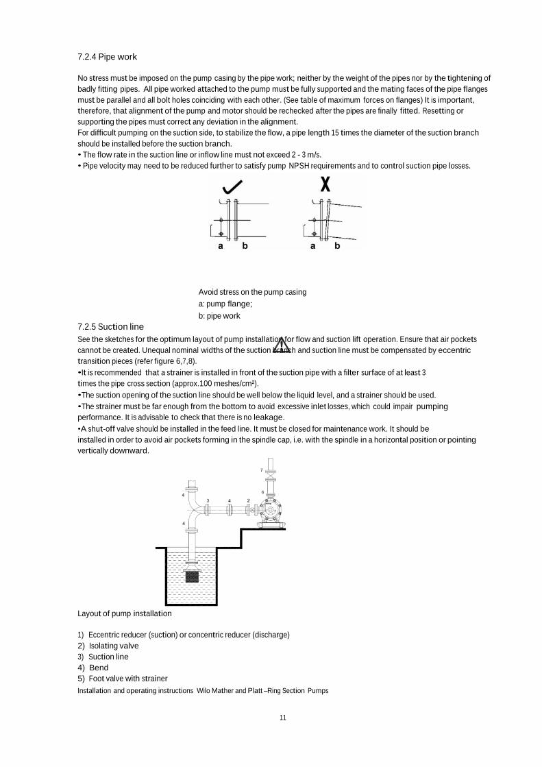
7.2.4 Pipe work
No stress must be imposed on the pump casing by the pipe work; neither by the weight of the pipes nor by the tightening of
badly fitting pipes. All pipe worked attached to the pump must be fully supported and the mating faces of the pipe flanges
must be parallel and all bolt holes coinciding with each other. (See table of maximum forces on flanges) It is important,
therefore, that alignment of the pump and motor should be rechecked after the pipes are finally fitted. Resetting or
supporting the pipes must correct any deviation in the alignment.
For difficult pumping on the suction side, to stabilize the flow, a pipe length 15 times the diameter of the suction branch
should be installed before the suction branch.
• The flow rate in the suction line or inflow line must not exceed 2 - 3 m/s.
• Pipe velocity may need to be reduced further to satisfy pump NPSH requirements and to control suction pipe losses.
7.2.5 Suction line
Avoid stress on the pump casing
a: pump flange;
b: pipe work
See the sketches for the optimum layout of pump installation for flow and suction lift operation. Ensure that air pockets
cannot be created. Unequal nominal widths of the suction branch and suction line must be compensated by eccentric
transition pieces (refer figure 6,7,8).
•It is recommended that a strainer is installed in front of the suction pipe with a filter surface of at least 3
times the pipe cross section (approx.100 meshes/cm²).
•The suction opening of the suction line should be well below the liquid level, and a strainer should be used.
•The strainer must be far enough from the bottom to avoid excessive inlet losses, which could impair pumping
performance. It is advisable to check that there is no leakage.
•A shut-off valve should be installed in the feed line. It must be closed for maintenance work. It should be
installed in order to avoid air pockets forming in the spindle cap, i.e. with the spindle in a horizontal position or pointing
vertically downward.
Layout of pump installation
1) Eccentric reducer (suction) or concentric reducer (discharge)
2) Isolating valve
3) Suction line
4) Bend
5) Foot valve with strainer
Installation and operating instructions Wilo Mather and Platt –Ring Section Pumps

12
6) Isolating valve
7) Regulating valve
7.2.6 Discharge line
CAUTION! Damage to the pump
Pump casings have sometimes been cracked by pressure surges imposed on them through the absence of a non-return
valve. A back flow can serisouly damage the bearings and the mechanical seal.
For flow regulation, a valve must be installed behind the pump. If non-return valves are used, they should close smoothly.
Pressure shocks must be avoided.
7.2.7 Mechanical seal
CAUTION! Damage to the pump
Never start the pump without liquid inside otherwise the mechanical seal will be damaged instantaneously.
No real operation is required during the setup of the pump. Only filling and venting the pump are mandatory before
switching on the main.
7.2.8 Pressure gauge connections
CAUTION! Risk of leakage of the fluid!
Never connect a pressure gauge onto the pump when the system is under pressure.
Pressure gauge connections are available on the pump casing close to the flanges. Then pressure gauge can be connected
on suction and discharge side.
7.2.9 Electrical connection
WARNING! Danger of electric shock
The electrical connection should be established by an electrician approved by the local electri- city supply company in
compliance with the applicable local regulations [e.g. VDE regulati- ons].
•The current type and voltage of the mains con- nection must correspond to the specifications on the name
plate.
•Refer to the motor and panels instruction manual at the time of installation and connection. Motors or
electrical control panels are operated with alternating or industrial high-voltage current.
•The electrical connection is established via a fixed mains connection line.
•The local regulations must be adhered to.
•Ensure that there is a provision for isolation of all energy sources and locking. If the machine has been switched
off by, a protective device, it must not be switched on again until the error has been corrected.
•The electrical system (machine including protective devices and operating position) must always be grounded.
Refer pump GA drawing & respective manuals of motor/electrical control panel for connecting earthing
suitable as per motor rating and relevant regulations and standards including proper earthing lug size and
fasteners.
•Under no circumstances may any connecting cables touch the pipeline or the pump or motor housing.
•If there is a possibility that people can come into contact with the machine and the pumped liquid (e.g. at
construction sites), the grounded connection must be additionally equipped with a fault current protectiondevice.
•To ensure drip water protection and strain relief of the cable connections, use cables with an appropriate outer
diameter and screw the cable glands tight. Furthermore any cables nearby screwed connections for outlet loops should be
bent in order to divert any accumulating drip water. Close any unassigned cable glands with the existing sealing discs and
screw them tight.
Installation and operating instructions Wilo Mather and Platt –Ring Section Pumps
13
8 Commissioning
WARNING! Danger of injury
The devices whether on pump/motor/electrical panels must never be dismantled or disabled. They must be
checked by an authorized technician for proper functioning before, start-up. Refer to motor & electrical
panel instruction manuals for electrical safety & control devices information.
WARNING! Danger of pump damage!
Do not operate the pump away from specified operating range. Operating beyond duty point may not
pose a risk to the operator but will reduce the efficiency of the pump or damage the pump itself.
Operation more than 5 minutes, at close valve condition is not recommended. For hot liquids this is not
recommended at all. Ensure that always site NPSH-A is more than NPSH-R.
8.1 Cleaning prior to start
8.1.1 Pipe work flushing
Before the pumps are brought into service, either on initial commissioning or on re-commissioning after
overhaul, the pipe work associated with the pumps must be flushed through. This will clear deposits or
scales which may have accumulated in the pipes, and which could damage the internal components of the
pumps.
8.1.2 Cleaning of Bearings
Where possible, especially if the unit has been in store for a long period before commissioning, the bearings
should be cleaned and flushed out with clean white spirit or good quality paraffin. Waste should not be used
for this purpose, as particles of foreign matter may be left behind which would cause damage when the
bearing is in service. Bearings should be then filled with recommended grade and quality of fresh lubricant to
the level. Refer list of lubricants at the end of this manual.
8.2 Filling and venting
Fill and vent the system correctly, through air cock. Brief dry running will damage the pump. Please also note that these
pumps are not self-priming, which means that the impeller & casing must always be fully filled with fluid to be handled
before putting in operation
WARNING! Danger of injury!
There is a risk of burns if the pump is touched! The entire pump may become very hot, depen- ding on the operating
state of the pump or system (fluid temperature).
CAUTION! Danger sealing system damage!
Any attempt to run the pump dry or partially full may result in seizure of the rotating internal components.
8.2.1 Pumps operating on flooded suction head
When these pumps operate on a flooded open the air release valve situated on top of the pump casing, open the pump inlet
isolating valve and vent the air out of the casing. When the liquid issues from the air vent, free of air, the pump is properly
primed. The air vent must be closed after priming and before the pumping set is started.
8.2.2 Pumps operating on negative suction head There are two methods of priming pumps that draw their liquid from an elevation lower than the pump inlet branch:
•If the inlet pipe work is fitted with a non-return foot valve, the pump casing and inlet pipe work can be filledwith liquid from
an external source under pressure. The pressure imposed on the pump by this method
must not exceed that for which the pump is designed. In certain cases pri- ming can be achieved by flooding back from the
delivery side of the pump.
•By extracting air or gas from the pump casing. To enable this method to be used, the gland arrangement
must be sufficiently air-tight or it should be liquid sealed from an external supply. For operation details of
gas exhausts reference should be made to the manufacturer’s instructions. Some form of priming
indicator is usually fitted to indicate when the priming operation is complete.
Installation and operating instructions Wilo Mather and Platt –Ring Section Pumps

14
8.3 Starting the pump
8.3.1 Direction of rotation
Disconnect the drive coupling and run the motor to check its direction of rotation. A directional arrow is provided on the
pump unit.
8.3.2 Pre-starting checks
•Check that the inlet isolating valve is open and that the delivery valve is closed.
•Check that there is no blockage in the strainer at the end of the suction line.
•Check for free rotation of the unit when coupled.
•Check that suction and delivery pressure gauges are connected. Test and make available any alarm,
signals, interlock systems and any of the protective devices incorporated in the auxiliary and main pumping
control system.
•Ensure that all electrical checks on motor, relay setting in panel etc have been carried out in accordance with the
instructions of motor manufacturer.
•Ensure that stuffing box sealing water seal connection is provided as shown in GA Drawing.
Pre-start Check up
Activities Checked on Remarks
1 Alignment with and without piping
2 Flushing of pipe lines and ensures no leakages
3 Availability of sufficient liquid in sump / suction
as per specifications
4 Installation of all instruments
• Suction and delivery pressure gauges
• Pressure switches
• Temperature gauges
• Any other as supplied/specified
5 Operation of suction, delivery and inline valves
6 Proper supports for piping and other allied equipments
7 Availability of flushing/sealing liquid for stuffing box
8 Free rotation of pump and drive shafts
9 Lubrication of bearings
10 Checking of insulation resistance of motor
11 Proper cable termination
12 Motor protection relay settings
13 Check all interlocks as specified/provided
14 No load trial operation of drive
• Direction of rotation is ok
• Noise and vibration within limits
• Bearing temperatures and winding temperatures
are within limits
• Overall operation is satisfactory
15 Coupling of pump and drive and free rotation of
shafts in coupled condition
16 Suction valve is fully opened
17 Pump is fully primed and all air is vented
18 Delivery valve is closed (if required)
19 Emergency shutdown is possible
Installation and operating instructions Wilo Mather and Platt –Ring Section Pumps

15
8.3.3 Normal starting and running checks
•When all the foregoing pre-start checks are satisfactory, start the pump and check the direction of rotation
(indicated by a direction arrow on the pump casing) otherwise stop the pump immediately for correction of direction of
rotation. Then run the pump at its rated speed.
•Check the ammeter reading to ensure that the motor is not being overloaded.
•Check that suction and delivery pressure gauges are connected. Test and make available any alarm, signals,
interlock systems and any of the protective devices incorporated in the auxiliary and main pumping control
system.
•Ensure that all electrical checks on motor, relay setting in panel etc have been carried out in accordance with the
instructions of motor manufacturer.
•Ensure that stuffing box sealing water seal connection is provided as shown in GA Drawing.
•Check the mechanical seal for leak. In the start phase (and also after downtimes) slight leakage can be
expected. Visual leakage checks are however required from time to time. Distinctly visible leakage will require an
exchange of the seal. Wilo Mather and Platt offers a repair set containing all parts required for an exchange.
•Check that the bearing is not overheating. Bea- rings will normally run at a temperature of 30 ̊ C-35 ̊ C above ambient
temperature. The ideal running temperature of bearings is 40 ˚C to 60 ˚C for ball bearings. The temperature should never
exceed 82 ˚C for ball bearings. If the bearings are overheating its cause should be investigated
immediately.
• If the foregoing checks are satisfactory, open the delivery valve slowly and bring the pump gradually up
to its rated parameters indicated in the data sheet/name plate and based on pressure gauge and ammeter readings.
Unless the pump is fitted with a special leak-off device, it should not be run for a long period against a closed delivery
valve. Check that the driving unit is not being overloaded during valve opening. Overloading may occur if the pump is
discharging into an empty system. If the pumping unit fails to generate at least its rated delivery pressure it must be
stopped immediately, the cause ascertained,
•Check vibration of pump set and ensure that vibration level is within limits specified. Check that noise
level is within stipulated limits.
•The pumps may be run for 8 hours trial operation and all the parameters like delivery pressure, current,
bearing temperature, etc. Be recorded periodically.
•Make the following checks at regular intervals. It is recommended that they be made at every change of shift.
•Check the suction and discharge pressure gauge for normal operating pressure, if there is significant drop in the suction
or discharge pressure the pump may have lost its supply. In the event of this fault occurring, the pump must be stopped
immediately and the cause of liquid loss eliminated.
•Check the mechanical seal for overheating.
8.3.4 Sealing system
Mechanical seal
CAUTION! Risk of damaging the pump!
A mechanical seal must never operate without fluid and lubrication even for a short period of time.
Insure that the pump is completely full of water and vented before starting the pump. Small leakages can occur during the
period of running-in, they should disappear after several hours of operation. If the leakages don’t stop, shut down the
pump disassemble the mechanical seal and control their condition.
8.3.5 Normal shutdown
WARNING! Risk of Burns!
If the fluid temperature and system pressure is high, close the isolation valves upstream and downstream of the
pump. Initially let the pump cool.
•Close the delivery valve to reduce the load on the driving unit.
•Stop the driver of the pump.
•When the pump has come to rest, close the suction-isolating valve.
•Isolate any ancillary supplies.
8.3.6 Emergency Shutdown
In the event of any malfunction of the equipment, switch off the pump set. When the pump has come to rest, close the
suction & discharge valves, isolate the driving unit power supply & rectify the fault.
Installation and operating instructions Wilo Mather and Platt –Ring Section Pumps

16
9 Maintenance
Maintenance and repair work should be carried out by qualified personnel only.
WARNING! Danger of electric shock!
Any danger from electrical current should be ruled out.
• The pump should be electrically isolated and secured against unauthorized switch-on prior to any maintenance
or repair work.
• Any damage to the connection cable should always be rectified by a qualified electrician only.
WARNING! Risk of scalding!
At high fluid temperatures and system pressu- res, allow the pump to cool down first and then depressurise the
system.
9.1 Routine maintenance and frequency of inspection
Centrifugal pump requires very little routine maintenance; however, serious troubles can be often avoided by regular
observation and analysis of various working parameters. Some of the routine maintenance checks for this purpose are as
under:
•To keep daily logbook records of working parameters like suction and discharge pressure, flow rate,
current drawn, bearing temperature, etc. These parameters should be recorded twice a shift. Any sudden change
should be a signal for investigation. Refer Section Maintenance & Inspection log.
•Check bearings for normal temperature. See 8.3.3
•Vibration & sound level readings should be taken once in a fortnight and values compared with that
of previous records.
•Check that there is sufficient leakage from the gland packing to ensure proper cooling and
lubrication. (if applicable) For mechanical seal, check that there is no visible leakage.
•For any abnormality observed from the visual/ manual inspection and through maintenance &
inspection logs, stop the pump and investigate.
•Fault finding - Many of the common faults which occur on centrifugal pumps and which can be
diagnosed by observations are given in the chart under section 10 Faults, causes and remedies.
Routine maintenance
Parts Action Period Remarks
Mechanical Seal Check for Leakage Daily 5.6 gm/hr per pair of seal face
Check for Leakage Half yearly If required replace with new pickings
Bearings Check temperature Weekly Bearings are greased for life and are
Suction Pressure Check Pressure Daily
Discharge Pressure Check Pressure Daily Flushing Check Flow Weekly Flow through the Flushing pipes must be
Vibration Vibration Weekly
Voltage and Current Check for the rated values Weekly Rotating element Check the rotating for wear Yearly Clearances Check the clearances between Yearly If value of clearance is more, neck ring
Total Dynamic Head Check Suction and Discharge TDH
Yearly
Alignment Check the alignment of pump
with motor
Half yearly For reference use pump motor GA Drawing
Installation and operating instructions Wilo Mather and Platt –Ring Section Pumps

17
9.2 Overhaul maintenance
9.2.1 General information
After a long period of service, wear will occur in parts of the pump, necessitating the renewal of a few components. Logbook
records will indicate wear as gradual deterioration of performance is noticed. Once this is known, pumps should be taken for
overhaul. It is recommended that yearly stripping & checking of wear & tear and clearances should be done and overhauling
where required.
If related pair of components show a marked degree of wear in relation to the rest of the unit, then it may be sufficient to
renew only the heavily worn components. If the wear is uniform throughout the pump, then all wearable components may
require renewal.
Measurements should be taken and recorded of all wearable components at the first, and every subsequent overhaul period.
Reference to these records will enable an accurate assessment of the rate of wear to be made, and a reasonably accurate
forecast regarding when a particular component may require renewal can be made.
Internal nominal Nominal gap at the
diameter of the wear diameter in (mm)
ring in (mm)
65 0.38
100 0.46
150 0.58 - 0.55
200 0.62
250 0.68
300 0.74
350 0.84 - 0.80
NOTE:
The figures given in the table above are only valid if the wear rings and the impeller are made with in the same materials of
low galling tendencies. For materials with higher galling tendencies (AISI 304/
316 etc...), higher clearance is provided (0.125 mm to be added to given values).
Information regarding original design dimensions and clearances is furnished in data sheet. Any other information, if needed,
can be requested from Service Department, Wilo Mather and Platt. Such request must quote name plate number and type of
the pump in question.
The parts most likely to be affected are:
•Impeller
•Mechanical seal
•Neck Rings
•Sleeves
•Stuffing Box Bush
•Bearings
•Coupling Bushes/ membrane set
Before commencing dismantling operations, ensure that the following tools and tackles are available:
•A crane / chain pulley block suitable for handling the weight of pumping unit.
•A selection of ring and open-ended spanners in
British and Metric sizes.
•Eyebolts in British and Metric sizes.
•Cotton rope, wire rope and slings.
•Hardwood and metal packing blocks.
•Miscellaneous tools including a set of Allen keys, drills, pin drivers, files etc.
•Extractor / puller for bearing and coupling.
The torque value to be set for a particular size of screw is dependent upon:
•Material of screw
•Parent metal
•Whether the screw is untreated or plated
•Whether the screw is dry or lubricated
•The depth of the thread
Installation and operating instructions Wilo Mather and Platt –Ring Section Pumps

18
9.3 Disassembling the pump
Assembly / Disassembly sequence for RN Pump
9.3.1 Disassembling of RN pump
•Isolate the pump motor electrically.
•Isolate the pump system by closing suction and delivery valve.
•Separate the motor first & Remove the coupling.
•Remove the bearing carrier & bush (1) from bottom.
•Support the bottom end of shaft using jack vertical position, So that distance of shaft end is maintained & shaft
will not fall.
•If the bearing (5) is fitted it will have to be drawn off with the help of suitable tackle.
•Remove the bearing cartridge (6) using jacking screw.
•Remove the stay bar of the pumps.
•Remove the motor stool.(7)
•Remove the seal (8).
•Remove the stuffing box cover (9).
•Now remove the spacer sleeve (10) delivery sleeve (11).
•Remove the balance piston bush (12).
•Now safely remove the delivery cover (13).
•Remove the balance piston (14).
•Remove the delivery diffuser (15).
•The delivery end impeller (16) should be removed carefully. Removal of subsequent impellers, middle bodies and
diffusers is effected in exactly the same way.
•Each impeller & key is stamped with number to enable it to be re-assembled in exact same sequence.
•Now carefully lift the suction cover from pump stool.
9.4 Examination of Internal components
With the disassembled rotating element, the internal components and clearances can be checked
9.4.1 Neck-ring
Use an internal micrometer to measure the bore of neck ring, taking measurements at intervals around the
circumference to check for uneven wear. A comparison between this dimension and that of the impeller neck will
indicate the amount of diametrical clearance between the casing neck ring and the impeller neck. If this clearance is
150% or more than the original design clearance, or if the deterioration in hydraulic performances has been such that
no further deterioration can be tolerated during the next operation period.
The impeller to neck ring clearance must be restored to the original design value by changing the neck ring and
impeller where required.
9.4.2 Shaft sleeves
The shaft sleeve should be examined to
see if it is grooved or generally worn. The outside diameter of the sleeve should be measured and a comparison made
with the bore of the balance valve cover or bore of suction cover through which the sleeve passes. The amount of
clearance between the two can thus be checked to determine whether or not it is within acceptable limit
9.4.3 Impeller
A) Inspect the impeller as follows:
•Examine the impeller for damage
•For corrosive/erosion pitting
•Cavitations pitting
•Bent or cracked vanes, inlet and outlet vane end wear
Any of the above may be repaired, or if damage is extensive, impeller may need replacement. Further information
should be sought from Service Dept., Pune before any decision on repair work is taken.
B) Examine around the eye at neck portion for grooving in alignment with spindle axis; slight grooving is acceptable but
deep or profuse grooving must be remedied by machining the impeller by taking a polish cut on neck diameter..
To check wear, around the impeller neck, use precision instruments such as outside micrometer to accurately measure the
outside diameter. Measurements should be taken at intervals around the circumference to check the uneven wear.
Differences between the neck OD and the neck bush ID measured will give us the clearance between the two. Clearance
thus obtained should not be more than 150% of maximum designed clearance.
Installation and operating instructions Wilo Mather and Platt –Ring Section Pumps

19
9.4.4 Bearings
The Bearings fitted on the Ring section pumps range are grease Lubricated for different Models. For list refer the chart.
Steps to follows during Ball bearing checking-
•Clean all the components using clean white spirit. Do not use chlorinated solvents such as trichloroethylene and
carbon tetrachloride because they introduce a corrosion risk when used on ferrous materials.
•Visually inspect the bearing. The balls, the inner and outer tracks must all be free from chipping, cracks,
abrasions or discoloration.
•Check that the parts of the cage are firmly fixed together.
•Visually inspect the bore for any sign of damage. Burrs or any scratches caused during bearing withdrawal
should be carefully removed by hand application of a fine oilstone, the treatment being confined to the
minimum possible area.
•Visually inspect the outside diameter for signs of fretting, any stains may be carefully polished off, but
abrasion must be kept to the absolute minimum that is required, followed by cleaning.
•Check that bearing rotates freely and smoothly. If there is any doubt regarding the serviceability of the
bearing it should be renewed. Inspect the Bearing Cage as follows:
•Visually inspect the bore for any signs of fretting, any stains may be carefully polished off, but abrasion
must be kept to the absolute minimum that is required, followed by cleaning.
•Where fretting has occurred, bearing and housing should be clean and dry, and trial assembled. It is a
transitional fit and may be described as a sucking fit without any detectable clearance or play between
the outer race and the housing bore. Any assembly, which achieves this, may be considered as being acceptable,
provided the bearing is serviceable. Assemblies, which do not achieve this degree.
NOTE:
An incorrect fit can allow one or both of the bearing tracks to creep, which will affect the running accuracy and the assembly
and dismantling of a pump. Creep is the slow rotation of one track relative to its seating, it is undesirable since the spindle
and the bore of the bearing or the housing and the outside -diameter of the bearing may become worn. Creep is not due to
friction within a bearing but is generally caused due to radial loads rotating or oscillating in respect to fixed point on the
track. If creep has occurred the interference fit of the bearing must be restored, either by metal spraying or chromium plating
and regrinding the seating to the correct diameter; interference fits must not simulated by knurling, scoring or distortion of
the seating on which creep has occurred because such practices are ineffective and creep will quickly reoccur.
Even if the bearing is prevented from creeping it will usually be distorted by the seating, and failure will result caused by local
overloading and high frequency vibration.
•Examine the abutment. Abutment for ball bearings must be flat and square with the axis-of rotation.
The radius at the root of an abutment must be smaller than the corner radius of the track located
against the abutment. The edge of the abutment must be reduced or chamfered; a burred edge can tilt or distort a
bearing track.
•If after inspection, the bearing is reusable, completely coat all parts with a rust preventive oil, working it
well into the internal parts of the bearing. Wrap in clean greaseproof paper and store until required for
replacement or refit on to the spindle if needed. In case of immediate use, coating of rust preventive oil
is not necessary.
9.4.5 Mechanical seal
Ensure that the sliding face do not present any scratches or abnormal wear. Verify that the driving collar is well screwed on
the shaft at the right place. Check that no material block the spring action.
9.5 Reassembling the pump
9.5.1 Disassembling of RN pump
• Before re-building, all joint faces should be cleaned & all burrs removed from the ends of impeller bosses, sleeves &
sleeve nuts as it is essential that all faces meet squarely.
•Place the suction cover on pump stool. Drop the shaft through the suction cover & let the shaft rest on jack.
•Push the suction side sleeve. Fit the first impeller key & push the first impeller.
•Spread the thin coating of joining compound over the corners on suction cover.
•Place the diffuser & middle bodies. It should fall quite easily into its spigots & from this point the process is repeated.
•Care should be taken to see that the vents of the middle bodies are correctly set on top of the casing.
•Then place the balance piston over the end impeller.
•Place the delivery cover correctly & then place the balance piston bush such that it should fall easily between balance
Installation and operating instructions Wilo Mather and Platt –Ring Section Pumps

20
piston & del cover gap.
•Push the delivery side sleeve & spacer sleeve & place the stuffing box cover.
•Place the seal (kindly mark the positions first & then tight) .
•Place the motor stool on delivery cover and match the position of holes.
•When the motor stool is fitted stay bars inserted & pinched up. Then the stay bar & nuts to be tightened evenly, working
diagonally across cover, & tightening each nut a little at time to prevent uneven strain.
•Place the bearing cartridge, Push thrust collar & roller bearings.
•The shaft should now be adjusted with the help of lock nut & lock washer so that impeller is in correct running position.
•The ideal running position is with the centerline of the impeller corresponding with the centerline of diffuser.
•Fit the coupling to shaft & place the motor on motor stool & tighten it using fasteners.
•Finally make all the connections as per drawing.
9.5.2 Reassembly of Pump with Mechanical seal
•Extreme cleanliness must be observed during installation, and damage to the seal faces and mounting
rings must be avoided
•Place the adjusting ring of mechanical seal at its pre marked position
•Place the grab screw(13) at its position on the adjusting ring, but tight it yet
•The O-rings may be oiled to reduce friction, during installation of the seal. EP-rubber O-rings should not
come into contact with oil or grease; In this case lubrication with glycerin or water is recommended.
•Never cover the sliding faces with a lubricant as they must be assembled completely dry, clean and dust-
free.
•When pressing in stationery seals, make sure that the pressure distribution is uniform. The O-ring must be
fitted using water or alcohol only.
•Crowned drive pins must be replaced whenever the seal is dismantled. During insertion of the stationary
seats, especially those of special carbon, care must be taken to exert pressure evenly.
•Now check the distance of seal as shown in the figure and adjust its value as per values given table
•For rest parts follow the above explained procedure as per gland pack version pump
1) Pump casing
2) Stationary seat
3) Stationary seat
4) Gland plate
5) O-ring
6) Shaft
X. Mechanical seal
1.6 Abutment ring
1.7 Abutment ring fixing screw
NOTE:
While assembling stainless steel component, molybdenum-disulphide paste should be applied to prevent galling /
seizure and also to facilitate easy removal in future.
Installation and operating instructions Wilo Mather and Platt –Ring Section Pumps

21
9.6 Recommended spare parts
In case of standard operation, we recommend the following list of spare part regarding the period of functioning.
For 2 years of normal operation:
•Mechanical seal, ball bearings required for the dismounting of the pump.
For 3 years of normal operation:
•Mechanical seal, ball bearings required for the dismounting of the pump,
Wear rings and their nuts.
For 5 years of normal operation:
Then in order to facilitate this operation we strongly recommended purchasing a batch of part with the pump in order to
reduce the shut down timing.
It is strongly recommended to purchase the original spares parts from WILO Mather and Platt. In order to avoid any mistake
we invite you to supply with any spare parts demand, the information mentioned on the data plate of the pump and / or
motor
10 Faults, Causes and Remedies
Symptoms Possible cause of trouble and remedies
(Each number is defined in the table below)
-- Pump does not deliver water 1,2,3,4,6,11,14,16,17,22,23
-- Insufficient capacity delivered 2,3,4,5,6,7,8,9,10.11.14.17,20,22,23.29,30,31
-- Insufficient pressure developed 5,14,16,17,20,22,29,30,31
-- Pump loses prime after starting 2,3,5,6,7,8,11,12,13
-- Pump requires excessive power 15,16,17,18,19,20,23,24.26,27,29,33,34,37
-- Pump vibrates or it is noisy 2,3,4,9,10,11,21.23,24,25.26.27,28,30,35,41,42,43, 44,45,46,47
-- Bearings have short life 24,26,27,28,35,36,41,42,43,44,45,46,47
-- Pump overheats and seizes 1,4,21,22,24.27,28,35,36,41
Causes Remedies
1 Pump not primed Ensure that casing is fully filled and water comes out from air-cock
2 Pump or suction pipe not completely Check leaking foot valve in case of negative suction
3 Suction lift too high Reduce by lowering pump elevation or increase Water level
4 Insufficient margin between pressure Check that NPSH available is at least 1 meter more 1 meter more than
5 Excessive amount of air in liquid Check the reasons and eliminate Gas gets entrapped in liquid Air may be
entering through suction joints
6 Air pocket in suction line Ensure pipe fully filled and there is nobend for negative suction
7 Air leaks into suction line Tighten pipe joints with solution
8 Air leaks into pump through stuffing Ensure stuffing box sealing
9 Foot valve too small or leaking Replace / Attend
10 Foot valve partially clogged Clean
11 Inlet of suction pipe insufficiently Ensure adequate submergence such that foot valve is not exposed
12 Water seal pipe clogged Clean or change
13 Speed too low Check motor RPM, supply frequency, Motor nameplate speed should be as
specified on pump nameplate 14 Speed too high Check motor RPM and supply frequency
15 Direction of rotating wrong Check correct direction of rotation for motor before coupling to motor
16 Total head of system higher than design Check the causes and refer to M&P Measure with pressure gauge
17 Total head of system lower than pump Check the causes and refer to M&P Measure with pressure gauge
18 Specific gravity of liquid different from Refer to Wilo Mather and Platt
19 Viscosity of liquid different from design Refer to Wilo Mather and Platt
20 0peration at very low capacity Check the causes and refer to M&P, Operate pump at rated duty
21 Parallel operation of pumps unsuitable Refer to Wilo Mather and Platt with characteristics curves of pump
22 Foreign matter in impeller Open and clean
23 Misalignment Check with Dial gauge should be within limits and without undue pipe
24 Foundations not rigid Check, vibration on Baseplate, check hollowness
Installation and operating instructions Wilo Mather and Platt –Ring Section Pumps
22
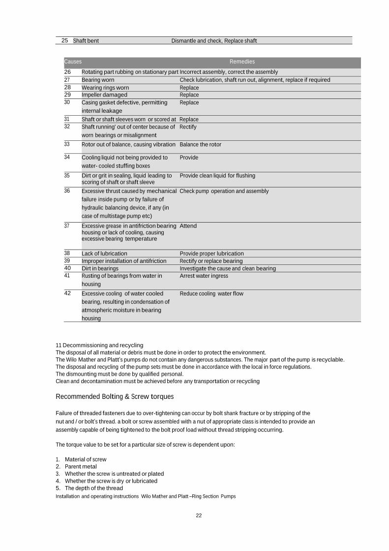
25 Shaft bent Dismantle and check, Replace shaft
Causes Remedies
26 Rotating part rubbing on stationary part Incorrect assembly, correct the assembly
27 Bearing worn Check lubrication, shaft run out, alignment, replace if required
28 Wearing rings worn Replace
29 Impeller damaged Replace
30 Casing gasket defective, permitting Replace
internal leakage
31 Shaft or shaft sleeves worn or scored at Replace
32 Shaft running' out of center because of Rectify
worn bearings or misalignment
33 Rotor out of balance, causing vibration Balance the rotor
34 Cooling liquid not being provided to Provide
water- cooled stuffing boxes
35 Dirt or grit in sealing, liquid leading to Provide clean liquid for flushing scoring of shaft or shaft sleeve
36 Excessive thrust caused by mechanical Check pump operation and assembly
failure inside pump or by failure of
hydraulic balancing device, if any (in
case of multistage pump etc)
37 Excessive grease in antifriction bearing Attend housing or lack of cooling, causing excessive bearing temperature
38 Lack of lubrication Provide proper lubrication
39 Improper installation of antifriction Rectify or replace bearing
40 Dirt in bearings Investigate the cause and clean bearing
41 Rusting of bearings from water in Arrest water ingress
housing
42 Excessive cooling of water cooled Reduce cooling water flow
bearing, resulting in condensation of
atmospheric moisture in bearing
housing
11 Decommissioning and recycling
The disposal of all material or debris must be done in order to protect the environment.
The Wilo Mather and Platt’s pumps do not contain any dangerous substances. The major part of the pump is recyclable.
The disposal and recycling of the pump sets must be done in accordance with the local in force regulations.
The dismounting must be done by qualified personal.
Clean and decontamination must be achieved before any transportation or recycling
Recommended Bolting & Screw torques
Failure of threaded fasteners due to over-tightening can occur by bolt shank fracture or by stripping of the
nut and / or bolt’s thread. a bolt or screw assembled with a nut of appropriate class is intended to provide an
assembly capable of being tightened to the bolt proof load without thread stripping occurring.
The torque value to be set for a particular size of screw is dependent upon:
1. Material of screw
2. Parent metal
3. Whether the screw is untreated or plated
4. Whether the screw is dry or lubricated
5. The depth of the thread
Installation and operating instructions Wilo Mather and Platt –Ring Section Pumps

23
Tightening torques – Untreated Screw (black finish); Coefficient of Friction 0.14
Property class
M6 M8 M10 M12 M16 M20 M24 M27 M30 M33 M36 M39
5.6 Nm 4.6 11 22 39 95 184 315 470 636 865 1111 1440
Ft. lb 3.3 8.1 16 28 70 135 232 346 468 637 819 1062
8.8 Nm 10.5 26 51 89 215 420 725 1070 1450 1970 2530 3290
Ft. lb 7.7 19 37 65 158 309 534 789 1069 1452 1865 2426
10.9 Nm 15 36 72 125 305 590 1020 1510 2050 2770 3680 4520
Ft. lb 11 26 53 92 224 435 752 1113 1511 2042 2625 3407
12.9 Nm 18 43 87 150 365 710 1220 1810 2450 3330 4260 5550
Ft. lb 13 31 64 110 269 523 899 1334 1805 2455 3156 4093
Pre-Stating Checks for Pump set
Sl
No
Activities Checked
on
Remarks
1 Alignment with and without piping
2 Flushing of pipe lines and ensure no leakages
3 Availability of sufficient liquid in sump / suction as per
specifications.
4 Installation of all instruments
Suction and delivery pressure gauges
Pressure switches
Temperature gauges
Any other as supplied / specified.
5 Operation of suction, delivery and inline valves
6 Proper supports for piping and other allied equipments.
7 Availability of flushing / sealing liquid for stuffing box.
8 Availability of sufficient cooling liquid for bearings as specified
9 Free rotation of pump and drive shafts
10 Lubrication of bearings
11 Checking of insulation resistance of motor
12 Proper cable termination
13 Motor protection relay settings
14 Check all interlocks as specified / provided
15 No load trial operation of drive
Direction of rotation is ok
Noise and vibration within limits
Bearing temperatures and winding temperatures are within
limits
Overall operation is satisfactory
16 Coupling of pump and drive and free rotation of shafts in
coupled condition
17 Suction valve is fully opened
18 Pump is fully primed and all air is vented
19 Delivery valve is closed (if required)
20 Emergency shutdown is possible.
Installation and operating instructions Wilo Mather and Platt –Ring Section Pumps

WILO Mather and Platt Pumps Pvt. Ltd.
Mumbai-Pune Road, Chinchwad,
Pune- 411 019, Maharashtra (India)
Tel: +91 20 27442100/1/2/3/4,
Toll Fee Service: 1-800-266-8866
Fax: +91 2027442111
www.wilo.in