Carbonite Setup Manual(4802DR 120 07.3) E - baixardoc
10
www.rossvideo.com Video Production Technology Carbonite v7.3 SETUP MANUAL
-
Upload
khangminh22 -
Category
Documents
-
view
1 -
download
0
Transcript of Carbonite Setup Manual(4802DR 120 07.3) E - baixardoc
www.rossvideo.comVideo Production Technology
Carbonite
v7.3
SETUP MANUAL
Document Information• Ross Part Number: 4802DR-120-07.3• Release Date: June, 2013. Printed in Canada• Equipment: This document applies to the Carbonite
(4802AR-200-xx), Carbonite MultiMedia(4802AR-201-xx), and Carbonite+(4802AR-202-xx) frames.
CopyrightCopyright © 2013 Ross Video Limited. All rightsreserved. This work is proprietary and confidential toRoss Video Limited, its subsidiaries and its otheraffiliated corporations andmay not be copied, distributed,sold or otherwise used or relied upon without the expresswritten permission of Ross Video Limited. Reproductionor reverse engineering of copyrighted software isprohibited.
PatentsThis product is protected by the following US Patents:4,205,346; 5,115,314; 5,280,346; 5,561,404; 7,034,886;7,508,455; 7,602,446; 7,834,886; 7,914,332. This productis protected by the following Canadian Patents: 2039277;1237518; 1127289. Other patents pending.
NoticeThe material in this document is furnished forinformational use only. It is subject to change withoutnotice and should not be construed as commitment byRoss Video Limited. Ross Video Limited assumes noresponsibility or liability for errors or inaccuracies thatmay appear in this document.
Trademarks• is a trademark of Ross Video Limited.• Ross, ROSS, ROSS®, MLE, Vision, Octane,
Carbonite, CrossOver, CrossOver Solo, CrossOverStudio, Squeeze& Tease, Squeeze& TeaseWARP,OverDrive, RossGear, openGear, DashBoardControl System, SoftMetal, XPression, Furio, andCamBot are registered and unregistered trademarksof Ross Video Limited.
• Windows is a registered trademark of MicrosoftCorporation in the United States and othercountries.
• All other product names and any registered andunregistered trademarks mentioned in thisdocument are used for identification purposes only
and remain the exclusive property of theirrespective owners.
Important Regulatory and SafetyNotices to Service Personnel
Before using this product and any associated equipment,refer to the “Important Safety Instructions” listed inthe front of this manual to avoid personnel injury and toprevent product damage.Product may require specific equipment, and/orinstallation procedures to be carried out to satisfy certainregulatory compliance requirements. Notices have beenincluded in this publication to call attention to thesespecific requirements.
Symbol Meanings
Protective Earth: This symbol identifies aProtective Earth (PE) terminal, which is providedfor connection of the supply system's protectiveearth (green or green/yellow) conductor.
Important: This symbol on the equipment refers you toimportant operating and maintenance (servicing) instructionswithin the Product Manual Documentation. Failure to heed thisinformation may present a major risk of damage or injury topersons or equipment.
Warning: The symbol with the word “Warning”within the equipment manual indicates apotentially hazardous situation which, if notavoided, could result in death or serious injury.
Caution: The symbol with the word “Caution”within the equipment manual indicates apotentially hazardous situation which, if notavoided, may result in minor or moderate injury.It may also be used to alert against unsafepractices.
Warning Hazardous Voltages: This symbol isintended to alert the user to the presence ofuninsulated “dangerous voltage” within theproduct enclosure that may be of sufficientmagnitude to constitute a risk of shock topersons.
ESDSusceptibility: This symbol is used to alertthe user that an electrical or electronic device orassembly is susceptible to damage from an ESDevent.
Important Safety Instructions1. Read these instructions.
2. Keep these instructions.
2 • Document Information — Carbonite Setup Manual (v7.3)

3. Heed all warnings.
4. Follow all instructions.
5. Do not use this apparatus near water.
6. Clean only with a dry cloth.
7.Do not block any ventilation openings. Install in accordancewith manufacturer's instructions.
8. Do not install near heat sources such as radiators, heatregisters, stoves, or other apparatus (including amplifiers)that produce heat.
9. Do not defeat the safety purpose of the polarized orgrounding-type plug. A polarized plug has two blades withone wider than the other. A grounding type plug has twoblades and a third grounding prong. The third prong isprovided for your safety. If the provided plug does not fit intoyour outlet, consult an electrician for replacement of theobsolete outlet.
10. Protect the power cord from being walked on or pinched,particularly at plugs, convenience receptacles, and the pointwhere they exit from the apparatus.
11. Only use attachments/accessories specified by themanufacturer.
12. Unplug this apparatus during lightning storms or whenunused for long periods of time.
13. Refer all servicing to qualified service personnel.Servicing is required when the apparatus has been damagedin any way, such as when the power-supply cord or plug isdamaged, liquid has been spilled or objects have fallen intothe apparatus, the apparatus has been exposed to rain ormoisture, does not operate normally, or has been dropped.
14. Do not expose this apparatus to dripping or splashing,and ensure that no objects filled with liquids, such as vases,are placed on the apparatus.
15. To completely disconnect this apparatus from the ACMains, disconnect the power supply cord plug from the ACreceptacle.
16. The mains plug of the power supply cord shall remainreadily operable.
17. Indoor Use: WARNING: To reduce the risk of fire orelectric shock, do not expose this apparatus to rain ormoisture.
18. The safe operation of this product requires that aprotective earth connection be provided. A groundingconductor in the equipment's supply cord provides thisprotective earth. To reduce the risk of electrical shock to theoperator and service personnel, this ground conductor mustbe connected to an earthed ground.
19. WARNING: This apparatus, when equipped with multiplepower supplies, can generate high leakage currents. Toreduce the risk of electric shock, ensure that each individualsupply cord is connected to its own separate branch circuitwith an earth connection.
20. CAUTION: These service instructions are for use byqualified service personnel only. To reduce the risk of electricshock, do not perform any servicing other than that containedin the operating instructions unless you are qualified to doso.
21. Service barriers within this product are intended to protectthe operator and service personnel from hazardous voltages.For continued safety, replace all barriers after servicing.
22. Certain parts of this equipment still present a safetyhazard with the power switch in the OFF position. To avoidelectrical shock, disconnect all A/C power cords from thechassis' rear appliance connectors before servicing.
23. This product contains safety critical parts, which, ifincorrectly replaced, may present a risk of fire or electricalshock. Components contained within the product's powersupplies and power supply area are not intended to becustomer-serviced and should be returned to the factory forrepair.
24. To reduce the risk of fire, replacement fuses must be thesame type and rating.
25. Use only power cords specified for this product andcertified for the country of use.
26. The safe operation of this equipment requires that theuser heed and adhere to all installation and servicinginstruction contained within the equipment's EngineeringManuals.
27. WARNING: This product includes an “Ethernet Port”which allows this product to be connected to a local areanetwork (LAN). Only connect to networks that remain insidethe building. Do not connect to networks that go outside thebuilding.
EMC NoticesUnited States of America — FCC Part 15This equipment has been tested and found to complywith the limits for a class A Digital device, pursuant topart 15 of the FCC Rules. These limits are designed toprovide reasonable protection against harmfulinterference when the equipment is operated in acommercial environment. This equipment generates,uses, and can radiate radio frequency energy and, if notinstalled and used in accordance with the instructionmanual, may cause harmful interference to radiocommunications. Operation of this equipment in aresidential area is likely to cause harmful interference inwhich case the user will be required to correct theinterference at his own expense.
Important: Changes or modifications to this equipment notexpressly approved by Ross Video Limited could void the user'sauthority to operate this equipment.
CanadaThis Class “A” digital apparatus complies with CanadianICES-003.Cet appareil numérique de la classe “A” est conforme ala norme NMB-003 du Canada.
Carbonite Setup Manual (v7.3) — Document Information • 3

EuropeThis equipment is in compliance with the essentialrequirements and other relevant provisions of CEDirective 93/68/EEC.
InternationalThis equipment has been tested toCISPR 22:1997 alongwith amendments A1:2000 and A2:2002, and found tocomply with the limits for a Class A Digital device.
Important: This is a Class A product. In domesticenvironments, this product may cause radio interference, inwhich case the user may have to take adequate measures.
General Handling Guidelines• Careful handling, using proper ESD precautions,
must be observed.• Power down the system before PCB removal.
A Word About Static DischargeThroughout the many procedures in this EngineeringManual, please observe all static discharge precautions.
Caution: Avoid handling the switcher circuitboards in high static environments such ascarpeted areas, and when synthetic fiber clothingis worn. Touch the frame to dissipate staticcharge before removing boards from the frame,and exercise proper grounding precautions whenworking on circuit boards. Exercise propergrounding precautions when working on circuitboards.
Warranty and Repair PolicyRoss Video Limited (Ross) warrants its switchers andrelated options, to be free from defects under normal useand service for a period of ONE YEAR from the date ofshipment. Fader handle assemblies are warranted for thelife of the product. If an item becomes defective withinthe warranty period Ross will repair or replace thedefective item, as determined solely by Ross.Warranty repairs will be conducted at Ross, with allshipping FOB Ross dock. If repairs are conducted at thecustomer site, reasonable out-of-pocket charges willapply. At the discretion of Ross, and on a temporary loanbasis, plug in circuit boards or other replacement partsmay be supplied free of charge while defective itemsundergo repair. Return packing, shipping, and specialhandling costs are the responsibility of the customer.Software upgrades for switchers may occur from time totime, and are determined by Ross Video. The upgradesare posted on the Ross Video website, and are free ofcharge for the life of the switcher.
This warranty is void if products are subjected to misuse,neglect, accident, improper installation or application,or unauthorized modification.In no event shall Ross Video Limited be liable for direct,indirect, special, incidental, or consequential damages(including loss of profit). Implied warranties, includingthat of merchantability and fitness for a particularpurpose, are expressly limited to the duration of thiswarranty.This warranty is TRANSFERABLE to subsequentowners, subject to Ross' notification of change ofownership.
Environmental InformationThe equipment that you purchased required theextraction and use of natural resources for itsproduction. It may contain hazardous substances thatcould impact health and the environment.To avoid the potential release of those substances intothe environment and to diminish the need for theextraction of natural resources, Ross Video encouragesyou to use the appropriate take-back systems. Thesesystems will reuse or recycle most of the materials fromyour end-of-life equipment in an environmentally friendlyand health conscious manner.The crossed-out wheeled bin symbol invites you to usethese systems.
If you need more information on the collection, reuse,and recycling systems, please contact your local orregional waste administration.You can also contact Ross Video for more informationon the environmental performances of our products.
Company AddressRoss Video Limited—8 John Street Iroquois, Ontario,Canada, K0E 1K0Ross Video Incorporated—P.O. Box 880, Ogdensburg,New York, USA, 13669-0880
(+1)613-652-4886General BusinessOffice:
(+1)613-652-4425Fax:
4 • Document Information — Carbonite Setup Manual (v7.3)

(+1)613-652-4886TechnicalSupport:
(+1)613-349-0006After HoursEmergency:
[email protected](Support):
[email protected](General):
www.rossvideo.comWebsite
Technical SupportAt Ross Video, we take pride in the quality of ourproducts, but if a problem does occur, help is as close asthe nearest telephone.Our 24-Hour Hot Line service ensures you have accessto technical expertise around the clock. After-salesservice and technical support are provided directly byRoss Video personnel. During business hours (easternstandard time), technical support personnel are availableby telephone. Outside of normal business hours and onweekends, a direct emergency technical support phoneline is available. If the technical support personnel whois on call does not answer this line immediately, a voicemessage can be left and the call will be returned shortly.Our Technical support staff are available to react to anyproblem and to do whatever is necessary to ensurecustomer satisfaction.
Supporting DocumentationRoss Video provides a wide variety of helpfuldocumentation for the setup and support of yourequipment. Most of this documentation can be foundeither on the Product Resources disk that came with yourequipment, on the Ross Video website(www.rossvideo.com), or on the Ross Video Communitysite (community.rossvideo.com)• OperationManual (4802DR-110)—operational
instructions for all Carbonite switchers• Carbonite SetupManual (4802DR-120)—setup
and configuration instructions for Carbonite,Carbonite+, and Carbonite MultiMedia frames
• Carbonite eXtremeSetupManual (4803DR-120)— setup and configuration instructions forCarbonite eXtreme frames
• Carbonite QuickStart Poster (4802DR-200)—setup information and specifications for theCarbonite, Carbonite+, and Carbonite MultiMediaframes
• Carbonite eXtreme QuickStart Poster(4803DR-200)— setup information andspecifications for the Carbonite eXtreme frame
• Upgrade Notes (4802DR-500)— upgradeinstructions, new features, and known issues for agiven software version
• Carbonite eXtreme Upgrade for NK-3G144-X—upgrade instructions for the NK-3G144-X routerto a Carbonite eXtreme switcher
• Software Licenses (4802DR-502)— third-partysoftware licences
• Carbonite Multilingual Safety Information(4802DR-503)— translated product safetyinformation
• Carbonite Frame Fan Replacement(4802DR-300)—instructions for replacing coolingfans in the Carbonite, Carbonite+, or CarboniteMultiMedia frames
• Carbonite Frame RAM Replacement(4802DR-301)— instructions for replacing theRAM in the Carbonite, Carbonite+, or CarboniteMultiMedia frames
• Control Panel DeskMounting (4802DR-302)—desk mounting instructions for Carbonite controlpanel
• 1-2 MLE Upgrade (4802DR-303)—1 to 2 MLEupgrade instructions for C1-A and C1M controlpanels
• SideBox Installation (4802DR-304)—installationand mounting instruction for SideBox module
• Auxiliary Control Panel Installation(4802DR-305)— installation and mountinginstruction for remote aux panel (CPS-AUX-053B)
• C10 2 MLE Upgrade (4802DR-306)— 1 to 2MLE upgrade instructions for the C10 control panel
• GVG100 Supported Command (4802DR-401)— connection and GVG100 commands supportedby the switcher
• LiveEDLSetup (4802DR-402)—setup recordingEDL files and LTC timecode source
• RossTalkCommands (4802DR-403)—supportedcommands using RossTalk protocol
• Device Setup Sheets (4802DR-6xx)— setupinformation for controlling external devices fromthe switcher
• Robotic Camera Control (4802DR-131)—overview of the operational interface whencontrolling a robotic camera from the switcher
Carbonite Setup Manual (v7.3) — Document Information • 5

• AudioMixerControl (4802DR-132)—overviewof the operational interface when controlling anaudio mixer from the switcher
• Video ServerControl (4802DR-133)—overviewof the operational interface when controlling avideo server from the switcher
• Configuration Guide (4802DR-100)— productdescription and marketing codes for switchers andoptions
6 • Document Information — Carbonite Setup Manual (v7.3)
Contents
Features........................................................9MultiMedia Inputs (MultiMedia Frame Only)............................9Custom Controls......................................................................9Device Control.........................................................................9DVE.........................................................................................9Effects Dissolve.......................................................................9General Purpose Interface......................................................9LiveEDL...................................................................................9Media-Store.............................................................................9MediaWipes.............................................................................9UltraChrome..........................................................................10Memory AI Recall Mode........................................................10Memory System.....................................................................10MLE Effect System................................................................10Media Manager......................................................................10MultiViewer............................................................................10Pattern and Matte/Wash Generators.....................................10Matte/Wash Generator..........................................................10Tally Outputs..........................................................................11
Video Reference........................................12Supported Reference Formats..............................................12Reference Setup....................................................................12
To Set a Reference Format..............................................12Frame Sync and Format Conversion.....................................13
Supported FSFC Input Mode Video Formats...................13FSFC For Carbonite Frame..............................................13FSFC For Carbonite MultiMedia/Carbonite+ Frames.......14
Output Reference Synchronizers..........................................15To Set Up an Output Reference Sync..............................15To Set Color Framing for Analog Reference....................15
Aspect Ratio Conversion.......................................................15Full....................................................................................16Zoom................................................................................16Letterbox...........................................................................16Pillarbox............................................................................16To Set an Aspect Ratio for 480i/576i................................16
Switching Field......................................................................16To Set the Switching Field................................................16
Video Input Setup......................................17MultiMedia Inputs..................................................................17
HDMI Inputs (MultiMedia Only)........................................17Analog Inputs (MultiMedia Only)......................................17
Auto Key Setup......................................................................18To Set Up an Auto Key Association..................................18
Source Names.......................................................................18To Set Up a Source Name................................................18
Control Panel Button Inserts..................................................19To Install a Button Insert...................................................19
Bus Maps...............................................................................19To Create a Bus Map........................................................20To Reset the Bus Map......................................................20
GPI Device Control................................................................20
To Assign a GPI to a Video Source..................................20
Video Outputs............................................21Output Sources......................................................................21
To Assign a Source to an Output......................................21Ancillary Data........................................................................21
To Strip or Pass Ancillary Data.........................................21FlexiClean Clean Feed..........................................................21
To Set Up Clean Feed......................................................22MultiViewer............................................................................22
To Set Up a MultiViewer...................................................22To Set Up a MultiViewer Clock.........................................23
Tallies.....................................................................................23To Set Up a Tally..............................................................23
Color Correction........................................25Proc AmpColor Correction (Carbonite + andMultiMedia Only).25
To Apply a Proc Amp to a Video Source..........................25RGB Color Correction (Carbonite+ and MultiMedia Only)......26
To Apply a RGB Color Correction to a Video Source.......26
ViewControl................................................27Connecting ViewControl........................................................27
To Set Up The Video Input for ViewControl......................27To Set Up the MultiViewer for ViewControl.......................27
Switcher Personality.................................29Auto Remove Key..................................................................29
To Set the Auto Remove Key Behavior............................29Auto Trans Second Press......................................................29
To Set the Auto Trans Second Press Behavior................29Background Double-Press.....................................................29
To Set the Background Double-Press Behavior...............29Color Schemes......................................................................29
To Select a Panel Color Scheme......................................29To Create a Custom Panel Color Scheme.......................30
Double-Press Rate................................................................30To Set the Double-Press Rate..........................................30
Editor Mode...........................................................................30To Set the Switcher to Editor Mode..................................30
Memory Bank Button Behavior (C2X/C2S)...........................30To Set the Bank Button Behavior.....................................30
Memory Recall Behavior (C10/C1)........................................30To Set the Memory Recall Behavior.................................30
Next Button Secondary Function...........................................30To Set the NEXT Button Secondary Function..................31
Next Transition Follow...........................................................31To Set the Next Transition Follow Behavior......................31
Next Transition Reset............................................................31To Set the Next Transition Reset Behavior.......................31
Power-Save Mode.................................................................31To Set the Power Save Mode and Timer..........................31
Program Row (C2/C2M/C2X/C2S)........................................31To Set the Program Row..................................................31
Roll GPO/Roll Clip.................................................................31To Set the Roll GPO/Clip Behavior...................................32
Transition Rate Units.............................................................32
Carbonite Setup Manual (v7.3) — Contents • 7
To Set the Units Used for Transition Rates......................32
Switcher Resources..................................33Switcher Resources...............................................................33
DVE Resource Capture....................................................33Chroma Key Resource Capture.......................................33
DVE/FSFC Resources (Carbonite Frame Only)....................33To Switch Between DVE/FSFC Resource Modes............33
Network Connections...............................34Network Setup.......................................................................34
To View the Current Network Settings..............................34To Set an IP Address Using DHCP..................................34To Set a Static IP Address................................................34
FTP Connection (RossLinq)..................................................35To Create an FTP Connection with Windows 7................35
GPI Control.................................................36GPI Trigger Types..................................................................36GPI Setup..............................................................................36
To Set Up a GPI Input......................................................36To Set Up a GPI Output....................................................37
GPI Output Triggers...............................................................37To Assign a GPI Output to a Video Source......................37To Set a GPI to Be Triggered Manually............................37To Manually Trigger a GPI Output....................................37
Diagnostics and Calibration.....................39Switcher Information and Logs..............................................39
Switcher Status in DashBoard..........................................39To View the Software Version...........................................39To Copy Logs To a USB...................................................39
Calibration.............................................................................39To Calibrate the Switcher.................................................39
System Real-Time Clock.......................................................40To Set the System Real-Time Clock.................................40
Diagnostics............................................................................40Frame Diagnostic LEDs...................................................40Frame DIP Switches.........................................................40To Run the Control Panel Test..........................................40To Run the LED Test........................................................40To Run the Display Test....................................................40To Run the RAM Test.......................................................41To Run the Tally Test........................................................41To Run the GPI Input Test................................................41To Run the GPI Output Test.............................................41
Error Messages.....................................................................41
Specifications............................................42Operating Temperature..........................................................42Video Input Specifications.....................................................42Video Output Specifications..................................................42Audio Specifications..............................................................42Power Rating.........................................................................42Serial Port..............................................................................42GPI Port.................................................................................43
Tally Port................................................................................43
Glossary.....................................................45
8 • Contents — Carbonite Setup Manual (v7.3)

FeaturesThank you for buying a Ross Video Carbonite SeriesMulti-Definition Live Production Switcher. TheCarbonite series builds on the Ross Video reputation fordesigning switchers that fit the needs of any productionenvironment.
MultiMedia Inputs (MultiMedia FrameOnly)
The fourMultiMedia inputs on the CarboniteMultiMediaframe can be used for de-interlacing SDI video signals,or inputting Analog Component, Analog Composite, ornon-HDCP HDMI video signals. These inputs alsosupport normal SDI.
Custom ControlsThis feature brings the power of macros to the switcheroperator. A series of button presses can be easily recordedand assigned to any custom control button. Step throughcomplex show openings as easily as pressing CustomControl buttons 1, 2, then 3.
Note: The C10 does not support recording or running customcontrols.
Device ControlThe switcher can control a number of external devices,such as video servers and robotic cameras. For a completelist of supported devices, and information on how to setup and control these devices, visit the Ross Video website(rossvideo.com/production-switchers/carbonite/interface-list).
DVEThe advanced 2D DVE comes standard with eachswitcher, and can be used for performing over theshoulder, or picture in picture shots. This allows presetpattern keys to be zoomed, cropped, and repositionedhorizontally and vertically to create the look you want,or you can use one of the useful pre-built 2D effects toperform 2D background transitions.The CarboniteMultiMedia and Carbonite+ frames comewith eight channels. The Carbonite and CarboniteeXtreme frames can select between 8 channels of DVEand no FSFC resources, or 4 channels of DVE and 6FSFC resources.
Effects DissolveThe Effects Dissolve feature allows you to interpolatefrom one memory to another using a memory recall. The
switcher will interpolate from the startingmemory to thedestination memory, creating a smooth, two key frameeffect.
Only elements such as clip level and pattern position canbe interpolated in the effects dissolve. Other elements,such as crosspoint selection, pattern, and next transitiondata are recalled first, and then the switcher will slew tothe recalled memory.An effects dissolve can be performed on as manyelements and MLEs as required, based on the memorythat is being recalled.
General Purpose InterfaceThe switcher is equipped with 34 GPI I/Os that can beassigned as either an input or output independently.The GPI inputs allow the switcher to interface withperipheral equipment such as editors. Each GPI inputcan be used to perform simple editing and switcherfunctions such as fade to black or an auto transition.
LiveEDLEdit Decision Lists (EDL) are files used by non-linearediting (NLE) suites to aid in post-production. Yourswitcher can capture EDL data in a file that you load intoyour NLE suite.For information on using the LiveEDL feature, visit theRoss Video Website (rossvideo.com).
Media-StoreUp to four (4) independent channels of still/animationsare available switcher-wide, allowing for thousands offull screen stills and logos that can be cached and usedon the switcher.Animation-Store comes standard with 8 Gigabytes ofcache. Channels 1 and 3 have 4 Gigabytes, and channels2 and 4 have 4 Gigabytes. The number of images cachedincreases considerably when smaller, non-full screenimages like logos are loaded from USB.
MediaWipesAMediaWipe™ allows you to use an animation from theMedia-Store to perform background and key transitions.When the transition starts, the switcher plays the selected
Carbonite Setup Manual (v7.3) — Features • 9
animation over top of the background and keys that arebeing transitioned. A cut is then performed behind theanimation to bring up the next shot when the animationends.A MediaWipe use Media-Store channels 2 and 4 for theanimation and alpha.
UltraChromeThe Ross UltraChrome™ uses advanced video processingtechnology to provide exceptional blue spill reductionand clean edges, even with difficult source material.Glass, smoke, translucent materials, and natural shadowsare handled superbly.Two floating Chroma Keys are available across bothMLEs.
Memory AI Recall ModeWe take the guessing out of memory recalls by ensuringthat a memory recall will not affect what is currentlyon-air. Memory AI uses the content of the memory toconfigure the Next Transition area and Preview bus forthe background and keyers so that the next transitiontakes the same sources on-air that were on-air in thememory.
Memory SystemStorage for 100 complete switcher snapshots per MLEcomes standard with all switchers. All of these memoriescan be stored to a USB media drive, providing customtailored memories for every operator and every show.
MLE Effect SystemThe MLE® (Multi-Level Effect) systems are standard.The number of MLEs depends on the chosen switchermodel.EachMLE provides four keyers supporting patternmask,box mask, self-key, linear key, and UltraChrome™advanced chroma key for each MLE and is available toeach keyer.
Media ManagerThe Media Manager allows you to easily manage stillsand animations on the switcher in a graphics interface.
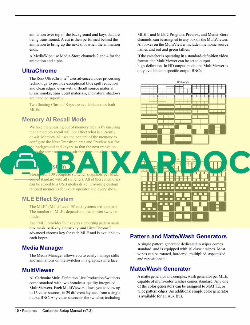
MultiViewerAll CarboniteMulti-Definition Live Production Switcherscome standard with two broadcast-quality integratedMultiViewers. Each MultiViewer allows you to view upto 16 video sources, in 29 different layouts, from a singleoutput BNC. Any video source on the switcher, including
MLE 1 and MLE 2 Program, Preview, and Media-Storechannels, can be assigned to any box on theMultiViewer.All boxes on the MultiViewer include mnemonic sourcenames and red and green tallies.If the switcher is operating in a standard-definition videoformat, the MultiViewer can be set to outputhigh-definition. In HD output mode, the MultiViewer isonly available on specific output BNCs.
Pattern and Matte/Wash GeneratorsA single pattern generator dedicated to wipes comesstandard, and is equipped with 10 classic wipes. Mostwipes can be rotated, bordered, multiplied, aspectized,and repositioned.
Matte/Wash GeneratorAmatte generator and complexwash generator perMLE,capable of multi-color washes comes standard. Any oneof the color generators can be assigned to MATTE, orwipe pattern edges. An additional simple color generatoris available for an Aux Bus.
10 • Features — Carbonite Setup Manual (v7.3)